Embed Size (px)
Citation preview
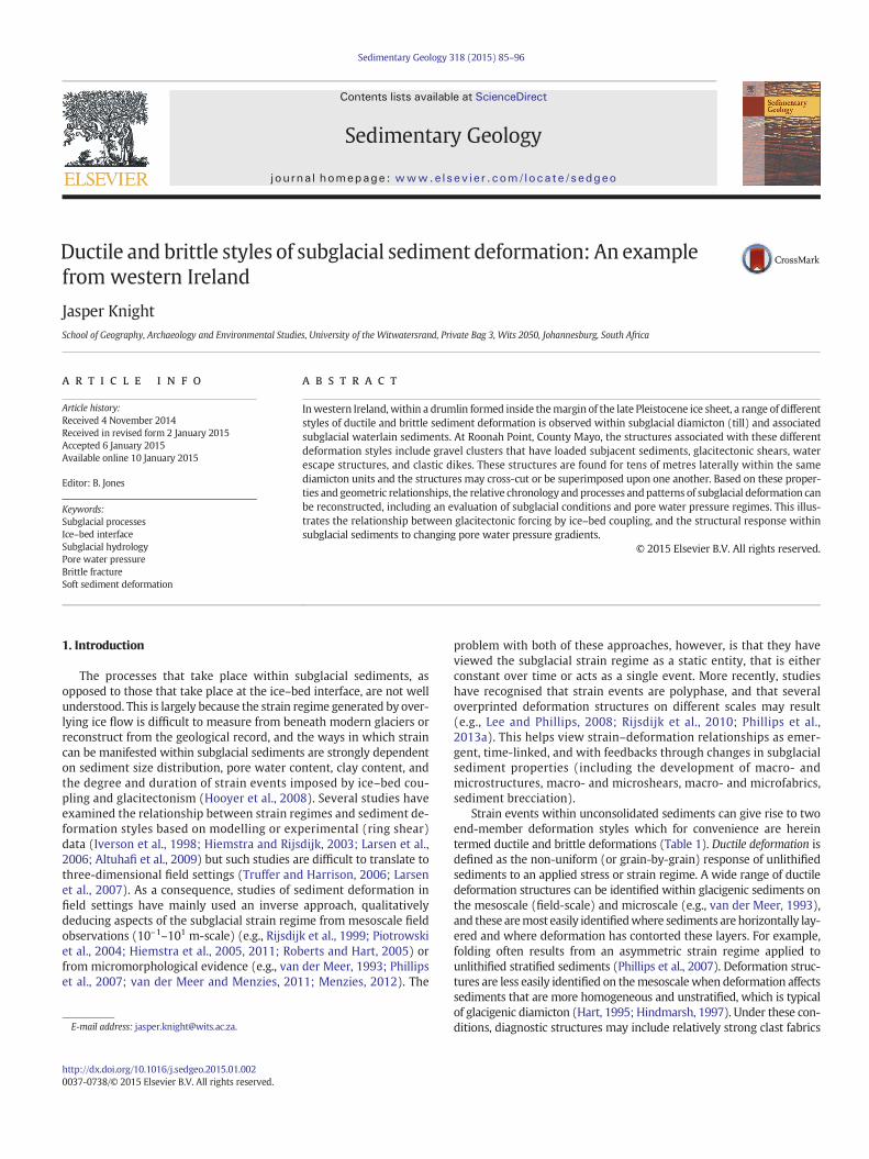
Sedimentary Geology 318 (2015) 85–96
Contents lists available at ScienceDirect
Sedimentary Geology
j ourna l homepage: www.e lsev ie r .com/ locate /sedgeo
Ductile and brittle styles of subglacial sediment deformation: An examplefrom western Ireland
Jasper KnightSchool of Geography, Archaeology and Environmental Studies, University of the Witwatersrand, Private Bag 3, Wits 2050, Johannesburg, South Africa
E-mail address: [email protected].
http://dx.doi.org/10.1016/j.sedgeo.2015.01.0020037-0738/© 2015 Elsevier B.V. All rights reserved.
a b s t r a c t
a r t i c l e i n f oArticle history:Received 4 November 2014Received in revised form 2 January 2015Accepted 6 January 2015Available online 10 January 2015
Editor: B. Jones
Keywords:Subglacial processesIce–bed interfaceSubglacial hydrologyPore water pressureBrittle fractureSoft sediment deformation
Inwestern Ireland,within a drumlin formed inside themargin of the late Pleistocene ice sheet, a range of differentstyles of ductile and brittle sediment deformation is observed within subglacial diamicton (till) and associatedsubglacial waterlain sediments. At Roonah Point, County Mayo, the structures associated with these differentdeformation styles include gravel clusters that have loaded subjacent sediments, glacitectonic shears, waterescape structures, and clastic dikes. These structures are found for tens of metres laterally within the samediamicton units and the structures may cross-cut or be superimposed upon one another. Based on these proper-ties and geometric relationships, the relative chronology and processes andpatterns of subglacial deformation canbe reconstructed, including an evaluation of subglacial conditions and pore water pressure regimes. This illus-trates the relationship between glacitectonic forcing by ice–bed coupling, and the structural response withinsubglacial sediments to changing pore water pressure gradients.
© 2015 Elsevier B.V. All rights reserved.
1. Introduction
The processes that take place within subglacial sediments, asopposed to those that take place at the ice–bed interface, are not wellunderstood. This is largely because the strain regime generated by over-lying ice flow is difficult to measure from beneath modern glaciers orreconstruct from the geological record, and the ways in which straincan be manifested within subglacial sediments are strongly dependenton sediment size distribution, pore water content, clay content, andthe degree and duration of strain events imposed by ice–bed cou-pling and glacitectonism (Hooyer et al., 2008). Several studies haveexamined the relationship between strain regimes and sediment de-formation styles based on modelling or experimental (ring shear)data (Iverson et al., 1998; Hiemstra and Rijsdijk, 2003; Larsen et al.,2006; Altuhafi et al., 2009) but such studies are difficult to translate tothree-dimensional field settings (Truffer and Harrison, 2006; Larsenet al., 2007). As a consequence, studies of sediment deformation infield settings have mainly used an inverse approach, qualitativelydeducing aspects of the subglacial strain regime from mesoscale fieldobservations (10–1–101 m-scale) (e.g., Rijsdijk et al., 1999; Piotrowskiet al., 2004; Hiemstra et al., 2005, 2011; Roberts and Hart, 2005) orfrom micromorphological evidence (e.g., van der Meer, 1993; Phillipset al., 2007; van der Meer and Menzies, 2011; Menzies, 2012). The
problem with both of these approaches, however, is that they haveviewed the subglacial strain regime as a static entity, that is eitherconstant over time or acts as a single event. More recently, studieshave recognised that strain events are polyphase, and that severaloverprinted deformation structures on different scales may result(e.g., Lee and Phillips, 2008; Rijsdijk et al., 2010; Phillips et al.,2013a). This helps view strain–deformation relationships as emer-gent, time-linked, and with feedbacks through changes in subglacialsediment properties (including the development of macro- andmicrostructures, macro- and microshears, macro- and microfabrics,sediment brecciation).
Strain events within unconsolidated sediments can give rise to twoend-member deformation styles which for convenience are hereintermed ductile and brittle deformations (Table 1). Ductile deformation isdefined as the non-uniform (or grain-by-grain) response of unlithifiedsediments to an applied stress or strain regime. A wide range of ductiledeformation structures can be identified within glacigenic sediments onthe mesoscale (field-scale) and microscale (e.g., van der Meer, 1993),and these aremost easily identifiedwhere sediments arehorizontally lay-ered and where deformation has contorted these layers. For example,folding often results from an asymmetric strain regime applied tounlithified stratified sediments (Phillips et al., 2007). Deformation struc-tures are less easily identified on themesoscalewhen deformation affectssediments that are more homogeneous and unstratified, which is typicalof glacigenic diamicton (Hart, 1995; Hindmarsh, 1997). Under these con-ditions, diagnostic structures may include relatively strong clast fabrics
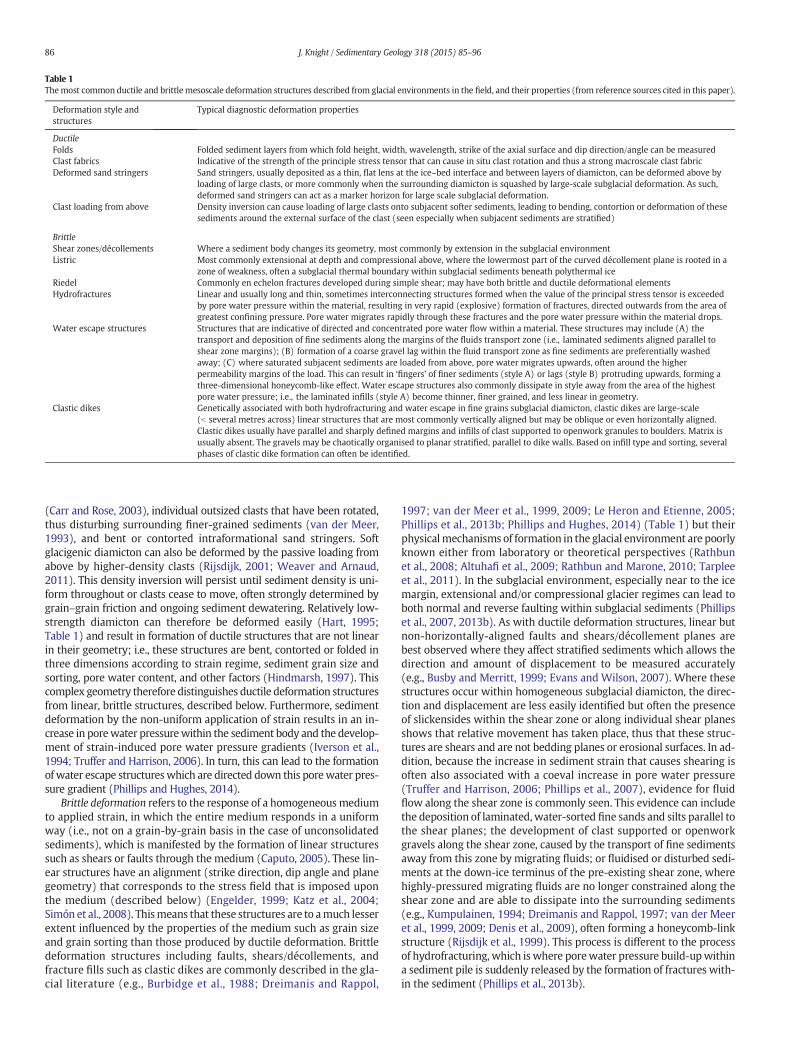
Table 1Themost common ductile and brittlemesoscale deformation structures described from glacial environments in the field, and their properties (from reference sources cited in this paper).
Deformation style andstructures
Typical diagnostic deformation properties
DuctileFolds Folded sediment layers from which fold height, width, wavelength, strike of the axial surface and dip direction/angle can be measuredClast fabrics Indicative of the strength of the principle stress tensor that can cause in situ clast rotation and thus a strong macroscale clast fabricDeformed sand stringers Sand stringers, usually deposited as a thin, flat lens at the ice–bed interface and between layers of diamicton, can be deformed above by
loading of large clasts, or more commonly when the surrounding diamicton is squashed by large-scale subglacial deformation. As such,deformed sand stringers can act as a marker horizon for large scale subglacial deformation.
Clast loading from above Density inversion can cause loading of large clasts onto subjacent softer sediments, leading to bending, contortion or deformation of thesesediments around the external surface of the clast (seen especially when subjacent sediments are stratified)
BrittleShear zones/décollements Where a sediment body changes its geometry, most commonly by extension in the subglacial environmentListric Most commonly extensional at depth and compressional above, where the lowermost part of the curved décollement plane is rooted in a
zone of weakness, often a subglacial thermal boundary within subglacial sediments beneath polythermal iceRiedel Commonly en echelon fractures developed during simple shear; may have both brittle and ductile deformational elementsHydrofractures Linear and usually long and thin, sometimes interconnecting structures formed when the value of the principal stress tensor is exceeded
by pore water pressure within the material, resulting in very rapid (explosive) formation of fractures, directed outwards from the area ofgreatest confining pressure. Pore water migrates rapidly through these fractures and the pore water pressure within the material drops.
Water escape structures Structures that are indicative of directed and concentrated pore water flow within a material. These structures may include (A) thetransport and deposition of fine sediments along the margins of the fluids transport zone (i.e., laminated sediments aligned parallel toshear zone margins); (B) formation of a coarse gravel lag within the fluid transport zone as fine sediments are preferentially washedaway; (C) where saturated subjacent sediments are loaded from above, pore water migrates upwards, often around the higherpermeability margins of the load. This can result in ‘fingers’ of finer sediments (style A) or lags (style B) protruding upwards, forming athree-dimensional honeycomb-like effect. Water escape structures also commonly dissipate in style away from the area of the highestpore water pressure; i.e., the laminated infills (style A) become thinner, finer grained, and less linear in geometry.
Clastic dikes Genetically associated with both hydrofracturing and water escape in fine grains subglacial diamicton, clastic dikes are large-scale(b several metres across) linear structures that are most commonly vertically aligned but may be oblique or even horizontally aligned.Clastic dikes usually have parallel and sharply defined margins and infills of clast supported to openwork granules to boulders. Matrix isusually absent. The gravels may be chaotically organised to planar stratified, parallel to dike walls. Based on infill type and sorting, severalphases of clastic dike formation can often be identified.
86 J. Knight / Sedimentary Geology 318 (2015) 85–96
(Carr and Rose, 2003), individual outsized clasts that have been rotated,thus disturbing surrounding finer-grained sediments (van der Meer,1993), and bent or contorted intraformational sand stringers. Softglacigenic diamicton can also be deformed by the passive loading fromabove by higher-density clasts (Rijsdijk, 2001; Weaver and Arnaud,2011). This density inversion will persist until sediment density is uni-form throughout or clasts cease to move, often strongly determined bygrain–grain friction and ongoing sediment dewatering. Relatively low-strength diamicton can therefore be deformed easily (Hart, 1995;Table 1) and result in formation of ductile structures that are not linearin their geometry; i.e., these structures are bent, contorted or folded inthree dimensions according to strain regime, sediment grain size andsorting, pore water content, and other factors (Hindmarsh, 1997). Thiscomplex geometry therefore distinguishes ductile deformation structuresfrom linear, brittle structures, described below. Furthermore, sedimentdeformation by the non-uniform application of strain results in an in-crease in porewater pressurewithin the sediment body and the develop-ment of strain-induced pore water pressure gradients (Iverson et al.,1994; Truffer and Harrison, 2006). In turn, this can lead to the formationofwater escape structureswhich are directed down this porewater pres-sure gradient (Phillips and Hughes, 2014).
Brittle deformation refers to the response of a homogeneousmediumto applied strain, in which the entire medium responds in a uniformway (i.e., not on a grain-by-grain basis in the case of unconsolidatedsediments), which is manifested by the formation of linear structuressuch as shears or faults through the medium (Caputo, 2005). These lin-ear structures have an alignment (strike direction, dip angle and planegeometry) that corresponds to the stress field that is imposed uponthe medium (described below) (Engelder, 1999; Katz et al., 2004;Simón et al., 2008). Thismeans that these structures are to amuch lesserextent influenced by the properties of the medium such as grain sizeand grain sorting than those produced by ductile deformation. Brittledeformation structures including faults, shears/décollements, andfracture fills such as clastic dikes are commonly described in the gla-cial literature (e.g., Burbidge et al., 1988; Dreimanis and Rappol,
1997; van der Meer et al., 1999, 2009; Le Heron and Etienne, 2005;Phillips et al., 2013b; Phillips and Hughes, 2014) (Table 1) but theirphysicalmechanisms of formation in the glacial environment are poorlyknown either from laboratory or theoretical perspectives (Rathbunet al., 2008; Altuhafi et al., 2009; Rathbun and Marone, 2010; Tarpleeet al., 2011). In the subglacial environment, especially near to the icemargin, extensional and/or compressional glacier regimes can lead toboth normal and reverse faulting within subglacial sediments (Phillipset al., 2007, 2013b). As with ductile deformation structures, linear butnon-horizontally-aligned faults and shears/décollement planes arebest observed where they affect stratified sediments which allows thedirection and amount of displacement to be measured accurately(e.g., Busby and Merritt, 1999; Evans and Wilson, 2007). Where thesestructures occur within homogeneous subglacial diamicton, the direc-tion and displacement are less easily identified but often the presenceof slickensides within the shear zone or along individual shear planesshows that relative movement has taken place, thus that these struc-tures are shears and are not bedding planes or erosional surfaces. In ad-dition, because the increase in sediment strain that causes shearing isoften also associated with a coeval increase in pore water pressure(Truffer and Harrison, 2006; Phillips et al., 2007), evidence for fluidflow along the shear zone is commonly seen. This evidence can includethe deposition of laminated, water-sorted fine sands and silts parallel tothe shear planes; the development of clast supported or openworkgravels along the shear zone, caused by the transport of fine sedimentsaway from this zone by migrating fluids; or fluidised or disturbed sedi-ments at the down-ice terminus of the pre-existing shear zone, wherehighly-pressured migrating fluids are no longer constrained along theshear zone and are able to dissipate into the surrounding sediments(e.g., Kumpulainen, 1994; Dreimanis and Rappol, 1997; van der Meeret al., 1999, 2009; Denis et al., 2009), often forming a honeycomb-linkstructure (Rijsdijk et al., 1999). This process is different to the processof hydrofracturing, which is where porewater pressure build-upwithina sediment pile is suddenly released by the formation of fractures with-in the sediment (Phillips et al., 2013b).
87J. Knight / Sedimentary Geology 318 (2015) 85–96
In practice, both ductile and brittle structures can be found withinthe same sediment units because they are both caused by an increaseand then the progressive decrease of pore water pressure (e.g., Phillipset al., 2007, 2013b; Lee and Phillips, 2008; Poppe et al., 2012; Neudorfet al., 2013). However, their precise relationships are uncertain. For ex-ample, subglacial sediment deformation (ductile) can lead to increasedporewater pressure and hydrofracturing (brittle). Porewatermigrationalong a shear zone (brittle) can lead to fluidisation or liquefaction at itsterminus (ductile).
In the subglacial environment, both styles of deformation describethe response of the sediment volume and thus pore water pressure tostress, which can be evaluated using the Mohr–Coulomb failure criteri-on and stress tensors σ1 to σ3 (de Paor, 1994; Engelder, 1999; Simónet al., 2008). Asymmetrical application of stress takes place in the sub-glacial environment mainly as a result of overlying ice flow, whichthus determines the direction of the principal stress tensor σ1
(Altuhafi et al., 2009). If strain exerted by the stress field exceeds thatof the Mohr failure envelope of that sediment, sediment deformationand/or failure can take place. Sediment response to strain in the subgla-cial environment can be identified in severalways. (1) If larger clasts arepresent within the sediment, then differences in strain between theupper and lower parts of the clast will induce torque, thus clast rotation,which is a style of ductile deformation. Clast rotation can be seen both inthe field and in micromorphological studies, where clasts are usuallysurrounded by an aureole of finer grained sediments which are moreeasily deformed within the clast rotation zone (van der Meer, 1993).The generation of such structures is strongly dependent on sizesorting and other geotechnical properties of the sediment (Hart,2006; Kilfeather and van derMeer, 2008) and gives rise to the forma-tion of clasts with a similar alignment within the sediment unit,which can be measured in the form of clast fabrics (Carr and Rose,2003). (2) If strain results in the realignment of finer sediments aswell as coarser sediments, then microscale shearing of parallel-aligned clay particles (Thomason and Iverson, 2006) can lead tofield-scale shearing and faulting – a style of brittle deformation – inwhich strain is accommodated by modification of the sediment vol-ume by compression or extension. Such brittle fracture is commonunder high and highly asymmetric stress regimes. In addition, suchtectonic conditions can lead to increased pore water pressure withinhighly-strained and low permeability sediments (Truffer and Harrison,2006), which can in turn promote the formation of hydrofracturing,water-escape structures and clastic dikes (Dreimanis, 1992; Dreimanisand Rappol, 1997; Phillips and Hughes, 2014) which are also brittle de-formation structures, as defined above. In sum, subglacial strain regimesand their changes over time/space strongly determine resultant defor-mation style, but these two elements have not been closely linked inmany previous studies. An inverse approach, using field evidence toinfer subglacial processes and conditions including strain regime, canhelp solve this problem (e.g., Piotrowski and Kraus, 1997; Roberts andHart, 2005; Larsen et al., 2006, 2007), and provides the context forthis study.
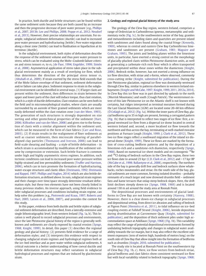
In this paper, evidence from both ductile and brittle styles of subgla-cial sediment deformation are described, from a laterally-extensive andsingle lithostratigraphic level, from western Ireland (Fig. 1a, b). This lo-cation is well placed to record subglacial processes and environments,since the late Pleistocene glacial history of the region is generally well-known and sediments are clearly exposed by coastal erosion (Synge,1968; Knight, 1999). In detail, this paper (1) describes the regionalgeology and glacial history; (2) presents field evidence for a range ofdeformation styles; and (3) interprets this evidence with respect tochanging subglacial strain regimes and hydrological regimes both atthe ice–bed interface and as pore water within subglacial sediments. Acritical outcome is a better understanding of how coeval ductile andbrittle deformation structures may reflect variations in subglacialhydrological processes and regimes that are induced by glacitectonicstrain.
2. Geology and regional glacial history of the study area
The geology of the Clew Bay region, western Ireland, comprises arange of Ordovician to Carboniferous igneous, metamorphic and sedi-mentary rocks (Fig. 1c). In the southwestern sector of the bay, granitesand metasediments including slates and quartzites are present inlandwith sandstones and slates found along the coastal fringe (Kennedy,1969), whereas in central and eastern Clew Bay Carboniferous lime-stones and sandstones are present (Graham, 1981; Maguire andGraham, 1995). The joints and bedding planes within the limestoneunits, in particular, have exerted a strong control on the morphologyof glacially-plucked clasts within Pleistocene diamicton units, as wellas generating a carbonate-rich rock flour which is often transportedand precipitated within shear zones within the diamictons (Knight,2006). Bedrock strike, however, has not exerted a strong influence onice flow direction, with striae and s-forms, where observed, commonlycross-cutting strike (Knight, submitted for publication). During thelate Pleistocene glaciation, regional ice flow was dominantly westwardthrough Clew Bay, similar to patterns elsewhere in western Ireland em-bayments (Knight andMcCabe, 1997; Knight, 1999, 2011, 2012a, 2014).In Clew Bay this ice flow was in part directed by uplands to the north(Murrisk Mountains) and south (Croagh Patrick). The westernmost ex-tent of this late Pleistocene ice on the Atlantic shelf is not known withcertainty, but ridges interpreted as terminal moraines formed duringthe Last Glacial Maximum (LGM) are located some 20–60 km offshore(Ó Cofaigh et al., 2012) (Fig. 1a).Within the inner parts of Clew Bay, gla-cial bedforms up to 35m high are present, forming a corrugated pattern(Fig. 1b) that is interpreted to reflect two stages of ice flow: first, a re-gional westward ice flow from a dispersal ice dome located in centralwestern Ireland and, second, a more localised ice flow towards thenorthwest and thus across the bay, terminating atwell-markedmorainepositions at Furnace Lough (Knight, 1999; J. Clark et al., 2012). Thesetwo ice flow stages reflect a southward migration of the inland ice dis-persal dome (Knight, 1999). These ice flows are marked by the forma-tion of cross-cutting bedform patterns and by the deposition of alimestone-rich and a sandstone-rich diamicton, respectively (Synge,1968). Based on numerical ice sheet models and on cosmogenic 10Beand 36Cl dating of bedrock surfaces in the Clew Bay region, these twoice flows date to around 23 kyr (C.D. Clark et al., 2012) and N17 kyr BP(McCabe et al., 1998; Ballantyne et al., 2008), respectively. The northernside of the bay is generally drift free and bedrock surfaces show whale-backs, roches moutonnées and striae. On the south side of the bay, gla-cial sediments aremore common, forming isolated drumlins – probablyremnants of a much larger and now drowned drumlin field – sedimentfans and kame terraces that onlap steep bedrock slopes. Here, the driftlimit declines steeply down-ice (Synge, 1968, 1969) and is locatedaround 130 m asl around the study area at Roonah Point.
The depositional processes and environments of glacial land-forms in Clew Bay are not known with certainty (Hanvey, 1988).However, there is a clear down-ice change in subglacial processesand depositional setting, from direct ice abrasion and rafting of bedrockat Pigeon Point (Hiemstra et al., 2011), to tidal influence on ice–bedcoupling events at Fallduff Strand (Knight, 2006), leeside depositionduring drumlinisation at Carrowmore Quay (Knight, submitted forpublication), and the deposition of thick sediment piles under high ac-commodation space at Askillaun (Synge, 1968) (Fig. 1b). This variabilitymay reflect the range of potential depositional environments formed byundulating bedrock topography and changes in subglacial water avail-ability towards the ice margin, but it may also reflect the excellent sed-iment exposures (tens of metres high, hundreds of metres long) on thesouth side of Clew Bay that allow insight into the formation of bedformssuch as drumlins (Knight, 2010, submitted for publication).
The study site is located at Roonah Point on the southwestern tipof Clew Bay (Fig. 1b, c). Here, ice flow vectors from bedrock striae,glacial bedforms and clast fabrics show consistent westward ice flowbut with local variability related to bedrock topography (Synge, 1968;
a b
200 m
d
53 o45’50”N
9o53’07”W
Section examined (Fig. 2)
H
H
H
Drumlin
Drumlin
c
Fig. 1. (a) Map of the Ireland showing land above 200 m elevation (shaded), major late Pleistocene ice flow vectors (arrows; Synge, 1969), LGM-stage offshore ice limits on the Atlanticshelf (Ó Cofaigh et al., 2012), andmarginal stillstands during ice retreat (hatched line; Synge, 1969). This location of Clew Bay in central western Ireland (inset b) is shown. DB=DonegalBay, GB=Galway Bay; (b) the distribution of late Pleistocene subglacial bedformswithin ClewBay (after Synge, 1968;McCabe et al., 1998; J. Clark et al., 2012;mapmodified fromKnight,submitted for publication), and the locations of important sediment exposures named in the text including Roonah Point. Contours (dashed lines) are at 100 m intervals; (c) generalisedgeology map of Clew Bay, modified after Long et al. (1995); (d) digitally enhanced and annotated Google Earth image of the Roonah Point study site (image date 18 April 2011), outerboundaries of drumlins (dotted lines) and hummocky morainic topography (H).
88 J. Knight / Sedimentary Geology 318 (2015) 85–96
Hanvey, 1988; Smith and Knight, 2011). This evidence suggests rela-tively thin ice, complex patterns of ice interaction with its bed, and a‘checkerboard’-like substrate pattern in which bedrock is locallyexposed in some places and sediments in others (e.g., Knight, 2002;Piotrowski et al., 2004; Tylmann et al., 2013). This setting provides thecontext for examining the coastal sediment exposure at Roonah Point,which is b200 m long and 3–6 m high. The exposure is northeast-facing and is cut into a subdued and low-elevation drumlin. Sedimentswithin this exposure have been described very briefly byHanvey (1988,pp. 94–96, under the site name Roevirohua). Previously, surface land-forms at this locality have been interpreted as part of an end morainesystem (Synge, 1968) and correlated to a similar ice limit on the adja-cent Clare Island (Coxon, 1994), although precise moraine positionsare unclear. Hummocky morainic topography is present in the areaaround Roonah Point (Fig. 1c) and bedrock with roches mountonnéesis exposed in places. On the foreshore, sandstone bedrock is exposedand shows a glacially-smoothed surface with striae that are aligned to-wards the northwest.
3. Methods
Sediments at Roonah Point were logged stratigraphically from bot-tom to top and recorded across the section using the facies codingscheme of Eyles et al. (1983). The entire section was photographedand sediment stratigraphy was drawn from a photo montage, andcalibrated from individual logs taken across the length of the section.Deformation structures of different types (described above) were
noted within the section with respect to their geometry, orientation(using a compass) and stratigraphic context, and which are shown inFig. 2. These directional data were plotted manually.
4. Results
4.1. Sediment stratigraphy and internal sedimentary structures
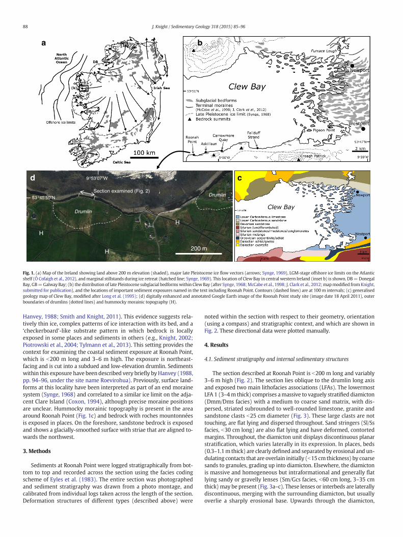
The section described at Roonah Point is b200 m long and variably3–6 m high (Fig. 2). The section lies oblique to the drumlin long axisand exposed two main lithofacies associations (LFAs). The lowermostLFA 1 (3–4m thick) comprises amassive to vaguely stratified diamicton(Dmm/Dms facies) with a medium to coarse sand matrix, with dis-persed, striated subrounded to well-rounded limestone, granite andsandstone clasts b25 cm diameter (Fig. 3). These large clasts are nottouching, are flat lying and dispersed throughout. Sand stringers (Sl/Ssfacies, b30 cm long) are also flat lying and have deformed, contortedmargins. Throughout, the diamicton unit displays discontinuous planarstratification, which varies laterally in its expression. In places, beds(0.3–1.1m thick) are clearly defined and separated by erosional and un-dulating contacts that are overlain initially (b15 cm thickness) by coarsesands to granules, grading up into diamicton. Elsewhere, the diamictonis massive and homogeneous but intraformational and generally flatlying sandy or gravelly lenses (Sm/Gcs facies, b60 cm long, 3–35 cmthick) may be present (Fig. 3a–c). These lenses or interbeds are laterallydiscontinuous, merging with the surrounding diamicton, but usuallyoverlie a sharply erosional base. Upwards through the diamicton,
10 20 300
0
2
4
6
m
m
East
West
Beach
C
7d
7b 7c
LFA 1
LFA 2
DBA
LFA 1
LFA 2
0
2
4
6
m
Ductile deformation structuresBrittle deformation structures
30 605040 m
7a
5b
5aLFA 1
LFA 2
LFA 1
LFA 2
Beach
Prominent clastsBed boundariesShear zones
Lithofacies codes (see text for description)
Sm
DmsDmm
DmmSs
Dmm
Dmm
Dms
Dmm
Dmm GcmDms
Gcm
GcmGcs
Ss
Gcs
Gcm
Sm
Dmm
Gcm
SsDms
DmmDms
DmmDms
Dmm
DmsSs
Dms
Gcs
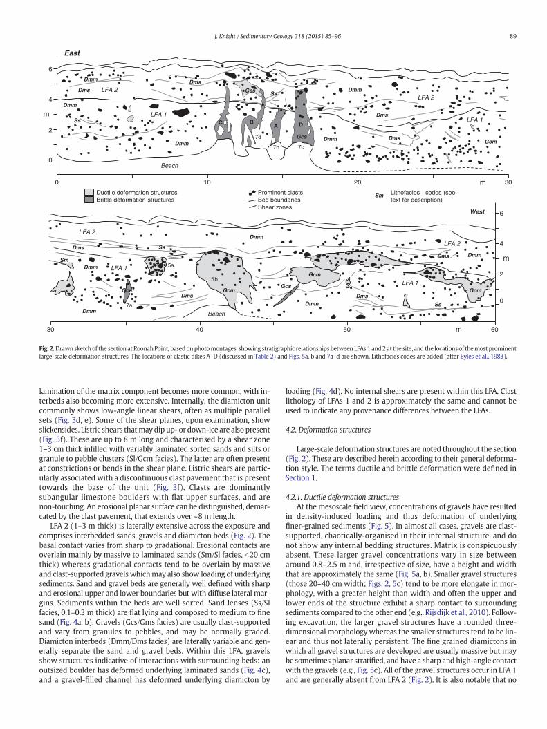
Fig. 2.Drawn sketch of the section at RoonahPoint, based on photomontages, showing stratigraphic relationships between LFAs 1 and 2 at the site, and the locations of themost prominentlarge-scale deformation structures. The locations of clastic dikes A–D (discussed in Table 2) and Figs. 5a, b and 7a–d are shown. Lithofacies codes are added (after Eyles et al., 1983).
89J. Knight / Sedimentary Geology 318 (2015) 85–96
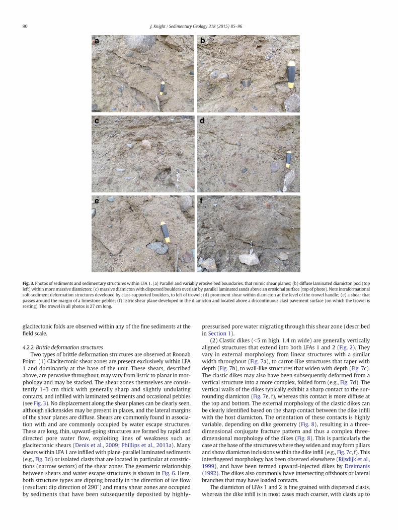
lamination of the matrix component becomes more common, with in-terbeds also becoming more extensive. Internally, the diamicton unitcommonly shows low-angle linear shears, often as multiple parallelsets (Fig. 3d, e). Some of the shear planes, upon examination, showslickensides. Listric shears thatmay dip up- or down-ice are also present(Fig. 3f). These are up to 8 m long and characterised by a shear zone1–3 cm thick infilled with variably laminated sorted sands and silts orgranule to pebble clusters (Sl/Gcm facies). The latter are often presentat constrictions or bends in the shear plane. Listric shears are partic-ularly associated with a discontinuous clast pavement that is presenttowards the base of the unit (Fig. 3f). Clasts are dominantlysubangular limestone boulders with flat upper surfaces, and arenon-touching. An erosional planar surface can be distinguished, demar-cated by the clast pavement, that extends over ~8 m length.
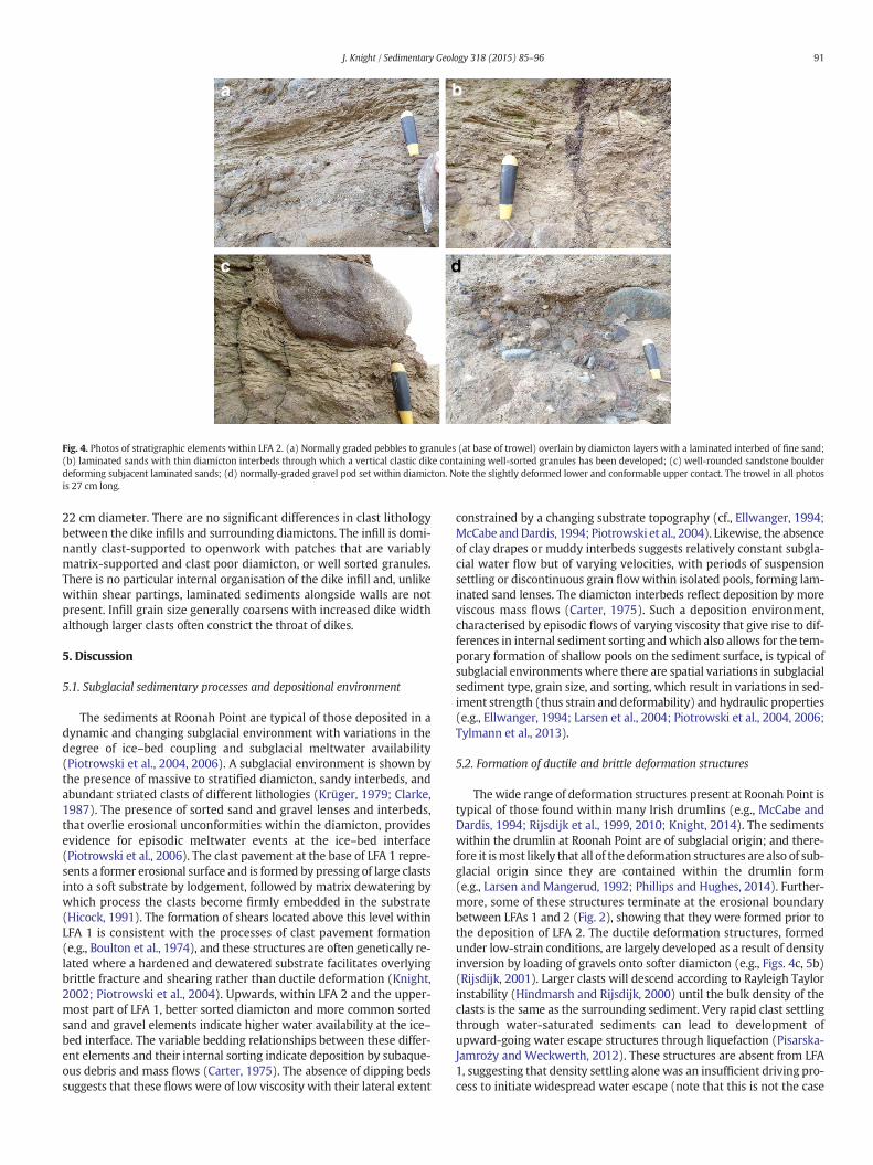
LFA 2 (1–3 m thick) is laterally extensive across the exposure andcomprises interbedded sands, gravels and diamicton beds (Fig. 2). Thebasal contact varies from sharp to gradational. Erosional contacts areoverlain mainly by massive to laminated sands (Sm/Sl facies, b20 cmthick) whereas gradational contacts tend to be overlain by massiveand clast-supported gravelswhichmay also show loading of underlyingsediments. Sand and gravel beds are generally well defined with sharpand erosional upper and lower boundaries but with diffuse lateral mar-gins. Sediments within the beds are well sorted. Sand lenses (Ss/Slfacies, 0.1–0.3 m thick) are flat lying and composed to medium to finesand (Fig. 4a, b). Gravels (Gcs/Gms facies) are usually clast-supportedand vary from granules to pebbles, and may be normally graded.Diamicton interbeds (Dmm/Dms facies) are laterally variable and gen-erally separate the sand and gravel beds. Within this LFA, gravelsshow structures indicative of interactions with surrounding beds: anoutsized boulder has deformed underlying laminated sands (Fig. 4c),and a gravel-filled channel has deformed underlying diamicton by
loading (Fig. 4d). No internal shears are present within this LFA. Clastlithology of LFAs 1 and 2 is approximately the same and cannot beused to indicate any provenance differences between the LFAs.
4.2. Deformation structures
Large-scale deformation structures are noted throughout the section(Fig. 2). These are described herein according to their general deforma-tion style. The terms ductile and brittle deformation were defined inSection 1.
4.2.1. Ductile deformation structuresAt the mesoscale field view, concentrations of gravels have resulted
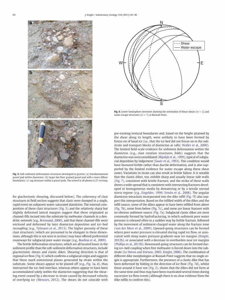
in density-induced loading and thus deformation of underlyingfiner-grained sediments (Fig. 5). In almost all cases, gravels are clast-supported, chaotically-organised in their internal structure, and donot show any internal bedding structures. Matrix is conspicuouslyabsent. These larger gravel concentrations vary in size betweenaround 0.8–2.5 m and, irrespective of size, have a height and widththat are approximately the same (Fig. 5a, b). Smaller gravel structures(those 20–40 cm width; Figs. 2, 5c) tend to be more elongate in mor-phology, with a greater height than width and often the upper andlower ends of the structure exhibit a sharp contact to surroundingsediments compared to the other end (e.g., Rijsdijk et al., 2010). Follow-ing excavation, the larger gravel structures have a rounded three-dimensional morphology whereas the smaller structures tend to be lin-ear and thus not laterally persistent. The fine grained diamictons inwhich all gravel structures are developed are usually massive but maybe sometimes planar stratified, and have a sharp and high-angle contactwith the gravels (e.g., Fig. 5c). All of the gravel structures occur in LFA 1and are generally absent from LFA 2 (Fig. 2). It is also notable that no
a b
c d
e f
Fig. 3. Photos of sediments and sedimentary structures within LFA 1. (a) Parallel and variably erosive bed boundaries, that mimic shear planes; (b) diffuse laminated diamicton pod (topleft) withinmoremassive diamicton; (c)massive diamictonwith dispersed boulders overlain by parallel laminated sands above an erosional surface (top of photo). Note intraformationalsoft-sediment deformation structures developed by clast-supported boulders, to left of trowel; (d) prominent shear within diamicton at the level of the trowel handle; (e) a shear thatpasses around the margin of a limestone pebble; (f) listric shear plane developed in the diamicton and located above a discontinuous clast pavement surface (on which the trowel isresting). The trowel in all photos is 27 cm long.
90 J. Knight / Sedimentary Geology 318 (2015) 85–96
glacitectonic folds are observed within any of the fine sediments at thefield scale.
4.2.2. Brittle deformation structuresTwo types of brittle deformation structures are observed at Roonah
Point: (1) Glacitectonic shear zones are present exclusively within LFA1 and dominantly at the base of the unit. These shears, describedabove, are pervasive throughout, may vary from listric to planar inmor-phology and may be stacked. The shear zones themselves are consis-tently 1–3 cm thick with generally sharp and slightly undulatingcontacts, and infilled with laminated sediments and occasional pebbles(see Fig. 3). No displacement along the shear planes can be clearly seen,although slickensides may be present in places, and the lateral marginsof the shear planes are diffuse. Shears are commonly found in associa-tion with and are commonly occupied by water escape structures.These are long, thin, upward-going structures are formed by rapid anddirected pore water flow, exploiting lines of weakness such asglacitectonic shears (Denis et al., 2009; Phillips et al., 2013a). Manyshearswithin LFA 1 are infilledwith plane-parallel laminated sediments(e.g., Fig. 3d) or isolated clasts that are located in particular at constric-tions (narrow sectors) of the shear zones. The geometric relationshipbetween shears and water escape structures is shown in Fig. 6. Here,both structure types are dipping broadly in the direction of ice flow(resultant dip direction of 290°) and many shear zones are occupiedby sediments that have been subsequently deposited by highly-
pressurised pore water migrating through this shear zone (describedin Section 1).
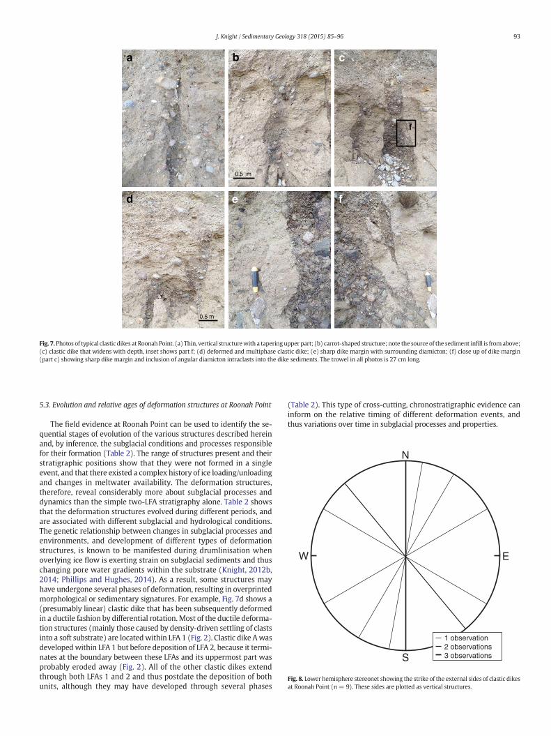
(2) Clastic dikes (b5 m high, 1.4 m wide) are generally verticallyaligned structures that extend into both LFAs 1 and 2 (Fig. 2). Theyvary in external morphology from linear structures with a similarwidth throughout (Fig. 7a), to carrot-like structures that taper withdepth (Fig. 7b), to wall-like structures that widen with depth (Fig. 7c).The clastic dikes may also have been subsequently deformed from avertical structure into a more complex, folded form (e.g., Fig. 7d). Thevertical walls of the dikes typically exhibit a sharp contact to the sur-rounding diamicton (Fig. 7e, f), whereas this contact is more diffuse atthe top and bottom. The external morphology of the clastic dikes canbe clearly identified based on the sharp contact between the dike infillwith the host diamicton. The orientation of these contacts is highlyvariable, depending on dike geometry (Fig. 8), resulting in a three-dimensional conjugate fracture pattern and thus a complex three-dimensional morphology of the dikes (Fig. 8). This is particularly thecase at the base of the structureswhere theywiden andmay formpillarsand show diamicton inclusionswithin the dike infill (e.g., Fig. 7c, f). Thisinterfingered morphology has been observed elsewhere (Rijsdijk et al.,1999), and have been termed upward-injected dikes by Dreimanis(1992). The dikes also commonly have intersecting offshoots or lateralbranches that may have loaded contacts.
The diamicton of LFAs 1 and 2 is fine grained with dispersed clasts,whereas the dike infill is in most cases much coarser, with clasts up to
a b
c d
Fig. 4. Photos of stratigraphic elements within LFA 2. (a) Normally graded pebbles to granules (at base of trowel) overlain by diamicton layers with a laminated interbed of fine sand;(b) laminated sands with thin diamicton interbeds through which a vertical clastic dike containing well-sorted granules has been developed; (c) well-rounded sandstone boulderdeforming subjacent laminated sands; (d) normally-graded gravel pod set within diamicton. Note the slightly deformed lower and conformable upper contact. The trowel in all photosis 27 cm long.
91J. Knight / Sedimentary Geology 318 (2015) 85–96
22 cm diameter. There are no significant differences in clast lithologybetween the dike infills and surrounding diamictons. The infill is domi-nantly clast-supported to openwork with patches that are variablymatrix-supported and clast poor diamicton, or well sorted granules.There is no particular internal organisation of the dike infill and, unlikewithin shear partings, laminated sediments alongside walls are notpresent. Infill grain size generally coarsens with increased dike widthalthough larger clasts often constrict the throat of dikes.
5. Discussion
5.1. Subglacial sedimentary processes and depositional environment
The sediments at Roonah Point are typical of those deposited in adynamic and changing subglacial environment with variations in thedegree of ice–bed coupling and subglacial meltwater availability(Piotrowski et al., 2004, 2006). A subglacial environment is shown bythe presence of massive to stratified diamicton, sandy interbeds, andabundant striated clasts of different lithologies (Krüger, 1979; Clarke,1987). The presence of sorted sand and gravel lenses and interbeds,that overlie erosional unconformities within the diamicton, providesevidence for episodic meltwater events at the ice–bed interface(Piotrowski et al., 2006). The clast pavement at the base of LFA 1 repre-sents a former erosional surface and is formed by pressing of large clastsinto a soft substrate by lodgement, followed by matrix dewatering bywhich process the clasts become firmly embedded in the substrate(Hicock, 1991). The formation of shears located above this level withinLFA 1 is consistent with the processes of clast pavement formation(e.g., Boulton et al., 1974), and these structures are often genetically re-lated where a hardened and dewatered substrate facilitates overlyingbrittle fracture and shearing rather than ductile deformation (Knight,2002; Piotrowski et al., 2004). Upwards, within LFA 2 and the upper-most part of LFA 1, better sorted diamicton and more common sortedsand and gravel elements indicate higher water availability at the ice–bed interface. The variable bedding relationships between these differ-ent elements and their internal sorting indicate deposition by subaque-ous debris and mass flows (Carter, 1975). The absence of dipping bedssuggests that these flows were of low viscosity with their lateral extent
constrained by a changing substrate topography (cf., Ellwanger, 1994;McCabe andDardis, 1994; Piotrowski et al., 2004). Likewise, the absenceof clay drapes or muddy interbeds suggests relatively constant subgla-cial water flow but of varying velocities, with periods of suspensionsettling or discontinuous grain flowwithin isolated pools, forming lam-inated sand lenses. The diamicton interbeds reflect deposition by moreviscous mass flows (Carter, 1975). Such a deposition environment,characterised by episodic flows of varying viscosity that give rise to dif-ferences in internal sediment sorting andwhich also allows for the tem-porary formation of shallow pools on the sediment surface, is typical ofsubglacial environments where there are spatial variations in subglacialsediment type, grain size, and sorting, which result in variations in sed-iment strength (thus strain and deformability) and hydraulic properties(e.g., Ellwanger, 1994; Larsen et al., 2004; Piotrowski et al., 2004, 2006;Tylmann et al., 2013).
5.2. Formation of ductile and brittle deformation structures
Thewide range of deformation structures present at Roonah Point istypical of those found within many Irish drumlins (e.g., McCabe andDardis, 1994; Rijsdijk et al., 1999, 2010; Knight, 2014). The sedimentswithin the drumlin at Roonah Point are of subglacial origin; and there-fore it ismost likely that all of thedeformation structures are also of sub-glacial origin since they are contained within the drumlin form(e.g., Larsen and Mangerud, 1992; Phillips and Hughes, 2014). Further-more, some of these structures terminate at the erosional boundarybetween LFAs 1 and 2 (Fig. 2), showing that they were formed prior tothe deposition of LFA 2. The ductile deformation structures, formedunder low-strain conditions, are largely developed as a result of densityinversion by loading of gravels onto softer diamicton (e.g., Figs. 4c, 5b)(Rijsdijk, 2001). Larger clasts will descend according to Rayleigh Taylorinstability (Hindmarsh and Rijsdijk, 2000) until the bulk density of theclasts is the same as the surrounding sediment. Very rapid clast settlingthrough water-saturated sediments can lead to development ofupward-going water escape structures through liquefaction (Pisarska-Jamroży and Weckwerth, 2012). These structures are absent from LFA1, suggesting that density settling alonewas an insufficient driving pro-cess to initiate widespread water escape (note that this is not the case
a
b
c
Fig. 5. Soft-sediment deformation structures developed in gravels. (a) Intraformationalgravel pod within diamicton; (b) larger but finer grained gravel pod with a more diffuseboundaries; (c) sag structure within a gravel pods. The trowel in all photos is 27 cm long.
W
S
N
E
ShearWater escape
Fig. 6. Lower hemisphere stereonet showing the orientation of linear shears (n = 2) andwater escape structures (n = 7) at Roonah Point.
92 J. Knight / Sedimentary Geology 318 (2015) 85–96
for glacitectonic shearing, discussed below). The coherency of claststructures in field section suggests that clasts were dumped in a single,rapid event on subjacent water-saturated diamicton. The internal com-position of these clast structures (Fig. 5) and the relatively sharp butslightly deformed lateral margins suggest that these originated aschannel-fills incised into the substrate by meltwater channels in a den-dritic network (e.g., Brennand, 2000), and that these channel-fills wereenclosed and deformed by later diamicton deposition and ice–bedrecoupling (e.g., Tylmann et al., 2013). The higher porosity of theseclast structures (which are presumed to be elongate in three dimen-sions, although this is not seen in section)may have offered preferentialrouteways for subglacial pore water escape (e.g., Boulton et al., 2009).
The brittle deformation structures, which are all located lower in thesediment profile than the soft-sediment deformation structures, includeglacitectonic shears and clastic dikes. Shearing direction is that ofregional iceflow (Fig. 6)which confirms a subglacial origin and suggeststhat these mark extensional planes generated by strain within thesubstrate. Some shears appear to be planed off (e.g., Fig. 3a, d), thusintersected the ice–bed interface, whereas others appear to have beenaccommodated solely within the diamicton suggesting that the shear-ing event ceased by a decrease in strain caused by decreased velocityof overlying ice (Menzies, 2012). The shears do not coincide with
pre-existing textural boundaries and, based on the height attained bythe shear along its length, were unlikely to have been formed byfreeze-on of basal ice (i.e., that the ice bed did not freeze on to the sub-strate and transport blocks of diamicton as rafts; Waller et al., 2000).The limited field-scale evidence for sediment deformation within thediamicton (e.g., clast rotation structures, folds) suggests that thediamictonwas overconsolidated (Rijsdijk et al., 1999), typical of subgla-cial deposition by lodgement (Sauer et al., 1993). This condition wouldhave favoured brittle rather than ductile deformation, and is also sup-ported by the limited evidence for water escape along these shearzones. Variations in strain can also result in brittle failure. It is notablethat the clastic dikes, too, exhibit sharp and usually linear side walls(Fig. 7), consistent with brittle fracture, and the strike of these wallsshows awide spread that is consistentwith intersecting fractures devel-oped in homogeneous media by dewatering or by a tensile normalstress regime (e.g., Engelder, 1999; Simón et al., 2008). The angulardiamicton intraclasts incorporated into the dike infill (Fig. 7f) also sup-port this interpretation. Based on the infilled width of the dikes and theinfill source, some of the dikes appear to have been infilled from above(Fig. 7b), some from below (Fig. 7c), and some are linear features withno obvious sediment source (Fig. 7a). Subglacial clastic dikes are mostcommonly formed by hydrofracturing, in which sediment pore waterpressure is released often in a sudden way by brittle fracture, followedby the movement of sediment-charged water along the fracture zone(van der Meer et al., 2009). Upward-going structures can be formedwhere pore water pressure is elevated during rapid ice flow, or asso-ciated with steep water pressure gradients near ice margins (Knight,2012b), or associated with a decrease in overburden near ice margins(Phillips et al., 2013b). Downward-going structures can be formed dur-ing ice–bed coupling when free meltwater is forced down into the sub-strate (Le Heron and Etienne, 2005; Knight, 2006). The combination ofdifferent dike morphologies at Roonah Point suggests that no single or-igin is appropriate. Furthermore, the presence of a clastic dike that hasbeen deformed by folding in the direction of ice flow (Fig. 7d), whilstthose around it have not (Fig. 2), shows that the dikes did not form atthe same time and thusmay have been reactivated several times duringsuccessive ice flow events (although there is no clear evidence from thedike infills to confirm this).
a b
d e
c
f
f
0.5 m
0.5 m
Fig. 7.Photos of typical clastic dikes at Roonah Point. (a) Thin, vertical structurewith a taperingupper part; (b) carrot-shaped structure; note the source of the sediment infill is fromabove;(c) clastic dike that widens with depth, inset shows part f; (d) deformed and multiphase clastic dike; (e) sharp dike margin with surrounding diamicton; (f) close up of dike margin(part c) showing sharp dike margin and inclusion of angular diamicton intraclasts into the dike sediments. The trowel in all photos is 27 cm long.
W
S
N
E
1 observation2 observations3 observations
Fig. 8. Lower hemisphere stereonet showing the strike of the external sides of clastic dikesat Roonah Point (n = 9). These sides are plotted as vertical structures.
93J. Knight / Sedimentary Geology 318 (2015) 85–96
5.3. Evolution and relative ages of deformation structures at Roonah Point
The field evidence at Roonah Point can be used to identify the se-quential stages of evolution of the various structures described hereinand, by inference, the subglacial conditions and processes responsiblefor their formation (Table 2). The range of structures present and theirstratigraphic positions show that they were not formed in a singleevent, and that there existed a complex history of ice loading/unloadingand changes in meltwater availability. The deformation structures,therefore, reveal considerably more about subglacial processes anddynamics than the simple two-LFA stratigraphy alone. Table 2 showsthat the deformation structures evolved during different periods, andare associated with different subglacial and hydrological conditions.The genetic relationship between changes in subglacial processes andenvironments, and development of different types of deformationstructures, is known to be manifested during drumlinisation whenoverlying ice flow is exerting strain on subglacial sediments and thuschanging pore water gradients within the substrate (Knight, 2012b,2014; Phillips and Hughes, 2014). As a result, some structures mayhave undergone several phases of deformation, resulting in overprintedmorphological or sedimentary signatures. For example, Fig. 7d shows a(presumably linear) clastic dike that has been subsequently deformedin a ductile fashion by differential rotation.Most of the ductile deforma-tion structures (mainly those caused by density-driven settling of clastsinto a soft substrate) are locatedwithin LFA 1 (Fig. 2). Clastic dike Awasdevelopedwithin LFA 1 but before deposition of LFA 2, because it termi-nates at the boundary between these LFAs and its uppermost part wasprobably eroded away (Fig. 2). All of the other clastic dikes extendthrough both LFAs 1 and 2 and thus postdate the deposition of bothunits, although they may have developed through several phases
(Table 2). This type of cross-cutting, chronostratigraphic evidence caninform on the relative timing of different deformation events, andthus variations over time in subglacial processes and properties.
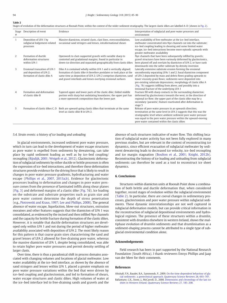
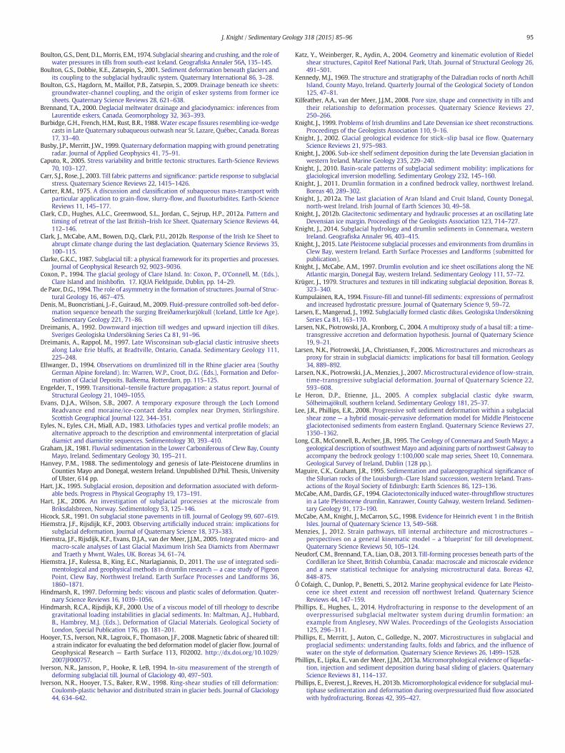
Table 2Stages of evolution of the deformation structures at Roonah Point, within the context of the wider sediment stratigraphy. The largest clastic dikes are labelled A–D (shown in Fig. 2).
Stage#
Description of event Evidence Interpretation of subglacial and pore water processes andenvironment
1 Deposition of LFA 1 bysubglacial lodgement-relatedprocesses
Massive diamicton, striated clasts, clast lines, overconsolidation,occasional sand stringers and lenses, intraformational shears
Low availability of free meltwater at the ice–bed interface,meltwater concentrated into Nye channels cut into the substrate;ice–bed coupling leading to shearing and some limited waterescape, ice–bed interactions become more episodic upwards withgreater meltwater availability
2 Formation of ductiledeformation structureswithin LFA 1
Openwork to clast-supported gravels with variable sharp tocontorted and gradational margins; found in particular indown-ice direction and separated geographically from clastic dikes
Nye channels that have been subsequently infilled by gravels;gravel structures have been variously deformed by glacitectonics,been planed off and overlain by diamicton of LFA 2, or have sunkdownwards into the softer substrate by density inversion
3 Erosional truncation of LFA 1and deposition of LFA 2;formation of clastic dike A
Dike A is contained wholly within LFA 1 and is vertically aligned;formation of clastic dike A therefore postdates or took place at thesame time as deposition of LFA 2; LFA 2 comprises diamicton, sandand gravel interbeds and lenses overlying erosional surfaces
Laterally extensive substrate erosion forming the erosionalunconformity separating LFAs 1 and 2; basal diamicton componentof LFA 2 deposited by mass and debris flows grading upwards tolower viscosity grain flows; sediments were deposited intopre-existing substrate depressions; morphology of clastic dike A(Fig. 7b) suggests infilling from above, and possibly into atensional fracture of the underlying LFA 1
4 Formation and deformationof clastic dike B
Tapered upper and lower parts of the clastic dike; folded middleportion with sharp but undulating boundaries; the upper part hasa more openwork composition than the lower part
Fracture fill with sharp contacts to the surrounding diamicton;deformed by glacitectonics towards the west, in the direction ofregional ice flow; the upper part of the clastic dike may be asecondary (parasitic) feature reactivated after deformation instage 5
5 Formation of clastic dikes C, D Both are upward-going clastic dikes that terminate at the samelevel as clastic dike B in LFA 2.
Release of pore water pressure in an upwards direction;termination at the same level in LFA 2 suggests that this was thestratigraphic level where ambient sediment pore water pressurewas equal to the pore water pressure within the upward-movingpore water contained within the clastic dikes
94 J. Knight / Sedimentary Geology 318 (2015) 85–96
5.4. Strain events: a history of ice loading and unloading
In glacial environments, increased sediment pore water pressure,which in turn can lead to the development of water escape structuresas pore water is expelled from sediments by dewatering, can takeplace by rapid sediment loading as well as by ice–bed coupling/recoupling (Rijsdijk, 2001;Weigelt et al., 2012). Glacitectonic deforma-tion of subglacial sediments by either ductile or brittle processes is oftenthe expression of ice–bed interactions, and therefore these deformationstructures provide evidence for the driving force that is likely to result inchanges in pore water pressure gradients, hydrofracturing and waterescape (Phillips et al., 2007, 2013a,b). Evidence for glacitectonicprocesses leading to deformation and changes in pore water pres-sure comes from the presence of laminated infills along shear planes(Fig. 3) and deformed margins of a clastic dike (Fig. 7d). Ice loadingon the substrate and substrate properties such as grain size andpore water content determine the depth of stress penetration(e.g., Piotrowski and Kraus, 1997; Lee and Phillips, 2008). The generalabsence of water escape, liquefaction, blow-out structures, extrusionmoraines and other features suggests that the diamicton of LFA 1 wasconsolidated, as evidenced by the incised and then infilled Nye channelsand the capacity for brittle fracture during formation of the clastic dikes.However, it is notable that ductile deformation structures are devel-oped only within LFA 1 and not during the period of higher meltwateravailability associated with deposition of LFA 2. The most likely reasonfor this pattern is that coarse grain sizes characterising the sand andgravel lenses of LFA 2 allowed for free-draining pore water, whereasthe massive diamicton of LFA 1, despite being consolidated, was ableto retain higher pore water pressures and permit density settling oflarger clasts.
Over time, there is thus a paradoxical shift in process domains asso-ciated with changing volumes and locations of glacial meltwater. Lowwater availability at the ice–bed interface, as shown by the absence ofsand stringers and lenses within LFA 1, placed a greater emphasis onpore water pressure variations within the bed that were driven byice–bed coupling and glacitectonism, and led to formation of shears,water escape structures and clastic dikes. High volumes of water atthe ice–bed interface led to free-draining sands and gravels and the
absence of such structures indicative of water flow. This shifting loca-tion of subglacial water activity has not been fully explored in manyprevious studies, but are relevant in the context of reconstructing icedynamics, since efficient evacuation of subglacial meltwater by sedi-ment dewatering leads to decreased ice velocity, ice–bed recouplingand ice margin stagnation (Boulton et al., 2001; Knight, 2012b).Reconstructing the history of ice loading and unloading from subglacialsediments can therefore be used as a tool to reconstruct ice sheetdynamics.
6. Conclusions
Structures within diamicton units at Roonah Point show a combina-tion of both brittle and ductile deformation that, when consideredtogether, record stages of evolution within the subglacial environment(Table 2). In particular, there are coeval changes in sedimentary pro-cesses, glacitectonism and pore water pressure within subglacial sedi-ments. These dynamic interrelationships are not well captured insubglacial deformation models, but can provide critical information inthe reconstruction of subglacial depositional environments and hydro-logical regimes. The presence of these structures within a drumlin,consistent with drumlins elsewhere in western Ireland, shows themul-tiphase evolution of drumlin sediments and that drumlinisation as asediment-shaping process cannot be attributed to a single type of sub-glacial environmental condition alone.
Acknowledgements
Field research has been in part supported by the National ResearchFoundation (South Africa). I thank reviewers Emrys Phillips and Jaapvan der Meer for their comments.
References
Altuhafi, F.N., Baudet, B.A., Sammonds, P., 2009. On the time-dependent behaviour of gla-cial sediments: a geotechnical approach. Quaternary Science Reviews 28, 693–707.
Ballantyne, C.K., Stone, J., McCarroll, D., 2008. Dimensions and chronology of the last icesheet in Western Ireland. Quaternary Science Reviews 27, 185–200.
95J. Knight / Sedimentary Geology 318 (2015) 85–96
Boulton, G.S., Dent, D.L., Morris, E.M., 1974. Subglacial shearing and crushing, and the role ofwater pressures in tills from south-east Iceland. Geografiska Annaler 56A, 135–145.
Boulton, G.S., Dobbie, K.E., Zatsepin, S., 2001. Sediment deformation beneath glaciers andits coupling to the subglacial hydraulic system. Quaternary International 86, 3–28.
Boulton, G.S., Hagdorn, M., Maillot, P.B., Zatsepin, S., 2009. Drainage beneath ice sheets:groundwater-channel coupling, and the origin of esker systems from former icesheets. Quaternary Science Reviews 28, 621–638.
Brennand, T.A., 2000. Deglacial meltwater drainage and glaciodynamics: inferences fromLaurentide eskers, Canada. Geomorphology 32, 363–393.
Burbidge, G.H., French, H.M., Rust, B.R., 1988.Water escape fissures resembling ice-wedgecasts in Late Quaternary subaqueous outwash near St. Lazare, Québec, Canada. Boreas17, 33–40.
Busby, J.P., Merritt, J.W., 1999. Quaternary deformation mappingwith ground penetratingradar. Journal of Applied Geophysics 41, 75–91.
Caputo, R., 2005. Stress variability and brittle tectonic structures. Earth-Science Reviews70, 103–127.
Carr, S.J., Rose, J., 2003. Till fabric patterns and significance: particle response to subglacialstress. Quaternary Science Reviews 22, 1415–1426.
Carter, R.M., 1975. A discussion and classification of subaqueous mass-transport withparticular application to grain-flow, slurry-flow, and fluxoturbidites. Earth-ScienceReviews 11, 145–177.
Clark, C.D., Hughes, A.L.C., Greenwood, S.L., Jordan, C., Sejrup, H.P., 2012a. Pattern andtiming of retreat of the last British–Irish Ice Sheet. Quaternary Science Reviews 44,112–146.
Clark, J., McCabe, A.M., Bowen, D.Q., Clark, P.U., 2012b. Response of the Irish Ice Sheet toabrupt climate change during the last deglaciation. Quaternary Science Reviews 35,100–115.
Clarke, G.K.C., 1987. Subglacial till: a physical framework for its properties and processes.Journal of Geophysical Research 92, 9023–9036.
Coxon, P., 1994. The glacial geology of Clare Island. In: Coxon, P., O'Connell, M. (Eds.),Clare Island and Inishbofin. 17. IQUA Fieldguide, Dublin, pp. 14–29.
de Paor, D.G., 1994. The role of asymmetry in the formation of structures. Journal of Struc-tural Geology 16, 467–475.
Denis, M., Buoncristiani, J.-F., Guiraud, M., 2009. Fluid-pressure controlled soft-bed defor-mation sequence beneath the surging Breiðamerkurjökull (Iceland, Little Ice Age).Sedimentary Geology 221, 71–86.
Dreimanis, A., 1992. Downward injection till wedges and upward injection till dikes.Sveriges Geologiska Undersökning Series Ca 81, 91–96.
Dreimanis, A., Rappol, M., 1997. Late Wisconsinan sub-glacial clastic intrusive sheetsalong Lake Erie bluffs, at Bradtville, Ontario, Canada. Sedimentary Geology 111,225–248.
Ellwanger, D., 1994. Observations on drumlinized till in the Rhine glacier area (SouthyGerman Alpine foreland). In: Warren, W.P., Croot, D.G. (Eds.), Formation and Defor-mation of Glacial Deposits. Balkema, Rotterdam, pp. 115–125.
Engelder, T., 1999. Transitional–tensile fracture propagation: a status report. Journal ofStructural Geology 21, 1049–1055.
Evans, D.J.A., Wilson, S.B., 2007. A temporary exposure through the Loch LomondReadvance end moraine/ice-contact delta complex near Drymen, Stirlingshire.Scottish Geographical Journal 122, 344–351.
Eyles, N., Eyles, C.H., Miall, A.D., 1983. Lithofacies types and vertical profile models; analternative approach to the description and environmental interpretation of glacialdiamict and diamictite sequences. Sedimentology 30, 393–410.
Graham, J.R., 1981. Fluvial sedimentation in the Lower Carboniferous of Clew Bay, CountyMayo, Ireland. Sedimentary Geology 30, 195–211.
Hanvey, P.M., 1988. The sedimentology and genesis of late-Pleistocene drumlins inCounties Mayo and Donegal, western Ireland. Unpublished D.Phil. Thesis, Universityof Ulster, 614 pp.
Hart, J.K., 1995. Subglacial erosion, deposition and deformation associated with deform-able beds. Progress in Physical Geography 19, 173–191.
Hart, J.K., 2006. An investigation of subglacial processes at the microscale fromBriksdalsbreen, Norway. Sedimentology 53, 125–146.
Hicock, S.R., 1991. On subglacial stone pavements in till. Journal of Geology 99, 607–619.Hiemstra, J.F., Rijsdijk, K.F., 2003. Observing artificially induced strain: implications for
subglacial deformation. Journal of Quaternary Science 18, 373–383.Hiemstra, J.F., Rijsdijk, K.F., Evans, D.J.A., van der Meer, J.J.M., 2005. Integrated micro- and
macro-scale analyses of Last Glacial Maximum Irish Sea Diamicts from Abermawrand Traeth y Mwnt, Wales, UK. Boreas 34, 61–74.
Hiemstra, J.F., Kulessa, B., King, E.C., Ntarlagiannis, D., 2011. The use of integrated sedi-mentological and geophysical methods in drumlin research — a case study of PigeonPoint, Clew Bay, Northwest Ireland. Earth Surface Processes and Landforms 36,1860–1871.
Hindmarsh, R., 1997. Deforming beds: viscous and plastic scales of deformation. Quater-nary Science Reviews 16, 1039–1056.
Hindmarsh, R.C.A., Rijsdijk, K.F., 2000. Use of a viscous model of till rheology to describegravitational loading instabilities in glacial sediments. In: Maltman, A.J., Hubbard,B., Hambrey, M.J. (Eds.), Deformation of Glacial Materials. Geological Society ofLondon, Special Publication 176, pp. 181–201.
Hooyer, T.S., Iverson, N.R., Lagroix, F., Thomason, J.F., 2008. Magnetic fabric of sheared till:a strain indicator for evaluating the bed deformation model of glacier flow. Journal ofGeophysical Research — Earth Surface 113, F02002. http://dx.doi.org/10.1029/2007JF000757.
Iverson, N.R., Jansson, P., Hooke, R. LeB, 1994. In-situ measurement of the strength ofdeforming subglacial till. Journal of Glaciology 40, 497–503.
Iverson, N.R., Hooyer, T.S., Baker, R.W., 1998. Ring-shear studies of till deformation:Coulomb-plastic behavior and distributed strain in glacier beds. Journal of Glaciology44, 634–642.
Katz, Y., Weinberger, R., Aydin, A., 2004. Geometry and kinematic evolution of Riedelshear structures, Capitol Reef National Park, Utah. Journal of Structural Geology 26,491–501.
Kennedy, M.J., 1969. The structure and stratigraphy of the Dalradian rocks of north AchillIsland, County Mayo, Ireland. Quarterly Journal of the Geological Society of London125, 47–81.
Kilfeather, A.A., van der Meer, J.J.M., 2008. Pore size, shape and connectivity in tills andtheir relationship to deformation processes. Quaternary Science Reviews 27,250–266.
Knight, J., 1999. Problems of Irish drumlins and Late Devensian ice sheet reconstructions.Proceedings of the Geologists Association 110, 9–16.
Knight, J., 2002. Glacial geological evidence for stick–slip basal ice flow. QuaternaryScience Reviews 21, 975–983.
Knight, J., 2006. Sub-ice shelf sediment deposition during the late Devensian glaciation inwestern Ireland. Marine Geology 235, 229–240.
Knight, J., 2010. Basin-scale patterns of subglacial sediment mobility: implications forglaciological inversion modelling. Sedimentary Geology 232, 145–160.
Knight, J., 2011. Drumlin formation in a confined bedrock valley, northwest Ireland.Boreas 40, 289–302.
Knight, J., 2012a. The last glaciation of Aran Island and Cruit Island, County Donegal,north-west Ireland. Irish Journal of Earth Sciences 30, 49–58.
Knight, J., 2012b. Glacitectonic sedimentary and hydraulic processes at an oscillating lateDevensian ice margin. Proceedings of the Geologists Association 123, 714–727.
Knight, J., 2014. Subglacial hydrology and drumlin sediments in Connemara, westernIreland. Geografiska Annaler 96, 403–415.
Knight, J., 2015. Late Pleistocene subglacial processes and environments from drumlins inClew Bay, western Ireland. Earth Surface Processes and Landforms (submitted forpublication).
Knight, J., McCabe, A.M., 1997. Drumlin evolution and ice sheet oscillations along the NEAtlantic margin, Donegal Bay, western Ireland. Sedimentary Geology 111, 57–72.
Krüger, J., 1979. Structures and textures in till indicating subglacial deposition. Boreas 8,323–340.
Kumpulainen, R.A., 1994. Fissure-fill and tunnel-fill sediments: expressions of permafrostand increased hydrostatic pressure. Journal of Quaternary Science 9, 59–72.
Larsen, E., Mangerud, J., 1992. Subglacially formed clastic dikes. Geologiska UndersökningSeries Ca 81, 163–170.
Larsen, N.K., Piotrowski, J.A., Kronborg, C., 2004. A multiproxy study of a basal till: a time-transgressive accretion and deformation hypothesis. Journal of Quaternary Science19, 9–21.
Larsen, N.K., Piotrowski, J.A., Christiansen, F., 2006. Microstructures and microshears asproxy for strain in subglacial diamicts: implications for basal till formation. Geology34, 889–892.
Larsen, N.K., Piotrowski, J.A., Menzies, J., 2007. Microstructural evidence of low-strain,time-transgressive subglacial deformation. Journal of Quaternary Science 22,593–608.
Le Heron, D.P., Etienne, J.L., 2005. A complex subglacial clastic dyke swarm,Sólheimajökull, southern Iceland. Sedimentary Geology 181, 25–37.
Lee, J.R., Phillips, E.R., 2008. Progressive soft sediment deformation within a subglacialshear zone — a hybrid mosaic-pervasive deformation model for Middle Pleistoceneglaciotectonised sediments from eastern England. Quaternary Science Reviews 27,1350–1362.
Long, C.B., McConnell, B., Archer, J.B., 1995. The Geology of Connemara and South Mayo; ageological description of southwestMayo and adjoining parts of northwest Galway toaccompany the bedrock geology 1:100,000 scale map series, Sheet 10, Connemara.Geological Survey of Ireland, Dublin (128 pp.).
Maguire, C.K., Graham, J.R., 1995. Sedimentation and palaeogeographical significance ofthe Silurian rocks of the Louisburgh–Clare Island succession, western Ireland. Trans-actions of the Royal Society of Edinburgh: Earth Sciences 86, 123–136.
McCabe, A.M., Dardis, G.F., 1994. Glaciotectonically inducedwater-throughflow structuresin a Late Pleistocene drumlin, Kanrawer, County Galway, western Ireland. Sedimen-tary Geology 91, 173–190.
McCabe, A.M., Knight, J., McCarron, S.G., 1998. Evidence for Heinrich event 1 in the BritishIsles. Journal of Quaternary Science 13, 549–568.
Menzies, J., 2012. Strain pathways, till internal architecture and microstructures –perspectives on a general kinematic model – a ‘blueprint’ for till development.Quaternary Science Reviews 50, 105–124.
Neudorf, C.M., Brennand, T.A., Lian, O.B., 2013. Till-forming processes beneath parts of theCordilleran Ice Sheet, British Columbia, Canada: macroscale and microscale evidenceand a new statistical technique for analysing microstructural data. Boreas 42,848–875.
Ó Cofaigh, C., Dunlop, P., Benetti, S., 2012. Marine geophysical evidence for Late Pleisto-cene ice sheet extent and recession off northwest Ireland. Quaternary ScienceReviews 44, 147–159.
Phillips, E., Hughes, L., 2014. Hydrofracturing in response to the development of anoverpressurised subglacial meltwater system during drumlin formation: anexample from Anglesey, NW Wales. Proceedings of the Geologists Association125, 296–311.
Phillips, E., Merritt, J., Auton, C., Golledge, N., 2007. Microstructures in subglacial andproglacial sediments: understanding faults, folds and fabrics, and the influence ofwater on the style of deformation. Quaternary Science Reviews 26, 1499–1528.
Phillips, E., Lipka, E., van der Meer, J.J.M., 2013a. Micromorphological evidence of liquefac-tion, injection and sediment deposition during basal sliding of glaciers. QuaternaryScience Reviews 81, 114–137.
Phillips, E., Everest, J., Reeves, H., 2013b. Micromorphological evidence for subglacial mul-tiphase sedimentation and deformation during overpressurized fluid flow associatedwith hydrofracturing. Boreas 42, 395–427.
96 J. Knight / Sedimentary Geology 318 (2015) 85–96
Piotrowski, J.A., Kraus, A.M., 1997. Response of sediment to ice-sheet loading in north-western Germany: effective stresses and glacier-bed stability. Journal of Glaciology43, 495–502.
Piotrowski, J.A., Larsen, N.K., Junge, F.W., 2004. Reflections on soft subglacial beds as amosaic of deforming and stable spots. Quaternary Science Reviews 23, 993–1000.
Piotrowski, J.A., Larsen, N.K., Menzies, J., Wysota, W., 2006. Formation of subglacial tillunder transient bed conditions: deposition, deformation, and basal decouplingunder a Weichselian ice sheet lobe, central Poland. Sedimentology 53, 83–106.
Pisarska-Jamroży, M., Weckwerth, P., 2012. Soft-sediment deformation structures in aPleistocene glaciolacustrine delta and their implications for the recognition ofsubenvironments in delta deposits. Sedimentology 60, 637–665.
Poppe, L.J., Oldale, R.N., Foster, D.S., Smith, S.M., 2012. Glaciotectonic deformation associ-ated with the Orient Point–Fishers Island moraine, westernmost Block Island Sound:further evidence of readvance of the Laurentide ice sheet. Geo-Marine Letters 32,279–288.
Rathbun, A.P., Marone, C., 2010. Effect of strain localization on frictional behavior ofsheared granular materials. Journal of Geophysical Research — Solid Earth 115,B01204. http://dx.doi.org/10.1029/2009JB006466.
Rathbun, A.P., Marone, C., Alley, R.B., Anandakrishnan, S., 2008. Laboratory study of thefrictional rheology of sheared till. Journal of Geophysical Research — Earth Surface113, F02020. http://dx.doi.org/10.1029/2007JF000815.
Rijsdijk, K.F., 2001. Density driven deformation in consolidated glacial diamicts: examplesfrom Traeth y Mwnt, Cardiganshire, Wales. Journal of Sedimentary Research 71,122–135.
Rijsdijk, K.F., Owen, G., Warren, W.P., McCarroll, D., van der Meer, J.J.M., 1999. Clasticdykes in over-consolidated tills: evidence for subglacial hydrofracturing at KillineyBay, eastern Ireland. Sedimentary Geology 129, 111–126.
Rijsdijk, K.F., Warren, W.P., van der Meer, J.J.M., 2010. The glacial sequence at Killiney, SEIreland: terrestrial deglaciation and polyphase glacitectonic deformation. QuaternaryScience Reviews 29, 696–719.
Roberts, D.H., Hart, J.K., 2005. The deforming bed characteristics of a stratified till assem-blage in north East Anglia, UK: investigating controls on sediment rheology and strainsignatures. Quaternary Science Reviews 24, 123–140.
Sauer, E.K., Egeland, A.K., Christiansen, E.A., 1993. Compression characteristics and indexproperties of tills and intertill clays in southern Saskatchewan, Canada. CanadianGeotechnical Journal 30, 257–275.
Simón, J.L., Arlegui, L.E., Liesa, C.L., 2008. Stress partitioning: a practical concept foranalysing boundary conditions of brittle deformation. Geodinamica Acta 21,107–115.
Smith, M.J., Knight, J., 2011. Palaeoglaciology of the last Irish Ice Sheet reconstructed fromstriae evidence. Quaternary Science Reviews 30, 147–160.
Synge, F.M., 1968. The glaciation of west Mayo. Irish Geography 5, 372–386.Synge, F.M., 1969. TheWürm ice limit in the west of Ireland. In:Wright Jr., H.E. (Ed.), Qua-
ternary Geology and Climate. National Academy of Sciences, Washington, D.C.,pp. 89–92.
Tarplee, M.F.V., van der Meer, J.J.M., Davis, G.R., 2011. The 3D microscopic ‘signature’ ofstrain within glacial sediments revealed using X-ray computed microtomography.Quaternary Science Reviews 30, 3501–3532.
Thomason, J.F., Iverson, N.R., 2006. Microfabric and microshear evolution in deformed till.Quaternary Science Reviews 25, 1027–1038.
Truffer, M., Harrison, W.D., 2006. In situ measurements of till deformation and waterpressure. Journal of Glaciology 52, 175–182.
Tylmann, K., Piotrowski, J.A., Wysota, W., 2013. The ice/bed interface mosaic: deformingspots intervening with stable areas under the fringe of the Scandinavian Ice Sheetat Sampława, Poland. Boreas 42, 428–441.
van der Meer, J.J.M., 1993. Microscopic evidence of subglacial deformation. QuaternaryScience Reviews 12, 553–587.
van der Meer, J.J.M., Menzies, J., 2011. The micromorphology of unconsolidatedsediments. Sedimentary Geology 238, 213–232.
van der Meer, J.J.M., Kjær, K.H., Krüger, J., 1999. Subglacial water-escape structures and tillstructures, Sléttjökull, Iceland. Journal of Quaternary Science 14, 191–205.
van der Meer, J.J.M., Kjær, K.H., Krüger, J., Rabassa, J., Kilfeather, A.A., 2009. Under pres-sure: clastic dykes in glacial settings. Quaternary Science Reviews 28, 708–720.
Waller, R.I., Murton, J.B., Kristensen, L., 2000. Glacier–permafrost interactions: processes,products and glaciological implications. Sedimentary Geology 255, 1–28.
Weaver, L., Arnaud, E., 2011. Polyphase glacigenic deformation in the Waterloo Moraine,Kitchener, Ontario, Canada. Sedimentary Geology 235, 292–303.
Weigelt, E., Uenzelmann-Neben, G., Gohl, K., Larter, R.D., 2012. Did massive glacialdewatering modify sedimentary structures on the Amundsen Sea Embayment shelf,West Antarctica? Global and Planetary Change 92–93, 8–16.


