Embed Size (px)
Citation preview
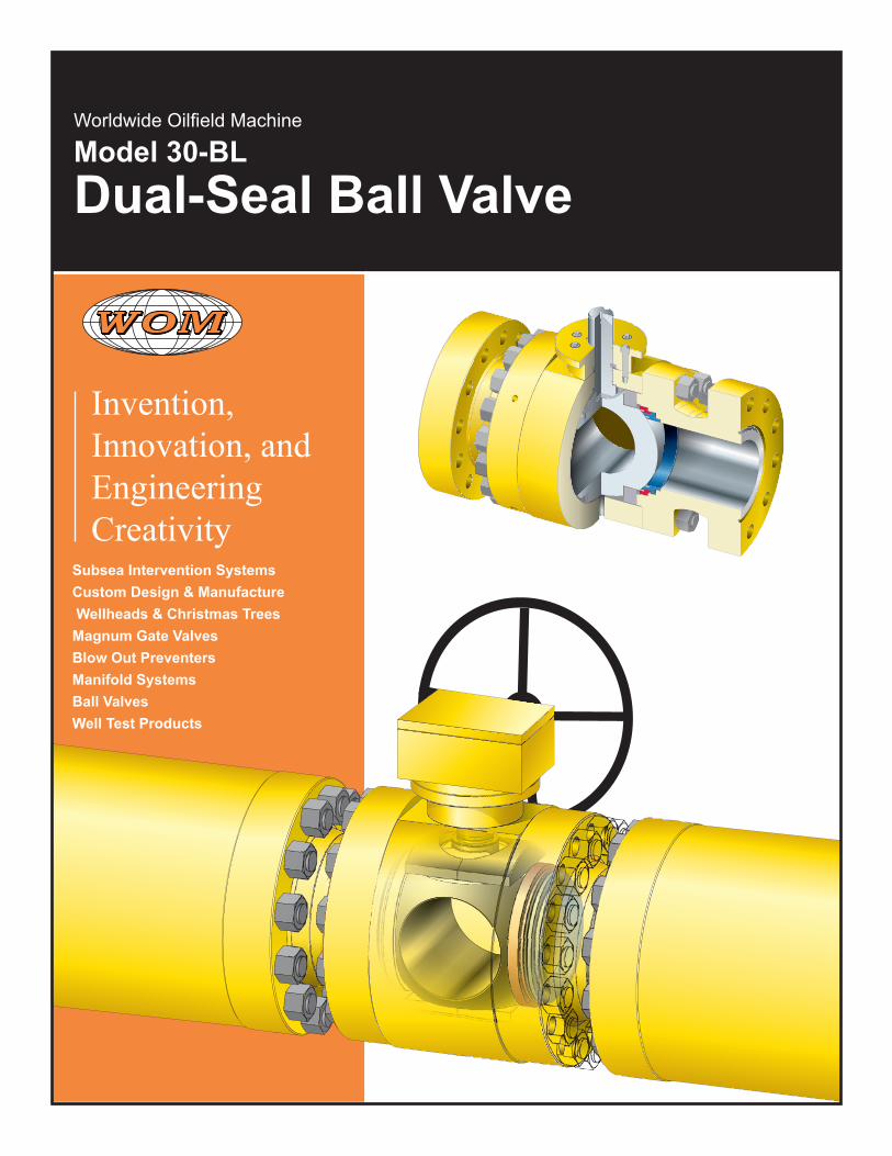
Invention, Innovation, and Engineering Creativity
Subsea Intervention SystemsCustom Design & Manufacture Wellheads & Christmas Trees Magnum Gate ValvesBlow Out PreventersManifold SystemsBall Valves Well Test Products
Worldwide Oilfield Machine
Model 30-BL
Dual-Seal Ball Valve

3
Model 30-BL
Introduction ..................................................................................................................4
Dual-Seal Ball Valve Features ......................................................................................5
Dimensional Data Class 150 ........................................................................................8
Dimensional Data Class 300 ........................................................................................9
Dimensional Data Class 600 ......................................................................................10
Dimensional Data Class 900 ...................................................................................... 11
Dimensional Data Class 1500 ....................................................................................12
Vertical Integration .....................................................................................................13
Special Options ..........................................................................................................13
General Design Standards .........................................................................................14
Typical Operating Pressures ......................................................................................14
Trim Chart ..................................................................................................................15
Fire Test Certification ..................................................................................................16
Patented Design .........................................................................................................17
The New Option .........................................................................................................18
Contact Us .................................................................................................................19
Table of Contents
4
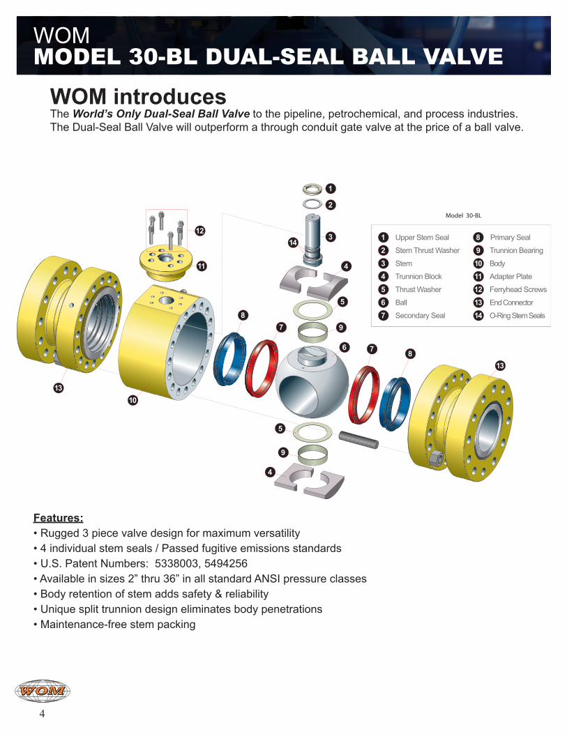
WOM introduces The World’s Only Dual-Seal Ball Valve to the pipeline, petrochemical, and process industries. The Dual-Seal Ball Valve will outperform a through conduit gate valve at the price of a ball valve.
Features:• Rugged 3 piece valve design for maximum versatility• 4 individual stem seals / Passed fugitive emissions standards• U.S. Patent Numbers: 5338003, 5494256• Available in sizes 2” thru 36” in all standard ANSI pressure classes• Body retention of stem adds safety & reliability• Unique split trunnion design eliminates body penetrations• Maintenance-free stem packing
WOM Model 30-Bl dual-Seal Ball ValVe
1
2
3
5
6
5
9
9
14
1013
11
121 Upper Stem Seal
2 Stem Thrust Washer
3 Stem
11 Adapter Plate
12 Ferryhead Screws
4 Trunnion Block
5 Thrust Washer
6 Ball
9 Trunnion Bearing
10 Body
13 End Connector
14 O-Ring Stem Seals7 Secondary Seal
8 Primary Seal
4
4
7 813
87
Model 30-BL
5
STEMPressure
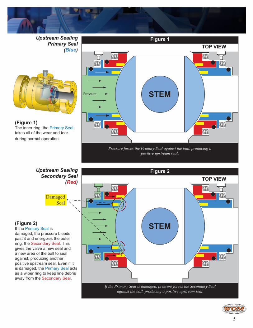
(Figure 1) The inner ring, the Primary Seal, takes all of the wear and tear during normal operation.
(Figure 2) If the Primary Seal is damaged, the pressure bleeds past it and energizes the outer ring, the Secondary Seal. This gives the valve a new seal and a new area of the ball to seal against, producing another positive upstream seal. Even if it is damaged, the Primary Seal acts as a wiper ring to keep line debris away from the Secondary Seal.
Figure 1
Pressure forces the Primary Seal against the ball, producing a positive upstream seal.
TOP VIEW
If the Primary Seal is damaged, pressure forces the Secondary Seal against the ball, producing a positive upstream seal.
Upstream SealingPrimary Seal
(Blue)
STEM
Figure 2TOP VIEW
Upstream SealingSecondary Seal
(Red)
DamagedSeal
6
WOM dual-Seal Ball ValVe
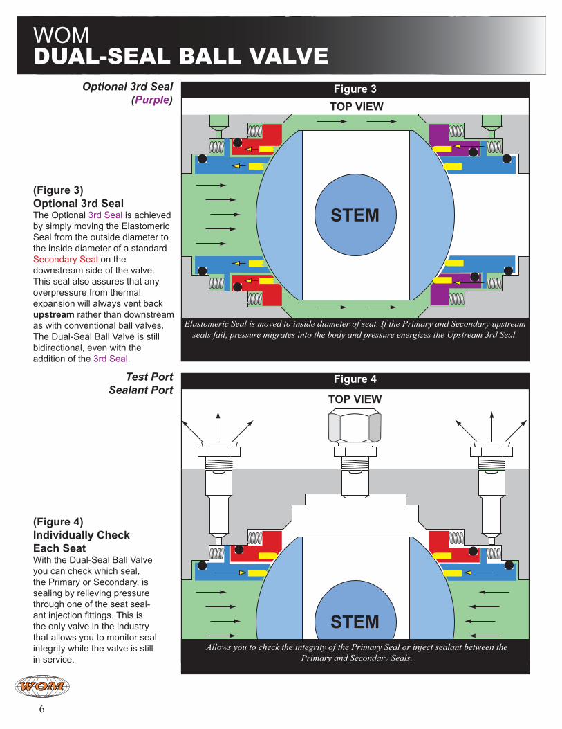
Allows you to check the integrity of the Primary Seal or inject sealant between the Primary and Secondary Seals.
(Figure 3)Optional 3rd Seal The Optional 3rd Seal is achieved by simply moving the Elastomeric Seal from the outside diameter to the inside diameter of a standard Secondary Seal on the downstream side of the valve. This seal also assures that any overpressure from thermal expansion will always vent back upstream rather than downstream as with conventional ball valves. The Dual-Seal Ball Valve is still bidirectional, even with the addition of the 3rd Seal.
(Figure 4)Individually Check Each Seat With the Dual-Seal Ball Valve you can check which seal, the Primary or Secondary, is sealing by relieving pressure through one of the seat seal-ant injection fittings. This is the only valve in the industry that allows you to monitor seal integrity while the valve is still in service.
STEM
Figure 3
Elastomeric Seal is moved to inside diameter of seat. If the Primary and Secondary upstream seals fail, pressure migrates into the body and pressure energizes the Upstream 3rd Seal.
TOP VIEW
STEM
Figure 4
TOP VIEW
Test PortSealant Port
Optional 3rd Seal(Purple)
7
STEM
STEM
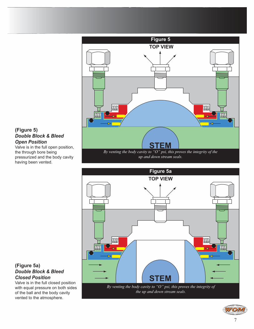
(Figure 5) Double Block & Bleed Open PositionValve is in the full open position, the through bore being pressurized and the body cavity having been vented.
(Figure 5a) Double Block & Bleed Closed PositionValve is in the full closed position with equal pressure on both sides of the ball and the body cavity vented to the atmosphere.
Figure 5
By venting the body cavity to “O” psi, this proves the integrity of the up and down stream seals.
TOP VIEW
By venting the body cavity to “O” psi, this proves the integrity of the up and down stream seals.
Figure 5aTOP VIEW
8
Dimensional data is to be used as general guidelines only; Not to be used for design work and is subject to change without notice.
H
GØ
B
CDØK
LØLØ
B
BCD DC
2.0” - 3.0”
4.0” - 6.0”
8.0” - 24.0”
(Square Key)
(Bolt Circle)
(drill thru)
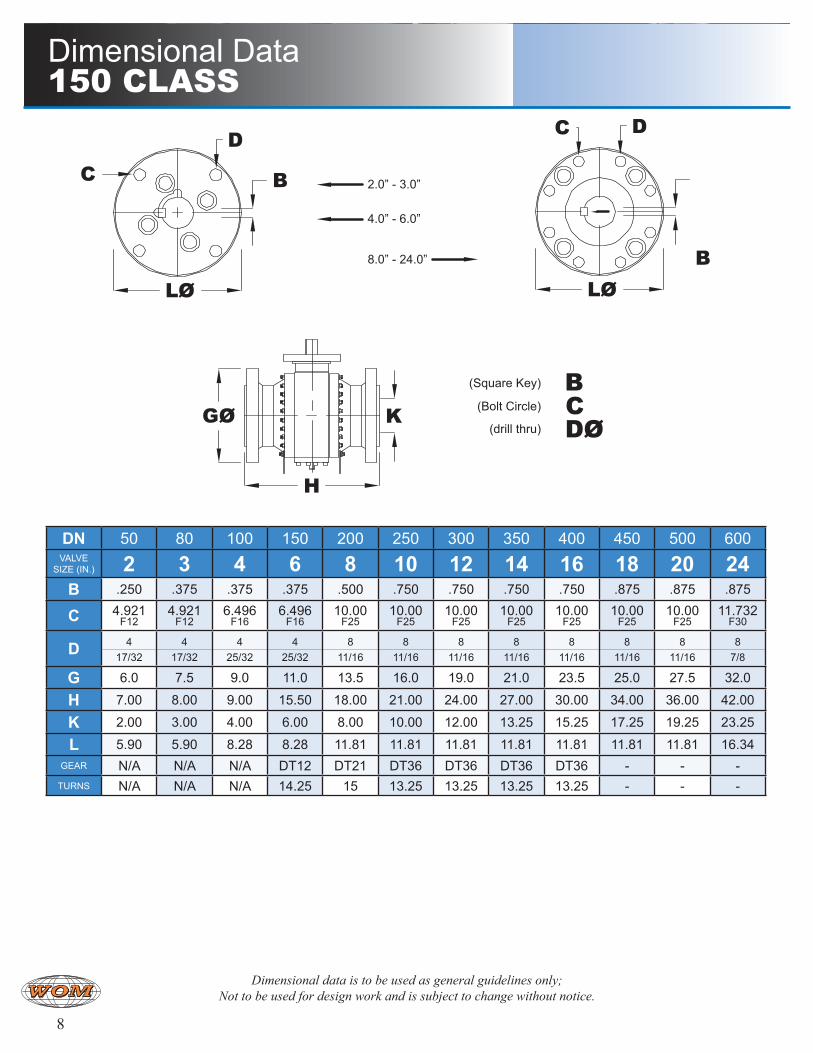
Dimensional Data 150 ClaSS
DN 50 80 100 150 200 250 300 350 400 450 500 600VALVE
SIZE (IN.) 2 3 4 6 8 10 12 14 16 18 20 24B .250 .375 .375 .375 .500 .750 .750 .750 .750 .875 .875 .875
C 4.921 F12
4.921 F12
6.496 F16
6.496 F16
10.00 F25
10.00 F25
10.00 F25
10.00 F25
10.00 F25
10.00 F25
10.00 F25
11.732 F30
D 417/32
417/32
425/32
425/32
811/16
811/16
811/16
811/16
811/16
811/16
811/16
87/8
G 6.0 7.5 9.0 11.0 13.5 16.0 19.0 21.0 23.5 25.0 27.5 32.0
H 7.00 8.00 9.00 15.50 18.00 21.00 24.00 27.00 30.00 34.00 36.00 42.00
K 2.00 3.00 4.00 6.00 8.00 10.00 12.00 13.25 15.25 17.25 19.25 23.25
L 5.90 5.90 8.28 8.28 11.81 11.81 11.81 11.81 11.81 11.81 11.81 16.34GEAR N/A N/A N/A DT12 DT21 DT36 DT36 DT36 DT36 - - -
TURNS N/A N/A N/A 14.25 15 13.25 13.25 13.25 13.25 - - -
9
H
GØ
B
CDØK
LØLØ
B
BCD DC
2.0” - 3.0”
4.0” - 6.0”
8.0” - 24.0”
(Square Key)
(Bolt Circle)
(drill thru)
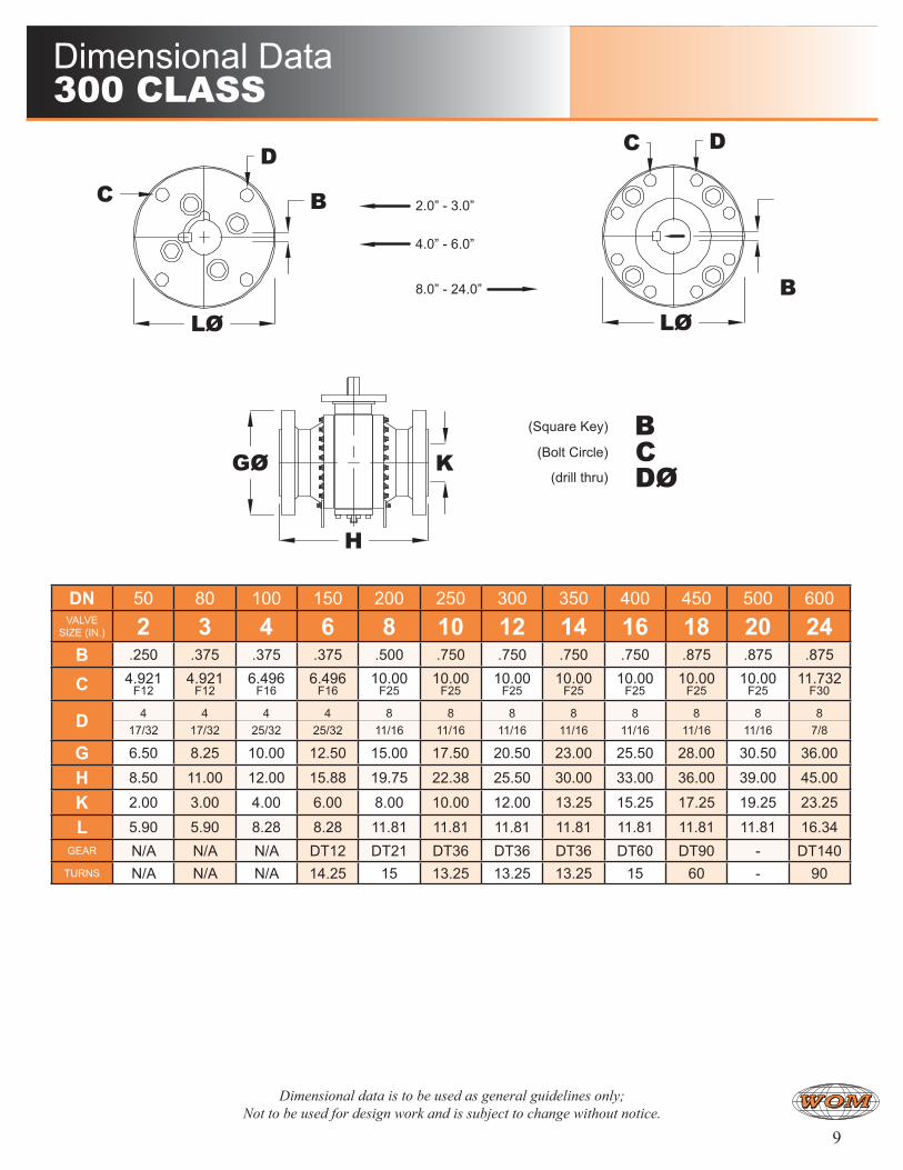
DN 50 80 100 150 200 250 300 350 400 450 500 600VALVE
SIZE (IN.) 2 3 4 6 8 10 12 14 16 18 20 24B .250 .375 .375 .375 .500 .750 .750 .750 .750 .875 .875 .875
C 4.921 F12
4.921 F12
6.496 F16
6.496 F16
10.00 F25
10.00 F25
10.00 F25
10.00 F25
10.00 F25
10.00 F25
10.00 F25
11.732 F30
D 417/32
417/32
425/32
425/32
811/16
811/16
811/16
811/16
811/16
811/16
811/16
87/8
G 6.50 8.25 10.00 12.50 15.00 17.50 20.50 23.00 25.50 28.00 30.50 36.00
H 8.50 11.00 12.00 15.88 19.75 22.38 25.50 30.00 33.00 36.00 39.00 45.00
K 2.00 3.00 4.00 6.00 8.00 10.00 12.00 13.25 15.25 17.25 19.25 23.25
L 5.90 5.90 8.28 8.28 11.81 11.81 11.81 11.81 11.81 11.81 11.81 16.34GEAR N/A N/A N/A DT12 DT21 DT36 DT36 DT36 DT60 DT90 - DT140
TURNS N/A N/A N/A 14.25 15 13.25 13.25 13.25 15 60 - 90
Dimensional Data 300 ClaSS
Dimensional data is to be used as general guidelines only; Not to be used for design work and is subject to change without notice.
10
DN 50 80 100 150 200 250 300 350 400 450 500 600 750VALVE
SIZE (IN.) 2 3 4 6 8 10 12 14 16 18 20 24 30B .250 .375 .375 .375 .500 .750 .750 .750 .750 .875 .875 .875 .875
C 4.921 F12
4.921 F12
6.496 F16
6.496 F16
10.00 F25
10.00 F25
10.00 F25
10.00 F25
10.00 F25
10.00 F25
10.00 F25
10.00 F25
11.732 F30
D 417/32
417/32
425/32
425/32
811/16
811/16
811/16
811/16
811/16
811/16
811/16
81-1/4
87/8
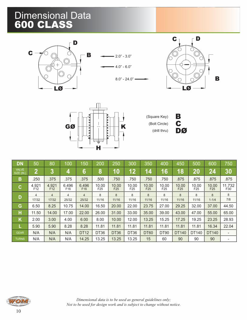
G 6.50 8.25 10.75 14.00 16.50 20.00 22.00 23.75 27.00 29.25 32.00 37.00 44.50
H 11.50 14.00 17.00 22.00 26.00 31.00 33.00 35.00 39.00 43.00 47.00 55.00 65.00
K 2.00 3.00 4.00 6.00 8.00 10.00 12.00 13.25 15.25 17.25 19.25 23.25 28.93
L 5.90 5.90 8.28 8.28 11.81 11.81 11.81 11.81 11.81 11.81 11.81 16.34 22.04GEAR N/A N/A N/A DT12 DT36 DT36 DT36 DT60 DT90 DT140 DT140 DT140 -
TURNS N/A N/A N/A 14.25 13.25 13.25 13.25 15 60 90 90 90 -
H
GØ
B
CDØK
LØLØ
B
BCD DC
2.0” - 3.0”
4.0” - 6.0”
8.0” - 24.0”
(Square Key)
(Bolt Circle)
(drill thru)
Dimensional Data 600 ClaSS
Dimensional data is to be used as general guidelines only; Not to be used for design work and is subject to change without notice.
11
DN 50 80 100 150 200 250 300 350 400 450 500 600 750VALVE
SIZE (IN.) 2 3 4 6 8 10 12 14 16 18 20 24 30B .250 .375 .375 .375 .500 .750 .750 .750 .750 .875 .875 .875 .875
C 4.921 F12
4.921 F12
6.496 F16
6.496 F16
10.00 F25
10.00 F25
10.00 F25
10.00 F25
10.00 F25
10.00 F25
10.00 F25
14.016 F35
11.732 F30
D 417/32
417/32
425/32
425/32
811/16
811/16
811/16
811/16
811/16
811/16
811/16
81-1/4
87/8
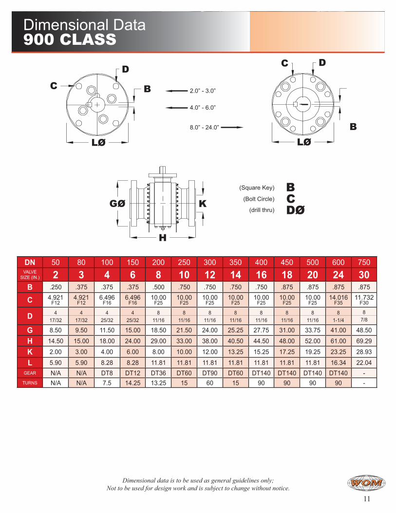
G 8.50 9.50 11.50 15.00 18.50 21.50 24.00 25.25 27.75 31.00 33.75 41.00 48.50
H 14.50 15.00 18.00 24.00 29.00 33.00 38.00 40.50 44.50 48.00 52.00 61.00 69.29
K 2.00 3.00 4.00 6.00 8.00 10.00 12.00 13.25 15.25 17.25 19.25 23.25 28.93
L 5.90 5.90 8.28 8.28 11.81 11.81 11.81 11.81 11.81 11.81 11.81 16.34 22.04GEAR N/A N/A DT8 DT12 DT36 DT60 DT90 DT60 DT140 DT140 DT140 DT140 -
TURNS N/A N/A 7.5 14.25 13.25 15 60 15 90 90 90 90 -
H
GØ
B
CDØK
LØLØ
B
BCD DC
2.0” - 3.0”
4.0” - 6.0”
8.0” - 24.0”
(Square Key)
(Bolt Circle)
(drill thru)
Dimensional Data 900 ClaSS
Dimensional data is to be used as general guidelines only; Not to be used for design work and is subject to change without notice.
12
DN 50 80 100 150 200 250 300VALVE
SIZE (IN.) 2 3 4 6 8 10 12B Pending Pending Pending Pending Pending Pending Pending
C Pending Pending Pending Pending Pending Pending Pending
D Pending Pending Pending Pending Pending Pending Pending
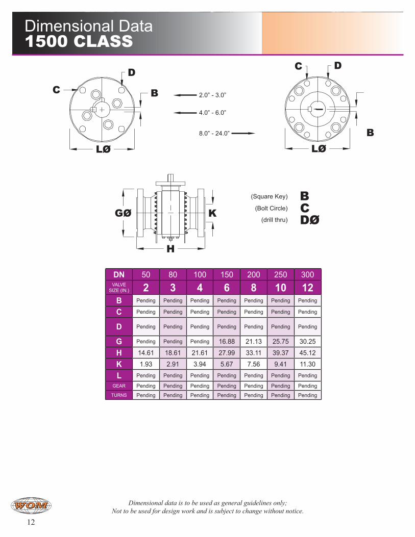
G Pending Pending Pending 16.88 21.13 25.75 30.25
H 14.61 18.61 21.61 27.99 33.11 39.37 45.12
K 1.93 2.91 3.94 5.67 7.56 9.41 11.30
L Pending Pending Pending Pending Pending Pending Pending
GEAR Pending Pending Pending Pending Pending Pending Pending
TURNS Pending Pending Pending Pending Pending Pending Pending
H
GØ
B
CDØK
LØLØ
B
BCD DC
2.0” - 3.0”
4.0” - 6.0”
8.0” - 24.0”
(Square Key)
(Bolt Circle)
(drill thru)
Dimensional Data 1500 ClaSS
Dimensional data is to be used as general guidelines only; Not to be used for design work and is subject to change without notice.
13
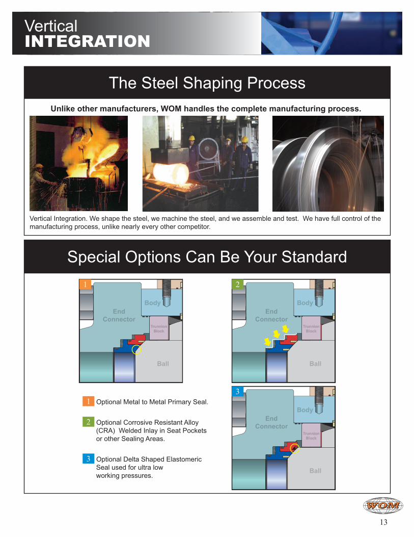
The Steel Shaping Process
Special Options Can Be Your Standard
Vertical Integration. We shape the steel, we machine the steel, and we assemble and test. We have full control of the manufacturing process, unlike nearly every other competitor.
EndConnector
BodyBody
TrunnionBlock
TrunnionBlock
Ball
EndConnector
BodyBody
TrunnionBlock
TrunnionBlock
Ball
EndConnector
BodyBody
TrunnionBlock
TrunnionBlock
Ball
1 Optional Metal to Metal Primary Seal.
2 Optional Corrosive Resistant Alloy (CRA) Welded Inlay in Seat Pockets or other Sealing Areas.
3 Optional Delta Shaped Elastomeric Seal used for ultra low working pressures.
3
21
Unlike other manufacturers, WOM handles the complete manufacturing process.
VerticalIntegratIon
14
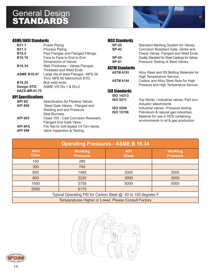
Operating Pressures - ASME B 16.34ANSIClass
WorkingPressure
API Class
Working Pressure
150 285300 740600 1480 2000 2000900 2220 3000 30001500 3705 5000 50002500 6170
Typical Operating PSI for Carbon Steel @ -20 to 100 degrees FTemperatures Higher or Lower, Please Consult Factory
General DesignStandardS
ASME/ANSI Standards B31.1 Power Piping. B31.3 Process Piping. B16.5 Pipe Flanges and Flanged Fittings. B16.10 Face to Face to End to End
Dimensions of Valves. B16.34 Wall Thickness - Valves Flanged,
Threaded and Weld Ends. ASME B16.47 Large dia.of steel Flanges –NPS 26
Thru’ NPS 60 Metric/Inch STD. B16.25 Butt weld ends. Design STD. ASME VIII Div.1 & Div.2. NACE-MR-01-75
API Specifications API 6D Specification for Pipeline Valves. API 600 Steel Gate Valves - Flanged and
Welding end and Pressure Seal Bonnets.
API 603 Class 150 - Cast Corrosion Resistant, Flanged End Gate Valve.
API 6FA Fire Test for Soft Seated 1/4 Turn Valves. API 598 Valve Inspection & Testing.
MSS Standards SP-25 Standard Marking System for Valves. SP-42 Corrosion Resistant Gate, Globe and
Check Valves, Flanged and Weld Ends. SP-55 Quality Standard for Steel Castings for Valves. SP-61 Pressure Testing of Steel Valves.
ASTM Standards ASTM A193 Alloy Steel and SS Bolting Materials for
High Temperature Service. ASTM A194 Carbon and Alloy Steel Nuts for High
Pressure and High Temperature Service.
ISO Standards ISO 14313 ISO 5211 Top Works –Industrial valves; Part turn
Actuator attachments ISO 5208 Industrial valves –Pressure testing ISO 15156 Petroleum & natural gas industries;
Material for use in H2S containing environments in oil & gas production
15
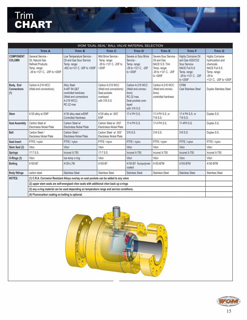
WOM “DUAL-SEAL” BALL VALVE MATERIAL SELECTION
Trim A Trim B Trim C Trim D Trim E Trim F Trim G
COMPONENT COLUMN
General Service - Oil, Natural Gas Refined Products Temp. range: -29 to +121 C, -20F to +200F
Low Temperature Service - Oil and Gas Sour Service Temp. range: -45C to+121 C, -50F to +200F
Mild Brine Service - Temp. range: -29 to +121 C, -20F to +200F
Severe or Sour Brine Service - Temp. range: -29 to +121 C, -20F to +200F
Severe Sour Service - Oil and Gas NACE S.S. Trim Temp. range: -29 to +121 C, -20F to +200F
Highly Corrosive Oil and Gas H2S/CO2 Sour Service- NACE Full S.S. Temp. range: -29 to +121 C, -20F to +200F
Highly Corrosive hydrocarbon and chemicals NACE Full S.S. Temp. range: -29 to +121 C, -20F to +200F
Body, End Connections (1)
Carbon A-216 WCC (Weld end connections)
Alloy Steel A-487 9A Q&T controlled hardness (Weld end connections A-216 WCC) RC-22 max
Carbon A-216 WCC (Weld end connections)Seat pockets overlayed with 316 S.S.
Carbon A-216 WCC (Weld end connec-tions) RC-22 max. Seat pockets over-layed with 316 S.S.
Carbon A-216 WCC (Weld end connec-tions) controlled hardness
CF8M Cast Stainless Steel
Duplex Stainless Steel
Stem 4130 alloy w/ ENP 4130 alloy steel w/ENP Controlled Hardness
4130 alloy w/ .003”ENP
17-4 PH S.S. 17-4 PH S.S. or718 S.S.
17-4 PH S.S. or718 S.S.
Duplex S.S.
Seat Assembly Carbon Steel w/ Electroless Nickel Plate
Carbon Steel w/ Electroless Nickel Plate
Carbon Steel w/ .003”Electroless Nickel Plate
17-4 PH S.S. 17-4 PH S.S. 17-4PH S.S. Duplex S.S.
Ball Carbon Steel / Electoless Nickel Plate
Carbon Steel / Electoless Nickel Plate
Carbon Steel w/ .003”Electoless Nickel Plate
316 S.S. 316 S.S. 316 S.S. Duplex S.S.
Seat Insert PTFE / nylon PTFE / nylon PTFE / nlyon PTFE / nylon PTFE / nylon PTFE / nylon PTFE / nylon
Stem Seal (2) Viton Viton Viton Viton Viton Viton Viton
Springs 17-7 S.S. Inconel X-750 17-7 S.S. Inconel X-750 Inconel X-750 Inconel X-750 Inconel X-750
O-Rings (3) Viton low temp o-ring Viton Viton Viton Viton Viton
Bolting A193-B7 A193-L7M A193-B7 A193-B7 fluropolymer coated
A193-B7M A193-B7M A193-B7M
Body fittings carbon steel Stainless Steel Stainless Steel Stainless Steel Stainless Steel Stainless Steel Stainless Steel
NOTES: (1) C.R.A. Corrosion Resistant Alloys overlay on seat pockets can be added to any valve (2) upper stem seals are self-energized viton seals with additional viton back up o-rings(3) any o-ring material can be used depending on temperature range and service conditions.(4) Fluorocarbon coating on bolting is optional.
TrimChart
16
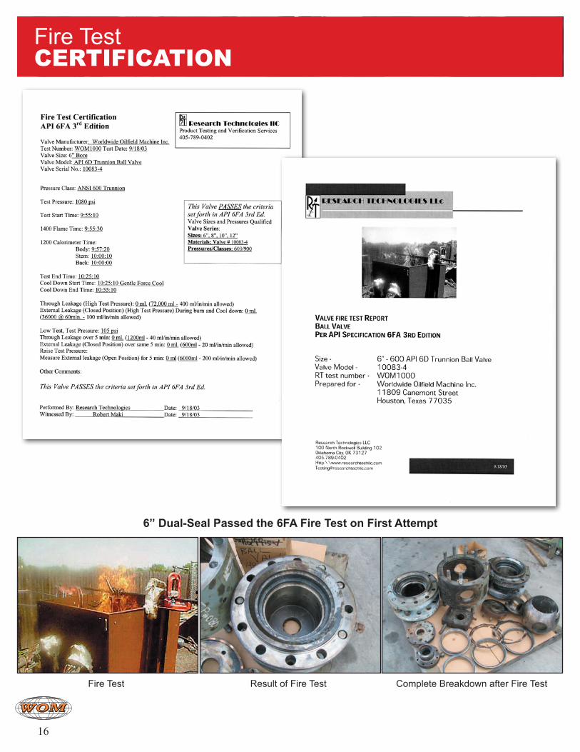
Fire Test Result of Fire Test Complete Breakdown after Fire Test
Fire TestCertIfICatIon
6” Dual-Seal Passed the 6FA Fire Test on First Attempt
17
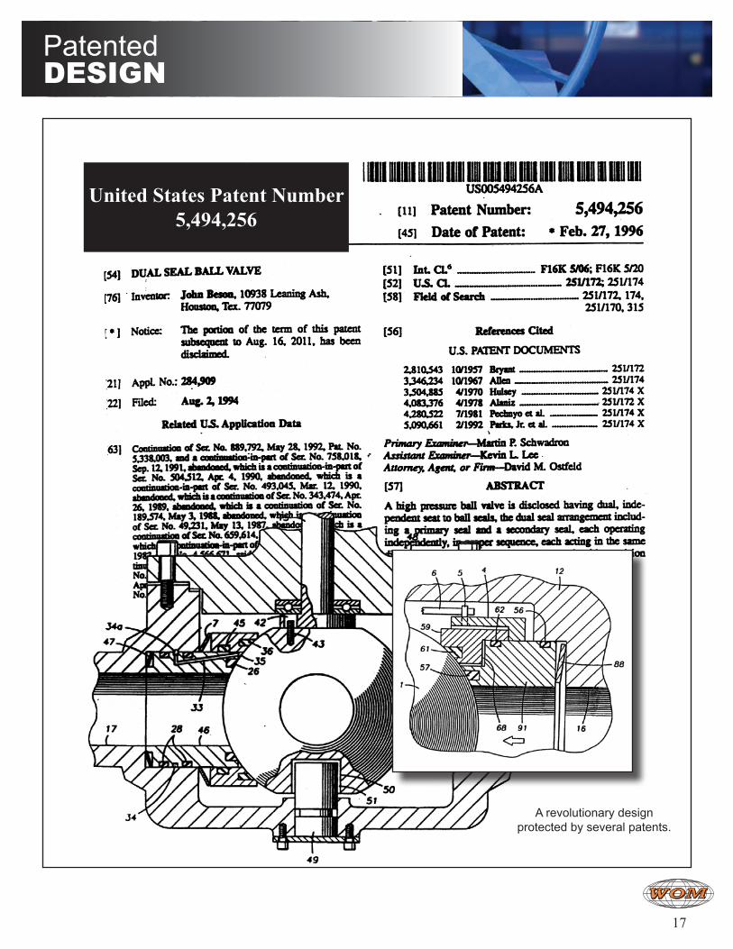
United States Patent Number5,494,256
A revolutionary design protected by several patents.
PatenteddeSIgn
18
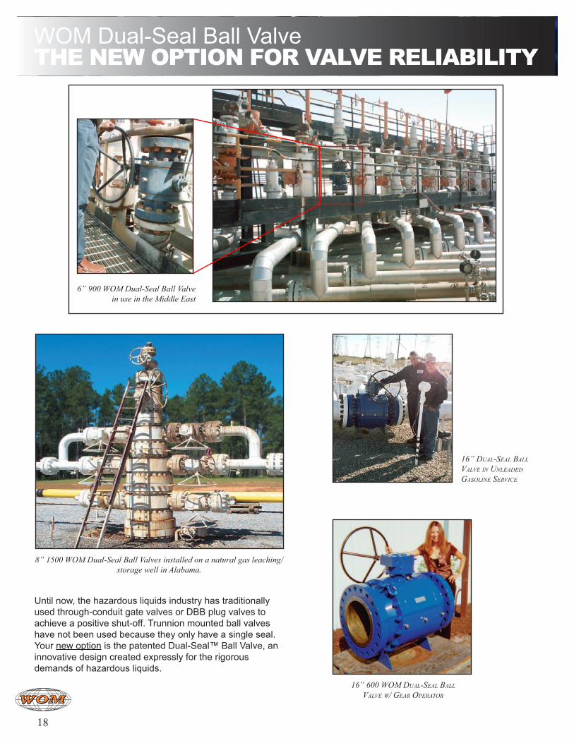
6” 900 WOM Dual-Seal Ball Valve in use in the Middle East
16” 600 WOM Dual-Seal Ball ValVe W/ Gear OperatOr
8” 1500 WOM Dual-Seal Ball Valves installed on a natural gas leaching/storage well in Alabama.
Until now, the hazardous liquids industry has traditionally used through-conduit gate valves or DBB plug valves to achieve a positive shut-off. Trunnion mounted ball valves have not been used because they only have a single seal. Your new option is the patented Dual-Seal™ Ball Valve, an innovative design created expressly for the rigorous demands of hazardous liquids.
16” Dual-Seal Ball ValVe in unleaDeD GaSOline SerVice
WOM Dual-Seal Ball Valvethe new optIon for ValVe relIaBIlIty
©2010 Worldwide Oilfield Machine, Inc. www.womusa.comRev JAN2010
Headquarters/U.S.A.Worldwide Oilfield Machine, Inc.11809 Canemont StreetHouston, Texas 77035 USAPhone: +1 (713) 729-9200Fax: +1 (713) 729-7321
Worldwide Oilfield Machine, Inc.5800 CunninghamHouston, Texas 77041 USAPhone: +1 (713) 937-0795Fax: +1 (713) 937-8574
Worldwide Oilfield Machine Pvt. Ltd.Gat No. 778, at Post VeluPune Satara Rd.Tal. Bhor, Dist. Pune. 412 205. IndiaPhone: +91 (2113) 252 357/499/422Fax: +91 (2113) 252 476
WOM, FranceCentre InitiaParc de la Porte Nord62700 Bruay-La BuissiereFrancePhone: +33 (0)3 21 64 46 65Fax: +33 (0)3 21 64 69 89
Magna Casting & Machine WorksGat No. 777, at Post VeluPune Satara Rd.Tal. Bhor, Dist. Pune. 412 205. IndiaPhone: +91 (2113) 252 357/499/422Fax: +91 (2113) 252 476
Magnum Forge & Machine WorksGat No. 777, at Post VeluPune Satara Rd.Tal. Bhor, Dist. Pune. 412 205. IndiaPhone: +91 (2113) 252 357/499/422Fax: +91 (2113) 252 476
Worldwide Oilfield Machine (UK) Ltd.7 St Machar RoadAberdeen AB24 2UUScotland, UKPhone: +44 (01224) 484400Fax: +44 (01224) 489740
WOM M.E.WMR/10, Westside CircleMezzanine FloorP.O. Box 32478Dubai, U.A.E.Phone: +971 (4) 299-5933Fax: +971 (4) 299-5944
WOM Southeast Asia Pte. Ltd.61A Tuas South Ave 1 Singapore 637326Phone: +65 6560 3857Fax: +65 6560 3859
Magnum Subsea Systems61A Tuas South Ave 1 Singapore 637326Phone: +65 6863 3533Fax: +65 6558 7562
Contact uS
LICENSED UNDER
6A-020316A-00806D-033016C-008817D-0023
CERT-0020744
No. CE-0041-PED-H-WOM-001-08-USA

Revised FEB2010


