Embed Size (px)
Citation preview
676 IEEE/CAA JOURNAL OF AUTOMATICA SINICA, VOL. 6, NO. 3, MAY 2019
Distributed Control of Multiple-Bus Microgrid WithParalleled Distributed Generators
Bo Fan, Student Member, IEEE, Jiangkai Peng, Student Member, IEEE, Jiajun Duan, Student Member, IEEE,Qinmin Yang, Senior Member, IEEE, and Wenxin Liu, Senior Member, IEEE
Abstract—A microgrid is hard to control due to its reducedinertia and increased uncertainties. To overcome the challengesof microgrid control, advanced controllers need to be developed.In this paper, a distributed, two-level, communication-economiccontrol scheme is presented for multiple-bus microgrids with eachbus having multiple distributed generators (DGs) connected inparallel. The control objective of the upper level is to calculatethe voltage references for one-bus subsystems. The objectives ofthe lower control level are to make the subsystems’ bus voltagestrack the voltage references and to enhance load current sharingaccuracy among the local DGs. Firstly, a distributed consensus-based power sharing algorithm is introduced to determine thepower generations of the subsystems. Secondly, a discrete-timedroop equation is used to adjust subsystem frequencies for voltagereference calculations. Finally, a Lyapunov-based decentralizedcontrol algorithm is designed for bus voltage regulation andproportional load current sharing. Extensive simulation studieswith microgrid models of different levels of detail are performedto demonstrate the merits of the proposed control scheme.
Index Terms—Coordinate control, decentralized control,multiple-bus microgrid, paralleled distributed generations, powersharing algorithm.
I. INTRODUCTION
M ICROGRID generally comprises a collection of loads,energy storage systems, and distributed generators
(DGs), operating in either grid-connected mode or islandedone [1], [2]. Different types of DGs such as photovoltaicsand wind turbines can be connected to a microgrid throughpower converters [3]. The power electronic-based converters
Manuscript received October 3, 2018; revised December 27, 2018; acceptedJanuary 13, 2019. This work was supported in part by the US Office of NavalResearch (N00014-16-1-312, N00014-18-1-2185) and in part by the NationalNatural Science Foundation of China (61673347, U1609214, 61751205).Recommended by Associate Editor Qinglai Wei. (Corresponding author:Qinmin Yang.)
Citation: B. Fan, J. K. Peng, J. J. Duan, Q. M. Yang, and W. X. Liu,“Distributed control of multiple-bus microgrid with paralleled distributedgenerators,” IEEE/CAA J. Autom. Sinica, vol. 6, no. 3, pp. 676−684, May2019.
B. Fan and Q. M. Yang are with the State Key Laboratory of IndustrialControl Technology, College of Control Science and Engineering, ZhejiangUniversity, Hangzhou 310027, China (e-mail: [email protected]; [email protected]).
J. K. Peng and W. X. Liu are with the Smart Microgrid and RenewableTechnology (SMRT) Research Laboratory, Department of Electrical andComputer Engineering, Lehigh University, Bethlehem, PA 18015 USA (e-mail: [email protected]; [email protected]).
J. J. Duan is with the Global Energy Interconnection Research InstituteNorth America (GEIRINA), San Jose, CA 95134 USA (e-mail: [email protected]).
Color versions of one or more of the figures in this paper are availableonline at http://ieeexplore.ieee.org.
Digital Object Identifier 10.1109/JAS.2019.1911477
make the DGs more flexible in their control and operation thanconventional synchronous generators (SGs).
However, due to the significant differences between thetraditional large-scale power systems and power converter-interfaced microgrids, especially in terms of low inertia anduncertainties, control solutions for traditional power grid can-not be introduced to microgrids directly [3]. Recent researcheson microgrid controls can be classified into two types. Thefirst one is to make the DGs in a microgrid behave similarlyto conventional SGs with the idea of virtual synchronousgenerator [4], [5]. Since the virtual inertias of microgrids areincreased, traditional control schemes that have been provedto be effective for traditional power grids can be introducedto microgrids [6]. However, such solutions cannot fully un-lock the advantages of modern power electronic techniques,especially in terms of flexibility and response speed [7].
Alternatively, the second type of solutions model a micro-grid as a cluster of decoupled subsystems, each of which iscomposed of a DG, a power converter, and an output filter[8]. In the hierarchical control scheme, a secondary controlalgorithm is developed on top of the traditional primary controlsystem [9], [10]. Since the microgrid system is formulatedsimilarly to that of unmanned vehicles that have no physicalconnections among the subsystems, various control techniquesfor multiagent systems (MASs) [11], including optimal control[12], cooperative control [13], [14], and game theory [15],can be introduced for the secondary control design. Suchsecondary control algorithms require continuous communi-cations for implementation. Also, the limited performanceof traditional primary control algorithms (droop and innerPI control loops) makes it hard to achieve desired dynamicperformance.
In most studies on microgrid control, the microgrid ismodeled as a multiple-bus system with each bus having onlyone DG connected [16], [17]. In many applications, multiplelocal DGs are connected to one bus, such as PV farms [18]and wind farms [19]. Sometimes, multiple DGs in a microgrid,which are located close enough, can also be modeled togetheras a one-bus subsystem. Since the dynamics of the parallel-DGs connected to one bus are not specifically consideredduring control designs, most existing solutions cannot bedirectly applied to such microgrids. This is mainly due to thedifferent models and parameters of the parallel-DGs. If thecontrols of the paralleled DGs are not well coordinated, largeload current sharing errors among DGs will degrade the energyefficiency and cause unexpected load sharing even systemfailures [20]. Thus, the control of multiple-bus microgrid with
FAN et al.: DISTRIBUTED CONTROL OF MULTIPLE-BUS MICROGRID WITH PARALLELED DISTRIBUTED GENERATORS 677
parallel-DGs should be well studied.In previous literature, the control of a one-bus multiple-
DG system, which is a subsystem of the above-mentionedmicrogrid, has been studied with the application for paralleleduninterruptible power supplies (UPSs) [21]. Over the pastdecades, many control strategies have been proposed for suchsystems. The first type of solutions require communicationsamong DGs including centralized control [22], master-slavecontrol [23], circular chain control [20], and etc. The require-ment of communications lowers not only flexibility but alsoreliability due to the imperfections with the communicationsystem [24]. To relax the communication requirement, droopcontrol, which has been the most popular decentralized controlsolution for microgrids [25]−[27], was introduced. However,droop control strategies are static proportional rule-based andsuffer from low response speed and static deviations, whichcould be problematic for high- performance applications [28].Although new control algorithms are available for paralleledUPSs, their applications for multiple-bus microgrids are inca-pable. To achieve good control performance over the targetedgeneral class of microgrids, hierarchical control schemes withadvanced primary control algorithms need to be developed.
In this study, an advanced two-level distributed controlsolution is presented for microgrids that consist of multipleconverter-interfaced parallel-DG subsystems. At the upperlevel, the objective is to obtain the desired voltage trajectoryreference for each parallel-DG subsystem. At the lower level,two control objectives are addressed: 1) The bus voltage iswell regulated under different operating conditions; 2) Theload current is proportionally shared among multiple localDGs. Since the control reference for primary control is updatedperiodically and held unchanged between updates, algorithmdesigns of the two control levels can be decoupled. This con-trol strategy not only simplifies algorithm designs but also low-ers communication requirement for control implementations.Firstly, a distributed consensus-based power sharing algorithmis introduced to determine the generations of subsystems. Sec-ondly, a discrete-time droop equation is used to periodicallyadjust the subsystem frequency at a smaller time scale tofight against uncertainties with line losses, generations, loadpredictions, and etc. Finally, a Lyapunov-based decentralizedcontrol algorithm is designed for bus voltage regulation andproportional load current sharing in the subsystem. Extensivesimulations are conducted to demonstrate the advantages ofthe proposed control scheme.
The rest of this paper is organized as follows. In Sec-tion II, the mathematical model of a multiple-bus microgridwith paralleled DGs is presented. Section III introduces theproposed control design along with the stability analysis.Simulations with microgrid models of different levels of detailare presented in Section IV. Concluding remarks are given inSection V.
II. PROBLEM FORMULATION
The topology of a multiple-bus microgrid consisting ofseveral parallelDG subsystems is illustrated in Fig. 1. Eachone-bus subsystem comprises multiple DGs and a lumpedload. The DGs are connected to a common bus through
power converters and LC-filters The average model is usedfor control design and the detailed switch-level model is usedfor control evaluation [29].
In this study, a microgrid consisting of N parallel-DGsubsystems is considered. The average model of the pthsubsystem (p = 1, 2, . . . , N) comprising np DGs is given as[21]
vp,o =
np∑q=1
ip,q
np∑q=1
Cp,q
−np∑
q=1ip,oq
np∑q=1
Cp,q
ip,q = − 1Lp,q
vp,o − Rp,q
Lp,qip,q + 1
Lp,qvp,q, q = 1, 2, . . . , np
(1)
where vp,o is the bus voltage, vp,q and ip,q are the output volt-age and input current to the filter of the qth DG, respectively,ip,oq is the output current, and Rp,q, Lp,q and Cp,q are theparameters of the qth LC-filter.
III. DISTRIBUTED CONTROL DESIGN FORMULTIPLE-BUS MICROGRIDS
In this section, a two-level control scheme is introducedfor the real-time coordination of subsystems within a large-scale microgrid [3]. In the proposed design, the objective ofthe upper-level is to obtain the desired voltage trajectory ref-erences for parallel-DG subsystems. First, fair power sharingis achieved by a distributed consensus-based algorithm. Theroot mean square (RMS) value of the subsystem bus voltagereferences, V , is fixed and only the desired bus frequency f∗pfor each subsystem is maneuvered by a discrete-time droopequation within a small range, periodically. As a result, thesubsystem’s bus phase angle δp can be adjusted indirectly toachieve fair power sharing.
For the lower-level control of each subsystem, two controlobjectives are considered. The first one is to maneuver thebus voltage of the pth subsystem, vp,o, to track a desiredtrajectory v∗p,o = V sin(2πf∗p t+ δp) with f∗p set by the upper-level controller. The second control objective is to achieveproportional load current sharing among DGs. In this way, thebus voltage V and system frequency f can be well regulatedtogether. Details of the proposed control solution are presentedin the following subsections.
A. Upper-Level Control Design
The upper-level controller is introduced to find the desiredbus voltage trajectory v∗p,o of the pth subsystem with the busfrequency references f∗p , based on the operational restrictionsof fair power sharing in a two-step manner.
Firstly, the distributed consensus algorithm [30] is employedto determine the power generation references (P ∗p ) of sub-systems. In order to achieve fair power sharing, the powergeneration of each subsystem is assigned based on a commonutilization level, which is decided by the overall demandincluding the total load demands and estimated system-widelosses, and the overall generation determined by the predictedintermittent sources and the capability of the non-intermittentsources. Next, the distributed consensus algorithm is utilizedto find the local utilization level with a relatively large time

678 IEEE/CAA JOURNAL OF AUTOMATICA SINICA, VOL. 6, NO. 3, MAY 2019
Fig. 1. A multiple-bus microgrid with parallel-DGs.
step TU , which is the same for the entire microgrid. Thus,the fair power sharing can be achieved by synchronizingthe utilization level and the impact of inaccurate generationprediction can be minimized as well.
Secondly, once the power generation reference P ∗p is ob-tained, the corresponding bus frequency reference f∗p canbe decided through a discrete-time droop equation with arelatively small time step of TD, which is expressed as
f∗p = frate − ηp(Pp − P ∗p ) (2)
where frate is the nominal frequency, Pp is the power gener-ation of the pth subsystem, and ηp is the active droop slopeof the pth subsystem. Thus, the desired bus voltage trajectorycan be calculated by v∗p,o = V sin(2πf∗p t + δp).
B. Lower-Level Control Design
To facilitate the control development, for the pth subsystem,define
up,q =−vp,o −Rp,qip,q + vp,q
Lp,qCp
xp,q =ip,q
Cp
dp =np∑
q=1
ip,oq
Cp
where Cp =∑np
q=1 Cp,q is the total capacitance, with up,q,xp,q, dp being the control input, the system state, and thedisturbance, respectively. Therefore, the original system model(1) can be rewritten in a compact form as
vp,o =np∑
q=1xp,q − dp
xp,q = up,q.
(3)
Before proceeding, the following assumption is given [31].Assumption 1: dp, and its first- and second-time derivatives
are unknown but bounded, i.e., |dp| ≤ D0, |dp| ≤ D1 and |dp|≤ D2, where D0, D1 and D2 are unknown positive constants.
1) Dynamics of the Filtered Tracking Error: Consider aparallel-DG subsystem (3). Define the tracking error as
ep,o = vp,o − v∗p,o. (4)
Next, define the filtered tracking error [32] as
rp = kpep,o + ep,o (5)
where kp is a positive constant. Furthermore, define
rp = kp,rrp + rp (6)
with kp,r being a positive constant. By recalling (3), the timederivative of rp is
˙rp = kp,r rp + kpep,o +np∑
q=1
up,q − dp − ...v ∗p,o. (7)
Apparently, systems (5) and (6) are Hurwitz. If the filteredtracking error rp or rp can be controlled to approach zero, theoriginal tracking error ep,o will converge to zero, too [33].
2) Controller Development and Stability Analysis: Basedon the dynamics of the filtered tracking error (7), design thedecentralized control law as
up,q = − kp
Cpip,oq +
Cp,q
Cpvp,o −mp,q(kp,rrp + rp)
−mp,q
∫ t
0
(k2p,r + ρp)rp(τ)dτ (8)
whose time derivative is equivalently given as
up,q = − kp
Cpip,oq +
Cp,q
Cp
...v p,o −mp,q(kp,r rp + ˙rp)
−mp,q(k2p,r + ρp)rp
= − kp
Cpip,oq +
Cp,q
Cp
...v p,o −mp,q(kp,r rp + ˙rp + ρprp)
(9)
where ρp is a positive constant, and 0 < mp,q < 1, q =1, 2, . . . , np is the load current sharing ratio of DG #p, q,satisfying
∑np
q=1 mp,q = 1. Noticed that the control law (8)is essentially decentralized for subsystem #p, in the sense
FAN et al.: DISTRIBUTED CONTROL OF MULTIPLE-BUS MICROGRID WITH PARALLELED DISTRIBUTED GENERATORS 679
that each individual DG only utilizes its own signals ip,oq,vp,o, and the information of v∗p,o obtained from the upper-level controller. No information is required to be shared amongmultiple DGs.
Subsequently, with the help of the definitions of rp and rp,substituting (9) into (7) yields
˙rp = kp,r rp + kpep,o +np∑
q=1
[− kp
Cpip,oq +
Cp,q
Cp
...v p,o
−mp,q(kp,r rp + ˙rp + ρprp)]− dp − ...
v ∗p,o
= kp,r rp + kpep,o − kpdp +...v p,o − kp,r rp − ˙rp
− ρprp − dp − ...v ∗p,o
=− kp,r rp − ρprp − kpdp − dp. (10)
Now the theoretical results of the proposed controller arestated in the following theorem.
Theorem 1: Consider a parallel-DG system characterized by(1) satisfying Assumption 1, and a decentralized control lawdeveloped as in (8). The following facts hold: 1) the load cur-rent sharing errors, defined as ep,qs = ip,oq/mp,q− ip,os/mp,s
for all q, s = 1, 2, . . . , np, q 6= s, can be eliminated; 2) thevoltage tracking error ep,o together with all the other signalsof the closed-loop system are bounded.
Proof: The proof of Theorem 1 is divided into two parts.Proof of Fact 1: With the help of the Kirchhoff’s current
law, one has
ip,oq = ip,q − Cp,q vp,o = Cpxp,q − Cpvp,o. (11)
Recalling the second differential equation in (6), and sub-stituting (8) into the time derivative of ip,oq yield
ip,oq = − kpip,oq − Cpmp,q(kp,rrp + rp)
− Cpmp,q
∫ t
0
(k2p,r + ρp)rp(τ)dτ. (12)
Thereafter, define a class of Lyapunov functions as
Vp,qs =12e2p,qs (13)
for q, s = 1, 2, . . . , np, q 6= s. Taking the time derivative ofVp,qs gives
Vp,qs = ep,qs
[−kpip,oq
mp,q− −kpip,os
mp,s− Cp(kp,rrp + rp)
+ Cp(kp,rrp + rp)− Cp
∫ t
0
(k2p,r + ρp)rp(τ)dτ
+ Cp
∫ t
0
(k2p,r + ρp)rp(τ)dτ
]
=− kpe2p,qs = −2kpVp,qs. (14)
By resorting to the standard Lyapunov synthesis [34], wehave
|ep,qs(t)| ≤ |ep,qs(0)| exp(−kpt) (15)
for q, s = 1, 2, . . . , np, q 6= s, where ep,qs(0) is the initialvalue of the load current sharing error, which will converge tozero exponentially. Thus, the first fact holds.
Proof of Fact 2: Define a Lyapunov function as
Vp =12r2p +
12ρp
r2p. (16)
Since rp = rp− kp,rrp, (10) can be borrowed to obtain thetime derivative of (16) as
Vp = rp(rp − kp,rrp) +1ρp
rp(−kp,r rp − ρprp − kpdp − dp)
= −kp,rr2p −
1ρp
kp,r r2p −
1ρp
rp(kpdp + dp). (17)
With the help of Assumption 1, one has
Vp ≤ −kp,rr2p −
1ρp
kp,r r2p +
1ρp|rp| (kpD1 + D2)
≤ −kp,rr2p −
1ρp
(kp,r − εp)r2p +
14ρpεp
(kpD1 + D2)2
≤ −2(kp,r − εp)Vp +1
4ρpεp(kpD1 + D2)2 (18)
where 0 < εp < kp,r is a constant. Furthermore, according toLemma 1.1 in [35], we have
limt→∞
rp ≤ kpD1 + D2√4ρpεp(kp,r − εp)
, limt→∞
rp ≤ kpD1 + D2√4εp(kp,r − εp)
(19)
and rp, rp are bounded for all time.From the definition of rp in (5), ep,o and ep,o can be treated
as the outputs of a stable linear system with the boundedinput rp. Therefore, ep,o and ep,o are bounded. From (6),one has that rp = rp − kp,rrp is bounded, which resultsin that ep,o = rp − kpep,o is also bounded. Notice that thedesired trajectory v∗p,o is a sinusoidal function, thus the firstand the second time derivatives of v∗p,o, v∗p,o, and v∗p,o, arealso bounded. With the boundedness of ep,o, ep,o, and ep,o,one can prove that vp,o = v∗p,o + ep,o, vp,o = v∗p,o + ep,o,and vp,o = v∗p,o + ep,o are all bounded. By recalling (15), onehas that ip,oq/mp,q− ip,os/mp,s is bounded for all time. Withthe help of Assumption 1,
∑np
q=1 ip,oq is also bounded. Fur-thermore, standard linear analysis methods can be applied toprove that ip,oq is bounded. Thereafter, ip,q = ip,oq +Cp,q vp,o
is bounded, and thus the second fact holds.Finally, with the proposed lower-level controller, the two
control objectives of the lower-level are achieved as illustratedin Theorem 1. ¥
Remark 1: Notice that the input transformation from vp,q toup,q is invertible. The actual control law for the parallel-DGsystem (1) is
vp,q = vp,o + Rp,qip,q + Lp,qCpup,q (20)
with up,q given in (8).Remark 2: According to (8), the information of the time
derivatives of the bus voltage vp,o is required in actual con-trollers, which can be obtained by the high-gain observers in[36] in the implementation of the proposed control.
680 IEEE/CAA JOURNAL OF AUTOMATICA SINICA, VOL. 6, NO. 3, MAY 2019
C. Control Implementation
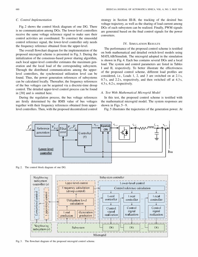
Fig. 2 shows the control block diagram of one DG. Thereis no communication among DGs. The lower-level controllersreceive the same voltage reference signal to make sure theircontrol activities are coordinated. To construct the sinusoidalcontrol reference signal, the lower-level controller only needsthe frequency reference obtained from the upper-level.
The overall flowchart diagram for the implementation of theproposed microgrid scheme is presented in Fig. 3. During theinitialization of the consensus-based power sharing algorithm,each local upper-level controller estimates the maximum gen-eration and the local load of the corresponding subsystem.Through the distributed communications among the upper-level controllers, the synchronized utilization level can befound. Thus, the power generation references of subsystemscan be calculated locally. Thereafter, the frequency referencesof the bus voltages can be acquired via a discrete-time droopcontrol. The detailed upper-level control process can be foundin [30] and is omitted here.
During the regulation process, the bus voltage referencesare firstly determined by the RMS value of bus voltagestogether with their frequency references obtained from upper-level controllers. Then, with the proposed decentralized control
strategy in Section III-B, the tracking of the desired busvoltage trajectory, as well as the sharing of load current amongDGs of each subsystem can be realized. Finally, PWM signalsare generated based on the final control signals for the powerconverters.
IV. SIMULATION RESULTS
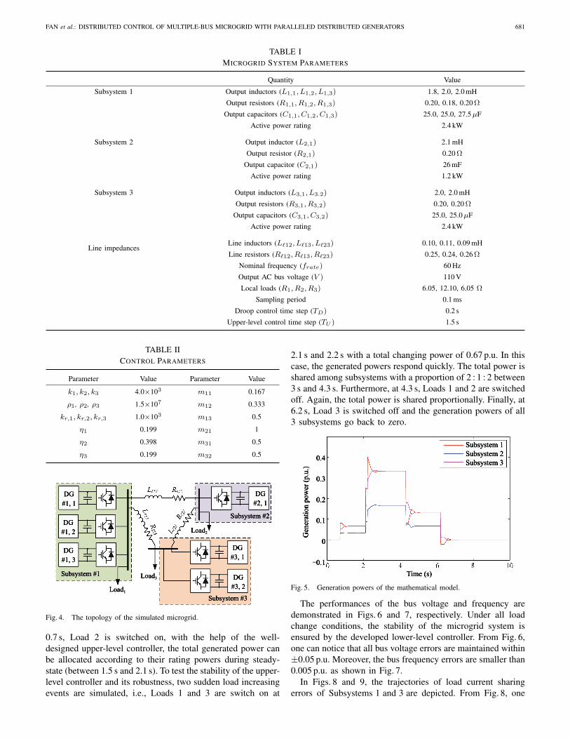
The performance of the proposed control scheme is testifiedon both mathematical and detailed switch-level models usingMATLAB/Simulink. The microgrid adopted in the simulationis shown in Fig. 4. Each bus contains several DGs and a localload. The system and control parameters are listed in TablesI and II, respectively. To better illustrate the effectivenessof the proposed control scheme, different load profiles areconsidered, i.e., Loads 1, 2, and 3 are switched on at 2.1 s,0.7 s, and 2.2 s, respectively, and then switched off at 4.3 s,4.3 s, 6.2 s, respectively.
A. Test With Mathematical Microgrid Model
In this test, the proposed control scheme is testified withthe mathematical microgrid model. The system responses areshown in Figs. 5−9.
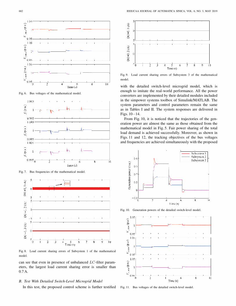
Fig. 5 illustrates the trajectories of the generation power. At
Fig. 2. The control block diagram of one DG.
Fig. 3. The flowchart diagram of the proposed microgrid control scheme.
FAN et al.: DISTRIBUTED CONTROL OF MULTIPLE-BUS MICROGRID WITH PARALLELED DISTRIBUTED GENERATORS 681
TABLE IMICROGRID SYSTEM PARAMETERS
Quantity Value
Subsystem 1 Output inductors (L1,1, L1,2, L1,3) 1.8, 2.0, 2.0 mH
Output resistors (R1,1, R1,2, R1,3) 0.20, 0.18, 0.20 Ω
Output capacitors (C1,1, C1,2, C1,3) 25.0, 25.0, 27.5 µF
Active power rating 2.4 kW
Subsystem 2 Output inductor (L2,1) 2.1 mH
Output resistor (R2,1) 0.20 Ω
Output capacitor (C2,1) 26 mF
Active power rating 1.2 kW
Subsystem 3 Output inductors (L3,1, L3.2) 2.0, 2.0 mH
Output resistors (R3,1, R3,2) 0.20, 0.20 Ω
Output capacitors (C3,1, C3,2) 25.0, 25.0 µF
Active power rating 2.4 kW
Line impedancesLine inductors (L`12, L`13, L`23) 0.10, 0.11, 0.09 mH
Line resistors (R`12, R`13, R`23) 0.25, 0.24, 0.26 Ω
Nominal frequency (frate) 60 Hz
Output AC bus voltage (V ) 110 V
Local loads (R1, R2, R3) 6.05, 12.10, 6.05 Ω
Sampling period 0.1 ms
Droop control time step (TD) 0.2 s
Upper-level control time step (TU ) 1.5 s
TABLE IICONTROL PARAMETERS
Parameter Value Parameter Value
k1, k2, k3 4.0×10³ m11 0.167
ρ1, ρ2, ρ3 1.5×10⁷ m12 0.333
kr,1, kr,2, kr,3 1.0×10³ m13 0.5
η1 0.199 m21 1
η2 0.398 m31 0.5
η3 0.199 m32 0.5
Fig. 4. The topology of the simulated microgrid.
0.7 s, Load 2 is switched on, with the help of the well-designed upper-level controller, the total generated power canbe allocated according to their rating powers during steady-state (between 1.5 s and 2.1 s). To test the stability of the upper-level controller and its robustness, two sudden load increasingevents are simulated, i.e., Loads 1 and 3 are switch on at
2.1 s and 2.2 s with a total changing power of 0.67 p.u. In thiscase, the generated powers respond quickly. The total power isshared among subsystems with a proportion of 2 : 1 : 2 between3 s and 4.3 s. Furthermore, at 4.3 s, Loads 1 and 2 are switchedoff. Again, the total power is shared proportionally. Finally, at6.2 s, Load 3 is switched off and the generation powers of all3 subsystems go back to zero.
Fig. 5. Generation powers of the mathematical model.
The performances of the bus voltage and frequency aredemonstrated in Figs. 6 and 7, respectively. Under all loadchange conditions, the stability of the microgrid system isensured by the developed lower-level controller. From Fig. 6,one can notice that all bus voltage errors are maintained within±0.05 p.u. Moreover, the bus frequency errors are smaller than0.005 p.u. as shown in Fig. 7.
In Figs. 8 and 9, the trajectories of load current sharingerrors of Subsystems 1 and 3 are depicted. From Fig. 8, one
682 IEEE/CAA JOURNAL OF AUTOMATICA SINICA, VOL. 6, NO. 3, MAY 2019
Fig. 6. Bus voltages of the mathematical model.
Fig. 7. Bus frequencies of the mathematical model.
Fig. 8. Load current sharing errors of Subsystem 1 of the mathematicalmodel.
can see that even in presence of unbalanced LC-filter param-eters, the largest load current sharing error is smaller than0.7 A.
B. Test With Detailed Switch-Level Microgrid Model
In this test, the proposed control scheme is further testified
Fig. 9. Load current sharing errors of Subsystem 3 of the mathematicalmodel.
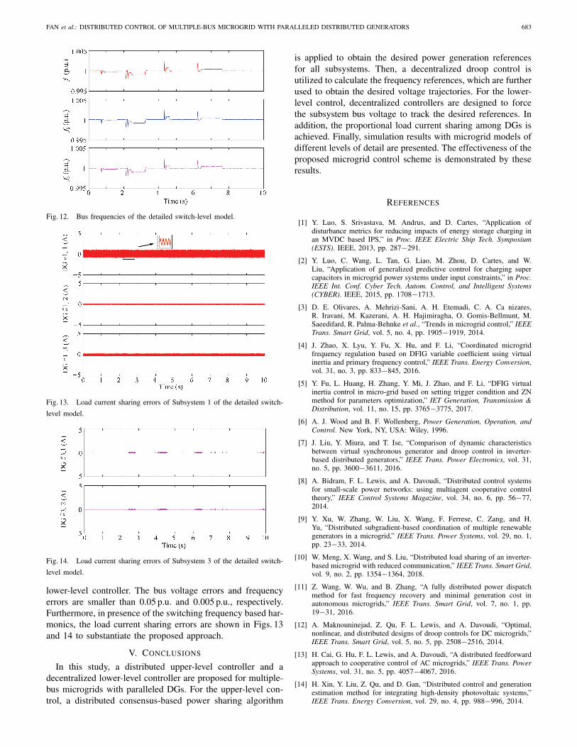
with the detailed switch-level microgrid model, which isenough to imitate the real-world performance. All the powerconverters are implemented by their detailed modules includedin the simpower systems toolbox of Simulink/MATLAB. Thesystem parameters and control parameters remain the sameas in Tables I and II. The system responses are delivered inFigs. 10−14.
From Fig. 10, it is noticed that the trajectories of the gen-eration power are almost the same as those obtained from themathematical model in Fig. 5. Fair power sharing of the totalload demand is achieved successfully. Moreover, as shown inFigs. 11 and 12, the tracking objectives of the bus voltagesand frequencies are achieved simultaneously with the proposed
Fig. 10. Generation powers of the detailed switch-level model.
Fig. 11. Bus voltages of the detailed switch-level model.
FAN et al.: DISTRIBUTED CONTROL OF MULTIPLE-BUS MICROGRID WITH PARALLELED DISTRIBUTED GENERATORS 683
Fig. 12. Bus frequencies of the detailed switch-level model.
Fig. 13. Load current sharing errors of Subsystem 1 of the detailed switch-level model.
Fig. 14. Load current sharing errors of Subsystem 3 of the detailed switch-level model.
lower-level controller. The bus voltage errors and frequencyerrors are smaller than 0.05 p.u. and 0.005 p.u., respectively.Furthermore, in presence of the switching frequency based har-monics, the load current sharing errors are shown in Figs. 13and 14 to substantiate the proposed approach.
V. CONCLUSIONS
In this study, a distributed upper-level controller and adecentralized lower-level controller are proposed for multiple-bus microgrids with paralleled DGs. For the upper-level con-trol, a distributed consensus-based power sharing algorithm
is applied to obtain the desired power generation referencesfor all subsystems. Then, a decentralized droop control isutilized to calculate the frequency references, which are furtherused to obtain the desired voltage trajectories. For the lower-level control, decentralized controllers are designed to forcethe subsystem bus voltage to track the desired references. Inaddition, the proportional load current sharing among DGs isachieved. Finally, simulation results with microgrid models ofdifferent levels of detail are presented. The effectiveness of theproposed microgrid control scheme is demonstrated by theseresults.
REFERENCES
[1] Y. Luo, S. Srivastava, M. Andrus, and D. Cartes, “Application ofdisturbance metrics for reducing impacts of energy storage charging inan MVDC based IPS,” in Proc. IEEE Electric Ship Tech. Symposium(ESTS). IEEE, 2013, pp. 287−291.
[2] Y. Luo, C. Wang, L. Tan, G. Liao, M. Zhou, D. Cartes, and W.Liu, “Application of generalized predictive control for charging supercapacitors in microgrid power systems under input constraints,” in Proc.IEEE Int. Conf. Cyber Tech. Autom. Control, and Intelligent Systems(CYBER). IEEE, 2015, pp. 1708−1713.
[3] D. E. Olivares, A. Mehrizi-Sani, A. H. Etemadi, C. A. Ca nizares,R. Iravani, M. Kazerani, A. H. Hajimiragha, O. Gomis-Bellmunt, M.Saeedifard, R. Palma-Behnke et al., “Trends in microgrid control,” IEEETrans. Smart Grid, vol. 5, no. 4, pp. 1905−1919, 2014.
[4] J. Zhao, X. Lyu, Y. Fu, X. Hu, and F. Li, “Coordinated microgridfrequency regulation based on DFIG variable coefficient using virtualinertia and primary frequency control,” IEEE Trans. Energy Conversion,vol. 31, no. 3, pp. 833−845, 2016.
[5] Y. Fu, L. Huang, H. Zhang, Y. Mi, J. Zhao, and F. Li, “DFIG virtualinertia control in micro-grid based on setting trigger condition and ZNmethod for parameters optimization,” IET Generation, Transmission &Distribution, vol. 11, no. 15, pp. 3765−3775, 2017.
[6] A. J. Wood and B. F. Wollenberg, Power Generation, Operation, andControl. New York, NY, USA: Wiley, 1996.
[7] J. Liu, Y. Miura, and T. Ise, “Comparison of dynamic characteristicsbetween virtual synchronous generator and droop control in inverter-based distributed generators,” IEEE Trans. Power Electronics, vol. 31,no. 5, pp. 3600−3611, 2016.
[8] A. Bidram, F. L. Lewis, and A. Davoudi, “Distributed control systemsfor small-scale power networks: using multiagent cooperative controltheory,” IEEE Control Systems Magazine, vol. 34, no. 6, pp. 56−77,2014.
[9] Y. Xu, W. Zhang, W. Liu, X. Wang, F. Ferrese, C. Zang, and H.Yu, “Distributed subgradient-based coordination of multiple renewablegenerators in a microgrid,” IEEE Trans. Power Systems, vol. 29, no. 1,pp. 23−33, 2014.
[10] W. Meng, X. Wang, and S. Liu, “Distributed load sharing of an inverter-based microgrid with reduced communication,” IEEE Trans. Smart Grid,vol. 9, no. 2, pp. 1354−1364, 2018.
[11] Z. Wang, W. Wu, and B. Zhang, “A fully distributed power dispatchmethod for fast frequency recovery and minimal generation cost inautonomous microgrids,” IEEE Trans. Smart Grid, vol. 7, no. 1, pp.19−31, 2016.
[12] A. Maknouninejad, Z. Qu, F. L. Lewis, and A. Davoudi, “Optimal,nonlinear, and distributed designs of droop controls for DC microgrids,”IEEE Trans. Smart Grid, vol. 5, no. 5, pp. 2508−2516, 2014.
[13] H. Cai, G. Hu, F. L. Lewis, and A. Davoudi, “A distributed feedforwardapproach to cooperative control of AC microgrids,” IEEE Trans. PowerSystems, vol. 31, no. 5, pp. 4057−4067, 2016.
[14] H. Xin, Y. Liu, Z. Qu, and D. Gan, “Distributed control and generationestimation method for integrating high-density photovoltaic systems,”IEEE Trans. Energy Conversion, vol. 29, no. 4, pp. 988−996, 2014.
684 IEEE/CAA JOURNAL OF AUTOMATICA SINICA, VOL. 6, NO. 3, MAY 2019
[15] L. -L. Fan, V. Nasirian, H. Modares, F. L. Lewis, Y. -D. Song, and A.Davoudi, “Game-theoretic control of active loads in DC microgrids,”IEEE Trans. Energy Conversion, vol. 31, no. 3, pp. 882−895, 2016.
[16] M. Hamzeh, H. Karimi, and H. Mokhtari, “Harmonic and negative-sequence current control in an islanded multi-bus MV microgrid,” IEEETrans. Smart Grid, vol. 5, no. 1, pp. 167−176, 2014.
[17] M. Hamzeh, H. Karimi, and H. Mokhtari, “A new control strategy fora multi-bus MV microgrid under unbalanced conditions,” IEEE Trans.Power Systems, vol. 27, no. 4, pp. 2225−2232, 2012.
[18] J. Chavarria, D. Biel, F. Guinjoan, C. Meza, and J. J. Negroni, “Energy-balance control of PV cascaded multilevel grid-connected invertersunder level-shifted and phase-shifted PWMs,” IEEE Trans. IndustrialElectronics, vol. 60, no. 1, pp. 98−111, 2013.
[19] X. Tang, Q. Yang, K. Wang, B. Stoevesandt, and Y. Sun, “Optimisationof wind farm layout in complex terrain via mixed-installation of differenttypes of turbines,” IET Renewable Power Generation, vol. 12, no. 9, pp.1065−1073, 2018.
[20] T. -F. Wu, Y. -K. Chen, and Y. -H. Huang, “3C strategy for inverters inparallel operation achieving an equal current distribution,” IEEE Trans.Industrial Electronics, vol. 47, no. 2, pp. 273−281, 2000.
[21] K. -S. Low and R. Cao, “Model predictive control of parallel-connectedinverters for uninterruptible power supplies,” IEEE Trans. IndustrialElectronics, vol. 55, no. 8, pp. 2884−2893, 2008.
[22] K. Tan, X. Peng, P. L. So, Y. C. Chu, and M. Chen, “Centralized controlfor parallel operation of distributed generation inverters in microgrids,”IEEE Trans. Smart Grid, vol. 3, no. 4, pp. 1977−1987, 2012.
[23] Y. J. Cheng and E. K. K. Sng, “A novel communication strategy fordecentralized control of paralleled multi-inverter systems,” IEEE Trans.Power Electronics, vol. 21, no. 1, pp. 148−156, 2006.
[24] K. Wang, X. Huang, B. Fan, Q. Yang, G. Li, and M. L. Crow,“Decentralized power sharing control for parallel-connected invertersin islanded single-phase micro-grids,” IEEE Trans. Smart Grid, vol. 9,no. 6, pp. 6721−6730, 2018.
[25] J. M. Guerrero, J. C. Vasquez, J. Matas, L. G. De Vicu na, andM. Castilla, “Hierarchical control of droop-controlled AC and DCmicrogrids — a general approach toward standardization,” IEEE Trans.Industrial Electronics, vol. 58, no. 1, pp. 158−172, 2011.
[26] L. -Y. Lu and C. -C. Chu, “Consensus-based droop control synthesisfor multiple DICs in isolated micro-grids,” IEEE Trans. Power Systems,vol. 30, no. 5, pp. 2243−2256, 2015.
[27] I. U. Nutkani, P. C. Loh, P. Wang, and F. Blaabjerg, “Cost-prioritizeddroop schemes for autonomous AC microgrids,” IEEE Trans. PowerElectronics, vol. 30, no. 2, pp. 1109−1119, 2015.
[28] J. Gurrero, L. G. De Vicu na, and J. Uceda, “Uninterruptible power sup-ply systems provide protection,” IEEE Industrial Electronics Magazine,vol. 1, no. 1, pp. 28−38, 2007.
[29] J. Duan, C. Wang, H. Xu, W. Liu, J. -C. Peng, and H. Jiang, “Distributedcontrol of inverter-interfaced microgrids with bounded transient linecurrents,” IEEE Trans. Industrial Informatics, vol. 14, no. 5, pp. 2052−2061, 2018.
[30] W. Zhang, Y. Xu, W. Liu, F. Ferrese, and L. Liu, “Fully distributedcoordination of multiple DFIGs in a microgrid for load sharing,” IEEETrans. Smart Grid, vol. 4, no. 2, pp. 806−815, 2013.
[31] J. A. Juarez-Abad, J. Linares-Flores, E. Guzman-Ramrez, and H. Sira-Ramirez, “Generalized proportional integral tracking controller for asingle-phase multilevel cascade inverter: An FPGA implementation,”IEEE Trans. Industrial Informatics, vol. 10, no. 1, pp. 256−266, 2014.
[32] B. Fan, Q. Yang, S. Jagannathan, and Y. Sun, “Asymptotic trackingcontroller design for nonlinear systems with guaranteed performance,”IEEE Trans. Cybernetics, vol. 48, no. 7, pp. 2001−2011, 2018.
[33] Q. Yang, S. S. Ge, and Y. Sun, “Adaptive actuator fault tolerant controlfor uncertain nonlinear systems with multiple actuators,” Automatica,vol. 60, pp. 92−99, 2015.
[34] J. -J. E. Slotine, W. Li, et al., Applied Nonlinear Control. EnglewoodCliffs, NJ, USA: Prentice-Hall, 1991.
[35] S. S. Ge and C. Wang, “Adaptive neural control of uncertain MIMOnonlinear systems,” IEEE Trans. Neural Networks, vol. 15, no. 3, pp.674−692, 2004.
[36] B. Li, B. Fan, Q. Yang, C. Wang, and W. Liu, “Adaptive performance-guaranteed control of UPS systems,” in Proc. IEEE Int. Conf. Informa-tion and Automation (ICIA). IEEE, 2016, pp. 258−263.
Bo Fan (S’15) received the B.S. degree in automa-tion from Zhejiang University, Hangzhou, China,in 2014, where he is currently pursuing the Ph.D.degree in control science and engineering. He isa member of the Group of Networked Sensingand Control (IIPC-NeSC), State Key Laboratory ofIndustrial Control Technology, Zhejiang University.His research interests include distributed control,nonlinear systems, and renewable energy systems.
Jiangkai Peng (S’16) received the B.Eng. (Hons)degree in electronics and electrical engineering fromthe University of Edinburgh, Edinburgh, UK, andSouth China University of Technology, Guangzhou,China, in 2016. Currently, he is pursuing the Ph.D.degree in electrical engineering at Lehigh University,Bethlehem, PA, USA. His research interests includemicrogrid, power electronics control system, andpower system.
Jiajun Duan (S’14) received the B.S. degree inpower system and automation from Sichuan Univer-sity, Chengdu, China, in 2013, and the M.S. andPh.D. degrees in electrical engineering from LehighUniversity, Bethlehem, PA, USA, in 2015 and 2018,respectively. Currently, he is a Post-doctoral Re-searcher in Global Energy Interconnection ResearchInstitute North America (GEIRINA), San Jose, CA,USA. His research interests include power system,power electronics, control systems, machine learn-ing, and deep learning.
Qinmin Yang (S’05−M’10−SM’18) received theB.S. degree in electrical engineering from the CivilAviation University of China, Tianjin, China, in2001, the M.S. degree in control science and en-gineering from the Institute of Automation, ChineseAcademy of Sciences, Beijing, China, in 2004, andthe Ph.D. degree in electrical engineering from theUniversity of Missouri-Rolla, Rolla, MO, USA, in2007. From 2007 to 2008, he was a Post-doctoralResearch Associate at University of Missouri-Rolla.In 2008, he was a system engineer with Caterpillar
Inc. From 2009 to 2010, he was a Post-doctoral Research Associate atUniversity of Connecticut. Since 2010, he has been with the State Key Lab-oratory of Industrial Control Technology, the College of Control Science andEngineering, Zhejiang University, China, where he is currently a Professor.His research interests include intelligent control, renewable energy systems,smart grid, and industrial big data.
Wenxin Liu (S’01−M’05−SM’14) received theB.S. degree in industrial automation and the M.S. de-gree in control theory and applications from North-eastern University, Shenyang, China, in 1996 and2000, respectively, and the Ph.D. degree in electricalengineering from the Missouri University of Scienceand Technology (formerly University of Missouri-Rolla), Rolla, MO, USA, in 2005. From 2005 to2009, he was an Assistant Scholar Scientist withthe Center for Advanced Power Systems, FloridaState University, Tallahassee, FL, USA. From 2009
to 2014, he was an Assistant Professor with the Klipsch School of Electricaland Computer Engineering, New Mexico State University, Las Cruces, NM,USA. He is currently an Associate Professor with the Department of Electricaland Computer Engineering, Lehigh University, Bethlehem, PA, USA. Hisresearch interests include power systems, power electronics, and controls. Dr.Liu is an Associate Editor of the IEEE Transactions on Industrial Informatics,an Editor of the IEEE Transactions on Smart Grid, IEEE Transactions onPower Systems, and Journal of Electrical Engineering & Technology.


