Embed Size (px)
Citation preview
Sandeep Anand
Department of Electrical EngineeringI.I.T. Kanpur, India
Renewable Integration (Solar PV) and Microgrid
QIP COURSE ON SMART GRID TECHNOLOGIES
May 10, 2019
PERI Laboratory IIT KANPUR
Overview
2
1. Solar PV Scenario – India,
Worldwide
2. Issues and Challenges in String
Inverters• Leakage Current
• Efficiency
• Reliability
3. Upcoming Grid Standards • Smart Solar Inverter
4. Microgrids• DC Microgrids
• AC Microgrids
5. Other projects• Transformer Controlled Switching
• Reliability Evaluation: Battery Charger
• GaN based dc-dc converter
• Dynamic Voltage Regulator
PERI Laboratory IIT KANPUR
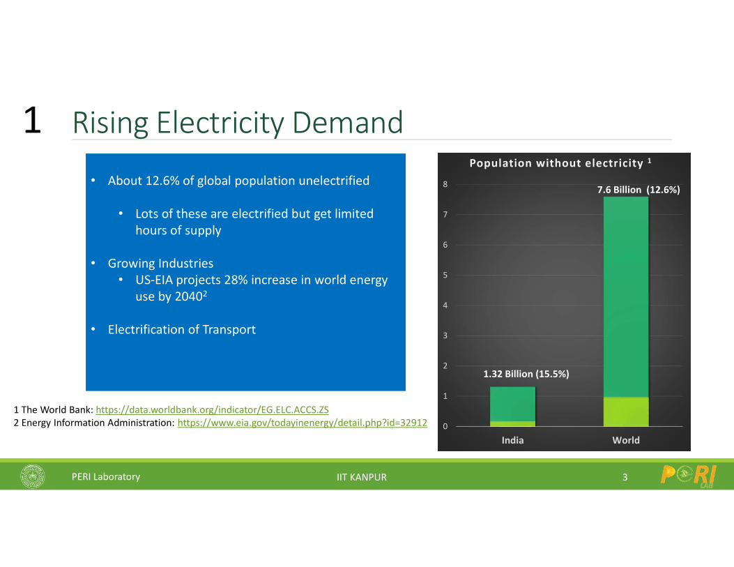
Rising Electricity Demand
3
1 The World Bank: https://data.worldbank.org/indicator/EG.ELC.ACCS.ZS2 Energy Information Administration: https://www.eia.gov/todayinenergy/detail.php?id=32912
• About 12.6% of global population unelectrified
• Lots of these are electrified but get limited hours of supply
• Growing Industries• US-EIA projects 28% increase in world energy
use by 20402
• Electrification of Transport
0
1
2
3
4
5
6
7
8
India World
Population without electricity 1
1.32 Billion (15.5%)
7.6 Billion (12.6%)
1
PERI Laboratory IIT KANPUR
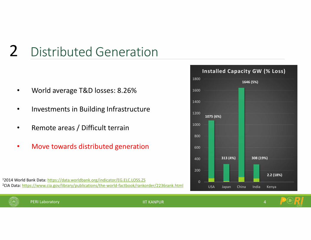
Distributed Generation
4
• World average T&D losses: 8.26%
• Investments in Building Infrastructure
• Remote areas / Difficult terrain
• Move towards distributed generation
12014 World Bank Data: https://data.worldbank.org/indicator/EG.ELC.LOSS.ZS2CIA Data: https://www.cia.gov/library/publications/the-world-factbook/rankorder/2236rank.html
0
200
400
600
800
1000
1200
1400
1600
1800
USA Japan China India Kenya
Installed Capacity GW (% Loss)
1075 (6%)
313 (4%)
1646 (5%)
308 (19%)
2.2 (18%)
2
PERI Laboratory IIT KANPUR
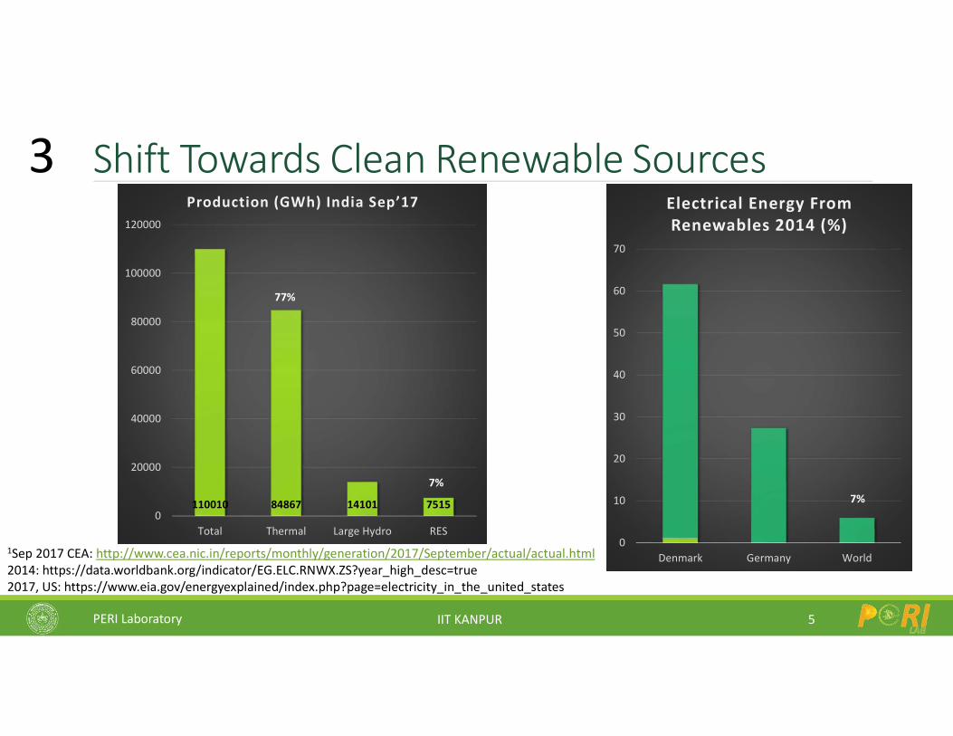
Shift Towards Clean Renewable Sources
5
1Sep 2017 CEA: http://www.cea.nic.in/reports/monthly/generation/2017/September/actual/actual.html2014: https://data.worldbank.org/indicator/EG.ELC.RNWX.ZS?year_high_desc=true2017, US: https://www.eia.gov/energyexplained/index.php?page=electricity_in_the_united_states
66%
14%
110010 84867 14101 75150
20000
40000
60000
80000
100000
120000
Total Thermal Large Hydro RES
Production (GWh) India Sep’17
77%
7%
0
10
20
30
40
50
60
70
Denmark Germany World
Electrical Energy From Renewables 2014 (%)
7%
3
PERI Laboratory IIT KANPUR
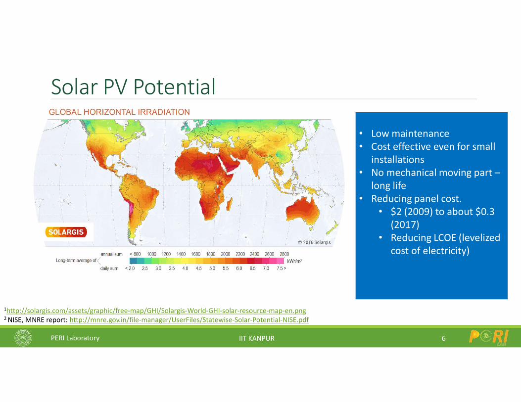
Solar PV Potential
6
1http://solargis.com/assets/graphic/free-map/GHI/Solargis-World-GHI-solar-resource-map-en.png2 NISE, MNRE report: http://mnre.gov.in/file-manager/UserFiles/Statewise-Solar-Potential-NISE.pdf
• Low maintenance• Cost effective even for small
installations• No mechanical moving part –
long life• Reducing panel cost.
• $2 (2009) to about $0.3 (2017)
• Reducing LCOE (levelized cost of electricity)

PERI Laboratory IIT KANPUR
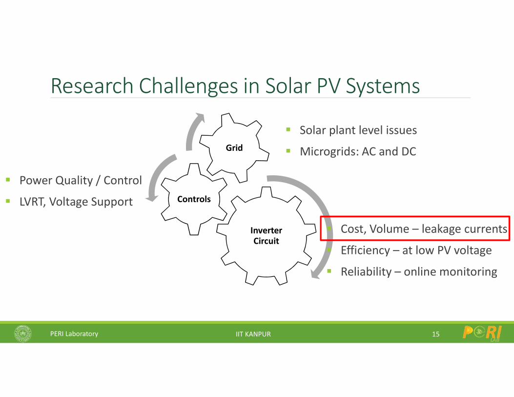
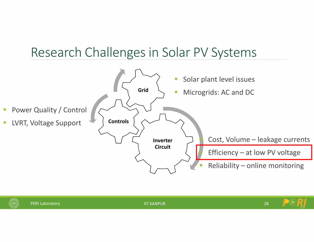
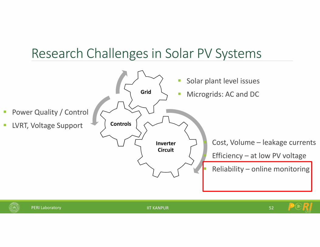
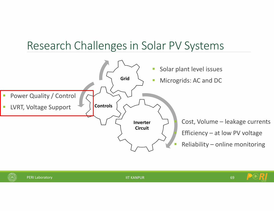
Research Challenges in Solar PV Systems
7
Inverter Circuit
Controls
Grid
Solar plant level issues
Microgrids: AC and DC
Power Quality / Control
LVRT, Voltage Support
Cost, Volume – leakage currents
Efficiency – at low PV voltage
Reliability – online monitoring
PERI Laboratory IIT KANPUR
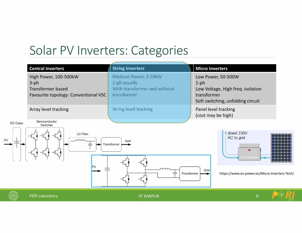
Solar PV Inverters: Categories
8
Central Inverters String Inverters Micro Inverters
High Power, 100-500kW3-phTransformer basedFavourite topology: Conventional VSC
Medium Power, 3-20kW1-ph usuallyWith transformer and without transformer
Low Power, 50-500W1-phLow Voltage, High freq. isolation transformerSoft switching, unfolding circuit
Array level tracking String level tracking Panel level tracking(cost may be high)
https://www.ev-power.eu/Micro-Inverters-Tech/
PERI Laboratory IIT KANPUR
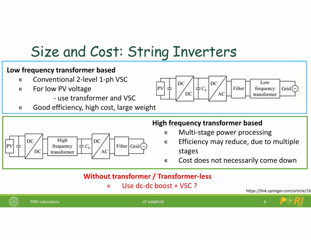
Size and Cost: String Inverters
9
Low frequency transformer based« Conventional 2-level 1-ph VSC« For low PV voltage
- use transformer and VSC« Good efficiency, high cost, large weight
High frequency transformer based« Multi-stage power processing« Efficiency may reduce, due to multiple
stages« Cost does not necessarily come down
Without transformer / Transformer-less« Use dc-dc boost + VSC ?
https://link.springer.com/article/10.1007/s40565
PERI Laboratory IIT KANPUR
Leakage Currents
10
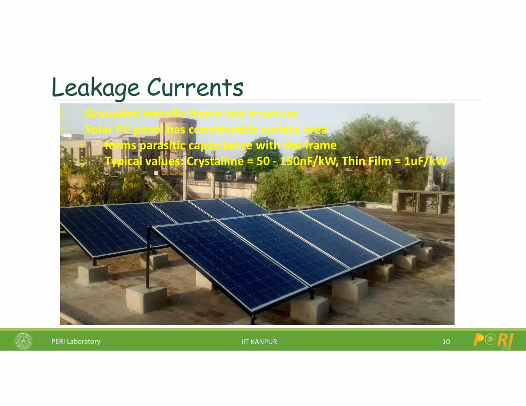
⁞ Grounded metallic frame and structure⁞ Solar PV panel has considerable surface area
⁞ forms parasitic capacitance with the frame⁞ Typical values: Crystalline = 50 - 150nF/kW, Thin Film = 1uF/kW
PERI Laboratory IIT KANPUR
Leakage Currents
11
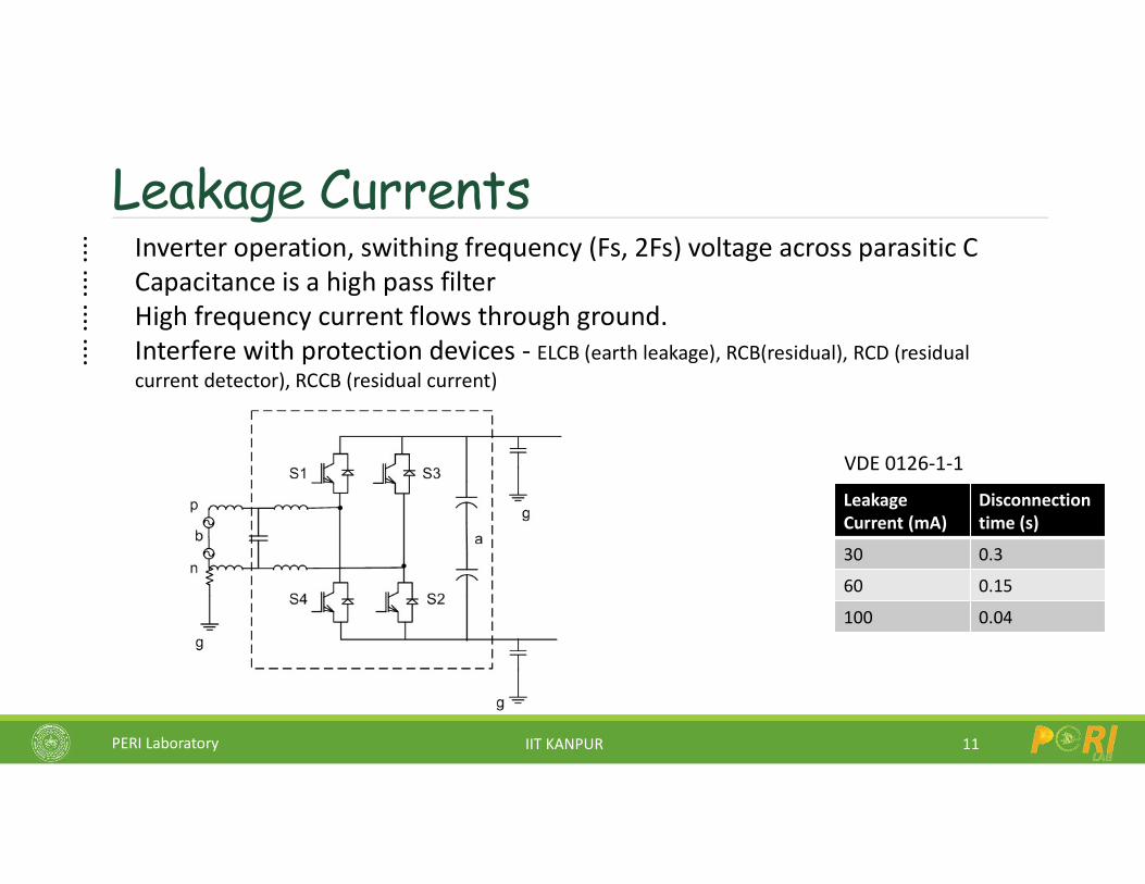
⁞ Inverter operation, swithing frequency (Fs, 2Fs) voltage across parasitic C⁞ Capacitance is a high pass filter⁞ High frequency current flows through ground.⁞ Interfere with protection devices - ELCB (earth leakage), RCB(residual), RCD (residual
current detector), RCCB (residual current)
Leakage Current (mA)
Disconnection time (s)
30 0.3
60 0.15
100 0.04
VDE 0126-1-1
PERI Laboratory IIT KANPUR
Voltage Across Cp
12
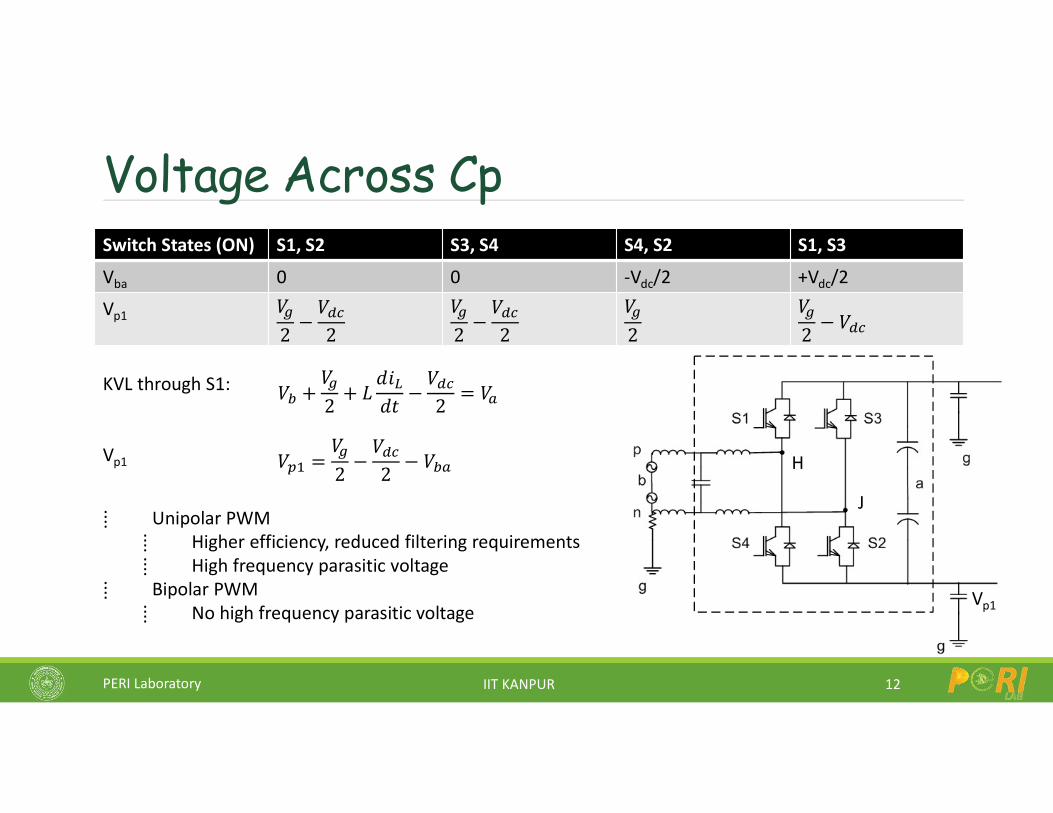
⁞ Unipolar PWM⁞ Higher efficiency, reduced filtering requirements⁞ High frequency parasitic voltage
⁞ Bipolar PWM⁞ No high frequency parasitic voltage
Switch States (ON) S1, S2 S3, S4 S4, S2 S1, S3
Vba 0 0 -Vdc/2 +Vdc/2
Vp1 𝑉
2−𝑉
2
𝑉
2−𝑉
2
𝑉
2
𝑉
2− 𝑉
Vp1
𝑉 +𝑉
2+ 𝐿
𝑑𝑖
𝑑𝑡−𝑉
2= 𝑉KVL through S1:
Vp1 𝑉 =𝑉
2−𝑉
2− 𝑉 H
J
PERI Laboratory IIT KANPUR
Understanding in terms of common mode voltage
13
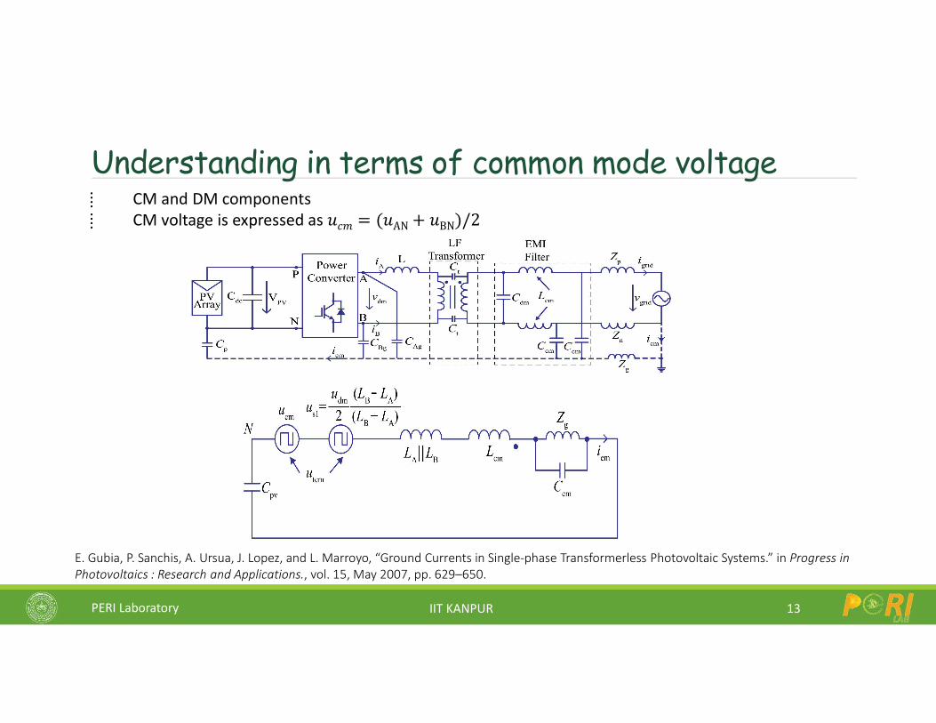
⁞ CM and DM components⁞ CM voltage is expressed as 𝑢𝑐𝑚 = (𝑢AN + 𝑢BN)/2
E. Gubia, P. Sanchis, A. Ursua, J. Lopez, and L. Marroyo, “Ground Currents in Single-phase Transformerless Photovoltaic Systems.” in Progress in Photovoltaics : Research and Applications., vol. 15, May 2007, pp. 629–650.
PERI Laboratory IIT KANPUR
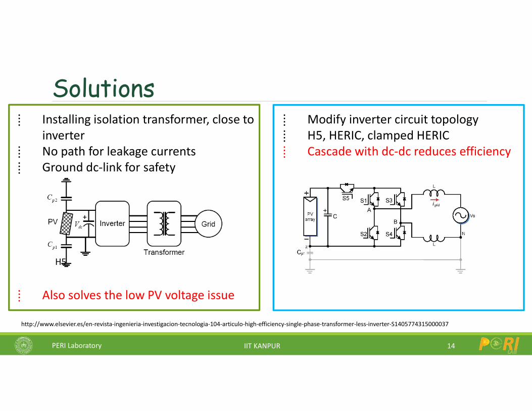
Solutions
14
⁞ Installing isolation transformer, close to inverter
⁞ No path for leakage currents⁞ Ground dc-link for safety
⁞ Also solves the low PV voltage issue
⁞ Modify inverter circuit topology⁞ H5, HERIC, clamped HERIC⁞ Cascade with dc-dc reduces efficiency
http://www.elsevier.es/en-revista-ingenieria-investigacion-tecnologia-104-articulo-high-efficiency-single-phase-transformer-less-inverter-S1405774315000037
H5
PERI Laboratory IIT KANPUR
Research Challenges in Solar PV Systems
15
Inverter Circuit
Controls
Grid
Solar plant level issues
Microgrids: AC and DC
Power Quality / Control
LVRT, Voltage Support
Cost, Volume – leakage currents
Efficiency – at low PV voltage
Reliability – online monitoring
PERI Laboratory IIT KANPUR
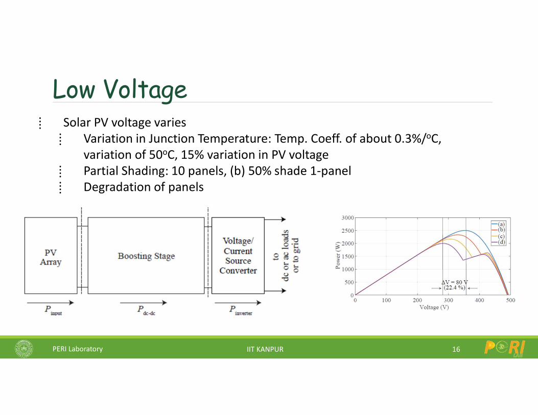
Low Voltage
16
⁞ Solar PV voltage varies⁞ Variation in Junction Temperature: Temp. Coeff. of about 0.3%/oC,
variation of 50oC, 15% variation in PV voltage⁞ Partial Shading: 10 panels, (b) 50% shade 1-panel⁞ Degradation of panels
PERI Laboratory IIT KANPUR
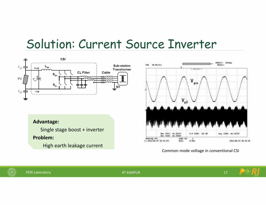
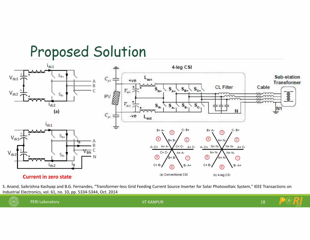
Solution: Current Source Inverter
17
Advantage: Single stage boost + inverter
Problem: High earth leakage current
Common mode voltage in conventional CSI
PERI Laboratory IIT KANPUR
Proposed Solution
18
S. Anand, Saikrishna Kashyap and B.G. Fernandes, "Transformer-less Grid Feeding Current Source Inverter for Solar Photovoltaic System," IEEE Transactions on Industrial Electronics, vol. 61, no. 10, pp. 5334-5344, Oct. 2014
Current in zero state
PERI Laboratory IIT KANPUR
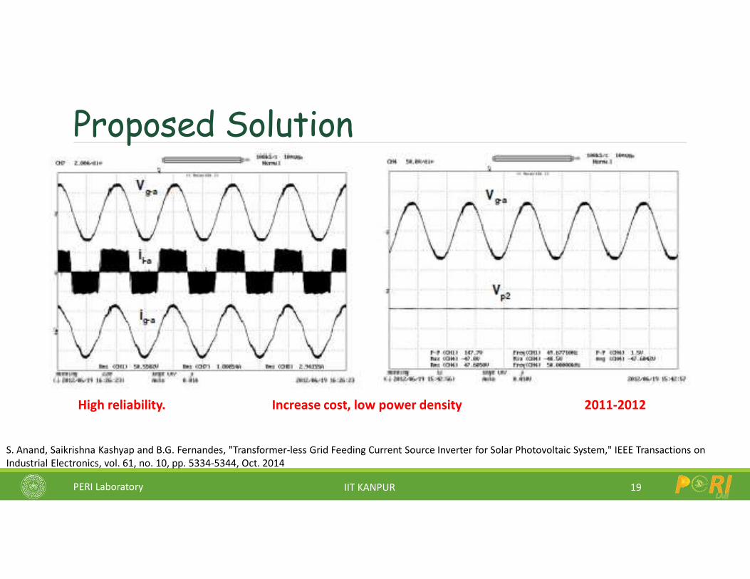
Proposed Solution
19
High reliability. Increase cost, low power density 2011-2012
S. Anand, Saikrishna Kashyap and B.G. Fernandes, "Transformer-less Grid Feeding Current Source Inverter for Solar Photovoltaic System," IEEE Transactions on Industrial Electronics, vol. 61, no. 10, pp. 5334-5344, Oct. 2014
PERI Laboratory IIT KANPUR
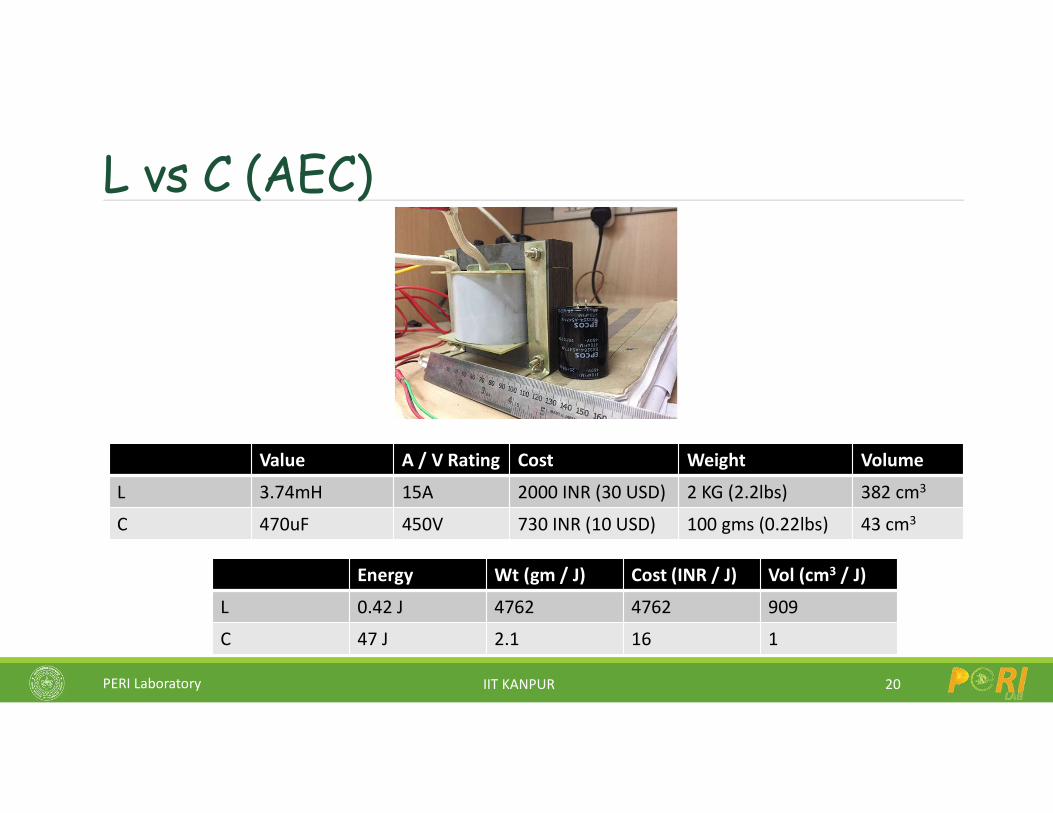
L vs C (AEC)
20
Value A / V Rating Cost Weight Volume
L 3.74mH 15A 2000 INR (30 USD) 2 KG (2.2lbs) 382 cm3
C 470uF 450V 730 INR (10 USD) 100 gms (0.22lbs) 43 cm3
Energy Wt (gm / J) Cost (INR / J) Vol (cm3 / J)
L 0.42 J 4762 4762 909
C 47 J 2.1 16 1
PERI Laboratory IIT KANPUR
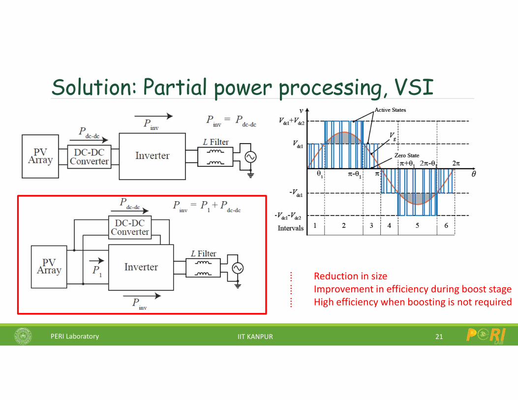
Solution: Partial power processing, VSI
21
⁞ Reduction in size⁞ Improvement in efficiency during boost stage⁞ High efficiency when boosting is not required
PERI Laboratory IIT KANPUR
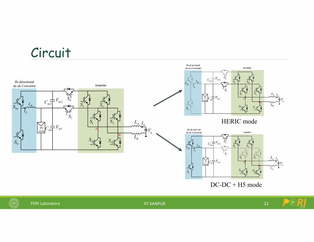
Circuit
22
HERIC mode
DC-DC + H5 mode
PERI Laboratory IIT KANPUR
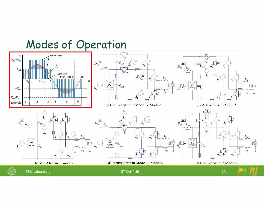
Modes of Operation
23
PERI Laboratory IIT KANPUR
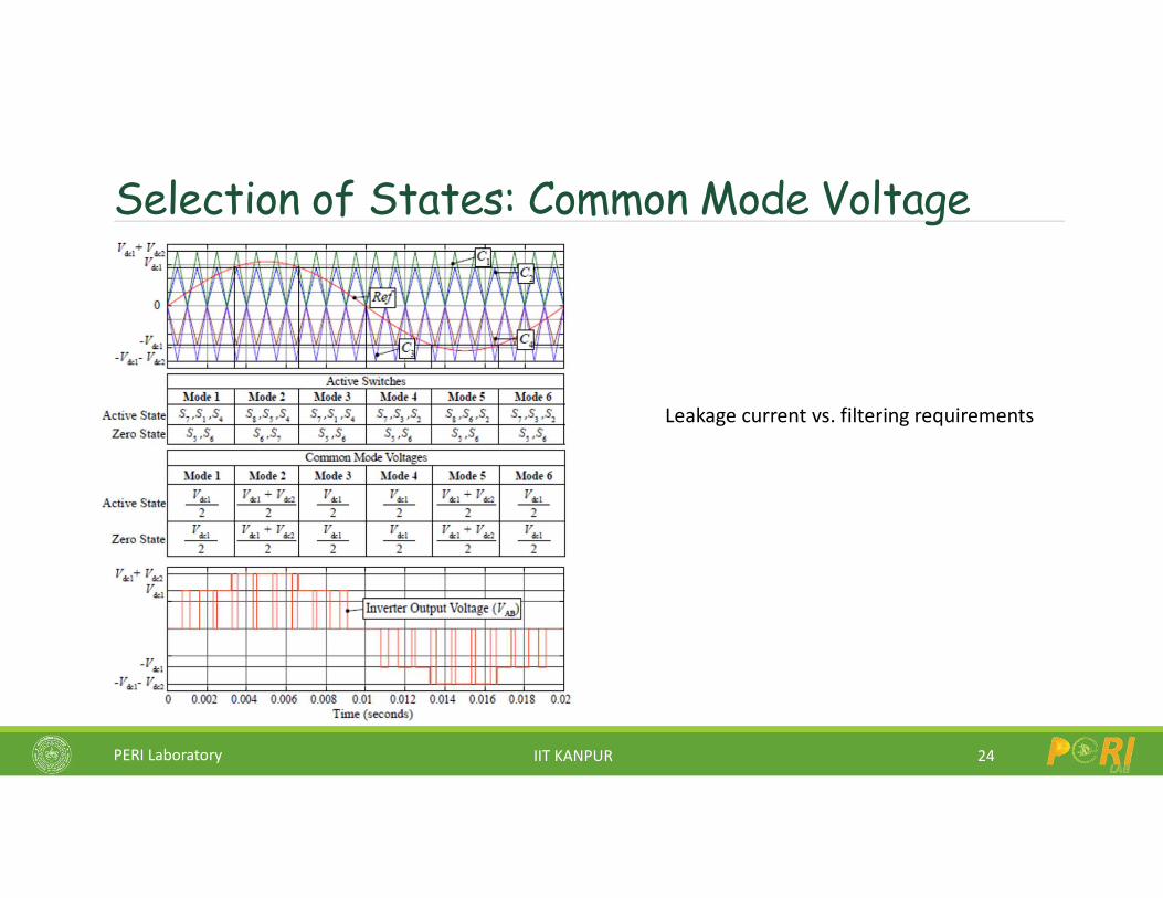
Selection of States: Common Mode Voltage
24
Leakage current vs. filtering requirements
PERI Laboratory IIT KANPUR
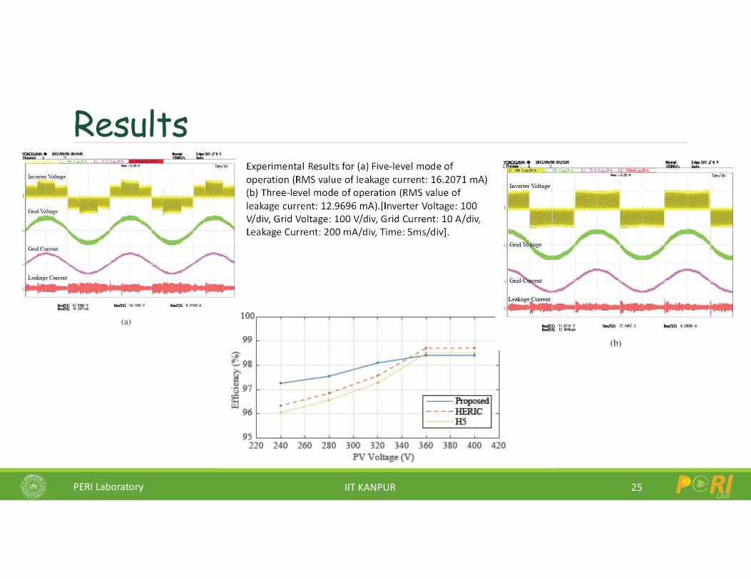
Results
25
Experimental Results for (a) Five-level mode of operation (RMS value of leakage current: 16.2071 mA) (b) Three-level mode of operation (RMS value of leakage current: 12.9696 mA).[Inverter Voltage: 100 V/div, Grid Voltage: 100 V/div, Grid Current: 10 A/div, Leakage Current: 200 mA/div, Time: 5ms/div].
PERI Laboratory IIT KANPUR
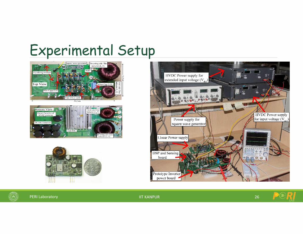
Experimental Setup
26
PERI Laboratory IIT KANPUR
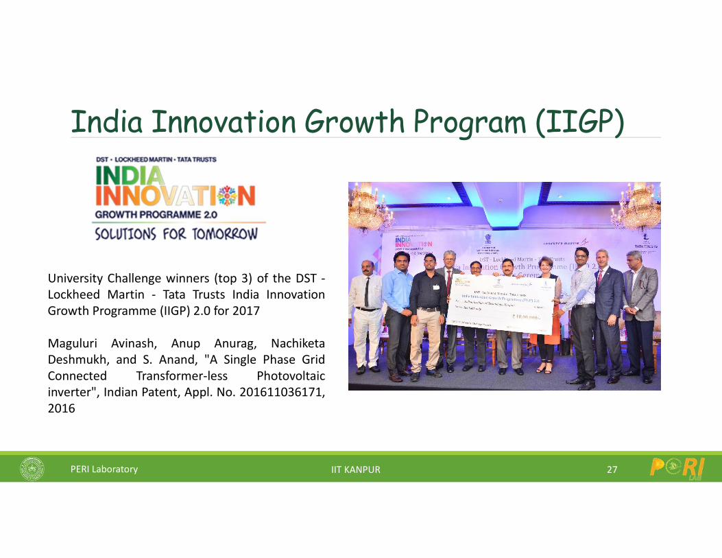
India Innovation Growth Program (IIGP)
27
University Challenge winners (top 3) of the DST -Lockheed Martin - Tata Trusts India InnovationGrowth Programme (IIGP) 2.0 for 2017
Maguluri Avinash, Anup Anurag, NachiketaDeshmukh, and S. Anand, "A Single Phase GridConnected Transformer-less Photovoltaicinverter", Indian Patent, Appl. No. 201611036171,2016
PERI Laboratory IIT KANPUR
Research Challenges in Solar PV Systems
28
Inverter Circuit
Controls
Grid
Solar plant level issues
Microgrids: AC and DC
Power Quality / Control
LVRT, Voltage Support
Cost, Volume – leakage currents
Efficiency – at low PV voltage
Reliability – online monitoring
PERI Laboratory IIT KANPUR
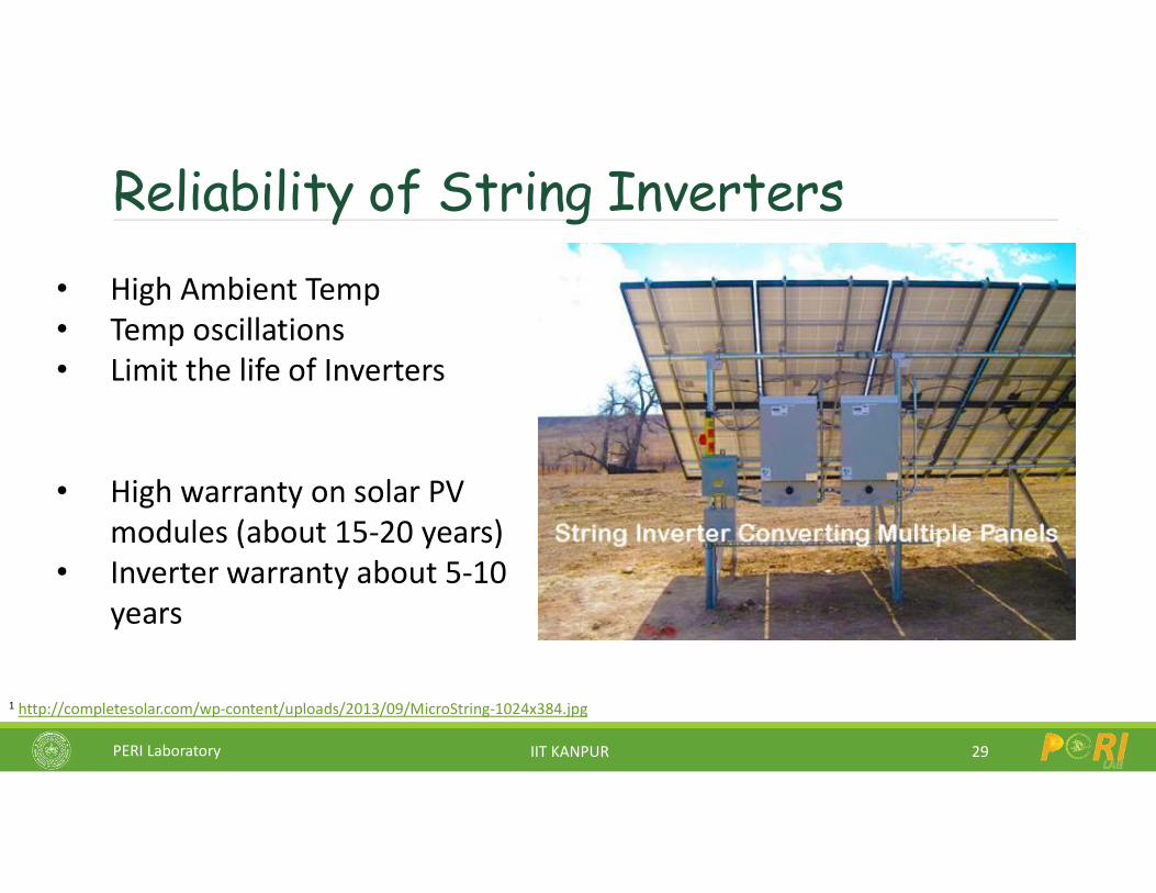
Reliability of String Inverters
29
• High Ambient Temp• Temp oscillations• Limit the life of Inverters
• High warranty on solar PV modules (about 15-20 years)
• Inverter warranty about 5-10 years
1 http://completesolar.com/wp-content/uploads/2013/09/MicroString-1024x384.jpg
PERI Laboratory IIT KANPUR
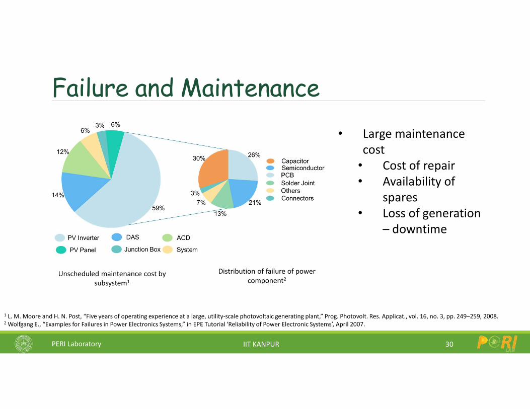
Failure and Maintenance
30
• Large maintenance cost
• Cost of repair • Availability of
spares• Loss of generation
– downtime
1 L. M. Moore and H. N. Post, “Five years of operating experience at a large, utility-scale photovoltaic generating plant,” Prog. Photovolt. Res. Applicat., vol. 16, no. 3, pp. 249–259, 2008.2 Wolfgang E., “Examples for Failures in Power Electronics Systems,” in EPE Tutorial ‘Reliability of Power Electronic Systems’, April 2007.
Distribution of failure of power component2
Unscheduled maintenance cost by subsystem1
PERI Laboratory IIT KANPUR
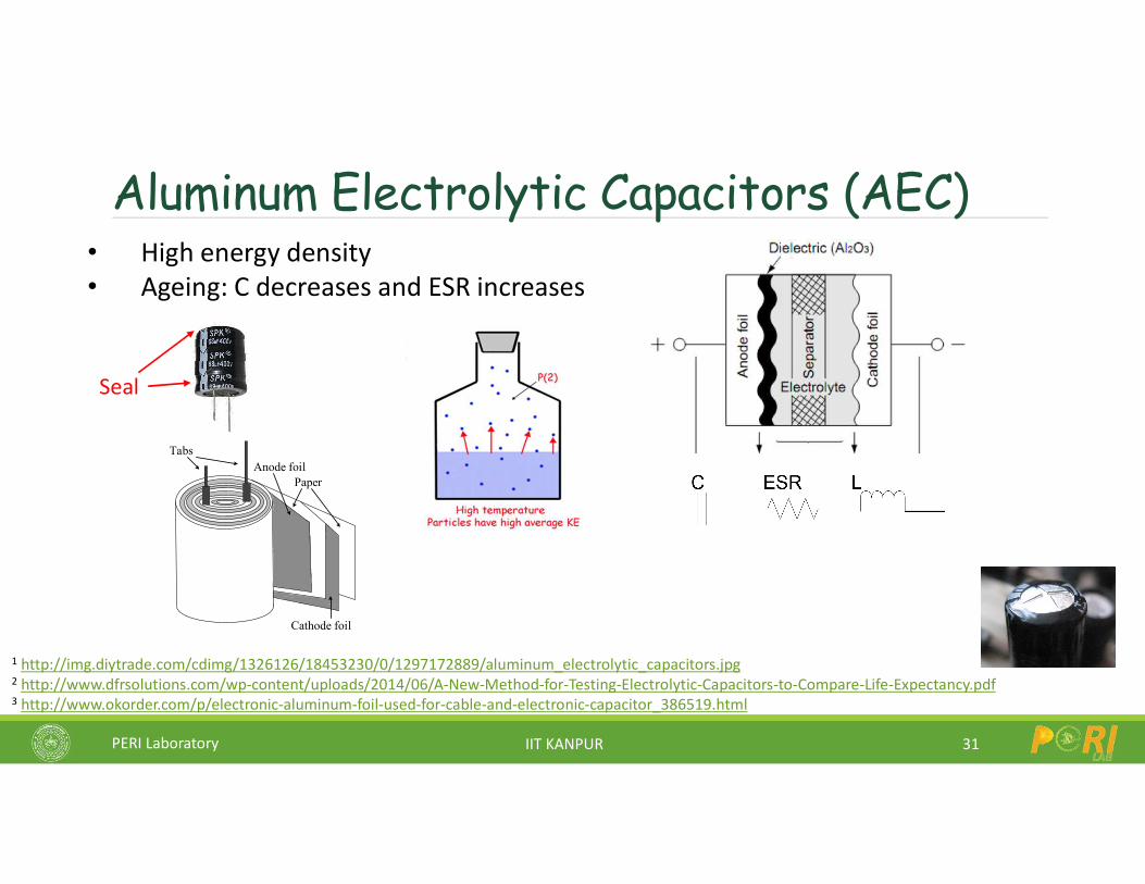
Aluminum Electrolytic Capacitors (AEC)
31
• High energy density• Ageing: C decreases and ESR increases
1 http://img.diytrade.com/cdimg/1326126/18453230/0/1297172889/aluminum_electrolytic_capacitors.jpg2 http://www.dfrsolutions.com/wp-content/uploads/2014/06/A-New-Method-for-Testing-Electrolytic-Capacitors-to-Compare-Life-Expectancy.pdf3 http://www.okorder.com/p/electronic-aluminum-foil-used-for-cable-and-electronic-capacitor_386519.html
PaperAnode foil
Cathode foil
Tabs
Seal
PERI Laboratory IIT KANPUR
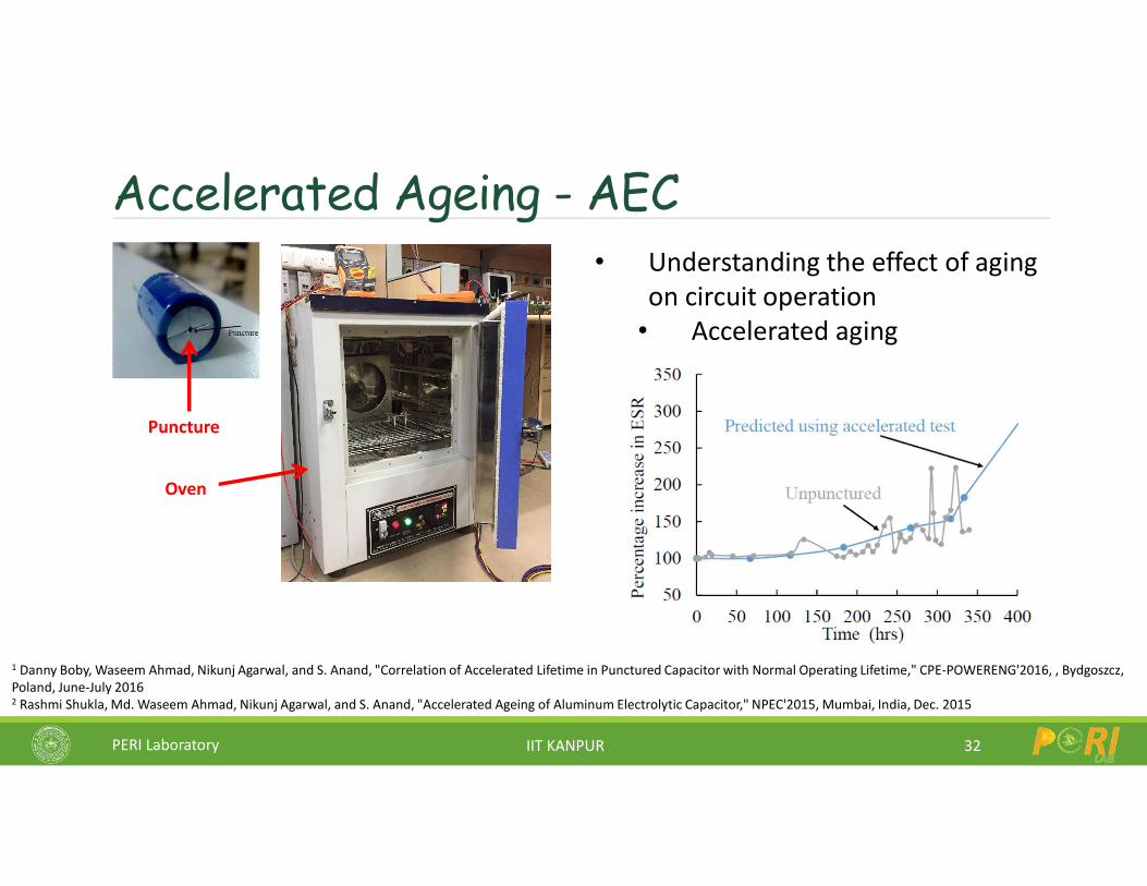
Accelerated Ageing - AEC
32
• Understanding the effect of aging on circuit operation
• Accelerated aging
1 Danny Boby, Waseem Ahmad, Nikunj Agarwal, and S. Anand, "Correlation of Accelerated Lifetime in Punctured Capacitor with Normal Operating Lifetime," CPE-POWERENG'2016, , Bydgoszcz, Poland, June-July 20162 Rashmi Shukla, Md. Waseem Ahmad, Nikunj Agarwal, and S. Anand, "Accelerated Ageing of Aluminum Electrolytic Capacitor," NPEC'2015, Mumbai, India, Dec. 2015
Puncture
Oven
PERI Laboratory IIT KANPUR
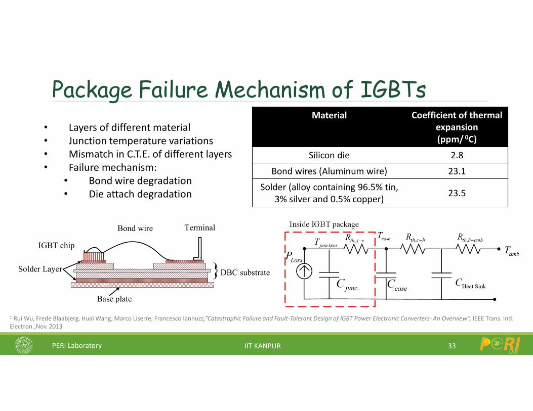
Package Failure Mechanism of IGBTs
33
• Layers of different material• Junction temperature variations• Mismatch in C.T.E. of different layers• Failure mechanism:
• Bond wire degradation• Die attach degradation
Solder Layer
IGBT chip
Bond wire
DBC substrate
Terminal
Base plate
Material Coefficient of thermal expansion (ppm/ 0C)
Silicon die 2.8
Bond wires (Aluminum wire) 23.1
Solder (alloy containing 96.5% tin, 3% silver and 0.5% copper) 23.5
1 Rui Wu, Frede Blaabjerg, Huai Wang, Marco Liserre, Francesco Iannuzz,”Catastrophic Failure and Fault-Tolerant Design of IGBT Power Electronic Converters- An Overview”, IEEE Trans. Ind. Electron.,Nov. 2013
PERI Laboratory IIT KANPUR
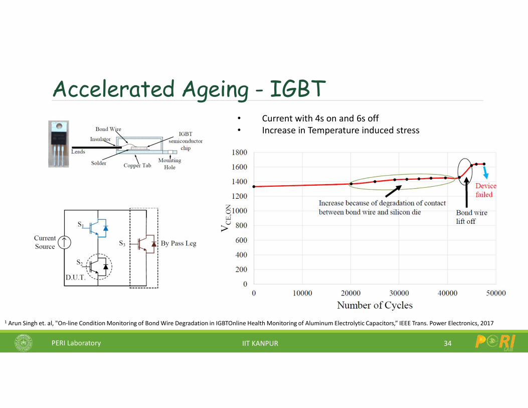
Accelerated Ageing - IGBT
34
• Current with 4s on and 6s off• Increase in Temperature induced stress
1 Arun Singh et. al, "On-line Condition Monitoring of Bond Wire Degradation in IGBTOnline Health Monitoring of Aluminum Electrolytic Capacitors,” IEEE Trans. Power Electronics, 2017
PERI Laboratory IIT KANPUR
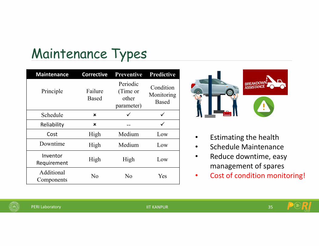
Maintenance Types
35
• Estimating the health• Schedule Maintenance• Reduce downtime, easy
management of spares• Cost of condition monitoring!
Maintenance Corrective Preventive Predictive
Principle Failure Based
Periodic (Time or
other parameter)
Condition Monitoring
Based
Schedule
Reliability --
Cost High Medium Low
Downtime High Medium Low
Inventor Requirement High High Low
Additional Components
No No Yes
PERI Laboratory IIT KANPUR
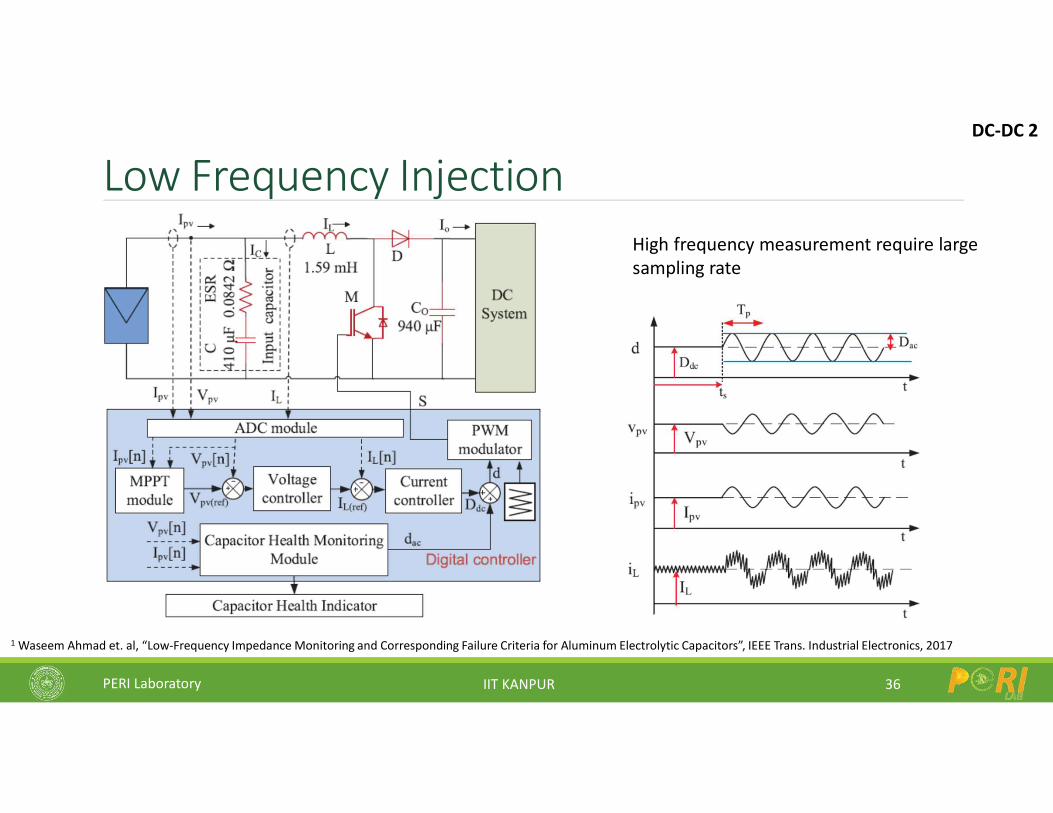
Low Frequency Injection
36
1 Waseem Ahmad et. al, “Low-Frequency Impedance Monitoring and Corresponding Failure Criteria for Aluminum Electrolytic Capacitors”, IEEE Trans. Industrial Electronics, 2017
DC-DC 2
High frequency measurement require large sampling rate
PERI Laboratory IIT KANPUR
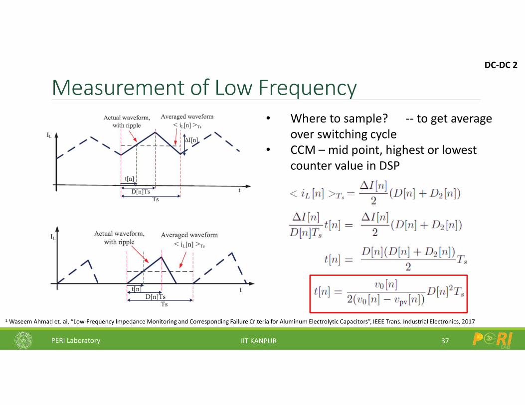
Measurement of Low Frequency
37
1 Waseem Ahmad et. al, “Low-Frequency Impedance Monitoring and Corresponding Failure Criteria for Aluminum Electrolytic Capacitors”, IEEE Trans. Industrial Electronics, 2017
DC-DC 2
• Where to sample? -- to get average over switching cycle
• CCM – mid point, highest or lowest counter value in DSP
PERI Laboratory IIT KANPUR
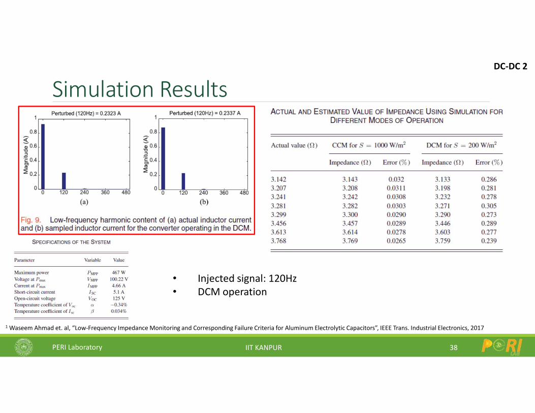
Simulation Results
38
1 Waseem Ahmad et. al, “Low-Frequency Impedance Monitoring and Corresponding Failure Criteria for Aluminum Electrolytic Capacitors”, IEEE Trans. Industrial Electronics, 2017
DC-DC 2
• Injected signal: 120Hz• DCM operation
PERI Laboratory IIT KANPUR
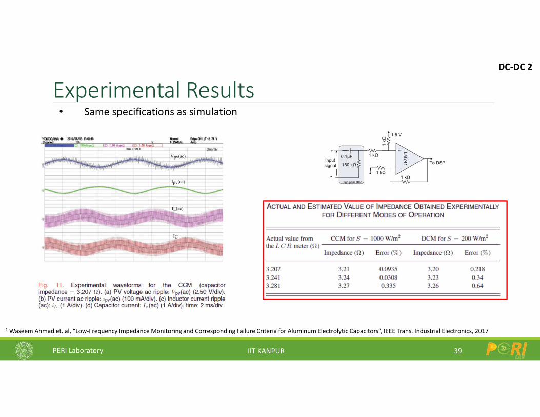
Experimental Results
39
1 Waseem Ahmad et. al, “Low-Frequency Impedance Monitoring and Corresponding Failure Criteria for Aluminum Electrolytic Capacitors”, IEEE Trans. Industrial Electronics, 2017
DC-DC 2
• Same specifications as simulation
PERI Laboratory IIT KANPUR
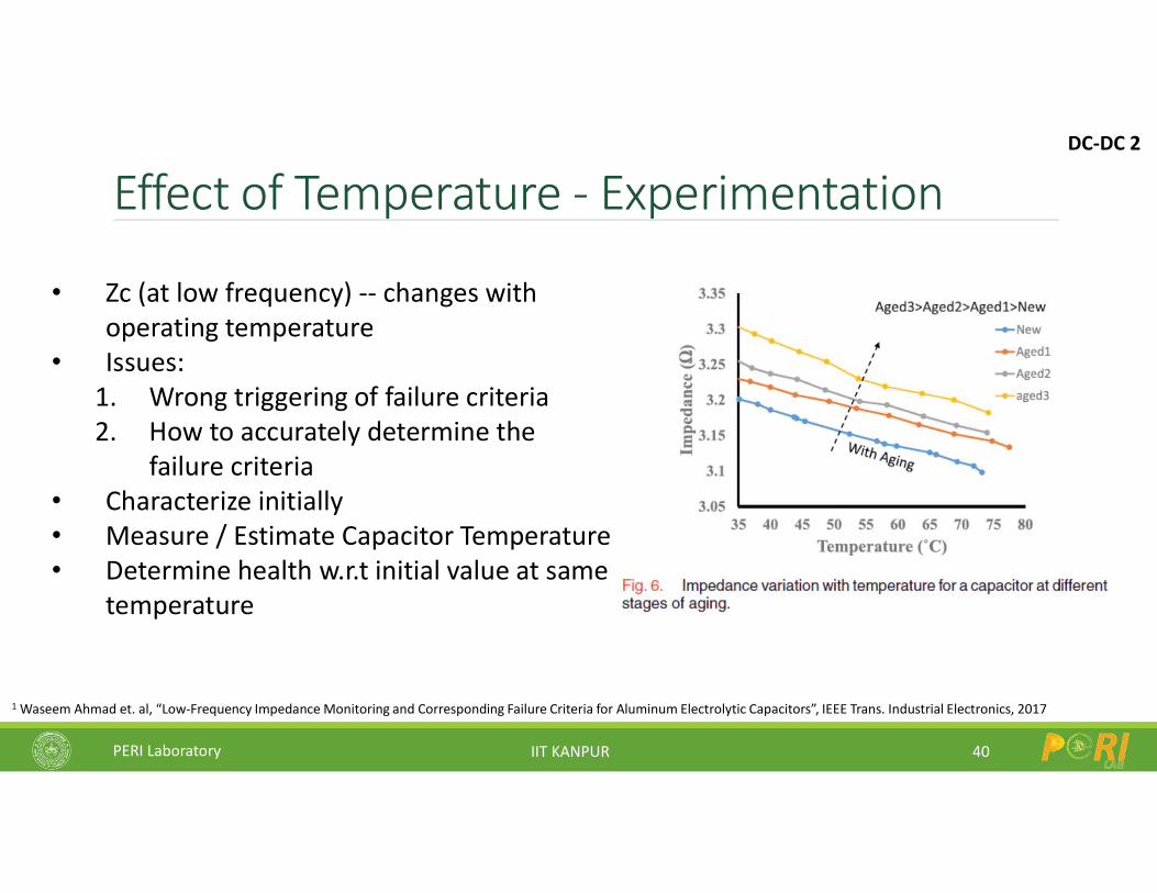
Effect of Temperature - Experimentation
40
1 Waseem Ahmad et. al, “Low-Frequency Impedance Monitoring and Corresponding Failure Criteria for Aluminum Electrolytic Capacitors”, IEEE Trans. Industrial Electronics, 2017
DC-DC 2
• Zc (at low frequency) -- changes with operating temperature
• Issues:1. Wrong triggering of failure criteria2. How to accurately determine the
failure criteria• Characterize initially• Measure / Estimate Capacitor Temperature• Determine health w.r.t initial value at same
temperature
PERI Laboratory IIT KANPUR
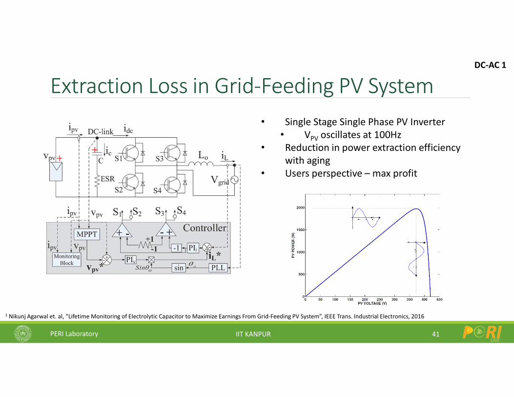
Extraction Loss in Grid-Feeding PV System
41
• Single Stage Single Phase PV Inverter• VPV oscillates at 100Hz
• Reduction in power extraction efficiency with aging
• Users perspective – max profit
1 Nikunj Agarwal et. al, “Lifetime Monitoring of Electrolytic Capacitor to Maximize Earnings From Grid-Feeding PV System”, IEEE Trans. Industrial Electronics, 2016
DC-AC 1
PERI Laboratory IIT KANPUR
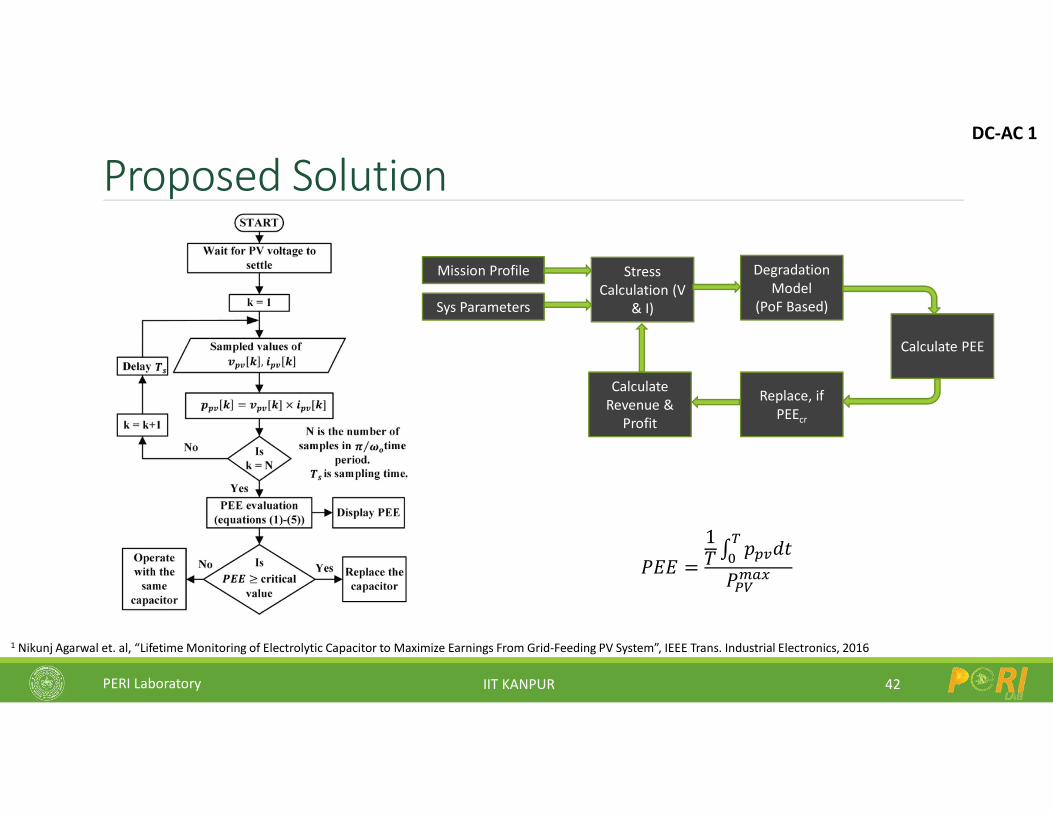
Proposed Solution
42
1 Nikunj Agarwal et. al, “Lifetime Monitoring of Electrolytic Capacitor to Maximize Earnings From Grid-Feeding PV System”, IEEE Trans. Industrial Electronics, 2016
𝑃𝐸𝐸 =
1𝑇 ∫
𝑝 𝑑𝑡
𝑃
DC-AC 1
Degradation Model
(PoF Based)
Mission Profile
Sys Parameters
Stress Calculation (V
& I)
Calculate Revenue &
Profit
Replace, if PEEcr
Calculate PEE
PERI Laboratory IIT KANPUR
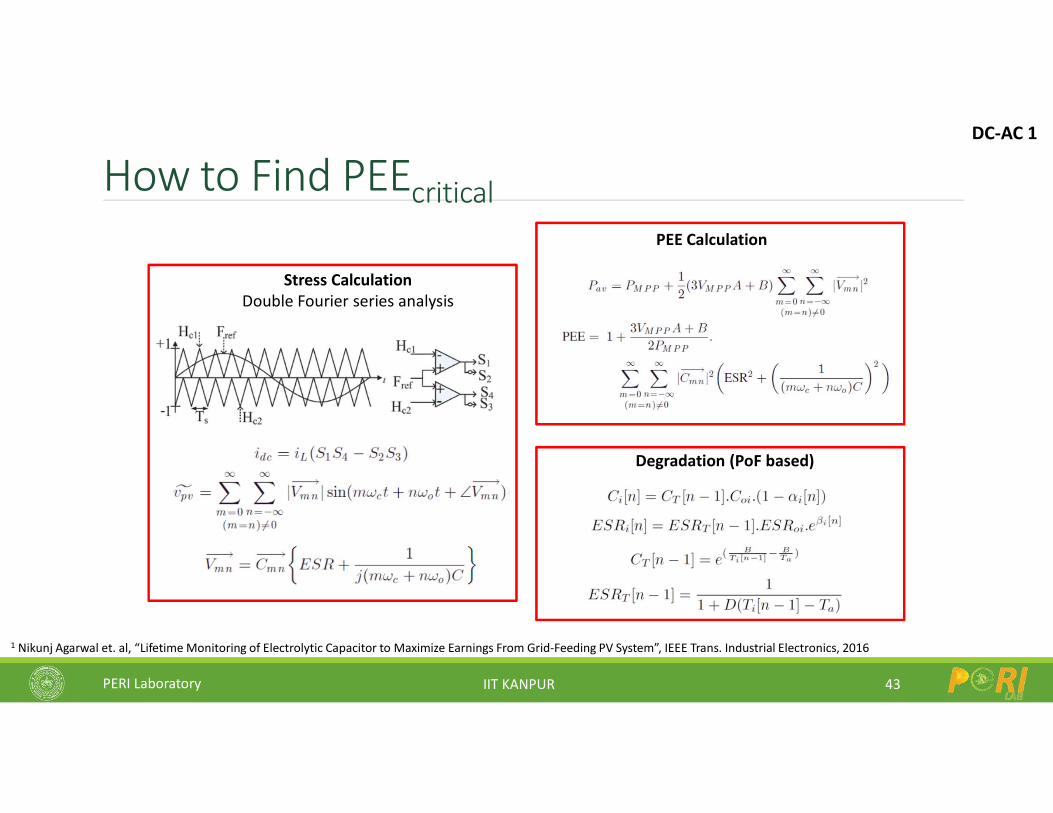
How to Find PEEcritical
43
1 Nikunj Agarwal et. al, “Lifetime Monitoring of Electrolytic Capacitor to Maximize Earnings From Grid-Feeding PV System”, IEEE Trans. Industrial Electronics, 2016
Stress CalculationDouble Fourier series analysis
PEE Calculation
Degradation (PoF based)
DC-AC 1
PERI Laboratory IIT KANPUR
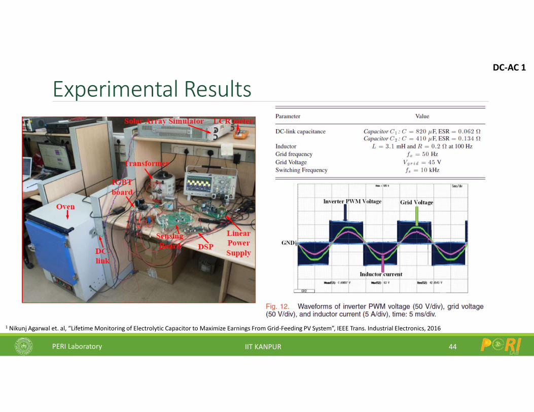
Experimental Results
44
1 Nikunj Agarwal et. al, “Lifetime Monitoring of Electrolytic Capacitor to Maximize Earnings From Grid-Feeding PV System”, IEEE Trans. Industrial Electronics, 2016
DC-AC 1
PERI Laboratory IIT KANPUR
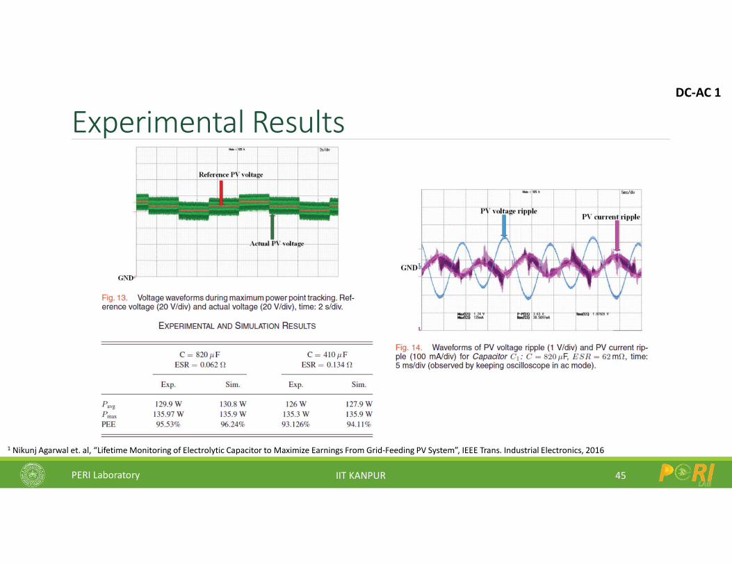
Experimental Results
45
1 Nikunj Agarwal et. al, “Lifetime Monitoring of Electrolytic Capacitor to Maximize Earnings From Grid-Feeding PV System”, IEEE Trans. Industrial Electronics, 2016
DC-AC 1
PERI Laboratory IIT KANPUR
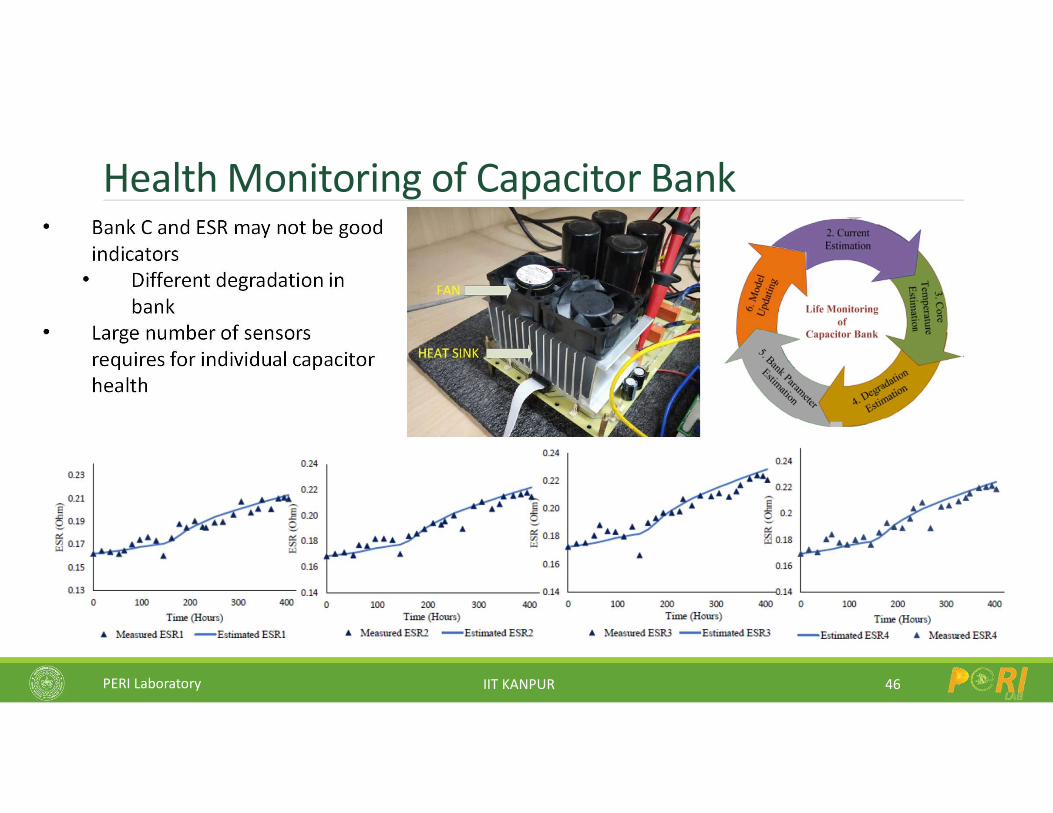
Health Monitoring of Capacitor Bank
46
• Bank C and ESR may not be good indicators
• Different degradation in bank
• Large number of sensors requires for individual capacitor health
PERI Laboratory IIT KANPUR
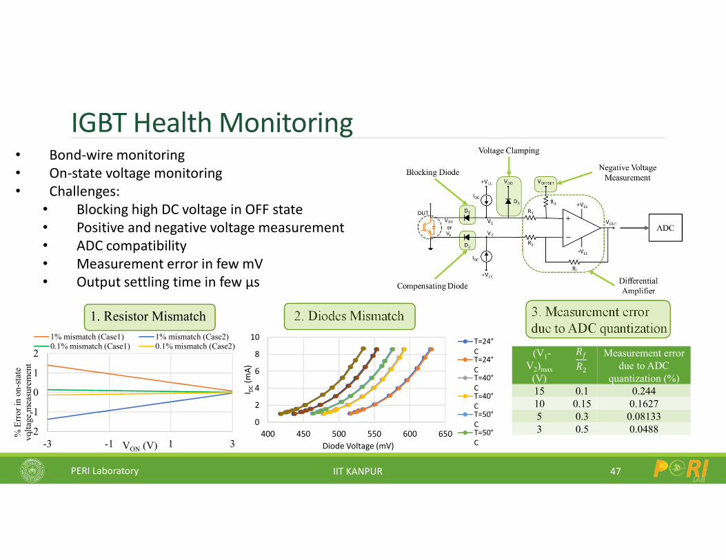
IGBT Health Monitoring
47
• Bond-wire monitoring• On-state voltage monitoring• Challenges:
• Blocking high DC voltage in OFF state• Positive and negative voltage measurement• ADC compatibility• Measurement error in few mV• Output settling time in few µs
-2
-1
0
1
2
-3 -1 1 3
% E
rror
in o
n-st
ate
volta
ge m
easu
rem
ent
VON (V)
1% mismatch (Case1) 1% mismatch (Case2)0.1% mismatch (Case1) 0.1% mismatch (Case2)
1. Resistor Mismatch 2. Diodes Mismatch 3. Measurement error due to ADC quantization
0
2
4
6
8
10
400 450 500 550 600 650
I DC
(mA)
Diode Voltage (mV)
T=24°CT=24°CT=40°CT=40°CT=50°CT=50°C
(V1-V2)max
(V)
𝑅𝑓𝑅2
Measurement error due to ADC
quantization (%)15 0.1 0.24410 0.15 0.16275 0.3 0.081333 0.5 0.0488

PERI Laboratory IIT KANPUR
Experimental Results of Measurement Circuit
48
PERI Laboratory IIT KANPUR
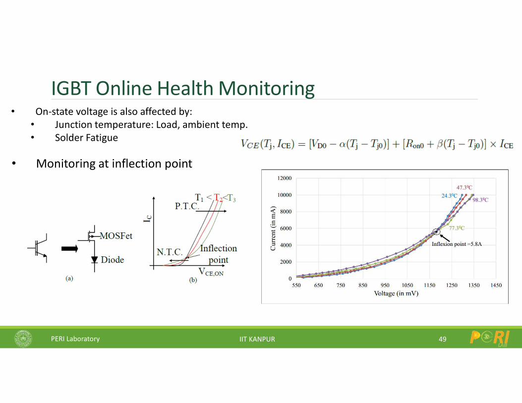
IGBT Online Health Monitoring
49
• On-state voltage is also affected by:• Junction temperature: Load, ambient temp.• Solder Fatigue
• Monitoring at inflection point
PERI Laboratory IIT KANPUR
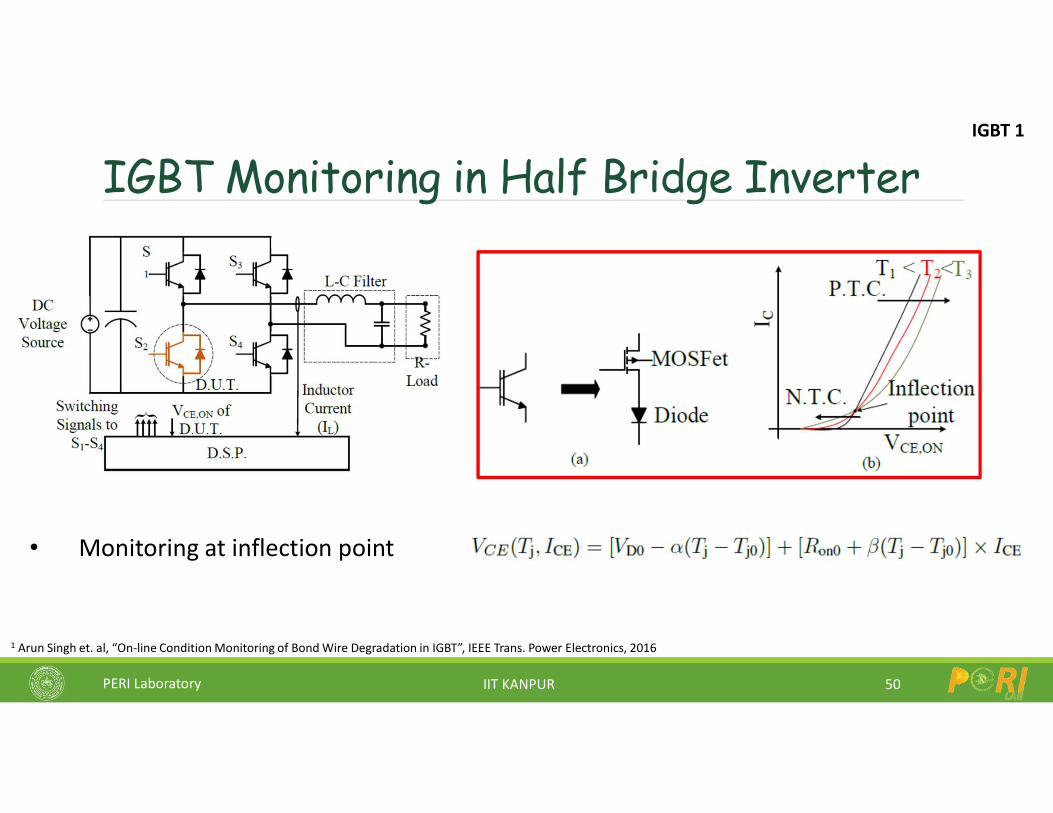
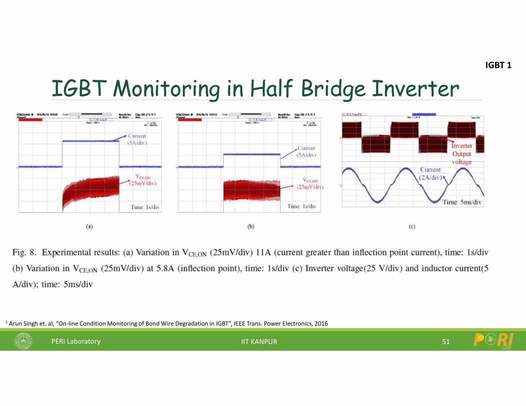
IGBT Monitoring in Half Bridge Inverter
50
• Monitoring at inflection point
1 Arun Singh et. al, “On-line Condition Monitoring of Bond Wire Degradation in IGBT”, IEEE Trans. Power Electronics, 2016
IGBT 1
PERI Laboratory IIT KANPUR
IGBT Monitoring in Half Bridge Inverter
51
1 Arun Singh et. al, “On-line Condition Monitoring of Bond Wire Degradation in IGBT”, IEEE Trans. Power Electronics, 2016
IGBT 1
PERI Laboratory IIT KANPUR
Research Challenges in Solar PV Systems
52
Inverter Circuit
Controls
Grid
Solar plant level issues
Microgrids: AC and DC
Power Quality / Control
LVRT, Voltage Support
Cost, Volume – leakage currents
Efficiency – at low PV voltage
Reliability – online monitoring
PERI Laboratory IIT KANPUR
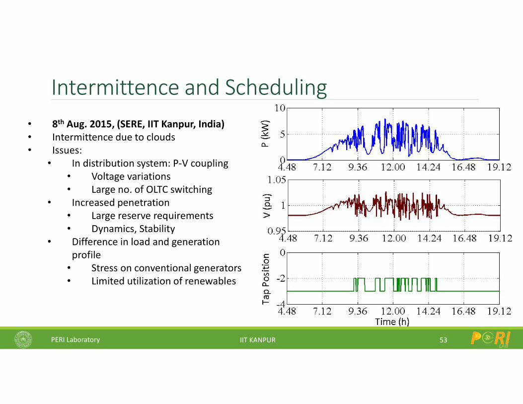
Intermittence and Scheduling
53
• 8th Aug. 2015, (SERE, IIT Kanpur, India)• Intermittence due to clouds• Issues:
• In distribution system: P-V coupling• Voltage variations• Large no. of OLTC switching
• Increased penetration• Large reserve requirements• Dynamics, Stability
• Difference in load and generation profile
• Stress on conventional generators• Limited utilization of renewables
PERI Laboratory IIT KANPUR
Challenges in Renewable Integration Intermittent generation dependent on season, weather and other
parameters-Power balancing .Voltage and frequency control; most of these sources do not have
reactive power generation.The sudden generation loss can lead to transient angle and voltage
instability.Stability issue more challenging due to inertia less generation, e.g. solar.Power Quality issues-Harmonics, flicker, under voltage ride through
capabilityPower management and Maximum power point tracking.
54
PERI Laboratory IIT KANPUR
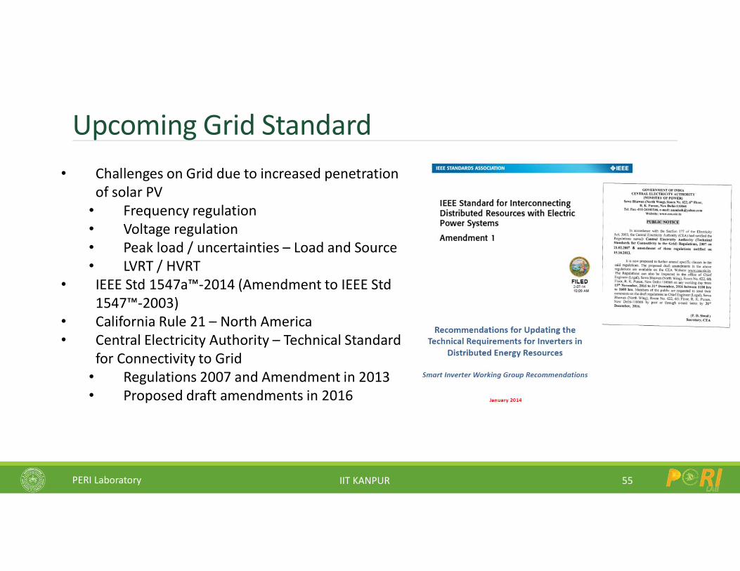
Upcoming Grid Standard
55
• Challenges on Grid due to increased penetration of solar PV
• Frequency regulation• Voltage regulation• Peak load / uncertainties – Load and Source• LVRT / HVRT
• IEEE Std 1547a™-2014 (Amendment to IEEE Std 1547™-2003)
• California Rule 21 – North America• Central Electricity Authority – Technical Standard
for Connectivity to Grid• Regulations 2007 and Amendment in 2013• Proposed draft amendments in 2016
PERI Laboratory IIT KANPUR
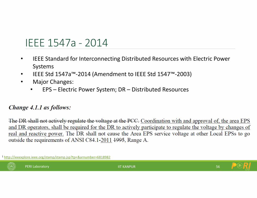
IEEE 1547a - 2014
56
• IEEE Standard for Interconnecting Distributed Resources with Electric Power Systems
• IEEE Std 1547a™-2014 (Amendment to IEEE Std 1547™-2003) • Major Changes:
• EPS – Electric Power System; DR – Distributed Resources
1 http://ieeexplore.ieee.org/stamp/stamp.jsp?tp=&arnumber=6818982
PERI Laboratory IIT KANPUR
IEEE 1547a - 2014
57
1 http://ieeexplore.ieee.org/stamp/stamp.jsp?tp=&arnumber=6818982
PERI Laboratory IIT KANPUR
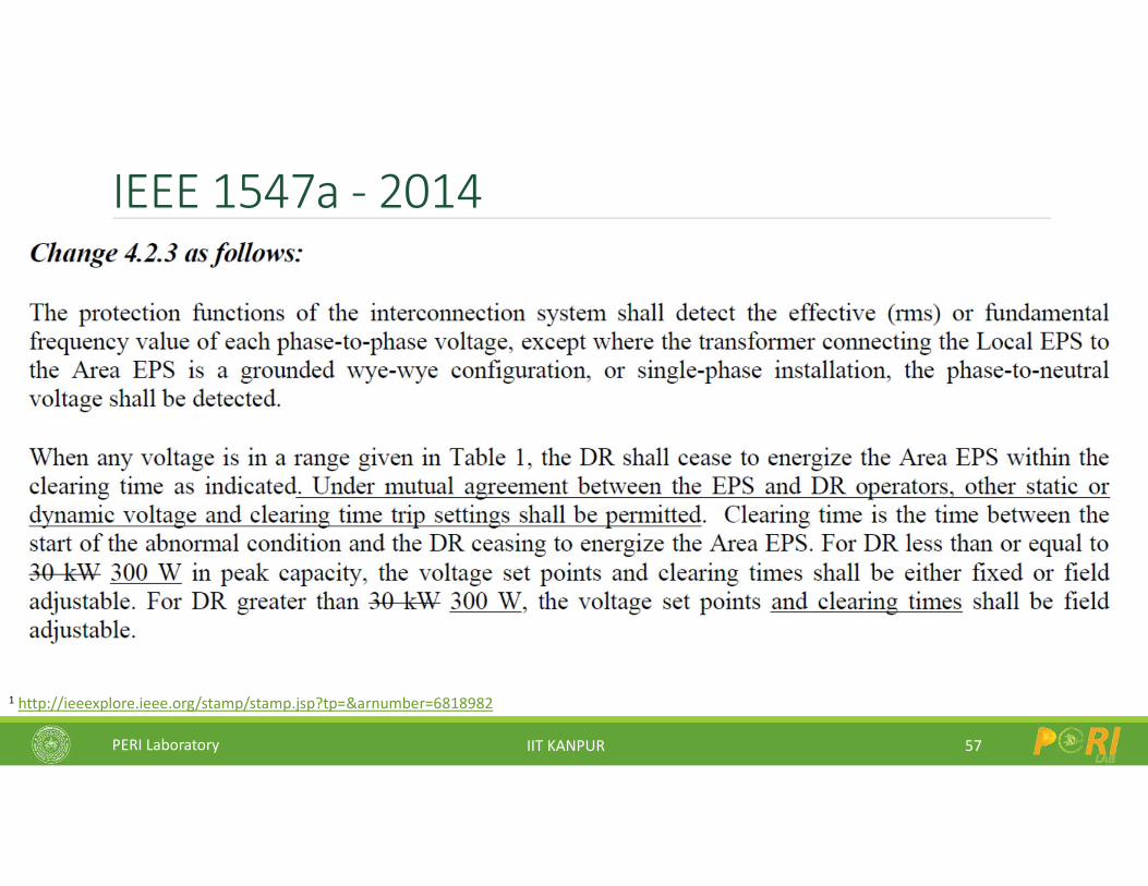
IEEE 1547a - 2014
58
1 http://ieeexplore.ieee.org/stamp/stamp.jsp?tp=&arnumber=6818982
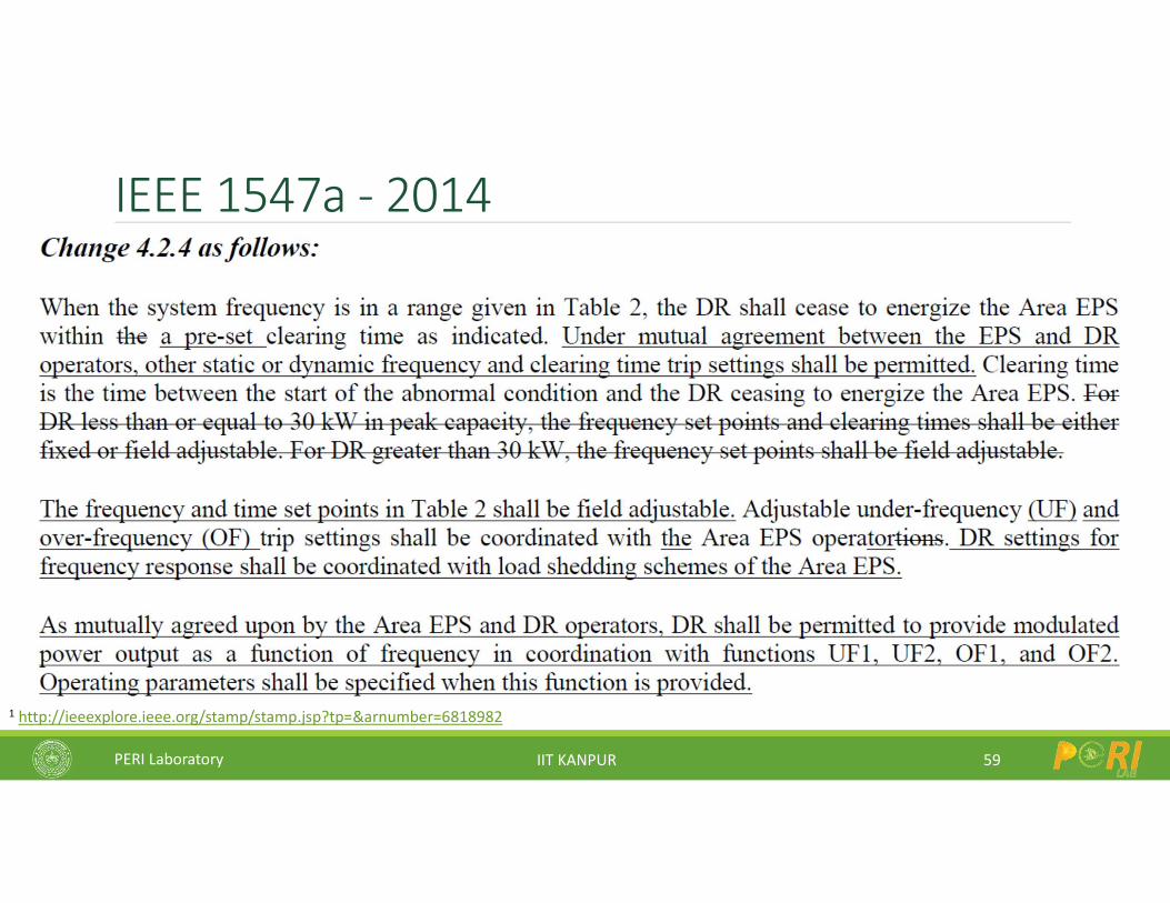
PERI Laboratory IIT KANPUR
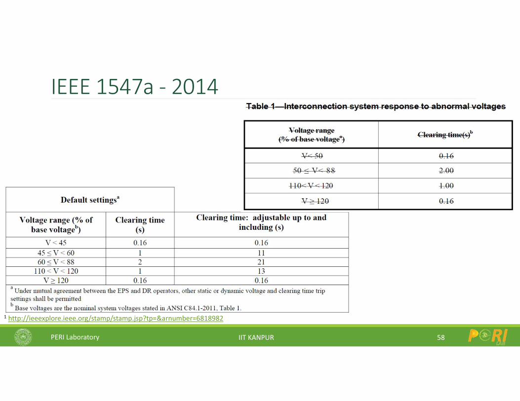
IEEE 1547a - 2014
59
1 http://ieeexplore.ieee.org/stamp/stamp.jsp?tp=&arnumber=6818982
PERI Laboratory IIT KANPUR
IEEE 1547a - 2014
60
1 http://ieeexplore.ieee.org/stamp/stamp.jsp?tp=&arnumber=6818982
PERI Laboratory IIT KANPUR
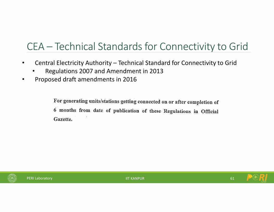
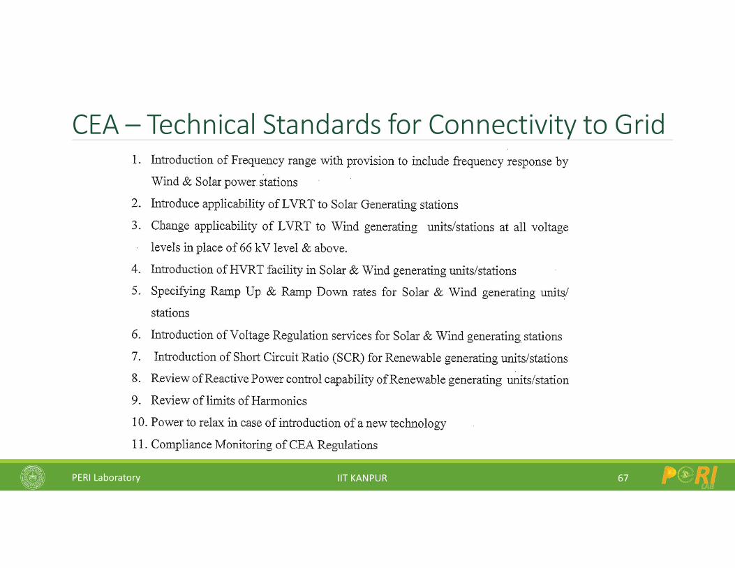
CEA – Technical Standards for Connectivity to Grid
61
• Central Electricity Authority – Technical Standard for Connectivity to Grid• Regulations 2007 and Amendment in 2013
• Proposed draft amendments in 2016
PERI Laboratory IIT KANPUR
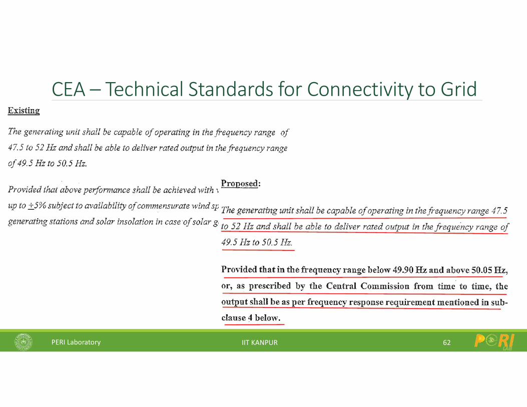
CEA – Technical Standards for Connectivity to Grid
62
PERI Laboratory IIT KANPUR
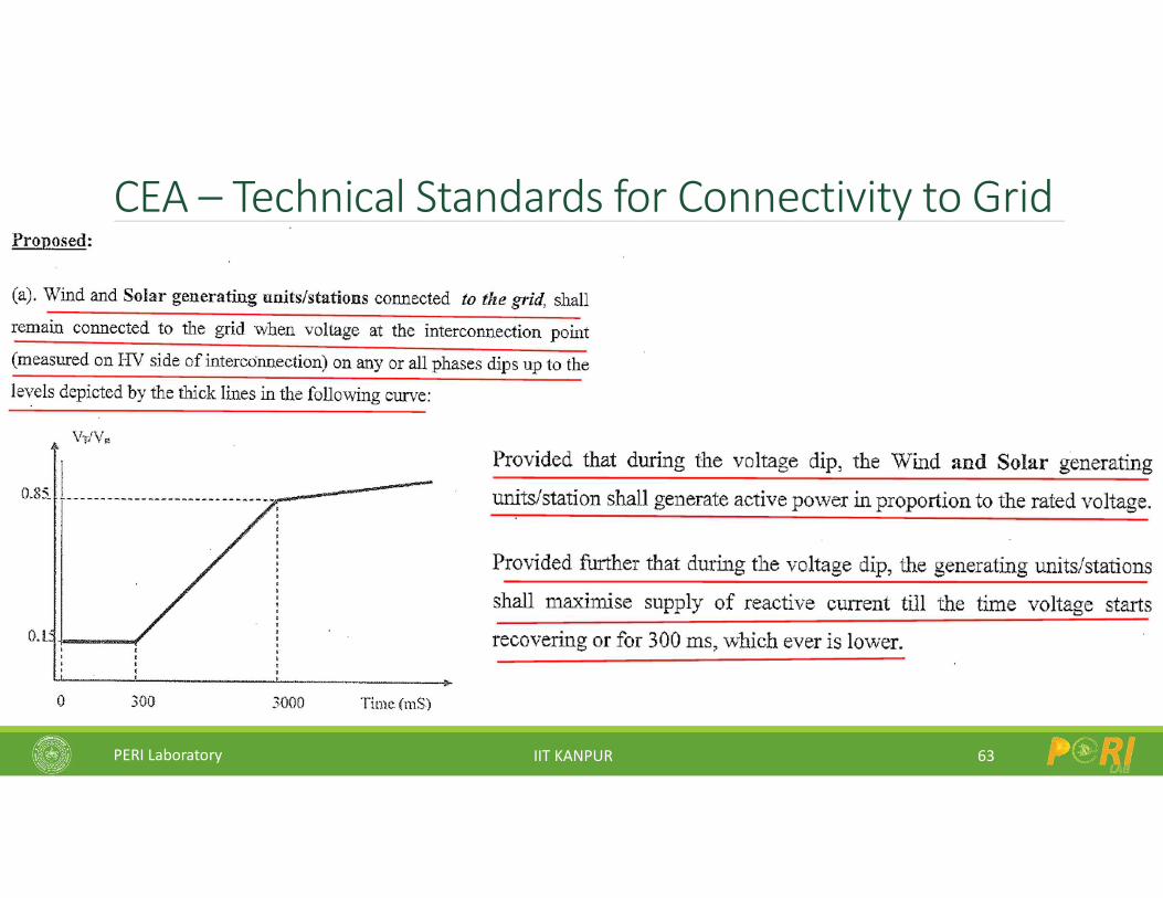
CEA – Technical Standards for Connectivity to Grid
63
PERI Laboratory IIT KANPUR
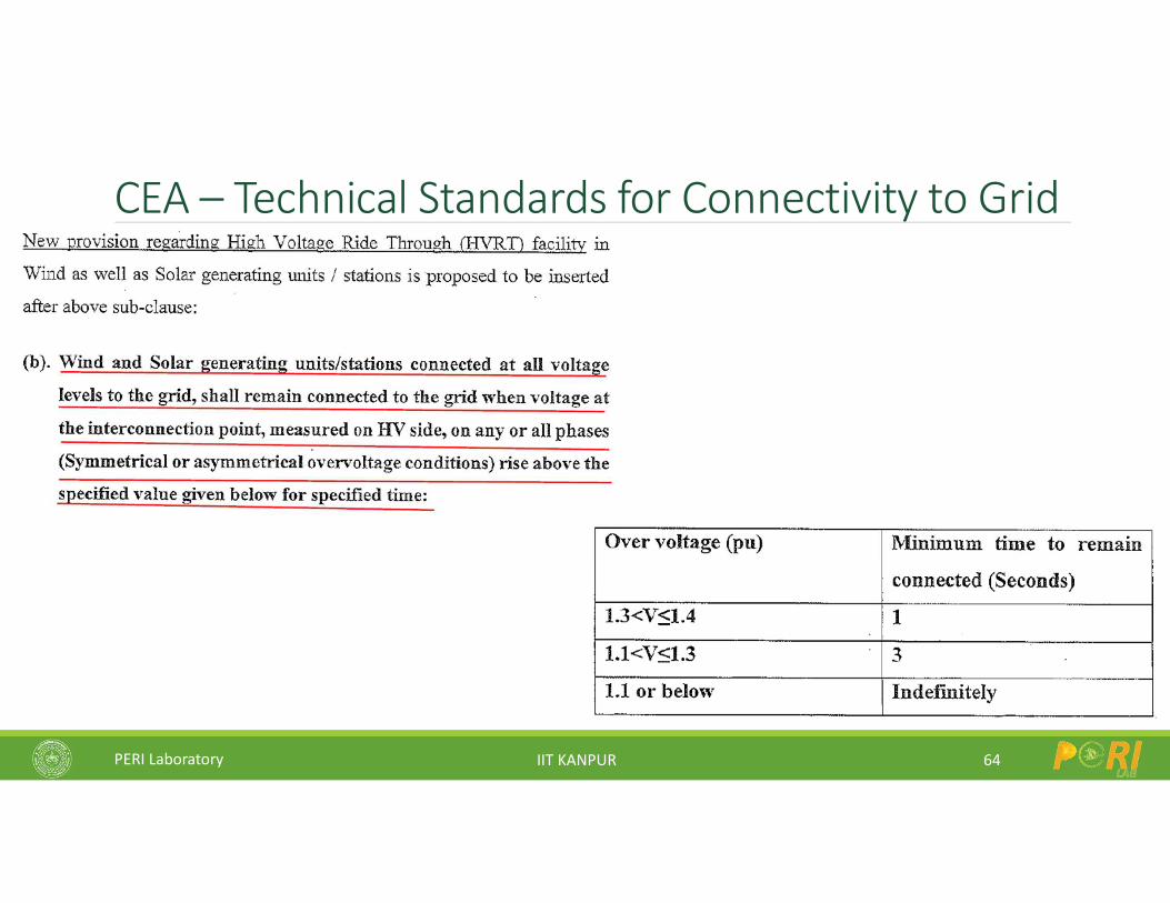
CEA – Technical Standards for Connectivity to Grid
64
PERI Laboratory IIT KANPUR
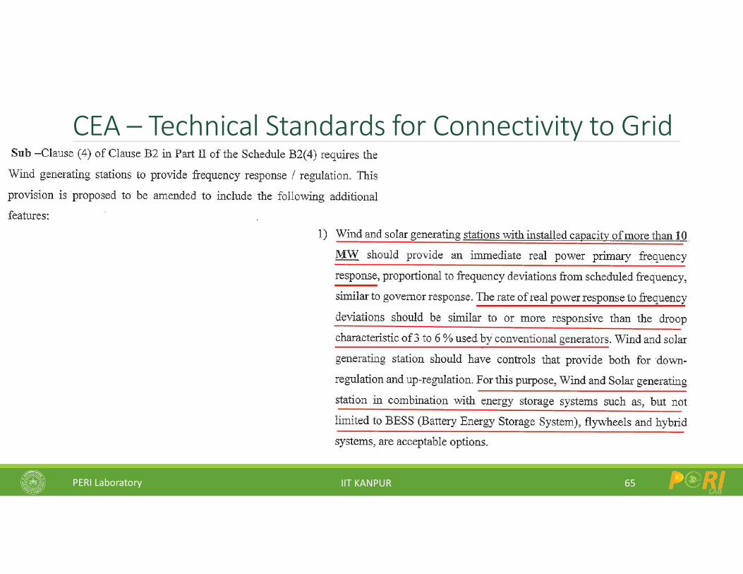
CEA – Technical Standards for Connectivity to Grid
65
PERI Laboratory IIT KANPUR
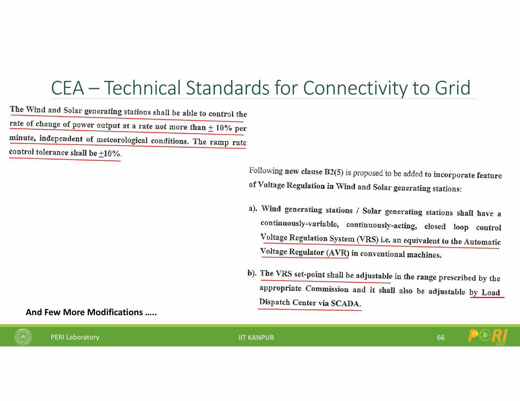
CEA – Technical Standards for Connectivity to Grid
66
And Few More Modifications …..
PERI Laboratory IIT KANPUR
CEA – Technical Standards for Connectivity to Grid
67
PERI Laboratory IIT KANPUR
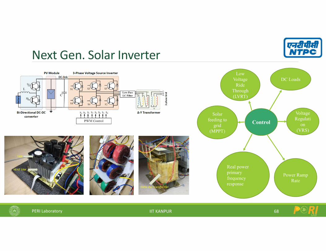
Next Gen. Solar Inverter
68
Voltage Regulati
on (VRS)
Solar feeding to
grid(MPPT)
Low Voltage
Ride Through (LVRT)
Real power primary frequency response
DC Loads
Control
Power Ramp Rate
PERI Laboratory IIT KANPUR
Research Challenges in Solar PV Systems
69
Inverter Circuit
Controls
Grid
Solar plant level issues
Microgrids: AC and DC
Power Quality / Control
LVRT, Voltage Support
Cost, Volume – leakage currents
Efficiency – at low PV voltage
Reliability – online monitoring
PERI Laboratory IIT KANPUR
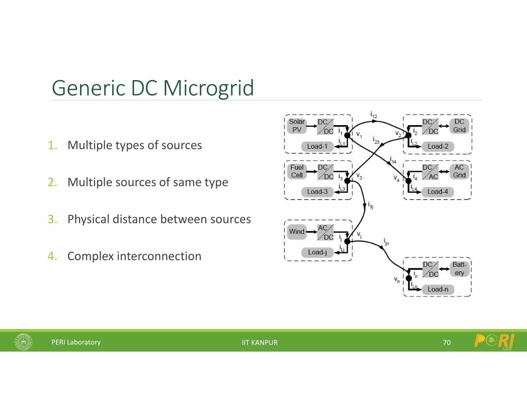
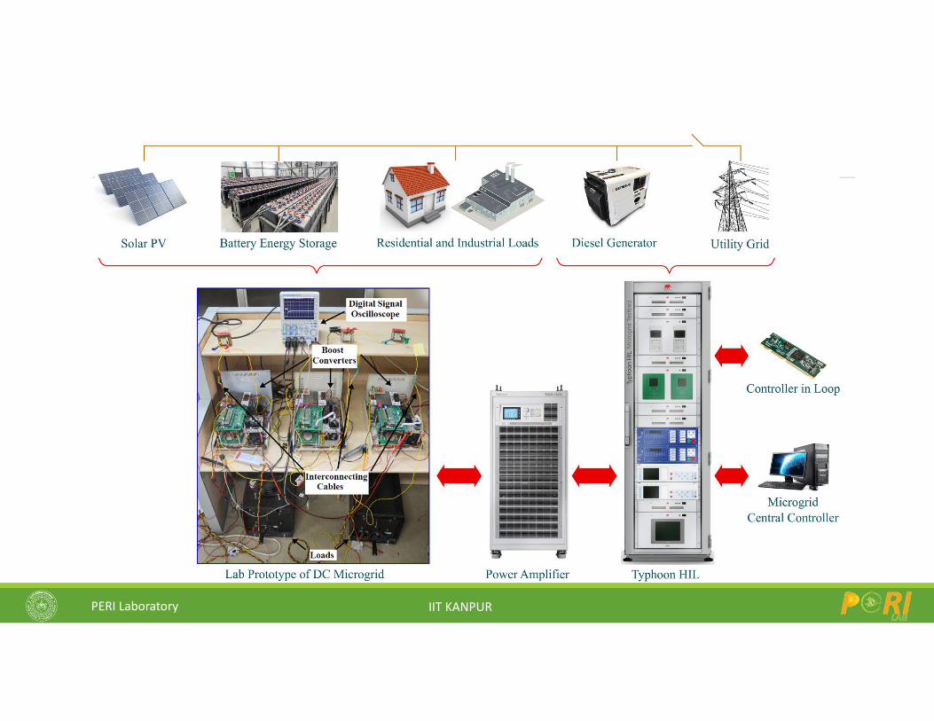
Generic DC Microgrid
1. Multiple types of sources
2. Multiple sources of same type
3. Physical distance between sources
4. Complex interconnection
70
PERI Laboratory IIT KANPUR
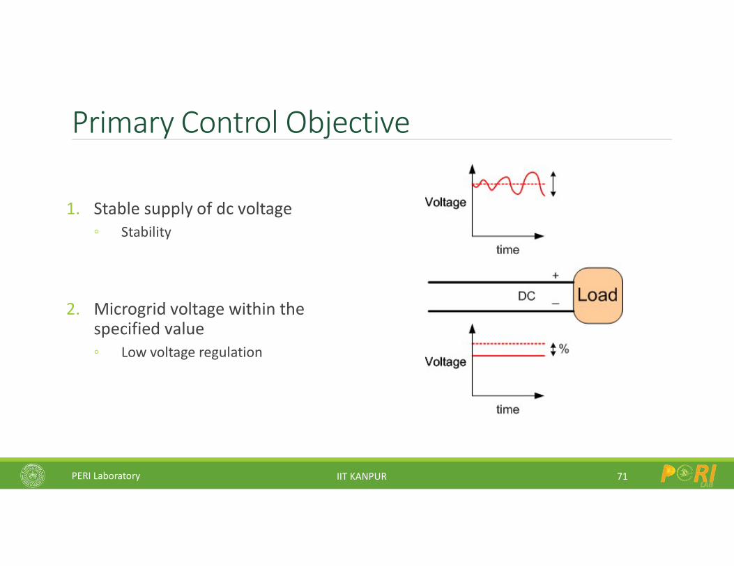
Primary Control Objective
1. Stable supply of dc voltage Stability
2. Microgrid voltage within the specified value Low voltage regulation
71
PERI Laboratory IIT KANPUR
Secondary Control Objectives
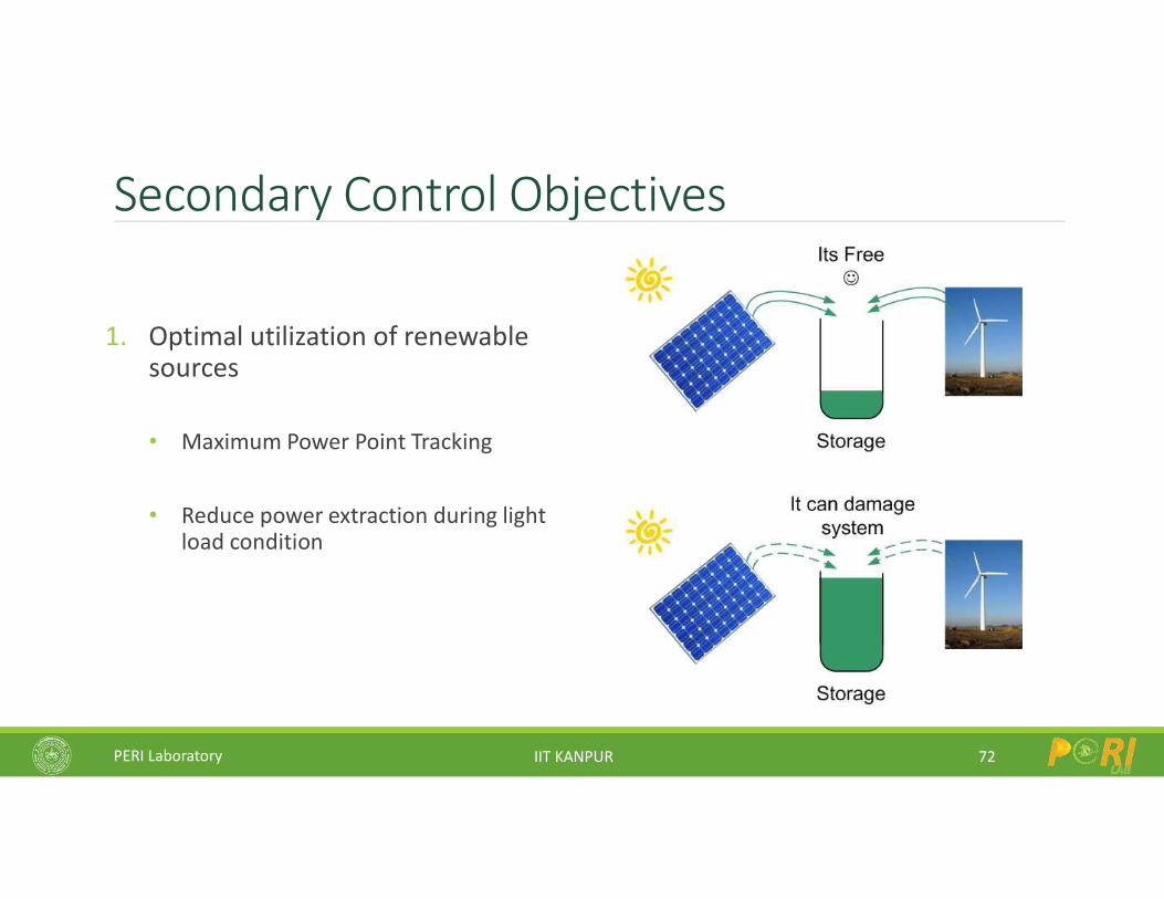
1. Optimal utilization of renewable sources
• Maximum Power Point Tracking
• Reduce power extraction during light load condition
72
PERI Laboratory IIT KANPUR
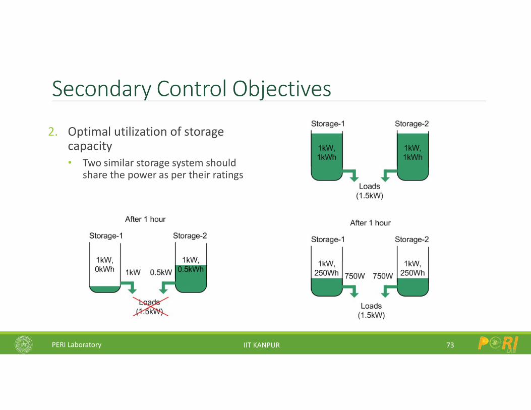
Secondary Control Objectives
2. Optimal utilization of storage capacity• Two similar storage system should
share the power as per their ratings
73
PERI Laboratory IIT KANPUR
Tertiary Control Objectives
1. Scheduling of sources within microgrid
2. Interactions with other microgrids
3. Main AC Grid interaction should be close to the scheduled power
Penalty on deviation from scheduled power
74
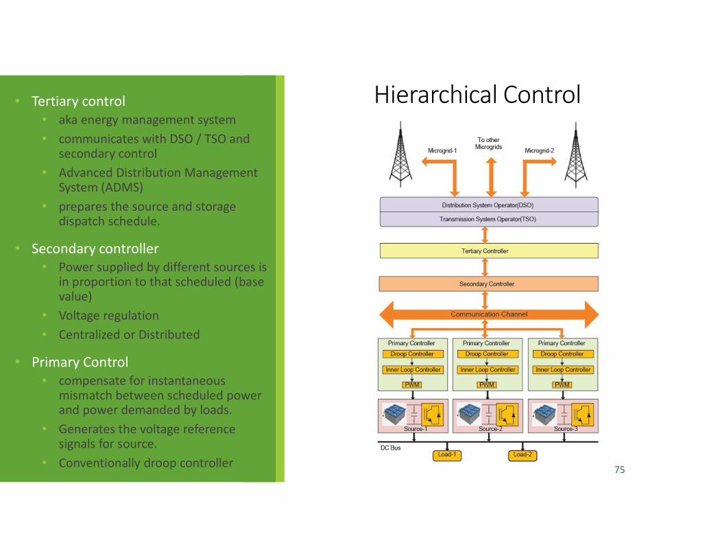
Hierarchical Control• Tertiary control • aka energy management system• communicates with DSO / TSO and
secondary control• Advanced Distribution Management
System (ADMS)• prepares the source and storage
dispatch schedule.
• Secondary controller• Power supplied by different sources is
in proportion to that scheduled (base value)
• Voltage regulation• Centralized or Distributed
• Primary Control • compensate for instantaneous
mismatch between scheduled power and power demanded by loads.
• Generates the voltage reference signals for source.
• Conventionally droop controller 75
PERI Laboratory IIT KANPUR
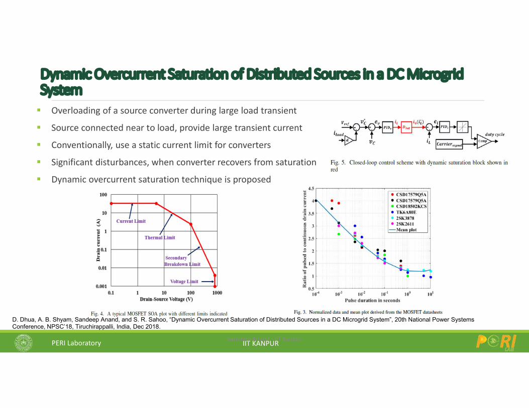
Dynamic Overcurrent Saturation of Distributed Sources in a DC Microgrid System Overloading of a source converter during large load transient
Source connected near to load, provide large transient current
Conventionally, use a static current limit for converters
Significant disturbances, when converter recovers from saturation
Dynamic overcurrent saturation technique is proposed
Sandeep Anand - IIT Kanpur
D. Dhua, A. B. Shyam, Sandeep Anand, and S. R. Sahoo, “Dynamic Overcurrent Saturation of Distributed Sources in a DC Microgrid System”, 20th National Power Systems Conference, NPSC’18, Tiruchirappalli, India, Dec 2018.
PERI Laboratory IIT KANPUR
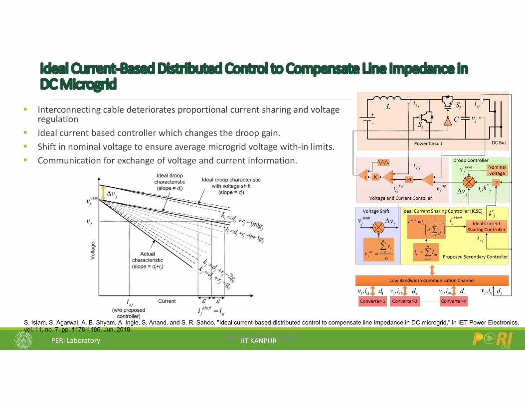
Ideal Current-Based Distributed Control to Compensate Line Impedance in DC Microgrid
Interconnecting cable deteriorates proportional current sharing and voltage regulation
Ideal current based controller which changes the droop gain. Shift in nominal voltage to ensure average microgrid voltage with-in limits. Communication for exchange of voltage and current information.
Sandeep Anand - IIT Kanpur
S. Islam, S. Agarwal, A. B. Shyam, A. Ingle, S. Anand, and S. R. Sahoo, "Ideal current-based distributed control to compensate line impedance in DC microgrid," in IET Power Electronics, vol. 11, no. 7, pp. 1178-1186, Jun. 2018.
PERI Laboratory IIT KANPUR
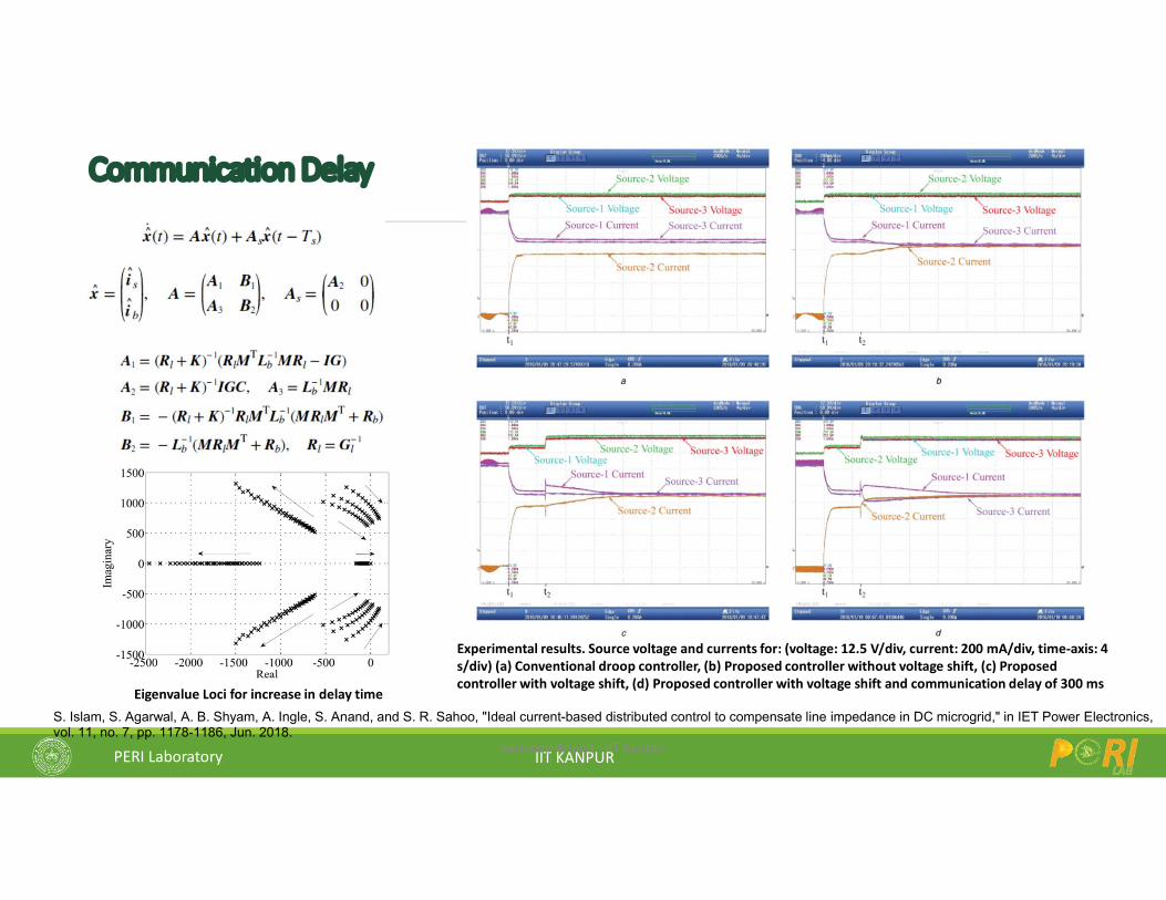
Communication Delay
Sandeep Anand - IIT Kanpur
S. Islam, S. Agarwal, A. B. Shyam, A. Ingle, S. Anand, and S. R. Sahoo, "Ideal current-based distributed control to compensate line impedance in DC microgrid," in IET Power Electronics, vol. 11, no. 7, pp. 1178-1186, Jun. 2018.
Experimental results. Source voltage and currents for: (voltage: 12.5 V/div, current: 200 mA/div, time-axis: 4 s/div) (a) Conventional droop controller, (b) Proposed controller without voltage shift, (c) Proposed controller with voltage shift, (d) Proposed controller with voltage shift and communication delay of 300 ms
Eigenvalue Loci for increase in delay time
PERI Laboratory IIT KANPUR
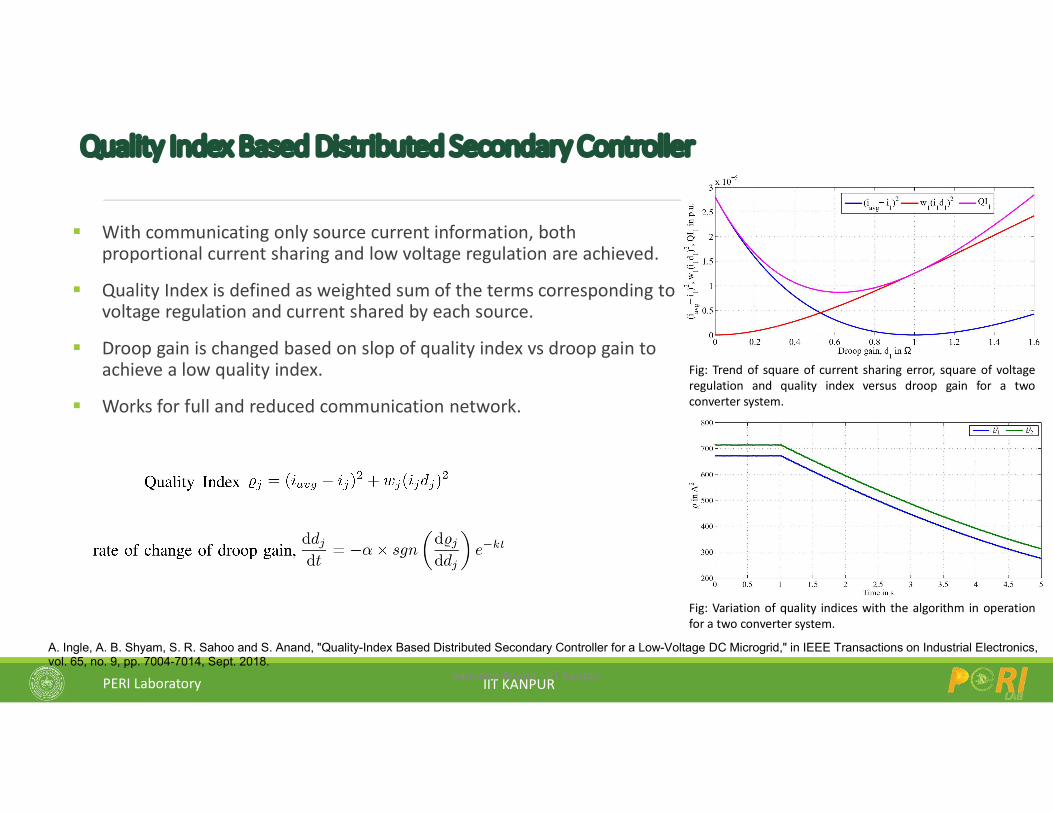
Quality Index Based Distributed Secondary Controller
With communicating only source current information, both proportional current sharing and low voltage regulation are achieved.
Quality Index is defined as weighted sum of the terms corresponding to voltage regulation and current shared by each source.
Droop gain is changed based on slop of quality index vs droop gain to achieve a low quality index.
Works for full and reduced communication network.
Sandeep Anand - IIT Kanpur
A. Ingle, A. B. Shyam, S. R. Sahoo and S. Anand, "Quality-Index Based Distributed Secondary Controller for a Low-Voltage DC Microgrid," in IEEE Transactions on Industrial Electronics, vol. 65, no. 9, pp. 7004-7014, Sept. 2018.
Fig: Trend of square of current sharing error, square of voltageregulation and quality index versus droop gain for a twoconverter system.
Fig: Variation of quality indices with the algorithm in operationfor a two converter system.
PERI Laboratory IIT KANPUR
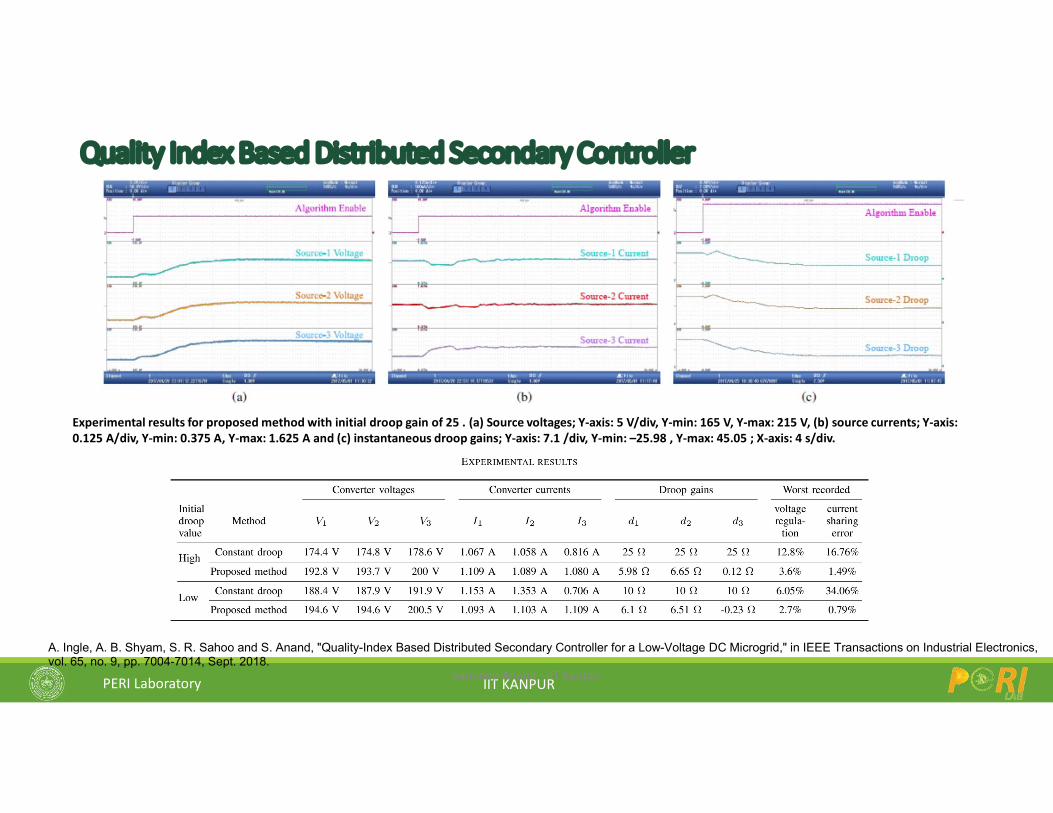
Quality Index Based Distributed Secondary Controller
Sandeep Anand - IIT Kanpur
A. Ingle, A. B. Shyam, S. R. Sahoo and S. Anand, "Quality-Index Based Distributed Secondary Controller for a Low-Voltage DC Microgrid," in IEEE Transactions on Industrial Electronics, vol. 65, no. 9, pp. 7004-7014, Sept. 2018.
Experimental results for proposed method with initial droop gain of 25 . (a) Source voltages; Y-axis: 5 V/div, Y-min: 165 V, Y-max: 215 V, (b) source currents; Y-axis: 0.125 A/div, Y-min: 0.375 A, Y-max: 1.625 A and (c) instantaneous droop gains; Y-axis: 7.1 /div, Y-min: –25.98 , Y-max: 45.05 ; X-axis: 4 s/div.
PERI Laboratory IIT KANPUR
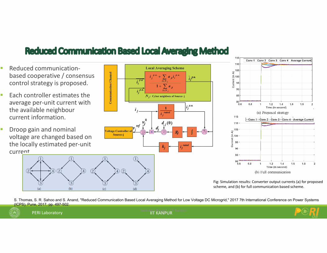
Reduced Communication Based Local Averaging Method
Reduced communication-based cooperative / consensus control strategy is proposed.
Each controller estimates the average per-unit current with the available neighbour current information.
Droop gain and nominal voltage are changed based on the locally estimated per-unit current.
Sandeep Anand - IIT Kanpur
S. Thomas, S. R. Sahoo and S. Anand, "Reduced Communication Based Local Averaging Method for Low Voltage DC Microgrid," 2017 7th International Conference on Power Systems (ICPS), Pune, 2017, pp. 497-502.
Fig: Simulation results: Converter output currents (a) for proposedscheme, and (b) for full communication based scheme.
PERI Laboratory IIT KANPUR
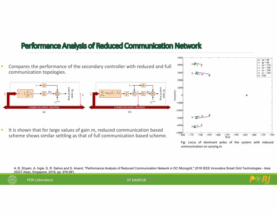
Performance Analysis of Reduced Communication Network
Compares the performance of the secondary controller with reduced and full communication topologies.
It is shown that for large values of gain m, reduced communication based scheme shows similar settling as that of full communication based scheme.
Sandeep Anand - IIT Kanpur
A. B. Shyam, A. Ingle, S. R. Sahoo and S. Anand, "Performance Analysis of Reduced Communication Network in DC Microgrid," 2018 IEEE Innovative Smart Grid Technologies - Asia (ISGT Asia), Singapore, 2018, pp. 976-981.
Fig: Locus of dominant poles of the system with reducedcommunication on varying m.
PERI Laboratory IIT KANPUR
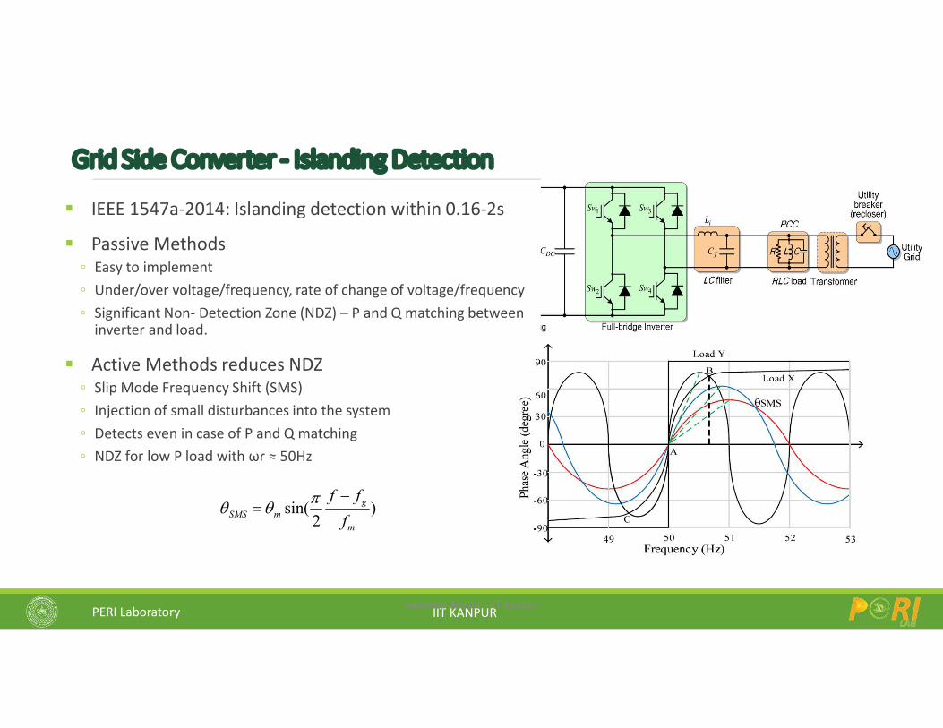
Grid Side Converter - Islanding Detection
IEEE 1547a-2014: Islanding detection within 0.16-2s
Passive Methods Easy to implement Under/over voltage/frequency, rate of change of voltage/frequency Significant Non- Detection Zone (NDZ) – P and Q matching between
inverter and load.
Active Methods reduces NDZ Slip Mode Frequency Shift (SMS) Injection of small disturbances into the system Detects even in case of P and Q matching NDZ for low P load with ωr ≈ 50Hz
Sandeep Anand - IIT Kanpur
)2
sin(m
gmSMS f
ff
PERI Laboratory IIT KANPUR
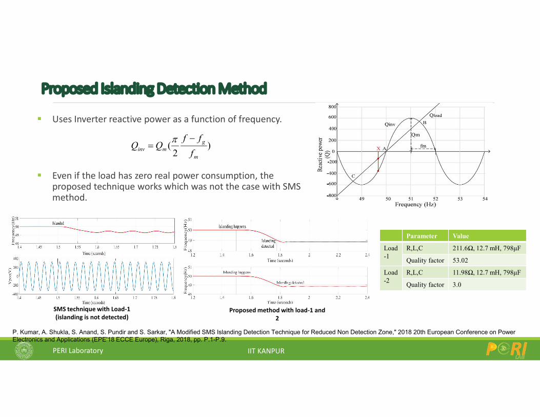
Proposed Islanding Detection Method
Uses Inverter reactive power as a function of frequency.
Even if the load has zero real power consumption, the proposed technique works which was not the case with SMS method.
P. Kumar, A. Shukla, S. Anand, S. Pundir and S. Sarkar, "A Modified SMS Islanding Detection Technique for Reduced Non Detection Zone," 2018 20th European Conference on Power Electronics and Applications (EPE'18 ECCE Europe), Riga, 2018, pp. P.1-P.9.
SMS technique with Load-1 (islanding is not detected)
Parameter Value
Load-1
R,L,C 211.6Ω, 12.7 mH, 798μF
Quality factor 53.02
Load-2
R,L,C 11.98Ω, 12.7 mH, 798μF
Quality factor 3.0
Proposed method with load-1 and 2
)2
(m
gminv f
ffQQ
PERI Laboratory IIT KANPUR
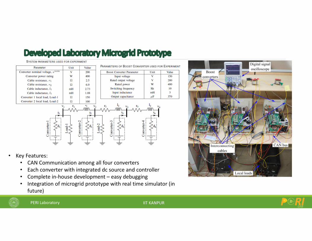
Developed Laboratory Microgrid Prototype
• Key Features: • CAN Communication among all four converters• Each converter with integrated dc source and controller• Complete in-house development – easy debugging• Integration of microgrid prototype with real time simulator (in
future)
PERI Laboratory IIT KANPUR
PERI Laboratory IIT KANPUR 87
Acknowledgements
Thank You
Suggestions / Comments / [email protected]
Web: https://www.perilab.org/