Embed Size (px)
Citation preview
FOR ENGINEERS AND ENGINEERING MANAGERS
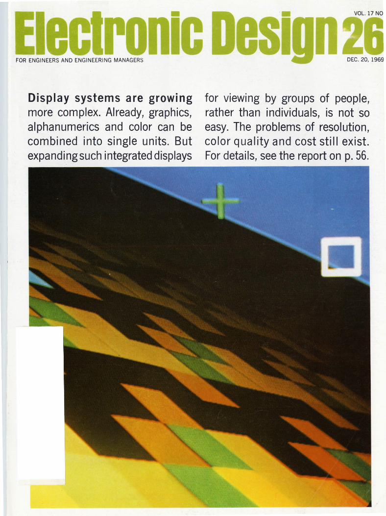
Display systems are growing more complex. Already, graphics, alphanumerics and color can be combined into single units. But expanding such integrated displays
DEC.20, 1969
for viewing by groups of people, rather than individuals, is not so easy. The problems of resolution, color quality and cost still exist. For details, see the report on p. 56.
IMH Z • SOMV .
HORIZONTAL
C AL 0
EXT
INPUT
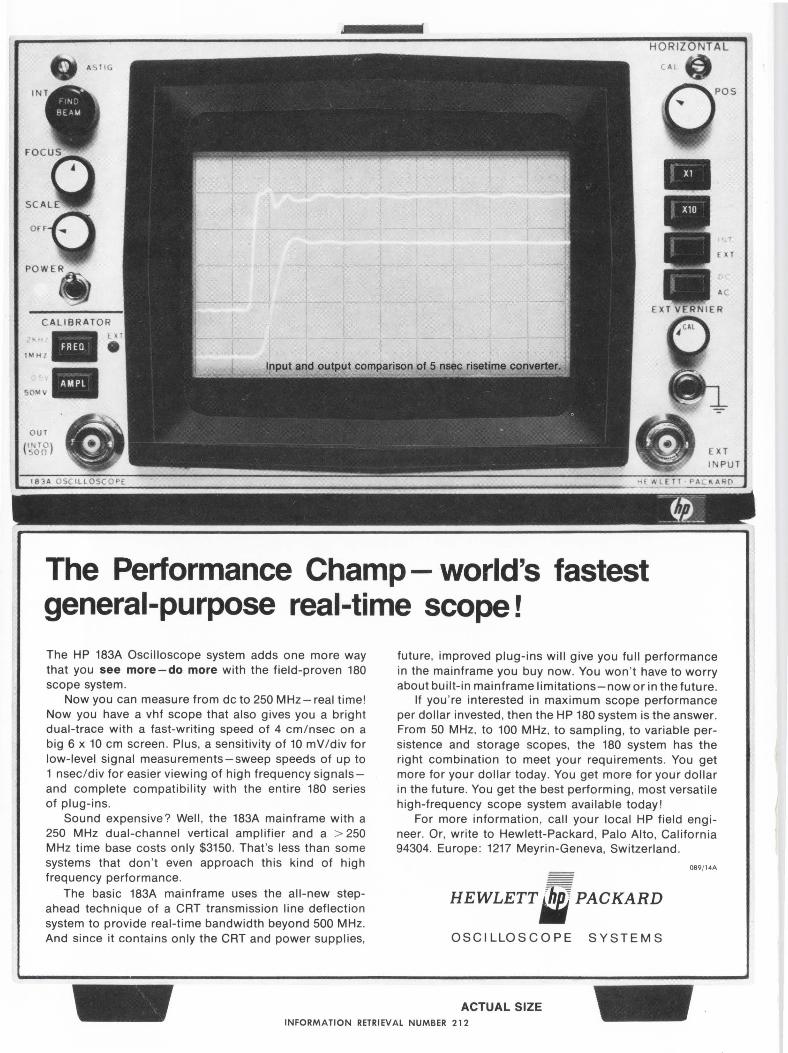
The Performance Champ - world's fastest general-purpose real-time scope!
The HP 183A Oscilloscope system adds one more way that you see more-do more with the field-proven 180 scope system .
Now you can measure from de to 250 MHz-real time! Now you have a vhf scope that also gives you a bright dual-trace with a fast-writing speed of 4 cm/nsec on a big 6 x 10 cm screen . Plus, a sensitivity of 10 mV/div for low-level signal measurements-sweep speeds of up to 1 nsec/div for easier viewing of high frequency signalsand complete compatibility with the entire 180 series of plug-ins.
Sound expensive? Well , the 183A mainframe with a 250 MHz dual-channel vertical amplifier and a > 250 MHz time base costs only $3150. That's less than some systems that don 't even approach this kind of high frequency performance.
The basic 183A mainframe uses the all-new stepahead technique of a CRT transmission line deflection system to provide real-time bandwidth beyond 500 MHz. And since it contains only the CRT and power supplies,
future, improved plug-ins will give you full performance in the mainframe you buy now. You won 't have to worry about built-in mainframe limitations-now or in the future .
If you 're interested in maximum scope performance per dollar invested, then the HP 180 system is the answer. From 50 MHz, to 100 MHz, to sampling, to variable persistence and storage scopes, the 180 system has the right combination to meet your requirements . You get more for your dollar today. You get more for your dollar in the future . You get the best performing , most versatile high-frequency scope system available today!
For more information, call your local HP field engineer. Or, write to Hewlett-Packard , Palo Alto, California 94304. Europe: 1217 Meyrin-Geneva, Switzerland .
HEWLETT"' PACKARD
OSCILLOSCOPE SYSTEMS
089/14A
ACTUAL SIZE INFORMATION RETRIEVAL NUMBER 212
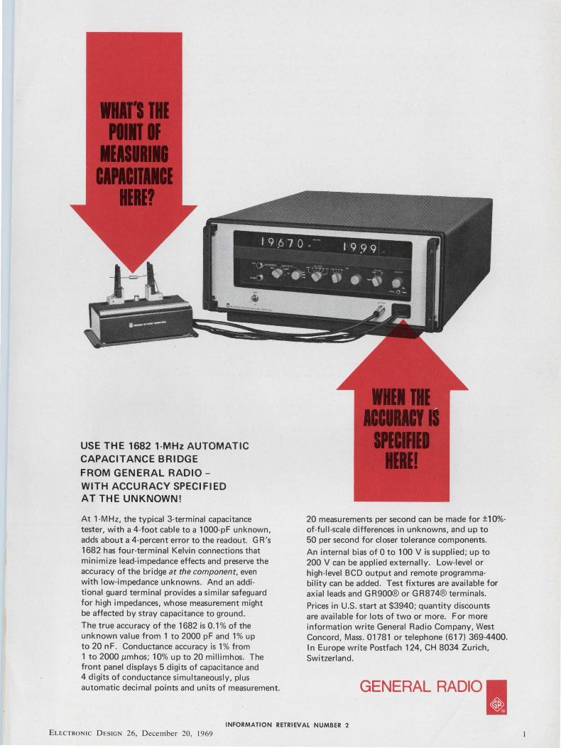
USE THE 1682 1-MHz AUTOMATIC CAPACITANCE BRIDGE FROM GENERAL RADIO -WITH ACCURACY SPECIFIED AT THE UNKNOWN!
At 1-MHz, the typical 3-terminal capacitance tester, with a 4-foot cable to a 1000-pF unknown, adds about a 4-percent error to the readout. GR 's 1682 has four-terminal Kelvin connections that minimize lead-impedance effects and preserve the accuracy of the bridge at the component, even with low-impedance unknowns. And an additional guard terminal provides a similar safeguard for high impedances, whose measurement might be affected by stray capacitance to ground.
The true accuracy of the 1682 is 0. 1 % of the unknown value from 1 to 2000 pF and 1% up to 20 n F. Conductance accuracy is 1 % from 1 to 2000 µmhos; 10% up to 20 millimhos. The front panel displays 5 digits of capacitance and 4 digits of conductance simultaneously, plus automatic decimal points and units of measurement.
20 measurements per second can be made for ±10%of-full-scale differences in unknowns, and up to 50 per second for closer tolerance components.
An internal bias of 0 to 100 Vis supplied; up to 200 V can be applied externally. Low-level or high-level BCD output and remote programma-bility can be added. Test fixtures are available for axial leads and GR900® or GR874® terminals.
Prices in U.S. start at $3940; quantity discounts are available for lots of two or more. For more information write General Radio Company, West Concord, Mass. 01781 or telephone (617) 369-4400. In Europe write Postfach 124, CH 8034 Zurich, Switzerland.
GENERAL RADIO I ~ 0
INFORMATION RETRIEVAL NUMBER 2 ELECTRON IC D ES IGN 26, December 20, 1969
AtWESCON. One of 157 Systron-Donner instruments. Electronic counters Pulse generators Microwave frequency
indicators Digital clocks Memory testers Analog computers Time code generators Data generators
Digital voltmeters Spectrum analyzers Digital panel meters Microwave signal
generators Laboratory magnets Data acquisition
systems Microwave test sets
~l~ctronic oesiunii NEWS 21 News Scope
25 It's time for a change in computer peripherals Major advances are on the way for this hardware, a tour of the Las Vegas fall conference suggests.
30 Will computers eliminate the specialist? By 1980, engineering knowledge could be reduced to routine practice by complex machines.
32 Mapping the sky at low frequencies
39 Washington Report
44 Sidelights
47 Editorial: We could shun controversy , but wouldn 't it be deadly?
TECHNOLOGY 56 Wanted: Easy-on-the-eye displays. Pa rt II of a special report on the
present state of displays and where they are going.
66 Single-map method speeds design of sequential logic circuits. A triple flip -flop i 11 ustrates the technique.
70 Convert digital data from parallel to serial and from serial to parallel , using ICs and applying logical design techniques.
76 Engineers should broaden their education if they want to be socially conscious and industrially competitive , says this noted scientist
81 Ideas for Design
89 Product Source Directory: Field Strength Meters
PRODUCTS 94 ICs & Semiconductors: Differential -like transistor senses magnetic fields.
97 Data Processing: Desk-top 10-key 14-digit calculator costs only $875.
100 Components: Chip resistors enhance reliability with gold beam leads.
104 Modules & Subassemblies 107 Packaging & Materials
106 Instrumentation
Departments
16 Designer 's Datebook
109 Evaluation Samples
110 Design Aids
111 Annual Reports
108 Microwaves & Lasers
112 New Literature
118 Advertisers ' Index
120 Information Retrieval Service
Information Retrieval Service Card inside back cover
Cover: Contact analog display built by United Aircraft 's Norden Div _ to test human factors involved in viewing.
ELECTRONIC DESIGN is published biweekly by Hayden Publishing Company, Inc., 850 Third Avenue, New York, N.Y. 10022. James S. Mu lholland, Jr., President. Printed at Brown Printing Co., Inc., Waseca, Minn. Controlled circu lation postage paid at Waseca, Minn., and New York, N.Y. Copyright © 1969, Hayden Publishing Company, Inc . 80,244 copies this issue .
... INFORMATION RETRIEVAL NUMBER J 3
4
When reliability and performance are essential,
Airco Temescal specifies General Electric components
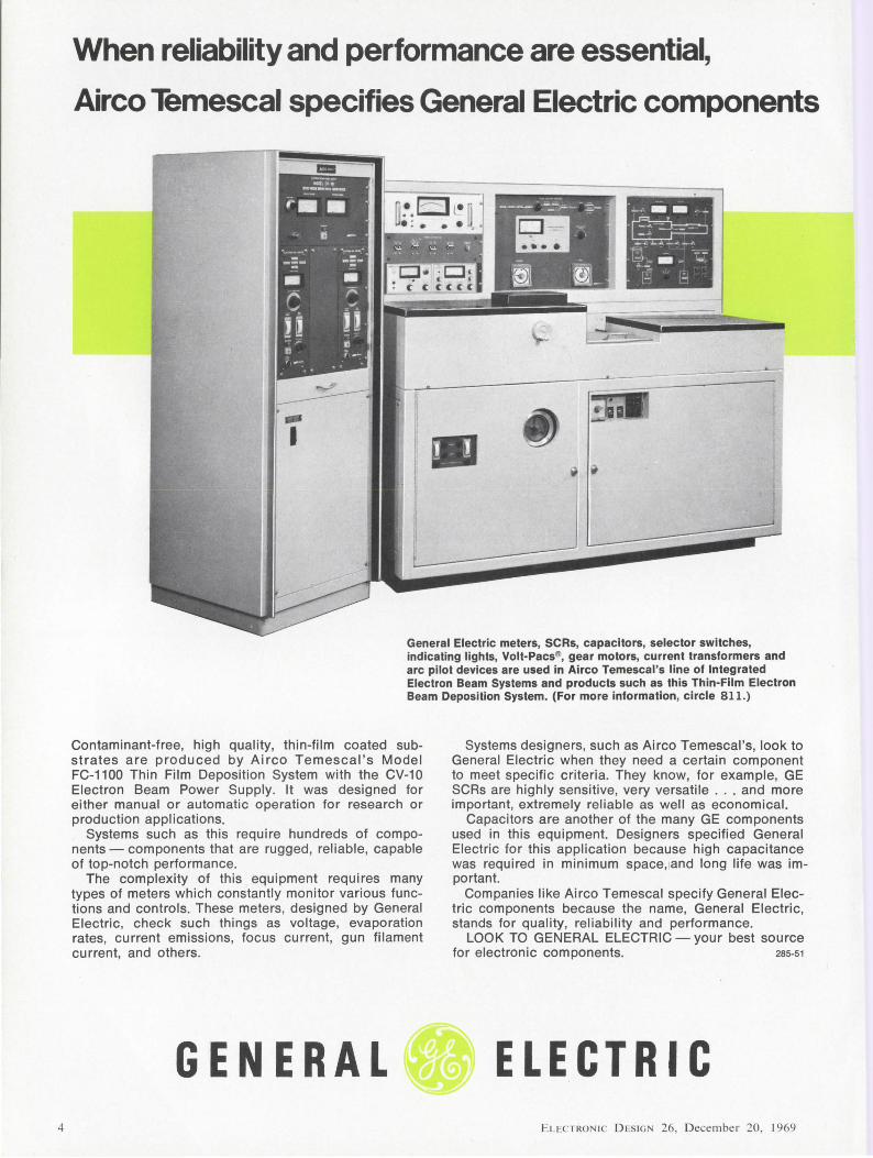
General Electric meters, SCRs, capacitors, selector switches, indicating lights, Volt-Pacs®, gear motors, current transformers and arc pilot devices are used in Airco Temescal's line of Integrated Electron Beam Systems and products such as this Thin-Film Electron Beam Deposition System. (For more information, circle 811.)
Contaminant-free, high quality, thin-film coated substrates are produced by Airco Temescal ' s Model FC-1100 Thin Film Deposition System with the CV-10 Electron Beam Power Supply. It was designed for either manual or automatic operation for research or production applications.
Systems such as this require hundreds of components - components that are rugged , reliable, capable of top-notch performance.
The complexity of this equipment requires many types of meters which constantly monitor various functions and controls. These meters, designed by General Electric, check such things as voltage, evaporation rates, current emissions, focus current, gun filament current, and others.
Systems designers, such as Airco Temescal's, look to General Electric when they need a certain component to meet specific criteria. They know, for example, GE SCRs are highly sensitive, very versatile . .. and more important, extremely reliable as well as economical.
Capacitors are another of the many GE components used in this equipment. Designers specified General Electric for this application because high capacitance was required in minimum space, and long life was important.
Companies like Airco Temescal specify General Electric components because the name, General Electric, stands for quality, reliability and performance.
LOOK TO GENERAL ELECTRIC - your best source for electronic components. 2s5.51
GENERAL . ELECTRIC EL!:CTRONIC DESIG 26, December 20, 1969
What can GE do for you?
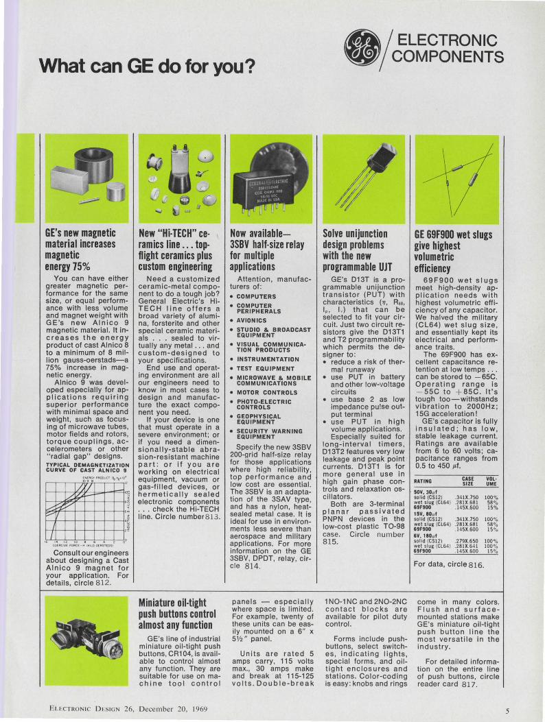
GE's new magnetic material increases magnetic energy 75%
You can have either greater magnetic performance for the same size, or equal performance with less volume and magnet weight with GE's new Alnico 9 magnetic material. It inc re as es the energy product of cast Alnico 8 to a minimum of 8 million gauss-oerstads-a 75% increase in magnetic energy.
Alnico 9 was developed especially for app Ii cations requiring superior performance with minimal space and weight, such as focusing of microwave tubes, motor fields and rotors, torque couplings , accelerometers or other " radial gap" designs. TYPICAL DEMAGNETIZATION CURVE OF CAST ALNICO 9
i.&f- ~ f-1-:z~;j£-+--J--t--t--1•~ L--W 9 v-17 •• .__,__...._..__ .......... -+---+---+--<•i ._...I ___.._.__.__.___,____._____.,.
16 14 tZ 10 8 6 4 Z OO COCACIV( r oAC£- M (O:ILO OUIST(OSI
Consult our engineers about designing a Cast Alnico 9 magnet for your application. For details, circle 812.
New "Hi-TECH" ceramics line ... topflight ceramics plus custom engineering
Need a customized ceramic-metal component to do a tough job? General Electric's HiT EC H line offers a broad variety of alumina, forsterite and other special ceramic materials . .. sealed to virtually any metal . . . and custom-designed to your specifications.
End use and operating environment are all our engineers need to know in most cases to design and manufacture the exact component you need.
If your device is one that must operate in a severe environment; or if you need a dimensionally-stable abrasion-resistant machine part: or if you are working on electrical equipment, vacuum or gas-filled devices, or hermetically sealed electronic components ... check the Hi-TECH line. Circle number 8 13.
Miniature oil-tight push buttons control almost any function
GE's line of industrial miniature oil-tight push buttons, CR104, is available to control almost any function. They are suitable for use on machine tool control
ELECTRO IC D cSIGN 26, D ecember 20, 1969
Now available-3SBV half -size relay for multiple applications
Attention , manufacturers of: • COMPUTERS
• COMPUTER PERIPHERALS
• AVIONICS
• STUDIO & BROADCAST EQUIPMENT
• VISUAL COMMUNICA· TION PRODUCTS
• INSTRUMENTATION
• TEST EQUIPMENT
• MICROWAVE & MOBILE COMMUNICATIONS
• MOTOR CONTROLS
• PHOTO-ELECTRIC CONTROLS
• GEOPHYSICAL EQUIPMENT
• SECURITY WARNING EQUIPMENT
Specify the new 3SBV 200-grid half-size relay for those applications where high reliability, top performance and low cost are essential. The 3SBV is an adaptation of the 3SAV type, and has a nylon, heatsealed metal case. It is ideal for use in environments less severe than aerospace and military applications. For more information on the GE 3SBV, DPDT, relay, circle 814.
panels - especially where space is limited. For example, twenty of these units can be easily mounted on a 6" x 5Y2" panel.
Units are rated 5 amps carry, 115 volts max., 30 amps make and break at 115-125 volts. Double-break
•I I ELECTRONIC I COMPONENTS
Solve unijunction design problems with the new programmable UJT
GE's 013T is a programmable unijunction transistor (PUT) with characteristics ('1 , R .. , Ip, I, ) that can be selected to fit your circuit. Just two circuit resistors give the 013T1 and T2 programmability which permits the designer to: • reduce a risk of ther
mal runaway • use PUT in battery
and other low-voltage circuits
• use base 2 as low impedance pulse output terminal
• use PUT in high volume applications. Especially suited for
long-interval timers, D13T2 features very low leakage and peak point currents. 013T1 is for more general use in high gain phase controls and relaxation oscillators.
Both are 3-terminal planar passivated PNPN devices in the low-cost plastic T0-98 case. Circle number 815.
1 N0-1 NC and 2N0-2NC contact blocks are available for pilot duty control.
Forms include pushbuttons, select switches, indicating lights , special forms, and oiltig ht enclosures and stations. Color-coding is easy : knobs and rings
GE 69F900 wet slugs give highest volumetric efficiency
69F900 wet slugs meet high-density application needs with highest volumetric efficiency of any capacitor. We halved the military (CL64) wet slug size , and essentially kept its electrical and performance traits.
The 69F900 has excel lent capacitance retention at low temps ... can be stored to - 65C. Operating range is - 55C to + a5c . It's tough too-withstands vibration to 2000Hz; 15G acceleration!
GE's capacitor is fully insulated; has low, stable leakage current. Ratings are available from 6 to 60 volts; capacitance ranges from 0.5 to 450 µf.
RATING CASE VOL· SIZE UME
· 50V, 30µ1 solid (CS12) .341X.750 100% wet slug (Cl64) .281X .681 58 % 69F900 .145X.600 15% 15V, 80µ1 solid (CS12) .341X.750 100% wet slug (Cl64) .281X.681 58 ~o 69F900 .145X.600 15 ~o
&V, 180µ1 solid (C512) .2 79X.650 100 % wet slug (Cl64) .281X.641 100°• 69F900 .145X .600 15%
For data, circle816.
come in many colors. Flush and surfacemounted stations make GE's miniature oil-tight push button line the most versatile in the industry.
For detailed information on the entire line of push buttons, circle reader card 817.
5
\.
Pick the types you need -from the line that offers more
6
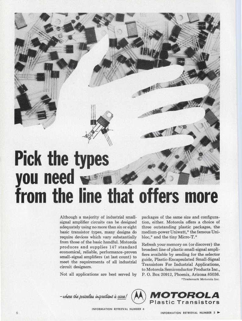
Although a majority of industrial smallsignal amplifier circuits can be designed adequately using no more than six or eight basic transistor types, many designs do require devices which vary substantially from those of the basic handful. Motorola produces and supplies 14 7 standard economical, reliable, performance-proven small-signal amplifiers (at last count) to meet the requirements of all industrial circuit designers.
Not all applications are best served by
packages of the same size and configuration, either. Motorola offers a choice of three outstanding plastic packages, the medium-power Uniwatt, *the famous Unibloc, * and the tiny Micro-T. *
Refresh your memory on (or discover) the broadest line of plastic small-signal amplifiers available by sending for the selector guide, Plastic-Encapsulated Small-Signal Transistors For Industrial Applications, to Motorola Semiconductor Products Inc., P. 0. Box 20912, Phoenix, Arizona 85036.
•Trademark Motorola Inc.
-wl,m,t1iep~U«J~t4~'@ MOTOROLA \CJ Plastic Transistors
INFORMATION RETRIEVAL NUMBER 4 INFORMATION RETRIEVAL NUMBER 5 ....
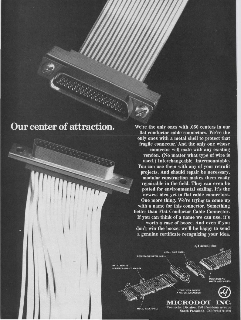
No, it's All a new conn
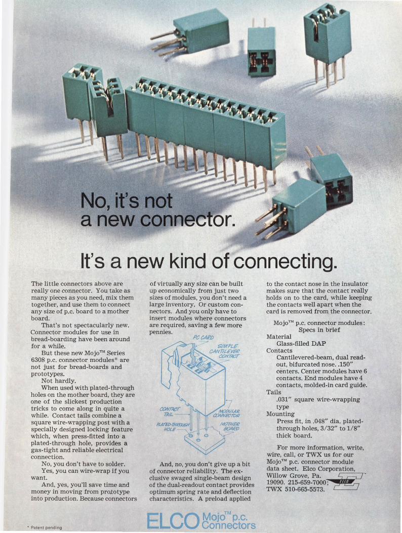
It's a new kind of connecting. The little connectors above are really one connector. You take as many pieces as you need, mix them together, and use them to connect any size of p.c. board to a mother board.
That's not spectacularly new. Connector modules for use in bread-boarding have been around for a while.
But these new MojoT" Series 6308 p.c. connector modules·x· are not just for bread-boards and prototypes.
Not hardly. When used with plated-through
holes on the mother board, they are one of the slickest production tricks to come along in quite a while. Contact tails combine a square wire-wrapping post with a specially designed locking feature which, when press-fitted into a plated-through hole, provides a gas-tight and reliable electrical connection.
No, you don't have to solder. Yes, you can wire-wrap if you
want. And, yes, you'll save time and
money in moving from pro.totype into production. Because connectors
• Patent pending
of virtually any size can be built up economically from just two sizes of modules, you don't need a large inventory. Or custom connectors. And you only have to insert modules where connectors are required, saving a few more pennies.
Pt:CllRD
And, no, you don't give up a bit of connector reliability. The exclusive swaged single-beam design of the dual-readout contact provides optimum spring rate and deflection characteristics. A preload applied
OJO p.c. E~COM •Tlvl
Connectors
to the contact nose in the insulator makes sure that the contact really holds on to the card, while keeping the contacts well apart when the card is removed from the connector.
MojoTM p.c. connector modules: Specs in brief
Material Glass-filled DAP
Contacts Cantilevered-beam, dual readout, bifurcated nose .. 150" centers. Center modules have 6 contacts. End modules have 4 contacts, molded-in card guide.
Tails .031" square wire-wrapping type
Mounting Press fit, in .048" dia. platedthrough holes, 3/ 32" to 1/8" thick board.
For more information, write, wire, call, or TWX us for our Mojo™ p.c. connector module data sheet. Elco Corporation, Willow Grove, Pa. ~ .. 19090. 215-659-7000; TWX 510-665-5573.
tl1e TM
GENERAL INSTRUMENT ADVANCED NITRIDE TECHNOLOGY
8 EL1c.CTRON 1c DESIGN 26, December 20, 1969
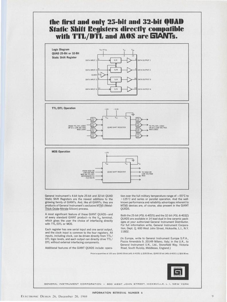
tl1e first a11tl tHll\' 25-ltit a11tl :12-ltit tPllAlt Static Sllift l~euisters tlirectl\' ctt1111.a1tiltle
'''itll 'l~'1~1,/lt'1~1, ;111tl i\\ttS are &IANTs.
Logic Diagram
QUAD 25-Bit or 32-Bit
Static Shift Register
TTL/DTL Operation
FROM TTL/ OTL LOGIC OR'Gl 's LOW VOLTAGE
MOS LOGIC
MOS Operation
- 12V
- 17V
+ 5.0V
TO TTL/ OTL LOGIC OR Gl 's LOW VOLTAGE MOS LOGIC
FROM HIGH OR LOW VOLTAGE
MOS OR TTL/ OTL REFERENCED TO
- 5.0 VOLTS
QUAD SHIFT REGISTER TO HIGH OR LOW VOLTAGE MOS
General Instrument's 4-bit byte 25-bit and 32-bit QUAD Static Shift Registers are the newest additions to the growing family of GIANTs. And, like all GIANTs, they are products of General Instrument's exclusive MI~S (Metal Thick Oxide-Nitride-Silicon) process.
A most significant feature of these GIANT QUADS-and of every standard GIANT product-is the V GI terminal , which gives the user the choice of interfacing directly with TTL/DTL or MOS.
Each register has one serial input and one serial output, and the clock input is common to the four registers . All inputs, including clock, can be driven directly from TTL/ DTL logic levels, and each output can directly drive TTL/ DTL without external interfacing components.
Additional features of the GIANT QUADS include: opera-
tion over the full military temperature range of -55°C to + 125°C and series or parallel operation. And the wellknown performance and reliability advantages inherent to MTNS devices are, of course, also present in the GIANT QUADS.
Both the 25-bit (#SL-6-4025) and the 32-bit (#SL-6-4032) QUADS are available in 14 lead dual in-line ceramic pack· ages at your authorized General Instrument Distributor. For full information write, General Instrument Corporation, Dept. Q, 600 West John Street, Hicksville, L.I. , N.Y. 11802.
(In Europe, write to General Instrument Europe S.P.A., Piazza Amendola 9, 20149 Milano, Italy; in the U.K. , to General Instrument U.K., Ltd ., Stonefield Way, Victoria Road , South Ruislip, Middlesex, England.)
Price in quantities of 100 pcs: QUAD 25·b•t (#SL-6-4025) @:: $18.20 ea.; QUAD 32-bit (#SL-6-4032) @.. $26.50 ea.
&I INSTRUMENT
GENERAL INSTRUMENT CORPORATION • BOO WEST .JOHN STREET, HICKSVILLE, L . I., NEW YORK
INFORMATION RETRIEVAL NUMBER 6
ELECTRONIC OLSIG 26, December 20. 1969 9
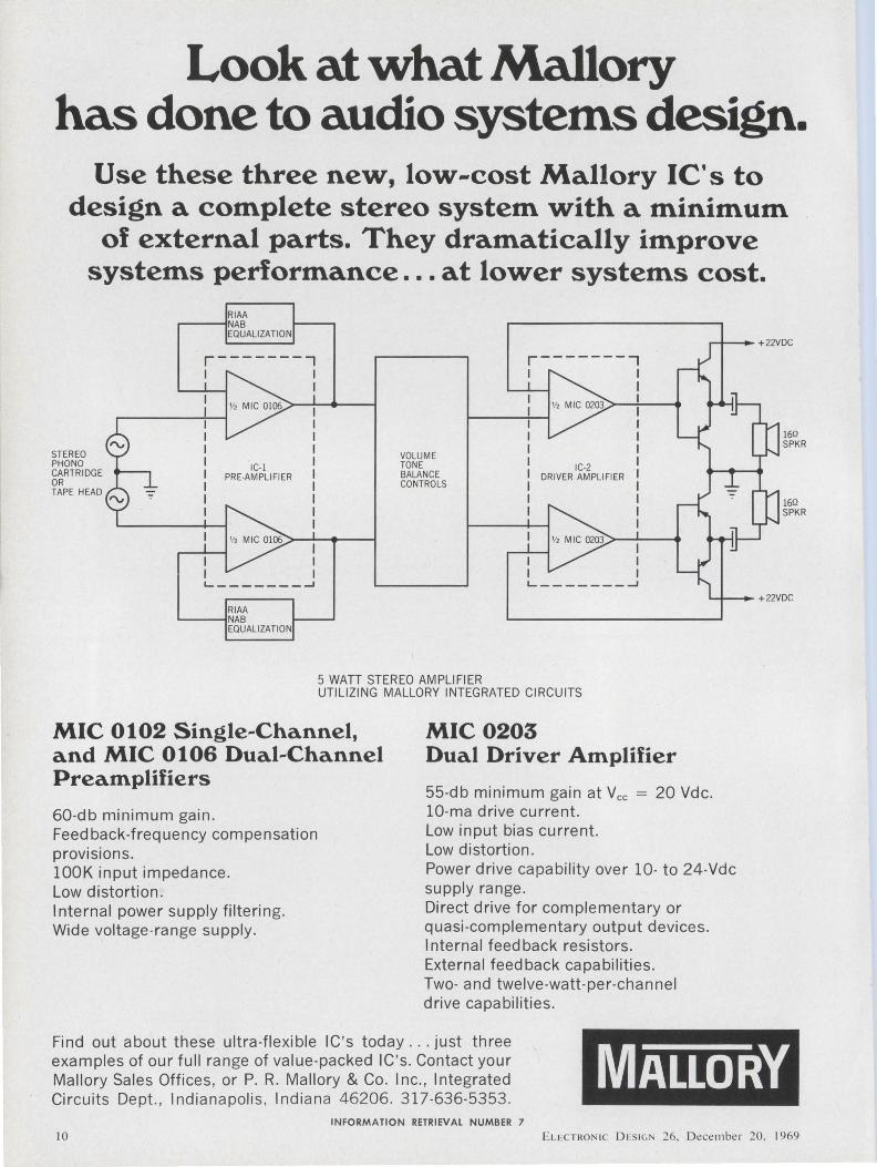
Look at what Mallory has done to audio systems design.
Use these three new, low-cost Mallory IC's to design a complete stereo system with a minimum
of external parts. They dramatically improve systems performance . .. at lower systems cost.
STEREO PHO NO CARTRIDGE OR TAPE HEAD
RIAA ~~NAB
EQUALIZATION
IC-1 PRE-AMPLIFIER
L---------1 RIAA
~--iNAB
EQUALIZATION
VOLUME TONE BALANCE CONTROLS
r-------..., I I
I I I I I I
IC-2 I DR /VER AM PU Fl ER I
I I I I
L._ _______ _J
5 WATT STEREO AMPLIFIER UTILIZING MALLORY INTEGRATED CIRCUITS
MIC 0102 Single-Channel, and MIC 0106 Dual-Channel Preamplifiers
60-db minimum gain. Feedback-frequency compensation provisions. lOOK input impedance. Low distortion. Internal power supply filtering. Wide voltage-range supply.
MIC 0203 Dual Driver Amplifier
55-db minimum gain at Yee = 20 Vdc. 10-ma drive current. Low input bias current. Low distortion. Power drive capability over 10- to 24-Vdc supply range. Direct drive for complementary or quasi-complementary output devices. Internal feedback resistors. External feedback capabilities. Two- and twelve-watt-per-channel drive capabilities.
16Q SPKR
160 SPKR
Find out about these ultra-flexible IC's today .. . just three examples of our full range of value-packed IC's. Contact your Mallory Sales Offices, or P. R. Mallory & Co. Inc., Integrated Circuits Dept., Indianapolis , Indiana 46206. 317-636-5353.
MALLORY INFORMATION RETRIEVAL NUMBER 7
10 E L ECTRON IC D I.SIGN 26, D ecembe r 20. 1969
I~
~ecember is a good month Jor you to think
abouttheyear; head
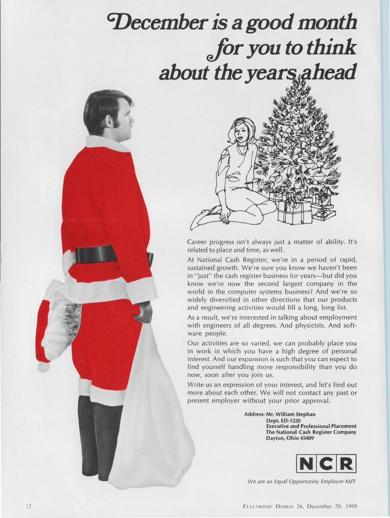
Career progress isn't always just a matter of ability. It's related to place and time, as well.
At National Cash Register, we're in a period of rapid, sustained growth. We're sure you know we haven' t been in " just" the cash register business for years-but did you know we' re now the second largest company in the world in the computer systems business? And we' re so widely diversified in other directions that our products and engineering activities would fill a long, long list.
As a result, we're interested in talking about employment with engineers of all degrees. And physicists. And software people.
Our activities are so varied, we can probably place you in work in which you have a high degree of personal interest. And our expansion is such that you can expect to find yourself handling more responsibility than you do now, soon after you join us.
Write us an expression of your interest, and let's find out more about each other. We will not contact any past or present employer without your prior approval.
Address: Mr. William Stephan Dept. ED-1220 Executive and Professional Placement The National Cash Register Company Dayton, Ohio 45409
We are an Equal Opportunity Employer M/F
E1. 1,c 1 RON IC D ES IGN 26. Decembe r 20, 1969
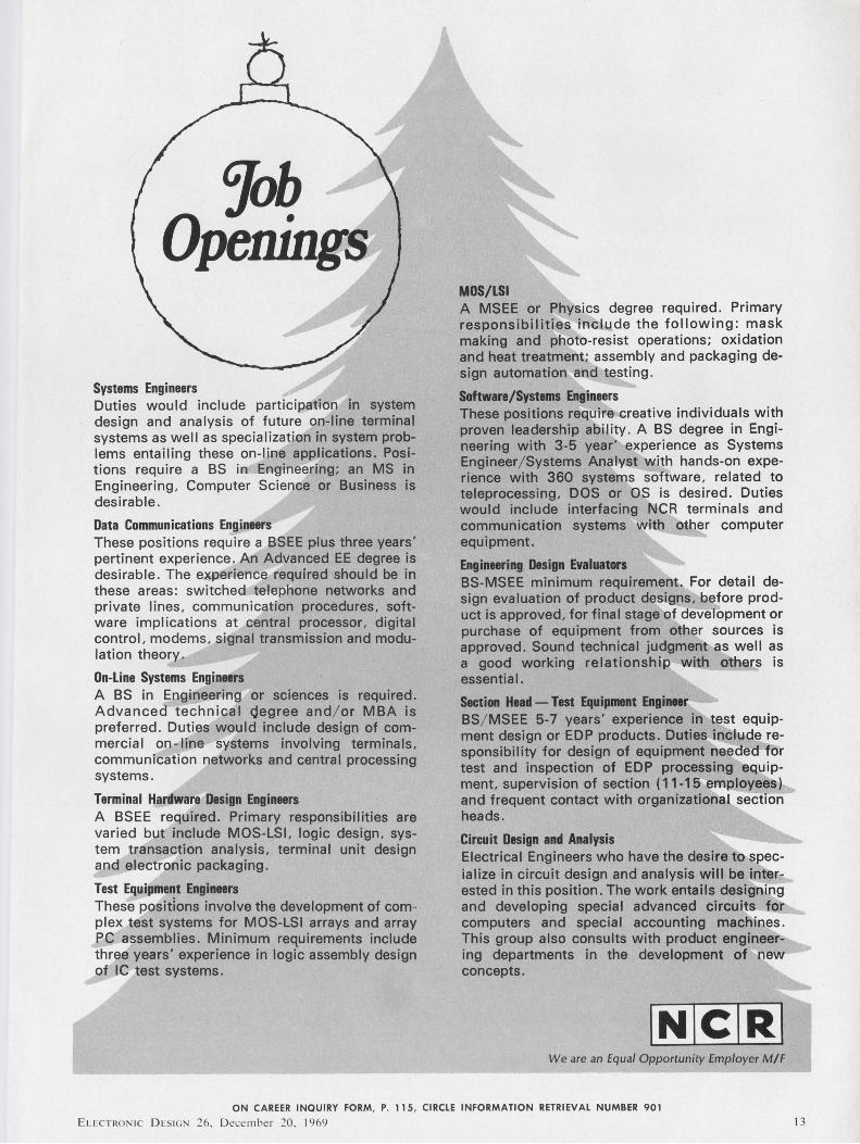
Gjob Openings
Systems Engineers Duties would include participation in system design and analysis of future on-line terminal systems as well as specialization in system problems entailing these on-line applications. Positions require a BS in Engineering; an MS in Engineering, Computer Science or Business is desirable.
Data Communications Engineers These positions require a BSEE plus three years' pertinent experience. An Advanced EE degree is desirable. The experience required should be in these areas: switched telephone networks and private lines, communication procedures, software implications at central processor, digital control, modems, signal transmission and modulation theory.
On-Line Systems Engineers A BS in Engineering or sciences is required. Advanced technical degree and/ or MBA is preferred. Duties would include design of commercial on- line systems involving terminals, communication networks and central processing systems.
Terminal Hardware Design Engineers A BSEE required. Primary responsibilities are varied but include MOS-LSI, logic design, system transaction analysis, terminal unit design and electronic packaging.
Test Equipment Engineers These positions involve the development of com· plex test systems for MOS-LSI arrays and array PC assemblies. Minimum requirements include three years' experience in logic assembly design of IC test systems.
MOS/LSI A MSEE or Physics degree required. Primary responsibilities include the following: mask making and photo-resist operations; oxidation and heat treatment; assembly and packaging design automation and testing.
Software/Systems Engineers These positions require creative individuals with proven leadership ability. A BS degree in Engineering with 3-5 year' experience as Systems Engineer/ Systems Analyst with hands-on experience with 360 systems software, related to teleprocessing, DOS or OS is desired. Duties would include interfacing NCR terminals and communication systems with other computer equipment.
Engineering Design Evaluators BS-MSEE minimum requirement. For detail design evaluation of product designs, before product is approved, for final stage of development or purchase of equipment from other sources is approved. Sound technical judgment as well as a good working relationship with others is essential.
Section Head - Test Equipment Engineer BS/ MSEE 5-7 years' experience in test equipment design or EDP products. Duties include responsibility for design of equipment needed for test and inspection of EDP processing equipment. supervision of section (11-15 employees) and frequent contact with organizational section heads.
Circuit Design and Analysis Electrical Engineers who have the desire to specialize in circuit design and analysis will be interested in this position. The work entails designing and developing special advanced circuits for computers and special accounting macliines. This group also consults with product engineering departments in the development of i;iew concepts.
We are an Equal Opportunity Employer M/F
ON CAREER INQUIRY FORM, P. 115, CIRCLE INFORMATION RETRIEVAL NUMBER 901
Eu: CTRON IC Dl: S IGN 26, December 20. 1969 13
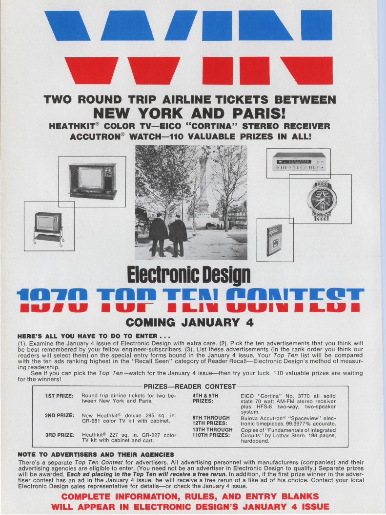
TWO ROUND TRIP AIRLINE TICKETS BETWEEN NEW YORK AND PARIS!
HEATHKIT® COLOR TV-EICO "CORTINA" STEREO RECEIVER ACCUTRON® WATCH-110 VALUABLE PRIZES IN ALL!
( -'°' I ii ,.., i ,.... r- i Ii r •
Electronic Design -ID-WO TDD Tl:lll lllDlllTCOT ......... .-- •LI• ............ .
COMING JANUARY 4 HERE'S ALL YOU HAVE TO DO TO ENTER ... (1 ). Examine the January 4 issue of Electronic Design with extra care. (2). Pick the ten advertisements that you think will be best remembered by your fellow engineer-subscribers. (3). List these advertisements (in the rank order you think our readers will select them) on the special entry forms bound in the January 4 issue. Your Top Ten list will be compared with the ten ads ranking highest in the " Recall Seen" category of Reader Recall-Electronic Design's method of measuring readership.
See if you can pick the Top Ten-watch for the January 4 issue-then try your luck. 110 valuable prizes are waiting for the winners!
1ST PRIZE: Round trip airline tickets for two between New York and Paris.
2ND PRIZE: New Heathkit® deluxe 295 sq. in. GR-681 color TV kit with cabinet.
3RD PRIZE: Heathkit® 227 sq. in . GR-227 color TV kit with cabinet and cart.
NOTE TO ADVERTJSERS AND THEIR AGENCIES
4TH & STH PRIZES:
6TH THROUGH 12TH PRIZES: 13TH THROUGH 110TH PRIZES:
EICO " Cortina" No. 3770 all solid state 70 watt AM-FM stereo receiver plus HFS-8 two-way, two-speaker system. Bulova Accutron® " Spaceview" electronic timepieces . 99.9977% accurate. Copies of " Fundamentals of Integrated Circuits " by Lothar Stern. 198 pages, hardbound.
There's a separate Top Ten Contest for advertisers. All advertising personnel with manufacturers (companies) and their advertising agencies are eligible to enter. (You need not be an advertiser in Electronic Design to qualify.) Separate prizes will be awarded. Each ad placing in the Top Ten will receive a free rerun. In addition, if the first prize winner in the advertiser contest has an ad in the January 4 issue, he will receive a free rerun of a like ad of his choice. Contact your local Electronic Design sales representative for details-or check the January 4 issue.
COMPLETE INFORMATION, RULES, AND ENTRY BLANKS WILL APPEAR IN ELECTRONIC DESIGN'S JANUARY 4 ISSUE
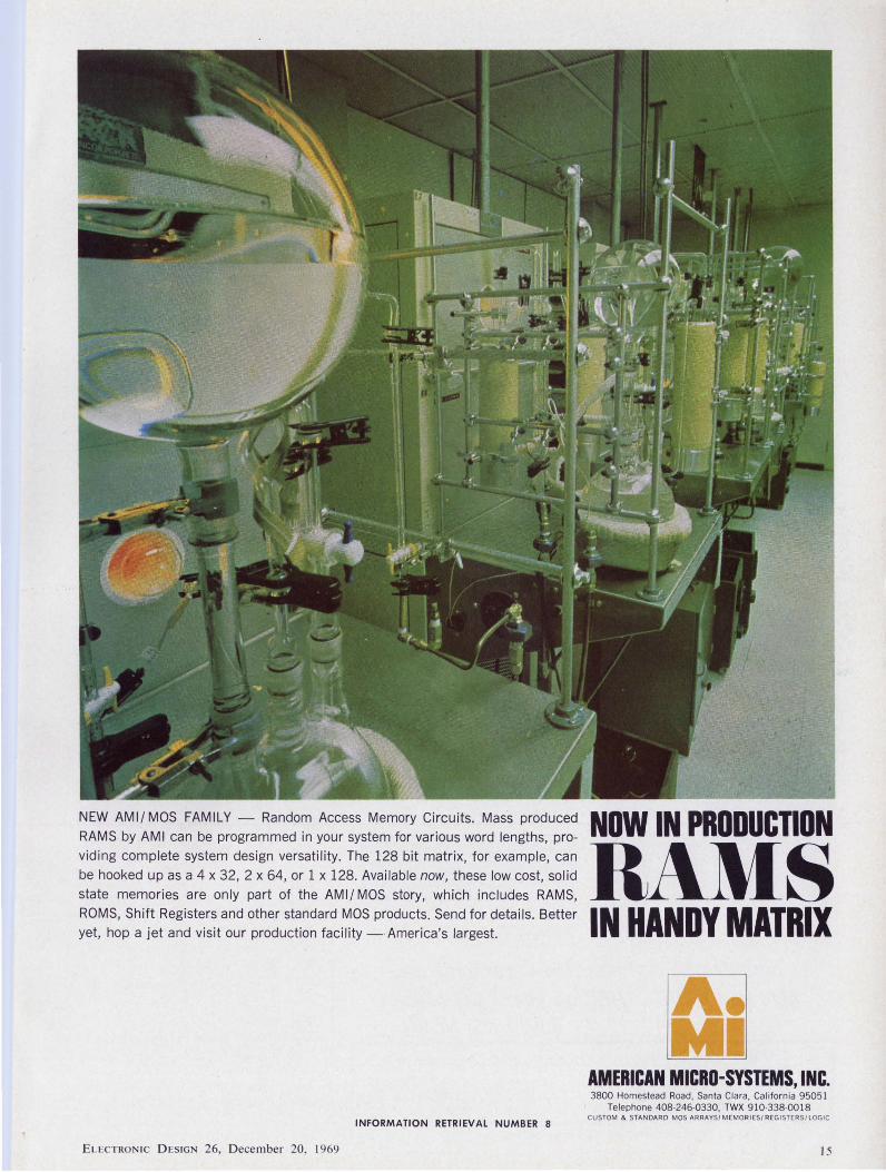
NEW AMI/ MOS FAMILY - Random Access Memory Circuits. Mass produced RAMS by AMI can be programmed in your system for various word lengths, providing complete system design versatility. The 128 bit matrix, for example, can be hooked up as a 4 x 32, 2 x 64, or 1 x 128. Available now, these low cost, solid state memories are only part of the AMI/ MOS story, which includes RAMS, ROMS, Shift Registers and other standard MOS products. Send for details. Better yet, hop a jet and visit our production facility -America's largest.
INFORMATION RETRIEVAL NUMBER 8
ELECTRON IC D ESIGN 26, D ecember 20, 1969
NOW IN PRODUCTION
RAMS IN HANDY MATRIX
~ Ml
AMERICAN MICRO-SYSTEMS, INC. 3800 Homestead Road. Santa Clara, California 9505 1
Telephone 408-246-0330, TWX 910-338-00 18 CUSTOM & STANDARD MOS ARRAYS / MEMORIES/ REGI STERS/ LOGIC
15
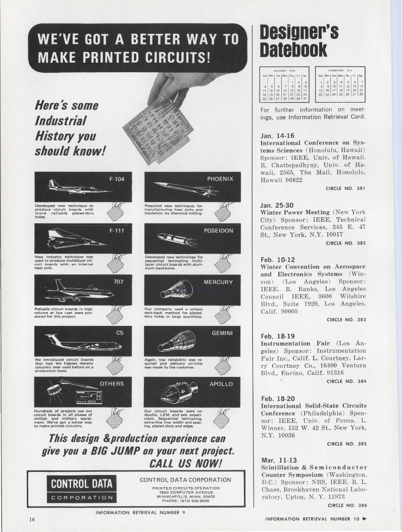
Heres some Industrial History you should know!
Hundreds of projects use our circuit boards in all phases of civilian and military equipment. We've got a better way to make printed circuitry.
~ MERCURY
~ Our company used a unique etch-back method for plated· thru holes in large quantities.
I APOLLO
Our circuit boards were on Apollo, LEM, and seis. experiment. Sequential laminating, extra-fine line width and spacing, plated slots and edges.
This design &production experience can give you a BIG JUMP on your next project.
16
CONTROL DATA CORPORATION
CALL US NOW! CONTROL DATA CORPORATION
PAINTED CIRCUITS OPERATION 7800 COMPUTER AVENUE
MINNEAPOLIS, MINN. 55435 PHONE : (612) 920-8600
INFORMATION RETRIEVAL NUMBER 9
Designer's oatebook
JANUARY 1970 FEBRUARY 1970
Sun Mon Tue Wed "' '" '" Sun Mon Tue Wed "" '" '" 1 2 3 2 3 4 5 6 7
4 5 6 7 8 9 10 9 10 11 12 13 14
11 12 13 14 15 16 17 15 16 17 18 19 20 21
18 19 20 21 22 23 24 22 23 24 25 26 27 28
25 26 27 28 29 30 31
For further information on meet ings, use Information Retrieval Card .
Jan. 14-16 International Conference on Systems Sciences (Hon olulu , Hawa ii ) Spon sor: IEEE, Univ. of Hawaii . R. Ch attopadhyay, Univ. of Hawaii , 2565, The Ma ll , Hon olulu , Hawaii 96822
CIRCLE NO. 381
Jan. 25-30 Winter Power Meeting (New York City) Spon sor: IEEE. Technical Conference Services, 345 E. 47 St., New York, N.Y. 10017
CIRCLE NO. 382
Feb. 10-12 Winter Convention on Aero pace and Electronics Systems (Wincon ) (Los Angeles) Sponsor: IEEE. R. Ba nks, Los Angeles Coun cil IEEE, 3600 Wil shire Blvd., Suite 1920, Los Angeles . Calif. 90005
CIRCLE NO. 383
Feb. 18-19 Instrumentation Fair (L os Angeles) Spon sor: Ins trumentation F a ir Inc., Calif. L. Courtney, Larr y Courtney Co., 16400 Ventura Blvd., Encino, Calif. 91316
CIRCLE NO. 384
Feb. 18-20 International Solid-State Circuits Conference (Philadelphia) Sponsor: IEEE, Univ. of P enna. L. W inner, 152 W . 42 St. , New York, N.Y. 10036
CIRCLE NO. 385
Mar. 11-13 Scintillation & Semi conductor Counter Symposium (Washin gton , D.C.) Spon sor: NBS, IEEE. R. L. Chase, Brookh aven Nation a l Labor ator y, Upton , N. Y. 11973
CIRCLE NO. 386
INFORMATION RETRIEVAL NUMBER 10 ...
rlame relarclanc
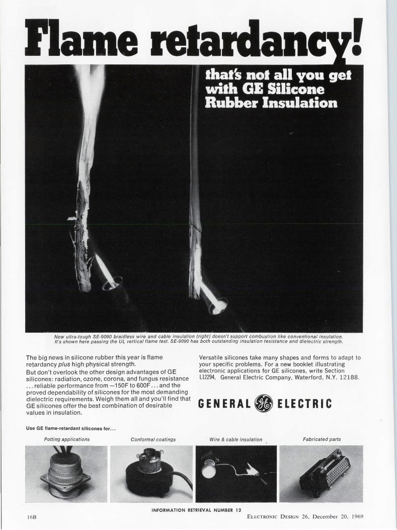
New ultra-tough SE-9090 braidless wire and cable insulation (right) doesn' t support combustion like conventional insulation . It's shown here passing the UL vertical flame test. SE-9090 has both outstanding insulation resistance and dielectric strength.
The big news in silicone rubber this year is flame retardancy plus high physical strength. But don't overlook the other design advantages of GE silicones: radiation , ozone, corona, and fungus resistance . .. reliable performance from -150F to 600F . .. and the proved dependability of silicones for the most demanding dielectric requirements. Weigh them all and you'll find that GE silicones offer the best combination of desirable values in insulation.
Use GE flame-retardant silicones for ...
Potting applications Conformal coatings
Versatile silicones take many shapes and forms to adapt to your specific problems. For a new booklet illustrating electronic applications for GE silicones, write Section L12294, General Electric Company, Waterford, N.Y. 12188.
GENERAL. ELECTRIC
Wire & cable insulation Fabricated parts
INFORMATION RETRIEVAL NUMBER 12
168 ELECTRONIC D ESIGN 26, D ecembe r 20, 1969
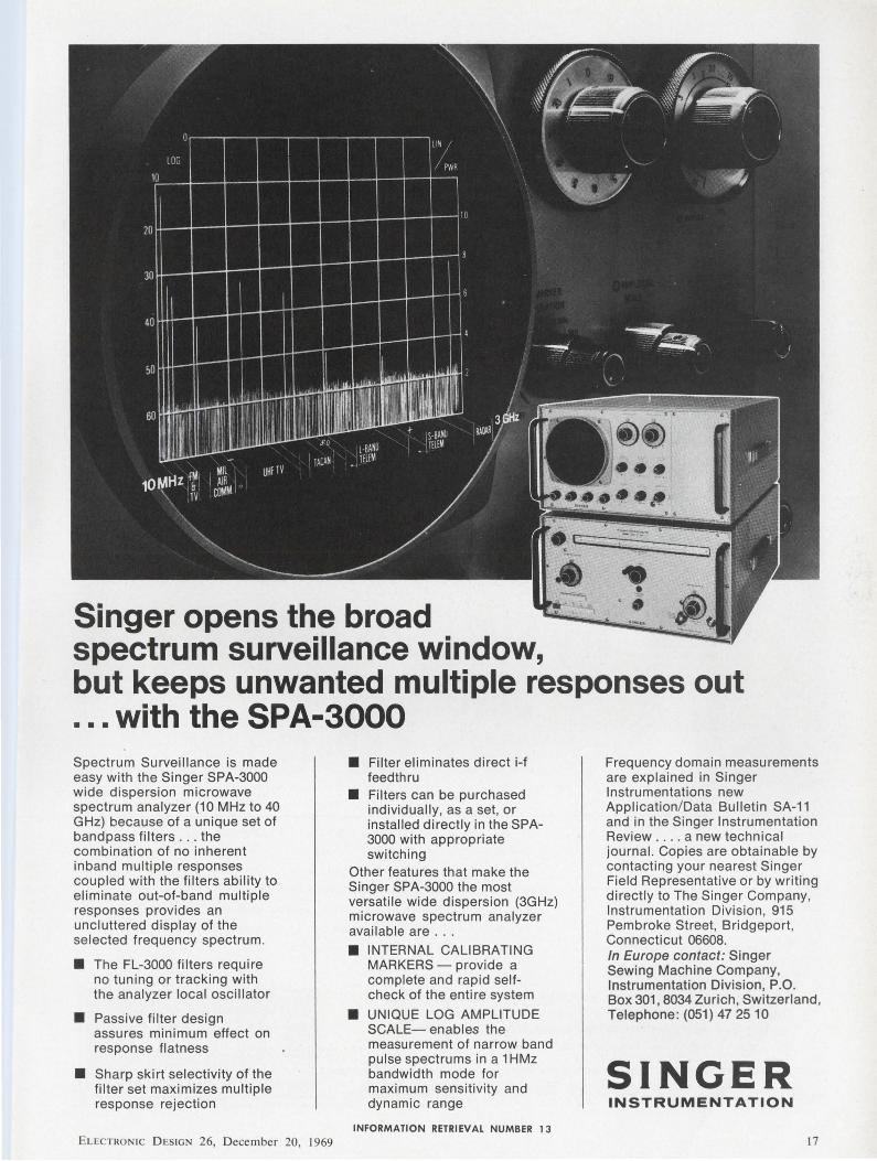
Singer opens the broad spectrum surveillance window,
• • ••
but keeps unwanted multiple responses out ... with the SPA-3000 Spectrum Surveillance is made easy with the Singer SPA-3000 wide dispersion microwave spectrum analyzer (10 MHz to 40 GHz) because of a unique set of bandpass filters . .. the combination of no inherent inband multiple responses coupled with the filters ability to eliminate out-of-band multiple responses provides an uncluttered display of the selected frequency spectrum.
• The FL-3000 filters require no tuning or tracking with the analyzer local oscillator
• Passive filter design assures minimum effect on response flatness
• Sharp skirt selectivity of the filter set maximizes multiple response rejection
ELECTRON IC D ESIGN 26, D ecemb er 20, 1969
• Filter eliminates direct i-f feedthru
• Filters can be purchased individually, as a set, or installed directly in the SPA-3000 with appropriate switching
Other features that make the Singer SPA-3000 the most versatile wide dispersion (3GHz) microwave spectrum analyzer available are . ..
• INTERNAL CALIBRATING MARKERS - provide a complete and rapid selfcheck of the entire system
• UNIQUE LOG AMPLITUDE SCALE- enables the measurement of narrow band pulse spectrums in a 1 HMz bandwidth mode for maximum sensitivity and dynamic range
INFORMATION RETRIEVAL NUMBER 13
Frequency domain measurements are explained in Singer Instrumentations new Application/Data Bulletin SA-11 and in the Singer Instrumentation Review . . .. a new technical journal. Copies are obtainable by contacting your nearest Singer Field Representative or by writing directly to The Singer Company, Instrumentation Division , 915 Pembroke Street, Bridgeport, Connecticut 06608. In Europe contact: Singer Sewing Machine Company, Instrumentation Division, P.O. Box 301 , 8034 Zurich, Switzerland, Telephone: (051) 47 25 10
SINGER INSTRUMENTATION
17
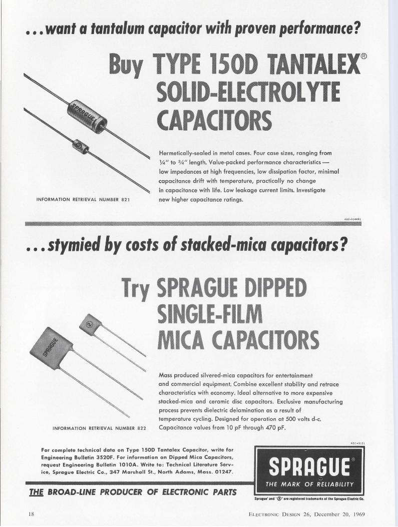
•.. want a tantalum capacitor with proven perlormance?
Buy TYPE lSOD TANTALEX® SOLID-ELECTROLYTE CAPACITORS Hermetically-sealed in metal cases. Four case sizes, ranging fre>m
14" to %" length. Value-packed performance characteristics -
low impedances at high frequencies, low dissipation factor, minimal
capacitance drift with temperature, practically no change
INFORMATION RETRIEVAL NUMBER 821
in capacitance with life. Low leakage current limits. Investigate
new higher capacitance ratings.
••
4SC~9144Rl
.stymied by costs of stacked-mica capacitors?
Try SPRAGUE DIPPED
INFORMATION RETRIEVAL NUMBER 822
SINGLE-FILM MICA CAPACITORS Mass produced silvered-mica capacitors for entertainment
and commercial equipment. Combine excellent stability and retrace
characteristics with economy. Ideal alternative to more expensive
stacked-mica and ceramic disc capacitors. Exclusive manufacturing
process prevents dielectric delamination as a result of
temperature cycling. Designed for operation at 500 volts d-c.
Capacitance values from 10 pF through 470 pF.
4SC • 9l5l
For complete technical data on Type 1500 Tantalex Capacitor, write for
Engineering Bulletin 3520F. For information on Dipped Mica Capacitors, request Engineering Bulletin 1010A. Write to: Technical Literature Service, Sprague Electric Co., 347 Marshall St., North Adams, Mass. 01247. SPRllGUE-
-THE MARK OF RELIABILITY
11:1.f. BROAD-LINE PRODUCER OF ELECTRONIC PARTS 0
18 ELECTRON IC D ESIGN 26, December 20, 1969
News
• • •., . , . ..... , I • ,, ,
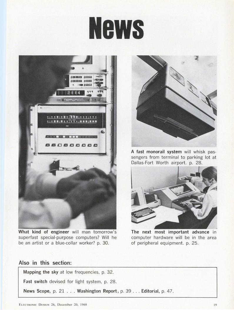
What kind of engineer will man tomorrow's superfast special-purpose computers? Will he be an artist or a blue-collar worker? p. 30.
Also in this section:
Mapping the sky at low frequencies , p. 32.
Fast switch devised for light system, p. 28.
The next most important advance in computer hardware will be in the area of peripheral equipment. p. 25 .
News Scope, p. 21 . . . Washington Report, p. 39 ... Editorial, p. 47.
ELECTRON IC DESIGN 26, D ecember 20, 1969 19
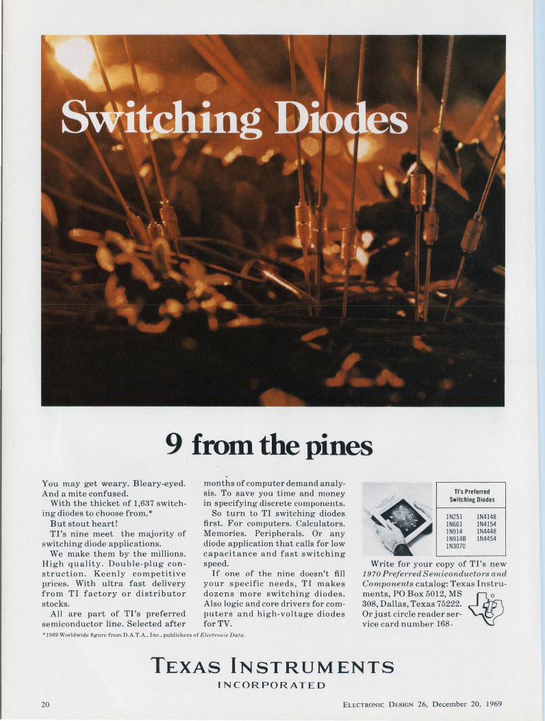
9 from the pines You may get weary. Bleary-eyed. And a mite confused.
With the thicket of 1,637 switching diodes to choose from.*
But stout heart! Tl's nine meet the majority of
switching diode applications. We make them by the millions.
High quality. Double-plug construction. Keenly competitive prices. With ultra fast delivery from TI factory or distributor stocks.
All are part of Tl's preferred semiconductor line. Selected after
months of computer demand analysis. To save you time and money in specifying discrete components.
So turn to TI switching diodes first. For computers. Calculators. Memories. Peripherals. Or any diode application that calls for low capacitance and fast switching speed.
If one of the nine doesn't fill your specific needs, TI makes dozens more switching diodes. Also logic and core drivers for computers and high-voltage diodes for TV.
Tl's Preferred Switching Diodes
1N251 1N661 1N914 1N914B 1N3070
1N4148 1N4154 1N4448 1N4454
Write for your copy of Tl's new 19 70 Preferred Semiconductors an d Components catalog: Texas Instruments, PO Box 5012, MS 308, Dallas, Texas 75222. Or just circle reader service card number 168 .
* 1969 Worl dwide figure from D.A.T .A ., Inc., publi shers of Electronic Data.
TEXAS INSTRUMENTS INCORPORATED
20 ELECTRONIC DESIGN 26, December 20, 1969
News scone
Drive focuses on perils in medical equipment
Medical electronics continues to draw the fire of professional ·groups concerned with consumer safety.
Citing h a z a rd s outlined by speakers at the National Conference on Medical Devices in Bethesda, Md., last September, the International Institute for Medical Electronics and Biological Engineering this month opened a drive to publicize the problems.
The Institute consists of some 3000 physicians, scientists and engineers concerned with the use and advancement of biomedical equipment. It is headquartered in Paris.
"We know there have been instances of device failure which resulted in patient injuries and fatalities," Dr. Herbert L. Ley, Commissioner of Food and Drugs in the Dept. of Health, Education and Welfare, told the September conference.
At the same conference Mrs. Virginia Knauer, Special Assistant to the President for Consumer Affairs, called attention to what she described as defective defibrillators, poorly designed dialysis units and accidental electrocutions in hospital operating rooms. Physicians are reluctant to report adverse experiences with electr<mic devices, Mrs. Knauer said, because of fear of malpractice suits and the difficulty of establishing a casual relationship between the adverse reaction and the use of a specific device.
"It is distressing to me as a consumer," Mrs. Knauer told the conference, "that the doctrine of caveat emptor still exists in this major health field."
Another conference speaker, Dr. Harry S. Lipscomb, co-chairman of the education and communication committee of the Association for the Advancement of Medical Instrumentation, noted that physi-
ELECTRONIC DESIGN 26, December 20, 1969
cians were confronted with an estimated total of 5000 different devices produced by more than 1300 manufacturers.
But all was not criticism at the Bethesda meeting. The lifesaving contributions were also cited. For example, prior to the advent of pacemakers, the mortality rate for patients was 69%; with pacemakers, it is 7%, the Association for the Advancement of Medical Instrumentation noted.
A number of companies manufacturing medical instruments went on record at the conference as opposed to legislation that would require pre-clearance from the Government before equipment could be marketed-the way drugs are controlled. John T. Kimbell, executive vice president of Boxter Laboratories, Inc. Morton Grove, Ill., argued that such legislation would:
• Slow and possibly prevent the availability of life-saving devices, because of the cost of pre-clearance procedures.
• Regulate out of existence small companies that do not have staffs to perform extensive procedures.
A program for control of medical devices was proposed by Dr. James Goddard, vice president for health services of EDP Technology, Inc. Washington, D.C.. He suggested that a group of qualified, non-governmental scientists test company devices. If the device showed promise and safety, broader testing could then be applied for. If a proposal were rejected, review would be provided at the National Academy of SciencesN ational Research Council level.
A National Center for Biomedical Engineering was suggested by Dr. R. F. Rushmore, director of the bioengineering program at the University of Washington. Such
an organization, he said, could perform unbiased investigations under the supervision of an appropriate governmental agency.
The coordinator of the safety and standards committee of the International Institute for Medical Electronics and Biological Engineering is Hans A. von der Mosel of Cliffside Park, N.J., a professor of biomedical engineering. "There is quite a serious risk involved in the use of biomedical devices/' he told ELECTRONIC DESIGN.
Many of the hazards, he continued, are "still unknown to many instrument manufacturers and to the majority of physicians, medical and paramedical personnel, hospital architects, hospital engineers, hospital administrators and governmental agencies."
The House Interstate and Foreign Commerce Committee, headed by Rep. Harley 0. Staggers (D.W.Va.), has received a number of bills to control therapeutic devices. But no hearings have yet been held, he said.
New Univac division to develop peripherals
Looking for significant growth in the computer peripheral equipment market, Sperry Rand Corp. has set up a new division-Univac Communications and Terminals Div.-to develop new devices and to sell them.
Univac's president, Robert E. McDonald, and Cecil M. Shuler, general manager of the new division, point to these marketing trends and projections:
1• Sales of computer terminals are expected to increase 43 % in 1970 over the 1969 totals, but an increase of only 22% is forecast in sales of central processors.
• Central processors now account for 37.7% of the computer sales market, and this figure should increase to 38 % in 1975. But terminals, now only 8% of the market, should rise to 16 % by 1975.
In conjunction with its new effort, Univac's marketing strategy is also undergoing a change in emphasis. The products of the new division are to be aimed at the original equipment manufacturer market, as well as at incorporation
21
News SCOP8coNTINUED
into Univac systems. As a start, the company an
nounced two new peripheral products, both compatible with equipment produced by competitors. One is the DCS-lC data communications system, which can be used w.ith Univac's 9000 series computers or with IBM's 360 family. The other is the DCT-1000 terminal, which is built around a low-cost buffered printer and which can be expanded with a keyboard, paper tape reader/ punch, card reader/ punch or other auxiliaries sti ll to be developed.
The DCT-1000 is similar to the older DC-500, which does not include a buffer. Both terminals are compatible with teletype equipment but operate at 30 characters a second, about 2.5 times as fast as the standard teletype.
Univac's Communications and Terminals Div. will be headquartered in Salt Lake City and will make use of facilities formerly used by the Sperry Utah Div. of the corporation,
NASA plans tests in '72 of laser communications
NA SA has ordered development of a laser communications system for testing by 1972. The system will be built by Aerojet-General Corp., Azusa, Calif., under a $5-million contract.
Tests are planned of communications between the earth and Applications Technology Satellite-F, schedu led for launching into a sta.tionary equatorial orbit in 1972. If that communications link is successfu l, a spacecraft-to-spacecraft laser commun ications test will be made in 1974 when ATS-G is launched into orbit.
The ATS-F test will be the first of laser communications with an unmanned satellite. An earlier system, using an infrared laser, was developed by International Business Machines and flighttested unsuccessfully between an
22
aircraft and a fixed station at the White Sands l\Iissile Range, N.M., in the early 1960s. Later, during the Gemini program, an RCA laser was similarly tested without success.
Aerojet-General will de v e 1 op both space and ground laser terminals, and provision will be made to permit a full range of wideband and conventional data communications, including teleprinter, voice, facsimile, color TV and still photographs. Both ATS-F and ATS-G will be equipped with a deployable, 30-foot-diameter, high-gain, steerable antenna.
MIT and Caltech plan a Clean Air Car Race
A Clean Air Car Race, featuring low-pollution vehicles-such as steam, turbine and electric-is planned for September, 1970, from the Massachusetts Institute of Technology to the California Institute of Technology.
The vehicles may be designed and built by an individual or organization, but according to bhe race's organizers-Dr. Richard M. Thornton, professor of electrical engineering at MIT, and Dr. Jerome Shapiro, professor of engineering at Caltech-the cars must be student-driven. Potential entrants are asked to notify both Dr. Thornton and Dr. Shapiro by Feb. 28. Qualifying trials will be held at MIT on Sept. 2, and the crosscountry race will start from there on Sept. 9.
The race is designed to encou rage the development of low-pollution vehicles. Significant qualifications are that the car be able to go 60 miles in no more than 90 minutes without refueling or recharging, and that it accelerate from 0 to 45 mph in a maximum of 14 seconds .
Amateur -radio satellite scheduled for launch
Radio amateurs all over the world, who are interested in the art of tracking satellites and participating in radio propagation experiments, will soon be able to practice on an amateur satellite called the Australis Oscar-A. What
is it? It's a 39-pound spacecraft that is scheduled to be launched as a secondary payload on the Tiros-M mission on January 9.
The Australis was constructed by a group of amateur radio operators at Melbourne University in Australia-hence the name. The second portion of the name is derived from Project Oscar, a U.S. West Coast organization of radio amateurs that has constructed and secured launches for four amateur satellites to date.
The West Coast group, called Radio Amateur Satellite Corp., has its headquarters in Washington, D.C. It was formed earlier this year to foster radio amateur participation in space projects.
The satellite will be placed into a near polar orbit at an inclination of 101.56 degrees to the earth's equator at an altitude of about 790 nautical miles. It will transmit low-power signals on two amateur bands-at 29.45 MHz in the 10-meter band and at 144.05 MHz in the 2-meter band.
Beacon transmissions will carry telemetry data pertaining to the condition of the spacecraft, including temperatures and the satellite's orientation with respect to the earth.
EIA adopts new system for numbering TV tubes
A new system for numbering the cathode-ray picture tubes in television sets has been adopted by the Electronic Industries Association. The purpose is to indicate more · accurately the diagonal dimension of a television screenthe usable picture area.
The new "type designation system" replaces the previous method of assigning numbers that indicated the outside dimension of the bulb itself.
Under the new system, the letter "V" will be added to the type designation to distinguish picture tubes based on the new system.
A color picture tube having a picture diagonal of 28 1/ 4 inches, for example, might be assigned type number 30ABP22 under the old system. Under the new, the designation would be 28VABP22, accurately reflecting the actual picture diagonal measurement.
INFORMATION RETRIEVAL NUMBER 15 ....
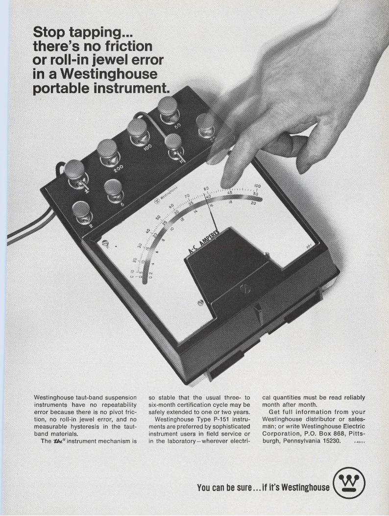
Stop tapping ... there's no friction or roll-in jewel error in a Westinghouse portable instrument.
Westinghouse taut-band suspension instruments have no repeatabil ity error because there is no pivot friction, no roll-in jewel error, and no measurable hysteresis in the tautband materials.
The "tb.L.® instrument mechanism is
so stable that the usual three- to six-month certification cycle may be safely extended to one or two years.
Westinghouse Type P-151 instruments are preferred by sophisticated instrument users in field service or in the laboratory - wherever electri-
cal quantities must be read reliably month after month.
Get full information from your Westinghouse distributor or salesman ; or write Westinghouse Electric Corporation, P.O. Box 868, Pittsburgh, Pennsylvania 15230.
You can be sure ••. if It's Westinghouse ®
j '
NEWS
It's time for change in computer peripherals Major advances are on the way for this hardware, a tour of the Las Vegas fall conference suggests
Any peripheral device that requires random-access memory can profit from the advent of the LSI semiconductor memory. Data concentrators and high-speed line printers are other possible applications.
Milton J. Lowenstein Technical Editor
One of the most significant trends discernible at the Fall Joint Computer Conference was one that wasn't on view. It came from behind the scenes, after a tour of the exhibits and discussions with knowledgeable computer men.
It's this: The next important advance in computer hardware will be in the area of peripheral equipment.
Most of the computer peripherals that were on view in Las Vegas last month-tape, disc and drum memories, and the various inputoutput devices-were designed many years ago. But central processors have been undergoing radical changes in recent years, with huge sums invested in improvements. As a result, the computer main frames have capabilities that cannot be exploited by existing peripheral equipment.
At the same time the mini-computer has made its debut and is gaining wide acceptance because of its relatively low cost. Peripherals are falling behind here, too. There has been no development of lowpriced peripheral devices to match the economy of the minis. Coupling a $50,000 disc memory to a $10,000 mini-computer just doesn't make economic sense.
Advances expected soon
The representatives of many computer-equipment manufacturers, both large and small, disclosed privately that they were expecting the peripheral field to advance, starting in 1970 and continuing for several years beyond that. Manufacturers are beginning to increase their investments in research, development, design and production activities.
One development on exhibit, originally tagged as a main-frame component, may very well be in the
.... INFORMATION RETRIEVAL NUMBER 16
forefront of the new peripheral devices. This is the semiconductor memory that uses large-scale integration technology.
Compact and inexpensive LSI memories are now in the last stages of development and will begin to appear as production components during 1970. Their advantages of small size and low cost are marginal in central processors, where so many other components account for the size and price of the completed computer. But what about an interactive graphic CRT terminal, in which the memory is now the most expensive and one of the largest components ? LSI memories might remove the cost barrier to use of this type of device and make its use more general. LSI might be the key to the long-delayed fulfillment of the promise of graphic terminals. And it would make them portable, too.
Low-cost peripherals due
What can be expected in peripheral equipment aimed at the burgeoning mini-computer market? Some possibilities were shown at the conference. Included were lowcost disc and drum memories, tapecassette d r i v e s for low-speed memory capability, and phonograph records for storing program libraries.
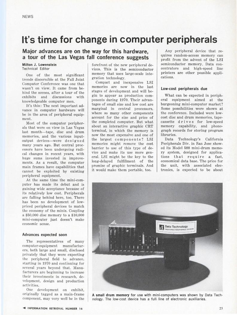
Data Technology's California Peripherals Div. in San Jose showed its Model 588 mini-drum memory system, designed for applications that require a fast, economical data base. The price for the unit, with associated electronics, is expected to be about
A small drum memory for use with mini-computers was shown by Data Tech · nology. The low-cost device has a full . line of electronic auxiliaries .
25
NEWS
(computer, continued)
$1500. Without the electronics, it will cost about $800. The unit measures 9 x 9 X 9 inches and it can store over 130 kbits on eight tracks. The average access time is 8.3 ms, and the bit transfer rate is. approximately 1 MHz.
A larger, more elaborate and more expensive disc memory-the Iodise Model 1012-was exhibited by Iomec, Inc., Santa Clara, Calif. It uses two discs, one removable and one nonremovable. It can store up to 22 million bits and read out at 720 kbits per sec. The access .time is 20 ms, and motion time averages 60 ms. The unit fits into a standard relay track 30 inches deep and 64 inches high.
Iomec has a contract to supply Hewlett-Packard with $2.5-million worth of Iodise memories. Deliveries will start in January. Hewlett-Packard will market the disc memory for $12,000, including controller, for its 2114, 2115 and 2116 stand-alone computers.
Cassettes and cartridges have blanketed the audio recording field
because of their handling ease, and they are now in a position to do the same in data recording. The relative merits of the cassette and cartridge depend on their packaging. The cartridge uses wider tape, which makes for somewhat easier tape handling and less need for precision, but it has only a single reel, which permits only unidirectional tape motion. The cassette, with its narrower tape, has two reels and bidirectional tape motion. It is, therefore, quicker to access a given bit with the cassette.
The cartridge has one additional advantage: It is available now.
Tri-Data Corp., Mountain View, Calif., is offering a complete datarecording system based on the tape cartridge, called Cartri-File. The cartridges used are not the same as the familiar eight-track audio cartridge. They operate on the same principle, but each contains two tapes. Each tape can store up to 150,000 six-bit words. The transfer rate is 857 six-bit words per second. The average search time for a 150-foot long tape is 90 seconds. The Model 4096 CartriFile can accommodate two cartridges each containing two tapes,
,, ll , lo)
i
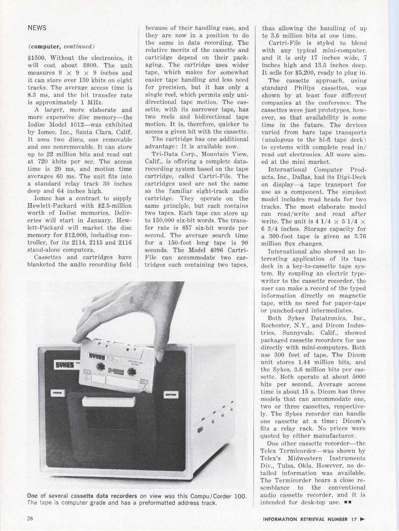
One of several cassette data recorders on view was this Compu /Corder 100. The tape is computer grade and has a preformatted address track.
26
thus allowing the handling of up to 3.6 million bits at one time.
Cartri-File is styled to blend with any typical mini-computer, and it is only 17 inches wide, 7 inches high and 13.5 inches deep. It sells for $5,200, ready to plug in.
The cassette approach, using standard Philips cassettes, was shown by at least four different companies at the conference. The cassettes were just prototypes, however, so that availability is some time in the future. The devices varied from bare tape transports (analogous to the hi-fi tape deck ) to systems with complete read in / read out electronics. All were aimed at the mini market.
International Computer Products, Inc., Dallas, had its Digi-Deck on display-a tape transport for use as a component. The simplest model includes read heads for two tracks. The most elaborate model can read / write and read after write. The unit is 4 1/4 X 5 1/ 4 X 6 3/4 inches. Storage capacity for a 300-foot tape is given as 3.76 million flux changes.
International also showed an interesting application of its tape deck in a key-to-cassette tape system. By coupling an electric typewriter to the cassette recorder, the user can make a record of the typed information directly on magnetic tape, with no need for paper-tape or punched-card intermediates.
Both Sykes Datatronics, Inc., Rochester, N.Y., and Dicom Industries, Sunnyvale, Calif., showed packaged cassette recorders for use directly with mini-computers. Both use 300 feet of tape. The Dicom unit stores 1.44 million bits, and the Sykes, 3.6 million bits per cassette. Both operate at about 5000 bits per second. Average access time is about 15 s. Dicom has three models that can accommodate one, two or three cassettes, respectively. The Sykes recorder can handle one cassette at a time; Dicom's fits a relay rack. No prices were quoted by either manufacturer.
One other cassette recorder-the Telex Termicorder-was shown by Telex's Midwestern Instruments Div., Tulsa, Okla. However, no detailed information was available. The Termicorder bears a close resemblance to the conventional audio cassette recorder, and it is intended for desk-top use. • •
INFORMATION RETRIEVAL NUMBER 17 ...
A-8 Type W variable resistor
shown about 5 times actual size
ALLEN - BRADLEY QUALITY ELE C TRONIC COMPONENTS
69
less than $1.00*
The QUALITY is Allen-Bradleythe price is COMPETITIVE! This new Type W variable resistor is a commercial version of the Type G control.
This Type W variable resistor features a solid, hot-molded resistance track for long operating life. Life tests show less than 10% resistance change after 50,000 complete cycles. Noise level is low initially and actually becomes less after normal use. Furthermore, the resolution is essentially infinite, and the low inductance permits operation at high frequencies where wirewound controls are useless.
The Type W control, while only Y2 inch in diameter, is immersionproof. The shaft is sealed with an " 0" ring, making it watertight at that point. ·
Rated Y2 watt at 70°C, the Type W can be operated at 120°C ambient with zero load. Nominal resistance values are from 100 ohms to 5.0 megohms.
You can get immediate delivery at factory prices from your authorized A-B industrial electronics distributor. Or write : Marketing Dept., Electronics Div., Allen-Bradley Co., 1201 S. Second St., Milwaukee, Wis. 53204. Export Office: 1293 Broad St., Bloomfield, N. J., U.S.A. 07003. In Canada: Allen-Bradley Canada Limited.
•standard unit with plain bushing and hardware, 20% tolerance in 1,000 p iece quantities. Price subject to change without notice.
EC69·1A
NEWS
Fast switch devised for light systems A light gate that switches in 5
trillionths of a second-1000 times better than the best commercial Kerr cell-has been developed by physicists M. A. Dugay and J. W. Hansen of Bell Telephone Laboratories, l\Iurray Hill, N.J.
The li ght gate, which may eventually be used as a light modulator for a laser communication system, or in high-s11eed photography, is switched on and off by a pulsed laser beam, similar to the way electrical pulses are used in a Kerr cell.
A powerful light pulse from a laser (at 1.06 microns) polarizes the molecules in a liquid dielectric (carbon disulphide or nitrobenzine) cell. This, in turn, produces birefringence and changes the refractive index of light passing through the liquid.
Pulses of green laser light (at 0.53 microns) pass through a polarizer before striking the carbon disulphide cell. As they pass through the cell, they are affected by the birefringence created by the 1.06-micron laser beam. The green light
Computer-run monorail for airport transit "The passenger presses one but
ton designating his destination. The vehicle then goes express via the shortest route to the destination." Simplicity is the beauty of this new airport transit system, according to Ray Brunson, manager of electrnnic and electrical engineering on the Monocab, at Varo, Inc., in Garland, Texas.
Designed for transferring passengers from one terminal to another, and for moving passengers between terminals and parking lots a mass transit system will be built for the new 18,000-acre DallasFort Worth Regional Airport. Due to open in the mid-1970s, the airport will act as a hub where most of the passengers leave one a irline and transfer to another. Varo has one of two contracts let to build prntotypes.
Called the Monocab Transit System. its prntotype consists of nume1·ous six-passenger, cab-type vehicles operat_ing on a suspended steel gu ideway above surface traffic. The cabs travel at 20 mph and can be brought to a stop in 3 seconds. A complex of special-purpose computers controls all operations.
According to Brunson, "We have a logic module on each vehicle. We have a logic package at the station, and we have a central surveillance module for status, track location,
28
vehicle location on track and malfunction location. The on-vehicle package contrnls operating and homing commands. The on-station package handles dispatching of merging vehicles. The central survei llance package interrogates every vehicle five times every second as to over-all vehicle condition."
It is a demand system, says Brunson. "You have vehicles only where you need them. If a vehicle is not in use it will be parked at a station. If a cab is not waiting at a station, a passenger can push a button that will call the nearest empty cab over to pick him up."
If more than one passenger gets on the cab, it will accept commands to stop at more than one station. However, if more than six passengers get on, the cab will instruct the extra passengers to get off before the cab wi ll move. Weight sensors detect more than six average passengers.
Highly advanced technology has gone into the design of this system. "We are using li ght as a communication media," reports Brunson. "We're using analog and digital control systems. We use electrical propulsion and electrical actuation on our cotnrols. The system is mostly integrated circuit and solid-state." ••
is then changed in polarization by 90 degrees, and this permits it to pass through the second polarizer.
The energy of the output pulses is monitored by a photomultiplier tube, recorded on tape, and displayed on an oscilloscope.
Dugay says that live sampling can be achieved once the pulse repetition rate of the laser is 1 kHz or better.
Other liquid dielectrics, besides nitrobenzene and carbon disulphide, are being studied by Dugay and Hansen. ••
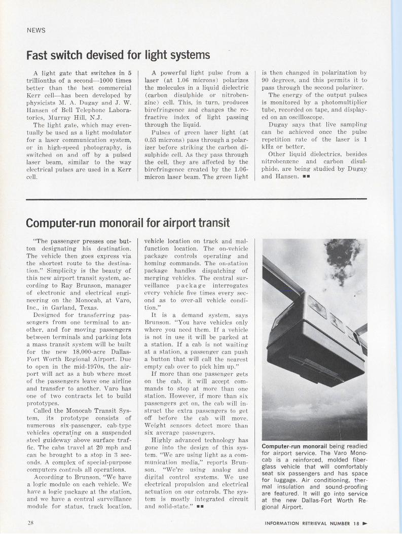
Computer-run monorail being readied for airport service. The Varo Monocab is a reinforced, molded fiberglass vehicle that will comfortably seat six passengers and has space for luggage. Air conditioning, thermal insulation and sound-proofing are featured. It will go into service at the new Dallas-Fort Worth Regional Airport .
INFORMATION RETRIEVAL NUMBER 18 ....
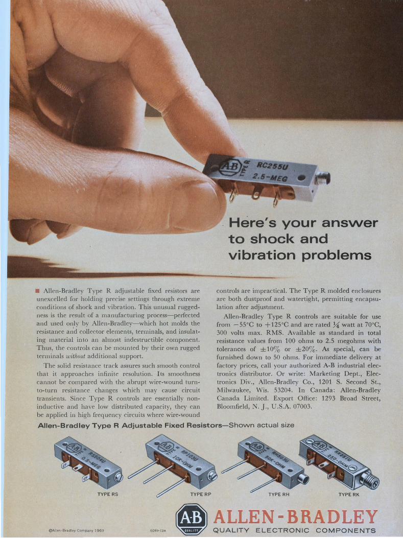
• Allen-Bradley Type R adjustable fixed resistors are unexcelled for holding precise settings through extreme conditions of shock and vibration. This unusual ruggedness is the result of a manufacturing process-perfected and used only by Allen-Bradley-which hot molds the resistance a1;d collector elements, terminals, and insulating material into an almost indestructible component. Thus, the controls can be mounted by their own rugged terminals without additional support.
The solid resistance track assures such smooth control that it approaches infinite resolution. Its smoothness cannot be compared with the abrupt wire-wound turnto-turn resistance changes which may cause circuit transients. Since Type R controls are essentially noninductive and have low distributed capacity, they can be applied in high frequency circuits where wire-wound
Here's your answer to shock and vibration problems
controls are impractical. The Type R molded enclosures are both dustproof and watertight, permitting encapsulation after adjustment.
Allen-Bradley Type R controls are suitable for use from - 55°C to + 125°C and are rated 7.;( watt at 70°C, 300 volts max. RMS. Available as standard in total resistance values from 100 ohms to 2.5 megohms with tolerances of ± 103 or ±203. As special, can be furnished down to 50 ohms. For immediate delivery at factory prices, call your authorized A-B industrial electronics distributor. Or write: Marketing Dept., Electronics Div., Allen-Bradley Co., 1201 S. Second St., Milwaukee, Wis. 53204. In Canada: Allen-Bradley Canada Limited. Export Office: 1293 Broad Street, Bloomfield, N. ]., U.S.A. 07003.
Allen-Bradley Type R Adjustable Fixed Resistors-Shown actual size
@Allen-Bradley Company 1969 EC69·12A
NEWS
Will computers eliminate the specialist? By 1980, engineering knowledge could be reduced to routine practice by complex machines
of 1980, if they are to be more than "blue-collar workers, applying canned computer programs prepared by unseen experts, wi ll have to be more artists than technicians and design with the paramount idea of service to people.
Ralph Dobriner Chief News Editor
Imagine the world of 1980 in which there are a few million computers-a thousand times faster than today's machines, and with terminals available wherever they might be needed.
A pipe dream? An entirely reasonable prediction, according to Robert Barton, professor of computer sc ience at the University of Utah . But it is a forecast that raises some important questions: Will there be engineers to man the consoles? And for that matter, what role will an engineer play?
Speaking on the uses of computers in engineering before the recent "Technology Forecast for 1980" meeting held in New York City, Barton cites the case of an acquaintance of his.
"He used computers heavily during work on his PhD in mechanical engineering, but he soon discovered that the specialized knowledge acquired during his graduate studies had been reduced to routine practi ce and been made obsolete by new computer programs then becoming available."
Supplanting the slide rule
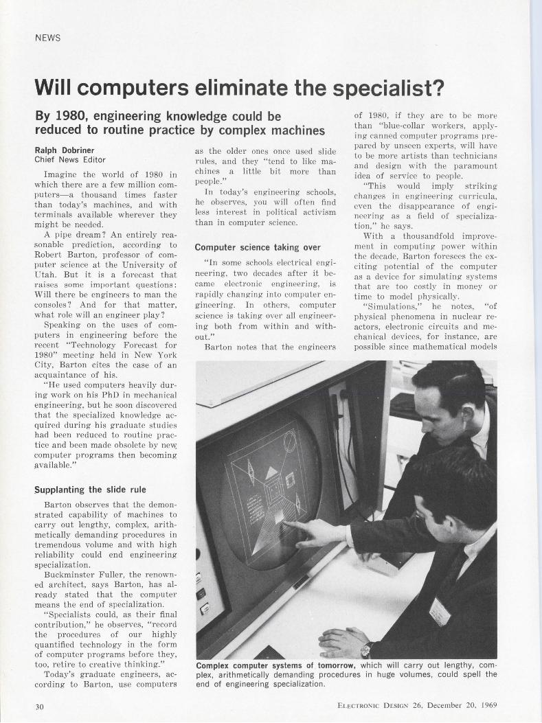
Barton observes that the demonstrated capabi li ty of machines to carry out lengthy, complex, arithmetically demanding procedures in tremendous volume and with high reliabi li ty could end engineering specialization.
Buckminster Fuller, the renowned architect, says Barton, has already stated that the computer means the end of specialization.
"Specialists could, as their final contribution," he observes, "record the procedures of our hi ghly quantified technology in the form of computer programs before they, too, retire to creative thinking."
Today's graduate engineers, according to Barton, use computers
30
as the older ones once used sli de mies, and they "tend to like machines a little bit more than people."
In today's engineering schools, he observes, you will often find less interest in political activism than in computer science.
Computer science taking over
"In some schools electrical engineering, two decades after it became electronic engineering, is rapidly changing into computer engineering. In others, computer science is taking over all engineering both from within and without."
Barton notes that the engineers
"This would imply striking changes in engineering cul'l'icu la, even the disappearance of engineering as a field of specialization," he says.
With a t housandfold improvement in computing power within the decade, Barton foresees the exciting potential of the computer as a device for simulating systems that are too costly in money or time to model physically.
"Simulations," he notes, "of phys ical phenomena in nuclear reactors, electronic circuits and mechanical devices, for instance, are possible since mathematical models
Complex computer systems of tomorrow, which will carry out lengthy, com· plex, arithmetically demanding procedures in huge volumes, could spell the end of engineering specialization .
ELECTRONIC DESIGN 26, December 20, 1969
ex ist that demand heavy computation.
" I n order to be useful in control app lications these computations must be performed at greater t han r eal-time rates. In other words, t he computation must be carr ied out at a speed that exceeds t he unfolding of the cor respondi ng physical phenomena."
The s imulated process, says Barton, w ill be obser ved perhaps by means of three-d imensional computer graphics, with dynami c mteraction fro m t he observer.
Computer graphics loom
"For t hose who tend ," says Barton, "to t hink of computer outp ut as consisting ma inly of numbers, a sampling of today's best work in computer graphics is r evealin g ."
Wi th t he predicted increase in comput ing speed by 1980, t he poss ib ilities of computer-pr oduced line drawings in motion are limit less, and so are the more r ealistic nearphotographic half -tone views of ob jects.
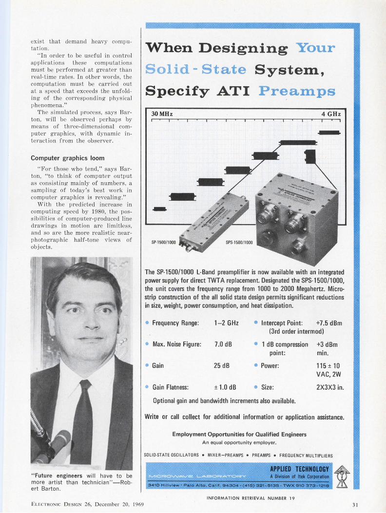
"Future engineers will have to be more artist th9n technician " -Robert Barton .
ELECTRON IC D ESIGN 26, D ecembe r 20, 1969
When Designing Your
Solid - State System,
Specify ATI Preamps
30MHz 4 GHz
.. SP-1500/1000
The SP-1500/1000 L-Band preamplifier is now available with an integrated power supply for direct TWTA replacement. Designated the SPS-1500/1000, the unit covers the frequency range from 1000 to 2000 Megahertz. Microstrip construction of the all solid state design permits significant reductions in size, weight, power consumption, and heat dissipation.
• Frequency Range: 1-2 GHz • Intercept Point: +7.5 dBm (3rd order intermod)
• Max. Noise Figure: 7.0 dB • 1 dB compression +3 dBm point: min.
• Gain 25 dB • Power: 115 ± 10 VAC, 2W
• Gain Flatness: ± 1.0 dB • Size: 2X3X3 in.
Optional gain and bandwidth increments also available.
Write or call collect for additional information or application assistance.
Employment Opportunities for Qualified Engineers An equal opportunity employer.
SOLID-STATE OSCILLATORS • MIXER-PREAMPS • PREAMPS • FREQUENCY MULTIPLIERS
APPLIED TECHNOLOGY A Division of Itek Corporation
3410 Hlllvlew •Palo Alto, Cal!f, 94304 • (415) 321-513!1 ·TWX 910 373- 1218
INFORMATION RETRIEVAL NUMBER 19
31
NEWS
(specialist, continued)
T o accomplish this would r equire development of special-purpose algorithm machines like those alr eady in wide use in geophysical calculat ions and in fast F ourier transform app licat ions. We would have to g ive up the widely held notion that ever larger generalpurpose computer s are always best ."
Programs need improvement
Along with the explos ive use of computers in the next decade, Barton sees the need for considerable improvement in programs.
It will be necessary, he says, to produce extraordinarily complex programs to do anything of s ignificance. What has been done so far in the area of programming, he notes, is "toylike."
If the engineer is reall y going to
be capable of usi ng tomorrow's computer systems as effective tools, programming has got to be made into a "communications skill."
And how do yo u go about doing that?
Barton suggests that we will have to learn to look at computer programs as the "preferred embodiment of technical knowledge."
What this means, he says, is that throughout the various specialized fi elds, programlike " lang uages" will be used to a much greater extent than they are now.
Programs must be made easy to use in a communi cations sense, Barton says-"not just easy to read, but easy to write.
"There's no language at present that is suited for this kind of thing. We have got to find ways of improving the construct ion and r eliability of computer programs, a nd one of the ways is to str ess the du al language idea."
In another two or three decades, says Barton, a good part of the
Mapping the sky at low frequencies An antenna twice as high as the
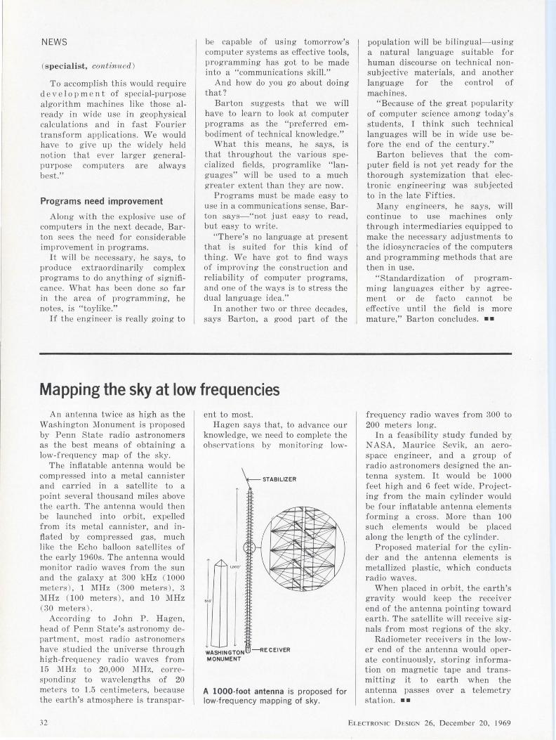
Washington Monument is proposed by Penn State radio astronomers as the best means of obtaining a low-frequency map of the sky.
The inflatable antenna wou ld be compressed into a metal cannister and carried in a satellite to a point several thousand mi les above the earth. The antenna would then be launched into orbit, expelled from its metal cannister, and infl at ed by compressed gas, much like the Echo balloon satellites of the early 1960s. The antenna would monitor radio waves from the sun and the galaxy at 300 kHz ( 1000 metcl'S ) , 1 MHz (300 mete1·s), 3 l\IHz (100 meter s), and 10 MHz ( 30 meters) .
According to J ohn P . Hagen, head of Penn State's astronomy department, most radio astronomers have studied the universe through hi gh-frequency radio waves from 15 l\IHz to 20,000 MHz, col'l'esponding to wavelengths of 20 mete rs to 1.5 centimete rs, because the earth's atmosphere is transpar-
ent to most. Hagen says that, to advance our
knowledge, we need to complete the observations by monitoring low-
l j WASHINGTON · ---RECEIVER MONUMENT
A 1000-foot antenna is proposed fo r low-frequency mapping of sky.
population will be bilingual-using a natural language suitable for human discourse on technical nonsubjective materials, and another language for the control of machines.
"Because of the great popularity of computer science among today's students, I think such technical languages will be in wide use before the end of the century."
Barton believes that the computer field is not yet ready for the thorough systemization that electronic engineering was subjected to in the late Fifties .
Many engineers, he says, will continue to use machines only through intermediaries equipped to make the necessary adjustments to the idiosyncracies of the computers and programming methods that are then in use.
"Standardization of programming languages either by agreement or de facto cannot be effective until the field is more mature," Barton concludes. • •
frequency radio waves from 300 to 200 meter s Jong.
In a feasibility study funded by NASA, Maurice Sevik, an aerospace engineer, and a group of radio astronomers designed the antenna system. It wou ld be 1000 feet hi gh and 6 feet wide. Projecting from the main cylinder would be four inflatable antenna clements forming a cross . More than 100 such elements would be placed along the length of the cylinder.
Proposed material for the cylinder and the antenna elements is metallized plastic, which conducts radio waves.
When placed in orbit, the earth's gravity would keep the receiver end of the antenna pointing toward earth. The satellite will r eceive signals from most r egions of the sky.
Radiometer receivers in the lower end of the antenna would operate continuously, storing information on magneti c tape and transmitting it to earth when the antenna passes over a telemetry station . ••
32 ELECTRON IC D ESIGN 26, December 20, 1969
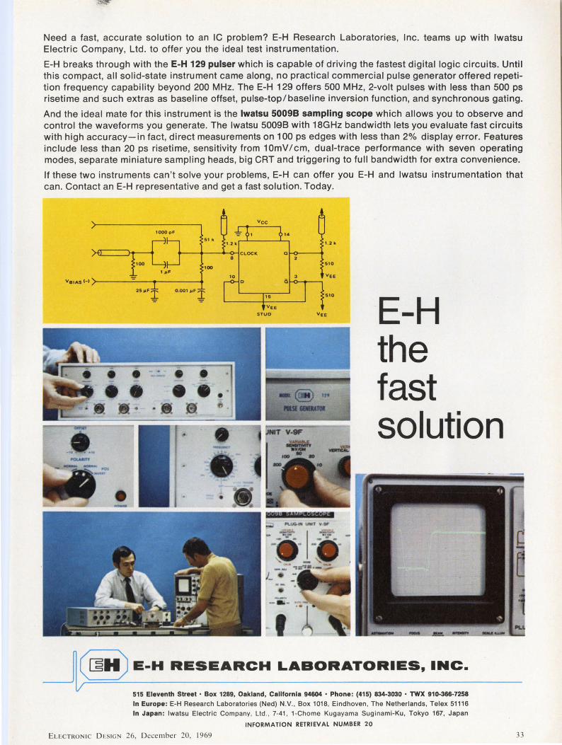
Need a fast, accurate solution to an IC problem? E-H Research Laboratories, Inc. teams up with lwatsu Electric Company, Ltd. to offer you the ideal test instrumentation.
E-H breaks through with the E-H 129 pulser which is capable of driving the fastest digital logic circuits. Until this compact, all solid-state instrument came along, no practical commercial pulse generator offered repetition frequency capability beyond 200 MHz. The E-H 129 offers 500 MHz, 2-volt pulses with less than 500 ps risetime and such extras as baseline offset, pulse-top/baseline inversion function, and synchronous gating.
And the ideal mate for this instrument is the lwatsu 50098 sampling scope which allows you to observe and control the waveforms you generate. The lwatsu 50098 with 18GHz bandwidth lets you evaluate fast circuits with high accuracy-in fact, direct measurements on 100 ps edges with less than 2% display error. Features include less than 20 ps risetime, sensitivity from 1 OmV I cm, dual-trace performance with seven operating modes, separate miniature sampling heads, big CRT and triggering to full bandwidth for extra convenience.
If these two instruments can't solve your problems, E-H can offer you E-H and lwatsu instrumentation that can. Contact an E-H representative and get a fast solution. Today.
1000 pf
51 k
~. Va1As H >------------
100
0.001 IJ.fi
8
10
15
VEE
STUD E-H the fast solution
--l ~ E-H RESEARCH LABORATORIES, INC.
515 Eleventh Street • Box 1289, Oakland, Callfornla 94604 • Phone: (415) 834-3030 • TWX 910-366-7258 In Europe: E-H Research laboratories (Ned) N.V., Box 1018, Eindhoven, The Netherlands, Telex 51116
In Japan: lwatsu Electric Company, ltd., 7-41, 1-Chome Kugayama Suginami-Ku, Tokyo 167, Japan
INFORMATION RETRIEVAL NUMBER 20
ELECTRON IC D ESIGN 26, D ecember 20, 1969 33
34
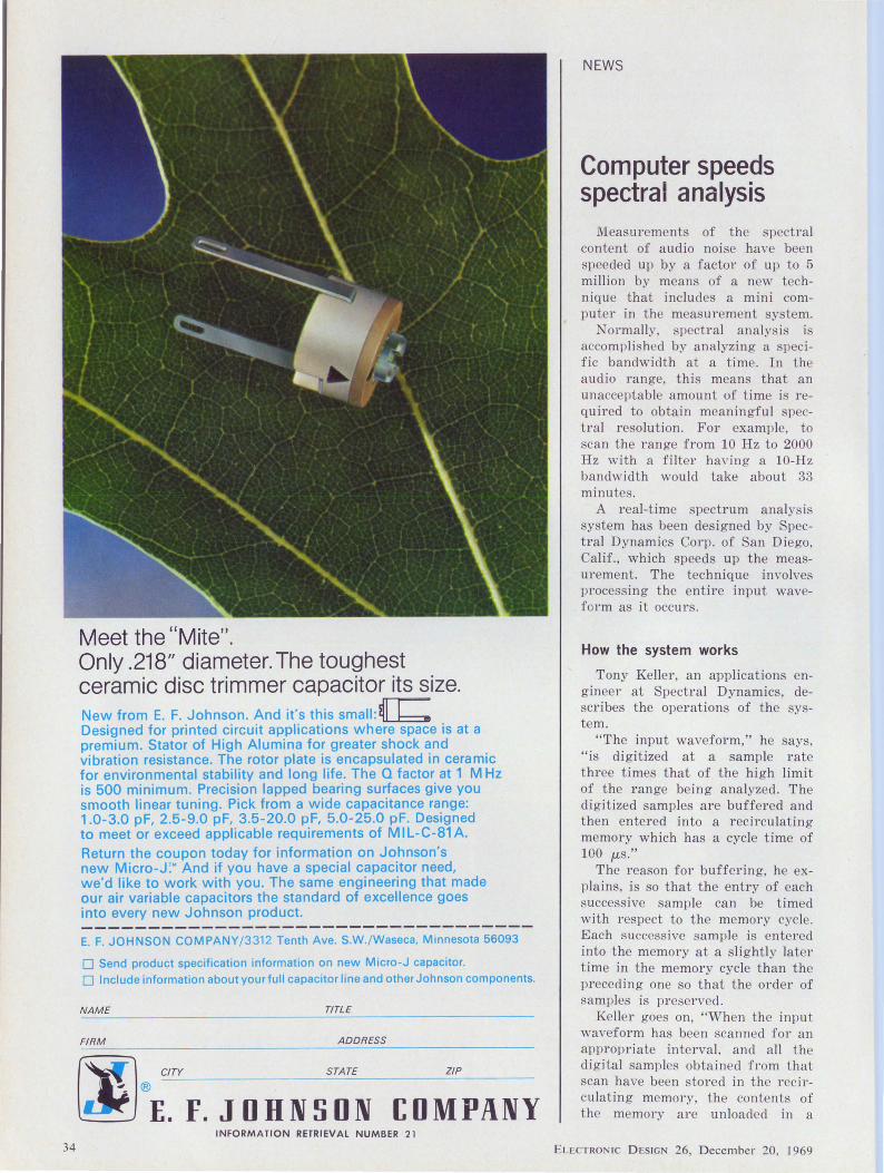
Meet the "Mite". Only .218" diameter. The toughest ceramic disc trimmer capacitor its size. New from E. F. Johnson. And it's this small: ~! b Designed for printed circuit applications where space is at a premium. Stator of High Alumina for greater shock and vibration resistance. The rotor plate is encapsulated in ceramic for environmental stability and long life. The Q factor at 1 MHz is 500 minimum. Precision lapped bearing surfaces give you smooth linear tuning. Pick from a wide capacitance range: 1.0-3.0 pF, 2.5 -9.0 pF, 3.5-20.0 pF, 5.0-25.0 pF. Designed to meet or exceed applicable requirements of MIL-C-81A. Return the coupon today for information on Johnson's new Micro-J:" And if you have a special capacitor need, we'd like to work with you. The same engineering that made our air variable capacitors the standard of excellence goes into every new Johnson product.
E. F. JOHNSON COMPANY/3312 Tenth Ave. S.W./Waseca, Minnesota 56093
O Send product specification information on new Micro-J capacitor. O Include information about yourfull capacitor line and other Johnson components.
NAME TITLE
FIRM ADDRESS
ZIP
l:OMPANY INFORMATION RETR IEVAL NUM BER 21
NEWS
Computer speeds spectral analysis
Measurements of the spectral content of audio noise have been speeded up by a factor of up to 5 million by means of a new technique that includes a mini computer in the measurement system.
Normally, spectral analysis is accomplished by analyzing a specific bandwidth at a time . In the audio range, this means that an unacceptable amount of time is required to obtain meaningful spectral resolution . For example, to scan the range from 10 Hz to 2000 Hz with a filter having a 10-Hz bandwidth would take about 33 minutes .
A real-time spectrum analysis system has been designed by Spectral Dynamics Corp. of San Diego, Calif., which speeds up the measurement. The technique involves processing the entire input waveform as it occurs.
How the system works
Tony Keller, an applications engineer at Spectral Dynamics, describes the operations of the system.
"The input waveform," he says, "is digitized at a sample rate three times that of the high limit of the range being analyzed. The digitized samples are buffered and then entered into a recircu lating memory which has a cycle time of 100 µ,s ."
The reason for buffering, he explains, is so that the entry of each successive sample can be timed with respect to the memory cycle. Each successive sample is entered into the memory at a slightly later time in the memory cycle than the preceding one so that the order of samples is preserved.
Keller goes on, "When the input waveform has been scanned for an appropriate interval, and all the digital samples obtained from that scan have been stored in the recirculating memory, the contents of the memory are unloaded in a
ELECTRONIC DESIGN 26, December 20, 1969
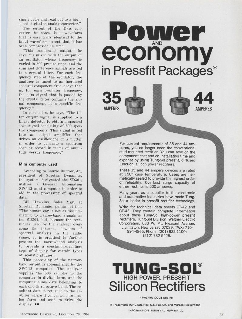
single cycle and read out to a highspeed digital-to-analog converter."
The output of the DI A converter, he notes, is a waveform that is essentially identical to the input waveform except that it has been compressed in time.
"This compressed output," he says, "is mixed with the output of an osci llator whose frequency is varied in 500 precise steps, and the sum and difference signals are fed to a crystal filter. For each frequency step of the oscillator, the analyzer is tuned to an increased spectral component frequency; that is, for each oscillator frequency, the sum signal that is passed by the cr ystal fi lter contains the signal component at a specific frequency."
In conclusion , he says, " The filter output signal is supplied to a linear detector to obtain a spectral scan s ignal consisting of 500 spectral components. This signal is fed into an output amplifier that drives an oscilloscope or a plotter in order to generate a spectrum scan or r ecord in terms of amplitude versus frequency."
Mini computer used
According to Laurie Burrow, Jr., president of Spectral Dynamics, the system, designated the SD301, utilizes a General Automation SPC-12 mini computer in order to aid in the processing of spectral data.
Bill Hawkins, Sales Mgr. at Spe~tral Dynamics, points out that "The human ear is not as discriminating to narrowband s ignals a the SD301, but, because the techniques used by the analyzer overcome the inherent slowness of spectral analysis in the audio range, it is practical to further process the narrowband analysis to provide a constant-percentage type of display for certain types of acoustic studies."
This processing of the narrowband output is accomplished by the SPC-12 computer. The analyzer supplies the 500 samples to the computer in digital fo rm, and the computer sums data belonging to each one-third octave band. The resultant data is returned to the analyzer where it converted into analog form and used to drive t he display. • •
ELECTRONIC D ESIGN 26, D ecember 20, 1969
Power AND
economy in Pres sf it Packages*
35 44 AMPERES
For current requirements of 35 and 44 amperes, you no longer need the conventional stud-mounted rectifier. You can save on the component cost and on installation time and expense by using Tung-Sol pressfit, diffused junction, silicon power rectifiers.
These 35 and 44 ampere devices are rated at 150° case temperature. Cases are hermetically sealed to provide the highest order of reliability. Overload surge capacity of either rectifier is 500 amperes.
Many years as a supplier to the electronic and automotive industries have made TungSol a leader in pressfit rectifier technology.
Write for technical data sheets CT-42 and CT-43. They contain complete information about these Tung-Sol high-power pressfit rectifiers. Tung-Sol Division, Wagner Electric Corporation, 630 W. Mt. Pleasant Avenue,
Livingston, New Jersey 07039. TWX: 710-994-4865. Phone: (201) 922-1100;
(212) 732-5426.
AMPERES
TUNG-SDI: HIGH POWER, PRESSFIT
Silicon Rectifiers *Modified D0-21 Outline
® Trademark TUNG-SOL Reg. U.S. Pat. Off, and Marcas Registradas
INFORMATION RETRIEVAL NUMBER 22
35
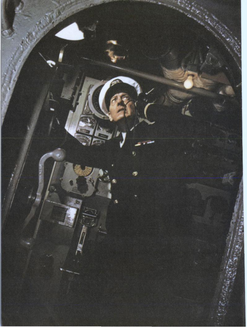
Everybody hates failures in their electronic gear. It's just that some guys hate failures a little bit more than others.
These are the guys that we try to please.
At Corning, we make our resistors and capacitors to perform like your whole system depended on them, because many times it does. We build an extra measure of performance into all our components to let you build extra reliability into the equipment you design.
Take our precision tin oxide resistors, for example. They're the best of the metal film class. Because the resistive tin film is completely oxidized and molecularly bonded to the glass substrate, our tin oxide resistors are impervious to moisture and environmental degradation. No other resistor can deliver the same stability and reliability over load life. They offer guaranteed moisture resistance across all ohmic values to set a standard of reliability that can't be matched by metal film, wire wounds, carbon comps or metal glaze resistors.
After a recent 56-day-long heat
test in an environment of extremely high humidity, our tin oxide resistors showed a resistance change of just 0.2 per cent. And in an ambient temperature test-now in its ninth year-not one of the 600 tin oxide resistors being tested has exceeded a resistance change of 1 .5 per cent.
Take our glass capacitors. The U.S. Air Force has found that our glass capacitors have much better stability and much higher insulation resistance than the ceramic, mica and the other capacitor types they tested. That's why glass capacitors are designed into so many major aerospace and missile projects.
And we've got something to offer when economy and value are the prime considerations. We've developed the Glass-Kn"' capacitor to give you the volumetric efficiency and economy of monolithic ceramic capacitors, but with the much improved stability and reiiability that only a glass dielectric can add. In resistors, our tin oxide resistors already offer long term economy over metal Alm, precision wire wound and metal glaze resistors.
INFORMATION RETRIEVAL NUMBER 23
ELECTRONIC DESIG 26, December 20, 1969
Our new C3 resistors, in addition to giving you a small case size, compete costwise with carbon comps.
Another important Corning development is the flame proof resistor. These resistors can withstand overloads of up to 100 times rated power without any trace of flame. And because they open under overload, they provide protection for the rest of the system.
At Corning we make components for guys who can't stand failures. Guys like your most important customers. Guys like you. So, next time you're designing a system, reach for your CORNING® capacitor and resistor catalogs and call your local Corning authorized distributor for off-theshelf delivery. They'll help you design-in an extra measure of performance.
If you don' t have our catalogs, ask your Corning distributor for copies or drop us a line at: Corning Glass Works, Electronic Products Division, Corning, New York 14830.
CORNING ELECTRONICS
37
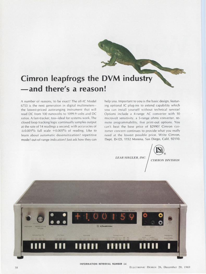
38
Cimron leapfrogs the DVM industry -and there's a reason! A number of reasons, to be exact' The all-IC Model
6753 is the next generation in digital multimetersthe lowest-priced autoranging instrument that will
read DC from 100 nanovolts to 1099.9 volts and DC
ratios. A fast-tracker, too-ideal for systems work. The
closed loop tracking logic continually samples output
at the rate of 14 readings a second, with accuracies of
±0.0010/o full scale +0.0050/o of reading. Like to
learn about automatic desensitization? repetitive
mode? out-of-range indication? Just ask how they can
help you. Important to you is the basic design, featu r
ing optional IC plug-ins to extend capability which
you can install yourself without technical service!
Options include a 4-range AC converter with 10
microvolt sensitivity, a 5-range ohms converter, re
mote programmability, five print-out options. You
can't beat the base price of $2990! Cimron customer concern continues to provide what you really
need at the lowest possible price. Write Cimron,
Dept. D-125, 1152 Morena. San Diego, Ca lif. 92110.
LEAR SIEGLER, INC. CI MRON DIVISION
- 0 - 0
INFORMATION RETRIEVAL NUMBER :£4
ELcCTRO IC DESIGN 26, December 20, 1969
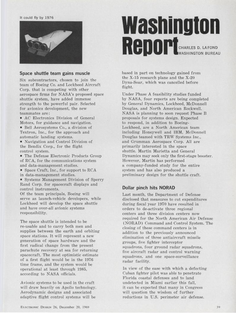
It could fly by 1976
Space shuttle team gains muscle Six subcontractors, chosen to join the team of Boeing Co. and Lockheed Aircraft Corp. that is competing with other aerospace firms for NASA's proposed space shuttle system, have added immense strength to the powerful pair. Selected for avionics development, the new teammates are: • AC Electronics Division of General Motors, for guidance and navigation. • Bell Aerosystems Co., a division of Textron, Inc., for the approach and automatic landing systems. • Navigation and Control Division of the Bendix Corp., for the flight control system. • The Defense Electronic Products Group of RCA, for the communications system and data-management studies. • Space Craft, Inc., for support to RCA in data-management studies. • Systems Management Division of Sperry Rand Corp. for spacecraft displays and control instruments. Of the team principals, Boeing will serve as launch-vehicle developers, while Lockheed will develop the space shuttle and have over-all avionic systems responsibility.
The space shuttle is intended to be re-usable and to carry both men and supplies between the earth and orbiting space stations. It will represent a new generation of space hardware and the first radical change from the present parachute recovery at sea for returning spacecraft. The most optimistic estimate of a first flight would be in the 1976 time frame, and the system would be operational at least through 1985, according to NASA officials.
Avionic systems to be used in the craft will draw heavily on Apollo technology. Aerodynamic designs and associated adaptive flight control systems will be
ELECTRONIC D ESIGN 26, D ec ember 20, 1969
Washington Rep 0 rt~~~=~~~T~NL:~:~u based in part on technology gained from the X-15 research plane and the X-20 Dyna-Soar, which was cancelled before flight.
Under Phase A feasibility studies funded by NASA, four reports are being completed by General Dynamics, Lockheed, McDonnell Douglas, and North American Rockwell. NASA is planning to soon request Phase B proposals for systems design. Expected to respond, in addition to Boeing-Lockheed, are a North American team including HoneywelJ and IBM, McDonnell Douglas teamed with TRW Systems Inc., and Grumman Aerospace Corp. AJJ are primarily interested in the space shuttle. Martin Marietta and General Dynamics may seek only the first-stage booster. However, Martin has performed a company-funded study for the entire system and has also produced a preliminary design for the shuttle craft.
Dollar pinch hits NORAD Last month, the Department of Defense disclosed that measures to cut expenditures during fiscal year 1970 have resulted in orders to de-activate three regional centers and three division centers now required for the North American Air Defense (NORAD) Command and Control System. The closing of these command centers is in addition to the previously announced elimination of three antiaircraft missile groups, five fighter interceptor squadrons, four ground radar squadrons, five aircraft radar and control warning squadrons, and one space-surveillance radar facility.
In view of the ease with which a defecting Cuban fighter pilot was able to penetrate Florida coastal defenses and to land undetected in Miami earlier this fall, it can be expected that many in Congress will question the wisdom of further reductions in U.S. perimeter air defense.
39
Washington R8DOrlcoNr1NuEo
The Pentagon says that upon a recent agreement between Canadian military leaders and NORAD Headquarters, the entire Command and Control System has been realigned. This combines the functions of the previous Air Defense Divisions with those of the Air Defense Regions and establishes seven regional commands within Canada and the Continental U.S.
NORAD says that the new configuration will employ command and control facilities already in place. Each new Air Defense Region has a control center for the deployment and direction of intercept missiles and aircraft, and each is provided with two Back-up Interceptor Control System control centers.
Can systems study revitalize D.C.? Our nation's capital is no model for urban development, and RCA president Robert W. Sarnoff pointed this out in an address to the Fourth Annual Computer Age Conference of the National Industrial Conference Board in New York City. He proposed a massive pilot program to apply a systems approach to revitalizing Washington, D.C.
"The time has come," he said, "for a demonstration project to determine whether the techniques that have succeeded in other fields can be applied to the urban and environmental crises." To ensure the program's completion, he recommended that Congress authorize at the outset total funding and phase appropriations annually.
The pilot program, Sarnoff proposed, should involve all elements including housing, transportation, communications, law enforcement and environmental control. The effort should go beyond physical planning for city regeneration and include the study of interacting problem~ by applying advanced techniques of operations research, system analysis, model building, simulation and long-range planning.
40
"As the program progressed, it would provide an immense inventory of new knowledge and new methods that could be applied to other beleaguered cities across the nation," Sarnoff asserted.
The first part of the program, he suggested, might be scheduled for completion in 1976 to coincide with the celebration of the country's 200th anniversary.
"The capital belongs to all our people," he declared. "A comprehensive systems effort to revitalize the city and its environs should invoke a nationwide response."
Sky-high rocket price may drop High-altitude instrumented meteorological rockets have been priced as high as they soar, but now, because of some Navyfunded research, a relatively simple craft requiring simplified launch facilities may be in the offing.
At present, multistaged rockets that reach altitudes above 400,000 feet-where the rarity of the atmosphere and the immense overview of the earth are invaluable to the meteorologist--approach six figures in cost.
Now a vehicle under development by The United Technology Center, a division of United Aircraft Corp., looks good in preliminary design, and the Navy is funding construction of several flight test craft. Measuring only 10 feet in length by 6-1/ 2 inches in diameter, it can be launched from an inclined rail.
Appropriately dubbed Kangaroo, the rocket has its second stage and its instrumented payload "pouched" within the first stage. The canister making up the payload will be instrumented to measure cosmic rays and solar radiation, concentrations of charged particles, and the frequency of micrometeoroid impacts. Such data, when telemetered to the earth, will be applied to the study of broad-area weather conditions, early warning of embryonic storm generation, and will also assist in the forecast of natural radio interference. The Kangaroo will be tested by the Navy from the Pacific Missile Range in California.
INFORMATION RETRIEVAL NUMBER 25 ._
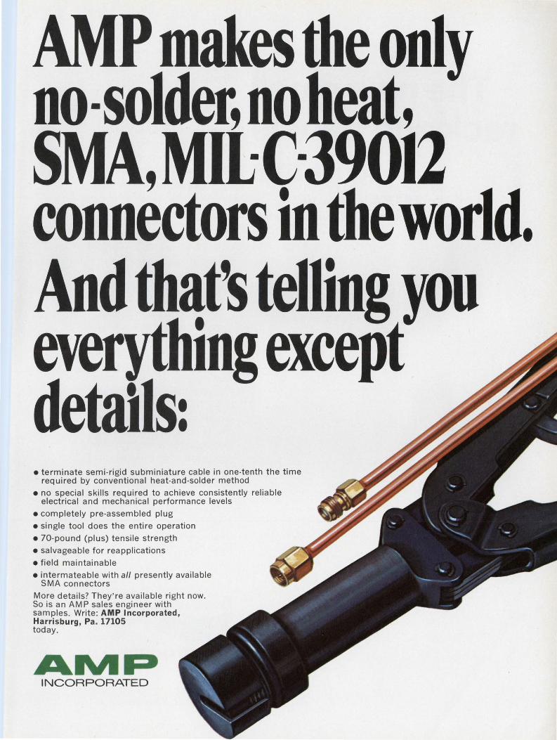
P makes the only no-solder, no heat, SMA,Mil:C-39012 connectors in the world. And that's telling you everything except details: • terminate semi-rigid subminiature cable in one-tenth the time
required by conventional heat-and-solder method • no special skills required to achieve consistently reliable
electrical and mechanical performance levels
• completely pre-assembled plug
• single tool does the entire operation
• 70-pound (plus) tensile strength
• salvageable for reapplications
• field maintainable • intermateable with a// presently available
SMA connectors
More details? They're available right now. So is an AMP sales engineer with samples. Write: AMP Incorporated, Harrisburg, Pa. 17105 today.
AIVIP INCORPORATED
The new small rack and panels
with the big difference.
Bendix is the difference. The difference in distribution,
delivery and supply. The difference that means you can get the rack and panels you need when you need them.
A big difference. A big advantage. But there are others. Bendix Regal B subminiatures are built to MIL-C-24308. Application potentials are practically unlimited. Use them in switching circuits, computers, business machines. In industrial equipment, communications, test equipment. And in rack and panel modular or printed circuit technology.
The selection of mounting options is just about endless, too. Choose from among .120 or .154-inch diameter, straightthrough holes, clinch nuts, float mounts, lock posts, plain flange and through - bulkhead types. Neoprene spacers or grommets. And solder or printed circuits. Even a crimp version with rear-release contacts comes in a variety of shell sizes and mounting configurations. All interchangeable with exist ing rack and panel connectors.
For more details, write: The Bendix Corporation, Electrical Components Division, Sidney, New York 1 3838.
Electronics
INFORMATION RETRIEVAL NUMBER 26
ELECTRONIC Ol:SIGN 26, December 20. 1969

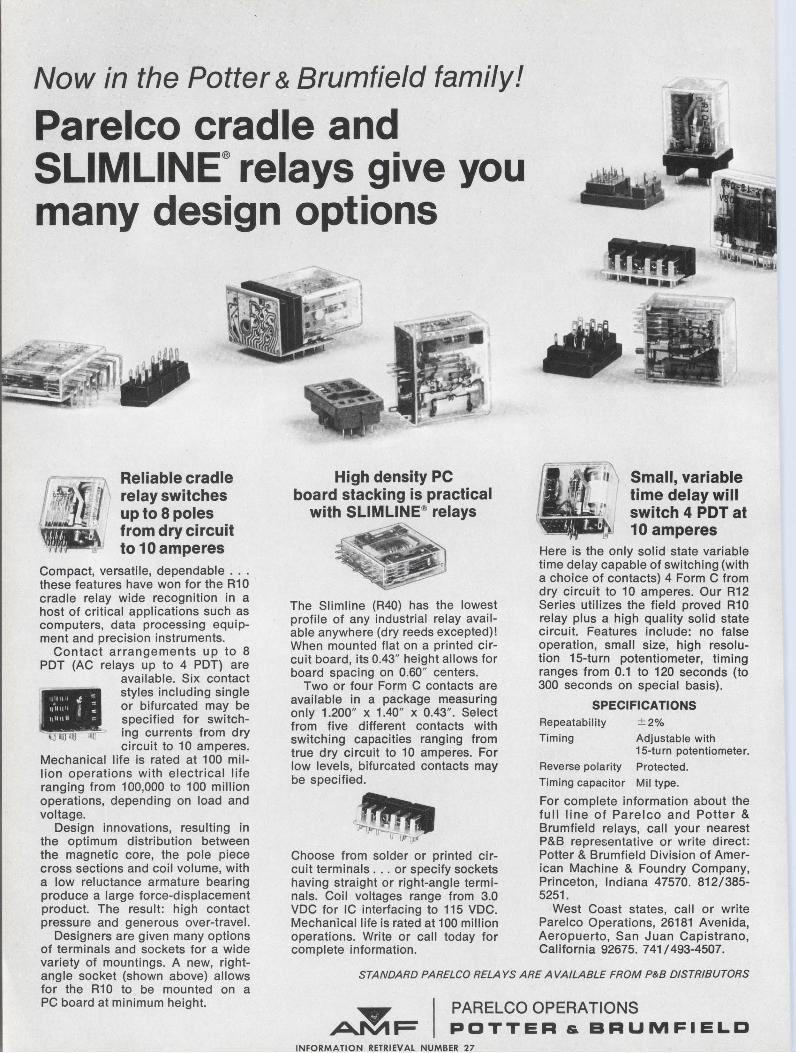
Now in the Potter & Brumfield family!
Parelco cradle and SLIMLINE® relays give you many design options
Reliable cradle relay switches up to 8 poles from dry circuit to 1 O amperes
Compact, versatile, dependable ... these features have won for the R10 cradle relay wide recognition in a host of critical applications such as computers, data processing equipment and precision instruments.
Contact arrangements up to 8 PDT (AC relays up to 4 PDT) are
available. Six contact
•
styles including single or bifurcated may be specified for switch
llUI •llll ]r ing currents from dry circuit to 10 amperes.
Mechanical life is rated at 100 million operations with electrical l ife ranging from 100,000 to 100 million operations, depending on load and voltage.
Design innovations, resulting in the optimum distribution between the magnetic core, the pole piece cross sections and coil volume, with a low reluctance armature bearing produce a large force-displacement product. The result : high contact pressure and generous over-travel.
High density PC board stacking is practical
with SLIMLINE® relays
The Slimline (R40) has the lowest profile of any industrial relay available anywhere (dry reeds excepted)! When mounted flat on a printed circuit board, its 0.43" height allows for board spacing on 0.60" centers.
Two or tour Form C contacts are available in a package measuring only 1.200" x 1.40" x 0.43" . Select from five different contacts with switching capacities ranging from true dry circuit to 10 amperes. For low levels, bifurcated contacts may be specified.
Choose from solder or printed circuit terminals .. . or specify sockets having straight or right-angle terminals. Coil voltages range from 3.0 VDC for IC interfacing to 115 VDC. Mechanical life is rated at 100 million operations. Write or call today for complete information.
Small, variable time delay will switch 4 PDT at 10 amperes
Here is the only solid state variable time delay capable of switching (with a choice of contacts) 4 Form C from dry circuit to 10 amperes. Our R12 Series utilizes the field proved R10 relay plus a high quality solid state circuit. Features include: no false operation, small size, high resolution 15-turn potentiometer, timing ranges from 0.1 to 120 seconds (to 300 seconds on special basis).
SPECIFICATIONS Repeatability ± 2%
Timing Adjustable with 15-turn potentiometer.
Reverse polarity Protected.
Timing capacitor Mil type.
For complete information about the full line of Parelco and Potter & Brumfield relays, call your nearest P&B representative or write direct: Potter & Brumfield Division of American Machine & Foundry Company, Princeton, Indiana 47570. 812/385-5251.
West Coast states, call or write Parelco Operations, 26181 Avenida, Aeropuerto, San Juan Capistrano, California 92675. 741/493-4507.
Designers are given many options of terminals and sockets tor a wide variety of mountings. A new, rightangle socket (shown above) allows for the R10 to be mounted on a PC board at minimum height.
STANDARD PARELCO RELAYS ARE AVAILABLE FROM P&B DISTRIBUTORS
~ I PARELCO OPERATIONS .Afi\llF POTTER & BRUMFIELD
INFORMATION RETRIEVAL NUMBER 27
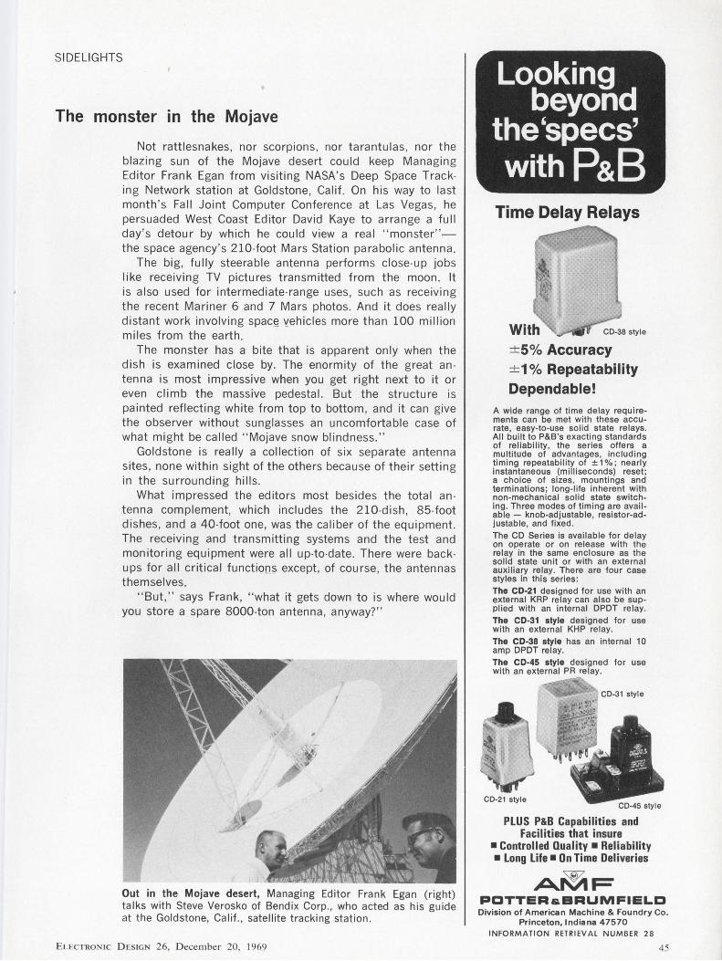
SIDELIGHTS
The monster m the Mojave
Not rattlesnakes, nor scorpions, nor tarantulas , nor the blazing sun of the Mojave desert could keep Managing Editor Frank Egan from visiting NASA's Deep Space Tracking Network station at Goldstone, Calif. On his way to last month 's Fall Joint Computer Conference at Las Vegas, he persuaded West Coast Editor David Kaye to arrange a full day's detour by which he could view a real " monster" the space agency 's 210-foot Mars Station parabolic antenna.
The big , fully steerable antenna performs close-up jobs like receiving TV pictures transmitted from the moon. It is also used for intermediate-range uses, such as receiving the recent Mariner 6 and 7 Mars photos. And it does really distant work involving spac(2 yehicles more than 100 million miles from the earth.
The monster has a bite that is apparent only when the dish is examined close by. The enormity of the great antenna is most impressive when you get right next to it or even climb the massive pedestal. But the structure is painted reflecting white from top to bottom , and it can give the observer without sunglasses an uncomfortable case of what might be called " Mojave snow blindness. "
Goldstone is really a collection of six separate antenna sites , none within sight of the others because of their setting in the surrounding hills.
What impressed the editors most besides the total an tenna complement, which includes the 210-dish , 85-foot dishes, and a 40-foot one, was the caliber of the equipment. The receiving and transmitting systems and the test and monitoring equipment were all up-to-date. There were backups for all critical function;; except , of course, the antennas themselves.
" But," says Frank, " what it gets down to is where would you store a spare 8000-ton antenna , anyway? "
Out in the Mojave desert, Managing Editor Frank Egan (right) talks with Steve Verosko of Bendix Corp., who acted as his guide at the Goldstone, Calif ., satellite tracking station .
ELECTRON IC D ESIGN 26, D ecember 20, 1969
Looking beyond
the'specs' with P&B
Time Delay Relays
+ 5% Accuracy + 1 % Repeatability Dependable!
A wide range of time de lay requirements can be met with these accurate, easy-to-use solid state relays. All built to P&B 's exacting standards of reliability, the series offers a multitude of advantages, including timing repeatability of ± 1 % ; nearly instantaneous (milliseconds) reset ; a choice of sizes, mountings and terminations; long-life inherent with non-mechanical solid state switching . Three modes of timing are available - knob-adjustable , resistor-adjustable, and fixed. The CD Series is available for delay on operate or on release with the relay in the same enclosure as the sol id state un it or with an external auxiliary relay. There are four case styles in this series: The CD-21 designed for use with an external KRP relay can also be suppl ied with an internal DPDT relay. The CD-31 style designed for use with an external KHP relay. The CD-38 style has an internal 10 amp DPDT relay. The CD-45 style designed for use with an external PR relay.
PLUS P&B Capabilities and Facilities that insure
•Controlled Quality • Reliability • Long Life• On Time Deliveries
A~F PCTTERs.BRUMFl·ELD Division of American Machine & Foundry Co.
Princeton, Indiana 47570 INFORMATION RETRIEVAL NUMBER 28
45
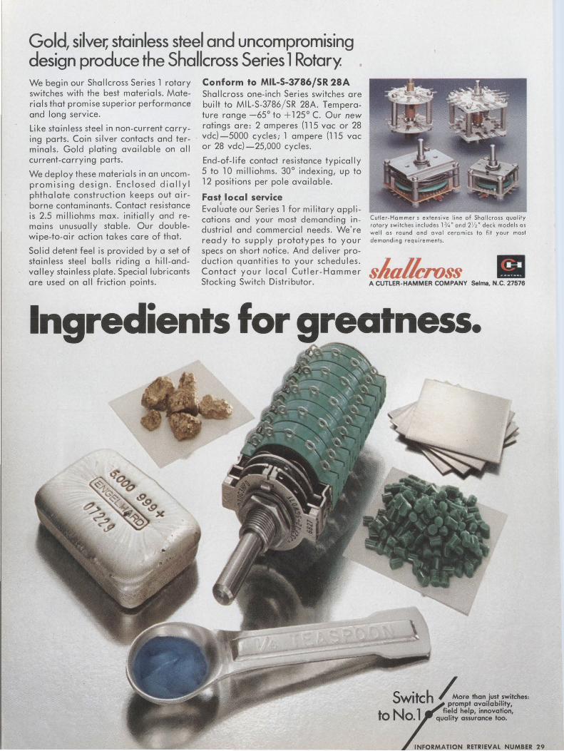
Gold, silver, stainless steel and uncompromising design produce the Shallcross Series 1 Rotary We begin our Shallcross Series l rotary switches with the best materials. Materials that promise superior performance' and long service.
Like stainless steel in non-current carrying parts. Coin si Iver contacts and terminals. Gold plating available on all current-carrying parts.
We deploy these materials in an uncompromising design. Enclosed dial I yl phthalate construction keeps out airborne contaminants. Contact resistance is 2.5 milliohms max. initially and remains unusually stable. Our doublewipe-to-air action takes care of that.
Solid detent feel is provided by a set of stainless steel balls riding a hill-andvalley stainless plate. Special lubricants are used on all friction points.
Conform to MIL-S-3786/SR 28A Shallcross one-inch Series switches are built to MIL-S-3786/ SR 28A. Temperature range -65° to + 125° C. Our new ratings are: 2 amperes (115 vac or 28 vdc)-5000 cycles; l ampere (115 voe or 28 vdc)-25,000 cycles.
End-of-life contact resistance typically 5 to l 0 milliohms. 30° indexing, up to 12 positions per pole available.
Fast local service Eval~ate our Series l for military applications and your most demanding industrial and commercial needs. We're ready to supply prototypes to your specs on short notice. And deliver production quantities to your schedules. Contact your local Cutler-Hammer Stocking Switch Distributor.
Cutler-Hommer s extensive line of Shallcross quality rotary switches includes l'l4" and 2 Y2" deck models as well as round and oval ceramics to fit your most demanding requirements.
s"alleross • A CUTLER-HAMMER COMPANY Selma, N.C. 27576
Ingredients for greatness.
Switch hore than.just. ~witches : prompt ava1lab1l1ty,
to No 1 fie.Id help, innovation, • quality assurance too.
INFORMATION RETRIEVAL NUMBER 29
Publisher Hugh R. Roome
Editor Howard Bierman
Managing Editor Frank Egan
Technical Editors Milton J. Lowenstein Charles G. Marrara Don Mennie Michael J. Riezenman Raymond D. Speer
Management Editor Richard L. Turmail
News Editors Ralph Dobriner, Chief John N. Kessler
Washington News Bureau Charles D. Lafond, Chief
Military-Aerospace Editor John F. Mason
East Coast Editor Jim McDermott
West Coast Edit.ors Elizabeth deAtley David N. Kaye
New. Products Editors Lucinda Mattera Roger Allan
Directory Manager Greg Guercio
Copy Editor Marion Allen
Editorial Production Dollie S. Viebig Richard D. Grissom
Art Director Clifford M. Gardiner
Art Assistant William Kelly
Technical Illustrators Rita Jendrzejewski Lynn E. Thompson JoJo Miskimmon
Production Manager Thomas V. Sedita
Asst. Production Manager Helen De Polo
Production Assistants Bernard Wolinsky Kathleen Mcconkey
Circulation Manager Nancy L. Merritt
Information Retrieval Genate Piccinetti
Eu:CTRON IC D1:SIGN 26, Decembe r 20. 1969
EDITORIAL
We could shun controversy, but wouldn't it be deadly?
Several days ago an engineering manager from a. West Coast company dropped in to discuss this magazine's editorial needs and objectives, with the intent of starting an article-writing program for his staff when he returned. When the discussion was over, he leaned back in his chair, lit a cigarette and commented: "By the way, I read your magazine regularly and find it very useful and interesting."
"Fine," I answered, "we enjoy compliments. But what don't you like? Anything annoying come to mind?"
My guest abandoned his relaxed position, meditated for a brief moment and then blurted out: "Yes, as a matter of fact, I take exception to some of the editorials you publish. Shouldn't you confine your views solely to the technical area of the electronics industry rather than tackle issues that are not directly related to the design engineer?"
He wasn't questioning the pertinence of editorials on such topics as a domestic satellite program decision by the FCC, or the need to apply the nation's technical resources to control pollution and other urban problems, or the benefits awaiting design engineers who become more involved with computer-aided design.
But why, my visitor wondered-as some of you may havedo we get involved with campus unrest, automobile safety standards or the pros and cons of an engineering union? And why should we gamble on antagonizing readers by asking them if they are cry-babies on the job or really mistreated engineers?
The answer: We believe our readers are alert humans and citizens first, engineers second. Editorials in the nation's newspapers, consumer magazines and business press are calling for increased involvement in all aspects of our daily life, not merely in the narrow specialty of our work or our local neighborhood. When timely topics related to engineering come up and lend themselves to editorial interpretation, we do our best to get the facts and take a position. We invite direct participation by readers sometimes. But we keep our opinions on the editorial page. The rest of the magazine is concerned with gathering the facts and presenting them as objectively as possible.
Maybe you don't agree with all of our opinions. You hold the final card. If you don't like our editorials, you can always write your own. We'll be happy to publish your comments too-in the Letters to the Editor section.
When your letters come in, applauding our position or denouncing a stand we took, we're human. We love the applause; we wince at the barbs. But both forms of comment make us aware that the editorial page is not being ignored. Silence in this case is not golden.
How ARD BIERMAN
47
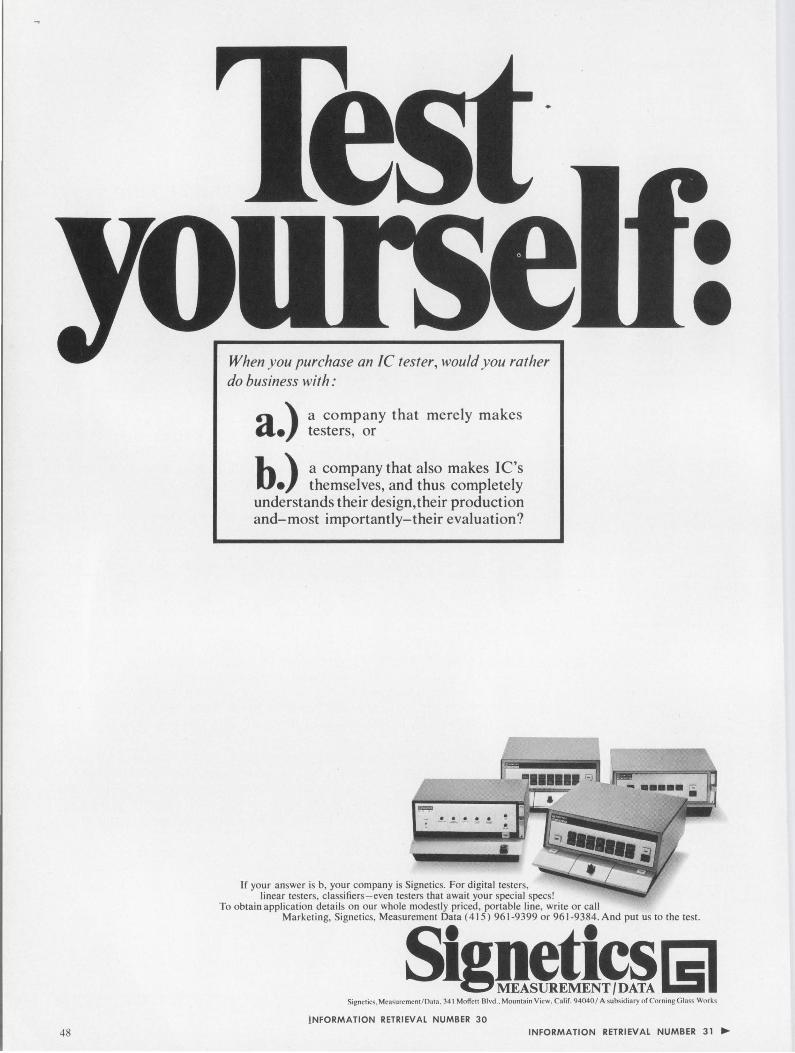
48
When you purchase an IC tester, would you rather do business with:
a company that merely makes testers, or a.)
b.) a company that also makes I C's themselves, and thus completely
understands their design, their production and-most importantly-their evaluation?
I
If your answer is b, your company is Signetics. For digital testers, linear testers, classifiers - even testers that await your special specs!
To obtain application details on our whole modestly priced, portable line, write or call Marketing, Signetics, Measurement Data ( 415) 961-9399 or 961-9384. And put us to the test.
Sigg~tl~~ISI Signctics. Mca~urcmcn1 /Da1a , 341 Moffct1 Blvd .. Mountain View. CaliL 94040 / A subsidiary of Co rning Glass Work~
!NFORMATION RETRIEVAL NUMBER 30 INFORMATION RETRIEVAL NUMBER 31 ....
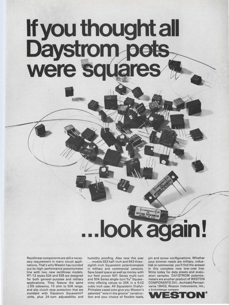
If you thought all Da ro were
•
•••
Rectilinear components are still a necessary requirement in many circuit applications. That's why Weston has rounded out its high-performance potentiometer line with two new rectilinear models. RT-12 styles 534 and 535 are designed for both general-purpose and military applications. They feature the same ± 5% tolerance, 10 ohm to 50K range, and slip clutch stop protection that are standard with Daystrom Squaretrim® units, plus 24-turn adjustability and
humidity proofing. Also new this year . .. models 553 half-inch and 543 threeeighth-inch Squaretrim potentiometers in military and commercial versions. Save board space as well as money with our field proven 501 Series multi-turn and 504 Series single-turn 'Vis" Squaretrims offering values to 20K in a 0.02 cubic inch case. All Squaretrim DiallylPhthalate cased pots give you Weston's patented "wire in the groove" construction and your choice of flexible leads,
pin and screw configurations. Whether your trimmer needs are military, industrial or commercial, you'll find the answer in this complete new low-cost line. Write today for data sheets and evaluation samples. DAYSTROM potentiometers are another product of WESTON COMPONENTS DIV., Archbald, Pennsylvania 18403, Weston Instruments, Inc., a Schlumberger company
WES ...... 10 .... N®
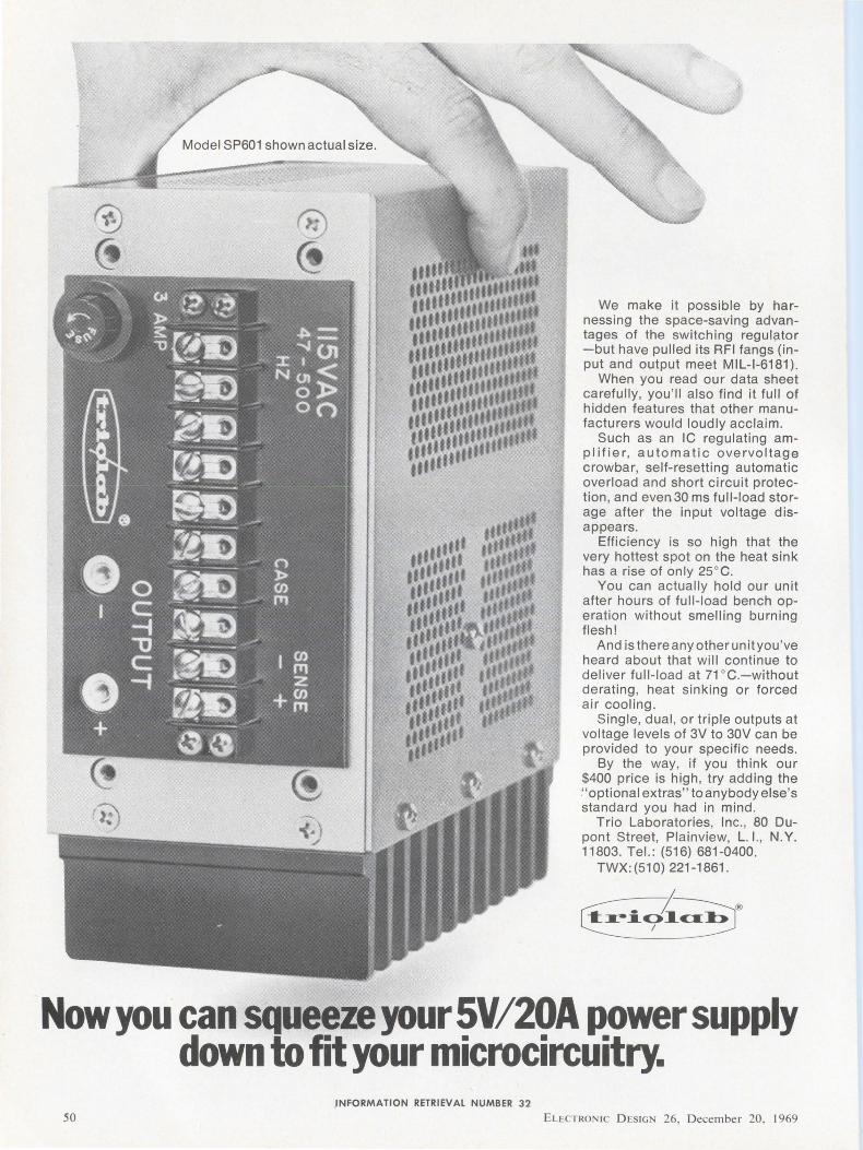
Model SP601 shown actual size.
•••• ••••• ••• , ......... .. ••••••••• •••••••••• tf ......
••••••• •••••••• •••••••••• ••'' .... •••••••••• , ... ,, .. •••••••••• ••••
We make it possible by harnessing the space-saving advantages of the switching regul?tor -but have pulled its RFI fangs (input and output meet MIL-1-6181 ).
When you read our data sheet carefully , you 'll also find it full of hidden features that other manufacturers would loudly acclaim .
Such as an IC regulating amplifier, automatic overvoltage crowbar, self-resetting automatic overload and short circuit protection, and even 30 ms full-load storage after the input voltage disappears.
Efficiency is so high that the very hottest spot on the heat sink has a rise of only 25°C.
You can actually hold our unit after hours of full-load bench operation without smelling burning flesh!
And is there any other unit you 've heard about that will continue to deliver full-load at 71 °C.-without derating, heat sinking or forced air cooling.
Single, dual , or triple outputs at voltage levels of 3V to 30V can be provided to your specific needs.
By the way, if you think our $400 price is high, try adding the ~· optional extras" to anybody else 's standard you had in mind .
Trio Laboratories, Inc., 80 Dupont Street, Plainview, L. I., N. Y. 11803. Tel.: (516) 681-0400.
TWX:(510) 221-1861 .
Now you can squeeze your SV/20A power supply down to fit your microcircuitry .
. INFORMATION RETRIEVAL NUMBER 32
50 ELl:CTRON IC D ESIGN 26, D ecember 20, 1969
in all Helipot Cermet Trimmers This significant advance in Helipot's cermet technology is now available at only a dime/unit more ... 100 ohms thru 2 megohms. In addition, you get essentially infinite resolution, environmental stability, reliability, no catastrophic failures- all superior to wirewound trimmers. We'll also deliver offthe-shelf , locally stocked trimmers with a standard tempco of ±100 ppm/ °C in the 100 ohm thru 2 megohm range.
Beckman
INSTRUMENTS, INC.
HELIPOT DIVISION FULLERTON, CALIFORN IA• 92634
INTERNATIONAL SUBSIOIARIES: AMSTERDAM; CAPE TOWN, GENEVA; GLENROlHES. SCOTLAND; LONDON; MDICO CITY; MUNICH; PARIS; STOCKHOLM; TOKYO; VIENNA
INFORMATION RETRIEVAL NUMBER 33
ELECTRON IC D ESIGN 26, D ecember 20, 1969 51
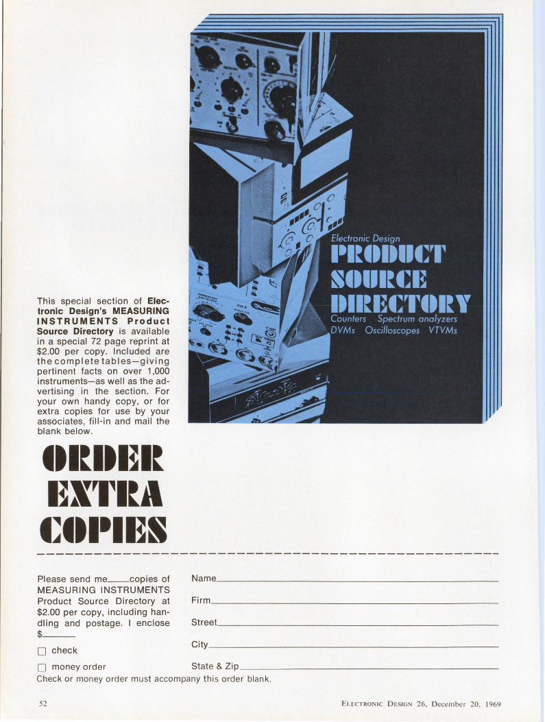
This special section of Electronic Design's MEASURING INSTRUMENTS Product Source Directory is available in a special 72 page reprint at $2.00 per copy. Included are the complete tables-giving pertinent facts on over 1,000 instruments-as well as the advertising in the section. For your own handy copy, or for extra copies for use by your associates, fill-in and mail the blank below.
tll~ltl~I~ l~X'l~l~A
t~tll111~S Please send me __ copies of MEASURING INSTRUMENTS Product Source Directory at $2.00 per copy, including handling and postage. I enclose $ __
D check
D money order
Firm ________________________ _
Street ________________________ _
City _ ________________________ _
State & Zip _ _ ____________________ _
Check or money order must accompany this order blank.
52 E LECTRON IC D ES IGN 26 , Decembe r 20. 1969
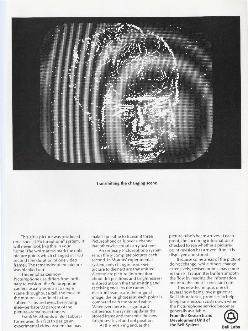
This girl's picture was produced on a special Picturephone® system; it will never look like this in your home. The white areas mark the only picture points which changed in 1/ 30 second (the duration of one video frame). The remainder of the picture was blanked out.
This emphasizes how Picturephone use differs from ordinary television : the Picturephone camera usually points at a single scene throughout a call and most of the motion is confined to the subject's lips and eyes. Everything else-perhaps 90 percent of the picture-remains stationary.
Frank W . Mounts of Bell Laboratories used this fact to design an experimental video system that may
Transmitting the changing scene
make it possible to transmit three Picturephone calls over a channel that otherwise could carry just one.
An ordinary Picturephone system sends thirty complete pictures each second . In Mounts' experimental system, only changes from one picture to the next are transmitted . A complete picture (information about dot positions and brightnesses) is stored at both the transmitting and receiving ends. As the camera's electron beam scans the original image, the brightness at each point is compared with the stored value. Whenever there is a significant difference, the system updates the stored frame and transmits the new brightness level and dot position.
At the receiving end, as the
picture tube's beam arrives at each point, the incoming information is checked to see whether a picturepoint revision has arrived. If so, it is displayed and stored .
Because some areas of the picture do not change, while others change extensively, revised points may come in bursts. Transmitter buffers smooth the flow by reading the information out onto the line at a constant rate.
This new technique, one of several now being investigated at Bell Laboratories, promises to help keep transmission costs down when the Picturephone service becomes generally available. @ From the Research and Development Unit of the Bell System- Bell Labs
Buckbee-Mears etches metal on glass masters that can be used and reused and reused ...
We call them the Unscratchables.
Up to now the only kind of glass master available for tooling had an emulsion coating that usually scratched after one or two uses. Costs to replace these emulsion masters were extremely high, and the production downtime to change masters was equally expensive.
Buckbee-Mears scientists have solved this problem by creating a way to etch metal on glass. Our metal on glass masters can be used over and over. The danger of scratching is eliminated.
The metals we etch include chrome, Ni-200 and copper. Copper on glass masters can be produced in sizes up to 24" x 32". Chrome and Ni-200 masters are available in a 2" x 2" size or smaller.
Buckbee-Mears will produce chrome or nickel masks to your specifications with tolerances of ± two microns on
• .. ... ..... ~-----~ .. ::::::: •..•...•. ........• ........• .......•. ..•.....• .•......• .......•. ..•.•.... .....•... ...•..•.. .......•. ..... ...
any line width or on-center measurement. Small copper on glass masters can be etched to ±.0005" (line widths up to ± .002" on large masters). On-center specifications for small size masters are ± two microns; ±.0005" for large size masters.
Buckbee-Mears' new metal on glass masters can be used in a variety of production situations where a photomechanical operation is involved, including printed circuits, semiconductors, integrated circuits and photoetching.
Solving your problems through improved photomechanical production techniques is our business. Buckbee-Mears has the most complete photoetching capabilities in the world.
For more information, call or write Bill Amundson, industrial sales manager. Phone 612-227-6371.
l~5'SmlON METAcl AND GLASS ETCHING • ELECTRO FORMING • AUTOMATED DESIGN
•« BUCKBEE-MEARS COMPANY SAINT PAUL, MINNESOTA 55101
INFORMATION RETRIEVAL NUMBER 35
54 ELECTRONIC D ESIGN 26, December 20. 1969
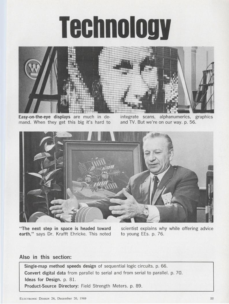
Techno1ou1
-. Easy-on-the-eye displays are much in demand. When they get this big it's hard to
integrate scans, alphanumerics, graphics and TV. But we're on our way. p. 56.
"The next step in space is headed toward earth," says Dr. Krafft Ehricke. This noted
scientist explains why while offering advice to young EEs. p. 76.
Also in this section:
Single-map method speeds design of sequential logic circuits. p. 66.
Convert digital data from parallel to serial and from serial to parallel. p. 70.
Ideas for Design. p. 81.
Product-Source Directory: Field Strength Meters. p. 89.
ELECTRONIC D ESIGN 26, December 20, 1969 55
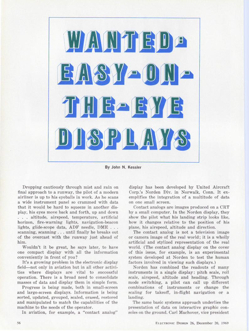
l[Jllllil\11 By John N. Kessler
Dropping cautiously through mist and rain on final approach to a runway, the pilot of a modern airliner is up to his eyeballs in work. As he scans a wide instrument panel so crammed with data that it would be hard to squeeze in another display, his eyes move back and forth, up and down . . . altitude, airspeed, temperature, artificial horizon, fire-warning lights, navigation-beacon lights, glide-scope data, ADF needle, DME ... scanning, scanning ... until finally he breaks out of the overcast with the runway just ahead of him.
Wouldn't it be great, he says later, to have one compact display with all the information conveniently in front of you?
It's a growing problem in the electronic diRplay field-not only in aviation but in all other activities where displays are vital to successful operation. There is a broad need to consolidate masses of data and display them in simple form.
Progress is being made, both in small-screen and large-screen displays. Information is being sorted, updated, grouped, ·scaled, erased, restored and manipulated to match the capabilities of the machine to the needs of the operator.
In aviation, for example, a "contact analog"
56
display has been developed by United Aircraft Corp.'s Norden Div. in Norwalk, Conn. It exemplifies the integration of a multitude of data on one small screen.
Contact analogs are images produced on a CRT by a small computer. In the Norden display, they show the pilot what his landing strip looks like, how it changes relative to the position of his plane, his airspeed, altitude and direction.
The contact analog is not a television image or camera image of the real world; it is a wholly artificial and stylized representation of the real world. (The contact analog display on the cover of this issue, for example, is an experimental system developed at Norden to test the human factors involved in viewing such displays.)
Norden has combined the readouts of many instruments in a single display: pitch scale, roll scale, airspeed, altitude and heading. Through mode switching, a pilot can call up different combinations of instruments or change the scaling for takeoff, in-flight navigation or a landing.
The same basic systems approach underlies the presentation of data on interactive graphic consoles on the ground. Carl Machover, vice president
ELECTRONIC DESIGN 26, December 20, 1969
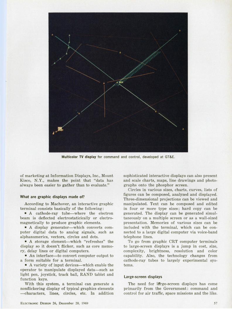
Multicolor TV display for command and control, developed at GT&E.
of marketing at Information Displays, Inc., Mount Kisco, N.Y., makes the point that "data has always been easier t o gather than to evaluate."
What are graphic displays made of?
According to Machover, an interactive graphic terminal consists basically of the following:
• A cathode-ray tube-where the electron beam is deflected electrostaticically or electromagnetically to produce graphic elements.
• A display generator-which converts computer digital data to analog signals, such as alphanumerics, vectors, circles and dots.
• A storage element--which "refreshes" the display so it doesn't fl icker, such as core memory, delay lines or digital computers.
• An interface-to convert computer output to a form suitable for a terminal.
• A variety of input devices-which enable the operator to manipulate displayed data-such as light pen, joystick, track ball, RAND tablet and function keys.
With th is system, a terminal can generate a nonflickering display of typical graphics elements -characters, lines, circles, etc. In addition
ELECTRONIC D ESIGN 26, December 20, 1969
sophisticated interactive displays can also present and scale charts, maps, line drawings and photographs onto the phosphor screen.
Circles in various sizes, charts, curves, lists of figures can be composed, analyzed and displayed. Three-dimensional projections can be viewed and manipulated. Text can be composed and edited in four or more type sizes; hard copy can be generated. The display can be generated simul-
. taneously on a multiple screen or as a wall-sized presentation. Memories of various sizes can be included with the terminal, which can be connected to a large digital computer via voice-band telephone lines.
To go from graphic CRT computer terminals to large-screen displays is a jump in cost, size, complexity, brightness, resolution and color capability. Also, the technology changes from cathode-ray tubes to largely experimental systems.
Large-screen displays
The need for lA'rge-screen displays has come primarily from the Government: command and control for air traffic, space missions and the like.
57
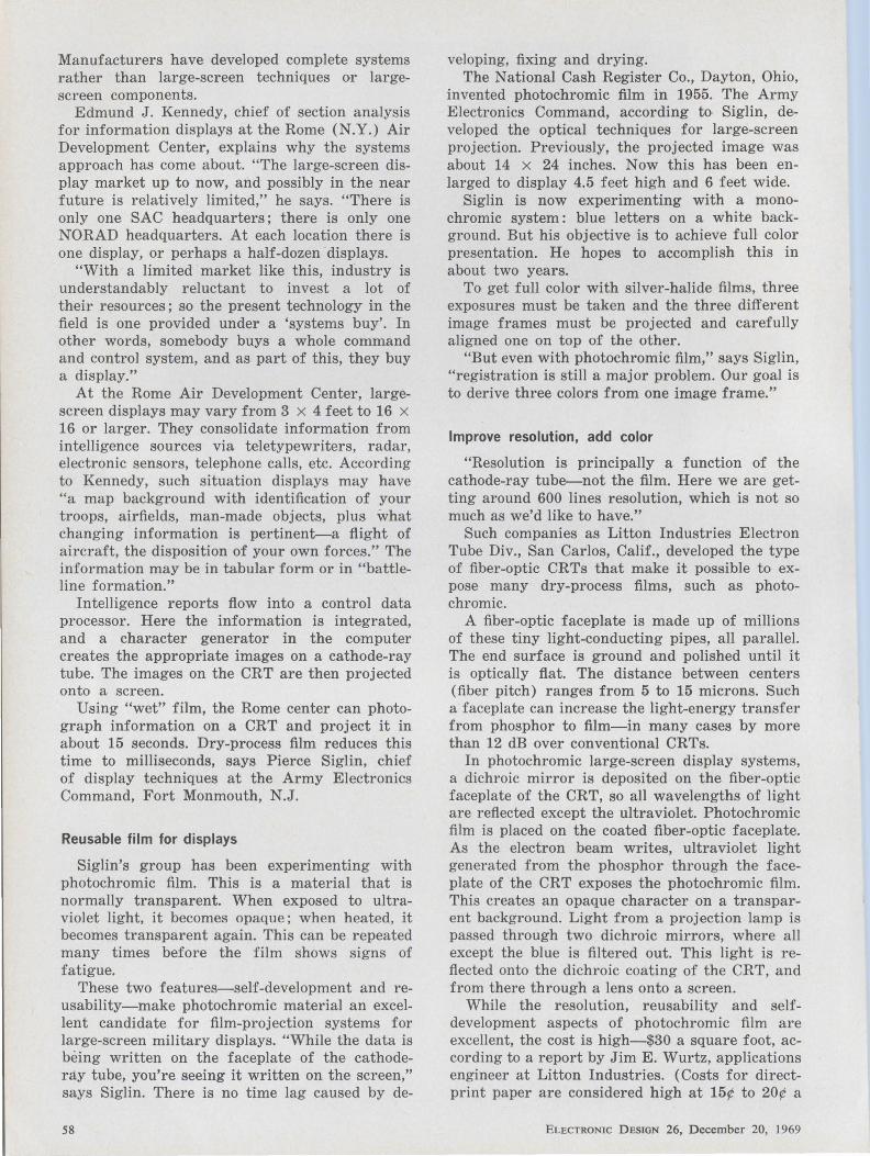
Manufacturers have developed complete systems rather than large-screen techniques or largescreen components.
Edmund J. Kennedy, chief of section analysis for information displays at the Rome (N.Y.) Air Development Center, explains why the systems approach has come about. "The large-screen display market up to now, and possibly in the near future is relatively limited," he says. "There is only one SAC headquarters; there is only one NORAD headquarters. At each location there is one display, or perhaps a half-dozen displays.
"With a limited market like this, industry is understandably reluctant to invest a lot of their resources; so the present technology in the field is one provided under a 'systems buy'. In other words, somebody buys a whole command and control system, and as part of this, they buy a display."
At the Rome Air Development Center, largescreen displays may vary from 3 x 4 feet to 16 x 16 or larger. They consolidate information from intelligence sources via teletypewriters, radar, electronic sensors, telephone calls, etc. According to Kennedy, such situation displays may have "a map background with identification of your troops, airfields, man-made objects, plus what changing information is pertinent-a flight of aircraft, the disposition of your own forces." The information may be in tabular form or in "battleline formation."
Intelligence reports flow into a control data processor. Here the information is integrated, and a character generator in the computer creates the appropriate images on a cathode-ray tube. The images on the CRT are then projected onto a screen.
Using "wet" film, the Rome center can photograph information on a CRT and project it in about 15 seconds. Dry-process film reduces this time to milliseconds, says Pierce Siglin, chief of display techniques at the Army Electronics Command, Fort Monmouth, N.J.
Reusable film for displays
Siglin's group has been experimenting with photochromic film. This is a material that is normally transparent. When exposed to ultraviolet light, it becomes opaque; when heated, it becomes transparent again. This can be repeated many times before the film shows signs of fatigue.
These two features-self-development and reusability-make photochromic material an excellent candidate for film-projection systems for large-screen military displays. "While the data is being written on the faceplate of the cathoderay tube, you're seeing it written on the screen," says Siglin. There is no time lag caused by de-
58
veloping, fixing and drying. The National Cash Register Co., Dayton, Ohio,
invented photochromic film in 1955. The Army Electronics Command, according to Siglin, developed the optical techniques for large-screen projection. Previously, the projected image was about 14 x 24 inches. Now this has been enlarged to display 4.5 feet high and 6 feet wide.
Siglin is now experimenting with a monochromic system: blue letters on a white background. But his objective is to achieve full color presentation. He hopes to accomplish this in about two years.
To get full color with silver-halide films, three exposures must be taken and the three different image frames must be projected and carefully aligned one on top of the other.
"But even with photochromic film," says Siglin, "registration is still a major problem. Our goal is to derive three colors from one image frame."
Improve resolution, add color
"Resolution is principally a function of the cathode-ray tube-not the film. Here we are getting around 600 lines resolution, which is not so much as we'd like to have."
Such companies as Litton Industries Electron Tube Div., San Carlos, Calif., developed the type of fiber-optic CRTs that make it possible to expose many dry-process films, such as photochromic.
A fiber-optic faceplate is made up of millions of these tiny light-conducting pipes, all parallel. The end surface is ground and polished until it is optically flat. The distance between centers (fiber pitch) ranges from 5 to 15 microns. Such a faceplate can increase the light-energy transfer from phosphor to film-in many cases by more than 12 dB over conventional CRTs.
In photochromic large-screen display systems, a dichroic mirror is deposited on the fiber-optic faceplate of the CRT, so all wavelengths of light are reflected except the ultraviolet. Photochromic film is placed on the coated fiber-optic faceplate. As the electron beam writes, ultraviolet light generated from the phosphor through the faceplate of the CRT exposes the photochromic film. This creates an opaque character on a transparent background. Light from a projection lamp is passed through two dichroic mirrors, where all except the blue is filtered out. This light is reflected onto the dichroic coating of the CRT, and from there through a lens onto a screen.
While the resolution, reusability and selfdevelopment aspects of photochromic film are excellent, the cost is high-$30 a square foot, according to a report by Jim E. Wurtz, applications engineer at Litton Industries. (Costs for directprint paper are considered high at 15¢ to 20¢ a
ELECTRONIC DESIGN 26, December 20, 1969
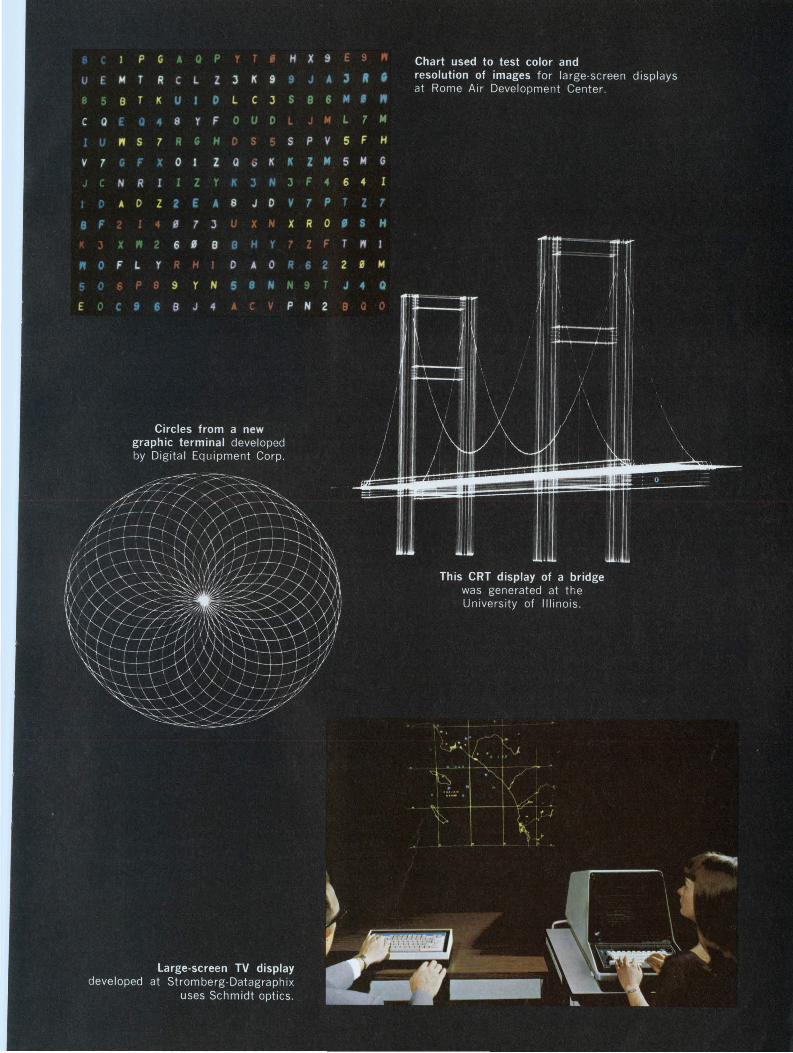
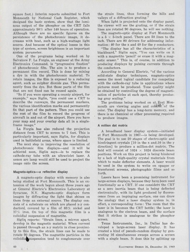
square foot.) Interim reports submitted to Fort Monmouth by National Cash Register, which designed the basic system, show that the luminous output of the phosphor on the CRT falls approximately 50 % after 140 hours of operation. Although there are no specific figures on the persistence of the photochromic image, it decreases with heat, such as a high-wattage light source. And because of the optical losses in this type of system, screen brightness is an important system parameter.
One of the programs being worked on by Salvatore F. La Forgia, an engineer at the Army Electronics Command, is "progressive fixation" of photochromic fil'm. The aim is to produce a permanent film record. This is done by mixing a dye in with the photochromic material. To retain images, the film is exposed to a reducing agent, such as sulphur dioxide gas. This permanently fixes the dye. But those parts of the film that are not fixed can be reused again.
"So if you were operating a county airport, for example," says Siglin, "you could use a CRT to describe the runways, the permanent markers, the various identification marks and permanently fix that part of the pattern. Then you could use the rest of the film to record the progress of aircraft in and out of the airport. Here you have your map and your overlay data all in a singleframe image."
La Forgia has also reduced the projection distance from CRT to screen to 7 feet. This is particularly important, says Siglin, for displays used in battlefield areas, where space is limited.
The next step in improving the resolution of photochromic film displays-and it will be achieved soon, Siglin says-is to replace the cathode-ray tube with an ultraviolet laser. A xenon arc lamp would still be used to project the image onto the screen.
Magneto-optics-a reflective display
A magneto-optic display with memory is also being studied at Fort Monmouth. This is an extension of the work begun about three years ago at General Electric's Electronics Laboratory at Syracuse, N.Y. Magneto-optic displays form images by diffracting the light that shines on them fro:µi an external source. The display consists of a substrate on which are placed x-y conductod, covered by a film of 83 % nickel and 17 % iron. On top of this magnetic film is a colloidial suspension of magnetite.
Sigli11 reports : "Strain lines, a micron apart, develop in the magnetic material. When current is passed through an x-y matrix in close proximity to this film, the strain lines can be made to rotate 90 degrees. The magnetite particles in the colloidi3'suspension tend to conglomerate over
60
the strain lines, thus forming the hills and valleys of a diffraction grating."
When light is projected onto the display panel, the viewer will see the grating, or if the strain lines are rotated 90 degrees, he will see nothing.
The magneto-optic display at Fort Monmouth is a 5 x 5-inch panel. There are 50 lines to the inch. There are 80 drivers for addressing information: 40 for the x and 40 for the y conductors.
"The display has all the characteristics of a blackboard," Siglin says, "You can write on it with a magnetite 'pencil' or erase it with a magnetic eraser." This is, of course, in addition to producing displays by pulsing currents through the conductors.
According to General Electric, "of the various solid-state display techniques, magneto-optics seems the most logical candidate for competing with the cathode-ray tube in applications where pictures must be produced. Tone quality might be obtained by controlling the degree of magnetization of particles at each spot, thereby producing gray scaling."
The problems being worked on at , F...-0r.t Monmouth are viewing angles and co'i'it'f~l ~ of the color. The display has a long-term memory, and there is no chemical or other processing,required to produce imagelil. . ·
A million dot matrix
A broadband laser display system-initiated at Fort Monmouth in 1967-is being developed. The goal is to use 20 stages of electro-optic and birefringent crystals [10 in the x and .. 10 in the y direction] to produce a million-dot matrix. The field will consist of 1024 x 1024 discrete beam positions. Work on this project is being hindered by a lack of high-quality crystal materials from which to make deflector elements. A laser would be used in the system to write on opaque or translucent screens, photographic films and so forth.
Lasers have been a promising instrument for large-screen displays, because they hav~ peen used functionally as a CRT. If one considers the CRT as a zero inertia beam that is being deflected electronically, with its light produced by fluorescence from an impinging surface, one can draw the analogy that a laser display system is, in effect, a corresponding form: The room that the laser is in becomes the CRT bottle; the laser is analogous to the electron beam, and the surface that it strikes is analogous to the phosphor screen.
Texas Instruments, Inc., in Dallas has developed a large-screen laser display. It has created a kind of pseudo-random display by generating 16 simultaneous sweeps across a screen with a single beam. It does this by splitting up
ELECTRONIC DESIGN 26, December 20, 1969
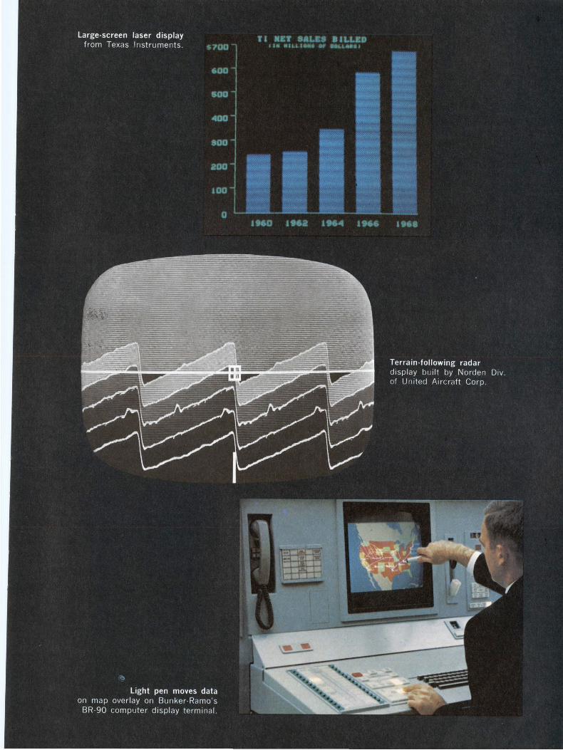
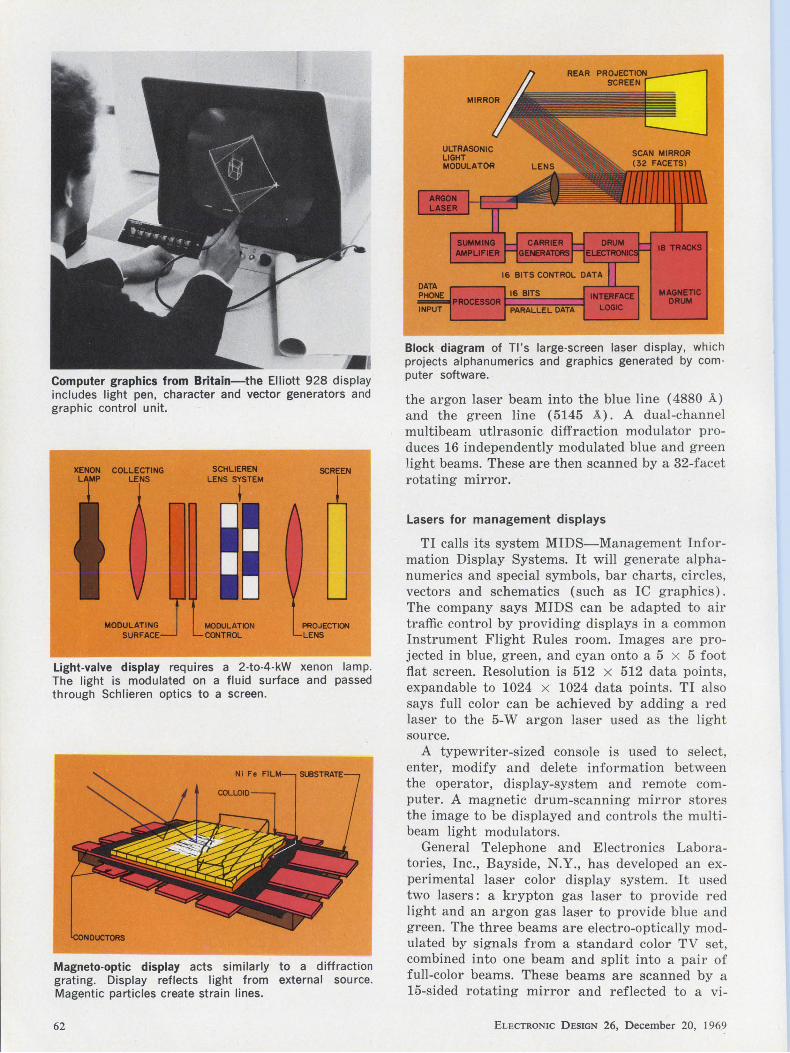
-. Computer graphics from Britain-the Elliott 928 display includes light pen, character and vector generators and graphic control unit.
XENON COLLECTING LENS
MODULATING SURFACE
SCHLIEREN LENS SYSTEM
' MODULATION ca.TROL
SCREEN
PROJECTION LENS
Light-valve display requires a 2-to-4-kW xenon lamp. The light is modulated on a fluid surface and passed through Schlieren optics to a screen.
Magneto-optic display acts similarly to a diffraction grating. Display reflects light from external source. Magentic particles create strain lines.
62
16 BITS
PARALLEL DATA
Block diagram of Tl's large-screen laser display, which projects alphanumerics and graphics generated by computer software.
the argon laser beam into the blue line ( 4880 A.) and the green line (5145 A). A dual-channel multibeam utlrasonic diffraction modulator produces 16 independently modulated blue and green light beams. These are then scanned by a 32-facet rotating mirror.
Lasers for management displays
TI calls its system MIDS-Management Information Display Systems. It will generate alphanumerics and special symbols, bar charts, circles, vectors and schematics (such as IC graphics). The company says MIDS can be adapted to air traffic control by providing displays in a common Instrument Flight Rules room. Images are projected in blue, green, and cyan onto a 5 x 5 foot fl.at screen. Resolution is 512 x 512 data points, expandable to 1024 x 1024 data points. TI also says full color can be achieved by adding a red laser to the 5-W argon laser used as the light source.
A typewriter-sized console is used to select, enter, modify and delete information between the operator, display-system and remote computer. A magnetic drum-scanning mirror stores the image to be displayed and controls the multibeam light modulators.
General Telephone and Electronics Laboratories, Inc., Bayside, N.Y., has developed an experimental laser color display system. It used two lasers : a krypton gas laser to provide red light and an argon gas laser to provide blue and green. The three beams are electro-optically modulated by signals from a standard color TV set, combined into one beam and split into a pair of full-color beams. These beams are scanned by a 15-sided rotating mirror and reflected to a vi-
ELECTRONIC DESIGN 26, December 20, 1969
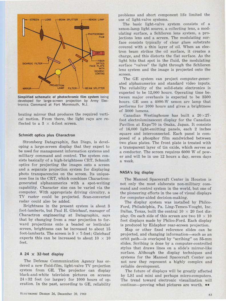
SCREEN LENS XENON LAMP
FIBER OPTICS
FACE PLATE WITH
D1CHROIC COATING
Simplified schematic of photochromic film system being developed for large-screen projection by Army Electronics Command at Fort Monmouth, N.J.
brating mirror that produces the required vertical motion_ From there, the light rays are reflected to a 3 x 4-foot screen.
Schmidt optics plus Charactron
Stromberg Datagraphix, San Diego, is developing a large-screen display that they expect to be used for management information systems and military command and control. The system consists basically of a high-brightness CRT, Schmidt optics for projecting the images onto a screen and a separate projection system for displaying photo transparencies on the screen. Its uniqueness lies in the CRT, which combines Charactrongenerated alphanumerics with a spot-writing capability. Character size can be varied via the computer. With appropriate driving circuitry, a TV raster could be projected. Scan-converted radar could also be added.
Brightness in the present system is about 3 foot-lamberts, but Paul H. Gleichauf, manager of Charactron engineering at Datagraphix, says that by changing from a rear. projection to forward projections onto a beaded or lenticular screen, brightness can be increased to about 15 foot-lamberts. The screen is 5 x 7-feet; Gleichauf expects this can be increased to about 10 x 10 feet.
A 24 x 32-foot display
The Defense Communication Agency has ordered a new fluid-film, light-valve TV projection system from GE. The projector can display black-and-white television pictures on screens 24 x 32 feet (or larger) for 1000 hours of operation. In the past, according to GE, reliability
EL ECTRONIC DESIGN 26, December 20, 1969
problems and short component life limited the use of light-valve systems.
The basic light-valve system consists of a xenon-lamp light source, a collecting lens, a modulating surface, a Schlieren lens system, a projections lens and a screen. The modulating surface consists typically of clear glass substrate covered with a thin layer of oil. When an electron beam strikes the oil surface, it creates a charge, and this distorts the flat surface. As the light hits that spot in the fluid, the modulating surface "valves" the light through the Schlieren lens system and the image is projected onto the screen.
The GE system can project computer-generated alphanumerics and standard video inputs. The reliability of the solid-state electronics is expected to be 12,000 hours. Operating time between major overhauls is expected to be 3500 hours. GE uses a 4000-W xenon arc lamp that performs for 1000 hours and gives a brightness of 3000 lumens.
Canadian Westinghouse has built a 20 x 27-foot electroluminescent display for the Canadian Pavilion at Expo'70 in Osaka, Japan. It consists of 16,000 light-emitting panels, each 2 inches square and interconnected. Each panel is composed of a phosphor film sandwiched between two glass plates. The front plate is treated with a transparent layer of tin oxide, which serves as a conductor. The screen requires 6000 W of power and will be in use 12 hours a day, seven days a week.
NASA's big display
The Manned Spacecraft Center in Houston is not only the most elaborate non-military command and control system in the world, but one of the pioneering efforts in the use of visual displays for computer-aided decision-making.
The display system was installed by PhilcoFord, Philadelphia, Pa. Ling-Temco-Vought, Inc. Dallas, Texas, built the central 10 x 20 foot display. On each side of this screen are two 10 x 10 foot displays made by Philco-Ford. Each display is produced by Eidaphor rear-screen projection.
Map or other fixed reference slides can be projected, and changing information-such as an orbit path-is overlayed by "scribing" on 35-mm slides. Scribing is done by a computer-controlled stylus that draws lines on a slide's mirror-like surface. Although the display techniques and systems for the Manned Spacecraft Center are not new they represent a highly complex and reliable development.
The future of displays will be greatly affected by LSI and mini and perhaps micro-computers. The trend toward electronic visualization will continue-proving what pictures are worth. ••
63

oes
•
64 ELECTRONIC D ESIGN 26, December 20. 1969
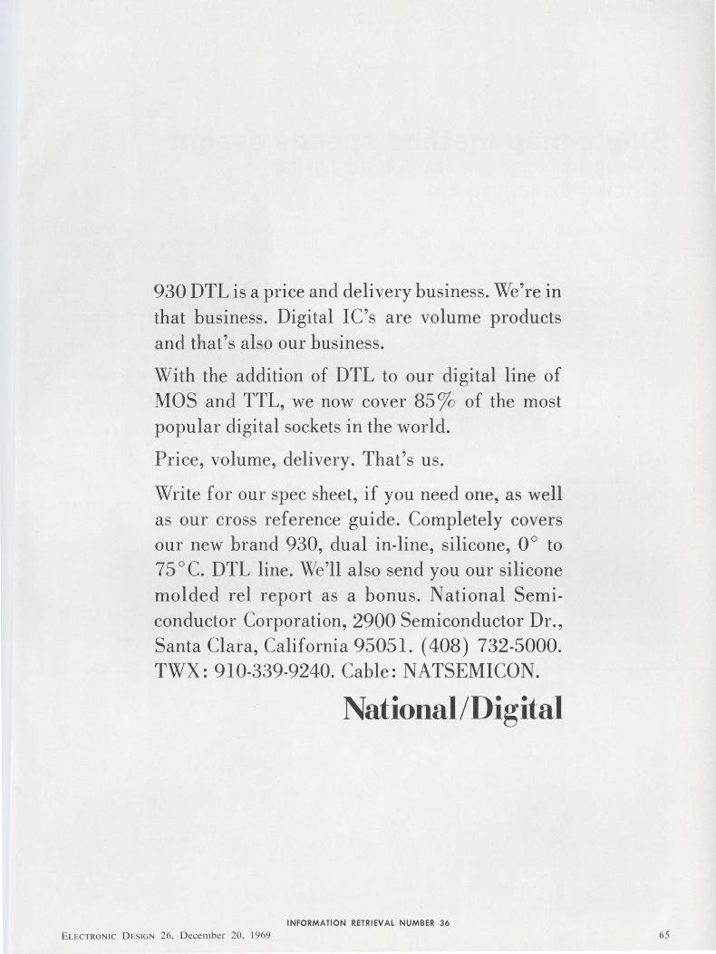
930 DTL is a price and delivery business. We're in that business. Digital IC's are volume products and that's also our business.
With the addition of DTL to our digital line of MOS and TTL, we now cover 85ro of the most popular digital sockets in the world.
Price, volume, delivery. That's us.
Write for our spec sheet, if you need one, as well as our cross reference guide. Completely covers our new brand 930, dual in-line, silicone, 0° to 75 ° C. DTL line. We'll also send you our silicone molded rel report as a bonus. National Semiconductor Corporation, 2900 Semiconductor Dr., Santa Clara, California 95051. ( 408) 732-5000. TWX: 910-339-9240. Cable: NATSEMICON.
National/Digital
INFORMATION RETRIEVAL NUMBER 36
E L ECTRON IC D ES IGN 26, Decembe r 20. 1969 65
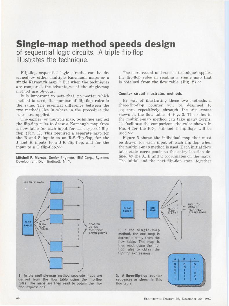
Single-map method speeds design of sequential logic circuits. A trip le flip-flop illustrates the technique.
Flip-flop sequential logic circuits can be designed by either multiple Karnaugh maps or a single Karnaugh map.1- 5 But when the techniques are compared, the advantages of the single-map method are obvious.
It is important to note that, no matter which method is used, the number of flip-flop rules is the same. The essential difference between the two methods lies in where in the procedure the rules are applied.
The earlier, or multiple map, technique applied the flip-flop rules to draw a Karnaugh map from a flow table for each input for each type of flipflop (Fig. 1). This required a separate map for the R and S inputs to an R-S flip-flop, for the J and K inputs to a J-K flip-flop, and for the input to a T flip-flop. 1•2•5
Mitchell P. Marcus, Senior Engineer, IBM Corp., Systems Development Div., Endicott, N. Y.
MULTIPLE MAPS
~ FLOP RULES I I
I I I I
READ TO OBTAIN FLIP-FLOP EXPRESSIONS
'
l. In the multiple-map method separate maps are derived from the flow table using the flip-flop rules. The maps are then read to obtain the flipflop expressions.
66
The more recent and concise technique6 applies the flip-flop rules in reading a single map that is obtained from the flow table (Fig. 2) .3•4
Counter circuit illustrates methods
By way of illustrating these two methods, a three-flip-flop counter will be designed to sequence repetitively through the six states shown in the flow table of Fig. 3. The rules in the multiple-map method can take many forms. To facilitate the comparison, the rules shown in Fig. 4 for the R-S1 J-K and T flip-flops will be used. 4
•5
•6
Figure 5 shows the individual map that must be drawn for each input of each flip-flop when the multiple-map method is used. Each initial flow table state corresponds to the entry location defined by the A, B and C coordinates on the maps. The initial and the next flip-flop state, together
2. In the single-map method, the one map is derived directly from the flow table. The map is then read, using the flip-flop rules to obtain the flip-flop expressions.
3. A three-flip-flop counter sequences as shown in this flow table.
READ TO OBTAIN FLIP-FLOP EXPRESSIONS
ELECTRONIC DESIGN 26, December 20, 1969
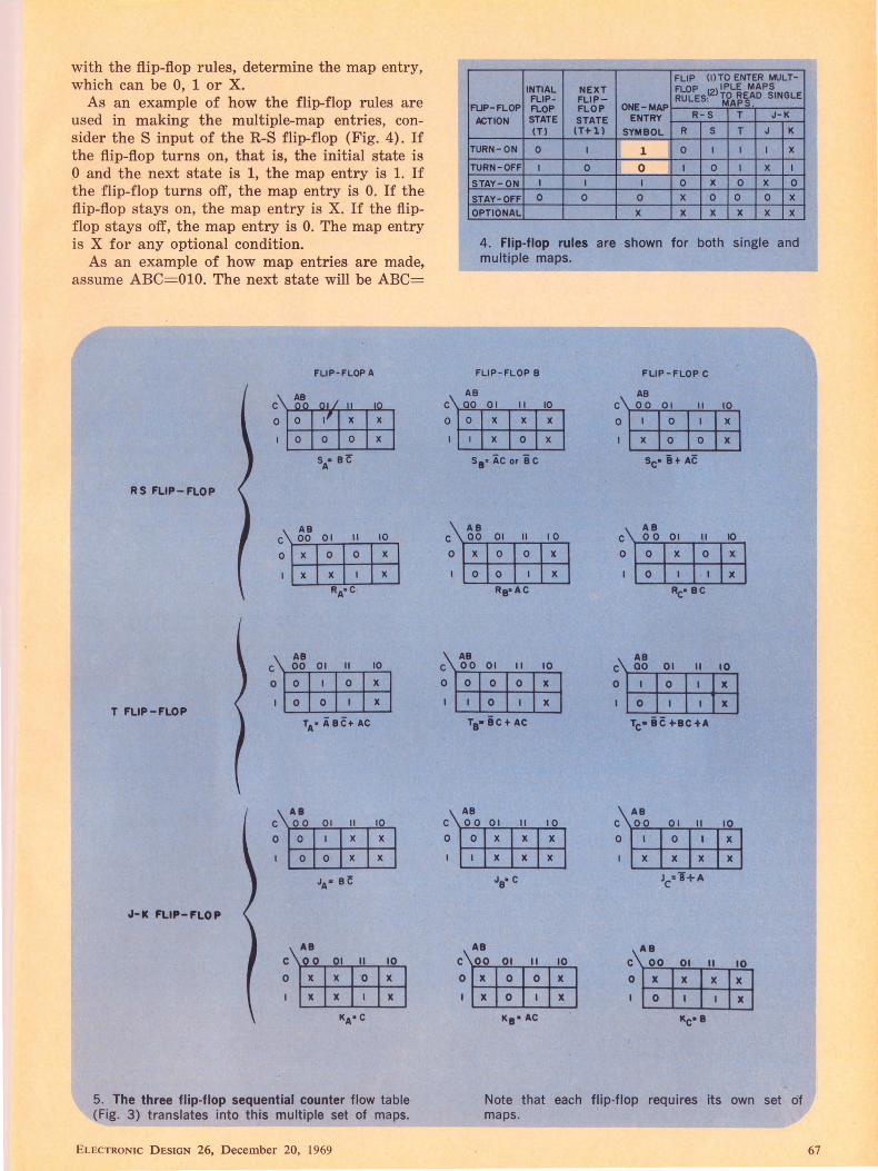
with the flip-flop rules, determine the map entry, which can be 0, 1 or X.
As an example of how the flip-flop rules are used in making the multiple-map entries, consider the S input of the R-S flip-flop (Fig. 4). If the flip-flop turns on, that is, the initial state is 0 and the next state is 1, the map entry is 1. If the flip-flop turns off, the map entry is 0. If the flip-flop st ays on, the map entry is X. If the flipflop stays off, the map entry is 0. The map entry is X for any optional condition.
As an example of how map entries are made, assume ABC= OlO. The next state will be ABC=
FLIP·FLOP A
RS FLIP-FLOP
AB C 00 01 II 10
0 x 0 0 x
x x x
AB c 00 01 II 10
0 0 0 x 0 0 x
T FLIP-FLOP TA• i BC+ AC
Al c 00 01 II
0 0 x
0 0 x
JA• Bf
J-IC FLIP-FLOP
c II 10
0 ·o x x
KA•C
5. The three flip-flop sequential counter flow table (Fig. 3) translates into this multiple set of maps.
ELECTRONIC D ESIGN 26, December 20, 1969
FLIP (l)TO ENTER MULT-INTIAL NEXT FLOP IPLE MAPS FLIP- FLIP- RULESl2llfA~~~O SINGLE
FLIP-FLOP FLOP FLOP ONE-MAP ACTION STATE STATE ENTRY R-S T J-K
(T) (THI SYMBOL R s T J K
TURN-ON 0 I 1 0 I I I x TURN-OFF I 0 0 I 0 I x I
STAY-ON I I I 0 x 0 x 0
STAY-OFF 0 0 0 x 0 0 0 x OPTIONAL x x x x x x
4. Flip-flop rules are shown for both single and multiple maps.
FLIP· FLOP 8
AB C 00 01 II
0 0 x x x 0
s1 • ic or ic
AB
10
x
x
C 00 01 II I 0
0 x 0 0 x
0 0 x
AB c 00 01 II 10
0 0 0 0 x 0 x
Ta• ic+ AC
AB c 00 01 II 10
0 0 x x x x x x
JB• c
AB
c 00 01 II 10
0 x 0 0 x x 0 x
K9• AC
FLIP-FLOP C
AB c l'-"'0_0-r""o .... 1 __,,_.1.._1 ....,.....1..,0 ...
0 0 x
x 0 0 x
Sc• i+ AC
AB C 0 0 01 II IO
0 0 x 0 x
0 x Rc•BC
AB c 00 01 II 10
0 0 JC
0 JC
Tc• ic +-IC+A
AB c 00 01 II
0 0 I
x x x Jc="J+A
AB
c 00 01 II 10
0 x x IC JC
0 x Kc•I
Note that each flip-flop requires its own set of maps.
67
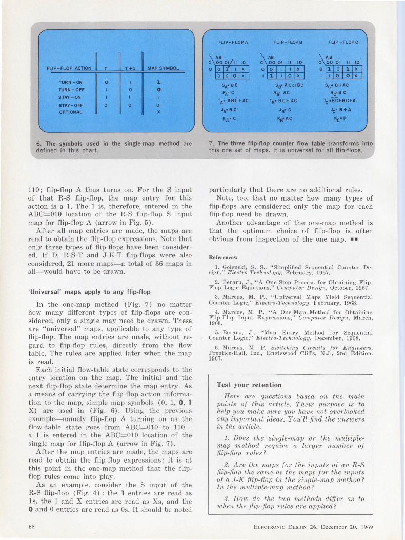
Fl,,!P-FLOP ACTION ~ T I !+;I. I MAP SYMBOL
TURN-ON 0 I 1 TURN-OFF 0 0 STAY-ON I I
STAY-OFF 0 0 0 OPTIONAL j(
6. The symbols used in the single-map method are defined in this chart.
110; flip-flop A thus turns on. For the S input of that R-S flip-flop, the map entry for this action is a 1. The 1 is, therefore, entered in the ABC=OlO location of the R-S flip-flop S input map for flip-flop A (arrow in Fig. 5).
After all map entries are made, the maps are read to obtain the flip-flop expressions. Note that only three types of flip-flops have been considered. If D, R-S-T and J-K-T flip-flops were also considered, 21 more maps-a total of 36 maps in all-would have to be drawn.
'Universal' maps apply to any flip-flop
In the one-map method (Fig. 7) no matter how many different types of flip-flops are considered, only a single may need be drawn. These are "universal" maps, applicable to any type of flip-flop. The map entries are made, without regard to flip-flop rules, directly from the flow table. The rules are applied later when the map is read.
Each initial flow-table state corresponds to the entry location on the map. The initial and the next flip-flop state determine the map entry. As a means of carrying the flip-flop action information to the map, simple map symbols (O, 1, 0, 1 X) are used in (Fig. 6). Using the previous example-namely flip-flop A turning on as the f low-table state goes from ABC=OlO to 110-a 1 is entered in the ABC= OlO location of the single map for flip-flop A (arrow in Fig. 7).
After the map entries are made, the maps are read to obtain the flip-flop expressions; it is at this point in the one-map method that the flipflop rules come into play.
As an example, consider the S input of the R-S flip-flop (Fig. 4) : the 1 entries are read as ls, the 1 and X entries are read as Xs, and the 0 and 0 entries are read as Os. It should be noted
68
FLIP-FLOP A FLIP-FLOPS FUP-FLOPC
II 10 II 10 II 10
I x I x l x 0 x I 0 x 0 x
sA· ee sB" lcor'lc Sc• l+A~
Ri.· c R" AC RcfBC
TA• lB~+AC T9•iC+AC Tc•BC+BC+A
JA•BC J~C "c• i +A
Ka•C !Ctf AC Kc·•
7. The three flip-flop counter flow table transforms into this one set of maps. It is universal for all flip-flops.
particularly that there are no additional rules. Note, too, that no matter how many types of
flip-flops are considered only the map for each flip-flop need be drawn.
Another advantage of the one-map method is that the optimum choice of flip-flop is often obvious from inspection of the one map. • •
References:
1. Golcnski, S. S., "Simplified Sequential Counter Design," Electro-Technology, February, 1967.
2. Beraru, J., "A One-Step Process for Obtaining FlipFlop Logic Equations," Computer Design, October, 1967.
3. Marcus, M. P., "Universal Maps Yield Sequential Counter Logic," Electro-Technology, February, 1968.
4. Marcus, M. P., "A One-Map Method for Obtaining Flip-Flop Input Expressions," Computer Design, March, 1968.
5. Beraru, J., "Map Entry Method for Sequential Counter Logic," Electro-Technology, December, 1968.
6. Marcus, M. P. Switching Circuits for Engineers, Prentice-Hall, Inc., Englewood Cliffs, N.J., 2nd Edition. 1967.
Test your retention
Here are questions based on the main points of this article. Their purpose is to help you make sure you have not overlooked any important ideas. You'll find the answers in the article.
1. Does the single-map or the multiplemap method require a larger number of fiip-fiop rules?
2. Are the maps for the inputs of an R-S fiip-fiop the same as the maps for the inputs of a J-K fiip-fiop in the single-map method? In the multiple-map method?
3. How do the two methods differ as to when the fiip-fiop rules a?·e applied?
ELECTRON IC D ESIGN 26, December 20, 1969
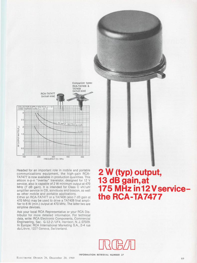
RCA-TA7477 (actual size)
COLLECTOR-SUPPLY VOLTS (V,d = 12 CASE TEMPERATURE (Td = 25 C
3
2.5
~ 2 ~ rn I= <( 1.5 :;:: f--::i a._ f-- 1 ::i 0 U-a:
0.5
0
~
Companion types: RCA-TA7408 & TA7409 (actual size)
~ El
RF tNPUT -WATTS(P,. 0.4
0.25
0.1
100 200 300 400 500 FREQUENCY (f)-MHz
Headed for an important role in mobi le and portable communications equipment, the high -gain RCATA7477 is now available in production quantities. Th is silicon n-p-n "overlay" transistor, designed for 12 V service, also is capable of 2 W minimum output at 470 MHz (7 dB gain). It is intended for Class C vhf / uhf amplifier service in CB, sonobuoy and beacon, as we ll as other mobi le and portabl e applications. Either an RCA-TA7477 or a TA7408 (also 7 dB gain at 470 MHz) may be used to drive a TA7409 final ampl ifier to 6 W (min .) output at 470 MHz. The latter two are stripline devices.
Ask your local RCA Representative or your RCA Distributor for more detailed information. For techn ical data, write: RCA Electronic Components, Commercial Engineering, Sec. G-12-2 / UF4, Harrison, N. J . 07029. In Europe: RCA International Marketing S.A. , 2-4 rue du Li evre, 1227 Geneva, Switzerland.
2 W (typ) output, 13 dB gain, at 175 MHz in12Vservicethe RCA-TA7477
INFORMATION RETRIEVAL NUMBER 37 ELloCTRO IC DI-SIGN 26, D ecember 20 . 1969 69
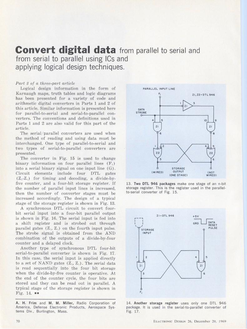
Convert digital data from parallel to serial and from serial to parallel using ICs and applying logical design techniques.
Part 3 of a three-part article Logical design information in the form of
Karnaugh maps, truth tables and logic diagrams has been presented for a variety of code and arithmetic digital converters in Parts 1 and 2 of this article. Similar information is presented here for parallel-to-serial and serial-to-parallel converters. The conventions and definitions used in Parts 1 and 2 are also valid for this part of the article.
The serial/parallel converters are used when the method of reading and using data must be interchanged. One type of parallel-to-serial and two types of serial-to-parallel converters are presented.
The converter in Fig. 15 is used to change binary information on four parallel lines (F;) into a serial binary signal on one input line ( G). Circuit elements include four DTL gates (Z 1-Z 1 ) for timing and decoding, a divide-byfive counter, and a four-bit storage register. If the number of parallel input lines is increased, then the number of converter stages must be increased accordingly. The design of a typical stage of the storage register is shown in Fig. 13.
A synchronous DTL circuit to convert fourbit serial input into a four-bit parallel output is shown in Fig. 16. The serial input is fed into a shift register and is strobed out through parallel gates (Z,, Z2 ) on the fourth input pulse. The strobe signal is obtained from the AND combination of the outputs of a divide-by-four counter and a delayed clock.
Another type of synchronous DTL four-bit serial-to-parallel converter is shown in Fig. 17. In this case, the serial input is applied directly to a set of NAND gates (Z,, Z2 ). The serial data is read sequentially into the four bit storage when the divide-by-five counter is operative. At the end of the counter cycle, the four bits are stored and they can be read out in parallel. A typical stage of the storage register is shown in Fig. 14. ••
A. H. Frim and M. M. Miller, Radio Corporation of America, Defense Electronic Products, Aerospace Systems Div., Burlington, Mass.
70
PARALLEL INPUT LINE
DATA STROBE
F;
2
STORAGE \WIRED) OUTPUT
\ONE STAGE)
ZI, Z2= DTL 946
\NOT WIRED)
13. Two DTL 946 packages make one stage of an n-bit storage register. This is the register used in the parallelto-serial converter of Fig. 15.
r--, I I I I ' I ...,....
" STORAGE INPUT
2
Zl=DTL946 +5V
~A RESET PULSE
4 5
14. Another storage register uses only one DTL 946 package. It is used in the serial-to-parallel converter of Fig. 17.
ELECTRONIC DESIGN 26, December 20. l 969

15. Parallel-to-serial converter
Operation: This converter provides a 4-bit serial output (G) from a 4-bit para I lei
input (F ). For the waveforms i I lustrated below, operation is as fol lows:
(a) Counter is cleared (A =0, B=O, C=O, A = I , B =I , C = I) on cp1. Also, F; are applied to 4-bit storage register.
(b) When cp2 and start-stop signals are both HIGH, Zl-6 is HIGH, so thatZ4-I,-2,-4, and -5 are HIGH , ZI-8 is HIGH and data is strobed into 4-bit storage register. The trailing edge of cp2 also starts the counter , so that the counter output C goes HIGH (C =I).
(c) During clock pulse cp3, C = I, B = 0, and F0 =1 so that Z2-l,
-2,-4, and -5 are HIGH, and therefore Z2-6 is LOW and Z4-8 is HIGH. This is the first pulse of the serial output G.
(d) During clock pulse cp4, F1 = 0, so that Z2-9 is LOW. In effect, Z4-8 is LOW and no serial output pulse occurs.
(e) During clock pulse cp5, F2 = 1, B =I, C =I, so that Z3-8 is LOW, and therefore output pulse occurs at Z4-8.
(f) During clock pulse cp6, F3 =1 and A = I, so thatZ3-6 is LOW, an~ therefore output pulse occurs at Z4-8.
Thus, the parallel input lOll appears as a serial output IOll.
Truth tables: Karnaugh maps:
Waveforms:
Counter Serial Stage Paral lel Input Output
A B c Data Fa F1 F2 F3 G Strobe
0 0 0 I 0 0 0 0 0
0 0 I 0 I 0 0 0 I
0 I 0 0 0 I 0 0 1
0 I 1 0 0 0 I 0 I
1 0 0 0 0 0 0 1 1
X = Don't Care = 5,6, 7
START-STOP o---~--.,.
CLOCK
CLEAR
CP2 CP3 CPI ! : J : CP4 CP5 CP6
CLOCK~ START-STOP~ COUNTER C
' ' ' COUNTER B ___ _._:_.!_I-Ii i-i ----,L_ COUNTER A l I I ..-----,__
Fo•I ____J : ; I ' '' ' '' ' '' F1-0 ---+-1-+-'-------
l: : :
F»I __J H ! i DATA STROBE '--+t-f'i------SERIAL
OUTPUT G
____f"L___Jl__j i'i 0 I I
ELECTRONIC D ESIGN 26, D ecembe r 20, 1969
(F 0)
00 OI ll 10
x x x
G0 =BC(F 0)
AB (F2)
c 00 01 ll 10
0 x x x
G2 = BC (F2)
Logic Diagram:
7- 5 COUNTER
CCBBAA
5 4 2 I
Z2
6
Zl•OTL 946 Z2,Z3,Z4 • DTL 930
Z4 S
AB
c
(F1) AB
00 OI ll 10 c 00 01 ll IO
0 x 0 1 x I x x x x
G1 = BC (F1) OS= A BC
(F3)
00 OJ 11 I O
x x x
G3 =A (F~
PARALLa INPUT
71
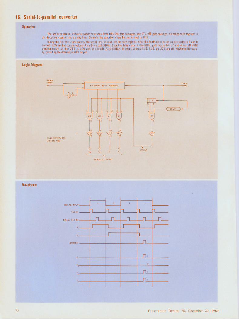
16. Serial-to-parallel converter
72
Operation:
The seri al-to-parallel converter shown here uses th ree DTL 946 gate packages, one OTL 930 gate package , a 4-stage shift register, a divide-by-four counter , and a de lay line. Consider the condition where the serial input is 1011.
During the first four clock pulses, the serial input is read into the shift register. After the fourth clock pulse, counter outputs A and B are both LOW so that counter outputs AandB are both HIGH. Since the delay clock is also HIGH, gate inputs Z4-l,-2 and -4 are al l HIGH simu ltaneously, so that Z4-6 is LOW and, as a resu lt, Z3-6 is HIGH. In effect, outputs Zl -6, Z2-6, and Z2-8 are all HIGH simu ltaneously , providing the desired parallel output.
Logic Diagram:
Waveforms:
SERIAL 1NPUT
4 -STAGE SHIFT REGISTER
\3 12 2 13 !2 2
ZJ ZI
ZI Z 1 8 6
z1,z2,z3,, DTL 946 z4,. DTL 930
SER IAL INPUT __J I
CLO CK ---11
DELA Y CLO CK
J
STROBE
Fz
PARALLEL OUTPUT
I 0
I n
L
J
I I n
J
CLOCK
DELAY
\ STROSE
I n n
L J
1
I
0
I
I
ELcCTRONIC D ESlGN 26, December 20, 1969
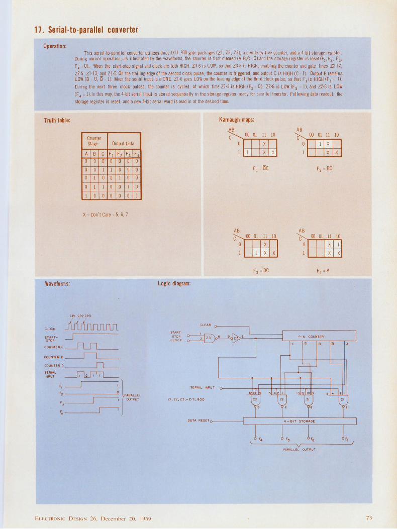
17. Serial-to-parallel converter
Operation: This serial-to-parallel converter utilizes three DTL 930 gate packages (Zl, Z2 , Z3), a divide-by-five counter , and a 4-bit storage register.
During normal operation, as illustrated by the waveforms, the coun ter is first cleared (A ,B,C=O) and the storage register is resetlF1, F2, F3,
F4= 0). When the start-stop signal and clock are both HI GH, Z3-6 is LOW, so that Z3-8 is HIGH, enabling the counter and gate lines Z2-12,
Z2-5 , Zl-13, and Zl-5. On the trailing edge of the second clock pulse, the counter is triggered , and output C is HIGH (C =I). Output B remains LOW (B = 0, B = I). When the seria l input is a ONE, Zl -6 goes LOW on the leading edge of the third clock pulse, so that F1 is HI GH (F 1 = I).
During the next three clock pulses, the counter is cycled , at which time Zl-8 is HIGH (F2 = 0), Z2-6 is LOW (F 3 = !), and Z2-8 is LOW
(F 4 = !). In this way, the 4-bit serial input is stored sequentially in tile storage register, ready for parallel transfer. Following data readou t, the
storage register is reset, and a new 4-bit serial word is read in at the desired time.
Truth table: Karnaugh maps:
Counter Stage Output Data
A B c F1 F2 F3 0 0 0 0 0 0
0 0 I I 0 0
0 I 0 0 1 0
0 I 1 0 0 1
1 0 0 0 0 0
X = Don't Care = 5, 6, 7
Waveforms:
CLOCK
ST ARTSTOP
CO UNTER C _____ILS1___ COUNTER D _IL_ COU NTER A___JL_ SERIAL INPUT ~
F 4
0
0
0
0
I
:~~)PARALLEL I OUTPUT
'3----~
F4~
ELECTRONI C D ESIGN 26, D ecembe r 20. 1969
Logic diagram:
CLEAR
STARTSTOP
CLOCK
I
~6
SERIAL INPUT
Zl,Z2,Z3,• DTL930
AB
DATA RESETo--------1
00 01 11 10
x x x
F 1 = BC
00 01 11 10
x x x
F3 = BC
AB
c 0
00 01 11 10
x x x
F2 = BC
00 01 11 10
x x x
-'.-- 5 COUNTER
PARALLEL OUT PUT
73
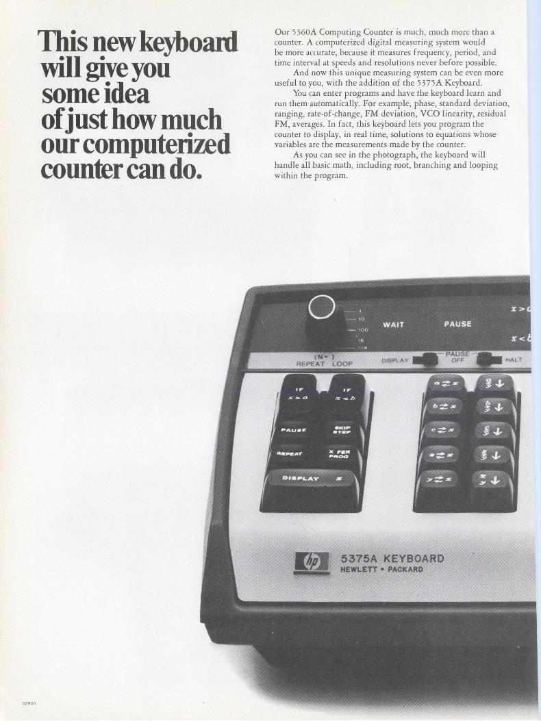
02906
This new keyboard will give you some idea of just how much our computeri7£d counter can do.
Our S360A Computing Counter is much, much more than a counter. A computerized digital measuring system would be more accurate, because it measures frequency, period, and time interval at speeds and resolutions never before possible.
And now this unique measuring system can be even more useful to you, with the addition of the S37SA Keyboard.
You can enter programs and have the keyboard learn and run them automatically. For example, phase, standard deviation, ranging, rate-of-change, FM deviation, VCO linearity, residual FM, averages. In fact, this keyboard lets you program the counter to display, in real time, solutions to equations whose variables are the measurements made by the counter.
As you can see in the photograph, the keyboard will handle all basic math, including root, branching and looping within the program.
5375A KEYBOARD HEWLETT • PACKARD
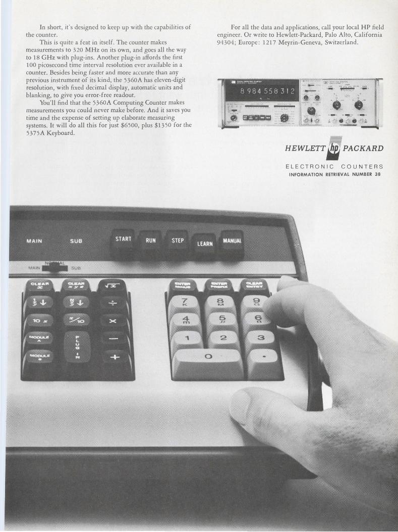
In short, it 's designed to keep up with the capabilities of the counter.
This is quite a feat in itself. The counter makes measurements to 320 MHz on its own, and goes all the way to 18 GHz with plug-ins. Another plug-in affords the first 100 picosecond time interval resolution ever available in a counter. Besides being faster and more accurate than any previous instrument of its kind, the 5360A has eleven-digit resolution, with fixed decimal display, automatic units and blanking, to give you error-free readout.
You'll find that the 5360A Computing Counter makes measurements you could never make before. And it saves you time and the expense of setting up elaborate measuring systems. It will do all this for just $6500, plus $1350 for the 5375A Keyboard.
For all the data and applications, call your local HP field engineer. Or write to Hewlett-Packard, Palo Alto, California 94304; Europe: 1217 Meyrin-Geneva, Switzerland.
-,-.,,.-, ;-·~-~-- -~~~~.!.,.,~'¥':....-'":~-··::_-, -~--;.,....
•:(~~ ,.. , ... .. l~:-~:.J-- , ...
HEWLETT. PACKARD
ELECTRONIC COUNTERS INFORMATION RETRIEVAL NUMBER 38
MANAGEMENT
Engineers need to stretch their minds by broadening their education if they want to be socially conscious and industrially competitive, says this noted scientist.
Richard L. Turmail, Management Editor
Overheard on engineering campuses across the nation:
"Sure, I'd like to take an elective, but I can't because I'm loaded down with required engineering courses."
"If I go to that English Lit seminar, I'll miss the computer symposium."
"Take a course in philosophy! What for? The only philosophy I need is 'optimum efficiency.' "
Many engineers have lived to regret not taking college courses in the humanities when they discover that often their careers broaden only in proportion to the scope of their educational background.
"I have always deplored specialized educational programs in the cases where the student took too much too fast," says Dr. Krafft Ehricke, chief scientific advisor for advanced programs at the space division of North American Rockwell Corp. in California.
Dr. Ehricke, one of the foremost creative scientists in the country today, and a guiding influence on NASA, says that there is an immense value to engineers in such courses as history, foreign languages, and astronomy, because they teach him the social implications of what he is doing. A specialized education makes it possible for an engineer to build the best spacecraft in the world while being at a loss to gauge or to explain to the hazing general public the broader social and economic implications of his accomplishments.
Next step in space: the earth
The overriding theme of Dr. Ehricke's message is that there is an urgent need for engineers to expand their education and develop a sense of social responsibility. And it's never too late for the older engineer who's willing to improve himself.
"The next step in space is headed toward earth," he says. "I mean that, before we can go further out in space, we must develop a planetary consciousness about our own earth."
Dr. Ehricke says that this consciousness is
76
vital because our planet can no longer sustain more human beings and their demands unless steps are taken to use the natural resources we haven't yet touched, and to curb the excessive drain on those we have. He recommends the following actions to overcome this "crisis":
• Conduct and maintain an inventory of our planet's resources.
• Form alliances of the major powers to cooperate on activities such as space and sea exploration, the search for new resources, and antipollution programs.
• Improve the earth's capability of sustaining more people by transferring part of the economy into the solar system by exploiting the moon, asteroids and uninhabited planets.
According to Ehricke, much of the success of a planetary consciousness rests on the attitudes of creative and well-informed engineers.
"The creative ones," he says, "have a drive that comes from a sense of obligation to the community. They must examine their engineering activities in the light of social, political, ethical, historical and philosophical considerations."
The longer you talk with Dr. Ehricke the more you realize that the consciousness about which he is concerned cannot come either from men who know only how to reach maximum efficiency or from men who claim technology is ruining the world. It must come from the scientifically and socially trained engineer who really believes that he is the translator of scientific knowledge for the benefit of human society.
Why is it so important for the engineer to be socially trained? Because, Ehricke says, in spite of much enlightenment, man remains strongly opinionated about himself and what he can do with his environment. "For ages we've had an emphasis on personal moral problems," Ehricke says, "but we have not until recently been told that we couldn't exploit and pollute the world without blacklash."
Problems that plague
So the engineer will need a broader education if he wants to take part in humanizing the world
ELECTRONIC OFSIG 26, December 20. 1969
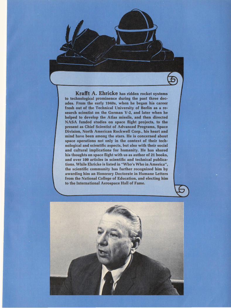
Krafft A. Ehricke has ridden rocket systems to technological prominence during the past three decades. From the early 1940s, when he began his career fresh out of the Technical University of Berlin as a research scientist on the German V-2, and later when he helped to develop the Atlas missile, and then directed NASA funded studies on space flight projects, to the present as Chief Scientist of Advanced Programs, Space Division, North American Rockwell Corp., his heart and mind have been among the stars. He is concerned about space operations not only in the context of their technological and scientific aspects, but also with their social and cultural implications for humanity. He has shared his thoughts on space flight with us as author of 21 books, and over 100 articles in scientific and technical publications. While Ehricke is listed in "Who's Who in America", the scientific community has further recognized him by awarding him an Honorary Doctorate in Humane Letters from the National College of Education, and electing him to the International Aerospace Hall of Fame.
of the future. Meanwhile, he has to make a living, and Dr. Ehricke believes that to compete in today's advanced technology an EE must obtain at least a master's degree.
"A diversified education is needed," Ehricke advises, "to combat the everyday career problems that can plague an engineer." Some of those problems are manifest in communicating, in presenting ideas, in career direction and future of the engineer, and in compromising.
The following guidelines offered by Ehricke should help the engineer no matter what direction his career takes-to the stars, or to a position of management, or both.
On writing Engineers very often are notoriously poor
writers. They write sentences filled with acronyms because they are accustomed to writing in terms of specialized language. They have trouble explaining in laymen's language what their subject is all about. If you can't explain it in plain terms you don't understand it yourself.
Most engineers can write reports for other engineers that are intelligible but not easily readable. Sentences are generally too long and basic logic is missing because the writer jumps from subject to subject without concern whether the reader is following him. Engineering courses emphasize specific methodologies but not systems of logic, such as a course in foreign language.
On ideas When I was young I had trouble getting my
ideas across, just like the young engineer today. I soon realized that since this is an imperfect world, there is no objective, unbiased attitude toward ideas. When people are already committed to other ideas, it's difficult to change their minds even if you have a better idea. So think ahead. Time your presentation to the period when their minds aren't yet made up-when they're prepared to listen."
Cre~tive people, or those in high positions, don't like to be told that they've made the wrong decision; they also don't like to get all their ideas from others. Be cognizant of the other guy's pride and exercise tact and diplomacy. Don't focus on competitiveness or conflict only. Try interpretation and synthesis as well.
On the future of the engineer It is frustrating that more often than not, the
only way you can climb in engineering is to become an administrator instead of an engineer. The problem is that the EE begins to think that what really counts is not his engineering knowledge but the politics of the organization. Some engineers treat the profession as a stepping stone. We must make it important enough so that they'll want to remain engineers.
78
What can be done? Companies should give an engineering manager a good second man of the administrative type who would be responsible for purely administrative matters. This would give the manager more time to attend to engineering duties. Companies should also give engineers as much active influence in decision making on engineering problems as possible.
On career directions But if you are interested in becoming an engi
neering manager, then I would suggest that you get a job with a large company so that you can get a variety of experience in management areas. Your advantage in working in a small company is that your individual responsibilities may broaden faster. But they are more limited, and you may not advance in knowledge.
If you are interested in specific componentsif you are an electronics engineer, for exampledon't go to a broad systems company, because the electronic aspects play a subordinate role to the total system. Start with an electronics company, then when you've had experience as a subcontractor, you can go on to a larger company if you desire to apply your special talents in a broader frame of reference.
On compromise In a free society such as ours, only your own
conscience can decide where compromise ends, and cowardice begins. You may be certain you should or should not participate in th~ building of a missile, or other weapon. Education and basic knowledge more than specialized training will allow you to make an informed decision. Emphasis must be on responsibility for your opinions and actions. If you don't dare to express your convictions or act on them responsibly, you have no cause to complain covertly. I find that in this country a person can have the courage of his convictions without fear of company reprisal.
There's no short cut
"What we as a society must do," Ehricke summarizes, "is make a long-range investment in our technology. Besides the educational investment that's necessary we must invest in planning. We must try to plan further ahead than just every four years between elections.
When settling into a new technical environment as we have in the space age, Ehricke says that the attending period of changes is always tortuous because many changes and adaptations are required. Vested interests are affected.
He concludes: "As the philosophers told King Midas, 'There is no king's road to mathematics; you've got to work hard'. So it is with engineers and their road to social understanding and competitive position: they've got to work hard." • •
ELECTRONIC DESIGN 26, December 20, 1969
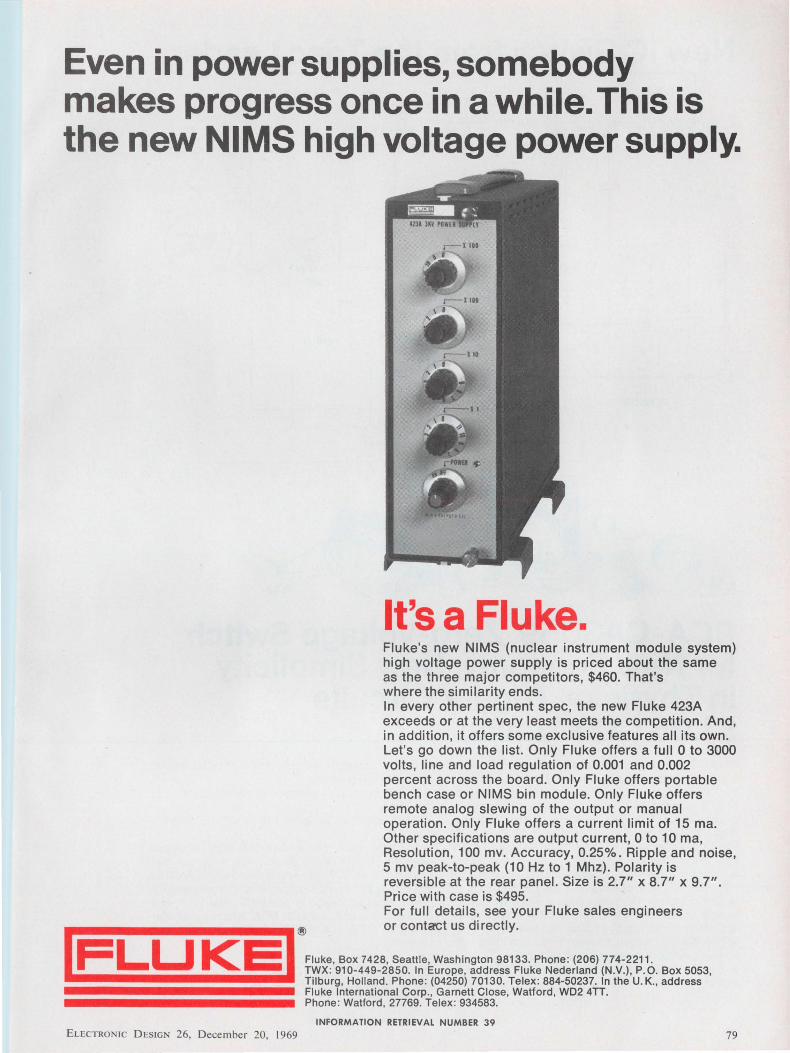
Even in power supplies, somebody makes progress once in a while. This is the new NIMS high voltage power supply.
It's a Fluke. Fluke's new NIMS (nuclear instrument module system) high voltage power supply is priced about the same as the three major competitors, $460. That's where the similarity ends. In every other pertinent spec, the new Fluke 423A exceeds or at the very least meets the competition. And, in addition, it offers some exclusive features all its own. Let's go down the list. Only Fluke offers a full O to 3000 volts, line and load regulation of 0.001 and 0.002 percent across the board. Only Fluke offers portable bench case or NIMS bin module. Only Fluke offers remote analog slewing of the output or manual operation. Only Fluke offers a current limit of 15 ma. Other specifications are output current, 0 to 1 O ma, Resolution, 100 mv. Accuracy, 0.25%. Ripple and noise, 5 mv peak-to-peak (10 Hz to 1 Mhz). Polarity is reversible at the rear panel. Size is 2.7" x 8.7" x 9.7". Price with case is $495. For full details, see your Fluke sales engineers or contact us directly. ®
Fluke, Box 7428, Seattle, Washington 98133. Phone: (206) 774-2211. I FL u KE I TWXo 910-449-2850. lo E"•ope, add"" Fl"ke Nede<laod (N.V.), P. 0. Bo< 5053, Tilburg, Holland. Phone: (04250) 70130. Telex: 884-50237. In the U. K., address Fluke International Corp., Garnett Close, Watford, WD2 4TT. Phone: Watford , 27769. Telex : 934583.
INFORMATION RETRIEVAL NUMBER 39 ELECTRONIC DESIGN 26, December 20, J 969 79
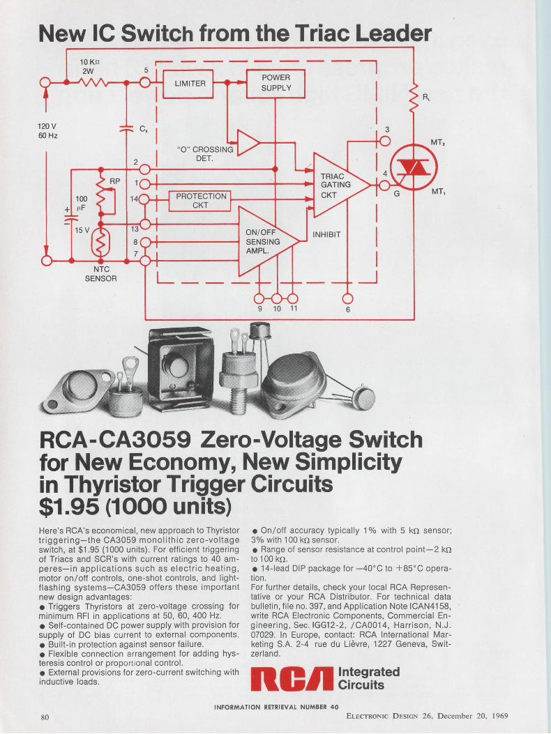
New IC Switch from the Triac Leader
120 v 60Hz
100 + µF
NTC SENSOR
r-- - -
LIMITER
c,
POWER SUPPLY
9 10 11
INHIBIT
6
I I I
I I I
_J
3
~ RCA-CA3059 Zero-Voltage Switch for New Economy, New Simplicity in Thyristor Trigger Circuits $1.95 (1000 units) Here's RCA's economical, new approach to Thyristor triggering-the CA3059 monolithic zero-voltage switch, at $1.95 (1000 units). For efficient triggering of Triacs and SCR's with current ratings to 40 amperes-in applications such as electric heating, motor on/off controls, one-shot controls, and lightflashing systems-CA3059 offers these important new design advantages: • Triggers Thyristors at zero-voltage crossing for minimum RFI in applications at 50, 60, 400 Hz. • Self-contained DC power supply with provision for supply of DC bias current to external components. • Built-in protection against sensor failure. • Flexible connection arrangement for adding hysteresis control or proportional control. • External provisions for zero-current switching with inductive loads.
• On/off accuracy typically 1 % with 5 kn sensor; 3% with 100 kn sensor. • Range of sensor resistance at control point-2 kn to 1 oo kn. • 14-lead DIP package for -40°C to +85°C operation. For further details, check your local RCA Representative or your RCA Distributor. For technical data bulletin, file no. 397, and Application Note ICAN4158, write RCA Electronic Components, Commercial Engineering, Sec. IGG12-2, /CA0014, Harrison, N.J. 07029. In Europe, contact: RCA International Marketing S.A. 2-4 rue du Lievre, 1227 Geneva, Switzerland.
noll ln_teg~ated C1rcu1ts
INFORMATION RETRIEVAL NUMBER 40
80 ELECTRONIC D ESIGN 26, December 20, 1969
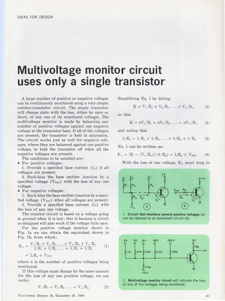
IDEAS FOR DESIGN
Multivoltage monitor circuit uses only a single transistor
A large number of positive or negative voltages can be continuously monitored using a very simple resistor-transistor circuit. The single transistor will change stat e with the loss, either by open or short, of any one of its monitored voltages. The .,, multivoltage monitor is made by balancing any number of posit ive voltages against one negative voltage at t he transistor base. If all of the voltages are present, the transistor is held in saturation. The circuit works just as well for negative voltages, where they are balanced against one positive voltage, to hold the transistor off when all the negative voltages are present.
The conditions to be satisfied are: • For positive voltages:
1. Provide a specified base current (lb) if all voltages are present.
2. Back-bias t he base emitter junction by a specified voltage (V BEr) with the loss of any one voltage. • For negative voltages :
1. Back-bias the base emitter j unction by a specified voltage (V BEr) when all voltages are present.
2. Provide a specified base current (lb) with the loss of any one voltage.
The monitor circuit is based on a voltage going to ground when it is lost; this is because a circuit so designed will also work if the voltage fails open.
For the positive voltage monitor shown in Fig. la we can obtain the equivalent shown in Fig. l b, from which:
E - V1 / R1 + Vd R2 ... + Vn/ Rn + V./R. (1) ''° - I / R1 + I / R2 . . . + I / Rn + I / R.
= Ii,RP + VaEr
where n is the number of positive voltages being monitored.
If this voltage must change by the same amount for the loss of any one positive voltage, we can write:
(2)
ELECTRONIC D ESIGN 26, December 20, 1969
Simplifying Eq. 1 by letting
(3)
so that
(4)
and noting that
l / Rp = l / R1 + l / R2 ... + l / Rn + l / R. (5)
Eq. 1 can be written as :
(6)
With the loss of one voltage, E 0 c must drop to
+v
1. Circuit that monitors several positive voltages (a) can be reduced to an equivalent circuit (b).
2V 5V 6V 40V 225V 5V
l.lk 2 2k 130k
-12v
2. Multivoltage monitor circuit will indicate the loss of any of the voltages being monitored .
81
Infinite VSWR ... 8 dB Gain ... 28 Volts High gain , high efficiency, and excellent VSWR are characteristics of a new family of 2 GHz broadband transistors developed by TRW. Type 2N5766 , the one watt unit , has 8 dB gain at greater than 30 % efficiency , and can withstand infinite VSWR at any phase. Both the 2.5 watt 2N5767, at 8 dB gain and greater than 30% efficiency, and the 5 watt 2N5768 at 7 dB gain and greater
82
than 35 % efficiency, can withstand 3:1 VSWR at any phase.
All three transistors provide excellent stability in a common base circuit. All are contained in exceptionally rugged , ultraceramic , hermetically sealed stripline packages, and operate from a 28 V source.
For further information or application assistance, contact any TRW distributor or TRW
INFORMATION RETRIEVAL NUMBER 41
Semiconductors Inc. , 14520 Aviation Boulevard , Lawndale, Calif. 90260. Phone (213) 679-4561; TWX: 910-325-6206. TRW Semiconductors is a subsidiary of TRW Inc.
TRI/It ELECTRONIC D ESIGN 26, D ecember 20. 1969
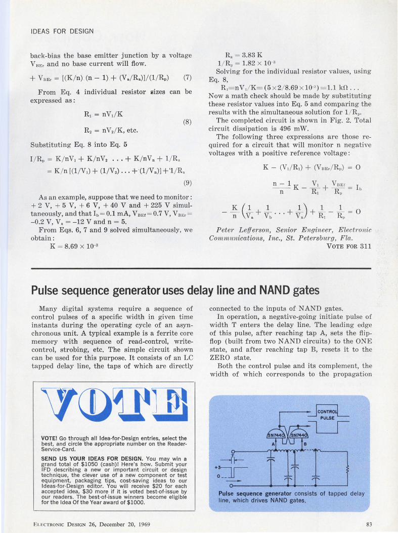
IDEAS FOR DESIGN
back-bias the base emitter junction by a voltage V BEr and no base current will flow.
+ VnEr = [(K / n) (n- 1) + (Va/ Ra)l/(l / RP) (7)
From Eq. 4 individual resistor 2izes can be expressed as :
(8) R2 = nVd K, etc.
Substituting Eq. 8 into Eq. 5
I / Rp = K / nV1 + K / nV2 ... + K / nVn + 1/ R.
= K / n [ (l / V1) + (l/V2) ... + ·(1 / V n}] + '1 / R.
(9)
As an example, suppose that we need to monitor: + 2 V, + 5 V, + 6 V, + 40 V and + 225 V simultaneously, and that l b= 0.1 mA, V BEr = 0.7 V, V BEr = -0.2 V, v. = -12 V and n = 5.
From Eqs. 6, 7 and 9 solved simultaneously, we obtain:
K = 8.69 x 10-s
Ra = 3.83 K l / Rp = 1.82 x 1o~a
Solving for the individual resistor values, using Eq. 8,
R1= nV1/ K= (5 x 2/ 8.69 x 10⁻³) = 1.1 k.fl .. .
Now a math check should be made by substituting these resistor values into Eq. 5 and comparing the results with the simultaneous solution for l / R 1,.
The completed circuit is shown in Fig. 2. Total circuit dissipation is 496 mW.
The following three expressions are those required for a circuit that will monitor n negative voltages with a positive reference voltage:
n - 1 K V1 + V nEr _ h - n- - R1 RP -
Peter Lef] erson, S enior Engineer , Electronic Cornrnunications, Inc., St. Petersburg, Fla.
VOTE FOR 311
Pulse sequence generator uses delay line and NANO gates Many digital systems require a sequence of
control pulses of a specific width in given time instants during the operating cycle of an asynchronous unit. A typical example is a ferrite core memory with sequence of read-control, writecontrol, strobing, etc. The simple circuit shown can be used for this purpose. It consists of an LC tapped delay line, the taps of which are directly
VOTE! Go through all Idea-for-Design entries, select the best, and circle the appropriate number on the ReaderService-Card.
SEND US YOUR IDEAS FOR DESIGN. You may win a grand total of $1050 (cash)! Here's how. Submit your IFD describing a new or important circuit or design technique, the clever use of a new component or test equipment, packaging tips, cost-saving ideas to our Ideas-for-Design editor. You will receive $20 for each accepted idea, $30 more if it is voted best-of-issue by our readers. The best-of-issue winners become eligible for the Idea Of the Year award of $1000.
ELECTRON IC D ESIGN 26, December 20, 1969
connected to the inputs of N AND gates. In operation, a negative-going initiate pulse of
width T enters the delay line. The leading edge of this pulse, after reaching tap A, sets the flipflop (built from two NAND circuits) to the ONE state, and after reaching tap B, resets it to the ZERO state.
Both the control pulse and its complement, the width of which corresponds to the propagation
0 I tT_:O
Pulse sequence generator consists of tapped delay line, which drives NANO gates.
83
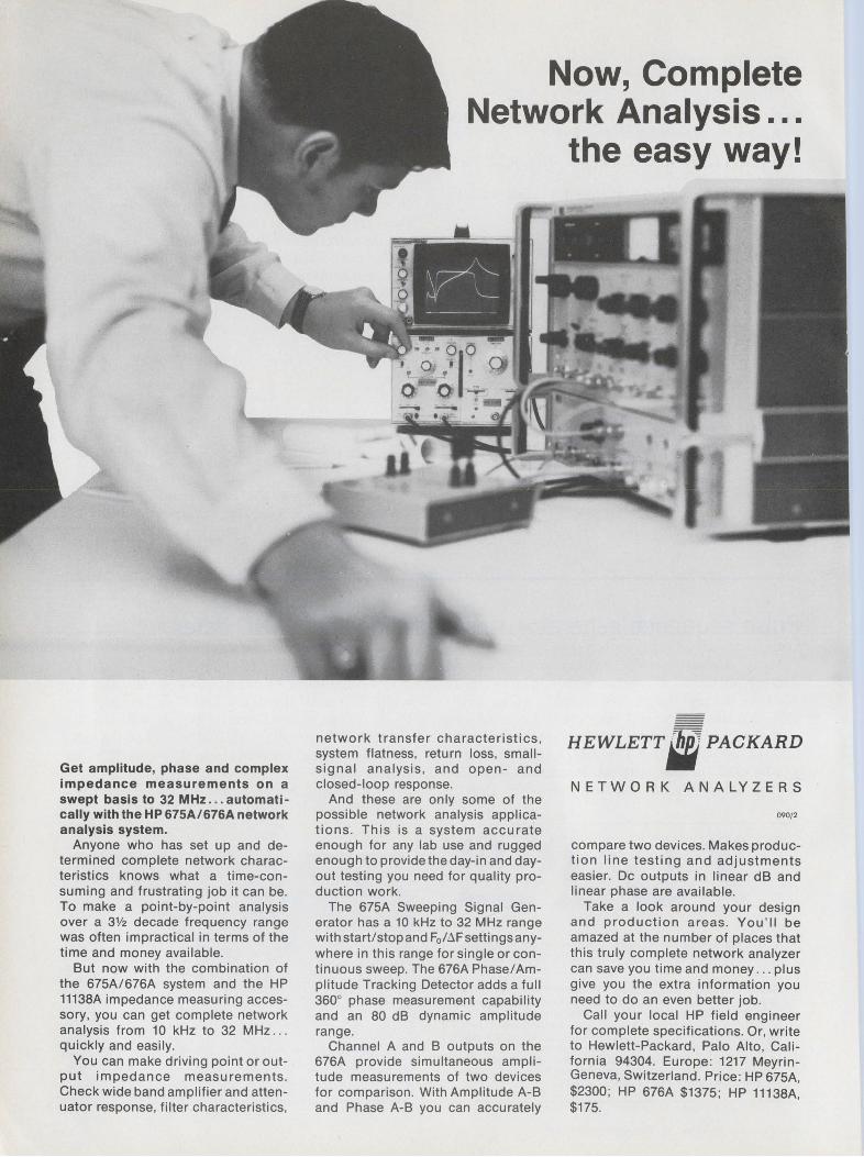
Get amplitude, phase and complex impedance measurements on a swept basis to 32 MHz ... automatically with the HP 675A/676A network analysis system.
Anyone who has set up and determined complete network characteristics knows what a time-consuming and frustrating job it can be. To make a point-by-point analysis over a 3Y2 decade frequency range was often impractical in terms of the time and money available.
But now with the combination of the 675A/676A system and the HP 11138A impedance measuring accessory, you can get complete network analysis from 10 kHz to 32 MHz . . . quickly and easily.
You can make driving point or output impedance measurements. Check wide band amplifier and attenuator response, filter characteristics,
Now, Complete Network Analysis ...
the easy way!
network transfer characteristics, system flatness, return loss, smallsig nal analysis, and open- and closed-loop response.
And these are only some of the possible network analysis applications. This is a system accurate enough for any lab use and rugged enough to provide the day-in and dayout testing you need for quality production work.
The 675A Sweeping Signal Generator has a 10 kHz to 32 MHz range with start/stop and F0 /~F settings anywhere in this range for single or continuous sweep. The 676A Phase/ Amplitude Tracking Detector adds a full 360° phase measurement capability and an 80 dB dynamic amplitude range.
Channel A and B outputs on the 676A provide simultaneous amplitude measurements of two devices for comparison. With Amplitude A-B and Phase A-B you can accurately
HEWLETT. PACKARD
NETWORK ANALYZERS
090/ 2
compare two devices. Makes production line testing and adjustments easier. De outputs in linear dB and linear phase are available.
Take a look around your design and production areas. You'll be amazed at the number of places that this truly complete network analyzer can save you time and money . . . plus give you the extra information you need to do an even better job.
Call your local HP field engineer for complete specifications. Or, write to Hewlett-Packard, Palo Alto, California 94304. Europe: 1217 MeyrinGeneva, Switzerland. Price: HP 675A $2300; HP 676A $1375; HP 11138A: $175.
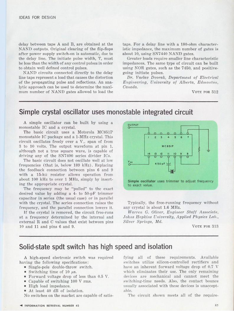
IDEAS FOR DESIGN
delay between taps A and B, are obtained at the N AND outputs. Original clearing of the flip-fl.ops after power supply switch-on is automatic, due to the delay line. The initiate pulse width, T, must be less than the width of any control pulses in order to obtain well defined control pulses.
N AND circuits connected directly to the delay line taps represent a load that causes the distortion of the propagating pulse and reflections. An analytic approach can be used to determine the maximum number of NAND gates allowed to load the
taps. For a delay line with a 180-ohm characteristic impedance, the maximum number of gates is about 10, using SN7 440 N AND gates.
Greater loads require smaller line characteristic impedances. The same type of circuit can be built using NOR gates, such as the 7450, and positivegoing initiate pulses.
Dr. Vaclav Dvorak, Department of Electrical Engineering, University of Alberta, Edmonton, Canada.
VOTE FOR 312
Simple crystal oscillator uses monostable integrated circuit A simple oscillator can be built by using a
monostable IC and a crystal. The basic circuit uses a Motorola MC851P
monostable IC package and a 1-MHz crystal. This circuit oscillates freely over a Vee span of from 3 to 10 volts. The output waveform at pin 1, although not a true square wave, is capable of driving any of the SN7 400 series divider I Cs.
The basic circuit does not oscillate well at low frequencies (that is, below 189 kHz). Replacing the feedback connection between pins 6 and 9 with a 15-kn resistor allows operation from about 100 kHz to over 1 MHz, simply by inserting the appropriate crystal.
The frequency may be "pulled" to the exact desired value by adding a 4- to 50-pF trimmer capacitor in series (the usual case) or in parallel with the crystal. The series connection raises the frequency, and the parallel connection lowers it.
If the crystal is removed, the circuit free-runs at a frequency determined by the internal and external R and C values that exist between pins 10 and 11 and pins 6 and 9.
OUTPUT
2 3 4 5 6 7
MC851P
Vee
Simple oscillator uses trimmer to adjust frequency to exact value.
Typically, the free-running frequency without any crystal is about 1.6 MHz.
Warren G. Oliver, Engineer Staff Associate, Johns Hopkins University, Applied Physics Lab. , Silver Springs, Md.
VOTE FOR 313
Solid-state spdt switch has high speed and isolation A high-speed electronic switch was required
having the following specifications: • Single-pole double-throw switch. • Switching time of 10 µ,s. • Forward voltage drop of less than 0.5 V. • Capable of switching 100 V rms. • High load impedance. • At least 40 dB of isolation. No switches on the market are capable of satis-
.... INFORMATION RETRIEVAL NUMBER 42
fying all of these requirements. Available switches utilize silicon-controlled rectifiers and have an inherent forward voltage drop of 0.7 V which eliminates their use. The only remaining devices are mechanical and cannot meet the switching-time needs. Also, the contact bounce usually associated with these devices is unacceptable.
The circuit shown meets all of the require-
85
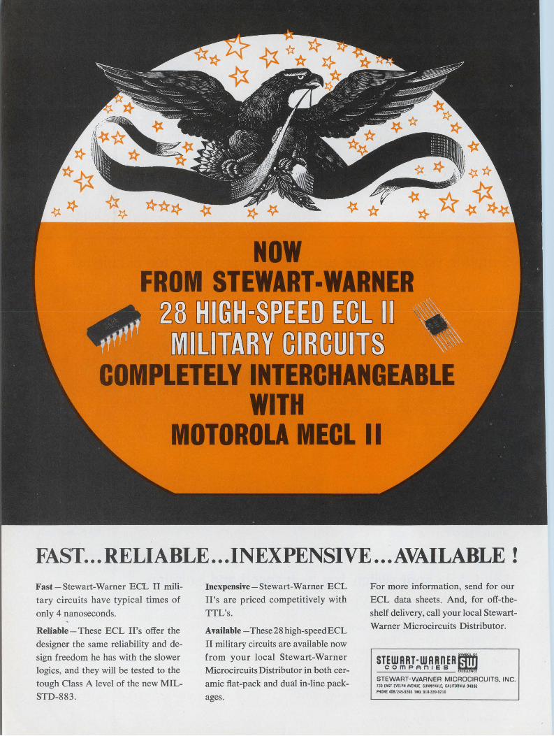
FAST ... RELIABLE ... INEXPENSIVE ... AVAILABLE ! Fast-Stewart-Warner ECL II mili
tary circuits have typical times of
only 4 nanoseconds.
Reliable - These ECL H's offer the
designer the same reliability and de
sign freedom he has with the slower logics, and they will be tested to the
tough Class A level of the new MIL
STD-883.
Inexpensive-Stewart-Warner ECL
II's are priced competitively with
TTL's.
Available -These28 high-speedECL
II military circuits are available now
from your local Stewart-Warner
Microcircuits Distributor in both cer
amic flat-pack and dual in-line pack
ages.
For more information, send for our
ECL data sheets. And, for off-the
shelf delivery, call your local Stewart
Warner Microcircuits Distributor.
STEWRRT-WRRnERfm comPRn1es ~
------- UClLLfNCl
STEWART-WARNER MICROCIRCUITS, INC. 730 EAST EVELYN AVENUE, SUNNYVALE, CALIFORNIA 94086 PHONE 408/245-9200 TWX 910-339-9210

IDEAS FOR DESIGN
ments. One inexpensive way to develop the switching voltage using low-voltage semiconductor devices is to drive an audio output transformer in reverse. This will easily develop the 400 V p-p square wave required for the switch. Of course, this limits the on time of the switch.
Circuit operation is as follows: Assume that a positive voltage is applied to input 1 and a negative voltage to input 2. The only requisite for this voltage is that it must be greater than the voltage being applied to inputs A or B. Under these conditions, diodes CR1, CR2, CRa, and CR, are forward-biased, and CR5, CR6 , CR1 and CR8
a.re reversed-biased. The voltage drops of the conducting diodes are not exactly equal, and resistors R, through R , are used to compensate for these differences and eliminate their effect on the operation of the switch.
A signal applied to input A maintains the junction of CR1 and CRa at that potential. In turn the junction of CR2 and CR1 follows that voltage, because it is in parallel with input A, a.nd the voltage drops of the diodes are equal and forward-biased. The signal is thereby "connected" to the output. Input B is not connected to the output because the diodes associated with it are reverse-biased and thus not conducting. The
SWITCH ANALOG
INPUT A
INPUT A
R2
"-~~~~~~~..,_~~~~~~--02
Solid-state switch provides high-speed, low forward drop and good isolation.
signal at input B is therefore disconnected from the output.
The maximum switching time of the switch is dependent on the internal capacitance of the diodes and can be compensated for. This, though, limits the attenuation capabilities of the switch. The input B is connected to the output when the switching input voltage is reversed. The switch is useful for multiplexing high-level ac voltages.
Vito Del Guercio, Senior Engineer, Aerojet.General Corp., Azusa, Calif.
VOTE FOR 314
Subminiature shielded wire made by using plating kit A simple and inexpensive method of manufac
turing subminiature shielded wire consists of processing conventional magnet wire of any suitable insulation with any of the commercially available electrolessi nickel or copper plating kits. Such kit manufacturers are Enthone, Shipley, and others. Formvar, polyurethane, and Teflon-coated wires of various insulation thicknesses have all been successfully plated, but single-coating wire is not recommended because of possible pinholes in the insulation that result in shorted shields.
If the dimensions of the final wire or jumper are known in advance, the wire should be precut to those dimensions, and the ends bared and tinned. The tinned portions, and a small area of insulation beyond them, should then be masked with Mylar tape, and the wire processed as recommended. It is suggested that the wire be plated loosely coiled rather than straight, since coiling or repeated bending of the material after processing may fracture the plating. Connections between circuit grounds and the shield are made with conductive epoxy .
... INFORMATION RETRIEVAL NUMBER 43
Such shielded wires have been used as jumpers on printed-circuit boards where leakage had to be kept to a minimum. Another application is as coaxial cables or high-frequency delay cables, whose characteristics will depend upon the dielectric properties of the insulating film. Tefloninsulated wire has the best high-frequency transmission characteriistics, and for a given wire size the impedance varies directly with the insulation thickness.
R. Michel Zilberstein, Senior Project E ngineer, Microsonics Div., Sangamo Electric Inc., Weymouth, Mass.
VOTE FOR 315
IFD Winner for September 1, 1969 Walter C. Dillon, Design Engineer, Oregon State University, Corvallis, Oregon. His Idea "Low-Frequency Multiplier Uses TwinT Network" has been voted the Most Valuable of Issue Award. Vote for the Best Idea in this Issue.
87

Before you make book on any other pot, we suggest you take a good close look at the small print. Pixiepot® is the smallest precision 10-turn wirewound potentiometer on the market today, and the only pot under $3.50 with all these high performance features:
Length: ONLY 3,4" Diameter: ONLY ~e" Linearity: ±0.25% Resistance Range: 100 ohms to 100K ohms Power Rating: 2 watts@ +20°C Temperature Range: -25°C to +85°C Resolution: Better than ANY wirewound pot TWICE its size Slotted Stainless Steel Shaft/C ring
One PIXIEPOT is worth 1,000 word
INFORMATION RETRIEVAL NUMBER 44
Specify Model 3253 Pixiepot for as low as $3.47 each in production quantities and only $4.95 each for 1-24 units. In-stock delivery, of course. Call, write or wire Duncan Electronics today for complete specifications. When it comes to mini-pots, we wrote the book.
DU NOA electronics int
DUNCAN ELECTRONICS SUBSIDIARY
¢ )+ SVSTRCN•CCNNER
2865 FAIRVIEW ROAD COSTA MESA,
CALIFORNIA 92626 (7141 545-8261
88 ELECTRON IC DESIGN 26, D ecember 20, 1969
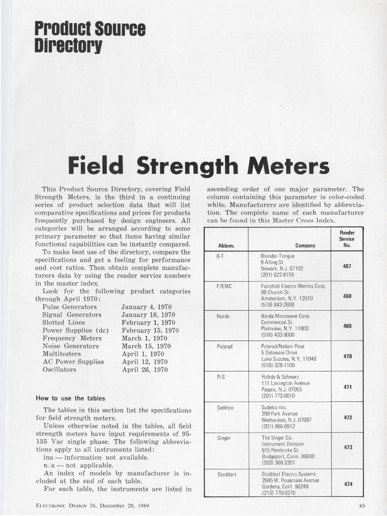
Product source Directory
Field Strength Meters This Product Source Directory, covering Field
Strength Meters, is the third in a continuing series of product selection data that will list comparative specifications and prices for products frequently purchased by design engineers. All categories will be arranged according to some primary parameter so that items having similar functional capabilities can be instantly compared.
To make best use of the directory, compare the specifications and get a feeling for performance and cost ratios. Then obtain complete manufacturers data by using the reader service numbers in the master index.
Look for the following product categories through April 1970:
Pulse Generators Signal Generators Slotted Lines Power Supplies (de) Frequency Meters Noise Generators Multi testers AC Power Supplies Oscillators
How to use the tables
January 4, 1970 January 18, 1970 February 1, 1970 February 15, 1970 March 1, 1970 March 15, 1970 April 1, 1970 April 12, 1970 April 26, 1970
The tables in this section list the specifications for field strength meters.
Unless otherwise noted in the tables, all field strength meters have input requirements of 95-135 Vac single phase. The following abbreviations apply to all instruments listed:
ina - information not available. n / a - not applicable. An index of models by manufacturer is m
cluded at the end of each table. For each table, the instruments are listed in
ELECTRONIC DESIGN 26, December 20, 1969
ascending order of one major parameter. The column containing this parameter is color-coded white. Manufacturers are identified by abbreviation. The complete name of each manufacturer can be found in thiR Master Crnss Index.
Reader Service
Abbrev. Company No.
B-T Blonder-Tongue 9 Alling St.
467 Newark, N.J. 07102 (201) 622-8155
F/EMC Fairchild Electro Metrics Corp. 88 Church St.
468 Amsterdam. N.Y. 12010 (518) 843-2600
Narda Narda Microwave Corp . Commercial St.
469 Plainview. N.Y. 11803 (516) 433-9000
Polarad Polarad/Nelson Ross 5 Delaware Drive
470 Lake Success, N.Y. 11040 (516) 328-1100
R-S Rohde & Schwarz 111 Lexington Avenue
471 Passaic, N .J. 07055 (201) 773-8010
Sadelco Sadelco Inc. 299 Park Avenue
472 Weehau ken, N .J. 07087 ( 201) 866-0912
Singer The Singer Co. Instrument Division 473 915 Pembroke St. Bridgeport, Conn. 06608 (203) 366-3201
Stoddart Stoddart Electro Systems 2045 W. Rosecrans Avenue
474 Gardena, Calif. 90249 (213) 770-0270
89
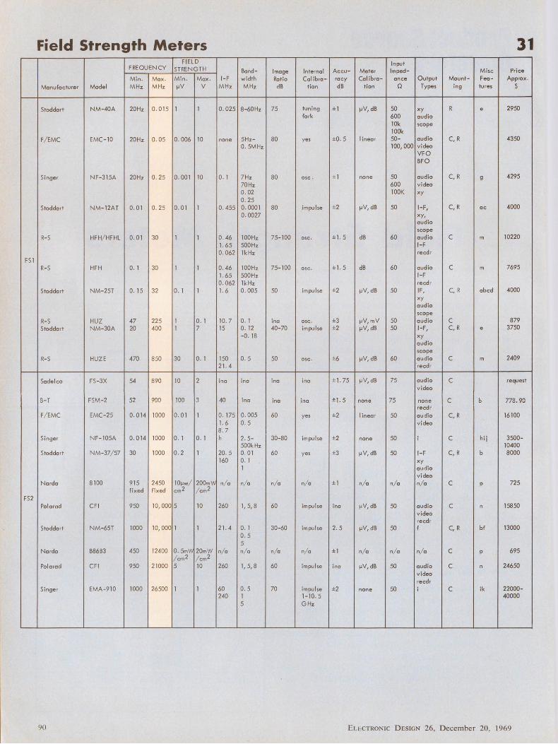
Field Strength Meters 31 FIELD Input
FREQUE NCY STRENGTH Band- Image Internal Ac cu- Meter Imped- Misc Price
Mi n. Max. Mi n. Max. 1-F width Ratio Calibre- ra cy Calibre- a nee Output Mount- Fea- Approx.
M anufactu rer Model MHz MHz µV v MHz MHz dB ti on dB ti on n Types ing tu res $
Stodda rt NM-40A 20Hz 0.015 1 1 0.025 8-60Hz 75 tuning ± 1 µV, dB 50 xy R e 2950 fo rk 600 audio
lOk scope lOOk
F/ EMC EMC-10 20Hz o. 05 o. 006 10 none 5 Hz- 80 yes ±0. 5 linear 50- audio C, R 4350 0 . 5MHz 100, 000 video
VFO BFO
Singe r N F-3 15A 20H z o. 25 o. 00 1 10 o. 1 7 Hz 80 osc. ± 1 none 50 aud io C, R g 4295 70 Hz 600 v ideo 0. 02 lOOK xy 0. 25
Stodda rt NM-12AT 0 . 0 1 o. 25 0 . 0 1 1 0. 455 0 . 000 1 80 im pu lse ±2 µ V, dB 50 1-F, C, R ac 4000 0. 0027 xy,
audio scope
R- S HFH/ HFHL 0.0 1 30 1 1 o. 46 l OO Hz 75-100 osc . ± ]. 5 dB 60 audio c m 10220 1. 65 500 Hz 1-F 0.062 lkHz recd r
FSl R- S HFH o. 1 30 1 1 0.46 l OO Hz 75-100 osc . ± 1. 5 dB 60 audio c m 7695
1. 65 500Hz 1-F 0.062 l k Hz recdr
Stodda rt NM - 25T o. 15 32 0. 1 1 1. 6 o. 005 50 impu lse ±2 µ V, dB 50 IF , C, R abed 4000 xy audio scope
R- S HUZ 47 225 1 o. 1 10. 7 o. 1 inc osc . ±3 µV,mV 50 audio c 879 Stodda rt NM - 30A 20 400 1 7 15 0. 12 40-70 impulse ±2 µV, dB 50 1- F, C, R e 3750
- 0 . 18 xy audio scope
R- S HUZE 470 850 30 o. 1 150 0 . 5 50 osc. ±6 µV, dB 60 audio c m 2409 21. 4 recdr
Sade I co FS - 3X 54 890 10 2 ino ina ino ino ± 1. 75 µ V,dB 75 audio c request v ideo
B- T FSM- 2 52 900 100 3 40 ina ina inc ±1.5 none 75 none c b 778. 90 recdr
F/ EMC EMC-25 0 . 0 14 1000 0 . 0 1 1 0 . 175 0 . 005 60 yes ±2 linear 50 audio C, R 16100 1. 6 o. 5 video 8 . 7
Singer N F-105A 0.0 14 1000 o. 1 o. 1 h 2 . 5- 30-80 im pulse ±2 none 50 i c hij 3500-500k Hz 10400
Stodda rt NM - 37/ 57 30 1000 0 .2 1 20.5 0 . 0 1 60 yes ±3 µ V, dB 50 1-F C, R b 8000 160 o. 1 xy
1 audio video
Na rdo 8 100 9 15 2450 lOµ w/ 200'!! \N n/ a n/ a n/ a n/ a ± 1 n/ a n/ a n/ a c p 725 fixed fixed cm2 / cm2
FS2 Pola rad CF ! 950 10, 000 5 10 260 1, 5, 8 60 impulse ina µ V, dB 50 audio c n 15850
video recdr
Stodda rt N M- 65T 1000 10, 000 1 1 2 1. 4 o. 1 30-60 im pulse 2. 5 µV, dB 50 f C, R bf 13000 0 . 5 5
Na rdo B86 B3 450 12400 0.5mW 20mW n/ a n/ a / cm2 / cm2
n/ a n/ a ± 1 n/ a n/ a n/ a c p 695
Po la rad CFI 950 21000 5 10 260 1, 5,8 60 im pul se ino µV, dB 50 audio c n 24650 v ideo recdr
Si nge r EMA-9 10 1000 26500 1 1 60 o. 5 70 impul se ±2 none 50 i c ik 22000-240 1 1-1 0. 5 40000
5 G Hz
90 EL ECTRON IC D ESIGN 26, D ecember 20, 1969
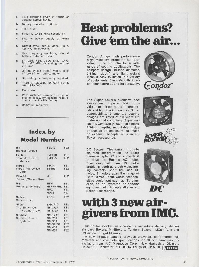
a. Field strength given in terms of voltage across 50 !1 .
b. Battery operation optional.
c. Solid state.
d. First i·f, 0.455 MHz second i·f.
e. External power supply at extra cost.
f . Output type: audio, video, lin & log, xy, fm detector.
g. Beat frequency oscillator, internal battery automatic scan.
h. 1-f: 225, 455, 1600 kHz, 10.73 MHz, 42 MHz depending on tun · ing unit.
1. Output types: audio, video, post i·f, pre i·f , xy, remote meter.
j. Depending on frequency required.
k. Price: 1·10.5 GHz, $22,000; 1·26.5 GHz, $40,000.
m. Per meter.
n. Price includes complete range of plug-in heads, for specific requirements check with factory.
p. Radiation monitors.
Index by
Model Number 8-T FSM-2 FS2 Blonder-Tongue
F/EMC EMC-10 FSl Fairchild Electro EMC-25 FS2
Metrics
Narda 8100 FS Narda Microwave B86B3 FS2
Corp.
Pola rad CFI FS2 Polarad/Nelsen Ross
R-S HFH FSl Rohde & Schwarz HFH/HFHL FSl
HUZ FSl HUZE FSl
Sadelco FS·3X FS2 Sadelco Inc.
Singer EMA-910 FS2 The Singer Co. NF-105A FS2
Instrument Div. NF-3 15A FSl
Stoddart NM-12AT FSl Stoddart Electro NM -25T FSl
Systems NM-30A FSl NM-37 /57 FS2 NM -40A FS2 NM -65T FS2
ELCCTRONIC DESIGN 26, December 20, 1969
Beat problems? G. ~ th . 1ve em eair ...
Condor. A new high performance high reliability propeller fan providing up to 575 cfm for a wide range of cooling applications. The compact design (10-inch diameter, 3.5-inch depth} and light weight make it easy to install in a variety of equipments. 6 models with different connectors add to its versatility.
The Super boxer's exclusive new aerodynamic impeller design provides exceptional output characteristics at high back pressures. Super dependability. 2 patented bearing designs are rated at 1 O years life under normal conditions. Super versatility. Compact (4.687-inch square, 1.5-inch depth), mountable inside or outside an enclosure, to intake or exhaust. Accepts all standard Boxer accessories.
DC Boxer. The small module mounted integrally on the Boxer frame accepts DC and converts it to drive the Boxer's AC motor. Does away with usual DC motor problems, such as brush wear, arcing contacts, short life, and RF noise. 8 models span the range of 12 to 38 VDC input. Cools heat sensitive equipment such as, TV cameras, sound systems, telephone equipment, etc. Accepts all standard Boxer accessories. DC
witll 3 new airgivers from IMO.
Distributor stocked nationwide for immediate delivery. As are standard Boxers, MiniBoxers, Tandem Boxers, IMCair fans and IMCair centrifugal blowers.
A new 16-page catalog provides drawings, performance parameters and complete specifications for all our airmovers. It's available from IMC Magnetics Corp., New Hampshire Division, Route 16B, Rochester, N. H. 03867, Tel. (603) 332-5300. IQj h ,X3
INFORMATION RETRIEVAL NUMBER 45
91
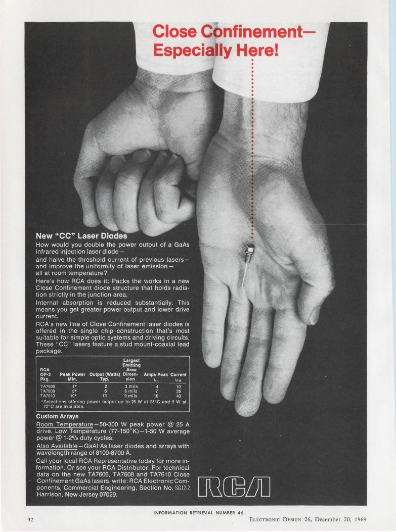
92
Close C nfinementEspecially Here!
INFORMATION RETRIEVAL NUMBER 46
ELECTRONIC D ESIGN 26, D ecemb er 20, 1969
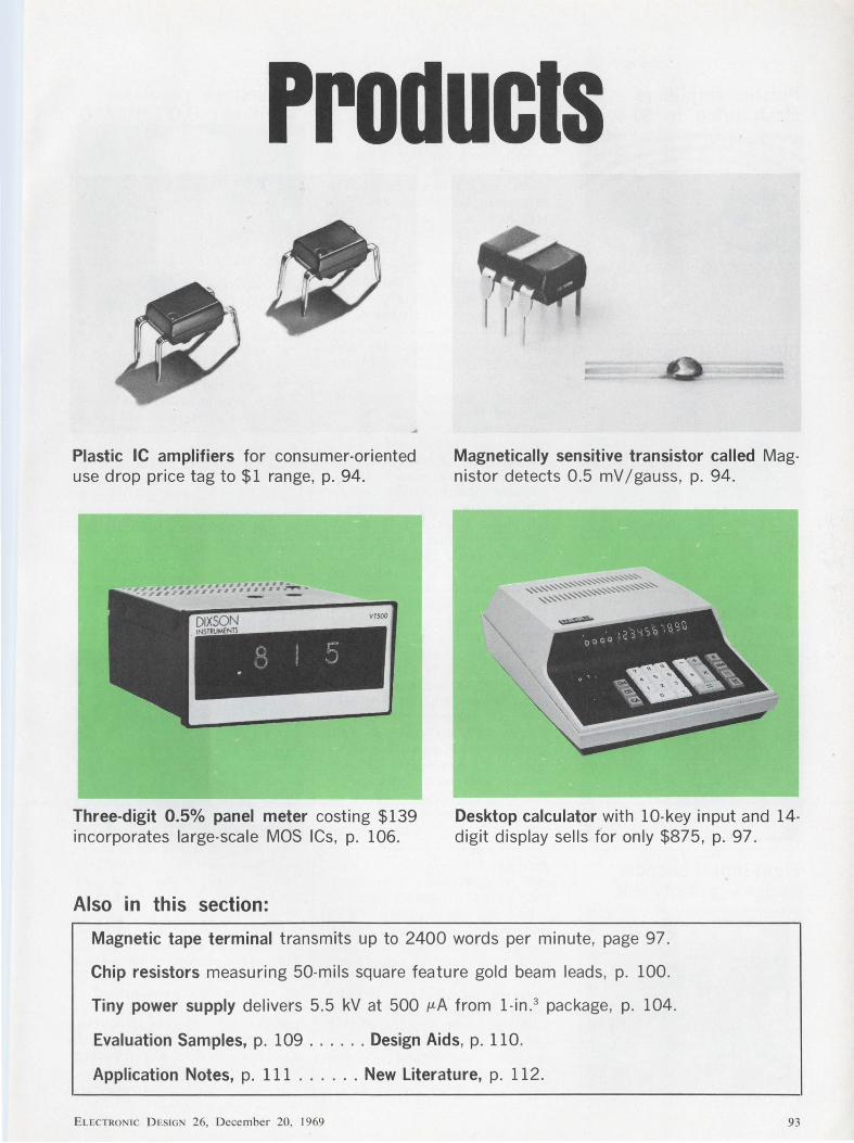
Products
Plastic IC amplifiers for consumer-oriented use drop price tag to $1 range, p. 94.
Magnetically sensitive transistor called Magni.star detects 0.5 mV /gauss, p. 94.
Three-digit 0.5% panel meter costing $139 incorporates large-scale MOS ICs, p. 106.
Desktop calculator with 10-key input and 14-digit display sells for only $875, p. 97.
Also in this section:
Magnetic tape terminal transmits up to 2400 words per minute, page 97.
Chip resistors measuring 50-mils square feature gold beam leads, p. 100.
Tiny power supply delivers 5.5 kV at 500 µ,A from 1-in. 3 package, p. 104.
Evaluation Samples, p. 109 ...... Design Aids, p. 110.
Application Notes, p. 111 ...... New Literature, p. 112.
ELECTRONIC DESIGN 26, December 20. 1969 93
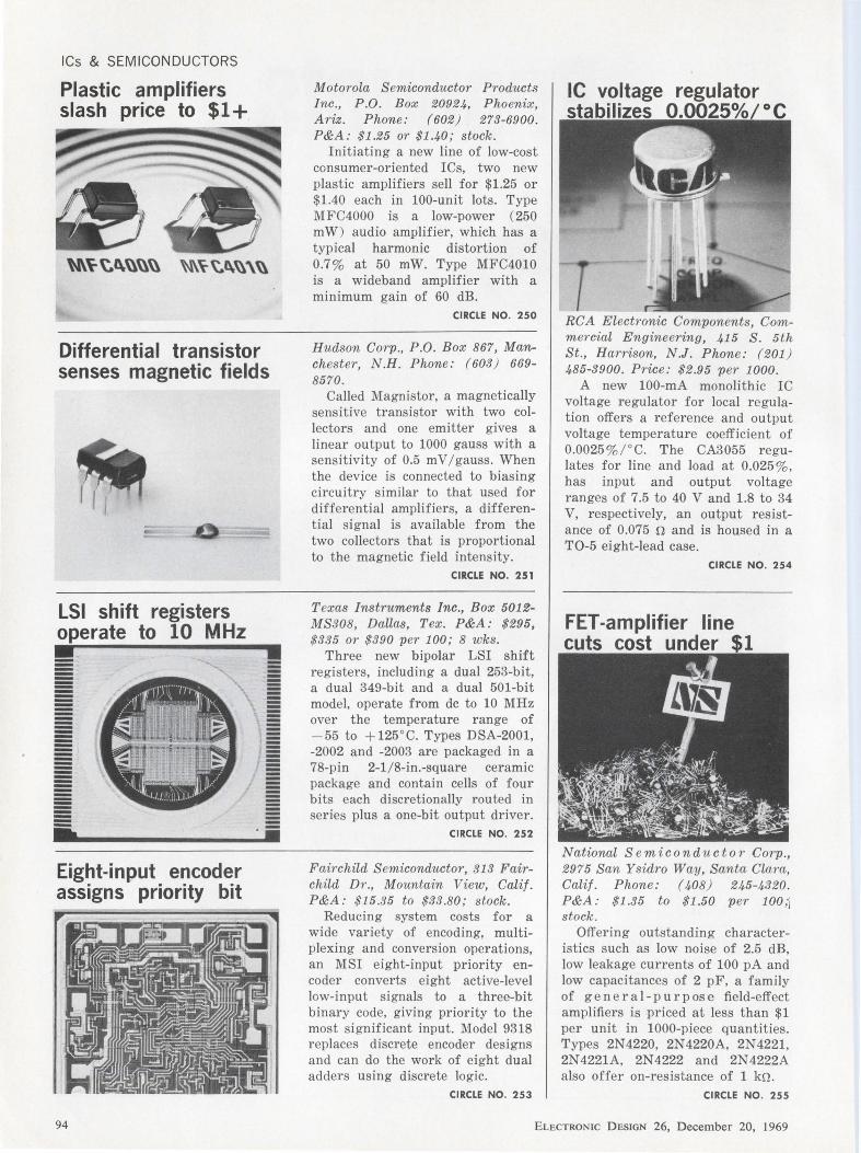
ICs & SEMICONDUCTORS
Plastic amplifiers slash price to $1+
Differential transistor senses magnetic fields
LSI shift registers operate to 10 MHz
= ·ii Eight-input encoder assigns priority bit
94
Motorola S emiconductor Products Inc., P.O. Box 20924, Phoenix, Ariz. Phone: (602) 273-6900. P&A: $1.25 or $1.40; stock .
Initiating a new line of low-cost consumer-oriented ICs, two new plastic amplifiers sell for $1.25 or $1.40 each in 100-unit lots. Type MFC4000 is a low-power (250 mW) audio amplifier, which has a typical harmonic distortion of 0.7 % at 50 mW. Type MFC4010 is a wideband amplifier with a minimum gain of 60 dB.
CIRCLE NO. 250
Hudson Corp., P .O. Box 867, Manchester, N.H. Phone: (603 ) 669-8570.
Called Magnistor, a magnetically sensitive transistor with two collectors and one emitter gives a linear output to 1000 gauss with a sensitivity of 0.5 mV / gauss. When the device is connected to biasing circuitry similar to that used for differential amplifiers, a differential signal is available from the two collectors that is proportional to the magnetic field intensity.
CIRCLE NO. 251
Texas Instruments Inc., Box 5012-MS308, Dallas, Tex. P&A: $295, $335 or $390 per 100; 8 wks .
Three new bipolar LSI shift registers, including a dual 253-bit, a dual 349-bit and a dual 501-bit model, operate from de to 10 MHz over the temperature range of - 55 to + 125°C. Types DSA-2001, -2002 and -2003 are packaged in a 78-pin 2-1 / 8-in.-square ceramic package and contain cells of four bits each discretionally routed in series plus a one-bit output driver.
CIRCLE NO. 252
Fairchild S emiconductor, 313 Fairchild Dr., Mountain View, Calif. P&A: $15.35 to $33.80; stock.
Reducing system costs for a wide variety of encoding, multiplexing and conversion operations, an MSI eight-input priority encoder converts eight active-level low-input signals to a three-bit binary code, giving priority to the most significant input. Model 9318 replaces discrete encoder designs and can do the work of eight dual adders using discrete logic.
CIRCLE NO. 2 53
IC voltage regulator stabilizes 0.0025%/°C
RCA Electronic Components, Comm ercial Engineering, 415 S. 5th St ., Harrison, N.J. Phone: (201 ) 485-3900. Price : $2.95 per 1000.
A new 100-mA monolithic IC voltage regulator for local regulation offers a reference and output voltage temperature coefficient of 0.0025 %/° C. The CA3055 regulates for line and load at 0.025 %, has input and output voltage ranges of 7.5 to 40 V and 1.8 to 34 V, respectively, an output resistance of 0.075 n and is housed in a T0 -5 eight-lead case.
CIRCLE NO. 254
FET-amplifier line cuts cost under $1
National S emiconductor Corp., 2975 San Ysidro Way, Santa Clara, Calif. Phone: ( 408) 245-4320. P&A: $1.35 to $1.50 per lOO;j stock.
Offering outstanding characteristics such as low noise of 2.5 dB, low leakage currents of 100 pA and low capacitances of 2 pF, a family of genera 1- purpose field-effect amplifiers is priced at less than $1 per unit in 1000-piece quantities. Types 2N4220, 2N4220A, 2N4221, 2N 4221A, 2N 4222 and 2N 4222A also offer on-resistance of 1 kn.
CIRCLE NO. 255
ELECTRONIC DESIGN 26, D ecember 20, 1969
We give it to you straight! If our new Tru-GlidcSlidcs
didn't slide that way we would have given them
another name. Honest! Being conscientious, upright people, we simply couldn't have devised a brand new ball bearing steel slide that wouldn't have been approved by lvfother. Vo/e named it "Tru-Glide" because it slides so good and so precisely. And even though we have priced it right down in the small change category you can be sure it's an OK slide. Not cheap, just inexpensive. Applicable to hun-
dreds of design situations where space allotments
are minimal and where quality action and ease of movement
are of special importance. And where low
cost is a factor! A big one. Yes, Tru-Glide is a hum-clinger. A bell ringer. A true blue lvfADE IN THE USA slide. VoJe hope it wobbles your clapper. How can we make such a good allpurpose industrial I commercial I etc. slide? Vo/ell, let us rema.rk that it's not exactly easy. Six years ago we had the basic design. Since then, we've come
up with some completely new concepts in part fabrication (our parts), including a whizzer
of an electronically-controlled production system that assures close tolerance, volume runs. Here at Jonathan we've had plenty of practice in this sort of thing. VoJe keep on producing our famous Thinline extruded aluminum slides that gave us our shiny bright reputation in the first place. And our respected Ultrathin steel slides that we also produce for defense, aerospace and other sophisticated-type
[left, Type 310 ; right, Type 311) applications. Vo/e just keep
INFORMATION RETRIEVAL NUMBER 47
E LECTRO IC D ESIGN 26, D ec embe r 20, 1969
doing our best. TruG lide slides come in
150 lb. capacity Type 310 three-section (%"wide x 2"
high] or 100 lb. capacity Type 311 two-section (15/32" wide x
1 % " high] versions, with or without mo'unting brackets . Lock-out in "open" position or disconnecting models are optional. Both models are available in standard lengths and travels, based on 2" increments . The moo-o-ving mechanisms are freeriding, precision-placed steel ball bearings contained in special rigid vinyl ball retainers. Lubricated bearings. Trouble-free multithousand cycling. Tru-Glide slides make designers happy. Just right for computers, business machines, office copiers, appliances, desks and equipment, audio/visual systems, medical-dental __ .,... __ .,. equipment, good furniture, telephonf systems and vending machines ,_...,._ for instance. Or send along your special problems -we love 'em! So
remember "Tru-Glide," an honest name for a straightforward slide. An OK slide . Built by mothers' sons'-everyone of them!
© 1969, Jonathan
r;I cu;;-ail u;;-J.;;;ath-;;-M"f;Ci;:---.. 1101 S. Acacia, I Fullerton, Ca. 92631.
I Quit fooling around, send facts .
I NAME TITLE __ I
I ADDRESS I
I CITY I I STATE ZIP I ~----------------~
95
ICs & SEMICONDUCTORS
Voltage reference units stabilize to 10 ppm/ °C
Dual 100-bit register lowers cost to 4¢/bit
Fast p-i-n photodiodes show 2-nA dark current
96
Dickson Electronics Corp ., Box 1390, Scottsdale, Ariz. Phone: (602) 947-2231. P&A: $6 .50 to $23 .20 pe1· 100 ; 2 wks.
Incorporating a self-contained constant-current sou rce and a temperature-compensated voltage reference diode to provide temperature compern;aLion and stability to + 100 ° C, a new line of reference voltage sources is available with coefficients of 10, 25, 50 and 100 ppm/° C at 6.4 V +5%, and operates from 12 to 40 V.
CIRCLE NO. 256
Fairchild S emiconductor Corp., 313 Fairchild Dr., Mountain View, Calif. Phone: ( 415) 962-3563. P&A: $36 ; stock.
A dual 100-bit static shift register provides 200 bits of storage at Rhift frequencies to 1 MHz, at a cost of less than 4¢ a bit. The 3307 unit is an MOS IC with a p-channel enhancement mode and a power drain of 1.5 mW per bit. It is avai lable in a T0-100 case with an operating temperature range of - 55 to +85°C.
CIRCLE NO. 2 57
Motorola S emiconductor Products Inc., Box 20924, Phoenix, Ariz. P&A: $7.25 or $6.60 per 100; stock . F eaturing radiation sensitivities of 1.8 µA / mW / cm2 and 0.4 µ,A / mW /cm", respectively, MRD-500 and MRD-510 p-i-n photodiodes display a 1-ns response time and 2-nA dark current at 25 °C. Both devices, which are packaged in T0-18 cases, are sensitive over a wavelength range of 0.4 to 1.1 µ,m, diss ipate 100 mW and have reverse breakdown ratings of 200 V.
CIRCLE NO. 258
Micro N etworks Corp., 5 Bar bara Lane, Worc ester, Mass. Phone: ( 61 7) 756-4635. Price: $33.75.
Mode I MN204 is a hybrid quad two-input non-invertin g power driver consisting of a TTL IC gate and four transistor output stages . Each output stage has a voltage rating of 40 V at a current of 300 mA. Internal voltage limiting is provided to r educe microcircuit power consumption. Operating t emperature range is - 55 to + 125°C. The unit is a 14-lead flatpack.
CIRCLE NO. 259
Hybrid regulator holds 0.05% at 1 A
Solitron Devices, Inc., Tninsisto1· Div., 11 77 Blue H eron Blvd, R iviera Beach, Flci. Phone: (305) 848-4311. Availability: stock.
Identified as the H CCA 100, a new high-power hybrid de voltage regulator offers a regulation of 0.05 % maximum (0.01 % typ ica l), from no load to a 1-A load. The unit has a vo ltage range of 8 to 50 V with a maximum output current of 3 A. P ower di ss ipation is 25 W (with heat s ink ) and temperature coefficient is 0.005 %/°C.
CIRCLE NO. 260
Thin-film ladder units are accurate to ±0.1 %
Crystalonics, A Teledyne Co., 147 Sherman St., Cambridge, Ma,ss. Phone: (617) 491-1670. P&A: $90; stock.
Operating over the temperature range of - 55 to + 125 ° C, a new series of tantalum-nitride thin-film 10 or 20-kn ladder networks provides an accuracy of ±0.1 % (1 / 4 bit ) . Type CDALl R/ 2R units have built-in feedback resistors for gains of 1/ 2, 1 or 2, are designed for use with hybrid d/a ladder switches and are housed in T0-5 cases.
CIRCLE NO. 261
ELECTRONIC D ESIGN 26, December 20, 1969
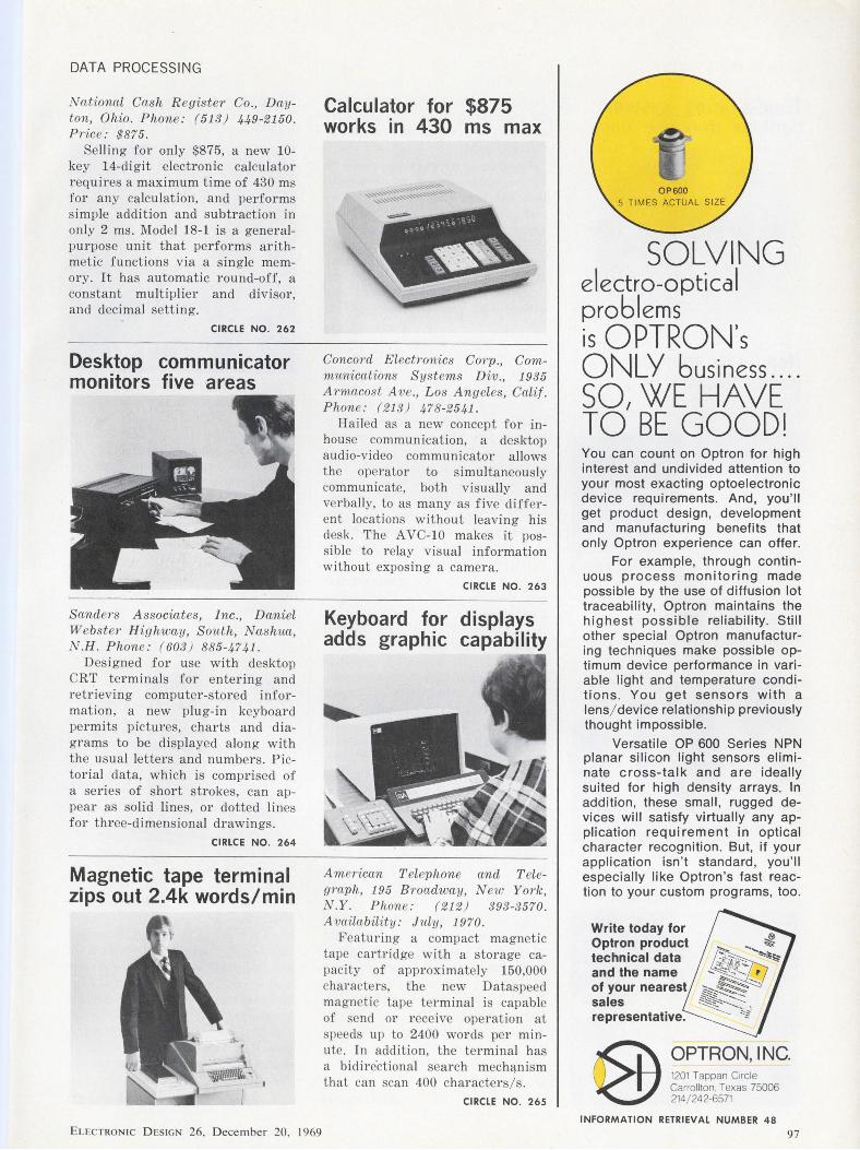
DATA PROCESSING
National Cash Register Co., Dayton, Ohio. Phone: (513) 449-2150. P1·ice : $875.
Selling for only $875, a new 10-key 14-digit electronic calculator requires a maximum time of 430 ms for any calculation, and performs simple addition and subtraction in only 2 ms. Model 18-1 is a generalpurpose unit that performs arithmetic functions via a s ingle memory. It has automatic round-off, a constant multiplier and divisor, and decimal setting.
CIRCLE NO. 262
Desktop communicator monitors five areas
Sande1·s Associates, Inc., Daniel Webster Highway, South, Nashua, N.H. Phone: (603 ) 885-4741.
Designed for use with desktop CRT terminals for entering and retrieving computer-stored information, a new plug-in keyboard permits pictures, charts and diagrams to be displayed along with the usual letters and numbers. Pictorial data, which is comprised of a series of short strokes, can appear as solid lines, or dotted lines for three-dimensional drawings.
CIRLCE NO. 264
Magnetic tape terminal zips out 2.4k words/min
ELECTRONIC DESIGN 26, December 20, 1969
Calculator for $875 works in 430 ms max
Concord Electronics Corp., Communications Systems Div., 1935 Armacost Ave., Los Angeles, Calif. Phone: ( 21 3) 478-2541 .
Hailed as a new concept for inhouse communication, a desktop audio-video communicator a llows the operator to simultaneously communicate, both visually and verbally, to as many as five different locations without leaving his desk. The A VC-10 makes it possible to relay visual information without exposing a camera.
CIRCLE NO. 263
Keyboard for displays adds graphic capability
American Telephone and Telegraph, 195 Broadwciy, N ew York, N.Y. Phone: ( 212) 393-3570. Availability: July, 1970.
F eaturing a compact magnetic tape cartridge with a storage capacity of approximately 150,000 characters, the new Dataspeed magnetic tape terminal is capable of send or receive operation at speeds up to 2400 words per minute. In addition, the terminal has a bidiredional search mechq.nism that can scan 400 characters / s.
CIRCLE NO. 265
SOLVING electro-optica I problems is OPTRON's ONLY business .... SO, WE HAVE TO BE GOOD! You can count on Optron for high interest and undivided attention to your most exacting optoelectronic device requirements. And, you'll get product design, development and manufacturing benefits that only Optron experience can offer.
For example, through continuous process monitoring made possible by the use of diffusion lot traceability, Optron maintains the highest possible reliability. Still other special Optron manufacturing techniques make possible optimum device performance in variable light and temperature conditions. You get sensors with a lens/ device relationship previously thought impossible.
Versatile OP 600 Series NPN planar silicon light sensors eliminate cross-talk and are ideally suited for high density arrays. In addition, these small, rugged devices will satisfy virtually any application requirement in optical character recognition. But, if your application isn't standard , you'll especially like Optron's fast reaction to your custom programs, too.
Write today for Optron product technical data and the name of your nearest sales representative.
OPTRON, I NC. 1201 Tappan Circle Carrollton. Texas 75006 214/ 242-6571
INFORMATION RETRIEVAL NUMBER 48
97
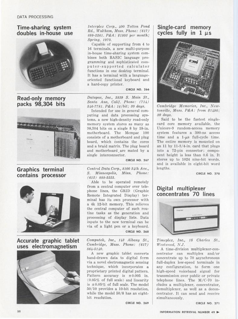
DATA PROCESSING
Time-sharing system doubles in-house use
Read-only memory packs 98,304 bits
Graphics terminal contains processor
Accurate graphic tablet uses electromagnetism
98
Interplex Corp., 400 Totten Pond Rd., Waltham, Mass. Phone: (617) 899-2261. P&A: $1803 per month; Spring, 1970.
Capable of supporting from 4 to 16 terminals, a new multi-purpose in-house time-sharing system combines both BASIC language programming and sophisticated computer - supported calculator functions in one desktop terminal. It has a terminal with a languageoriented functional keyboard and a hard-copy printer.
CIRCLE NO. 266
Datapac, Inc., 3839 S. Main St., Santa Ana, Calif. Phone: (714) 546-7781. P&A: 1¢/bit; 30 days.
Intended for use in general computing and data processing systems, a new high-density read-only memory system stores as many as 98,304 bits on a single 8 by 18-in. motherboard. The Mempac 100 consists of a motherboard and plug board, which contains the cores and a braid matrix. The plug board and motherboard. are mated by a single interconnector.
CIRCLE NO. 267
Control Data Corp., 8100 34th Ave., S. Minneapolis, Minn. Phone: (612) 888-5555.
Able to be operated remotely from a central computer over telephone lines, the GRID (Graphic Remote Integrated Display) terminal has its own processor with a 4k 12-bit memory. This relieves the central computer of such routine tasks as the generation and processing of display lists. Data inputs to the new terminal can be via of a light pen or a keyboard.
CIRCLE NO. 268
Computek, Inc., 143 Albany St., Cambridge, Mass. Phone: (617) 864-5140.
A new graphic tablet converts hand-drawn data to digital form via a novel electromagnetic sensing technique, which incorporates a proprietary printed digital pattern. Pattern accuracy is ± 0.005 in. ( 0.05 % of full scale) and linearity is ± 0.05 % of full scale. The model 50/ 10 provides a 10-bit resolution, while the model 50/8 has an eightbit resolution.
CIRCLE NO. 269
Single-card memory cycles fully in 1 µs
Cambridge M emories, Inc., N ewtonville, Mass. P&A: from $1490; 30 days.
Said to be the fastest singlecard core memory available, the Unicore-9 random-access memory system features a 300-ns access time and a 1-µ.s full-cycle time. The entire memory is mounted on an 11 by 11-3/ 4-in. card that plugs into a 72-pin connector; component height is less than 0.6 in. It stores up to 1024 nine-bit words, and is available in eight-bit word lengths.
CIRCLE NO. 270
Digital multiplexer concentrates 70 lines
!--.,..=:. -=-= -= -= -
Timeplex, Inc., 15 Charles St., Westw ood, N.J.
A time-division multiplexer-concentrator can multiplex and / or concentrate up to 70 asynchronous full-duplex low-speed terminals in any configuration, to form one high-speed voiceband signal for transmission over public or private telephone lines. The M/ C-70 includes a multiplexer, concentrator,; demultiplexer, as well as a deconcentrator. It can send and receive simultaneously.
CIRCLE NO. 271
INFORMATION RETRIEVAL NUMBER 49 ....
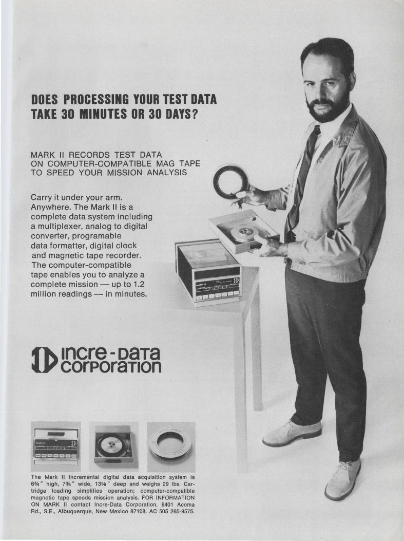
DOES PROCESSING YOUR TEST DATA TAKE 30 MINUTES OR 30 DAYS?
MARK 11 RECORDS TEST DATA ON COMPUTER-COMPATIBLE MAG TAPE TO SPEED YOUR MISSION ANALYSIS
Carry it under your arm. Anywhere. The Mark 11 is a complete data system including a multiplexer, analog to digital converter, programable data formatter, digital clock and magnetic tape recorder. The computer-compatible tape enables you to analyze a complete mission - up to 1.2 million readings - in minutes.
~ 1ncre -oaTa tv corPoraT1on
The Mark II incremental digital data acquisition system is 6~" high, 7:Y4" wide, 135/a" deep and weighs 29 lbs. Cartridge loading simplifies operation; computer-compatible magnetic tape speeds mission analysis. FOR INFORMATION ON MARK II contact lncre-Data Corporation, 6401 Acoma Rd., S.E., Albuquerque, New Mexico 87108. AC 505 265-9575.
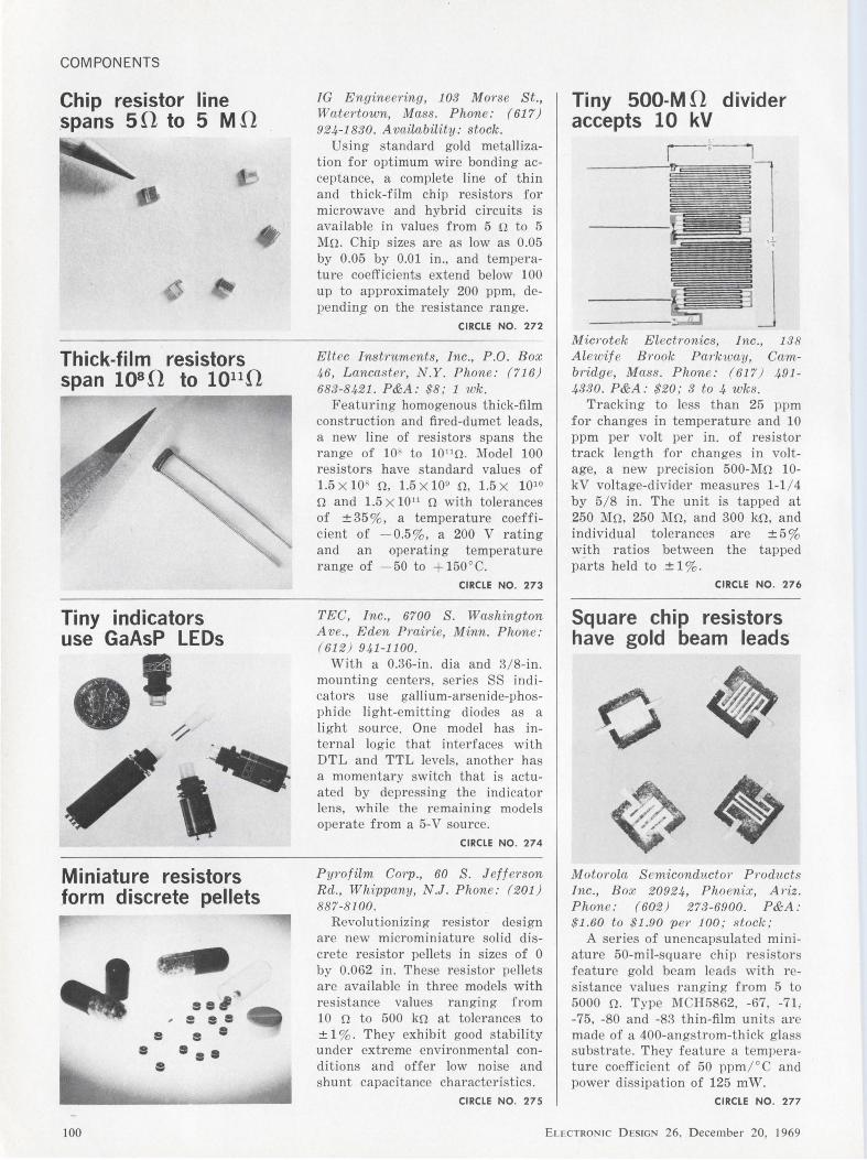
COMPONENTS
Chip resistor line .spans 50 to 5 MD
Thick-film resistors span 1osn to 1011n
Tiny indicators use GaAsP LEDs
Miniature resistors form discrete pellets
e
JG Engineering, 103 Morse St., Wcitertown, Mass. Phone: (617) 924-1830. Avciilability: stock.
Using standard gold metallization for optimum wire bonding acceptance, a complete line of t h in and thick-film chip resistors for microwave and hybrid circuits is avai lable in values from 5 o to 5 Mn. Chip sizes are as low as 0.05 by 0.05 by 0.01 in., and temperature coefficients extend below 100 up to approximately 200 ppm, dependin_g on the resistance range.
CIRCLE NO. 272
Eltec Instruments, Inc., P.O. Box 46, Lanccister, N.Y. Phone: (716) 683-8421. P&A: $8; 1 wk.
Featuring homogenous thick-film construction and fired-dumet leads, a new line of resistors spans the range of 10' to 10 11 !1. Model 100 resistors have standard values of 1.5 x 10' n, 1.5 x 10⁹ n, 1.5 x 10¹⁰
n and 1.5 x 10¹¹ n with tolerances of ± 35 % , a temperature coefficient of - 0.5 % , a 200 V rating and an operating temperature range of -50 to +150°C.
CIRCLE NO. 273
TEC, Inc., 6700 S. Washington Ave. , Eden Prairie, Minn. Phone: ( 612 ) 941-1100.
With a 0.36-in . dia and 3/8-in. mounting centers, series SS indicators use gall ium-arsenide-phosphide light-emitting diodes as a light source. One model has internal logic that interfaces with DTL and TTL levels, another has a momentary switch that is actuated by depressing the indicator lens, while the remaining models operate from a 5-V source.
CIRCLE NO. 274
Pyrofilm Corp., 60 S. Jeff erson Rd., Whippany, N.J. Phone: (201) 887-8100 .
Revolutionizing resistor design are new microminiature solid discrete resistor pellets in sizes of 0 by 0.062 in. These resistor pellets are avai lable in three models with resistance values ranging from 10 n to 500 kn at tolerances to ± 1 % . They exhibit good stabi lity under extreme environmental conditions and offer low noise and shunt capacitance characteristics.
Tiny 500-M D divider accepts 10 kV
Micrntek Electrnnics, Inc., 138 Alewif e B1'0ok Parkway, Cambridge, Mass. Phone: (617) 491-4330. P&A: $20; 3 to 4 wks.
Tracking to less than 25 ppm for changes in temperature and 10 ppm per volt per in. of resistor track length for changes in voltage, a new precision 500-M.n 10-kV voltage-divider measures 1-1 / 4 by 5/ 8 in. The unit is tapped at 250 Mn, 250 Mn, and 300 kn, and individual tolerances are ± 5 % with ratios between the tapped parts held to ± 1 %.
CIRCLE NO. 276
Square chip resistors have gold beam leads
M oto1'0la S emiconductor P1'0ducts Inc., Box 20924, Phoenix, Ariz. Phone: (602) 273-6900. P&A: $1.60 to $1.90 per 100; stock;
A series of unencapsu lated miniature 50-mil-square chip resistors feature gold beam leads with resistance values ranging from 5 to 5000 n. Type MCH5862, -67, -71; -75, -80 and -83 th in-film units are made of a 400-angstrom-thick glass substrate. They feature a temperature coefficient of 50 ppm/°C and power dissipation of 125 mW.
CIRCLE NO. 275 CIRCLE NO. 277
100 ELECTRONIC DESIGN 26, December 20, 1969
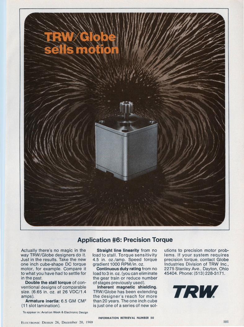
Application #6: Precision Torque
Actually there's no magic in the way TRW/Globe designers do it. Just in the results. Take the new one inch cube-shape DC torque motor, for example. Compare it to what you have had to settle for in the past.
Double the stall torque of conventional designs of comparable size. (6.65 in. oz. at 26 VDC/1.4 amps).
Armature inertia: 6.5 GM CM 2
(11 slot lamination).
To appear in : Av iation Week & Elect ronic Design
Straight line linearity from no load to stall. Torque sensitivity 4.5 in. oz.lamp. Speed torque gradient 1000 RPM/in . oz.
Continuous duty rating from no load to 3 in . oz. (you can eliminate the gear train or reduce number of stages previously used).
Inherent magnetic shielding. TRW/ Globe has been extending the designer's reach for more than 20 years. The one inch cube is just one of a series of new sol-
INFORMATION RETRIEVAL NUMBER 50
ELECTRON IC D ESIGN 26, December 20, 1969
utions to precision motor prob-1 ems. If your system requires precision torque, contact Globe Industries Division of TRW Inc., 2275 Stanley Ave. , Dayton, Ohio 45404. Ph.one : (513) 228-3171.
TRW 101
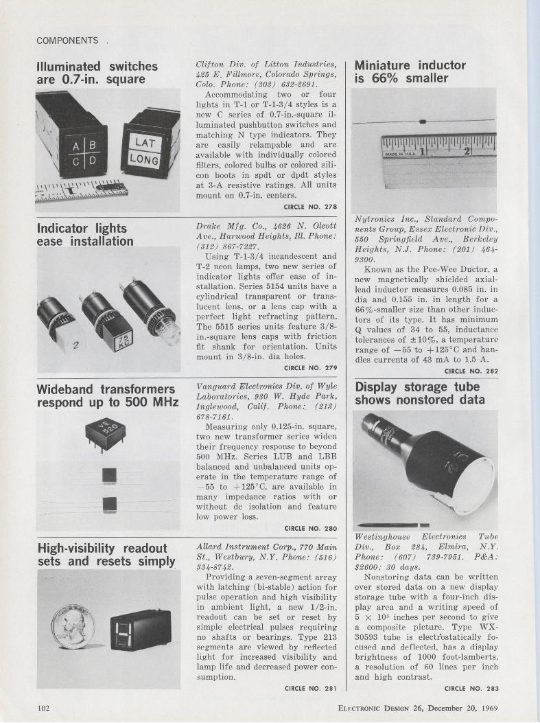
COMPONENTS
Illuminated switches are 0.7-in. square
Indicator lights ease installation
Wideband transformers respond up to 500 MHz
• II
• High-visibility readout sets and resets simply
I I " .. -,
Clifton Div. of Litton Industries, 425 E. Fillmore, Colorado Springs, Colo. Phone: (303) 632-2691.
Accommodating two or four lights in T-1 or T-1-3/4 styles is a new C series of 0.7-in.-square illuminated pushbutton switches and matching N type indicators. They are easily relampable and are available with individually colored filters, colored bulbs or colored silicon boots in spdt or dpdt styles at 3-A resistive ratings. All units mount on 0.7-in. centers.
CIRCLE NO. 278
Drake Mfg. Co., 4626 N. Olcott Ave., Harwood Heights, Ill. Phone: (312) 867-7227.
Using T-1-3/4 incandescent and T-2 neon lamps, two new series of indicator lights offer ease of installation. Series 5154 units have a cylindrical transparent or translucent lens, or a lens cap with a perfect light refracting pattern. The 5515 series units feature 3/8-in.-square lens caps with friction fit shank for orientation. Units mount in 3/8-in. dia holes.
CIRCLE NO. 279
Vanguard Electronics Div. of Wyle Laboratories, 930 W. Hyde Park, Inglewood, Calif. Phone:. (213) 678-7161 .
Measuring only 0.125-in. square, two new transformer series widen their frequency response to beyond 500 MHz. Series LUE and LBB balanced and unbalanced units operate in the temperature range of - 55 to + 125°C, are available in many impedance ratios with or without de isolation and feature low power loss.
CIRCLE NO. 280
Allard Instrument Corp., 770 Main St., Westbury, N.Y. Phone: (516) {134-87 42.
Providing a seven-segment array with latching (bi-stable) action for pulse operation and high visibility in ambient light, a new 1/2-in. readout can be set or reset by simple electrical pulses requiring no shafts or bearings. Type 213 segments are viewed by reflected light for increased visibility and lamp life and decreased power consumption.
Miniature inductor is 66% smaller
·----- - -- ---- - --r111111r1111111 \ll!(I ji 11 111,, ,,, 1111111
MAOE '" U.S.A.. 1 2
Nytronics Inc., Standard Components Group, Essex Electronic Div., 550 Springfield Ave., Berkeley Heights, N.J. Phone: (201) 464-9300.
Known as the Pee-Wee Ductor, a new magnetically shielded axiallead inductor measures 0.085 in. in dia and 0.155 in. in length for a 66%-smaller size than other inductors of its type. It has minimum Q values of 34 to 55, inductance tolerances of ± 10%, a temperature range of - 55 to + 125 ° C and handles currents of 43 mA to 1.5 A.
CIRCLE NO. 282
Display storage tube shows nonstored data
-----·-Westinghouse Electronics Div., Box 284, Elmira, Phone: (607) 739-7951. $2600; 30 days.
Tub e N.Y.
P&A:
N onstoring data can be written over stored data on a new display storage tube with a four-inch display area and a writing speed of 5 x 105 inches per second to give a composite picture. Type WX-30593 tube is electrostatically focused and deflected, has a display brightness of 1000 foot-lamberts, a resolution of 60 lines per inch and high contrast.
CIRCLE NO. 281 CIRCLE NO. 283
102 ELECTRONIC DESIGN 26, December 20, 1969
We're big in bipolars. Big because we've got fast-thinking, bright young engineers working with some of the real pioneers in the business. All supported by the resources of a $14 billion corporation. Take a look at the results.
High-speed T2L: 30 types in production, more to comeSeries 9600, pin-compatible with SUHL • II.
Medium-speed T2L: 20 types in production, more coming -Series 74 with clamp diode input ... improved hermetic cerdip packaging.
DTL: More than 30 commercial, hi-rel, and radiationhardened circuits ... Series 9930 now in high-volume production.
RTL: Popular Milliwatt and Microloglc** types in volume production.
Linear IC's: 11 standard types---in cerdip packaging for
top reliability.
MSI: 9300 Series on the way.
A comprehensive line? You're right. It's backed by an established reputation for quality. And by high-volume pro
duction capability. We're one of the largest IC facilities in
the country. No wonder our sales have increased 50% in
the past year.
So if it's a bipolar IC, check with us. Write or call Bipolar
Marketing, Philco-Ford Microelectronics Division, Blue Bell, Pa. 19422. (215) 646-9100.
•Trademark of Sylvania Electric Products, Inc. ••Trademark of Fairchild Camera & Instrument Corp.
The better idea people in bipolar /C's. PHILCO
INFORMATION RETRIEVAL NUMBER 51
ELECTRON IC D ESIGN 26, D ecember 20, 1969 103
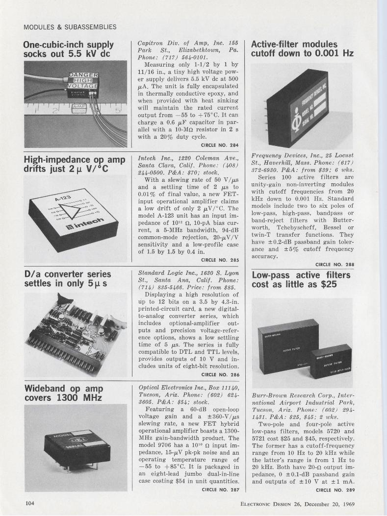
MODULES & SUBASSEMBLIES
One-cubic-inch supply socks out 5.5 kV de
High-impedance op amp drifts just 2 µ V/°C
Dia converter series settles in only 5 µ s
Wideband op amp covers 1300 MHz
Capitron Div. of Amp, Inc. 155 Park St., Elizabethtown, Pa. Phone: (717) 564-0101 .
Measuring only 1-1/ 2 by 1 by 11/ 16 in., a tiny high voltage power supply delivers 5.5 kV de at 500 µ,A. The unit is fully encapsulated in thermally conductive epoxy, and when provided with heat sinking will maintain the rated current output from -55 to +75°C. It can charge a 0.6 µF capacitor in parallel with a 10-M.n resistor in 2 s with a 20% duty cycle.
CIRCLE NO. 284
Intech Inc ., 1220 Coleman Ave., Santa Clara, Calif. Phone: ( 408) 244-0500. P&A: $70; stock.
With a slewing rate of 50 VI µ,s and a settling time of 2 µs to 0.01 % of final value, a new FETinput operational amplifier claims a low drift of only 2 µ, V /° C. The model A-123 unit has an input impedance of 101 2 .n, 10-pA bias current, a 5-MHz bandwidth, 94-dB common-mode rejection, 20-µ, V / V sensitivity and a low-profile case of 1.5 by 1.5 by 0.4 in.
CIRCLE NO. 285
Standard Logic Inc., 1630 S. Lyon St., Santa Ana, Calif. Phone: (714) 835-5466. Price: from $85.
Displaying a high resolution of up to 12 bits on a 3.5 by 4.3-in. printed-circuit card, a new digitalto-analog converter series, which includes optional-amplifier outputs and precision voltage-reference options, shows a low settling time of 5 µ,s. The series is fully compatible to DTL and TTL levels, provides outputs of 10 V and includes units of eight-bit resolution.
CIRCLE NO. 286
Optical Electronics Inc ., Box 11140, Tucson, Ariz. Phone: (602) 624-3605. P&A: $54; stock.
Featuring a 60-dB open-loop voltage gain and a ± 360-VI µ,s slewing rate, a new FET hybrid operational amplifier boasts a 1300-MHz gain-bandwidth product. The model 9706 has a 101 0 .n input impedance, 15-µ, V pk-pk noise and an operating temperature range of - 55 to + 85 ° C. It is packaged in an eight-lead jumbo dual-in-line case costing $54 in unit quantities.
Active-filter modules cutoff down to 0.001 Hz
Frequency Devices, Inc., 25 Locust St., Haverhill, Mass. Phone: (617) 372-6930. P&A: from $39; 6 wks.
Series 100 active filters are unity-gain non-inverting modules with cutoff frequencies from 20 kHz down to 0.001 Hz. Standard models include two to six poles of low-pass, high-pass, bandpass or band-reject filters with Butterworth, Tchebyscheff, Bessel or twin-T transfer functions. They have ± 0.2-dB passband gain tolerance and ±5% cutoff frequency accuracy.
CIRCLE NO. 288
Low-pass active filters cost as little as $25
Burr-Brown R esearch Corp., International Airport Industrial Park, Tucson, Ariz. Phone: (602 ) 294-1431. P&A: $25, $45; 2 wks.
Two-pole and four-pole active low-pass filters, models 5720 and 5721 cost $25 and $45, respectively. The former has a cutoff-frequency range from 10 Hz to 20 kHz while the latter's range is from 1 Hz to 20 kHz. Both have 20-o output impedance, 0 ± 0.1-dB passband gain and outputs of ± 10 V at ± 1 mA.
CIRCLE NO. 287 CIRCLE NO. 289
104 ELECTRONIC DESIGN 26, December 20, 1969
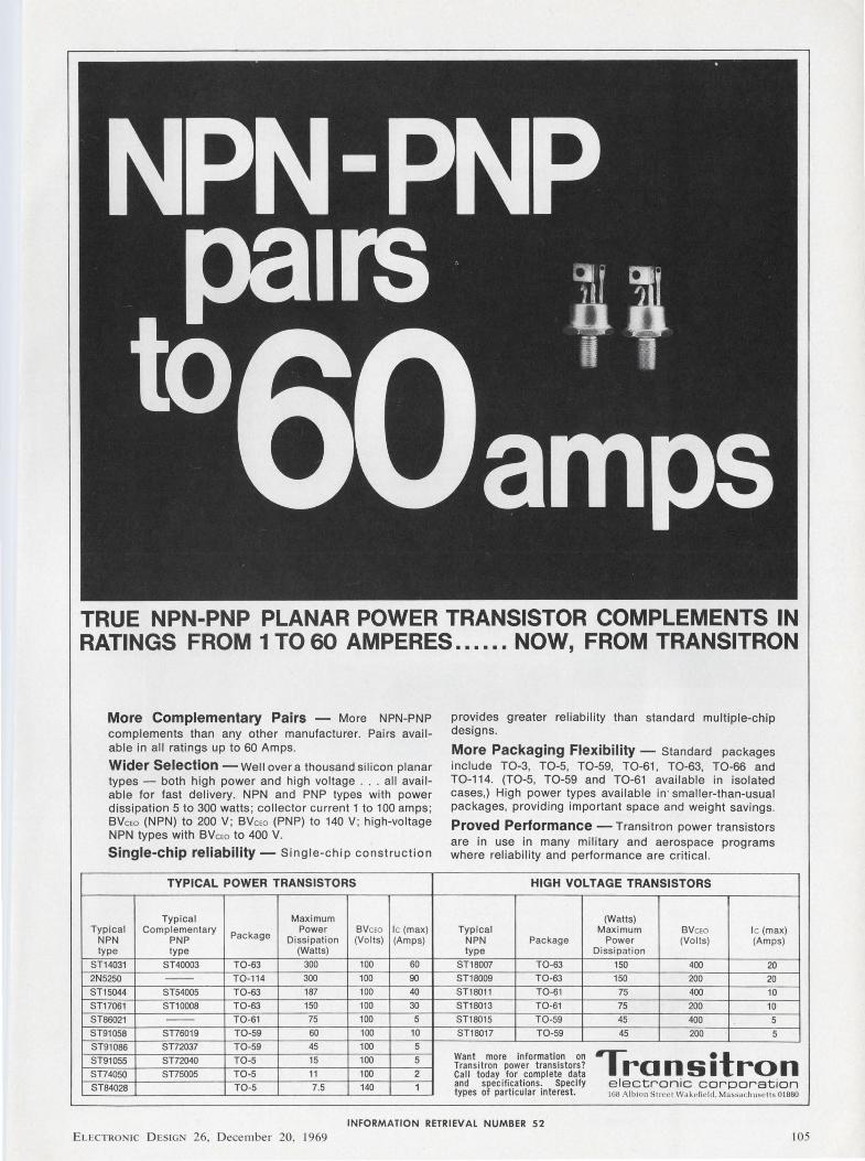
TRUE NPN-PNP PLANAR POWER TRANSISTOR COMPLEMENTS IN RATINGS FROM 1TO60 AMPERES ...... NOW, FROM TRANSITRON
More Complementary Pairs - More NPN-PNP complements than any other manufacturer. Pairs available in all ratings up to 60 Amps.
Wider Selection -Well over a thousand silicon planar types - both high power and high voltage . .. all available for fast delivery. NPN and PNP types with power dissipation 5 to 300 watts; collector current 1 to 100 amps; BVcw (NPN) to 200 V; BVcw (PNP) to 140 V; high-voltage NPN types with BVcw to 400 V.
Single-chip reliability - Single-chip construction
TYPICAL POWER TRANSISTORS
Typical Maximum Typical Complementary
Package Power BVcw le (max)
NPN PNP Dissipation (Volts) (Amps) type type (Watts)
ST14031 ST40003 T0-63 300 100 60
2N5250 -- T0-114 300 100 90
ST15044 ST54005 T0-63 187 100 40
ST17061 ST10008 T0-63 150 100 30
ST86021 -- T0-61 75 100 5
ST91058 ST76019 T0-59 60 100 10
ST91086 ST72037 T0-59 45 100 5
ST91055 ST72040 T0-5 15 100 5
ST74050 ST75005 T0-5 11 100 2
ST84028 T0-5 7.5 140 1
provides greater reliability than standard multiple-chip designs.
More Packaging Flexibility - Standard packages include T0-3, T0-5, T0-59, T0-61, T0-63, T0-66 and T0-114. (T0-5, T0-59 and T0-61 available in isolated cases,) High power types available in· smaller-than-usual packages, providing important space and weight savings.
Proved Performance - Transitron power transistors are in use in many military and aerospace programs where reliability and performance are critical.
HIGH VOLTAGE TRANSISTORS
(Watts) Typical Maximum BVcw le (max)
NPN Package Power (Volts) (Amps) type Dissipation
ST18007 T0-63 150 400 20 ST18009 T0-63 150 200 20 ST18011 T0-61 75 400 10
ST18013 T0-61 75 200 10 ST18015 T0-59 45 400 5 ST18017 T0-59 45 200 5
Want more information on Transitron Transitron power transistors? Call today for complete data and specifications. Specify electronic corporation types of parti cular interest. lliH Albio n Sln•t>t Wa lwfil'ld , Massdchusrlls 01880
INFORMATION RETRIEVAL NUMBER 52
ELECTRONIC DESIGN 26, December 20, 1969 105
- PULSE-Fast Rise-Time
for • High Resolution Video
• Nuclear Instrumentation
• Laser-Optics
• Digital Computer Design
1 nS to 10 nS Rise times
5 Hz Response 12 V Peak, 50 a Load Matched In / Out Impedances
$95-$775
- FAMILY FEATURES -• Low Frequency Response
• Output thru ± 25V Peak
• High Gain 20 thru 60 dB
• Spin-offs from AEC/ NASA Advanced Design Projects
• Missile Reliability
• Adjustable Gain in Some Versions
1 nS Response (10-903 levels) Rise Time of a 5 nS Positive Pulse Oscilloscope : Tektronix 561 -B Vertical: 200 mV/ cm. Horizontal : I nS; cm.
EXAMPLES R.T. Gain Output Model
1 nS 23dB ± 6 Vp 3010-AP
2 nS 40dB - 6Vp 3364-G
3 nS · 20dB + 4Vp 3329-F - 8Vp
4 nS 60dB + 4Vp 3388-F - 8Vp
5 nS 20dB ± 1 V. Vp 3518
Select from 17 models off-the-shelf. "C-COR Amplifiers ... Rated First Where Performance is Rated First."
~
C-COR ELECTRONICS, INC.
60 Decibel Road State College, Pennsylvania 16801
814 238-2461
INFORMATION RETRIEVAL NUMBER 53
106
INSTRUMENTATION
Versatile test clip eases DIP handling
A P, Inc., 72 Corwin Dr., Cleveland, Ohio. Plwne: (216) 357-5597. P&A: $7.50; stock.
Ideal for field service work and for laboratory and production circuit checking, a new test clip provides easy accessibility to hard-toreach pins on dual-in-line integrated circuits. Particularly useful with oscilloscope probes, the unit can also be used as an inspection test fixture and as a tool for easy damage-free removal of dual-inli ne packages.
CIRCLE NO. 290
Logic-status test set displays 40-ns
• • x
• • Dataprobe, Inc., 290 Huyler St., S. Hackensack, N .J . Phone: (201) 489-5588. P&A : $95; stock.
Designed to test high-threshold logic systems, a new logic unit indicates logic levels and displays pulses as short as 40 ns, and includes a latching mode to detect and capture noise or a single pulse. Pulse-detection systems for the ST-15 Status Seeker unit are independent of a self-contained generator, enabling the unit to generate and detect pulses simultaneously.
CIRCLE NO. 291
Economy 3-d igit meter uses large-scale ICs
DIXSON INSTIUMENTS
vr.soo
Q r:· . ;_) ; .J
Dixson Inc., P.O. \Box 1449, Grand Junction, Colo. Phone: (303) 242-8863. P&A: $139; stock.
Incorporating large-scale MOS integrated circuits, a new threedigit panel meter features 0.5 % accuracy, an automatic zero, an internal calibration voltage, and a 100-µ, V resolution. Model VT 500, which is capable of operating from 117 V ac or 12 V de, is designed for general industrial applications and analog meter replacement. It costs only $139.
CIRCLE NO. 292
Amplifer /filter unit triples as a voltmeter
Dynatronics Co., Inc., 4800 Evanswood Dr., Columbus, Ohio. Phone:'. (614) 885-3303. P&A: $990; stock.
Known as the model 717S, a new instrument is a narrowband fi lter, an amplifier, and a narrowband voltmeter in one unit. As a fi lter it is tunable over the frequency range of 20 Hz to 20 kHz; as an amplifier its gain can be varied from .:._ 50 to + 60 dB ; and as a voltmeter with an input impedance of 10 Mn, full-scale sensitivity can be varied from 1 mV to 300 V.
CIRCLE NO. 293
ELECTRONIC DESIGN 26, December 20, 1969
PACKAGING & MATERIALS
Ace Chemical Co., 4401 N. Ravens-1cood Ave., Chicago, Ill. Phone: ( 312) 728-1065. Price: $14.95 per gallon.
Simply by brushing on RustRemovo then flushing with water, you can easily remove rust from iron and steel, corrosion from chrome and aluminum and tarnish from copper, brass and bronze. This new jell is a blend of mineral acids, special solvents and wetting agents . It leaves a protective coating after being flushed away.
CIRCLE NO. 294
Fiber-optic cones stop distortion
OPTI
FIBH
JVTI< lLOG
CONES
\NC
Starnetics Co., 10639 Riverside, N. Hollywood, Calif. Phone: (213) 769-8437. Price: $19.50 per gallon, $6.50 per quart.
Easily peeled from masked surfaces of ceramic and plastic circuit boards, a new flexible material masks solder applications on undesired board areas. SC-300 material can withstand short exposures to solder temperatures of 500 °F, cures in 30 minutes at 72°F or 10 minutes at 150°F. It is easily brushed on.
CIRCLE NO. 296
Dual-in-line boards accept discretes
Rust-removing jell is water rinsable
Optics Technology, Inc., 901 California Ave., Palo Alto, Calif. Phone: ( 415) 327-6600.
A new line of fiber-optic products includes 40-mm-dia cones that can magnify or demagnify images 2 to 3 times (in cones as short as 1 in.) without distortion, and resolutions from 50 line-pairs/mm to 150 line-pairs/ mm. The family also includes 3-in.-dia vacuum tight faceplates . Both products are fritsealable with no scintillation under high voltage.
CIRCLE NO. 295
Flexible compound masks out solder r
SAE Advanced Packaging, Inc., 1357 E. Edinger Ave., Santa Ana, Calif. Phone: (714) 547-3935. P&A: $1.02 to $1 .26; 1 wk.
Available with 14 or 16 goldplated phosphor-bronze pins, types A and B plug-in component mounting boards accept discrete components for systems with DIP cases. Type A has hollow pins while type B has posts, for soldering and hooking component leads. They have epoxy-glass bases and locating chamfered corner.
CIRCLE NO. 297
INFORMATION RETRIEVAL NUMBER 54 ....
ANY voltage from 2 .0 to 16 .0 at the industry 's LOWEST PRICES!
Quantity
1-99 100-499
500-999 1000-4999
Price each $1.07
.97
.91
.86
.82
THE HI-RELIABLE I No fragile na i l heads . Silicon junction aligned between two , parallel , offset tantalum heat sinks . . . great lead tension strength . All welded and brazed assembly. High pressure molded package. Gold plated nickel-clad copper leads. Write or phone for Form 68-4 for complete rating data and other tolerance prices.
Semiconductor Division
SCHAUER MANUFACTURING CORP. 4511 Alpine Avenue
Cincinnati , 0 . 45242 Ph. (513) 791 -3030
INFORMATION RETRI EVAL NUMBER 55
108
MICROWAVES & LASERS
Tiny S-band oscillator scans 2.2 to 2.3 GHz
• •'
Step-recovery diodes show 70-ps transition
Frequency synchronizer converts rf oscillators
Microwave Products Group, Inc ., 100 Express St., Plainview, N.Y . Phone : (516) 938-8200 . P&A: $395; stock to 30 days.
Centered at 2250 MHz, a new miniature S-band oscillator manually tunes from 2200 to 2300 MHz with typical output power of 70 mW. Model M2250-50 keeps its second harmonic content down by 20 dB from its fundamental frequency and is powered by -28 V at 25 mA while measuring only 1 by 1-1/2 in.
CIRCLE NO. 335
Synergistics, Inc., 10 Tech Ci?"cle, Natick, Mass. Phone : (617) 655-1340. Price: $1800 to $16,300.
A compact line of light modulators responds from de to 100 MHz in single or multi-channel units up to 100 in-line or 200 mosaic-pattern channels. They temperaturestabilize over t he operating range of - 20 to +50°C, without an oi l bath or oven, need only 100 V for 100% modulation, have 0.5 to 2.5-mm apertures per channel and measure from 1 bz 3-1/2 in .
CIRCLE NO. 336
GHZ Devices, Inc., Kennedy Dr., N . Chelmsf01·d, Mass . Phone: (617) 77 4-0577.
Offering orders of mult iplication from 2 through 20, Series GC-2500 step-recovery silicon diodes for X and Ku-bands feature a maximum snap time of 70 to 100 ps with maximum series resistance of 0.6 to 0.9 n. Also featured are output power efficiencies ranging from l / N to 2/ N and an operating and storage temperature range from - 65 to +200°C.
CIRCLE NO. 337
Microdot, Inc., Instrumentation Div., 220 Pasadena Ave., S. Pasadena, Calif. Phone: (213) 682-3351.
Converting rf power osci llators into accurate power sources, the model 1929 frequency synchronizer handles up to 50 W of output power from 2 to 2500 MHz. It receives an oscillator's rf signal, mixes it with a local oscillator, amplifies and limits t he difference applies it to a discriminator for ~ de s ignal to frequency-lock t he osci Ila tor.
CIRCLE NO. 338
ELECTRONIC DESIGN 26, D ecem ber 20, 1969
Evaluation samples
Rfi gasketing Five actual sample pieces of rfi
strip gasketing material are supplied free, along with a four-page brochure entitled "Rfi/Environmental Strip Gaskets." The samples are D-strips and 0-strips, in both Cho-Seal and Cho-Sil materials, and a combination conductive/nonconductive Cho-Seal strip gasket. This gasketing provides both rfi and environmental protection by using highly conductive fillers dispersed in silicone binders, rather than wires or wire mesh. Chomerics, Inc.
CIRCLE NO. 339
Plastic spacers Tough, rigid and strong-plastic
spacers are now available as free evaluation samples for use in either prototype or production assembly. The plastic units represent a substantial saving in cost and in weight over metal spacers. They are made for #4, #6, #8 and # 10 screws in lengths from 1/ 4 to 1 in. Their temperature resistance is as high as 225°F. Richco Plastic Co.
CIRCLE NO. 340
Called Randi-Pac tapes, new pre-cut strips of tape in pocketsize dispenser books provide a new convenient method to splice, insulate, tie or code wires and cables. There are 14 different Handi-Pacs containing from 40 to 240 strips of electri cal-grade tape in different lengths, widths and colors. The varied supply from a compact source eliminates the need to carry several different rolls. Because only the length of tape itself is involved in wrapping the wire, hands are free to complete the application firmly, with ease and speed. Free evaluation samples are available . W. H. Brady Co.
Cl RCLE NO. 341
Sheet insulation Quintex I and II are improved
types of asbestos electrical sheet insulations that are presented to potential users via a new booklet of actual free samples of both types. There is a variety of thicknesses: 3 to 15 mils for Quintex I and 5 to 29 mils for Quintex II. These flexible dielectrics are principally composed of specially processed asbestos fibers, uniformly dispersed high-temperature synthetic textile fibers, and a small quantity of heat-stable elastomeric binder. In add ition to high strength, Quintex also has excellent thermal stability and high thermal conductivity. Johns-Manvi lle.
CIRCLE NO. 342
INFORMATION RETRIEVAL NUMBER 56 ....
INFORMATION RETRIEVAL NUMBER 57
MAKE IT VECTOR PLUGGABLE
~1 ~ g u
HF Module
110
I ;rt
Various models come with 7, 8, 9, 11, 12, or 14 pin tube base plugs and inside
mountings for dual-in-line integrateds, flat packs, transistors or other components •
Older equipment can perform like new without ~ expensive chassis rewiring • Modular ,a plug-ins solve field repair problems • Vector Pluggables come in many sizes to meet nearly all requirements • For high R.F. Shielding requirements special units are available • For rack mounted modules adjustable versatile Vector Strut Cages are available •
Send for CfJ?nplete literature
VECTOR ELECTRONIC CO.,INC. 12460 Gladstone Ave., Sylmar, California 91342 Phone: (213) 365-9661 TWX (910) 496-1539
INFORMATION RETRIEVAL NUMBER 58
Design Aids
Design sketch paper Record your brilliant design
ideas for posterity (or for your boss) while they are still fresh in your mind. Can't decide whether to use pen or pencil? You can use either with a new engineer's work paper for sketching and calculations. It has 16 squares to the inch printed in non-reproducing blue ink. The absence of accented lines allows the grid to be adapted to many scales. The new forms, which are pre-punched for a three-ring binder, are just the right design aid for you. Ross-Martin Co.
CIRCLE NO. 343
QC sample calculator Called Sample Scope, a heavy
plastic circular slide rule presents all of the sample plans in MILSTD-105. It gives the sample size required for single, double, and multiple-sampling plans as a function of lot size and the level o.f inspection required. It also finds the acceptance and rejection numbers for each of these plans as a function of acceptable quality level. Costing only $10, Sample Scope is a handy device for · solving inspection and quality-control problems. TAD Products Corp.
CIRCLE NO. 344
Periodic table Printed on plastic-coated durable
cardboard, a colorful copy of one of the newest versions of the Periodic Table of the Elements is now available in two sizes-either 8-1/2 by 11 in. or 11 by 17 in. This special edition of the Periodic Table uses an unusual arrangement that readily distinguishes between the regular elements and the transition elements. The chart also includes the latest data on properties not usually found in periodic tables, making it, in effect, an abbreviated chemical handbook. Kawecki Berylco Industries Inc.
CIRCLE NO. 345
ELECTRONIC DESIGN 26, December 20, 1969
APPllCBllOD Notes
A Texas Instruments Application Report
ECL thermal effects A 12-page application report
discusses the effect of temperature on logic levels in emitter-coupledlogic (ECL ) circuits and describes a method of designing an air-cooled ECL system. ECL modules, the bulletin notes, dissipate a considerable amount of heat while achieving their under-5-ns propagation delay. The publication details a method for estimating the temperature limits within which an air-cooled ECL system can be operated error-free. Texas Instruments, Inc., Components Group.
CIRCLE NO. 346
Packaging guide Interesting facts on packaging,
including examples and package testing techniques, are discussed in the latest issue of "Motorgram" (Vol. 49, No. 4) . The discussion points out that industrial packaging should reach two primary goals: protect the product during shipment, and make it easy to handle. Also included is an article about a fractional-horsepower gear motor used in a line of equipment that measures and records microscopic surface features. Bodine Electric Co.
CIRCLE NO. 347
Diode detectors Definitions, discussions, and
formulas are all included in a concise four-page brochure on tunneldiode detectors. The technical information i n c 1 u d es tangential signal sensitivity, dynamic range, noise characteristics, temperature stability, bias application, and power handling capability. There is also a graph showing typical transfer characteristics. Aertech Industries.
CIRCLE NO. 348
Cable system noise A technical discussion of noise
in cable systems is given a thorough treatment in an eight-page booklet. A general description of electrical noise and its origins opens the talk, which goes on to cover coaxial cable, ground loops, and common-mode returns. Also discussed are radiated fields, twinax and triax cable, two types of guarded cable, and bonding and grounding problems. Trompeter Electronics, Inc.
CIRCLE NO. 349
Energy control Design Monograph No. 9 is an
eight-page two-color article that presents several methods for controlling mechanical energy in the interest of product improvement. The -three basic approaches are constrained accommodation of motion, isolation of energy flow, and suppression of energy effects. The discussion spells out six objectives of taking these uncommon approaches to mechanical energy control, and presents illustrated examples of how they have been achieved in specific applications. Lord Manufacturing Co., div. of Lord Corp.
CIRCLE NO. 350
INFORMATION RETRIEVAL NUMBER 59 ....
New Literature
Diodes and converters Diodes, diode arrays, pu lse gen
erators and converters ar e detailed in a new data fi le. Included are a description of a Ga-As injection laser diode, hetero-strncture Ga-As laser· diodes, laser diode arrays, miniatu r ized laser pulse generators, laboratory laser pulse generators and de to de conver ters. Given is s uch data as performance and operating characteristics with photographs and dimensional outlines . Laser Diode Laboratories, sub. of T he Un ited Cor p.
CIRCLE NO. 351
Switches A complete line of prec1s10n
snap-action, t humbwheel and leverwheel switches is shown in a new 44-page catalog. Included are photographs, cutaway illustrations, descr iptions, deta iled specifications and appli cation data for hundreds of standar d switches. Also included is a handy new sw itch selector locator table and 20 pages devoted to snap-action switch terminology. Cher ry E lectr ical Products Cor p.
CIRCLE NO. 352
Calibration standards The latest de techniques for pre
cision test and measurement in general product ion and engineering areas, as we ll as standards and ca libration laboratories . are descr ibed in detai l in a 12-page cata:log. Featured is a special sect ion devoted to theory and app li cat ion information and specificat ions for man ual, automated and computerized systems for use in test, measurement and control. Julie Research Laboratories, Inc.
CIRCLE NO. 353
11 2
Circular connectors Two popular families of high
dens ity microminiature circu lar connector s are described in a new 16-page catalog. It features color photographs, line drawings, electrical character istics and mechanical specificat ions on the complete line of two series of connector s . A selection gu ide and a detai led "how to or der" section complete information necessary for finding t he r ight high density microminiature connector of any given circuit application. Amphenol Industrial Div.
CIRCLE NO. 354
Crimping tools Crimping tools for a wide va
riety of applications, including class I and class II specifications of MIL-T-22520, are detai led in a 38-page loose-leaf catalog. It explains crimp tool phraseology and lists better crimping techn iques. The catalog includes tools in standard and miniature sizes of four and eight-indent, automatic and manua l feed, and C-frame configurations, plus an assortment of crimping tool kits. Buchanan E lectrical Products Corp.
CIRCLE NO. 355
Computer terminals A computer terminal that com
bines plotting and typing capabi lit ies in a single mechanism is described in an eight-page technical brochure. It contains specific examples of the terminal's plotting and typ ing capabi lities, application infor mation and a description of t he software. Shown are units having plots w ith a resolution of 0.02 in . at up to 10 computed points per second. Any character on the standard teleprinter keyboard can be used fo r plott ing, and plotting and text typing can be intermixed on the same sheet of paper. Typagraph Corp.
CIRCLE NO. 356
IC multiplexer Applications information on a
new MOS P-channel IC s ix-channel multip lexer is provided in a new brochure. Included is such information as its use as a high-reliabil ity multiplexer or as a group of six electrical switches for a variety of functions. The brochure a lso includes maximum ratings, characteristics, mechanical data, diagrams and a test circut for switchi ng time detail. Union Carbide Cor p.
CIRCLE NO. 357
Copper alloys A broad line of copper alloys in
rod and wire form is described in a new 16-page brochure. These special-purpose a lloys include coppers, copper nickels, phosphor bronzes, brasses, nickel silvers, si licon bronzes and silicon manganese bronzes. Also included is a discuss ion of such applications as springs, free machining parts, welding wire, and optical parts. Bridgeport Brass Co., Div. of National Disti llers & Chemical Corp.
CIRCLE NO. 358
Space exploration A six-page reprinted fo lder on
communications on the moon and limited quantities of a 32-page booklet entitled "Man and Space" are availab le. They provide a brief summary, complete with photographs, on communications methods employed on lunar spacecraft and a summary of the Apollo lunar program with information on major space programs already completed. RCA / Defense E lectronic Products .
CIRCLE NO. 359
ELECTRONIC DESIGN 26, D ecember 20, 1969
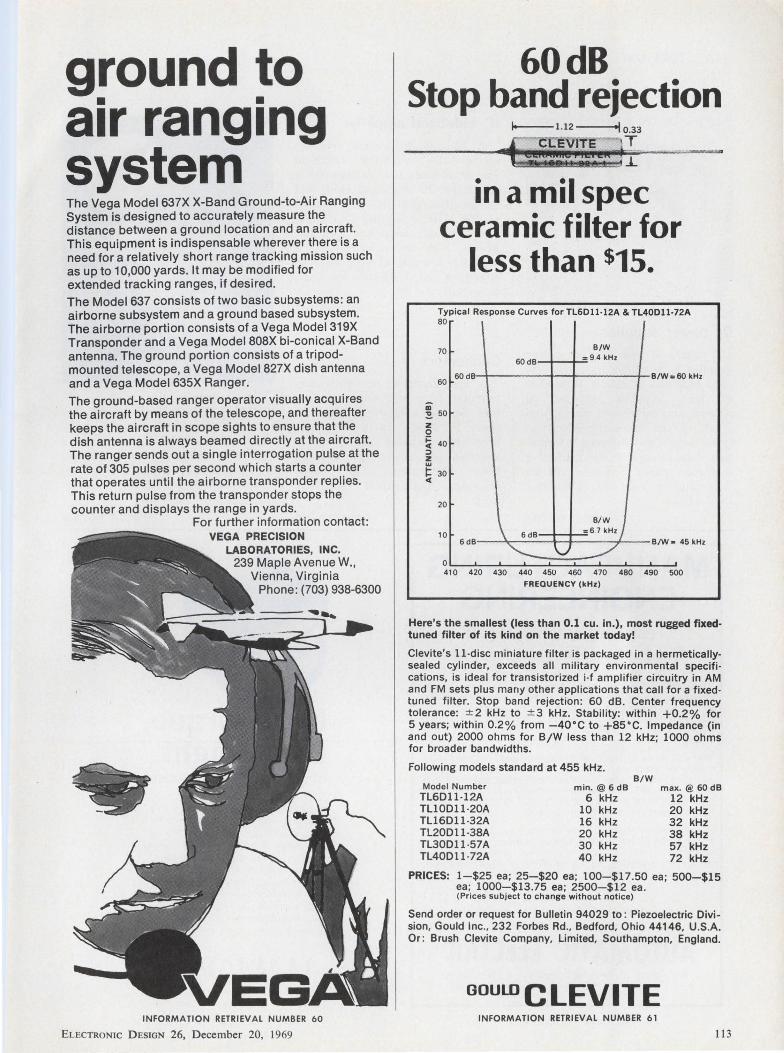
ground to • • air ranging
system The Vega Model 637X X-Band Ground-to-Air Ranging System is designed to accurately measure the distance between a ground location and an aircraft. This equipment is indispensable wherever there is a need for a relatively short range tracking mission such as up to 10,000 yards. It may be modified for extended tracking ranges, if desired. The Model 637 consists of two basic subsystems: an airborne subsystem and a ground based subsystem. The airborne portion consists of a Vega Model 319X Transponder and a Vega Model 808X bi-conical X-Band antenna. The ground portion consists of a tripodmounted telescope, a Vega Model 827X dish antenna and a Vega Model 635X Ranger. The ground-based ranger operator visually acquires the aircraft by means of the telescope, and thereafter keeps the aircraft in scope sights to ensure that the dish antenna is always beamed directly at the aircraft. The ranger sends out a single interrogation pulse at the rate of 305 pulses per second which starts a counter that operates until the airborne transponder replies. This return pulse from the transponder stops the counter and displays the range in yards.
For further information contact: VEGA PRECISION
LABORATORIES, INC. 239 Maple Avenue W.,
Vienna, Virginia Phone: (703) 938-6300
INFORMATION RETRIEVAL NUMBER 60
ELECTRONIC D ESIGN 26, December 20, 1969
60dB Stop band rejection
Ill
J_
in a mil spec ceramic filter for
less than $15. Typical Response Curves for TL6Dll ·12A & TL40Dl1·72A 80 ..
B/W
60dB = 9.4 kHz 70
60 60dB B/Wc 60 kHz
~ 50 z 0
~ 40 ::> z ~ 30 c(
20
10
0
6dB-.l 6dB
~
I B/W
=6.7 kHz/ B/W• 45 kHz
y 4, 0 420 430 440 450 460 4 70 480 490 500
FREQUENCY (kHz)
Here's the smallest (less than 0.1 cu. in.), most rugged fixedtuned filter of its kind on the market today!
Clevite's 11-disc miniature filter is packaged in a hermetically· sealed cylinder, exceeds all military environmental specifi· cations, is ideal for transistorized i·f amplifier circuitry in AM and FM sets plus many other applications that call for a fixed· tuned filter. Stop band rejection: 60 dB. Center frequency tolerance: ::t2 kHz to ± 3 kHz. Stability: within +0.2% for 5 years; within 0.2% from -40°C to +85°C. Impedance (in and out) 2000 ohms for B/W less than 12 kHz; 1000 ohms for broader bandwidths.
Following models standard at 455 kHz. B/W
Model Number min. @ 6 dB max. @ 60 dB TL6Dll-12A TL10D11·20A TL16Dll-32A TL20D11 ·38A TL30Dll -57A TL40D11·72A
6 kHz 12 kHz 10 kHz 20 kHz 16 kHz 32 kHz 20 kHz 38 kHz 30 kHz 57 kHz 40 kHz 72 kHz
PRICES: 1-$25 ea; 25-$20 ea; 100-$17.50 ea; 500-$15 ea; 1000-$13.75 ea; 2500-$12 ea. (Prices subject to change without notice)
Send order or request for Bulletin 94029 to : Piezoelectric Division, Gould Inc., 232 Forbes Rd., Bedford, Ohio 44146, U.S.A. Or : Brush Clevite Company, Limited, Southampton, England.
GOULD CLEVITE INFORMATION RETRIEVAL NUMBER 61
113
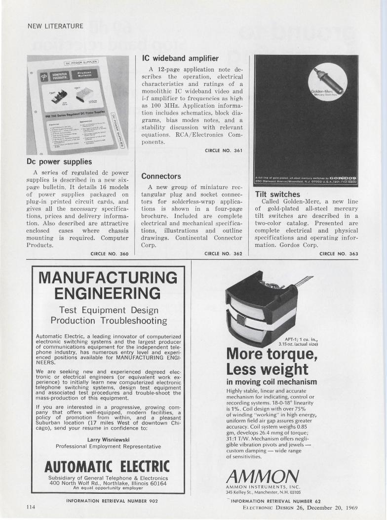
NEW LITERATURE
•
•
•
___ ...... DC_ ....... ,...11111---
De power supplies
IC wideband amplifier A 12-page application note de
scr ibes the operation, electrical characteristics and ratings of a monolithic IC wideband video and i-f ampli fier to frequencies as hi gh as 100 MHz. Application information includes schematics, block diagrams, bias modes notes, and a stabili ty discussion with relevant equations . RCA / Electronics Components.
CIRCLE NO. 361
Connectors
Tilt switches
A series of regulated de power supplies is described in a new sixpage bulletin. It details 16 models of power supplies packaged on plug-in printed circuit cards, and gives all the necessary specifications, prices and delivery information. Also described are attractive enclosed cases where chassis mounting is required. Computer Products.
A new group of miniature rectangular plug and socket connectors for solderless-wrap applicat ions is shown in a four-page brochure. Included are complete electrical and mechanical specifications, illustrations and outline drawings. Continental Connector Corp.
Called Golden-Mere, a new line of gold-plated all-steel mercury tilt switches are described in a two-color catalog. Presented are complete electrical and physical specifications and operating information. Gordos Corp.
114
CIRCLE NO. 360
MANUFACTURING ENGINEERING Test Equipment Design
Production Troubleshooting
Automatic Electric, a leading innovator of computerized electronic switching systems and the largest producer of communications equipment for the independent tele· phone industry, has numerous entry level and experi· enced positions available for MANUFACTURING ENGi· NEERS.
We are seeking new and experienced degreed elec· tronic or electrical engineers (or equivalent work ex· perience) to initially learn new computerized electronic telephone switching systems, design test equipment and associated test procedures and trouble-shoot the mass-production of this equipment.
If you are interested in a progressive, growing com· pany that offers well-equipped , modern facilities, a policy of promotion from within, and a pleasant Suburban location (17 miles West of downtown Chi· cago) , send your resume in confidence to:
Larry Wisniewski Professional Employment Representative
AUTOMATIC ELECTRIC Subsidiary of General Telephone & Electronics 400 North Wolf Rd., Northlake, Illinois 60164
An equal opportunity employer
INFORMATION RETRIEVAL NUMBER 902
CIRCLE NO. 362
APT-1; 1 cu. in., 3.15 oz . (actual size)
More torque, Less weight in moving coil mechanism Highly stab le, linear and accurate mechanism for indicating, control or recording systems. 18-0-18° linearity is 1%. Coil design with over 75% of winding " working" in high energy, uniform field air gap assures greater accuracy. Coil system weighs 0.85 gm, develops 26.4 mmg of torque; 31 :1 T/W. Mechanism offers negligible vibration pivots and jewels -custom damping - wide range of sensitiviti es.
AMMON AMMON IN STRUMENTS , INC. 345 Kelley St., Manchester, N.H. 03105
CIRCLE NO. 363
INFORMATION RETRIEVAL NUMBER 62
ELECTRON IC D ESIGN 26, December 20, 1969
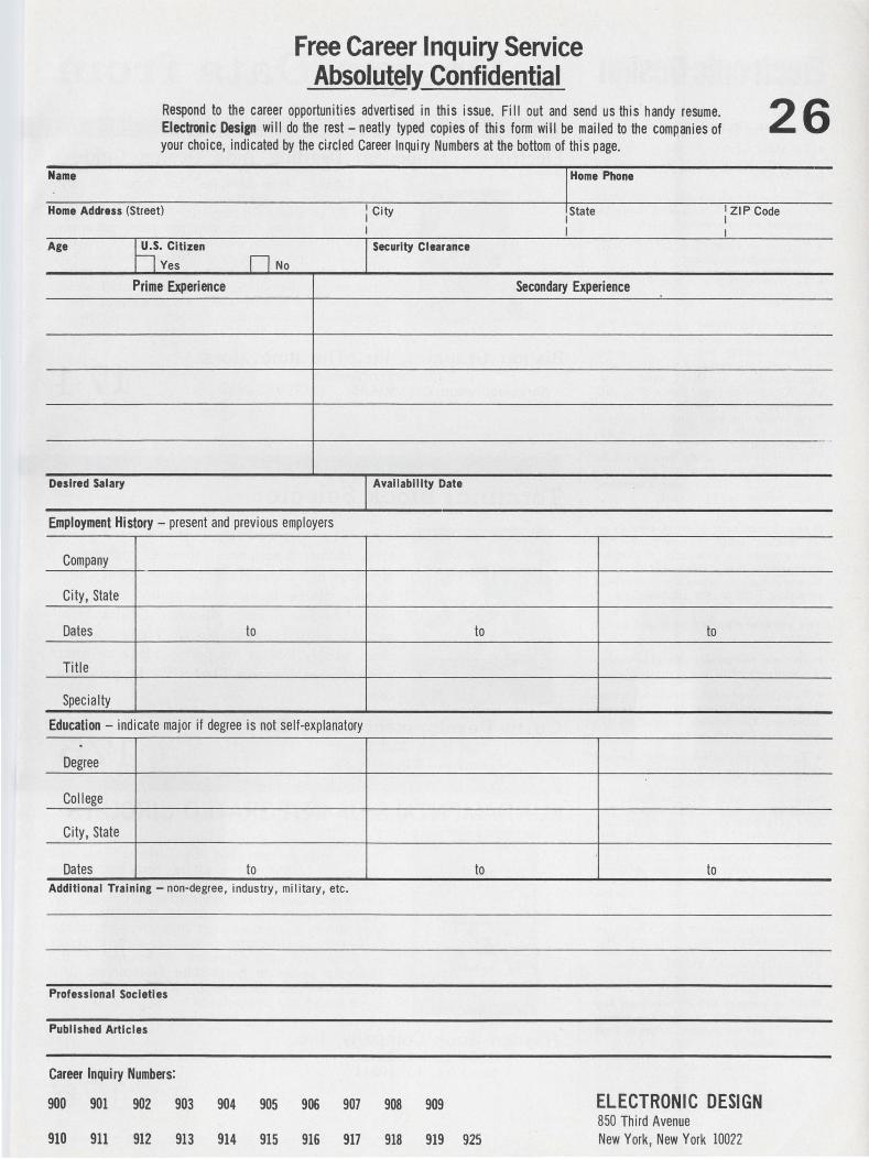
Free Career Inquiry Service AbsolutelY. Confidential
Respond to the career opportunities advertised in this issue. Fill out and send us this handy resume. Electronic Design will do the rest - neatly typed copies of this form will be mailed to the companies of your choice, indicated by the ci.rcled Career Inquiry Numbers at the bottom of this page.
Name
Home Address (Street)
Age
Desired Salary
TIU· Citizen
Oves
Prime Experience LJNo
Employment History - present and previous employers
Company
City, State
Dates to
Title
Specialty
: City
I l Security Clearance
] Availability Date
Education - indicate major if degree is not self-explanatory .
Degree
College
City, State
Dates to Additional Training - non-degree, industry, military , etc.
Professional Societies
Published Articles
Career Inquiry Numbers:
to
to
I •••. """ 1 State
I
Secondary Experience
to
to
26
I ZIP Code I I
900 901 902 903 904 905 906 907 908 909 ELECTRONIC DESIGN 850 Third Avenue
910 911 912 913 914 915 916 917 918 919 925 New York, New York 10022
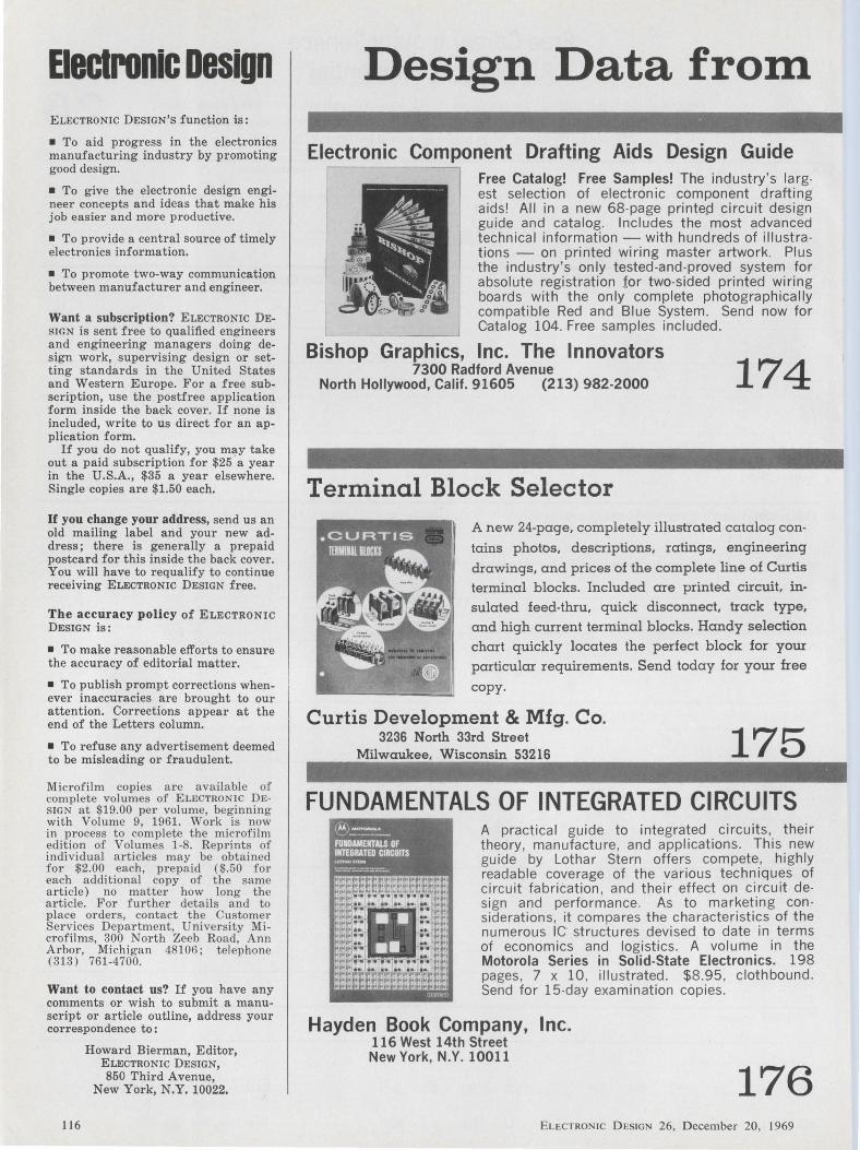
Electronic Design ELECTRONIC DESIGN'S function is:
• To aid progress in the electronics manufacturing industry by promoting good design.
• To give the electronic design engineer concepts and ideas that make his job easier and more productive.
• To provide a central source of timely electronics information.
• To promote two-way communication between manufacturer and engineer.
Want a subscription? ELECTRONIC DESIGN is sent free to qualified engineers and engineering managers doing design work, supervising design or setting standards in the United States and Western Europe. For a free subscription, use the postfree application form inside the back cover. If none is included, write to us direct for an application form.
If you do not qualify, you ml!-Y take out a paid subscription for $25 a year in the U.S.A., $35 a year elsewhere. Single copies are $1.50 each.
If you change your address, send us an old mailing label and your new address; there is generally a prepaid postcard for this inside the back cover. You will have to requalify to continue receiving ELECTRONIC DESIGN free.
The accuracy policy of ELECTRONIC DESIGN is:
• To make reasonable efforts to ensure the accuracy of editorial matter.
• To publish prompt corrections whenever inaccuracies are brought to our attention. Corrections appear at the end of the Letters column.
• To refuse any advertisement deemed to be misleading or fraudulent.
Microfilm copies a r e avail able of complete volumes of ELECTRON IC DESIGN at $19.00 per volume, beginning with Volume 9, 1961. Wor k is now in process to complet e the microfilm edition of Volumes 1-8. Reprints of individual a r t icles may be obtained fo r $2.00 each, prepaid ($.50 for each additional copy of the same article) no matter how long the article. F or fu r ther details and to place order s, contact t he Customer Ser vices Department, University Microfilms , 300 North Zeeb Road, Ann Arbor , Michigan 48106; telephone (313) 761-4700.
Want to contact us? If you have any comments or wish to submit a manuscript or article outline, address your correspondence to:
116
Howard Bierman, Editor, ELECTRONIC DESIGN, 850 Third A venue,
New York, N.Y. 10022.
Design Data from
Electronic Component Drafting Aids Design Guide
l Free Catalog! Free Samples! The industry's largest selection of electronic component drafting aids! All in a new 68-page printed circuit design guide and catalog. Includes the most advanced technical information - with hundreds of illustra tions - on printed wiring master artwork. Plus the industry's only tested-and-proved system for absolute registration for two-sided printed wiring boards with the only complete photographically compatible Red and Blue System. Send now for Catalog 104. Free samples included.
Bishop Graphics, Inc. The Innovators 7300 Radford Avenue 174 North Hollywood, Calif. 91605 (213) 982-2000
Terminal Block Selector A new 24-page, completely illustrated catalog con
tains photos, descriptions, ratings, engineering
drawings, and prices of the complete line of Curtis terminal blocks. Included are printed circuit, in
sulated feed-thru, quick disconnect. track type, and high current terminal blocks. Handy selection chart quickly locates the perfect block for your
particular requirements. Send today for your free
copy.
Curtis Development & Mfg. Co. 3236 North 33rd Street
Milwaukee. Wisconsin 53216 175 FUNDAMENTALS OF INTEGRATED CIRCUITS ®~ FUllOAllEllTAl.S OF lllTE&RATED CIRCUITS ...... ,,_ =:...-::.::.==-
A practical guide to integrated circuits , their theory, manufacture, and applications. This new guide by Lothar Stern offers compete, highly readable coverage of the various techniques of circuit fabrication , and their effect on circuit design and performance. As to marketing con siderations, it compares the characteristics of the numerous IC structures devised to date in terms of economics and logistics. A volume in the Motorola Series in Solid-State Electronics. 198 pages, 7 x 10, illustrated. $8.95 , clothbound. Send for 15-day examination copies .
Hayden Book Company, Inc. 116 West 14th Street New York, N.Y. 10011
176 ELECTRON IC DESIGN 26, December 20, 1969
Manufacturers Advertisements of booklets, brochures, catalogs and data sheets. To order use Reader-ServiceCard
(Advertisement)
The Latest In the State of the Power Supply Art
POWER SUPPLIES
~e'Latest in tlie$tate ef tfieArt
Kepco, Inc. 131-38 Sanford Avenue
Flushing, New York 11352
Kepco's Power Supply Catalog (8-693) is updated by a new six-page supplement entitled "The Latest in the State of the Art. " Covered are five separate Power Supply groups: Modules for 1-C systems, dual modules for linear circuits, and a new extension of kepco's "PRM" ferroresonant regulators in a 60VA package. The new PRM's feature voltage selection by internal taps.
The supplement also covers three new bipolar power amplifiers up to ±72V at ±5A, and a group of high voltage operational power supplies 0-500V, 0-lOOOV and 0-2000V at 20 watts.
Check number below for your copy of The Latest in the State of the Art ... from Kepco.
177
PEM Preassembled Captive Screw Fasteners PEM self-clinching panel fasteners are completely preassembled with captive screw, spring and retaining washer in stainless steel retainers ready for permanent mounting in panels as thin as 0.060". Knurled and slotted captive screws with tapered leads can be removed if desired from their permanently mounted retainers. Send for free PEM bulletin describing self-clinching, preassembled panel fasteners in thread sizes #4-40 through V4 -20. Each thread size is available in three screw lengths.
Penn Engineering & Mfg. Corp.
178 Box 311 Doylestown, Pa. 18901
AUTOMATIC REAL-TIME PSD SYSTEM Hands-off automatic averaging, display, plotting,
- and readout (to computer) of PSD data in real
Automatic real-time PSD~~l_ISing UbiquitoUs SpeCtrun1 Analyzer.
time, can now be performed using PSD-6/ AU Ubiquitous® Power Spectral Density System. Options provide complete automatic cycling and control of external peripheral equipment for a time history display or repetitive plotting. MOD AU option provides for rapid previewing of aver
·aged data or digital recording , in conjunction with various interface units; ACU -6 Control Unit con· trols input tape recorders and output X-Y plotters. System is built around th~ proven Real -Time Ubiquitous:ID Spectrum Analyzer for high-speed analysis of noise, vibration and other low-fre· quency random data, and for detection of low-level periodic signals buried in noise.
Federal Scientific Corporation
179 a subsidiary of Elgin National Industries, Inc. 615 West 131st Street, New York, N. Y. 10027
ELECTRONIC D ES IGN 26, December 20, 1969
Electronic Design Advertising Sales Staff
Keith Aldrich Sales Manager
New York 10022 Robert W. Gascoigne Thomas P. Barth Samuel M. Deitch 850 Third Avenue (212) Plaza 1-5530 TWX: 867-7866
Philadelphia 19066 William C. Repetto P. 0. Box 206 Merion Station, Pa. (215) MA-3 -5888
Boston 01945 Richard Parker P. 0. Box 645 Clifton Station Marblehead, Mass. (617) 742-0252
Chicago 60611 Thomas P. Kavooras Berry Conner, Jr. 200 East Ontario (312) 337-0588
Cleveland Thomas P. Kavooras (Chicago) (312) 337-0588 (call collect)
Los Angeles 90303 Stanley I. Ehrenclou W. James Bischof 2930 Imperial Highway Inglewood, Calif. (213) 757-0183
San Francisco 94022 Arthur R. Shields, Jr. 175 San Antonio Rd., S 243 Los Altos, Calif. (415) 941-3084
London W. 1 For United Kingdom and Holland
Brayton C. Nichols 44 Conduit Street Tel: Rl::Gent 4714
Verviers, Belgium For Continental Europe
Andre Jamar 1, Rue Mallar, 1 (087) 253.83 Telex 41563
Tokyo Haruki Hirayama Electronic Media Service Rm. 601, Daini Miyauchi Bldg. 6-8-14, Roppongi, Minato-ku Phone: 402-4556 Cable: Electronicmedia , Tokyo
..... _.~ AMERICAN BUSINESS PRESS, INC.
I 17
CRYSTAL CLEAR EPOXIES, SILICONES, ETC. FOR
ELECTRONICS & DISPLAY
ECCOCLEAR designates a brood line of transparent costing resins useful for visual display and inspection of electrical / electronic com ponents. New folder presents 11 systems , including dig-out & repair types, complete with
properties selector chart.
INFORMATION RETRIEVAL NUMBER 141
CONDUCTIVE ADHESIVE MAKES ELECTRICAL BOND
WITHOUT HEAT
~) ECCOBOND SOLDER 56-C is the original silver-loaded epoxy cement which can be used for making electrical connections whenever hot-soldering is impractical. Cures at 120°F; volume resistivity less than 0.0002 ohm-cm. Send for Technical Bulletin.
INFORMATION RETRIEVAL NUMBER 142
FAST-CURING EPOXY FOR HIGH SPEED POTTING
STYCAST® 1240 is a low viscosity epoxy system designed for potting units at high production rates. It cures rapidly without high exothe rm . Protects heat-sensitive compone nts, and units can be handled minutes after potting.
INFORMATION RETRIEVAL NUMBER 143
Emerson & Cuming, Inc.
~ CANTON, MASS, GARDENA, CALIF.
NORTHBROOK, ILL. Sales Offices in Principal Cities
EMERSON & CUMING EUROPE N.V., Devel, Belgium
11 8
Advertisers' Index Advertiser Page
AMP, Incorpo rated ---- ··-······························-·-···· 41 Alco Electronic Products, lnc ......... 107, 109, 111 Allen-Bradley Co . ··················-·····- --····-27 , 29 American Micro-Systems, Inc. ·········-····-· ·-·····- 15 Ammon Instruments, Inc . ... ......................... .... 114 Applied Technology A Division of
Itek Corporation ··-·----···································· 31
Barnes Corporation .............. .. ............... ... .. ........ 110 Beckman Instruments, Inc., Helipot Divi sion 51 Bell Laboratories -·- ··························--·---··-·····-···· 53 Bendix Corpo ration, The Electrical
Bi~~o~pGnr~~~ic~ivi~~~n ... :::::::::: : ::::::::::: :: :: ::::::~~'. 1 n Buckbee Mears Co. ··-·······························-········· 54
C-Co r Electrunit:~ , Inc . .......... ...... ............. ....... 106 C ELCO (Constantine Engineering
La boratories Co.) ........ ....... ..... ....... .. .... ........... 119 Control Data Corporation ----·---- ------ -·-·-·-······· ··· 16 Corning Glass Works, Electronic
Products Division ...................................... 36, 37 Curtis Development & Mfg. Co ...................... . 116 C utler-Hammer ··-··········································-···--· 46
Da le Electronics, Inc . ............................ Cover III Dunca n Electronics, Division of
Systron-Donner Corporation ........................ 88
E-H Research Laboratories, Inc. ·--·--··········· ··· 33 Eastman Chemical Products, Inc. . ............... 119 Elco Corpora tion ··--···················-·---·- ____ -······ ··--- 7 Electronic Design .......................................... 14, 52 Emerson & Cuming, Inc. ···············-·---··-·--·····-·· 11 8
Federal Scientific Corp . .................................. .. 117 Fluke Mfg. Co., Inc. , John .............................. 79
Gene ral Electric Company, Electronic Components ................................ 4, 5
Gene ral Elecetric Company, Capacitor & Battery Dept. ---·-------·-·-- ········ 16A
General Electri c Compa ny, Silicone Products Depa rtment .................... I 6B
General Instrument Corporation ---·--·············· 8, 9 General Radio Company ·-····················-·---·-··- I Golay, S. A. Bernard .............. .... ............. ...... . 96B G ould, Inc. Piezoelectric Division ................ 113
Hayden Book Company, Inc. ········--···- ·- ----·- 116 Hewlett-Packa rd ......... Cover II , 74, 75 , 84
IMC Magnetics Corporation ···-··-··-·- ---··--······-·· 91 lncre-Data Corporation ········-··········--············ 99
Johnson Co mpany, E. F . .... ......... ...... ...... ... 34 Jona than M anufacturing Company -··---····-····- 95
Advertiser Page
Kepco, Inc . ·-·-·---···················-···········- ······ ·········· .117
Lea r Siegler, Inc. , Cimron Division............... 38
Ma llo ry & Co ., Inc., P . R ..... ....... 10 Micro dot, Inc. .................................... 24 Mo torola Semiconducto r Products, Inc. ..... 6
Nationa l Semiconductor Corpora tion ........ 64, 65
Optron, Inc. ·················-··············----···-············--- 97
Penn Engineering & Mfg. Co rp. ----·· ········· .... 117 Philco-Fo rd Corpo ration . ····-··-·········---··- .. .. 103 Potter & Brumfield Division of
American Machine & Foundry Compa ny ...... ------- -······· ···· ···· --- --- -·············- .44, 45
RC A Electronic Components a nd Devices ···· ···· ·· ··------··--······ ····69, 80, 92, Co ver IV
S. 0 . G. I. E. --- -···-······ ·····-·-·- -·-·-······· ·-··· ··· ...... 96A Shallcross, A Cutler-Hammer Company ----··· 46 Sha uer Manufacturing Corp. . ..... 108 Signetics Measurement / Data ... ----·········· ··-- 48 Sing_e r .Compa ny, The, Instrumentation
D1 v1s1on ··················--··--·····························-- 17 Sprague Electric Compa ny __ ----·-···-· ····· ·····- 18 Stewa rt Wa rner Microcircuits Inc. ····-- 86 Systron-Donner Co rpo ra tio n --------······ ····· ···· - 2
TRW, Inc., Globe Industries Division ........... 10 1 TRW Semiconductors,
A Subsidi a ry of TRW, Inc. --·········· ···· ····· 82 T exas Instruments, Incorporated,
Components Group -· ·································· ···- 20 Transitro n El ectro nic Corporation .......... 105 Trio Labo ra to ries, Inc. ·····-··-·····-··-··-··- ---·--- 50 Tung-Sol Division, Wagner
Electri c Co rpo ratio n .... .................................. 35
Union Ca rbide Corporation, Components Dept. -· ······-·--··-············ ········-·· ·-·- 11
Vecto r Electronic Co. Inc. ··--·--···-·····-··-········ . 11 0 Vega Precision Labs, Inc. ·--··-·· ···················· ·· . 113 V itramon , Incorpo rated ·············---··-- ·······-·-- ___ _ 119
Westinghouse Electric Corporation ····--- --···- 23 Weston Instruments, Inc.
Components Division ·--· ·········-·-··-··-··· -- ·-- ---· 49
Career Ad\lertising
Automa ti c Electric ........... .... .. __________ I 14 National Cash Register Company, The ...... 12, 13
ELECTRONIC D ESIGN 26, December 20, 1969
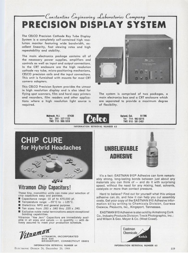
..--------ConJfanfine Gngineering cf!atoraforieJ Compan'I
PRECISION DISPLAY SYSTEM The CELCO Precision Cathode Ray Tube Display System is a completely self-contained high resolution monitor featuring wide bandwidth, excellent linearity, fast slewing rates and high repeatability and stability.
The main electronics package contains all of the necessary power supplies, amplifiers and controls as well as input and output· connections. In the CRT enclosure are the high resolution cathode ray tube, micro-positioning mechanisms, CELCO precision coils and the input connections. This unit is furnished with mounts for most CRT camera adapters.
This CELCO Precision System provides the utmost in high resolution display and is also ideal for flying spot scanners, film and hard copy printers and recorders, film readers and other applications where a high resolution light source is required.
Mahwah, N.J. 07430 Tel. 201·327·1123 TWX 710 · 988·1018
The system is comprised of two packages, a main electronics box and a CRT enclosure which are separated to provide a maximum degree of flexibility.
Upland, Cal. 91786 Tel. 714 · 982·0215 TWX 910 · 581 -3401
INFORMATION RETRIEVAL NUMBER 63
Vitramon Chip Capacitors! These tiny, monolithic units can make your selection of chip capacitors easy and painless. • Capacitance range: 10 pf to 470,000 pf. • Temperature range: -55°C to + 125°C. • Dielectrics: NPO and general purpose. • Ten sizes: from .050 x .040 thru .220 x .240. • Exclusive noble metal terminations assure exceptional
bonding capabilities. Vitramon " Vee Jem" Capacitors are immediately avail able in all sizes and values - in quantity - with de· livery assured to meet your production schedule.
®
-,~MON, INCORPORATED ,, BOX 544
BRIDGEPORT, CONNECTICUT 06601
UNBELIEVABLE ADHESIVE
It's a fact : EASTMAN 910® Adhesive can form remarkably strong, long-lasting bonds between just about any materials you can think of - and do it with surprising speed, without the need for any mixing, heat, solvents, catalysts or more than contact pressure.
Hard to believe? Find out for yourself what this unique adhesive can do, and how it can help you cut assembly costs. Get your copy of the EASTMAN 910 Adhesive information kit by writing to Chemicals Division, EASTMAN CHEMICAL PRooucTs, INc., Kingsport, Tennessee.
EASTMAN 91 O Adhesive is also sold by Armstrong Cork Co., Industry Products Division ; Treck Photographic, Inc. ; and Wilson & Geo. Meyer & Co. (West Coast).
INFORMATION RETRIEVAL NUMBER 64 INFORMATION RETRIEVAL NUMBER 65
ELECTRON IC D ES IGN 26, December 20, 1969 119
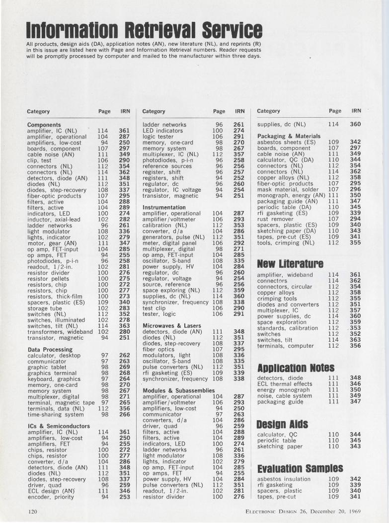
1n1ormation Retrieval service All products, design aids (DA), application notes (AN), new literature (NL), and reprints (R) in this issue are listed here with Page and Information Retrieval numbers. Reader requests will be promptly processed by computer and mailed to the manufacturer within three days.
Category Page IRN Category Page IRN Category Page
Components ladder networks 96 261 supplies, de (NL) 114 amplifier, IC (NL) 114 361 LED indicators 100 274 amplifier, operational 104 287 logic tester 106 291 Packaging & Materials amplifiers, low-cost 94 250 memory, one-card 98 270 asbestos sheets (ES) 109 boards, component 107 297 memory system 98 267 boards, component 107 cable noise (AN) 111 349 multiplexer, IC (NL) 112 357 cable noise (AN) 111 clip, test 106 290 photodiodes, p-i-n 96 258 calculator, QC (DA) 110 con nectars (NL) 112 354 reference sources 96 256 con nectars (NL) 112 connectors (NL) 114 362 register, shift 96 257 con nectars (NL) 114 detectors, diode (AN) 111 348 registers, shift 94 252 copper alloys (NL) 112 diodes (NL) 112 351 regulator, de 96 260 fiber-optic products 107 diodes, step-recovery 108 337 regulator, IC voltage 94 254 mask material , solder 107 fiber-optic products 107 295 transistor, magnetic 94 251 monograph , energy (AN) 111 tilters, active 104 288 packaging guide (AN) 111 filters, active 104 289 Instrumentation periodic table (DA) 110 indicators, LED 100 274 amplifier, operational 104 287 rfi gasketing (ES) 109 inductor, axial-lead 102 282 amplifier /voltmeter 106 293 rust remover 107 ladder networks 96 261 calibration (NL) 112 353 spacers , plastic (ES) 109 light modulator 108 336 converter, d /a 104 286 sketching paper (DA) 110 lights, indicator 102 279 generators, pulse (NL) 112 351 tapes, pre-cut (ES) 109 motor, gear (AN) 111 347 meter, digital panel 106 292 tools, crimping (NL) 112 op amp, FET-input 104 285 multiplexer, digital 98 271 op amps , FET 94 255 op amp, FET-input 104 285 photodiodes, p-i -n 96 258 oscillator, S-band 108 335 New Literature readout , 1 /2-in. 102 281 power supply, HV 104 284 resistor divider 100 276 regulator, de 96 260 amplifier, wideband 114 resistor pellets 100 275 regulator, voltage 94 254 connectors 114 resistors, chip 100 272 source, reference 96 256 connectors , circular 112 resistors, chip 100 277 space exploring (NL) 112 359 copper alloys 112 resistors , thick-film 100 273 supplies, de (NL) 114 360 crimping tools 112 spacers, plastic (ES) 109 340 synchronizer, frequency 108 338 diodes and converters 112 storage tube 102 283 test clip 106 290 multiplexer, IC 112 switches (NL) 112 352 tester, logic 106 291 power supplies, de 114 switches, illuminated 102 278 space exploration 112 switches, tilt (NL) 114 363 Microwaves & Lasers standards, calibration 112 transformers, wideband 102 280 detectors , diode (AN) 111 348 switches 112 transistor, magnetic 94 251 diodes (NL) 112 351 switches, tilt 114
diodes , step-recovery 108 337 terminals , computer 112 Data Processing fiber optics 107 295 calculator, desktop 97 262 modulators, light 108 336 communicator 97 263 oscillator, S-band 108 335 graphic tablet 98 269 pulse converters (NL) 112 351 APPliCBt,on Notes graphics terminal 98 268 rfi gasketing (ES) 109 339 keyboard, graphics 97 264 synchronizer, frequency 108 338 detectors, diode 111 memory, one-card 98 270 ECL thermal effects 111 memory system 98 267 Modules & Subassemblies energy monograph 111 multiplexer, digital 98 271 amplifier, operational 104 287 noise, cable system 111 terminal , magnetic tape 97 265 amplifier/ voltmeter 106 293 packaging guidf! 111 terminals , data (NL) 112 356 amplifiers, low-cost 94 250 time-sharing system 98 266 communicator 97 263
converters, d /a 104 286 Design Aids ICs & Semiconductors driver, quad 96 259 amplifier, IC (NL) 114 361 filters, active 104 288 calculator, QC 110 amplifiers, low-cost 94 250 filters, active 104 289 periodic table 110 amplifiers, FET 94 255 indicators, LED 100 274 sketching paper 110 chips, resistor 100 272 ladder networks 96 261 chips, resistor 100 277 light modulator 108 336 converter, d /a 104 286 lights, indicator 102 279 detectors, diode (AN) 111 348 op amp, FET-input 104 285 Evaluation samples diodes (NL) 112 351 op amps, FET 94 255 diodes, step-recovery 108 337 power supply, HV 104 284 asbestos insulation 109 driver, quad 96 259 pulse converters (NL) 112 351 rfi gasketing 109 ECL design (AN)' 111 346 readout, 1/2-in. 102 281 spacers , plastic 109 encoder, priority 94 253 resistor divider 100 276 tapes , pre-cut 109
120 ELECTRON IC D ESIGN 26, December 20.
IRN
360
342 297 349 344 354 362 358 295 296 350 347 345 339 294 340 343 341 355
361 362 354 358 355 351 357 360 359
. 353 352 363 356
348 346 350 349 347
344 345 343
342 339 340 341
1969
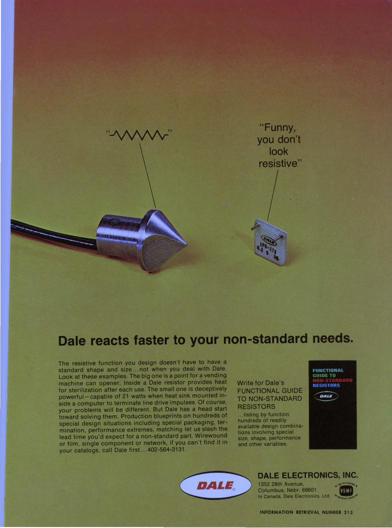
''-1\N\1'/v-'' "Funny, you don't
look resistive"
Dale reacts faster to your non-standard needs.
The resistive function you design doesn 't have to have a standard shape and size ... not when you deal with Dale. Look at these examples. The big one is a point for a vending machine can opener. Inside a Dale resistor provides heat for sterilization after each use. The small one is deceptively powerful-capable of 21 watts when heat sink mounted inside a computer to terminate line drive impulses. Of course, your problems will be different. But Dale has a head start toward solving them. Production blueprints on hundreds of special design situations including special packaging, termination, performance extremes, matching let us slash the lead time you 'd expect for a non-standard part. Wirewound or film, single component or network, if you can 't find it in your catalogs, call Dale first. .. 402-564-3131.
Write for Dale's FUNCTIONAL GUIDE TO NON-STANDARD RESISTORS .. . listing by function hundreds of readily available design combinations involving special size, shape, performance and other variables.
DALE ELECTRONICS, INC. 1352 28th Avenue, .,,"''"'""""""• Columbus, Nebr. 68601 """ In Canada, Dale Electronics, Ltd. '•, . ,':"Jill, ,,.,.,•'
6F/t Jll t l \
INFORMATION RETRIEVAL NUMBER 213
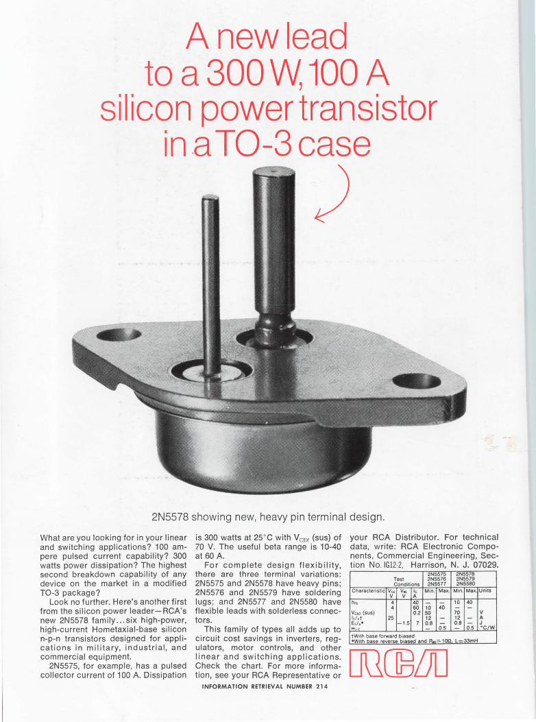
A new lead to a 300 W, 100 A
silicon power transistor in .a T0-3 case
2N5578 showing new, heavy pin terminal design.
What are you looking for in your linear and switching applications? 100 ampere pulsed current capability? 300 watts power dissipation? The highest second breakdown capability of any device on the market in a modified T0-3 package?
is 300 watts at 25°C with VcEx (sus) of 70 V. The useful beta range is 10-40 at 60 A.
For complete design flexibility, there are three terminal variations: 2N5575 and 2N5578 have heavy pins; 2N5576 and 2N5579 have soldering lugs ; and 2N5577 and 2N5580 have flexible leads with solderless connectors.
your RCA Distributor. For technical data, write: RCA Electronic Components, Commercial Engineering, Section No. IG12-2, Harrison, N. J. 07029.
Look no further. Here's another first from the silicon power leader-RCA's new 2N5578 family ... six high-power, high-current Hometaxial-base silicon n-p-n transistors designed for applications in military, industrial, and commercial equipment.
2N5575, for example, has a pulsed collector current of 100 A. Dissipation
This family of types all adds up to circuit cost savings in inverters, regulators, motor controls, and other linear and switching applications. Check the chart. For more information, see your RCA Representative or
INFORMATION RETRIEVAL NUMBER 214
2N5575 Test 2N5576 Conditions 2N5577
Characteristic Vc1 v .. le Min. Max. v v A
h .. 4 40 - -4 60 10 40
Vc10 (sus) 0.2 50 1,1.t 25 12 -Es/b• -1.5 7 0.8 -H,c - 0.5
tW1th base forward biased •With base reverse biased and A,..: 1 on
2N5578 2N5579 2N5580
Min. Max. Units
10 40 - -70 v 12 - A 0.8 - J - 0.5 ·c1w
L-33mH