Embed Size (px)
Citation preview
Dublin Institute of TechnologyARROW@DIT
Articles Crest: Centre for Research in Engineering SurfaceTechnology
2014-06-30
Developments of Cobalt Ferrite NanoparticlesPrepared by The Sol–Gel ProcessM. SajjiaaDublin City University
Mohamed OubahaDublin Institute of Technology, [email protected]
M. HasanuzzamanDublin City University
A.G. OlabiUniversity of the West of Scotland
Follow this and additional works at: https://arrow.dit.ie/cenresart
Part of the Physical Sciences and Mathematics Commons
This Article is brought to you for free and open access by the Crest: Centrefor Research in Engineering Surface Technology at ARROW@DIT. It hasbeen accepted for inclusion in Articles by an authorized administrator ofARROW@DIT. For more information, please [email protected], [email protected], [email protected].
Recommended CitationSajjiaa, M., Oubaha, M., Hasanuzzaman, M. and Olabi, A. G. (2014) Developments of Cobalt Ferrite Nanoparticles Prepared by TheSol–Gel Process. Ceramics International, Volume 40, Issue 1, Part A, January 2014, Pages 1147-1154. doi:10.1016/j.ceramint.2013.06.116
CERAMICSINTERNATIONAL
Available online at www.sciencedirect.com
Ceramics International 40 (2014) 1147–1154
Developments of cobalt ferrite nanoparticles prepared by thesol–gel process
M. Sajjiaa, M. Oubahab, M. Hasanuzzamana, A.G. Olabic,n
aSchool of Mechanical and Manufacturing Engineering, Dublin City University, Glasnevin, Dublin 9, IrelandbOptical Sensor Laboratory, National Centre for Sensor Research, Dublin City University, Glasnevin, Dublin 9, Ireland
cSchool of Engineering, University of the West of Scotland, Paisley, PA1 2BE, UK
Received 19 March 2013; received in revised form 13 June 2013; accepted 30 June 2013Available online 4 July 2013
Abstract
In the phase of the study reported, the sol–gel technique was followed in the preparation of cobalt ferrite amorphous powder following thesame procedure which was selected as the best approach as described in a previous study. It was assumed that there must be a correlation betweenthe heat treatment operational parameters and the structural properties of the material being synthesized. Similarly, it was understood that someheat treatment is necessary to completely decompose the organic and nitrate contents present in the amorphous powder. Having ensured that theheat treatment parameters could be changed without producing a material with poorer properties, it was then possible to produce batches ofpowders using milder conditions in the heat treatment operation. The particle size distributions of these new batches of nanoparticles wereestimated to be in the range 7–28 nm and since the results showed promise, their magnetic properties were also determined.& 2013 Elsevier Ltd and Techna Group S.r.l. All rights reserved.
Keywords: A. Sol–gel; C. Magnetic properties; Cobalt ferrite nanoparticles; Heat treatment
1. Introduction
Cobalt ferrite nanoparticles have recently been of interest tomany researchers due to their diverse potential industrial andbiomedical applications [1–3]. Cobalt ferrite nanoparticles wereproposed as a promising solution in biomedical applications, suchas magnetic thermo-drug delivery and hyperthermia, biosensorsand magnetic resonance imaging [4–6].
Many techniques have already been employed in thedevelopment of cobalt ferrite nanoparticles including a novelsolvothermal approach [7], microemulsions [8], a new non-aqueous route [9], a chemical co-precipitation method [10] andthe sol–gel technique [11].
Among the various liquid-phase chemical techniques, reportedin the literature and employed for the synthesis of cobalt ferritenanoparticles, the sol–gel process (including a heat treatmentoperation) is probably the most effective and feasible route todevelop high purity, homogeneous and crystalline nanoparticles.The sol–gel technique is a low temperature process which
involves hydrolysis and condensation reactions of metal precur-sors (salts or alkoxides) leading to the formation of a three-dimensional inorganic network [12,13]. Metal hydroxyl groups(M-OH) are formed during the hydrolysis. These groups subse-quently condense into strong, rigid and irreversible metal-oxo-metal bridges (M-O-M).In a previous study [14], cobalt ferrite powders were
prepared and developed. It was suspected that the nanoparti-cles which had been synthesized had agglomerated and formedlarger particles as a result of the heat treatment operation. Thisis because these nanoparticles were found to be in the sizerange between 20 and 250 nm. Therefore, there is a need toinvestigate whether the thermal energy released in the heattreatment operation could be reduced because it might beresponsible for the undesired growth of particle size during thisoperation.In the phase of the study reported in this paper, the sol–gel
technique was followed in the preparation of cobalt ferriteamorphous powder following the same procedure which wasselected as the best approach as described in the previous study.It was assumed that there must be a correlation between the heattreatment operational parameters and the structural properties (the
www.elsevier.com/locate/ceramint
0272-8842/$ - see front matter & 2013 Elsevier Ltd and Techna Group S.r.l. All rights reserved.http://dx.doi.org/10.1016/j.ceramint.2013.06.116
nCorresponding author. Tel.: +44 14 18483450.E-mail address: [email protected] (A.G. Olabi).
crystallinity and the freedom from unwanted oxides) of the materialbeing synthesized. Similarly, it was understood that some heattreatment is necessary to completely decompose the organic andnitrate contents present in the amorphous powder and finally toform the spinel structure without these kinds of impurities also.It was therefore important when attempting to change theseoperational parameters of the heat treatment that this would notresult in a material with poorer properties. Having ensured that theheat treatment parameters could be changed without producing amaterial with poorer properties, it was then possible to producebatches of powders using milder conditions in the heat treatmentoperation. The particle size distributions of these new batches ofnanoparticles were estimated and since the results showed promise,their magnetic properties were also determined.
2. Experimental procedure
2.1. Material development
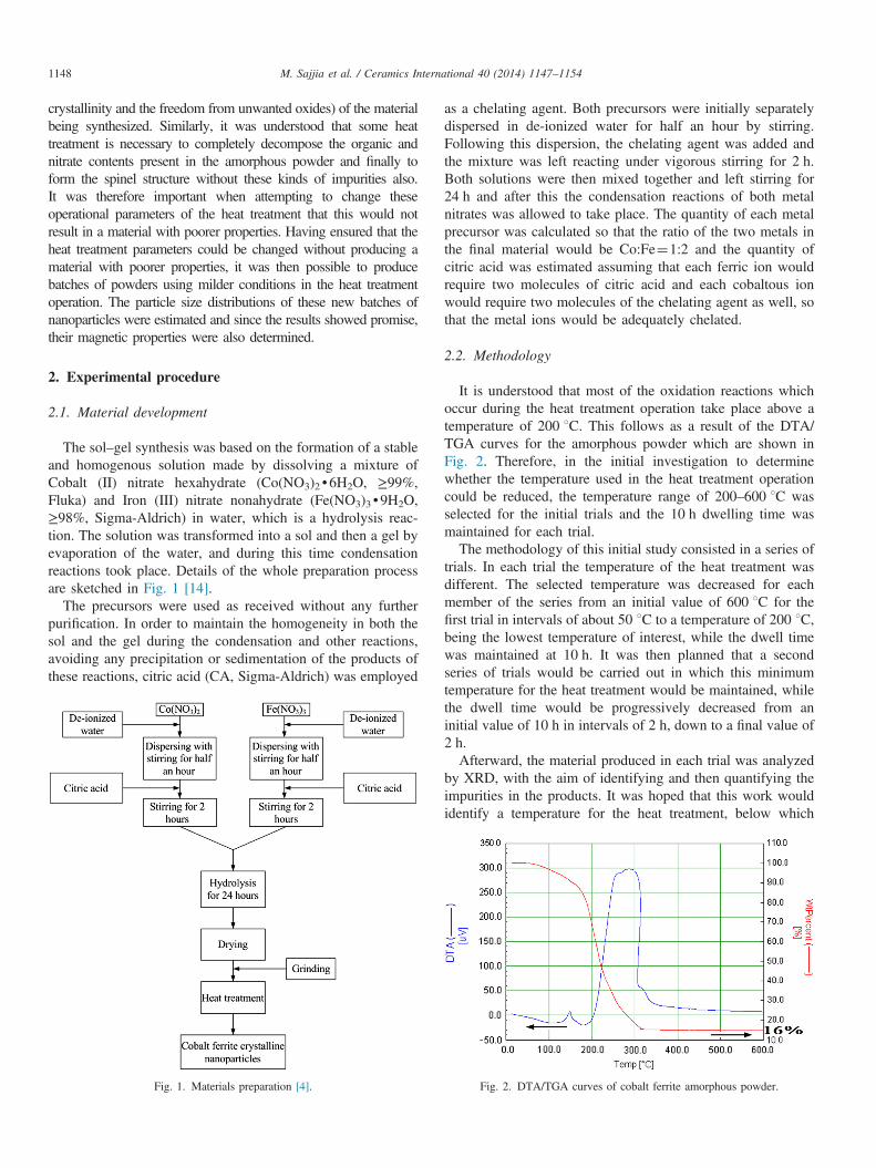
The sol–gel synthesis was based on the formation of a stableand homogenous solution made by dissolving a mixture ofCobalt (II) nitrate hexahydrate (Co(NO3)2d6H2O, ≥99%,Fluka) and Iron (III) nitrate nonahydrate (Fe(NO3)3d9H2O,≥98%, Sigma-Aldrich) in water, which is a hydrolysis reac-tion. The solution was transformed into a sol and then a gel byevaporation of the water, and during this time condensationreactions took place. Details of the whole preparation processare sketched in Fig. 1 [14].
The precursors were used as received without any furtherpurification. In order to maintain the homogeneity in both thesol and the gel during the condensation and other reactions,avoiding any precipitation or sedimentation of the products ofthese reactions, citric acid (CA, Sigma-Aldrich) was employed
as a chelating agent. Both precursors were initially separatelydispersed in de-ionized water for half an hour by stirring.Following this dispersion, the chelating agent was added andthe mixture was left reacting under vigorous stirring for 2 h.Both solutions were then mixed together and left stirring for24 h and after this the condensation reactions of both metalnitrates was allowed to take place. The quantity of each metalprecursor was calculated so that the ratio of the two metals inthe final material would be Co:Fe¼1:2 and the quantity ofcitric acid was estimated assuming that each ferric ion wouldrequire two molecules of citric acid and each cobaltous ionwould require two molecules of the chelating agent as well, sothat the metal ions would be adequately chelated.
2.2. Methodology
It is understood that most of the oxidation reactions whichoccur during the heat treatment operation take place above atemperature of 200 1C. This follows as a result of the DTA/TGA curves for the amorphous powder which are shown inFig. 2. Therefore, in the initial investigation to determinewhether the temperature used in the heat treatment operationcould be reduced, the temperature range of 200–600 1C wasselected for the initial trials and the 10 h dwelling time wasmaintained for each trial.The methodology of this initial study consisted in a series of
trials. In each trial the temperature of the heat treatment wasdifferent. The selected temperature was decreased for eachmember of the series from an initial value of 600 1C for thefirst trial in intervals of about 50 1C to a temperature of 200 1C,being the lowest temperature of interest, while the dwell timewas maintained at 10 h. It was then planned that a secondseries of trials would be carried out in which this minimumtemperature for the heat treatment would be maintained, whilethe dwell time would be progressively decreased from aninitial value of 10 h in intervals of 2 h, down to a final value of2 h.Afterward, the material produced in each trial was analyzed
by XRD, with the aim of identifying and then quantifying theimpurities in the products. It was hoped that this work wouldidentify a temperature for the heat treatment, below which
Fig. 1. Materials preparation [4]. Fig. 2. DTA/TGA curves of cobalt ferrite amorphous powder.
M. Sajjia et al. / Ceramics International 40 (2014) 1147–11541148
there would be problems with impurities, and above which therisk of impurities developing would be insignificant. Thistemperature would be the minimum temperature at which theheat treatment could be operated in a process to produce purecobalt ferrite with its spinel structure.
However, as the work progressed it became clear that with atemperature of only 200 1C, the heat treatment could still resultin producing the cobalt ferrite with the spinel structure with noother oxides. At this point, the investigation became focussedon the dwell time of the heat treatment, and this was thenstudied. It could be safely assumed that investigations studyingdifferent dwell times (10, 8, 6, 4 and 2 h) at temperatureswhich are much higher than the minimum temperature, e.g.500 or 600 1C, would result in products with the spinelstructure and without impurities. As the research interest isto determine the critical conditions, it was believed it is betterto focus the interest on studying the morphology and magneticproperties of nanoparticles prepared under these critical con-ditions whose significance lies in the fact that they are muchmore likely to be produced on a larger scale. The list ofsamples investigated in this study and their conditions ofpreparation are indicated in Table 1.
2.3. Characterization
A Horizontal Tube Furnace (Carbolite Ltd., Sheffield, UK)was used to carry out the heat treatment operation on theamorphous powders with 10 1C/min as the heating/coolingramp rates under ambient atmosphere. The structural charac-terization of powders was carried out by measuring their XRDpatterns employing an X-ray diffractometer (D8 ADVANCE-BRUKER) using Cu-Kα radiation. Differential Thermal Ana-lysis (DTA) and Thermo-Gravimetric Analysis (TGA) wereperformed in air to determine the temperatures at which thedecomposition and oxidation of the chelating agent take place.The curves were obtained using heating/cooling rates of 10 1C/min under ambient atmosphere to investigate and identify thepurity of the materials. Fourier Transform Infrared Spectro-scopy (FTIR) was used to investigate the molecular structureof the materials for comparison reasons. The morphology of
the materials (homogeneity and particle size) was observed bya Field Emission-Scanning Electron Microscope (FE-SEM).The magnetic properties (hysteresis loops) were recorded atboth room temperature and 10 1K using a Vibrating SampleMagnetometer (VSM) with a maximum magnetic field of50 kOe. 20 mg of powder was used in each determination. Thetemperature dependence of the magnetization curve underzero-field cooled conditions was also recorded.
3. Results and discussion
3.1. Structural and thermal analyses
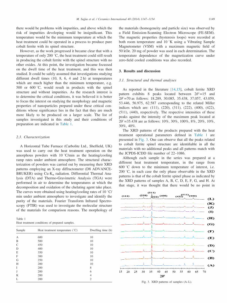
As reported in the literature [14,15], cobalt ferrite XRDpattern exhibits 8 peaks located between 2θ1=15 and2θ1=70 as follows: 18.289, 30.085, 35.438, 37.057, 43.059,53.446, 56.975, 62.587 corresponding to the related Millerindices which are: (111), (220), (311), (222), (400), (422),(511), (440), respectively. The respective intensities of thesepeaks against the intensity of the maximum peak located at2θ1=35.438 are as follows: 10%, 30%, 100%, 8%, 20%, 10%,30%, 40%.The XRD patterns of the products prepared with the heat
treatment operational parameters defined in Table 1 arepresented in Fig. 3. One can observe that all the peaks relatedto cobalt ferrite spinel structure are identifiable in all thematerials with no additional peaks and all patterns match withthe JCPDS-ICDD file number of 22–1086.Although each sample in the series was prepared at a
different heat treatment temperature, in the range from600 1C down to the minimum temperature of interest, i.e.200 1C, in each case the only phase observable in the XRDpatterns is that of the cobalt ferrite spinel phase as indicated bythe XRD patterns of samples A, B, C, D, E, F, G, and H. Atthat stage, it was thought that there would be no point in
Table 1Heat treatment conditions of prepared samples.
Sample Heat treatment temperature (1C) Dwelling time (h)
A 600 10B 500 10C 450 10D 400 10E 350 10F 300 10G 250 10H 200 10I 200 8J 200 6K 200 4L 200 2
Fig. 3. XRD patterns of samples (A–L).
M. Sajjia et al. / Ceramics International 40 (2014) 1147–1154 1149
operating the equipment with a dwell time of 10 h if reducingthe time could also result in reducing the particle sizes.Therefore, in a further series of trials the 10 h dwell timewas reduced to 8, 6, 4, and then finally to 2 h while thetemperature was maintained at 200 1C. Again in each case theonly phase observable in the XRD patterns is that of the spinelstructure as indicated by the XRD patterns of samples I, J, K,and L shown in Fig. 3.
These results indicate the success of the particular form andarrangement of the sol–gel technique, described in the previousstudy in developing a material with the cobalt ferrite spinelstructure. It can be assumed that with this particular choice ofstarting materials and procedures, the cobalt ferrite structurewould have been obtained with a heat treatment temperatureanywhere within the range between 200 and 600 1C. However,as XRD patterns can only be used to identify crystallinestructures present in a material they do not give any informa-tion about the purity of the materials, if these materials alsocontain substances which are not crystalline, such as organicconstituents. It was therefore decided to perform thermalanalyses such as DTA/TGA to identify the purity of theprepared materials taking into account non-crystalline sub-stances. These other techniques would identify the minimumtemperature and time required to complete the decompositionof the nitrates and the decomposition or oxidation of organicmoieties, initially present in the precursors and in the chelatingagent or having been produced in reactions during the sol–gelprocessing.
To pursue this approach further, the dwell times andtemperatures of the heat treatment operation, which weredesignated above as A and L were selected for comparison,because they represent the two extremes of the parameters,being the strongest 600 1C, for 10 h and the mildest 200 1C,for 2 h respectively. The heat treatment operations were thencarried out, but in the DTA/TGA equipment using the samestarting material, the amorphous powder produced by the sol–gel process, and using the equipment's programmable ramprates and set temperatures to repeat, as closely as possible, theoperation of the horizontal tube furnace, normally used for theheat treatment operation. According to the work reported in theprevious study, the heat treatment conditions designated as Awere carried out already, in both the horizontal tube furnace,and in the DTA/TGA equipment (sample 14 and Fig. 7) [14].The analyses suggest that the product, identified as cobaltferrite with a spinel structure, at 350 1C, became free of anyorganic or unstable inorganic impurities, because the solid(WtPercent[%]) became stable with no further oxidation ordecomposition reactions to form gases about and above350 1C. These results can therefore be used as a referencefor comparison with the heat treatment parameters designatedas L.
The thermal analysis following the heat treatment conditionsdesignated by A is shown in Fig. 2. In the results one canobserve that within the range of temperatures between roomtemperature and 600 1C, the DTA curve exhibits two exother-mic peaks or bands centered at 150 1C and 300 1C. The bandcentered at 300 1C is actually spread out over a range of
temperatures from 205 1C up to 345 1C. This band seems toresult from the superimposition of several overlapping bands.In fact, it is well known that the oxidation of various, similarorganic compounds take place in this domain of temperatures.In this case, it is very likely that the width of the band resultsfrom both the decomposition of the nitrate ions, which wereoriginally linked to both the Co and the Fe ions and theoxidation and decomposition of the citric acid, which havebecome linked to both the Co and the Fe ions. Furthermore,the TGA curve shows that the initial weight of materialreduces to 16% of its original value during the heat treatment.The additional components contribute 84% to the total weightof the amorphous powder.The results of the DTA/TGA following the heat treatment
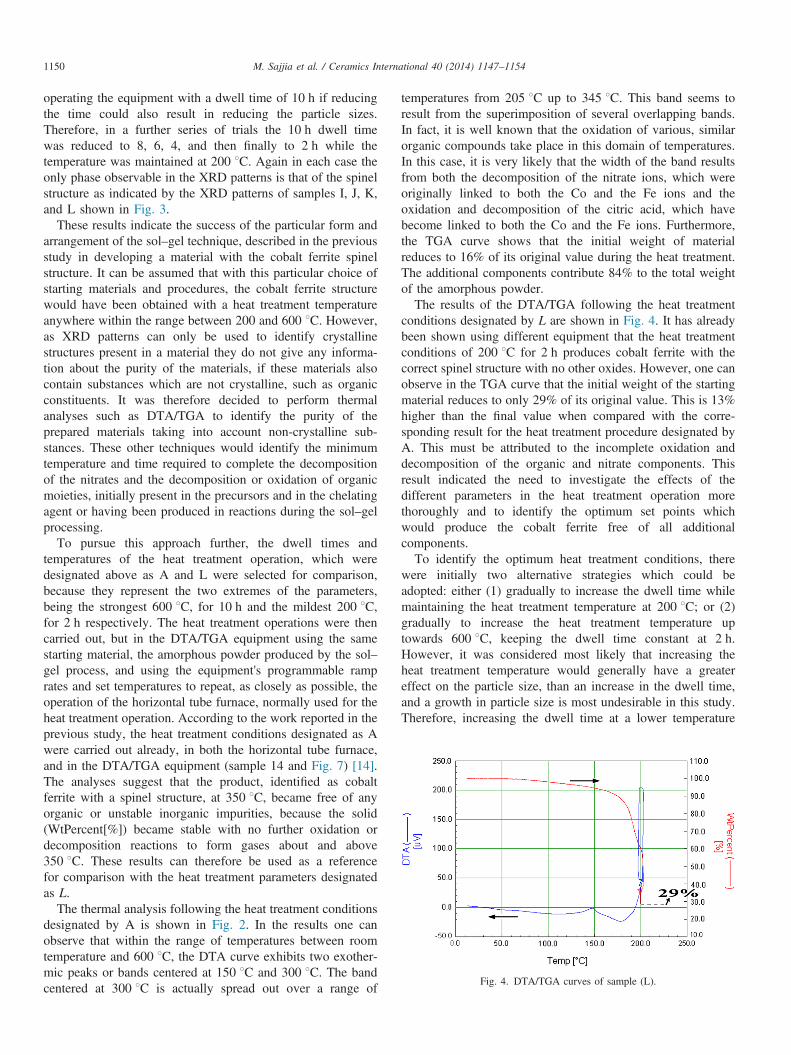
conditions designated by L are shown in Fig. 4. It has alreadybeen shown using different equipment that the heat treatmentconditions of 200 1C for 2 h produces cobalt ferrite with thecorrect spinel structure with no other oxides. However, one canobserve in the TGA curve that the initial weight of the startingmaterial reduces to only 29% of its original value. This is 13%higher than the final value when compared with the corre-sponding result for the heat treatment procedure designated byA. This must be attributed to the incomplete oxidation anddecomposition of the organic and nitrate components. Thisresult indicated the need to investigate the effects of thedifferent parameters in the heat treatment operation morethoroughly and to identify the optimum set points whichwould produce the cobalt ferrite free of all additionalcomponents.To identify the optimum heat treatment conditions, there
were initially two alternative strategies which could beadopted: either (1) gradually to increase the dwell time whilemaintaining the heat treatment temperature at 200 1C; or (2)gradually to increase the heat treatment temperature uptowards 600 1C, keeping the dwell time constant at 2 h.However, it was considered most likely that increasing theheat treatment temperature would generally have a greatereffect on the particle size, than an increase in the dwell time,and a growth in particle size is most undesirable in this study.Therefore, increasing the dwell time at a lower temperature
Fig. 4. DTA/TGA curves of sample (L).
M. Sajjia et al. / Ceramics International 40 (2014) 1147–11541150
was considered to be a better strategy than increasing thetemperature with a short dwell time.
This investigation started, therefore with 200 1C as the heattreatment temperature, and the dwell time was graduallyincreased in a series of trials using the DTA/TGA equipment.However, even when the dwell time had been extended to10 h, the TGA curve showed that the initial weight of thestarting material was reduced only to 24% of the originalvalue. This indicates that there was insufficient thermal energyto oxidize or decompose the organic and nitrate componentscompletely.
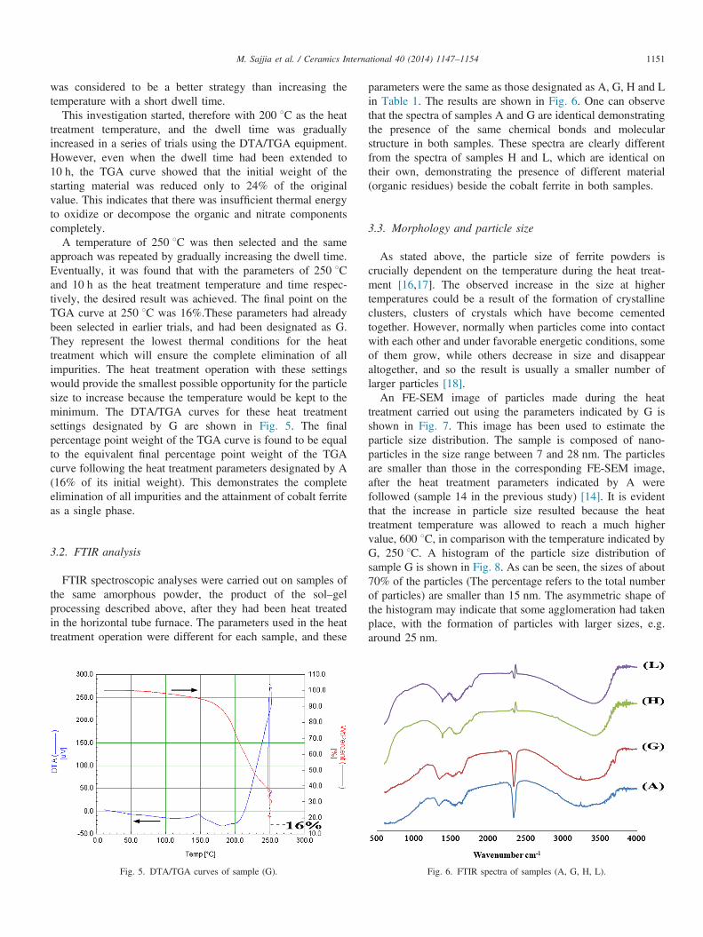
A temperature of 250 1C was then selected and the sameapproach was repeated by gradually increasing the dwell time.Eventually, it was found that with the parameters of 250 1Cand 10 h as the heat treatment temperature and time respec-tively, the desired result was achieved. The final point on theTGA curve at 250 1C was 16%.These parameters had alreadybeen selected in earlier trials, and had been designated as G.They represent the lowest thermal conditions for the heattreatment which will ensure the complete elimination of allimpurities. The heat treatment operation with these settingswould provide the smallest possible opportunity for the particlesize to increase because the temperature would be kept to theminimum. The DTA/TGA curves for these heat treatmentsettings designated by G are shown in Fig. 5. The finalpercentage point weight of the TGA curve is found to be equalto the equivalent final percentage point weight of the TGAcurve following the heat treatment parameters designated by A(16% of its initial weight). This demonstrates the completeelimination of all impurities and the attainment of cobalt ferriteas a single phase.
3.2. FTIR analysis
FTIR spectroscopic analyses were carried out on samples ofthe same amorphous powder, the product of the sol–gelprocessing described above, after they had been heat treatedin the horizontal tube furnace. The parameters used in the heattreatment operation were different for each sample, and these
parameters were the same as those designated as A, G, H and Lin Table 1. The results are shown in Fig. 6. One can observethat the spectra of samples A and G are identical demonstratingthe presence of the same chemical bonds and molecularstructure in both samples. These spectra are clearly differentfrom the spectra of samples H and L, which are identical ontheir own, demonstrating the presence of different material(organic residues) beside the cobalt ferrite in both samples.
3.3. Morphology and particle size
As stated above, the particle size of ferrite powders iscrucially dependent on the temperature during the heat treat-ment [16,17]. The observed increase in the size at highertemperatures could be a result of the formation of crystallineclusters, clusters of crystals which have become cementedtogether. However, normally when particles come into contactwith each other and under favorable energetic conditions, someof them grow, while others decrease in size and disappearaltogether, and so the result is usually a smaller number oflarger particles [18].An FE-SEM image of particles made during the heat
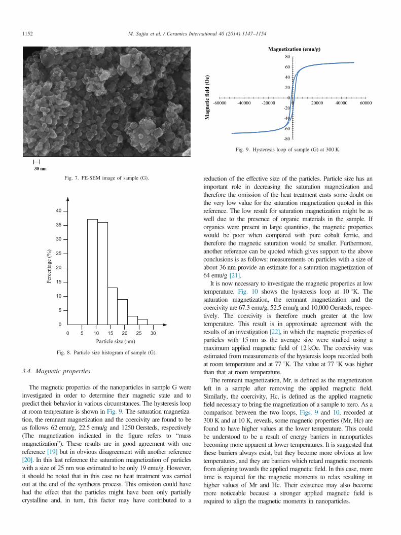
treatment carried out using the parameters indicated by G isshown in Fig. 7. This image has been used to estimate theparticle size distribution. The sample is composed of nano-particles in the size range between 7 and 28 nm. The particlesare smaller than those in the corresponding FE-SEM image,after the heat treatment parameters indicated by A werefollowed (sample 14 in the previous study) [14]. It is evidentthat the increase in particle size resulted because the heattreatment temperature was allowed to reach a much highervalue, 600 1C, in comparison with the temperature indicated byG, 250 1C. A histogram of the particle size distribution ofsample G is shown in Fig. 8. As can be seen, the sizes of about70% of the particles (The percentage refers to the total numberof particles) are smaller than 15 nm. The asymmetric shape ofthe histogram may indicate that some agglomeration had takenplace, with the formation of particles with larger sizes, e.g.around 25 nm.
Fig. 5. DTA/TGA curves of sample (G). Fig. 6. FTIR spectra of samples (A, G, H, L).
M. Sajjia et al. / Ceramics International 40 (2014) 1147–1154 1151
3.4. Magnetic properties
The magnetic properties of the nanoparticles in sample G wereinvestigated in order to determine their magnetic state and topredict their behavior in various circumstances. The hysteresis loopat room temperature is shown in Fig. 9. The saturation magnetiza-tion, the remnant magnetization and the coercivity are found to beas follows 62 emu/g, 22.5 emu/g and 1250 Oersteds, respectively(The magnetization indicated in the figure refers to “massmagnetization”). These results are in good agreement with onereference [19] but in obvious disagreement with another reference[20]. In this last reference the saturation magnetization of particleswith a size of 25 nm was estimated to be only 19 emu/g. However,it should be noted that in this case no heat treatment was carriedout at the end of the synthesis process. This omission could havehad the effect that the particles might have been only partiallycrystalline and, in turn, this factor may have contributed to a
reduction of the effective size of the particles. Particle size has animportant role in decreasing the saturation magnetization andtherefore the omission of the heat treatment casts some doubt onthe very low value for the saturation magnetization quoted in thisreference. The low result for saturation magnetization might be aswell due to the presence of organic materials in the sample. Iforganics were present in large quantities, the magnetic propertieswould be poor when compared with pure cobalt ferrite, andtherefore the magnetic saturation would be smaller. Furthermore,another reference can be quoted which gives support to the aboveconclusions is as follows: measurements on particles with a size ofabout 36 nm provide an estimate for a saturation magnetization of64 emu/g [21].It is now necessary to investigate the magnetic properties at low
temperature. Fig. 10 shows the hysteresis loop at 10 1K. Thesaturation magnetization, the remnant magnetization and thecoercivity are 67.3 emu/g, 52.5 emu/g and 10,000 Oersteds, respec-tively. The coercivity is therefore much greater at the lowtemperature. This result is in approximate agreement with theresults of an investigation [22], in which the magnetic properties ofparticles with 15 nm as the average size were studied using amaximum applied magnetic field of 12 kOe. The coercivity wasestimated from measurements of the hysteresis loops recorded bothat room temperature and at 77 1K. The value at 77 1K was higherthan that at room temperature.The remnant magnetization, Mr, is defined as the magnetization
left in a sample after removing the applied magnetic field.Similarly, the coercivity, Hc, is defined as the applied magneticfield necessary to bring the magnetization of a sample to zero. As acomparison between the two loops, Figs. 9 and 10, recorded at300 K and at 10 K, reveals, some magnetic properties (Mr, Hc) arefound to have higher values at the lower temperature. This couldbe understood to be a result of energy barriers in nanoparticlesbecoming more apparent at lower temperatures. It is suggested thatthese barriers always exist, but they become more obvious at lowtemperatures, and they are barriers which retard magnetic momentsfrom aligning towards the applied magnetic field. In this case, moretime is required for the magnetic moments to relax resulting inhigher values of Mr and Hc. Their existence may also becomemore noticeable because a stronger applied magnetic field isrequired to align the magnetic moments in nanoparticles.
5 10 15 20
5
10
15
20
25
30
35
40
25 300
0
Particle size (nm)
Perc
enta
ge (%
)
Fig. 8. Particle size histogram of sample (G).
-80
-60
-40
-20
0
20
40
60
80
-60000 -40000 -20000 0 20000 40000 60000
Mag
netic
fiel
d (O
e)
Magnetization (emu/g)
Fig. 9. Hysteresis loop of sample (G) at 300 K.
Fig. 7. FE-SEM image of sample (G).
M. Sajjia et al. / Ceramics International 40 (2014) 1147–11541152
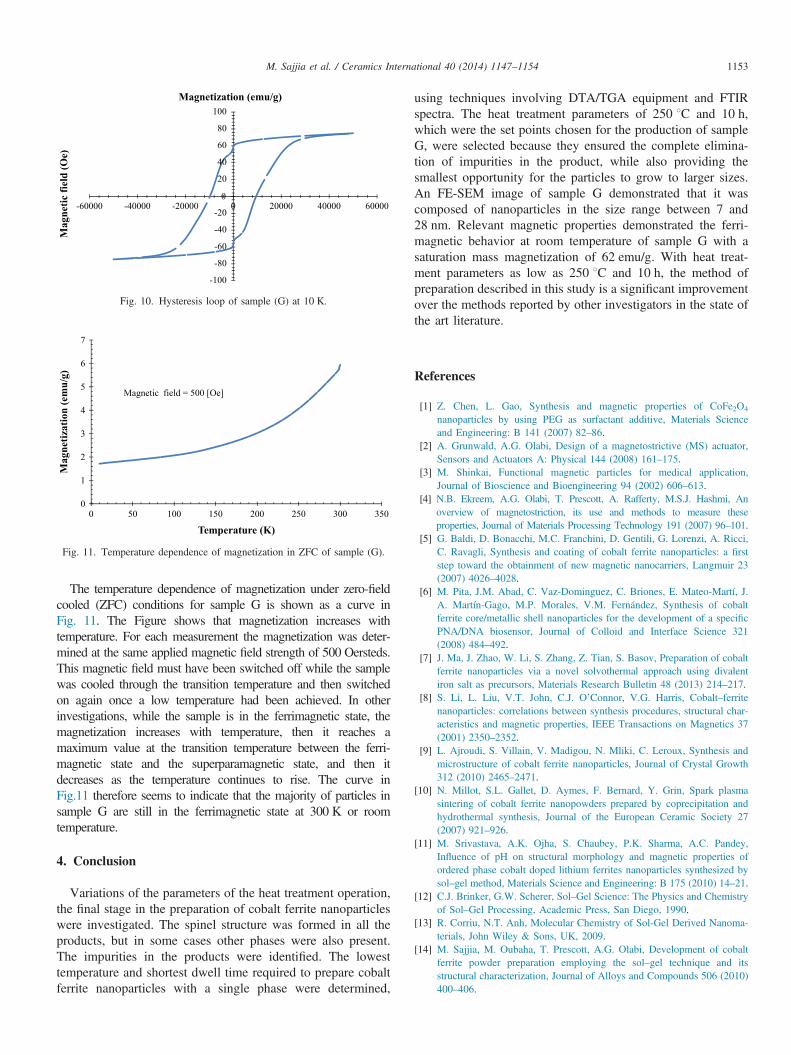
The temperature dependence of magnetization under zero-fieldcooled (ZFC) conditions for sample G is shown as a curve inFig. 11. The Figure shows that magnetization increases withtemperature. For each measurement the magnetization was deter-mined at the same applied magnetic field strength of 500 Oersteds.This magnetic field must have been switched off while the samplewas cooled through the transition temperature and then switchedon again once a low temperature had been achieved. In otherinvestigations, while the sample is in the ferrimagnetic state, themagnetization increases with temperature, then it reaches amaximum value at the transition temperature between the ferri-magnetic state and the superparamagnetic state, and then itdecreases as the temperature continues to rise. The curve inFig.11 therefore seems to indicate that the majority of particles insample G are still in the ferrimagnetic state at 300 K or roomtemperature.
4. Conclusion
Variations of the parameters of the heat treatment operation,the final stage in the preparation of cobalt ferrite nanoparticleswere investigated. The spinel structure was formed in all theproducts, but in some cases other phases were also present.The impurities in the products were identified. The lowesttemperature and shortest dwell time required to prepare cobaltferrite nanoparticles with a single phase were determined,
using techniques involving DTA/TGA equipment and FTIRspectra. The heat treatment parameters of 250 1C and 10 h,which were the set points chosen for the production of sampleG, were selected because they ensured the complete elimina-tion of impurities in the product, while also providing thesmallest opportunity for the particles to grow to larger sizes.An FE-SEM image of sample G demonstrated that it wascomposed of nanoparticles in the size range between 7 and28 nm. Relevant magnetic properties demonstrated the ferri-magnetic behavior at room temperature of sample G with asaturation mass magnetization of 62 emu/g. With heat treat-ment parameters as low as 250 1C and 10 h, the method ofpreparation described in this study is a significant improvementover the methods reported by other investigators in the state ofthe art literature.
References
[1] Z. Chen, L. Gao, Synthesis and magnetic properties of CoFe2O4
nanoparticles by using PEG as surfactant additive, Materials Scienceand Engineering: B 141 (2007) 82–86.
[2] A. Grunwald, A.G. Olabi, Design of a magnetostrictive (MS) actuator,Sensors and Actuators A: Physical 144 (2008) 161–175.
[3] M. Shinkai, Functional magnetic particles for medical application,Journal of Bioscience and Bioengineering 94 (2002) 606–613.
[4] N.B. Ekreem, A.G. Olabi, T. Prescott, A. Rafferty, M.S.J. Hashmi, Anoverview of magnetostriction, its use and methods to measure theseproperties, Journal of Materials Processing Technology 191 (2007) 96–101.
[5] G. Baldi, D. Bonacchi, M.C. Franchini, D. Gentili, G. Lorenzi, A. Ricci,C. Ravagli, Synthesis and coating of cobalt ferrite nanoparticles: a firststep toward the obtainment of new magnetic nanocarriers, Langmuir 23(2007) 4026–4028.
[6] M. Pita, J.M. Abad, C. Vaz-Dominguez, C. Briones, E. Mateo-Martí, J.A. Martín-Gago, M.P. Morales, V.M. Fernández, Synthesis of cobaltferrite core/metallic shell nanoparticles for the development of a specificPNA/DNA biosensor, Journal of Colloid and Interface Science 321(2008) 484–492.
[7] J. Ma, J. Zhao, W. Li, S. Zhang, Z. Tian, S. Basov, Preparation of cobaltferrite nanoparticles via a novel solvothermal approach using divalentiron salt as precursors, Materials Research Bulletin 48 (2013) 214–217.
[8] S. Li, L. Liu, V.T. John, C.J. O’Connor, V.G. Harris, Cobalt–ferritenanoparticles: correlations between synthesis procedures, structural char-acteristics and magnetic properties, IEEE Transactions on Magnetics 37(2001) 2350–2352.
[9] L. Ajroudi, S. Villain, V. Madigou, N. Mliki, C. Leroux, Synthesis andmicrostructure of cobalt ferrite nanoparticles, Journal of Crystal Growth312 (2010) 2465–2471.
[10] N. Millot, S.L. Gallet, D. Aymes, F. Bernard, Y. Grin, Spark plasmasintering of cobalt ferrite nanopowders prepared by coprecipitation andhydrothermal synthesis, Journal of the European Ceramic Society 27(2007) 921–926.
[11] M. Srivastava, A.K. Ojha, S. Chaubey, P.K. Sharma, A.C. Pandey,Influence of pH on structural morphology and magnetic properties ofordered phase cobalt doped lithium ferrites nanoparticles synthesized bysol–gel method, Materials Science and Engineering: B 175 (2010) 14–21.
[12] C.J. Brinker, G.W. Scherer, Sol–Gel Science: The Physics and Chemistryof Sol–Gel Processing, Academic Press, San Diego, 1990.
[13] R. Corriu, N.T. Anh, Molecular Chemistry of Sol-Gel Derived Nanoma-terials, John Wiley & Sons, UK, 2009.
[14] M. Sajjia, M. Oubaha, T. Prescott, A.G. Olabi, Development of cobaltferrite powder preparation employing the sol–gel technique and itsstructural characterization, Journal of Alloys and Compounds 506 (2010)400–406.
-100
-80
-60
-40
-20
0
20
40
60
80
100
-60000 -40000 -20000 0 20000 40000 60000
Mag
netic
fiel
d (O
e)
Magnetization (emu/g)
Fig. 10. Hysteresis loop of sample (G) at 10 K.
0
1
2
3
4
5
6
7
0 50 100 150 200 250 300 350
Mag
netiz
atio
n (e
mu/
g)
Temperature (K)
Magnetic field = 500 [Oe]
Fig. 11. Temperature dependence of magnetization in ZFC of sample (G).
M. Sajjia et al. / Ceramics International 40 (2014) 1147–1154 1153
[15] M. Sajjia, K.Y. Benyounis, A.G. Olabi, The simulation and optimizationof heat treatment of cobalt ferrite nanoparticles prepared by the sol–geltechnique, Powder Technology 222 (2012) 143–151.
[16] S.H. Xiao, W.F. Jiang, L.Y. Li, X.J. Li, Low-temperature auto-combus-tion synthesis and magnetic properties of cobalt ferrite nanopowder,Materials Chemistry and Physics 106 (2007) 82–87.
[17] J.B. Silva, W. de Brito, N.D.S. Mohallem, Influence of heat treatment oncobalt ferrite ceramic powders, Materials Science and Engineering: B 112(2004) 182–187.
[18] C. Caizer, M. Stefanescu, Magnetic characterization of nanocrystallineNi–Zn ferrite powder prepared by the glyoxylate precursor method,Journal of Physics D: Applied Physics 35 (2002) 3035–3040.
[19] Z. Zi, Y. Sun, X. Zhu, Z. Yang, J. Dai, W. Song, Synthesis and magneticproperties of CoFe2O4 ferrite nanoparticles, Journal of Magnetism andMagnetic Materials 321 (2009) 1251–1255.
[20] J. Wang, T. Deng, Y. Lin, C. Yang, W. Zhan, Synthesis and characteriza-tion of CoFe2O4 magnetic particles prepared by co-precipitation method:effect of mixture procedures of initial solution, Journal of Alloys andCompounds 450 (2008) 532–539.
[21] C.N. Chinnasamy, M. Senoue, B. Jeyadevan, O. Perales-Perez, K. Shinoda,K. Tohji, Synthesis of size-controlled cobalt ferrite particles with highcoercivity and squareness ratio, Journal of Colloid and Interface 263 (2003)80–83Sci 263 (2003) 80–83.
[22] B.G. Toksha, S.E. Shirsath, S.M. Patange, K.M. Jadhav, Structuralinvestigations and magnetic properties of cobalt ferrite nanoparticlesprepared by sol–gel auto combustion method, Solid State Communications147 (2008) 479–483.
M. Sajjia et al. / Ceramics International 40 (2014) 1147–11541154


