Embed Size (px)
Citation preview
2506 Galen DriveChampaign, IL 61821Voice 217.344.1243 • Fax 217.344.1245www.cobaltdigital.com
Product Manual
9926-xHtoS-OM (V1.2)
Cobalt Digital Inc.
9926-xHtoS9926-xHtoS
3G/HD/SD Multi-Channel openGear® HDMI-To-SDI Converters with Per-Channel Frame Sync• 9926-4HtoS 3G/HD/SD Quad-Channel openGear® HDMI-To-SDI Converter with Per-Channel Frame Sync
• 9926-2HtoS 3G/HD/SD Dual-Channel openGear® HDMI-To-SDI Converter with Per-Channel Frame
Copyright©Copyright 2021, Cobalt Digital Inc. All Rights Reserved.Duplication or distribution of this manual and any information contained within is strictly prohibited without the express written permission of Cobalt Digital Inc. This manual and any information contained within, may not be reproduced, distributed, or transmitted in any form, or by any means, for any purpose, without the express written permission of Cobalt Digital Inc. Reproduction or reverse engineering of software used in this device is prohibited.
DisclaimerThe information in this document has been carefully examined and is believed to be entirely reliable. However, no responsibility is assumed for inaccuracies. Furthermore, Cobalt Digital Inc. reserves the right to make changes to any products herein to improve readability, function, or design. Cobalt Digital Inc. does not assume any liability arising out of the application or use of any product or circuit described herein.
Trademark InformationCobalt® is a registered trademark of Cobalt Digital Inc.
openGear® is a registered trademark of Ross Video Limited. DashBoard™ is a trademark of Ross Video Limited.
Dolby® is a registered trademark of Dolby Laboratories, Inc. Other product names or trademarks appearing in this manual are the property of their respective owners.
Congratulations on choosing the Cobalt® 9926-xHtoS 3G/HD/SD Multi-Channel openGear® HDMI-To-SDIConverter with Per-Channel Frame Sync model. The 9926-xHtoS models are part of a full line of modularprocessing and conversion gear for broadcast TV environments. The Cobalt Digital Inc. line includes videodecoders and encoders, audio embedders and de-embedders, distribution amplifiers, format converters, remotecontrol systems and much more. Should you have questions pertaining to the installation or operation of your 9926-xHtoS model, please contact us at the contact information on the front cover.
Manual No.: 9926-xHtoS-OM
Document Version: V1.2
Release Date: July 6, 2021
Applicable for Firmware Version(or greater):
1.008 or greater
Description ofproduct/manualchanges:
- Minor editorial revisions/clarifications.
9926-xHtoS-OM (V1.2)
Table of Contents
Chapter 1 Introduction . . . . . . . . . . . . . . . . . . . . . . . . . . . . . . . . . . . . . . . . . . . 1-1Overview ............................................................................................................................. 1-1
9926-xHtoS Card Software Versions and this Manual ....................................................... 1-2
Cobalt Reference Guides ..................................................................................................... 1-2
Manual Conventions............................................................................................................ 1-3
Warnings, Cautions, and Notes .............................................................................. 1-4Labeling Symbol Definitions ................................................................................. 1-4
Safety and Regulatory Summary......................................................................................... 1-5
Warnings................................................................................................................. 1-5Cautions .................................................................................................................. 1-5
9926-xHtoS Functional Description.................................................................................... 1-6
9926-xHtoS Input/Output Formats......................................................................... 1-6Video Processor Description .................................................................................. 1-8Audio Processor Description .................................................................................. 1-9User Control Interface .......................................................................................... 1-119926-xHtoS Rear I/O Modules............................................................................. 1-13
Technical Specifications.................................................................................................... 1-13
Warranty and Service Information .................................................................................... 1-15
Cobalt Digital Inc. Limited Warranty .................................................................. 1-15Contact Cobalt Digital Inc. ................................................................................................ 1-16
Chapter 2 Installation and Setup . . . . . . . . . . . . . . . . . . . . . . . . . . . . . . . . . . . 2-1Overview ............................................................................................................................. 2-1
Installing the 9926-xHtoS Into a Frame Slot....................................................................... 2-1
Installing a Rear I/O Module ............................................................................................... 2-3
9926-xHtoS Rear I/O Modules............................................................................... 2-4Setting Up 9926-xHtoS Network Remote Control.............................................................. 2-5
Chapter 3 Operating Instructions. . . . . . . . . . . . . . . . . . . . . . . . . . . . . . . . . . . 3-1Overview ............................................................................................................................. 3-1
Control and Display Descriptions........................................................................................ 3-1
Function Menu/Parameter Overview ..................................................................... 3-2DashBoard™ User Interface .................................................................................. 3-3
Cobalt® Remote Control Panel User Interfaces...................................................... 3-4Accessing the 9926-xHtoS Card via Remote Control ......................................................... 3-5
Accessing the 9926-xHtoS Card Using DashBoard™ ........................................... 3-5
Accessing the 9926-xHtoS Card Using a Cobalt® Remote Control Panel ............. 3-6Checking 9926-xHtoS Card Information ............................................................................ 3-7
9926-xHtoS-OM (V1.2) 9926-XHTOS PRODUCT MANUAL i
9926-xHtoS Function Menu List and Descriptions............................................................. 3-8
Input Video Controls ............................................................................................. 3-9Video Proc/Color Correction .............................................................................. 3-10Framesync ........................................................................................................... 3-13Output Video Routing ......................................................................................... 3-16GPO Setup Controls ............................................................................................ 3-17Presets .................................................................................................................. 3-17Admin .................................................................................................................. 3-19Network Settings Controls .................................................................................. 3-20User Events Setup Controls ................................................................................. 3-22Input Audio Routing/Controls ............................................................................. 3-23Output Audio Routing/Controls .......................................................................... 3-27
Troubleshooting................................................................................................................. 3-31
Error and Failure Indicator Overview .................................................................. 3-31Basic Troubleshooting Checks............................................................................. 3-33Troubleshooting Network/Remote Control Errors............................................... 3-34In Case of Problems ............................................................................................. 3-34
ii 9926-XHTOS PRODUCT MANUAL 9926-xHtoS-OM (V1.2)
Chapter 1
Chapter 1 Introduction
OverviewNote: This manual covers the 9926 series of openGear® H-to-S converter/ frame
sync cards, which consists of the:
- 9926-4HtoS 3G/HD/SD Quad-Channel openGear® HDMI-To-SDI Converter with Per-Channel Frame Sync
- 9926-2HtoS 3G/HD/SD Dual-Channel openGear® HDMI-To-SDI Converter with Per-Channel Frame Sync
These cards vary primarily in the channel capacity of HDMI-to-SDI processing. Where differences exist, the differences are described for each individual model.
This manual provides installation and operating instructions for the9926 cards specified above (also collectively referred to herein as the 9926-xHtoS).
This manual consists of the following chapters:
• Chapter 1, “Introduction” – Provides information about this manual and what is covered. Also provides general information regarding the 9926-xHtoS.
• Chapter 2, “Installation and Setup” – Provides instructions for installing the 9926-xHtoS in a frame, and optionally installing a 9926-xHtoS Rear I/O Module.
• Chapter 3, “Operating Instructions” – Provides overviews of operating controls and instructions for using the 9926-xHtoS.
This chapter contains the following information:
• 9926-xHtoS Card Software Versions and this Manual (p. 1-2)
• Manual Conventions (p. 1-3)
• Safety and Regulatory Summary (p. 1-5)
• 9926-xHtoS Functional Description (p. 1-6)
• Technical Specifications (p. 1-13)
• Warranty and Service Information (p. 1-15)
• Contact Cobalt Digital Inc. (p. 1-16)
9926-xHtoS-OM (V1.2) 9926-XHTOS PRODUCT MANUAL 1-1
1 9926-xHtoS Card Software Versions and this Manual
9926-xHtoS Card Software Versions and this ManualWhen applicable, Cobalt Digital Inc. provides for continual product enhancements through software updates. As such, functions described in this manual may pertain specifically to cards loaded with a particular software build.
The Software Version of your card can be checked by viewing the Card Info menu in DashBoard™. See Checking 9926-xHtoS Card Information (p. 3-7) in Chapter 3, “Operating Instructions” for more information. You can then check our website for the latest software version currently released for the card as described below.
Note: Not all functionality described in this manual may appear on cards with initial software versions.
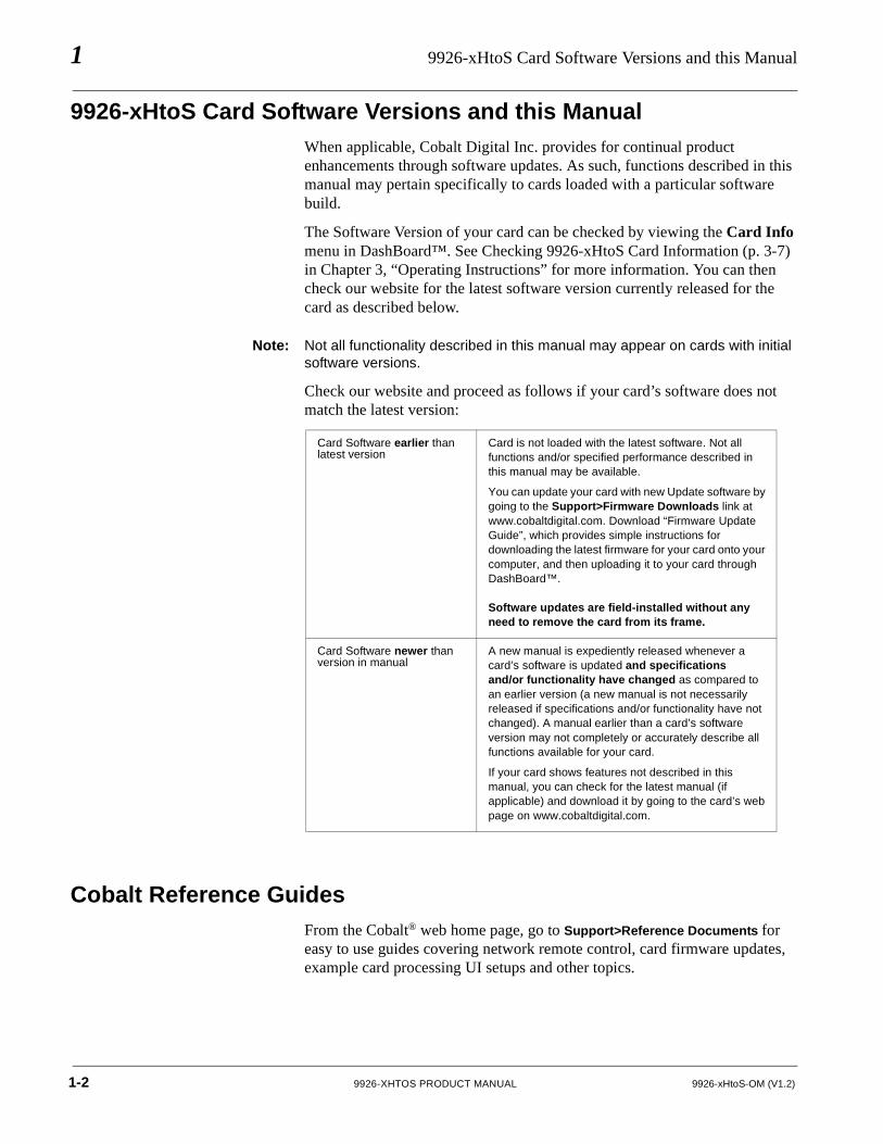
Check our website and proceed as follows if your card’s software does not match the latest version:
Cobalt Reference GuidesFrom the Cobalt® web home page, go to Support>Reference Documents for easy to use guides covering network remote control, card firmware updates, example card processing UI setups and other topics.
Card Software earlier than latest version
Card is not loaded with the latest software. Not all functions and/or specified performance described in this manual may be available.
You can update your card with new Update software by going to the Support>Firmware Downloads link at www.cobaltdigital.com. Download “Firmware Update Guide”, which provides simple instructions for downloading the latest firmware for your card onto your computer, and then uploading it to your card through DashBoard™.
Software updates are field-installed without any need to remove the card from its frame.
Card Software newer than version in manual
A new manual is expediently released whenever a card’s software is updated and specificationsand/or functionality have changed as compared to an earlier version (a new manual is not necessarily released if specifications and/or functionality have not changed). A manual earlier than a card’s software version may not completely or accurately describe all functions available for your card.
If your card shows features not described in this manual, you can check for the latest manual (if applicable) and download it by going to the card’s web page on www.cobaltdigital.com.
1-2 9926-XHTOS PRODUCT MANUAL 9926-xHtoS-OM (V1.2)
Introduction Manual Conventions
Manual ConventionsIn this manual, display messages and connectors are shown using the exact name shown on the 9926-xHtoS itself. Examples are provided below.
• Card-edge display messages are shown like this:
• Connector names are shown like this: HDMI IN 1
In this manual, the terms below are applicable as follows:
• Frame refers to the HPF-9000, oGx, OG3-FR, 8321, or similar 20-slot frame that houses Cobalt® or other cards.
• Device and/or Card refers to a Cobalt® or other card.
• System and/or Video System refers to the mix of interconnected production and terminal equipment in which the 9926-xHtoS and other cards operate.
• Functions and/or features that are available only as an option are denoted in this manual like this:
Most options are covered in this manual. However, if your card has DashBoard tabs that are not described in this manual it indicates that the optional function/feature is covered in a separate Manual Supplement.
BOOT
9926-xHtoS-OM (V1.2) 9926-XHTOS PRODUCT MANUAL 1-3
1 Manual Conventions
Warnings, Cautions, and Notes
Certain items in this manual are highlighted by special messages. The definitions are provided below.
Warnings
Warning messages indicate a possible hazard which, if not avoided, could result in personal injury or death.
Cautions
Caution messages indicate a problem or incorrect practice which, if not avoided, could result in improper operation or damage to the product.
Notes
Notes provide supplemental information to the accompanying text. Notes typically precede the text to which they apply.
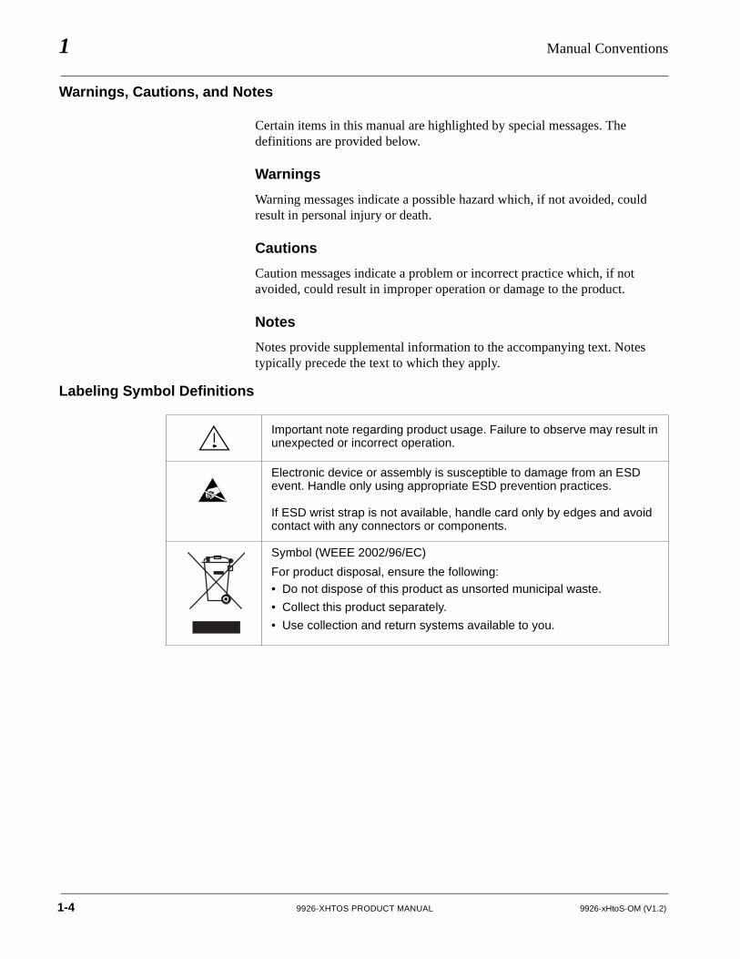
Labeling Symbol Definitions
Important note regarding product usage. Failure to observe may result in unexpected or incorrect operation.
Electronic device or assembly is susceptible to damage from an ESD event. Handle only using appropriate ESD prevention practices.
If ESD wrist strap is not available, handle card only by edges and avoid contact with any connectors or components.
Symbol (WEEE 2002/96/EC)
For product disposal, ensure the following:• Do not dispose of this product as unsorted municipal waste.
• Collect this product separately.
• Use collection and return systems available to you.
1-4 9926-XHTOS PRODUCT MANUAL 9926-xHtoS-OM (V1.2)
Introduction Safety and Regulatory Summary
Safety and Regulatory Summary
Warnings
Cautions
! WARNING !To reduce risk of electric shock do not remove line voltage service barrier cover on frame equipment containing an AC power supply. NO USER SERVICEABLE PARTS INSIDE. REFER SERVICING TO QUALIFIED SERVICE PERSONNEL.
CAUTION This device is intended for environmentally controlled use only in appropriate video terminal equipment operating environments.
CAUTION This product is intended to be a component product of an openGear® frame. Refer to the openGear® frame Owner's Manual for important safety instructions regarding the proper installation and safe operation of the frame as well as its component products.
CAUTION Heat and power distribution requirements within a frame may dictate specific slot placement of cards. Cards with many heat-producing components should be arranged to avoid areas of excess heat build-up, particularly in frames using only convection cooling. Frame loading recommendations as follows:
• OG3 Frame: (5) cards• HPF-9000 Frame: (5) cards• oGx Frame: (7) cards
CAUTION If required, make certain Rear I/O Module(s) is installed before installing the 9926-xHtoS into the frame slot. Damage to card and/or Rear I/O Module can occur if module installation is attempted with card already installed in slot.
CAUTION If card resists fully engaging in rear I/O module mating connector, check for alignment and proper insertion in slot tracks. Damage to card and/or rear I/O module may occur if improper card insertion is attempted.
9926-xHtoS-OM (V1.2) 9926-XHTOS PRODUCT MANUAL 1-5
1 9926-xHtoS Functional Description
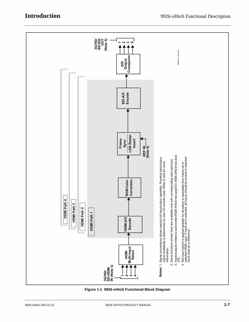
9926-xHtoS Functional DescriptionFigure 1-1 shows a functional block diagram of the 9926-xHtoS. The 9926-xHtoS provides up to four independent signal paths (HDMI Channel 1 thru HDMI Channel 4) of HDMI-to-SDI conversion and frame sync. The multiple paths share input and output crosspoints to receive and send four outputs. Independent frame sync processing allows independent V/H offsets and frame delay settings for the multiple processing paths. Each path can be set to provide disable, freeze, or flat-field insert upon loss of respective video input.
Note: Model 9926-4HtoS offers four independent paths and controls/functions for its four paths. Model 9926-2HtoS offers two independent paths and controls/functions for its two paths.
9926-xHtoS Input/Output Formats
The 9926-xHtoS provides the following inputs and outputs (which can be independently used for Path 1 thru Path 4):
• Inputs:
• HDMI IN 1 thru HDMI IN 4 – up to four HDMI inputs which can be selected to be applied to the four independent processing paths (-2HtoS models offers only two HDMI inputs and processing paths).
• Outputs:
• 3G/HD/SD-SDI OUT (1-4) – four independent 3G/HD/SD-SDI processed video outputs which can be independently sourced from processing Path 1 thru Path 4. (-2HtoS models offers only two SDI outputs sourced independently from Path 1 or Path 2).
1-6 9926-XHTOS PRODUCT MANUAL 9926-xHtoS-OM (V1.2)
Introduction 9926-xHtoS Functional Description
Figure 1-1 9926-xHtoS Functional Block Diagram
9926
BD
V1.
0LB
149
HD
MI A
/V
Dec
ode
HD
MI
Mul
ti-In
put
Sele
ct
Not
es:1
.Sig
nal c
onne
ctio
ns s
how
n de
pict
s fu
ll in
put/o
utpu
t cap
abilit
y. P
ract
ical
inpu
t/out
put
sign
al a
vaila
bilit
y is
det
erm
ined
by
rear
I/O
mod
ule
used
. Ref
er to
text
for m
ore
info
rmat
ion.
2.S
ome
func
tions
sho
wn
here
are
ava
ilabl
e on
ly w
ith c
orre
spon
ding
car
d op
tion(
s).
3.In
puts
/out
puts
limite
d to
car
d m
odel
(992
6-4H
toS
has
qua
d I/O
; 992
6-2H
toS
has
dua
l I/O
).4.
Ref
inpu
t (w
hich
is a
pplie
d gl
obal
ly fo
r all
path
s) is
sel
ecta
ble
from
fram
e re
f or
sele
cted
HD
MI i
nput
. If i
nput
ref i
s se
lect
ed, a
ll in
puts
sho
uld
be lo
cked
to s
elec
ted
inpu
t use
d as
a re
fere
nce.
1 2 3 4
3G/H
D/
SD-H
DM
I IN
(Not
e 3)
RG
B C
olor
C
orre
ctio
n
Fram
eSy
ncLO
S R
aste
r In
sert
SDI A
/V
Enco
deSD
I O
utpu
t C
ross
poin
t
3G/H
D/
SD-S
DI
OU
T(N
ote
3)
HD
MI P
ath
1
HD
MI P
ath
2
HD
MI P
ath
3
HD
MI P
ath
4
REF
IN(N
ote
4)
1 2 3 4
9926-xHtoS-OM (V1.2) 9926-XHTOS PRODUCT MANUAL 1-7
1 9926-xHtoS Functional Description
Video Processor Description
Note: Unless otherwise noted, the following functions are independently available for Path 1 thru Path 4 processing paths.
The 9926-xHtoS video subsystem provides the functions described below.
Input Video Select Functions
Used in common as a routing source for Path 1 thru Path 4 is a GUI-based control that allows the card to select from up to four HDMI inputs to be used as four sources for Path 1 thru Path 4 processed video paths.
Additionally for each path, Source Colorimetry can be independently set for used as marked, or set for BT.709 or BT.2020. Also for each path, Source OETF can be independently set for used as marked, or set for SDR, PQ/ST 2084, or HLG.
Frame Sync Function
This function provides for frame sync control using either one of two external FRAME REF IN (1,2) reference signals distributed with the card frame, selected input video, or internal timing as a frame sync reference.
This function also independently allows horizontal and/or vertical offset to be added between the output video and the frame sync reference for any of the up to card’s four processed video paths.
Frame sync can select from either of two card frame reference sources, or free-run input video sync. Selectable failover allows alternate reference selection should the initial reference source become unavailable or invalid. In the event of input video loss of signal, the output can be set to disable video, go to an internal flat-field generator, or freeze to the last intact frame (last frame having valid SAV and EAV codes).
Color Corrector
Option +COLOR converts the YCbCr SDI input video to the 4:4:4 RGB color space (where the color correction is applied), and then back to YCbCr SDI on the output. Controls are available to adjust each RGB level independently for both white levels (gain) and black levels (offset). Gamma can also be independently adjusted for each RGB channels. Various controls can be ganged to provide adjustment for all three color channels simultaneously. Color Correction allows custom independent user settings for each of the up to four processing paths.
1-8 9926-XHTOS PRODUCT MANUAL 9926-xHtoS-OM (V1.2)
Introduction 9926-xHtoS Functional Description
Video Output Crosspoint
Used in common as a routing source for Path 1 thru Path 4 is a four-output video matrix crosspoint that allows independently applying the card processed video output to any of the four card discrete coaxial outputs(SDI OUT 1 thru SDI OUT 4).
Audio Processor Description
The audio processing block consists of an Input Audio crosspoint/mixer (which directs selected input audio to the processing paths) and an Output Audio crosspoint/mixer (which selects from any of the four path’s embedded audio sources).
Input Audio Processing
Note: Path 1 thru Path 4 have individual independent digital audio routing controls for each of the processing path’s 16-channels of embedded audio.
The input audio processor operates as an internal audio router to each path’s Audio Bus Channel bank. This function chooses from the following inputs:
• 16 channels of embedded audio from the path SDI video input (default 1-to-1 routing to card internal audio buses)
• Downmixer outputs (see below)
• Flex Mix summing node outputs (see below)
The input audio processing subsection is built around card internal 16-channel audio buses corresponding to each processing path (Path 1 thru Path 4). Each 16-channel bus receives inputs from an input routing crosspoint that routes audio on Audio Bus Channels 1 thru 16 corresponding to each processing path.
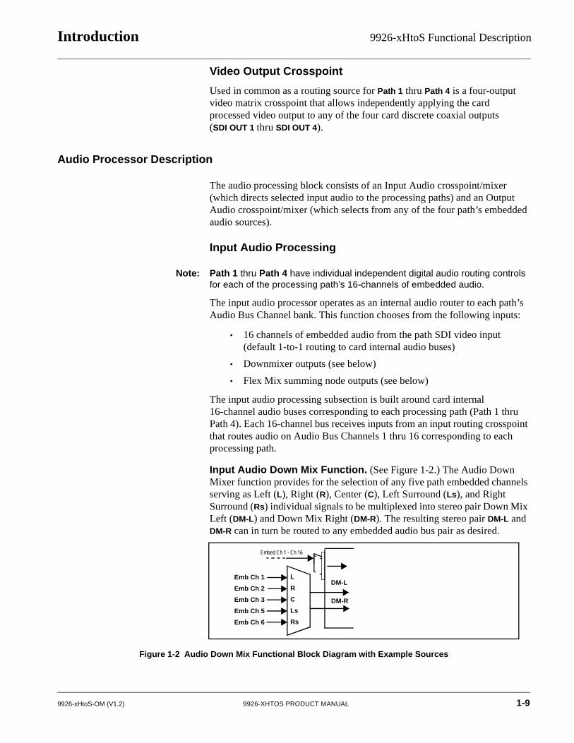
Input Audio Down Mix Function. (See Figure 1-2.) The Audio Down Mixer function provides for the selection of any five path embedded channels serving as Left (L), Right (R), Center (C), Left Surround (Ls), and Right Surround (Rs) individual signals to be multiplexed into stereo pair Down Mix Left (DM-L) and Down Mix Right (DM-R). The resulting stereo pair DM-L and DM-R can in turn be routed to any embedded audio bus pair as desired.
Figure 1-2 Audio Down Mix Functional Block Diagram with Example Sources
DM-LL
R
C
Ls
Rs
DM-R
Emb Ch 1
Emb Ch 2
Emb Ch 3
Emb Ch 5
Emb Ch 6
Embed Ch 1 - Ch 16
9926-xHtoS-OM (V1.2) 9926-XHTOS PRODUCT MANUAL 1-9
1 9926-xHtoS Functional Description
Flex Buses. For both input and output nodes before and after the card internal buses, flex buses provide flexible-structure mixer in which any of 16 summing nodes (Flex Mix Bus A thru Flex Mix Bus P) can receive any card audio input, thereby allowing several customizable mixing schemes. Similarly, any of the 16 card internal bus signals can be applied to an output flex bus mixer. The output flex bus allows cross-sourcing from Path 1 thru Path 4 embedded internal Audio Bus sources to the Path 1 thru Path 4 discrete output audio crosspoints.
Audio Delay Processing. Each of the four paths offers an overall Bulk Delay control, as well as Per-channel Delay Offset controls.
Note: Per-channel audio delay controls will allow individual delay offsets for channels within a pair for PCM. However, when the card detects a Dolby pair it will offset both channels an identical amount as set using either channel controls. This preserves the integrity of the Dolby pair.
Output Audio Processing
The output audio processing subsection is built around card internal 16-channel audio buses corresponding to each processing path (Path 1 thru Path 4). From this point, path-specific Audio Bus channels are directed to path embedded audio channels.
The output audio processor chooses from the following inputs:
• 16 channels of Path 1 thru Path 4 Audio Bus channels
• Downmixer outputs
• Output Flex Mix summing node outputs
An Audio Status display shows the presence of each SDI embedded pair for each of the four paths. Lock status and payload is identified (PCM or data such as Dolby® D or E).
1-10 9926-XHTOS PRODUCT MANUAL 9926-xHtoS-OM (V1.2)
Introduction 9926-xHtoS Functional Description
User Control Interface
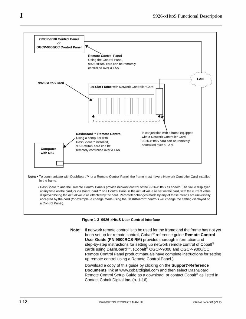
Figure 1-3 shows the user control interface options for the 9926-xHtoS. These options are individually described below.
Note: All user control interfaces described here are cross-compatible and can operate together as desired. Where applicable, any control setting change made using a particular user interface is reflected on any other connected interface.
• DashBoard™ User Interface – Using DashBoard™, the 9926-xHtoS and other cards installed in openGear®1 frames can be controlled from a computer and monitor.
DashBoard™ allows users to view all frames on a network with control and monitoring for all populated slots inside a frame. This simplifies the setup and use of numerous modules in a large installation and offers the ability to centralize monitoring. Cards define their controllable parameters to DashBoard™, so the control interface is always up to date.
The DashBoard™ software can be downloaded from the Cobalt Digital Inc. website: www.cobaltdigital.com (enter “DashBoard” in the search window). The DashBoard™ user interface is described in Chapter 3,“Operating Instructions”.
• Cobalt® OGCP-9000 and OGCP-9000/CC Remote Control Panels – The OGCP-9000 and OGCP-9000/CC Remote Control Panels conveniently and intuitively provide parameter monitor and control of the 9926-xHtoS and other video and audio processing terminal equipment meeting the open-architecture Cobalt® cards for openGear™ standard.
In addition to circumventing the need for a computer to monitor and control signal processing cards, the Control Panels allow quick and intuitive access to hundreds of cards in a facility, and can monitor and allow adjustment of multiple parameters at one time.
The Remote Control Panels are totally compatible with the openGear™ control software DashBoard™; any changes made with either system are reflected on the other. The Remote Control Panel user interface is described in Chapter 3,“Operating Instructions”.
1. openGear® is a registered trademark of Ross Video Limited. DashBoard™ is a trademark of RossVideo Limited.
9926-xHtoS-OM (V1.2) 9926-XHTOS PRODUCT MANUAL 1-11
1 9926-xHtoS Functional Description
Figure 1-3 9926-xHtoS User Control Interface
Note: If network remote control is to be used for the frame and the frame has not yet been set up for remote control, Cobalt® reference guide Remote Control User Guide (PN 9000RCS-RM) provides thorough information and step-by-step instructions for setting up network remote control of Cobalt® cards using DashBoard™. (Cobalt® OGCP-9000 and OGCP-9000/CC Remote Control Panel product manuals have complete instructions for setting up remote control using a Remote Control Panel.)
Download a copy of this guide by clicking on the Support>Reference Documents link at www.cobaltdigital.com and then select DashBoard Remote Control Setup Guide as a download, or contact Cobalt® as listed in Contact Cobalt Digital Inc. (p. 1-16).
Computer with NIC
OGCP-9000 Control Panelor
OGCP-9000/CC Control Panel
20-Slot Frame with Network Controller Card
LAN9926-xHtoS Card
In conjunction with a frame equipped with a Network Controller Card, 9926-xHtoS card can be remotely controlled over a LAN
Remote Control PanelUsing the Control Panel, 9926-xHtoS card can be remotely controlled over a LAN
DashBoard™ Remote ControlUsing a computer with DashBoard™ installed, 9926-xHtoS card can be remotely controlled over a LAN
Note: • To communicate with DashBoard™ or a Remote Control Panel, the frame must have a Network Controller Card installed in the frame.
• DashBoard™ and the Remote Control Panels provide network control of the 9926-xHtoS as shown. The value displayed at any time on the card, or via DashBoard™ or a Control Panel is the actual value as set on the card, with the current value displayed being the actual value as effected by the card. Parameter changes made by any of these means are universally accepted by the card (for example, a change made using the DashBoard™ controls will change the setting displayed on a Control Panel).
1-12 9926-XHTOS PRODUCT MANUAL 9926-xHtoS-OM (V1.2)
Introduction Technical Specifications
9926-xHtoS Rear I/O Modules
The 9926-xHtoS physically interfaces to system video connections at the rear of its frame using a Rear I/O Module.
All inputs and outputs shown in the 9926-xHtoS Functional Block Diagram (Figure 1-1) enter and exit the card via the card edge backplane connector. The Rear I/O Module breaks out the 9926-xHtoS card edge connections to coaxial and other connectors that interface with other components and systems in the signal chain.
The full assortment of 9926-xHtoS Rear I/O Modules is shown and described in 9926-xHtoS Rear I/O Modules (p. 2-4) in Chapter 2, “Installation and Setup”.
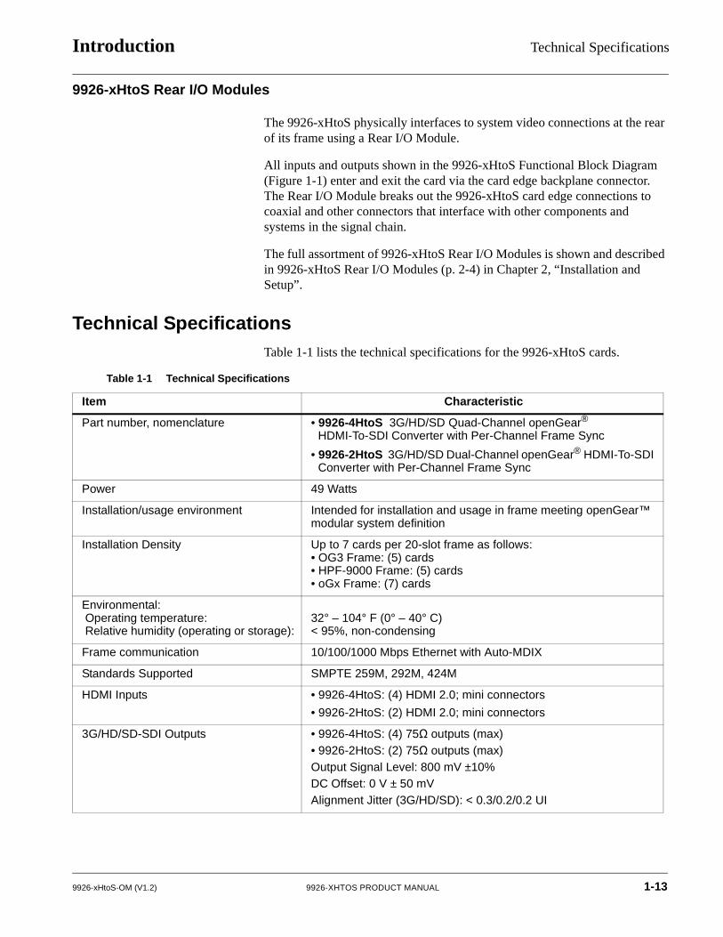
Technical SpecificationsTable 1-1 lists the technical specifications for the 9926-xHtoS cards.
Table 1-1 Technical Specifications
Item Characteristic
Part number, nomenclature • 9926-4HtoS 3G/HD/SD Quad-Channel openGear® HDMI-To-SDI Converter with Per-Channel Frame Sync
• 9926-2HtoS 3G/HD/SD Dual-Channel openGear® HDMI-To-SDI Converter with Per-Channel Frame Sync
Power 49 Watts
Installation/usage environment Intended for installation and usage in frame meeting openGear™ modular system definition
Installation Density Up to 7 cards per 20-slot frame as follows:• OG3 Frame: (5) cards• HPF-9000 Frame: (5) cards• oGx Frame: (7) cards
Environmental:Operating temperature:Relative humidity (operating or storage):
32° – 104° F (0° – 40° C)< 95%, non-condensing
Frame communication 10/100/1000 Mbps Ethernet with Auto-MDIX
Standards Supported SMPTE 259M, 292M, 424M
HDMI Inputs • 9926-4HtoS: (4) HDMI 2.0; mini connectors
• 9926-2HtoS: (2) HDMI 2.0; mini connectors
3G/HD/SD-SDI Outputs • 9926-4HtoS: (4) 75Ω outputs (max) • 9926-2HtoS: (2) 75Ω outputs (max)Output Signal Level: 800 mV ±10%DC Offset: 0 V ± 50 mVAlignment Jitter (3G/HD/SD): < 0.3/0.2/0.2 UI
9926-xHtoS-OM (V1.2) 9926-XHTOS PRODUCT MANUAL 1-13
1 Technical Specifications
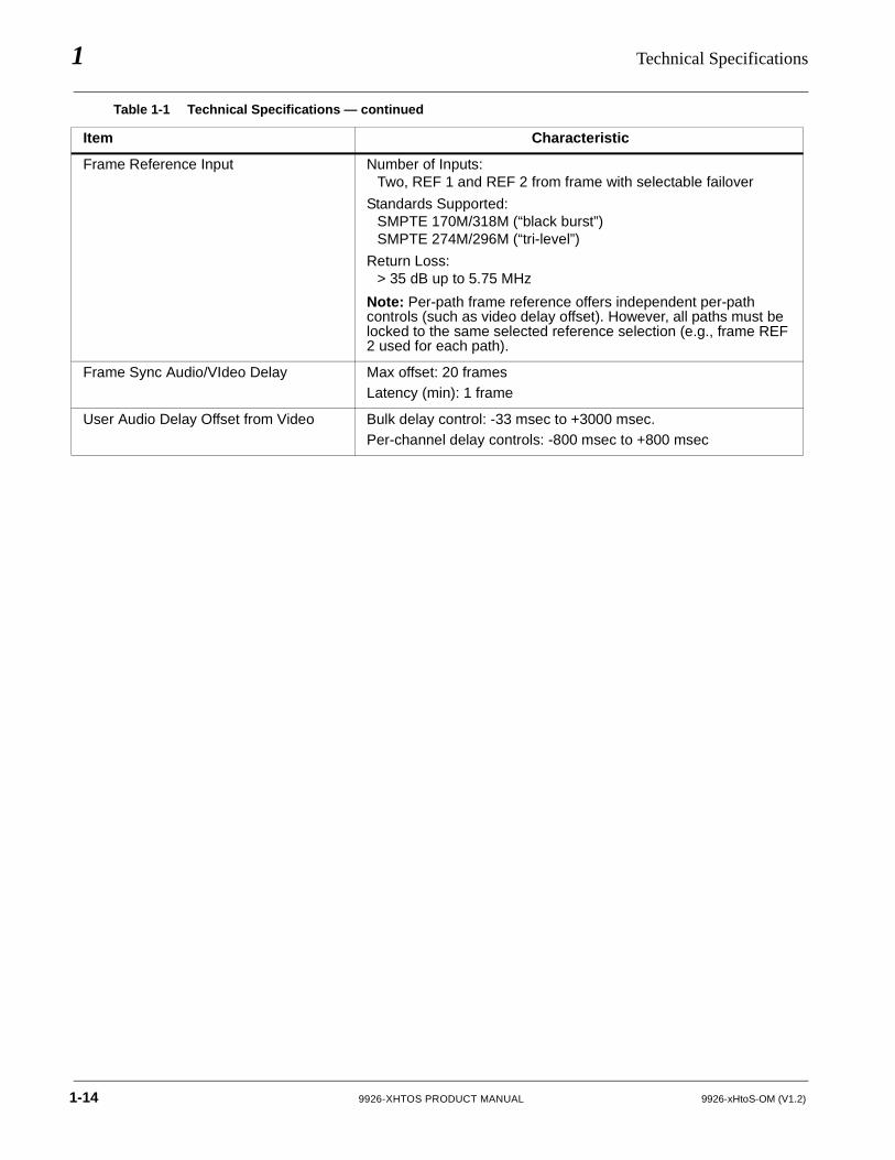
Frame Reference Input Number of Inputs:Two, REF 1 and REF 2 from frame with selectable failover
Standards Supported:SMPTE 170M/318M (“black burst”)SMPTE 274M/296M (“tri-level”)
Return Loss:> 35 dB up to 5.75 MHz
Note: Per-path frame reference offers independent per-path controls (such as video delay offset). However, all paths must be locked to the same selected reference selection (e.g., frame REF 2 used for each path).
Frame Sync Audio/VIdeo Delay Max offset: 20 framesLatency (min): 1 frame
User Audio Delay Offset from Video Bulk delay control: -33 msec to +3000 msec. Per-channel delay controls: -800 msec to +800 msec
Table 1-1 Technical Specifications — continued
Item Characteristic
1-14 9926-XHTOS PRODUCT MANUAL 9926-xHtoS-OM (V1.2)
Introduction Warranty and Service Information
Warranty and Service Information
Cobalt Digital Inc. Limited Warranty
This product is warranted to be free from defects in material and workmanship for a period of five (5) years from the date of shipment to the original purchaser, except that 4000, 5000, 6000, 8000 series power supplies, and Dolby® modules (where applicable) are warranted to be free from defects in material and workmanship for a period of one (1) year.
Cobalt Digital Inc.'s (“Cobalt”) sole obligation under this warranty shall be limited to, at its option, (i) the repair or (ii) replacement of the product, and the determination of whether a defect is covered under this limited warranty shall be made at the sole discretion of Cobalt.
This limited warranty applies only to the original end-purchaser of the product, and is not assignable or transferrable therefrom. This warranty is limited to defects in material and workmanship, and shall not apply to acts of God, accidents, or negligence on behalf of the purchaser, and shall be voided upon the misuse, abuse, alteration, or modification of the product. Only Cobalt authorized factory representatives are authorized to make repairs to the product, and any unauthorized attempt to repair this product shall immediately void the warranty. Please contact Cobalt Technical Support for more information.
To facilitate the resolution of warranty related issues, Cobalt recommends registering the product by completing and returning a product registration form. In the event of a warrantable defect, the purchaser shall notify Cobalt with a description of the problem, and Cobalt shall provide the purchaser with a Return Material Authorization (“RMA”). For return, defective products should be double boxed, and sufficiently protected, in the original packaging, or equivalent, and shipped to the Cobalt Factory Service Center, postage prepaid and insured for the purchase price. The purchaser should include the RMA number, description of the problem encountered, date purchased, name of dealer purchased from, and serial number with the shipment.
Cobalt Digital Inc. Factory Service Center2506 Galen Drive Office: (217) 344-1243Champaign, IL 61821 USA Fax: (217) 344-1245www.cobaltdigital.com Email: [email protected]
THIS LIMITED WARRANTY IS EXPRESSLY IN LIEU OF ALL OTHER WARRANTIES EXPRESSED OR IMPLIED, INCLUDING THE WARRANTIES OF MERCHANTABILITY AND FITNESS FOR A PARTICULAR PURPOSE AND OF ALL OTHER OBLIGATIONS OR LIABILITIES ON COBALT'S PART. ANY SOFTWARE PROVIDED WITH, OR FOR USE WITH, THE PRODUCT IS PROVIDED “AS IS.” THE BUYER OF THE PRODUCT ACKNOWLEDGES THAT NO OTHER REPRESENTATIONS WERE MADE OR RELIED UPON WITH RESPECT TO THE QUALITY AND FUNCTION OF THE GOODS HEREIN SOLD. COBALT PRODUCTS ARE NOT AUTHORIZED FOR USE IN LIFE SUPPORT APPLICATIONS.
COBALT'S LIABILITY, WHETHER IN CONTRACT, TORT, WARRANTY, OR OTHERWISE, IS LIMITED TO THE REPAIR OR REPLACEMENT, AT ITS OPTION, OF ANY DEFECTIVE PRODUCT, AND SHALL IN NO EVENT INCLUDE SPECIAL, INDIRECT, INCIDENTAL, OR CONSEQUENTIAL DAMAGES (INCLUDING LOST PROFITS), EVEN IF IT HAS BEEN ADVISED OF THE POSSIBILITY OF SUCH DAMAGES.
9926-xHtoS-OM (V1.2) 9926-XHTOS PRODUCT MANUAL 1-15
1 Contact Cobalt Digital Inc.
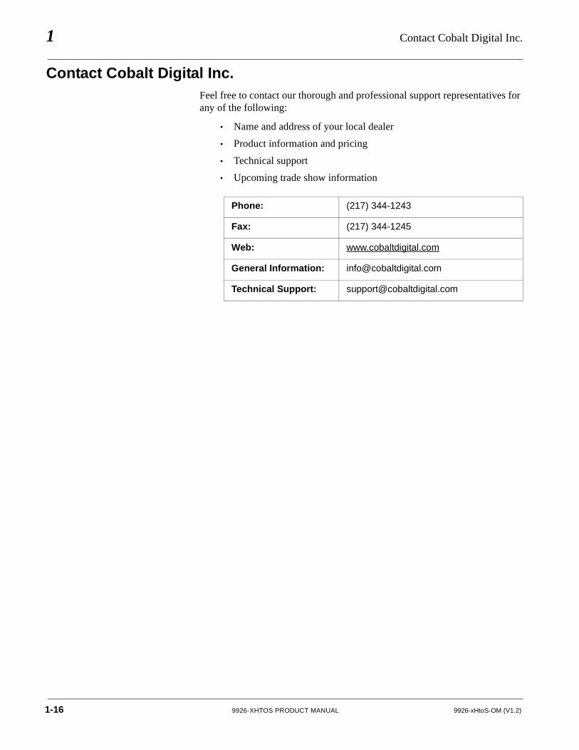
Contact Cobalt Digital Inc.Feel free to contact our thorough and professional support representatives for any of the following:
• Name and address of your local dealer
• Product information and pricing
• Technical support
• Upcoming trade show information
Phone: (217) 344-1243
Fax: (217) 344-1245
Web: www.cobaltdigital.com
General Information: [email protected]
Technical Support: [email protected]
1-16 9926-XHTOS PRODUCT MANUAL 9926-xHtoS-OM (V1.2)
Chapter 2
Chapter 2 Installation and Setup
OverviewThis chapter contains the following information:
• Installing the 9926-xHtoS Into a Frame Slot (p. 2-1)
• Installing a Rear I/O Module (p. 2-3)
• Setting Up 9926-xHtoS Network Remote Control (p. 2-5)
Installing the 9926-xHtoS Into a Frame SlotCAUTION
Heat and power distribution requirements within a frame may dictate specific slot placement of cards. Cards with many heat-producing components should be arranged to avoid areas of excess heat build-up, particularly in frames using only convection cooling. The 9926-xHtoS has a high power dissipation with maximum frame loading recommendations as follows:
• OG3 Frame: (5) cards• HPF-9000 Frame: (5) cards• oGx Frame: (7) cards
CAUTION
Note: If installing the 9926-xHtoS in a slot with no rear I/O module, a Rear I/O Module is required before cabling can be connected. Refer to Installing a Rear I/O Module (p. 2-3) for rear I/O module installation procedure.
This device contains semiconductor devices which are susceptible to serious damage from Electrostatic Discharge (ESD). ESD damage may not be immediately apparent and can affect the long-term reliability of the device.
Avoid handling circuit boards in high static environments such as carpeted areas, and when wearing synthetic fiber clothing. Always use proper ESD handling precautions and equipment when working on circuit boards and related equipment.
9926-xHtoS-OM (V1.2) 9926-XHTOS PRODUCT MANUAL 2-1
2 Installing the 9926-xHtoS Into a Frame Slot
CAUTION
If required, make certain Rear I/O Module(s) is installed before installing the 9926-xHtoS into the frame slot. Damage to card and/or Rear I/O Module can occur if module installation is attempted with card already installed in slot.
Note: Check the packaging in which the 9926-xHtoS was shipped for any extra items such as a Rear I/O Module connection label. In some cases, this label is shipped with the card and to be installed on the Rear I/O connector bank corresponding to the slot location of the card.
Install the 9926-xHtoS into a frame slot as follows:
1. Determine the slot in which the 9926-xHtoS is to be installed.
2. Open the frame front access panel.
3. While holding the card by the card edges, align the card such that the plastic ejector tab is on the bottom.
4. Align the card with the top and bottom guides of the slot in which the card is being installed.
5. Gradually slide the card into the slot. When resistance is noticed, gently continue pushing the card until its rear printed circuit edge terminals engage fully into the rear I/O module mating connector.
CAUTION
If card resists fully engaging in rear I/O module mating connector, check for alignment and proper insertion in slot tracks. Damage to card and/or rear I/O module may occur if improper card insertion is attempted.
6. Verify that the card is fully engaged in rear I/O module mating connector.
7. Close the frame front access panel.
8. Connect the input and output cables as shown in 9926-xHtoS Rear I/O Modules (p. 2-4).
9. Repeat steps 1 through 8 for other 9926-xHtoS cards.
Note: • The 9926-xHtoS BNC inputs are internally 75-ohm terminated. It is not necessary to terminate unused coaxial inputs or outputs.
• External frame sync reference signals are received by the card over a reference bus on the card frame, and not on any card rear I/O module connectors. The frame has BNC connectors labeled REF 1 and REF 2 which receive the reference signal from an external source such as a house distribution.
• To remove a card, press down on the ejector tab to unseat the card from the rear I/O module mating connector. Evenly draw the card from its slot.
2-2 9926-XHTOS PRODUCT MANUAL 9926-xHtoS-OM (V1.2)
Installation and Setup Installing a Rear I/O Module
10. If network remote control is to be used for the frame and the frame has not yet been set up for remote control, perform setup in accordance with Setting Up 9926-xHtoS Network Remote Control (p. 2-5).
Note: If installing a card in a frame already equipped for, and connected to DashBoard™, no network setup is required for the card. The card will be dis-covered by DashBoard™ and be ready for use.
Installing a Rear I/O Module
Note: • This procedure is applicable only if a Rear I/O Module is not currently installed in the slot where the 9926-xHtoS is to be installed.
• When determining slot to use, see 9926-xHtoS Rear I/O Modules (p. 2-4) and check notes (where applicable) for rear module being considered for use.
Install a Rear I/O Module as follows:
1. On the frame, determine the slot in which the 9926-xHtoS is to be installed.
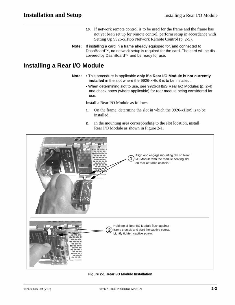
2. In the mounting area corresponding to the slot location, install Rear I/O Module as shown in Figure 2-1.
Figure 2-1 Rear I/O Module Installation
Align and engage mounting tab on RearI/O Module with the module seating slot on rear of frame chassis.
Hold top of Rear I/O Module flush against frame chassis and start the captive screw.Lightly tighten captive screw.
1
2
9926-xHtoS-OM (V1.2) 9926-XHTOS PRODUCT MANUAL 2-3
2 Installing a Rear I/O Module
9926-xHtoS Rear I/O Modules
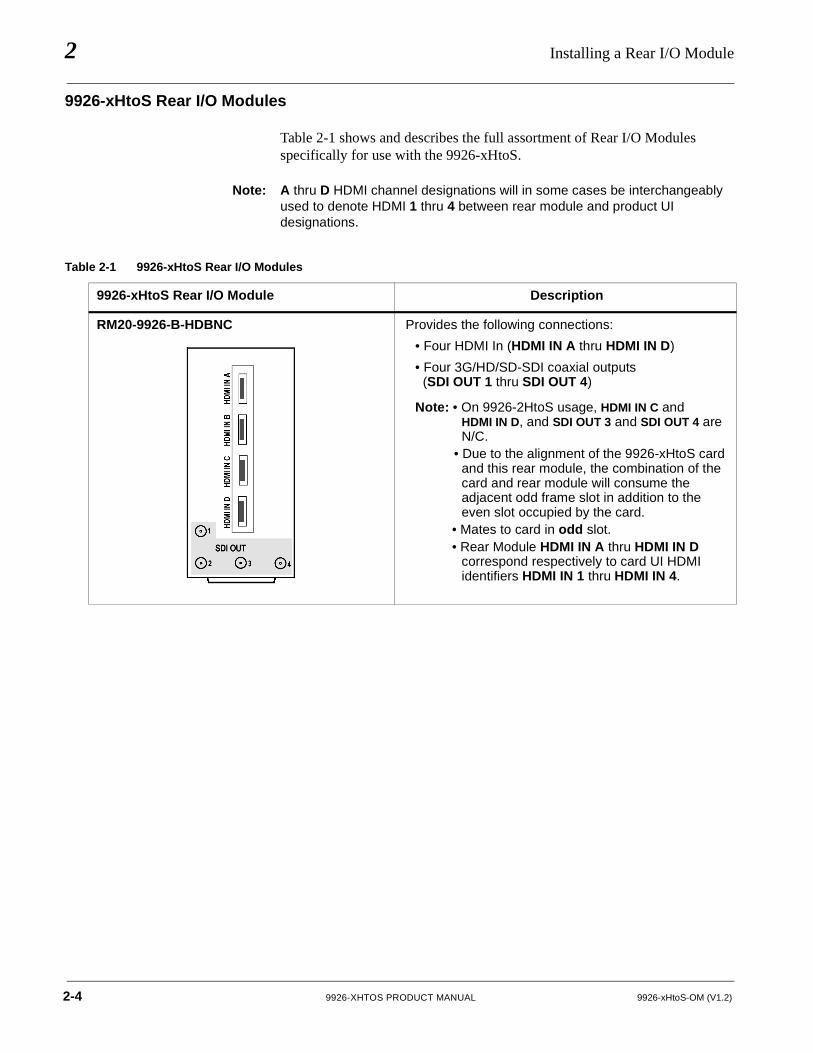
Table 2-1 shows and describes the full assortment of Rear I/O Modules specifically for use with the 9926-xHtoS.
Note: A thru D HDMI channel designations will in some cases be interchangeably used to denote HDMI 1 thru 4 between rear module and product UI designations.
Table 2-1 9926-xHtoS Rear I/O Modules
9926-xHtoS Rear I/O Module Description
RM20-9926-B-HDBNC Provides the following connections:
• Four HDMI In (HDMI IN A thru HDMI IN D)
• Four 3G/HD/SD-SDI coaxial outputs (SDI OUT 1 thru SDI OUT 4)
Note: • On 9926-2HtoS usage, HDMI IN C and HDMI IN D, and SDI OUT 3 and SDI OUT 4 are N/C.
• Due to the alignment of the 9926-xHtoS card and this rear module, the combination of the card and rear module will consume the adjacent odd frame slot in addition to the even slot occupied by the card.
• Mates to card in odd slot.• Rear Module HDMI IN A thru HDMI IN D
correspond respectively to card UI HDMI identifiers HDMI IN 1 thru HDMI IN 4.
1937S
2-4 9926-XHTOS PRODUCT MANUAL 9926-xHtoS-OM (V1.2)
Installation and Setup Setting Up 9926-xHtoS Network Remote Control
Setting Up 9926-xHtoS Network Remote ControlPerform remote control setup in accordance with Cobalt® reference guide “Remote Control User Guide” (PN 9000RCS-RM).
Note: • If network remote control is to be used for the frame and the frame has not yet been set up for remote control, Cobalt® reference guide Remote Control User Guide (PN 9000RCS-RM) provides thorough information and step-by-step instructions for setting up network remote control of Cobalt® cards using DashBoard™. (Cobalt® OGCP-9000 and OGCP-9000/CC Remote Control Panel product manuals have complete instructions for setting up remote control using a Remote Control Panel.)
Download a copy of this guide by clicking on theSupport>Reference Documents link at www.cobaltdigital.com and then select DashBoard Remote Control Setup Guide as a download, or contact Cobalt® as listed in Contact Cobalt Digital Inc. (p. 1-16).
• If installing a card in a frame already equipped for, and connected toDashBoard™, no network setup is required for the card. The card will be dis-covered by DashBoard™ and be ready for use.
9926-xHtoS-OM (V1.2) 9926-XHTOS PRODUCT MANUAL 2-5

This page intentionally blank
2-6 9926-XHTOS PRODUCT MANUAL 9926-xHtoS-OM (V1.2)
Chapter 3
Chapter 3 Operating Instructions
OverviewThis chapter contains the following information:
• Control and Display Descriptions (p. 3-1)
• Accessing the 9926-xHtoS Card via Remote Control (p. 3-5)
• Checking 9926-xHtoS Card Information (p. 3-7)
• 9926-xHtoS Function Menu List and Descriptions (p. 3-8)
• Troubleshooting (p. 3-31)
Control and Display DescriptionsThis section describes the user interface controls, indicators, and displays for using the 9926-xHtoS card. The 9926-xHtoS functions can be accessed and controlled using any of the user interfaces described here.
The format in which the 9926-xHtoS functional controls, indicators, and displays appear and are used varies depending on the user interface being used. Regardless of the user interface being used, access to the 9926-xHtoS functions (and the controls, indicators, and displays related to a particular function) follows a general arrangement of Function Menus under which related controls can be accessed (as described in Function Menu/Parameter Overview below).
Note: When a setting is changed, settings displayed on DashBoard™ (or a Remote Control Panel) are the settings as effected by the card itself and reported back to the remote control; the value displayed at any time is the actual value as set on the card.
If you are already familiar with using DashBoard or a Cobalt
Remote Control Panel to control Cobalt cards, please skip to
9926-xHtoS Function Menu List and Descriptions (p. 3-8).
9926-xHtoS-OM (V1.2) 9926-XHTOS PRODUCT MANUAL 3-1
3 Control and Display Descriptions
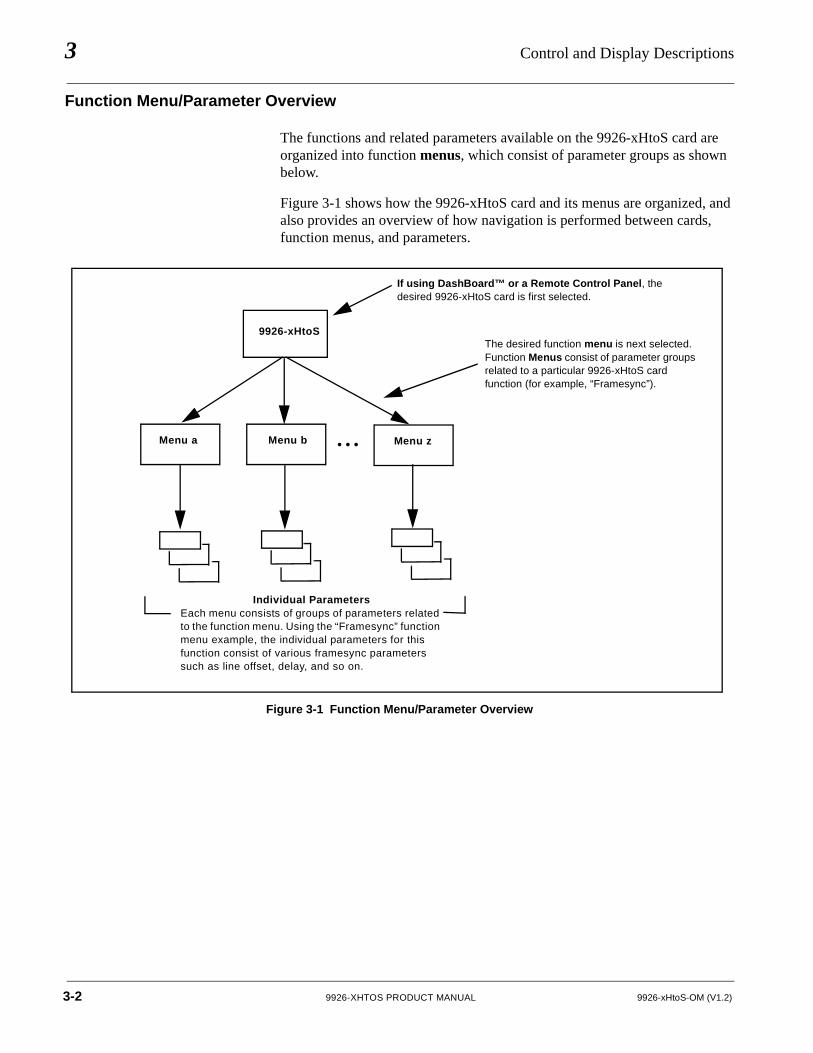
Function Menu/Parameter Overview
The functions and related parameters available on the 9926-xHtoS card are organized into function menus, which consist of parameter groups as shown below.
Figure 3-1 shows how the 9926-xHtoS card and its menus are organized, and also provides an overview of how navigation is performed between cards, function menus, and parameters.
Figure 3-1 Function Menu/Parameter Overview
9926-xHtoS
Menu a Menu b Menu z• • •
Individual ParametersEach menu consists of groups of parameters related to the function menu. Using the “Framesync” function menu example, the individual parameters for this function consist of various framesync parameters such as line offset, delay, and so on.
If using DashBoard™ or a Remote Control Panel, the desired 9926-xHtoS card is first selected.
The desired function menu is next selected. Function Menus consist of parameter groups related to a particular 9926-xHtoS card function (for example, “Framesync”).
3-2 9926-XHTOS PRODUCT MANUAL 9926-xHtoS-OM (V1.2)
Operating Instructions Control and Display Descriptions
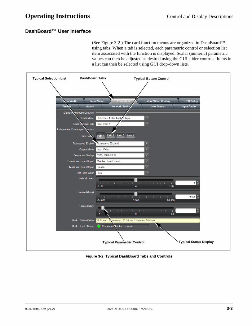
DashBoard™ User Interface
(See Figure 3-2.) The card function menus are organized in DashBoard™ using tabs. When a tab is selected, each parametric control or selection list item associated with the function is displayed. Scalar (numeric) parametric values can then be adjusted as desired using the GUI slider controls. Items in a list can then be selected using GUI drop-down lists.
Figure 3-2 Typical DashBoard Tabs and Controls
DashBoard Tabs
Typical Parametric Control
Typical Button ControlTypical Selection List
Typical Status Display
9926-xHtoS-OM (V1.2) 9926-XHTOS PRODUCT MANUAL 3-3
3 Control and Display Descriptions
Cobalt® Remote Control Panel User Interfaces
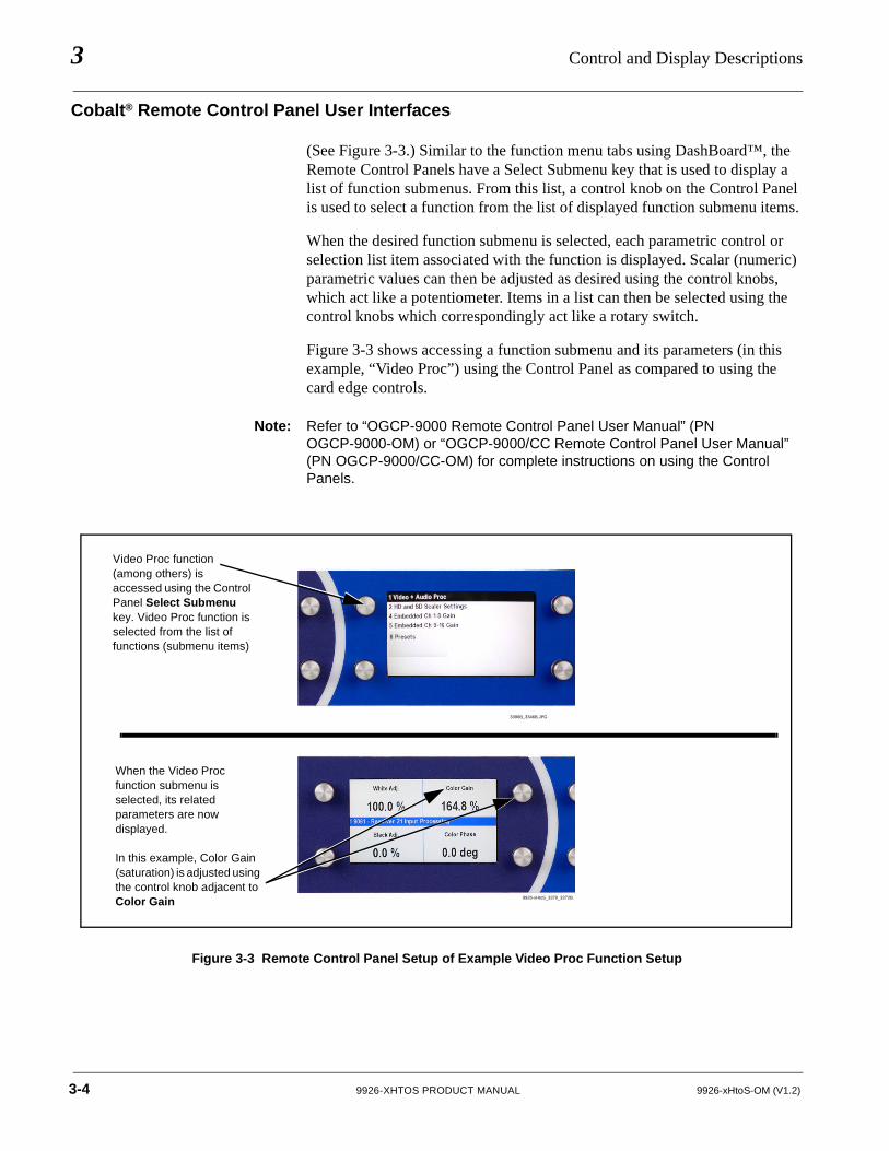
(See Figure 3-3.) Similar to the function menu tabs using DashBoard™, the Remote Control Panels have a Select Submenu key that is used to display a list of function submenus. From this list, a control knob on the Control Panel is used to select a function from the list of displayed function submenu items.
When the desired function submenu is selected, each parametric control or selection list item associated with the function is displayed. Scalar (numeric) parametric values can then be adjusted as desired using the control knobs, which act like a potentiometer. Items in a list can then be selected using the control knobs which correspondingly act like a rotary switch.
Figure 3-3 shows accessing a function submenu and its parameters (in this example, “Video Proc”) using the Control Panel as compared to using the card edge controls.
Note: Refer to “OGCP-9000 Remote Control Panel User Manual” (PN OGCP-9000-OM) or “OGCP-9000/CC Remote Control Panel User Manual” (PN OGCP-9000/CC-OM) for complete instructions on using the Control Panels.
Figure 3-3 Remote Control Panel Setup of Example Video Proc Function Setup
Video Proc function (among others) is accessed using the Control Panel Select Submenu key. Video Proc function is selected from the list of functions (submenu items)
3396B_3346B.JPG
9926-xHtoS_3370_3372B.J
When the Video Proc function submenu is selected, its related parameters are now displayed.
In this example, Color Gain (saturation) is adjusted using the control knob adjacent to Color Gain
3-4 9926-XHTOS PRODUCT MANUAL 9926-xHtoS-OM (V1.2)
Operating Instructions Accessing the 9926-xHtoS Card via Remote Control
Accessing the 9926-xHtoS Card via Remote ControlAccess the 9926-xHtoS card using DashBoard™ or Cobalt® Remote Control Panel as described below.
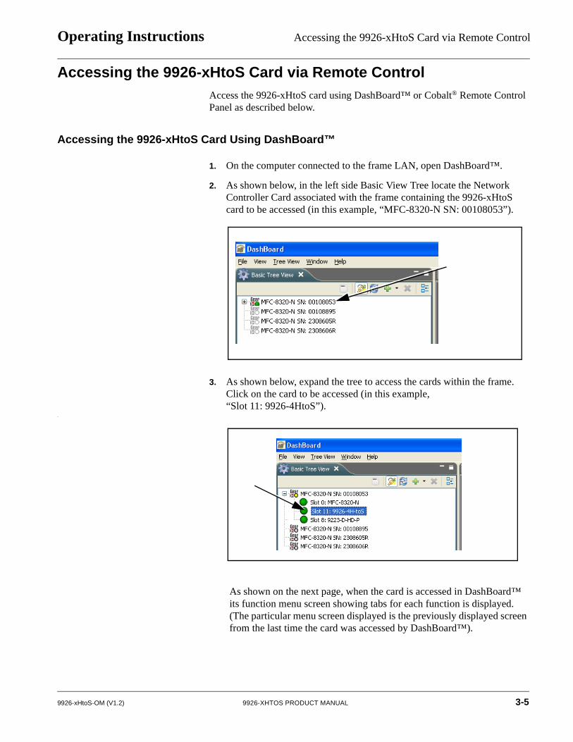
Accessing the 9926-xHtoS Card Using DashBoard™
1. On the computer connected to the frame LAN, open DashBoard™.
2. As shown below, in the left side Basic View Tree locate the Network Controller Card associated with the frame containing the 9926-xHtoS card to be accessed (in this example, “MFC-8320-N SN: 00108053”).
3. As shown below, expand the tree to access the cards within the frame. Click on the card to be accessed (in this example,“Slot 11: 9926-4HtoS”).
.
As shown on the next page, when the card is accessed in DashBoard™ its function menu screen showing tabs for each function is displayed. (The particular menu screen displayed is the previously displayed screen from the last time the card was accessed by DashBoard™).
9926-xHtoS-OM (V1.2) 9926-XHTOS PRODUCT MANUAL 3-5
3 Accessing the 9926-xHtoS Card via Remote Control
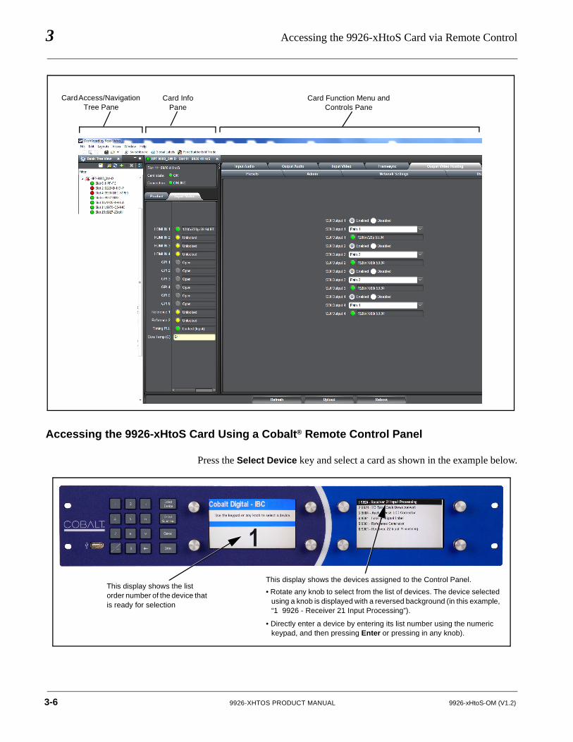
Accessing the 9926-xHtoS Card Using a Cobalt® Remote Control Panel
Press the Select Device key and select a card as shown in the example below.
Card Access/Navigation Tree Pane
Card InfoPane
Card Function Menu and Controls Pane
This display shows the list order number of the device that is ready for selection
This display shows the devices assigned to the Control Panel.
• Rotate any knob to select from the list of devices. The device selected using a knob is displayed with a reversed background (in this example, “1 9926 - Receiver 21 Input Processing”).
• Directly enter a device by entering its list number using the numeric keypad, and then pressing Enter or pressing in any knob).
3-6 9926-XHTOS PRODUCT MANUAL 9926-xHtoS-OM (V1.2)
Operating Instructions Checking 9926-xHtoS Card Information
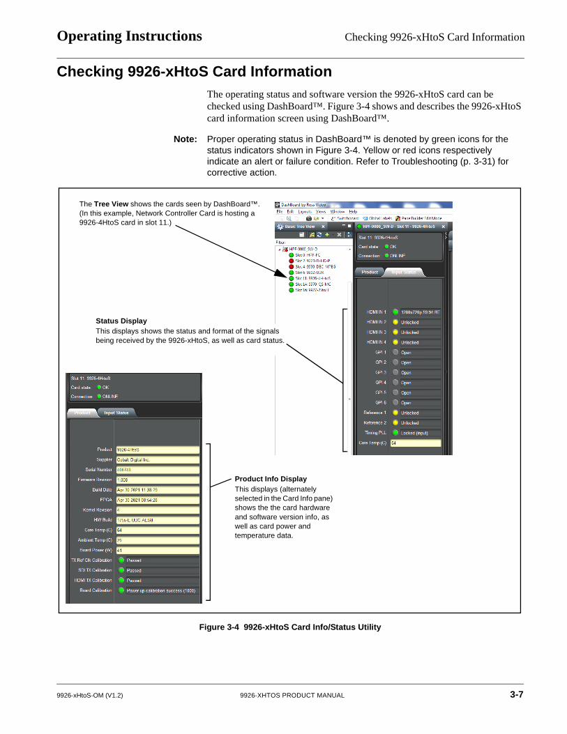
Checking 9926-xHtoS Card InformationThe operating status and software version the 9926-xHtoS card can be checked using DashBoard™. Figure 3-4 shows and describes the 9926-xHtoS card information screen using DashBoard™.
Note: Proper operating status in DashBoard™ is denoted by green icons for the status indicators shown in Figure 3-4. Yellow or red icons respectively indicate an alert or failure condition. Refer to Troubleshooting (p. 3-31) for corrective action.
Figure 3-4 9926-xHtoS Card Info/Status Utility
The Tree View shows the cards seen by DashBoard™. (In this example, Network Controller Card is hosting a 9926-4HtoS card in slot 11.)
Product Info DisplayThis displays (alternately selected in the Card Info pane) shows the the card hardware and software version info, as well as card power and temperature data.
Status DisplayThis displays shows the status and format of the signals being received by the 9926-xHtoS, as well as card status.
9926-xHtoS-OM (V1.2) 9926-XHTOS PRODUCT MANUAL 3-7
3 9926-xHtoS Function Menu List and Descriptions
9926-xHtoS Function Menu List and DescriptionsTable 3-1 individually lists and describes each 9926-xHtoS function menu and its related list selections, controls, and parameters. Where helpful, examples showing usage of a function are also provided. Table 3-1 is primarily based upon using DashBoard™ to access each function and its corresponding menus and parameters.
Note: UI depictions in this section show 4-path model 9926-4HtoS. Model 9926-2HtoS has identical controls, but limited to 2-path I/O and path controls.
On DashBoard™ itself and in Table 3-1, the function menu items are organized using tabs as shown below.
The table below provides a quick-reference to the page numbers where each function menu item can be found.
Some functions use Subtabs to help maintain clarity and organization. In these instances, Table 3-1 shows the ordinate tab along with its subtabs. Highlighted subtabs indicate that controls described are found by selecting this subtab (in this example, the Status subtab on the Output Audio tab/page).
Function Menu Item Page Function Menu Item Page
Input Video Controls 3-9 Admin 3-19
Video Proc/Color Correction 3-10 Network Settings Controls 3-20
Framesync 3-13 User Events Setup Controls 3-22
Output Video Routing 3-16 Input Audio Routing/Controls 3-23
GPO Setup Controls 3-17 Output Audio Routing/Controls 3-27
Presets 3-17
3-8 9926-XHTOS PRODUCT MANUAL 9926-xHtoS-OM (V1.2)
Operating Instructions 9926-xHtoS Function Menu List and Descriptions
Table 3-1 9926-xHtoS Function Menu List
Input Video Controls
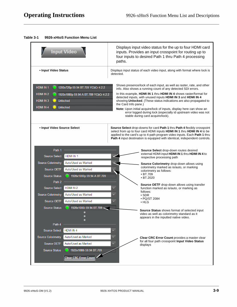
Displays input video status for the up to four HDMI card inputs. Provides an input crosspoint for routing up to four inputs to desired Path 1 thru Path 4 processing paths.
• Input Video Status Displays input status of each video input, along with format where lock is detected.
• Input Video Source Select Source Select drop-downs for card Path 1 thru Path 4 flexibly crosspoint select from up to four card HDMI inputs HDMI IN 1 thru HDMI IN 4 to be applied to the card’s up to 4-path program video inputs. Each Path 1 thru Path 4 input destination is equipped with identical, independent controls.
Shows presence/lock of each input, as well as raster, rate, and other info. Also shows a running count of any detected SDI errors.
In this example, HDMI IN 1 thru HDMI IN 4 shows raster/format for detected inputs, with unused inputs HDMI IN 3 and HDMI IN 4 showing Unlocked. (These status indications are also propagated to the Card Info pane.)
Note: Upon initial acquire/lock of inputs, display here can show an error logged during lock (especially id upstream video was not stable during card acquire/lock).
Source Select drop-down routes desired external HDMI input HDMI IN 1 thru HDMI IN 4 to respective processing path
Source Colorimetry drop-down allows using colorimetry marked as is/auto, or marking colorimetry as follows:• BT.709 • BT.2020
Source OETF drop-down allows using transfer function marked as is/auto, or marking as follows:• SDR • PQ/ST 2084• HLG
Source Status shows format of selected input video as well as colorimetry standard as it appears in the inputted native video.
Clear CRC Error Count provides a master clear for all four path crosspoint Input Video Status displays
9926-xHtoS-OM (V1.2) 9926-XHTOS PRODUCT MANUAL 3-9
3 9926-xHtoS Function Menu List and Descriptions
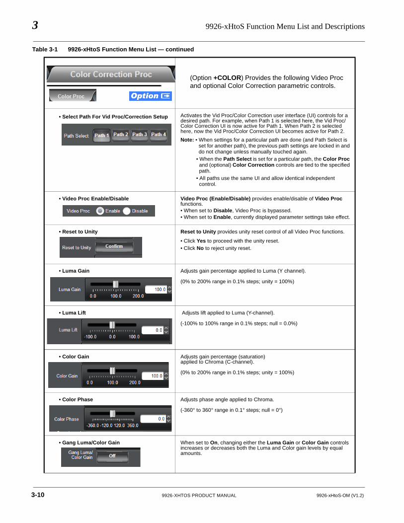
(Option +COLOR) Provides the following Video Proc and optional Color Correction parametric controls.
• Select Path For Vid Proc/Correction Setup Activates the Vid Proc/Color Correction user interface (UI) controls for a desired path. For example, when Path 1 is selected here, the Vid Proc/Color Correction UI is now active for Path 1. When Path 2 is selected here, now the Vid Proc/Color Correction UI becomes active for Path 2.
Note: • When settings for a particular path are done (and Path Select is set for another path), the previous path settings are locked in and do not change unless manually touched again.
• When the Path Select is set for a particular path, the Color Proc and (optional) Color Correction controls are tied to the specified path.
• All paths use the same UI and allow identical independent control.
• Video Proc Enable/Disable Video Proc (Enable/Disable) provides enable/disable of Video Proc functions. • When set to Disable, Video Proc is bypassed.• When set to Enable, currently displayed parameter settings take effect.
• Reset to Unity Reset to Unity provides unity reset control of all Video Proc functions.
• Click Yes to proceed with the unity reset.• Click No to reject unity reset.
• Luma Gain Adjusts gain percentage applied to Luma (Y channel).
(0% to 200% range in 0.1% steps; unity = 100%)Video Proc/Color Correction
• Luma Lift Adjusts lift applied to Luma (Y-channel).
(-100% to 100% range in 0.1% steps; null = 0.0%)
• Color Gain Adjusts gain percentage (saturation)applied to Chroma (C-channel).
(0% to 200% range in 0.1% steps; unity = 100%)
• Color Phase Adjusts phase angle applied to Chroma.
(-360° to 360° range in 0.1° steps; null = 0°)
• Gang Luma/Color Gain When set to On, changing either the Luma Gain or Color Gain controls increases or decreases both the Luma and Color gain levels by equal amounts.
Table 3-1 9926-xHtoS Function Menu List — continued
3-10 9926-XHTOS PRODUCT MANUAL 9926-xHtoS-OM (V1.2)
Operating Instructions 9926-xHtoS Function Menu List and Descriptions
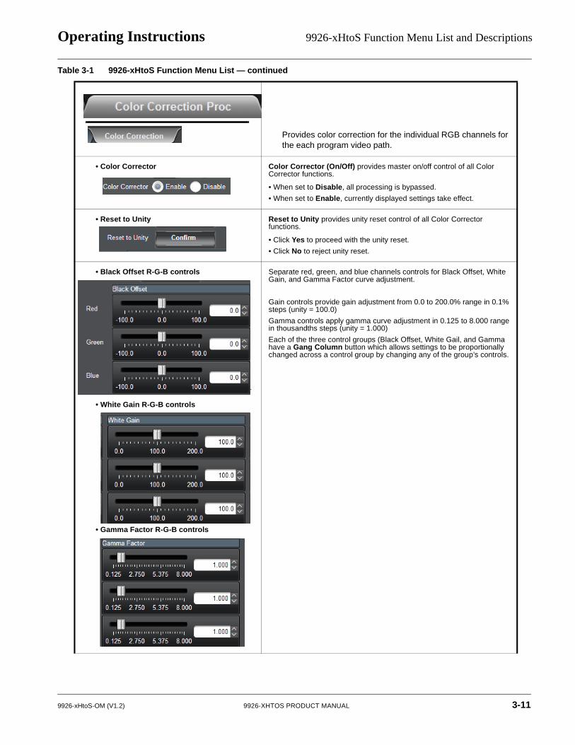
Provides color correction for the individual RGB channels for the each program video path.
• Color Corrector Color Corrector (On/Off) provides master on/off control of all Color Corrector functions.
• When set to Disable, all processing is bypassed.
• When set to Enable, currently displayed settings take effect.
• Reset to Unity Reset to Unity provides unity reset control of all Color Corrector functions.
• Click Yes to proceed with the unity reset.
• Click No to reject unity reset.
• Black Offset R-G-B controls
• White Gain R-G-B controls
• Gamma Factor R-G-B controls
Separate red, green, and blue channels controls for Black Offset, White Gain, and Gamma Factor curve adjustment.
Gain controls provide gain adjustment from 0.0 to 200.0% range in 0.1% steps (unity = 100.0)
Gamma controls apply gamma curve adjustment in 0.125 to 8.000 range in thousandths steps (unity = 1.000)
Each of the three control groups (Black Offset, White Gail, and Gamma have a Gang Column button which allows settings to be proportionally changed across a control group by changing any of the group’s controls.
Table 3-1 9926-xHtoS Function Menu List — continued
9926-xHtoS-OM (V1.2) 9926-XHTOS PRODUCT MANUAL 3-11
3 9926-xHtoS Function Menu List and Descriptions
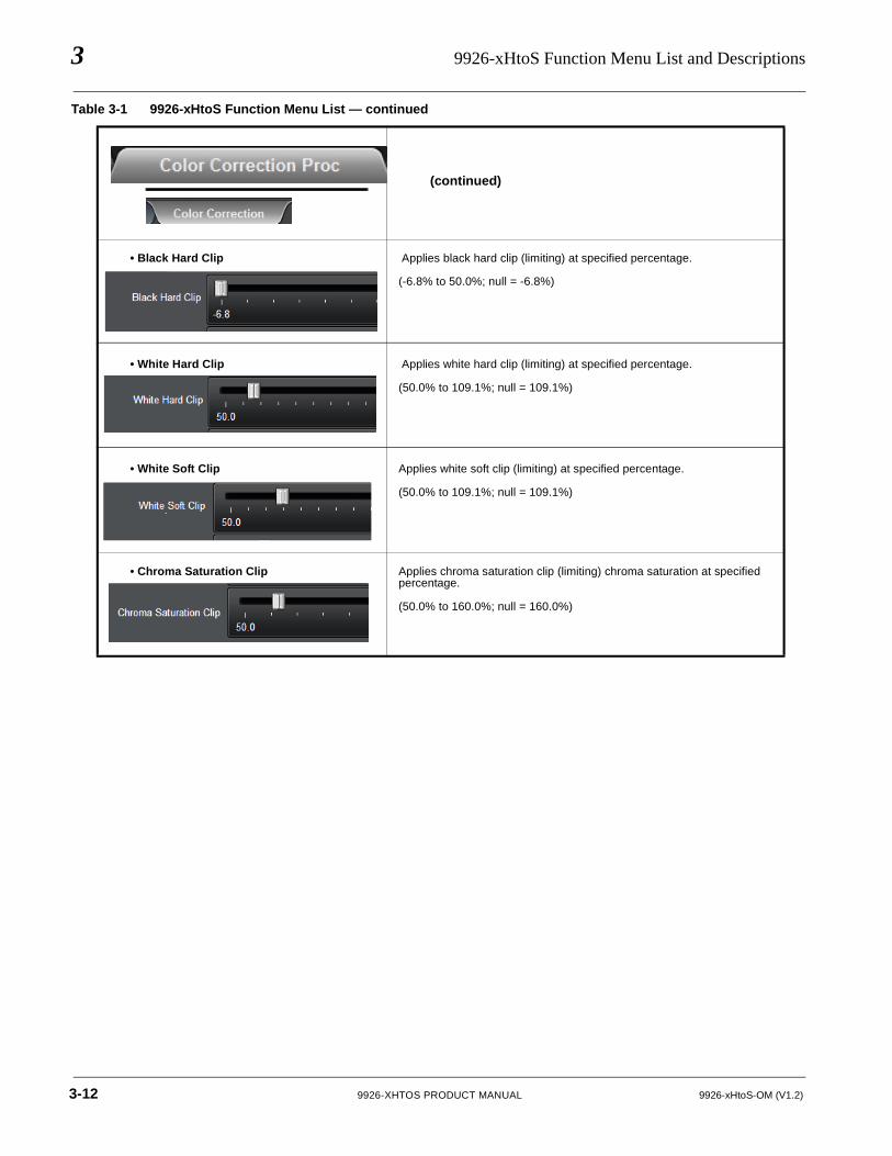
(continued)
• Black Hard Clip Applies black hard clip (limiting) at specified percentage.
(-6.8% to 50.0%; null = -6.8%)
• White Hard Clip Applies white hard clip (limiting) at specified percentage.
(50.0% to 109.1%; null = 109.1%)
• White Soft Clip Applies white soft clip (limiting) at specified percentage.
(50.0% to 109.1%; null = 109.1%)
• Chroma Saturation Clip Applies chroma saturation clip (limiting) chroma saturation at specified percentage.
(50.0% to 160.0%; null = 160.0%)
Table 3-1 9926-xHtoS Function Menu List — continued
3-12 9926-XHTOS PRODUCT MANUAL 9926-xHtoS-OM (V1.2)
Operating Instructions 9926-xHtoS Function Menu List and Descriptions
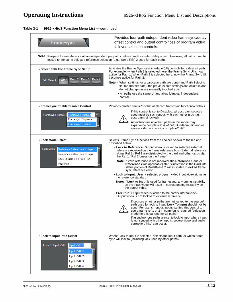
Framesync
Provides four-path independent video frame sync/delay offset control and output control/loss of program video failover selection controls.
Note: Per-path frame reference offers independent per-path controls (such as video delay offset). However, all paths must be locked to the same selected reference selection (e.g., frame REF 2 used for each path).
• Select Path For Frame Sync Setup Activates the Frame Sync user interface (UI) controls for a desired path. For example, when Path 1 is selected here, the Frame Sync UI is now active for Path 1. When Path 2 is selected here, now the Frame Sync UI becomes active for Path 2.
Note: • When settings for a particular path are done (and Path Select is set for another path), the previous path settings are locked in and do not change unless manually touched again.
• All paths use the same UI and allow identical independent control.
• Framesync Enable/Disable Control Provides master enable/disable of all card framesync functions/controls.
If this control is set to Disabled, all upstream sources used must be sychronous with each other (such as upstream ref locked).
Asynchronous unlocked paths in this mode may experience complete loss of output video/audio and/or severe video and audio corruption/”hits”.
• Lock Mode Select Selects Frame Sync functions from the choices shown to the left and described below.
• Lock to Reference: Output video is locked to selected external reference received on the frame reference bus. (External reference signal Ref 1 / Ref 2 are distributed to the card and other cards via the Ref 1 / Ref 2 buses on the frame.)
Note: If valid reference is not received, the Reference 1 and/or Reference 2 (as applicable) status indication in the Card Info status portion of DashBoard™ will indicate Unlocked frame sync reference error.
• Lock to Input: Uses a selected program video input video signal as the reference standard.Note: If Lock to Input is used for framesync, any timing instability
on the input video will result in corresponding instability on the output video.
• Free Run: Output video is locked to the card’s internal clock. Output video is not locked to external reference.
If sources on other paths are not locked to the source/path used for lock to input, Lock To Input should not be used. For asyncrhonous inputs, setting this control to use a frame ref 1 or 2 in common is required (selection made here is ganged for all paths).If asynchronous paths are set to lock to input where input is not synced with other inputs, severe video and audio corruption/”hits” can occur.
• Lock to Input Path Select Where Lock to Input is selected, selects the input path for which frame sync will lock to (including lock used by other paths).
Table 3-1 9926-xHtoS Function Menu List — continued
9926-xHtoS-OM (V1.2) 9926-XHTOS PRODUCT MANUAL 3-13
3 9926-xHtoS Function Menu List and Descriptions
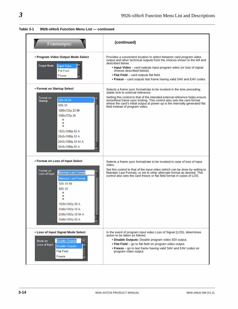
(continued)
• Program Video Output Mode Select Provides a convenient location to select between card program video output and other technical outputs from the choices shown to the left and described below.
• Input Video – card outputs input program video (or loss of signal choices described below).
• Flat Field – card outputs flat field.• Freeze – card outputs last frame having valid SAV and EAV codes.
• Format on Startup Select Selects a frame sync format/rate to be invoked in the time preceding stable lock to external reference.
Setting this control to that of the intended external reference helps ensure smoothest frame sync locking. This control also sets the card format where the card’s initial output at power-up is the internally generated flat field instead of program video.
• Format on Loss of Input Select Selects a frame sync format/rate to be invoked in case of loss of input video.
Set this control to that of the input video (which can be done by setting to Maintain Last Format), or set to other alternate format as desired. This control also sets the card freeze or flat field format in cases of LOS.
• Loss of Input Signal Mode Select In the event of program input video Loss of Signal (LOS), determines action to be taken as follows:
• Disable Outputs: Disable program video SDI output.• Flat Field – go to flat field on program video output.• Freeze – go to last frame having valid SAV and EAV codes on
program video output.
Table 3-1 9926-xHtoS Function Menu List — continued
3-14 9926-XHTOS PRODUCT MANUAL 9926-xHtoS-OM (V1.2)
Operating Instructions 9926-xHtoS Function Menu List and Descriptions
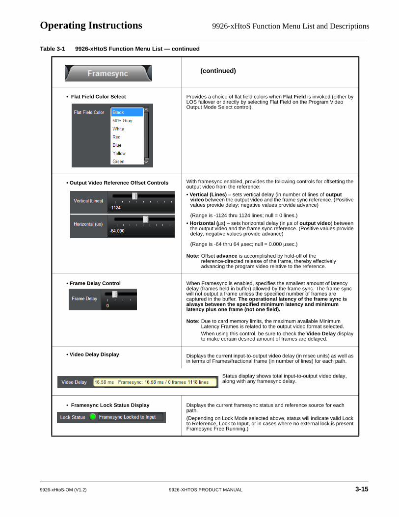
(continued)
• Flat Field Color Select Provides a choice of flat field colors when Flat Field is invoked (either by LOS failover or directly by selecting Flat Field on the Program Video Output Mode Select control).
• Output Video Reference Offset Controls With framesync enabled, provides the following controls for offsetting the output video from the reference:
• Vertical (Lines) – sets vertical delay (in number of lines of output video between the output video and the frame sync reference. (Positive values provide delay; negative values provide advance)
(Range is -1124 thru 1124 lines; null = 0 lines.)
• Horizontal (µs) – sets horizontal delay (in µs of output video) between the output video and the frame sync reference. (Positive values provide delay; negative values provide advance)
(Range is -64 thru 64 µsec; null = 0.000 µsec.)
Note: Offset advance is accomplished by hold-off of the reference-directed release of the frame, thereby effectively advancing the program video relative to the reference.
• Frame Delay Control
Minimum Latency Frames Control
When Framesync is enabled, specifies the smallest amount of latency delay (frames held in buffer) allowed by the frame sync. The frame sync will not output a frame unless the specified number of frames are captured in the buffer. The operational latency of the frame sync is always between the specified minimum latency and minimum latency plus one frame (not one field).
Note: Due to card memory limits, the maximum available Minimum Latency Frames is related to the output video format selected.When using this control, be sure to check the Video Delay display to make certain desired amount of frames are delayed.
• Video Delay Display Displays the current input-to-output video delay (in msec units) as well as in terms of Frames/fractional frame (in number of lines) for each path.
• Framesync Lock Status Display Displays the current framesync status and reference source for each path.
(Depending on Lock Mode selected above, status will indicate valid Lock to Reference, Lock to Input, or in cases where no external lock is present Framesync Free Running.)
Table 3-1 9926-xHtoS Function Menu List — continued
Status display shows total input-to-output video delay, along with any framesync delay.
9926-xHtoS-OM (V1.2) 9926-XHTOS PRODUCT MANUAL 3-15
3 9926-xHtoS Function Menu List and Descriptions
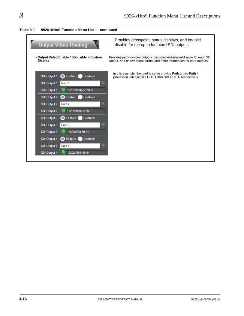
Provides crosspoint, status displays, and enable/disable for the up to four card SDI outputs.
Output Video Routing
• Output Video Enable / Status/Identification Display
Provides path-to-video output crosspoint and enable/disable for each SDI output, and shows video format and other information for card outputs.
Table 3-1 9926-xHtoS Function Menu List — continued
In this example, the card is set to provide Path 1 thru Path 4 processed video to SDI OUT 1 thru SDI OUT 4, respectively.
3-16 9926-XHTOS PRODUCT MANUAL 9926-xHtoS-OM (V1.2)
Operating Instructions 9926-xHtoS Function Menu List and Descriptions
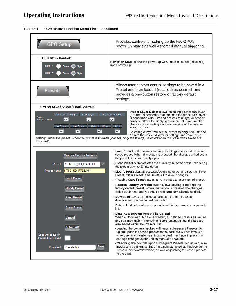
GPO Setup Controls
Provides controls for setting up the two GPO’s power-up states as well as forced manual triggering.
• GPO Static ControlsPower-on State allows the power-up GPO state to be set (initialized) upon power-up
Presets
Allows user custom control settings to be saved in a Preset and then loaded (recalled) as desired, and provides a one-button restore of factory default settings.
• Preset Save / Select / Load Controls
Table 3-1 9926-xHtoS Function Menu List — continued
• Load Preset button allows loading (recalling) a selected previously saved preset. When this button is pressed, the changes called out in the preset are immediately applied.
• Clear Preset button deletes the currently selected preset, rendering the preset back to Empty default.
• Modify Preset button activates/opens other buttons such as Save Preset, Clear Preset, and Delete All to allow changes.
• Pressing Save Preset saves current states to user-named preset.
• Restore Factory Defaults button allows loading (recalling) the factory default preset. When this button is pressed, the changes called out in the factory default preset are immediately applied.
• Download saves all individual presets to a .bin file to be downloaded to a connected computer.
• Delete All deletes all saved presets within the current user presets list.
• Load Autosave on Preset File Upload When a Download .bin file is created, all defined presets as well as any current transient (“unwritten”) card settings/state in place are also saved within the Presets .bin. - Leaving the box unchecked will, upon subsequent Presets .bin upload, push the saved presets to the card but will not invoke or write over any transient settings the card may have in place (no settings changes occur unless manually enacted).
- Checking the box will, upon subsequent Presets .bin upload, also invoke any transient settings the card may have had in place during Presets .bin save/download, as well as pushing the saved presets to the card.
Preset Layer Select allows selecting a functional layer (or “area of concern”) that confines the preset to a layer it is concerned with. Limiting presets to a layer or area of concern allows for highly specific presets, and masks changing card settings in areas outside of the layer or area of concern.
Selecting a layer will set the preset to only “look at” and “touch” the selected layer(s) settings and save these
settings under the preset. When the preset is invoked (loaded), only the layer(s) selected when the preset was saved are “touched”.
9926-xHtoS-OM (V1.2) 9926-XHTOS PRODUCT MANUAL 3-17
3 9926-xHtoS Function Menu List and Descriptions
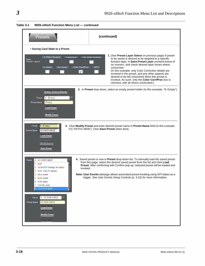
(continued)
• Saving Card State to a Preset
Table 3-1 9926-xHtoS Function Menu List — continued
1. (See Preset Layer Select on previous page) If preset to be saved is desired to be targeted to a specific function layer, in Save Preset Layer uncheck boxes of no concern, and check desired layer boxes where concerned. (In this example, only Color Correction details are involved in the preset, and any other aspects are desired to be left untouched when this preset is invoked. As such, only the Color Corr/Proc box is checked, with all others unchecked.)
2. In Preset drop-down, select an empty preset holder (in this example, “8: Empty”).
3. Click Modify Preset and enter desired preset name In Preset Name field (in this example, “CC-PATH1-NEW”). Click Save Preset when done.
4. Saved preset is now in Preset drop-down list. To manually load the saved preset from this page, select the desired saved preset from the list and click Load Preset. After confirming with Confirm pop-up, selected preset will be loaded and invoked.
Note: User Events tab/page allows automated preset invoking using GPI states as a trigger. See User Events Setup Controls (p. 3-22) for more information.
3-18 9926-XHTOS PRODUCT MANUAL 9926-xHtoS-OM (V1.2)
Operating Instructions 9926-xHtoS Function Menu List and Descriptions
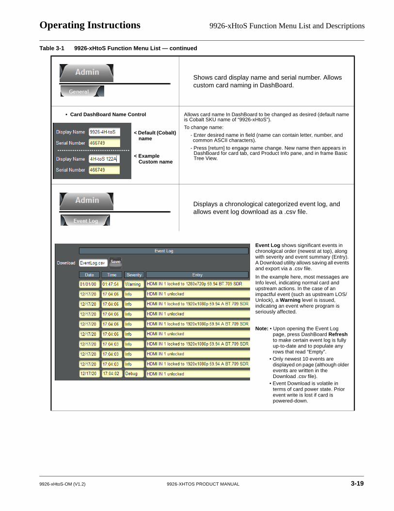
Admin
Shows card display name and serial number. Allows custom card naming in DashBoard.
• Card DashBoard Name Control Allows card name In DashBoard to be changed as desired (default name is Cobalt SKU name of “9926-xHtoS”).
To change name:
- Enter desired name in field (name can contain letter, number, and common ASCII characters).
- Press [return] to engage name change. New name then appears in DashBoard for card tab, card Product Info pane, and in frame Basic Tree View.
Displays a chronological categorized event log, and allows event log download as a .csv file.
Table 3-1 9926-xHtoS Function Menu List — continued
< Default (Cobalt) name
< Example Custom name
Event Log shows significant events in chronolgical order (newest at top), along with severity and event summary (Entry).A Download utility allows saving all events and export via a .csv file.
In the example here, most messages are Info level, indicating normal card and upstream actions. In the case of an impactful event (such as upstream LOS/Unlock), a Warning level is issued, indicating an event where program is seriously affected.
Note: • Upon opening the Event Log page, press DashBoard Refresh to make certain event log is fully up-to-date and to populate any rows that read “Empty”.
• Only newest 10 events are displayed on page (although older events are written in the Download .csv file).
• Event Download is volatile in terms of card power state. Prior event write is lost if card is powered-down.
9926-xHtoS-OM (V1.2) 9926-XHTOS PRODUCT MANUAL 3-19
3 9926-xHtoS Function Menu List and Descriptions
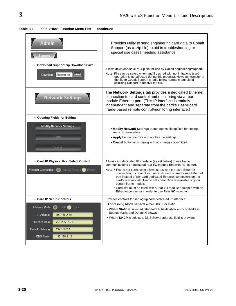
Provides utility to send engineering card data to Cobalt Support (as a .zip file) to aid in troubleshooting or special use cases needing assistance.
• Download Support zip Download/SaveAllows download/save of .zip file for use by Cobalt engineering/support.
Note: File can be saved when and if desired with no limitations (card operation is not affected during this process). However, transfer of the file to Cobalt Support should follow normal channels of soliciting Support to receive the file.
Network Settings Controls
The Network Settings tab provides a dedicated Ethernet connection to card control and monitoring via a rear module Ethernet port. (This IP interface is entirely independent and separate from the card’s DashBoard frame-based remote control/monitoring interface.)
• Opening Fields for Editing
• Modify Network Settings button opens dialog field for setting network parameters.
• Apply button commits and applies the settings.
• Cancel button exits dialog with no changes committed.
• Card IP Physical Port Select Control Allows card dedicated IP interface (as set below) to use frame communications or dedicated rear I/O module Ethernet RJ-45 port.
Note: • Frame net connection allows cards with per-card Ethernet connection to connect with network via a shared frame Ethernet port instead of per-card dedicated Ethernet connectors on the card’s rear module. Frame net connection is available only on certain frame models.
• Card slot must be fitted with a rear I/O module equipped with an Ethernet connector in order to use Rear I/O selection.
• Card IP Setup Controls Provides controls for setting up card dedicated IP interface.
• Addressing Mode selsects either DHCP or static.
• Where Static is selected, standard IP fields allow entry of Address, Subnet Mask, and Default Gateway.
• Where DHCP is selected, DNS Server address field is provided.
Table 3-1 9926-xHtoS Function Menu List — continued
3-20 9926-XHTOS PRODUCT MANUAL 9926-xHtoS-OM (V1.2)
Operating Instructions 9926-xHtoS Function Menu List and Descriptions
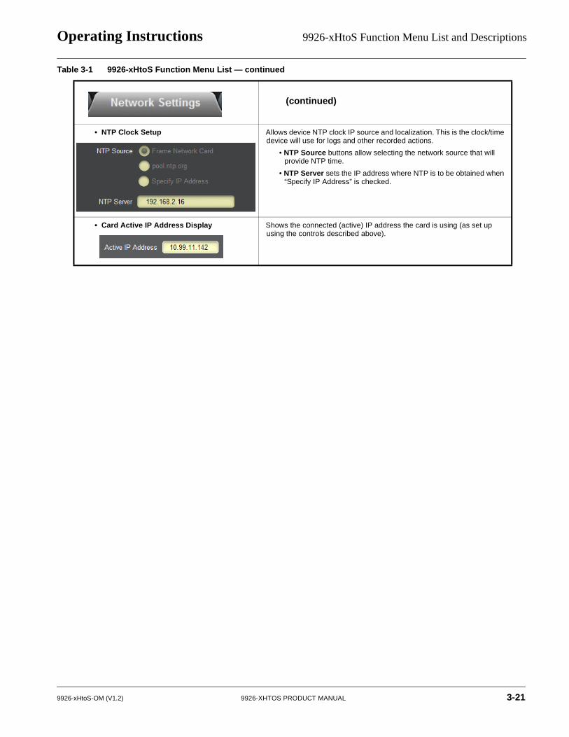
(continued)
• NTP Clock Setup Allows device NTP clock IP source and localization. This is the clock/time device will use for logs and other recorded actions.
• NTP Source buttons allow selecting the network source that will provide NTP time.
• NTP Server sets the IP address where NTP is to be obtained when “Specify IP Address” is checked.
• Card Active IP Address Display Shows the connected (active) IP address the card is using (as set up using the controls described above).
Table 3-1 9926-xHtoS Function Menu List — continued
9926-xHtoS-OM (V1.2) 9926-XHTOS PRODUCT MANUAL 3-21
3 9926-xHtoS Function Menu List and Descriptions
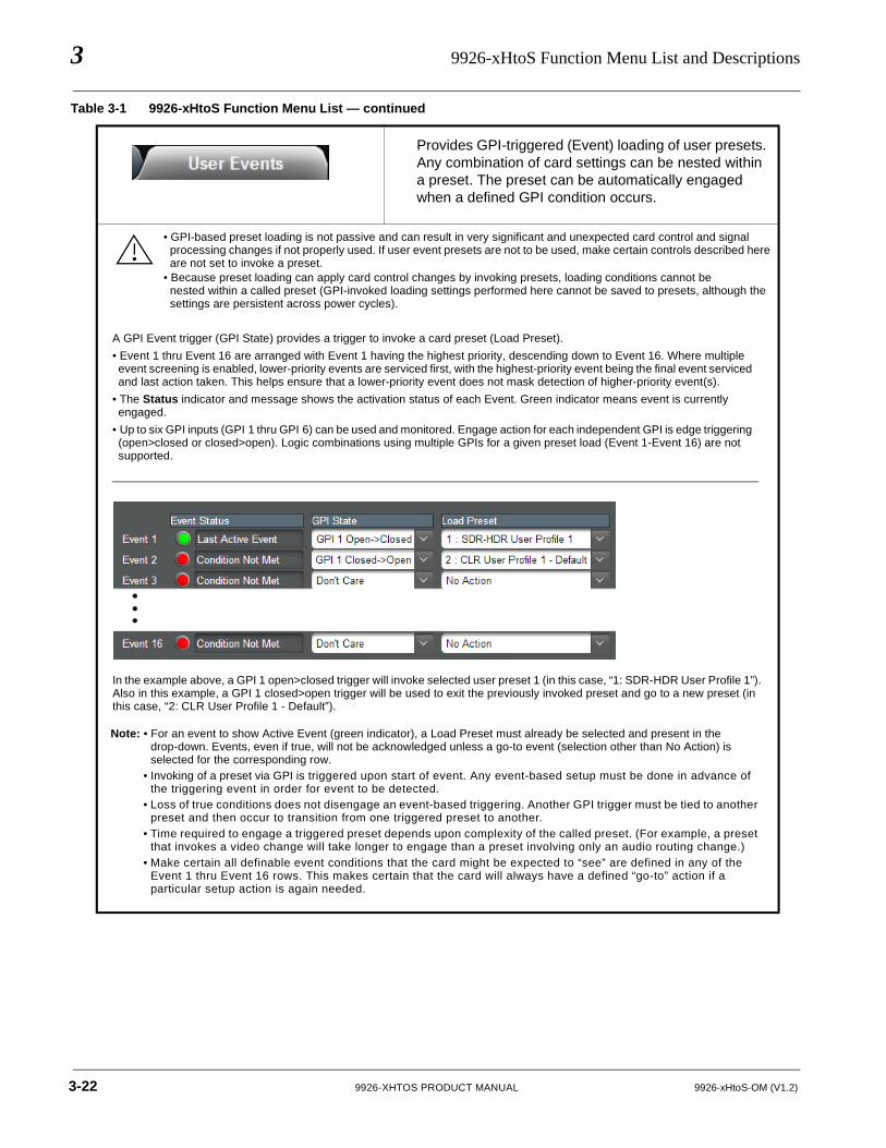
Provides GPI-triggered (Event) loading of user presets. Any combination of card settings can be nested within a preset. The preset can be automatically engaged when a defined GPI condition occurs.
User Events Setup Controls
• GPI-based preset loading is not passive and can result in very significant and unexpected card control and signal processing changes if not properly used. If user event presets are not to be used, make certain controls described hereare not set to invoke a preset.
• Because preset loading can apply card control changes by invoking presets, loading conditions cannot benested within a called preset (GPI-invoked loading settings performed here cannot be saved to presets, although the settings are persistent across power cycles).
Table 3-1 9926-xHtoS Function Menu List — continued
A GPI Event trigger (GPI State) provides a trigger to invoke a card preset (Load Preset).
• Event 1 thru Event 16 are arranged with Event 1 having the highest priority, descending down to Event 16. Where multiple event screening is enabled, lower-priority events are serviced first, with the highest-priority event being the final event serviced and last action taken. This helps ensure that a lower-priority event does not mask detection of higher-priority event(s).
• The Status indicator and message shows the activation status of each Event. Green indicator means event is currently engaged.
• Up to six GPI inputs (GPI 1 thru GPI 6) can be used and monitored. Engage action for each independent GPI is edge triggering (open>closed or closed>open). Logic combinations using multiple GPIs for a given preset load (Event 1-Event 16) are not supported.
Note: • For an event to show Active Event (green indicator), a Load Preset must already be selected and present in the drop-down. Events, even if true, will not be acknowledged unless a go-to event (selection other than No Action) is selected for the corresponding row.
• Invoking of a preset via GPI is triggered upon start of event. Any event-based setup must be done in advance of the triggering event in order for event to be detected.
• Loss of true conditions does not disengage an event-based triggering. Another GPI trigger must be tied to another preset and then occur to transition from one triggered preset to another.
• Time required to engage a triggered preset depends upon complexity of the called preset. (For example, a preset that invokes a video change will take longer to engage than a preset involving only an audio routing change.)
• Make certain all definable event conditions that the card might be expected to “see” are defined in any of the Event 1 thru Event 16 rows. This makes certain that the card will always have a defined “go-to” action if a particular setup action is again needed.
In the example above, a GPI 1 open>closed trigger will invoke selected user preset 1 (in this case, “1: SDR-HDR User Profile 1”). Also in this example, a GPI 1 closed>open trigger will be used to exit the previously invoked preset and go to a new preset (in this case, “2: CLR User Profile 1 - Default”).
3-22 9926-XHTOS PRODUCT MANUAL 9926-xHtoS-OM (V1.2)
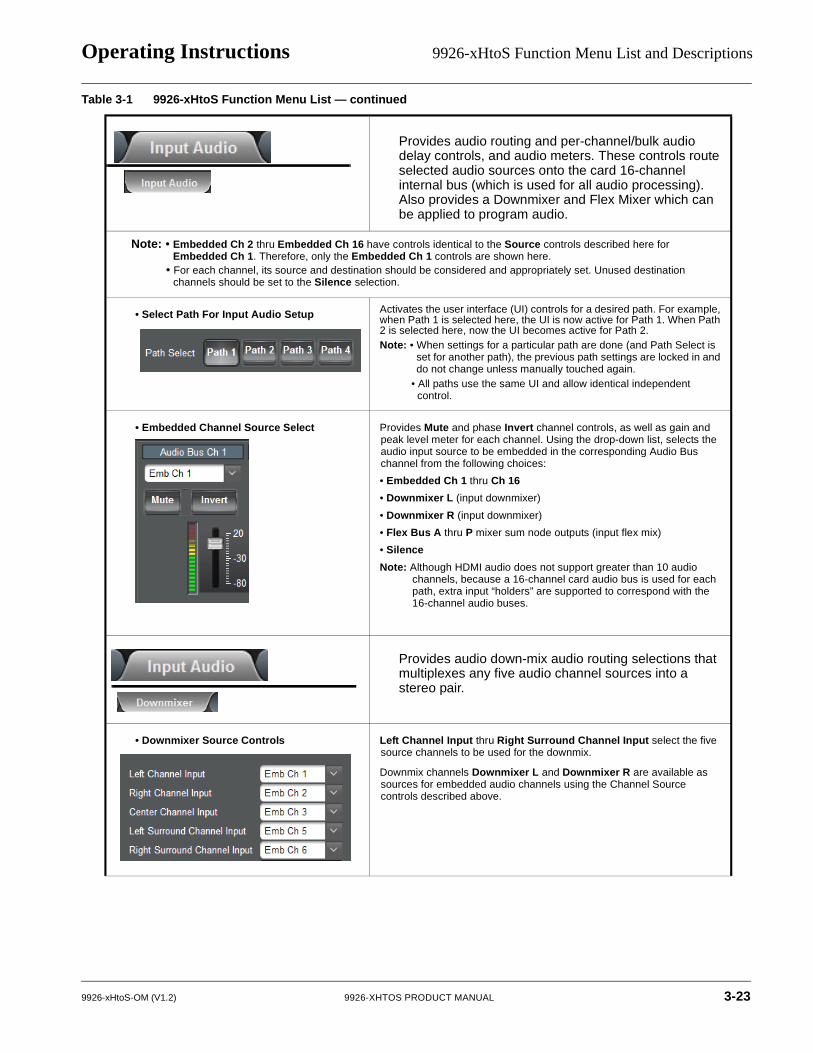
Operating Instructions 9926-xHtoS Function Menu List and Descriptions
Input Audio Routing/Controls
Provides audio routing and per-channel/bulk audio delay controls, and audio meters. These controls route selected audio sources onto the card 16-channel internal bus (which is used for all audio processing). Also provides a Downmixer and Flex Mixer which can be applied to program audio.
Note: • Embedded Ch 2 thru Embedded Ch 16 have controls identical to the Source controls described here for Embedded Ch 1. Therefore, only the Embedded Ch 1 controls are shown here.
• For each channel, its source and destination should be considered and appropriately set. Unused destination channels should be set to the Silence selection.
• Select Path For Input Audio Setup Activates the user interface (UI) controls for a desired path. For example, when Path 1 is selected here, the UI is now active for Path 1. When Path 2 is selected here, now the UI becomes active for Path 2.Note: • When settings for a particular path are done (and Path Select is
set for another path), the previous path settings are locked in and do not change unless manually touched again.
• All paths use the same UI and allow identical independent control.
• Embedded Channel Source Select
Audio Routing Controls
Provides Mute and phase Invert channel controls, as well as gain and peak level meter for each channel. Using the drop-down list, selects the audio input source to be embedded in the corresponding Audio Bus channel from the following choices:
• Embedded Ch 1 thru Ch 16
• Downmixer L (input downmixer)
• Downmixer R (input downmixer)
• Flex Bus A thru P mixer sum node outputs (input flex mix)
• Silence
Note: Although HDMI audio does not support greater than 10 audio channels, because a 16-channel card audio bus is used for each path, extra input “holders” are supported to correspond with the 16-channel audio buses.
Provides audio down-mix audio routing selections that multiplexes any five audio channel sources into a stereo pair.
Downmixer Controls
• Downmixer Source Controls Left Channel Input thru Right Surround Channel Input select the five source channels to be used for the downmix.
Downmix channels Downmixer L and Downmixer R are available as sources for embedded audio channels using the Channel Source controls described above.
Table 3-1 9926-xHtoS Function Menu List — continued
9926-xHtoS-OM (V1.2) 9926-XHTOS PRODUCT MANUAL 3-23
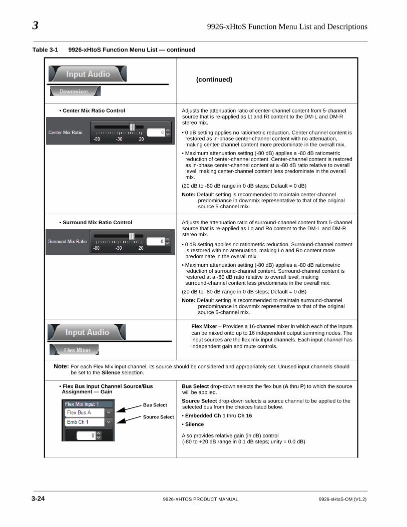
3 9926-xHtoS Function Menu List and Descriptions
(continued)
• Center Mix Ratio Control Adjusts the attenuation ratio of center-channel content from 5-channel source that is re-applied as Lt and Rt content to the DM-L and DM-R stereo mix.
• 0 dB setting applies no ratiometric reduction. Center channel content is restored as in-phase center-channel content with no attenuation, making center-channel content more predominate in the overall mix.
• Maximum attenuation setting (-80 dB) applies a -80 dB ratiometric reduction of center-channel content. Center-channel content is restored as in-phase center-channel content at a -80 dB ratio relative to overall level, making center-channel content less predominate in the overall mix.
(20 dB to -80 dB range in 0 dB steps; Default = 0 dB)
Note: Default setting is recommended to maintain center-channel predominance in downmix representative to that of the original source 5-channel mix.
• Surround Mix Ratio Control Adjusts the attenuation ratio of surround-channel content from 5-channel source that is re-applied as Lo and Ro content to the DM-L and DM-R stereo mix.
• 0 dB setting applies no ratiometric reduction. Surround-channel content is restored with no attenuation, making Lo and Ro content more predominate in the overall mix.
• Maximum attenuation setting (-80 dB) applies a -80 dB ratiometric reduction of surround-channel content. Surround-channel content is restored at a -80 dB ratio relative to overall level, making surround-channel content less predominate in the overall mix.
(20 dB to -80 dB range in 0 dB steps; Default = 0 dB)
Note: Default setting is recommended to maintain surround-channel predominance in downmix representative to that of the original source 5-channel mix.
Flex Mixer – Provides a 16-channel mixer in which each of the inputs can be mixed onto up to 16 independent output summing nodes. The input sources are the flex mix input channels. Each input channel has independent gain and mute controls.
Flex Mix Controls
Note: For each Flex Mix input channel, its source should be considered and appropriately set. Unused input channels should be set to the Silence selection.
• Flex Bus Input Channel Source/Bus Assignment — Gain
Bus Select drop-down selects the flex bus (A thru P) to which the source will be applied.
Source Select drop-down selects a source channel to be applied to the selected bus from the choices listed below.
• Embedded Ch 1 thru Ch 16
• Silence
Also provides relative gain (in dB) control (-80 to +20 dB range in 0.1 dB steps; unity = 0.0 dB)
Table 3-1 9926-xHtoS Function Menu List — continued
Bus Select
Source Select
3-24 9926-XHTOS PRODUCT MANUAL 9926-xHtoS-OM (V1.2)
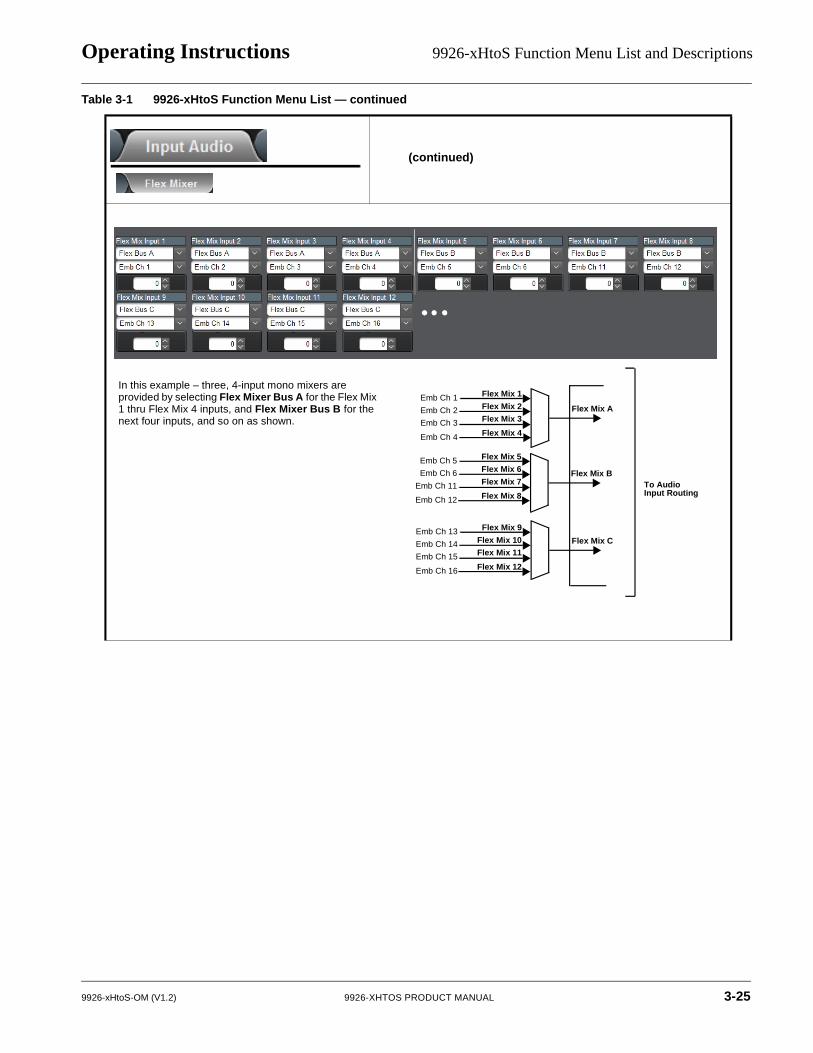
Operating Instructions 9926-xHtoS Function Menu List and Descriptions
(continued)
Table 3-1 9926-xHtoS Function Menu List — continued
Flex Mix A
Flex Mix 1
Flex Mix 2
Flex Mix 3
Flex Mix 4
Flex Mix B
Flex Mix C
To Audio BInput Routing
Emb Ch 1
Emb Ch 2
Emb Ch 3
Emb Ch 4
Flex Mix 5
Flex Mix 6
Flex Mix 7
Flex Mix 8
Emb Ch 5
Emb Ch 6
Emb Ch 11
Emb Ch 12
Flex Mix 9
Flex Mix 10
Flex Mix 11
Flex Mix 12
Emb Ch 13
Emb Ch 14
Emb Ch 15
Emb Ch 16
In this example – three, 4-input mono mixers are provided by selecting Flex Mixer Bus A for the Flex Mix 1 thru Flex Mix 4 inputs, and Flex Mixer Bus B for the next four inputs, and so on as shown.
9926-xHtoS-OM (V1.2) 9926-XHTOS PRODUCT MANUAL 3-25
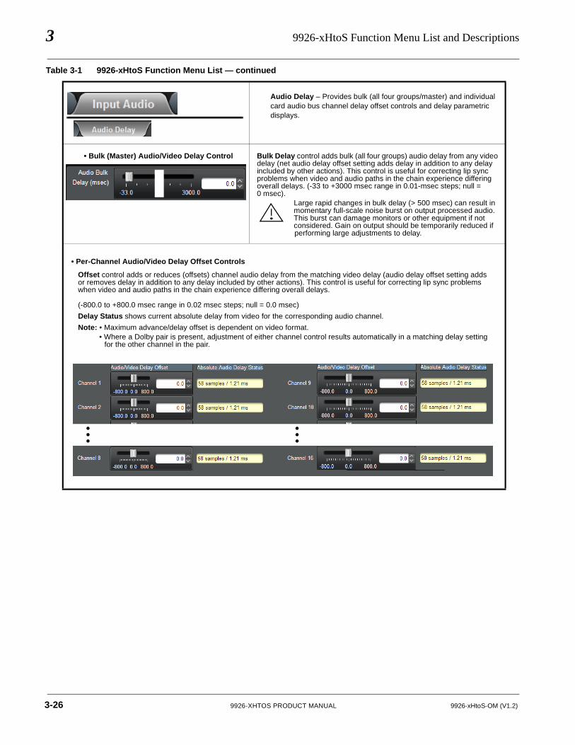
3 9926-xHtoS Function Menu List and Descriptions
Audio Delay – Provides bulk (all four groups/master) and individual card audio bus channel delay offset controls and delay parametric displays.
Audio Delay Controls
• Bulk (Master) Audio/Video Delay Control Bulk Delay control adds bulk (all four groups) audio delay from any video delay (net audio delay offset setting adds delay in addition to any delay included by other actions). This control is useful for correcting lip sync problems when video and audio paths in the chain experience differing overall delays. (-33 to +3000 msec range in 0.01-msec steps; null = 0 msec).
Large rapid changes in bulk delay (> 500 msec) can result in momentary full-scale noise burst on output processed audio. This burst can damage monitors or other equipment if not considered. Gain on output should be temporarily reduced ifperforming large adjustments to delay.
Table 3-1 9926-xHtoS Function Menu List — continued
• Per-Channel Audio/Video Delay Offset Controls
Offset control adds or reduces (offsets) channel audio delay from the matching video delay (audio delay offset setting adds or removes delay in addition to any delay included by other actions). This control is useful for correcting lip sync problems when video and audio paths in the chain experience differing overall delays.
(-800.0 to +800.0 msec range in 0.02 msec steps; null = 0.0 msec)
Delay Status shows current absolute delay from video for the corresponding audio channel.
Note: • Maximum advance/delay offset is dependent on video format.• Where a Dolby pair is present, adjustment of either channel control results automatically in a matching delay setting
for the other channel in the pair.
3-26 9926-XHTOS PRODUCT MANUAL 9926-xHtoS-OM (V1.2)
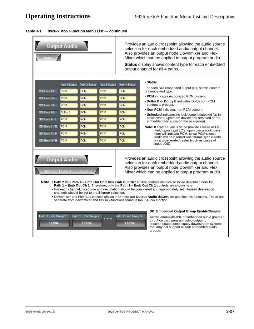
Operating Instructions 9926-xHtoS Function Menu List and Descriptions
Output Audio Routing/Controls
Provides an audio crosspoint allowing the audio source selection for each embedded audio output channel. Also provides an output node Downmixer and Flex Mixer which can be applied to output program audio.
Status display shows content type for each embedded output channel for all 4 paths.
Provides an audio crosspoint allowing the audio source selection for each embedded audio output channel. Also provides an output node Downmixer and Flex Mixer which can be applied to output program audio.
Note: • Path 2 thru Path 4 – Emb Out Ch 2 thru Emb Out Ch 16 have controls identical to those described here for Path 1 – Emb Out Ch 1. Therefore, only the Path 1 – Emb Out Ch 1 controls are shown here.
• For each channel, its source and destination should be considered and appropriately set. Unused destination channels should be set to the Silence selection.
• Downmixer and Flex Bus choices shown in UI here are Output Audio downmixer and flex mix functions. These are separate from downmixer and flex mix functions found in Input Audio function.
Table 3-1 9926-xHtoS Function Menu List — continued
• Status
For each SDI embedded output pair, shows content presence and type.
• PCM indicates recognized PCM present.
• Dolby D or Dolby E indicates Dolby non-PCM content is present.
• Non-PCM indicates non-PCM content.
• Unlocked indicates no lock/content detected (as in cases where upstream device has removed or not embedded any audio on the pair/group).
Note: If Frame Sync is set to provide Freeze or Flat Field upon input LOS, upon pair unlock, pairs here will indicate PCM, since PCM silence audio will be inserted when frame sync inserts a card-generated raster (such as cases of input LOS).
SDI Embedded Output Group Enable/Disable
Allows enable/disable of embedded audio groups 1 thru 4 on card program video output to accommodate some legacy downstream systems that may not support all four embedded audio groups.
9926-xHtoS-OM (V1.2) 9926-XHTOS PRODUCT MANUAL 3-27
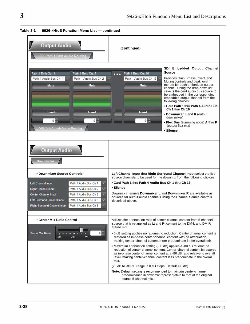
3 9926-xHtoS Function Menu List and Descriptions
(continued)
• Downmixer Source Controls Left Channel Input thru Right Surround Channel Input select the five source channels to be used for the downmix from the following choices:
• Card Path 1 thru Path 4 Audio Bus Ch 1 thru Ch 16
• Silence
Downmix channels Downmixer L and Downmixer R are available as sources for output audio channels using the Channel Source controls described above.
• Center Mix Ratio Control Adjusts the attenuation ratio of center-channel content from 5-channel source that is re-applied as Lt and Rt content to the DM-L and DM-R stereo mix.
• 0 dB setting applies no ratiometric reduction. Center channel content is restored as in-phase center-channel content with no attenuation, making center-channel content more predominate in the overall mix.
• Maximum attenuation setting (-80 dB) applies a -80 dB ratiometric reduction of center-channel content. Center-channel content is restored as in-phase center-channel content at a -80 dB ratio relative to overall level, making center-channel content less predominate in the overall mix.
(20 dB to -80 dB range in 0 dB steps; Default = 0 dB)
Note: Default setting is recommended to maintain center-channel predominance in downmix representative to that of the original source 5-channel mix.
Table 3-1 9926-xHtoS Function Menu List — continued
SDI Embedded Output ChannelSource
Provides Gain, Phase Invert, and Muting controls and peak level meters for each embedded output channel. Using the drop-down list, selects the card audio bus source to be embedded in the corresponding embedded output channel from the following choices:
• Card Path 1 thru Path 4 Audio Bus Ch 1 thru Ch 16
• Downmixer L and R (output downmixer)
• Flex Bus (summing node) A thru P (output flex mix)
• Silence
3-28 9926-XHTOS PRODUCT MANUAL 9926-xHtoS-OM (V1.2)
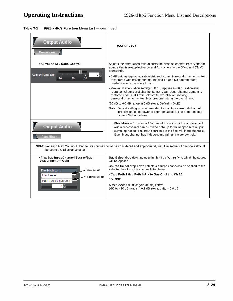
Operating Instructions 9926-xHtoS Function Menu List and Descriptions
(continued)
• Surround Mix Ratio Control Adjusts the attenuation ratio of surround-channel content from 5-channel source that is re-applied as Lo and Ro content to the DM-L and DM-R stereo mix.
• 0 dB setting applies no ratiometric reduction. Surround-channel content is restored with no attenuation, making Lo and Ro content more predominate in the overall mix.
• Maximum attenuation setting (-80 dB) applies a -80 dB ratiometric reduction of surround-channel content. Surround-channel content is restored at a -80 dB ratio relative to overall level, making surround-channel content less predominate in the overall mix.
(20 dB to -80 dB range in 0 dB steps; Default = 0 dB)
Note: Default setting is recommended to maintain surround-channel predominance in downmix representative to that of the original source 5-channel mix.
Flex Mixer – Provides a 16-channel mixer in which each selected audio bus channel can be mixed onto up to 16 independent output summing nodes. The input sources are the flex mix input channels. Each input channel has independent gain and mute controls.
Flex Mix Controls
Note: For each Flex Mix input channel, its source should be considered and appropriately set. Unused input channels should be set to the Silence selection.
• Flex Bus Input Channel Source/Bus Assignment — Gain
Bus Select drop-down selects the flex bus (A thru P) to which the source will be applied.
Source Select drop-down selects a source channel to be applied to the selected bus from the choices listed below.
• Card Path 1 thru Path 4 Audio Bus Ch 1 thru Ch 16
• Silence
Also provides relative gain (in dB) control (-80 to +20 dB range in 0.1 dB steps; unity = 0.0 dB)
Table 3-1 9926-xHtoS Function Menu List — continued
Bus Select
Source Select
9926-xHtoS-OM (V1.2) 9926-XHTOS PRODUCT MANUAL 3-29
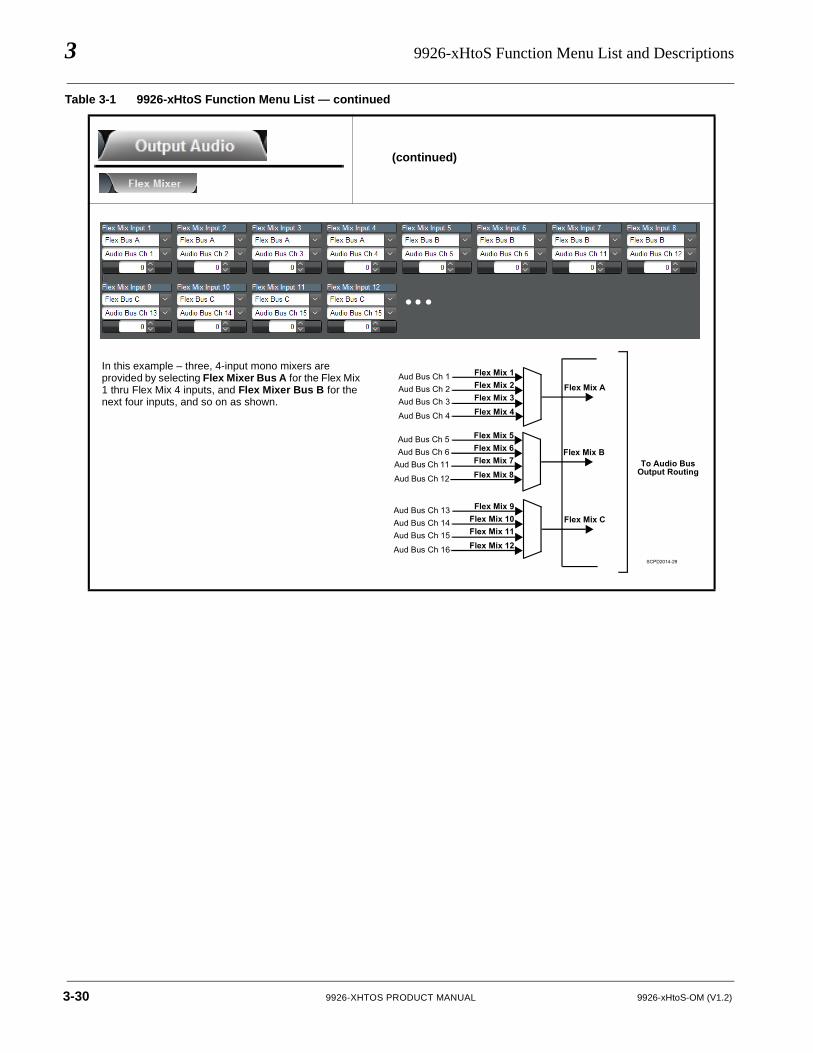
3 9926-xHtoS Function Menu List and Descriptions
(continued)
Table 3-1 9926-xHtoS Function Menu List — continued
Flex Mix A
Flex Mix 1Flex Mix 2Flex Mix 3Flex Mix 4
Flex Mix B
Flex Mix C
To Audio Bus Output Routing
Aud Bus Ch 1Aud Bus Ch 2Aud Bus Ch 3
Aud Bus Ch 4
Flex Mix 5Flex Mix 6Flex Mix 7Flex Mix 8
Aud Bus Ch 5Aud Bus Ch 6
Aud Bus Ch 11
Aud Bus Ch 12
Flex Mix 9Flex Mix 10Flex Mix 11Flex Mix 12
Aud Bus Ch 13Aud Bus Ch 14Aud Bus Ch 15
Aud Bus Ch 16SCPD2014-29
In this example – three, 4-input mono mixers are provided by selecting Flex Mixer Bus A for the Flex Mix 1 thru Flex Mix 4 inputs, and Flex Mixer Bus B for the next four inputs, and so on as shown.
3-30 9926-XHTOS PRODUCT MANUAL 9926-xHtoS-OM (V1.2)
Operating Instructions Troubleshooting
TroubleshootingThis section provides general troubleshooting information and specific symptom/corrective action for the 9926-xHtoS card and its remote control interface. The 9926-xHtoS card requires no periodic maintenance in its normal operation; if any error indication (as described in this section) occurs, use this section to correct the condition.
Error and Failure Indicator Overview
The 9926-xHtoS card itself and its remote control systems all (to varying degrees) provide error and failure indications. Depending on how the 9926-xHtoS card is being used (i.e, standalone or network controlled through DashBoard™ or a Remote Control Panel), check all available indications in the event of an error or failure condition.
The various 9926-xHtoS card and remote control error and failure indicators are individually described below.
Note: The descriptions below provide general information for the various status and error indicators. For specific failures, also use the appropriate subsection listed below.
• Basic Troubleshooting Checks (p. 3-33)
• Troubleshooting Network/Remote Control Errors (p. 3-34)
• In Case of Problems (p. 3-34)
9926-xHtoS-OM (V1.2) 9926-XHTOS PRODUCT MANUAL 3-31
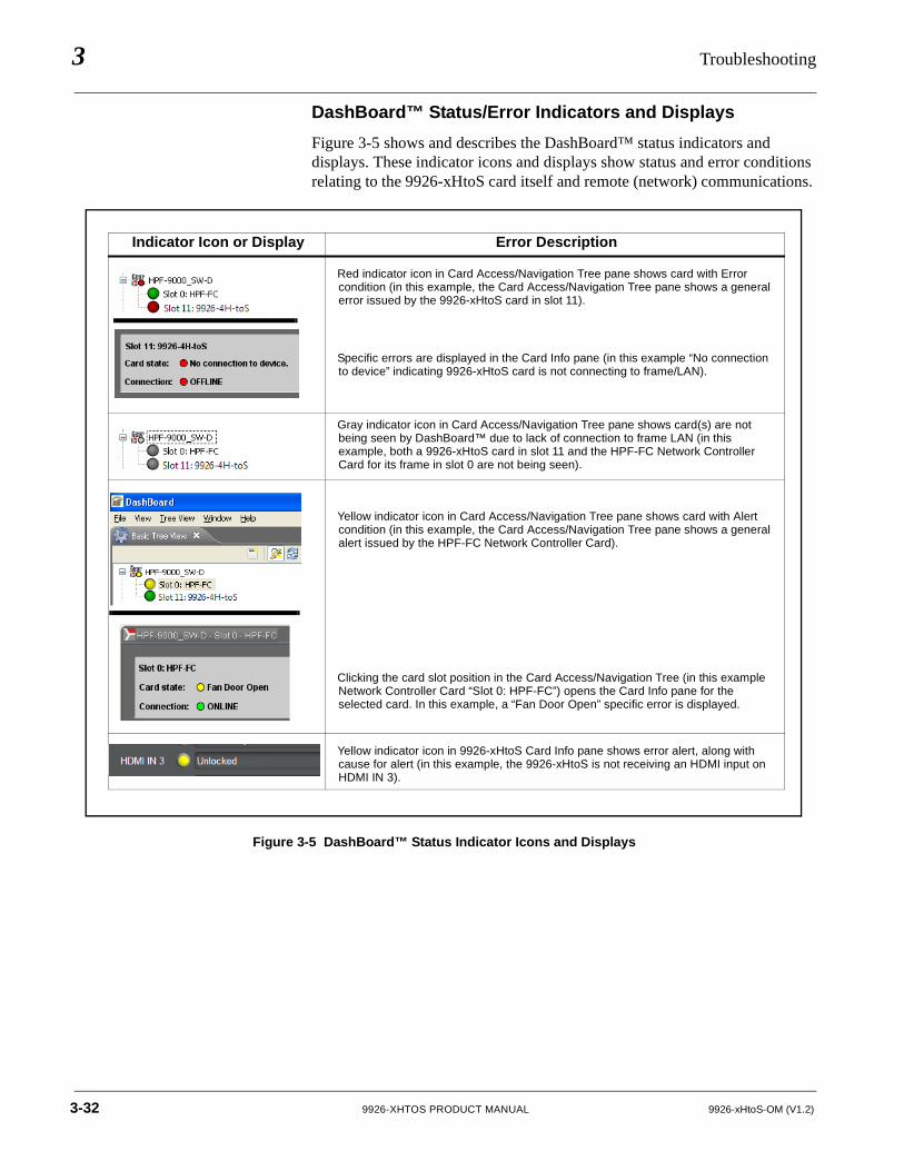
3 Troubleshooting
DashBoard™ Status/Error Indicators and Displays
Figure 3-5 shows and describes the DashBoard™ status indicators and displays. These indicator icons and displays show status and error conditions relating to the 9926-xHtoS card itself and remote (network) communications.
Figure 3-5 DashBoard™ Status Indicator Icons and Displays
Indicator Icon or Display Error Description
Red indicator icon in Card Access/Navigation Tree pane shows card with Error condition (in this example, the Card Access/Navigation Tree pane shows a general error issued by the 9926-xHtoS card in slot 11).
Specific errors are displayed in the Card Info pane (in this example “No connection to device” indicating 9926-xHtoS card is not connecting to frame/LAN).
Gray indicator icon in Card Access/Navigation Tree pane shows card(s) are not being seen by DashBoard™ due to lack of connection to frame LAN (in this example, both a 9926-xHtoS card in slot 11 and the HPF-FC Network Controller Card for its frame in slot 0 are not being seen).
Yellow indicator icon in Card Access/Navigation Tree pane shows card with Alert condition (in this example, the Card Access/Navigation Tree pane shows a general alert issued by the HPF-FC Network Controller Card).
Clicking the card slot position in the Card Access/Navigation Tree (in this example Network Controller Card “Slot 0: HPF-FC”) opens the Card Info pane for the selected card. In this example, a “Fan Door Open” specific error is displayed.
Yellow indicator icon in 9926-xHtoS Card Info pane shows error alert, along with cause for alert (in this example, the 9926-xHtoS is not receiving an HDMI input on HDMI IN 3).
3-32 9926-XHTOS PRODUCT MANUAL 9926-xHtoS-OM (V1.2)
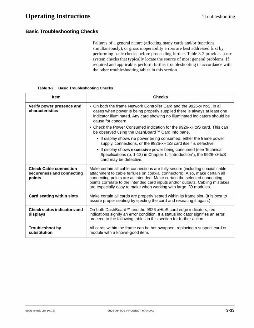
Operating Instructions Troubleshooting
Basic Troubleshooting Checks
Failures of a general nature (affecting many cards and/or functions simultaneously), or gross inoperability errors are best addressed first by performing basic checks before proceeding further. Table 3-2 provides basic system checks that typically locate the source of most general problems. If required and applicable, perform further troubleshooting in accordance with the other troubleshooting tables in this section.
Table 3-2 Basic Troubleshooting Checks
Item Checks
Verify power presence and characteristics
• On both the frame Network Controller Card and the 9926-xHtoS, in all cases when power is being properly supplied there is always at least one indicator illuminated. Any card showing no illuminated indicators should be cause for concern.
• Check the Power Consumed indication for the 9926-xHtoS card. This can be observed using the DashBoard™ Card Info pane.
• If display shows no power being consumed, either the frame power supply, connections, or the 9926-xHtoS card itself is defective.
• If display shows excessive power being consumed (see Technical Specifications (p. 1-13) in Chapter 1, “Introduction”), the 9926-xHtoS card may be defective.
Check Cable connection secureness and connecting points
Make certain all cable connections are fully secure (including coaxial cable attachment to cable ferrules on coaxial connectors). Also, make certain all connecting points are as intended. Make certain the selected connecting points correlate to the intended card inputs and/or outputs. Cabling mistakes are especially easy to make when working with large I/O modules.
Card seating within slots Make certain all cards are properly seated within its frame slot. (It is best to assure proper seating by ejecting the card and reseating it again.)
Check status indicators and displays
On both DashBoard™ and the 9926-xHtoS card edge indicators, red indications signify an error condition. If a status indicator signifies an error, proceed to the following tables in this section for further action.
Troubleshoot by substitution
All cards within the frame can be hot-swapped, replacing a suspect card or module with a known-good item.
9926-xHtoS-OM (V1.2) 9926-XHTOS PRODUCT MANUAL 3-33
3 Troubleshooting
Troubleshooting Network/Remote Control Errors
Refer to Cobalt® reference guide “Remote Control User Guide” (PN 9000RCS-RM) for network/remote control troubleshooting information.
In Case of Problems
Contact and Return Authorization
Should any problem arise with this product that was not solved by the information in this section, please contact the Cobalt Digital Inc. Technical Support Department.
If required, a Return Material Authorization number (RMA) will be issued to you, as well as specific shipping instructions. If required, a temporary replacement item will be made available at a nominal charge. Any shipping costs incurred are the customer’s responsibility. All products shipped to you from Cobalt Digital Inc. will be shipped collect.
The Cobalt Digital Inc. Technical Support Department will continue to provide advice on any product manufactured by Cobalt Digital Inc., beyond the warranty period without charge, for the life of the product.
See Contact Cobalt Digital Inc. (p. 1-16) in Chapter 1, “Introduction“ for contact information.
3-34 9926-XHTOS PRODUCT MANUAL 9926-xHtoS-OM (V1.2)


Cobalt Digital Inc.
2506 Galen DriveChampaign, IL 61821Voice 217.344.1243 • Fax 217.344.1245www.cobaltdigital.com
9926-xHtoS-OM (V1.2) Printed in USA


