Embed Size (px)
Citation preview

Development of a Robust and Cost-Effective Friction StirWelding Process for Use in Advanced Military Vehicles
M. Grujicic, G. Arakere, B. Pandurangan, A. Hariharan, C.-F. Yen, and B.A. Cheeseman
(Submitted February 5, 2010)
To respond to the advent of more lethal threats, recently designed aluminum-armor-based military-vehiclesystems have resorted to an increasing use of higher strength aluminum alloys (with superior ballisticresistance against armor piercing (AP) threats and with high vehicle-light weighing potential). Unfortu-nately, these alloys are not very amenable to conventional fusion-based welding technologies and in-order toobtain high-quality welds, solid-state joining technologies such as Friction stir welding (FSW) have to beemployed. However, since FSW is a relatively new and fairly complex joining technology, its introductioninto advanced military vehicle structures is not straight forward and entails a comprehensive multi-stepapproach. One such (three-step) approach is developed in the present work. Within the first step, experi-mental and computational techniques are utilized to determine the optimal tool design and the optimalFSW process parameters which result in maximal productivity of the joining process and the highestquality of the weld. Within the second step, techniques are developed for the identification and qualificationof the optimal weld joint designs in different sections of a prototypical military vehicle structure. In thethird step, problems associated with the fabrication of a sub-scale military vehicle test structure and theblast survivability of the structure are assessed. The results obtained and the lessons learned are used tojudge the potential of the current approach in shortening the development time and in enhancing reliabilityand blast survivability of military vehicle structures.
Keywords aluminum, automotive, joining, welding
1. Introduction
Friction stir welding (FSW) is a solid-state metal-joiningprocess that was invented in 1991 at The Welding Institute inthe United Kingdom (Ref 1). FSW can be used to produce butt,corner, lap, T, spot, fillet, and hem joints, as well as to weldhollow objects, such as tanks and tubes/pipes, stock withdifferent thicknesses, tapered sections and parts with three-dimensional contours. This welding process is particularlysuited for butt and lap joining of aluminum alloys which areotherwise quite difficult to join using conventional arc/fusionwelding processes. FSW has established itself as a preferredjoining technique for aluminum components and its applica-tions for joining other difficult-to-weld metals are graduallyexpanding. Currently, this joining process is being widely usedin many industrial sectors such as shipbuilding and marine,aerospace, railway, land transportation, etc.
The basic concept behind FSW is described using theexample of butt welding, Fig. 1. As shown in Fig. 1, a non-consumable rotating tool moves along the contacting surfaces of
two rigidly butt-clamped plates. As seen in this figure, the toolconsists of a cylindrical pin which is threaded, at one end, andequipped with a shoulder, at the other. Also, during joining, thework-piece (i.e., the two clamped plates) is generally placed on arigid backing support. At the same time, the shoulder is forced tomake a firm contact with the top surface of the work-piece. Asthe tool rotates and moves along the butting surfaces, heat isbeing generated at the shoulder/work-piece and, to a lesserextent, at the pin/work-piece contact surfaces, as a result of thefrictional-energy dissipation. This, in turn, causes an increase intemperature and gives rise to softening of the material adjacentto these contacting surfaces. As the tool advances along thebutting surfaces, thermally softened material in front of the toolis (heavily) deformed, extruded around the tool to the regionbehind the tool and compacted/forged to form a joint/weld.
Relative to the traditional fusion-welding technologies,FSW offers a number of advantages such as:
(a) good mechanical properties in the as-welded conditionand substantial improvements in the consistency ofweld quality (even in those alloys that are considerednon-weldable by conventional techniques);
(b) improved safety due to the absence of toxic fumes orthe spatter of molten material;
(c) no consumables such as the filler metal or gas shieldare required;
(d) ease of process automation;(e) ability to operate in all positions (horizontal, vertical,
overhead, orbital, etc.), as there is no weld pool;(f) minimal thickness under/over-matching which reduces
the need for expensive post-weld machining;(g) low environmental impact;
M. Grujicic, G. Arakere, B. Pandurangan, and A. Hariharan,Department of Mechanical Engineering, Clemson University,Clemson, SC 29634; and C.-F. Yen and B.A. Cheeseman, ArmyResearch Laboratory, Survivability Materials Branch, Aberdeen,Proving Ground, MD 21005-5069. Contact e-mails: [email protected] and [email protected].
JMEPEG (2011) 20:11–23 �ASM InternationalDOI: 10.1007/s11665-010-9650-0 1059-9495/$19.00
Journal of Materials Engineering and Performance Volume 20(1) February 2011—11

(h) aluminum-alloy welds in a 0.02-3.0 in range can beproduced and, typically, in a single pass;
(i) dissimilar aluminum-alloy grades (e.g., AA6061 toAA5083), wrought and cast aluminum alloys, as wellas aluminum matrix composites can be readily FSWed;
(j) due to lower attendant temperatures, the residual stres-ses and distortions are substantially reduced in compar-ison to those encountered in traditional arc weldingprocesses;
(k) the innermost zone of the FSW joint typically consistsof a fine equiaxed grain structure which may possesssuperior impact resistance properties;
(l) a complete absence of filler-induced defects (since,FSW is a filler-less process) and hydrogen-embrittlementcracking (since no hydrocarbon fuel is used);
(m) the joining process can be carried out by using modi-fied traditional machine tool technologies;
(n) replacement of fastened joints with FSW joints canlead to significant weight reduction and cost savings;
(o) since FSW is a solid-state process, the joint is free ofsolidification-induced defects and, consequently, certain2xxx and 7xxx aluminum alloys which are difficult tojoin using conventional fusion welding processes canbe readily FSWed.
Unfortunately, the FSW technology is burdened by severaldisadvantages such as:
(a) an exit hole is left after the tool is withdrawn from thework-piece;
(b) relatively large tool press-down and plates-clampingforces are required;
(c) lower flexibility of the process with respect to variable-thickness and non-linear welds;
(d) often associated with lower welding rates than conven-tional fusion-welding techniques, although this short-coming is somewhat lessened since fewer weldingpasses are required; and
(e) FSW equipment cost is typically significantly higherthan the equipment cost encountered in most traditionalfusion welding processes. This disadvantage is some-what mitigated by the associated lower labor cost andby a lower need for skilled labor.
Recent efforts of the U.S. Army have been aimed atbecoming more mobile, deployable, and sustainable whilemaintaining or surpassing the current levels of lethality andsurvivability. Current battlefield vehicles have reached inexcess of 70 tons due to ever increasing lethality of ballistic
threats which hinders their ability to be readily transported andsustained. Therefore, a number of research and developmentprograms are under way to engineer light-weight, highlymobile, transportable, and lethal battlefield vehicles with atarget weight under 20 tons. To attain these goals, significantadvances are needed in the areas of light-weight structural- andarmor-materials development (including aluminum-based struc-tural/armor-grade materials).
Historically, aluminum alloy AA5083-H131 has been usedin military-vehicle systems such as the M1113 and the M109, inaccordance with the MIL-DTL-46027J specification (Ref 2).The main reasons for the selection of this alloy are its lighterweight, ease of joining by various welding techniques,a relatively high level of performance against fragmentation-based threats, and superior corrosion resistance.
To respond to the advent of more lethal threats, recentlydesigned aluminum-armor-based military-vehicle systems, suchas the M2 Bradley Fighting Vehicle, have relied on the use ofhigher strength aluminum alloys, such as AA2139 (Ref 3),AA7039 (Ref 4), AA2219 (Ref 5), and AA2519 (Ref 6). Thesealloys provide increased ballistic protection against armorpiercing (AP) threats due to their higher dynamic strength. Inaddition, higher quasi-static tensile strength levels offered bythese alloys are very desirable for vehicle-hull designs as theyenable significant reductions in the vehicle weight. However,these alloys also show some significant shortcomings primarilydue to their lower fusion-based weldability and inferior corro-sion resistance in comparison to that observed in AA5083-H131.Fortunately, there are efficient remedies for these shortcomings:The low corrosion-resistance shortcomings can be, in general,overcome through the use of various coating and claddingtechnologies (not the subject of the present work), while the lowweldability shortcomings can be addressed using FSW (the mainsubject of the present work). However, since FSW is a relativelynew and fairly complex joining technology, its introduction intoadvanced military vehicle structures is not straight forward andentails a comprehensive multi-prong approach. Development ofone such approach is the subject of the present work.
Within the present approach, the three main stages for theintroduction of FSW process into advanced military vehiclestructures are identified as:
(a) Determination of the optimal tool design and the optimalFSW process parameters which result in maximal pro-ductivity of the joining process (as measured by the tooltravel speed) and the highest quality of the weld (asquantified by the weld mechanical properties and theirreproducibility), for a given choice of the high-strengthaluminum-alloy grades being welded. As will be shownlater, at this stage the traditional experimentally basedprocess-development efforts are complimented by anextensive program of weld-material property character-ization/testing and thermal/mechanical computationalanalyses which can help establish correlations betweenthe FSW process parameters and the weld microstruc-ture/mechanical properties;
(b) Identification of the optimal weld joint design for differ-ent sections of the military vehicle structures and employ-ment of experimental test procedures (e.g., ballistic shocktest, discussed later) to qualify the welded joints; and
(c) Fabrication of a sub-scale military vehicle test structureand the employment of experimental techniques toaccess their blast survivability.
Fig. 1 A schematic of the friction stir welding (FSW) process
12—Volume 20(1) February 2011 Journal of Materials Engineering and Performance

The organization of the paper is as follows: A detaileddescription of the FSW process parameters (including weld toolgeometry), weld material microstructure spatial distribution andtemporal evolution as well as correlations between the FSWprocess parameters and the weld-material microstructure/properties are all discussed in Section 2. Details pertaining tothe design and testing of FSW joints for use in military vehiclestructures are presented in Section 3. A brief discussionregarding the fabrication and blast-survivability testing of thesub-scale military vehicle test structure is provided in Sec-tion 4. It should be noted that due to the sensitive nature of thesubject matter and for the potential misuse of the findingsobtained in the present work, some critical quantitative resultshad to be left out. The main conclusions resulting from thepresent study are summarized in Section 5.
2. FSW Process and Weld Joint Material Analysis
2.1 FSW Process
2.1.1 Mass/Heat Transport and Thermo-mechanicalAspects. FSW normally involves complex interactions andcompetition between various thermo-mechanical processessuch as frictional-energy dissipation, plastic deformation, andthe associated heat dissipation, material transport/flow, dynamicrecrystallization, local cooling, etc. (Ref 7-14). A uniquefeature of the FSW process is that heat transfer does not onlytake place via thermal conduction but also via transport of thework-piece material adjacent to the tool from the region in frontto the region behind the advancing tool. In general both the heatand the mass transfer depend on the work-piece materialproperties, tool geometry, and the FSW process parameters. Aswill be discussed later in greater details, mass transport isaccompanied by extensive plastic deformation and dynamicrecrystallization of the transported material. The attendantstrain rates as high as 10 s�1 have been assessed/measured(Ref 15, 16).
2.1.2 Process Parameters. The main FSW processparameters which affect both the weld quality and the processefficiency are: (a) rotational and transverse velocities of thetool; (b) tool-plunge depth; (c) tool tilt-angle; and (d) tool-design/material. Since, in-general, higher temperatures areencountered in the case of higher rotational and lowertransverse tool velocities, it is critical that a delicate balancebetween these two velocities is attained. In other words, whenthe temperatures are not high enough and the material has notbeen sufficiently softened, the weld zone may develop variousflaws/defects arising from low ductility of the material.Conversely, when the temperatures are too high undesirablechanges in the material microstructure/properties may takeplace and possibly incipient-melting flaws may be createdduring joining. To ensure that the necessary level of shoulder/work-piece contact pressure is attained and that the tool fullypenetrates the weld, the tool-plunge depth (defined as the depthof the lowest point of the shoulder below the surface of thewelded plate) has to be set correctly. Typically, insufficient tool-plunge depths result in low-quality welds (due to inadequateforging of the material at the rear of the tool), while excessivetool-plunge depths lead to under-matching of the weld thick-ness compared to the base-materials thickness. Tool rearwardtilting by 2-4 degrees has been often found to be beneficialsince it enhances the effect of the forging process.
Tool design is one of the most important factors thatinfluences the FSW joint profile as well as the weld materialmicrostructure and properties. Initially, one-piece steel toolswere used with both the pin and the shoulder having a (smooth-surface) right circular cylindrical geometry. Consequently, onlylimited material flow and mixing were produced. The two-pieceFSW tools used today typically contain (flat-ended) threaded,fluted, and/or frustum (with flats) pin designs which promotematerial transport around the tool as well as in the work-piecethrough-the-thickness direction. This, in turn, enables higherweld speeds and higher quality void free weld joints. Inaddition, current FSW tools contain scrolled shoulders whicheliminates the need for the aforementioned tool tilting (facilitatewelding around corners and production of non-linear welds),weld surface undercutting and the flash that extrudes under thetool shoulder. Novel FSW tools often contain non-circular (e.g.,oval, paddle, etc.) cross sections to increase the volume ofstirred material and improve weld properties. Tool design isprobably the most guarded secret in FSW community, ascompanies/researchers are generally reluctant to disclose tool-ing information.
2.1.3 Weld Advancing and Retreating Sides. Whenanalyzing the FSW process, one often makes a distinctionbetween the so-called advancing side of the weld (the side onwhich the peripheral velocity of the rotating tool coincides withthe transverse velocity of the tool) and the retreating side (theside on which the two velocities are aligned in the oppositedirections). It is generally recognized that the differences in thetwo weld sides give rise to asymmetry in heat transfer, materialflow, and weld microstructure-properties (Ref 17).
2.2 Weld Material Microstructure/Property Distributionand Evolution
2.2.1 Weld Zones and Associated Microstructure Char-acteristics. Metallographic examinations of the FSW jointstypically reveal the existence of the following four zones,Fig. 2:
(a) an un-effected zone which is far enough from the weldso that material microstructure/properties are not alteredby the joining process;
(b) the heat-affected zone (HAZ) in which material micro-structure/properties are effected only by the thermal ef-fects associated with FSW. While this zone is normallyfound in the case of fusion-welds, the nature of themicrostructural changes may be different in the FSWcase due to generally lower temperatures and a morediffuse heat source;
(c) the thermo-mechanically affected zone (TMAZ) whichis located closer than the HAZ zone to the butting
Fig. 2 A schematic of the four microstructural zones associatedwith the typical FSW joint
Journal of Materials Engineering and Performance Volume 20(1) February 2011—13

surfaces. Consequently both the thermal and themechanical aspects of the FSW affect the materialmicrostructure/properties in this zone. Typically, the ori-ginal grains are retained in this zone although they mayhave undergone severe plastic deformation; and
(d) the weld nugget is the innermost zone of an FSW joint.As a result of the way the material is transported fromthe regions ahead of the tool to the wake regions behindthe tool, this zone typically contains the so called‘‘onion-ring’’ features. The material in this region hasbeen subjected to most severe conditions of plasticdeformation and high temperature exposure and conse-quently contains a very-fine dynamically recrystallizedequiaxed grain microstructure.
2.2.2 Weld Microstructure Evolution During FSW Pro-cess. As clearly demonstrated in our prior work (Ref 18),while weld-microstructure evolution will vary with the choiceof base materials and FSW process parameters, these changesshow some clear differences between non-heat treatable (nonage-hardenable) and heat treatable aluminum-alloy grades.Specifically, in the case of non-age-hardenable alloys (e.g.,AA5083), the dominant microstructure evolution processestaking place during FSW are extensive plastic deformation anddynamic recrystallization of highly deformed material sub-jected to elevated temperatures approaching the solidustemperature of the alloy. On the other hand, in the case ofage-hardenable alloys (e.g., AA2139), in addition to plasticdeformation and dynamic recrystallization, precipitate coars-ening, over-aging, dissolution, and re-precipitation typicallytake place.
2.2.3 Weld Microstructure/Property Relations. Takinginto account the basic physical metallurgy aspects of the alloysbeing welded and considering the aforementioned spatialdistribution and temporal evolution of the weld-materialmicrostructure, it is to be expected that local material properties(in particular mechanical properties) may vary over the weldjoint.
In the case of non-heat treatable aluminum alloys materialstrength (and ductility) is controlled by the following strength-ening mechanisms:
(a) Solid Solution Strengthening: This hardening mechanismis present in all four weld-zones and its contribution tothe material hardness is expected to be fairly uniformacross the entire weld region;
(b) Strain Hardening: When a non-heat treatable alloy iscold worked, strain hardening mechanism provides acontribution to the material hardness in the base-metalzone which is larger than the contributions of the othertwo mechanisms. In the HAZ, some annealing will takeplace. However, since this annealing is primarily due torecovery or polygonization, the contribution of strainhardening to the material hardness in this region willremain quite comparable to that in the base metalregion. The contribution of strain hardening to the over-all material hardness in the TMAZ is expected toincrease since the material in this region typically expe-riences significant levels of plastic deformation. In theweld nugget region, material microstructure and proper-ties are dominated by dynamic recrystallization and,hence, the contribution of strain hardening to the overallmaterial hardness in this region is minimal; and
(c) Grain Size Refinement: Since, to a first-order approxima-tion, the average grain size does not change between thebase-metal zone, the HAZ and the TMAZ, the contribu-tion of this strengthening mechanism to the overallmaterial strength is expected to be comparable in thesethree weld-zones. On the other hand, dynamic recrystal-lization yields a very fine grain structure within thenugget zone so that the overall contribution of the grain-refinement mechanism to the material hardness isexpected to be largest in this weld zone.
In the case of heat treatable aluminum alloys materialstrength (and ductility) is controlled by the following strength-ening mechanisms: (a) precipitation hardening; (b) strainhardening; and (c) grain-size refinement. Relative importanceof the strain hardening and the grain-size refinement mecha-nisms within the four weld-zones was discussed earlier in thecontext of non-heat treatable alloys. The main points made atthat time are equally valid in the case of heat-treatable alloys. Asfar as the role of the precipitation hardening mechanism in heat-treatable alloys is concerned, the following main observationscan be made. Typically in heat-treatable alloys, precipitationhardening provides a contribution to the material hardness in thebase-metal zone which is larger than the contributions of theother two mechanisms. In general, material exposure to high-temperatures within the remaining three main weld-zonescauses over-aging and the associated loss in material strength.This loss increases in its extent as one approaches the originalweld-line, i.e., as one moves through the HAZ, then through theTMAZ and ultimately through the weld nugget.
2.3 Correlation Between FSW-Process Parametersand Weld Joint Material Performance
2.3.1 Experimental Approach. Over the last two dec-ades, considerable experimental research efforts have beeninvested toward providing a better understanding of the FSWjoining mechanism and the accompanying evolution of thewelded-materials microstructure/properties (e.g. Ref 19-22) aswell as to rationalizing the effect of various FSW processparameters on the weld quality/integrity (e.g. Ref 10, 23-25). Itshould be recognized, however, that the aforementioned exper-imental efforts were able to only correlate the post-mortemwelded-materials microstructure/properties with the FSW pro-cess parameters and provided relatively little real-time insightinto the physics of heat/mass transfer and microstructure-evolution processes. As shown in our previous work (Ref 26),this insight can be gained by carrying out a detailed physicallybased computational analysis of the FSW process. Nevertheless,experimental techniques involving weld-material microstructureand property characterizations for FSW joints obtained undervarious combinations of process parameters and the toolgeometry remain invaluable for calibration and validation ofthe aforementioned computational-based analyses. The weldmaterial microstructure characterization techniques typicallyinclude optical, scanning-electron and transmission-electronmicroscopies, and x-ray diffraction analysis. Among the weld-material mechanical property characterization techniques themost widely used are transverse tensile tests, all-weld longitu-dinal tensile test and a transverse bend test (Ref 27).
2.3.2 Computational Approach. A detailed review ofthe prior research efforts dealing with computational investi-gations of the FSW process reported in the public domain
14—Volume 20(1) February 2011 Journal of Materials Engineering and Performance

literature was conducted in our previous work (Ref 26). Hence,no overview of the prior computational FSW research effortswill be presented here. Instead, a brief overview will beprovided of our recent fully coupled thermo-mechanical finite-element analysis of the FSW process which combines the mass,momentum, and heat-transfer conservation equations with thebasic physical metallurgy (microstructure evolution) of thealuminum alloy grades being FSWed (Ref 26). Within thisanalysis, various microstructure-evolution processes takingplace during FSW (e.g., extensive plastic-deformation inducedgrain-shape distortion and dislocation-density increase,dynamic recrystallization, and precipitates coarsening, over-aging, dissolution, and re-precipitation) are considered topredict the material microstructure/properties in the variousFSW zones of the alloys being welded. For each of theaforementioned microstructure evolution processes, the appro-priate material state variables are introduced and their evolutionequations constructed and parameterized (using available openliterature sources pertaining to the kinetics of the microstructureevolution processes). Next, the thermo-mechanical constitutivemodel for the alloys being FSWed is modified to include theeffect of the local material microstructure. This procedureenabled examination of the two-way interactions between theFSW process and the weld-material microstructure evolution.In other words, both the effect of the current materialmicrostructure on its thermo-mechanical response during theFSW process and the effects of thermo-mechanical history of amaterial point during the FSW process on the associatedmicrostructure could be analyzed.
In the remainder of this section a few typical FSW processsimulation results obtained using our FSW model (Ref 26) arepresented and briefly discussed.
Equivalent Plastic Strain Field. An example of the typicalresults pertaining to spatial distribution and temporal evolutionof the equivalent plastic strain in the work-piece during FSW isdisplayed in Fig. 3(a-d). Simple examination of the results likethe ones displayed in these figures but generated under differentFSW process conditions reveals that: (a) depending on the FSWprocess conditions such as tool contact pressure, tool rotational
and translational speeds, equivalent plastic strains in a rangebetween 20 and 50 are observed; (b) the highest equivalentplastic strains are always found in the work-piece materialright below the tool shoulder and equivalent plastic strainsprogressively decreased from this region as a function of thedistance in the radial and through-the-thickness directions;(c) there is a highly pronounced asymmetry in the distribu-tion of the equivalent plastic strain relative to the initiallocation of the butting surfaces. This asymmetry is related tothe aforementioned differences in the material transport (atthe advancing and the retreating sides of the weld) from theregion ahead of the tool to the region behind the tool; and(d) as the tool translational speed is decreased and the tool/work-piece contact pressure is increased, higher equivalentplastic strains are observed and equivalent plastic straindifferences between the top and bottom surfaces of the workpiece are reduced. This finding suggests that under theseFSW process conditions the extent of material stirring/mixing(which plays a critical role in weld quality/joint-strength) isincreased.
Nodal Velocity Field. The distribution of nodal velocities at theouter surfaces of the work-piece at two different times (0.0 and0.5 s) is displayed in Fig. 4(a-b). For clarity, the tool is notshown. These figures clearly show that the initially assignedunidirectional velocity field (to the work-piece material withinthe Arbitrary-Lagrangian-Eulerian (ALE) finite-element formu-lation used in Ref 26) in the direction of welding, quicklytransforms into the velocity field in which there is a well-defined stir region right below the shoulder (within which thematerial circles around the pin) and the remainder of the field(within which the material tends to flow around the stir region).A comparison of the results displayed in Fig. 4(a-b) clearlyshows how the region underneath the tool shoulder which isinitially unfilled becomes filled as FSW proceeds (please notean increase in the work-piece hole upper-rim altitude). Once thespace under the shoulder is fully filled it remains filled as theFSW process continues. The material in this region isconstantly being refreshed as the tool advances in the weldingdirection.
Fig. 3 Typical results pertaining to spatial distribution and temporal evolution of the equivalent plastic strain during FSW: (a) zero-time step;(b) at the end of tool-insertion; (c) 7 s afterwards; and (d) 14 s afterwards. Equivalent-plastic strain range: 0.0 (blue) to 50.0 (red)
Journal of Materials Engineering and Performance Volume 20(1) February 2011—15
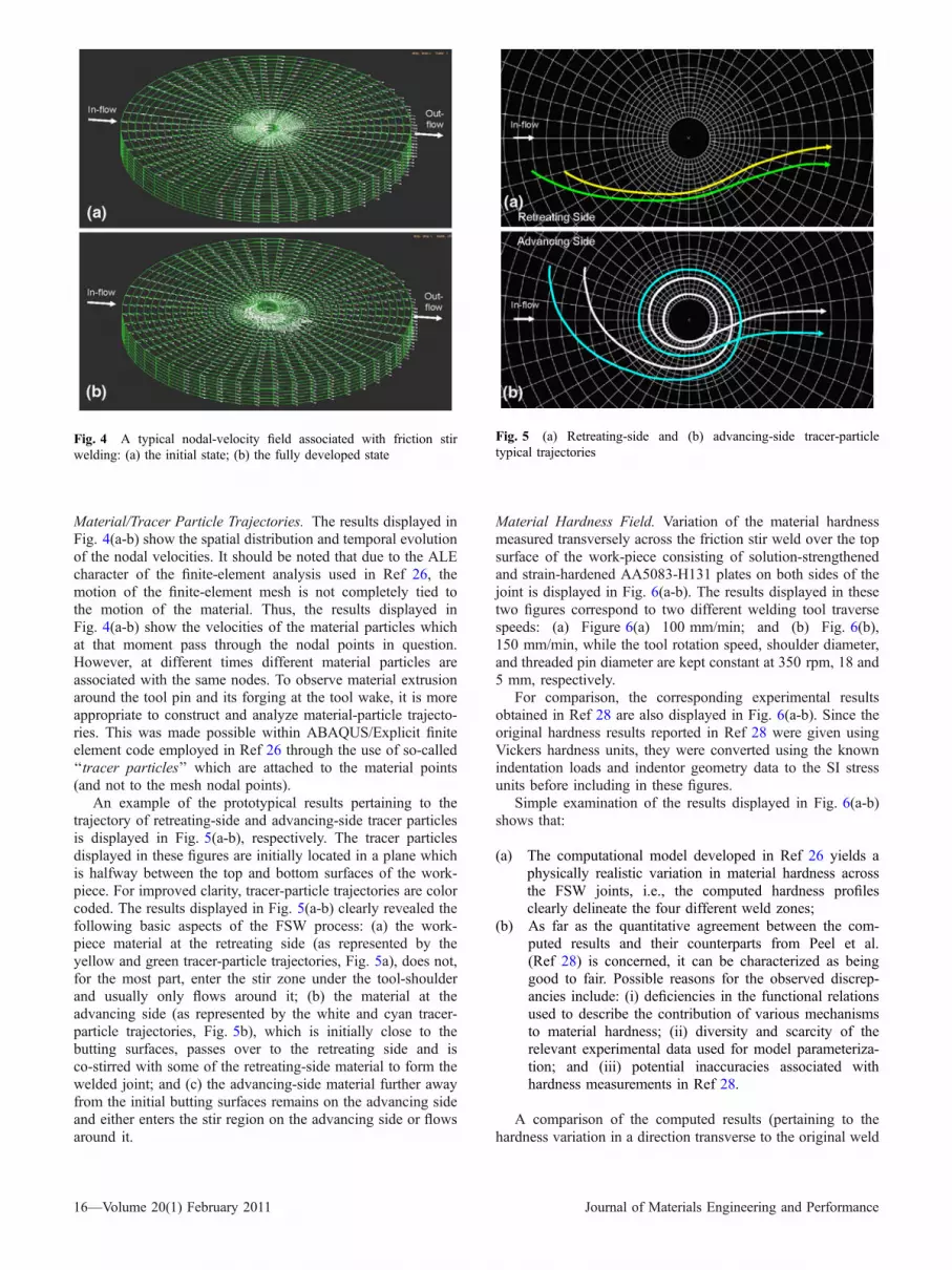
Material/Tracer Particle Trajectories. The results displayed inFig. 4(a-b) show the spatial distribution and temporal evolutionof the nodal velocities. It should be noted that due to the ALEcharacter of the finite-element analysis used in Ref 26, themotion of the finite-element mesh is not completely tied tothe motion of the material. Thus, the results displayed inFig. 4(a-b) show the velocities of the material particles whichat that moment pass through the nodal points in question.However, at different times different material particles areassociated with the same nodes. To observe material extrusionaround the tool pin and its forging at the tool wake, it is moreappropriate to construct and analyze material-particle trajecto-ries. This was made possible within ABAQUS/Explicit finiteelement code employed in Ref 26 through the use of so-called‘‘tracer particles’’ which are attached to the material points(and not to the mesh nodal points).
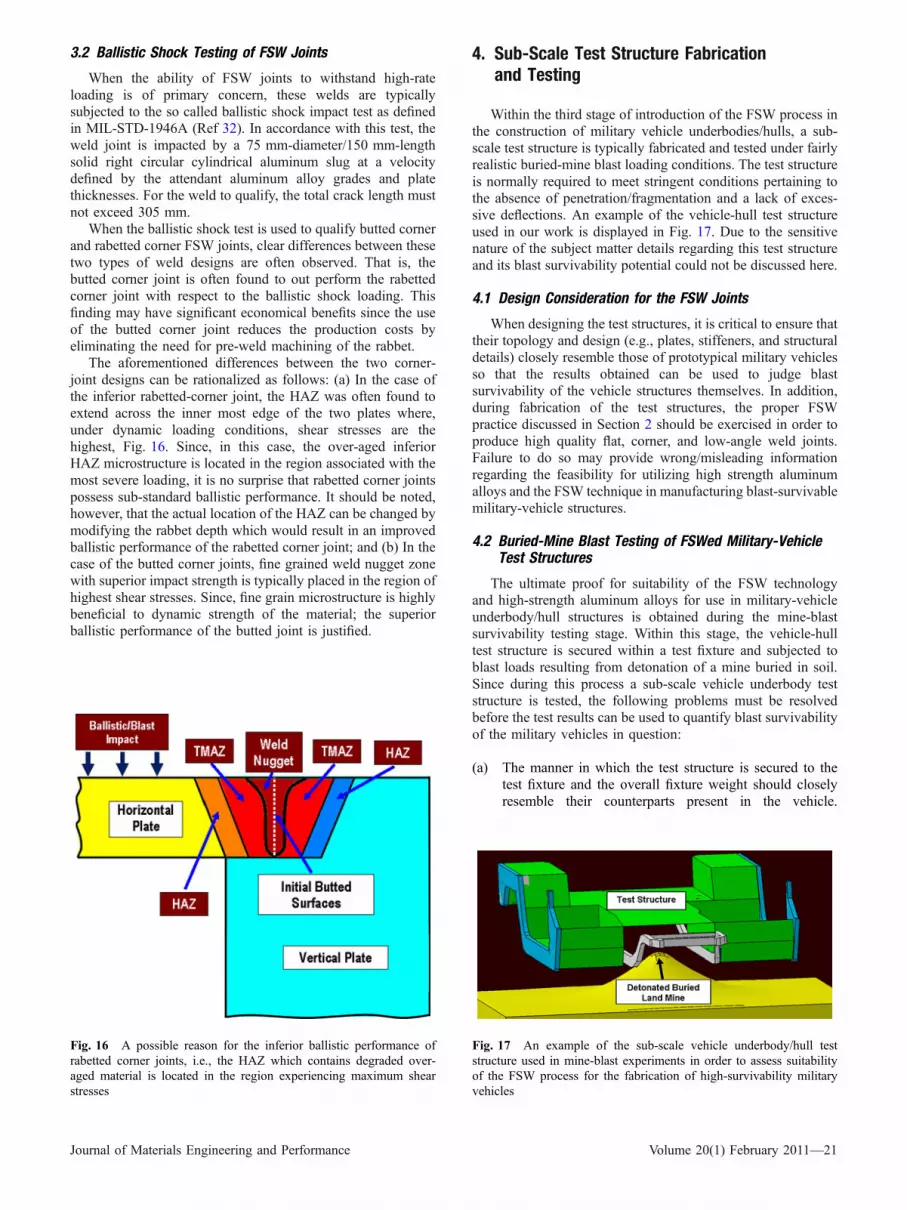
An example of the prototypical results pertaining to thetrajectory of retreating-side and advancing-side tracer particlesis displayed in Fig. 5(a-b), respectively. The tracer particlesdisplayed in these figures are initially located in a plane whichis halfway between the top and bottom surfaces of the work-piece. For improved clarity, tracer-particle trajectories are colorcoded. The results displayed in Fig. 5(a-b) clearly revealed thefollowing basic aspects of the FSW process: (a) the work-piece material at the retreating side (as represented by theyellow and green tracer-particle trajectories, Fig. 5a), does not,for the most part, enter the stir zone under the tool-shoulderand usually only flows around it; (b) the material at theadvancing side (as represented by the white and cyan tracer-particle trajectories, Fig. 5b), which is initially close to thebutting surfaces, passes over to the retreating side and isco-stirred with some of the retreating-side material to form thewelded joint; and (c) the advancing-side material further awayfrom the initial butting surfaces remains on the advancing sideand either enters the stir region on the advancing side or flowsaround it.
Material Hardness Field. Variation of the material hardnessmeasured transversely across the friction stir weld over the topsurface of the work-piece consisting of solution-strengthenedand strain-hardened AA5083-H131 plates on both sides of thejoint is displayed in Fig. 6(a-b). The results displayed in thesetwo figures correspond to two different welding tool traversespeeds: (a) Figure 6(a) 100 mm/min; and (b) Fig. 6(b),150 mm/min, while the tool rotation speed, shoulder diameter,and threaded pin diameter are kept constant at 350 rpm, 18 and5 mm, respectively.
For comparison, the corresponding experimental resultsobtained in Ref 28 are also displayed in Fig. 6(a-b). Since theoriginal hardness results reported in Ref 28 were given usingVickers hardness units, they were converted using the knownindentation loads and indentor geometry data to the SI stressunits before including in these figures.
Simple examination of the results displayed in Fig. 6(a-b)shows that:
(a) The computational model developed in Ref 26 yields aphysically realistic variation in material hardness acrossthe FSW joints, i.e., the computed hardness profilesclearly delineate the four different weld zones;
(b) As far as the quantitative agreement between the com-puted results and their counterparts from Peel et al.(Ref 28) is concerned, it can be characterized as beinggood to fair. Possible reasons for the observed discrep-ancies include: (i) deficiencies in the functional relationsused to describe the contribution of various mechanismsto material hardness; (ii) diversity and scarcity of therelevant experimental data used for model parameteriza-tion; and (iii) potential inaccuracies associated withhardness measurements in Ref 28.
A comparison of the computed results (pertaining to thehardness variation in a direction transverse to the original weld
Fig. 4 A typical nodal-velocity field associated with friction stirwelding: (a) the initial state; (b) the fully developed state
Fig. 5 (a) Retreating-side and (b) advancing-side tracer-particletypical trajectories
16—Volume 20(1) February 2011 Journal of Materials Engineering and Performance

line) and their experimental counterparts obtained in Ref 29 inthe case of two friction-stir-welded age-hardened AA2139plates is displayed in Fig. 7(a-b). The results displayed inFig. 7(a-b) correspond, respectively, to the hardness measure-ments over the top and bottom surfaces of the work piece. Inboth cases the same FSW process parameters (welding speed:100 mm/min; tool rotational speed: 350 rpm; shoulder diam-eter: 18 mm; and pin diameter: 5 mm) were used.
Simple examination of the results displayed in Fig. 7(a-b)shows that as in the case of AA5083, the computational modeldeveloped in Ref 26 provides physically realistic hardnessprofiles in a direction transversely oriented with respect to theweld (at different locations through the thickness of thework-piece).
Material Grain-Size Field. A comparison between the grain-size results obtained computationally in Ref 26 and their
experimental counterparts reported in Ref 30 is displayedin Fig. 8. Considering the fact that not all the FSW processparameters were specified in Ref 30, the level of agreementobserved in Fig. 8 can be judged as reasonable.
A comparison of the computed variation in the averagegrain-size across the FSW joint (Ref 26) and its experimentalcounterpart obtained in Ref 31 is displayed in Fig. 9. Theseresults pertain to the top surface of the work-piece. Simpleexamination of the results displayed in Fig. 9 shows that thecomputation/experiment agreement is comparable to thatobtained in the case of AA5083 (i.e., the agreement isreasonable).
Residual Stress Field. A comparison between the computed(Ref 26) and the experimentally measured (Ref 28) resultspertaining to variation of the longitudinal and transverseresidual stresses as a function of the distance from the initial
Fig. 6 A comparison between the computed and the experimentalhardness (transverse) profiles over the top surface of the 5083 workpiece. Please see the text for details regarding the friction stir weldparameters associated with the results displayed in (a) and (b). Datapertaining to the advancing side of the weld joint are on the right-hand side of the plot
Fig. 7 A comparison between the computed and experimentalhardness profiles over a transverse cut through the 2139 work pieceweld: (a) top surface of the work piece and (b) the bottom surface ofthe work piece. Please see the text for details regarding the frictionstir welding parameters. Data pertaining to the advancing side of theweld joint are on the right-hand side of the plot
Journal of Materials Engineering and Performance Volume 20(1) February 2011—17

location of the butting surfaces in AA5083 is displayedin Fig. 10(a-b). Two sets of computational results are presented:one based on the use of the original Johnson-Cook materialmodel while the other was based on the use of the modifiedJohnson-Cook model (Ref 26). Simple examination of theresults presented in Fig. 10(a-b) shows that the results based onthe modified Johnson-Cook model are in better agreement withthe experimental results. While some disagreement still existsbetween the computational results based on the modifiedJohnson-Cook model and the experimental results, the overallresidual stress distribution profile appears to be reasonably
well reproduced by the computational analysis (Ref 26).Specifically:
(a) The residual stresses are compressive at larger distancesfrom the weld-line at the advancing side of the weld(the right-hand side in Fig. 10a-b);
(b) As one approaches the weld-line at the advancing side,the residual stresses first increase in magnitude and thenswitch their character (i.e., becomes tensile), at a dis-tance of 15-20 mm from the weld-line (at the advancingside);
(c) In the innermost portion of the nugget, the tensile resid-ual stresses tend to decrease somewhat;
(d) As the distance from the weld-line increases on theretreating side, the stresses gradually decrease towardzero; and
(e) The longitudinal residual stresses are generally higherthan their transverse counterparts.
Fig. 8 A comparison between the computed and experimentalgrain-size profiles over the top surface of the 5083 work piece. Datapertaining to the advancing side of the weld joint are on the right-hand side of the plot
Fig. 9 A comparison between the computed and experimentalgrain-size profiles over the top surface of the 2139 work piece. Datapertaining to the advancing side of the weld joint are on the right-hand side of the plot
Fig. 10 Variation of the: (a) longitudinal and (b) transverse residualstresses as a function of the distance from the weld-line in 5083.Data pertaining to the advancing side of the weld joint are on theright-hand side of the plot
18—Volume 20(1) February 2011 Journal of Materials Engineering and Performance

2.4 FSW Process and Weld Tool Optimization
When coupled with conventional Design of Experiments(DOE) and/or Design Optimization (DO) techniques, theexperimental and computational analyses overviewed in theprevious section can be used to identify an optimal combinationof the FSW process parameters and tool design geometrical/material parameters for a given choice of the aluminum-alloygrades and plate thicknesses. While attempting to identifyoptimal FSW process and weld-tool parameters, the emphasis isplaced on maximizing the manufacturing efficiency of thejoining process (as quantified by the tool travel speed),maximizing the quality of the FSW joint (as quantified by thematerial mechanical properties and their consistency) andminimizing the forces which must be applied to the tool and thework piece during the welding process (primarily the axial tool-driving and the transverse work-piece clamping forces).
2.4.1 FSW Process Optimization. The optimal FSWprocess parameters (for a given tool design and the choice ofthe aluminum-alloy grades and plate thicknesses), are generallydetermined by employing the computational analyses like theone reported in Ref 26. An example output from such analysesis displayed in Fig. 11 in which a thermal foot-print at the frontand rear of the shoulder of the weld tool are shown.Temperature distribution within the foot-print and the knowl-edge of the material solidus temperature (the lowest temper-ature at which melting is observed) and the effect oftemperature on the material strength are used to determine theoptimal FSW process parameters.
This procedure typically reveals that (for a given tooldesign, the rotational speed of the tool and the choice of thealuminum alloy grades and plate thicknesses), there is anoptimal range of the tool traverse speeds. Tool travel speedsexceeding this range typically give rise to the formation of low-ductility flaws within the weld, while, for tool speeds below this
range, microstructural defects associated with excessive heatingare often observed. Within this range lower velocities typicallycause HAZ to possess over-aging induced inferior microstruc-ture/properties (i.e., welds typically fracture in this weld zone).On the other hand, in the upper region of the optimal tool-speedrange, failure typically occurs within the weld nugget region(since, material over-aging within the HAZ is less pronouncedand the properties less degraded).
2.4.2 FSW Tool-Design Optimization. The problem offinding the optimal design of the weld tool is generally quitechallenging since the tool geometry can be quite complex andentails a large number of parameters for its full description.Typically, there is an optimal pin length an optimal pin-diameter to pin-length ratio as well as an optimal pin-diameterto shoulder-diameter ratio. In addition to these tool designparameters, there is a relatively large number of parameterswhich describe the pin shape (i.e., thread, flute, frustum withflats, etc.), and the shoulder shape (scroll, spiral etc.).
Typically, when high strength aluminum alloys are FSWed,the optimal weld-tool design involves a flat ended threaded,frustum-shaped pin profile with three-four equally spaced flatsmachined into the profiled surfaces and a scroll or spiralshoulder profile, Fig. 12. The flat end of the pin helps toproduce a better stir zone or weld nugget penetration to theback of the work-piece. The threaded portion of the pin bodypromotes material transport in the work-piece through-the-thickness direction while the frustum-shaped pin profilepromotes material extrusion around the tool and its forging inthe region behind the tool. The scroll shoulder design enableswelding without tilting the welding tool relative to the work-piece, which facilitates welding around corners.
3. FSW Weld Joint Design and Testing
3.1 Design Considerations for the FSW Joints
3.1.1 90o Corner Joints. Construction of complex struc-tural components such as military-vehicle underbodies/hullstypically involves not only in-plane (planar) but also out-of-plane (e.g., corner) joint configurations. Hence, one of thechallenges associated with the construction of these structures
Fig. 11 Typical temperature distribution over one-half of thework-piece obtained by cutting along: (a) the longitudinal; and(b) transverse directions: Maximum (red) = 400 �C; Minimum(blue) = 25 �C
Fig. 12 Typical optimal design of the FSW tool used for joininghigh-strength aluminum-alloy grades
Journal of Materials Engineering and Performance Volume 20(1) February 2011—19

is determination of the optimal weld joint configuration(s). Forexample, in the case of corner FSW joints, like the oneassociated with the joining of the vehicle floor section to theframe sidewalls, one can choose between a butted corner joint,Fig. 13(a), and a rabbeted corner joint, Fig. 13(b). Furthermore,in the latter case, the joint is characterized by a singlegeometrical design parameter (the rabbet depth), Fig. 13(b).
Each of the two aforementioned corner joints possess certainadvantages and shortcomings, e.g., while the butted corner jointrequires less pre-weld preparation (i.e., less or no machining isrequired for preparation of the weld surfaces), it entails specialtooling in-order to support the horizontal weld plate, Fig. 13(a).On the other hand, in the case of the rabbet corner weld jointwhich is commonly used in conventional arc welding, fixturingis less challenging but a segment between the horizontal andvertical members is left un-welded, Fig. 13(b). To obtain loadtransfer between the horizontal and vertical members in thisregion, it is a common arc welding practice to deposit a filletweld along the inner edge. As shown in Fig. 14, FSW alsoenables formation of a seam weld along the inner edge.
To identify the optimal FSW corner-joint configuration, itis a common practice to fabricate and test these joints.While, the mechanical response of these joints whensubjected to a variety of loading conditions can be, inprinciple, assessed computationally, these types of computa-tional analyses are not frequently employed. Instead, thewelds are qualified almost exclusively using experimentalmeans (e.g., the so called ballistic shock test described in thenext section).
3.1.2 Low Angle Out-of-Plane Joints. Military-vehicleunderbody/hull constructions often involve low angle out-of-plane joints (e.g., V-shaped hulls). While, it is, in principle,possible to produce such joints by directly welding theangled plates, the welding process is quite challenging andthe weld quality is often deficient. Consequently, it issuggested that machined or extruded angular transitionmembers be used in this case and that a single low-angleout-of-plane joint be replaced by two planar butt joints,Fig. 15(a) and (b).
3.1.3 Complex Three-Dimensional Weld Joints. Due tohigh complexity of the military-vehicle underbody/hullconstructions, FSW weld tool is often required to followintricate three-dimensional trajectories. Under such circum-stances, it is advantageous that the tool remains normal tothe outer surface of the plates being welded. As mentionedearlier, this can be attained, while ensuring a high quality ofthe weld, by using a scrolled shoulder. Also, to prevent therelative motion of the plates being welded and to ensuregood dimensional accuracy it is suggested that the sectionsbeing joined be Friction-stir tack welded prior to beingFSWed.
Fig. 13 Two designs of corner joints most often in conjunctionwith the FSW process: (a) butted corner joint; and (b) rabetted cor-ner joint
Fig. 14 Joining of the 90� angled plates along their inner edgeusing FSW
Fig. 15 Two possible designs for a low angle out-of-plane joints.A single low angle out-of-plane joint in (a) is replaced (with thehelp of an angular transition section) into two planar butt jointsin (b)
20—Volume 20(1) February 2011 Journal of Materials Engineering and Performance
3.2 Ballistic Shock Testing of FSW Joints
When the ability of FSW joints to withstand high-rateloading is of primary concern, these welds are typicallysubjected to the so called ballistic shock impact test as definedin MIL-STD-1946A (Ref 32). In accordance with this test, theweld joint is impacted by a 75 mm-diameter/150 mm-lengthsolid right circular cylindrical aluminum slug at a velocitydefined by the attendant aluminum alloy grades and platethicknesses. For the weld to qualify, the total crack length mustnot exceed 305 mm.
When the ballistic shock test is used to qualify butted cornerand rabetted corner FSW joints, clear differences between thesetwo types of weld designs are often observed. That is, thebutted corner joint is often found to out perform the rabettedcorner joint with respect to the ballistic shock loading. Thisfinding may have significant economical benefits since the useof the butted corner joint reduces the production costs byeliminating the need for pre-weld machining of the rabbet.
The aforementioned differences between the two corner-joint designs can be rationalized as follows: (a) In the case ofthe inferior rabetted-corner joint, the HAZ was often found toextend across the inner most edge of the two plates where,under dynamic loading conditions, shear stresses are thehighest, Fig. 16. Since, in this case, the over-aged inferiorHAZ microstructure is located in the region associated with themost severe loading, it is no surprise that rabetted corner jointspossess sub-standard ballistic performance. It should be noted,however, that the actual location of the HAZ can be changed bymodifying the rabbet depth which would result in an improvedballistic performance of the rabetted corner joint; and (b) In thecase of the butted corner joints, fine grained weld nugget zonewith superior impact strength is typically placed in the region ofhighest shear stresses. Since, fine grain microstructure is highlybeneficial to dynamic strength of the material; the superiorballistic performance of the butted joint is justified.
4. Sub-Scale Test Structure Fabricationand Testing
Within the third stage of introduction of the FSW process inthe construction of military vehicle underbodies/hulls, a sub-scale test structure is typically fabricated and tested under fairlyrealistic buried-mine blast loading conditions. The test structureis normally required to meet stringent conditions pertaining tothe absence of penetration/fragmentation and a lack of exces-sive deflections. An example of the vehicle-hull test structureused in our work is displayed in Fig. 17. Due to the sensitivenature of the subject matter details regarding this test structureand its blast survivability potential could not be discussed here.
4.1 Design Consideration for the FSW Joints
When designing the test structures, it is critical to ensure thattheir topology and design (e.g., plates, stiffeners, and structuraldetails) closely resemble those of prototypical military vehiclesso that the results obtained can be used to judge blastsurvivability of the vehicle structures themselves. In addition,during fabrication of the test structures, the proper FSWpractice discussed in Section 2 should be exercised in order toproduce high quality flat, corner, and low-angle weld joints.Failure to do so may provide wrong/misleading informationregarding the feasibility for utilizing high strength aluminumalloys and the FSW technique in manufacturing blast-survivablemilitary-vehicle structures.
4.2 Buried-Mine Blast Testing of FSWed Military-VehicleTest Structures
The ultimate proof for suitability of the FSW technologyand high-strength aluminum alloys for use in military-vehicleunderbody/hull structures is obtained during the mine-blastsurvivability testing stage. Within this stage, the vehicle-hulltest structure is secured within a test fixture and subjected toblast loads resulting from detonation of a mine buried in soil.Since during this process a sub-scale vehicle underbody teststructure is tested, the following problems must be resolvedbefore the test results can be used to quantify blast survivabilityof the military vehicles in question:
(a) The manner in which the test structure is secured to thetest fixture and the overall fixture weight should closelyresemble their counterparts present in the vehicle.
Fig. 16 A possible reason for the inferior ballistic performance ofrabetted corner joints, i.e., the HAZ which contains degraded over-aged material is located in the region experiencing maximum shearstresses
Fig. 17 An example of the sub-scale vehicle underbody/hull teststructure used in mine-blast experiments in order to assess suitabilityof the FSW process for the fabrication of high-survivability militaryvehicles
Journal of Materials Engineering and Performance Volume 20(1) February 2011—21

This is a critical requirement since often the performanceof structures (including joints) is greatly affected by theeffect of surrounding constraints/interactions;
(b) If the test structure is sub-scaled then a dimensionalanalysis should be employed to account for the scalingeffects (e.g. Ref 33);
(c) While a full-factorial blast-testing schedule over thedesign/test variables (mine size, shape and explosionenergy, depth of burial, stand-off distance, soil type,compaction level, and degree of saturation, etc.) is pre-ferred, in many cases blast testing under most adversecombinations of these test variables may suffice; and
(d) A comprehensive failure analysis should be conductedfollowing each mine-blast test. Past experience hasshown that one can learn a great deal about the behaviorof materials and structures by investigating the mannerin which they fail in the presence of various loadingand constraining conditions.
5. Summary Remarks
In the present article, a procedure is developed for theintroduction of friction stir welding (FSW) technology andhigh-strength age-hardened aluminum alloys to the constructionof blast-survivable military-vehicle underbody/hull structures.The procedure involves three basic steps, Fig. 18.
Within the first step, various experimental and computa-tional methods are employed in order to optimize the FSWprocess and the weld-tool design with respect to attaining highproductivity of the welding process, high quality of the weld(i.e., low defect content and superior mechanical properties ofthe weld material) and low axial (tool driving) and transverse(work-piece clamping) forces required for the FSW process.
Within the second step, various FSW-joint designs areconsidered in order to identify the optimal design for differentjoints encountered during construction of the military-vehicleunderbody/hull structures. Typical procedures used to qualifyindividual weld joints with respect to dynamic loads as thoseaccompanying mine blast are also considered.
In the third step, fully fabricated (sub-scale) military-vehicle underbody/hull test structures are subjected to mine-blast loads in order to assess their level of blast survivability.The key aspects of test structures fabrication and testing aswell as of the data reduction (including the scaling effects) arealso discussed.
Acknowledgments
The material presented in this article is based on worksupported by the U.S. Army/Clemson University CooperativeAgreements W911NF-04-2-0024 and W911NF-06-2-0042 and bythe Army Research Office sponsored Grant W911NF-09-1-0513.
References
1. W.M. Thomas, E.D. Nicholas, J.C. Needham, M.G. Murch, P. Temple-Smith, and C.J. Dawes, ‘‘Friction Stir Butt Welding,’’ InternationalPatent Application No. PCT/GB92/02203, 1991
2. ‘‘Armor Plate, Aluminum Alloy, Weldable 5083 and 5456,’’ MIL-DTL-46027J, U.S. Department of Defense, Washington DC, August1992
3. A. Cho, Alcan Rolled Products, Ravenswood, WV, USA, PrivateCommunication, June 2009
4. ‘‘Armor Plate, Aluminum Alloy, 7039,’’ MIL-DTL-46063H, U.S.Department of Defense, Washington DC, December 1992
5. ‘‘Aluminum Alloy Armor, 2219, Rolled Plate and Die Forged Shapes,’’MIL-DTL-46118E, U.S. Department of Defense, Washington DC,August 1998
6. ‘‘Aluminum Alloy Armor Rolled Plate (1/2 to 4 Inches Thick),Weldable (Alloy 2519),’’ MIL-DTL-46118E, U.S. Department ofDefense, Washington DC, February 2000
7. H. Liu, H. Fulii, M. Maeda, and K. Nogi, Tensile Properties andFracture Locations of Friction-Stir Welded Joints of 6061-T6 Alumin-ium Alloy, J. Mater. Sci. Lett., 2003, 22, p 1061–1063
8. W.B. Lee, C.Y. Lee, W.S. Chang, Y.M. Yeon, and S.B. Jung,Microstructural Investigation of Friction Stir Welded Pure Titanium,Mater. Lett., 2005, 59, p 3315–3318
9. W.M. Thomas and E.D. Nicholas, Friction Stir Welding for theTransportation Industries, Mater. Des., 1997, 18, p 269–273
10. J.Q. Su, T.W. Nelson, R. Mishra, and M. Mahoney, MicrostructuralInvestigation of Friction Stir Welded 7050-T651 Aluminum, ActaMater., 2003, 51, p 713–729
11. O. Frigaard, Ø. Grong, and O.T. Midling, A Process Model for FrictionStir Welding of Age Hardening Aluminum Alloys, Metall. Mater.Trans. A, 2001, 32, p 1189–1200
12. M.W. Mahoney, C.G. Rhodes, J.G. Flintoff, R.A. Spurling, and W.H.Bingel, Properties of Friction-Stir-Welded 7075 T651 Aluminum,Metall. Mater. Trans. A, 1998, 29, p 1955–1964
13. C.G. Rhodes, M.W. Mahoney, W.H. Bingel, R.A. Spurling, and C.C.Bampton, Effect of Friction Stir Welding on Microstructure of 7075Aluminum, Scripta Mater., 1997, 36, p 69–75
14. G. Liu, L.E. Murr, C.S. Niou, J.C. McClure, and F.R. Vega,Microstructural Aspects of the Friction-Stir-Welding of 6061-T6Aluminum, Scripta Mater., 1997, 37, p 355–361
15. K.V. Jata and S.L. Semiatin, Continuous Dynamic RecrystallizationDuring Friction Stir Welding, Scripta Mater., 2000, 43, p 743–748
16. K. Masaki, Y.S. Sato, M. Maeda, and H. Kokawa, ExperimentalSimulation of Recrystallized Microstructure in Friction Stir Welded AlAlloy Using a Plane-Strain Compression Test, Scripta Mater., 2008,58, p 355–360
Fig. 18 A three-step procedure for the introduction of friction stirwelding (FSW) technology and high-strength age-hardened alumi-num alloys to the construction of blast-survivable military-vehicleunderbody hull structures
22—Volume 20(1) February 2011 Journal of Materials Engineering and Performance

17. J.H. Cho, D.E. Boyce, and P.R. Dawson, Modeling Strain Hardeningand Texture Evolution in Friction Stir Welding of Stainless Steel,Mater. Sci. Eng. A, 2005, 398, p 146–163
18. M. Grujicic, G. Arakere, H.V. Yalavarthy, T. He, C.-F. Yen, and B.A.Cheeseman, Modeling of AA5083 Material-Microstructure EvolutionDuring Butt Friction-Stir Welding, J. Mater. Eng. Perform., acceptedfor publication, July 2009. doi:10.1007/s11665-009-9536-1
19. W.M. Thomas, E.D. Nicholas, J.C. NeedHam, M.G. Murch,P. Templesmith, and C.J. Dawes, ‘‘Friction Stir Welding,’’ InternationalPatent Application No. PCT/GB92102203 and Great Britain PatentApplication No. 9125978.8, 1991
20. R.S. Mishra and Z.Y. Ma, Friction Stir Welding and Processing, Mater.Sci. Eng. R Rep., 2005, 50, p 1–78
21. H.W. Zhang, Z. Zhang, and J.T. Chen, The Finite Element Simulationof the Friction Stir Welding Process, Mater. Sci. Eng. A, 2005, 403,p 340–348
22. A.J. Ramirez and M.C. Juhas, Microstructural Evolution in Ti-6Al-4VFriction Stir Welds, Mater. Sci. Forum, 2003, 426–432, p 2999–3004
23. H.G. Salem, A.P. Reynolds, and J.S. Lyons, Microstructure andRetention of Superplasticity of Friction Stir Welded Superplastic 2095Sheet, Scripta Mater., 2002, 46, p 337–342
24. H.J. Liu, Y.C. Chen, and J.C. Feng, Effect of Zigzag Line on theMechanical Properties of Friction Stir Welded Joints of an Al-Cu Alloy,Scripta Mater., 2006, 55, p 231–234
25. Z.Y. Ma, S.R. Sharma, and R.S. Mishra, Effect of Friction StirProcessing on the microstructure of Cast A356 Aluminum, Mater. Sci.Eng. A, 2006, 433, p 269–278
26. M. Grujicic, T. He, G. Arakere, H.V. Yalavarthy, C.-F. Yen, and B.A.Cheeseman, Fully-Coupled Thermo-Mechanical Finite-Element Inves-tigation of Material Evolution During Friction-Stir Welding ofAA5083, J. Eng. Manuf., accepted for publication, September 2009.doi:10.1243/09544054JEM1750
27. G. Campbell and T. Stotler, Friction-stir Welding of Armor GradeAluminum Plate, Welding J., 1999, 78(12), p 4547
28. M. Peel, A. Steuwer, M. Preuss, and P.J. Withers, Microstructure,Mechanical properties and Residual Stresses as a function of WeldingSpeed in Aluminium AA5083 Friction Stir Welds, Acta Mater., 2003,51, p 4791–4801
29. D. Allehaux and F. Marie, Mechanical and Corrosion Behavior of the2139 Aluminum-Copper-Alloy Welded by the Friction Stir WeldingUsing the Bobbin Tool Technique, Mater. Sci. Forum, 2006, 519–521,p 1131–1138
30. Y.S. Sato, S. Hwan, C. Park, and H. Kokawa, Microstructural FactorsGoverning Hardness in Friction-Stir Welds of Solid-Solution-HardenedAl Alloys, Metall. Mater. Trans. A, 2001, 32A, p 3033–3042
31. L. Fratini, G. Buffa, and D. Palmeri, Using a Neural Network forPredicting the Average Grain-Size in Friction Stir Welding Processes,Comput. Struct., 2009, 87, p 1166–1174
32. ‘‘Military Standard forWelding of AluminumAlloyArmor,’’MIL-STD-1946A, U.S. Department of Defense, Washington DC, January 1990
33. A. Wenzel and J.M. Hennessey, Analysis and Measurements of theResponse of Armor Plates to Land Mine Attacks, Proceedings of theArmy Symposium on Solid Mechanics, Warren, Michigan, July 1972,p 114–128
Journal of Materials Engineering and Performance Volume 20(1) February 2011—23