Embed Size (px)
Citation preview
NSRP SP-7 Meeting
Ann Arbor, MI, 13 April 2011
Constructing a Prototype Man-Portable Friction Stir Welding System
Development Team: Fred Callahan, Engineering Consulting Services, NC
George Talia, Wichita State University, KS
NSWCCD Participants: David Forrest, Carrie Davis
NGSB-GC Participant: Lee Kvidahl
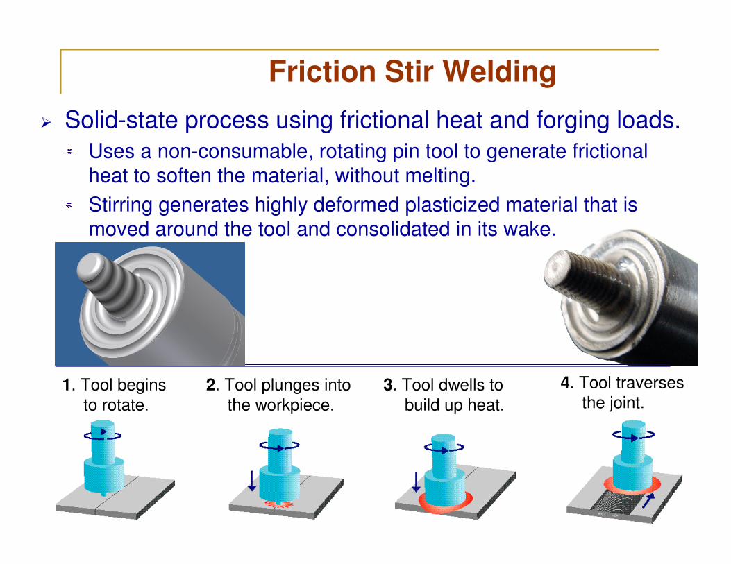
� Solid-state process using frictional heat and forging loads.
Uses a non-consumable, rotating pin tool to generate frictional
heat to soften the material, without melting.
Stirring generates highly deformed plasticized material that is
moved around the tool and consolidated in its wake.
1. Tool begins
to rotate.
2. Tool plunges into
the workpiece.
3. Tool dwells to
build up heat.
4. Tool traverses
the joint.
Friction Stir Welding
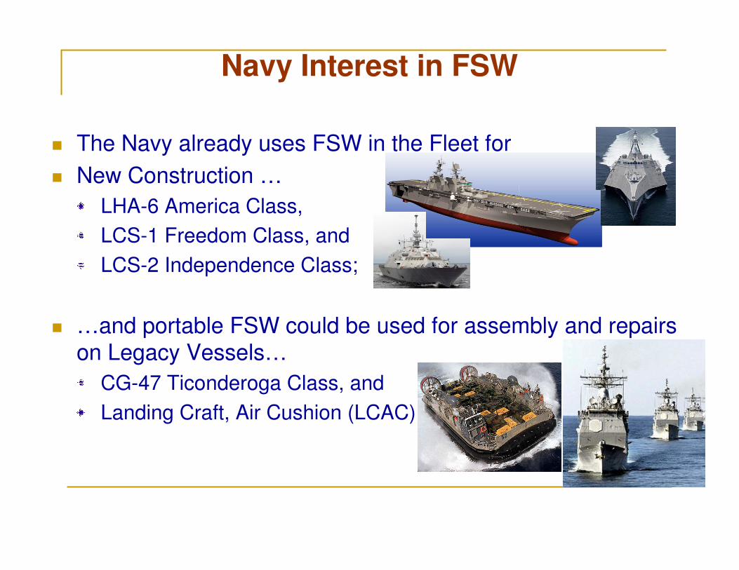
Navy Interest in FSW
� The Navy already uses FSW in the Fleet for
� New Construction …
LHA-6 America Class,
LCS-1 Freedom Class, and
LCS-2 Independence Class;
� …and portable FSW could be used for assembly and repairs
on Legacy Vessels…
CG-47 Ticonderoga Class, and
Landing Craft, Air Cushion (LCAC).
4
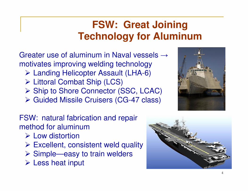
FSW: Great Joining Technology for Aluminum
Greater use of aluminum in Naval vessels →
motivates improving welding technology� Landing Helicopter Assault (LHA-6)
� Littoral Combat Ship (LCS)� Ship to Shore Connector (SSC, LCAC)
� Guided Missile Cruisers (CG-47 class)
FSW: natural fabrication and repair
method for aluminum� Low distortion
� Excellent, consistent weld quality
� Simple—easy to train welders� Less heat input
Arc-weld
Distortion
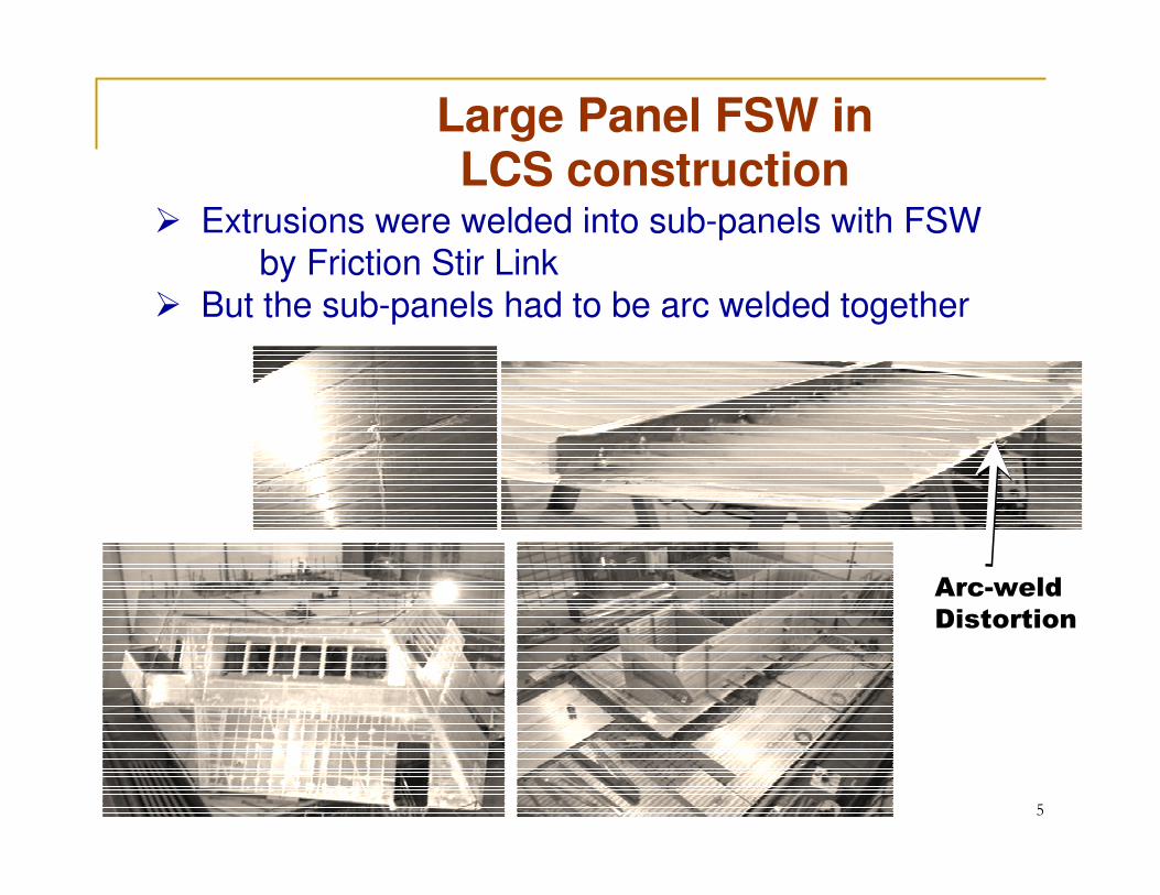
Large Panel FSW in LCS construction
� Extrusions were welded into sub-panels with FSW by Friction Stir Link
� But the sub-panels had to be arc welded together
5
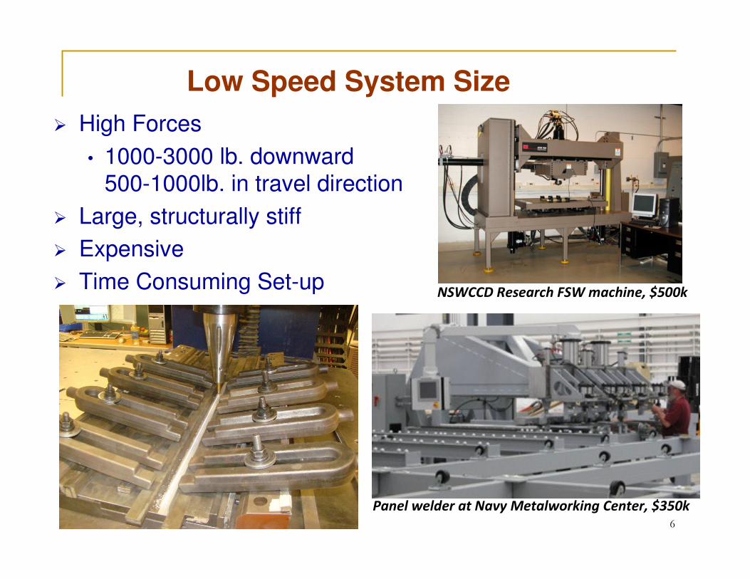
Low Speed System Size
� High Forces
• 1000-3000 lb. downward500-1000lb. in travel direction
� Large, structurally stiff
� Expensive
� Time Consuming Set-upNSWCCD Research FSW machine, $500k
Panel welder at Navy Metalworking Center, $350k6
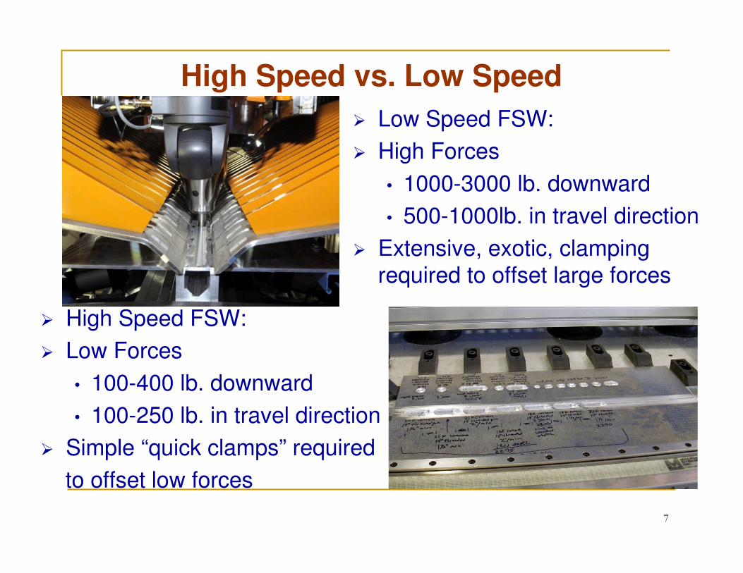
High Speed vs. Low Speed
7
� Low Speed FSW:
� High Forces
• 1000-3000 lb. downward
• 500-1000lb. in travel direction
� Extensive, exotic, clamping required to offset large forces
� High Speed FSW:
� Low Forces
• 100-400 lb. downward
• 100-250 lb. in travel direction
� Simple “quick clamps” required
to offset low forces
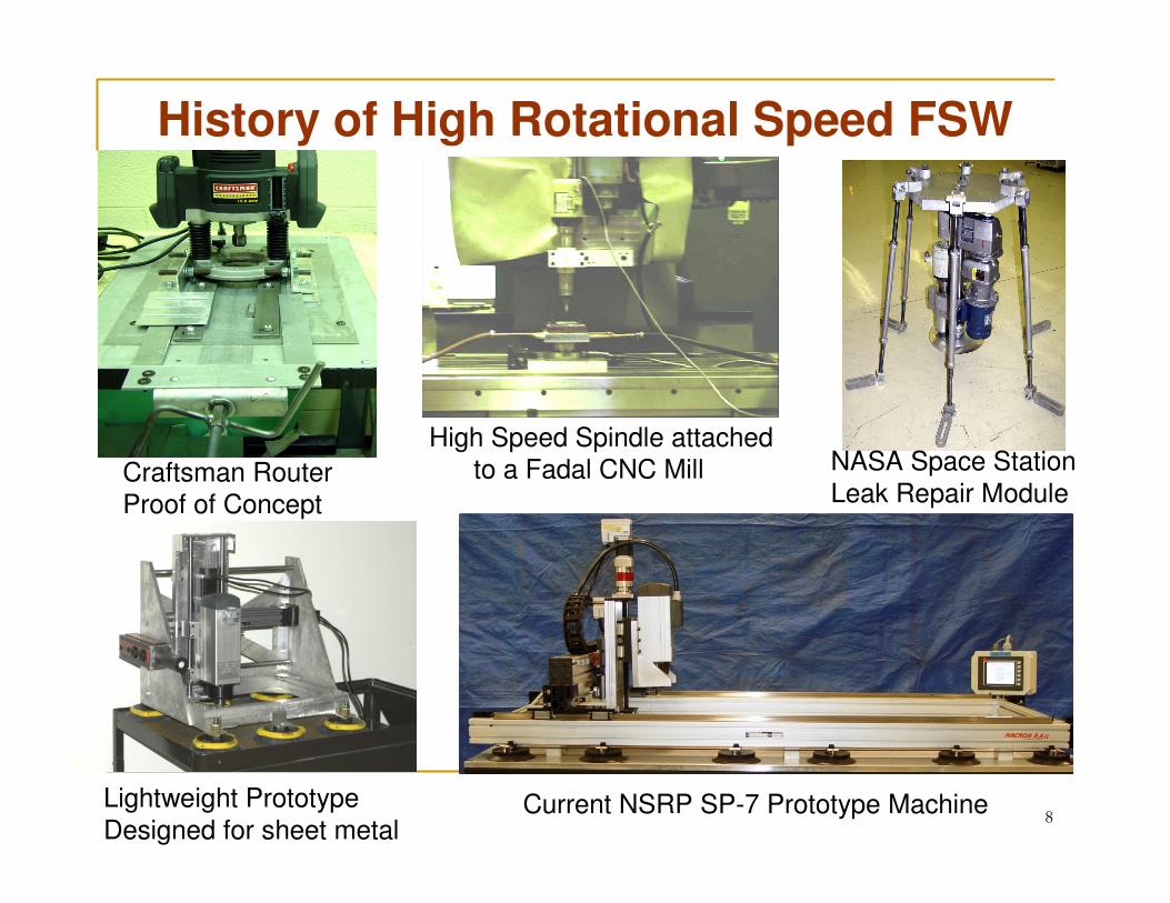
History of High Rotational Speed FSW
8
Craftsman Router
Proof of Concept
High Speed Spindle attached
to a Fadal CNC Mill NASA Space Station
Leak Repair Module
Lightweight Prototype
Designed for sheet metalCurrent NSRP SP-7 Prototype Machine
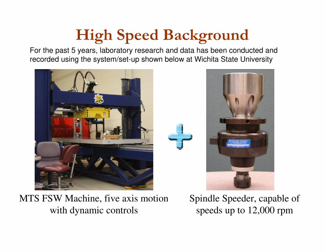
MTS FSW Machine, five axis motion
with dynamic controls
Spindle Speeder, capable of
speeds up to 12,000 rpm
High Speed BackgroundFor the past 5 years, laboratory research and data has been conducted and
recorded using the system/set-up shown below at Wichita State University
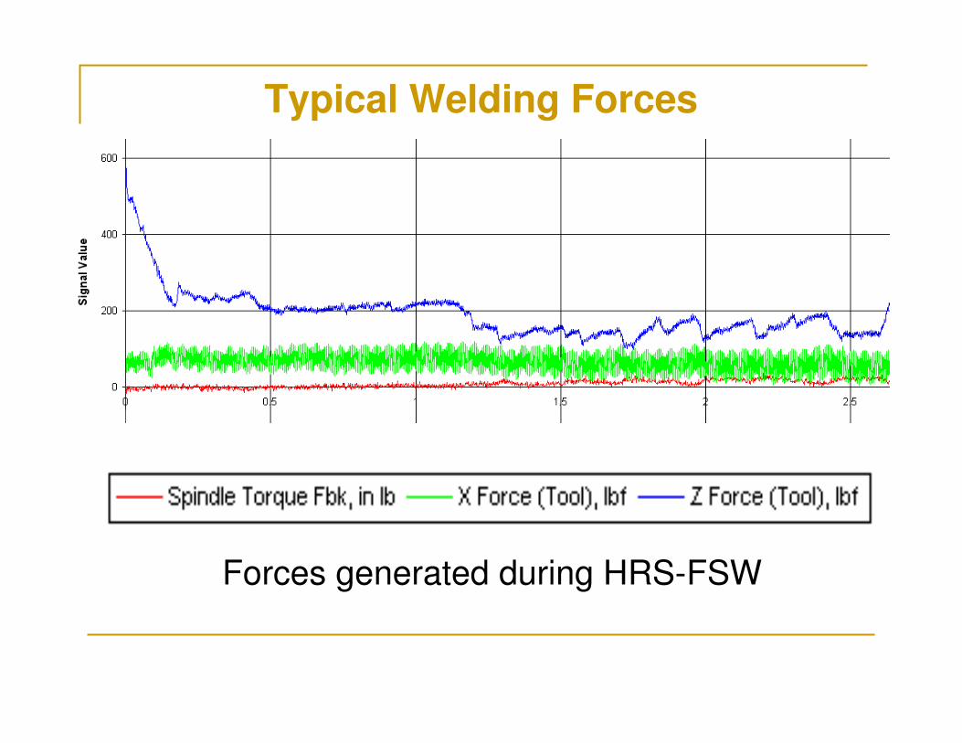
Typical Welding Forces
Forces generated during HRS-FSW
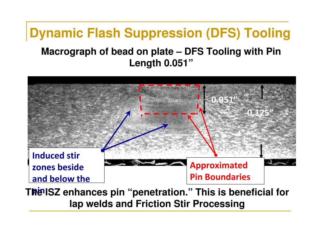
Dynamic Flash Suppression (DFS) Tooling
Macrograph of bead on plate – DFS Tooling with Pin Length 0.051”
0.125”
0.051”
Induced stir
zones beside
and below the
pinThe ISZ enhances pin “penetration.” This is beneficial for lap welds and Friction Stir Processing
Approximated
Pin Boundaries
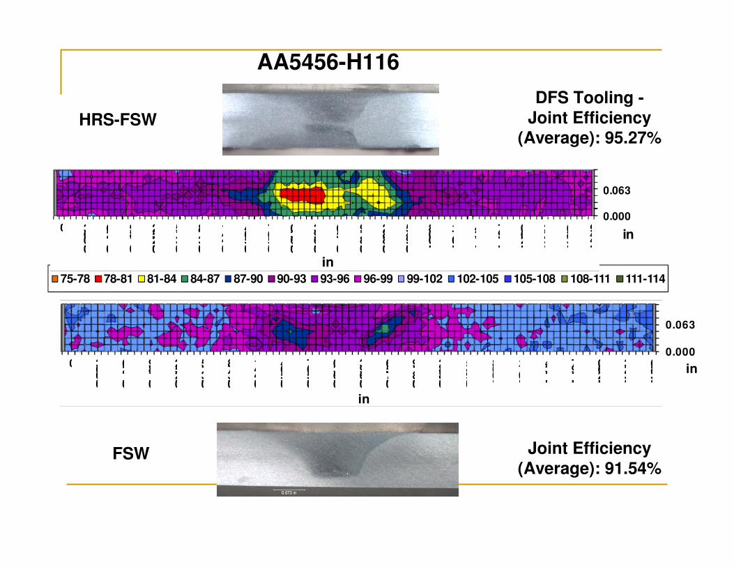
AA5456-H116
DFS Tooling -
Joint Efficiency (Average): 95.27%
HRS-FSW
Joint Efficiency
(Average): 91.54%
75-78 78-81 81-84 84-87 87-90 90-93 93-96 96-99 99-102 102-105 105-108 108-111 111-114
0.000
0.063
0
0.063
0.126
0.189
0.252
0.315
0.378
0.441
0.504
0.567
0.630
0.693
0.756
0.819
0.882
0.945
1.008
1.071
1.134
1.197
1.260
1.323
1.386 in
in
0.000
0.063
0
0.063
0.126
0.189
0.252
0.315
0.378
0.441
0.504
0.567
0.630
0.693
0.756
0.819
0.882
0.945
1.008
1.071
1.134
1.197
1.260
1.323
1.386
1.449
in
in
FSW
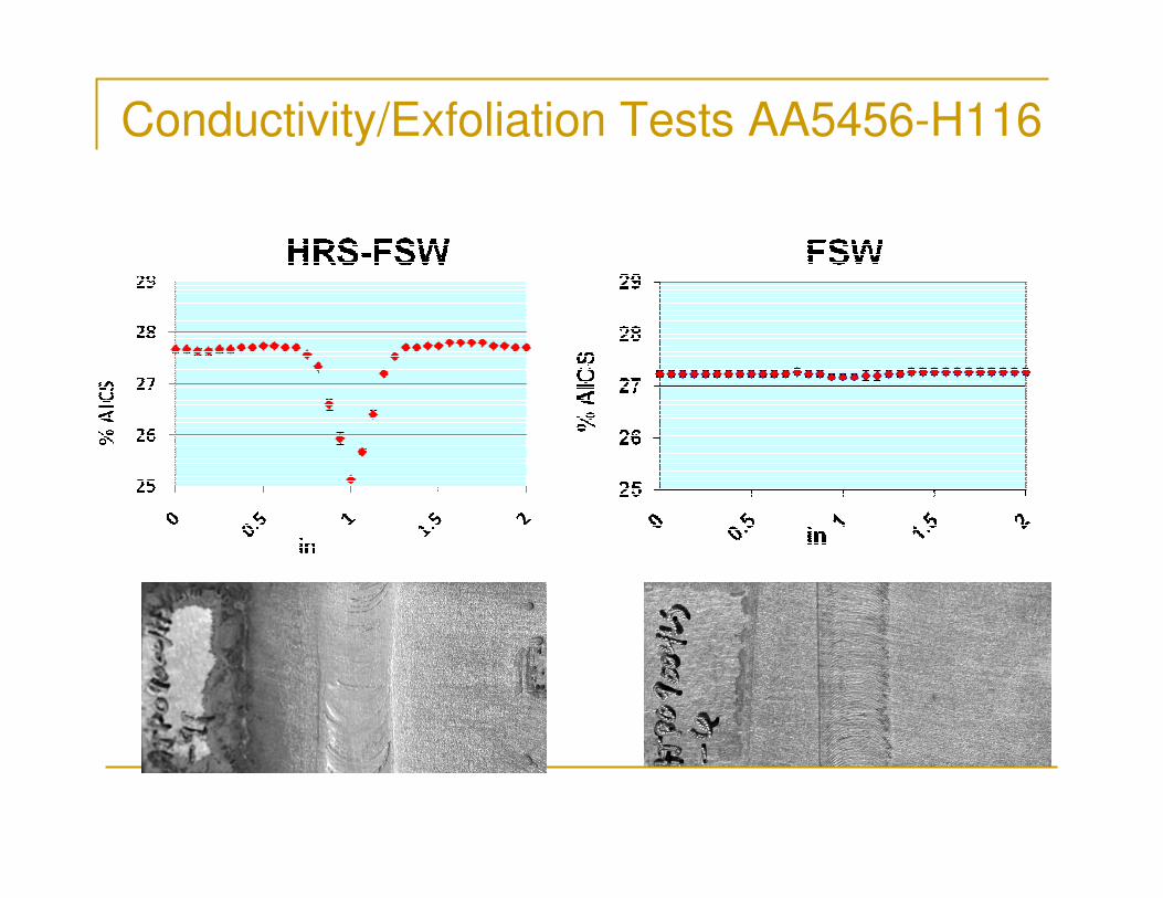
Conductivity/Exfoliation Tests AA5456-H116
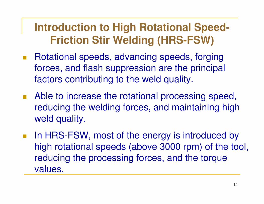
Introduction to High Rotational Speed-Friction Stir Welding (HRS-FSW)
� Rotational speeds, advancing speeds, forging
forces, and flash suppression are the principal
factors contributing to the weld quality.
� Able to increase the rotational processing speed,
reducing the welding forces, and maintaining high
weld quality.
� In HRS-FSW, most of the energy is introduced by
high rotational speeds (above 3000 rpm) of the tool,
reducing the processing forces, and the torque
values.
14
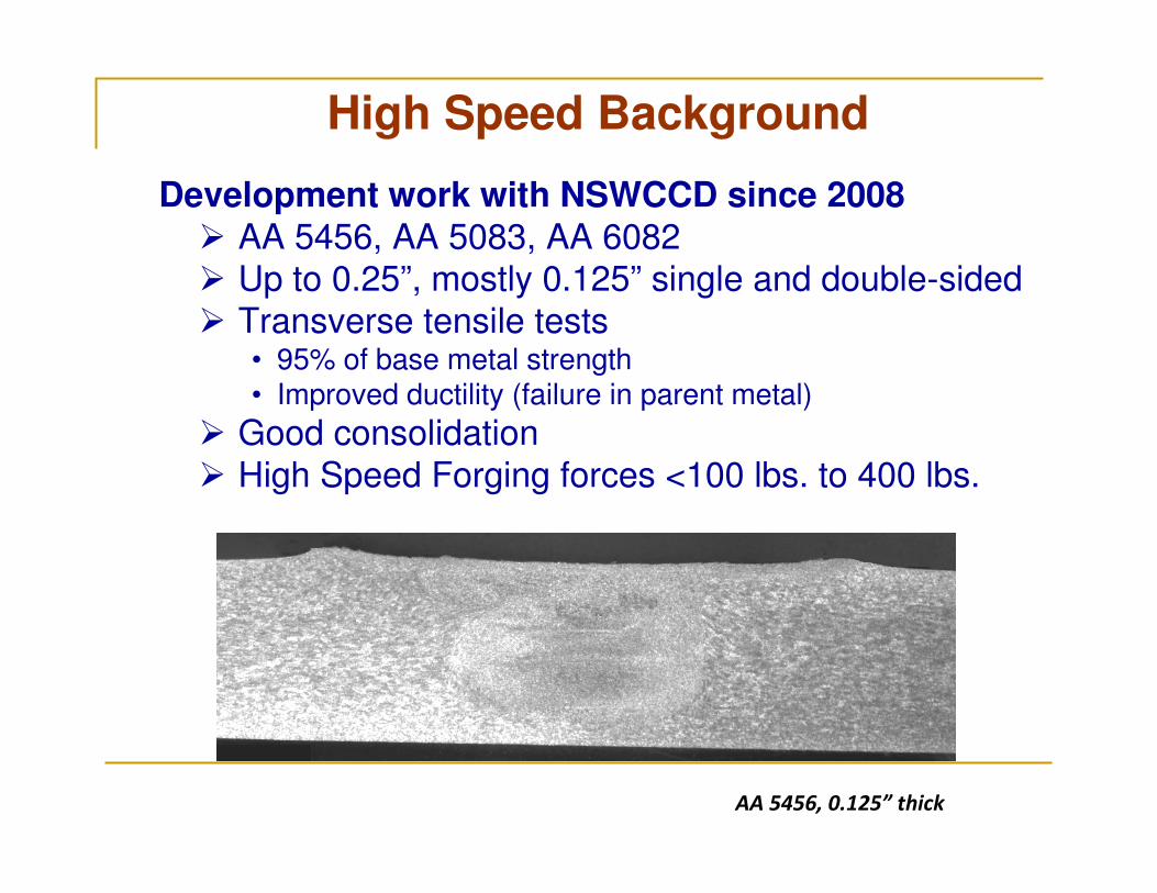
High Speed Background
Development work with NSWCCD since 2008� AA 5456, AA 5083, AA 6082 � Up to 0.25”, mostly 0.125” single and double-sided
� Transverse tensile tests• 95% of base metal strength• Improved ductility (failure in parent metal)
� Good consolidation
� High Speed Forging forces <100 lbs. to 400 lbs.
AA 5456, 0.125” thick
Long Range Objectives
� To develop and implement innovative technologies to allow the friction stir welding and repairs of aluminum Naval structures in situations where standard, stand-alone friction stir welding machines cannot be used.
� The approach must develop uncomplicated, robust measures, which currently do not exist.
� To create a reliable friction stir weld in marine-grade aluminum plates and wrought products for ship assembly/subassembly construction and repair applications.
� Achieving applied welding loads that would permit manual manipulation of the equipment during friction stir weld aluminum plate – is a goal of this project.
16
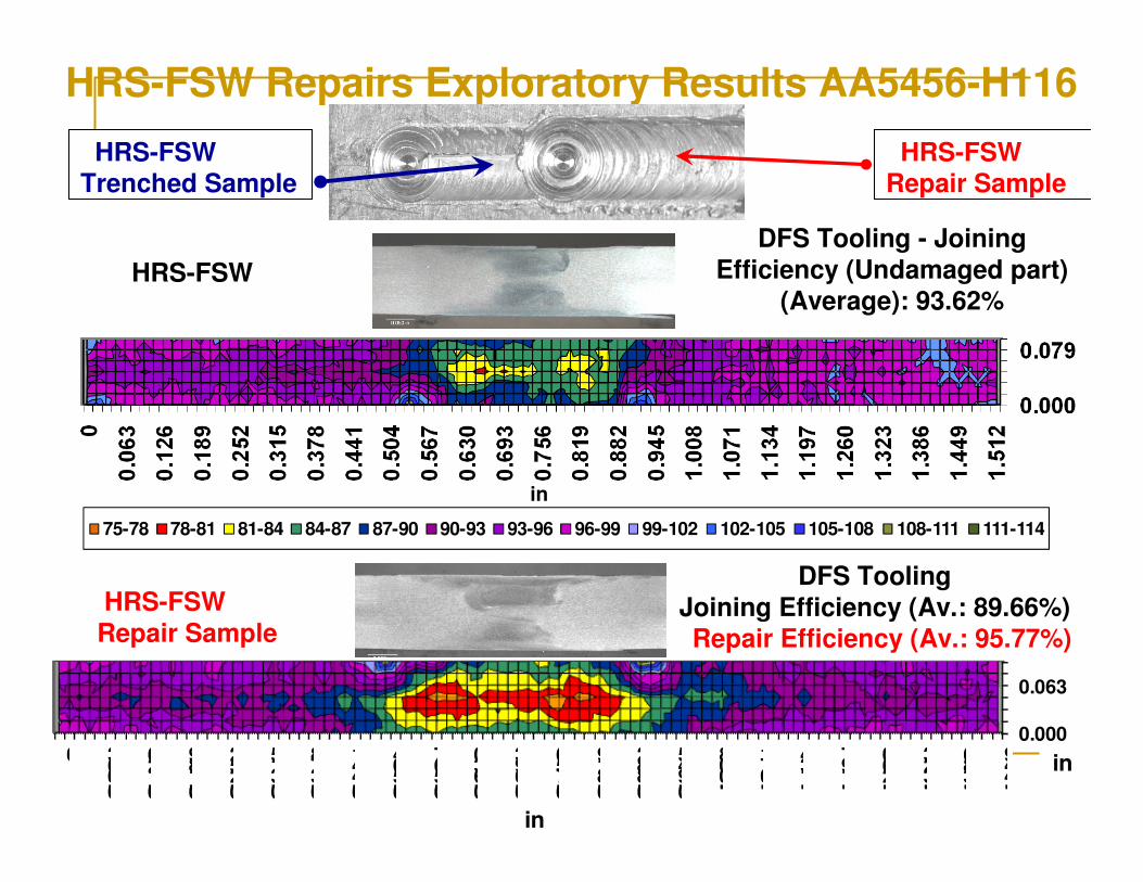
HRS-FSW Repairs Exploratory Results AA5456-H116
0.000
0.063
0
0.063
0.126
0.189
0.252
0.315
0.378
0.441
0.504
0.567
0.630
0.693
0.756
0.819
0.882
0.945
1.008
1.071
1.134
1.197
1.260
1.323
1.386
1.449 in
in
DFS Tooling
Joining Efficiency (Av.: 89.66%)Repair Efficiency (Av.: 95.77%)
75-78 78-81 81-84 84-87 87-90 90-93 93-96 96-99 99-102 102-105 105-108 108-111 111-114
in
HRS-FSW
DFS Tooling - Joining
Efficiency (Undamaged part) (Average): 93.62%
HRS-FSW Repair Sample
HRS-FSW
Repair Sample
HRS-FSW Trenched Sample
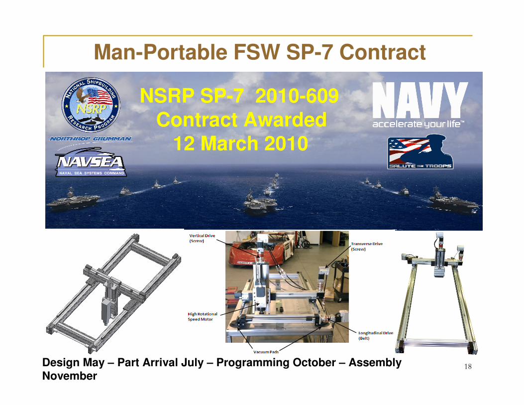
Man-Portable FSW SP-7 Contract
18
NSRP SP-7 2010-609Contract Awarded
12 March 2010
Design May – Part Arrival July – Programming October – Assembly November
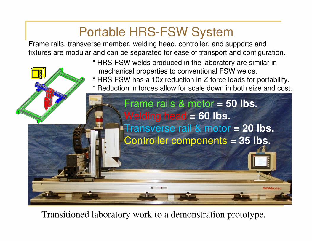
Portable HRS-FSW System
Transitioned laboratory work to a demonstration prototype.
Frame rails, transverse member, welding head, controller, and supports and
fixtures are modular and can be separated for ease of transport and configuration.
Frame rails & motor = 50 lbs.Welding head = 60 lbs.Transverse rail & motor = 20 lbs.Controller components = 35 lbs.
* HRS-FSW welds produced in the laboratory are similar in
mechanical properties to conventional FSW welds.
* HRS-FSW has a 10x reduction in Z-force loads for portability.
* Reduction in forces allow for scale down in both size and cost.
Progress
� Contract Awarded 12 March 2010:
� 16 March 2010: Pascagoula• Tour with Lee Kvidahl• Fabrication issues• Finalized target—3/8” plate, 40 foot• Guided the design envelope of 4’ length welds
� 13 July 2010: Panama City• Tour with Glen Campbell• Repair issues
� Design decisions: May
� Programming: October
� Assembly: Mid-November
� Testing: December to present
� Contract ended 31 March 2011
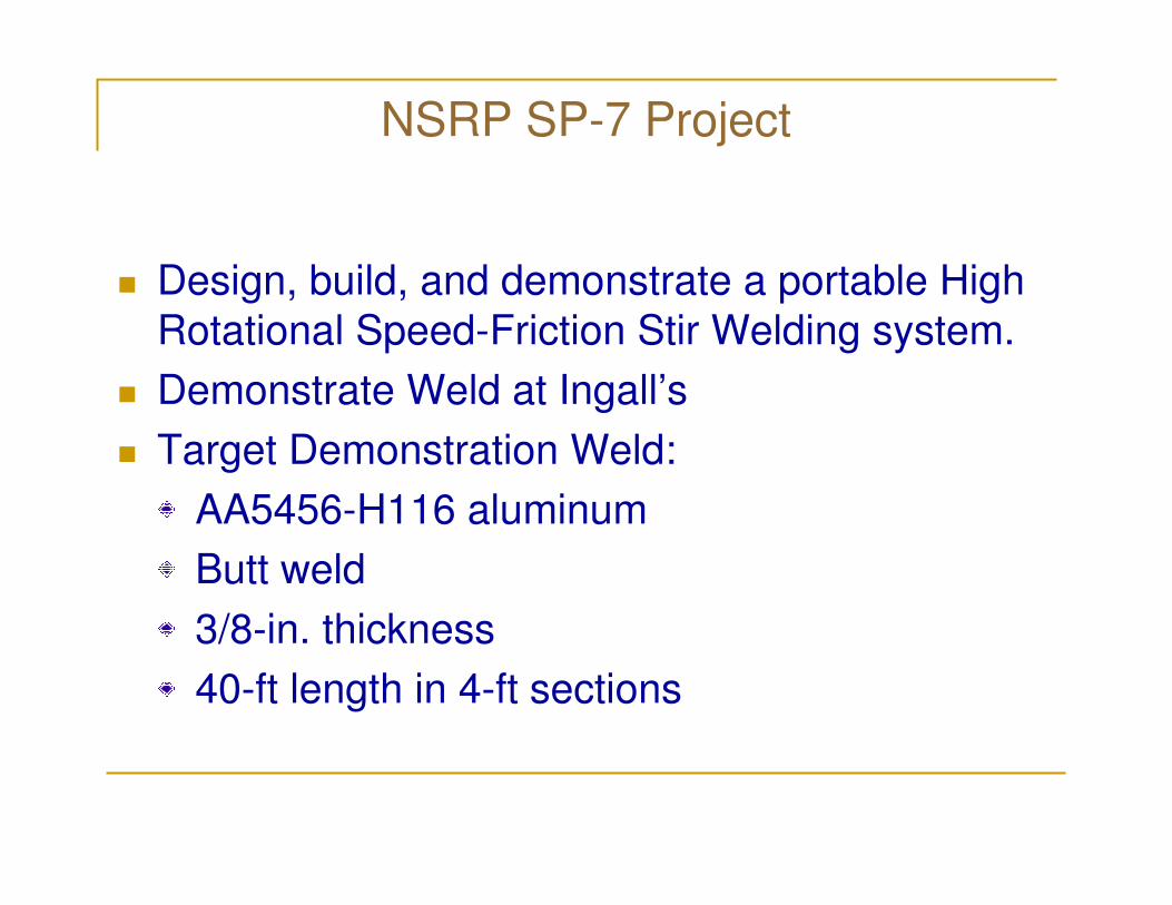
NSRP SP-7 Project
� Design, build, and demonstrate a portable High
Rotational Speed-Friction Stir Welding system.
� Demonstrate Weld at Ingall’s
� Target Demonstration Weld:
AA5456-H116 aluminum
Butt weld
3/8-in. thickness
40-ft length in 4-ft sections
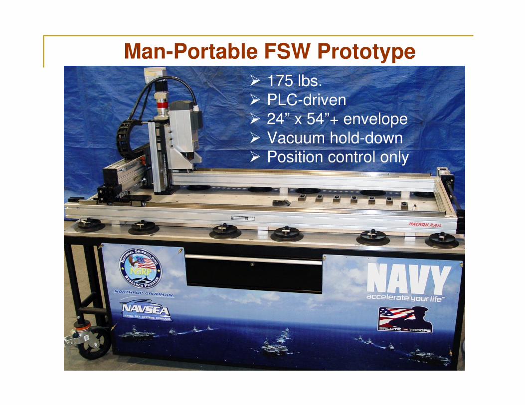
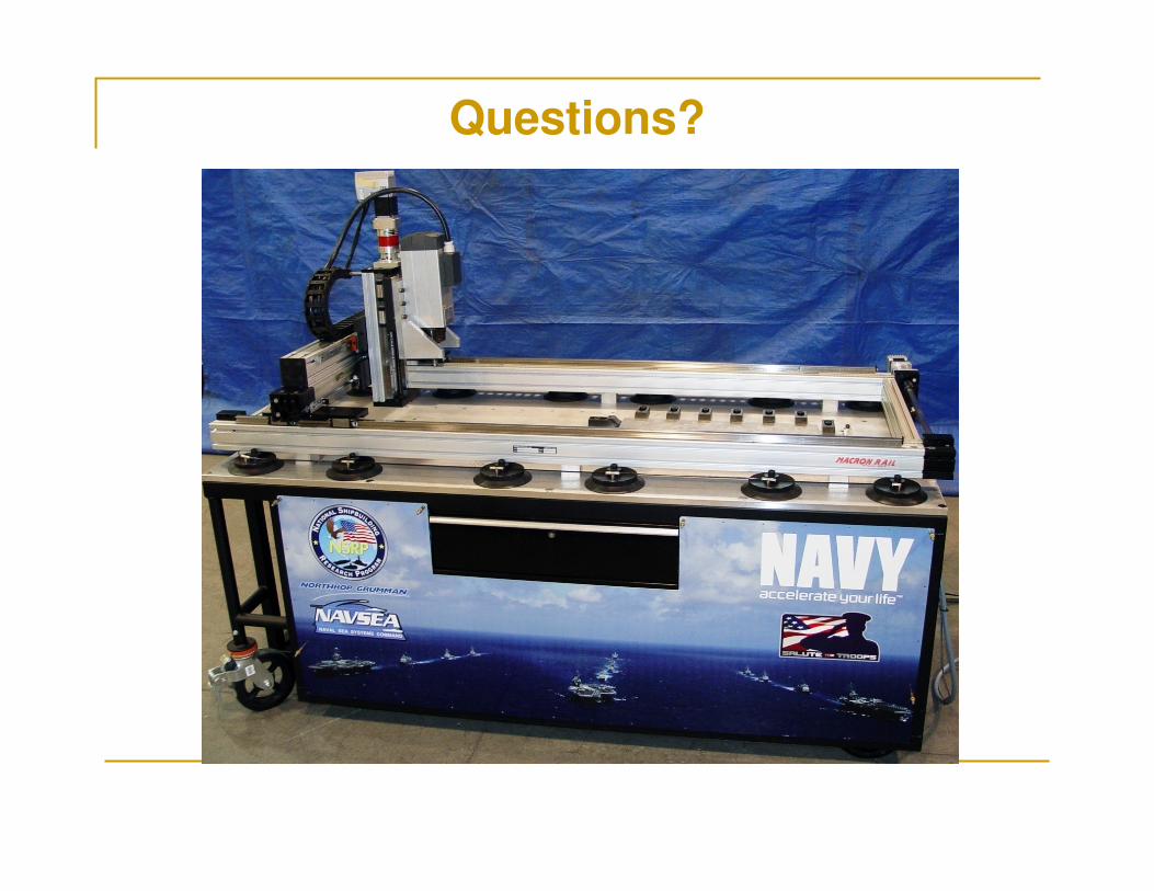
Man-Portable FSW Prototype
� 175 lbs.
� PLC-driven� 24” x 54”+ envelope
� Vacuum hold-down� Position control only
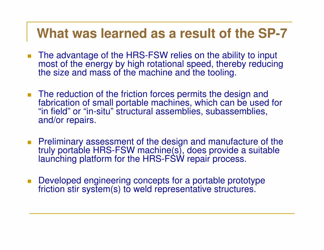
What was learned as a result of the SP-7
� The advantage of the HRS-FSW relies on the ability to input most of the energy by high rotational speed, thereby reducing the size and mass of the machine and the tooling.
� The reduction of the friction forces permits the design and fabrication of small portable machines, which can be used for “in field” or “in-situ” structural assemblies, subassemblies, and/or repairs.
� Preliminary assessment of the design and manufacture of the truly portable HRS-FSW machine(s), does provide a suitable launching platform for the HRS-FSW repair process.
� Developed engineering concepts for a portable prototype friction stir system(s) to weld representative structures.
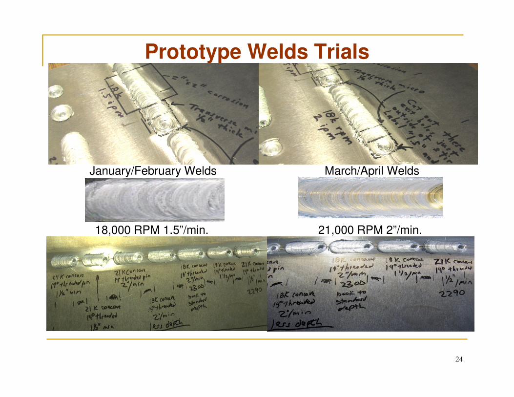
Prototype Welds Trials
24
January/February Welds March/April Welds
18,000 RPM 1.5”/min. 21,000 RPM 2”/min.
Remaining Tasks
� Develop process parameters for 3/8” plate
� Mechanical/Metallurgical Testing
� Continue Tool research program (April/May 2011)
• 3 different style prototype tools on order
• Varying shoulder diameter and features
• Varying pin dimensions and features
� Demonstration welds
• Invitation to NSRP members
• At Ingalls
Acknowledgements
Lee Kvidahl
– Northrop Grumman Shipbuilding – Gulf
Coast
National Shipbuilding Research Program
– Welding Technology Panel
�This award significantly advanced the
development of this technology.

Video Trials
27
Questions?


