Embed Size (px)
Citation preview
HAL Id: hal-00826308https://hal.archives-ouvertes.fr/hal-00826308
Submitted on 2 Jul 2013
HAL is a multi-disciplinary open accessarchive for the deposit and dissemination of sci-entific research documents, whether they are pub-lished or not. The documents may come fromteaching and research institutions in France orabroad, or from public or private research centers.
L’archive ouverte pluridisciplinaire HAL, estdestinée au dépôt et à la diffusion de documentsscientifiques de niveau recherche, publiés ou non,émanant des établissements d’enseignement et derecherche français ou étrangers, des laboratoirespublics ou privés.
Determination of mechanical properties bynanoindentation independently of indentation depth
measurementGaylord Guillonneau, Guillaume Kermouche, Sandrine Bec, Jean-Luc Loubet
To cite this version:Gaylord Guillonneau, Guillaume Kermouche, Sandrine Bec, Jean-Luc Loubet. Determinationof mechanical properties by nanoindentation independently of indentation depth measurement.Journal of Materials Research, Cambridge University Press (CUP), 2012, 27, pp.2551-2560.�10.1557/jmr.2012.261�. �hal-00826308�
Determination of mechanical properties by nanoindentation
independently of indentation depth measurement
Gaylord Guillonneaua)
Ecole Centrale de Lyon, Université de Lyon, Laboratoire de Tribologie et Dynamique des Systèmes,UMR 5513 CNRS/ECL/ENISE, 69134 Ecully, France
Guillaume KermoucheEcole Nationale d’Ingénieurs de Saint-Etienne, Université de Lyon, Laboratoire de Tribologieet Dynamique des Systèmes, UMR 5513 CNRS/ECL/ENISE, 42000 Saint-Etienne, France
Sandrine Bec and Jean-Luc LoubetEcole Centrale de Lyon, Université de Lyon, Laboratoire de Tribologie et Dynamique des Systèmes,UMR 5513 CNRS/ECL/ENISE, 69134 Ecully, France
(Received 20 April 2012; accepted 18 July 2012)
A new technique based on the detection of the amplitude of the second harmonic was described
in a previous paper. To compute the elastic modulus and the hardness of materials, the technique
uses only the derivative of the contact radius with respect to the indentation depth. For this
reason, this method is applicable only to homogeneous materials. In this paper, the method is
extended to any materials with constant Young modulus. The indentation depth value is not
needed at all, thus eliminating uncertainties related to the displacement measurement, which are
very influent at small penetration depths. Furthermore, we also explain how to compute the
indentation depth from the detection of the amplitude of the second harmonic. This new
measurement technique was tested on three samples: fused silica, Poly(methyl methacrylate)
(PMMA), and calcite, which is expected to exhibit indentation size effect. The obtained results
show that mechanical properties and the indentation depth can be determined with good accuracy
for penetration depths between 25 and 100 nm using this method.
I. INTRODUCTION
The nanoindentation technique is widely used to
measure the hardness H and the reduced elastic modulus
E9* of materials at the nanometer scale. The first hardness
tests were realized by Brinell, who used a hard steel sphere
to indent samples (see Tabor1). Other hardness tests were
developed later, such as the Vickers test or the Knoop test,
which differ in the indenter geometry.2 To measure
hardness, the load and the projected contact area have to
be known. For these tests, the load is imposed, and the
contact area is measured after the test with an optical
microscope. At a smaller scale, optical measurement of the
contact area is not precise enough, so instrumented in-
dentation testing has been developed. With instrumented
nanoindentation testing, the load P and the displacement
hm are measured continuously during the test. With this
technique, which is based on load and displacement mea-
surement, Bulychev et al.3 showed that the reduced elastic
modulus of the material can be obtained from the unload-
ing curve. A great number of authors have contributed to
the understanding of the loading–unloading curves with
new methods of analysis.4–10
The past 20 years or so have seen the development of
a dynamic technique called Continuous Stiffness Mea-
surement (CSM).6 The principle is to superimpose a small
oscillation amplitude on the displacement (or load) signal
and to measure the load (or displacement) response.
The harmonic contact stiffness and the harmonic contact
damping of the tested material can be computed from the
analysis of the dynamic response of the system.Viscoelastic
properties are thus obtainedwith the CSMmethod, which is
useful for polymeric materials characterization.11 In addi-
tion, with the CSM technique, mechanical properties can
be measured as a function of the indentation depth, which
is helpful for the characterization of coatings or graded
materials.
To compute the static and dynamic properties cited
above, the projected contact area value is necessary. With
the nanoindentation technique, the tip displacement is
measured, not the contact depth or the projected contact
area. Many methods to estimate this area have been pro-
posed, but a lot of uncertainties related to the displacement
measurement influence the data, which is problematic for
contact area measurement, particularly at small penetration
depths (see Sec. II). This paper presents a new technique
a)Address all correspondence to this author.e-mail: [email protected]
DOI: 10.1557/jmr.2012.261
J. Mater. Res., Vol. 27, No. 19, Oct 14, 2012 �Materials Research Society 2012 2551
based on the detection of the amplitude of the second
harmonic. This technique was already suggested in
a previous paper, in which the equations were written
as a function of the derivative of the contact radius versus
indentation depth.12 Mechanical properties were more
precise at smaller penetration depths, but the proposed
equations were applicable only for materials with a con-
stant H/Ec9* ratio (Ec
9* is the reduced contact modulus
between the tip and the sample). This paper presents an
improved technique that does not use the indentation depth
and thus is applicable to any materials with constant
reduced elastic modulus.
In this paper, we begin by the discussion of the pro-
jected contact area calculation and the uncertainties related
to the displacement measurement. It is followed by the
unloading curve study to show how it is possible to com-
pute the elastic modulus, the hardness, and the indenta-
tion depth without any use of the indentation depth. The
fourth part explains the link between the elastic modulus
and the amplitude of the second harmonic. The fifth part
presents the experimental tests, and the sixth part dis-
cusses the results.
II. DETERMINATION OF THE PROJECTED
CONTACT AREA
A. Mechanical properties measured with the CSM
method
With instrumented nanoindentation testing, the hard-
ness H, the reduced elastic contact modulus Ec9*, and the
loss contact modulus Ec0* of tested materials are com-
puted as a function of the indentation depth. The hardness
is defined as the load divided by the projected contact area
between the indenter and the sample1,6,11,12:
H ¼P
Ac
; ð1Þ
where P is the applied load and Ac is the projected contact
area. The reduced elastic contact modulus can be com-
puted using the Sneddon relation13:
E9�c¼
S
2
ffiffiffiffiffi
p
Ac
r
; ð2Þ
where S is the harmonic contact stiffness measured
continuously with the CSM technique. This equation is
valid for any axisymmetric indenter. The loss modulus is
defined by the following equation14,15:
E0�c¼
DSx
2
ffiffiffiffiffi
p
Ac
r
; ð3Þ
where Ds is the harmonic contact damping and x is the
angular frequency. Equations (2) and (3) can be multiplied
by a constant coefficient to take into account the non-
axisymmetry of the indenter.8,15,16With the static method,
the hardness and the reduced elastic contact modulus are
obtained at maximum load. With the CSM technique, the
mechanical properties described by Eqs. (1)–(3) are mea-
sured as a function of the indentation depth h. All equations
depend on the projected contact area Ac. With a perfect con-
ical indenter, the projected contact area Ac can be calculat-
ed from the contact depth hc using a geometrical relation:
Ac ¼ pðtanðhÞhcÞ2
; ð4Þ
where h is the equivalent angle of the conical indenter (fora Berkovich tip, h 5 70.32°). In instrumented nano-
indentation, the contact depth hc is computed from the
indentation depth value h. The calculation of the actual
contact depth is very difficult because the relation between
the contact depth and the indentation depth is influenced
by measurement uncertainties (thermal drift, tip defect,
etc.) and by material pileup or sink-in around the indent
during the test. A lot of methods can be used to precisely
determine this relation. The Oliver and Pharr model6 is the
mainly used method. The contact depth is defined by the
following equation:
hc ¼ h� eP
S; ð5Þ
where h is the indentation depth and e is a constant
depending on the indenter geometry. Then, Oliver and
Pharr propose computing the projected contact area with
an area function, which takes into account the nonperfect
geometry of the indenter.6Loubet et al.17,18 propose another
method. The relation between the contact depth and the
indentation depth is given by the following equation:
hc ¼ a h�P
Sþ h0
� �
; ð6Þ
where h0 is an equivalent height of the tip defect. Piling-up
and sinking-in phenomena are taken into account by the
coefficient a, the value of which is 1.2 for a Berkovich
indenter.17 The Loubet model can be used for a large range
of materials. We note that the ratio P/S can be written as
a function of hardness, reduced elastic modulus, and
contact depth by combining Eqs. (1), (2), and (4):
P
S¼
p
2tanðhÞ
H
E9�c
hc : ð7Þ
This relation will be used in Sec. III.
B. Displacement uncertainties
To determine the indentation depth h, the precise
identification of the contact point hin is necessary. The
G. Guillonneau et al.: Determination of mechanical properties by nanoindentation independently of indentation depth measurement
J. Mater. Res., Vol. 27, No. 19, Oct 14, 20122552
indentation depth is related to the measured tip displace-
ment hm by the following equation:
h ¼ hm � hin : ð8Þ
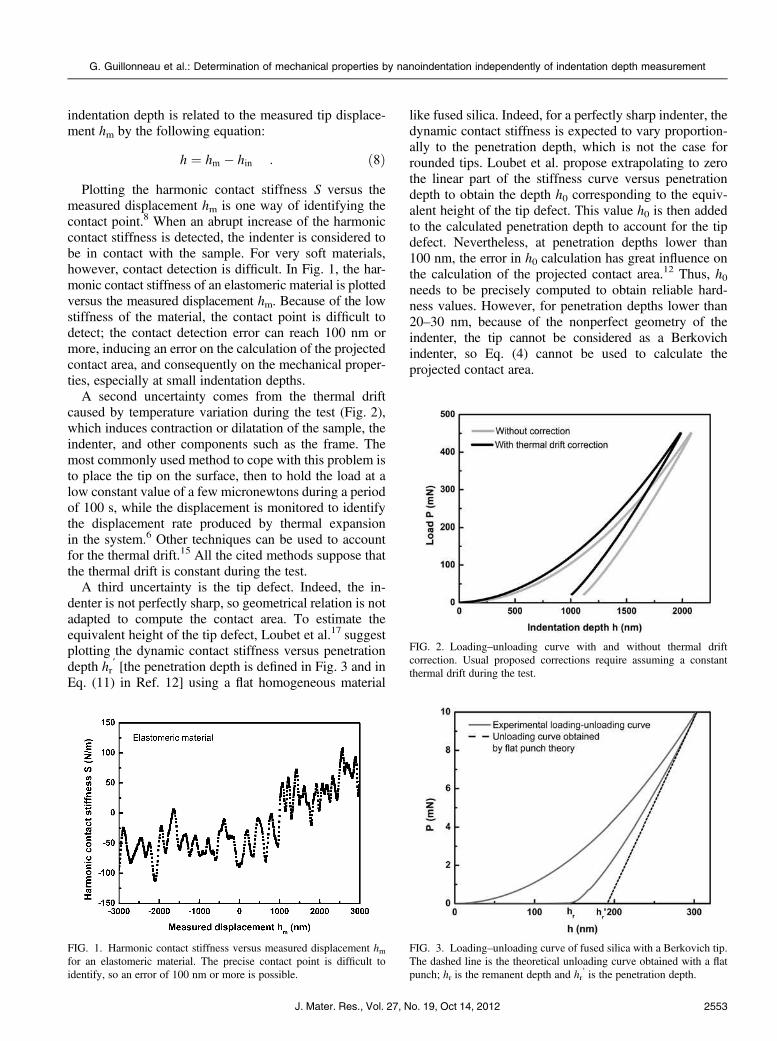
Plotting the harmonic contact stiffness S versus the
measured displacement hm is one way of identifying the
contact point.8 When an abrupt increase of the harmonic
contact stiffness is detected, the indenter is considered to
be in contact with the sample. For very soft materials,
however, contact detection is difficult. In Fig. 1, the har-
monic contact stiffness of an elastomeric material is plotted
versus the measured displacement hm. Because of the low
stiffness of the material, the contact point is difficult to
detect; the contact detection error can reach 100 nm or
more, inducing an error on the calculation of the projected
contact area, and consequently on the mechanical proper-
ties, especially at small indentation depths.
A second uncertainty comes from the thermal drift
caused by temperature variation during the test (Fig. 2),
which induces contraction or dilatation of the sample, the
indenter, and other components such as the frame. The
most commonly used method to cope with this problem is
to place the tip on the surface, then to hold the load at a
low constant value of a few micronewtons during a period
of 100 s, while the displacement is monitored to identify
the displacement rate produced by thermal expansion
in the system.6 Other techniques can be used to account
for the thermal drift.15 All the cited methods suppose that
the thermal drift is constant during the test.
A third uncertainty is the tip defect. Indeed, the in-
denter is not perfectly sharp, so geometrical relation is not
adapted to compute the contact area. To estimate the
equivalent height of the tip defect, Loubet et al.17 suggest
plotting the dynamic contact stiffness versus penetration
depth hr9 [the penetration depth is defined in Fig. 3 and in
Eq. (11) in Ref. 12] using a flat homogeneous material
like fused silica. Indeed, for a perfectly sharp indenter, the
dynamic contact stiffness is expected to vary proportion-
ally to the penetration depth, which is not the case for
rounded tips. Loubet et al. propose extrapolating to zero
the linear part of the stiffness curve versus penetration
depth to obtain the depth h0 corresponding to the equiv-
alent height of the tip defect. This value h0 is then added
to the calculated penetration depth to account for the tip
defect. Nevertheless, at penetration depths lower than
100 nm, the error in h0 calculation has great influence on
the calculation of the projected contact area.12 Thus, h0needs to be precisely computed to obtain reliable hard-
ness values. However, for penetration depths lower than
20–30 nm, because of the nonperfect geometry of the
indenter, the tip cannot be considered as a Berkovich
indenter, so Eq. (4) cannot be used to calculate the
projected contact area.
FIG. 1. Harmonic contact stiffness versus measured displacement hmfor an elastomeric material. The precise contact point is difficult to
identify, so an error of 100 nm or more is possible.
FIG. 2. Loading–unloading curve with and without thermal drift
correction. Usual proposed corrections require assuming a constant
thermal drift during the test.
FIG. 3. Loading–unloading curve of fused silica with a Berkovich tip.
The dashed line is the theoretical unloading curve obtained with a flat
punch; hr is the remanent depth and hr9 is the penetration depth.
G. Guillonneau et al.: Determination of mechanical properties by nanoindentation independently of indentation depth measurement
J. Mater. Res., Vol. 27, No. 19, Oct 14, 2012 2553
In a recent paper,12 we proposed a new method that
eliminates all these uncertainties. This method was based
on the measurement of the displacement second harmonic
amplitude but was only valid for homogeneous materials.
In the present paper, we extend this method to non-
homogeneous materials by computing the mechanical
properties only from dynamic measurements (i.e., CSM)
and not from static measurements (i.e., indentation depth).
III. STUDY OF THE UNLOADING CURVE
Figure 3 shows a typical loading–unloading curve ob-
tained on a fused silica sample. With the unloading part,
it is possible to calculate the contact stiffness S, expressed
as a function of the reduced elastic contact modulus Ec9*
with the following equation13,15:
S ¼ 2E9�ca ; ð9Þ
where a is the equivalent tip contact radius. This expres-
sion is valid for an elastic contact for all axisymmetric
indenters.19 If the contact radius is substituted by the con-
tact depth hc, for a pyramid-shaped indenter, the following
equation is obtained:
S ¼ 2 tanðhÞE9�chc : ð10Þ
For indentation test with a flat punch, the stiffness is
simply the slope of the unloading curve (dashed line in
Fig. 3). As shown in Fig. 3, the unloading curve for a
pyramid-shaped indenter is not linear, so a second de-
rivative is computable. After derivation of Eq. (10) with
respect to the indentation depth h, and assuming that the
reduced elastic contact modulus is constant during the
unloading, the following equation is obtained:
dS
dh¼ 2 tanðhÞE9�
c
dhc
dh: ð11Þ
This expression depends on the indenter geometry, on
the reduced elastic contact modulus, and on the derivative
of the contact depth hc with respect to the indentation
depth h. The last term is of primary importance, as it takes
into account the pileup or sink-in of the material. The
Loubet contact depth model in Eq. (7) yields to:
hc ¼a
1þ ap tanðhÞ2
HE9�c
ðhþ h0Þ : ð12Þ
After derivation of Eq. (12) with respect to the in-
dentation depth h, the following equation is obtained:
dhc
dh¼
a
1þ ap tanðhÞ2
HE9�c
: ð13Þ
The hardness H can also be substituted in Eq. (13) by
the following expression:
H ¼4P
pS2ðE9�
cÞ2 : ð14Þ
The reduced elastic contact modulus can be then
computed from Eqs. (11), (13), and (14):
E9�c¼
dSdhS2
2a tanðhÞ S2 � P dSdh
� � : ð15Þ
The hardness is computed with Eq. (14) and the
reduced elastic modulus E9* of the material is computed
with the following equation:
1
E9�¼
1
E9�c
�1
E9�i
; ð16Þ
where Ei9* is the reduced elastic modulus of the indenter.
The displacement measurement is no longer needed,
which is of primary interest regarding the uncertainties
mentioned in the previous paragraph. The expression of
the derivative of the contact depth with respect to the
indentation depth has been computed with the Loubet
model, but the same calculation can be done with the
Oliver and Pharr model.
We note that the indentation depth h can be directly
computed from the ratio of the harmonic contact stiffness
[Eq. (10)] over the derivative of the contact stiffness
versus indentation depth [Eq. (11)], by noticing that:
S
�
dS
dh¼ hc
�
dhc
dh¼ hþ h0 : ð17Þ
To obtain the reduced elastic modulus, the hardness,
and the indentation depth without any displacement
measurement, it is necessary to determine the derivative
of the contact stiffness with respect to the indentation
depth. The following section presents the method that we
use to make such determination.
IV. SECOND DERIVATIVE AND SECOND
HARMONIC (CSM METHOD)
In a previous paper, with the expression of the Fourier
series and the Taylor development at the second order, it
was shown how to link the second derivative of load with
respect to the indentation depth with the second harmonic
of load12:
P2e�ju2 ¼
h212
d2P
dh2; ð18Þ
where P2 is the amplitude of the second harmonic of load,
u2 is the phase angle between the second harmonic of load
G. Guillonneau et al.: Determination of mechanical properties by nanoindentation independently of indentation depth measurement
J. Mater. Res., Vol. 27, No. 19, Oct 14, 20122554
and the second harmonic of displacement, and h1 is the
oscillation amplitude of displacement. For a system con-
trolled by CSM, the derivative of the load with respect
to the indentation depth is expressed by the following
equation:
dP
dh¼ ðK � x2mÞð1þ j tanðu1ÞÞ ; ð19Þ
where K is the total harmonic stiffness, u1 is the phase
angle between the first harmonic of load and the first
harmonic of displacement, and m is the column mass. To
obtain the second derivative, Eq. (19) is derived with
respect to the indentation depth in the following way:
d2P
dh2¼
d dPdh
� �
dK�dK
dS�
dS
dhc�dhc
dh: ð20Þ
The first term is computed by deriving Eq. (19) with
respect to K and supposing the phase angle to be constant.
The second term is computed by deriving the following
equation with respect to S:
K ¼1
Sþ
1
Kc
� ��1
þKS ; ð21Þ
where Kc is the column stiffness and Ks is the support
springs stiffness. The third and fourth terms are computed
with Eqs. (11) and (13).
Using Eqs. (18) and (20), the reduced elastic contact
modulus is thus expressed by the following equation:
E9�c¼
P2j jS2
a tanðhÞffiffiffiffiffiffiffiffiffiffiffiffiffiffiffiffiffiffiffiffiffiffiffiffiffi
1þ tan2ðu1Þp
h1j jKð Þ2�2P P2j j� :
ð22Þ
The reduced elastic modulus E9* of the tested material
is obtained from Eqs. (15) and (16) and the hardness
H from Eq. (14). This new expression is interesting
because the indentation depth is not needed to compute
the mechanical properties.
We note that the equations derived above are only
usable for displacement-controlled systems. In the case
of load-controlled systems, the amplitude of the second
harmonic of displacement is expressed by the following
equation:
h2e�ju2 ¼
P21
2
d2h
dP2; ð23Þ
where h2 is the amplitude of the second harmonic of
displacement. The second derivative of the indentation
depth with respect to the load can be expressed in a very
simple way as a function of the second derivative of the
load with respect to the indentation depth:
d2h
dP2¼ �
1
v3d2P
dh2; ð24Þ
where v ¼ dPdh. With Eqs. (19), (20), (23), and (24), the
expression of the reduced elastic contact modulus is:
E9�c¼
h2j jS2
a tanðhÞ P1j jKð Þ2
ðK�x2mÞ3ð1þtan2ðu1ÞÞ� 2P h2j j
� : ð25Þ
The reduced Young modulus is computed with
Eq. (16) and the hardness with Eq. (14). In Eq. (25), the
amplitude of the second harmonic h2j j, the total harmonic
stiffness K, the applied load P, the phase angle u1, and the
harmonic load P1 are measured, the harmonic contact
stiffness S is computed, the angular frequency x is fixed,
and the indenter angle h and the column mass m are
known, so it is possible to calculate the reduced elastic
contact modulus Ec9*, the reduced elastic modulus E9*, and
the hardness H from the detection of the amplitude of the
second harmonic, and thus the indentation depth h using
Eq. (17). With this new technique, the indentation depth
h is not needed, and the uncertainties related to the
assessment of the indentation depth, such as the tip defect
height estimation, the contact detection, and the thermal
drift, are eliminated. Thus, this new technique could be
interesting to use for high-temperature tests where reliable
indentation depth values are complicated to obtain. It is
very important to note that all equations are valid if Ec9* is
constant during the unloading. With the CSM technique,
the unloading curve corresponds to the oscillation ampli-
tude, which is usually set between 0 and 5 nm. If the reduced
elastic modulus is quite constant along the indentation
depth, the above equations can be used.
V. EXPERIMENTATION
A. Samples and nanoindenter
Experiments were performed on three smooth materi-
als: fused silica, PMMA, and calcite. Fused silica and
PMMA samples are supposed to be homogeneous. The
calcite was chosen because it exhibits a small indentation
size effect (ISE) on the hardness results.20
A Nano Indenter SA2� equipped with a DCM head
system (Agilent Technologies, Santa Clara, CA) was used.
This load-controlled apparatus has high resolution in
displacement and force measurement (0.2 pm and 1 nN,
respectively). A Berkovich diamond tip was used in the
experiments. The equivalent height of the tip defect h0was
approximately 5 nm. To record the amplitude of the
second harmonic of the displacement signal, a second
lock-in amplifier (EG&G 7260DSP�, EG&G Technical
Services, Norfolk, VA) was attached to the SA2. For
more details about the apparatus and materials, please refer
to Guillonneau et al.12
G. Guillonneau et al.: Determination of mechanical properties by nanoindentation independently of indentation depth measurement
J. Mater. Res., Vol. 27, No. 19, Oct 14, 2012 2555
B. Indentation procedure
The maximum load applied to the specimens was 5 mN
for silica, 0.15 mN for PMMA, and 4.5 mN for calcite.
The oscillation amplitude was set to h1 5 4 nm for fused
silica and PMMA samples, whereas for calcite, the
oscillation amplitude was gradually increased with the
load to avoid loss of information and loss of contact at
small penetration depths.21 More precisely, the oscillation
amplitude was h1 5 2 nm for load between 0 and 0.2 mN
and 4 nm for load between 0.2 and 4.5 mN. The oscillation
frequency was 97 Hz for fused silica and calcite and 31 Hz
for PMMA. The strain rate was _P/P 5 0.005 s�1 for
PMMA and calcite and _P/P5 0.003 s�1 for fused silica.14
Ten indentation tests were realized on each sample. In the
following, all the data are mean curves from these 10 tests.
VI. RESULTS AND DISCUSSION
A. Amplitude of the second harmonic
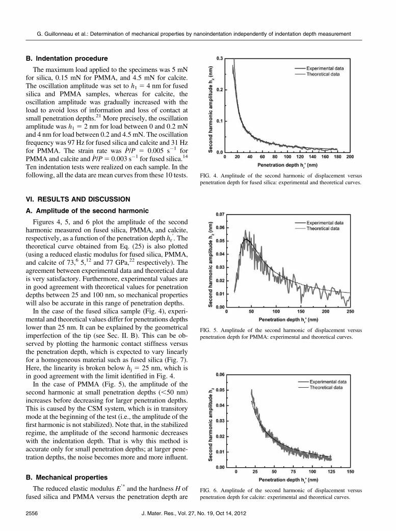
Figures 4, 5, and 6 plot the amplitude of the second
harmonic measured on fused silica, PMMA, and calcite,
respectively, as a function of the penetration depth hr9. The
theoretical curve obtained from Eq. (25) is also plotted
(using a reduced elastic modulus for fused silica, PMMA,
and calcite of 73,6 5,12 and 77 GPa,22 respectively). The
agreement between experimental data and theoretical data
is very satisfactory. Furthermore, experimental values are
in good agreement with theoretical values for penetration
depths between 25 and 100 nm, so mechanical properties
will also be accurate in this range of penetration depths.
In the case of the fused silica sample (Fig. 4), experi-
mental and theoretical values differ for penetrations depths
lower than 25 nm. It can be explained by the geometrical
imperfection of the tip (see Sec. II. B). This can be ob-
served by plotting the harmonic contact stiffness versus
the penetration depth, which is expected to vary linearly
for a homogeneous material such as fused silica (Fig. 7).
Here, the linearity is broken below hj 5 25 nm, which is
in good agreement with the limit identified in Fig. 4.
In the case of PMMA (Fig. 5), the amplitude of the
second harmonic at small penetration depths (,50 nm)
increases before decreasing for larger penetration depths.
This is caused by the CSM system, which is in transitory
mode at the beginning of the test (i.e., the amplitude of the
first harmonic is not stabilized). Note that, in the stabilized
regime, the amplitude of the second harmonic decreases
with the indentation depth. That is why this method is
accurate only for small penetration depths; at larger pene-
tration depths, the noise becomes more and more influent.
B. Mechanical properties
The reduced elastic modulus E9* and the hardness H of
fused silica and PMMA versus the penetration depth are
FIG. 5. Amplitude of the second harmonic of displacement versus
penetration depth for PMMA: experimental and theoretical curves.
FIG. 4. Amplitude of the second harmonic of displacement versus
penetration depth for fused silica: experimental and theoretical curves.
FIG. 6. Amplitude of the second harmonic of displacement versus
penetration depth for calcite: experimental and theoretical curves.
G. Guillonneau et al.: Determination of mechanical properties by nanoindentation independently of indentation depth measurement
J. Mater. Res., Vol. 27, No. 19, Oct 14, 20122556
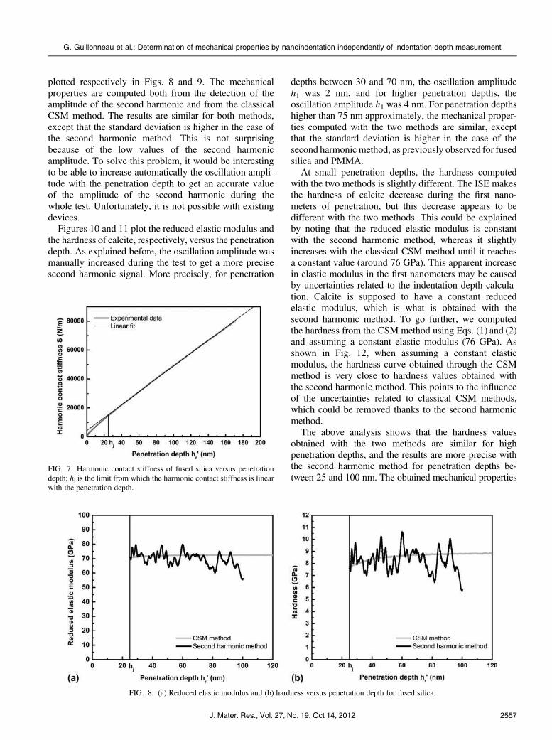
plotted respectively in Figs. 8 and 9. The mechanical
properties are computed both from the detection of the
amplitude of the second harmonic and from the classical
CSM method. The results are similar for both methods,
except that the standard deviation is higher in the case of
the second harmonic method. This is not surprising
because of the low values of the second harmonic
amplitude. To solve this problem, it would be interesting
to be able to increase automatically the oscillation ampli-
tude with the penetration depth to get an accurate value
of the amplitude of the second harmonic during the
whole test. Unfortunately, it is not possible with existing
devices.
Figures 10 and 11 plot the reduced elastic modulus and
the hardness of calcite, respectively, versus the penetration
depth. As explained before, the oscillation amplitude was
manually increased during the test to get a more precise
second harmonic signal. More precisely, for penetration
depths between 30 and 70 nm, the oscillation amplitude
h1 was 2 nm, and for higher penetration depths, the
oscillation amplitude h1 was 4 nm. For penetration depths
higher than 75 nm approximately, the mechanical proper-
ties computed with the two methods are similar, except
that the standard deviation is higher in the case of the
second harmonic method, as previously observed for fused
silica and PMMA.
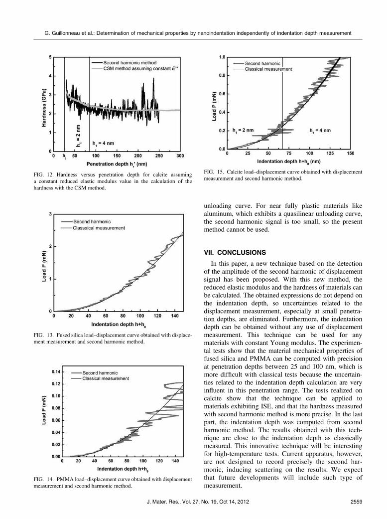
At small penetration depths, the hardness computed
with the two methods is slightly different. The ISE makes
the hardness of calcite decrease during the first nano-
meters of penetration, but this decrease appears to be
different with the two methods. This could be explained
by noting that the reduced elastic modulus is constant
with the second harmonic method, whereas it slightly
increases with the classical CSM method until it reaches
a constant value (around 76 GPa). This apparent increase
in elastic modulus in the first nanometers may be caused
by uncertainties related to the indentation depth calcula-
tion. Calcite is supposed to have a constant reduced
elastic modulus, which is what is obtained with the
second harmonic method. To go further, we computed
the hardness from the CSM method using Eqs. (1) and (2)
and assuming a constant elastic modulus (76 GPa). As
shown in Fig. 12, when assuming a constant elastic
modulus, the hardness curve obtained through the CSM
method is very close to hardness values obtained with
the second harmonic method. This points to the influence
of the uncertainties related to classical CSM methods,
which could be removed thanks to the second harmonic
method.
The above analysis shows that the hardness values
obtained with the two methods are similar for high
penetration depths, and the results are more precise with
the second harmonic method for penetration depths be-
tween 25 and 100 nm. The obtained mechanical propertiesFIG. 7. Harmonic contact stiffness of fused silica versus penetration
depth; hj is the limit from which the harmonic contact stiffness is linear
with the penetration depth.
FIG. 8. (a) Reduced elastic modulus and (b) hardness versus penetration depth for fused silica.
G. Guillonneau et al.: Determination of mechanical properties by nanoindentation independently of indentation depth measurement
J. Mater. Res., Vol. 27, No. 19, Oct 14, 2012 2557
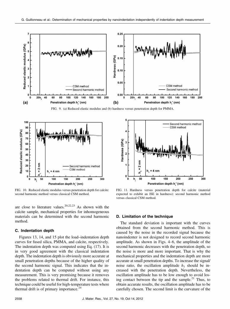
are close to literature values.20,22,23 As shown with the
calcite sample, mechanical properties for inhomogeneous
materials can be determined with the second harmonic
method.
C. Indentation depth
Figures 13, 14, and 15 plot the load–indentation depth
curves for fused silica, PMMA, and calcite, respectively.
The indentation depth was computed using Eq. (17). It is
in very good agreement with the classical indentation
depth. The indentation depth is obviously more accurate at
small penetration depths because of the higher quality of
the second harmonic signal. This indicates that the in-
dentation depth can be computed without using any
measurement. This is very promising because it removes
the problems related to thermal drift. For instance, this
technique could be useful for high-temperature tests where
thermal drift is of primary importance.24
D. Limitation of the technique
The standard deviation is important with the curves
obtained from the second harmonic method. This is
caused by the noise in the recorded signal because the
nanoindenter is not designed to record second harmonic
amplitude. As shown in Figs. 4–6, the amplitude of the
second harmonic decreases with the penetration depth, so
the noise is more and more important. That is why the
mechanical properties and the indentation depth are more
accurate at small penetration depths. To increase the signal/
noise ratio, the oscillation amplitude h1 should be in-
creased with the penetration depth. Nevertheless, the
oscillation amplitude has to be low enough to avoid los-
ing contact between the tip and the sample.21 Thus, to
obtain accurate results, the oscillation amplitude has to be
carefully chosen. The second limit is the curvature of the
FIG. 9. (a) Reduced elastic modulus and (b) hardness versus penetration depth for PMMA.
FIG. 10. Reduced elastic modulus versus penetration depth for calcite:
second harmonic method versus classical CSM method.
FIG. 11. Hardness versus penetration depth for calcite (material
expected to exhibit an ISE in hardness): second harmonic method
versus classical CSM method.
G. Guillonneau et al.: Determination of mechanical properties by nanoindentation independently of indentation depth measurement
J. Mater. Res., Vol. 27, No. 19, Oct 14, 20122558
unloading curve. For near fully plastic materials like
aluminum, which exhibits a quasilinear unloading curve,
the second harmonic signal is too small, so the present
method cannot be used.
VII. CONCLUSIONS
In this paper, a new technique based on the detection
of the amplitude of the second harmonic of displacement
signal has been proposed. With this new method, the
reduced elastic modulus and the hardness of materials can
be calculated. The obtained expressions do not depend on
the indentation depth, so uncertainties related to the
displacement measurement, especially at small penetra-
tion depths, are eliminated. Furthermore, the indentation
depth can be obtained without any use of displacement
measurement. This technique can be used for any
materials with constant Young modulus. The experimen-
tal tests show that the material mechanical properties of
fused silica and PMMA can be computed with precision
at penetration depths between 25 and 100 nm, which is
more difficult with classical tests because the uncertain-
ties related to the indentation depth calculation are very
influent in this penetration range. The tests realized on
calcite show that the technique can be applied to
materials exhibiting ISE, and that the hardness measured
with second harmonic method is more precise. In the last
part, the indentation depth was computed from second
harmonic method. The results obtained with this tech-
nique are close to the indentation depth as classically
measured. This innovative technique will be interesting
for high-temperature tests. Current apparatus, however,
are not designed to record precisely the second har-
monic, inducing scattering on the results. We expect
that future developments will include such type of
measurement.
FIG. 12. Hardness versus penetration depth for calcite assuming
a constant reduced elastic modulus value in the calculation of the
hardness with the CSM method.
FIG. 14. PMMA load–displacement curve obtained with displacement
measurement and second harmonic method.
FIG. 15. Calcite load–displacement curve obtained with displacement
measurement and second harmonic method.
FIG. 13. Fused silica load–displacement curve obtained with displace-
ment measurement and second harmonic method.
G. Guillonneau et al.: Determination of mechanical properties by nanoindentation independently of indentation depth measurement
J. Mater. Res., Vol. 27, No. 19, Oct 14, 2012 2559
REFERENCES
1. D. Tabor: The Hardness of Metals (Oxford University Press,
Oxford, UK, 2000).
2. D. Tabor: The hardness of solids. Rev. Phys. Technol. 1, 145–179
(1970).
3. S.I. Bulychev, V.P. Alekhin, M.K. Shorshorov, A.P. Ternovskii,
and G.D. Shnyrev: Determining Young modulus from the indenter
penetration diagram. Ind. Lab. 41, 1409–1412 (1975). (English
translation of Zavodskaya Laboratoriya).
4. J.L. Loubet, M. Bauer, A. Tonck, S. Bec, and B. Gauthier-Manuel:
Nano-indentation with a surface force apparatus. In Mechanical
Properties and Deformation of Materials Having Ultra-Fine
Microstructure. (NATO ASI Series - Series E : Applied Sciences,
vol. 233, Dordrecht, Netherlands, 1993); pp. 72–89.
5. J.L. Loubet, J.M. Georges, and G. Meille: Vickers Indentation
Curves of Elastoplastic Materials. Microindentation Techniques in
Materials Science and Engineering (American Society for Testing
and Materials, Philadelphia, PA, 1986); pp. 72–89.
6. W.C. Oliver andG.M. Pharr: An improved technique for determining
hardness and elastic-modulus using load and displacement sensing
indentation experiments. J. Mater. Res. 7, 1564–1583 (1992).
7. G.M. Pharr and A. Bolshakov: Understanding nanoindentation
unloading curves. J. Mater. Res. 17, 2660–2671 (2002).
8. W.C. Oliver and G.M. Pharr: Measurement of hardness and elastic
modulus by instrumented indentation: Advances in understanding
and refinements to methodology. J. Mater. Res. 19, 3–20 (2004).
9. M.F. Doerner and W.D. Nix: A method for interpreting the data
from depth-sensing indentation instruments. J. Mater. Res. 1,
601–609 (1986).
10. J.B. Pethica, R. Hutchings, and W.C. Oliver: Hardness measure-
ment at penetration depths as small as 20-nm. Philos. Mag. A
48, 593–606 (1983).
11. S.A.S. Asif, K.J.Wahl, and R.J. Colton: Nanoindentation and contact
stiffness measurement using force modulation with a capacitive load-
displacement transducer. Rev. Sci. Instrum. 70, 2408–2413 (1999).
12. G. Guillonneau, G. Kermouche, S. Bec, and J-L. Loubet: Extraction
of mechanical properties with second harmonic detection for
dynamic nanoindentation testing. Exp. Mech. 52, 933–944 (2012).
13. I.N. Sneddon: The relation between load and penetration in the
axisymmetric Boussinesq problem for a punch of arbitrary profile.
Int. J. Eng. Sci. 3, 47–57 (1965).
14. B.N. Lucas, W.C. Oliver, G.M. Pharr, and J-L. Loubet: Time
dependent deformation during indentation testing, in Thin Films:
Stresses and Mechanical Properties VI, edited by W.W. Gerberich,
H. Gao, J-E. Sundgren, and S.P. Baker (Mater. Res. Soc. Symp.
Proc. 436, Pittsburgh, PA, 1997); p. 233.
15. A.C. Fischer-Cripps: Nanoindentation (Springer-Verlag New York
Inc., New York, NY, 2002).
16. R.B. King: Elastic analysis of some punch problems for a layered
medium. Int. J. Solids Struct. 23, 1657–1664 (1987).
17. S. Bec, A. Tonck, J-M. Georges, E. Georges, and J.-L. Loubet:
Improvements in the indentation method with a surface force
apparatus. Philos. Mag. A 74, 1061 (1996).
18. G. Hochstetter, A. Jimenez, and J.L. Loubet: Strain-rate effects
on hardness of glassy polymers in the nanoscale range. Comparison
between quasi-static and continuous stiffness measurements.
J. Macromol. Sci. Part B Phys. 38, 681 (1999).
19. G.M. Pharr, W.C. Oliver, and F.R. Brotzen: On the generality of
the relationship among contact stiffness, contact area, and elastic
modulus during indentation. J. Mater. Res. 7, 613–617 (1992).
20. S. Zügner, K. Marquardt, and I. Zimmermann: Influence of nano-
mechanical crystal properties on the comminution process of
particulate solids in spiral jet mills. Eur. J. Pharm. Biopharm.
62, 194–201 (2006).
21. G.M. Pharr, J.H. Strader, andW.C. Oliver: Critical issues in making
small-depth mechanical property measurements by nanoindentation
with continuous stiffness measurement. J. Mater. Res. 24, 653–666
(2009).
22. M. Broz, R. Cook, and D. Whitney: Microhardness, toughness,
and modulus of Mohs scale minerals. Am. Mineral. 91, 135–142
(2006).
23. D.L. Whitney, M. Broz, and R.F. Cook: Hardness, toughness, and
modulus of some common metamorphic minerals. Am. Mineral.
92, 281–288 (2007).
24. C.A. Schuh, C.E. Packard, and A.C. Lund: Nanoindentation and
contact-mode imaging at high temperatures. J. Mater. Res. 3, 725–
736 (2006).
G. Guillonneau et al.: Determination of mechanical properties by nanoindentation independently of indentation depth measurement
J. Mater. Res., Vol. 27, No. 19, Oct 14, 20122560