Embed Size (px)
Citation preview
CITY OF SPOKANE
DEPARTMENT OF ENGINEERING SERVICES
DESIGN STANDARDS
FEBRUARY, 2007
City of Spokane Design Standards TABLE OF CONTENTS February 2007 Page i
CITY OF SPOKANE ENGINEERING SERVICES
DESIGN STANDARDS TABLE OF CONTENTS
1.0 OVERVIEW........................................................................................................... 1-1 1.1 Purpose and Scope........................................................................................................1-1 1.2 Definitions ......................................................................................................................1-1 1.3 References.....................................................................................................................1-2 1.4 Variance Requests .........................................................................................................1-3 1.5 Environmental Checklist.................................................................................................1-3 1.6 Design Coordination/Technical Assistance....................................................................1-3 1.7 Permits and Licenses.....................................................................................................1-4 1.8 Material Acceptance.......................................................................................................1-4 1.9 Amendments; Process and Authority .............................................................................1-4
2.0 DEVELOPER/CONSULTANT SERVICES ........................................................... 2-1 2.1 Definitions ......................................................................................................................2-1 2.2 Preliminary Procedures ..................................................................................................2-1 2.3 Design Review Submittals..............................................................................................2-1 2.4 Penalties ........................................................................................................................2-6
3.0 STREETS, ALLEYS AND BIKEWAYS................................................................. 3-1 3.1 Definitions ......................................................................................................................3-1 3.2 Right of Way...................................................................................................................3-3 3.3 Roadways and Alleys .....................................................................................................3-3
3.3-1 Street Width............................................................................................................3-3 3.3-2 Turnarounds ...........................................................................................................3-3 3.3-3 Entrance Gates ......................................................................................................3-4 3.3-4 Queuing Area .........................................................................................................3-4 3.3-5 Intersections ...........................................................................................................3-4 3.3-6 On-Street Parking...................................................................................................3-4 3.3-7 Alleys......................................................................................................................3-4 3.3-8 Profile Grades ........................................................................................................3-4 3.3-9 Horizontal Curves...................................................................................................3-5 3.3-10 Vertical Curves .....................................................................................................3-5 3.3-11 Through Traffic Lanes ..........................................................................................3-5 3.3-12 Exclusive Turn Lanes ...........................................................................................3-5 3.3-13 Tapers ..................................................................................................................3-5 3.3-14 Medians................................................................................................................3-5 3.3-15 Bus Zones ............................................................................................................3-5 3.3-16 Roundabouts ........................................................................................................3-5 3.3-17 Roadway Side Slopes ..........................................................................................3-5 3.3-18 Roadway Drainage...............................................................................................3-6 3.3-19 Pavement Markings..............................................................................................3-6 3.3-20 Monuments...........................................................................................................3-6 3.3-21 Asphalt Binder Selection ......................................................................................3-6 3.3-22 Pavement Section Thickness ...............................................................................3-6 3.3-23 Pavement Patching ..............................................................................................3-7
3.4 Curbs, Gutters, Pedestrian Buffer Strips, Driveways and Sidewalks .............................3-7 3.4-1 Curbs and Gutters ..................................................................................................3-7
TABLE OF CONTENTS City of Spokane Design Standards Page ii February 2007
3.4-2 Sidewalks ...............................................................................................................3-7 3.4-3 Pedestrian Buffer Strips .........................................................................................3-8 3.4-4 Curb Ramps ...........................................................................................................3-8 3.4-5 Driveways...............................................................................................................3-8
3.5 Roadside Planting ..........................................................................................................3-9 3.5-1 Existing Street Trees ..............................................................................................3-9 3.5-2 New Street Trees ...................................................................................................3-9
3.6 Signing and Illumination ...............................................................................................3-10 3.6-1 Street Signs..........................................................................................................3-10 3.6-2 Street Lighting and Traffic Signalization...............................................................3-10
3.7 Clearances/Clear Zones...............................................................................................3-11 3.7-1 Vertical Clearances ..............................................................................................3-11 3.7-2 Horizontal Clearances ..........................................................................................3-11 3.7-3 Clear Zones..........................................................................................................3-11
3.8 Bikeways ......................................................................................................................3-11 3.9 Tables and Figures.......................................................................................................3-12
4.0 SANITARY SEWERS ........................................................................................... 4-1 4.1 Definitions ......................................................................................................................4-1 4.2 Public Sewers.................................................................................................................4-3
4.2-1 Pipe Sizes ..............................................................................................................4-3 4.2-2 Pipe Slopes ............................................................................................................4-4 4.2-3 Pipe Depth..............................................................................................................4-4 4.2-4 Roughness Coefficient ...........................................................................................4-5 4.2-5 Horizontal Alignment ..............................................................................................4-5 4.2-6 Vertical Alignment ..................................................................................................4-5 4.2-7 Manholes................................................................................................................4-5 4.2-8 Temporary Manholes .............................................................................................4-5 4.2-9 Combined Sewers ..................................................................................................4-6 4.2-10 Separation of Sewers and Other Utilities .............................................................4-6 4.2-11 Easements ...........................................................................................................4-6
4.3 Side Sewers ...................................................................................................................4-6 4.3-1 Pipe Size and Alignment ........................................................................................4-6 4.3-2 Pipe Depth..............................................................................................................4-6 4.3-3 Connection to Manholes and Catch Basins ...........................................................4-6 4.3-4 Connection to Public Sewer Main ..........................................................................4-6 4.3-5 Cleanouts ...............................................................................................................4-6
4.4 Private Sewers ...............................................................................................................4-7 4.5 Tables and Figures.........................................................................................................4-8
5.0 WASTEWATER PUMP STATIONS...................................................................... 5-1 5.1 Definitions ......................................................................................................................5-1 5.2 General Requirements ...................................................................................................5-2
5.2-1 Minimal Pump Station Design Requirements.........................................................5-2 5.3 Site Selection and Plan ..................................................................................................5-3
5.3-1 Location..................................................................................................................5-3 5.3-2 Security/Equipment Protection ...............................................................................5-3 5.3-3 Temporary Lift Stations ..........................................................................................5-3
5.4 Station Access................................................................................................................5-4 5.5 Wet Pit/Dry Pit Station Design........................................................................................5-4
5.5-1 Wet Pit Layout ........................................................................................................5-4
City of Spokane Design Standards TABLE OF CONTENTS February 2007 Page iii
5.5-2 Wet Pit Storage Volume .........................................................................................5-4 5.5-3 Wet Pit Detention Time ..........................................................................................5-5 5.5-4 Odor Control...........................................................................................................5-5 5.5-5 Dry Pit Design ........................................................................................................5-5
5.6 Submersible Station Design...........................................................................................5-5 5.7 Pumps ............................................................................................................................5-6
5.7-1 Cycle Time .............................................................................................................5-6 5.7-2 Pump Control Staging ............................................................................................5-6 5.7-3 Number of Pumps ..................................................................................................5-6 5.7-4 Net Positive Suction Head (NPSH) ........................................................................5-7 5.7-5 Head Loss Curves..................................................................................................5-7 5.7-6 Additional Pump Design Parameters .....................................................................5-7 5.7-7 Bypass Piping.........................................................................................................5-8
5.8 Force Mains....................................................................................................................5-8 5.9 Power Supply .................................................................................................................5-9 5.10 Emergency Operation ..................................................................................................5-9
5.10-1 Emergency Power ................................................................................................5-9 5.10-2 Emergency Storage..............................................................................................5-9
5.11 Miscellaneous Equipment and Appurtenances ............................................................5-9 5.11-1 Screens, Racks and Traps ...................................................................................5-9 5.11-2 Controls/Flow Monitoring......................................................................................5-9 5.11-3 Valves.................................................................................................................5-10 5.11-4 Ventilation...........................................................................................................5-10 5.11-5 Alarm System .....................................................................................................5-10 5.11-6 Trolleys/Hoists....................................................................................................5-10 5.11-7 Egress ................................................................................................................5-10 5.11-8 Auxiliary Generating Equipment.........................................................................5-10
5.12 Buoyancy Calculations...............................................................................................5-11 5.13 Water Hammer Calculations ......................................................................................5-11 5.14 Thrust Restraint for Force Mains................................................................................5-12 5.15 Private Pump Stations................................................................................................5-12 5.16 Exceptions..................................................................................................................5-12 5.17 Tables and Figures.....................................................................................................5-13
6.0 STORM WATER MANAGEMENT ........................................................................ 6-1 6.1 Definitions ......................................................................................................................6-1 6.2 Calculation of Runoff and Soil Permeability ...................................................................6-4
6.2-1 Runoff Calculations - Drainage Areas 10 Acres or Less ........................................6-4 6.2-2 Runoff Calculations - Drainage Areas over 10 Acres.............................................6-4 6.2-3 Soil Permeability and Infiltration Rate ....................................................................6-4
6.3 Methods of Stormwater Conveyance and Disposal .......................................................6-4 6.3-1 Gutter Flow.............................................................................................................6-4 6.3-2 Grass Percolation Areas (GPA’s)...........................................................................6-5 6.3-3 Infiltration Galleries.................................................................................................6-5 6.3-4 Absorption Trenches ..............................................................................................6-5 6.3-5 Drywells..................................................................................................................6-6 6.3-6 Sedimentation and Detention Structures................................................................6-6 6.3-7 Storm Sewers.........................................................................................................6-6 6.3-8 Combined Sewers ..................................................................................................6-7
6.4 Stormwater Drainage in the Public Right of Way ...........................................................6-7 6.4-1 Hydraulic Design of Roadways, Gutters and Culverts ...........................................6-7
TABLE OF CONTENTS City of Spokane Design Standards Page iv February 2007
6.4-2 Preferred Stormwater Disposal Methods in the Public Right of Way .....................6-7 6.4-3 Draining Stormwater from the Public Right of Way to Private Property .................6-8
6.5 Stormwater Drainage on Private Property......................................................................6-8 6.5-1 Grading/Erosion Control Plans...............................................................................6-8 6.5-2 On-Site Stormwater Disposal .................................................................................6-8
6.7 Tables and Figures........................................................................................................6-9 6.8 References...................................................................................................................6-13
7.0 EROSION AND SEDIMENT CONTROL PLANS <RESERVED>........................ 7-1
8.0 WATER ................................................................................................................. 8-1 8.1 Definitions ......................................................................................................................8-1 8.2 Water Demands .............................................................................................................8-1
8.2-1 Average Day and Maximum Day Demands ...........................................................8-1 8.2-2 Peak Hour Demands ..............................................................................................8-2 8.2-3 Fire Flow Demands ................................................................................................8-2 8.2-4 Hydraulic Modeling.................................................................................................8-2
8.3 Water Pressure ..............................................................................................................8-3 8.4 Size of Pipe ....................................................................................................................8-3
8.4-1 Standard Sizes .......................................................................................................8-3 8.4-2 Sizing Based on Velocity........................................................................................8-4
8.5 Type of Pipe ...................................................................................................................8-4 8.6 Location For Fittings, Valves, Air Valves, Blow-Off Valves .............................................8-4
8.6-1 Distribution Mains...................................................................................................8-4 8.6-2 Transmission Mains ...............................................................................................8-4 8.6-3 Pipe Thrust Restraint Design .................................................................................8-5
8.7 Depth of Pipes................................................................................................................8-6 8.8 Location of Fire Hydrants ...............................................................................................8-6 8.9 Distance From Other Utilities .........................................................................................8-6 8.10 Pressure Systems ........................................................................................................8-6 8.11 Laying Pipe on a Radius ..............................................................................................8-7 8.12 Easements ...................................................................................................................8-7 8.13 Special Regulations for P.U.D.'s ..................................................................................8-7 8.14 Booster Stations...........................................................................................................8-7 8.15 Reservoirs ..................................................................................................................8-10 8.16 Tables and Figures.....................................................................................................8-11 8.17 References.................................................................................................................8-12
9.0 TRAFFIC CONTROL DEVICES <RESERVED>.................................................. 9-1
10.0 DRAFTING/CADD STANDARDS..................................................................... 10-1 10.1 General ......................................................................................................................10-1
10.1-1 Flat Sheet Segment Identity ...............................................................................10-1 10.1-2 Multiple Utility Lines in a Single Segment ..........................................................10-2 10.1-3 Title Blocks .........................................................................................................10-2
10.2 Standard Symbols and Line Types ............................................................................10-3 10.3 Construction Drawings ...............................................................................................10-3
10.3-1 Cover Sheet .......................................................................................................10-3 10.3-2 Plans, Profiles and Details - All Projects ............................................................10-4 10.3-3 Street Drawings..................................................................................................10-5 10.3-4 Sanitary/Storm Sewer and Water Drawings.......................................................10-6 10.3-5 Grading, Erosion Control and Stormwater Drawings .........................................10-6
City of Spokane Design Standards TABLE OF CONTENTS February 2007 Page v
10.4 Record Drawings........................................................................................................10-7
11.0 CONTRACT DOCUMENTS .............................................................................. 11-1 11.1 Plan Sets....................................................................................................................11-1 11.2 Specifications .............................................................................................................11-1
LIST OF FIGURES Figure 1-1 Engineering Services Organization Chart Figure 4-1 Circular Channel Ratios (variable n) Figure 5-1 Pump-Head Relationships Figure 5-2 Bypass Piping Example Figure 6-1 Rainfall Intensity-Duration Frequency Curves Figure 6-2 Example Swale Configuration in Public Right of Way LIST OF TABLES Table 3-A Arterial and Commercial Roadway Requirements and Widths Table 3-B Residential Local Access Roadway Requirements and Widths Table 3-C Vertical Curve Design Parameters Table 3-D Side Slopes Table 3-E Street Profile Grades Table 3-F Curb Design Parameters Table 3-G Sidewalk and Pedestrian Buffer Strip Design Parameters Table 6-A Minimum Design Storm Frequencies for Hydraulic Structures Table 6-B Runoff Coefficients for Determining Peak Discharge* Table 8-A Pipe Restraint Table APPENDICES APPENDIX A - Record Drawings Policy APPENDIX B - Drawing Layout and Electronic File Naming APPENDIX C - City of Spokane Drafting Standards APPENDIX D - Sample Plans APPENDIX E - Underground Utility Location APPENDIX F - Other Policies and Ordinances
City of Spokane Design Standards 1.0 OVERVIEW February 2007 Page 1-1
1.0 OVERVIEW
1.1 Purpose and Scope The purpose of these Standards is to standardize design elements where necessary for consistency and to help assure that the minimum requirements of the public are met, including safety, welfare, convenience, aesthetics and economical maintenance.
These Standards cannot provide for all situations. They are intended to assist, but not to substitute for competent work by design professionals. It is expected that land surveyors, engineers, and architects will bring to each project the best skills and abilities from their respective disciplines to see that the project is designed in a manner consistent with the intent of the Standards.
These Standards are not intended to limit unreasonably any innovative or creative effort which could result in higher quality, lower cost or both. Any proposed departure from these Standards will be judged, however, on the likelihood that such variance produces a compensating or comparable result, in every way suitable for public use.
These Standards shall govern design for new construction and major upgrades to all streets, sewers, water lines and other utilities in new or existing City rights-of-way, easements or areas which are proposed for dedication to the City of Spokane.
Before the City accepts any improvements which are to be maintained by City forces, such improvements shall meet or exceed these Standards.
If any part of these Design Standards is found to be invalid, all other non-conflicting parts shall remain in effect.
1.2 Definitions The following definitions apply to terms and abbreviations used throughout this manual. Additional terms applicable to specific aspects of design are defined at the beginning of each section.
AASHTO The American Association of State Highway Transportation Officials. The abbreviation may also be used throughout these Standards to reference AASHTO's publication, "A Policy on Geometric Design of Highways and Streets".
ADA Americans with Disabilities Act.
ADAAG Americans with Disabilities Act Accessibility Guidelines.
Applicant An individual or firm applying for design approval from the City for a project.
AWWA The American Water Works Association.
Designer The project engineer or architect.
Developer Refers to the owner (or financial sponsor) of a privately funded project. May also be taken to mean the owner's consulting architect, engineer or other agent.
Engineer The Director of Engineering Services, Streets, Water or Wastewater Management as applicable or his designated representative.
MUTCD The U.S. Department of Transportation Manual on Uniform Traffic Control Devices.
Owner Legal owner of the property on which a project is to be constructed.
Private Project A project which is to be constructed on privately-owned property.
Public Project A project which is to be constructed within the public right-of-way. Public projects may be designed by either private consultants or the City's in-house engineering staff.
1.0 OVERVIEW City of Spokane Design Standards Page 1-2 February 2007
P.U.D or PUD "Planned Unit Development". A privately developed project normally consisting of multiple residences or commercial units within a single tax parcel. Typically water, sewer and roadway systems within a P.U.D. are privately owned, with maintenance for these systems funded through home owner association dues or a similar arrangement.
RCW Revised Code of Washington.
SEPA State Environmental Policy Act.
SMC Spokane Municipal Code.
Specifications Defined as the most current versions of the following documents: 1. WSDOT Standard Specifications for Road, Bridge and Municipal Construction and the and
amendments thereto 2. the City of Spokane General Special Provisions for Private Development (which are intended
for privately funded projects) or City of Spokane General Special Provisions (which are intended for City funded projects). Henceforth both are referred to as City of Spokane GSPs.
STA Spokane Transit Authority.
Standard Plans The City of Spokane Standard Plans.
Variance A grant of relief from the requirements of this section that permits construction in a manner that would otherwise be prohibited by these design standards.
WSDOT Washington State Department of Transportation.
1.3 References Except where these Standards provide otherwise, design, detail, workmanship, and materials shall be in accordance with the current editions of the following publications:
a) Standard Specifications for Road, Bridge, and Municipal Construction as amended. (Published by WSDOT).
b) City of Spokane GSPs. c) Spokane Regional Stormwater Manual. d) WSDOT Standard Plans for Road and Bridge Construction.. e) WSDOT Design Manual. f) WSDOT Hydraulics Manual. g) NRCS Urban Hydrology for Small Water Sheds TR-55. h) AWWA Standards. i) WSDOH Water System Design Manual. j) Department of Transportation Manual on Uniform Traffic Control Devices, as amended
(MUTCD). k) A Policy on Geometric Design of Highways and Streets (AASHTO). l) Americans with Disabilities Act Accessibility Guidelines for Buildings and Facilities
(ADAAG). (Published by the U.S. Architectural and Transportation Barriers Compliance Board).
m) Spokane Transit Authority Design Guidelines. n) Washington State Department of Ecology Criteria for Sewage Works Design. o) City and County Design Standards for the Construction of Urban and Rural Arterials and
Collectors, Washington State. (Published by WSDOT.) p) The following elements of the City of Spokane Comprehensive Plan:
• Arterial Street Plan • Bikeways Plan • Comprehensive Water Management Plan • Critical Areas Report • Downtown Spokane Development Plan • Fire Station Plan • Growth Management Plan • Historic Preservation Plan
City of Spokane Design Standards 1.0 OVERVIEW February 2007 Page 1-3
• Land Use Plan • North River Bank Design Plan • Park and Open Spaces Plan • Sewerage Facilities Plan • Shorelines Plan • Solid Waste Management Plan • Wastewater System Plan • Wetlands Plan • Neighborhood Design Plans:
Browne's Addition Chief Garry Park East Central Emerson Garfield Hillyard Latah Creek Lincoln Heights Logan Manito Cannon Hill Nevada-Lidgerwood North Hill Peaceful Valley West Central
n) Other specifications. These include the following, which shall be applicable when pertinent, when specifically cited in the Standards, or when required by funding authorities. This list is not intended to be all inclusive, and designers are responsible to meet all requirements applicable to their project(s). 1. City of Spokane codes and ordinances. 2. International Building Code (IBC). 3. Design criteria of governing federal and state agencies.
1.4 Variance Requests To gain approval for a variance from these Design Standards, the designer shall complete and submit a "Variance Request Form" to the Engineering Services Department, documenting the reasons for the variance request. Additional supporting information, plans or design data prepared by a professional engineer, licensed in the State of Washington should be attached to the form as needed.
Variances from these Standards may be granted by the Engineer upon evidence that such variances are in the public interest, and that requirements for safety, function, fire protection, appearance, and maintainability are fully met.
Variances must be approved prior to construction. Whenever the need for a variance can be identified in advance, the variance should be proposed at the preliminary design stage and included for consideration during plan review and public hearing.
1.5 Environmental Checklist The State Environmental Policy Act (SEPA) chapter 43.21C RCW, requires all governmental agencies to consider the environmental impacts of a proposal before making decisions. The SEPA environmental checklist, together with the SEPA rules contained in chapter 197-11 WAC are used as guidelines to assess the probable environmental impact of any development which is not otherwise exempt from the process. Categorical exemption guidelines and thresholds are described and defined in the above references. Use of the SEPA checklist provides information to help the developer reduce or avoid impacts from the proposal and to help the agency determine whether an environmental impact statement (EIS) is required. An EIS must be prepared for all proposals with probable significant adverse impacts on the quality of the environment.
The designer is referred to the Spokane Environmental Ordinance (SMC 17E.050), adopted by the City of Spokane on September 17, 1984; and the Spokane Wetlands Protection Ordinance (SMC 11.19), adopted on November 1, 1993.
1.6 Design Coordination/Technical Assistance Design in accordance with the Standards presented herein will often involve coordinating with
1.0 OVERVIEW City of Spokane Design Standards Page 1-4 February 2007
individual sections of the Engineering Services department, and with City departments and divisions outside of Engineering Services. Throughout these Standards, the designer is referred to appropriate City agencies as needed.
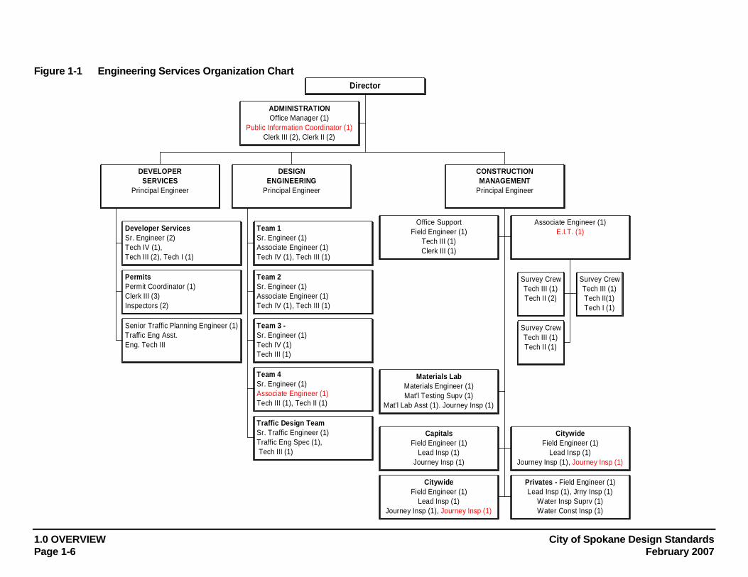
Figure 1-1 is provided to show the organization of the Engineering Services Department.
1.7 Permits and Licenses Applicants are responsible to acquire all permits and licenses necessary for the completion of the project. The City of Spokane will not be held responsible, financially or otherwise, for any delay or additional expenses the applicant may incur due to the Applicant's oversight in obtaining all necessary permits and licenses.
1.8 Material Acceptance It shall be the applicant's responsibility to provide the City with a materials acceptance list for all materials used on the project when required by the City. The materials acceptance list shall confirm that the items meet City specifications through supplier's verification, materials testing reports or reports stamped and signed by a professional engineer.
All reports, materials verifications and other documents submitted to the City for acceptance shall be stamped and signed by an engineer.
If the Applicant desires to have materials tested after non-acceptance by the City, all materials testing shall be at the expense of the applicant.
1.9 Amendments; Process and Authority The Engineer has the authority to oversee, approve and implement all amendments issued to these Design Standards. Noted errors or suggested revisions to these Standards should be addressed to the Engineer. All such suggested amendments must be in writing, identifying an issue, providing supporting information as well as providing a suggestion on how to address the issue.
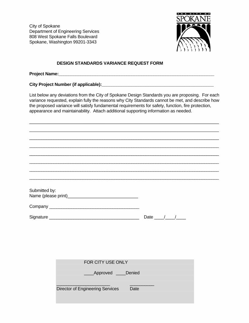
City of Spokane Department of Engineering Services 808 West Spokane Falls Boulevard Spokane, Washington 99201-3343 DESIGN STANDARDS VARIANCE REQUEST FORM Project Name:________________________________________________________________ City Project Number (if applicable):______________________________________________ List below any deviations from the City of Spokane Design Standards you are proposing. For each variance requested, explain fully the reasons why City Standards cannot be met, and describe how the proposed variance will satisfy fundamental requirements for safety, function, fire protection, appearance and maintainability. Attach additional supporting information as needed. ______________________________________________________________________________
______________________________________________________________________________
______________________________________________________________________________
______________________________________________________________________________
______________________________________________________________________________
______________________________________________________________________________
______________________________________________________________________________
______________________________________________________________________________
Submitted by: Name (please print)_____________________________ Company _____________________________________ Signature _____________________________________ Date ____/____/____
FOR CITY USE ONLY ____Approved ____Denied ______________________ __________ Director of Engineering Services Date
1.0 OVERVIEW City of Spokane Design Standards Page 1-6 February 2007
ADMINISTRATIONOffice Manager (1)
Public Information Coordinator (1)Clerk III (2), Clerk II (2)
Developer ServicesSr. Engineer (2)Tech IV (1),Tech III (2), Tech I (1)
PermitsPermit Coordinator (1)Clerk III (3)Inspectors (2)
Senior Traffic Planning Engineer (1)Traffic Eng Asst.Eng. Tech III
DEVELOPERSERVICES
Principal Engineer
Team 1Sr. Engineer (1)Associate Engineer (1)Tech IV (1), Tech III (1)
Team 2Sr. Engineer (1)Associate Engineer (1)Tech IV (1), Tech III (1)
Team 3 -Sr. Engineer (1)Tech IV (1)Tech III (1)
Team 4Sr. Engineer (1)Associate Engineer (1)Tech III (1), Tech II (1)
Traffic Design TeamSr. Traffic Engineer (1)Traffic Eng Spec (1), Tech III (1)
DESIGNENGINEERING
Principal Engineer
Office SupportField Engineer (1)
Tech III (1)Clerk III (1)
Survey CrewTech III (1)Tech II (2)
Survey CrewTech III (1)Tech II(1)Tech I (1)
Survey CrewTech III (1)Tech II (1)
Associate Engineer (1)E.I.T. (1)
Materials LabMaterials Engineer (1)Mat'l Testing Supv (1)
Mat'l Lab Asst (1). Journey Insp (1)
CapitalsField Engineer (1)
Lead Insp (1)Journey Insp (1)
CitywideField Engineer (1)
Lead Insp (1)Journey Insp (1), Journey Insp (1)
CitywideField Engineer (1)
Lead Insp (1)Journey Insp (1), Journey Insp (1)
Privates - Field Engineer (1)Lead Insp (1), Jrny Insp (1)
Water Insp Suprv (1)Water Const Insp (1)
CONSTRUCTIONMANAGEMENT
Principal Engineer
Director
Figure 1-1 Engineering Services Organization Chart

City of Spokane Design Standards 1.0 OVERVIEW February 2007 Page 1-7
Developer Services reviews plat applications, provides property information, existing water and sewer service information, facilitates the street vacation process, performs plan review of proposed private projects, certificate of occupancy inspections for completed private projects related to wastewater, street, sidewalk and on-site stormwater treatment issues, and routine sewer, street and sidewalk inspections.
Design is responsible for designing street, water, sanitary sewer, and storm water facilities, manages consultant engineer contracts for peak workload and specialty design work, maintains City of Spokane GSPs, Standard Plans, design standards, bid estimate system, and contract provisions system, reviews design variances and represents the City in statewide standards committees, coordinates state and federal requirements for inclusion in local and federal funded projects, administers the local improvement district (LID) system and the engineering drawing archive system, provides technical engineering support to other City departments, provides project, non-project, and traffic engineering information to the public through public meetings, letters and individual visits.
Traffic Design is responsible for construction design and management of traffic elements of projects, such as signals, street striping and signing; traffic planning; and review of development projects.
Construction Management is tasked with management of public works projects in the field and inspection of privately funded construction of infrastructure which will be turned over to the City.
City of Spokane Design Standards 2.0 DEVELOPER/CONSULTANT SERVICES February 2007 Page 2-1
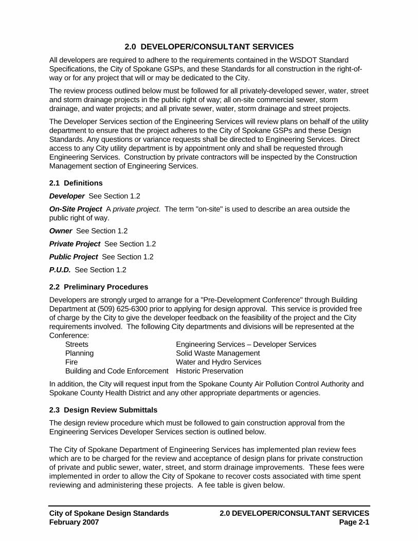
2.0 DEVELOPER/CONSULTANT SERVICES All developers are required to adhere to the requirements contained in the WSDOT Standard Specifications, the City of Spokane GSPs, and these Standards for all construction in the right-of-way or for any project that will or may be dedicated to the City.
The review process outlined below must be followed for all privately-developed sewer, water, street and storm drainage projects in the public right of way; all on-site commercial sewer, storm drainage, and water projects; and all private sewer, water, storm drainage and street projects.
The Developer Services section of the Engineering Services will review plans on behalf of the utility department to ensure that the project adheres to the City of Spokane GSPs and these Design Standards. Any questions or variance requests shall be directed to Engineering Services. Direct access to any City utility department is by appointment only and shall be requested through Engineering Services. Construction by private contractors will be inspected by the Construction Management section of Engineering Services.
2.1 Definitions Developer See Section 1.2
On-Site Project A private project. The term "on-site" is used to describe an area outside the public right of way.
Owner See Section 1.2
Private Project See Section 1.2
Public Project See Section 1.2
P.U.D. See Section 1.2
2.2 Preliminary Procedures Developers are strongly urged to arrange for a "Pre-Development Conference" through Building Department at (509) 625-6300 prior to applying for design approval. This service is provided free of charge by the City to give the developer feedback on the feasibility of the project and the City requirements involved. The following City departments and divisions will be represented at the Conference:
Streets Engineering Services – Developer Services Planning Solid Waste Management Fire Water and Hydro Services Building and Code Enforcement Historic Preservation
In addition, the City will request input from the Spokane County Air Pollution Control Authority and Spokane County Health District and any other appropriate departments or agencies.
2.3 Design Review Submittals The design review procedure which must be followed to gain construction approval from the Engineering Services Developer Services section is outlined below. The City of Spokane Department of Engineering Services has implemented plan review fees which are to be charged for the review and acceptance of design plans for private construction of private and public sewer, water, street, and storm drainage improvements. These fees were implemented in order to allow the City of Spokane to recover costs associated with time spent reviewing and administering these projects. A fee table is given below.
2.0 DEVELOPER/CONSULTANT SERVICES City of Spokane Design Standards Page 2-2 February 2007
The following summarizes the design review process for private projects: 1. A transmittal letter is to be forwarded to the Department of Engineering Services –
Developer Services. This transmittal letter is to be from the design Engineer/ Architect who is submitting the design plans and requesting the review and acceptance, and is to contain the following information:
a. The name of the design project b. The type(s) of facilities included for project review c. The design plan sheets which are being included for review d. The name, address, and phone number of the owner of the project e. The name of the individual/ organization who will pay the appropriate plan review
and inspection fees and/ or charges f. A request for permission to construct the project.
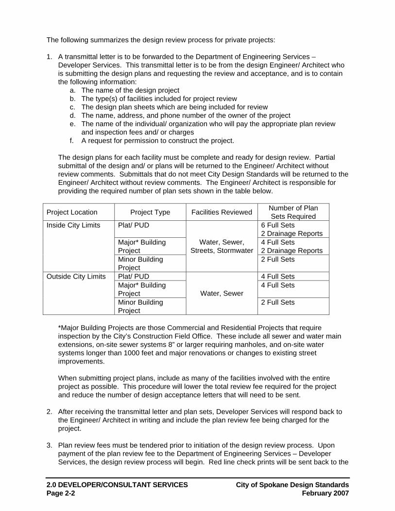
The design plans for each facility must be complete and ready for design review. Partial submittal of the design and/ or plans will be returned to the Engineer/ Architect without review comments. Submittals that do not meet City Design Standards will be returned to the Engineer/ Architect without review comments. The Engineer/ Architect is responsible for providing the required number of plan sets shown in the table below.
Project Location Project Type Facilities Reviewed Number of Plan Sets Required
Plat/ PUD 6 Full Sets 2 Drainage Reports
Major* Building Project
4 Full Sets 2 Drainage Reports
Inside City Limits
Minor Building Project
Water, Sewer, Streets, Stormwater
2 Full Sets
Plat/ PUD 4 Full Sets Major* Building Project
4 Full Sets Outside City Limits
Minor Building Project
Water, Sewer 2 Full Sets
*Major Building Projects are those Commercial and Residential Projects that require inspection by the City’s Construction Field Office. These include all sewer and water main extensions, on-site sewer systems 8” or larger requiring manholes, and on-site water systems longer than 1000 feet and major renovations or changes to existing street improvements. When submitting project plans, include as many of the facilities involved with the entire project as possible. This procedure will lower the total review fee required for the project and reduce the number of design acceptance letters that will need to be sent.
2. After receiving the transmittal letter and plan sets, Developer Services will respond back to
the Engineer/ Architect in writing and include the plan review fee being charged for the project.
3. Plan review fees must be tendered prior to initiation of the design review process. Upon
payment of the plan review fee to the Department of Engineering Services – Developer Services, the design review process will begin. Red line check prints will be sent back to the
City of Spokane Design Standards 2.0 DEVELOPER/CONSULTANT SERVICES February 2007 Page 2-3
design Engineer/ Architect along with a plan review comment letter. These red line check prints must be returned for re-review along with a set of corrected plans. A letter indicating how each of the review comments was addressed or a reason for not making the changes must be included with the re-submittal. If the red lines are not returned, or changes are not properly addressed, the review of the plans will be delayed and/ or additional plan review fees may be charged.
4. During the review process, if the design of the project should change and/ or new plans are
re-submitted for review after they have already once been reviewed, an additional plan review fee will be assessed. The additional review fee will be based on the cost of construction for the length of the project which is being re-submitted. Payment of this additional fee will be required before a new review is initiated.
5. Once the project design plans are complete, and all other items relating to the project have
been completed, the review engineer will request that mylar copies of the plans be submitted. The letter giving acceptance of the design and permission to construct will be prepared for signature by the project owner and the review engineer. Copies of the letter and plans will be provided to all involved with the project. One copy of stamped, accepted design plans is provided to the design engineer and three copies of the stamped, accepted design plans are provided to the owner/ developer. If additional copies are needed, an additional fee will be charged. If, at a later date, additional design approval letters must be prepared and/ or additional copies of any plans must be made due to developer design changes or request, there will be an additional charge. Letter preparation will be charged $50 and copies of plans will be charged $2 each. These additional charges will be collected prior to the requested action.
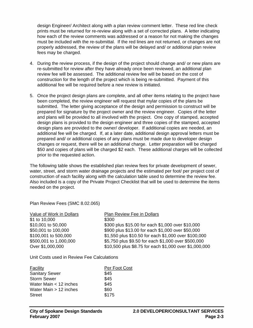
The following table shows the established plan review fees for private development of sewer, water, street, and storm water drainage projects and the estimated per foot/ per project cost of construction of each facility along with the calculation table used to determine the review fee. Also included is a copy of the Private Project Checklist that will be used to determine the items needed on the project.
Plan Review Fees (SMC 8.02.065) Value of Work in Dollars Plan Review Fee in Dollars $1 to 10,000 $300 $10,001 to 50,000 $300 plus $15.00 for each $1,000 over $10,000 $50,001 to 100,000 $900 plus $13.00 for each $1,000 over $50,000 $100,001 to 500,000 $1,550 plus $10.50 for each $1,000 over $100,000 $500,001 to 1,000,000 $5,750 plus $9.50 for each $1,000 over $500,000 Over $1,000,000 $10,500 plus $8.75 for each $1,000 over $1,000,000 Unit Costs used in Review Fee Calculations Facility Per Foot Cost Sanitary Sewer $45 Storm Sewer $45 Water Main < 12 inches $45 Water Main > 12 inches $60 Street $175
2.0 DEVELOPER/CONSULTANT SERVICES City of Spokane Design Standards Page 2-4 February 2007
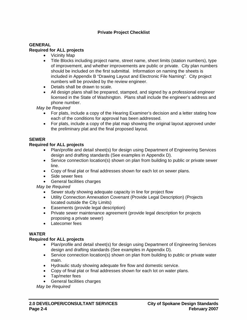
Private Project Checklist
GENERAL Required for ALL projects
• Vicinity Map • Title Blocks including project name, street name, sheet limits (station numbers), type
of improvement, and whether improvements are public or private. City plan numbers should be included on the first submittal. Information on naming the sheets is included in Appendix B “Drawing Layout and Electronic File Naming”. City project numbers will be provided by the review engineer.
• Details shall be drawn to scale. • All design plans shall be prepared, stamped, and signed by a professional engineer
licensed in the State of Washington. Plans shall include the engineer’s address and phone number.
May be Required • For plats, include a copy of the Hearing Examiner’s decision and a letter stating how
each of the conditions for approval has been addressed. • For plats, include a copy of the plat map showing the original layout approved under
the preliminary plat and the final proposed layout. SEWER Required for ALL projects
• Plan/profile and detail sheet(s) for design using Department of Engineering Services design and drafting standards (See examples in Appendix D).
• Service connection location(s) shown on plan from building to public or private sewer line.
• Copy of final plat or final addresses shown for each lot on sewer plans. • Side sewer fees • General facilities charges
May be Required • Sewer study showing adequate capacity in line for project flow • Utility Connection Annexation Covenant (Provide Legal Description) (Projects
located outside the City Limits) • Easements (provide legal description) • Private sewer maintenance agreement (provide legal description for projects
proposing a private sewer) • Latecomer fees
WATER Required for ALL projects
• Plan/profile and detail sheet(s) for design using Department of Engineering Services design and drafting standards (See examples in Appendix D).
• Service connection location(s) shown on plan from building to public or private water main.
• Hydraulic study showing adequate fire flow and domestic service. • Copy of final plat or final addresses shown for each lot on water plans. • Tap/meter fees • General facilities charges
May be Required
City of Spokane Design Standards 2.0 DEVELOPER/CONSULTANT SERVICES February 2007 Page 2-5
• Utility connection annexation covenant (provide legal description for projects located outside the city limits)
• Easements (provide legal description) • Fire district approval (projects located outside the City Limits) • Latecomer fees
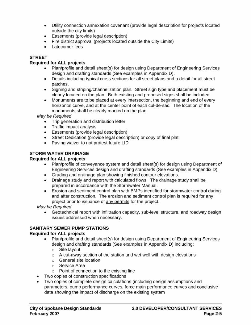
STREET Required for ALL projects
• Plan/profile and detail sheet(s) for design using Department of Engineering Services design and drafting standards (See examples in Appendix D).
• Details including typical cross sections for all street plans and a detail for all street patches.
• Signing and striping/channelization plan. Street sign type and placement must be clearly located on the plan. Both existing and proposed signs shall be included.
• Monuments are to be placed at every intersection, the beginning and end of every horizontal curve, and at the center point of each cul-de-sac. The location of the monuments shall be clearly marked on the plan.
May be Required • Trip generation and distribution letter • Traffic impact analysis • Easements (provide legal description) • Street Dedication (provide legal description) or copy of final plat • Paving waiver to not protest future LID
STORM WATER DRAINAGE Required for ALL projects
• Plan/profile of conveyance system and detail sheet(s) for design using Department of Engineering Services design and drafting standards (See examples in Appendix D).
• Grading and drainage plan showing finished contour elevations. • Drainage study and report with calculated flows. The drainage study shall be
prepared in accordance with the Stormwater Manual. • Erosion and sediment control plan with BMPs identified for stormwater control during
and after construction. The erosion and sediment control plan is required for any project prior to issuance of any permits for the project.
May be Required • Geotechnical report with infiltration capacity, sub-level structure, and roadway design
issues addressed when necessary. SANITARY SEWER PUMP STATIONS Required for ALL projects
• Plan/profile and detail sheet(s) for design using Department of Engineering Services design and drafting standards (See examples in Appendix D) including: o Site layout o A cut-away section of the station and wet well with design elevations o General site location o Service Area o Point of connection to the existing line
• Two copies of construction specifications • Two copies of complete design calculations (including design assumptions and
parameters, pump performance curves, force main performance curves and conclusive data showing the impact of discharge on the existing system
2.0 DEVELOPER/CONSULTANT SERVICES City of Spokane Design Standards Page 2-6 February 2007
All design drawings submitted must conform to the City's Drafting/CAD Standards, which are outlined in Section 10.0. Based on the location and scope of the project, Developer Services may require additional studies. In most cases where stormwater facilities are proposed, a geotechnical report will be required. An erosion and sediment control plan is required for all ground disturbing projects.
Note: The Developer Services Section provides review services only, and shall not be called on to design the project for the Developer. The City reserves the right to refuse to review any project for which the Developer has not demonstrated an earnest effort to design in accordance with the City of Spokane GSPs and these Design Standards. Incomplete submittals may be returned to the engineer without comments. Projects requiring multiple submittals may be charged additional review fees. Construction for all private projects is initiated and coordinated through the City's Construction Management office after the plans are accepted in writing by Developer Services. Construction drawings shall be turned into final record drawings as outlined in Section 10.0.
2.4 Penalties Failure to comply with the plan review procedure outlined above may be cause for withholding or withdrawing approval of plans, forfeiture of bond or non-acceptance of work by the City.
City of Spokane Design Standards 3.0 STREETS, ALLEYS AND BIKEWAYS February 2007 Page 3-1
3.0 STREETS, ALLEYS AND BIKEWAYS Streets, alleys and bikeways shall be designed to provide efficient and economical travel ways, including pedestrian and bicycle travel, and create a safe and pleasant environment for the citizens of Spokane. An effective design shall consider the location of facilities in relation to land use, pedestrian and bicycle safety, adequate right of way width, traffic standards and safety, landscaping, drainage facilities, ease of maintenance, and the ability to provide effective and efficient public services. This section provides the specific design parameters for individual street elements.
3.1 Definitions AASHTO See Section 1.2
ADA See Section 1.2
ADAAG See Section 1.2
Alley A public or private way designed or intended to provide secondary access to abutting properties. Alleys are generally not intended for through vehicle movements.
Arterial See Principal Arterial, Minor Arterial, Collector Arterial, or Parkway.
Bikeways/Pathways Facilities designated for use by commuters and recreational users on foot or bicycle. The following types of bikeway facilities are identified and further defined in the Spokane Regional Pedestrian/Bikeway Plan published by the Spokane Regional Transportation Council:
• Residential Bikeway • Shared-Use Lane • Paved Shoulder • Bicycle Lane • Shared-Use Pathway
Center Crown A roadway cross-section with the highest point of the traveled way located at the center of the road.
Clear Sight Triangle The corner area at an intersection or driveway which must be free of sight obstructions over 36 inches in height to provide adequate sight distance.
Clear Street Width The width of a street from curb to curb (or other obstruction) minus the width of on-street parking lanes.
Clear Zone The unobstructed, relatively flat area provided beyond the edge of the traveled way for the recovery of errant vehicles.
Collector Arterials A relatively low speed street serving an individual neighborhood. Collector arterials are typically low speed, two-lane roads with on-street parking; their function is to collect and distribute traffic from local access streets to principal and minor arterials. See the Arterial Street Plan portion of the City's Comprehensive Plan for additional discussion.
Cross Slope A slope that is perpendicular to the direction of travel.
Crown (Roadway Crown) The term used to define the highest point of the traveled way on a roadway cross-section. The City recognizes three types of roadway sections to facilitate drainage: center crown, quarter crown and curb crown, which are defined herein.
Curb Crown A roadway cross-section with the highest point of the traveled way located at one curb.
Curb Ramp A ramp constructed in the sidewalk to allow wheelchair access from the sidewalk to
3.0 STREETS, ALLEYS AND BIKEWAYS City of Spokane Design Standards Page 3-2 February 2007
the street.
Driveway A cement concrete driveway structure as shown in the Standard Plans.
Integral Curb and Gutter Concrete curb and gutter which is formed and placed as one unit.
Local Access Streets A street that provides access from individual properties to collector and minor arterials. Refer to the Arterial Street Plan portion of the City's Comprehensive Plan for additional discussion.
Median A painted or raised traffic island used to channel, separate and otherwise control vehicular traffic.
Minor Arterials A two to four lane facility which collects and distributes traffic from principal arterials to collector arterials and local access streets. Refer to the Arterial Street Plan portion of the City's Comprehensive Plan for additional discussion.
Monument A physical survey monument as shown in the City's Standard Plans.
MUTCD See Section 1.2
Parkway A roadway serving as a principal, minor or collector arterial, typically with recreational or scenic amenities. Parkways often have landscaped medians.
Pedestrian Buffer Strips Hard surfaced or landscaped areas between travel or parking lanes and sidewalks, also called Planting Strips. Pedestrian Buffer Strips improve safety by separating vehicles and pedestrians and provide space for drainage and snow storage.
Principal Arterials A four to six lane street serving as the primary facility for access between the central business district, major employment districts and major shopping centers. Refer to the Arterial Street Plan portion of the City's Comprehensive Plan for additional discussion.
Private Streets Roadways which are not controlled or maintained by a public authority, and which serve two or more properties.
Quarter Crown A roadway cross-section with the highest point of the traveled way located at a distance from one curb of one-fourth the roadway width (as measured from face of curb to face of curb).
Queuing Area A length of public or private street on the public side of an entrance gate that allows vehicles to exit the connecting street prior to the gate.
Street Classifications Arterial and local access streets are classified in the Arterial Street Plan portion of the City's Comprehensive plan as follows:
• Principal Arterial • Minor Arterial • Collector Arterial • Local Access Street • Parkway
Definitions of all of the above classifications are included herein. Private streets are not classified.
Structural Sidewalks Structural sidewalks shall be defined as all elevated slabs, grates, and panels located within a sidewalk or driveway not supported on grade. Typical examples of elevated structural sidewalks are concrete slabs, steel grates, and steel plates for utility vault lids, service elevator covers, and utility covers.
Traveled Way The area of roadway which is intended to carry vehicular traffic, including any shoulders.
City of Spokane Design Standards 3.0 STREETS, ALLEYS AND BIKEWAYS February 2007 Page 3-3
3.2 Right of Way Public right of way widths shall be in accordance with SMC 17H.010.050, the City's Comprehensive Plan or as directed by the Engineer. Minimum right of way widths are shown in Tables 3-A and 3-B. The required right of way width varies based on the required street elements including number of lanes, on-street parking, bike lanes, medians, turn lanes, roadside swales, pedestrian buffer strips, and street trees.
Narrower right of way widths may be allowed at the discretion of the Engineer. Variance requests will be evaluated based on topography, traffic circulation, emergency vehicle access, zoning, existing development and on-street parking requirements.
3.3 Roadways and Alleys
3.3-1 Street Width
Street widths shall be in accordance with SMC 17H.010.060, SMC 17H.010.070, the City’s Comprehensive Plan or as required by the Engineer. Minimum curb-to-curb street widths are shown in Tables 3-A and 3-B. Street width varies based on the street designation and the required street elements including number of lanes, on-street parking, bike lanes, medians, and turn lanes. Generally, street design shall allow for a 20-foot clear roadway width. On-street parking lane widths are as shown in Tables 3-A and 3-B.
3.3-2 Turnarounds
Turnarounds are required at all street dead-ends to allow emergency and service vehicles to turn around. The following types of turnarounds are acceptable for public and private streets. Other turn around designs will be considered by the Engineer on a case-by-case basis.
• Standard Cul-de-sac: The standard cul-de-sac is preferred for construction on local access dead end streets. The radius point of the bulb is on the street centerline.
• Offset Cul-de-sac: An offset cul-de-sac has a radius point offset from the centerline, with one curb being tangent to the bulb curb. Like the standard cul-de-sac, it is intended for use on local access dead end streets.
• Temporary Cul-de-sac: A temporary cul-de-sac is similar to the standard cul-de-sac but allows for planned street continuation. Curbing is not installed in the temporary cul-de-sac, and the roadway dimensions resume at the terminus in preparation of further street construction (the terminus is suitably blocked to eliminate immediate access). When the street is extended, new curbs are constructed along the roadway tangent, extending from the end points of the original curbs and the excess asphalt is removed.
• Hammerhead: The hammerhead termination may be used on local access dead ends, but is primarily intended for use in dead end residential alleys. Construction of a hammerhead termination on local access streets is allowed only on approval of the Engineer.
The following specific design criteria shall apply to the design of cul-de-sacs:
1. Cul-de-sac islands may be an option for any permanent cul-de-sac. The island area shall be finished in a manner approved by the Engineer.
2. Minimum curb radius for the bulb shall be 50 feet plus the radius of a center island, if used. 3. Minimum right of way radius for the bulb section shall be 56 feet plus the radius of a center
island, if used. If the sidewalk is to be located on an easement, the minimum right of way radius is 51 feet.
3.0 STREETS, ALLEYS AND BIKEWAYS City of Spokane Design Standards Page 3-4 February 2007
4. Unless otherwise approved by the Engineer, cul-de-sacs shall be designed to "drain out" to the adjacent street to avoid flooding if the storm drainage system fails.
5. Cul-de-sac profiles shall be established to provide minimum two percent grades at all places along the gutter lines.
3.3-3 Entrance Gates
Proposed entrance gates shall be designed in accordance with SMC 17H.010.100 and shall not interfere with emergency vehicle access. An adequate fire lane must be provided. If a center island is used, a minimum 14-foot wide lane between the face of curb and center island shall be provided. The center island shall not extend past the end of the gate when it is fully opened. In a case where there is no center island, the minimum road width is 20 feet. No parking on either side of the street will be allowed within 48 feet of the gate on both sides of the gate. The no parking zone shall be clearly signed on both sides of the gate. When fully opened, the gate shall not block access to structures or fire hydrants.
3.3-4 Queuing Area
Gated streets require a queuing area to allow vehicles to exit the connecting street prior to the gate. The queuing area must be at least 48 feet long to accommodate fire vehicles. Queuing areas longer than 150 feet will require a public turnaround designed to City Standards.
3.3-5 Intersections
Arterial intersection designs are driven by the demands of the anticipated traffic flow. The minimum centerline distance between intersections shall be 150 feet.
Generally, intersections should be at right angles. The minimum acute intersecting angle for streets shall be 70 degrees. For stop sign-controlled streets the 70° (tangent) portion shall extend along the controlled street a minimum of 30 feet from the end of the curb radius. For all cases, the effects of sight distance shall be considered.
3.3-6 On-Street Parking
On-street parking lane widths shall be in accordance with SMC 17H.010.120, the City's Comprehensive Plan and/or as directed by the Engineer. Parking lane widths are shown in Tables 3-A and 3-B.
On-street parking shall be required in accordance with SMC 17H.010.120 and the Standard Plans. Requests for a reduced street cross-section will be evaluated on a case-by-case basis and a waiver of the on-street parking requirement granted at the discretion of the Engineer.
3.3-7 Alleys
Alleys shall be constructed in accordance with SMC 17H.010.130 and the Standard Plans. All alleys shall have a minimum paved width of 12 feet with a 4-foot buffer strip on each side. The buffer strips may be paved, grassed, or graveled. The buffer strip may be used for utilities, but must be kept free of all vertical obstructions. Fences may not be placed in the buffer strip.
3.3-8 Profile Grades
The maximum profile grade for all streets, alleys, and pathways is 8 percent. A variance may be granted by the Engineer considering topography, safety, maintainability, function, and emergency vehicle access. The minimum profile grade for all streets, alleys, and pathways is 0.8 percent. Cul-de-sac profiles shall be established per section 3.3-2.
The profile grade at all residential intersections, along minor roadways at arterials, and for all
City of Spokane Design Standards 3.0 STREETS, ALLEYS AND BIKEWAYS February 2007 Page 3-5
roadways at controlled intersections shall be no greater than 3 percent at any point within 100 feet of the near end of the curb radius.
3.3-9 Horizontal Curves
Horizontal curves are to be determined in accordance with normal civil engineering procedures, considering design speeds, sight distances, roadway crown, building proximity, and vertical grades. A 100-foot radius shall be considered the minimum unless otherwise authorized by the Engineer.
The maximum superelevation on horizontal curves shall be two percent. The minimum horizontal curve radii shall be determined per AASHTO Design for Low Speed Urban Streets, based on design speed, which shall be 5 mph over the speed limit, and considering the roadway crown.
Pavement widening on horizontal curves to accommodate large vehicles shall be considered per AASHTO Chapter III - Elements of Design, Table III-23.
3.3-10 Vertical Curves
Refer to Table 3-C for sag and crest vertical curve design criteria.
3.3-11 Through Traffic Lanes
Refer to Tables 3-A and 3-B for traffic lane design width guidelines.
3.3-12 Exclusive Turn Lanes
Refer to Table 3-A for exclusive turn lane widths.
3.3-13 Tapers
The standard taper length for narrowing or offsetting of a lane shall be based on the design speed, per the U.S. Department of Transportation Manual on Uniform Traffic Control Devices (MUTCD).
3.3-14 Medians
If medians are included on principal arterials, they must be 15 feet wide and may include turn lanes. If striped as a two-lane roadway, minor arterials shall have a planted or raised median at least 8 feet wide. Medians on parkways shall be 20 feet wide. Proposed medians on local access and collector arterials will be evaluated on a case-by-case basis and allowed at the discretion of the Engineer. Unless approved by the Engineer, there shall be no parking adjacent to any median. The area inside all medians shall meet the requirements of the City of Spokane GSPs.
Medians, where constructed, shall not exceed 600 feet in length without a break that allows emergency vehicles to cross through the median and continue in the same direction (S-Turn movement). The break in the median does not need to allow for U-turn movements.
3.3-15 Bus Zones
Refer to the Spokane Transit Authority Design Guidelines for bus zone design criteria.
3.3-16 Roundabouts
Roundabouts will be reviewed in every case and shall be designed in accordance with WSDOT’s design standards. Roundabouts are intended for arterial intersections only.
3.3-17 Roadway Side Slopes
Roadway side slopes shall meet the requirements of Table 3-D; special sloping may be required to meet minimum sight distances.
3.0 STREETS, ALLEYS AND BIKEWAYS City of Spokane Design Standards Page 3-6 February 2007
3.3-18 Roadway Drainage
Minimum roadway profile grades are shown in Table 3-E. Standard Plan W-101 provide a chart for selecting a roadway crown section based on roadway width and curb height differential. Refer to the City's Standard Plans for cross-section and staking data. For vertical curves, the designer's attention is called to the limiting K-value factors shown in Table 3-C.
Generally, no more than three lanes should be sloped in any one direction. On wide streets, a quarter-crown or center-crown cross-section is recommended, or the designer may consider storm water collection at the median.
Refer to section 6 herein for stormwater disposal methods and design requirements.
3.3-19 Pavement Markings
Design plans for pavement markings shall be submitted to Engineering Services for review and acceptance prior to construction. Plans shall include all existing and proposed striping, show the full width of the street, and show existing conditions beyond the proposed development. Any existing markings that are to be removed shall be clearly designated.
3.3-20 Monuments
At a minimum, monumentation shall be provided in the following locations:
a) At center of each cul-de-sac b) At point of curvature on all horizontal curves c) At point of tangency on all horizontal curves d) On the roadway centerline at the end of every plat.
Wherever practical, monument pins with cases shall be installed at these locations in accordance with the City's Standard Plans.
3.3-21 Asphalt Binder Selection
All Hot Mix Asphalt used in the traveled way shall use Performance Grade asphalt binders, in accordance with AASHTO Designation MP-1. The minimum base binder used shall be PG 64–28. Required base binders based on street type and condition are provided in the following table:
Street Type/Condition Performance Grade
Local Access Streets 64-28
Arterials 70-28
3.3-22 Pavement Section Thickness
The minimum asphalt thickness shall be in accordance with Standard Plan W-101A. As noted in W-101A, the Engineer may require a pavement design for local access (residential or commercial) streets. This will be evaluated on a case-by-case basis. All arterials require a pavement design, which shall be approved by the Engineer. A rational pavement design for either arterials or residential streets must contain the following:
1. Traffic Loading – an estimate of the number and types of loadings that roadway will carry for the design life. This estimate of loading must be established by a procedure accepted by the Engineer and be expressed in 18-Kip Equivalent Single Axle Loads (ESAL’s).
City of Spokane Design Standards 3.0 STREETS, ALLEYS AND BIKEWAYS February 2007 Page 3-7
2. Subgrade Support—a representative value for the stiffness of the native material on which the road will be built. This value will be established by a procedure accepted by the Engineer and be expressed as resilient modulus (MR). When determining MR, soil sampling is to include:
a) Obtaining a sufficient number of soil samples which adequately represents the subgrade MR, and where significant changes in MR occur;
b) Constructing a soil log to a minimum of five foot depth below proposed subgrade and classify the soil per USC; and
c) Recording the location of where the samples were obtained, normally by station and offset.
3. Analysis- a procedure for establishing the surfacing depth requirements for a given traffic loading and subgrade resilient modulus. The Engineer must approve this procedure. The following procedure is pre-approved: Guide for Design of Pavement Structures (26), 1994 the American Association of State Highway and Transportation Officials (AASHTO).
The pavement design life is 20 years for new construction and 15 years for pavement overlays. The structural pavement calculations, soil sample locations, lab results, design criteria and recommendations are to be included in a report prepared by the sponsor’s engineer. All design factors used are to be listed in the report, including traffic loads projected to occur over the life of the pavement. The report is to be stamped by an engineer, licensed in the State of Washington.
3.3-23 Pavement Patching
The City of Spokane has adopted a pavement cut policy which has been included in Appendix F. All pavement cuts for utility work and patches shall be designed and constructed in accordance with this policy and the City of Spokane GSPs.
3.4 Curbs, Gutters, Pedestrian Buffer Strips, Driveways and Sidewalks
3.4-1 Curbs and Gutters
Integral cement concrete curb and gutter shall be constructed per the City standard plan on all new construction. Special drainage issues may require the use of other curbing with gutter grading, upon approval of the Engineer. When repairing or replacing existing sections of curb, the type of curb constructed may match the adjacent curb.
The curb radius at alley entrances shall be 5 ft. Refer to Table 3-F for minimum simple curb radii on streets.
The actual curb return geometry must be able to accommodate the minimum design vehicle, as shown in Table 3-F, with the appropriate lane encroachment constraints.
3.4-2 Sidewalks
Sidewalks shall be located as required by SMC 17H.010.180. Width and profile grade design criteria for sidewalks are outlined in Table 3-G. Sidewalks shall be designed in accordance with the Standard Plans and City of Spokane GSPs.
Sidewalks that are elevated 2 feet or more above the abutting property shall have suitable barriers along the edge of the sidewalk.
Elevated structural sidewalks shall be designed in accordance with the applicable portions of
3.0 STREETS, ALLEYS AND BIKEWAYS City of Spokane Design Standards Page 3-8 February 2007
the latest edition of the Uniform Building Code. The minimum concentrated load, L, to be used in the design shall be 10,000 pounds applied over a contact area of 100 square inches. The minimum single axle load shall be 20,000 pounds.1 The design tire load shall be 600 pounds per inch of tire width.
When development occurs on sites with existing sidewalks, all broken, heaved, or delaminated sidewalk adjacent to the project shall be repaired or replaced as part of the project. Locations of sidewalk repair or replacement shall be included on plans submitted to Engineering Services for review.
3.4-3 Pedestrian Buffer Strips
Pedestrian Buffer Strips can be hard surfaced or planted depending on the location. The width and type of pedestrian buffer strip for each street shall comply with the requirements of SMC 17H.010.190 and the Comprehensive Plan as shown in Table 3-G. Planted strips shall be at least 6.5 feet wide. Hard surfaces include concrete, bricks and other pavers and shall be at least 3 feet wide.
If roadside swales are proposed to treat stormwater runoff, the pedestrian buffer strip must be at least 6.5 feet wide on local access streets and 10 feet wide on arterials.
In situations where a separation between the sidewalk and the street is constrained by topography, narrow right of way, or existing development, a variance from this standard may be granted by the Engineer. In cases where sidewalk has been omitted on one side of the street, the pedestrian buffer strip may also be omitted on that side.
3.4-4 Curb Ramps
Curb ramps shall be designed in accordance with the requirements of ADAAG, the WSDOT Standard Specifications, and the City of Spokane Standard Plans and General Special Provisions. Curb ramps shall be located in accordance with the City of Spokane Standard Plans and SMC 17H.010.200.
3.4-5 Driveways
Driveway locations shall be designed to provide for safe operations and minimal disruption of traffic flow. In general, the higher the street classification, the fewer the number of access points that are allowed. In areas of high-density housing, shared driveways are encouraged. Multiple unshared driveways that have minimal separation between them are discouraged.
The following criteria will be considered when reviewing a proposed driveway:
• Land use • Design vehicle and site needs • Street classification • Street operational characteristics • Level of improvement on adjacent street • Distance from existing or proposed traffic control devices • Distance from intersections or other driveways • Potential exposure for pedestrians and bicycles • Sight distance
1 Source: 1999 Washington State Commercial Vehicle Guide
City of Spokane Design Standards 3.0 STREETS, ALLEYS AND BIKEWAYS February 2007 Page 3-9
Driveways shall be designed in accordance with SMC 17H.010.220. Generally, driveways shall be no less than 12 feet nor greater than 30 feet wide. A deviation may be granted for truck movements in commercial areas.
In new developments, driveway locations shall be shown on street plans. Deed restrictions may be required where drainage facilities are dependent on driveway placement.
3.5 Roadside Planting Any roadside planting shall conform to the City's clearances/clear zone standards as discussed in Section 3.7. A permit in accordance with SMC 12.02.910 is required for the planting, removal, or pruning of any street tree. Guidelines for proper tree installation can be obtained from the Parks Department. Locations of all existing and proposed street trees shall be shown on plans submitted to Engineering Services for review.
3.5-1 Existing Street Trees
When development occurs on sites with existing street trees, the following items must be addressed as part of the project:
• All dead or diseased trees must be removed and replaced. • Trees that are missing shall be replaced. • Broken or missing irrigation systems shall be repaired or replaced. • Broken or missing tree grates shall be repaired or replaced. • All concrete tree grates shall be replaced with metal grates meeting ADA requirements. • When structural sidewalk is removed and backfilled, concrete planter vaults shall be
removed and replaced with metal culverts 6’ in diameter by 3’ depth as approved by Eng. Services.
• Gaps between the tree grate and the soil surface exceeding 2 inches shall be filled in with pea gravel.
• Tree grates that are not flush with the surrounding sidewalk shall be raised or lowered as necessary to prevent a tripping hazard.
3.5-2 New Street Trees
Tree selection shall be coordinated through the City Parks Department. Approval shall be obtained from the Engineer and the Director of Parks prior to planting tree(s) in the City right of way.
In an effort to assist in the selection of an appropriate tree, the City has published a document entitled "Recommended Street Trees for the City of Spokane Washington" which is included in Appendix F. Not all of the trees appearing on this list are acceptable for every situation. Requests to plant trees not included on the list will be considered on a case-by-case basis. The Parks Department can provide the most current list.
When locating street trees, the following specific criteria shall apply:
a) Street tree installations shall meet all City of Spokane visibility requirements.
b) Street trees installed in tree pits or sidewalk cutouts shall be located so as to not interfere with street signs, lighting poles, STA stops or pads and to accommodate ADA pedestrian requirements.
c) Minimum horizontal distances from the centerline of a tree to other structures or improvements in the planting strip shall be as follows:
1) 15 feet to edge of driveway; 2) 25 feet to street light luminaire (15 feet may be allowed where lighting pattern is not
3.0 STREETS, ALLEYS AND BIKEWAYS City of Spokane Design Standards Page 3-10 February 2007
affected); 3) 15 feet to hydrants and utility poles. No new utility pole location shall be established
closer than 5 feet to an existing tree; 4) As required to provide an adequate clear sight triangle as defined below and shown in
the Appendix; 5) 5 feet to underground duct or pipe; 6) 10 feet from curb cut for drainage; 7) 20 feet from drywell;
d) Trees that are suitable for wet areas shall be selected for planting within grass percolation areas. Trees that are planted within grass percolation areas shall not interfere with, obstruct, or retard the flow of water in the swale.
e) Spacing of street trees will be determined by the permitting department. Contact the Parks Department for more information.
f) If trees are to be planted in an area with no planting strip, the following criteria shall apply:
1) A permanent, hard walking surface at least four feet wide shall be provided between the tree well or planting area and any structure or obstruction.
2) Sidewalk cuts in concrete for tree planting shall be at least 44" x 44" as shown on the Standard Plans to allow air and water to the root area.
3) In cases where the existing walk cannot meet the four foot width requirement after tree planting, additional sidewalk width must be added within street right of way or an easement or the tree position must be modified.
g) Irrigation systems shall be required for all areas where street trees are planted.
h) Any proposed deviation from these conditions shall require submittal of a written request/ explanation to the Department of Engineering Services and shall be subject to review and approval by the Engineer and/or the Director of Parks and Recreation.
3.6 Signing and Illumination
3.6-1 Street Signs
All existing and proposed street signs required as part of street design shall be shown on the plans submitted to Engineering Services and shall be subject to review and approval by the Engineer. The plans shall include all existing and proposed signs, show the full width of the street, include any signs on the opposite side of the street, and show existing conditions beyond the proposed development. Prior to construction, shop drawings for all new street signs shall be submitted to Street Maintenance - Signs and Markers for approval.
3.6-2 Street Lighting and Traffic Signalization
Design of street lighting and traffic signalization shall be submitted to Engineering Services and shall be subject to review and approval by the Engineer. Street lighting shall be designed in accordance with SMC 17H.010.230. Street lighting plans shall be provided on arterials. If pedestrian or street lighting is proposed elsewhere, a lighting plan must be submitted to the Department of Engineering Services for review prior to construction.
City of Spokane Design Standards 3.0 STREETS, ALLEYS AND BIKEWAYS February 2007 Page 3-11
3.7 Clearances/Clear Zones
3.7-1 Vertical Clearances
The clearance above any street surface shall be as provided in SMC 17H.010.240, SMC 12.02.0462 and SMC 11.17.
3.7-2 Horizontal Clearances
The clear horizontal sight distance triangle at intersections shall be as described in AASHTO “A Policy on Geometric Design of Highways and Streets”, Chapter 9, section on Sight Distance, and Section 11.19.590 of the Spokane Municipal Code. A copy of Section 11.19.590 has been included in the Appendix.
3.7-3 Clear Zones
The minimum clear zone design parameters are as provided in the City’s Clear Zone policy. The policy has been included in the Appendix. The values presented in the policy are minimum allowable clear zone distances. Design engineers should evaluate and provide larger clear zone distances wherever practical. Attainment of the minimum clear zone distances does not relieve the design engineer of the responsibility to evaluate sight distances in accordance with applicable design standards.
3.8 Bikeways Bicycle facilities shall be employed where designated in the City’s Comprehensive Plan and in the Spokane Regional Pedestrian/ Bikeway Plan, and shall be designed in accordance with SMC 17H.010.260. Side slopes adjacent to bikeways shall meet the requirements of Table 3-D. Minimum widths for bicycle facilities are shown in Tables 3-A and 3-B. Where shared pedestrian/ bicycle pathways are constructed, the minimum width shall be 8 feet.
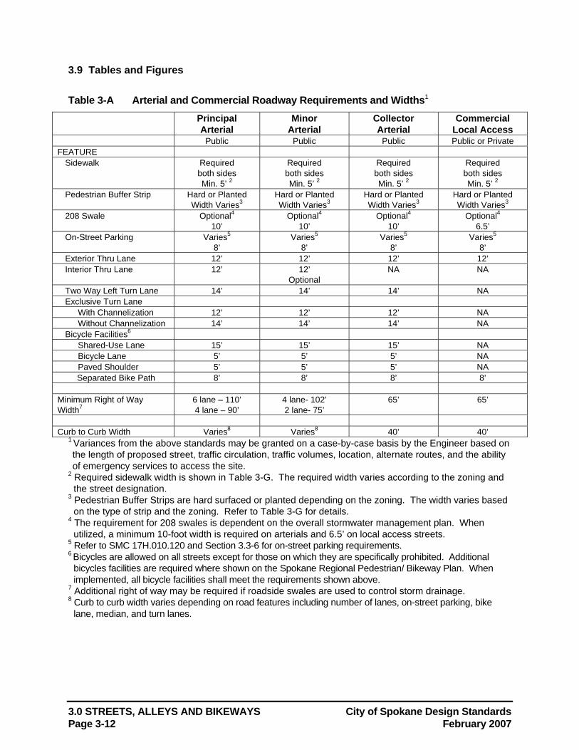
3.0 STREETS, ALLEYS AND BIKEWAYS City of Spokane Design Standards Page 3-12 February 2007
3.9 Tables and Figures Table 3-A Arterial and Commercial Roadway Requirements and Widths1
Principal Arterial
Minor Arterial
Collector Arterial
Commercial Local Access
Public Public Public Public or Private FEATURE
Sidewalk Required both sides Min. 5’ 2
Required both sides Min. 5’ 2
Required both sides Min. 5’ 2
Required both sides Min. 5’ 2
Pedestrian Buffer Strip Hard or Planted Width Varies3
Hard or Planted Width Varies3
Hard or Planted Width Varies3
Hard or Planted Width Varies3
208 Swale Optional4 10’
Optional4 10’
Optional4 10’
Optional4 6.5’
On-Street Parking Varies5 8’
Varies5 8’
Varies5 8’
Varies5 8’
Exterior Thru Lane 12’ 12’ 12’ 12’ Interior Thru Lane 12’ 12’
Optional NA NA
Two Way Left Turn Lane 14’ 14’ 14’ NA Exclusive Turn Lane With Channelization 12’ 12’ 12’ NA Without Channelization 14’ 14’ 14’ NA Bicycle Facilities6
Shared-Use Lane 15’ 15’ 15’ NA Bicycle Lane 5’ 5’ 5’ NA Paved Shoulder 5’ 5’ 5’ NA Separated Bike Path 8’ 8’ 8’ 8’
Minimum Right of Way Width7
6 lane – 110’ 4 lane – 90’
4 lane- 102’ 2 lane- 75’
65’ 65’
Curb to Curb Width Varies8 Varies8 40’ 40’
1 Variances from the above standards may be granted on a case-by-case basis by the Engineer based on the length of proposed street, traffic circulation, traffic volumes, location, alternate routes, and the ability of emergency services to access the site.
2 Required sidewalk width is shown in Table 3-G. The required width varies according to the zoning and the street designation.
3 Pedestrian Buffer Strips are hard surfaced or planted depending on the zoning. The width varies based on the type of strip and the zoning. Refer to Table 3-G for details.
4 The requirement for 208 swales is dependent on the overall stormwater management plan. When utilized, a minimum 10-foot width is required on arterials and 6.5’ on local access streets.
5 Refer to SMC 17H.010.120 and Section 3.3-6 for on-street parking requirements. 6 Bicycles are allowed on all streets except for those on which they are specifically prohibited. Additional
bicycles facilities are required where shown on the Spokane Regional Pedestrian/ Bikeway Plan. When implemented, all bicycle facilities shall meet the requirements shown above.
7 Additional right of way may be required if roadside swales are used to control storm drainage. 8 Curb to curb width varies depending on road features including number of lanes, on-street parking, bike
lane, median, and turn lanes.
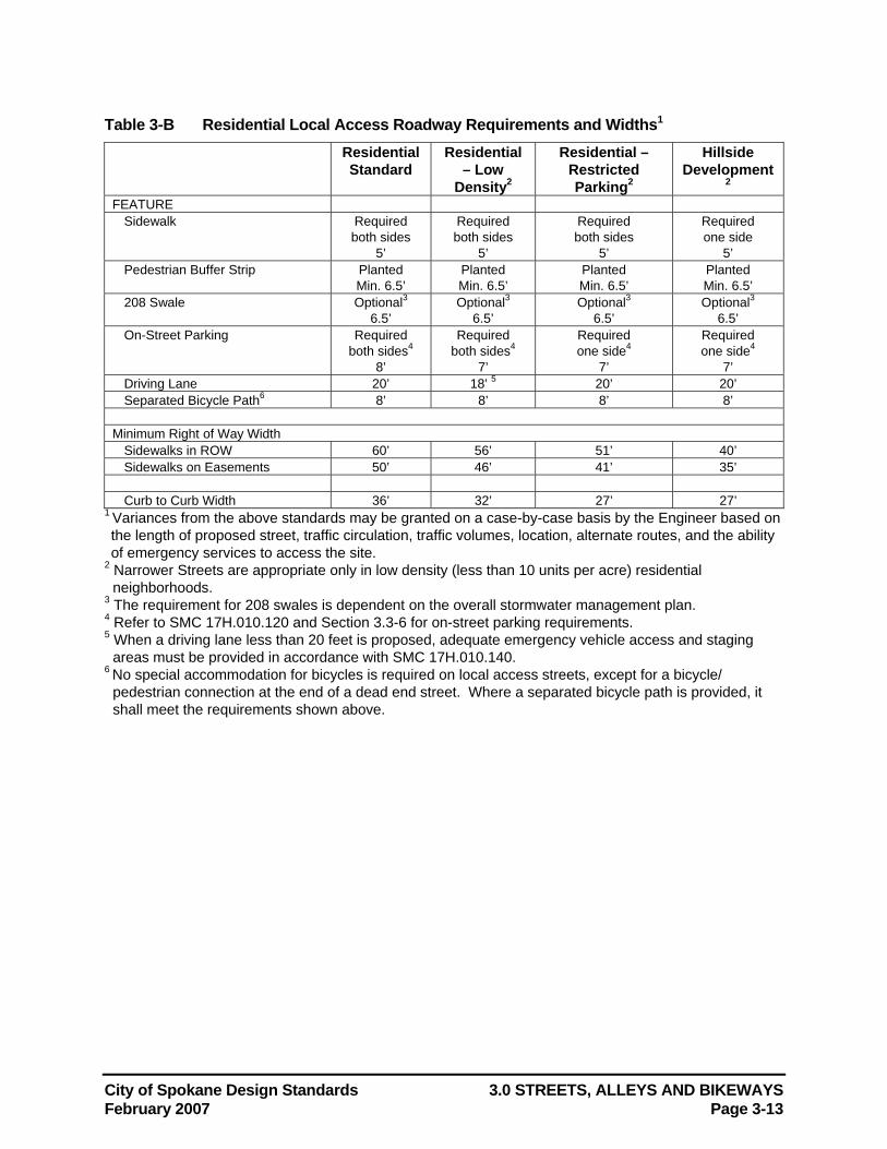
City of Spokane Design Standards 3.0 STREETS, ALLEYS AND BIKEWAYS February 2007 Page 3-13
Table 3-B Residential Local Access Roadway Requirements and Widths1 Residential
Standard Residential
– Low Density2
Residential – Restricted Parking2
Hillside Development
2 FEATURE
Sidewalk Required both sides
5’
Required both sides
5’
Required both sides
5’
Required one side
5’ Pedestrian Buffer Strip Planted
Min. 6.5’ Planted Min. 6.5’
Planted Min. 6.5’
Planted Min. 6.5’
208 Swale Optional3 6.5’
Optional3 6.5’
Optional3 6.5’
Optional3 6.5’
On-Street Parking Required both sides4
8’
Required both sides4
7’
Required one side4
7’
Required one side4
7’ Driving Lane 20’ 18’ 5 20’ 20’ Separated Bicycle Path6 8’ 8’ 8’ 8’
Minimum Right of Way Width
Sidewalks in ROW 60’ 56’ 51’ 40’ Sidewalks on Easements 50’ 46’ 41’ 35’
Curb to Curb Width 36’ 32’ 27’ 27’
1 Variances from the above standards may be granted on a case-by-case basis by the Engineer based on the length of proposed street, traffic circulation, traffic volumes, location, alternate routes, and the ability of emergency services to access the site.
2 Narrower Streets are appropriate only in low density (less than 10 units per acre) residential neighborhoods.
3 The requirement for 208 swales is dependent on the overall stormwater management plan. 4 Refer to SMC 17H.010.120 and Section 3.3-6 for on-street parking requirements. 5 When a driving lane less than 20 feet is proposed, adequate emergency vehicle access and staging
areas must be provided in accordance with SMC 17H.010.140. 6 No special accommodation for bicycles is required on local access streets, except for a bicycle/
pedestrian connection at the end of a dead end street. Where a separated bicycle path is provided, it shall meet the requirements shown above.
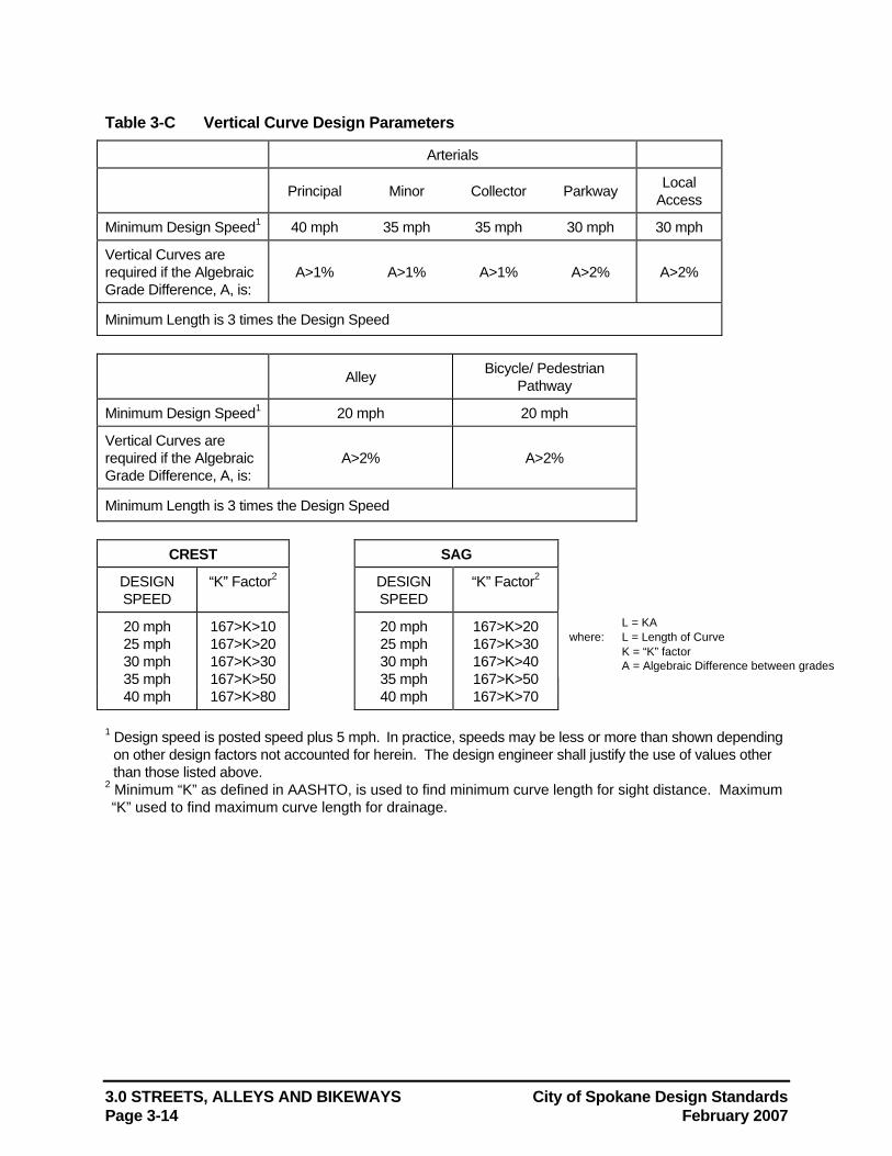
3.0 STREETS, ALLEYS AND BIKEWAYS City of Spokane Design Standards Page 3-14 February 2007
Table 3-C Vertical Curve Design Parameters
Arterials
Principal Minor Collector Parkway Local Access
Minimum Design Speed1 40 mph 35 mph 35 mph 30 mph 30 mph
Vertical Curves are required if the Algebraic Grade Difference, A, is:
A>1% A>1% A>1% A>2% A>2%
Minimum Length is 3 times the Design Speed
Alley Bicycle/ Pedestrian Pathway
Minimum Design Speed1 20 mph 20 mph
Vertical Curves are required if the Algebraic Grade Difference, A, is:
A>2% A>2%
Minimum Length is 3 times the Design Speed
CREST SAG
DESIGN SPEED
“K” Factor2
DESIGN SPEED
“K” Factor2
20 mph 167>K>10 20 mph 167>K>20 25 mph 167>K>20 25 mph 167>K>30 30 mph 167>K>30 30 mph 167>K>40 35 mph 167>K>50 35 mph 167>K>50 40 mph 167>K>80 40 mph 167>K>70
1 Design speed is posted speed plus 5 mph. In practice, speeds may be less or more than shown depending on other design factors not accounted for herein. The design engineer shall justify the use of values other than those listed above.
2 Minimum “K” as defined in AASHTO, is used to find minimum curve length for sight distance. Maximum “K” used to find maximum curve length for drainage.
L = KA where: L = Length of Curve K = “K” factor
A = Algebraic Difference between grades
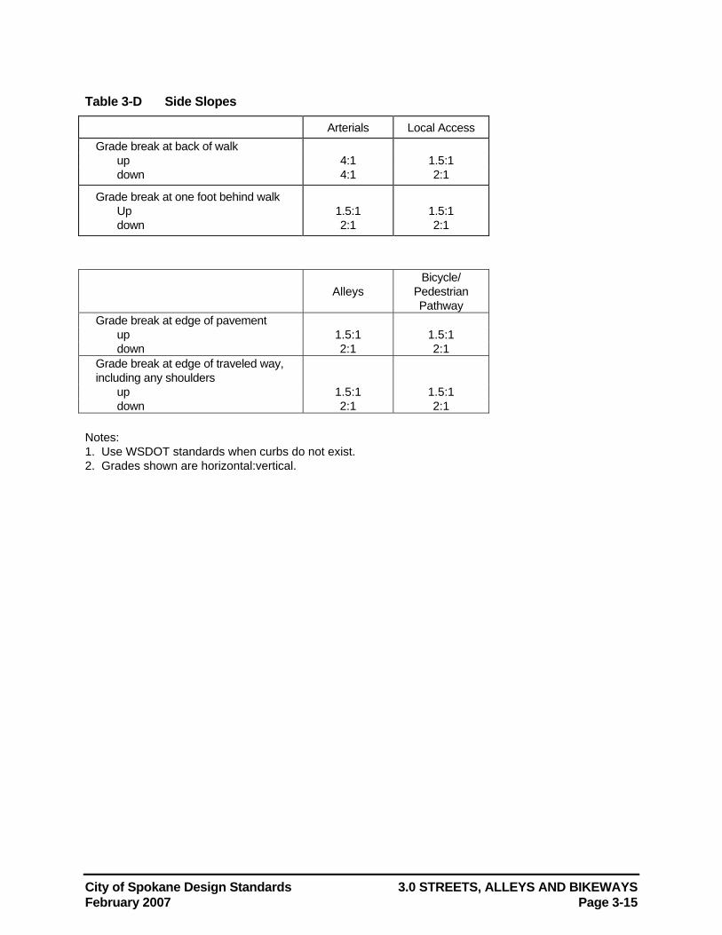
City of Spokane Design Standards 3.0 STREETS, ALLEYS AND BIKEWAYS February 2007 Page 3-15
Table 3-D Side Slopes
Arterials Local Access Grade break at back of walk
up 4:1 1.5:1 down 4:1 2:1
Grade break at one foot behind walk Up 1.5:1 1.5:1 down 2:1 2:1
Alleys Bicycle/
Pedestrian Pathway
Grade break at edge of pavement up 1.5:1 1.5:1 down 2:1 2:1
Grade break at edge of traveled way, including any shoulders
up 1.5:1 1.5:1 down 2:1 2:1
Notes: 1. Use WSDOT standards when curbs do not exist. 2. Grades shown are horizontal:vertical.
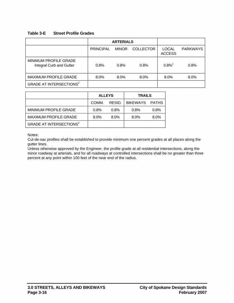
3.0 STREETS, ALLEYS AND BIKEWAYS City of Spokane Design Standards Page 3-16 February 2007
Table 3-E Street Profile Grades
ARTERIALS
PRINCIPAL MINOR COLLECTOR LOCAL ACCESS
PARKWAYS
MINIMUM PROFILE GRADE Integral Curb and Gutter 0.8% 0.8% 0.8% 0.8%1 0.8%
MAXIMUM PROFILE GRADE 8.0% 8.0% 8.0% 8.0% 8.0%
GRADE AT INTERSECTIONS2
ALLEYS TRAILS
COMM. RESID. BIKEWAYS PATHS
MINIMUM PROFILE GRADE 0.8% 0.8% 0.8% 0.8%
MAXIMUM PROFILE GRADE 8.0% 8.0% 8.0% 8.0%
GRADE AT INTERSECTIONS2 Notes: Cul-de-sac profiles shall be established to provide minimum one percent grades at all places along the gutter lines. Unless otherwise approved by the Engineer, the profile grade at all residential intersections, along the minor roadway at arterials, and for all roadways at controlled intersections shall be no greater than three percent at any point within 100 feet of the near end of the radius.
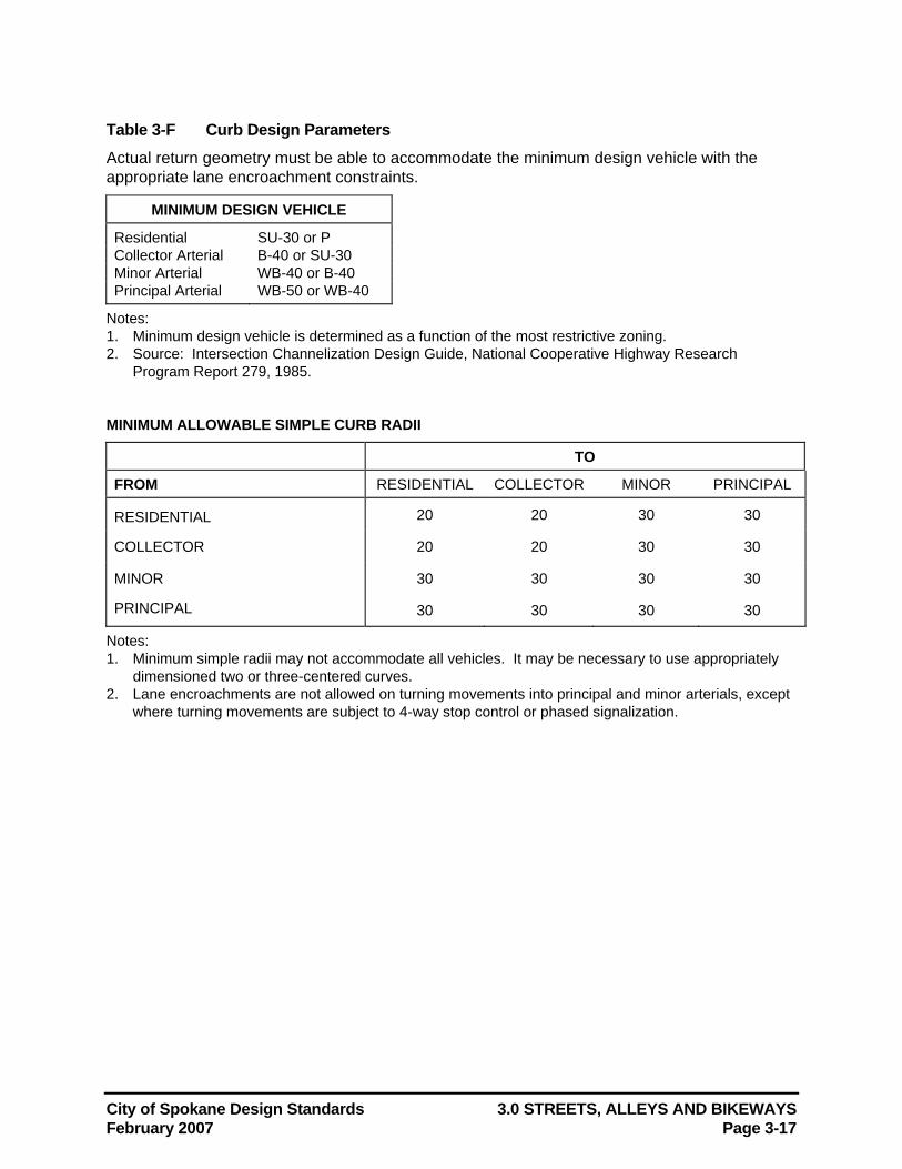
City of Spokane Design Standards 3.0 STREETS, ALLEYS AND BIKEWAYS February 2007 Page 3-17
Table 3-F Curb Design Parameters Actual return geometry must be able to accommodate the minimum design vehicle with the appropriate lane encroachment constraints.
MINIMUM DESIGN VEHICLE
Residential SU-30 or P Collector Arterial B-40 or SU-30 Minor Arterial WB-40 or B-40 Principal Arterial WB-50 or WB-40
Notes: 1. Minimum design vehicle is determined as a function of the most restrictive zoning. 2. Source: Intersection Channelization Design Guide, National Cooperative Highway Research
Program Report 279, 1985.
MINIMUM ALLOWABLE SIMPLE CURB RADII
TO
FROM RESIDENTIAL COLLECTOR MINOR PRINCIPAL
RESIDENTIAL 20 20 30 30
COLLECTOR 20 20 30 30
MINOR 30 30 30 30
PRINCIPAL 30 30 30 30
Notes: 1. Minimum simple radii may not accommodate all vehicles. It may be necessary to use appropriately
dimensioned two or three-centered curves. 2. Lane encroachments are not allowed on turning movements into principal and minor arterials, except
where turning movements are subject to 4-way stop control or phased signalization.
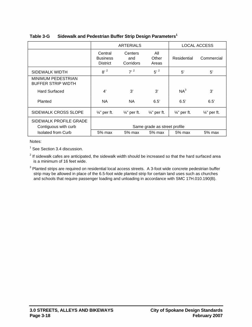
3.0 STREETS, ALLEYS AND BIKEWAYS City of Spokane Design Standards Page 3-18 February 2007
Table 3-G Sidewalk and Pedestrian Buffer Strip Design Parameters1
ARTERIALS LOCAL ACCESS
Central
Business District
Centers and
Corridors
All Other Areas
Residential Commercial
SIDEWALK WIDTH 8’ 2 7’ 2 5’ 2 5’ 5’ MINIMUM PEDESTRIAN BUFFER STRIP WIDTH
Hard Surfaced 4’ 3’ 3’ NA3 3’
Planted NA NA 6.5’ 6.5’ 6.5’
SIDEWALK CROSS SLOPE ¼” per ft. ¼” per ft. ¼” per ft. ¼” per ft. ¼” per ft.
SIDEWALK PROFILE GRADE Contiguous with curb Same grade as street profile Isolated from Curb 5% max 5% max 5% max 5% max 5% max
Notes: 1 See Section 3.4 discussion. 2 If sidewalk cafes are anticipated, the sidewalk width should be increased so that the hard surfaced area
is a minimum of 16 feet wide. 3 Planted strips are required on residential local access streets. A 3-foot wide concrete pedestrian buffer
strip may be allowed in place of the 6.5-foot wide planted strip for certain land uses such as churches and schools that require passenger loading and unloading in accordance with SMC 17H.010.190(B).
City of Spokane Design Standards 4.0 SANITARY SEWERS February 2007 Page 4-1
4.0 SANITARY SEWERS Sanitary sewers should be designed to maintain self-cleaning velocities and allow for ease of maintenance.
This section presents design guidance for construction of sewers in the public right-of-way and on private property. Design criteria for wastewater pumping stations are discussed in Section 5.0. Refer to Chapter 13 of the Spokane Municipal Code for additional regulations governing sewers.
4.1 Definitions Average Design Flow The average daily flow of the maximum month.
Building Drain That part of the lowest piping of a drainage system which receives the sanitary discharge from piping inside the walls of a structure or building, and conveys it to a point two feet outside the outer face of a structure, wall or foundation into the side sewer or to an on-site sewage disposal system. Building drains shall not carry roof drainage, groundwater or surface runoff.
Cleanout An upturned pipe which provides a means for flushing or inserting cleaning tools.
Combined Sewer A sewer which conveys any category of wastewater, as permitted by the Wastewater Director, and performs the functions for both a sanitary sewer and a storm sewer.
Cutoff Wall A wall, collar or other structure intended to control movement of the groundwater along a trench constructed for sewer line placement. Cutoff walls are typically used in areas of rock, when a natural barrier to groundwater is disturbed by sewer line construction. Cutoff wall details are shown in the Standard Plans.
Effluent Wastewater or other liquid, partially or completely treated, or in its natural state, flowing out of a reservoir, basin, treatment plant, or industrial treatment plant, or any part thereof.
Exterior Pipe Drop A vertical pipe installed in the sewer line outside a manhole, which allows a deeper connection to the manhole. An exterior pipe drop connection is used only where the elevation of the incoming pipe considerably exceeds that of the outgoing sewer, and the size of pipe precludes the use of an interior pipe drop.
Industrial Process Wastewater or Process Wastewater: That category of wastewater containing water carried wastes other than those traditionally derived from human or household customer sources. Process wastewater is also sometimes referred to as "non-domestic sewage". There are two subcategories of process wastewater:
a. "Manufacturing Process Wastewater", which is wastewater of a nature, concentration, or consistency traditionally originating from industrial or manufacturing customers. This generally includes sewage from one or more heavy industrial or manufacturing process sources or industrial cleanup procedures. It includes one-process discharges or several commingled process discharges.
b. "Non-manufacturing Process Wastewater", which includes all other process wastewater. This generally includes wastewater from business, institutional or commercial customers which generate non-domestic wastewater components derived from a business or commercial process other than manufacturing or heavy industry. Examples of included sources are wastewater from commercial laundries, radiator shops, photo finishers as well as wastewater from vehicles used for storage or transportation of wastewater, such as septic tank pumpers or haulers.
Interior Channel Drop A planned drop of the invert elevation within a manhole to convey wastewater from the incoming pipe(s) to the outgoing sewer.
4.0 SANITARY SEWERS City of Spokane Design Standards Page 4-2 February 2007
Interior Pipe Drop A vertical pipe installed inside a manhole where the elevation of the incoming sewer considerably exceeds that of the outgoing sewer.
Lateral or Lateral Sewer A sewer to which side or private sewers may be connected from adjacent properties.
Natural Outlet Any outlet into a watercourse, pond, ditch, lake or other body of surface water or groundwater. It does not include connections to the City of Spokane Wastewater Treatment Plant, authorized on-site sewage, stormwater disposal systems, or other authorized sewage disposal mechanisms or systems.
Noncontact Cooling Water That category of wastewater consisting of water used for cooling, generally in an industrial or manufacturing process, which does not come into direct contact with any raw material, intermediate product, waste product, or finished product. The term excludes all other categories of wastewater identified herein.
Nonstandard Strength Sewage Wastewater accepted for discharge into the Wastewater Treatment Plant, but which does not meet the criteria for acceptance as standard strength sewage, whether because of special characteristics, special treatment requirements, special monitoring or additional handling as a condition of acceptance. Nonstandard strength sewage is further defined in Chapter 13 of the Spokane Municipal Code.
On-Site Sewage Disposal System Any system or combination of piping, treatment or other facilities that store, treat, and/or dispose of sewage and effluent on the property where it originates, or an adjacent or nearby property under the ownership of the user of the system or in which the user has a recorded interest for the purpose of maintaining the system on such other property. In general, these include septic tanks, drainfields, pressure mounds, etc.
Peak Flow The maximum momentary load placed on a wastewater pumping station, sewer main, force main, etc..
Peak Factor A value which, when multiplied by the average design flow, yields an estimate of the highest flow rate to be expected over a short period of time.
Practicable Capable of being accomplished within prudent natural, social or economic constraints using readily available resources and reasonable reliable technology and practices.
Private Pump Station An appurtenance of a side sewer, private sewer or on-site sewage disposal system which, alone or in conjunction with the side sewer or private sewer, conveys standard strength sewage or effluent by lifting or pumping to another sewer.
Private Sewer A sewer which is not controlled or maintained by a public authority, and which serves two or more buildings, residences, or properties, and is constructed by private contract.
Private Storm Sewer A storm sewer not controlled or maintained by a public authority.
Public Sewer A sewer which is controlled and maintained by a public authority.
Sanitary Sewage Also sometimes referred to as "domestic sewage" is that category of wastewater consisting of water-carried wastes from human and household customer sources. The term also includes water-carried wastes from some business, institutional or commercial customers which do not generate industrial process wastewater.
Sanitary Sewer A sewer which conveys sanitary sewage. Additionally, the term is used to mean any public sewer except a storm sewer.
Sewage A combination of the water-carried wastes from domestic, business or commercial, industrial or manufacturing sources, including residences, business buildings, institutions and industrial establishments. Sewage also includes surface water and storm water when discharged into a sewer.
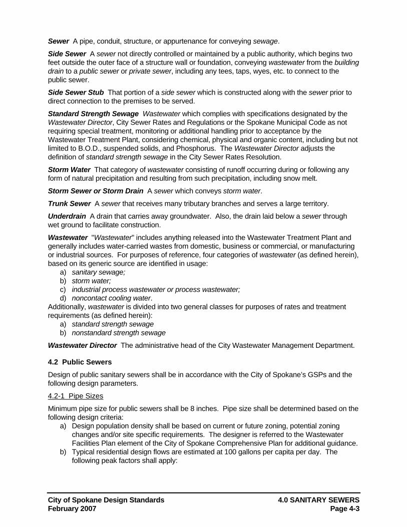
City of Spokane Design Standards 4.0 SANITARY SEWERS February 2007 Page 4-3
Sewer A pipe, conduit, structure, or appurtenance for conveying sewage.
Side Sewer A sewer not directly controlled or maintained by a public authority, which begins two feet outside the outer face of a structure wall or foundation, conveying wastewater from the building drain to a public sewer or private sewer, including any tees, taps, wyes, etc. to connect to the public sewer.
Side Sewer Stub That portion of a side sewer which is constructed along with the sewer prior to direct connection to the premises to be served.
Standard Strength Sewage Wastewater which complies with specifications designated by the Wastewater Director, City Sewer Rates and Regulations or the Spokane Municipal Code as not requiring special treatment, monitoring or additional handling prior to acceptance by the Wastewater Treatment Plant, considering chemical, physical and organic content, including but not limited to B.O.D., suspended solids, and Phosphorus. The Wastewater Director adjusts the definition of standard strength sewage in the City Sewer Rates Resolution.
Storm Water That category of wastewater consisting of runoff occurring during or following any form of natural precipitation and resulting from such precipitation, including snow melt.
Storm Sewer or Storm Drain A sewer which conveys storm water.
Trunk Sewer A sewer that receives many tributary branches and serves a large territory.
Underdrain A drain that carries away groundwater. Also, the drain laid below a sewer through wet ground to facilitate construction.
Wastewater "Wastewater" includes anything released into the Wastewater Treatment Plant and generally includes water-carried wastes from domestic, business or commercial, or manufacturing or industrial sources. For purposes of reference, four categories of wastewater (as defined herein), based on its generic source are identified in usage:
a) sanitary sewage; b) storm water; c) industrial process wastewater or process wastewater; d) noncontact cooling water.
Additionally, wastewater is divided into two general classes for purposes of rates and treatment requirements (as defined herein):
a) standard strength sewage b) nonstandard strength sewage
Wastewater Director The administrative head of the City Wastewater Management Department.
4.2 Public Sewers Design of public sanitary sewers shall be in accordance with the City of Spokane’s GSPs and the following design parameters.
4.2-1 Pipe Sizes
Minimum pipe size for public sewers shall be 8 inches. Pipe size shall be determined based on the following design criteria:
a) Design population density shall be based on current or future zoning, potential zoning changes and/or site specific requirements. The designer is referred to the Wastewater Facilities Plan element of the City of Spokane Comprehensive Plan for additional guidance.
b) Typical residential design flows are estimated at 100 gallons per capita per day. The following peak factors shall apply:
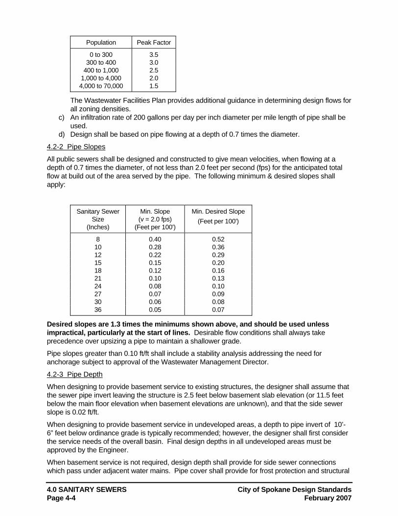
4.0 SANITARY SEWERS City of Spokane Design Standards Page 4-4 February 2007
Population Peak Factor
0 to 300 3.5 300 to 400 3.0
400 to 1,000 2.5 1,000 to 4,000 2.0 4,000 to 70,000 1.5
The Wastewater Facilities Plan provides additional guidance in determining design flows for all zoning densities.
c) An infiltration rate of 200 gallons per day per inch diameter per mile length of pipe shall be used.
d) Design shall be based on pipe flowing at a depth of 0.7 times the diameter.
4.2-2 Pipe Slopes
All public sewers shall be designed and constructed to give mean velocities, when flowing at a depth of 0.7 times the diameter, of not less than 2.0 feet per second (fps) for the anticipated total flow at build out of the area served by the pipe. The following minimum & desired slopes shall apply:
Sanitary Sewer Size
(Inches)
Min. Slope (v = 2.0 fps)
(Feet per 100')
Min. Desired Slope (Feet per 100')
8 0.40 0.52 10 0.28 0.36 12 0.22 0.29 15 0.15 0.20 18 0.12 0.16 21 0.10 0.13 24 0.08 0.10 27 0.07 0.09 30 0.06 0.08 36 0.05 0.07
Desired slopes are 1.3 times the minimums shown above, and should be used unless impractical, particularly at the start of lines. Desirable flow conditions shall always take precedence over upsizing a pipe to maintain a shallower grade.
Pipe slopes greater than 0.10 ft/ft shall include a stability analysis addressing the need for anchorage subject to approval of the Wastewater Management Director.
4.2-3 Pipe Depth
When designing to provide basement service to existing structures, the designer shall assume that the sewer pipe invert leaving the structure is 2.5 feet below basement slab elevation (or 11.5 feet below the main floor elevation when basement elevations are unknown), and that the side sewer slope is 0.02 ft/ft.
When designing to provide basement service in undeveloped areas, a depth to pipe invert of 10’-6” feet below ordinance grade is typically recommended; however, the designer shall first consider the service needs of the overall basin. Final design depths in all undeveloped areas must be approved by the Engineer.
When basement service is not required, design depth shall provide for side sewer connections which pass under adjacent water mains. Pipe cover shall provide for frost protection and structural
City of Spokane Design Standards 4.0 SANITARY SEWERS February 2007 Page 4-5
considerations. A minimum pipe cover of 6 feet shall apply.
Sewers greater than 16 ft. deep shall have a minimum grade 1.2 times the standard minimum to offset construction difficulties.
4.2-4 Roughness Coefficient
A roughness coefficient n = 0.013 shall be used for all pipe. The variable - n curve shown in Figure 4-1 shall be used for design.
4.2-5 Horizontal Alignment
Sanitary sewers shall generally be located along the centerline of the road or alley. Pipeline marking tape shall be installed at mid-depth in the sewer trench directly over the pipe to mark the pipe location as per the City of Spokane GSPs.
The maximum distance between manholes shall be 600 feet on trunk sewers and 400 feet on all other straight sewer lines unless otherwise approved by the Engineer.
Curvilinear sewers are not allowed without approval of the Engineer.
4.2-6 Vertical Alignment
All sewers shall be laid with uniform slope between manholes. Pipe crowns shall be matched when upsizing, subject to the minimum drops specified below. Downsizing of pipes shall be allowed only on approval of the Engineer. When downsizing is approved, a decrease in diameter of only one pipe size smaller shall be allowed at a manhole, and the invert elevation of the smaller (downsized) pipe shall provide the required minimum drop through the manhole.
A minimum interior channel drop of 0.1 feet in a through-manhole, 0.2 feet in the presence of one horizontal bend and 0.3 feet where two laterals enter a manhole shall be required. Maximum interior channel drops shall be determined according to manhole size Standard Plan Z-110.
Interior pipe drops in manholes may be used on the condition that a 48-inch clear space is provided in the manhole (see Standard Plan Z-111). The use of exterior pipe drops is discouraged. Instead, the installation of an additional manhole is preferred where the elevation of the incoming pipe considerably exceeds that of the outgoing sewer, and an interior pipe drop cannot be accommodated. Exterior pipe drop connections will be allowed only on approval of the Engineer.
4.2-7 Manholes
The following design parameters shall apply to manholes in public sewers: a) When Type II or Type III manholes are used, the manhole opening and steps shall be
positioned above the upstream invert. For Type I manholes, steps shall be positioned over the shelf having the largest footing area.
b) Manholes shall be placed at each change of alignment, grade or pipe size, and at the intersection of two or more sewer pipes 8 inches or larger.
c) Manhole spacing requirements are detailed above in Section 4.2-5. d) Manhole channel drops shall be constructed as required in Section 4.2-6. e) All manholes shall be located using Washington state plane coordinates shown on the
plans
4.2-8 Temporary Manholes
Temporary manholes shall be placed on all extensions of sewer pipes. These manholes are not required to have poured channels and are removed when the line is extended.
4.0 SANITARY SEWERS City of Spokane Design Standards Page 4-6 February 2007
4.2-9 Combined Sewers
Combined sanitary and storm sewers are prohibited. No surface, groundwater or roof drain may be connected to a public sanitary sewer without the specific approval of the Engineer.
4.2-10 Separation of Sewers and Other Utilities
Crossings of sanitary sewers and other utilities shall be designed and constructed as shown in the Standard Plans.
4.2-11 Easements
Sewer easements shall be a minimum of thirty feet wide unless otherwise approved by the Engineer. Additional width may be required for sewers.
4.3 Side Sewers This section provides recommended design guidelines pertaining specifically to sanitary side sewers. Connection of storm drains, roof drains, underdrains or any other type of surface or ground water collection facility to a side sewer is expressly prohibited. 4.3-1 Pipe Size and Alignment
Side sewer stubs shall be a minimum of 4-inch diameter for single family residences and duplexes and 6-inch diameter for all other uses including multi-family housing, and shall be installed from the public main to the right-of-way line or to a point 10 feet behind any existing or future sidewalk or curb, whichever is further back. Construction requirements for side sewer connections to the public main are shown in Standard Plan Z-116.
The building drain shall extend at least 2 feet beyond the wall of the building served. Side sewers shall drain away from the building with a minimum slope of 0.02 ft/ft (1/4 inch per foot). Vertical and horizontal curves are not recommended.
4.3-2 Pipe Depth
All side sewers should have at least 3.5 feet of cover in all traveled ways or other locations where the weight of the vehicular traffic might crush the pipe, and not less than 2 feet of cover in other areas. Frost protection via pipe cover or insulation shall be considered in all designs.
4.3-3 Connection to Manholes and Catch Basins
No catch basin or surface drain may be connected to a side, private or public sewer without specific permission from the Engineer. Storm drainage and sanitary sewage shall not be combined in a single sewer on private property.
4.3-4 Connection to Public Sewer Main
All taps shall be made with an approved concrete, vitrified clay or PVC tapping fitting, made by a manufacturer for that purpose. Tapping permits will be issued by the Engineering Services Department only with the consent of the Wastewater Director.
Side sewer connections shall be in accordance with Standard Plan Z-116. Any proposed variance from the construction method shown on Standard Plan Z-116 shall require submittal and approval of a Design Standards Variance Request Form to the Engineering Services Department. Side sewers shall not connect directly to a manhole.
4.3-5 Cleanouts
Cleanouts, no deeper than one foot from the ground surface, are recommended on all side sewers. Cleanouts shall be provided every 100 feet and at every angle point 45 degrees or greater.
City of Spokane Design Standards 4.0 SANITARY SEWERS February 2007 Page 4-7
4.4 Private Sewers Sewers for Planned Unit Developments (P.U.D.'s) shall adhere to the standards discussed above for Public Sewers. All other private sanitary sewers shall conform to the following design standards:
a) Permission for private sewers will be granted only by the Engineer. b) Minimum pipe size shall be 6-inch for private sewers. c) Minimum pipe slope shall be 0.021 feet per foot. d) Pipe depths for private sewers shall conform to the standards for side sewers in
Section 4.3-2. e) A manhole is required at the intersection of two lines 8-inches in diameter or larger. f) Manholes are required on private sewers 300 or more feet in length. Where
required, manholes shall be at maximum 300’ spacing. Where cleanouts are used, they shall be installed at each change in pipe direction; cleanout spacing shall not exceed 100 feet. Cleanout pipes shall be the same size as the pipe they access.
g) Vertical curves are not allowed.
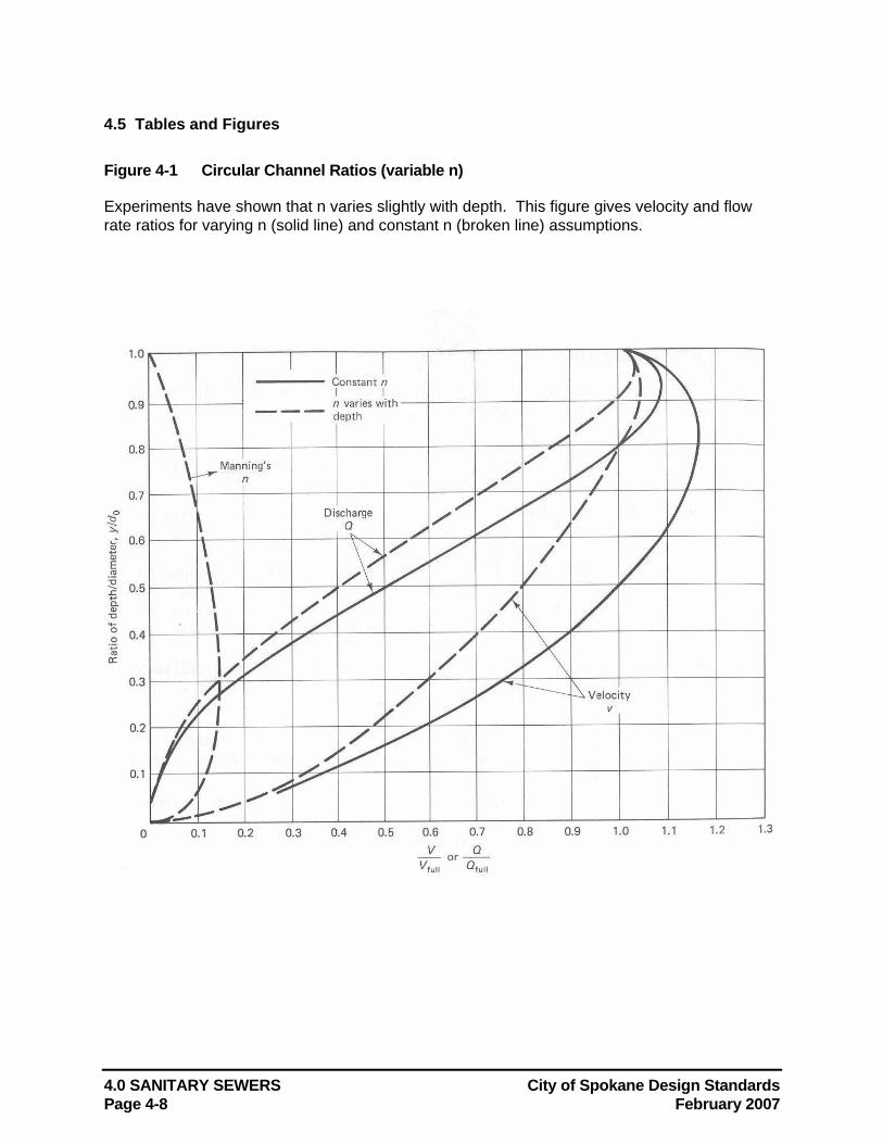
4.0 SANITARY SEWERS City of Spokane Design Standards Page 4-8 February 2007
4.5 Tables and Figures Figure 4-1 Circular Channel Ratios (variable n) Experiments have shown that n varies slightly with depth. This figure gives velocity and flow rate ratios for varying n (solid line) and constant n (broken line) assumptions.
City of Spokane Design Standards 5.0 WASTEWATER PUMP STATIONS February 2007 Page 5-1
5.0 WASTEWATER PUMP STATIONS Design of wastewater pumping stations shall be performed by a professional engineer licensed in the State of Washington. Due consideration shall be given to the selection of all materials used in the construction of wastewater pump stations, because of the presence of hydrogen sulfide and other corrosive gases, greases, oils, and other constituents frequently present in sewage.
5.1 Definitions Air Release Valve An air valve placed at the high points of a pipeline to release the air automatically and prevent the pipeline from becoming air-bound with a resultant increased head loss.
Average Design Flow The average daily flow of the maximum month.
Backflow Prevention Device Any effective device, method or construction used to prevent backflow into a potable water system.
Bar Screen A rack composed of parallel bars, either vertical or inclined, placed in a waterway to catch debris.
Centrifugal Pump A pump consisting of an impeller fixed on a rotating shaft and enclosed in a casing, and having an inlet and a discharge connection. The rotating impeller creates pressure in the liquid by the velocity derived from centrifugal force.
Combined Sewer See Section 4.1.
Datum Reference point for all readings for suction lift, suction head, total discharge head (TDH) and net positive suction head (NPSH). For horizontal shaft pumps, the datum elevation is the pump centerline. For vertical shaft pumps, the datum elevation is the elevation of the entrance eye of the suction impeller. See Figure 5-1.
Dry Pit A dry compartment in a pumping station, near or below pumping level, where the pumps are located (not to be confused with the dry well defined in Section 6)
Force Main A pressure pipe joining the pump discharge at a wastewater pumping station with a point of gravity flow.
Impeller A rotating set of vanes designed to impel rotation of a mass of fluid.
Lift Station A wastewater pumping station that pumps wastewater to a higher elevation when the continuance of the sewer at reasonable slopes would involve excessive depths of trench (depths where repair or replacement would require special or costly construction techniques), or that raises wastewater from areas too low to drain into available sewers.
Net Positive Suction Head (NPSH) The total suction head, in feet of liquid absolute, determined at the suction nozzle, less the vapor pressure of the liquid in feet absolute. See Figure 5-1.
Peak Design Flow The largest estimated flow rate sustained over a 60-minute period in the design year of the pump station.
Sewer See Section 4.1.
Static Head The difference in suction and discharge water levels, does not include dynamic losses.
5.0 WASTEWATER PUMP STATIONS City of Spokane Design Standards Page 5-2 February 2007
Suction Head Suction head exists when the total suction head is above atmospheric pressure. As determined on test, it is the reading of the gage at the suction of the pump converted to feet of liquid and referred to datum, plus the velocity head at a the point of gage attachment. See Figure 5-1.
Suction Lift Suction lift exists when the total suction head is below atmospheric pressure. Total suction lift, as determined on test, is the reading of a liquid manometer at the suction nozzle of the pump converted to feet of liquid and referred to datum, minus the velocity head at the point of gage attachment. See Figure 5-1.
Sump A tank or pit that receives wastewater and stores it temporarily, and from which the wastewater is pumped or ejected.
Total Discharge Head The reading of a pressure gage at the discharge of the pump, converted to feet of liquid and referred to datum, plus the velocity head at the point of gage attachment. See Figure 5-1.
Total Dynamic Head (TDH) Also called "total head", TDH is the measure of energy increase per pound of the liquid imparted to it by the pump. Where suction lift exists, TDH is equal to the sum of the total discharge head and total suction lift, and, where positive suction head exists, TDH is the total discharge head minus the total suction head. See Figure 5-1.
Velocity Head The theoretical vertical height to which a liquid body may be raised by its kinetic energy. It is equal to the square of the velocity divided by twice the acceleration due to gravity (v2/2g). See Figure 5-1.
Wastewater See Section 4.1.
Wastewater Director See Section 4.1.
Water Hammer The phenomenon of oscillations in the pressure of water about its normal pressure in a closed conduit, flowing full, that results from a too-rapid acceleration or retardation of flow. Momentary pressures greatly in excess of the normal static pressure may be produced in a closed conduit by this phenomenon.
Wet Well A compartment in which wastewater is collected, and: (a) to which the suction pipe of a pump is connected, or (b) in which a submersible pump is installed.
5.2 General Requirements Justification for any proposed lift station is required which clearly exhibits that gravity lines are not available and not economically feasible.
The number of lift stations for each basin shall be optimized.
5.2-1 Minimal Pump Station Design Requirements
The applicant’s engineer shall submit all supporting documentation, in report form, including all relevant design information needed for the City to review for adequacy of the proposed design. The report is to be stamped by an engineer, licensed in the State of Washington. At a minimum the following information shall be submitted.
1) The pump station design must have a minimum of two pumps 2) Design flow analysis (break down of phases if applicable) 3) All relevant elevations, such as; pump(s) off, discharge elevation, pump(s) on, alarm
elevation, max allowable storage elevation, etc. 4) Maximum static head 5) Force main size and length 6) Pump station capacity (gpm) per each pump and multiple pumps
City of Spokane Design Standards 5.0 WASTEWATER PUMP STATIONS February 2007 Page 5-3
7) Velocity within force main 8) System head and pump curves (including compound pump curves when applicable) 9) “n” values of force main 10) Friction head loss (calculations) 11) Velocity head 12) Total dynamic head 13) Pump time/cycle and number of cycles per day 14) Storage available and storage required during a power outage scenario (min and max time) 15) Discussion of odor control 16) Water hammer calculations 17) Buoyancy calculations (if the potential for high groundwater exists) 18) Pump station specifications (generator specifications if applicable) 19) Pump(s) specifications 20) System back up plan (i.e. storage method, alternate power source) 21) Maintenance Agreement (for private systems) 22) Wiring Schematic
5.3 Site Selection and Plan
5.3-1 Location
A lift station site shall be selected to serve the entire basin, considering ultimate build-out of the basin.
In selecting a lift station site, consideration shall be given to minimizing its aesthetic, noise, and odor nuisance potential. The site shall be located at least 50 feet from any building or houses and a buffer zone between the lift station and its surrounding environment shall be provided. Buffer zones shall be designed to allow the lift station to blend into the surrounding environment and provide noise mitigation.
The lift station site shall be readily accessible by maintenance vehicles during all weather conditions. The facility should be located off the traveled way of streets and alleys. The station should have a paved access road at least 12 feet wide and a maximum slope of 8%. A paved vehicle turn-around area with a 50 foot outside turning radius to allow a two-ton truck to turn around shall be provided if the access road exceeds 50 feet in length from the nearest dedicated street.
5.3-2 Security/Equipment Protection
The lift station site shall be enclosed in a security fence at least 6 feet high. All slabs, equipment, and utilities shall be located within the fenced area at least 3 feet from the fence.
The lift station structures, electrical and mechanical equipment shall be designed to sustain no physical damage by the 100 year flood. The station should remain fully operational and accessible during the 25 year flood.
5.3-3 Temporary Lift Stations
For temporary lift stations, the owner must grant an easement to the City. A copy of the recorded easement, plat, legal description and any other legal documents granting the easement shall be delivered prior to acceptance for operation and maintenance by the City. The easement shall extend to at least five feet outside the lift station fence and shall include the access road and turn-around areas. This easement shall be separate and in addition to any necessary pipeline easements. If the lift station is to become a permanent installation, transfer of title and ownership of the land to the City will be required prior to acceptance of the station for operation and maintenance.
5.0 WASTEWATER PUMP STATIONS City of Spokane Design Standards Page 5-4 February 2007
5.4 Station Access A suitable and safe means of access to dry/wet pits shall be provided. Entrance hatches larger than 40 inches in diameter shall be spring loaded.
For built-in-place pump stations, a stairway with rest landings shall be provided at vertical intervals not to exceed 12 feet. For factory-built pump stations over 15 feet deep, a rigidly fixed landing shall be provided at vertical intervals not to exceed 10 feet. Where a landing is used, a suitable and rigidly fixed barrier shall be provided to prevent an individual from falling past the intermediate landing to a lower level. Where acceptable to the Wastewater Director, a manlift or elevator may be used in lieu of landings in a factory-built station, provided emergency access is included in the design. Access must meet current WISHA confined space requirements.
5.5 Wet Pit/Dry Pit Station Design A conventional wet pit/dry pit installation with centrifugal sewage pumps and controls housed in the dry pit shall be required.
5.5-1 Wet Pit Layout
Consideration should be given to dividing the wet pit into multiple sections, properly interconnected, to facilitate repairs and cleaning. The bottom of the wet pit shall have a minimum slope to the intake of 1 vertical to 1 horizontal. There shall be no projections in the wet pit which would allow deposition of solids. Wet pits shall be designed to avoid turbulence near the pump intakes.
The clear distance between the bottom of the pump intake structure and the floor of the wet pit shall be between D/3 and D/2, where D is the diameter of the flared pump inlet or as otherwise may be justified by the design engineer.
The inflow line into the wet pit shall be so designed as to prevent entrapped air from reaching the flared pump inlet. A discharge point below static water level in the wet pit is recommended.
To prevent air entrainment, wastewater should not enter the wet pit with a free vertical drop greater than one foot above high water level. A short distance grade increase in the inflow line is recommended where necessary to achieve this. Exterior pipe drops into the wet pit may be approved. Energy dissipaters at the inlet pipe discharge or non-flared pump intakes may be required to reduce air entrainment.
5.5-2 Wet Pit Storage Volume
The wet pit shall be sized to provide adequate storage volume at peak design flows, and a pump cycle time of sufficient duration to prevent pump short cycling and consequential damage. (See Section 5.7.) Static head shall be calculated for "pump on" and "pump off" elevations in the wet pit and included in the system head pump/pump curve.
The following excerpt from Design of Wastewater and Stormwater Pump Stations, Manual of Practice No. FD-4, published by the Water Pollution Control Federation, describes typical volume calculations for wet pits:
From a mechanical standpoint, it is desirable to operate a pump for long periods, if not continuously. Such performance, however, is not compatible with the maintenance of aerobic conditions in the wastewater when it results in long retention periods. Methods have been developed to determine the wet pit volume required to maintain the pump cycle greater than a given time for single and multiple fixed speed pumps.
City of Spokane Design Standards 5.0 WASTEWATER PUMP STATIONS February 2007 Page 5-5
The volume of a wet pit between start and stop elevations for a single pump or a single speed control step for variable speed or multispeed operation is given by Equation 4.
V = θq/4 (4)
where: V = required capacity in gallons, θ = minimum time of one pumping cycle between successive
starts, or speed increases of a pump operating over the control range in minutes, and
q = pump capacity in gallons per minute, for one pump, or the incremental pumping capacity for an additional pump, or pump speed
The use of the above principles allows the pumping system to maintain the required number of starts and stops per hour.
5.5-3 Wet Pit Detention Time
Sewage detention time in the wet pit shall be calculated using the following equations:
Tdet = tf + te
where: tf = time to fill the wet pit in minutes te = time to empty the wet pit in minutes
tf = V/i te = V/(q-i)
where: V = volume of wet pit between "lead pump on" and "lead pump off"
elevations in gallons q = pump capacity in gpm i = inflow to the station in gpm
If the lift station serves commercial flow only, the maximum detention time shall be equivalent to the following equation:
24 hrs - employee shift hrs = detention time, hrs day day day
5.5-4 Odor Control
Odor control shall be provided for the wet pit if there is no station inflow for 480 minutes or if the wet pit detention time exceeds 480 minutes.
5.5-5 Dry Pit Design
A separate sump pump, equipped with dual check valves shall be provided in the dry pits to remove leakage or drainage, with the discharge located as high as possible. Water ejectors connected to a potable water supply will not be approved. All floor and walkway surfaces should have an adequate slip proof slope to a point of drainage. Pump seal water shall be piped to the sump. The floor shall slope 1/8 inch per foot toward the sump pit.
5.6 Submersible Station Design Submersible pumps are discouraged. Proposed submersible pump systems require prior approval of the Engineer.
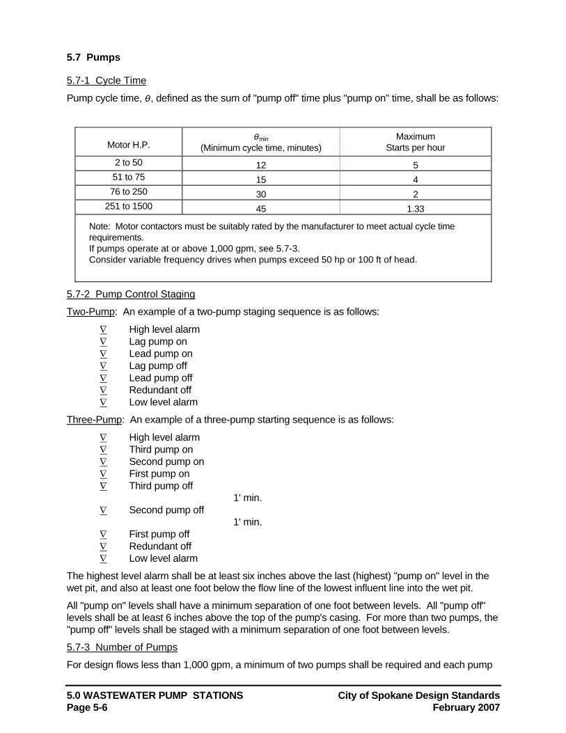
5.0 WASTEWATER PUMP STATIONS City of Spokane Design Standards Page 5-6 February 2007
5.7 Pumps
5.7-1 Cycle Time
Pump cycle time, θ, defined as the sum of "pump off" time plus "pump on" time, shall be as follows:
Motor H.P.
θmin (Minimum cycle time, minutes)
Maximum Starts per hour
2 to 50 12 5 51 to 75 15 4 76 to 250 30 2
251 to 1500 45 1.33
Note: Motor contactors must be suitably rated by the manufacturer to meet actual cycle time requirements. If pumps operate at or above 1,000 gpm, see 5.7-3. Consider variable frequency drives when pumps exceed 50 hp or 100 ft of head.
5.7-2 Pump Control Staging
Two-Pump: An example of a two-pump staging sequence is as follows:
∇ High level alarm ∇ Lag pump on ∇ Lead pump on ∇ Lag pump off ∇ Lead pump off ∇ Redundant off ∇ Low level alarm
Three-Pump: An example of a three-pump starting sequence is as follows:
∇ High level alarm ∇ Third pump on ∇ Second pump on ∇ First pump on ∇ Third pump off
1' min. ∇ Second pump off
1' min. ∇ First pump off ∇ Redundant off ∇ Low level alarm
The highest level alarm shall be at least six inches above the last (highest) "pump on" level in the wet pit, and also at least one foot below the flow line of the lowest influent line into the wet pit.
All "pump on" levels shall have a minimum separation of one foot between levels. All "pump off" levels shall be at least 6 inches above the top of the pump's casing. For more than two pumps, the "pump off" levels shall be staged with a minimum separation of one foot between levels.
5.7-3 Number of Pumps
For design flows less than 1,000 gpm, a minimum of two pumps shall be required and each pump
City of Spokane Design Standards 5.0 WASTEWATER PUMP STATIONS February 2007 Page 5-7
shall be capable of delivering the design flow with the largest pump out of service.
For design flows of 1,000 gpm or larger, multiple pumps shall be installed to efficiently handle the maximum/minimum flows and to reduce the time of detention in the wet pit. When more than two pumps are utilized, the capacity of the pumps shall be such that the design flow can be handled with the largest pump out of service.
Lift stations with more than three pumps require design coordination with the Wastewater Treatment Division.
5.7-4 Net Positive Suction Head (NPSH)
The net positive suction head (NPSH) required by the pump selected shall be compared with the NPSH available in the system at the eye of the impeller. The engineer shall consult the pump manufacturer for the NPSH required values for the pump and compare them with calculated values for the NPSH available. The NPSH available should be greater than or equal to the NPSH required for a flooded suction pump. The following equation may be used for calculating the NPSH available:
NPSHA = PB ± HS - PV - Hfs ≈ 29.9 ± HS - Hfs where: PB = barometric pressure in feet absolute HS = minimum static suction head in feet; positive if flooded; negative if suction PV = vapor pressure of liquid in feet absolute Hfs = friction loss in suction pipe in feet.
For lift stations in Spokane, a barometric pressure of 30.5 feet and a vapor pressure of 0.59 feet may be used. These values are based on an altitude of 1740 feet above sea level, a water temperature of 60o F and a specific gravity of water equaling 0.99905 for 60o F.
5.7-5 Head Loss Curves
Data points for the system capacity curve shall be provided in tabular form and graphed with pump head capacity curve on the same axis. System capacity curves shall be plotted using the Hazen Williams coefficient values of C=100 and C=130.
Pump output in gpm at maximum and minimum head shall be clearly shown on system curves for each pump and combination of pumps.
For stations with two or more pumps operating in parallel, multiple and single operation points shall be plotted on the system curve.
Pumps with the best efficiencies at all operating points shall be chosen.
If a station is equipped with smaller impellers during start-up to handle lower than design flows, impellers sized to handle the design flow shall also be provided.
5.7-6 Additional Pump Design Parameters
Pumps shall be capable of passing spheres of at least 3 inches in diameter. Pump suction and discharge openings shall be at least 4 inches in diameter.
All suction piping shall be flanged ductile iron and have a minimum diameter of 4 inches. Each pump shall have a separate suction pipe. Suction piping shall have a velocity of 1 to 2 fps. All suction pipes inside the wet pit shall be equipped with a flared type, down-turned intake. (See Section 5.5-1 for mitigation of entrained air.)
All pumps and piping shall be protected from freezing temperatures.
Stations with pump parameters greater than 50 hp or 100 feet of head shall submit a design for variable frequency drives (VFD) as an alternate.
Motors 40 HP and larger shall be high efficiency frames. Overall wire to water efficiency should be
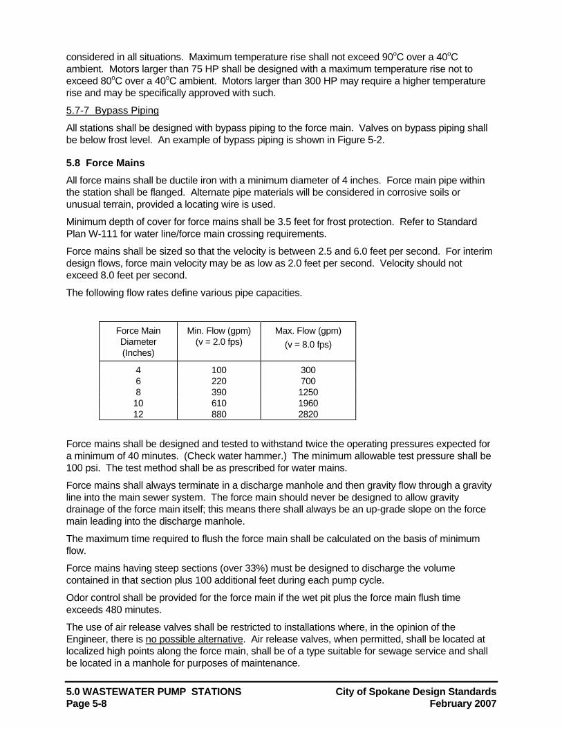
5.0 WASTEWATER PUMP STATIONS City of Spokane Design Standards Page 5-8 February 2007
considered in all situations. Maximum temperature rise shall not exceed 90oC over a 40oC ambient. Motors larger than 75 HP shall be designed with a maximum temperature rise not to exceed 80oC over a 40oC ambient. Motors larger than 300 HP may require a higher temperature rise and may be specifically approved with such.
5.7-7 Bypass Piping
All stations shall be designed with bypass piping to the force main. Valves on bypass piping shall be below frost level. An example of bypass piping is shown in Figure 5-2.
5.8 Force Mains All force mains shall be ductile iron with a minimum diameter of 4 inches. Force main pipe within the station shall be flanged. Alternate pipe materials will be considered in corrosive soils or unusual terrain, provided a locating wire is used.
Minimum depth of cover for force mains shall be 3.5 feet for frost protection. Refer to Standard Plan W-111 for water line/force main crossing requirements.
Force mains shall be sized so that the velocity is between 2.5 and 6.0 feet per second. For interim design flows, force main velocity may be as low as 2.0 feet per second. Velocity should not exceed 8.0 feet per second.
The following flow rates define various pipe capacities.
Force Main Diameter (Inches)
Min. Flow (gpm) (v = 2.0 fps)
Max. Flow (gpm) (v = 8.0 fps)
4 100 300 6 220 700 8 390 1250 10 610 1960 12 880 2820
Force mains shall be designed and tested to withstand twice the operating pressures expected for a minimum of 40 minutes. (Check water hammer.) The minimum allowable test pressure shall be 100 psi. The test method shall be as prescribed for water mains.
Force mains shall always terminate in a discharge manhole and then gravity flow through a gravity line into the main sewer system. The force main should never be designed to allow gravity drainage of the force main itself; this means there shall always be an up-grade slope on the force main leading into the discharge manhole.
The maximum time required to flush the force main shall be calculated on the basis of minimum flow.
Force mains having steep sections (over 33%) must be designed to discharge the volume contained in that section plus 100 additional feet during each pump cycle.
Odor control shall be provided for the force main if the wet pit plus the force main flush time exceeds 480 minutes.
The use of air release valves shall be restricted to installations where, in the opinion of the Engineer, there is no possible alternative. Air release valves, when permitted, shall be located at localized high points along the force main, shall be of a type suitable for sewage service and shall be located in a manhole for purposes of maintenance.
City of Spokane Design Standards 5.0 WASTEWATER PUMP STATIONS February 2007 Page 5-9
5.9 Power Supply Stations should be designed to operate on 480 volt 3-phase power supply whenever possible. Electrical system and components (e.g. motors, lights, cables, conduits, switch boxes, control circuits, etc.) in raw sewage wet pits, or in enclosed or partially enclosed spaces where hazardous concentrations of flammable gases or vapors may be present, shall comply with the National Electrical Code requirements for Class I, Group D, Division I locations. In addition, electrical equipment located in the wet pit shall be suitable for use under corrosive conditions. Each flexible cable shall be provided with watertight seal and separate strain relief. A fused disconnect switch located above ground shall be provided for all pumping stations. When such equipment is exposed to weather, it shall meet the minimum requirements of weatherproof equipment (NEMA 3R) and be located in a water resistant maintenance environment.
5.10 Emergency Operation Provisions shall be provided to accommodate station inflow in the event of a power outage. This may be affected by (a) including an emergency power supply, or (b) construction of emergency storage. All public stations except small STEP areas shall have an emergency backup power supply.
5.10-1 Emergency Power
Provisions for an emergency power supply shall be made either through connection of the station to at least two independent public utility sources, or through installation of in-place internal combustion power generation equipment (See Section 5.11-8).
5.10-2 Emergency Storage
Where storage is to be provided in lieu of an emergency power supply, wet pit capacity above the high level alarm should be sufficient to hold the peak flow expected during the areas maximum historic power outage but not less than twenty four hours
5.11 Miscellaneous Equipment and Appurtenances
5.11-1 Screens, Racks and Traps
Pumps handling stormwater shall be preceded by readily accessible bar racks to protect the pumps from clogging or damage. Bar racks shall have clear openings not exceeding 2 inches. Where a bar rack is provided, a mechanical hoist shall also be provided.
In addition, screens and racks are required on all pump stations with capacity less than 1 million gallons per day capacity. For stations with 1 million gallons per day capacity or greater, mechanically cleaned racks shall be provided.
If necessary, rock traps may be constructed in the manhole immediately upstream of the pump station. A depressed section of the manhole channel may serve as a rock trap, allowing heavy debris to sink and the remaining wastewater to flow over the trap.
5.11-2 Controls/Flow Monitoring
Control systems shall be of the ultrasonic type, located away from the turbulence of incoming flow and pipe suction.
In all stations, provisions should be made to automatically alternate the pumps in use, and to manually change the lead pump.
Suitable devices for measuring sewage flow for stations with pumping rates of 1,000 gpm or greater shall be required. The use of a parshall flume and an ultrasonic measurement device is acceptable.
5.0 WASTEWATER PUMP STATIONS City of Spokane Design Standards Page 5-10 February 2007
5.11-3 Valves
Suitable rising stem shutoff valves shall be placed on the suction line of each pump and on the station bypass line to the force main. Suitable shutoff and check valves shall be placed on the discharge line of each pump. The check valve shall be located between the shutoff valve and the pump. Check valves shall be suitable for the material being handled, and shall not be placed on the vertical portion of discharge piping. The seats of all check valves shall be removable without removing the valve itself. Valves shall be capable of withstanding normal pressure and water hammer.
Gate valves higher than 6 feet off the floor shall have chain operators. Valves shall not be located in the wet pit.
Valves larger than 16 inch shall be power-actuated.
5.11-4 Ventilation
Adequate ventilation shall be provided for all pump stations. Where the pump pit is below the ground surface, mechanical ventilation is required, so arranged as to independently ventilate the dry pit and wet pit if screens or mechanical equipment requiring inspection are located in the wet pit. There shall be no interconnection between the wet pit and dry pit ventilation systems.
In pits over 15 feet deep, multiple inlets and outlets are desirable. Dampers should not be used on exhaust or fresh air ducts and fine screens or other restrictions in air ducts should be avoided to prevent clogging.
Switches for operation of ventilation equipment should be marked and located conveniently. All intermittently operated ventilation equipment shall be interconnected with the respective pit lighting system. Consideration should also be given to automatic controls where intermittent operation is used. The fan wheel should be fabricated from non-sparking material. Consideration should be given to installation of automatic heating and/or dehumidifying equipment. Cooling may be required for large motors and controls.
Ventilation for the wet pit may be either continuous or intermittent. Ventilation, if continuous, shall provide at least 12 complete air changes per hour; if intermittent, at least 30 complete air changes per hour. Air shall be forced into the wet pit rather than exhausted from the wet pit.
Ventilation for the dry pit may be either continuous or intermittent. Ventilation, if continuous, shall provide at least 6 complete air changes per hour; if intermittent, at least 30 complete air changes per hour. Temperature compensation may be necessary.
5.11-5 Alarm System
Alarm systems shall be provided for all pumping stations. The alarm shall be activated in cases of power failure, pump failure, use of the lag pump, or any cause of pump station malfunction. Pumping station alarms shall be telemetered, including identification of the alarm condition, to a municipal facility that is manned 24 hours a day. The alarm system and components must have the prior approval of the Wastewater Treatment Plant Pump Station Division.
5.11-6 Trolleys/Hoists
All stations shall be designed with mechanical facilities adequate to lift the pumps.
5.11-7 Egress
All station designs shall include a method to remove workmen from confined spaces, in accordance with applicable WISHA regulations.
5.11-8 Auxiliary Generating Equipment
The following general requirements shall apply to all internal combustion engines used to drive

City of Spokane Design Standards 5.0 WASTEWATER PUMP STATIONS February 2007 Page 5-11
auxiliary electrical generating equipment:
Engine/Equipment Protection: The engine must be protected from operating conditions that would result in damage to equipment. Unless continuous manual supervision is planned, protective equipment shall be capable of shutting down the engine and activating an alarm on site. Protective equipment shall monitor for conditions of low oil pressure and overheating. Emergency equipment shall be protected from damage at the restoration of regular electrical power (located in a suitable building).
Engine block heaters are required.
Size: The engine shall have adequate rated power to start and continuously operate all connected loads.
Fuel: Reliability and ease of starting, especially during cold weather conditions should be considered in the selection of the type of fuel. Propane or natural gas is preferred. Fuel storage is required to supply a minimum of 12 hours of operation at maximum design load. No buried tanks will be allowed.
Engine Ventilation: The engine shall be located above grade with adequate ventilation of fuel vapors and exhaust gases.
Routine Start-up: All emergency equipment shall be provided with instructions indicating the need for regular starting and running of such units at full loads. Engines shall be automatically exercised every 7 days.
Engine-Driven Generating Equipment: Generating unit size shall be adequate to provide power for pump motor starting current and for lighting, ventilation, and other auxiliary equipment necessary for safety and proper operation of the lift station. Provisions shall be made for automatic and manual start-up and load transfer. The generator must be protected from operating conditions that would result in damage to equipment. Provisions should be considered to allow the engine to start and stabilize at operating speed before assuming the load.
5.12 Buoyancy Calculations The lift station design shall include a complete analysis of buoyant forces.
5.13 Water Hammer Calculations Calculations showing maximum pressures which would occur upon total power failure while pumping shall be provided. Water hammer shall be calculated according to the following equations:
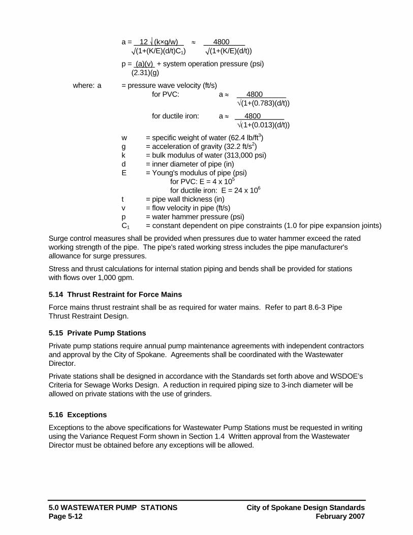
5.0 WASTEWATER PUMP STATIONS City of Spokane Design Standards Page 5-12 February 2007
a = 12 (k×g/w) ≈ 4800 √(1+(K/E)(d/t)C1) √(1+(K/E)(d/t))
p = (a)(v) + system operation pressure (psi) (2.31)(g)
where: a = pressure wave velocity (ft/s) for PVC: a ≈ 4800
√(1+(0.783)(d/t))
for ductile iron: a ≈ 4800 √(1+(0.013)(d/t))
w = specific weight of water (62.4 lb/ft3) g = acceleration of gravity (32.2 ft/s2) k = bulk modulus of water (313,000 psi) d = inner diameter of pipe (in) E = Young's modulus of pipe (psi)
for PVC: E = 4 x 10⁵ for ductile iron: E = 24 x 106
t = pipe wall thickness (in) v = flow velocity in pipe (ft/s) p = water hammer pressure (psi) C1 = constant dependent on pipe constraints (1.0 for pipe expansion joints)
Surge control measures shall be provided when pressures due to water hammer exceed the rated working strength of the pipe. The pipe's rated working stress includes the pipe manufacturer's allowance for surge pressures.
Stress and thrust calculations for internal station piping and bends shall be provided for stations with flows over 1,000 gpm.
5.14 Thrust Restraint for Force Mains Force mains thrust restraint shall be as required for water mains. Refer to part 8.6-3 Pipe Thrust Restraint Design.
5.15 Private Pump Stations Private pump stations require annual pump maintenance agreements with independent contractors and approval by the City of Spokane. Agreements shall be coordinated with the Wastewater Director.
Private stations shall be designed in accordance with the Standards set forth above and WSDOE’s Criteria for Sewage Works Design. A reduction in required piping size to 3-inch diameter will be allowed on private stations with the use of grinders.
5.16 Exceptions Exceptions to the above specifications for Wastewater Pump Stations must be requested in writing using the Variance Request Form shown in Section 1.4 Written approval from the Wastewater Director must be obtained before any exceptions will be allowed.
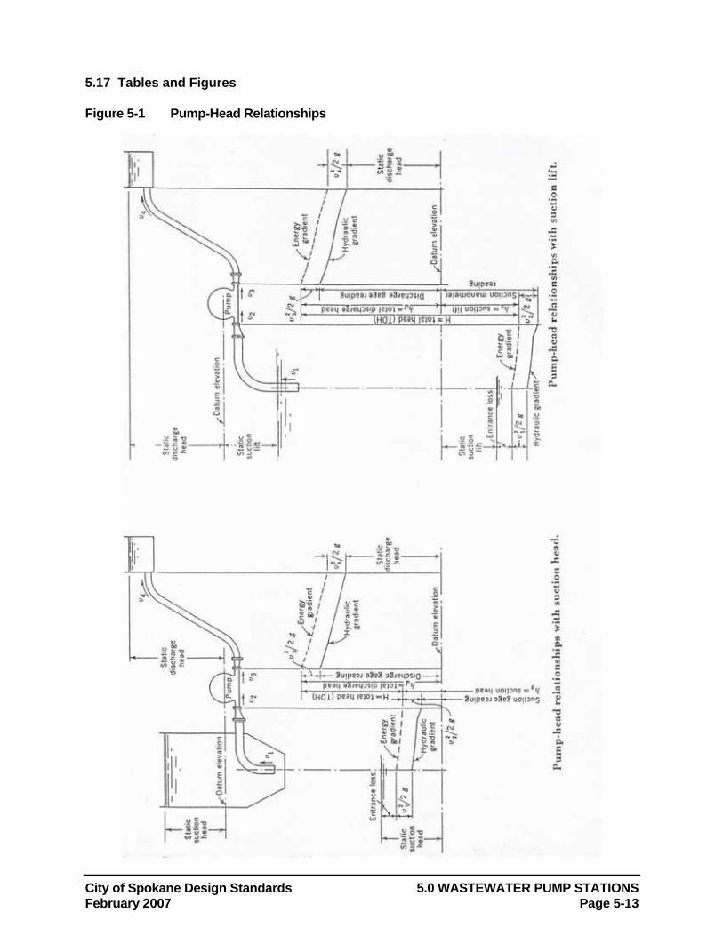
City of Spokane Design Standards 5.0 WASTEWATER PUMP STATIONS February 2007 Page 5-13
5.17 Tables and Figures Figure 5-1 Pump-Head Relationships
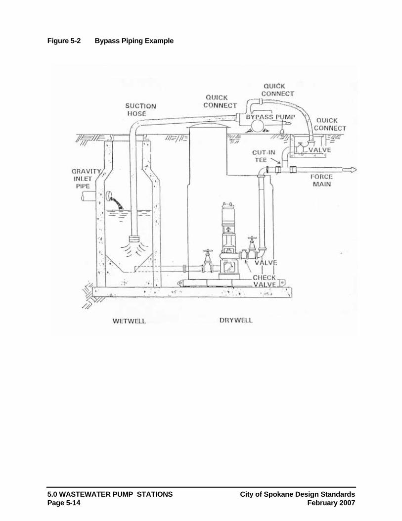
5.0 WASTEWATER PUMP STATIONS City of Spokane Design Standards Page 5-14 February 2007
Figure 5-2 Bypass Piping Example
City of Spokane Design Standards 6.0 STORM WATER MANAGEMENT February 2007 Page 6-1
6.0 STORM WATER MANAGEMENT The Spokane Regional Stormwater Manual, currently under development by the City of Spokane, Spokane County and the City of Spokane Valley, will supersede portions of this section. Until it is adopted, the requirements of this section shall apply.
The Spokane Aquifer Water Quality Management Plan, prepared in 1979 for Spokane County, discusses recommended policies and actions related to stormwater to preserve the quality of the Spokane aquifer. Spokane County's "208" Water Quality Management Program was developed as a result of this study.
This section outlines standard methods for calculating runoff and infiltration rates, and describes acceptable systems for stormwater disposal within the City. Specific handling of stormwater on public and private properties is also discussed.
Erosion and Sediment Control Plans are required for projects or activities which could potentially cause significant excess runoff, erosion, or water quantity/quality impacts. Refer to Section 7.0 for Erosion and Sediment Control Plan requirements.
6.1 Definitions “208” Swale: See Grass Percolation Area Swale (GPA).
Absorption Trench An underground channel constructed beneath a roadway or paved surface which is filled with gravel and used to store storm water runoff until soil conditions permit natural drainage/absorption into the ground below. Surface runoff enters the absorption trench via a drywell and drain tile.
Aquifer or Spokane Aquifer A subterranean body of flowing water, also known as the Spokane-Rathdrum Aquifer, that runs from Pend Oreille Lake to the Little Spokane River.
Aquifer Sensitive Area That area or overlay zone from which runoff directly recharges the Aquifer, including the surface over the Aquifer itself, and the hillside areas immediately adjacent to the Aquifer.
Backwater Effect The effect which a stream obstruction has in raising the water surface upstream.
Biofiltration The simultaneous process of filtration, infiltration, adsorption and biological uptake of pollutants in stormwater that takes place when runoff flows through and ponds in vegetated areas.
Catch Basin A drainage structure which receives stormwater prior to discharge to a storm sewer or subterranean dissipation structure. Generally a catch basin’s purpose is to allow sediment and debris to settle out the stormwater, and to retain these materials to prevent them from entering the primary disposal system.
Combined Sewer See Section 4.1.
Culvert A closed conduit used as an artificial channel under a roadway or embankment to maintain free passage of surface drainage water from a natural channel or drainage ditch.
Design Storm The storm frequency for which a hydraulic structure is designed. For example: a “50-year” storm is the largest rainfall event that can be expected to occur once every 50 years. A structure with a 50-year design storm should be capable of handling the runoff volume or peak flow rate which is generated by the 50-year storm.
Detention The storage and subsequent release of excess stormwater runoff for a site, generally for flow control purposes. AASHTO defines detention as short-term storage, usually less than a
6.0 STORM WATER MANAGEMENT City of Spokane Design Standards Page 6-2 February 2007
day, with release at a lower, controlled rate.
Drainage a) The process of removing surplus ground or surface water by artificial means. b) The manner in which the water of an area is removed.
Drainage Basin An area from which surface runoff is carried away by a single drainage system.
Drainage Area The area served by a stormwater disposal system.
Drainage System (or Storm System) A system of conduits and structures for effecting drainage. Also, all piping within public or private premises which conveys stormwater to a legal point of disposal; but which does not include the pipes of a public sanitary sewer system.
Flood Frequency The average time interval between occurrences of a hydrologic event of a given or greater magnitude, usually expressed in years. May also be called recurrence interval.
Grass Percolation Area (Swale): A grassed percolation area (GPA) designed to accept and treat storm runoff from impervious areas such as roadways, parking lots, roofs, etc.
Graphical Peak Discharge Method A method presented in SCS TR-55 for determining peak discharge of a watershed.
Hydrograph A graph showing stage, flow, velocity or other property of water with respect to time.
Impervious Not allowing, or allowing only with great difficulty, the movement of water; impermeable.
Infiltration The flow or movement of water through the interstices or pores of a soil or other porous medium.
Infiltration Rate A measure of the speed of water movement through soil. The rate of infiltration at a specific site may vary based on hydraulic head. See Appendix I of the Spokane County Guidelines for Stormwater Management for infiltration rate testing procedures.
Infiltration Gallery An underground channel beneath a landscaped area or swale, which is filled with sand and gravel, and used to store storm water runoff until soil moisture conditions permit natural drainage/absorption into the ground below.
Natural Outlet See Section 4.1.
Noncontact Cooling Water See Section 4.1.
Outfall The point, location or structure where wastewater or drainage discharges from a sewer, drain or other conduit. Also, the conduit leading to the ultimate disposal area.
Permeability A measure of a soil's ability to absorb and convey water. Unlike the infiltration rate, permeability is not dependent on hydraulic head.
Ponding Depth The vertical distance between the top of drywell and the bottom of a swale.
Private Storm Sewer A storm sewer not controlled or maintained by a public authority, which is connected to a public sewer (See Section 4.1) or discharged into a natural outlet (See Section 4.1).
Rainfall-Intensity Curve A curve that expresses the relation of rates of rainfall and their duration. Each curve is generally for a period of years during which time the intensities shown will not, on the average, be exceeded more than once.
Rational Method A method of estimating runoff in a drainage basin for a specific point and time by means of the Rational Runoff Formula. For each drainage area, the rainfall rate under a stated intensity-duration relationship, the fraction that will appear as runoff, and the basin area above the specified point are estimated. Their product is the flow. This method is used to estimate storm runoff in urban areas and flood flows in streams.
City of Spokane Design Standards 6.0 STORM WATER MANAGEMENT February 2007 Page 6-3
Rational Runoff Formula A formula used to relate rainfall intensity to runoff. It is Q=CiA, where Q is peak discharge in cfs; C is the runoff coefficient, generally considered to be that part of the rainfall rate which will contribute to the runoff rate; i is the average intensity of rainfall in inches per hour during the time required for all parts of the watershed to contribute to runoff (time of concentration); A is the area of the drainage basin in acres. The formula is based on the approximation that one inch/hr/acre = one cfs.
Retention Storage of stormwater runoff, generally for the purpose of flood control or for treatment by settling or eutrophication. Some retention facilities have flow-control devices for subsequent release of stormwater. Others have no outlet but may allow water to dissipate through soil infiltration or evaporation. AASHTO considers retention to mean storage for several days or more; in contrast with detention, which is shorter-term storage.
Roof Drain A drain installed to receive water collecting on the surface of a roof and discharge it to the onsite drainage system.
Runoff That part of the precipitation which runs off the surface of a drainage area and reaches a stream or other body of water or a drain or sewer.
Runoff Coefficient Ratio of the maximum rate of runoff to the uniform rate of rainfall with a duration equaling or exceeding the time of concentration which produced this rate of runoff.
Runoff Curve Number Method A procedure presented in SCS TR-55 for estimating runoff in conjunction with the Tabular Hydrograph method or Graphical Peak Discharge method for drainage basin analysis. Briefly, under the Runoff Curve Number method, discharge Q is determined using the equation Q = (P-0.2S)2/(P+0.8S), where P is rainfall in inches, and S is the potential maximum retention after runoff begins (in inches). S is related to soil and cover conditions through a Curve Number (CN) according to the following equation: S = (1000/CN)-10. Refer to SCS TR-55 for additional detail on this method.
Runoff Rate The volume of water running off in a unit of time from a surface, expressed in inches depth per hour, cfs, cfs per square mile or other units.
Sanitary Sewer See Section 4.1.
SCS TR-55 U.S. Soil Conservation Service Technical Release 55, "Urban Hydrology for Small Watersheds". See also Runoff Curve Number method and Tabular Hydrograph method.
Sedimentation Gravitational deposit of transported material in flowing or standing water.
Settling Basin A basin or tank in which water or wastewater containing settleable solids is retained to remove by gravity a part of the suspended matter.
Storm Water See Section 4.1.
Storm Sewer or Storm Drain See Section 4.1.
Swale See Grass Percolation Area Swale.
Tabular Hydrograph Method: Method used to develop hydrographs and calculate runoff for drainage areas with time of concentration between 0.1 and 2.0 hours. See the U.S. Soil Conservation Service (SCS) Technical Release 55 (TR-55), "Urban Hydrology for Small Watersheds" for further description of this method.
Time of Concentration a) The period of time required for storm runoff to flow from the most hydraulically remote point
of a catchment or drainage area to the outlet or point under consideration. It is not a constant, but varies with depth of flow and condition of channel.
b) The time at which the rate of runoff equals the rate of rainfall of a storm of uniform intensity.
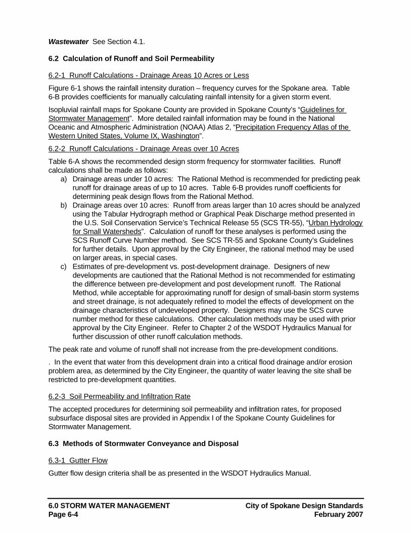
6.0 STORM WATER MANAGEMENT City of Spokane Design Standards Page 6-4 February 2007
Wastewater See Section 4.1.
6.2 Calculation of Runoff and Soil Permeability
6.2-1 Runoff Calculations - Drainage Areas 10 Acres or Less
Figure 6-1 shows the rainfall intensity duration – frequency curves for the Spokane area. Table 6-B provides coefficients for manually calculating rainfall intensity for a given storm event.
Isopluvial rainfall maps for Spokane County are provided in Spokane County’s “Guidelines for Stormwater Management”. More detailed rainfall information may be found in the National Oceanic and Atmospheric Administration (NOAA) Atlas 2, “Precipitation Frequency Atlas of the Western United States, Volume IX, Washington”.
6.2-2 Runoff Calculations - Drainage Areas over 10 Acres
Table 6-A shows the recommended design storm frequency for stormwater facilities. Runoff calculations shall be made as follows:
a) Drainage areas under 10 acres: The Rational Method is recommended for predicting peak runoff for drainage areas of up to 10 acres. Table 6-B provides runoff coefficients for determining peak design flows from the Rational Method.
b) Drainage areas over 10 acres: Runoff from areas larger than 10 acres should be analyzed using the Tabular Hydrograph method or Graphical Peak Discharge method presented in the U.S. Soil Conservation Service’s Technical Release 55 (SCS TR-55), “Urban Hydrology for Small Watersheds”. Calculation of runoff for these analyses is performed using the SCS Runoff Curve Number method. See SCS TR-55 and Spokane County’s Guidelines for further details. Upon approval by the City Engineer, the rational method may be used on larger areas, in special cases.
c) Estimates of pre-development vs. post-development drainage. Designers of new developments are cautioned that the Rational Method is not recommended for estimating the difference between pre-development and post development runoff. The Rational Method, while acceptable for approximating runoff for design of small-basin storm systems and street drainage, is not adequately refined to model the effects of development on the drainage characteristics of undeveloped property. Designers may use the SCS curve number method for these calculations. Other calculation methods may be used with prior approval by the City Engineer. Refer to Chapter 2 of the WSDOT Hydraulics Manual for further discussion of other runoff calculation methods.
The peak rate and volume of runoff shall not increase from the pre-development conditions.
. In the event that water from this development drain into a critical flood drainage and/or erosion problem area, as determined by the City Engineer, the quantity of water leaving the site shall be restricted to pre-development quantities.
6.2-3 Soil Permeability and Infiltration Rate
The accepted procedures for determining soil permeability and infiltration rates, for proposed subsurface disposal sites are provided in Appendix I of the Spokane County Guidelines for Stormwater Management.
6.3 Methods of Stormwater Conveyance and Disposal
6.3-1 Gutter Flow
Gutter flow design criteria shall be as presented in the WSDOT Hydraulics Manual.
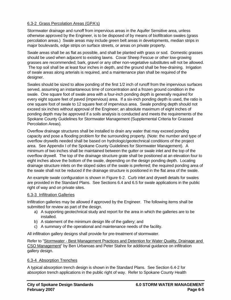
City of Spokane Design Standards 6.0 STORM WATER MANAGEMENT February 2007 Page 6-5
6.3-2 Grass Percolation Areas (GPA’s)
Stormwater drainage and runoff from impervious areas in the Aquifer Sensitive area, unless otherwise approved by the Engineer, is to be disposed of by means of biofiltration swales (grass percolation areas.) Swale areas may include green belt areas in developments, median strips in major boulevards, edge strips on surface streets, or areas on private property.
Swale areas shall be as flat as possible, and shall be planted with grass or sod. Domestic grasses should be used when adjacent to existing lawns. Covar Sheep Fescue or other low-growing grasses are recommended; bark, gravel or any other non-vegetative substitutes will not be allowed. The top soil shall be at least four inches in depth, and the ground shall be free-draining. Irrigation of swale areas along arterials is required, and a maintenance plan shall be required of the designer.
Swales should be sized to allow ponding of the first 1/2 inch of runoff from the impervious surfaces served, assuming an instantaneous time of concentration and a frozen ground condition in the swale. One square foot of swale area with a four-inch ponding depth is generally required for every eight square feet of paved (impervious) area. If a six-inch ponding depth is used, the ratio is one square foot of swale to 12 square feet of impervious area. Swale ponding depth should not exceed six inches without approval of the Engineer; an absolute maximum of eight inches of ponding depth may be approved if a soils analysis is conducted and meets the requirements of the Spokane County Guidelines for Stormwater Management (Supplemental Criteria for Grassed Percolation Areas).
Overflow drainage structures shall be installed to drain any water that may exceed ponding capacity and pose a flooding problem for the surrounding property. (Note: the number and type of overflow drywells needed shall be based on hydrologic/geotechnical conditions of the project area. See Appendix I of the Spokane County Guidelines for Stormwater Management). A minimum of two inches shall be maintained between the gutter or swale inlet and the top of the overflow drywell. The top of the drainage structure grate shall be positioned at an elevation four to eight inches above the bottom of the swale, depending on the design ponding depth. Locating drainage structure inlets on the sloped sides of the swale is preferred; the required ponding area of the swale shall not be reduced if the drainage structure is positioned in the flat area of the swale.
An example swale configuration is shown in Figure 6-2. Curb inlet and drywell details for swales are provided in the Standard Plans. See Sections 6.4 and 6.5 for swale applications in the public right of way and on private sites.
6.3-3 Infiltration Galleries
Infiltration galleries may be allowed if approved by the Engineer. The following items shall be submitted for review as part of the design.
a) A supporting geotechnical study and report for the area in which the galleries are to be installed.
b) A statement of the minimum design life of the gallery; and c) A summary of the operational and maintenance needs of the facility.
All infiltration gallery designs shall provide for pre-treatment of stormwater.
Refer to ”Stormwater - Best Management Practices and Detention for Water Quality, Drainage and CSO Management” by Ben Urbanoas and Peter Stahre for additional guidance on infiltration gallery design.
6.3-4 Absorption Trenches
A typical absorption trench design is shown in the Standard Plans. See Section 6.4-2 for absorption trench applications in the public right of way. Refer to Spokane County Health
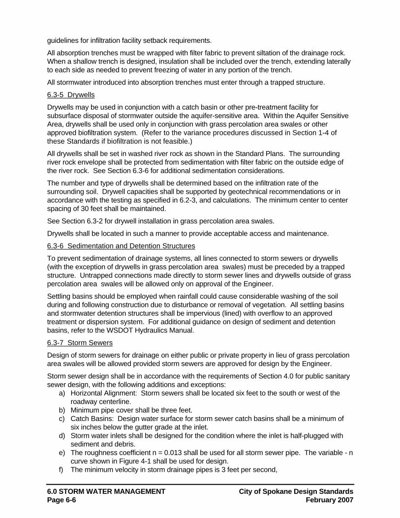
6.0 STORM WATER MANAGEMENT City of Spokane Design Standards Page 6-6 February 2007
guidelines for infiltration facility setback requirements.
All absorption trenches must be wrapped with filter fabric to prevent siltation of the drainage rock. When a shallow trench is designed, insulation shall be included over the trench, extending laterally to each side as needed to prevent freezing of water in any portion of the trench.
All stormwater introduced into absorption trenches must enter through a trapped structure.
6.3-5 Drywells
Drywells may be used in conjunction with a catch basin or other pre-treatment facility for subsurface disposal of stormwater outside the aquifer-sensitive area. Within the Aquifer Sensitive Area, drywells shall be used only in conjunction with grass percolation area swales or other approved biofiltration system. (Refer to the variance procedures discussed in Section 1-4 of these Standards if biofiltration is not feasible.)
All drywells shall be set in washed river rock as shown in the Standard Plans. The surrounding river rock envelope shall be protected from sedimentation with filter fabric on the outside edge of the river rock. See Section 6.3-6 for additional sedimentation considerations.
The number and type of drywells shall be determined based on the infiltration rate of the surrounding soil. Drywell capacities shall be supported by geotechnical recommendations or in accordance with the testing as specified in 6.2-3, and calculations. The minimum center to center spacing of 30 feet shall be maintained.
See Section 6.3-2 for drywell installation in grass percolation area swales.
Drywells shall be located in such a manner to provide acceptable access and maintenance.
6.3-6 Sedimentation and Detention Structures
To prevent sedimentation of drainage systems, all lines connected to storm sewers or drywells (with the exception of drywells in grass percolation area swales) must be preceded by a trapped structure. Untrapped connections made directly to storm sewer lines and drywells outside of grass percolation area swales will be allowed only on approval of the Engineer.
Settling basins should be employed when rainfall could cause considerable washing of the soil during and following construction due to disturbance or removal of vegetation. All settling basins and stormwater detention structures shall be impervious (lined) with overflow to an approved treatment or dispersion system. For additional guidance on design of sediment and detention basins, refer to the WSDOT Hydraulics Manual.
6.3-7 Storm Sewers
Design of storm sewers for drainage on either public or private property in lieu of grass percolation area swales will be allowed provided storm sewers are approved for design by the Engineer.
Storm sewer design shall be in accordance with the requirements of Section 4.0 for public sanitary sewer design, with the following additions and exceptions:
a) Horizontal Alignment: Storm sewers shall be located six feet to the south or west of the roadway centerline.
b) Minimum pipe cover shall be three feet. c) Catch Basins: Design water surface for storm sewer catch basins shall be a minimum of
six inches below the gutter grade at the inlet. d) Storm water inlets shall be designed for the condition where the inlet is half-plugged with
sediment and debris. e) The roughness coefficient n = 0.013 shall be used for all storm sewer pipe. The variable - n
curve shown in Figure 4-1 shall be used for design. f) The minimum velocity in storm drainage pipes is 3 feet per second,
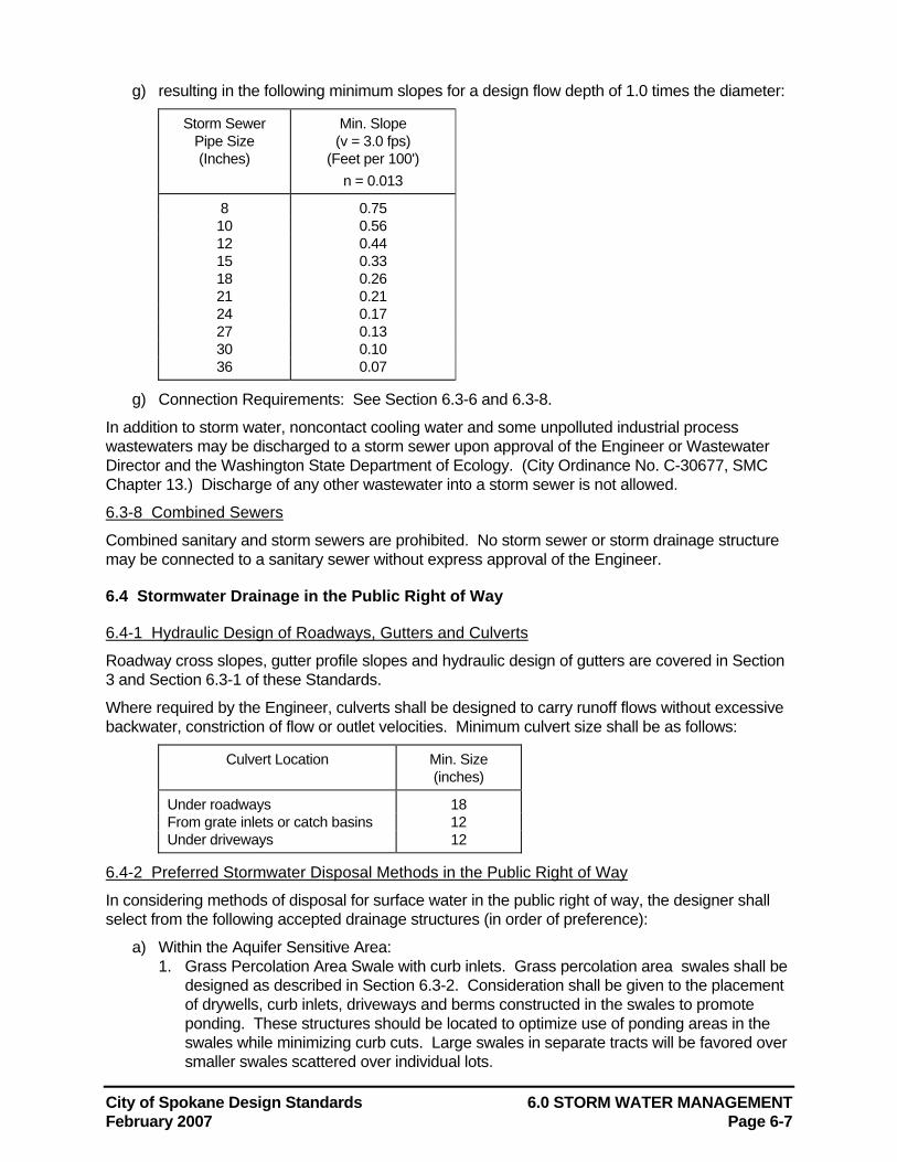
City of Spokane Design Standards 6.0 STORM WATER MANAGEMENT February 2007 Page 6-7
g) resulting in the following minimum slopes for a design flow depth of 1.0 times the diameter:
Storm Sewer Pipe Size (Inches)
Min. Slope (v = 3.0 fps)
(Feet per 100') n = 0.013
8 0.75 10 0.56 12 0.44 15 0.33 18 0.26 21 0.21 24 0.17 27 0.13 30 0.10 36 0.07
g) Connection Requirements: See Section 6.3-6 and 6.3-8.
In addition to storm water, noncontact cooling water and some unpolluted industrial process wastewaters may be discharged to a storm sewer upon approval of the Engineer or Wastewater Director and the Washington State Department of Ecology. (City Ordinance No. C-30677, SMC Chapter 13.) Discharge of any other wastewater into a storm sewer is not allowed.
6.3-8 Combined Sewers
Combined sanitary and storm sewers are prohibited. No storm sewer or storm drainage structure may be connected to a sanitary sewer without express approval of the Engineer.
6.4 Stormwater Drainage in the Public Right of Way
6.4-1 Hydraulic Design of Roadways, Gutters and Culverts
Roadway cross slopes, gutter profile slopes and hydraulic design of gutters are covered in Section 3 and Section 6.3-1 of these Standards.
Where required by the Engineer, culverts shall be designed to carry runoff flows without excessive backwater, constriction of flow or outlet velocities. Minimum culvert size shall be as follows:
Culvert Location Min. Size (inches)
Under roadways 18 From grate inlets or catch basins 12 Under driveways 12
6.4-2 Preferred Stormwater Disposal Methods in the Public Right of Way
In considering methods of disposal for surface water in the public right of way, the designer shall select from the following accepted drainage structures (in order of preference):
a) Within the Aquifer Sensitive Area: 1. Grass Percolation Area Swale with curb inlets. Grass percolation area swales shall be
designed as described in Section 6.3-2. Consideration shall be given to the placement of drywells, curb inlets, driveways and berms constructed in the swales to promote ponding. These structures should be located to optimize use of ponding areas in the swales while minimizing curb cuts. Large swales in separate tracts will be favored over smaller swales scattered over individual lots.
6.0 STORM WATER MANAGEMENT City of Spokane Design Standards Page 6-8 February 2007
2. When the swale is adjacent to a sidewalk, a flat area at least one foot wide should be maintained next to the walk at the same elevation as the edge of walk. When this flat strip is not provided, the maximum slope of the swale bank adjacent to the sidewalk shall be 4:1.
3. Grass Percolation Area Swales Along Roadways: Sidewalks are recommended to be placed on easements to facilitate wider swale widths.
b) Outside the Aquifer Sensitive Area: 1. Type 2 catch basin connected to a drywell or storm sewer. Type 2 catch basins
with inlet details are shown in the Standard Plans. Grade and ride characteristics of the road should be considered in the design of catch basins.
2. Surface inlet structure (with outlet trap) connected to a drywell or storm sewer. Catch Basin Types 0, and 1 shall be constructed as per the Standard Plans. Type 0 catch basins may be used where depth restrictions will not allow Type I catch basins with a design variance.
3. Grate inlet (See Standard Plans) connected to trapped structure and draining to a drywell or storm sewer.
Refer to Spokane County Health guidelines for minimum setback requirements for infiltration facilities.
6.4-3 Draining Stormwater from the Public Right of Way to Private Property
Street dedications, sale of property to the City or easements are required for construction of swales on private property for the purpose of draining stormwater from the public right-of-way. Covenants or deeds shall be established to prohibit alteration or filling in of swale areas. Adjacent property owners shall be required to maintain the swale areas within an easement and provide access for City maintenance personnel.
6.5 Stormwater Drainage on Private Property
6.5-1 Grading/Erosion Control Plans
Grading Plans with one-foot contours and/or Erosion and Sediment Control Plans for private developments may be required by the Plan Review Section of Engineering Services for review and approval. Said plans shall include all platted lots and streets or parking lots which are proposed. Refer to Section 7.0 for Erosion and Sediment Control Plan requirements.
6.5-2 On-Site Stormwater Disposal
Storm water generated on private property shall be disposed of on-site using grass percolation area swales (see Section 6.3-2). Areas of roofs draining directly onto a paved area must be included in the impervious area computation. Alternatively, roof drainage may be "tight-lined" directly into a drywell sized to take the runoff, providing there are no mechanical systems on the building's roof. Construction of swales along private roadways should conform to the requirements for swales in the public right of way in Section 6.4-2.
Swales shall be provided on commercial sites to accept runoff from parking and impervious areas whenever 6,000 sf or more of unpaved (pervious) surface is made impervious (through paving, etc.), and considering the methods used in draining roofs of any new buildings. Additionally, swales shall be installed whenever an existing parking area 6,000 sf or larger is regraded. Design of swales for commercial areas shall conform to the requirements of Section 6.3-2.
Designs employing methods of storm water disposal other than swales on private property shall require approval of the Engineer. (Stormwater collection systems with detention or retention facilities, along with irrigation systems, if appropriate may be approved for larger developments.)
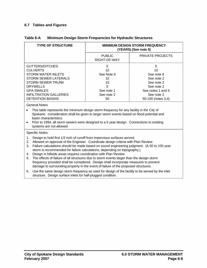
City of Spokane Design Standards 6.0 STORM WATER MANAGEMENT February 2007 Page 6-9
6.7 Tables and Figures Table 6-A Minimum Design Storm Frequencies for Hydraulic Structures
TYPE OF STRUCTURE MINIMUM DESIGN STORM FREQUENCY (YEARS) (See note 5)
PUBLIC RIGHT-OF-WAY
PRIVATE PROJECTS
GUTTERS/DITCHES 5 5 CULVERTS 10 10 STORM WATER INLETS See Note 6 See note 6 STORM SEWER LATERALS 10 See note 2 STORM SEWER TRUNK 10 See note 2 DRYWELLS 5 See note 2 GPA SWALES See note 1 See notes 1 and 4 INFILTRATION GALLERIES See note 2 See note 2 DETENTION BASINS 50 50-100 (notes 3,4)
General Notes • This table represents the minimum design storm frequency for any facility in the City of
Spokane. consideration shall be given to larger storm events based on flood potential and basin characteristics.
• Prior to 1994, all storm sewers were designed to a 5 year design. Connections to existing systems are not allowed.
Specific Notes: 1. Design to hold first 1/2 inch of runoff from impervious surfaces served. 2. Allowed on approval of the Engineer. Coordinate design criteria with Plan Review. 3. Failure calculations should be made based on sound engineering judgment. (A 50 to 100 year
storm is recommended for failure calculations, depending on topography.) 4. Design in hillside areas requires coordination with Plan Review. 5. The effects of failure of all structures due to storm events larger than the design storm
frequency provided shall be considered. Design shall incorporate measures to prevent damage to surrounding property in the event of failure of the proposed structures.
6. Use the same design storm frequency as used for design of the facility to be served by the inlet structure. Design surface inlets for half-plugged condition.
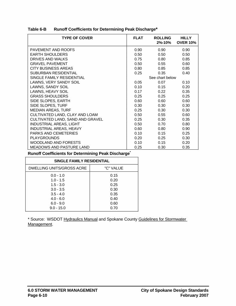
6.0 STORM WATER MANAGEMENT City of Spokane Design Standards Page 6-10 February 2007
Table 6-B Runoff Coefficients for Determining Peak Discharge*
TYPE OF COVER FLAT ROLLING 2%-10%
HILLY OVER 10%
PAVEMENT AND ROOFS 0.90 0.90 0.90 EARTH SHOULDERS 0.50 0.50 0.50 DRIVES AND WALKS 0.75 0.80 0.85 GRAVEL PAVEMENT 0.50 0.55 0.60 CITY BUSINESS AREAS 0.80 0.85 0.85 SUBURBAN RESIDENTIAL 0.25 0.35 0.40 SINGLE FAMILY RESIDENTIAL See chart below LAWNS, VERY SANDY SOIL 0.05 0.07 0.10 LAWNS, SANDY SOIL 0.10 0.15 0.20 LAWNS, HEAVY SOIL 0.17 0.22 0.35 GRASS SHOULDERS 0.25 0.25 0.25 SIDE SLOPES, EARTH 0.60 0.60 0.60 SIDE SLOPES, TURF 0.30 0.30 0.30 MEDIAN AREAS, TURF 0.25 0.30 0.30 CULTIVATED LAND, CLAY AND LOAM 0.50 0.55 0.60 CULTIVATED LAND, SAND AND GRAVEL 0.25 0.30 0.35 INDUSTRIAL AREAS, LIGHT 0.50 0.70 0.80 INDUSTRIAL AREAS, HEAVY 0.60 0.80 0.90 PARKS AND CEMETERIES 0.10 0.15 0.25 PLAYGROUNDS 0.20 0.25 0.30 WOODLAND AND FORESTS 0.10 0.15 0.20 MEADOWS AND PASTURE LAND 0.25 0.30 0.35
Runoff Coefficients for Determining Peak Discharge*
SINGLE FAMILY RESIDENTIAL
DWELLING UNITS/GROSS ACRE "C" VALUE
0.0 - 1.0 1.0 - 1.5 1.5 - 3.0 3.0 - 3.5 3.5 - 4.0 4.0 - 6.0 6.0 - 9.0 9.0 - 15.0
0.15 0.20 0.25 0.30 0.35 0.40 0.60 0.70
* Source: WSDOT Hydraulics Manual and Spokane County Guidelines for Stormwater Management.
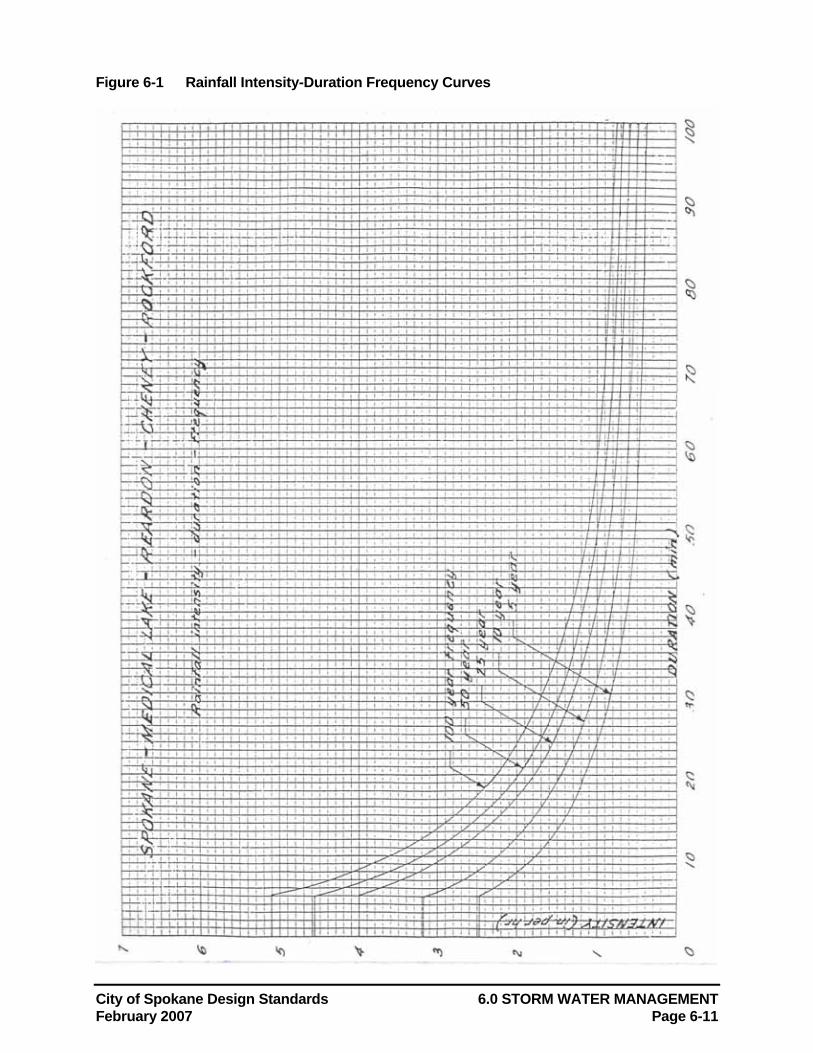
City of Spokane Design Standards 6.0 STORM WATER MANAGEMENT February 2007 Page 6-11
Figure 6-1 Rainfall Intensity-Duration Frequency Curves
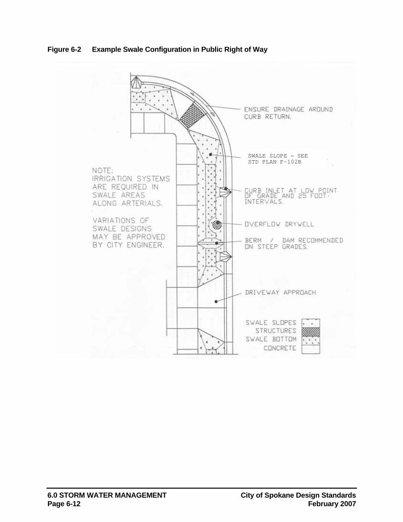
6.0 STORM WATER MANAGEMENT City of Spokane Design Standards Page 6-12 February 2007
Figure 6-2 Example Swale Configuration in Public Right of Way
SWALE SLOPE – SEE STD PLAN F-102B
City of Spokane Design Standards 6.0 STORM WATER MANAGEMENT February 2007 Page 6-13
6.8 References AASHTO, 1992. Highway Drainage Guidelines. Washington, D.C.: AASHTO, Inc.
Denver County Urban Drainage and Flood Control District, 1969. Drainage Criteria Manual.
Horner, Richard R., 1988. Biofiltration Systems for Storm Runoff Water Quality Control. Seattle, Washington: Washington State Department of Ecology.
Joint Committee of the Water Pollution Control Federation and the American Society of Civil Engineers, 1970. WPCF Manual of Practice No. 9, Design and Construction of Sanitary and Storm Sewers. Washington D.C.: Board of Control, Water Pollution Control Federation.
National Oceanic and Atmospheric Administration, 1973. NOAA Atlas 2, “Precipitation Frequency Atlas of the Western United States, Volume IX, Washington”. Washington D.C.: United States Government Printing Office. (This document is no longer in print, but is available on microfiche from the National Technical Information Service (NTIS), Springfield, Virginia 22161)
Spokane County Engineer's Office, 1984. Guidelines for Stormwater Management. Spokane, Washington.
Spokane County Office of the County Engineer, 1979. Spokane Aquifer Water Quality Management Plan. Spokane, Washington.
Spokane Water Quality Management Program Coordination Office and Technical Advisory Committee, 1986. Critical Materials Handbook. Spokane, Washington.
Urbonas, Ben and Peter Stahre, 1993. Stormwater - Best Management Practices and Detention for Water Quality, Drainage and CSO Management. Pretence Hall.
U.S. Department of Agriculture Soil Conservation Service, Engineering Division, 1975. Urban Hydrology for Small Watersheds, Technical Release No. 55. Washington, D.C.
Washington State Department of Transportation, 1993. Highway Runoff Manual (Draft). Olympia, Washington: WSDOT Engineering Publications.
Washington State Department of Transportation, 1989. Hydraulics Manual, M23-03. Olympia Washington: WSDOT Engineering Publications.
City of Spokane Design Standards 7.0 EROSION AND SEDIMENT CONTROL PLANS February 2007 Page 7-1
7.0 EROSION AND SEDIMENT CONTROL PLANS <RESERVED> Contact the Engineering Services Developer Services section for project-specific requirements. Any grading or erosion control drawings required for submittal shall conform to the requirements of Section 10.0.
City of Spokane Design Standards 8.0 WATER February, 2007 Page 8-1
8.0 WATER
8.1 Definitions Air/Vacuum Relief Valve An air valve placed at the high points in a pipeline to release air automatically and prevent the pipeline from becoming air-bound with a resultant increase of pressure and also permits inlet of air into an empty pipe to relieve a vacuum.
Backflow A flow condition, induced by a differential in pressure, that causes the flow of water or other liquid into the distribution pipes of a potable water supply from any source or sources other than its intended source.
Check Valve A valve provided with a hinged disk that opens in the direction of normal flow and closes with reversal of flow.
Distribution Main A public water pipe comprising part of the distribution system used to deliver potable water, for customer needs which, in many cases, includes irrigation and fire protection, to the customer's individual service line(s); and to deliver water to fire hydrant leads for fire protection.
Distribution System That portion of a public water system which conveys water from the transmission facilities to consumers.
Fire Flow: A water demand calculated by the fire or building official for a specific development to be used in the design of the water system for the project. The system must be designed to deliver this flow, on top of the maximum day demand, without dropping the pressure below 20 PSI, and without exceeding a velocity of 15 feet per second, in any portion of the system, whether new or existing.
Gate Valve A valve in which the closing element consists of a disk which slides over the opening or cross-sectional area through which water passes, and fits tightly against it.
Pressure Reducing Valve (PRV) An automatic control valve designed to reduce a higher inlet pressure to a lower constant outlet pressure regardless of fluctuating flow rates and/or varying inlet pressure.
P.U.D. See Section 1.2
Transmission Main A large diameter public water pipe comprising part of the distribution system used to deliver large quantities of potable water over long distances from the source to a reservoir, booster pumping facility, and/or to a networked system of distribution mains. Typically, services and fire hydrants are not connected to transmission mains.
Water Service Tap & Service Line The water service tap is the connection to the distribution main of a service line. The service line is the pipe which extends from the service tap into the customer's property used to deliver potable water, for domestic needs as well as, in some cases, irrigation and fire protection.
8.2 Water Demands
8.2-1 Average Day and Maximum Day Demands
The Maximum Day Demands shall be estimated in accordance with the City of Spokane’s Comprehensive Water System Plan, 2000 or its most current edition. Calculations shall be based upon the following Spokane area planning factors:
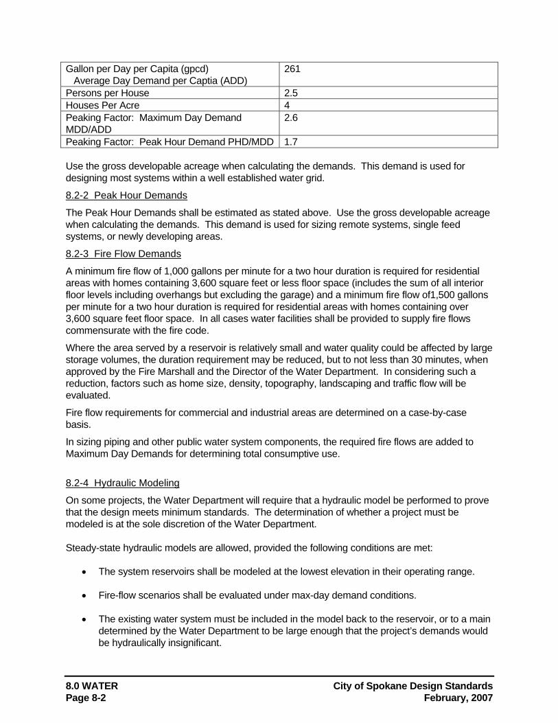
8.0 WATER City of Spokane Design Standards Page 8-2 February, 2007
Gallon per Day per Capita (gpcd) Average Day Demand per Captia (ADD)
261
Persons per House 2.5 Houses Per Acre 4 Peaking Factor: Maximum Day Demand MDD/ADD
2.6
Peaking Factor: Peak Hour Demand PHD/MDD 1.7 Use the gross developable acreage when calculating the demands. This demand is used for designing most systems within a well established water grid.
8.2-2 Peak Hour Demands
The Peak Hour Demands shall be estimated as stated above. Use the gross developable acreage when calculating the demands. This demand is used for sizing remote systems, single feed systems, or newly developing areas.
8.2-3 Fire Flow Demands
A minimum fire flow of 1,000 gallons per minute for a two hour duration is required for residential areas with homes containing 3,600 square feet or less floor space (includes the sum of all interior floor levels including overhangs but excluding the garage) and a minimum fire flow of1,500 gallons per minute for a two hour duration is required for residential areas with homes containing over 3,600 square feet floor space. In all cases water facilities shall be provided to supply fire flows commensurate with the fire code.
Where the area served by a reservoir is relatively small and water quality could be affected by large storage volumes, the duration requirement may be reduced, but to not less than 30 minutes, when approved by the Fire Marshall and the Director of the Water Department. In considering such a reduction, factors such as home size, density, topography, landscaping and traffic flow will be evaluated.
Fire flow requirements for commercial and industrial areas are determined on a case-by-case basis.
In sizing piping and other public water system components, the required fire flows are added to Maximum Day Demands for determining total consumptive use.
8.2-4 Hydraulic Modeling
On some projects, the Water Department will require that a hydraulic model be performed to prove that the design meets minimum standards. The determination of whether a project must be modeled is at the sole discretion of the Water Department. Steady-state hydraulic models are allowed, provided the following conditions are met:
• The system reservoirs shall be modeled at the lowest elevation in their operating range.
• Fire-flow scenarios shall be evaluated under max-day demand conditions.
• The existing water system must be included in the model back to the reservoir, or to a main determined by the Water Department to be large enough that the project’s demands would be hydraulically insignificant.
City of Spokane Design Standards 8.0 WATER February, 2007 Page 8-3
• Demands shall be calculated only in accordance with the method contained in the City of Spokane Water Department’s Comprehensive Plan. This calculation shall be included in the model submission.
• The datum used for elevations within the model shall be clearly referenced.
• The model submission shall include a map with pipe and node numbers legibly marked,
and reservoirs identified as actual or representative of a tie-in to the existing water system. The map shall also include references to existing streets and features to help orient the map properly.
8.3 Water Pressure Water pressures during maximum day demand conditions, with reservoirs at average water level, should be designed between 45 and 100 psi at every point in the system with few exceptions. Noted exceptions, upon approval of the Water Department Director, are near the intake of booster stations where pressures may be lower and in rough topography where pressures may be allowed to exceed the 100 psi limit.
Residual water pressures during fire flow demand conditions shall be designed to be no less than 20 psi at every point in the system.
Pressures Over 80 psi: If static pressures exceed 80 psi then each service line shall be required to have an individual pressure reducing valve set to reduce pressures to a maximum of 80 psi. Refer to regulations pertaining to water service taps and meters.
Where the water system is expanded in such a way as to be delivering water in excess of 80 psi of static pressure, a PRV station shall be installed on the distribution line at the location necessary to reduce delivered pressures to below 80 psi.
Areas Served by Pressure Reducing Valves: Some areas may be supplied through pressure reducing valves in the main supply system. In areas where this is allowed, no matter what the local service pressure is, an individual pressure reducing valve is also required for each service connection. Refer to City regulations pertaining to water service taps and meters, available at the Permits counter in Engineering Services.
8.4 Size of Pipe
8.4-1 Standard Sizes
Only City of Spokane standard sizes of pipes shall be allowed. Standard sizes are 6", 8", 10”, 12", 18" and increments of every 6" above 18".
Exceptions to the above sizes are as follows: a) In cases of a bridge crossing (existing bridge) or other conditions where a standard size
would be infeasible or would limit the capacity below that needed, special consideration may be given to using non-standard sizes.
b) On permanent cul-de-sacs where fire service can be provided from a hydrant at the entrance to the cul-de-sac a 4" water service line may be allowed. No hydrants shall be allowed to be fed from or through 4” water lines. Guidelines for the distance from any occupiable building to the hydrant must be strictly complied with.
Service line sizes shall be coordinated with the Water Department.
8.0 WATER City of Spokane Design Standards Page 8-4 February, 2007
8.4-2 Sizing Based on Velocity
The following criteria shall be used to determine the sizes of the pipes to be used: a) At maximum day demand, 5 fps maximum design velocity. b) At fire flow demand, 15 fps maximum at required fire flow. c) See design parameters above.
8.5 Type of Pipe Only ductile iron pipe meeting the requirements of Section 9-30.1(1) of the Specifications shall be used for water mains. On bridge crossings or in other locations where pipes are not directly buried in earth fill, restraint shall be provided by the use of TR Flex restrained joint pipe and fittings, or approved equal. On bridge crossings or in other locations where structural constraints exclude the use of bell and spigot pipe, welded steel pipe may be considered.
Service lines smaller than 2" are to be type "K" copper; 2" services are to be high density polyethylene (HDPE) or type "K" copper; and services larger than 2" are to be ductile iron.
8.6 Location For Fittings, Valves, Air Valves, Blow-Off Valves
8.6-1 Distribution Mains
Fittings: Bends are required where a change of direction of the water main occurs which cannot be accommodated by pipe joint deflection as provided in Section 8.11 below. Tees and crosses are required where lateral mains are needed as part of the project and where future needs dictate. Tees are required where fire hydrant leads are needed as part of the project and where future fire hydrant needs dictate. Reducers are needed where a change of pipe size is required. All fittings shall be mechanical joint type unless otherwise specified.
Valves: In-line valves are needed at street intersections so as to allow the distribution system to be isolated and shutdown, block by block, for repairs to the piping and fittings. Generally, the valves are to be installed in line with the intersection right-of-way lines in order to keep the valves out of the intersection itself - the desire here is for the safety of the valve operating personnel in that the intersection itself presents traffic from multiple directions. In-line valves on the distribution main are needed between fire hydrants. Valves are needed on all fire hydrant leads, and shall be located approximately 2 feet from the main between the main and the fire hydrant. All valves shall be mechanical joint type unless otherwise specified.
Air/Vacuum Relief Valves: Air/vacuum relief valves are not typically needed on distribution mains.
Blow-Off Valves: Blow-off valves are not typically needed on distribution mains.
8.6-2 Transmission Mains
Fittings: Bends are required where a change of direction of the water main occurs which cannot be accommodated by pipe joint deflection as provided in Section 8.11 below. Tees and crosses are required where lateral mains are needed as part of the project and where future needs dictate. Reducers are needed where a change of pipe size is required. All fittings shall be mechanical joint type unless otherwise specified.
Valves: In-line valves are needed at intersecting points with other mains and, if possible, at street intersections. Otherwise, in-line valve spacing should generally be 1,500 feet, unless otherwise specified, in order to limit the extent of main shut-down for repair and maintenance. Generally, the valves are to be installed in line with the intersection right-of-way lines in order to keep the valves out of the intersection itself - the desire here is for the safety of the valve operating personnel in that the intersection itself presents traffic from multiple directions. All valves shall be mechanical joint type unless otherwise specified. Operating nuts shall be oriented to the north or east side of
City of Spokane Design Standards 8.0 WATER February, 2007 Page 8-5
the water main.
Air/Vacuum Relief Valves: Air/vacuum relief valves are needed on transmission mains at high points to allow release of air during filling the pipe with water as well as to allow accumulated air to be expelled under normal operation. Further, air valves are needed to prevent a vacuum from occurring and to allow air into the main when draining the pipe. At least one air valve is required between in-line valves. The high point on the main often occurs on the downhill side of an in-line valve. Typically 2" air valves suffice.
Blow-Off Valves: Blow-off valves are needed on transmission mains at low points to allow the pipe to be drained. At least one blow-off valve is required between in-line valves. The low point on the main often occurs on the uphill side of an in-line valve. Typically 4" blow-off valves suffice. Drained water is generally discharged into a drywell.
8.6-3 Pipe Thrust Restraint Design
The City of Spokane does not allow the use of thrust blocks on water mains as a means of resisting thrust.
The City has developed a Restrained Joint Table (Table 8-A) as a generically approved design standard for restraining pipe sizes 4", 6", 8" and 12". The table is for ductile iron pipe not incorporating polyethylene encasement. The table was established from field experience by City Water Department construction and maintenance personnel and represents conservative results.
Alternatively, the designer is allowed the option of designing the required pipe thrust restrained lengths for the specific project under design. In this case, the criteria and basis of design shall be as published by the Ductile Iron Pipe Research Association (DIPRA) entitled Thrust Restraint Design For Ductile Iron Pipe, current edition.
The parameters to be used shall be as follows: • Valves, tees (branch direction only), and 90o bends shall be designed as "dead ends". • When designing a deflection utilizing multiple bends, determine the total angle of deflection
and increase the angle design to that of the next standard bend for determining the angle to be restrained.
• Design test pressures shall be 175 psi or 1.5 times working pressure - whichever is greater. • Factor of safety shall be as follows:
12" and smaller water mains - 2.5 18" water mains - 2.0 24" and larger water mains - 1.5
When DIPRA is used for restraint design, so note this fact on the plans listing: A pipe thrust restraint table along with design pressure, factor of safety, soil type, trench type, and any other assumptions or factors utilized.
In addition to DIPRA, a computer software program for pipe thrust restraint design has been developed by EBAA Iron Sales, Inc. entitled Restrained Length Calculator, current version. The program has been examined and utilized by City Engineering staff. The program is based on the same engineering principles, criteria, and analytical approach as the DIPRA design requirements. Thus, the use of the program by EBAA is hereby approved. The parameters to be used shall be the same as those listed above for DIPRA.
When the EBAA program is used for restraint design, so note this fact on the plans listing: A pipe thrust restraint table along with design pressure, factor of safety, soil type, trench type, and any other assumptions or factors utilized.
8.0 WATER City of Spokane Design Standards Page 8-6 February, 2007
8.7 Depth of Pipes Water mains shall be installed with a depth to invert of 5 1/2 feet. The following exceptions may apply:
a) 7 feet to the invert is maximum and will be allowed only in special cases. b) 4 1/2 feet to the invert for short distances will be permitted on a case by case basis to allow
for adjustment to other previously existing utilities. This is not allowed for lines with little or no flow (i.e. fire hydrant lines, building fire lines, lines feeding irrigation systems).
c) Consideration shall be given to the vertical alignment of future or proposed roadways whenever known.
8.8 Location of Fire Hydrants Within the City limits, fire hydrant locations will be reviewed by the City Fire Department. Hydrants inside the City limits should ordinarily be located within 250 unobstructed feet along a path of travel to the property line. Hydrants located on the opposite side of four-laned, or larger, arterials shall not be considered in calculating service to a property. Consideration shall be given to placing hydrants at intersections or other access points that allow service in multiple directions. Based on these considerations the maximum distance may be extended to 300 feet.
Locations of hydrants outside the City limits shall be reviewed by the presiding Fire Department or District. Not all Fire Districts follow the same guidelines and each of them may interpret fire codes differently. (Most outside fire districts require hydrants to be within 300 feet of occupiable buildings.) All plans must be reviewed and signed by the fire districts prior to approval, however, the more stringent of the guidelines shall prevail.
All supply valves serving hydrants must meet the City of Spokane standards as provided in the Specifications. Hydrants shall be located at the ER’s (end of radius) at intersections, 2 feet inside of the right-of-way line. The hydrant flange shall be installed 3 inches above the top of curb elevation. Where curbs and sidewalks do not exist, hydrants shall be installed at the intersection of right-of-way lines with the hydrant flange 3 inches above finish grade elevation. Hydrants shall not be located within 5 feet of wheelchair drops or within 3 feet of driveway drops. Hydrants shall be installed in locations that provide clear and unobstructed access for operations and maintenance.
8.9 Distance From Other Utilities Water line locations and distances from other utilities shall be shown in Standard Plans W-110, W-111 and W-112. No new utility pole shall be located within 8 feet of an existing hydrant or water line.
8.10 Pressure Systems A pressure system consists of its own pumps, reservoirs and distribution mains. In some limited instances, a system consists of pressure reducing valves to maintain water pressure.
As development continues and the water system is expanded, areas will be encountered which are at elevations that will require the establishment of additional pressure zones in order provide water service within appropriate water pressures. Generally this will require the construction of additional booster pumping stations and reservoirs. In some cases the use of pressure reducing valves will be the means of establishing the pressure zone. However, when considering the use of pressure reducing valves, an examination of the potential and feasibility of extending service from an
City of Spokane Design Standards 8.0 WATER February, 2007 Page 8-7
established pressure zone which will provide the area within appropriate water pressures and which is supported by reservoir(s) storage will be required. If such an established pressure zone can be extended and utilized, preference in this regard will be generally the required approach. The creation of a new pressure zone will be allowed only on approval of the Director of the Water Department.
8.11 Laying Pipe on a Radius Pipe may be laid on a radius provided the radius is a minimum of 1.33 times the minimum radius allowed by the manufacturer (75% of the manufacturer’s allowable joint deflection). If pipe cannot be laid on a radius then it shall be laid on tangent sections with appropriate bends placed at approximately equal intervals around the curve.
For additional information, refer to Section 9-30 of the Specifications and the City of Spokane GSPs.
8.12 Easements No easement shall be allowed unless approved in advance by the Director of the Water Department. If an easement is to be used it must provide all weather access for two wheel drive service vehicles. In addition, sleeving may be required as directed by the Director of the Water Department.
8.13 Special Regulations for P.U.D.'s "Wheeling" water through a P.U.D. or any other private water system shall not be permitted. Water from the City's distribution system entering a P.U.D., must not be allowed to return to the public system. A meter and a double check valve assembly must be provided at each connection to the City Water System to prevent water from re-entering the City water system from the P.U.D.
All meter vaults shall be constructed immediately behind the property line of the P.U.D. and all pressure reducing valves and double check valve assemblies shall be placed downstream of the meter. The City's water system and responsibility for maintenance terminates at the meter.
Connections to P.U.Ds are similar to service connections and are subject to City tap and meter regulations. Current regulations are available from the permits counter in the Engineering Services Department.
8.14 Booster Stations General: General construction of pump station buildings and appurtenances is required to conform to International Building Code, Uniform Plumbing Code and National Electrical Code. Further, during design and procurement of components that go into the system, many national standards are specified for minimum conformance. They are as follows: ANSI - American National Standards Institute ASTM - American Society for Testing and Materials AWWA - American Water Works Association CFR - Code of Federal Regulations FSS - Federal Specifications and Standards, General Services Administration HIPS - Hydraulic Institute Pump Standards IEEE - Institute of Electrical and Electronics Engineers NEC National Electrical Code
8.0 WATER City of Spokane Design Standards Page 8-8 February, 2007
NEMA - National Electrical Manufacturers' Association NEPA - National Environmental Policy Act NFPA - National Fire Protection association OSHA - Occupational Safety and Health Administration RCW - Revised Code of Washington (Laws of the State) SEPA - State Environmental Policy Act SSPC - Steel structures Painting Council UL - Underwriter Laboratory listing WAC - Washington Administrative Code WISHA - Washington Industrial Safety and Health Administration Pump Station: Booster pump stations shall be incorporated whenever a development needs higher pressure than is available from the existing source. The pump stations shall be above ground, cement block construction, with good insulation and sound barrier unless otherwise approved by the Director of the Water Department. Underground booster stations are not allowed. The roofing shall be long lasting (50- year life), low maintenance type with good insulation for energy conservation. The pump station shall be designed and located such that it pumps from a storage source on the suction side to a storage facility on the discharge side. There shall be suction and discharge headers with easy accessibility. On the discharge side, there shall be a sufficient straight run of transmission pipe in order to incorporate a flow meter. For maintenance, the flow meter shall be installed inside a vault. The pump station shall be built to minimize vandalism and break-in. The station shall be equipped with intrusion alarms wired to communicate to the water system operators through the SCADA system. The pump station shall have provisions to install antennas (provided by City) for radio communication connected to SCADA system. Pump station site shall be landscaped and irrigated with timed automatic sprinklers. Preference shall be given to shrub patches rather than grass to provide screening and decrease maintenance. Telephone service to the station is required in order to operate the station with the City's SCADA system.
Ventilation and/or a cooling system is required in or to protect pump motors from high temperatures.
A heating system is required for heating during cold weather.
A flow meter is required on either the suction line or discharge line. The station shall be designed so as to ease removal of existing pumps and motors for maintenance as well as to allow installation of future pumps and motors. Easy access to the station must be provided for maintenance as well as for daily status inspection.
Pumps and Motors: The pump stations shall have at least TWO pumps to provide redundancy. The number of pumps required will generally be dictated by the capacity size of the station keeping with prudent modern design for efficiency and flexibility of operation to meet varying demands considering summer to winter average daily demand varies over a factor of two. The station shall be so designed that
City of Spokane Design Standards 8.0 WATER February, 2007 Page 8-9
required maximum day demand can be met with the largest pump out of service. As the electrical tariff uses a demand factor, it is important to size the pumps so that pump run times are maximized, rather than larger size pumps running for repeated short periods. The pumps selected shall conform to hydraulic standards and the manufacturer shall conform to applicable NEMA and ANSI standards. Pump types in the order of preference are as follows: horizontal split case, end suction, and vertical. Pump performance curve shall have smooth drooping characteristic from the cut-off head to the lowest operating head. The pumps chosen shall operate with high efficiency (75% or more) in the operating range. Pump motor shall always be directly coupled and sized to meet the power required by the pump through the designed range of total pumping heads and pumping volumes. Motors shall have copper windings and operate at efficiency of 92% or above in the operating range. Motors 10 hp or above shall be three phase squirrel cage induction motors. Pumps shall not be set directly on the floor. Rather, pumps shall be mounted on concrete pedestals to a height for ease of maintenance. Pump selection shall meet the following criteria:
• The pump performance curve shall support proper pump performance through the designed range of total pumping heads and pumping volumes while operating within the most efficient portion of the pump curve. The proper operation includes performing without cavitation and within suction heads designed for the pump. The performance curve shall always be positive from shutoff head throughout the range of the curve. No pump shall be selected which has the potential of reaching shutoff head through possible adverse system pressure ranges.
• Pump motor shall be sized so as not to exceed maximum rated horsepower through the designed range of the pump.
• Wire-to-water pump/motor efficiency through the designed range of the pump shall be an important consideration when selecting such equipment.
• Pumps with discharge pressures exceeding 100 psi shall be furnished with mechanical seals.
• Generally greased lubricated bearings are preferred.
Each pump shall be equipped with isolation valves in the suction and discharge lines and a check valve in the discharge line. Electrical: Electrical service from the utility shall be 3 – phase, 480 volt or lower. If a transformer is provided, the primary shall be connected delta and the distribution side wye with neutral grounded. A separate 240 / 120 volt station service shall be provided by the electric utility or derived from a station service transformer. All station electrical shall conform to the latest National Electrical Code. All electrical components and wirings shall be UL listed as applicable, and be industrial grade. Protection systems are required on electrical equipment to protect against phase-to-phase and phase-to-ground faults as well as to protect against single phasing. The booster station shall have a well designed grounding system to which all the equipment grounds need to be connected.
8.0 WATER City of Spokane Design Standards Page 8-10 February, 2007
The short circuit ratings of electrical switchgear shall be the calculated available or the industry standard, whichever is higher. Stations shall have receptacles conveniently placed to ease maintenance equipments to be plugged in without extension cords. All the receptacles shall be GFI or distributed from a GFI circuit breaker installed in the station service panel. One of the duplex receptacles shall be an isolated ground type installed near the enclosure containing the SCADA Remote Terminal Unit (RTU). The stations shall have good interior lighting and dusk to dawn motion sensor, tamper proof exterior lighting. All the controllers and the associated protection equipment shall be centrally located in a free standing motor control center (MCC) with copper incoming bus sized adequately in order to allow future expansion. NEMA 12 enclosures are preferred. The control shall be soft-start/soft-stop with pump control and running bypass circuitry. Each motor drive shall have a motor circuit protector. Further, each motor shall have an integrated protection module to detect and isolate the motor for overload, phase loss, phase reversal and ground faults, as a minimum. There shall be push button switches to turn the pump on and off locally and a selector switch (Local – Off – Remote) to switch from local to remote control. Also, there shall be LED indicator lights – red to indicate running, green as stand-by. The MCC shall have indicator instrumentation for station voltage, current, power factor, and kW / kWh. Additionally, each of those meters shall incorporate an output signal 4 – 20 mA and / or pulse in order to communicate over the RTU. An integrated instrumentation module with RS 232 / RS 485 output connector (MODBUS PROTOCOL) shall be incorporated. Provision shall be made to install City supplied RTU by mounting a Hoffman Enclosure (A162006LP for storage facilities and A 242408LP for pump station) on the wall near the MCC and the isolated ground receptacle.
8.15 Reservoirs Reservoirs shall be above ground, steel, and of “standpipe” design or either “hydropillar” or “spheroid” in design unless otherwise approved by the Director of the Water Department. All reservoirs constructed and added to the City’s water system shall incorporate an internal passive water mixing system. Water mixing systems shall have no external piping and no mechanical or motorized elements. Water mixing systems shall be the Tideflex Mixing System manufactured by The Red Valve Company of Carnegie, Pennsylvania, or approved equal.
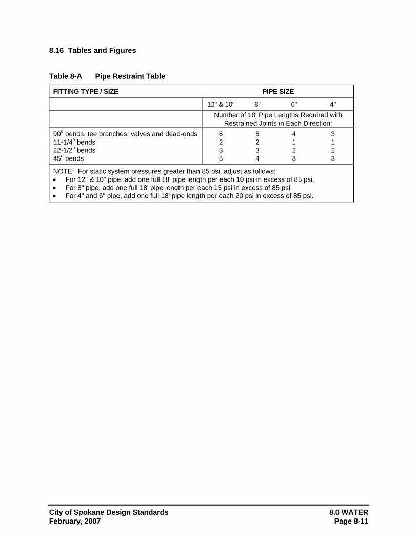
City of Spokane Design Standards 8.0 WATER February, 2007 Page 8-11
8.16 Tables and Figures Table 8-A Pipe Restraint Table
FITTING TYPE / SIZE PIPE SIZE
12" & 10” 8" 6" 4" Number of 18' Pipe Lengths Required with
Restrained Joints in Each Direction: 90o bends, tee branches, valves and dead-ends 6 5 4 3 11-1/4o bends 2 2 1 1 22-1/2o bends 3 3 2 2 45o bends 5 4 3 3
NOTE: For static system pressures greater than 85 psi, adjust as follows: • For 12" & 10" pipe, add one full 18' pipe length per each 10 psi in excess of 85 psi. • For 8" pipe, add one full 18' pipe length per each 15 psi in excess of 85 psi. • For 4" and 6" pipe, add one full 18' pipe length per each 20 psi in excess of 85 psi.
8.0 WATER City of Spokane Design Standards Page 8-12 February, 2007
8.17 References American Water Works Association. AWWA Standards.
City of Spokane Department of Water and Hydroelectric Services. City of Spokane Water Department Rules and Regulations. (Handout.)
2000 Comprehensive Water System Plan, City of Spokane, Water & Hydroelectric Services.
Culp, Wesner, Culp, 1986. Handbook of Public Water Systems. New York: Van Nostrand Reinhold Company.
Great Lakes - Upper Mississippi River Board of State and Provincial Public Health and Environmental Managers. 2003 Edition. Recommended Standards for Water Works. Health Educations Services; Albany, New York. Washington State Department of Health, Division of Environmental Health, Office of Drinking Water. Water System Design Manual. August 2001.
City of Spokane Design Standards 9.0 TRAFFIC CONTROL DEVICES February, 2007 Page 9-1
9.0 TRAFFIC CONTROL DEVICES <RESERVED> Contact the Street Department for project-specific requirements.
City of Spokane Design Standards 10.0 DRAFTING/CADD STANDARDS February, 2007 Page 10-1
10.0 DRAFTING/CADD STANDARDS
10.1 General All drawings submitted to Engineering Services shall be completed with the current version of the City of Spokane Drafting Standards.
Original construction drawing sheets shall be good quality reproducible. Final record drawings shall be archive quality reproducible, ink on 4 mil mylar (polyester film); or a photo mylar. An electronic format drawing is expected, as well, in *.dxf or *.dwg extension, or as necessary for the City's standards. The City currently uses AutoCAD, and will accept the latest versions.
Cover sheet and lead sheets, plan sheets, plan-profile sheets, and detail sheets shall be 24" x 36". Margins shall be 1" on the right, .7” on the top and bottom, and 2" on the left. The utilized area becomes 22.6" x 33.9".
For assignment of flat sheet limits, and the flat sheet naming convention, refer to Appendix B. Sample plans are provided in Appendix D.
PRIVATE COMPANY LOGOS: Logos and graphics that identify the consulting agencies or design companies are limited to not more than one-half the size of the Official City Logo on any page, but never more than four square inches, exclusive of normal typed address and phone identification text. They are to be removed from the final record drawing. They will remain on record with the redlined copy submitted as the field record drawing upon completion of the project.
10.1-1 Flat Sheet Segment Identity
For each flat sheet segment one of each of the following flat sheets are typically created and the identifier is placed in the upper right portion of the title block to identify the improvement:
"STREET", "ALLEY", "WATER", "SANITARY", "STORM" "RIGHT OF WAY" "EASEMENT" “TRAIL” "TRAFFIC"
"DETAIL" and "IRRIGATION" labels may also be used as appropriate.
In some cases a sanitary and storm sewer may need to be shown on the same segment sheet, the sheet should then be labeled "SAN/STO".
Streets and alleys may share a flatsheet labeled "STR/ALY", with the alley plan and profile shown on the drawing for the street parallel on the north or west.
10.0 DRAFTING/CADD STANDARDS City of Spokane Design Standards Page 10-2 February, 2007
10.1-2 Multiple Utility Lines in a Single Segment
Occasionally, more than one flat sheet may be needed for a utility within a given segment. For example, if there are three separate sanitary sewer lines in a roadway segment and not enough room on the profile portion of a single flat sheet to clearly show the three profiles, up to three separate sheets may be generated. In this case, if the sheets are drawn using CADD, all three sheets for that single segment should be combined into one CADD drawing. A bold note shall be placed on each sheet referencing the other sewer sheets. The note should be placed in the lower right hand corner of the plan as near to the plan number block as possible.
Whenever a flat sheet shows more than one utility line in the plan view, any utility line not shown in the profile shall be represented in the plan view with a thinner and, for CADD drawings, lighter-shaded line. The line type used should indicate whether the feature is "proposed" (solid line) or "existing" (broken line).
10.1-3 Title Blocks
Refer to the Sample Drawings in Appendix D for title block configuration. Title blocks on each sheet shall include:
a) SEGMENT LIMITS, street name and limits for the flat sheet of approximate 1/4 mile length (see Appendix B for assignment of flat sheet limits).
b) PROJECT LIMITS which define a current project, are moved to the RECORD DRAWING block when creating the record drawing sheet;
c) CITY PLAN NUMBER identifies the flatsheet segment (see Appendix B for flat sheet numbering conventions);
d) CITY PROJECT NUMBER is assigned by Engineering Services Administration. It identifies current PROJECT LIMITS and is moved to the ASBUILT box when the project is completed;
e) TYPE OF IMPROVEMENT; one of the following labels or identifiers: STREET, ALLEY, WATER, SANITARY, STORM, IRRIGATION, DETAIL, or if combined SAN/STO, or STR/ALY.
f) EFN (Electronic File Name) the CADD file name, during construction is placed below the project number. When creating the record drawing the name is placed in the RECORD DRAWING block.
g) CURRENT DESIGN STANDARDS record the City of Spokane Design Standards in use at the time.
h) DATUM information is available from Engineering Services Field Office or Design office. As of January 1, 2000, all projects shall be designed to NAVD 88 (North American Vertical Datum) datum. The conversion of datum are as follows:
• NGVD 29 Elevation + 16.93 ft = City Datum Elevation • NGVD 29 Elevation + 3.80 ft = NAVD 88 elevation • NAVD 88 Elevation + 13.13 ft = City Datum Elevation
i) COORIDNATE SYSTEM used for surveys shall be Washington State Plane , North Zone, Lambert conformal conic projection as described in RCW 58.20 and WAC 332.130
j) SCALE; Horizontal and Vertical, and a bar scale to verify the scale if the sheet is reproduced at a scale other than the original;
k) ONE CALL utility locating service number shown as "CALL BEFORE YOU DIG 456-8000";
l) GRADE ESTABLISHMENTS LIST; (Information available in the Engineering Design Support Services Grade Establishment Database references the City Clerk's ordinances.)
m) REVISION BLOCK; used to note changes during construction, but critical notes may be retained when creating record drawings;
City of Spokane Design Standards 10.0 DRAFTING/CADD STANDARDS February, 2007 Page 10-3
n) RECORD DRAWING information block, project name and numbers, Council acceptance date, limits, and EFN are placed for a permanent record.
o) ENGINEERING STAMP and signature of a Professional Engineer registered as such in the State of Washington, shall be shown on the Construction drawings for the current project. On the record drawings, the stamp and signature shall be removed, and the engineer's name, license number, project number and date of original signature shall be recorded in an "Engineer's Record Block".
10.2 Standard Symbols and Line Types The current version of City of Spokane Drafting Standards layers, symbols and line types shall be used for all drawings.
Appendix C contains additional information on the City of Spokane Drafting Standards symbol standards and menus.
The complete City of Spokane Drafting Standards may be obtained by contacting Engineering Services at 625-6700. There may be a nominal fee for reproduction costs. Refer also to the department website at www.spokaneengineering.org.
In the case where an unconventional item must be drawn for which no standard exists, the designer may adopt a special symbol and/or layer name for the item, referenced with an appropriate legend note, on the "README" layer.
10.3 Construction Drawings
10.3-1 Cover Sheet
Plans consisting of three or more total plan or detail sheets must have a plan cover sheet, or cover sheet and index sheets. Larger plan sets may require an index sheet. The index sheet would provide for overflow from the cover sheet. An example cover sheet is provided in Appendix D. The cover sheet shall be Sheet 1 of the plans, and shall contain the following information:
a) PROJECT TITLE shall be in large, bold text, located on the lower center of the cover sheet. Typical project titles shall describe the district title, area, or primary street name and the street termini. If the greater project title describes an area, or project type, the streets are then listed separately in an index.
b) CITY PROJECT NUMBER is an official Engineering Services five or seven digit project number assigned by the Engineering Services Administration Section. This number shall always be boldly located in the lower right corner of the Cover Sheet, page 1.
c) PROJECT DESCRIPTION identifies the types of works the project includes such as Street paving with sidewalk, curb, Traffic control, Sewer construction, Storm Drainage construction, Lift Station, Reservoir, etc. The description should be located directly above the City Project Number in the lower right corner of cover sheet page 1.
d) ELECTED AND APPOINTED CITY OFFICIALS are listed on the upper right-hand portion of the cover sheet near the official City logo. The Mayor is first titled and named; Spokane City Council Members are then listed as on the Official Gazette of the City of Spokane.
Appointed officials include: • "Deputy Mayor" • "Director – Public Works" • The "Principal Engineer", "Design Engineer", and/or "Director - (department)"
may also be shown. Other officials may also require identification. e) SITE PLAN / DISTRICT PLAN; an overall site or district plan drawn to an appropriate
scale, showing the entire project and its connection to the existing street network is
10.0 DRAFTING/CADD STANDARDS City of Spokane Design Standards Page 10-4 February, 2007
typically shown on the central portion of the cover sheet. The site plan scale is set as convenient.
f) VICINITY AND LOCATION MAPS; include a vicinity map of the City oriented in the same direction as the site plan, outlining the project site in the left portion of the cover sheet. Scale for vicinity maps may vary according to convenience.
g) A LOCATION MAP of the State of Washington, placed in the upper left corner with the City of Spokane identified.
h) NOTES; standard notes which are applicable to the project; i) INDEX; The plan set index is shown in the approximate center of the cover sheet,
plan/profile site sheets should be referenced to the overall site or district map. The index is usually the first item to be moved to page 2, index sheet.
j) LEGEND; The legend may describe directions, and/or symbols not found in the Drafting Standards.
k) FEDERAL AND STATE REQUIREMENTS; Capital funded projects usually require particular information which must be obtained from Engineering Services. This information may identify the project with alpha/numeric data, and include a logo that identifies the funding department or governing agency. This logo shall not be smaller than a private logo, and remains on the drawing at record drawings.
l) A note/block will be placed in the lower right hand corner of all plans. The note/block will state, “CONSTRUCTION DRAWINGS, NOT AS-BUILT”.
10.3-2 Plans, Profiles and Details - All Projects
Plan Elements. All projects shall include the following on the plan portion of the drawing sheets: a) SCALES; horizontal scale shall be 1"=50'. b) NORTH ARROW. The north arrow shall be located in the lower right corner of the plan. c) DRAWING ORIENTATION. North should be oriented generally to the top or to the right
of the drawing. The plan shall be shown on the lower portion of the sheet with the profile concatenated in the upper portion of the sheet. The drawing shall be oriented according to the current Engineering Services flat sheet layout convention. (See Appendix B for assignment of flat sheet segment limits).
d) STATIONING. Stationing shall be 100-foot stationing along the centerline unless otherwise provided for, beginning at the southern or western section line and increasing to the north or east and reading from left to right. At the point a project crosses a section line, stationing shall begin anew with 0+00. Stations for points of curve, tangent and intersection shall be given. Stations shall be tied to monuments or survey control points.
e) RIGHT-OF-WAY information. Right-of-way lines, property lines, and easements shall be shown with appropriate dimensions. Subdivisions, blocks, and lots shall be labeled and numbered for the entire segment.
f) EXISTING TOPOGRAPHIC features and finished grade. Topographic features shall be shown in areas within the right-of-way limits, future right-of-way limits, and beyond (as deemed necessary by the Engineer) to resolve questions of setback, slope, drainage, access onto abutting property, and street continuations. Generally topography is required for the site and at least 50 feet beyond the site boundaries.
g) EXISTING STRUCTURES; Footprints of existing structures within 100 feet of project boundaries.
h) EXISTING UTILITIES; all existing utilities and surface improvements (shown with current Drafting Standards).
Service Laterals: On projects where subsurface utility work is performed, the plans will need to show: 1) All side sewers that may be in conflict and are between the surface and two
feet below the invert of the proposed pipe. A general note will be placed on the plans noting that the location of the side sewer is not exact but is provided
City of Spokane Design Standards 10.0 DRAFTING/CADD STANDARDS February, 2007 Page 10-5
to indicate the expected number of side sewers that may be encountered. 2) A standard general detail for water services. The detail will show the general
location of the water services for a typical lot. A note will be placed below the detail that states, “The detail shown is for general purposes only, the exact locations of the water services for each lot will be marked in the field”.
3) Any private utilities that are known by the project owner to be located within the proposed area of excavation will also be shown. A note will be placed stating, “ The private utility locations shown were provided by the utility”.
i) PROPOSED UTILITIES; any proposed utilities and/or surface improvements that are
intended for construction (shown with current Drafting Standards). j) INTERSECTING STREETS. Intersecting streets with names and dimensions shall be
shown along with their accompanying topography, utilities and other improvements for at least 150 feet.
k) PROJECT LIMITS. The construction area for street construction should be shaded at 10% to 20% on the plans.
l) MONUMENTS AND CONTROL POINTS. Existing and proposed improvements shall be tied to these points. Some common ties are City benchmarks, city reference monuments, property pipes, section corners, curve points (VPI’s, PIs, PCs, PTs), GPS references. Dimensions shall be placed to ROW lines and curb lines from center line and, or monument lines. See: 10.3-2 e).
m) A note/block will be placed in the lower right hand corner of all plans. The note/block will state, “CONSTRUCTION DRAWINGS, NOT AS-BUILT”.
Profile Elements. All projects shall include the following on the profile portion of the drawing sheets:
a) THE PROFILE shall occupy the upper 10" x 33" of the drawing sheet. The profile grid shall consist of horizontal lines forming a one by one grid with a horizontal scale of 1" = 50', and a vertical scale of 1" = 10'. Major grid line 1" squares shall be no more than a 0.35mm solid line. Minor grid lines 0.1" squares shall be a line at least 0.10mm finer than the major grid line, solid, shaded, or a 10x dot grid.
b) EXISTING GROUND LINE or FINISHED STREET GRADE . c) PROPOSED STREET GRADE to four decimal places (if applicable). Street grade
breaks shall be indicated on all water and sewer profile drawings using a small open circle to mark the location of a grade change. Note that the street grade must be established prior to design of water or sewer mains.
d) STATIONING on the profile shall be coordinated with the plan view.
Detail Sheets. Details for all projects with multiple page plan sets should be consolidated and placed on sheets at the end of the plan set. Plan/profile sheets and detail sheets shall be cross referenced with the sheet and detail numbers of appropriate details.
10.3-3 Street Drawings
In addition to the items listed in Sections 10.3-1 and 10.3-2, plan/profile sheets for street projects shall contain the following information:
a) TANGENT GRADES for both curb lines shall be carried to four decimal places. Centerline, traffic islands, walls, and other structures related to construction may also be represented here.
b) VERTICAL CURVE DATA including curve length shall be delineated on the profile with a horizontal line with arrows terminating at a vertical dimension line at each end. The Vertical Point of Intersection (VPI), and K-factor shall be called out on the profile with
10.0 DRAFTING/CADD STANDARDS City of Spokane Design Standards Page 10-6 February, 2007
station and elevation. c) HORIZONTAL CURVE DATA for centerline including radius, delta, arc length, and
tangent shall be shown on the plan for all horizontal curves. Stations of the PC, PI, and PT shall be called out on the plan.
d) CURBLINE CURVE DATA, for radius, tangents, and elevations; or for multi-centered returns, complete curve data including radius, delta, curve length, PC to PI and PI to PT shall be shown on the plan.
10.3-4 Sanitary/Storm Sewer and Water Drawings
Sanitary sewer, storm sewer and water drawings shall show the following in addition to the information listed in 10.3-1 and 10.3-2, specific NAVD88 elevations shall be used (not project specific datum , nor "±" distances):
a) HORIZONTAL PIPE ALIGNMENT including radius, delta, tangent and arc length, and stations of all PC's, PI's and PT's. Size of pipe should be shown on the plan and profile, with text, and graphically as nominal pipe height from invert to top of pipe.
b) PROFILE portions of water and sewer drawings shall show invert elevations of all structures, and manhole surface elevations, length of pipe between structures or pipe grade breaks, top of pipe, pipe invert, and pipe grade to four decimal places.
c) CONNECTIONS, locations of water lines and side sewers with permit information. The number of tees and wyes, and the pipe distance between structures. Stationing and elevations to be appropriately included on the record drawings.
d) UTILITY underground crossings. e) LOAD for rigid pipe sewers. f) TYPE OF PIPE. g) LOCATION INFORMATION of sewer or water easements, if any, with appropriate
survey information h) STATIONING and inverts for sewer drawings to include all pipe ends, and at manholes,
etc. i) CONSTRUCTION DETAILS for manholes, pipe bedding, etc. j) SIGNATURE BLOCK on all water drawings shall be included for approvals by the
appropriate fire department or district.
10.3-5 Grading, Erosion Control and Stormwater Drawings
Grading, Erosion Control and Swale drawings shall include the following in addition to the items listed above in 10.3-1, and 10.3-2:
a) CONTOURS in intervals stated on the site plan (extending 50 feet beyond property lines) as follows:
Slope % Contour Interval (ft.) 0-15 2
16-40 5 >40 10
b) THE 100-YEAR FLOOD HAZARD ZONE on the site plan where the project is in or abuts said zone.
c) SOIL TYPES and LOCATIONS of percolation test and/or bore sites. d) CROSS SECTIONS of all open ditches and/or swales. e) DITCH OR SWALE invert elevations, slopes, and lengths. f) INLET entrance details, elevations, and locations. g) SILT FENCES AND TRAP location and details. h) MULCHING AND VEGETATION plan. i) CLEARING AND GRUBBING limits. j) ELEVATIONS of all inlet grates and low points.
City of Spokane Design Standards 10.0 DRAFTING/CADD STANDARDS February, 2007 Page 10-7
k) SIZE, TYPES, AND INVERT ELEVATIONS of all culverts and/or pipe systems, and structures such as catch basins, drywells or manholes.
l) CONSTRUCTION DETAILS for inlets, drywells and detention facilities (notes referring to Standard Plans may suffice).
m) DRAINAGE EASEMENTS with appropriate survey information. n) LOT GRADING ELEVATIONS where appropriate. o) APPLICABLE STORM SEWER DATA as required in 10.3-4,. p) EXISTING AND PROPOSED UNDERGROUND meters, fuel tanks, wells, etc. within the
setbacks specified by Spokane County Health Guidelines. q) GRADE, proposed and existing. r) INSPECTION SCHEDULE for erosion control facilities.
10.4 Record Drawings Record drawings shall be archive-quality reproducible; ink on 4 mil mylar. The City's record drawings policy is provided in Appendix A.
After construction, drawings shall be modified to include following: a) A RECORD BLOCK for signature and date references pertaining to projects
Professional Engineer signature and stamp dates. b) PROJECT LIMITS construction definitions by shading shall be removed, text removed
from PROJECT LIMITS title block and placed in Record Drawing information area. c) Drawings shall be revised to reflect changes made in the field through the project’s
completion. d) All improvements that were constructed shall be shown to current City of Spokane
Drafting Standards indicating they are now existing features. e) Sheet limits shall conform to the City's flat sheet layout convention discussed in
Appendix B. f) For CADD drawings without ‘Layouts’, there shall be one electronic file per roadway
segment. g) Before archiving, if the drawing was generated using CADD, the City's electronic file
name shall also be shown in the RECORD DRAWING title block.
Items to be retained include all required items listed in section 10 and Typical Sections when provided. Details should remain provided there is room. In addition, when old linens or other manually produced flat sheets have been used to generate CADD drawings for a segment, the following shall be done when updating record drawings:
a) All design, ordinance, and record drawings information from the old drawing shall be transferred to the new drawing.
b) An up to date record of all record drawings must be transferred to the RECORD DRAWINGS block on the new drawing. Critical revisions must be maintained with the REVISION block.
c) Any grade ordinance data shown on the old drawings must also be provided on the new drawings GRADE ESTABLISHMENT block.
d) Record blocks to replace or revise all Engineers' stamps shown on the old original shall be placed on the new drawing.
e) Do not discard the old drawings! When record drawings are complete, the old and new drawings shall be sent to the archiving technician with a note attached to the old sheets indicating all relevant information has been transferred to new drawings.
City of Spokane Design Standards 11.0 CONTRACT DOCUMENTS February, 2007 Page 11-1
11.0 CONTRACT DOCUMENTS
11.1 Plan Sets Plan sets shall be prepared according to Section 10.0 of these Design Standards. Sheets shall be arranged in the following order:
a) Cover Sheet (if 3 or more plan/profile or detail sheets) b) Site Map (if not on cover sheet) c) Index (if not on cover sheet) d) Plan/Profile Sheets e) Detail Sheets
11.2 Specifications The specifications are defined in Section 1.2. City of Spokane GSPs and City Standard Plans may be obtained from the Engineering Services counter in City Hall for a nominal fee.

City of Spokane Design Standards APPENDIX A February, 2007
APPENDIX A - Record Drawings Policy

CITY OF SPOKANE ENGINEERING SERVICES DEPARTMENT
RECORD DRAWINGS POLICY
I. Materials for Archive Drawings for archive in the Engineering Services Department must be good quality reproducible ink on 4 mil mylar or sepia mylar. Note: photocopies, bluelines and electrostatic plots are unacceptable for archive. Only original mylar record drawings, photo mylars, or silverslicks will be accepted. All drawings shall be prepared in accordance with the City's CADD/Drafting Standards as set forth in the City of Spokane Design Standards Manual.
NOTE: Five and one-quarter inch floppy disks are obsolete and will not be accepted for electronic files.
II. Public Projects For all projects designed and constructed in-house by Engineering Services or by a Consultant Firm, the procedure shall be as follows:
a) The Engineering Services Administrative Section shall send fourteen (14) sets of construction plans to the Engineering Services field office.
b) The Design Team or Consulting Firm will provide to Engineering Services electronic construction drawings for archiving.
c) The original drawings shall then be updated by the Construction Management Team assigned to the project or by the Consultant Firm to reflect changes shown on the inspector’s redlines.
d) When final, the original record drawing mylars, and electronic CADD files on magnetic or optical disk shall be returned to Engineering Services for archive.
III. Water/Hydro Projects For all projects designed and constructed in-house by the Water/Hydro Department, the following procedure shall apply:
a) The Water/Hydro Department shall provide the Engineering Services Department with two sets of construction Plans. One set for Engineering Services Design Section, the second set for Engineering Services Developer Services Section.
b) When final, the original record drawing mylars, and electronic CADD files on Magnetic or Optical disk shall be returned to Engineering Services for archive.
IV. Privately Funded Projects/P.U.D.s For privately funded projects in the public right of way and Planned Unit Developments (P.U.D.s) the following record drawings procedure shall apply:
Option A - Record Drawings by the Developer:a) If the developer elects to have record drawings produced by his/her consultant, payment
provisions for record drawing services must be included as part of the developer's contract with the consultant. Proof of a consultant retainer for record drawing services shall be supplied to the City prior to construction approval. Record drawing services include, but are not limited to the following: 1. The consultant shall send one (1) complete set of final accepted mylar design drawings
to the Engineering Services Developer Services Section. If project is in the public right of way he (the consultant) shall include electronic design drawings for archiving.
2. The consultant shall provide an engineer at the project site to inspect construction and
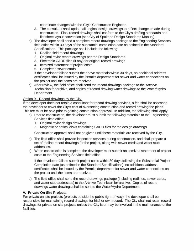
coordinate changes with the City's Construction Engineer. 3. The consultant shall update all original design drawings to reflect changes made during
construction. Final record drawings shall conform to the City's drafting standards and flat sheet layout convention (see City of Spokane Design Standards Manual).
b) The developer shall send a complete record drawings package to the Engineering Services field office within 30 days of the substantial completion date as defined in the Standard Specifications. This package shall include the following: 1. Redline field record drawings 2. Original mylar record drawings per the Design Standards 3. Electronic CADD files (if any) for original record drawings 4. Itemized statement of project costs 5. Completed sewer cards If the developer fails to submit the above materials within 30 days, no additional address certificates shall be issued by the Permits department for sewer and water connections on the project until the items are received.
c) After review, the field office shall send the record drawings package to the Archive Technician for archive, and copies of record drawing water drawings to the Water/Hydro Department.
Option B - Record drawings by the City:If the developer does not retain a consultant for record drawing services, a fee shall be assessed the developer to cover the City's cost of overseeing construction and record drawing the plans. This fee must be paid prior to gaining construction approval. In addition, the following shall apply:
a) Prior to construction, the developer must submit the following materials to the Engineering Services field office: 1. Original mylar design drawings 2. Magnetic or optical disks containing CADD files for the design drawings
Construction approval shall not be given until these materials are received by the City.
b) The field office shall provide inspection services during construction, and shall prepare a set of redline record drawings for the project, along with sewer cards and water stub addresses.
c) When construction is complete, the developer must submit an itemized statement of project costs to the Engineering Services field office.
If the developer fails to submit project costs within 30 days following the Substantial Project Completion date (as defined in the Standard Specifications), no additional address certificates shall be issued by the Permits department for sewer and water connections on the project until the items are received.
d) The field office shall send the record drawings package (including redlines, sewer cards, and water stub addresses) to the Archive Technician for archive. Copies of record drawings water drawings shall be sent to the Water/Hydro Department.
V. Private On-Site Projects For private on-site projects (projects outside the public right-of-way), the developer shall be responsible for maintaining record drawings for his/her own record. The City shall not retain record drawings for private on-site projects unless the City is or may be involved in the maintenance of the facilities.

City of Spokane Design Standards APPENDIX B February, 2007
APPENDIX B - Drawing Layout and Electronic File Naming
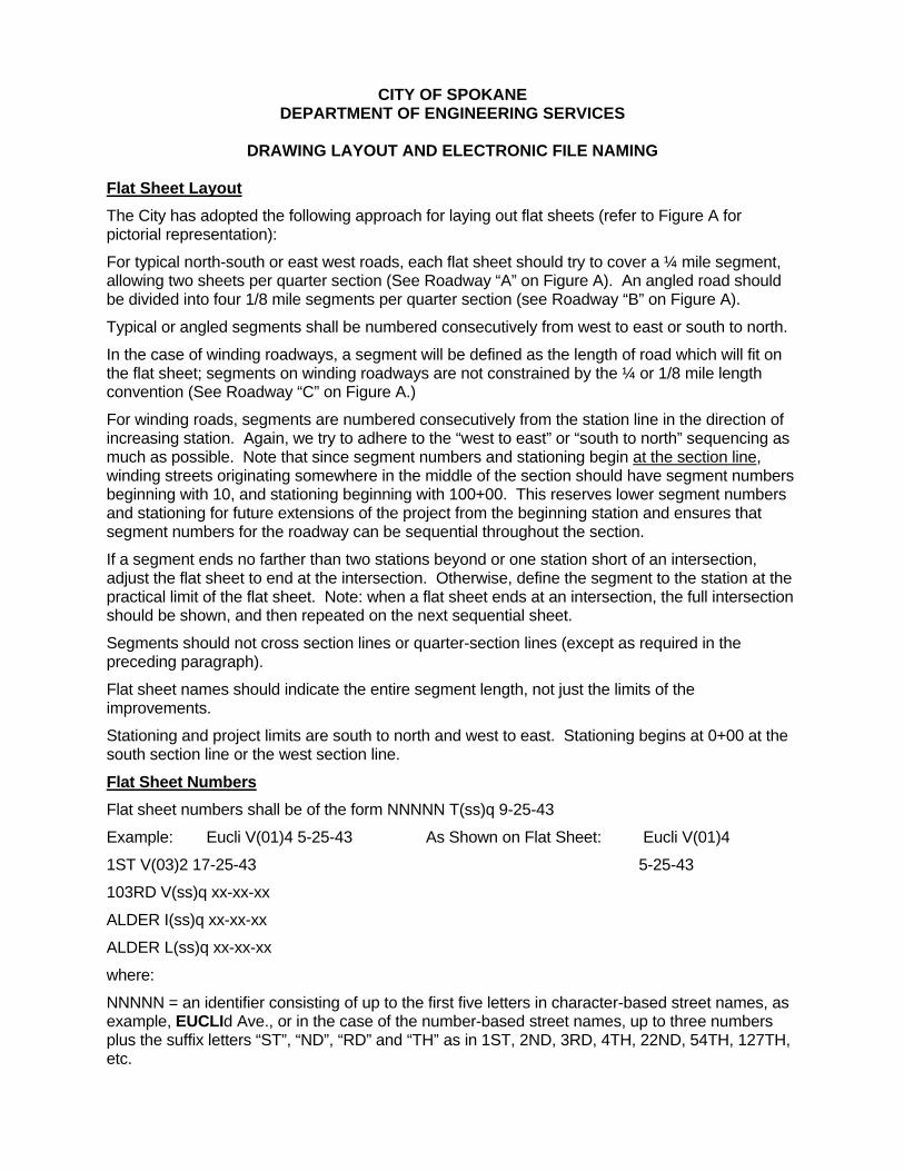
CITY OF SPOKANE DEPARTMENT OF ENGINEERING SERVICES
DRAWING LAYOUT AND ELECTRONIC FILE NAMING
Flat Sheet Layout The City has adopted the following approach for laying out flat sheets (refer to Figure A for pictorial representation):
For typical north-south or east west roads, each flat sheet should try to cover a ¼ mile segment, allowing two sheets per quarter section (See Roadway “A” on Figure A). An angled road should be divided into four 1/8 mile segments per quarter section (see Roadway “B” on Figure A).
Typical or angled segments shall be numbered consecutively from west to east or south to north.
In the case of winding roadways, a segment will be defined as the length of road which will fit on the flat sheet; segments on winding roadways are not constrained by the ¼ or 1/8 mile length convention (See Roadway “C” on Figure A.)
For winding roads, segments are numbered consecutively from the station line in the direction of increasing station. Again, we try to adhere to the “west to east” or “south to north” sequencing as much as possible. Note that since segment numbers and stationing begin at the section line, winding streets originating somewhere in the middle of the section should have segment numbers beginning with 10, and stationing beginning with 100+00. This reserves lower segment numbers and stationing for future extensions of the project from the beginning station and ensures that segment numbers for the roadway can be sequential throughout the section.
If a segment ends no farther than two stations beyond or one station short of an intersection, adjust the flat sheet to end at the intersection. Otherwise, define the segment to the station at the practical limit of the flat sheet. Note: when a flat sheet ends at an intersection, the full intersection should be shown, and then repeated on the next sequential sheet.
Segments should not cross section lines or quarter-section lines (except as required in the preceding paragraph).
Flat sheet names should indicate the entire segment length, not just the limits of the improvements.
Stationing and project limits are south to north and west to east. Stationing begins at 0+00 at the south section line or the west section line.
Flat Sheet NumbersFlat sheet numbers shall be of the form NNNNN T(ss)q 9-25-43
Example: Eucli V(01)4 5-25-43 As Shown on Flat Sheet: Eucli V(01)4
1ST V(03)2 17-25-43 5-25-43
103RD V(ss)q xx-xx-xx
ALDER I(ss)q xx-xx-xx
ALDER L(ss)q xx-xx-xx
where:
NNNNN = an identifier consisting of up to the first five letters in character-based street names, as example, EUCLId Ave., or in the case of the number-based street names, up to three numbers plus the suffix letters “ST”, “ND”, “RD” and “TH” as in 1ST, 2ND, 3RD, 4TH, 22ND, 54TH, 127TH, etc.
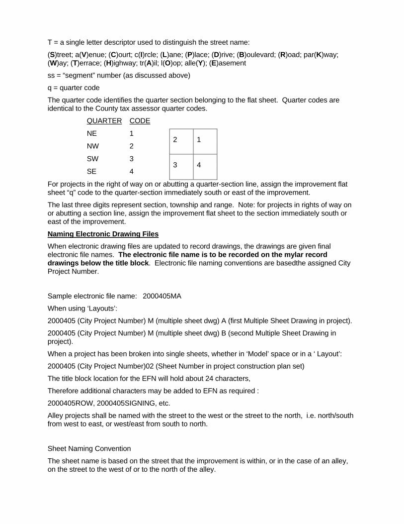
T = a single letter descriptor used to distinguish the street name:
(S)treet; a(V)enue; (C)ourt; c(I)rcle; (L)ane; (P)lace; (D)rive; (B)oulevard; (R)oad; par(K)way; (W)ay; (T)errace; (H)ighway; tr(A)il; l(O)op; alle(Y); (E)asement
ss = “segment” number (as discussed above)
q = quarter code
The quarter code identifies the quarter section belonging to the flat sheet. Quarter codes are identical to the County tax assessor quarter codes.
QUARTER CODE
NE 1
NW 2 2 1
SW 3
SE 4 3 4
For projects in the right of way on or abutting a quarter-section line, assign the improvement flat sheet “q” code to the quarter-section immediately south or east of the improvement.
The last three digits represent section, township and range. Note: for projects in rights of way on or abutting a section line, assign the improvement flat sheet to the section immediately south or east of the improvement.
Naming Electronic Drawing FilesWhen electronic drawing files are updated to record drawings, the drawings are given final electronic file names. The electronic file name is to be recorded on the mylar record drawings below the title block. Electronic file naming conventions are basedthe assigned City Project Number.
Sample electronic file name: 2000405MA
When using ‘Layouts’:
2000405 (City Project Number) M (multiple sheet dwg) A (first Multiple Sheet Drawing in project).
2000405 (City Project Number) M (multiple sheet dwg) B (second Multiple Sheet Drawing in project).
When a project has been broken into single sheets, whether in ‘Model’ space or in a ‘ Layout’:
2000405 (City Project Number)02 (Sheet Number in project construction plan set)
The title block location for the EFN will hold about 24 characters,
Therefore additional characters may be added to EFN as required :
2000405ROW, 2000405SIGNING, etc.
Alley projects shall be named with the street to the west or the street to the north, i.e. north/south from west to east, or west/east from south to north.
Sheet Naming Convention
The sheet name is based on the street that the improvement is within, or in the case of an alley, on the street to the west of or to the north of the alley.
City of Spokane Design Standards APPENDIX C February, 2007
APPENDIX C - City of Spokane Drafting Standards
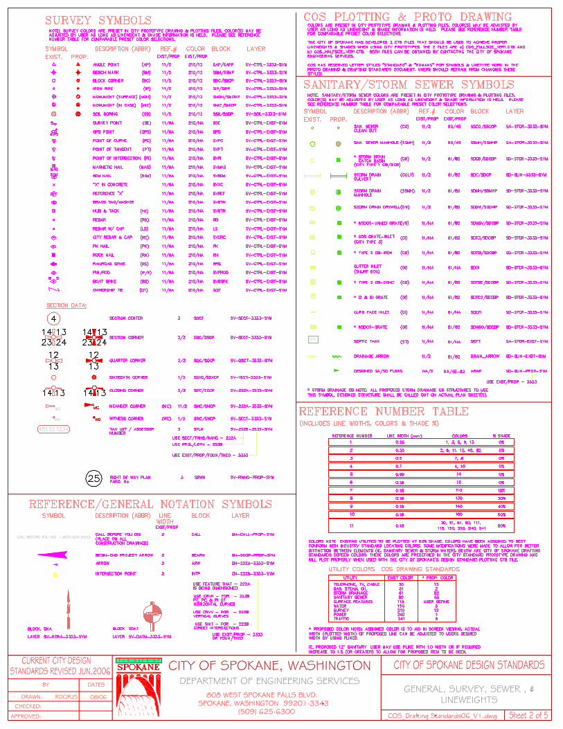
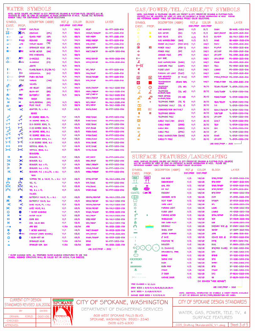
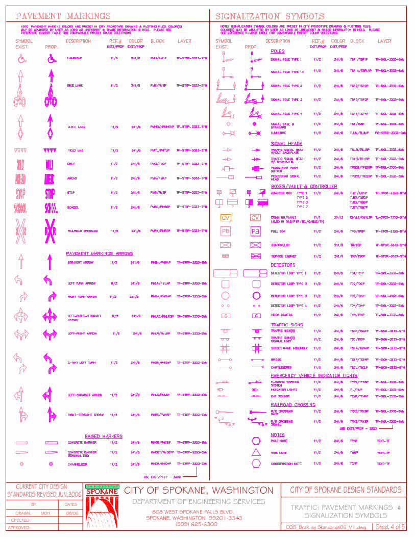
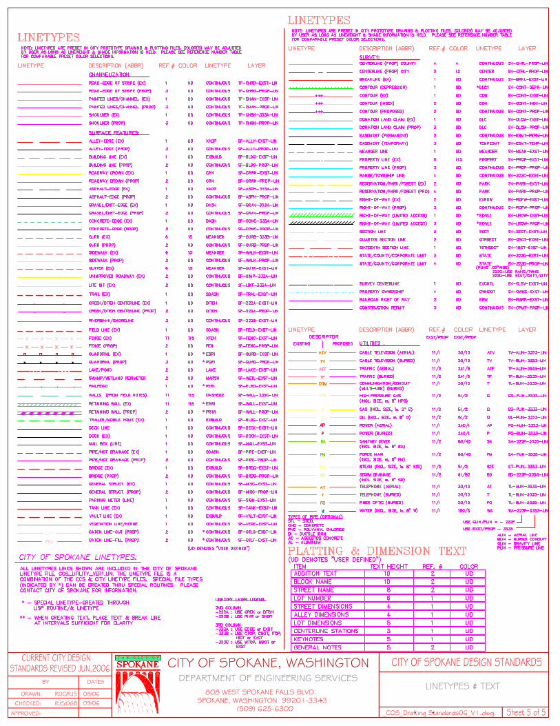
City of Spokane Design Standards APPENDIX D February, 2007
APPENDIX D - Sample Plans
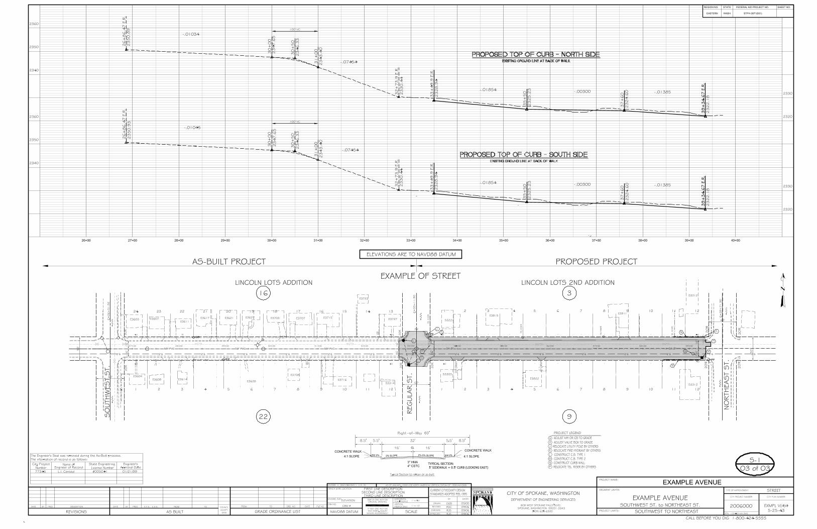
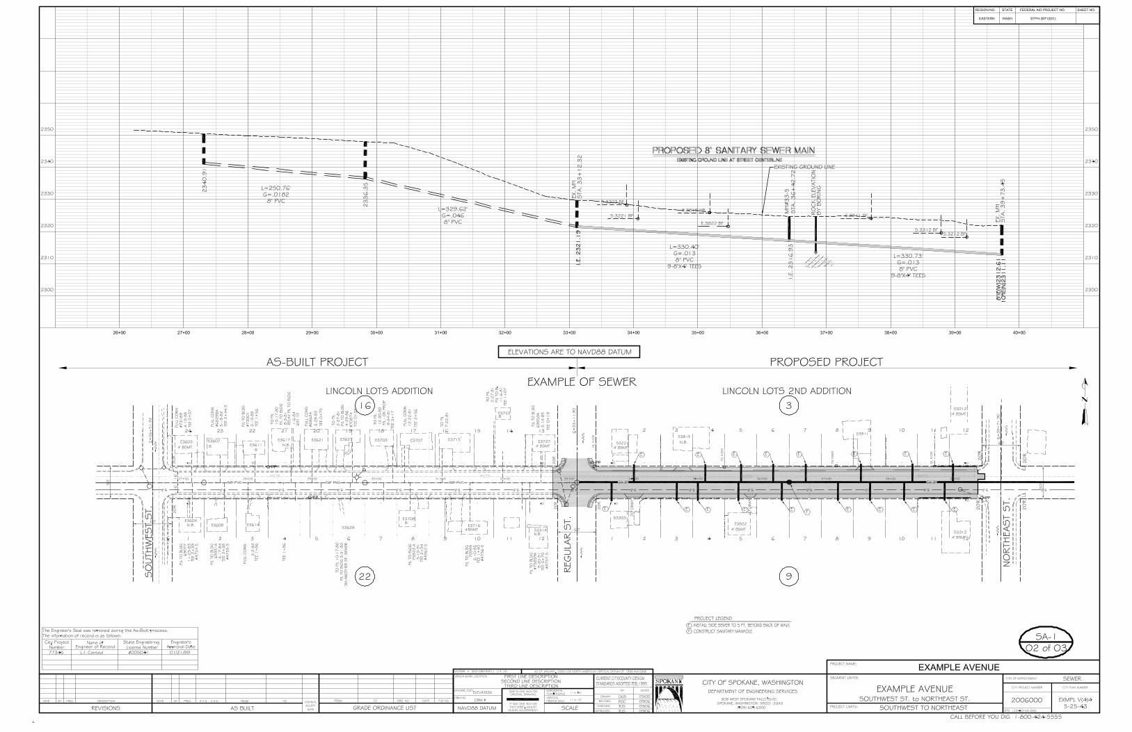
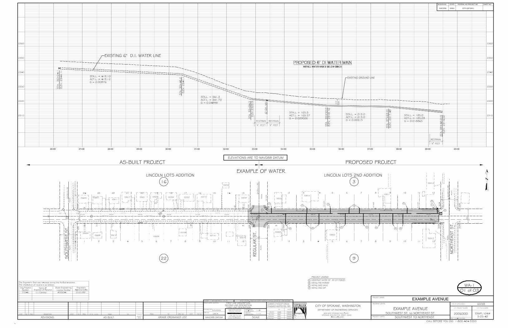

City of Spokane Design Standards APPENDIX E February, 2007
APPENDIX E - Underground Utility Location
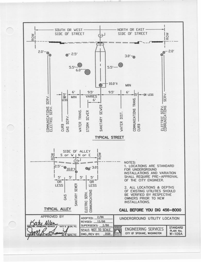
City of Spokane Design Standards APPENDIX F February, 2007
APPENDIX F - Other Policies and Ordinances
Pavement Cut Policy
Clear Zone Policy Clear Sight Triangle (SMC 11.19-590)
Recommended Street Trees
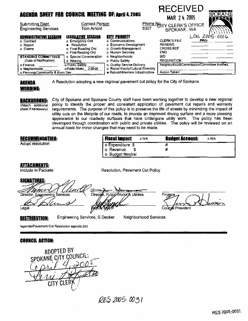
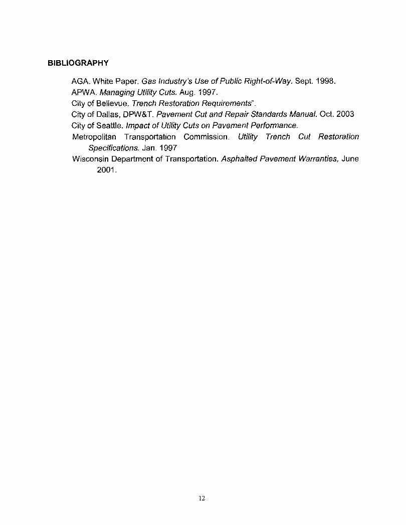
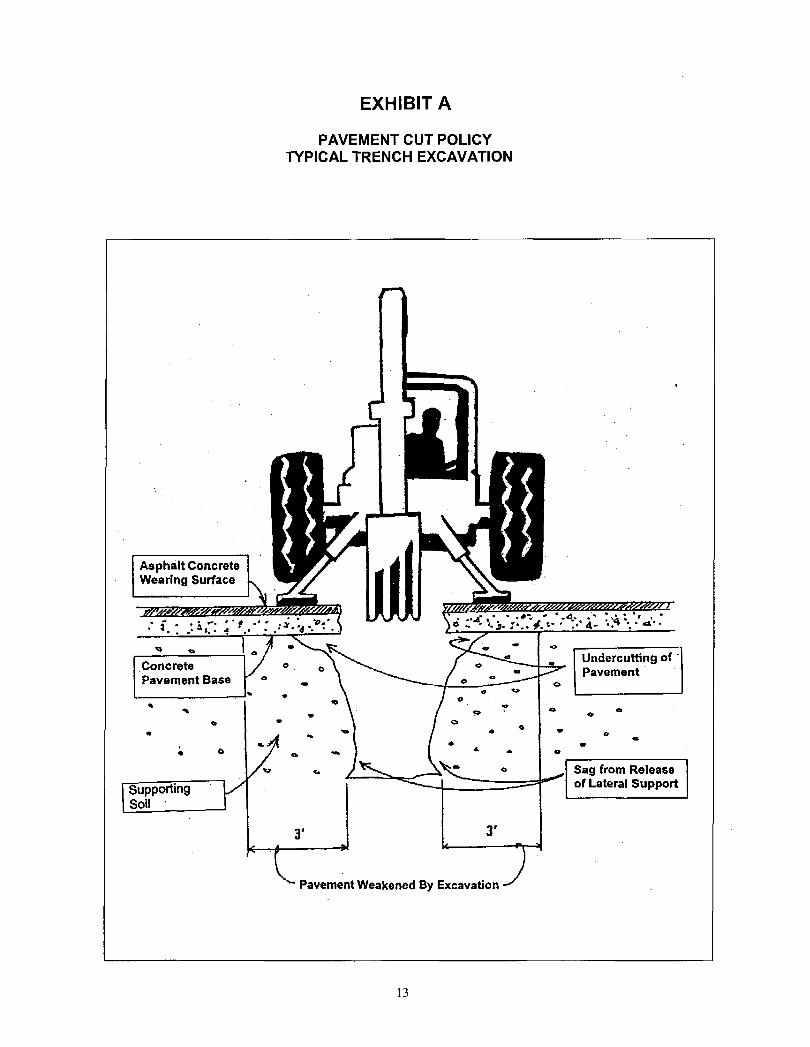
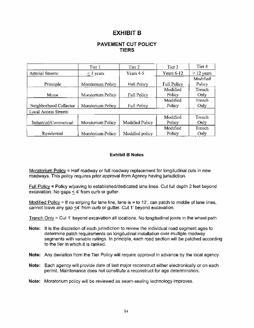
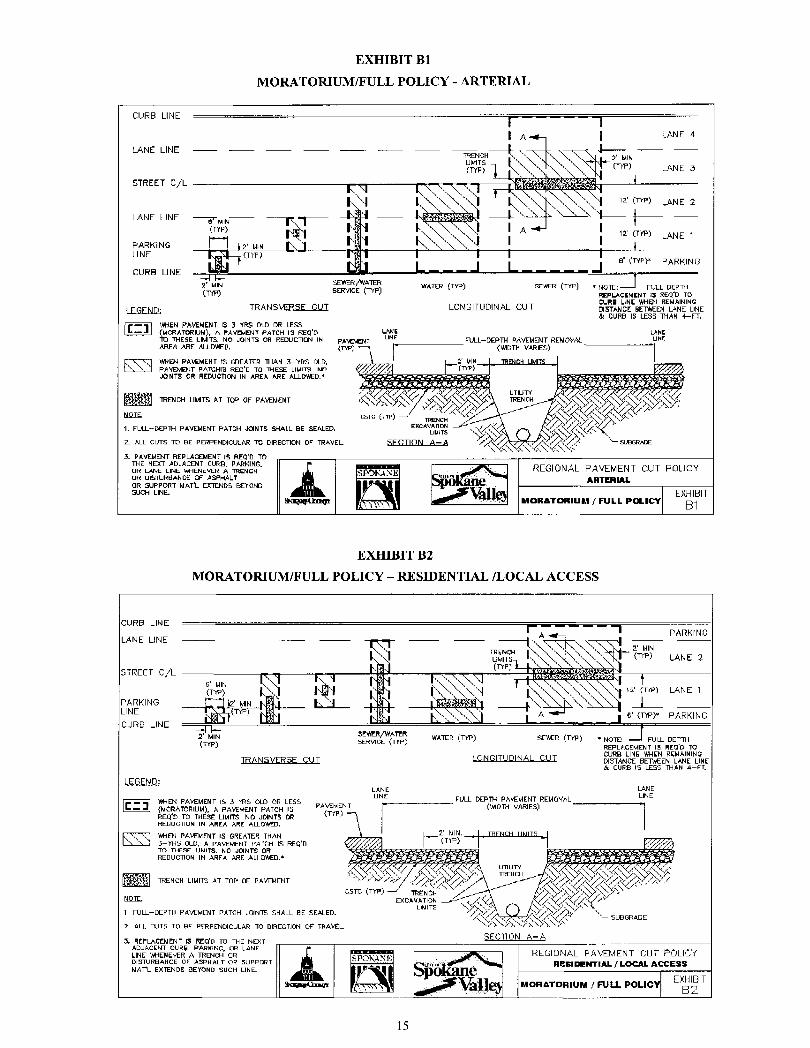
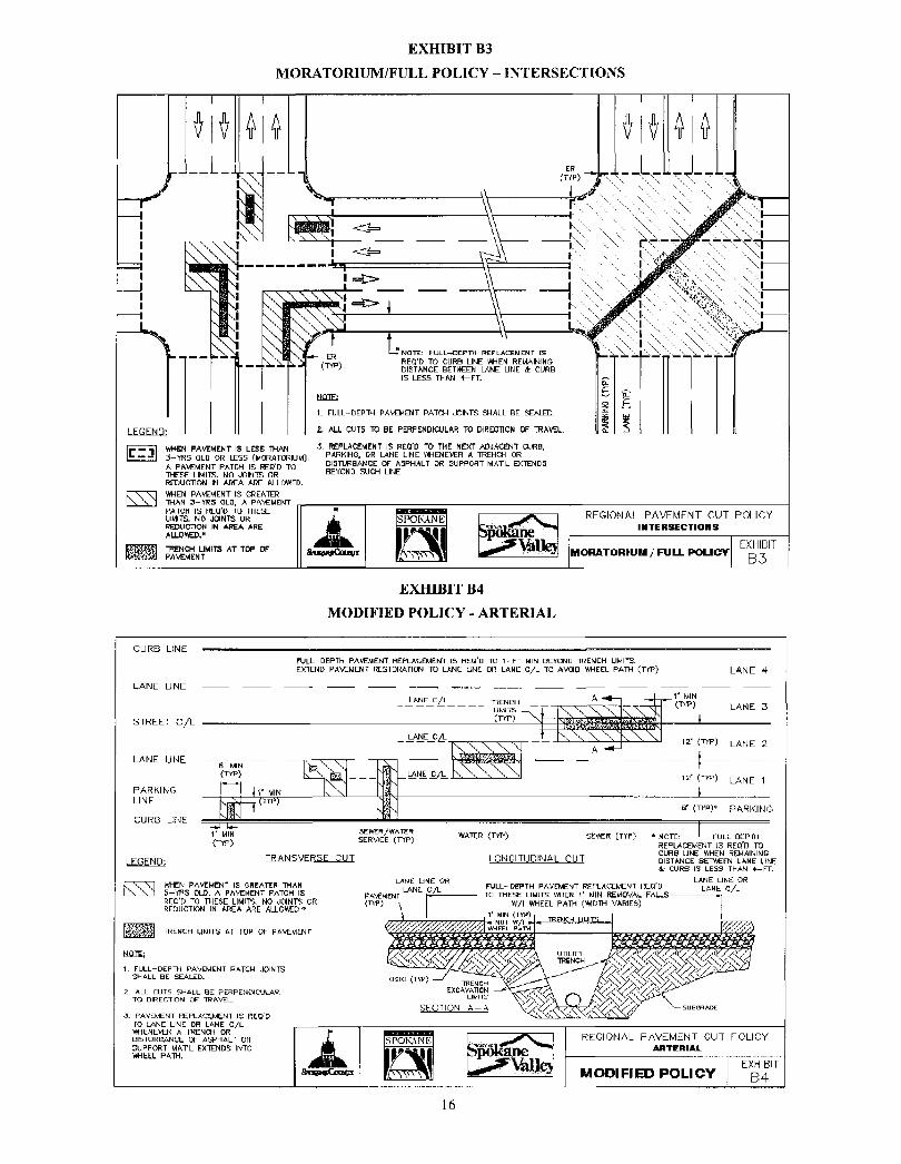
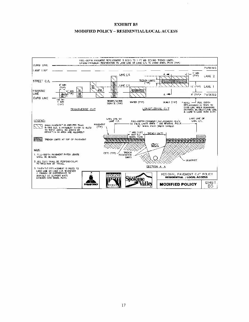
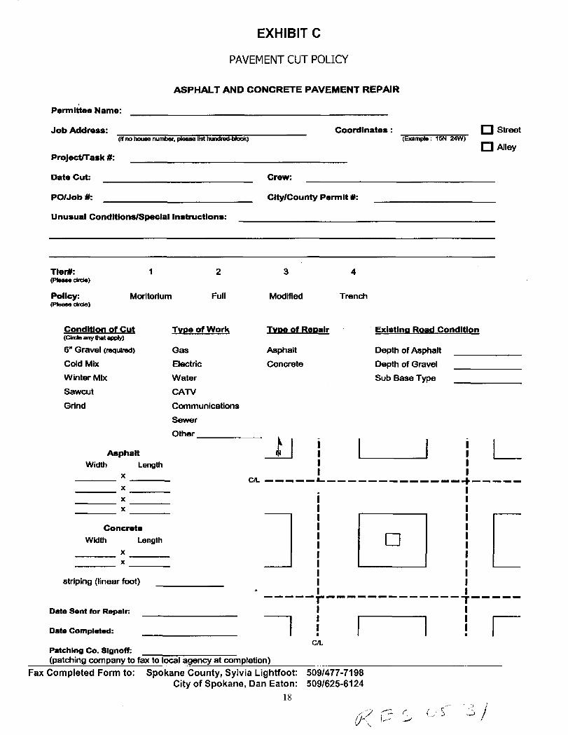
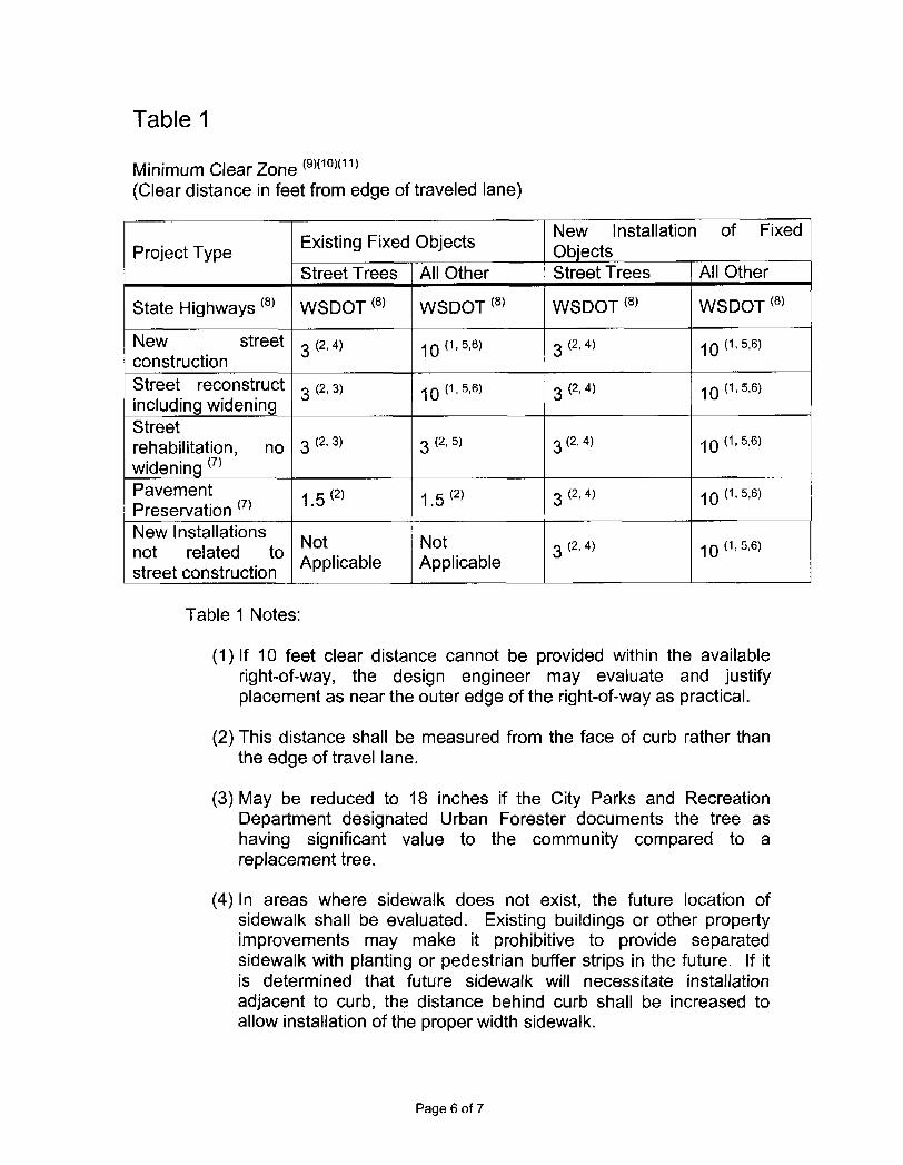
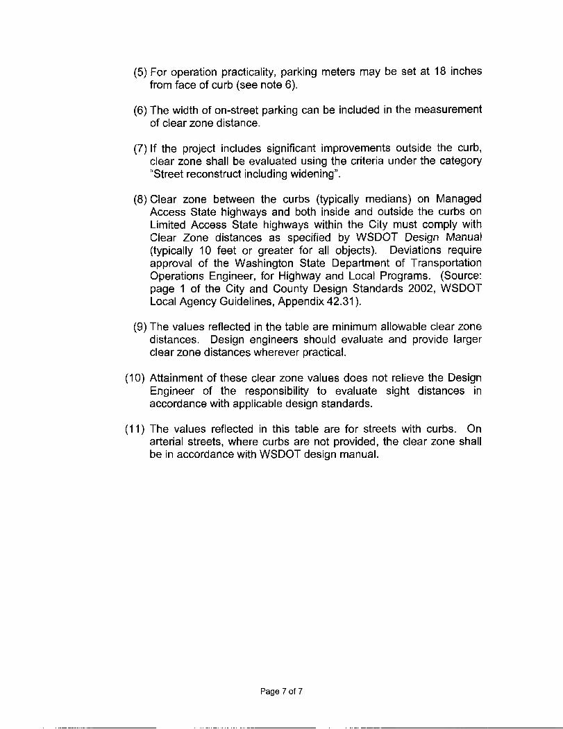
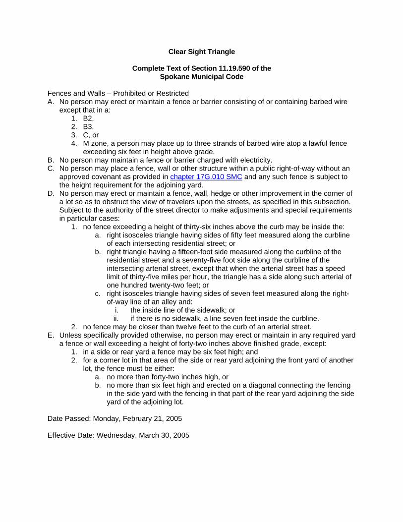
Clear Sight Triangle
Complete Text of Section 11.19.590 of the Spokane Municipal Code
Fences and Walls – Prohibited or Restricted A. No person may erect or maintain a fence or barrier consisting of or containing barbed wire
except that in a: 1. B2, 2. B3, 3. C, or 4. M zone, a person may place up to three strands of barbed wire atop a lawful fence
exceeding six feet in height above grade. B. No person may maintain a fence or barrier charged with electricity. C. No person may place a fence, wall or other structure within a public right-of-way without an
approved covenant as provided in chapter 17G.010 SMC and any such fence is subject to the height requirement for the adjoining yard.
D. No person may erect or maintain a fence, wall, hedge or other improvement in the corner of a lot so as to obstruct the view of travelers upon the streets, as specified in this subsection. Subject to the authority of the street director to make adjustments and special requirements in particular cases:
1. no fence exceeding a height of thirty-six inches above the curb may be inside the: a. right isosceles triangle having sides of fifty feet measured along the curbline
of each intersecting residential street; or b. right triangle having a fifteen-foot side measured along the curbline of the
residential street and a seventy-five foot side along the curbline of the intersecting arterial street, except that when the arterial street has a speed limit of thirty-five miles per hour, the triangle has a side along such arterial of one hundred twenty-two feet; or
c. right isosceles triangle having sides of seven feet measured along the right-of-way line of an alley and:
i. the inside line of the sidewalk; or ii. if there is no sidewalk, a line seven feet inside the curbline.
2. no fence may be closer than twelve feet to the curb of an arterial street. E. Unless specifically provided otherwise, no person may erect or maintain in any required yard
a fence or wall exceeding a height of forty-two inches above finished grade, except: 1. in a side or rear yard a fence may be six feet high; and 2. for a corner lot in that area of the side or rear yard adjoining the front yard of another
lot, the fence must be either: a. no more than forty-two inches high, or b. no more than six feet high and erected on a diagonal connecting the fencing
in the side yard with the fencing in that part of the rear yard adjoining the side yard of the adjoining lot.
Date Passed: Monday, February 21, 2005 Effective Date: Wednesday, March 30, 2005
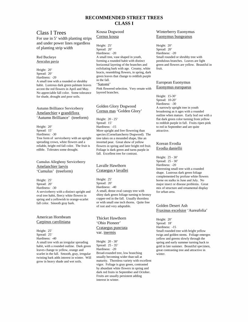
RECOMMENDED STREET TREES CLASS I
Class I Trees For use in 5’ width planting strips and under power lines regardless of planting strip width Red Buckeye Aesculus pavia Height: 20’ Spread: 20’ Hardiness: -20 A small tree with a rounded or shrubby habit. Lustrous dark green palmate leaves accent the red flowers in April and May. No appreciable fall color. Some tolerance for shade, drought and poor soils. Autumn Brilliance Serviceberry Amelanchier x grandiflora ‘Autumn Brilliance’ (treeform) Height: 20’ Spread: 15’ Hardiness: -30 Tree form of serviceberry with an upright spreading crown, white flowers and a reliable, bright red fall color. The fruit is edible. Tolerates some drought. Cumulus Allegheny Serviceberry Amelanchier laevis ‘Cumulus’ (treeform) Height: 25’ Spread: 20’ Hardiness: -30 A serviceberry with a distinct upright and oval tree habit, fleecy white flowers in spring and a yellowish to orange-scarlet fall color. Smooth gray bark. American Hornbeam Carpinus caroliniana Height: 25’ Spread: 25’ Hardiness: -40 A small tree with an irregular spreading habit, with a rounded outline. Dark green leaves change to yellow, orange and scarlet in the fall. Smooth, gray, irregular twisting bark adds interest in winter. Will grow in heavy shade and wet soils.
Kousa Dogwood Cornus kousa Height: 25’ Spread: 20’ Hardiness: -20 A small tree, vase shaped in youth, forming a rounded habit with distinct horizontal layering of the branches and exfoliating bark with age. Creamy, white bracts, resembling flowers, in spring, dark green leaves that change to reddish purple in the fall. ‘Satomi’ Pink flowered selection. Very ornate with layered branches. Golden Glory Dogwood Cornus mas ‘Golden Glory’ Height: 20 - 25’ Spread: 15’ Hardiness: -15 More upright and free flowering than species (Corneliancherry Dogwood). The tree takes on a mounded shape, like an inverted pear. Great show of yellow flowers in spring and later bright red fruit. Foliage is dark green and turns purple in fall. Excellent tree for contrast. Lavalle Hawthorn Crataegus x lavallei Height: 25’ Spread: 20’ Hardiness: -40 A small, dense oval canopy tree with shiny dark green foliage turning to bronzy copper-red in the fall. Usually thornless or with small one inch thorns. Quite free of rust and very adaptable. Thicket Hawthorn ‘Ohio Pioneer’ Crataegus punctata var. inermis Height: 20 - 30’ Spread: 25 - 35’ Hardiness: -20 Broad-rounded tree, low branching usually becoming wider than tall at maturity. Thornless variety with excellent vigor. Foliage is gray green, contrasted by abundant white flowers in spring and dark red fruits in September and October. Fruits are usually persistent adding interest in winter.
Winterberry Euonymus Euonymus bungeanus Height: 20’ Spread: 20’ Hardiness: -20 Small rounded or shrubby tree with pendulous branches. Leaves are light green and flowers are yellow. Beautiful in fruit. European Euonymus Euonymus europaeus Height: 15-30’ Spread: 10-20’ Hardiness: -30 A narrowly upright tree in youth broadening as it ages with a rounded outline when mature. Early leaf out with a flat dark green color turning from yellow to reddish purple in fall. Fruits ripen pink to red in September and are quite attractive. Korean Evodia Evodia daniellii Height: 25 - 30’ Spread: 25 - 30’ Hardiness: -20 Interesting small tree with a rounded shape. Lustrous dark green foliage complemented by profuse white flowers borne on stalks in June and July. No major insect or disease problems. Great mix of structure and ornamental display for urban area. Golden Desert Ash Fraxinus excelsior ‘Aureafolia’ Height: 20’ Spread: 18’ Hardiness: -15 Small rounded tree with bright yellow twigs and golden stems. Foliage emerges yellow and greens slowly through the spring and early summer turning back to gold in late summer. Beautiful specimen, great contrasting tree and attractive in winter.
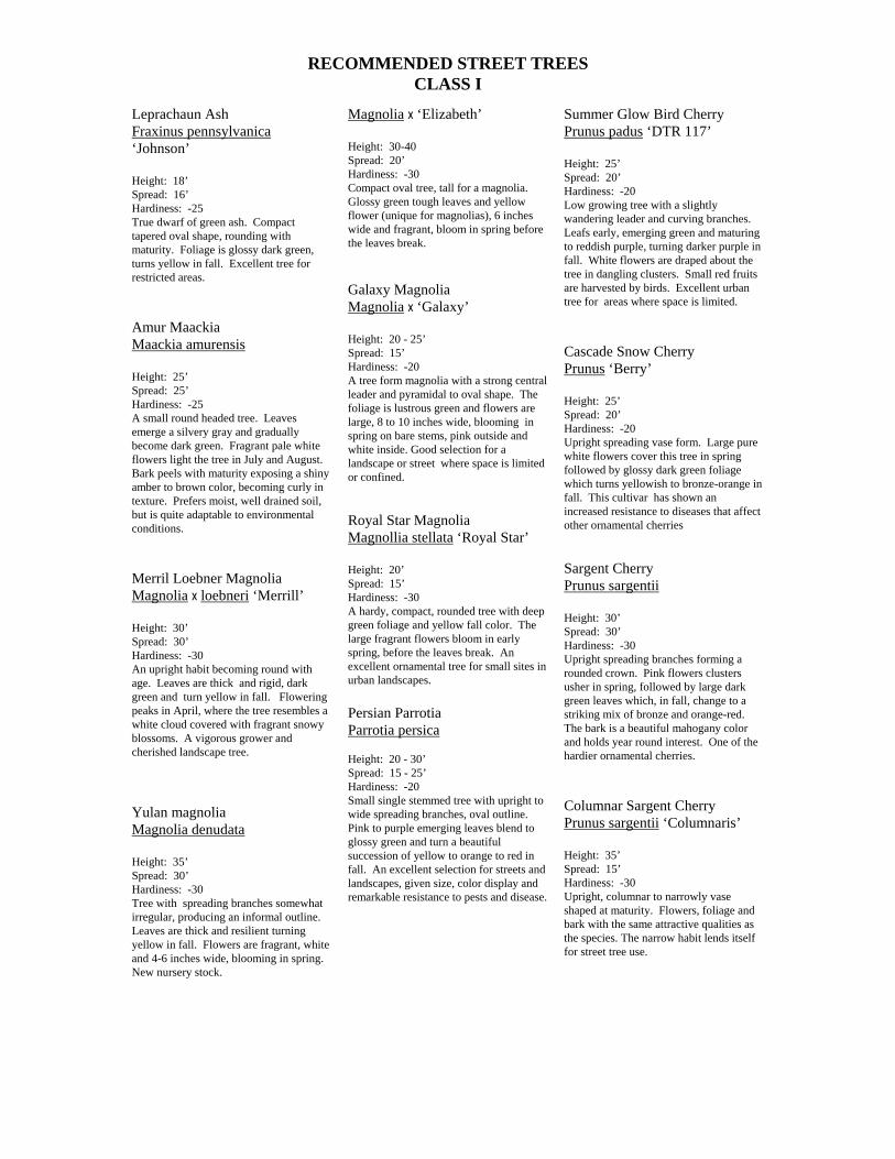
RECOMMENDED STREET TREES CLASS I
Leprachaun Ash Fraxinus pennsylvanica ‘Johnson’ Height: 18’ Spread: 16’ Hardiness: -25 True dwarf of green ash. Compact tapered oval shape, rounding with maturity. Foliage is glossy dark green, turns yellow in fall. Excellent tree for restricted areas. Amur Maackia Maackia amurensis Height: 25’ Spread: 25’ Hardiness: -25 A small round headed tree. Leaves emerge a silvery gray and gradually become dark green. Fragrant pale white flowers light the tree in July and August. Bark peels with maturity exposing a shiny amber to brown color, becoming curly in texture. Prefers moist, well drained soil, but is quite adaptable to environmental conditions. Merril Loebner Magnolia Magnolia x loebneri ‘Merrill’ Height: 30’ Spread: 30’ Hardiness: -30 An upright habit becoming round with age. Leaves are thick and rigid, dark green and turn yellow in fall. Flowering peaks in April, where the tree resembles a white cloud covered with fragrant snowy blossoms. A vigorous grower and cherished landscape tree. Yulan magnolia Magnolia denudata Height: 35’ Spread: 30’ Hardiness: -30 Tree with spreading branches somewhat irregular, producing an informal outline. Leaves are thick and resilient turning yellow in fall. Flowers are fragrant, white and 4-6 inches wide, blooming in spring. New nursery stock.
Magnolia x ‘Elizabeth’ Height: 30-40 Spread: 20’ Hardiness: -30 Compact oval tree, tall for a magnolia. Glossy green tough leaves and yellow flower (unique for magnolias), 6 inches wide and fragrant, bloom in spring before the leaves break. Galaxy Magnolia Magnolia x ‘Galaxy’ Height: 20 - 25’ Spread: 15’ Hardiness: -20 A tree form magnolia with a strong central leader and pyramidal to oval shape. The foliage is lustrous green and flowers are large, 8 to 10 inches wide, blooming in spring on bare stems, pink outside and white inside. Good selection for a landscape or street where space is limited or confined. Royal Star Magnolia Magnollia stellata ‘Royal Star’ Height: 20’ Spread: 15’ Hardiness: -30 A hardy, compact, rounded tree with deep green foliage and yellow fall color. The large fragrant flowers bloom in early spring, before the leaves break. An excellent ornamental tree for small sites in urban landscapes. Persian Parrotia Parrotia persica Height: 20 - 30’ Spread: 15 - 25’ Hardiness: -20 Small single stemmed tree with upright to wide spreading branches, oval outline. Pink to purple emerging leaves blend to glossy green and turn a beautiful succession of yellow to orange to red in fall. An excellent selection for streets and landscapes, given size, color display and remarkable resistance to pests and disease.
Summer Glow Bird Cherry Prunus padus ‘DTR 117’ Height: 25’ Spread: 20’ Hardiness: -20 Low growing tree with a slightly wandering leader and curving branches. Leafs early, emerging green and maturing to reddish purple, turning darker purple in fall. White flowers are draped about the tree in dangling clusters. Small red fruits are harvested by birds. Excellent urban tree for areas where space is limited. Cascade Snow Cherry Prunus ‘Berry’ Height: 25’ Spread: 20’ Hardiness: -20 Upright spreading vase form. Large pure white flowers cover this tree in spring followed by glossy dark green foliage which turns yellowish to bronze-orange in fall. This cultivar has shown an increased resistance to diseases that affect other ornamental cherries Sargent Cherry Prunus sargentii Height: 30’ Spread: 30’ Hardiness: -30 Upright spreading branches forming a rounded crown. Pink flowers clusters usher in spring, followed by large dark green leaves which, in fall, change to a striking mix of bronze and orange-red. The bark is a beautiful mahogany color and holds year round interest. One of the hardier ornamental cherries. Columnar Sargent Cherry Prunus sargentii ‘Columnaris’ Height: 35’ Spread: 15’ Hardiness: -30 Upright, columnar to narrowly vase shaped at maturity. Flowers, foliage and bark with the same attractive qualities as the species. The narrow habit lends itself for street tree use.
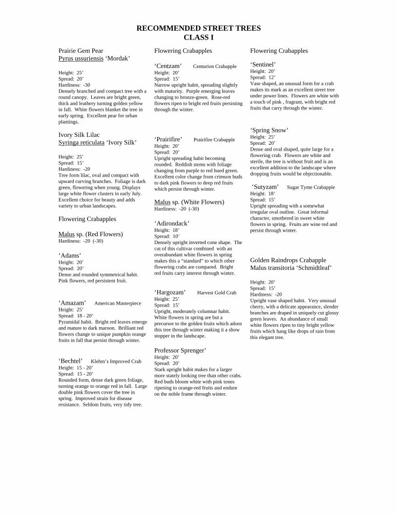
RECOMMENDED STREET TREES CLASS I
Prairie Gem Pear Pyrus ussuriensis ‘Mordak’ Height: 25’ Spread: 20’ Hardiness: -30 Densely branched and compact tree with a round canopy. Leaves are bright green, thick and leathery turning golden yellow in fall. White flowers blanket the tree in early spring. Excellent pear for urban plantings. Ivory Silk Lilac Syringa reticulata ‘Ivory Silk’ Height: 25’ Spread: 15’ Hardiness: -20 Tree form lilac, oval and compact with upward curving branches. Foliage is dark green, flowering when young. Displays large white flower clusters in early July. Excellent choice for beauty and adds variety to urban landscapes. Flowering Crabapples Malus sp. (Red Flowers) Hardiness: -20 (-30) ‘Adams’ Height: 20’ Spread: 20’ Dense and rounded symmetrical habit. Pink flowers, red persistent fruit. ‘Amazam’ American Masterpiece Height: 25’ Spread: 18 - 20’ Pyramidal habit. Bright red leaves emerge and mature to dark maroon. Brilliant red flowers change to unique pumpkin orange fruits in fall that persist through winter. ‘Bechtel’ Klehm’s Improved Crab Height: 15 - 20’ Spread: 15 - 20’ Rounded form, dense dark green foliage, turning orange to orange red in fall. Large double pink flowers cover the tree in spring. Improved strain for disease resistance. Seldom fruits, very tidy tree.
Flowering Crabapples ‘Centzam’ Centurion Crabapple Height: 20’ Spread: 15’ Narrow upright habit, spreading slightly with maturity. Purple emerging leaves changing to bronze-green. Rose-red flowers ripen to bright red fruits persisting through the winter. ‘Prairifire’ Prairifire Crabapple Height: 20’ Spread: 20’ Upright spreading habit becoming rounded. Reddish stems with foliage changing from purple to red hued green. Excellent color change from crimson buds to dark pink flowers to deep red fruits which persist through winter. Malus sp. (White Flowers) Hardiness: -20 (-30) ‘Adirondack’ Height: 18’ Spread: 10’ Densely upright inverted cone shape. The cut of this cultivar combined with an overabundant white flowers in spring makes this a “standard” to which other flowering crabs are compared. Bright red fruits carry interest through winter. ‘Hargozam’ Harvest Gold Crab Height: 25’ Spread: 15’ Upright, moderately columnar habit. White flowers in spring are but a precursor to the golden fruits which adorn this tree through winter making it a show stopper in the landscape. Professor Sprenger’ Height: 20’ Spread: 20’ Stark upright habit makes for a larger more stately looking tree than other crabs. Red buds bloom white with pink tones ripening to orange-red fruits and endure on the noble frame through winter.
Flowering Crabapples ‘Sentinel’ Height: 20’ Spread: 12’ Vase shaped, an unusual form for a crab makes its mark as an excellent street tree under power lines. Flowers are white with a touch of pink , fragrant, with bright red fruits that carry through the winter. ‘Spring Snow’ Height: 25’ Spread: 20’ Dense and oval shaped, quite large for a flowering crab. Flowers are white and sterile, the tree is without fruit and is an excellent addition to the landscape where dropping fruits would be objectionable. ‘Sutyzam’ Sugar Tyme Crabapple Height: 18’ Spread: 15’ Upright spreading with a somewhat irregular oval outline. Great informal character, smothered in sweet white flowers in spring. Fruits are wine red and persist through winter. Golden Raindrops Crabapple Malus transitoria ‘Schmidtleaf’ Height: 20’ Spread: 15’ Hardiness: -20 Upright vase shaped habit. Very unusual cherry, with a delicate appearance, slender branches are draped in uniquely cut glossy green leaves. An abundance of small white flowers ripen to tiny bright yellow fruits which hang like drops of rain from this elegant tree.
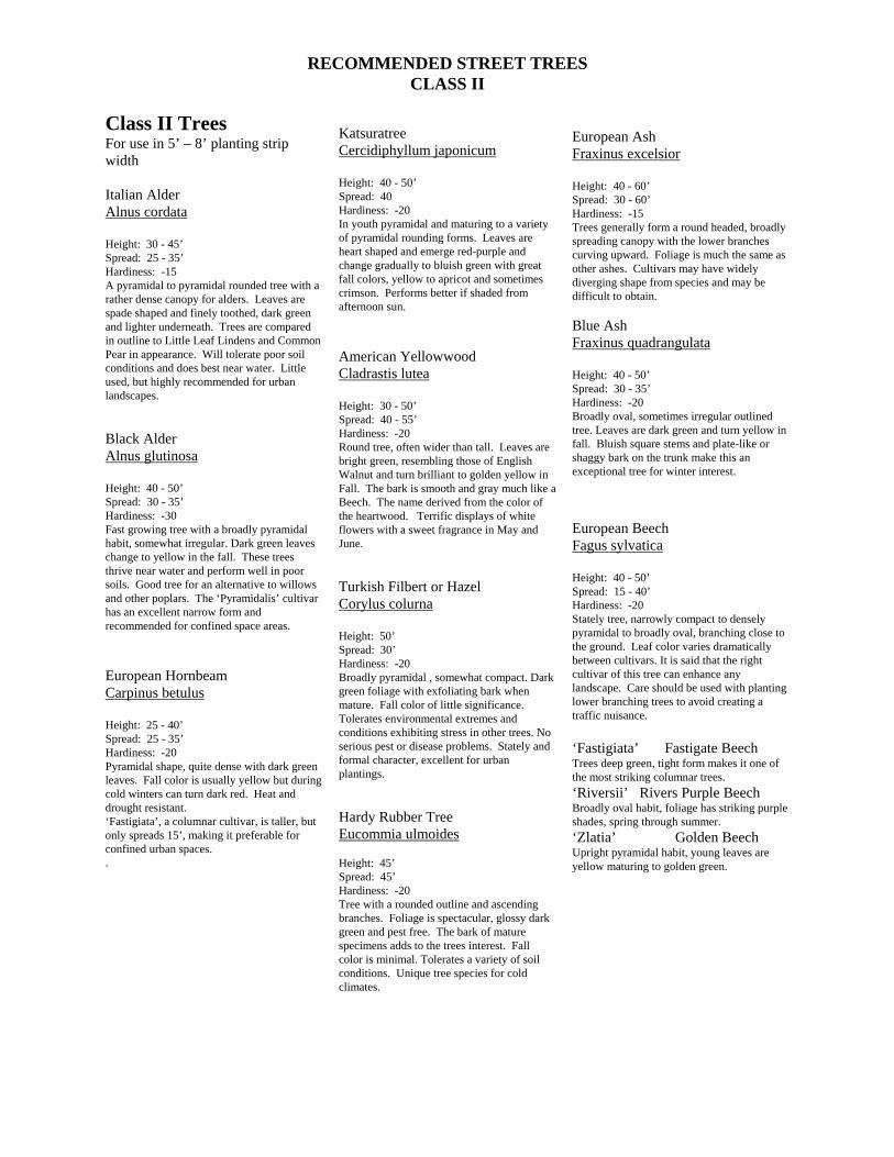
RECOMMENDED STREET TREES CLASS II
Class II Trees For use in 5’ – 8’ planting strip width Italian Alder Alnus cordata Height: 30 - 45’ Spread: 25 - 35’ Hardiness: -15 A pyramidal to pyramidal rounded tree with a rather dense canopy for alders. Leaves are spade shaped and finely toothed, dark green and lighter underneath. Trees are compared in outline to Little Leaf Lindens and Common Pear in appearance. Will tolerate poor soil conditions and does best near water. Little used, but highly recommended for urban landscapes. Black Alder Alnus glutinosa Height: 40 - 50’ Spread: 30 - 35’ Hardiness: -30 Fast growing tree with a broadly pyramidal habit, somewhat irregular. Dark green leaves change to yellow in the fall. These trees thrive near water and perform well in poor soils. Good tree for an alternative to willows and other poplars. The ‘Pyramidalis’ cultivar has an excellent narrow form and recommended for confined space areas. European Hornbeam Carpinus betulus Height: 25 - 40’ Spread: 25 - 35’ Hardiness: -20 Pyramidal shape, quite dense with dark green leaves. Fall color is usually yellow but during cold winters can turn dark red. Heat and drought resistant. ‘Fastigiata’, a columnar cultivar, is taller, but only spreads 15’, making it preferable for confined urban spaces. .
Katsuratree Cercidiphyllum japonicum Height: 40 - 50’ Spread: 40 Hardiness: -20 In youth pyramidal and maturing to a variety of pyramidal rounding forms. Leaves are heart shaped and emerge red-purple and change gradually to bluish green with great fall colors, yellow to apricot and sometimes crimson. Performs better if shaded from afternoon sun. American Yellowwood Cladrastis lutea Height: 30 - 50’ Spread: 40 - 55’ Hardiness: -20 Round tree, often wider than tall. Leaves are bright green, resembling those of English Walnut and turn brilliant to golden yellow in Fall. The bark is smooth and gray much like a Beech. The name derived from the color of the heartwood. Terrific displays of white flowers with a sweet fragrance in May and June. Turkish Filbert or Hazel Corylus colurna Height: 50’ Spread: 30’ Hardiness: -20 Broadly pyramidal , somewhat compact. Dark green foliage with exfoliating bark when mature. Fall color of little significance. Tolerates environmental extremes and conditions exhibiting stress in other trees. No serious pest or disease problems. Stately and formal character, excellent for urban plantings. Hardy Rubber Tree Eucommia ulmoides Height: 45’ Spread: 45’ Hardiness: -20 Tree with a rounded outline and ascending branches. Foliage is spectacular, glossy dark green and pest free. The bark of mature specimens adds to the trees interest. Fall color is minimal. Tolerates a variety of soil conditions. Unique tree species for cold climates.
European Ash Fraxinus excelsior Height: 40 - 60’ Spread: 30 - 60’ Hardiness: -15 Trees generally form a round headed, broadly spreading canopy with the lower branches curving upward. Foliage is much the same as other ashes. Cultivars may have widely diverging shape from species and may be difficult to obtain. Blue Ash Fraxinus quadrangulata Height: 40 - 50’ Spread: 30 - 35’ Hardiness: -20 Broadly oval, sometimes irregular outlined tree. Leaves are dark green and turn yellow in fall. Bluish square stems and plate-like or shaggy bark on the trunk make this an exceptional tree for winter interest. European Beech Fagus sylvatica Height: 40 - 50’ Spread: 15 - 40’ Hardiness: -20 Stately tree, narrowly compact to densely pyramidal to broadly oval, branching close to the ground. Leaf color varies dramatically between cultivars. It is said that the right cultivar of this tree can enhance any landscape. Care should be used with planting lower branching trees to avoid creating a traffic nuisance. ‘Fastigiata’ Fastigate Beech Trees deep green, tight form makes it one of the most striking columnar trees. ‘Riversii’ Rivers Purple Beech Broadly oval habit, foliage has striking purple shades, spring through summer. ‘Zlatia’ Golden Beech Upright pyramidal habit, young leaves are yellow maturing to golden green.
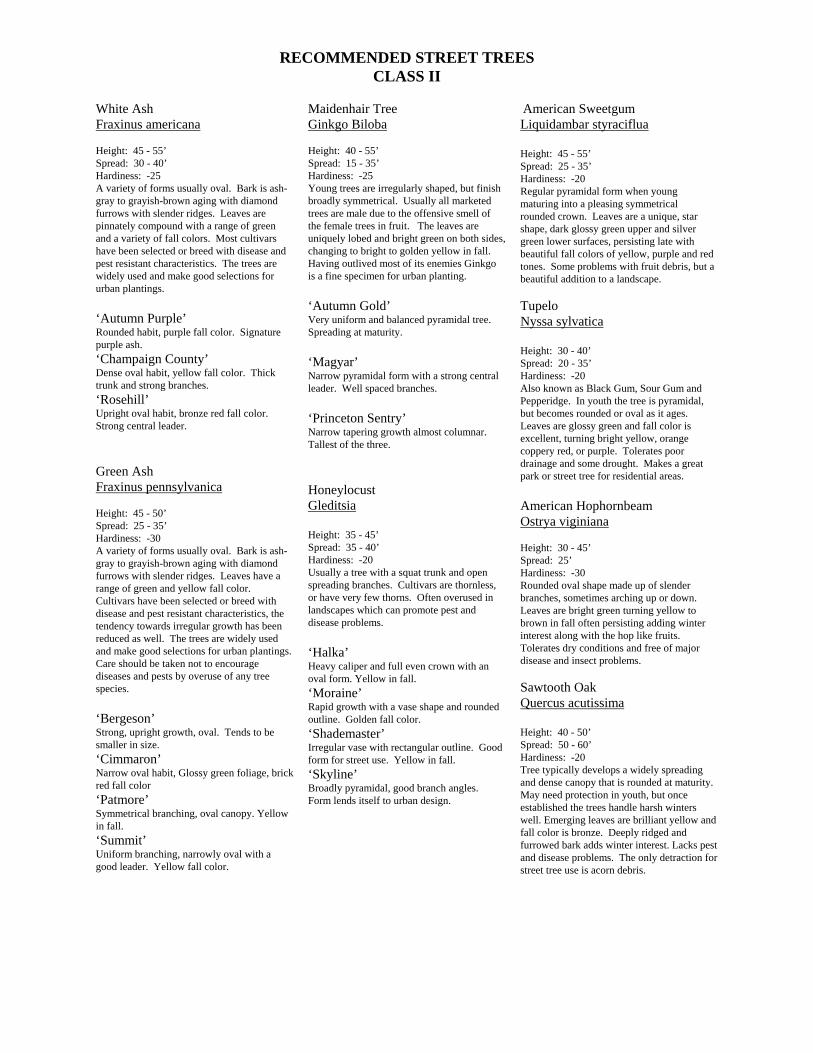
RECOMMENDED STREET TREES CLASS II
White Ash Fraxinus americana Height: 45 - 55’ Spread: 30 - 40’ Hardiness: -25 A variety of forms usually oval. Bark is ash-gray to grayish-brown aging with diamond furrows with slender ridges. Leaves are pinnately compound with a range of green and a variety of fall colors. Most cultivars have been selected or breed with disease and pest resistant characteristics. The trees are widely used and make good selections for urban plantings. ‘Autumn Purple’ Rounded habit, purple fall color. Signature purple ash. ‘Champaign County’ Dense oval habit, yellow fall color. Thick trunk and strong branches. ‘Rosehill’ Upright oval habit, bronze red fall color. Strong central leader. Green Ash Fraxinus pennsylvanica Height: 45 - 50’ Spread: 25 - 35’ Hardiness: -30 A variety of forms usually oval. Bark is ash-gray to grayish-brown aging with diamond furrows with slender ridges. Leaves have a range of green and yellow fall color. Cultivars have been selected or breed with disease and pest resistant characteristics, the tendency towards irregular growth has been reduced as well. The trees are widely used and make good selections for urban plantings. Care should be taken not to encourage diseases and pests by overuse of any tree species. ‘Bergeson’ Strong, upright growth, oval. Tends to be smaller in size. ‘Cimmaron’ Narrow oval habit, Glossy green foliage, brick red fall color ‘Patmore’ Symmetrical branching, oval canopy. Yellow in fall. ‘Summit’ Uniform branching, narrowly oval with a good leader. Yellow fall color.
Maidenhair Tree Ginkgo Biloba Height: 40 - 55’ Spread: 15 - 35’ Hardiness: -25 Young trees are irregularly shaped, but finish broadly symmetrical. Usually all marketed trees are male due to the offensive smell of the female trees in fruit. The leaves are uniquely lobed and bright green on both sides, changing to bright to golden yellow in fall. Having outlived most of its enemies Ginkgo is a fine specimen for urban planting. ‘Autumn Gold’ Very uniform and balanced pyramidal tree. Spreading at maturity. ‘Magyar’ Narrow pyramidal form with a strong central leader. Well spaced branches. ‘Princeton Sentry’ Narrow tapering growth almost columnar. Tallest of the three. Honeylocust Gleditsia Height: 35 - 45’ Spread: 35 - 40’ Hardiness: -20 Usually a tree with a squat trunk and open spreading branches. Cultivars are thornless, or have very few thorns. Often overused in landscapes which can promote pest and disease problems. ‘Halka’ Heavy caliper and full even crown with an oval form. Yellow in fall. ‘Moraine’ Rapid growth with a vase shape and rounded outline. Golden fall color. ‘Shademaster’ Irregular vase with rectangular outline. Good form for street use. Yellow in fall. ‘Skyline’ Broadly pyramidal, good branch angles. Form lends itself to urban design.
American Sweetgum Liquidambar styraciflua Height: 45 - 55’ Spread: 25 - 35’ Hardiness: -20 Regular pyramidal form when young maturing into a pleasing symmetrical rounded crown. Leaves are a unique, star shape, dark glossy green upper and silver green lower surfaces, persisting late with beautiful fall colors of yellow, purple and red tones. Some problems with fruit debris, but a beautiful addition to a landscape. Tupelo Nyssa sylvatica Height: 30 - 40’ Spread: 20 - 35’ Hardiness: -20 Also known as Black Gum, Sour Gum and Pepperidge. In youth the tree is pyramidal, but becomes rounded or oval as it ages. Leaves are glossy green and fall color is excellent, turning bright yellow, orange coppery red, or purple. Tolerates poor drainage and some drought. Makes a great park or street tree for residential areas. American Hophornbeam Ostrya viginiana Height: 30 - 45’ Spread: 25’ Hardiness: -30 Rounded oval shape made up of slender branches, sometimes arching up or down. Leaves are bright green turning yellow to brown in fall often persisting adding winter interest along with the hop like fruits. Tolerates dry conditions and free of major disease and insect problems. Sawtooth Oak Quercus acutissima Height: 40 - 50’ Spread: 50 - 60’ Hardiness: -20 Tree typically develops a widely spreading and dense canopy that is rounded at maturity. May need protection in youth, but once established the trees handle harsh winters well. Emerging leaves are brilliant yellow and fall color is bronze. Deeply ridged and furrowed bark adds winter interest. Lacks pest and disease problems. The only detraction for street tree use is acorn debris.
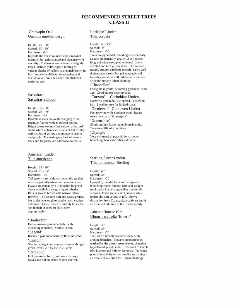
RECOMMENDED STREET TREES CLASS II
Chinkapin Oak Quercus muehlenbergii Height: 40 - 50’ Spread: 50 - 60’ Hardiness: -15 In youth the tree is rounded and somewhat irregular, but gains stature and elegance with maturity. The leaves are indented to slightly lobed, lustrous yellow green turning to various shades of yellow to orangish brown in fall. Somewhat difficult to transplant and dislikes alkali soils, but once established it performs well. Sassafras Sassafras albidum Height: 30 - 60’ Spread: 25 - 40’ Hardiness: -20 Pyramidal shape in youth changing to an irregular flat top with an oblong outline. Bright green leaves offset yellow, often, red stems which enhance an excellent fall display with shades of yellow and orange to scarlet and purple. The mahogany bark of mature trees and fragrance are additional interests. American Linden Tilia americana Height: 35 - 50’ Spread: 20 - 35’ Hardiness: -40 Tall stately trees, cultivars generally smaller in size especially when used in urban areas. Leaves are generally 4 to 8 inches long and about as wide in a range of green shades. Bark is gray to brown with narrow lateral furrows. The wood is soft and easily prunes, but is elastic enough to handle most weather extremes. These trees will entirely block the sun in their shadow so place them appropriately. ‘Boulevard’ Dense, narrow pyramidal habit with ascending branches. Yellow in fall. ‘Legend’ Rounded pyramidal habit, yellow fall color. ‘Lincoln’ Slender, upright and compact form with light green leaves, 25’ by 15’ in 25 years. ‘Redmond’ Full pyramidal form, uniform with large leaves and red branches, winter interest.
Littleleaf Linden Tilia cordata Height: 40 - 45’ Spread: 45’ Hardiness: -30 Trees are pyramidal, rounding with maturity. Leaves are generally smaller, 2 to 3 inches long and wide, (except Glenleven) finely serrated and turn yellow in fall. Trunks are usually straight and bark smooth. Likes well drained alkali soils, but pH adaptable and tolerates pollution well. Makes an excellent selection for any urban planting. ‘Chancellor’ Fastigiate in youth, becoming pyramidal with age. Good branch development. ‘Corzam’ Corinthian Linden Narrowly pyramidal, 15’ spread. Yellow in fall. Excellent tree for limited space. ‘Glenleven’ Glenleven Linden Fast growing with a straight trunk, leaves twice the size of ‘Greenspire’ ‘Greenspire’ Single straight leader, good branch angle. Tolerates difficult conditions. ‘Olympic’ Very symmetrical pyramid form, better branching than some other cultivars. Sterling Silver Linden Tilia tomentosa ‘Sterling’ Height: 45’ Spread: 35’ Hardiness: -20 Upright pyramidal form with a superior branching frame, smooth bark and straight trunk make it a very appealing tree for all seasons. Furry green leaves, silvery white underside, turn yellow in fall. Shows distinction from Tilia cordata cultivars and is an excellent addition to the Linden family Athena Chinese Elm Ulmus parvifolia ‘Emer I’ Height: 30’ Spread: 35’ Hardiness: -20 Tree with a broadly rounded shape with arching branches. Flowers inconspicuous, masked by the glossy green leaves, changing to yellowish purple in fall. Resistant to Dutch Elm Disease and Phloem Necrosis. Tolerates poor soils and dry or wet conditions making it an excellent selection for urban plantings.
.
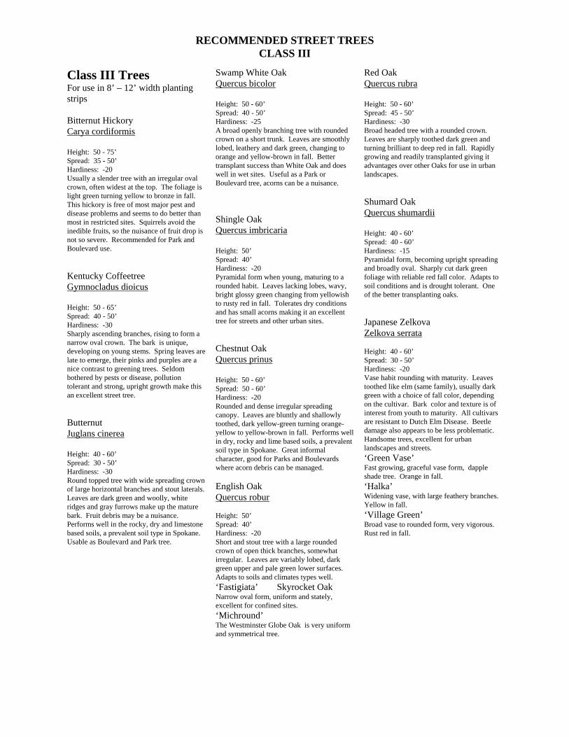
RECOMMENDED STREET TREES CLASS III
Class III Trees For use in 8’ – 12’ width planting strips Bitternut Hickory Carya cordiformis Height: 50 - 75’ Spread: 35 - 50’ Hardiness: -20 Usually a slender tree with an irregular oval crown, often widest at the top. The foliage is light green turning yellow to bronze in fall. This hickory is free of most major pest and disease problems and seems to do better than most in restricted sites. Squirrels avoid the inedible fruits, so the nuisance of fruit drop is not so severe. Recommended for Park and Boulevard use. Kentucky Coffeetree Gymnocladus dioicus Height: 50 - 65’ Spread: 40 - 50’ Hardiness: -30 Sharply ascending branches, rising to form a narrow oval crown. The bark is unique, developing on young stems. Spring leaves are late to emerge, their pinks and purples are a nice contrast to greening trees. Seldom bothered by pests or disease, pollution tolerant and strong, upright growth make this an excellent street tree. Butternut Juglans cinerea Height: 40 - 60’ Spread: 30 - 50’ Hardiness: -30 Round topped tree with wide spreading crown of large horizontal branches and stout laterals. Leaves are dark green and woolly, white ridges and gray furrows make up the mature bark. Fruit debris may be a nuisance. Performs well in the rocky, dry and limestone based soils, a prevalent soil type in Spokane. Usable as Boulevard and Park tree.
Swamp White Oak Quercus bicolor Height: 50 - 60’ Spread: 40 - 50’ Hardiness: -25 A broad openly branching tree with rounded crown on a short trunk. Leaves are smoothly lobed, leathery and dark green, changing to orange and yellow-brown in fall. Better transplant success than White Oak and does well in wet sites. Useful as a Park or Boulevard tree, acorns can be a nuisance. Shingle Oak Quercus imbricaria Height: 50’ Spread: 40’ Hardiness: -20 Pyramidal form when young, maturing to a rounded habit. Leaves lacking lobes, wavy, bright glossy green changing from yellowish to rusty red in fall. Tolerates dry conditions and has small acorns making it an excellent tree for streets and other urban sites. Chestnut Oak Quercus prinus Height: 50 - 60’ Spread: 50 - 60’ Hardiness: -20 Rounded and dense irregular spreading canopy. Leaves are bluntly and shallowly toothed, dark yellow-green turning orange-yellow to yellow-brown in fall. Performs well in dry, rocky and lime based soils, a prevalent soil type in Spokane. Great informal character, good for Parks and Boulevards where acorn debris can be managed. English Oak Quercus robur Height: 50’ Spread: 40’ Hardiness: -20 Short and stout tree with a large rounded crown of open thick branches, somewhat irregular. Leaves are variably lobed, dark green upper and pale green lower surfaces. Adapts to soils and climates types well. ‘Fastigiata’ Skyrocket Oak Narrow oval form, uniform and stately, excellent for confined sites. ‘Michround’ The Westminster Globe Oak is very uniform and symmetrical tree.
Red Oak Quercus rubra Height: 50 - 60’ Spread: 45 - 50’ Hardiness: -30 Broad headed tree with a rounded crown. Leaves are sharply toothed dark green and turning brilliant to deep red in fall. Rapidly growing and readily transplanted giving it advantages over other Oaks for use in urban landscapes. Shumard Oak Quercus shumardii Height: 40 - 60’ Spread: 40 - 60’ Hardiness: -15 Pyramidal form, becoming upright spreading and broadly oval. Sharply cut dark green foliage with reliable red fall color. Adapts to soil conditions and is drought tolerant. One of the better transplanting oaks. Japanese Zelkova Zelkova serrata Height: 40 - 60’ Spread: 30 - 50’ Hardiness: -20 Vase habit rounding with maturity. Leaves toothed like elm (same family), usually dark green with a choice of fall color, depending on the cultivar. Bark color and texture is of interest from youth to maturity. All cultivars are resistant to Dutch Elm Disease. Beetle damage also appears to be less problematic. Handsome trees, excellent for urban landscapes and streets. ‘Green Vase’ Fast growing, graceful vase form, dapple shade tree. Orange in fall. ‘Halka’ Widening vase, with large feathery branches. Yellow in fall. ‘Village Green’ Broad vase to rounded form, very vigorous. Rust red in fall.
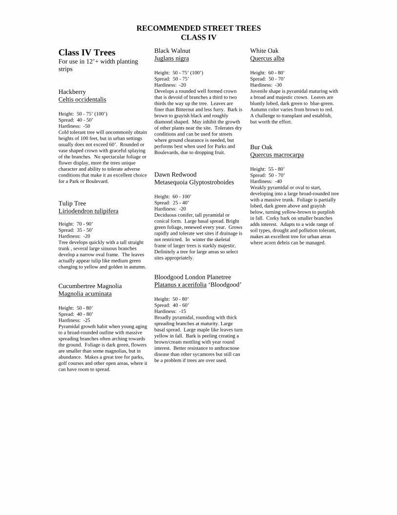
RECOMMENDED STREET TREES CLASS IV
Class IV Trees For use in 12’+ width planting strips Hackberry Celtis occidentalis Height: 50 - 75’ (100’) Spread: 40 - 50’ Hardiness: -50 Cold tolerant tree will uncommonly obtain heights of 100 feet, but in urban settings usually does not exceed 60’. Rounded or vase shaped crown with graceful splaying of the branches. No spectacular foliage or flower display, more the trees unique character and ability to tolerate adverse conditions that make it an excellent choice for a Park or Boulevard. Tulip Tree Liriodendron tulipifera Height: 70 - 90’ Spread: 35 - 50’ Hardiness: -20 Tree develops quickly with a tall straight trunk , several large sinuous branches develop a narrow oval frame. The leaves actually appear tulip like medium green changing to yellow and golden in autumn. Cucumbertree Magnolia Magnolia acuminata Height: 50 - 80’ Spread: 40 - 80’ Hardiness: -25 Pyramidal growth habit when young aging to a broad-rounded outline with massive spreading branches often arching towards the ground. Foliage is dark green, flowers are smaller than some magnolias, but in abundance. Makes a great tree for parks, golf courses and other open areas, where it can have room to spread.
Black Walnut Juglans nigra Height: 50 - 75’ (100’) Spread: 50 - 75’ Hardiness: -20 Develops a rounded well formed crown that is devoid of branches a third to two thirds the way up the tree. Leaves are finer than Bitternut and less furry. Bark is brown to grayish black and roughly diamond shaped. May inhibit the growth of other plants near the site. Tolerates dry conditions and can be used for streets where ground clearance is needed, but performs best when used for Parks and Boulevards, due to dropping fruit. Dawn Redwood Metasequoia Glyptostroboides Height: 60 - 100’ Spread: 25 - 40’ Hardiness: -20 Deciduous conifer, tall pyramidal or conical form. Large basal spread. Bright green foliage, renewed every year. Grows rapidly and tolerate wet sites if drainage is not restricted. In winter the skeletal frame of larger trees is starkly majestic. Definitely a tree for large areas so select sites appropriately. Bloodgood London Planetree Platanus x acerifolia ‘Bloodgood’ Height: 50 - 80’ Spread: 40 - 60’ Hardiness: -15 Broadly pyramidal, rounding with thick spreading branches at maturity. Large basal spread. Large maple like leaves turn yellow in fall. Bark is peeling creating a brown/cream mottling with year round interest. Better resistance to anthracnose disease than other sycamores but still can be a problem if trees are over used.
White Oak Quercus alba Height: 60 - 80’ Spread: 50 - 70’ Hardiness: -30 Juvenile shape is pyramidal maturing with a broad and majestic crown. Leaves are bluntly lobed, dark green to blue-green. Autumn color varies from brown to red. A challenge to transplant and establish, but worth the effort. Bur Oak Quercus macrocarpa Height: 55 - 80’ Spread: 50 - 70’ Hardiness: -40 Weakly pyramidal or oval to start, developing into a large broad-rounded tree with a massive trunk. Foliage is partially lobed, dark green above and grayish below, turning yellow-brown to purplish in fall. Corky bark on smaller branches adds interest. Adapts to a wide range of soil types, drought and pollution tolerant, makes an excellent tree for urban areas where acorn debris can be managed.


