Embed Size (px)
Citation preview
SCREW CONVEYOR BASIC DESIGN CALCULATION CEMA (Conveyor Equipment Manufacturer Association) Approach
HISTORY & APPLICATION
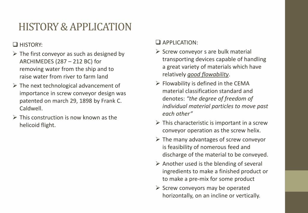
HISTORY:
The first conveyor as such as designed by
ARCHIMEDES (287 – 212 BC) for
removing water from the ship and to
raise water from river to farm land
The next technological advancement of
importance in screw conveyor design was
patented on march 29, 1898 by Frank C.
Caldwell.
This construction is now known as the
helicoid flight.
APPLICATION:
Screw conveyor s are bulk material
transporting devices capable of handling
a great variety of materials which have
relatively good flowability.
Flowability is defined in the CEMA
material classification standard and
denotes: “the degree of freedom of
individual material particles to move past
each other”
This characteristic is important in a screw
conveyor operation as the screw helix.
The many advantages of screw conveyor
is feasibility of nomerous feed and
discharge of the material to be conveyed.
Another used is the blending of several
ingredients to make a finished product or
to make a pre-mix for some product
Screw conveyors may be operated
horizontally, on an incline or vertically.
MATERIAL CODE & BULK MATERIAL CHARACTERISTICS
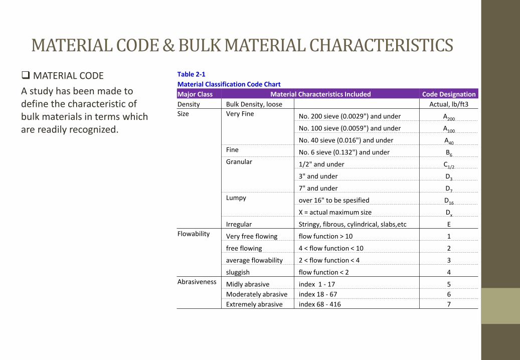
MATERIAL CODE
A study has been made to
define the characteristic of
bulk materials in terms which
are readily recognized.
Table 2-1
Material Classification Code Chart
Major Class Material Characteristics Included Code Designation
Density Bulk Density, loose Actual, lb/ft3
Size Very Fine No. 200 sieve (0.0029") and under A200
No. 100 sieve (0.0059") and under A100
No. 40 sieve (0.016") and under A40
Fine No. 6 sieve (0.132") and under B6
Granular 1/2" and under C1/2
3" and under D3
7" and under D7
Lumpy over 16" to be spesified D16
X = actual maximum size Dx
Irregular Stringy, fibrous, cylindrical, slabs,etc E
Flowability Very free flowing flow function > 10 1
free flowing 4 < flow function < 10 2
average flowability 2 < flow function < 4 3
sluggish flow function < 2 4
Abrasiveness Midly abrasive index 1 - 17 5
Moderately abrasive index 18 - 67 6
Extremely abrasive index 68 - 416 7
MATERIAL CODE & BULK MATERIAL CHARACTERISTICS
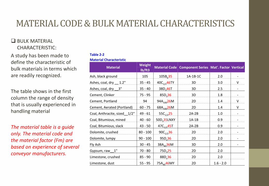
Table 2-2
Material Characteristic
Material Weight
Material Code Component Series Mat'. Factor Vertical lb/ft3
Ash, black ground 105 105B635 1A-1B-1C 2.0 -
Ashes, coal, dry __ 1.2" 35 - 45 40C1/246TY 3D 3.0 V
Ashes, coal, dry __3" 35 - 40 38D346T 3D 2.5 -
Cement, Clinker 75 - 95 85D336 3D 1.8 -
Cement, Portland 94 94A10026M 2D 1.4 V
Cement, Aerated (Portland) 60 - 75 68A10026M 2D 1.4 V
Coal, Anthracite, sized__1/2" 49 - 61 55C1/225 2A-2B 1.0 -
Coal, Bitumious, mined 40 - 60 50D335LNXY 1A-1B 0.9 -
Coal, Bitumious, slack 43 - 50 47C1/245T 2A-2B 0.9 -
Dolomite, crushed 80 - 100 90C1/236 2D 2.0 -
Dolomite, lumpy 90 - 100 95Dx36 2D 2.0 -
Fly Ash 30 - 45 38A4036M 3D 2.0 -
Gypsum, raw__1" 70 - 80 75D325 2D 2.0
Limestone, crushed 85 - 90 88Dx36 2D 2.0
Limestone, dust 55 - 95 75A4046MY 2D 1.6 - 2.0
BULK MATERIAL
CHARACTERISTIC:
A study has been made to
define the characteristic of
bulk materials in terms which
are readily recognized.
The table shows in the first
column the range of density
that is usually experienced in
handling material
The material table is a guide
only. The material code and
the material factor (Fm) are
based on experience of several
conveyor manufacturers.
SELECTION OF CONVEYOR SIZE AND SPEED – 1
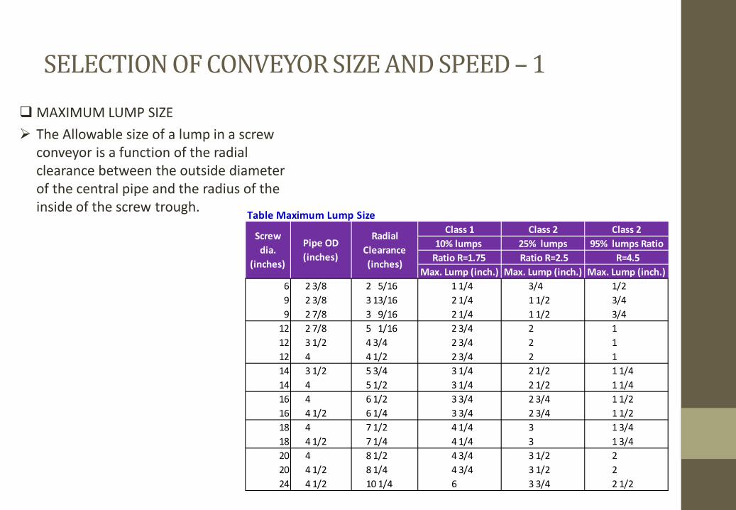
MAXIMUM LUMP SIZE
The Allowable size of a lump in a screw
conveyor is a function of the radial
clearance between the outside diameter
of the central pipe and the radius of the
inside of the screw trough.
Table Maximum Lump Size
Class 1 Class 2 Class 2
10% lumps 25% lumps 95% lumps Ratio
Ratio R=1.75 Ratio R=2.5 R=4.5
Max. Lump (inch.) Max. Lump (inch.) Max. Lump (inch.)
6 2 3/8 2 5/16 1 1/4 3/4 1/2
9 2 3/8 3 13/16 2 1/4 1 1/2 3/4
9 2 7/8 3 9/16 2 1/4 1 1/2 3/4
12 2 7/8 5 1/16 2 3/4 2 1
12 3 1/2 4 3/4 2 3/4 2 1
12 4 4 1/2 2 3/4 2 1
14 3 1/2 5 3/4 3 1/4 2 1/2 1 1/4
14 4 5 1/2 3 1/4 2 1/2 1 1/4
16 4 6 1/2 3 3/4 2 3/4 1 1/2
16 4 1/2 6 1/4 3 3/4 2 3/4 1 1/2
18 4 7 1/2 4 1/4 3 1 3/4
18 4 1/2 7 1/4 4 1/4 3 1 3/4
20 4 8 1/2 4 3/4 3 1/2 2
20 4 1/2 8 1/4 4 3/4 3 1/2 2
24 4 1/2 10 1/4 6 3 3/4 2 1/2
Radial
Clearance
(inches)
Pipe OD
(inches)
Screw
dia.
(inches)
SELECTION OF CONVEYOR SIZE AND SPEED – 1
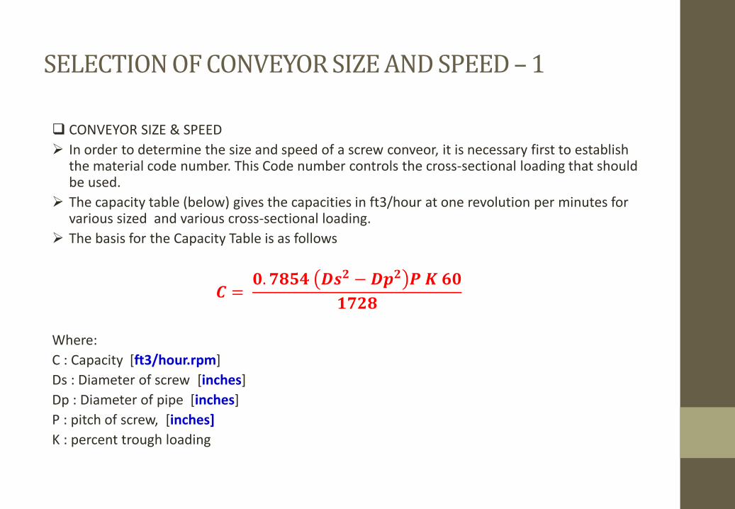
CONVEYOR SIZE & SPEED
In order to determine the size and speed of a screw conveor, it is necessary first to establish the material code number. This Code number controls the cross-sectional loading that should be used.
The capacity table (below) gives the capacities in ft3/hour at one revolution per minutes for various sized and various cross-sectional loading.
The basis for the Capacity Table is as follows
察 = 宋.挿��� 拶�匝 − 拶�匝 皿 皐 掃宋層挿匝�
Where:
C : Capacity [ft3/hour.rpm]
Ds : Diameter of screw [inches]
Dp : Diameter of pipe [inches]
P : pitch of screw, [inches]
K : percent trough loading
SELECTION OF CONVEYOR SIZE AND SPEED – 2
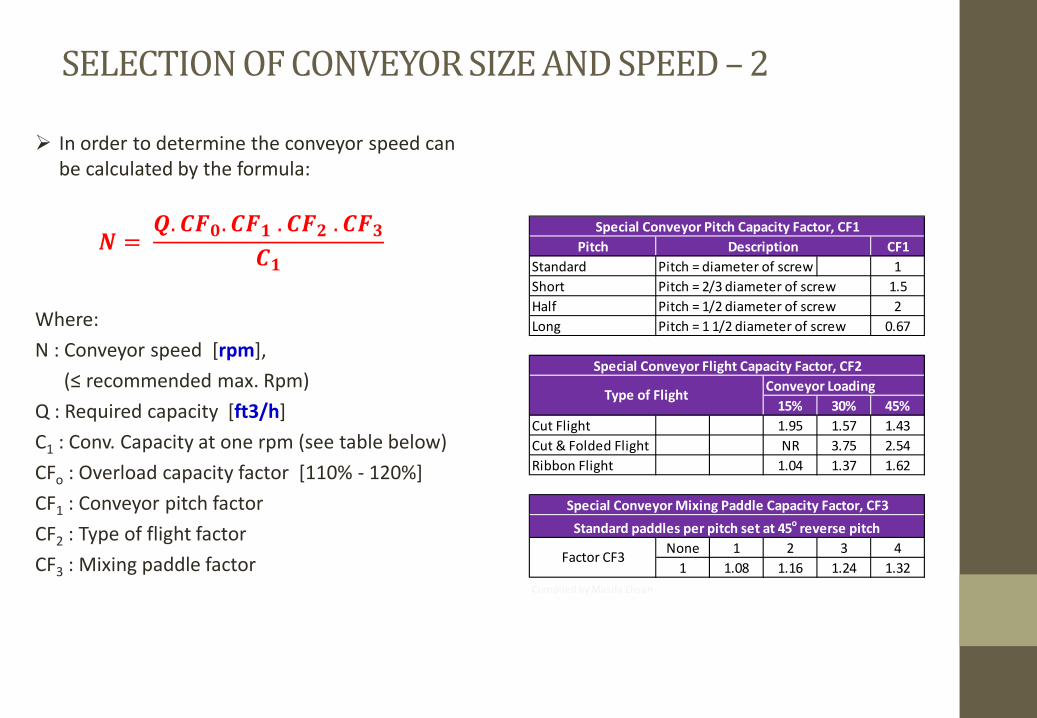
In order to determine the conveyor speed can
be calculated by the formula:
� = 晒.察�宋.察�層 .察�匝 .察�惣察層
Where:
N : Conveyor speed [rpm],
ふ≤ recoママeミded マax. Rpマぶ Q : Required capacity [ft3/h]
C1 : Conv. Capacity at one rpm (see table below)
CFo : Overload capacity factor [110% - 120%]
CF1 : Conveyor pitch factor
CF2 : Type of flight factor
CF3 : Mixing paddle factor
Pitch CF1
Standard Pitch = diameter of screw 1
Short Pitch = 2/3 diameter of screw 1.5
Half Pitch = 1/2 diameter of screw 2
Long Pitch = 1 1/2 diameter of screw 0.67
Conveyor Loading
15% 30% 45%
Cut Flight 1.95 1.57 1.43
Cut & Folded Flight NR 3.75 2.54
Ribbon Flight 1.04 1.37 1.62
None 1 2 3 4
1 1.08 1.16 1.24 1.32
Compiled by Masda Ehsan
Special Conveyor Mixing Paddle Capacity Factor, CF3
Factor CF3
Standard paddles per pitch set at 45o reverse pitch
Special Conveyor Pitch Capacity Factor, CF1
Special Conveyor Flight Capacity Factor, CF2
Type of Flight
Description
SELECTION OF CONVEYOR SIZE AND SPEED – 3
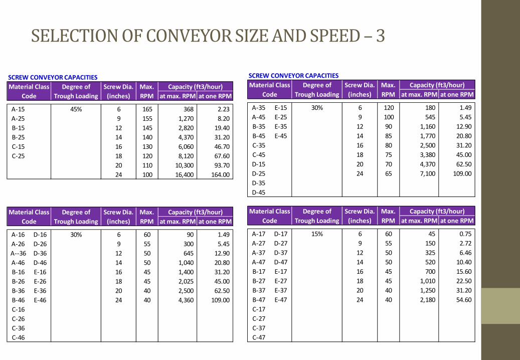
SCREW CONVEYOR CAPACITIES
at max. RPM at one RPM
A-15 45% 6 165 368 2.23
A-25 9 155 1,270 8.20
B-15 12 145 2,820 19.40
B-25 14 140 4,370 31.20
C-15 16 130 6,060 46.70
C-25 18 120 8,120 67.60
20 110 10,300 93.70
24 100 16,400 164.00
at max. RPM at one RPM
A-16 D-16 30% 6 60 90 1.49
A-26 D-26 9 55 300 5.45
A--36 D-36 12 50 645 12.90
A-46 D-46 14 50 1,040 20.80
B-16 E-16 16 45 1,400 31.20
B-26 E-26 18 45 2,025 45.00
B-36 E-36 20 40 2,500 62.50
B-46 E-46 24 40 4,360 109.00
C-16
C-26
C-36
C-46
Material Class
Code
Degree of
Trough Loading
Screw Dia.
(inches)
Max.
RPM
Capacity (ft3/hour)
Capacity (ft3/hour)Degree of
Trough Loading
Screw Dia.
(inches)
Max.
RPM
Material Class
Code
SCREW CONVEYOR CAPACITIES
at max. RPM at one RPM
A-35 E-15 30% 6 120 180 1.49
A-45 E-25 9 100 545 5.45
B-35 E-35 12 90 1,160 12.90
B-45 E-45 14 85 1,770 20.80
C-35 16 80 2,500 31.20
C-45 18 75 3,380 45.00
D-15 20 70 4,370 62.50
D-25 24 65 7,100 109.00
D-35
D-45
at max. RPM at one RPM
A-17 D-17 15% 6 60 45 0.75
A-27 D-27 9 55 150 2.72
A-37 D-37 12 50 325 6.46
A-47 D-47 14 50 520 10.40
B-17 E-17 16 45 700 15.60
B-27 E-27 18 45 1,010 22.50
B-37 E-37 20 40 1,250 31.20
B-47 E-47 24 40 2,180 54.60
C-17
C-27
C-37
C-47
Material Class
Code
Degree of
Trough Loading
Screw Dia.
(inches)
Max.
RPM
Capacity (ft3/hour)
Material Class
Code
Degree of
Trough Loading
Screw Dia.
(inches)
Max.
RPM
Capacity (ft3/hour)
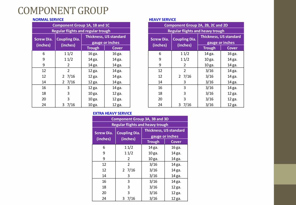
COMPONENT GROUP NORMAL SERVICE HEAVY SERVICE
Trough Cover Trough Cover
6 1 1/2 16 ga. 16 ga. 6 1 1/2 14 ga. 16 ga.
9 1 1/2 14 ga. 14 ga. 9 1 1/2 10 ga. 14 ga.
9 2 14 ga. 14 ga. 9 2 10 ga. 14 ga.
12 2 12 ga. 14 ga. 12 2 3/16 14 ga.
12 2 7/16 12 ga. 14 ga. 12 2 7/16 3/16 14 ga.
14 2 7/16 12 ga. 14 ga. 14 3 3/16 14 ga.
16 3 12 ga. 14 ga. 16 3 3/16 14 ga.
18 3 10 ga. 12 ga. 18 3 3/16 12 ga.
20 3 10 ga. 12 ga. 20 3 3/16 12 ga.
24 3 7/16 10 ga. 12 ga. 24 3 7/16 3/16 12 ga.
Component Group 2A, 2B, 2C and 2D
Regular flights and heavy trough
Screw Dia.
(inches)
Coupling Dia.
(inches)
Thickness, US standard
gauge or inches
Thickness, US standard
gauge or inchesCoupling Dia.
(inches)
Screw Dia.
(inches)
Component Group 1A, 1B and 1C
Regular flights and regular trough
EXTRA HEAVY SERVICE
Trough Cover
6 1 1/2 14 ga. 16 ga.
9 1 1/2 10 ga. 14 ga.
9 2 10 ga. 14 ga.
12 2 3/16 14 ga.
12 2 7/16 3/16 14 ga.
14 3 3/16 14 ga.
16 3 3/16 14 ga.
18 3 3/16 12 ga.
20 3 3/16 12 ga.
24 3 7/16 3/16 12 ga.
Component Group 3A, 3B and 3D
Regular flights and heavy trough
Screw Dia.
(inches)
Coupling Dia.
(inches)
Thickness, US standard
gauge or inches
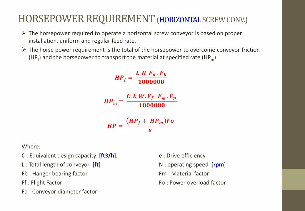
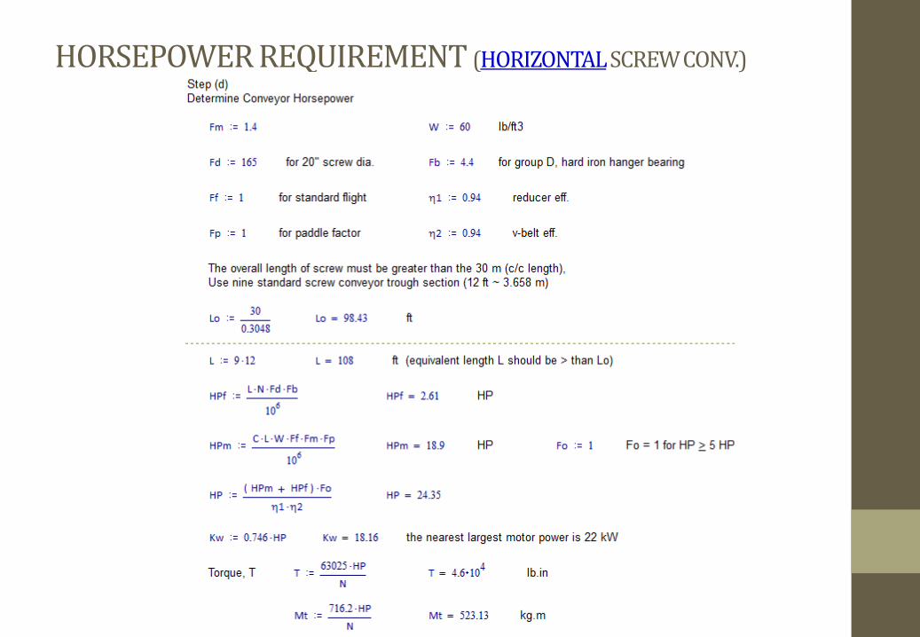
HORSEPOWER REQUIREMENT (HORIZONTAL SCREW CONV.)
The horsepower required to operate a horizontal screw conveyor is based on proper
installation, uniform and regular feed rate.
The horse power requirement is the total of the horsepower to overcome conveyor friction
(HPf) and the horsepower to transport the material at specified rate (HPm)
�皿讃 = 鯖.�.�纂 .��層宋宋宋宋宋宋
�皿� = 察. 鯖.�.�讃 .�� .�� 層宋宋宋宋宋宋
�皿 = �皿讃 + �皿� ��蚕
Where:
C : Equivalent design capacity [ft3/h], e : Drive efficiency
L : Total length of conveyor [ft] N : operating speed [rpm]
Fb : Hanger bearing factor Fm : Material factor
Ff : Flight Factor Fo : Power overload factor
Fd : Conveyor diameter factor
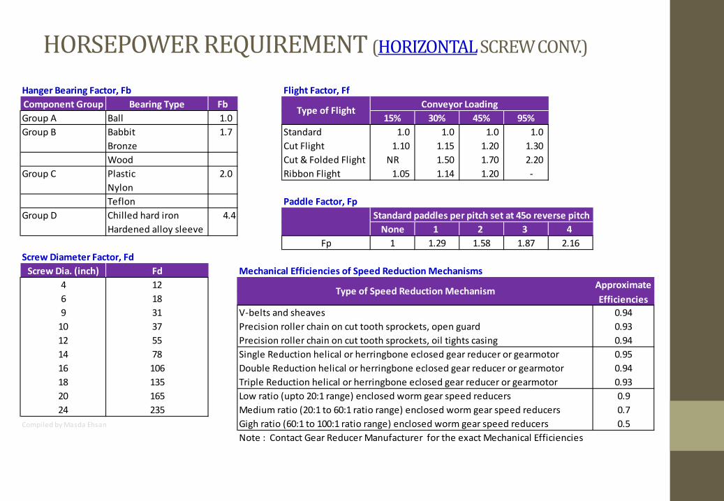
HORSEPOWER REQUIREMENT (HORIZONTAL SCREW CONV.)
Hanger Bearing Factor, Fb Flight Factor, Ff
Component Group Bearing Type Fb
Group A Ball 1.0 15% 30% 45% 95%
Group B Babbit 1.7 Standard 1.0 1.0 1.0 1.0
Bronze Cut Flight 1.10 1.15 1.20 1.30
Wood Cut & Folded Flight NR 1.50 1.70 2.20
Group C Plastic 2.0 Ribbon Flight 1.05 1.14 1.20 -
Nylon
Teflon Paddle Factor, Fp
Group D Chilled hard iron 4.4
Hardened alloy sleeve None 1 2 3 4
Fp 1 1.29 1.58 1.87 2.16
Screw Diameter Factor, Fd
Screw Dia. (inch) Fd Mechanical Efficiencies of Speed Reduction Mechanisms
4 12
6 18
9 31 V-belts and sheaves 0.94
10 37 Precision roller chain on cut tooth sprockets, open guard 0.93
12 55 Precision roller chain on cut tooth sprockets, oil tights casing 0.94
14 78 Single Reduction helical or herringbone eclosed gear reducer or gearmotor 0.95
16 106 Double Reduction helical or herringbone eclosed gear reducer or gearmotor 0.94
18 135 Triple Reduction helical or herringbone eclosed gear reducer or gearmotor 0.93
20 165 Low ratio (upto 20:1 range) enclosed worm gear speed reducers 0.9
24 235 Medium ratio (20:1 to 60:1 ratio range) enclosed worm gear speed reducers 0.7
Compiled by Masda Ehsan Gigh ratio (60:1 to 100:1 ratio range) enclosed worm gear speed reducers 0.5
Note : Contact Gear Reducer Manufacturer for the exact Mechanical Efficiencies
Type of Speed Reduction MechanismApproximate
Efficiencies
Type of FlightConveyor Loading
Standard paddles per pitch set at 45o reverse pitch
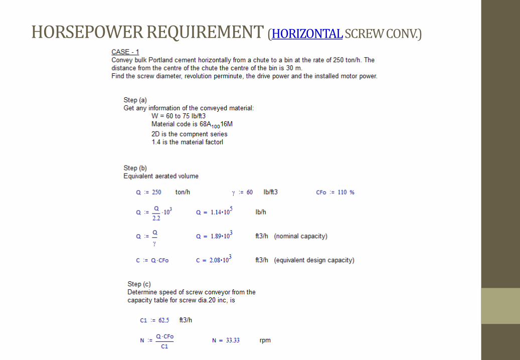
HORSEPOWER REQUIREMENT (HORIZONTAL SCREW CONV.)
HORSEPOWER REQUIREMENT (HORIZONTAL SCREW CONV.)
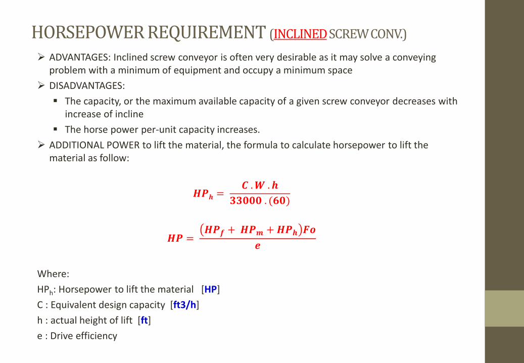
HORSEPOWER REQUIREMENT (INCLINED SCREW CONV.)
ADVANTAGES: Inclined screw conveyor is often very desirable as it may solve a conveying
problem with a minimum of equipment and occupy a minimum space
DISADVANTAGES:
The capacity, or the maximum available capacity of a given screw conveyor decreases with
increase of incline
The horse power per-unit capacity increases.
ADDITIONAL POWER to lift the material, the formula to calculate horsepower to lift the
material as follow:
�皿� = 察 .� .�惣惣宋宋宋 . (掃宋)
�皿 = �皿讃 + �皿� + �皿� ��蚕
Where:
HPh: Horsepower to lift the material [HP]
C : Equivalent design capacity [ft3/h]
h : actual height of lift [ft]
e : Drive efficiency
PROBLEMS ASSOCIATED WITH INCLINED SCREW CONVEYOR
Several things can be done to overcome many of the problems associated with inclined screw
conveyor:
Limit the use of standard screw components to inclines of less than 25o, preferably not
over 15o
Use close clearance between trough and screw
Increase the speed over that applicable for a horizontal screw conveyor of the same size
Use short pitch screws, 2/3 or ½ pitch


