Embed Size (px)
Citation preview
GASVESSEL – 723030 Compressed Natural Gas Transport System
_______________________________________________________________________________________
TECHNICAL PROPOSALS FOR THE CONSTRUCTION AND EQUIPMENT OF
LOADING AND UNLOADING MODULES
Project: GASVESSEL
Project No.: 723030
Deliverable No.: D6.1
Deliverable Name: TECHNICAL PROPOSALS FOR THE CONSTRUCTION AND EQUIPMENT OF LOADING AND UNLOADING
MODULES
WP n. 6
Document Version: 2.0
Document Preparation Date: 2019–11–29
Responsibility: PARTNER No. 9 (CENERGY)
Type of Deliverable
R Document, Report X
DEM Demonstrator, pilot, prototype
DEC Websites, patent fillings, videos, etc.
OTHER
ETHICS Ethics requirements
ORDP Open Research Data Pilot
Dissemination Level
PU Public X
CO Confidential, only for Members of the Consortium (including the EU Commission Services)
Version Management
Software used Word, GASVESSEL Simulator
Company Internal Doc. n. 180GASV–REL–050–T02A01 – Technical proposals for the construction and equipment of loading and unloading modules
Author(s) Chinese T. Malabotti S.
Reviewed by Taccani R., Capobianco M.
Approved by Project management team
Authorized by Authorized by coordinator WP6
Revision No. Date Modification description
RV A01 2019–10–31 Issued for quality check
RV A02 2019–11–29 Final Version for uploading
Ref. Ares(2019)7355843 - 29/11/2019

GASVESSEL – 723030 Compressed Natural Gas Transport System
______________________________________________________________________________________
CENERGY WP6 Deliverable No. 6.1 2/103
EC Grant Agreement No.723030
Project Acronym GASVESSEL
Project Title Compressed Natural Gas Transport System
Instrument HORIZON 2020
Programme Smart, green and integrated Transport
Start Date of Project 2017–06–01
Duration 48 months
Organisation Name of Lead Contractor for this Deliverable
Partner No 5 – VTG
Financial/Administrative Coordinator
Project Coordinator Name Mr. Loris COK
Project Coordinator Organization Name NAVALPROGETTI Srl
Address Via dei Papaveri, 21 34151 TRIESTE (Italy)
Phone Numbers 0039 040 212918,
Email [email protected] [email protected]
Project web–sites & other Access Points www.gassvessel.eu
The GASVESSEL Project has received funding from the European Union’s Horizon 2020 Research and Innovation
Programme under Grant Agreement no. 723030
GASVESSEL – 723030 Compressed Natural Gas Transport System
______________________________________________________________________________________
CENERGY WP6 Deliverable No. 6.1 3/103
Contents Index of Figures ................................................................................................................................................. 4
Index of Tables ................................................................................................................................................... 6
1 Introduction ............................................................................................................................................ 8
1.1 Alternative solutions for CNG ship transportation .................................................................. 8
1.2 Compressed natural gas ship transportation .......................................................................... 9
1.2.1 Coselle technology ................................................................................................. 10
1.2.2 VOTRANS technology ............................................................................................. 11
1.2.3 GTM technology ..................................................................................................... 12
1.2.4 PNG technology ...................................................................................................... 12
1.2.5 CRPV technology .................................................................................................... 13
1.3 State of art for CNG loading and unloading systems ............................................................. 14
1.4 Basic Requirements and Reference Scenario for Loading and Unloading System Design .... 16
2 Review of applicable Standards and Regulations ................................................................................. 18
2.1 Generalities ............................................................................................................................ 18
2.2 Considerations about Risk Assessment and Risk Management ............................................ 18
2.3 Recommendations about CARGO ROOMS and TANKS .......................................................... 20
2.4 Technical Regulations on PIPING SYSTEM and LOADING AND UNLOADING PROCESS ......... 22
2.5 Technical Regulations on COMPRESSORS AND COOLING SYSTEM........................................ 24
3 Onboard GAS Distribution System ........................................................................................................ 26
3.1 Piping Configurations for onboard Gas Distribution and Collection ..................................... 26
3.2 Valves ..................................................................................................................................... 31
3.3 Loading/offloading pipes ....................................................................................................... 36
4 Compressors .......................................................................................................................................... 39
4.1 Possible Compressing Technologies ...................................................................................... 39
4.2 Reciprocating Compressors ................................................................................................... 40
4.3 Centrifugal Compressors........................................................................................................ 40
4.4 ICL Compressors ..................................................................................................................... 40
4.5 Choice of the compressors .................................................................................................... 41
5 Compressors’ Accessories ..................................................................................................................... 45
5.1 Needs for Accessories ............................................................................................................ 45
5.2 Power system ......................................................................................................................... 45
5.2.1 Gas Turbines ........................................................................................................... 45
5.2.2 Electric Motors ....................................................................................................... 46
5.3 Heat Exchangers (Cooling technology) .................................................................................. 46
GASVESSEL – 723030 Compressed Natural Gas Transport System
______________________________________________________________________________________
CENERGY WP6 Deliverable No. 6.1 4/103
5.3.1 Sea water cooling ................................................................................................... 47
5.3.2 Air cooling ............................................................................................................... 47
5.4 Lubrification ........................................................................................................................... 48
6 Heat Exchangers .................................................................................................................................... 50
6.1 Generalities on Heat Exchangers ........................................................................................... 50
6.2 Compression Chiller choice .................................................................................................... 58
6.3 Fan coil selection for the holds .............................................................................................. 60
6.4 Auxiliaries and Dimensioning of Auxiliaries ........................................................................... 62
7 Loading and Unloading Process Description ......................................................................................... 64
7.1 Introduction to the Loading Process ...................................................................................... 64
7.2 Free loading phase ................................................................................................................. 65
7.3 Forced loading phase ............................................................................................................. 66
7.4 Introduction to the Unloading Process .................................................................................. 67
7.5 Free unloading phase ............................................................................................................. 68
7.6 Forced Unloading ................................................................................................................... 69
8 References ............................................................................................................................................. 71
Appendix A. Applicable Standards and Regulations .................................................................................. 73
Appendix B. P&ID (see joint document
“180GASV–DRW–050–T02A01 Loading and Unloading System P&Id”) ................................ 82
Appendix C. Metering Unit Datasheet ....................................................................................................... 83
Appendix D. Control Valves Datasheet ...................................................................................................... 85
Appendix E. Emergency Relief Hatches Datasheet .................................................................................... 86
Appendix F. Gate Valves Datasheet ........................................................................................................... 87
Appendix G. Valves Remote Control System Datasheet ............................................................................ 88
Appendix H. Flexible Hoses Data Sheets .................................................................................................... 90
Appendix I. PCHE Datasheet ..................................................................................................................... 91
Appendix J. Plates Heat Exchangers Datasheet ........................................................................................ 93
Appendix K. Chiller Datasheet.................................................................................................................... 97
Appendix L. Fan coils Datasheet ................................................................................................................ 98
Appendix M. Compressors Datasheets ....................................................................................................... 99
GASVESSEL – 723030 Compressed Natural Gas Transport System
______________________________________________________________________________________
CENERGY WP6 Deliverable No. 6.1 5/103
Index of Figures Figure 1.1 – Coselle general arrangement ...................................................................................................... 11
Figure 1.2 – VOLTRANS technology – ship rendering ...................................................................................... 12
Figure 1.3 – GTM Technology – ship rendering ............................................................................................... 12
Figure 1.4 – PNG technology general arrangement ........................................................................................ 13
Figure 1.5 – Mondarra gas storage facility main layout .................................................................................. 14
Figure 2.1 – FSA Methodology flowchart [4] ................................................................................................... 20
Figure 3.1 – Reference layout for GASVESSEL ................................................................................................. 26
Figure 3.2 – Main holds and front holds (tanks organized in groups of 4)...................................................... 26
Figure 3.3 – Piping system general layout ....................................................................................................... 27
Figure 3.4 – Pressure cylinder bundle layout .................................................................................................. 28
Figure 3.5 – Loading and unloading process diagram ..................................................................................... 30
Figure 3.6 – Typical pressure seal gate valve layout ....................................................................................... 34
Figure 3.7 – Typical Bonded Flexible Pipe ....................................................................................................... 36
Figure 4.1 – MAN RB28–7 Performance curves .............................................................................................. 42
Figure 4.2 – Typical layout of a MAN RB28–7 – Plant view ............................................................................. 43
Figure 4.3 – General arrangement of GASVESSEL with highlighted the position of the compressor room –
plant view ........................................................................................................................................................ 43
Figure 4.4 – General arrangement of GASVESSEL with highlighted the position of the compression room –
section view ..................................................................................................................................................... 44
Figure 5.1 – Compressor Drive consisting of Gas Turbine and Electric Starter/Helper Motor [27] ................ 45
Figure 5.2 – Compressor Drive consisting of an Adjustable Speed Drive and Synchronous Motor [27] ........ 46
Figure 5.3 – Typical layout of a direct seawater cooling system ..................................................................... 47
Figure 5.4 – Typical layout of air cooling system ............................................................................................. 47
Figure 6.1 – Cooling system diagram – Starboard ........................................................................................... 50
Figure 6.2 – Dimensions of PCHE exchangers used for heater ........................................................................ 51
Figure 6.3 – Dimensions of PCHE exchangers used for the intercooler. The same HE could be used for the
post cooler as the specifications are similar. .................................................................................................. 53
Figure 6.4 – Dimensions of the plate heat exchangers used for the Intercooler and the Post–cooler. In the
figure the stream in the intercooler only operation are shown. .................................................................... 55
Figure 6.5 – Dimensions of the plate heat exchanger used for the Intercooler and the Heater .................... 56
Figure 6.6 – Dimensions of the plates heat exchangers used for the HE15, HE16 ......................................... 60
Figure 6.7 – Fan coils layout in hold 3S (Typical) ............................................................................................. 61
Figure 7.1 – Loading process phases ............................................................................................................... 64
Figure 7.2 – Ship–Grid Connection via Flexible Hoses ..................................................................................... 64
Figure 7.3 – Free loading phase schematics .................................................................................................... 65
Figure 7.4 – Forced loading phase schematics ................................................................................................ 66
Figure 7.5 – Unloading process phases ........................................................................................................... 68
Figure 7.6 – Free unloading phase schematics ................................................................................................ 68
Figure 7.7 – Forced unloading phase schematics ............................................................................................ 69
GASVESSEL – 723030 Compressed Natural Gas Transport System
______________________________________________________________________________________
CENERGY WP6 Deliverable No. 6.1 6/103
Index of Tables Table 1.1 – State of Art of CNG ship transport technologies .......................................................................... 10
Table 1.2 – Mondarra gas storage facility main components ......................................................................... 14
Table 1.3 – Selected scenario for design and dimensioning of loading and unloading system ...................... 16
Table 1.4 – Technological Options ................................................................................................................... 16
Table 2.1 – Minimum LNG and CNG safety levels ........................................................................................... 19
Table 3.1 – CNG piping specifications ............................................................................................................. 30
Table 3.2 – Valves specifications ..................................................................................................................... 31
Table 3.3 – Typical valve materials .................................................................................................................. 33
Table 3.4 – VRC system main items specification ........................................................................................... 35
Table 3.5 – Flexible lines specifications ........................................................................................................... 37
Table 4.1 – Compressors specifications........................................................................................................... 42
Table 6.1 – PCHE heat exchanger specification (HE01, HE02)* ...................................................................... 51
Table 6.2 – Intercooler specification (HE03, HE05) ......................................................................................... 52
Table 6.3 – PCHE Post–cooler specification (HE04, HE06) .............................................................................. 53
Table 6.4 – Sea water plates heat exchangers HE07, HE09 ............................................................................ 54
Table 6.5 – Sea water plates heat exchangers HE08, HE10 ............................................................................ 55
Table 6.6 – Glycol heat exchangers specifications (HE17, HE18) .................................................................... 56
Table 6.7 – Exchangers (HE19, HE20) .............................................................................................................. 57
Table 6.8 – Lube oil exchangers HE11, HE12 ................................................................................................... 58
Table 6.9 – Chillers specifications .................................................................................................................... 59
Table 6.10 – Chiller/Heater exchangers specifications (HE15, HE16) ............................................................. 59
Table 6.11 – Fan coils specifications ................................................................................................................ 60
Table 6.12 – Expansion vessels specifications ................................................................................................. 62
Table 6.13 – Glycol/Fresh water pumps specifications ................................................................................... 62
Table 6.14 – Sea water pumps specifications.................................................................................................. 63
Table 6.15 – Chillers water pumps specifications ........................................................................................... 63
Table 6.16 – Chiller warm–side pumps specifications .................................................................................... 63
Table 6.17 – Ballast water heat capacity ......................................................................................................... 63
Table 7.1 – Free loading phase process steps ................................................................................................. 65
Table 7.2 – Forced loading phase process steps ............................................................................................. 67
Table 7.3 – Free unloading phase process steps ............................................................................................. 69
Table 7.4 – Forced unloading phase process steps ......................................................................................... 70

GASVESSEL – 723030 Compressed Natural Gas Transport System
______________________________________________________________________________________
CENERGY WP6 Deliverable No. 6.1 7/103
Foreword The present document describes the on–board loading and unloading system for compressed natural gas
(CNG) designed to serve the needs of GASVESSEL for all possible scenarios.
Chapter §1 briefly introduces the state of art of CNG ship transportation and CNG loading and unloading
systems based on the available public information as hint for the development of GASVESSEL loading and
unloading system. A review of applicable standards and regulations for the overall system and for the most
important components is introduced in Chapter §2.
The general arrangement of the on-board gas distribution system (primarily piping and valves) is analysed in
Chapter §3 while the main components of the loading and unloading system are introduced and discussed
respectively in Chapter §4 (Compressors), Chapter §5 (Compressors’ accessories) and Chapter §6 (Heat
Exchangers).
The loading and unloading philosophy and the detailed description of the processes and the sequence of
operations are introduced in Chapter §7.
We recall that piping and piping distribution as well as sizing of power system, of compressors, and of heat
exchangers have been defined in relation with the needs and the outcomes of WP5. Valves, including
Emergency Shutdown valves and Pressure Relief Valves location and specification take in consideration the
outcomes of the activity of WP8.
It is worth to note that in addition to the compressors that are necessary to reduce the time required for
loading and for unloading, a fundamental role is played by the heating and cooling systems, especially to
maximize the commercial loading capacity.
For a better understanding of the loading and unloading system design, please refer to the joint P&ID
document “180GASV–DRW–050–T02A01 Loading and Unloading System P&Id”.
GASVESSEL – 723030 Compressed Natural Gas Transport System
______________________________________________________________________________________
CENERGY WP6 Deliverable No. 6.1 8/103
1 Introduction
1.1 Alternative solutions for CNG ship transportation
The increasing demand in natural gas will involve a change in forms of transport. Transport technologies represent a fundamental part of natural gas chain and establish a reference point for the economic viability of the field development. The expansion of the gas market, linked to the increase in supplying countries and the growth of currently developing markets, give rise to the commercial development of numerous transport technologies which have so far remained relegated to the experimental or design phase. The shift towards LNG (Liquid Natural Gas) for long distance transport has already begun and a rapid increase in supply is forecasted in many geographical areas. At present, there are numerous alternatives for the transport of gas, all aiming to improve the ratio of volumetric transport capacity to associated energy content by its liquefaction or compression. Several alternatives to LNG have been evaluated:
GTL: gas–to–liquids, conversion of natural gas in easily transported hydrocarbons;
GTW: gas–to–wire, production of electricity through natural gas at the producing field and transportation by high–voltage direct current transmission lines over long distances;
CNG: compressed natural gas, a solution that avoids the cost of liquefaction;
GTS: gas–to–solid, conversion of gas into solids formed of gas hydrates for storage and transportation.
Among these technologies, the only one used commercially until 2004 was LNG, which accounts for just over 25% of the natural gas transport market. GTL is in the expansion phase, with two operational plants: one in South Africa belonging to Sasol, and one in Malaysia belonging to Shell, with a further 14 plants planned to come into operation. GTW is already in a commercial stage, but still requires technology development in order to improve efficiency. The two latter options (CNG and GTS) have been studied a lot in order to verify their potential and their economic feasibility, but there aren't solutions available on the market yet. Concerning CNG technologies the ongoing projects expect to be able to transport gas in containers at high pressures, typically 125 bar to 300 bar. This technology is interesting for those scenarios where pipelines are not feasible because of long distance, ocean topography, limited reserves, modest demand, or environmental factors, or where LNG is not economical due to its high cost of liquefaction and regasification facilities. Another interesting field of application of the CNG technology is the valorisation of the flare gas in the oil fields. Indeed, oil extraction is associated with a limited natural gas production, which often it is not economically feasible to recover and is hence burned. This is not environmentally sustainable and is increasingly being forbidden in many countries. CNG has a density which is one third of that of LNG, and the compression in gaseous phase has a high energy cost, however the plant is much simpler compared to an LNG treatment plant, since liquefaction and regasification are not required. The safety of the process, and in particular, risks associated with the storage of a flammable material at high pressure, represented a limitation to the applicability of gas transport in the form of CNG. The development of advanced engineering
GASVESSEL – 723030 Compressed Natural Gas Transport System
______________________________________________________________________________________
CENERGY WP6 Deliverable No. 6.1 9/103
technologies has allowed the transport system to become more efficient and safer: in particular, gas storage systems with a higher degree of intrinsic safety have been developed using composite materials. The threshold volume of gas reserves is relatively low for commercial viability, providing shipping costs can be kept low. The main advantages of CNG compared to LNG can be summarized as follows:
containment system operates at ambient temperature, avoiding high capital cost required for liquefaction facilities;
shorter project development time allows earlier production and greater returns on investment;
60%–85% of the CNG value chain is moveable, whereas fixed facilities represents 60% of the cost of an LNG project;
CNG can be stored indefinitely without boil–off;
5%–8% gas used during CNG transport process, compared to 15% for LNG. Concerning CNG advantages over pipelines:
lower cost over longer distances;
transport capacity can be more easily reconfigured in the event of field or consumer developments;
60%–85% of the CNG value chain is moveable. Pipelines cannot be redeployed upon reservoir depletion;
CNG projects can span deep water trenches and are unaffected by challenging sea–floor formations and conditions;
CNG projects are usually not subject to the same cross–border issues that challenge pipeline projects.
1.2 Compressed natural gas ship transportation
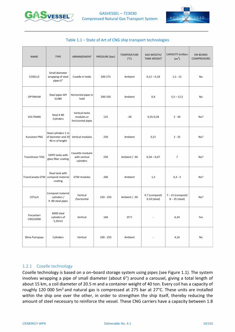
The first projects for CNG transportation by ships were developed in the late sixties. In 1968 Ocean Transport Pressure System designed a ship in which Natural Gas was stored in vertical vessels at 80 bar and 60°C. Other possible designs were conceived in the '70s at slightly higher pressures, but these projects never reached the market because of the extremely high costs of the pressurized containers. Following the development of other transport technologies (LNG), and the evolution of the oil and gas market, a new type of pressurized tank has been developed and named Coselle (from the words `coil' and `carousel'); the potential generated by this innovation has renewed interest in the marine transport of CNG. Since then various other technologies have been developed, such as EnerSea Transport's Volume Optimized TRANsport and Storage (VOTRANS), Knutsen OAS's Pressurized Natural Gas (PNG), TransCanada's Gas Transport Module (GTM) and Trans Ocean Gas's Composite Reinforced Pressure Vessel (CRPV). Table 1.1 reports the main characteristics of the ongoing projects of ship transporting compressed natural gas.
GASVESSEL – 723030 Compressed Natural Gas Transport System
______________________________________________________________________________________
CENERGY WP6 Deliverable No. 6.1 10/103
Table 1.1 – State of Art of CNG ship transport technologies
1.2.1 Coselle technology
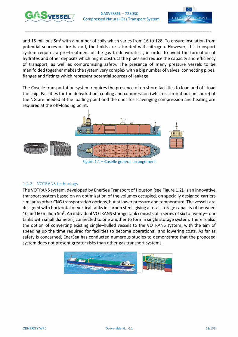
Coselle technology is based on a on–board storage system using pipes (see Figure 1.1). The system involves wrapping a pipe of small diameter (about 6") around a carousel, giving a total length of about 15 km, a coil diameter of 20.5 m and a container weight of 40 ton. Every coil has a capacity of roughly 120 000 Sm3 and natural gas is compressed at 275 bar at 27°C. These units are installed within the ship one over the other, in order to strengthen the ship itself, thereby reducing the amount of steel necessary to reinforce the vessel. These CNG carriers have a capacity between 1.8
NAME TYPE ARRANGEMENT PRESSURE (bar)TEMPERATURE
(°C)
GAS WEIGTH/
TANK WEIGHT
CAPACITY (million
Sm3)
ON BOARD
COMPRESSORS
COSELLE
Small diameter
wrapping of steal
pipes 6''
Coselle in holds 200-275 Ambient 0,12 – 0,18 1,5 - 15 No
OPTIMUMSteal pipes API
5LX80
Horizontal pipes in
hold200-250 Ambient 0,4 5,5 – 12,5 No
VOLTRANSSteal X-80
Cylinders
Vertical tanks
modules or
horizzontal pipes
125 -30 0,35-0,39 2 - 30 No?
Kunutsen PNG
Steal cylinders 1 m
of diameter and 20-
40 m of lenght
Vertical modules 250 Ambient 0,21 2 - 35 No?
TransOcean TOGHDPE tanks with
glass fiber coating
Cassette moduels
with vertical
cylinders
250 Ambient / -30 0,34 – 0,47 7 No?
TransCanada GTM
Steal tank with
composit material
coating
GTM modules 206 Ambient 1,5 0,3 - 3 No?
CETech
Composit material
cylinders /
X -80 steal pipes
Vertical
/horizontal150 - 250 Ambient / -30
0.7 (composit)
0.24 (steal)
7 – 15 (composit)
8 – 35 (steal)No?
Fincantieri
CNG32000
6000 steal
cylinders of
5,35m3
Vertical 166 25°C - 6,34 Yes
Bima Putrajaya Cylinders Vertical 100 - 250 Ambient - 4,16 No
GASVESSEL – 723030 Compressed Natural Gas Transport System
______________________________________________________________________________________
CENERGY WP6 Deliverable No. 6.1 11/103
and 15 millions Sm3 with a number of coils which varies from 16 to 128. To ensure insulation from potential sources of fire hazard, the holds are saturated with nitrogen. However, this transport system requires a pre–treatment of the gas to dehydrate it, in order to avoid the formation of hydrates and other deposits which might obstruct the pipes and reduce the capacity and efficiency of transport, as well as compromising safety. The presence of many pressure vessels to be manifolded together makes the system very complex with a big number of valves, connecting pipes, flanges and fittings which represent potential sources of leakage. The Coselle transportation system requires the presence of on shore facilities to load and off–load the ship. Facilities for the dehydration, cooling and compression (which is carried out on shore) of the NG are needed at the loading point and the ones for scavenging compression and heating are required at the off–loading point.
Figure 1.1 – Coselle general arrangement
1.2.2 VOTRANS technology
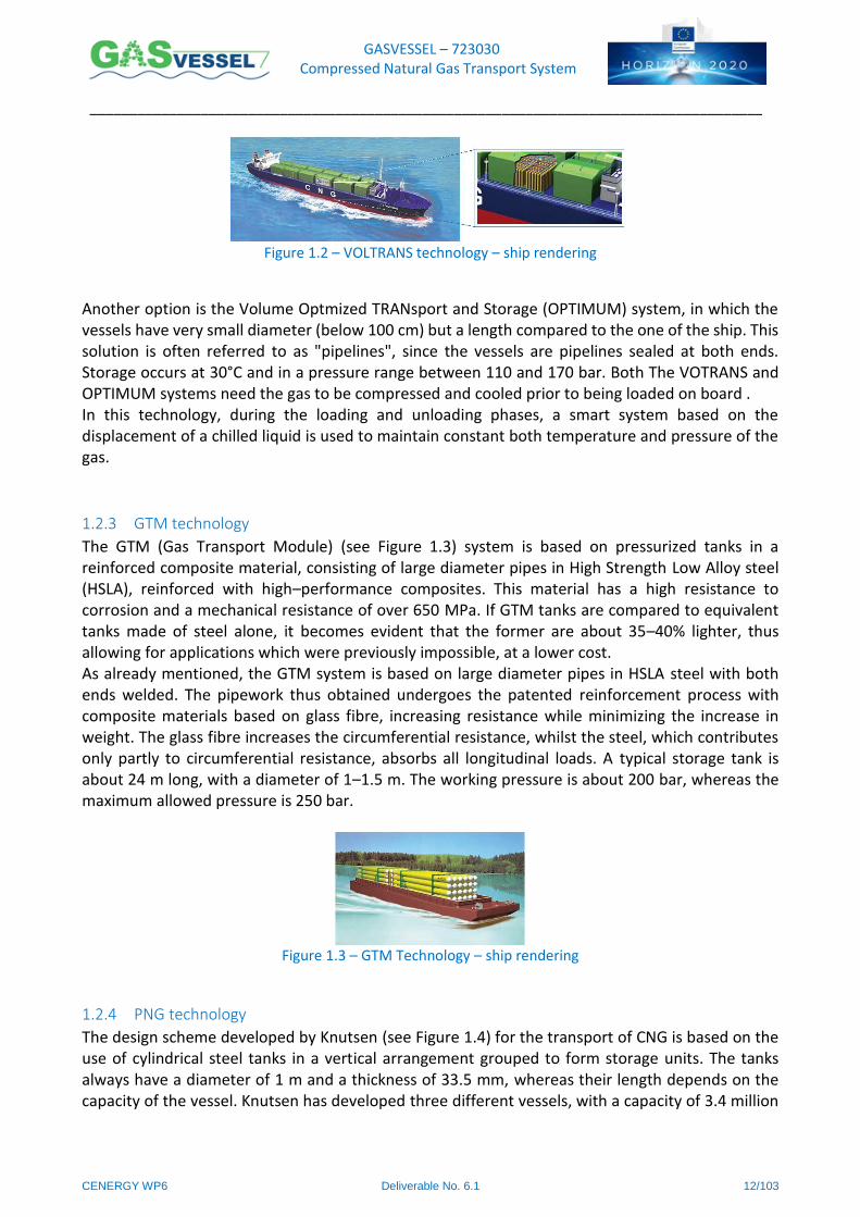
The VOTRANS system, developed by EnerSea Transport of Houston (see Figure 1.2), is an innovative transport system based on an optimization of the volumes occupied, on specially designed carriers similar to other CNG transportation options, but at lower pressure and temperature. The vessels are designed with horizontal or vertical tanks in carbon steel, giving a total storage capacity of between 10 and 60 million Sm3. An individual VOTRANS storage tank consists of a series of six to twenty–four tanks with small diameter, connected to one another to form a single storage system. There is also the option of converting existing single–hulled vessels to the VOTRANS system, with the aim of speeding up the time required for facilities to become operational, and lowering costs. As far as safety is concerned, EnerSea has conducted numerous studies to demonstrate that the proposed system does not present greater risks than other gas transport systems.
GASVESSEL – 723030 Compressed Natural Gas Transport System
______________________________________________________________________________________
CENERGY WP6 Deliverable No. 6.1 12/103
Figure 1.2 – VOLTRANS technology – ship rendering
Another option is the Volume Optmized TRANsport and Storage (OPTIMUM) system, in which the vessels have very small diameter (below 100 cm) but a length compared to the one of the ship. This solution is often referred to as "pipelines", since the vessels are pipelines sealed at both ends. Storage occurs at 30°C and in a pressure range between 110 and 170 bar. Both The VOTRANS and OPTIMUM systems need the gas to be compressed and cooled prior to being loaded on board . In this technology, during the loading and unloading phases, a smart system based on the displacement of a chilled liquid is used to maintain constant both temperature and pressure of the gas.
1.2.3 GTM technology
The GTM (Gas Transport Module) (see Figure 1.3) system is based on pressurized tanks in a reinforced composite material, consisting of large diameter pipes in High Strength Low Alloy steel (HSLA), reinforced with high–performance composites. This material has a high resistance to corrosion and a mechanical resistance of over 650 MPa. If GTM tanks are compared to equivalent tanks made of steel alone, it becomes evident that the former are about 35–40% lighter, thus allowing for applications which were previously impossible, at a lower cost. As already mentioned, the GTM system is based on large diameter pipes in HSLA steel with both ends welded. The pipework thus obtained undergoes the patented reinforcement process with composite materials based on glass fibre, increasing resistance while minimizing the increase in weight. The glass fibre increases the circumferential resistance, whilst the steel, which contributes only partly to circumferential resistance, absorbs all longitudinal loads. A typical storage tank is about 24 m long, with a diameter of 1–1.5 m. The working pressure is about 200 bar, whereas the maximum allowed pressure is 250 bar.
Figure 1.3 – GTM Technology – ship rendering
1.2.4 PNG technology
The design scheme developed by Knutsen (see Figure 1.4) for the transport of CNG is based on the use of cylindrical steel tanks in a vertical arrangement grouped to form storage units. The tanks always have a diameter of 1 m and a thickness of 33.5 mm, whereas their length depends on the capacity of the vessel. Knutsen has developed three different vessels, with a capacity of 3.4 million

GASVESSEL – 723030 Compressed Natural Gas Transport System
______________________________________________________________________________________
CENERGY WP6 Deliverable No. 6.1 13/103
Sm3, 20 million Sm3, and 30 million Sm3. The vessels contain 870, 2672 and 3900 cylinders respectively. For loading and unloading operations, the possibility of connecting through the keel of the vessel has been studied. This allows for both direct loading from subsea satellites at a depth of between 50 and 500 m, and the use of a specially designed mooring system for safe loading/offloading operations from the coast. In this context, Knutsen has developed an offloading terminal using the same storage technology as the vessel, in other words a series of vertical tanks. This type of terminal has the purpose of shortening the time required to offload the vessel, and allowing the delivery of natural gas to the network to be regulated. Knutsen claims a great simplicity in the design and operation due to the simple infrastructure requirements, operation in ambient temperature that prevent costly temperature control systems and insulations and the benefits of the all–steel design the allows an easy heat handling compared to the composite materials. This technology allows both on–shore and off–shore loading so the compression phase can be carried out both on–shore or off–shore
Figure 1.4 – PNG technology general arrangement
1.2.5 CRPV technology
Trans Ocean Gas (TOG) proposes the CRPV technology for the transport of natural gas, based on the use of tanks in a composite material grouped into modules and inserted vertically one inside the other within the vessel's hull. Tanks in a composite material (CPVs, Composite Pressure Vessels) are lighter and safer than their steel counterparts, moreover they are corrosion resistant. Each individual element has a diameter of about 1 m and a length of 12 m, and is designed to withstand a pressure of 250 bar. Trans Ocean Gas believes that it is preferable to use glass fibre rather than carbon fibre for CNG transport, with the aim of containing costs at the expense of lightness. In fact a CPV covered in glass fibre only weighs one third of a conventional steel tank, and it is thus possible to use a carrier with a larger storage capacity and higher sailing speed. The modular system developed by TOG consists of a framework containing about 18 CPVs arranged vertically and linked to one another at both ends. These modules, known as cassettes, can be arranged in several tiers depending on the size of the vessel; for example, a ship with a tonnage of 60,000 ton has two tiers of cassettes.
GASVESSEL – 723030 Compressed Natural Gas Transport System
______________________________________________________________________________________
CENERGY WP6 Deliverable No. 6.1 14/103
The transport system is completed with valve systems placed on the main deck and a conventional cooling system, used to maximize storage capacity and inhibit the formation of hydrates during the loading and offloading phases. The compression unit placed on board can be used for loading and offloading at offshore mooring terminal.
1.3 State of art for CNG loading and unloading systems
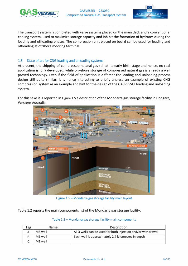
At present, the shipping of compressed natural gas still at its early birth stage and hence, no real application is fully developed, while on–shore storage of compressed natural gas is already a well proved technology. Even if the field of application is different the loading and unloading process design still quite similar, it is hence interesting to briefly analyse an example of existing CNG compression system as an example and hint for the design of the GASVESSEL loading and unloading system. For this sake it is reported in Figure 1.5 a description of the Mondarra gas storage facility in Dongara, Western Australia.
Figure 1.5 – Mondarra gas storage facility main layout
Table 1.2 reports the main components list of the Mondarra gas storage facility.
Table 1.2 – Mondarra gas storage facility main components
Tag Name Description
A M8 well All 3 wells can be used for both injection and/or withdrawal
B M6 well Each well is approximately 2.7 kilometres in depth
C M1 well

GASVESSEL – 723030 Compressed Natural Gas Transport System
______________________________________________________________________________________
CENERGY WP6 Deliverable No. 6.1 15/103
Tag Name Description
D Aerial reciprocating compressors
2x driven by Caterpillar 3612 gas engines including filtration facilities used for both injection and withdrawal. The reservoir is operated at a higher pressure than gas in pipelines.
E Raw Gas Processing (“slug catcher”) removes any free liquid that is produced in the wells during withdrawal as part of the gas stream.
F Production Cooler and Separator
gas being withdrawn from the reservoir can be up to 100°C. The production cooler cools the hot gas to pipeline temperature specification. The separator captures any liquid that is knocked out of the gas stream when it is cooled by the production cooler.
G Silica Gel Gas Conditioning Package Unit
this package dries and conditions the gas to ensure it meets pipeline specifications. Gas is streamed through the compressors and production filter before entering into either the DBNGP or PGP
H All water and impurities captured in the slug catcher and production separator are sent to the evaporation pond where disposal is via natural evaporation.
I Gas Engine Alternators gas engines that generate all the electrical power to the site.
In the Mondarra gas storage facility natural gas is stored in a reservoir able to store up to 18 petajoules of gas. The gas is stored 2,700 metres below the surface in a porous sandstone reservoir capped by an impermeable layer of shale. Gas can be held in the reservoir indefinitely without leakage or deterioration in quality. Three wells access the reservoir and, boosted by the use of two compressors, allow the injection of up to 70 terajoules or the withdrawal of up to 150 terajoules of gas per day. Associated processing equipment ensures the extracted gas meets all pipeline specifications. The facility can be expanded by tying–in additional wells, compressors and gas processing equipment.
As shown in Figure 1.5 the Dampier to Bunbury Natural Gas Pipeline (DBNGP) and APA’s Parmelia Gas Pipeline (PGP) are connected to MGSF flow in a north to south direction. Gas supply for the storage facility can only be injected from the DBNGP, however gas withdrawn from the MGSF can be sent south to Perth using either the DBNGP or PGP depending on the customer’s preference/transport arrangement.
To inject gas into the underground reservoir, the gas must be raised to a higher pressure than the reservoir pressure. This is done using the compressors that deliver the compressed gas via injection pipelines through to any of the three high pressure wellheads (A, B, C) for injection into the reservoir. Gas can be injected up to rates of 70 TJ/day (2.92 TJ/hour). Gas can be repeatedly injected and withdrawn from the storage facility and can also stay in the storage reservoir indefinitely without leakage or deterioration in quality. Gas can be withdrawn either by free flow or using the compressors at rates up to 150 TJ/day (6.25 TJ/ hour). The gas goes through a series of processing and conditioning procedures to ensure it meets pipeline specifications before being delivered into either the DBNGP or PGP for transport south to Perth.

GASVESSEL – 723030 Compressed Natural Gas Transport System
______________________________________________________________________________________
CENERGY WP6 Deliverable No. 6.1 16/103
1.4 Basic Requirements and Reference Scenario for Loading and Unloading System Design
In WP2, CHC performed the identification of different scenarios corresponding to different geographical
regions in which GASVESSEL could operate.
The definition of GASSVESSEL volume is issued by an analysis performed by Navalprogetti with the help of
the modelling tool developed by ESTECO. This study allowed the identification of the size of the ship that
could satisfy the gas volume demand for the considered scenarios. The size has been chosen in order to
minimize the gas transport tariff but keeping a reasonable size from the marine point of view, considering
accessibility to ports and manoeuvrability and cruise speed.
This analysis brought to the choice of two ships, one with capacity of about 12 millions Nm3 (commercial
volume) of gas stored at 300 bar (@40°C) in 272 tanks with a liquid volume of 155 m3 each and the other
one with a commercial volume capacity of 9 millions Nm3 of gas stored at the same conditions.
For the design and dimensioning of the loading and unloading system to be installed on board, receiving and
delivering pressures are crucial for the definition of the needs of compression and hence the identification
of the technical option for loading and unloading system. Gas composition and temperature are also two
important parameters that can influence the choice of the compression technology.
The design and dimensioning of the on–board piping system and compression station has been performed
for the 12 millions Nm3 (commercial volume) ship using a reference scenario with the conditions reported in
Table 1.3:
Table 1.3 – Selected scenario for design and dimensioning of loading and unloading system
Receiving
Pressure
Receiving
Temperature
Gas Composition Storage/Transport
Pressure
Delivery Pressure
240bar 25°C 100% Methane 335bar 80bar
Different technological options have been taken into account for the determination of the compression
system to be installed on board. In particular Table 1.4 reports the technological options analysed to best fit
the defined scenario.
Table 1.4 – Technological Options
Technology Options
Compressing Technology Reciprocating compressors
Centrifugal compressors
Reciprocating + centrifugal/ICL compressors
Powered by Electric Motor
Gas Turbine
Cooling technology Air Exchange
Sea Water Exchange
Chillers
GASVESSEL – 723030 Compressed Natural Gas Transport System
______________________________________________________________________________________
CENERGY WP6 Deliverable No. 6.1 17/103
Two main available compression technology are reciprocating compressors or centrifugal compressors.
Hybrid solutions have also been taken into account, such as parallel operation of independent centrifugal
and reciprocating compressor or ICL compressors1.
All type of compressors can be powered either by an electric motor or by a gas turbine. The choice of the
power system must be performed carefully taking into account: volume, weight, efficiency, and maintenance
issues for the two powering solutions.
Relevant pressure and temperature values are defined as follow:
Normal storage pressure pw (ISO working pressure @ 15°C) = 260 bar
Maximum allowable operating pressure pmax (ISO maximum pressure @ 65°C) = 370 bar
Relief valve set pressure = 375 bar
Design pressure p0 = 385 bar
Test Pressure ph= 1.5 x pw= 390 bar (According to ISO code)
Burst Pressure pb = 2.43 x ph = 950 bar (According to ISO code)
1 The ICL (Integrated Compressor Line) is a fully integrated compression system by BHGE, incorporating a
high speed electric motor drive and a centrifugal compressor in a single sealed casing.
GASVESSEL – 723030 Compressed Natural Gas Transport System
______________________________________________________________________________________
CENERGY WP6 Deliverable No. 6.1 18/103
2 Review of applicable Standards and Regulations
2.1 Generalities The guideline published by ABS for “VESSELS INTENDED TO CARRY COMPRESSED NATURAL GASES IN BULK”
[1] is the leading reference document in the design process of GASVESSEL project. This guide is based on the
ABS requirements for transport of Liquefied Natural Gas (LNG) defined in the: “Rule Requirements for Vessels
Intended to Carry Liquefied Gases in Bulk” (Part 5C, Chapter 8 of the ABS Rules for Building and Classing Steel
Vessels) [2].
This last document is in full agreement with the IMO IGC Code [3] but do not envisage the carriage of
Compressed Natural Gas (CNG). However, it is considered that the requirements indicated in this document
are an excellent starting point for ABS to establish requirements for the safe transport of CNG by sea.
IMO Guidelines for Formal Safety Assessment (FSA) for use in the IMO Rule–Making Process [4], should be
used as well to qualify such a novel concept. In accordance with Chapter 19 of the IGC Code, a vessel
transporting methane is required to comply with the requirements for a type 2G ship, or 2PG if of 150 meters
in length or less, as defined in 2.1.2 of the Code. Accordingly, ABS would consider the same to be applicable
for the CNG carriers [1].
2.2 Considerations about Risk Assessment and Risk Management Some of the hazards applicable to LNG carriers, such as methane vapour release, fire, explosion, toxicity,
collision and grounding, would also be applicable to CNG carriers. However, there are additional hazards or
possible increased risk from the same hazards due to the differences between LNG and CNG. In particular,
following recommendations reported in [1] the following aspects need to be taken into consideration:
possibility of critical structure being exposed to low temperatures from impingement of auto–cooled
escaping gas.
gas dispersion analysis must be carried out to demonstrate that areas normally considered gas safe
will not be engulfed during a venting or blow–down of high pressure gas or during an upset condition.
Depending on the results of the gas dispersion analysis, a vessel Emergency Shut–down system may
be required to protect against the migration of methane gas into spaces normally containing a source
of vapour ignition.
since the gas is stored at high pressure in containers in cargo holds, a rapid gas release due to
container or piping system failure could result in an overpressure condition in the cargo hold
jeopardizing the integrity of the vessel’s hull. Accordingly, overpressure protection for cargo hold
spaces should be provided. The relief devices should have sufficient capacity to handle a rupture of
the largest cargo tank, assuming rupture at any location. In addition to these relief devices, hatches
shall be provided in each hold space cover. Discharge from the hold spaces shall be routed to a safe
location.
While the IMO Gas Code includes requirements for active and passive fire protection systems
applicable for liquid methane fires, it does not envisage a high pressure (jet) fire which could result
from the ignition of a high pressure gas flow from a ruptured pipe. Accordingly, means to protect
against such an occurrence will be required to be demonstrated for CNG carriers.
ABS will require specific qualitative and quantitative risk assessments as well as consequence studies to be
conducted in order to obtain class approval. Specifically, the submitted risk assessment plan must as a
minimum contain the following studies: Hazard Identification (HAZID), Containment and Cargo Handling
GASVESSEL – 723030 Compressed Natural Gas Transport System
______________________________________________________________________________________
CENERGY WP6 Deliverable No. 6.1 19/103
System Hazard and Operability Study (HAZOP) and Quantitative Risk Assessment (QRA) of CNG Carrier Critical
Systems
As a minimum, ABS requires the following consequence modelling related to the containment, loading and
discharging systems [1]:
Gas dispersion – Of particular interest are the dispersion characteristics and the potential for
explosive fuel air mixtures covering both “normal” and inadvertent release scenarios.
Smoke and gas ingress – Of particular interest is the potential impact on accommodations or other
normally–manned spaces.
Explosions (fragmentation and overpressure effects, as applicable).
Jet fires – Particular focus should be placed on flame impingement on containment system
components and ship structure which may result in escalation as applicable.
Thermal radiation effects – Of particular interest is the potential impact on normally–manned spaces,
such as the accommodations, emergency routes and muster areas, as well as the potential impact
on adjacent gas–retaining components and tank and structure which may result in escalation.
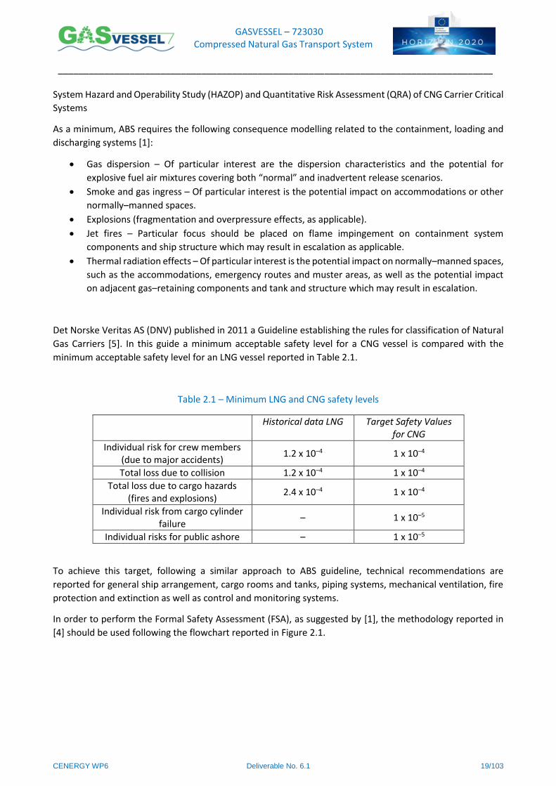
Det Norske Veritas AS (DNV) published in 2011 a Guideline establishing the rules for classification of Natural
Gas Carriers [5]. In this guide a minimum acceptable safety level for a CNG vessel is compared with the
minimum acceptable safety level for an LNG vessel reported in Table 2.1.
Table 2.1 – Minimum LNG and CNG safety levels
Historical data LNG Target Safety Values for CNG
Individual risk for crew members (due to major accidents)
1.2 x 10⁻⁴ 1 x 10⁻⁴
Total loss due to collision 1.2 x 10⁻⁴ 1 x 10⁻⁴
Total loss due to cargo hazards (fires and explosions)
2.4 x 10⁻⁴ 1 x 10⁻⁴
Individual risk from cargo cylinder failure
– 1 x 10⁻⁵
Individual risks for public ashore – 1 x 10⁻⁵
To achieve this target, following a similar approach to ABS guideline, technical recommendations are
reported for general ship arrangement, cargo rooms and tanks, piping systems, mechanical ventilation, fire
protection and extinction as well as control and monitoring systems.
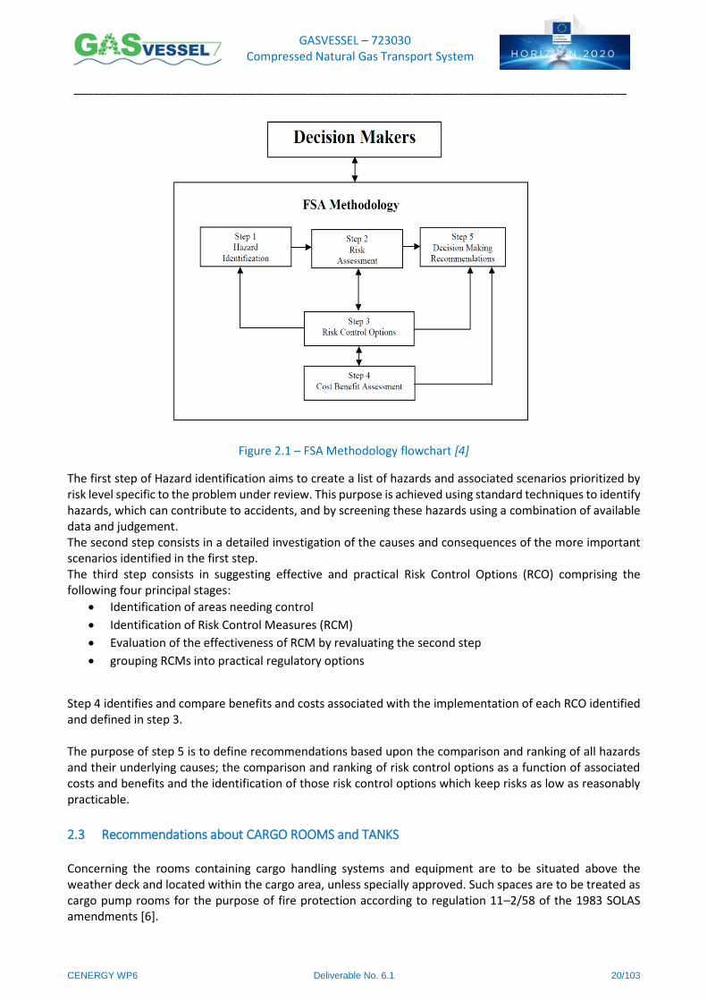
In order to perform the Formal Safety Assessment (FSA), as suggested by [1], the methodology reported in
[4] should be used following the flowchart reported in Figure 2.1.
GASVESSEL – 723030 Compressed Natural Gas Transport System
______________________________________________________________________________________
CENERGY WP6 Deliverable No. 6.1 20/103
Figure 2.1 – FSA Methodology flowchart [4]
The first step of Hazard identification aims to create a list of hazards and associated scenarios prioritized by risk level specific to the problem under review. This purpose is achieved using standard techniques to identify hazards, which can contribute to accidents, and by screening these hazards using a combination of available data and judgement. The second step consists in a detailed investigation of the causes and consequences of the more important scenarios identified in the first step. The third step consists in suggesting effective and practical Risk Control Options (RCO) comprising the following four principal stages:
Identification of areas needing control
Identification of Risk Control Measures (RCM)
Evaluation of the effectiveness of RCM by revaluating the second step
grouping RCMs into practical regulatory options
Step 4 identifies and compare benefits and costs associated with the implementation of each RCO identified and defined in step 3. The purpose of step 5 is to define recommendations based upon the comparison and ranking of all hazards and their underlying causes; the comparison and ranking of risk control options as a function of associated costs and benefits and the identification of those risk control options which keep risks as low as reasonably practicable.
2.3 Recommendations about CARGO ROOMS and TANKS Concerning the rooms containing cargo handling systems and equipment are to be situated above the weather deck and located within the cargo area, unless specially approved. Such spaces are to be treated as cargo pump rooms for the purpose of fire protection according to regulation 11–2/58 of the 1983 SOLAS amendments [6].
GASVESSEL – 723030 Compressed Natural Gas Transport System
______________________________________________________________________________________
CENERGY WP6 Deliverable No. 6.1 21/103
Cargo and fuel gas handling equipment is to be located in the process area. Any enclosed space in the process
area handling cargo gas is to be treated as a cargo pump rooms for the purpose of fire protection according
to regulation 11–2/58 of the 1983 SOLAS amendments [6].
All valves necessary for cargo handling are to be readily accessible to personnel wearing protective clothing.
Suitable arrangements are to be made to deal with gas freeing of such spaces.
If CNG is carried at a temperature below –10°C, suitable insulation, as detailed in Chapter 5, Section 9, is to
be provided to ensure that the temperature of the hull structure does not fall below the minimum allowable
design temperature as given in the ABS Rules for Materials and Welding
The requirements for process pressure vessels are to meet recognized pressure vessel codes and the ABS
Rules for Building and Classing Facilities on Offshore Installations [7].
This Division 3 of Section VIII of the ASME – “Boiler and Pressure Vessel Code” [8] provides requirements
applicable to the design, fabrication, inspection, testing, and certification of pressure vessels operating at
either internal or external pressures generally above 10,000 psi.
Emergency blowdown for each cargo tank is required and is to be designed in accordance with the
requirements of the ABS Rules for Building and Classing Facilities on Offshore Installations [7].
Vent and relief headers and their capacity for each cargo tank are to be determined in accordance with the
requirements of the ABS Rules for Building and Classing Facilities on Offshore Installations [7] and Chapter 9
of the “Vessel Intended to Carry Compressed Natural Gases in Bulk” guide [1].
For cargo tanks, all connections, except safety relief valves and liquid level gauging devices, must be equipped
with a manually operated stop valve and a remotely controlled emergency shutdown valve.
One remotely operated emergency shutdown valve is to be provided at each cargo transfer manifold
connection.
Total volume of cargo carried on the CNG carrier should be subdivided in an appropriate number of individual
cargo tanks within cargo holds. Each cargo hold is to be separated as required in Chapter 4 of “Vessel Intended
to Carry Compressed Natural Gases in Bulk” guide [1].
Each cargo tank should be provided with an independent relieving system connected to an appropriate relief
header.
No cargo communication is allowed between holds in normal and emergency situations.
Each cargo tank is to be fitted with at least two pressure relief valves of approximately equal capacity, suitably
designed and constructed for the prescribed service.
Each cargo tank must be provided with a piping system allowing safely gas–freeing and safely purging.
Each pressure relief valve installed on a cargo tank is to be connected to a venting system, which is to be built
in such a wat that the discharge of gas will be directed upwards and arranged to minimize the possibility of
water or snow entering the vent system. The height of vent exits is to be not less than the maximum between
B/3 and 6 m, above the weather deck and 6 m above the working area and the fore–and–aft gangway.
GASVESSEL – 723030 Compressed Natural Gas Transport System
______________________________________________________________________________________
CENERGY WP6 Deliverable No. 6.1 22/103
2.4 Technical Regulations on PIPING SYSTEM and LOADING AND UNLOADING PROCESS Piping may be arranged to permit Bow, Stern and Turret (Internal/External) loading and unloading.
Cargo piping and related piping equipment outside the cargo area must have only welded connections. The
piping outside the cargo area must run on the open deck and must be set at least 760 mm inboard, except
for athwart ships shore connection piping. Such piping is to be clearly identified and fitted with a shutoff
valve at its connection to the cargo piping system within the cargo area. At this location, it is also to be
capable of being separated by means of a removable spool piece and blank flanges when not in use.
Piping system must be allowed to be purged and gas–freed after use. When not in use, the spool pieces are
to be removed and the pipe ends be blank–flanged. The vent pipes connected with the purge are to be
located in the cargo area.
In order to protect the piping, the piping system components and the cargo tanks from excessive stresses
due to thermal movement and from movements of the cargo tank and hull structure, designer must provide
offsets, loops, bends and mechanical expansion joints or similar suitable means of protection.
Low–temperature piping is to be thermally isolated from the adjacent hull structure, where necessary, to
prevent the temperature of the hull from falling below the design temperature of the hull material.
Where cargo tanks or piping are separated from the ship’s structure by thermal isolation, electrically bonding
must be guaranteed for both the piping and the cargo tanks. All gasketed pipe joints and other nonconductive
connections are to be electrically bonded.
All piping or components that are pressurized with cargo and may be isolated must be provided with relief
valves. Relief valves must be able to discharge the cargo from the piping system into the cargo vent system.
Temperature of the gas in the pipes must be carefully studied, indeed, the use of flanged joints at either high
or low temperatures shall take into consideration the risk of joint leakage due to forces and moments
developed in the connected piping or equipment. At temperatures above 200°C for class 150 and above 400
°C for other classes designations, flanged joints may develop leakage problems unless care is taken to avoid
imposing severe external loads, severe thermal gradients, or both [9]. Some materials, in particular some
carbon steels, may undergo a decrease in ductility when used at low temperatures to such an extent as to be
unable to safely resist shock loading, sudden changes of stress, or high stress concentration. For temperature
below −29°C impact testing for applications is required. Pressure–Temperature rating as well as Material
specification are reported in [9].
The wall thickness of pipes must be greater than [1]:
𝑡 = 𝑡0 + 𝑏 + 𝑐
1 −𝑎
100
𝑚𝑚
Where:
to = theoretical thickness = PD/(20 Ke + P) mm
P = design pressure, in bar, (maximum gauge pressure to which the system may be subjected in service)
D = outside diameter, in mm K = allowable stress, in N/mm2
e = efficiency factor
GASVESSEL – 723030 Compressed Natural Gas Transport System
______________________________________________________________________________________
CENERGY WP6 Deliverable No. 6.1 23/103
b = allowance for bending, in mm. = 𝐷𝑡0
2.5𝑟 𝑚𝑚
r = mean radius of the bend, in mm
c = corrosion allowance, in mm
a = negative manufacturing tolerance for thickness, %.
An appropriate corrosion allowance thickness of the pipes must be used in the design. If a design is accepted
with no additional thickness margin for corrosion, a suitable and acceptable means of thickness monitoring
is to be provided to confirm that there is no corrosion during the service life of the CNG carrier. The design
of any piping system where corrosion inhibition is expected to be utilized should consider the installation of
additional wall thickness in piping design and/or reduction of velocity to reduce the effect of stripping
inhibitor film from the pipe wall. In such systems it is suggested that a wall thickness monitoring method be
instituted [10]
The piping is to be full penetration butt welded and fully radiographed, regardless of pipe diameter and
design temperature. Butt welds are to be either double–welded or equivalent to a double–welded butt joint.
Flange connections in the piping are only permitted within the cargo area and at the shore connection.
Flexible pipes used in transfer operations offshore with buoys must follow the requirements of the ABS Rules
for Building and Classing Facilities on Offshore Installations [7].
Pipes must be subjected to stress analysis when: operating at high temperatures or low temperatures,
connected to sensitive equipment, subject to vibration due to internal forces, connected to pressure relief
valves and rupture discs, along the derrick and the flare tower, affected by movement of connecting
equipment or by structural deflection, long vertical lines (>20m), Lines 3" NPS and larger with wall thickness
in excess of 10% of outside diameter, thin walled piping of 20" NPS and larger with wall thickness less than
1% of the outside diameter [11].
In lines where pressure drop does not have a cost penalty, gas velocity shall not exceed limits which may
create noise or vibrations problems. As a rule of thumb the velocity should be kept below [12]:
𝑉 = 175 (1
𝜌)
0.43 or 60 m/s, whichever is lowest.
API 14E RP [10] define the method to calculate the flow velocity:
𝑉 = 60𝑍𝑄𝑔𝑇
𝑑𝑖2𝑃
Where:
V = gas velocity (feet/second)
di = inner pipe diameter (inches)
Qg = Flow rate (million cubic feet/day at 14.7 psia and 60°F)
T = operating temperature (°R Ranking)
P = operating pressure (psia)
Z = gas compressibility factor
GASVESSEL – 723030 Compressed Natural Gas Transport System
______________________________________________________________________________________
CENERGY WP6 Deliverable No. 6.1 24/103
Pressure drops inside the pipe, can be calculated through Weymouth Equation, Panhandle Equation or
Spitzglass Equation [10] depending on the pipe geometry, the operating pressure and Reynolds number of
the gas flow.
Material Specification List, Pressure–Temperature ratings and minimum wall thickness for valves and flanges
are reported in [13]. Valve sizing and design criteria are specified in [14].
Piping manufacturing process, material definition and welding criteria are reported in ASME B31.8 [15] and
in API 5L [16], while ASME B31.8s [17] gives an integrity management plan to allow correct long term
operation of piping distribution systems. Mitigation activities identified in this standard refers to three main
categories of threats: time dependent, stable and time–independent.
Time dependent typical threats are: internal and external corrosion, stress corrosion and cracking. Stable
threats are typically: defects of construction of the piping system and defects on the welding, while time–
independent threats are mechanical damage, incorrect operational procedure, whether related damage.
Welding process of piping system must follow prescription of API 1104 [18] which presents methods for the
production of high–quality welds through the use of qualified welders using approved welding procedures,
materials, and equipment.
Concerning the requirements and guidelines for pressure reliving and depressuring systems, ATI 521 [19] lists
the principal causes of overpressure, determines individual relieving rates and gives guidelines for selecting
and designing disposal systems, including such component parts as piping, vessels, flares, and vent stacks.
When CNG carrier loading and unloading operation is performed offshore using SPM or Turret, appropriate
dynamic loads are to be determined for the duration of this operation using the ABS Rules for Building and
Classing Single Point Moorings or ABS Rules for Building and Classing Offshore Installations.
Suitable means must be provided to relieve the pressure from cargo loading and discharging headers and
other cargo pressurized lines to the suitable location before disconnecting from the loading or offloading
facility.
2.5 Technical Regulations on COMPRESSORS AND COOLING SYSTEM Natural gas compressors can be divided in two main categories: reciprocating and centrifugal compressors.
Reciprocating compressors must undergo to ISO 13707 [20], ISO 13631 [21] and API 618 [22] standards, while
centrifugal compressors must respect prescriptions of API 617 [23], API 619 [24], API 672 [25].
In these standards, basic design requirements, material characteristics, dimensioning of rotating elements or
compressor cylinders, as well as rod and gas loads, critical speeds and all accessorises technical characteristics
for minimum safety requirements are reported.
The standard API 673 [26], covers centrifugal fans that can be used for the air cooling system of the
compressor, engine or engine room.
The refrigeration system must consist of one or more units able to maintain the required cargo
pressure/temperature under conditions of the upper ambient design temperatures [1]. A stand–by unit
consisting in a compressor with its driving motor, a control system and any necessary fittings to allow
independent operation must be provided. A stand–by heat exchanger must be provided as well, unless the
normal heat exchanger for the unit has an excess capacity of at least 25% of the largest required capacity.

GASVESSEL – 723030 Compressed Natural Gas Transport System
______________________________________________________________________________________
CENERGY WP6 Deliverable No. 6.1 25/103
If water cooling is required in the refrigeration systems, an adequate supply must be provided by a pump or
pumps used exclusively for this purpose. These pumps must have at least two sea suction lines, where
practicable, leading from sea–chests, one port and one starboard.
In the vent piping system, means for draining liquid from places where it may accumulate must be provided.
The pressure relief valves and piping must to be arranged in such a way that liquid cannot accumulate in or
near the pressure relief valves.
Cargo compressors are to be arranged to shut down automatically if the emergency shutdown valves occur
to be closed.

GASVESSEL – 723030 Compressed Natural Gas Transport System
______________________________________________________________________________________
CENERGY WP6 Deliverable No. 6.1 26/103
3 Onboard GAS Distribution System
3.1 Piping Configurations for onboard Gas Distribution and Collection Building upon the configuration defined by NAVALPROGETTI for the vessels (Figure 3.1, Figure 3.2), the
compressor room and the landing area, the assessment of the piping configurations has been undertaken
applying the following priorities:
Minimising length and weight of the piping system
Minimising number of connection/welding in large diameter pipes
Avoid implementing bellows or omegas in large pipes
Maximise symmetry of the system to allow uniform velocity in pipes
Figure 3.1 – Reference layout for GASVESSEL
Figure 3.2 – Main holds and front holds (tanks organized in groups of 4)
GASVESSEL – 723030 Compressed Natural Gas Transport System
______________________________________________________________________________________
CENERGY WP6 Deliverable No. 6.1 27/103
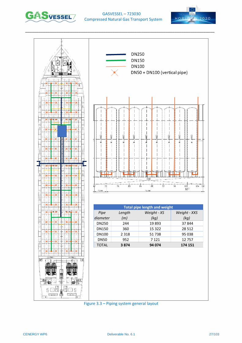
Figure 3.3 – Piping system general layout
Length Weight - XS Weight - XXS
(m) (kg) (kg)
DN250 244 19 893 37 844
DN150 360 15 322 28 512
DN100 2 318 51 738 95 038
DN50 952 7 121 12 757
TOTAL 3 874 94 074 174 151
Pipe
diameter
Total pipe length and weight
GASVESSEL – 723030 Compressed Natural Gas Transport System
______________________________________________________________________________________
CENERGY WP6 Deliverable No. 6.1 28/103
The sizing and connections choice for the pipelines has been performed following the ASME B16.5 and Norsok
P–002 standards.
Minimum pipe diameters are defined from the estimation of the speed limits.
In lines where pressure drop does not have a cost penalty, gas velocity shall not exceed limits which may
create noise or vibrations problems. As a rule of thumb the velocity should be kept below [12]:
𝑉 = 175 (1
𝜌)
0.43 or 60 m/s, whichever is lowest.
The suggested configuration consists in two main DN250 lines one at bow and one at stern. From these
main pipelines, eight DN150 lines enter the eight holds and reaches the bundles of four
vessels that constitute the cargo tank. From here a DN100 line goes down to the bottom of
the vessels and it branches off in four DN50 lines that reaches the four vessel inlets. (see
Figure 3.3).
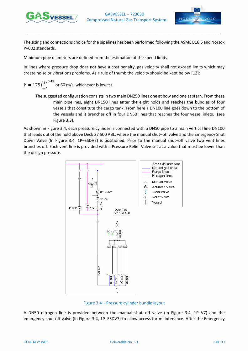
As shown in Figure 3.4, each pressure cylinder is connected with a DN50 pipe to a main vertical line DN100
that leads out of the hold above Deck 27 500 ABL, where the manual shut–off valve and the Emergency Shut
Down Valve (In Figure 3.4, 1P–ESDV7) is positioned. Prior to the manual shut–off valve two vent lines
branches off. Each vent line is provided with a Pressure Relief Valve set at a value that must be lower than
the design pressure.
Figure 3.4 – Pressure cylinder bundle layout
A DN50 nitrogen line is provided between the manual shut–off valve (In Figure 3.4, 1P–V7) and the
emergency shut off valve (In Figure 3.4, 1P–ESDV7) to allow access for maintenance. After the Emergency
GASVESSEL – 723030 Compressed Natural Gas Transport System
______________________________________________________________________________________
CENERGY WP6 Deliverable No. 6.1 29/103
Shut Down Valve the DN100 pipe of each cargo tank connects into a DN150 line for each cargo hold, where
a manual shut–off valve is set. The eight DN150 lines connect to a main DN250 line that leads to compressor
room and to the manifolds.
All the cargo deck piping and valves are positioned above the cargo holds dome, in a central position.
All the CNG pipes and valves are butt–welded without flange connections with exception to the piping system
of the compressors room.
The cargo holds are protected from the overpressure due to high inert gas pressure, accidental release of
cargo in hold due to containment failure, variation in ambient pressure and temperature, etc. thanks to
pressure relief valves set at 0.2 bar allow the overpressure protection in case of CNG leakage in the cargo
holds. These valves blow directly to a dedicated venting line. In addition, suitable relief hatches set at 0.2 bar
protect the cargo holds and the piping area structures venting directly to the atmosphere. Hold spaces will
be provided with a proper drainage system separated from drainage of the machinery and steering area
above Deck at 9000 ABL. Means for detecting leakage of water into the hold space shall be provided. Piping
systems common to multiple cargo holds are arranged so that release of gas from one hold space shall not
leak into other hold spaces.
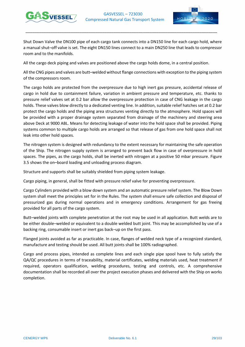
The nitrogen system is designed with redundancy to the extent necessary for maintaining the safe operation
of the Ship. The nitrogen supply system is arranged to prevent back flow in case of overpressure in hold
spaces. The pipes, as the cargo holds, shall be inerted with nitrogen at a positive 50 mbar pressure. Figure
3.5 shows the on–board loading and unloading process diagram.
Structure and supports shall be suitably shielded from piping system leakage.
Cargo piping, in general, shall be fitted with pressure relief valve for preventing overpressure.
Cargo Cylinders provided with a blow down system and an automatic pressure relief system. The Blow Down
system shall meet the principles set for in the Rules. The system shall ensure safe collection and disposal of
pressurized gas during normal operations and in emergency conditions. Arrangement for gas freeing
provided for all parts of the cargo system.
Butt–welded joints with complete penetration at the root may be used in all application. Butt welds are to
be either double–welded or equivalent to a double welded butt joint. This may be accomplished by use of a
backing ring, consumable insert or inert gas back–up on the first pass.
Flanged joints avoided as far as practicable. In case, flanges of welded neck type of a recognized standard,
manufacture and testing should be used. All butt joints shall be 100% radiographed.
Cargo and process pipes, intended as complete lines and each single pipe spool have to fully satisfy the
QA/QC procedures in terms of traceability, material certificates, welding materials used, heat treatment if
required, operators qualification, welding procedures, testing and controls, etc. A comprehensive
documentation shall be recorded all over the project execution phases and delivered with the Ship on works
completion.
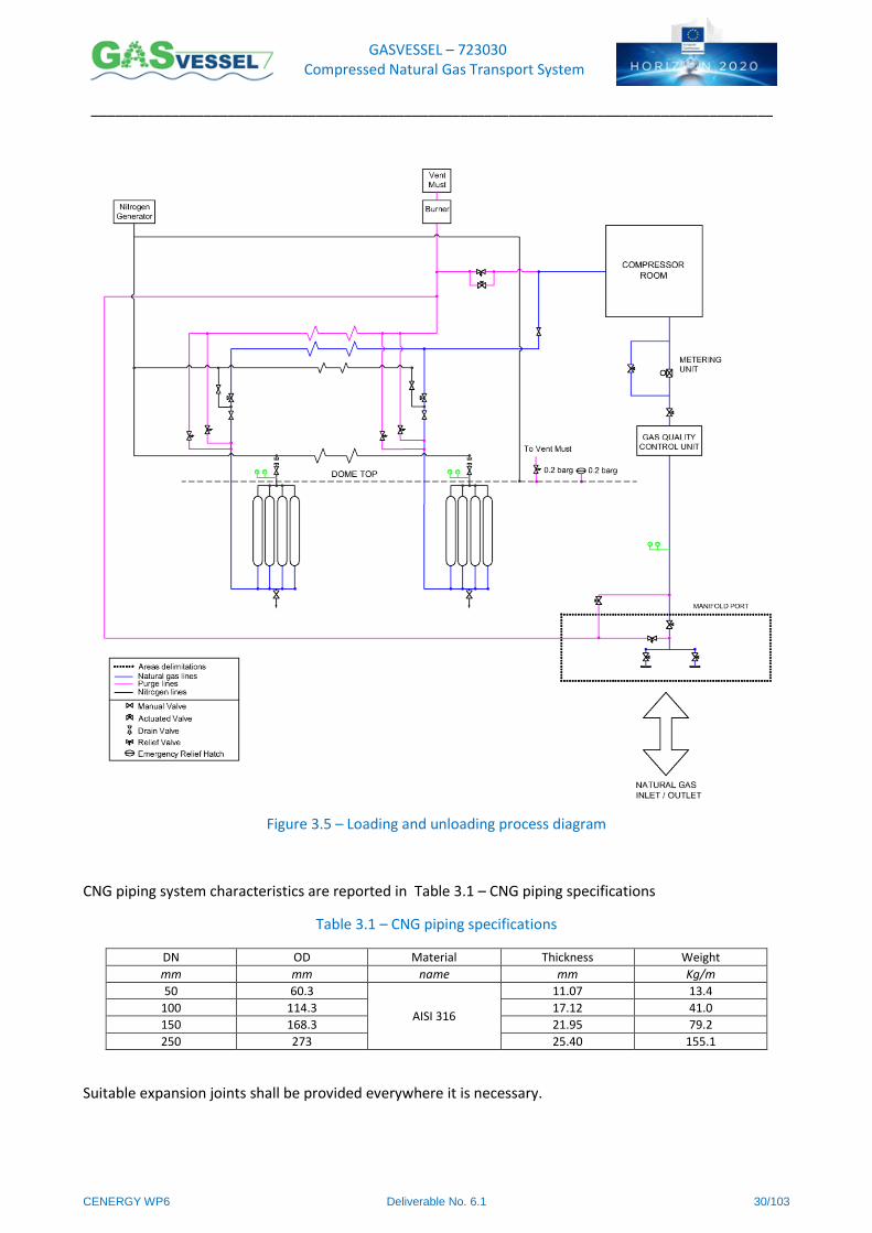
GASVESSEL – 723030 Compressed Natural Gas Transport System
______________________________________________________________________________________
CENERGY WP6 Deliverable No. 6.1 30/103
Figure 3.5 – Loading and unloading process diagram
CNG piping system characteristics are reported in Table 3.1 – CNG piping specifications
Table 3.1 – CNG piping specifications
DN OD Material Thickness Weight
mm mm name mm Kg/m
50 60.3
AISI 316
11.07 13.4
100 114.3 17.12 41.0
150 168.3 21.95 79.2
250 273 25.40 155.1
Suitable expansion joints shall be provided everywhere it is necessary.
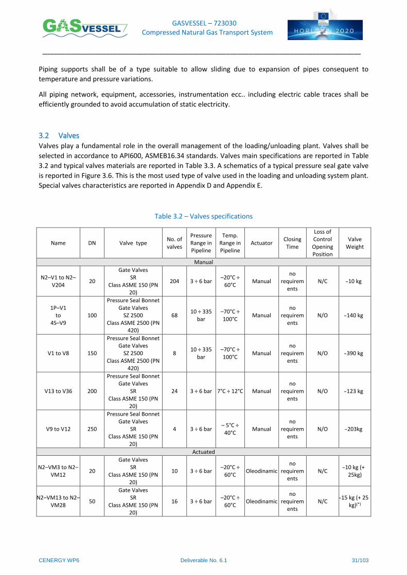
GASVESSEL – 723030 Compressed Natural Gas Transport System
______________________________________________________________________________________
CENERGY WP6 Deliverable No. 6.1 31/103
Piping supports shall be of a type suitable to allow sliding due to expansion of pipes consequent to
temperature and pressure variations.
All piping network, equipment, accessories, instrumentation ecc.. including electric cable traces shall be
efficiently grounded to avoid accumulation of static electricity.
3.2 Valves Valves play a fundamental role in the overall management of the loading/unloading plant. Valves shall be
selected in accordance to API600, ASMEB16.34 standards. Valves main specifications are reported in Table
3.2 and typical valves materials are reported in Table 3.3. A schematics of a typical pressure seal gate valve
is reported in Figure 3.6. This is the most used type of valve used in the loading and unloading system plant.
Special valves characteristics are reported in Appendix D and Appendix E.
Table 3.2 – Valves specifications
Name DN Valve type No. of valves
Pressure Range in Pipeline
Temp. Range in Pipeline
Actuator Closing Time
Loss of Control Opening Position
Valve Weight
Manual
N2–V1 to N2–V204
20
Gate Valves SR
Class ASME 150 (PN 20)
204 3 ÷ 6 bar –20°C ÷
60°C Manual
no requirem
ents N/C 10 kg
1P–V1 to
4S–V9 100
Pressure Seal Bonnet Gate Valves
SZ 2500 Class ASME 2500 (PN
420)
68 10 ÷ 335
bar –70°C ÷ 100°C
Manual no
requirements
N/O 140 kg
V1 to V8 150
Pressure Seal Bonnet Gate Valves
SZ 2500 Class ASME 2500 (PN
420)
8 10 ÷ 335
bar –70°C ÷ 100°C
Manual no
requirements
N/O 390 kg
V13 to V36 200
Pressure Seal Bonnet Gate Valves
SR Class ASME 150 (PN
20)
24 3 ÷ 6 bar 7°C ÷ 12°C Manual no
requirements
N/O 123 kg
V9 to V12 250
Pressure Seal Bonnet Gate Valves
SR Class ASME 150 (PN
20)
4 3 ÷ 6 bar – 5°C ÷
40°C Manual
no requirem
ents N/O 203kg
Actuated
N2–VM3 to N2–VM12
20
Gate Valves SR
Class ASME 150 (PN 20)
10 3 ÷ 6 bar –20°C ÷
60°C Oleodinamic
no requirem
ents N/C
10 kg (+ 25kg)
N2–VM13 to N2–VM28
50
Gate Valves SR
Class ASME 150 (PN 20)
16 3 ÷ 6 bar –20°C ÷
60°C Oleodinamic
no requirem
ents N/C
15 kg (+ 25 kg)(*)
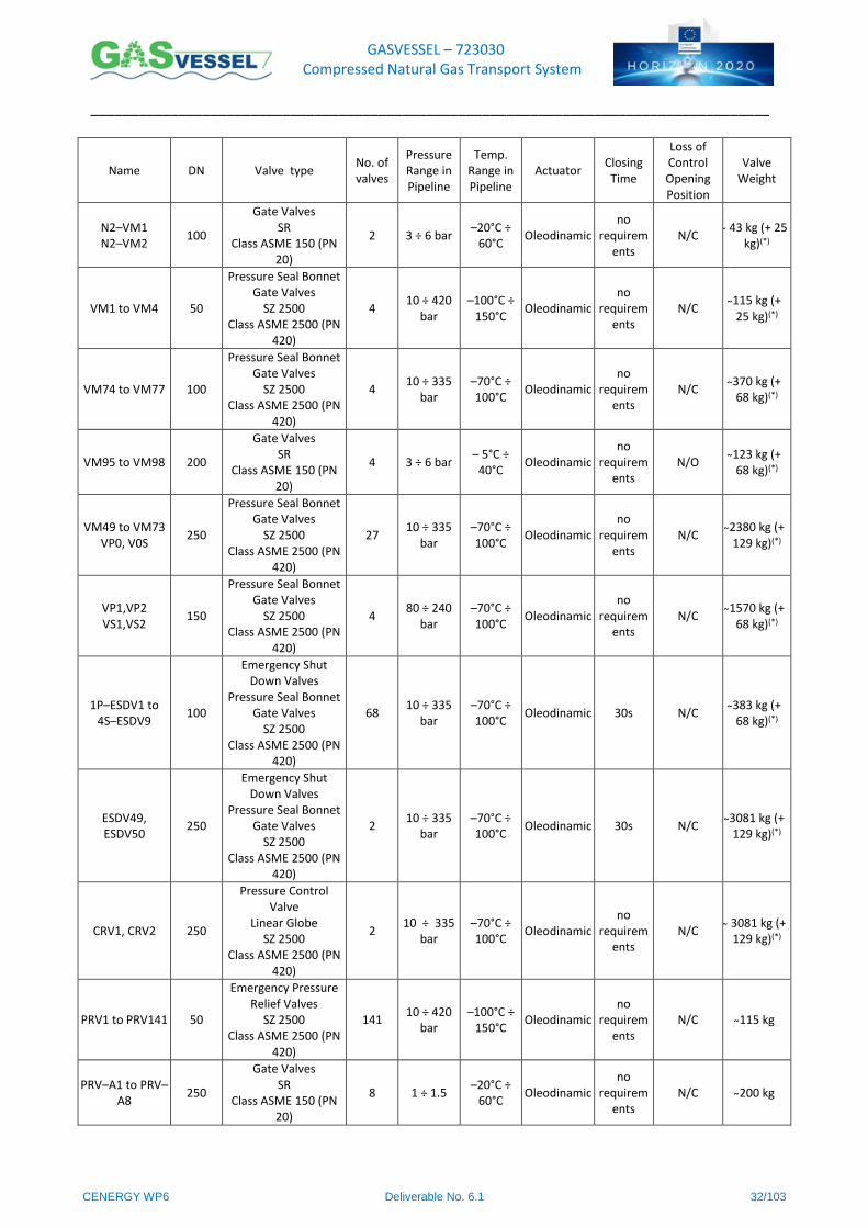
GASVESSEL – 723030 Compressed Natural Gas Transport System
______________________________________________________________________________________
CENERGY WP6 Deliverable No. 6.1 32/103
Name DN Valve type No. of valves
Pressure Range in Pipeline
Temp. Range in Pipeline
Actuator Closing Time
Loss of Control Opening Position
Valve Weight
N2–VM1 N2–VM2
100
Gate Valves SR
Class ASME 150 (PN 20)
2 3 ÷ 6 bar –20°C ÷
60°C Oleodinamic
no requirem
ents N/C
43 kg (+ 25 kg)(*)
VM1 to VM4 50
Pressure Seal Bonnet Gate Valves
SZ 2500 Class ASME 2500 (PN
420)
4 10 ÷ 420
bar –100°C ÷
150°C Oleodinamic
no requirem
ents N/C
115 kg (+ 25 kg)(*)
VM74 to VM77 100
Pressure Seal Bonnet Gate Valves
SZ 2500 Class ASME 2500 (PN
420)
4 10 ÷ 335
bar –70°C ÷ 100°C
Oleodinamic no
requirements
N/C 370 kg (+ 68 kg)(*)
VM95 to VM98 200
Gate Valves SR
Class ASME 150 (PN 20)
4 3 ÷ 6 bar – 5°C ÷
40°C Oleodinamic
no requirem
ents N/O
123 kg (+ 68 kg)(*)
VM49 to VM73 VP0, V0S
250
Pressure Seal Bonnet Gate Valves
SZ 2500 Class ASME 2500 (PN
420)
27 10 ÷ 335
bar –70°C ÷ 100°C
Oleodinamic no
requirements
N/C 2380 kg (+ 129 kg)(*)
VP1,VP2 VS1,VS2
150
Pressure Seal Bonnet Gate Valves
SZ 2500 Class ASME 2500 (PN
420)
4 80 ÷ 240
bar –70°C ÷ 100°C
Oleodinamic no
requirements
N/C 1570 kg (+
68 kg)(*)
1P–ESDV1 to 4S–ESDV9
100
Emergency Shut Down Valves
Pressure Seal Bonnet Gate Valves
SZ 2500 Class ASME 2500 (PN
420)
68 10 ÷ 335
bar –70°C ÷ 100°C
Oleodinamic 30s N/C 383 kg (+ 68 kg)(*)
ESDV49, ESDV50
250
Emergency Shut Down Valves
Pressure Seal Bonnet Gate Valves
SZ 2500 Class ASME 2500 (PN
420)
2 10 ÷ 335
bar –70°C ÷ 100°C
Oleodinamic 30s N/C 3081 kg (+ 129 kg)(*)
CRV1, CRV2 250
Pressure Control Valve
Linear Globe SZ 2500
Class ASME 2500 (PN 420)
2 10 ÷ 335
bar –70°C ÷ 100°C
Oleodinamic no
requirements
N/C 3081 kg (+ 129 kg)(*)
PRV1 to PRV141 50
Emergency Pressure Relief Valves
SZ 2500 Class ASME 2500 (PN
420)
141 10 ÷ 420
bar –100°C ÷
150°C Oleodinamic
no requirem
ents N/C 115 kg
PRV–A1 to PRV–A8
250
Gate Valves SR
Class ASME 150 (PN 20)
8 1 ÷ 1.5 –20°C ÷
60°C Oleodinamic
no requirem
ents N/C 200 kg

GASVESSEL – 723030 Compressed Natural Gas Transport System
______________________________________________________________________________________
CENERGY WP6 Deliverable No. 6.1 33/103
Name DN Valve type No. of valves
Pressure Range in Pipeline
Temp. Range in Pipeline
Actuator Closing Time
Loss of Control Opening Position
Valve Weight
ASV01 to ASV04 250
Antisurge Valve SZ 2500
Class ASME 2500 (PN 420)
4 10 ÷ 335
bar –70°C ÷ 100°C
Oleodinamic
no requirem
ents N/C
3081 kg (+ 129 kg)(*)
BDV01 BDV02
250
Blowdown Valve SZ 2500
Class ASME 2500 (PN 420)
2 10 ÷ 335
bar –70°C ÷ 100°C
Oleodinamic
no requirem
ents N/C
3081 kg (+ 129 kg)(*)
LMV1 LMV2
250
Lamination Valves SZ 2500
Class ASME 2500 (PN 420)
2 10 ÷ 335
bar –70°C ÷ 100°C
Oleodinamic
no requirem
ents N/C
3081 kg (+ 129 kg)(*)
TWV01 to TWV04
200
Three Ways Valves SR
Class ASME 150 (PN 20)
4 3 – 6 bar – 5°C ÷
40°C Oleodinamic
no requirem
ents –
164 kg (+ 68 kg)(*)
TW05, TW06 250
Three Ways Valves SR
Class ASME 150 (PN 20)
2 3 – 6 bar – 5°C ÷
40°C Oleodinamic
no requirem
ents –
270kg (+ 129 kg)(*)
ERH1 to ERH8 590 Emergency Relief
Hatches 8 1 ÷ 1.5 bar
–20°C ÷ 60°C
–
no requirem
ents N/C 84 kg
(*) actuator weight
Table 3.3 – Typical valve materials
# Valve Element Material
1 BODY ASTM A 351 GR CF8
2 BONNET ASTM A 182 GR F 304
4 WEDGE ASTM A 351 GR CF8 + AWS A5.21 ERCoCr–A
5 SEAT AISI 304 + AWS A5.21 ERCoCr–A
6 SEATING SURFACE AWS A5.14 ERNiCrMo–3
7 BACKSEATING SURFACE AWS A5.21 ERCoCr–A
9 STEM ASTM A 276 TYPE XM–19
11 GLAND ASTM A 276 TYPE 316
12 FOUR PIECES RING ASTM A 276 TYPE XM–19
18 P.S. GASKET AISI 316 L
29 YOKE ASTM A 351 GR CF8
30 FIRE SAFE GASKET GRAPHITE
31 YOKE BOLT + NUT ASTM A 193 GR B8 cl.2 / ASTM A 194 GR 8
36 SPACER RING AISI 316
39 LOCKING FLANGE ASTM A 276 TYPE 316
40 SCREW BS EN ISO 3506 A4–80
42 HEXAGONAL HEAD SET SCREW BS EN ISO 3506 A4–80
47 BONNET HALF RING ASTM A 276 TYPE XM–19
70 LIP SEAL + CHEVRON PACKING PTFE + PEEK +ELGILOY
139 PUPS AISI 304
149 TRANSITION PIECES AISI 304

GASVESSEL – 723030 Compressed Natural Gas Transport System
______________________________________________________________________________________
CENERGY WP6 Deliverable No. 6.1 34/103
Figure 3.6 – Typical pressure seal gate valve layout
Actuated valves shall be controlled by a Valve Remote Control (VRC) System Hydraulic type, 2 Hydraulic
Power Units (HPU’s) and 8 control cabinets to control up to 30 valves each. Remote control valves of cargo
system will be operated by a separate system from other valves on board.
To fulfil functional capability and redundancy of main function, plant architecture shall be divided in two
section (PORT & STBD) and each of them in different further zones according to the P&I design. The hydraulic
VRC system will be completely interfaced with the Ship Automation System, therefore, in addition to the
remote control from the Central Station, all valves will be controlled with independent local electric modules
(WCM), operable inside the valves control cabinets in case of remote control failure. The remote and local
back up control will run independently so that a failure in one system will not jeopardize the operation of the
others. The full redundant Hydraulic Power Unit (HPP’s), each one with two hydraulic pumps (with 100%
capacity and one of them to be used as a stand–by), will be installed in an area “safe for location” and they
supply the control cabinets located in the same room at Mezzanine Deck at 13 000 ABL (H.P.U. Room in AFT
part of the ship). Each panel is equipped by a stored power unit in way to survive, even in case of failure of

GASVESSEL – 723030 Compressed Natural Gas Transport System
______________________________________________________________________________________
CENERGY WP6 Deliverable No. 6.1 35/103
the HPU’s. Valve control cabinets are connected to the HPU’s via two main rings for Pressure and Return lines
with a third line at high pressure to charge the hydraulics accumulators. Winners WCM is an intelligent
distributed VRC system, characterized by electronic and electrohydraulic actuators, E–TorkLT and E–RAM,
and electric control modules WCM.
VRC systems main specifications are reported in Table 3.4.
Table 3.4 – VRC system main items specification
Main Item Height Width Depth Weight
Controlled Valves
(including spares)
mm mm mm kg No.
Hydraulic power unit 1
1800 1650 1200 200 –
Hydraulic power unit 2
1800 1650 1200 200 –
Solenoid Rack 1 2010 1200 500 800 30
Solenoid Rack 2 2010 1200 500 800 30
Solenoid Rack 3 2010 1200 500 800 30
Solenoid Rack 4 2010 1200 500 800 30
Solenoid Rack 5 2010 1200 500 800 30
Solenoid Rack 6 2010 1200 500 800 30
Solenoid Rack 7 2010 1200 500 800 30
Solenoid Rack 8 2010 1200 500 800 30
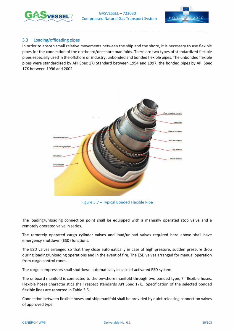
GASVESSEL – 723030 Compressed Natural Gas Transport System
______________________________________________________________________________________
CENERGY WP6 Deliverable No. 6.1 36/103
3.3 Loading/offloading pipes In order to absorb small relative movements between the ship and the shore, it is necessary to use flexible
pipes for the connection of the on–board/on–shore manifolds. There are two types of standardized flexible
pipes especially used in the offshore oil industry: unbonded and bonded flexible pipes. The unbonded flexible
pipes were standardized by API Spec 17J Standard between 1994 and 1997, the bonded pipes by API Spec
17K between 1996 and 2002.
Figure 3.7 – Typical Bonded Flexible Pipe
The loading/unloading connection point shall be equipped with a manually operated stop valve and a
remotely operated valve in series.
The remotely operated cargo cylinder valves and load/unload valves required here above shall have
emergency shutdown (ESD) functions.
The ESD valves arranged so that they close automatically in case of high pressure, sudden pressure drop
during loading/unloading operations and in the event of fire. The ESD valves arranged for manual operation
from cargo control room.
The cargo compressors shall shutdown automatically in case of activated ESD system.
The onboard manifold is connected to the on–shore manifold through two bonded type, 7’’ flexible hoses.
Flexible hoses characteristics shall respect standards API Spec 17K. Specification of the selected bonded
flexible lines are reported in Table 3.5.
Connection between flexible hoses and ship manifold shall be provided by quick releasing connection valves
of approved type.
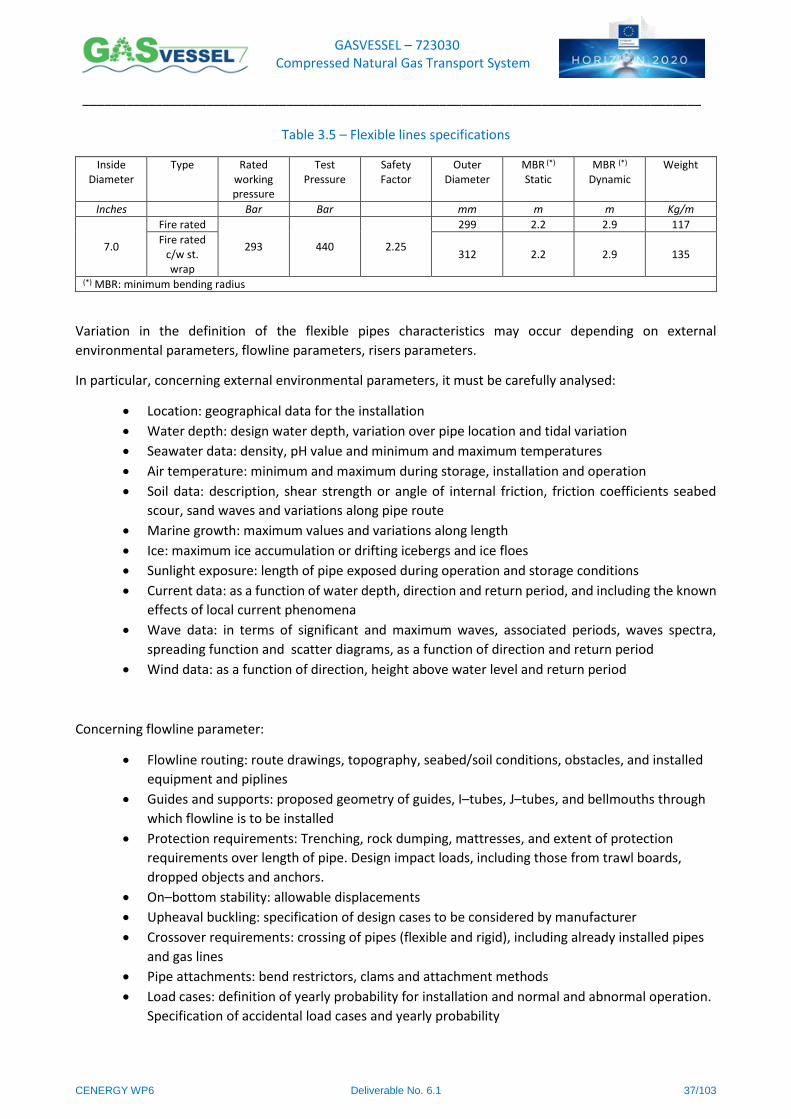
GASVESSEL – 723030 Compressed Natural Gas Transport System
______________________________________________________________________________________
CENERGY WP6 Deliverable No. 6.1 37/103
Table 3.5 – Flexible lines specifications
Inside Diameter
Type Rated working pressure
Test Pressure
Safety Factor
Outer Diameter
MBR (*) Static
MBR (*) Dynamic
Weight
Inches Bar Bar mm m m Kg/m
7.0
Fire rated
293 440 2.25
299 2.2 2.9 117
Fire rated c/w st. wrap
312 2.2 2.9 135
(*) MBR: minimum bending radius
Variation in the definition of the flexible pipes characteristics may occur depending on external
environmental parameters, flowline parameters, risers parameters.
In particular, concerning external environmental parameters, it must be carefully analysed:
Location: geographical data for the installation
Water depth: design water depth, variation over pipe location and tidal variation
Seawater data: density, pH value and minimum and maximum temperatures
Air temperature: minimum and maximum during storage, installation and operation
Soil data: description, shear strength or angle of internal friction, friction coefficients seabed
scour, sand waves and variations along pipe route
Marine growth: maximum values and variations along length
Ice: maximum ice accumulation or drifting icebergs and ice floes
Sunlight exposure: length of pipe exposed during operation and storage conditions
Current data: as a function of water depth, direction and return period, and including the known
effects of local current phenomena
Wave data: in terms of significant and maximum waves, associated periods, waves spectra,
spreading function and scatter diagrams, as a function of direction and return period
Wind data: as a function of direction, height above water level and return period
Concerning flowline parameter:
Flowline routing: route drawings, topography, seabed/soil conditions, obstacles, and installed
equipment and piplines
Guides and supports: proposed geometry of guides, I–tubes, J–tubes, and bellmouths through
which flowline is to be installed
Protection requirements: Trenching, rock dumping, mattresses, and extent of protection
requirements over length of pipe. Design impact loads, including those from trawl boards,
dropped objects and anchors.
On–bottom stability: allowable displacements
Upheaval buckling: specification of design cases to be considered by manufacturer
Crossover requirements: crossing of pipes (flexible and rigid), including already installed pipes
and gas lines
Pipe attachments: bend restrictors, clams and attachment methods
Load cases: definition of yearly probability for installation and normal and abnormal operation.
Specification of accidental load cases and yearly probability
GASVESSEL – 723030 Compressed Natural Gas Transport System
______________________________________________________________________________________
CENERGY WP6 Deliverable No. 6.1 38/103
Concerning risers parameter:
Riser configuration: specification of any requirements for the configuration, including description,
layout and components. Selection of configuration or confirmation of suitability of specified
configuration
Connection system: description of upper and lower connection system, including quick
disconnection systems and buoy disconnection systems, connection angles and location tolerances
Pipe attachments: bend stiffeners, buoys, ect., and attachment methods
Attached vessel data: data for attached floating vessels, including the following:
Vessel data, dimension, draft, and the like
Static offsets
First (RAOs) and second order motions
Vessels motion phase data
Vessels motion reference point
Mooring systems interface data
Position tolerances
Interference requirements: specification of possible interference areas, including other risers,
mooring lines, platform columns, vessel pontoons, tanker keel, and so on, and definition of
allowable interference/dashing
Load cases: definition of yearly probability for installation, and normal and abnormal operation
specification of accidental load cases yearly probability.
GASVESSEL – 723030 Compressed Natural Gas Transport System
______________________________________________________________________________________
CENERGY WP6 Deliverable No. 6.1 39/103
4 Compressors
4.1 Possible Compressing Technologies Commercial available compression technologies can be divided into two main classifications, based on the
way of transferring the energy from the machine to the fluid.
Dynamic compressors
Volumetric compressors
The dynamic compressors are those machines provided of high speed rotative blades which gives to the
fluid an increasing of static pressure and kinetic energy, afterward transformed in pressure energy in the
fix pipes of the machine. In dynamic compressors, flow is continuous and can follow either the direction
parallel to the main axis of the machine (Axial compressors) or radially (Centrifugal compressors).
Volumetric compressors are those machines in which the increasing of the pressure is given by cyclic
and progressive reduction of the volume where the fluid is enclosed. This volume reduction can occur
either in a machine composed by cylinder, piston, rod and crank (Alternative compressors) or using
specific rotating gears (Rotative compressors).
In order to select the technology for the gas compression system of GASVESSEL, some main criteria have
been analysed:
High flow to reduce loading time
Reduced size of the compressor
Low maintenance
Flexibility
Efficiency
Power needs
Axial technology as well as rotative technologies, based on gears have been abandoned since the operational
range in terms of flow and pressure ratio are out of the operative range of these technologies.
For this reason available commercial technologies study of possible compressors that could satisfy the needs
of GASVESSEL can be mainly divided into two main categories:
Reciprocating compressors
Centrifugal compressors
The main advantages of reciprocating compressors with respect to centrifugal ones are:
High efficiency for high compression ratios
Relative low cost for low size machines
Smaller sensitivity to variation in gas composition and density
Ideal for fluids characterized by low specific volume and high compression ratio
The main advantages of centrifugal compressors with respect to alternative ones are:
High efficiency at design point of operation
Simple design, less moving components
Low maintenance
No vibration or pulsation of flow
Ideal for fluids characterized by high specific volume and low compression ratio
GASVESSEL – 723030 Compressed Natural Gas Transport System
______________________________________________________________________________________
CENERGY WP6 Deliverable No. 6.1 40/103
4.2 Reciprocating Compressors Reciprocating compressors have the advantage of being able to operate with variable compression ratios and
hence be more flexible and suitable for a large range of receiving and delivery pressures. This is an important
advantage when considering that a single boat configuration could be maintained for all geographical
scenarios and for all loading and unloading conditions with no strict limitation in pressure. This could allow
as well, a better use of the GASVESSEL available storage volume on board, allowing to empty more the vessels
at each roundtrip increasing in this way the amount of transported gas.
The main disadvantage of this technology is the low flowrate that makes increase the loading and unloading
process time and the higher power needs.
An increased attention to maintenance aspects must also be kept during the operational life of the
compressor. Eventually, no (or really limited) liquid fraction is admitted in this compressors, hence stronger
control of condensation conditions must be performed during operation.
4.3 Centrifugal Compressors Centrifugal compressors have the advantage to be able to manage a larger amount of gas per unit of time
reducing the duration of loading and unloading time during GASVESSEL operation. This is one determining
criteria, indeed reducing the loading/unloading time has an important economic impact on the gas
transportation tariff.
However, these compressors have a much smaller operative range and hence must be designed for a specific
application. Each scenario will hence need a specific design and optimisation of the compression system.
Moreover, in order to avoid exiting the operating map of the compressor, a higher amount of gas should be
left inside the tanks at the end of the unloading process, reducing the total storage volume of GASVESSEL.
This type of compressors, can handle a small amount of condensate (up to 5%), which can allow a less strict
thermodynamic control of the loading/unloading phase during the operation of GASVESSEL, and they also
have less maintenance issues during their operative life with respect to reciprocating compressors.
An additional technology for centrifugal compressor has been taken into account for its reduced size and
high performance: the ICL (integrated compression line) technology. The ICL combines the centrifugal
compressor technology with an electric motor driver in a single, completely sealed casing that provides an
efficient and easily installed compression solution.
4.4 ICL Compressors The ICL (Integrated Compressor Line) consist in a compact design of a centrifugal compressor powered by a
high–speed electric motor fully integrated with the compressor in a single sealed casing. This technology has
the main purpose to reduce as much as possible the size of the system and it is ideal for any applications with
space constrains.
Both the multistage and the single–stage ICL compressor casings are directly flanged onto the motor,
avoiding any alignment requirements. The single–stage ICL compressor rotor uses a single impeller, directly
mounted on the motor shaft through a hirth coupling. The multistage ICL compressor rotor features a shaft
on which up to nine impellers can be stacked. The rotor is connected to the motor through a flexible coupling,
eliminating the need for complex tuning of the bearing system and simplifying future rewheeling of the
compressor.
GASVESSEL – 723030 Compressed Natural Gas Transport System
______________________________________________________________________________________
CENERGY WP6 Deliverable No. 6.1 41/103
4.5 Choice of the compressors The choice of the compressor has been performed referring to the selected scenario for the dimensioning of
the whole loading and unloading system (see Table 1.3). The choice has been performed taking into account
the following considerations:
1) The dimensioning of the compression system has been done for a specific selected scenario at fixed
and constant receiving and delivery pressure.
2) The loading/unloading process time should be the shortest as possible. For this reason, high flow
compressors have been preferred.
3) On board maintenance should be possibly done by not specialized workers; minimize the
maintenance issues and simplify the ordinary maintained is a parameter that shall be as well taken
into account in the choice of the compressor.
4) Lastly, the power need for compression should not be higher that the power available on board
installed for propulsion. Indeed, compression system starts operating when the ship is at the deck,
hence propulsion engines can be off. It would be no sense to install additional power strictly
dedicated for loading and unloading process. This would strongly increase cost and reduce space on
board of the ship.
Although the reciprocating technology appears to be more flexible to deal with a large variety of possible
situations, based on preliminary evaluation of the possible scenarios of interest we decided to adopt
centrifugal compression technology for the onboard compressors by restricting the possible range of
receiving and delivery pressure. Practically speaking this choice means that the compressor size and the
compressor working point shall need to be optimized in relation with the specific application of the specific
GASVESSEL.
For the selected reference scenario (Table 1.3) two centrifugal cargo compressors of 5.9MW each are
expected to be installed on board with relevant auxiliary services and cargo heat exchangers arranged
forward above Deck at 27 500 ABL.
Selected compressors have been sized in order to be able to perform both loading and unloading process.
Dimensioning of the compressors has been performed considering a commercial gas volume of 12 millions
Nm3 with a loading time lower than 52 hours and an unloading time lower than 72 hours.
During the loading process each of the two compressors has to be able to displace 1.07 million Nm3 in about
5 hours with a compression ratio of 1.40.
During the unloading each of the two compressors has to be able to displace 2.5 million Nm3 in about process
53 hours with a compression ratio of 4.
Table 4.1 reports the main specification of the selected compressors.
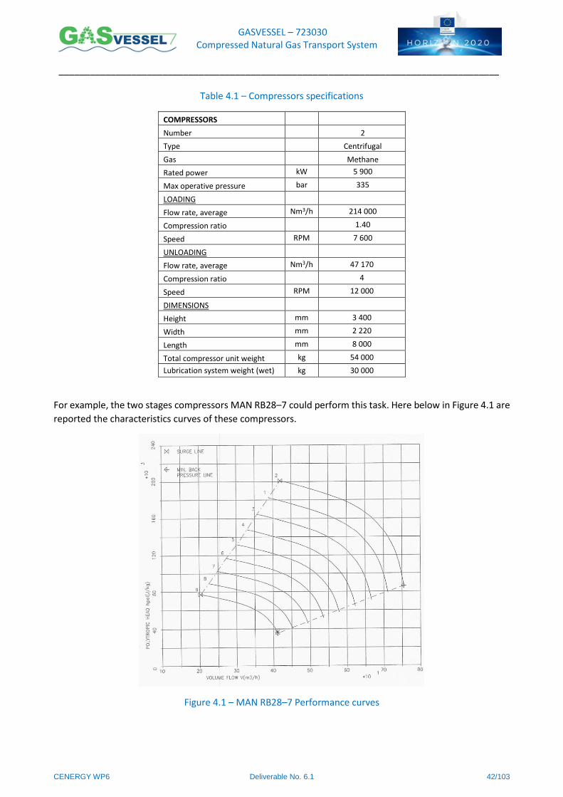
GASVESSEL – 723030 Compressed Natural Gas Transport System
______________________________________________________________________________________
CENERGY WP6 Deliverable No. 6.1 42/103
Table 4.1 – Compressors specifications
COMPRESSORS
Number 2
Type Centrifugal
Gas Methane
Rated power kW 5 900
Max operative pressure bar 335
LOADING
Flow rate, average Nm3/h 214 000
Compression ratio 1.40
Speed RPM 7 600
UNLOADING
Flow rate, average Nm3/h 47 170
Compression ratio 4
Speed RPM 12 000
DIMENSIONS
Height mm 3 400
Width mm 2 220
Length mm 8 000
Total compressor unit weight kg 54 000
Lubrication system weight (wet) kg 30 000
For example, the two stages compressors MAN RB28–7 could perform this task. Here below in Figure 4.1 are
reported the characteristics curves of these compressors.
Figure 4.1 – MAN RB28–7 Performance curves
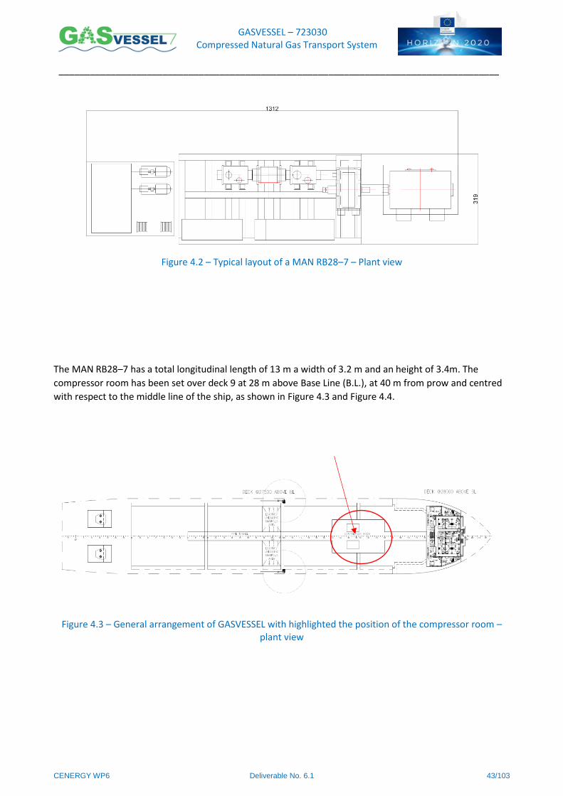
GASVESSEL – 723030 Compressed Natural Gas Transport System
______________________________________________________________________________________
CENERGY WP6 Deliverable No. 6.1 43/103
Figure 4.2 – Typical layout of a MAN RB28–7 – Plant view
The MAN RB28–7 has a total longitudinal length of 13 m a width of 3.2 m and an height of 3.4m. The
compressor room has been set over deck 9 at 28 m above Base Line (B.L.), at 40 m from prow and centred
with respect to the middle line of the ship, as shown in Figure 4.3 and Figure 4.4.
Figure 4.3 – General arrangement of GASVESSEL with highlighted the position of the compressor room – plant view
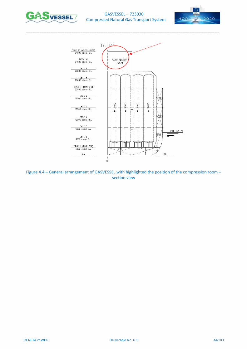
GASVESSEL – 723030 Compressed Natural Gas Transport System
______________________________________________________________________________________
CENERGY WP6 Deliverable No. 6.1 44/103
Figure 4.4 – General arrangement of GASVESSEL with highlighted the position of the compression room – section view
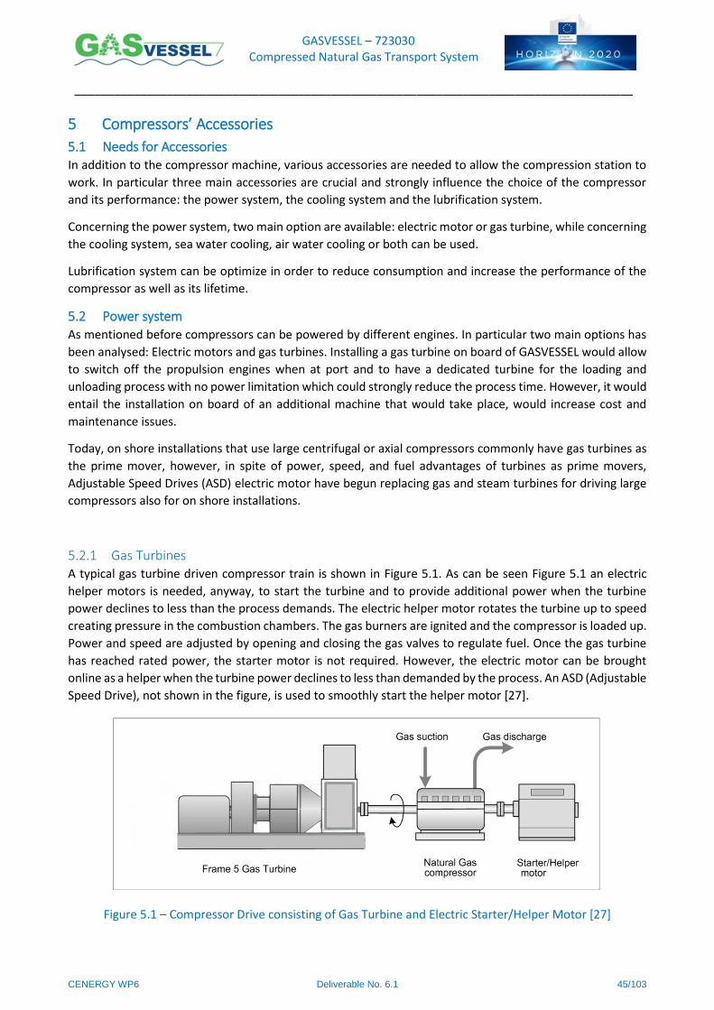
GASVESSEL – 723030 Compressed Natural Gas Transport System
______________________________________________________________________________________
CENERGY WP6 Deliverable No. 6.1 45/103
5 Compressors’ Accessories
5.1 Needs for Accessories In addition to the compressor machine, various accessories are needed to allow the compression station to
work. In particular three main accessories are crucial and strongly influence the choice of the compressor
and its performance: the power system, the cooling system and the lubrification system.
Concerning the power system, two main option are available: electric motor or gas turbine, while concerning
the cooling system, sea water cooling, air water cooling or both can be used.
Lubrification system can be optimize in order to reduce consumption and increase the performance of the
compressor as well as its lifetime.
5.2 Power system As mentioned before compressors can be powered by different engines. In particular two main options has
been analysed: Electric motors and gas turbines. Installing a gas turbine on board of GASVESSEL would allow
to switch off the propulsion engines when at port and to have a dedicated turbine for the loading and
unloading process with no power limitation which could strongly reduce the process time. However, it would
entail the installation on board of an additional machine that would take place, would increase cost and
maintenance issues.
Today, on shore installations that use large centrifugal or axial compressors commonly have gas turbines as
the prime mover, however, in spite of power, speed, and fuel advantages of turbines as prime movers,
Adjustable Speed Drives (ASD) electric motor have begun replacing gas and steam turbines for driving large
compressors also for on shore installations.
5.2.1 Gas Turbines A typical gas turbine driven compressor train is shown in Figure 5.1. As can be seen Figure 5.1 an electric
helper motors is needed, anyway, to start the turbine and to provide additional power when the turbine
power declines to less than the process demands. The electric helper motor rotates the turbine up to speed
creating pressure in the combustion chambers. The gas burners are ignited and the compressor is loaded up.
Power and speed are adjusted by opening and closing the gas valves to regulate fuel. Once the gas turbine
has reached rated power, the starter motor is not required. However, the electric motor can be brought
online as a helper when the turbine power declines to less than demanded by the process. An ASD (Adjustable
Speed Drive), not shown in the figure, is used to smoothly start the helper motor [27].
Figure 5.1 – Compressor Drive consisting of Gas Turbine and Electric Starter/Helper Motor [27]
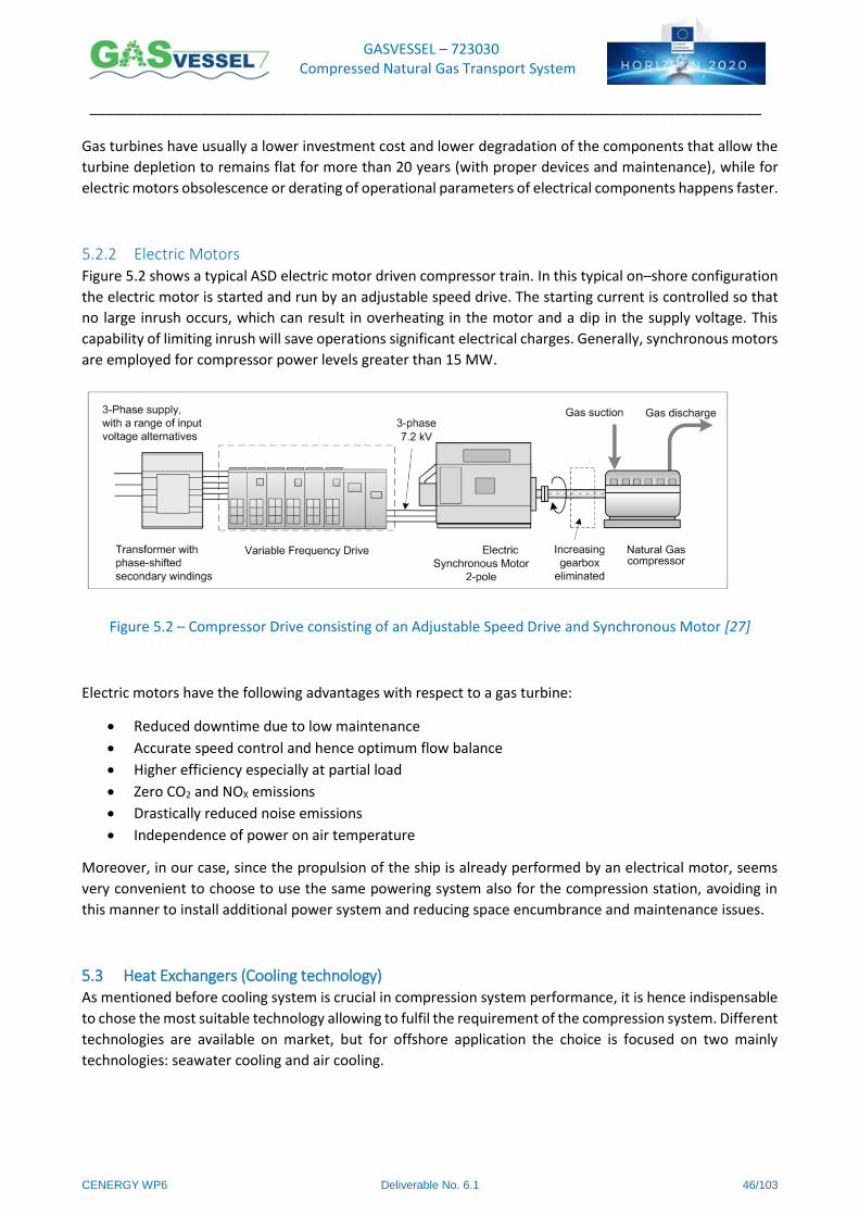
GASVESSEL – 723030 Compressed Natural Gas Transport System
______________________________________________________________________________________
CENERGY WP6 Deliverable No. 6.1 46/103
Gas turbines have usually a lower investment cost and lower degradation of the components that allow the
turbine depletion to remains flat for more than 20 years (with proper devices and maintenance), while for
electric motors obsolescence or derating of operational parameters of electrical components happens faster.
5.2.2 Electric Motors Figure 5.2 shows a typical ASD electric motor driven compressor train. In this typical on–shore configuration
the electric motor is started and run by an adjustable speed drive. The starting current is controlled so that
no large inrush occurs, which can result in overheating in the motor and a dip in the supply voltage. This
capability of limiting inrush will save operations significant electrical charges. Generally, synchronous motors
are employed for compressor power levels greater than 15 MW.
Figure 5.2 – Compressor Drive consisting of an Adjustable Speed Drive and Synchronous Motor [27]
Electric motors have the following advantages with respect to a gas turbine:
Reduced downtime due to low maintenance
Accurate speed control and hence optimum flow balance
Higher efficiency especially at partial load
Zero CO2 and NOX emissions
Drastically reduced noise emissions
Independence of power on air temperature
Moreover, in our case, since the propulsion of the ship is already performed by an electrical motor, seems
very convenient to choose to use the same powering system also for the compression station, avoiding in
this manner to install additional power system and reducing space encumbrance and maintenance issues.
5.3 Heat Exchangers (Cooling technology) As mentioned before cooling system is crucial in compression system performance, it is hence indispensable
to chose the most suitable technology allowing to fulfil the requirement of the compression system. Different
technologies are available on market, but for offshore application the choice is focused on two mainly
technologies: seawater cooling and air cooling.
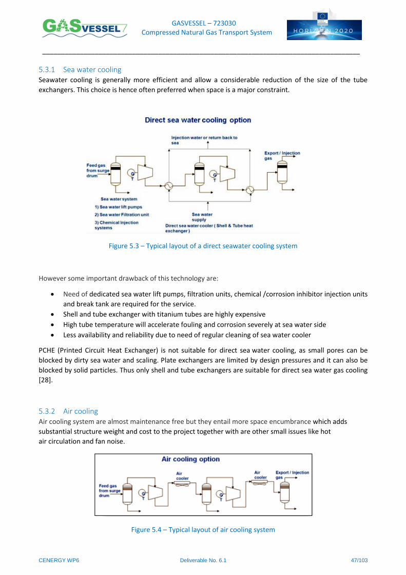
GASVESSEL – 723030 Compressed Natural Gas Transport System
______________________________________________________________________________________
CENERGY WP6 Deliverable No. 6.1 47/103
5.3.1 Sea water cooling Seawater cooling is generally more efficient and allow a considerable reduction of the size of the tube
exchangers. This choice is hence often preferred when space is a major constraint.
Figure 5.3 – Typical layout of a direct seawater cooling system
However some important drawback of this technology are:
Need of dedicated sea water lift pumps, filtration units, chemical /corrosion inhibitor injection units
and break tank are required for the service.
Shell and tube exchanger with titanium tubes are highly expensive
High tube temperature will accelerate fouling and corrosion severely at sea water side
Less availability and reliability due to need of regular cleaning of sea water cooler
PCHE (Printed Circuit Heat Exchanger) is not suitable for direct sea water cooling, as small pores can be
blocked by dirty sea water and scaling. Plate exchangers are limited by design pressures and it can also be
blocked by solid particles. Thus only shell and tube exchangers are suitable for direct sea water gas cooling
[28].
5.3.2 Air cooling Air cooling system are almost maintenance free but they entail more space encumbrance which adds
substantial structure weight and cost to the project together with are other small issues like hot
air circulation and fan noise.
Figure 5.4 – Typical layout of air cooling system

GASVESSEL – 723030 Compressed Natural Gas Transport System
______________________________________________________________________________________
CENERGY WP6 Deliverable No. 6.1 48/103
5.4 Lubrification Lubrification is a crucial issue to reach long term and safe operation of any compressor. Needs of lubrification
strongly vary depending on the type of compressor and the nature of the gas to be compressed.
In general, lubricating issues are more complex in alternative compressors since more areas and moving
components require lubrification and especially because lubricant get in contact with the gas. For centrifugal
compressors, where oil and gas do not get in contact lubrication requirements are much simpler. Usually,
for centrifugal compressors, a good rust and oxidation–inhibited oil will provide satisfactory lubrication of
the bearings, gears and seals [29].
Lubrication of alternative compressors is needed for the following areas and components [30]:
Compressor Frame
Main bearings
Connecting rod bearings
Cross head bearings
Motor bearings
Cylinder Region
Rider bands
Compression rings
Packing
Valves
If the frame bearings and cylinder are using the same oil for lubrication, the oil is pumped from a reservoir
where the oil is filtered and cooled. In many cases, two different lubricants are used. The frame bearings
don’t require synthetics because of the moderate conditions. High–pressure, high–temperature conditions
may require synthetics or compounded oils in the cylinder. Also, higher pressures require higher viscosities.
A separate oil system is used to supply oil to the injectors for the cylinder.
Hydrocarbon or wet gases can have a large dilution effect on an oil; as pressures are increased oil viscosity
should increase. Polyalkylene glycols (PAG) and diester are a good choice when working with high pressures
or temperature above 150°C. PAG are very resistant to dilution by hydrocarbons, and diesters have high
thermal stability and excellent solvency that prevents exhaust–valve deposits (a major problem at high
temperatures).
In centrifugal compressors few key components require a coolant/lubricant: gears, bearings and seals. To
date, the majority of dynamic compressors use oil film–lubricated seals. Only labyrinth seals or gas–
lubricated seals operate without a liquid film separating the faces. On the more conventional liquid–
lubricated seals, the bearing and sealing lubricant are often the same [29].
The lube oil system supplies oil to the compressors and other components needing lubrification. The lube oil
is pumped from a reservoir and fed under pressure through coolers and filters to the bearings and then
circulated back to the reservoir. Pressure inside the lube oil tank should be by setting the reservoir at a
different height with respect to the compressor, this allow to keep pressure in the tank also when the engine
is off.
An oil temperature control system can be installed to provide preheating at cold–start and cooling at peak
charge.
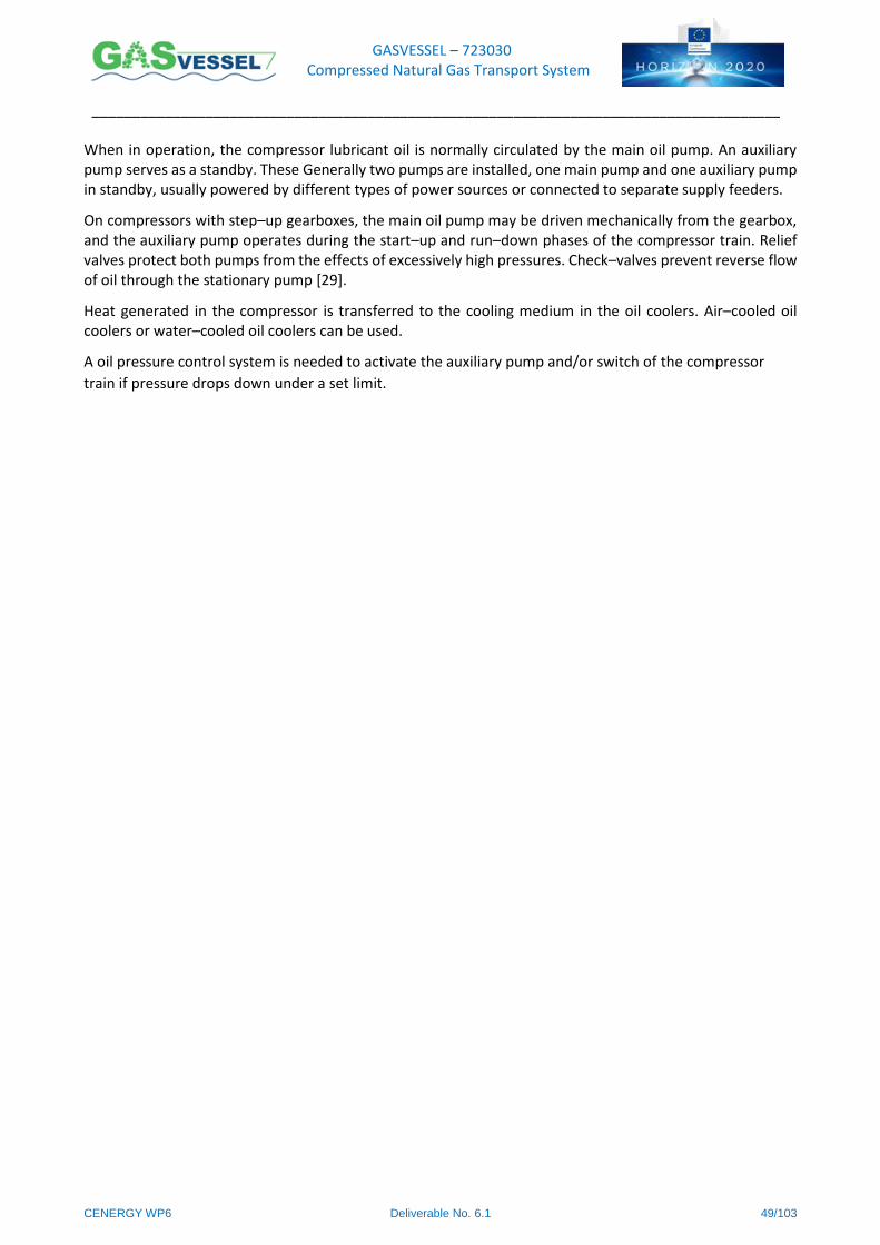
GASVESSEL – 723030 Compressed Natural Gas Transport System
______________________________________________________________________________________
CENERGY WP6 Deliverable No. 6.1 49/103
When in operation, the compressor lubricant oil is normally circulated by the main oil pump. An auxiliary pump serves as a standby. These Generally two pumps are installed, one main pump and one auxiliary pump in standby, usually powered by different types of power sources or connected to separate supply feeders.
On compressors with step–up gearboxes, the main oil pump may be driven mechanically from the gearbox, and the auxiliary pump operates during the start–up and run–down phases of the compressor train. Relief valves protect both pumps from the effects of excessively high pressures. Check–valves prevent reverse flow of oil through the stationary pump [29].
Heat generated in the compressor is transferred to the cooling medium in the oil coolers. Air–cooled oil coolers or water–cooled oil coolers can be used.
A oil pressure control system is needed to activate the auxiliary pump and/or switch of the compressor
train if pressure drops down under a set limit.
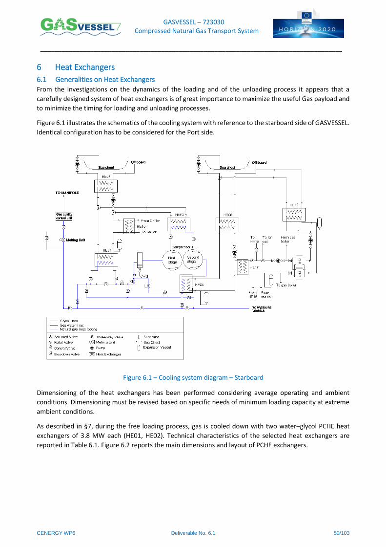
GASVESSEL – 723030 Compressed Natural Gas Transport System
______________________________________________________________________________________
CENERGY WP6 Deliverable No. 6.1 50/103
6 Heat Exchangers
6.1 Generalities on Heat Exchangers From the investigations on the dynamics of the loading and of the unloading process it appears that a
carefully designed system of heat exchangers is of great importance to maximize the useful Gas payload and
to minimize the timing for loading and unloading processes.
Figure 6.1 illustrates the schematics of the cooling system with reference to the starboard side of GASVESSEL.
Identical configuration has to be considered for the Port side.
Figure 6.1 – Cooling system diagram – Starboard
Dimensioning of the heat exchangers has been performed considering average operating and ambient
conditions. Dimensioning must be revised based on specific needs of minimum loading capacity at extreme
ambient conditions.
As described in §7, during the free loading process, gas is cooled down with two water–glycol PCHE heat
exchangers of 3.8 MW each (HE01, HE02). Technical characteristics of the selected heat exchangers are
reported in Table 6.1. Figure 6.2 reports the main dimensions and layout of PCHE exchangers.
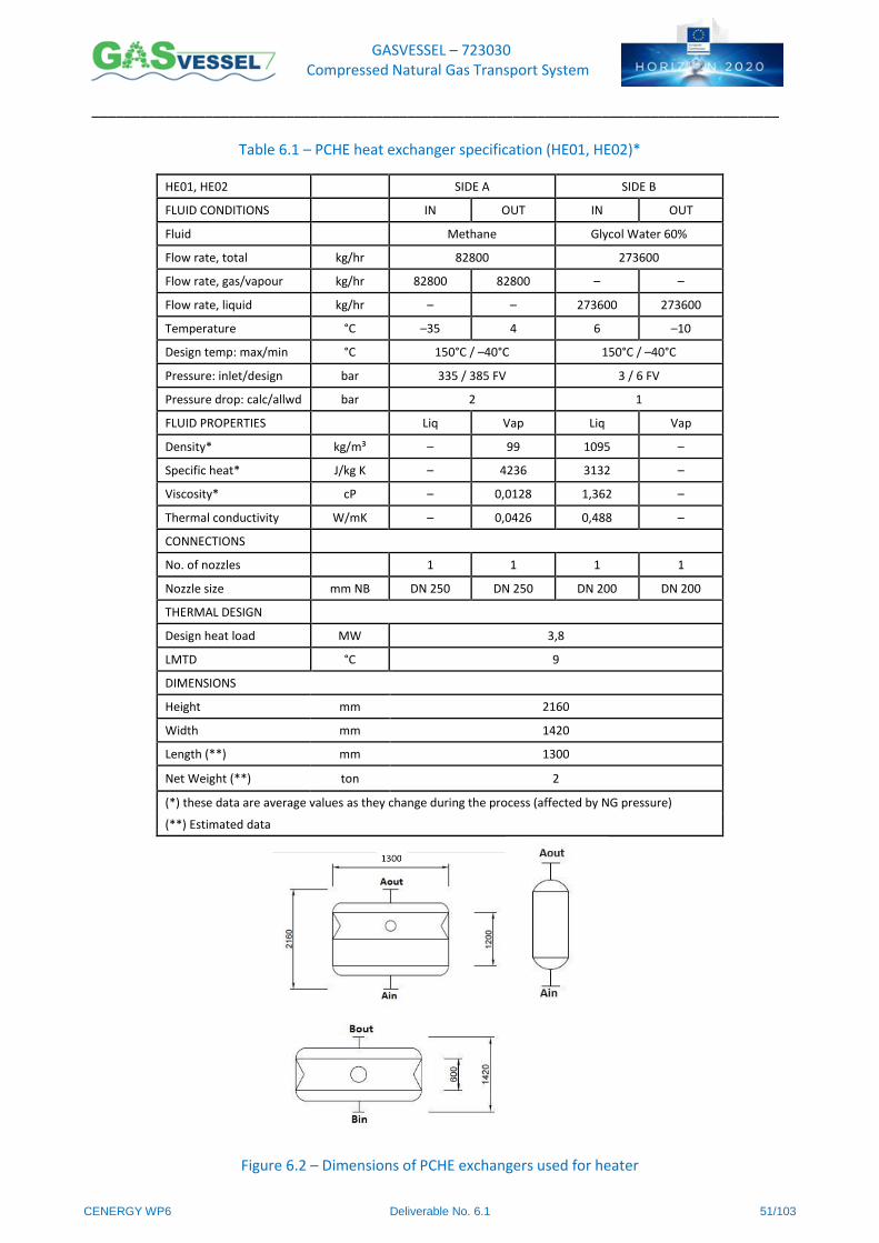
GASVESSEL – 723030 Compressed Natural Gas Transport System
______________________________________________________________________________________
CENERGY WP6 Deliverable No. 6.1 51/103
Figure 6.2 – Dimensions of PCHE exchangers used for heater
Table 6.1 – PCHE heat exchanger specification (HE01, HE02)*
HE01, HE02 SIDE A SIDE B
FLUID CONDITIONS IN OUT IN OUT
Fluid Methane Glycol Water 60%
Flow rate, total kg/hr 82800 273600
Flow rate, gas/vapour kg/hr 82800 82800 – –
Flow rate, liquid kg/hr – – 273600 273600
Temperature °C –35 4 6 –10
Design temp: max/min °C 150°C / –40°C 150°C / –40°C
Pressure: inlet/design bar 335 / 385 FV 3 / 6 FV
Pressure drop: calc/allwd bar 2 1
FLUID PROPERTIES Liq Vap Liq Vap
Density* kg/m³ – 99 1095 –
Specific heat* J/kg K – 4236 3132 –
Viscosity* cP – 0,0128 1,362 –
Thermal conductivity W/mK – 0,0426 0,488 –
CONNECTIONS
No. of nozzles 1 1 1 1
Nozzle size mm NB DN 250 DN 250 DN 200 DN 200
THERMAL DESIGN
Design heat load MW 3,8
LMTD °C 9
DIMENSIONS
Height mm 2160
Width mm 1420
Length (**) mm 1300
Net Weight (**) ton 2
(*) these data are average values as they change during the process (affected by NG pressure)
(**) Estimated data
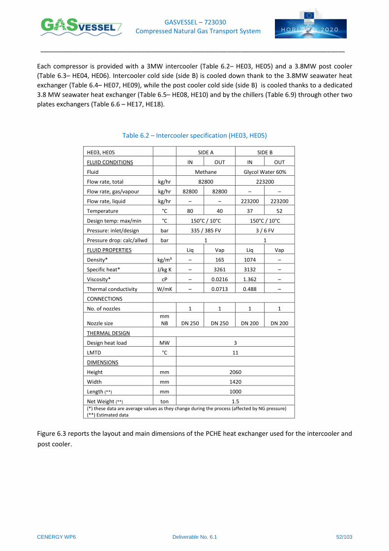
GASVESSEL – 723030 Compressed Natural Gas Transport System
______________________________________________________________________________________
CENERGY WP6 Deliverable No. 6.1 52/103
Each compressor is provided with a 3MW intercooler (Table 6.2– HE03, HE05) and a 3.8MW post cooler
(Table 6.3– HE04, HE06). Intercooler cold side (side B) is cooled down thank to the 3.8MW seawater heat
exchanger (Table 6.4– HE07, HE09), while the post cooler cold side (side B) is cooled thanks to a dedicated
3.8 MW seawater heat exchanger (Table 6.5– HE08, HE10) and by the chillers (Table 6.9) through other two
plates exchangers (Table 6.6 – HE17, HE18).
Table 6.2 – Intercooler specification (HE03, HE05)
HE03, HE05 SIDE A SIDE B
FLUID CONDITIONS IN OUT IN OUT
Fluid Methane Glycol Water 60%
Flow rate, total kg/hr 82800 223200
Flow rate, gas/vapour kg/hr 82800 82800 – –
Flow rate, liquid kg/hr – – 223200 223200
Temperature °C 80 40 37 52
Design temp: max/min °C 150°C / 10°C 150°C / 10°C
Pressure: inlet/design bar 335 / 385 FV 3 / 6 FV
Pressure drop: calc/allwd bar 1 1
FLUID PROPERTIES Liq Vap Liq Vap
Density* kg/m³ – 165 1074 –
Specific heat* J/kg K – 3261 3132 –
Viscosity* cP – 0.0216 1.362 –
Thermal conductivity W/mK – 0.0713 0.488 –
CONNECTIONS
No. of nozzles 1 1 1 1
Nozzle size mm NB DN 250 DN 250 DN 200 DN 200
THERMAL DESIGN
Design heat load MW 3
LMTD °C 11
DIMENSIONS
Height mm 2060
Width mm 1420
Length (**) mm 1000
Net Weight (**) ton 1.5 (*) these data are average values as they change during the process (affected by NG pressure) (**) Estimated data
Figure 6.3 reports the layout and main dimensions of the PCHE heat exchanger used for the intercooler and
post cooler.
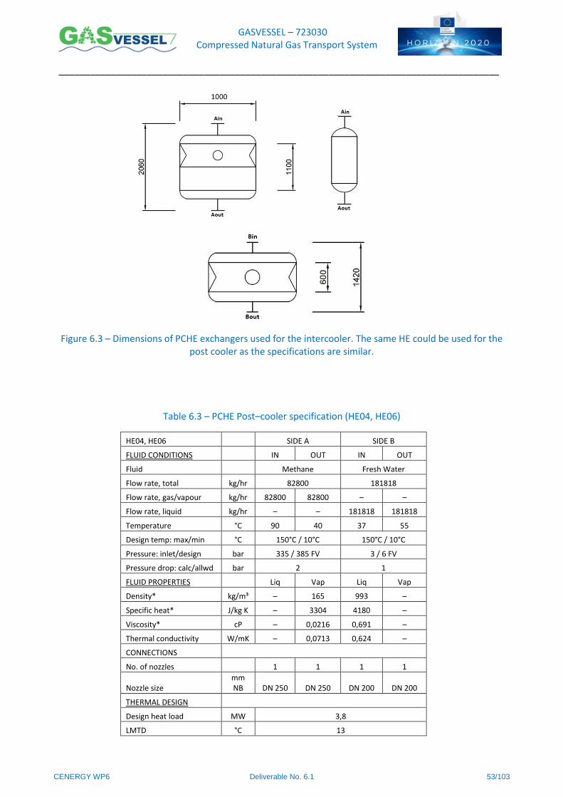
GASVESSEL – 723030 Compressed Natural Gas Transport System
______________________________________________________________________________________
CENERGY WP6 Deliverable No. 6.1 53/103
Figure 6.3 – Dimensions of PCHE exchangers used for the intercooler. The same HE could be used for the
post cooler as the specifications are similar.
Table 6.3 – PCHE Post–cooler specification (HE04, HE06)
HE04, HE06 SIDE A SIDE B
FLUID CONDITIONS IN OUT IN OUT
Fluid Methane Fresh Water
Flow rate, total kg/hr 82800 181818
Flow rate, gas/vapour kg/hr 82800 82800 – –
Flow rate, liquid kg/hr – – 181818 181818
Temperature °C 90 40 37 55
Design temp: max/min °C 150°C / 10°C 150°C / 10°C
Pressure: inlet/design bar 335 / 385 FV 3 / 6 FV
Pressure drop: calc/allwd bar 2 1
FLUID PROPERTIES Liq Vap Liq Vap
Density* kg/m³ – 165 993 –
Specific heat* J/kg K – 3304 4180 –
Viscosity* cP – 0,0216 0,691 –
Thermal conductivity W/mK – 0,0713 0,624 –
CONNECTIONS
No. of nozzles 1 1 1 1
Nozzle size mm NB DN 250 DN 250 DN 200 DN 200
THERMAL DESIGN
Design heat load MW 3,8
LMTD °C 13
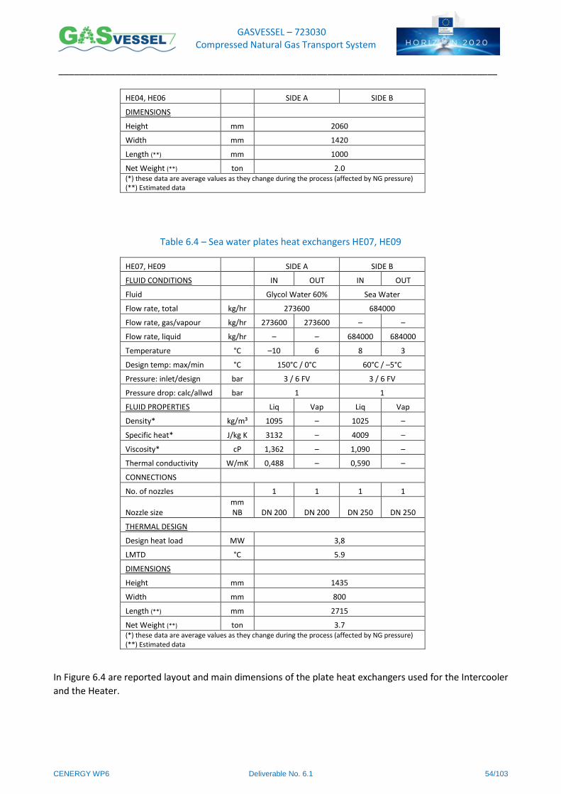
GASVESSEL – 723030 Compressed Natural Gas Transport System
______________________________________________________________________________________
CENERGY WP6 Deliverable No. 6.1 54/103
HE04, HE06 SIDE A SIDE B
DIMENSIONS
Height mm 2060
Width mm 1420
Length (**) mm 1000
Net Weight (**) ton 2.0 (*) these data are average values as they change during the process (affected by NG pressure) (**) Estimated data
Table 6.4 – Sea water plates heat exchangers HE07, HE09
HE07, HE09 SIDE A SIDE B
FLUID CONDITIONS IN OUT IN OUT
Fluid Glycol Water 60% Sea Water
Flow rate, total kg/hr 273600 684000
Flow rate, gas/vapour kg/hr 273600 273600 – –
Flow rate, liquid kg/hr – – 684000 684000
Temperature °C –10 6 8 3
Design temp: max/min °C 150°C / 0°C 60°C / –5°C
Pressure: inlet/design bar 3 / 6 FV 3 / 6 FV
Pressure drop: calc/allwd bar 1 1
FLUID PROPERTIES Liq Vap Liq Vap
Density* kg/m³ 1095 – 1025 –
Specific heat* J/kg K 3132 – 4009 –
Viscosity* cP 1,362 – 1,090 –
Thermal conductivity W/mK 0,488 – 0,590 –
CONNECTIONS
No. of nozzles 1 1 1 1
Nozzle size mm NB DN 200 DN 200 DN 250 DN 250
THERMAL DESIGN
Design heat load MW 3,8
LMTD °C 5.9
DIMENSIONS
Height mm 1435
Width mm 800
Length (**) mm 2715
Net Weight (**) ton 3.7 (*) these data are average values as they change during the process (affected by NG pressure) (**) Estimated data
In Figure 6.4 are reported layout and main dimensions of the plate heat exchangers used for the Intercooler
and the Heater.
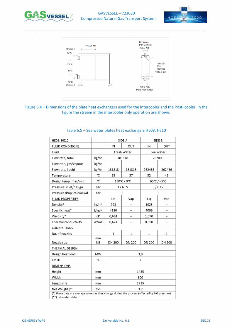
GASVESSEL – 723030 Compressed Natural Gas Transport System
______________________________________________________________________________________
CENERGY WP6 Deliverable No. 6.1 55/103
Figure 6.4 – Dimensions of the plate heat exchangers used for the Intercooler and the Post–cooler. In the figure the stream in the intercooler only operation are shown.
Table 6.5 – Sea water plates heat exchangers HE08, HE10
HE08, HE10 SIDE A SIDE B
FLUID CONDITIONS IN OUT IN OUT
Fluid Fresh Water Sea Water
Flow rate, total kg/hr 181818 262000
Flow rate, gas/vapour kg/hr – – – –
Flow rate, liquid kg/hr 181818 181818 262486 262486
Temperature °C 55 37 32 45
Design temp: max/min °C 150°C / 0°C 60°C / –5°C
Pressure: inlet/design bar 3 / 6 FV 3 / 6 FV
Pressure drop: calc/allwd bar 1 1
FLUID PROPERTIES Liq Vap Liq Vap
Density* kg/m³ 993 – 1025 –
Specific heat* J/kg K 4180 – 4009 –
Viscosity* cP 0,691 – 1,090 –
Thermal conductivity W/mK 0,624 – 0,590 –
CONNECTIONS
No. of nozzles 1 1 1 1
Nozzle size mm NB DN 200 DN 200 DN 200 DN 200
THERMAL DESIGN
Design heat load MW 3,8
LMTD °C 7
DIMENSIONS
Height mm 1435
Width mm 800
Length (**) mm 2715
Net Weight (**) ton 3.7 (*) these data are average values as they change during the process (affected by NG pressure) (**) Estimated data
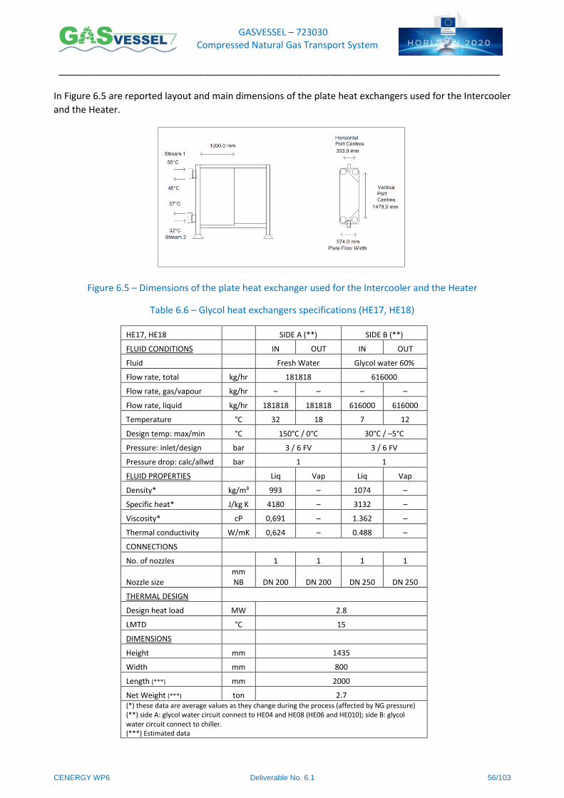
GASVESSEL – 723030 Compressed Natural Gas Transport System
______________________________________________________________________________________
CENERGY WP6 Deliverable No. 6.1 56/103
In Figure 6.5 are reported layout and main dimensions of the plate heat exchangers used for the Intercooler
and the Heater.
Figure 6.5 – Dimensions of the plate heat exchanger used for the Intercooler and the Heater
Table 6.6 – Glycol heat exchangers specifications (HE17, HE18)
HE17, HE18 SIDE A (**) SIDE B (**)
FLUID CONDITIONS IN OUT IN OUT
Fluid Fresh Water Glycol water 60%
Flow rate, total kg/hr 181818 616000
Flow rate, gas/vapour kg/hr – – – –
Flow rate, liquid kg/hr 181818 181818 616000 616000
Temperature °C 32 18 7 12
Design temp: max/min °C 150°C / 0°C 30°C / –5°C
Pressure: inlet/design bar 3 / 6 FV 3 / 6 FV
Pressure drop: calc/allwd bar 1 1
FLUID PROPERTIES Liq Vap Liq Vap
Density* kg/m³ 993 – 1074 –
Specific heat* J/kg K 4180 – 3132 –
Viscosity* cP 0,691 – 1.362 –
Thermal conductivity W/mK 0,624 – 0.488 –
CONNECTIONS
No. of nozzles 1 1 1 1
Nozzle size mm NB DN 200 DN 200 DN 250 DN 250
THERMAL DESIGN
Design heat load MW 2.8
LMTD °C 15
DIMENSIONS
Height mm 1435
Width mm 800
Length (***) mm 2000
Net Weight (***) ton 2.7 (*) these data are average values as they change during the process (affected by NG pressure) (**) side A: glycol water circuit connect to HE04 and HE08 (HE06 and HE010); side B: glycol water circuit connect to chiller. (***) Estimated data
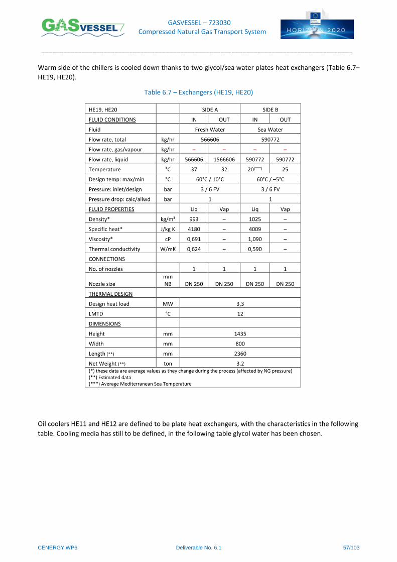
GASVESSEL – 723030 Compressed Natural Gas Transport System
______________________________________________________________________________________
CENERGY WP6 Deliverable No. 6.1 57/103
Warm side of the chillers is cooled down thanks to two glycol/sea water plates heat exchangers (Table 6.7–
HE19, HE20).
Table 6.7 – Exchangers (HE19, HE20)
HE19, HE20 SIDE A SIDE B
FLUID CONDITIONS IN OUT IN OUT
Fluid Fresh Water Sea Water
Flow rate, total kg/hr 566606 590772
Flow rate, gas/vapour kg/hr – – – –
Flow rate, liquid kg/hr 566606 1566606 590772 590772
Temperature °C 37 32 20(***) 25
Design temp: max/min °C 60°C / 10°C 60°C / –5°C
Pressure: inlet/design bar 3 / 6 FV 3 / 6 FV
Pressure drop: calc/allwd bar 1 1
FLUID PROPERTIES Liq Vap Liq Vap
Density* kg/m³ 993 – 1025 –
Specific heat* J/kg K 4180 – 4009 –
Viscosity* cP 0,691 – 1,090 –
Thermal conductivity W/mK 0,624 – 0,590 –
CONNECTIONS
No. of nozzles 1 1 1 1
Nozzle size mm NB DN 250 DN 250 DN 250 DN 250
THERMAL DESIGN
Design heat load MW 3,3
LMTD °C 12
DIMENSIONS
Height mm 1435
Width mm 800
Length (**) mm 2360
Net Weight (**) ton 3.2 (*) these data are average values as they change during the process (affected by NG pressure) (**) Estimated data (***) Average Mediterranean Sea Temperature
Oil coolers HE11 and HE12 are defined to be plate heat exchangers, with the characteristics in the following
table. Cooling media has still to be defined, in the following table glycol water has been chosen.
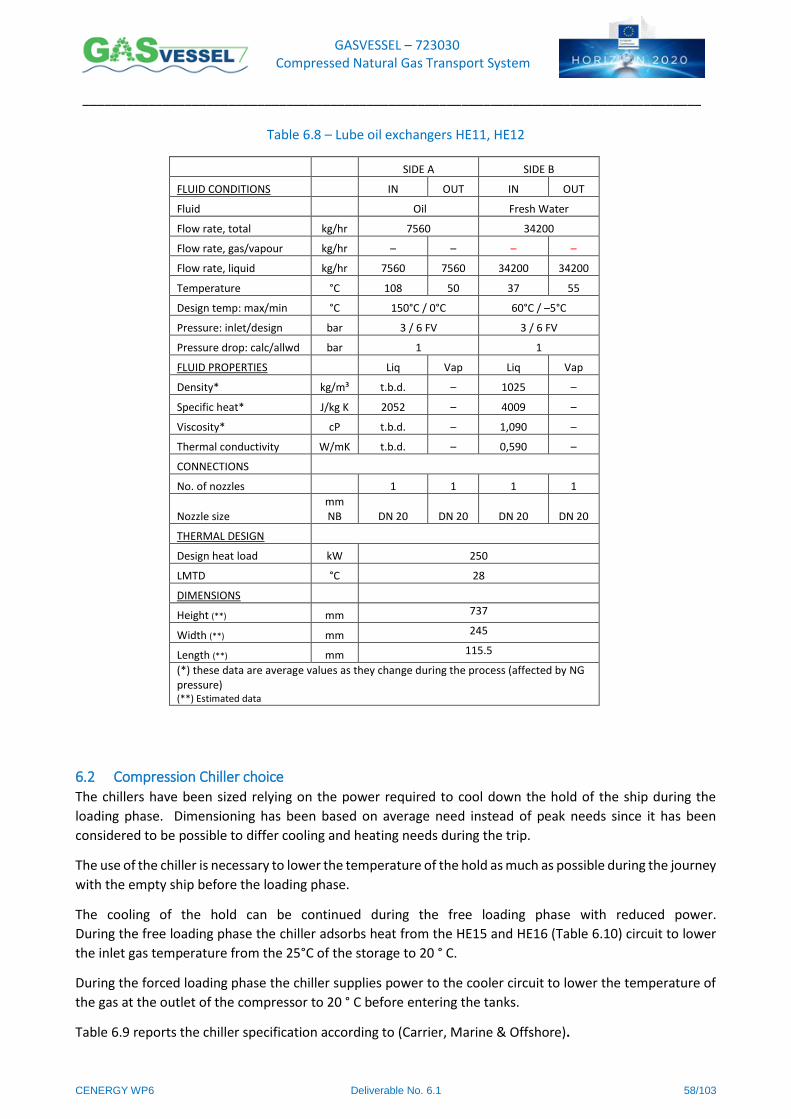
GASVESSEL – 723030 Compressed Natural Gas Transport System
______________________________________________________________________________________
CENERGY WP6 Deliverable No. 6.1 58/103
Table 6.8 – Lube oil exchangers HE11, HE12
SIDE A SIDE B
FLUID CONDITIONS IN OUT IN OUT
Fluid Oil Fresh Water
Flow rate, total kg/hr 7560 34200
Flow rate, gas/vapour kg/hr – – – –
Flow rate, liquid kg/hr 7560 7560 34200 34200
Temperature °C 108 50 37 55
Design temp: max/min °C 150°C / 0°C 60°C / –5°C
Pressure: inlet/design bar 3 / 6 FV 3 / 6 FV
Pressure drop: calc/allwd bar 1 1
FLUID PROPERTIES Liq Vap Liq Vap
Density* kg/m³ t.b.d. – 1025 –
Specific heat* J/kg K 2052 – 4009 –
Viscosity* cP t.b.d. – 1,090 –
Thermal conductivity W/mK t.b.d. – 0,590 –
CONNECTIONS
No. of nozzles 1 1 1 1
Nozzle size mm NB DN 20 DN 20 DN 20 DN 20
THERMAL DESIGN
Design heat load kW 250
LMTD °C 28
DIMENSIONS
Height (**) mm 737
Width (**) mm 245
Length (**) mm 115.5
(*) these data are average values as they change during the process (affected by NG pressure) (**) Estimated data
6.2 Compression Chiller choice The chillers have been sized relying on the power required to cool down the hold of the ship during the
loading phase. Dimensioning has been based on average need instead of peak needs since it has been
considered to be possible to differ cooling and heating needs during the trip.
The use of the chiller is necessary to lower the temperature of the hold as much as possible during the journey
with the empty ship before the loading phase.
The cooling of the hold can be continued during the free loading phase with reduced power.
During the free loading phase the chiller adsorbs heat from the HE15 and HE16 (Table 6.10) circuit to lower
the inlet gas temperature from the 25°C of the storage to 20 ° C.
During the forced loading phase the chiller supplies power to the cooler circuit to lower the temperature of
the gas at the outlet of the compressor to 20 ° C before entering the tanks.
Table 6.9 reports the chiller specification according to (Carrier, Marine & Offshore).
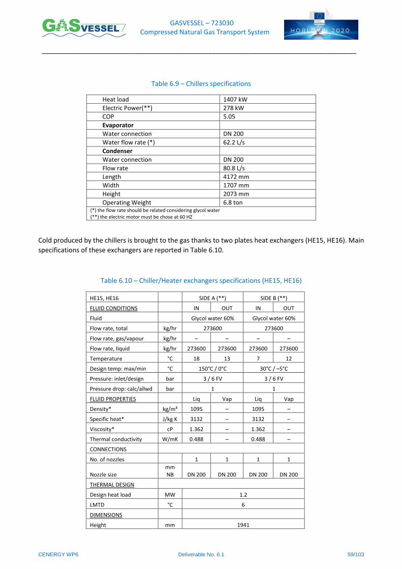
GASVESSEL – 723030 Compressed Natural Gas Transport System
______________________________________________________________________________________
CENERGY WP6 Deliverable No. 6.1 59/103
Table 6.9 – Chillers specifications
Heat load 1407 kW
Electric Power(**) 278 kW
COP 5.05
Evaporator
Water connection DN 200
Water flow rate (*) 62.2 L/s
Condenser
Water connection DN 200
Flow rate 80.8 L/s
Length 4172 mm
Width 1707 mm
Height 2073 mm
Operating Weight 6.8 ton (*) the flow rate should be related considering glycol water (**) the electric motor must be chose at 60 HZ
Cold produced by the chillers is brought to the gas thanks to two plates heat exchangers (HE15, HE16). Main
specifications of these exchangers are reported in Table 6.10.
Table 6.10 – Chiller/Heater exchangers specifications (HE15, HE16)
HE15, HE16 SIDE A (**) SIDE B (**)
FLUID CONDITIONS IN OUT IN OUT
Fluid Glycol water 60% Glycol water 60%
Flow rate, total kg/hr 273600 273600
Flow rate, gas/vapour kg/hr – – – –
Flow rate, liquid kg/hr 273600 273600 273600 273600
Temperature °C 18 13 7 12
Design temp: max/min °C 150°C / 0°C 30°C / –5°C
Pressure: inlet/design bar 3 / 6 FV 3 / 6 FV
Pressure drop: calc/allwd bar 1 1
FLUID PROPERTIES Liq Vap Liq Vap
Density* kg/m³ 1095 – 1095 –
Specific heat* J/kg K 3132 – 3132 –
Viscosity* cP 1.362 – 1.362 –
Thermal conductivity W/mK 0.488 – 0.488 –
CONNECTIONS
No. of nozzles 1 1 1 1
Nozzle size mm NB DN 200 DN 200 DN 200 DN 200
THERMAL DESIGN
Design heat load MW 1.2
LMTD °C 6
DIMENSIONS
Height mm 1941

GASVESSEL – 723030 Compressed Natural Gas Transport System
______________________________________________________________________________________
CENERGY WP6 Deliverable No. 6.1 60/103
HE15, HE16 SIDE A (**) SIDE B (**)
Width mm 610
Length (***) mm 1100
Net Weight (***) ton 2.2 (*) these data are average values as they change during the process (affected by NG pressure) (**) side A: glycol water circuit connect to HE01, HE07 and HE03 (HE02, HE09 and HE05); side B: glycol water circuit connect to chiller. (***) Estimated data
Figure 6.6 – Dimensions of the plates heat exchangers used for the HE15, HE16 reports layout and main
dimensions of the plates heat exchanger used for HE15 and HE16.
Figure 6.6 – Dimensions of the plates heat exchangers used for the HE15, HE16
The heat exchangers are also connected to two seawater heat exchangers of 3.8MW each (Table 6.4).
6.3 Fan coil selection for the holds In order to increase the total loading capacity of the ship, it is important to decrease as much as possible
both the gas temperature and the hold temperature. For this reason 224 fan coils of 25kW each (Table 6.11)
has been installed on the dome of the holds as, for example, shown in Figure 6.7
Table 6.11 – Fan coils specifications
Fan coil(*) Specification Total Values Single Unit
Cooling Heat load 5.6 MW 25 kW
Number of fan coil 224 1
Electric Power 246.4 kW 1.1 kW
Water flow rate 345.6 kg/s 1.5 kg/s
length – 1536 mm
width – 525 mm
height – 780 mm
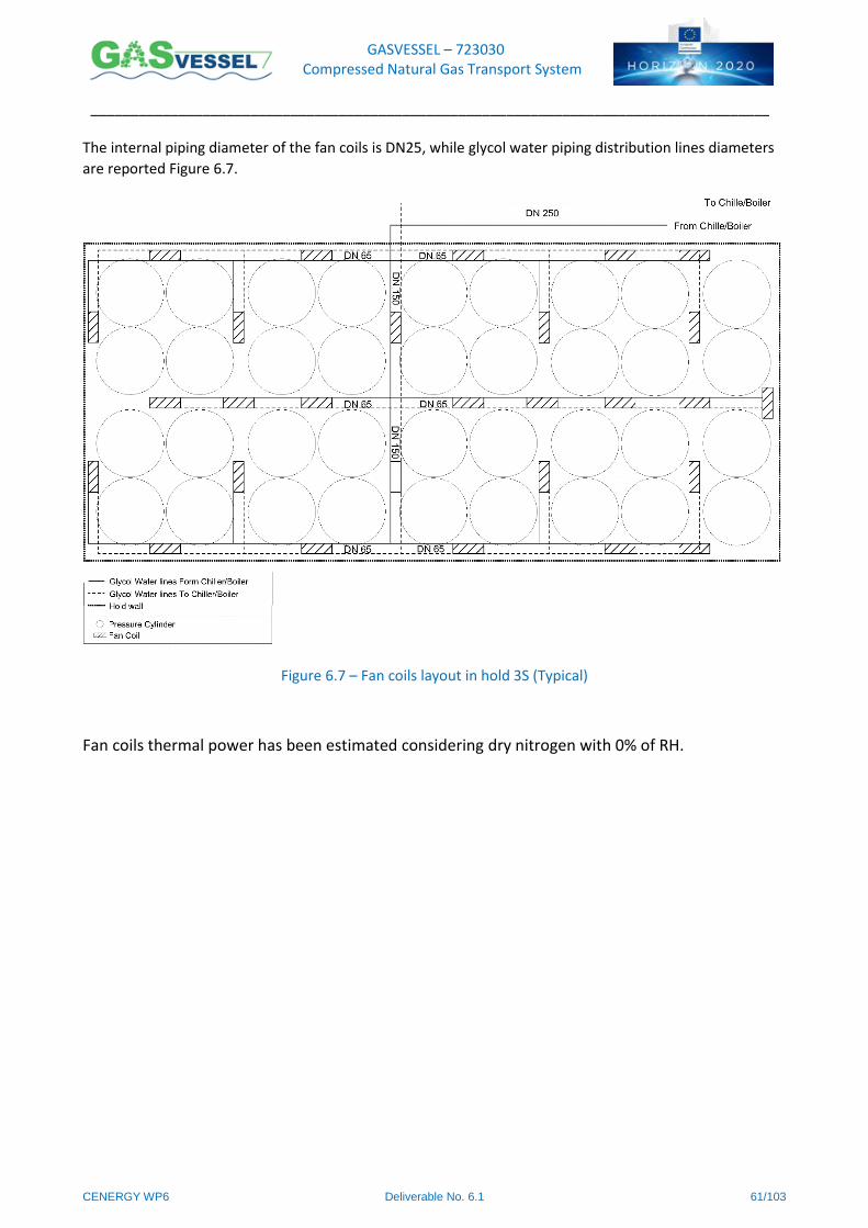
GASVESSEL – 723030 Compressed Natural Gas Transport System
______________________________________________________________________________________
CENERGY WP6 Deliverable No. 6.1 61/103
The internal piping diameter of the fan coils is DN25, while glycol water piping distribution lines diameters
are reported Figure 6.7.
Figure 6.7 – Fan coils layout in hold 3S (Typical)
Fan coils thermal power has been estimated considering dry nitrogen with 0% of RH.
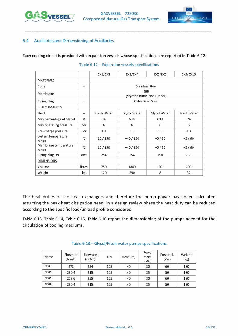
GASVESSEL – 723030 Compressed Natural Gas Transport System
______________________________________________________________________________________
CENERGY WP6 Deliverable No. 6.1 62/103
6.4 Auxiliaries and Dimensioning of Auxiliaries
Each cooling circuit is provided with expansion vessels whose specifications are reported in Table 6.12.
Table 6.12 – Expansion vessels specifications
EX1/EX3 EX2/EX4 EX5/EX6 EX9/EX10
MATERIALS
Body – Stainless Steel
Membrane – SBR
(Styrene Butadiene Rubber)
Piping plug – Galvanized Steel
PERFORMANCES
Fluid – Fresh Water Glycol Water Glycol Water Fresh Water
Max percentage of Glycol % 0% 60% 60% 0%
Max operating pressure bar 6 6 6 6
Pre–charge pressure Bar 1.3 1.3 1.3 1.3
System temperature range
°C 10 / 150 –40 / 150 –5 / 30 –5 / 60
Membrane temperature range
°C 10 / 150 –40 / 150 –5 / 30 –5 / 60
Piping plug DN mm 254 254 190 250
DIMENSIONS
Volume litres 750 1800 50 200
Weight kg 120 290 8 32
The heat duties of the heat exchangers and therefore the pump power have been calculated
assuming the peak heat dissipation need. In a design review phase the heat duty can be reduced
according to the specific load/unload profile considered.
Table 6.13, Table 6.14, Table 6.15, Table 6.16 report the dimensioning of the pumps needed for the
circulation of cooling mediums.
Table 6.13 – Glycol/Fresh water pumps specifications
Name Flowrate (ton/h)
Flowrate (m3/h)
DN Head (m) Power mech. (kW)
Power el. (kW)
Weight (kg)
EP01 273 254 125 40 30 60 180
EP04 230.4 215 125 40 25 50 180
EP05 273.6 255 125 40 30 60 180
EP06 230.4 215 125 40 25 50 180
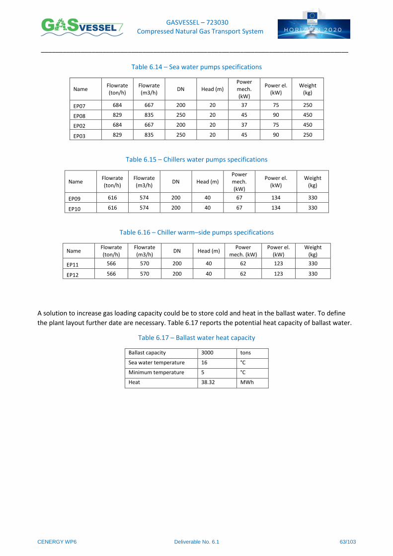
GASVESSEL – 723030 Compressed Natural Gas Transport System
______________________________________________________________________________________
CENERGY WP6 Deliverable No. 6.1 63/103
Table 6.14 – Sea water pumps specifications
Name Flowrate (ton/h)
Flowrate (m3/h)
DN Head (m) Power mech. (kW)
Power el. (kW)
Weight (kg)
EP07 684 667 200 20 37 75 250
EP08 829 835 250 20 45 90 450
EP02 684 667 200 20 37 75 450
EP03 829 835 250 20 45 90 250
Table 6.15 – Chillers water pumps specifications
Name Flowrate (ton/h)
Flowrate (m3/h)
DN Head (m) Power mech. (kW)
Power el. (kW)
Weight (kg)
EP09 616 574 200 40 67 134 330
EP10 616 574 200 40 67 134 330
Table 6.16 – Chiller warm–side pumps specifications
Name Flowrate (ton/h)
Flowrate (m3/h)
DN Head (m) Power
mech. (kW) Power el.
(kW) Weight
(kg)
EP11 566 570 200 40 62 123 330
EP12 566 570 200 40 62 123 330
A solution to increase gas loading capacity could be to store cold and heat in the ballast water. To define
the plant layout further date are necessary. Table 6.17 reports the potential heat capacity of ballast water.
Table 6.17 – Ballast water heat capacity
Ballast capacity 3000 tons
Sea water temperature 16 °C
Minimum temperature 5 °C
Heat 38.32 MWh
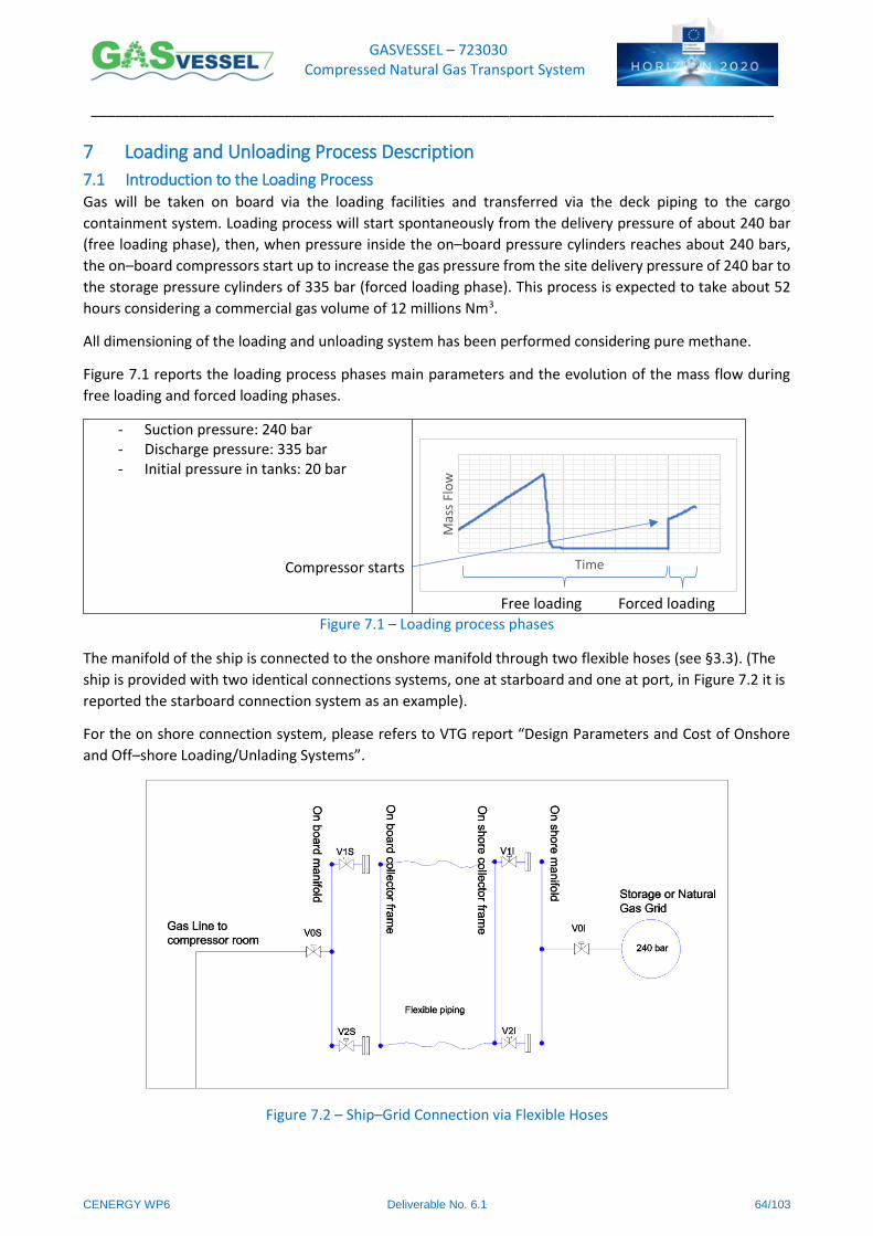
GASVESSEL – 723030 Compressed Natural Gas Transport System
______________________________________________________________________________________
CENERGY WP6 Deliverable No. 6.1 64/103
7 Loading and Unloading Process Description
7.1 Introduction to the Loading Process Gas will be taken on board via the loading facilities and transferred via the deck piping to the cargo
containment system. Loading process will start spontaneously from the delivery pressure of about 240 bar
(free loading phase), then, when pressure inside the on–board pressure cylinders reaches about 240 bars,
the on–board compressors start up to increase the gas pressure from the site delivery pressure of 240 bar to
the storage pressure cylinders of 335 bar (forced loading phase). This process is expected to take about 52
hours considering a commercial gas volume of 12 millions Nm3.
All dimensioning of the loading and unloading system has been performed considering pure methane.
Figure 7.1 reports the loading process phases main parameters and the evolution of the mass flow during
free loading and forced loading phases.
- Suction pressure: 240 bar - Discharge pressure: 335 bar - Initial pressure in tanks: 20 bar
Compressor starts
Free loading Forced loading
Figure 7.1 – Loading process phases
The manifold of the ship is connected to the onshore manifold through two flexible hoses (see §3.3). (The
ship is provided with two identical connections systems, one at starboard and one at port, in Figure 7.2 it is
reported the starboard connection system as an example).
For the on shore connection system, please refers to VTG report “Design Parameters and Cost of Onshore
and Off–shore Loading/Unlading Systems”.
Figure 7.2 – Ship–Grid Connection via Flexible Hoses
Time
Mas
s Fl
ow
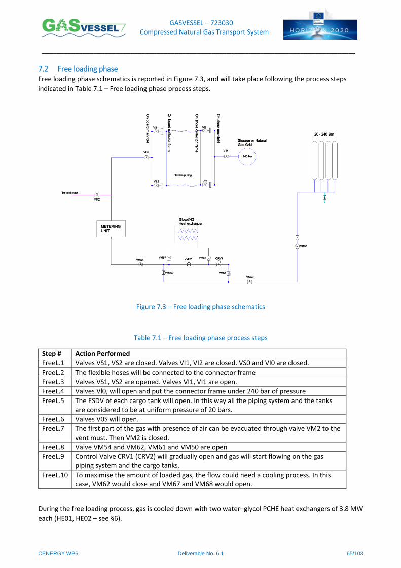
GASVESSEL – 723030 Compressed Natural Gas Transport System
______________________________________________________________________________________
CENERGY WP6 Deliverable No. 6.1 65/103
7.2 Free loading phase Free loading phase schematics is reported in Figure 7.3, and will take place following the process steps
indicated in Table 7.1 – Free loading phase process steps.
Figure 7.3 – Free loading phase schematics
Table 7.1 – Free loading phase process steps
Step # Action Performed
FreeL.1 Valves VS1, VS2 are closed. Valves VI1, VI2 are closed. VS0 and VI0 are closed.
FreeL.2 The flexible hoses will be connected to the connector frame
FreeL.3 Valves VS1, VS2 are opened. Valves VI1, VI1 are open.
FreeL.4 Valves Vl0, will open and put the connector frame under 240 bar of pressure
FreeL.5 The ESDV of each cargo tank will open. In this way all the piping system and the tanks are considered to be at uniform pressure of 20 bars.
FreeL.6 Valves V0S will open.
FreeL.7 The first part of the gas with presence of air can be evacuated through valve VM2 to the vent must. Then VM2 is closed.
FreeL.8 Valve VM54 and VM62, VM61 and VM50 are open
FreeL.9 Control Valve CRV1 (CRV2) will gradually open and gas will start flowing on the gas piping system and the cargo tanks.
FreeL.10 To maximise the amount of loaded gas, the flow could need a cooling process. In this case, VM62 would close and VM67 and VM68 would open.
During the free loading process, gas is cooled down with two water–glycol PCHE heat exchangers of 3.8 MW
each (HE01, HE02 – see §6).
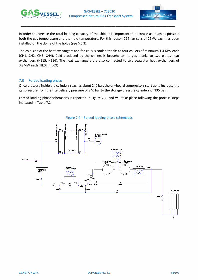
GASVESSEL – 723030 Compressed Natural Gas Transport System
______________________________________________________________________________________
CENERGY WP6 Deliverable No. 6.1 66/103
In order to increase the total loading capacity of the ship, it is important to decrease as much as possible
both the gas temperature and the hold temperature. For this reason 224 fan coils of 25kW each has been
installed on the dome of the holds (see § 6.3).
The cold side of the heat exchangers and fan coils is cooled thanks to four chillers of minimum 1.4 MW each
(CH1, CH2, CH3, CH4). Cold produced by the chillers is brought to the gas thanks to two plates heat
exchangers (HE15, HE16). The heat exchangers are also connected to two seawater heat exchangers of
3.8MW each (HE07, HE09)
7.3 Forced loading phase Once pressure inside the cylinders reaches about 240 bar, the on–board compressors start up to increase the
gas pressure from the site delivery pressure of 240 bar to the storage pressure cylinders of 335 bar.
Forced loading phase schematics is reported in Figure 7.4, and will take place following the process steps
indicated in Table 7.2
Figure 7.4 – Forced loading phase schematics
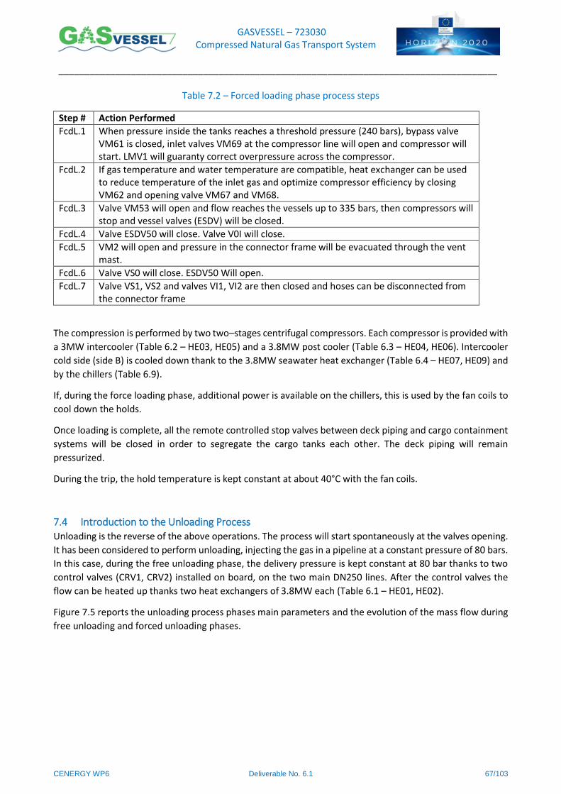
GASVESSEL – 723030 Compressed Natural Gas Transport System
______________________________________________________________________________________
CENERGY WP6 Deliverable No. 6.1 67/103
Table 7.2 – Forced loading phase process steps
Step # Action Performed
FcdL.1 When pressure inside the tanks reaches a threshold pressure (240 bars), bypass valve VM61 is closed, inlet valves VM69 at the compressor line will open and compressor will start. LMV1 will guaranty correct overpressure across the compressor.
FcdL.2 If gas temperature and water temperature are compatible, heat exchanger can be used to reduce temperature of the inlet gas and optimize compressor efficiency by closing VM62 and opening valve VM67 and VM68.
FcdL.3 Valve VM53 will open and flow reaches the vessels up to 335 bars, then compressors will stop and vessel valves (ESDV) will be closed.
FcdL.4 Valve ESDV50 will close. Valve V0I will close.
FcdL.5 VM2 will open and pressure in the connector frame will be evacuated through the vent mast.
FcdL.6 Valve VS0 will close. ESDV50 Will open.
FcdL.7 Valve VS1, VS2 and valves VI1, VI2 are then closed and hoses can be disconnected from the connector frame
The compression is performed by two two–stages centrifugal compressors. Each compressor is provided with
a 3MW intercooler (Table 6.2 – HE03, HE05) and a 3.8MW post cooler (Table 6.3 – HE04, HE06). Intercooler
cold side (side B) is cooled down thank to the 3.8MW seawater heat exchanger (Table 6.4 – HE07, HE09) and
by the chillers (Table 6.9).
If, during the force loading phase, additional power is available on the chillers, this is used by the fan coils to
cool down the holds.
Once loading is complete, all the remote controlled stop valves between deck piping and cargo containment
systems will be closed in order to segregate the cargo tanks each other. The deck piping will remain
pressurized.
During the trip, the hold temperature is kept constant at about 40°C with the fan coils.
7.4 Introduction to the Unloading Process Unloading is the reverse of the above operations. The process will start spontaneously at the valves opening.
It has been considered to perform unloading, injecting the gas in a pipeline at a constant pressure of 80 bars.
In this case, during the free unloading phase, the delivery pressure is kept constant at 80 bar thanks to two
control valves (CRV1, CRV2) installed on board, on the two main DN250 lines. After the control valves the
flow can be heated up thanks two heat exchangers of 3.8MW each (Table 6.1 – HE01, HE02).
Figure 7.5 reports the unloading process phases main parameters and the evolution of the mass flow during
free unloading and forced unloading phases.
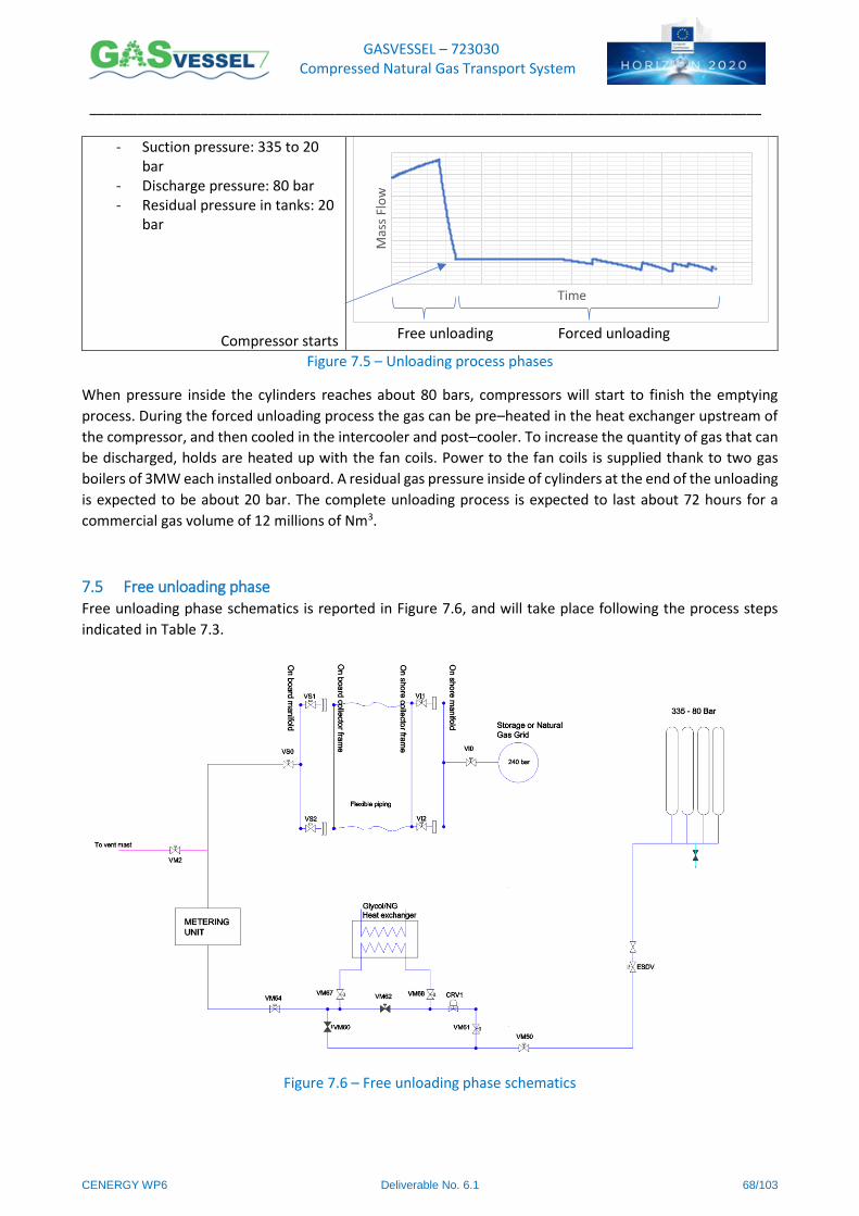
GASVESSEL – 723030 Compressed Natural Gas Transport System
______________________________________________________________________________________
CENERGY WP6 Deliverable No. 6.1 68/103
- Suction pressure: 335 to 20 bar
- Discharge pressure: 80 bar - Residual pressure in tanks: 20
bar
Compressor starts
Free unloading Forced unloading
Figure 7.5 – Unloading process phases
When pressure inside the cylinders reaches about 80 bars, compressors will start to finish the emptying
process. During the forced unloading process the gas can be pre–heated in the heat exchanger upstream of
the compressor, and then cooled in the intercooler and post–cooler. To increase the quantity of gas that can
be discharged, holds are heated up with the fan coils. Power to the fan coils is supplied thank to two gas
boilers of 3MW each installed onboard. A residual gas pressure inside of cylinders at the end of the unloading
is expected to be about 20 bar. The complete unloading process is expected to last about 72 hours for a
commercial gas volume of 12 millions of Nm3.
7.5 Free unloading phase Free unloading phase schematics is reported in Figure 7.6, and will take place following the process steps
indicated in Table 7.3.
Figure 7.6 – Free unloading phase schematics
Time
Mas
s Fl
ow

GASVESSEL – 723030 Compressed Natural Gas Transport System
______________________________________________________________________________________
CENERGY WP6 Deliverable No. 6.1 69/103
Table 7.3 – Free unloading phase process steps
Step # Action Performed
FreeU.1 Valves VS1, VS2 are closed. Vl1, Vl2 are closed. Valves VS0 and Valve Vl0 are closed.
FreeU.2 Flexible hoses are connected to the connector frame
FreeU.3 ESDV of all cargo tanks are opened. In this way all the piping system and tanks will be at uniform pressure of 335 bars.
FreeU.4 Valves VS1, VS2 are open. Vl1, Vl2 are open.
FreeU.5 The compressor inlet valves are closed. VM60 and VM62 are closed while valves VM67 and VM68 are opened. Flow will pass through heater to guaranty minimum output temperature of 7°C. (if temperature of the gas is higher, valves VM68 and VM67 will close and valve VM62 will open).
FreeU.6 Valve CRV1 will guaranty delivery pressure at 80bars.
FreeU.7 Valve Vl0 will open.
7.6 Forced Unloading Forced unloading phase schematics is reported in Figure 7.7, and will take place following the process steps
indicated in Table 7.4.
Figure 7.7 – Forced unloading phase schematics
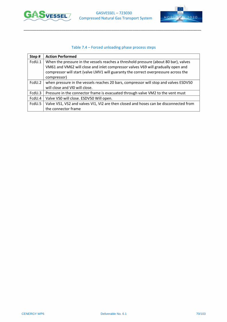
GASVESSEL – 723030 Compressed Natural Gas Transport System
______________________________________________________________________________________
CENERGY WP6 Deliverable No. 6.1 70/103
Table 7.4 – Forced unloading phase process steps
Step # Action Performed
FcdU.1 When the pressure in the vessels reaches a threshold pressure (about 80 bar), valves VM61 and VM62 will close and inlet compressor valves V69 will gradually open and compressor will start (valve LMV1 will guaranty the correct overpressure across the compressor)
FcdU.2 when pressure in the vessels reaches 20 bars, compressor will stop and valves ESDV50 will close and Vl0 will close.
FcdU.3 Pressure in the connector frame is evacuated through valve VM2 to the vent must
FcdU.4 Valve VS0 will close. ESDV50 Will open.
FcdU.5 Valve VS1, VS2 and valves VI1, VI2 are then closed and hoses can be disconnected from the connector frame
GASVESSEL – 723030 Compressed Natural Gas Transport System
______________________________________________________________________________________
CENERGY WP6 Deliverable No. 6.1 71/103
8 References
[1] ABS. VESSELS INTENDED TO CARRY COMPRESSED NATURAL GASES IN BULK 2018;2005.
[2] ABS. RULES FOR BUILDING AND CLASSING STEEL VESSELS 2010.
[3] IMO. International Code for the Construction and Equipment of Ships Carrying Liquefied Gases in Bulk. 1993.
[4] IMO. GUIDELINES FOR FORMAL SAFETY ASSESSMENT (FSA) FOR USE IN THE IMO RULE–MAKING PROCESS 2002.
[5] DNV. Compressed Natural Gas Carriers 2011.
[6] MSC. ADOPTION OF AMENDMENTS TO THE INTERNATIONAL CONVENTION FOR THE SAFETY OF LIFE AT SEA 1983.
[7] ABS. RULES FOR BUILDING AND CLASSING OFFSHORE INSTALLATIONS 2018.
[8] ASME. Boiler and Pressure Vessel Code – Section VIII 2017.
[9] ASME. Pipe Flanges and Flanged Fittings 2008;2003.
[10] API. Standard 14E RP – Recommended Practice for Design and Installation of Offshore Production Platform Piping Systems Issued by 2002.
[11] NORSOK. PIPING DESIGN , LAYOUT AND STRESS ANALYSIS 1996.
[12] NORSOK. PROCESS DESIGN 1997.
[13] Asme. Valves—Flanged, Threaded, and Welding End 2008;2004.
[14] API. Standard 6D – Specification for Pipeline Valves n.d.
[15] ASME. Gas Transmission and Distribution Piping Systems n.d.
[16] API. Standard 5L – Specification for Line Pipe n.d.
[17] ASME. Standard B318s – Managing System Integrity of Gas Pipelines n.d.
[18] API. Standart 1104 – Standard for Welding Pipelines and Related Facilities n.d.
[19] API. Standard 521 – Pressure–relieving and Depressuring Systems 2014.
[20] ISO. Standard 13707 – Petroleum and natural gas industries–Reciprocating compressors 2000;2000.
[21] ISO. Standard 13631 – Petroleum and natural gas industries – Packaged reciprocating gas compressors 2003.
[22] API/ANSI. Standard 618 – Reciprocating Compressors for Petroleum , Chemical , and Gas Industry Services 2010.
[23] API. Standard 617 – Axial and Centrifugal Compressors and Expander– compressors 2014;7056:0–4.
[24] API. Standard 619 – Rotary–Type Positive– Displacement Compressors for Petroleum , Petrochemical , and Natural Gas Industries 2005.
[25] API. Standard 672 – Packaged , Integrally Geared Centrifugal Air Compressors for Petroleum , Chemical , and Gas Industry Services 2010.

GASVESSEL – 723030 Compressed Natural Gas Transport System
______________________________________________________________________________________
CENERGY WP6 Deliverable No. 6.1 72/103
[26] API. Standard 673 – Centrifugal Fans for Petroleum , Chemical , and Gas Industry Services 2014.
[27] Blaiklock P, Verma M, Bondy S. When should an Electric Adjustable Speed Drive be used instead of a Gas or Steam Turbine ? 2013.
[28] offshoreteknikk. Air and Seawater Cooling Part.1 n.d. https://offshoreteknikk.com/2014/02/21/air–and–seawater–cooling–part–1/ (accessed August 24, 2018).
[29] Bloch HP. Compressor Lubrication Best Practices 2000. https://www.machinerylubrication.com/Read/488/compressor–lubricants (accessed August 27, 2018).
[30] Staff EP. Compressor Lubrication, Part IV–A: Positive–Displacement Types 2012. https://www.efficientplantmag.com/2012/08/compressor–lubrication–part–iv–a–positive–displacement–types/ (accessed August 27, 2018).
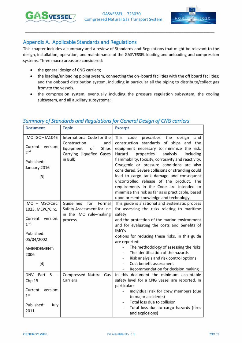
GASVESSEL – 723030 Compressed Natural Gas Transport System
______________________________________________________________________________________
CENERGY WP6 Deliverable No. 6.1 73/103
Appendix A. Applicable Standards and Regulations This chapter includes a summary and a review of Standards and Regulations that might be relevant to the
design, installation, operation, and maintenance of the GASVESSEL loading and unloading and compression
systems. Three macro areas are considered:
the general design of CNG carriers;
the loading/unloading piping system, connecting the on–board facilities with the off board facilities;
and the onboard distribution system, including in particular all the piping to distribute/collect gas
from/to the vessels.
the compression system, eventually including the pressure regulation subsystem, the cooling
subsystem, and all auxiliary subsystems;
Summary of Standards and Regulations for General Design of CNG carriers Document Topic Excerpt
IMO IGC – IA104E
Current version:
2nd
Published:
January 2016
[3]
International Code for the Construction and Equipment of Ships Carrying Liquefied Gases in Bulk
This code prescribes the design and construction standards of ships and the equipment necessary to minimize the risk. Hazard properties analysis including flammability, toxicity, corrosivity and reactivity. Cryogenic or pressure conditions are also considered. Severe collisions or stranding could lead to cargo tank damage and consequent uncontrolled release of the product. The requirements in the Code are intended to minimize this risk as far as is practicable, based upon present knowledge and technology.
IMO – MSC/Circ.
1023, MEPC/Circ.
Current version:
1nst
Published:
05/04/2002
AMENDEMENT:
2006
[4]
Guidelines for Formal Safety Assessment for use in the IMO rule–making process
This guide is a rational and systematic process for assessing the risks relating to maritime safety and the protection of the marine environment and for evaluating the costs and benefits of IMO’s options for reducing these risks. In this guide are reported:
- The methodology of assessing the risks - The identification of the hazards - Risk analysis and risk control options - Cost benefit assessment - Recommendation for decision making
DNV Part 5 –
Chp.15
Current version:
1st
Published: July
2011
Compressed Natural Gas Carriers
In this document the minimum acceptable safety level for a CNG vessel are reported. In particular:
- Individual risk for crew members (due to major accidents)
- Total loss due to collision - Total loss due to cargo hazards (fires
and explosions)

GASVESSEL – 723030 Compressed Natural Gas Transport System
______________________________________________________________________________________
CENERGY WP6 Deliverable No. 6.1 74/103
Document Topic Excerpt
[5] - Individual risk from cargo cylinder failure
- Individual risks for public ashore
ABS Part 5C,
Chapter 8
Current version:
11th
Published:
January 2018
ERRATA 1: May
2018
[2]
Rule Requirements for Vessels Intended to Carry Liquefied Gases in Bulk
ABS defines the minimum safety requirements
to obtain ABS classification for vessels intended
to carry Liquified gases in bulk. Technical
standards are defined for:
- Ship arrangement
- Cargo containment
- Process pressure vessels and piping
system
- Construction materials
- Pressure/temperature controls
- Vent systems
- Fire protections
- Electrical installations
- Required instrumentation
- Operating requirements
ABS Guide
Current version:
8th
Published: March
2018
[1]
Vessels intended to carry compressed natural gases in bulk
Based on the rule requirements for vessels
intended to transport liquified gases in bulk,
ABS defines the minimum safety requirements
to obtain ABS classification of new concepts of
CNG carriers. Specific qualitative and
quantitative risk assessments of different
hazards are required. Technical best practices
to improve safety on board are reported for:
- Ship arrangement
- Cargo containment
- Process pressure vessels and piping
system
- Construction materials
- Pressure/temperature controls
- Vent systems
- Fire protections
- Electrical installations
- Required instrumentation
- Operating requirements
MSC – SOLAS
Amendments
1983
Current version:
48th
1983 Amendments to International Convention for the Safety of Life at Sea, 1974 (MSC.6(48)) Volume 1
These amendments report technical
specifications for:
- Machinery and electrical installations
- Fire protections, fire detection and
extinction
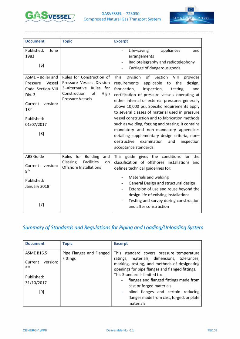
GASVESSEL – 723030 Compressed Natural Gas Transport System
______________________________________________________________________________________
CENERGY WP6 Deliverable No. 6.1 75/103
Document Topic Excerpt
Published: June
1983
[6]
- Life–saving appliances and
arrangements
- Radiotelegraphy and radiotelephony
- Carriage of dangerous goods
ASME – Boiler and
Pressure Vessel
Code Section VIII
Div. 3
Current version:
13th
Published:
01/07/2017
[8]
Rules for Construction of Pressure Vessels Division 3–Alternative Rules for Construction of High Pressure Vessels
This Division of Section VIII provides
requirements applicable to the design,
fabrication, inspection, testing, and
certification of pressure vessels operating at
either internal or external pressures generally
above 10,000 psi. Specific requirements apply
to several classes of material used in pressure
vessel construction and to fabrication methods
such as welding, forging and brazing. It contains
mandatory and non–mandatory appendices
detailing supplementary design criteria, non–
destructive examination and inspection
acceptance standards.
ABS Guide
Current version:
9th
Published:
January 2018
[7]
Rules for Building and Classing Facilities on Offshore Installations
This guide gives the conditions for the
classification of offshores installations and
defines technical guidelines for:
- Materials and welding
- General Design and structural design
- Extension of use and reuse beyond the
design life of existing installations
- Testing and survey during construction
and after construction
Summary of Standards and Regulations for Piping and Loading/Unloading System
Document Topic Excerpt
ASME B16.5
Current version:
5th
Published:
31/10/2017
[9]
Pipe Flanges and Flanged Fittings
This standard covers pressure–temperature ratings, materials, dimensions, tolerances, marking, testing, and methods of designating openings for pipe flanges and flanged fittings. This Standard is limited to:
- flanges and flanged fittings made from
cast or forged materials
- blind flanges and certain reducing
flanges made from cast, forged, or plate
materials
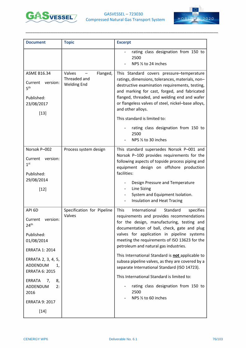
GASVESSEL – 723030 Compressed Natural Gas Transport System
______________________________________________________________________________________
CENERGY WP6 Deliverable No. 6.1 76/103
Document Topic Excerpt
- rating class designation from 150 to
2500
- NPS ½ to 24 inches
ASME B16.34
Current version:
5th
Published:
23/08/2017
[13]
Valves – Flanged, Threaded and Welding End
This Standard covers pressure–temperature
ratings, dimensions, tolerances, materials, non–
destructive examination requirements, testing,
and marking for cast, forged, and fabricated
flanged, threaded, and welding end and wafer
or flangeless valves of steel, nickel–base alloys,
and other alloys.
This standard is limited to:
- rating class designation from 150 to
2500
- NPS ½ to 30 inches
Norsok P–002
Current version:
1st
Published:
29/08/2014
[12]
Process system design This standard supersedes Norsok P–001 and
Norsok P–100 provides requirements for the
following aspects of topside process piping and
equipment design on offshore production
facilities:
- Design Pressure and Temperature
- Line Sizing
- System and Equipment Isolation.
- Insulation and Heat Tracing
API 6D
Current version:
24th
Published:
01/08/2014
ERRATA 1: 2014
ERRATA 2, 3, 4, 5,
ADDENDUM 1,
ERRATA 6: 2015
ERRATA 7, 8,
ADDENDUM 2:
2016
ERRATA 9: 2017
[14]
Specification for Pipeline Valves
This International Standard specifies
requirements and provides recommendations
for the design, manufacturing, testing and
documentation of ball, check, gate and plug
valves for application in pipeline systems
meeting the requirements of ISO 13623 for the
petroleum and natural gas industries.
This International Standard is not applicable to
subsea pipeline valves, as they are covered by a
separate International Standard (ISO 14723).
This International Standard is limited to:
- rating class designation from 150 to
2500
- NPS ½ to 60 inches
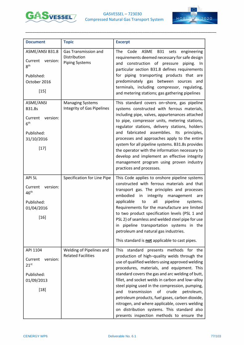
GASVESSEL – 723030 Compressed Natural Gas Transport System
______________________________________________________________________________________
CENERGY WP6 Deliverable No. 6.1 77/103
Document Topic Excerpt
ASME/ANSI B31.8
Current version:
8th
Published:
October 2016
[15]
Gas Transmission and Distribution Piping Systems
The Code ASME B31 sets engineering
requirements deemed necessary for safe design
and construction of pressure piping. In
particular section B31.8 defines requirements
for piping transporting products that are
predominately gas between sources and
terminals, including compressor, regulating,
and metering stations; gas gathering pipelines
ASME/ANSI
B31.8s
Current version:
6th
Published:
31/10/2016
[17]
Managing Systems Integrity of Gas Pipelines
This standard covers on–shore, gas pipeline
systems constructed with ferrous materials,
including pipe, valves, appurtenances attached
to pipe, compressor units, metering stations,
regulator stations, delivery stations, holders
and fabricated assemblies. Its principles,
processes and approaches apply to the entire
system for all pipeline systems. B31.8s provides
the operator with the information necessary to
develop and implement an effective integrity
management program using proven industry
practices and processes.
API 5L
Current version:
46th
Published:
01/04/2016
[16]
Specification for Line Pipe This Code applies to onshore pipeline systems
constructed with ferrous materials and that
transport gas. The principles and processes
embodied in integrity management are
applicable to all pipeline systems.
Requirements for the manufacture are limited
to two product specification levels (PSL 1 and
PSL 2) of seamless and welded steel pipe for use
in pipeline transportation systems in the
petroleum and natural gas industries.
This standard is not applicable to cast pipes.
API 1104
Current version:
21st
Published:
01/09/2013
[18]
Welding of Pipelines and Related Facilities
This standard presents methods for the
production of high–quality welds through the
use of qualified welders using approved welding
procedures, materials, and equipment. This
standard covers the gas and arc welding of butt,
fillet, and socket welds in carbon and low–alloy
steel piping used in the compression, pumping,
and transmission of crude petroleum,
petroleum products, fuel gases, carbon dioxide,
nitrogen, and where applicable, covers welding
on distribution systems. This standard also
presents inspection methods to ensure the
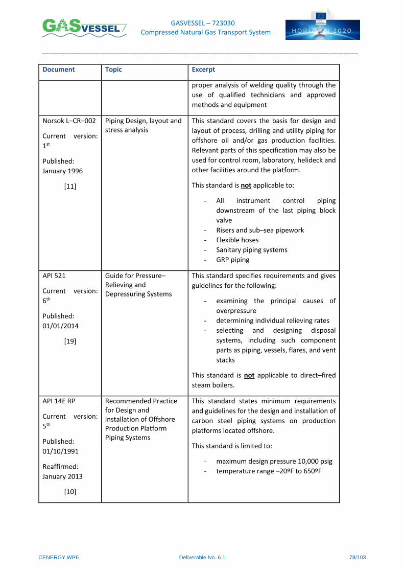
GASVESSEL – 723030 Compressed Natural Gas Transport System
______________________________________________________________________________________
CENERGY WP6 Deliverable No. 6.1 78/103
Document Topic Excerpt
proper analysis of welding quality through the
use of qualified technicians and approved
methods and equipment
Norsok L–CR–002
Current version:
1st
Published:
January 1996
[11]
Piping Design, layout and stress analysis
This standard covers the basis for design and
layout of process, drilling and utility piping for
offshore oil and/or gas production facilities.
Relevant parts of this specification may also be
used for control room, laboratory, helideck and
other facilities around the platform.
This standard is not applicable to:
- All instrument control piping
downstream of the last piping block
valve
- Risers and sub–sea pipework
- Flexible hoses
- Sanitary piping systems
- GRP piping
API 521
Current version:
6th
Published:
01/01/2014
[19]
Guide for Pressure–Relieving and Depressuring Systems
This standard specifies requirements and gives
guidelines for the following:
- examining the principal causes of
overpressure
- determining individual relieving rates
- selecting and designing disposal
systems, including such component
parts as piping, vessels, flares, and vent
stacks
This standard is not applicable to direct–fired
steam boilers.
API 14E RP
Current version:
5th
Published:
01/10/1991
Reaffirmed:
January 2013
[10]
Recommended Practice for Design and installation of Offshore Production Platform Piping Systems
This standard states minimum requirements
and guidelines for the design and installation of
carbon steel piping systems on production
platforms located offshore.
This standard is limited to:
- maximum design pressure 10,000 psig
- temperature range –20ºF to 650ºF
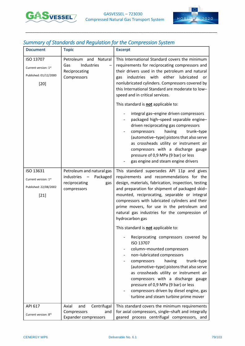
GASVESSEL – 723030 Compressed Natural Gas Transport System
______________________________________________________________________________________
CENERGY WP6 Deliverable No. 6.1 79/103
Summary of Standards and Regulation for the Compression System Document Topic Excerpt
ISO 13707
Current version: 1st
Published: 01/12/2000
[20]
Petroleum and Natural
Gas Industries –
Reciprocating
Compressors
This International Standard covers the minimum
requirements for reciprocating compressors and
their drivers used in the petroleum and natural
gas industries with either lubricated or
nonlubricated cylinders. Compressors covered by
this International Standard are moderate to low–
speed and in critical services.
This standard is not applicable to:
- integral gas–engine driven compressors
- packaged high–speed separable engine–
driven reciprocating gas compressors
- compressors having trunk–type
(automotive–type) pistons that also serve
as crossheads utility or instrument air
compressors with a discharge gauge
pressure of 0,9 MPa (9 bar) or less
- gas engine and steam engine drivers
ISO 13631
Current version: 1st
Published: 22/08/2002
[21]
Petroleum and natural gas
industries – Packaged
reciprocating gas
compressors
This standard supersedes API 11p and gives
requirements and recommendations for the
design, materials, fabrication, inspection, testing
and preparation for shipment of packaged skid–
mounted, reciprocating, separable or integral
compressors with lubricated cylinders and their
prime movers, for use in the petroleum and
natural gas industries for the compression of
hydrocarbon gas
This standard is not applicable to:
- Reciprocating compressors covered by
ISO 13707
- column–mounted compressors
- non–lubricated compressors
- compressors having trunk–type
(automotive–type) pistons that also serve
as crossheads utility or instrument air
compressors with a discharge gauge
pressure of 0,9 MPa (9 bar) or less
- compressors driven by diesel engine, gas
turbine and steam turbine prime mover
API 617
Current version: 8th
Axial and Centrifugal Compressors and Expander compressors
This standard covers the minimum requirements for axial compressors, single–shaft and integrally geared process centrifugal compressors, and
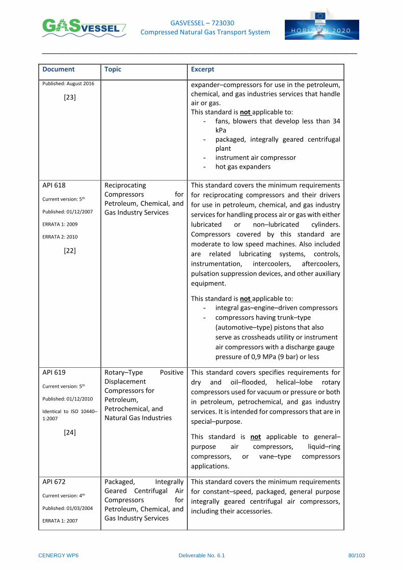
GASVESSEL – 723030 Compressed Natural Gas Transport System
______________________________________________________________________________________
CENERGY WP6 Deliverable No. 6.1 80/103
Document Topic Excerpt
Published: August 2016
[23]
expander–compressors for use in the petroleum, chemical, and gas industries services that handle air or gas. This standard is not applicable to:
- fans, blowers that develop less than 34 kPa
- packaged, integrally geared centrifugal plant
- instrument air compressor - hot gas expanders
API 618
Current version: 5th
Published: 01/12/2007
ERRATA 1: 2009
ERRATA 2: 2010
[22]
Reciprocating Compressors for Petroleum, Chemical, and Gas Industry Services
This standard covers the minimum requirements
for reciprocating compressors and their drivers
for use in petroleum, chemical, and gas industry
services for handling process air or gas with either
lubricated or non–lubricated cylinders.
Compressors covered by this standard are
moderate to low speed machines. Also included
are related lubricating systems, controls,
instrumentation, intercoolers, aftercoolers,
pulsation suppression devices, and other auxiliary
equipment.
This standard is not applicable to: - integral gas–engine–driven compressors
- compressors having trunk–type
(automotive–type) pistons that also
serve as crossheads utility or instrument
air compressors with a discharge gauge
pressure of 0,9 MPa (9 bar) or less
API 619
Current version: 5th
Published: 01/12/2010
Identical to ISO 10440–
1:2007
[24]
Rotary–Type Positive Displacement Compressors for Petroleum, Petrochemical, and Natural Gas Industries
This standard covers specifies requirements for
dry and oil–flooded, helical–lobe rotary
compressors used for vacuum or pressure or both
in petroleum, petrochemical, and gas industry
services. It is intended for compressors that are in
special–purpose.
This standard is not applicable to general–
purpose air compressors, liquid–ring
compressors, or vane–type compressors
applications.
API 672
Current version: 4th
Published: 01/03/2004
ERRATA 1: 2007
Packaged, Integrally Geared Centrifugal Air Compressors for Petroleum, Chemical, and Gas Industry Services
This standard covers the minimum requirements
for constant–speed, packaged, general purpose
integrally geared centrifugal air compressors,
including their accessories.
GASVESSEL – 723030 Compressed Natural Gas Transport System
______________________________________________________________________________________
CENERGY WP6 Deliverable No. 6.1 81/103
Document Topic Excerpt
ERRATA 2: 2010
[25]
This standard is not applicable to machines that
develop a pressure rise of less than 0.35 bar.
API 673
Current version: 3rd
Published: 01/12/2014
[26]
Centrifugal Fans for Petroleum, Chemical and Gas Industry Services
This standard covers the minimum requirements
for centrifugal fans for use in petroleum,
chemical, and gas industry services.
This standard is not applicable to axial flow, aerial
cooler, cooling tower, and ventilation fans and
positive displacement blowers.
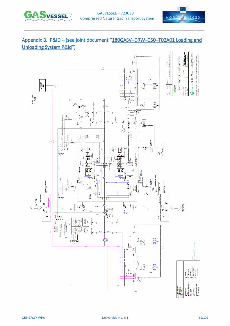
GASVESSEL – 723030 Compressed Natural Gas Transport System
______________________________________________________________________________________
CENERGY WP6 Deliverable No. 6.1 82/103
Appendix B. P&ID – (see joint document “180GASV–DRW–050–T02A01 Loading and
Unloading System P&Id”)

GASVESSEL – 723030 Compressed Natural Gas Transport System
______________________________________________________________________________________
CENERGY WP6 Deliverable No. 6.1 83/103
Appendix C. Metering Unit Datasheet
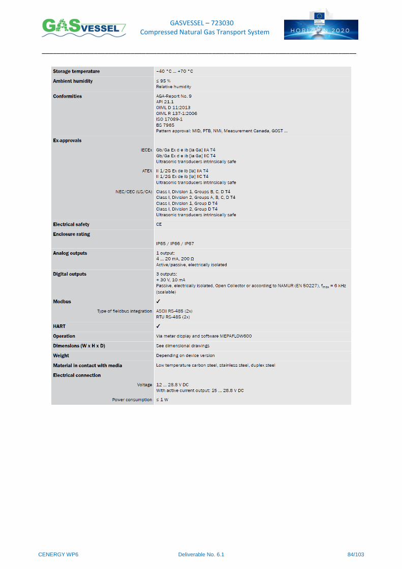
GASVESSEL – 723030 Compressed Natural Gas Transport System
______________________________________________________________________________________
CENERGY WP6 Deliverable No. 6.1 84/103
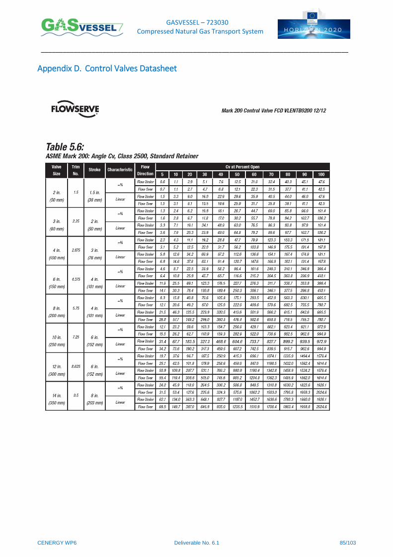
GASVESSEL – 723030 Compressed Natural Gas Transport System
______________________________________________________________________________________
CENERGY WP6 Deliverable No. 6.1 85/103
Appendix D. Control Valves Datasheet
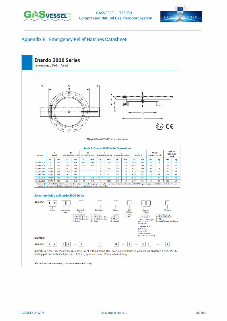
GASVESSEL – 723030 Compressed Natural Gas Transport System
______________________________________________________________________________________
CENERGY WP6 Deliverable No. 6.1 86/103
Appendix E. Emergency Relief Hatches Datasheet
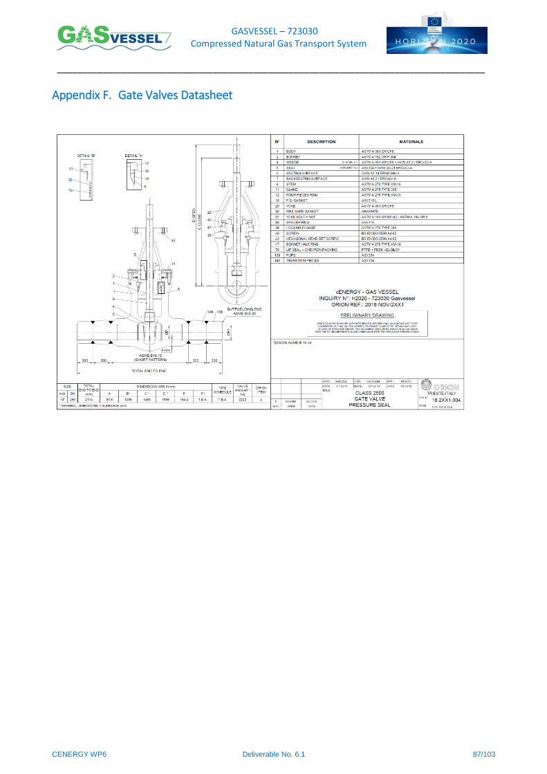
GASVESSEL – 723030 Compressed Natural Gas Transport System
______________________________________________________________________________________
CENERGY WP6 Deliverable No. 6.1 87/103
Appendix F. Gate Valves Datasheet
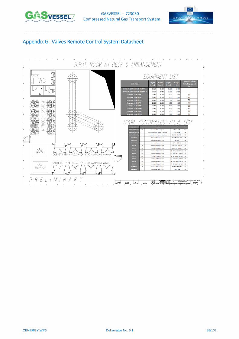
GASVESSEL – 723030 Compressed Natural Gas Transport System
______________________________________________________________________________________
CENERGY WP6 Deliverable No. 6.1 88/103
Appendix G. Valves Remote Control System Datasheet
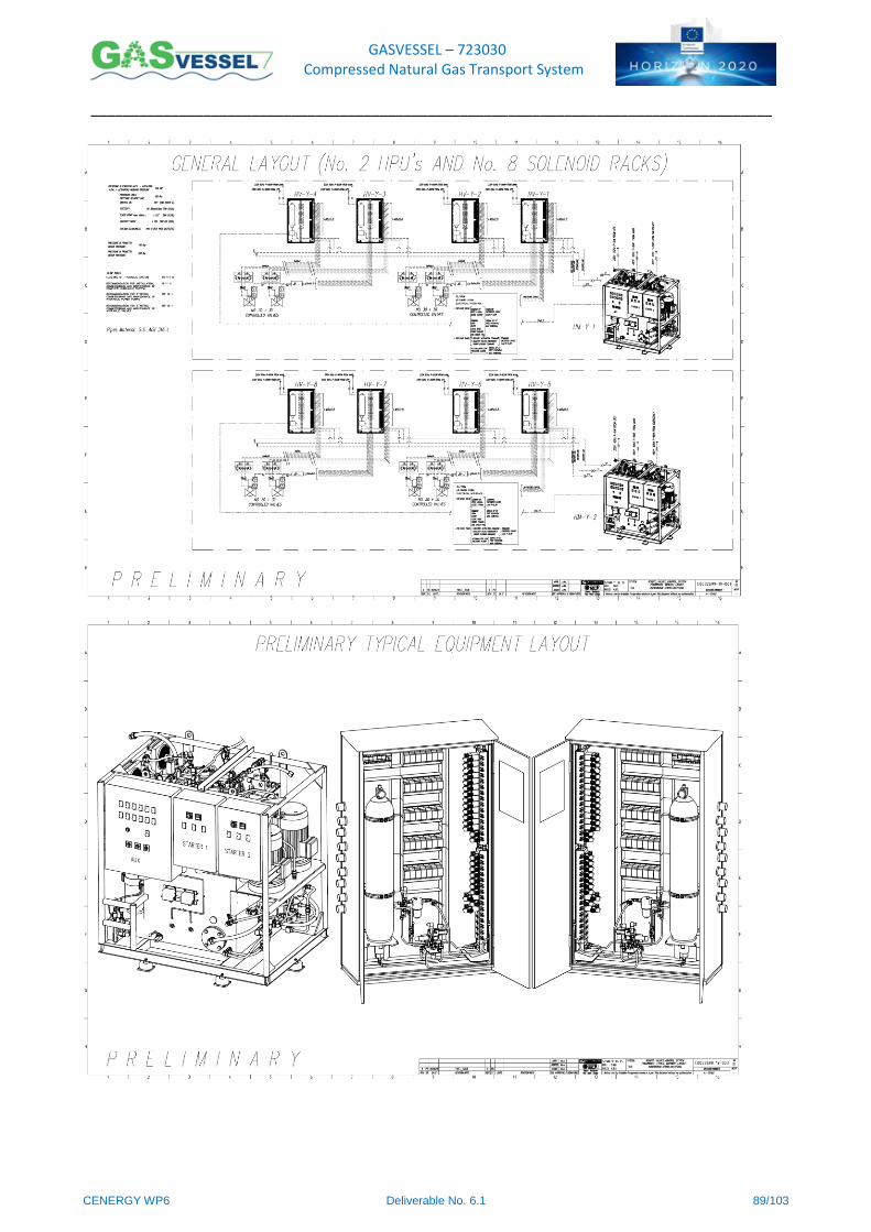
GASVESSEL – 723030 Compressed Natural Gas Transport System
______________________________________________________________________________________
CENERGY WP6 Deliverable No. 6.1 89/103
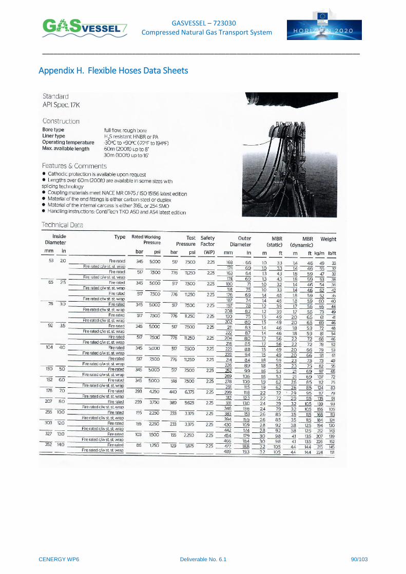
GASVESSEL – 723030 Compressed Natural Gas Transport System
______________________________________________________________________________________
CENERGY WP6 Deliverable No. 6.1 90/103
Appendix H. Flexible Hoses Data Sheets
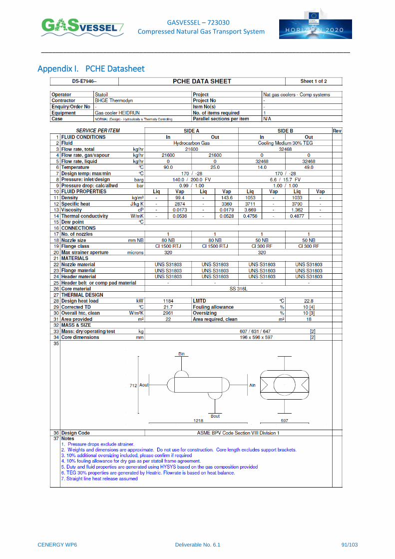
GASVESSEL – 723030 Compressed Natural Gas Transport System
______________________________________________________________________________________
CENERGY WP6 Deliverable No. 6.1 91/103
Appendix I. PCHE Datasheet
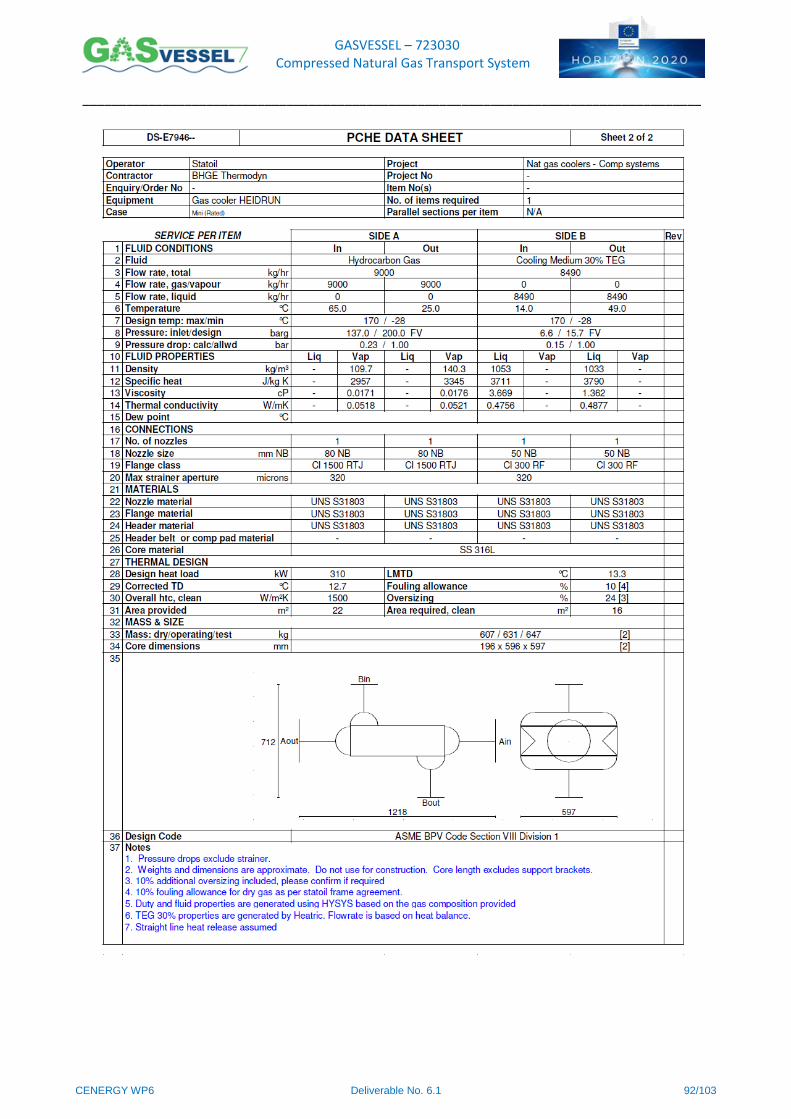
GASVESSEL – 723030 Compressed Natural Gas Transport System
______________________________________________________________________________________
CENERGY WP6 Deliverable No. 6.1 92/103
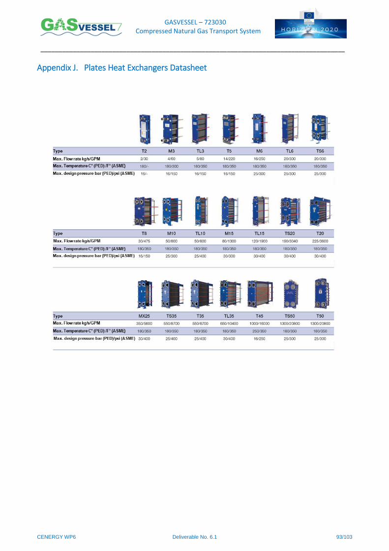
GASVESSEL – 723030 Compressed Natural Gas Transport System
______________________________________________________________________________________
CENERGY WP6 Deliverable No. 6.1 93/103
Appendix J. Plates Heat Exchangers Datasheet

GASVESSEL – 723030 Compressed Natural Gas Transport System
______________________________________________________________________________________
CENERGY WP6 Deliverable No. 6.1 94/103
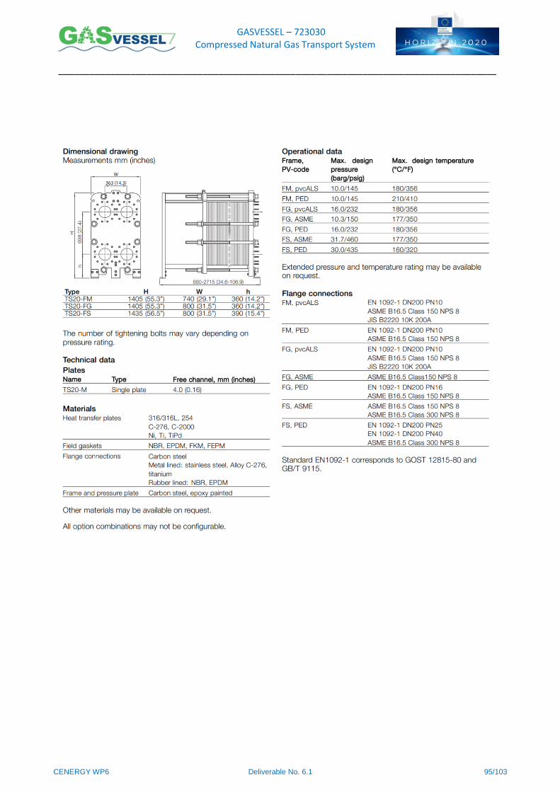
GASVESSEL – 723030 Compressed Natural Gas Transport System
______________________________________________________________________________________
CENERGY WP6 Deliverable No. 6.1 95/103
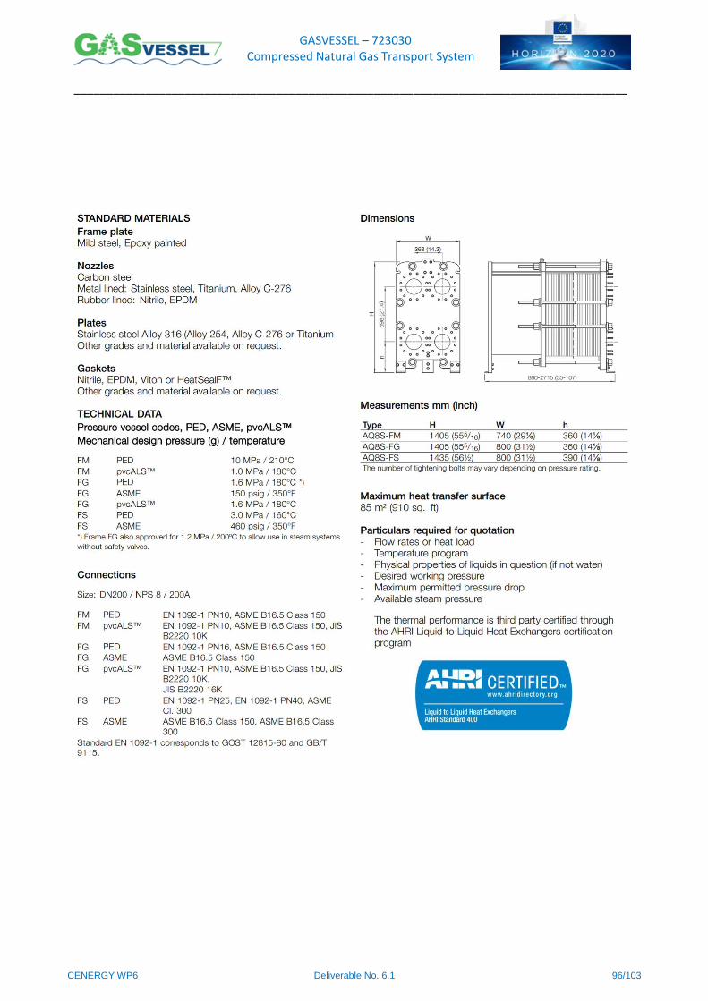
GASVESSEL – 723030 Compressed Natural Gas Transport System
______________________________________________________________________________________
CENERGY WP6 Deliverable No. 6.1 96/103
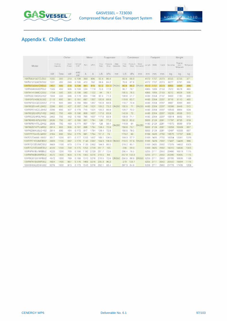
GASVESSEL – 723030 Compressed Natural Gas Transport System
______________________________________________________________________________________
CENERGY WP6 Deliverable No. 6.1 97/103
Appendix K. Chiller Datasheet
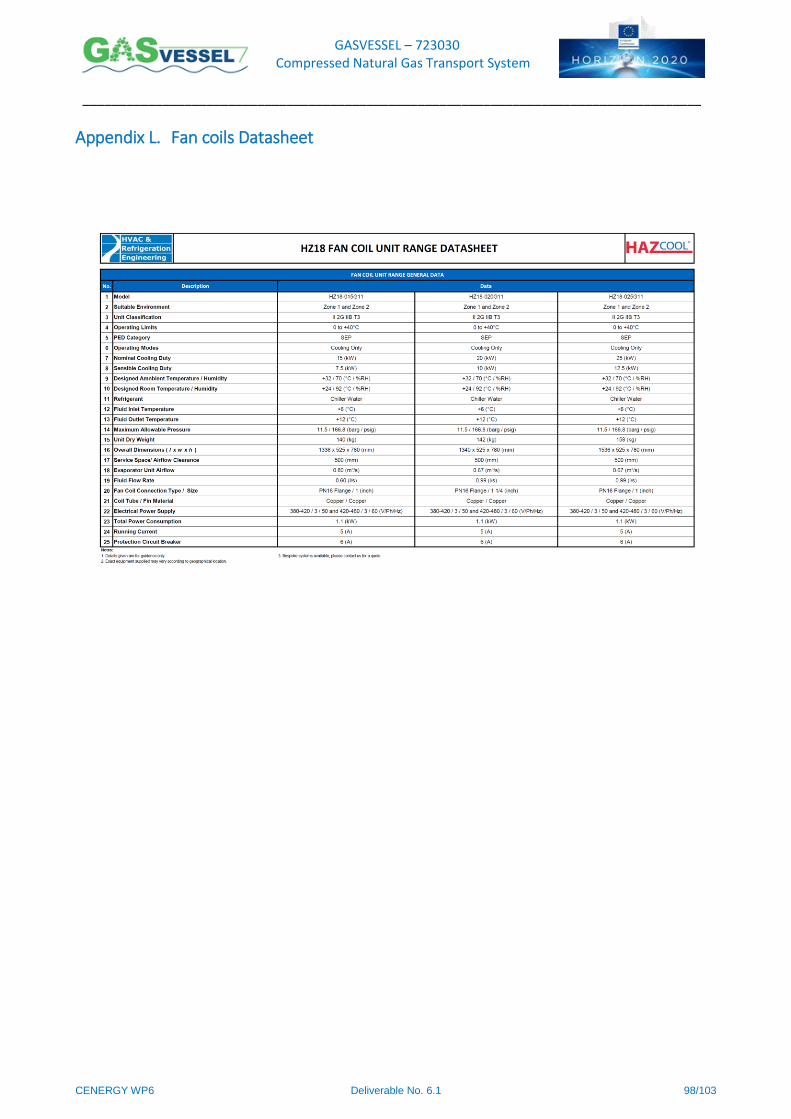
GASVESSEL – 723030 Compressed Natural Gas Transport System
______________________________________________________________________________________
CENERGY WP6 Deliverable No. 6.1 98/103
Appendix L. Fan coils Datasheet
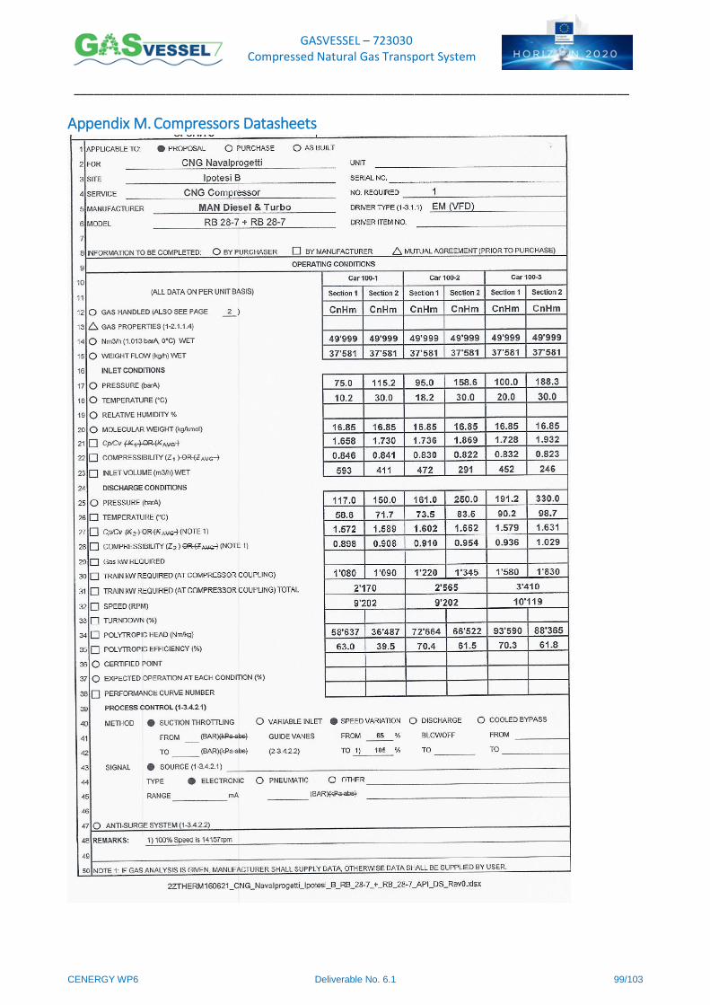
GASVESSEL – 723030 Compressed Natural Gas Transport System
______________________________________________________________________________________
CENERGY WP6 Deliverable No. 6.1 99/103
Appendix M. Compressors Datasheets
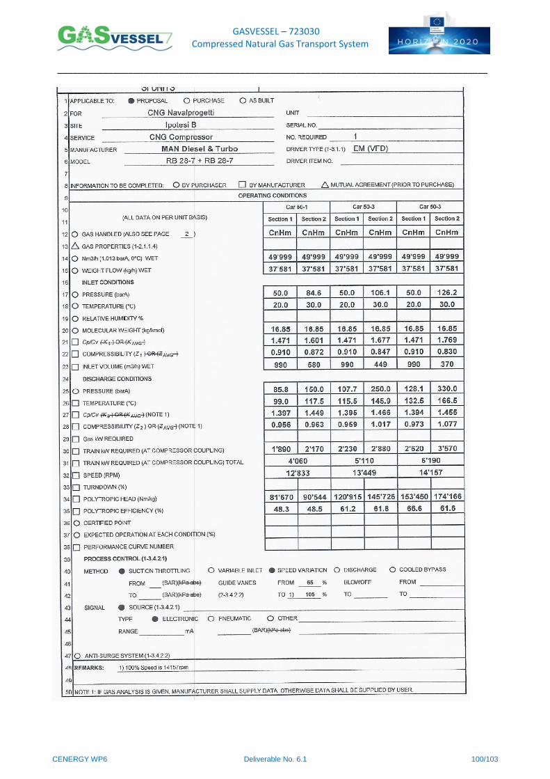
GASVESSEL – 723030 Compressed Natural Gas Transport System
______________________________________________________________________________________
CENERGY WP6 Deliverable No. 6.1 100/103
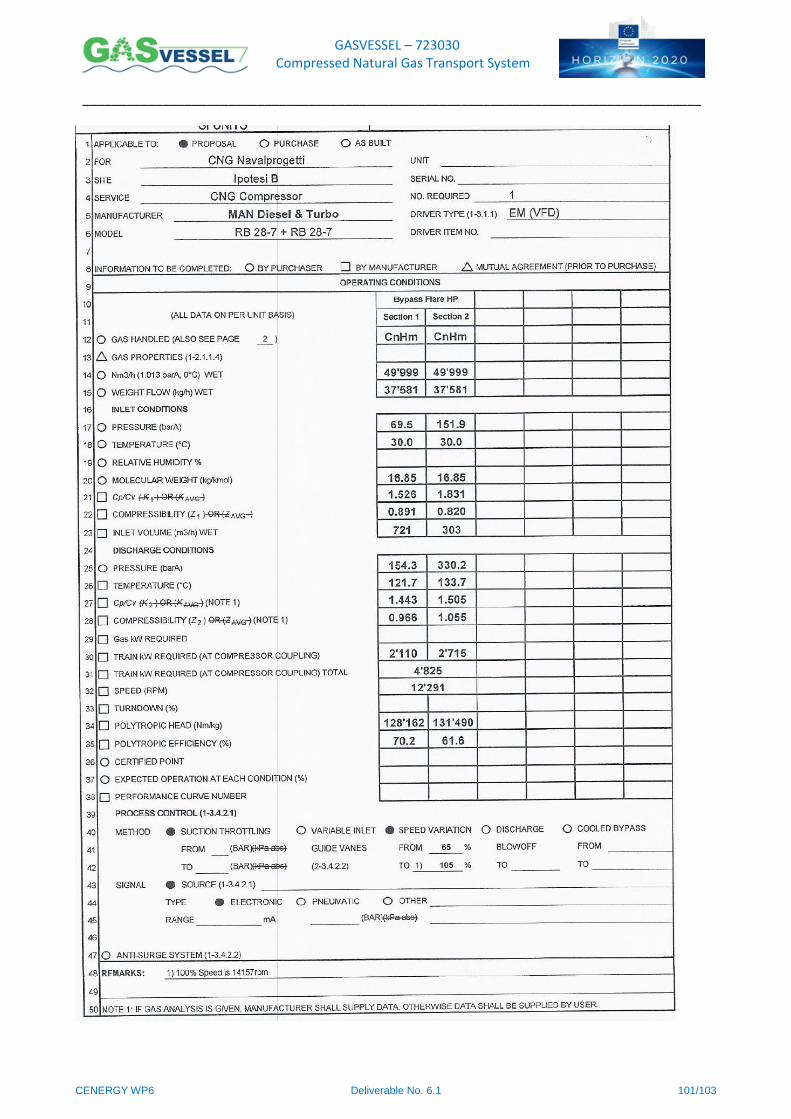
GASVESSEL – 723030 Compressed Natural Gas Transport System
______________________________________________________________________________________
CENERGY WP6 Deliverable No. 6.1 101/103
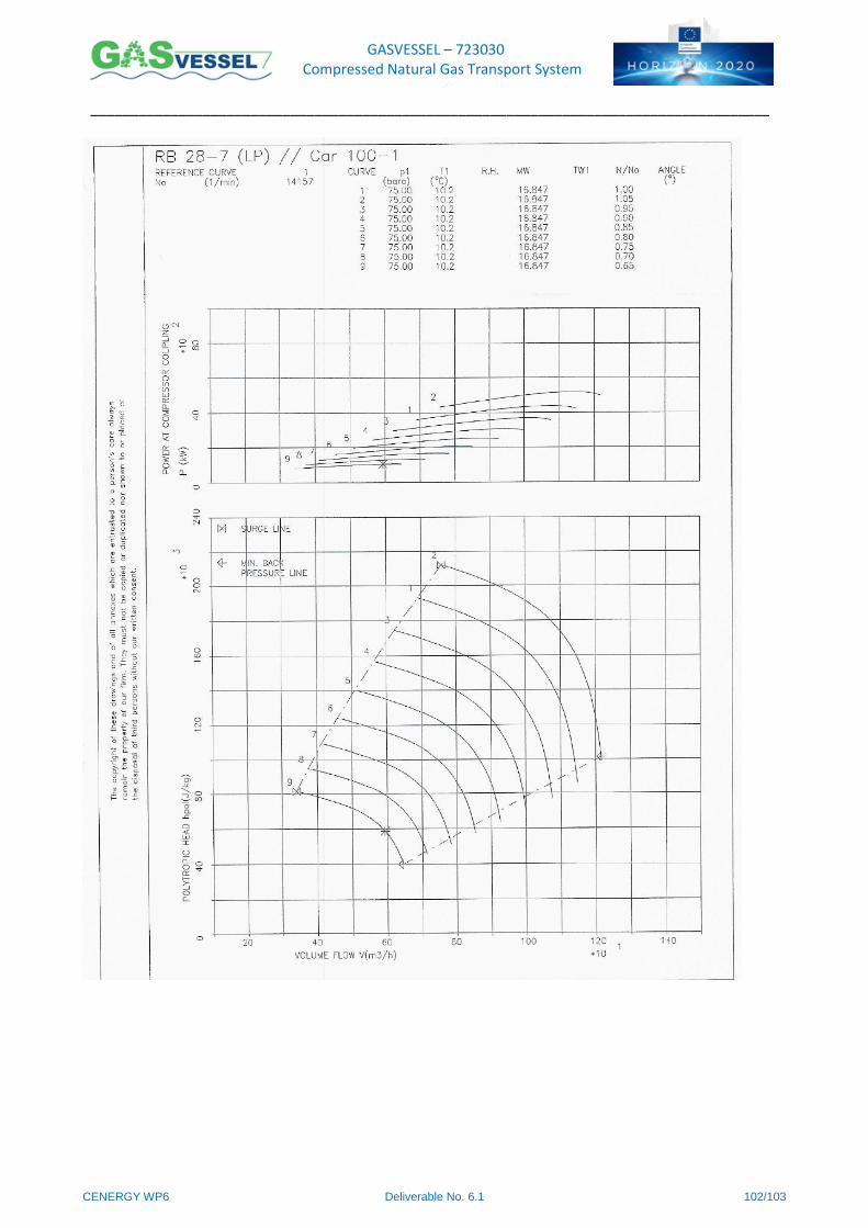
GASVESSEL – 723030 Compressed Natural Gas Transport System
______________________________________________________________________________________
CENERGY WP6 Deliverable No. 6.1 102/103
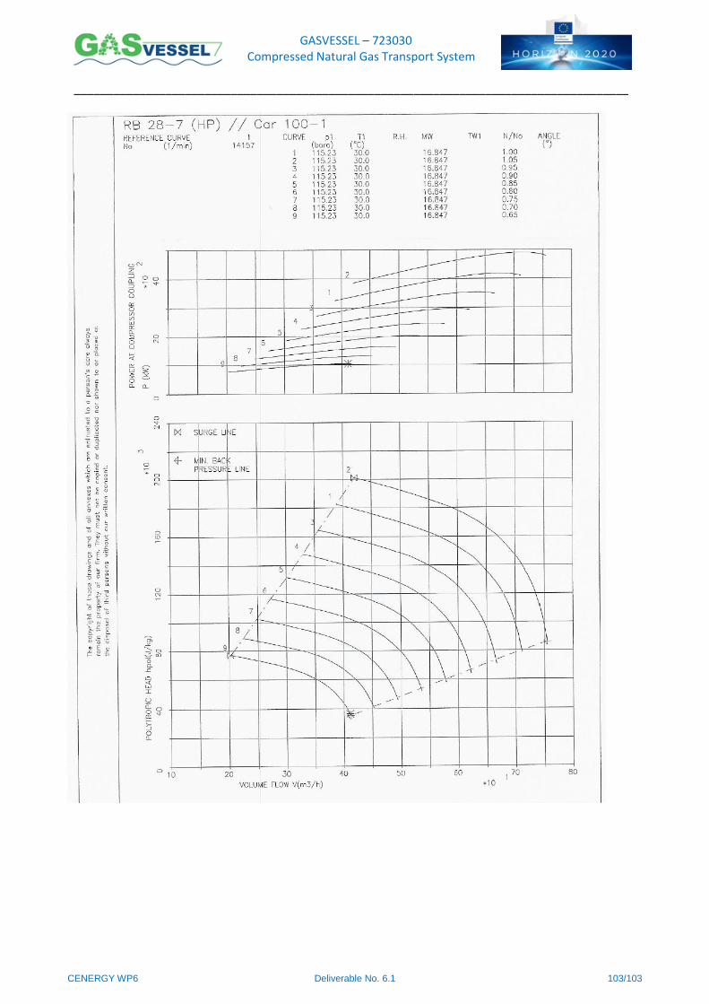
GASVESSEL – 723030 Compressed Natural Gas Transport System
______________________________________________________________________________________
CENERGY WP6 Deliverable No. 6.1 103/103
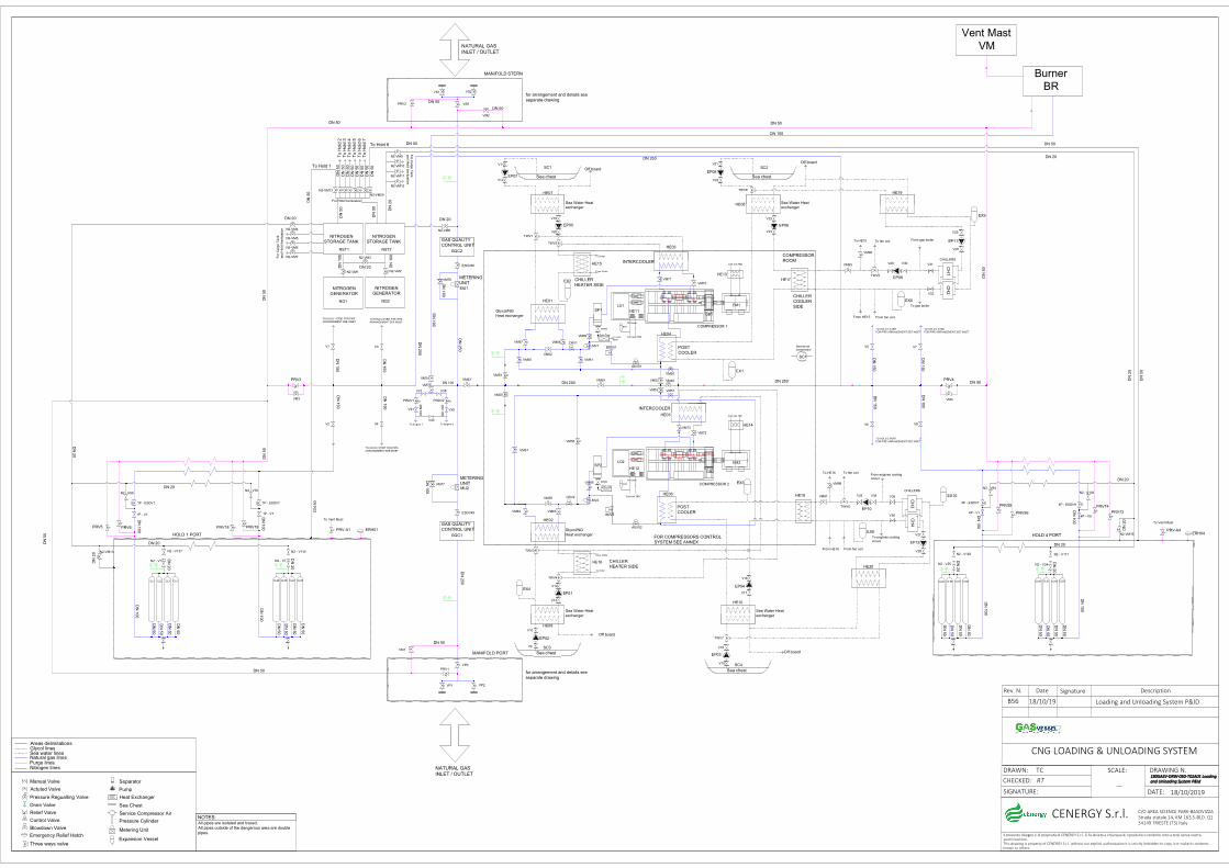
POST
COOLER
INTERCOOLER
DRAIN
DRAIN TO HOLD 3 STBD
FOR PIPE ARRANGEMENT SEE INSET
TO HOLD 3 PORT
FOR PIPE ARRANGEMENT SEE INSET
TO HOLD 4 STBD
FOR PIPE ARRANGEMENT SEE INSET
HOLD 4 PORT
Vent Mast
VM
NITROGEN
GENERATOR
TO HOLD 2 STBD FOR PIPE
ARRANGEMENT SEE INSET
TO HOLD 2 PORT FOR PIPE
ARRANGEMENT SEE INSET
TO HOLD 1 STBD FOR PIPE
ARRANGEMENT SEE INSET
HOLD 1 PORT
MANIFOLD PORT
for arrangement and details see
separate drawing
COMPRESSOR
ROOM
FOR COMPRESSORS CONTROL
SYSTEM SEE ANNEX
CNG LOADING & UNLOADING SYSTEM
DRAWING N.
DATE: 18/10/2019
DRAWN: TC
CHECKED: RT
SIGNATURE:
Rev. N. Date Signature Description
SCALE:
Il presente disegno è di proprietà di CENERGY S.r.l. Si fa divieto a chiunque di riprodurlo o renderlo noto a terzi senza nostra auotrizzazione.This drawing is property of CENERGY S.r.l. without our explicit authorisation it is strictly forbidden to copy it or make its contents known to others.
C/O AREA SCIENCE PARK-BASOVIZZA
Strada statale 14, KM 163,5-BLD. Q134149 TRIESTE (TS) Italy
111188880000GGGGAAAASSSSVVVV----DDDDRRRRWWWW----000055550000----TTTT00002222AAAA00001111 LLLLooooaaaaddddiiiinnnngggg
aaaannnndddd UUUUnnnnllllooooaaaaddddiiiinnnngggg SSSSyyyysssstttteeeemmmm PPPP&&&&IIIIdddd
CENERGY S.r.l.
B56 18/10/19 Loading and Unloading System P&ID
METERING
UNIT
DN
50
Sea Water Heat
exchanger
Oil Cooler
Sea chest
Glycol/NG
Heat exchanger
Sea Water Heat exchanger
Sea chest
Glycol/NG
Heat exchanger
INTERCOOLER
Sea Water Heat exchanger
Sea chest
Sea Water Heat
exchanger
Sea chest
METERING
UNIT
HE01
HE02
HE03
HE04
HE05
HE06
HE07
HE08
HE09
HE10
VP1 VP2
VS1 VS2
HE12
VS0
VP0
Cold side TBD
DN
50
DN
50
DN
50
DN
100
DN
100
DN
50
DN
50
DN
50
DN
50
DN
100
DN
10
0
DN 250
DN
25
0
DN
250
DN
15
0
DN
150
DN
15
0
DN
150
DN 250
DN
15
0
DN
150
DN
15
0
DN
15
0
DN
50
DN
50
DN
50
DN
50
DN
50
DN
50
DN
50
DN
50
DN
10
0
DN
10
0
DN
10
0
DN
10
0
EP01
EP02
EP03
EP04
EP05 EP06
EP07EP08
Cold side TBD
Cold side TBD
DN 250
Service air compressor
Actuted Valve
Pressure Regualting Valve
Drain Valve
Relief Valve
Control Valve
Blowdown Valve
CL1 CL2 CL3 CL4 CL25 CL26 CL27 CL28CL65 CL66 CL67 CL68 CL90 CL91 CL92 CL93
V10
V14
V13
V18
V2 V4
V1 V3 V5
V6
V7
V8
V9
V15
V16
V17
V11
V12
V19
V20
V21
V22
V23
V24
VM49
VM50
VM51VM52
VM53
VM54
VM55
VM56
VM57
VM58
TWV1
TWV2
TWV3
TWV4
EX1
EX2
EX3
EX4
SP1
SP2
SC1
MU2
MU1
NG2
SC1 SC2
SC3
SC4
PRV6 PRV19
BDV01
BDV2
ASV01
ASV02
LMV1
LMV2
Manual Valve
Areas delimitationsGlycol linesSea water linesNatural gas linesPurge linesNitrogen lines NATURAL GAS
INLET / OUTLET
NATURAL GAS
INLET / OUTLET
NOTES:All pipes are isolated and traced.
All pipes outside of the dangerous area are double
pipes.
VM59
VM60 VM61
VM62
VM63
VM64 VM65
VM66
VM67 VM68
VM69
VM70
VM71
VM72
Separator
Pump
Heat Exchanger
Sea Chest
Service Compressor Air
Pressure Cylinder
Expansion Vessel
GAS QUALITY
CONTROL UNIT
GQC2
GAS QUALITY
CONTROL UNIT
GQC1
ESDV50
NITROGEN
GENERATOR
NG1
NITROGEN
STORAGE TANK
To
Ho
ld 2
T
o H
old
3
To
Ho
ld 4
T
o H
old
5
To
Ho
ld 6
T
o H
old
7
Emergency Relief Hatch
PRV1
PRV2
Off board
Off board
Off board
Off board
MANIFOLD STERN
for arrangement and details see
separate drawing
ESDV49
PRV4PRV3
DN
20
PRV-A1 PRV-A4
DN
20
DN
20
DN
20
1P - ESDV1 1P - ESDV7 4P - ESDV1
1P - V1
T PT P
T P T P
T P
T P
T P
T P
T
P
ERH01
VM1
VM2
Drain Tank
Drain Tank
VM3 VM4
EX8
DN
20
DN 20
DN 20
DN 50
DN 20
DN 20
DN 20
DN
20
DN
50
DN
50
DN
50
DN
50
DN 50
DN 50
DN 50
DN 50
DN 50
DN 50
DN 50
DN
25
0
N2 - V69
N2 - V1
DN
50
DN
50
DN
50
DN
50
DN
50
DN
50
DN
50
DN
50
DN
50
DN
50
VM73
Oil Cooler
HE11
Cold side TBD
EX7
DN
100
DN
100
From Chiller
To Chiller
From Chiller
To chiller
V34V33
V30V29
TWV6
TWV5
HE15
HE16
HE18
HE17
EP10
EP09
To fan coil
From fan coil
To fan coil
From fan coil
To HE15
From HE15
To HE16
From HE16
CHILLER
HEATER SIDE
CHILLER
HEATER SIDE
CHILLER
COOLER
SIDE
VM97
VM98
VM95
VM96
CRV1
CRV2
PRV5 PRV18
From gas boiler
To gas boiler
From engines cooling
circuit
To engines cooling
circuit
EX5
EX6
To Vent Must To Vent Must
To Engine 1 To Engine 2
DN
10
0
DN
100
DN 100
HE19
HE20
EX10
EX9
EM2
EM1
GB1
GB2
LO2
LO1
HE13
HE14
TWV7
TWV8
COMPRESSOR 1
COMPRESSOR 2
CH
1
V31
V32
V35
V36
V37 V38
V39V41
V40
PRDV1 PRDV2
VM75
VM76
VM77
NST2
N2-VM1 N2-VM2
N2-VM8N2-VM4
N2 - V7
N2 - V76
1P - V7 4P - V1
4P - ESDV9
4P - V9
EP11
EP12
V25
V26
V27
V28
Burner
BR
VM74
DN
100
DN 100
For Hold Inertization
Fo
r C
arg
o T
ank
and
Ho
ld I
ne
rtiz
atio
n
NITROGEN
STORAGE TANK
NST1
DN
20
DN
20
To Vent
Mast
N2-VM5
N2-VM6
N2-VM3N2-VM7
N2-VM9
N2-VM10
N2-VM11
N2-VM12
Metering Unit
Three ways valve
For C
arg
o T
ank
and
Ho
ld In
ertiz
atio
n
To Hold 1
To Hold 8
N2-VM13
N2-VM20
DN
20
DN
50
DN
50
DN
50
DN 20
DN 50
DN 20
DN 20DN
100
DN
10
0
N2 - V137 N2 - V144
PRV74PRV55
N2 - V25
PRV56 PRV73
N2 - V34
N2 - V94
N2 - V103
N2 - V162 N2 - V171
ERH04
N2-VM13
N2-VM16
POST
COOLER
CH
2
CH
3C
H4
CHILLERS
CHILLERS
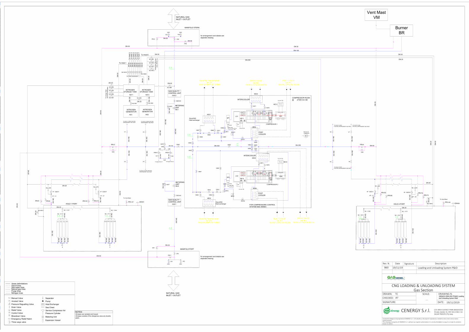
POST COOLER
INTERCOOLER
DRAIN
DRAIN TO HOLD 3 STBDFOR PIPE ARRANGEMENT SEE INSET
TO HOLD 3 PORTFOR PIPE ARRANGEMENT SEE INSET
TO HOLD 4 STBDFOR PIPE ARRANGEMENT SEE INSET
HOLD 4 PORT
NITROGEN GENERATOR
TO HOLD 2 STBD FOR PIPE ARRANGEMENT SEE INSET
TO HOLD 2 PORT FOR PIPE ARRANGEMENT SEE INSET
TO HOLD 1 STBD FOR PIPE ARRANGEMENT SEE INSET
HOLD 1 PORT
MANIFOLD PORT
for arrangement and details see separate drawing
COMPRESSOR ROOM@ 27500 mm AB
FOR COMPRESSORS CONTROL SYSTEM SEE ANNEX
CNG LOADING & UNLOADING SYSTEMGas Section
DRAWING N.
DATE: 19/11/2019
DRAWN: TCCHECKED: RT
SIGNATURE:
Rev. N. Date Signature Description
SCALE:
Il presente disegno è di proprietà di CENERGY S.r.l. Si fa divieto a chiunque di riprodurlo o renderlo noto a terzi senza nostra auotrizzazione.This drawing is property of CENERGY S.r.l. without our explicit authorisation it is strictly forbidden to copy it or make its contents known to others.
C/O AREA SCIENCE PARK-BASOVIZZA Strada statale 14, KM 163,5-BLD. Q134149 TRIESTE (TS) Italy
180GASV-DRW-050-T03A01 Loading and Unloading System P&Id
CENERGY S.r.l.
B60 19/11/19 Loading and Unloading System P&ID
METERING UNIT
DN
50
Oil Cooler
Glycol/NG Heat exchanger
Glycol/NG Heat exchanger
INTERCOOLER
METERING UNIT
HE01
HE02
HE03
HE04
HE05
HE06
VP1 VP2
VS1 VS2
HE12
VS0
VP0
Cold side TBD
DN
50
DN
50
DN
50
DN
10
0
DN
100
DN
50
DN
50
DN
50
DN
50
DN
100
DN
100
DN 250
DN
25
0
DN
250
DN
150
DN
150
DN
150
DN
15
0
DN 250
DN
15
0
DN
15
0
DN
15
0
DN
150
DN
50
DN
50
DN
50
DN
50
DN
50
DN
50
DN
50
DN
50
DN
10
0
DN
100
DN
10
0
DN
10
0
Cold side TBD
Cold side TBD
DN 250
Service air compressor
Actuted Valve
Pressure Regualting Valve
Drain Valve
Relief Valve
Control Valve
Blowdown Valve
CL1 CL2 CL3 CL4 CL25 CL26 CL27 CL28 CL65 CL66 CL67 CL68 CL90 CL91 CL92 CL93
V2 V4
V1 V3 V5
V6
V7
V8
VM49
VM50
VM51VM52
VM53
VM54
VM55
VM56
VM57
VM58
SP1
SP2
SC1
MU2
MU1
NG2
PRV6 PRV19
BDV01
BDV2
ASV01
ASV02
LMV1
LMV2
Manual Valve
Areas delimitationsGlycol linesSea water linesNatural gas linesPurge linesNitrogen lines NATURAL GAS
INLET / OUTLET
NATURAL GAS INLET / OUTLET
NOTES:All pipes are isolated and traced.All pipes outside of the dangerous area are double pipes.
VM59
VM60 VM61
VM62
VM63
VM64 VM65
VM66
VM67 VM68
VM69
VM70VM71
VM72
Separator
Pump
Heat Exchanger
Sea Chest
Service Compressor Air
Pressure Cylinder
Expansion Vessel
GAS QUALITY CONTROL UNIT
GQC2
GAS QUALITY CONTROL UNIT
GQC1
ESDV50
NITROGEN GENERATOR
NG1
NITROGEN STORAGE TANK
To
Ho
ld 2
T
o H
old
3
To
Ho
ld 4
T
o H
old
5T
o H
old
6
To
Ho
ld 7
Emergency Relief Hatch
PRV1
PRV2
MANIFOLD STERN
for arrangement and details see separate drawing
ESDV49
PRV4PRV3
DN
20
PRV-A1 PRV-A4
DN
20
DN
20
DN
20
1P - ESDV1 1P - ESDV7 4P - ESDV1
1P - V1
T PT P
T P T P
T P
T P
T P
T P
T
P
ERH01
VM1
VM2
Drain Tank
Drain Tank
VM3 VM4
EX8
DN
20
DN 20
DN 20
DN 50
DN 20
DN 20
DN 20
DN
20
DN
50
DN
50
DN
50
DN
50
DN 50
DN 50
DN 50
DN 50
DN 50
DN 50
DN 50
DN
25
0
N2 - V69
N2 - V1
DN
50
DN
50
DN
50
DN
50
DN
50
DN
50
DN
50
DN
50
DN
50
DN
50
VM73
Oil Cooler
HE11
Cold side TBD
EX7
DN
10
0
DN
100
CRV1
CRV2
PRV5 PRV18
To Vent Must To Vent Must
To Engine Room 1 To Engine Room 2
DN
10
0
DN
100
DN 100
EM2
EM1
GB1
GB2
LO2
LO1
HE13
HE14
COMPRESSOR 1
COMPRESSOR 2
V37 V38
V39V41
V40
PRDV1 PRDV2
VM75
VM76
VM77
NST2
N2-VM1 N2-VM2
N2-VM8N2-VM4
N2 - V7
N2 - V76
1P - V7 4P - V1
4P - ESDV9
4P - V9
VM74
DN
100
DN 100
For Hold Inertization
For
Ca
rgo
Ta
nkan
d H
old
In
ertiz
atio
n
NITROGEN STORAGE TANK
NST1
DN
20
DN
20
To VentMast
N2-VM5
N2-VM6
N2-VM3N2-VM7
N2-VM9
N2-VM10
N2-VM11
N2-VM12
Metering Unit
Three ways valve
Fo
r Ca
rgo T
ank
an
d H
old In
ertization
To Hold 1
To Hold 8
N2-VM13N2-VM20
DN
20
DN
50
DN
50
DN
50
DN 20
DN 50
DN 20
DN 20DN
100
DN
100
N2 - V137 N2 - V144
PRV74PRV55
N2 - V25
PRV56 PRV73
N2 - V34
N2 - V94
N2 - V103
N2 - V162 N2 - V171
ERH04
N2-VM13
N2-VM16
POST COOLER
Vent Mast VM
Burner BR
POST COOLERsee doc.
180GASV-DRW-050-T02B56
Glycol/NG Heat exchangersee doc.
180GASV-DRW-050-T02B56
INTERCOOLERsee doc.
180GASV-DRW-050-T02B56
INTERCOOLERsee doc.
180GASV-DRW-050-T02B56
Glycol/NG Heat exchangersee doc.
180GASV-DRW-050-T02B56
POST COOLERsee doc.
180GASV-DRW-050-T02B56
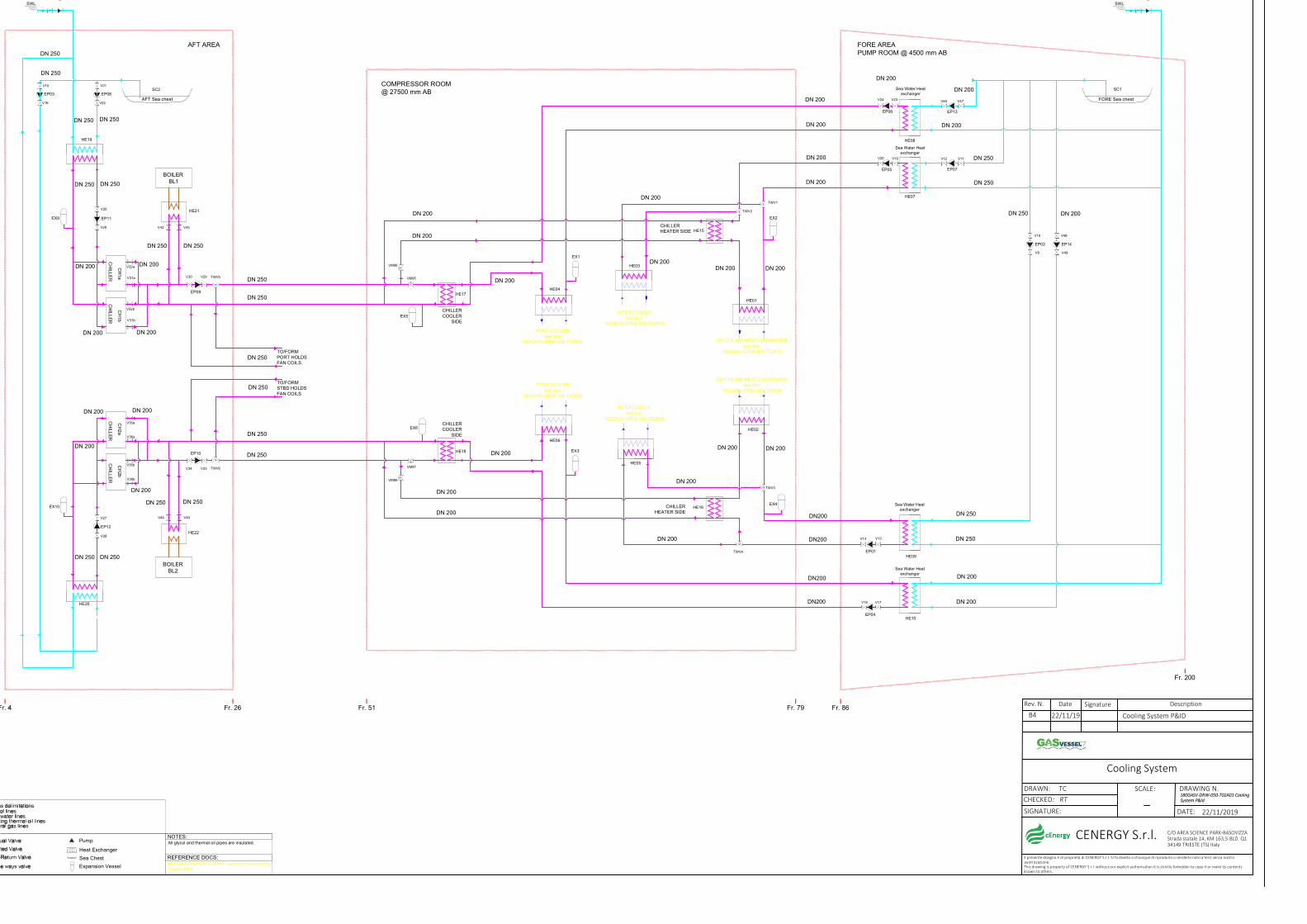
POST COOLERsee doc.
180GASV-DRW-050-T02B58
COMPRESSOR ROOM@ 27500 mm AB
Sea Water Heat exchanger
Sea Water Heat exchanger
FORE Sea chest
GLYCOL/NG HEAT EXCHANGERsee doc.
180GASV-DRW-050-T02B58
INTERCOOLERsee doc.
180GASV-DRW-050-T02B58
Sea Water Heat exchanger
AFT Sea chest
HE01
HE02
HE03
HE05
HE07
HE08
HE09EP01
EP05
EP06
EP07
EP08
V14 V13
V11V12V19V20
V21
V22V23V24
TWV2
TWV3
TWV4
EX1
EX2
EX4
SC1SC2
CH
ILL
ER
V30 V29 TWV5
HE15
HE16
HE17EP09
CHILLER HEATER SIDE
CHILLER HEATER SIDE
CHILLER COOLER
SIDE
VM95
VM96
EX5
HE19
EX9
CH
1b
V31a
V32b
EP11
V25
V26
V10
V9
HE04
Sea Water Heat exchanger
HE10EP04
V17V18
V34 V33 TWV6
HE18EP10
CHILLER COOLER
SIDE
VM97
VM98
HE20
EP12
V28
V27
HE06
EX10
EX3
EP03
V15
V16
EX6
Cooling System
DRAWING N.
DATE: 22/11/2019
DRAWN: TCCHECKED: RT
SIGNATURE:
Rev. N. Date Signature Description
SCALE:
Il presente disegno è di proprietà di CENERGY S.r.l. Si fa divieto a chiunque di riprodurlo o renderlo noto a terzi senza nostra auotrizzazione.This drawing is property of CENERGY S.r.l. without our explicit authorisation it is strictly forbidden to copy it or make its contents known to others.
C/O AREA SCIENCE PARK-BASOVIZZA Strada statale 14, KM 163,5-BLD. Q134149 TRIESTE (TS) Italy
180GASV-DRW-050-T02A01 Cooling System P&Id
CENERGY S.r.l.
B4 22/11/19 Cooling System P&ID
NOTES:All glycol and thermal oil pipes are insulated.Pump
Heat Exchanger
Sea Chest
Expansion Vessel
TO/FORMPORT HOLDSFAN COILS
TO/FORMSTBD HOLDSFAN COILS
CH
ILLE
R
CH
1a
V31b
V32a
AFT AREA
V48
V49
EP02 EP14
EP13
V47V46
FORE AREAPUMP ROOM @ 4500 mm AB
CH
ILLE
R
CH
2a
CH
ILLE
R
CH
2b
V36a
V35a
V36b
V35b
Fr. 79Fr. 51Fr. 26 Fr. 86
Fr. 200
SWL SWL
POST COOLERsee doc.
180GASV-DRW-050-T02B58
INTERCOOLERsee doc.
180GASV-DRW-050-T02B58
GLYCOL/NG HEAT EXCHANGERsee doc.
180GASV-DRW-050-T02B58
REFERENCE DOCS:180GASV-DRW-050-T02B58 Loading and Unloading System P&Id
BOILER BL1
BOILER BL2
TWV1
DN200
DN 200
DN 200
DN200
DN 250
DN 250
DN 250
DN 250
DN 250
DN 200
DN 200
DN 200
DN 200
DN 250
DN 250
DN 200
DN 200
DN 200
DN 200
DN 200
DN 200
DN 250
DN 200
DN 250
DN 250
DN 250
DN 250
DN 200
DN 200
DN 200
DN200
DN200
DN 250
DN 200
DN 200
DN 250
DN 250 DN 200
DN 200
DN 200
DN 200DN 200
DN 200
DN 250
DN 250
DN 250
DN 250
DN 250
DN 250
DN 250
DN 250
V42 V43
V44 V45
DN 200
DN 200
HE21
HE22
DN 200
DN 200
DN 200
DN 200
DN 200
DN 200