Embed Size (px)
Citation preview
Automation and RoboticsFlexible Manufacturing System
Courseware Sample
38770-F0
A


AUTOMATION AND ROBOTICSFLEXIBLE MANUFACTURING SYSTEM
COURSEWARE SAMPLE
bythe Staff
ofLab-Volt Ltd.
Copyright © 2008 Lab-Volt Ltd.
All rights reserved. No part of this publication may be reproduced,in any form or by any means, without the prior written permissionof Lab-Volt Ltd.
Printed in CanadaMay 2008
III
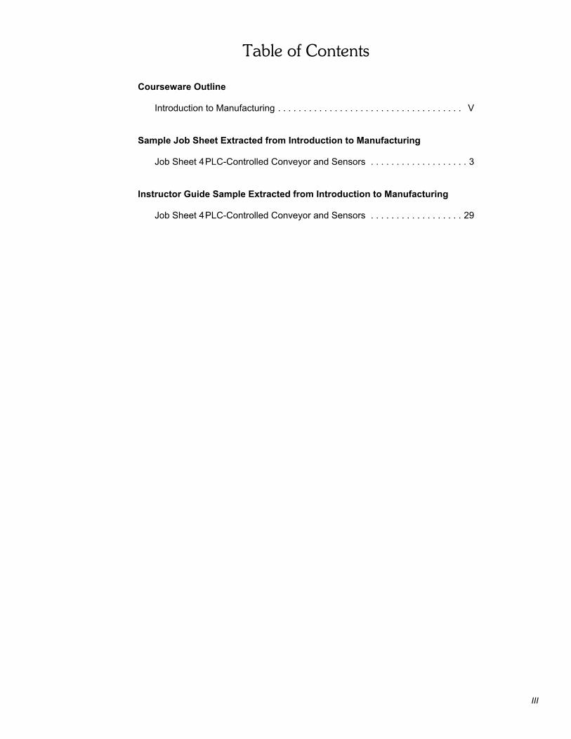
Table of Contents
Courseware Outline
Introduction to Manufacturing . . . . . . . . . . . . . . . . . . . . . . . . . . . . . . . . . . . . V
Sample Job Sheet Extracted from Introduction to Manufacturing
Job Sheet 4PLC-Controlled Conveyor and Sensors . . . . . . . . . . . . . . . . . . . 3
Instructor Guide Sample Extracted from Introduction to Manufacturing
Job Sheet 4PLC-Controlled Conveyor and Sensors . . . . . . . . . . . . . . . . . . 29

IV
INTRODUCTION TO MANUFACTURING – JOB SHEET
Courseware Outline
V
Introduction
Job Sheet 1 Familiarization with the AC Drive
Job Sheet 2 Ethernet Communication and PLC ProgrammingLanguages
Job Sheet 3 Network Communications
Job Sheet 4 PLC-Controlled Conveyor and Sensors
Job Sheet 5 Sorting Process
Job Sheet 6 Filling Process
Appendices A Equipment Utilization ChartB Documentation provided on the Lab-Volt Flexible
Manufacturing System Resource Kit CD-ROMC AC Drive – Quick Start GuideD Changing the PLC IP address settingE Hydraulics and Pneumatics Graphic SymbolsF Changing the node address of the DeviceNet devicesG Safety ProceduresH Troubleshooting
We Value Your Opinion!

Sample Job Sheet
Extracted from
Introduction to Manufacturing

4
PLC-CONTROLLED CONVEYOR AND SENSORS
INTRODUCTION TO MANUFACTURING 3
Sensors
Sensors are the eyes and ears of the PLC. Usually sensors are divided in two largecategories: contact and non-contact. Contact sensors require a physical contact withthe target to be triggered while non-contact sensors can sense the target withouttouching it, as long as the target is within the sensing distance. Sensors used in theFlexible Manufacturing System are non-contact sensors. The different types ofsensors used with the Flexible Manufacturing System are presented below.
Inductive sensor
Inductive sensors are designed to detect metal targets passing within their sensingdistance. The inductive sensors provided with the Flexible Manufacturing System areidentified as Inductive Proximity Switch, Model 6375-B. They are either mounted ona flexible support or on another device such as the Pneumatic Sorting Device.
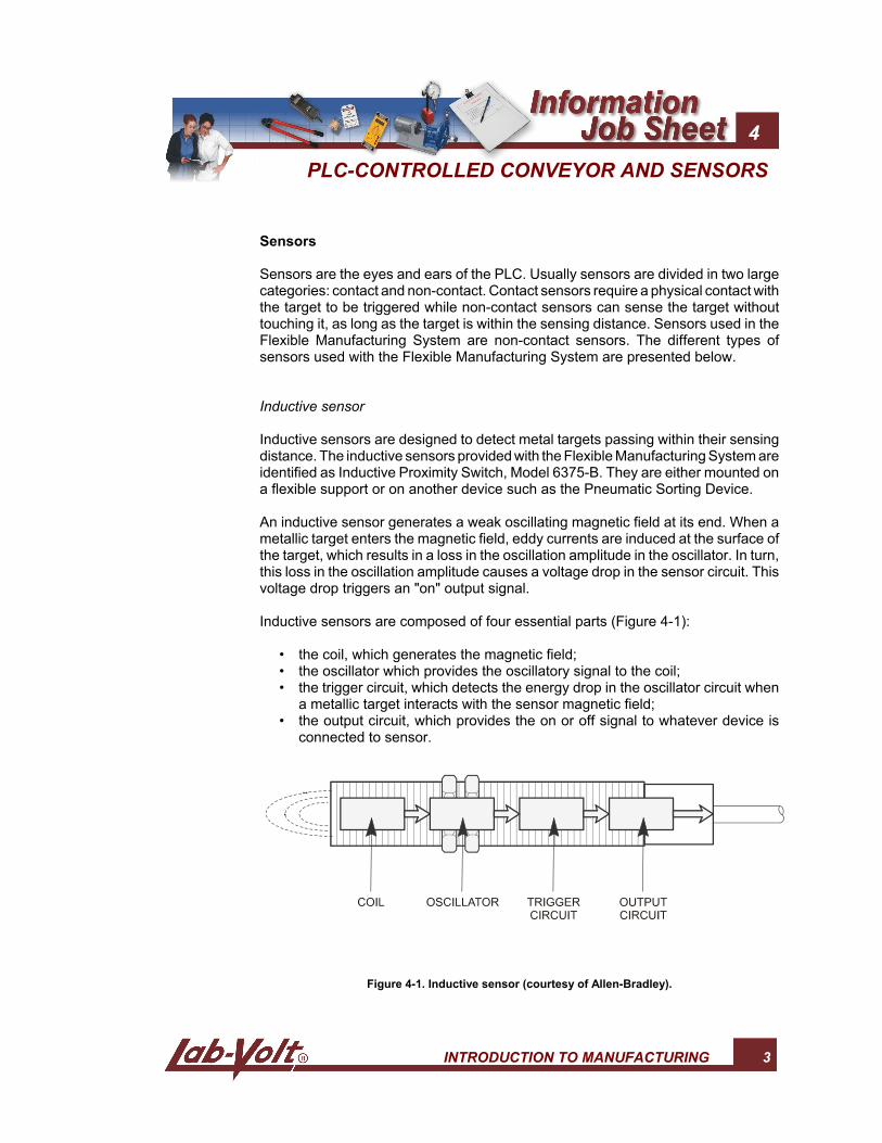
An inductive sensor generates a weak oscillating magnetic field at its end. When ametallic target enters the magnetic field, eddy currents are induced at the surface ofthe target, which results in a loss in the oscillation amplitude in the oscillator. In turn,this loss in the oscillation amplitude causes a voltage drop in the sensor circuit. Thisvoltage drop triggers an "on" output signal.
Inductive sensors are composed of four essential parts (Figure 4-1):
• the coil, which generates the magnetic field;• the oscillator which provides the oscillatory signal to the coil;• the trigger circuit, which detects the energy drop in the oscillator circuit when
a metallic target interacts with the sensor magnetic field;• the output circuit, which provides the on or off signal to whatever device is
connected to sensor.
Figure 4-1. Inductive sensor (courtesy of Allen-Bradley).
PLC-CONTROLLED CONVEYOR AND SENSORS
4 INTRODUCTION TO MANUFACTURING
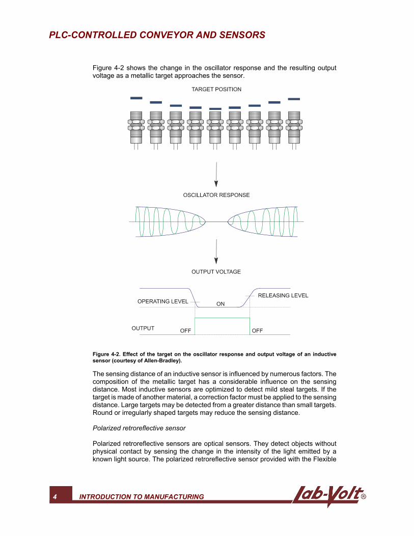
Figure 4-2 shows the change in the oscillator response and the resulting outputvoltage as a metallic target approaches the sensor.
Figure 4-2. Effect of the target on the oscillator response and output voltage of an inductivesensor (courtesy of Allen-Bradley).
The sensing distance of an inductive sensor is influenced by numerous factors. Thecomposition of the metallic target has a considerable influence on the sensingdistance. Most inductive sensors are optimized to detect mild steal targets. If thetarget is made of another material, a correction factor must be applied to the sensingdistance. Large targets may be detected from a greater distance than small targets.Round or irregularly shaped targets may reduce the sensing distance.
Polarized retroreflective sensor
Polarized retroreflective sensors are optical sensors. They detect objects withoutphysical contact by sensing the change in the intensity of the light emitted by aknown light source. The polarized retroreflective sensor provided with the Flexible
PLC-CONTROLLED CONVEYOR AND SENSORS
INTRODUCTION TO MANUFACTURING 5
Manufacturing System is mounted on a flexible support and is identified as PolarizedRetroreflective Photoelectric Switch, Model 6374-B.
A polarized retroreflective sensor uses an LED (Light Emitting Diode) as a lightsource. The LED emits light within a narrow band of wavelengths (usually infrared),which is reflected by a special reflector. The reflected light is detected by a lightdetector installed in the same housing as the light source. If an object gets betweenthe sensor and the reflector, the light beam is cut and the light detector senses thedifference. The appropriate output signal is then generated by the output circuit.
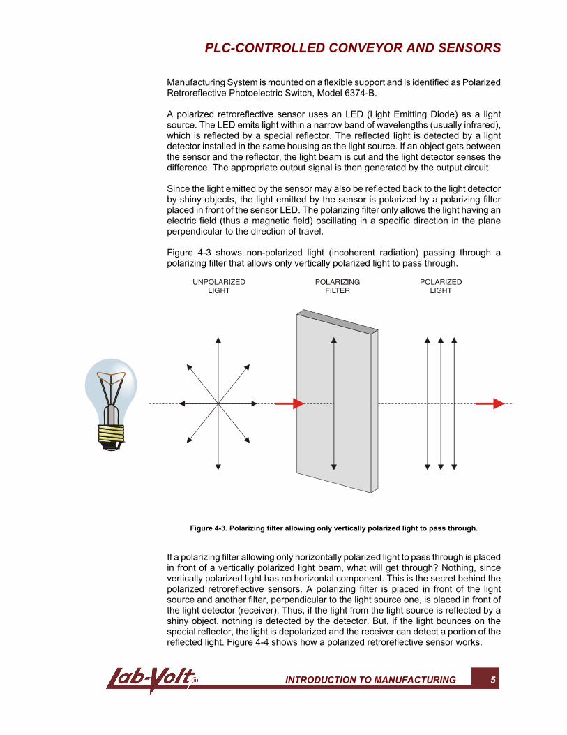
Since the light emitted by the sensor may also be reflected back to the light detectorby shiny objects, the light emitted by the sensor is polarized by a polarizing filterplaced in front of the sensor LED. The polarizing filter only allows the light having anelectric field (thus a magnetic field) oscillating in a specific direction in the planeperpendicular to the direction of travel.
Figure 4-3 shows non-polarized light (incoherent radiation) passing through apolarizing filter that allows only vertically polarized light to pass through.
Figure 4-3. Polarizing filter allowing only vertically polarized light to pass through.
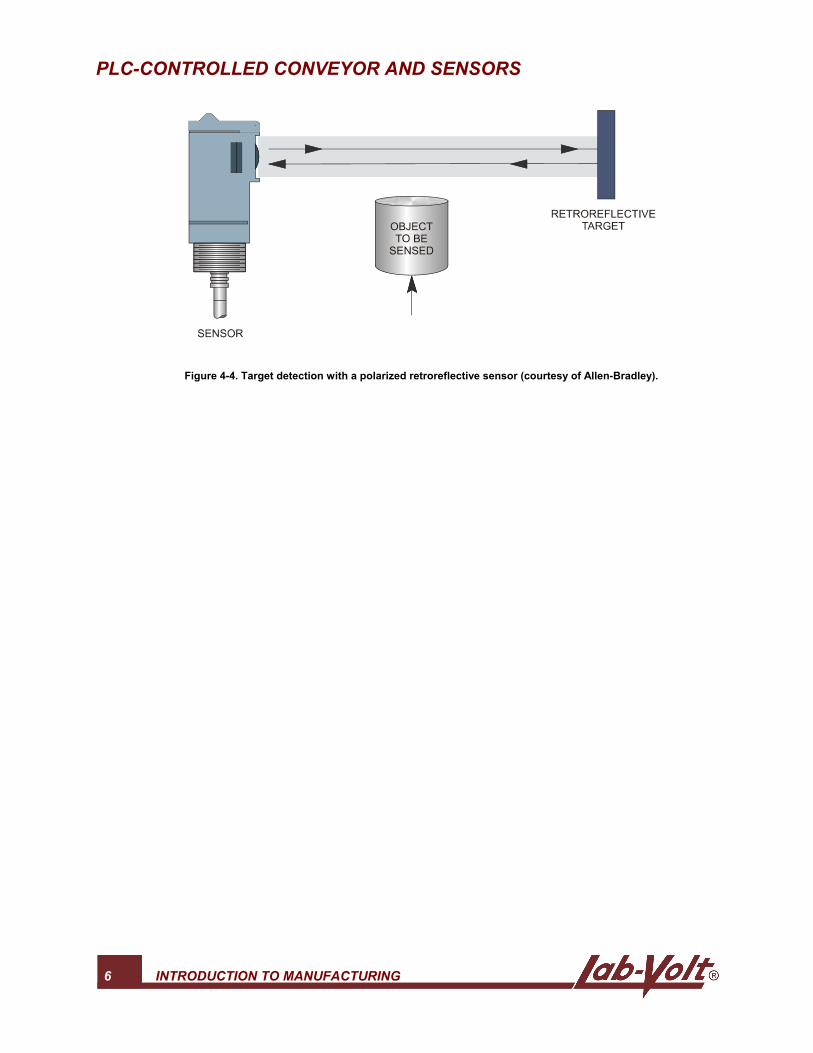
If a polarizing filter allowing only horizontally polarized light to pass through is placedin front of a vertically polarized light beam, what will get through? Nothing, sincevertically polarized light has no horizontal component. This is the secret behind thepolarized retroreflective sensors. A polarizing filter is placed in front of the lightsource and another filter, perpendicular to the light source one, is placed in front ofthe light detector (receiver). Thus, if the light from the light source is reflected by ashiny object, nothing is detected by the detector. But, if the light bounces on thespecial reflector, the light is depolarized and the receiver can detect a portion of thereflected light. Figure 4-4 shows how a polarized retroreflective sensor works.
PLC-CONTROLLED CONVEYOR AND SENSORS
6 INTRODUCTION TO MANUFACTURING
Figure 4-4. Target detection with a polarized retroreflective sensor (courtesy of Allen-Bradley).
PLC-CONTROLLED CONVEYOR AND SENSORS
INTRODUCTION TO MANUFACTURING 7
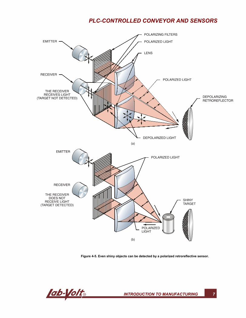
Figure 4-5. Even shiny objects can be detected by a polarized retroreflective sensor.
PLC-CONTROLLED CONVEYOR AND SENSORS
8 INTRODUCTION TO MANUFACTURING
Background-suppression diffuse sensor
Background-suppression diffuse sensors are also optical sensors but, unlikeretroreflective sensors, they do not require a reflector. The background-suppressiondiffuse sensor provided with the Flexible Manufacturing System is mounted on aflexible support and identified as a Background Suppression Photoelectric Switch,Model 6373-B.
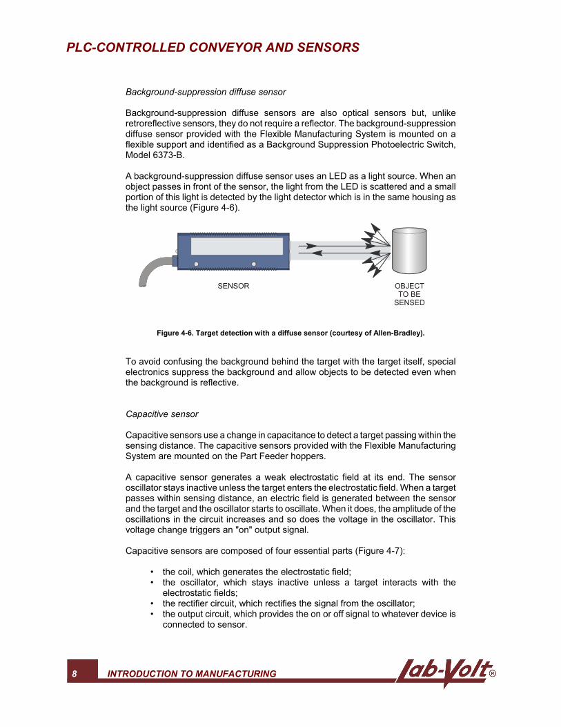
A background-suppression diffuse sensor uses an LED as a light source. When anobject passes in front of the sensor, the light from the LED is scattered and a smallportion of this light is detected by the light detector which is in the same housing asthe light source (Figure 4-6).
Figure 4-6. Target detection with a diffuse sensor (courtesy of Allen-Bradley).
To avoid confusing the background behind the target with the target itself, specialelectronics suppress the background and allow objects to be detected even whenthe background is reflective.
Capacitive sensor
Capacitive sensors use a change in capacitance to detect a target passing within thesensing distance. The capacitive sensors provided with the Flexible ManufacturingSystem are mounted on the Part Feeder hoppers.
A capacitive sensor generates a weak electrostatic field at its end. The sensoroscillator stays inactive unless the target enters the electrostatic field. When a targetpasses within sensing distance, an electric field is generated between the sensorand the target and the oscillator starts to oscillate. When it does, the amplitude of theoscillations in the circuit increases and so does the voltage in the oscillator. Thisvoltage change triggers an "on" output signal.
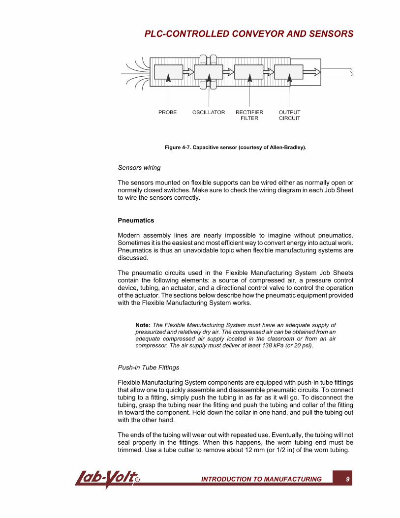
Capacitive sensors are composed of four essential parts (Figure 4-7):
• the coil, which generates the electrostatic field;• the oscillator, which stays inactive unless a target interacts with the
electrostatic fields;• the rectifier circuit, which rectifies the signal from the oscillator;• the output circuit, which provides the on or off signal to whatever device is
connected to sensor.
PLC-CONTROLLED CONVEYOR AND SENSORS
INTRODUCTION TO MANUFACTURING 9
Figure 4-7. Capacitive sensor (courtesy of Allen-Bradley).
Sensors wiring
The sensors mounted on flexible supports can be wired either as normally open ornormally closed switches. Make sure to check the wiring diagram in each Job Sheetto wire the sensors correctly.
Pneumatics
Modern assembly lines are nearly impossible to imagine without pneumatics.Sometimes it is the easiest and most efficient way to convert energy into actual work.Pneumatics is thus an unavoidable topic when flexible manufacturing systems arediscussed.
The pneumatic circuits used in the Flexible Manufacturing System Job Sheetscontain the following elements: a source of compressed air, a pressure controldevice, tubing, an actuator, and a directional control valve to control the operationof the actuator. The sections below describe how the pneumatic equipment providedwith the Flexible Manufacturing System works.
Note: The Flexible Manufacturing System must have an adequate supply ofpressurized and relatively dry air. The compressed air can be obtained from anadequate compressed air supply located in the classroom or from an aircompressor. The air supply must deliver at least 138 kPa (or 20 psi).
Push-in Tube Fittings
Flexible Manufacturing System components are equipped with push-in tube fittingsthat allow one to quickly assemble and disassemble pneumatic circuits. To connecttubing to a fitting, simply push the tubing in as far as it will go. To disconnect thetubing, grasp the tubing near the fitting and push the tubing and collar of the fittingin toward the component. Hold down the collar in one hand, and pull the tubing outwith the other hand.
The ends of the tubing will wear out with repeated use. Eventually, the tubing will notseal properly in the fittings. When this happens, the worn tubing end must betrimmed. Use a tube cutter to remove about 12 mm (or 1/2 in) of the worn tubing.
PLC-CONTROLLED CONVEYOR AND SENSORS
10 INTRODUCTION TO MANUFACTURING
Pneumatic cylinders
Some of the applications presented in this Job Sheet and in the following Job Sheetsrequire that pneumatic cylinders extend and retract automatically. This is calledcylinder reciprocation. Cylinder reciprocation involves a change in direction of thecylinder. Automatic reversal is achieved using the Directional Control Valve Station.The shifts of the four directional valves of the station are triggered with signals fromthe PLC. This allows extension or retraction of the cylinders according to theinformation provided by the sensors and other devices.
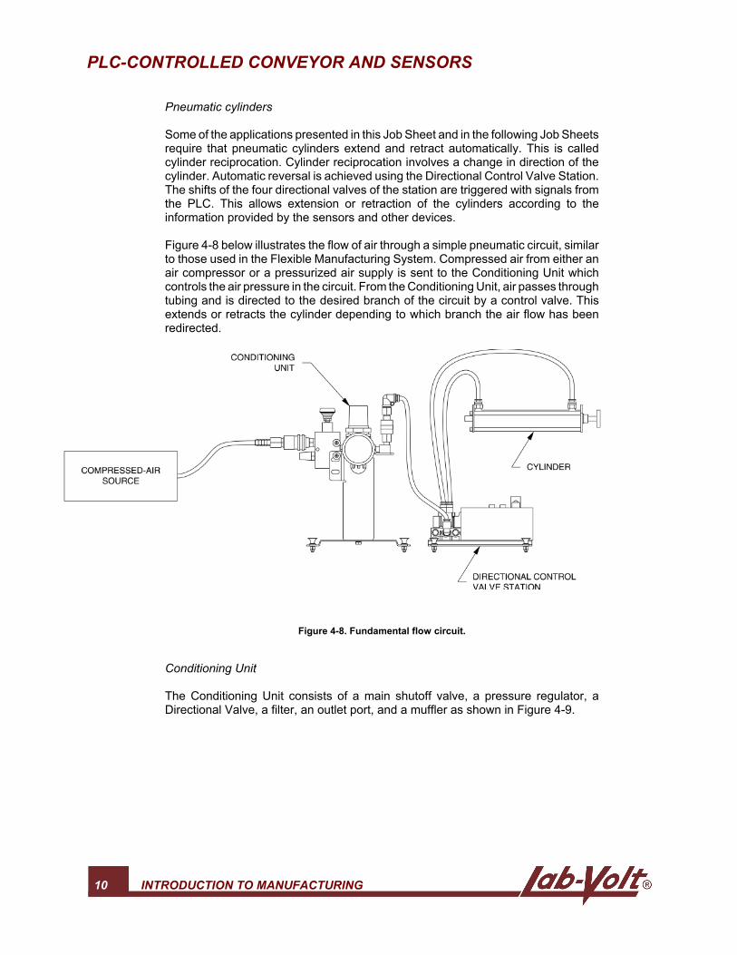
Figure 4-8 below illustrates the flow of air through a simple pneumatic circuit, similarto those used in the Flexible Manufacturing System. Compressed air from either anair compressor or a pressurized air supply is sent to the Conditioning Unit whichcontrols the air pressure in the circuit. From the Conditioning Unit, air passes throughtubing and is directed to the desired branch of the circuit by a control valve. Thisextends or retracts the cylinder depending to which branch the air flow has beenredirected.
Figure 4-8. Fundamental flow circuit.
Conditioning Unit
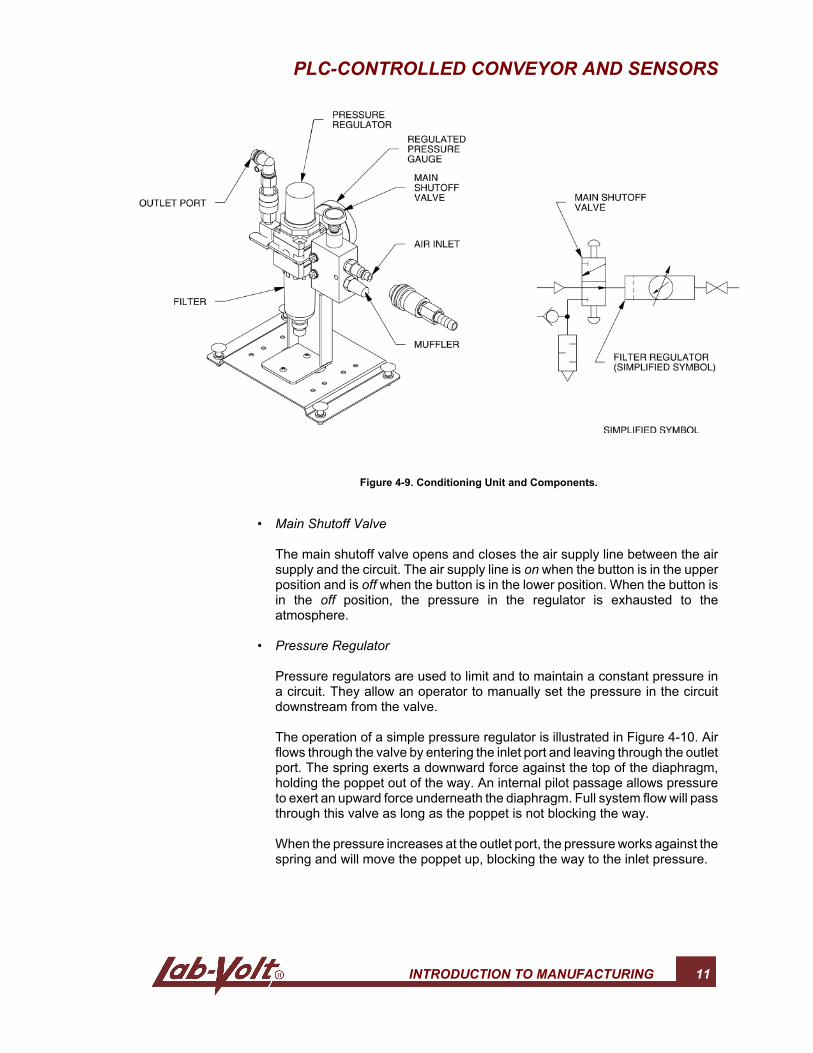
The Conditioning Unit consists of a main shutoff valve, a pressure regulator, aDirectional Valve, a filter, an outlet port, and a muffler as shown in Figure 4-9.
PLC-CONTROLLED CONVEYOR AND SENSORS
INTRODUCTION TO MANUFACTURING 11
Figure 4-9. Conditioning Unit and Components.
• Main Shutoff Valve
The main shutoff valve opens and closes the air supply line between the airsupply and the circuit. The air supply line is on when the button is in the upperposition and is off when the button is in the lower position. When the button isin the off position, the pressure in the regulator is exhausted to theatmosphere.
• Pressure Regulator
Pressure regulators are used to limit and to maintain a constant pressure ina circuit. They allow an operator to manually set the pressure in the circuitdownstream from the valve.
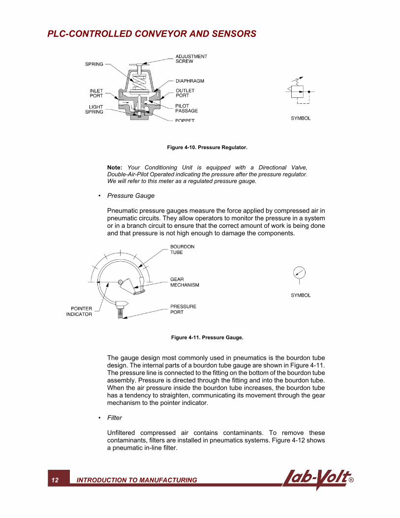
The operation of a simple pressure regulator is illustrated in Figure 4-10. Airflows through the valve by entering the inlet port and leaving through the outletport. The spring exerts a downward force against the top of the diaphragm,holding the poppet out of the way. An internal pilot passage allows pressureto exert an upward force underneath the diaphragm. Full system flow will passthrough this valve as long as the poppet is not blocking the way.
When the pressure increases at the outlet port, the pressure works against thespring and will move the poppet up, blocking the way to the inlet pressure.
PLC-CONTROLLED CONVEYOR AND SENSORS
12 INTRODUCTION TO MANUFACTURING
Figure 4-10. Pressure Regulator.
Note: Your Conditioning Unit is equipped with a Directional Valve,Double-Air-Pilot Operated indicating the pressure after the pressure regulator.We will refer to this meter as a regulated pressure gauge.
• Pressure Gauge
Pneumatic pressure gauges measure the force applied by compressed air inpneumatic circuits. They allow operators to monitor the pressure in a systemor in a branch circuit to ensure that the correct amount of work is being doneand that pressure is not high enough to damage the components.
Figure 4-11. Pressure Gauge.
The gauge design most commonly used in pneumatics is the bourdon tubedesign. The internal parts of a bourdon tube gauge are shown in Figure 4-11.The pressure line is connected to the fitting on the bottom of the bourdon tubeassembly. Pressure is directed through the fitting and into the bourdon tube.When the air pressure inside the bourdon tube increases, the bourdon tubehas a tendency to straighten, communicating its movement through the gearmechanism to the pointer indicator.
• Filter
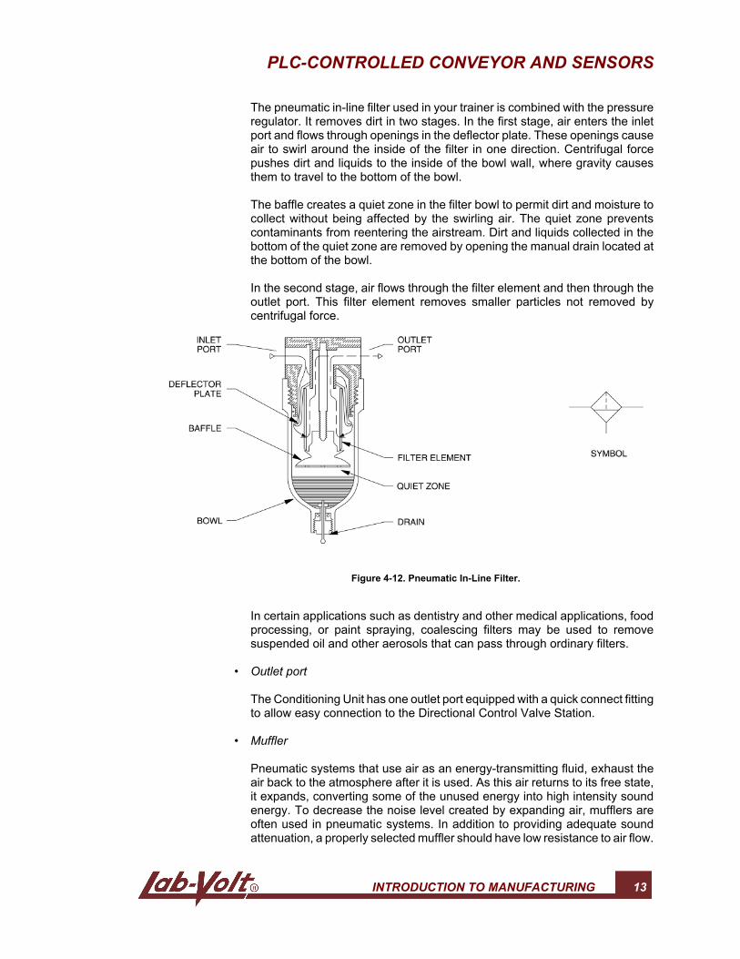
Unfiltered compressed air contains contaminants. To remove thesecontaminants, filters are installed in pneumatics systems. Figure 4-12 showsa pneumatic in-line filter.
PLC-CONTROLLED CONVEYOR AND SENSORS
INTRODUCTION TO MANUFACTURING 13
The pneumatic in-line filter used in your trainer is combined with the pressureregulator. It removes dirt in two stages. In the first stage, air enters the inletport and flows through openings in the deflector plate. These openings causeair to swirl around the inside of the filter in one direction. Centrifugal forcepushes dirt and liquids to the inside of the bowl wall, where gravity causesthem to travel to the bottom of the bowl.
The baffle creates a quiet zone in the filter bowl to permit dirt and moisture tocollect without being affected by the swirling air. The quiet zone preventscontaminants from reentering the airstream. Dirt and liquids collected in thebottom of the quiet zone are removed by opening the manual drain located atthe bottom of the bowl.
In the second stage, air flows through the filter element and then through theoutlet port. This filter element removes smaller particles not removed bycentrifugal force.
Figure 4-12. Pneumatic In-Line Filter.
In certain applications such as dentistry and other medical applications, foodprocessing, or paint spraying, coalescing filters may be used to removesuspended oil and other aerosols that can pass through ordinary filters.
• Outlet port
The Conditioning Unit has one outlet port equipped with a quick connect fittingto allow easy connection to the Directional Control Valve Station.
• Muffler
Pneumatic systems that use air as an energy-transmitting fluid, exhaust theair back to the atmosphere after it is used. As this air returns to its free state,it expands, converting some of the unused energy into high intensity soundenergy. To decrease the noise level created by expanding air, mufflers areoften used in pneumatic systems. In addition to providing adequate soundattenuation, a properly selected muffler should have low resistance to air flow.
PLC-CONTROLLED CONVEYOR AND SENSORS
14 INTRODUCTION TO MANUFACTURING
As shown in Figure 4-9, the muffler supplied with your Conditioning Unit islocated at the outlet port of the main shutoff valve. A quick fitting locatedabove the muffler allows the connection of any compressed air lines to beexhausted to atmosphere through the muffler.
Directional Control Valves
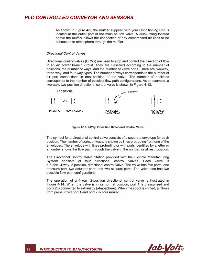
Directional control valves (DCVs) are used to stop and control the direction of flowin an air power branch circuit. They are classified according to the number ofpositions, the number of ways, and the number of valve ports. There are two-way,three-way, and four-way types. The number of ways corresponds to the number ofair port connections in one position of the valve. The number of positionscorresponds to the number of possible flow path configurations. As an example, atwo-way, two-position directional control valve is shown in Figure 4-13.
Figure 4-13. 2-Way, 2-Position Directional Control Valve.
The symbol for a directional control valve consists of a separate envelope for eachposition. The number of ports, or ways, is shown by lines protruding from one of theenvelopes. The envelope with lines protruding or with ports identified by a letter ora number shows the flow path through the valve in the normal, or at rest, position.
The Directional Control Valve Station provided with the Flexible ManufacturingSystem consists of four directional control valves. Each valve isa 5-port, 4-way, 2-position, directional control valve. The valve has five ports: onepressure port, two actuator ports and two exhaust ports. The valve also has twopossible flow path configurations.
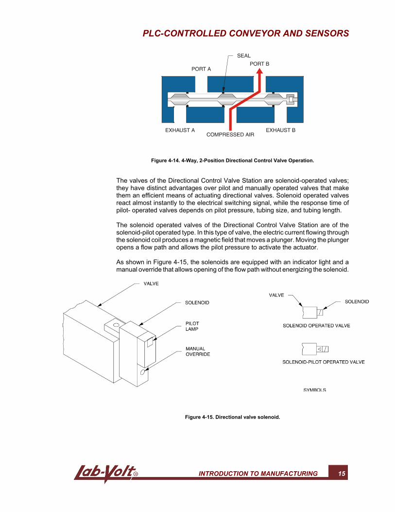
The operation of a 4-way, 2-position directional control valve is illustrated inFigure 4-14. When the valve is in its normal position, port 1 is pressurized andports 2 is connected to exhaust 2 (atmosphere). When the spool is shifted, air flowsfrom pressurized port 1 and port 2 is pressurized.
PLC-CONTROLLED CONVEYOR AND SENSORS
INTRODUCTION TO MANUFACTURING 15
Figure 4-14. 4-Way, 2-Position Directional Control Valve Operation.
The valves of the Directional Control Valve Station are solenoid-operated valves;they have distinct advantages over pilot and manually operated valves that makethem an efficient means of actuating directional valves. Solenoid operated valvesreact almost instantly to the electrical switching signal, while the response time ofpilot- operated valves depends on pilot pressure, tubing size, and tubing length.
The solenoid operated valves of the Directional Control Valve Station are of thesolenoid-pilot operated type. In this type of valve, the electric current flowing throughthe solenoid coil produces a magnetic field that moves a plunger. Moving the plungeropens a flow path and allows the pilot pressure to activate the actuator.
As shown in Figure 4-15, the solenoids are equipped with an indicator light and amanual override that allows opening of the flow path without energizing the solenoid.
Figure 4-15. Directional valve solenoid.

16 INTRODUCTION TO MANUFACTURING
4
PLC-CONTROLLED CONVEYOR AND SENSORS
INTRODUCTION TO MANUFACTURING 17
OBJECTIVE
To familiarize yourself with the various sensors provided with the FlexibleManufacturing System and measure their respective sensing ranges. To use the FlatBelt Conveyor to drive a box from the Pneumatic Box Feeder to the sensor installedin the middle of the conveyor.
PROCEDURE
G 1. Perform the basic safety procedures listed in Appendix G of this manual.
G 2. Make sure the system is configured for Ethernet communication asdescribed in the Ethernet configuration procedure given in Job Sheet 2.
G 3. Make sure the DeviceNet network is configured according to the proceduredescribed in Job Sheet 3.
Note: Use the saved DeviceNet configuration file(Networx_1st_Config) to speed up the DeviceNet configuration.
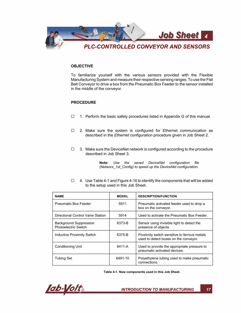
G 4. Use Table 4-1 and Figure 4-16 to identify the components that will be addedto the setup used in this Job Sheet.
NAME MODEL DESCRIPTION/FUNCTION
Pneumatic Box Feeder 5911 Pneumatic activated feeder used to drop abox on the conveyor.
Directional Control Valve Station 5914 Used to activate the Pneumatic Box Feeder.
Background SuppressionPhotoelectric Switch
6373-B Sensor using invisible light to detect thepresence of objects.
Inductive Proximity Switch 6375-B Proximity switch sensitive to ferrous metalsused to detect boxes on the conveyor.
Conditioning Unit 6411-A Used to provide the appropriate pressure topneumatic activated devices.
Tubing Set 6491-10 Polyethylene tubing used to make pneumaticconnections.
Table 4-1. New components used in this Job Sheet.
PLC-CONTROLLED CONVEYOR AND SENSORS
18 INTRODUCTION TO MANUFACTURING
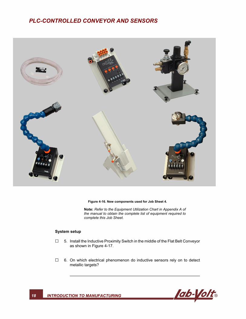
Figure 4-16. New components used for Job Sheet 4.
Note: Refer to the Equipment Utilization Chart in Appendix A ofthe manual to obtain the complete list of equipment required tocomplete this Job Sheet.
System setup
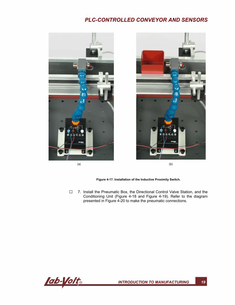
G 5. Install the Inductive Proximity Switch in the middle of the Flat Belt Conveyoras shown in Figure 4-17.
G 6. On which electrical phenomenon do inductive sensors rely on to detectmetallic targets?
PLC-CONTROLLED CONVEYOR AND SENSORS
INTRODUCTION TO MANUFACTURING 19
Figure 4-17. Installation of the Inductive Proximity Switch.
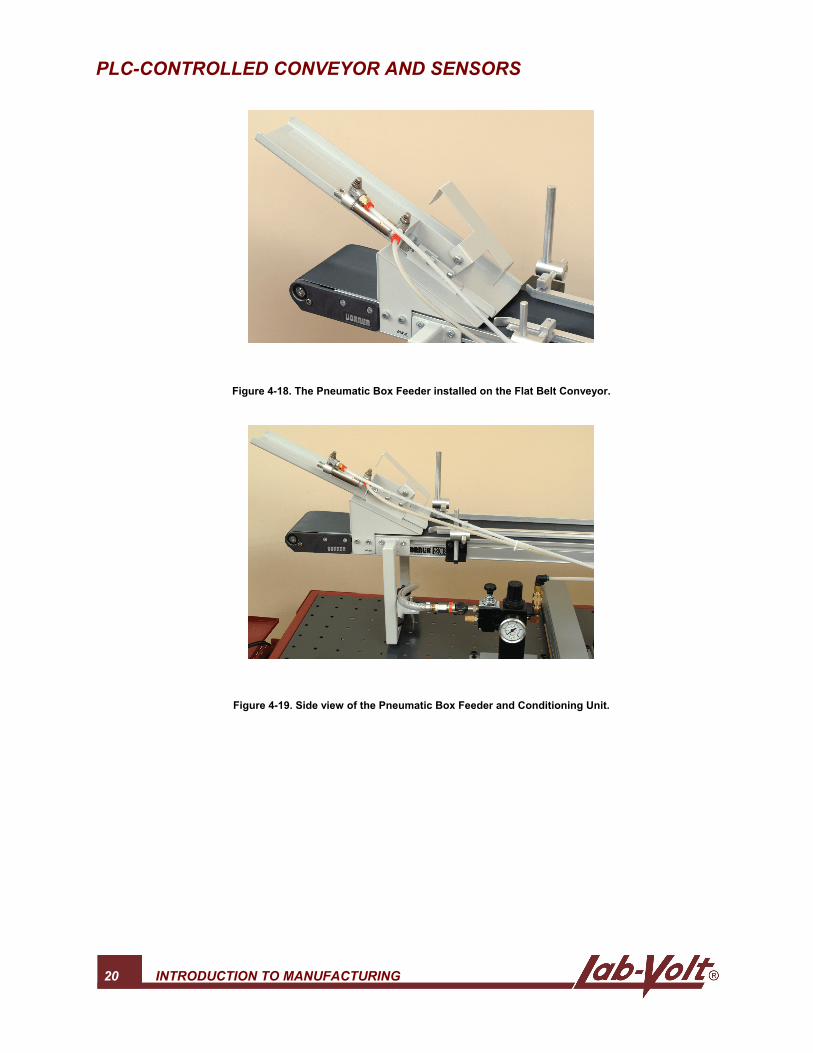
G 7. Install the Pneumatic Box, the Directional Control Valve Station, and theConditioning Unit (Figure 4-18 and Figure 4-19). Refer to the diagrampresented in Figure 4-20 to make the pneumatic connections.
PLC-CONTROLLED CONVEYOR AND SENSORS
20 INTRODUCTION TO MANUFACTURING
Figure 4-18. The Pneumatic Box Feeder installed on the Flat Belt Conveyor.
Figure 4-19. Side view of the Pneumatic Box Feeder and Conditioning Unit.
PLC-CONTROLLED CONVEYOR AND SENSORS
INTRODUCTION TO MANUFACTURING 21
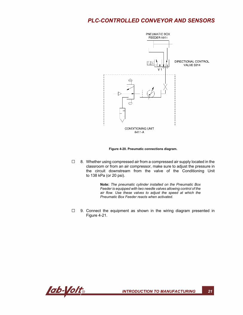
Figure 4-20. Pneumatic connections diagram.
G 8. Whether using compressed air from a compressed air supply located in theclassroom or from an air compressor, make sure to adjust the pressure inthe circuit downstream from the valve of the Conditioning Unitto 138 kPa (or 20 psi).
Note: The pneumatic cylinder installed on the Pneumatic BoxFeeder is equipped with two needle valves allowing control of theair flow. Use these valves to adjust the speed at which thePneumatic Box Feeder reacts when activated.
G 9. Connect the equipment as shown in the wiring diagram presented inFigure 4-21.
PLC-CONTROLLED CONVEYOR AND SENSORS
22 INTRODUCTION TO MANUFACTURING
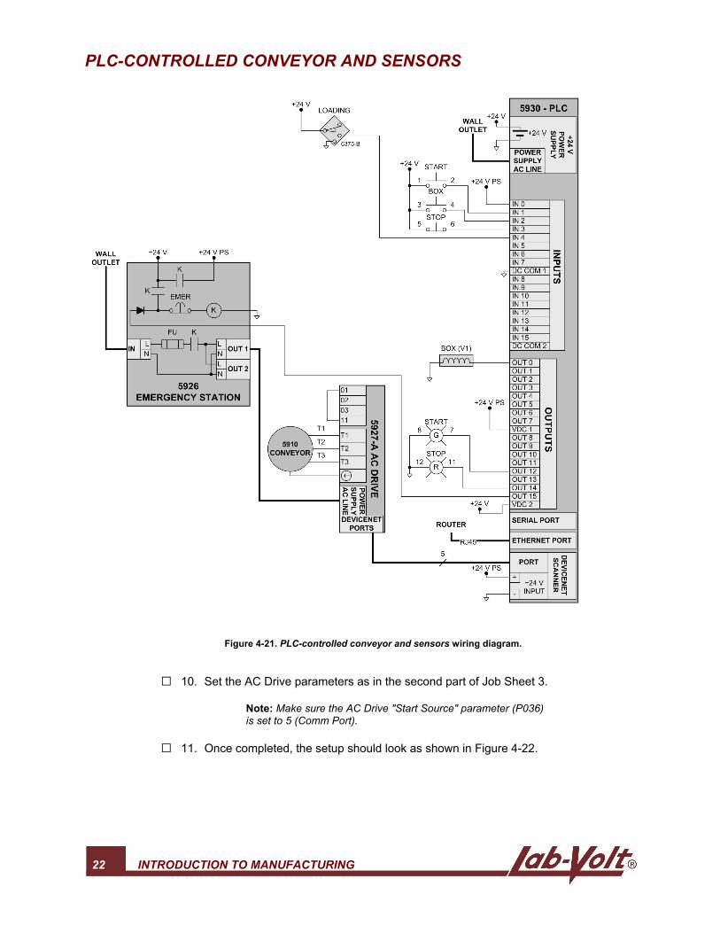
Figure 4-21. PLC-controlled conveyor and sensors wiring diagram.
G 10. Set the AC Drive parameters as in the second part of Job Sheet 3.
Note: Make sure the AC Drive "Start Source" parameter (P036)is set to 5 (Comm Port).
G 11. Once completed, the setup should look as shown in Figure 4-22.
PLC-CONTROLLED CONVEYOR AND SENSORS
INTRODUCTION TO MANUFACTURING 23
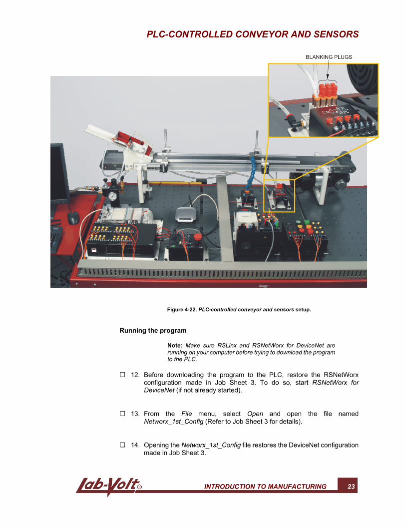
Figure 4-22. PLC-controlled conveyor and sensors setup.
Running the program
Note: Make sure RSLinx and RSNetWorx for DeviceNet arerunning on your computer before trying to download the programto the PLC.
G 12. Before downloading the program to the PLC, restore the RSNetWorxconfiguration made in Job Sheet 3. To do so, start RSNetWorx forDeviceNet (if not already started).
G 13. From the File menu, select Open and open the file namedNetworx_1st_Config (Refer to Job Sheet 3 for details).
G 14. Opening the Networx_1st_Config file restores the DeviceNet configurationmade in Job Sheet 3.

PLC-CONTROLLED CONVEYOR AND SENSORS
24 INTRODUCTION TO MANUFACTURING
G 15. Open the RSLogix 5000 project file named intro_manu_stu4.acd anddownload the program to the PLC. Refer to the Running the programsprocedure given in Job Sheet 2 for details on downloading programs.
G 16. Make sure the setup is working properly. You should be able to:
• start the Flat Belt Conveyor (clockwise rotation) using the green pushbutton on the Indicator Light/Push-Button Station;
• stop the Flat Belt Conveyor using the red push button on the IndicatorLight/Push-Button Station (pressing the green push button resumes themanufacturing process simulation);
• cut off the power in case of emergency with the Emergency SwitchStation;
• drop another box using the yellow push button on the IndicatorLight/Push-Button Station;
• observe that the red indicator light turns on when the AC Drive is readyand turns off when the Flat Belt Conveyor is rotating;
• observe that the green indicator light turns on when the Flat BeltConveyor is rotating clockwise;
• observe that once the Flat Belt Conveyor is rotating, a box is droppedby the Pneumatic Box Feeder;
• Reset the system using the red push button on the Indicator Light/Push-Button Station;
• observe that the Flat Belt Conveyor stops if a box is detected by theInductive Proximity Switch.
A video of the setup presented in this Job Sheet is availableon the Lab-Volt Flexible Manufacturing System ResourceKit (student) CD-ROM.
G 17. Once you are sure the setup is working properly, press on the green buttonto start the Flat Belt Conveyor.
G 18. Use the AC Drive potentiometer to adjust the AC Drive output frequency (i.e.the conveyor speed) to 10 Hz.
G 19. Drop a box on the Flat Belt Conveyor using the yellow push button. Theconveyor should stop before the box reaches the sensor.
PLC-CONTROLLED CONVEYOR AND SENSORS
INTRODUCTION TO MANUFACTURING 25
G 20. Measure the distance between the active face of the Inductive ProximitySwitch and the side of the box when the conveyor stops. This is the sensingdistance of the Inductive Proximity Switch for this setup. Write down thesensing distance of the Inductive Proximity Switch below:
Inductive Proximity Switch sensing distance:
G 21. Replace the Inductive Proximity Switch with the Background SuppressionPhotoelectric Switch. Use the same wiring as for the Inductive ProximitySwitch.
G 22. Proceed as for the Inductive Proximity Switch and write down the sensingdistance of the Background Suppression Photoelectric Switch below:
Background Suppression Photoelectric Switch sensing distance:
G 23. Ask the instructor to check and approve your work.
Troubleshooting exercise
Note: Prior to this exercise, the instructor must insert a fault intothe circuit of the Flexible Manufacturing System.
G 24. Try to use the setup and determine whether everything is working properly.
G 25. If the system is not working properly, describe the symptom(s).
G 26. Use your troubleshooting skills to identify the malfunctioning module(s) andisolate the problem(s).

PLC-CONTROLLED CONVEYOR AND SENSORS
26 INTRODUCTION TO MANUFACTURING
G 27. Explain in detail your approach to isolate the problem.
G 28. Ask the instructor to check and approve the Troubleshooting Exercise.
Programming exercise
Note: Make sure there is no fault from the troubleshootingexercise left on the setup.
In this Job Sheet, a box is dropped on the conveyor by pressing the yellow button.The conveyor stops when the sensor detects the box.
Modify the program so that the yellow light turns on if the operation described aboveis performed five times in a row.
G 29. Once this exercise is complete, ask the instructor to check and approve yourwork.
Name: Date:
Instructor's approval:
Instructor Guide Sample
Extracted from
Introduction to Manufacturing

Introduction to Manufacturing
INTRODUCTION TO MANUFACTURING 29
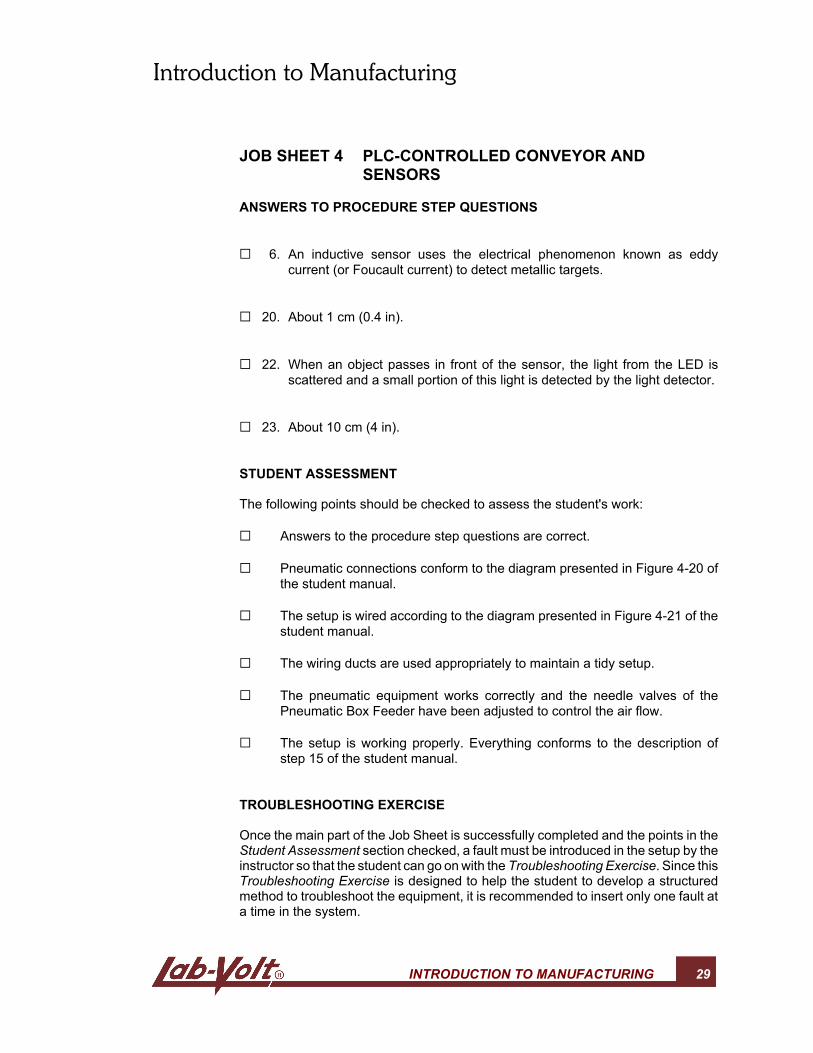
JOB SHEET 4 PLC-CONTROLLED CONVEYOR ANDSENSORS
ANSWERS TO PROCEDURE STEP QUESTIONS
G 6. An inductive sensor uses the electrical phenomenon known as eddycurrent (or Foucault current) to detect metallic targets.
G 20. About 1 cm (0.4 in).
G 22. When an object passes in front of the sensor, the light from the LED isscattered and a small portion of this light is detected by the light detector.
G 23. About 10 cm (4 in).
STUDENT ASSESSMENT
The following points should be checked to assess the student's work:
G Answers to the procedure step questions are correct.
G Pneumatic connections conform to the diagram presented in Figure 4-20 ofthe student manual.
G The setup is wired according to the diagram presented in Figure 4-21 of thestudent manual.
G The wiring ducts are used appropriately to maintain a tidy setup.
G The pneumatic equipment works correctly and the needle valves of thePneumatic Box Feeder have been adjusted to control the air flow.
G The setup is working properly. Everything conforms to the description ofstep 15 of the student manual.
TROUBLESHOOTING EXERCISE
Once the main part of the Job Sheet is successfully completed and the points in theStudent Assessment section checked, a fault must be introduced in the setup by theinstructor so that the student can go on with the Troubleshooting Exercise. Since thisTroubleshooting Exercise is designed to help the student to develop a structuredmethod to troubleshoot the equipment, it is recommended to insert only one fault ata time in the system.
Introduction to Manufacturing
30 INTRODUCTION TO MANUFACTURING
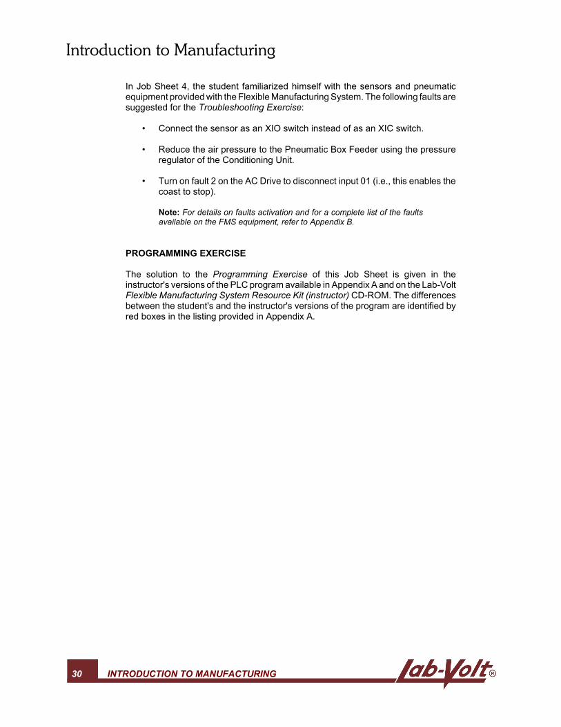
In Job Sheet 4, the student familiarized himself with the sensors and pneumaticequipment provided with the Flexible Manufacturing System. The following faults aresuggested for the Troubleshooting Exercise:
• Connect the sensor as an XIO switch instead of as an XIC switch.
• Reduce the air pressure to the Pneumatic Box Feeder using the pressureregulator of the Conditioning Unit.
• Turn on fault 2 on the AC Drive to disconnect input 01 (i.e., this enables thecoast to stop).
Note: For details on faults activation and for a complete list of the faultsavailable on the FMS equipment, refer to Appendix B.
PROGRAMMING EXERCISE
The solution to the Programming Exercise of this Job Sheet is given in theinstructor's versions of the PLC program available in Appendix A and on the Lab-VoltFlexible Manufacturing System Resource Kit (instructor) CD-ROM. The differencesbetween the student's and the instructor's versions of the program are identified byred boxes in the listing provided in Appendix A.