Embed Size (px)
Citation preview
Hindawi Publishing CorporationJournal of NanomaterialsVolume 2011, Article ID 760237, 10 pagesdoi:10.1155/2011/760237
Research Article
Controlled Release from Core-Shell Nanoporous Silica Particlesfor Corrosion Inhibition of Aluminum Alloys
Xingmao Jiang,1, 2 Ying-Bing Jiang,3 Nanguo Liu,4 Huifang Xu,5 Shailendra Rathod,1
Pratik Shah,1 and C. Jeffrey Brinker1, 6
1 Department of Chemical and Nuclear Engineering and Center for Micro-Engineered Materials,University of New Mexico, Albuquerque, NM 87106, USA
2 Aerosol and Respiratory Dosimetry Program, Lovelace Respiratory Research Institute, 2425 Ridgecrest Dr. SE,Albuquerque, NM 87108, USA
3 Transmission Electron Microscopy Labs, The University of New Mexico, Albuquerque, NM 87131, USA4 SCB Innovation Accelerator, Dow Corning Corporation, 2200 W. Salzburg Road, P.O. Box 0994, Midland, MI 48686, USA5 Department of Geoscience, University of Wisconsin-Madison, Madison, WI 53706, USA6 Advanced Material Laboratory, Sandia National Laboratories, Albuquerque, NM 87185, USA
Correspondence should be addressed to C. Jeffrey Brinker, [email protected]
Received 3 November 2010; Accepted 2 December 2010
Academic Editor: Hugh D. Smyth
Copyright © 2011 Xingmao Jiang et al. This is an open access article distributed under the Creative Commons Attribution License,which permits unrestricted use, distribution, and reproduction in any medium, provided the original work is properly cited.
Cerium (Ce) corrosion inhibitors were encapsulated into hexagonally ordered nanoporous silica particles via single-step aerosol-assisted self-assembly. The core/shell structured particles are effective for corrosion inhibition of aluminum alloy AA2024-T3.Numerical simulation proved that the core-shell nanostructure delays the release process. The effective diffusion coefficientelucidated from release data for monodisperse particles in water was 1.0×10⁻¹⁴ m2s for Ce3+ compared to 2.5×10⁻¹³ m2s for NaCl.The pore size, pore surface chemistry, and the inhibitor solubility are crucial factors for the application. Microporous hydrophobicparticles encapsulating a less soluble corrosion inhibitor are desirable for long-term corrosion inhibition.
1. Introduction
Controlled release is of particular interest for a broadspectrum of studies dealing with corrosion inhibition, fer-tilizers, and medical applications such as gene delivery, tissueengineering, and diagnostic agents. Long-term cost-effectivecorrosion inhibition of steels and alloys requires a controlledrelease of corrosion inhibitors especially for protecting thealuminum alloy AA2024-T3 used in aeronautic applica-tions [1]. AA 2024 is composed of (in weight percentage)93.5% Aluminum (Al), 4.4% Copper (Cu), 0.6% Manganese(Mn), and 1.5% Magnesium (Mg). Currently, carcinogenicchromate compounds have been widely used as corrosioninhibitors [2, 3], but these are expensive to process andmaintain. The most potent and less toxic candidate inhibitorsfor aluminum alloys, according to the study by Scully’sgroup and Tailor’s group, are lanthanide, metavanadate,molybdenum, and cobalt ions [1, 4]. The inhibitors not only
suppress cathodic reactions in the alloys that are essential forcorrosion inhibition and copper replating, but they provideself-healing for the alloys as well. Much effort has been madeto investigate corrosion inhibition, ranging from barrierto conversion coatings or pigmentation of the inhibitors[5–8]. Layered clays have been tried for encapsulating theinhibitors by ion exchange [9]. A multifunctional organiccoating containing silica can be formed by the in situ sol-gelprocess. However, this method lacks appropriate storage andslow release of corrosion inhibitors [10–13]. Nanoporoussilica is a mechanically and thermally stable, cheap, and anenvironmentally benign ceramic, and it has found variousapplications in adsorption, separation, and catalysis [14, 15].The well-controlled pore size, narrow pore size distribution,and controllable functionality and pore surface chemistriesof self-assembled nanoporous silica materials suggest theiruse as the encapsulating material for controlled release ofcorrosion inhibitors. The promising nanocapsules can be
2 Journal of Nanomaterials
50 50 nm
(a)
30 30 nm
(b)
50 50 nm
(c)
50 50 nm
(d)
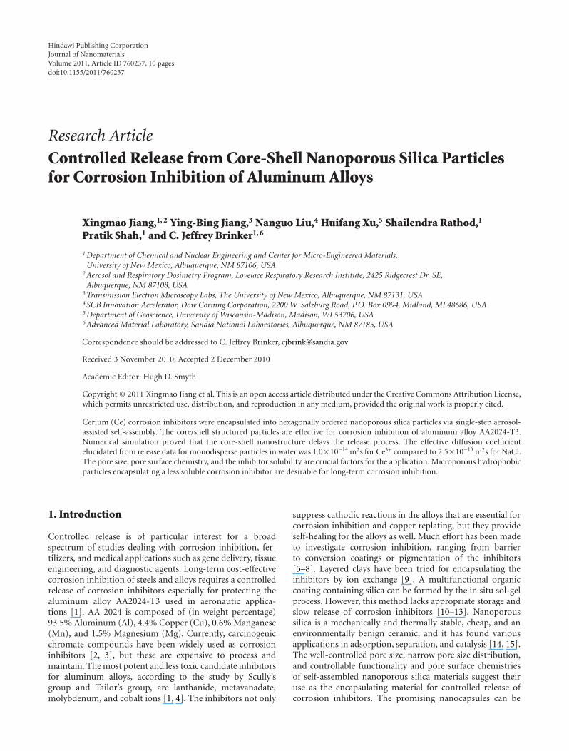
Figure 1: TEM images of nanostructured particles (a–d) with different loadings of Ce. The molar ratios of the precursor sol compositionsare TEOS : EtOH : H2O : HCl : CTAB : CeCl3 = 1 : 7.7 : 24.8 : 0.00125 : 0.18 : x, where x = 0, 0.06, 0.12, and 0.18, respectively, for particlesamples (a)–(d).
dispersed as pigments into a protective epoxy coating for along-term cost-effective protection of the alloys.
In this paper, we report a novel single-step methodfor encapsulating cerium (Ce) corrosion inhibitors intonanoporous silica particles by aerosol-assisted evaporation-induced self-assembly (EISA). Nanostructured particles witha core of Ce compounds and a shell of ordered nanoporoussilica were prepared. These core-shell nanostructured par-ticles are effective for inhibiting corrosion of aluminumalloy AA2024-T3. We investigated the controlled release ofinhibitors and found that long-term corrosion inhibition canbe realized using hydrophobic microporous nanocapsules.
2. Results and Discussion
The core-shell nanostructured particles were synthesized viaaerosol-assisted EISA using cetyltrimethylammonium bro-mide (CTAB) as a structure-directing agent. Figure 1 shows
representative transmission electron microscopy (TEM)images of calcined silica particles. At low Ce loading theparticles keep a hexagonally ordered mesoporous silicastructure featuring parallel aligned stripes and hexagonallyarranged pores (Figure 1(a)), reflecting differing orientationsof a 2D hexagonal silica mesophase confined within aspherical shell. By increasing the loading of cerium chloride(CeCl3), the mesostructure turns into a core-shell structure(Figures 1(b) and 1(c)). At high loading (Figure 1(d)), theparticles became worm-like or even less ordered, especiallynear the particle center.
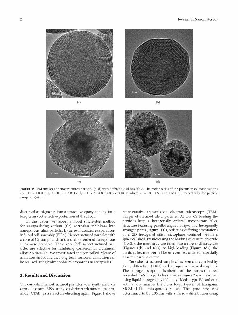
Core-shell structured sample c has been characterized byX-ray diffraction (XRD) and nitrogen isothermal sorption.The nitrogen sorption isotherm of the nanostructuredcore-shell Ce/silica particles shown in Figure 2 was measuredusing liquid nitrogen at 77 K and yielded a type IV isothermwith a very narrow hysteresis loop, typical of hexagonalMCM-41-like mesoporous silicas. The pore size wasdetermined to be 1.95 nm with a narrow distribution using
Journal of Nanomaterials 3
0
50
100
150
200
250
300
N2
adso
rbed
(cm
3/g
)
0 0.2 0.4 0.6 0.8 1
Relative pressure (P/P0)
AdsorptionDesorption
0
10
20
30
40
50
60
70dVp/dRp
5 10 15 20 25 30
Pore radius (A)
Figure 2: Nitrogen sorption for core-shell mesoporous particle b(Figure 1). Inset shows the BJH pore size distribution.
0
5
10
15
20
25
30×102
Inte
nsi
ty(c
oun
ts)
0 2 4 6 8 10
2(θ)
Pure silicaCeCl3/silica
Figure 3: XRD patterns for sample a (pure silica) and sample c(Figure 1).
the Barrett-Joyner-Halenda (BJH) model. The Brunauer-Emmett-Teller (BET) surface area is 615 m2/g. The low-anglepeaks are associated with the 2D hexagonal silica mesophase.As can be seen from the XRD patterns shown in Figure 3,compared to pure mesoporous silica the mesostructuralorder for sample c (Figure 1) is reduced as measured by lessintense diffraction peaks.
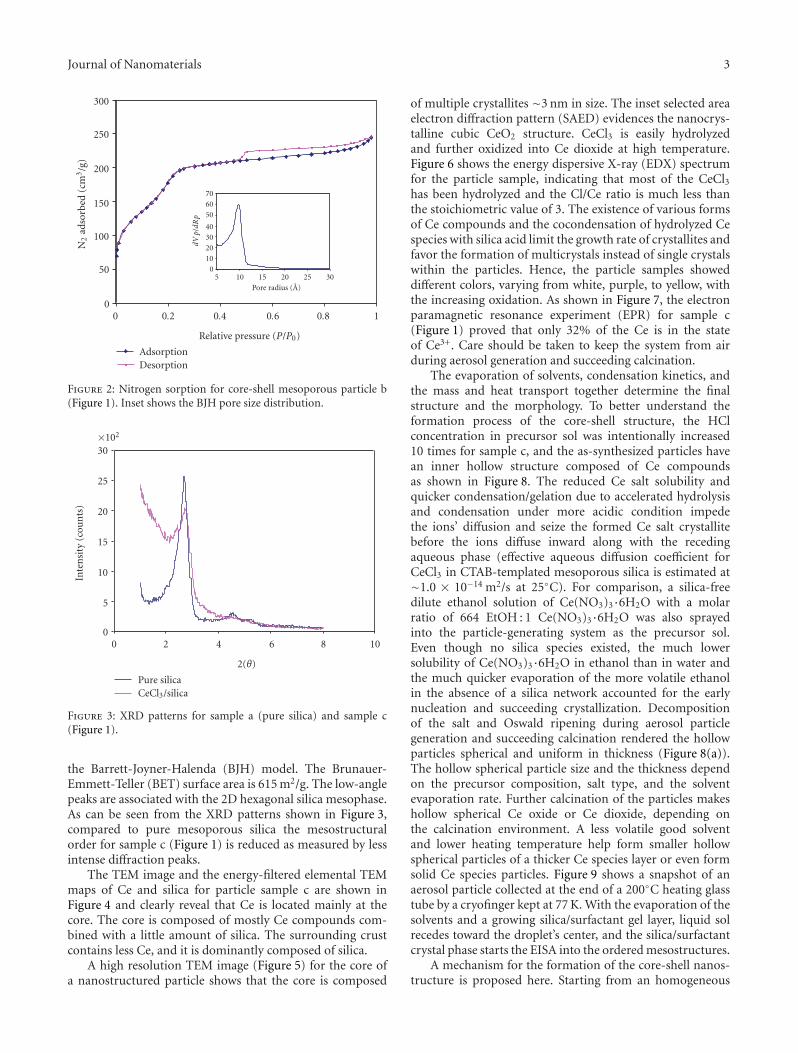
The TEM image and the energy-filtered elemental TEMmaps of Ce and silica for particle sample c are shown inFigure 4 and clearly reveal that Ce is located mainly at thecore. The core is composed of mostly Ce compounds com-bined with a little amount of silica. The surrounding crustcontains less Ce, and it is dominantly composed of silica.
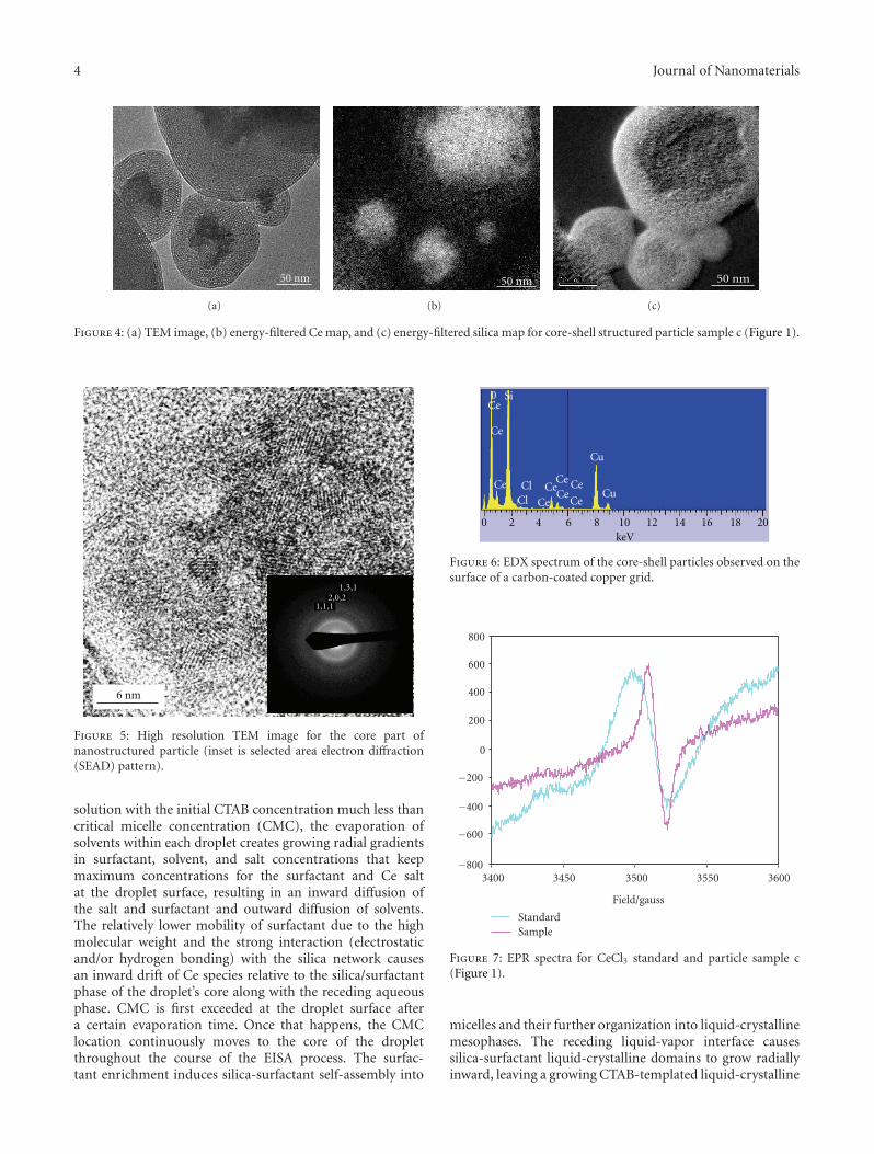
A high resolution TEM image (Figure 5) for the core ofa nanostructured particle shows that the core is composed
of multiple crystallites ∼3 nm in size. The inset selected areaelectron diffraction pattern (SAED) evidences the nanocrys-talline cubic CeO2 structure. CeCl3 is easily hydrolyzedand further oxidized into Ce dioxide at high temperature.Figure 6 shows the energy dispersive X-ray (EDX) spectrumfor the particle sample, indicating that most of the CeCl3has been hydrolyzed and the Cl/Ce ratio is much less thanthe stoichiometric value of 3. The existence of various formsof Ce compounds and the cocondensation of hydrolyzed Cespecies with silica acid limit the growth rate of crystallites andfavor the formation of multicrystals instead of single crystalswithin the particles. Hence, the particle samples showeddifferent colors, varying from white, purple, to yellow, withthe increasing oxidation. As shown in Figure 7, the electronparamagnetic resonance experiment (EPR) for sample c(Figure 1) proved that only 32% of the Ce is in the stateof Ce3+. Care should be taken to keep the system from airduring aerosol generation and succeeding calcination.
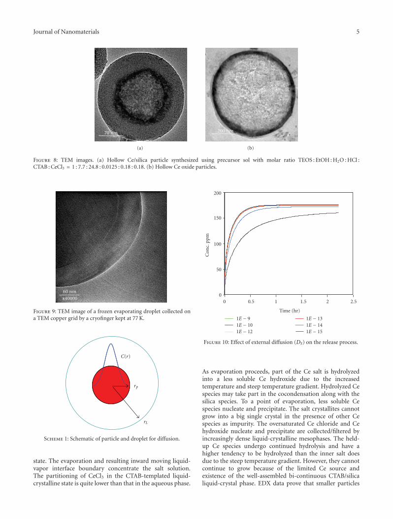
The evaporation of solvents, condensation kinetics, andthe mass and heat transport together determine the finalstructure and the morphology. To better understand theformation process of the core-shell structure, the HClconcentration in precursor sol was intentionally increased10 times for sample c, and the as-synthesized particles havean inner hollow structure composed of Ce compoundsas shown in Figure 8. The reduced Ce salt solubility andquicker condensation/gelation due to accelerated hydrolysisand condensation under more acidic condition impedethe ions’ diffusion and seize the formed Ce salt crystallitebefore the ions diffuse inward along with the recedingaqueous phase (effective aqueous diffusion coefficient forCeCl3 in CTAB-templated mesoporous silica is estimated at∼1.0 × 10⁻¹⁴ m2/s at 25◦C). For comparison, a silica-freedilute ethanol solution of Ce(NO3)3·6H2O with a molarratio of 664 EtOH : 1 Ce(NO3)3·6H2O was also sprayedinto the particle-generating system as the precursor sol.Even though no silica species existed, the much lowersolubility of Ce(NO3)3·6H2O in ethanol than in water andthe much quicker evaporation of the more volatile ethanolin the absence of a silica network accounted for the earlynucleation and succeeding crystallization. Decompositionof the salt and Oswald ripening during aerosol particlegeneration and succeeding calcination rendered the hollowparticles spherical and uniform in thickness (Figure 8(a)).The hollow spherical particle size and the thickness dependon the precursor composition, salt type, and the solventevaporation rate. Further calcination of the particles makeshollow spherical Ce oxide or Ce dioxide, depending onthe calcination environment. A less volatile good solventand lower heating temperature help form smaller hollowspherical particles of a thicker Ce species layer or even formsolid Ce species particles. Figure 9 shows a snapshot of anaerosol particle collected at the end of a 200◦C heating glasstube by a cryofinger kept at 77 K. With the evaporation of thesolvents and a growing silica/surfactant gel layer, liquid solrecedes toward the droplet’s center, and the silica/surfactantcrystal phase starts the EISA into the ordered mesostructures.
A mechanism for the formation of the core-shell nanos-tructure is proposed here. Starting from an homogeneous
4 Journal of Nanomaterials
50 nm
(a)
50 nm
(b)
50 nm
(c)
Figure 4: (a) TEM image, (b) energy-filtered Ce map, and (c) energy-filtered silica map for core-shell structured particle sample c (Figure 1).
1,1,12,0,2
1,3,1
6 nm
Figure 5: High resolution TEM image for the core part ofnanostructured particle (inset is selected area electron diffraction(SEAD) pattern).
solution with the initial CTAB concentration much less thancritical micelle concentration (CMC), the evaporation ofsolvents within each droplet creates growing radial gradientsin surfactant, solvent, and salt concentrations that keepmaximum concentrations for the surfactant and Ce saltat the droplet surface, resulting in an inward diffusion ofthe salt and surfactant and outward diffusion of solvents.The relatively lower mobility of surfactant due to the highmolecular weight and the strong interaction (electrostaticand/or hydrogen bonding) with the silica network causesan inward drift of Ce species relative to the silica/surfactantphase of the droplet’s core along with the receding aqueousphase. CMC is first exceeded at the droplet surface aftera certain evaporation time. Once that happens, the CMClocation continuously moves to the core of the dropletthroughout the course of the EISA process. The surfac-tant enrichment induces silica-surfactant self-assembly into
Cu
Cu
Ce
Ce
CeCe
CeCe
Ce CeCe
ClCl
0 Si
0 2 4 6 8 10 12 14 16 18 20keV
Figure 6: EDX spectrum of the core-shell particles observed on thesurface of a carbon-coated copper grid.
−800
−600
−400
−200
0
200
400
600
800
3400 3450 3500 3550 3600
Field/gauss
StandardSample
Figure 7: EPR spectra for CeCl3 standard and particle sample c(Figure 1).
micelles and their further organization into liquid-crystallinemesophases. The receding liquid-vapor interface causessilica-surfactant liquid-crystalline domains to grow radiallyinward, leaving a growing CTAB-templated liquid-crystalline
Journal of Nanomaterials 5
70 nm
(a)
200 nm
(b)
Figure 8: TEM images. (a) Hollow Ce/silica particle synthesized using precursor sol with molar ratio TEOS : EtOH : H2O : HCl :CTAB : CeCl3 = 1 : 7.7 : 24.8 : 0.0125 : 0.18 : 0.18. (b) Hollow Ce oxide particles.
60 nmx40000
Figure 9: TEM image of a frozen evaporating droplet collected ona TEM copper grid by a cryofinger kept at 77 K.
C(r)
rp
rL
Scheme 1: Schematic of particle and droplet for diffusion.
state. The evaporation and resulting inward moving liquid-vapor interface boundary concentrate the salt solution.The partitioning of CeCl3 in the CTAB-templated liquid-crystalline state is quite lower than that in the aqueous phase.
0
50
100
150
200
Con
c.pp
m
0 0.5 1 1.5 2 2.5
Time (hr)
1E − 91E − 101E − 12
1E − 131E − 141E − 15
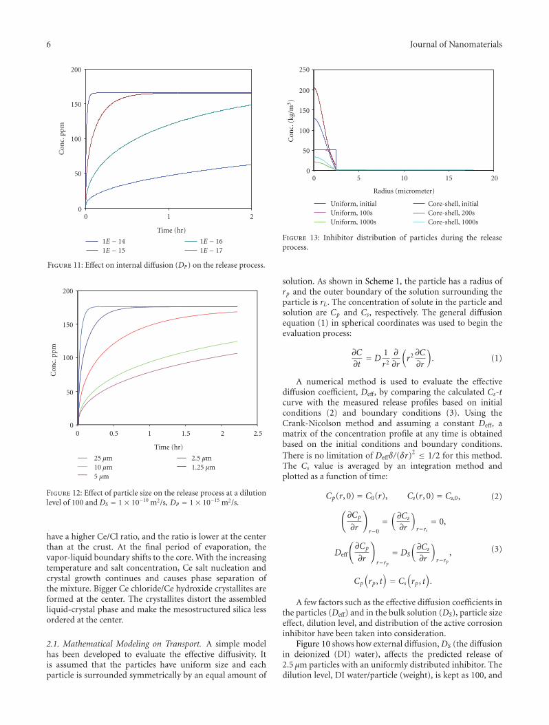
Figure 10: Effect of external diffusion (DS) on the release process.
As evaporation proceeds, part of the Ce salt is hydrolyzedinto a less soluble Ce hydroxide due to the increasedtemperature and steep temperature gradient. Hydrolyzed Cespecies may take part in the cocondensation along with thesilica species. To a point of evaporation, less soluble Cespecies nucleate and precipitate. The salt crystallites cannotgrow into a big single crystal in the presence of other Cespecies as impurity. The oversaturated Ce chloride and Cehydroxide nucleate and precipitate are collected/filtered byincreasingly dense liquid-crystalline mesophases. The held-up Ce species undergo continued hydrolysis and have ahigher tendency to be hydrolyzed than the inner salt doesdue to the steep temperature gradient. However, they cannotcontinue to grow because of the limited Ce source andexistence of the well-assembled bi-continuous CTAB/silicaliquid-crystal phase. EDX data prove that smaller particles
6 Journal of Nanomaterials
0
50
100
150
200C
onc.
ppm
0 1 2
Time (hr)
1E − 141E − 15
1E − 161E − 17
Figure 11: Effect on internal diffusion (DP) on the release process.
0
50
100
150
200
Con
c.pp
m
0 0.5 1 1.5 2 2.5
Time (hr)
25 μm10 μm5 μm
2.5 μm1.25 μm
Figure 12: Effect of particle size on the release process at a dilutionlevel of 100 and DS = 1× 10⁻¹⁰ m2/s, DP = 1× 10⁻¹⁵ m2/s.
have a higher Ce/Cl ratio, and the ratio is lower at the centerthan at the crust. At the final period of evaporation, thevapor-liquid boundary shifts to the core. With the increasingtemperature and salt concentration, Ce salt nucleation andcrystal growth continues and causes phase separation ofthe mixture. Bigger Ce chloride/Ce hydroxide crystallites areformed at the center. The crystallites distort the assembledliquid-crystal phase and make the mesostructured silica lessordered at the center.
2.1. Mathematical Modeling on Transport. A simple modelhas been developed to evaluate the effective diffusivity. Itis assumed that the particles have uniform size and eachparticle is surrounded symmetrically by an equal amount of
0
50
100
150
200
250
Con
c.(k
g/m
3)
0 5 10 15 20
Radius (micrometer)
Uniform, initialUniform, 100sUniform, 1000s
Core-shell, initialCore-shell, 200sCore-shell, 1000s
Figure 13: Inhibitor distribution of particles during the releaseprocess.
solution. As shown in Scheme 1, the particle has a radius ofrp and the outer boundary of the solution surrounding theparticle is rL. The concentration of solute in the particle andsolution are Cp and Cs, respectively. The general diffusionequation (1) in spherical coordinates was used to begin theevaluation process:
∂C
∂t= D
1r2
∂
∂r
(r2 ∂C
∂r
). (1)
A numerical method is used to evaluate the effectivediffusion coefficient, Deff, by comparing the calculated Cs-tcurve with the measured release profiles based on initialconditions (2) and boundary conditions (3). Using theCrank-Nicolson method and assuming a constant Deff, amatrix of the concentration profile at any time is obtainedbased on the initial conditions and boundary conditions.There is no limitation of Deffδ/(δr)
2 ≤ 1/2 for this method.The Cs value is averaged by an integration method andplotted as a function of time:
Cp(r, 0) = C0(r), Cs(r, 0) = Cs,0, (2)(∂Cp
∂r
)r=0
=(∂Cs∂r
)r=rs
= 0,
Deff
(∂Cp
∂r
)r=rp
= DS
(∂Cs∂r
)r=rp
,
Cp
(rp, t
)= Cs
(rp, t
).
(3)
A few factors such as the effective diffusion coefficients inthe particles (Deff) and in the bulk solution (DS), particle sizeeffect, dilution level, and distribution of the active corrosioninhibitor have been taken into consideration.
Figure 10 shows how external diffusion,DS (the diffusionin deionized (DI) water), affects the predicted release of2.5 μm particles with an uniformly distributed inhibitor. Thedilution level, DI water/particle (weight), is kept as 100, and
Journal of Nanomaterials 7
0
0.05
0.1
0.15
0.2
0.25
0.3
0.35
UV
abs.
0 0.5 1 1.5 2 2.5 3
Time (hr)
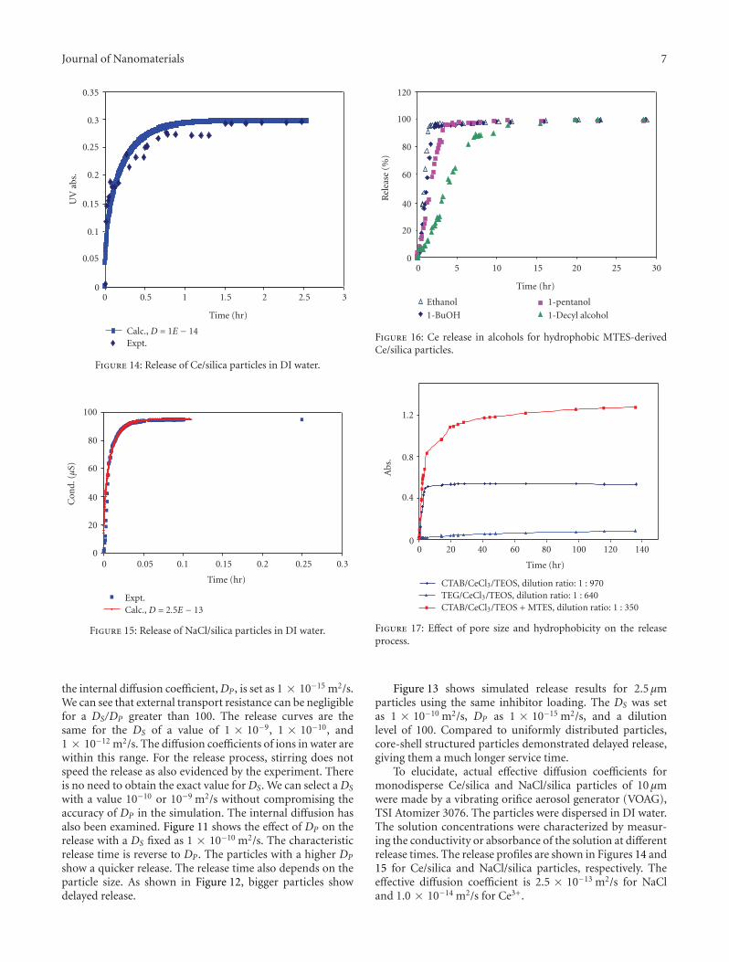
Calc., D = 1E − 14Expt.
Figure 14: Release of Ce/silica particles in DI water.
0
20
40
60
80
100
Con
d.(μ
S)
0 0.05 0.1 0.15 0.2 0.25 0.3
Time (hr)
Calc., D = 2.5E − 13Expt.
Figure 15: Release of NaCl/silica particles in DI water.
the internal diffusion coefficient,DP , is set as 1 × 10⁻¹⁵ m2/s.We can see that external transport resistance can be negligiblefor a DS/DP greater than 100. The release curves are thesame for the DS of a value of 1 × 10⁻⁹, 1 × 10⁻¹⁰, and1 × 10−12 m2/s. The diffusion coefficients of ions in water arewithin this range. For the release process, stirring does notspeed the release as also evidenced by the experiment. Thereis no need to obtain the exact value forDS. We can select aDS
with a value 10−10 or 10−9 m2/s without compromising theaccuracy of DP in the simulation. The internal diffusion hasalso been examined. Figure 11 shows the effect of DP on therelease with a DS fixed as 1 × 10⁻¹⁰ m2/s. The characteristicrelease time is reverse to DP . The particles with a higher DP
show a quicker release. The release time also depends on theparticle size. As shown in Figure 12, bigger particles showdelayed release.
0
20
40
60
80
100
120
Rel
ease
(%)
0 5 10 15 20 25 30
Time (hr)
Ethanol
1-BuOH
1-pentanol
1-Decyl alcohol
Figure 16: Ce release in alcohols for hydrophobic MTES-derivedCe/silica particles.
0
0.4
0.8
1.2
Abs
.
0 20 40 60 80 100 120 140
Time (hr)
CTAB/CeCl3/TEOS, dilution ratio: 1 : 970TEG/CeCl3/TEOS, dilution ratio: 1 : 640CTAB/CeCl3/TEOS + MTES, dilution ratio: 1 : 350
Figure 17: Effect of pore size and hydrophobicity on the releaseprocess.
Figure 13 shows simulated release results for 2.5 μmparticles using the same inhibitor loading. The DS was setas 1 × 10⁻¹⁰ m2/s, DP as 1 × 10⁻¹⁵ m2/s, and a dilutionlevel of 100. Compared to uniformly distributed particles,core-shell structured particles demonstrated delayed release,giving them a much longer service time.
To elucidate, actual effective diffusion coefficients formonodisperse Ce/silica and NaCl/silica particles of 10 μmwere made by a vibrating orifice aerosol generator (VOAG),TSI Atomizer 3076. The particles were dispersed in DI water.The solution concentrations were characterized by measur-ing the conductivity or absorbance of the solution at differentrelease times. The release profiles are shown in Figures 14 and15 for Ce/silica and NaCl/silica particles, respectively. Theeffective diffusion coefficient is 2.5 × 10⁻¹³ m2/s for NaCland 1.0 × 10⁻¹⁴ m2/s for Ce3+.
8 Journal of Nanomaterials
(a) (b) (c)
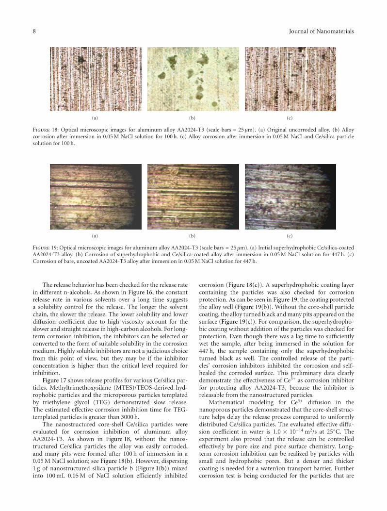
Figure 18: Optical microscopic images for aluminum alloy AA2024-T3 (scale bars = 25 μm). (a) Original uncorroded alloy. (b) Alloycorrosion after immersion in 0.05 M NaCl solution for 100 h. (c) Alloy corrosion after immersion in 0.05 M NaCl and Ce/silica particlesolution for 100 h.
(a) (b) (c)
Figure 19: Optical microscopic images for aluminum alloy AA2024-T3 (scale bars = 25 μm). (a) Initial superhydrophobic Ce/silica-coatedAA2024-T3 alloy. (b) Corrosion of superhydrophobic and Ce/silica-coated alloy after immersion in 0.05 M NaCl solution for 447 h. (c)Corrosion of bare, uncoated AA2024-T3 alloy after immersion in 0.05 M NaCl solution for 447 h.
The release behavior has been checked for the release ratein different n-alcohols. As shown in Figure 16, the constantrelease rate in various solvents over a long time suggestsa solubility control for the release. The longer the solventchain, the slower the release. The lower solubility and lowerdiffusion coefficient due to high viscosity account for theslower and straight release in high-carbon alcohols. For long-term corrosion inhibition, the inhibitors can be selected orconverted to the form of suitable solubility in the corrosionmedium. Highly soluble inhibitors are not a judicious choicefrom this point of view, but they may be if the inhibitorconcentration is higher than the critical level required forinhibition.
Figure 17 shows release profiles for various Ce/silica par-ticles. Methyltrimethoxysilane (MTES)/TEOS-derived hyd-rophobic particles and the microporous particles templatedby triethylene glycol (TEG) demonstrated slow release.The estimated effective corrosion inhibition time for TEG-templated particles is greater than 3000 h.
The nanostructured core-shell Ce/silica particles wereevaluated for corrosion inhibition of aluminum alloyAA2024-T3. As shown in Figure 18, without the nanos-tructured Ce/silica particles the alloy was easily corroded,and many pits were formed after 100 h of immersion in a0.05 M NaCl solution; see Figure 18(b). However, dispersing1 g of nanostructured silica particle b (Figure 1(b)) mixedinto 100 mL 0.05 M of NaCl solution efficiently inhibited
corrosion (Figure 18(c)). A superhydrophobic coating layercontaining the particles was also checked for corrosionprotection. As can be seen in Figure 19, the coating protectedthe alloy well (Figure 19(b)). Without the core-shell particlecoating, the alloy turned black and many pits appeared on thesurface (Figure 19(c)). For comparison, the superhydropho-bic coating without addition of the particles was checked forprotection. Even though there was a lag time to sufficientlywet the sample, after being immersed in the solution for447 h, the sample containing only the superhydrophobicturned black as well. The controlled release of the parti-cles’ corrosion inhibitors inhibited the corrosion and self-healed the corroded surface. This preliminary data clearlydemonstrate the effectiveness of Ce3+ as corrosion inhibitorfor protecting alloy AA2024-T3, because the inhibitor isreleasable from the nanostructured particles.
Mathematical modeling for Ce3+ diffusion in thenanoporous particles demonstrated that the core-shell struc-ture helps delay the release process compared to uniformlydistributed Ce/silica particles. The evaluated effective diffu-sion coefficient in water is 1.0 × 10⁻¹⁴ m2/s at 25◦C. Theexperiment also proved that the release can be controlledeffectively by pore size and pore surface chemistry. Long-term corrosion inhibition can be realized by particles withsmall and hydrophobic pores. But a denser and thickercoating is needed for a water/ion transport barrier. Furthercorrosion test is being conducted for the particles that are
Journal of Nanomaterials 9
dispersed into a protective hydrophobic or epoxy coatinglayer for alloy AA2024-T3.
3. Conclusion
In conclusion, the nanostructured particles with a ceriumcore and mesoporous silica shell were synthesized viaaerosol-assisted EISA and characterized using TEM, XRD,EPR, and so forth. We also demonstrated that the core-shell nanostructured particles were effective for corrosioninhibition of aluminum alloy AA2024-T3.
4. Experimental
4.1. Materials. All the chemicals were used as received.TEOS, MTES, cetyltrimethylammonium bromide (CTAB),Ce(NO3)3·6H2O, and CeCl3·7H2O were obtained fromSigma-Aldrich (St. Louis, MO). Hydrochloric acid wasVWR brand (VWR International, West Chester, PA), whileabsolute ethanol was obtained from Aaper (Brookfield,CT). DI water (Millipore, Billerica, MA) was used for allexperiments. Aluminum alloy AA20240-T3 was obtained asa 3.0-mm-thick sheet from Davidson Aluminum & MetalCorporation (Deer Park, NY).
4.2. Particles Synthesis. Silica/surfactant aerosols were gen-erated using a commercial atomizer (Model 9302A; TSI,Inc., St. Paul, MN) operated with nitrogen as a car-rier/atomization gas. The procedure was the same asdescribed by Lu et al. [14, 15]. It starts with a homogeneoussolution of soluble silica, acid, and surfactant prepared inan ethanol/water solvent with an initial surfactant concen-tration much less than the CMC. The pressure drop at thepinhole was 20 psi. The temperature for three heating zoneswas kept at 400◦C. Particles were collected on a DuraporeMembrane Filter maintained at 80◦C. The precursor solmolar ratio was 1 TEOS : 7.7 EtOH : 24.8 water : 0.0125HCl : 0.18 CTAB : 0–0.24 CeCl3. All calcination treatmentswere performed in a Lindberg tube furnace at 500◦C for 5 hin forming gas (7% H2 and 93% N2) at a heating rate of1◦C/min.
4.3. Characterization. XRD spectra were recorded on aSiemens D-500 diffractometer, using Ni-filtered Cu Kαradiation with λ = 1.5406 A, a graphite monochromator, anda scintillation detector; data were refined using the JADEsoftware package (Materials Data Inc., Livermore, CA).
TEM was performed using a JEOL 2010 HREM equippedwith Oxford-Link X-ray energy-dispersive spectroscopy(EDS). A Gatan slow scan CCD camera was used forrecording TEM images and electron diffraction patterns,operating at an accelerating voltage of 200 kV.
4.4. N2 Isothermal Sorption. Nitrogen isothermal adsorptionwas measured at 77 K on a Micromeritics ASAP 2010porosimeter. Surface area was estimated by using the BETequation. The pore size was calculated using the BJH model.
4.5. EPR Spectroscopy. Electron paramagnetic resonance(EPR) analysis was operated using a Bruker Elexsys spec-trometer with a microwave frequency of 9.8 GHz, a mod-ulation amplitude of 10 GHz (100 kHz), a receiver gain of104, and a time constant of 82 ms. Samples were prepared bymixing ground pure CeCl3 or sample c with boron nitride.The standard sample made from pure CeCl3 had the same Celoading as the sample c mixtures. The Ce3+/(Ce3+ + Ce4+)was calculated by the ratio of integrated EPR signals ofsample c to the standard sample.
Release of NaCl and Ce3+ from the particles was char-acterized by measuring the conductivity or the absorptionusing a conductivity meter or an UV-Vis spectrometer.
4.6. Corrosion Inhibition Test. The corrosion inhibition ofparticles was checked by dispersing the particles in 0.05 MNaCl aqueous solution. AA2024-T3 alloy coupons wereimmersed in the solution over 100 h followed by opticalmicroscopy analysis.
4.6.1. Superhydrophobic Coating on AA20240-T3. Tetrame-thylorthosilicate (TMOS), methanol, ammonium hydroxide(35% wt), 3,3,3-trifluoropropyltrimethyoxysilane (TFPT-MOS), and DI water were mixed in a molar ratio of1 : 41.56 : 0.003 : 0.33 : 5.85. The mixture was stirred for10 min and aged for 48 h at 50◦C. The formed gel was washedwith hexane and ethanol for 2 h. The gel was diluted with1 : 1 ethanol and kept for sonification for reliquefaction.The redispersed sol was filtered through a 1 μm glass fiberfilter. The filtered sol was mixed with core-shell Ce/silicaparticles (100 : 1 wt) and was spin-coated at 200 rpm for20 s on a AA20240-T3 alloy substrate. AA2024-T3 alloycoupons with superhydrophobic coating containing core-shell particles were dipped in a 0.05 M NaCl aqueous solutionfor 447 h before optical microscopy analysis.
Acknowledgments
We thank Dr. D. L. Tierney, Department of Chemistry andBiochemistry, Miami University, for assistance with EPR.Also we thank Dr. Scully Jr. of the University of Virginia forthe help with the corrosion test. This work was supportedby National Science Foundation NIRT Grant: EE C-0210835,NSF: EF-0830117, the Air Force Office of Scientific ResearchAward Number F49620-01-0168, the DOD MURI ProgramContract 318651, NIH: U19 ES019528 (The Center forNanobiology and Predictive Toxicology at the University ofCalifornia, Los Angeles), and the NIH/Roadmap for MedicalResearch grant PHS 2 PN2 EY016570B. Sandia National Lab-oratories is a multiprogram laboratory operated by SandiaCorporation, a Lockheed Martin Company, for the UnitedStates Department of Energy’s National Nuclear SecurityAdministration under Contract DE-AC04-94AL85000.
References
[1] M. A. Jakab and J. R. Scully, “On-demand release of corrosion-inhibiting ions from amorphous Al-Co-Ce alloys,” NatureMaterials, vol. 4, no. 9, pp. 667–670, 2005.
10 Journal of Nanomaterials
[2] J. V. Kloet, W. Schmidt, A. W. Hassel, and M. Stratmann,“The role of chromate in filiform corrosion inhibition,”Electrochimica Acta, vol. 48, no. 9, pp. 1211–1222, 2003.
[3] M. W. Kendig and R. G. Buchheit, “Corrosion inhibitionof aluminum and aluminum alloys by soluble chromates,chromate coatings, and chromate-free coatings,” Corrosion,vol. 59, no. 5, pp. 379–400, 2003.
[4] R. L. Cook Jr., “Pigment-derived inhibitors for aluminumalloy 2024-T3,” Corrosion, vol. 56, no. 3, pp. 321–333, 2000.
[5] P. Campestrini, H. Terryn, A. Hovestad, and J. H. W. de Wit,“Formation of a cerium-based conversion coating on AA2024:relationship with the microstructure,” Surface and CoatingsTechnology, vol. 176, no. 3, pp. 365–381, 2004.
[6] M. Forsyth, K. Wilson, T. Behrsing, C. Forsyth, G. B. Deacon,and A. Phanasgoankar, “Effectiveness of rare-earth metalcompounds as corrosion inhibitors for steel,” Corrosion, vol.58, no. 11, pp. 953–960, 2002.
[7] P. Traverso, R. Spiniello, and L. Monaco, “Corrosion inhibitionof Al 6061 T6/Al2O3p 10% (v/v) composite in 3.5% NaClsolution with addition of cerium (III) chloride,” Surface andInterface Analysis, vol. 34, no. 1, pp. 185–188, 2002.
[8] B. Davo and J. J. De Damborenea, “Use of rare earth salts aselectrochemical corrosion inhibitors for an Al-Li-Cu (8090)alloy in 3.56% NaCl,” Electrochimica Acta, vol. 49, no. 27, pp.4957–4965, 2004.
[9] R. G. Buchheit, H. Guan, S. Mahajanam, and F. Wong, “Activecorrosion protection and corrosion sensing in chromate-freeorganic coatings,” Progress in Organic Coatings, vol. 47, no. 3-4, pp. 174–182, 2003.
[10] N. N. Voevodin, V. N. Balbyshev, M. Khobaib, and M. S.Donley, “Nanostructured coatings approach for corrosionprotection,” Progress in Organic Coatings, vol. 47, no. 3-4, pp.416–423, 2003.
[11] T. L. Metroke, O. Kachurina, and E. T. Knobbe, “Spectroscopicand corrosion resistance characterization of GLYMO-TEOSOrmosil coatings for aluminum alloy corrosion inhibition,”Progress in Organic Coatings, vol. 44, no. 4, pp. 295–305, 2002.
[12] T. L. Metroke, O. M. Kachurina, E. Stesikova, and E. T.Knobbe, “Composite coatings based on hybrid silicate andtrivalent chromium conversion layers for aluminum alloycorrosion inhibition,” Abstracts of Papers of the AmericanChemical Society, vol. 220, p. U341, 2000.
[13] A. Pepe, M. Aparicio, S. Cere, and A. Duran, “Preparationand characterization of cerium doped silica sol-gel coatingson glass and aluminum substrates,” Journal of Non-CrystallineSolids, vol. 348, pp. 162–171, 2004.
[14] Y. Lu, H. Fan, A. Stump, T. L. Ward, T. Rieker, and C. J. Brinker,“Aerosol-assisted self-assembly of mesostructured sphericalnanoparticles,” Nature, vol. 398, no. 6724, pp. 223–226, 1999.
[15] Y. Lu, R. Ganguli, C. A. Drewien et al., “Continuous formationof supported cubic and hexagonal mesoporous films by sol-geldip-coating,” Nature, vol. 389, no. 6649, pp. 364–368, 1997.


