Embed Size (px)
Citation preview

I
l+, Thailand
tcBangkok
FrFl- l-LTI L FT|-ILNLLI IEL
2"AU N/SEED-Net Begional [onterence on.M]ENERGY ENGINEEBINGAdvoncement in lechnology ond Monogement for Tomonow
PROTTEDINGS
l(\ lTL
A,A,a)/Y*r
,*,."-fk::,,ry
F nuluseeo-lr"t jitca, ,4b\SEACUS'It:.t ::;;:;i *;

FIFF T-
HLLNELtcBangkok13.-14.1
iland014
I, Thal.e
+
2.0 AUN/SEED-Net
Regional Conference on
Energy Engineering
Advancement in Technology and Management for Tomorrow
Proceedings
@ 2014Published by King Mongkut's Institute ofTechnology Ladkrabang (Kf,4lTL)

I rne Committees
King Mohgkut's lhsti tute of TechnoloqvLadkrabang (KMITL). Facu ty of Eng neefing. nternat onal Co eqe. Southeast Astan Center for
Urlran S!stainabi i tyJICA AUN/SEED-Net
Prof. Dr. lvlonai Krair ikshKN4iTL, Tha and
Prof. Hideaki 0hgakiKyoto Untv Japa nProf. Keiichi lshiharaKyoio l ln v., JapanProf. Jun TanimotoKy! sfru Un v., JapanProf. lman K. ReksowardojolTB, lndones aProf. h Mariatt iJaafarUSM, Ma ays aDt lssarachai NgamrooKM TL , Tha i l a nd
Assoc. Prof. Supat Kitt iratsatchaKN4 TL, Tha andDr. lssarachai NgamrooKM TL, ThailandDr. Ronnachai TiyarattanachaiKlVlTL, Tha andDr.- lng. Nicholas HollmanhKN,] TL, Tha andDt Jochen AmrehnKN4 TL, ThailandDr. Sompob PolmaiKN4lTL, Tha and
Dr. Sompob PolmaiKNllTL, Tha land
Dr. Komson HongesombutKU Tha iandDr. Ronhachai TiyarattanachaiKl\, , l TL, ThalandDr, Tanawan PinnaratKMITL, Tha la ndAsst. Prof. Dr. Unnat pinsoponKN4 TL, Tha i la ndProf. Dr. lssarachai NgamrooKM TL, Thal andDr. Bun LongTC, CambodiaDr. Iman K. ReksowardojoITB ndones aAssoc. Prof. Dr. lr . Mariatt i JaafarUM, l"4a lays aDr. I l\4ade AstinaTB, lndonesiaDr Chhoun ViThuhHCNiIUT, V etnarn
Assoc. Prof. Dr. Supat Kitt iratsatchaKM TL nternational CollegeE ma l: c@km tl.ac thIel A 2329 826l , A 2329 8262Fax A 2329 8262
JICA, AUN/SEED-NetThai Oil Public Company Limited, Thaitand
1 . . , 4 . 0 r . B " r q . o RCEneE 2014 _1

Honorary Chair OfThe RCEneE zot4
n behalf of K ng [/ongkL]t snsl tute of TechnoloqyLadkfabang (KN,l TL) i is
rny qfeat pleasure to we come yoLlto the second AUN/SEED Net Reglona Conference on Energy Engineer nq. This conference wh ch isco organized by Klvl lTL andAUN/SEED Net, s a plalforrn for
seaTch t rends and expe r ences nreg onal common ssues as we asto pub icize research work ofAUN/SEE-Net rnembers
From November l3 to Novembef14 researchers frorn theAUN/SEED-Net partner un vers;t es: < s , a , < . ! 1 . n ( n . : l a r < t r ^ m
Japan and Europe wil present theirresearch work Top cs w cover aw de range of f ields such as energyeffc ency, energy services fac tymanaqement, planl engineering,envirofmenla compl ance to a ternative energy technolog es andstraleg es.
I arn espec al y happy to we comeso many renowne0 keynole speaK-e rs f rom Japan and Germany whow I present not on y lhe r atesl re-search resu ts but a so expeT encesfron'r ndustr al appl cat ons Thecornb nation of academic researchand indus t r i a app ca tonw generate great opportunit ies for discuss on and joint research deas.
0n Novernber l3 the orqan z nqcommittee has afianged for a wel-corn ng recept on Jh s event w
prov de oppodunit es for the part lcipants to meet and exchangeideas in a moae lnforrna env ronment. I hope that th s evening wistrenqthen already ex st nq as welas establ sh new research co abo-rations araong oLtr rnember lnsti tut ions.
wou d l ike to lhank the AUN/SeedNet and the Southeast As an Cen-ter for Urban S!stainabl ty (SEA-
ference. W thout their hard workth s conference woLrld not havebeen possible.
My specia thanks go to the mernbers of Steer ng Committee 0rga'n z nq Comm ttee the Rev ew ngComm ttee and Technica Programcomrn ltee for the r conslant support and cooperat on. In part icu ar,wou d l ike to thank the authors
who have made this conferenceposs b e.
w sh this conference two successful and frui i fu days and amook ng forward to nierest ng pre-sentations and discuss ons
l^ V"^)-Prof Dr Mona Kra r ksh
Act ng Pres dentK ng Monkut s nsti tute ofTechnology Ladkrabang
L BCEneE 2014 2nd AUN/SEED Net Begona Conf€rence o i Enerqy Enq neer ngi l3 l4 . l L2014 n Bangkok

8:35
840
I Conference program
l3:40 Keynote: Mr Mich""l.liili"h A U. lt"r@lconsutectra unternehmensberatung GmbH, cn^"ry I Eit"x" birpiitii, LZ,p""il'
14120 Keynote:Dr- Ing. Shigekazu Sakabe phD tvotution ot enerqy Strstem and lec_hnicatTrends for pVlnverters"; [Tabuchl E/ectrlc Ca. Ltd, Executive vjce president. dio'Je;anj
- -- '
, ^^ SessionA - Smaft cr id And Microgir i l Ir ) . ,U Ino LF\ tor ASSFSS ng and \ leaqu. nq l , .F--pt io-S ,
to Quantify Power System performanie,,
"Realizlng the Wlreless Smart Meter for Sman Grid' t I
I t r U -uoner iuoervse ior Crep. R- .F - , ,Power supeTvise for creen Base Stations in
CellLtlar Networks us ng ADE7753',l6:?0 Conrolo " Vtcro C-.0 B"\eo o, D sl t iD leo
Cooperative Control of Multi-Agentsyslemb . ) u ( o o - d n a t 4 d C o t o l o D E | G W n o . t b i ^ e a n o
SVC for Stab lzation of powef System Osclllation,
Speech: AUN/SEED t\iet RepresentativeOo. i g Spe" I Proi Dr. Monai Krair iksh: D.", toent o.1inq Vono.,r f , nstitute of Technology LadkrabangPhoto sessionKeynote: Proi Keiich i tshihara - neloLr nO etfect of en ergy savin q ca se study of efn c,ent fiq h mq projecr. ,r 7ndia"; IDepaftment of sacia-Envionment of Eneryy s"i"i*, xv"tiuiii,iiijr;;;i'
.
xeynoterrof:un rinirnoio - rettuhr aulomaton riaffa ilow, tane changle, Dilemma game, n person 7Pr soneis Diremma"; [/nrerdjscip]inaty Graduate scnoolor hgiriiriig sl,i;iJi,kyusiiJntverstty, Lapanl
8:45
900
940
l0:50 Keynote: Mr Taw"t"h"i Su.r"n*Autha r ity a f f h a i I a n d (Ec AT)l
I I r30
I5 :50
S-essioD B - Auromorive And Fuel Isrudv 0r uovetopmp t ol [ ,4dp-Bd-"d Data ,or Eat] 4
olComn on qa I uP Syst"m
Llb' of Btooro D "sal-V on T-g r . p.1otn ". . - 4
, . d f n L s i o " C F a t a e . s t , c . t n a . g , l - D . )u esel Enq ne
z A p 6 , s p F c t , e o - i h e F u t u r e o . q l , c . o q e d s a . ' 15Energy Source"
' 2 | J . l L c o o n r ' o l J F A p n a v . t - r . - D | | p p n p
' ln/ost,oai ,o" on SFlf-b nd rq aq-nt t -Lowqan- loCoa during Low Temperature BtnderlessBrrquetting Process',
Day | - 13.1L.2oL4
we come Remarks prof. Dr lss"rachai@
19r00 Conference Banquet
\a-b paDl o. c,erld,af nne 1. M.. u. Q8 ̂ 5 M,nb e
2tu aUN/SEED Net negiona coiter@ BCEneE 2014 _3

Day ll - 14.rr.2o\4
8:30 'T ming of Hybrid Waste-So af Power Plant withBeneft Cost Analysis '
Session C - Smart Grid And Microgird II Session D - Green Fuel l
l7 "Hydro isomerzation of n C5andn C6 Mixlure l9to Produce Blend ng Stock for Green Fuel'
8:50 "Smaft PV Farrns for Frequency Conlrol in Multi-Area nterconnecied Power Systera'
9 lO Pob . Po^e rO , ( a ronOarp gbTO t 'wnOTLtrbine us ng N,'lixed H2 /Hco Contro'
lT "Sirnultaneous conversion oftarand part icles" l9
'B Bog . )D lod . l o _n9^ ,dP lob ( ' q - "n " i S 7OBatch Reactor (ASBR) System for Pa m 0 |Wastewaler'
9:30 "Analysis Des gn and mp ementation ofaTwo '18 "HydrothermalTreatrnent of0i Palm Empty Fruit 20Bunch to Produce Green Sold FLre 'Switch Forward Convertef
Session E - Photovoltaic System And Othersl0I0 'Exper rnenta Ana ysis for Tempefature Effect on 21
Amorphous Silicon (A-Si) Photovo ta c Modu e UsinqAL tnm) t i . | ^ , . 1qA a . l ^n av< tam '
S€ssion F - E riroimental Engineering 1"Effects of ow carbon pollc es on the power 23sectors ofSri Lanka and Thaiand'
1030 'A Methodologyfor Fauts L4ode Ing ofPhotovoltaic 2lAf iay '
l 0 c 0 4 l e s l a r ' a n s ' o n e o D o d u . n g / n a 9 ^ r " 'Breakdown'
"Feed n Tar ffs underTha land RenewableE ectr city P an""Energy Economic mpacts of Feed nTarffPrograms under Thai Renewable EnergyE ectricity P an "
'I l:10 "Tensile Propert es of L ght We ghi StructLtre based 22on Carbon Nanotubes/Epoxy/Glass Fiber Lam nates'
"ExperimentalStudy on Separat on of lvletalLayer in Alumlnum-plasl lc Packag ng byEmploying Hydfotherma Process"
26
Session G - Automotive And Fuel 2'I 3:00 "Feas b I ty Stld es forthe Preparation of Secondary 27
Fue L4 xture f iom nd genous Coals for lndustria!F r ing Purposes"
t s:zo "cont nuous ldsoipl on Refr geration System
Session H - Environmenral Engineering 2'Quali ty of Life at Green and Non Green Campus 30Llniversit ies"
2828
'Li fe Cycle Assessment of Ut iz ng R ce Hul '
l3:40 "infuence of DWE Fuelon Performance and
'I 4 00' The Fut!re of Biornass Energy in lndonesia"
'Supp y 0pt mization for Power Demand fromPHEV Charging Stal ions
3l
29 'Qua jty Management of Munic pa So id waste at 3lN4ater al Recovery Fac lt es"
Session I - Special S€ssion1440 Keynote:Prof- Dr.- lng. Christoph Menke Aspects ofopt n'ra lnteqrat on ofvariab e renewable energies
(Pv/solar and W nd) inlo nationalgr ds"t lTrier Universily ofAppiied Sciences, Getmany and The JaintGraduate Schaolaf Energy and Enviranment (JGSEE), Bangkok, Thailand)
t0
15120 KeynoteiProl Hideakiohgaki- N4id nfrared Free Electron Laser (KU FEL) gengerat on and appl cat ons' ; l0l/nstitute ofAdvanced En ergy, Kyota University, Japan]
l6:00 Keynote: Ivl r Toku mitsu Kobayash i - ' Un versity- Ind ustry Collaboralion u n der S EED Net' lchlef Research l0and Netwark Prcmotian Unit, SEED Nei Secrefariat (JICA Expetl)l
l6:40 AUN/SEED-NeI Hl Meetingtn.te: P.pet ptesentation tlme:l5 Minute, QEA 5 Mnute
4_ RCEneE 2014 Znd AUN/SEED N€t Reg on a Confercnce on Enerqy Engineeringi l 3. l 4.l l 201 4 in Banqkok
I rist of Papers
LRebound effect of energy saving: case study of effi-cient lighting projects in IndiaProf Ke ichl shihara
Lcellular automaton, TrafJlc flow Lahe change,Dilemma game, n-person Prisoner,s DitemmaProf. Jun Ianimoto
LRegional Power Sector DevelopmehtMr Tawatchai Sum ranwantch
LThai 0il group's Energy Management and SuccessCases
N4f An!ntasak Suksas p
LN€w Approach for Waste-to-Energy for SoutheastAsia
N4r. M chaelJ i l ch, Mr HaruoTar! i
LEvolution of En€rgy System and Technical Trendsfor PV lnverters
D. lng Shrqekaz! sakabe PhD
lllAspects of optimal integration of variable renew-able energi€s (Pv/solar and Wind) into nationalgridsProf Dr- ng. Chrsroph Menke
]ll_lvid Intrared Free Electron Laser (KU FEL) gengera-tion and applications
Prof Hideak Ohqaki
]tLUniversity-lndustry Collaboration under SEED-NetTokumitsu Kobayash
lllndices for Assessing and Measuring Inte(uptionsto Quantify Power System Peformanc€
LeVretTen Nguyen Vet L nh, Tran Dafq Khoa
llRealizing the wireless sman Meter for Smart cridNslyen Huy Ph!onq, Nquy€n Tunq Lam, Bu Dang Thanh
llPower supervise for Green Base Stations ih CellularNetworks using ADE7753D nh Luyen Nguyen,Th Lan HLrong Nguy€n Tung\quy€n
Llcontrolof a l\,4icro-Grid Based on Distributed Coop-erative Control of Multi-AgentSystem
Dafith Lenq, sompob Po ma
llcoordinated Control of DF|G Wind Turbine and SVCfor Stabilization of Power System Oscillation
Sothy Uong, lssaracha Nqamroa
lllstudy of Development of tvlap-Based Data for ECUof Common Rail Fuel System
Khonq V! Quang, Pham M nh Tuan, Nquy€n DuyTief, Ho
llEffect of Biopro DieselTM on Engine performanceand Emissions Characteristics in a Light-DutyDiesel EngineY H Teoh, H N Masjuki, H G Fow t.l,/ Noor B.Mohamed Jan, B. S All
ILA Perspective on the Future oI Hydrogen as an En-ergy SourceArshad Ahmad
_:1 FuelEconomy ofJeepneys in the Phil ippinesEdwln N Qulros, Kar 8.N Verqel
_l]llnvestigation on Self-binding Agent in Low RankCoal during Low Temperature Binderless Briquet-ting Process
Toto Hardianto, Adian R zq lhamna, pandj prawisudha,Aryad SLWono
]lTiming of Hybrid Waste-solar Power plant withBenefit-Cost Analysis
Farzal , nqgnan
llsmart PV Farms lor Frequency Control in Multi-Area Interconnected Power SystemWoraporg Kreeumporn, lssafacha Nqamroo
lLRobust Power Oscillation Damping by DFtc WindTurbine using Mixed H2 /H@ Control
Uonq Solh)a ssarachai Nqamroo
llAnalysis Design and lmplemehtation of a Two-Switch Forwad ConverterV Wuti, A. Luangpo, K Tatwoi!, C.8un aksananusorn
llHydro-isomerization of n-C5 and n-C5 Mixture toProduce Blending Stockfor creen Fuel
DaoThiKim Thoa, L l ru Cam Loc
lLSimultaneous conversion of tar and particlesSamsud I Anis, Z.A Zainal
zlBiogas Production using Anaerobic SequencingBatch Beactor (ASBR) System for palm Oil Waste-
T aoo - Pro 'r oro. Wrr \" Do aoa-c rv"n , ".ro
2lHydrotherhal Treatmeni of Oil Palm Empty FruitBunch to Produce Green Solid Fuel
Pandli Pfawisudha,Achmad Rofi lrsyad,Ar DarrnawanPasek, Sikand Noviant. Kunio Yosh kawa
2lExperimental Analysis for Temperature Effect onAmorphous Silicon (A-Si) Photovoltaic tvodule LJs-ing Automatic Load Selection SystemSyed Zahurul, Nofman Mar Lrn, Mohammad Lutf orhman,H:sh m Hizam, Arash ToLrdeshkl zham Zaina Abd n
zLA Methodology for Faults [4odelling of photovoltaicArray
Lonq 8!n, Bedfand Raison, cilles Rosrainq
ZTensile Properties of Light Weight Structure basedon Carbon Nanotubes/Epoxy/Glass Fiber Lami-nates
N.4 N4ar aft, B.K Ong
2^AUN/SEEDNetReglonalConferenc€onEnergyEnqtneerinqtt3 '14|.20t4nBanqkok RCEn€E 2014 -5

AA Tesla Transformer for Producing 2 - m Length AirBreakdownW3tchara Pongsatht, Surasak Noimor, NorasaqePattanadech, Peerawui Yutthaqowith
2lEftects of low carbon policies on the power sectorsof Sri Lanka and ThailandSul€ethaSelvakkumaran, Bundit Lmmeechockchai
2LFeed-in Tariffs under Thailand Renewable Electric-ity PIanPawinee S!ksuntornsiri Pa boon Limptipan ch, Warune€Tia, S!nd i L lmm€echockchai Pt lP i ta, Pemika Mis i la
2lEnergy Economic lmpacts of Feed-in Tarifl Pro-grams under Thai Renewable Energy ElectricityPlanPawinee SLrksuntornsiri Pa boon Limpit pan ch, WaruneeTia B!nd I L imm€echockchai Pt iP i ta
zlExperimental Study on Separation of Nretal Layer inAluminum-plastic Packaging by Employing Hydro-thermal Process
Pandl Pfawisudha G€a Fard as Mu m n, AriDarmawanPasek, K!nio Yoshikawa
2LFeasibility Studies for the Preparation of SecondaryFuel Mixture from Indigenous Coals for IndustrialFiring Purposes
2LContinuous Adsolption Refrigeration Systeml lVadeAsl na, Dw Marhaendro Jat iPurnomo, Maoodam
&lnfluence of DWE Fuel on Performance and Emis-sronsAnh Tlan Pham, Cofq Thanh Hlynh, Long Dafq TranDung Nqoc NguyefTan f"4 nh Phan,Thanh Tlan Nquyen
29_The Future of Biomass Ehergy in IndonesiaHarwin Saptoadi
3.o-Quality of Life at Green and Non-Grcen campusUniversities
N sanatJ ras i t , Ronnacha Tyafat tanacha, N cho as
LLife cycle Assessment of Utilizing Rice HullDan el. loseph Marano, Jose Manle Buenvenido B ona
3lsupply Opdmization for Power Demand from PHEVCharging Stationsoiumin Donq, DLrsit Niyato, P nq Wanq, Zhlr Han
3-LQuality Nlanagem€nt of Municipal solid waste atMaterial Recovery Facilities
Ronnacha Tiyarattanachai,Tingting Han, lsafa
6- RCEn€E 2014 2ndAUN/SEED Net ReqionalConfererce on Enerqy Enq n€er nq;13. l4 l l .20l4inBangkok

Continrrou s Adsornti on Refri seraiion Svsf ernExDeriments of l,,4ethanol and R-134a with Activated-Carbon
I Niade Astina', Dwi Marhaendro Jati PurnomoFaculty of Vlechan ca and Aerospace Englneefing, Insi t l t Tekno ogi BandLrng, ndonesia'asrina@ftmd iib ac id
Mao 0damD-p o -d - . 1 -o
"ndV" ' - i d 9 ee n9 . . Leo ' r e (Fnoog o ' " ^bod "nao.atlan@ymail con
Abstfact- Heat driven adsorpt;on refrigeration systems have drawn considerable attention due to their potential usesof solar energy and waste heat from other process. Although they are predominanl in the area of heat driven refriger-ation technologies, adsorption systems have some distinct advances over the other systems in view points of theirability to be driven by relatively low temperature heat source. Indonesia as an agrarian country with large farming andfishing areas wil l be su pported to handle their products with cheap and simple storage technology due to theadsorp-rion system can be operated without €lectric power and is easily operated in rural. Research on the adsolption refrig-eration system was done with local activated carbon as solid sorption and two refrigerants as sorbate were intro-duced in experiments, i .e. methanol and R-134a. Two reactors with 3370 cm3 of sol id sorption volume were used towork as generator and absorber intermittently so that evaporator can work continuously. The main results show thatboth pairs can performs in the experimeht with different performances. For a simple conflguration and testing bedused, cycl€ t ime ofthe experihents is I50 minltes for methanol and 105 minutes for R34a, respectively. coP (coeff i-cient of performance) and speciflc cooling capacity of pair of methanol-activated carbon are 0.I2 and 4385.76kJlm3 activated carbon, and coP and speciflc cooling capacity of pair of R]34a-activated carbon are 0.15 and12014.84 kJ/m3 activated carbon. These al l are for op€rating set at 100'C of hol water temperature, I2'C of cold wa_ter temperature.
lndex Terms adsorpiion system, F134a, methanoL activated carban, experimental adsarption
Influence of DWE Fuel on Performance and EmissionsHeavy Duly Dl Diesel Engine Equipped with Turbocharger
Anh Tuan Pham', Cong Thanh Huynh, Long Dang Tran, Dung Ngoc NguyenVNU Key - Lab fo r ln te rna CombustonEnq lne ,HoChlN i lnhCi tyUnvers i l yo fTechnoogy,[email protected] edr vn
Tan Minh Phan, Thanh Tuan NguyenNo Ch N/inh C ty Department of Sclence and Techno ogy, v elnam
/bstract In this study, we €xperimentally investigate the influence of diesel-water €mulsions (DwE) firel on perfor-mance and exhaust qas emissiohs of a heavy duty diesel engine. A 6-cyl inder Dl-diesel engine (HlNo EP100)equipped with turbocharger was used for the measurements. The experimental results indicated that the fuel con-sumption of diesel engine fuelled with water-diesel emulsified fuel was increased compared to ihat with conventionaldiesel fuel at specifled ehgine loads and speeds. However, the diesel fuel ecohomy of diesel-water emulsified fuelwas sliqhtly better than conventional diesel fuel due to the presence of water. Regarding the comparison of exhaustgas emissions, No, level was lower for DWE as compared to diesel oi l , while the smoke opacity, Hc, and c0 lev€lwere found to increase when fuell ing wilh the emulsion fuel.
hdex Terms Water-diesel emulsions (DWE), heavy-duty diesel engine, turbocharger, petfotmance, exhaust gasem,ssrons.
28- RCEneE 2Cl4 2nd AUN/SEED N€t Bes o ia Confefence on Ener ly Enq feer nq 13. l4 . l I 2014 n Bangkok

Continuous Adsorption Refrigeration System: Experiments of Methanol and R-134a with Activated-Carbon
I Made Astina, Dwi Marhaendro Jati Purnomo Faculty of Mechanical and Aerospace Engineering
Institut Teknologi Bandung Bandung, Indonesia
Mao Odam Dept. of Industrial and Mechanical Engineering
Institute of Technology of Cambodia Phnom Penh, Cambodia [email protected]
Abstract—Heat driven adsorption refrigeration systems have drawn considerable attention due to their potential uses of solar energy and waste heat from other process. Although they are not predominant in the area of heat driven refrigeration technologies, adsorption systems have some distinct advances over the other systems in view points of their ability to be driven by relatively low temperature heat source. Indonesia as agrarian country with large farming and fishing areas will be supported to handle their products with cheap and simple storage technology due to the adsorption system can be operated without electric power and is easily operated in rural area. Research on the adsorption refrigeration system was conducted with local activated carbon as solid sorption and two refrigerants as absorbate were introduced in experiments, i.e. methanol and R-134a. Two beds with 3370 cm3 of solid sorption volume were used to work as generator and absorber intermittently so that evaporator can work continuously. The main results show that both pairs can performs in the experiment with different performances. For a simple configuration and testing bed used, cycle time of the experiments is 150 minutes for methanol and 105 minutes for R-134a, respectively. COP (coefficient of performance) and specific cooling capacity of pair of methanol + activated carbon are 0.12 and 4385.76 kJ/m3 activated carbon, and COP and specific cooling capacity of pair of R-134a + activated carbon are 0.15 and 12014.84 kJ/m3 activated carbon. These all are for operating set at 100oC of hot water temperature, 12oC of cold water temperature.
Index Terms—adsorption system, R-134a, methanol, activated carbon, experimental adsorption
INTRODUCTION A conventional refrigeration system is driven mechanically
by a compressor, on the other hand a sorption refrigeration system is driven by a heat source. The heat could be widely available in world. It may be gotten from fuel, waste heat and solar heat. Therefore, sorption refrigeration systems offer a great advantage compared with conventional systems. There are two types of sorption refrigeration system, i.e. liquid sorption which commonly called as vapor absorption, and solid sorption which also called as adsorption system [1]. The adsorption system likes the simple vapor compression refrigeration system but the mechanical compressor is replaced with a thermal compressor or the adsorption bed. The bed is
composed of porous medium that has the ability to absorb the refrigerant (absorbate).
The use of sorption system is more easily in the remote part of developing countries where no electricity supply is used for storage of medical products, foods or habitat comfort needing. Other reason is that sorption system are driven by heat rather than electric power. It causes a number of implementation areas in which they may be energetically advantageous, for examples tri-generation systems which burn a fuel to produce electricity, heating and/or cooling, solar powered cooling system, gas fired heat pumps, and so on. It means that sorption systems have drawn considerable attention due to their lower environmental impact and large energy saving potential as the systems neither use ozone depleting gases nor the fossil fuel and electricity as driving source.
Adsorption cycle can be illutrated in Clapeyron diagram as shown in Fig. 1. The process 2 – 3’, process 3’ – 4’ and process 4’ – 1’ are serial processses of condensation, isenthalpy expansion, and evaporation. These processes are similar in vapor compresion cycle. However, the compressor is replaced by the adsorption bed which will operate process 1 – 2, process 2 – 3, process 3 – 4, and process 4 – 1.
Ln(p)
-1/T
pc
pe
Pure Absorbate/Refrigerant
-1/Te -1/Tc -1/Ta1 -1/Tg1 -1/Ta2 -1/Tg2
cmax cmin
3' 2 3
4' 1 4
Fig. 1. Adsorption cyle on Clapeyron diagram Adsorption bed working principle can be explained from
state 1. Starting with the state 1, in which the adsorption bed is cold and saturated with the absorbate/refrigerant, adsorption
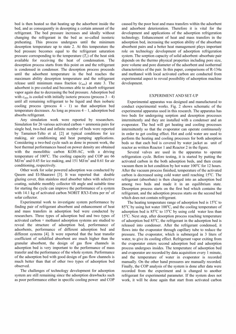
bed is then heated so that heating up the adsorbent inside the bed, and as consequently in desorpting a certain amount of the refrigerant. The bed pressure increases and ideally without changing the refrigerant in the bed as so-called isosteric preheating. This process undergoes until the minimum desorption temperature up to state 2. At this temperature the bed pressure becomes equal to the refrigerant saturation pressure corresponding to the temperature (Tc) of the heat sink available for receiving the heat of condensation. The desorption process starts from this point on and the refrigerant is condensed in condensor. The desorption process proceeds until the adsorbent temperature in the bed reaches the maximum ability desorption temperature and the refrigerant release until minimum mass fraction (cmin) at state 3. The adsorbent is pre-cooled and becomes able to adsorb refrigerant vapor again due to decreasing the bed pressure. Adsorption bed with cmin is cooled with initially isoteric process (process 3 – 4) until all remaining refrigerant to be liquid and then isobaric cooling process (process 4 - 1) so that adsorption bed temperature decreases. As long as process 4 – 1, adsorption bed absorbs refrigerant.
Any simulation work were reported by researchers. Simulation for 26 various activated carbon + ammonia pairs for single bed, two-bed and infinite number of beds were reported by Tamainot-Telto et al. [2] at typical conditions for ice making, air conditioning and heat pumping applications. Considering a two-bed cycle such as done in present work, the best thermal performances based on power density are obtained with the monolithic carbon KOH-AC, with a driving temperature of 100oC. The cooling capacity and COP are 66 MJ/m3 and 0.45 for ice making, and 151 MJ/m3 and 0.61 for air conditioning, respectively.
Other work for solar powered adsorption was conducted by Qasem and El-Shaarawi [3]. It was reported that double glazing cover, thin stainless steel absorber tubes with selective coating, suitable monthly collector tilt angle and suitable time for starting the cycle can improve the performance of a system with 14.1 kg of activated carbon NORIT RX3-Extra per m2 of solar collector.
Experimental work to investigate system performance by finding pair of refrigerant absorbent and enhancement of heat and mass transfers in adsorption bed were conducted by researchers. Three types of adsorption bed and two types of activated carbon + methanol adsorption systems are studied to reveal the structure of adsorption bed, performance of adsorbents, performance of different adsorption bed and different systems [4]. It were reported that the heat transfer coefficient of solidified absorbent are much higher than the granular absorbent, the design of gas flow channels in adsorption bed is very important to the performance of mass transfer and the performance of the whole system. Performance of the adsorption bed with good design of gas flow channels is much better than that of other two types of adsorption bed observed.
The challenges of technology development for adsorption system are still remaining since the adsorption drawbacks such as poor performance either in specific cooling power and COP
caused by the poor heat and mass transfers within the adsorbent and adsorbent deterioration. Therefore it is vital for the development and applications of the adsorption refrigeration technology. Enhancement of heat and mass transfers in the adsorption bed, increasing the sorption ability of the absorbate absorbent pairs and a better heat management plays important role on technology development of adsorption refrigeration system. The sorption capacity of solid adsorbent–absorbate pair depends on the thermo physical properties including pore size, pore volume and pore diameter of the adsorbent and isothermal characteristics of the pair. In this paper, comparisons of R-134a and methanol with local activated carbon are conducted from experimental aspect to reveal possibility of adsorption machine development.
EXPERIMENT AND SET-UP Experimental apparatus was designed and manufactured to
conduct experimental works. Fig. 2 shows schematic of the experimental apparatus used in this research. The apparatus has two beds for undergoing sorption and desorption processes intermittently and they are installed with a condenser and an evaporator. The bed will get heating and cooling processes intermittently so that the evaporator can operate continuously in order to get cooling effect. Hot and cold water are used to perform the heating and cooling processes for both adsorption beds so that each bed is covered by water jacket as unit of reactor as written Reactor 1 and Reactor 2 in the figure.
Several valves are used in the apparatus to operate refrigeration cycle. Before testing, it is started by putting the activated carbon in the both adsorption beds, and then create vacuum them in hot condition by hot water 100oC for 12 hours. After the vacuum process finished, temperature of the activated carbon is decreased using cold water until reaching 15oC. The refrigerant (absorbate) is then charged into an adsorption bed among two beds and made it in an equilibrium state. Desorption process starts on the first bed which contains the refrigerant, and the adsorption process starts on the second bed which does not contain refrigerant.
The heating temperature range of adsorption bed is 15oC to 85oC by using hot water 100oC, and the cooling temperature of adsorption bed is 85oC to 15oC by using cold water less than 15oC. Next step, after desorption process reaching temperature of adsorption bed 85oC, the refrigerant in the adsorption bed is released into condenser. After the refrigerant condensed, it flows into the evaporator through capillary tube to reduce the pressure. The evaporator, which is submerged in 3 liters of water, to give its cooling effect. Refrigerant vapor exiting from the evaporator enters second adsorption bed and adsorption process undergoes insides. The temperature of adsorption bed and evaporator are recorded by data acquisition every 1 minute, and the temperature of water in evaporator is recorded manually. On the other hand pressures are manually recorded. Finally, the COP analysis of the system is done after data were recorded from the experiment and is changed to another refrigerant for experimental parameter. If the system does not work, it will be done again that start from activated carbon
degassing by using vacuum pump and hot water 100oC during 12 hours.
Fig. 2. Schematic of the experiment apparatus
The adsorption bed plays important role on the experimental apparatus. The bed is wrapped with water jacket so that hot or cold water can be flowed for heating or cooling process as shown in Fig. 2. Since the fluid used for heating and cooling is water, temperature range of higher temperature is not able more than 100oC and so for lower temperature is not able lower than 4oC as a limited condition of the apparatus besides constraints of heater and cooler capacities. Each bed is filled by 1.8 kg of activated carbon.
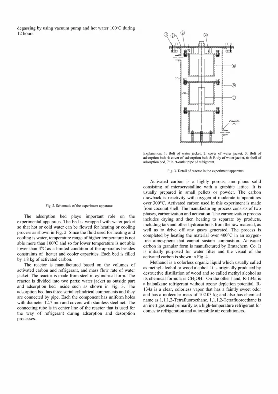
The reactor is manufactured based on the volumes of activated carbon and refrigerant, and mass flow rate of water jacket. The reactor is made from steel in cylindrical form. The reactor is divided into two parts: water jacket as outside part and adsorption bed inside such as shown in Fig. 3. The adsorption bed has three serial cylindrical components and they are connected by pipe. Each the component has uniform holes with diameter 12.7 mm and covers with stainless steel net. The connecting tube is in center line of the reactor that is used for the way of refrigerant during adsorption and desorption processes.
Explanation: 1: Bolt of water jacket; 2: cover of water jacket; 3: Bolt of adsorption bed; 4: cover of adsorption bed; 5: Body of water jacket, 6: shell of adsorption bed, 7: inlet/outlet pipe of refrigerant.
Fig. 3. Detail of reactor in the experiment apparatus
Activated carbon is a highly porous, amorphous solid
consisting of microcrystalline with a graphite lattice. It is usually prepared in small pellets or powder. The carbon drawback is reactivity with oxygen at moderate temperatures over 300°C. Activated carbon used in this experiment is made from coconut shell. The manufacturing process consists of two phases, carbonization and activation. The carbonization process includes drying and then heating to separate by products, including tars and other hydrocarbons from the raw material, as well as to drive off any gases generated. The process is completed by heating the material over 400°C in an oxygen-free atmosphere that cannot sustain combustion. Activated carbon in granular form is manufactured by Bratachem, Co. It is initially purposed for water filter and the visual of the activated carbon is shown in Fig. 4.
Methanol is a colorless organic liquid which usually called as methyl alcohol or wood alcohol. It is originally produced by destructive distillation of wood and so called methyl alcohol as its chemical formula is CH3OH. On the other hand, R-134a is a haloalkane refrigerant without ozone depletion potential. R-134a is a clear, colorless vapor that has a faintly sweet odor and has a molecular mass of 102.03 kg and also has chemical name as 1,1,1,2-Tetrafluoroethane. 1,1,1,2-Tetrafluoroethane is an inert gas used primarily as a high-temperature refrigerant for domestic refrigeration and automobile air conditioners.

Fig. 4. Activated carbon for the experiment A. Temperature Control System
Hot and cold water have to keep in temperature set. Two temperature controllers are installed to control both temperatures. Both of them use the same system to control the temperature. Thermocouple is installed into the system to measure temperature points. A measured temperature is then compared to the temperature setting in the controller. The temperature controller will switch on/off current to the contactor. Temperature is higher than the temperature setting for heating and the temperature is lower than the temperature setting for cooling. The current will drive the contactor to open circuit block so that the current from source through the contactor circuit block to drive the apparatus. The apparatus will operate and change the temperature of the system as desired.
B. Leakage Test and Vacuum
Leakage test has to be conducted to keep refrigerant content in the apparatus. Vacuum condition has to be achieved before refrigerant charging. Vacuum condition plays important role on system’s process. Before testing, the activated carbon in two adsorption beds is degassed at about l00°C under high vacuum pressure for around 12 hours depends on the amount of water has in the activated carbon. In the vacuum process, inherent moisture in the activated carbon release the water vapor out from the system trapping in vacuum pump oil so that change the vacuum pump oil pump must be replaced every four hours. Reducing contaminant content in refrigerant gas, methanol is dropped in the system several times during the vacuum process so that the gas contaminant to be very low.
The most critical condition of system operation is leakage especially for the system that has to be operated under atmospheric pressure. The system has to be assured in 100 percent seal to get a very accurate data from experiment. After the design, fabrication and instrumentation are already done, some work for well preparation have to be done. Since the pressure of the system might varies from 0 inHg up to 60 inHg, a leakage test with pressure of compressed air 5 bar would be enough to check if there is leakage from any of the component
in the system. The whole system is closed and compressed to 5 bar of air and keep for several hours to make sure that no pressure drop.
C. Measurement
The system performance is derived from operation parameters measured. The pressures are manually recorded from bourdon manometer. Data acquisition is recording apparatus points for getting the data of temperature. K-type thermocouple is used as temperature sensor with 0.1oC of accuracy. Omega data acquisition Multi-function I/O USB model OMB-DAQ-2416 has 32 channels for recording data from thermocouple. The data acquisition is highly accurate, multi-function measurement, and control modules for the USB bus.
A pump is a device that moves fluids using mechanical action. The pump is used to flow the water through the piping system to the reactor for conditioning adsorption bed inside. Normally, water flow rate is measured by flow meter which is commercially available, but the flow rate will be regulated by adjusting the pump head pressure in this experiment water. It is basically simple and more reliable, eventhough it requires characteristic of the pump. The pump will be used to circulate both hot and cold water with temperature varies from 15oC – 100oC. D. Cycle Operation
The apparatus is operated manually by opening or closing valve so that the adsorption cycle can undergo. Table I gives an time of operation procedure of the experiment apparatus which being supported by two adsorption beds.
TABLE I. CYCLE OPERATION SET UP
Sorption Pairs* Operational Time
Cycle time (min)
Desorption time (min)
Adsorption time (min)
AC + methanol 150 90 120
AC + R-134a 105 50 60 *AC: activated carbon
FORMULATION EVALUATION Any formulation of mass and energy balance for analyzing
the cycle of the system are needed to perform thermodynamic analysis. In accordance with processes undergoing in the cycle, a number of formulations are needed to reveal performance of the cycle.
Adsorption isotherm
Dubinin-Astakhov (D-A) model, which is expressed by Eq. (1), which is used to estimate the equilibrium uptake of activated carbon + refrigerant on the mass basis.
⎟⎟
⎠
⎞
⎜⎜
⎝
⎛⎟⎟⎠
⎞⎜⎜⎝
⎛−=
ns
ppTD
cc lnexp0
(1)

Where c is absorbate mass fraction in adsorption bed, co is maximum absorbate mass fraction in adsorption bed, D is energy constant, ps is vapor pressure at operating temperature, T is operating temperature of the bed, p is operating pressure and and n is constant of absorbate-absorbent pair. The numerical of c0, n and D are evaluated experimentally as written Saha et al. [5]. Isosteric process
The pressure will increase when the bed is heated. The relation of pressure and temperature as relation given in Eq. (2).
⎟⎟⎠
⎞⎜⎜⎝
⎛−
Δ=
122
1 11lnTTR
Hpp ads (2)
Where ΔHads is adsorption enthalpy, T2 and T1 are final and initial temperature of the process, p2 and p1 are final and initial pressure of the process, and R is refrigerant gas constant. ΔHads can be found by using Eq. (3), also can be estimated by using graph which is defined by Saha et al. [6]. Adsorption enthalpy can be evaluated with Eq. (3).
⎥⎥
⎦
⎤
⎢⎢
⎣
⎡
⎟⎟⎠
⎞⎜⎜⎝
⎛+⎟
⎠⎞
⎜⎝⎛+=Δ
b
c
n
fgads TTa
ccEhH
1
0ln (3)
Where hfg is evaporation enthalpy at operating temperature, T is operating temperature of the bed, c is the same parameter in equation (1), E is energy characteristics, and Tc is critical temperature of absorbate. On the other hand E, a and b are empirical constants, The numerical values of E, a and b are evaluated experimentally as the way written by Saha et al. [ 6] and El-Sharkawy et al. [7].
Experimental formulation The quantity of energy used to generate refrigerant vapor from the adsorbent during the generation process (Qgen) is calculated by Eq. (4).
fggrgrpmgriraagen hmhhmTcmmTcmQ ,12,13,,13 )()( +−+Δ−+Δ= (4)
Where right sides of the equation consisting of four tems. The first term is activated carbon sensible heat, second term is remaining refrigerant in bed, third term is bed-released refrigerant sensible heat, and forth term is bed-released refrigerant latent heat.
The quantity of heat transferred into the evaporator (Qeva) during refrigeration process is evaluated by Eq. (5).
)( 1,, ewpeweva TTcmQ −= (5)
Where T1 is initial temperature of the water, Te is evaporator temperatures, m is water mass in evaporator box, and cp,w is specific heat of water in evaporator box.
The cooling coefficient of performance (COP) for this system is ratio of cooling capacity and desorption heating heat as a relation presented in the Eq. (6).
gen
eva
=COP (6)
This COP considers heating heat received from the heating process without including heat loss from the heat source in heating process and energy needed for the control system.
EXPERIMENTAL RESULT
The experiment is carried out within only one sample of activated carbon and two refrigerants (methanol and R-134a) to figure charateristic adsorption refrigeration system. The experimental works need to test several times in order to get a good data because some data may be error value by operation and apparatus. In this experiment, the system is continuous cooling process of evaporator, so that the data were taken four cycles per time to make variety of the data. Partial data points are recorded manually and the others are recorded by data acquisition with a data sampling rate 0.017 (1 sample per minute). Notation 1, 2, 3 and 4 for temperature and pressure in the following figure just indicate serial time of the experiments for the same operating apparatus set-up as long as cycle .
The Fig. 5 presents the heating pressure of methanol in the adsorption bed and all curves of each pressure is not significant difference so that the curves of pressure in the heating confirm that the system works well and has stability. On the other hand, the pressure 1 and pressure 3 of first adsorption bed is different from pressure 2 and pressure 4 of the second adsorption bed because of the indicator of pressure gauge of the bed has small deviation. This deviation occurs as consequence of different content concentration of methanol in adsorption bed. It agrees with recharging based on pressure.
Fig. 5. Bed pressure of methanol related to time during heating process
Increasing of temperature of the adsorption bed consisting methanol is shown in Fig. 6. All the curves of the bed temperature in the heating reach the alternative temperature at the same time, but all curves are very different before reach the final temperature because the thermocouple is connected to the system which affects with the ambient temperature, and hot

water temperature is not stable due to high initial heat transfer in the transient condition and effect of manually control of hot water flow by gate valve in discharge section of the pump.
Fig. 6. Bed temperature of methanol related to time during heating process
Fig. 7 shows the temperature curves during cooling
process. The curves are not significantly different among the others. The final temperature for each curve is reached at almost the same time for each curve. The deviations are only in middle of the process.
Fig. 7. Bed temperature of methanol related to time during cooling process
Fig. 8 shows the COP of methanol that works on different cycle. The COP in the first cycle is smaller than other because the system is not stable on the initial operation, and then it is stable for the next cycles.
For the R-134a, the data are always recorded manually every 5 minutes. The pressure curves of the R-134a adsorption bed during heating process are given in Fig. 9. The curves are only slightly difference among the others. It means the system is working well and stable when the heating process.
Fig. 8. Coefficient of performance four cycles of methanol
Fig. 10 shows the heating temperature of both adsorber bed of R-134a, and the temperature does not significantly change through all curves of four cycle operations. This result means that eventhought the valve is operated manually, the system can work stable.
Fig. 9. Bed pressure of R-134a related to time during heating process
Fig. 10. Bed temperature of R134 related to time during heating process
0
0.02
0.04
0.06
0.08
0.1
0.12
0.14
0.16
3.05 6.1 9.15 12.2
COP
Time(h)
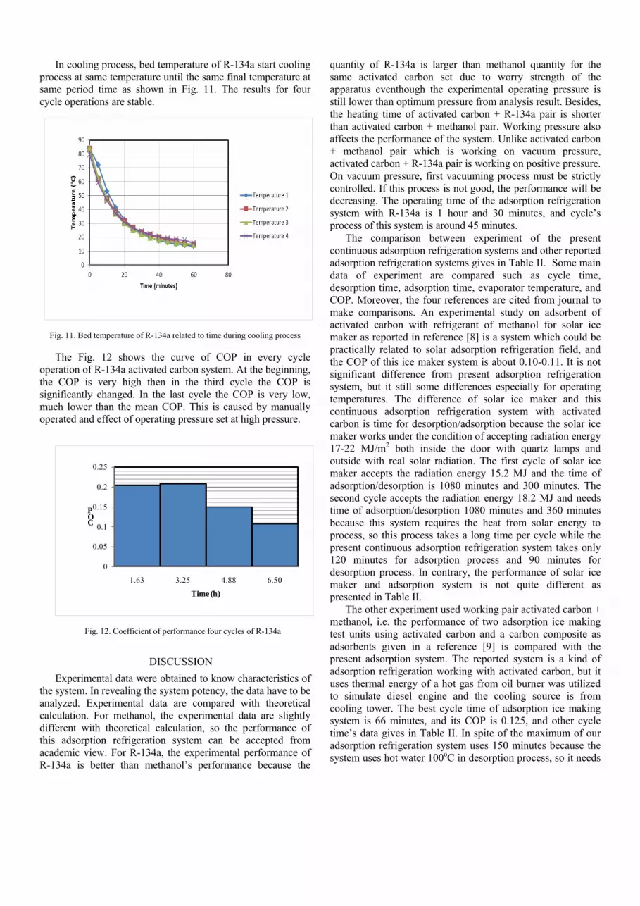
In cooling process, bed temperature of R-134a start cooling process at same temperature until the same final temperature at same period time as shown in Fig. 11. The results for four cycle operations are stable.
Fig. 11. Bed temperature of R-134a related to time during cooling process
The Fig. 12 shows the curve of COP in every cycle operation of R-134a activated carbon system. At the beginning, the COP is very high then in the third cycle the COP is significantly changed. In the last cycle the COP is very low, much lower than the mean COP. This is caused by manually operated and effect of operating pressure set at high pressure.
Fig. 12. Coefficient of performance four cycles of R-134a
DISCUSSION Experimental data were obtained to know characteristics of
the system. In revealing the system potency, the data have to be analyzed. Experimental data are compared with theoretical calculation. For methanol, the experimental data are slightly different with theoretical calculation, so the performance of this adsorption refrigeration system can be accepted from academic view. For R-134a, the experimental performance of R-134a is better than methanol’s performance because the
quantity of R-134a is larger than methanol quantity for the same activated carbon set due to worry strength of the apparatus eventhough the experimental operating pressure is still lower than optimum pressure from analysis result. Besides, the heating time of activated carbon + R-134a pair is shorter than activated carbon + methanol pair. Working pressure also affects the performance of the system. Unlike activated carbon + methanol pair which is working on vacuum pressure, activated carbon + R-134a pair is working on positive pressure. On vacuum pressure, first vacuuming process must be strictly controlled. If this process is not good, the performance will be decreasing. The operating time of the adsorption refrigeration system with R-134a is 1 hour and 30 minutes, and cycle’s process of this system is around 45 minutes.
The comparison between experiment of the present continuous adsorption refrigeration systems and other reported adsorption refrigeration systems gives in Table II. Some main data of experiment are compared such as cycle time, desorption time, adsorption time, evaporator temperature, and COP. Moreover, the four references are cited from journal to make comparisons. An experimental study on adsorbent of activated carbon with refrigerant of methanol for solar ice maker as reported in reference [8] is a system which could be practically related to solar adsorption refrigeration field, and the COP of this ice maker system is about 0.10-0.11. It is not significant difference from present adsorption refrigeration system, but it still some differences especially for operating temperatures. The difference of solar ice maker and this continuous adsorption refrigeration system with activated carbon is time for desorption/adsorption because the solar ice maker works under the condition of accepting radiation energy 17-22 MJ/m2 both inside the door with quartz lamps and outside with real solar radiation. The first cycle of solar ice maker accepts the radiation energy 15.2 MJ and the time of adsorption/desorption is 1080 minutes and 300 minutes. The second cycle accepts the radiation energy 18.2 MJ and needs time of adsorption/desorption 1080 minutes and 360 minutes because this system requires the heat from solar energy to process, so this process takes a long time per cycle while the present continuous adsorption refrigeration system takes only 120 minutes for adsorption process and 90 minutes for desorption process. In contrary, the performance of solar ice maker and adsorption system is not quite different as presented in Table II.
The other experiment used working pair activated carbon + methanol, i.e. the performance of two adsorption ice making test units using activated carbon and a carbon composite as adsorbents given in a reference [9] is compared with the present adsorption system. The reported system is a kind of adsorption refrigeration working with activated carbon, but it uses thermal energy of a hot gas from oil burner was utilized to simulate diesel engine and the cooling source is from cooling tower. The best cycle time of adsorption ice making system is 66 minutes, and its COP is 0.125, and other cycle time’s data gives in Table II. In spite of the maximum of our adsorption refrigeration system uses 150 minutes because the system uses hot water 100oC in desorption process, so it needs
0
0.05
0.1
0.15
0.2
0.25
1.63 3.25 4.88 6.50
COP
Time (h)

time for heating the system while the adsorption ice making system uses waste heat from Diesel engine that has high temperature, but the performance of both systems is not significant difference as presented in Table II.
TABLE II. EXPERIMENTAL RESULT AND COMPARISON
Sorption Pairs*
Condition and Performance Parameters
Cycle number
Cycle time (min)
Desorption time (min)
Adsorption time (min)
Evap. temp. (°C)
COP
AC +
methanol
1 150 90 120 12.8 0.045
2 150 90 120 13.1 0.117
3 150 90 120 16.8 0.104
4 150 90 120 13.1 0.146
AC +
R-134a
1 105 50 60 8.6 0.204
2 105 50 60 9.5 0.205
3 105 50 60 9.7 0.151
4 105 50 60 9.4 0.106 AC +
methanol [8]
1 N/A 300 1080 N/A 0.113
2 N/A 360 1080 N/A 0.105
AC + methanol
[9]
1 36 N/A N/A -5.4 0.088
2 46 N/A N/A -9.5 0.097
3 56 N/A N/A -10.2 0.12
4 66 N/A N/A -10.9 0.125
5 76 N/A N/A -10.9 0.115
6 86 N/A N/A -10.5 0.101 AC +
R-134a [10]
1 N/A N/A N/A N/A 0.165
2 N/A N/A N/A N/A 0.248 AC +
R-134a [11]
1 15 9 9 -10 0.16
*AC: activated carbon Investigation on two stage activated carbon + R-134a solar
powered adsorption refrigeration system reported in reference [10] is a kind of adsorption system that processes full day because this system needs solar energy as heat source in day time for making desorption process and needs cold temperature at night for adsorption process so that it needs 24 hours for processing per cycle. However, the adsorption refrigeration system with activated carbon + R-134a uses electric heater as heat source and cooling unit to make cold water has cycle time of adsorption process is shorter than solar powered adsorption system, but the performance of both systems are quite the same as given in Table II.
An article of the other experiment with working pair activated carbon + R-134a which is performance evaluation of combined adsorption refrigeration cycles is reported in reference [11]. This system compares with our adsorption refrigeration system with activated carbon. The combined adsorption refrigeration cycle has function for processing the system that is same as the present refrigeration system, and the COP of this system is not quite different from our system as given in Table II, but it has some differences. The differences are time of adsorption, desorption, and cycle time. Besides,
the processing time of this system is very fast than the present adsorption refrigeration system, and it uses only 9 minutes for adsorption, 9 minutes for desorption, and 15 minutes for cycle time. This means that the present adsorption bed performs lower heat and mass rate than the work in the article.
CONCLUSION A continuous adsorption refrigeration system was
developed and Dubinin equation was applied to evaluate performance of the system. Activated carbon with methanol and R-134a were considered as the working pairs in the adsorption refrigeration system to compare their performance. The theoritical analysis method is useful to apply in the system to find the time for heating/cooling the adsorption bed, and the result of numerical analysis method is accepted by using approximated method to verify its value. The time for heating/cooling of adsorption bed is around 20 minutes. The inlet and outlet temperature of heating water are 95oC and 80oC, and the inlet and outlet temperature of cooling water are 15oC and 25oC, respectively. COP of methanol and R-134a is 0.17 and 0.148. The adsorption refrigeration system uses time for heating/cooling the system around 90 minutes. The COP of the continuous adsorption refrigeration system is 0.12 when evaporating temperature at 15oC, and cooling capacity (Qeva) is 14.78 kJ. For R-134a refrigerant, the system needs time for heating/cooling 60 minutes and gives cooling capacity (Qeva) of 40.49 kJ corresponds to the COP of the system is 0.15 for evaporating temperature 10oC, respectively.
ACKNOWLEDGMENT The authors thank to AUN/SEED-net which give financial
support for this research topic.
REFERENCES [1] I M. Astina, “State of the art on sorption refrigeration: a
challenging and prospective”, CD Proceeding RCMEAE, Bali, 2010
[2] Z. Tamainot-Telto, S. J. Metcalf, R. E. Critoph, Y. Zhong, and R. Thorpe, “Carbon–ammonia pairs for adsorption refrigeration applications: ice making, air conditioning and heat pumping”, Int. J. of Refrigeration, 32 (2009) 1212 – 1229
[3] Naef A.A. Qasem and Maged A.I. El-Shaarawi, “Improving ice productivity and performance for an activated carbon/methanol solar adsorption ice-maker”, Solar Energy, 98 (2013) 523–542
[4] L. W. Wang, J. Y. Wu, R. Z. Wang, Y. X. Xu, S. G. Wang, and X. R. Li, “Study of the performance of activated carbon–methanol adsorption systems concerning heat and mass transfer”, Applied Thermal Engineering, 23 (2003) 1605–1617
[5] B. B. Saha and Bidyut Baran, “Accurate adsorption isotherms of R-134a onto activated carbons for cooling and freezing applications”, Int. J. of Refrigeration, 30 (2010) 1-7.
[6] B. B. Saha and B. Baran, “Adsorption characteristics and heat of adsorption measurements of R-134a on activated carbon”, International Journal of Refrigeration, 32(7) (2009)1563-1569.

[7] I. I. El-Sharkawy, B.B. Saha, S. Koyama, and K. Srinivasan, “Isosteric heats of adsorption extracted from experiments of ethanol and HFC-134a on carbon based adsorbents”, Int. J. of Heat Mass Transfer, 50(5-6) (2007) 902-907
[8] M. Li, H. B. Huang, R. Z. Wang, L. L. Wang, W. D. Cai, and W. M. Yang, “Experimental study on adsorbent of activated carbon with refrigerant of methanol and ethanol for solar ice maker”, Renewable Energy, 29 (2004) 2235-2244.
[9] L. W. Wang , R. Z. Wang, Z. S. Lu, C. J. Chen, K. Wang, and J. Y. Wu, “The performance of two adsorption ice making test
units using activated carbon and a carbon composite as adsorbents”, Carbon, 44 (2006) 2671-2680.
[10] V. Baiju and C. Muralledharam, “Investigations on two stage activated carbon-R134a solar assisted adsorption refrigeration system”, Energy Conversion and Management, 44 (2012) 224-227.
[11] Khairul Habib, B. B. Saha, A. Chakraborty, S. Koyama, and K. Srinivsan, “Performance evaluation of combined adsorption refrigeration cycles”, Int. J. of Refrigeration, 34 (2011) 129-137.

I fist Of Contributing Authors
HarLto TarLt i . . . . . . . . . . . . . . . . . . . . . 9
o(um . hoba/a, " i 0
Tung Nquyen.... .
32- RCEneE20l4 2ndAUN/SEEDNetRegonaConfercnceonEnergyEngineeinq; '13'14. ' l l .20l4inBanqkok


