Embed Size (px)
Citation preview
Version 1.8

Important Note
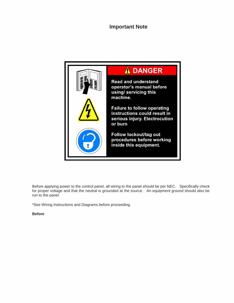
Before applying power to the control panel, all wiring to the panel should be per NEC. Specifically check for proper voltage and that the neutral is grounded at the source. An equipment ground should also be run to the panel.
*See Wiring Instructions and Diagrams before proceeding.
Before

Standard Vilter Warranty
Seller warrants the products it manufactures to be free from defects in material and workmanship for a period of eighteen (18) months from the date of shipment from Seller’s manufacturing plant or twelve (12) months from date of installation at the initial end users location, whichever occurs first. In addition, Seller provides the following extended warranties: (a) three (3) years from the date of shipment on single screw compressor internal rotating parts, (b) two (2) years from the date of shipment on reciprocating compressors and single screw and reciprocating compressor parts, and (c) two (2) years on all other parts on a single screw compressor unit. Such warranties do not apply to ordinary wear and tear. Seller does not warrant that the product complies with any particular law or regulation not explicitly set forth in the specifications, and Buyer is responsible for ensuring that the product contains all features necessary to safely perform in Buyer’s and its customer’s plants and operations. Buyer must notify Seller of any warranty claim within ten (10) days after such claim arises, otherwise Buyer waives all rights to such claim. Products supplied by Seller, which are manufactured by others, are not warranted by Seller, but rather Seller merely passes through the manufacturer’s warranty to Buyer.
Unless otherwise agreed in writing, Buyer’s sole remedy for breach of warranty is, at Seller’s option, the re-pair of the defect, the correction of the service, or the providing a replacement part FOB Seller’s office. Seller will not be responsible for costs of dismantling, lost refrigerant, reassembling, or transporting the product. Further, Seller will not be liable for any other direct, indirect, consequential, incidental, or special damages arising out of a breach of warranty. THESE WARRANTY REMEDIES ARE EXCLUSIVE AND ALL OTHER WAR-RANTY REMEDIES ARE EXCLUDED. Products or parts for which a warranty claim is made are to be returned transportation prepaid to Seller’s factory. Any improper use, corrosion, neglect, accident, operation beyond rated capacity, substitution of parts not approved by Seller, or any alteration or repair by others which, in Seller’s judgement, adversely affects the Product, shall void all warranties and warranty obligations. Further, Seller shall not be liable under the above warranties should Buyer be in default of its payment obligations to Seller under this Agreement or any credit agreement.
Vission 20/20 Warranty 1
SELLER EXPRESSLY DISCLAIMS ALL OTHER WARRANTIES, WHETHER EXPRESS OR IMPLIED, INCLUDING THE IMPLIED WARRANTIES OF MERCHANTABILITY AND FITNESS FOR A PARTICULAR PURPOSE.
Table of Contents
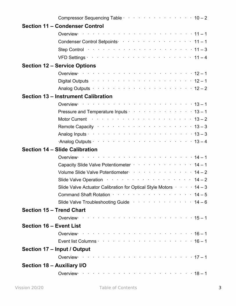
Section 1 – Operational Flow Charts
Requirements to Start Compressor · · · · · · · · · · · · 1 - 1
Run Logic at Start · · · · · · · · · · · · · · · · · · · 1 - 1
Amp Load Limiting · · · · · · · · · · · · · · · · · · · 1 - 1
Discharge Pressure Load Limiting · · · · · · · · · · · · · 1 - 1
Suction Pressure Load Limiting · · · · · · · · · · · · · · 1 - 2
Section 2 – Installation
Proper Wire Sizing · · · · · · · · · · · · · · · · · · · 2 - 1
Voltage Source · · · · · · · · · · · · · · · · · · · · 2 - 1
Grounding · · · · · · · · · · · · · · · · · · · · · · 2 - 3
Mixed Voltages · · · · · · · · · · · · · · · · · · · · 2 - 4
Wiring Methods · · · · · · · · · · · · · · · · · · · · 2 - 5
Best Practices · · · · · · · · · · · · · · · · · · · · 2 - 6
Section 3 – Hardware Architecture
Overview· · · · · · · · · · · · · · · · · · · · · · · 3 - 1
Digital Input/Output · · · · · · · · · · · · · · · · · · 3 - 1
Analog Inputs · · · · · · · · · · · · · · · · · · · · · 3 - 5
Analog Outputs · · · · · · · · · · · · · · · · · · · · 3 - 7
Digital & Analog I/O Boards Layout · · · · · · · · · · · · 3 - 8
Digital Output Boards · · · · · · · · · · · · · · · · · 3 - 9
Digital Input Boards · · · · · · · · · · · · · · · · · · 3 - 10
Digital in-out Boards · · · · · · · · · · · · · · · · · · 3 - 11
Analog Input Boards · · · · · · · · · · · · · · · · · · 3 - 12
Analog Outputs · · · · · · · · · · · · · · · · · · · · 3 – 17
Section 4 – Main Screen
Overview · · · · · · · · · · · · · · · · · · · · · · 4 – 1
Top Status Bar · · · · · · · · · · · · · · · · · · · · 4 – 1
Parameters Bar · · · · · · · · · · · · · · · · · · · · 4 – 2
Bottom Status Bar· · · · · · · · · · · · · · · · · · · 4 – 3
Splash Screen · · · · · · · · · · · · · · · · · · · · 4 – 4
Vission 20/20 Table of Contents 1

Section 5 – Menu
Overview · · · · · · · · · · · · · · · · · · · · · · 5 – 1
Navigation Buttons · · · · · · · · · · · · · · · · · · 5 – 1
Section 6 – Compressor Control
Overview· · · · · · · · · · · · · · · · · · · · · · · 6 – 1
Pulse Proportional Control · · · · · · · · · · · · · · · · 6 – 1
Auto-cycle · · · · · · · · · · · · · · · · · · · · · · 6 – 2
VFD· · · · · · · · · · · · · · · · · · · · · · · · · 6 – 3
Pumpdown Control · · · · · · · · · · · · · · · · · · 6 – 4
Pulldown Control · · · · · · · · · · · · · · · · · · · 6 – 5
Control Mode · · · · · · · · · · · · · · · · · · · · · 6 – 7
Stop Load & Force Unload· · · · · · · · · · · · · · · · 6 – 7
Capacity Slide Triggered Output · · · · · · · · · · · · · 6 – 7
Volume Slide Position Offset· · · · · · · · · · · · · · · 6 – 8
Soft Load · · · · · · · · · · · · · · · · · · · · · · 6 – 8
Load Anticipating · · · · · · · · · · · · · · · · · · · 6 – 8
Oil Control · · · · · · · · · · · · · · · · · · · · · · 6 – 8
Liquid Injection · · · · · · · · · · · · · · · · · · · · 6 – 9
Section 7 – Alarms & Trips
Overview· · · · · · · · · · · · · · · · · · · · · · · 7 – 1
Alarms and Trips Setpoints · · · · · · · · · · · · · · · 7 – 1
Compressor Inhibits · · · · · · · · · · · · · · · · · · 7 – 3
·Safety Failure Messages · · · · · · · · · · · · · · · · 7 – 4
Section 8 – Timers
Overview· · · · · · · · · · · · · · · · · · · · · · · 8 – 1
Timer Setpoints · · · · · · · · · · · · · · · · · · · · 8 – 1
Section 9 – Compressor Scheduling
Overview· · · · · · · · · · · · · · · · · · · · · · · 9 – 1
Scheduling Setpoints · · · · · · · · · · · · · · · · · · 9 – 1
Section 10 – Compressor Sequencing
Overview · · · · · · · · · · · · · · · · · · · · · · 10 – 1
Pressure Control Setpoints· · · · · · · · · · · · · · · · 10 – 1
Capacity Load / Unload Timers · · · · · · · · · · · · · · 10 – 2
Vission 20/20 Table of Contents 2
Compressor Sequencing Table · · · · · · · · · · · · · · 10 – 2
Section 11 – Condenser Control
Overview· · · · · · · · · · · · · · · · · · · · · · · 11 – 1
Condenser Control Setpoints· · · · · · · · · · · · · · · 11 – 1
Step Control · · · · · · · · · · · · · · · · · · · · · 11 – 3
VFD Settings · · · · · · · · · · · · · · · · · · · · · 11 – 4
Section 12 – Service Options
Overview· · · · · · · · · · · · · · · · · · · · · · · 12 – 1
Digital Outputs · · · · · · · · · · · · · · · · · · · · 12 – 1
Analog Outputs · · · · · · · · · · · · · · · · · · · · 12 – 2
Section 13 – Instrument Calibration
Overview· · · · · · · · · · · · · · · · · · · · · · · 13 – 1
Pressure and Temperature Inputs · · · · · · · · · · · · · 13 – 1
Motor Current · · · · · · · · · · · · · · · · · · · · 13 – 2
Remote Capacity · · · · · · · · · · · · · · · · · · · 13 – 3
Analog Inputs · · · · · · · · · · · · · · · · · · · · · 13 – 3
·Analog Outputs · · · · · · · · · · · · · · · · · · · · 13 – 4
Section 14 – Slide Calibration
Overview· · · · · · · · · · · · · · · · · · · · · · · 14 – 1
Capacity Slide Valve Potentiometer · · · · · · · · · · · · 14 – 1
Volume Slide Valve Potentiometer· · · · · · · · · · · · · 14 – 2
Slide Valve Operation · · · · · · · · · · · · · · · · · 14 – 2
Slide Valve Actuator Calibration for Optical Style Motors · · · · 14 – 3
Command Shaft Rotation · · · · · · · · · · · · · · · · 14 – 5
Slide Valve Troubleshooting Guide · · · · · · · · · · · · 14 – 6
Section 15 – Trend Chart
Overview· · · · · · · · · · · · · · · · · · · · · · · 15 – 1
Section 16 – Event List
Overview· · · · · · · · · · · · · · · · · · · · · · · 16 – 1
Event list Columns · · · · · · · · · · · · · · · · · · · 16 – 1
Section 17 – Input / Output
Overview· · · · · · · · · · · · · · · · · · · · · · · 17 – 1
Section 18 – Auxiliary I/O
Overview· · · · · · · · · · · · · · · · · · · · · · · 18 – 1
Vission 20/20 Table of Contents 3

Digital Inputs · · · · · · · · · · · · · · · · · · · · · 18 – 1
Digital Outputs · · · · · · · · · · · · · · · · · · · · 18 – 2
Analog Inputs· · · · · · · · · · · · · · · · · · · · · 18 – 3
Analog Outputs · · · · · · · · · · · · · · · · · · · · 18 – 3
Section 19 – Configuration
Overview· · · · · · · · · · · · · · · · · · · · · · · 19 – 1
Units · · · · · · · · · · · · · · · · · · · · · · · · 19 – 1
Communications· · · · · · · · · · · · · · · · · · · · 19 – 2
Touchscreen · · · · · · · · · · · · · · · · · · · · · 19 – 3
Anti-Recycle · · · · · · · · · · · · · · · · · · · · · 19 – 3
Restart On Power Failure · · · · · · · · · · · · · · · · 19 – 3
Compressor Sequencing · · · · · · · · · · · · · · · · 19 – 4
Language · · · · · · · · · · · · · · · · · · · · · · 19 – 4
Model & Refrigerant · · · · · · · · · · · · · · · · · · 19 – 4
Compressor Control · · · · · · · · · · · · · · · · · · 19 – 5
Optional Function Selection · · · · · · · · · · · · · · · 19 – 5
Condenser Control· · · · · · · · · · · · · · · · · · · 19 – 5
Oil Pump Control · · · · · · · · · · · · · · · · · · · 19 – 5
Oil Cooling · · · · · · · · · · · · · · · · · · · · · · 19 – 6
Motor Current Device· · · · · · · · · · · · · · · · · · 19 – 6
Digital Inputs · · · · · · · · · · · · · · · · · · · · · 19 – 6
Analog Inputs · · · · · · · · · · · · · · · · · · · · · 19 – 6
Analog Outputs · · · · · · · · · · · · · · · · · · · · 19 – 7
Digital Outputs · · · · · · · · · · · · · · · · · · · · 19 – 7
I/O Configuration · · · · · · · · · · · · · · · · · · · 19 – 7
Section 20– Data Backup
Overview· · · · · · · · · · · · · · · · · · · · · · · 20 – 1
Save / Load · · · · · · · · · · · · · · · · · · · · · 20 – 1
Migrate · · · · · · · · · · · · · · · · · · · · · · · 20 – 2
Factory Reset· · · · · · · · · · · · · · · · · · · · · 20 – 3
Section 21 – Maintenance
Overview· · · · · · · · · · · · · · · · · · · · · · · 21 – 1
Checklist· · · · · · · · · · · · · · · · · · · · · · · 21 – 1
Vission 20/20 Table of Contents 4
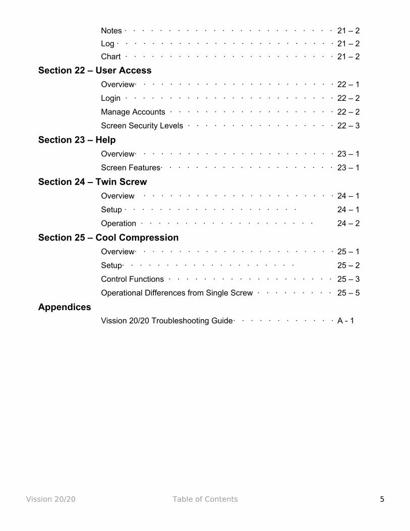
Notes · · · · · · · · · · · · · · · · · · · · · · · · 21 – 2
Log · · · · · · · · · · · · · · · · · · · · · · · · · 21 – 2
Chart · · · · · · · · · · · · · · · · · · · · · · · · 21 – 2
Section 22 – User Access
Overview· · · · · · · · · · · · · · · · · · · · · · · 22 – 1
Login · · · · · · · · · · · · · · · · · · · · · · · · 22 – 2
Manage Accounts · · · · · · · · · · · · · · · · · · · 22 – 2
Screen Security Levels · · · · · · · · · · · · · · · · · 22 – 3
Section 23 – Help
Overview· · · · · · · · · · · · · · · · · · · · · · · 23 – 1
Screen Features· · · · · · · · · · · · · · · · · · · · 23 – 1
Section 24 – Twin Screw
Overview · · · · · · · · · · · · · · · · · · · · · · 24 – 1
Setup · · · · · · · · · · · · · · · · · · · · 24 – 1
Operation · · · · · · · · · · · · · · · · · · · · 24 – 2
Section 25 – Cool Compression
Overview· · · · · · · · · · · · · · · · · · · · · · · 25 – 1
Setup· · · · · · · · · · · · · · · · · · · · 25 – 2
Control Functions · · · · · · · · · · · · · · · · · · · 25 – 3
Operational Differences from Single Screw · · · · · · · · · 25 – 5
Appendices
Vission 20/20 Troubleshooting Guide· · · · · · · · · · · · A - 1
Vission 20/20 Table of Contents 5
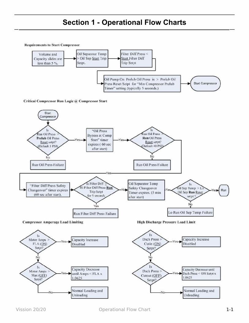
Section 1 - Operational Flow Charts
Vission 20/20 Operational Flow Chart 1-1
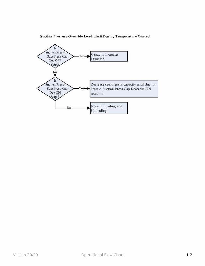
Vission 20/20 Operational Flow Chart 1-2
Section 2 - Installation Recommendations
Proper Wire Sizing:• Always size wire gauges as specified by the National Electrical Code (NEC) for
electronic control devices.
• For improved noise immunity, install one size larger wire gauge than the NEC requirement to assure ample current-carrying capability.
• Never under size wire gauges.
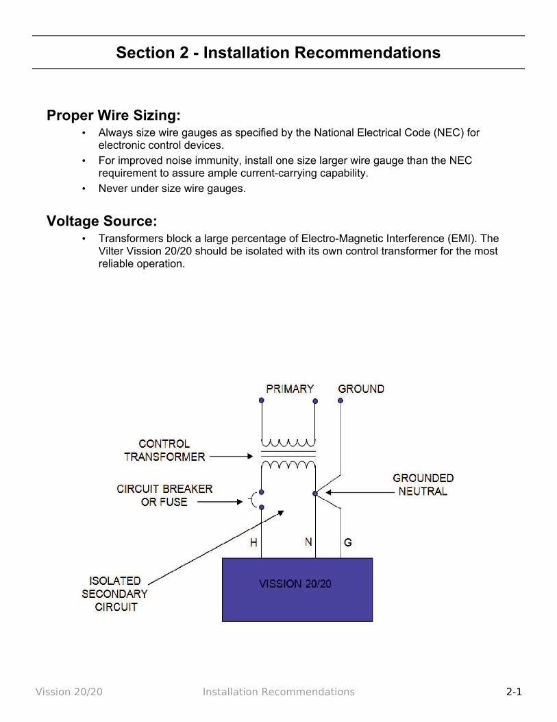
Voltage Source:• Transformers block a large percentage of Electro-Magnetic Interference (EMI). The
Vilter Vission 20/20 should be isolated with its own control transformer for the most reliable operation.
Vission 20/20 Installation Recommendations 2-1
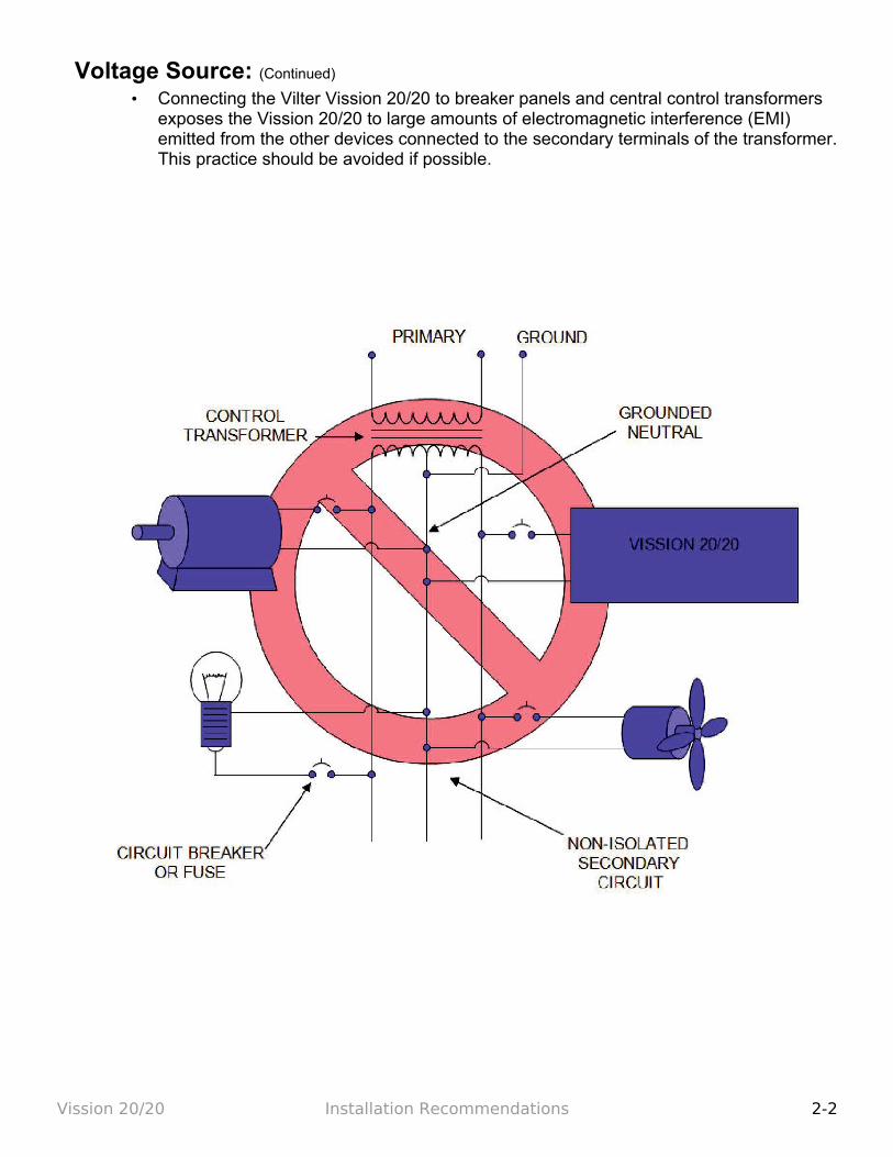
Voltage Source: (Continued) • Connecting the Vilter Vission 20/20 to breaker panels and central control transformers
exposes the Vission 20/20 to large amounts of electromagnetic interference (EMI) emitted from the other devices connected to the secondary terminals of the transformer. This practice should be avoided if possible.
Vission 20/20 Installation Recommendations 2-2

Grounding:• Continuous grounds must be run from the utility ground to the Vission 20/20.
• Grounds must be copper or aluminum wire.
• Never use conduit grounds.
Vission 20/20 Installation Recommendations 2-3

Mixing Voltages:• Separate different voltages from each other and separate AC from DC.
• Each voltage level must be run in separate conduit:
• 460 VAC
• 230 VAC
• 120 VAC
• 24 VAC
• DC signals
• If your installation site has wire-ways or conduit trays, dividers must be installed between the different voltages.
Vission 20/20 Installation Recommendations 2-4
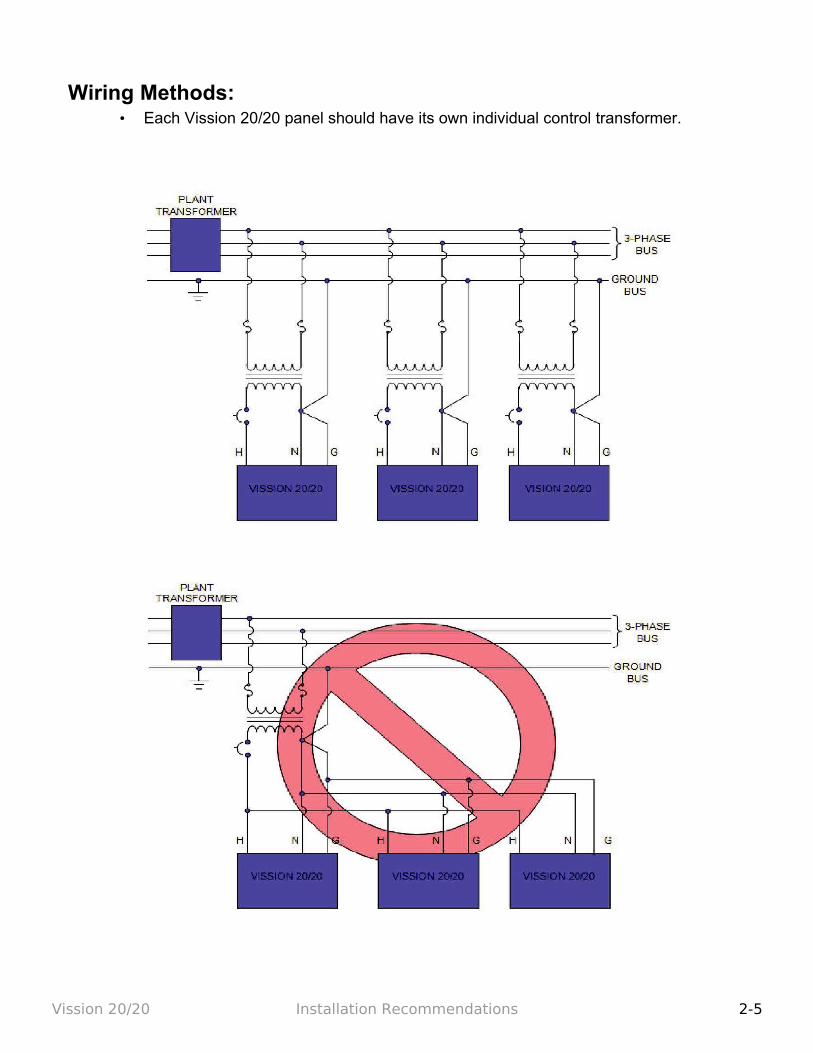
Wiring Methods:• Each Vission 20/20 panel should have its own individual control transformer.
Vission 20/20 Installation Recommendations 2-5
Best Practices:Do:
• Keep AC wires away from circuit boards.
• Always run conduit into the bottom or sides of an enclosure.
• If the conduit must be placed in the top of an enclosure, use a water-tight conduit fit-ting to keep water from entering the enclosure.
• The Vission 20/20 is supplied with pre-punched conduit holes. Use them!
Don't:
• Don’t run wires through the Vission 20/20 enclosure that are not related to the com-pressor control.
• Don’t add relays, timers, transformers, etc. in the Vission 20/20 enclosure without first checking with Vilter.
• Don’t run conduit into the top of an enclosure.
• Don’t run refrigerant tubing inside the enclosure.
• Don’t drill metal enclosures without taking proper precautions to protect circuit boards from damage.
Vission 20/20 Installation Recommendations 2-6

Section 3 – Hardware Architecture
Overview:The Vission 20/20 control panel utilizes X-86 PC technology with a Linux operating system. The Vission 20/20 has the following attributes:
• Low power, Industrial rated X-86 CPU. • 15” XGA, high resolution LCD display. (Outdoor viewable LCD optional). • 8-wire touch screen operator interface. • Flexible and expandable I/O. • NEMA-4 enclosure (NEMA-4X optional). • Industrial temperature range design.
Digital Input/Output:
BOARD # I/O # DESCRIPTION TYPE
1 1 Compressor Start OUTPUT
1 2 Oil Pump Start OUTPUT
1 3 Capacity Increase OUTPUT
1 4 Capacity Decrease OUTPUT
1 5 Volume Increase OUTPUT
1 6 Volume Decrease OUTPUT
1 7 Oil Separator Heater OUTPUT
1 8 Trip indicator (ON=Normal) OUTPUT
Vission 20/20 Hardware Architecture 3-1
I/O
I/O
I/O
I/O
I/O SBC
Touch Screen
LCD Display
DC Power
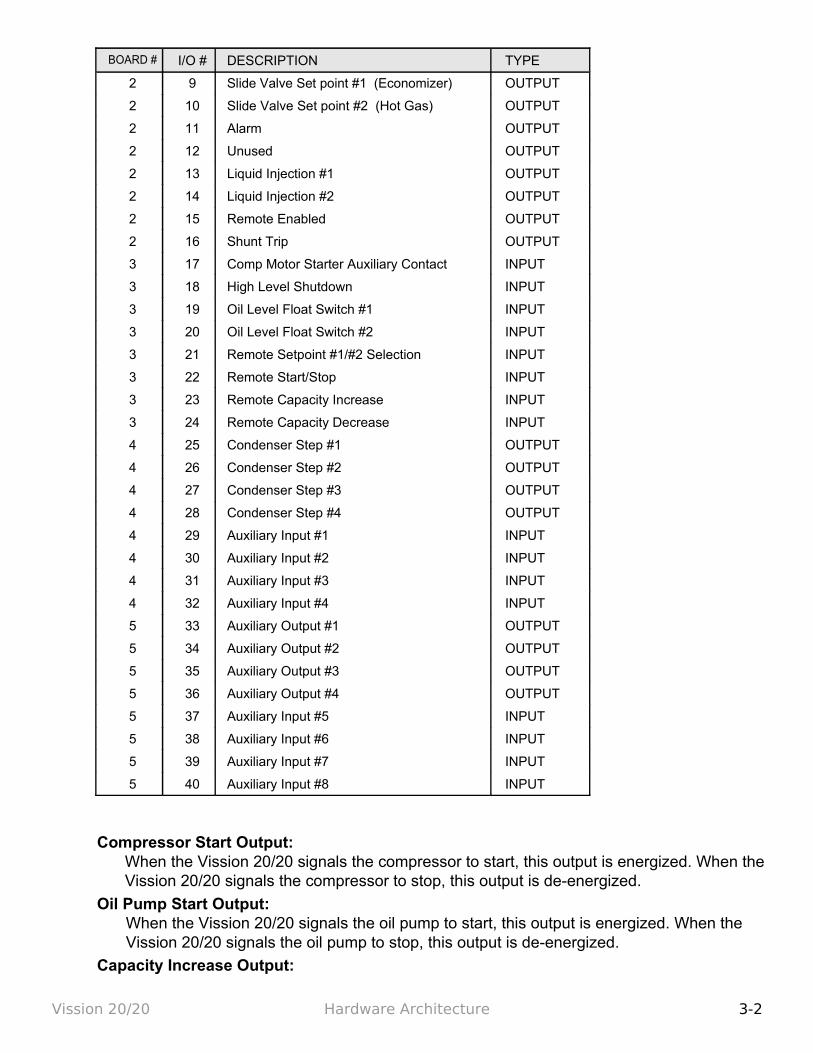
BOARD # I/O # DESCRIPTION TYPE
2 9 Slide Valve Set point #1 (Economizer) OUTPUT
2 10 Slide Valve Set point #2 (Hot Gas) OUTPUT
2 11 Alarm OUTPUT
2 12 Unused OUTPUT
2 13 Liquid Injection #1 OUTPUT
2 14 Liquid Injection #2 OUTPUT
2 15 Remote Enabled OUTPUT
2 16 Shunt Trip OUTPUT
3 17 Comp Motor Starter Auxiliary Contact INPUT
3 18 High Level Shutdown INPUT
3 19 Oil Level Float Switch #1 INPUT
3 20 Oil Level Float Switch #2 INPUT
3 21 Remote Setpoint #1/#2 Selection INPUT
3 22 Remote Start/Stop INPUT
3 23 Remote Capacity Increase INPUT
3 24 Remote Capacity Decrease INPUT
4 25 Condenser Step #1 OUTPUT
4 26 Condenser Step #2 OUTPUT
4 27 Condenser Step #3 OUTPUT
4 28 Condenser Step #4 OUTPUT
4 29 Auxiliary Input #1 INPUT
4 30 Auxiliary Input #2 INPUT
4 31 Auxiliary Input #3 INPUT
4 32 Auxiliary Input #4 INPUT
5 33 Auxiliary Output #1 OUTPUT
5 34 Auxiliary Output #2 OUTPUT
5 35 Auxiliary Output #3 OUTPUT
5 36 Auxiliary Output #4 OUTPUT
5 37 Auxiliary Input #5 INPUT
5 38 Auxiliary Input #6 INPUT
5 39 Auxiliary Input #7 INPUT
5 40 Auxiliary Input #8 INPUT
Compressor Start Output:When the Vission 20/20 signals the compressor to start, this output is energized. When the Vission 20/20 signals the compressor to stop, this output is de-energized.
Oil Pump Start Output:When the Vission 20/20 signals the oil pump to start, this output is energized. When the Vission 20/20 signals the oil pump to stop, this output is de-energized.
Capacity Increase Output:
Vission 20/20 Hardware Architecture 3-2
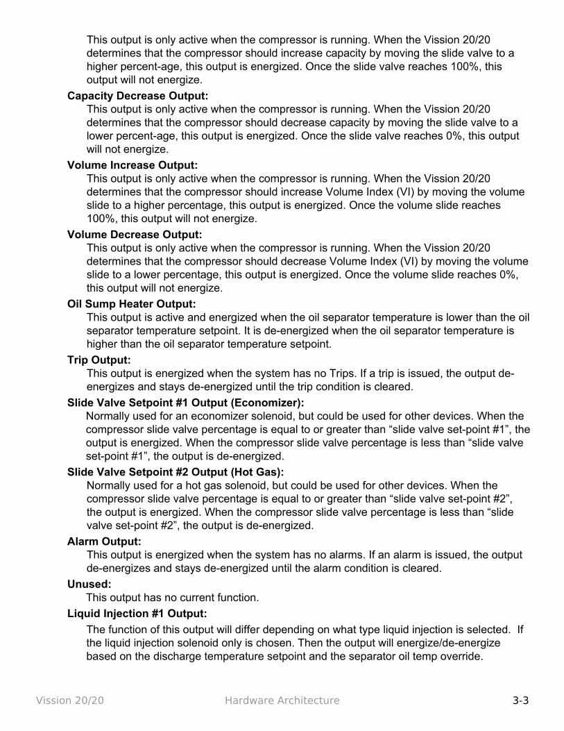
This output is only active when the compressor is running. When the Vission 20/20 determines that the compressor should increase capacity by moving the slide valve to a higher percent-age, this output is energized. Once the slide valve reaches 100%, this output will not energize.
Capacity Decrease Output:This output is only active when the compressor is running. When the Vission 20/20 determines that the compressor should decrease capacity by moving the slide valve to a lower percent-age, this output is energized. Once the slide valve reaches 0%, this output will not energize.
Volume Increase Output:This output is only active when the compressor is running. When the Vission 20/20 determines that the compressor should increase Volume Index (VI) by moving the volume slide to a higher percentage, this output is energized. Once the volume slide reaches 100%, this output will not energize.
Volume Decrease Output:This output is only active when the compressor is running. When the Vission 20/20 determines that the compressor should decrease Volume Index (VI) by moving the volume slide to a lower percentage, this output is energized. Once the volume slide reaches 0%, this output will not energize.
Oil Sump Heater Output:This output is active and energized when the oil separator temperature is lower than the oil separator temperature setpoint. It is de-energized when the oil separator temperature is higher than the oil separator temperature setpoint.
Trip Output:This output is energized when the system has no Trips. If a trip is issued, the output de-energizes and stays de-energized until the trip condition is cleared.
Slide Valve Setpoint #1 Output (Economizer):Normally used for an economizer solenoid, but could be used for other devices. When the compressor slide valve percentage is equal to or greater than “slide valve set-point #1”, the output is energized. When the compressor slide valve percentage is less than “slide valve set-point #1”, the output is de-energized.
Slide Valve Setpoint #2 Output (Hot Gas):Normally used for a hot gas solenoid, but could be used for other devices. When the compressor slide valve percentage is equal to or greater than “slide valve set-point #2”, the output is energized. When the compressor slide valve percentage is less than “slide valve set-point #2”, the output is de-energized.
Alarm Output:This output is energized when the system has no alarms. If an alarm is issued, the output de-energizes and stays de-energized until the alarm condition is cleared.
Unused:This output has no current function.
Liquid Injection #1 Output:
The function of this output will differ depending on what type liquid injection is selected. If the liquid injection solenoid only is chosen. Then the output will energize/de-energize based on the discharge temperature setpoint and the separator oil temp override.
Vission 20/20 Hardware Architecture 3-3

If the compressor has liquid injection with motorized value oil cooling, then this output is active when the compressor is running and the discharge temperature is above the oil separator temperature override set-point and the oil separator temperature is above the override setpoint, then the output is energized. The output is de-energized when the discharge temperature falls below the “on” setpoint minus the solenoid differential.
Liquid Injection #2 Output:Not Defined
Remote Enabled Output:This output is energized when the Vission 20/20 panel is enabled for remote control. If the compressor parameter do not satisfy start conditions or is placed into the manual stop position, this output is de-energized.
Shunt Trip:This output is designed to be connected to a master power breaker with a shut trip input. If the Vission 20/20 detect the compressor motor is running when its not suppose to be, then this output can be energized to trip the breaker suppling power to a starter.
Comp Motor Starter Auxiliary Contact:This input looks for a feedback signal from the compressor starter, confirming that the compressor starter is energized.
High Level Shutdown Input:This input must be energized in order for the compressor to operate. If de-energized, the compressor will shut down and issue a high level trip.
Oil Level Float Switch #1 Input:This input must be energized in order for the compressor to operate. If de-energized, the compressor will shut down and issue a oil level #1 trip
Oil Level Float Switch #2 Input:This input must be energized in order for the compressor to operate. If de-energized, the compressor will shut down and issue a oil level #2 trip.
Remote Select #1/#2 Input:This input enables or disables remote I/O control. Energizing this input enables the Remote Capacity Increase and Remote Capacity Decrease inputs.
Remote Start/Stop Input:If the compressor is enabled for remote I/O control, this input is enabled. Energizing this input will issue a start for the compressor as long as it is available to run. De-energizing this input stops the compressor.
Remote Capacity Increase Input:If the compressor is enabled for remote I/O control, this input is enabled. Operational only when the compressor is running. Energizing this input will increase the slide valve position. The slide valve will continuously increase as long as this input is energized. The slide valve will not increase when this input is de-energized.NOTE: The scan interval on the remote increase and decrease inputs is approximately ONE SECOND. Please take that into account when developing a control scheme using the remote increase and remote decrease inputs for compressor control.
Remote Capacity Decrease Input:Operational only when the compressor is running. This input is enabled if the compressor is enabled for remote I/O control. Energizing this input will decrease the slide valve position. The slide valve will continuously decrease as long as this input is energized. The
Vission 20/20 Hardware Architecture 3-4
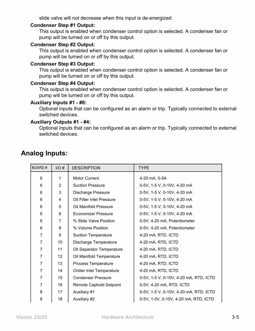
slide valve will not decrease when this input is de-energized.
Condenser Step #1 Output:This output is enabled when condenser control option is selected. A condenser fan or pump will be turned on or off by this output.
Condenser Step #2 Output:This output is enabled when condenser control option is selected. A condenser fan or pump will be turned on or off by this output.
Condenser Step #3 Output:This output is enabled when condenser control option is selected. A condenser fan or pump will be turned on or off by this output.
Condenser Step #4 Output:This output is enabled when condenser control option is selected. A condenser fan or pump will be turned on or off by this output.
Auxiliary Inputs #1 - #8:Optional inputs that can be configured as an alarm or trip. Typically connected to external switched devices.
Auxiliary Outputs #1 - #4:Optional inputs that can be configured as an alarm or trip. Typically connected to external switched devices.
Analog Inputs:
BOARD # I/O # DESCRIPTION TYPE
6 1 Motor Current 4-20 mA, 0-5A
6 2 Suction Pressure 0-5V, 1-5 V, 0-10V, 4-20 mA
6 3 Discharge Pressure 0-5V, 1-5 V, 0-10V, 4-20 mA
6 4 Oil Filter Inlet Pressure 0-5V, 1-5 V, 0-10V, 4-20 mA
6 5 Oil Manifold Pressure 0-5V, 1-5 V, 0-10V, 4-20 mA
6 6 Economizer Pressure 0-5V, 1-5 V, 0-10V, 4-20 mA
6 7 % Slide Valve Position 0-5V, 4-20 mA, Potentiometer
6 8 % Volume Position 0-5V, 4-20 mA, Potentiometer
7 9 Suction Temperature 4-20 mA, RTD, ICTD
7 10 Discharge Temperature 4-20 mA, RTD, ICTD
7 11 Oil Separator Temperature 4-20 mA, RTD, ICTD
7 12 Oil Manifold Temperature 4-20 mA, RTD, ICTD
7 13 Process Temperature 4-20 mA, RTD, ICTD
7 14 Chiller Inlet Temperature 4-20 mA, RTD, ICTD
7 15 Condenser Pressure 0-5V, 1-5 V, 0-10V, 4-20 mA, RTD, ICTD
7 16 Remote Caphold Setpoint 0-5V, 4-20 mA, RTD, ICTD
8 17 Auxiliary #1 0-5V, 1-5 V, 0-10V, 4-20 mA, RTD, ICTD
8 18 Auxiliary #2 0-5V, 1-5V, 0-10V, 4-20 mA, RTD, ICTD
Vission 20/20 Hardware Architecture 3-5
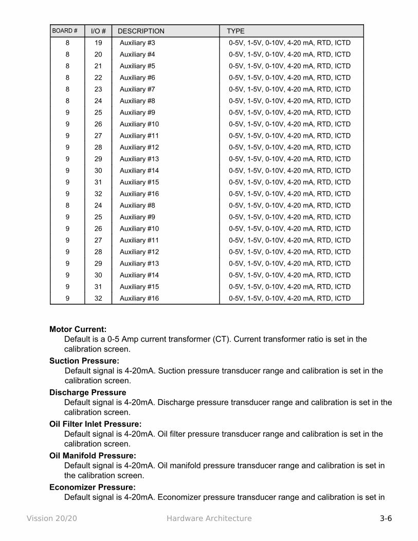
BOARD # I/O # DESCRIPTION TYPE
8 19 Auxiliary #3 0-5V, 1-5V, 0-10V, 4-20 mA, RTD, ICTD
8 20 Auxiliary #4 0-5V, 1-5V, 0-10V, 4-20 mA, RTD, ICTD
8 21 Auxiliary #5 0-5V, 1-5V, 0-10V, 4-20 mA, RTD, ICTD
8 22 Auxiliary #6 0-5V, 1-5V, 0-10V, 4-20 mA, RTD, ICTD
8 23 Auxiliary #7 0-5V, 1-5V, 0-10V, 4-20 mA, RTD, ICTD
8 24 Auxiliary #8 0-5V, 1-5V, 0-10V, 4-20 mA, RTD, ICTD
9 25 Auxiliary #9 0-5V, 1-5V, 0-10V, 4-20 mA, RTD, ICTD
9 26 Auxiliary #10 0-5V, 1-5V, 0-10V, 4-20 mA, RTD, ICTD
9 27 Auxiliary #11 0-5V, 1-5V, 0-10V, 4-20 mA, RTD, ICTD
9 28 Auxiliary #12 0-5V, 1-5V, 0-10V, 4-20 mA, RTD, ICTD
9 29 Auxiliary #13 0-5V, 1-5V, 0-10V, 4-20 mA, RTD, ICTD
9 30 Auxiliary #14 0-5V, 1-5V, 0-10V, 4-20 mA, RTD, ICTD
9 31 Auxiliary #15 0-5V, 1-5V, 0-10V, 4-20 mA, RTD, ICTD
9 32 Auxiliary #16 0-5V, 1-5V, 0-10V, 4-20 mA, RTD, ICTD
Motor Current:Default is a 0-5 Amp current transformer (CT). Current transformer ratio is set in the calibration screen.
Suction Pressure:Default signal is 4-20mA. Suction pressure transducer range and calibration is set in the calibration screen.
Discharge PressureDefault signal is 4-20mA. Discharge pressure transducer range and calibration is set in the calibration screen.
Oil Filter Inlet Pressure:Default signal is 4-20mA. Oil filter pressure transducer range and calibration is set in the calibration screen.
Oil Manifold Pressure:Default signal is 4-20mA. Oil manifold pressure transducer range and calibration is set in the calibration screen.
Economizer Pressure:Default signal is 4-20mA. Economizer pressure transducer range and calibration is set in
Vission 20/20 Hardware Architecture 3-6
the calibration screen.
Slide Valve Position:Reads the 0-5 volt signal back from the slide position motor actuator to indicate cur-rent slide valve position.
Volume Position:Reads the 0-5 volt signal back from the slide volume motor actuator to indicate current volume position.
Suction Temperature:Default signal is RTD. Suction temperature calibration is set in the calibration screen.
Discharge Temperature:Default signal is RTD. Discharge temperature calibration is set in the calibration screen.
Oil Separator Temperature:Default signal is RTD. Oil separator temperature calibration is set in the calibration screen.
Oil Manifold Temperature:Default signal is RTD. Oil manifold temperature calibration is set in the calibration screen.
Process Temperature:Default signal is 4-20mA. Process temperature calibration and range are set in the calibration screen.
Chiller Inlet Temperature:Default signal is 4-20mA. Measures separator level. Chiller Inlet Temperature calibration and range are set in the calibration screen.
Condenser Pressure:Default signal is 4-20mA. Condenser pressure transducer range and calibration is set in the calibration screen.
Remote Caphold:Default signal is 4-20mA. Active in “Direct I/O” mode. Adjusts the capacity of the compressor from 0-100%, proportional to the 4-20mA signal.
Auxiliary #1 - #16:Flexible analog inputs that can be configured to control, alarm or trip.
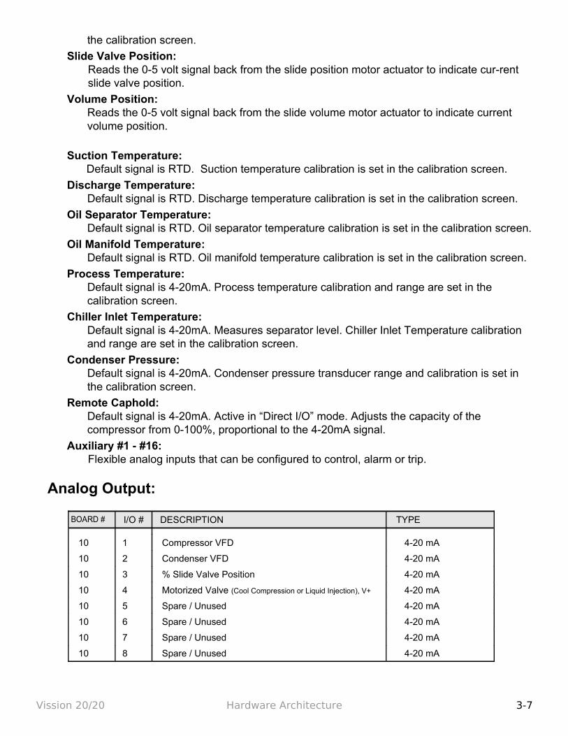
Analog Output:
BOARD # I/O # DESCRIPTION TYPE
10 1 Compressor VFD 4-20 mA
10 2 Condenser VFD 4-20 mA
10 3 % Slide Valve Position 4-20 mA
10 4 Motorized Valve (Cool Compression or Liquid Injection), V+ 4-20 mA
10 5 Spare / Unused 4-20 mA
10 6 Spare / Unused 4-20 mA
10 7 Spare / Unused 4-20 mA
10 8 Spare / Unused 4-20 mA
Vission 20/20 Hardware Architecture 3-7
Compressor Vfd:4-20mA output to control compressor motor speed with a Variable Frequency Drive (VFD).
Condenser Vfd:4-20mA output to control one condenser fan which is interleaved between the remaining condenser steps for smoother control.
% Slide Valve Position:4-20mA signal that transmits the slide valve position for remote monitoring.
Motorized Valve (V+): for a cool compression compressor, this 4-20mA signal controls a motorized valve to regulate the liquid refrigerant level in the oil separator. For a liquid injection application on a standard single screw, this 4-20mA signal controls a motorized valve to regulate the liquid refrigerant injected into the compressor for oil cooling purposes.
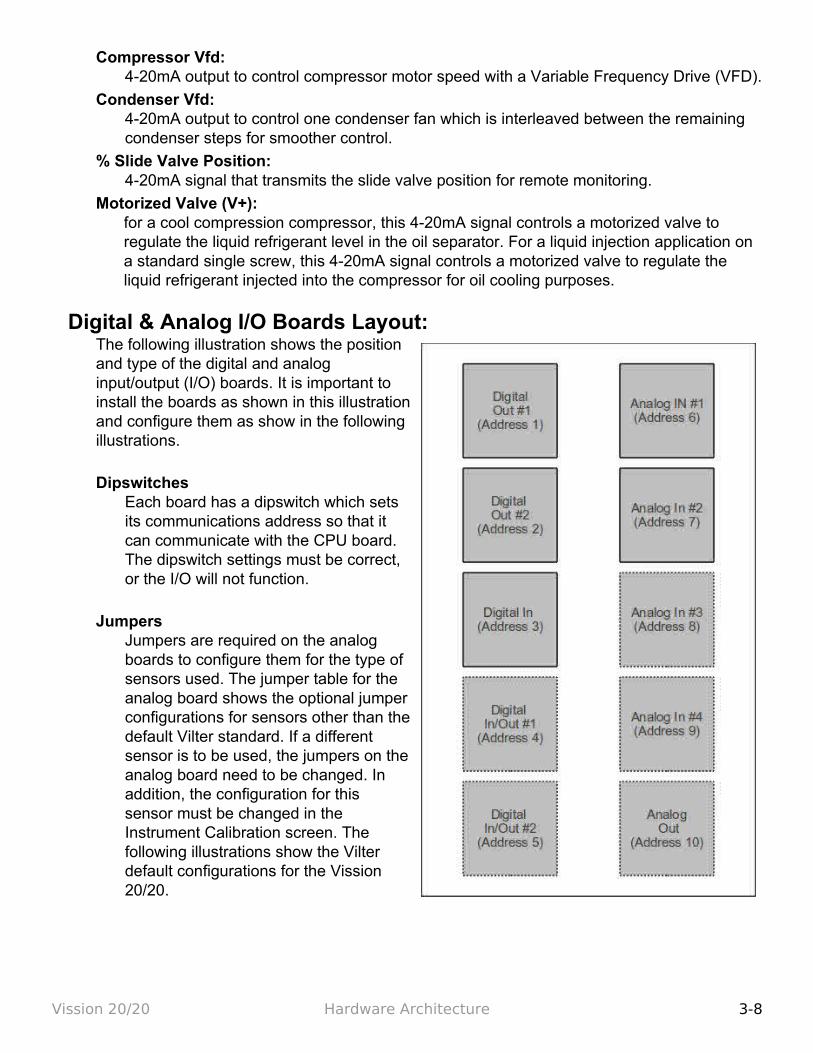
Digital & Analog I/O Boards Layout:The following illustration shows the position and type of the digital and analog input/output (I/O) boards. It is important to install the boards as shown in this illustration and configure them as show in the following illustrations.
DipswitchesEach board has a dipswitch which sets its communications address so that it can communicate with the CPU board. The dipswitch settings must be correct, or the I/O will not function.
JumpersJumpers are required on the analog boards to configure them for the type of sensors used. The jumper table for the analog board shows the optional jumper configurations for sensors other than the default Vilter standard. If a different sensor is to be used, the jumpers on the analog board need to be changed. In addition, the configuration for this sensor must be changed in the Instrument Calibration screen. The following illustrations show the Vilter default configurations for the Vission 20/20.
Vission 20/20 Hardware Architecture 3-8
Digital Output Boards:The digital output board convert signals generated by the Vission 20/20 program into 120 Vac signals that can be energize or signal other devices. All the signals are digital in that the only two states available or either on or off.
Signal LED's:Marked in the diagram below in Blue. These LED's indicated when a 120Vac output is being produced.
Voltage LED's:Marked in the diagram below in Orange. These LED's indicated the correct voltage of both the 5Vdc and 24Vdc power sources.
Communication LED's:Marked in the diagram below in Green. These LED's Show the active communications between the digital output board and the Vission 20/20 CPU board.
Address Dipswitches:Marked in the diagram below in Red. These dipswitches are used to assign each board its address position. The addresses are binary and therefor the address of a digital output board will either be address as 1 (0001) or 2 (0010).
Vission 20/20 Hardware Architecture 3-9
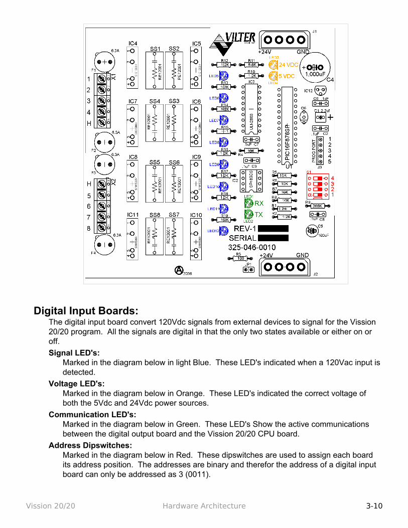
Digital Input Boards:The digital input board convert 120Vdc signals from external devices to signal for the Vission 20/20 program. All the signals are digital in that the only two states available or either on or off.
Signal LED's:Marked in the diagram below in light Blue. These LED's indicated when a 120Vac input is detected.
Voltage LED's:Marked in the diagram below in Orange. These LED's indicated the correct voltage of both the 5Vdc and 24Vdc power sources.
Communication LED's:Marked in the diagram below in Green. These LED's Show the active communications between the digital output board and the Vission 20/20 CPU board.
Address Dipswitches:Marked in the diagram below in Red. These dipswitches are used to assign each board its address position. The addresses are binary and therefor the address of a digital input board can only be addressed as 3 (0011).
Vission 20/20 Hardware Architecture 3-10
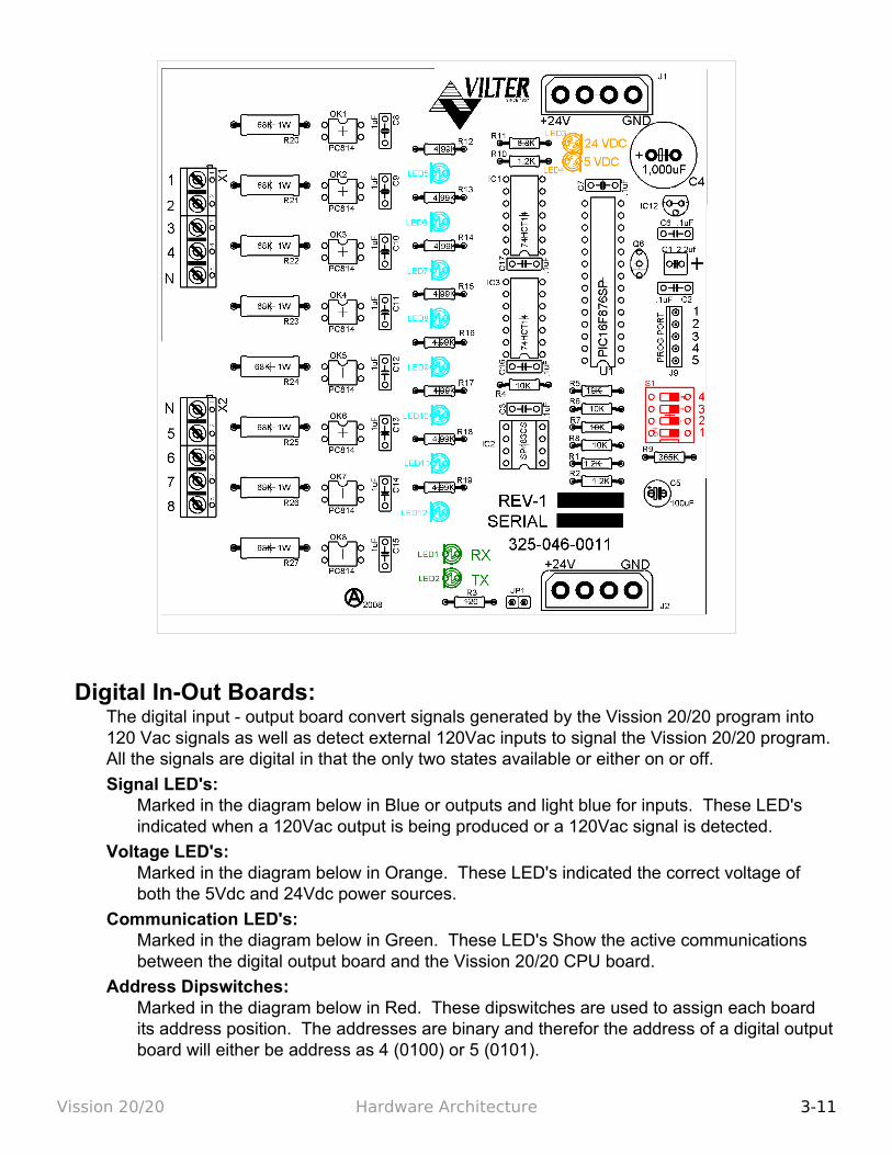
Digital In-Out Boards:The digital input - output board convert signals generated by the Vission 20/20 program into 120 Vac signals as well as detect external 120Vac inputs to signal the Vission 20/20 program. All the signals are digital in that the only two states available or either on or off.
Signal LED's:Marked in the diagram below in Blue or outputs and light blue for inputs. These LED's indicated when a 120Vac output is being produced or a 120Vac signal is detected.
Voltage LED's:Marked in the diagram below in Orange. These LED's indicated the correct voltage of both the 5Vdc and 24Vdc power sources.
Communication LED's:Marked in the diagram below in Green. These LED's Show the active communications between the digital output board and the Vission 20/20 CPU board.
Address Dipswitches:Marked in the diagram below in Red. These dipswitches are used to assign each board its address position. The addresses are binary and therefor the address of a digital output board will either be address as 4 (0100) or 5 (0101).
Vission 20/20 Hardware Architecture 3-11
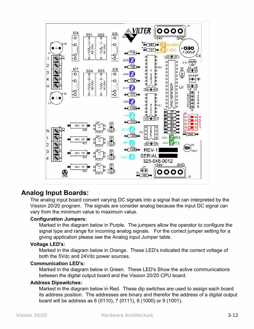
Analog Input Boards:The analog input board convert varying DC signals into a signal that can interpreted by the Vission 20/20 program. The signals are consider analog because the input DC signal can vary from the minimum value to maximum value.
Configuration Jumpers:Marked in the diagram below in Purple. The jumpers allow the operator to configure the signal type and range for incoming analog signals. For the correct jumper setting for a giving application please see the Analog input Jumper table.
Voltage LED's:Marked in the diagram below in Orange. These LED's indicated the correct voltage of both the 5Vdc and 24Vdc power sources.
Communication LED's:Marked in the diagram below in Green. These LED's Show the active communications between the digital output board and the Vission 20/20 CPU board.
Address Dipswitches:Marked in the diagram below in Red. These dip switches are used to assign each board its address position. The addresses are binary and therefor the address of a digital output board will be address as 6 (0110), 7 (0111), 8 (1000) or 9 (1001).
Vission 20/20 Hardware Architecture 3-12
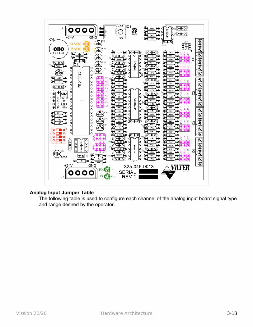
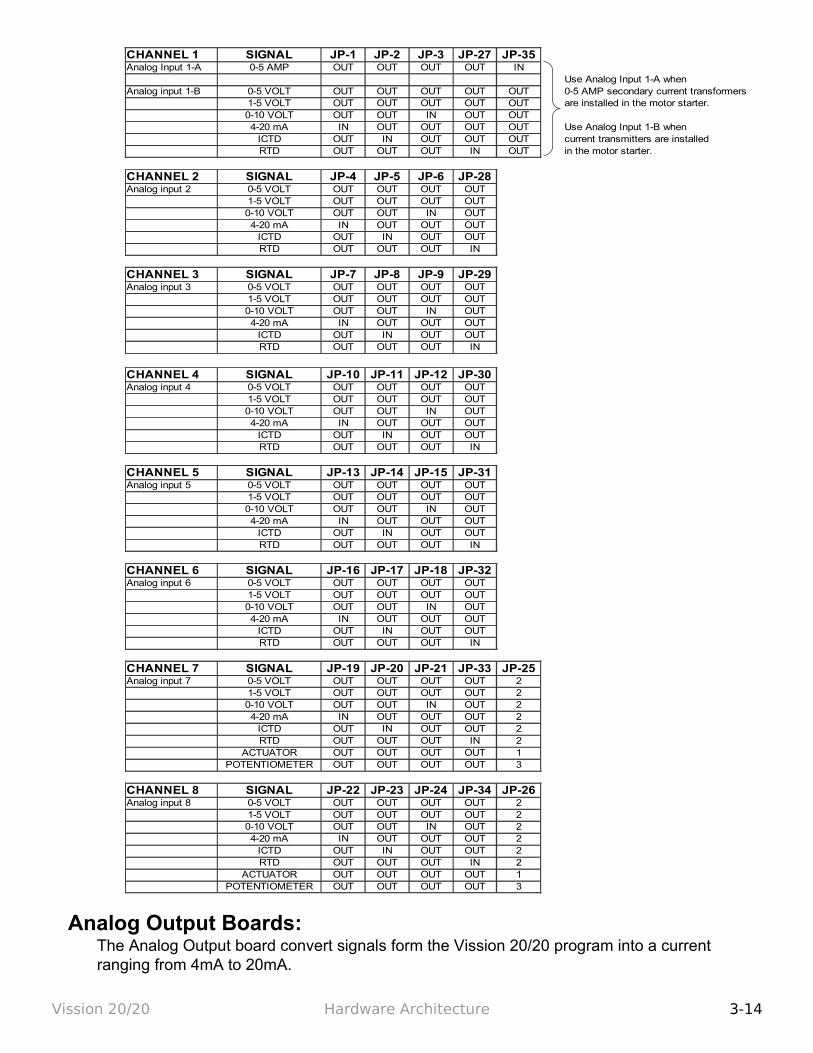
Analog Input Jumper TableThe following table is used to configure each channel of the analog input board signal type and range desired by the operator.
Vission 20/20 Hardware Architecture 3-13
Analog Output Boards:The Analog Output board convert signals form the Vission 20/20 program into a current ranging from 4mA to 20mA.
Vission 20/20 Hardware Architecture 3-14
CHANNEL 1 SIGNAL JP-1 JP-2 JP-3 JP-27 JP-35Analog Input 1-A 0-5 AMP OUT OUT OUT OUT IN
Use Analog Input 1-A whenAnalog input 1-B 0-5 VOLT OUT OUT OUT OUT OUT 0-5 AMP secondary current transformers
1-5 VOLT OUT OUT OUT OUT OUT are installed in the motor starter.0-10 VOLT OUT OUT IN OUT OUT4-20 mA IN OUT OUT OUT OUT Use Analog Input 1-B when
ICTD OUT IN OUT OUT OUT current transmitters are installedRTD OUT OUT OUT IN OUT in the motor starter.
CHANNEL 2 SIGNAL JP-4 JP-5 JP-6 JP-28Analog input 2 0-5 VOLT OUT OUT OUT OUT
1-5 VOLT OUT OUT OUT OUT0-10 VOLT OUT OUT IN OUT4-20 mA IN OUT OUT OUT
ICTD OUT IN OUT OUTRTD OUT OUT OUT IN
CHANNEL 3 SIGNAL JP-7 JP-8 JP-9 JP-29Analog input 3 0-5 VOLT OUT OUT OUT OUT
1-5 VOLT OUT OUT OUT OUT0-10 VOLT OUT OUT IN OUT4-20 mA IN OUT OUT OUT
ICTD OUT IN OUT OUTRTD OUT OUT OUT IN
CHANNEL 4 SIGNAL JP-10 JP-11 JP-12 JP-30Analog input 4 0-5 VOLT OUT OUT OUT OUT
1-5 VOLT OUT OUT OUT OUT0-10 VOLT OUT OUT IN OUT4-20 mA IN OUT OUT OUT
ICTD OUT IN OUT OUTRTD OUT OUT OUT IN
CHANNEL 5 SIGNAL JP-13 JP-14 JP-15 JP-31Analog input 5 0-5 VOLT OUT OUT OUT OUT
1-5 VOLT OUT OUT OUT OUT0-10 VOLT OUT OUT IN OUT4-20 mA IN OUT OUT OUT
ICTD OUT IN OUT OUTRTD OUT OUT OUT IN
CHANNEL 6 SIGNAL JP-16 JP-17 JP-18 JP-32Analog input 6 0-5 VOLT OUT OUT OUT OUT
1-5 VOLT OUT OUT OUT OUT0-10 VOLT OUT OUT IN OUT4-20 mA IN OUT OUT OUT
ICTD OUT IN OUT OUTRTD OUT OUT OUT IN
CHANNEL 7 SIGNAL JP-19 JP-20 JP-21 JP-33 JP-25Analog input 7 0-5 VOLT OUT OUT OUT OUT 2
1-5 VOLT OUT OUT OUT OUT 20-10 VOLT OUT OUT IN OUT 24-20 mA IN OUT OUT OUT 2
ICTD OUT IN OUT OUT 2RTD OUT OUT OUT IN 2
ACTUATOR OUT OUT OUT OUT 1POTENTIOMETER OUT OUT OUT OUT 3
CHANNEL 8 SIGNAL JP-22 JP-23 JP-24 JP-34 JP-26Analog input 8 0-5 VOLT OUT OUT OUT OUT 2
1-5 VOLT OUT OUT OUT OUT 20-10 VOLT OUT OUT IN OUT 24-20 mA IN OUT OUT OUT 2
ICTD OUT IN OUT OUT 2RTD OUT OUT OUT IN 2
ACTUATOR OUT OUT OUT OUT 1POTENTIOMETER OUT OUT OUT OUT 3
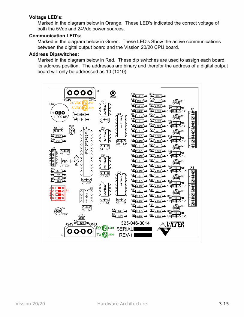
Voltage LED's:Marked in the diagram below in Orange. These LED's indicated the correct voltage of both the 5Vdc and 24Vdc power sources.
Communication LED's:Marked in the diagram below in Green. These LED's Show the active communications between the digital output board and the Vission 20/20 CPU board.
Address Dipswitches:Marked in the diagram below in Red. These dip switches are used to assign each board its address position. The addresses are binary and therefor the address of a digital output board will only be addressed as 10 (1010).
Vission 20/20 Hardware Architecture 3-15
Section 4 - Main Screen
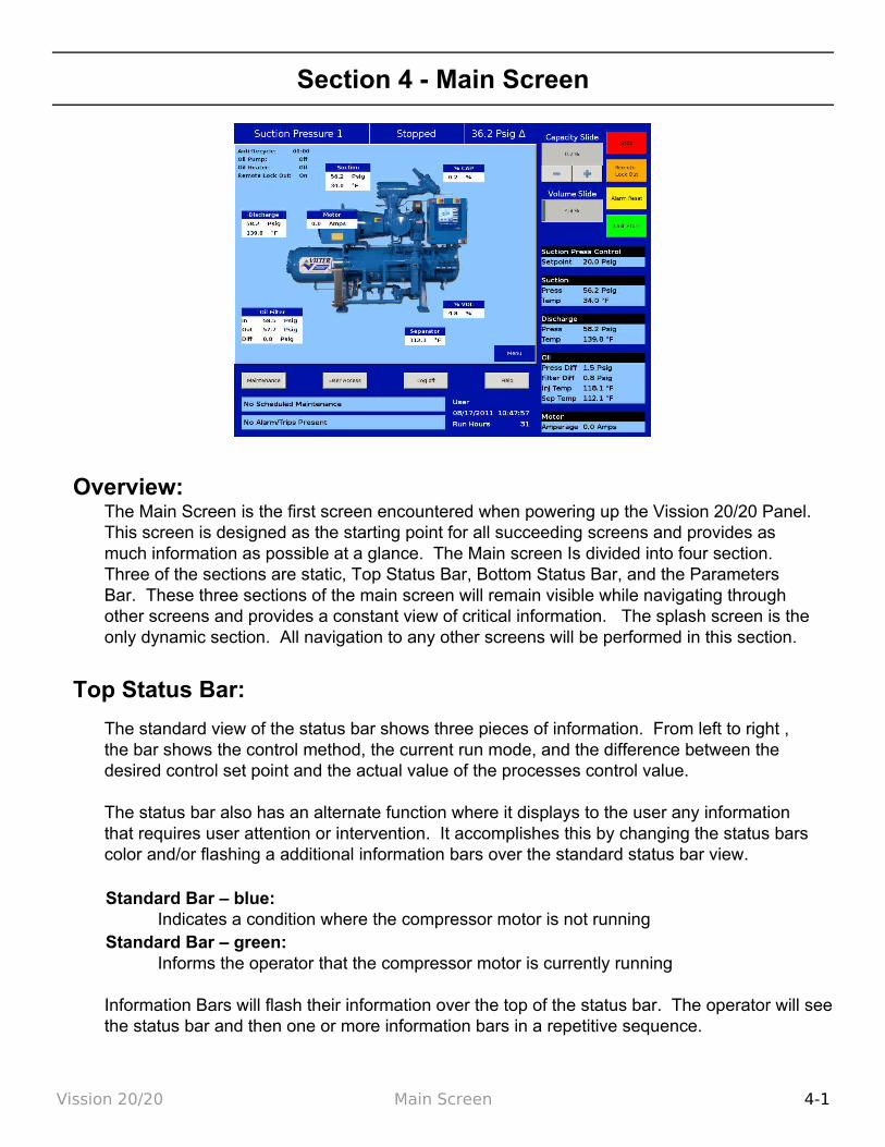
Overview:The Main Screen is the first screen encountered when powering up the Vission 20/20 Panel. This screen is designed as the starting point for all succeeding screens and provides as much information as possible at a glance. The Main screen Is divided into four section. Three of the sections are static, Top Status Bar, Bottom Status Bar, and the Parameters Bar. These three sections of the main screen will remain visible while navigating through other screens and provides a constant view of critical information. The splash screen is the only dynamic section. All navigation to any other screens will be performed in this section.
Top Status Bar:
The standard view of the status bar shows three pieces of information. From left to right , the bar shows the control method, the current run mode, and the difference between the desired control set point and the actual value of the processes control value.
The status bar also has an alternate function where it displays to the user any information that requires user attention or intervention. It accomplishes this by changing the status bars color and/or flashing a additional information bars over the standard status bar view.
Standard Bar – blue: Indicates a condition where the compressor motor is not running
Standard Bar – green: Informs the operator that the compressor motor is currently running
Information Bars will flash their information over the top of the status bar. The operator will see the status bar and then one or more information bars in a repetitive sequence.
Vission 20/20 Main Screen 4-1
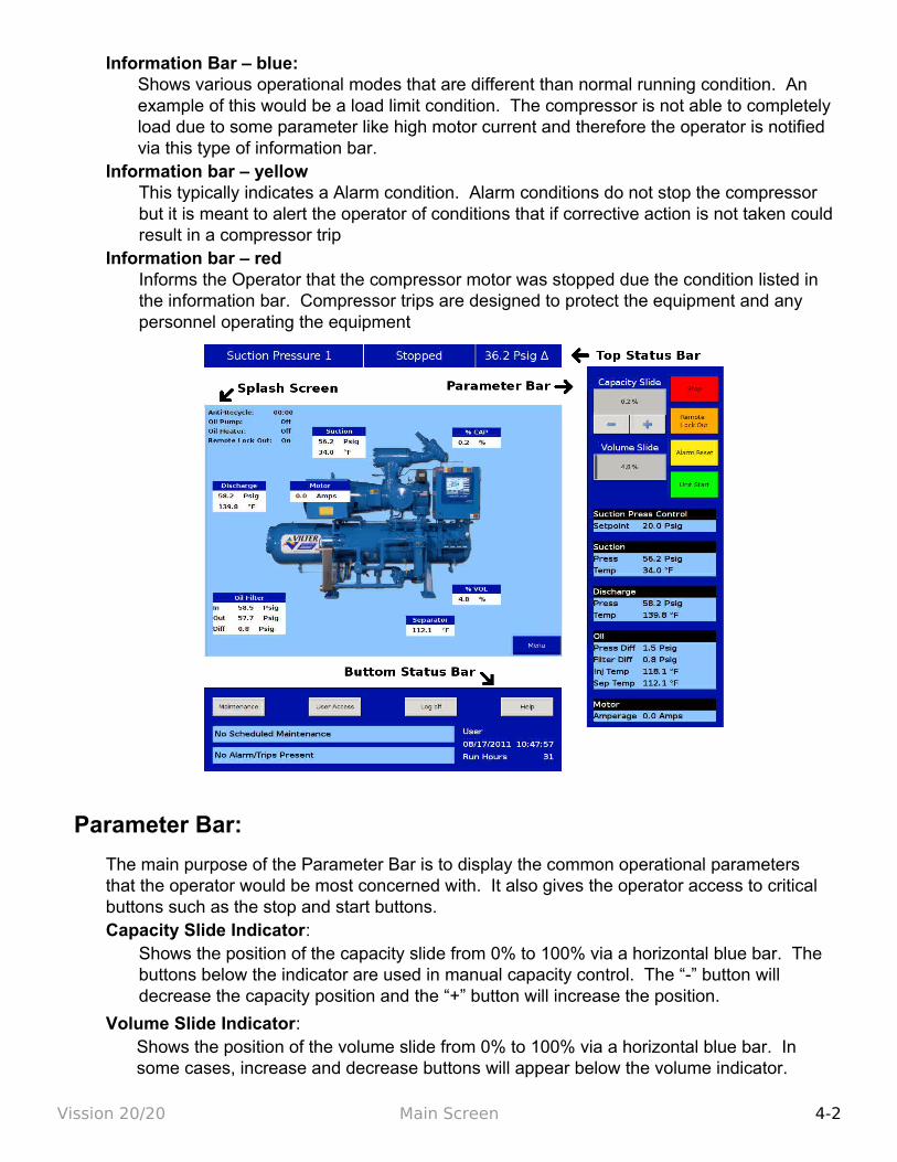
Information Bar – blue: Shows various operational modes that are different than normal running condition. An example of this would be a load limit condition. The compressor is not able to completely load due to some parameter like high motor current and therefore the operator is notified via this type of information bar.
Information bar – yellowThis typically indicates a Alarm condition. Alarm conditions do not stop the compressor but it is meant to alert the operator of conditions that if corrective action is not taken could result in a compressor trip
Information bar – redInforms the Operator that the compressor motor was stopped due the condition listed in the information bar. Compressor trips are designed to protect the equipment and any personnel operating the equipment
Parameter Bar:
The main purpose of the Parameter Bar is to display the common operational parameters that the operator would be most concerned with. It also gives the operator access to critical buttons such as the stop and start buttons.Capacity Slide Indicator:
Shows the position of the capacity slide from 0% to 100% via a horizontal blue bar. The buttons below the indicator are used in manual capacity control. The “-” button will decrease the capacity position and the “+” button will increase the position.
Volume Slide Indicator: Shows the position of the volume slide from 0% to 100% via a horizontal blue bar. In some cases, increase and decrease buttons will appear below the volume indicator.
Vission 20/20 Main Screen 4-2
The buttons only appear if the operator who is logged on has sufficient privileges. If available, the buttons work to increase and decrease the volume slide position in the same manner as the capacity slide.
Stop Button: When pressed, stops the compressor in all cases
Remote Lock Out Button: When pressed, activates the remote lock out option. This is a safety feature that prevents any external devices from assuming control and starting the compressor. To release the remote lock out, the operator must press the unit start button and then the remote button when the start dialog box appears.
Alarm Reset Button: When pressed, clears any current alarms, trips or status messages that may be displayed on the information bar. Note that if the condition that created the alarm, trip or status message still exits, the message will reappear.
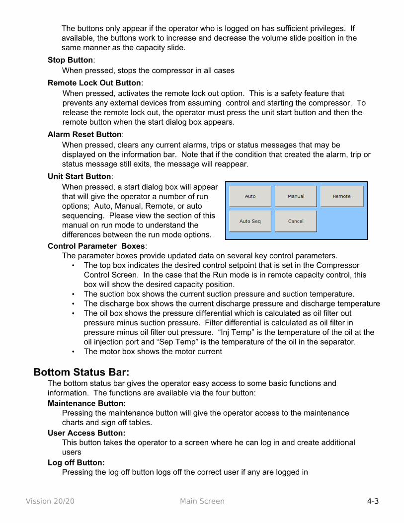
Unit Start Button: When pressed, a start dialog box will appear that will give the operator a number of run options; Auto, Manual, Remote, or auto sequencing. Please view the section of this manual on run mode to understand the differences between the run mode options.
Control Parameter Boxes:The parameter boxes provide updated data on several key control parameters.
• The top box indicates the desired control setpoint that is set in the Compressor Control Screen. In the case that the Run mode is in remote capacity control, this box will show the desired capacity position.
• The suction box shows the current suction pressure and suction temperature. • The discharge box shows the current discharge pressure and discharge temperature• The oil box shows the pressure differential which is calculated as oil filter out
pressure minus suction pressure. Filter differential is calculated as oil filter in pressure minus oil filter out pressure. “Inj Temp” is the temperature of the oil at the oil injection port and “Sep Temp” is the temperature of the oil in the separator.
• The motor box shows the motor current
Bottom Status Bar:The bottom status bar gives the operator easy access to some basic functions and information. The functions are available via the four button:Maintenance Button:
Pressing the maintenance button will give the operator access to the maintenance charts and sign off tables.
User Access Button:This button takes the operator to a screen where he can log in and create additional users
Log off Button:Pressing the log off button logs off the correct user if any are logged in
Vission 20/20 Main Screen 4-3
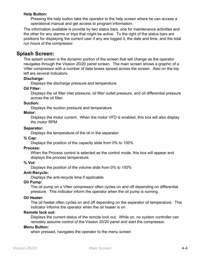
Help Button:Pressing the help button take the operator to the help screen where he can access a operational manual and get access to program information.
The information available is provide by two status bars, one for maintenance activities and the other for any alarms or trips that might be active. To the right of the status bars are positions for displaying the current user if any are logged it, the date and time, and the total run hours of the compressor.
Splash Screen:The splash screen is the dynamic portion of the screen that will change as the operator navigates through the Vission 20/20 panel screen. The main screen shows a graphic of a Vilter compressor with a number of data boxes spread across the screen. Also on the top left are several indicators.Discharge:
Displays the discharge pressure and temperature.Oil Filter:
Displays the oil filter inlet pressure, oil filter outlet pressure, and oil differential pressure across the oil filter.
Suction:Displays the suction pressure and temperature
Motor:Displays the motor current. When the motor VFD is enabled, this box will also display the motor RPM
Separator:Displays the temperature of the oil in the separator
% Cap:Displays the position of the capacity slide from 0% to 100%
Process:When the Process control is selected as the control mode, this box will appear and displays the process temperature.
% Vol:Displays the position of the volume slide from 0% to 100%
Anti-Recycle:Displays the anti-recycle time if applicable
Oil Pump:The oil pump on a Vilter compressor often cycles on and off depending on differential pressure. This indicator inform the operator when the oil pump is running.
Oil Heater:The oil heater often cycles on and off depending on the separator oil temperature. This indicator informs the operator when the oil heater is on
Remote lock out:Displays the current status of the remote lock out. While on, no system controller can remotely assume control of the Vission 20/20 panel and start the compressor.
Menu Button:when pressed, navigates the operator to the menu screen
Vission 20/20 Main Screen 4-4

Menu Screen
Overview:The menu screen is the launching point to every other section of the Vission 20/20 panel software. Every screen navigated to from this screen will return to the menu screen upon exiting.
Navigation Buttons:Compressor control:
Navigates to the compressor control screen where the operator can set the various compressor control parameters.
Alarms and trips:Navigates to the alarms and trips screen where the operator can set the various alarm and trip parameters.
Timers:Navigates to the timer screen where the operator can set the various time related parameters.
Compressor scheduling:Navigates to the compressor scheduling screen where the operator can set the scheduler to change the control method at settable dates and times.
Compressor sequencing:Navigates to the compressor sequencing screen where the operator can set-up compressor to sequence up to four other compressors. This is also sometimes known as lead-lag control.
Condenser control:Navigates to the condenser control screen where the operator can set up local condenser control parameter.
Vilter VFD:
Vission 20/20 Menu Screen 5-1
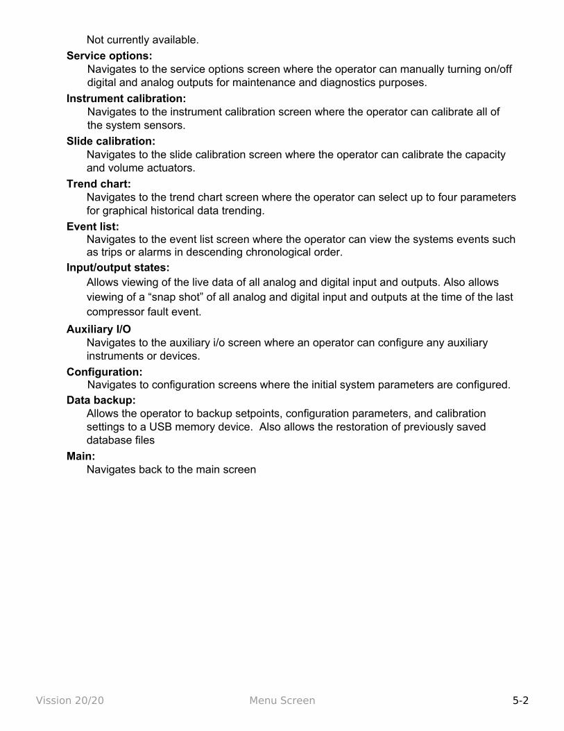
Not currently available.
Service options:Navigates to the service options screen where the operator can manually turning on/off digital and analog outputs for maintenance and diagnostics purposes.
Instrument calibration:Navigates to the instrument calibration screen where the operator can calibrate all of the system sensors.
Slide calibration:Navigates to the slide calibration screen where the operator can calibrate the capacity and volume actuators.
Trend chart:Navigates to the trend chart screen where the operator can select up to four parameters for graphical historical data trending.
Event list:Navigates to the event list screen where the operator can view the systems events such as trips or alarms in descending chronological order.
Input/output states:Allows viewing of the live data of all analog and digital input and outputs. Also allows viewing of a “snap shot” of all analog and digital input and outputs at the time of the last compressor fault event.
Auxiliary I/ONavigates to the auxiliary i/o screen where an operator can configure any auxiliary instruments or devices.
Configuration:Navigates to configuration screens where the initial system parameters are configured.
Data backup:Allows the operator to backup setpoints, configuration parameters, and calibration settings to a USB memory device. Also allows the restoration of previously saved database files
Main:Navigates back to the main screen
Vission 20/20 Menu Screen 5-2
Section 6 – Compressor Control
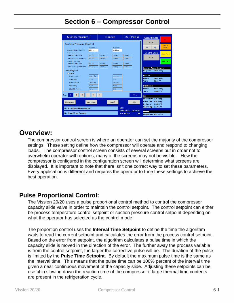
Overview:The compressor control screen is where an operator can set the majority of the compressor settings. These setting define how the compressor will operate and respond to changing loads. The compressor control screen consists of several screens but in order not to overwhelm operator with options, many of the screens may not be visible. How the compressor is configured in the configuration screen will determine what screens are displayed. It is important to note that there isn't one correct way to set these parameters. Every application is different and requires the operator to tune these settings to achieve the best operation.
Pulse Proportional Control:The Vission 20/20 uses a pulse proportional control method to control the compressor capacity slide valve in order to maintain the control setpoint. The control setpoint can either be process temperature control setpoint or suction pressure control setpoint depending on what the operator has selected as the control mode.
The proportion control uses the Interval Time Setpoint to define the time the algorithm waits to read the current setpoint and calculates the error from the process control setpoint. Based on the error from setpoint, the algorithm calculates a pulse time in which the capacity slide is moved in the direction of the error. The further away the process variable is from the control setpoint, the larger the corrective pulse will be. The duration of the pulse is limited by the Pulse Time Setpoint. By default the maximum pulse time is the same as the interval time. This means that the pulse time can be 100% percent of the interval time given a near continuous movement of the capacity slide. Adjusting these setpoints can be useful in slowing down the reaction time of the compressor if large thermal time contents are present in the refrigeration cycle.
Vission 20/20 Compressor Control 6-1
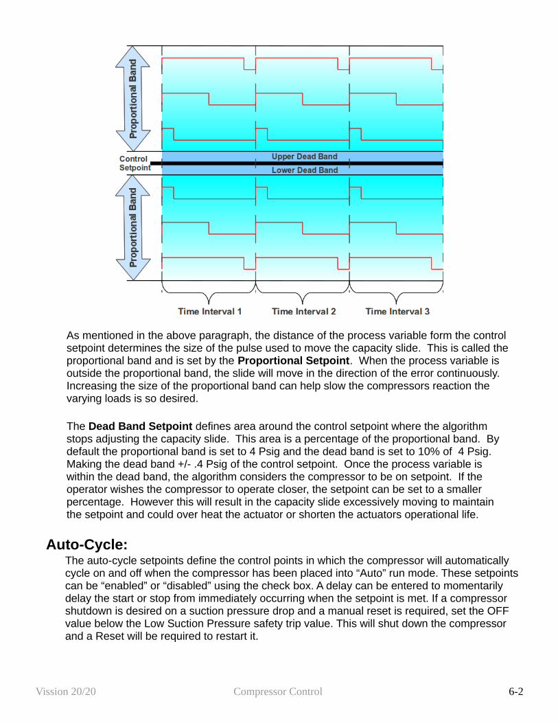
As mentioned in the above paragraph, the distance of the process variable form the control setpoint determines the size of the pulse used to move the capacity slide. This is called the proportional band and is set by the Proportional Setpoint. When the process variable is outside the proportional band, the slide will move in the direction of the error continuously. Increasing the size of the proportional band can help slow the compressors reaction the varying loads is so desired.
The Dead Band Setpoint defines area around the control setpoint where the algorithm stops adjusting the capacity slide. This area is a percentage of the proportional band. By default the proportional band is set to 4 Psig and the dead band is set to 10% of 4 Psig. Making the dead band +/- .4 Psig of the control setpoint. Once the process variable is within the dead band, the algorithm considers the compressor to be on setpoint. If the operator wishes the compressor to operate closer, the setpoint can be set to a smaller percentage. However this will result in the capacity slide excessively moving to maintain the setpoint and could over heat the actuator or shorten the actuators operational life.
Auto-Cycle:The auto-cycle setpoints define the control points in which the compressor will automatically cycle on and off when the compressor has been placed into “Auto” run mode. These setpoints can be “enabled” or “disabled” using the check box. A delay can be entered to momentarily delay the start or stop from immediately occurring when the setpoint is met. If a compressor shutdown is desired on a suction pressure drop and a manual reset is required, set the OFF value below the Low Suction Pressure safety trip value. This will shut down the compressor and a Reset will be required to restart it.
Vission 20/20 Compressor Control 6-2
The auto-cycle function will operate only in local “Auto” mode and Direct I/O “Remote Auto” mode. If the auto-cycle feature is enabled while running in any other remote mode, the function will simply be ignored. However, the Minimum slide position will continue to be respected in Remote “Auto” mode. If the compressor changes from a remote mode back to Local “Auto” mode, the auto-cycle feature will operate normally. Enable:
Enables the Auto-cycle control. Uncheck the box to disable the Auto-cycle set-points. Start Pressure:
When the suction pressure meets or exceeds this set-point, the compressor will start. Start Delay:
delays the compressor from starting when the suction pressure meets or exceeds this setpoint.
Stop Pressure:When the suction pressure meets or falls below this setpoint, the compressor will stop.
Stop Delay:delays the compressor from stopping when the suction pressure meets or exceeds this setpoint.
Minimum Slide Position:The minimum capacity slide position that the compressor is allowed to run at.
NOTE: When the Pump-down Feature is enabled, the Auto-cycle setpoints are automatically disabled. Pump-down mode will cause the compressor to cycle off via the Pump-down Stop Pressure setpoint, and will not allow the compressor to start again.
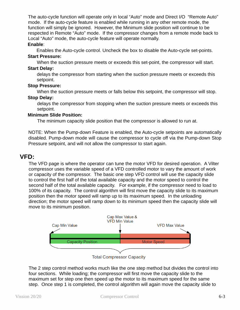
VFD:The VFD page is where the operator can tune the motor VFD for desired operation. A Vilter compressor uses the variable speed of a VFD controlled motor to vary the amount of work or capacity of the compressor. The basic one step VFD control will use the capacity slide to control the first half of the total available capacity and the motor speed to control the second half of the total available capacity. For example, if the compressor need to load to 100% of its capacity. The control algorithm will first move the capacity slide to its maximum position then the motor speed will ramp up to its maximum speed. In the unloading direction; the motor speed will ramp down to its minimum speed then the capacity slide will move to its minimum position.
The 2 step control method works much like the one step method but divides the control into four sections. While loading; the compressor will first move the capacity slide to the maximum set for step one then speed up the motor to its maximum speed for the same step. Once step 1 is completed, the control algorithm will again move the capacity slide to
Vission 20/20 Compressor Control 6-3
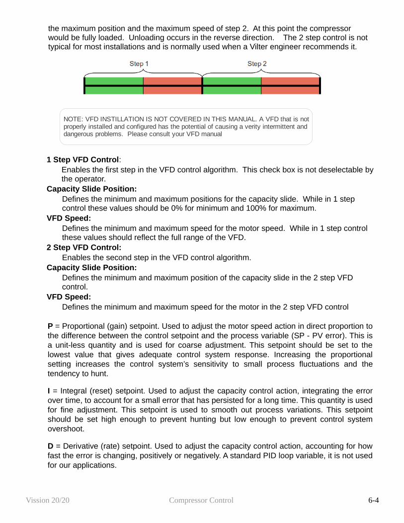
the maximum position and the maximum speed of step 2. At this point the compressor would be fully loaded. Unloading occurs in the reverse direction. The 2 step control is not typical for most installations and is normally used when a Vilter engineer recommends it.
1 Step VFD Control:Enables the first step in the VFD control algorithm. This check box is not deselectable by the operator.
Capacity Slide Position:Defines the minimum and maximum positions for the capacity slide. While in 1 step control these values should be 0% for minimum and 100% for maximum.
VFD Speed:Defines the minimum and maximum speed for the motor speed. While in 1 step control these values should reflect the full range of the VFD.
2 Step VFD Control:Enables the second step in the VFD control algorithm.
Capacity Slide Position:Defines the minimum and maximum position of the capacity slide in the 2 step VFD control.
VFD Speed:Defines the minimum and maximum speed for the motor in the 2 step VFD control
P = Proportional (gain) setpoint. Used to adjust the motor speed action in direct proportion to the difference between the control setpoint and the process variable (SP - PV error). This is a unit-less quantity and is used for coarse adjustment. This setpoint should be set to the lowest value that gives adequate control system response. Increasing the proportional setting increases the control system’s sensitivity to small process fluctuations and the tendency to hunt.
I = Integral (reset) setpoint. Used to adjust the capacity control action, integrating the error over time, to account for a small error that has persisted for a long time. This quantity is used for fine adjustment. This setpoint is used to smooth out process variations. This setpoint should be set high enough to prevent hunting but low enough to prevent control system overshoot.
D = Derivative (rate) setpoint. Used to adjust the capacity control action, accounting for how fast the error is changing, positively or negatively. A standard PID loop variable, it is not used for our applications.
Vission 20/20 Compressor Control 6-4
NOTE: VFD INSTILLATION IS NOT COVERED IN THIS MANUAL. A VFD that is not properly installed and configured has the potential of causing a verity intermittent and dangerous problems. Please consult your VFD manual
Pumpdown Control:The Pumpdown Control defines a method of "pumping" down a chiller, which is to draw off refrigerant from the chiller. This feature can be enabled or disabled from this menu which is the part of Compressor Control Screen. If Pumpdown is enabled, this feature will only function when the compressor is running in local Auto mode & Control Mode configured is Suction Pressure.
If Pumpdown Feature is enabled, then;• The Auto-cycle functionality is ignored. Pumpdown mode will cause the compressor to
cycle off via the Pumpdown Stop Pressure setpoint. Normally, the Pumpdown Stop pressure setpoint will be set lower than the Auto-cycle Stop setpoint. Therefore, as the suction pressure is pulled down, the compressor is prevented from shutting down prematurely via the Auto-cycle Stop setpoint by automatically ignoring the Auto-cycle feature.
• The compressor will be placed into "Stop" mode after the suction pressure is equal to, or goes below the Pumpdown Stop pressure.
Pumpdown: This checkbox enables the Pumpdown feature. If this box is unchecked, Pumpdown setpoints are ignored & user is not allowed to edit Pumpdown setpoints.
Stop Pressure: This setpoint defines the suction pressure value at which the compressor will cycle off. Normally, this setpoint is set below the Suction Pressure Auto-cycle Stop Pressure setpoint.
Stop Delay: This setpoint delays the compressor from stopping when the suction pressure is equal to or less than the stop pressure.
Min Slide Position: The minimum capacity slide is the setpoint that the compressor is allowed to run at. By forcing the compressor capacity to operate at a value above minimum, we insure that the suction pressure will be pulled down to the Stop pressure setpoint value.
Pumpdown Operation (Run/Stop): This button starts/stops the Pumpdown operation. This button is active only when compressor is in local Auto mode and Control Mode configured is Suction Pressure. This button will display “Run” when Pumpdown operation has not started or stopped, while button will display “Stop” when Pumpdown operation is running.
When Pumpdown feature is enabled, Pulldown checkbox is automatically grayed out. Similarly when Pulldown feature is enabled, Pumpdown checkbox is automatically grayed out and hence user will not be able to operate Pumpdown feature. This is done to keep Pumpdown & Pulldown features mutually exclusive.
Pulldown ControlThe Pulldown Control defines a method of slowly pulling the suction pressure down from a high value. This is sometimes required on systems that have liquid recirculation systems or on new building to prevent structural damage by limiting the rate at which to build is cooled.
Vission 20/20 Compressor Control 6-5
This feature can be enabled or disabled from this menu which is the part of Compressor Control Screen. If Pulldown is enabled, this feature will only function when the compressor is running in local Auto, Auto Sequencing mode and the control mode is Suction Pressure 1.
The Pulldown feature provides a method to slowly pull the suction pressure down to operating conditions. The pull-down method used is to step the suction pressure down over a defined time interval.
Example:Assume the suction pressure is at 85 psig and the set-point we want to get to is 20 psig. The operator wants to allow 48 hours of pull-down time. Pick a reasonable step pressure of 5 psig for every step. This defines a change of (80 – 20 = 60) psig.
• Note: First step is applied immediately. So first step starts at (85 – 5 = 80) psig• Number of steps = delta 60 psig change * 1 step/5 psig = 12 steps.• Delay per Step = 48 hours / 12 steps = 4 hours/step.• So for the first 4 hours, the compressor runs at 80 psig.• Next 4 hours @ 75 psig• Next 4 hours @ 70 psig• And so forth.
After the 12th step (running at 25 psig), 48 hours will have elapsed, and the new set-point becomes 20 psig, achieving the 20 psig set-point after 48 hours. After the pull-down set-point is equal to or is less than the control set-point, the pull-down feature will disable itself.
Pulldown: This checkbox enables the Pulldown feature. If this box is unchecked, Pulldown setpoints are ignored and the operator is not allowed to edit Pulldown setpoints.
Initiate Pulldown at Next Start: This checkbox when enabled, turns on the Pulldown process at the next start cycle. Pulldown operation will work in following manners when compressor is started next time.• Pulldown only works when control mode is suction pressure 1.• If not started in suction pressure 1 then Pulldown process will not run until stopped and
restarted in suction pressure 1.• If started in suction pressure 1 and changed after start, then Pulldown process will be
suspended and restart once control mode is changed back to suction pressure 1.Step Pressure:
This setpoint defines the step decrements at which the suction pressure value will be controlled at.
Delay Per Step: This setpoint defines the time increment at which the compressor will be controlled at each step.
Stop Pressure: This setpoint defines the suction pressure value at which Pulldown operation will get completed. When suction pressure value is equal to or goes below this setpoint, Pulldown
Vission 20/20 Compressor Control 6-6
feature disables itself. Also “Pulldown” & “Initiate Pulldown at Next Start” checkboxes will be automatically deselected as normally this is one time use feature.
Auto Cycle Differential: This setpoint defines the offset pressure values for Auto Cycle Start Pressure & Stop Pressure from Suction Pressure Setpoint value. Auto Cycle Start Pressure value will be Suction Pressure Setpoint value incremented by this setpoint pressure value, while Auto Cycle Stop Pressure value will be Suction Pressure Setpoint value decremented by this setpoint pressure value.
When Pulldown feature is enabled, Pumpdown checkbox is automatically grayed out. Similarly when Pumpdown feature is enabled, Pulldown checkbox is automatically grayed out and hence user will not be able to operate Pulldown feature. This is done to keep Pulldown & Pumpdown features mutually exclusive.
Control Mode:This drop down box gives the operator the ability to change the type of control mode such as suction pressure control or process temperature control. The operator can also switch from setpoint 1 and setpoint 2 for each control method. What is available in this dropdown box is dependent on the number and type of control selected in the configuration screen.
Stop load & Force unload:The stop load and force unload features primary purpose is to attempt to prevent the compressor from tripping off due to particular instrument reading. For example, if the suction pressure drops to low, the compressor will trip of for safety reason. However, the stop load & force unload algorithm recognizes a potential trip and either stops the compressor from loading up or even unloads the compressor to prevent the trip
Stop load:When this value is reached, the capacity slide will not advance in any condition.
Force Unload:When this value is reach, the capacity slide position will decrease until the variable reading is below this value.
High Motor Amps:Motor current values for stop load and force unload
High Discharge Pressure:Discharge pressure value for stop load and force unload
Low Suction Pressure:Suction pressure values for stop load and force unload
Capacity Slide Triggered Outputs:The Vission 20/20 offers two digital output that can be triggered at a specified capacity slide position. By default, the outputs are preselected for economizer and hot gas bypass. However, these preselected outputs are customizable by the operator.
Vission 20/20 Compressor Control 6-7
Slide Valve Setpoint:Operator editable labels for the each output.
Slide %:Indicates the capacity slide position where the digital output is triggered.
State Below Setpoint:Defines the state of the digital output when the slide position is below the “Slide %” setpoint. The operator can choice between “N.O.” or “N.C.”
Active:Check box to enable the digital output.
Volume Slide Position Offset:These setpoints offer the ability to alter the Volume position table to take advantage of potential energy savings. Since the volume position is a function of the capacity position, the offset to the volume is based on the position of the capacity slide. The volume offset can be applied to the entire capacity slide range or just a portion using the Capacity Range minimum and maximum setpoints.
Volume Slide Adjustment %:The value in percentage of the volume slide offset
Capacity Range:Defines the range that the volume position slide offset will be applied.
Soft Load:This setpoint is used to slow the loading of the compressor. In some refrigeration systems, a loading compressor can have dramatically effects on the system parameters. This setpoint allows an operator to reduce the continuous load pulse as defined in the proportional control section to a percent duty cycle.
Soft load %:Defines the duty cycle of the continuous load pulse. 100% mean the continuous pulse will truly be continuous. 50% would mean the continuous pulse would be reduced to half time on and half time off in the time interval defined in the proportional control section.
Load Anticipating:The purpose of the load anticipating algorithm is to reduce the amount of overshoot of the capacity slide position while the compressor attempts to meet the control setpoint. This advanced feature of the Vission 20/20 closely monitors the rate of change of the process variable and compares it to the control setpoint. If the process variable is changing in the direction of the control setpoint at the specified rate or greater, then the normal command to move the capacity slide is interrupted. The rate is calculated between time intervals set in the proportional control section of this screen.
Enable Load Anticipation Algorithm:Allows the operator to chose if the load anticipation algorithm runs
Rate Deadband:Defines the rate at which the capacity slide movement will be interrupted. This value is an
Vission 20/20 Compressor Control 6-8

absolute value of the process variable. For example, the default value is 0.25. If the control mode is suction pressure, then this value is .25 Psig or if process temperature is the control mode then the value would be .25 F.
Oil Control:These setpoints determine how the Vission 20/20 will manage the oil of the compressor
Oil Pump Press Restart Ratio:The on and off setpoints define when the oil pump will cycle on and off if the oil pump is selected to cycle from the configuration screen
Oil Separator Heater Temp:When the oil temperature falls below this set point the oil heater will turn on. Note, there is a 5 degree differential associated with this setpoint. So when set to 100 degrees, the heater will turn on at 95 degrees and off at 105 degrees.
Liquid Injection:The setpoints is this section are to control the behavior of the liquid refrigerant injected into the compressor for oil cooling purposes. The liquid injection solenoid control is based off of discharge temperature whether the compressor uses just an injection solenoid or a motorized valve in conjunction with the solenoid.
Liquid Injection Solenoid Control ONLYWhen using only the liquid injection solenoid, the solenoid is activated once the value of discharge temperature meets or exceeds the value of “Liquid inj. Setpoint 1” and the value of oil separator temperature meets or exceeds the value of “Oil Sep. Temp. Override”. The Injection solenoid will deactivate if either of setpoints are not met. This will prevent situations where the discharge temperature may rise quickly, but the oil temperature is still very cold. By preventing the liquid injection solenoid from turning on at this point, the oil separator will not be subjected to additional liquid refrigerant, that would cool the oil even further.
Liquid Injection Control using a 4-20ma motorized valve.When a motorized valve is used to control the amount of liquid being injected into the compressor the previously mentions setpoints have a slightly different function. The Oil Sep. Temp. Override is still used in controlling the injection solenoid, however the Liquid inj. Setpoint 1 is now used as the target temperature for the P.I.D. Algorithm that controls the position of the motorized valve. The algorithm compares the actual discharge temperature against the Liq Inj Sol Setpoint 1. The difference between these is the error. The PID algorithm tries to drive the error to "zero" by moving the positioning valve to allow more or less liquid refrigerant to be injected into the compressor.
P.I.D. Algorithm can be notoriously hard to tune. As a result the Vission 20/20 offers a couple of additional features to help control wild fluctuations in oil temperatures that could result in the compressor tripping off. The operator can choose to enable the minimum value position that automatically sets the liquid injection motorized value to the specified value when ever the discharge temp has fallen below the Liquid inj. Setpoint 1. This feature nearly eliminates the overshoot of the PID in the downward direction and reduces the chance of the compressor tripping off due to low oil temperature. The operator can also choose to use an average of the
Vission 20/20 Compressor Control 6-9
discharge temperature and the oil manifold temperature as the control variable. The discharge temperature can vary quite drastically forcing the PID algorithm to drastically adjust the motorized value. By averaging the more stable oil manifold temperature and discharge temperature, the control variable stabilizes and the PID is more easily tunned.
Please note that as stated above, PID algorithms can be difficult to tune and there is no one set of PID value that will work. The work required for a compressor to meet the requirement of its installation very greatly and therefore the amount of heat transfered to the oil varies just as greatly. We recommend the operator consults PID tuning guides available from many different source before attempting to tune this PID.
Liquid inj. Setpoint 1:Setpoint at which the liquid solenoid will activate if in solenoid control or the setting for the control variable for the PID in liquid motorized value control.
Liquid inj. Setpoint 2:Not yet available
Oil Sep. Temp. Override:Defines the temperature the oil must reach before the liquid injection solenoid is allowed to be activated
P = Proportional (Gain):Used to adjust the positioning valve in direct proportion to the difference between the control setpoint and the discharge temp (SetPt - DT = error). The proportional term is a unit-less quantity and is used for coarse adjustment. This setpoint should be set to the lowest value that gives adequate control system response. Increasing the proportional setting increases the control system's sensitivity to small discharge temperature fluctuations and the tendency to hunt.
I = Integral (reset):This parameter integrates the error over time, to account for a small error that has persisted for a long time. This quantity is used for fine adjustment. This setpoint is used to smooth out discharge temperature variations. This setpoint should be set high enough to prevent hunting but not too high or it will cause control system overshoot.
D = Derivative (rate):This parameter accounts for how fast the error is changing, positively or negatively.
Minimum Valve Open %:When enabled, this is the valve position used whenever the control variable drops below Liquid inj. Setpoint 1. Use only if the compressor is tripping off for low oil temperature due to large overshoots and all other tunning methods have failed.
Avg. with Oil Manifold Temperature:When enabled, averages the Oil manifold temperature and the discharge temperature. This creates a more stable control variable and should result in more stable control.
Vission 20/20 Compressor Control 6-10
Section 7 - Alarms and Trips
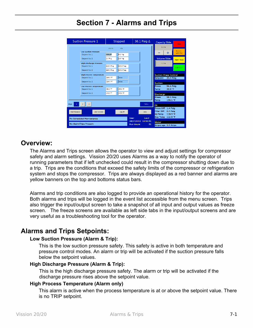
Overview:The Alarms and Trips screen allows the operator to view and adjust settings for compressor safety and alarm settings. Vission 20/20 uses Alarms as a way to notify the operator of running parameters that if left unchecked could result in the compressor shutting down due to a trip. Trips are the conditions that exceed the safety limits of the compressor or refrigeration system and stops the compressor. Trips are always displayed as a red banner and alarms are yellow banners on the top and bottoms status bars.
Alarms and trip conditions are also logged to provide an operational history for the operator. Both alarms and trips will be logged in the event list accessible from the menu screen. Trips also trigger the input/output screen to take a snapshot of all input and output values as freeze screen. The freeze screens are available as left side tabs in the input/output screens and are very useful as a troubleshooting tool for the operator.
Alarms and Trips Setpoints:Low Suction Pressure (Alarm & Trip):
This is the low suction pressure safety. This safety is active in both temperature and pressure control modes. An alarm or trip will be activated if the suction pressure falls below the setpoint values.
High Discharge Pressure (Alarm & Trip):This is the high discharge pressure safety. The alarm or trip will be activated if the discharge pressure rises above the setpoint value.
High Process Temperature (Alarm only)This alarm is active when the process temperature is at or above the setpoint value. There is no TRIP setpoint.
Vission 20/20 Alarms & Trips 7-1
Low Process Temperature (Alarm & Trip):This is the low control temperature safety. This safety is active when process temperature control has been selected in the Control Mode dropdown selection found in the Compressor Control screen. An alarm or trip will be activated on a drop in process temperature below the set-point value.
Low Suction Temperature (Alarm & Trip):This is the low suction temperature safety. The alarm or trip will be activated if the suction temperature drops below the setpoint value.
High Discharge Temperature (Alarm & Trip): This is the high discharge temperature safety. The alarm or trip will be activated if the discharge temperature rises above the setpoint value.
Low Oil Separator Start Temperature (Alarm & Trip):This is the starting low oil separator temperature safety. The compressor is prevented from starting or running if the oil in the separator is below the alarm value. After a time delay (setting of the Oil Separator Temperature Safety Changeover timer), this safety is deactivated and the Low Oil Separator Run Temperature alarm and safety setpoints become active.
Low Oil Separator Run Temperature (Alarm & Trip):This is the running low oil separator temperature safety. After a time delay, (setting of the Oil Separator Temperature Safety Changeover timer), the Low Oil Separator Start Temperature is bypassed and Low Oil Separator Run Temperature alarm and safety setpoints become active. The alarm or trip will be activated if the oil temperature in the separator drops below the set-point value.
Low Oil Injection Temperature (Alarm & Trip):This is the low oil injection safety. The alarm and trip set-points are bypassed at start for a time period (setting of the Oil Injection Temperature Safety Changeover timer). The alarm and trip will be activated after the time delay has expired.
High Oil Injection Temperature (Alarm & Trip):This is the high oil injection temperature safety. The alarm or trip will be activated if the oil injection temperature rises above the setpoint value.
Pre-lube Oil Pressure (Alarm & Trip):This is the pre-lube oil pump failure safety. If the pre-lube oil pressure does not rise above the alarm setting with in 60 seconds for a minimum time set at Minimum Comp. Pre-lube Time, then the start sequence will be aborted. The Minimum Comp. Pre-lube Time is set on the Timer screen. The pre-lube oil pressure is defined as manifold pressure minus discharge pressure. This safety insures adequate lubrication of the the compressor at startup.
Low (Run) Oil Pressure (Alarm & Trip):This is the running oil pressure safety. The normal alarm and trip setpoints of this safety are “messaged” as soon as the compressor starts. The “Pre lube Oil Pressure” Alarm and Trip setpoints are substituted into this safety setpoints for a time of the “Oil Pressure Bypass” timer (typically 60 seconds). After this timer expires, then the setpoints return back to the normal settings. The action of adjusting the setpoints for about a minute allows the (Run) Oil Pressure to build up to normal running pressures after the compressor starts. After the Oil Pressure Bypass Timer has expired, the Oil Pressure must be above the normal setpoints, or else an Alarm or Trip will occur. An alarm or trip will be active if the oil pressure drops below the normal setpoint values after the Oil Pressure Bypass timer has
Vission 20/20 Alarms & Trips 7-2
expired. This time limit is set on the Timer menu screen. Run oil pressure is defined as manifold pressure minus suction pressure.
High Filter Differential Pressure Start (Alarm & Trip):This safety allows a higher than normal filter differential pressure to exist during the first minute after a compressor starts. This allows time for cold oil that is present in the oil piping and filters to be passed and replaced with warmer oil. After a time delay (setting of the Filter Diff Pressure Safety Changeover timer), this safety is deactivated and the High Filter Differential Pressure-Run alarm and safety set-points become active. An alarm or trip will be active if the filter differential (= Filter Inlet Pressure minus Filter Outlet Pressure) exceeds the setpoint value.
High Filter Differential Pressure Run (Alarm & Trip):This safety setpoint is active when the compressor has started and the Filter Diff Pressure Safety Changeover timer has timed out. An alarm or trip will be active if the filter differential (= Filter Inlet Pressure minus Filter Outlet Pressure) exceeds by the setpoint value.
High Motor Amps:This safety set-point is active after the Volume Decrease At Start Timer expires (this timer is not settable by the operator). A trip will occur if the motor amperage exceeds the safety set-point value. For a motor with a 1.15 Service Factor, the trip set-point should be set at 125% of the motor full load amperage value. The alarm set-point should be set at 120% of the motor full load amperage value.
Compressor Inhibits:The Vission 20/20 uses several start inhibits to prevent the compressor from starting to protect the compressor and the refrigeration system. While starting the compressor, the inhibits are checked first before the oil pump is started or the motor is started. The failed starts due to an inhibit does not count toward any of the anti-recycle timers included hot starts. The Inhibits uses the alarm setpoint to trigger an aborted start and message. All inhibits will be logged in the event list.
Safety Failure MessagesLow Suction Pressure Trip - This message will appear when the suction pressure falls below
the safety setting of the Low Suction Pres-sure Trip Setpoint No.1 or No. 2.High Discharge Pressure Trip – This message will appear when the discharge pressure
exceeds the safety setting of the Hi Dsch Press Trip Setpoint No. 1 or No. 2.Low Suction Temp Trip – This message will appear when the suction temperature falls below
the safety setting of the Low Suction Temperature Trip setpoint.High Discharge Temp Trip – This message will appear when the discharge temperature rises
above the safety setting of the High Dis-charge Temperature Trip setpoint.Low Oil Separator Temp Trip – This message will appear when the Oil Separator Temp is
below the Low Oil Separator Start Temp Trip setpoint. In addition this message will appear after the Oil Separator Temp Safety Changeover timer times out and the Oil Separator temperature fails to rise above the Low Oil Separator Start Temp Reset after the compressor is started.
Low Oil Separator Temp Trip – This message will appear when the Oil Separator Temp is below the Low Oil Separator Run Temp Reset setpoint after the Oil Separator Temp Safety
Vission 20/20 Alarms & Trips 7-3

Changeover timer times out.Low Process Temp Trip – This message will appear when the Process Control Temperature
falls below the safety setting of the Lo Control Temperature Trip Setpoint.Prelube Oil Pump Inhibit – This message will appear when the Prelube Oil Pressure
(Manifold minus Discharge) has remained below the Prelub Oil Pressure Reset setpoint. The oil pump will try to generate “prelube pressure” for the time period of the Low Oil Pressure Safety Bypass timer setting.
Low Oil Pressure Trip – This message will appear when the Running Oil Pressure (Manifold minus Suction) has remained below the low Oil Pressure Reset setpoint when the Oil Pressure Bypass Start timer times out. This message will also appear when the Runnning Oil Pressure falls below the Low Oil Pressure trip setpoint after the Low Oil Pressure Safety Bypass timer times out.
Low Oil Injection Temp Trip – This message will appear when the Oil Injection temperature falls below the Low Oil Injection Temperature trip setpoint. This message will also appear when the Oil Injection temperature fails to rise above the Low Oil Injection Temperature reset setpoint after the Low Oil Injection Temp Bypass timer times out.
High Oil Injection Temp Trip – This message will appear when the Oil Injection temperature rises above the High Oil Injection Temperature trip setpoint.
High Filter Differential Trip – This message will appear if the Filter Differential Pressure rises above the High Fltr Diff Press – Start setpoint before the Filter Differential Pressure Safety Changeover timer times out.
High Filter Differential Trip – This message will appear if the Filter Differential pressure rises above the High Fltr Diff Press Run setpoint after the Filter Differential Pressure Safety Changeover timer times out.
High Motor Current Trip – This message will appear if the motor amperage rises above the Hi Motor Amps trip setpoint.
Compressor Interlock Trip – This message will appear if the Motor Auxiliary contact fails to close before the Compressor Starter Auxiliary Contact Bypass timer times out. Refer to wiring diagram.
High Level Shutdown Trip – This message will appear when power is removed from the input module that is designated as “Auxiliary #1 Safety” (please refer to your wiring diagram).
False Start – This message appears when the compressor stops and the motor auxiliary contact fails to open. The mes-sage will also appear if the compressor shuts down and the amperage is 20% of the maximum amp setting, indicating that the starter is still energized.
Low Oil Level Trip – This message appears when power is removed from the input module that is designated as (please refer to your wiring diagram). This safety will activate only after the oil level has been low for the time period defined by the “Low Oil Separator Safety Trip Delay” timer.
Vission 20/20 Alarms & Trips 7-4
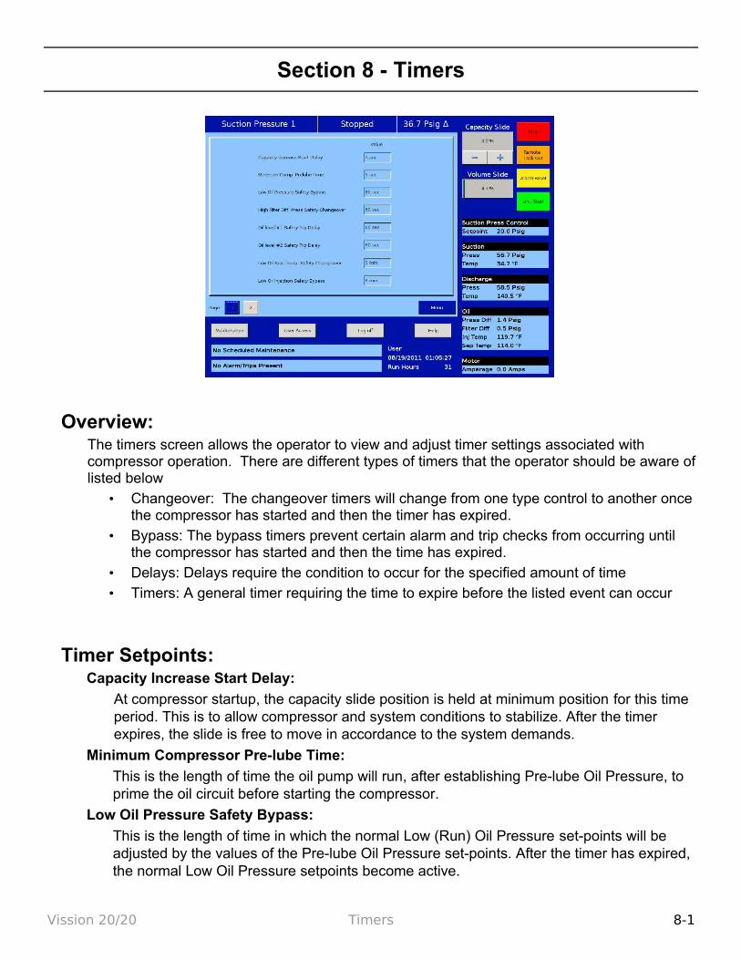
Section 8 - Timers
Overview:The timers screen allows the operator to view and adjust timer settings associated with compressor operation. There are different types of timers that the operator should be aware of listed below
• Changeover: The changeover timers will change from one type control to another once the compressor has started and then the timer has expired.
• Bypass: The bypass timers prevent certain alarm and trip checks from occurring until the compressor has started and then the time has expired.
• Delays: Delays require the condition to occur for the specified amount of time
• Timers: A general timer requiring the time to expire before the listed event can occur
Timer Setpoints:Capacity Increase Start Delay:
At compressor startup, the capacity slide position is held at minimum position for this time period. This is to allow compressor and system conditions to stabilize. After the timer expires, the slide is free to move in accordance to the system demands.
Minimum Compressor Pre-lube Time:
This is the length of time the oil pump will run, after establishing Pre-lube Oil Pressure, to prime the oil circuit before starting the compressor.
Low Oil Pressure Safety Bypass:
This is the length of time in which the normal Low (Run) Oil Pressure set-points will be adjusted by the values of the Pre-lube Oil Pressure set-points. After the timer has expired, the normal Low Oil Pressure setpoints become active.
Vission 20/20 Timers 8-1

High Filter Differential Pressure Safety Changeover:
This timer bypasses the High Filter Differential Run Pressure safety settings when the compressor starts. It defines how long the High Filter Differential Start Pressure set-points will be active after the compressor starts. After the timer has expired, then the High Filter Differential Run Pressure safety setpoints will be active.
Oil Separator Level #1 Safety Trip Delay:
This timer bypasses the low oil level switch for momentary drops in the oil level. This timer activates when the low oil level switch opens, and deactivates when the switch closes. If the switch is still open after the timer has timed out, the compressor will be shut down and a trip message will be displayed. This timer is available if the unit is equipped with a low oil separator float switch (the oil level switch is standard on all liquid injection units and optional on all others).
Oil Separator Level #2 Safety Trip Delay:
This timer bypasses the low oil level switch for momentary drops in the oil level. This timer activates when the low oil level switch opens, and deactivates when the switch closes. If the switch is still open after the timer has timed out, the compressor will be shut down and a trip message will be displayed. This timer is available if the unit is equipped with a low oil separator float switch (the oil level switch is standard on all liquid injection units and optional on all others).
Low Oil Separator Temperature Safety Changeover:
This timer allows Low Oil Separator Start Temperature safety set-point to protect the compressor against cold oil during starting. After the timer has expired, the Low Oil Separator Run Temperature is then active.
Low Oil Injection Safety Bypass:
This timer bypasses the Low Oil Injection Temperature Safety set-point during start-up, to allow any cold oil in the oil lines and filter to pass. After the timer expires, the Low Oil Injection Temperature safety is active.
Max Restart After Power Failure:
This timer forces the compressor to wait for the set time period after a power failure and the panels restarts before it can be started automatically. By staggering the time settings of this timer between other compressor panels, the compressors can be allowed to start automatically, one at a time, after a power failure. This will prevent excessive load demand on the power system that could occur if all of the compressor equipment were to start at the same time. The Power-up Auto Re-Start [x]Enable option must be selected on the Configuration screen for this option to be active.
Hot Starts per Hour:
This counter counts compressor starts. After every start, a one-hour timer is reset and starts timing. If the timer times out, the hot starts counter is reset. When the counter reaches its preset value, it will not allow another compressor start until the one-hour timer times out and resets the counter. The hot starts counter, therefore, will be reset when the time between compressor starts total one hour. This counter allows repetitive compressor starts, but once the counter has reached its set point, it requires a one-hour window between compressor starts in order for the counter to be reset.
True Anti-Recycle Timer:
Vission 20/20 Timers 8-2
Once the compressor turns off, this timer will keep the compressor off for the setting of the True Anti-Recycle Timer. This timer is used to prevent short cycling of the compressor.
Accumulative Anti-Recycle Timer:
This timer forces a specified time between compressor starts. When the compressor starts, the timer resets and starts timing and accumulates running time. Once the compressor shuts down, it will not be allowed to restart for the remainder of time left on the Accumulative Anti-Recycle Timer. Unlike the True Anti-Recycle Timer, if the compressor has run for a time period that exceeds the set-point of the Accumulative Anti-Recycle Timer, then when the compressor shuts down, it will be allowed to restart immediately.
Compressor Interlock Bypass:
Once the Vission 20/20 has sent a command to the compressor starter to start, a return signal is expected. This timer defines how much time to wait for that signal before setting a trip condition.
High Motor Amps Safety Bypass:
Starting motors can typically pull much more than its rates full load amps for a short time. This timer ignores that sudden inrush of current for the specified time.
Emergency Stop Timer:
Defines the amount of time the compressor is in a False start condition before activating the Emergency stop. The emergency stop output can be connected to a shunt-trip in the case of a run away compressor to remove all power to the system.
Low Suction Pressure Safety Bypass:
Sets the time that the compressor is allowed to run at lower suction pressure then would usually be allow at start up.
High Superheat Temp Safety Changeover:
This timer activates at shutdown and changes the restart parameters if the time has not been met.
Vission 20/20 Timers 8-3

Section 9 - Compressor Scheduling
Overview:This menu allows the operator to schedule control setpoint switching during the day and week. This feature can be enabled and disabled from the Compressor Schedule screen. Up to 4 setpoint "switch" events can be scheduled per day.
Scheduling Setpoint:Schedule:
The options for selection are “Enable” & “Disable”. Operator is allowed to configure/edit setpoints related to schedule events only when schedule is disabled.
Operator can Enable Compressor Scheduling Feature, only if Time Intervals are in order of Event 1 < Event 2 < Event 3 < Event 4 for all days. If events are not in order, invalid events are marked with caution symbol to indicate the operator to correct events and then enable feature.
Control Mode:These Dropdown boxes allow selection of operating modes which gets switched once schedule event time is achieved.
The list of allowable modes depends on the No. of controllers selected in configuration screen. Let’s say if No. of Suction Pressure Control Setpoints selected is “2” and No. of Process Temperature Control Setpoints selected is “1”, then Control Mode dropdown box will have “Unscheduled”, “Suction Pressure SP1”, “Suction Pressure SP2” and “Process Temperature SP1” as options for selection.
Vission 20/20 Compressor Scheduling 9-1
If Control Mode is selected as "Unscheduled" and Time set in an event is achieved, then control mode will not get switched. Hence Control Mode can be set as "Unscheduled" if operator does not want to use all 4 events per day.
Time:This setpoint allows selection of Hours, Minutes and AM/PM values for an event. When time set for an event is achieved, control mode will get changed as selected for that event.
The range of values allowed to set for Hours setpoint is 0 – 12 for 12 hour format and 0 – 23 for 24 hour format. The range of values allowed to set for Minutes setpoint is 0 – 59. AM/PM selection is active for selection only when Time Format selected in configu-ration screen is 12 hour.
When scheduling feature is enabled and No. of controllers for Suction Pressure Control & Process Temperature Control are changed in configuration screen which makes control modes selected in compressor scheduling screen as invalid, then feature will get disabled automatically and indication will be sent to operator to correct the setting.
Vission 20/20 Compressor Scheduling 9-2
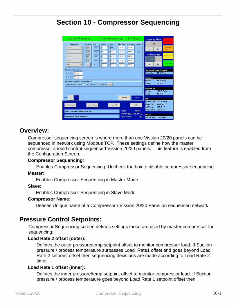
Section 10 - Compressor Sequencing
Overview:Compressor sequencing screen is where more than one Vission 20/20 panels can be sequenced in network using Modbus TCP. These settings define how the master compressor should control sequenced Vission 20/20 panels. This feature is enabled from the Configuration Screen.Compressor Sequencing:
Enables Compressor Sequencing. Uncheck the box to disable compressor sequencing. Master:
Enables Compressor Sequencing in Master Mode.Slave:
Enables Compressor Sequencing in Slave Mode.Compressor Name:
Defines Unique name of a Compressor / Vission 20/20 Panel on sequenced network.
Pressure Control Setpoints:Compressor Sequencing screen defines settings those are used by master compressor for sequencing. Load Rate 2 offset (outer):
Defines the outer pressure/temp setpoint offset to monitor compressor load. If Suction pressure / process temperature surpasses Load Rate1 offset and goes beyond Load Rate 2 setpoint offset then sequencing decisions are made according to Load Rate 2 timer.
Load Rate 1 offset (inner):Defines the inner pressure/temp setpoint offset to monitor compressor load. If Suction pressure / process temperature goes beyond Load Rate 1 setpoint offset then
Vission 20/20 Compressor Sequencing 10-1
sequencing decisions are made according to Load Rate 1 timer. Suction Pressure / Process Temperature Control Setpoint:
The target setpoints are read only values here. These setpoints can be changed by logging on to “Compressor Control” Screen.
Unload Rate 1 offset (inner):Defines the inner pressure/temp setpoint to monitor compressor load. If Suction pressure / process temperature drops below Unload Rate 1 setpoint offset then sequencing decisions are made according to Unload Rate 1 timer.
Unload Rate 2 offset (outer):Defines the outer pressure/temp setpoint offset to monitor compressor load. If Suction pressure / process temperature drops below Unload Rate1 offset and goes below Unload Rate 2 setpoint offset then sequencing decisions are made according to Unload Rate 2 timer.
Capacity Load / Unload Timers:One of the following Capacity Load / Unload rate timers are used to make sequencing decisions periodicaly. Suction Pressure/ process temperature Setpoints are monitored to identify which one of the following timers to be used.Load Rate 1 (inner):
If Suction pressure / process temperature goes beyond Load Rate 1 setpoint offset then Load Rate 1 timer is used to make periodic sequencing decisions.
Load Rate 2 (outer):If Suction pressure / process temperature surpasses Load Rate1 offset and goes beyond Load Rate 2 setpoint offset then Load Rate 2 timer is used to make periodic sequencing decisions.
Unload Rate 1 (inner):If Suction pressure / process temperature goes below Unload Rate 1 setpoint offset then Unload Rate 1 timer is used to make periodic sequencing decisions.
Unload Rate 2 (outer):If Suction pressure / process temperature surpasses Unload Rate1 offset and goes below Unload Rate 2 setpoint offset then Unload Rate 2 timer is used to make periodic sequencing decisions.
Compressor Sequencing Table:Compressor sequencing table menu allows operator to view and adjust settings those are used for compressor sequencing. Equipment:
Options of this combo box are updated automatically. This contains names of all the compressors in the network communicating with Master compressor. Equipment name can be selected from drop down list. Same Equipment name should not be configured more than once in Sequencing table.
Control:Inclusion/exclusion of compressor partaking in the sequencing can be decided on basis of this toggle button. Compressors can be included / excluded by toggling ON /OFF.
Vission 20/20 Compressor Sequencing 10-2

NOTE: Switching a compressor control to OFF when running in auto seq mode puts repective slave compressor into local auto mode. This feature is used to add / remove slave compressors to sequence table when running in auto sequence mode.
CFM:CFM column is read only. These values are updated automatically when Equipment combo box is changed. This indicates Slave compressor capacity in CFM.
Priority:This defines priorities of compressors on the network. This priority will decide the sequence in which compressors will be turned on and off during sequence cycle. Lower the priority number greater the priority of the compressor.
Step:This parameter would decide stepwise increment / decrement value in percentage of the compressor capacity. In the case when last step makes total capacity greater than maximum capacity, total capacity will get reduced to maximum capacity. Same is applicable when last step makes total capacity lower than minimum capacity takes priority.
Min Cap:Defines the lowest capacity in percentage with which a compressor is allowed to run. Minimum capacity value takes preference on first step value.
Max Cap:Defines the highest capacity in percentage with which a compressor is allowed to run. Maximum capacity value takes preference over last step value.
Machine Start Time:Machine start timer shows the time in seconds that the Master Compressor will hold before starting slave compressor once (Start) decision is taken.
Status Symbols:Status symbols shows status of Slave compressors on the sequencing table. Please see application Note for more details.
Slave Compressor is detected but is not configured in the sequencing table.
Default, If slave Compressor is not present.
Slave Compressor is configured in sequencing table but is not configured in “Remote” mode.
Slave Compressor configured in sequencing table and is in ready to run state.
Slave Compressor is running with Alarm condition.
Slave Compressor stopped due to Error Condition.
Slave Compressor running at maximum capacity without any error.
Slave Compressor under active control of Master Compressor
Slave Compressor running into its stop timer, will be stopped.
Vission 20/20 Compressor Sequencing 10-3
Machine Stop Time:Machine Stop timer shows the time in sec that the Master Compressor will hold before stoping slave compressor once (Stop ) decision is taken.
Refresh:Compressor Sequencing table is automatcally refreshed every 1 minute. Pressing “Refresh” button refreshes the status of the Compressor Sequencing table on Master Compressor.
NOTE: Before Configuring Sequencing table on Master Compressor, log on to slave compressors one by one and enable sequencing in slave mode, put slave in remote mode. Then log on to Master Compressor and wait till all slaves show up their names under equipment List.
Vission 20/20 Compressor Sequencing 10-4
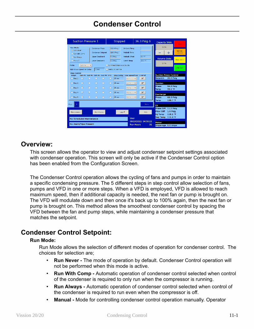
Condenser Control
Overview:This screen allows the operator to view and adjust condenser setpoint settings associated with condenser operation. This screen will only be active if the Condenser Control option has been enabled from the Configuration Screen.
The Condenser Control operation allows the cycling of fans and pumps in order to maintain a specific condensing pressure. The 5 different steps in step control allow selection of fans, pumps and VFD in one or more steps. When a VFD is employed, VFD is allowed to reach maximum speed, then if additional capacity is needed, the next fan or pump is brought on. The VFD will modulate down and then once it's back up to 100% again, then the next fan or pump is brought on. This method allows the smoothest condenser control by spacing the VFD between the fan and pump steps, while maintaining a condenser pressure that matches the setpoint.
Condenser Control Setpoint:Run Mode:
Run Mode allows the selection of different modes of operation for condenser control. The choices for selection are;
• Run Never - The mode of operation by default. Condenser Control operation will not be performed when this mode is active.
• Run With Comp - Automatic operation of condenser control selected when control of the condenser is required to only run when the compressor is running.
• Run Always - Automatic operation of condenser control selected when control of the condenser is required to run even when the compressor is off.
• Manual - Mode for controlling condenser control operation manually. Operator
Vission 20/20 Condensing Control 11-1
controls the operation by manual stepping using an on/off toggle button at each step.
Condenser Press:This is the read only parameter and it displays the present value of condenser pressure.
Condenser Setpoint:This is the condenser pressure setpoint that needs to be maintained.
Upper Deadband:This is the condenser pressure setpoint upper deadband value. No additional condenser capacity is added when the condenser is selected for automatic step control and the condenser pressure falls within this deadband.
Lower Deadband:This is the condenser pressure setpoint lower deadband value. Condenser capacity is not reduced when the condenser is selected for automatic step control and the condenser pressure falls within this deadband.
Ambient Temp:This is the read only parameter and it displays the present value of ambient temperature. This is displayed only when Ambient Sensor is enabled from Configuration Screen.
Wetbulb Temp:This is the read only parameter and it displays the present value of wetbulb temperature. This is displayed only when Wetbulb Sensor is enabled from Configuration Screen.
Wetbulb Offset:This is the offset value from wetbulb temperature as the override point.
Switch Temp:This is the ambient temperature setpoint used for automatic switching of profile from summer to winter & vice-versa.
Profile Selection:Profile selection allows operator to have two different output profiles for summer & winter. Operator can have different selection of fans, pumps & VFD in 5 steps of step control table. Different profiles allow inclusion/exclusion of water pumps in cold weather when summer/winter auto switch is enabled. This selection is inactive when Run mode is Auto and Summer/Winter Auto Switch is enabled.
High to Low Speed Fan Delay:This is time delay for fan spin down in case of 2 speed motor/dual speed fan.
Summer/Winter Auto Switch:This checkbox when enabled allows profiles to switch automatically depending on ambient temperature setpoint when Run Mode is “Auto”. When ambient temperature falls below ambient temperature setpoint, winter profile is used. Similarly when ambient temperature is above ambient temperature setpoint, summer profile is used.
Wetbulb Override:This checkbox when enabled gives operator a functionality to control wastage of energy. When condenser temperature reaches wetbulb temperature plus the operator given offset, then condenser control operation does not add any additional steps. This is done as it is not possible to lower the temperature any more and adding more fans or pump
Vission 20/20 Condensing Control 11-2
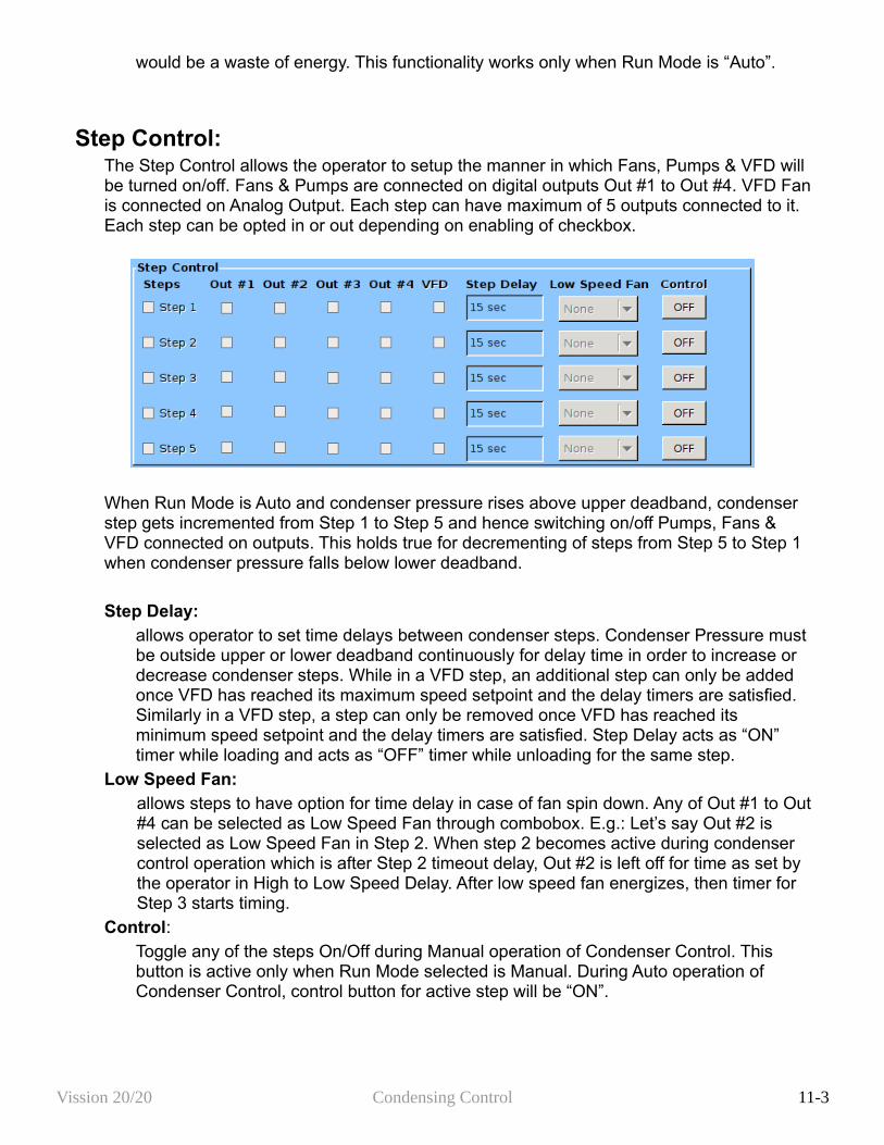
would be a waste of energy. This functionality works only when Run Mode is “Auto”.
Step Control:The Step Control allows the operator to setup the manner in which Fans, Pumps & VFD will be turned on/off. Fans & Pumps are connected on digital outputs Out #1 to Out #4. VFD Fan is connected on Analog Output. Each step can have maximum of 5 outputs connected to it. Each step can be opted in or out depending on enabling of checkbox.
When Run Mode is Auto and condenser pressure rises above upper deadband, condenser step gets incremented from Step 1 to Step 5 and hence switching on/off Pumps, Fans & VFD connected on outputs. This holds true for decrementing of steps from Step 5 to Step 1 when condenser pressure falls below lower deadband.
Step Delay:allows operator to set time delays between condenser steps. Condenser Pressure must be outside upper or lower deadband continuously for delay time in order to increase or decrease condenser steps. While in a VFD step, an additional step can only be added once VFD has reached its maximum speed setpoint and the delay timers are satisfied. Similarly in a VFD step, a step can only be removed once VFD has reached its minimum speed setpoint and the delay timers are satisfied. Step Delay acts as “ON” timer while loading and acts as “OFF” timer while unloading for the same step.
Low Speed Fan:allows steps to have option for time delay in case of fan spin down. Any of Out #1 to Out #4 can be selected as Low Speed Fan through combobox. E.g.: Let’s say Out #2 is selected as Low Speed Fan in Step 2. When step 2 becomes active during condenser control operation which is after Step 2 timeout delay, Out #2 is left off for time as set by the operator in High to Low Speed Delay. After low speed fan energizes, then timer for Step 3 starts timing.
Control:Toggle any of the steps On/Off during Manual operation of Condenser Control. This button is active only when Run Mode selected is Manual. During Auto operation of Condenser Control, control button for active step will be “ON”.
Vission 20/20 Condensing Control 11-3
VFD SettingsThis page is active only when Condenser VFD is selected in Configuration Screen. When a VFD Fan is used for condenser control operation, the speed of the VFD is controlled using PID algorithm.
P = Proportional (gain):Used to adjust the fan speed action in direct proportion to the difference between the control setpoint and the process variable (SP - PV = error). The proportional term is a unit less quantity and is used for coarse adjustment. This setpoint should be set to the lowest value that gives adequate control system response. Increasing the proportional setting increases the control system's sensitivity to small process fluctuations and the tendency to hunt.
I = Integral (reset):Used to adjust the capacity control action, integrating the error over time, to account for a small error that has persisted for a long time. This quantity is used for fine adjustment. This setpoint is used to smooth out process variations. This setpoint should be set high enough to prevent hunting but not too high or it will cause control system overshoot.
D = Derivative (rate):Used to adjust the capacity control action, accounting for how fast the error is changing, positively or negatively.
Maximum Speed:This setpoint defines the maximum speed in percentage for Condenser VFD Fan at which it should run for continuous step delay time to increase condenser steps. E.g. let’s say setpoint is kept at 95%. Then condenser VFD fan will have to run at speed of 95% or more to advance to next step. Maximum Speed can be set as 100%, which is when analog output (at which condenser VFD fan is connected) reaches to 20mA in its normal range of 4-20 mA
Minimum Speed:This setpoint defines the minimum speed in percentage for Condenser VFD Fan at which it should run for continuous step delay time to decrease condenser steps. E.g. let’s say setpoint is kept at 5%. Then condenser VFD fan will have to run at speed 5% or less to advance to next step. Minimum Speed can be set as 0%, which is when analog output (at which condenser VFD fan is connected) reaches 4mA in its normal range of 4-20 mA
Vission 20/20 Condensing Control 11-4
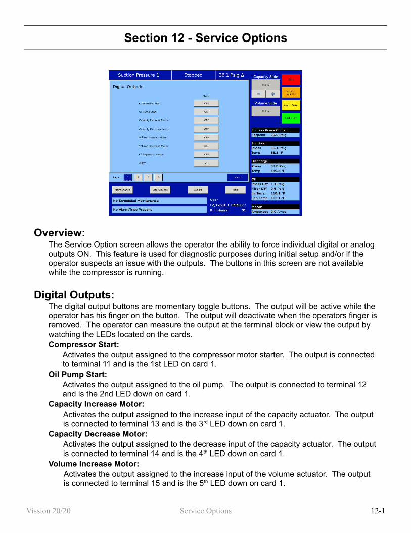
Section 12 - Service Options
Overview:The Service Option screen allows the operator the ability to force individual digital or analog outputs ON. This feature is used for diagnostic purposes during initial setup and/or if the operator suspects an issue with the outputs. The buttons in this screen are not available while the compressor is running.
Digital Outputs:The digital output buttons are momentary toggle buttons. The output will be active while the operator has his finger on the button. The output will deactivate when the operators finger is removed. The operator can measure the output at the terminal block or view the output by watching the LEDs located on the cards.Compressor Start:
Activates the output assigned to the compressor motor starter. The output is connected to terminal 11 and is the 1st LED on card 1.
Oil Pump Start:Activates the output assigned to the oil pump. The output is connected to terminal 12 and is the 2nd LED down on card 1.
Capacity Increase Motor:Activates the output assigned to the increase input of the capacity actuator. The output is connected to terminal 13 and is the 3rd LED down on card 1.
Capacity Decrease Motor:Activates the output assigned to the decrease input of the capacity actuator. The output is connected to terminal 14 and is the 4th LED down on card 1.
Volume Increase Motor:Activates the output assigned to the increase input of the volume actuator. The output is connected to terminal 15 and is the 5th LED down on card 1.
Vission 20/20 Service Options 12-1
Volume Decrease Motor:Activates the output assigned to the decrease input of the volume actuator. The output is connected to terminal 16 and is the 6th LED down on card 1.
Oil Separator HeaterActivates the output assigned to the oil separator heater. The output is connected to terminal 17 and is the 7th LED down on card 1.
Trip:Deactivates the output during a trip or inhibit condition. This is a reverse acting output. The output is connected to terminal 18 and is the bottom LED on card 1.
Slide Valve Setpoint # 1 (Economizer):Activates the output typically assigned to the economizer solenoid, but can be changed by the operator. The output is connected to terminal 21 and is the 1st LED on card 2.
Slide Valve Setpoint # 2 (Hot Gas Bypass):Activates the output typically assigned to the hot gas bypass solenoid, but can be changed by the operator. The output is connected to terminal 22 and is the 2nd LED on card 2.
Alarm:Activates the output during an alarm condition. This is a reverse acting output. The output is connected to terminal 23 and is the 3rd LED on card 2.
Liquid Injection # 1:Activates the output assigned to the liquid injection solenoid. The output is connected on terminal 25 and is the 5th LED on card 2.
Liquid Injection # 2:Not currently enabled
Remote Enabled:Activates the output assigned to notify a central control system of the Visison 20/20 run status. The output is connected to terminal 27 and is the 7th LED on card 2.
Shunt Trip:Activates the output during a false start condition and the emergency stop timer has expired. This output could be wired the a breaker with a shunt trip that feeds power to a starter to force a shutdown. The output is connected to terminal 28 and is the 8 th LED on card 2.
Condenser Step # 1:Activates the output assigned to the 1st step of the condenser. The output is connected to terminal 41 and is the 1st LED on card 4.
Condenser Step # 2:Activates the output assigned to the 2nd step of the condenser. The output is connected to terminal 42 and is the 2nd LED on card 4.
Condenser Step # 3:Activates the output assigned to the 3rd step of the condenser. The output is connected to terminal 43 and is the 3rd LED on card 4.
Condenser Step # 4:Activates the output assigned to the 4th step of the condenser. The output is connected to terminal 44 and is the 4rd LED on card 4.
Analog Outputs:The analog output selections allow the operator to enter a desired value of the output then
Vission 20/20 Service Options 12-2
turn on the output. The operator will have to measure the output using meter capable of measuring a 4-20mA signal.Compressor VFD:
Sets the analog output assigned to the compressor VFD. The output is connected to AO #1 on card 10.
Condenser VFD:Sets the analog output assigned to the condenser VFD. The output is connected to AO #2 on card 10.
% Slide Valve PositionSets the analog output assigned to the Slide Value position used to inform a central control system of the capacity position. The output is connected to AO #3 on card 10.
Liquid injection Motorized Valve:Sets the analog output assigned to the liquid injection motorized value position. The output is connected to AO #4 on card 10.
Vission 20/20 Service Options 12-3

Section 13 – Instruments Calibration
Overview:The Instrument calibration screen allows the operator to define how the Vission 20/20 will interprets the signal from any devices attached to the panel's analog inputs. The instrument calibration screen is organized in up to 6 pages. Each page is then divided into several left side selected tabs. Each tab will be headed with an information bar labeled “I/O” that give the basic information for that device. The “A/D bit Value” display box shows the unmodified value read by the Vission 20/20 analog to digital converters. This display box is not affected by any changes to the calibrations settings and as long as a device is connected to the associated input, there will be a value in this display box. The “Calibrated Value” display box shows the end result of the calibration process. Therefore any changes to the calibration setpoint will effect what value is shown.
All instruments are calibrated using a two point linear calibration process. Any device that has a non-linear response to environmental stimuli will not be able to be calibrated through the Vission 20/20.
Pressure and Temperature Inputs:The most commonly used instruments are temperature and pressure sensor. The first two pages of the Instrument Calibration screen are dedicated to these instruments.
Each tab on these two pages is divided into two sections, Device Calibration and Channel Calibration. The device calibration section is where the operation parameters of the instrument is defined. The channel calibration defines the type of signal sent by the instrument.Default Devices:
By selecting this option, the operator will have access via a drop down box of several common devices. The devices are predefined and if one is selected all the setpoints will
Vission 20/20 Instrument Calibration 13-1
be set for the operator.Custom Device:
This option allows the operator to chose the minimum and maximum value of the instrument being used.
Offset:Once the two point calibration is completed, it is not uncommon for there to be a small error. By entering the value of the error from the calibrated value and the actual value into the adjustment entry box, that error will be added/subtracted from the total offset. The offset is applied to the calibrated value which should correct for the error.
Range:This option is available when the custom device option is chosen. Here the operator defines the signal type and range transmitted by the instrument. The operator can choose from several predefined ranges in the dropdown box, or enter his own.
Motor Current:The Vission 20/20 has two options for measuring motor current. A 4-20mA signal transmitted from an external devise or a 0-5amp AC current Transformer. The type of device being used is selected in the configuration screen.
The motor current tab has the ability to calibrate both measurement options through the 4-20mA scale and current transformer ratio sections. However, the device type that is selected in the configuration screen will be the only section that will be available to the operator.
The calibration differs from all other calibration procedures in that the motor current must be calibrated while the compressor is running at as close to full load amps as possible. In addition, the operator will need to enter a value into the “Enter Desired Value” entry box that is equal to the measured value in amps by a calibrating measurement device. After entering the measured value, the displayed motor current may still be off slightly. In this case re-enter the desired value and the displayed value should get progressively closer.
4-20mA Scale:4mA:
Not editable by the operator. Defines the minimum value in amps represented by a 4ma inputs
20mA:Defines the maximum value in amps represented by a 20ma inputs.
Enter Desired Value:The operator enters the correct current value. Each entry will recalculate the point-slope calculations of the current calibration.
Total Error:Not editable by the operator. Displays the total error offset of entries from the “Enter Desired Value” setpoint
Current Transformer Ratio:Primary
Defines the upper value of the current transformerSecondary:
Vission 20/20 Instrument Calibration 13-2
Not editable by the operator. Defines the minimum value of the current transformer. Enter Desired Value:
The operator enters the value of the correct current value. Each entry will recalculate the point-slop calculations of the current calibration.
Total Error:Not editable by the operator. Displays the total error offset of entries from the “Enter Desired Value” setpoint
Remote Capacity:The remote capacity input allows a system controller such as PLC to control the capacity position during direct I/O control.Control Input:
This dropdown box is not used at this time.Scale:
Defines the minimum and maximum Capacity position between 0% & 100% for the 4-20ma input.
Offset:Used to correct any error in the capacity position. By entering a value into the Adjustment entry box, that value will be added to the total offset displayed in the “total offset” entry box.
Analog Inputs:This section of the Calibration screen allows the operator to define the parameters of an installed auxiliary analog instrument. These instruments are usually not part of a typical compressor setup but Vission 20/20 provides a way for the operator to add additional capabilities. The layout of this screen is typical to the pressure and temperature calibration screens.Device Calibration:
These setpoints allow the operator to define what the input from the auxiliary instrument means in terms of units and range. If a temperature measuring instrument is connected, then the operator would select temperature from the Unit dropdown box then set the maximum and minimum value for the scale.
Offset:Once the two point calibration is completed, it is not uncommon for there to be a small error. By entering the value of the error from the calibrated value and the actual value into the adjustment entry box, that error will be added/subtracted from the total offset. The offset is applied to the calibrated value which should correct for the error.
Range:Here the operator defines the signal type and range transmitted by the instrument. The operator can choose from several predefined ranges in the dropdown box, or enter his own.
Vission 20/20 Instrument Calibration 13-3

Analog outputs:The Analog output card of the Vission 20/20 generates a 4 – 20mA signal to any attached devices. However, it is not uncommon that small difference in the board components might result in small difference in the output. So this screen offers the operator the ability to fine tune the upper and lower output values.Test Limits:
By pressing either the Test Min or Test Max buttons, the output will go to either 4ma or 20 ma. The operator can then measure the output for accuracy.
Min (mA):If the 4ma output has an unacceptable amount of error. The operator can use the “+” & “-” buttons to adjust the output.
Max (mA):If the 20ma output has an unacceptable amount of error. The operator can use the “+” & “-” buttons to adjust the output.
Vission 20/20 Instrument Calibration 13-4

Section 14 – Slide Calibration
Overview:The Slide Calibration screen is used in calibrating the slide actuators and to establish Vission 20/20 control parameters. It is important that the operator uses caution while operating in this screen. The normal safety checks that prevent the slide from colliding with the mechanical stops are overridden. When the calibration process is completed and the operator exits the screen, Both actuator will return the slides back to their minimum positions.
Capacity Slide Valve Potentiometer:This section provides critical information and control parameters related to the capacity slide actuator. The “% cap” display shows the actual value in percent of the capacity slide with out any conditioning that might be applied to the other capacity position displays. In addition, this section displays the value of the actuator signals in millivolts in the “input Value” display box.“-” Button:
When the operator presses and holds this button, the output associated with capacity slide decrease is energized. If the actuator does not turn in the correct direction when this button is pressed, then the operator will have to alter how the actuator is wired to the panel.
“+” Button:When the operator presses and holds this button, the output associated with capacity slide increase is energized. If the actuator does not turn in the correct direction when this button is pressed, then the operator will have to alter how the actuator is wired to the panel.
Software limit setpoint:
Vission 20/20 Slide Calibration 14-1

The Vission 20/20 uses the “Min Limit” and “Max Limit” setpoint to define an area within the mechanical stops for normal slide travel. These software limits purpose is to prevent the slide from actually hitting the mechanical stops which could result in a number of undesirable consequences. By default, the software limits are set to 150mV from either end point. The position percentage is calculated from the software limits. Therefore It is possible to read a value greater than 100% or less than 0% if inertial carries the slides after these limits are reached.
Volume Slide Valve Potentiometer:This section provided critical information and control parameters related to the volume slide actuator. The “% Vol” display shows the actual value in percent of the volume slide with out any conditioning that might be applied to the other volume position displays. In addition, this section displays the value of the actuator signals in millivolts in the “input Value” display box.“-” Button:
When the operator presses and holds this button, the output associated with volume slide decreases is energized. If the actuator does not turn in the correct direction when this button is pressed, then the operator will have to alter how the actuator is wired to the panel.
“+” Button:When the operator presses and holds this button, the output associated with volume slide increase is energized. If the actuator does not turn in the correct direction when this button is pressed, then the operator will have to alter how the actuator is wired to the panel.
Software limit setpoint:The Vission 20/20 uses the “Min Limit” and “Max Limit” setpoint to define an area within the mechanical stops for normal slide travel. These software limits purpose is to prevent the slide from actually hitting the mechanical stops which could result in a number of undesirable consequences. By default, the software limits are set to 150mV from either end point. The position percentage is calculated from the software limits. Therefore It is possible to read a value greater than 100% or less than 0% if inertial carries the slides after these limits are reached.
Slide Valve Operation:The slide valve actuator is a gear-motor with a position sensor. The motor is powered in the forward and reverse directions from the main computer in the control panel. The position sensor tells the main computer the position of the slide valve. The main computer uses the position and process information to decide where to move the slide valve next.During calibration, the position sensor records the high and low count of motor turns. The operator tells the position sensor when the actuator is at the high or low position with the push button. Refer to the calibration instructions for the detailed calibration procedure.The position sensor can get “lost” if the motor is moved while the position sensor is not powered. To prevent this, the motor can only be moved electrically while the position sensor is powered. When the position sensor loses power, power is cut to the motor. A capacitor stores enough energy to keep the position sensor circuitry alive long enough for the motor to come to a complete stop and then save the motor position to non-volatile EEPROM memory. When power is restored, the saved motor position is read from EEPROM memory and the actuators resumes normal function
Vission 20/20 Slide Calibration 14-2
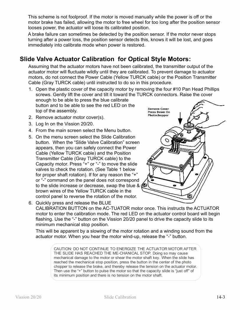
This scheme is not foolproof. If the motor is moved manually while the power is off or the motor brake has failed, allowing the motor to free wheel for too long after the position sensor looses power, the actuator will loose its calibrated position.A brake failure can sometimes be detected by the position sensor. If the motor never stops turning after a power loss, the position sensor detects this, knows it will be lost, and goes immediately into calibrate mode when power is restored.
Slide Valve Actuator Calibration for Optical Style Motors:Assuming that the actuator motors have not been calibrated, the transmitter output of the actuator motor will fluctuate wildly until they are calibrated. To prevent damage to actuator motors, do not connect the Power Cable (Yellow TURCK cable) or the Position Transmitter Cable (Gray TURCK cable) until instructed to do so in this procedure.1. Open the plastic cover of the capacity motor by removing the four #10 Pan Head Phillips
screws. Gently lift the cover and tilt it toward the TURCK connectors. Raise the cover enough to be able to press the blue calibrate button and to be able to see the red LED on the top of the assembly.
2. Remove actuator motor cover(s). 3. Log In on the Vission 20/20. 4. From the main screen select the Menu button. 5. On the menu screen select the Slide Calibration
button. When the “Slide Valve Calibration” screen appears, then you can safely connect the Power Cable (Yellow TURCK cable) and the Position Transmitter Cable (Gray TURCK cable) to the Capacity motor. Press “+” or “-” to move the slide valves to check the rotation. (See Table 1 below for proper shaft rotation). If for any reason the “+” or “-” command on the panel does not correspond to the slide increase or decrease, swap the blue & brown wires of the Yellow TURCK cable in the control panel to reverse the rotation of the motor.
6. Quickly press and release the BLUE CALIBRATION BUTTON on the AC-TUATOR motor once. This instructs the ACTUATOR motor to enter the calibration mode. The red LED on the actuator control board will begin flashing. Use the “-” button on the Vission 20/20 panel to drive the capacity slide to its minimum mechanical stop position.This will be apparent by a slowing of the motor rotation and a winding sound from the actuator motor. When you hear the motor wind-up, release the “-” button.
Vission 20/20 Slide Calibration 14-3
CAUTION: DO NOT CONTINUE TO ENERGIZE THE ACTUATOR MOTOR AFTER THE SLIDE HAS REACHED THE ME-CHANICAL STOP. Doing so may cause mechanical damage to the motor or shear the motor shaft key. When the slide has reached the mechanical stop position, press the button in the center of the photo chopper to release the brake, and thereby release the tension on the actuator motor. Then use the “+” button to pulse the motor so that the capacity slide is “just off” of its minimum position and there is no tension on the motor shaft.
7. Quickly press and release the BLUE CALIBRATION BUTTON on the ACTUATOR motor once. The red LED will now flash at a slower rate. This now instructs the ACTUATOR motor that this point is the minimum slide position. This point will correspond to 0 volts AFTER the ACTUATOR calibration procedure is completed.
8. Use the “+” button on the Vission 20/20 to drive the capacity slide to its maximum mechanical stop position. This will be apparent by a slowing of the motor rotation and a winding sound from the actuator motor. When you hear the motor wind-up, release the “+” button.
9. Quickly press and release the BLUE CALIBRATION BUTTON on the ACTUATOR motor once. The red LED will stop flashing. This now instructs the ACTUATOR motor that this point is the maximum slide position. This point corresponds to 5 volts. The ACTUATOR calibration procedure is completed.Now the Capacity Channel is automatically calibrated based on the calibration settings made to the actuator.
10.Gently lower the plastic cover to where it contacts the base and o-ring seal. After making sure that the cover is not binding, gently tighten the four # 10 Phillips screws.
11. Repeat the same procedure for the Volume slide motor
Vission 20/20 Slide Calibration 14-4
CAUTION: DO NOT CONTINUE TO ENERGIZE THE ACTUATOR MOTOR AFTER THE SLIDE HAS REACHED THE ME-CHANICAL STOP. Doing so may cause mechanical damage to the motor or shear the motor shaft key. When the slide has reached the mechanical stop position, press the button in the center of the photo chopper to release the brake, and thereby release the tension on the actuator motor. Then use the “+” button to pulse the motor so that the capacity slide is “just off” of its minimum position and there is no tension on the motor shaft.
CAUTION: it is possible to crack the plastic cover by over tightening the screws.
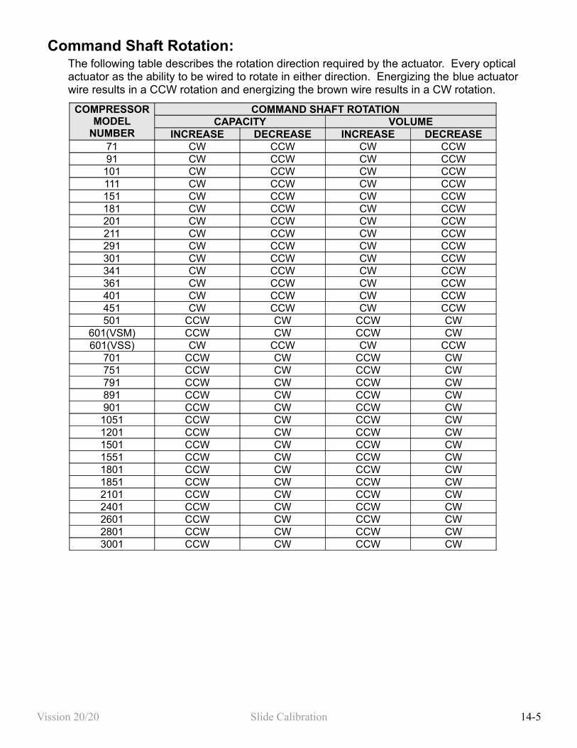
Command Shaft Rotation:The following table describes the rotation direction required by the actuator. Every optical actuator as the ability to be wired to rotate in either direction. Energizing the blue actuator wire results in a CCW rotation and energizing the brown wire results in a CW rotation.
COMPRESSOR MODEL
NUMBER
COMMAND SHAFT ROTATIONCAPACITY VOLUME
INCREASE DECREASE INCREASE DECREASE71 CW CCW CW CCW91 CW CCW CW CCW
101 CW CCW CW CCW111 CW CCW CW CCW151 CW CCW CW CCW181 CW CCW CW CCW201 CW CCW CW CCW211 CW CCW CW CCW291 CW CCW CW CCW301 CW CCW CW CCW341 CW CCW CW CCW361 CW CCW CW CCW401 CW CCW CW CCW451 CW CCW CW CCW501 CCW CW CCW CW
601(VSM) CCW CW CCW CW601(VSS) CW CCW CW CCW
701 CCW CW CCW CW751 CCW CW CCW CW791 CCW CW CCW CW891 CCW CW CCW CW901 CCW CW CCW CW1051 CCW CW CCW CW1201 CCW CW CCW CW1501 CCW CW CCW CW1551 CCW CW CCW CW1801 CCW CW CCW CW1851 CCW CW CCW CW2101 CCW CW CCW CW2401 CCW CW CCW CW2601 CCW CW CCW CW2801 CCW CW CCW CW3001 CCW CW CCW CW
Vission 20/20 Slide Calibration 14-5
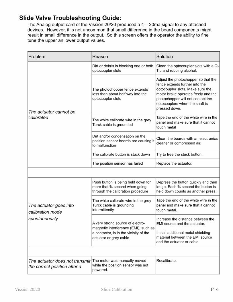
Slide Valve Troubleshooting Guide:The Analog output card of the Vission 20/20 produced a 4 – 20ma signal to any attached devices. However, it is not uncommon that small difference in the board components might result in small difference in the output. So this screen offers the operator the ability to fine tune the upper an lower output values.
Problem Reason Solution
The actuator cannot be calibrated
Dirt or debris is blocking one or both optocoupler slots
Clean the optocoupler slots with a Q-Tip and rubbing alcohol.
The photochopper fence extends less than about half way into the optocoupler slots
Adjust the photochopper so that the fence extends further into the optocoupler slots. Make sure the motor brake operates freely and the photochopper will not contact the optocouplers when the shaft is pressed down.
The white calibrate wire in the grey Turck cable is grounded
Tape the end of the white wire in the panel and make sure that it cannot touch metal
Dirt and/or condensation on the position sensor boards are causing it to malfunction
Clean the boards with an electronics cleaner or compressed air.
The calibrate button is stuck down Try to free the stuck button.
The position sensor has failed Replace the actuator.
The actuator goes into
calibration mode
spontaneously
Push button is being held down for more that ¾ second when going through the calibration procedure
Depress the button quickly and then let go. Each ¾ second the button is held down counts as another press.
The white calibrate wire in the grey Turck cable is grounding intermittently
Tape the end of the white wire in the panel and make sure that it cannot touch metal.
A very strong source of electro-magnetic interference (EMI), such as a contactor, is in the vicinity of the actuator or grey cable
Increase the distance between the EMI source and the actuator.
Install additional metal shielding material between the EMI source and the actuator or cable.
The actuator does not transmit the correct position after a
The motor was manually moved while the position sensor was not powered.
Recalibrate.
Vission 20/20 Slide Calibration 14-6
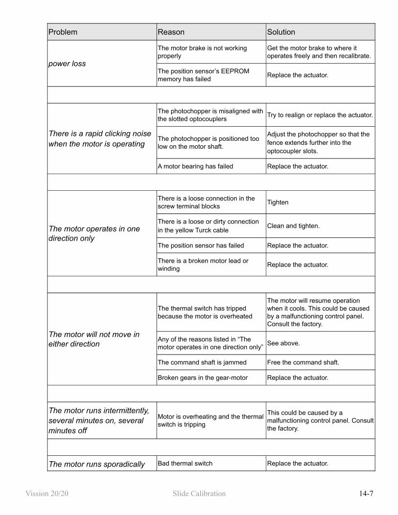
Problem Reason Solution
power loss
The motor brake is not working properly
Get the motor brake to where it operates freely and then recalibrate.
The position sensor’s EEPROM memory has failed
Replace the actuator.
There is a rapid clicking noise when the motor is operating
The photochopper is misaligned with the slotted optocouplers
Try to realign or replace the actuator.
The photochopper is positioned too low on the motor shaft.
Adjust the photochopper so that the fence extends further into the optocoupler slots.
A motor bearing has failed Replace the actuator.
The motor operates in one direction only
There is a loose connection in the screw terminal blocks
Tighten
There is a loose or dirty connection in the yellow Turck cable
Clean and tighten.
The position sensor has failed Replace the actuator.
There is a broken motor lead or winding
Replace the actuator.
The motor will not move in either direction
The thermal switch has tripped because the motor is overheated
The motor will resume operation when it cools. This could be caused by a malfunctioning control panel. Consult the factory.
Any of the reasons listed in “The motor operates in one direction only”
See above.
The command shaft is jammed Free the command shaft.
Broken gears in the gear-motor Replace the actuator.
The motor runs intermittently, several minutes on, several minutes off
Motor is overheating and the thermal switch is tripping
This could be caused by a malfunctioning control panel. Consult the factory.
The motor runs sporadically Bad thermal switch Replace the actuator.
Vission 20/20 Slide Calibration 14-7
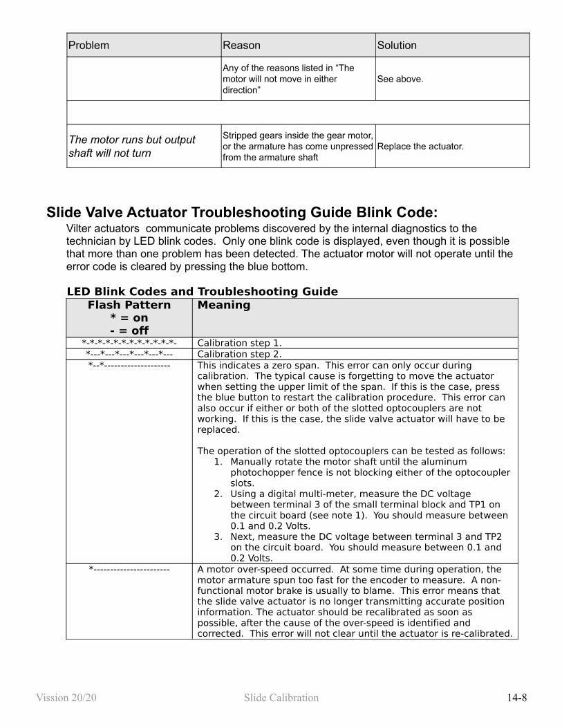
Problem Reason Solution
Any of the reasons listed in “The motor will not move in either direction”
See above.
The motor runs but output shaft will not turn
Stripped gears inside the gear motor, or the armature has come unpressed from the armature shaft
Replace the actuator.
Slide Valve Actuator Troubleshooting Guide Blink Code:Vilter actuators communicate problems discovered by the internal diagnostics to the technician by LED blink codes. Only one blink code is displayed, even though it is possible that more than one problem has been detected. The actuator motor will not operate until the error code is cleared by pressing the blue bottom.
LED Blink Codes and Troubleshooting GuideFlash Pattern
* = on- = off
Meaning
*-*-*-*-*-*-*-*-*-*-*-*- Calibration step 1. *---*---*---*---*---*--- Calibration step 2.*--*-------------------- This indicates a zero span. This error can only occur during
calibration. The typical cause is forgetting to move the actuator when setting the upper limit of the span. If this is the case, press the blue button to restart the calibration procedure. This error can also occur if either or both of the slotted optocouplers are not working. If this is the case, the slide valve actuator will have to be replaced.
The operation of the slotted optocouplers can be tested as follows:1. Manually rotate the motor shaft until the aluminum
photochopper fence is not blocking either of the optocoupler slots.
2. Using a digital multi-meter, measure the DC voltage between terminal 3 of the small terminal block and TP1 on the circuit board (see note 1). You should measure between 0.1 and 0.2 Volts.
3. Next, measure the DC voltage between terminal 3 and TP2 on the circuit board. You should measure between 0.1 and 0.2 Volts.
*----------------------- A motor over-speed occurred. At some time during operation, the motor armature spun too fast for the encoder to measure. A non-functional motor brake is usually to blame. This error means that the slide valve actuator is no longer transmitting accurate position information. The actuator should be recalibrated as soon as possible, after the cause of the over-speed is identified and corrected. This error will not clear until the actuator is re-calibrated.
Vission 20/20 Slide Calibration 14-8
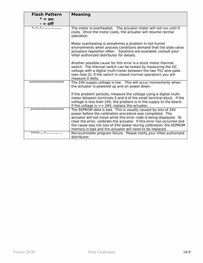
Flash Pattern* = on- = off
Meaning
*--*--*----------------- The motor is overheated. The actuator motor will not run until it cools. Once the motor cools, the actuator will resume normal operation.
Motor overheating is sometimes a problem in hot humid environments when process conditions demand that the slide valve actuators reposition often. Solutions are available; consult your Vilter authorized distributor for details.
Another possible cause for this error is a stuck motor thermal switch. The thermal switch can be tested by measuring the DC voltage with a digital multi-meter between the two TS1 wire pads (see note 2). If the switch is closed (normal operation) you will measure 0 Volts.
********************* The 24V supply voltage is low. This will occur momentarily when the actuator is powered up and on power down.
If the problem persists, measure the voltage using a digital multi-meter between terminals 3 and 4 of the small terminal block. If the voltage is less than 24V, the problem is in the supply to the board. If the voltage is >= 24V, replace the actuator..
-******************** The EEPROM data is bad. This is usually caused by loss of 24V power before the calibration procedure was completed. The actuator will not move while this error code is being displayed. To clear the error, calibrate the actuator. If this error has occurred and the cause was not loss of 24V power during calibration, the EEPROM memory is bad and the actuator will need to be replaced.
*****----*-------------- Microcontroller program failure. Please notify your Vilter authorized distributor.
Vission 20/20 Slide Calibration 14-9
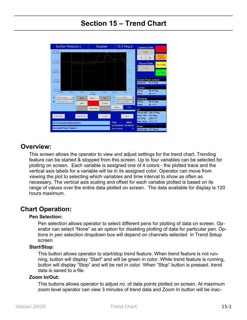
Section 15 – Trend Chart
Overview:This screen allows the operator to view and adjust settings for the trend chart. Trending feature can be started & stopped from this screen. Up to four variables can be selected for plotting on screen. Each variable is assigned one of 4 colors - the plotted trace and the vertical axis labels for a variable will be in its assigned color. Operator can move from viewing the plot to selecting which variables and time interval to show as often as necessary. The vertical axis scaling and offset for each variable plotted is based on its range of values over the entire data plotted on screen. The data available for display is 120 hours maximum.
Chart Operation:Pen Selection:
Pen selection allows operator to select different pens for plotting of data on screen. Op-erator can select “None” as an option for disabling plotting of data for particular pen. Op-tions in pen selection dropdown box will depend on channels selected in Trend Setup screen.
Start/Stop:This button allows operator to start/stop trend feature. When trend feature is not run-ning, button will display “Start” and will be green in color. While trend feature is running, button will display “Stop” and will be red in color. When “Stop” button is pressed, trend data is saved to a file.
Zoom In/Out:This buttons allows operator to adjust no. of data points plotted on screen. At maximum zoom level operator can view 3 minutes of trend data and Zoom In button will be inac-
Vission 20/20 Trend Chart 15-1
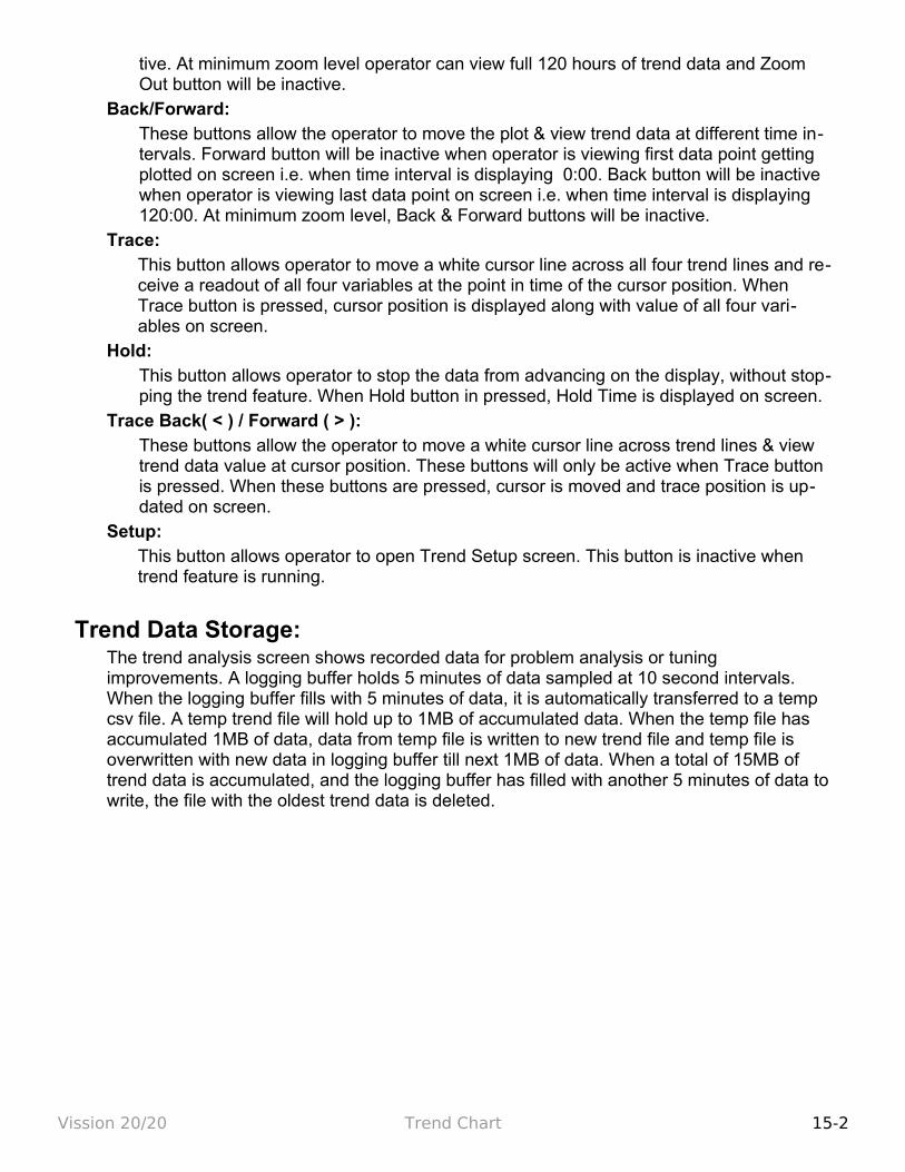
tive. At minimum zoom level operator can view full 120 hours of trend data and Zoom Out button will be inactive.
Back/Forward:These buttons allow the operator to move the plot & view trend data at different time in-tervals. Forward button will be inactive when operator is viewing first data point getting plotted on screen i.e. when time interval is displaying 0:00. Back button will be inactive when operator is viewing last data point on screen i.e. when time interval is displaying 120:00. At minimum zoom level, Back & Forward buttons will be inactive.
Trace:This button allows operator to move a white cursor line across all four trend lines and re-ceive a readout of all four variables at the point in time of the cursor position. When Trace button is pressed, cursor position is displayed along with value of all four vari-ables on screen.
Hold:This button allows operator to stop the data from advancing on the display, without stop-ping the trend feature. When Hold button in pressed, Hold Time is displayed on screen.
Trace Back( < ) / Forward ( > ):These buttons allow the operator to move a white cursor line across trend lines & view trend data value at cursor position. These buttons will only be active when Trace button is pressed. When these buttons are pressed, cursor is moved and trace position is up-dated on screen.
Setup:This button allows operator to open Trend Setup screen. This button is inactive when trend feature is running.
Trend Data Storage:The trend analysis screen shows recorded data for problem analysis or tuning improvements. A logging buffer holds 5 minutes of data sampled at 10 second intervals. When the logging buffer fills with 5 minutes of data, it is automatically transferred to a temp csv file. A temp trend file will hold up to 1MB of accumulated data. When the temp file has accumulated 1MB of data, data from temp file is written to new trend file and temp file is overwritten with new data in logging buffer till next 1MB of data. When a total of 15MB of trend data is accumulated, and the logging buffer has filled with another 5 minutes of data to write, the file with the oldest trend data is deleted.
Vission 20/20 Trend Chart 15-2

Setup:
Operator can modify options for pen selection dropdown box from trend setup screen. Trend setup screen will appear on press of Setup button when trending feature is not running. Trend Setup screen allows operator to select maximum of 10 analog I/O channels for trending. Operator can also set path for trend data files from dropdown box in setup screen. USB will appear as an option in dropdown box only when USB Drive is mounted on panel.
If there is no space available on USB or when USB is unmounted from panel and USB is selected for saving trend files, trend data files will be written to hard disk.
If operator changes Press/Temp units from configuration screen when trending feature is running, then background trending is stopped.
Vission 20/20 Trend Chart 15-3
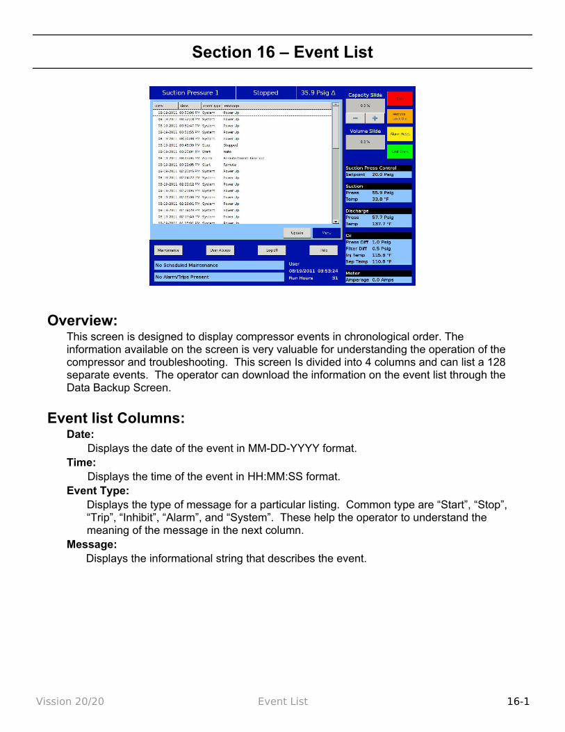
Section 16 – Event List
Overview:This screen is designed to display compressor events in chronological order. The information available on the screen is very valuable for understanding the operation of the compressor and troubleshooting. This screen Is divided into 4 columns and can list a 128 separate events. The operator can download the information on the event list through the Data Backup Screen.
Event list Columns:Date:
Displays the date of the event in MM-DD-YYYY format.Time:
Displays the time of the event in HH:MM:SS format.Event Type:
Displays the type of message for a particular listing. Common type are “Start”, “Stop”, “Trip”, “Inhibit”, “Alarm”, and “System”. These help the operator to understand the meaning of the message in the next column.
Message:Displays the informational string that describes the event.
Vission 20/20 Event List 16-1
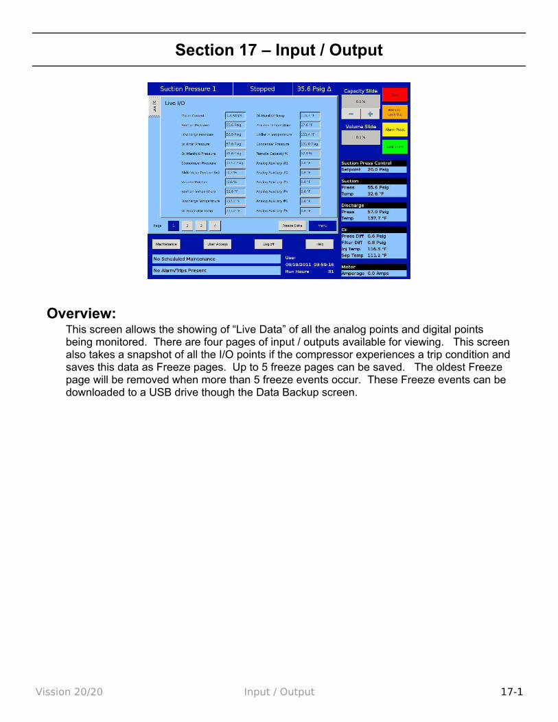
Section 17 – Input / Output
Overview:This screen allows the showing of “Live Data” of all the analog points and digital points being monitored. There are four pages of input / outputs available for viewing. This screen also takes a snapshot of all the I/O points if the compressor experiences a trip condition and saves this data as Freeze pages. Up to 5 freeze pages can be saved. The oldest Freeze page will be removed when more than 5 freeze events occur. These Freeze events can be downloaded to a USB drive though the Data Backup screen.
Vission 20/20 Input / Output 17-1

Section 18 – Auxiliary I/O
Overview:The Auxiliary I/O section of the Vission 20/20 gives the operator flexibility to add peripheral instruments and/or devices such as motors, valves and solenoids. These addition, customer configurable, I/O's are useful in expanding the functions of the Vission 20/20 where it was not explicitly designed to control.
Setting up one or more of the auxiliary inputs or outputs start with the configuration screen. In order to enable the auxiliary I/O, the Vission 20/20 must first be equipped with one of the available expandable I/O cards and the card must be selected on page 6 of the configuration screen. Once the appropriate card is available, then the operator will be permitted to enable and name the desired auxiliary I/O. The operator can then navigate to the Auxiliary I/O screen where he can define how that I/O will operate.
Digital Inputs:The Digital Inputs section of the auxiliary I/O allows an operator to configure the auxiliary digital inputs. The digital input can be configured to produce an alarm, a trip, an inhibit on either a high or low input. A low input is 0vac and a high is 120vac on the enabled input. Leaving all options in their default setting will mean no action will be taken on an enable input. The input will simply be available for viewing at the panel or by communications.
Trip/Alarm Check: Selecting this checkbox enables the alarms and/or trip functions of the Vission 20/20 for the desired digital input. The accompanying drop down box gives the operator the flexibility to choose whether the alarm and/or tip occurs if the input Is high or low.
Vission 20/20 Auxiliary I/O 18-1
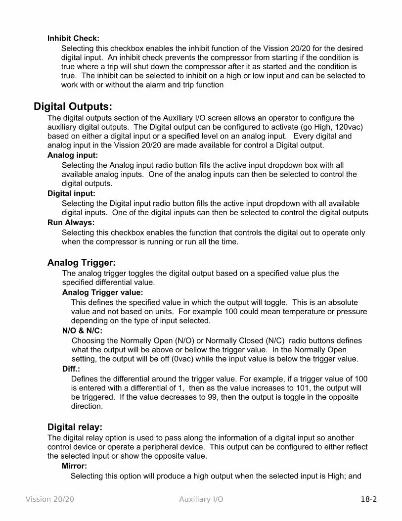
Inhibit Check: Selecting this checkbox enables the inhibit function of the Vission 20/20 for the desired digital input. An inhibit check prevents the compressor from starting if the condition is true where a trip will shut down the compressor after it as started and the condition is true. The inhibit can be selected to inhibit on a high or low input and can be selected to work with or without the alarm and trip function
Digital Outputs:The digital outputs section of the Auxiliary I/O screen allows an operator to configure the auxiliary digital outputs. The Digital output can be configured to activate (go High, 120vac) based on either a digital input or a specified level on an analog input. Every digital and analog input in the Vission 20/20 are made available for control a Digital output.Analog input:
Selecting the Analog input radio button fills the active input dropdown box with all available analog inputs. One of the analog inputs can then be selected to control the digital outputs.
Digital input:Selecting the Digital input radio button fills the active input dropdown with all available digital inputs. One of the digital inputs can then be selected to control the digital outputs
Run Always:Selecting this checkbox enables the function that controls the digital out to operate only when the compressor is running or run all the time.
Analog Trigger:The analog trigger toggles the digital output based on a specified value plus the specified differential value. Analog Trigger value:
This defines the specified value in which the output will toggle. This is an absolute value and not based on units. For example 100 could mean temperature or pressure depending on the type of input selected.
N/O & N/C:Choosing the Normally Open (N/O) or Normally Closed (N/C) radio buttons defines what the output will be above or bellow the trigger value. In the Normally Open setting, the output will be off (0vac) while the input value is below the trigger value.
Diff.:Defines the differential around the trigger value. For example, if a trigger value of 100 is entered with a differential of 1, then as the value increases to 101, the output will be triggered. If the value decreases to 99, then the output is toggle in the opposite direction.
Digital relay:The digital relay option is used to pass along the information of a digital input so another control device or operate a peripheral device. This output can be configured to either reflect the selected input or show the opposite value.
Mirror:Selecting this option will produce a high output when the selected input is High; and
Vission 20/20 Auxiliary I/O 18-2
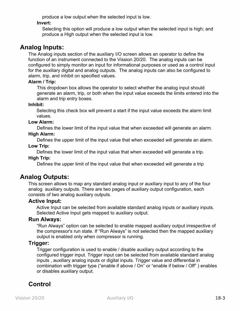
produce a low output when the selected input is low.Invert:
Selecting this option will produce a low output when the selected input is high; and produce a High output when the selected input is low.
Analog Inputs:The Analog inputs section of the auxiliary I/O screen allows an operator to define the function of an instrument connected to the Vission 20/20. The analog inputs can be configured to simply monitor an input for informational purposes or used as a control input for the auxiliary digital and analog outputs. The analog inputs can also be configured to alarm, trip, and inhibit on specified values. Alarm / Trip:
This dropdown box allows the operator to select whether the analog input should generate an alarm, trip, or both when the input value exceeds the limits entered into the alarm and trip entry boxes.
Inhibit:Selecting this check box will prevent a start if the input value exceeds the alarm limit values.
Low Alarm:Defines the lower limit of the input value that when exceeded will generate an alarm.
High Alarm:Defines the upper limit of the input value that when exceeded will generate an alarm.
Low Trip:Defines the lower limit of the input value that when exceeded will generate a trip.
High Trip:Defines the upper limit of the input value that when exceeded will generate a trip
Analog Outputs:This screen allows to map any standard analog input or auxiliary input to any of the four analog auxiliary outputs. There are two pages of auxiliary output configuration, each consists of two analog auxiliary outputs.
Active Input:Active Input can be selected from available standard analog inputs or auxiliary inputs. Selected Active Input gets mapped to auxiliary output.
Run Always:“Run Always” option can be selected to enable mapped auxiliary output irrespective of the compressor's run state. If “Run Always” is not selected then the mapped auxiliary output is enabled only when compressor is running.
Trigger:Trigger configuration is used to enable / disable auxiliary output according to the configured trigger input. Trigger input can be selected from available standard analog inputs , auxiliary analog inputs or digital inputs. Trigger value and differential in combination with trigger type (“enable if above / On” or “enable if below / Off” ) enables or disables auxiliary output.
Control
Vission 20/20 Auxiliary I/O 18-3
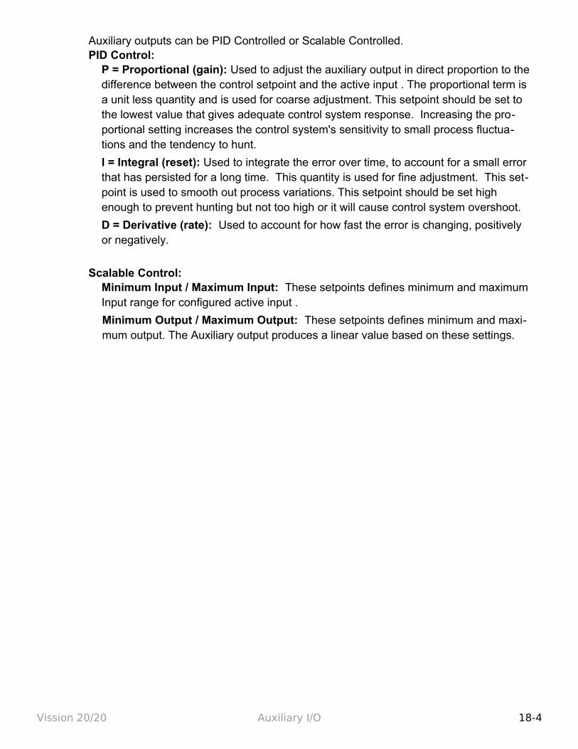
Auxiliary outputs can be PID Controlled or Scalable Controlled.PID Control:
P = Proportional (gain): Used to adjust the auxiliary output in direct proportion to the difference between the control setpoint and the active input . The proportional term is a unit less quantity and is used for coarse adjustment. This setpoint should be set to the lowest value that gives adequate control system response. Increasing the pro-portional setting increases the control system's sensitivity to small process fluctua-tions and the tendency to hunt.
I = Integral (reset): Used to integrate the error over time, to account for a small error that has persisted for a long time. This quantity is used for fine adjustment. This set-point is used to smooth out process variations. This setpoint should be set high enough to prevent hunting but not too high or it will cause control system overshoot.
D = Derivative (rate): Used to account for how fast the error is changing, positively or negatively.
Scalable Control:Minimum Input / Maximum Input: These setpoints defines minimum and maximum Input range for configured active input .
Minimum Output / Maximum Output: These setpoints defines minimum and maxi-mum output. The Auxiliary output produces a linear value based on these settings.
Vission 20/20 Auxiliary I/O 18-4
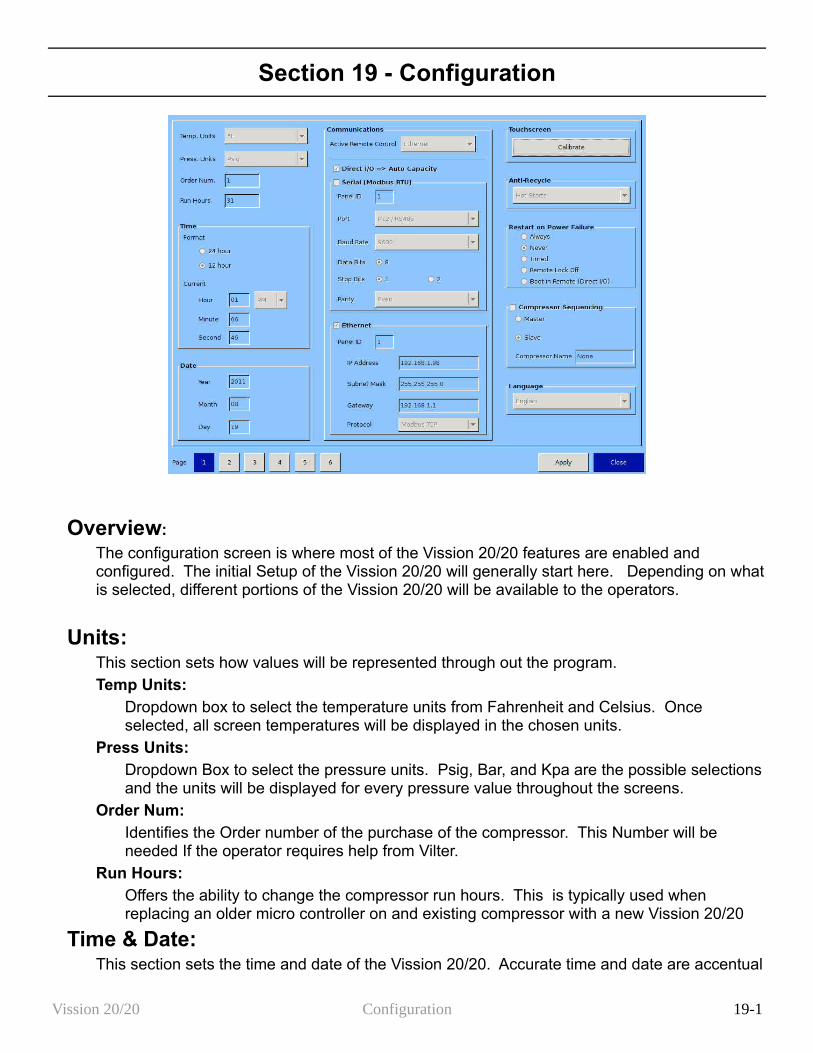
Section 19 - Configuration
Overview:
The configuration screen is where most of the Vission 20/20 features are enabled and configured. The initial Setup of the Vission 20/20 will generally start here. Depending on what is selected, different portions of the Vission 20/20 will be available to the operators.
Units:This section sets how values will be represented through out the program. Temp Units:
Dropdown box to select the temperature units from Fahrenheit and Celsius. Once selected, all screen temperatures will be displayed in the chosen units.
Press Units:Dropdown Box to select the pressure units. Psig, Bar, and Kpa are the possible selections and the units will be displayed for every pressure value throughout the screens.
Order Num:Identifies the Order number of the purchase of the compressor. This Number will be needed If the operator requires help from Vilter.
Run Hours:Offers the ability to change the compressor run hours. This is typically used when replacing an older micro controller on and existing compressor with a new Vission 20/20
Time & Date:This section sets the time and date of the Vission 20/20. Accurate time and date are accentual
Vission 20/20 Configuration 19-1
for accurate logging and troubleshooting. Setting these parameter will set the hardware clock embedded in the Vission 20/20 CPU. If the time is not retained after powering down the panel, the operator should check and/or replace the coin style battery on the panel SBC behind the touchscreen.Format:
Selection to choose between 12 hour or 24 hours clockHour:
Entry box to set the clock hours. AM or PM dropdown box will available if the 12 hour format is selected.
Minute:Entry Box to set the clock minutes
Second:Entry Box to set the clock seconds
Year:Entry Box to set the current year
Month:Entry Box to set the current month
Day:Entry Box to set the current date
Communications:The communication section is the control center for all communications to the Vission 20/20 panel. It is possible to have multiple modes of communications enabled and used. However, only one mode can be used to control the Vission 20/20 which is selected in the “Active Remote Control” dropdown box. For a complete list of communication registers, please refer to the Vission 20/20 communication table.Active Remote Control:
Selects the mode of remote control. The operator can select between Direct I/O, Serial, or Ethernet.
Direct I/O:Enables the Direct I/O inputs. Once selected a pop-up will be displayed and the operator will need to choose a one of the three Direct I/O options
Serial (Modbus RTU):Enables the Serial Modbus RTU protocol. Once selected, the remainder of the serial setpoints will be available for editing.
Panel ID:Panel Identifier used by the controller when communicating with multiple panels
Port:The Vission 20/20 has two ways to communicate on serial bus. Either via the built in serial port, P12, or through one of the USB ports. This dropdown box allows the operator to chose which one will be used.
Baud Rate:Sets the Baud Rate for the serial communication
Data Bits:
Vission 20/20 Configuration 19-2
Fixed at 8 Data bitsStop Bits:
Identifies the end of character for resynchronizing. Parity:
Identifies the type of error detectionEthernet:
Enables the Ethernet port. Once selected, the remainder of the Ethernet setpoints will be available for editing.
Panel ID:Panel Identifier used by the controller when communicating with multiple panels
IP Address:Entry box to set the IP address
Subnet Mask:Entry box to set the Subnet Mask
Gateway:Entry box to set the Gateway address
Protocol:Dropdown box to select the type of protocol used to remotely control the Vission 20/20.
Touchscreen:The “Calibrate” button changes the screen into touchscreen calibration mode. Calibrating the touchscreen is only required if the operator finds that the pointer arrow no longer follows his finger. The calibration mode requires the operator to touch the four corners of the touchscreen and then the accept button.
Anti-Recycle:Anti-Recycle defines the method of motor protection due to repeated motor starts. The operator has 3 choices of protection. Hot starts allows only a certain number of starts per hour before setting an hour to the anti-recycle timer. The number of starts is set in the timer page. Accumulative immediately adds time to the anti-recycle timer once the compressor is started and the time can be set in the timers screen. True anti-recycle adds to the anti-recycle timer once the compressor is shutdown. The motor of the compressor can not be restarted as long as there is anti-recycle time left and the operator can view this time on the top left corner of the main screen.
Restart On Power Failure:This feature of the Vission 20/20 offers the ability to define how the Vission 20/20 will handle a power failure. This can also be useful to allow system controller to regain control of the Vission panel without the need for operator intervention. Always:
When selected, initiates a start after the panel powers back up after a power failure, but only if the compressor was running before the power failure and starts the compressor in Auto mode.
Never:When selected, prevents any automatic action once the panel powers back up after a
Vission 20/20 Configuration 19-3
power failure.Timed:
When selected, initiates a start after the panel powers back up after a power failure and the operator set timer runs out. When there are multiple compressor in a larger system, it is recommended that the operator gives each compressor a different start times. A restart will only occur if the compressor was running before the power failure and starts the compressor in Auto mode.
Remote Lock Off:When selected, turns the remote lock out off when the panel powers up. Select this option if the operator wishes a system controller to regain control of the Vission 20/20 without human interference.
Boot in Remote (Direct I/O)When selected, places the panel into remote mode when the panel powers up. Select this option when under direct I/O control and the system controller is to gain control of the Vission 20/20 without human interference.
Compressor Sequencing:The compressor sequencing is a feature of the Vission 20/20 that allows the operator to setup as many as five compressor to automatically start, stop and maintain system loads. The compressor that is designated as the master will monitor systems parameter and make decisions on how many compressor are required to meet the load as efficiently as possible. Compressor Sequencing:
Enables the compressor sequencing algorithms and allows access to the compressor sequencing screen.
Master:Identifies the panel as the master while in sequencing control.
Slave:Identifies the panel as a slave while in sequencing control.
Compressor Name:Unique identifier that is broadcasted to all other Vission 20/20's in the sequencing network.
Language:Allows the operator to select the language all screen will be displayed in.
Model & Refrigerant:This section tells the Vission 20/20 algorithm critical information on how to efficiently and safely control the compressor.Compressor:
Dropdown box to select the compressor type. This selection is critical for proper volume slide control.
Model:Dropdown box to select the compressor size. This selection is critical for proper volume slide control.
Refrigerant:Dropdown box to select the type of refrigerant. This selection is critical for proper volume slide control.
Vission 20/20 Configuration 19-4
Other (K-Factor):Optional setting to adjust volume slide control.
Compressor Control:Vilter compressors typically run in one of two control modes, suction pressure or process temperature control.Suction Pressure Control:
This defines the suction pressure input as the process variable and all controls will be based on suction pressure. The operator has the option to select up to two controllers where each can have its own set of setpoints.
Process Temp. Control:This defines the process temperature input as the process variable and all controls will be based on the process temperature. The operator has the option to select up to two controllers where each can have its own set of setpoints.
Optional Function Selection:The following options are addition features of the Vission 20/20 that can be selected. Some of these options will not be available for selection unless the proper I/O cards are installed and enabled.Compressor VFD:
Enables the compressor motor VFD option% Slide Volume Position:
Unused.Economizer Pressure:
Enables the economizer presser inputSuperheat Monitor:
Enables the superheat safety algorithms
Condenser Control:This Section enables the condenser control feature of the Vission 20/20. Once selected the check boxes will become available for selection and the condenser control screen will be available via the menu screen. Some of the options check boxes in this section may not be available for selection unless the proper I/O cards are installed and enabled.Ambient Sensor:
Enables the ambient temperature option for the condenser control algorithm.Wetbulb Sensor:
Enables the wetbulb temperature override option for the condenser control algorithm.VFD Fan:
Enables the VFD output option for the condenser control algorithm,
Oil Pump:This section defines how the Vission 20/20 will control the Oil pump.No Pump:
Disables all functions for oil pump control.Cycling:
Enables option for cycling oil pump. Oil pump is cycled on and off depending on
Vission 20/20 Configuration 19-5
compressor differential pressure.Full Time:
Enables option for full time oil pump. Oil pump will always be running while the compressor is running.
# Pumps:Not currently used
Oil Cooling:The section defines how the Vission 20/20 will monitor and/or control the temperature of the compressor oil.Thermosyphon:
defines the compressor oil cooling method as thermosyphon.H20 Oil Cooler:
defines the compressor oil cooling method as water heat exchange.Liquid Injection:
defines the compressor oil cooling method as liquid refrigerant injection.Solenoids:
Enables the solenoid for liquid injection control.Motorized Valve:
Enables the motorized value for liquid injection controlled by PID settings.
Motor Current Device:The Vission 20/20 can read the motor current in a couple different ways. The following selections define the method. Current Transformer:
Defines the input used for motor current when a current transformer is used.4-20ma Transformer:
Defines the input used for motor current
Digital Inputs:The Vission 20/20 has several digital inputs that the operator can choose how the input will be used. Once an input is enabled, the Auxiliary I/O screen will be available from the menu screen where the operator can further define the inputs operation.Enable Input #:
Enables the selected digital input.Set Name:
Allows the operator to assign a name to the input.
Analog Inputs:The Vission 20/20 has several Analog inputs that the operator can choose how the input will be used. Once an input is enabled, the Auxiliary I/O screen will be available from the menu screen where the operator can further define the inputs operationEnable Input #:
Enables the selected analog input.Set Name:
Allows the operator to assign a name to the input.
Vission 20/20 Configuration 19-6
Analog Outputs:The Vission 20/20 has several Analog outputs that the operator can choose how the outputs will be used. Once an output is enabled, the Auxiliary I/O screen will be available from the menu screen where the operator can further define the outputs operation. Enable Output #:
Enables the selected analog output.Set Name:
Allows the operator to assign a name to the output.
Digital Outputs:The Vission 20/20 has several Digital outputs that the operator can choose how the output will be used. Once an output is enabled, the Auxiliary I/O screen will be available from the menu screen where the operator can further define the outputs operation. Enable Output #:
Enables the selected digital output.Set Name:
Allows the operator to assign a name to the output
I/O Configuration:If any additional I/O card are added to Vission 20/20, this is where these cards are enabled for use by the Vission 20/20 algorithms. Some feature of the Vission 20/20 will not be available unless specific expansions cards are selected. Digital Output 1:
Not editable by the operator. Identifies that the Digital Output card 1 is enabled.Digital Output 2:
Not editable by the operator. Identifies that the Digital Output card 2 is enabled.Digital Input 1:
Not editable by the operator. Identifies that the Digital Input card 1 is enabled.Digital Input/Output 1:
Enables the optional digital input/output card 1Digital Input/Output 2:
Enables the optional digital input/output card 2Analog Input 1:
Not editable by the operator. Identifies that the Analog Input card 1 is enabled.Analog Input 2:
Not editable by the operator. Identifies that the Analog Input card 2 is enabled.Analog Input 3:
Enables the optional Analog input card 3.Analog Input 4:
Enables the optional Analog input card 4.Analog Output:
Enables the optional Analog Output card.
Vission 20/20 Configuration 19-7

Section 20 – Data Backup
Overview:The database backup screen provides the operator a way to extract information out of the Vission 20/20 for backup purposes or diagnostics. Through this screen, the operator can download all the Setpoint Databases, Maintenance Logs, Event lists, Freeze Data, Trend Data and Compressor Run Hours to a portables USB flash Drive. That information can then be uploaded back to the Vission 20/20 in the case of data corruption or to update the Vission program. Built in migrate function examines the previous setpoint databases, compares it with newer program setpoint database, and moves the old information into the new programs. In addition, this screen also allows the operator to reset all values to the factory defaults.
All the information saved to the flash drive is open information. Meaning none of the information is encrypted and the operator is free to examine it. The log files are all saves as simple ASCII text and the databases can be examined with SQLite.
Refresh:The Refresh button is used to initiate a scan of the USB ports and list any devices found in the “Available Devices” window.
Save / Load:Save / load section is where the operator can either save the Vission 20/20 setpoints and log information to a USB flash drive or load from a USB flash drive back to the Vission 20/20
Save: Selecting save allows the operator to save the Vission 20/20 Data to a USB flash drive using the information provided further down the screen. The bottom button will be labeled “Save” when this is selected.
Vission 20/20 Data Backup 20-1
Load:
Selecting load allows the operator to load data from a USB flash Drive to the Vission 20/20 using the Information provided further down the screen. The bottom button will be labeled “Load” when this is selected
Available Devices:This window displays any USB flash drive plugged into one of the Vission 20/20 USB ports. Once one of the available devices is selected, then the drives contents will be displayed in the “Select Folder / File” window. If the USB drive plugged in by the operator is not showing up, then operator can try pressing the “Refresh” button at the bottom of the screen. Unfortunately not all USB drives manufacturers are compatible and will never show up as available device.
Select Folder/File:
This window displays the folders and files contained in the USB flash drive selected in the “Available Devices” window. The information from the Vission 20/20 will be contained into a .zip file. So a zip file will have to be selected to load or overwritten when saved. Once a zip files is selected, the name will be shown in the filename window.
Unmount:
By pressing the Unmount button, any USB drive selected in the “Available Devices” window will be disconnected from the operating system and can be safely removed from the USB port.
Back:
The back button returns the operator to the preceding window display of files and folders.
Filename:
This window is where the operator can give a name to a saved backup file. This field will automatically be populated if a file is selected in the “Select Folder/File” window.
Settings:
Using this table, the operator can choice to save or load all or part of the information contained in the Vission 20/20.
Data Items:
Using this table, the operator can choice to save or load all or part of the information contained in the Vission 20/20 according to checkbox selections.
Save / Load Button:
This button initiates the save or load process. There will be pop-up windows that will be displayed and the operator will have to answer the questions.
Migrate:
Loading data from an older version of the Vission 20/20 software to a newer one can be complicated due to differences in Databases. This migrate function closely examines each field in the database being loaded and determines whether it can be used in the new program. The Migrate function is executed automatically when a data is loaded from a USB flash drive. The only time an operator should have to use the following migrate button is if a new Vission 20/20 program is loaded over an existing Flash card.
Vission 20/20 Data Backup 20-2
Migrate:
This button initiate the migrate function explained above.
Factory Reset:The Factory reset button offers the operator the ability to reset all the Vission 20/20 setpoint back to factory defaults. The operator has the ability to reset all database back to factory setting or a specific database. If the operator finds that a screen will not load when selected, it is likely that the database associated with that screen has been corrupted. Unfortunately, data corruption is always a possibility in any system. So this function was designed to help the operator to regain control.
Reset:
Pressing the Reset button initiates the removes of the selected databases tables and new tables are rebuild with factory defaults.
Vission 20/20 Data Backup 20-3
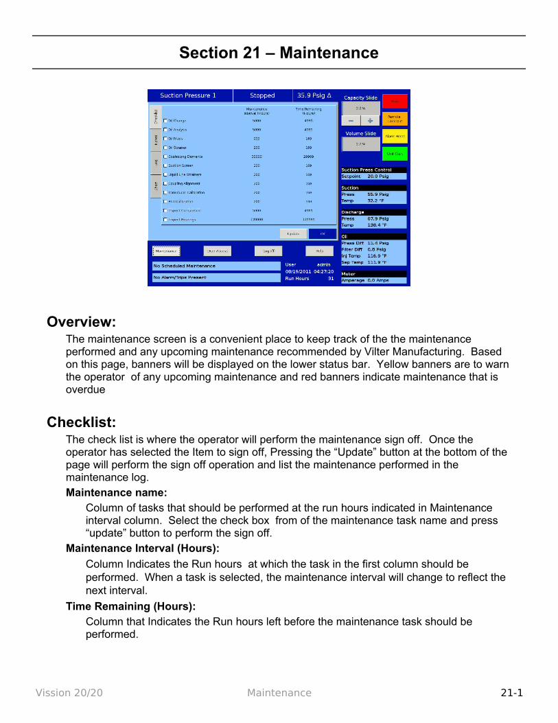
Section 21 – Maintenance
Overview:The maintenance screen is a convenient place to keep track of the the maintenance performed and any upcoming maintenance recommended by Vilter Manufacturing. Based on this page, banners will be displayed on the lower status bar. Yellow banners are to warn the operator of any upcoming maintenance and red banners indicate maintenance that is overdue
Checklist:The check list is where the operator will perform the maintenance sign off. Once the operator has selected the Item to sign off, Pressing the “Update” button at the bottom of the page will perform the sign off operation and list the maintenance performed in the maintenance log. Maintenance name:
Column of tasks that should be performed at the run hours indicated in Maintenance interval column. Select the check box from of the maintenance task name and press “update” button to perform the sign off.
Maintenance Interval (Hours):
Column Indicates the Run hours at which the task in the first column should be performed. When a task is selected, the maintenance interval will change to reflect the next interval.
Time Remaining (Hours):Column that Indicates the Run hours left before the maintenance task should be performed.
Vission 20/20 Maintenance 21-1
Notes:The notes tab allows the operator to make notes to any other personnel that might have access to the Vission 20/20. This space can be used for anything the operator wishes.
Log:The maintenance log tab list all the maintenance tasked perform in descending order.
Date:
Lists the date the maintenance task was performed
Time:
Lists the time the maintenance task was performed
User:
Lists the operator name who performed the maintenance task
Maintenance Performed:
Lists the maintenance task name that was performed
Run Hours:
Lists the run hours as which the maintenance task performed
Chart:This Chart is a the original Maintenance chart that is provided with the compressor
Vission 20/20 Maintenance 21-2
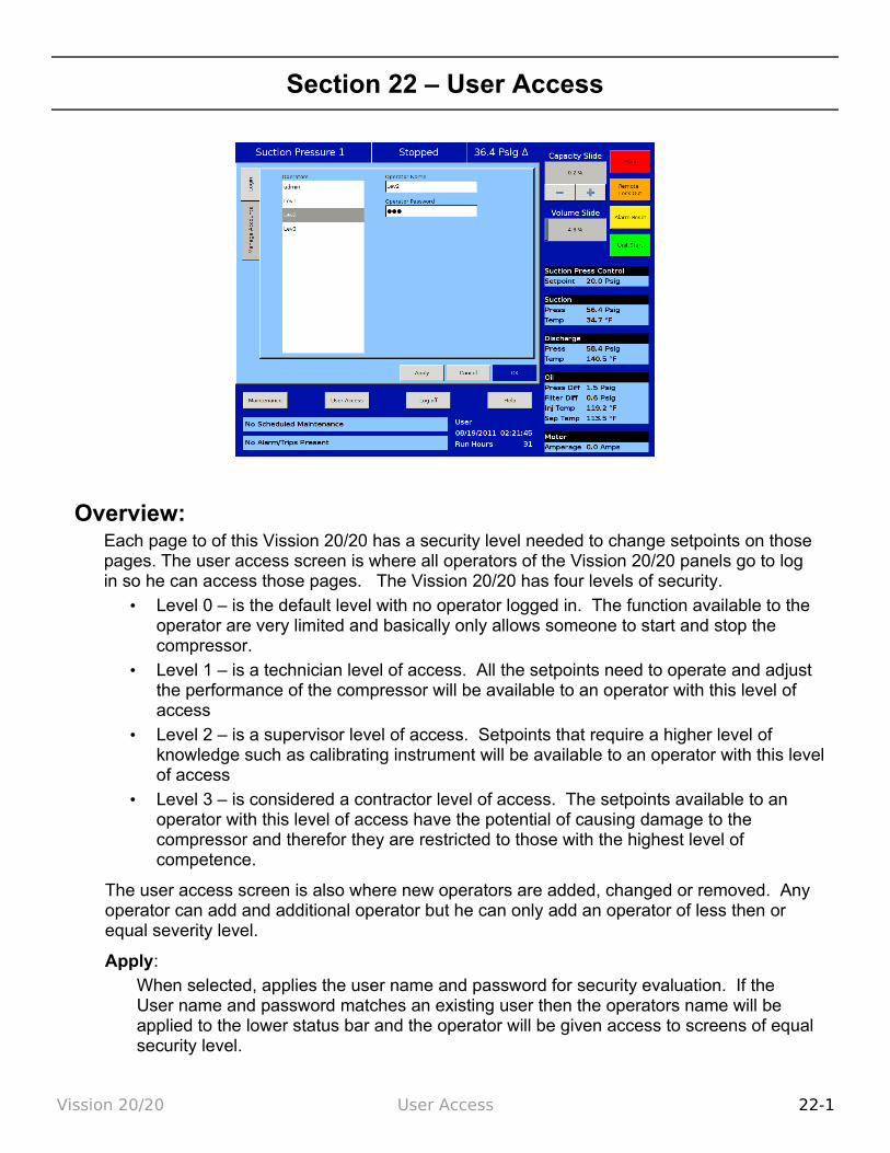
Section 22 – User Access
Overview:Each page to of this Vission 20/20 has a security level needed to change setpoints on those pages. The user access screen is where all operators of the Vission 20/20 panels go to log in so he can access those pages. The Vission 20/20 has four levels of security.
• Level 0 – is the default level with no operator logged in. The function available to the operator are very limited and basically only allows someone to start and stop the compressor.
• Level 1 – is a technician level of access. All the setpoints need to operate and adjust the performance of the compressor will be available to an operator with this level of access
• Level 2 – is a supervisor level of access. Setpoints that require a higher level of knowledge such as calibrating instrument will be available to an operator with this level of access
• Level 3 – is considered a contractor level of access. The setpoints available to an operator with this level of access have the potential of causing damage to the compressor and therefor they are restricted to those with the highest level of competence.
The user access screen is also where new operators are added, changed or removed. Any operator can add and additional operator but he can only add an operator of less then or equal severity level.
Apply:When selected, applies the user name and password for security evaluation. If the User name and password matches an existing user then the operators name will be applied to the lower status bar and the operator will be given access to screens of equal security level.
Vission 20/20 User Access 22-1
Login:The Login tab is where an operator will enter his user name and password in order to gain access to Vission 20/20 screens.Operators:
All operators that have been added to the Vission 20/20 user tables will be displayed in this window. If a name of an operator is selected from this window, the name is added to the “Operator Name” entry box.
Operator Name:
The operator will add the user-name for his account in this entry box. The operator can either select the user-name from the operators window or enter the name manually by touching the entry box and entering the name via the pop-up keyboard.
Operator Password:The operator will enter in him password.
Manage Accounts:
This tab allows the addition, removal, and modification of authorize users.
Operators:
This window contains the list of authorized users already added to the Vission 20/20. Selecting a name from this list will add that name to the “Operator Name” entry box.
Operator Name:
The operator will add the user-name for the account to be added, removed or modified in this entry box. The operator can either select the user-name from the operators window if he wants to change or remove the user. Or to he can enter the name manually by touching the entry box and entering the name via the pop-up keyboard.
Operator Password:
The operator will add the password for the entered user name by touching the entry box and typing the password via the pop-up keyboard.
Verify Password:
The operator will re-enter the password for the entered user name by touching the entry box and typing the password via the pop-up keyboard.
Security Level:
The operator will need to select a security level for the account being added or modified. Only levels that are equal to or less than the operators own security level will be shown.
Add / Update:
Pressing this button will initiate the creation or modification of the specified account.
Delete:
Pressing this button will delete the specified account
Vission 20/20 User Access 22-2
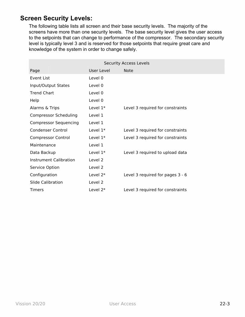
Screen Security Levels:The following table lists all screen and their base security levels. The majority of the screens have more than one security levels. The base security level gives the user access to the setpoints that can change to performance of the compressor. The secondary security level is typically level 3 and is reserved for those setpoints that require great care and knowledge of the system in order to change safely.
Security Access Levels
Page User Level Note
Event List Level 0
Input/Output States Level 0
Trend Chart Level 0
Help Level 0
Alarms & Trips Level 1* Level 3 required for constraints
Compressor Scheduling Level 1
Compressor Sequencing Level 1
Condenser Control Level 1* Level 3 required for constraints
Compressor Control Level 1* Level 3 required for constraints
Maintenance Level 1
Data Backup Level 1* Level 3 required to upload data
Instrument Calibration Level 2
Service Option Level 2
Configuration Level 2* Level 3 required for pages 3 - 6
Slide Calibration Level 2
Timers Level 2* Level 3 required for constraints
Vission 20/20 User Access 22-3
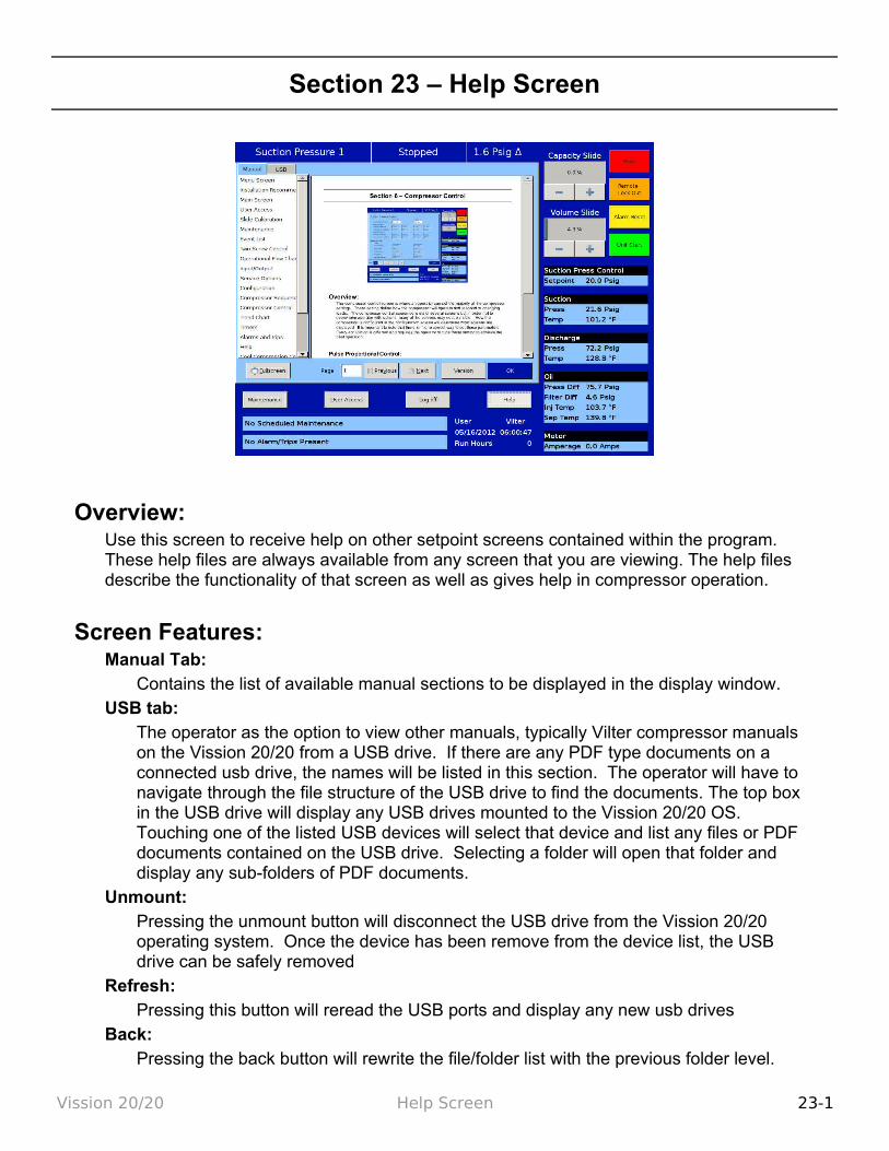
Section 23 – Help Screen
Overview:Use this screen to receive help on other setpoint screens contained within the program. These help files are always available from any screen that you are viewing. The help files describe the functionality of that screen as well as gives help in compressor operation.
Screen Features:Manual Tab:
Contains the list of available manual sections to be displayed in the display window.USB tab:
The operator as the option to view other manuals, typically Vilter compressor manuals on the Vission 20/20 from a USB drive. If there are any PDF type documents on a connected usb drive, the names will be listed in this section. The operator will have to navigate through the file structure of the USB drive to find the documents. The top box in the USB drive will display any USB drives mounted to the Vission 20/20 OS. Touching one of the listed USB devices will select that device and list any files or PDF documents contained on the USB drive. Selecting a folder will open that folder and display any sub-folders of PDF documents.
Unmount:Pressing the unmount button will disconnect the USB drive from the Vission 20/20 operating system. Once the device has been remove from the device list, the USB drive can be safely removed
Refresh:Pressing this button will reread the USB ports and display any new usb drives
Back:Pressing the back button will rewrite the file/folder list with the previous folder level.
Vission 20/20 Help Screen 23-1
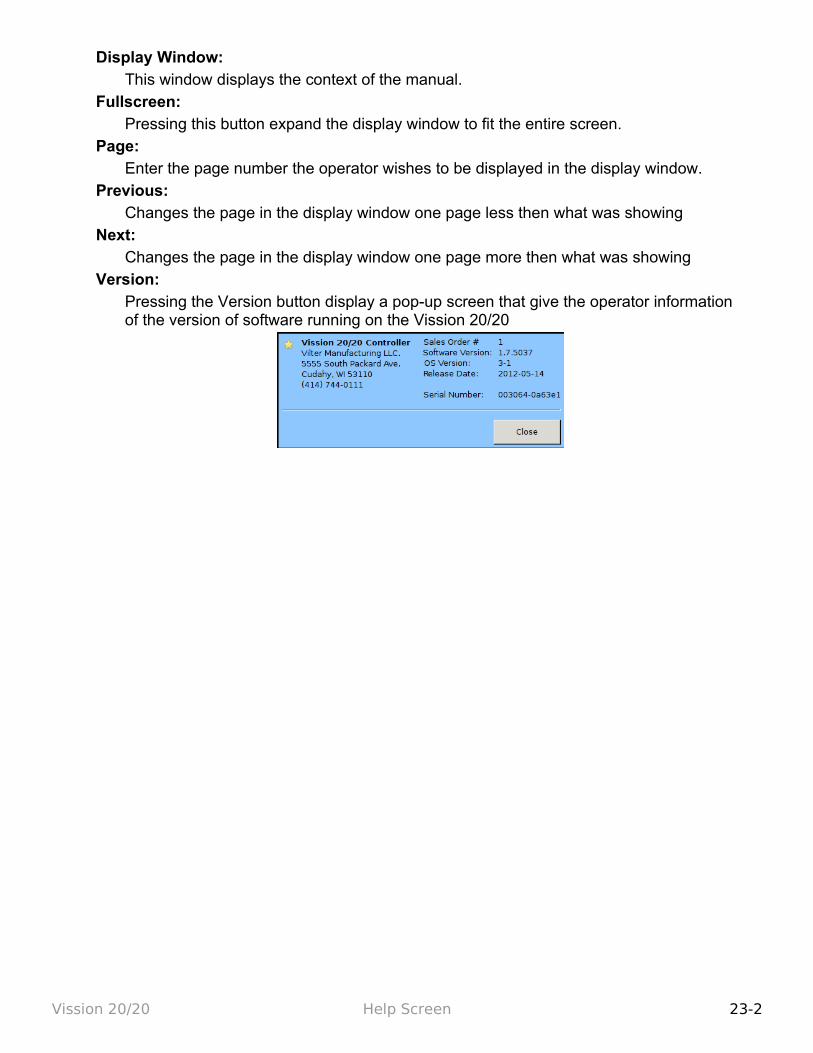
Display Window: This window displays the context of the manual.
Fullscreen: Pressing this button expand the display window to fit the entire screen.
Page: Enter the page number the operator wishes to be displayed in the display window.
Previous: Changes the page in the display window one page less then what was showing
Next: Changes the page in the display window one page more then what was showing
Version: Pressing the Version button display a pop-up screen that give the operator information of the version of software running on the Vission 20/20
Vission 20/20 Help Screen 23-2

Section 24 - Twin Screw Control
Overview:The Vission 20/20 is capable of operating a twin screw compressor from a number of different manufacturers. The Vission 20/20 currently operates as a twin screw controller in the full time oil pump and the no oil pump configuration.
Setup:Configuration Screen:
To setup the Vission 20/20 panel for twin screw, navigate to the configuration screen, page 2, and select “VRS” from the dropdown box label “Compressor”. Once selected, another dropdown box labeled “Operation Type” will appear directly below the “Com-pressor” dropdown box. You should also notice that the oil pump control becomes grayed out because the oil pump operation is now determined by the type of compres-sor that is select from the “Type” dropdown box.
• Standard - Selects the oil pump operation as “Full Time”
• Stal - Selects the oil pump control as “No pump”
Menu Changes: When selecting the twin screw option there will be other changes that occur in other menu pages.
• Volume position indicator will disappear from the main screen and right data panel
• Prelube oil pump alarms and trip values will be changed to default values for the twin screw
• Run oil pump alarm and trip values will be changed to default values for the twin
Vission 20/20 Twin Screw 24-1
screw
Operation:Once the twin screw is configured, its operation is very similar as the single screw and all options that are available for single screw configuration are also available for twin screw. The only operational difference is the manual mode of operation. Twin screw compressors can experience leaky slide seals that can cause the capacity slide to drift after it has been positioned by the controller. To counteract the capacity slide drift problem, the twin screw manual mode operation has an added anti-drift feature that automatically maintains the position the hydraulic actuator to counteract the drift of the capacity slide associated with leaky slide seals.
Vission 20/20 Twin Screw 24-2

Section 25 - Cool Compression Control
Overview:The cool compression compressor operation is similar to the standard single screw packages, except that there is no external oil cooler to the unit. A blanket of liquid ammonia lies on top of the oil in the oil separator. The liquid ammonia level is regulated by sensing the liquid ammonia level with a level probe, and using a positioning valve to vary the amount of liquid ammonia be-ing added to the separator. The cooling occurs through the entire compression and separation process. The Cool Compression compressor does not have an oil pump. When the Cool Compression compressor unit is commanded to start, the control panel first insures that the slide valves are at their minimum positions. The suction oil injection solenoid (SOI) is ener-gized – allowing a path for oil to flow into the compressor. The compressor now starts. There is an initial pressure drop in the suction chamber of the compressor and a corresponding in-crease in pressure on the discharge of the compressor. This creates a pressure differential that forces the oil and liquid ammonia mixture through the suction oil injection line into the suc-tion chamber of the compressor. This oil and liquid provides lubrication and cooling until full pressure differential lubrication is attained. As the differential pressure increases, the oil and liquid ammonia is now injected into the screw during the compression process and the oil injec-tion valve is allowed to close.
Setup:Configuration Screen:
To setup the Vission 20/20 panel for Cool Compression, first insure that an analog output card is installed in the panel, and it is selected/enabled from page 6 of the configuration screen. Navigate to configuration page 2, and select “R717-Cool Comp” from the drop-down box that is labeled “Refrigerant”. Once selected “Cool Compression” option will ap-
Vission 20/20 Cool Compression 25-1
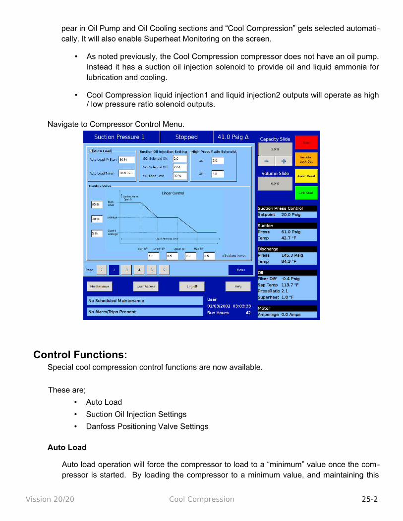
pear in Oil Pump and Oil Cooling sections and “Cool Compression” gets selected automati-cally. It will also enable Superheat Monitoring on the screen.
• As noted previously, the Cool Compression compressor does not have an oil pump. Instead it has a suction oil injection solenoid to provide oil and liquid ammonia for lubrication and cooling.
• Cool Compression liquid injection1 and liquid injection2 outputs will operate as high / low pressure ratio solenoid outputs.
Navigate to Compressor Control Menu.
Control Functions:Special cool compression control functions are now available.
These are;
• Auto Load
• Suction Oil Injection Settings
• Danfoss Positioning Valve Settings
Auto Load
Auto load operation will force the compressor to load to a “minimum” value once the com-pressor is started. By loading the compressor to a minimum value, and maintaining this
Vission 20/20 Cool Compression 25-2
capacity, we create a pressure ratio across the compressor, to insure adequate lubrication of the compressor, and also insuring that the compressor does not experience high dis-charge superheat conditions. Since compressor lubrication is of greatest importance, all load limiting is disabled when auto load is engaged.
Auto Load @ Start = Defines the value at which Compressor (capacity slide) should be loaded (and maintained) at start if Auto Load is enabled.
Auto Load Timer = This timer defines the maximum time that the Auto Load operation will be engaged. After the timer expires, Auto Load will be disengaged.
Auto load will be disengaged when one of the following conditions occur;
• Pressure ratio reaches a value of 2.0 or greater.
• Compressor has been running for 10 minutes (defined by Auto Load Timer).
• Suction pressure setpoint has been reached.
Suction Oil Injection Setting
In order to maintain adequate lubrication during low pressure ratio conditions, the Suction Oil Injection (SOI) solenoid is turned ON and the capacity of the compressor is reduced. The SOI solenoid will cycle ON and OFF based on the pressure ratio across the compres-sor.
SOI Solenoid ON = Defines the Pressure ratio value at which SOI is turned ON (default 2.00) (Digital Output Board #1:2).
SOI Solenoid OFF = Defines the Pressure ratio value at which SOI is turned OFF (default 2.04) (Digital Output Board #1:2).
SOI Load Limit = Defines the capacity slide position at which the compressor capacity slide will unload to if pressure ratio falls below “SOI Solenoid ON” setpoint. This setpoint is not active until Auto Load disengages.
The SOI solenoid will also cycle on if the discharge temp superheat reaches a value of 5 deg F (this value is not settable). Generally, anytime the SOI solenoid cycles on, the ca-pacity is limited to the SOI Load Limit setpoint. However, this is not true if the SOI sole-noid cycles on based on the discharge temp superheat 5 deg F rule. If discharge temp su-perheat continues to climb and reaches a value of 6 deg F, the compressor will be inhib-ited from loading. If discharge temp superheat still continues to climb and reaches a value of 8 degrees F or more, then the compressor will be unloaded until the superheat drops below 8 deg F or the capacity has reached the SOI Load Limit setting.
Using a Positioning Valve for Liquid Ammonia Level Control
Vission 20/20 Cool Compression 25-3

A level probe inserted in the oil separator detects liquid ammonia level. Based on the level of the ammonia (0-100%), the level probe sends a directly proportional 4-20 mA signal to the Vis-sion 20/20 panel. The positioning valve is then positioned based on the Positioning Valve set -tings graph shown in Figure 2.
Looking at the graph, when the compressor starts, the positioning valve placement (Vertical Axis) is determined based on the liquid ammonia level that is sensed in the oil separator (Hori -zontal Axis). It can be seen that as the liquid ammonia level increases (corresponding to a larger mA value), the positioning valve moves towards a closed position.
The Positioning Valve position (0-100% limits) is defined at three distinct levels;
• Start Level (lowest liquid ammonia level - positioning valve at maximum open posi-tion)
• Leakage (normal operating position and ammonia level)
• Overfill Leakage ( highest liquid ammonia level – positioning valve at minimum open position.
Liquid ammonia levels are defined at four distinct levels (4-20ma limits);
• Start SP (minimum liquid ammonia level in separator – the positioning valve is max-imum open.)
• Linear SP (minimum level of liquid ammonia for normal operating position)
• Upper SP (maximum level of liquid ammonia for normal operating position)
• Max SP (maximum liquid ammonia level – positioning valve is minimum open posi-tion, maintaining some leakage)
On Alarms and Trips screen, Low Oil Separator Start Temperature, High Filter Diff Start Pres-sure settings are disabled.
On Timers screen Oil Level #1 Safety Trip Delay, Oil Level #2 Safety Trip Delay settings are disabled.
Operational Differences from Single Screw:Once the Cool Compression is configured, most setup options available for a standard single screw are also available for Cool Compression. However, there are significant operational dif-ferences from the standard single screw, mostly associated with the compressor safeties:
1. The Cool Compression program ignores,
• Low Oil Separator Alarm / Trip at start
• High Filter Differential at start
Vission 20/20 Cool Compression 25-4
• Prelub Oil Pressure Alarm and Trip
• Run Oil Pressure Alarm and Trip (Pressure Ratios are monitored instead).
• High Discharge Temp Alarm and Trip (Discharge Temp Superheat is monitored)
• Low Suction Temp Alarm and Trip
• Low Oil Injection Temp Alarm and Trip
• High Oil Injection Temp Alarm and Trip
2. SOI solenoid is forced on for first 60 seconds of running and 10 minutes after compres-sor is stopped.
3. Auto Load Enabled: When Auto Load is engaged at start, it then maintains the position of capacity slide to the Auto Load limit (approx : 30 %, but less than 50 %). It displays status message “Cool Compression Capacity Hold” when it is running. Unless Auto load is disengaged compressor will run at auto load limit position. Auto load disengages if enough Pressure Ratio is built (typically more than 2.04) or setpoints are achieved.
4. Suction Oil Injection Solenoid: During normal operation if pressure ratio drops to a lower value (typically below 2.00) then it energizes SOI solenoid and maintains the po-sition of capacity slide to the SOI Load limit(approx : 30 %, less than 50 %). It also dis-plays status message “Cool Compression Capacity Hold”. If enough Pressure Ratio is built across compressor (typically more than 2.04), it agains resumes the run mode and control normally.
5. It performs Cool Compression specific checks periodically like,
• Controlling the liquid level positioning valve as liquid ammonia level changes
• Low / high Pressure Oil Injection ports control as Pressure Ratio and Superheat temperature changes
Supplemental Oil Cooling Solenoids
Some cool compression units will have supplemental oil cooling solenoids. One is called the suction liquid injection solenoid and is controlled via discharge superheat. When the discharge superheat reaches 5 deg F, the solenoid is turned on. When it falls back to be-low 4 deg F, the solenoid is turned off. An additional solenoid (referenced as SV4 – as called the High Press Ratio solenoid) provides supplemental oil cooling based on pressure ratio. When the pressure ratio rises above 5.0, the solenoid is turned on. When the pres-sure ratio falls back to below 4.8, the solenoid is turned off.
Level Switches
Vission 20/20 Cool Compression 25-5
There are two level switches in the oil separator, a “high" and a "low". During normal run-ning operation, the oil level is above both switches. When the oil level starts to drop – and opens the high level switch, a 10 minute timer starts. When the timer elapses a flashing “add oil to middle of sight glass” message appears on the main screen.
When the operator adds enough oil to close the high level switch, the message disap-pears.
If he fails to add oil, and the oil level continues to drop - thereby opening the "low" oil level switch, again a 10 minute timer starts. When the timer elapses, the compressor shut-downs IMMEDIATELY and displays “Low Oil Level” failure.
When he adds enough oil to close the low level switch, then he is able to press the reset button and clear the “Low Oil Level” failure. At the same time – the “Add Oil” message is cleared. Neither message will be cleared until he presses the reset button and the low oil level switch is satisfied. It is the operator’s responsibility to add enough oil so that the oil level reaches the middle of the middle sight glass.
Oil Level Messaging after Compressor STOPS
The low level switch is monitored after the compressor stops. If the switch opens AFTER the compressor stops, a two minute timer starts timing. If the switch stays open, and the timer expires, a failure is generated called “Lo Oil Level Fail after Stop” and the compres-sor is disabled from restarting until oil is added to close the low level switch. Note that this failure is generated ONLY when the low level switch opens AFTER the compressor stops.
Vission 20/20 Cool Compression 25-6


Version 1.8


