Embed Size (px)
Citation preview
640REFRIGERATION CYCLES
pressure drops in the connecting lines between the components, show the cycle on a T-s diagram with respect to satura-tion lines, and determine (a) the rate of heat removal from the refrigerated space and the power input to the compres-sor, (b) the isentropic efficiency of the compressor, and (c) the COP of the refrigerator. Answers: (a) 9.42 kW, 3.63 kW,
(b) 74.1 percent, (c) 2.60
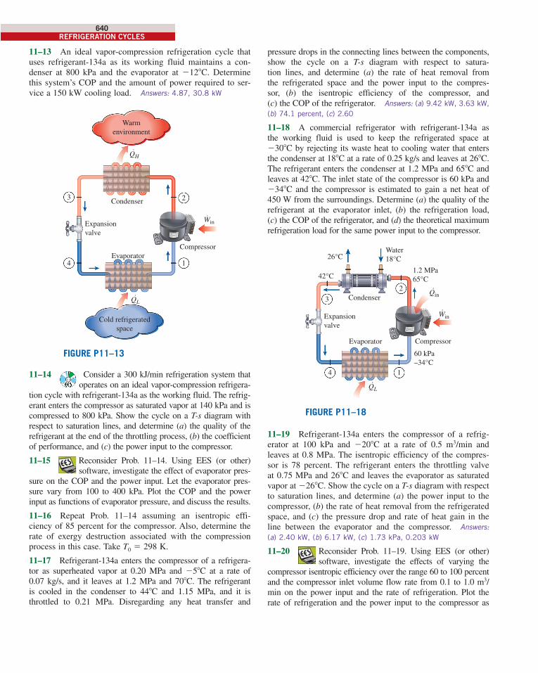
11–18 A commercial refrigerator with refrigerant-134a as the working fluid is used to keep the refrigerated space at 2308C by rejecting its waste heat to cooling water that enters the condenser at 188C at a rate of 0.25 kg/s and leaves at 268C. The refrigerant enters the condenser at 1.2 MPa and 658C and leaves at 428C. The inlet state of the compressor is 60 kPa and 2348C and the compressor is estimated to gain a net heat of 450 W from the surroundings. Determine (a) the quality of the refrigerant at the evaporator inlet, (b) the refrigeration load, (c) the COP of the refrigerator, and (d) the theoretical maximum refrigeration load for the same power input to the compressor.
1.2 MPa65°C
60 kPa–34°C
Water18°C26°C
42°C
·
2
3
14
Compressor
Condenser
WinExpansionvalve
·QL
Evaporator
·Qin
FIGURE P11–18
11–19 Refrigerant-134a enters the compressor of a refrig-erator at 100 kPa and 2208C at a rate of 0.5 m3/min and leaves at 0.8 MPa. The isentropic efficiency of the compres-sor is 78 percent. The refrigerant enters the throttling valve at 0.75 MPa and 268C and leaves the evaporator as saturated vapor at 2268C. Show the cycle on a T-s diagram with respect to saturation lines, and determine (a) the power input to the compressor, (b) the rate of heat removal from the refrigerated space, and (c) the pressure drop and rate of heat gain in the line between the evaporator and the compressor. Answers:
(a) 2.40 kW, (b) 6.17 kW, (c) 1.73 kPa, 0.203 kW
11–20 Reconsider Prob. 11–19. Using EES (or other) software, investigate the effects of varying the
compressor isentropic efficiency over the range 60 to 100 percent and the compressor inlet volume flow rate from 0.1 to 1.0 m3/min on the power input and the rate of refrigeration. Plot the rate of refrigeration and the power input to the compressor as
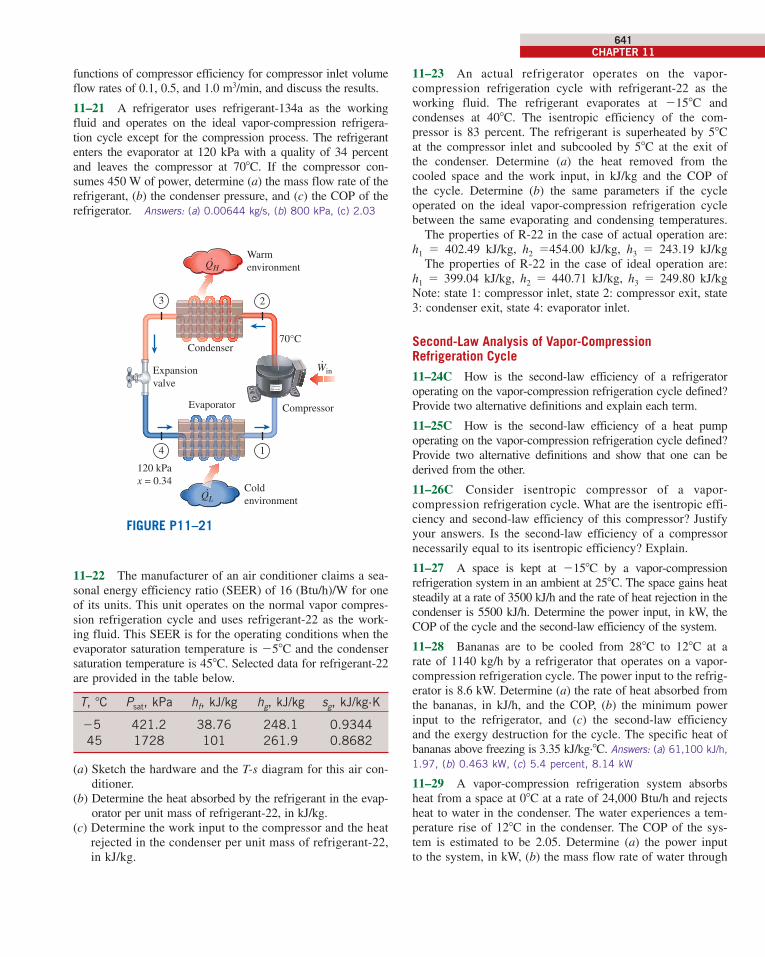
11–13 An ideal vapor-compression refrigeration cycle that uses refrigerant-134a as its working fluid maintains a con-denser at 800 kPa and the evaporator at 2128C. Determine this system’s COP and the amount of power required to ser-vice a 150 kW cooling load. Answers: 4.87, 30.8 kW
QH˙
Win˙
QL ˙
Compressor
Condenser
Cold refrigerated
space
Expansion
valve
Evaporator4
3
1
2
Warm
environment
FIGURE P11–13
11–14 Consider a 300 kJ/min refrigeration system that operates on an ideal vapor-compression refrigera-
tion cycle with refrigerant-134a as the working fluid. The refrig-erant enters the compressor as saturated vapor at 140 kPa and is compressed to 800 kPa. Show the cycle on a T-s diagram with respect to saturation lines, and determine (a) the quality of the refrigerant at the end of the throttling process, (b) the coefficient of performance, and (c) the power input to the compressor.
11–15 Reconsider Prob. 11–14. Using EES (or other) software, investigate the effect of evaporator pres-
sure on the COP and the power input. Let the evaporator pres-sure vary from 100 to 400 kPa. Plot the COP and the power input as functions of evaporator pressure, and discuss the results.
11–16 Repeat Prob. 11–14 assuming an isentropic effi-ciency of 85 percent for the compressor. Also, determine the rate of exergy destruction associated with the compression process in this case. Take T0 5 298 K.
11–17 Refrigerant-134a enters the compressor of a refrigera-tor as superheated vapor at 0.20 MPa and 258C at a rate of 0.07 kg/s, and it leaves at 1.2 MPa and 708C. The refrigerant is cooled in the condenser to 448C and 1.15 MPa, and it is throttled to 0.21 MPa. Disregarding any heat transfer and
cen98179_ch11_607-654.indd 640cen98179_ch11_607-654.indd 640 11/28/13 3:56 PM11/28/13 3:56 PM
CHAPTER 11641
11–23 An actual refrigerator operates on the vapor-compression refrigeration cycle with refrigerant-22 as the working fluid. The refrigerant evaporates at 2158C and condenses at 408C. The isentropic efficiency of the com-pressor is 83 percent. The refrigerant is superheated by 58C at the compressor inlet and subcooled by 58C at the exit of the condenser. Determine (a) the heat removed from the cooled space and the work input, in kJ/kg and the COP of the cycle. Determine (b) the same parameters if the cycle operated on the ideal vapor-compression refrigeration cycle between the same evaporating and condensing temperatures. The properties of R-22 in the case of actual operation are: h1 5 402.49 kJ/kg, h2 5454.00 kJ/kg, h3 5 243.19 kJ/kg The properties of R-22 in the case of ideal operation are: h1 5 399.04 kJ/kg, h2 5 440.71 kJ/kg, h3 5 249.80 kJ/kgNote: state 1: compressor inlet, state 2: compressor exit, state 3: condenser exit, state 4: evaporator inlet.
Second-Law Analysis of Vapor-Compression Refrigeration Cycle
11–24C How is the second-law efficiency of a refrigerator operating on the vapor-compression refrigeration cycle defined? Provide two alternative definitions and explain each term.
11–25C How is the second-law efficiency of a heat pump operating on the vapor-compression refrigeration cycle defined? Provide two alternative definitions and show that one can be derived from the other.
11–26C Consider isentropic compressor of a vapor-compression refrigeration cycle. What are the isentropic effi-ciency and second-law efficiency of this compressor? Justify your answers. Is the second-law efficiency of a compressor necessarily equal to its isentropic efficiency? Explain.
11–27 A space is kept at 2158C by a vapor-compression refrigeration system in an ambient at 258C. The space gains heat steadily at a rate of 3500 kJ/h and the rate of heat rejection in the condenser is 5500 kJ/h. Determine the power input, in kW, the COP of the cycle and the second-law efficiency of the system.
11–28 Bananas are to be cooled from 288C to 128C at a rate of 1140 kg/h by a refrigerator that operates on a vapor-compression refrigeration cycle. The power input to the refrig-erator is 8.6 kW. Determine (a) the rate of heat absorbed from the bananas, in kJ/h, and the COP, (b) the minimum power input to the refrigerator, and (c) the second-law efficiency and the exergy destruction for the cycle. The specific heat of bananas above freezing is 3.35 kJ/kg·8C. Answers: (a) 61,100 kJ/h,
1.97, (b) 0.463 kW, (c) 5.4 percent, 8.14 kW
11–29 A vapor-compression refrigeration system absorbs heat from a space at 08C at a rate of 24,000 Btu/h and rejects heat to water in the condenser. The water experiences a tem-perature rise of 128C in the condenser. The COP of the sys-tem is estimated to be 2.05. Determine (a) the power input to the system, in kW, (b) the mass flow rate of water through
functions of compressor efficiency for compressor inlet volume flow rates of 0.1, 0.5, and 1.0 m3/min, and discuss the results.
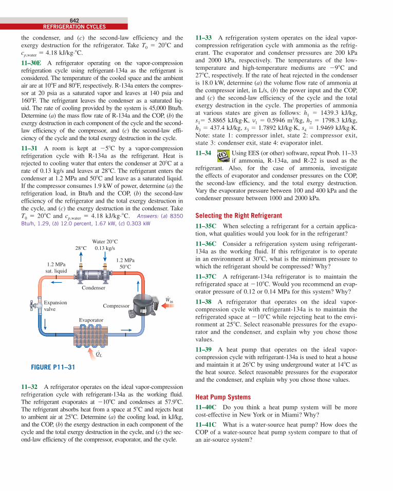
11–21 A refrigerator uses refrigerant-134a as the working fluid and operates on the ideal vapor-compression refrigera-tion cycle except for the compression process. The refrigerant enters the evaporator at 120 kPa with a quality of 34 percent and leaves the compressor at 708C. If the compressor con-sumes 450 W of power, determine (a) the mass flow rate of the refrigerant, (b) the condenser pressure, and (c) the COP of the refrigerator. Answers: (a) 0.00644 kg/s, (b) 800 kPa, (c) 2.03
FIGURE P11–21
120 kPax = 0.34
.QL
Coldenvironment
70°C
Warmenvironment
·
23
14
Compressor
Condenser
WinExpansionvalve
Evaporator
.QH
11–22 The manufacturer of an air conditioner claims a sea-sonal energy efficiency ratio (SEER) of 16 (Btu/h)/W for one of its units. This unit operates on the normal vapor compres-sion refrigeration cycle and uses refrigerant-22 as the work-ing fluid. This SEER is for the operating conditions when the evaporator saturation temperature is 258C and the condenser saturation temperature is 458C. Selected data for refrigerant-22 are provided in the table below.
T, 8C Psat, kPa hf, kJ/kg hg, kJ/kg sg, kJ/kg·K
25 421.2 38.76 248.1 0.9344
45 1728 101 261.9 0.8682
(a) Sketch the hardware and the T-s diagram for this air con-ditioner.
(b) Determine the heat absorbed by the refrigerant in the evap-orator per unit mass of refrigerant-22, in kJ/kg.
(c) Determine the work input to the compressor and the heat rejected in the condenser per unit mass of refrigerant-22, in kJ/kg.
cen98179_ch11_607-654.indd 641cen98179_ch11_607-654.indd 641 11/28/13 3:56 PM11/28/13 3:56 PM
642REFRIGERATION CYCLES
11–33 A refrigeration system operates on the ideal vapor-compression refrigeration cycle with ammonia as the refrig-erant. The evaporator and condenser pressures are 200 kPa and 2000 kPa, respectively. The temperatures of the low-temperature and high-temperature mediums are 298C and 278C, respectively. If the rate of heat rejected in the condenser is 18.0 kW, determine (a) the volume flow rate of ammonia at the compressor inlet, in L/s, (b) the power input and the COP, and (c) the second-law efficiency of the cycle and the total exergy destruction in the cycle. The properties of ammonia at various states are given as follows: h1 5 1439.3 kJ/kg, s15 5.8865 kJ/kg·K, v1 5 0.5946 m3/kg, h2 5 1798.3 kJ/kg, h3 5 437.4 kJ/kg, s3 5 1.7892 kJ/kg·K, s4 5 1.9469 kJ/kg·K. Note: state 1: compressor inlet, state 2: compressor exit, state 3: condenser exit, state 4: evaporator inlet.
11–34 Using EES (or other) software, repeat Prob. 11–33 if ammonia, R-134a, and R-22 is used as the
refrigerant. Also, for the case of ammonia, investigate the effects of evaporator and condenser pressures on the COP, the second-law efficiency, and the total exergy destruction. Vary the evaporator pressure between 100 and 400 kPa and the condenser pressure between 1000 and 2000 kPa.
Selecting the Right Refrigerant
11–35C When selecting a refrigerant for a certain applica-tion, what qualities would you look for in the refrigerant?
11–36C Consider a refrigeration system using refrigerant-134a as the working fluid. If this refrigerator is to operate in an environment at 308C, what is the minimum pressure to which the refrigerant should be compressed? Why?
11–37C A refrigerant-134a refrigerator is to maintain the refrigerated space at 2108C. Would you recommend an evap-orator pressure of 0.12 or 0.14 MPa for this system? Why?
11–38 A refrigerator that operates on the ideal vapor- compression cycle with refrigerant-134a is to maintain the refrigerated space at 2108C while rejecting heat to the envi-ronment at 258C. Select reasonable pressures for the evapo-rator and the condenser, and explain why you chose those values.
11–39 A heat pump that operates on the ideal vapor- compression cycle with refrigerant-134a is used to heat a house and maintain it at 268C by using underground water at 148C as the heat source. Select reasonable pressures for the evaporator and the condenser, and explain why you chose those values.
Heat Pump Systems11–40C Do you think a heat pump system will be more cost-effective in New York or in Miami? Why?
11–41C What is a water-source heat pump? How does the COP of a water-source heat pump system compare to that of an air-source system?
the condenser, and (c) the second-law efficiency and the exergy destruction for the refrigerator. Take T0 5 208C and cp,water 5 4.18 kJ/kg·8C.
11–30E A refrigerator operating on the vapor-compression refrigeration cycle using refrigerant-134a as the refrigerant is considered. The temperature of the cooled space and the ambient air are at 108F and 808F, respectively. R-134a enters the compres-sor at 20 psia as a saturated vapor and leaves at 140 psia and 1608F. The refrigerant leaves the condenser as a saturated liq-uid. The rate of cooling provided by the system is 45,000 Btu/h. Determine (a) the mass flow rate of R-134a and the COP, (b) the exergy destruction in each component of the cycle and the second-law efficiency of the compressor, and (c) the second-law effi-ciency of the cycle and the total exergy destruction in the cycle.
11–31 A room is kept at 258C by a vapor-compression refrigeration cycle with R-134a as the refrigerant. Heat is rejected to cooling water that enters the condenser at 208C at a rate of 0.13 kg/s and leaves at 288C. The refrigerant enters the condenser at 1.2 MPa and 508C and leave as a saturated liquid. If the compressor consumes 1.9 kW of power, determine (a) the refrigeration load, in Btu/h and the COP, (b) the second-law efficiency of the refrigerator and the total exergy destruction in the cycle, and (c) the exergy destruction in the condenser. Take T0 5 208C and cp,water 5 4.18 kJ/kg·8C. Answers: (a) 8350
Btu/h, 1.29, (b) 12.0 percent, 1.67 kW, (c) 0.303 kW
1.2 MPa50°C1.2 MPa
sat. liquid
Water 20°C0.13 kg/s28°C
·
·
Compressor
Condenser
WinExpansionvalve
QL
Evaporator
FIGURE P11–31
11–32 A refrigerator operates on the ideal vapor-compression refrigeration cycle with refrigerant-134a as the working fluid. The refrigerant evaporates at 2108C and condenses at 57.98C. The refrigerant absorbs heat from a space at 58C and rejects heat to ambient air at 258C. Determine (a) the cooling load, in kJ/kg, and the COP, (b) the exergy destruction in each component of the cycle and the total exergy destruction in the cycle, and (c) the sec-ond-law efficiency of the compressor, evaporator, and the cycle.
cen98179_ch11_607-654.indd 642cen98179_ch11_607-654.indd 642 11/28/13 3:56 PM11/28/13 3:56 PM
CHAPTER 11643
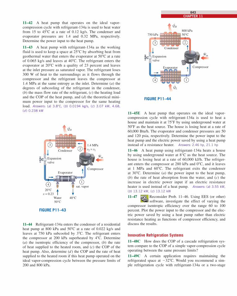
750 kPa800 kPa50°C
·
23
14
Compressor
Condenser
WinExpansionvalve
Evaporator
.QH
.QL
FIGURE P11–44
11–45E A heat pump that operates on the ideal vapor-compression cycle with refrigerant-134a is used to heat a house and maintain it at 758F by using underground water at 508F as the heat source. The house is losing heat at a rate of 60,000 Btu/h. The evaporator and condenser pressures are 50 and 120 psia, respectively. Determine the power input to the heat pump and the electric power saved by using a heat pump instead of a resistance heater. Answers: 2.46 hp, 21.1 hp
11–46 A heat pump using refrigerant-134a heats a house by using underground water at 8°C as the heat source. The house is losing heat at a rate of 60,000 kJ/h. The refriger-ant enters the compressor at 280 kPa and 08C, and it leaves at 1 MPa and 608C. The refrigerant exits the condenser at 308C. Determine (a) the power input to the heat pump, (b) the rate of heat absorption from the water, and (c) the increase in electric power input if an electric resistance heater is used instead of a heat pump. Answers: (a) 3.55 kW,
(b) 13.12 kW, (c) 13.12 kW
11–47 Reconsider Prob. 11–46. Using EES (or other) software, investigate the effect of varying the
compressor isentropic efficiency over the range 60 to 100 percent. Plot the power input to the compressor and the elec-tric power saved by using a heat pump rather than electric resistance heating as functions of compressor efficiency, and discuss the results.
Innovative Refrigeration Systems11–48C How does the COP of a cascade refrigeration sys-tem compare to the COP of a simple vapor-compression cycle operating between the same pressure limits?
11–49C A certain application requires maintaining the refrigerated space at 2328C. Would you recommend a sim-ple refrigeration cycle with refrigerant-134a or a two-stage
11–42 A heat pump that operates on the ideal vapor- compression cycle with refrigerant-134a is used to heat water from 15 to 458C at a rate of 0.12 kg/s. The condenser and evaporator pressures are 1.4 and 0.32 MPa, respectively. Determine the power input to the heat pump.
11–43 A heat pump with refrigerant-134a as the working fluid is used to keep a space at 258C by absorbing heat from geothermal water that enters the evaporator at 508C at a rate of 0.065 kg/s and leaves at 408C. The refrigerant enters the evaporator at 208C with a quality of 23 percent and leaves at the inlet pressure as saturated vapor. The refrigerant loses 300 W of heat to the surroundings as it flows through the compressor and the refrigerant leaves the compressor at 1.4 MPa at the same entropy as the inlet. Determine (a) the degrees of subcooling of the refrigerant in the condenser, (b) the mass flow rate of the refrigerant, (c) the heating load and the COP of the heat pump, and (d) the theoretical mini-mum power input to the compressor for the same heating load. Answers: (a) 3.88C, (b) 0.0194 kg/s, (c) 3.07 kW, 4.68,
(d ) 0.238 kW
1.4 MPas2 = s1
40°CWater50°C
20°Cx = 0.23
sat. vapor
·
23
14
Compressor
Condenser
WinExpansionvalve
Evaporator
.QH
FIGURE P11–43
11–44 Refrigerant-134a enters the condenser of a residential heat pump at 800 kPa and 508C at a rate of 0.022 kg/s and leaves at 750 kPa subcooled by 38C. The refrigerant enters the compressor at 200 kPa superheated by 48C. Determine (a) the isentropic efficiency of the compressor, (b) the rate of heat supplied to the heated room, and (c) the COP of the heat pump. Also, determine (d ) the COP and the rate of heat supplied to the heated room if this heat pump operated on the ideal vapor- compression cycle between the pressure limits of 200 and 800 kPa.
cen98179_ch11_607-654.indd 643cen98179_ch11_607-654.indd 643 11/28/13 3:56 PM11/28/13 3:56 PM
644REFRIGERATION CYCLES
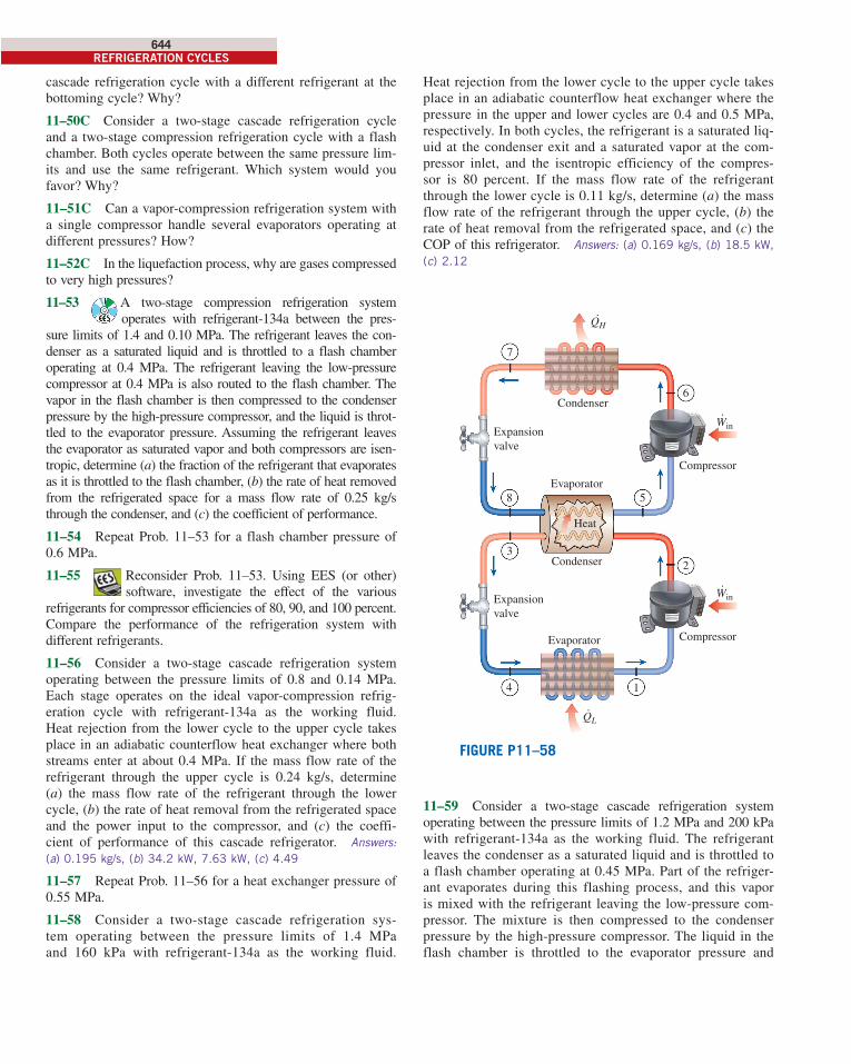
Heat rejection from the lower cycle to the upper cycle takes place in an adiabatic counterflow heat exchanger where the pressure in the upper and lower cycles are 0.4 and 0.5 MPa, respectively. In both cycles, the refrigerant is a saturated liq-uid at the condenser exit and a saturated vapor at the com-pressor inlet, and the isentropic efficiency of the compres-sor is 80 percent. If the mass flow rate of the refrigerant through the lower cycle is 0.11 kg/s, determine (a) the mass flow rate of the refrigerant through the upper cycle, (b) the rate of heat removal from the refrigerated space, and (c) the COP of this refrigerator. Answers: (a) 0.169 kg/s, (b) 18.5 kW,
(c) 2.12
·Win
·Win
5
Condenser
Evaporator
Compressor
Expansionvalve
7
Compressor
Expansionvalve
32
6
Condenser
Evaporator
4 1
Heat
8
.QH
.QL
FIGURE P11–58
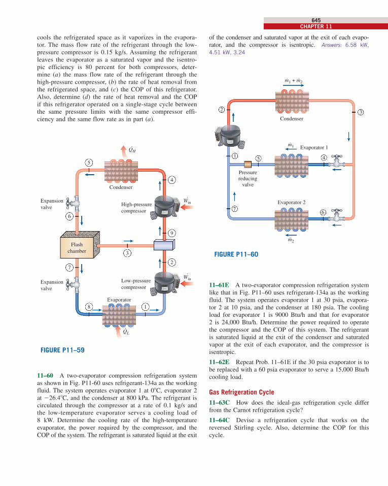
11–59 Consider a two-stage cascade refrigeration system operating between the pressure limits of 1.2 MPa and 200 kPa with refrigerant-134a as the working fluid. The refrigerant leaves the condenser as a saturated liquid and is throttled to a flash chamber operating at 0.45 MPa. Part of the refriger-ant evaporates during this flashing process, and this vapor is mixed with the refrigerant leaving the low-pressure com-pressor. The mixture is then compressed to the condenser pressure by the high-pressure compressor. The liquid in the flash chamber is throttled to the evaporator pressure and
cascade refrigeration cycle with a different refrigerant at the bottoming cycle? Why?
11–50C Consider a two-stage cascade refrigeration cycle and a two-stage compression refrigeration cycle with a flash chamber. Both cycles operate between the same pressure lim-its and use the same refrigerant. Which system would you favor? Why?
11–51C Can a vapor-compression refrigeration system with a single compressor handle several evaporators operating at different pressures? How?
11–52C In the liquefaction process, why are gases compressed to very high pressures?
11–53 A two-stage compression refrigeration system operates with refrigerant-134a between the pres-
sure limits of 1.4 and 0.10 MPa. The refrigerant leaves the con-denser as a saturated liquid and is throttled to a flash chamber operating at 0.4 MPa. The refrigerant leaving the low-pressure compressor at 0.4 MPa is also routed to the flash chamber. The vapor in the flash chamber is then compressed to the condenser pressure by the high-pressure compressor, and the liquid is throt-tled to the evaporator pressure. Assuming the refrigerant leaves the evaporator as saturated vapor and both compressors are isen-tropic, determine (a) the fraction of the refrigerant that evaporates as it is throttled to the flash chamber, (b) the rate of heat removed from the refrigerated space for a mass flow rate of 0.25 kg/s through the condenser, and (c) the coefficient of performance.
11–54 Repeat Prob. 11–53 for a flash chamber pressure of 0.6 MPa.
11–55 Reconsider Prob. 11–53. Using EES (or other) software, investigate the effect of the various
re frig erants for compressor efficiencies of 80, 90, and 100 percent. Compare the performance of the refrigeration system with different refrigerants.
11–56 Consider a two-stage cascade refrigeration system operating between the pressure limits of 0.8 and 0.14 MPa. Each stage operates on the ideal vapor-compression refrig-eration cycle with refrigerant-134a as the working fluid. Heat rejection from the lower cycle to the upper cycle takes place in an adiabatic counterflow heat exchanger where both streams enter at about 0.4 MPa. If the mass flow rate of the refrigerant through the upper cycle is 0.24 kg/s, determine (a) the mass flow rate of the refrigerant through the lower cycle, (b) the rate of heat removal from the refrigerated space and the power input to the compressor, and (c) the coeffi-cient of performance of this cascade refrigerator. Answers: (a) 0.195 kg/s, (b) 34.2 kW, 7.63 kW, (c) 4.49
11–57 Repeat Prob. 11–56 for a heat exchanger pressure of 0.55 MPa.
11–58 Consider a two-stage cascade refrigeration sys-tem operating between the pressure limits of 1.4 MPa and 160 kPa with refrigerant-134a as the working fluid.
cen98179_ch11_607-654.indd 644cen98179_ch11_607-654.indd 644 11/28/13 3:56 PM11/28/13 3:56 PM
CHAPTER 11645
of the condenser and saturated vapor at the exit of each evapo-rator, and the compressor is isentropic. Answers: 6.58 kW,
4.51 kW, 3.24
Pressurereducing
valve
Evaporator 1
Evaporator 27
1
m2˙
m1˙
m1 + m2˙ ˙
5
Condenser
2 3
4
6
FIGURE P11–60
11–61E A two-evaporator compression refrigeration system like that in Fig. P11–60 uses refrigerant-134a as the working fluid. The system operates evaporator 1 at 30 psia, evapora-tor 2 at 10 psia, and the condenser at 180 psia. The cooling load for evaporator 1 is 9000 Btu/h and that for evaporator 2 is 24,000 Btu/h. Determine the power required to operate the compressor and the COP of this system. The refrigerant is saturated liquid at the exit of the condenser and saturated vapor at the exit of each evaporator, and the compressor is isentropic.
11–62E Repeat Prob. 11–61E if the 30 psia evaporator is to be replaced with a 60 psia evaporator to serve a 15,000 Btu/h cooling load.
Gas Refrigeration Cycle
11–63C How does the ideal-gas refrigeration cycle differ from the Carnot refrigeration cycle?
11–64C Devise a refrigeration cycle that works on the reversed Stirling cycle. Also, determine the COP for this cycle.
cools the refrigerated space as it vaporizes in the evapora-tor. The mass flow rate of the refrigerant through the low-pressure compressor is 0.15 kg/s. Assuming the refrigerant leaves the evaporator as a saturated vapor and the isentro-pic efficiency is 80 percent for both compressors, deter-mine (a) the mass flow rate of the refrigerant through the high-pressure compressor, (b) the rate of heat removal from the refrigerated space, and (c) the COP of this refrigerator. Also, determine (d) the rate of heat removal and the COP if this refrigerator operated on a single-stage cycle between the same pressure limits with the same compressor effi-ciency and the same flow rate as in part (a).
.QL
Condenser
High-pressure
compressor
Expansion
valve
Expansion
valve
Evaporator
Flash
chamber
Low-pressure
compressor
·Win
·Win
2
9
4
3
8 1
7
6
5
.QH
FIGURE P11–59
11–60 A two-evaporator compression refrigeration system
as shown in Fig. P11-60 uses refrigerant-134a as the working
fluid. The system operates evaporator 1 at 08C, evaporator 2
at 226.48C, and the condenser at 800 kPa. The refrigerant is
circulated through the compressor at a rate of 0.1 kg/s and
the low-temperature evaporator serves a cooling load of
8 kW. Determine the cooling rate of the high-temperature
evaporator, the power required by the compressor, and the
COP of the system. The refrigerant is saturated liquid at the exit
cen98179_ch11_607-654.indd 645cen98179_ch11_607-654.indd 645 11/28/13 3:56 PM11/28/13 3:56 PM
646REFRIGERATION CYCLES
flow rate of air for a refrigeration rate of 12 kW. Answers:
(a) 299.48C, (b) 1.12, (c) 0.237 kg/s
11–75 Repeat Prob. 11–74 assuming isentropic efficien-
cies of 75 percent for the compressor and 80 percent for the
turbine.
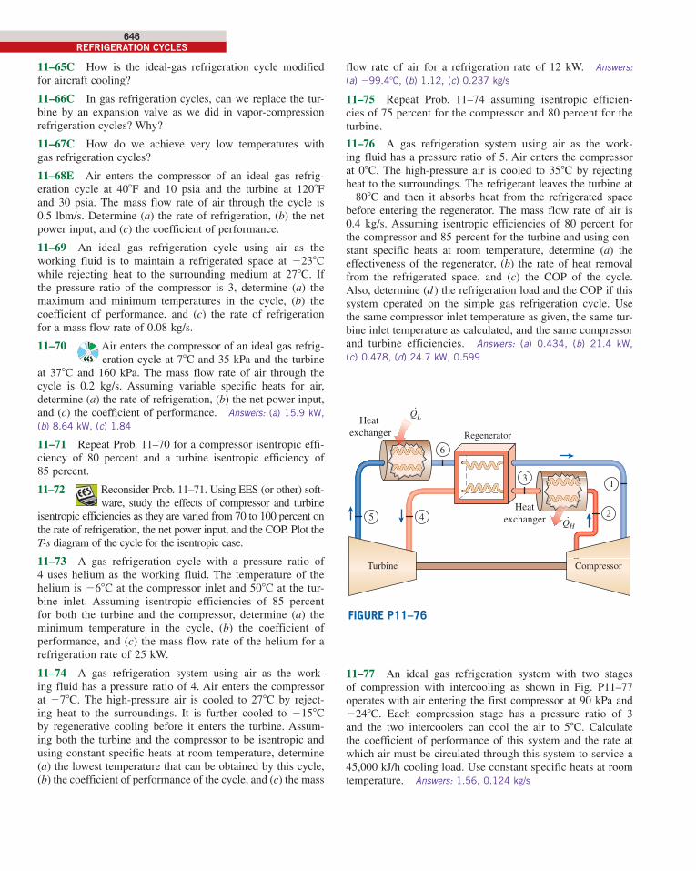
11–76 A gas refrigeration system using air as the work-
ing fluid has a pressure ratio of 5. Air enters the compressor
at 08C. The high-pressure air is cooled to 358C by rejecting
heat to the surroundings. The refrigerant leaves the turbine at
2808C and then it absorbs heat from the refrigerated space
before entering the regenerator. The mass flow rate of air is
0.4 kg/s. Assuming isentropic efficiencies of 80 percent for
the compressor and 85 percent for the turbine and using con-
stant specific heats at room temperature, determine (a) the
effectiveness of the regenerator, (b) the rate of heat removal
from the refrigerated space, and (c) the COP of the cycle.
Also, determine (d ) the refrigeration load and the COP if this
system operated on the simple gas refrigeration cycle. Use
the same compressor inlet temperature as given, the same tur-
bine inlet temperature as calculated, and the same compressor
and turbine efficiencies. Answers: (a) 0.434, (b) 21.4 kW,
(c) 0.478, (d) 24.7 kW, 0.599
Heat
exchanger
1
45
Compressor
QH·
QL·
2
3
6
Regenerator
Heat
exchanger
Turbine
FIGURE P11–76
11–77 An ideal gas refrigeration system with two stages
of compression with intercooling as shown in Fig. P11–77
operates with air entering the first compressor at 90 kPa and
2248C. Each compression stage has a pressure ratio of 3
and the two intercoolers can cool the air to 58C. Calculate
the coefficient of performance of this system and the rate at
which air must be circulated through this system to service a
45,000 kJ/h cooling load. Use constant specific heats at room
temperature. Answers: 1.56, 0.124 kg/s
11–65C How is the ideal-gas refrigeration cycle modified
for aircraft cooling?
11–66C In gas refrigeration cycles, can we replace the tur-
bine by an expansion valve as we did in vapor-compression
refrigeration cycles? Why?
11–67C How do we achieve very low temperatures with
gas refrigeration cycles?
11–68E Air enters the compressor of an ideal gas refrig-
eration cycle at 408F and 10 psia and the turbine at 1208F
and 30 psia. The mass flow rate of air through the cycle is
0.5 lbm/s. Determine (a) the rate of refrigeration, (b) the net
power input, and (c) the coefficient of performance.
11–69 An ideal gas refrigeration cycle using air as the
working fluid is to maintain a refrigerated space at 2238C
while rejecting heat to the surrounding medium at 278C. If
the pressure ratio of the compressor is 3, determine (a) the
maximum and minimum temperatures in the cycle, (b) the
coefficient of performance, and (c) the rate of refrigeration
for a mass flow rate of 0.08 kg/s.
11–70 Air enters the compressor of an ideal gas refrig-
eration cycle at 78C and 35 kPa and the turbine
at 378C and 160 kPa. The mass flow rate of air through the
cycle is 0.2 kg/s. Assuming variable specific heats for air,
determine (a) the rate of refrigeration, (b) the net power input,
and (c) the coefficient of performance. Answers: (a) 15.9 kW,
(b) 8.64 kW, (c) 1.84
11–71 Repeat Prob. 11–70 for a compressor isentropic effi-
ciency of 80 percent and a turbine isentropic efficiency of
85 percent.
11–72 Reconsider Prob. 11–71. Using EES (or other) soft-
ware, study the effects of compressor and turbine
isentropic efficiencies as they are varied from 70 to 100 percent on
the rate of refrigeration, the net power input, and the COP. Plot the
T-s diagram of the cycle for the isentropic case.
11–73 A gas refrigeration cycle with a pressure ratio of
4 uses helium as the working fluid. The temperature of the
helium is 268C at the compressor inlet and 508C at the tur-
bine inlet. Assuming isentropic efficiencies of 85 percent
for both the turbine and the compressor, determine (a) the
minimum temperature in the cycle, (b) the coefficient of
performance, and (c) the mass flow rate of the helium for a
refrigeration rate of 25 kW.
11–74 A gas refrigeration system using air as the work-
ing fluid has a pressure ratio of 4. Air enters the compressor
at 278C. The high-pressure air is cooled to 278C by reject-
ing heat to the surroundings. It is further cooled to 2158C
by regenerative cooling before it enters the turbine. Assum-
ing both the turbine and the compressor to be isentropic and
using constant specific heats at room temperature, determine
(a) the lowest temperature that can be obtained by this cycle,
(b) the coefficient of performance of the cycle, and (c) the mass
cen98179_ch11_607-654.indd 646cen98179_ch11_607-654.indd 646 11/28/13 3:56 PM11/28/13 3:56 PM
CHAPTER 11647
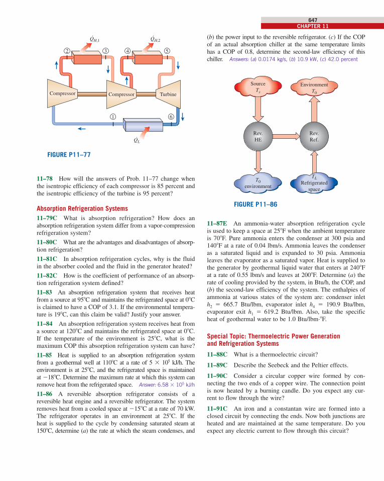
(b) the power input to the reversible refrigerator. (c) If the COP
of an actual absorption chiller at the same temperature limits
has a COP of 0.8, determine the second-law efficiency of this
chiller. Answers: (a) 0.0174 kg/s, (b) 10.9 kW, (c) 42.0 percent
T0
environment
Rev.
HE
TLRefrigerated
space
Rev.
Ref.
Source
Ts
Environment
T0
FIGURE P11–86
11–87E An ammonia-water absorption refrigeration cycle
is used to keep a space at 258F when the ambient temperature
is 708F. Pure ammonia enters the condenser at 300 psia and
1408F at a rate of 0.04 lbm/s. Ammonia leaves the condenser
as a saturated liquid and is expanded to 30 psia. Ammonia
leaves the evaporator as a saturated vapor. Heat is supplied to
the generator by geothermal liquid water that enters at 2408F
at a rate of 0.55 lbm/s and leaves at 2008F. Determine (a) the
rate of cooling provided by the system, in Btu/h, the COP, and
(b) the second-law efficiency of the system. The enthalpies of
ammonia at various states of the system are: condenser inlet
h2 5 665.7 Btu/lbm, evaporator inlet h4 5 190.9 Btu/lbm,
evaporator exit h1 5 619.2 Btu/lbm. Also, take the specific
heat of geothermal water to be 1.0 Btu/lbm·8F.
Special Topic: Thermoelectric Power Generation and Refrigeration Systems
11–88C What is a thermoelectric circuit?
11–89C Describe the Seebeck and the Peltier effects.
11–90C Consider a circular copper wire formed by con-
necting the two ends of a copper wire. The connection point
is now heated by a burning candle. Do you expect any cur-
rent to flow through the wire?
11–91C An iron and a constantan wire are formed into a
closed circuit by connecting the ends. Now both junctions are
heated and are maintained at the same temperature. Do you
expect any electric current to flow through this circuit?
5
QH,2
6
QL˙
1
3
QH,1˙ ˙
42
Compressor Compressor Turbine
FIGURE P11–77
11–78 How will the answers of Prob. 11–77 change when
the isentropic efficiency of each compressor is 85 percent and
the isentropic efficiency of the turbine is 95 percent?
Absorption Refrigeration Systems11–79C What is absorption refrigeration? How does an
ab sorption refrigeration system differ from a vapor-compression
refrigeration system?
11–80C What are the advantages and disadvantages of absorp-
tion refrigeration?
11–81C In absorption refrigeration cycles, why is the fluid
in the absorber cooled and the fluid in the generator heated?
11–82C How is the coefficient of performance of an absorp-
tion refrigeration system defined?
11–83 An absorption refrigeration system that receives heat
from a source at 958C and maintains the refrigerated space at 08C
is claimed to have a COP of 3.1. If the environmental tempera-
ture is 198C, can this claim be valid? Justify your answer.
11–84 An absorption refrigeration system receives heat from
a source at 1208C and maintains the refrigerated space at 08C.
If the temperature of the environment is 258C, what is the
maximum COP this absorption refrigeration system can have?
11–85 Heat is supplied to an absorption refrigeration system
from a geothermal well at 1108C at a rate of 5 3 105 kJ/h. The
environment is at 258C, and the refrigerated space is maintained
at 2188C. Determine the maximum rate at which this system can
remove heat from the refrigerated space. Answer: 6.58 3 105 kJ/h
11–86 A reversible absorption refrigerator consists of a
reversible heat engine and a reversible refrigerator. The system
removes heat from a cooled space at 2158C at a rate of 70 kW.
The refrigerator operates in an environment at 258C. If the
heat is supplied to the cycle by condensing saturated steam at
1508C, determine (a) the rate at which the steam condenses, and
cen98179_ch11_607-654.indd 647cen98179_ch11_607-654.indd 647 11/28/13 3:56 PM11/28/13 3:56 PM
648REFRIGERATION CYCLES
in the cooling mode, determine (a) the average rate of heat removal from the drink, (b) the average rate of heat supply to the coffee, and (c) the electric power drawn from the battery of the car, all in W.
11–102 It is proposed to run a thermoelectric generator in conjunction with a solar pond that can supply heat at a rate of 7 3 106 kJ/h at 908C. The waste heat is to be rejected to the environment at 228C. What is the maximum power this thermo-electric generator can produce?
Review Problems
11–103 A typical 200-m2 house can be cooled adequately by a 3.5-ton air conditioner whose COP is 4.0. Determine the rate of heat gain of the house when the air conditioner is running continuously to maintain a constant temperature in the house.
11–104 Consider a steady-flow Carnot refrigeration cycle that uses refrigerant-134a as the working fluid. The maximum and minimum temperatures in the cycle are 30 and 2208C, respectively. The quality of the refrigerant is 0.15 at the begin-ning of the heat absorption process and 0.80 at the end. Show the cycle on a T-s diagram relative to saturation lines, and determine (a) the coefficient of performance, (b) the con-denser and evaporator pressures, and (c) the net work input.
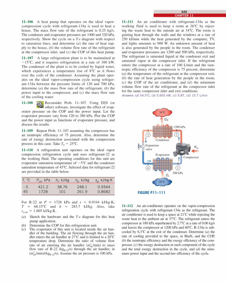
11–105 A heat pump water heater (HPWH) heats water by absorbing heat from the ambient air and transferring it to water. The heat pump has a COP of 3.4 and consumes 6 kW of electricity when running. Determine if this heat pump can be used to meet the cooling needs of a room most of the time for “free” by absorbing heat from the air in the room. The rate of heat gain of a room is usually less than 45,000 kJ/h.
FIGURE P11–105
Coldwater
in
Waterheater
Cool airto the room
Warm airfrom the room
Hotwaterout
11–92C A copper and a constantan wire are formed into a closed circuit by connecting the ends. Now one junction is heated by a burning candle while the other is maintained at room temperature. Do you expect any electric current to flow through this circuit?
11–93C How does a thermocouple work as a temperature measurement device?
11–94C Why are semiconductor materials preferable to metals in thermoelectric refrigerators?
11–95C Is the efficiency of a thermoelectric generator lim-ited by the Carnot efficiency? Why?
11–96E A thermoelectric generator receives heat from a source at 3408F and rejects the waste heat to the environment at 908F. What is the maximum thermal efficiency this thermo-electric generator can have? Answer: 31.3 percent
11–97 A thermoelectric refrigerator removes heat from a refrigerated space at 258C at a rate of 130 W and rejects it to an environment at 208C. Determine the maximum coef-ficient of performance this thermoelectric refrigerator can have and the minimum required power input. Answers:
10.72, 12.1 W
11–98 A thermoelectric cooler has a COP of 0.15 and removes heat from a refrigerated space at a rate of 180 W. Determine the required power input to the thermoelectric cooler, in W.
11–99E A thermoelectric cooler has a COP of 0.18 and the power input to the cooler is 1.8 hp. Determine the rate of heat removed from the refrigerated space, in Btu/min.
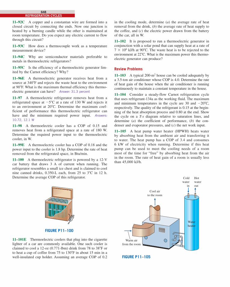
11–100 A thermoelectric refrigerator is powered by a 12-V car battery that draws 3 A of current when running. The refrigerator resembles a small ice chest and is claimed to cool nine canned drinks, 0.350-L each, from 25 to 38C in 12 h. Determine the average COP of this refrigerator.
FIGURE P11–100
11–101E Thermoelectric coolers that plug into the cigarette lighter of a car are commonly available. One such cooler is claimed to cool a 12-oz (0.771-lbm) drink from 78 to 388F or to heat a cup of coffee from 75 to 1308F in about 15 min in a well-insulated cup holder. Assuming an average COP of 0.2
cen98179_ch11_607-654.indd 648cen98179_ch11_607-654.indd 648 11/28/13 3:56 PM11/28/13 3:56 PM
CHAPTER 11649
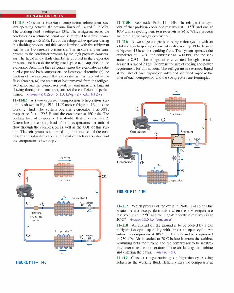
11–111 An air conditioner with refrigerant-134a as the working fluid is used to keep a room at 268C by reject-ing the waste heat to the outside air at 348C. The room is gaining heat through the walls and the windows at a rate of 250 kJ/min while the heat generated by the computer, TV, and lights amounts to 900 W. An unknown amount of heat is also generated by the people in the room. The condenser and evaporator pressures are 1200 and 500 kPa, respectively. The refrigerant is saturated liquid at the condenser exit and saturated vapor at the compressor inlet. If the refrigerant enters the compressor at a rate of 100 L/min and the isen-tropic efficiency of the compressor is 75 percent, determine (a) the temperature of the refrigerant at the compressor exit, (b) the rate of heat generation by the people in the room, (c) the COP of the air conditioner, and (d ) the minimum volume flow rate of the refrigerant at the compressor inlet for the same compressor inlet and exit conditions.Answers: (a) 54.58C, (b) 0.665 kW, (c) 5.87, (d ) 15.7 L/min
1200 kPa
500 kPa
·
23
14
Compressor
WinExpansionvalve
Evaporator
.QL
26°C
Condenser
.QH
34°C
FIGURE P11–111
11–112 An air-conditioner operates on the vapor- compression refrigeration cycle with refrigerant-134a as the refrigerant. The air conditioner is used to keep a space at 218C while rejecting the waste heat to the ambient air at 378C. The refrigerant enters the compressor at 180 kPa superheated by 2.78C at a rate of 0.06 kg/s and leaves the compressor at 1200 kPa and 608C. R-134a is sub-cooled by 6.38C at the exit of the condenser. Determine (a) the rate of cooling provided to the space, in Btu/h, and the COP, (b) the isentropic efficiency and the exergy efficiency of the com-pressor, (c) the exergy destruction in each component of the cycle and the total exergy destruction in the cycle, and (d) the mini-mum power input and the second-law efficiency of the cycle.
11–106 A heat pump that operates on the ideal vapor-compression cycle with refrigerant-134a is used to heat a house. The mass flow rate of the refrigerant is 0.25 kg/s. The condenser and evaporator pressures are 1400 and 320 kPa, respectively. Show the cycle on a T-s diagram with respect to saturation lines, and determine (a) the rate of heat sup-ply to the house, (b) the volume flow rate of the refrigerant at the compressor inlet, and (c) the COP of this heat pump.
11–107 A large refrigeration plant is to be maintained at 2158C, and it requires refrigeration at a rate of 100 kW. The condenser of the plant is to be cooled by liquid water, which experiences a temperature rise of 88C as it flows over the coils of the condenser. Assuming the plant oper-ates on the ideal vapor-compression cycle using refriger-ant-134a between the pressure limits of 120 and 700 kPa, determine (a) the mass flow rate of the refrigerant, (b) the power input to the compressor, and (c) the mass flow rate of the cooling water.
11–108 Reconsider Prob. 11–107. Using EES (or other) software, investigate the effect of evap-
orator pressure on the COP and the power input. Let the evaporator pressure vary from 120 to 380 kPa. Plot the COP and the power input as functions of evaporator pressure, and discuss the results.
11–109 Repeat Prob. 11–107 assuming the compressor has an isentropic efficiency of 75 percent. Also, determine the rate of exergy destruction associated with the compression process in this case. Take T0 5 258C.
11–110 A refrigeration unit operates on the ideal vapor compression refrigeration cycle and uses refrigerant-22 as the working fluid. The operating conditions for this unit are evaporator saturation temperature of 258C and the condenser saturation temperature of 458C. Selected data for refrigerant-22 are provided in the table below.
T, 8C Psat, kPa hf, kJ/kg hg, kJ/kg sg, kJ/kg·K
25 421.2 38.76 248.1 0.9344
45 1728 101 261.9 0.8682
For R-22 at P 5 1728 kPa and s 5 0.9344 kJ/kg·K, T 5 68.158C and h 5 283.7 kJ/kg. Also, take cp,air 5 1.005 kJ/kg·K.
(a) Sketch the hardware and the T-s diagram for this heat pump application.
(b) Determine the COP for this refrigeration unit. (c) The evaporator of this unit is located inside the air han-
dler of the building. The air flowing through the air han-dler enters the air handler at 278C and is limited to a 208C temperature drop. Determine the ratio of volume flow rate of air entering the air handler (m3
air/min) to mass flow rate of R-22 (kgR-22/s) through the air handler, in (m3
air/min)/(kgR-22/s). Assume the air pressure is 100 kPa.
cen98179_ch11_607-654.indd 649cen98179_ch11_607-654.indd 649 11/28/13 3:56 PM11/28/13 3:56 PM
650REFRIGERATION CYCLES
11–115E Reconsider Prob. 11–114E. The refrigeration sys-tem of that problem cools one reservoir at 2158F and one at 408F while rejecting heat to a reservoir at 808F. Which process has the highest exergy destruction?
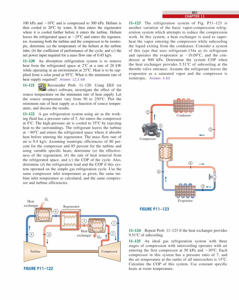
11–116 A two-stage compression refrigeration system with an adiabatic liquid-vapor separation unit as shown in Fig. P11–116 uses refrigerant-134a as the working fluid. The system operates the evaporator at 2328C, the condenser at 1400 kPa, and the sep-arator at 8.98C. The refrigerant is circulated through the con-denser at a rate of 2 kg/s. Determine the rate of cooling and power requirement for this system. The refrigerant is saturated liquid at the inlet of each expansion valve and saturated vapor at the inlet of each compressor, and the compressors are isentropic.
Condenser
2
Separator
Evaporator
1
4
3
5
7
8
m2˙
m6˙
6
Compressor
Compressor
FIGURE P11–116
11–117 Which process of the cycle in Prob. 11–116 has the greatest rate of exergy destruction when the low-temperature reservoir is at 2228C and the high-temperature reservoir is at 208C? Answer: 30.9 kW (condenser)
11–118 An aircraft on the ground is to be cooled by a gas refrigeration cycle operating with air on an open cycle. Air enters the compressor at 308C and 100 kPa and is compressed to 250 kPa. Air is cooled to 708C before it enters the turbine. Assuming both the turbine and the compressor to be isentro-pic, determine the temperature of the air leaving the turbine and entering the cabin. Answer: 29°C
11–119 Consider a regenerative gas refrigeration cycle using helium as the working fluid. Helium enters the compressor at
11–113 Consider a two-stage compression refrigeration sys-tem operating between the pressure limits of 1.4 and 0.12 MPa. The working fluid is refrigerant-134a. The refrigerant leaves the condenser as a saturated liquid and is throttled to a flash cham-ber operating at 0.5 MPa. Part of the refrigerant evaporates during this flashing process, and this vapor is mixed with the refrigerant leaving the low-pressure compressor. The mixture is then com-pressed to the condenser pressure by the high-pressure compres-sor. The liquid in the flash chamber is throttled to the evaporator pressure, and it cools the refrigerated space as it vaporizes in the evaporator. Assuming the refrigerant leaves the evaporator as satu-rated vapor and both compressors are isentropic, determine (a) the fraction of the refrigerant that evaporates as it is throttled to the flash chamber, (b) the amount of heat removed from the refriger-ated space and the compressor work per unit mass of refrigerant flowing through the condenser, and (c) the coefficient of perfor-mance. Answers: (a) 0.290, (b) 116 kJ/kg, 42.7 kJ/kg, (c) 2.72
11–114E A two-evaporator compression refrigeration sys-tem as shown in Fig. P11–114E uses refrigerant-134a as the working fluid. The system operates evaporator 1 at 308F, evaporator 2 at 229.58F, and the condenser at 160 psia. The cooling load of evaporator 1 is double that of evaporator 2. Determine the cooling load of both evaporators per unit of flow through the compressor, as well as the COP of this sys-tem. The refrigerant is saturated liquid at the exit of the con-denser and saturated vapor at the exit of each evaporator, and the compressor is isentropic.
FIGURE P11–114E
Pressurereducing
valve
Evaporator 1
Evaporator 27
1
m2˙
m1˙
m1 + m2˙ ˙
5
Condenser
2 3
4
6
cen98179_ch11_607-654.indd 650cen98179_ch11_607-654.indd 650 11/28/13 3:56 PM11/28/13 3:56 PM
CHAPTER 11651
11–123 The refrigeration system of Fig. P11–123 is another variation of the basic vapor-compression refrig-eration system which attempts to reduce the compression work. In this system, a heat exchanger is used to super-heat the vapor entering the compressor while subcooling the liquid exiting from the condenser. Consider a system of this type that uses refrigerant-134a as its refrigerant and operates the evaporator at 210.098C, and the con-denser at 900 kPa. Determine the system COP when the heat exchanger provides 5.518C of subcooling at the throttle valve entrance. Assume the refrigerant leaves the evaporator as a saturated vapor and the compressor is isentropic. Answer: 4.60
2
1
6
Condenser
Evaporator
4
3
5
Compressor
FIGURE P11–123
11–124 Repeat Prob. 11–123 if the heat exchanger provides 9.518C of subcooling.
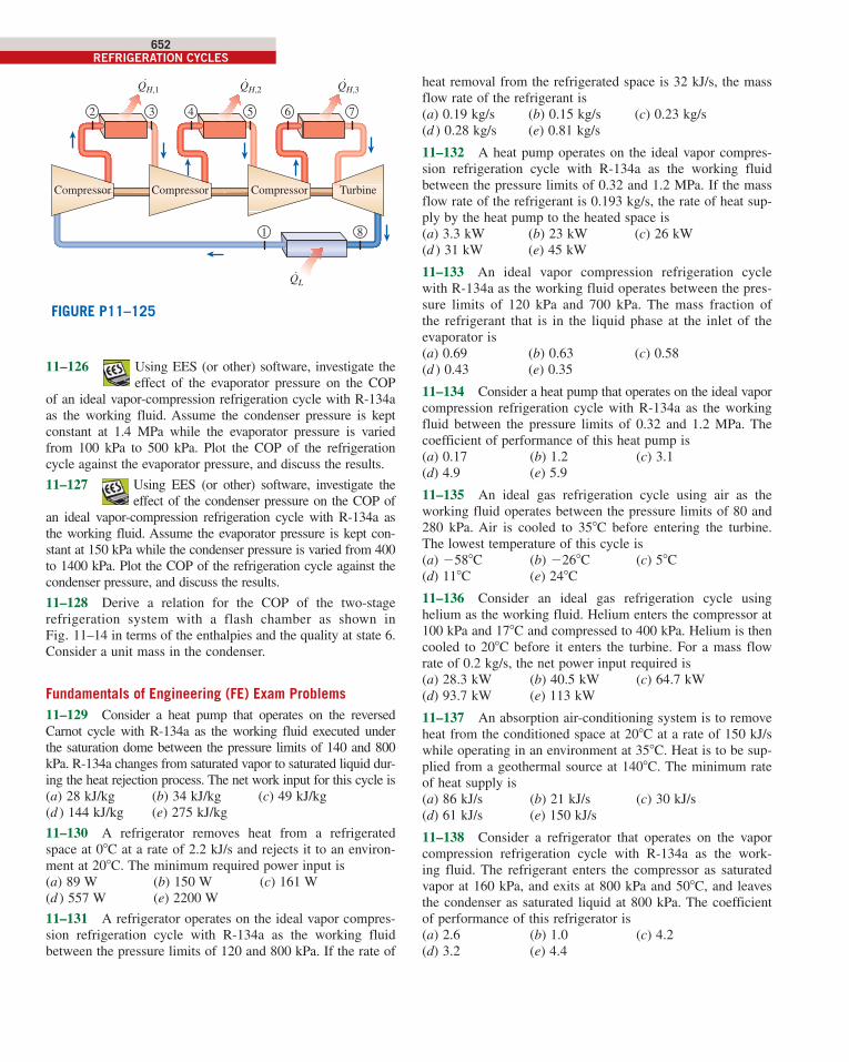
11–125 An ideal gas refrigeration system with three stages of compression with intercooling operates with air entering the first compressor at 50 kPa and 2308C. Each compressor in this system has a pressure ratio of 7, and the air temperature at the outlet of all intercoolers is 158C. Calculate the COP of this system. Use constant specific heats at room temperature.
100 kPa and 2108C and is compressed to 300 kPa. Helium is then cooled to 208C by water. It then enters the regenerator where it is cooled further before it enters the turbine. Helium leaves the refrigerated space at 2258C and enters the regenera-tor. Assuming both the turbine and the compressor to be isentro-pic, determine (a) the temperature of the helium at the turbine inlet, (b) the coefficient of performance of the cycle, and (c) the net power input required for a mass flow rate of 0.45 kg/s.
11–120 An absorption refrigeration system is to remove heat from the refrigerated space at 28C at a rate of 28 kW while operating in an environment at 258C. Heat is to be sup-plied from a solar pond at 958C. What is the minimum rate of heat supply required? Answer: 12.3 kW
11–121 Reconsider Prob. 11–120. Using EES (or other) software, investigate the effect of the
source temperature on the minimum rate of heat supply. Let the source temperature vary from 50 to 2508C. Plot the minimum rate of heat supply as a function of source temper-ature, and discuss the results.
11–122 A gas refrigeration system using air as the work-ing fluid has a pressure ratio of 5. Air enters the compressor at 08C. The high-pressure air is cooled to 358C by rejecting heat to the surroundings. The refrigerant leaves the turbine at 2808C and enters the refrigerated space where it absorbs heat before entering the regenerator. The mass flow rate of air is 0.4 kg/s. Assuming isentropic efficiencies of 80 per-cent for the compressor and 85 percent for the turbine and using variable specific heats, determine (a) the effective-ness of the regenerator, (b) the rate of heat removal from the refrigerated space, and (c) the COP of the cycle. Also, determine (d) the refrigeration load and the COP if this sys-tem operated on the simple gas refrigeration cycle. Use the same compressor inlet temperature as given, the same tur-bine inlet temperature as calculated, and the same compres-sor and turbine efficiencies.
FIGURE P11–122
Heat exchanger
1
45
Compressor
QH·
QL·
2
3
6
Regenerator
Heatexchanger
Turbine
cen98179_ch11_607-654.indd 651cen98179_ch11_607-654.indd 651 11/28/13 3:56 PM11/28/13 3:56 PM
652REFRIGERATION CYCLES
heat removal from the refrigerated space is 32 kJ/s, the mass flow rate of the refrigerant is(a) 0.19 kg/s (b) 0.15 kg/s (c) 0.23 kg/s(d ) 0.28 kg/s (e) 0.81 kg/s
11–132 A heat pump operates on the ideal vapor compres-sion refrigeration cycle with R-134a as the working fluid between the pressure limits of 0.32 and 1.2 MPa. If the mass flow rate of the refrigerant is 0.193 kg/s, the rate of heat sup-ply by the heat pump to the heated space is(a) 3.3 kW (b) 23 kW (c) 26 kW(d ) 31 kW (e) 45 kW
11–133 An ideal vapor compression refrigeration cycle with R-134a as the working fluid operates between the pres-sure limits of 120 kPa and 700 kPa. The mass fraction of the refrigerant that is in the liquid phase at the inlet of the evaporator is(a) 0.69 (b) 0.63 (c) 0.58(d ) 0.43 (e) 0.35
11–134 Consider a heat pump that operates on the ideal vapor compression refrigeration cycle with R-134a as the working fluid between the pressure limits of 0.32 and 1.2 MPa. The coefficient of performance of this heat pump is(a) 0.17 (b) 1.2 (c) 3.1(d) 4.9 (e) 5.9
11–135 An ideal gas refrigeration cycle using air as the working fluid operates between the pressure limits of 80 and 280 kPa. Air is cooled to 358C before entering the turbine. The lowest temperature of this cycle is(a) 2588C (b) 2268C (c) 58C(d) 118C (e) 248C
11–136 Consider an ideal gas refrigeration cycle using helium as the working fluid. Helium enters the compressor at 100 kPa and 178C and compressed to 400 kPa. Helium is then cooled to 208C before it enters the turbine. For a mass flow rate of 0.2 kg/s, the net power input required is(a) 28.3 kW (b) 40.5 kW (c) 64.7 kW(d) 93.7 kW (e) 113 kW
11–137 An absorption air-conditioning system is to remove heat from the conditioned space at 208C at a rate of 150 kJ/s while operating in an environment at 358C. Heat is to be sup-plied from a geothermal source at 1408C. The minimum rate of heat supply is(a) 86 kJ/s (b) 21 kJ/s (c) 30 kJ/s(d) 61 kJ/s (e) 150 kJ/s
11–138 Consider a refrigerator that operates on the vapor compression refrigeration cycle with R-134a as the work-ing fluid. The refrigerant enters the compressor as saturated vapor at 160 kPa, and exits at 800 kPa and 508C, and leaves the condenser as saturated liquid at 800 kPa. The coefficient of performance of this refrigerator is(a) 2.6 (b) 1.0 (c) 4.2(d) 3.2 (e) 4.4
81
QL˙
3
QH,1˙ QH,2
˙ QH,3˙
2 54 6 7
Compressor Compressor Compressor Turbine
FIGURE P11–125
11–126 Using EES (or other) software, investigate the effect of the evaporator pressure on the COP
of an ideal vapor-compression refrigeration cycle with R-134a as the working fluid. Assume the condenser pressure is kept constant at 1.4 MPa while the evaporator pressure is varied from 100 kPa to 500 kPa. Plot the COP of the refrigeration cycle against the evaporator pressure, and discuss the results.
11–127 Using EES (or other) software, investigate the effect of the condenser pressure on the COP of
an ideal vapor-compression refrigeration cycle with R-134a as the working fluid. Assume the evaporator pressure is kept con-stant at 150 kPa while the condenser pressure is varied from 400 to 1400 kPa. Plot the COP of the refrigeration cycle against the condenser pressure, and discuss the results.
11–128 Derive a relation for the COP of the two-stage refrigeration system with a flash chamber as shown in Fig. 11–14 in terms of the enthalpies and the quality at state 6. Consider a unit mass in the condenser.
Fundamentals of Engineering (FE) Exam Problems11–129 Consider a heat pump that operates on the reversed Carnot cycle with R-134a as the working fluid executed under the saturation dome between the pressure limits of 140 and 800 kPa. R-134a changes from saturated vapor to saturated liquid dur-ing the heat rejection process. The net work input for this cycle is(a) 28 kJ/kg (b) 34 kJ/kg (c) 49 kJ/kg(d ) 144 kJ/kg (e) 275 kJ/kg
11–130 A refrigerator removes heat from a refrigerated space at 08C at a rate of 2.2 kJ/s and rejects it to an environ-ment at 208C. The minimum required power input is(a) 89 W (b) 150 W (c) 161 W(d ) 557 W (e) 2200 W
11–131 A refrigerator operates on the ideal vapor compres-sion refrigeration cycle with R-134a as the working fluid between the pressure limits of 120 and 800 kPa. If the rate of
cen98179_ch11_607-654.indd 652cen98179_ch11_607-654.indd 652 11/28/13 3:56 PM11/28/13 3:56 PM


