Embed Size (px)
Citation preview
RNN; Reviewed; SPOC 10/14/2011
Solution Interoperability Lab Application Notes ©2011 Avaya Inc. All Rights Reserved.
1 of 48 G860SM61AAC60.doc
Avaya Solution Interoperability Test Lab
Configuring SIP Trunks among Avaya Aura® Conferencing Server 6.0.1, Avaya Aura® Session Manager 6.1, and Avaya G860 Media Gateway R2.1.1 – Issue 1.0
Abstract
These Application Notes describe a sample configuration of a network that uses SIP trunks among Avaya G860 Media GatewayR2.1.1, Avaya Aura® Session Manager Release 6.1 and Avaya Aura® Conferencing Standard Edition R6.0.1 to route calls between PSTN conference participants and Avaya Aura® Conferencing Standard Edition R6.0.1 to support audio conferencing.
Avaya Aura® Session Manager provides SIP proxy/routing functionality, routing SIP sessions across a TCP/IP network with centralized routing policies and registrations for SIP endpoints.
Avaya G860 Media Gateway consolidates PSTN facilities by concentrating and routing the calls over SIP interface to Avaya Aura® Session Manager.
These Application Notes provide information for the setup, configuration, and verification of the call flows tested on this solution.
RNN; Reviewed; SPOC 10/14/2011
Solution Interoperability Lab Application Notes ©2011 Avaya Inc. All Rights Reserved.
2 of 48 G860SM61AAC60.doc
Table of Contents
1. Introduction ........................................................................................................................... 4
2. Equipment and Software Validated ....................................................................................... 5
3. Prerequisite Knowledge ........................................................................................................ 5
4. Configure Avaya Aura® Conferencing Standard Edition .................................................... 5
4.1. Log in to Avaya Aura® System Manager ....................................................................................... 6
4.2. Administer SIP Signaling Options .................................................................................................. 6
4.3. Administer Access Numbers ........................................................................................................... 7
4.4. Administer Dial-Out ........................................................................................................................ 8
4.5. Apply Changes .............................................................................................................................. 10
5. Configure Avaya Aura® Session Manager ......................................................................... 11
5.1. Log in to Avaya Aura® System Manager ..................................................................................... 11
5.2. Specify SIP Domains .................................................................................................................... 12
5.3. Add Locations ............................................................................................................................... 13
5.4. Add Avaya G860 Media Gateway as a SIP Entity ........................................................................ 14
5.5. Add Avaya Aura® Conferencing Standard Edition as a SIP Entity ............................................. 14
5.6. Define an Entity Link for Avaya G860 Media Gateway............................................................... 15
5.7. Define the Entity Link for Avaya Aura® Conferencing ............................................................... 16
5.8. Define Time Ranges ...................................................................................................................... 16
5.9. Define Routing Policies for Avaya Aura® Conferencing ............................................................. 17
5.10. Define Dial Plan for Avaya Aura® Conferencing ........................................................................ 18
5.11. Define Routing Policies for Avaya G860 Media Gateway ........................................................... 20
5.12. Define Dial Plan for Avaya G860 Media Gateway ....................................................................... 22
6. Configure Avaya G860 Media Gateway ............................................................................. 24
6.1. Log in to Avaya G860 Media Gateway ........................................................................................ 24
6.2. SIP Region Administration ........................................................................................................... 25
6.3. Select the G860 to Configure ........................................................................................................ 25
6.4. Configure TP6310 Board .............................................................................................................. 26
6.4.1. Take TP6310 Board Out-of-Service ......................................................................................... 26
6.4.2. Set TP Board IP Address and Parameters ................................................................................ 26
6.4.3. Configure DS3/DS1 Trunking .................................................................................................. 29
6.5. Set SIP Protocols and Ports ........................................................................................................... 30
6.6. Setup Codec Preferences/Order .................................................................................................... 33
6.7. Add a SIP Trunk Group ................................................................................................................ 34
RNN; Reviewed; SPOC 10/14/2011
Solution Interoperability Lab Application Notes ©2011 Avaya Inc. All Rights Reserved.
3 of 48 G860SM61AAC60.doc
6.8. Setup PSTN to SIP Routing .......................................................................................................... 35
6.9. Configure SIP to PSTN Routing ................................................................................................... 38
6.10. Configure Digit Manipulation (as Needed) ................................................................................... 39
6.11. Restore Service of TP Board ......................................................................................................... 40
7. Verification Steps ................................................................................................................ 40
7.1. Verify Avaya Aura® Session Manager Configuration ................................................................. 40
7.1.1. Verify Avaya Aura® Session Manager is Operational ............................................................ 40
7.1.2. Verify SIP Entity Link Status ................................................................................................... 41
7.2. Verify Avaya Aura® Conferencing Configuration ....................................................................... 42
7.2.1. Verify Processes on Avaya Conferencing Bridge .................................................................... 42
7.2.2. Verify Virtual Machines Status ................................................................................................ 43
7.3. Verify Avaya G860 Media Gateway Configuration ..................................................................... 43
7.3.1. Verify Avaya G860 Media Gateway is Operational ................................................................ 43
7.4. Call Flow to Avaya Aura® Conferencing 6.0.1 ............................................................................ 46
7.5. Call Scenarios Verified ................................................................................................................. 46
8. Conclusions ......................................................................................................................... 47
9. Additional References ......................................................................................................... 47
RNN; Reviewed; SPOC 10/14/2011
Solution Interoperability Lab Application Notes ©2011 Avaya Inc. All Rights Reserved.
4 of 48 G860SM61AAC60.doc
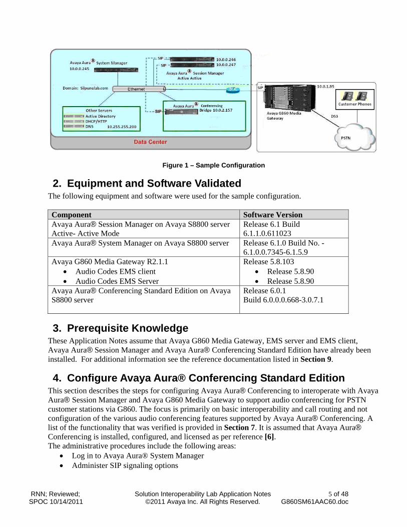
1. Introduction These Application Notes describe a sample configuration of a network that uses SIP trunks between Avaya G860 Media Gateway R2.1.1 Avaya Aura® Session Manager Release 6.1, and Avaya Aura® Conferencing Standard Edition Release 6.0.1. In the sample configuration, inbound PSTN calls over DS3 trunk were routed via G860 Media Gateway over a SIP trunk to Avaya Aura® Session Manager which further routes it to Avaya Aura® Conferencing. SIP trunks connect Avaya G860 Media Gateway and Avaya Aura® Conferencing Standard Edition to Avaya Aura® Session Manager. All inter-system calls are carried over these SIP trunks. Avaya Aura® Session Manager is managed by Avaya Aura® System Manager via the management network interface. Installation and configuration details of Avaya Aura® Session Manager can be found in references [1] to [5] in Section 9. Avaya Aura® Conferencing Standard Edition is a fully integrated audio and data conferencing solution. Conferencing Standard Edition consists of a number of components which provide booking engines, account management utilities, data sharing functionality, billing outputs, directory server integration capabilities, and audio management for all calls. In Conferencing Standard Edition, the media server and the application server reside on a single server. Conferencing Standard Edition is managed by either Avaya Aura® Conferencing Manager or Avaya Aura® System Manager, if one already exists. These Application Notes focus on TCP connectivity. As shown in Figure 1, Avaya Aura® Conferencing Standard Edition Release 6.0.1 runs on an Avaya S8800 Server. Avaya Aura® Conferencing Standard Edition R6.0.1 is connected over a SIP trunk to Session Manager, using the SIP Entity network interface. Avaya Aura® Session Manager is managed by Avaya Aura® System Manager. For the sample configuration, System Manager and Session Manager run on separate Avaya S8800 Servers. For the sample configuration, Conferencing Standard Edition runs on an Avaya S8800 Server and G860 Media Gateway runs on Mediant 5000 hardware. These Application Notes will focus on the configuration of the SIP trunks and call routing needed to test calls from PSTN via Avaya G860 to a Conference DDI on Avaya Aura® Conferencing Standard Edition R6.0.1. For detailed administration of Avaya G860 Media Gateway, Avaya Aura® Session Manager or Avaya Aura® Conferencing Standard Edition R6.0.1 please see the appropriate documentation listed in Section 9.
RNN; Reviewed; SPOC 10/14/2011
Solution Interoperability Lab Application Notes ©2011 Avaya Inc. All Rights Reserved.
5 of 48 G860SM61AAC60.doc
Figure 1 – Sample Configuration
2. Equipment and Software Validated The following equipment and software were used for the sample configuration. Component Software Version Avaya Aura® Session Manager on Avaya S8800 server Active- Active Mode
Release 6.1 Build 6.1.1.0.611023
Avaya Aura® System Manager on Avaya S8800 server Release 6.1.0 Build No. - 6.1.0.0.7345-6.1.5.9
Avaya G860 Media Gateway R2.1.1 Audio Codes EMS client Audio Codes EMS Server
Release 5.8.103 Release 5.8.90 Release 5.8.90
Avaya Aura® Conferencing Standard Edition on Avaya S8800 server
Release 6.0.1 Build 6.0.0.0.668-3.0.7.1
3. Prerequisite Knowledge These Application Notes assume that Avaya G860 Media Gateway, EMS server and EMS client, Avaya Aura® Session Manager and Avaya Aura® Conferencing Standard Edition have already been installed. For additional information see the reference documentation listed in Section 9.
4. Configure Avaya Aura® Conferencing Standard Edition This section describes the steps for configuring Avaya Aura® Conferencing to interoperate with Avaya Aura® Session Manager and Avaya G860 Media Gateway to support audio conferencing for PSTN customer stations via G860. The focus is primarily on basic interoperability and call routing and not configuration of the various audio conferencing features supported by Avaya Aura® Conferencing. A list of the functionality that was verified is provided in Section 7. It is assumed that Avaya Aura® Conferencing is installed, configured, and licensed as per reference [6]. The administrative procedures include the following areas:
Log in to Avaya Aura® System Manager Administer SIP signaling options
RNN; Reviewed; SPOC 10/14/2011
Solution Interoperability Lab Application Notes ©2011 Avaya Inc. All Rights Reserved.
6 of 48 G860SM61AAC60.doc
Administer access numbers Administer Dial-Out Apply changes
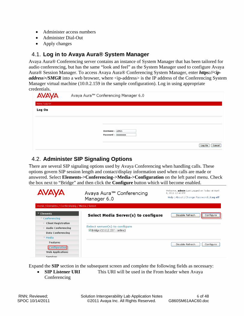
4.1. Log in to Avaya Aura® System Manager Avaya Aura® Conferencing server contains an instance of System Manager that has been tailored for audio conferencing, but has the same “look and feel” as the System Manager used to configure Avaya Aura® Session Manager. To access Avaya Aura® Conferencing System Manager, enter https://<ip-address>/SMGR into a web browser, where <ip-address> is the IP address of the Conferencing System Manager virtual machine (10.0.2.159 in the sample configuration). Log in using appropriate credentials.
4.2. Administer SIP Signaling Options There are several SIP signaling options used by Avaya Conferencing when handling calls. These options govern SIP session length and contact/display information used when calls are made or answered. Select Elements->Conferencing->Media->Configuration on the left panel menu. Check the box next to “Bridge” and then click the Configure button which will become enabled.
Expand the SIP section in the subsequent screen and complete the following fields as necessary:
SIP Listener URI This URI will be used in the From header when Avaya Conferencing
RNN; Reviewed; SPOC 10/14/2011
Solution Interoperability Lab Application Notes ©2011 Avaya Inc. All Rights Reserved.
7 of 48 G860SM61AAC60.doc
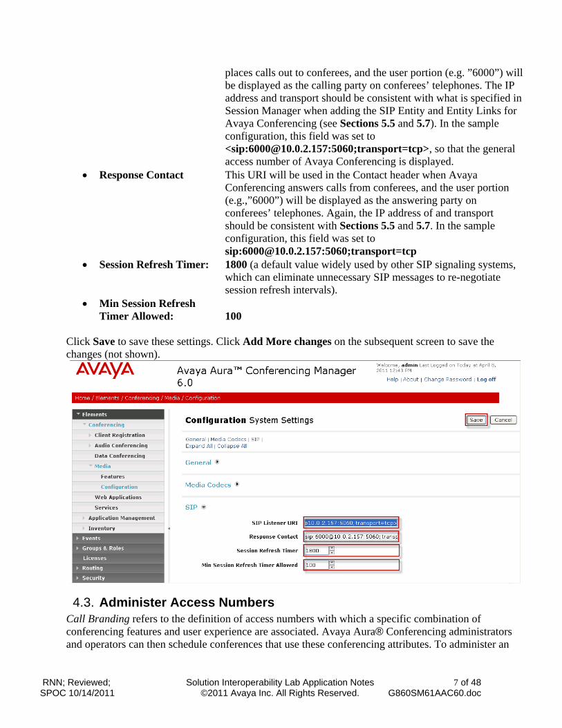
places calls out to conferees, and the user portion (e.g. ”6000”) will be displayed as the calling party on conferees’ telephones. The IP address and transport should be consistent with what is specified in Session Manager when adding the SIP Entity and Entity Links for Avaya Conferencing (see Sections 5.5 and 5.7). In the sample configuration, this field was set to <sip:[email protected]:5060;transport=tcp>, so that the general access number of Avaya Conferencing is displayed.
Response Contact This URI will be used in the Contact header when Avaya Conferencing answers calls from conferees, and the user portion (e.g.,”6000”) will be displayed as the answering party on conferees’ telephones. Again, the IP address of and transport should be consistent with Sections 5.5 and 5.7. In the sample configuration, this field was set to sip:[email protected]:5060;transport=tcp
Session Refresh Timer: 1800 (a default value widely used by other SIP signaling systems, which can eliminate unnecessary SIP messages to re-negotiate session refresh intervals).
Min Session Refresh Timer Allowed: 100
Click Save to save these settings. Click Add More changes on the subsequent screen to save the changes (not shown).
4.3. Administer Access Numbers Call Branding refers to the definition of access numbers with which a specific combination of conferencing features and user experience are associated. Avaya Aura® Conferencing administrators and operators can then schedule conferences that use these conferencing attributes. To administer an
RNN; Reviewed; SPOC 10/14/2011
Solution Interoperability Lab Application Notes ©2011 Avaya Inc. All Rights Reserved.
8 of 48 G860SM61AAC60.doc
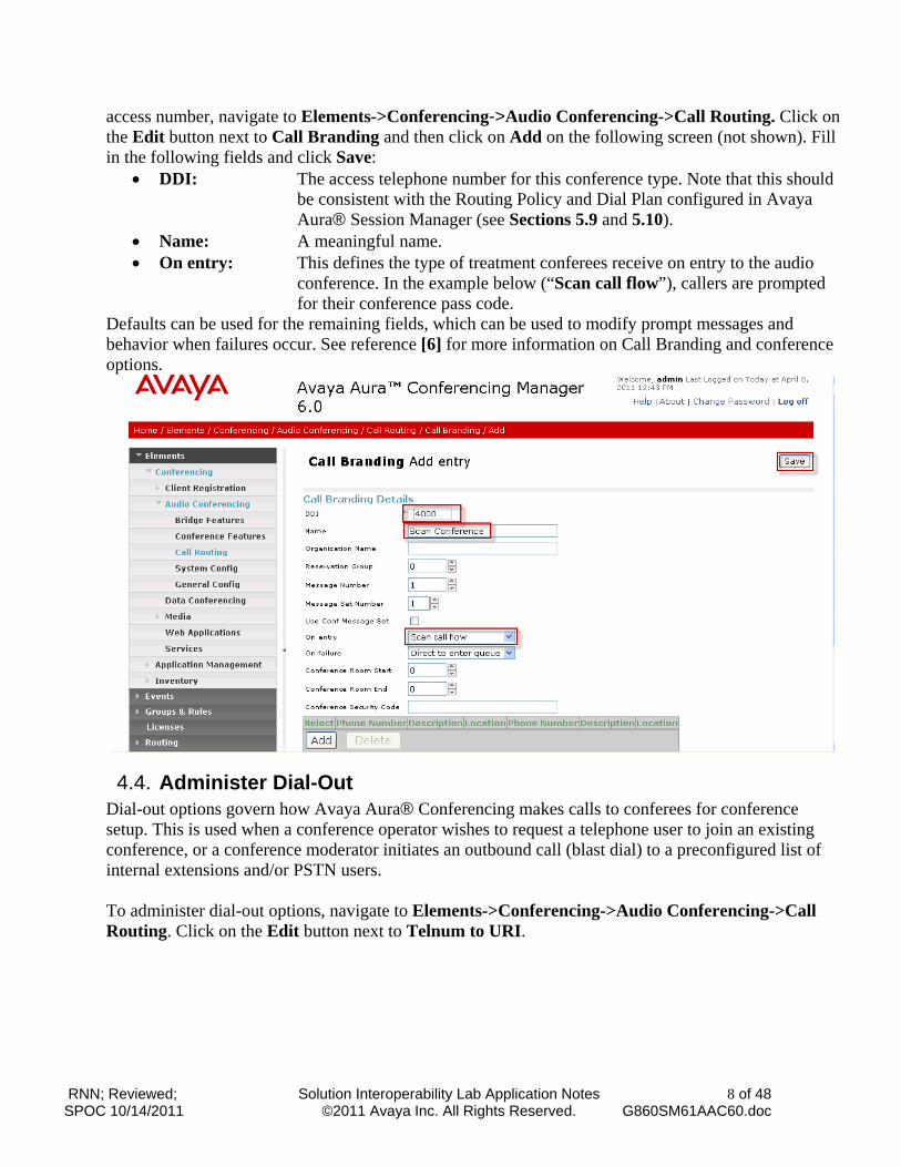
access number, navigate to Elements->Conferencing->Audio Conferencing->Call Routing. Click on the Edit button next to Call Branding and then click on Add on the following screen (not shown). Fill in the following fields and click Save:
DDI: The access telephone number for this conference type. Note that this should be consistent with the Routing Policy and Dial Plan configured in Avaya Aura® Session Manager (see Sections 5.9 and 5.10).
Name: A meaningful name. On entry: This defines the type of treatment conferees receive on entry to the audio
conference. In the example below (“Scan call flow”), callers are prompted for their conference pass code.
Defaults can be used for the remaining fields, which can be used to modify prompt messages and behavior when failures occur. See reference [6] for more information on Call Branding and conference options.
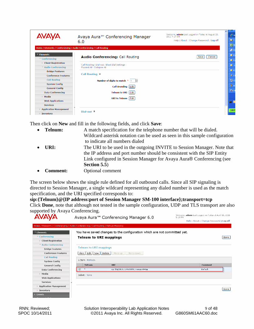
4.4. Administer Dial-Out Dial-out options govern how Avaya Aura® Conferencing makes calls to conferees for conference setup. This is used when a conference operator wishes to request a telephone user to join an existing conference, or a conference moderator initiates an outbound call (blast dial) to a preconfigured list of internal extensions and/or PSTN users. To administer dial-out options, navigate to Elements->Conferencing->Audio Conferencing->Call Routing. Click on the Edit button next to Telnum to URI.
RNN; Reviewed; SPOC 10/14/2011
Solution Interoperability Lab Application Notes ©2011 Avaya Inc. All Rights Reserved.
9 of 48 G860SM61AAC60.doc
Then click on New and fill in the following fields, and click Save:
Telnum: A match specification for the telephone number that will be dialed. Wildcard asterisk notation can be used as seen in this sample configuration to indicate all numbers dialed
URI: The URI to be used in the outgoing INVITE to Session Manager. Note that the IP address and port number should be consistent with the SIP Entity Link configured in Session Manager for Avaya Aura® Conferencing (see Section 5.5)
Comment: Optional comment The screen below shows the single rule defined for all outbound calls. Since all SIP signaling is directed to Session Manager, a single wildcard representing any dialed number is used as the match specification, and the URI specified corresponds to: sip:{Telnum}@{IP address:port of Session Manager SM-100 interface};transport=tcp Click Done, note that although not tested in the sample configuration, UDP and TLS transport are also supported by Avaya Conferencing.
RNN; Reviewed; SPOC 10/14/2011
Solution Interoperability Lab Application Notes ©2011 Avaya Inc. All Rights Reserved.
10 of 48 G860SM61AAC60.doc
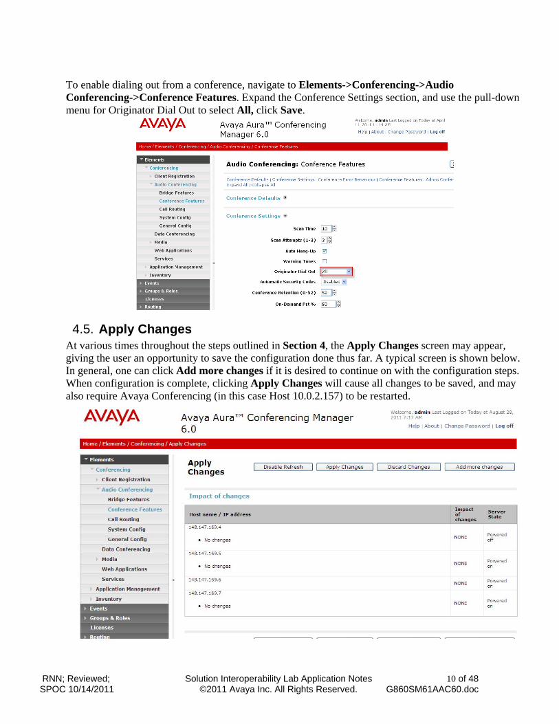
To enable dialing out from a conference, navigate to Elements->Conferencing->Audio Conferencing->Conference Features. Expand the Conference Settings section, and use the pull-down menu for Originator Dial Out to select All, click Save.
4.5. Apply Changes At various times throughout the steps outlined in Section 4, the Apply Changes screen may appear, giving the user an opportunity to save the configuration done thus far. A typical screen is shown below. In general, one can click Add more changes if it is desired to continue on with the configuration steps. When configuration is complete, clicking Apply Changes will cause all changes to be saved, and may also require Avaya Conferencing (in this case Host 10.0.2.157) to be restarted.
RNN; Reviewed; SPOC 10/14/2011
Solution Interoperability Lab Application Notes ©2011 Avaya Inc. All Rights Reserved.
11 of 48 G860SM61AAC60.doc
5. Configure Avaya Aura® Session Manager This section provides the procedures for configuring Avaya Aura® Session Manager to route calls from PSTN customer stations via Avaya G860 Media Gateway to Avaya Aura® Conferencing Standard Edition and from an Avaya Aura® Conferencing Standard Edition to Customer stations via Avaya G860 Media Gateway. These instructions assume Avaya Aura® System Manager and the Session Managers are already installed and functioning properly. Configuration is accomplished by accessing the browser-based GUI of Avaya Aura® System Manager, using the URL “http://<ip-address>/SMGR”, where “<ip-address>” is the IP address of Avaya Aura® System Manager.
Log in to Avaya Aura® System Manager Specify SIP Domains Add Locations Add Avaya G860 Media Gateway as a SIP Entity Add Avaya Aura® Conferencing Standard Edition as a SIP Entity Define an Entity Link for Avaya G860 Media Gateway Define the Entity Link for Avaya Aura® Conferencing Define Time Ranges Define Routing Policies for Avaya Aura® Conferencing Define Dial Plan for Avaya Aura® Conferencing Define Routing Policies for Avaya G860 Media Gateway Define Dial Plan for Avaya G860 Media Gateway
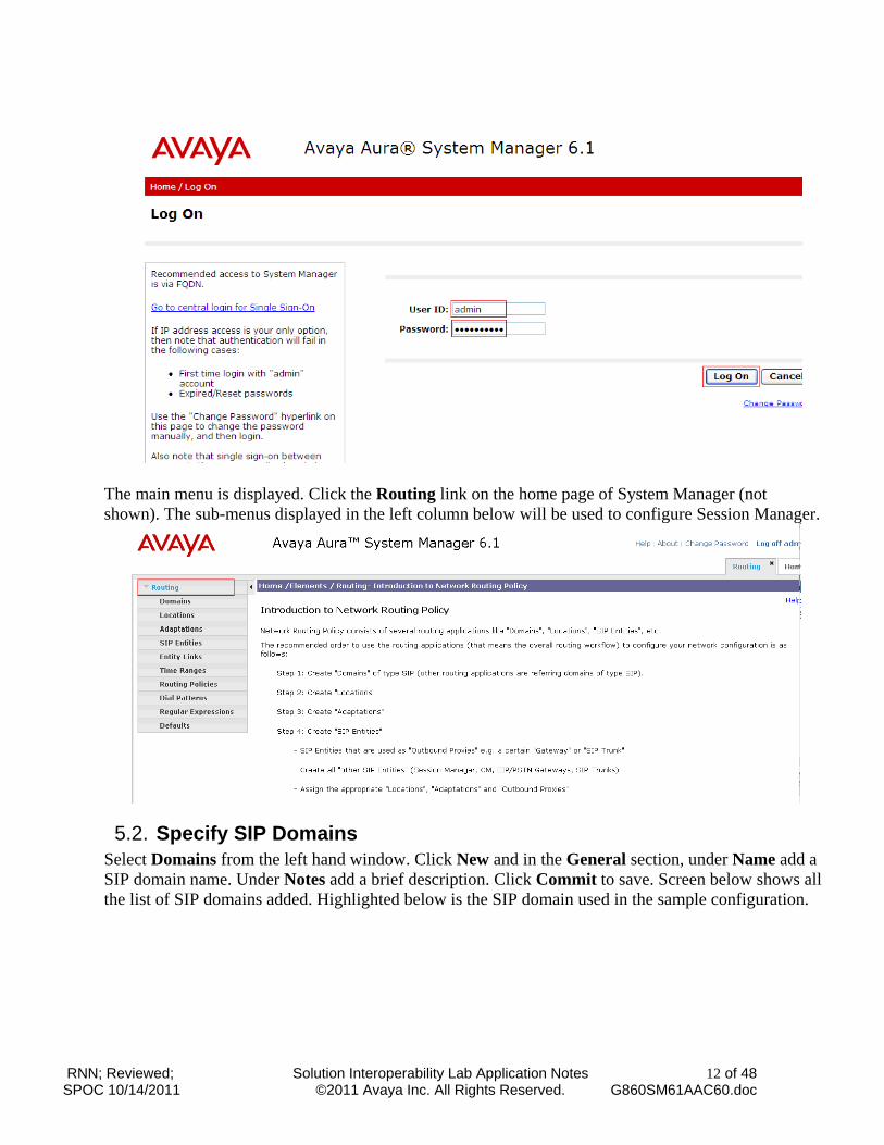
5.1. Log in to Avaya Aura® System Manager Avaya Aura® Conferencing server contains an instance of System Manager used to configure Avaya Aura® Session Manager. To access Avaya Aura® System Manager, enter https://<ip-address>/SMGR into a web browser, where <ip-address> is the IP address of the System Manager virtual machine (10.0.2.159 in the sample configuration, see Figure 1). Log in using appropriate credentials.
RNN; Reviewed; SPOC 10/14/2011
Solution Interoperability Lab Application Notes ©2011 Avaya Inc. All Rights Reserved.
12 of 48 G860SM61AAC60.doc
The main menu is displayed. Click the Routing link on the home page of System Manager (not shown). The sub-menus displayed in the left column below will be used to configure Session Manager.
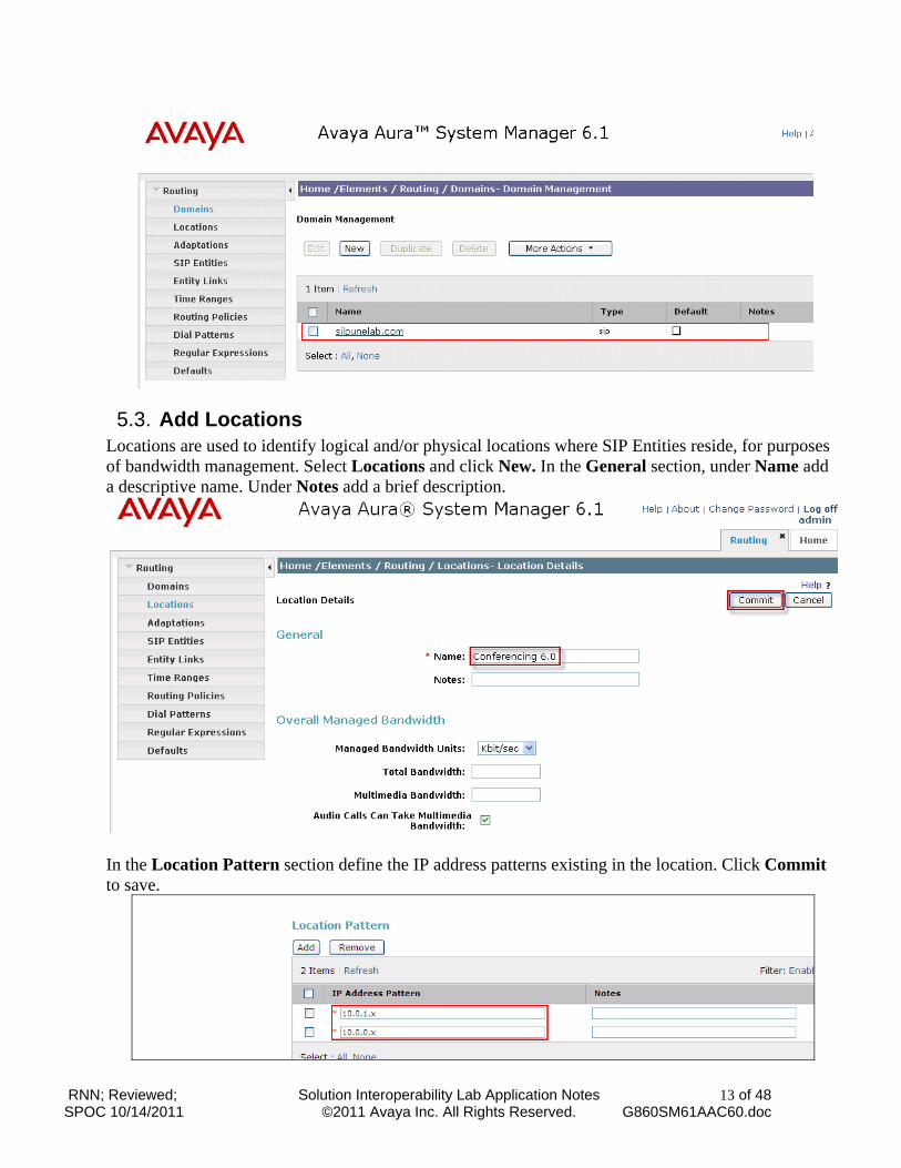
5.2. Specify SIP Domains Select Domains from the left hand window. Click New and in the General section, under Name add a SIP domain name. Under Notes add a brief description. Click Commit to save. Screen below shows all the list of SIP domains added. Highlighted below is the SIP domain used in the sample configuration.
RNN; Reviewed; SPOC 10/14/2011
Solution Interoperability Lab Application Notes ©2011 Avaya Inc. All Rights Reserved.
13 of 48 G860SM61AAC60.doc
5.3. Add Locations Locations are used to identify logical and/or physical locations where SIP Entities reside, for purposes of bandwidth management. Select Locations and click New. In the General section, under Name add a descriptive name. Under Notes add a brief description.
In the Location Pattern section define the IP address patterns existing in the location. Click Commit to save.
RNN; Reviewed; SPOC 10/14/2011
Solution Interoperability Lab Application Notes ©2011 Avaya Inc. All Rights Reserved.
14 of 48 G860SM61AAC60.doc
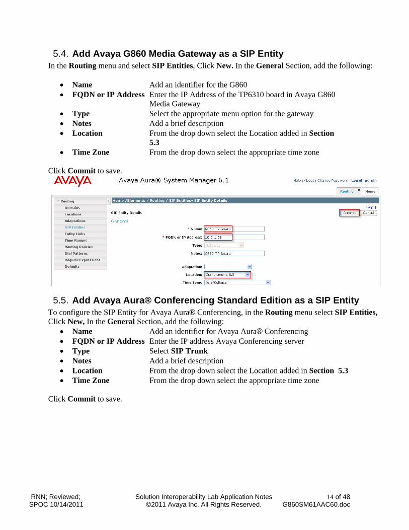
5.4. Add Avaya G860 Media Gateway as a SIP Entity In the Routing menu and select SIP Entities, Click New. In the General Section, add the following:
Name Add an identifier for the G860 FQDN or IP Address Enter the IP Address of the TP6310 board in Avaya G860
Media Gateway Type Select the appropriate menu option for the gateway Notes Add a brief description Location From the drop down select the Location added in Section
5.3 Time Zone From the drop down select the appropriate time zone
Click Commit to save.
5.5. Add Avaya Aura® Conferencing Standard Edition as a SIP Entity To configure the SIP Entity for Avaya Aura® Conferencing, in the Routing menu select SIP Entities, Click New, In the General Section, add the following:
Name Add an identifier for Avaya Aura® Conferencing FQDN or IP Address Enter the IP address Avaya Conferencing server Type Select SIP Trunk Notes Add a brief description Location From the drop down select the Location added in Section 5.3 Time Zone From the drop down select the appropriate time zone
Click Commit to save.
RNN; Reviewed; SPOC 10/14/2011
Solution Interoperability Lab Application Notes ©2011 Avaya Inc. All Rights Reserved.
15 of 48 G860SM61AAC60.doc
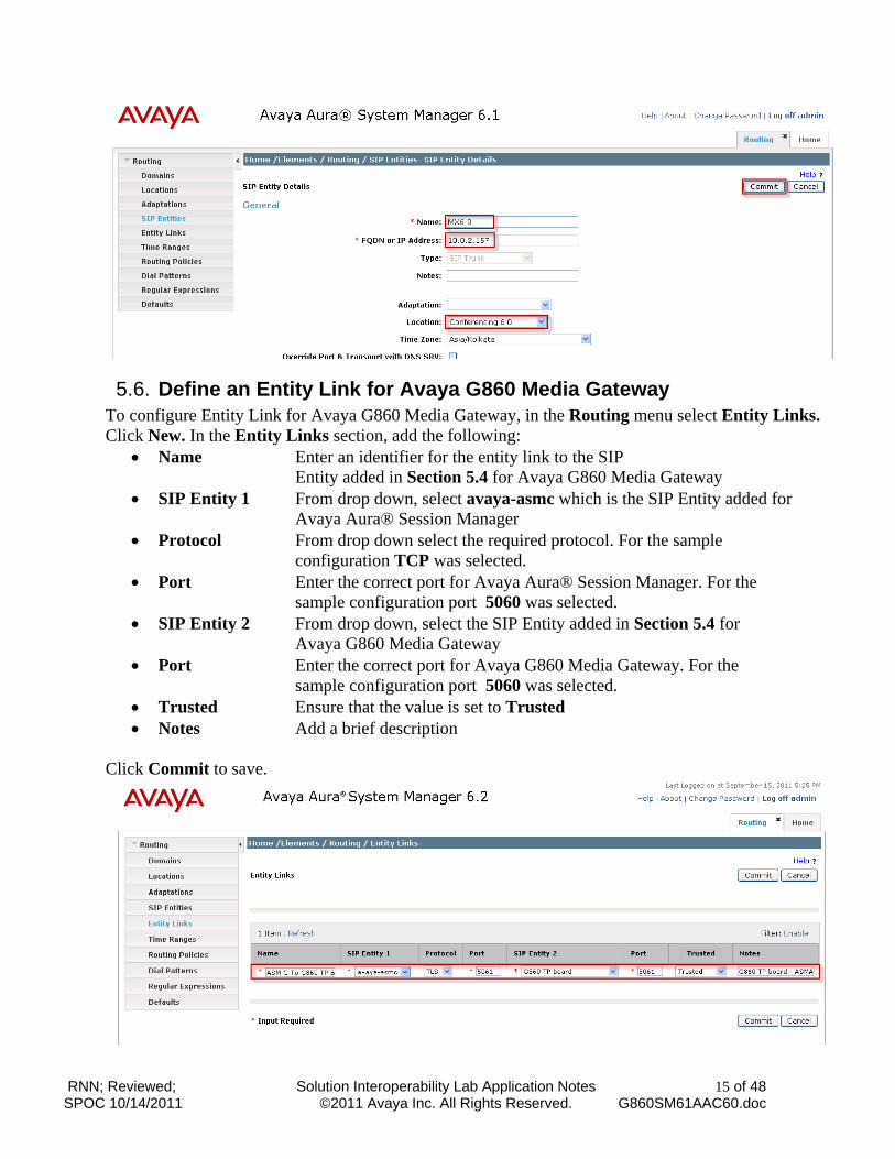
5.6. Define an Entity Link for Avaya G860 Media Gateway To configure Entity Link for Avaya G860 Media Gateway, in the Routing menu select Entity Links. Click New. In the Entity Links section, add the following:
Name Enter an identifier for the entity link to the SIP Entity added in Section 5.4 for Avaya G860 Media Gateway
SIP Entity 1 From drop down, select avaya-asmc which is the SIP Entity added for Avaya Aura® Session Manager
Protocol From drop down select the required protocol. For the sample configuration TCP was selected.
Port Enter the correct port for Avaya Aura® Session Manager. For the sample configuration port 5060 was selected.
SIP Entity 2 From drop down, select the SIP Entity added in Section 5.4 for Avaya G860 Media Gateway
Port Enter the correct port for Avaya G860 Media Gateway. For the sample configuration port 5060 was selected.
Trusted Ensure that the value is set to Trusted Notes Add a brief description
Click Commit to save.
RNN; Reviewed; SPOC 10/14/2011
Solution Interoperability Lab Application Notes ©2011 Avaya Inc. All Rights Reserved.
16 of 48 G860SM61AAC60.doc
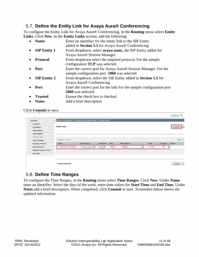
5.7. Define the Entity Link for Avaya Aura® Conferencing To configure the Entity Link for Avaya Aura® Conferencing, in the Routing menu select Entity Links. Click New. In the Entity Links section, add the following:
Name Enter an identifier for the entity link to the SIP Entity added in Section 5.5 for Avaya Aura® Conferencing
SIP Entity 1 From dropdown, select avaya-asmc, the SIP Entity added for Avaya Aura® Session Manager
Protocol From dropdown select the required protocol. For the sample configuration TCP was selected.
Port Enter the correct port for Avaya Aura® Session Manager. For the sample configuration port 5060 was selected.
SIP Entity 2 From dropdown, select the SIP Entity added in Section 5.5 for Avaya Aura® Conferencing
Port Enter the correct port for the link For the sample configuration port 5060 was selected.
Trusted Ensure the check box is checked Notes Add a brief description
Click Commit to save.
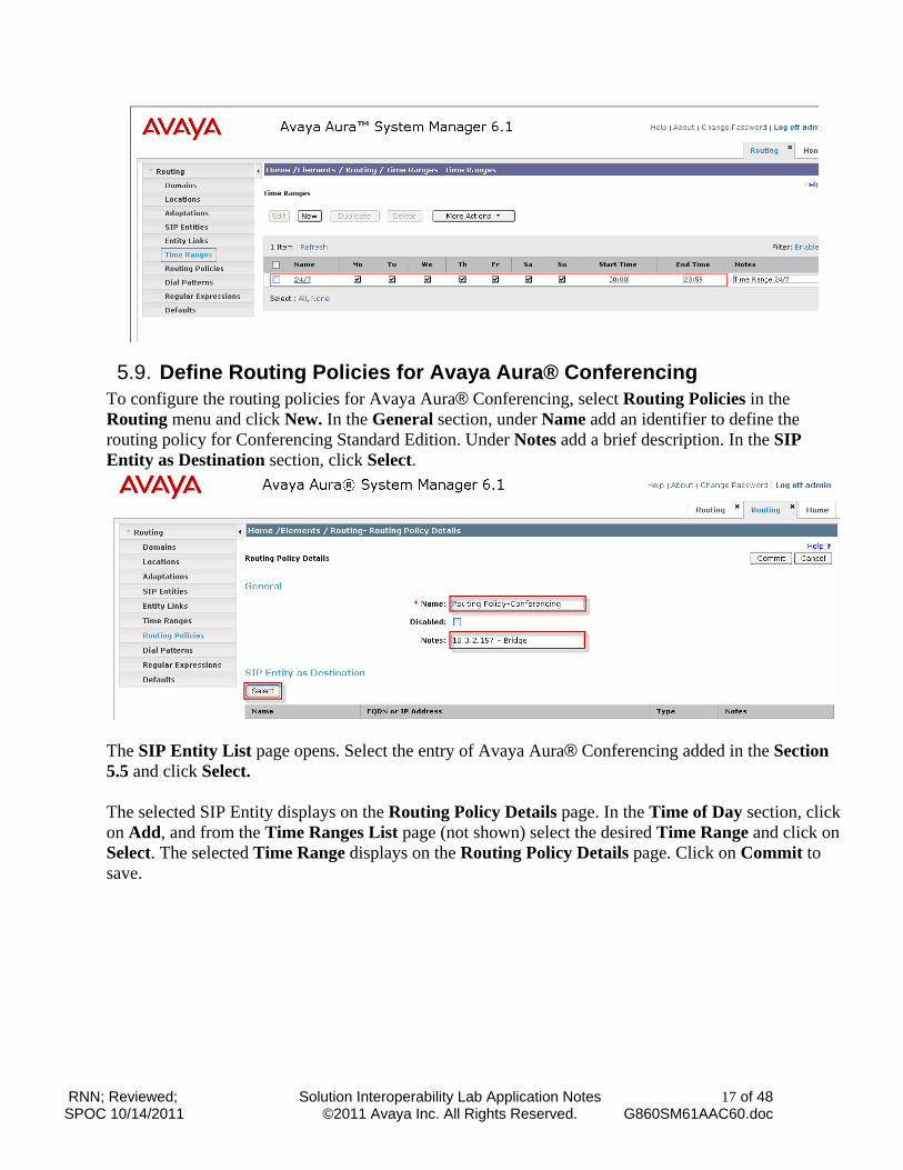
5.8. Define Time Ranges To configure the Time Ranges, in the Routing menu select Time Ranges. Click New. Under Name enter an identifier. Select the days of the week, enter time values for Start Time and End Time. Under Notes add a brief description. When completed, click Commit to save. Screenshot below shows the updated information.
RNN; Reviewed; SPOC 10/14/2011
Solution Interoperability Lab Application Notes ©2011 Avaya Inc. All Rights Reserved.
17 of 48 G860SM61AAC60.doc
5.9. Define Routing Policies for Avaya Aura® Conferencing To configure the routing policies for Avaya Aura® Conferencing, select Routing Policies in the Routing menu and click New. In the General section, under Name add an identifier to define the routing policy for Conferencing Standard Edition. Under Notes add a brief description. In the SIP Entity as Destination section, click Select.
The SIP Entity List page opens. Select the entry of Avaya Aura® Conferencing added in the Section 5.5 and click Select.
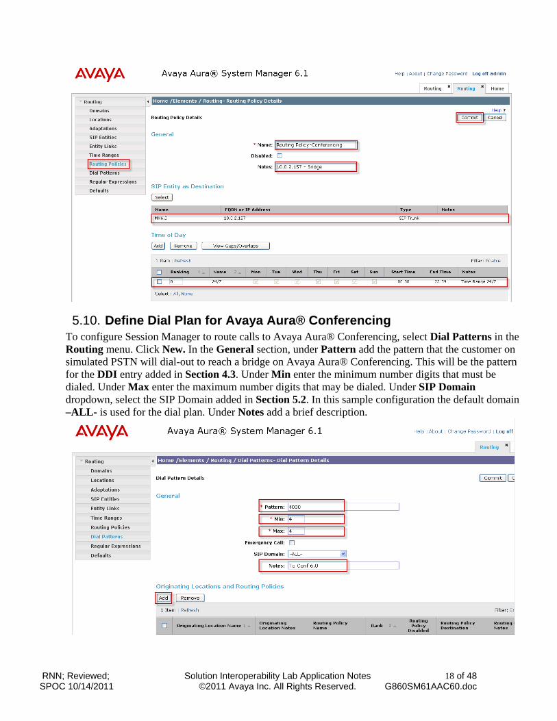
The selected SIP Entity displays on the Routing Policy Details page. In the Time of Day section, click on Add, and from the Time Ranges List page (not shown) select the desired Time Range and click on Select. The selected Time Range displays on the Routing Policy Details page. Click on Commit to save.
RNN; Reviewed; SPOC 10/14/2011
Solution Interoperability Lab Application Notes ©2011 Avaya Inc. All Rights Reserved.
18 of 48 G860SM61AAC60.doc
5.10. Define Dial Plan for Avaya Aura® Conferencing To configure Session Manager to route calls to Avaya Aura® Conferencing, select Dial Patterns in the Routing menu. Click New. In the General section, under Pattern add the pattern that the customer on simulated PSTN will dial-out to reach a bridge on Avaya Aura® Conferencing. This will be the pattern for the DDI entry added in Section 4.3. Under Min enter the minimum number digits that must be dialed. Under Max enter the maximum number digits that may be dialed. Under SIP Domain dropdown, select the SIP Domain added in Section 5.2. In this sample configuration the default domain –ALL- is used for the dial plan. Under Notes add a brief description.
RNN; Reviewed; SPOC 10/14/2011
Solution Interoperability Lab Application Notes ©2011 Avaya Inc. All Rights Reserved.
19 of 48 G860SM61AAC60.doc
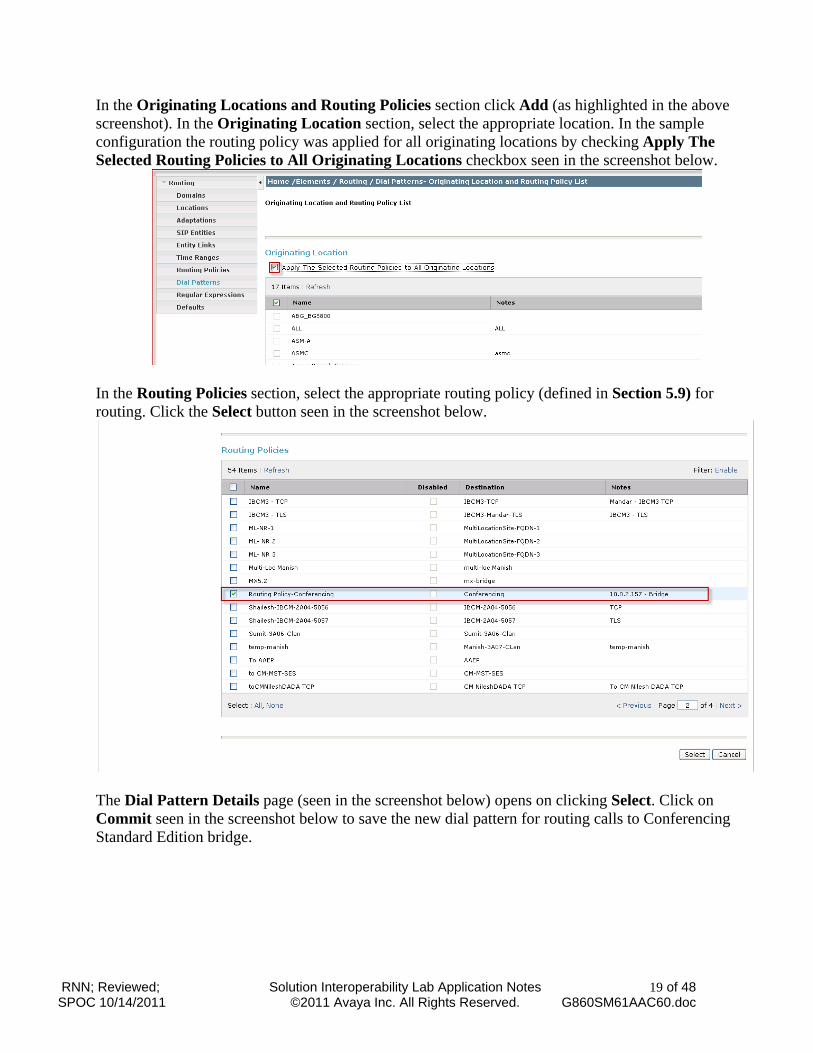
In the Originating Locations and Routing Policies section click Add (as highlighted in the above screenshot). In the Originating Location section, select the appropriate location. In the sample configuration the routing policy was applied for all originating locations by checking Apply The Selected Routing Policies to All Originating Locations checkbox seen in the screenshot below.
In the Routing Policies section, select the appropriate routing policy (defined in Section 5.9) for routing. Click the Select button seen in the screenshot below.
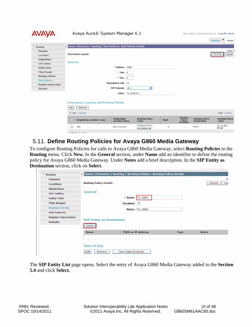
The Dial Pattern Details page (seen in the screenshot below) opens on clicking Select. Click on Commit seen in the screenshot below to save the new dial pattern for routing calls to Conferencing Standard Edition bridge.
RNN; Reviewed; SPOC 10/14/2011
Solution Interoperability Lab Application Notes ©2011 Avaya Inc. All Rights Reserved.
20 of 48 G860SM61AAC60.doc
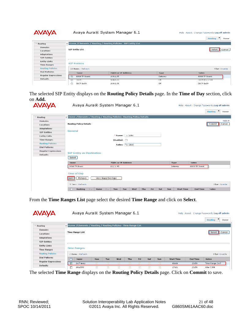
5.11. Define Routing Policies for Avaya G860 Media Gateway To configure Routing Policies for calls to Avaya G860 Media Gateway, select Routing Policies in the Routing menu. Click New. In the General section, under Name add an identifier to define the routing policy for Avaya G860 Media Gateway. Under Notes add a brief description. In the SIP Entity as Destination section, click on Select.
The SIP Entity List page opens. Select the entry of Avaya G860 Media Gateway added in the Section 5.4 and click Select.
RNN; Reviewed; SPOC 10/14/2011
Solution Interoperability Lab Application Notes ©2011 Avaya Inc. All Rights Reserved.
21 of 48 G860SM61AAC60.doc
The selected SIP Entity displays on the Routing Policy Details page. In the Time of Day section, click on Add.
From the Time Ranges List page select the desired Time Range and click on Select.
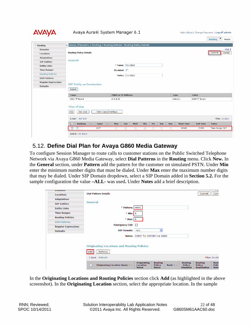
The selected Time Range displays on the Routing Policy Details page. Click on Commit to save.
RNN; Reviewed; SPOC 10/14/2011
Solution Interoperability Lab Application Notes ©2011 Avaya Inc. All Rights Reserved.
22 of 48 G860SM61AAC60.doc
5.12. Define Dial Plan for Avaya G860 Media Gateway To configure Session Manager to route calls to customer stations on the Public Switched Telephone Network via Avaya G860 Media Gateway, select Dial Patterns in the Routing menu. Click New. In the General section, under Pattern add the pattern for the customer on simulated PSTN. Under Min enter the minimum number digits that must be dialed. Under Max enter the maximum number digits that may be dialed. Under SIP Domain dropdown, select a SIP Domain added in Section 5.2. For the sample configuration the value –ALL- was used. Under Notes add a brief description.
In the Originating Locations and Routing Policies section click Add (as highlighted in the above screenshot). In the Originating Location section, select the appropriate location. In the sample
RNN; Reviewed; SPOC 10/14/2011
Solution Interoperability Lab Application Notes ©2011 Avaya Inc. All Rights Reserved.
23 of 48 G860SM61AAC60.doc
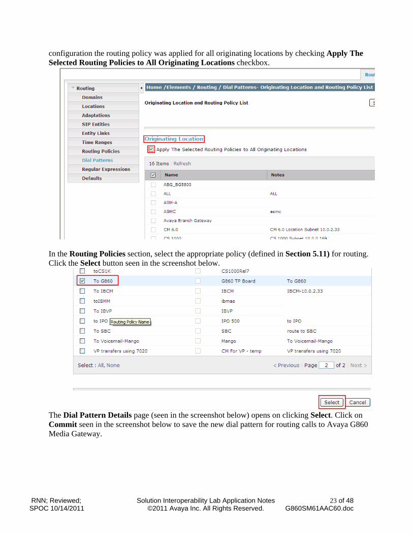
configuration the routing policy was applied for all originating locations by checking Apply The Selected Routing Policies to All Originating Locations checkbox.
In the Routing Policies section, select the appropriate policy (defined in Section 5.11) for routing. Click the Select button seen in the screenshot below.
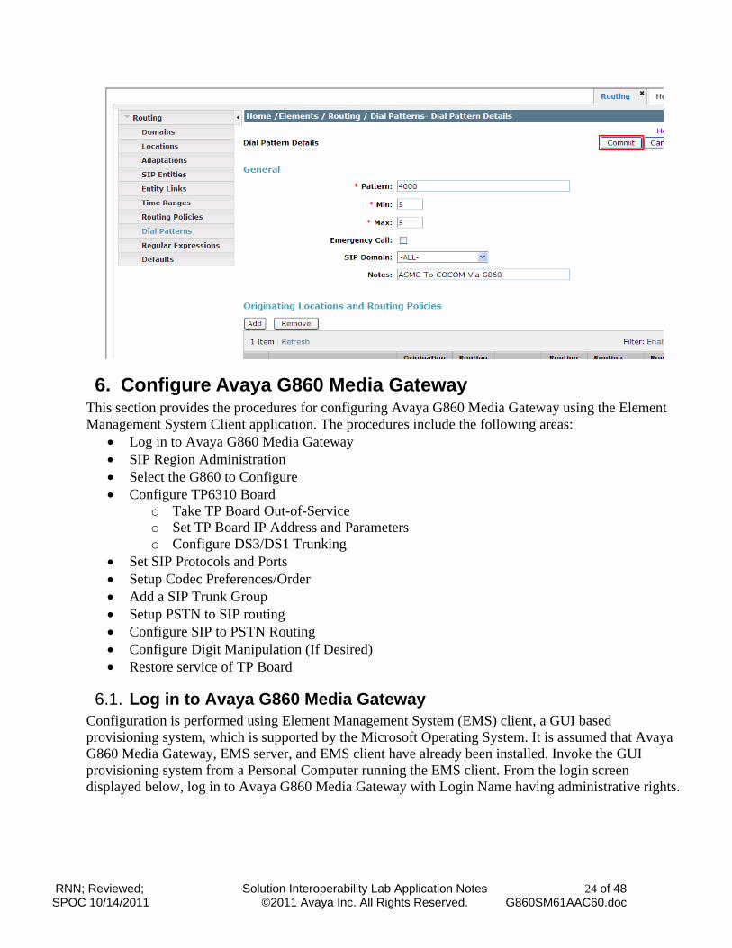
The Dial Pattern Details page (seen in the screenshot below) opens on clicking Select. Click on Commit seen in the screenshot below to save the new dial pattern for routing calls to Avaya G860 Media Gateway.
RNN; Reviewed; SPOC 10/14/2011
Solution Interoperability Lab Application Notes ©2011 Avaya Inc. All Rights Reserved.
24 of 48 G860SM61AAC60.doc
6. Configure Avaya G860 Media Gateway This section provides the procedures for configuring Avaya G860 Media Gateway using the Element Management System Client application. The procedures include the following areas:
Log in to Avaya G860 Media Gateway SIP Region Administration Select the G860 to Configure Configure TP6310 Board
o Take TP Board Out-of-Service o Set TP Board IP Address and Parameters o Configure DS3/DS1 Trunking
Set SIP Protocols and Ports Setup Codec Preferences/Order Add a SIP Trunk Group Setup PSTN to SIP routing Configure SIP to PSTN Routing Configure Digit Manipulation (If Desired) Restore service of TP Board
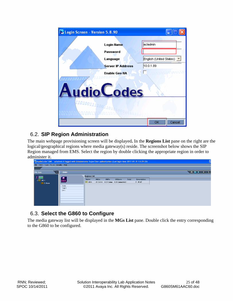
6.1. Log in to Avaya G860 Media Gateway Configuration is performed using Element Management System (EMS) client, a GUI based provisioning system, which is supported by the Microsoft Operating System. It is assumed that Avaya G860 Media Gateway, EMS server, and EMS client have already been installed. Invoke the GUI provisioning system from a Personal Computer running the EMS client. From the login screen displayed below, log in to Avaya G860 Media Gateway with Login Name having administrative rights.
RNN; Reviewed; SPOC 10/14/2011
Solution Interoperability Lab Application Notes ©2011 Avaya Inc. All Rights Reserved.
25 of 48 G860SM61AAC60.doc
6.2. SIP Region Administration The main webpage provisioning screen will be displayed. In the Regions List pane on the right are the logical/geographical regions where media gateway(s) reside. The screenshot below shows the SIP Region managed from EMS. Select the region by double clicking the appropriate region in order to administer it.
6.3. Select the G860 to Configure The media gateway list will be displayed in the MGs List pane. Double click the entry corresponding to the G860 to be configured.
RNN; Reviewed; SPOC 10/14/2011
Solution Interoperability Lab Application Notes ©2011 Avaya Inc. All Rights Reserved.
26 of 48 G860SM61AAC60.doc
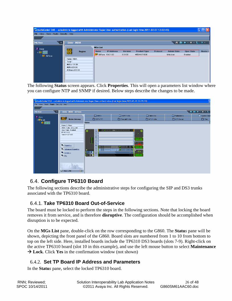
The following Status screen appears. Click Properties. This will open a parameters list window where you can configure NTP and SNMP if desired. Below steps describe the changes to be made.
6.4. Configure TP6310 Board The following sections describe the administrative steps for configuring the SIP and DS3 trunks associated with the TP6310 board.
6.4.1. Take TP6310 Board Out-of-Service The board must be locked to perform the steps in the following sections. Note that locking the board removes it from service, and is therefore disruptive. The configuration should be accomplished when disruption is to be expected.
On the MGs List pane, double-click on the row corresponding to the G860. The Status pane will be shown, depicting the front panel of the G860. Board slots are numbered from 1 to 10 from bottom to top on the left side. Here, installed boards include the TP6310 DS3 boards (slots 7-9). Right-click on the active TP6310 board (slot 10 in this example), and use the left mouse button to select Maintenance Lock. Click Yes in the confirmation window (not shown)
6.4.2. Set TP Board IP Address and Parameters In the Status pane, select the locked TP6310 board.
RNN; Reviewed; SPOC 10/14/2011
Solution Interoperability Lab Application Notes ©2011 Avaya Inc. All Rights Reserved.
27 of 48 G860SM61AAC60.doc
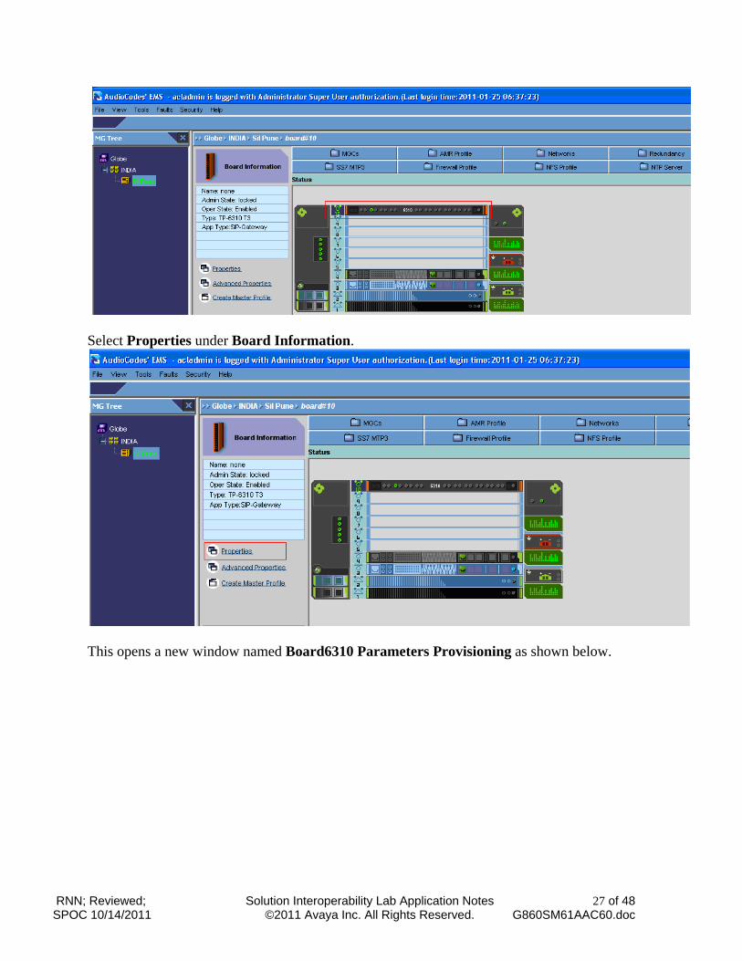
Select Properties under Board Information.
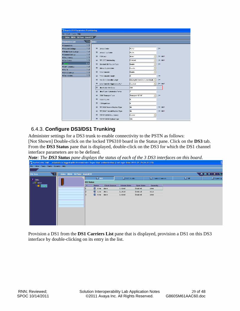
This opens a new window named Board6310 Parameters Provisioning as shown below.
RNN; Reviewed; SPOC 10/14/2011
Solution Interoperability Lab Application Notes ©2011 Avaya Inc. All Rights Reserved.
28 of 48 G860SM61AAC60.doc
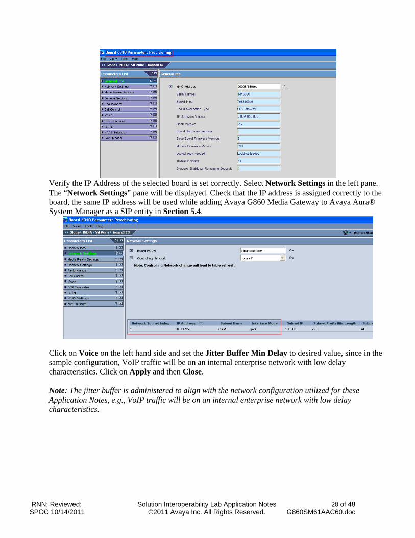
Verify the IP Address of the selected board is set correctly. Select Network Settings in the left pane. The “Network Settings” pane will be displayed. Check that the IP address is assigned correctly to the board, the same IP address will be used while adding Avaya G860 Media Gateway to Avaya Aura® System Manager as a SIP entity in Section 5.4.
Click on Voice on the left hand side and set the Jitter Buffer Min Delay to desired value, since in the sample configuration, VoIP traffic will be on an internal enterprise network with low delay characteristics. Click on Apply and then Close. Note: The jitter buffer is administered to align with the network configuration utilized for these Application Notes, e.g., VoIP traffic will be on an internal enterprise network with low delay characteristics.
RNN; Reviewed; SPOC 10/14/2011
Solution Interoperability Lab Application Notes ©2011 Avaya Inc. All Rights Reserved.
29 of 48 G860SM61AAC60.doc
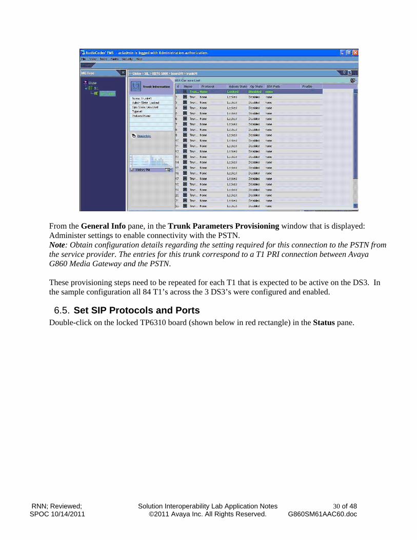
6.4.3. Configure DS3/DS1 Trunking Administer settings for a DS3 trunk to enable connectivity to the PSTN as follows: [Not Shown] Double-click on the locked TP6310 board in the Status pane. Click on the DS3 tab. From the DS3 Status pane that is displayed, double-click on the DS3 for which the DS1 channel interface parameters are to be defined. Note: The DS3 Status pane displays the status of each of the 3 DS3 interfaces on this board.
Provision a DS1 from the DS1 Carriers List pane that is displayed, provision a DS1 on this DS3 interface by double-clicking on its entry in the list.
RNN; Reviewed; SPOC 10/14/2011
Solution Interoperability Lab Application Notes ©2011 Avaya Inc. All Rights Reserved.
30 of 48 G860SM61AAC60.doc
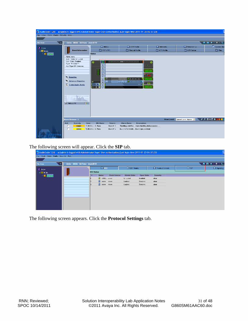
From the General Info pane, in the Trunk Parameters Provisioning window that is displayed: Administer settings to enable connectivity with the PSTN. Note: Obtain configuration details regarding the setting required for this connection to the PSTN from the service provider. The entries for this trunk correspond to a T1 PRI connection between Avaya G860 Media Gateway and the PSTN.
These provisioning steps need to be repeated for each T1 that is expected to be active on the DS3. In the sample configuration all 84 T1’s across the 3 DS3’s were configured and enabled.
6.5. Set SIP Protocols and Ports Double-click on the locked TP6310 board (shown below in red rectangle) in the Status pane.
RNN; Reviewed; SPOC 10/14/2011
Solution Interoperability Lab Application Notes ©2011 Avaya Inc. All Rights Reserved.
31 of 48 G860SM61AAC60.doc
The following screen will appear. Click the SIP tab.
The following screen appears. Click the Protocol Settings tab.
RNN; Reviewed; SPOC 10/14/2011
Solution Interoperability Lab Application Notes ©2011 Avaya Inc. All Rights Reserved.
32 of 48 G860SM61AAC60.doc
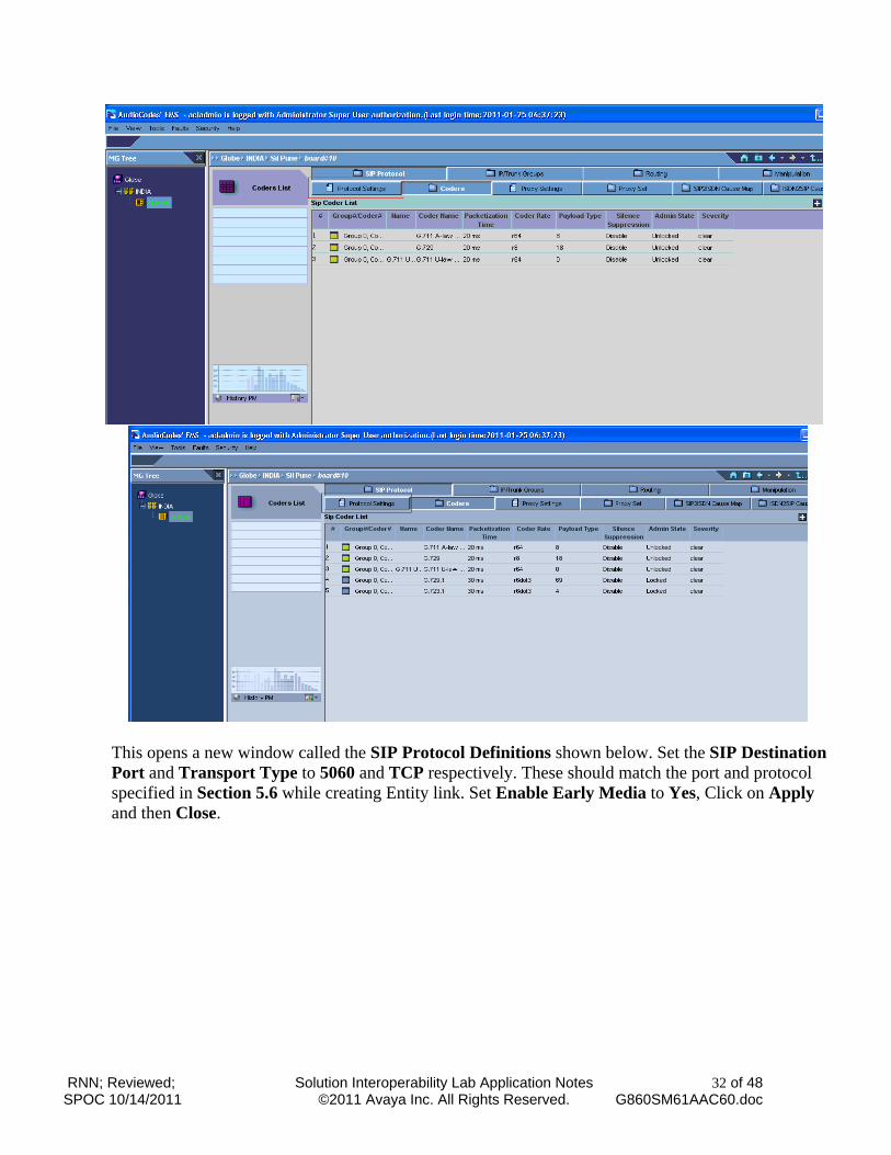
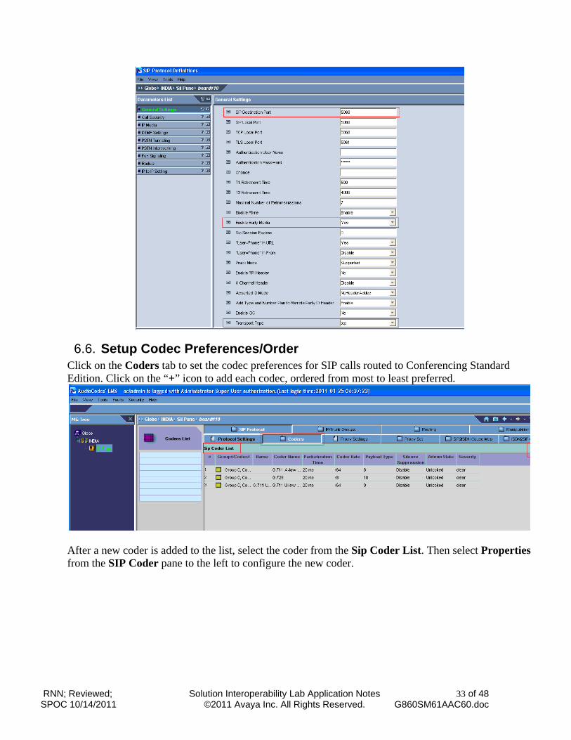
This opens a new window called the SIP Protocol Definitions shown below. Set the SIP Destination Port and Transport Type to 5060 and TCP respectively. These should match the port and protocol specified in Section 5.6 while creating Entity link. Set Enable Early Media to Yes, Click on Apply and then Close.
RNN; Reviewed; SPOC 10/14/2011
Solution Interoperability Lab Application Notes ©2011 Avaya Inc. All Rights Reserved.
33 of 48 G860SM61AAC60.doc
6.6. Setup Codec Preferences/Order Click on the Coders tab to set the codec preferences for SIP calls routed to Conferencing Standard Edition. Click on the “+” icon to add each codec, ordered from most to least preferred.
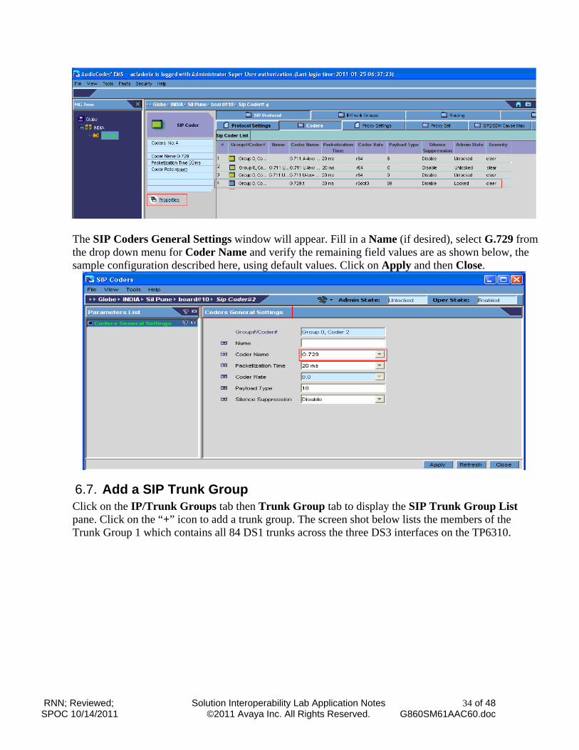
After a new coder is added to the list, select the coder from the Sip Coder List. Then select Properties from the SIP Coder pane to the left to configure the new coder.
RNN; Reviewed; SPOC 10/14/2011
Solution Interoperability Lab Application Notes ©2011 Avaya Inc. All Rights Reserved.
34 of 48 G860SM61AAC60.doc
The SIP Coders General Settings window will appear. Fill in a Name (if desired), select G.729 from the drop down menu for Coder Name and verify the remaining field values are as shown below, the sample configuration described here, using default values. Click on Apply and then Close.
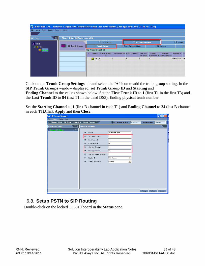
6.7. Add a SIP Trunk Group Click on the IP/Trunk Groups tab then Trunk Group tab to display the SIP Trunk Group List pane. Click on the “+” icon to add a trunk group. The screen shot below lists the members of the Trunk Group 1 which contains all 84 DS1 trunks across the three DS3 interfaces on the TP6310.
RNN; Reviewed; SPOC 10/14/2011
Solution Interoperability Lab Application Notes ©2011 Avaya Inc. All Rights Reserved.
35 of 48 G860SM61AAC60.doc
Click on the Trunk Group Settings tab and select the “+” icon to add the trunk group setting. In the SIP Trunk Groups window displayed, set Trunk Group ID and Starting and Ending Channel to the values shown below. Set the First Trunk ID to 1 (first T1 in the first T3) and the Last Trunk ID to 84 (last T1 in the third DS3); Ending physical trunk number. Set the Starting Channel to 1 (first B-channel in each T1) and Ending Channel to 24 (last B-channel in each T1).Click Apply and then Close.
6.8. Setup PSTN to SIP Routing Double-click on the locked TP6310 board in the Status pane.
RNN; Reviewed; SPOC 10/14/2011
Solution Interoperability Lab Application Notes ©2011 Avaya Inc. All Rights Reserved.
36 of 48 G860SM61AAC60.doc
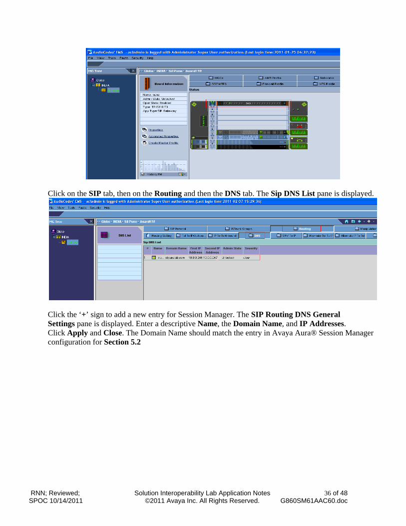
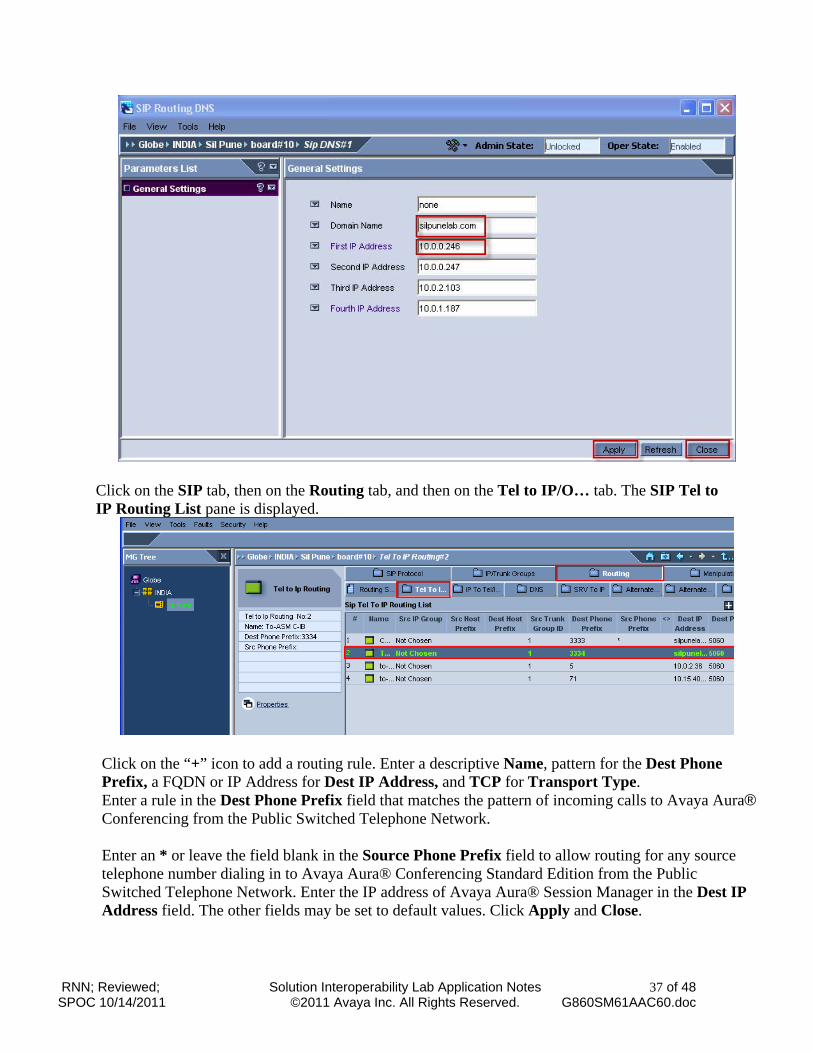
Click on the SIP tab, then on the Routing and then the DNS tab. The Sip DNS List pane is displayed.
Click the ‘+’ sign to add a new entry for Session Manager. The SIP Routing DNS General Settings pane is displayed. Enter a descriptive Name, the Domain Name, and IP Addresses. Click Apply and Close. The Domain Name should match the entry in Avaya Aura® Session Manager configuration for Section 5.2
RNN; Reviewed; SPOC 10/14/2011
Solution Interoperability Lab Application Notes ©2011 Avaya Inc. All Rights Reserved.
37 of 48 G860SM61AAC60.doc
Click on the SIP tab, then on the Routing tab, and then on the Tel to IP/O… tab. The SIP Tel to IP Routing List pane is displayed.
Click on the “+” icon to add a routing rule. Enter a descriptive Name, pattern for the Dest Phone Prefix, a FQDN or IP Address for Dest IP Address, and TCP for Transport Type. Enter a rule in the Dest Phone Prefix field that matches the pattern of incoming calls to Avaya Aura® Conferencing from the Public Switched Telephone Network. Enter an * or leave the field blank in the Source Phone Prefix field to allow routing for any source telephone number dialing in to Avaya Aura® Conferencing Standard Edition from the Public Switched Telephone Network. Enter the IP address of Avaya Aura® Session Manager in the Dest IP Address field. The other fields may be set to default values. Click Apply and Close.
RNN; Reviewed; SPOC 10/14/2011
Solution Interoperability Lab Application Notes ©2011 Avaya Inc. All Rights Reserved.
38 of 48 G860SM61AAC60.doc
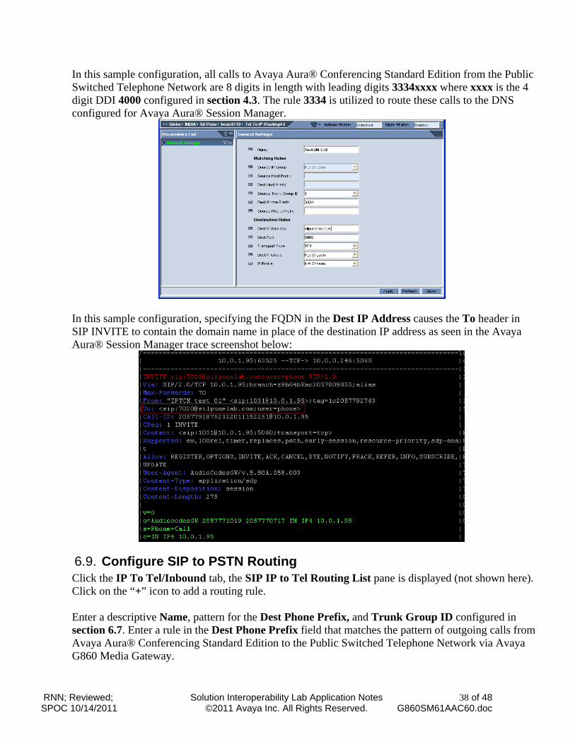
In this sample configuration, all calls to Avaya Aura® Conferencing Standard Edition from the Public Switched Telephone Network are 8 digits in length with leading digits 3334xxxx where xxxx is the 4 digit DDI 4000 configured in section 4.3. The rule 3334 is utilized to route these calls to the DNS configured for Avaya Aura® Session Manager.
In this sample configuration, specifying the FQDN in the Dest IP Address causes the To header in SIP INVITE to contain the domain name in place of the destination IP address as seen in the Avaya Aura® Session Manager trace screenshot below:
6.9. Configure SIP to PSTN Routing Click the IP To Tel/Inbound tab, the SIP IP to Tel Routing List pane is displayed (not shown here). Click on the “+” icon to add a routing rule. Enter a descriptive Name, pattern for the Dest Phone Prefix, and Trunk Group ID configured in section 6.7. Enter a rule in the Dest Phone Prefix field that matches the pattern of outgoing calls from Avaya Aura® Conferencing Standard Edition to the Public Switched Telephone Network via Avaya G860 Media Gateway.
RNN; Reviewed; SPOC 10/14/2011
Solution Interoperability Lab Application Notes ©2011 Avaya Inc. All Rights Reserved.
39 of 48 G860SM61AAC60.doc
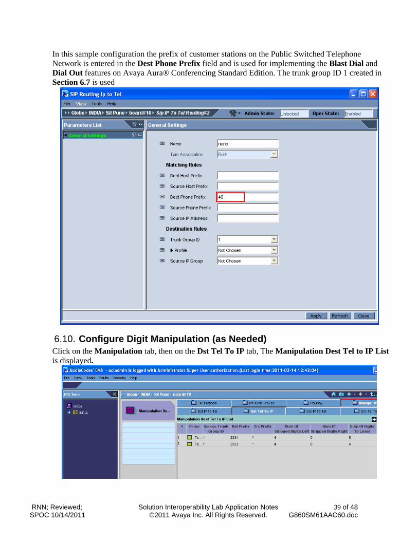
In this sample configuration the prefix of customer stations on the Public Switched Telephone Network is entered in the Dest Phone Prefix field and is used for implementing the Blast Dial and Dial Out features on Avaya Aura® Conferencing Standard Edition. The trunk group ID 1 created in Section 6.7 is used
6.10. Configure Digit Manipulation (as Needed) Click on the Manipulation tab, then on the Dst Tel To IP tab, The Manipulation Dest Tel to IP List is displayed.
RNN; Reviewed; SPOC 10/14/2011
Solution Interoperability Lab Application Notes ©2011 Avaya Inc. All Rights Reserved.
40 of 48 G860SM61AAC60.doc
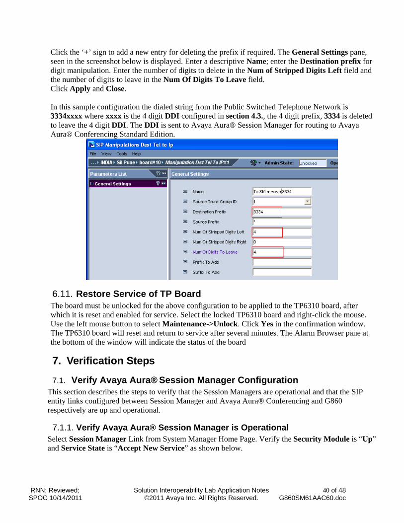
Click the ‘+’ sign to add a new entry for deleting the prefix if required. The General Settings pane, seen in the screenshot below is displayed. Enter a descriptive Name; enter the Destination prefix for digit manipulation. Enter the number of digits to delete in the Num of Stripped Digits Left field and the number of digits to leave in the Num Of Digits To Leave field. Click Apply and Close.
In this sample configuration the dialed string from the Public Switched Telephone Network is 3334xxxx where xxxx is the 4 digit DDI configured in section 4.3., the 4 digit prefix, 3334 is deleted to leave the 4 digit DDI. The DDI is sent to Avaya Aura® Session Manager for routing to Avaya Aura® Conferencing Standard Edition.
6.11. Restore Service of TP Board The board must be unlocked for the above configuration to be applied to the TP6310 board, after which it is reset and enabled for service. Select the locked TP6310 board and right-click the mouse. Use the left mouse button to select Maintenance->Unlock. Click Yes in the confirmation window. The TP6310 board will reset and return to service after several minutes. The Alarm Browser pane at the bottom of the window will indicate the status of the board
7. Verification Steps
7.1. Verify Avaya Aura® Session Manager Configuration This section describes the steps to verify that the Session Managers are operational and that the SIP entity links configured between Session Manager and Avaya Aura® Conferencing and G860 respectively are up and operational.
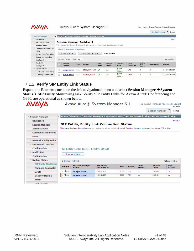
7.1.1. Verify Avaya Aura® Session Manager is Operational Select Session Manager Link from System Manager Home Page. Verify the Security Module is “Up” and Service State is “Accept New Service” as shown below.
RNN; Reviewed; SPOC 10/14/2011
Solution Interoperability Lab Application Notes ©2011 Avaya Inc. All Rights Reserved.
41 of 48 G860SM61AAC60.doc
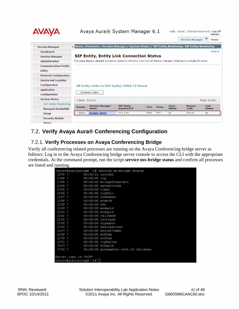
7.1.2. Verify SIP Entity Link Status Expand the Elements menu on the left navigational menu and select Session Manager System Status SIP Entity Monitoring task. Verify SIP Entity Links for Avaya Aura® Conferencing and G860, are operational as shown below:
RNN; Reviewed; SPOC 10/14/2011
Solution Interoperability Lab Application Notes ©2011 Avaya Inc. All Rights Reserved.
42 of 48 G860SM61AAC60.doc
7.2. Verify Avaya Aura® Conferencing Configuration
7.2.1. Verify Processes on Avaya Conferencing Bridge Verify all conferencing related processes are running on the Avaya Conferencing bridge server as follows: Log in to the Avaya Conferencing bridge server console to access the CLI with the appropriate credentials. At the command prompt, run the script service mx-bridge status and confirm all processes are listed and running.
RNN; Reviewed; SPOC 10/14/2011
Solution Interoperability Lab Application Notes ©2011 Avaya Inc. All Rights Reserved.
43 of 48 G860SM61AAC60.doc
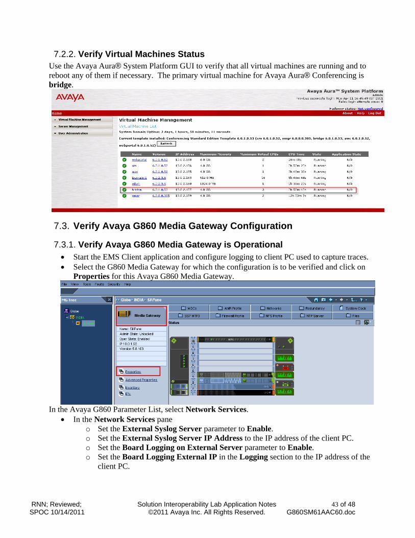
7.2.2. Verify Virtual Machines Status Use the Avaya Aura® System Platform GUI to verify that all virtual machines are running and to reboot any of them if necessary. The primary virtual machine for Avaya Aura® Conferencing is bridge.
7.3. Verify Avaya G860 Media Gateway Configuration
7.3.1. Verify Avaya G860 Media Gateway is Operational Start the EMS Client application and configure logging to client PC used to capture traces. Select the G860 Media Gateway for which the configuration is to be verified and click on
Properties for this Avaya G860 Media Gateway.
In the Avaya G860 Parameter List, select Network Services.
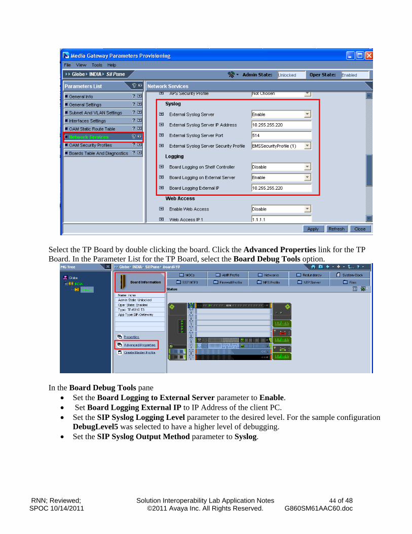
In the Network Services pane o Set the External Syslog Server parameter to Enable. o Set the External Syslog Server IP Address to the IP address of the client PC. o Set the Board Logging on External Server parameter to Enable. o Set the Board Logging External IP in the Logging section to the IP address of the
client PC.
RNN; Reviewed; SPOC 10/14/2011
Solution Interoperability Lab Application Notes ©2011 Avaya Inc. All Rights Reserved.
44 of 48 G860SM61AAC60.doc
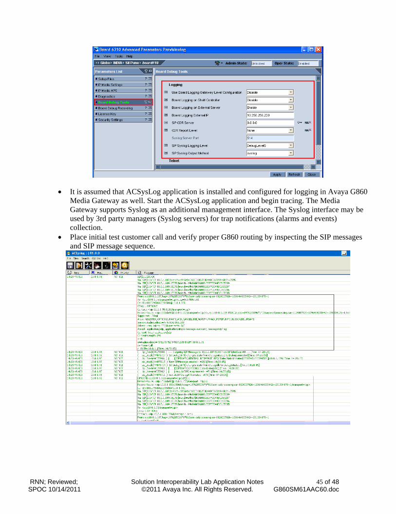
Select the TP Board by double clicking the board. Click the Advanced Properties link for the TP Board. In the Parameter List for the TP Board, select the Board Debug Tools option.
In the Board Debug Tools pane
Set the Board Logging to External Server parameter to Enable. Set Board Logging External IP to IP Address of the client PC. Set the SIP Syslog Logging Level parameter to the desired level. For the sample configuration
DebugLevel5 was selected to have a higher level of debugging. Set the SIP Syslog Output Method parameter to Syslog.
RNN; Reviewed; SPOC 10/14/2011
Solution Interoperability Lab Application Notes ©2011 Avaya Inc. All Rights Reserved.
45 of 48 G860SM61AAC60.doc
It is assumed that ACSysLog application is installed and configured for logging in Avaya G860 Media Gateway as well. Start the ACSysLog application and begin tracing. The Media Gateway supports Syslog as an additional management interface. The Syslog interface may be used by 3rd party managers (Syslog servers) for trap notifications (alarms and events) collection.
Place initial test customer call and verify proper G860 routing by inspecting the SIP messages and SIP message sequence.
RNN; Reviewed; SPOC 10/14/2011
Solution Interoperability Lab Application Notes ©2011 Avaya Inc. All Rights Reserved.
46 of 48 G860SM61AAC60.doc
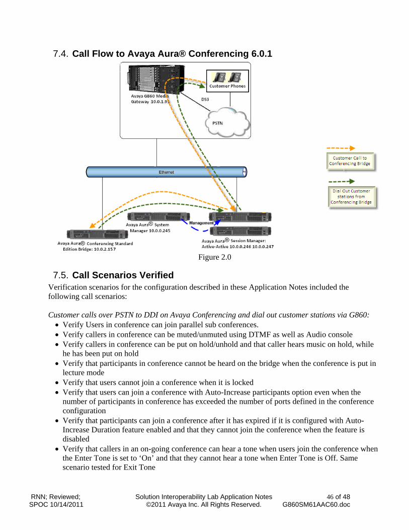
7.4. Call Flow to Avaya Aura® Conferencing 6.0.1
Figure 2.0
7.5. Call Scenarios Verified Verification scenarios for the configuration described in these Application Notes included the following call scenarios: Customer calls over PSTN to DDI on Avaya Conferencing and dial out customer stations via G860: Verify Users in conference can join parallel sub conferences. Verify callers in conference can be muted/unmuted using DTMF as well as Audio console Verify callers in conference can be put on hold/unhold and that caller hears music on hold, while
he has been put on hold Verify that participants in conference cannot be heard on the bridge when the conference is put in
lecture mode Verify that users cannot join a conference when it is locked Verify that users can join a conference with Auto-Increase participants option even when the
number of participants in conference has exceeded the number of ports defined in the conference configuration
Verify that participants can join a conference after it has expired if it is configured with Auto-Increase Duration feature enabled and that they cannot join the conference when the feature is disabled
Verify that callers in an on-going conference can hear a tone when users join the conference when the Enter Tone is set to ‘On’ and that they cannot hear a tone when Enter Tone is Off. Same scenario tested for Exit Tone
RNN; Reviewed; SPOC 10/14/2011
Solution Interoperability Lab Application Notes ©2011 Avaya Inc. All Rights Reserved.
47 of 48 G860SM61AAC60.doc
Verify that a station rings and can join conference when the station is dialed out using Audio Console. Also verify that the station can be dialed out to have Moderator or Participant privileges on joining the conference after Dial Out is complete
Verify that conference ends when Moderator hangs up if the Moderator hang up feature is enabled in the conference
Verify that when conference size is limited to a certain value, Avaya Aura® Conferencing does not allow more participants to join the same conference than the value specified. Auto Increase participants is disabled in this scenario.
Verify that Code duration value is respected in conference and that users cannot join the conference after the code duration has expired
8. Conclusions These Application Notes describe a sample configuration of a network that uses SIP trunks between Avaya Aura® Conferencing 6.0.1, Avaya Aura® Session Manager Release 6.1, and Avaya G860 Media Gateway R2.1.1. Interoperability testing included verification of calls to Avaya Aura® Conferencing bridge from endpoints on PSTN and verifying features on Avaya Aura® Conferencing 6.0.1.
9. Additional References This section references the product documentation relevant to these Application Notes. Avaya Aura® Session Manager
1) Avaya Aura™ Session Manager Overview, Doc ID 03-603323. Available at http://support.avaya.com.
2) Installing and Upgrading Avaya Aura™ Session Manager 6.0, Doc ID 03-603324. Available at http://support.avaya.com.
3) Installing and Upgrading Avaya Aura™ System Manager 6.0. Available at http://support.avaya.com.
4) Maintaining and Troubleshooting Avaya Aura™ Session Manager 6.0, Doc ID 03-603325, available at http://support.avaya.com.
5) Avaya Aura™ Session Manager Case Studies, dated January 2, 2010. Available at http://support.avaya.com.
Avaya Aura® Conferencing Standard Edition 6) Avaya Aura® Conferencing Standard Edition Implementing Avaya Aura® Conferencing,
Document # 04-603508, June, 2010. Available at http://support.avaya.com
Avaya G860 Media Gateway
7) G860/EMS Installation, Operation & Maintenance Manual http://support.avaya.com/css/P8/documents/100041466
8) Installing and Operating the Avaya G860 Media Gateway http://support.avaya.com/css/P8/documents/100041404
RNN; Reviewed; SPOC 10/14/2011
Solution Interoperability Lab Application Notes ©2011 Avaya Inc. All Rights Reserved.
48 of 48 G860SM61AAC60.doc
©2011 Avaya Inc. All Rights Reserved. Avaya and the Avaya Logo are trademarks of Avaya Inc. All trademarks identified by ® and ™ are registered trademarks or trademarks, respectively, of Avaya Inc. All other trademarks are the property of their respective owners. The information provided in these Application Notes is subject to change without notice. The configurations, technical data, and recommendations provided in these Application Notes are believed to be accurate and dependable, but are presented without express or implied warranty. Users are responsible for their application of any products specified in these Application Notes. Please e-mail any questions or comments pertaining to these Application Notes along with the full title name and filename, located in the lower right corner, directly to the Avaya Solution & Interoperability Test Lab at [email protected]