Embed Size (px)
Citation preview

Compressive Object Tracking using Entangled Photons
Omar S. Magana-Loaiza,1, a) Gregory A. Howland,2 Mehul Malik,1 John C. Howell,2 and
Robert W. Boyd1, b)
1)The Institute of Optics, University of Rochester, Rochester, NY 14627,
USA
2)Department of Physics and Astronomy, University of Rochester, Rochester,
NY 14627, USA
(Dated: 11 June 2013)
We present a compressive sensing protocol that tracks a moving object by removing
static components from a scene. The implementation is carried out on a ghost imaging
scheme to minimize both the number of photons and the number of measurements
required to form a quantum image of the tracked object. This procedure tracks an
object at low light levels with fewer than 3% of the measurements required for a
raster scan, permitting us to more effectively use the information content in each
photon.
a)[email protected])Also at Department of Physics, University of Ottawa, Ottawa, Ontario K1N 6N5, Canada.
1
arX
iv:1
306.
2270
v1 [
quan
t-ph
] 1
0 Ju
n 20
13
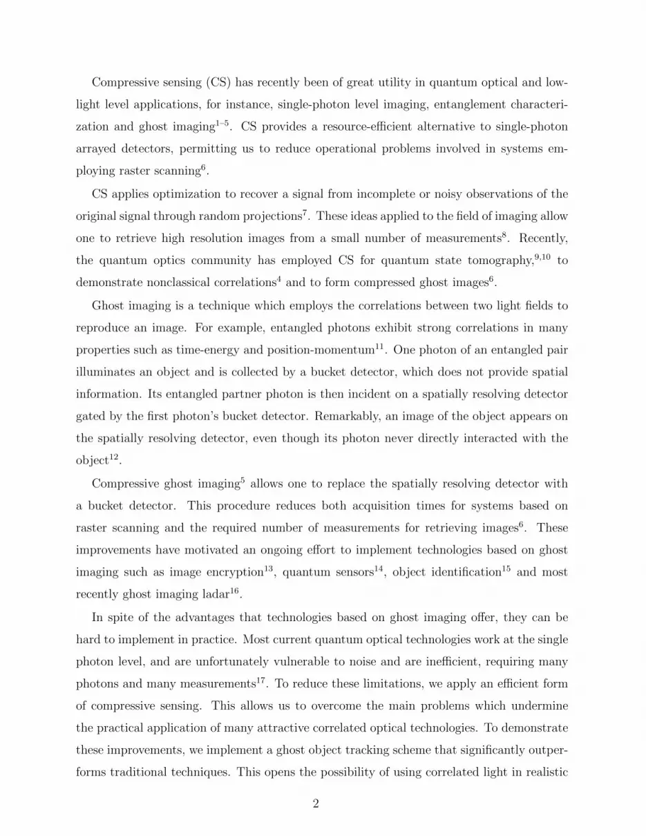
Compressive sensing (CS) has recently been of great utility in quantum optical and low-
light level applications, for instance, single-photon level imaging, entanglement characteri-
zation and ghost imaging1–5. CS provides a resource-efficient alternative to single-photon
arrayed detectors, permitting us to reduce operational problems involved in systems em-
ploying raster scanning6.
CS applies optimization to recover a signal from incomplete or noisy observations of the
original signal through random projections7. These ideas applied to the field of imaging allow
one to retrieve high resolution images from a small number of measurements8. Recently,
the quantum optics community has employed CS for quantum state tomography,9,10 to
demonstrate nonclassical correlations4 and to form compressed ghost images6.
Ghost imaging is a technique which employs the correlations between two light fields to
reproduce an image. For example, entangled photons exhibit strong correlations in many
properties such as time-energy and position-momentum11. One photon of an entangled pair
illuminates an object and is collected by a bucket detector, which does not provide spatial
information. Its entangled partner photon is then incident on a spatially resolving detector
gated by the first photon’s bucket detector. Remarkably, an image of the object appears on
the spatially resolving detector, even though its photon never directly interacted with the
object12.
Compressive ghost imaging5 allows one to replace the spatially resolving detector with
a bucket detector. This procedure reduces both acquisition times for systems based on
raster scanning and the required number of measurements for retrieving images6. These
improvements have motivated an ongoing effort to implement technologies based on ghost
imaging such as image encryption13, quantum sensors14, object identification15 and most
recently ghost imaging ladar16.
In spite of the advantages that technologies based on ghost imaging offer, they can be
hard to implement in practice. Most current quantum optical technologies work at the single
photon level, and are unfortunately vulnerable to noise and are inefficient, requiring many
photons and many measurements17. To reduce these limitations, we apply an efficient form
of compressive sensing. This allows us to overcome the main problems which undermine
the practical application of many attractive correlated optical technologies. To demonstrate
these improvements, we implement a ghost object tracking scheme that significantly outper-
forms traditional techniques. This opens the possibility of using correlated light in realistic
2

applications for sparsity-based remote-sensing.
We present a proof-of-principle experiment based on a quantum ghost imaging scheme
that allows us to identify changes in a scene using a small number of photons and many fewer
realizations than those established by the Nyquist-Shannon criterion.18 Object tracking and
retrieval is performed significantly faster in comparison to previous protocols5,6,12,19–21. This
scheme uses compressive sampling to exploit the sparsity of the relative changes of a scene
with a moving object. With this approach we can identify the moving object and reveal its
trajectory. Our strategy involves removing static components of a scene and reduces the
environmental noise present during the measurement process. This leads to the reduction
of the number of measurements that we take and the number of photons required to form
an image, both important issues in proposals for object tracking and identification15,19. The
reduction of noise and removal of static components of a scene is carried out by subtracting
two observation vectors, corresponding to two realizations of a scene. We call this technique
ghost background subtraction. Our results demonstrate that this technique is adequate for
object tracking at low light levels.
Consider the ghost imaging scheme depicted in Fig. 1. A laser pumps a nonlinear crystal
oriented for type-I spontaneous parametric down-conversion (SPDC). The approximated
output state is given by first order perturbation theory, which leads us to the following
two-photon entangled state:
|Ψ〉 =
∫d~kgd~kof(~kg + ~ko)a
†g(~kg)a
†o(~ko) |0〉. (1)
We refer to the down-converted photons as the ghost and object photons denoted by the
subindices g and o, respectively. The two-photon probability amplitude, which is responsible
for the transverse momentum correlations existing between the ghost and object photons, is
represented by the non-factorizable function f(~kg +~ko), where k is the transverse wavevector
of the ghost or object photon. The form of this function depends on the phase-matching
conditions, but it is often approximated by a double gaussian function22. This two-photon
entangled state is strongly anti-correlated in transverse momentum, such that if the trans-
verse momentum of the object photon is measured, the transverse momentum of the ghost
photon is found to have the same magnitude and opposite direction. These momentum
anti-correlations allow us to perform ghost imaging.
In our experiment, we use digital micromirror devices (DMDs) to impress spatial infor-
3

FIG. 1. Entangled photons at 650 nm are generated in a Bismuth Barium Borate (BiBO) crystal
through type-I degenerate spontaneous parametric downconversion (SPDC). The far field of the
BiBO crystal is imaged onto two digital micromirror devices (DMDs) with a lens and a beam
splitter (BS). One DMD is used to display the object we want to track, while the other is used
to display random binary patterns. Single-photon counting modules (SPCMs) are used for joint
detection of the ghost and object photons.
mation onto the entangled photon pair. The DMDs work by controlling the retro-reflection
of each individual pixel on the display. After each photon is reflected by a DMD, a single-
photon counting module (SPCM) counts the number of photons in it. The correlations
between the two down-converted photons allows one to correlate the images displayed in the
DMDs.
We jointly detect photons pairs reflected off a changing scene O and a series of random
matrices Am. The subindex m indicates the m-th realization. The coincidence counts
between the two detectors are given by
Jm ∝∫d~ρ
DMD
∣∣∣∣Am
(~ρDMD
mr
)∣∣∣∣2∣∣∣∣∣O(~−ρ
DMD
mo
)∣∣∣∣∣2
, (2)
where Am and O are the reflectivity functions displayed on the DMDg located in the
ghost arm and on DMDo in the object arm, respectively. Meanwhile mr and mo are their
corresponding magnification factors. These are determined by the ratio of the distance
between the nonlinear crystal to the lens and the distance from the lens to DMDg or DMDo.
4

In our experiment mr and mo, are equal. ~ρDMD
represents the transverse coordinates of one
of the DMDs.
Eq. 2 critically shows that the joint-detection rate is proportional to the spatial overlap
between the images displayed on DMDo and DMDg. This behavior can be interpreted
as a nonlocal projection, which demonstrates the suitability for implementing compressive
sensing techniques nonlocally with ghost imaging6.
Compressive sensing uses optimization to recover a sparse n-dimensional signal from a
series of m incoherent projective measurements, where the compression comes from the fact
that m < n. Image reconstruction via compressive sensing consists of a series of linear
projections23. Each projection is the product of the image O consisting of n pixels, with
a pseudorandom binary pattern Am. Each pattern produces a single measurement, which
constitutes an element of the observation vector J . After a series of m measurements, a
sparse approximation O of the original image O can be retrieved by solving the optimization
problem, known as total variation minimization24, given by Eq. 3.
minO∈Cn
∑i
∣∣∣∣∣∣DiO∣∣∣∣∣∣1
+µ
2
∣∣∣∣∣∣AO − J∣∣∣∣∣∣22. (3)
DiO is a discrete gradient of O at pixel i, µ is a weighting factor between the two terms,
and A is the total sensing matrix containing all the pseudorandom matrices Am. Each
matrix Am is represented into a 1D vector and constitutes a row of the total sensing matrix
A. The algorithm known as Total Variation Minimization by Augmented Lagrangian and
Alternating Direction (TVAL3) allows us to solve the aforementioned problem. The solution
of the optimization problem allows us to recover the image O, which is the compressed version
of the original image O, with a resolution given by the dimensions of the matrix Am. The
original image O is characterized by a sparsity number k, which means that the image can
be represented in a certain sparse basis where k of its coefficients are nonzero. The number
of performed measurements m is greater than the sparsity number k, but far fewer than the
total number of pixels n contained in the original image. The constraints imposed in the
recovery algorithm minimize the noise introduced during the measurement process.
We are able to compressively track and identify a moving object in a scene by discarding
static pixels. A scene with a moving object possesses static elements that do not provide
5
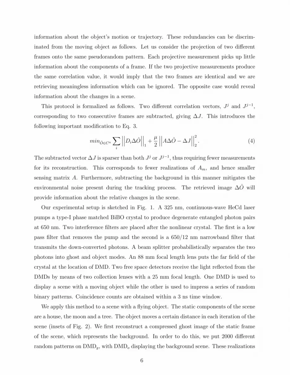
information about the object’s motion or trajectory. These redundancies can be discrim-
inated from the moving object as follows. Let us consider the projection of two different
frames onto the same pseudorandom pattern. Each projective measurement picks up little
information about the components of a frame. If the two projective measurements produce
the same correlation value, it would imply that the two frames are identical and we are
retrieving meaningless information which can be ignored. The opposite case would reveal
information about the changes in a scene.
This protocol is formalized as follows. Two different correlation vectors, J j and J j−1,
corresponding to two consecutive frames are subtracted, giving ∆J . This introduces the
following important modification to Eq. 3.
minO∈Cn
∑i
∣∣∣∣∣∣Di∆O∣∣∣∣∣∣1
+µ
2
∣∣∣∣∣∣A∆O −∆J∣∣∣∣∣∣22. (4)
The subtracted vector ∆J is sparser than both J j or J j−1, thus requiring fewer measurements
for its reconstruction. This corresponds to fewer realizations of Am, and hence smaller
sensing matrix A. Furthermore, subtracting the background in this manner mitigates the
environmental noise present during the tracking process. The retrieved image ∆O will
provide information about the relative changes in the scene.
Our experimental setup is sketched in Fig. 1. A 325 nm, continuous-wave HeCd laser
pumps a type-I phase matched BiBO crystal to produce degenerate entangled photon pairs
at 650 nm. Two interference filters are placed after the nonlinear crystal. The first is a low
pass filter that removes the pump and the second is a 650/12 nm narrowband filter that
transmits the down-converted photons. A beam splitter probabilistically separates the two
photons into ghost and object modes. An 88 mm focal length lens puts the far field of the
crystal at the location of DMD. Two free space detectors receive the light reflected from the
DMDs by means of two collection lenses with a 25 mm focal length. One DMD is used to
display a scene with a moving object while the other is used to impress a series of random
binary patterns. Coincidence counts are obtained within a 3 ns time window.
We apply this method to a scene with a flying object. The static components of the scene
are a house, the moon and a tree. The object moves a certain distance in each iteration of the
scene (insets of Fig. 2). We first reconstruct a compressed ghost image of the static frame
of the scene, which represents the background. In order to do this, we put 2000 different
random patterns on DMDg, with DMDo displaying the background scene. These realizations
6

represent 49% of a raster scan. For each random pattern, we count coincidence detections
for 8 s. Typical single count rates were 13.8 x 10³ counts/s for the ghost and object arms
with the coincidence counts approximately 2% of the single counts. Fig. 2(a) shows the
retrieved background scene O. After this, subsequent frames of the scene with the object in
different positions are displayed on DMDo. After applying the optimization algorithm, the
moving object was clearly identified as shown in Figs. 2(b)-(f). The reconstructions were
done using 400 patterns, which represents 9.7% the measurements of a raster scan. The
negative values in the retrieved images are due to background subtraction and fluctuations
in the measurements process.
A straightforward examination of the limits of our protocol is carried out by reducing
the number of measurements used to track an object. The images shown in Fig. 3 were
reconstructed with only 200 and 100 measurements, corresponding to 4.88% and 2.44% of
the measurements of a raster scan. The metric employed to characterize the fidelity of these
reconstructions is the mean-squared error5 defined as MSE = (1/n)‖O − O‖2. The MSE
is seen to increase as the number of measurements is decreased. Although, it is still possible
to detect the object trajectory with just 100 measurements.
The photon efficiency is studied by estimating the dependence of the MSE on the num-
!"# $"# %"# &"# '"# ("#("#'"#
&"#
%"#
$"#
!"#
)"*+#
)"*(#
)"*&#
)"*$#
"#
)"*,#
)"*'#
)"*%#
)"*!#
)"*-# )"*,#
)"*'#
)"*%#
)"*!#
"*!#
)"*+#
)"*(#
)"*&#
)"*$#
"#
)"*,#
)"*'#
)"*%#
)"*!#
"*!#
"#
"*$#
"*&#
"*(#
"*+#
!# ./0# .10#
.20# .30# .40#
5678"*"$"'# 5678"*"!-%#
5678"*"$$,# 5678"*"$,ᘮ"*"$!+#
.90# "*$# "*%#
"*%#"*!#"*$#
!" #!" #!"
#!" #!" #!"
FIG. 2. Compressed ghost image of (a) the background of the scene and (b-f) the tracked object
in different positions. These reconstructions were obtained by defining different ∆J vectors with
400 elements, corresponding to the number of measurements. The insets show the original frames
of the scene displayed on the DMD.
7

!"#$#
!"#$
%!"&$
!"'$
%!"'$
%!"#$
%!"($
%!"&$
%!"($
%!"#$
%!"'$
!"'$
%!")$
%!"&$
%!"($
%!"#$
%!"'$!$
%!"*$
%!"+$
%!",$
%!"-$!$
%!"&$
%!"($
%!"#$
%!"'$
!"'$
%!"($
%!"#$
%!"'$
!"'$
!"#$
%!")$
%!"&$
%!"($
%!"#$
%!"'$
%!"+$
%!",$
%!"-$
!$$!"-$
%!",$
%!"-$
!$
!"-$
!",$
'!!$./0123/./451$
607$
687$
697$
6:7$
6;7$
6<7$
6=7$
6>7$ 6?7$
%!"+$%!",$
%!"-$
!$
!"-$6/7$
@ABC!"!-#,$ @ABC!"!-,)$ @ABC!"!-(&$ @ABC!"!--($ @ABC!"!#'($
@ABC!"!-)#$ @ABC!"!-)($ @ABC!"!##($ @ABC!"!-)'$ @ABC!"!#)($
!"-$ !"#$
-!!$./0123/./451$!"# !"# !"# !"# !"#
!"# !"# !"# !"# !"#
FIG. 3. Reconstructed ghost image of (a-e) tracked object with 200 measurements. (f-j) same
object with 100 measurements.
ber of photons per measurement, for a fixed number of measurements. A simulation of
the protocol was carried out by using the data employed in the experiment. In order to
achieve realistic experimental conditions, dark and shot noise were introduced by means of
poissonian distributions. The amount of dark noise was modeled based on the frequency
distribution of counts obtained when both of the DMDs were turned off. We have consid-
ered reconstructions employing 100 and 400 measurements. Fig. 4 shows the dependence of
image quality on the number of detected photons per measurement. The minimum number
of photons per measurement needed to distinguish the silhouette of the object by eye are 500
photons/measurement and 200 photons/measurement for 100 and 400 measurements respec-
tively. The estimated thresholds correspond to a MSE oscillating around 0.04. For the sit-
uation where an object was tracked with 100 measurements and 500 photons/measurement,
we estimate that we can impress approximately 0.082 bits/photon. This is considering that
for a binary image the number of pixels corresponds to the number of bits25.
The maximum object velocity that we can track is limited by the number of photons that
we are able to detect. In our setup, each scene reconstruction took 13.3 minutes (for the case
of 100 measurements) due to the low photon flux. If we were to use a high brightness source
of entangled photons, we could shorten the acquisition time needed to retrieve a compressed
ghost image with an MSE below the threshold shown in Fig. 4. As such, there is no hard
theoretical limit on the maximum object velocity that can be tracked using this method.
In conclusion, we have proposed and demonstrated a proof-of-principle object-tracking
8

!"""# $"""# %"""# &"""# '""""#!"#$#%&'()*&+,)()%$-
'!"""#"("')#
"("!#
"("!)#
"("*#
"("*)#
"("$#
"("$)#
"(")#
"("))#'""#+,-./0,+,12.#
)""#
$""#+,-./0,+,12.#340,.4567#850#'""#+,-./0,+,12.#340,.4567#850#$""#+,-./0,+,12.#
"#
./0-
FIG. 4. (Color online) Calculated mean-squared error of the compressed tracked object at the
position shown in Fig. 2(b). Green (Red) line indicates the MSE using 400 (100) measurements.
The thresholds indicate that a low quality image is retrieved and is not possible to track the object.
protocol in a ghost imaging scheme. This protocol uses compressive sensing to exploit the
sparsity existing between two realizations of a scene with a moving object. It also reduces
the environmental noise introduced during the measurement process. Further, it allows us to
perform image retrieval significantly faster by employing single pixel detectors. Our method
is photon-measurement efficient, allowing us to track an object with only 2.44 % of the
number of measurements established by the Nyquist criterion, even at low light levels. This
economic procedure shows potential for real-life applications.
ACKNOWLEDGMENTS
The authors would like to thank M. Mirhosseini and A.C. Liapis, P. Ybarra-Reyes and
J.J. Sanchez-Mondragon for helpful discussions. This work was supported by the DARPA
AFOSR GRANT FA9550-13-1-0019 and the CONACYT.
REFERENCES
1H. Wang, S. Han, and M. I. Kolobov, Optics Express 20, 23235 (2012).
2W.-K. Yu, X.-F. Liu, X.-R. Yao, C. Wang, S.-Q. Gao, G.-J. Zhai, Q. Zhao, and M.-L. Ge,
arXiv:1202.5866v1 physics.optics (2012).
9
3G. A. Howland, P. B. Dixon, and J. C. Howell, Appl. Opt. 50, 5917 (2011).
4G. A. Howland and J. C. Howell, Physical Review X 3, 011013 (2013).
5O. Katz, Y. Bromberg, and Y. Silberberg, Appl. Phys. Lett. 95, 131110 (2009).
6P. Zerom, K. W. C. Chan, J. Howell, and R. Boyd, Phys. Rev. A 84, 061804 (2011).
7E. J. Candes and T. Tao, Information Theory (2006).
8E. J. Candes and M. B. Wakin, Sig. Proc. Mag. (2008).
9D. Gross, Y.-K. Liu, S. T. Flammia, S. Becker, and J. Eisert, Phys. Rev. Lett. 105,
150401 (2010).
10W. T. Liu, T. Zhang, J. Y. Liu, P. X. Chen, and J. M. Yuan, Phys. Rev. Lett. 108,
170403(2012).
11A. K. Jha, M. Malik, and R. W. Boyd, Phys. Rev. Lett. 101, 180405 (2008).
12T. Pittman, Y. Shih, D. Strekalov, and A. Sergienko, Phys. Rev. A 52, R3429 (1995).
13P. Clemente, V. Duran, V. Torres-Company, E. Tajahuerce, and J. Lancis, Opt. Lett. 35,
2391 (2010).
14S. Karmakar and Y. Shih, Phys. Rev. A 81, 033845 (2010).
15M. Malik, H. Shin, M. O’Sullivan, P. Zerom, and R. W. Boyd, Phys. Rev. Lett. 104,
163602 (2010).
16W. Gong, C. Zhao, J. Jiao, E. Li, M. Chen, H. Wang, W. Xu, and S. Han,
arXiv:1301.5767v1 quant-ph (2013).
17J. L. O’Brien, A. Furusawa, and J. Vuckovic, Nature Photon 3, 687 (2009).
18C. E. Shannon, Proc. IRE 37, 10 (1949).
19M. Malik, H. Shin, and R. W. Boyd, Laser Science (2011).
20R. Bennink, S. Bentley, and R. Boyd, Phys. Rev. Lett. 89, 113601 (2002).
21A. Gatti, E. Brambilla, M. Bache, and L. Lugiato, Phys. Rev. Lett. 93, 093602 (2004).
22C. Monken, P. Ribeiro, and S. Padua, Phys. Rev. A 57, 3123 (1998).
23R. M. Willett, R. F. Marcia, and J. M. Nichols, Optical Engineering 50, 072601 (2011).
24C. Li, Master Thesis, Rice University 1, 92 (2009).
25S. Nakadate, T. Yatagai, and H. Saito, Appl. Opt. 19, 1879 (1980).
10


