Embed Size (px)
Citation preview

634 IEEE TRANSACTIONS ON GEOSCIENCE AND REMOTE SENSING, VOL. 43, NO. 3, MARCH 2005
Compact Polarimetry Based on Symmetry Propertiesof Geophysical Media: The �=4 Mode
Jean-Claude Souyris, Member, IEEE, Patrick Imbo, Roger Fjørtoft, Member, IEEE, Sandra Mingot, andJong-Sen Lee, Life Fellow, IEEE
Abstract—In this paper, we assess the performance of syntheticaperture radar (SAR) compact polarimetry architectures basedon mixed basis measurements, where the transmitter polarizationis either circular or orientated at 45 ( 4), and the receivers areat horizontal and vertical polarizations with respect to the radarline of sight. An original algorithm is proposed to reconstruct thefull polarimetric (FP) information from this architecture. Theperformance assessment is twofold: it first concerns the level of in-formation preserved in comparison with FP, both for point targetanalysis and crop fields classification, using L-band SIRC/XSARimages acquired over Landes forest and Jet Propulsion Labora-tory AIRSAR images acquired over Flevoland. Then, it addressesthe space implementation complexity, in terms of processed swath,downloading features, power budget, calibration, and ionosphericeffects. The polarization uniqueness in transmission of this mixedbasis mode, hereafter referred to as the 4 mode, maintains thestandard lower pulse repetition frequency operation and hencemaximizes the coverage of the sensor. Because of the mismatchbetween transmitter and receiver basis, the power budget isdeteriorated by a factor of 3 dB, but it can partly be compensated.
Index Terms—Crop classification, partial polarimetry, radar po-larimetry, spaceborne synthetic aperture radar, symmetry proper-ties of geophysical media, synthetic aperture radar (SAR).
I. INTRODUCTION
RADAR polarimetry has made significant advancementsince the release of the first polarimetric radar concepts
dating back to the early 1950s [1]. Throughout the years andespecially in the last two decades, a wide range of applicationshave been shown to be critically improved by polarimetry. Theyinclude natural surface segmentation and classification [2]–[7],estimation of forest parameters [8], roughness state classifica-tion [9], soil moisture mapping [10], characterization of lavaflows [11], ice [12] and snow [13], [14], topographic mea-surements [15], [16], urban classification [17], target detection[18], [19], and analysis [20]–[24]. Moreover, recent contribu-tions [25] have opened a promising field of new applications(such as the possibility of extracting a multilayer topographicinformation over forested areas) by merging polarimetric and
Manuscript received June 1, 2004; revised November 8, 2004.J.-C. Souyris, R. Fjørtoft, and S. Mingot are with the Centre National d’Etudes
Spatiales (CNES), 31401 Toulouse, Cedex 9 France (e-mail: [email protected]).P. Imbo is with the Laboratoire Informatique et Mathématiques Appliquées,
Institut de Rechereche en Informatique de Toulouse, Ecole Nationale Supérieured’Electrotechnique, d’Electronique, d’Informatique, d’Hydraulique et des Télé-communications, 31071 Toulouse, France.
J.-S. Lee is with the Naval Research Laboratory, Washington, DC 20375USA.
Digital Object Identifier 10.1109/TGRS.2004.842486
interferometric assets in the framework of polarimetry-inter-ferometry (POL-INSAR). Extended reviews of polarimetricdecomposition techniques, processing, and applications can befound in [26] and [27].
The interest for radar polarimetry has significantly increased,due to the high-quality data produced by various airborne(JPL/AIRSAR, DLR/ESAR, EMISAR, ONERA/RAMSES,TNO/PHARUS, CCRS/CONVAIR, etc.), and spaceborne(SIR-C/XSAR) missions. This trend should be further strength-ened with the implementation of polarimetric capabilities inthe framework of operational spaceborne missions: for the firsttime, ASAR/ENVISAT (launched in March 2002) currentlyoffers multipolarization capabilities, although the polarimetricacquisition remains partial. The next step will be the forth-coming launch of FP spaceborne synthetic aperture radar (SAR)missions (RADARSAT-2, TERRASAR-X, ALOS), operatingin C-, X-, or L-band in the 3–10-m resolution range.
In spite of this favorable context, spaceborne polarimetry re-mains extremely demanding with respect to certain aspects ofthe system design: antenna technology, data downloading, sizeof the processed swath, and power consumption are all limitingfactors. In particular, the bottle neck of the downloading datarate generally advocates in favor of resolution rather than po-larimetry. The overall objective of this study is to assess variousdesigns of compact polarimetry (CP) architectures that couldbe implemented on low-cost/low-mass space segments. In pre-vious studies [28], [29] two CP options have been investigatedin particular. The first one is limited to a unique linear polariza-tion in transmission (e.g., horizontal), while receiving in bothco- and cross-polarized channels (horizontal and vertical). Inthis case, only the hh and hv terms of the backscattering ma-trix are collected. This option guarantees a rather simple design,thanks to the polarization uniqueness in transmission. However,it led to poor classification performances compared to FP data,for L-band data acquired over a flat agricultural area (Flevoland)[4], and over an airport including a runway, low vegetated areas,agricultural fields, and buildings [28]. This trend is expected tobe observed over a wider range of situations, including C-bandimagery. An example of crop classification using L-band datawill be illustrated in Section V. The second option considers twointerleaved polarizations in transmission ( and ), the recep-tion being restricted to copolarized channels (i.e., hh and vv).The polarimetric information is better preserved than in the pre-vious case [4], [29] and the power budget more comfortable (thehv term which was here left out is usually 7–10 dB below hhand vv). However, the main drawback of this option is linkedto the need for transmitting two polarizations. Consequently, in
0196-2892/$20.00 © 2005 IEEE

SOUYRIS et al.: COMPACT POLARIMETRY BASED ON SYMMETRY PROPERTIES OF GEOPHYSICAL MEDIA 635
comparison with a standard single-polarized SAR, the requiredincrease in pulse repetition frequency (PRF) causes swath cov-erage limitations (by a factor of 2) in order to maintain immunityfrom range ambiguities.
In order to circumvent the above-mentioned drawbacks, wehere assess an alternative CP architecture in possession of polar-ization uniqueness in transmission, and polarization diversity inreception. In order to reduce the loss of information caused bya single transmitted polarization, we propose a design in whichthe two linear receiving polarizations are oriented at on eachside of the unique transmitted linear polarization. We will showhow this symmetry improves the preservation of information,compared to a FP system or to other CP architectures. An al-gorithm aiming at reconstructing the FP over extended targetsfrom this design (hereafter referred to as the mode) will beproposed, based on various hypotheses on the symmetry prop-erties of geophysical media. The behavior of point targets willbe also discussed.
Section II briefly reviews the basics of FP. Section III dis-cusses how symmetry properties of geophysical media manifestthemselves in the covariance matrix. Section IV introduces theconcept of the mode. A procedure to estimate FP informa-tion over extended targets from this design will be proposed.Quantitative comparisons of the classification accuracy for FPand the mode will be made in Section V. The behavior ofpoint targets is also considered. Section VI is dedicated to thesystem architecture, outlining the expected simplifications pro-vided by the mode. Section VII resumes our conclusions.
II. FULL POLARIMETRY
A polarimetric radar is a phase-coherent sensor used to mea-sure the target vector
(1)
are the complex backscattering terms. Expression (1) ap-plies for the mono-static case only . Acquiring theentire polarimetric information requires to switch the transmit-ting polarization every other pulse. Hence, when compared to astandard single-polarized SAR, the value of the PRF has to bedoubled in order to maintain the azimuth resolution. The polari-metric information covariance matrix is given by
H PX
P V(2)
The operator represents spatial averaging over neighborpixels. For the sake of simplicity, the notations , and
are replaced hereafter by , , and , respectively, and, , , and by H, V, X, and
P, respectively. An alternative target vector form [30] leads tothe coherency matrix, from which we usually proceed to thedecomposition of the backscattering process into an incoherentsum of elementary, fully polarized mechanisms, and to the
Fig. 1. Lay-out of symmetry planes involved in reflection, rotation, andazimuth symmetries, with respect to the incident wave.
derivation of polarimetric entropy and average backscatteringmechanism [22]. Unlike the pixel-based target vector, the useof higher order statistics (covariance or coherency matrix)naturally implies spatial averaging, leading to a loss in spatialresolution.
The next section shortly reviews how symmetry properties ofgeophysical media manifest themselves in the covariance matrixcoefficients.
III. EFFECT OF SYMMETRY PROPERTIES
OF GEOPHYSICAL MEDIA
The main outcomes of geophysical media symmetry proper-ties on the covariance matrix coefficients can be found in [31].Three types of symmetries are accounted for: reflection, rota-tion, and azimuthal symmetries.
Referring to Fig. 1, and are the horizontal and verticaldirections belonging to the transverse plane P of an incidentwave . The incidence plane P contains and . Reflec-tion symmetry occurs when the observed media is symmetricwith respect to P . Such a symmetry is found on water surfacesin the upwind or downwind direction, and in all isotropic andanisotropic natural media on a horizontal plane [31], such asforest, snow, sea ice, and soil surfaces without row structures. Itis also the case for volume scattering from random layer mediacontaining spherical particles [32]. Under this assumption, thereis a complete decorrelation of the copolarized and the cross-po-larized backscattering coefficients
(3)
This result is valid with any reference to scattering mechanisms.As (3) is valid for most natural surfaces at standard frequencies(C- or L-band), it is usually integrated in standard polarimetriccalibration schemes [33].
When a medium presents rotation symmetry about an axis ,the covariance matrix remains unchanged after a rotation by an

636 IEEE TRANSACTIONS ON GEOSCIENCE AND REMOTE SENSING, VOL. 43, NO. 3, MARCH 2005
Fig. 2. Geometrical lay-out of the �=4 mode. Transmitting a circularpolarization yields the same properties.
angle in the transverse plane P Fig. 1. As this property holdsfor any , the covariance matrix terms obey
H VX H X V P H V
(4)
where is the degree of coherence between the andsignals. It is generally a complex value, which becomes realunder rotation symmetry condition.
Finally, azimuthal symmetry possesses the characteristics ofboth reflection and rotation symmetry, i.e., it guarantees a reflec-tion symmetry in any vertical plane passing the axis of rotation
, which leads to
H V
X H X V P H V
(5)
This kind of symmetry is often observed in forests (even at pen-etrating frequencies) and over slightly rough surfaces at low in-cidences , as supported by work in POL-InSAR [34],[35] or SAR tomography at L-band [36]. More generally, mostvolume scattering mechanisms are expected to have a behaviorcompatible with azimuthal symmetry [31].
The next section presents the mode and demonstrateshow assumptions bearing on the symmetry properties ofobserved geophysical media permit to reconstruct the FPinformation.
IV. MODE
The mode features two linear receiving polarizations ori-ented at on each side of an unique transmitted linear polar-ization (Fig. 2)
(6)
The two receiving polarizations are parallel to and , respec-tively. For the sake of simplicity, the coefficient is omittedhereafter, but we keep in mind that it impacts on the powerbudget (3 dB), as discussed in Section VI. The target vector at-tached to the design is given by
(7)
A similar formulation would be obtained if a circular polariza-tion was transmitted, leading to the target vector
(8)
The sign corresponds to anticlockwise and clockwise cir-
cular polarizations, respectively. Using would involvethe same properties as those established hereafter with atransmitted linear polarization. Therefore, we will limit our dis-cussion to the linear case, although some specific applicationsmay be facilitated by the transmission of a circular polarization[37]. Moreover, circular polarizations will be less sensitive toFaraday rotation effects attached to low-frequency propagationin the ionosphere [38].
In the light of (7) and (8), the mode inevitably leads to ablend of co- and cross-polar terms, which prevents reconstruc-tion of the FP information at the pixel level. Consequently, re-construction can only be envisaged at the level of higher orderstatistics estimated over several samples. A drawback of thisscheme will, therefore, be a deterioration of the spatial reso-lution, but a speckle filtering algorithm [39] can be applied toreduce this deficiency.
A. Higher Order Statistics of the Mode
The covariance matrix of the mode is given by (9), shownat the bottom of the page, which can be rewritten as the combi-nation of three contributions. The first term concerns the po-larimetric behavior of copolar channels; the second one is pro-portional to the cross-polarization magnitude; the third one is aresidue
H PP V
X
(10)
We come up with an underdetermined system of four equations(linked to the two real measurements and the complexone ) and nine unknown variables (H, V, X, P, , and
). Additional information is, therefore, required to solveit. For this reason, we will introduce two new hypotheses related
to the polarimetric behavior of the components. The firstone supposes reflection symmetry, and the second one assumesa pseudodeterministic trend relating H, V, X, and P.
H X P XP X V X
(9)

SOUYRIS et al.: COMPACT POLARIMETRY BASED ON SYMMETRY PROPERTIES OF GEOPHYSICAL MEDIA 637
(a) (b) (c)
(d) (e) (f)
Fig. 3. Average and root mean square of azimuth symmetry assumptions versus analysis window sample number, for various frequencies and resolutions.(Circle) X-band, 1.25 m. (Five-pointed star) X-band, 2.5 m. (Four-pointed star) X-band, 5 m. (Square) C-band. (Triangle) L-band. 2 � <hh � x i=(H + X).(b) Average of 2 � <hv � x i=(V + X). (c) Average of jhh � x i+ hx � v ij=jP + Xj. (d) Root mean square of 2 � <hh � x i=(H + X). (e) Root mean square of2 � <hv � x i=(V + X) (f) Root mean square of jhh � x i + hx � v ij=jP + Xj.
B. Impact of Reflection Symmetry
The reflection symmetry assumption [condition (3) insertedin (10)] can be considered as valid as long as
H X
V X
P X (11)
The validity range of (11) has been assessed on C- and L-bandimages acquired by the SIR-C mission over the Landes areain southwestern France [8], which includes a collection offorest stands at various ages, water (a lake and the sea), andurban areas. Complementary tests have also been conducted onX-band data acquired by the ONERA/RAMSES sensor overan airport including a runway, low vegetated areas, agriculturalfields, and buildings. Several spatial resolutions were consid-ered at X-band (1.25, 2.5, and 5 m), in order to assess theirimpact on assumptions (11). Fig. 3(a)–(e) depicts, for variousfrequencies and resolutions, the behavior of average and rootmean square of the reflection symmetry assumptions versus thenumber of samples in the analysis window.
Although it is difficult to precisely distinguish the impact ofdifferent parameters from the available data (the different fre-quencies being delivered at different resolutions), it appears that
L- and C-band data in the 10-m resolution range are well withinthe limits of the assumptions (11), even for a low number ofsamples. The impact of spatial resolution can be assessed forX-band only: improving the spatial resolution hampers the con-formity to these assumptions. However, if we typically select a7 7 window size, the estimation error which is committed ifthe residue matrix is neglected in (10), is approximately 15% forX-band (5-m resolution), and less than 2% for L- and C-band.Given these figures, we assume reflection symmetry hereafter.
Updating (10) with reflection symmetry still does not permitto retrieve the FP information, as we have still five unknownsH, V, X, P for four measurements. In order to remove this per-
sistent deficit, we propose to consider various pseudodetermin-istic relationships linking and the average cross-polariza-tion ratio X H V .
C. Reconstruction of FP Using Reflection and “Light”Rotation Symmetry
Can we establish a relationship between X, H, V, and P as faras natural surfaces are concerned? A possible approach wouldbe to assume rotation symmetry, which provides such a rela-tionship. Under this assumption, even if reflection symmetryis not verified, the mode permits to reconstruct the FP in-formation. By considering (4), (7), and (10), a straightforward

638 IEEE TRANSACTIONS ON GEOSCIENCE AND REMOTE SENSING, VOL. 43, NO. 3, MARCH 2005
calculation leads to the estimation of , shown in (12) at thebottom of the page. The reconstruction the FP information is notsurprising in this case. Even a “standard” CP mode (e.g., hori-zontal transmission only, dual-polarized reception) would do so(even simply!) once rotation symmetry is assumed. However,this assumption being severe (in particular it forces the equalitybetween and ), we choose to put it aside in its completeform (5). This assumption can be lightened if only the rotationinvariance of the cross-polarization term is imposed (itis a priori less stringent than the invariance of other covariancematrix terms), leading to the relationship
X H V P (13)
Coupled with reflection symmetry, (13) leads to an alternate es-
timation of , shown in (14) at the bottom of the page. Unlike(12), the interest of (14) is that it preserves the anisotropy be-tween and at the price of cross-correlation terms nul-lity. Preliminary tests have shown that (12)—and to a lesser ex-tent (14)—provide promising results. However, the underlyinghypotheses seem to be too strict, and far better results are ob-tained when a physical approach based on the polarization stateof backscattered waves is used.
D. Reconstruction of FP Using PolarizationState Extrapolation
The relationships linking X, H, V, and P are here establishedunder the specific circumstances of either a fully polarized or afully depolarized backscattered wave and are subsequently ex-trapolated for any polarization state.
For fully polarized backscattered waves, a very low level ofcross-polarized energy is usually observed X . At the sametime, . For a fully depolarized backscattered wave,the average power collected by the receiving antenna does notdepend on its polarization state. Put differently, the coherencymatrix in this case reduces to identity [40]. A straightforwardconsequence is that and H V X.
Between these two limits, the most natural extrapolation re-lies on a linear behavior, leading to the relationship
X H V (15)
(a) (b)
(c) (d)
Fig. 4. (a) Reference value of j� j inferred from FP. L-band SIR-C, LandesForest, France. 7� 7 window size. (0 = black; 1 = white). (b)–(d). Zero-,first-, and second-order estimates of j� j.
TABLE IMEAN QUADRATIC ERROR OF X=(H + V) VERSUS j� j, AS A FUNCTION OF
FREQUENCY, RESOLUTION, AND LOCAL VALUE OF h�v COHERENCE
The similarity between (4) derived from rotation symmetry and(15) is obvious, although the differentiation between H and V
(12)
(14)

SOUYRIS et al.: COMPACT POLARIMETRY BASED ON SYMMETRY PROPERTIES OF GEOPHYSICAL MEDIA 639
Fig. 5. (a)–(c) Reconstruction performances for H, V, and X channels (L-band). (d) Reconstructed degree of coherence versus actual degree of coherence(L-band). (e) Reconstructed entropy versus actual entropy (L-band). (f) Reconstructed � versus actual � (L-band).
is now preserved. It should be noted that although (15) is a rea-sonable assumption for geophysical media, it will be clearly vi-olated in the case of point targets. Their specific behavior is dis-cussed in Section V-A.
The extrapolation accuracy of (15) depends on : thecloud dispersion decreases as increases, leading to abetter reconstruction quality when the backscattered wave iswell polarized. The mean quadratic errors of extrapolation (15)are given in Table I for various values of .
Merging (10), (11), and (15) finally permits to come up witha well-determined nonlinear system of four equations and fourunknowns, that can be solved numerically through an iterativeapproach as follows.
E. Full Polarimetric Information Reconstruction Algorithm
The above-mentioned nonlinear system of four equations andfour unknowns cannot be solved rigorously. An iterative ap-proach is required. From (10) and (11), the h-v degree of co-herence is given by
X X X (16)
A zero-order estimate of can be derived by neglecting thecross-polarization in (16)
(17)
From the knowledge of , we infer a zero-order estimate ofX, using (15)–(17)
X H V
X (18)
leading to
X (19)
An iterative process is subsequently set up, by using X torefine the estimation of from (16), and so forth
X X X(20)
Due to violations of the underlying hypotheses, and the fact thatthe iterative process is based on an approximation (15), it occursthat (where is the order of iteration) may become largerthan one for certain pixels, or even that the denominator of (20)becomes the square root of a negative number. In both cases, we
regularize by setting and X and then haltthe iteration.
Fig. 4(b)–(d) displays the mapping of for consecu-tive orders of estimation. The test is conducted on the LandesL-band SIR-C data, with a 7 7 analysis window. Fig. 4(a) dis-plays the FP reference value. The zero-order estimate where

640 IEEE TRANSACTIONS ON GEOSCIENCE AND REMOTE SENSING, VOL. 43, NO. 3, MARCH 2005
(a) (b)
Fig. 6. (a) Multilooked full polarimetric image. Landes Forest, L-band. The Red channel is H, the Green channel is X, and the Blue channel is V. (b) Multilooked�=4 image. Landes Forest, L-band. Red channel is H, Green channel is X, Blue channel is V.
TABLE IIVALUES OF DIHEDRAL-LIKE ( ) AND DIPOLE-LIKE (�) VERTEX DIRECTIONS
GENERATING AMBIGUITIES IN POINT TARGET DISCRIMINATION.~k = ~k = ~k ARE THE MODIFIED TARGET VECTORS
OF SPHERE, DOUBLE—BOUNCE, AND DIPOLE-LIKE
MECHANISMS, RESPECTIVELY
X [Fig. 4(b)] produces a “milky” impression, which al-ters the image contrast. It is explained by the overestimationof the degree of coherence when this one is intrinsically low.In this particular case, the neglected cross-polarized term is ac-tually critically high, and the nullity assumption is not valid.However, the first iterations drastically reduce this drawback[Fig. 4(c)–(d)]. Already after one or two iterations, we see thatthe estimated coherence is qualitatively very close to the FPcoherence.
The th-order estimate of the FP covariance matrix for ex-tended targets is given by
X X
XX X
(21)
where X is the th-order estimation of X. The null compo-nents are characteristic of the reflection symmetry assumption.A convergence criterion could be introduced, although a stabi-lization of the estimates has been systematically observed be-yond the second iteration.
V. QUANTITATIVE ASSESSMENT OF THE MODE
Fig. 5(a)–(c) shows the performances of the reconstructionalgorithm based on the polarization state extrapolation for H, V,and X channels at L-band over the Landes test site. For everychannel, an overall good agreement is observed between recon-structed and actual radiometric values. As can be observed, Xremains the most delicate term to reconstruct due to its low ra-diometry, which is typically 7–10 dB below H and V.
Fig. 5(d) displays the reconstructed degree of coherenceversus the actual degree of coherence at L-band. As expected,
SOUYRIS et al.: COMPACT POLARIMETRY BASED ON SYMMETRY PROPERTIES OF GEOPHYSICAL MEDIA 641
(a) (b)
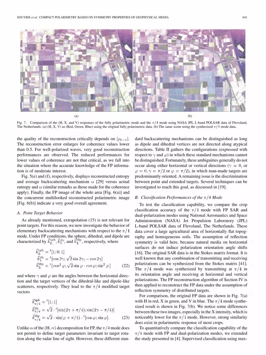
Fig. 7. Comparison of the (H, X, and V) responses of the fully polarimetric mode and the �=4 mode using NASA JPL L-band POLSAR data of Flevoland,The Netherlands. (a) (H, X, V) as (Red, Green, Blue) using the original fully polarimetric data. (b) The same scene using the synthesized �=4 mode data.
the quality of the reconstruction critically depends on .The reconstruction error enlarges for coherence values lowerthan 0.5. For well-polarized waves, very good reconstructionperformances are observed. The reduced performances forlower values of coherence are not that critical, as we fall intothe situation where the accurate knowledge of the FP informa-tion is of moderate interest.
Fig. 5(e) and (f), respectively, displays reconstructed entropyand average backscattering mechanism [29] versus actualentropy and (similar remarks as those made for the coherenceapply). Finally, the FP image of the whole area [Fig. 6(a)] andthe concurrent multilooked reconstructed polarimetric image[Fig. 6(b)] indicate a very good overall agreement.
A. Point Target Behavior
As already mentioned, extrapolation (15) is not relevant forpoint targets. For this reason, we now investigate the behavior ofelementary backscattering mechanisms with respect to themode. Under FP conditions, the sphere, dihedral, and dipole arecharacterized by , and , respectively, where
(22)
and where and are the angles between the horizontal direc-tion and the target vertices of the dihedral-like and dipole-likescatterers, respectively. They lead to the modified targetvectors
(23)
Unlike of the H decomposition for FP, the mode doesnot permit to define target parameters invariant to target rota-tion along the radar line of sight. However, these different stan-
dard backscattering mechanisms can be distinguished as longas dipole and dihedral vertices are not directed along atypicaldirections. Table II gathers the configurations (expressed withrespect to and ) in which these standard mechanisms cannotbe distinguished. Fortunately, these ambiguities generally do notoccur along either horizontal or vertical directions ( , or
or ), in which man-made targets arepredominantly oriented. A remaining issue is the discriminationbetween point and extended targets. Several techniques can beinvestigated to reach this goal, as discussed in [19].
B. Classification Performances of the Mode
To test the classification capability, we compare the cropclassification accuracy of the mode with FP SAR anddual-polarization modes using National Aeronautics and SpaceAdministration (NASA) Jet Propulsion Laboratory (JPL)L-band POLSAR data of Flevoland, The Netherlands. Thesedata cover a large agricultural area of horizontally flat topog-raphy and homogeneous soils. The assumption of reflectionsymmetry is valid here, because natural media on horizontalsurfaces do not induce polarization orientation angle shifts[16]. The original SAR data is in the Stokes matrix format. It iswell known that any combination of transmitting and receivingpolarizations can be synthesized from the Stokes matrix [41].The mode was synthesized by transmitting at inits orientation angle and receiving at horizontal and verticalpolarizations. The FP reconstruction algorithm of Section IV isthen applied to reconstruct the FP data under the assumption ofreflection symmetry of distributed targets.
For comparison, the original FP data are shown in Fig. 7(a)with H in red, X in green, and V in blue. The mode synthe-sized result is shown in Fig. 7(b). We notice some differencesbetween these two images, especially in the X intensity, which isnoticeably lower for the mode. However, strong similaritydoes exist in polarimetric response of most crops.
To quantitatively compare the classification capability of themode with FP and dual-polarization modes, we extended
the study presented in [4]. Supervised classification using max-

642 IEEE TRANSACTIONS ON GEOSCIENCE AND REMOTE SENSING, VOL. 43, NO. 3, MARCH 2005
Fig. 8. Comparison of classification results of the FP mode versus the �=4mode. The two classification maps are strikingly similar. (a) Ground truth measurement.(b) Class label. (c) Classification map—Fully polarimetric data. (d) Classification map ��=4 mode.
imum-likelihood distance measures derived from the complexWishart distribution is adopted and their classification rates areevaluated. The ground truth measurement is shown in Fig. 8(a).A total of 11 classes are identified, consisting of eight cropclasses ranging from stem beans to wheat and three other classesof bare soil, water and forest. The class labels are shown inFig. 8(b). The classification maps based on the FP data and the
mode are shown in Fig. 8(c) and (d), respectively. The re-sults are strikingly similar. The classification rates of themode as compared to the FP mode and dual-polarization mode,are listed in Table III. It occurs that the classification accuracyof the mode is comparable to that of the FP and the ( and
) mode, and is much better than the ( and ) and ( and )modes. The advantage of using the mode rather than the (and ) mode is discussed in Section VI in terms of radar systemaspects. The ( and ) and ( and ) lead to a simpler radardesign, but they suffer from a considerable degradation in clas-sification accuracy.
It should be noted that this classification algorithm is basedon the Wishart distance measure, which is statistical in nature.Speckle in PolSAR data affect classification rates. Due to the
large number of classes in this classification, classification ratesfor individual classes may have small fluctuations that are diffi-cult to predict theoretically. For example, as shown in Table III,both the mode and the complex and mode have higherclassification rate in lucerne than the FP mode. Consequently,the important numbers are the total classification rates, whichclearly show the advantage of the mode for L-band cropclassification as compared with the or modes.
We can also foresee the following thematic applications ofthe mode.
1) Soil moisture and surface roughness effects are relatedand cannot be separated in most of estimation algorithms.Jointly, they can be estimated empirically or based on theintegral equation method model using the copolarizationsignatures. The mode can be applied, with an effectdepending on its noise floor. Recently, an algorithm basedon scattering decomposition parameters entropy andangle has been proposed in [35]. The reconstructed en-tropy and angle of the mode shown in Fig. 5(e) and(f) indicates that the mode may be used for soil mois-ture estimation.
SOUYRIS et al.: COMPACT POLARIMETRY BASED ON SYMMETRY PROPERTIES OF GEOPHYSICAL MEDIA 643
TABLE IIIL-BAND CROP CLASSIFICATION ACCURACIES (EXPRESSED IN PERCENT) BASED
ON FP AND DUAL POLARIZATION, AND �=4 MODE DATA ARE LISTED HERE
2) The biomass can be estimated by the intensity of a singlepolarization of L-band and P-band. In general, H or Vhave been used for biomass estimations, and X displayless saturation in radar cross section than H and V for thickforest. mode can be applied, with a reduced effect of3-dB loss (see Section VI), as radar returns from forest aregenerally much higher than from crops.
VI. SYSTEM ASPECTS
This section addresses the system assets of the modewhich we expect will render it compliant with the constraintsof low-cost/low-mass satellite platforms.
1) Chronogram and Swath: As already mentioned, dualpolarization in transmission critically increases the systemcomplexity, mainly because of the need to double the PRFcompared to a standard single polarized SAR. Consequently, inorder to maintain immunity against range ambiguities [42], theprocessed swath has to be halved (which leads to a reductionof the revisit delay by a factor of two). This swath reduction iscritical for certain applications (e.g., sea ice). The single po-larization of the mode in transmission permits to maintainboth the PRF and the swath at a standard value.
2) Radiometric Balance of the Receiving Channels andPower Budget: Thanks to their symmetric configuration rela-tively to the transmitted polarization, the receiving channels arewell balanced in terms of collected power. Conversely, when(or ) is transmitted rather than , the receiving channels areaffected by critically different signal-to-noise ratio, X beingtypically 7–10 dB below H and V.
Dealing with the power budget, a drawback of the modeis related to the nonparallelism of transmitted and received
fields, leading to a loss of 3 dB on the power link. At the imagelevel, the noise equivalent NE increases by 3 dB, trans-forming a typical value of dBm /m to dBm /m .However, the PRF is typically twice less as for a FP SAR.Hence, bearing in mind that NE is inversely proportional tothe average power P PRF P ( is the pulse duration,P the radar peak power), we can afford to maintain NE byconsidering a peak power increased by a factor of two, and thiswithout spending extra average power in comparison with FP.An alternative option is to adjust the tradeoff between powerconsumption and NE level.
3) Downloading Features: For a given swath, the amount ofcomplex data generated per line is for FP, where is thenumber of range gates ( if the data are symmetrized on-board). This amount is halved in the mode. It should benoted, however, that the swath of the FP radar is typically halfthe one of the mode. Put differently, compared to FP, the
mode allows to process a swath enlarged by a factor oftwo without modifying the downloading data rate. In addition,as the receiving channels will mostly collect similar amountsof energy, dedicated data compression schemes could be im-plemented onboard (e.g., channel sum and difference could beencoded using a block adaptive quantization (BAQ) algorithm[43]). The mode coupled to BAQ could allow us to imple-ment polarimetry in the framework of radar planetary missions.
4) Calibration: We briefly describe the outcome of our pre-liminary investigation on the subject. Inspired from [33], andignoring background noise, the measured target vector canbe written as
(24)
is the complex cross-talk when the electric fieldis transmitted, (respectively ) the complex cross-talk whenvertically (respectively, horizontally) fields are received, theone-way complex copolarized channel imbalance. The overallabsolute calibration term is omitted in (24), as it does not raisespecific problems. Reciprocity between transmission and recep-tion leads to a relationship between , and : noting thatthe transmitted electric field in this case can be written either
or , we obtain
(25)
At this point, we have four measurements , andnine unknowns H V X P . Assuming that an azimuthallysymmetric extended target is available over the imaged area,equations (5) reduce the number of unknowns by three (HV P real, and X H P H). Finally, if a trihedral cornerreflector is deployed, which locally insures and ,we obtain from (24) and (25) a complex relationship linkingand , still reducing the number of unknowns by two. We finallycome up with an a priori well-balanced system of four measure-ments and four unknowns. Without investigating in more detail,we conclude that the radar returns from an azimuthally sym-metric natural target and at least one trihedral corner reflector areenough to achieve the calibration. It should be noted that FP

644 IEEE TRANSACTIONS ON GEOSCIENCE AND REMOTE SENSING, VOL. 43, NO. 3, MARCH 2005
calibration requires similar conditions, with the exception thatonly reflection symmetry of the natural target is required for FP.
5) Impact of Ionospheric Effects: The impact of ionosphereon SAR imagery mainly concerns L-band. As stated in [38],Faraday rotation can be neglected at solar minimum on average,although corrections are required at other times of the solarcycle (11 years duration) and under disturbed conditions. Wepropose, hereafter, a strategy to cope with Faraday correction inthe absence of noise and calibration errors. Under this assump-
tion, the observed scattering matrix is given by [38]
(26)
where is the one-way Faraday rotation angle. When reflectionsymmetry is assumed, (10) and (26) lead to
XXX
HV
P P(27)
and is a 3 3 matrix dependingonly on , as in (28), shown at the bottom of the page. In theabsence of ionospheric effects, , (27) naturally reducesto (10). Faraday effects adds a degree of freedom, which onceagain makes the FP estimation impossible, as we have four mea-surements and six unknown (H, V, X, , P). The only way toovercome this obstacle is to locally assume the presence of a sur-face with azimuth symmetry (e.g., a thick vegetated area), whichreequilibrates (27). Under this hypothesis, it can be shown thata local estimation of is given by
(29)
The ambiguity linked to the modulo of can be easilyremoved, although it was not checked entirely. Knowing , wefinally set up an iterative process similar to the one exposed inSection IV-E. The estimation of will be regularly refreshedat a spatial scale compliant with ionospheric inhomogeneity. Fi-nally, it should be noted that the transmission of a circular polar-ization along with the standard reception would removethe ionosphere impact.
VII. CONCLUSION
The overall objective of this study has been to assess CP de-signs that could be implemented on low-cost/low-mass spacesegments. We have investigated to what extent the modepermits to reconstruct the FP information from a single linearor circular transmitted polarization. Symmetry properties of the
geophysical media (reflection, rotation, azimuth) help us in pro-ceeding to this reconstruction. However, the key property usedto estimate the FP information is reflection symmetry, whichreveals a complete decorrelation of copolarized and cross-po-larized backscattering coefficients. An in-depth study of howvarious types of observed media (soil, water, vegetation, terrainslope, etc.) and radar features (frequency, resolution) impact onthese symmetry properties remains to be done. In this context, aparticular attention should be paid to metric resolution X-bandsystems.
Unlike FP, the mode does not permit to discriminate pointtarget elementary mechanisms (single bounce, double bounce,dipole) for any orientation of theses target vertices with respectto the radar line of sight. However, these ambiguities gener-ally occur for unusual orientations of the vertices, and actuallynot along either horizontal or vertical directions, in which man-made targets are predominantly oriented. For distributed targets,such as crops, forest, etc., we have investigated the mode’sdiscriminating capability. The results indicate that the modecan match FP and the ( and ) polarization in classification ac-curacy, especially at L-band, based on the JPL Flevoland data.It is inconclusive for the C-band data, because C-band data arenot well suited for crop classification.
The mixed basis modes may present a particular interest in theframework of bistatic missions based on micro-satellite constel-lations. In this context, polarization selection can be made in-dependently on each platform. As an example, two microsatel-lite platforms flying on cartwheel-like orbits [44] can be used.The first one transmits and receives a circular polarization, thesecond one is a passive receiver capturing both linear horizontaland vertical polarizations. Such a configuration permits to applythe reconstruction algorithms. Moreover, the bistatic anglecan be selected in accordance with interferometric conditions,assuming that this bistatic effect is not strong enough to com-promise the polarimetric reconstruction. A more general bistaticgeometry actually does not longer guarantee that hv vh. Theloss of this property should have to be accounted for carefully inthe concurrent reconstruction algorithm, as the mode wouldmeasure in this case two different mixtures of co- and cross-po-larized signals. In a further study, the use of available polar-ization diversity to optimize the interferometric performancescould be assessed.
Several issues still have to be investigated in order to com-plete the study of these mixed basis modes. The primaryconcern is the development of a complete mode calibrationscheme, including simultaneously Faraday rotation, systemchannel cross-talk and amplitude imbalance corrections. Thisissue is mostly critical for L-band, as Faraday rotations mightprevail. Another task will be the refinement of the powerbudget. Finally, the impact of topography on the signaturesdeserves more specific studies.
(28)

SOUYRIS et al.: COMPACT POLARIMETRY BASED ON SYMMETRY PROPERTIES OF GEOPHYSICAL MEDIA 645
ACKNOWLEDGMENT
The authors wish to acknowledge S. Cloude for preliminarydiscussions about the mode (it was in Sydney duringIGARSS’01!), and ONERA/DEMR for providing airborneRAMSES images. The authors are also very thankful to thereviewers, who have greatly contributed by their remarks toimprove the quality of this paper, and (last but not least) toA. Mathur for polishing the English.
REFERENCES
[1] G. Sinclair, “Transmission and reception of elliptically polarized waves,”Proc. IRE, vol. 38, pp. 148–151, 1950.
[2] J. S. Lee, M. R. Grunes, and R. Kwok, “Classification of multi-look SARimagery based on complex Wishart distribution,” Int. J. Remote Sens.,vol. 15, pp. 2299–2311, 1994.
[3] J. S. Lee, M. R. Grunes, T. L. Ainsworth, L. Du, D. L. Schuler, and S. R.Cloude, “Unsupervised classification of polarimetric SAR imageryon target decomposition and wishart distribution,” IEEE Trans.Geosci. Remote Sens., vol. 37, no. 5, pp. 2249–2258, Sep. 1999.
[4] J. S. Lee et al., “Quantitative comparison of classification capability:Fully-polarimetric versus partially polarimetric SAR,” IEEE Trans.Geosci. Remote Sens., vol. 39, no. 11, pp. 2343–2351, Nov. 2001.
[5] J. S. Lee, M. R. Grunes, E. Pottier, and L. Ferro-Famil, “Unsupervisedterrain classification preserving scattering characteristics,” IEEE Trans.Geosci. Remote Sens., vol. 42, no. 4, pp. 722–731, Apr. 2004.
[6] L. Ferro-Famail, E. Pottier, and J. S. Lee, “Unsupervised classification ofmulti-frequency and fully polarimetric SAR data analysis,” IEEE Trans.Geosci. Remote Sens., vol. 39, no. 11, pp. 2332–2342, Nov. 2001.
[7] A. Freeman, J. Villasenor, J. D. Klein, P. Hoogeboom, and J. Groot, “Onthe use of multi-frequency and polarimetric radar backscatter featuresfor classification and agricultural crops,” Int. J. Remote Sens., vol. 15,no. 9, pp. 1799–1812, 2001.
[8] T. Le Toan, A. Beaudoin, J. Riom, and D. Guyon, “Relating forestbiomass to SAR data,” IEEE Trans. Geosci. Remote Sens., vol. 30, no.2, Mar. 1992.
[9] F. Mattia, T. Le Toan, J. C. Souyris, G. De Carolis, N. Floury, F. Posa,and G. Pasquariello, “The effect of surface roughness on multifrequencypolarimetric SAR data,” IEEE Trans. Geosci. Remote Sens., vol. 35, no.4, pp. 954–966, Jul. 1997.
[10] P. C. Dubois, J. J. Van Zyl, and T. Engman, “Measuring soil moisturewith imaging radars,” IEEE Trans. Geosci. Remote Sens., vol. 33, no. 4,pp. 915–926, Jul. 1995.
[11] H. A. Zebker, J. J. Van Zyl, and D. N. Held, “Imaging radar polarimetryfrom wave synthesis,” J. Geophys. Res., vol. 92, no. B1, pp. 683–701,Jan. 1987.
[12] H. Skriver and L. T. Petersen, “Polarimetric signatures of sea ice in theGreenland Sea,” in Proc. IGARSS, Florence, Italy, pp. 1792–1794.
[13] J. Shi and J. Dozier, “ Estimation of snow water equivalence usingSIR-C/X-SAR. I. Inferring snow density and subsurface properties,”IEEE Trans. Geosci. Remote Sens., vol. 38, no. 6, pp. 2465–2474, Nov.2000.
[14] J. Shi and J. Dozier, “Estimation of snow water equivalence usingSIR-C/X-SAR. II. Inferring snow depth and particle size,” IEEETrans. Geosci. Remote Sens., vol. 38, no. 6, pp. 2475–2488, Nov.2000.
[15] D. L. Schuler, J. S. Lee, and G. De Grandi, “Measurement of topographyusing polarimetric SAR images,” IEEE Trans. Geosci. Remote Sens.,vol. 34, no. 5, pp. 1210–1221, Sep. 1996.
[16] J. S. Lee, D. Schuler, T. L. Ainsworth, E. Krogager, D. Kasilingam,and W. M. Boerner, “On the estimation of radar polarization orientationshifts induced by terrain slopes,” IEEE Trans. Geosci. Remote Sens., vol.40, no. 1, pp. 30–41, Jan. 2002.
[17] D. G. Corr, A. Walker, U. Benz, I. Lingenfelder, and A. Rodrigues,“Classification of urban SAR imagery using object oriented techniques,”in Proc. IGARSS, Toulouse, France, Jul. 21–25, 2003.
[18] L. M. Novak and M. C. Burl, “Optimal speckle reduction in polarimetricSAR imagery,” IEEE Trans. Aerosp. Electron. Syst., vol. 26, no. 2, pp.293–305, Mar. 1990.
[19] J. C. Souyris, C. Henry, and F. Adragna, “On the use of complex SARimage spectral analysis for target detection: Assessment of polarimetry,”IEEE Trans. Geosci. Remote Sens., vol. 41, no. 12, Dec. 2003.
[20] W. L. Cameron, N. Youssef, and L. K. Leung, “Simulated polarimetricsignatures of primitive geometrical shapes,” IEEE Trans. Geosci. Re-mote Sens., vol. 34, no. 3, pp. 793–803, May 1996.
[21] E. Krogager, “New decomposition of the radar target scattering matrix,”Electron.Lett., vol. 26, no. 18, pp. 1525–1527, 1990.
[22] S. R. Cloude and E. Pottier, “An entropy based classification scheme forland applications of polarimetric SAR,” IEEE Trans. Geosci. RemoteSens., vol. 35, no. 1, pp. 68–78, Jan. 1997.
[23] A. Freeman and S. L. Durden, “A three-component scattering model forpolarimetric SAR data,” IEEE Trans. Geosci. Remote Sens., vol. 36, no.3, pp. 963–973, May 1998.
[24] R. Touzi and F. Charbonneau, “Characterization ot target symmetricscattering using polarimetric SAR’s,” IEEE Trans. Geosci. RemoteSens., vol. 40, pp. 2507–2516, Dec. 2002.
[25] S. R. Cloude and K. P. Papathanassiou, “Polarimetric SAR interferom-etry,” IEEE Trans. Geosci. Remote Sens., vol. 36, no. 5, pp. 1551–1565,Sep. 1998.
[26] S. R. Cloude and E. Pottier, “A review of target decomposition theoremsin radar polarimetry,” IEEE Trans. Geosci. Remote Sens., vol. 34, no. 2,pp. 498–518, Mar. 1996.
[27] R. Touzi, W. N. Boerner, J. S. Lee, and E. Lueneburg, “Optimum po-larization information extraction from SAR images: A review,” Can. J.Remote Sens., vol. 30, no. 3, pp. 380–407, 2004.
[28] P. Imbo and J. C. Souyris, “Assessment of partial polarimetry versus fullpolarimetry architectures for target analysis,” in Proc. EUSAR, 2000.
[29] , “Visualization of the polarimetric information: Comparison be-tween partial versus full polarimetry architectures,” in Proc. IGARSS,Honolulu, HI, Jul. 2000.
[30] S. R. Cloude et al., “Uniqueness of target decomposition theoremsin radar polarimetry,” in Direct and Inverse Methods in Radar Po-larimetry, NATO-ARW-DIMRP, NATO-ASI Series C, W. M. Boerner etal., Eds. Norwell, MA: Kluver, 1992, pt. Part 1 & 2, vol. C-350, pp.267–296.
[31] S. V. Nghiem, S. H. Yueh, R. Kwok, and F. K. Li, “Symmetry propertiesin polarimetric remote sensing,” Radio Sci., vol. 27, no. 5, pp. 693–711,Sep.-Oct. 1992.
[32] M. Borgeaud, R. T. Shin, and J. A. Kong, “Theoretical models for polari-metric radar clutter,” J. Electromagn. Waves Appl., vol. 1, no. 1, 1987.
[33] J. J. Van Zyl, “Calibration of polarimetric radar images using onlyimage parameters and trihedral corner reflector responses,” IEEE Trans.Geosci. Remote Sens., vol. 20, pp. 337–348, 3 1990.
[34] S. R. Cloude and K. P. Papathanassiou, “A 3-stage inversion processfor polarimetric SAR interferometry,” in Proc. Inst. Elect. Eng., Radar,Sonar, Navig., vol. 150, Jun. 2003, pp. 125–134.
[35] K. P. Papathanassiou and S. R. Cloude, “Single baseline polarimetricSAR interferometry,” IEEE Trans. Geosci. Remote Sens., vol. 39, no.11, pp. 2352–2363, Nov. 2001.
[36] A. Reigber, “Airborne polarimetric SAR tomography,” DLR, Wessling,Germany, DLR Rep. ISRN DLR-FB-2002-02, 2002.
[37] Y. M. M. Antar, A. Hendry, and G. C. McCormik, “Circular polariza-tion for remote sensing of precipitation,” IEEE Trans. Antennas Propag.Mag., vol. 34, no. 6, Dec. 1992.
[38] P. A. Wright, S. Quegan, N. S. Wheadon, and C. D. Hall, “Faraday ro-tation effects on L-band spaceborne SAR data,” IEEE Trans. Geosci.Remote Sens., vol. 41, no. 12, pp. 2735–2744, Dec. 2003.
[39] J. S. Lee, M. R. Grunes, and G. De Grandi, “Polarimetric SAR specklefiltering and its impact on terrain classification,” IEEE Trans. Geosci.Remote Sens., vol. 37, no. 5, pp. 2363–2373, Sep. 1999.
[40] M. Born and E. Wolf, Principles of Optics, 4th ed. New York: Perg-amon, 1970.
[41] J. J. van Zyl, H. A. Zebker, and C. Elachi, “Imaging radar polarimetricsignatures: Theory and observation,” Radio Sci., vol. 22, pp. 529–543,1987.
[42] C. Elachi, Spaceborne Radar Remote Sensing: Applications and Tech-niques.
[43] R. Kwok and W. T. K. Johnson, “Block adaptive quantization of mag-ellan SAR data,” IEEE Trans. Geosci. Remote Sens., vol. 27, no. 4, pp.375–383, Jul. 1989.
[44] D. Massonnet, “Capabilities and limitations of the interferometric cart-wheel,” IEEE Trans. Geosci. Remote Sens., vol. 39, no. 3, pp. 506–520,Mar. 2001.

646 IEEE TRANSACTIONS ON GEOSCIENCE AND REMOTE SENSING, VOL. 43, NO. 3, MARCH 2005
Jean-Claude Souyris (M’02) was born in 1966.He received the Engineering degree in electronicsfrom Ecole Nationale Supérieure d’Electronique,Electrotechnique, Informatique et Hydraulique deToulouse, Toulouse, France, and the Ph.D. degreefrom the Université Paul Sabatier, Toulouse, in 1989and 1992, respectively.
In 1993, he joined the Remote Sensing group,Centre d’Etudes Spatiales des Rayonnements,Toulouse. In 1994, he was a Visiting Scientist at theCenter for Electromagnetics Theory and Applica-
tions, Massachusetts Institute of Technology, Cambridge. From 1995 to 1997,he was a Research Associate at the Centre d’Etudes Spatiales de la Biosphère,Toulouse, working on polarimetric and interferometric scattering. He joined theCentre National d’Etudes Spatiales, Toulouse, in 1997, where he is currentlyresponsible for SAR signal and image processing activities in the Altimetryand Radar Department.
Dr. Souyris served as the Technical Chairman of IGARSS’03, held inToulouse.
Patrick Imbo was born in Dakar, Sénégal, in 1974.He received the M.S. degree in signal processing,image processing, and communications from theUniversité Paul Sabatier, Toulouse, France, and thePh.D. degree from the Institut National Polytech-nique, Toulouse, in 1998 and 2004, respectively.
From 1998 to 2000 and from 2002 to 2004, hewas a Ph.D. student working on SAR polarimetryand SAR processing at the Centre National d’EtudesSpatiales, Toulouse. From 2000 to 2002, he was aVisiting Scientist in the Radar Data Exploitation
Group, Defence Research Establishment Ottawa, Ottawa, ON, Canada. He iscurrently with the Laboratoire Informatique et Mathématiques Appliquies, In-stitut de Rechereche en Informatique de Toulouse, Ecole Nationale Supérieured’Electrotechnique, d’Electronique, d’Informatique, d’Hydraulique et desTélécommunications, Toulouse.
Roger Fjørtoft (M’01) received the M.S. degree inelectronics from the Norwegian Institute of Tech-nology, Trondheim, in 1993, and the Ph.D. degreein signal processing, image processing, and commu-nications from the Institut National Polytechnique,Toulouse, France, in 1999.
Since 2000, he has been with the NorwegianComputing Center, Oslo, where he works onautomatic image analysis for remote sensingapplications. He is currently a Visiting Scientistwith the Altimetry and Radar Department, French
Space Agency (CNES), Toulouse.
Sandra Mingot was born in Barcelona, Spain, in1973. She received the Eng. degree in telecom-munications from the Escola Tècnica Superiord’Enginyeria en Telecomunicacions de Barcelona,Barcelona, Spain, in 1998.
In 1999, she joined the Earth Science Division,European Space Agency, Noordwijk, TheNetherlands. In 2001, she was with the CentreNational d’Etudes Spatiales, Toulouse, France,where she had worked on several aspects ofSAR image and signal processing activities. She is
now with Intespace, Toulouse.
Jong-Sen Lee (M’69–SM’91–F’97–LF’05) receivedthe B.S. degree from the National Cheng-Kung Uni-versity, Tainan, Taiwan, R.O.C., in 1963, and theM.A. and Ph.D. degrees from Harvard University,Cambridge, MA, in 1965 and 1969, respectively.
He is currently Head of the Image Science Section,Remote Sensing Division, Naval Research Labo-ratory, Washington, DC, where he is the PrincipalInvestigator for several remote sensing programs onpolarimetric SAR and interferometric SAR. He hasdeveloped several speckle filtering algorithms that
have been implemented in many GIS, such as ERDAS, PCI, and ENVI, etc.His research covers a wide spectrum of areas, from control theory, operationresearch, and radiative transfer to SAR and polarimetric SAR image processing.He has investigated SAR image segmentation, inverse SAR, polarimetric SARimagery statistics and speckle filtering, SAR polarimetry, and terrain/land-useclassification and applications. His current research interests are in the area ofSAR polarimetry, scattering signature modeling, polarimetric SAR calibration,polarimetric SAR interferometry, and unsupervised segmentation and classi-fication using polarimetric and interferometric SAR data. He was granted aU.S. patent for the invention of a topography measurement technique usingpolarimetric SAR. He has published more than 60 papers in refereed journalsand more than 150 papers in conference proceedings and has given tutorials atIGARSS’97 and IGARSS’98.
Dr. Lee was presented the Best Paper Award and the Best Poster Awardat the Third and Fourth European Conference on Synthetic Aperture Radar(EUSAR2000 and EUSAR2002), respectively. He was made a Fellow of IEEEfor his contribution toward information processing of SAR and polarimetricSAR imagery. He has chaired and organized many sessions in internationalconferences and is currently an Associate Editor of the IEEE TRANSACTIONS
ON GEOSCIENCE AND REMOTE SENSING.