Embed Size (px)
Citation preview

Collier County Public Utilities SCWRF Reclaimed Water System Improvements Technical Specifications
PROJECT #70204
Prepared for:
Collier County Public Utilities Engineering and Project Management
Division
Prepared by:
Stantec Consulting Services Inc.
Mechanical/Civil:
Linda Pass, PE FL Lic. No. #84029
April 5, 2018 Revised: August 20, 2019

NO TEXT FOR THIS PAGE

COLLIER COUNTY Page 4 of 4 SCWRF Reclaimed Water System Improvements TABLE OF CONTENTS TECHNICAL SPECIFICATIONS Printed: 4/5/2018
NO TEXT FOR THIS PAGE
COLLIER COUNTY Page 1 of 4 SCWRF Reclaimed Water System Improvements TABLE OF CONTENTS TECHNICAL SPECIFICATIONS Printed: 6/6/2019
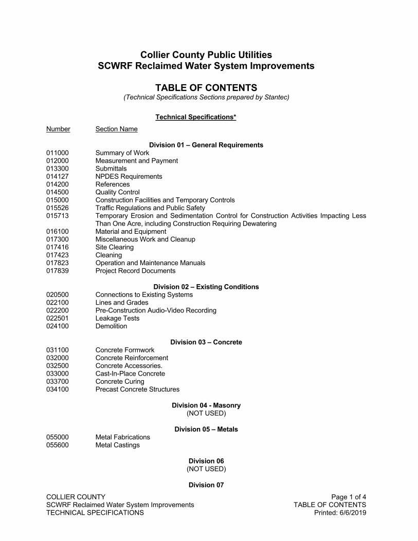
Collier County Public Utilities SCWRF Reclaimed Water System Improvements
TABLE OF CONTENTS
(Technical Specifications Sections prepared by Stantec)
Technical Specifications* Number Section Name
Division 01 – General Requirements 011000 Summary of Work 012000 Measurement and Payment 013300 Submittals 014127 NPDES Requirements 014200 References 014500 Quality Control 015000 Construction Facilities and Temporary Controls 015526 Traffic Regulations and Public Safety 015713 Temporary Erosion and Sedimentation Control for Construction Activities Impacting Less
Than One Acre, including Construction Requiring Dewatering 016100 Material and Equipment 017300 Miscellaneous Work and Cleanup 017416 Site Clearing 017423 Cleaning 017823 Operation and Maintenance Manuals 017839 Project Record Documents
Division 02 – Existing Conditions 020500 Connections to Existing Systems 022100 Lines and Grades 022200 Pre-Construction Audio-Video Recording 022501 Leakage Tests 024100 Demolition
Division 03 – Concrete 031100 Concrete Formwork 032000 Concrete Reinforcement 032500 Concrete Accessories. 033000 Cast-In-Place Concrete 033700 Concrete Curing 034100 Precast Concrete Structures
Division 04 - Masonry (NOT USED)
Division 05 – Metals 055000 Metal Fabrications 055600 Metal Castings
Division 06 (NOT USED)
Division 07
COLLIER COUNTY Page 2 of 4 SCWRF Reclaimed Water System Improvements TABLE OF CONTENTS TECHNICAL SPECIFICATIONS Printed: 6/6/2019
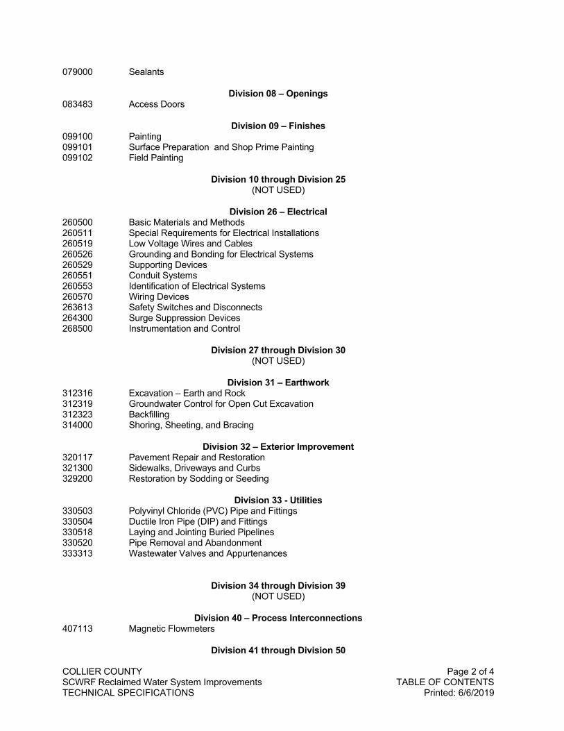
079000 Sealants
Division 08 – Openings 083483 Access Doors
Division 09 – Finishes 099100 Painting 099101 Surface Preparation and Shop Prime Painting 099102 Field Painting
Division 10 through Division 25 (NOT USED)
Division 26 – Electrical 260500 Basic Materials and Methods 260511 Special Requirements for Electrical Installations 260519 Low Voltage Wires and Cables 260526 Grounding and Bonding for Electrical Systems 260529 Supporting Devices 260551 Conduit Systems 260553 Identification of Electrical Systems 260570 Wiring Devices 263613 Safety Switches and Disconnects 264300 Surge Suppression Devices 268500 Instrumentation and Control
Division 27 through Division 30 (NOT USED)
Division 31 – Earthwork 312316 Excavation – Earth and Rock 312319 Groundwater Control for Open Cut Excavation 312323 Backfilling 314000 Shoring, Sheeting, and Bracing
Division 32 – Exterior Improvement 320117 Pavement Repair and Restoration 321300 Sidewalks, Driveways and Curbs 329200 Restoration by Sodding or Seeding
Division 33 - Utilities 330503 Polyvinyl Chloride (PVC) Pipe and Fittings 330504 Ductile Iron Pipe (DIP) and Fittings 330518 Laying and Jointing Buried Pipelines 330520 Pipe Removal and Abandonment 333313 Wastewater Valves and Appurtenances
Division 34 through Division 39 (NOT USED)
Division 40 – Process Interconnections 407113 Magnetic Flowmeters
Division 41 through Division 50

COLLIER COUNTY Page 3 of 4 SCWRF Reclaimed Water System Improvements TABLE OF CONTENTS TECHNICAL SPECIFICATIONS Printed: 6/6/2019
(NOT USED)
*(In case of a conflict between the Technical Specifications by Stantec and the Collier County Utilites Standards Manual, whichever provisions are more strict shall govern.)

COLLIER COUNTY Page 4 of 4 SCWRF Reclaimed Water System Improvements TABLE OF CONTENTS TECHNICAL SPECIFICATIONS Printed: 6/6/2019
NO TEXT FOR THIS PAGE
COLLIER COUNTY 011000-1 of 4 SCWRF Reclaimed Water System Improvements SUMMARY OF WORK TECHNICAL SPECIFICATIONS Printed: 6/6/2019
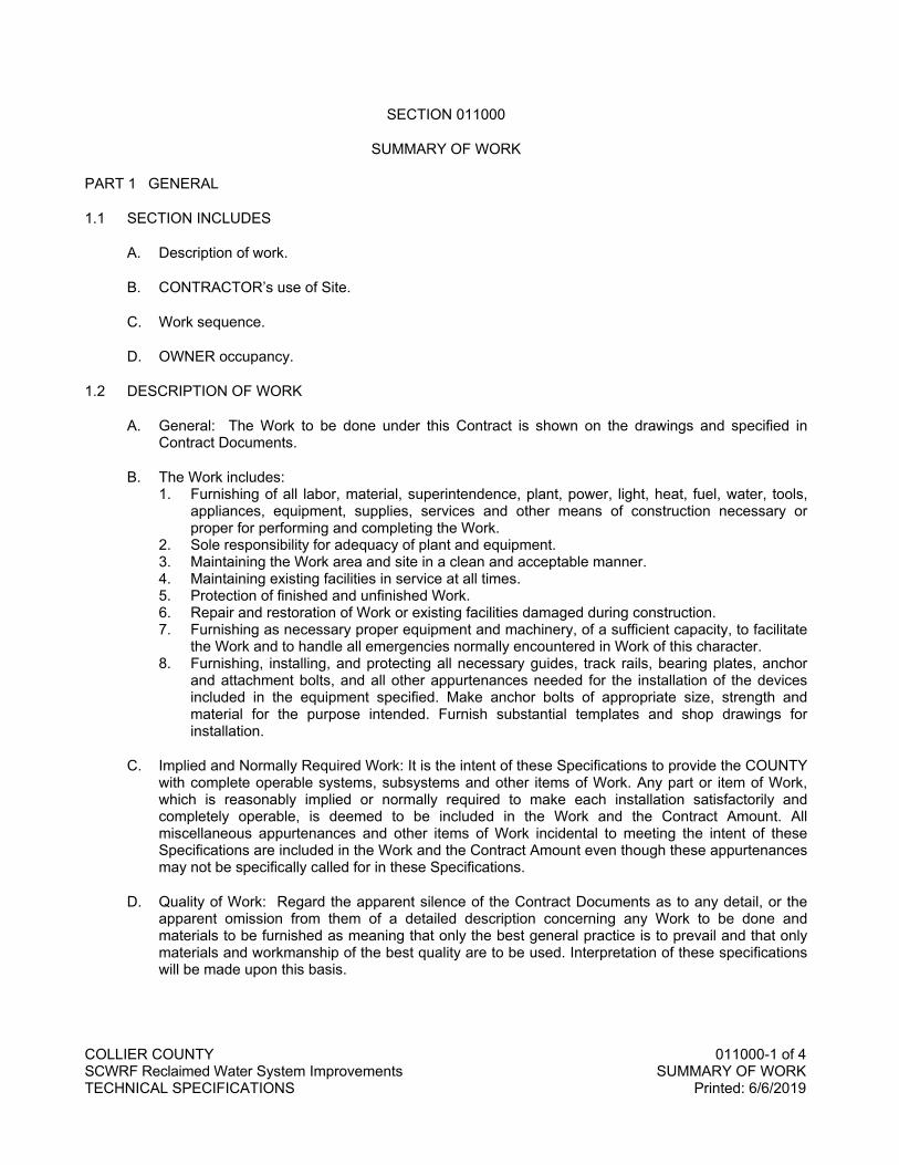
SECTION 011000
SUMMARY OF WORK
PART 1 GENERAL
1.1 SECTION INCLUDES
A. Description of work.
B. CONTRACTOR’s use of Site.
C. Work sequence.
D. OWNER occupancy.
1.2 DESCRIPTION OF WORK
A. General: The Work to be done under this Contract is shown on the drawings and specified in Contract Documents.
B. The Work includes: 1. Furnishing of all labor, material, superintendence, plant, power, light, heat, fuel, water, tools,
appliances, equipment, supplies, services and other means of construction necessary or proper for performing and completing the Work.
2. Sole responsibility for adequacy of plant and equipment. 3. Maintaining the Work area and site in a clean and acceptable manner. 4. Maintaining existing facilities in service at all times. 5. Protection of finished and unfinished Work. 6. Repair and restoration of Work or existing facilities damaged during construction. 7. Furnishing as necessary proper equipment and machinery, of a sufficient capacity, to facilitate
the Work and to handle all emergencies normally encountered in Work of this character. 8. Furnishing, installing, and protecting all necessary guides, track rails, bearing plates, anchor
and attachment bolts, and all other appurtenances needed for the installation of the devices included in the equipment specified. Make anchor bolts of appropriate size, strength and material for the purpose intended. Furnish substantial templates and shop drawings for installation.
C. Implied and Normally Required Work: It is the intent of these Specifications to provide the COUNTY with complete operable systems, subsystems and other items of Work. Any part or item of Work, which is reasonably implied or normally required to make each installation satisfactorily and completely operable, is deemed to be included in the Work and the Contract Amount. All miscellaneous appurtenances and other items of Work incidental to meeting the intent of these Specifications are included in the Work and the Contract Amount even though these appurtenances may not be specifically called for in these Specifications.
D. Quality of Work: Regard the apparent silence of the Contract Documents as to any detail, or the apparent omission from them of a detailed description concerning any Work to be done and materials to be furnished as meaning that only the best general practice is to prevail and that only materials and workmanship of the best quality are to be used. Interpretation of these specifications will be made upon this basis.
COLLIER COUNTY 011000-2 of 4 SCWRF Reclaimed Water System Improvements SUMMARY OF WORK TECHNICAL SPECIFICATIONS Printed: 9/30/2019
1.3 CONTRACTOR'S USE OF SITE
A. In addition to the requirements of the Supplemental Terms and Conditions, limit use of site and premises for work and storage to allow for the following: 1. Coordination of the Work under this CONTRACT with the work of the other contractors where
Work under this CONTRACT encroaches on the Work of other contractors. 2. COUNTY occupancy and access to operate existing facilities. 3. Coordination of site use with ENGINEER. 4. Responsibility for protection and safekeeping of products under this CONTRACT. 5. Providing additional off-site storage at no additional cost to the COUNTY as needed.
B. Access to Site: Limited to work areas as shown on the Drawings.
C. Construction Operations: Limited to work areas as shown on the Drawings.
D. Time Restrictions for Performing Work: Operation of construction equipment is only permitted Monday through Friday from 7:00 a.m. to 7:00 p.m.; Work on Saturdays must be requested in writing and approved by the Project Manager; Special approval must be obtained from Growth Management for any Sunday work.
1.4 WORK SEQUENCE
A. Construct Work in stages to accommodate the COUNTY’s use of premises during construction period and in accordance with the limitations on the sequence of construction specified. Coordinate construction schedules and operations with ENGINEER.
B. Coordinate work of all subcontractors.
C. The South County Water Reclamation Facility shall remain in service at all times during construction, with the exception of required pipe and valve tie-ins. 1. A maximum of 4-hours downtime will be allowed for each tie-in. 2. Coordinate plant downtime for tie-ins with plant operations well in advance of the work with
minimum 10-day notice. Reschedule tie-ins as required by COUNTY based on plant operational needs, weather events, etc.
3. Work requiring a partial plant shutdown, flow diversion, or piping cut-in shall not be imitated on Fridays or a day before a holiday.
D. New Plant Effluent force main reclaimed/reject manifold header pipe to be in service before 48-inch tie-in is installed.
E. Maintain one Transfer Pump Station Plant Effluent (PE) force main in service at all times.
F. Existing equipment and structures are to remain in service until new equipment, materials, and equipment necessary to complete the installation are delivered to the Site and are ready to be installed.
G. Provide temporary power to existing and proposed structures and equipment when work sequence dictates.
1.5 COUNTY OCCUPANCY
A. The COUNTY will occupy premises during entire period of construction in order to maintain normal operations. Cooperate with the COUNTY's Manager or designee in all construction operations to minimize conflict, and to facilitate COUNTY usage.
COLLIER COUNTY 011000-3 of 4 SCWRF Reclaimed Water System Improvements SUMMARY OF WORK TECHNICAL SPECIFICATIONS Printed: 6/6/2019
B. Conduct operations with the least inconvenience to the general public.
1.6 PROTECTION OF EXISTING UTILITIES
A. In case of damage to existing utilities caused by construction activities, contact the owner of the utility or appropriate COUNTY department (Water or Wastewater) immediately. Repair any damage to existing utilities caused by construction activities in coordination with or as directed by the owner of the utility.
PART 2 PRODUCTS
Not used.
PART 3 EXECUTION
A. Starting Work: Start Work within 10 days following the date stated in the Notice to Proceed and execute with such progress as may be required to prevent delay to other contractors or to the general completion of the project. Execute Work at such items and in or on such parts of the project, and with such forces, material and equipment, as to complete the Work in the time established by the Contract.
B. At all times, schedule and direct the Work so that it provides an orderly progression to completion within the specified time for completion.
END OF SECTION

COLLIER COUNTY 011000-4 of 4 SCWRF Reclaimed Water System Improvements SUMMARY OF WORK TECHNICAL SPECIFICATIONS Printed: 6/6/2019
NO TEXT FOR THIS PAGE

COLLIER COUNTY 012000-1 of 6 SCWRF Reclaimed Water System Improvements MEASUREMENT AND PAYMENT PROCEDURES TECHNICAL SPECIFICATIONS Printed: 9/23/2019
SECTION 012000
MEASUREMENT AND PAYMENT
PART 1 GENERAL
1.1 SECTION INCLUDES
A. Explanation and definitions.
B. Measurement.
C. Payment.
D. Schedule of values.
E. Applications for payment.
F. Change procedures.
1.2 EXPLANATION AND DEFINITIONS
A. The following explanation of the Measurement and Payment for the Bid Schedule items is made for information and guidance. The omission of reference to any item in this description shall not, however, alter the intent of the Bid Schedule or relieve the CONTRACTOR of the necessity of furnishing such as a part of the Contract. Measurement and payment for all Contract Items shall made be in accordance with this section or as modified by the Supplemental Terms and Conditions.
1.3 MEASUREMENT
A. The items set forth in the bid form are an approximate breakdown of the project and should be inclusive of all work stated in the plans and specifications. The County reserves the right to increase or decrease the quantity of any class or portion of the work during the progress of construction in accord with the terms of the Contract.
1.4 PAYMENT
A. Make payment for the items listed on the Bid Schedule on the basis of the percentage of work actually performed and completed, such work including but not limited to, the furnishing of all necessary labor, materials, equipment, transportation, clean up, restoration of disturbed areas, and all other appurtenances to complete the construction and installation of the work as shown on the drawings and described in the specifications.
1.5 SCHEDULE OF VALUES
A. Approval of Schedule: Submit for approval a preliminary schedule of values, in duplicate, for all of the Work. Prepare preliminary schedule in accordance with the Supplemental Terms and Conditions. Submit preliminary schedule of values within 10 calendar days after the Notice to Proceed. Submit final schedule of values in accordance with the Supplemental Terms and Conditions.
B. Format: Utilize a format similar to the Table of Contents of the Project Specifications. Identify each line item with number and title of the major specification items. Identify site mobilization, bonds and insurance. Include within each line item, a direct proportional amount of CONTRACTOR’s overhead
COLLIER COUNTY 012000-2 of 6 SCWRF Reclaimed Water System Improvements MEASUREMENT AND PAYMENT PROCEDURES TECHNICAL SPECIFICATIONS Printed: 9/23/2019
profit. Listings shall be coordinated with the construction progress schedule (i.e., equate time versus dollars). Provide breakdowns within individual Specifications Sections as requested by ENGINEER.
C. Revisions: With each Application for Payment, revise schedule to list approved Change Orders.
D. Include in each line item, the amount of approved Owner-Directed Allowances as specified in this Section.
1.6 APPLICATIONS FOR PAYMENT
A. Submit the number of copies of each application as required by the COUNTY on an Application for Payment form with format approved by COUNTY.
B. Content and Format: Utilize schedule of values for listing items in Applications for Payment.
C. Payment Period: Monthly.
D. For payments for materials and equipment furnished and installed, furnish evidence that manufacturer’s installation instructions were delivered with the material or equipment.
E. Include an updated construction progress schedule.
F. Include an updated schedule of Shop Drawing and Sample submittals.
G. Include an updated set of Contractor’s redline “As-built” drawings.
H. Include all other affidavits, certifications, and documentation as required by the COUNTY and the General Conditions.
1.7 CHANGE PROCEDURES
A. ENGINEER will advise of minor changes in the Work not involving an adjustment to Contract Price or Contract Time as authorized by the General Conditions by issuing supplemental instructions in a Work Directive for zero dollars and zero additional time.
B. OWNER may issue a request for a change which includes a detailed description of the proposed change with supplementary or revised Drawings and Specifications. CONTRACTOR will prepare and submit within 15 days, a statement describing the effect on the Contract Price and Contract Time with full documentation.
C. CONTRACTOR may propose changes by submitting a request for change to ENGINEER, describing the proposed change and its full effect on the Work. Include a statement describing the reason for the change, and the effect on the Contract Price and Contract Time with full documentation. Document any requested substitutes and “or-equals”.
D. Work Directive: ENGINEER may issue a Work Directive signed by OWNER, instructing CONTRACTOR to proceed with a change in the Work, for subsequent inclusion in a Change Order. Document will describe changes in the Work, and designate method of determining any change in Contract Price or Contract Time. Promptly execute the change.
E. Change Order: ENGINEER will issue Change Orders for signatures of parties as provided in the conditions of the Contract.
COLLIER COUNTY 012000-3 of 6 SCWRF Reclaimed Water System Improvements MEASUREMENT AND PAYMENT PROCEDURES TECHNICAL SPECIFICATIONS Printed: 9/23/2019
F. Cost of the Work Change Order: Submit itemized account and supporting data after completion of change, within time limits indicated in the conditions of the Contract. ENGINEER will determine the change allowable in Contract Price and Contract Time as provided in the Contract Documents.
PART 2 PRODUCTS
Not used.
PART 3 EXECUTION
3.1 GENERAL
A. Measurement and Payment shall be made on the basis of work actually performed completing each item in the Bid, such work including, but not limited to, the furnishing of all necessary labor, materials, equipment, transportation, cleanup, and all other appurtenances to complete the construction and installation of the work to the configuration and extent as shown on the drawings and described in the specifications. Payment for each item includes compensation for project layout, cleanup, maintaining As-builts, and will be considered as ten percent (10%) of each pay item. Complete payment will not be made until all cleanup and as-builts are completed.
B. The Total Bid price shall cover all Work required by the Contract Documents for the system to operate trouble-free as intended. All costs for the providing of all services, materials, equipment, labor, transportation, construction equipment and machinery, tools, appliances, fuel, power, light, heat, telephone, water, sanitary facilities, temporary facilities, and all other facilities and incidentals necessary for the performance, testing, start-up, and completion of the Work, and other overhead and profit shall be included in the unit and lump sum prices bid. All Work not specifically set forth as a pay item in the Bid shall be considered a subsidiary obligation of CONTRACTOR, and all costs in connection therewith shall be included in the prices bid.
3.2 PAY ITEMS
A. Mobilization (Bid Item No. 1): Payment for mobilization will be made at the Contract lump sum price for mobilization and demobilization. This price shall be full compensation for all costs incurred for preparatory work and operations including, but not limited to those necessary for the movement of personnel, equipment, supplies and incidentals to the project site; for the establishment of a temporary facilities necessary for work on project site; fees for bonds and insurance; and for all other work and operations including submittals and obtaining construction permits, which must be performed prior to beginning work on various items. This item amount shall not exceed of 5% of the Bid Subtotal, and shall be payable as follows:
Up to 15% Can be invoiced by contractor in the first application for payment.
Up to 50% Can be invoiced by the Contractor in the application for payment proceeding the Contractor’s approved application for payment for at least 50% of the value of work completed.
Up 100% Can be invoiced by the Contractor in the application for payment proceeding the Contractor’s approved application for payment for at least 75% of the value of work completed.
The value of work completed shall not include any amounts due or paid for mobilization.
COLLIER COUNTY 012000-4 of 6 SCWRF Reclaimed Water System Improvements MEASUREMENT AND PAYMENT PROCEDURES TECHNICAL SPECIFICATIONS Printed: 9/23/2019
B. Restoration (Bid Item No. 2): Payment for this Work shall be made at the Contract lump sum price for restoration of the work areas. This item includes furnishing all equipment, labor, and material to place sod and watering until it has established roots to the underlying soil, restoration of asphalt or concrete, and any other item that involves restoring the project site to pre-construction or better conditions. The item also includes all fertilization, pest control, and mowing until Final Completion. Contractor shall provide all water at no additional cost to the County.
C. Reclaimed / Reject Piping Improvements (Bid Item No. 3): Payment for construction of the reclaimed and reject piping improvements, as shown on Sheet M-101, M-102 and their respective details, shall be made at the appropriate contract lump sum price. Payment shall include all necessary labor, materials, equipment, services, testing, permitting, dewatering, sheeting and shoring, painting, pipe restraints. Work shall include but not be limited to furnishing and installing the work as shown in the Contract Documents and as described below to be placed in trouble-free operation as intended:
1. Buried Piping from TPS-1: This work consists of all buried piping from the existing 30-inch plant effluent piping, as shown in Section A, Drawing M-101, to the aboveground TPS-1, TPS-2, RW (reclaimed water) and RJW (reject water) connection assembly. This item shall be measured from the 30-inch by 30-inch mechanical joint tee to the buried, rolled 20-inch 90 degree bend below magnetic flow meter No. 1.
2. 48-inch TPS-2: The connection to the existing 48-inch reject water (RJW) pipe and all fittings and piping to connect to the above ground tank piping assembly. This item shall be measured from the 48-inch by 30-inch to the flanged end of the 30-inch riser pipe.
3. Aboveground Piping Assembly and Structure: All other aboveground piping, concrete support structure assembly, formwork, scaffolding, valves, motorized valve actuators, flow meters, fittings, air release valves, pipe sleeves, mechanical wall seals, and appurtenances to connect to the reclaimed/reject tank as shown in the plans.
D. Electrical and Instrumentation and Control (I&C) Improvements (Bid Item No. 4): Payment for construction of the electrical and I&C improvements, as shown in the Contract Documents shall be made at the appropriate contract lump sum price. Payment shall include all necessary labor, materials, equipment, services, testing, permitting, and coordination with the owner for furnishing and installing all conduit, conductors, disconnects, junction boxes, support racks, electrical equipment racks, sunshields, penetrations, terminations to new and existing equipment and instruments, existing electrical equipment modifications, PLC panels, cabinets, panels, cabinet and panel supports, instrumentation, switches, fiber optic work, grounding and bonding, labels, and nameplates. The County shall be responsible for all programming and integration with existing plant network architecture for operating the MOV’s in trouble-free operation as intended.
E. 2-inch Water Service (Bid Item No. 5): Payment for construction of the 2-inch water service shall be made at the appropriate contract lump sum price. Payment shall include all necessary labor, equipment, materials, services, and testing for furnishing and installing all piping, fittings, appurtenances, anchoring hardware, and connections to existing plant service water for placing the 2-inch water service in trouble-free operation as intended.
F. 8-inch Water Main Relocation (Bid Item No. 6): Payment for construction of the 8-inch water main relocation shall be made at the appropriate contract lump sum price. Payment shall include all the necessary labor, equipment, materials, services, dewatering, testing, and sheeting and shoring necessary to furnish and install the water main relocation, piping, fittings, restraints, and appurtenances to relocate the existing 8-inch water main and place in trouble-free operation as intended.
G. 36-inch Valve and Valve Vault (Bid Item No. 7): Payment for the construction of the valve and valve vault assembly shall be made at the appropriate contract lump sum price. Payment shall include all necessary labor, equipment, materials, permitting, testing, dewatering sheeting and shoring, services,
COLLIER COUNTY 012000-5 of 6 SCWRF Reclaimed Water System Improvements MEASUREMENT AND PAYMENT PROCEDURES TECHNICAL SPECIFICATIONS Printed: 9/23/2019
and testing necessary to furnish and install the valve, piping connections, sleeves, fittings, appurtenances, vault, and vault hatch as shown on the plans and placing in trouble-free operation as intended.
H. Inline Check Valves (Bid Item No. 8): Payment for the inline check valve installation (Valve Nos. 9 through 11 shown on Drawing M-301 and identified in Valve Schedule on Drawing M-501) shall be made at the appropriate contract unit price. Payment shall include all necessary labor, equipment, materials, permitting, services, and testing necessary to furnish and install the valves in accordance with the plans for trouble-free operation as intended. Dewatering the structures, confirming dimensions and existing conditions, materials shall also be included as part of this
I. Owner-Directed Allowance (Bid Item No. 9): 1. Costs included in Allowances and adjusting differences in costs shall be in accordance with
paragraph 11.02 of the General Conditions. 2. Owner-Directed Allowance:
a. Included in the Bid Proposal Total Amount of Bid is an Owner-Directed Allowance in the amount of $150,000 to be used on a time and material (T&M) basis). This allowance is to be used to cover the cost of unforeseen changes to the Work. The CONTRACTOR shall, prior to performing any extra Work, obtain the written approval of the COUNTY for payment under this item.
b. Adjustments to the Owner-Directed Allowance will be made by Change Order. c. The CONTRACTOR shall be reimbursed for Work furnished under this allowance on a
monthly basis by including said allowance in his monthly applications for partial payment. d. Supporting invoices shall be attached to each application that includes such request for
reimbursement. e. At the completion and final acceptance of all Work performed under this contract, the
CONTRACTOR shall be paid in the Final Application for Payment the total amount of the Work performed minus the balance of funds remaining in the Owner-Directed Allowance.
END OF SECTION

COLLIER COUNTY 012000-6 of 6 SCWRF Reclaimed Water System Improvements MEASUREMENT AND PAYMENT PROCEDURES TECHNICAL SPECIFICATIONS Printed: 9/23/2019
NO TEXT FOR THIS PAGE
COLLIER COUNTY 013300-1 of 6 SCWRF Reclaimed Water System Improvements SUBMITTALS TECHNICAL SPECIFICATIONS Printed: 4/5/2018
SECTION 013300
SUBMITTALS
PART 1 GENERAL
1.1 SECTION INCLUDES
A. Submittal procedures.
B. Construction progress schedule.
C. Shop drawings.
D. Certificates.
E. Manufacturer’s instructions.
1.2 REQUIREMENTS
A. The types of submittals controlled by these general requirements include shop drawings, product data, samples, construction schedule and miscellaneous work-related submittals. The individual submittal requirements are specified in applicable sections for each unit of work. 1. Unless otherwise noted, each item of submittal shall be submitted to the Engineer for review prior
to construction or installation. 2. Engineer’s review is for general conformance with the design concept and Contract Documents.
B. The submittal will not be accepted for review unless it is clear, legible and contains complete information and complies with the specifications. Submittals that are not accepted will be returned with attached notations of requirements necessary for acceptance. Resubmit after the material has been amended to comply with the comments.
C. If submittals show deviations from Contract requirements because of standard shop practice or for other reasons, the Contractor shall clearly describe such deviations in his letter of transmittal. If the Contractor fails to describe such deviations, he shall not be relieved of the responsibility of executing the work in accordance with the Contract, even though such submittals have been reviewed.
1.3 DEFINITIONS
A. The work-related submittals of this section, in addition to the definitions of the General Conditions and elsewhere in the Contract Documents, are defined as follows: 1. Shop drawings include custom-prepared data of all forms, including drawings, diagrams, pipe
laying schedule, performance curves, data sheets, schedules, templates, patterns, reports, calculations, instructions, measurements and similar information not in standard printed form applicable to other projects.
2. Product data includes standard printed information on materials, products and systems not custom-prepared for this project, other than the designation of selections from available choices.
3. Samples include both fabricated and un-fabricated physical examples of materials, products and work; both as complete units and as smaller portions of units of work; either for limited visual inspection or (where indicated) for detailed testing and analysis.
4. Mock-ups are a special form of samples, which are, because of size, usually constructed on the project site.
COLLIER COUNTY 013300-2 of 6 SCWRF Reclaimed Water System Improvements SUBMITTALS TECHNICAL SPECIFICATIONS Printed: 4/5/2018
5. Construction schedule includes custom-prepared data for the construction of said project. All stages of work shall be included. Contractor shall revise during the course of construction as needed, and submit to the Engineer with monthly application payment.
B. Miscellaneous submittals related directly to the work, (non-administrative) include extended warranties or guarantees, maintenance agreements, project photographs (DVD format), survey data and reports, physical work records, statements of applicability, quality testing, calculation and certifying reports, copies of industry standards, record drawings, operating and maintenance materials, overrun stock and similar information, devices and materials applicable to the work.
1.4 CONSTRUCTION PROGRESS SCHEDULE
A. Submit four copies of preliminary progress schedule at pre-construction conference. Development of progress schedule shall be in accordance with the requirements of the General Conditions.
B. Revise and resubmit as required.
C. Submit revised schedule with each Application for Payment, identifying changes since previous version.
D. Submit a computer-generated horizontal bar chart with separate line for each portion of Work or operation, identifying first work day of each week, or submit a computer-generated network analysis diagram using the critical path method, as outlined in Associated General Contractors of America (AGC) publication “The use of CPM in Construction - A Manual for General Contractors and the Construction Industry”.
E. Show complete sequence of construction by activity, identifying Work of separate stages and other logically grouped activities. Indicate the early and late start, early and late finish, float dates, and duration.
F. Indicate estimated percentage of completion for each item of Work at each submission.
1.5 SHOP DRAWINGS
A. The CONTRACTOR shall review, approve, and submit, with reasonable promptness and in such sequence as shown on the Shop Drawing Submittal Schedule so as to cause no delay in the Contract Work or in the Work of the OWNER or any separate contractor, all shop drawings, product data, working drawings and samples required by the Contract Documents.
B. Submittals shall be electronic in *.pdf format of descriptive or product data submittals to complement shop drawings for the ENGINEER. The ENGINEER will review the submittal and return to the CONTRACTOR a set of marked-up reproducibles with appropriate review comments. If in the opinion of the ENGINEER a submittal is nonreproducible, the CONTRACTOR shall submit four (4) additional sets of blueline shop drawings. Once submittals are approved and require no additional submittal, electronic copies of each submittal will be forwarded to the OWNER.
C. All submittals shall be made directly to the ENGINEER with a copy via email to the OWNER.
D. Shop drawings, product data, working drawings and samples shall be furnished with the following information: 1. Number and title of the drawing. 2. Date of drawing or revision. 3. Name of project building or facility. 4. Name of contractor, subcontractor, and manufacturer submitting drawing.
COLLIER COUNTY 013300-3 of 6 SCWRF Reclaimed Water System Improvements SUBMITTALS TECHNICAL SPECIFICATIONS Printed: 4/5/2018
5. Clear identification of contents, location of the work, and the sheet numbers where the product is found in the contract drawings.
6. Contractor Certification Statement. 7. Submittal Identification Number. 8. Contract Drawing Number Reference.
E. In accordance with subparagraph 1.07 A below, each shop drawing, working drawing, sample, and catalog data submitted by the CONTRACTOR shall have affixed to it the following Certification Statement, signed by the CONTRACTOR:
"Certification Statement: By this submittal, I hereby represent that I have determined and verified all field measurements, field construction criteria, materials, dimensions, catalog numbers, and similar data and I have checked and coordinated each item with other applicable approved shop drawings and all contract requirements."
F. The CONTRACTOR shall utilize a 10-character submittal identification numbering system in the following manner: 1. The first character shall be a D, S, P, M, or R, which represents Shop/Working Drawing and other
Product Data (D), Sample (S), Preliminary Submittal (P), Operating/ Maintenance Manual (M), or Request for Information (R).
2. The next five/six digits shall be the applicable Specification Section Number. 3. The next three digits shall be the numbers 001-999 to sequentially number each initial separate
item or drawing submitted under each specific Section Number. 4. The last character shall be a letter, A-Z, indicating the submission, or resubmission of the same
drawing, i.e., A=1st submission, B=2nd submission, C=3d submission, etc. A typical submittal number would be as follows: D-033504-008-B D = Shop Drawing 330504 = Specification Section for Ductile Iron Pipe (DIP) & Fittings 008 = The eighth initial submittal under this specification section B = The second submission (first resubmission) of that particular shop drawing
G. The CONTRACTOR shall submit a copy of each submittal transmittal sheet (for shop drawings, product data, working drawings and samples) to the Resident Project Representative simultaneously with the CONTRACTOR'S submission of said drawings, data, samples or manual packages to the ENGINEER and OWNER.
H. All items specified are not necessarily intended to be a manufacturer's standard product. Variations from specified items will be considered on an "or equal" basis. If submittals show variations from Contract requirements because of standard shop practice or for other reasons, the CONTRACTOR shall describe such variations in his letter of transmittal and on the shop drawings along with notification of his intent to seek contract adjustment. If acceptable, proper adjustment in the Contract shall be implemented where appropriate. If the CONTRACTOR fails to describe such variations he shall not be relieved of the responsibility for executing the work in accordance with the Contract, even though such drawings have been reviewed. Variations submitted but not described may be cause for rejection. Any variations initiated by the CONTRACTOR will not be considered as an addition to the scope of work unless specifically noted and then approved as such in writing by the ENGINEER.
I. Data on materials and equipment shall include materials and equipment lists giving, for each item thereon, the name and location of the supplier or manufacturer, trade name, catalog reference, material, size, finish, and all other pertinent data.
COLLIER COUNTY 013300-4 of 6 SCWRF Reclaimed Water System Improvements SUBMITTALS TECHNICAL SPECIFICATIONS Printed: 4/5/2018
J. For all material furnished, the CONTRACTOR shall provide a list including the material name, address, and telephone number of the manufacturer's representative and service company so that service and/or spare parts can be readily obtained.
K. The CONTRACTOR shall use the color "green" to make his remarks on the Submittals. Only the ENGINEER will utilize the color "red" in marking submittals.
L. Before final payment is made, the CONTRACTOR shall furnish to ENGINEER one (1) set of record shop drawings as described in Section 017839. These record shop drawings shall be in conformance with the approved documents and should show any field conditions that may affect their accuracy.
M. Submit working drawings of piping; detail drawings of steel reinforcing, both bars and mesh, showing size and arrangement; details of machinery, apparatus and materials; dimensional drawings, ladder-type schematic diagrams, connection diagrams and other data for all electrically operated equipment, and all communication, instrumentation, control, and related equipment; and layout drawings of the complete electrical work. Drawings shall designate the complete installation and shall be suitable for coordinating work of the various trades.
N. Layout drawings for electrical work shall include all underground, concealed, and exposed conduits, and shall show locations and sizes of conduit runs, sizes and number of wires, pull and junction boxes, outlets, lighting fixtures, panelboards, motor starter switchboards, motor controls, switches, control stations, disconnects, etc., and will be used by ENGINEER to verify the location and size of conduit, wire and equipment. Layout drawings shall be submitted early. No Work shall proceed until such drawings have been returned (with review stamp affixed) by ENGINEER.
O. Shop Drawings shall include all information on electrical components and characteristics, appropriate curve data at various operating and efficiency levels, manufacturer's motor data sheets, hardware and accessories. Electrical characteristics include electrical power supply required and electrical loading information. Shop Drawings will not be reviewed and returned until all such information is received.
P. CONTRACTOR may utilize Contract Drawings with necessary details marked thereon for electrical conduit layout drawings. However, the Drawings must have CONTRACTOR's title block in lieu of ENGINEER's title block.
1.6 CERTIFICATES
A. When specified in individual Specifications Sections, submit certification by the manufacturer, installation/application subcontractor, or CONTRACTOR to ENGINEER, in quantities specified for Shop Drawings.
B. Indicate material or equipment conforms to or exceeds specified requirements. Submit supporting reference data, affidavits, and certifications as appropriate.
C. Certificates may be recent or previous test results on material or equipment but must be acceptable to ENGINEER.
1.7 MANUFACTURER’S INSTRUCTIONS
A. Keep one copy of manufacturer's printed instructions for delivery, storage, assembly, installation, start-up, adjusting, and finishing on Site. Maintain with Record Documents as required under Section 017839.
B. Indicate special procedures, perimeter conditions requiring special attention, and special environmental criteria required for application or installation.

COLLIER COUNTY 013300-5 of 6 SCWRF Reclaimed Water System Improvements SUBMITTALS TECHNICAL SPECIFICATIONS Printed: 4/5/2018
PART 2 PRODUCTS
Not used.
PART 3 EXECUTION
Not used.
END OF SECTION

COLLIER COUNTY 013300-6 of 6 SCWRF Reclaimed Water System Improvements SUBMITTALS TECHNICAL SPECIFICATIONS Printed: 4/5/2018
NO TEXT FOR THIS PAGE
COLLIER COUNTY 014127-1 of 6 SCWRF Reclaimed Water System Improvements NPDES REQUIREMENTS TECHNICAL SPECIFICATIONS Printed: 6/6/2019
SECTION 014127
NPDES SWPPP
PART 1 GENERAL
1.1 DESCRIPTION
A. This Section describes the required documentation to be prepared and signed by the CONTRACTOR before conducting construction operations, in accordance with the terms and conditions of the National Pollutant Discharge Elimination System (NPDES) Stormwater Permit, as required by Florida Administrative Code (F.A.C.) Chapter 62-621.
B. The CONTRACTOR shall be for responsible for implementation, maintenance and inspection of stormwater pollution prevention control measures in accordance with F.A.C. Chapter 62-621 including, but not limited to, erosion and sediment control, stormwater management plans, waste collection and disposal, off-site vehicle tracking, and other practices shown on the Drawings and/or specified elsewhere in this or other specifications. The stormwater pollution prevention control measures shall include protection of offsite public and private storm sewer facilities potentially impacted during construction. Stormwater facilities include streets, inlets, pipes, ditches, swales, canals, culverts, control structures, and detention/retention areas.
C. The CONTRACTOR shall prepare and review implementation of the Stormwater Pollution Prevention Plan (SWPPP) in a meeting with the County Manager or designee prior to start of construction.
1.2 UNIT PRICES
A. Unless indicated in the Unit Price Schedule as a pay item, no separate payment will be made for work performed under this Section. Include cost of work to be performed under this Section in pay items of which this work is a component.
1.3 REFERENCE DOCUMENTS
A. ASTM D3786 – Standard Test Method for Hydraulic Bursting Strength for Knitted Goods and Nonwoven Fabrics.
B. ASTM D4632 – Standard Test Method for Grab Breaking Load and Elongation of Geotextiles.
PART 2 PRODUCTS
Not used.
PART 3 EXECUTION
3.1 NOTICE OF INTENT (NOI)
A. Fill out, sign and date a Notice of Intent to Use Generic Permit for Stormwater Discharge from Large and Small Construction Activities, (FDEP Form 62621.300(4)(b)). Submit the signed copy of the NOI to the County Manager or designee. The County Manager or designee will submit the completed form to the FDEP along with the required permit fee.
3.2 CERTIFICATION REQUIREMENTS
COLLIER COUNTY 014127-2 of 6 SCWRF Reclaimed Water System Improvements NPDES REQUIREMENTS TECHNICAL SPECIFICATIONS Printed: 6/6/2019
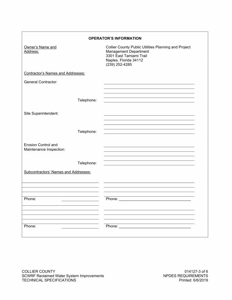
A. On the attached OPERATOR’S INFORMATION form, fill out the name, address and telephone number for the CONTRACTOR, persons or firms responsible for maintenance and inspection of erosion and sediment control measures, and all Subcontractors.
B. The CONTRACTOR and Subcontractors named in the Operator’s Information form shall read, sign and date the attached CONTRACTOR’S/SUBCONTRACTOR’S CERTIFICATION form.
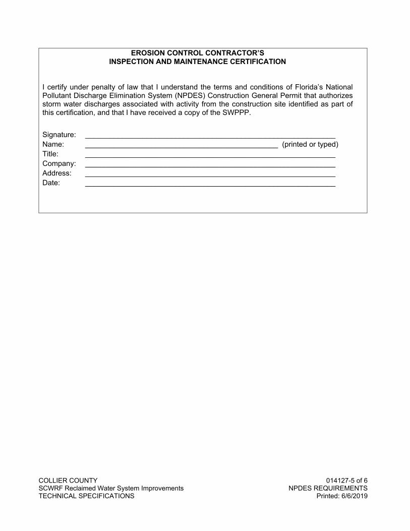
C. The persons or firms responsible for maintenance and inspection of erosion and sediment control measures shall read, sign and date the attached EROSION CONTROL CONTRACTOR’S INSPECTION AND MAINTENANCE CERTIFICATION form.
D. Submit all forms to the County Manager or designee before beginning construction.
3.3 RETENTION OF RECORDS
A. Retain a copy of the SWPPP at the construction site and at the Contractor’s office from the date that it became effective to the date of project completion.
B. At project closeout, submit to the County Manager or designee all NPDES forms and certifications, as well as a copy of the SWPPP. Stormwater pollution prevention records will be retained by the County Manager or designee for a period of three (3) years from the date of project completion.
3.4 REQUIRED NOTICES
A. The following notices shall be posted from the date that the SWPPP goes into effect until the date of final site stabilization: 1. A copy of the submitted NOI and a brief project description, as given in the SWPPP, shall be
posted at the construction site and at the CONTRACTOR’s office in a prominent place for public viewing.
2. Notice to drivers of equipment and vehicles, instructing them to stop, check and clean tires of debris and mud before driving onto traffic lanes. Post such notices at every stabilized construction exit area.
3. Post a notice of waste disposal procedures in an easily visible location on 4. site. 5. Notice of hazardous material handling and emergency procedures shall be posted with the NOI
on site. Keep copies of Material Safety Data Sheets at a location on site that is known to all personnel.
6. Keep a copy of each signed certification at the construction site and at the CONTRACTOR’s office.
REQUIRED FORMS FOLLOW
COLLIER COUNTY 014127-3 of 6 SCWRF Reclaimed Water System Improvements NPDES REQUIREMENTS TECHNICAL SPECIFICATIONS Printed: 6/6/2019
OPERATOR’S INFORMATION
Owner’s Name and Collier County Public Utilities Planning and Project Address: Management Department 3301 East Tamiami Trail Naples, Florida 34112 (239) 252-4285 Contractor’s Names and Addresses: General Contractor: Telephone: Site Superintendent: Telephone: Erosion Control and Maintenance Inspection: Telephone: Subcontractors’ Names and Addresses: Phone: Phone: __________________________________ Phone: Phone: __________________________________

COLLIER COUNTY 014127-4 of 6 SCWRF Reclaimed Water System Improvements NPDES REQUIREMENTS TECHNICAL SPECIFICATIONS Printed: 6/6/2019
CONTRACTOR’S / SUBCONTRACTOR’S CERTIFICATION I certify under penalty of law that I understand the terms and conditions of Florida’s National Pollutant Discharge Elimination System (NPDES) Construction General Permit that authorizes storm water discharges associated with activity from the construction site identified as part of this certification, and that I have received a copy of the SWPPP. Signature: _____________________________________________________________ Name: _______________________________________________ (printed or typed) Title: _____________________________________________________________ Company: _____________________________________________________________ Address: _____________________________________________________________ _____________________________________________________________ Signature: _____________________________________________________________ Name: _______________________________________________ (printed or typed) Title: _____________________________________________________________ Company: _____________________________________________________________ Address: _____________________________________________________________ _____________________________________________________________ Signature: _____________________________________________________________ Name: _______________________________________________ (printed or typed) Title: _____________________________________________________________ Company: _____________________________________________________________ Address: _____________________________________________________________ _____________________________________________________________
COLLIER COUNTY 014127-5 of 6 SCWRF Reclaimed Water System Improvements NPDES REQUIREMENTS TECHNICAL SPECIFICATIONS Printed: 6/6/2019
EROSION CONTROL CONTRACTOR’S INSPECTION AND MAINTENANCE CERTIFICATION
I certify under penalty of law that I understand the terms and conditions of Florida’s National Pollutant Discharge Elimination System (NPDES) Construction General Permit that authorizes storm water discharges associated with activity from the construction site identified as part of this certification, and that I have received a copy of the SWPPP.
Signature: _____________________________________________________________ Name: _______________________________________________ (printed or typed) Title: _____________________________________________________________ Company: _____________________________________________________________ Address: _____________________________________________________________ Date: _____________________________________________________________
COLLIER COUNTY 014127-6 of 6 SCWRF Reclaimed Water System Improvements NPDES REQUIREMENTS TECHNICAL SPECIFICATIONS Printed: 6/6/2019
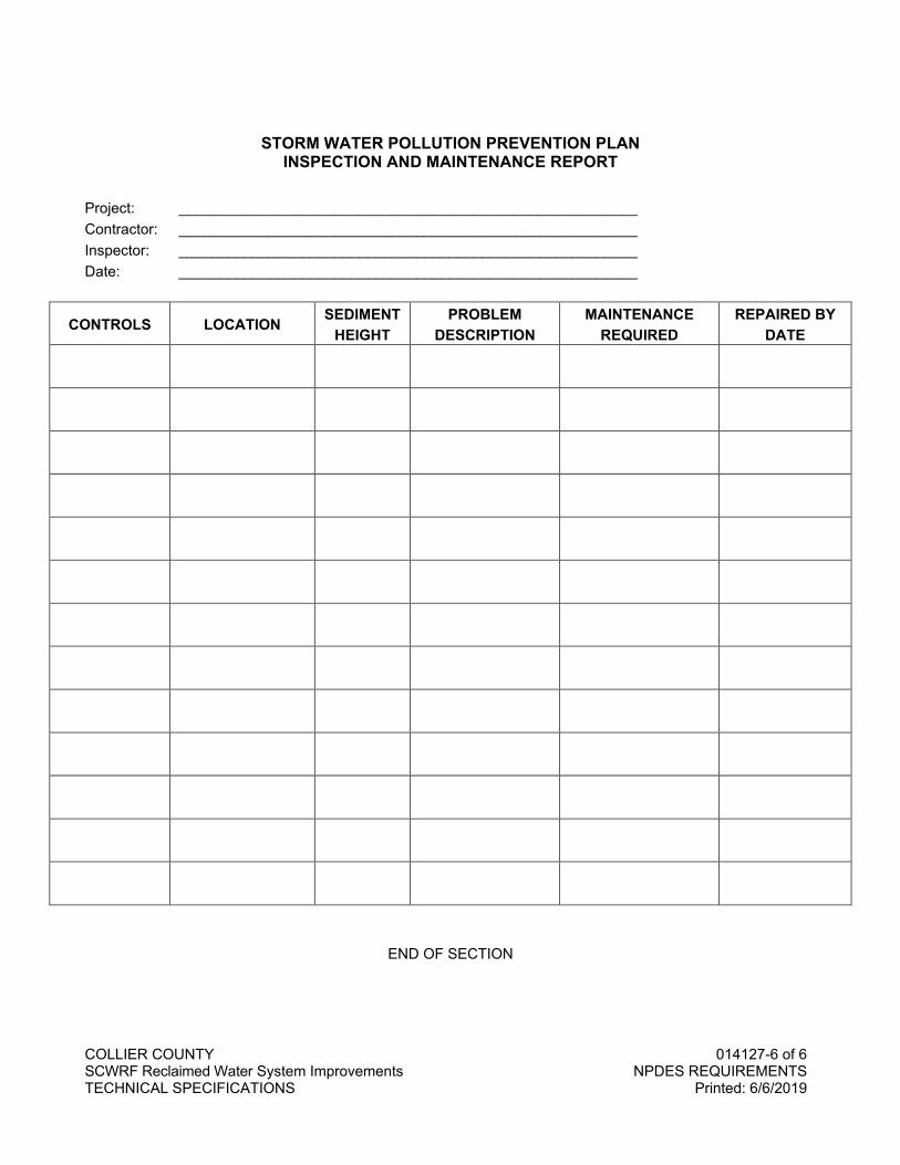
STORM WATER POLLUTION PREVENTION PLAN INSPECTION AND MAINTENANCE REPORT
Project: ________________________________________________________ Contractor: ________________________________________________________ Inspector: ________________________________________________________ Date: ________________________________________________________
CONTROLS LOCATION SEDIMENT HEIGHT
PROBLEM DESCRIPTION
MAINTENANCE REQUIRED
REPAIRED BY DATE
END OF SECTION
COLLIER COUNTY 014200-1 of 6 SCWRF Reclaimed Water System Improvements REFERENCES TECHNICAL SPECIFICATIONS Printed: 4/5/2018
SECTION 014200
REFERENCES
PART 1 GENERAL
1.1 SECTION INCLUDES
A. Reference abbreviations.
B. Abbreviations.
C. Reference standards.
D. Definitions.
1.2 RELATED SECTIONS
A. Information provided in this section is used where applicable in individual Specification Sections.
1.3 REFERENCE ABBREVIATIONS
A. Reference to a technical society, trade association or standards setting organization, may be made in the Specifications by abbreviations in accordance with the following list: 1. AABC Associated Air Balance Council. 2. AAMA Architectural Aluminum Manufacturers Association. 3. AASHTO American Association of State Highway and Transportation Officials. 4. AATCC American Association of Textile Chemists and Colorists. 5. ACI American Concrete Institute. 6. ADC Air Diffusion Council. 7. AFBMA Anti-friction Bearing Manufacturers Association. 8. AGA American Gas Association. 9. AGMA American Gear Manufacturers Association. 10. AHA Association of Home Appliance Manufacturers. 11. AISC American Institute of Steel Construction. 12. AISI American Iron and Steel Institute. 13. AMCA Air Movement and Control Association, Inc. 14. ANSI American National Standards Institute. 15. APA American Plywood Association. 16. ARI American Refrigeration Institute. 17. ASCE American Society of Civil Engineers. 18. ASHRAE American Society of Heating, Refrigerating and Air Conditioning Engineers. 19. ASME American Society of Mechanical Engineers. 20. ASSE American Society of Sanitary Engineers. 21. ASTM American Society for Testing and Materials. 22. AWI Architectural Woodwork Institute. 23. AWPA American Wood Preservers Association. 24. AWS American Welding Society. 25. AWWA American Water Works Association. 26. BHMA Builders' Hardware Manufacturers Association. 27. BIA Brick Institute of American. 28. CABO Council of American Building Officials. 29. CAGI Compressed Air and Gas Institute. 30. CISPI Cast Iron Soil Pipe Institute.
COLLIER COUNTY 014200-2 of 6 SCWRF Reclaimed Water System Improvements REFERENCES TECHNICAL SPECIFICATIONS Printed: 4/5/2018
31. CMAA Crane Manufacturers Association of America. 32. CRD U.S. Corps of Engineers Specifications. 33. CRSI Concrete Reinforcing Steel Institute. 34. CTI Cooling Tower Institute. 35. DHI Door and Hardware Institute. 36. DOH Department of Health. 37. DOT Department of Transportation. 38. Fed. Spec. Federal Specifications. 39. FGMA Flat Glass Marketing Association. 40. FM Factory Mutual. 41. HMI Hoist Manufacturing Institute. 42. HPMA See HPVA. 43. HPVA Hardwood Plywood Veneer Association. 44. ICEA Insulated Cable Engineers Association. 45. IEEE Institute of Electrical and Electronics Engineers. 46. IFI Industrial Fasteners Institute. 47. MIL Military Specifications. 48. MSS Manufacturer's Standardization Society. 49. NAAMM National Association of Architectural Metal Manufacturers. 50. NACM National Association of Chain Manufacturers. 51. NBS National Bureau of Standards, See NIST. 52. NEBB National Environmental Balancing Bureau. 53. NEC National Electrical Code. 54. NEMA National Electrical Manufacturers Association. 55. NETA National Electrical Testing Association. 56. NFPA National Fire Protection Association. 57. NFPA National Forest Products Association. 58. NFPA National Fluid Power Association. 59. NIST National Institute of Standards and Technology. 60. NLMA National Lumber Manufacturers Association. 61. NSF National Sanitation Foundation. 62. OSHA Occupational Safety and Health Act. 63. PCI Prestressed Concrete Institute. 64. PDI Plumbing and Drainage Institute. 65. SAE Society of Automotive Engineers. 66. SCPRF Structural Clay Products Research Foundation. 67. SMACNA Sheet Metal and Air Conditioning Contractors' National Association. 68. SPI Society of the Plastics Industry. 69. SSPC Steel Structures Painting Council. 70. STI Steel Tank Institute. 71. TCA Tile Council of American. 72. TIMA Thermal Insulation Manufacturers' Association. 73. UL Underwriters' Laboratories, Inc. 74. USBR U. S. Bureau of Reclamation. 75. USBS U. S. Bureau of Standards, See NIST.
1.4 ABBREVIATIONS
A. Abbreviations which may be used in individual Specification Sections are as follows:
alternating current.............................. ac American wire gauge......................AWG ampere(s)......................................... amp ampere-hour(s) ................................. AH
annual ............................................... ann Ampere Interrupting Capacity .......................................... AIC atmosphere(s)................................... atm
COLLIER COUNTY 014200-3 of 6 SCWRF Reclaimed Water System Improvements REFERENCES TECHNICAL SPECIFICATIONS Printed: 4/5/2018
average ............................................. avg biochemical oxygen demand.......... BOD Board Foot ...................................... FBM brake horsepower ............................. bhp Brinell Hardness ............................... BH British thermal unit(s).........................Btu calorie(s) .............................................cal carbonaceous biochemical oxygen demand ......................... CBOD Celsius (centigrade)............................. C Center to Center .......................... C to C centimeter(s) ..................................... cm chemical oxygen demand............... COD coefficient, valve flow.......................... Cv condensate return.............................. CR cubic................................................... cu cubic centimeter(s) ..............................cc cubic feet per day .............................. cfd cubic feet per hour............................. cfh cubic feet per minute ........................ cfm cubic feet per minute, standard conditions......................... scfm cubic feet per second .........................cfs cubic foot (feet) ................................ cu ft cubic inch(es) .................................. cu in cubic yard(s)................................... cu yd decibels ...............................................dB decibels (A scale)............................. dBa degree(s) ...........................................deg dewpoint temperature ........................ dpt diameter ............................................. dia direct current ....................................... dc dissolved oxygen ...............................DO dissolved solids .................................. DS dry-bulb temperature.......................... dbt efficiency ............................................. eff elevation .............................................. el entering water temperature............... ewt entering air temperature .................... eat equivalent direct radiation..................edr face area .............................................. fa face to face....................................... f to f Fahrenheit ............................................ F feet per day ........................................ fpd feet per hour....................................... fph feet per minute .................................. fpm feet per second .................................. fps foot (feet) ............................................... ft
foot-candle............................................ fc foot-pound ......................................... ft-lb foot-pounds per minute.............. ft-lb/min foot-pounds per second ............. ft-lb/sec formazin turbidity unit(s) .................. FTU frequency .......................................... freq fuel oil ................................................. FO fuel oil supply ...................................FOS fuel oil return ....................................FOR gallon(s) ............................................. gal gallons per day ................................. gpd gallons per day per cubic foot................................. gpd/cu ft gallons per day per square foot .............................. gpd/sq ft gallons per hour ............................... gph gallons per minute ........................... gpm gallons per second............................ gps gas chromatography and mass spectrometry ................... GC-MS gauge .................................................. ga grain(s) ................................................. gr gram(s).................................................. g grams per cubic centimeter ...........gm/cc Heat Transfer Coefficient .....................U height ................................................. hgt Hertz................................................... Hz horsepower ........................................ hp horsepower-hour.............................hp-hr hour(s)................................................. hr humidity, relative................................. rh hydrogen ion concentration ................pH inch(es) .................................................in inches per second...............................ips inside diameter ....................................ID Jackson turbidity unit(s)....................JTU kelvin .................................................... K kiloamperes......................................... kA kilogram(s) .......................................... kg kilometer(s) ........................................ km kilovar (kilovolt-amperes reactive) ......................................... kvar kilovolt(s) ............................................. kV kilovolt-ampere(s) .............................kVA kilowatt(s) ........................................... kW kilowatt-hour(s) ................................ kWh linear foot (feet).................................lin ft liter(s) .................................................... L

COLLIER COUNTY 014200-4 of 6 SCWRF Reclaimed Water System Improvements REFERENCES TECHNICAL SPECIFICATIONS Printed: 4/5/2018
megavolt-ampere(s)........................ MVA meter(s) ................................................ m micrograms per liter ....................... ug/L miles per hour ..................................mph milliampere(s).................................... mA milligram(s)........................................ mg milligrams per liter .......................... mg/L milliliter(s) .......................................... mL millimeter(s)...................................... mm million gallons................................... MG million gallons per day .................... mgd millisecond(s) .................................... ms millivolt(s) .......................................... mV minute(s) .......................................... min mixed liquor suspended solids ........................................... MLSS nephelometric turbidity unit..................................................NTU net positive suction head ..............NPSH noise criteria ........................................ nc noise reduction coefficient .............. NRC number ................................................ no ounce(s) .............................................. oz outside air............................................ oa outside diameter.................................OD parts per billion................................. ppb parts per million............................... ppm percent .............................................. pct phase (electrical)............................ . . ph pound(s) .............................................. lb pounds per cubic foot........................ pcf pounds per cubic foot per hour ........................................pcf/hr pounds per day ........................... lbs/day pounds per day per cubic foot ........................... lbs/day/cu ft pounds per day per square foot ........................ lbs/day/sq ft pounds per square foot..................... psf pounds per square foot per hour ........................................psf/hr pounds per square inch .................... psi pounds per square inch absolute.......................................... psia pounds per square inch gauge ..............................................psig power factor ........................................PF pressure drop or difference .......................................... dp pressure, dynamic (velocity)............... vp pressure, vapor............................. vap pr
quart(s)................................................. qt Rankine ................................................ R relative humidity................................... rh resistance.......................................... res return air............................................... ra revolution(s) ...................................... rev revolutions per minute ...................... rpm revolutions per second ..................... rps root mean squared........................... rms safety factor ......................................... sf second(s) .......................................... sec shading coefficient ............................ SC sludge density index ........................ SDI Sound Transmission Coefficient ..................................... STC specific gravity ............................... sp gr specific volume ............................ Sp Vol sp ht at constant pressure ................. Cp square ................................................ sq square centimeter(s)......................sq cm square foot (feet) ............................. sq ft square inch (es) ...............................sq in square meter(s) ............................. sq m square yard(s).................................sq yd standard ............................................ std static pressure ................................. st pr supply air........................................ . . sa suspended solids .............................. SS temperature .................................... temp temperature difference...................... TD temperature entering......................... TE temperature leaving ........................... TL thousand Btu per hour .................... Mbh thousand circular mils .................... kcmil thousand cubic feet.......................... Mcf threshold limit value ........................ TLV tons of refrigeration .......................... tons torque ............................................. TRQ total dissolved solids ....................... TDS total dynamic head......................... TDH total kjeldahl nitrogen ...................... TKN total oxygen demand...................... TOD total pressure .................................... TP total solids ......................................... TS total suspended solids .................... TSS total volatile solids ........................... TVS vacuum............................................. vac viscosity............................................ visc volatile organic chemical................ VOC
COLLIER COUNTY 014200-5 of 6 SCWRF Reclaimed Water System Improvements REFERENCES TECHNICAL SPECIFICATIONS Printed: 4/5/2018
volatile solids ...................................... VS volatile suspended solids................ VSS volt(s) ............................................... V volts-ampere(s) ................................. VA volume ............................................... vol watt(s)................................................. W watthour(s) ....................................... Wh watt-hour demand .......................... WHD
watt-hour demand meter............. WHDM week(s) ............................................... wk weight ................................................. wt wet-bulb ............................................ WB wet bulb temperature ..................... WBT yard(s) ................................................. yd year(s) .................................................. yr
1.5 REFERENCE PUBLICATIONS
A. The following publications are incorporated into this Manual and are made a part of this Manual as is set out verbatim in this Manual. Violations of any provision of every such publication, as updated from time-to-time by Resolution(s) of the Board of County Commissioners, shall be a violation of the Collier County Utilities Standards and Procedures Ordinance, as then amended. 1. Water Environment Federation, Manual of Practice No. 8, Wastewater Treatment Plant Design,
W.E.F., 601 Wythe Street, Alexandria, VA, 22314-1994. 2. Water Environment Federation, Manual of Practice No. 9, Design and Construction of Sanitary
and Storm Sewers, W.E.F., 601 Wythe Street, Alexandria, VA, 22314-1994. 3. Great Lakes/Upper Mississippi River Board of State Sanitary Engineers. Recommended
Standards for Sewage Works, Health Education Service, Inc., P.O. Box 7283, Albany, New York, 12224.
4. Great Lakes/Upper Mississippi River Board of State Sanitary Engineers. Recommended Standards for Water Works, Health Education Service, Inc., P.O. Box 7283, Albany, New York, 12224.
5. Rules of the Florida Department of Environmental Protection for Water, Wastewater, and Reclaimed Water Systems, latest revisions of F.A.C. Chapters 62-550, 62-555, 62-600, 62-604, 62-610, 64E-6, and 64E-8, 3900 Commonwealth Boulevard M.S. 49, Tallahassee, Florida, 32399.
6. American Water Works Association, Inc., Water Treatment Plant Design, 6666 West Quincy Avenue, Denver, Colorado, 80235.
7. American Water Works Association, Inc., Water Treatment Plant Design, AWWA Standards and Applicable Manuals, 6666 West Quincy Avenue, Denver, Colorado, 80235.
8. Ductile Iron Pipe Research Association, Handbook, Ductile Iron Pipe/Cast Iron Pipe, Ductile Iron Pipe Research Association, 245 Riverchase Parkway East, Birmingham, Alabama, 35244.
9. Uni-Bell Plastic Pipe Association, Handbook of PVC Pipe, Uni-Bell Plastic Pipe Association, 2655 Villa Creek Drive, Suite 164, Dallas, Texas, 75234.
10. American National Standards Institute, latest revisions of applicable standards, 1819 L Street NW, Suite 600, Washington, D.C., 20036.
11. American Society for Testing and Materials, latest revisions of applicable standards, ASTM International, 100 Barr Harbor Drive, PO Box C700, West Conshohocken, Pennsylvania, 19428-2959.
12. National Water Research Institute, Treatment Technologies for Removal of MTBE. NWRI, 10500 Ellis Ave., P.O. Box 20865, Fountain Valley, CA, 92728.
13. National Water Research Institute, Valuing Ground Water: Economic Concepts/Approaches. NWRI, 10500 Ellis Ave., P.O. Box 20865, Fountain Valley, CA, 92728.7.3.14.
14. U.S. Environmental Protection Agency, Design Criteria for Mechanical, Electric, and Fluid System and Component Reliability, Supplement to the Federal Guidelines for Design, Operation, and Maintenance of Wastewater Treatment Facilities, Technical Bulletin EPA-430-99-74-001, U.S. EPA, Office of Water Program Operations.
15. Florida Department of Transportation, Standard Specifications for Road and Bridge Construction, Maps & Publications Sales, Mail Station 12, 605 Suwannee Street, Tallahassee, Florida 32399-0450.
COLLIER COUNTY 014200-6 of 6 SCWRF Reclaimed Water System Improvements REFERENCES TECHNICAL SPECIFICATIONS Printed: 4/5/2018
16. Plastics Pipe Institute, Handbook of Polyethylene Pipe, 1825 Connecticut Ave., NW, Suite 680, Washington, DC 20009.
17. National Fire Protection Association, 1995 Edition of NFPA 24 – Standard for the Installation of Private Fire Service Mains and Their Appurtenances, 1 Batterymarch Park, Quincy, MA 02169.
18. Collier County Water-Sewer District Utilities Standards Manual. 19. National Electrical Code, latest revisions of applicable requirements. 20. Metcalf and Eddy, Wastewater Engineering Treatment and Reuse, 4th Edition, McGrawHill, 2002. 21. Water Environment Federation, Manual of Practice No. 11, Operation of Municipal Wastewater
Treatment Plants, 601 Wythe Street, Alexandria, VA 22314-1994.
1.6 REFERENCE STANDARDS
A. Latest Edition: Construe references to furnishing materials or testing, which conform to the standards of a particular technical society, organization, or body, to mean the latest standard, code, or specification of that body, adopted and published as of the date of bidding this Contract. Standards referred to herein are made a part of these Specifications to the extent that is indicated or intended.
B. Precedence: The duties and responsibilities of the COUNTY, CONTRACTOR or ENGINEER, or any of their consultants, agents or employees are set forth in the Contract Documents, and are not changed or altered by any provision of any referenced standard specifications, manuals or code, whether such standard manual or code is or is not specifically incorporated by reference in the Contract Documents. Any duty or authority to supervise or direct the furnishing or performance of the Work or any duty or authority, to undertake responsibility contrary to the powers of the ENGINEER as set forth in the Contract Documents cannot be assigned to the ENGINEER or any of the ENGINEER's consultants, agents or employees.
1.7 DEFINITIONS
A. In these Contract Documents the words furnish, install and provide are defined as follows: 1. Furnish (Materials): to supply and deliver to the project ready for installation and in operable
condition. 2. Install (services or labor): to place in final position, complete, anchored, connected in operable
condition. 3. Provide: to furnish and install complete. Includes the supply of specified services. When neither
furnish, install or provide is stated, provided is implied. 4. COUNTY: Collier County Board of Commissioners, County Government Center, 3301 East
Tamiami Trail, Naples, Florida 34112, or authorized staff or representatives. 5. ENGINEER: The terms Design Professional, Design Engineer, and Engineer are
interchangeably used throughout the Contract Documents.
PART 2 PRODUCTS
Not used.
PART 3 EXECUTION
Not used.
END OF SECTION
COLLIER COUNTY 014500-1 of 6 SCWRF Reclaimed Water System Improvements QUALITY CONTROL TECHNICAL SPECIFICATIONS Printed: 4/5/2018
SECTION 014500
QUALITY CONTROL
PART 1 GENERAL
1.1 SECTION INCLUDES
A. Submittals.
B. Inspection services.
C. Inspection of materials.
D. Quality control.
E. Costs of inspection.
F. Acceptance tests.
G. Failure to comply with contract.
1.2 SUBMITTALS
A. General: Provide all submittals, including the following, as specified in the individual material sections.
B. Certificate Submittals: Furnish the ENGINEER authoritative evidence in the form of Certificates of Manufacture that the materials and equipment to be used in the Work have been manufactured and tested in conformity with the Contract Documents. Include copies of the results of physical tests and chemical analyses, where necessary, that have been made directly on the product or on similar products of the manufacturer.
1.3 INSPECTION SERVICES
A. COUNTY's Access: At all times during the progress of the Work, and until the date of final completion, afford the County Manager or designee and ENGINEER every reasonable, safe, and proper facility for inspecting the Work at the site. The observation and inspection of any work will not relieve the CONTRACTOR of any obligations to perform proper and satisfactory work as specified. Replace work rejected due to faulty design, inferior, or defective materials, poor workmanship, improper installation, excessive wear, or nonconformity with the requirements of the Contract Documents, with satisfactory work at no additional cost to the COUNTY. Replace as directed, finished or unfinished work found notto be in strict accordance with the Contract, even though such work may have been previously approved and payment made therefor.
B. Rejection: The County’s Manager or designee has the right to reject materials and workmanship which are defective or require correction. Promptly remove rejected work and materials from the site.
C. Inferior Work Discoveries: Failure or neglect on the part of the County Manager or designee to condemn or reject bad or inferior work or materials does not imply an acceptance of such work or materials. Neither is it to be construed as barring the County Manager or designee at any subsequent time from recovering damages or a sum of money needed to build anew all portions of the Work in which inferior work or improper materials were used.
COLLIER COUNTY 014500-2 of 6 SCWRF Reclaimed Water System Improvements QUALITY CONTROL TECHNICAL SPECIFICATIONS Printed: 4/5/2018
D. Removal for Examination: Should it be considered necessary or advisable by the County Manager or designee, at any time before final acceptance of the Work, to make examinations of portions of the Work already completed, by removing or tearing out such portions, promptly furnish all necessary facilities, labor, and material, to make such an examination. If such Work is found to be defective in any respect, defray all expenses of such examination and of satisfactory reconstruction. If, however, such work is found to meet the requirements of the Contract, the cost of examination and restoration of the Work will be considered a change in the Work to be paid for in accordance with applicable provisions of the Contract.
E. Operation Responsibility: Assume full responsibility for the proper operation of equipment during tests and instruction periods. Make no claim, other than provided in the Contract Documents, for damage that may occur to equipment prior to the time when the County Manager or designee accepts the Work.
F. Rejection Prior to Warranty Expiration: If at any time prior to the expiration of any applicable warranties or guarantees, defective equipment is rejected by the County Manager or designee, repay to the COUNTY all sums of money received for the rejected equipment on progress certificates or otherwise on account of the Contract lump sum prices, and upon the receipt of the sum of money, County Manager or designee will execute and deliver a bill of sale of all its rights, title, and interest in and to the rejected equipment. Do not remove the equipment from the premises of the COUNTY until the County Manager or designee obtains from other sources, equipment to take the place of that rejected. The County Manager or designee hereby agrees to obtain other equipment within a reasonable time and the CONTRACTOR agrees that the COUNTY may use the equipment furnished by the CONTRACTOR without rental or other charge until the other new equipment is obtained.
1.4 INSPECTION OF MATERIALS
A. Premanufacture Notification: Give notice in writing to the ENGINEER sufficiently in advance of the commencement of manufacture or preparation of materials especially manufactured or prepared for use in or as part of the permanent construction. When required, notice to include a request for inspection, the date of commencement, and the expected date of completion of the manufacture or preparation of materials. Upon receipt of such notice, ENGINEER will arrange to have a representative present at such times during the manufacture or testing as may be necessary to inspect the materials, or will notify CONTRACTOR that the inspection will be made at a point other than the point of manufacture or testing, or that the inspection will be waived. Comply with these provisions before shipping any materials. Such inspection will not constitute a release from the responsibility for furnishing materials meeting the requirements of the Contract Documents.
B. Testing Standards: Conduct tests of electrical and mechanical equipment and appliances in accordance with recognized, applicable test codes.
1.5 QUALITY CONTROL
A. Testing (by CONTRACTOR): 1. Field and Laboratory:
a. Provide the following periodic observation and associated services. 1) Soils: Observe and test excavations, placement and compaction of soils. Determine
suitability of excavated material. Observe subgrade soils and foundations. 2) Concrete: Observe forms and reinforcement; observe concrete placement; witness air
entrainment tests, facilitate concrete cylinder preparation and assist with other tests performed by ENGINEER.
3) Masonry: Sample and test mortar, bricks, blocks and grout; inspect brick and block samples and sample panels; inspect placement of reinforcement and grouting.
4) Structural Steel: Verify that all welders are certified; visually inspect all structural steel welds; mechanically test high-tensile bolted connections.
COLLIER COUNTY 014500-3 of 6 SCWRF Reclaimed Water System Improvements QUALITY CONTROL TECHNICAL SPECIFICATIONS Printed: 4/5/2018
b. When specified in the Contract Documents, provide an independent laboratory testing facility to perform required testing. Qualify the laboratory as having performed previous satisfactory work. Prior to use, submit to the ENGINEER for approval.
c. Cooperate with the ENGINEER and laboratory testing representatives. Provide at least 24-hours notice prior to when specified testing is required. Provide labor and materials, and necessary facilities at the site as required by the ENGINEER and the testing laboratory.
d. When an independent electrical testing agency is specified in the Contract Documents, provide a member of the National Electrical Testing Association to perform inspections and tests.
2. Equipment: Coordinate and demonstrate test procedures as specified in the Contract Documents and as required during the formal tests.
3. Pipeline and Other Testing: Conform to test procedures and requirements specified in the appropriate Specification Section.
4. Testing of Gravity Sanitary Sewer Lines: a. Watertight Construction: It is imperative that all sewers and force mains, manholes, and
service connections be built watertight and that the CONTRACTOR adhere rigidly to the specifications for material and workmanship. Since all of the water and sewage in the lines will be treated at the treatment plant, special care and attention must be given to securing watertight construction. After completion, the sewers or sections thereof will be tested and gauged. If infiltration or exfiltration is above the limits specified, the sewer construction work will be rejected.
b. Cleaning: Exercise care during construction of the manhole to see that materials do not enter the sewer line. Keep the invert and shelf of the manhole clean of all mortar, broken brick, sand, or any other materials falling into the manhole. Immediately remove such material. Maintain this condition until final acceptance of the work. Prior to testing of gravity sanitary sewer lines, clean the lines using appropriate tools.
c. Gravity Sewers - Visual Inspections: On completion of each block or section of sewer, or at such other times as the County Manger or designee may direct, the block or section of sewer is to be cleaned, Tested and inspected. Each section of the sewer is to show, on examination from either end, a full circle of light between manholes. Each manhole, or other appurtenance to the system, shall be of the specified size and form, be watertight, neatly and substantially constructed, with the rim set permanently to design position and grade. All repairs shown necessary by the inspection are to be made; broken or cracked pipe replaced, all deposits removed and the sewers left true to line and grade, entirely clean and ready for use.
d. Infiltration Limits: Provide the equipment necessary to check the lines for infiltration or exfiltration as directed by the County Manager or designee, before they are put in service. Infiltration in excess of fifty (50) gallons per day inch-mile of sewer will result in having the CONTRACTOR go over the lines, ascertain where the leakage exists, and repair the lines to the extent necessary to bring the infiltration down within acceptable limits. Observable inflow is not permitted.
e. Exfiltration Limits: The length of sewer subject to an exfiltration test shall be the distance between two (2) adjacent manholes. Close the inlets of the upstream and downstream manholes with watertight plugs and the test section filled with water until the elevation of the water in the upstream manhole is two (2) feet above the crown of the pipe in the line being tested, or two (2) feet above the existing groundwater in the trench, whichever is higher. A standpipe may be used instead of the upstream manhole for providing the pressure head when approved by the County Manager or designee. Measure exfiltration by determining the amount of water required to maintain the initial water elevation for one (1) hour period from the start of the test. The maximum allowable leakage, including manholes, shall be 50 gallons per inch for diameter per mile of pipe per day.
f. Air Testing: Air testing shall be required if, in the opinion of the County Manager or designee, conditions are such that infiltration measurements may be inconclusive. Conduct the test in the presence of the County Manager or designee and conform to the following requirements:
COLLIER COUNTY 014500-4 of 6 SCWRF Reclaimed Water System Improvements QUALITY CONTROL TECHNICAL SPECIFICATIONS Printed: 4/5/2018
1) Test pressure shall be 3.5 psi increased by the groundwater pressure above the top of the sewer.
2) Pressure loss from shall not exceed 0.5 psi during the required testing time. 3) Testing time in minutes shall be calculated as 0.625 x nominal pipe size (inches).
g. Deformation Test: 1) Deformation tests shall be performed on all gravity sewer lines. The test shall be
conducted after the final backfill has been in place at least 30 days to permit stabilization of the soil-pipe system.
2) No pipe shall exceed a deformation of five percent (5%). If deformation exceeds 5%, mechanical methods to correct deformation may be used. If mechanical methods are unsuccessful, the pipe shall be excavated. Replacement or correction shall be accomplished in accordance with requirements in the approved specifications.
3) The rigid ball or mandrel used for the deflection test shall have a diameter not less than 95 percent of the base inside diameter or average inside diameter of the pipe depending on which is specified in the ASTM Specification, including the appendix, to which the pipe is manufactured. The test shall be performed without mechanical pulling devices.
B. Reports: 1. Certified Test Reports: Where transcripts or certified test reports are required by the Contract
Documents, meet the following requirements: a. Before delivery of materials or equipment submit and obtain approval of the ENGINEER for
all required transcripts, certified test reports, certified copies of the reports of all tests required in referenced specifications or specified in the Contract Documents. Perform all testing in an approved independent laboratory or the manufacturer's laboratory. Submit for approval reports of shop equipment tests within thirty days of testing. Transcripts or test reports are to be accompanied by a notarized certificate in the form of a letter from the manufacturer or supplier certifying that tested material or equipment meets the specified requirements and the same type, quality, manufacture and make as specified. The certificate shall be signed by an officer of the manufacturer or the manufacturer's plant manager.
2. Certificate of Compliance: At the option of the ENGINEER, submit for approval a notarized Certificate of Compliance. The Certificates may be in the form of a letter stating the following: a. Manufacturer has performed all required tests b. Materials to be supplied meet all test requirements. c. Tests were performed not more than one year prior to submittal of the certificate. d. Materials and equipment subjected to the tests are of the same quality, manufacture and
make as those specified. e. Identification of the materials.
1.6 COSTS OF INSPECTION
A. COUNTY's Obligation: Initial inspection and testing of materials furnished under this Contract will be performed by the CONTRACTOR, unless otherwise expressly specified.
B. CONTRACTOR's Obligation: Include in the Contract Price, the cost of all shop and field tests of equipment and other tests specifically called for in the Contract Documents.
1.7 ACCEPTANCE TESTS
A. Preliminary Field Tests: As soon as conditions permit, furnish all labor and materials and services to perform preliminary field tests of all equipment provided under this Contract. If the preliminary field tests disclose that any equipment furnished and installed under this Contract does not meet the requirements of the Contract Documents, make all changes, adjustments and replacements required prior to the acceptance tests.
COLLIER COUNTY 014500-5 of 6 SCWRF Reclaimed Water System Improvements QUALITY CONTROL TECHNICAL SPECIFICATIONS Printed: 4/5/2018
B. Final Field Tests: Upon completion of the Work and prior to final payment, subject all equipment, piping and appliances installed under this Contract to specified acceptance tests to demonstrate compliance with the Contract Documents. 1. Furnish all labor, fuel, energy, water and other materials, equipment, instruments and services
necessary for all acceptance tests. 2. Conduct field tests in the presence of the ENGINEER. Perform the field tests to demonstrate
that under all conditions of operation each equipment item: a. Has not been damaged by transportation or installation. b. Has been properly installed. c. Has been properly lubricated. d. Has no electrical or mechanical defects. e. Is in proper alignment. f. Has been properly connected. g. Is free of overheating of any parts. h. Is free of all objectionable vibration. i. Is free of overloading of any parts. j. Operates as intended.
3. Operate work or portions of work for a minimum of 100 hours or 14 days of continuous service, whichever comes first. For those items of equipment that would normally operate on wastewater or sludge, plant effluent may be used if available when authorized by ENGINEER. If water cannot properly exercise equipment, conduct 100-hour test after plant startup. Conduct test on those systems that require load produced by weather (heating or cooling) exercise only when weather will produce proper load.
4. Failure of Tests: If the acceptance tests reveal defects in material or equipment, or if the material or equipment in any way fails to comply with the requirements of the Contract Documents, then promptly correct such deficiencies. Failure or refusal to correct the deficiencies, or if the improved materials or equipment, when tested again, fail to meet the guarantees or specified requirements, the County Manager or designee, notwithstanding its partial payment for work and materials or equipment, may reject said materials or equipment and may order the CONTRACTOR to remove the defective work from the site at no addition to the Contract Price, and replace it with material or equipment which meets the Contract Documents.
1.8 FAILURE TO COMPLY WITH CONTRACT
A. Unacceptable Materials: If it is ascertained by testing or inspection that the material or equipment does not comply with the Contract, do not deliver said material or equipment, or if delivered remove it promptly from the site or from the Work and replace it with acceptable material without additional cost to the COUNTY. Fulfill all obligations under the terms and conditions of the Contract even though the County Manager or designee fail to ascertain noncompliance or notify the CONTRACTOR of noncompliance.
PART 2 PRODUCTS
Not used.
PART 3 EXECUTION
Not used.
END OF SECTION

COLLIER COUNTY 014500-6 of 6 SCWRF Reclaimed Water System Improvements QUALITY CONTROL TECHNICAL SPECIFICATIONS Printed: 4/5/2018
NO TEXT FOR THIS PAGE
COLLIER COUNTY 015000-1 of 8 SCWRF Reclaimed Water System Improvements CONSTRUCTION FACILITIES AND CONTROLS TECHNICAL SPECIFICATIONS Printed: 4/5/2018
SECTION 015000
CONSTRUCTION FACILITIES AND TEMPORARY CONTROLS
PART 1 GENERAL
1.1 SECTION INCLUDES
A. General requirements.
B. Temporary utilities.
C. Temporary construction.
D. Barricades and enclosures.
E. Fences.
F. Security.
G. Temporary controls.
H. Traffic regulation.
I. Field offices and sheds.
J. Protection of installed work.
K. Haul routes.
L. Staging areas.
M. Parking.
N. Storage and removal of excavated material.
O. Removal of temporary utilities, facilities, and controls.
P. Replacements.
1.2 RELATED SECTIONS
A. Section 011000 – Summary of Work.
B. Section 015526 – Traffic Regulations and Public Safety.
C. Section 020500 – Connection to Existing Systems.
D. Section 312319 – Groundwater Control for Open Cut Excavation.
E. Section 320117 – Pavement Repair and Restoration.
F. Section 330518 – Laying and Jointing Buried Pipelines.
COLLIER COUNTY 015000-2 of 8 SCWRF Reclaimed Water System Improvements CONSTRUCTION FACILITIES AND CONTROLS TECHNICAL SPECIFICATIONS Printed: 4/5/2018
1.3 GENERAL REQUIREMENTS
A. Plant and Facilities: Furnish, install, maintain and remove all false work, scaffolding, ladders, hoist ways, braces, pumping plants, shields, trestles, roadways, sheeting, centering forms, barricades, drains, flumes, and the like, any of which may be needed in the construction of any part of the Work and which are not herein described or specified in detail. Accept responsibility for the safety and efficiency of such works and for any damage that may result from their failure or from their improper construction, maintenance or operation.
B. First Aid: Maintain a readily accessible, completely equipped first aid kit at each location where work is in progress.
C. Safety Responsibility: Accept sole responsibility for safety and security at the site. Indemnify and hold harmless the COUNTY and the County’s Manager or designee, including the ENGINEER, for any safety violation, or noncompliance with governing bodies and their regulations, and for accidents, deaths, injuries, or damage at the site during occupancy or partial occupancy of the site by CONTRACTOR's forces while performing any part of the Work.
D. Hazard Communication: Furnish two copies of the CONTRACTOR's Hazard Communication Program required under OSHA regulations before beginning on site activities. Furnish two copies of amendments to Hazard Communications Program as they are prepared.
1.4 TEMPORARY UTILITIES
A. Water: Provide all necessary and required water without additional cost, unless otherwise specified. If necessary, provide and lay water lines to the place of use; secure all necessary permits; pay for all taps to water mains and hydrants and for all water used at the established rates.
B. Light and Power: Provide without additional cost to the COUNTY temporary lighting and power facilities required for the proper construction and inspection of the Work. If, in the ENGINEER's opinion, these facilities are inadequate, do NOT proceed with any portion of the Work affected thereby. Maintain temporary lighting and power until the Work is accepted.
C. Heat: Provide temporary heat, whenever required, for work being performed during cold weather to prevent freezing of concrete, water pipes, and other damage to the Work or existing facilities.
D. Sanitary Facilities: Provide sufficient sanitary facilities for construction personnel. Prohibit and prevent nuisances on the site of the Work or on adjoining property. Discharge any employee who violates this rule. Abide by all environmental regulations or laws applicable to the Work.
1.5 TEMPORARY CONSTRUCTION
A. Bridges: Design and place suitable temporary bridges where necessary for the maintenance of vehicular and pedestrian traffic. Assume responsibility for the sufficiency and safety of all such temporary work or bridges and for any damage that may result from their failure or their improper construction, maintenance, or operation. Indemnify and save harmless the COUNTY and the COUNTY's representatives from all claims, suits or actions, and damages or costs of every description arising by reason of failure to comply with the above provisions.
1.6 BARRICADES, LIGHTS AND ENCLOSURES
A. Protection of Workmen and Public: Effect and maintain at all times during the prosecution of the Work, barriers, lights and enclosures necessary for the protection of workmen and the public. Perform all
COLLIER COUNTY 015000-3 of 8 SCWRF Reclaimed Water System Improvements CONSTRUCTION FACILITIES AND CONTROLS TECHNICAL SPECIFICATIONS Printed: 4/5/2018
work within the County rights-of-way in strict accordance with the COUNTY Maintenance of Traffic Policy and other applicable statutory requirements.
B. Provide suitable barricades, lights, signs and watchmen at excavation sites and all other places where the Work causes obstructions to normal traffic or constitutes in any way a hazard to the public.
1.7 FENCES
A. Existing Fences: Obtain written permission from property owner(s) prior to relocating or dismantling fences that interfere with construction operations. Reach agreements with the fence owner as to the period the fence may be left relocated or dismantled. Install adequate gates where fencing must be maintained. Keep gates closed and locked at all times when not in use.
B. Restoration: Restore all fences to their original or better condition and to their original location on completion of the Work.
1.8 SECURITY
A. Preservation of Property: 1. Preserve from damage, all property along the line of the Work, in the vicinity of or in any way
affected by the Work, the removal or destruction of which is not called for by the Drawings. Preserve from damage, public utilities, trees, lawn areas, building monuments, fences, pipe and underground structures, and public streets. Note: Normal wear and tear of streets resulting from legitimate use by the CONTRACTOR are not considered as damage. Whenever damages occur to such property, immediately restore to its original condition. Costs for such repairs are incidental to the Contract.
2. In case of failure on the part of the CONTRACTOR to restore property or make good on damage or injury, the County Manager or designee may, upon 24 hours written notice, proceed to repair, rebuild, or otherwise restore such property as may be deemed necessary, and the cost thereof will be deducted from any moneys due or which may become due the CONTRACTOR under this Contract. If removal, repair or replacement of public or private property is made necessary by alteration of grade or alignment authorized by the County Manager or designee and not contemplated by the Contract Documents, the CONTRACTOR will be compensated, in accordance with the General Conditions, provided that such property has not been damaged through fault of the CONTRACTOR or the CONTRACTOR's employees.
B. Public Utility Installations and Structures: 1. Public utility installations and structures include all poles, tracks, pipes, wires, conduits, vaults,
valves, hydrants, manholes, and other appurtenances and facilities, whether owned or controlled by public bodies or privately owned individuals, firms or corporations, used to serve the public with transportation, gas, electricity, telephone, storm and sanitary sewers, water, or other public or private utility services. Facilities appurtenant to public or private property that may be affected by the Work are deemed included hereunder.
2. The Contract Documents contain data relative to existing public utility installations and structures above and below the ground surface. Existing public utility installations and structures are indicated on the Drawings only to the extent such information was made available to, or found by, the ENGINEER in preparing the Drawings. These data are not guaranteed for completeness or accuracy, and the CONTRACTOR is responsible for making necessary investigations to become fully informed as to the character, condition, and extent of all public utility installations and structures that may be encountered and that may affect the construction operations.
3. Before starting construction, identify and mark all existing valves and maintain access to the valves at all times during construction.
4. Contact utility locating service sufficiently in advance of the start of construction to avoid damage to the utilities and delays to the completion date.
COLLIER COUNTY 015000-4 of 8 SCWRF Reclaimed Water System Improvements CONSTRUCTION FACILITIES AND CONTROLS TECHNICAL SPECIFICATIONS Printed: 4/5/2018
5. If existing utilities are damaged during the Work, immediately notify the owner of the affected utility. In coordination with or as directed by the owner, remove, replace, relocate, repair, rebuild, and secure any public utility installations and structures damaged as a direct or indirect result of the Work under this Contract. Costs for such work are incidental to the Contract. Be responsible and liable for any consequential damages done to or suffered by any public utility installations or structures. Assume and accept responsibility for any injury, damage, or loss that may result from or be consequent to interference with, or interruption or discontinuance of, any public utility service.
6. At all times in the performance of Work, employ proven methods and exercise reasonable care and skill to avoid unnecessary delay, injury, damage, or destruction to public utility installations and structures. Avoid unnecessary interference with, or interruption of, public utility services. Cooperate fully with the owners thereof to that end.
7. Provide notice to the County Manager or designee of any proposed connections to existing utilities, interruptions of service or shutdowns in accordance with Section 020500. Give written notice to the owners of all public utility installations and structures affected by proposed construction operations sufficiently in advance of breaking ground in any area or on any unit of the Work, to obtain their permission before disrupting the lines and to allow them to take measures necessary to protect their interests. Advise the Transportation Operations Department, Fire and Rescue Services of any excavation in public streets or the temporary shut-off of any water main.
8. Provide at least 48-hours notice to all affected property owners whenever service connections are taken out of service.
C. Work on Private Property: Work on this project will require operations on private property, rights of way or easements. The County Manager or designee has secured the appropriate easements or rights of entry from the affected property owners. Comply with all easement or rights of entry provisions. Conduct operations along rights-of-way and easements through private property to avoid damage to the property and to minimize interference with its ordinary use. Upon completion of the Work through such property, restore the surface and all fences or other structures disturbed by the construction as nearly as possible to the preconstruction conditions. Do not remove any material from private property without the consent of the property owner or responsible party in charge of such property. Hold the COUNTY harmless from any claim or damage arising out of or in connection with the performance of work across and through private property.
D. Miscellaneous Structures: Assume and accept responsibility for all injuries or damage to culverts, building foundations and walls, retaining walls, or other structures of any kind met with during the prosecution of the Work. Assume and accept liability for damages to public or private property resulting therefrom. Adequately protect against freezing all pipes carrying liquid.
E. Protection of Trees and Lawn Areas: 1. Protect with boxes, trees and shrubs, except those ordered to be removed. Do not place
excavated material so as to cause injury to such trees or shrubs. Replace trees or shrubs destroyed by accident or negligence of the CONTRACTOR or CONTRACTOR's employees with new stock of similar size and age, at the proper season, at no additional cost to the COUNTY. If required by Contract Documents, provide preconstruction audio-video recording of project in accordance with the Technical Specifications.
2. Leave lawn areas in as good condition as before the start of the Work. Restore areas where sod has been removed by seeding or sodding.
1.9 TEMPORARY CONTROLS
A. During Construction: 1. Keep the site of the Work and adjacent premises free from construction materials, debris, and
rubbish. Remove this material from any portion of the site if such material, debris, or rubbish constitutes a nuisance or is objectionable.
COLLIER COUNTY 015000-5 of 8 SCWRF Reclaimed Water System Improvements CONSTRUCTION FACILITIES AND CONTROLS TECHNICAL SPECIFICATIONS Printed: 9/30/2019
2. Remove from the site all surplus materials and temporary structures when they are no longer needed.
3. Neatly stack construction materials such as concrete forms and scaffolding when not in use. Store pipe to be incorporated into the Work in accordance with AWWA standards. Promptly remove splattered concrete, asphalt, oil, paint, corrosive liquids, and cleaning solutions from surfaces to prevent marring or other damage.
4. Properly store volatile wastes in covered metal containers and remove from the site daily. 5. Do not bury or burn on the site or dispose of into storm drains, sanitary sewers, streams, or
waterways, any waste material. Remove all wastes from the site and dispose of in a manner complying with applicable ordinances and laws.
B. Smoke Prevention: 1. Strictly observe all air pollution control regulations. 2. Open fires will be allowed only if permitted under current ordinances.
C. Noises: 1. In accordance with the COUNTY’s Noise Ordinance, maintain acceptable noise levels in the
vicinity of the Work. Limit noise production to acceptable levels by using special mufflers, barriers, enclosures, equipment positioning, and other approved methods.
2. Supply written notification to the County Manager or designee sufficiently in advance of the start of any work that violates this provision. Proceed only when all applicable authorizations and variances have been obtained in writing.
D. Hours of Operation: 1. Operation of construction equipment is only permitted Monday through Friday, 7:00 AM to 7:00
PM. Work on Saturdays must be requested in writing and approved by the Project Manager.Obtain written consent from the County Manager or designee for operation of construction equipment during any other period.
2. Do not carry out non-emergency work, including equipment moves, on Sundays without prior written authorization by the County Growth Management.
E. Dust Control: 1. Take measures to prevent unnecessary dust. Keep earth surfaces exposed to dusting moist with
water or a chemical dust suppressant. Cover materials in piles or while in transit to prevent blowing or spreading dust.
2. Adequately protect buildings or operating facilities that may be affected adversely by dust. Protect machinery, motors, instrument panels, or similar equipment by suitable dust screens. Include proper ventilation with dust screens.
F. Temporary Drainage Provisions: 1. Provide for the drainage of stormwater and any water applied or discharged on the site in
performance of the Work. Provide adequate drainage facilities to prevent damage to the Work, the site, and adjacent property.
2. Supplement existing drainage channels and conduits as necessary to carry all increased runoff from construction operations. Construct dikes as necessary to divert increased runoff from entering adjacent property (except in natural channels), to protect the COUNTY's facilities and the Work, and to direct water to drainage channels or conduits. Provide ponding as necessary to prevent downstream flooding.
3. Maintain excavations free of water. Provide, operate, and maintain pumping equipment. Dewater trenches in accordance with Sections 312319 and 330518.
G. Pollution: Prevent the pollution of drains and watercourses by sanitary wastes, sediment, debris, and other substances resulting from construction activities. Do not permit sanitary wastes to enter any drain or watercourse other than sanitary sewers. Do not permit sediment, debris, or other substances
COLLIER COUNTY 015000-6 of 8 SCWRF Reclaimed Water System Improvements CONSTRUCTION FACILITIES AND CONTROLS TECHNICAL SPECIFICATIONS Printed: 4/5/2018
1.10 TRAFFIC REGULATION
A. Parking: Provide and maintain suitable parking areas for the use of all construction workers and others performing work or furnishing services in connection with the Contract, to avoid any need for parking personal vehicles where they may interfere with public traffic or construction activities.
B. Access: Conduct Work to interfere as little as possible with public travel, whether vehicular or pedestrian. Provide and maintain suitable and safe bridges, detours, or other temporary expedients for the accommodation of public and private travel. Whenever it is necessary to cross, obstruct, or close roads, driveways, and walks, whether public or private, give reasonable notice to owners of private drives before interfering with them. Such maintenance of traffic will not be required when the CONTRACTOR has obtained permission from the owner or tenant of private property, or from the authority having jurisdiction over the public property involved, to obstruct traffic at the designated point.
1.11 FIELD OFFICES AND SHEDS
A. Office: Weather-tight, with lighting, electrical outlets, heating, cooling and ventilating equipment, and equipped with sturdy furniture, drawing rack, drawing display table, and other equipment and facilities deemed necessary by CONTRACTOR.
B. Provide space for progress meetings, with table and chairs to accommodate six persons.
C. Locate offices and sheds a minimum distance of 30 feet from existing and new structures.
1.12 PROTECTION OF INSTALLED WORK
A. Protect installed work and provide special protection where specified in individual Specifications Sections.
B. Provide temporary and removable protection for installed materials and equipment. Control activity in immediate work area to prevent damage.
C. Provide protective coverings at walls, projections, jambs, sills, and soffits of openings.
D. Protect finished floors, stairs, and other surfaces from traffic, dirt, wear, damage, or movement of heavy objects, by protecting with durable sheet materials.
E. Prohibit traffic or storage upon water-proofed or roofed surfaces. If traffic or activity is necessary, obtain instructions for protection from water-proofing or roofing material manufacturer.
F. Prohibit traffic from landscaped areas.
1.13 HAUL ROUTES
A. CONTRACTOR shall obtain approval from COUNTY for the use of local streets and roads as haul routes.
B. Haul routes will be reviewed by representatives of COUNTY and CONTRACTOR prior to construction to determine the condition of the streets and roads and after the Project is completed in order to determine the amount of restoration required of CONTRACTOR.
C. Haul routes will be established on the conditions that all hauling will comply with established legal load limits and that all State and local traffic laws will be obeyed. Maximum legal truck capacity shall be posted on or listed in trucks.
COLLIER COUNTY 015000-7 of 8 SCWRF Reclaimed Water System Improvements CONSTRUCTION FACILITIES AND CONTROLS TECHNICAL SPECIFICATIONS Printed: 4/5/2018
1.14 PARKING
A. Provide temporary gravel surface parking areas to accommodate construction personnel.
B. When Site space is not adequate, provide additional off-site parking.
C. Do not allow vehicle parking on existing pavement.
1.15 PROGRESS CLEANING AND WASTE REMOVAL
A. Maintain areas free of waste materials, debris, and rubbish. Maintain Site in a clean and orderly condition.
B. Collect and remove waste materials, debris, and rubbish from Site weekly and dispose off-site.
1.16 STORAGE AND REMOVAL OF EXCAVATED MATERIAL
A. Remove all excess excavated material which has been stockpiled at the Site, and which will not be used for backfill or other fill purposes, from the Project area within 48 hours. Limit size and maintain stockpiles of excavated material in such a manner that they will not block existing drainage or be hazardous to pedestrian or vehicular traffic in any way. The limitation relative to the stockpiling of all excavated material shall be controlled by COUNTY and ENGINEER. In the event CONTRACTOR fails to remove excess excavated material as required above, or fails to satisfactorily modify his operations relative to the stockpiling of excavated materials upon order of COUNTY or ENGINEER, all Work except clean-up operations will be stopped, and remain stopped, until the order of COUNTY or ENGINEER has been complied with.
B. The removal and disposal of surplus excavated material shall be the responsibility of CONTRACTOR. Provide COUNTY with any surplus material COUNTY desires. CONTRACTOR shall not be required to haul such material for a greater distance than would be required to otherwise dispose of the material.
C. Place silt barriers around long term stockpiles of soil as well as along the down slope, or drainage course, and portions of staging sites.
D. Do not place excavated materials next to or against trees.
1.17 REMOVAL OF TEMPORARY UTILITIES, FACILITIES, AND CONTROLS
A. Remove temporary utilities, equipment, facilities, materials, prior to Substantial Completion inspection.
B. Remove underground installations to a minimum depth of 3 feet. Grade Site as indicated.
C. Clean and repair damage caused by installation or use of temporary work.
D. Restore permanent facilities used during construction to original condition.
1.18 REPLACEMENTS
A. Replace existing pavements, driveways, parking areas, curbs, gutters, berm stone, sidewalks, water lines, gas lines, sewers, catch basins, headwalls, drains, field tile, conduit pipes, cables, fences, grassed areas, and other existing facilities removed or otherwise disturbed in carrying out the Work in as good a condition as found and to the approval of COUNTY.
COLLIER COUNTY 015000-8 of 8 SCWRF Reclaimed Water System Improvements CONSTRUCTION FACILITIES AND CONTROLS TECHNICAL SPECIFICATIONS Printed: 4/5/2018
B. All materials broken or disturbed to such an extent as to require replacement shall be replaced with new material at the expense of CONTRACTOR.
C. Exception to the above shall be made in the case of Work and materials for which payment will be made under Sections subsequently specified and at the appropriate unit prices, if any, included in the Contract.
D. Work and materials shall be in accordance with applicable requirements of these Contract Documents and, where not included herein, the requirements of applicable FDOT Sections as approved by ENGINEER.
E. In any event, CONTRACTOR shall be liable for any damage to public or private property caused by movement of equipment or by other operations and shall repair or replace, to the condition existent prior to the Work, any public or private property damaged by his operations.
PART 2 PRODUCTS
Not used.
PART 3 EXECUTION
Not used.
END OF SECTION
COLLIER COUNTY 015526-1 of 4 SCWRF Reclaimed Water System Improvements TRAFFIC REGULATION AND PUBLIC SAFETY TECHNICAL SPECIFICATIONS Printed: 4/5/2018
SECTION 015526
TRAFFIC REGULATION AND PUBLIC SAFETY
PART 1 GENERAL
1.1 SECTION INCLUDES
A. General requirements.
B. Traffic control.
C. Public safety.
1.2 RELATED SECTIONS
A. Section 015000 – Construction Facilities and Temporary Controls.
B. Section 320117 – Pavement Repair and Restoration.
C. Section 330201 – Roadway Crossings by Open Cut.
1.3 GENERAL REQUIREMENTS
A. Perform all work within COUNTY rights-of-way in strict accordance with the County’s Maintenance of Traffic Policy and other applicable statutory requirements to protect the public safety.
B. Be responsible for providing safe and expeditious movement of traffic through construction zones. A construction zone is defined as the immediate areas of actual construction and all abutting areas which are used by the CONTRACTOR and which interfere with the driving or walking public.
C. Remove temporary equipment and facilities when no longer required. Restore grounds to original or specified conditions.
D. The requirements specified herein are in addition to the plan for Maintenance of Traffic as specified in Section 330201.
1.4 TRAFFIC CONTROL
A. Include as necessary precautions, not to be limited to, such items as proper construction warning signs, signals, lighting devices, marking, barricades, channelization, and hand signaling devices. Be responsible for installation and maintenance of all devices and requirements for the duration of the Construction period.
B. Provide notice, at least five (5) working days prior to construction, to the State or County Department of Transportation of the necessity to close any portion of a roadway carrying vehicles or pedestrians so that the final approval of such closings can be obtained at least 48 hours in advance. At no time will more than one (1) lane of roadway be closed to vehicles and pedestrians. With any such closings make adequate provision for the safe expeditious movement of each.
C. Be responsible for notifying Transportation Operations Department, Police, Fire, and other Emergency Departments whenever construction is within roadways and of the alternate routes.
COLLIER COUNTY 015526-2 of 4 SCWRF Reclaimed Water System Improvements TRAFFIC REGULATION AND PUBLIC SAFETY TECHNICAL SPECIFICATIONS Printed: 4/5/2018
D. Be responsible for removal, relocation, or replacement of any traffic control device in the construction area that exists as part of the normal pre-construction traffic control scheme.
E. Immediately notify the County Manager or designee of any vehicular or pedestrian safety or efficiency problems incurred as a result of the construction of the project.
F. Be responsible for notifying all residents of any road construction and limited access at least 72 hours in advance.
1.5 PUBLIC SAFETY (DURING CONSTRUCTION, ALTERATION OR REPAIR)
A. In areas of high vehicular traffic, provide a safe walkway around the work area.
B. Use barricades or other barriers to prevent any possibility of injury to the public caused by the CONTRACTOR's work.
C. Keep walk areas around the work areas clean of sand, stones, and any other material that could cause a pedestrian accident.
D. Barricade work areas left overnight. Install flashing warning lights in areas required by the COUNTY.
E. Unless an approved detour is provided at any open cut crossings, a minimum of one-way traffic will be maintained during the daylight hours and two-way traffic at night. All traffic detours will be restricted to limits of the Right-of-Way with necessary flagmen and/or marking devices. These detours shall be approved by the COUNTY. Detour of traffic outside of the Right-of-Way will be considered with the approval of local governmental agencies and private concerns involved.
F. Crossing and Intersections: Do not isolate residences and places of business. Provide access to all residences and places of business whenever construction interferes with existing means of access. Maintain access at all times. If pavement is disturbed, a cold mix must be applied at the end of the day.
G. Detours 1. Construct and maintain detour facilities wherever it becomes necessary to divert traffic from any
existing roadway or bridge, or wherever construction operations block the flow of traffic. The location of all detours will require prior approval of the COUNTY.
2. Furnishing of Devices and Barriers: Furnish all traffic control devices (including signs), warning devices and barriers. Costs of such devices shall be incidental to construction and included in unit prices bid.
3. Maintenance of Devices and Barriers: Keep traffic control devices, warning devices and barriers in the correct position, properly directed, clearly visible and clean, at all times. Immediately repair replace or clean damaged, defaced or dirty devices or barriers as necessary.
H. Flagmen: Provide certified flagmen (flaggers) to direct traffic where one-way operation in a single lane is in effect and in other situations as may be required. Radios may be required if flagmen cannot maintain contact with each other.
I. Utilize all necessary signs, flagmen, and other safety devices during construction.
J. Perform all work with the requirements set forth by the Occupational Safety Health Administration.
PART 2 PRODUCTS
Not Used.
COLLIER COUNTY 015526-3 of 4 SCWRF Reclaimed Water System Improvements TRAFFIC REGULATION AND PUBLIC SAFETY TECHNICAL SPECIFICATIONS Printed: 4/5/2018
PART 3 EXECUTION
Not Used. .
END OF SECTION

COLLIER COUNTY 015526-4 of 4 SCWRF Reclaimed Water System Improvements TRAFFIC REGULATION AND PUBLIC SAFETY TECHNICAL SPECIFICATIONS Printed: 4/5/2018
NO TEXT FOR THIS PAGE
COLLIER COUNTY 015713-1 of 4 SCWRF Reclaimed Water System Improvements TEMPORARY EROSION AND SEDIMENTATION CONTROL FOR CONSTRUCTION ACTIVITIES IMPACTING LESS THAN ONE ACRE, INCLUDING CONSTRUCTION REQUIRING DEWATERING TECHNICAL SPECIFICATIONS Printed: 4/5/2018
SECTION 015713
TEMPORARY EROSION AND SEDIMENTATION CONTROL FOR CONSTRUCTION ACTIVITIES IMPACTING LESS THAN ONE ACRE,
INCLUDING CONSTRUCTION REQUIRING DEWATERING
PART 1 GENERAL
1.1 DESCRIPTION
A. The work specified in this Section consists of designing, providing, maintaining and removing temporary erosion and sedimentation controls as necessary.
B. Temporary erosion controls include, but are not limited to rip rap channels, road stabilization, grassing, mulching, setting, watering, and reseeding onsite surfaces and spoil and borrow area surfaces and providing interceptor ditches at ends of berms and at those locations which will ensure that erosion during construction will be either eliminated or maintained within acceptable limits as established by the COUNTY.
C. Temporary sedimentation controls include, but are not limited to; silt dams, traps, barriers, public and private on and off-site storm sewer inlets protectors, and appurtenances at the foot of sloped surfaces which will ensure that sedimentation pollution will be either eliminated or maintained within acceptable limits as established by the COUNTY.
D. If required by regulation or COUNTY, CONTRACTOR is responsible for providing an approved Erosion Control Plan for effective temporary erosion and sediment control measures during construction or until final controls become effective.
1.2 REFERENCE DOCUMENTS
A. South Florida Building Code and Standard Building Code.
PART 2 PRODUCTS
2.1 EROSION CONTROL
A. Sodding and Seeding is specified in Section 329200.
B. Rip Rap Channel.
C. Road Stabilization.
D. Netting fabricated of material acceptable to the County Manager or designee.
2.2 SEDIMENTATION CONTROL
A. Temporary sediment trap.
B. Sediment fence.
C. Bales clean, seed free pine needle or cereal hay type.
COLLIER COUNTY 015713-2 of 4 SCWRF Reclaimed Water System Improvements TEMPORARY EROSION AND SEDIMENTATION CONTROL FOR CONSTRUCTION ACTIVITIES IMPACTING LESS THAN ONE ACRE, INCLUDING CONSTRUCTION REQUIRING DEWATERING TECHNICAL SPECIFICATIONS Printed: 4/5/2018
D. Netting fabricated of material acceptable to the County Manager or designee.
E. Filter Stone crushed stone conforming to Florida Department of Transportation specifications.
F. Concrete Block hollow, non-load-bearing type.
G. Concrete exterior grade not less than one inch thick.
PART 3 EXECUTION
3.1 EROSION CONTROL
A. Minimum procedures for grassing are: 1. Scarify slopes to a depth of not less than six inches and remove large clods, rock, stumps, roots
larger than 1/2 inch in diameter and debris. 2. Sow seed within twenty-four (24) hours after the ground is scarified with either mechanical seed
drills or rotary hand seeders. 3. Apply mulch loosely and to a thickness of between 3/4 inch and 1-1/2 inches. 4. Apply netting over mulched areas on sloped surfaces. 5. Roll and water seeded areas in a manner which will encourage sprouting of seeds and growing
of grass. Reseed areas that exhibit unsatisfactory growth (less than 70 percent coverage). Backfill and seed eroded areas, removing eroded material from effected drainage facilities.
B. Minimum procedures for rip rap channel are: 1. Clear the foundation of all trees, stumps, and roots. 2. Excavate the bottom and sides of the channel 30 inches below grade at all points to allow for the
placement of riprap as shown in the typical cross-section in the Standard Details. 3. Install extra strength filter fabric on the bottom and sides of the channel foundation, placing the
upstream fabric over the downstream fabric with at least a 1 foot overlap on all joints. The fabric is to be securely held in place with metal pins.
4. Place riprap evenly to the lines and grades shown on the drawings and staked in the field. Place riprap immediately following the installation of the filter fabric.
5. Riprap shall meet the specification for F.D.O.T. Class 2 Riprap. 6. Restore all disturbed areas in accordance with a vegetation plan submitted in advance and
approved by the County Manager or designee.
C. Minimum Procedures for road stabilization are: 1. Clear roadbed and parking areas of all vegetation, roots and other objectionable material. 2. Provide surface drainage. 3. Spread 6-inch course of lime rock evenly over the full width of road and parking area and smooth
to avoid depressions. 4. After grading, seed or resod all disturbed areas adjoining roads and parking areas conforming to
existing conditions prior to construction.
3.2 SEDIMENTATION CONTROL
A. Install and maintain silt dams, traps, barriers, and appurtenances as required. 1. Replace deteriorated hay bales and dislodged filter stone.
B. Minimum requirements for sediment trap: 1. Clear, grub and strip the area under the embankment of all vegetation and root mat. 2. Clear retention area to elevation as approved by the County Manager or designee.
COLLIER COUNTY 015713-3 of 4 SCWRF Reclaimed Water System Improvements TEMPORARY EROSION AND SEDIMENTATION CONTROL FOR CONSTRUCTION ACTIVITIES IMPACTING LESS THAN ONE ACRE, INCLUDING CONSTRUCTION REQUIRING DEWATERING TECHNICAL SPECIFICATIONS Printed: 4/5/2018
3. Use fill material free of roots, woody vegetation and organic matter. Place fill in lifts not to exceed 9 inches and machine compact.
4. Construct dam and stone spillway to dimensions, slopes and elevations shown. 5. Ensure that the spillway crest is level and at least 18 inches below the top of the dam at all points. 6. Stone used for spillway section Class "B" erosion control stone. 7. Stone used on inside spillway face to control drainage #67 washed stone. 8. Extend stone outlet section to vegetated road ditch on zero grade with top elevation of stone level
with bottom of drain. 9. Ensure that the top of the dam at all points is 6 inches above natural surrounding ground. 10. Stabilize the embankment and all disturbed area above the sediment pools as shown in the
vegetation plan.
C. Minimum requirements for sediment fence: 1. Construct sediment fence on low side of topsoil stockpile to prevent sediment from being washed
into the drainage system. Fence to extend around approximately 70 percent of the perimeter of the stockpile. Fence must be unobstructed so as to maintain a minimum of 75 percent of its design flow rate.
2. Locate posts down slope of fabric to help support fencing. 3. Bury toe of fence approximately 8 inches deep to prevent undercutting. 4. When joints are necessary, securely fasten the fabric at a support post with overlap to the next
post. 5. Filter fabric shall be of nylon, polyester, propylene or ethylene yarn with extra strength – 50
pounds per linear inch (minimum) and with a flow rate of at least 0.30 gallons per foot per minute. Fabric should contain ultraviolet ray inhibitors and stabilizers.
6. Post to be 4-inch diameter pine with a minimum length of 4 feet.
D. Minimum Requirement for stormwater facilities protection: 1. Public and private storm sewer facilities, both on and offsite, shall be protected at all inlets affected
by construction. Storm sewer facilities include streets, inlets, pipes, ditches, swales, canals, culverts, control structures, and detention/retention areas.
2. Grated drop inlets shall be rapped with filter fabric in a manner that allows removal of accumulated sediment from the fabric before removing the grate.
3. Curb inlets shall be protected from sediment, turbid water from stormwater or dewatering activities; also, construction debris, concrete mix and rinsate, and any other pollution.
4. Stormwater runoff entering such storm sewer inlets and stormwater detention/retention facilities with a turbidity greater than 50 NTU shall be considered to be in non-compliance with these regulations.
3.3 PERFORMANCE
A. Should any of the temporary erosion and sediment control measures employed fail to produce results which comply with the requirements of the State of Florida, immediately take steps necessary to correct the deficiency at no expense to the COUNTY. Sedimentation or turbid water violations to stormwater facilities on or offsite shall require the contractor to remove all sediment from the affected facilities.
END OF SECTION

COLLIER COUNTY 015713-4 of 4 SCWRF Reclaimed Water System Improvements TEMPORARY EROSION AND SEDIMENTATION CONTROL FOR CONSTRUCTION ACTIVITIES IMPACTING LESS THAN ONE ACRE, INCLUDING CONSTRUCTION REQUIRING DEWATERING TECHNICAL SPECIFICATIONS Printed: 4/5/2018
NO TEXT FOR THIS PAGE
COLLIER COUNTY 016100-1 of 8 SCWRF Reclaimed Water System Improvements MATERIAL AND EQUIPMENT TECHNICAL SPECIFICATIONS Printed: 4/5/2018
SECTION 016100
MATERIAL AND EQUIPMENT
PART 1 GENERAL
1.1 SECTION INCLUDES
A. Description.
B. Substitutions.
C. Manufacturer's written instructions.
D. Transportation and handling.
E. Storage, protection and maintenance.
F. Manufacturer's field quality control services.
G. Post startup services.
H. Special tools and lubricating equipment.
I. Lubrication.
1.2 DESCRIPTION
A. Proposed Manufacturers List: Within 15 calendar days of the date of the Notice to Proceed, submit to the ENGINEER a list of the names of proposed manufacturers, material men, suppliers and subcontractors, obtain approval of this list by the County Manager or designee prior to submission of any working drawings. Upon request submit evidence to ENGINEER that each proposed manufacturer has manufactured a similar product to the one specified and that it has previously been used for a like purpose for a sufficient length of time to demonstrate its satisfactory performance.
B. All material and equipment designed or used in connection with a potable (drinking) water system shall conform to the requirements of the National Sanitation Foundation (NSF) Standard 61, “Drinking Water System Components –Health Effects.”
C. Furnish and install Material and Equipment which meets the following: 1. Conforms to applicable specifications and standards. 2. Complies with size, make, type, and quality specified or as specifically approved, in writing, by
ENGINEER. 3. Will fit into the space provided with sufficient room for operation and maintenance access and for
properly connecting piping, ducts and services, as applicable. Make the clear spaces that will be available for operation and maintenance access and connections equal to or greater than those shown and meeting all the manufacturers' requirements. If adequate space is not available, the CONTRACTOR shall advise the ENGINEER for resolution.
4. Manufactured and fabricated in accordance with the following: a. Design, fabricate, and assemble in accordance with best engineering and shop practices. b. Manufacture like parts of duplicate units to standard sizes and gauges, to be
interchangeable. c. Provide two or more items of same kind identical, by same manufacturer. d. Provide materials and equipment suitable for service conditions.
COLLIER COUNTY 016100-2 of 8 SCWRF Reclaimed Water System Improvements MATERIAL AND EQUIPMENT TECHNICAL SPECIFICATIONS Printed: 4/5/2018
e. Adhere to equipment capabilities, sizes, and dimensions shown or specified unless variations are specifically approved, in writing, in accordance with the Contract Documents.
f. Adapt equipment to best economy in power consumption and maintenance. Proportion parts and components for stresses that may occur during continuous or intermittent operation, and for any additional stresses that may occur during fabrication or installation.
g. Working parts are readily accessible for inspection and repair, easily duplicated and replaced.
5. Use material or equipment only for the purpose for which it is designed or specified.
1.3 SUBSTITUTIONS
A. Substitutions: 1. Make any CONTRACTOR's requests for changes in equipment and materials from those required
by the Contract Documents in writing, for approval by the COUNTY. Such requests are considered requests for substitutions and are subject to CONTRACTOR's representations and review provisions of the Contract Documents when one of following conditions are satisfied: a. Where request is directly related to an "or County approved equal" clause or other language
of same effect in Specifications. b. Where required equipment or material cannot be provided within Contract Time, but not as
result of CONTRACTOR's failure to pursue Work promptly or to coordinate various activities properly.
c. Where required equipment or material cannot be provided in manner compatible with other materials of Work, or cannot be properly coordinated therewith.
2. CONTRACTOR'S Options: a. Where more than one choice is available as options for CONTRACTOR's selection of
equipment or material, select option compatible with other equipment and materials already selected (which may have been from among options for other equipment and materials).
b. Where compliance with specified standard, code or regulation is required, select from among products that comply with requirements of those standards, codes, and regulations.
c. Or County approved Equal: For equipment or materials specified by naming one or more equipment manufacturer(s) and "or County approved equal", submit request for substitution for any equipment or manufacturer not specifically named.
B. Conditions Which are Not Substitution: 1. Requirements for substitutions do not apply to CONTRACTOR options on materials and
equipment provided for in the Specifications. 2. Revisions to Contract Documents, where requested by the County Manager or designee or
ENGINEER, are "changes" not "substitutions". 3. CONTRACTOR's determination of and compliance with governing regulations and orders issued
by governing authorities do not constitute substitutions and do not constitute basis for a Change Order, except as provided for in Contract Documents.
1.4 MANUFACTURER'S WRITTEN INSTRUCTIONS
A. Instruction Distribution: When the Contract Documents require that installation, storage, maintenance and handling of equipment and materials comply with manufacturer's written instructions, obtain and distribute printed copies of such instructions to parties involved in installation, including six copies to ENGINEER. 1. Maintain one set of complete instructions at jobsite during storage and installation, and until
completion of work.
B. Manufacturer's Requirements: Store, maintain, handle, install, connect, clean, condition, and adjust products in accordance with manufacturer's written instructions and in conformity with Specifications. 1. Should job conditions or specified requirements conflict with manufacturer's instructions, consult
ENGINEER for further instructions.
COLLIER COUNTY 016100-3 of 8 SCWRF Reclaimed Water System Improvements MATERIAL AND EQUIPMENT TECHNICAL SPECIFICATIONS Printed: 4/5/2018
2. Do not proceed with work without written instructions.
C. Performance Procedures: Perform work in accordance with manufacturer's written instructions. Do not omit preparatory steps or installation procedures, unless specifically modified or exempted by Contract Documents.
1.5 TRANSPORTATION AND HANDLING
A. Coordination with Schedule: Arrange deliveries of materials and equipment in accordance with Construction Progress Schedules. Coordinate to avoid conflict with work and conditions at site. 1. Deliver materials and equipment in undamaged condition, in manufacturer's original containers
or packaging, with identifying labels intact and legible. 2. Protect bright machined surfaces, such as shafts and valve faces, with a heavy coat of grease
prior to shipment. 3. Immediately upon delivery, inspect shipments to determine compliance with requirements of
Contract Documents and approved submittals and that material and equipment are protected and undamaged.
B. Handling: Provide equipment and personnel to handle material and equipment by methods recommended by manufacturer to prevent soiling or damage to materials and equipment or packaging.
1.6 STORAGE, PROTECTION, AND MAINTENANCE
A. On-site storage areas and buildings: 1. Conform storage buildings to requirements of Section 015000. 2. Coordinate location of storage areas with ENGINEER and the COUNTY. 3. Arrange on site storage areas for proper protection and segregation of stored materials and
equipment with proper drainage. Provide for safe travel around storage areas and safe access o stored materials and equipment.
4. Store loose granular materials in a well-drained area on solid surfaces to prevent mixing with foreign matter.
5. Store materials such as pipe, reinforcing and structural steel, and equipment on pallets, blocks or racks, off ground.
6. PVC Pipe may be damaged by prolonged exposure to direct sunlight, take necessary precautions during storage and installation to avoid this damage. Store pipe under cover, and install with sufficient backfill to shield it from the sun.
7. Store fabricated materials and equipment above ground, on blocking or skids, to prevent soiling or staining. Cover materials and equipment that are subject to deterioration with impervious sheet coverings; provide adequate ventilation to avoid condensation.
B. Interior Storage: 1. Store materials and equipment in accordance with manufacturer's instructions, with seals and
labels intact and legible. 2. Store materials and equipment, subject to damage by elements, in weathertight enclosures. 3. Maintain temperature and humidity within ranges required by manufacturer's instructions.
C. Accessible Storage: Arrange storage in a manner to provide easy access for inspection and inventory. Make periodic inspections of stored materials or equipment to assure that materials or equipment are maintained under specified conditions and free from damage or deterioration. 1. Perform maintenance on stored materials of equipment in accordance with manufacturer's
instructions, in presence of the County Manager or designee or ENGINEER. 2. Submit a report of completed maintenance to ENGINEER with each Application for Payment. 3. Failure to perform maintenance, to notify ENGINEER of intent to perform maintenance or to
submit maintenance report may result in rejection of material or equipment.
COLLIER COUNTY 016100-4 of 8 SCWRF Reclaimed Water System Improvements MATERIAL AND EQUIPMENT TECHNICAL SPECIFICATIONS Printed: 4/5/2018
D. COUNTY's Responsibility: The COUNTY assumes no responsibility for materials or equipment stored in buildings or on-site. CONTRACTOR assumes full responsibility for damage due to storage of materials or equipment.
E. CONTRACTOR's Responsibility: For COUNTY Capital Improvement Projects, the CONTRACTOR assumes full responsibility for protection of completed construction until facilities (or portions of facilities) are accepted for operation and placed in service. Repair and restore damage to completed Work equal to its original condition.
F. Special Equipment: Use only rubber tired wheelbarrows, buggies, trucks, or dollies to wheel loads over finished floors, regardless if the floor has been protected or not. This applies to finished floors and to exposed concrete floors as well as those covered with composition tile or other applied surfacing.
G. Surface Damage: Where structural concrete is also the finished surface, take care to avoid marking or damaging surface.
1.7 MANUFACTURER'S FIELD QUALITY CONTROL SERVICES
A. General: 1. Provide manufacturer's field services in accordance with this subsection for those tasks specified
in other sections. 2. Include and pay all costs for suppliers' and manufacturers' services, including, but not limited to,
those specified.
B. Installation Instruction: Provide instruction by competent and experienced technical representatives of equipment manufacturers or system suppliers as necessary to resolve assembly or installation procedures that are attributable to, or associated with, the equipment furnished.
C. Installation Inspection, Adjustments and Startup Participation: 1. Provide competent and experienced technical representatives of equipment manufacturers or
system suppliers to inspect the completed installation as follows. a. Verify that each piece of equipment or system has been checked for proper lubrication, drive
rotation, belt tension, control sequence, or for other conditions that may cause damage. b. Verify that tests, meter readings, and specified electrical characteristics agree with those
required by the equipment or system manufacturer. c. Verify that wiring and support components for equipment are complete. d. Verify that equipment or system is installed in accordance with the manufacturer's
recommendations, approved shop drawings and the Contract Documents. e. Verify that nothing in the installation voids any warranty.
2. Provide manufacturer's representatives to perform initial equipment and system adjustment and calibration conforming to the manufacturer's recommendations and instructions, approved shop drawings and the Contract Documents.
3. Start-up of Equipment: Provide prior written notice of proposed start-up to the County Manager or designee and ENGINEER. Obtain ENGINEER's approval before start-up of equipment. COUNTY’s departmental representative must be on-site during start-up. Execute start-up under supervision of applicable manufacturer's representative in accordance with manufacturers' instructions.
4. Furnish ENGINEER with three copies of the following. When training is specified, furnish the copies at least 48 hours prior to training. a. "Certificate of Installation, Inspection and Start-up Services" by manufacturers'
representatives for each piece of equipment and each system specified, certifying: 1) That equipment is installed in accordance with the manufacturers' recommendations,
approved shop drawings, and the Contract Documents. 2) That nothing in the installation voids any warranty.
COLLIER COUNTY 016100-5 of 8 SCWRF Reclaimed Water System Improvements MATERIAL AND EQUIPMENT TECHNICAL SPECIFICATIONS Printed: 4/5/2018
3) That equipment has been operated in the presence of the manufacturer's representative.
4) That equipment, as installed, is ready to be operated by others. b. Detailed report by manufacturers' representatives, for review by ENGINEER of the
installation, inspection and start-up services performed, including: 1) Description of calibration and adjustments if made; if not in Operation and Maintenance
Manuals, attach copy. 2) Description of any parts replaced and why replaced. 3) Type, brand name, and quantity of lubrication used, if any. 4) General condition of equipment. 5) Description of problems encountered, and corrective action taken. 6) Any special instructions left with CONTRACTOR or ENGINEER.
D. Field Test Participation: Provide competent and experienced technical representatives of all equipment manufacturers and system suppliers as necessary to participate in field testing of the equipment specified in Section 014500.
E. Trouble-Free Operation: Provide competent and experienced technical representatives of all equipment manufacturers and system suppliers as necessary to place the equipment in trouble-free operation after completion of start-up and field tests.
1.8 SPECIAL TOOLS AND LUBRICATING EQUIPMENT
A. General: Furnish, per manufacturer's recommendations, special tools required for checking, testing, parts replacement, and maintenance. (Special tools are those which have been specially designed or adapted for use on parts of the equipment, and which are not customarily and routinely carried by maintenance mechanics.)
B. Time of Delivery: Deliver special tools and lubricating equipment to the COUNTY when unit is placed into operation and after operating personnel have been properly instructed in operation, repair, and maintenance of equipment.
C. Quality: Provide tools and lubricating equipment of a quality meeting equipment manufacturer's requirements.
1.9 LUBRICATION
A. General: Where lubrication is required for proper operation of equipment, incorporate in the equipment the necessary and proper provisions in accordance with manufacturer's requirements. Where possible, make lubrication automated and positive.
B. Oil Reservoirs: Where oil is used, supply reservoir of sufficient capacity to lubricate unit for a 24-hour period.
1.10 WARRANTY
A. Provide copies of any warranties of materials or equipment to the County Manager or designee with documentation showing compliance with warranty requirements.
PART 2 PRODUCTS
Not used.
PART 3 EXECUTION

COLLIER COUNTY 016100-6 of 8 SCWRF Reclaimed Water System Improvements MATERIAL AND EQUIPMENT TECHNICAL SPECIFICATIONS Printed: 4/5/2018
Not used.
COLLIER COUNTY 016100-7 of 8 SCWRF Reclaimed Water System Improvements MATERIAL AND EQUIPMENT TECHNICAL SPECIFICATIONS Printed: 4/5/2018
COLLIER COUNTY 016100-8 of 8 SCWRF Reclaimed Water System Improvements MATERIAL AND EQUIPMENT TECHNICAL SPECIFICATIONS Printed: 4/5/2018
END OF SECTION
COLLIER COUNTY 017300-1 of 2 SCWRF Reclaimed Water System Improvements MISCELLANEOUS WORK AND CLEANUP TECHNICAL SPECIFICATIONS Printed: 4/5/2018
SECTION 017300
MISCELLANEOUS WORK AND CLEANUP
PART 1 GENERAL
1.1 SCOPE OF WORK
A. This Section includes operations that cannot be specified in detail as separate items but can be sufficiently described as to the kind and extent of work involved. Furnish all labor, materials, equipment and incidentals to complete the work under this Section.
B. The work of this Section includes, but is not limited to, the following: 1. Restoring of sidewalks, driveways, curbing and gutters. 2. Crossing utilities. 3. Relocation of existing water lines, low pressure, gas lines, telephone lines, electric lines, cable
TV lines and storm drains as necessary, all as shown on the drawings. 4. Restoring easements and rights-of-ways. 5. Cleaning up. 6. Incidental work.
1.2 WORK SPECIFIED UNDER OTHER SECTIONS
A. Complete all work in a workmanlike manner by competent workmen in full compliance with all applicable sections of these Specifications.
PART 2 PRODUCTS
2.1 MATERIALS
A. Materials required for this Section shall be of at least the same type and quality as materials that are to be restored. Where possible, reuse existing materials that are removed and then replaced, with the exception of paving.
PART 3 EXECUTION
3.1 RESTORING OF CURBING, FENCES, AND GUARD RAILS
A. Protect existing curbing. If necessary, remove curbing from joint to joint and replace after backfilling. Replace curbing that is damaged during construction with curbing of equal quality and dimension.
3.2 CROSSING UTILITIES
A. This item shall include any extra work required in crossing culverts, water courses, drains, water mains, and other utilities, including all sheeting and bracing, extra excavation and backfill, or any other work required for the crossing, whether or not shown on the drawings.
3.3 RELOCATIONS OR REPLACEMENT OF EXISTING GAS LINES, TELEPHONE LINES, ELECTRIC LINES, CABLE TV LINES AND DRAINAGE CULVERT
A. Notify the proper authority of the utility involved when relocation or replacement of these lines is required. Coordinate all work by the utility so that the progress of construction will not be hampered.
COLLIER COUNTY 017300-2 of 2 SCWRF Reclaimed Water System Improvements MISCELLANEOUS WORK AND CLEANUP TECHNICAL SPECIFICATIONS Printed: 4/5/2018
B. Reference all side drains, side ditches, swales, and storm sewers as to grade and location prior to construction, maintain them during construction, and repair them as necessary after construction. Where drainage structures are disturbed and must be replaced, the minimum size replacement shall be twelve inches (12"). All drainage culverts installed shall have mitered ends in conformance with the Collier County Standard Details. Place the culvert to the specified elevations and regrade or reshape the swale and road shoulders that have been disturbed or damaged during construction.
3.4 PROTECTION AND RESTORATION OF PROPERTY
A. Protection and Restoration of Property: 1. During the course of construction, take special care and provide adequate protection in order to
minimize damage to vegetation, surfaced areas, and structures within the construction right-of-way, easement or site, and take full responsibility for the replacement or repair thereof. Immediately repair any damage to private property created by encroachment thereon.
2. Should the removal or trimming of valuable trees, shrubs, or grass be required to facilitate the installation within the designated construction area, this work shall be done in cooperation with the County and/or local communities which the work takes place.
3. Said valuable vegetation, removed or damaged, shall be replanted, if possible, or replaced by items of equal quality, and maintained until growth is re-established.
4. Topsoil damaged in the course of work shall be replaced in kind with suitable material, graded to match existing grade.
5. Following construction completion, the work area along the route of the installation shall be finish grade to elevations compatible with the adjacent surface, with grassing or hand raking required within developed areas.
B. Existing lawn surfaces damaged by construction shall be re-graded and re-sodded or re-seeded. These areas shall be maintained until all work under this Contract has been completed and accepted.
3.5 CLEANING UP
A. Remove all construction material, excess excavation, buildings, equipment and other debris remaining on the job as a result of construction operations and shall render the site of the work in a neat and orderly condition.
B. Work site clean-up shall follow construction operations without delay and in accordance with Section 017423.
3.6 INCIDENTAL WORK
A. Do all incidental work not otherwise specified, but obviously necessary for the proper completion of the Contract as specified and as shown on the drawings.
END OF SECTION
COLLIER COUNTY 017416-1 of 4 SCWRF Reclaimed Water System Improvements SITE CLEARING TECHNICAL SPECIFICATIONS Printed: 4/5/2018
SECTION 017416
SITE CLEARING
PART 1 GENERAL
1.1 SUMMARY
A. Section Includes: Requirements for clearing of all areas within the Contract limits and other areas shown, including work designated in permits and other agreements, in accordance with the requirements of Division 1.
B. Related Work Specified in Other Sections Includes: 1. Section 024100 – Demolition. 2. Section 312316 – Excavation – Earth and Rock. 3. Section 312323 – Backfilling. 4. Section 329200 – Restoration by Sodding or Seeding.
1.2 DEFINITIONS
A. Clearing: Clearing is the removal from the ground surface and disposal, within the designated areas, of trees, brush, shrubs, down timber, decayed wood, other vegetation, rubbish and debris as well as the removal of fences.
B. Grubbing: Grubbing is the removal and disposal of all stumps, buried logs, roots larger than 1-1/2 inches, matted roots and organic materials.
PART 2 PRODUCTS
Not used.
PART 3 EXECUTION
3.1 PROTECTION OF EXISTING UTILITIES
A. Prior to site clearing, locate and mark all existing utilities in coordination with the COUNTY and other affected owners. Protect all existing utilities and markings from damage. In case of damage to existing utilities caused by construction activities, contact the owner of the utility or appropriate COUNTY department (Water or Wastewater) immediately. Repair any damage to existing utilities or markings caused by construction activities in coordination with or as directed by the owner of the utility.
3.2 TREE REMOVAL
A. Tree Removal Within Right-of-Way Limits: Remove trees and shrubs within the right-of-way unless otherwise indicated. 1. Remove trees and shrubs to avoid damage to trees and shrubs designated to remain. 2. Grub and remove tree stumps and shrubs felled within the right-of-way to an authorized disposal
site. Fill depressions created by such removal with material suitable for backfill as specified in Section 312323.
B. Tree Removal Outside Right-of-Way Limits: Do not cut or damage trees outside the right-of-way unless plans show trees to be removed or unless written permission has been obtained from the property owner. Furnish three copies of the written permission before removal operations commence.
COLLIER COUNTY 017416-2 of 4 SCWRF Reclaimed Water System Improvements SITE CLEARING TECHNICAL SPECIFICATIONS Printed: 4/5/2018
C. If the landowner desires the timber or small trees, cut and neatly pile it in 4 foot lengths for removal by the owner; otherwise, dispose of it by hauling it away from the project site. If hauled timber is of merchantable quality, credit shall accrue to the CONTRACTOR.
3.3 TREES AND SHRUBS TO BE SAVED
A. Protection: Protect trees and shrubs within the work limits that are so delineated or are marked in the field to be saved from defacement, injury and destruction. 1. Work within the limits of the tree drip line with extreme care using either hand tools or equipment
that will not cause damage to trees. a. Do not disturb or cut roots unnecessarily. Do not cut roots 1-1/2 inches and larger unless
approved. b. Immediately backfill around tree roots after completion of construction in the vicinity of trees. c. Do not operate any wheeled or tracked equipment within drip line.
2. Protect vegetation from damage caused by emissions from engine-powered equipment. 3. During working operations, protect the trunk, foliage and root system of all trees to be saved with
boards or other guards placed as shown and as required to prevent damage, injury and defacement. a. Do not pile excavated materials within the drip line or adjacent to the trunk of trees. b. Do not allow runoff to accumulate around trunk of trees. c. Do not fasten or attach ropes, cables, or guy wires to trees without permission. When such
permission is granted, protect the tree before making fastening or attachments by providing burlap wrapping and softwood cleats.
d. The use of axes or climbing spurs for trimming will not be permitted. e. Provide climbing ropes during trimming.
4. Remove shrubs to be saved, taking a sufficient earth ball with the roots to maintain the shrub. a. Temporarily replant if required, and replace at the completion of construction in a condition
equaling that which existed prior to removal. b. Replace in kind if the transplant fails.
5. Have any tree and shrub repair performed by a tree surgeon properly licensed by the State of Florida and within 24 hours after damage occurred.
3.4 CLEARING AND GRUBBING
A. Clearing: Clear all items specified to the limits shown and remove cleared and grubbed materials from the site. 1. Do not start earthwork operations in areas where clearing and grubbing is not complete, except
that stumps and large roots may be removed concurrent with excavation. 2. Comply with erosion, sediment control and storm management measures as specified in Division
1.
B. Grubbing: Clear and grub areas to be excavated, areas receiving less than 3 feet of fill and areas upon which structures are to be constructed. 1. Remove stumps and root mats in these areas to a depth of not less than 18 inches below the
subgrade of sloped surfaces. 2. Fill all depressions made by the removal of stumps or roots with material suitable for backfill as
specified in Section 312323.
C. Limited Clearing: Clear areas receiving more than 3 feet of fill by cutting trees and shrubs as close as practical to the existing ground. Grubbing will not be required.
D. Dispose of all material and debris from the clearing and grubbing operation by hauling such material and debris away to an approved dump. The cost of disposal (including hauling) of cleared and grubbed material and debris shall be considered a subsidiary obligation of the CONTRACTOR; include the cost in the bid for the various classes of work.
COLLIER COUNTY 017416-3 of 4 SCWRF Reclaimed Water System Improvements SITE CLEARING TECHNICAL SPECIFICATIONS Printed: 4/5/2018
3.5 TOPSOIL
A. Stripping: Strip existing topsoil from areas that will be excavated or graded prior to commencement of excavating or grading and place in well-drained stockpiles in approved locations.
END OF SECTION

COLLIER COUNTY 017416-4 of 4 SCWRF Reclaimed Water System Improvements SITE CLEARING TECHNICAL SPECIFICATIONS Printed: 4/5/2018
NO TEXT FOR THIS PAGE
COLLIER COUNTY 017423-1 of 2 SCWRF Reclaimed Water System Improvements CLEANING TECHNICAL SPECIFICATIONS Printed: 4/5/2018
SECTION 017423
CLEANING
PART 1 GENERAL
1.1 SECTION INCLUDES
A. General requirements.
B. Disposal requirements.
1.2 GENERAL REQUIREMENTS
A. Execute cleaning during progress of the work and at completion of the work.
1.3 DISPOSAL REQUIREMENTS
A. Conduct cleaning and disposal operations to comply with codes, ordinances, regulations, and anti-pollution laws.
PART 2 PRODUCTS
Not used.
PART 3 EXECUTION
3.1 DURING CONSTRUCTION
A. Execute daily cleaning to keep the work, the site, and adjacent properties free from accumulations of waste materials, rubbish, and windblown debris, resulting from construction operations.
B. Provide onsite containers for the collection of waste materials, debris and rubbish. All waste materials including containers, food debris and other miscellaneous materials must be disposed of daily in onsite containers.
C. Remove waste materials, debris and rubbish from the site periodically and dispose of at legal disposal areas away from the site.
3.2 FINAL CLEANING
A. Requirements: At the completion of work and immediately prior to final inspection, clean the entire project as follows: 1. Thoroughly clean, sweep, wash, and polish all work and equipment provided under the Contract,
including finishes. Leave the structures and site in a complete and finished condition to the satisfaction of the ENGINEER.
2. Direct all subcontractors to similarly perform, at the same time, an equivalent thorough cleaning of all work and equipment provided under their contracts.
3. Remove all temporary structures and all debris, including dirt, sand, gravel, rubbish and waste material.
4. Should the CONTRACTOR not remove rubbish or debris or not clean the buildings and site as specified above, the OWNER reserves the right to have the cleaning done at the expense of the CONTRACTOR.
COLLIER COUNTY 017423-2 of 2 SCWRF Reclaimed Water System Improvements CLEANING TECHNICAL SPECIFICATIONS Printed: 4/5/2018
B. Employ experienced workers, or professional cleaners, for final cleaning.
C. Use only cleaning materials recommended by manufacturer of surface to be cleaned.
D. In preparation for substantial completion or occupancy, conduct final inspection of sight-exposed interior and exterior surfaces, and of concealed spaces.
E. Remove grease, dust, dirt, stains, labels, fingerprints, and other foreign materials from sight-exposed interior and exterior finished surfaces. Polish surfaces so designated to shine finish.
F. Repair, patch, and touch up marred surfaces to specified finish, to match adjacent surfaces.
G. Replace air-handling filters if units were operated during construction.
H. Clean ducts, blowers, and coils, if air-handling units were operated without filters during construction.
I. Vacuum clean all interior spaces, including inside cabinets.
J. Handle materials in a controlled manner with as few handlings as possible. Do not drop or throw materials from heights.
K. Schedule cleaning operations so that dust and other contaminants resulting from cleaning process will not fall on wet, newly-painted surfaces.
L. Clean interior of all panel cabinets, pull boxes, and other equipment enclosures.
M. Wash and wipe clean all lighting fixtures, lamps, and other electrical equipment that may have become soiled during installation.
N. Perform touch-up painting.
O. Broom clean exterior paved surfaces; rake clean other surfaces of the grounds.
P. Remove erection plant, tools, temporary structures and other materials.
Q. Remove and dispose of all water, dirt, rubbish or any other foreign substances.
3.3 FINAL INSPECTION
A. After cleaning is complete the final inspection may be scheduled. The inspection will be done with the OWNER and ENGINEER.
END OF SECTION
COLLIER COUNTY 017823-1 of 4 SCWRF Reclaimed Water System Improvements OPERATION AND MAINTENANCE MANUALS TECHNICAL SPECIFICATIONS Printed: 4/5/2018
SECTION 017823
OPERATION AND MAINTENANCE MANUALS
PART 1 GENERAL
1.1 SECTION INCLUDES
A. Description.
B. Quality assurance.
C. Format and contents.
1.2 DESCRIPTION
A. Scope: Furnish to the ENGINEER three (3) printed copies and one (1) electronic copy of an Operation and Maintenance Manual for all equipment and associated control systems furnished and installed.
1.3 QUALITY ASSURANCE
A. Reference Codes and Specifications: No current government or commercial specifications or documents apply.
1.4 FORMAT AND CONTENTS
A. Prepare and arrange each copy of the manual as follows: 1. One copy of an equipment data summary (see sample form) for each item of equipment. 2. One copy of an equipment preventive maintenance data summary (see sample form) for each
item of equipment. 3. One copy of the manufacturer's operating and maintenance instructions. Operating instructions
include equipment start-up, normal operation, shutdown, emergency operation and troubleshooting. Maintenance instructions include equipment installation, calibration and adjustment, preventive and repair maintenance, lubrication, troubleshooting, parts list and recommended spare parts. Include Manufacturer’s telephone numbers for Technical Support.
4. List of electrical relay settings and control and alarm contact settings. 5. Electrical interconnection wiring diagram for equipment furnished including all control and lighting
systems. 6. One valve schedule giving valve number, location, fluid, and fluid destination for each valve
installed. Group all valves in same piping systems together in the schedule. Obtain a sample of the valve numbering system from the ENGINEER.
7. Furnish all O&M Manual material on 8-1/2 by 11 commercially printed or typed forms or an acceptable alternative format.
B. Organize each manual into sections paralleling the equipment specifications. Identify each section using heavy section dividers with reinforced holes and numbered plastic index tabs. Use 3-ring, hard-back binders. Punch all loose data for binding. Arrange composition and printing so that punching does not obliterate any data. Print on the cover and binding edge of each manual the project title, and manual title, as furnished and approved by the ENGINEER.
C. Leave all operating and maintenance material that comes bound by the equipment manufacturer in its original bound state. Cross-reference the appropriate sections of the CONTRACTOR's O&M manual to the manufacturers' bound manuals.
COLLIER COUNTY 017823-2 of 4 SCWRF Reclaimed Water System Improvements OPERATION AND MAINTENANCE MANUALS TECHNICAL SPECIFICATIONS Printed: 4/5/2018
D. Label binders Volume 1, 2, and so on, where more than one binder is required. Include the table of contents for the entire set, identified by volume number, in each binder.
PART 2 PRODUCTS
Not used.
PART 3 EXECUTION
Not used.
END OF SECTION
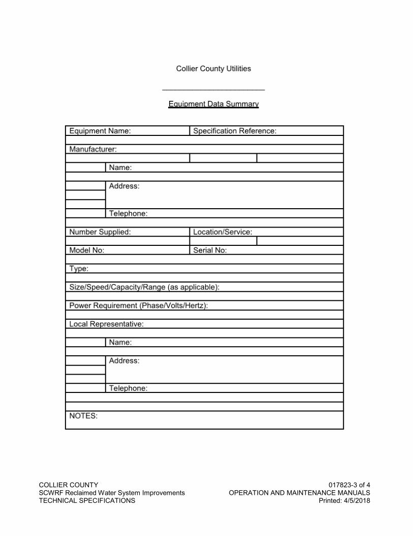
COLLIER COUNTY 017823-3 of 4 SCWRF Reclaimed Water System Improvements OPERATION AND MAINTENANCE MANUALS TECHNICAL SPECIFICATIONS Printed: 4/5/2018
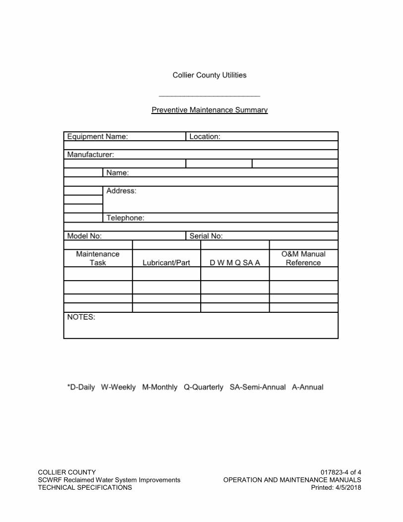
COLLIER COUNTY 017823-4 of 4 SCWRF Reclaimed Water System Improvements OPERATION AND MAINTENANCE MANUALS TECHNICAL SPECIFICATIONS Printed: 4/5/2018

COLLIER COUNTY 017839-1 of 4 SCWRF Reclaimed Water System Improvements PROJECT RECORD DOCUMENTS TECHNICAL SPECIFICATIONS Printed: 4/5/2018
SECTION 017839
PROJECT RECORD DOCUMENTS
PART 1 GENERAL
1.1 SECTION INCLUDES
A. Requirements for preparation, maintenance and submittal of project record documents. The Contractor's attention is specifically directed to Part 3.2.B. of this Section, which requires use of a Florida licensed surveyor to sign and seal all record drawings.
1.2 RELATED SECTIONS
A. Section 014500 – Quality Control.
B. Section 022100 – Lines and Grades.
1.3 SUBMITTALS
A. General: Provide all submittals as specified.
B. At Contract close out, three (3) sets of signed and sealed Record Drawings for the potable water OR non-potable irrigation water OR wastewater systems to be conveyed shall be submitted to the County or District. If potable water AND wastewater, AND/OR non-potable irrigation water systems or portion(s) thereof are being conveyed, five (5) sets of signed and sealed Record Drawings shall be submitted to the County.
C. Provide electronic submittal as specified in Part 3.02.B of this Section.
1.4 REQUIREMENTS (For County Capital Projects Only)
A. Contractor shall maintain at the site for the County one record copy of: 1. Drawings. 2. Specifications. 3. Addenda. 4. Change orders and other modifications to the Contract. 5. Design Engineer’s field orders or written instructions. 6. Approved shop drawings, working drawings and samples. 7. Field test records.
PART 2 PRODUCTS
Not used.
PART 3 EXECUTION
3.1 MAINTENANCE OF DOCUMENTS AND SAMPLES
A. Project record documents shall be stored in Contractor’s field office or other location approved by the County apart from documents used for construction.
B. Maintain documents in a clean, dry, legible condition and in good order. Do not use record documents for construction purposes.
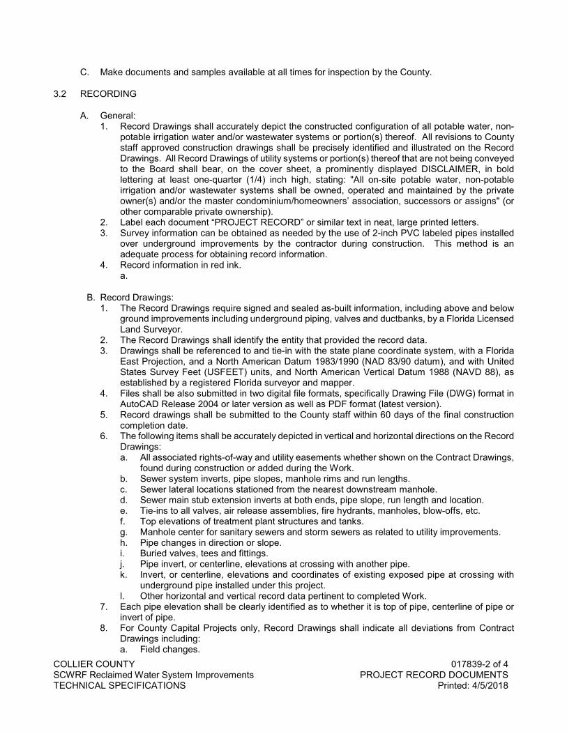
COLLIER COUNTY 017839-2 of 4 SCWRF Reclaimed Water System Improvements PROJECT RECORD DOCUMENTS TECHNICAL SPECIFICATIONS Printed: 4/5/2018
C. Make documents and samples available at all times for inspection by the County.
3.2 RECORDING
A. General: 1. Record Drawings shall accurately depict the constructed configuration of all potable water, non-
potable irrigation water and/or wastewater systems or portion(s) thereof. All revisions to County staff approved construction drawings shall be precisely identified and illustrated on the Record Drawings. All Record Drawings of utility systems or portion(s) thereof that are not being conveyed to the Board shall bear, on the cover sheet, a prominently displayed DISCLAIMER, in bold lettering at least one-quarter (1/4) inch high, stating: "All on-site potable water, non-potable irrigation and/or wastewater systems shall be owned, operated and maintained by the private owner(s) and/or the master condominium/homeowners’ association, successors or assigns" (or other comparable private ownership).
2. Label each document “PROJECT RECORD” or similar text in neat, large printed letters. 3. Survey information can be obtained as needed by the use of 2-inch PVC labeled pipes installed
over underground improvements by the contractor during construction. This method is an adequate process for obtaining record information.
4. Record information in red ink. a.
B. Record Drawings: 1. The Record Drawings require signed and sealed as-built information, including above and below
ground improvements including underground piping, valves and ductbanks, by a Florida Licensed Land Surveyor.
2. The Record Drawings shall identify the entity that provided the record data. 3. Drawings shall be referenced to and tie-in with the state plane coordinate system, with a Florida
East Projection, and a North American Datum 1983/1990 (NAD 83/90 datum), and with United States Survey Feet (USFEET) units, and North American Vertical Datum 1988 (NAVD 88), as established by a registered Florida surveyor and mapper.
4. Files shall be also submitted in two digital file formats, specifically Drawing File (DWG) format in AutoCAD Release 2004 or later version as well as PDF format (latest version).
5. Record drawings shall be submitted to the County staff within 60 days of the final construction completion date.
6. The following items shall be accurately depicted in vertical and horizontal directions on the Record Drawings: a. All associated rights-of-way and utility easements whether shown on the Contract Drawings,
found during construction or added during the Work. b. Sewer system inverts, pipe slopes, manhole rims and run lengths. c. Sewer lateral locations stationed from the nearest downstream manhole. d. Sewer main stub extension inverts at both ends, pipe slope, run length and location. e. Tie-ins to all valves, air release assemblies, fire hydrants, manholes, blow-offs, etc. f. Top elevations of treatment plant structures and tanks. g. Manhole center for sanitary sewers and storm sewers as related to utility improvements. h. Pipe changes in direction or slope. i. Buried valves, tees and fittings. j. Pipe invert, or centerline, elevations at crossing with another pipe. k. Invert, or centerline, elevations and coordinates of existing exposed pipe at crossing with
underground pipe installed under this project. l. Other horizontal and vertical record data pertinent to completed Work.
7. Each pipe elevation shall be clearly identified as to whether it is top of pipe, centerline of pipe or invert of pipe.
8. For County Capital Projects only, Record Drawings shall indicate all deviations from Contract Drawings including: a. Field changes.
COLLIER COUNTY 017839-3 of 4 SCWRF Reclaimed Water System Improvements PROJECT RECORD DOCUMENTS TECHNICAL SPECIFICATIONS Printed: 4/5/2018
b. Changes made by Change Order. c. Details, utilities, piping or structures not on original Contract Drawings. d. Equipment and piping relocations.
C. Specifications and Addenda (For County Capital Projects Only) 1. Legibly mark each Section to record: Manufacturer, trade name, catalog number and supplier of
each product and item of equipment actually installed. 2. Changes made by Field Order or Change Order.
D. Shop Drawings (For County Capital Projects Only) 1. Keep one copy of the final, approved shop drawing with the Record Documents. 2. Record documents should include all shop drawing information submitted. Additional information
submitted during the review process should be filed with the appropriate submittal.
END OF SECTION

COLLIER COUNTY 017839-4 of 4 SCWRF Reclaimed Water System Improvements PROJECT RECORD DOCUMENTS TECHNICAL SPECIFICATIONS Printed: 4/5/2018
NO TEXT FOR THIS PAGE
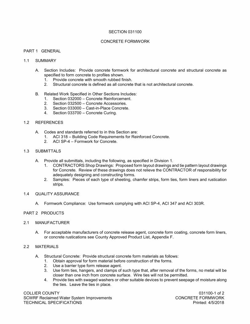
COLLIER COUNTY 031100-1 of 2 SCWRF Reclaimed Water System Improvements CONCRETE FORMWORK TECHNICAL SPECIFICATIONS Printed: 4/5/2018
SECTION 031100
CONCRETE FORMWORK
PART 1 GENERAL
1.1 SUMMARY
A. Section Includes: Provide concrete formwork for architectural concrete and structural concrete as specified to form concrete to profiles shown. 1. Provide concrete with smooth rubbed finish. 2. Structural concrete is defined as all concrete that is not architectural concrete.
B. Related Work Specified in Other Sections Includes: 1. Section 032000 – Concrete Reinforcement. 2. Section 032500 – Concrete Accessories. 3. Section 033000 – Cast-in-Place Concrete. 4. Section 033700 – Concrete Curing.
1.2 REFERENCES
A. Codes and standards referred to in this Section are: 1. ACI 318 – Building Code Requirements for Reinforced Concrete. 2. ACI SP-4 – Formwork for Concrete.
1.3 SUBMITTALS
A. Provide all submittals, including the following, as specified in Division 1. 1. CONTRACTORS Shop Drawings: Proposed form layout drawings and tie pattern layout drawings
for Concrete. Review of these drawings does not relieve the CONTRACTOR of responsibility for adequately designing and constructing forms.
2. Samples: Pieces of each type of sheeting, chamfer strips, form ties, form liners and rustication strips.
1.4 QUALITY ASSURANCE
A. Formwork Compliance: Use formwork complying with ACI SP-4, ACI 347 and ACI 303R.
PART 2 PRODUCTS
2.1 MANUFACTURER
A. For acceptable manufacturers of concrete release agent, concrete form coating, concrete form liners, or concrete rustications see County Approved Product List, Appendix F.
2.2 MATERIALS
A. Structural Concrete: Provide structural concrete form materials as follows: 1. Obtain approval for form material before construction of the forms. 2. Use a barrier type form release agent. 3. Use form ties, hangers, and clamps of such type that, after removal of the forms, no metal will be
closer than one inch from concrete surface. Wire ties will not be permitted. 4. Provide ties with swaged washers or other suitable devices to prevent seepage of moisture along
the ties. Leave the ties in place.
COLLIER COUNTY 031100-2 of 2 SCWRF Reclaimed Water System Improvements CONCRETE FORMWORK TECHNICAL SPECIFICATIONS Printed: 4/5/2018
5. Use lugs, cones, washers, or other devices that do not leave holes or depressions greater than 7/8-inch in diameter.
PART 3 EXECUTION
3.1 DESIGN
A. Design Responsibility: Be responsible for the design, engineering and construction of the architectural concrete formwork and the structural concrete formwork. Conform the work to the recommendations of ACI SP-4 and ACI 303R.
B. Setting Time and Slag Use: The presence of fly ash or ground granulated blast furnace slag in the concrete mix for architectural concrete and structural concrete will delay the setting time. Take this into consideration in the design and removal of the forms.
C. Responsibility During Placement: Assume and take sole responsibility for adequate design of all form elements for support of the wet concrete mixtures specified and delivered.
D. Consistency: Design forms to produce concrete members identical in shape, lines and dimensions to members shown.
3.2 CONSTRUCTION DETAILS FOR FORMWORK
A. Structural Concrete Details: Follow the following details for all structural concrete: 1. Provide forms that are substantial, properly braced, and tied together to maintain position and
shape and to resist all pressures to which they may be subjected. Make forms sufficiently tight to prevent leakage of concrete.
2. Determine the size and spacing of studs and wales by the nature of the work and the height to which concrete is placed. Make forms adequate to produce true, smooth surfaces with not more than 1/8-inch variation in either direction from a geometrical plane. Provide horizontal joints that are level, and vertical joints, which are plumb.
3. Supply forms for repeated use in sufficient number to ensure the required rate of progress. 4. Thoroughly clean all forms before reuse and inspect forms immediately before concrete is placed.
Remove deformed, broken, or defective forms from the work. 5. Provide temporary openings in forms at convenient locations to facilitate cleaning and inspection. 6. Coat the entire inside surfaces of forms with a suitable form release agent just prior to placing
concrete. Form release agent is not permitted on the reinforcing steel. 7. Assume and take responsibility for the adequacy of all forms and remedying any defects resulting
from their use.
3.3 FORM REMOVAL
A. Structural Concrete Form Removal: Do not remove forms for structural concrete until the concrete has hardened sufficiently to support its own load safely, plus any superimposed load that might be placed thereon.
3.4 TOLERANCES
A. Tolerance Limits: Design, construct and maintain concrete form and place the concrete to provide completed concrete work within the tolerance limits set forth in ACI SP-4.
END OF SECTION
COLLIER COUNTY 032000-1 of 4 SCWRF Reclaimed Water System Improvements CONCRETE REINFORCEMENT TECHNICAL SPECIFICATIONS Printed: 4/5/2018
SECTION 032000
CONCRETE REINFORCEMENT
PART 1 GENERAL
1.1 SUMMARY
A. Section Includes: Requirements for providing concrete reinforcement as shown and specified herein. Reinforcement includes all steel bars, wire and welded wire fabric as shown and specified.
B. Related Work Specified in Other Sections Includes: 1. Section 031100 – Concrete Formwork. 2. Section 032500 – Concrete Accessories. 3. Section 033000 – Cast-in-Place Concrete. 4. Section 033700 – Concrete Curing. 5. Section 034100 – Precast Concrete Structures.
1.2 REFERENCES
A. Codes and standards referred to in this Section are: 1. ACI SP66 - ACI Detailing Manual. 2. ACI 318 - Latest edition "Building Code Requirements for Reinforced Concrete". 3. ASTM A 185 - Steel Welded Wire Fabric, Plain, for Concrete Reinforcement. 4. ASTM A 615/A615M - Deformed and Plains Billet-Steel Bars for Concrete. 5. ASTM A 706/A706M - Low Alloy Steel Deformed Bars for Concrete Reinforcement. 6. ASTM A 775/A775M - Epoxy Coated Reinforcing Steel Bars. 7. AWS D1.4 - Structural Welding Code - Reinforcing Steel.
1.3 SUBMITTALS
A. Provide all submittals, including the following, as specified in Division 01. 1. Product Data and Information: Submit manufacturers literature with product data, and material
description of fusion bonded epoxy coating for reinforcement and reinforcement accessories, including manufacturer's recommendations for field touch-up of mars and cut ends when epoxy coated reinforcement is specified to be used.
2. CONTRACTORS' Shop Drawings: Submit checked Working Drawings, including bar lists, schedules, bending details, placing details, and placing plans and elevations for fabrication and placing reinforcing steel conforming to "ACI Detailing Manual SP-66". a. Do not bill wall and slab reinforcing in sections. Show complete elevations of all walls and
complete plans of all slabs, except that, when more than one wall or slab are identical, only one such elevation or plan is required. These plans and elevations need not be true views of the walls or slabs shown. Bill every reinforcing bar in a slab on a plan. Bill every reinforcing bar in a wall on an elevation. Take sections to clarify the arrangement of the steel reinforcement. Identify all bars, but do not bill on such sections.
b. For all reinforcing bars, unless the location of a bar is clear, give the location of such bar or bars by a dimension to some structural feature that will be readily distinguishable at the time bars are placed.
c. Make the reinforcing steel placing drawings complete for placing reinforcement including the location of support bars and chairs, without reference to the design drawings.
d. Submit Detailer certification that every reinforcing steel placing drawing and bar list is completely checked and corrected before submittal for approval.
e. If, after reinforcing steel placing drawings and bar lists have been submitted for approval, a review reveals that the drawings and lists obviously have not been checked and corrected they will be returned for checking and correcting by the Detailer.
COLLIER COUNTY 032000-2 of 4 SCWRF Reclaimed Water System Improvements CONCRETE REINFORCEMENT TECHNICAL SPECIFICATIONS Printed: 4/5/2018
3. Samples: Submit the following samples when epoxy coated reinforcement is specified to be used. a. 12-inch long epoxy-coated steel reinforcing bar, of any size typical to this Project b. One of each type of epoxy-coated reinforcement accessory used on this Project c. 12-inch long, nylon coated tie wire
4. Certificates: Test certificates of the chemical and physical properties covering each shipment of reinforcing steel bars. Test for bars 3/4 inches in diameter and larger shall consist of the bar being bent cold to 90 degrees around a pin 3 times the diameter of the test bar without evidence of cracking.
1.4 DELIVERY, STORAGE, AND HANDLING
A. Deliver, store, and handle all products and materials as specified in Division 1 (and as follows:) 1. Delivery Requirements: Have reinforcing steel delivered to the work in strongly tied bundles.
Identify each group of both bent and straight bars with a metal tag giving the identifying number corresponding to the reinforcing steel placing drawings and bar lists.
2. Storage: Properly store all bars in an orderly manner, with all bars completely off the ground. Keep bars clean after delivery to the site of the work.
PART 2 PRODUCTS
2.1 MANUFACTURERS
A. The brand of manufacturer shall be legibly rolled on all bars, and when loaded for mill shipment, all bars shall be properly separated and tagged with manufacturer's test identification number.
B. For acceptable manufacturers of mechanical connections see County Approved Product List, Appendix F.
2.2 MATERIALS
A. Steel Bars: Use new billet steel bars, deformed bars, meeting the requirements of ASTM A615/A625M Grade 60 for reinforcing steel bars. 1. Roll all reinforcing steel bars with special deformations or identifying marks indicating the ASTM
Specification and Grade. 2. Use bars free from defects, kinks and from bends that cannot be readily and fully straightened in
the field. 3. Supply reinforcing bars in lengths that will allow convenient placement in the work and provide
the required length of at least 40 diameters of lap of joints as shown. Provide dowels of proper length, size and shape for tying walls, beams, floors, and the like together.
B. Epoxy Coating: Conform fusion bonded epoxy coated reinforcing steel bars to ASTM A775/A775M when used. Leave portions of the reinforcing steel bars uncoated where mechanical connections are shown.
C. Welded Wire Fabric: Use welded wire fabric of the electrically welded type, with wires arranged in rectangular patterns, of the sizes shown or specified and meeting the requirements of ASTM A185.
D. Supports and Accessories: Provide bar supports and other accessories and, if necessary, additional supports to hold bars in proper position while concrete is being placed. 1. Use side form spacers against vertical or sloping forms to maintain prescribed side cover and
cross position of bars. 2. Use individual hi-chairs with welded cross ties or circular hoops to support top bars in slabs thicker
than 8 inches. 3. Bolsters, chairs and other accessories:
COLLIER COUNTY 032000-3 of 4 SCWRF Reclaimed Water System Improvements CONCRETE REINFORCEMENT TECHNICAL SPECIFICATIONS Printed: 4/5/2018
a. Use hot-dipped galvanized or provide plastic coated legs when in contact with forms for surfaces of concrete other than architectural surfaces.
b. Use stainless steel when in contact with forms for architecturally exposed surfaces. c. Use epoxy coated bolsters, chairs and accessories including wire ties for epoxy coated
reinforcing bars. d. Use chairs of an approved type and space them properly to support and hold reinforcing
bars in position in all beams and slabs including slabs placed directly on the subgrade or work mat. Do not use continuous hi-chairs for supporting of top bars in slabs over 8 inches in thickness.
E. Mechanical Connections: Provide mechanical connections that develop at least 125 percent of the specified yield strength of the bar in tension.
F. Stirrups and Ties: Provide stirrups and ties as shown and specified and meeting the requirements of ASTM A185.
2.3 FABRICATION
A. Drawing Review Prior to Fabrication: Do not fabricate any material before final review and approval of shop drawings.
B. Bending and Cutting: Cut bars to required length and bend accurately before placing. Bend bars in the shop unless written approval for field bending is obtained. If field bending is permitted, do it only when the air temperature, where the bending operation is performed, is above 30 degrees F. Do not field bend bars that have been partially embedded in concrete.
C. Splices: Use lapped splices for tension and compression splices unless otherwise noted.
D. Cleaning: Clean and bend reinforcement in accordance with ACI 315 and ACI 318.
PART 3 EXECUTION
3.1 INSTALLATION
A. Placement: Place all bars in accordance with CRSI "Recommended Practice for Placing Reinforcing Bars".
B. Tolerances: Place bars used for top reinforcement in slabs to a vertical tolerance of plus or minus 1/4-inch. Place all other reinforcement to the tolerances given to ACI 318.
C. Cleaning: Have reinforcing steel delivered without rust other than that accumulated during transportation to the work. At all times, fully protect reinforcing steel from moisture, grease, dirt, mortar and concrete. Before being placed in position, thoroughly clean reinforcing steel of all loose mill scale and rust and of any dirt, oil, grease coatings, or other material that might reduce the bond. If there is a delay in depositing concrete, inspect and satisfactorily clean the steel immediately before the concrete is placed.
D. Bar Positioning: Place bars in the exact positions shown with the required spacing and cross wire bars securely in position at intersections to prevent displacement during the placing of the concrete. Fasten the bars with annealed wire of not less than 17 gauge or other approved devices.
E. Bar Extension Beyond Formwork: On any section of the work where horizontal bars extend beyond the length of the forms, perforate the form or head against which the work ends or at the proper places to allow the bars to project through a distance at least equal to the lap specified.

COLLIER COUNTY 032000-4 of 4 SCWRF Reclaimed Water System Improvements CONCRETE REINFORCEMENT TECHNICAL SPECIFICATIONS Printed: 4/5/2018
F. Unacceptable Materials: Do not place reinforcing steel with damaged, unsuitably bonded epoxy coating or rusting. If approved, mars, exposed threads of mechanical connections and cut ends may be field coated with approved epoxy coating material.
G. Review of Placement: Have reinforcing placement reviewed by the ENGINEER before concrete is placed.
H. Welding - Not Approved: Do not use reinforcing bar assemblies made by welding of any kind, or accessories of any kind which require field welding to reinforcing bars.
I. Welding - Approved: Where welding of reinforcing steel is shown, AWS D1.4 "Structural Welding Code - Reinforcing Steel" applies.
J. Tension and Compression Lap Splices: Conform tension and compression lap splices to ACI 318 with all supplements. Avoid splices at points of maximum tensile stress wherever possible. Provide temperature bars with the clear spacing shown. Stagger all bar splices in hoop tension bars in circular tanks with not more than 50 percent of the bars spliced in any one direction. Have welded splices made by certified welders in accordance with AWS D1.4.
K. Welded Wire Fabric: Place welded wire fabric in the positions shown, specified, or required to fit the work. Furnish and place suitable spacing chairs or supports, as specified for bars, to maintain the fabric in the correct location. Where a flat surface of fabric is required, provide flat sheets, when available. Otherwise reverse roll the fabric or straighten to make a perfectly flat surface before placing. Obtain approval for the length of laps not indicated.
L. Concrete Cover: Place reinforcing steel and welded wire fabric and hold in position so that the concrete cover, as measured from the surface of the bar or wire to the surface of the concrete, is as shown or specified.
END OF SECTION
COLLIER COUNTY 032500-1 of 4 SCWRF Reclaimed Water System Improvements CONCRETE ACCESSORIES TECHNICAL SPECIFICATIONS Printed: 4/5/2018
SECTION 032500
CONCRETE ACCESSORIES
PART 1 GENERAL
1.1 SUMMARY
A. Forming expansion, contraction and control joints.
B. Furnishing and installing waterstops.
C. Furnishing and installing anchors and inserts.
1.2 REFERENCE STANDARDS
A. ASTM D994 - Preformed Expansion Joint Filler for Concrete (Bituminous Type).
1.3 SUBMITTALS
A. Submit Shop Drawings, product data and manufacturers' information in accordance with Section 013300.
B. Expansion and/or Contraction Joints: Submit 12-inch long sample and manufacturer's installation instructions.
C. Waterstops: Submit the following: 1. Samples and catalog cuts. 2. Manufacturer's installation and splicing instructions. 3. Shop Drawings showing lengths, locations and splicing points.
D. Anchors and Inserts: Submit product data and manufacturer's installation instructions.
PART 2 PRODUCTS
2.1 ACCEPTABLE MANUFACTURERS
A. Specification includes references to designated manufacturers to illustrate minimum acceptable requirements for products.
B. Substitutions: Products of equal or better quality, detail, function and performance may be proposed for substitution by following the procedures in Section 016100.
2.2 INTEGRAL JOINT MATERIALS
A. Formed Control Joints: Extruded plastic; tongue and groove type profile, with removable top strip exposing sealant trough; knockout holes at 6-inch centers to receive doweling; with anchors.
2.3 PREMOLDED ASPHALT EXPANSION JOINT FILLER
A. Joint: Asphalt with vegetable fibers, mineral fillers and two (2) asphalt-saturated felt liners, complying with ASTM D994.
COLLIER COUNTY 032500-2 of 4 SCWRF Reclaimed Water System Improvements CONCRETE ACCESSORIES TECHNICAL SPECIFICATIONS Printed: 4/5/2018
B. Uses: Provide at joints in and between sidewalks, driveways, curbs, castings, hydrants, building walls, steps, and at other locations shown on the Drawings.
C. Dimensions: Unless otherwise shown on the Drawings: Thickness - 1/2 inch; Depth - Thickness of concrete minus 1/4 inch.
2.4 WATERSTOPS
A. Ribbed Design: Extruded virgin polyvinyl chloride as manufactured by Paul Murphy Plastics Co. Use of reclaimed materials is not acceptable.
B. Cold Joint Waterstop: Self-adhering volclay joint sealant. Cross section dimensions 1 inch by 3/4 inch. Waterstop-RX as manufactured by American Colloid Co. RX primer as manufactured by American Colloid Co.
2.5 SEALANTS
A. Sealant and Primer: Specified in Section 07900.
2.6 ANCHORS AND INSERTS
A. Expansion anchors used for fastening material to concrete, concrete block, brick and stone: Rawl anchors as manufactured by The Rawlplug Company, Inc.
B. Anchor bolts and inserts shall be of the size, length and material required by the equipment or material manufacturers and/or as shown on the Drawings.
PART 3 EXECUTION
3.1 EXPANSION, CONTRACTION AND CONTROL JOINT INSTALLATION
A. Locate and form expansion, contraction and control joints.
B. Place formed control joints in floor slab pattern placement sequence. Set top screed to required elevations. Secure joint material to resist movement of wet concrete.
C. Install joint fillers in accordance with manufacturer's instructions.
D. Apply primers and sealants in accordance with Section 07900.
3.2 WATERSTOP INSTALLATION
A. Provide waterstops at all construction joints in watertight construction and where indicated on the Drawings. Watertight construction means construction which has at least one of its sides in contact with a liquid. Install waterstops to form a continuous watertight seal in the joint. Adequately support and protect waterstops during the course of the Work, to insure proper location and function. Install waterstops in as long lengths as practicable. Join waterstops in compliance with manufacturer's splicing instructions. Waterstops in floor and wall joints shall be joined to waterstops in wall footings.
B. Cold Joint Waterstop: Apply and fasten material directly to the joint using primer or cut nails to securely adhere the material in a location which will result in the material being contained within the joint after the concrete is placed.
3.3 ANCHOR AND INSERT INSTALLATION
COLLIER COUNTY 032500-3 of 4 SCWRF Reclaimed Water System Improvements CONCRETE ACCESSORIES TECHNICAL SPECIFICATIONS Printed: 4/5/2018
A. Expansion anchors shall be installed in predrilled holes in accordance with manufacturer's installation instructions.
B. Inserts shall be installed in accordance with the manufacturer's recommendations and instructions.
C. Anchor bolts shall be preset in locations shown on the Drawings using templates. .
END OF SECTION

COLLIER COUNTY 032500-4 of 4 SCWRF Reclaimed Water System Improvements CONCRETE ACCESSORIES TECHNICAL SPECIFICATIONS Printed: 4/5/2018
NO TEXT FOR THIS PAGE
COLLIER COUNTY 033000-1 of 12 SCWRF Reclaimed Water System Improvements CAST-IN-PLACE CONCRETE TECHNICAL SPECIFICATIONS Printed: 6/6/2019
SECTION 033000
CAST-IN-PLACE CONCRETE
PART 1 GENERAL
1.1 SUMMARY
A. Cast-in-place concrete as shown on the Drawings or specified herein, including but not limited to:
B. Building frame members, foundation walls and supported slabs.
C. Tankage and chambers.
D. Slabs on grade.
E. Equipment pads, pole bases, site structures, etc.
F. Concrete toppings.
G. Admixtures, bonding agents and adhesives.
1.2 REFERENCE STANDARDS
A. AASHTO T26 - Quality of Water to be Used in Concrete.
B. ACI 211 - Recommended Practice for Selecting Proportions for Normal and Heavyweight Concrete.
C. ACI 301 - Structural Concrete for Buildings.
D. ACI 305 - Recommended Practice for Hot Weather Concreting.
E. ACI 318 - Building Code Requirements for Reinforced Concrete.
F. ACI SP-15 - Field Reference Manual Publication (ACI 301).
G. ASTM C31 - Making and Curing Concrete Test Specimens in the Field.
H. ASTM C33 - Concrete Aggregates.
I. ASTM C39 - Compressive Strength of Cylindrical Concrete Specimens.
J. ASTM C40 - Organic Impurities in Fine Aggregates for Concrete.
K. ASTM C42 - Obtaining and Testing Drilled Cores and Sawed Beams of Concrete.
L. ASTM C94 - Ready-Mixed Concrete.
M. ASTM C138 - Unit Weight, Yield and Air Content (Gravimetric) of Concrete.
N. ASTM C143 - Slump of Portland Cement Concrete.
O. ASTM C150 - Portland Cement.
COLLIER COUNTY 033000-2 of 12 SCWRF Reclaimed Water System Improvements CAST-IN-PLACE CONCRETE TECHNICAL SPECIFICATIONS Printed: 6/6/2019
P. ASTM C172 - Sampling Fresh Concrete.
Q. ASTM C192 - Making and Curing Concrete Test Specimens in the Laboratory.
R. ASTM C231 - Air Content of Freshly Mixed Concrete by the Pressure Method.
S. ASTM C494 - Chemical Admixtures for Concrete.
T. Truck Mixer Manufacturer's Bureau - Truck Mixer and Agitating Standards.
1.3 SUBMITTALS
A. Submit the following data for review prior to initiation of concrete work in accordance with Section 013300: 1. Name, address and telephone number of concrete supplier and the batching plant. 2. Concrete design mix, material test reports and other data required under Article 1.5 DESIGN
MIXES. 3. Methods for conveying and placing concrete. 4. Gradations of aggregates. 5. Catalog cuts, technical data and manufacturers' recommendations on quantities and use of
admixture. 6. Certification that water meets the requirements of Article 2.6 MIXING WATER and identification
of water source. 7. Catalog cuts, technical data and manufacturers' recommendations on quantities, use and
applications of adhesives, hardeners, and other materials proposed for use. 8. Drawings showing locations of all proposed construction joints. 9. Description of hot and cold weather practices to be employed.
B. Submit transit-mix delivery slips with each truck load at project site.
1.4 QUALITY ASSURANCE
A. The CONTRACTOR shall have, and be completely familiar with, a copy of the Field Reference Manual Publication SP-15 (ACI 301) at the job site during construction. To obtain ACI publications, write: American Concrete Institute, P.O. Box 19150, Detroit, Michigan 48219.
B. Provide at least one person who shall be present at all times during execution of this portion of the Work and who shall be thoroughly trained and experienced in placing the types of concrete specified and who shall direct all work performed under this Section.
C. For finishing of exposed concrete, use only thoroughly trained and experienced concrete finishers.
D. Comply with all recommendations and requirements of ACI Publication ACI 318.
E. Perform Work in accordance with ACI 301.
F. To further insure uniform consistency, coloring, finish, and quality, all aggregates, cement, water and other ingredients shall each be obtained from the same source for the duration of the Project.
G. Provide proper facilities at the concrete batch plant and at the construction site for ENGINEER or his testing laboratory consultant to secure samples, to inspect ingredients and processes used in batching, methods of delivering; and, for securing and curing sample test cylinders at the site.
COLLIER COUNTY 033000-3 of 12 SCWRF Reclaimed Water System Improvements CAST-IN-PLACE CONCRETE TECHNICAL SPECIFICATIONS Printed: 6/6/2019
1.5 DESIGN MIXES
A. At least 35 days prior to the initial placement of concrete, submit concrete design mixes to ENGINEER for his acceptance. Except where otherwise specified, the design of mixes shall be in accordance with ACI 211.
B. Submit the following with the design mixes: 1. Mix proportions. 2. Source of cement, type, brand and certified copies of Mill reports, including physical and chemical
analyses. 3. Source of fine aggregates and results of tests made in accordance with ASTM C33 and ASTM
C40. 4. Sources of coarse aggregates and results of tests made in accordance with ASTM C33. 5. For each mix proposed, make and cure four standard 6-inch diameter concrete test specimens
in the laboratory in accordance with ASTM C192. Furnish compression test results made in accordance with ASTM C39. Break one cylinder at 7 days and three at 28 days.
6. Copies of 7-day and 28-day compression test results from other recent projects for which the specified concrete mix was used.
C. CONTRACTOR'S testing laboratory shall develop concrete mix designs and test all materials and mixes for conformance with this Specification.
D. ENGINEER may accept the use of previously established design mixes if all test results, made within the last six months by a recognized testing laboratory, are positive and provide sufficient evidence of full compliance with this Specification. If ENGINEER determines that insufficient documentation and test results exist, he may request additional testing or he may request a new design mix with complete testing.
E. If the adopted mix fails to produce concrete meeting the requirements for strength and placability, ENGINEER may order additional cement or adjustments to mix proportions.
1.6 ENVIRONMENTAL REQUIREMENTS
A. Only place concrete when environmental conditions are satisfactory. Do not place concrete when conditions may adversely affect the placing, finishing or curing of concrete, or its strength.
1.7 SCHEDULING
A. Formwork and steel reinforcing installation shall be completed at least 24 hours in advance of placing concrete.
B. Notify ENGINEER upon completion of formwork and completion of steel reinforcing installation.
C. Notify ENGINEER at least 24 hours in advance of placing concrete.
PART 2 PRODUCTS
2.1 ACCEPTABLE MANUFACTURERS
A. Specification includes references to designated manufacturers to illustrate minimum acceptable requirements for products.
B. Substitutions: Products of equal or better quality, detail, function and performance may be proposed for substitution by following the procedures in Section 016100.
COLLIER COUNTY 033000-4 of 12 SCWRF Reclaimed Water System Improvements CAST-IN-PLACE CONCRETE TECHNICAL SPECIFICATIONS Printed: 6/6/2019
2.2 CONCRETE
A. Unless otherwise specified, all concrete exposed to weather, or in structures to contain water or sewage shall be a minimum of 4,000 psi concrete. Concrete fill used under structures shall be a minimum 2,500 psi concrete. All other concrete shall be a minimum of 3,500 psi concrete.
B. Concrete shall conform to the following requirements:
Min. 28-Day Compressive Strength (psi) 4,000 3,500 2,500 Max. Water-Cement Ratio (lb./lb.) 0.44 0.51 0.67 Min. Cement Factor (Sacks/C.Y.) 5.8 5.5 5.0 Entrained Air Content (%) 4-6 4-6 2-5 Slump (Inches) 3-5 3-5 3-5
2.3 CEMENT
A. Portland Cement - ASTM C150, Type II unless otherwise specified.
B. Use of air-entraining cement is prohibited. Other types of cements are prohibited without the prior review and acceptance by ENGINEER.
C. Use only one brand of cement. Color variations which affect the appearance of exposed concrete are unacceptable.
2.4 AGGREGATES
A. Fine Aggregate - ASTM C33.
B. Coarse Aggregate - ASTM C33, 3/4-inch maximum size for structural concrete.
2.5 ADMIXTURES
A. Air Entraining: "Darex AEA," by W.R. Grace or "Pozzolith MB-VR" by Master Builders.
B. Water Reducing Retarder: ASTM C494, "Plastiment" by Sika Chemical Corporation or "Pozzolith 322N" by Master Builders. Quantity of retarder to be added per sack of cement shall be as recommended by the approved manufacturer as required for actual ambient or mix temperatures.
C. Water Reducing: "WRDA with Hycol" by W.R. Grace or "Pozzolith 100N" by Master Builders.
D. No other admixtures are permitted without the prior review and acceptance by ENGINEER.
E. Admixtures shall be compatible with one another and with aggregates, cement, finishing materials, and other materials which may be affected.
2.6 MIXING WATER
A. Water shall be fresh, clean and potable. Water known to be of potable quality may be used without tests. Water of questionable quality shall be tested in accordance with AASHTO T26.
2.7 SAND-CEMENT GROUT
A. Sand-Cement Grout: 3 parts sand to 1 part cement.
COLLIER COUNTY 033000-5 of 12 SCWRF Reclaimed Water System Improvements CAST-IN-PLACE CONCRETE TECHNICAL SPECIFICATIONS Printed: 6/6/2019
2.8 CONCRETE MORTAR
A. Concrete mortar shall have the following proportions: 1. Portland Cement: 1 part. 2. Fine Aggregate: 2-1/4 to 3 times the volume of the cement.
B. The fine aggregate shall have the following gradation:
Sieve Size Percent Passing 3/8 inch 100
No. 4 95 - 100 No. 8 80 - 100 No. 16 50 - 85 No. 30 25 - 60 No. 50 10 - 30
No. 100 2 - 10
2.9 CONCRETE FILL
A. Concrete fill within structures shall be: 1. Fill less than 3 inches thick - concrete mortar. 2. Fill more than 3 inches thick - minimum 3500 psi concrete.
PART 3 EXECUTION
3.1 INSPECTION
A. Inspect all formwork and verify that it has been properly set and is ready for the placement of concrete.
B. Verify that all reinforcing has been properly set and secured and that items to be embedded in, built-in, or passed through concrete are at their proper locations and elevations.
C. Before placing concrete, verify that all piping, conduits and other work to be installed within concrete or below slabs on grade have been installed and have received and passed all required tests and inspections.
3.2 PREPARATION
A. Remove all wood and wood scraps, sawdust, hardened concrete, construction debris, and other foreign materials from and between forms and from other areas in which concrete will be placed.
B. Remove water from forms and excavations and divert flows of water to avoid washing over, under or through freshly deposited concrete.
C. Earth subgrades to receive concrete shall be clean, undisturbed surfaces, free from mud, debris and standing or running water.
D. Rock subgrades shall be approximately level and sufficiently rough for satisfactory bond with the concrete. Clean out faults and seams and clean rock surfaces of coatings and materials which may reduce bonding of the concrete to the rock.
E. Prepare previously placed concrete by cleaning surfaces of set concrete and apply sand-cement grout or bonding agent in accordance with paragraph 3.09 BONDING.
COLLIER COUNTY 033000-6 of 12 SCWRF Reclaimed Water System Improvements CAST-IN-PLACE CONCRETE TECHNICAL SPECIFICATIONS Printed: 6/6/2019
F. At locations where new concrete is doweled to existing work, drill holes of twice dowel diameter at a 30-degree downward angle in existing concrete, clean hole thoroughly with compressed air, fill hole with epoxy grout, and insert steel dowels into grout filled hole.
G. Thoroughly clean concrete transporting and handling equipment. Prepare runways for wheeled equipment. Wheeled equipment shall not run upon, nor shall runways or supports bear upon, reinforcing steel or fresh concrete.
H. Verify that environmental conditions are and will remain satisfactory throughout the period when concrete will be placed, finished, and cured.
I. Should ENGINEER permit the placement of concrete during inclement weather, store required protective materials on site and use as required.
J. Verify all scheduling to ensure that the concrete will be placed continuously, without delay or interruption.
K. Verify that ENGINEER has completed all tests and inspections prior to placement of concrete.
3.3 BUILT-IN ITEMS
A. General: Make all necessary provisions for the forming and setting of all items to be built into concrete work. Locate items so that they will not impair the strength or stability of any structural member.
B. Pipe and Conduit in Slabs: In structural slabs less than 4 inches thick, pipes or conduits having an outside diameter (OD) over 1 inch are prohibited. In structural slabs 4 inches and thicker, the OD shall not exceed 1-3/8 inches. Where pipe and conduit are permitted in the slab, the center-to-center spacing shall not be closer than 3 x OD and in no case, less than 2 inches clear.
C. Junction Boxes in Slabs: Junction boxes are not permitted in slabs less than 4 inches thick. Junction boxes in slabs 4 inches and thicker shall not exceed 4-1/2 inches in width and length, and 2 inches in depth. When placed flush with the bottom in the middle half of the span of slabs, the boxes shall be separated by at least 6 inches of concrete. When placed outside the middle half of the span, they shall be separated by at least 2 inches of concrete.
D. Openings in Slabs: Provide openings and depressions in slabs to the sizes and at the locations shown on the Drawings. Verify that additional reinforcing has been placed around opening.
3.4 MIXING CONCRETE
A. All cast-in-place concrete shall be transit-mix concrete in accordance with ASTM C94.
B. Do not mix or agitate batches of greater volume than maximum capacities on the mixer manufacturer's rating plate.
C. Mix or agitate at drum speeds within rating plate tolerances.
D. Continue mixing until a uniform concrete is produced, using between 70 to 100 revolutions of the drum. The use of concrete which is not uniformly mixed in 15 minutes or less, is prohibited.
E. When Type II cement is used, elapsed time between initial contact of the cement with water and the completed discharge of the batch at the Project site shall not exceed 1-1/2 hours or 300 revolutions of the drum, whichever comes first. Reduce the above limits when conditions result in quick-stiffening of the concrete, or when directed by ENGINEER.
COLLIER COUNTY 033000-7 of 12 SCWRF Reclaimed Water System Improvements CAST-IN-PLACE CONCRETE TECHNICAL SPECIFICATIONS Printed: 6/6/2019
F. Retempering of concrete is not permitted.
3.5 PLACING CONCRETE
A. Weather Conditions: Do not place concrete when weather conditions are not suitable for the proper placing, finishing or curing of the concrete. Unless otherwise accepted by ENGINEER, place concrete only during dry weather. In the event of sudden rainstorms, cover exposed, freshly placed concrete and protect from damage. When cold or hot weather concreting is authorized by ENGINEER, comply with Article 3.6 HOT WEATHER PLACEMENT.
B. Consistency and Quality of Concrete: Mix, transport and place concrete so as to maintain proper consistency, to avoid segregation, and to insure placement in final position before initial set takes place. Retempering of concrete is prohibited. Control the rate of placement so that the concrete remains plastic and flows readily into spaces between the reinforcing bars, and can be worked into corners and around inserts without forming voids.
C. Conveying and Placing Concrete: Convey concrete to the forms as rapidly as practicable, utilizing methods which will not cause segregation or loss of ingredients. Free fall from mixer or truck to conveyance shall not exceed 3 feet. When placing concrete in final position, the free fall shall not exceed 5 feet. Place concrete in horizontal layers approximately 2 feet thick and avoid the formation of cold joints and poorly bonded sections between layers. The horizontal distribution of concrete by spading or vibration is prohibited.
D. Vibration: Unless otherwise specified or directed by ENGINEER, vibrate all reinforced concrete. Use only approved mechanical vibrators operated by experienced operators. Apply vibrators at uniformly spaced points not further apart than the visible effectiveness of the machine. Vibrate concrete sufficiently to produce satisfactory consolidation without causing segregation. Do not use vibrators to transport concrete in the forms or insert them into lower layers of concrete that have begun to set.
E. At least 48 hours shall elapse before depositing new concrete against previously placed concrete.
F. All slabs on grade shall be placed in alternate panels not exceeding 900 square feet.
3.6 HOT WEATHER PLACEMENT
A. Do not place concrete when the temperature of the concrete is 85ΕF. or greater, or the ambient temperature is above 90ΕF.
B. When hot weather placement of the concrete is authorized in writing by ENGINEER, comply with the recommended practices of ACI 305.
3.7 CONSTRUCTION JOINTS
A. General: The approximate locations of construction joints are indicated on the Drawings. Submit shop drawings of proposed locations and methods of forming joints with reinforcing steel shop drawing submittal. Locate joints such that the strength and appearance of the structure is not impaired. Make provisions for the transferring of shear and other forces through construction joints.
B. Columns, Piers and Walls: Make joints in columns and piers at the underside of the deepest girder or beam framing. In walls having door and window openings terminate the lifts of individual pours at the top or bottom of opening. Terminate other lifts at such levels as indicated or as required to conform to structural requirements or architectural details, or both.
COLLIER COUNTY 033000-8 of 12 SCWRF Reclaimed Water System Improvements CAST-IN-PLACE CONCRETE TECHNICAL SPECIFICATIONS Printed: 6/6/2019
C. Maximum Spacing of Joints: Unless otherwise accepted by ENGINEER, the distance between construction joints shall not exceed the following: 1. Walls and Grade Beams - Thirty (30) feet. 2. Foundation Slabs and Slabs on Grade - Thirty (30) feet. 3. Structural Slabs - Twenty-five (25) feet.
D. Foundation Slabs and Slabs on Grade: Reinforcing steel shall be continuous through construction joints and adequately supported above the subgrade.
E. Waterstops: Provide waterstops at all construction joints in watertight construction and where indicated on the Drawings. See Section 032500.
F. Shear Keys: Provide shear keys in all construction joints. Unless otherwise shown on Drawings, keyways shall be at least 1-1/2 inches deep and 1/3 the width of the member located in the center of the member; construct shear key by installing tapered form stock. Cutting in keyways or removing key form before concrete sets is not permitted.
G. When no keyway is required at the construction joints between walls and base mats, the concrete surface shall be roughened by applying non-toxic surface retarder immediately after placement of base mat and removing after 24 hours with medium water pressure.
3.8 BONDING
A. Construction Joints: Before depositing new concrete against concrete which has set, clean surfaces of the set concrete, remove laitance, foreign matter and loose particles, and thoroughly retighten the forms against the previously placed concrete. At vertical joints, coat the surfaces of set concrete with a sand-cement grout. At horizontal surfaces, place a 1/2-inch minimum thick coat of sand-cement grout. Place new concrete before the grout attains initial set.
3.9 CURING CONCRETE
A. Cure concrete in accordance with Section 033700.
3.10 PATCHING CONCRETE
A. General: As soon as forms are removed, patch and repair tie holes and other surface defects.
B. Epoxy Coated Surfaces: Patching of surfaces to receive epoxy coatings is specified in Article 3.12 FINISHING FORMED SURFACES.
C. Preparation: Do not do any patching until all honeycomb and laitance have been removed to solid concrete. If chipping is necessary, chip areas to be patched to a depth of at least 1 inch, with edges regular and perpendicular to the surface, or slightly undercut. Thoroughly wet the prepared areas, including the area 6 inches all around each prepared area, just before applying the patching mortar.
D. Mortar: Mortar for patching shall be of the same materials and proportions used for the concrete, except that the coarse aggregate shall be omitted and a sufficient amount of white cement shall be substituted for the grey cement in order to produce a patch whose color matches the color of the surrounding surfaces. Mortar shall not have less than 1 part cement to 3 parts sand. Keep mixing water to a minimum. Retemper mortar, without addition of water, by occasional mixing to prevent setting. Using mortar which has begun to set or is more than 1 hour old is not permitted.
E. Application of Mortar: Thoroughly compact mortar into place and screed to leave the patch slightly higher than the adjacent surface. Leave undisturbed for one to two hours to permit initial shrinkage
COLLIER COUNTY 033000-9 of 12 SCWRF Reclaimed Water System Improvements CAST-IN-PLACE CONCRETE TECHNICAL SPECIFICATIONS Printed: 6/6/2019
before being finally finished to match adjoining work. Patches exceeding 1 inch in depth shall be filled to within 1 inch of the surface and, after sufficient time has elapsed for shrinkage, final patching shall proceed. Keep all patches wet for at least 5 days.
F. Tie Holes: Solidly fill with mortar all holes left by bolts or ties. Holes passing entirely through the wall shall be filled from the inside face with a device that will force mortar through to the outside face, using a stop held at the outside face to insure complete filling. Holes not passing entirely through walls shall be packed full. Strike off excess mortar flush with adjacent surface.
3.11 FINISHING CONCRETE SLABS
A. General: Surfaces shall be brought to accurate lines and levels to receive subsequent finishes. Unless otherwise indicated on the Drawings or specified herein, make all slabs even and uniform in appearance and, where no slope is required, level within plus or minus 1/8-inch in ten feet. 1. Provide slab depressions where required. 2. Where floor drains or gutters are indicated and where floor slopes are required, slope slabs
uniformly to provide an even fall for drainage.
B. All floor surfaces, including floor surfaces of channels tanks and structures, shall be given a monolithic finish.
C. Do not sprinkle dry cement or mixture of dry cement and sand on the surface to absorb moisture.
D. Where surface is to receive concrete mortar finish (i.e. clarifiers, etc.) screed surface true to grades shown on Drawings.
E. Floor Hardener: All concrete floors to remain exposed and not finished with tile, not specified to be painted, coated or given some other finish, shall be treated with a floor hardener or sealer-hardener. Apply hardener in accordance with the manufacturer's instructions.
3.12 FINISHING FORMED SURFACES
A. Rough Form Finish: Concrete surfaces below grade and other surfaces not exposed to view after construction, shall have fins and rough edges removed. All tie holes and defects shall be patched in accordance with paragraph 3.10 PATCHING CONCRETE. All channels and other surfaces used to convey liquids shall be provided with a smooth form finish, whether or not it may be exposed to view.
B. Smooth Form Finish: Provide a smooth finish on all exterior and interior surfaces exposed to view after construction and on surfaces of channels which will convey a liquid or solid material. As soon as forms are removed, grind all fins and rough edges smooth with adjacent surfaces and patch all voids and tie holes in accordance with paragraph 3.10 PATCHING CONCRETE.
C. Grout Cleaned Finish: Thoroughly wet and brush on a cement grout composed of 1 part cement to 2 parts fine sand, mixed with water to the consistency of heavy cream. Cement shall be light colored to produce a finish matching the color of the concrete. Thoroughly rub grout over the entire area with clean burlap or a sponge rubber float to fill pits and voids completely. While the grout is still plastic, rub the surfaces with a dry mix of the grout until no materials remain on the surface, except within pits and voids. The grouting operation for an area shall be completed the day it is started.
D. Surfaces to Receive Epoxy Coatings: Remove oil and grease, and any curing compounds and other materials which are incompatible with or may adversely affect the bonding of the epoxy coatings. Prepare the concrete surfaces as specified for smooth form finish. Refer to Division 9 for additional surface preparation requirements.
COLLIER COUNTY 033000-10 of 12 SCWRF Reclaimed Water System Improvements CAST-IN-PLACE CONCRETE TECHNICAL SPECIFICATIONS Printed: 6/6/2019
3.13 FIELD QUALITY CONTROL
A. General: All concrete will be sampled, tested and evaluated in accordance with the following paragraphs.
B. The OWNER will be responsible for the following tests at no cost to the CONTRACTOR: 1. Sampling Fresh Concrete: Taking all samples in accordance with ASTM C172, except that
samples of fresh concrete shall be taken from the middle third of each batch. 2. Recording Temperature-Weather: During the placement of all concrete, maintain a record of the
date, time, outside air temperature, temperature of concrete as delivered and after placement, and weather (calm, windy, clear, cloudy, etc.). During cold weather placement, also record temperatures (for 3 days at 8-hour intervals) at several points within enclosures and on concrete surface, corners, and edges in sufficient number to show highest and lowest concrete temperatures.
3. Slump Test: Testing each batch of concrete in accordance with ASTM C143 and when additional water is added.
4. Entrained Air Content: Testing each batch of concrete in accordance with ASTM C231. 5. Compressive Strength: Making and curing one set of four 6-inch diameter 12 inch cylinders in
accordance with ASTM C31 for each 50 cubic yards of concrete placed with at least one set made for each day's placement of concrete. For each set of four test cylinders, one cylinder shall be tested in accordance with ASTM C39 at 7 days, two at 28 days and, if any of the 28-day cylinders are unsatisfactory, the remaining cylinder shall be tested at 42 days.
6. Sampling and Testing: An approved testing laboratory will perform the compressive strength tests, determine the concrete density, and perform concrete corings. ENGINEER may perform the slump and entrained air tests; make, cure and transport concrete test cylinders.
C. Evaluation and Acceptance of Concrete Work: 1. If test cylinders are lost or destroyed, or if cylinder test results indicate low compressive strengths,
or for other reasons ENGINEER questions the adequacy of placed concrete, the concrete shall be tested in accordance with ACI 301 or cored and tested in accordance with ASTM C42.
2. In the event that the concrete does not meet the requirements of these specifications, the CONTRACTOR shall bear all costs associated with retesting as required by the ENGINEER.
3.14 PROTECTION
A. Protect concrete from damage due to sun, rain, flowing water, frost, weather and mechanical injury.
B. Maintain concrete temperature at a minimum of 50 degrees F for not less than 3 days and do not expose concrete to a temperature below 40 degrees F for a minimum of 7 days after placement.
C. Do not subject concrete walls to lateral pressures until the supporting members are placed and cured for a minimum of 14 days with the concrete attaining a minimum of 75 percent of the required 28-day compressive strength. CONTRACTOR shall be responsible for damage to, or misalignment of, walls resulting from earth backfilling, trapped water or other causes.
D. Keep heavy loads away from any wall until the concrete attains its design strength. Place warning markers to prevent encroachment.
E. Finished floors which will not be subsequently finished with tile, carpeting or other topping, shall be covered with a non-absorbent paper, weighing 35 pounds per 100 square feet, or polyethylene sheeting not less than 4 mils thick. Lay paper or sheeting in as large sheets as practicable, with joints lapped at least 4 inches and sealed. Leave covering in place for at least 2 weeks. Areas subject to traffic shall be further protected by means of boardwalks.
COLLIER COUNTY 033000-11 of 12 SCWRF Reclaimed Water System Improvements CAST-IN-PLACE CONCRETE TECHNICAL SPECIFICATIONS Printed: 6/6/2019
3.15 CORRECTING SURFACE DEFECTS
A. All exposed concrete walls shall be finished smooth, aesthetically pleasing, uniform in color and appearance and free from depressions, sags, holes, trowel marks, bumps, projections and other surface imperfections. CONTRACTOR shall perform all repairs, replacements and corrective work which may be required to attain a finish acceptable to ENGINEER, including grinding or painting if necessary.
B. If correction of surface defects is required, submit to ENGINEER the measures and methods proposed.
END OF SECTION

COLLIER COUNTY 033000-12 of 12 SCWRF Reclaimed Water System Improvements CAST-IN-PLACE CONCRETE TECHNICAL SPECIFICATIONS Printed: 6/6/2019
NO TEXT FOR THIS PAGE
COLLIER COUNTY 033700-1 of 2 SCWRF Reclaimed Water System Improvements CONCRETE CURING TECHNICAL SPECIFICATIONS Printed: 4/5/2018
SECTION 033700
CONCRETE CURING
PART 1 GENERAL
1.1 WORK INCLUDED
A. Concrete curing materials and methods.
1.2 REFERENCE STANDARDS
A. ACI 301 - Structural Concrete for Buildings.
B. ASTM C309 - Liquid Membrane-Forming Compounds for Curing Concrete.
C. ASTM D2103 - Polyethylene Film and Sheeting.
1.3 SUBMITTALS
A. Submit product data in accordance with Section 01340.
B. Submit manufacturer's instructions for installation and use.
1.4 QUALITY ASSURANCE
A. Conform to requirements of ACI 301.
B. ENVIRONMENTAL REQUIREMENTS
C. Maintain environmental requirements in accordance with ACI 301.
PART 2 PRODUCTS
2.1 MATERIALS
A. Water: Clean and not detrimental to concrete.
B. Absorptive Mat: Clean, rolled burlap fabric.
C. Polyethylene Sheeting: ASTM D2103, 4-mil thick, clear color.
D. Kraft Paper: Non-staining reinforced Kraft paper coated with not less than 2-mil polyethylene sheeting.
E. Curing Compounds: 1. Liquid Membrane-Forming Curing Compound: ASTM C309, Type I, Class A, applied at 200 sq.ft.
per gallon, Kure-N-Seal manufactured by Sonneborn-Chemrex; L & M Cure manufactured by L & M Construction Chemicals, Inc.; or Mastercure 100W manufactured by Masterbuilders, Inc.
2. Water-Based Acrylic Membrane Curing Compound: ASTM C309, Type I, Class B. Dress & Seal WB manufactured by L & M Construction Chemicals, Inc.; Mastercure 100W manufactured by Masterbuilders, Inc.
PART 3 EXECUTION
COLLIER COUNTY 033700-2 of 2 SCWRF Reclaimed Water System Improvements CONCRETE CURING TECHNICAL SPECIFICATIONS Printed: 4/5/2018
3.1 INSPECTION
A. Verify concrete surfaces are ready for curing.
3.2 CURING CONCRETE
A. General: Cure concrete by any of the following methods or combinations thereof. Augment these methods, or adopt additional protective measures, when required to compensate for changes in humidity, temperature, wind, or other conditions. Minimum curing period shall be 7 days.
B. Water Curing: Water curing during cold weather concreting is not permitted. Water curing is mandatory for all channels, tanks and structures which will contain a liquid. Keep concrete surfaces wet continuously by covering with water, by continuous fog spraying, or by covering with burlap, cotton mats, or other acceptable material thoroughly saturated with water and kept wet by intermittent hosing. Protect water cured concrete against freezing for the entire curing period specified.
C. Curing Compounds: The use of curing compounds is not permitted during hot weather concreting; when they are incompatible with subsequent coatings; and, on waterworks projects when they may release pollutants, contaminants, or toxic materials.
D. Waterproof Paper and Sheeting: Slabs, mats and other horizontal surfaces may be covered with non-staining reinforced Kraft paper, polyethylene sheeting not less than 4-mil thick, or Kraft paper coated with not less than 2-mil thick polyethylene sheeting. Completely cover surfaces, with edges and ends lapped at least 4-inches and sealed with a mastic or pressure-sensitive tape. Secure sheeting to avoid displacement. Immediately repair tears or holes appearing during the curing period.
.
END OF SECTION
COLLIER COUNTY 034100-1 of 4 SCWRF Reclaimed Water System Improvements PRECAST CONCRETE STRUCTURES TECHNICAL SPECIFICATIONS Printed: 4/5/2018
SECTION 034100
PRECAST CONCRETE STRUCTURES
PART 1 GENERAL
1.1 SCOPE OF WORK
A. Furnish all materials, labor, and equipment and construct precast sections as shown on the Drawings and as specified herein.
B. The forms, dimensions, concrete, and construction methods shall be approved by the ENGINEER in advance of construction.
C. These specifications are intended to give a general description of what is required, but do not purport to cover all of the structural design details which will vary in accordance with the requirements of the equipment as offered. It is, however, intended to cover the furnishing, shop testing, delivery, and complete installation of all precast structures whether specifically mentioned in these specifications or not.
D. The supplier of the precast concrete structures and accessory items shall coordinate his work with that of the CONTRACTOR to the end that the unit will be delivered and installed in the excavation provided by the CONTRACTOR, in accordance with the CONTRACTOR's construction schedule.
E. Coordinate the precast structures fabrication with the equipment supplied to achieve the proper structural top slab openings, spacings, and related dimensions for the selected equipment frames and covers. The top slabs, frames, covers, and subsurface structures shall be capable of supporting a live load of 150 pounds per square foot.
1.2 SUBMITTALS
A. Submit to the ENGINEER, as provided in the General Conditions, shop drawings showing details of construction, reinforcing and joints.
B. Shop Drawings: 1. Content:
a. Dimensions and finishes. b. Estimated camber. c. Reinforcing and connection details. d. Anchors. e. Lifting and erection inserts. f. Other items cast into members.
2. Show location of unit by same identification mark placed on member. 3. Include design calculations.
C. Manufacturer's Literature: Manufacturer's recommended installation instructions.
D. Manufacturer's certificates of material conformance with specifications.
E. Test Reports: Reports of tests on concrete.
F. Testing: 1. Valve Vault Top Slab: Four (4) concrete test cylinders shall be taken for the valve vault top slab.
COLLIER COUNTY 034100-2 of 4 SCWRF Reclaimed Water System Improvements PRECAST CONCRETE STRUCTURES TECHNICAL SPECIFICATIONS Printed: 4/5/2018
2. Certification: The supplier shall provide the certified results of testing (7 day, 28 day) for the test cylinders stated herein. Random test cylinders may be taken at any time by the ENGINEER at the COUNTY's expense.
1.3 INSPECTION
A. The quality of all materials, the process of manufacture, and the finished sections shall be subject to inspection and approval by the ENGINEER, or the County Manager or designee. Such inspection may be made at the place of manufacture, or at the site after delivery, or at both places, and the sections shall be subject to rejection at any time on account of failure to meet any of the Specification requirements; even though sample sections may have been accepted as satisfactory at the place of manufacture. Sections rejected after delivery to the job shall be marked for identification and shall be removed from the job at once. All sections which have been damaged after delivery will be rejected, and if already installed, shall be repaired, if permitted and accepted by ENGINEER, or removed and replaced, entirely at the CONTRACTOR's expense.
B. At the time of inspection, the sections will be carefully examined for compliance with ASTM C478 designation and these Specifications, and with the approved manufacturer's drawings. All sections shall be inspected for general appearance, dimension, "scratch-strength", blisters, cracks, roughness, soundness, etc. The surface shall be dense and close-textured.
C. Imperfections may be repaired, subject to the approval of the ENGINEER, after demonstration by the manufacturer that strong and permanent repairs result. Repairs shall be carefully inspected before final approval. Cement mortar used for repairs shall have a minimum compressive strength of 4,000 psi at the end of 7 days and 5,000 psi at the end of 28 days, Epoxy mortar may be utilized for repairs subject to the approval of the ENGINEER.
PART 2 PRODUCTS
2.1 PRECAST CONCRETE VALVE VAULT TOPS
A. Precast valve vault tops: Concrete shall be air entrained at the time of delivery and shall have a minimum compressive strength of 4,000 psi at the end of 28 days.
B. Joints between precast concrete sections shall be set by plastic shims and fitted with non-metallic non-shrink grout as shown on the Drawings.
C. The top slab sections shall be fitted with watertight hatches with continuous drainage gutter with a 1-1/2 inch drain to yard. The frames and covers will be sized for the openings shown on the drawings.
D. The various precast sections should have the inside dimensions and minimum thickness of concrete as indicated on the Drawings. All precast and cast-in-place concrete members shall conform to the Building Code Requirements for Reinforced Concrete ACI 318.
E. Precast structures shall be constructed to the dimensions as shown on the drawings and as specified in these Specifications.
F. Type II cement shall be used except as otherwise approved.
G. The date of manufacture and the name or trademark of the manufacturer shall be clearly marked on the inside of each precast section.
H. Sections shall be cured by an approved method and shall not be shipped until the minimum 7-day compressive strength has been attained.
COLLIER COUNTY 034100-3 of 4 SCWRF Reclaimed Water System Improvements PRECAST CONCRETE STRUCTURES TECHNICAL SPECIFICATIONS Printed: 4/5/2018
I. Each precast section manufactured in accordance with the drawings shall be clearly marked to indicate the intended installation location. The CONTRACTOR shall be responsible for the installation of the correct precast sections in their designated locations.
J. All interior surfaces of valve vaults shall be coated with two coats of coal tar epoxy (9 mils each).
PART 3 EXECUTION
3.1 INSTALLATION
A. Do not set the valve vault top onto the vault until the installation procedure and vault have been approved by the County Manager or designee.
B. Shape the tops of the cast-in-place walls to mate with the precast vault top, and adjust in grade so that the top slab is at the approximately correct elevation.
C. Install the precast top in a manner that will result in a watertight joint.
D. Plug holes in the concrete sections required for handling or other purposes with a non-shrinking grout or by grout in combination with concrete plugs.
E. Where holes must be cut in the precast sections to accommodate valve stems, cutting shall be done by core drilling.
END OF SECTION

COLLIER COUNTY 034100-4 of 4 SCWRF Reclaimed Water System Improvements PRECAST CONCRETE STRUCTURES TECHNICAL SPECIFICATIONS Printed: 4/5/2018
NO TEXT FOR THIS PAGE
COLLIER COUNTY 055000-1 of 2 SCWRF Reclaimed Water System Improvements METAL FABRICATIONS TECHNICAL SPECIFICATIONS Printed: 4/5/2018
SECTION 055000
METAL FABRICATIONS
PART 1 GENERAL
1.1 RELATED DOCUMENTS
A. Drawings and general provisions of the Contract, including General Conditions, Supplementary Conditions (if included), and Division 1 Specifications Sections, apply to this Section.
1.2 SECTION INCLUDES
A. Shop-Fabricated Ferrous Metal Items: 1. Fabricated metal pipe straps.
1.3 REGULATORY REQUIREMENTS
A. Ladders, including manhole steps installed as ladders (individual rung ladders), shall be constructed and installed in accordance with applicable OSHA requirements and ANSI A14.3.
PART 2 PRODUCTS
2.1 MATERIALS - STEEL
A. Plates: Type 304 Stainless Steel.
B. Bolts, Nuts, and Washers: ASTM F593 bolts, ASTM F94 Type 316 nuts, stainless steel.
C. Anchor Bolts and Expansion Anchors: Follow Section 05501; ASTM A307, zinc-coated, or ASTM F593 Type 316, stainless steel as indicated.
D. Gaskets: Neoprene rubber.
2.2 FABRICATION
A. Fit and shop-assemble items in largest practical sections for delivery to Site.
B. Fabricate items with joints tightly fitted and secured.
C. Continuously seal joined members by continuous welds.
D. Grind exposed joints flush and smooth with adjacent finish surface. Make exposed joints butt-tight, flush, and hairline. Ease exposed edges to small uniform radius.
E. Exposed Mechanical Fastenings: Flush countersunk screws or bolts; unobtrusively located; consistent with design of component except where specifically noted otherwise.
F. Supply components required for anchorage of fabrications. Fabricate anchors and related components of same material and finish as fabrication, except where specifically noted otherwise.
2.3 FABRICATION TOLERANCES
A. Squareness: 1/8-inch maximum difference in diagonal measurements.
COLLIER COUNTY 055000-2 of 2 SCWRF Reclaimed Water System Improvements METAL FABRICATIONS TECHNICAL SPECIFICATIONS Printed: 4/5/2018
B. Maximum Offset Between Faces: 1/16 inch.
C. Maximum Misalignment of Adjacent Members: 1/16 inch.
D. Maximum Bow: 1/8 inch in 60 inches.
E. Maximum Deviation from Plane: 1/16 inch in 60 inches.
2.4 FINISHES - STEEL
A. Prepare surfaces to be primed in accordance with SSPC SP-6 for non-immersion service, and SP-10 for immersion service.
B. Do not prime surfaces where field welding is required.
C. Prime paint items with one coat.
PART 3 EXECUTION
3.1 EXAMINATION
A. Verify that field conditions are acceptable and are ready to receive Work.
3.2 PREPARATION
A. Supply items required to be cast into concrete or embedded in masonry with setting templates to appropriate sections.
3.3 INSTALLATION
A. Install items plumb and level, accurately fitted, free from distortion or defects, and at the elevations indicated.
B. Anchor items to structure using specified type for substrate.
C. Provide for erection loads, and for sufficient temporary bracing to maintain true alignment until completion of erection and installation of permanent attachments.
D. Provide neoprene gasket between concrete surfaces and metal sleeves and plates.
E. Obtain approval prior to site cutting or making adjustments not scheduled.
3.4 ITEM FINISH SCHEDULE
A. Pipe Strap: Mill finish.
END OF SECTION
COLLIER COUNTY 055600-1 of 2 SCWRF Reclaimed Water System Improvements METAL CASTINGS TECHNICAL SPECIFICATIONS Printed: 4/5/2018
SECTION 055600
METAL CASTINGS
PART 1 GENERAL
1.1 SUMMARY
A. Section Includes: Miscellaneous ferrous and nonferrous castings. 1. This classification includes wheel guards, valve boxes, manhole frames and covers, manhole
steps, stop plank grooves, brackets and supports for piping and gutter inlets, floor drains, cleanouts and special malleable iron castings and inserts.
1.2 REFERENCES
A. Codes and standards referred to in this Section are: 1. ASTM A 27/A27M - Specification for Steel Castings, Carbon for General Applications. 2. ASTM A 47 - Specification for Ferric Malleable Iron Castings. 3. ASTM A 48 - Specifications for Gray Cast Iron Castings. 4. ASTM A 148/A148M - Specifications for Steel Castings. 5. ASTM A 536 - Specifications for Ductile Iron Castings. 6. ASTM B 26/B26M – Aluminum. 7. ASTM B 148 - Aluminum Bronze Sand Castings. 8. ASTM B 584 - Manganese Bronze.
PART 2 PRODUCTS
2.1 WORKMANSHIP
A. Provide castings accurately made to the approved dimensions, and plane or grind castings where marked or where otherwise necessary to secure flat and true surfaces. Make allowance in the patterns so that the specified thickness is not reduced.
B. Provide manhole covers which conform to the details shown and which are true and seat at all points.
C. Supply castings showing the name of the manufacturer and the country of manufacture.
D. No plugging or welding of defective castings will be permitted.
2.2 WEIGHTS
A. Reject castings with a weight which is less than the theoretical weight based on required dimensions by more than 5 percent. Provide facilities at the site for weighing castings in the presence of the ENGINEER, or furnish invoices showing true weights, certified by the supplier.
PART 3 EXECUTION
3.1 INSTALLATION
A. Erect all castings to accurate grades and alignment, and when placing in concrete carefully support castings to prevent movement during concreting.
3.2 PAINTING
COLLIER COUNTY 055600-2 of 2 SCWRF Reclaimed Water System Improvements METAL CASTINGS TECHNICAL SPECIFICATIONS Printed: 4/5/2018
A. Deliver all manhole castings to the job site unpainted. If painting is specified, clean metal castings thoroughly before painting. Give manhole frames and covers and valve boxes one coat of primer and two coats of an approved asphaltum varnish or other approved coating at the point of manufacture. 1. Paint all other castings as specified in the Collier County Standard Details.
END OF SECTION
COLLIER COUNTY 079000-1 of 2 SCWRF Reclaimed Water System Improvements SEALANTS TECHNICAL SPECIFICATIONS Printed: 4/5/2018
SECTION 079000
SEALANTS
PART 1 GENERAL
1.1 SUMMARY
A. Furnishing all joint sealants as shown on the Drawings and as specified herein.
B. Installation.
1.2 SUBMITTALS
A. Submit manufacturer's product data and installation instructions in accordance with Section 013300.
B. Submit list of products to be used, the location where each of the products will be used and the conditions required for use.
C. Submit charts for color selection.
PART 2 PRODUCTS
2.1 ACCEPTABLE MANUFACTURERS
A. Specifications: Based on materials manufactured by Tremco and Pecora.
B. Substitutions: Products of equal quality, detail, function, and performance may be proposed for substitution by following the procedures in Section 016100.
2.2 SEALANTS
A. Tremco Dymeric 3-Part epoxidized polyurethane terpolymer sealant, TT-S-00227E, Class A. 1. Masonry control joints. 2. Expansion joints. 3. Door frame, window, louver perimeters in exterior insulation and finish system. 4. Use with approved primer on metal surfaces.
B. GE SIL-N Silicon rubber sealant TT-S-00230C, Type II, Class A. 1. Flashing joints. 2. Reglets.
C. Joint Backing Bond Breaker: 1. Adhesive backed polyethylene bond breaker tape. 2. Expanded polyethylene joint backing: flexible, compressible, non-staining, closed-cell
polyethylene in round or square shape of not less than 10 psi compressions deflection (25%); except provide higher compression deflection strength as may be necessary to withstand installation forces and provide proper support for sealants; surface water absorption of not more than 0.1 lbs. per square foot.
D. Primer: As recommended by sealant manufacturer for substrate encountered and as follows: 1. Precast concrete: Tremco Primer #1 (with THC 900). 2. Anodized Aluminum: Tremco 200 Cleaner (with Dymeric) Tremco Primer #6.
COLLIER COUNTY 079000-2 of 2 SCWRF Reclaimed Water System Improvements SEALANTS TECHNICAL SPECIFICATIONS Printed: 4/5/2018
E. All sealants to be in color selected and to match adjacent surfaces where applicable.
PART 3 EXECUTION
3.1 INSTALLATION
A. Clean joint surfaces and prime as recommended by sealant manufacturer. 1. Metal Surfaces: Wipe clean with solvent cleaner. 2. Concrete and Masonry Surfaces: Wire brush surface; air blow clean; wipe with clean, dry rag.
B. Support sealant from back with construction as shown, or with joint filler, or with backer rod where necessary to provide joint configuration as shown on the Drawings or as required by the sealant manufacturer.
C. Provide bond breaker where backing is not required.
D. Nontraffic joints: Depth equal to 50% of normal joint width, but not more than 1/2 inch and not less than 1/4 inch.
E. Bond or "weld" ends of gasket members to form a continuous, uninterrupted seal; miter corners or use molded corner units.
F. Spread sealant over entire contact surface of door saddles.
G. Apply with gun nozzle opening so bead will fill the joint completely. Tool bead immediately after application of bead.
H. Install sealants in compliance with the manufacturer's recommendation.
I. Immediately after application of sealant, tool joint using materials and techniques recommended by manufacturers. Immediately remove all excess sealant and smears from surfaces adjacent to joint using solvents recommended by manufacturer.
.
END OF SECTION
COLLIER COUNTY 083483-1 of 2 SCWRF Reclaimed Water System Improvements ACCESS DOORS TECHNICAL SPECIFICATIONS Printed: 6/6/2019
SECTION 083483
ACCESS DOORS
PART 1 GENERAL
1.1 SECTION INCLUDES
A. Exterior access doors.
PART 2 PRODUCTS
2.1 ACCESS DOORS
A. Manufacturers: 1. The Bilco Company, Type J-AL. 2. Halliday Products, Inc., Series W1S.
B. Load Rating: 300 pounds per square foot.
C. Frame: 1. Material: Extruded aluminum sections shaped to serve as a continuous drainage gutter with a
1-1/2 inch drain coupling. 2. Anchors: Continuous anchor flange. 3. Apply manufacturer’s standard protective coating to surfaces of frame that will be in contact with
concrete.
D. Cover: 1. Material: ¼-inch mill finish aluminum diamond plate reinforced with stiffening ribs. 2. Hinges: Stainless steel; butt type with compression spring operators enclosed in telescopic
tubes. 3. Hold Open Arm: Stainless steel; automatically locks door at 90-degree position; provide vinyl
grip handle to release door for closing. 4. Lock: Stainless steel; slam type with fixed handle inside and removable key wrench outside.
E. Hardware and Fasteners: Type 316 stainless steel.
F. Accessories: Provide one key wrench for each door supplied.
PART 3 EXECUTION
3.1 INSTALLATION
A. Install units in accordance with manufacturer's instructions.
END OF SECTION

COLLIER COUNTY 083483-2 of 2 SCWRF Reclaimed Water System Improvements ACCESS DOORS TECHNICAL SPECIFICATIONS Printed: 6/6/2019
NO TEXT FOR THIS PAGE
COLLIER COUNTY 099100-1 of 8 SCWRF Reclaimed Water System Improvements PAINTING TECHNICAL SPECIFICATIONS Printed: 4/5/2018
SECTION 099100
PAINTING
PART 1 GENERAL
1.1 SUMMARY
A. Surface preparation.
B. Surface paint finishes.
1.2 REFERENCES
A. ANSI/ASTM D16 - Definitions of Terms Relating to Paint, Varnish, Lacquer, and Related Products.
B. ASTM D2016 - Test Method for Moisture Content of Wood.
1.3 DEFINITIONS
A. Conform to ANSI/ASTM D16 for interpretation of terms used in this Section.
1.4 QUALITY ASSURANCE
A. Product Manufacturer: Company specializing in manufacturing quality paint and finish products with five years of experience.
B. Applicator: Company specializing in commercial painting and finishing with five years documented experience.
1.5 REGULATORY REQUIREMENTS
A. Conform to applicable code for flame/fuel/smoke rating requirements for finishes.
1.6 TESTS
A. Provide analysis and testing under provisions of Section 014500 QUALITY CONTROL.
1.7 SUBMITTALS
A. Submit product data, samples, and installation instruction under provisions of Section 013300.
B. Provide product data on all finishing products.
C. Submit two samples 6 x 6 inch in size illustrating range of colors and textures available for each surface finishing product scheduled, for selection.
1.8 DELIVERY, STORAGE, AND HANDLING
A. Deliver, store, and protect products under provisions of Section 016100.
B. Deliver products to site in sealed and labeled containers. Inspect to verify acceptance.
COLLIER COUNTY 099100-2 of 8 SCWRF Reclaimed Water System Improvements PAINTING TECHNICAL SPECIFICATIONS Printed: 4/5/2018
C. Container labeling to include manufacturer’s name, type of paint, brand name, brand code, coverage, surface preparation, drying time, cleanup, color designation, and instructions for mixing and reducing.
D. Store paint materials at minimum ambient temperature of 45 degrees F and a maximum of 90 degrees F in well ventilated area, unless required otherwise by manufacturer’s instructions.
E. Take precautionary measures to prevent fire hazards and spontaneous combustion.
1.9 ENVIRONMENTAL REQUIREMENTS
A. Provide continuous ventilation and heating facilities to maintain surface and ambient temperatures above 45 degrees F for 24 hours before, during, and 48 hours after application of finishes, unless required otherwise by manufacturer’s instructions.
B. Do not apply exterior coatings during rain or snow, or when relative humidity is above 50 percent, unless required otherwise by manufacturer’s instructions.
C. Minimum Application Temperatures for Latex Paints: 45 degrees F for interiors; 50 degrees F for exterior; unless required otherwise by manufacturer’s instructions.
D. Minimum Application Temperature for Varnish Finishes: 65 degrees F for interior or exterior, unless required otherwise by manufacturer’s instructions.
E. Provide lighting level of 80 ft candles measured mid-height at surface substrate surface.
1.10 EXTRA STOCK
A. Provide a one-gallon container of each color and surface texture to COUNTY with Project Close-out Documents.
B. Label each container with color, texture and room locations, in addition to the manufacturer’s label.
PART 2 PRODUCTS
2.1 ACCEPTABLE MANUFACTURERS
A. Paint and Epoxy: 1. Porter Paints. 2. Tnemec Company, Inc. 3. Benjamin Moore & Co. 4. Duron Paints and Wallcoverings. 5. PPG Industries, Inc. 6. SCM Glidden Coating Systems. 7. The Sherwin-Williams Company. 8. Or approved alternate.
B. Primer-Sealers: 1. Porter Paints. 2. Tnemec Company, Inc. 3. Benjamin Moore & Co. 4. Duron Paints and Wallcoverings. 5. PPG Industries, Inc. 6. SCM Glidden Coating Systems.
COLLIER COUNTY 099100-3 of 8 SCWRF Reclaimed Water System Improvements PAINTING TECHNICAL SPECIFICATIONS Printed: 4/5/2018
7. The Sherwin-Williams Company. 8. Or approved alternate.
2.2 MATERIALS
A. Coatings: 1. Ready mixed, except field catalyzed coatings. Process pigments to a soft paste consistency,
capable of being readily and uniformly dispersed to a homogeneous coating. 2. Good flow and brushing properties; capable of drying or curing free of streaks, runs, or sags.
B. Accessory Materials: Linseed oil, shellac, turpentine, paint thinners and other materials not specifically indicated but required to achieve the finishes specified, of commercial quality.
2.3 FINISHES
A. Refer to SCHEDULE at end of this Section for surface finish schedule.
PART 3 EXECUTION
3.1 INSPECTION
A. Verify that surfaces and substrate conditions are ready to receive work as instructed by the product manufacturer.
B. Examine surfaces scheduled to be finished prior to commencement of work. Report any condition that may potentially affect proper application.
C. Measure moisture content of surfaces using an electronic moisture meter. Do not apply finishes unless the moisture content of the surface is below the following maximum: 1. Masonry, Concrete, and Concrete Unit Masonry: 12 percent.
D. Beginning of installation means acceptance of existing surfaces and substrate.
3.2 PREPARATION
A. Remove electrical plates, hardware, light fixture trim, and fittings prior to preparing surfaces or finishing.
B. Correct minor defects and clean surfaces which affect work of this Section.
C. Shellac and seal marks which may bleed through surface finishes.
D. Impervious Surfaces: Remove mildew by scrubbing with solution of tri-sodium phosphate and bleach. Rinse with clean water and allow surface to dry.
E. Aluminum Surfaces Scheduled for Paint Finish: Remove surface contamination by steam or high pressure water. Remove oxidation with acid etch and solvent washing. Apply etching primer immediately following cleaning.
F. Asphalt, Creosote, or Bituminous Surfaces Scheduled for Paint Finish: Remove foreign particles to permit adhesion of finishing materials. Apply compatible sealer or primer.
G. Concrete Floors: Remove contamination, acid etch, and rinse floors with clear water. Verify required acid-alkali balance is achieved. Allow to dry.
COLLIER COUNTY 099100-4 of 8 SCWRF Reclaimed Water System Improvements PAINTING TECHNICAL SPECIFICATIONS Printed: 4/5/2018
H. Gypsum Board Surfaces: Latex fill minor defects and blemishes. Spot prime defects after repair. Remove sanding dust from wall surfaces.
I. Galvanized Surfaces: Remove surface contamination and oils and wash with solvent. Apply coat of etching primer.
J. Concrete and Unit Masonry Surfaces Scheduled to Receive Paint Finish: Remove dirt, loose mortar, scale, salt or alkali powder, and other foreign matter. Remove oil and grease with a solution of tri-sodium phosphate; rinse well and allow to dry. Remove stains caused by weathering of corroding metals with a solution of sodium metasilicate after thoroughly wetting with water. Allow to dry.
K. Uncoated Steel and Iron Surfaces: Remove grease, scale, dirt, and rust. Where heavy coatings of scale are evident, remove by wire brushing or sandblasting; clean by washing with solvent. Apply a treatment of phosphoric acid solution, ensuring weld joints, bolts, and nuts are similarly cleaned. Spot prime paint after repairs.
L. Shop Primed Steel Surfaces: Sand and scrape to remove loose primer and rust. Feather edges to make touch-up patches inconspicuous. Clean surfaces with solvent. Prime bare steel surfaces.
3.3 PROTECTION
A. Protect elements surrounding the work of this Section from damage or disfiguration.
B. Repair damage to other surfaces caused by work of this Section.
C. Furnish drop cloths, shields, and protective methods to prevent spray or droppings from disfiguring other surfaces.
D. Immediately remove empty paint containers from site.
3.4 APPLICATION
A. Apply products in accordance with manufacturer’s instructions.
B. Do not apply finishes to surfaces that are not dry.
C. Apply each coat to uniform finish.
D. Apply each coat of paint slightly darker than preceding coat.
E. Sand lightly between coats to achieve required finish.
F. Allow applied coat to completely dry before next coat is applied.
G. Where clear finishes are required, tint fillers to match wood. Work fillers into the grain before set. Wipe excess from surface.
3.5 FINISHING MECHANICAL AND ELECTRICAL EQUIPMENT
A. Paint shop primed equipment.
B. Remove unfinished louvers, grilles, covers, and access panels on mechanical and electrical components and paint separately where possible.
COLLIER COUNTY 099100-5 of 8 SCWRF Reclaimed Water System Improvements PAINTING TECHNICAL SPECIFICATIONS Printed: 4/5/2018
C. Replace identification markings on mechanical or electrical equipment when painted accidentally.
D. Paint exposed conduit and electrical equipment occurring in finished areas.
E. Paint both sides and edges of plywood backboards for electrical and telephone equipment before installing equipment.
F. Replace electrical plates, hardware, light fixture trim, and fittings removed prior to finishing.
G. Do not paint lighting fixtures or security or fire protection detection equipment, unless directed otherwise.
3.6 RE-PAINT SURFACE PREPARATION
A. The CONTRACTOR shall be completely responsible for the quality of the repaint work insofar as proper surface preparation will affect finished appearance. Quality of finishes shall be subject to the COUNTY MANAGER OR DESIGNEE’S approval or rejection. Recoat work as a result of rejection shall be at no expense to the COUNTY.
B. Prepare previously painted surface where rust, powdering, scaling peeling or flaking is present by wire brushing, scraping and sanding to solid material. Sand solid edges smooth.
C. Prepare hard, glossy, repaint surfaces for paint adhesion by sandpapering, followed by surface washing and rinsing. When a de-glosser is used, the washing and rinsing may be eliminated.
D. To avoid rust showing from nails’ heads in repaint wood surfaces, countersink nails and fill the holes, together with all other crevices, with wood filler similar to DAP 33 after the priming coat has dried. Lightly sand wood filler to a smooth surface. Coat knots and sappy spots with shellac before painting.
E. Do not paint fire protection system detection devices, if any, or sprinkler heads, if any, or exposed or recessed light fixtures. Provide in-place protection for such.
F. Just prior to application of paint or coatings, re-paint surfaces must be completely dry, clean and free of loose dirt, dust and grit.
G. Patch test unknown old coatings for compatibility.
3.7 APPLICATION
A. General: 1. Strictly follow paint manufacturer’s label instructions for mixing, thinning, proper spreading rate
and drying time. In no case shall film thickness be less than manufacturer’s recommendations nor shall area coverage per gallon exceed manufacturer’s recommendations.
2. If material has thickened or must be diluted for application, the coating shall be built up to the same film thickness achieved with undiluted material. Do not use thinner to extend coverage of the paint.
3. Regardless of the surface, it shall be the painter’s responsibility to achieve a protective and decorative finish either by decreasing the coverage rate or by applying additional coats of paint.
B. Method of Application: 1. Workmanship: In general, finished surface regardless of method of paint application shall show
no evidence of improper application according to accepted trade practice. Do not use paint rollers having nap exceeding 3/8 inch.
2. Multi-coat Application:
COLLIER COUNTY 099100-6 of 8 SCWRF Reclaimed Water System Improvements PAINTING TECHNICAL SPECIFICATIONS Printed: 4/5/2018
a. Succeeding coats of paint shall show visual difference from preceding coats. Each coat shall have a uniform appearance and be tinted to the final coat. The final coat shall present solid hiding with edges of paint adjoining other paint or materials made clean and sharp without overlap. Wipe or otherwise render undercoats dust free just prior to application of succeeding coatings.
b. Do not apply additional coats of paint until the film to be recoated is sufficiently cured to receive the next coat.
c. If the time limit is exceeded for coatings that have a maximum recoat time, consult paint manufacturer before proceeding with next coat.
3.8 PAINTING EXPOSED/CONCEALED SURFACES
A. It is a requirement of this specification that all exposed interior surfaces be painted except as specified herein and elsewhere in the specifications.
B. Exterior and interior surfaces painted as scheduled.
C. In interior concealed areas no painting is required including mechanical and electrical systems therein, except that pipe identification is required on piping in concealed but accessible areas.
D. Paint exposed mechanical and electrical systems, including grilles, louvers, and the same color as adjacent wall color. Paint materials as scheduled herein.
E. Paint exposed exterior aluminum surfaces as directed.
3.9 CLEANING
A. As Work proceeds, promptly remove paint where spilled, splashed, or spattered.
B. During progress of Work maintain premises free of unnecessary accumulation of tools, equipment, surplus materials, and debris.
C. Collect cotton waste, cloths, and material which may constitute a fire hazard, place in closed metal containers and remove daily from site.
3.10 SCHEDULE – EXTERIOR SURFACES
A. Steel – Unprimed: 1. One coat Fabricator’s standard primer. 2. Two coats alkyd enamel, semi-gloss.
B. Steel – Shop Primed: 1. Touch-up with Fabricator’s standard primer. 2. Two coats alkyd enamel, semi-gloss.
3.11 SCHEDULE - INTERIOR SURFACES
A. Steel – Unprimed (structural components): 1. One coat Fabricator’s standard primer.
B. Steel - Primed: 1. Touch-up with Fabricator’s standard primer. 2. Two coats alkyd enamel, gloss
COLLIER COUNTY 099100-7 of 8 SCWRF Reclaimed Water System Improvements PAINTING TECHNICAL SPECIFICATIONS Printed: 4/5/2018
C. Zinc-Coated Metal: 1. One coat zinc chromate metal primer. 2. Two coats alkyd enamel, gloss.
3.12 SCHEDULE - PAINT AND COLOR CODING
Piping Legend Color* Wastewater Green Potable Water Blue Reuse Water Purple *New piping to match existing piping colors or as approved by the OWNER.
END OF SECTION

COLLIER COUNTY 099100-8 of 8 SCWRF Reclaimed Water System Improvements PAINTING TECHNICAL SPECIFICATIONS Printed: 4/5/2018
NO TEXT FOR THIS PAGE
COLLIER COUNTY 099101-1 of 2 SCWRF Reclaimed Water System Improvements SURFACE PREPARATION AND SHOP PRIME PAINTING TECHNICAL SPECIFICATIONS Printed: 4/5/2018
SECTION 099101
SURFACE PREPARATION AND SHOP PRIME PAINTING
PART 1 GENERAL
1.1 SCOPE OF WORK
A. The CONTRACTOR shall furnish all labor, materials, equipment and incidentals required for the surface preparation and application of shop primers on ferrous metals, excluding stainless steels, as specified herein.
1.2 RELATED WORK (REQUIREMENTS)
A. The Contract Documents include, but not limited to: 1. Section 099100 – Painting. 2. Section 099102 – Field Painting.
1.3 SUBMITTALS
A. Submit to the COUNTY MANAGER OR DESIGNEE, as provided in Section 013400 for shop drawings, manufacturer's specifications and data on the proposed primers and detailed surface preparation, application procedures and dry film thicknesses, and complete schedule of paints.
B. Submit representative physical samples of the proposed primers, if required by the COUNTY MANAGER OR DESIGNEE.
PART 2 PRODUCTS
2.1 MATERIALS
A. Submerged Surfaces - Shop primer for ferrous metals which will be submerged or which are subject to splash action or which are specified to be considered submerged service shall be sprayed with one coat of Tnemec 66 Red, primer, dry film thickness 3.5 to 4.5 mils by Tnemec Co.
B. Non-Submerged Surfaces - Spray apply one coat of Tnemec 66 Red primer, dry film thickness 3. to 4.0 mils by Tnemec Co., equal by Carboline, Valspar or equal.
C. Non-Primed Surfaces - Gears, bearings surfaces and other similar surfaces obviously not to be painted shall be given a heavy shop coat of grease or other suitable rust-resistant coating. This coating shall be maintained as necessary to prevent corrosion during all periods of storage and erection and shall be satisfactory to the COUNTY MANAGER OR DESIGNEE up to the time of the final acceptance test.
D. Compatibility of Coating Systems - Shop priming shall be done with primers that are guaranteed by the manufacturer to be compatible with their corresponding primers and finish coats specified in Section 099102 for use in the field and which are recommended for use together.
PART 3 EXECUTION
3.1 APPLICATION
A. Surface Preparation and Priming 1. Non-submerged components scheduled for priming, as defined above, shall be blast cleaned in
accordance with SSPC SP 6, Commercial Grade, immediately prior to priming. Submerged
COLLIER COUNTY 099101-2 of 2 SCWRF Reclaimed Water System Improvements SURFACE PREPARATION AND SHOP PRIME PAINTING TECHNICAL SPECIFICATIONS Printed: 4/5/2018
components scheduled for priming, as defined above, shall be blast cleaned in accordance with SSPC SP 10.
2. Surfaces shall be dry and free of dust, oil, grease and other foreign material before priming. 3. Shop prime in accordance with approved manufacturer's recommendations.
B. Non-Primed Surfaces 1. Apply approved coating per manufacturer's recommendations.
END OF SECTION
COLLIER COUNTY 099102-1 of 4 SCWRF Reclaimed Water System Improvements FIELD PAINTING TECHNICAL SPECIFICATIONS Printed: 4/5/2018
SECTION 099102
FIELD PAINTING
PART 1 GENERAL
1.1 SCOPE OF WORK
A. The CONTRACTOR shall furnish all materials, labor, equipment, and incidentals required to perform all the painting necessary to complete this contract in its entirety.
B. It is the intent of these Specifications to paint all exposed structural and miscellaneous steel; mechanical and electrical equipment, operators, posts, conveying systems, pipe, fittings and valves; electrical conduit and appurtenances; all as specified in the attached painting schedules and all other work obviously required to be painted unless otherwise specified. Minor items not mentioned in the schedule of work shall be included in the work of this Section where they come within the general intent of the specifications as stated herein.
C. The following items will not be painted: 1. Non-ferrous metals and stainless steels, unless specifically noted otherwise. 2. Packing glands and other adjustable parts and name plates of mechanical equipment. 3. Mechanical equipment which has been finished painted in the factory as specified in other
Divisions.
1.2 RELATED WORK (REQUIREMENTS)
A. Submit to the COUNTY MANAGER OR DESIGNEE, as provided in 013400 for shop drawings, manufacturer's specifications, data, and complete schedule of paints.
B. Submit color cards for initial color selections.
PART 2 PRODUCTS
2.1 MATERIALS
A. All painting materials shall be by the Tnemec Company, Inc.; Sika, Valspar Co.; Kop Coat; or equal. The painting schedule has been prepared on the basis of Tnemec products (unless otherwise noted) and Tnemec recommendations for application. No brand other than those named will be considered for approval unless the brand and type of paint proposed for each item in the following schedule together with sufficient data substantiated by certified tests conducted at no expense to the Owner, to demonstrate its equality to the paint(s) named is submitted to the COUNTY MANAGER OR DESIGNEE in writing. The type and number of tests performed shall be subject to the COUNTY MANAGER OR DESIGNEE’S approval.
B. All painting materials shall be delivered in unbroken packages, bearing the manufacturer's brand and name. They shall be used without adulteration and mixed, thinned and applied in strict accordance with manufacturer's directions for the applicable materials and surface.
C. Shop priming shall be done with primers that are guaranteed by the manufacturer to be compatible with the finish paints to be used. Refer to Section 099101 for special primers.
D. No paint containing lead will be allowed. Oil shall be pure boiled linseed oil.
COLLIER COUNTY 099102-2 of 4 SCWRF Reclaimed Water System Improvements FIELD PAINTING TECHNICAL SPECIFICATIONS Printed: 4/5/2018
E. Materials shall be in full compliance with the requirements of pertinent codes and fire regulations. Proper containers outside of the buildings shall be provided and used for painting wastes and no plumbing fixture shall be used for this purpose.
2.2 COLOR CODING FOR PIPES AND EQUIPMENT
A. The color code establishes, defines and assigns a definite color for each process system. All elements which are an integral part of the system, that is originating from the equipment and/or supplying the equipment shall be painted between and up to, but not including, the fixed flanges nor the flexible conduit connections on the equipment. Valves and fittings shall be painted in the color of the main body of the pipe. Stainless steel bolts, washers, and nuts shall not be painted.
B. All pipes and equipment shall be painted according to Color Schedule attached. Elements which are not listed on the Schedule will be assigned a color by the COUNTY MANAGER OR DESIGNEE and shall be treated as an integral part of the Contract.
C. All hanger saddles and pipe support floor stands shall be painted the same color and with the same paint as the pipe it supports unless made of stainless steel. Stainless steel components shall not be painted.
PART 3 EXECUTION
3.1 PREPARATION OF SURFACES
A. All surfaces to be painted shall be prepared as specified herein and shall be dry and clean before painting.
B. All metal welds, blisters, etc, shall be ground and sanded smooth. All pits and dents shall be filled and all imperfections shall be corrected so as to provide a smooth surface for painting. All rust, loose scale, oil, tar and asphalt bearing coatings, grease and dirt shall be removed by use of approved solvents, wire brushing, grinding or sanding.
C. Concrete surfaces shall have been finished as specified in Section 03300, Cast-in-Place Concrete.
D. All PVC pipe and other plastic matrix surfaces to be painted shall be lightly sanded and cleaned of residue before painting.
E. Galvanized surfaces shall have all oxidation and foreign material removed before painting by SSPC SP 1, Solvent Cleaning using an approved V.O.C. compliant method.
3.2 PAINTING SCHEDULE
A. All colors will be selected by the COUNTY based on the color schedule herein.
B. The following types of paints by Tnemec Co. have been used as a basis for the paint schedule:
C. Hi build Epoxoline (Series 66) polyamide cured epoxy
D. Endura-Shield (Series 73) - aliphatic acrylic polyurethane.
E. The following surfaces shall have the types of paint scheduled below applied at the minimum dry film thickness (DFT) in mils per coat noted: 1. Exterior non-submerged ferrous metals, previously primed with red primer. 1 coat Series 66 gray
(4.0 DFT), 1 coat Series 73 green (3.0 DFT)
COLLIER COUNTY 099102-3 of 4 SCWRF Reclaimed Water System Improvements FIELD PAINTING TECHNICAL SPECIFICATIONS Printed: 4/5/2018
2. Submerged ferrous metals and ferrous metals subject to submersion or splashing, previously primed with red primer. Surface shall be lightly sanded or abraded before application of finish coats. 2 coats Series 66 total (6.0 DFT): first cost gray, second coat green.
3.3 WORKMANSHIP
A. General: 1. At the request of the COUNTY MANAGER OR DESIGNEE, samples of the finished work
prepared in strict accordance with these Specifications shall be furnished and all painting shall be equal in quality to the approved samples. Finished areas shall be adequate for the purpose of determining the quality of workmanship. Experimentation with color tints shall be furnished to the satisfaction of the COUNTY MANAGER OR DESIGNEE where standard chart colors are not satisfactory.
2. Protection of furniture and other movable objects, equipment, fittings and accessories shall be provided throughout the painting operation. Canopies of lighting fixtures shall be loosened and removed from contact with surface, covered and protected and reset upon completion. Remove all electric plates, surface hardware, etc, before painting, protect and replace when completed. Mask all machinery name plates and all machined parts not receiving a paint finish. Dripped or spattered paint shall be promptly removed. Lay drop cloths in all areas where painting is being done to adequately protect flooring and other work from all damage during the operation and until the finished job is accepted.
3. On metal surfaces apply each coat of paint at the rate specified by the Manufacturer to achieve the minimum dry mil thickness required. If material has thickened or must be diluted for application by spray gun, the coating shall be built up to the same film thickness achieved with undiluted material. One gallon of paint as originally furnished by the manufacturer shall not cover a greater area when applied by spray gun than when applied unthinned by brush. Deficiencies in film thickness shall be corrected by the application of an additional coat(s). On masonry, application rates will vary according to surface texture; however, in no case shall the manufacturer's stated coverage rate be exceeded. On porous surfaces, it shall be the painter's responsibility to achieve a protective and decorative finish either by decreasing the coverage rate or by applying additional coats of paint.
B. Field Priming: 1. Steel members, metal castings, mechanical and electrical equipment and other metals which are
shop primed before delivery at the site will not require a prime coat on the job. All piping and other bare metals to be painted shall receive one coat of primer before exposure to the weather, and this prime coat shall be the first coat as specified in the painting schedule.
2. Equipment which is specified to receive a baked on enamel finish or other factory finish shall not be field painted unless the finish has been damaged in transit or during installation. Surfaces that have been shop painted and have been damaged, or where the shop coat or coats of paint have deteriorated, shall be properly cleaned and retouched before any successive painting is done on them in the field. All such field painting shall match as nearly as possible the original finish.
3. Equipment shipped with a protective shop painting coat or coats shall be touched up to the satisfaction of the COUNTY MANAGER OR DESIGNEE with primers as recommended by the manufacturer of the finish paint.
C. Field Painting: 1. All painting at the site shall be designated as Field Painting and shall be under the direct and
complete control of the CONTRACTOR and only skilled painters and specialists, where required, shall be used on the work.
2. All paint shall be at room temperature before applying, and no painting shall be done when the temperature is below 50° F, in dust laden air, when rain is falling, or until all traces of moisture have completely disappeared from the surface to be painted.
3. Painting shall be continuous and shall be accomplished in an orderly manner so as to facilitate inspection. Materials subject to weather shall be primed coated as quickly as possible. Surfaces
COLLIER COUNTY 099102-4 of 4 SCWRF Reclaimed Water System Improvements FIELD PAINTING TECHNICAL SPECIFICATIONS Printed: 4/5/2018
of exposed members that will be inaccessible after erection shall be cleaned and painted before erection.
4. All painting shall be performed by approved methods with number of coats modified as required to obtain the total dry film thickness specified. Spray painting shall be performed specifically by methods submitted and as approved by the COUNTY MANAGER OR DESIGNEE.
5. All surfaces to be painted as well as the atmosphere in which painting is to be done shall be kept dry by heating and ventilation, if necessary, until each coat of paint has hardened. Any defective paint shall be scraped off and repainted in accordance with the Engineer’s approval.
6. Before final acceptance of the work, all damaged surfaces of paint shall be cleaned and repainted as approved by the COUNTY MANAGER OR DESIGNEE.
3.4 CLEANUP
A. At all times keep the premises free from accumulation of waste material and rubbish caused by employees or work.
B. Upon completion, remove all paint where it has been spilled, splashed, or spattered on all surfaces.
3.5 SCHEDULE – PAINT AND COLOR CODING SCHEDULE (In Accordance with Collier County Public Utilities)
Piping and Legend Color Wastewater Green
Potable Water Blue Air Piping N/A
Reuse Water Pantone Purple
END OF SECTION
COLLIER COUNTY 260500-1 of 8 SCWRF Reclaimed Water System Improvements BASIC ELECTRICAL MATERIALS AND METHODS TECHNICAL SPECIFICATIONS Printed: 4/5/2018
SECTION 260500
BASIC ELECTRICAL MATERIALS AND METHODS
PART 1 GENERAL
1.1 SUMMARY
A. Section Includes: General requirements for providing basic electrical materials, methods and specific work included as follows:
B. The work required includes all materials, labor and auxiliaries required to install a complete and properly operating electrical system. The electrical system required under this Division consists basically of, but is not limited to the following: 1. Electrical distribution for power including feeders, and connections to motors and other power
loads. 2. Bonding and grounding. 3. Power, instrumentation and control surge suppression systems. 4. Instrumentation and control conduit and wiring systems. 5. Concrete work for pad mounted equipment, encased raceways, etc. 6. Electrical testing of equipment. 7. Control PLC system modifications and programming. 8. Supervisory Control and Data Acquisition Systems (SCADA).
1.2 RELATED SECTIONS
A. Section 013300 – Submittals.
B. Section 014500 – Quality Control.
C. Section 016100 - Materials and Equipment.
D. Section 017823 - Operation and Maintenance Manuals.
1.3 GENERAL REQUIREMENTS
A. Certain items of equipment, and various control devices including conduit and wiring which are indicated on electrical drawings to be connected, but are specified in other sections pertaining to plumbing, heating, ventilating, air conditioning, temperature control systems, process equipment, process control systems, and instrumentation. Install and connect these items to the electrical system as indicated or required in accordance with the Contract Documents
B. Overall Application of Specifications: This Section applies to all sections of Division 26 and to other sections that include electrical equipment requirements except when in these individual sections requirements are otherwise specified to provide and install all materials necessary for a complete operational system.
C. Temporary Requirements: This Section applies to any temporary circuits, overcurrent devices, conduit, wiring, and other equipment required during changeover from existing to a new electrical system. This Section also applies to temporary rewiring of lighting and power circuits, instruments and devices.
COLLIER COUNTY 260500-2 of 8 SCWRF Reclaimed Water System Improvements BASIC ELECTRICAL MATERIALS AND METHODS TECHNICAL SPECIFICATIONS Printed: 4/5/2018
D. Drawings are diagrammatic. Correlate final equipment locations with governing Architectural, Structural, Process Mechanical and Instrumentation and Control drawings. Lay out before installation so that all trades may install equipment in spaces available. Provide coordination as required for installation in a neat and workmanlike manner. Provide layout shop drawings for engineers review for all MCC and electrical equipment rooms.
1.4 QUALITY ASSURANCE
A. Design Requirements: Design requirements are specified in the applicable sections
B. Performance Requirements: Performance requirements are specified in the applicable sections.
1.5 SUBMITTALS
A. General: Reference Submittals Section 013300: Provide submittals for all electrical material and devices.
B. Substitutions: 1. Each bidder represents that his bid is based upon the materials and equipment described in this
division of the specifications. 2. No substitutions will be considered unless written request has been submitted to the Engineer
for approval at least ten days prior to the bid date. Submittal shall include the name of the material or equipment for which it is to be substituted, drawings, cuts, performance and test data and any other data or information necessary for the Engineer to determine that the equipment meets all specification and requirements. If the Engineer approves any proposed substitutions, such approval will be set forth in an addendum.
3. Substituted equipment or optional equipment where permitted and approved, must conform to space requirements. Any substituted equipment that cannot meet space requirements, whether approved or not, shall be replaced at the Contractor's expense. Any modifications of related systems as a result of substitutions shall be made at the Contractor's expense.
C. Product Data and Information: 1. Provide complete list of electrical equipment and materials to be furnished showing
manufacturer, catalog number, size, type, voltage rating and other pertinent information. 2. Provide catalog data on manufacturer's standard equipment and materials. Clearly indicate on
catalog cuts the equipment and devices being proposed. 3. Identification: Provide complete schedule and listing of system and equipment identification
labels with legends. 4. Material shall not be ordered or shipped until the shop drawings have been approved. 5. The Engineer's shop drawing review shall be for conformance with the design concept of the
project and compliance with the Specifications and the Drawings. Errors and omissions on approved shop drawings shall not relieve the Contractor from the responsibility of providing materials and workmanship required by the Specifications and the Drawings.
6. Shop drawings shall be stamped with the date checked by the contractor and a statement indicating that the shop drawings conform the Specifications and the Drawings. This statement shall also list all exceptions to the Specifications and the Drawings. Shop drawings not so checked and noted shall be returned.
7. Provide an adequately sized, hard-cover, 3-ring binder for 8-1/2" X 11" for all submittal sheets. Provide correct designation on outside cover and on end of binder. First sheet in the brochure shall be a photocopy of the Electrical Index pages used as a table of contents and tabbed
COLLIER COUNTY 260500-3 of 8 SCWRF Reclaimed Water System Improvements BASIC ELECTRICAL MATERIALS AND METHODS TECHNICAL SPECIFICATIONS Printed: 4/5/2018
accordingly. The second tab shall be the electrical cost breakdown "Schedule of Values" for electrical work. Cost of material and labor for each major item shall be shown. Provide reinforced separation sheets tabbed with the appropriate specification reference number. Provide Technical Information consisting of marked catalog sheets or shop drawings shall be inserted in the brochure in proper order on all items herein specified or shown on drawings.
D. CONTRACTOR's Shop Drawings: Provide shop drawings on items manufactured for the Contract. 1. Provide connection diagram and schematic for each piece of electrical equipment. A
manufacturer's standard connection diagram or schematic showing more than one method of connection is not acceptable unless it is clearly marked to show the intended method of connection.
2. Provide diagrams showing connections to field equipment. Clearly differentiate between manufacturer's wiring and field wiring.
3. Provide raceway layout drawings showing conduits, boxes, and panels which contain the conductors to be provided. Include schedules listing conduit sizes and conductor content and identification.
4. Where additions and modifications are made to existing equipment, provide drawings which include both retained existing equipment and new Work.
E. Coordination Drawings: Prepare to scale coordination drawings (1/4"=1'-0"); detailing major elements, components, and systems of electrical equipment and materials in relationship with other systems, installations, and building components. Provide detailed shop drawings for all electrical equipment to be supplied. Provide detailed plan view shop drawings at expanded scale indicating how actual size of equipment to be provided is to fit into space available; show NEC required working space clearances on plan. Provide detailed elevation views at expanded scale of actual equipment to be provided and how it fits into available wall spaces. Drawings shall be on 11" X 17" or 22" X 34" paper and drawn with a computer aided design (CAD) package. The computer aided design package shall be AutoCAD or converted to AutoCAD format. Engineering plan backgrounds of the facility shown on the contract documents will be available to the contractor on request. Submittals shall include hard copy and CD-ROM media electronic copies. Additional shop drawing requirements: Includes but not necessarily limited to the following: 1. Indicate the proposed locations of major raceway systems, equipment, and materials. All
dimensions shall be field verified at the job site and coordinated with the work of all other trades. Include the following: a. Clearances for servicing equipment, including space for equipment disassembly required
for periodic maintenance. b. Exterior wall and foundation penetrations. c. Fire-rated wall and floor penetrations. d. Equipment connections and support details. e. Sizes and location of required concrete pads and bases.
F. Record Documents: Prepare record documents, and in addition to the requirements specified in Division 1. As the work progresses, legibly record all field changes on a set of Project Contract Drawings, (the "Record Drawings"). indicate installed conditions for: 1. Major raceway systems, size and location, for both exterior and interior; locations of control
devices; distribution and branch electrical circuitry; and fuse and circuit breaker size and arrangements.
2. Equipment locations (exposed and concealed), dimensioned from prominent building lines. 3. Approved substitutions, and actual equipment and materials installed.
COLLIER COUNTY 260500-4 of 8 SCWRF Reclaimed Water System Improvements BASIC ELECTRICAL MATERIALS AND METHODS TECHNICAL SPECIFICATIONS Printed: 4/5/2018
4. Record Drawings shall accurately show the installed condition of the following items: Power Riser Diagram(s). Equipment elevations (front views). Raceways and pull boxes. Conductor sizes and conduit fills. Control Wiring Diagram(s). Underground raceway and duct bank routing. Plan view, sizes and locations of distribution transformers and outdoor electrical equipment enclosure.
5. Submit a schedule of control wiring raceways and wire numbers, including the following information: Circuit origin, destination and wire numbers. Field wiring terminal strip names and numbers.
6. In addition to the schedule, provide point to point connection diagrams showing the same information submitted in the schedule of control wiring raceways including all designations and wire numbers. Comply with PLC tag designation on all instrumentation and control cabling in and out of PLC racks.
7. The schedule of control wiring raceways and wire numbers and the point to point connection diagrams shall be in electronic AutoCAD and Word format (i.e. no hand-written or drawn schedules, drawings, or diagrams will be accepted)
G. Operation and Maintenance Manuals: Prepare operation and maintenance manuals, and in addition to the requirements specified in other Divisions, include the following information for equipment items: 1. Description of function, normal operating characteristics and limitations, performance curves,
engineering data and tests, and complete nomenclature and catalog numbers of replacement parts. Complete parts list with stock numbers, including spare parts. A complete bill of material supplied, including serial numbers, ranges and pertinent data.
2. Manufacturer's printed operating procedures to include start-up, break-in, and routine and normal operating instructions; regulation, control, stopping, shutdown, and emergency instructions; and summer and winter operating instructions. The operating instructions shall also incorporate a functional description of the entire system, with references to the systems schematic drawings and instructions.
3. Maintenance procedures for routine preventative maintenance and troubleshooting; disassembly, repair, and reassembly; aligning and adjusting instructions.
4. A comprehensive index. 5. A complete "As-Built" set of approved shop drawings. 6. A table listing of the "as left" settings for all timing relays and alarm and trip setpoints. A
complete listing of As left programmable parameters for all drives, soft-starters and other microprocessor controlled equipment.
7. System schematic drawings "As Built", illustrating all components, piping and electric connections of the systems supplied under this Section.
1.6 QUALITY ASSURANCE
A. Codes: Provide all electrical Work in accordance with applicable local codes, regulations and ordinances. If there is a conflict between the requirements specified in the Contract Documents and the codes, follow the more stringent requirements as determined and approved.
B. Testing: As a minimum, provide standard factory and field tests for each type of equipment. Other tests may be specified in the applicable equipment section.
C. Labeling: Provide all electrical equipment and materials listed and approved by Underwriters Laboratories with the UL label or other OSHA recognized testing laboratories attached to it.
COLLIER COUNTY 260500-5 of 8 SCWRF Reclaimed Water System Improvements BASIC ELECTRICAL MATERIALS AND METHODS TECHNICAL SPECIFICATIONS Printed: 4/5/2018
D. Standard Products: Unless otherwise indicated, provide electrical materials and equipment which are the standard products of manufacturers regularly engaged in the production of such materials and equipment. Provide the manufacturer's latest standard design that conforms to these Specifications. When two or more units of the same class of material and equipment are required, provide the products of the same manufacturer.
1.7 DELIVERY, STORAGE AND HANDLING
A. General: Deliver, store and handle all products and materials as specified in Division 1 and as follows:
B. Shipping and Packing: Provide materials and equipment suitably boxed, crated or otherwise completely enclosed and protected during shipment, handling, and storage. Clearly label such boxes, crates or enclosures with manufacturer's name, and name of material or equipment enclosed.
C. Acceptance at Site: Conform to acceptance requirements as required in Division 1. Repair or replace all materials and equipment damaged by handling and storage as directed at no additional Contract cost.
D. Storage and Protection: Protect materials and equipment from exposure to the elements and keep them dry at all times. Handle and store to prevent damage and deterioration in accordance with manufacturer's recommendations.
1.8 PROJECT CONDITIONS
A. General: The Drawings indicate the extent and general arrangement of the principal electrical elements, outlets and circuit layouts. Connect and install all electrical elements and devices to form a workable system as required by the Contract Documents whether the connections and installations are specifically stated in the Specifications or shown. Provide necessary materials and installation wherever required to conform to the specific requirements of the furnished equipment and for proper installation of the Work.
B. Schematics: In general, the runs of feeders are shown schematically and are not intended to show exact routing and locations of raceways. Verify actual and final arrangement, equipment locations, and prepare circuit and raceway layouts before ordering materials and equipment. Equipment locations are approximate and are subject to modifications as determined by equipment dimensions.
C. Coordination of Work: Coordinate the Work so that the electrical equipment may be installed without altering other equipment or installations.
D. Coordinate arrangement, mounting, and support of electrical equipment: To provide for ease of disconnecting the equipment with minimum interference to other installations. To allow the right of way for piping and conduit installed at the required slope. To clear connecting raceways, cables, wireways, cable trays, and busways of obstructions and of the working and access space of other equipment. Coordinate the installation of required supporting devices and set sleeves in cast-in-place concrete, and other structural components as they are constructed. Coordinate electrical testing of electrical, mechanical, and architectural items, so that functionally interdependent equipment and systems demonstrate successful interoperability.
COLLIER COUNTY 260500-6 of 8 SCWRF Reclaimed Water System Improvements BASIC ELECTRICAL MATERIALS AND METHODS TECHNICAL SPECIFICATIONS Printed: 4/5/2018
E. Departure from Design: If departures are deemed necessary due to structural conditions, obstructions or other problems, provide details of such departures and the reasons for requesting approval as soon as practicable but not later than the submittal of the raceway layout drawings. Do not make any departures without written approval.
PART 2 PRODUCTS
Not used.
PART 3 EXECUTION
3.1 ROUGH-IN
A. Final Location: Verify final locations for rough-ins with field measurements, vendor shop drawings and with the requirements of the actual equipment to be connected.
B. The Drawings are not intended to show exact locations of conduit runs. Coordinate the conduit installation with other trades and the actual supplied equipment.
C. Install each 3-phase circuit in a separate conduit unless otherwise shown.
D. Except where dimensions are shown, the locations of equipment, fixtures, outlets and similar devices shown on the Drawings are approximate only. Exact locations shall be determined by the Contractor and approved by the Engineer during construction. Obtain information relevant to the placing of electrical work and in case
E. Surface mounted panel boxes, junction boxes, conduit, etc., shall be supported by spacers to provide a clearance between wall and equipment.
F. All floor mounted electrical equipment shall be placed on 4-inch thick (3/4-inch, 45-degree chamfer at all exposed edges) concrete pads, provide reinforcement, anchors, etc.
3.2 ELECTRICAL INSTALLATIONS
A. Sequence, coordinate, and integrate the various elements of electrical systems, materials, and equipment. Comply with the following requirements: 1. Coordinate electrical systems, equipment, and materials installation with other components.
Verify all dimensions by field measurements. Investigate each area through which equipment must pass to reach its final location. Coordinate shipping splits with the manufacturer to permit safe handling and passage through restricted areas.
2. The equipment shall be kept upright at all times during storage and handling. When equipment must be tilted for passage through restricted areas, brace the equipment to ensure that the tilting does not impair the functional integrity of the equipment.
3. Coordinate the installation of required supporting devices and sleeves to be set in cast-in-place concrete and other structural components, as they are constructed.
4. Sequence, coordinate, and integrate installations of electrical materials and equipment for efficient flow of the Work.
5. Coordinate connection of electrical systems with exterior underground and overhead utilities and services. Comply with requirements of governing regulations, franchised service companies, and controlling agencies. Provide required connection for each service.
6. Install systems, materials, and equipment to conform with approved submittal data, including coordination drawings, to greatest extent possible. Conform to arrangements indicated by the Contract Documents, recognizing that portions of the Work are shown only in diagrammatic form.
COLLIER COUNTY 260500-7 of 8 SCWRF Reclaimed Water System Improvements BASIC ELECTRICAL MATERIALS AND METHODS TECHNICAL SPECIFICATIONS Printed: 4/5/2018
Where coordination requirements conflict with individual system requirements, refer conflict to the ENGINEER for resolution.
7. Install systems, materials, and equipment level and plumb, parallel and perpendicular to other building systems and components, where installed exposed in finished spaces.
8. Install electrical equipment to facilitate servicing, maintenance, and repair or replacement of equipment components. As much as practical, connect equipment for ease of disconnecting, with minimum of interference with other installations.
9. Furnish and install reinforced concrete pads for transformers, electrical equipment racks, and the control panel of size as shown on the drawings or required.
10. Provide rubber insulation mats on floor in front of electrical equipment extending 18” beyond. Mats to be minimum 3 feet wide or equal to isle width. Provide OSHA approved insulating mats meeting OSHA regulation 1910.137 with 20,000 volt insulating strength. Ranco Industries or equal Phone: (800) 228- 5543 Corrugated Switchboard matting. Bottom knurled with certification engraved. ASTM D-178, Type II, Class 1, 20,000VAC Dielectric Test Voltage, Maximum use voltage 7,500VAC.
11. Install systems, materials, and equipment giving right-of-way priority to systems required to be installed at a specified slope.
3.3 EXISTING CONDITIONS
A. Investigate site thoroughly and reroute all conduit and wiring in area of new construction in order to maintain continuity of existing circuitry. Contractor must verify and coordinate existing site conduits and pipes to any excavation on site. Bids to include costs for this requirement.
.
END OF SECTION

COLLIER COUNTY 260500-8 of 8 SCWRF Reclaimed Water System Improvements BASIC ELECTRICAL MATERIALS AND METHODS TECHNICAL SPECIFICATIONS Printed: 4/5/2018
NO TEXT FOR THIS PAGE
COLLIER COUNTY 260511-1 of 10 SCWRF Reclaimed Water System Improvements SPECIAL ELECTRICAL REQUIREMENTS TECHNICAL SPECIFICATIONS Printed: 4/5/2018
SECTION 260511
SPECIAL ELECTRICAL REQUIREMENTS
PART 1 GENERAL
1.1 SCOPE OF WORK
A. Furnish all labor, materials, equipment and incidentals required and install complete and make operational, electrical and process instrumentation systems for the Collier County Utilities Department as shown on the Drawings and as specified herein.
B. The work shall include furnishing, installing and testing the equipment and materials specified in other Sections of the Specifications and shown on the Drawings. Provide all required coordination and supervision where work connects to or is affected by work of others, and comply with all requirements affecting this Division. Work required under other divisions, specifications or drawings, indicated to be performed by this Division shall be coordinated with the Contractor and such work performed at no additional cost to Owner including but not limited to electrical work required for roll- up doors, control panel installation, instrumentation and control installation, etc.
C. It is the intent of these Specifications that the electrical system shall be suitable in every way for the service required. All material and all work which may be reasonably implied as being incidental to the work of this Section shall be furnished at no extra cost. The work shall include but not be limited to furnishing and installing the following: 1. Conduit, wire and field connections for all motors, motor controllers, control devices, control
panels and electrical equipment furnished under other Divisions of these specifications. 2. Conduit, wiring and terminations for all field-mounted instruments furnished under other Divisions
of these specifications, including process instrumentation primary elements, transmitters, local indicators and control panels. Lightning and surge protection equipment wiring at process instrumentation transmitters. Install vendor furnished cables specified under other Divisions of these specifications.
3. The drawings and specifications describe specific sizes of switches, breakers, fuses, conduits, conductors, motor starters and other items of wiring equipment. These sizes are based on specific items of power consuming equipment (heaters, lights, motors for fans, compressors, pumps, etc.). Wherever the contractor provides power consuming equipment which differs from, the basis of design, drawings and specifications, the wiring and associated circuit components for such equipment shall be changed to proper sizes to match at no additional expense to the Owner.
4. A complete raceway system for the Data Network Cables and specialty cable systems. Install the Data Network Cables and other specialty cable systems furnished under other divisions in accordance with system integrator and the system manufacturers' installation instructions. Review the raceway layout, prior to installation, with the system integrator and the cable manufacturer to ensure raceway compatibility with the systems and materials being furnished.
5. Furnish and install precast manholes and precast handholes. Furnish and install manhole and handhole frames and covers.
6. Provide a complete grounding system and special grounds as required or noted. 7. Provide Power and signal Surge Suppression systems. 8. Provide Concrete work for pad mounted equipment. 9. Provide Instrumentation and control conduit and wiring systems and installation of field
instrumentation. 10. Provide Electrical testing of equipment 11. Provide Lightning protection, bonding and grounding systems where indicated.
D. Each bidder or their authorized representatives shall, before preparing their proposal, visit all areas of the existing site and structures in which work under this Division is to be performed and inspect the present installation carefully. The submission of the proposal by this bidder shall be considered
COLLIER COUNTY 260511-2 of 10 SCWRF Reclaimed Water System Improvements SPECIAL ELECTRICAL REQUIREMENTS TECHNICAL SPECIFICATIONS Printed: 4/5/2018
evidence that their representative has visited the site and structures and noted the locations and conditions under which the work will be performed and that the bidder takes full responsibility for a complete knowledge of all factors governing the work.
E. Field verify all existing underground electrical and mechanical piping. Locate all openings required for work performed under this section.
F. Provide sleeves, guards or other approved methods to allow passage of items installed under this section.
G. The Contractor shall prepare and furnish electrical and instrumentation conduit layout shop drawings for yard electrical, within and under all roads, buildings and structures to the Engineer for approval prior to commencing work. Layouts shall include but not be limited to equipment, pull boxes, conduit routing, dimensioning, methods and locations of supports, reinforcing, encasement, materials, conduit sizing, equipment access, potential conflicts, building and yard lighting, and all other pertinent technical specifications for all electrical and instrumentation conduits and equipment to be furnished. All layouts shall be drawn to scale on 24 x 36 sheets.
H. The work shall include complete testing of all equipment and wiring at the completion of work and making any minor correction changes or adjustments necessary for the proper functioning of the system and equipment. All workmanship shall be of the highest quality; substandard work will be rejected.
I. A single manufacturer shall provide panelboards, main breakers, transformers, disconnect switches, etc.
J. Contractor shall provide their own temporary power for miscellaneous power (drills, pumps, etc.). No facility circuits shall be used unless approved by the engineer. Any temporary added shall be removed at job completion.
K. Complete coordination with other contractors. Contractor shall coordinate with all other contractors equipment submittals and obtain all relevant submittals.
L. Mount transmitters, process instruments, operator’s stations, etc. furnished under other Divisions of these specifications.
M. Concrete electrical duct encasement, including but not limited to excavation, concrete, conduit, reinforcement, backfilling, grading and seeding is included. Excavation, bedding material, forms, concrete and backfill for underground raceways; forms and concrete for electrical equipment furnished herein is included in this Division.
1.2 QUALIFICATIONS
A. The electrical contractor shall have regularly engaged in the installation of industrial electrical power systems for a minimum period of ten (10) years. When requested by the engineer, an acceptable list of installations with similar equipment shall be provided demonstrating compliance with this requirement.
B. Provide a field superintendent who has had a minimum of ten (10) years previous successful experience on projects of comparable size and complexity. Superintendent shall be present at all times that work under this Division is being installed or affected. A resume of the Superintendent’s experience shall be submitted to Engineer before starting work.
1.3 RELATED WORK
COLLIER COUNTY 260511-3 of 10 SCWRF Reclaimed Water System Improvements SPECIAL ELECTRICAL REQUIREMENTS TECHNICAL SPECIFICATIONS Printed: 4/5/2018
A. Submittals Section 013300
B. Quality Control Section 014500
C. Materials and Equipment Section 016100
D. Operation and Maintenance Manuals Section 017823.
E. Cast in place concrete work, including concrete encasements for electrical duct banks, equipment pads, and reinforcing steel, is specified in other Divisions.
F. Excavation and backfilling, including gravel or sand bedding for underground electrical work is specified in other Divisions.
1.4 REFERENCE STANDARDS
A. Electric equipment, materials and installation shall comply with the latest edition of National Electrical Code (NEC) and with the latest edition of the following codes and standards: 1. National Electrical Safety Code (NESC) 2. Occupational Safety and Health Administration (OSHA) 3. National Fire Protection Association (NFPA) 4. National Electrical Manufacturers Association (NEMA) 5. American National Standards Institute (ANSI) 6. Insulated Cable Engineers Association (ICEA) 7. Instrument Society of America (ISA) 8. Underwriters Laboratories (UL) 9. Factory Mutual (FM) 10. International Electrical Testing Association (NETA) 11. Institute of Electrical and Electronic Engineers (IEEE) 12. American Society for Testing and Materials (ASTM) 13. Electrical Safety in the Workplace (NFPA70E-2012) 14. Florida Building Code 15. Local Codes and Ordinances
B. All electrical equipment and materials shall be listed by Underwriter's Laboratories, Inc., or a nationally recognized Electrical Testing Agency and shall bear the appropriate UL listing mark or classification marking. Equipment, materials, etc. utilized not bearing a UL certification shall be field or factory UL certified prior to equipment acceptance and use. Where reference is made to one of the above standards, the revision in effect at the time of bid opening shall apply.
C. All materials shall be new and free of defects, and shall be U.L. listed, bear the U.L. label or be labeled or listed with an approved,. Where no labeling or listing service is available for certain types of equipment, test data shall be submitted to prove to the Engineer that equipment meets or exceeds available standards.
1.5 ENCLOSURE TYPES
A. Unless otherwise specified herein or shown on the Drawings, electrical enclosures shall have the following ratings: 1. NEMA 1 for dry, non-process indoor locations. 2. NEMA 12 for "DUST" locations. 3. NEMA 4X for all outdoor locations, rooms below grade (buried vaults), "DAMP" and "WET"
locations. 4. NEMA 4X for "CORROSIVE" locations.
COLLIER COUNTY 260511-4 of 10 SCWRF Reclaimed Water System Improvements SPECIAL ELECTRICAL REQUIREMENTS TECHNICAL SPECIFICATIONS Printed: 4/5/2018
5. NEMA 7 (and listed for use in the area classifications shown) for "Class I Division 1 Group D", "Class I Division 2 Group D" and "Class II Division 1" hazardous locations shown on the Drawings.
1.6 CODES, INSPECTION AND FEES
A. Equipment, materials and installation shall comply with the requirements of the local authority having jurisdiction. The installation shall comply with the governing state and local codes or ordinances. Completed electrical installation shall be inspected and certified by all applicable agencies that it is in compliance with all codes. Comply with latest utility company regulations.
B. Obtain all necessary permits and pay all fees required for permits and inspections. It is the contractor's responsibility to contact the required Utility Company to determine if any fees, charges or costs will be due the Utility Company, as required by the Utility Company for temporary power, installations, hook-ups, etc. This fee, charge or cost shall be included in this contractor's bid price.
1.7 TESTS AND SETTINGS
A. Test systems and equipment furnished under Division 16 and other divisions supplying electrical equipment. Repair or replace all defective work and equipment. Refer to Acceptance Testing section and the individual equipment sections for additional specific testing requirements.
B. Make adjustments to the systems and instruct the Owner's personnel in the proper operation of the systems.
C. In addition to the specific testing requirements listed and the individual Sections, the following minimum tests and settings shall be performed. Submit test reports upon completion of testing. 1. Mechanical inspection, testing and settings of circuit breakers, disconnect switches, motor
starters, overload relays, control circuits and equipment for proper operation. 2. Check the full load current draw of each motor. Where power factor correction capacitors are
provided the capacitor shall be in the circuit at the time of the measurement. Check ampere rating of thermal overloads for motors and submit a typed record to the Engineer of the same, including driven load designation, motor service factor, horsepower, and Code letter. If incorrect thermal overloads are installed replace same with the correct size overload.
3. Check power and control power fuse ratings. Replace fuses if they are found to be of the incorrect size.
4. Check settings of the motor circuit protectors. Adjust settings to lowest setting that will allow the motor to be started when under load conditions.
5. Check motor nameplates for correct phase and voltage. Check bearings for proper lubrication. 6. Check rotation of motors prior to testing the driven load. Disconnect the driven equipment if
damage could occur due to wrong rotation. If the rotation is incorrect for the driven equipment correct motor connections at the motor terminal box.
7. Check interlocking, control and instrument wiring for each system and/or part of a system to prove that the system will function properly as indicated by control schematic and wiring diagrams.
8. Inspect each piece of equipment in areas designated as HAZARDOUS to ensure that equipment of proper rating is installed.
9. Verify all terminations at transformers, equipment, panels and enclosures by producing a 1, 2, 3 rotation on a phase sequenced motor when connected to "A", "B" and "C" phases.
10. Check all wire and cable terminations. Verify to the Engineer connections meet the equipment’s torque requirements.
11. Field set all transformer taps as required to obtain the proper secondary voltage. 12. Infra-red hot spot inspection shall be made of all electrical equipment including but not limited to
switchgear, motor control centers, transformers, switches, power and control panels, etc. This shall be done under representative load conditions before the equipment is used by the Owner.
1.8 PHASE BALANCING
COLLIER COUNTY 260511-5 of 10 SCWRF Reclaimed Water System Improvements SPECIAL ELECTRICAL REQUIREMENTS TECHNICAL SPECIFICATIONS Printed: 4/5/2018
A. The Drawings do not attempt to balance the electrical loads across the phases. Circuits on panelboards shall be field connected to result in evenly balanced loads across all phases.
B. Field balancing of circuits shall not alter the conductor color coding requirements as specified herein.
1.9 EQUIPMENT IDENTIFICATION
A. Identify equipment (disconnect switches, control stations, etc.) furnished under Division 26 with the name of the equipment it serves. Control panels, panelboards, main breakers, junction or terminal boxes, etc., shall have nameplate designations as shown on the Drawings. Nameplates shall adequately describe the function of the particular equipment involved. Where nameplates are detailed on the drawings, inscription and size of letters shall be as shown and shop drawing submitted for approval. Nameplates for panelboards and switchboards shall include the panel designation, voltage and phase of the supply. For example, "Panel A, 277/480V, 3- phase, 4-wire". The name of the machine on the nameplates for a particular machine shall be the same as the one used on all motor starters, disconnect and P.B. station nameplates for that machine.
B. Nameplates shall be engraved, laminated plastic, not less than 1/16-in thick by 3/4-in by 2-1/2-in with 3/16-in high white letters on a black background. Attach with brass nuts and bolts.
C. Electrical systems shall be identified at junction and pull boxes, terminal cabinets and equipment racks. Electrical contractor is responsible for nameplates on electrical equipment supplied by other divisions and installed and wired by electrical including all instrumentation and controls equipment. A portion of existing equipment affected by this contract shall also receive nameplates as determined by the Engineer.
D. Nameplates shall be screw mounted to NEMA 1 enclosures. Nameplates shall be bonded to all other enclosure types using an epoxy or similar permanent waterproof adhesive. Two sided foam adhesive tape is not acceptable. Where the equipment size does not have space for mounting a nameplate, the nameplate shall be permanently fastened to the adjacent mounting surface. Cemented nameplates shall not be drilled.
E. All voltages (e.g. 480 volts, 240 volts, etc.) within pull boxes, junction boxes etc. shall be identified on the front exterior cover. Signs shall be red background with white engraved lettering, lettering shall be a minimum of 1" high.
F. All receptacles, wall switches, lighting fixtures, photo cells, emergency lights, exit lights, etc. shall be identified with the panel and circuit to which it is connected. Identification shall be with machine generated labels with ¼” high letters.
G. Abbreviations or initials used. A/C Air Conditioning A.C. Alternating Current AFF Above Finished Floor AFG Above Finished grade AHU Air Handler Unit AIC Amps interrupting Capacity AL Aluminum AMP Ampere ANSI American National Standards Institute ATS Automatic Transfer Switch AUX Auxiliary AWG American Wire Gauge BKR Breaker oC Degrees Centigrade
COLLIER COUNTY 260511-6 of 10 SCWRF Reclaimed Water System Improvements SPECIAL ELECTRICAL REQUIREMENTS TECHNICAL SPECIFICATIONS Printed: 4/5/2018
CAB Cabinet C. Conduit or Conductor C.B. Circuit Breaker CFM Cubic Feet per Minute CKT. Circuit COND. Conductor Conn. Connection CP Control Panel CPT Control Power Transformer CT Current Transformer CU. Copper DC Direct Current Deg. Degree Disc. Disconnect DO Draw Out DPST Double Pole Single Throw EMT Electric Metallic Tubing E-Net Ethernet Network E.C. Electrical Contractor E.O. Electrically Operated oF Degrees Fahrenheit FLA Full Load Amperes FHP Fractional Horsepower FM Factory Mutual FPS Feet per Second FT. Feet FVNR Full Voltage Non-Reversing GFI (GFIC) Ground Fault Interrupting gnd. (GD.) Ground hp. Horsepower hr. Hour IEEE Institute of Electrical and Electronic Engineers in. Inches JB Junction Box KV Kilovolt KVA Kilo-Volt-Amps KW Kilowatts LCP Local Control Panel LED Light Emitting Diode max. Maximum MCB Main Circuit Breaker MCC Motor Control Center MCP Motor Circuit Protector min. Minimum MLO Main Lugs Only MTS Manual Transfer Switch N. Neutral NEC National Electric Code NECA National Electrical Contractors Association NEMA National Electrical Manufacturers Association NETA National Electrical Testing Association NFPA National Fire Protection Association NIC. Not in Contract NF Non Fused
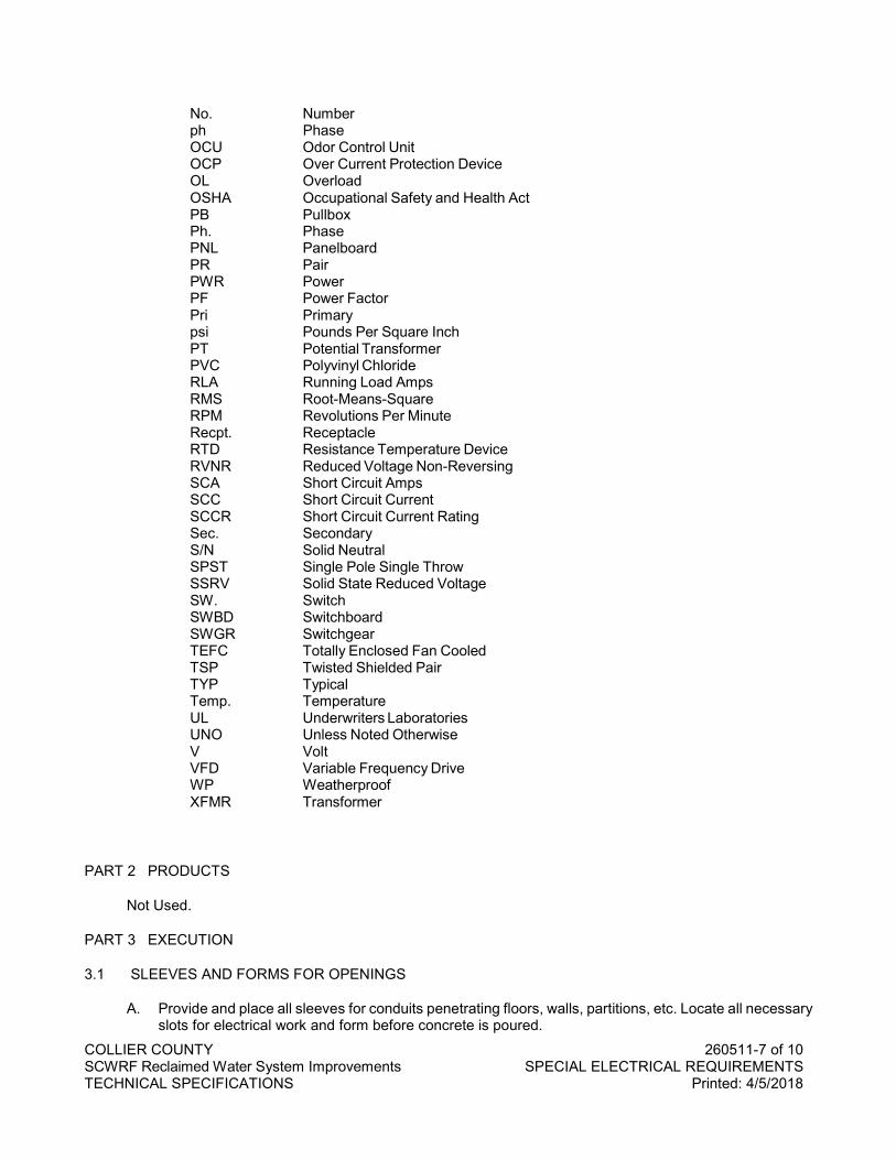
COLLIER COUNTY 260511-7 of 10 SCWRF Reclaimed Water System Improvements SPECIAL ELECTRICAL REQUIREMENTS TECHNICAL SPECIFICATIONS Printed: 4/5/2018
No. Number ph Phase OCU Odor Control Unit OCP Over Current Protection Device OL Overload OSHA Occupational Safety and Health Act PB Pullbox Ph. Phase PNL Panelboard PR Pair PWR Power PF Power Factor Pri Primary psi Pounds Per Square Inch PT Potential Transformer PVC Polyvinyl Chloride RLA Running Load Amps RMS Root-Means-Square RPM Revolutions Per Minute Recpt. Receptacle RTD Resistance Temperature Device RVNR Reduced Voltage Non-Reversing SCA Short Circuit Amps SCC Short Circuit Current SCCR Short Circuit Current Rating Sec. Secondary S/N Solid Neutral SPST Single Pole Single Throw SSRV Solid State Reduced Voltage SW. Switch SWBD Switchboard SWGR Switchgear TEFC Totally Enclosed Fan Cooled TSP Twisted Shielded Pair TYP Typical Temp. Temperature UL Underwriters Laboratories UNO Unless Noted Otherwise V Volt VFD Variable Frequency Drive WP Weatherproof XFMR Transformer
PART 2 PRODUCTS
Not Used.
PART 3 EXECUTION
3.1 SLEEVES AND FORMS FOR OPENINGS
A. Provide and place all sleeves for conduits penetrating floors, walls, partitions, etc. Locate all necessary slots for electrical work and form before concrete is poured.
COLLIER COUNTY 260511-8 of 10 SCWRF Reclaimed Water System Improvements SPECIAL ELECTRICAL REQUIREMENTS TECHNICAL SPECIFICATIONS Printed: 4/5/2018
B. Exact locations are required for stubbing-up and terminating concealed conduit. Obtain shop drawings and templates from equipment vendors or other subcontractors and locate the concealed conduit before the floor slab is poured.
C. Where setting drawings are not available in time to avoid delay in scheduled floor slab pours, the Engineer may allow the installations of such conduit to be exposed. Requests for this deviation must be submitted in writing. No additional compensation for such change will be allowed.
D. Seal all openings, sleeves, penetration and slots.
3.2 INSTALLATION
A. Any work not installed according to the Drawings and this Division or without approval by the Engineer shall be subject to change as directed by the Engineer. No extra compensation will be allowed for making these changes.
B. Electrical equipment shall at all times during construction be adequately protected against mechanical injury or damage by water. Electrical equipment shall not be stored out-of-doors. Electrical equipment shall be stored in dry permanent shelters. If an apparatus has been damaged, such damage shall be repaired at no additional cost. If any apparatus has been subject to possible injury by water, it shall be replaced at no additional cost to the Owner, the damaged unit(s) or systems shall remain on site and returned to the manufacturer after the replacement unit(s) or systems have been delivered to the site. Under no circumstances will electrical equipment damaged by water be rehabilitated or repaired, new equipment shall be supplied and all cost associated with replacement shall be borne by the Contractor.
C. Equipment that has been damaged shall be replaced or repaired by the equipment manufacturer, at the Engineer's discretion.
D. Repaint any damage to factory applied paint finish using touch-up paint furnished by the equipment manufacturer. The entire damaged panel or section shall be repainted at no additional cost to the Owner.
3.3 MANUFACTURERS SERVICE
A. Provide manufacturer's services for testing and start-up of all major electrical equipment: VFDs, ATS, Genset, MCCs, Switchboards, Switchgear, Etc.
B. Testing and startup shall not be combined with training. Testing and start-up time shall not be used for manufacturer’s warranty repairs.
C. The manufacturers of the above listed equipment shall provide experienced Field Service Engineer to accomplish the following tasks:
D. The equipment shall be visually inspected upon completion of installation and prior to energization to assure that wiring is correct, interconnection complete and the installation is in compliance with the manufacturer's criteria. Documentation shall be reviewed to assure that all Drawings, operation and maintenance manuals, parts list and other data required to check out and sustain equipment operation is available on-site. Documentation shall be red-lined to reflect any changes or modifications made during the installation so that the
E. "as-built" equipment configuration will be correctly defined. Spare parts shall be inventoried to assure correct type and quantity.
F. The Field Service Engineers shall provide engineering support during the
COLLIER COUNTY 260511-9 of 10 SCWRF Reclaimed Water System Improvements SPECIAL ELECTRICAL REQUIREMENTS TECHNICAL SPECIFICATIONS Printed: 4/5/2018
G. energization and check-out of each major equipment assembly. They shall perform any calibration or adjustment required for the equipment to meet the manufacturer's performance specifications.
H. Upon satisfactory completion of equipment test, they shall provide engineering support of system tests to be performed in accordance with manufacturer's test specifications.
I. A final report shall be written and submitted to the Contractor within fourteen days from completion of final system testing. The report shall document the inspection and test activity, define any open problems and recommend remedial action. The reports after review by the Contractor shall be submitted to the Engineer.
3.4 TRAINING
A. The cost of training programs to be conducted with Owner's personnel shall be included in the Contract Price. The training and instruction, insofar as practicable, shall be directly related to the system being supplied.
B. Provide detailed O&M manuals to supplement the training courses. The manuals shall include specific details of equipment supplied and operations specific to the project.
C. The training program shall represent a comprehensive program covering all aspects of the operation and maintenance including trouble-shooting of each system.
D. All training schedules shall be coordinated with and at the convenience of the Owner. Shift training may be required to correspond to the Owner's working schedule. The training shall be conducted with record "as-built" drawings sufficient for each class member.
E. The Contractor shall submit an overview of the proposed training plan. This overview shall include, for each course proposed: 1. An overview of the training plan. 2. Course title and objectives. 3. Recommended types of attendees. 4. Course Content - A topical outline. 5. Course Format - Lecture, laboratory demonstration, etc. 6. Schedule of training courses including dates, duration and locations of each class.
F. The work under this Division shall include a two-year warranty. This warranty shall be by the Contractor to the Owner for any defective workmanship or material that has been furnished under this Contract at no cost to the Owner for a period of two years from the date of substantial completion of the System. This guarantee shall not include light bulbs or batteries in service after six months from date of Substantial Completion of the System.
.
END OF SECTION

COLLIER COUNTY 260511-10 of 10 SCWRF Reclaimed Water System Improvements SPECIAL ELECTRICAL REQUIREMENTS TECHNICAL SPECIFICATIONS Printed: 4/5/2018
NO TEXT FOR THIS PAGE
COLLIER COUNTY 260519-1 of 6 SCWRF Reclaimed Water System Improvements LOW VOLTAGE WIRES AND CABLES TECHNICAL SPECIFICATIONS Printed: 4/5/2018
SECTION 260519
LOW VOLTAGE WIRES AND CABLES
PART 1 GENERAL
1.1 SECTION INCLUDES
A. Power conductors.
B. Taps and splices.
C. Color coding.
D. Instrument and control cable.
E. Data network signal cable.
F. Cable labeling and separation.
1.2 STANDARDS
A. Institute of Electrical and Electronics Engineers, Inc./American National Standards Institute (IEEE/ANSI):
B. Standard for Flame Testing of Cables for Use in Cable Tray in Industrial and Commercial Occupancies.
C. National Electrical Manufacturers Association (NEMA): ICS 4, Industrial Control and Systems: Terminal Blocks.
D. National Electrical Manufacturers Association/Insulated Cable Engineers Association (NEMA/ICEA): WC 57/S-73-532, Standard for Control Cables: WC 70/S- 95-658, Non-Shielded Power Cables Rated 2000 Volts or Less for the Distribution of Electrical Energy.
E. National Fire Protection Association NFPA-70, National Electrical Code (NEC).
F. Underwriters Laboratories, Inc. (UL44): Standard for Safety Thermoset-Insulated Wires and Cables; (UL83): Standard for Safety Thermoplastic-Insulated Wires and Cables; UL467 Standard for Safety Grounding and Bonding Equipment. UL486A Standard for Safety Wire Connectors and Soldering Lugs for use with Copper Conductors; UL 486C, Standard for Safety Splicing Wire Connections. UL510, Standard for Safety Polyvinyl Chloride, Polyethylene and Rubber Insulating Tape.
1.1 DEFINITIONS
G. Building Wire: Copper single conductor, cross link polyethylene insulated; type XHHW-2;
H. Cable: Multi-conductor, insulated, with outer sheath containing either building wire or instrumentation wire.
I. Instrumentation Cable (Analog signal cable): Multiple conductor, polyethylene insulated, twisted Pair/Triad, with individual Pair/Triad shield and outer overall shield and outer sheath. Used for the transmission of low current (e.g., 4-20mA DC) using No. 14 AWG conductors. Common Types, TSP: Twisted shielded pair, TST: Twisted shielded triad.
COLLIER COUNTY 260519-2 of 6 SCWRF Reclaimed Water System Improvements LOW VOLTAGE WIRES AND CABLES TECHNICAL SPECIFICATIONS Printed: 4/5/2018
J. Control Cable: Multi-conductor, insulated, with outer sheath containing building wires, No. 14, AWG. With overall shield where specified. Type SIS and MTW approved for use in the wiring of control equipment within control panels and field wiring of control equipment within switchgear, switchboards, motor control centers; otherwise type XHHW-2.
K. Power Cable: Multi-conductor, insulated, with outer sheath containing building wire, No. 12 AWG and larger. Rated XHHW-2
L. Digital signal cable: Used for the transmission of digital signals between computers, PLC's, RTU's, etc. Common Types: Ethernet UTP-unshielded twisted pair.
1.2 SUBMITTALS
A. Submit cut sheets on all major types of wires and cables including splicing tape, and terminating/splicing lugs, conductor identification systems and connectors and cable sleeves. Submit sample of all instrumentation and control cable. Sample shall be a minimum of 24" with exterior sheath clearly marked.
B. Submit sample of all cable identification systems products.
PART 2 PRODUCTS
2.1 POWER CONDUCTORS
A. Branch circuits and feeder conductors for electric power shall be stranded copper type XHHW-2 cross-link polyethylene (XLP) insulation and derated to 75 degrees Centigrade. No aluminum wiring shall be permitted. Wire shall be in accordance to NEC and minimum No. 12, except that branch "homeruns" over 50 ft. in length shall be minimum No. 10 for 120/208V circuits. All branch lighting circuits serving HID and Fluorescent fixtures shall be minimum #10 with each circuit provided with a separate neutral. All wire shall be manufactured in the USA.
B. Motor leads from variable frequency drives to driven motor shall be shielded VFD drive cable for all VFD motors. Provide flexible VFD shielded drive cables, 3 Class-I conductor cable plus 3 trisectional green insulated ground wires. Provide electrostatic shielding of tinned copper braided shield with aluminum-polyester laminated tape shielding system. Cross-linked polyolefin insulation system and neoprene outer jacket, type TC cable as manufactured by Rockbestos-Surprenant Cable Corp. or equal. Shielded VFD motor cables require increased conduit sizes over standard wire installations. Contractor to verify conduit sizes.
2.2 TAPS AND SPLICES
A. All power wiring taps and splices in No. 8 or smaller wire shall be fastened together by means of terminal strips except within lighting fixtures and wiring devices where conformance to NEC practices will be acceptable (Twist/screw on type connectors). All taps and splices in wire larger than No. 8 shall be made with compression type connectors and taped to provide insulation equal to wire. Tape shall be heavy duty, flame retardant and weather resistant vinyl electrical tape, minimum 7 mil premium grade with an operating temperature of 0 degree F. to 220 degree F. Provide tape meeting UL 510 and CSA standard C22.2.
B. All taps and splices in manholes or in ground pull boxes, etc. shall be approved by the engineer on a case by case basis; be made with high press long barrel double crimp compression type connectors and covered with Raychem heavy wall cable sleeves (type CTE or WCS) with type "S" sealant coating. Install sleeve kits as per manufacturer's installation instructions.
COLLIER COUNTY 260519-3 of 6 SCWRF Reclaimed Water System Improvements LOW VOLTAGE WIRES AND CABLES TECHNICAL SPECIFICATIONS Printed: 4/5/2018
2.3 COLOR CODING
A. All power feeders and branch circuits No. 6 and smaller shall be wired with color- coded wire with the same color used for a system throughout the building. Power feeders above No. 6 shall either be fully color-coded or shall have black insulation and be similarly color-coded with tape or paint in all junction boxes and panels. Tape or paint shall completely cover the full length of conductor insulation within the box or panel except for the wire markings.
B. Unless otherwise approved, color-code shall be as follows: Neutrals to be white for 120/208V system, natural grey for 277/480V system; ground wire green, bare or green with yellow strips. Nominal Voltage: 120/208V, Phase A -black; Phase B - red; Phase C - blue. 480/277V, Phase A brown; Phase B - orange; Phase C - yellow. All switch legs, other voltage system wiring, control and interlock wiring shall be color-coded other than those above. In exiting or expansion projects, comply with existing color coding established within the facility.
2.4 INSTRUMENTATION AND CONTROL CABLE
A. Multiconductor and Multi pair Process instrumentation cable shall be #16 AWG stranded, twisted pair, 600 V, (XLP) cross link polyethylene insulated, aluminum tape pair shielding, cross link polyethylene or chlorinated polyethylene (CPE) overall sheathed and shielded, type TC instrument cable as manufactured by the American Insulated Wire Co., Belden Wire Co. or equal.
B. Multiconductor control cable shall be #14 AWG stranded, 600V, (XLP) cross link polyethylene insulated or polyolefin, with cross link polyethylene or chlorinated polyethylene (CPE or Hypalon) overall sheathed type TC control cable except for control cable into and out of VFD cabinets. Multiconductor control cable into and out of VFD cabinets shall be as indicated above and in addition include an aluminum polyester tape overall shield and drain wire. As a contractor alternate to shielded control cable into and out of VFD cabinets, provide twisted shielded instrument cable as specified above. Contractor to provide increased conduit size as required if instrument cable alternate is used into and out of VFD cabinets.
2.5 DATA NETWORK SIGNAL CABLE
A. Ethernet Data Cable: Provide field cable that is Multi paired Data Signal cable, TIA 5638B Cat 5e, #22 AWG, twisted pair, 600V, PVC insulated, aluminum tape pair shielding, thermoplastic (PVC) overall sheathed and shielded, industrial ethernet cable as manufactured by the Allen Bradley 1585-C8HB or equal. Option to provide pre-molded M12 and RJ45 patch-cords Allen Bradley 1585D and 1585J is acceptable at contractor’s option.
B. Ethernet Cable Connections: 1. All conductor connections shall be to RJ45 and M12 compatible jacks. 2. All conductors shall be marked with mylar wrap type "Brady" labels. Identification labels shall be
permanent type and be machine printed. All terminal block terminations shall be labeled. The inside portion of the terminal cabinet doors shall display a protected terminal cabinet drawing with all connections shown and described as to color code, number assigned to connection function of conductor and destination.
3. Wire shall be guided within terminal cabinets by cable supports. All conductors shall be neatly led to terminations.
4. Instrumentation and control field cables on the unprotected side of SPD devices within the cabinet shall not run in parallel to the cables on the protected side of the SPD device. Separate cable supports (duct) will be provided.
5. No splices shall be made within a conduit run or in manholes.
C. Fiber Optic Cable: Fiber optic cable shall contain a minimum of six (6) optical tubing pairs or more as indicated on the drawings. Fiber optic tubing shall be multifiber; 62.5/125 micron, tight-buffered, riser
COLLIER COUNTY 260519-4 of 6 SCWRF Reclaimed Water System Improvements LOW VOLTAGE WIRES AND CABLES TECHNICAL SPECIFICATIONS Printed: 4/5/2018
rated multi-fiber breakout type, with an Aramid strength member. Maximum attenuation through the fiber shall not exceed 3.0 dB/km at 850nm. Bandwidth shall be 200 Mhz-km at 850 nm. Cable shall be suitable for duct or aerial applications with a UV resistant black PVC sheath. Maximum tensile load shall be 3000 N short term and 1200 N long term. Minimum bend radius shall be 20X outside diameter under installation tensile load and 10X outside diameter long term tensile load. Operating temperature range shall be -40 to +85º c. Fiber optic cable shall be UL-listed OFNR rated as manufactured by Optical Cable Corporation, B-Series Ultra Fox. Fiber optic cable shall utilize mechanically spliced, field installable, LC compatible connectors. Connections shall have a typical loss of 0.2 dB or better. Heat or UV cured connections shall not be acceptable. Contractor shall terminate and test the fiber optic cable. Contractor shall measure the dB loss of each fiber over the cable length and provide a report of the test results to the Engineer for approval.
PART 3 EXECUTION
3.1 CABLE LABELING AND SEPARATION
A. All plant control system field wiring shall be labeled per the instrumentation and control contractor loop drawings from the field device, through the intermediate cabinets, to the PLC cabinet. The labeling system shall be consistent throughout the loop and follow the standard tag designation: PLC#-Rack#-Slot#-Point# (example PLC1-R2-S3-P4).
B. Provide for separation of Data, Instrumentation, Control Cables from power conductors. Provide a minimum of 24-inch separation for parallel run of power conduit and Data, Instrumentation or control conduit. This separation can be reduced to 8" if metallic grounded separation is provided.
C. Connections: 1. All conductor connections shall be on terminal strips including all spare conductors. Provide
terminal strips in all cabinets; motor control centers; etc. 2. All connections of stranded wire to screw terminals shall be by insulated spade lugs, crimp
fastened to wire. Provide stranded wire crimp ferrules for all stranded wire connections not requiring spade lugs for screw type terminal blocks. The stranded wire ferrule is to be crimped to all stranded wire using a crimping tool specifically approved for crimping the size and type of ferrule.
3. All conductors shall be marked with mylar wrap type "Brady" labels. Identification labels shall be permanent type and be machine printed. All terminal block terminations shall be labeled. The inside portion of the terminal cabinet doors shall display a protected terminal cabinet drawing with all connections shown and described as to color code, number assigned to connection function of conductor and destination.
4. Wire shall be guided within terminal cabinets by cable supports. All conductors shall be neatly led to terminations.
5. Instrumentation and control field cables on the unprotected side of SPD devices within the cabinet shall not run in parallel to the cables on the protected side of the SPD device. Separate cable supports (duct) will be provided.
6. Cabinets: All cabinets shall be labeled with an engraved plastic laminate label riveted to the door. 7. No splices shall be made within a conduit run or in manholes.
D. All plant control system field wiring shall be labeled per the instrumentation and control contractor loop drawings from the field device, through the intermediate cabinets, to the PLC cabinet. The labeling system shall be consistent throughout the loop and follow the standard tag designation: PLC#-Rack#-Slot#-Point# (example PLC1-R2-S3-P4).
E. Provide for separation of instrumentation, control and power conductors. Provide a minimum of 24-inch separation for parallel run of power conduit and instrumentation or control conduit. This separation can be reduced to 8" if metallic grounded separation is provided.

COLLIER COUNTY 260519-5 of 6 SCWRF Reclaimed Water System Improvements LOW VOLTAGE WIRES AND CABLES TECHNICAL SPECIFICATIONS Printed: 4/5/2018
END OF SECTION

COLLIER COUNTY 260519-6 of 6 SCWRF Reclaimed Water System Improvements LOW VOLTAGE WIRES AND CABLES TECHNICAL SPECIFICATIONS Printed: 4/5/2018
NO TEXT FOR THIS PAGE
COLLIER COUNTY 260526-1 of 4 SCWRF Reclaimed Water System Improvements GROUNDING AND BONDING TECHNICAL SPECIFICATIONS Printed: 4/5/2018
SECTION 260526
GROUNDING AND BONDING FOR ELECTRICAL SYSTEMS
PART 1 GENERAL
1.1 DESCRIPTION
A. the terms “connect”, “ground” and “bond” are used interchangeably in this specification and have the same meaning
B. This section specifies general grounding and bonding requirements of electrical equipment operations and to provide a low impedance path for possible ground fault currents.
C. “Grounding electrode system” refers to all electrodes required by NEC, as well as including made, supplementary, perimeter counterpoise ground, lightning protection system grounding electrodes.
1.2 RELATED WORK
A. Section 260500 – Basic Materials and Methods.
B. Section 260519 - Low Voltage Wires and Cables.
1.3 SUBMITTALS
A. Submit in accordance with Division 26 and Section 013300.
B. Shop Drawings: 1. Sufficient information, clearly presented, shall be included to determine compliance with drawings
and specifications. 2. Include the location of system grounding electrode connections and the routing of aboveground
and underground grounding electrode conductors.
C. Test Reports: Provide certified test reports of ground resistance.
D. Certifications: Two weeks prior to final inspection, submit four copies of the following to the Project Engineer: 1. Certification, by the Contractor, that the complete installation has been properly installed and
tested.
1.4 APPLICABLE PUBLICATIONS
A. American Society for Testing and Materials (ASTM).
B. Institute of Electrical and Electronics Engineers, Inc. (IEEE).
C. Guide for Measuring Earth Resistivity, Ground Impedance, and Earth Surface Potentials of a Ground System.
D. National Fire Protection Association (NFPA): National Electrical Code (NEC) 2008.
E. Underwriters Laboratories, Inc. (UL): Thermoset-Insulated Wires and Cables Thermoplastic-Insulated Wires and Cables Grounding and Bonding Equipment.
COLLIER COUNTY 260526-2 of 4 SCWRF Reclaimed Water System Improvements GROUNDING AND BONDING TECHNICAL SPECIFICATIONS Printed: 4/5/2018
F. Wire Connectors.
PART 2 PRODUCTS
2.1 GROUNDING AND BONDING CONDUCTORS
A. Equipment grounding conductors shall be UL 83 insulated stranded copper, except that sizes 2 AWG and smaller may be solid copper unless noted otherwise noted on the drawings. Insulation color shall be continuous green for all equipment grounding conductors, except that wire sizes 4 AWG and larger shall be permitted to be identified per NEC.
B. Bonding conductors shall be ASTM B8 bare stranded copper, except that sizes 2 AWG and smaller may be ASTM B1 solid bare copper wire.
C. Electrical System Grounding: Conductor sizes shall not be less than what is shown on the drawings and not less than required by the NEC, whichever is greater.
2.2 SPLICES AND TERMINATION COMPONENTS
A. Components shall meet or exceed UL 467 and be clearly marked with the manufacturer, catalog number, and permitted conductor size(s).
2.3 GROUND CONNECTIONS
A. Above Grade: 1. Bonding Jumpers: compression type connectors, using zinc-plated fasteners and external tooth
lock washers. 2. Ground Busbars: Two-hole compression type lugs using tin-plated copper or copper alloy bolts
and nuts.
PART 3 EXECUTION
3.1 GENERAL
A. Ground in accordance with the NEC, as shown on drawings, and as hereinafter specified.
B. System Grounding: 1. Secondary service neutrals: Ground at the supply side of the secondary disconnecting means
and at the related transformers. 2. Separately derived systems (transformers downstream from the service entrance): Ground the
secondary neutral.
C. Equipment Grounding: Metallic structures (including ductwork and building steel), enclosures, raceways, junction boxes, outlet boxes, cabinets, machine frames, and other conductive items in close proximity with electrical circuits shall be bonded and grounded.
3.2 GROUNDING CONNECTIONS
A. Make grounding connections that are below grade by exothermic weld. Make grounding connections that are above grade but are otherwise normally inaccessible (poured columns, within walls) with exothermic weld.
3.3 SECONDARY EQUIPMENT AND CIRCUITS
COLLIER COUNTY 260526-3 of 4 SCWRF Reclaimed Water System Improvements GROUNDING AND BONDING TECHNICAL SPECIFICATIONS Printed: 4/5/2018
A. Transformers: 1. Exterior: Exterior transformers supplying interior service equipment shall have the neutral
grounded at the transformer secondary. Provide a grounding electrode at the transformer. 2. Separately derived systems (transformers downstream from service equipment): Ground the
secondary neutral at the transformer. Provide a grounding electrode conductor from the transformer to the ground bar at the service equipment.
B. Conduit Systems: 1. Ground all metallic conduit systems. All conduit systems shall contain an equipment grounding
conductor (except service entrance with grounded neutral). Ground conductor shall be bonded to metallic conduit systems at the entrance and exit from the conduit.
C. Boxes, Cabinets, Enclosures, and Panelboards: 1. Bond the equipment grounding conductor to each pullbox, junction box, outlet box, device box,
cabinets, and other enclosures through which the conductor passes. 2. Provide lugs in each box and enclosure for equipment grounding conductor termination. 3. Provide ground bars in panelboards, bolted to the housing, with sufficient lugs to terminate the
equipment grounding conductors.
D. Motors and Starters: Provide lugs in motor terminal box and starter housing or motor control center compartment to terminate equipment grounding conductors.
E. Receptacles shall not be grounded through their mounting screws. Ground with a jumper from the receptacle green ground terminal to the device box ground screw and the branch circuit equipment grounding conductor.
3.4 CORROSION INHIBITORS
A. When making ground and ground bonding connections, apply a corrosion inhibitor to all contact surfaces. Use corrosion inhibitor appropriate for protecting a connection between the metals used.
3.5 CONDUCTIVE PIPING
A. Bond all conductive piping systems, interior and exterior, to the building to the grounding electrode system.
3.6 GROUND RESISTANCE
A. Grounding system resistance to ground shall not exceed 5 ohms. Make necessary modifications or additions to the grounding electrode system for compliance without additional cost to the owner. Final tests shall assure that this requirement is met.
B. Resistance of the grounding electrode system shall be measured using a four-terminal fall-of-potential method as defined in IEEE 81. Ground resistance measurements shall be made before the electrical distribution system is energized and shall be made in normally dry conditions not less than 48 hours after the last rainfall. Resistance measurements of separate grounding electrode systems shall be made before the systems are bonded together below grade. The combined resistance of separate systems may be used to meet the required resistance, but the specified number of electrodes must still be provided.
C. Below-grade connections shall be visually inspected by the Project Engineer prior to backfilling. Provide ground inspection wells at all ground rod locations.
3.7 GROUND ROD INSTALLATION
COLLIER COUNTY 260526-4 of 4 SCWRF Reclaimed Water System Improvements GROUNDING AND BONDING TECHNICAL SPECIFICATIONS Printed: 4/5/2018
A. Drive each rod vertically in the earth, not less than 20 feet in depth.
B. Where permanently concealed ground connections are required, make the connections by the exothermic process to form solid metal joints. Make above grade accessible ground connections with mechanical pressure type ground connectors.
C. Where rock prevents the driving of vertical ground rods, drill rock then install rod. Backfill with flowable fill or concrete mix. Obtain the necessary permits if required for drilling.
.
END OF SECTION
COLLIER COUNTY 260529-1 of 2 SCWRF Reclaimed Water System Improvements SUPPORTING DEVICES TECHNICAL SPECIFICATIONS Printed: 4/5/2018
SECTION 260529
SUPPORTING DEVICES
PART 1 GENERAL
1.1 SECTION INCLUDES
A. Electrical supporting devices. 1. The work under this section includes conduit and equipment supports, straps, clamps, steel
channel, etc., and fastening hardware for supporting electrical work. Furnish and install all supports, hangers and inserts required to mount fixtures, conduit, cables, pull boxes and other equipment furnished under this Division. All supporting devices and hardware exterior of buildings or interior of structures except in air-conditioned spaces shall be stainless steel. Aluminum and nonmetallic supports (fiberglass) and hardware will be reviewed by the Engineer on a case-by-case basis.
2. All items shall be supported from the structural portion of the building. Supports and hangers shall be of a type approved by Underwriters' Laboratories. Wire or plastic tie straps shall not be used as a support. Boxes and conduit shall not be supported or fastened to ceiling suspension wires or to ceiling channels.
3. The Contractor shall furnish and install all sleeves that may be required for openings through floors, wall etc. Where plans call for conduit to be run exposed, the Contractor shall furnish and install all inserts and clamps for the supporting of conduit. If the Contractor does not properly install all sleeves and inserts required, contractor to provide cutting and patching to the satisfaction of the Engineer.
1.2 SUBMITTALS
A. Product Data: Provide data for support channel.
1.3 QUALITY ASSURANCE
A. Support systems shall be adequate for weight of equipment and conduit, including wiring, which they carry.
PART 2 PRODUCTS
2.1 MATERIAL
A. Support Channel: Stainless steel throughout except galvanized steel in conditioned interior areas.
B. Hardware: Stainless steel throughout.
C. Minimum sized threaded rod for supports shall be 3/8”.
D. Conduit clamps, straps, supports, etc., shall be stainless steel or malleable iron. One-hole straps shall be heavy duty type.
PART 3 EXECUTION
3.1 INSTALLATION
A. All steel conduits shall be securely fastened in place on maximum of 6-foot intervals; all PVC conduits shall be securely fastened in place on maximum of 3 foot intervals vertically and 2 foot intervals
COLLIER COUNTY 260529-2 of 2 SCWRF Reclaimed Water System Improvements SUPPORTING DEVICES TECHNICAL SPECIFICATIONS Printed: 4/5/2018
horizontally. Hangers, supports or fastenings shall be provided at each elbow and at the end of each straight run terminating at a box or cabinet. The required strength of the supporting equipment and size and type of anchors shall be based on the combined weight of conduit, hanger and cables. Horizontal and vertical conduit runs may be supported by two-hole malleable straps, clamp-backs, or other approved devices with suitable bolts, expansion shields (where needed) or beam-clamps for mounting to building structure or special brackets.
B. On concrete or masonry construction, use "Tapcon" type fasteners. For brick construction, insert anchors shall be installed with round head machine screws. In wood construction, round head screws shall be used. An electric or hand drill shall be used for drilling holes for all inserts in brick, concrete or similar construction. Steel members shall be drilled and tapped, and round head machine screws shall be used. All screws, bolts, washers, etc., used for supporting conduit or outlets shall be fabricated from stainless steel, or approved substitution.
C. Fasten hanger rods, conduit clamps, outlet, junction and pull boxes to building structure using preset inserts, beam clamps, expansion anchors, or spring steel clips (interior metal stud walls only). Use toggle bolts or hollow wall fasteners in hollow masonry, plaster, or gypsum board partitions and walls; expansion anchors or preset inserts in solid masonry walls; self-drilling anchors or expansion anchors on concrete surfaces; sheet metal screws in sheet metal studs and wood screws in wood construction.
D. File and de-bur cut ends of support channel and spray paint with cold galvanized paint to prevent rusting. Do not fasten supports to piping, ductwork, mechanical equipment, cable tray or conduit. Do not drill structural steel members unless approved by the engineer.
E. Fabricate supports from stainless steel or galvanized steel channel, rigidly welded or bolted to present a neat appearance. Use hexagon head bolts with spring lock washers under all nuts. Install surface-mounted cabinets and panelboards with minimum of four anchors. Provide steel channel supports to stand cabinet one inch (25 mm) off wall.
F. Furnish and install all supports as required to fasten all electrical components required for the project, including free standing supports required for those items remotely mounted from the building structure, catwalks, walkways etc.
.
END OF SECTION
COLLIER COUNTY 260551-1 of 6 SCWRF Reclaimed Water System Improvements CONDUIT SYSTEMS TECHNICAL SPECIFICATIONS Printed: 4/5/2018
SECTION 260551
CONDUIT SYSTEMS
PART 1 GENERAL
1.1 SECTION INCLUDES
A. Electrical conduit and fittings.
B. Requirements for raceways, fittings, boxes, enclosures, and cabinets for electrical, instrumentation and control system wiring.
1.2 GENERAL REQUIREMENTS
A. Only heavy wall PVC (Schedule 80) shall be used for all raceways trapped underground without concrete encasement protection. Conduits in concrete encasement use Schedule 40-PVC. Above ground in areas subject to chemical degradation (chemical storage, chlorine rooms, odor control and scrubber area, etc.) use Schedule 80-PVC. Use rigid galvanized conduit or aluminum conduit for exposed above grade interior area. Electrical Metallic Tubing shall be used within air-conditioned electrical rooms for power and for instrumentation and control conduits. Use rigid aluminum conduit above grade on exterior of buildings and in above grade interior wet locations. Where PVC conduit penetrates a floor from underground or in a slab; a black mastic coated rigid steel conduit elbow shall be used for all conduits.
B. Minimum conduit size for all systems shall be ¾-inches. All conduits shall be U.L. listed and labeled. Conduit sizes shown on the drawings are to aid the CONTRACTOR in bidding only; the CONTRACTOR is responsible for conduit sizes as required by NEC fill tables but do not provide smaller conduits than indicated. The CONTRACTOR is responsible to coordinate the required conduit sizes and conductor quantities for all control and instrumentation system conduit and wiring with the controls subcontractor prior to installation.
C. All conduit and fittings shall be non-metallic.
D. Provide stainless steel or non-metallic conduit supports and 316 stainless steel hardware in all areas.
1.3 SUBMITTALS
A. Product Data: 1. Product data shall be submitted on: 2. Conduit, raceways, wireways. 3. Conduit fittings, boxes, enclosures and cabinets. 4. Surface metal raceway.
PART 2 PRODUCTS
2.1 FLEXIBLE CONDUIT
A. Flexible, Nonmetallic, Liquid-Tight Conduit: 1. Material: PVC core with fused flexible PVC jacket. UL 1660 listed for: Dry Conditions: 80 degrees
C insulated conductors. 2. Wet Conditions: 60 degrees C insulated conductors.
B. Manufacturers and Products:
COLLIER COUNTY 260551-2 of 6 SCWRF Reclaimed Water System Improvements CONDUIT SYSTEMS TECHNICAL SPECIFICATIONS Printed: 4/5/2018
1. Carlon; Carflex or X Flex.; 2. T & B; Xtraflex LTC or EFC.
2.2 PVC CONDUIT
A. PVC conduit shall be composed of High Impact Virgin homo-polymer, PVC (polyvinyl chloride C-200 Compound), and shall conform to industry standards, and be UL 651 listed in accordance with Article 347 of National Electrical Code for underground and exposed use and NEMA standard TC-2. Materials must have tensile strength of 55 PSI, at 70oF, flexural strength of 11,000 PSI, compression strength of 8600 PSI. Manufacturer shall have five years' extruding PVC experience. Consistent with requirements provide PVC conduit products by one of the following manufacturers: 1. Carlon. 2. Cantex. 3. J.M. Plastics. 4. Queen City Plastics.
2.3 CONDUIT FITTINGS
A. Fittings for Conduit (Including all Types and Flexible and Liquidtight), EMT, and Cable: NEMA FB 1; listed for type and size raceway with which used, and for application and environment in which installed.
B. Conduit Fittings for Hazardous (Classified) Locations: Comply with UL 886.
C. Fittings for EMT: Steel compression type.
D. Fittings, surface boxes and conduit bodies for RGC shall be heavy cast ferroalloy malleable iron with external raised hubs and mounting lugs; cadmium plated and enamel finish - Appleton, Crouse Hinds or approved substitution. Cover plates cast iron ferroalloy.
E. Fittings, surface boxes and conduit bodies for Rigid Aluminum Conduit shall be heavy cast aluminum with external raised hubs and mounting lugs: Appleton, Crouse Hinds or approved substitution. Cover plates cast aluminum. Zinc die cast not acceptable.
F. Conduit locknuts shall be aluminum throughout except steel is acceptable within air conditioned spaces.
G. Conduit expansion fittings shall be malleable iron, and shall be hot dipped galvanized inside and outside. These fittings shall have a four-inch expansion chamber to allow approximately two-inch movement parallel to conduit run in either direction from normal. They shall have factory-installed packing and internal tinned copper braid packing to serve as an emergency bonding jumper. Unless the fitting used is listed by Underwriters' Laboratories for use "without external bonding jumpers", an external copper bonding jumper shall be installed with each expansion fitting with one end clamped on each conduit entering fitting.
H. Flexible, Nonmetallic, Liquid-Tight Conduit shall meet requirements of UL 514B with high-strength plastic body, complete with lock nut, O-ring seal, threaded ferrule, sealing ring. Threaded ferrule designed to ensure high mechanical pullout strength and watertight seal. Manufacturer, Carlon; Type LN or approved equal.
I. Ceiling outlet boxes shall be 4" octagonal or 4" square X 1-1/2" deep or larger as required for number and size of conductors and arrangement, size and number of conduits terminating at them. Switch, wall receptacle, telephone and other wall outlet boxes in drywall shall be 4" square X 1-1/2" deep. For
COLLIER COUNTY 260551-3 of 6 SCWRF Reclaimed Water System Improvements CONDUIT SYSTEMS TECHNICAL SPECIFICATIONS Printed: 4/5/2018
furred-out block walls, provide 4" square box with required extension for block depth and required extension for drywall depth.
J. Covers for cast boxes (flush and surface) installed in damp or wet locations shall be UL approved for weatherproof locations (UL standard 498 and 514; OSHA standard Subpart "S"; NEMA Standard WD-1) with plug inserted and shall comply with NEC- 410-57b; shall be heavy cast copper free aluminum with 2 coat baked epoxy finish; self-closing door with stainless steel hinge and springs; EPDM gaskets. Provide Crouse Hinds, Appleton or equal. This requirement includes outlets mounted flush in exterior lighting poles.
PART 3 EXECUTION
3.1 MOUNTING HEIGHT
A. Height of wall outlets to bottom above finished floors shall be as follows, unless specifically noted otherwise. Verify with the Architectural plans and shop drawings for installing. 1. Switches: 4'-0" Maximum to centerline. 2. Receptacles: 1'-4". 3. Lighting Panels (top of Panel Trim): 6'-6".
B. Bottoms of outlets above counter tops or base cabinets shall be minimum 2" above counter top or backsplash, whichever is highest. Outlets may be raised so that bottom rests on top of concrete block course, but all outlets above counters in same area shall be at same height. It is the responsibility of this Division to secure cabinet drawings and coordinate outlet locations in relation to all cabinets as shown on plans, prior to rough-in, regardless of height shown on Division 16 drawings.
C. Height of wall-mounted fixtures shall be as shown on the drawings or as required by Architectural plans and conditions. Fixture outlet boxes shall be equipped with fixture studs when supporting fixtures.
D. Locate special purpose outlets as indicated on the drawings for the equipment served. Location and type of outlets shall be coordinated with appropriate trades involved. The securing of complete information for proper electrical roughing-in shall be included as work required under this section of specifications.
3.2 INSTALLATION
A. All raceways shall be run in neat and workmanlike manner and shall be properly supported in accordance with latest edition of NEC with approved conduit clamps, hanger rods and structural fasteners except for PVC conduit installed in exterior locations. PVC conduit installed in exterior locations shall be supported at two foot intervals. Supporting conduit and boxes with wire is not approved. All raceways except those from surface-mounted switches, outlet boxes or panels shall be run concealed from view. Exposed raceways shall be supported with clamp fasteners with toggle bolt on hollow walls, and with lead expansion shields on masonry. Rigid steel box connections shall be made with double locknuts and bushings. Where PVC penetrates a floor from underground or in slab, a black mastic coated steel conduit elbow shall be used on all conduits. All individual bare copper ground conductors (i.e. service, transformer, or lightning protection grounds) shall be installed in PVC conduit, not metal conduit. This does not apply to bare copper ground conductors run with feeders (as specified in this section). Conduits shall be run parallel to building walls wherever possible, exposed or concealed, and shall be grouped in workmanlike fashion. Crisscrossing of conduits shall be minimized.
COLLIER COUNTY 260551-4 of 6 SCWRF Reclaimed Water System Improvements CONDUIT SYSTEMS TECHNICAL SPECIFICATIONS Printed: 4/5/2018
B. All raceways runs, whether terminated in boxes or not, shall be capped during the course of construction and until wires are pulled in, and covers are in place. No conductors shall be pulled into raceways until construction work which might damage the raceways has been completed.
C. All raceways shall be kept clear of plumbing fixtures to facilitate future repair or replacement of said fixtures without disturbing wiring. Except where it is necessary for control purposes, all raceways shall be kept away from items producing heat.
D. All raceway runs in masonry shall be installed at the same time as the masonry so that no face cutting is required, except to accommodate boxes.
E. All raceways shall be run from outlet to outlet exactly as shown on the drawings, unless permission is granted to alter arrangement shown. If permission is granted arrangement shall be marked on field set of drawings as previously specified.
F. All underground raceways (with exception of raceways installed under floor slab) shall be installed in accordance with Section 300-5 of the NEC except that the minimum cover for any conduit shall be two feet. Included under this Section shall be the responsibility for verifying finished lines in areas where raceways will be installed underground before the grading is complete.
G. All raceways shall have an insulated copper system ground conductor throughout the entire length of circuit installed within conduit in strict accordance with NEC. Grounding conductor shall be included in total conduit fill determining conduit sizes, even though not included or shown on drawings. Grounding conductors run with feeders shall be bonded to portions of conduit that are metal by approved ground bushings.
H. Insulated bushings shall be used on all rigid steel conduits terminating in panels, wire gutters, or cabinets, and shall be impact resistant plastic molded in an irregular shape at the top to provide smooth insulating surface at top and inner edge. Material in these bushings must not melt or support flame.
I. Spare conduit stubs shall be capped and location and use marked with concrete marker set flush with finish grade or terminated in a manhole. Marker shall be 6" round X 6" deep with appropriate symbol embedded into top to indicate use. Also, tag conduits in panels where originating.
J. All conduit stubbed above floor shall be separated with plastic interlocking spacers manufactured specifically for this purpose, or shall be strapped to Kindorf channel supported by conduit driven into ground or tied to steel.
K. Raceways which do not have conductors furnished under this Division of the specifications shall be left with an approved nylon pullcord in raceway.
L. Rigid Metallic Conduit electrical metallic tubing, flexible steel conduit and PVC conduit shall be manufactured within the United States.
M. All connections to motors or other vibrating equipment (except dry type transformers) or at other locations where required shall be made with not less than 12" nor more than 20” of flexible liquid-tight steel conduit, using special type of connectors with strain relief fittings at both terminations of conduit. Flex connectors shall have insulated throat and shall be T & B 3100 Series or approved substitution. Use angle connectors wherever necessary to relieve angle strain on flex conduit. Connections to dry type transformers shall be made with flexible conduit. Typical length of flex conduit shall be limited to 20” unless specifically approved by the engineer.
N. PVC joints shall be solvent welded. Threads will not be permitted on PVC conduit and fittings, except for rigid steel to PVC couplings. Installation of PVC conduit shall be in accordance with manufacturer's
COLLIER COUNTY 260551-5 of 6 SCWRF Reclaimed Water System Improvements CONDUIT SYSTEMS TECHNICAL SPECIFICATIONS Printed: 4/5/2018
recommendations. PVC conduit shall not be used to support fixture or equipment. Field bends shall be made with approved hotbox. Heating with flame and hand held heat guns are prohibited.
O. Expansion fittings shall be installed in the following cases: In each conduit run wherever it crosses an expansion joint in the concrete structure; on one side of joint with its sliding sleeve end flush with joint, and with a length of bonding jumper in expansion equal to at least three times the normal width of joints; in each conduit run which mechanically attached to separate structures to relieve strain caused by shift on one structure in relation to the other; in straight conduit run above ground which is more than fifty feet long and interval between expansion fittings in such a runs shall not be greater than 100 feet for steel conduit and 50 feet for PVC conduit.
P. Electric metallic tubing (thin wall) shall be installed inside buildings above ground floor slab where not subject to mechanical injury or wet areas. Tubing shall be joined with steel fittings and steel compression connectors.
Q. Rigid metallic conduit installed underground shall be coated with waterproofing black mastic before installation, and all joints shall be recoated after installation.
R. Conduit installations on roofs shall be kept to a bare minimum. Where required, conduit shall be rigid aluminum conduit, including couplings. Conduit shall be supported above roof at least 6 inches using approved conduit supporting devices. Supports to be fastened to roof using roofing adhesive as approved by roofing contractor.
S. Underground cable identification: bury a continuous, pre-printed, bright colored metalized plastic (electronically traceable) ribbon cable marker with each underground conduit (or group of conduits), regardless of whether conduits are in ductbanks. Locate directly over conduits, 6" to 8" below finished grade. Delete this requirement under building slabs.
T. Provide for separation of instrumentation, control and power conductors. Provide a minimum of 24- inch separation for parallel runs of power conduit to instrumentation or control conduit with either conduit being PVC or Aluminum. This separation can be reduced to 6" if metallic grounded separation is provided (steel conduit).
U. All flush outlet boxes shall be mounted so that covers and plates will finish flush with finished surfaces without the use of shims, mats or other devices not submitted or approved for the purpose. Add-a-Depth rings or switch box extension rings are not acceptable. Plates shall not support wiring devices. Provide gang switches with common plate where two or more are indicated in the same location. Wall-mounted devices of different systems (switches, thermostats, etc.) shall be coordinated for symmetry when located near each other on the same wall. Outlets on each side of walls shall have separate boxes. Through-wall type boxes shall not be permitted. Back-to-back mounting shall not be permitted. Trim rings shall be extended to within 1/8" of finish wall surface. Outlet boxes mounted in metal stud walls, are to be supported to studs with two (2) screws inside of outlet box to a horizontal stud brace between vertical studs.
.
END OF SECTION

COLLIER COUNTY 260551-6 of 6 SCWRF Reclaimed Water System Improvements CONDUIT SYSTEMS TECHNICAL SPECIFICATIONS Printed: 4/5/2018
NO TEXT FOR THIS PAGE
COLLIER COUNTY 260553-1 of 4 SCWRF Reclaimed Water System Improvements IDENTIFICATION OF ELECTRICAL SYSTEMS TECHNICAL SPECIFICATIONS Printed: 4/5/2018
SECTION 260553
IDENTIFICATION OF ELECTRICAL SYSTEMS
PART 1 GENERAL
1.1 GENERAL
A. Provide materials and installation for the identification of electrical equipment, components, cables and wiring and safety signs.
B. Related Work Specified in Other Sections Includes: 1. Basic Electrical Materials and Methods. 2. Acceptance Testing. 3. Wires and Cables. 4. Control Panels.
1.2 REFERENCES:
A. Codes and standards incorporated within this Section are: 1. ANSIC2/NFPA70E: National Electrical Safety Code (NESC). 2. ANSI Z535.1: Safety Color Code. 3. ANSI Z535.2: Environmental and Facility Safety Signs. 4. ANSI Z535.3: Criteria for Safety Symbols. 5. OSHA Occupational Safety and Health Act: specification 1910.145, Standards for Accident
Prevention, Signs and Tags.
1.3 Submittals: Furnish all product submittals used; follow Section 013300.
A. Product Data and Information: Furnish manufacturer's catalog data for safety signs, nameplates, labels and markers.
B. Furnish manufacturer's instructions indicating application conditions and limitations of use; and storage, handling, protection, examination and installation of product.
PART 2 PRODUCTS
2.1 MANUFACTURERS
A. Acceptable Manufacturers: Acceptable manufacturers are listed below. Other manufacturers of equivalent products may be submitted for review. 1. W. H. Brady Company. 2. Seton. 3. Thomas & Betts. 4. Approved equal.
2.2 MATERIALS
A. General: Provide identification materials listed and classified by UL or tested by an acceptable Electrical Testing Company certifying the equivalence of the materials to UL listing requirements and OSHA approved.
B. Laminated Plastic Nameplates: Provide engraved three layer laminated plastic nameplates with black letters on white background with lettering etched through the outer covering and fastened with
COLLIER COUNTY 260553-2 of 4 SCWRF Reclaimed Water System Improvements IDENTIFICATION OF ELECTRICAL SYSTEMS TECHNICAL SPECIFICATIONS Printed: 4/5/2018
corrosion resistant brass or stainless steel screws. Do not use mounting cement for fastening nameplates. 1. Provide nameplates with 1-inch high lettering for main breakers, automatic transfer switches,
panelboards, transformers, VFD's, control panels and disconnect switches. 2. Provide nameplates for each motor identifying service or function and lettering of an appropriate
size to suit each motor. Submersible motor nameplates to be affixed to equipment disconnect. 3. Provide approved directories of circuits with typewritten designations of each branch circuit in
each panelboard. 4. Provide smaller lettering for a neat, legible nameplate where the amount of 5. Lettering causes excessively large nameplates.
2.3 WIRE MARKERS
A. Identify wire bundles and each individual wire.
B. Wire bundles: Provide a permanent waterproof brass or rigid fiber identifying tag attached with nylon self-locking "Ty-Raps".
C. Wire identification markers: Provide a printed white, heat-shrink, seamless tubing type with black bold lettering for wires size No. 10 AWG and smaller. Provide a printed self-laminating white, vinyl type with black bold lettering for wires No. 8 AWG and larger
D. Color-Coding Conductor Tape: Colored, self-adhesive vinyl tape not less than 3 mils thick by 1 to 2 inches wide.
E. Marker Tapes: Vinyl or vinyl-cloth, self-adhesive wraparound type, with circuit identification legend machine printed by thermal transfer or equivalent process.
F. Write-On Tags: Polyester tag, 0.015-inch thick, with corrosion-resistant grommet and polyester or nylon tie for attachment to conductor or cable: Marker for Tags: Permanent, waterproof, black-ink marker recommended by tag manufacturer.
2.4 SAFETY SIGNS
A. Provide safety signs in accordance with OSHA standards meeting the requirements of ANSI C2, ANSI Z535.1, ANSI Z535.2 and ANSI Z535.3. Comply with NFPA 70 and 29 CFR 1910.145
B. Provide safety signs manufactured from vinyl having a minimum thickness of 60 mils with red and black letters and graphics on a white background.
C. Size: Provide 7-inch by 10-inch signs or smaller if larger size cannot be applied.
D. Mount safety signs using corrosion-resistant screws. Do not use mounting cement.
E. Self-Adhesive Warning Labels: Factory printed, multicolor, pressure-sensitive adhesive labels, configured for display on front cover, door, or other access to equipment, unless otherwise indicated.
F. All receptacles and switches shall be identified on the inside of the cover plate by circuit number and panelboard.
G. Baked-Enamel Warning Signs: Preprinted aluminum signs, punched or drilled for fasteners, with colors, legend, and size required for application and with 1/4-inch grommets in corners for mounting. Nominal size, 7 by 10 inches.
COLLIER COUNTY 260553-3 of 4 SCWRF Reclaimed Water System Improvements IDENTIFICATION OF ELECTRICAL SYSTEMS TECHNICAL SPECIFICATIONS Printed: 4/5/2018
H. Metal-Backed, Butyrate Warning Signs: Weather-resistant, non-fading, preprinted, cellulose-acetate butyrate signs with 0.0396-inch galvanized-steel backing, and with colors, legend, and size required for application and with 1/4-inch grommets in corners for mounting. Nominal size, 10 by 14 inches.
2.5 EQUIPMENT IDENTIFICATION LABELS
A. Engraved, Laminated Acrylic or Melamine Label: Punched or drilled for screw mounting. White letters on a dark-gray background. Minimum letter height shall be 3/8 inch. Identification plates shall be furnished for lighting and power panelboards, motor control centers, all line voltage heating and ventilating control panels, fire detector and sprinkler alarms, pilot lights, disconnect switches, manual starting switches, magnetic starters, and all miscellaneous controls, switches and enclosures.
B. Process control devices and pilot lights shall have identification plates. Identification plates shall be furnished for all line-voltage enclosed-circuit breakers; the plates shall identify the equipment served, voltage, phase(s), and power source. Circuits 480 volts and above shall have conspicuously located warning signs in accordance with OSHA requirements.
C. Identification plates shall be three-layer white-black-white, engraved to show black letters on a white background. Letters shall be uppercase. Identification plates 1-1/2 inches high and smaller shall be 1/16-inch thick with engraved lettering 1/8 inch high. Identification plates larger than 1-1/2 inches high shall be 1/8-inch thick with engraved lettering not less than 3/16 inch high. Identification plates having edges of 1-1/2 inches high and larger shall be beveled:
D. Provide nameplates of minimum letter height as follows: Panelboards, switchboards, safety switches and motor control centers: 1/4-inch, identify panel name; 1/8-inch, identify voltage, phase, number of wires, and source.
E. Safety color coding for identification of warning signs shall conform to NEMA Z 535. Red identification plates reading CAUTION: 480/277 VOLTS shall be provided in switch and outlet boxes containing 277-or 480-volt circuits. An identification plate marked DANGER: 480 VOLTS shall be provided on the outside of 480-volt enclosures. Identification plate shall use white lettering on a red laminated plastic.
F. Any equipment with externally powered wiring shall be marked with a laminated plastic name plate having 3/16-inch-high white letters on a red background as follows: DANGER – EXTERNAL VOLTAGE SOURCE.
PART 3 EXECUTION
3.1 INSTALLATION
A. General: Install nameplates on the front of equipment, parallel to the equipment lines and secured with corrosion resistant screws. Labels to be consistent with wiring diagrams, schedules, and the Operation and Maintenance Manual designations. Warning Labels for Cabinets, Boxes, and Enclosures for Power and Lighting: Comply with 29 CFR 1910.145 and apply metal-backed, butyrate warning signs. Identify system voltage with black letters on an orange background. Apply to exterior of door, cover, or other access.
B. Install laminated nameplates identifying, each electrical equipment enclosure and Individual equipment and devices. The following items shall be equipped with nameplates: All motors; motor starters, motor-control centers, pushbutton stations, control panels, time switches, disconnect switches panelboards, circuit breakers, contactors, recorders, transmitters, instruments or relays in separate enclosures, thermostats, photocells, power receptacles, switches controlling equipment or receptacles, switches controlling lighting fixtures where the fixtures are not located within the same space as the controlling switch, termination cabinets, manholes and pull boxes, instrumentation and
COLLIER COUNTY 260553-4 of 4 SCWRF Reclaimed Water System Improvements IDENTIFICATION OF ELECTRICAL SYSTEMS TECHNICAL SPECIFICATIONS Printed: 4/5/2018
control terminal cabinets, pull boxes manholes and cabinets. Special electrical systems shall be identified at junction and pull boxes, terminal cabinets and equipment racks.
C. Electrical contractor is responsible for nameplates on electrical equipment supplied by other divisions and installed and wired by electrical including all instrumentation and controls equipment. A portion of existing equipment affected by this contract shall also receive nameplates as determined by the engineer.
D. Surface Preparation: Degrease and clean surfaces to receive nameplates, labels and marking paint.
E. Nameplates shall adequately describe the function of the particular equipment involved. Nameplates for panelboards and switchboards shall include the panel designation, voltage and phase of the supply. For example, "Panel A, 277/480V, 3- phase, 4-wire". The name of the machine on the nameplates for a particular machine shall be the same as the one used on all motor starters, disconnect and
F. P.B. station nameplates for that machine. Equipment Requiring Workspace Clearance shall be labeled According to NFPA 70 applied to door or cover of equipment.
G. Rework or reuse of existing equipment will require new identification tags for some existing equipment.
H. Wire Markers: Identify each individual wire with identification tags as follows: 1. Wire identification markers: Provide wire identification markers on each wire at all termination
points. a. On power and lighting circuits: The branch circuit or feeder number b. As indicated on drawings c. On control circuits terminated in motor control centers, switchgears, control panels and alike:
The field device and terminal number of the opposite end connection. 2. On control circuits at each field device: The panel or compartment number and terminal number
of the opposite end connection.
I. Provide oversize wire markers so that after heat shrinking the wire marker can be rotated on the wire. Rotate wire markers so that wire identification number is visible.
J. Raceway Tags 1. Provide raceway tags to identify origin and destination of conduit. Install tags at each terminus
and at midpoint of run. Provide tags at minimum intervals of every 50 feet of above grade raceway except where concealed in walls. Provide brass tags and nylon straps for attachment.
K. Safety Signs: Provide safety signs as follows or as shown: 1. Wording: "DANGER – ELECTRICAL EQUIPMENT, AUTHORIZED PERSONNEL ONLY" 2. Location: On the outside door of all electrical equipment rooms or areas. On the outside door of
all electrical equipment cabinets. 3. Wording: "DANGER – POWERED FROM MORE THAN ONE SOURCE" Location: Outside all
equipment that operates from more than one power source; ATS, PLCs, Main Tie Main switchgear/MCCs, etc.
4. Wording: "NOTICE – KEEP DOOR CLOSED" Location: On all doors with another safety sign installed.
5. Wording: "CAUTION – CONTROLS & INTERLOCKS POWERED FROM MULTIPLE SOURCES". Location: On all control panel doors, MCCs I&C terminal cabinets, etc.
.
END OF SECTION
COLLIER COUNTY 260570-1 of 4 SCWRF Reclaimed Water System Improvements WIRING DEVICES TECHNICAL SPECIFICATIONS Printed: 4/5/2018
SECTION 260570
WIRING DEVICES
PART 1 GENERAL
1.1 SECTION INCLUDES
A. Snap switches.
B. Receptacles.
C. Plug caps and cords.
D. Device plates.
E. Motor-rated disconnect switches.
1.2 REFERENCES
A. The latest edition of the following codes or standards shall apply to the design and fabrication of the products and equipment to be supplied under this contract. 1. NEC (NFPA 70) National Electrical Code 2. NETA International Electrical Testing Association - Acceptance Testing specifications 3. NEMA 250 - Enclosure for Electrical Equipment (1,000 Volts Maximum) 4. Local Building Codes and Standards 5. UL 1449 3rd edition Standard for Surge Protection Devices 6. UL 498 Standard for Safety Attachment Plugs and Receptacles
1.3 SUBMITTALS
A. Furnish submittals in accordance with Section 16050.
B. Shop Drawings: Complete catalog cuts of switches, receptacles, enclosures, covers, and appurtenances, marked to clearly identify proposed materials
C. Documentation showing that proposed materials comply with the requirements of NEC and U.L.
1.4 TESTING
A. Provide checkout, field, and functional testing of wiring devices.
B. Test each receptacle for polarity and ground integrity with a standard receptacle tester.
C. Test GFCI receptacle for correct tripping operation with tester.
PART 2 PRODUCTS
2.1 MANUFACTURERS
A. Provide extra heavy duty wiring devices as manufactured by General Electric, Bryant, Hubbell, Pass and Seymour, Sierra, Leviton, or approved equal.
COLLIER COUNTY 260570-2 of 4 SCWRF Reclaimed Water System Improvements WIRING DEVICES TECHNICAL SPECIFICATIONS Printed: 4/5/2018
2.2 SNAP SWITCHES
A. Unless otherwise specified, each snap switch (flush tumbler-toggle) shall be of the Specification grade, heavy-duty type for mounting in a single-gang spacing, fully rated 20 amperes, minimum, at 120-277 VAC, conforming to minimum requirements of the latest revision of the UL.
B. Switches shall operate in any position and shall be fully enclosed cup type with entire body molded phenolic or melamine. Fiber, paper of similar insulating material shall not be used for body or cover. Ivory color handles unless otherwise indicated on the drawings. Silver or silver alloy contacts. Brass contact arm.
C. Switches for hazardous locations shall be factory sealed, rated at 20 amperes, 120-277 VAC, capable of controlling 100 percent tungsten filament, fluorescent and HID lamp loads.
2.3 RECEPTACLES
A. Industrial or Hospital Grade: receptacles shall be in accordance with NEMA Publications and UL Listings. Receptacles shall be rated for 125VAC, 20 amperes, shall be polarized 3 wire type for use with 3 wire cord with grounded lead and 1 designated stud shall be permanently grounded to the conduit system (NEMA 5-20R). Receptacles shall also be fire-resistant, with nylon top (face) and bodies and bases with metal plaster ears (integral with the supporting member).
B. Provide single or duplex receptacles as shown or noted on drawings, and ivory color unless otherwise noted, with triple wipe or equivalent brass alloy power contacts for each prong. Approved manufacturers are Hubbell, Cooper, Pass & Seymour, or Leviton.
C. All receptacles shall be grounding type with a green-colored hexagonal equipment ground screw of adequate size to accommodate an insulated grounding jumper in accordance with NEC, Article 250. Grounding terminals of all receptacles shall be internally connected to the receptacle mounting yoke.
D. GFCI: Ground-fault circuit interrupting receptacles (GFCI's) shall be installed at the locations indicated and as required by the NEC. GFCI's shall be duplex, Industrial or Hospital grade, tripping at 5 mA. Ratings shall be 125 V, 20 amperes, NEMA WD-1, Configuration 5-20R, capable of interrupting 5,000 amperes without damage.
E. Provide GFCI receptacles where shown and as required. Feed-through type GFCI's serving standard receptacles will not be permitted.
F. Pedestal type boxes receptacles shall be cast iron 3/4 inch N.P.T. tapped flanged inlet; double gang, meeting UL Standard 514.
G. Special purpose receptacles shall have ratings and number of poles as indicated or required for anticipated purpose. Matching plug with cord-grip features shall be provided with each special-purpose receptacle.
H. Receptacles for hazardous locations shall be single gang receptacles with spring door. Receptacles shall have a factory sealed chamber. The receptacles shall have a delayed action feature requiring the plug to be inserted in the receptacle and rotated before the electrical connection is made. The receptacle shall not work with non-hazardous rated plugs. One plug shall be furnished with each receptacle. The receptacles shall be rated for 20 amps at 125 VAC.
I. SPD Receptacles: Transient voltage surge suppressing receptacles provide with a filtering capacitor for 7 to 1 average noise reduction and two-way protection for line equipment. Response time less than
COLLIER COUNTY 260570-3 of 4 SCWRF Reclaimed Water System Improvements WIRING DEVICES TECHNICAL SPECIFICATIONS Printed: 4/5/2018
1 nanosecond for un-mounted Metal Oxide Varistor (MOV); Thermal Overcurrent protection; Varistor with voltage capabilities of 150V RMS.
J. Outdoor mounted Receptacles shall be Corrosion-Resistant and shall in addition to meeting the requirements of general-purpose receptacle have Nickel coated metal parts. Manufacturer; Hubbell Bryant; 20A rated HBL53CM62 Series or equal.
2.4 PLUG CAPS AND CORDS
A. Provide and install a matching plug cap and properly sized cord for equipment items noted on the drawings.
2.5 DEVICE PLATES
A. Provide device plates for each switch, receptacle, signal and telephone outlet, and special purpose outlet. Do not use sectional gang plates for multi- gang boxes. Plates shall be of stainless steel.
B. Covers for cast boxes (flush and surface) installed in damp or wet locations shall be UL approved for weatherproof locations (UL standard 498 and 514; OSHA standard Subpart "S"; NEMA Standard WD-1) with plug inserted and shall comply with NEC-410-57b; shall be heavy cast copper free aluminum with 2 coat baked epoxy finish; self-closing door with stainless steel hinge and springs; EPDM gaskets. Provide Crouse Hinds, Appleton or equal. This requirement includes outlets mounted flush in exterior lighting poles.
2.6 DISCONNECT SWITCH, MOTOR-RATED
A. Two-pole or three-pole, manual motor starting/disconnect switch without overload protection. UL 508 listed. Totally enclosed snap-action switch. Quick-make, slow-break design with silver alloy contacts. Minimum General Purpose
B. Rating: 30 amperes, 600V ac. Manufacturer: Cooper Arrow Hart; Hubbell Bryant: HBL78 Series; Leviton.
PART 3 EXECUTION
3.1 GENERAL
A. Perform work in accordance with the National Electrical Code.
3.2 CONNECTION
A. Rigidly attach wiring devices in accordance with National Electrical Code. Coordinate installation avoiding interference with other equipment.
3.3 GROUNDING
A. Ground all devices, including switches and receptacles, in accordance with NEC, ART 250.
B. Ground switches and associated metal plates through switch mounting yoke, outlet box, and raceway system.
C. Ground flush receptacles and their metal plates through grounding jumper connections to outlet box and grounding system.
.

COLLIER COUNTY 260570-4 of 4 SCWRF Reclaimed Water System Improvements WIRING DEVICES TECHNICAL SPECIFICATIONS Printed: 4/5/2018
END OF SECTION
COLLIER COUNTY 263613-1 of 2 SCWRF Reclaimed Water System Improvements SAFTEY SWITCHES AND DISCONNECTS TECHNICAL SPECIFICATIONS Printed: 4/5/2018
SECTION 263613
SAFETY SWITCHES AND DISCONNECTS
PART 1 GENERAL
1.1 SECTION INCLUDES
A. Quick-make/quick-break fusible switches.
B. Fusible and non-fusible switches.
1.2 GENERAL REQUIREMENTS
A. All single throw disconnect switches and double throw manual transfer switches shall be heavy-duty horsepower rated type. Safety switches shall be rated for the available fault current where installed. Provide enclosed molded case switch type disconnects where required to meet high available fault current areas (above 10kaic). Switches shall be fusible only where required to meet equipment nameplate requirements.
B. Switches shall be 240 volt rated on systems up to and including 120/208V and 600V rated on higher voltage systems. All switches for motors shall be horsepower rated. All switches shall be NEMA 4X stainless steel enclosure except switches mounted in air-conditioned spaces. As an alternate to NEMA 4X stainless steel enclosure provide NEMA 4X switches with aluminum enclosure as manufactured by Bryant. As an alternate to NEMA 4X stainless steel enclosures provide polyglass enclosures for 30amp (10hp) switches in the chemical areas equal to Hubbell Circuit-Lock.
C. Provide and install lugs on disconnect switch as required to accept conductors called for on drawings.
D. Provide Switches with an externally operated handle; quick make quick break mechanism; the handle shall be interlocked with the switch cover by means of a defeatable interlock device. The switch shall be lockable in the "off" position with a padlock. Switches shall have arch suppressors, pin hinges and be horsepower rated at 600 volts.
PART 2 PRODUCTS
2.1 QUICK-MAKE/QUICK-BREAK FUSIBLE SWITCHES
A. Fusible switches devices shall be quick-make/quick-break type. Fusible switches 30 amperes through 600 amperes frames shall be furnished with rejection Class “R” or “J” type fuse clips unless otherwise scheduled. Fusible switches 800 amperes through 1200 amperes shall be furnished with Class L fuse clips.
B. Switches shall incorporate safety cover interlocks to prevent opening the cover with the switch in the ON position or prevent placing the switch in the ON position with the cover open. Provide defeater for authorized personnel.
C. Handles shall have provisions for padlocking and shall clearly indicate the ON or OFF position. Front cover doors shall be pad lockable in the closed position.
2.2 FUSIBLE SWITCHES
A. Manufacturers: 1. Eaton.
COLLIER COUNTY 263613-2 of 2 SCWRF Reclaimed Water System Improvements SAFTEY SWITCHES AND DISCONNECTS TECHNICAL SPECIFICATIONS Printed: 4/5/2018
2. General Electric. 3. Siemens. 4. Square D. 5. Or approved equal.
B. Switch shall be Heavy Duty, UL 98 and NEMA KS 1, horsepower rated, with clips or bolt pads to accommodate indicated fuses, lockable handle with capability to accept three padlocks, and interlocked with cover in closed position.
C. Accessories: 1. Equipment Ground Kit: Internally mounted and labeled for copper and aluminum ground
conductors. 2. Class R Fuse Kit: Provides rejection of other fuse types when Class R fuses are specified. 3. Lugs: Suitable for number, size, and conductor material.
2.3 NONFUSIBLE SWITCHES
A. Manufacturers: 1. Eaton 2. General Electric 3. Siemens 4. Square D 5. Or approved equal
B. Switch shall be Heavy Duty, UL 98 and NEMA KS 1, horsepower rated, lockable handle with capability to accept three padlocks, and interlocked with cover in closed position.
C. Accessories: 1. Equipment Ground Kit: Internally mounted and labeled for copper and aluminum ground
conductors. 2. Lugs: Suitable for number, size, and conductor material.
PART 3 EXECUTION
3.1 ENCLOSURES
A. Enclosed Switches and Circuit Breakers shall comply with NEMA AB 1, NEMA KS 1, NEMA 250, and UL 50.
B. Enclosures shall be suitable environmental conditions at installed location. 1. Indoor, Dry and Clean Locations: NEMA Type 1. 2. Outdoor Locations: NEMA Type 4X Stainless Steel. 3. Wet or Damp, Locations: NEMA Type 4x Stainless Steel 4. Indoor Locations Subject to Dust, Falling Dirt, and Dripping Noncorrosive Liquids: NEMA Type
12. .
END OF SECTION
COLLIER COUNTY 264300-1 of 10 SCWRF Reclaimed Water System Improvements SURGE PROTECTIVE DEVICES TECHNICAL SPECIFICATIONS Printed: 4/5/2018
SECTION 264300
SURGE PROTECTIVE DEVICES (SPDs)
PART 1 GENERAL
1.1 SECTION INCLUDES
A. Surge protective devices and appurtenances.
B. The Contractor shall furnish and install the Surge Protective Device (SPD) equipment having the electrical characteristics, ratings, and modifications as specified herein and as shown on the contract drawings. To maximize performance and reliability and to obtain the lowest possible let-through voltages, the ac surge protection shall be integrated into electrical distribution equipment such as switchgear, switchboards, panelboards, busway (integrated within bus plug), or motor control centers. Refer to related sections for surge requirements in:
1.2 REFERENCES
A. SPD units and all components shall be designed, manufactured, and tested in accordance with the latest applicable UL standard (ANSI/UL 1449 3rd Edition).
1.3 SUBMITTALS
A. The following information shall be submitted to the ENGINEER: 1. Provide verification that the SPD complies with the required ANSI/UL 1449 3rd Edition listing by
Underwriters Laboratories (UL) or other Nationally Recognized Testing Laboratory (NRTL). Compliance may be in the form of a file number that can be verified on UL’s website or on any other NRTL’s website, as long as the website contains the following information at a minimum: model number, SPD Type, system voltage, phases, modes of protection, Voltage Protection Rating (VPR), and Nominal Discharge Current (In).
2. For side mount mounting applications (SPD mounted external to electrical assembly), electrical/mechanical drawings showing unit dimensions, weights, installation instruction details, and wiring configuration.
B. Where applicable the following additional information shall be submitted to the ENGINEER: 1. Descriptive bulletins. 2. Product sheets.
C. The following information shall be submitted for record purposes: 1. Final as-built drawings and information for items listed and shall incorporate all changes made
during the manufacturing process.
1.4 QUALIFICATIONS
A. The manufacturer of the assembly shall be the manufacturer of the major components within the assembly.
B. For the equipment specified herein, the manufacturer shall be ISO 9001 or 9002 certified.
C. The manufacturer of this equipment shall have produced similar electrical equipment for a minimum period of five (5) years. When requested by the ENGINEER, an acceptable list of installations with similar equipment shall be provided demonstrating compliance with this requirement.
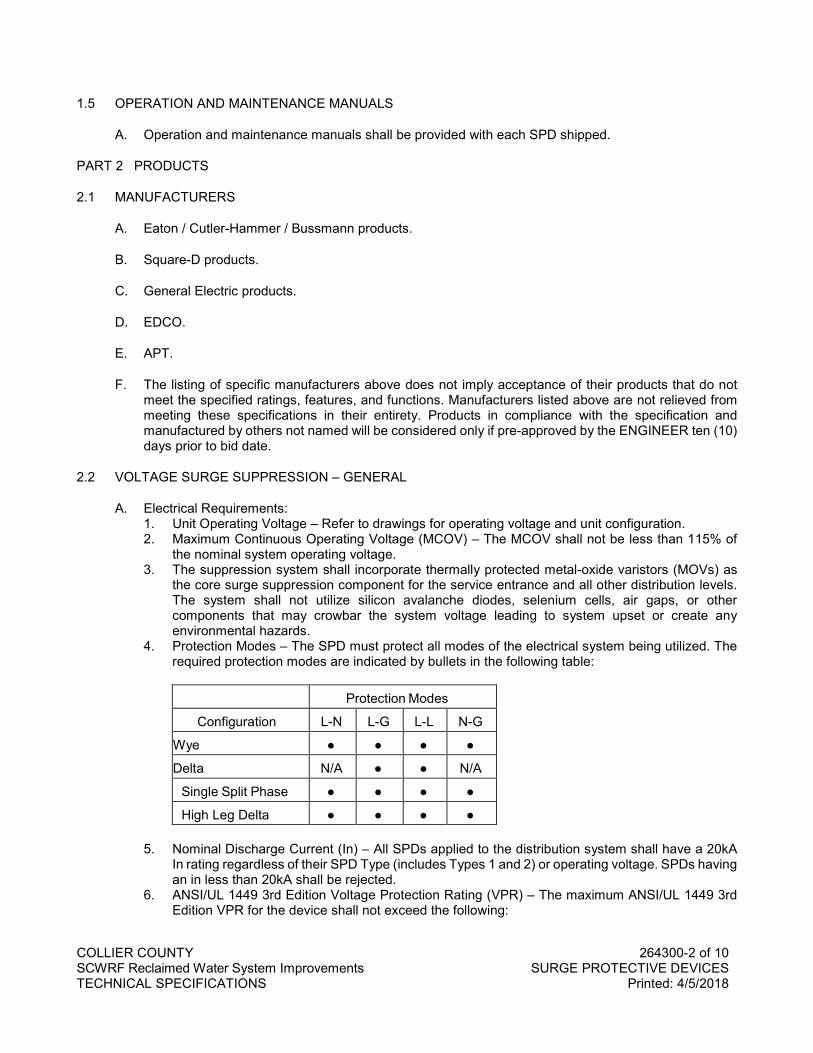
COLLIER COUNTY 264300-2 of 10 SCWRF Reclaimed Water System Improvements SURGE PROTECTIVE DEVICES TECHNICAL SPECIFICATIONS Printed: 4/5/2018
1.5 OPERATION AND MAINTENANCE MANUALS
A. Operation and maintenance manuals shall be provided with each SPD shipped.
PART 2 PRODUCTS
2.1 MANUFACTURERS
A. Eaton / Cutler-Hammer / Bussmann products.
B. Square-D products.
C. General Electric products.
D. EDCO.
E. APT.
F. The listing of specific manufacturers above does not imply acceptance of their products that do not meet the specified ratings, features, and functions. Manufacturers listed above are not relieved from meeting these specifications in their entirety. Products in compliance with the specification and manufactured by others not named will be considered only if pre-approved by the ENGINEER ten (10) days prior to bid date.
2.2 VOLTAGE SURGE SUPPRESSION – GENERAL
A. Electrical Requirements: 1. Unit Operating Voltage – Refer to drawings for operating voltage and unit configuration. 2. Maximum Continuous Operating Voltage (MCOV) – The MCOV shall not be less than 115% of
the nominal system operating voltage. 3. The suppression system shall incorporate thermally protected metal-oxide varistors (MOVs) as
the core surge suppression component for the service entrance and all other distribution levels. The system shall not utilize silicon avalanche diodes, selenium cells, air gaps, or other components that may crowbar the system voltage leading to system upset or create any environmental hazards.
4. Protection Modes – The SPD must protect all modes of the electrical system being utilized. The required protection modes are indicated by bullets in the following table:
Protection Modes
Configuration L-N L-G L-L N-G
Wye ● ● ● ●
Delta N/A ● ● N/A
Single Split Phase ● ● ● ●
High Leg Delta ● ● ● ●
5. Nominal Discharge Current (In) – All SPDs applied to the distribution system shall have a 20kA In rating regardless of their SPD Type (includes Types 1 and 2) or operating voltage. SPDs having an in less than 20kA shall be rejected.
6. ANSI/UL 1449 3rd Edition Voltage Protection Rating (VPR) – The maximum ANSI/UL 1449 3rd Edition VPR for the device shall not exceed the following:
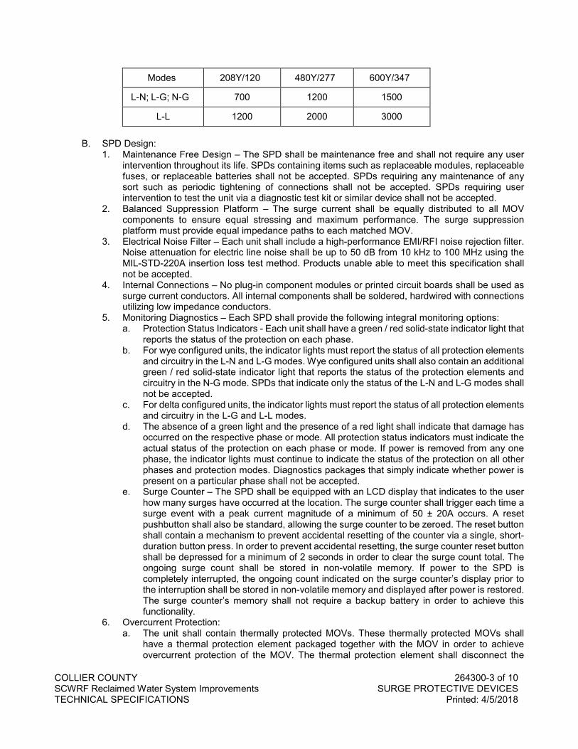
COLLIER COUNTY 264300-3 of 10 SCWRF Reclaimed Water System Improvements SURGE PROTECTIVE DEVICES TECHNICAL SPECIFICATIONS Printed: 4/5/2018
Modes 208Y/120 480Y/277 600Y/347
L-N; L-G; N-G 700 1200 1500
L-L 1200 2000 3000
B. SPD Design: 1. Maintenance Free Design – The SPD shall be maintenance free and shall not require any user
intervention throughout its life. SPDs containing items such as replaceable modules, replaceable fuses, or replaceable batteries shall not be accepted. SPDs requiring any maintenance of any sort such as periodic tightening of connections shall not be accepted. SPDs requiring user intervention to test the unit via a diagnostic test kit or similar device shall not be accepted.
2. Balanced Suppression Platform – The surge current shall be equally distributed to all MOV components to ensure equal stressing and maximum performance. The surge suppression platform must provide equal impedance paths to each matched MOV.
3. Electrical Noise Filter – Each unit shall include a high-performance EMI/RFI noise rejection filter. Noise attenuation for electric line noise shall be up to 50 dB from 10 kHz to 100 MHz using the MIL-STD-220A insertion loss test method. Products unable able to meet this specification shall not be accepted.
4. Internal Connections – No plug-in component modules or printed circuit boards shall be used as surge current conductors. All internal components shall be soldered, hardwired with connections utilizing low impedance conductors.
5. Monitoring Diagnostics – Each SPD shall provide the following integral monitoring options: a. Protection Status Indicators - Each unit shall have a green / red solid-state indicator light that
reports the status of the protection on each phase. b. For wye configured units, the indicator lights must report the status of all protection elements
and circuitry in the L-N and L-G modes. Wye configured units shall also contain an additional green / red solid-state indicator light that reports the status of the protection elements and circuitry in the N-G mode. SPDs that indicate only the status of the L-N and L-G modes shall not be accepted.
c. For delta configured units, the indicator lights must report the status of all protection elements and circuitry in the L-G and L-L modes.
d. The absence of a green light and the presence of a red light shall indicate that damage has occurred on the respective phase or mode. All protection status indicators must indicate the actual status of the protection on each phase or mode. If power is removed from any one phase, the indicator lights must continue to indicate the status of the protection on all other phases and protection modes. Diagnostics packages that simply indicate whether power is present on a particular phase shall not be accepted.
e. Surge Counter – The SPD shall be equipped with an LCD display that indicates to the user how many surges have occurred at the location. The surge counter shall trigger each time a surge event with a peak current magnitude of a minimum of 50 ± 20A occurs. A reset pushbutton shall also be standard, allowing the surge counter to be zeroed. The reset button shall contain a mechanism to prevent accidental resetting of the counter via a single, short-duration button press. In order to prevent accidental resetting, the surge counter reset button shall be depressed for a minimum of 2 seconds in order to clear the surge count total. The ongoing surge count shall be stored in non-volatile memory. If power to the SPD is completely interrupted, the ongoing count indicated on the surge counter’s display prior to the interruption shall be stored in non-volatile memory and displayed after power is restored. The surge counter’s memory shall not require a backup battery in order to achieve this functionality.
6. Overcurrent Protection: a. The unit shall contain thermally protected MOVs. These thermally protected MOVs shall
have a thermal protection element packaged together with the MOV in order to achieve overcurrent protection of the MOV. The thermal protection element shall disconnect the
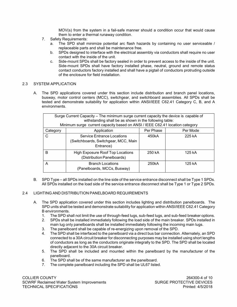
COLLIER COUNTY 264300-4 of 10 SCWRF Reclaimed Water System Improvements SURGE PROTECTIVE DEVICES TECHNICAL SPECIFICATIONS Printed: 4/5/2018
MOV(s) from the system in a fail-safe manner should a condition occur that would cause them to enter a thermal runaway condition.
7. Safety Requirements: a. The SPD shall minimize potential arc flash hazards by containing no user serviceable /
replaceable parts and shall be maintenance free. b. SPDs designed to interface with the electrical assembly via conductors shall require no user
contact with the inside of the unit. c. Side-mount SPDs shall be factory sealed in order to prevent access to the inside of the unit.
Side-mount SPDs shall have factory installed phase, neutral, ground and remote status contact conductors factory installed and shall have a pigtail of conductors protruding outside of the enclosure for field installation.
2.3 SYSTEM APPLICATION
A. The SPD applications covered under this section include distribution and branch panel locations, busway, motor control centers (MCC), switchgear, and switchboard assemblies. All SPDs shall be tested and demonstrate suitability for application within ANSI/IEEE C62.41 Category C, B, and A environments.
Surge Current Capacity – The minimum surge current capacity the device is capable of
withstanding shall be as shown in the following table: Minimum surge current capacity based on ANSI / IEEE C62.41 location category
Category Application Per Phase Per Mode C Service Entrance Locations
(Switchboards, Switchgear, MCC, Main Entrance)
450kA 225 kA
B High Exposure Roof Top Locations (Distribution Panelboards)
250 kA 125 kA
A Branch Locations (Panelboards, MCCs, Busway)
250kA 125 kA
B. SPD Type – all SPDs installed on the line side of the service entrance disconnect shall be Type 1 SPDs. All SPDs installed on the load side of the service entrance disconnect shall be Type 1 or Type 2 SPDs.
2.4 LIGHTING AND DISTRIBUTION PANELBOARD REQUIREMENTS
A. The SPD application covered under this section includes lighting and distribution panelboards. The SPD units shall be tested and demonstrate suitability for application within ANSI/IEEE C62.41 Category B environments. 1. The SPD shall not limit the use of through-feed lugs, sub-feed lugs, and sub-feed breaker options. 2. SPDs shall be installed immediately following the load side of the main breaker. SPDs installed in
main lug only panelboards shall be installed immediately following the incoming main lugs. 3. The panelboard shall be capable of re-energizing upon removal of the SPD. 4. The SPD shall be interfaced to the panelboard via a direct bus bar connection. Alternately, an SPD
connected to a 30A circuit breaker for disconnecting purposes may be installed using short lengths of conductors as long as the conductors originate integrally to the SPD. The SPD shall be located directly adjacent to the 30A circuit breaker.
5. The SPD shall be included and mounted within the panelboard by the manufacturer of the panelboard.
6. The SPD shall be of the same manufacturer as the panelboard. 7. The complete panelboard including the SPD shall be UL67 listed.
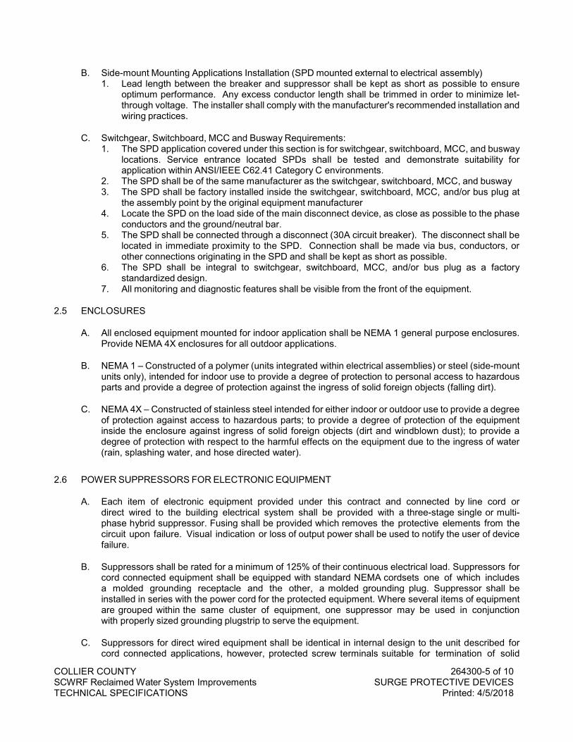
COLLIER COUNTY 264300-5 of 10 SCWRF Reclaimed Water System Improvements SURGE PROTECTIVE DEVICES TECHNICAL SPECIFICATIONS Printed: 4/5/2018
B. Side-mount Mounting Applications Installation (SPD mounted external to electrical assembly) 1. Lead length between the breaker and suppressor shall be kept as short as possible to ensure
optimum performance. Any excess conductor length shall be trimmed in order to minimize let-through voltage. The installer shall comply with the manufacturer's recommended installation and wiring practices.
C. Switchgear, Switchboard, MCC and Busway Requirements: 1. The SPD application covered under this section is for switchgear, switchboard, MCC, and busway
locations. Service entrance located SPDs shall be tested and demonstrate suitability for application within ANSI/IEEE C62.41 Category C environments.
2. The SPD shall be of the same manufacturer as the switchgear, switchboard, MCC, and busway 3. The SPD shall be factory installed inside the switchgear, switchboard, MCC, and/or bus plug at
the assembly point by the original equipment manufacturer 4. Locate the SPD on the load side of the main disconnect device, as close as possible to the phase
conductors and the ground/neutral bar. 5. The SPD shall be connected through a disconnect (30A circuit breaker). The disconnect shall be
located in immediate proximity to the SPD. Connection shall be made via bus, conductors, or other connections originating in the SPD and shall be kept as short as possible.
6. The SPD shall be integral to switchgear, switchboard, MCC, and/or bus plug as a factory standardized design.
7. All monitoring and diagnostic features shall be visible from the front of the equipment.
2.5 ENCLOSURES
A. All enclosed equipment mounted for indoor application shall be NEMA 1 general purpose enclosures. Provide NEMA 4X enclosures for all outdoor applications.
B. NEMA 1 – Constructed of a polymer (units integrated within electrical assemblies) or steel (side-mount units only), intended for indoor use to provide a degree of protection to personal access to hazardous parts and provide a degree of protection against the ingress of solid foreign objects (falling dirt).
C. NEMA 4X – Constructed of stainless steel intended for either indoor or outdoor use to provide a degree of protection against access to hazardous parts; to provide a degree of protection of the equipment inside the enclosure against ingress of solid foreign objects (dirt and windblown dust); to provide a degree of protection with respect to the harmful effects on the equipment due to the ingress of water (rain, splashing water, and hose directed water).
2.6 POWER SUPPRESSORS FOR ELECTRONIC EQUIPMENT
A. Each item of electronic equipment provided under this contract and connected by line cord or direct wired to the building electrical system shall be provided with a three-stage single or multi-phase hybrid suppressor. Fusing shall be provided which removes the protective elements from the circuit upon failure. Visual indication or loss of output power shall be used to notify the user of device failure.
B. Suppressors shall be rated for a minimum of 125% of their continuous electrical load. Suppressors for cord connected equipment shall be equipped with standard NEMA cordsets one of which includes a molded grounding receptacle and the other, a molded grounding plug. Suppressor shall be installed in series with the power cord for the protected equipment. Where several items of equipment are grouped within the same cluster of equipment, one suppressor may be used in conjunction with properly sized grounding plugstrip to serve the equipment.
C. Suppressors for direct wired equipment shall be identical in internal design to the unit described for cord connected applications, however, protected screw terminals suitable for termination of solid
COLLIER COUNTY 264300-6 of 10 SCWRF Reclaimed Water System Improvements SURGE PROTECTIVE DEVICES TECHNICAL SPECIFICATIONS Printed: 4/5/2018
copper wire shall be used for wiring terminations. One suppressor may be used to support several equipment cabinets provided all cabinets are located within the same equipment cluster and the maximum connected load shall not exceed eighty percent of the rated suppressor capacity.
D. Suppressors shall be constructed with a phenolic non-flammable exterior housing with provisions for mounting to the interior of equipment racks, cabinets, or to the exterior of free-standing equipment. Suppressors shall be constructed as three- stage devices. The first stage shall include a high-energy varistor clamp between line and neutral and from neutral to ground. The second stage shall consist of series air-core inductor installed in the line conductor(s) to properly coordinate the action of the first and third stages. The third, fast acting, hard clamping stage shall consist of a network of silicon avalanche bipolar surge suppression diodes between the neutral and line conductor(s).
E. Minimum suppressor performance characteristics shall be as follows: 1. Maximum single impulse line-to-neutral current withstand: 15,000 Amperes (8 x 20 us waveform) 2. Maximum single impulse neutral-to-ground current withstand: 10,000 Amperes (8 x 20 us
waveform) 3. Pulse lifetime rating Category B worst case current waveform (8 x 20 us @ 3000 Amperes):
1200 occurrences 4. Pulse lifetime rating for 200 Ampere (8 x 20 us waveform): 10,000 occurrences 5. Worst case response time: Five Nanoseconds 6. Worst case (Maximum Single Impulse Current Conditions) clamping voltage: 400% of nominal
phase-to-ground RMS voltage. 7. Initial breakdown voltage: 200% of nominal phase-to-ground RMS voltage.
2.7 SURGE PROTECTIVE DEVICES FOR DATA / SIGNAL / IO
A. Suppression devices for conductor pair protection shall be provided in multi-circuit pluggable packages suitable for the circuitry to be protected. Units for protection of data circuits which utilize standard connector configurations shall be equipped with connectors which install in series with the data cable to the protected equipment. Units intended for use with multiple wiring pairs shall be equipped with an accessory terminal blocks or strips suitable for the type of wiring being used. Single pair units shall be configured as encapsulated units with wire leads or screw-terminal wiring terminations. Suppressors installed outside of terminal or equipment cabinets (except at designated terminal boards) shall be provided with a housing to afford physical protection for the surge suppression modules.
B. Suppression for each pair shall consist of a three-element gas tube first stage, an isolating element in series with each conductor of the pair, and a silicon avalanche second stage. Second stage clamping shall be provided across the pair for differential mode protection and from each side of the pair to ground for common mode protection. Resistive limiting elements may be used on low current circuits where the effect of voltage drop across the series resistance has no effect on circuit operation. Inductive series elements shall be used on higher current circuits to effectively pass direct or low frequency alternating currents while limiting passage of fast risetime surge waveforms. Silicon avalanche devices shall be designed for surge suppressor applications and shall be polarized or bipolar as appropriate for each circuit.
C. Provide Foundation Field Bus surge suppression on all FFB controlled motor operated valves. Provide SPD rated for FFB circuits equal to Bussmann BSPD24DINLHF with over voltage protection for two separate floating signal circuits (Foundation Fieldbus-H1), consisting of a base element and a plug-in module which are both included in the Bussmann BSPD24DINLHF. The unit provides a protection element with a max continuous operating DC/AC voltage “Uc” 33VDC/23.3VAC) in conjunction with fast response.
D. Minimum performance criteria (each circuit) shall be as follows:
COLLIER COUNTY 264300-7 of 10 SCWRF Reclaimed Water System Improvements SURGE PROTECTIVE DEVICES TECHNICAL SPECIFICATIONS Printed: 4/5/2018
1. SPD must be listed to UL 497B. 2. Maximum total nominal discharge current (8/20µs): 20KA. 3. Maximum nominal discharge current (8/20µs) per line: 10KA. 4. Maximum Voltage Protection Level line-line: 65V. 5. Maximum Voltage Protection Level line-ground: 550V. 6. Maximum Capacitance line-line: 25 pF. 7. Maximum Capacitance line-ground: 16 pF.
E. DIN-Rail Surge Protective Devices to use for binary signal applications (or equivalent):
Bussmann SPD Part Number
Nominal Voltage
BSPD5DING 5 BSPD12DING 12 BSPD24DING 24 BSPD48DING 48
F. Applications using RJ45 connected systems (Gigabit Ethernet, ATM, ISDN, VoiP, and CAT 6). All SPDs must meet the following requirements: 1. Application shall be protected via shielded SPD at the both ends of the RJ45 cable feeding the
equipment. 2. Maximum Continuous Operating Voltage (MCOV) 48Vdc. 3. UL 497B Listed. 4. Capacitance line-to-line ≤30Pf. 5. Capacitance line-to-PG (physical ground) ≤25Pf. 6. SPD shall be DIN-Rail or panel mountable with supplied bracket. 7. SPD shall have five-year product warranty. 8. SPD shall have IP10 degree of protection. 9. SPD shall have an insertion loss of ≤3db with a frequency range up to 250MHz with all four (1/2,
3/6, 4/5, 7/8) pairs protected with gas discharge tubes and an adapter filter matrix. 10. SPD enclosure shall be made of metallic material. 11. SPD shall have an operating temperature range of -40°C to +80°C. 12. SPD shall provide grounding means via DIN-Rail/bracket.
2.8 SURGE PROTECTIVE DEVICES FOR AC POWER IN CONTROL PANELS
A. All Control Panels shall have Surge Protective Devices installed immediately after the main overcurrent device or immediately after the supply conductors to the panel have been terminated. The Surge Protective Device(s) shall follow IEEE C62.41 recommendation for cascading to protect all voltage levels to and including 24 volts AC/DC and shall be as follows: 1. DIN-Rail Surge Protective Devices Shall:
a. Be UL 1449 3rd Edition Recognized for UL Type 2 applications except at 48 volts AC/DC and below may be UL 1449 3rd Edition for Type 3 applications.
b. Provide suppression for both normal mode (L-N [Wye]) and common mode (L+N-G [Wye] or L-G [Delta]).
c. Have a Surge Current Capacity (Imax) of at least 40kA. d. Have a Nominal Surge Current Rating (In) of 20kA. e. Have SCCRs of 200kA, except that 347Y/600V, 240/480V Highleg Delta and 347V single-
phase SPDs shall have a minimum SCCR of 125kA. f. Use MOV technology with thermal disconnect. g. Be RoHS compliant. h. SPD status monitoring shall be provided by local visual indication and, if needed, by remote
contact signaling using an optional Form C contact relay.
COLLIER COUNTY 264300-8 of 10 SCWRF Reclaimed Water System Improvements SURGE PROTECTIVE DEVICES TECHNICAL SPECIFICATIONS Printed: 4/5/2018
i. SPD shall have replaceable modules.
B. DIN-Rail Surge Protective Devices to use based on system voltage (or equivalent):
Bussmann SPD Part Number System Voltage Description
Voltage (AC)
BSPM1120S2GR 120V single-phase 120 BSPM2240S3GR 120/240V split-phase center tap 240 BSPM3240DLGR 240V Delta - 3 phase 3 wire + ground 240
BSPM3480DLGR 480V Delta - 3 phase 3 wire + ground 277/480 Wye - 3 phase 3 wire + ground 480
BSPM3208WYGR 120/208 Wye - 3 phase 3 wire + ground 208
PART 3 EXECUTION
3.1 BONDING AND GROUNDING CONDUCTORS AND MATERIALS
A. Conductors utilized for surge suppressor bonding shall be a minimum of #6 AWG solid insulated copper unless otherwise specified.
B. Ground bus or strip material shall be copper, a minimum of 26 gauge in thickness and three inches wide unless otherwise specified. Bus materials may be secured to surfaces with an appropriate mastic material or mechanical fasteners. Bus connections shall be bolted or brazed and reinforced as necessary on thin bus material to provide a permanent and secure connection.
C. Unless otherwise specified, all surge suppression grounding electrodes shall be 5/8" diameter copper weld rods, twenty feet in length.
D. Connectors, splices, and other fittings used to interconnect grounding conductors, bond to equipment or ground bars, shall comply with requirements of the National Electric Code and be approved by Underwriters Laboratories for the purpose.
E. Connectors and fittings for grounding and bonding conductors shall be of the compression or set-screw type in above grade locations. Connections below grade shall be exothermically welded or brazed.
F. Bonding connections between electrically dissimilar metals shall be made using exothermic welds or using bi-metal connectors designed to prevent galvanic corrosion.
3.2 SEGREGATION OF WIRING
A. All system wiring shall be classified into protected and non-protected categories. Wiring on the exposed side of suppression devices shall be considered unprotected. Surge suppressor grounding and bonding conductors shall also fall into this category.
B. All wiring between surge suppressors and protected equipment shall be considered protected. Isolated circuitry exempted from surge suppression requirements in part one of this section shall also be considered protected.
C. A minimum of three inches of separation shall be provided between parallel runs of protected and unprotected wiring in control panels, terminal cabinets, terminal boards and other locations. In no case
COLLIER COUNTY 264300-9 of 10 SCWRF Reclaimed Water System Improvements SURGE PROTECTIVE DEVICES TECHNICAL SPECIFICATIONS Printed: 4/5/2018
shall protected and unprotected wiring be bundled together or routed through the same conduit. Where bundles of protected and unprotected wiring cross, such crossings shall be made at right angles.
3.3 INSTALLATION OF SUPPRESSORS
A. Suppressors shall be installed as close as practical to the equipment to be protected consistent with available space. Where space permits and no code restrictions apply, suppressors may be installed within the same cabinet as the protected equipment. Suppressors installed in this manner shall utilize the equipment chassis as a medium for bonding of their ground terminals. Bonding jumpers not exceeding two inches in length shall be installed between the chassis and suppressor ground terminals. Bolted connections with star washers shall be used to insure electrical and mechanical integrity of connections to the equipment chassis.
B. Suppressors shall be installed in a neat, workmanlike manner. Lead dress shall be consistent with recommended industry practices for the system on which these devices are installed.
C. Bonding between ground terminals for power and signal line suppressors serving a particular item or cluster of equipment shall be kept as short as possible. Where practical, suppressors shall be installed in a common location for the cluster with their ground terminals bonded closely together. For installations requiring separation between the various suppressor grounds and equipment chassis within an equipment cluster, the following table shall be used to determine bonding conductor requirements (distances are measured between most distant suppressor or chassis grounds):
BONDING DISTANCE MATERIAL 0 - 10 feet #6 AWG Bare Copper (Solid) 10- 25 feet 1-1/2" Copper Strip 26ga. Min. 25- 50 feet 3" Copper Strip 26ga. Min.
Over 50 feet 6" Copper Strip 26ga. Min. 1. Care shall be exercised to avoid connection of incidental grounds to the bonding bus system.
D. Where terminal cabinets are used to house surge suppressors, painted steel backboards shall be used to serve as a low impedance ground plane for bonding surge suppressor leads together. Terminal boards used for the same purpose shall be laminated with a single sheet of 14 ga. galvanized steel to serve as a ground plane for suppressors. Suppressors with ground terminals not inherently bonded to the ground plane through their mounting shall be bonded to this plane using a two- inch maximum length of #12AWG copper wire and suitable lug. Ground planes and backboards shall be drilled to accept self-tapping screws, any paint in the area of the bond shall be removed and star washers shall be used.
E. Supplementary grounding and bonding connections required between the bonding bus or ground plane for each equipment cluster and other locations as indicated herein shall be accomplished using #6 AWG bare copper conductors and approved connections unless otherwise noted.
3.4 WARRANTY
A. The manufacturer shall provide a full ten (10) year warranty unless specified otherwise in this document from the date of shipment against any SPD part failure when installed in compliance with manufacturer's written instructions and any applicable national or local code.
PART 4 PRODUCTS
Not used.

COLLIER COUNTY 264300-10 of 10 SCWRF Reclaimed Water System Improvements SURGE PROTECTIVE DEVICES TECHNICAL SPECIFICATIONS Printed: 4/5/2018
END OF SECTION
COLLIER COUNTY 268500-1 of 6 SCWRF Reclaimed Water System Improvements INSTRUMENTATION AND CONTROL TECHNICAL SPECIFICATIONS Printed: 8/14/2019
SECTION 268500
INSTRUMENTATION AND CONTROL
PART 1 GENERAL
1.1 SCOPE
A. Furnish and install all field equipment including a new PLC panel, connections wiring and raceways, complete with all accessories, to tie in the following devices to the existing PLC control panels at the plant: 1. Magnetic Flowmeter: one (1). 2. Motor Operated Valves: five (5).
B. Modifications and programming of existing plant control panels will be the responsibility of the owner.
C. All programming and integration with the existing plant network architecture for operating the MOV’s is by others. The Contractor shall coordinate this activity with the owner.
D. This Specification has been developed to establish minimum requirements for modifications to the existing plant control system. This installation shall be designed, constructed, tested and documented in strict accordance with the guidelines of this document.
E. This specification is intended to be used in conjunction with all drawings supplied and is not intended to be complete without reference diagrams on system configurations, etc. All bidders must conform to all areas of the documentation.
1.2 RELATED SECTIONS
A. Section 333314 – Wastewater Valves and Appurtenances. See Section 333314 for Electric Motor Valve Actuators and Magnetic Flow Meters.
1.3 SUBMITTALS
A. Shop Drawings shall be submitted in accordance with Section 260500 BASIC ELECTRICAL MATERIALS AND METHODS and Section 013330. These drawings shall include: 1. A cover sheet consisting of a Bill of Material, purchase order number, manufacturer's job number,
Owner's name, location, application and shipping address. 2. Mechanical layouts detailing the overall external dimensions of all enclosures. Include all pertinent
information such as location of door handles, windows, lifting lugs and enclosure mounted items such as pump controller chassis and I/O modules (show cable connections on modules), relays, cooling fans, etc.
PART 2 PRODUCTS
2.1 NETWORK CABLE
A. Fiber optic cable shall contain a minimum of six (6) fibers or more as indicated on the drawings. Fiber optic tubing shall be multi-mode fiber. The Cable shall incorporate an inner core comprising an inner cable sheath containing a central strength member, cores of Single Mode Low Water Peak fibers meeting ITU-T Recommendation G652.D, Loose tubes containing either 6 or 12 fibers per tube, and core blocking material, a black polyethylene inner sheath. General Installation cable shall incorporate an insect resistant jacket, a rodent resistant layer and polyethylene outer sheath.
COLLIER COUNTY 268500-2 of 6 SCWRF Reclaimed Water System Improvements INSTRUMENTATION AND CONTROL TECHNICAL SPECIFICATIONS Printed: 8/14/2019
B. Ethernet Copper UTP Cable: Provide field cable that is Multi paired Data Signal cable, TIA 5638B Cat 5e, #22 AWG, twisted pair, 600V, PVC insulated, aluminum tape pair shielding, thermoplastic (PVC) overall sheathed and shielded, industrial Ethernet cable as manufactured by the Allen Bradley 1585- C8HB or equal. Option to provide pre-molded M12 and RJ45 patch-cords Allen Bradley 1585D and 1585J is acceptable at CONTRACTOR’s option.
2.2 Ethernet Cable Connections: All conductor connections shall be to RJ45 and M12 compatible jacks. All conductors shall be marked with Mylar wrap type "Brady" labels. Identification labels shall be permanent type and be machine printed. All terminal block terminations shall be labeled. The inside portion of the terminal cabinet doors shall display a protected terminal cabinet drawing with all connections shown and described as to color code, number assigned to connection function of conductor and destination. Wire shall be guided within terminal cabinets by cable supports. All conductors shall be neatly led to terminations. Instrumentation and control field cables on the unprotected side of SPD devices within the cabinet shall not run in parallel to the cables on the protected side of the SPD device. Separate cable supports (duct) will be provided. No splices shall be made within a conduit run or in manholes.PLC PANEL ENCLOSURE
A. Refer to section 268501 PLC Panel.
2.3 ELECTRICAL SURGE AND TRANSIENT PROTECTION
A. General: All instrument and control equipment mounted outside of protective structures (field-mounted equipment) shall be equipped with suitable surge- arresting devices to protect the equipment from damage due to electrical transients induced in the interconnecting lines from lightning discharges and nearby electrical devices. Surge suppression equipment shall meet or exceed the requirements as specified herein. Surge suppressors shall be as manufactured by EDCO, Inc., of Ocala, Florida.
B. Suppressor Locations: Surge suppression equipment described herein and indicated on the contract drawings shall be installed in the following locations: At the point of connection between each equipment item and its power supply conductors (direct wired equipment).
C. Power Supply Suppressor Assemblies: Provide suppressors suitable for connection to 120-volt, single-phase power supply. Suppressors shall be EDCO "HSP-121 SERIES", or equal, and shall meet or exceed the following requirements: 1. Suppressors for direct wired equipment shall be provided with two 3- terminal barrier terminal
strips capable of accepting no. 12 AWG solid or stranded copper wire. One terminal strip shall be located on each end of the suppressor unit.
2. Suppressors shall be epoxy encapsulated within a phenolic nonflammable enclosure with provision for mounting to interior of equipment racks, cabinets or to the exterior of free standing equipment. Epoxy encapsulation shall be flame retardant.
3. Suppressors shall be constructed as multistage devices. The first stage shall be a high energy metal oxide varistor element. The second stage shall consist of fast acting high power bipolar silicon avalanche devices. First and second stages shall be interconnected through a series air core inductor of sufficient current carrying capacity to permit a continuous operating current of 15 amperes. a. Suppressors shall meet or exceed the following performance criteria based on a test surge
waveshape of 8 times 20 microseconds. b. Maximum Operating Voltage: 130V ac Minimum Breakdown Voltage: 150V ac Maximum
Operating Current: 15 amps Response Time: 5 nanoseconds c. Peak First Stage Clamping Voltage: 20,000 amps Maximum First Stage Clamping Voltage:
350 Volts Maximum Second Stage clamping Voltage: 210 Volts Pulse Life Before Failure: 2,000 occurrences
D. Analog Signal Cable Suppressor Assemblies: Suppressors shall be EDCO SRA or DRS Series, or equal. Provide EDCO type SS64 surge suppressors at all loop powered instrument locations. Suppressors shall be epoxy encapsulated within a phenolic enclosure and stainless steel for SS64
COLLIER COUNTY 268500-3 of 6 SCWRF Reclaimed Water System Improvements INSTRUMENTATION AND CONTROL TECHNICAL SPECIFICATIONS Printed: 8/14/2019
units. Suppressor Assembly shall be flame retardant. Suppressor assemblies shall be four lead devices and shall include a threaded mounting/grounding stud. Suppressors shall meet or exceed the following performance criteria based on a test surge waveshape of 8 times 20 microseconds: 1. Components: Hybird circuit consisting of a 3-electrode gas tube and silicone avalanche devices
to clamp each line to ground. High energy gas tube and silicone avalanche devices shall be separated by a series impedance.
2. Recovery: Automatic. 3. Peak Surge Current: 10,000 amps. 4. Pulse Life Before Failure: 100 occurrences. 5. Response Time: 5 nanoseconds. 6. Minimum Voltage Clamp Rating: 40 volts. 7. Series Impedance: 24 ohms total. 8. Temperature Range: -40 degrees C to +85 degrees C. 9. Operating Voltage: Less than 30V dc. 10. Operating Current: 4 to 20 Ma dc. 11. Resistance Line to Ground: Greater than 1 megohm.
E. Hybrid power and analog signal suppressor assemblies. Suppressors shall be EDCO SLAC units or approved equal.
F. Surge suppressor input (unprotected) and output (protected) wiring shall be kept segregated at the point of connection to the surge unit and external to the unit. Do not route unprotected cable adjacent to protected cable.
PART 3 EXECUTION
3.1 INSTALLATION
A. The work included in this section consists of furnishing, installing the instruments and appurtenances, including all conduit, wiring.
B. Include the services of a factory trained, qualified service engineer of the equipment manufacturer to inspect the complete equipment installation to assure that it is installed in accordance with the manufacturer's recommendations, make all adjustments necessary to place the system in trouble-free operation and instruct the operating personnel in the proper care and operation of the equipment furnished.
C. All workmanship utilized in the manufacture and installation of this system shall be of the highest quality and performed in a manner which is consistent with all accepted practices for industrial controls.
D. Provide continuous protection of the installed instrumentation equipment from the elements, moisture, construction damage, dust, debris, paint spatter or other conditions which will adversely affect the unit operation until such time as the equipment is scheduled for start-up testing.
3.2 MOUNTING OF EQUIPMENT AND ACCESSORIES
A. Install and mount equipment in accordance with the Contract Documents, manufacturer's instructions and installation detailed shop drawings. Mount equipment so that they are rigidly supported, level and plumb, and in such a manner as to provide accessibility; protection from damage; isolation from heat, shock and vibration; and freedom from interference with other equipment, piping, and electrical work. Do not install field enclosures, cabinets, and panels until heavy construction work adjacent to the equipment has been completed to the extent that there shall be no damage to the equipment.
COLLIER COUNTY 268500-4 of 6 SCWRF Reclaimed Water System Improvements INSTRUMENTATION AND CONTROL TECHNICAL SPECIFICATIONS Printed: 8/14/2019
B. Locate devices, including accessories, where they shall be accessible from grade, except as shown otherwise.
C. Coordinate the installation of the electrical service to components related to the system to assure a compatible and functionally correct system. All accessories shall be coordinated and installation supervised by the CONTRACTOR.
3.3 CALIBRATION
A. Calibrate each instrument in the factory before shipping and furnish with the calibration data and the certification of calibration.
B. The service technician shall calibrate all instruments and components of the instrumentation system with field adjustable ranges and/or settings after installation in conformance with the manufacturer's instructions, the Contract Documents and the reviewed shop drawings. Set each instrument and components for the specific conditions and intended application as specified for this installation. Replace defective instruments and components which cannot achieve correct calibration of stated accuracy, either individually or collectively within the system.
C. Certify in writing to the Owner that all calibrations have been completed and the instrumentation system is ready to be operated. Provide instrumentation calibration sheets in the O&M manuals for future reference for both factory and field calibration tests. Calibration certification documents shall be available on site at the time of substantial completion. Certification documents shall include the signature of the service technician performing the calibration.
3.4 GENERAL TESTING REQUIREMENTS
A. The CONTRACTOR shall provide the services of experienced factory trained technicians, tools and equipment to field calibrate, test, inspect, and adjust all equipment in accordance with manufacturer's specifications and instructions.
B. The CONTRACTOR shall maintain master log books for each phase of installation, startup and testing activities specified herein. Log book shall include signal, loop or control strategy tag number, equipment identification, description and space for sign-off dates, CONTRACTOR signature and Engineer signature. Example test documentation specific to each phase of testing shall be approved prior to initiation of that testing, as specified here.
C. All test data shall be recorded on test forms, previously approved by the Engineer. When each test has been successfully completed, a copy of all test results shall be furnished to the Engineer together with a statement that all specified test requirements have been met and that the system is operating in accordance with the Contract Documents.
3.5 INITIAL FIELD TESTING
A. Primary elements such as transmitters and switch devices shall be calibrated and tested as specified.
B. Each final control element shall be individually tested as by CONTRACTOR.
C. Each instrument and control loop shall be tested by CONTRACTOR.
D. Verify that each instrument, meters, and gage has been properly installed, connected, grounded and calibrated. Perform three-point calibration on continuous elements and systems. Provide calibration records.
COLLIER COUNTY 268500-5 of 6 SCWRF Reclaimed Water System Improvements INSTRUMENTATION AND CONTROL TECHNICAL SPECIFICATIONS Printed: 8/14/2019
E. Verify that the inputs/outputs functions of each instrument conform to the requirements of the application.
3.6 LOOP CHECKS
A. Prior to control system startup and testing, each monitoring and control loop shall be tested by the CONTRACTOR on an individual basis from the primary element to the final termination
B. Signals from transducers, sensors, and transmitters shall be utilized to verify control responses. Simulated input data signals may be used subject to prior written approval by the Engineer. All modes of control shall be exercised and checked for proper operation.
C. The accuracy of all analog inputs shall be verified using field inputs or by manually applying input signals at the final controller, and then reading and recording the resulting analog input data at the PCL or work station.
D. Each loop tested shall be witnessed, dated and signed off by both the CONTRACTOR and the Engineer/owner upon satisfactory completion.
3.7 WARRANTY
A. All products mentioned herein must be warranted by the supplier for a period of two (2) years from the date of system turnover; final acceptance.
.
END OF SECTION

COLLIER COUNTY 268500-6 of 6 SCWRF Reclaimed Water System Improvements INSTRUMENTATION AND CONTROL TECHNICAL SPECIFICATIONS Printed: 8/14/2019
NO TEXT FOR THIS PAGE
SCWRF RECLAIMED TANK IMPROVEMENTS 268501-1 of 6 TECHNICAL SPECIFICATIONS PLC PANELS Printed: 4/5/2018
SECTION 268501
PLC PANEL
PART 1 - GENERAL
1.1 WORK INCLUDED
A. Furnish all labor, equipment, and materials for PLC panels as indicated on the drawings and specified herein. The panel supplier shall be a UL listed panel shop and all panels shall be UL-508 certified and labeled.
B. PLC panel equipment shall be coordinated to provide all the specified control as indicate in the elementary diagrams or specified herein.
C. The Contractor shall be responsible for coordinating and interfacing with equipment and instrumentation supplied under other sections of the Contract Documents that are an integral part of the plant control systems. This interfacing shall be incorporated in the detailed systems drawings and data sections to be submitted by the contractor prior to rough-in work.
1. SUBMITTALS
A. The contractor shall submit to the Engineer for approval complete shop drawings,
wiring diagrams, data, and operation and maintenance manuals of all equipment to be furnished under this section.
B. Coordination and Shop Drawings: Prepare and submit coordination drawings for
installation of products and materials fabricated. Coordination and shop drawings shall be prepared using a computer aided drafting system compatible with Autodesk AutoCAD version 2004 or greater. Coordination and shop drawings shall be submitted on hard copy and electronic CD-Rom (dwg) format.
1. Submit component interconnect drawings showing the interconnecting
wiring between each component including equipment supplied under other sections requiring interfacing with the control system. Diagrams shall show all component and panel terminal board identification numbers, and external wire and cable numbers. Note, this diagram shall include all intermediate terminations between field elements and panels (e.g., terminal junction boxes, pull boxes, etc.). Diagrams' devise designations, and symbols shall be in accordance with NEMA ICS 1-101.
2. Panel Wiring Diagrams: Elementary diagrams shall be similar to those
diagrams shown in the drawings, but with the addition of all auxiliary devices such as additional relays, alarms, fuses, lights, fans, heaters, etc.
3. Panel wiring diagrams shall identify wire numbers and types, terminal
numbers, tag numbers and PLC I/O identification (address) numbers. Wiring diagrams shall show all circuits individually; no common diagrams shall be allowed.
4. Submit arrangement and construction drawings for PLC panel, and for
other special enclosed assemblies for field installation. Include dimensions, identification of all components, preparation and finish data,
SCWRF RECLAIMED TANK IMPROVEMENTS 268501-2 of 6 TECHNICAL SPECIFICATIONS PLC PANELS Printed: 4/5/2018
nameplates, enough other details to define the style and overall appearance of the assembly and a finish treatment. Drawings shall show the location of all front panel mounted devices to scale, and shall include a panel legend and a bill of materials. The panel legend shall list and identify all front of panel devices by their assigned tag numbers, all nameplate inscriptions, service legends and annunciator inscriptions. The bill of materials shall list all devices mounted within the panel that are not listed in the panel legend, and shall include the tag number, description, manufacturer and complete model number for each service.
5. Submit installation, mounting, and anchoring details for all components.
C. Operation, Maintenance and Repair Manuals
1. Submit operation and maintenance manuals.
2. CODES AND STANDARDS:
A. Equipment, materials, and workmanship shall comply with the latest revisions of
the following codes and standards
1. Instrumentation: Instrument Society of America (ISA). 2. National Electrical Code (NEC) 2005, 3. Wiring: ISA S5.3 and S5.4, latest issue. 4. Control Panels and equipment: NEMA, UL and ANSI. 5. Control Logic: Joint Industrial Council (JIC). 6. UL508A and UL508A-SB
PART 2 - PRODUCTS
2.1 General
A. Unless otherwise specified, instruments shall be solid state, electronic, using
enclosures to suit specified environmental conditions. All instruments shall be provided with mounting hardware and floor stands, wall brackets, or instrument racks as shown on the Drawings, or as required. Equipment installed in a hazardous area shall meet Class, Group, and Division as shown on the Drawings, to comply with the National Electrical Code. Provide heavy-duty type devices throughout that are designed for continuous industrial service. Equipment used shall be U.L. approved.
B. All field instrumentation for outdoor service shall be furnished and installed in
Field Panels or Sun Shade. Unless otherwise specified, provide field instrument enclosures of stainless steel, powder coated white with NEMA 4X rated construction; provide sunshades for all exposed exterior panels.
C. Unless otherwise shown or specified, local indicators shall be provided for all
instruments. Where instruments are located in inaccessible locations, local indicators shall be provided and shall be mounted remotely. All indicator readouts shall be linear in process units. Readouts of 0-100% shall not be acceptable (except for valve position). Floating isolated outputs shall be provided for all transmitters.
SCWRF RECLAIMED TANK IMPROVEMENTS 268501-3 of 6 TECHNICAL SPECIFICATIONS PLC PANELS Printed: 4/5/2018
D. Electronic equipment shall utilize printed circuitry and shall be coated (tropicalized) to prevent contamination by dust, moisture and fungus. Solid-state components shall be conservatively rated for long-term performance and dependability over ambient atmosphere fluctuations. Ambient conditions shall be -15 to 50 degrees C and 20 to 100 percent relative humidity, unless otherwise specified. Field mounted equipment and system components shall be designed for installation in dusty, humid, and corrosive service conditions.
E. All analog transmitter and controller outputs shall be isolated, 4-20 milliamps into
a load of 0-750 ohms, unless specifically noted otherwise. All switches shall have double-pole, double-throw contacts rated at a minimum of 600 VA, unless specified otherwise.
2.2 PLC Panels.
A. PLC panels shall be UL508A/SB compliant. PLC panels shall be marked with
a short circuit current rating (SCCR). The SCCR shall be equal to or more than the short circuit current available at the panel line terminals and in no case be less than 10,000A SCCR for 480V supplied panels or 5000A SCCR for 208/120V panels. The panel designer shall verify the available short circuit required.
B. The electrical control equipment shall be mounted within a pad-lockable NEMA
Type 4X enclosure constructed of not less than 304 stainless steel and shall be equipped with a 3-point latch with all hardware and exterior components construction of 300 series stainless steel (except PLC panels in air conditioned spaces and electrical room may be NEMA 1 painted steel). The enclosure shall be powder coated white and have sunshields mounted on the top, sides and front of the enclosure. The enclosure shall be equipped with a removable, aluminum or stainless steel back panel on which control components shall be mounted. Back panel shall be secured to enclosure with collar studs. All hardware shall be stainless steel. Provide safety hardware to hold the door in an open position. Provide a folding shelf on the door for convenient temporary support of a laptop computer.
C. All P L C panel wiring shall be identified at both ends with type written heat
shrinkable wire markers with the numbering system shown on the control submittal drawings.
1. Control wiring shall be stranded copper, minimum size #14 AWG (except
for shielded instrumentation cable may be #16 AWG), with 600 volt, 90 degree C, flame retardant, Type MTW thermoplastic insulation.
2. Wire shall be guided within control and terminal cabinets by cable supports (duct). Instrumentation and control field cables on the unprotected side of SPD devices within the cabinet shall not run in parallel to the cables on the protected side of the SPD device. Separate cable supports (duct) will be provided.
3. All conductors shall be neatly led to terminations. All connections of stranded wire to screw type terminal blocks shall be by insulated spade lugs, crimp fastened to wire. Provide stranded wire crimp ferrules for all stranded wire connections not requiring spade lugs for screw type terminal blocks.
D. The PLC panel shall be provided with nameplates identifying each component,
SCWRF RECLAIMED TANK IMPROVEMENTS 268501-4 of 6 TECHNICAL SPECIFICATIONS PLC PANELS Printed: 4/5/2018
PLC, UPS, Field Terminals, etc. Nameplates shall be permanently affixed using an epoxy process. Nameplates shall be laminated plastic, engraved white letters with a black background.
E. Corrosion Inhibitor Emitter: Provide an industrial corrosion inhibitor emitter on all
exterior mounted PLC panels that will protect internal components of the panel from corrosion one year. Provide one spare emitter for each panel.
F. Terminal strips shall be provided for all signals as indicated on the drawings plus
all spare conductors as specified. Terminal strips shall be switch type with integral fuses equal to Allen Bradley 1492-H6. Wiring from the PLC panel to the terminal strips shall be factory installed. All spare conductors shall be terminated and identified. All terminals over 200V phase to phase shall be covered with approved plastic shields.
G. The cabinet shall be arranged to separate the incoming field terminal interface
blocks and surge suppression from the PLC I/O signals in the cabinet.
H. Fused terminal blocks shall be provided for all field inputs and outputs. Blocks shall be permanently marked to indicate the appropriate I/O address of each circuit on the pump controller. Surge suppressors shall be provided for all analog and digital inputs and outputs.
I. The assembled system shall include circuit breakers, fuse blocks and other
electrical components as required by the application and in accordance with the standard requirements of the National Electric Code as well as all State and Local electrical code requirements.
J. All I/O racks, processor racks and power supplies shall be grounded in
accordance with the manufacturer's specifications.
K. All cables, plugs, connectors and receptacles requiring user field installation shall be designed to withstand an industrial environment.
L. Provide an Allen Bradley Compact Logix PLC controller per County standards.
PLC shall have Ethernet connectivity as shown on the drawings. The Ethernet connection will be connected via Cat-6 (5e) UTP to the Control System Stratix Switch and fiber to the plant PLC as shown on the Control Network block diagram.
M. Provide an Allen Bradley Stratix 8000 managed 100 base-T/FL Ethernet switch in the PLC panel. Provide mixed media Ethernet switch with minimum 8-port RJ45 10/100Base-TX auto-sensing and 2-port 100Base-FX fiber ports. Provide Allen Bradley Stratix-8000 Switch model# 1783-MS10T.
PART 3 - EXECUTION
1. MOUNTING OF EQUIPMENT AND ACCESSORIES
A. Install and mount equipment in accordance with the Contract Documents, and
installation detailed shop drawings. Mount equipment so that they are rigidly supported, level and plumb, and in such a manner as to provide accessibility; protection from damage; isolation from heat, shock and vibration; and freedom from interference with other equipment, piping, and electrical work.
SCWRF RECLAIMED TANK IMPROVEMENTS 268501-5 of 6 TECHNICAL SPECIFICATIONS PLC PANELS Printed: 4/5/2018
B. Mount local equipment in cabinets or existing panels as specified. Mount associated terminals on a common panel or rack; all terminals over 200V phase to phase shall be covered with plastic shields.
C. Provide services of panel manufacturer to test the completed system after installation to assure that all components are operating with the specified range and all interlocks are functioning properly. Panel manufacturer shall certify functional operation and calibration in written startup report. Perform field tests on all completed control assemblies to demonstrate conformance to specifications and functional compatibility.
END OF SECTION

SCWRF RECLAIMED TANK IMPROVEMENTS 268501-6 of 6 TECHNICAL SPECIFICATIONS PLC PANELS Printed: 4/5/2018
NO TEXT FOR THIS PAGE
COLLIER COUNTY 312316-1 of 6 SCWRF Reclaimed Water System Improvements EXCAVATION – EARTH AND ROCK TECHNICAL SPECIFICATIONS Printed: 4/5/2018
SECTION 312316
EXCAVATION – EARTH AND ROCK
PART 1 GENERAL
1.1 SUMMARY
A. Section Includes: Requirements for performing open cut excavations to the widths and depths necessary for constructing structures and pipelines, including excavation of any material necessary for any purpose pertinent to the construction of the Work.
B. Related Work Specified in Other Sections Includes: 1. Section 017416 – Site Clearing. 2. Section 033100 – Concrete, Masonry, Mortar and Grout. 3. Section 312319 – Groundwater Control for Open Cut Excavation. 4. Section 312323 – Backfilling. 5. Section 314000 – Shoring, Sheeting and Bracing.
1.2 DEFINITIONS
A. Earth: "Earth" includes all materials which, in the opinion of the ENGINEER, do not require blasting, barring, wedging or special impact tools for their removal from their original beds, and removal of which can be completed using standard excavating equipment. Specifically excluded are all ledge and bedrock and boulders or pieces of masonry larger than one cubic yard in volume.
B. Rock: "Rock" includes all materials which, in the opinion of the ENGINEER, require blasting, barring, wedging and/or special impact tools such as jack hammers, sledges, chisels, or similar devices specifically designed for use in cutting or breaking rock for removal from their original beds and which have compressive strengths in their natural undisturbed state in excess of 300 psi. Boulders or masonry larger than one cubic yard in volume are classed as rock excavation.
1.3 SUBMITTALS
A. General: Provide all submittals, including the following, as specified in Division 1.
B. Engage the services of a Professional Engineer who is registered in the State of Florida to design all cofferdam and sheeting and bracing systems which the CONTRACTOR feels necessary for the execution of his work. Submit to the ENGINEER a signed statement that he has been employed by the CONTRACTOR to design all sheeting and bracing systems. After the systems have been installed, furnish to the ENGINEER an additional signed statement that the cofferdams and sheeting and bracing systems have been installed in accordance with his design.
C. If a detour is required, submit a traffic control plan for approval to County Manager or designee and/or the Florida Department of Transportation as described in Section 015526.
1.4 SITE CONDITIONS
A. Actual Conditions: Make any geotechnical investigations deemed necessary to determine actual site conditions.
B. Underground Utilities and Collier County Damage Prevention Policy: 1. This policy has been put in place to avoid damage to Collier County underground utilities. A
minimum distance of five feet (5’) horizontally and eighteen inches (18”) vertically must be
COLLIER COUNTY 312316-2 of 6 SCWRF Reclaimed Water System Improvements EXCAVATION – EARTH AND ROCK TECHNICAL SPECIFICATIONS Printed: 4/5/2018
maintained away from Collier County utilities. Any and all variations from this order must be the Water or Wastewater Department.
2. Before commencement of any excavation at road crossings or any boring or any drilling, the contractor shall mark the proposed run alignment with white paint or flags. Subsequent to placement of the white markings, the existing underground utilities in the area affected by the work must be marked by Sunshine One Call after proper notification to them by either calling 811 in Florida or toll free at 1-800-432-4770. Visit www.callsunshine.com for more information. Before commencing excavation for the work, potholing of all potential conflicts must be performed.
3. All lines in conflict must be physically located by the contractor and verified by Collier County Locate Department personnel before performing work. Utilities under concrete or pavement may require soft dig vacuum locates which also is the contractor’s responsibility to perform. All utilities will be field marked per Sunshine State One Call’s statutes and guidelines. For line verification or any other information concerning locates, please call the Locate Department at 239-252-5922 during normal business hours. For line verification or emergency locates after hours, call emergency numeric pager at 239-890-0809. In the event the potholing and/or vacuum soft dig does not locate the marked utility, work must be stopped and the affected utility owner contacted. Failure to comply with this policy and obtain required signature(s) may result in delay or denial of permit.
4. The contractor must comply with all provisions of Florida Statute 556, the Underground Facility Damage Prevention and Safety Act.
C. Quality and Quantity: Make any other investigations and determinations necessary to determine the quality and quantities of earth and rock and the methods to be used to excavate these materials.
PART 2 PRODUCTS
Not used.
PART 3 EXECUTION
3.1 GENERAL
A. Clearing: Clear open cut excavation sites of obstructions preparatory to excavation. Clearing in accordance with Section 017416, includes removal and disposal of vegetation, trees, stumps, roots and bushes, except those specified to be protected during trench excavation.
B. Banks: Shore or slope banks to the angle of repose to prevent slides or cave-ins in accordance with Section 314000.
C. Safety: Whenever an excavation site or trench is left unattended by the CONTRACTOR or when an area is not within 100 feet of observation by the CONTRACTOR, the excavation site or trench shall be filled and/or, at the County’s Manager or designee discretion, protected by other means to prevent accidental or unauthorized entry. Include barricades and other protection devices requested by the ENGINEER or County Manager or designee, including temporary fencing, snow fencing, or temporary "structure" tape. Such safety items shall not relieve the CONTRACTOR of any site safety requirements or liabilities established by Federal, State and local laws and agencies, including OSHA, but is intended as additional safety measures to protect the general public.
D. Hazardous Materials: If encountered, take care of hazardous materials not specifically shown or noted in accordance with Section 015000.
E. During excavation and any site work, take storm water pollution prevention measures to ensure that water quality criteria are not violated in the receiving water body and all state and local regulatory requirements are met.
COLLIER COUNTY 312316-3 of 6 SCWRF Reclaimed Water System Improvements EXCAVATION – EARTH AND ROCK TECHNICAL SPECIFICATIONS Printed: 4/5/2018
3.2 STRUCTURE EXCAVATION
A. Excavation Size: Provide excavations of sufficient size and only of sufficient size to permit the Work to be economically and properly constructed in the manner and of the size specified.
B. Excavation Shape: Shape and dimension the bottom of the excavation in earth or rock to the shape and dimensions of the underside of the structure or drainage blanket wherever the nature of the excavated material permits.
C. Compaction: Before placing foundation slabs, footings or backfill, proof roll the bottom of the excavations to detect soft spots. 1. For accessible areas, proof roll with a ten-wheel tandem axle dump truck loaded to at least 15
tons or similarly loaded construction equipment. 2. For small areas, proof roll with a smooth-faced steel roller filled with water or sand, or compact
with a mechanical tamper. 3. Make one complete coverage, with overlap, of the area. 4. Over excavate soft zones and replace with compacted select fill.
3.3 TRENCH EXCAVATION
A. Preparation: Properly brace and protect trees, shrubs, poles and other structures which are to be preserved. Unless shown or specified otherwise, preserve all trees and large shrubs. Hold damage to the root structure to a minimum. Small shrubs may be preserved or replaced with equivalent specimens.
B. Adequate Space: Keep the width of trenches to a minimum, however provide adequate space for workers to place, joint and backfill the pipe properly. 1. The minimum width of the trench shall be equal to at least 3.5 feet or the outside diameter of the
pipe at the joint plus 8-inches for un-sheeted trench or 12 inches for sheeted trench, whichever is greater. Conform the trench walls to OSHA Regulations.
2. In sheeted trenches, measure the clear width of the trench at the level of the top of the pipe to the inside of the sheeting.
C. Depth: 1. Excavate trenches to a minimum depth of 8 inches, but not more than 12 inches, below the bottom
of the pipe so that bedding material can be placed in the bottom of the trench and shaped to provide a continuous, firm bearing for pipe barrels and bells.
2. Standard trench grade shall be defined as the bottom surface of the utility to be constructed or placed within the trench. Trench grade for utilities in rock or other non-cushioning material shall be defined as additional undercuts backfilled with crushed stone compacted in 6-inch lifts, below the standard 8-inches minimum trench undercut. Backfill excavation below trench grade not ordered in writing by the ENGINEER with acceptable Class I, II or III embedment material to trench grade and compact to density equal to native soil.
D. Unstable or Unsuitable Materials: If unstable or unsuitable material is exposed at the level of the bottom of the trench excavation, excavate the material in accordance with the subsection headed "Authorized Additional Excavation". 1. Remove material for the full width of the trench and to the depth required to reach suitable
foundation material. 2. When in the judgment of the ENGINEER the unstable or unsuitable material extends to an
excessive depth, the ENGINEER may advise, in writing, the need for stabilization of the trench bottom with additional select fill material, crushed stone, washed shell, gravel mat or the need to provide firm support for the pipe or electrical duct by other suitable methods.
3. Crushed stone, washed shell and gravel shall be as specified in Section 312323.
COLLIER COUNTY 312316-4 of 6 SCWRF Reclaimed Water System Improvements EXCAVATION – EARTH AND ROCK TECHNICAL SPECIFICATIONS Printed: 4/5/2018
4. Payment for such trench stabilization will be made under the appropriate Contract Items or where no such items exist, as a change in the Work.
E. Length of Excavation: Keep the open excavated trench preceding the pipe laying operation and the unfilled trench, with pipe in place, to a minimum length which causes the least disturbance. Provide ladders for a means of exit from the trench as required by applicable safety and health regulations.
F. Excavated Material: Neatly deposit excavated material to be used for backfill at the sides of the trenches where space is available. Where stockpiling of excavated material is required, obtain the sites to be used and maintain operations to provide for natural drainage and not present an unsightly appearance.
G. Water: Allow no water to rise in the trench excavation until sufficient backfill has been placed to prevent pipe flotation. Provide trench dewatering in accordance with Section 312319.
3.4 ROCK EXCAVATION
A. Rock Excavation: Excavate rock within the boundary lines and grades as shown, specified or required. 1. Rock removed from the excavation becomes the property of the CONTRACTOR. Transport and
dispose of excavated rock at an off-site disposal location. Obtain the off-site disposal location. 2. Remove all shattered rock and loose pieces.
B. Structure Depths: For cast-in-place structures, excavate the rock only to the bottom of the structure, foundation slab, or drainage blanket.
C. Trench Width: Maintain a minimum clear width of the trench at the level of the top of the pipe of the outside diameter of the pipe barrel plus 2 feet, unless otherwise approved.
D. Trench Depth: For trench excavation, in which pipelines are to be placed, excavate the rock to a minimum depth of 8 inches below the bottom of the pipe or duct encasement. Provide a cushion of sand or suitable crushed rock. Refill the excavated space with pipe bedding material in accordance with Section 312323. Include placing, compacting and shaping pipe bedding material in the appropriate Contract Items.
E. Manhole Depths: For manhole excavation, excavate the rock to a minimum depth of 8 inches below the bottom of the manhole base for pipelines 24 inches in diameter and larger and 6 inches below the bottom manhole base for pipelines less than 24 inches in diameter. Refill the excavated space with pipe bedding material in accordance with Section 312323. Include placing, compacting and shaping pipe bedding material for manhole bases in the appropriate Contract Items.
F. Over-excavated Space: Refill the excavated space in rock below structures, pipelines, conduits and manholes, which exceeds the specified depths with 2,500 psi concrete, crushed stone, washed shell, or other material as directed. Include refilling of over-excavated space in rock as part of the rock excavation.
G. Other Requirements: Follow, where applicable, the requirements of the subsections on "Trench Excavation" and "Structure Excavation".
H. Payment: Rock excavation, including placing, compacting and shaping of the select fill material, will be paid for under the appropriate Contract Items or where no such items exist, as a change in the Work.
3.5 FINISHED EXCAVATION
COLLIER COUNTY 312316-5 of 6 SCWRF Reclaimed Water System Improvements EXCAVATION – EARTH AND ROCK TECHNICAL SPECIFICATIONS Printed: 4/5/2018
A. Finish: Provide a reasonably smooth finished surface for all excavations, which is uniformly compacted and free from irregular surface changes.
B. Finish Methods: Provide a degree of finish that is ordinarily obtainable from blade grade operations and in accordance with Section 312323.
3.6 PROTECTION
A. Traffic and Erosion: Protect newly graded areas from traffic and from erosion.
B. Repair: Repair any settlement or washing away that may occur from any cause, prior to acceptance. Re-establish grades to the required elevations and slopes.
C. It shall be the CONTRACTOR’s responsibility to acquaint himself with all existing conditions and to locate all structures and utilities along the proposed utility alignment in order to avoid conflicts. Where actual conflicts are unavoidable, coordinate work with the facility owner and perform work so as to cause as little interference as possible with the service rendered by the facility disturbed in accordance with Section 020500. Repair and/or replace facilities or structures damaged in the prosecution of the work immediately, in conformance with current standard practices of the industry, or according to the direction of the owner of such facility, at the CONTRACTOR’s expense.
D. Other Requirements: Conduct all Work in accordance with the environmental protection requirements specified in Division 1.
3.7 AUTHORIZED ADDITIONAL EXCAVATION
A. Additional Excavation: Carry the excavation to such additional depth and width as authorized in writing, for the following reasons: 1. In case the materials encountered at the elevations shown are not suitable. 2. In case it is found desirable or necessary to go to an additional depth, or to an additional depth
and width.
B. Refill Materials: Refill such excavated space with either authorized 2500 psi concrete or compacted select fill material, in compliance with the applicable provisions of Section 312323.
C. Compaction: Compact fill materials to avoid future settlement. As a minimum, backfill layers shall not exceed 6-inches in thickness for the full trench width and compaction shall equal 95% of maximum density, or 98% if under paved area of roadway, as determined by using ASTM D 1557. Perform compaction density tests at all such backfill areas with spacing not to exceed 100 feet apart and on each 6-inch compacted layer.
D. Payment: Additional earth excavations so authorized and concrete or select fill materials authorized for filling such additional excavation and compaction of select fill materials will be paid for under the appropriate Contract Items or where no such items exist, as a change in the Work.
3.8 UNAUTHORIZED EXCAVATION
A. Stability: Refill any excavation carried beyond or below the lines and grades shown, except as specified in the subsection headed "Authorized Additional Excavation", with such material and in such manner as may be approved in order to provide for the stability of the various structures.
B. Refill Materials: Refill spaces beneath all manholes, structures, pipelines, or conduits excavated without authority with 2500 psi concrete or compacted select fill material, as approved.
COLLIER COUNTY 312316-6 of 6 SCWRF Reclaimed Water System Improvements EXCAVATION – EARTH AND ROCK TECHNICAL SPECIFICATIONS Printed: 4/5/2018
C. Payment: Refill for unauthorized excavation will not be measured and no payment will be made therefor.
3.9 SEGREGATION STORAGE AND DISPOSAL OF MATERIAL
A. Stockpiling Suitable Materials: Stockpile topsoil suitable for final grading and landscaping and excavated material suitable for backfilling or embankments separately on the site in approved locations.
B. Stockpile Locations: Store excavated and other material a sufficient distance away from the edge of any excavation to prevent its falling or sliding back into the excavation and to prevent collapse of the wall of the excavation. Provide not less than 2 feet clear space between the top of any stockpile and other material and the edge of any excavation.
C. Excess Materials: Be responsible for transport and disposal of surplus excavated material and excavated material unsuitable for backfilling or embankments at an off-site disposal location secured by the CONTRACTOR.
3.10 REMOVAL OF WATER
A. Water Removal: At all times during the excavation period and until completion and acceptance of the WORK at final inspection, provide ample means and equipment with which to remove promptly and dispose of properly all water entering any excavation or other parts of the WORK.
B. Dry Excavations: Keep the excavation dry, in accordance with Section 312319.
C. Water Contact: Allow no water to rise over or come in contact with masonry and concrete until the concrete and mortar have attained a set and, in any event, not sooner than 12 hours after placing the masonry or concrete.
D. Discharge of Water: Dispose of water pumped or drained from the Work in a safe and suitable manner without damage to adjacent property or streets or to other work under construction.
E. Protection: Provide adequate protection for water discharged onto streets. Protect the street surface at the point of discharge.
F. Sanitary Sewers: Discharge no water into sanitary sewers.
G. Storm Sewers: Discharge no water containing settleable solids into storm sewers.
H. Repair: Promptly repair any and all damage caused by dewatering the Work.
END OF SECTION
COLLIER COUNTY 312319-1 of 4 SCWRF Reclaimed Water System Improvements GROUNDWATER CONTROL FOR OPEN CUT EXCAVATION TECHNICAL SPECIFICATIONS Printed: 4/5/2018
SECTION 312319
GROUNDWATER CONTROL FOR OPEN CUT EXCAVATION
PART 1 GENERAL
1.1 DESCRIPTION OF REQUIREMENTS
A. This section provides for furnishing all permits, labor, materials, equipment, power and incidentals for performing all operations necessary to dewater, depressurize, drain and maintain excavations as described herein and as necessary for installation of pipeline and appurtenances. Included are installing, maintaining, operating and removing dewatering systems and other approved devices for the control of surface and groundwater during the construction of pipelines and appurtenances, open cut excavations, directional drilling. Included also are protecting work against rising waters and repair of any resulting damage.
1.2 CONTRACTOR'S RESPONSIBILITY
A. It is the sole responsibility of the CONTRACTOR to identify groundwater conditions and to provide any and all labor, material, equipment, techniques and methods to lower, control and handle the groundwater as necessary for his construction methods and to monitor the effectiveness of this installed system and its effect on adjacent facilities.
B. Operate, maintain and modify the system(s) as required to conform to these Specifications. Upon completion of the Construction, remove the system(s). The development, drilling and abandonment of all wells used in the dewatering system shall comply with regulations of the Florida Department of Environmental Protection and the governing Water Management District.
C. Assume sole responsibility for dewatering systems and for all loss or damage resulting from partial or complete failure of protective measures and any settlement or resultant damage caused by the dewatering operation.
1.3 PLANS AND OTHER DATA TO BE SUBMITTED
A. Prior to commencement of work, submit complete drawings, details and layouts showing the proposed dewatering plans in sufficient detail (i.e., general arrangements, procedures to be used, etc.) so as to allow the ENGINEER to evaluate the proposed dewatering systems. Include the following, as required by the CONTRACTOR's proposed operation: 1. Names of equipment suppliers. 2. Names of installation subcontractors. 3. Plan for dewatering at access shafts and control of surface drainage. 4. Plan for dewatering for cut-and-cover excavations, or otherwise controlling groundwater. 5. Eductor system layout and details. 6. Deep well locations and details. 7. Well point system layout and details. 8. Installation reports for eductors, deep wells and well points. 9. Water level readings from piezometers or observation wells, and method of maintenance. 10. As part of his request for approval of a dewatering system, demonstrate the adequacy of the
proposed system and well point filler sand by means of a test installation.
PART 2 PRODUCTS
A. Select equipment including but not limited to pumps, eductors, well points and piping and other material desired.
COLLIER COUNTY 312319-2 of 4 SCWRF Reclaimed Water System Improvements GROUNDWATER CONTROL FOR OPEN CUT EXCAVATION TECHNICAL SPECIFICATIONS Printed: 4/5/2018
PART 3 EXECUTION
3.1 DEWATERING EXCAVATIONS
A. Obtain all permits necessary for dewatering operations and file a copy of all such permits with the County Manager or designee and ENGINEER.
B. Furnish, install, operate and maintain all necessary equipment for dewatering the various parts of the Work and for maintaining free of water the excavations and such other parts of the Work as required for Construction operations. Dewatering system should provide for continuous operation including nights, weekends, holidays, etc. Provide appropriate backup if electrical power is primary energy source for dewatering system.
C. Continue dewatering in all required areas, until the involved work is completed, including the placing and compaction of backfill materials.
D. Provide a uniform diameter for each pipe drain run constructed for dewatering. Remove the pipe drain when it has served its purpose. If removal of the pipe is impractical, provide grout connections at 50-foot intervals, and fill the pipe with clay grout or cement and sand grout when the pipe has served its purpose.
3.2 DEWATERING TRENCH
A. Dewatering Excavation Plan: Develop an excavation dewatering plan that considers site ground and groundwater conditions, the type and arrangement of the equipment to be used and the proper method of groundwater disposal. Prepare the dewatering plan before beginning excavations below groundwater. Maintain one copy of the dewatering plan at the project site to be available for inspection while all dewatering operations are underway.
B. Do not lay any pipeline in a trench in the presence of water. Remove all water from the trench sufficiently ahead of the pipeline placing operation. The ENGINEER shall have full and final authority to require dewatering of the trench to ensure a dry, firm bed on which to place the pipeline. As a minimum, maintain water levels at least 6 inches below the bottom of the trench. Continue to dewater trench until trench backfilling operations have been completed. 1. If a dry trench bottom has not been obtained with usual methods of trench dewatering, then the
order to excavate below grade and place sufficient select fill material, crushed stone, or 2500 psi concrete over the trench bottom may be given.
2. If all efforts fail to obtain a stable dry trench bottom, and it is determined that the trench bottom is unsuitable for pipe foundation, present an alternate system for stabilization to the Engineer of Record for approval by the County Manager or designee on a case-by-case basis.
C. Removal of water may be accomplished by pumping in connection with well point installation as the particular situation may warrant.
D. If the soils encountered at the trench grade are suitable for the passage of water, without destroying the sides or utility foundation of the trench, sumps may be provided at intervals at the side of the main trench excavation. Use pumps to lower the water level by taking their suction from said sumps.
3.3 REQUIREMENTS FOR EDUCTOR, WELL POINTS OR DEEP WELLS
A. Eductor, well points or deep wells, where used, must be furnished, installed and operated by a reputable CONTRACTOR regularly engaged in this business, and approved.
COLLIER COUNTY 312319-3 of 4 SCWRF Reclaimed Water System Improvements GROUNDWATER CONTROL FOR OPEN CUT EXCAVATION TECHNICAL SPECIFICATIONS Printed: 4/5/2018
3.4 DURATION OF DRAINAGE
A. In areas where concrete is to be placed, carry out the foundation drainage so that the required lowering of the water table will be effected prior to placing reinforcing steel. Keep foundation beds free from water to the same levels for 3 days after placing concrete.
3.5 PROTECTION OF STRUCTURES
A. Provide adequate protection for all structures to avoid damage to concrete.
B. Operate construction equipment over completed concrete slabs or structures only with approval. Rubber tire equipment heavier than 5 tons and crawlers heavier than 7 tons will require adequate load spreading by sand fill or other means.
3.6 DISCHARGE OF WATER
A. Do not discharge pumped drainage water into the sanitary sewer system or inhibit pedestrian or vehicular traffic with the groundwater control system.
B. Discharge pumped drainage water into the storm sewer system or drainage ditch by direct means (i.e., discharge hose to inlet, burying header, etc.). Monitor the discharged water to determine that soil particles are not being removed.
C. Conform all discharge to current South Florida Water Management District and Collier County Department of Stormwater Management rules, regulations, procedures and regulatory permits and if discharged into receiving waters, shall not exceed 29 N.T.U.’s above background.
3.7 REPAIR OF DAMAGE
A. Assume full responsibility for all loss and damage due to flooding, rising water or seepage resulting from dewatering operations in any part of the work. Repair any damage to partially completed work from these or other causes, including the removal of slides, repair of foundation beds and performance of any other work necessitated by lack of adequate dewatering or drainage facilities.
END OF SECTION

COLLIER COUNTY 312319-4 of 4 SCWRF Reclaimed Water System Improvements GROUNDWATER CONTROL FOR OPEN CUT EXCAVATION TECHNICAL SPECIFICATIONS Printed: 4/5/2018
NO TEXT FOR THIS PAGE
COLLIER COUNTY 312323-1 of 6 SCWRF Reclaimed Water System Improvements BACKFILLING TECHNICAL SPECIFICATIONS Printed: 4/5/2018
SECTION 312323
BACKFILLING
PART 1 GENERAL
1.1 SUMMARY
A. General Requirements: Backfill all excavation to the original surface of the ground or to such other grades as may be shown or required. For areas to be covered by topsoil, leave or stop backfill (12) inches below the finished grade. Obtain approval for the time elapsing before backfilling against masonry structures. Remove from all backfill, any compressible, putrescible, or destructible rubbish and refuse and all lumber and braces from the excavated space before backfilling is started. Leave sheeting and bracing in place or remove as the work progresses.
B. Equipment Limitations: Do not permit construction equipment used to backfill to travel against and over cast-in-place concrete structures until the specified concrete strength has been obtained, as verified by concrete test cylinders. In special cases where conditions warrant, the above restriction may be modified providing the concrete has gained sufficient strength, as determined from test cylinders, to satisfy design requirements for the removal of forms and the application of load.
C. Related Work Specified in Other Sections Includes: 1. Section 017416 – Site Clearing. 2. Section 312316 – Excavation – Earth and Rock.
1.2 REFERENCES
A. Codes and standards referred to in this Section are: 1. ASTM D 1557 - Standard Test Methods for Moisture-Density Relations of Soil and Soil-Aggregate
Mixtures Using 10 lb Rammer and 18 in Drop
PART 2 PRODUCTS
2.1 BACKFILL MATERIAL - GENERAL
A. General: Refer to Utilities Standards and Procedures Ordinance Section 9.1.2 for laying and backfilling requirements. Backfill with sound materials, free from waste, organic matter, rubbish, boggy or other unsuitable materials. Acceptable backfill shall not contain rocks or stones larger than 2 inches in size.
B. General Materials Requirements: Conform materials used for backfilling to the requirements specified. Follow common fill requirements whenever drainage or select fill is not specified. Determine and obtain the approval of the appropriate test method where more than one compaction test method is specified.
C. Classification of Approved Embedment Materials: Embedment materials listed here include a number of processed materials plus the soil types defined according to the Unified Soil Classification System (USCS) in ASTM D2487. These materials are grouped into 5 broad categories according to their suitability for this application. 1. Class I:
a. Angular, 0.25 inch to 1.5 inch (6 to 40 mm) graded stone, including a number of fill materials that have regional significance such as coral, slag, cinders, crushed shells and crushed stone. (Note: The size range and resulting high void ratio of Class I material makes it suitable for use to dewater trenches during pipe installation.
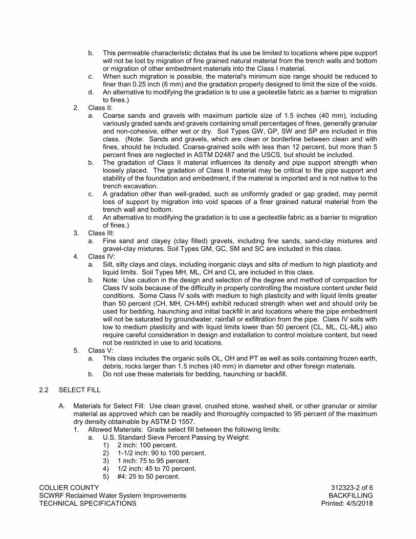
COLLIER COUNTY 312323-2 of 6 SCWRF Reclaimed Water System Improvements BACKFILLING TECHNICAL SPECIFICATIONS Printed: 4/5/2018
b. This permeable characteristic dictates that its use be limited to locations where pipe support will not be lost by migration of fine grained natural material from the trench walls and bottom or migration of other embedment materials into the Class I material.
c. When such migration is possible, the material's minimum size range should be reduced to finer than 0.25 inch (6 mm) and the gradation properly designed to limit the size of the voids.
d. An alternative to modifying the gradation is to use a geotextile fabric as a barrier to migration to fines.)
2. Class II: a. Coarse sands and gravels with maximum particle size of 1.5 inches (40 mm), including
variously graded sands and gravels containing small percentages of fines, generally granular and non-cohesive, either wet or dry. Soil Types GW, GP, SW and SP are included in this class. (Note: Sands and gravels, which are clean or borderline between clean and with fines, should be included. Coarse-grained soils with less than 12 percent, but more than 5 percent fines are neglected in ASTM D2487 and the USCS, but should be included.
b. The gradation of Class II material influences its density and pipe support strength when loosely placed. The gradation of Class II material may be critical to the pipe support and stability of the foundation and embedment, if the material is imported and is not native to the trench excavation.
c. A gradation other than well-graded, such as uniformly graded or gap graded, may permit loss of support by migration into void spaces of a finer grained natural material from the trench wall and bottom.
d. An alternative to modifying the gradation is to use a geotextile fabric as a barrier to migration of fines.)
3. Class III: a. Fine sand and clayey (clay filled) gravels, including fine sands, sand-clay mixtures and
gravel-clay mixtures. Soil Types GM, GC, SM and SC are included in this class. 4. Class IV:
a. Silt, silty clays and clays, including inorganic clays and silts of medium to high plasticity and liquid limits. Soil Types MH, ML, CH and CL are included in this class.
b. Note: Use caution in the design and selection of the degree and method of compaction for Class IV soils because of the difficulty in properly controlling the moisture content under field conditions. Some Class IV soils with medium to high plasticity and with liquid limits greater than 50 percent (CH, MH, CH-MH) exhibit reduced strength when wet and should only be used for bedding, haunching and initial backfill in arid locations where the pipe embedment will not be saturated by groundwater, rainfall or exfiltration from the pipe. Class IV soils with low to medium plasticity and with liquid limits lower than 50 percent (CL, ML, CL-ML) also require careful consideration in design and installation to control moisture content, but need not be restricted in use to arid locations.
5. Class V: a. This class includes the organic soils OL, OH and PT as well as soils containing frozen earth,
debris, rocks larger than 1.5 inches (40 mm) in diameter and other foreign materials. b. Do not use these materials for bedding, haunching or backfill.
2.2 SELECT FILL
A. Materials for Select Fill: Use clean gravel, crushed stone, washed shell, or other granular or similar material as approved which can be readily and thoroughly compacted to 95 percent of the maximum dry density obtainable by ASTM D 1557. 1. Allowed Materials: Grade select fill between the following limits:
a. U.S. Standard Sieve Percent Passing by Weight: 1) 2 inch: 100 percent. 2) 1-1/2 inch: 90 to 100 percent. 3) 1 inch: 75 to 95 percent. 4) 1/2 inch: 45 to 70 percent. 5) #4: 25 to 50 percent.
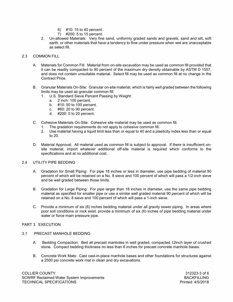
COLLIER COUNTY 312323-3 of 6 SCWRF Reclaimed Water System Improvements BACKFILLING TECHNICAL SPECIFICATIONS Printed: 4/5/2018
6) #10: 15 to 40 percent. 7) #200: 5 to 15 percent.
2. Un-allowed Materials: Very fine sand, uniformly graded sands and gravels, sand and silt, soft earth, or other materials that have a tendency to flow under pressure when wet are unacceptable as select fill.
2.3 COMMON FILL
A. Materials for Common Fill: Material from on-site excavation may be used as common fill provided that it can be readily compacted to 90 percent of the maximum dry density obtainable by ASTM D 1557, and does not contain unsuitable material. Select fill may be used as common fill at no change in the Contract Price.
B. Granular Materials On-Site: Granular on-site material, which is fairly well graded between the following limits may be used as granular common fill: 1. U.S. Standard Sieve Percent Passing by Weight:
a. 2 inch: 100 percent. b. #10: 50 to 100 percent. c. #60: 20 to 90 percent. d. #200: 0 to 20 percent.
C. Cohesive Materials On-Site: Cohesive site material may be used as common fill. 1. The gradation requirements do not apply to cohesive common fill. 2. Use material having a liquid limit less than or equal to 40 and a plasticity index less than or equal
to 20.
D. Material Approval: All material used as common fill is subject to approval. If there is insufficient on-site material, import whatever additional off-site material is required which conforms to the specifications and at no additional cost.
2.4 UTILITY PIPE BEDDING
A. Gradation for Small Piping: For pipe 18 inches or less in diameter, use pipe bedding of material 90 percent of which will be retained on a No. 8 sieve and 100 percent of which will pass a 1/2-inch sieve and be well graded between those limits.
B. Gradation for Large Piping: For pipe larger than 18 inches in diameter, use the same pipe bedding material as specified for smaller pipe or use a similar well graded material 90 percent of which will be retained on a No. 8 sieve and 100 percent of which will pass a 1-inch sieve.
C. Provide a minimum of six (6) inches bedding material under all gravity sewer piping. In areas where poor soil conditions or rock exist, provide a minimum of six (6) inches of pipe bedding material under water or force main pressure pipe.
PART 3 EXECUTION
3.1 PRECAST MANHOLE BEDDING
A. Bedding Compaction: Bed all precast manholes in well graded, compacted 12inch layer of crushed stone. Compact bedding thickness no less than 6 inches for precast concrete manhole bases.
B. Concrete Work Mats: Cast cast-in-place manhole bases and other foundations for structures against a 2500 psi concrete work mat in clean and dry excavations.
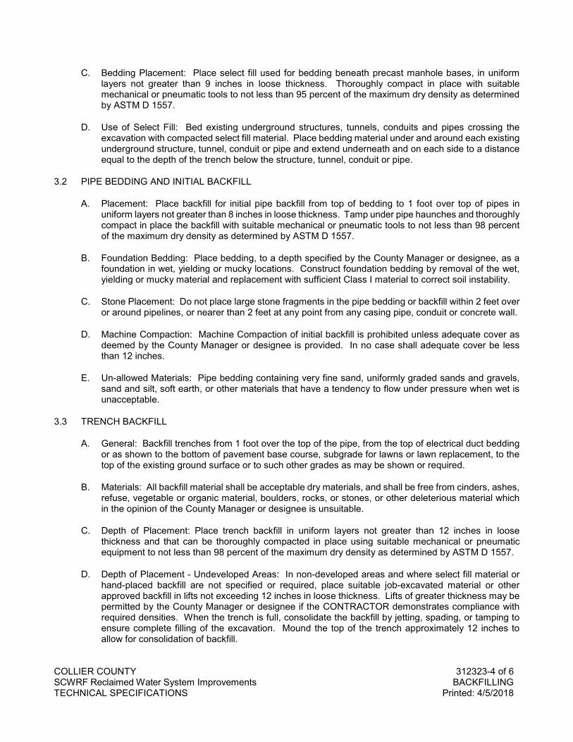
COLLIER COUNTY 312323-4 of 6 SCWRF Reclaimed Water System Improvements BACKFILLING TECHNICAL SPECIFICATIONS Printed: 4/5/2018
C. Bedding Placement: Place select fill used for bedding beneath precast manhole bases, in uniform layers not greater than 9 inches in loose thickness. Thoroughly compact in place with suitable mechanical or pneumatic tools to not less than 95 percent of the maximum dry density as determined by ASTM D 1557.
D. Use of Select Fill: Bed existing underground structures, tunnels, conduits and pipes crossing the excavation with compacted select fill material. Place bedding material under and around each existing underground structure, tunnel, conduit or pipe and extend underneath and on each side to a distance equal to the depth of the trench below the structure, tunnel, conduit or pipe.
3.2 PIPE BEDDING AND INITIAL BACKFILL
A. Placement: Place backfill for initial pipe backfill from top of bedding to 1 foot over top of pipes in uniform layers not greater than 8 inches in loose thickness. Tamp under pipe haunches and thoroughly compact in place the backfill with suitable mechanical or pneumatic tools to not less than 98 percent of the maximum dry density as determined by ASTM D 1557.
B. Foundation Bedding: Place bedding, to a depth specified by the County Manager or designee, as a foundation in wet, yielding or mucky locations. Construct foundation bedding by removal of the wet, yielding or mucky material and replacement with sufficient Class I material to correct soil instability.
C. Stone Placement: Do not place large stone fragments in the pipe bedding or backfill within 2 feet over or around pipelines, or nearer than 2 feet at any point from any casing pipe, conduit or concrete wall.
D. Machine Compaction: Machine Compaction of initial backfill is prohibited unless adequate cover as deemed by the County Manager or designee is provided. In no case shall adequate cover be less than 12 inches.
E. Un-allowed Materials: Pipe bedding containing very fine sand, uniformly graded sands and gravels, sand and silt, soft earth, or other materials that have a tendency to flow under pressure when wet is unacceptable.
3.3 TRENCH BACKFILL
A. General: Backfill trenches from 1 foot over the top of the pipe, from the top of electrical duct bedding or as shown to the bottom of pavement base course, subgrade for lawns or lawn replacement, to the top of the existing ground surface or to such other grades as may be shown or required.
B. Materials: All backfill material shall be acceptable dry materials, and shall be free from cinders, ashes, refuse, vegetable or organic material, boulders, rocks, or stones, or other deleterious material which in the opinion of the County Manager or designee is unsuitable.
C. Depth of Placement: Place trench backfill in uniform layers not greater than 12 inches in loose thickness and that can be thoroughly compacted in place using suitable mechanical or pneumatic equipment to not less than 98 percent of the maximum dry density as determined by ASTM D 1557.
D. Depth of Placement - Undeveloped Areas: In non-developed areas and where select fill material or hand-placed backfill are not specified or required, place suitable job-excavated material or other approved backfill in lifts not exceeding 12 inches in loose thickness. Lifts of greater thickness may be permitted by the County Manager or designee if the CONTRACTOR demonstrates compliance with required densities. When the trench is full, consolidate the backfill by jetting, spading, or tamping to ensure complete filling of the excavation. Mound the top of the trench approximately 12 inches to allow for consolidation of backfill.
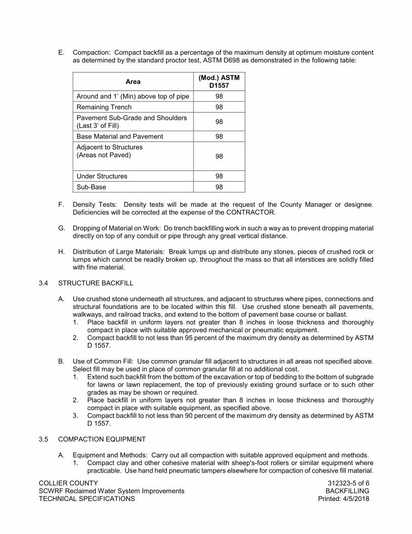
COLLIER COUNTY 312323-5 of 6 SCWRF Reclaimed Water System Improvements BACKFILLING TECHNICAL SPECIFICATIONS Printed: 4/5/2018
E. Compaction: Compact backfill as a percentage of the maximum density at optimum moisture content as determined by the standard proctor test, ASTM D698 as demonstrated in the following table:
Area (Mod.) ASTM D1557
Around and 1’ (Min) above top of pipe 98 Remaining Trench 98 Pavement Sub-Grade and Shoulders (Last 3’ of Fill) 98
Base Material and Pavement 98 Adjacent to Structures (Areas not Paved)
98
Under Structures 98 Sub-Base 98
F. Density Tests: Density tests will be made at the request of the County Manager or designee. Deficiencies will be corrected at the expense of the CONTRACTOR.
G. Dropping of Material on Work: Do trench backfilling work in such a way as to prevent dropping material directly on top of any conduit or pipe through any great vertical distance.
H. Distribution of Large Materials: Break lumps up and distribute any stones, pieces of crushed rock or lumps which cannot be readily broken up, throughout the mass so that all interstices are solidly filled with fine material.
3.4 STRUCTURE BACKFILL
A. Use crushed stone underneath all structures, and adjacent to structures where pipes, connections and structural foundations are to be located within this fill. Use crushed stone beneath all pavements, walkways, and railroad tracks, and extend to the bottom of pavement base course or ballast. 1. Place backfill in uniform layers not greater than 8 inches in loose thickness and thoroughly
compact in place with suitable approved mechanical or pneumatic equipment. 2. Compact backfill to not less than 95 percent of the maximum dry density as determined by ASTM
D 1557.
B. Use of Common Fill: Use common granular fill adjacent to structures in all areas not specified above. Select fill may be used in place of common granular fill at no additional cost. 1. Extend such backfill from the bottom of the excavation or top of bedding to the bottom of subgrade
for lawns or lawn replacement, the top of previously existing ground surface or to such other grades as may be shown or required.
2. Place backfill in uniform layers not greater than 8 inches in loose thickness and thoroughly compact in place with suitable equipment, as specified above.
3. Compact backfill to not less than 90 percent of the maximum dry density as determined by ASTM D 1557.
3.5 COMPACTION EQUIPMENT
A. Equipment and Methods: Carry out all compaction with suitable approved equipment and methods. 1. Compact clay and other cohesive material with sheep's-foot rollers or similar equipment where
practicable. Use hand held pneumatic tampers elsewhere for compaction of cohesive fill material.
COLLIER COUNTY 312323-6 of 6 SCWRF Reclaimed Water System Improvements BACKFILLING TECHNICAL SPECIFICATIONS Printed: 4/5/2018
2. Compact low cohesive soils with pneumatic-tire rollers or large vibratory equipment where practicable. Use small vibratory equipment elsewhere for compaction of cohesionless fill material.
3. Do not use heavy compaction equipment over pipelines or other structures, unless the depth of fill is sufficient to adequately distribute the load.
3.6 FINISH GRADING
A. Final Contours: Perform finish grading in accordance with the completed contour elevations and grades shown and blend into conformation with remaining natural ground surfaces. 1. Leave all finished grading surfaces smooth and firm to drain. 2. Bring finish grades to elevations within plus or minus 0.10 foot of elevations or contours shown.
B. Surface Drainage: Perform grading outside of building or structure lines in a manner to prevent accumulation of water within the area. Where necessary or where shown, extend finish grading to ensure that water will be carried to drainage ditches, and the site area left smooth and free from depressions holding water.
3.7 RESPONSIBILITY FOR AFTER-SETTLEMENT
A. After-settlement Responsibility: Take responsibility for correcting any depression which may develop in backfilled areas from settlement within one year after the work is fully completed. Provide, as needed, backfill material, pavement base replacement, permanent pavement, sidewalk, curb and driveway repair or replacement, and lawn replacement, and perform the necessary reconditioning and restoration work to bring such depressed areas to proper grade as approved.
3.8 INSPECTION AND TESTING OF BACKFILLING
A. Sampling and Testing: Provide sampling, testing, and laboratory methods in accordance with the appropriate ASTM Standard Specification. Subject all backfill to these tests.
B. Correction of Work: Correct any areas of unsatisfactory compaction by removal and replacement, or by scarifying, aerating or sprinkling as needed and re-compaction in place prior to placement of a new lift.
C. Testing Schedule: 1. Compaction Schedule. 2. Optimum Moisture Content (Proctor Test).
END OF SECTION
COLLIER COUNTY 314000-1 of 2 SCWRF Reclaimed Water System Improvements SHORING, SHEETING, AND BRACING TECHNICAL SPECIFICATIONS Printed: 4/5/2018
SECTION 314000
SHORING, SHEETING, AND BRACING
PART 1 GENERAL
1.1 SUMMARY
A. Section Includes: Work required for protection of an excavation or structure through shoring, sheeting, and bracing.
B. Related Work Specified in Other Sections Includes: 1. Section 312316 – Excavation – Earth and Rock. 2. Section 312323 – Backfilling.
1.2 SUBMITTALS
A. General: Provide all submittals, including the following, as specified in Division 01.
B. CONTRACTOR's Submittals: All sheeting and bracing shall be the responsibility of the CONTRACTOR to retain qualified design services for these systems, and to be completed with strict adherence to OSHA Regulations. Submit complete design calculations and working drawings of proposed shoring, sheeting and bracing which have been prepared, signed and sealed by a Licensed Professional Engineer experienced in Structural Engineering and registered in the State of Florida, before starting excavation for jacking pits and structures. Use the soil pressure diagram shown for shoring, sheeting and bracing design. ENGINEER's review of calculations and working drawings will be limited to confirming that the design was prepared by a licensed professional engineer and that the soil pressure diagram shown was used.
1.3 REFERENCES
A. Design: Comply with all Federal and State laws and regulations applying to the design and construction of shoring, sheeting, and bracing.
B. N.B.S. Building Science Series 127 "Recommended Technical Provisions for Construction Practice in Shoring and Sloping Trenches and Excavations.”
1.4 QUALITY ASSURANCE
A. Regulatory Requirements: Do work in accordance with the U.S. Department of Labor Safety and Health Regulations for construction promulgated under the Occupational Safety Act of 1970 (PL 91-596) and under Section 107 of the Contract Work Hours and Safety Standards Act (PL 91-54), and the Florida Trench Safety Act. Observe 29 CFR 1910.46 OSHA regulations for Confined Space Entry.
PART 2 PRODUCTS
2.1 MANUFACTURERS AND MATERIALS
A. Material Recommendations: Use manufacturers and materials for shoring, sheeting and bracing as recommended by the Licensed Professional Engineer who designed the shoring, sheeting, and bracing. 1. Wood Materials: Oak, or treated fir or pine for wood lagging.
COLLIER COUNTY 314000-2 of 2 SCWRF Reclaimed Water System Improvements SHORING, SHEETING, AND BRACING TECHNICAL SPECIFICATIONS Printed: 4/5/2018
PART 3 EXECUTION
3.1 SHORING, SHEETING AND BRACING INSTALLATION
A. General: Provide safe working conditions, to prevent shifting of material, to prevent damage to structures or other work, to avoid delay to the work, all in accordance with applicable safety and health regulations. Properly shore, sheet, and brace all excavations which are not cut back to the proper slope and where shown. Meet the general trenching requirements of the applicable safety and health regulations for the minimum shoring, sheeting and bracing for trench excavations. 1. CONTRACTOR's Responsibility: Sole responsibility for the design, methods of installation, and
adequacy of the shoring, sheeting and bracing.
B. Arrange shoring, sheeting and bracing so as not to place any strain on portions of completed work until the general construction has proceeded far enough to provide ample strength.
C. If ENGINEER is of the opinion that at any point the shoring, sheeting or bracing are inadequate or unsuited for the purpose, resubmission of design calculations and working drawings for that point may be ordered, taking into consideration the observed field conditions. If the new calculations show the need for additional shoring, sheeting and bracing, it should be installed immediately.
D. Monitoring: Periodically monitor horizontal and vertical deflections of sheeting. Submit these measurements for review.
E. Accurately locate all underground utilities and take the required measures necessary to protect them from damage. Keep all underground utilities in service at all times as specified in Division 1.
F. Driven Sheeting: Drive tight sheet piling in that portion of any excavation in paved or surface streets City collector and arterial streets and in State and County highways below the intersection of a one-on-one slope line from the nearest face of the excavation to the edge of the existing pavement or surface.
G. Sheeting Depth: In general drive or place sheeting for pipelines to a depth at elevation equal to the top of the pipe as approved. 1. If it is necessary to drive sheeting below that elevation in order to obtain a dry trench or
satisfactory working conditions, cut the sheeting off at the top of the pipe and leave in place sheeting below the top of the pipe.
2. Do not cut the sheeting until backfill has been placed and compacted to the top of the pipe.
H. Sheeting Removal: In general, remove sheeting and bracing above the top of the pipe as the excavation is refilled in a manner to avoid the caving in of the bank or disturbance to adjacent areas or structures. Remove sheeting as backfilling progresses so that the sides are always supported or when removal would not endanger the construction of adjacent structures. When required to eliminate excessive trench width or other damages, shoring or bracing shall be left in place and the top cut off at an elevation 2.5 feet below finished grade, unless otherwise directed. 1. Carefully fill voids left by the withdrawal of the sheeting by jetting, ramming or otherwise. 2. No separate payment will be made for filling of such voids.
END OF SECTION
COLLIER COUNTY 320117-1 of 4 SCWRF Reclaimed Water System Improvements PAVEMENT REPAIR AND RESTORATION TECHNICAL SPECIFICATIONS Printed: 4/5/2018
SECTION 320117
PAVEMENT REPAIR AND RESTORATION
PART 1 GENERAL
1.1 SCOPE OF WORK
A. Furnish all labor, materials, equipment, and incidentals required and remove and replace pavements over trenches excavated for installation of pipelines as shown on the drawings and/or specified herein.
1.2 GENERAL
A. Repair all damage, as a result of work under this project, done to existing pavement, driveways, paved areas, curbs and gutters, sidewalks, shrubbery, grass, trees, utility poles, utility pipe lines, conduits, drains, catch basins, or stabilized areas or driveways and including all obstructions not specifically named herein, in a manner satisfactory to the ENGINEER. Include in the bid price, the furnishing of all labor, materials, equipment, and incidentals necessary for the cutting, repair, and restoration of the damaged areas unless pay items for specific types of repair are included in the Bid Form.
B. Keep the surface of the backfilled area of excavation in a safe condition and level with the remaining pavement until the pavement is restored in the manner specified herein. All surface irregularities that are dangerous or obstructive to traffic are to be removed. Conform the repair to applicable COUNTY or State requirements for pavement repair and as described herein.
C. The COUNTY reserves the right to require soil bearing or loading tests or materials tests, should the adequacy of the foundation or the quality of materials used be questionable. Costs of these tests shall be the responsibility of the COUNTY, if found acceptable; the costs of all failed tests shall be the responsibility of the CONTRACTOR.
D. Make all street and road repair in accordance with the details indicated on the drawings and in accordance with the applicable requirements of these Specifications and meeting the permit requirements and approval of the governing Department of Transportation agencies.
E. Replace pavement or roadway surfaces cut or damaged in equal or better condition than the original, including stabilization, base course, surface course, curb and gutter or other appurtenances. Obtain the necessary permits prior to any roadway work. Provide advance notice to the appropriate authority, as required, prior to construction operations. 1. Roadway Restoration (within Collier County Department of Transportation & Engineering
jurisdiction): Perform restoration in accordance with the requirements set forth in the “Right-of-Way Utility Construction Activities Policy” and these Standards. Obtain prior approval from Collier County DOT for the materials of construction and method of installation, along with the proposed restoration design for items not referred or specified herein. a. Where existing pavement is to be removed, mechanical saw cut the surface prior to trench
excavation, leaving a uniform and straight edge parallel or perpendicular to the roadway centerline with minimum disturbance to the remaining adjacent surfacing. Provide minimal width of cut for this phase of existing pavement removal.
b. Immediately following the specified backfilling and compaction, apply a temporary sand seal coat surface to the cut areas. For this temporary surfacing, provide a smooth traffic surface with the existing roadway and maintain until final restoration. Ensure that surfacing remains for a minimum of ten (10) days in order to assure the stability of the backfill under normal traffic conditions. Thirty (30) days following this period and prior to sixty (60) days after application: remove the temporary surfacing and perform final roadway surface restoration.
COLLIER COUNTY 320117-2 of 4 SCWRF Reclaimed Water System Improvements PAVEMENT REPAIR AND RESTORATION TECHNICAL SPECIFICATIONS Printed: 4/5/2018
c. In advance of final restoration, remove the temporary surfacing and mechanically saw the existing pavement straight and clean to the stipulated dimensions, if needed. Following the above operation, proceed immediately with final pavement restoration in accordance with the requirements set forth by Collier County Department of Transportation.
d. No layer shall be greater than two inches (2") when compacted. Where a surface course is constructed to a thickness greater than two inches (2"), construct it in approximately equal layers, each not exceeding two inches (2").
e. Where necessitated by traffic conditions, lay mixture in strips in such manner as to provide for the passage of traffic. Where the road is closed to traffic, mixture may be laid to the full width, by machines traveling in parallel.
2. Roadway Restoration (outside Collier County Department of Transportation jurisdiction): Conform work within the rights-of-way of public thoroughfares which are not under jurisdiction of Collier County to the requirements of the Governmental agency having jurisdiction or the Florida Department of Transportation, if no governmental agencies have jurisdiction. Work within State Highway right-of-way shall be in full compliance with all requirements of the permit drawings, and to the satisfaction of the Florida Department of Transportation.
1.3 QUALITY ASSURANCE
A. Applicable provisions of the latest version of the Florida Department of Transportation "Standard Specifications for Road and Bridge Construction", and Supplemental Specifications hereunder govern the work under this Section. The Florida Department of Transportation will hereafter be referred to as FDOT.
PART 2 PRODUCTS
2.1 MATERIALS
A. Use materials for concrete sidewalks and asphalt base course as specified in the latest version of the Florida Department of Transportation "Standard Specifications for Road and Bridge Construction".
B. Asphalt concrete pavements: Bituminous materials; follow FDOT Section 916.
PART 3 EXECUTION
3.1 CUTTING PAVEMENT
A. Cut and remove pavement to straight edges, 6 inches outside each edge of proposed trench to avoid pavement damage during installation of the new pipelines and appurtenances and for making connections to existing pipelines.
B. Before removing pavement, mark the pavement for cuts nearly paralleling pipelines and existing street lines. Cut asphalt pavement along the markings with a jackhammer, rotary saw, or other suitable tool.
C. No pavement shall be machine pulled until completely broken and separated along the marked cuts.
D. The pavement adjacent to pipeline trenches shall neither be disturbed nor damaged. If the adjacent pavement is disturbed or damaged, irrespective of cause, remove the damaged pavement replace it at CONTRACTOR’s expense.
3.2 GENERAL RESTORATION
A. Restore, replace or rebuild existing street paving, driveways, etc., using the same type of construction as was in the original. Be responsible for restoring all such work, including sub-grade and base
COLLIER COUNTY 320117-3 of 4 SCWRF Reclaimed Water System Improvements PAVEMENT REPAIR AND RESTORATION TECHNICAL SPECIFICATIONS Printed: 4/5/2018
courses where present. Obtain and pay for such local or other governmental permits as may be necessary for the opening of streets. Meet any requirements other than those herein set forth which may affect the type, quality and manner of carrying on the restoration of surfaces by reason of jurisdiction of such governmental bodies.
B. In all cases, maintain, without additional compensation, all permanent replacement of street paving, done by him under this Contract until accepted by the County Manager or designee, including the removal and replacement of such work wherever surface depressions or underlying cavities result from settlement of trench backfill.
C. Complete all the final resurfacing or re-paving of streets or roads, over the excavations and relay paving surfaces of roadbed that have failed or been damaged prior to acceptance by the County Manager or designee. Conform backfilling of trenches and the preparation of sub-grades to the requirements of Section 312323.
D. Do all re-paving or resurfacing in accordance with Florida Department of Transportation Specifications, to which the following requirement of trench backfill will be added: Where pipeline construction crosses paved areas such as streets, backfill the top 24 inches of trench below the road bases or concrete slabs with compacted A-4 or better material that will provide a bearing value of not less than 75 when tested by the Florida Department of Transportation Soil Bearing Test Methods.
3.3 PRIME AND TACK COATS
A. Apply bituminous prime and tack coats on the previously prepared base course in accordance with Section 300 of the FDOT Specifications.
3.4 WEARING COURSE
A. Use plant-mixed hot bituminous pavement to the thickness indicated in the drawings conforming to Type III asphaltic concrete in accordance with Section 334 of the FDOT Specifications. The requirements for plant and equipment are specified in Section 320 and the general construction requirements for asphaltic concrete pavement are contained in Section 330 of the FDOT specifications.
3.5 TESTING
A. Perform all field-testing at an independent laboratory employed by the COUNTY. Test and certify all materials by the producer. Repeat tests of sub-grade or base not meeting specified compaction at the CONTRACTOR's expense.
3.6 MISCELLANEOUS RESTORATION
A. Restore sidewalks, cut or damaged by construction, in full sections or blocks to a minimum thickness of four inches. Restore concrete curb or curb gutter to the existing height and cross section in full sections or lengths between joints. Concrete shall be as specified on the drawings. Restore grassed yards, shoulders and parkways to match the existing sections with grass seed or sod of a type matching the existing grass.
3.7 CLEANUP
A. After all repair and restoration or paving has been completed, remove all excess asphalt, dirt, and other debris from the roadways. Check and clean all existing storm sewers and inlets of any construction debris.

COLLIER COUNTY 320117-4 of 4 SCWRF Reclaimed Water System Improvements PAVEMENT REPAIR AND RESTORATION TECHNICAL SPECIFICATIONS Printed: 4/5/2018
END OF SECTION
COLLIER COUNTY 321300-1 of 6 SCWRF Reclaimed Water System Improvements SIDEWALKS, DRIVEWAYS, AND CURBS TECHNICAL SPECIFICATIONS Printed: 4/5/2018
SECTION 321300
SIDEWALKS, DRIVEWAYS, AND CURBS
PART 1 GENERAL
1.1 SUMMARY
A. Section Includes: Sidewalks, sidewalk ramps, driveways, curbs and drive approaches complete with concrete materials, concrete curing compounds, joint materials, field quality control and appurtenances.
1.2 REFERENCES
A. Reference Standards: Conform the work for this Section to the applicable portions of the following standard Specifications. 1. ASTM - American Society of Testing and Materials 2. AASHTO - American Association of State Highway and Transportation Officials 3. FDOT - Florida Department of Transportation - Standard Specifications for Road and Bridge
Construction. 4. FAC - Florida Accessibility Code. 5. ADAAG - American with Disabilities Act Accessibility Guidelines 6. UFAS - Uniform Federal Accessibility Standards
1.3 SUBMITTALS
A. Reports: Written permission for the use of all local disposal sites Furnish copies to the ENGINEER.
B. Test Reports: 1. Thickness and Compressive Strength: Provide the ENGINEER with two (2) certified copies of
the test results. Perform the tests by a laboratory approved by the ENGINEER.
1.4 JOB CONDITIONS
A. Environmental Requirements: 1. Temperature: Comply with the requirements for concrete installation due to outside ambient air
temperatures as specified under Article 3.3.I of this Section.
B. Protection: 1. Protection Against Rain: Comply with the requirements for protecting new work against damage
from Rain, as specified under Article 3.3.I of this Section.
PART 2 PRODUCTS
2.1 MATERIALS
A. Concrete: Use 2,500-psi concrete except as modified herein; follow FDOT Section 520.
B. Ready-Mixed Concrete: Use ready-mixed concrete that conforms to ASTM C94, Alternate 2.
C. Water: Use water for mixing and curing concrete reasonably clean and free from oil, salt, acid, alkali, chlorides, sugar, vegetable, or other substances injurious to the finished product. Waters from sources approved by the local Health Department as potable may be used without test. Test water requiring
COLLIER COUNTY 321300-2 of 6 SCWRF Reclaimed Water System Improvements SIDEWALKS, DRIVEWAYS, AND CURBS TECHNICAL SPECIFICATIONS Printed: 4/5/2018
testing in accordance with the current Method of Test for Quality of Water to be Used in Concrete, AASHTO T-26.
D. Concrete Curing Compounds: Use white membrane curing compound for curing concrete that conforms to AASHTO M148, Type 1 clear, or Type 2 while per FDOT Section 925.
E. Pre-molded Joint Filler: Use fiber joint filler that conforms to ASTM D1751. Use filler of the thickness, as specified herein, or as directed by the ENGINEER.
F. Steel Hook Bolts: Use hook bolts that conform to ASTM A706, or for Grade 60 of ASTM A615, A616, or A617. Use 5/8-inch diameter hook bolts self-tapping.
G. Joint Sealant: Use hot-poured type joint sealant that conforms to ASTM D1190.
PART 3 EXECUTION
3.1 CONTRACTOR’S VERIFICATION
A. Excavation and Forming: Prior to the installation of any concrete, examine the excavation and forms for the proper grades, lines, and levels required to receive the new work. Ascertain that all excavation and compacted subgrades are adequate to receive the concrete to be installed. 1. Correct all defects and deficiencies before proceeding with the work.
B. Existing Improvements: Investigate and verify location of existing improvements to which the new work is to be connected. 1. Making necessary adjustment in line and grade to align the new work with the existing
improvements must be approved by the ENGINEER prior to any change.
3.2 PREPARATION
A. Forms: Use wood or metal forms, straight and free from warp, clean, and sufficient strength to resist springing during the process of depositing concrete against them. 1. Use full depth of the concrete forms.
3.3 INSTALLATION
A. Sidewalks, Sidewalk Ramps, Driveways and Driveway Approaches: Construct all sidewalks and sidewalk ramps four (4) inches thick except at driveways and alleys. Construct thickness of the sidewalks six (6) inches at driveways and alleys. Construct sidewalks five (5) feet wide unless otherwise noted on the Plans, and slope 1/4-inch per foot towards the center of the road. Normally, sidewalks will be located within the right-of-way, parallel the property lines, at a distance of 1-foot from the property line. 1. Construct alleys, driveways and approaches six (6) inches thick. Construct the width of the
driveways and driveway approaches as shown on the Plans or as directed by the ENGINEER.
B. Removal of Existing Curb for Sidewalk Ramps and Driveway Approaches: Conform construction of sidewalk ramps within street intersections where curbed pavement existing to the current FDOT Roadway and Traffic Design Standards. 1. Saw cut, to full depth of pavement, and remove a minimum of an 18-inch wide curb and gutter
section where there is no proper curb drop for the sidewalk ramp or driveway approach. When mountable curbs are present, remove a 24-inch wide curb and gutter section for the construction of sidewalk ramps, as specified above.
2. Remove curb and gutter as determined by the ENGINEER in the field but remove curb and gutter at least as wide as the proposed sidewalk ramp plus 1-foot on each side.
COLLIER COUNTY 321300-3 of 6 SCWRF Reclaimed Water System Improvements SIDEWALKS, DRIVEWAYS, AND CURBS TECHNICAL SPECIFICATIONS Printed: 4/5/2018
3. Replace the removed curb and gutter section with materials, equal to what was removed and seal joint with hot poured rubber asphalt.
C. Install 5/8-inch diameter self-tapping hook bolts, in the existing concrete pavement as indicated on the Plans prior to placing concrete for the removed curb and gutter section.
D. Placement of Forms: Use wood forms, straight and free from warp, of nominal depth for sidewalk sections less than 25 feet in length. 1. Stake forms to line and grade in a manner that will prevent deflection and settlement. 2. When unit slab areas are to be poured, place slab division forms such that the slab division joints
will be straight and continuous. 3. Set forms for sidewalk ramps to provide a grade toward the centerline of the right-of-way in
accordance with current standards. Use a uniform grade, except as may be necessary to eliminate short grade changes.
4. Oil forms before placing concrete. Leave forms in place at least 12 hours after the concrete is placed. Place forms ahead of the pouring operations to maintain uninterrupted placement of concrete.
5. The use of slip form pavers can be allowed when approved by the ENGINEER in lieu of the construction system described above.
E. Joints: Construct transverse and longitudinal expansion and plane-of-weakness joints at the locations specified herein, or as indicated on the Plans or as directed by the ENGINEER. 1. Place the transverse expansion joints for the full width and depth of the new work. Use transverse
expansion joints placed against an existing pavement a minimum of six (6) inches deep but no less than the thickness of the concrete being placed.
2. Conform longitudinal expansion joints to the requirements as transverse expansion joints. 3. Construct joints true to line with their faces perpendicular to the surface of the sidewalk. Install
the top slightly below the finished surface of the sidewalk. Construct transverse joints at right angles to the centerline of the sidewalk and construct longitudinal joints parallel to the centerline or as directed by the ENGINEER.
4. Place transverse expansion joints, 1/2-inch thick, through the sidewalk at uniform intervals of not more than 50 feet and elsewhere as shown on the Plans, or as directed by the ENGINEER.
5. Place expansion joints, 1/2-inch thick, between the sidewalk and back of abutting parallel curb, buildings or other rigid structures, concrete driveways and driveway approaches. When directed by the ENGINEER, place the expansion joint between sidewalks and buildings 1-foot from the property line and parallel to it.
6. Form plane-of-weakness joints every five (5) feet. Form joints by use of slab divisions forms extending to the full depth of the concrete or by cutting joints in the concrete, after floating, to a depth equal to 1/4 the thickness on the sidewalk. Construct cut joints not less than 1/8-inch or more than 1/4-inch in width and finish smooth and at right angles to the centerline on the sidewalk.
F. Placing and Finishing Concrete: Place all concrete on a prepared unfrozen, smooth, leveled, rolled and properly compacted base. Place concrete on a moist surface with no visible water present. 1. Deposit the concrete, in a single layer to the depth specified. Spade or vibrate and compact the
concrete to fill in all voids along the forms and joints. Strike off the concrete with a strike board until all voids are removed and the surface has the required grade and cross section as indicated on the Plans, or as directed by the ENGINEER.
2. Float the surface of the concrete just enough to produce a smooth surface free from irregularities. Round all edges and joints with an edger having a 1/4-inch radius.
3. Broom the surface of sidewalks, driveways and approaches to slightly roughen the surface. 4. Texture the surface of the sidewalk ramps with a coarse broom transversely to the ramp slope,
and coarser roughen than the remainder of the sidewalk. Contract the ramp slope in color (using a brick-red dye or approved equal) from the remainder of the sidewalk. Comply with minimum color contract and slope requirements from FAC, UFAS, ADAAG, Local Government Standards, or as directed by the ENGINEER.
COLLIER COUNTY 321300-4 of 6 SCWRF Reclaimed Water System Improvements SIDEWALKS, DRIVEWAYS, AND CURBS TECHNICAL SPECIFICATIONS Printed: 4/5/2018
G. Curing: After finishing operations have been completed and immediately after the free water has left the surface, completely coat and seal the surface of the concrete (and sides if slip-forming is used) with a uniform layer of white membrane curing compound. Do not thin the curing compound. Apply the curing compound at the rate of one gallon per 200 square feet of surface.
H. Barricades: Place suitable barricades and lights around all newly poured sidewalks, sidewalk ramps, driveways, driveway approaches and curb and gutter sections in order to protect the new work from damage from pedestrians, vehicles and others until the concrete has hardened. 1. Leave barricades in place for a minimum of two (2) days, except for driveway approaches and
curb and gutter sections. Leave barricades in place for a minimum of three (3) days. 2. Remove and replace any concrete that suffers surface or structural damage at no additional cost.
I. Protection: 1. Against Rain: Protect new concrete from the effects of rain before the concrete has sufficiently
hardened. Have available on the job site at all times enough burlap or 6-mil thick polyurethane film to cover and protect one day’s work. Stop work and cover completed work when rain appears eminent. As soon as the rain ceases, uncover the concrete and burlap drag the surface where necessary. Apply curing compound to any areas where the compound has been disturbed or washed away.
2. Against Cold Weather: If concrete is placed between December 15 and February 15, have available on the site sufficient amount of clean, dry straw or hay to cover one (1) day’s production. If the temperature reaches 40 degrees F and is falling, place the hay or straw 12 inches thick, immediately after the curing compound is applied.
3. Concrete Temperature Limitations: Do not place concrete when the temperature of the concrete at the point of placement is above 90 degrees F.
J. Cleanup: After the concrete has gained sufficient strength, but no sooner than within 12 hours, remove the fixed forms and backfill the spaces on both sides with sound earth of topsoil quality. Compact, level and leave backfill in a neat condition.
K. Gutters and Curbs: Construct gutters and curbs in accordance with Section 520 FDOT Standard Specifications for Road and Bridge Construction, latest edition, including supplements.
3.4 FIELD QUALITY CONTROL
A. Concrete Delivery Ticket: Use a ticket system for recording the transportation of concrete from the batching plant to point of delivery. Issue this ticket to the truck operator at the point of loading and give to the ENGINEER upon delivery.
B. Concrete Delivery Rejection: Remove concrete not permitted for inclusion in the work by the ENGINEER from the site. Rejection of concrete will be determined through Field Quality Control and elapsed time from mixer charging to delivery.
C. Concrete Testing at Placement: Perform tests of each batch of concrete delivered, each 50 cubic yards, or whenever consistency appears to vary. The sampling and testing of slump, air content and strength will be performed at no cost to the CITY. 1. Sampling: Secure composite samples in accordance with the Method of Sampling Fresh
Concrete, ASTM C172. 2. Slump Test: Test in accordance with ASTM C143. Use the least slump possible consistent with
workability for proper placing of the various classifications of concrete. a. Place structural concrete for walls and slabs, by means of vibratory equipment, with a slump
of four (4) inches. b. A tolerance of up to 1-inch above the indicated maximum will be allowed for individual
batches provided the average for all batches or the most recent ten (10) batches tested, whichever is fewer, does not exceed the maximum limit.
COLLIER COUNTY 321300-5 of 6 SCWRF Reclaimed Water System Improvements SIDEWALKS, DRIVEWAYS, AND CURBS TECHNICAL SPECIFICATIONS Printed: 4/5/2018
3. Air Content: Determine air content of normal weight concrete in accordance with Method of Test for Air Content of Freshly Mixed Concrete by the Pressure Method, ASTM C23 1, or by the volumetric method, ASTM C 173, for each strength test.
4. Compressive Strength: Make two (2) strength tests of three (3) samples each for each 50 cubic yards, or fraction thereof, of each mix design of concrete placed in any one (1) day. a. Handling Samples: Mold and cure three (3) specimens from each sample in accordance
with Method of Making and Curing Concrete Test Specimens in the Field, ASTM C31. Record any deviations from the requirements of this Standard in the test report.
b. Testing: Test specimens in accordance with Method of Test for Compressive Strength of Cylindrical Concrete Specimens, ASTM C39. Test one (1) specimen at seven (7) days for information and test two (2) at 28 days for acceptance. Use the average of the strengths of the two (2) specimens tested at 28 days. Discard results if one (1) specimen in a test manifests evidence of improper sampling, molding or testing, and use the strength of the remaining cylinder. Should both specimens in test show any of the above defects, discard the entire test.
c. Acceptance of Concrete: The strength level of the concrete will be considered satisfactory so long as the averages of all sets of three consecutive strength test results equal or exceed the specified 28-day strength and no individual strength test results falls below the specified 28-day strength by more than 500 psi. If the strength test is not acceptable, perform further testing to qualify the concrete.
d. Concrete Temperature: Determine the temperature of concrete sample for each strength test.
D. Reductions due to deficiencies in thickness or compressive strength are additive, that is, if an area is deficient by 3/8 inch and under strength by 200 psi, the total reduction is 20% plus 0.02% or 0.40% reduction.
END OF SECTION

COLLIER COUNTY 321300-6 of 6 SCWRF Reclaimed Water System Improvements SIDEWALKS, DRIVEWAYS, AND CURBS TECHNICAL SPECIFICATIONS Printed: 4/5/2018
NO TEXT FOR THIS PAGE
COLLIER COUNTY 329200-1 of 4 SCWRF Reclaimed Water System Improvements RESTORATION BY SODDING OR SEEDING TECHNICAL SPECIFICATIONS Printed: 4/5/2018
SECTION 329200
RESTORATION BY SODDING OR SEEDING
PART 1 GENERAL
1.1 DESCRIPTION OF REQUIREMENTS
A. The work in this section consists of furnishing all labor, material and equipment to restore all areas disturbed during construction to match preconstruction conditions. Establish a stand of grass within the areas disturbed by furnishing and placing grass sod where required, or by seeding and mulching areas not requiring sod.
1.2 REFERENCE DOCUMENTS
A. Use materials conforming to the requirements of Florida Department of Transportation Standard Specifications for Road and Bridge Construction as follows: 1. Section 570 – Grassing (by Seeding). 2. Section 575 – Sodding. 3. Section 981 – Grassing and Sodding Materials. 4. Section 982 – Commercial Fertilizer. 5. Section 983 – Water for Grassing.
1.3 SUBMITTALS
A. Submit certifications and identification labels for all sodding supplied in accordance with General Conditions.
PART 2 PRODUCTS
2.1 SODDING
A. Types: Sod may be of either St. Augustine or Argentine Bahia grass or as that disturbed, as established prior to construction. Use well matted sod with roots. When replacing sod in areas that are already sodded, use sod of the same type as the existing sod.
B. Provide sod as required in accordance with Florida Department of Transportation Specifications 575 and 981. Furnish sod equal to and similar in type as that disturbed. Place and water in accordance with FDOT Specifications Section 575.
C. Use sod in commercial-size rectangles, preferably 12-inch by 24-inch or larger, except where 6-inch strip sodding is called for.
D. Use sod that is sufficiently thick to secure a dense stand of live grass. Use sod that is live, fresh and uninjured at the time of planting, having a soil mat of sufficient thickness adhering firmly to the roots to withstand all necessary handling. It shall be reasonably free of weeds and other grasses. Plant sod as soon as possible after being dug, and shade and keep moist from the time it is dug until it is planted.
E. Handle sod in a manner to prevent breaking or other damage. Do not handle by dumping from trucks or other vehicles. Use care at all times to retain the native soil on the roots of each sod roll during stripping and handling. Sod that has been damaged by handling during delivery, storage or installation will be rejected.
COLLIER COUNTY 329200-2 of 4 SCWRF Reclaimed Water System Improvements RESTORATION BY SODDING OR SEEDING TECHNICAL SPECIFICATIONS Printed: 4/5/2018
F. Swales: Place sod to the proper grade and cross section in all flow areas to ensure the design flow of water in the ditch. In excavating for the placement of sod, provide a minimum of 3 inches of undercut.
2.2 FERTILIZER
A. Supply chemical fertilizer in suitable bags with the net weight certification of the shipment. Fertilizer shall be 12-8-8 and comply with Section 982 of the FDOT Standard Specification for Road and Bridge Construction.
B. The numerical designations for fertilizer indicate the minimum percentages (respectively) of (1) total nitrogen, (2) available phosphoric acid and (3) water soluble potash, contained in the fertilizer.
C. The chemical designation of the fertilizer shall be 12-8-8, with at least 50 percent of the nitrogen from a non-water soluble organic source. The nitrogen source may be a urea-formaldehyde source provided it is not derived from a waste product of the plastic industry.
2.3 EQUIPMENT
A. Spread fertilizer uniformly at the specified rate.
2.4 NETTING
A. See County Approved Product List, Appendix F.
2.5 SEEDING
A. Seed all unpaved areas disturbed during construction that do not require sod. Complete all seeding in conformance with FDOT Specifications Sections 570 and 981. Mulch and fertilize the grassed areas shall be mulched and fertilized in accordance with FDOT Specifications.
B. Provide mulch material free of weeds. Mulch shall be oat straw or rye, Pangola, peanut, Coastal Bermuda, or Bahia grass hay.
C. All seeds must have been tested within 6 months of planting. Submit a seed bag tag with final payment requests from each type or mixture of seed used.
2.6 TOPSOIL
A. Topsoil stockpiled during excavation may be used. If additional topsoil is required to replace topsoil removed during construction, it shall be obtained off site at no additional cost to the COUNTY. Topsoil shall be fertile, natural surface soil, capable of producing all trees, plants, and grassing specified herein.
2.7 MULCH
A. Furnish small grain straw mulch. Apply mulch at a rate of 1.5 tons per acre, corresponding to a depth not less than 1-inch or more than 3-inches according to texture and moisture content of mulch material. Apply asphalt emulsion at a rate of 150 gallons per ton of straw to anchor the straw applied.
2.8 WATER
A. It is the CONTRACTOR’S responsibility to supply all water to the site, as required during seeding and sodding operations and through the maintenance period and until the work is accepted. Make whatever arrangements may be necessary to ensure an adequate supply of water to meet the needs
COLLIER COUNTY 329200-3 of 4 SCWRF Reclaimed Water System Improvements RESTORATION BY SODDING OR SEEDING TECHNICAL SPECIFICATIONS Printed: 4/5/2018
for the work. Furnish all necessary hose, equipment, attachments, and accessories for the adequate irrigation of lawns and planted areas as may be required. Water shall be suitable for irrigation and free from ingredients harmful to plant life.
2.9 SOIL IMPROVEMENTS
A. Apply lime at the rate of 1 to 1.5 tons per acre. Apply 10-10-10 commercial fertilizer at the rate of 800 pounds per acre and work well into the top inch of topsoil.
PART 3 EXECUTION
3.1 SOD BED PREPARATION
A. Clear areas to be sodded and/or seeded of all rough grass, weeds, and debris, and bring soil to an even grade.
B. Thoroughly till soil to a minimum 4-inch depth.
C. Bring area to proper grade, free of sticks, stones, or other foreign matter over 1inch in diameter or dimension. The surface shall conform to finish grade, less the thickness of sod, free of water-retaining depressions, the soil friable and of uniformly firm texture.
3.2 INSPECTION
A. Verify that soil preparation and related preceding work has been completed.
B. Do not start work until conditions are satisfactory.
3.3 SOD HANDLING AND INSTALLATION
A. During delivery, prior to planting, and during the planting of sod areas, protect the sod panels at all times from excessive drying and unnecessary exposure of the roots to the sun. Stack sod during construction and planting so as not to be damaged by sweating or excessive heat and moisture.
B. After completion of soil conditioning as specified above, lay sod panels tightly together so as to make a solid sodded lawn area. On mounds and other slopes, the long dimension of the sod shall be laid perpendicular to the slope. Immediately following sod laying, roll the lawn areas with a lawn roller customarily used for such purposes, and then thoroughly water.
C. Place sod at all areas where sod existed prior to construction, on slopes of 3 horizontal to 1 vertical (3:1) or greater, in areas where erosion of soils will occur, and as directed by the ENGINEER. On areas where the sod may slide, due to height and slope, the ENGINEER may direct that the sod be pegged, with pegs driven through the sod blocks into firm earth, at suitable intervals.
3.4 USE OF SOD ON ROADWAY PROJECTS
A. In accordance with the FDOT District One Standard Practice, establish permanent green grass at the completion of roadway construction and maintenance work. The following shall apply to all restoration involving State or County roadways: 1. Use sod in lieu of seed and mulch on all roadways with urban (raised curb) typical sections. 2. One inch water per week shall be required for a minimum of four (4) consecutive weeks for the
purpose of establishing sod. This can be waived during construction, if and only if there is a minimum of one inch of rain per week on all sod on the project.
3. Placed sod on slopes 1:3 or greater. Stake sod on slopes 1:2 or greater.
COLLIER COUNTY 329200-4 of 4 SCWRF Reclaimed Water System Improvements RESTORATION BY SODDING OR SEEDING TECHNICAL SPECIFICATIONS Printed: 4/5/2018
4. On all curves with superelevation, place sod from the edge of pavement to the toe of slope on the downhill side(s) for the entire length of the superelevated roadway. On multi-lane divided rural facilities, place sod in the median and on the inside of the curve in the superelevated areas. This does not apply to reverse crowns.
5. Use sod for all projects with less than 10,000 square yards grass area. 6. On tangent sections and on outside of curves, use sod between the edge of pavement and a
point 4 feet beyond the shoulder break point. 7. The entire width of sod should not exceed 15 feet from the edge of pavement. 8. Sod is to be used to eliminate narrow seed and mulch areas. Sod areas less than 6 feet in width. 9. Place sod around drainage structures as per the standard Indexes and extend to the edge of
pavement.
3.5 SOD MAINTENANCE
A. The sod shall produce a dense, well-established growth. Repair and re-sod all eroded or bare spots until project acceptance. Repair to sodding shall be accomplished as in the original work.
B. Perform sufficient watering to maintain adequate moisture for optimum development of the seeded and sodded areas, and no less than 1.5 inches of water per week for at least 2 weeks. Thereafter, apply water for a minimum of 60 days as needed until the sod takes root and starts to grow or until final acceptance, whichever is latest.
3.6 GUARANTEE
A. Guarantee a live and vigorous stand of permanent grass at the time of acceptance of the work consisting of 80 percent minimum coverage for seeded grass areas with no bare spots greater than 5 square feet.
3.7 CLEANING
A. Remove debris and excess materials from the project site.
END OF SECTION
COLLIER COUNTY 330503-1 of 4 SCWRF Reclaimed Water System Improvements POLYVINYL CHLORIDE (PVC) PIPE AND FITTINGS TECHNICAL SPECIFICATIONS Printed: 6/6/2019
SECTION 330503
POLYVINYL CHLORIDE (PVC) PIPE AND FITTINGS
PART 1 GENERAL
1.1 SUMMARY
A. Section Includes: Requirements for providing buried PVC pipe, fittings and appurtenances. 1. Provide PVC pipe and fittings complete with all necessary jointing facilities and materials,
specials, adapters and other appurtenances required for installation in and completion of the pipelines to be constructed.
2. Provide plain end or rubber gaskets (push-on or mechanical joint) of the types, sizes and classes shown or specified.
B. Related Work Specified in Other Sections Includes: 1. Section 022501 – Leakage Tests. 2. Section 330518 – Laying and Jointing Buried Pipelines. 3. AWWA C900 - Polyvinyl Chloride (PVC) Pressure Pipe, 4 In. through 12 In.. 4. AWWA C907 - Polyvinyl Chloride (PVC) Pressure Fittings, 4 In. through 8 In. 5. ASTM F477 - Elastomeric Seals (Gaskets) For Joining Plastic Pipe.
1.2 SYSTEM DESCRIPTION
A. Provide pipe of the various sizes and classes as specified in the schedule or shown. Restrain all pressure pipe joints.
B. Construct concrete encasements only with written permission from the Water Director.
1.3 SUBMITTALS
A. General: Provide all submittals, including the following, as specified in Division 01.
B. Submit the following shop drawings: 1. Pipe joints, fittings, sleeves and cleanouts. Where special designs or fittings are required, show
the work in large detail and completely describe and dimension all items. 2. Fully dimensioned drawings of piping layouts, including fittings, couplings, sleeves, cleanouts,
valves, supports and anchors. Label pipe size, materials, type, and class on drawings and include the limits of each reach of restrained joints. Provide cross sections showing elevations of cleanouts, pipes, fittings, sleeves, and valves.
3. Catalog data for pipe, joints, fittings, sleeves, harnessing and cleanouts.
C. Quality Control: Submit certificate of compliance for pipe, fittings, gaskets, coatings, specials, sleeves and cleanouts in accordance with this Section.
1.4 DELIVERY, STORAGE AND HANDLING
A. Deliver, store and handle all pipe, fittings and appurtenances as specified in Division 01 and Section 330518.
COLLIER COUNTY 330503-2 of 4 SCWRF Reclaimed Water System Improvements POLYVINYL CHLORIDE (PVC) PIPE AND FITTINGS TECHNICAL SPECIFICATIONS Printed: 6/6/2019
PART 2 PRODUCTS
2.1 MATERIALS
A. Plant Service Water: 1. PVC Pressure Pipe and Fittings:
a. Pipe: ASTM D 1785, Schedule 80; 20-foot nominal laying length. b. Joints:
1) Socket Joints: ASTM D2855, solvent weld. 2) Threaded: Taper pipe threads. 3) Flanged: One-piece solid design; compatible with ANSI B16.5, Class 150 metal
flanges. c. Fittings:
1) Socket: ASTM D 2467. 2) Threaded: ASTM D2464.
d. Unions: O-ring seal type; transition type for joining dissimilar materials. 2. Quick connect coupling: Plastic, Type-F cam and groove type quick disconnect or as approved
by COUNTY; Camlock, or equal. a. Ends: Threaded. b. Maximum operating pressure: 150 psi.
B. Color: Provide pipe made of 100 percent of the color specified. Provide green sewer or force main pipe. Provide blue potable water pipe. Provide white raw water pipe. Provide purple non-potable irrigation, reclaimed or reuse water pipe.
C. Pipe Marking: Provide mark on each pipe at internals of 5 feet or less to designate compliance with applicable ASTM or AWWA specification.
D. Date of Manufacturer: Provide pipe and fitting manufactured no earlier than 12-month period preceding the date of the Agreement.
E. Restraining Devices: Joint restraining devices (see County Approved Product List, Appendix F) shall be placed at all bends, tees, plugs, reducers, and other fittings to provide lateral support, and shall conform to the Collier County Standard Details. Concrete thrust blocks shall only be utilized if Approved by Collier County Utilities.
PART 3 EXECUTION
3.1 INSTALLATION
A. Install all buried PVC pipe and fittings in accordance with the manufacturer's recommendations, approved shop drawings, as specified in Division 01, and Section 330518.
3.2 LEAKAGE TESTING
A. Cleaning: Flush clean and test all pipes after installation.
B. Testing: Test pipes for leaks and repair or tighten as required.
C. Procedures: Conduct tests in accordance with Section 022501.
3.3 SCHEDULES
COLLIER COUNTY 330503-3 of 4 SCWRF Reclaimed Water System Improvements POLYVINYL CHLORIDE (PVC) PIPE AND FITTINGS TECHNICAL SPECIFICATIONS Printed: 6/6/2019
A. Refer to the Schedules contained in Section 330518 Laying and Jointing Buried Pipelines for information on the piping that is to be constructed using the pipe materials and methods specified herein.
END OF SECTION

COLLIER COUNTY 330503-4 of 4 SCWRF Reclaimed Water System Improvements POLYVINYL CHLORIDE (PVC) PIPE AND FITTINGS TECHNICAL SPECIFICATIONS Printed: 6/6/2019
NO TEXT FOR THIS PAGE
COLLIER COUNTY 330504-1 of 8 SCWRF Reclaimed Water System Improvements DUCTILE IRON PIPE (DIP) AND FITTINGS TECHNICAL SPECIFICATIONS Printed: 4/5/2018
SECTION 330504
DUCTILE IRON PIPE (DIP) AND FITTINGS
PART 1 GENERAL
1.1 SCOPE OF WORK
A. Furnish all labor, materials, equipment, and incidentals required, and install ductile iron pipe, fittings and appurtenances as shown on the Drawings and as specified herein.
1.2 RELATED SECTIONS
A. Section 330518 - Laying and Jointing Buried Pipe.
1.3 REFERENCE SPECIFICATIONS, CODES, AND STANDARDS
A. Commercial Standards: (Latest Revision) 1. ANSI/AWWA C104/A21.4: Cement-Mortar Lining for Ductile-Iron Pipe and Fittings for Water. 2. ANSI/AWWA C105/A21.5: Polyethylene Encasement for Ductile-Iron Piping for Water and Other
Liquids. 3. ANSI/AWWA C110/A21.10: Ductile-Iron Fittings, 3 in. Through 48 Inches, for Water and Other
Liquids. (C110 2-48 inches). 4. ANSI/AWWA C111/A21.11: Rubber Gasket Joints for Ductile-Iron Pressure Pipe and Fittings. 5. ANSI/AWWA C115/A21.15: Flanged Ductile-Iron Pipe with Threaded Flanges. 6. ANSI/AWWA C150/A21.50: Thickness Design of Ductile-Iron Pipe. 7. ANSI/AWWA C151/A21.51: Ductile-Iron Pipe, Centrifugally Cast for Water or Other Liquids. 8. ANSI/AWWA C153/A21.53: Ductile-Iron Compact Fittings, 3 inches through 16 inches, for Water
and Other Liquids. 9. AWWA C600: Installation of Ductile Iron Water Mains and Their Appurtenances. 10. Collier County: Utilities Standards and Procedures Ordinance.
1.4 CONTRACTOR SUBMITTALS
A. Shop Drawings: Submit shop drawings of pipe and fittings in accordance with the requirements in the General Conditions, the requirements of the referenced standards and the following supplemental requirements as applicable: 1. Certified dimensional drawings of all valves, fittings, and appurtenances. 2. In all cases, a line layout to indicate the limits of each reach of restrained joints or of concrete
encasement shall be supplied. (NOTE: Obtain COUNTY Water Director’s approval of all proposed concrete encasement of ductile iron pipe.)
B. Certifications: Furnish a certified affidavit of compliance for all pipe and other products or materials furnished under this Section of the Specifications, which indicates that all tests have been made and that all results comply with the requirements of AWWA C151, including but not necessarily limited to the following: 1. Acceptance Tests. 2. Hydrostatic Tests. 3. Low Temperature Impact Tests.
C. Additional Documentation: Upon request, furnish foundry records in the form of written transcripts.
D. All expenses incurred for certification, testing, and data submittal shall be borne by the CONTRACTOR or the Supplier.
COLLIER COUNTY 330504-2 of 8 SCWRF Reclaimed Water System Improvements DUCTILE IRON PIPE (DIP) AND FITTINGS TECHNICAL SPECIFICATIONS Printed: 4/5/2018
1.5 QUALITY ASSURANCE
A. Inspection: All pipe shall be available for inspection at the place of manufacture prior to shipping in accordance with the provisions of the referenced standards. Notify the ENGINEER in writing not less than 10 calendar days prior to the shipping of the pipe.
B. The ENGINEER shall be given access to all areas where manufacturing and testing is performed and shall be permitted to make all inspections necessary to confirm manufacturer compliance with these Specifications.
C. Tests: Except as modified herein, all materials used in the manufacture of the pipe shall be tested in accordance with the requirements of the referenced standards as applicable.
D. Provide data on material tests at no additional cost to the COUNTY.
E. In addition to those tests specifically required, the ENGINEER may request additional samples of any material including lining and coating samples for testing by the COUNTY. Furnish the additional samples at no additional cost to the COUNTY.
1.6 CORROSION PROTECTION
A. If specifically approved by Collier County Utilities for use, provide exterior protection for underground ductile iron pipe and fittings within areas of severe corrosive conditions. This shall be accomplished by the installation of polyethylene encasement through the area of concern. The soil test evaluation to determine the necessity for extra protection in suspect areas shall be those set forth in ANSI Standard A21.5. Additionally, where other existing utilities are known to be cathodically protected, ductile iron pipe crossing said utility shall be protected for a distance of 20 feet to each side. If ductile iron pipe is to be installed parallel to and within 10 feet of cathodically protected pipe, then protection shall be provided for the entire length. Do not install steel pipe in severe corrosion areas.
PART 2 PRODUCTS
2.1 GENERAL
A. Protective Lining for Water Mains: Cement mortar lined ductile iron pipe shall conform to ANSI/AWWA C151 and C104, subject to the following supplemental requirements. The pipe shall be of the diameter and class shown, shall be furnished complete with rubber gaskets as indicated in the Contract Documents, and all specials and fittings shall be provided as required under the Contract Documents.
B. Protective Lining for Force Mains and Sewers: Where lining is shown, specified or required, for the protection of pipelines carrying sewage from corrosive gases, line the pipe using protective ceramic epoxy coating or polyethylene lining (see County Approved Product List, Appendix F) in accordance with the manufacturer’s written instructions. For ceramic epoxy lining, abrasive blast clean pipe and fittings to a near white surface to SSPC SP-10 and provide 40 mils minimum of dry film thickness of ceramic epoxy lining.
C. Handling and Storage: Handle the pipe by using wide slings, padded cradles, or other devices designed and constructed to prevent damage to the pipe and its lining. The use of equipment or handling, which might injure the pipe and its lining, will not be permitted. Stockpiled pipe shall be suitably supported and shall be secured to prevent accidental rolling. Assure that all other pipe handling equipment and methods is acceptable to the ENGINEER.
D. Laying lengths: Maximum pipe laying lengths shall be 20 feet.
COLLIER COUNTY 330504-3 of 8 SCWRF Reclaimed Water System Improvements DUCTILE IRON PIPE (DIP) AND FITTINGS TECHNICAL SPECIFICATIONS Printed: 4/5/2018
E. Finish: The pipe shall have smooth dense interior surfaces and shall be free from fractures, excessive interior surface crazing and roughness, in accordance with ANSI/AWWA C104.
F. Closures and Correction Pieces: Provide closures and correction pieces as required so that closures may be made due to different headings in the pipe laying operation and so that correction may be made to adjust the pipe laying to conform to pipe stationing shown on the Drawings or line layouts where applicable.
2.2 PIPE DESIGN CRITERIA
A. General: Ductile Iron pipe shall be designed in accordance with the requirements of ANSI/AWWA C150 as applicable and as modified in this Section.
B. Pipe Wall Thickness for Internal Pressure: The pipe shall be designed with a net thickness to withstand the design internal pressure in accordance with the hoop stress formula. In addition to the requirements of the Section, the minimum wall thickness shall be in accordance with the minimum thickness wall depicted in table 50.5 of ANSI/AWWA C150.
C. Potable, Raw and Non-Potable Irrigation Water Mains: 1. Ductile Iron Pipe shall be a minimum pressure Class 250 and will be accepted in any diameter
for use within the water distribution system. 2. All aboveground potable water main pipe shall be painted Federal Safety Blue. All aboveground
raw water main pipe shall be painted white. All aboveground non-potable irrigation, reclaimed or reuse water main pipe shall be painted Pantone Purple 522C. The pipe wall thickness shall not be less than that required by a working pressure of 250 psi in laying condition Type 4 “B” with 5-foot cover in conformance with ANSI Standard A21.50.
D. Force Mains and Gravity Sewers: 1. Ductile Iron Pipe shall be a minimum pressure Class150 and will be accepted in any diameter for
use within the wastewater collection system. 2. Ductile iron pipe for Gravity Sewer applications in not permitted unless the ENGINEER can
demonstrate that C900 PVC pipe, Class 150 or 200, cannot be utilized from a structural standpoint.
3. All aboveground force main pipe shall be painted Safety Green. The pipe wall thickness shall not be less than that required by a working pressure of 150 psi.
2.3 MATERIALS
A. Ductile Iron Pipe: Pipe materials shall conform to the requirements of ANSI/AWWA C151.
B. Adapters to connect ductile iron pipe or fittings to pipe or fittings of dissimilar materials shall be supplied by the CONTRACTOR in accordance with ASTM specifications and the pipe manufacturer recommendations, and as approved by the ENGINEER.
C. Water Mains: 1. All water mains shall contain cement for mortar lining conforming to the requirements of
ANSI/AWWA C104. Cement for mortar lining shall be Type II or V. A fly ash or pozzolan shall not be used.
2. All Ductile Iron buried water main pipelines shall have blue stripes applied to the pipe wall. Stripe width shall comply with AWWA standards. The stripes shall be applied by one of the methods described below: a. Pipes striped during manufacturing of the pipe shall have continuous stripes that run parallel
to the axis of the pipe located at no greater than 90 degree intervals around the pipe and that will remain intact during and after installation of the pipe.
COLLIER COUNTY 330504-4 of 8 SCWRF Reclaimed Water System Improvements DUCTILE IRON PIPE (DIP) AND FITTINGS TECHNICAL SPECIFICATIONS Printed: 4/5/2018
b. Pipes striped during installation shall incorporate blue tape or blue paint. The tape or paint shall be applied in a continuous line that runs parallel to the axis of the pipe and that is located along the top of the pipe.
3. All pipe with an internal diameter of 24” or greater, tape or paint shall be applied in continuous lines along each side of the pipe as well as along the top of the pipe.
D. Force Mains and Gravity Sewer: 1. All Ductile iron pipe used within the wastewater system shall be lined with polyethylene in
accordance with ASTM D1248. Pipe and fittings shall be lined as specified herein. Each piece of pipe shall bear a marking denoting the class to which it belongs.
2.4 SPECIALS AND FITTINGS
A. Fittings for Potable, Raw, Non-Potable Irrigation, Reclaimed and Reuse Water Systems: 1. Fittings for ductile iron pipe shall conform to the requirements of ANSI/AWWA C153/A21.53 or
ANSI/AWWA C110/A21.10 for diameters 3 inches through 48 inches and shall have a minimum pressure rating of 350 psi for pipe sizes 6 inches through 24 inches and 250 psi for sizes larger than 24 inches. Ductile iron fittings shall be double cement lined, seal coated and outside coated with an asphaltic material in accordance with AWWA C104 as specified.
B. Fittings for Wastewater System: 1. Fittings in direct contact with wastewater 8 inches in diameter and smaller, shall be interior coated
with a 12-mil thickness of coal tar epoxy coating. Pipe and fittings, for force mains 10 inches in diameter and larger, shall be interior coated with either a 20 mil to 40 mil thickness polyethylene as specified above or a 12-mil thickness of coal tar epoxy coating in conformance with ASTM 1248. Pipe and fittings shall have an outside asphaltic coating as specified in AWWA Standard C151. Each piece of pipe shall bear a marking denoting the class to which it belongs.
2.5 DESIGN OF PIPE
A. General: The pipe furnished shall be ductile iron pipe, lined as specified, with rubber gasketed joints.
B. The pipe shall be designed, manufactured, tested, inspected, and marked according to applicable requirements previously stated and except as hereinafter modified, shall conform to ANSI/AWWA C150 and ANSI/AWWA C151.
C. Pipe Dimensions: The pipe shall be of the diameter and class shown. The minimum wall thickness for each pipe size shall be as specified herein or shown on the Drawings.
D. Fitting Dimensions: The fittings shall be of the diameter shown and class specified.
E. Joint Design: Ductile Iron pipe and fittings shall be furnished with mechanical joints, push-on joints and flanged joints as follows: 1. For buried pipe applications, unless otherwise indicated, mechanical and push-on joints shall
conform to ANSI/AWWA C111/A21.11, with the minimum pressure rating of 350 psi. 2. For above-ground or buried vault applications, unless otherwise indicated, flanged joints shall
conform to ANSI/AWWA C115/A21.15, with the minimum pressure rating of 250 psi. All above-ground fittings shall be painted blue.
3. Use manufactured, labeled gasket lubricant for push on joints with trade name and pipe manufacturer name, other lubricants are prohibited.
4. Nuts and bolts for flanged joints shall be 304 stainless, as specified by the COUNTY, and conform to ANSI/AWWA C111.
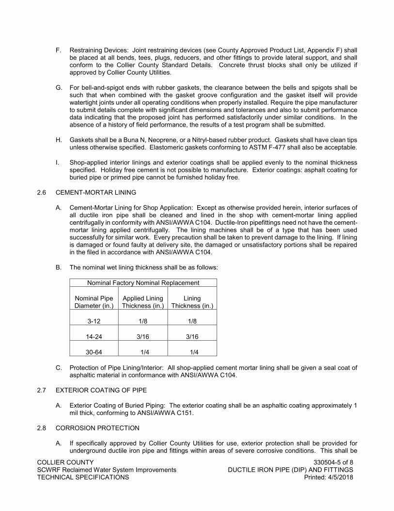
COLLIER COUNTY 330504-5 of 8 SCWRF Reclaimed Water System Improvements DUCTILE IRON PIPE (DIP) AND FITTINGS TECHNICAL SPECIFICATIONS Printed: 4/5/2018
F. Restraining Devices: Joint restraining devices (see County Approved Product List, Appendix F) shall be placed at all bends, tees, plugs, reducers, and other fittings to provide lateral support, and shall conform to the Collier County Standard Details. Concrete thrust blocks shall only be utilized if approved by Collier County Utilities.
G. For bell-and-spigot ends with rubber gaskets, the clearance between the bells and spigots shall be such that when combined with the gasket groove configuration and the gasket itself will provide watertight joints under all operating conditions when properly installed. Require the pipe manufacturer to submit details complete with significant dimensions and tolerances and also to submit performance data indicating that the proposed joint has performed satisfactorily under similar conditions. In the absence of a history of field performance, the results of a test program shall be submitted.
H. Gaskets shall be a Buna N, Neoprene, or a Nitryl-based rubber product. Gaskets shall have clean tips unless otherwise specified. Elastomeric gaskets conforming to ASTM F-477 shall also be acceptable.
I. Shop-applied interior linings and exterior coatings shall be applied evenly to the nominal thickness specified. Holiday free cement is not possible to manufacture. Exterior coatings: asphalt coating for buried pipe or primed pipe cannot be furnished holiday free.
2.6 CEMENT-MORTAR LINING
A. Cement-Mortar Lining for Shop Application: Except as otherwise provided herein, interior surfaces of all ductile iron pipe shall be cleaned and lined in the shop with cement-mortar lining applied centrifugally in conformity with ANSI/AWWA C104. Ductile-Iron pipefittings need not have the cement-mortar lining applied centrifugally. The lining machines shall be of a type that has been used successfully for similar work. Every precaution shall be taken to prevent damage to the lining. If lining is damaged or found faulty at delivery site, the damaged or unsatisfactory portions shall be repaired in the filed in accordance with ANSI/AWWA C104.
B. The nominal wet lining thickness shall be as follows:
Nominal Factory Nominal Replacement
Nominal Pipe Diameter (in.)
Applied Lining Thickness (in.)
Lining Thickness (in.)
3-12 1/8 1/8
14-24 3/16 3/16
30-64 1/4 1/4
C. Protection of Pipe Lining/Interior: All shop-applied cement mortar lining shall be given a seal coat of asphaltic material in conformance with ANSI/AWWA C104.
2.7 EXTERIOR COATING OF PIPE
A. Exterior Coating of Buried Piping: The exterior coating shall be an asphaltic coating approximately 1 mil thick, conforming to ANSI/AWWA C151.
2.8 CORROSION PROTECTION
A. If specifically approved by Collier County Utilities for use, exterior protection shall be provided for underground ductile iron pipe and fittings within areas of severe corrosive conditions. This shall be
COLLIER COUNTY 330504-6 of 8 SCWRF Reclaimed Water System Improvements DUCTILE IRON PIPE (DIP) AND FITTINGS TECHNICAL SPECIFICATIONS Printed: 4/5/2018
accomplished by the installation of polyethylene encasement through the area of concern. The soil test evaluation to determine the necessity for extra protection in suspect areas shall be those set forth in ANSI Standard A21.5. Additionally, where other existing utilities are known to be cathodically protected, ductile iron pipe crossing said utility shall be protected for a distance of 20 feet to each side. If ductile iron pipe is to be installed parallel to and within 10 feet of cathodically protected pipe, then protection shall be provided for the entire length. Steel pipe shall not be installed in severe corrosion areas.
PART 3 EXECUTION
3.1 INSTALLATION OF PIPE
A. Handling and Storage: Carefully handle and protect all pipe, fittings, etc., against damage, impact shocks, and free fall and in accordance with ANSI/AWWA C600. Do not place pipe directly on rough rocky ground, but in such instances, support the pipe in a manner that will protect the pipe against injury whenever stored at such trench site or elsewhere. Do not install any pipe where the lining or coating show defects that may be harmful as determined by the ENGINEER. Repair such damaged lining or coating, or furnish and install a new undamaged pipe.
B. Repair or replace all pipe damaged prior to Substantial Completion or during warrantee period.
C. Inspect each pipe and fitting prior to installation to ensure that no damaged portions of pipe are installed.
D. Before placement of pipe in the trench, thoroughly clean each pipe or fitting of any foreign substance that may have collected therein, and keep the pipe clean at all times thereafter. For this purpose, close the openings of all pipes and fittings in the trench during any interruption to the work.
E. Pipe Laying: Install the pipe in accordance with ANSI/AWWA C600.
F. Lay pipe directly on the bedding material. Refer to the Utilities Standards and Procedures Ordinance Section 9.1.2 for laying and backfilling requirements. No blocking will be permitted, and the bedding shall be such that it forms a continuous, solid bearing for the full length of the pipe. Make excavations as needed to facilitate removal of handling devices after the pipe is laid. Form bell holes at the ends of the pipe to prevent point loading at the bells or couplings. Make excavations as needed outside the normal trench section at field joints to permit adequate access to the joints for field connection operations and for application of coating on field joints.
G. Where necessary to raise or lower the pipe due to unforeseen obstructions or other causes, the ENGINEER may change the alignment and/or the grades. Such change may be made by the deflection of joints, by the use of bevel adapters, or by the use of additional fittings. However, in no case shall the deflection in the joint exceed 70 percent of the maximum deflection recommended by the pipe manufacturer. No joint shall be misaligned any amount which will be detrimental to the strength and water tightness of the finished joint.
H. Pipe and Specials Protection: Protect the openings of all pipe and specials with suitable bulkheads to prevent unauthorized access by persons, animals, water, or any undesirable substance. At all times, provide means to prevent the pipe from floating.
I. Pipe Cleanup: As pipe laying progresses, keep the pipe interior free of all debris. Completely clean the interior of the pipe of all sand, dirt, mortar splatter and any other debris following completion of pipe laying, pointing of joints, and any necessary interior repairs per ANSI/AWWA C600 and C602 prior to testing and disinfecting the completed pipeline. For pipe larger than 12" diameter, utilize a polyurethane foam plug "Poly Pig" to remove all debris from main.
COLLIER COUNTY 330504-7 of 8 SCWRF Reclaimed Water System Improvements DUCTILE IRON PIPE (DIP) AND FITTINGS TECHNICAL SPECIFICATIONS Printed: 4/5/2018
3.2 RUBBER GASKETED JOINTS
A. Rubber Gasketed Joints: Immediately before jointing pipe, thoroughly clean the bell end of the pipe, and place a clean rubber gasket in the bell groove. Carefully clean the bell and spigot end of push-on joint pipe, and lubricate with a vegetable-based lubricant or per manufacturer's recommendation. Insert the spigot end of the pipe section into the bell of the previously laid joint and telescope into the proper position. Do not tilt the pipe to insert the spigot into the bell.
3.3 INSTALLATION OF PIPE APPURTENANCES
A. Installation of Valves: Handle all valves in a manner to prevent any injury or damage to any part of the valve. Thoroughly clean and prepare all joints prior to installation. Adjust all stem packing and operate each valve prior to installation to insure proper operation.
B. Install all valves so that the valve stems are plumb and in the location shown on the Drawings.
C. Mechanical joints consisting of bell, socket, gland, gasket, bolts, and nuts shall conform to ANSI Standard A21.11. Bolts and nuts shall be high strength, low alloy, Cor-Ten, T-Head Type having hexagonal nuts. Bolts and nuts shall be machined through and nuts shall be tapped at right angles to a smooth bearing surface. Single sealed gasket push-on type joints (see County Approved Product List, Appendix F) shall conform to the requirements of ANSI A21.11.
D. Mechanical joint retainer glands may be used to restrain mechanical joint pipe and fittings to the plain end of ductile iron pipe and fittings when used in conjunction with thrust blocks of reduced size. The Utilities ENGINEER must approve thrust block size. Maintain joint flexibility.
3.4 LEAKAGE TESTING
A. Test completed water or force main pipeline in accordance with Section 022501.
END OF SECTION

COLLIER COUNTY 330504-8 of 8 SCWRF Reclaimed Water System Improvements DUCTILE IRON PIPE (DIP) AND FITTINGS TECHNICAL SPECIFICATIONS Printed: 4/5/2018
NO TEXT FOR THIS PAGE
COLLIER COUNTY 330518-1 of 6 SCWRF Reclaimed Water System Improvements LAYING AND JOINTING BURIED PIPE TECHNICAL SPECIFICATIONS Printed: 4/5/2018
SECTION 330518
LAYING AND JOINTING BURIED PIPELINES
PART 1 GENERAL
1.1 SECTION INCLUDES
A. Installation of all underground pipelines. Provide pipeline materials, coatings and linings as specified and pipe of the types, sizes and classes shown or specified. 1. Use proper and suitable tools and appliances for the safe and convenient cutting, handling, and
laying of the pipe and fittings. 2. Use suitable fittings where shown and at connections or where grade or alignment changes
require offsets greater than those recommended and approved. 3. Lay all underground pipelines not supported on piles or concrete cradle in select fill bedding
material. 4. Close off all lines with bulkheads when pipe laying is not in progress.
B. Related Work Specified in Other Sections Includes: 1. Section 022501 – Leakage Tests. 2. Section 025400 – Disinfection. 3. Section 312316 – Excavation - Earth and Rock. 4. Section 312319 – Groundwater Control for Open Excavation. 5. Section 312323 – Backfilling. 6. Section 330503 - Polyvinyl Chloride (PVC) Pipe and Fittings. 7. Section 330504 - Ductile Iron Pipe (DIP) and Fittings.
1.2 REFERENCES
A. Codes and standards referred to in this Section are: 1. ASTM D 2774 - Practice for Underground Installation of Thermoplastic Pressure Piping. 2. AWWA C600 - Installation of Ductile-Iron Water Mains and Their Appurtenances. 3. ASTM A 307 - Specification for Carbon Steel Bolts and Studs, 60000 psi Tensile. 4. ASME B16.1 - Cast Iron Pipe Flanges and Flanged Fittings, C25, 125, 250, 800. 5. ASME B16.21 - Nonmetallic Flat Gaskets for Pipe Flanges. 6. AWWA C111/A21.11 - Rubber-Gasket Joints for Ductile-Iron Pressure Pipe and Fittings. 7. AWWA C115/A21.15 - Flanged Ductile-Iron Pipe with Threaded Flanges. 8. Uni-Bell - Handbook of PVC Pipe. 9. Collier County - Utilities Standards and Procedures Ordinance.
1.3 DELIVERY, STORAGE AND HANDLING
A. General: Deliver, store and handle all products and materials as specified in Division 01 and as follows: 1. Transportation and Delivery: Take every precaution to prevent injury to the pipe during
transportation and delivery to the site. 2. Loading and Unloading: Take extreme care in loading and unloading the pipe and fittings.
a. Work slowly with skids or suitable power equipment, and keep pipe under perfect control at all times.
b. Under no condition is the pipe to be dropped, bumped, dragged, pushed, or moved in any way that will cause damage to the pipe or coating.
3. Sling: When handling the pipe with a crane, use a suitable sling around the pipe. a. Under no condition pass the sling through the pipe. Interior of pipe is to be kept free of dirt
and foreign matter at all times.
COLLIER COUNTY 330518-2 of 6 SCWRF Reclaimed Water System Improvements LAYING AND JOINTING BURIED PIPE TECHNICAL SPECIFICATIONS Printed: 4/5/2018
b. Use a nylon canvas type sling or other material designed to prevent damage to the pipe and coating.
c. When handling reinforced concrete pipe or uncoated steel or ductile iron pipe, steel cables, chain or like slings are acceptable.
B. Damaged Piping: If in the process of transportation, handling, or laying, any pipe or fitting is damaged, replace or repair such pipe or pipes.
C. Blocking and Stakes: Provide suitable blocking and stakes installed to prevent pipe from rolling. 1. Obtain approval for the type of blocking and stakes, and the method of installation.
D. Storage for Gaskets: Store gaskets for pipe joints in a cool place and protect gaskets from light, sunlight, heat, oil, or grease until installed. Store gaskets in a sealed container (such as a vented drum). When long-term storage with exposure to direct sunlight is unavoidable, PVC pipe should be covered with an opaque material while permitting adequate air circulation above and around the pipe as required to prevent excessive heat accumulation (Uni-Bell PVC Handbook). 1. Do not use any gaskets showing signs of cracking, weathering or other deterioration. 2. Do not use gasket material stored in excess of six months without approval.
1.4 FIELD CONDITIONS
A. Repair of Sanitary Sewers and Services: Re-bed, in compacted select fill material, sanitary sewers which cross over the new pipe or which cross under the new pipe with less than 12-inches clear vertical separation. Compact the bedding to densities required for new pipeline construction and extend bedding below the sewer to undisturbed earth. Reconstruct sewers damaged by pipeline construction. 1. Furnish and install all materials and do all work necessary for the reconstruction or repairs of
sanitary sewers and services. 2. Provide pipe for reconstruction of sanitary sewers and services meeting the appropriate
specification requirements. 3. Provide pipe of the same size as the existing sewer or when the same size is not available, use
the next larger size of pipe. Obtain approval of joints made between new pipe and existing pipe.
PART 2 PRODUCTS
2.1 PIPE MATERIALS
A. Pipe Jointing: Follow Section 333313
PART 3 EXECUTION
3.1 PREPARATION
A. Dry Trench Bottoms: Lay pipe only in dry trenches having a stable bottom. 1. Where groundwater is encountered, make every effort to obtain a dry trench bottom in accordance
with Section 312319. 2. Perform trench excavation and backfill in accordance with Sections 312316 and 312323.
3.2 INSTALLATION
A. General: Install all piping in accordance with the manufacturer's recommendations and approved shop drawings and as specified in Division 1. Where pipe joint deflections are used, do not exceed 80 percent of the maximum deflection limits shown in AWWA C600. Gravity systems shall contain no joint deflection.
COLLIER COUNTY 330518-3 of 6 SCWRF Reclaimed Water System Improvements LAYING AND JOINTING BURIED PIPE TECHNICAL SPECIFICATIONS Printed: 4/5/2018
1. Arrange miscellaneous pipelines, which are shown in diagram form on the Plans, clear of other pipelines and equipment.
2. Gravity systems shall not contain vertical dips greater than one and a half inches (1.5”).
B. Code Requirements: Provide pipeline installations complying with AWWA C600 for iron pipe, AWWA Manual M11 for steel pipe, ASTM D 2774 for thermoplastic pressure piping, and as modified or supplemented by the Specifications.
C. Pipe Laying - General: 1. Thoroughly inspect all pipe for damage and cleanliness. If found to be defective, tag, remove and
replace pipe with satisfactory pipe or fittings at no additional charge to COUNTY. 2. Generally, lay all pipe with bells pointing ahead. 3. Carefully place all pipe, pipe fittings, valves and hydrants into trench by means of a derrick, ropes
or other suitable tools or equipment in such a manner as to prevent damage and check for alignment and grade.
4. Make adjustments to bring pipe to line and grade by scraping away or filling in select fill material under the body of the pipe.
5. Wedging or blocking up the pipe barrel is not permitted. 6. Bring the faces of the spigot ends and the bells of pipes into fair contact and firmly and completely
shove the pipe home. 7. As the work progresses, clean the interior of pipelines of all dirt and superfluous materials of every
description. 8. Keep all lines absolutely clean during construction. 9. Lay pipelines accurately to line and grade. 10. During suspension of work for any reason at any time, a suitable stopper shall be placed in the
end of the pipe last laid to prevent mud or other material from entering the pipe.
D. Pipe Laying - Trenches: 1. Carefully lay all pipelines in trench excavations piece by piece using suitable tools or equipment
on select fill bedding (refer to Utilities Standards and Procedures Ordinance, Section 9.1.2), concrete cradle or other foundations as shown, specified or ordered in writing. Prevent damage to materials, protective coatings and linings.
2. Do not dump or drop pipe or pipe materials into trench. 3. Properly secure the pipe against movement and make the pipe joints in the excavation as
required. 4. Carefully grade and compact pipe bedding. 5. Bell Holes:
a. Cut out bell holes for each joint as required to permit the joint to be properly made and allow the barrel of the pipe to have full bearing throughout its length.
b. Thoroughly tamp bell holes full of select fill material following the making of each joint to provide adequate support to the pipe throughout its entire length.
E. Other Foundations: Install pipelines laid on other types of foundations as specified for such other foundations or as ordered in writing.
F. Field Cuts of Pipelines: For shorter than standard pipe lengths, make field cuts in a manner producing a cut square and perpendicular to the pipe axis. Remove any sharp, rough edges which otherwise might injure the gasket.
G. Procedure for sealing cut ends and repairing field damaged areas of polyethylene lined pipe and fittings is as follows: 1. Remove burrs caused by field cutting of ends or handling damage and smooth out edge of
polyethylene lining if made rough by field cutting or handling damage. 2. Remove oil or lubricant used during field cutting operations.
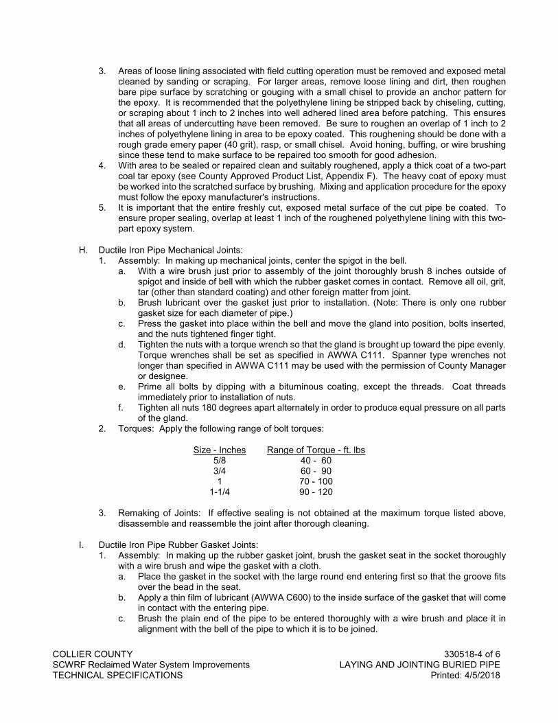
COLLIER COUNTY 330518-4 of 6 SCWRF Reclaimed Water System Improvements LAYING AND JOINTING BURIED PIPE TECHNICAL SPECIFICATIONS Printed: 4/5/2018
3. Areas of loose lining associated with field cutting operation must be removed and exposed metal cleaned by sanding or scraping. For larger areas, remove loose lining and dirt, then roughen bare pipe surface by scratching or gouging with a small chisel to provide an anchor pattern for the epoxy. It is recommended that the polyethylene lining be stripped back by chiseling, cutting, or scraping about 1 inch to 2 inches into well adhered lined area before patching. This ensures that all areas of undercutting have been removed. Be sure to roughen an overlap of 1 inch to 2 inches of polyethylene lining in area to be epoxy coated. This roughening should be done with a rough grade emery paper (40 grit), rasp, or small chisel. Avoid honing, buffing, or wire brushing since these tend to make surface to be repaired too smooth for good adhesion.
4. With area to be sealed or repaired clean and suitably roughened, apply a thick coat of a two-part coal tar epoxy (see County Approved Product List, Appendix F). The heavy coat of epoxy must be worked into the scratched surface by brushing. Mixing and application procedure for the epoxy must follow the epoxy manufacturer's instructions.
5. It is important that the entire freshly cut, exposed metal surface of the cut pipe be coated. To ensure proper sealing, overlap at least 1 inch of the roughened polyethylene lining with this two-part epoxy system.
H. Ductile Iron Pipe Mechanical Joints: 1. Assembly: In making up mechanical joints, center the spigot in the bell.
a. With a wire brush just prior to assembly of the joint thoroughly brush 8 inches outside of spigot and inside of bell with which the rubber gasket comes in contact. Remove all oil, grit, tar (other than standard coating) and other foreign matter from joint.
b. Brush lubricant over the gasket just prior to installation. (Note: There is only one rubber gasket size for each diameter of pipe.)
c. Press the gasket into place within the bell and move the gland into position, bolts inserted, and the nuts tightened finger tight.
d. Tighten the nuts with a torque wrench so that the gland is brought up toward the pipe evenly. Torque wrenches shall be set as specified in AWWA C111. Spanner type wrenches not longer than specified in AWWA C111 may be used with the permission of County Manager or designee.
e. Prime all bolts by dipping with a bituminous coating, except the threads. Coat threads immediately prior to installation of nuts.
f. Tighten all nuts 180 degrees apart alternately in order to produce equal pressure on all parts of the gland.
2. Torques: Apply the following range of bolt torques:
Size - Inches Range of Torque - ft. lbs 5/8 40 - 60 3/4 60 - 90 1 70 - 100
1-1/4 90 - 120
3. Remaking of Joints: If effective sealing is not obtained at the maximum torque listed above, disassemble and reassemble the joint after thorough cleaning.
I. Ductile Iron Pipe Rubber Gasket Joints: 1. Assembly: In making up the rubber gasket joint, brush the gasket seat in the socket thoroughly
with a wire brush and wipe the gasket with a cloth. a. Place the gasket in the socket with the large round end entering first so that the groove fits
over the bead in the seat. b. Apply a thin film of lubricant (AWWA C600) to the inside surface of the gasket that will come
in contact with the entering pipe. c. Brush the plain end of the pipe to be entered thoroughly with a wire brush and place it in
alignment with the bell of the pipe to which it is to be joined.
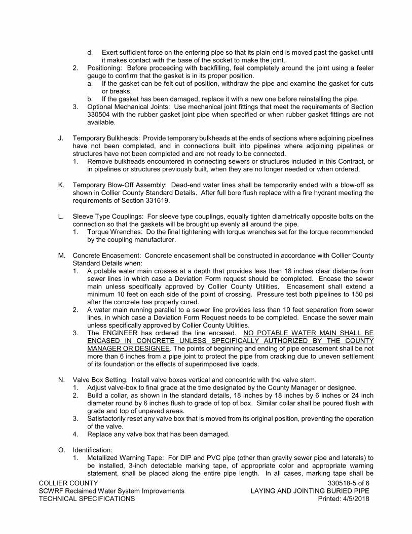
COLLIER COUNTY 330518-5 of 6 SCWRF Reclaimed Water System Improvements LAYING AND JOINTING BURIED PIPE TECHNICAL SPECIFICATIONS Printed: 4/5/2018
d. Exert sufficient force on the entering pipe so that its plain end is moved past the gasket until it makes contact with the base of the socket to make the joint.
2. Positioning: Before proceeding with backfilling, feel completely around the joint using a feeler gauge to confirm that the gasket is in its proper position. a. If the gasket can be felt out of position, withdraw the pipe and examine the gasket for cuts
or breaks. b. If the gasket has been damaged, replace it with a new one before reinstalling the pipe.
3. Optional Mechanical Joints: Use mechanical joint fittings that meet the requirements of Section 330504 with the rubber gasket joint pipe when specified or when rubber gasket fittings are not available.
J. Temporary Bulkheads: Provide temporary bulkheads at the ends of sections where adjoining pipelines have not been completed, and in connections built into pipelines where adjoining pipelines or structures have not been completed and are not ready to be connected. 1. Remove bulkheads encountered in connecting sewers or structures included in this Contract, or
in pipelines or structures previously built, when they are no longer needed or when ordered.
K. Temporary Blow-Off Assembly: Dead-end water lines shall be temporarily ended with a blow-off as shown in Collier County Standard Details. After full bore flush replace with a fire hydrant meeting the requirements of Section 331619.
L. Sleeve Type Couplings: For sleeve type couplings, equally tighten diametrically opposite bolts on the connection so that the gaskets will be brought up evenly all around the pipe. 1. Torque Wrenches: Do the final tightening with torque wrenches set for the torque recommended
by the coupling manufacturer.
M. Concrete Encasement: Concrete encasement shall be constructed in accordance with Collier County Standard Details when: 1. A potable water main crosses at a depth that provides less than 18 inches clear distance from
sewer lines in which case a Deviation Form request should be completed. Encase the sewer main unless specifically approved by Collier County Utilities. Encasement shall extend a minimum 10 feet on each side of the point of crossing. Pressure test both pipelines to 150 psi after the concrete has properly cured.
2. A water main running parallel to a sewer line provides less than 10 feet separation from sewer lines, in which case a Deviation Form Request needs to be completed. Encase the sewer main unless specifically approved by Collier County Utilities.
3. The ENGINEER has ordered the line encased. NO POTABLE WATER MAIN SHALL BE ENCASED IN CONCRETE UNLESS SPECIFICALLY AUTHORIZED BY THE COUNTY MANAGER OR DESIGNEE. The points of beginning and ending of pipe encasement shall be not more than 6 inches from a pipe joint to protect the pipe from cracking due to uneven settlement of its foundation or the effects of superimposed live loads.
N. Valve Box Setting: Install valve boxes vertical and concentric with the valve stem. 1. Adjust valve-box to final grade at the time designated by the County Manager or designee. 2. Build a collar, as shown in the standard details, 18 inches by 18 inches by 6 inches or 24 inch
diameter round by 6 inches flush to grade of top of box. Similar collar shall be poured flush with grade and top of unpaved areas.
3. Satisfactorily reset any valve box that is moved from its original position, preventing the operation of the valve.
4. Replace any valve box that has been damaged.
O. Identification: 1. Metallized Warning Tape: For DIP and PVC pipe (other than gravity sewer pipe and laterals) to
be installed, 3-inch detectable marking tape, of appropriate color and appropriate warning statement, shall be placed along the entire pipe length. In all cases, marking tape shall be
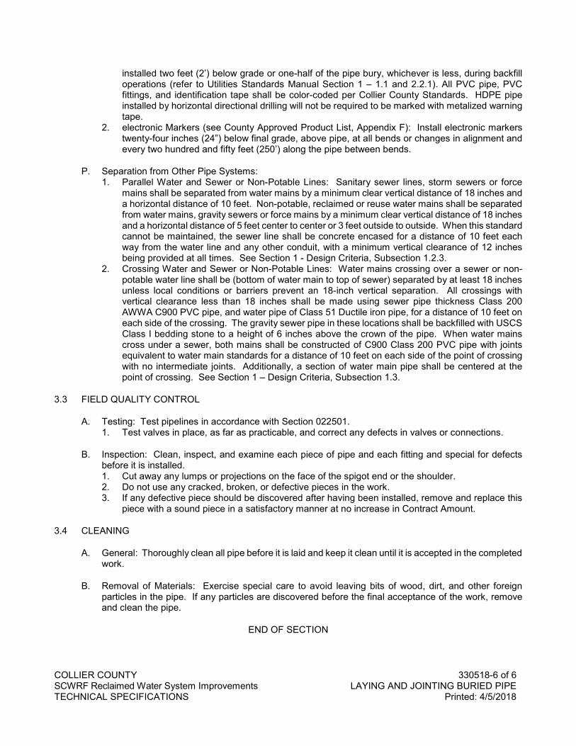
COLLIER COUNTY 330518-6 of 6 SCWRF Reclaimed Water System Improvements LAYING AND JOINTING BURIED PIPE TECHNICAL SPECIFICATIONS Printed: 4/5/2018
installed two feet (2’) below grade or one-half of the pipe bury, whichever is less, during backfill operations (refer to Utilities Standards Manual Section 1 – 1.1 and 2.2.1). All PVC pipe, PVC fittings, and identification tape shall be color-coded per Collier County Standards. HDPE pipe installed by horizontal directional drilling will not be required to be marked with metalized warning tape.
2. electronic Markers (see County Approved Product List, Appendix F): Install electronic markers twenty-four inches (24”) below final grade, above pipe, at all bends or changes in alignment and every two hundred and fifty feet (250’) along the pipe between bends.
P. Separation from Other Pipe Systems: 1. Parallel Water and Sewer or Non-Potable Lines: Sanitary sewer lines, storm sewers or force
mains shall be separated from water mains by a minimum clear vertical distance of 18 inches and a horizontal distance of 10 feet. Non-potable, reclaimed or reuse water mains shall be separated from water mains, gravity sewers or force mains by a minimum clear vertical distance of 18 inches and a horizontal distance of 5 feet center to center or 3 feet outside to outside. When this standard cannot be maintained, the sewer line shall be concrete encased for a distance of 10 feet each way from the water line and any other conduit, with a minimum vertical clearance of 12 inches being provided at all times. See Section 1 - Design Criteria, Subsection 1.2.3.
2. Crossing Water and Sewer or Non-Potable Lines: Water mains crossing over a sewer or non-potable water line shall be (bottom of water main to top of sewer) separated by at least 18 inches unless local conditions or barriers prevent an 18-inch vertical separation. All crossings with vertical clearance less than 18 inches shall be made using sewer pipe thickness Class 200 AWWA C900 PVC pipe, and water pipe of Class 51 Ductile iron pipe, for a distance of 10 feet on each side of the crossing. The gravity sewer pipe in these locations shall be backfilled with USCS Class I bedding stone to a height of 6 inches above the crown of the pipe. When water mains cross under a sewer, both mains shall be constructed of C900 Class 200 PVC pipe with joints equivalent to water main standards for a distance of 10 feet on each side of the point of crossing with no intermediate joints. Additionally, a section of water main pipe shall be centered at the point of crossing. See Section 1 – Design Criteria, Subsection 1.3.
3.3 FIELD QUALITY CONTROL
A. Testing: Test pipelines in accordance with Section 022501. 1. Test valves in place, as far as practicable, and correct any defects in valves or connections.
B. Inspection: Clean, inspect, and examine each piece of pipe and each fitting and special for defects before it is installed. 1. Cut away any lumps or projections on the face of the spigot end or the shoulder. 2. Do not use any cracked, broken, or defective pieces in the work. 3. If any defective piece should be discovered after having been installed, remove and replace this
piece with a sound piece in a satisfactory manner at no increase in Contract Amount.
3.4 CLEANING
A. General: Thoroughly clean all pipe before it is laid and keep it clean until it is accepted in the completed work.
B. Removal of Materials: Exercise special care to avoid leaving bits of wood, dirt, and other foreign particles in the pipe. If any particles are discovered before the final acceptance of the work, remove and clean the pipe.
END OF SECTION

COLLIER COUNTY 330520-1 of 6 SCWRF Reclaimed Water System Improvements PIPE REMOVAL AND ABANDONMENT TECHNICAL SPECIFICATIONS Printed: 4/5/2018
SECTION 330520
PIPE REMOVAL AND ABANDONMENT
PART 1 GENERAL
1.1 SUMMARY
A. Section Includes: Removal and abandonment of piping and appurtenances, wholly or in part, as required to complete Work as shown on the Drawings and specified in this Section.
B. Related Work Specified in other Sections Includes: 1. Section 020500 – Connection to Existing Systems. 2. Section 033100 – Concrete, Masonry Mortar and Grout. 3. Section 312316 – Excavation – Earth and Rock. 4. Section 312323 – Backfilling.
1.2 SUBMITTALS
A. General: Provide all submittals, including the following, as specified in Division 01.
B. Submit the following: 1. Proposed methods for pipe removal and abandonment; 2. Equipment proposed to be used to do pipe removal and abandonment work; 3. Resume of pipe grouting subcontractor; 4. Pipe removal and abandonment schedule/sequence.
C. If a detour is required, submit a traffic control plan for approval to County Manager or designee and/or the Florida Department of Transportation as described in Section 015526.
1.3 SITE CONDITIONS
A. General: 1. Prior to any work, a proper and approved maintenance of traffic plan (MOT) shall be submitted to
the engineer and the County. 2. Execute pipe removal and abandonment so that there is no injury to persons or damage to
adjacent buildings, structures, equipment, materials, piping, wiring, pavement, fences, trees, guardrails, and other adjacent improvements. Execute demolition and abandonment so that access to facilities that are in operation and to residences and businesses is free and safe.
3. Execute pipe removal and abandonment so that interference to vehicular traffic and personnel traffic does not exceed scheduled interference. Do not place rubble, excavation, piping, or other materials removed on roadways, drives, or sidewalks that are to remain in service.
PART 2 PRODUCTS
2.1 TEMPORARY MATERIALS
A. Provide temporary fencing, barricades, barriers, piping, valves, pumps, power and controls, and water necessary to meet the requirements of this Section.
B. Temporary fencing, barricades, barriers, and enclosures shall be suitable to the purpose intended.
2.2 REPAIR AND REPLACEMENT MATERIALS
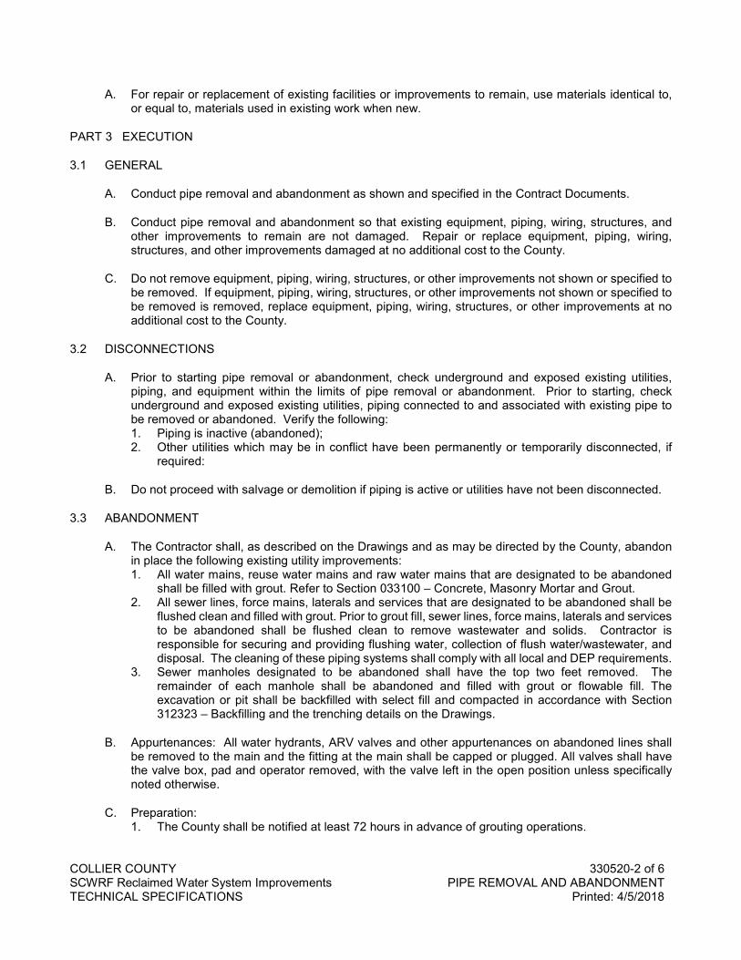
COLLIER COUNTY 330520-2 of 6 SCWRF Reclaimed Water System Improvements PIPE REMOVAL AND ABANDONMENT TECHNICAL SPECIFICATIONS Printed: 4/5/2018
A. For repair or replacement of existing facilities or improvements to remain, use materials identical to, or equal to, materials used in existing work when new.
PART 3 EXECUTION
3.1 GENERAL
A. Conduct pipe removal and abandonment as shown and specified in the Contract Documents.
B. Conduct pipe removal and abandonment so that existing equipment, piping, wiring, structures, and other improvements to remain are not damaged. Repair or replace equipment, piping, wiring, structures, and other improvements damaged at no additional cost to the County.
C. Do not remove equipment, piping, wiring, structures, or other improvements not shown or specified to be removed. If equipment, piping, wiring, structures, or other improvements not shown or specified to be removed is removed, replace equipment, piping, wiring, structures, or other improvements at no additional cost to the County.
3.2 DISCONNECTIONS
A. Prior to starting pipe removal or abandonment, check underground and exposed existing utilities, piping, and equipment within the limits of pipe removal or abandonment. Prior to starting, check underground and exposed existing utilities, piping connected to and associated with existing pipe to be removed or abandoned. Verify the following: 1. Piping is inactive (abandoned); 2. Other utilities which may be in conflict have been permanently or temporarily disconnected, if
required:
B. Do not proceed with salvage or demolition if piping is active or utilities have not been disconnected.
3.3 ABANDONMENT
A. The Contractor shall, as described on the Drawings and as may be directed by the County, abandon in place the following existing utility improvements: 1. All water mains, reuse water mains and raw water mains that are designated to be abandoned
shall be filled with grout. Refer to Section 033100 – Concrete, Masonry Mortar and Grout. 2. All sewer lines, force mains, laterals and services that are designated to be abandoned shall be
flushed clean and filled with grout. Prior to grout fill, sewer lines, force mains, laterals and services to be abandoned shall be flushed clean to remove wastewater and solids. Contractor is responsible for securing and providing flushing water, collection of flush water/wastewater, and disposal. The cleaning of these piping systems shall comply with all local and DEP requirements.
3. Sewer manholes designated to be abandoned shall have the top two feet removed. The remainder of each manhole shall be abandoned and filled with grout or flowable fill. The excavation or pit shall be backfilled with select fill and compacted in accordance with Section 312323 – Backfilling and the trenching details on the Drawings.
B. Appurtenances: All water hydrants, ARV valves and other appurtenances on abandoned lines shall be removed to the main and the fitting at the main shall be capped or plugged. All valves shall have the valve box, pad and operator removed, with the valve left in the open position unless specifically noted otherwise.
C. Preparation: 1. The County shall be notified at least 72 hours in advance of grouting operations.
COLLIER COUNTY 330520-3 of 6 SCWRF Reclaimed Water System Improvements PIPE REMOVAL AND ABANDONMENT TECHNICAL SPECIFICATIONS Printed: 4/5/2018
2. Bulkheads shall be spaced at intervals of not more than 1,000 feet. If the line to be abandoned is longer, bulkheads shall be inserted in the pipe to maintain the required maximum spacing between bulkheads.
3. Temporary vents shall be installed in the line to be filled at a maximum spacing of 150 ft. The vents shall be capable of being capped to allow further grouting operations.
D. Equipment: 1. The materials shall be mixed or delivered in equipment of sufficient size and capacity to provide
the desired amount of grout material for each stage in a single operation. The equipment shall be capable of mixing the grout at densities required for the approved procedure and shall also be capable of changing density as dictated by field conditions any time during the grouting operation.
2. Mixers and Pumps - The grout shall be delivered to the injection point at a steady pressure with a non-pulsating centrifugal or triplex pump. Means shall be provided to increase or decrease the water-cement ratio. The system shall mix the grout to a homogeneous consistency. Means of accurately measuring grout component quantities, pumping pressures, and volumes pumped shall be provided.
3. Pressure Gauges - CONTRACTOR shall provide one pressure gauge at the point of injection and one pressure gauge at the grout pump. Grouting shall not proceed without appropriate calibrated gauges in place and in working order. Pressure gauges shall be equipped with diaphragm seals, have a working range between 1.5 to 2.0 times the design grout pressure, and have an accuracy within 0.5 percent of full range. Pressure gauges shall be instrument oil filled and attached to a saddle-type diaphragm seal to prevent clogging with grout.
E. Grouting: 1. Once grouting operations begin, grouting shall proceed uninterrupted from bulkhead to bulkhead.
Grout placement shall not be terminated until both of the following conditions have been met, unless otherwise approved by the County: a) The estimated volume of grout to fill the line has been injected; and, b) grout has been expelled from the furthest vent or bulkhead. Bulkheads and temporary vents shall not be removed until the grout has set.
F. Testing and Sampling: 1. Take four test specimens for each 50 cubic yards of grout or for each four hours of placing. 2. Test in accordance with ASTM C109 except:
a. The specimens shall be 3 inch by 6 inch cylinders covered after casting to prevent damage and loss of moisture. Moist cure specimens for a period up to 7 days prior to a 28-day compressive strength test.
b. Do not oven dry specimens that are load tested. Specimens may be tested at any age to monitor compressive strength. The material may require special handling and testing techniques.
G. The CONTRACTOR may remove the pipe in accordance with the Paragraph 3.04 in lieu of abandonment if acceptable to the County. Such removal, however, will be paid at the same price for pipe abandonment.
H. All work under this Section shall comply with City, County, State and Federal regulations.
3.4 REMOVAL AND DISPOSAL
A. The Contractor shall, as described on the Drawings and as may be directed by the County, remove the following existing utility improvements: 1. All water mains, reuse water mains and raw water mains that are designated to be removed. 2. All sewer lines, sewer manholes, force mains, laterals and services that are designated to be
removed shall be flushed clean with water prior to removal. Contractor is responsible for securing and providing flushing water, collection of flush water/wastewater, and disposal. The cleaning of these piping systems shall comply with all local and DEP requirements.
COLLIER COUNTY 330520-4 of 6 SCWRF Reclaimed Water System Improvements PIPE REMOVAL AND ABANDONMENT TECHNICAL SPECIFICATIONS Printed: 4/5/2018
B. The pipe removal and disposal shall include all valves, fittings and appurtenances.
3.5 SALVAGE OF EQUIPMENT, PIPING, AND MATERIALS
A. Remove items identified on the drawings or specified to remain the property of the County. Do not damage equipment, piping, and materials to be salvaged.
B. Following removal or equipment, piping, and materials to be salvaged, place equipment, piping, and materials in a location within the County limits as designated by the County.
3.6 REPAIRS
A. Repair structural elements, equipment, piping, conduit, and other improvements to remain that are damaged during demolition. Use workers specifically qualified in trade, or trades, involved to repair damaged work.
3.7 DISPOSAL
A. Remove and dispose of all equipment, piping, and materials from the jobsite not specifically designated to be retained by the County.
B. Contractor shall not accumulate or store debris from demolition on the project site.
C. The disposal of the piping, manholes and appurtenances shall be in accordance with County, State and Federal laws.
3.8 BACKFILLING
A. Backfill excavations, trenches, and pits resulting from abandonment and removal according to Section 312323 – Backfilling.
B. Backfill of the pipe trenches shall be according to the County details for pipe trench backfill. Pipe trenches for removed pipes that were within 3 horizontal feet of the edge of pavement shall be backfilled according to the detail for the type of roadway.
3.9 CLEANUP AND CLOSURE
A. Following pipe abandonment or removal, clean-up areas where other work is to be done as specified in this Section, or Sections applicable to work to be done.
B. Following pipe abandonment or removal, clean-up areas where no other work is to be done under this Contract. Remove debris and rubbish, temporary facilities, and equipment. Level surface irregularities to eliminate depressions. Leave work in a neat and presentable condition.
C. In locations where a pipe to be abandoned or removed connects to a pipe that remains in service, the Contractor shall install a suitable cap or plug on the end of the active pipe.
3.10 SCHEDULE
A. Remove the following equipment and materials for OWNER’s retention. Deliver to location designated by OWNER: 1. Existing 20-inch diameter reclaim water meter (1).

COLLIER COUNTY 330520-5 of 6 SCWRF Reclaimed Water System Improvements PIPE REMOVAL AND ABANDONMENT TECHNICAL SPECIFICATIONS Printed: 4/5/2018
END OF SECTION

COLLIER COUNTY 330520-6 of 6 SCWRF Reclaimed Water System Improvements PIPE REMOVAL AND ABANDONMENT TECHNICAL SPECIFICATIONS Printed: 4/5/2018
NO TEXT FOR THIS PAGE
COLLIER COUNTY 333314-1 of 12 SCWRF Reclaimed Water System Improvements WASTEWATER VALVES AND APPURTENANCES TECHNICAL SPECIFICATIONS Printed: 4/5/2018
SECTION 333313
WASTEWATER VALVES AND APPURTENANCES
PART 1 GENERAL
1.1 SCOPE OF WORK
A. Furnish all labor, materials, equipment and incidentals required and install complete and ready for operation all valves and appurtenances as shown on the Drawings and as specified herein.
B. The equipment shall include, but not be limited to, the following: 1. Inline check valves, slip-in type. 2. Butterfly valves for reclaimed water service. 3. Gate valves, PVC type for pressure reclaimed water lines. 4. Gate valves, stainless steel type for air release blow-offs on reclaimed water lines. 5. Valve appurtenances. 6. Manual valve operators. 7. Electric motor actuators. 8. Valve boxes. 9. Couplings. 10. Pipe sleeves. 11. Unions. 12. Mechanical type seals. 13. Flow meters.
C. Contract Bid Unit Price Item 2: Inline Check Valve No. V-10, 36-inch diameter, slip-in type: 1. The Contract Price includes quantities a Unit Price in the Bid to pay for the cost of furnishing and
installing inline check valve at location V-10; see Section 012000.
1.2 RELATED SECTIONS
A. Section 407113 – Magnetic Flow Meters.
1.3 DESCRIPTION OF SYSTEMS
A. All of the equipment and materials specified herein are intended to be standard for use in controlling the flow of wastewater and reclaimed water.
1.4 QUALIFICATIONS
A. All of the types of valves and appurtenances shall be products of well-established reputable firms who are fully experienced, reputable and qualified in the manufacture of the particular equipment to be furnished. The equipment shall be designed, constructed and installed in accordance with the best practices and methods and shall comply with these specifications as applicable.
1.5 SUBMITTALS
A. Submit within 30 days after execution of the contract a list of materials to be furnished, the names of the suppliers and the date of delivery of materials to the site.
B. Complete shop drawings of all valves and appurtenances shall be submitted to the ENGINEER for approval in accordance with the General Conditions.
COLLIER COUNTY 333314-2 of 12 SCWRF Reclaimed Water System Improvements WASTEWATER VALVES AND APPURTENANCES TECHNICAL SPECIFICATIONS Printed: 4/5/2018
1.6 TOOLS
A. Special tools, if required for normal operation and maintenance shall be supplied with the equipment.
PART 2 PRODUCTS
2.1 GENERAL
A. All valves and appurtenances shall be of the size shown on the Drawings and as far as possible all equipment of the same type shall be from one manufacturer.
B. All valves and appurtenances shall have the name of the maker and the working pressure for which they are designed cast in raised letters upon some appropriate part of the body.
C. Pressure Rating: As specified, either herein or by referenced Standard, unless otherwise indicated in the Valve Schedule on Drawings.
D. Valve Ends: See Valve Schedule on Drawings. 1. Flanged: ANSI B16.1 Class 125. 2. Mechanical: AWWA C111. 3. Threaded: NPT Standard. 4. Grooved: AWWA C606. 5. Socket: Solvent-weld.
E. Type of Operator: See Valve Schedule on Drawings.
F. Valves to open counterclockwise, unless otherwise specified; verify direction with OWNER.
2.2 INLINE CHECK VALVE, SLIP-IN TYPE
A. Description: All neoprene rubber, one-piece, flexible sleeve with nylon reinforcement; flow operated to allow passage of flow in one direction while preventing reverse flow.
B. Ends: Flanged or inside clamp type.
C. Clamps, Anchor Bolts, and Pins: 316 stainless steel.
D. Manufacturer: Red Valve Co., Tideflex Ultraflex Checkmate Check Valve.
2.3 BUTTERFLY VALVE, AWWA TYPE
A. AWWA C504, short body design, unless otherwise indicated in the Valve Schedule on Drawings, with resilient seat.
B. Class: 150B.
C. Body: Cast iron, ASTM A126, Class B.
D. Ends: 1. Flanged ends: Faced and drilled per ANSI B16.1 standard for cast iron flanges. 2. Mechanical joint ends: AWWA C111/ANSI A21.11.
E. Disc: Cast iron, ASTM A126, or ductile iron, ASTM A536; either with solid stainless steel seating edge. Offset to provide an uninterrupted 360-degree seating edge.
COLLIER COUNTY 333314-3 of 12 SCWRF Reclaimed Water System Improvements WASTEWATER VALVES AND APPURTENANCES TECHNICAL SPECIFICATIONS Printed: 4/5/2018
F. Shaft: Type 304 Stainless steel with self-compensating V-ring seals. 1. 3 to 20-Inch: Non-metallic and permanently lubricated. 2. 24-Inch to 72-Inch: Teflon lined with a non-metallic fiberglass composite backing; permanently
lubricated.
G. Seat: EDPM. 1. 3 to 20-Inch: Molded in and vulcanized to the valve body. 2. 24-Inch to 72-Inch: Retained within a dovetail groove in the valve body and locked in place by an
epoxy compound edge.
H. Worm Gear: IW Series AWWA C504 and C5PV-3; 100% grease filled for life and fully sealed.
I. For buried installation, bolts, nuts, and washers used by manufacturer to assemble valves to be Type 304 stainless steel.
J. Provide a valve tag indicating direction of flow.
K. Manufacturer: DeZurik BAW.
2.4 GATE VALVE, PVC
A. Type: Heavy-bodied PVC gate valve with non-rising stem, fully repairable.
B. Ends: flanged or socket-welded.
C. Internal pressure rating: 200 psi at 73 degrees F.
D. O-rings: Buna N, EPDM, or KFM as recommended for service.
E. Operator: See SCHEDULE in Drawings.
F. Manufacturer: Spears PVC Gate Valve, or equal.
2.5 BALL VALVE, STAINLESS STEEL 2 INCHES AND SMALLER:
A. ASTM A276 GR 316 or ASTM A351 GR CF8M stainless steel body, standard port, 316 SST ball, one-piece body, 316 SST trim, threaded ends, rated 1000 pound WOG, with seat, body seal, and stem packing reinforced PTFE, lever operator.
B. Manufacturer: Nibco, Stainless Steel Ball Valves; Walworth, or equal.
2.6 VALVE APPURTENANCES
A. Extension Stems: Steel; size as instructed by the valve manufacturer. Terminate extension stems for buried valves 2 feet below ground surface, and for non-buried valves between 1 and 4 inches below surrounding surface.
B. Operating Nuts: Provide 2-inch square nut with each extension stem. Locate centered in valve or floor box, or as otherwise shown.
C. Operating Wrench: T-type; 5 feet long.
D. Floor Stand: Cast iron, non-rising stem. Provide ½-inch thick grout pad beneath floor stands.
COLLIER COUNTY 333314-4 of 12 SCWRF Reclaimed Water System Improvements WASTEWATER VALVES AND APPURTENANCES TECHNICAL SPECIFICATIONS Printed: 4/5/2018
E. Valve Box: SEE COUNTY APPROVED PRODUCT LIST, APPENDIX F.
2.7 MANUAL VALVE OPERATORS
A. Type: Handwheel, chain wheel, lever, or operating nut. See Valve Schedule on Drawings.
B. For valves 6’-0” or higher from operating floor, provide stainless steel chain wheel.
C. Each valve to have a permanently attached operator. One portable operator for several valves is not acceptable.
D. Provide gearing for all valves requiring operating torque in excess of 80 pounds on handwheel or maximum input of 150 foot pounds on operating nuts, unless otherwise noted.
2.8 ELECTRIC MOTOR ACTUATOR
A. Manufacturer: Rotork Controls IQ Series (Open/Close) with HART® Actuator Control.
B. Comply with AWWA C540, Power Actuating Devices for Valves and Slide Gates. Manufacturer or manufacturer’s authorized distributor responsible for proper sizing and mounting.
C. Enclosure: O-ring sealed, watertight to IP66/IP68 21feet for 72hrs, NEMA 4, 6.
D. Motor: 1. Power supply: as shown in Drawings. 2. Low inertia high torque design, class F insulated with a class B temperature rise. 3. Protection:
a. Stall: The motor shall be de-energized within 8 seconds in the event of a stall when attempting to unseat a jammed valve.
b. Over temperature: Thermostat will cause tripping of the motor. Auto-reset on cooling c. Single phasing: Lost phase protection. d. Direction: Phase rotation correction.
4. Three-Phase Actuators: Three-phase, AC, induction motor. Include self-correcting circuitry or lock-out circuitry for protection against out-of-phase rotation.
5. Size for a minimum of 1.5 times the required actuator torque. 6. Motor Controller: Electrically interlocked OPEN and CLOSE contactors rated for 60 starts per
hour.
E. Gearing: Totally enclosed, oil-filled.
F. Design to allow the motor and controller components of the actuator to be removed without unloading the valve stem, and to allow manual operation of the stem without the removed components.
G. Hand Operation: Provide a handwheel for emergency operation, engaged when the motor is declutched by a lever or similar means, the drive being restored to electrical operation automatically by starting the motor. 1. The handwheel or selection lever shall not move on restoration of motor drive. 2. Provision shall be made for the hand/auto selection lever to be locked in both hand and auto
positions. It should be possible to select hand operation while the actuator is running or start the actuator motor while the hand/auto selection lever is locked in hand without damage to the drive train.
3. Clockwise operation of the handwheel shall give closing movement of the valve unless otherwise stated in the data sheet. For linear valve types the actuator handwheel drive must be mechanically independent of the motor drive and should be such as to permit valve operation in
COLLIER COUNTY 333314-5 of 12 SCWRF Reclaimed Water System Improvements WASTEWATER VALVES AND APPURTENANCES TECHNICAL SPECIFICATIONS Printed: 4/5/2018
a reasonable time with a manual force not exceeding 400N through stroke and 800N for seating/unseating of the valve.
H. Drive Interface: Furnish actuator with a drive bushing, easily detachable for machining to suit the valve stem or gearbox input shaft. Thrust bearings shall be sealed for life and the base shall be capable of withstanding five times the rated thrust of the actuator.
I. Local Controls: Incorporate local controls for Open, Close and Stop and a Local/Stop/Remote mode selector switch lockable in any one of the following three positions: local control only, stop (no electrical operation), remote control plus local stop only. It shall be possible to select maintained or non-maintained local control. 1. Arrange local controls so that the direction of valve travel can be reversed without the necessity
of stopping the actuator. 2. The local controls and display shall be rotatable through increments of 90 degrees to suit valve
and actuator orientation.
J. Torque and Limits: 1. Torque and turns limitation to be adjustable as follows:
a. Position setting range – multi-turn: 2.5 to 8,000 turns, with resolution to 7.5 deg. of actuator output.
b. Position setting range – direct drive part turn actuators: 90 degrees +/-10 degrees, with resolution to 0.1 degree of actuator output.
c. Torque setting: 40% to 100% rated torque. 2. Provide absolute position measurement to be incorporated within the actuator. 3. Provide measurement of torque from direct measurement of force at the output of the actuator. 4. Provide a means for automatic “torque switch bypass” to inhibit torque off during valve unseating
and “latching” to prevent torque switch hammer under maintained or repeated control signals. 5. The electrical circuit diagram of the actuator should not vary with valve type remaining identical
regardless of whether the valve is to open or close on torque or position limit.
K. Remote Valve Position and Status Indication: 1. Four contacts shall be provided which can be selected to indicate any position of the valve;
Provision shall be made for the selection of a normally closed or open contact form. Contacts shall maintain and update position indication during handwheel operation when all external power to the actuator is isolated. The contacts shall be rated for 5mA to 5A, 120V AC, 30V DC.
2. As an alternative to providing valve position indication any of the four above contacts shall be selectable to signal one of the following: a. Valve opening, closing or moving. b. Thermostat tripped, lost phase. c. Motor tripped on torque in mid travel, motor stalled. d. Remote selected. e. Actuator being operated by handwheel. f. Actuator fault.
3. Provision shall be made in the design for an additional eight contacts having the same functionality.
4. A configurable monitor relay shall be provided as standard, which can be used to indicate either Availability or Fault. The relay should be a spring return type with a Normally Open / Normally Closed contact pre-wired to the terminal bung.
5. The Monitor (availability or fault) relay, being energized from the control transformer will de-energize under any one or more the following conditions: a. Available Mode. b. Loss of main or customer 24V DC power supply. c. Actuator control selected to local or stop. d. Motor thermostat tripped. e. Actuator internal fault.
COLLIER COUNTY 333314-6 of 12 SCWRF Reclaimed Water System Improvements WASTEWATER VALVES AND APPURTENANCES TECHNICAL SPECIFICATIONS Printed: 4/5/2018
f. Loss of main or customer 24V DC power supply. g. Motor thermostat tripped. h. Actuator internal fault.
6. Provision shall be made in the design for the addition of a contactless transmitter to give a 4-20mA analogue signal corresponding to valve travel and / or torque for remote indication when required. The transmitter will auto range to the set limits
L. Local Position Indication: 1. The actuator display shall include a dedicated numeric/symbol digital position indicator displaying
valve position from fully open to fully close in 0.1% increments. Valve closed and open positions shall be indicated by symbols showing valve position in relation to the pipework to ensure that valve status is clearly interpreted. With mains power connected, the display shall be backlit to enhance contrast at all ambient light levels and shall be legible from a distance of at least 5m (16ft).
2. Red, green, and yellow LEDs corresponding to open, closed and intermediate valve positions shall be included on the actuator display when power is switched on. The yellow LED should also be fully programmable for on/off, blinker and fault indication. The digital display shall be maintained and updated during handwheel operation when mains power to the actuator is isolated. In the event of a (main) power (supply) loss or failure, the position contacts must continue to be able to supply remote position feedback and maintain interlock capabilities. If batteries are required to maintain contact functionality the actuator vendor shall provide a supply sufficient for 45 continuous days of un-powered operation with one complete valve cycle every hour
3. The actuator display shall include a fully configurable dot-matrix display element with a minimum pixel resolution of 168 x 132 to display operational, alarm, configuration and graphical datalogger information. The text display shall be selectable between English and other languages such as: Spanish, German, French, and Italian. Provision shall be made to upload a different language without removal of any covers or using specialized tools not provided as standard with the actuator.
4. Datalogger graphical displays should as a minimum be able to display log and trend graphs on the local LCD for the following: a. Torque versus Position. b. Number of Starts versus Position. c. Number of starts per hour. d. Dwell Time. e. Average temperature.
5. The main display shall be capable of indicating 4 different home-screens of the following configuration: a. Position and status. b. Position and torque (analog). c. Position and torque (digital). d. Position and demand (positioning).
6. Provision shall be made for the addition of an optional environmental cover to protect the display from high levels of UV radiation or abrasive materials.
7. The local controls and display shall be rotatable through increments of 90 degrees to suit valve and actuator orientation.
8. Actuators that are not accessible shall have the capability of a “mirror image” of the face of the actuator Remote Hand Station. (RHS) shall be suitable for remote connection to an electric actuator up to 100m distance, include local control facilities, a backlit LCD display and terminals for communication highway connection to the host actuator housed within a self-contained, double-sealed enclosure. In order to maintain the integrity of the enclosure, setting of the actuator torque levels, position limits and configuration of the indication contacts etc. shall be carried out without the removal of any covers via a Bluetooth® wireless interface.
M. Integral Starter and Transformer:
COLLIER COUNTY 333314-7 of 12 SCWRF Reclaimed Water System Improvements WASTEWATER VALVES AND APPURTENANCES TECHNICAL SPECIFICATIONS Printed: 4/5/2018
1. The reversing starter, control transformer and local controls shall be integral with the valve actuator, suitably housed to prevent breathing and condensation. The starter shall be suitable for 60 starts per hour and of rating appropriate to motor size. The controls supply transformer shall be fed from two of the incoming three phases and incorporate overload protection. It shall have the necessary tapping and be adequately rated to provide power for the following functions: a. Energizing of the contactor coils. b. 24V DC or 110V AC output for remote controls (maximum 5W/VA) c. Supply for all the internal electrical circuits.
N. Remote Control Facilities: 1. The necessary control, wiring and terminals shall be provided integral to the actuator enclosure.
Open and close external interlocks shall be made available to inhibit local and remote valve opening / closing control. It shall be possible to configure the interlocks to be active in remote control only.
2. Remote control signals fed from an internal 24V DC (or 110VAC) supply and/or from an external supply between 20V and 60 VDC or 40V and 120VAC, to be suitable for any one or more of the following methods of control: a. Open, Close and Stop control. b. Open and Close maintained or “push to run” (inching) control. c. Overriding Emergency Shut-down to close (or open) valve from a normally closed or open
contact. d. Two-wire control, energize to close (or open), de-energize to open (or close).
3. Additionally, provision shall be made for a separate ‘drive enable’ input to prevent any unwanted electrical operation.
4. It shall be possible to reverse valve travel without the necessity of stopping the actuator. The motor starter shall be protected from excessive current surges during rapid travel reversal. The internal circuits associated with the remote control and monitoring functions are to be designed to withstand simulated lightning impulses of up to 2kV.
5. Provision shall be made for operation by distributed control system utilizing the following network systems: Collier County Version Hart.
O. Monitoring Facilities: 1. Facilities shall be provided for monitoring actuator operation and availability as follows:
a. Actuator text display indication of the following status/alarms: 1) Closed Limit, open limit, moving open, moving closed, stopped. 2) Torque trip closing, torque trip opening, stalled. 3) ESD active, interlock active. 4) Thermostat trip, phase lost, 24V supply lost, Local control failure. 5) Configuration error, Position sensor failure, Torque sensor failure. 6) Battery low, power loss inhibit.
b. Integral datalogger to record and store the following operational data: 1) Opening last /average torque against position. 2) Closing last /average torque against position. 3) Opening motor starts against position. 4) Closing motor starts against position. 5) Total open/closed operations. 6) Maximum recorded opening and closing torque values. 7) Event recorder logging operational conditions (valve, control and actuator).
2. The datalogger shall record relevant time and date information for stored data. 3. Datalogger data shall be accessed via non-intrusive Bluetooth® communication and data
displayed on the local LCD. Sufficient standard intrinsically safe tools shall be provided for downloading datalogger and actuator configuration files from the actuators and subsequent uploading to a PC. The actuator manufacturer shall supply PC software to enable datalogger files to be viewed and analyzed.
COLLIER COUNTY 333314-8 of 12 SCWRF Reclaimed Water System Improvements WASTEWATER VALVES AND APPURTENANCES TECHNICAL SPECIFICATIONS Printed: 4/5/2018
P. Wiring and Termination: 1. Internal wiring shall be tropical grade PVC insulated stranded cable of appropriate size for the
control and 3-phase power. Each wire shall be clearly identified at each end. The terminals shall be embedded in a terminal block of high tracking resistance compound.
2. The terminal compartment shall be separated from the inner electrical components of the actuator by means of a watertight seal and shall be provided with a minimum of 3 threaded cable entries with provision for an additional 5 extra conduit entries.
3. All wiring supplied as part of the actuator to be contained within the main enclosure for physical and environmental protection. External conduit connections between components are not acceptable.
4. A durable terminal identification card showing a plan of terminals shall be provided attached to the inside of the terminal box cover indicating: a. Serial number b. External voltage values c. Wiring diagram number d. Terminal layout
5. The code card shall be suitable for the contractor to inscribe cable core identification alongside terminal numbers.
Q. Commissioning Kit: Each actuator shall be supplied with a start-up kit comprising installation instruction manual, electrical wiring diagram and cover seals to make good any site losses during the commissioning period. In addition, sufficient actuator commissioning tools shall be supplied to enable actuator set-up and adjustment during valve/actuator testing and site installation commissioning.
R. Performance and Test Certificate: 1. Each actuator must be performance tested and individual test certificates shall be supplied free
of charge. The test equipment should simulate a typical valve load, and the following parameters should be recorded: a. Current at maximum torque setting b. Torque at max. torque setting c. Flash test voltage d. Actuator output speed or operating time.
2. In addition, the test certificate should record details of specification such as gear ratios for both manual and automatic and second stage gearing if provided, drive closing direction, wiring diagram number.
S. On-site Start-Up Assistance: Prior to start up, contractor shall inform service techs of all requirements of the certificate of proper installation. All forms and documentation required for the certificate of proper installation shall be given to service tech prior to start up. Minimum of 1 day per two actuators. Start-up shall be performed by direct factory tech that resides in Florida.
T. Warranty: Each actuator shall be warranted for a minimum of 24 months of operation up to a maximum of 36 months from shipment.
U. Valves for Buried Service: 1. Valves for buried service shall meet all the requirements as specified herein for interior except
that buried valves shall have mechanical joint ends.
2.9 VALVE BOXES
A. All buried valves shall have cast-iron two-piece valve boxes (see County Approved Product List, Appendix F), valve boxes shall be provided with suitable heavy bonnets to extend to such elevation at the finished grade surface as directed by the ENGINEER. The barrel shall be two-piece, screw type. The upper section shall have a flange at the bottom having sufficient bearing area to prevent settling, shall be designed so as to prevent the transmission of surface loads directly to the valve or piping, and
COLLIER COUNTY 333314-9 of 12 SCWRF Reclaimed Water System Improvements WASTEWATER VALVES AND APPURTENANCES TECHNICAL SPECIFICATIONS Printed: 4/5/2018
shall be complete with cast iron covers. Covers shall have "SEWER" cast into the top. The covers shall be so constructed as to prevent tipping or rattling. All valve boxes located in paved roadways or sidewalks shall have locking covers.
B. Where valves are located out of pavement, the boxes shall be adjusted to finished grade and a concrete slab two feet square and six inches thick shall be poured around the box, as shown in the Details.
C. Valve boxes shall be of the heavy duty, traffic bearing cast iron, adjustable screw type with a drop cover. The valve box assembly shall consist of a bottom section, top section and cover which is cast from gray iron, formulated to ASTM specification A-48 latest revision, minimum tensile of 21,000 psi and shall be free from blowholes, shrinkage or other imperfections not true to pattern. The shaft size shall be 5 1/4" and the adjustable length shall be from 18" to 36". The wall thickness shall be 1/4”. The weight of the assembly shall be 61 pounds + 2 pounds, with the cover weight being a minimum of 13 pounds.
D. The name of the manufacturer and foundry of origin shall be cast into each of the components of the assembly in legible form. The assembly shall be suitable for highway traffic wheel loads of 16,000 pounds and shall withstand a proof load test of 25,000 pounds without failure or permanent deflection. The valve box shall be cast, machined, assembled, and packaged within the United States and shall fully comply with the Buy American provisions of Public Law 102-240, enacted 12/18/91.
2.10 COUPLINGS
A. Flange adapter couplings: Shall be of the size and pressure rating required for each installation and shall be suitable for use on either cast iron or ductile iron pipe. They shall be similar or equal to Dresser Company, Style 128. All couplings shall have a sufficient number of factory installed anchor studs to meet or exceed the test pressure rating for this project, 100-psi minimum. 1. Material: Ductile iron; comply with ASTM A536. 2. Bolt Circle: Comply with AWWA C115. 3. Restraint Device: Individually actuated gripping wedges, with torque-limiting actuating screws. 4. Capable of up to 3 degrees of joint deflection during assembly or permit lengths of pipe to be
field-cut to within 2 inches of maximum distance between flanges to allow for simplified alignment of flanged connections.
B. Split type couplings: Shall be either the split type or the sleeve type as shown on the Drawings. The couplings shall be mechanical type for radius groove piping. The couplings shall mechanically engage and lock grooved pipe ends in a positive coupling and allow for angular deflection and contraction and expansion.
C. Couplings shall consist of malleable iron, ASTM Specification A47, Grade 32510 housing clamps in two or more parts, a single chlorinated butyl composition sealing gasket with a "C" shaped cross-section and internal sealing lips projecting diagonally inward, and two or more oval track head type bolts with hexagonal heavy nuts conforming to ASTM Specification A183 and A194 to assemble the housing clamps. Bolts and nuts shall be Series 300 stainless steel.
D. Victaulic type couplings and fittings may be used in lieu of flanged joints. Pipes shall be radius grooved as specified for use with the Victaulic couplings. Flanged adapter connections (see County Approved Product List, Appendix F) at fittings, valves, and equipment.
E. Sleeve type couplings: (see County Approved Product List, Appendix F) shall be used with all buried piping. The couplings shall be of steel. The coupling shall be provided with stainless steel bolts and nuts unless indicated otherwise.
COLLIER COUNTY 333314-10 of 12 SCWRF Reclaimed Water System Improvements WASTEWATER VALVES AND APPURTENANCES TECHNICAL SPECIFICATIONS Printed: 4/5/2018
F. All couplings shall be furnished with the pipe stop removed.
G. Couplings shall be provided with gaskets of a composition suitable for exposure to the liquid within the pipe.
H. If the CONTRACTOR decides to use Victaulic couplings in lieu of flanged joints, he shall be responsible for supplying supports for the joints.
2.11 PIPE SLEEVES
A. Material: Standard weight steel pipe or 18 gage galvanized steel.
B. Integral water stop collar.
C. Size: 1. Diameter: Large enough to allow for movement due to expansion and contraction. Allow for
mechanical seal or continuous protective neoprene wrap. 2. Length: Flush with wall or floor, unless otherwise indicated.
2.12 UNIONS
A. Unions on ferrous pipe 2" in diameter and smaller shall be 150-pound malleable iron, zinc-coated.
B. Unions on water piping 22" in diameter and larger shall be flange pattern, 125-pound class, zinc-coated.
C. Gaskets for flanged unions shall be of the best quality fiber, plastic, or leather.
D. Unions shall not be concealed in walls, ceilings, or partitions.
2.13 MECHANICAL TYPE SEALS
A. Mechanical type seals (see County Approved Product List, Appendix F) shall consist of an adjustable modular bolted, EDPM synthetic rubber and Glass-reinforced nylon plastic sealing element.
B. Bolts and Nuts: Type 304 stainless steel.
2.14 FLOW METERS
A. Magnetic Flow Meters: Follow Section 407113.
PART 3 EXECUTION
3.1 INSTALLATION
A. Install all valves and appurtenances in the locations shown, true to alignment and rigidly supported. Repair any damage to the above items to the satisfaction of the ENGINEER before they are installed.
B. Carefully inspect each valve, open it wide and then tightly close it, and test the various nuts and bolts for tightness. Take special care to prevent any foreign matter from becoming lodged in the valve seat. Valves, unless shown otherwise shall be set with their operator shaft vertically. Repair and replace any valve that does not operate correctly.
COLLIER COUNTY 333314-11 of 12 SCWRF Reclaimed Water System Improvements WASTEWATER VALVES AND APPURTENANCES TECHNICAL SPECIFICATIONS Printed: 4/5/2018
C. Carefully center valve boxes over the operating nuts of the valves so as to permit a valve wrench or key to be fitted easily to the operating nut. Valve boxes shall be set to conform to the level of the finished surface and held in position by a ring of concrete placed under the support flange as shown on the Collier County Standard Details. The valve box shall not transmit surface loads to the pipe or valve. Care shall be taken to prevent earth and other material from entering the valve box. Any valve box which is out of alignment or whose top does not conform to the finished ground surface shall be dug out and reset. Before final acceptance of the work, adjust all valve boxes to finish grade. Valve operating risers shall be installed with any valves required to ensure that the operating nut is 30-inches or less from the ground surface.
D. After installation, test all valves and appurtenances for at least 1 hour at the working pressure corresponding to the class of pipe, unless a different test pressure is specified. If any joint proves to be defective, repair it to the satisfaction of the ENGINEER.
E. Install all floor boxes, brackets, extension rods, guides, the various types of operators and appurtenances as shown on the Drawings that are in masonry floors or walls, and install concrete inserts for hangers and supports as soon as forms are erected and before concrete is poured. Before setting these items, check all plans and figures that have a direct bearing on their location and he shall be responsible for the proper location of these valves and appurtenances during the construction of the structures.
F. Pipe for use with flexible couplings shall have plain ends as specified in the respective pipe sections.
G. Buried flanged or mechanical joints shall be made with Series 300, stainless steel bolts. All exposed bolts shall be made with Series 300 stainless steel bolts.
H. Prior to assembly of split couplings, thoroughly clean the grooves as well as other parts. The ends of the pipes and outside of the gaskets shall be moderately coated with petroleum jelly, cup grease, soft soap or graphite paste, and the gasket shall be slipped over one pipe end. After the other pipe has been brought to the correct position, center the gasket properly over the pipe ends with the lips against the pipes. The housing sections then shall be placed. After the bolts have been inserted, tighten the nuts until the housing sections are firmly in contact, metal-to-metal, without excessive bolt tension.
I. Prior to the installation of sleeve-type couplings, thoroughly clean the pipe ends for a distance of 8". Soapy water may be used as a gasket lubricant. A follower and gasket, in that order, shall be slipped over each pipe to a distance of about 6" from the end, and the middle ring shall be placed on the already laid pipe end until it is properly centered over the joint. Insert the other pipe end into the middle ring and bring to proper position in relation to the pipe already laid. The gaskets and followers shall then be pressed evenly and firmly into the middle ring flairs. After the bolts have been inserted and all nuts have been made up finger-tight, uniformly tighten diametrically opposite nuts progressively all around the joint, preferably by use of a torque wrench of the appropriate size and torque for the bolts.
J. Carefully inspect each valve, open it wide and then tightly close it and test the various nuts and bolts for tightness. Special care shall be taken to prevent any foreign matter from becoming lodged in the valve seat. Gate valves, unless shown otherwise, shall be set with their stems vertically above the centerline of the pipe. Remove and replace any valve that does not operate correctly.
K. Carefully center valve boxes over the operating nuts of the valves so as to permit a valve wrench or key to be fitted easily to the operating nut. Valve boxes shall be set to conform to the level of the finished surface and held in position by a ring of concrete placed under the support flange as shown in Section 3, Utility Detail Drawings. The valve box shall not transmit surface loads to the pipe or valve. Exercise care to prevent earth and other material from entering the valve box. Any valve box which is out of alignment or whose top does not conform to the finished ground surface shall be dug and reset. Before final acceptance of the work, adjust all valve boxes to finish grade. Valve extension stems or risers shall not be used.
COLLIER COUNTY 333314-12 of 12 SCWRF Reclaimed Water System Improvements WASTEWATER VALVES AND APPURTENANCES TECHNICAL SPECIFICATIONS Printed: 4/5/2018
L. Install valves for convenient operation.
M. Install valves plumb and level; free from distortion and strain from misaligned piping or equipment.
N. Provide ½-inch thick grout pad beneath floor stands.
O. Install electric motor actuators so that control devices and handwheel are readily accessible.
3.2 AIR RELEASE VALVE INSTALLATION
A. Each air release valve shall be installed at a high point in the pipeline.
B. Prior to pressure testing a pipeline, all air release valve assemblies on that pipeline shall be installed.
3.3 SHOP PAINTING
A. Coat ferrous surfaces of valves and appurtenances with rust-inhibitive epoxy primer. Cap all pipe connection openings to prevent the entry of foreign matter prior to installation.
3.4 FIELD PAINTING
A. Paint all metal valves and appurtenances specified herein and installed in valve and meter pits as specified.
3.5 INSPECTION AND TESTING
A. Subject completed pipe to hydrostatic pressure test at full working pressure. Repair all leaks and retest the line as approved by the ENGINEER. Prior to testing, support the gravity pipelines in an approved manner to prevent movement during tests.
3.6 MANUFACTURER’S START-UP SERVICES
A. Provide two 8-hour days of service for the electric motor actuators. 1. Set all actuators for valves and gates to stop on the fully-open limit switch, with the fully open
torque switch used only as backup. 2. Set actuators to stop on the fully-closed torque switch for valves which require firm seating. 3. Set limit switches used for remote monitoring in the fully-open and fully-closed positions at 99
percent open and 99 percent closed to prevent end-of-travel limit switches from activating prior to activating the limit switches used for remote monitoring.
4. Set mid-travel position limit switches, if required. 5. For modulating valves, drive the valve position to the extreme ends of travel using a 4-20 mAdc
input signal and verify the accuracy of the position feedback signal. Also verify accuracy at 25, 50, and 75 percent open.
6. Verify correct wiring of remote field wiring. Provide assistance with final connection of control wiring to actuators if needed.
.
END OF SECTION
COLLIER COUNTY 407113-1 of 4 SCWRF Reclaimed Water System Improvements MAGNETIC FLOW METERS TECHNICAL SPECIFICATIONS Printed: 8/14/2019
SECTION 407113
MAGNETIC FLOWMETERS
PART 1 GENERAL
1.1 SECTION INCLUDES
A. Electromagnetic flowmeters and appurtenances.
1.2 CERTIFICATES
A. Furnish certified data substantiating meter proportions and performance as applicable to the type of meter.
B. Furnish test certificates for accuracy of registration and pressure test on each size of a particular design of meter furnished.
1.3 QUALITY ASSURANCE
A. Provide corrosion-resistant metal data plates, mechanically attached to each unit, giving the following: 1. Manufacturer’s name. 2. Model identification. 3. Serial number. 4. Pipe size. 5. Pressure rating. 6. Flow rate. 7. Other pertinent data as applicable to the type of unit.
B. Mark direction of flow on body.
C. The materials and methods of manufacture, and completed meters and appurtenances are subject to inspection and rejection at all times. OWNER and ENGINEER have the right to make inspections.
1.4 SPARE PARTS
A. Provide one spare transmitter for each type flow meter provided.
PART 2 PRODUCTS
2.1 ELECTROMAGNETIC FLOWMETERS
A. Manufacturer: Endress & Hauser ProMag Series W 400 5W4C with HART protocol and Heartbeat Technology.
B. Type: Electromagnetic type with Teflon lining, stainless steel electrodes and ultrasonic cleaning and designed to record both the peak pumping station capacity and anticipated minimum flows with equally high accuracy. The meters shall be direct reading in gallons per minute, totalizing in million gallons per day. All meters shall also be tied to the Radio Telemetry SCADA System. Provide sensor with certified corrosion protection (EN ISO 12944) and transmitter suitable for reclaimed water and wastewater industry; maintenance free, no moving parts
C. Liner: Polyurethane; Hard rubber.
COLLIER COUNTY 407113-2 of 4 SCWRF Reclaimed Water System Improvements MAGNETIC FLOW METERS TECHNICAL SPECIFICATIONS Printed: 8/14/2019
D. Electrodes: 316L stainless steel.
E. Transmitter: 1. Description: Microprocessor-based transmitter unit requiring no calibration over its expected
life, under normal use. 2. Power Supply: Operate meters from 120 VAC (+1 percent) at 60 Hz (+5 percent). Factory-wire
and assembly primary head and transmitter components, ready for external field connections. Provide required lengths of shielded signal cable for connecting the primary head and transmitter.
3. Housing: NEMA 4X enclosure or better; remotely or integrally mounted as indicated in the Schedule at end of this Section. Integrally mounted transmitters mounted below grade shall be IP67 rated for accidental submergence in 30 feet of water for at least 48 hours.
4. Local Display: Provide local LCD display with minimum two lines, 16 characters per line. 5. Accuracy:
a. +1.0 percent of flow rate or better for flows above 1 foot/second. b. +0.5 percent of flow rate or better for flows above 2 feet/second.
6. Low Flow Cutoff: Adjustable low flow cutoff set point. Output shall be driven to zero (4 mAdc) when flow falls below low flow cutoff point.
7. Empty Pipe Detection: Drive output to zero (4 mAdc) when empty pipe is detected. 8. Totalization: Provide totalization of flow for direction of measured flow. 9. Temperature Range: -18 to 60 degrees C. 10. Outputs:
a. 4-20 mA into 500 ohms, providing 50 megohms of isolation from ground, and isolated from the transmitter’s power supply. Minimum of 250 ohms is required for HART communicator.
b. Pulse output with minimum time duration of 0.5 seconds.
2.2 ACCESSORIES
A. For meters where calibration of the electromagnetic meter is not available via keypad functions on the front of the transmitter unit, provide one handheld programming unit for programming of the meter via HART protocol.
B. Supply a length of flanged ductile iron pipe (spool piece) properly sized to replace the meter in the piping system if the meter is removed for service. Provide one spool piece for each size of meter provided.
PART 3 EXECUTION
3.1 INSTALLATION
A. To create optimum flow conditions, install meter with a straight length of pipe equal to 8 to 10 pipe diameters on the inlet side of the meter and 3 to 5 pipe diameters of straight pipe on the outlet side of meter, as is possible. Consult with specific meter manufacturer for optimum installation instructions.
B. Install in accordance with manufacturer’s instructions.
C. Grounding: 1. If the magnetic flowmeter does not provide a continuous flange-to-flange conductive path
outside the area of the magnetic field, install ground rings and connect to each other with a No. 6 AWG ground wire.
2. Ground magnetic flowmeter to the structure ground with a No. 6 AWG ground wire.
D. Electrical work for underground and potential flooding areas:
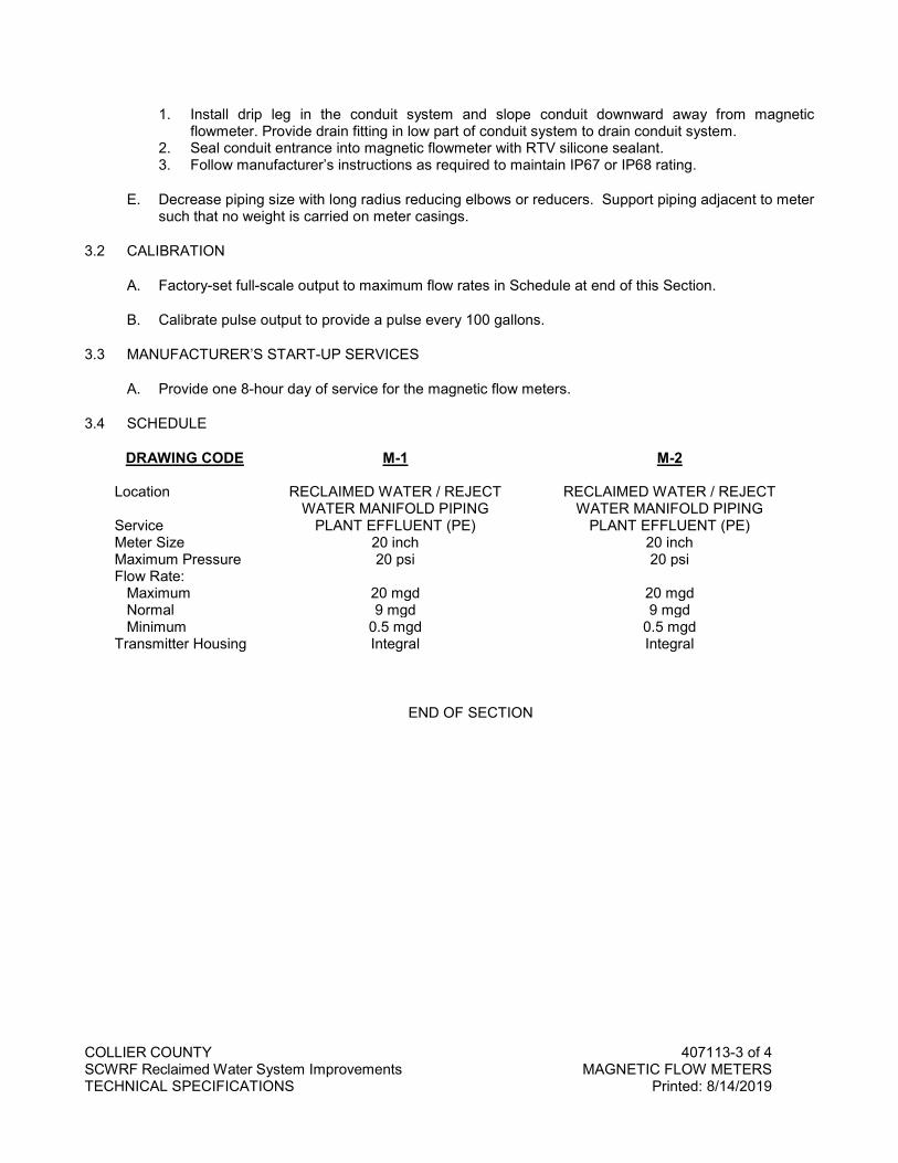
COLLIER COUNTY 407113-3 of 4 SCWRF Reclaimed Water System Improvements MAGNETIC FLOW METERS TECHNICAL SPECIFICATIONS Printed: 8/14/2019
1. Install drip leg in the conduit system and slope conduit downward away from magnetic flowmeter. Provide drain fitting in low part of conduit system to drain conduit system.
2. Seal conduit entrance into magnetic flowmeter with RTV silicone sealant. 3. Follow manufacturer’s instructions as required to maintain IP67 or IP68 rating.
E. Decrease piping size with long radius reducing elbows or reducers. Support piping adjacent to meter such that no weight is carried on meter casings.
3.2 CALIBRATION
A. Factory-set full-scale output to maximum flow rates in Schedule at end of this Section.
B. Calibrate pulse output to provide a pulse every 100 gallons.
3.3 MANUFACTURER’S START-UP SERVICES
A. Provide one 8-hour day of service for the magnetic flow meters.
3.4 SCHEDULE
DRAWING CODE M-1 M-2 Location RECLAIMED WATER / REJECT
WATER MANIFOLD PIPING RECLAIMED WATER / REJECT
WATER MANIFOLD PIPING Service PLANT EFFLUENT (PE) PLANT EFFLUENT (PE) Meter Size 20 inch 20 inch Maximum Pressure 20 psi 20 psi Flow Rate: Maximum 20 mgd 20 mgd Normal 9 mgd 9 mgd Minimum 0.5 mgd 0.5 mgd Transmitter Housing Integral Integral
END OF SECTION

COLLIER COUNTY 407113-4 of 4 SCWRF Reclaimed Water System Improvements MAGNETIC FLOW METERS TECHNICAL SPECIFICATIONS Printed: 8/14/2019
NO TEXT FOR THIS PAGE


![UXJL GROD]DN LVXVRYD.D X VMHYHUQX +UYDWVNX](https://img.dokumen.tips/doc/110x75/63241215117b4414ec0c9b68/uxjl-groddn-lvxvrydd-x-vmhyhuqx-uydwvnx-.jpg)


![]{X-¡p-dn¸v Iowþ2020 _n.^mw tImgvkn-te-¡pÅ {]th-i-\w-þ2020](https://img.dokumen.tips/doc/110x75/6331c4627f0d9c38da011f05/x-p-dnv-iowth2020-nmw-timgvkn-te-pa-th-i-w-th2020.jpg)


