Embed Size (px)
Citation preview
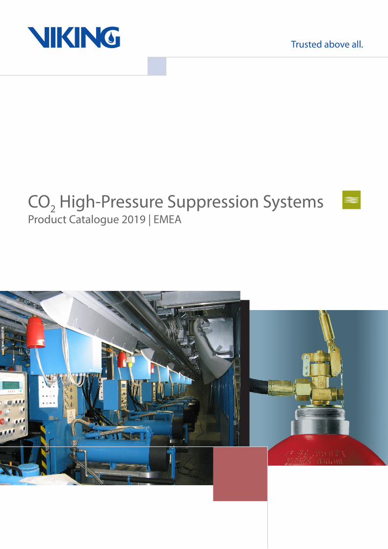
CO2 High-Pressure Suppression SystemsProduct Catalogue 2019 | EMEA

© Viking S.A. | Z.I. Haneboesch | L-4562 Differdange/Niederkorn | www.viking-emea.com |
Product Sheet | Gas
Contents Page I
Version: 2019-01
Product CatalogGas-Based Suppression System
Carbon Dioxide Extinguishing SystemsFight fires using CO2 High Pressure
This product catalog is intended for sales purposes only. For planning, installation,commissioning and operation, please refer to the corresponding technical documentation,which are enclosed with the products.
Contents Catalog Page
© Viking S.A. | Z.I. Haneboesch | L-4562 Differdange/Niederkorn | www.viking-emea.com |
Product Sheet | Gas
Contents Page II
Extinguishing technology Carbon dioxide (CO2) - extinguishing systems ....................................................................................................1
Cylinder filled CO2 - Cylinder EU ................................................................................................................................................2 CO2 - Cylinder RU ...............................................................................................................................................4 CO2 - Cylinder DOT .............................................................................................................................................6 CO2 - Cylinder K85Ex EU ....................................................................................................................................8 CO2 - Cylinder MX K633 EU ................................................................................................................................9
Cylinder valve CO2 Cylinder valve ............................................................................................................................................ 11 CO2 Cylinder valve, UL ......................................................................................................................................12 CO2 Cylinder valve type K85-62.0-S5Ex ...........................................................................................................13 CO2 Cylinder valve MX K633 .............................................................................................................................15
Cylinder accessories Bursting disc securing 250 bar ..........................................................................................................................17
Ad-on part cylinder Weighing device WE4 ........................................................................................................................................18 Weighing device WE4-L .....................................................................................................................................20 Weight weighing device .....................................................................................................................................22 Support ARGOTEC ............................................................................................................................................23 Release device for K85.62.0-S5Ex ....................................................................................................................24 Hose CO2 / IG W21.8 x 3/4 x 375, 235 bar ........................................................................................................26
Manifold Manifold 140 bar - M300 ....................................................................................................................................27 Check valve KRV-1 complete ............................................................................................................................29
Cylinder rack mechanical Cylinder rack CO2 - master actuation - M300 ....................................................................................................30 Cylinder rack CO2 - slave actuation - M300 .......................................................................................................32 Cylinder rack CO2 - master actuation - M300R .................................................................................................34 Cylinder rack CO2 - master actuation - M300 - 80 l ...........................................................................................36 Cylinder rack CO2 - slave actuation - M300 - 80 l ..............................................................................................38 Cylinder rack CO2 - 40 l - master actuation .......................................................................................................40 Cylinder rack CO2 - 40 l - slave actuation ..........................................................................................................42 Cylinder rack CO2 - 40 l - R - master actuation .................................................................................................44 Release box VZ3 ...............................................................................................................................................46 Release box VZ3-R 24 V complete ...................................................................................................................48 Cylinder rack CO2 - master actuation - Ex .........................................................................................................50 Cylinder rack CO2 - slave actuation - Ex ...........................................................................................................52 Cylinder rack CO2 - 40 l - master actuation - Ex ................................................................................................54 Cylinder rack CO2 - 40 l - slave actuation - Ex ..................................................................................................56 Release box VZ3-Ex ..........................................................................................................................................58 Cylinder rack - CO2 single cylinder release for pilot cylinder .............................................................................60 Accessories cable duct for cylinder banks .........................................................................................................62 Disable device release box BEA ........................................................................................................................63 Release cylinder ................................................................................................................................................65 Cover - M300 .....................................................................................................................................................66
Single cylinder system Single cylinder system CO2 and Argon 67,5 l - 200 bar ....................................................................................68
Contents Catalog Page
© Viking S.A. | Z.I. Haneboesch | L-4562 Differdange/Niederkorn | www.viking-emea.com |
Product Sheet | Gas
Contents Page III
Pipe element Manifold HD - DN50 PB 235 CO2 / IG / MX 1230/200 .......................................................................................70
Valve Ball valve BK-MK DN25, DN40 and DN50 ........................................................................................................71
Pipe coupling Fittings for CO2 / IG upstream piping - 200 bar .................................................................................................72 Fittings "PT" for CO2 with pressure test upstream piping - 140 bar ...................................................................74
CO2 Manifold Manifold selector valve DN65/80/100 complete pneumatic, CO2 / inert gas (CF) / MX 1230/200 .....................76
Selector valve Selector valve BV DN25 - 50 complete PB 235, pneumatic, CO2 / IG / MX 1230/200 .......................................78 Selector valve MX-BV DN25 - 50 PB235, CO2 / IG / MX 1230/200 ...................................................................80
Selecor valve accessories Push-button selector valve ................................................................................................................................82 Ball valve MX-BV DN25, DN40 and DN50 ........................................................................................................83 Manifold support complete - manifold 365 bar ...................................................................................................84 Push-button selector valve ................................................................................................................................85
Safety valve Safety valve G1/2 - 140 bar ...............................................................................................................................86 Safety valve G1/2 - 120 bar ...............................................................................................................................87
Nozzle Local application nozzle ED - 1/2 and 3/4 .........................................................................................................88 Nozzle MX1/4-H .................................................................................................................................................90 Nozzle type DD ..................................................................................................................................................91 Nozzleassemblyflushtypeandinsertiontype ..................................................................................................92 Booth protection nozzle KD 2 - 42,5 .................................................................................................................93 CO2 nozzle deep-fat fryers CSD ........................................................................................................................94 Nozzle RD 1/2 and 3/4 .......................................................................................................................................95 Nozzle RD 1/2 and 3/4 UL-Code .......................................................................................................................97
Alarm device Makrofon MX-1 ..................................................................................................................................................99 Silencer makrofon MX-1 ..................................................................................................................................101
Control device Release device EM ..........................................................................................................................................102 Reset tool for release device EM and bracket for reset tool ............................................................................103 Lever - cylinder valve EM-release ...................................................................................................................104 Adapter connection CO2 DN4 and DN8 ...........................................................................................................105 Safety device malfunction pressure SFD DN4 ................................................................................................106 Pilot control manifold CO2 - DN15 ...................................................................................................................108 Disable device MX complete ........................................................................................................................... 110 Shuttle non-return valves MX-WRV DN4 and DN8.......................................................................................... 112 Shuttle non-return valve block ......................................................................................................................... 113 Control device pneumatic SEP-2 ..................................................................................................................... 114 Control device pneumatic SEP-2-B blocking ................................................................................................... 115 Solenoid valve 2/2-ways compl. 0 - 150 bar, NW1.5 ....................................................................................... 116 Door release unit FH and angle bracket door release unit FH ........................................................................ 118 Triggeringunitforpneumaticpressurereliefflap .............................................................................................120
Contents Catalog Page
© Viking S.A. | Z.I. Haneboesch | L-4562 Differdange/Niederkorn | www.viking-emea.com |
Product Sheet | Gas
Contents Page IV
Pneumatic release device PAE - CO2 mechanical with protective cover .........................................................122Pneumatic release device PAE - CO2 electrical ...............................................................................................124Pneumatic release device PAE - CO2 electrical FM/UL ...................................................................................126Pneumatic release device PAE - CO2 electrical DOT FM/UL ...........................................................................128Pneumatic release device PAE - CO2 - Ex - S electrical, without protective cover ..........................................130 Pneumatic release device PAE - CO2 - Ex - M/R electrical, without protective cover, with reserve .................132Pneumatic release device PAE - CO2 / BM .....................................................................................................134Lever - cylinder valve .......................................................................................................................................136Connection CO2 slave release .........................................................................................................................137Solenoid release box VZ ..................................................................................................................................138Cylinder ø25 x H30 ..........................................................................................................................................140Fusible link MX5 ..............................................................................................................................................141Manual release box mechanical type MX-HAKM ............................................................................................143Rope disconnection right and left ....................................................................................................................144Wire rope pulley A and B .................................................................................................................................146Ropes and accessories ...................................................................................................................................147Weight 12 kg - complete ..................................................................................................................................148Steel boxes with limit switch for release weight ...............................................................................................149Steel box for release weight ............................................................................................................................151Release device EM-Ex T55 .............................................................................................................................152
Monitoring deviceLimit switch ZS 256-11z ...................................................................................................................................154Limit switch Typ US 432y, 2 contacts ...............................................................................................................155Limit switch US 434y, 4 contacts .....................................................................................................................156Limit switch EM 41 D 1Ö/1S ............................................................................................................................157Monitoring release device EM .........................................................................................................................158Limit switch pneum. operated ..........................................................................................................................159Monitoring loss extinguishing agent with reed contact limit switch ..................................................................161Reed contact limit switch .................................................................................................................................162Monitoring loss extinguishing agent with light barrier ......................................................................................163Light barrier for monitoring loss .......................................................................................................................164Monitoring loss pneumatic activation device PAE............................................................................................165Monitoring for non electrical control device HP systems .................................................................................166Monitoring rope pneumatic activation device PAE ..........................................................................................167Limit switch system monitoring / I88-SU1Zw ...................................................................................................168Limit switch type UK 432y U=180 ....................................................................................................................169Pressure gauges PN 250 bar ..........................................................................................................................170Shut-off valves AR- brass ................................................................................................................................171Pressure switch CO2 / Inertgase ......................................................................................................................172Pressure switch CO2 / Ar / N2 ..........................................................................................................................173Plug socket for pressure switch .......................................................................................................................174
Release device electricalThermo switch STS - 1 ....................................................................................................................................175Mounting socket for thermo switch STS ..........................................................................................................177Key switch K2 ..................................................................................................................................................178Emergency push-button H compl. ...................................................................................................................179Thermo switch STS-Ex ....................................................................................................................................180
Test deviceTest device pneumatic activation .....................................................................................................................181Adapter plug coupling test connection and socket plug-in coupling test connection .......................................182Test connection pneumatic activation ..............................................................................................................184
Contents Catalog Page
© Viking S.A. | Z.I. Haneboesch | L-4562 Differdange/Niederkorn | www.viking-emea.com |
Product Sheet | Gas
Contents Page V
System accessories Cylinder lifting device .......................................................................................................................................185 Extension cylinder lifting device .......................................................................................................................186 Label CO2 - Feuerlöschanlage ........................................................................................................................187 Label MINIMAX ................................................................................................................................................188 Label - CE für CO2 - Hochdruckanlage ............................................................................................................189 Label for CO2 protected area - PVC ...............................................................................................................190 Label Gaslöschanlage/Lebensgefahr ..............................................................................................................191 Label W9 - Alu Warning of danger ...................................................................................................................192 Label - CO2- Alu für CO2- geschützten Raum ..................................................................................................193 Label - CO2- Alu Reparaturarbeiten CO2 .........................................................................................................194 Labels - CO2- Alu Carbon Dioxide ...................................................................................................................195 Label NFPA 12 .................................................................................................................................................196 Label 260 danger to life ...................................................................................................................................198 Label locking pin - valve lever ..........................................................................................................................199
Mounting accessories Hoocked wrench for coupling HD ....................................................................................................................200 Support for weighing device ............................................................................................................................201 Support weighing device PAE ..........................................................................................................................202
Pipe welded connection Pipe welded connection DN50 - 200 ...............................................................................................................203
Welding fitting and flange Pipefittings ......................................................................................................................................................204 WeldingneckflangeDIN2638-PN160 ..........................................................................................................206
Pipe threaded connection Pipe threaded connection DN15 - 80 ...............................................................................................................207
Fitting threaded connection Fittings - type D, EN 10242 galvanized ...........................................................................................................208
Pilot pipe Pipe for extinguishing pipework and pilot pipes ...............................................................................................210
Fitting pilot pipe Unions - stock list ............................................................................................................................................. 211
Bracket pilot piping network Cable clip B16 galv. .........................................................................................................................................217 Hose clip DIN 3017 and pipe clip RSGU1. ......................................................................................................218
Accessories flange connection Gaskets PN160 ................................................................................................................................................219

© Viking S.A. | Z.I. Haneboesch | L-4562 Differdange/Niederkorn | www.viking-emea.com |
Product Sheet | Gas
Page 1
214-
010_
001
/ AI0
1_20
15en
The
cont
ents
of t
his
publ
icat
ion
are
subj
ect t
o m
odifi
catio
ns w
ithou
t not
ice.
All
right
s re
serv
ed.
Extinguishing technology CO2 HP
1/1
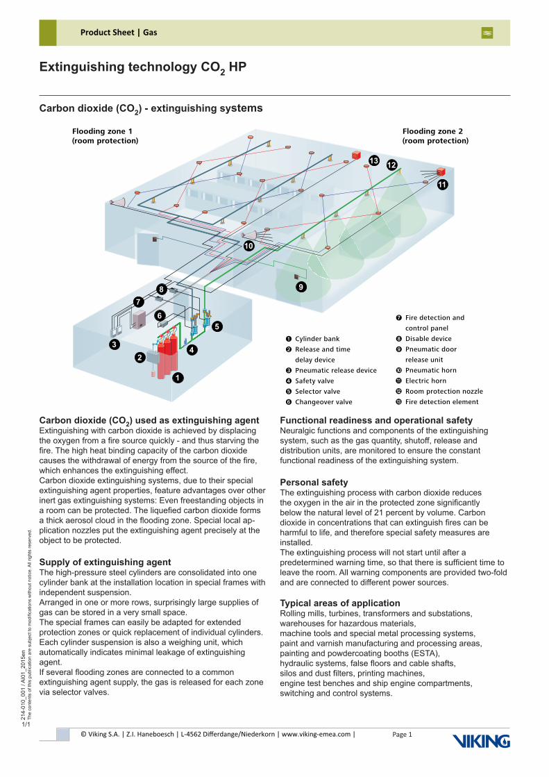
Carbon dioxide (CO2) - extinguishing systems
Carbon dioxide (CO2) used as extinguishing agentExtinguishing with carbon dioxide is achieved by displacing the oxygen from a fire source quickly - and thus starving thefire. The high heat binding capacity of the carbon dioxide causes the withdrawal of energy from the source of the fire, which enhances the extinguishing effect.Carbon dioxide extinguishing systems, due to their special extinguishing agent properties, feature advantages over other inert gas extinguishing systems: Even freestanding objects in a room can be protected. The liquefied carbon dioxide formsa thick aerosol cloud in the flooding zone. Special local ap-plication nozzles put the extinguishing agent precisely at the object to be protected.
Supply of extinguishing agentThe high-pressure steel cylinders are consolidated into one cylinder bank at the installation location in special frames with independent suspension.Arranged in one or more rows, surprisingly large supplies of gas can be stored in a very small space.The special frames can easily be adapted for extendedprotection zones or quick replacement of individual cylinders. Each cylinder suspension is also a weighing unit, whichautomatically indicates minimal leakage of extinguishing agent.If several flooding zones are connected to a commonextinguishing agent supply, the gas is released for each zone via selector valves.
Functional readiness and operational safetyNeuralgic functions and components of the extinguishingsystem, such as the gas quantity, shutoff, release anddistribution units, are monitored to ensure the constantfunctional readiness of the extinguishing system.
Personal safetyThe extinguishing process with carbon dioxide reducesthe oxygen in the air in the protected zone significantlybelow the natural level of 21 percent by volume. Carbondioxide in concentrations that can extinguish fires can be harmful to life, and therefore special safety measures are installed.The extinguishing process will not start until after apredetermined warning time, so that there is sufficient time to leave the room. All warning components are provided two-fold and are connected to different power sources.
Typical areas of applicationRolling mills, turbines, transformers and substations,warehouses for hazardous materials,machine tools and special metal processing systems,paint and varnish manufacturing and processing areas,painting and powdercoating booths (ESTA),hydraulic systems, false floors and cable shafts,silos and dust filters, printing machines,engine test benches and ship engine compartments,switching and control systems.
1
5
6
2
3
4
7
8
9
11
12
10
13
sToragEin high-pressure steel cylinders
➐ Fire detection and
control panel
➑ Disable device
➒ Pneumatic door
release unit
➓ Pneumatic horn
Electric horn
Room protection nozzle
Fire detection element
Flooding zone 2 (room protection)
Flooding zone 1 (room protection)
With more or less pressure The carbon dioxide is supplied in high-pressure cylinders or low-pressure vessels. The optimum supply method depends on the quantity of gas required and the individual situation.
Supply of extinguishing agent in high-pressure steel cylindersThe high-pressure steel cylinders are consolidated into one cylinder bank at the installation location in special frames with independent suspension. Arranged in one or more rows, surprisingly large supplies of gas can be stored in a very small space. The special frames can easily be adapted for extended protection zones or quick replacement of individual cylinders. Each cylinder suspension is also a weighing unit, which automatically indicates minimal leakage of extinguishing agent.
Functional readiness and operational safetyNeuralgic functions and components of the extin-guishing system, such as the gas quantity, shut-off, release and distribution units, are monitored to ensure the constant functional readiness of the extinguishing system.
➊ Cylinder bank
➋ Release and time
delay device
➌ Pneumatic release device
➍ Safety valve
➎ Selector valve
➏ Changeover valve
© Viking S.A. | Z.I. Haneboesch | L-4562 Differdange/Niederkorn | www.viking-emea.com |
Product Sheet | Gas
Page 2
214-
113_
001
/ AI0
3_20
17en
The
cont
ents
of t
his
publ
icat
ion
are
subj
ect t
o m
odifi
catio
ns w
ithou
t not
ice.
All
right
s re
serv
ed.
Extinguishing technology CO2 HPCylinder CO2 filled
1/2
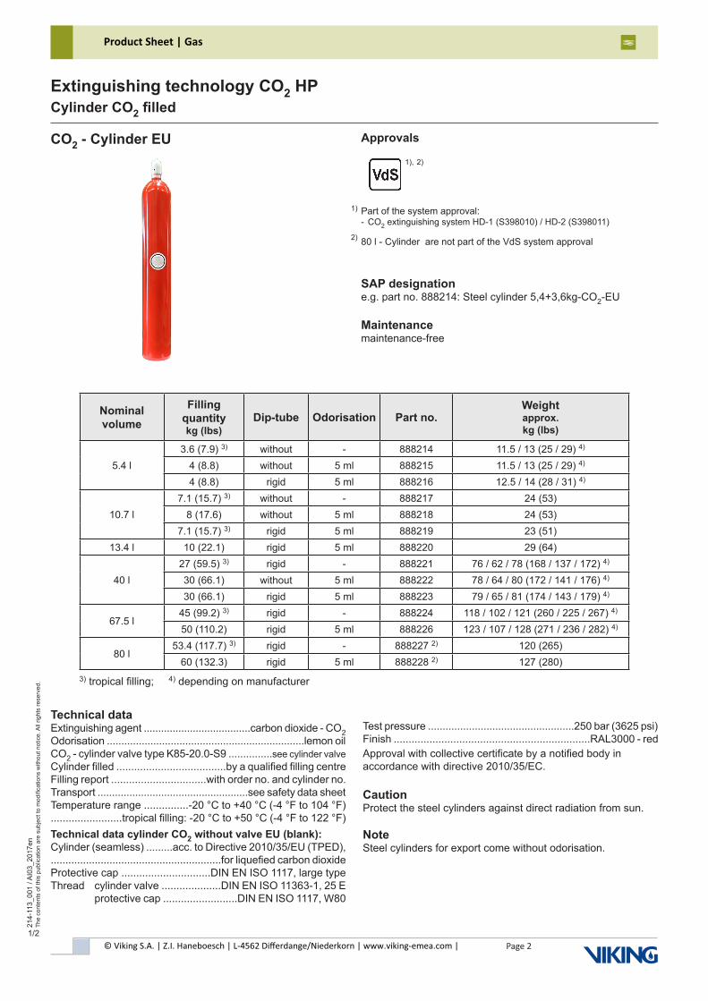
CO2 - Cylinder EU Approvals
SAP designatione.g. part no. 888214: Steel cylinder 5,4+3,6kg-CO2-EU
Maintenancemaintenance-free
3) tropical filling; 4) depending on manufacturer
Technical dataExtinguishing agent .....................................carbon dioxide - CO2Odorisation ....................................................................lemon oilCO2 - cylinder valve type K85-20.0-S9 ...............see cylinder valve Cylinder filled .....................................by a qualified filling centreFilling report ................................with order no. and cylinder no.Transport ....................................................see safety data sheetTemperature range ...............-20 °C to +40 °C (-4 °F to 104 °F)........................tropical filling: -20 °C to +50 °C (-4 °F to 122 °F)Technical data cylinder CO2 without valve EU (blank):Cylinder (seamless) .........acc. to Directive 2010/35/EU (TPED),..........................................................for liquefied carbon dioxideProtective cap ..............................DIN EN ISO 1117, large typeThread cylinder valve ....................DIN EN ISO 11363-1, 25 E protective cap .........................DIN EN ISO 1117, W80
Test pressure ..................................................250 bar (3625 psi)Finish ..................................................................RAL3000 - redApproval with collective certificate by a notified body inaccordance with directive 2010/35/EC.
CautionProtect the steel cylinders against direct radiation from sun.
NoteSteel cylinders for export come without odorisation.
Part of the system approval:- CO2 extinguishing system HD-1 (S398010) / HD-2 (S398011)
80 l - Cylinder are not part of the VdS system approval
1)
1), 2)
2)
Nominal volume
Filling quantitykg (lbs)
Dip-tube Odorisation Part no.Weightapprox. kg (lbs)
5.4 l3.6 (7.9) 3) without - 888214 11.5 / 13 (25 / 29) 4)
4 (8.8) without 5 ml 888215 11.5 / 13 (25 / 29) 4)
4 (8.8) rigid 5 ml 888216 12.5 / 14 (28 / 31) 4)
10.7 l7.1 (15.7) 3) without - 888217 24 (53)
8 (17.6) without 5 ml 888218 24 (53)7.1 (15.7) 3) rigid 5 ml 888219 23 (51)
13.4 l 10 (22.1) rigid 5 ml 888220 29 (64)
40 l27 (59.5) 3) rigid - 888221 76 / 62 / 78 (168 / 137 / 172) 4)
30 (66.1) without 5 ml 888222 78 / 64 / 80 (172 / 141 / 176) 4)
30 (66.1) rigid 5 ml 888223 79 / 65 / 81 (174 / 143 / 179) 4)
67.5 l45 (99.2) 3) rigid - 888224 118 / 102 / 121 (260 / 225 / 267) 4)
50 (110.2) rigid 5 ml 888226 123 / 107 / 128 (271 / 236 / 282) 4)
80 l53.4 (117.7) 3) rigid - 888227 2) 120 (265)
60 (132.3) rigid 5 ml 888228 2) 127 (280)
© Viking S.A. | Z.I. Haneboesch | L-4562 Differdange/Niederkorn | www.viking-emea.com |
Product Sheet | Gas
Page 3
214-
113_
001
/ AI0
3_20
17en
The
cont
ents
of t
his
publ
icat
ion
are
subj
ect t
o m
odifi
catio
ns w
ithou
t not
ice.
All
right
s re
serv
ed.
Extinguishing technology CO2 HPCylinder CO2 filled
2/2
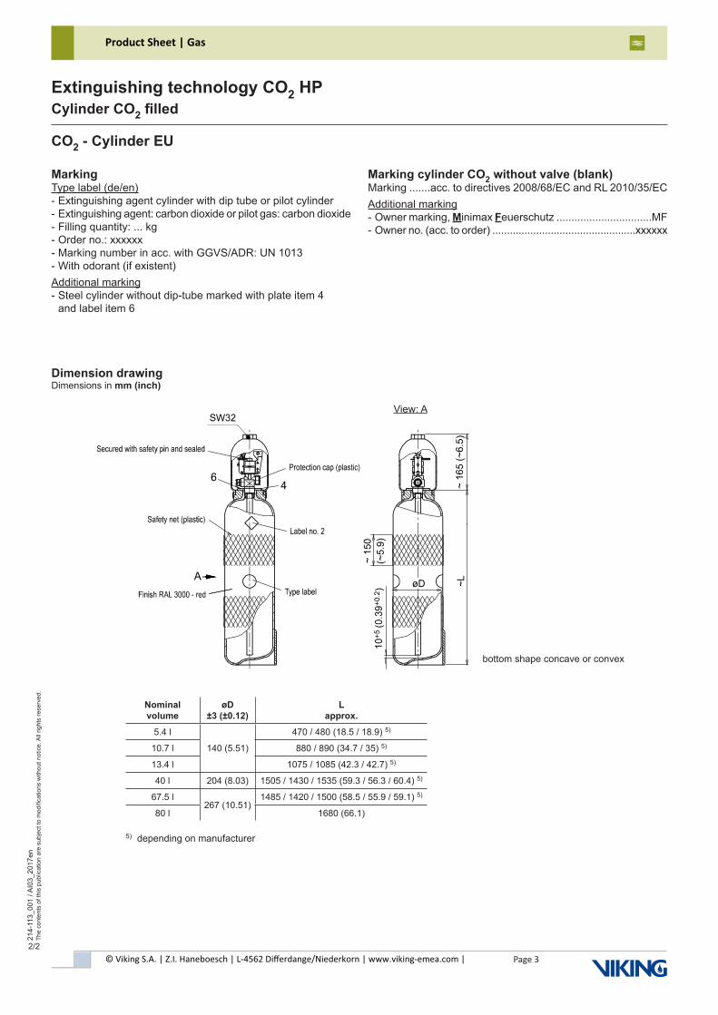
MarkingType label (de/en)- Extinguishing agent cylinder with dip tube or pilot cylinder- Extinguishing agent: carbon dioxide or pilot gas: carbon dioxide- Filling quantity: ... kg- Order no.: xxxxxx- Marking number in acc. with GGVS/ADR: UN 1013- With odorant (if existent)Additional marking- Steel cylinder without dip-tube marked with plate item 4 and label item 6
CO2 - Cylinder EU
bottom shape concave or convex
Dimension drawingDimensions in mm (inch)
Marking cylinder CO2 without valve (blank)Marking .......acc. to directives 2008/68/EC and RL 2010/35/ECAdditional marking- Owner marking, Minimax Feuerschutz ................................MF- Owner no. (acc. to order) .................................................xxxxxx
5) depending on manufacturer
View: A
Nominal volume
øD ±3 (±0.12)
L approx.
5.4 l
140 (5.51)
470 / 480 (18.5 / 18.9) 5)
10.7 l 880 / 890 (34.7 / 35) 5)
13.4 l 1075 / 1085 (42.3 / 42.7) 5)
40 l 204 (8.03) 1505 / 1430 / 1535 (59.3 / 56.3 / 60.4) 5)
67.5 l267 (10.51)
1485 / 1420 / 1500 (58.5 / 55.9 / 59.1) 5)
80 l 1680 (66.1)
© Viking S.A. | Z.I. Haneboesch | L-4562 Differdange/Niederkorn | www.viking-emea.com |
Product Sheet | Gas
Page 4
214-
113_
003
/ AI0
2_20
16en
The
cont
ents
of t
his
publ
icat
ion
are
subj
ect t
o m
odifi
catio
ns w
ithou
t not
ice.
All
right
s re
serv
ed.
Extinguishing technology CO2 HPCylinder CO2 filled
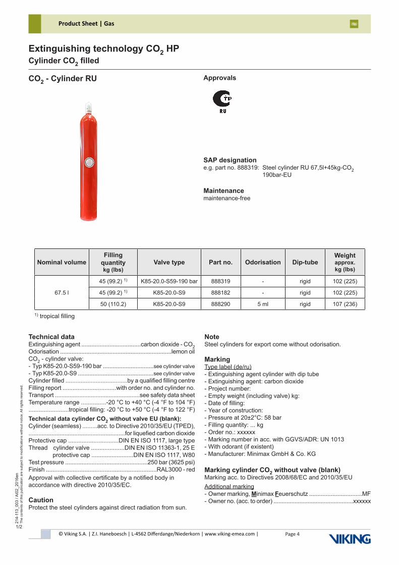
CO2 - Cylinder RU Approvals
SAP designatione.g. part no. 888319: Steel cylinder RU 67,5l+45kg-CO2 190bar-EU
Maintenancemaintenance-free
Technical dataExtinguishing agent ....................................carbon dioxide - CO2Odorisation ....................................................................lemon oilCO2 - cylinder valve: - Typ K85-20.0-S59-190 bar ...............................see cylinder valve - Typ K85-20.0-S9 ..............................................see cylinder valve Cylinder filled .....................................by a qualified filling centreFilling report ................................with order no. and cylinder no.Transport ....................................................see safety data sheetTemperature range ...............-20 °C to +40 °C (-4 °F to 104 °F)........................tropical filling: -20 °C to +50 °C (-4 °F to 122 °F)Technical data cylinder CO2 without valve EU (blank):Cylinder (seamless) .........acc. to Directive 2010/35/EU (TPED),...........................................................for liquefied carbon dioxideProtective cap ..............................DIN EN ISO 1117, large typeThread cylinder valve ....................DIN EN ISO 11363-1, 25 E protective cap .........................DIN EN ISO 1117, W80Test pressure ..................................................250 bar (3625 psi)Finish ..................................................................RAL3000 - redApproval with collective certificate by a notified body inaccordance with directive 2010/35/EC.
CautionProtect the steel cylinders against direct radiation from sun.
NoteSteel cylinders for export come without odorisation.
MarkingType label (de/ru)- Extinguishing agent cylinder with dip tube- Extinguishing agent: carbon dioxide- Project number:- Empty weight (including valve) kg:- Date of filling:- Year of construction:- Pressure at 20±2°C: 58 bar- Filling quantity: ... kg- Order no.: xxxxxx- Marking number in acc. with GGVS/ADR: UN 1013- With odorant (if existent)- Manufacturer: Minimax GmbH & Co. KG
Marking cylinder CO2 without valve (blank)Marking acc. to Directives 2008/68/EC and 2010/35/EUAdditional marking- Owner marking, Minimax Feuerschutz ................................MF- Owner no. (acc. to order) .................................................xxxxxx
1) tropical filling
Nominal volumeFilling
quantitykg (lbs)
Valve type Part no. Odorisation Dip-tubeWeightapprox. kg (lbs)
67.5 l
45 (99.2) 1) K85-20.0-S59-190 bar 888319 - rigid 102 (225)
45 (99.2) 1) K85-20.0-S9 888182 - rigid 102 (225)
50 (110.2) K85-20.0-S9 888290 5 ml rigid 107 (236)
1/2
© Viking S.A. | Z.I. Haneboesch | L-4562 Differdange/Niederkorn | www.viking-emea.com |
Product Sheet | Gas
Page 5
214-
113_
003
/ AI0
2_20
16en
The
cont
ents
of t
his
publ
icat
ion
are
subj
ect t
o m
odifi
catio
ns w
ithou
t not
ice.
All
right
s re
serv
ed.
Extinguishing technology CO2 HPCylinder CO2 filled
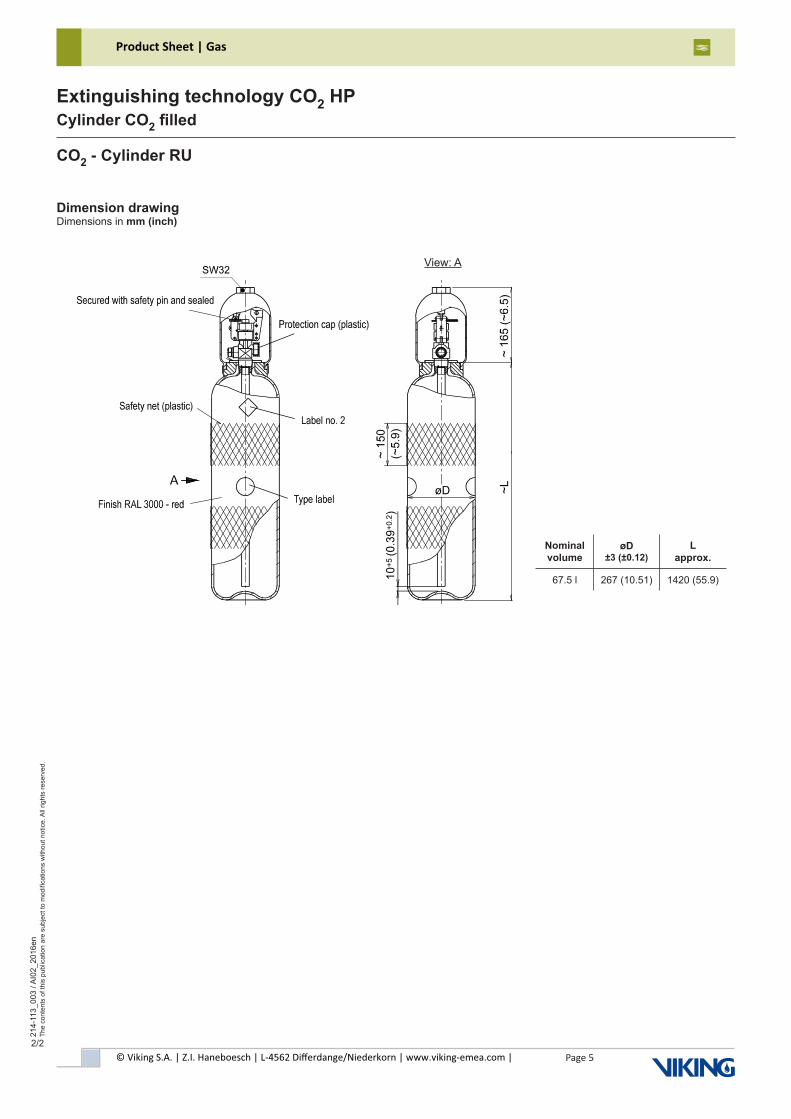
CO2 - Cylinder RU
Dimension drawingDimensions in mm (inch)
View: A
Nominal volume
øD ±3 (±0.12)
L approx.
67.5 l 267 (10.51) 1420 (55.9)
2/2
© Viking S.A. | Z.I. Haneboesch | L-4562 Differdange/Niederkorn | www.viking-emea.com |
Product Sheet | Gas
Page 6
214-
113_
005
/ AI0
2_20
16en
The
cont
ents
of t
his
publ
icat
ion
are
subj
ect t
o m
odifi
catio
ns w
ithou
t not
ice.
All
right
s re
serv
ed.
Extinguishing technology CO2 HPCylinder CO2 filled
1/2
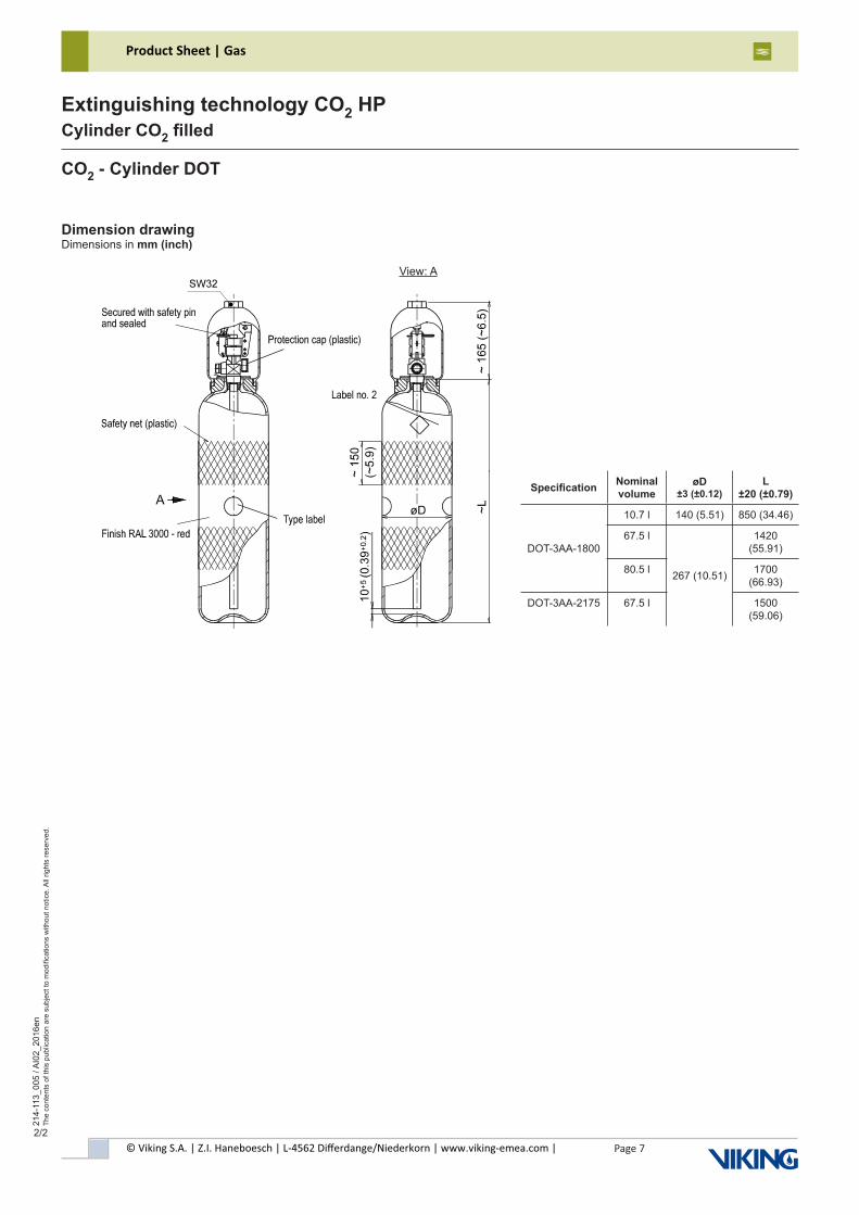
CO2 - Cylinder DOT Approvalswithout approval
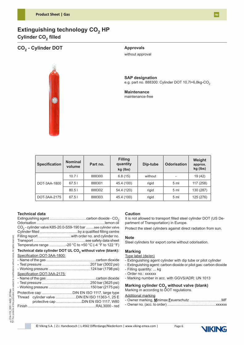
SAP designatione.g. part no. 888300: Cylinder DOT 10,7l+6,8kg-CO2
Maintenancemaintenance-free
Technical dataExtinguishing agent .....................................carbon dioxide - CO2Odorisation ....................................................................lemon oilCO2 - cylinder valve K85-20.0-S59-190 bar ........see cylinder valve Cylinder filled .....................................by a qualified filling centreFilling report ................................with order no. and cylinder no.Transport ....................................................see safety data sheetTemperature range ................-20 °C to +50 °C (-4 °F to 122 °F)Technical data cylinder DOT UL CO2 without valve (blank):Specification DOT-3AA-1800:- Name of the gas ..................................................carbon dioxide- Test pressure ................................................207 bar (3002 psi)- Working pressure ..........................................124 bar (1798 psi)Specification DOT-3AA-2175:- Name of the gas ..................................................carbon dioxide- Test pressure ................................................250 bar (3625 psi)- Working pressure ..........................................150 bar (2175 psi)Protective cap ..............................DIN EN ISO 1117, large typeThread cylinder valve ....................DIN EN ISO 11363-1, 25 E protective cap .........................DIN EN ISO 1117, W80Finish ..................................................................RAL3000 - red
CautionIt is not allowed to transport filled steel cylinder DOT (US De-partment of Transportation) in Europe.Protect the steel cylinders against direct radiation from sun.
NoteSteel cylinders for export come without odorisation.
MarkingType label (de/en)- Extinguishing agent cylinder with dip tube or pilot cylinder- Extinguishing agent: carbon dioxide or pilot gas: carbon dioxide- Filling quantity: ... kg- Order no.: xxxxxx- Marking number in acc. with GGVS/ADR: UN 1013
Marking cylinder CO2 without valve (blank)Marking in according to DOT regulations.Additional marking- Owner marking, Minimax Feuerschutz ...............................MF- Owner no. (acc. to order) .................................................xxxxxx
Specification Nominal volume Part no.
Filling quantitykg (lbs)
Dip-tube OdorisationWeightapprox. kg (lbs)
DOT-3AA-1800
10.7 l 888300 6.8 (15) without - 19 (42)
67.5 l 888301 45.4 (100) rigid 5 ml 117 (258)
80.5 l 888302 54.4 (120) rigid 5 ml 130 (287)
DOT-3AA-2175 67.5 l 888303 45.4 (100) rigid 5 ml 125 (276)
© Viking S.A. | Z.I. Haneboesch | L-4562 Differdange/Niederkorn | www.viking-emea.com |
Product Sheet | Gas
Page 7
214-
113_
005
/ AI0
2_20
16en
The
cont
ents
of t
his
publ
icat
ion
are
subj
ect t
o m
odifi
catio
ns w
ithou
t not
ice.
All
right
s re
serv
ed.
Extinguishing technology CO2 HPCylinder CO2 filled
2/2
CO2 - Cylinder DOT
Dimension drawingDimensions in mm (inch)
View: A
Specification Nominal volume
øD ±3 (±0.12)
L ±20 (±0.79)
DOT-3AA-1800
10.7 l 140 (5.51) 850 (34.46)
67.5 l
267 (10.51)
1420 (55.91)
80.5 l 1700 (66.93)
DOT-3AA-2175 67.5 l 1500 (59.06)
© Viking S.A. | Z.I. Haneboesch | L-4562 Differdange/Niederkorn | www.viking-emea.com |
Product Sheet | Gas
Page 8
214-
113_
006
/ AI0
1_20
17en
The
cont
ents
of t
his
publ
icat
ion
are
subj
ect t
o m
odifi
catio
ns w
ithou
t not
ice.
All
right
s re
serv
ed.
Extinguishing technology CO2 HPCylinder CO2 filled
1/1
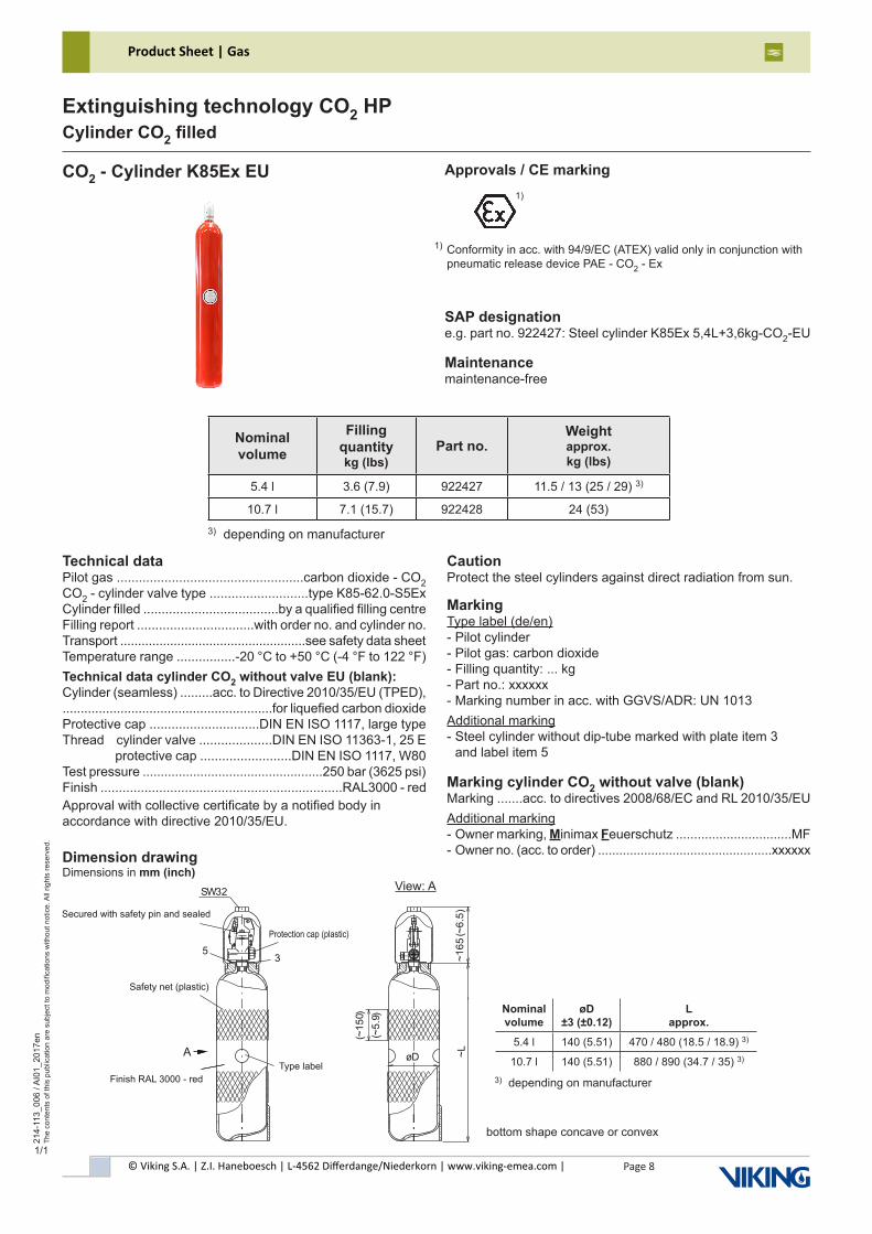
CO2 - Cylinder K85Ex EU Approvals / CE marking
SAP designatione.g. part no. 922427: Steel cylinder K85Ex 5,4L+3,6kg-CO2-EU
Maintenancemaintenance-free
3) depending on manufacturer
Technical dataPilot gas ...................................................carbon dioxide - CO2CO2 - cylinder valve type ...........................type K85-62.0-S5ExCylinder filled .....................................by a qualified filling centreFilling report ................................with order no. and cylinder no.Transport ....................................................see safety data sheetTemperature range ................-20 °C to +50 °C (-4 °F to 122 °F)Technical data cylinder CO2 without valve EU (blank):Cylinder (seamless) .........acc. to Directive 2010/35/EU (TPED),..........................................................for liquefied carbon dioxideProtective cap ..............................DIN EN ISO 1117, large typeThread cylinder valve ....................DIN EN ISO 11363-1, 25 E protective cap .........................DIN EN ISO 1117, W80Test pressure ..................................................250 bar (3625 psi)Finish ..................................................................RAL3000 - redApproval with collective certificate by a notified body inaccordance with directive 2010/35/EU.
CautionProtect the steel cylinders against direct radiation from sun.
MarkingType label (de/en)- Pilot cylinder- Pilot gas: carbon dioxide- Filling quantity: ... kg- Part no.: xxxxxx- Marking number in acc. with GGVS/ADR: UN 1013Additional marking- Steel cylinder without dip-tube marked with plate item 3 and label item 5
Marking cylinder CO2 without valve (blank)Marking .......acc. to directives 2008/68/EC and RL 2010/35/EUAdditional marking- Owner marking, Minimax Feuerschutz ................................MF- Owner no. (acc. to order) .................................................xxxxxx
Nominal volume
Filling quantitykg (lbs)
Part no.Weightapprox. kg (lbs)
5.4 l 3.6 (7.9) 922427 11.5 / 13 (25 / 29) 3)
10.7 l 7.1 (15.7) 922428 24 (53)
bottom shape concave or convex
Dimension drawingDimensions in mm (inch)
View: A
Nominal volume
øD ±3 (±0.12)
L approx.
5.4 l 140 (5.51) 470 / 480 (18.5 / 18.9) 3)
10.7 l 140 (5.51) 880 / 890 (34.7 / 35) 3)
3) depending on manufacturer
A
(~5.
9)
53
SW32
(~15
0)
~165
(~6.
5)~LøD
1)
Conformity in acc. with 94/9/EC (ATEX) valid only in conjunction withpneumatic release device PAE - CO2 - Ex
1)
© Viking S.A. | Z.I. Haneboesch | L-4562 Differdange/Niederkorn | www.viking-emea.com |
Product Sheet | Gas
Page 9
214-
113_
007
/ AI0
0_20
17en
The
cont
ents
of t
his
publ
icat
ion
are
subj
ect t
o m
odifi
catio
ns w
ithou
t not
ice.
All
right
s re
serv
ed.
Extinguishing technology CO2 HPCylinder CO2 filled
1/2
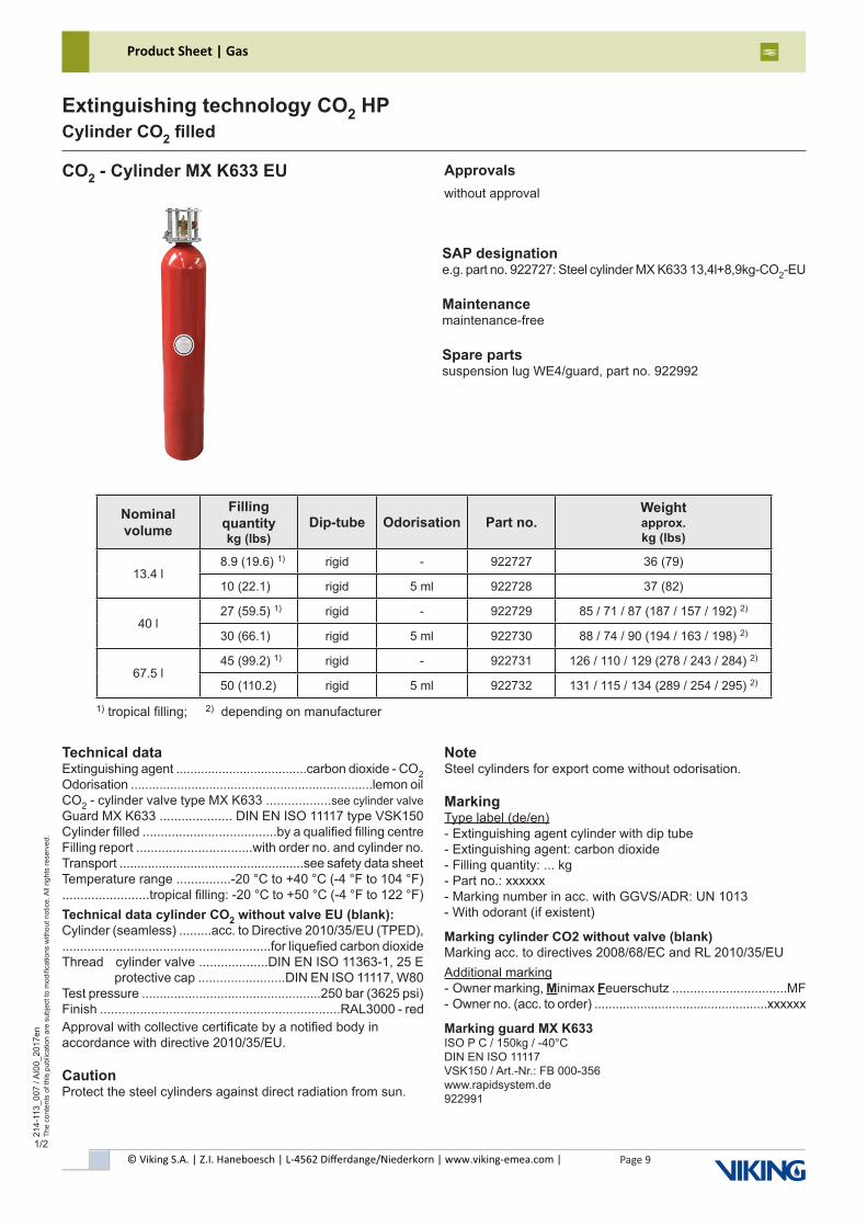
CO2 - Cylinder MX K633 EU
SAP designatione.g. part no. 922727: Steel cylinder MX K633 13,4l+8,9kg-CO2-EU
Maintenancemaintenance-free
Spare partssuspension lug WE4/guard, part no. 922992
1) tropical filling; 2) depending on manufacturer
Technical dataExtinguishing agent .....................................carbon dioxide - CO2Odorisation ....................................................................lemon oilCO2 - cylinder valve type MX K633 ..................see cylinder valve Guard MX K633 .................... DIN EN ISO 11117 type VSK150Cylinder filled .....................................by a qualified filling centreFilling report ................................with order no. and cylinder no.Transport ....................................................see safety data sheetTemperature range ...............-20 °C to +40 °C (-4 °F to 104 °F)........................tropical filling: -20 °C to +50 °C (-4 °F to 122 °F)Technical data cylinder CO2 without valve EU (blank):Cylinder (seamless) .........acc. to Directive 2010/35/EU (TPED),..........................................................for liquefied carbon dioxideThread cylinder valve ...................DIN EN ISO 11363-1, 25 E protective cap ........................DIN EN ISO 11117, W80Test pressure ..................................................250 bar (3625 psi)Finish ..................................................................RAL3000 - redApproval with collective certificate by a notified body inaccordance with directive 2010/35/EU.
CautionProtect the steel cylinders against direct radiation from sun.
Nominal volume
Filling quantitykg (lbs)
Dip-tube Odorisation Part no.Weightapprox. kg (lbs)
13.4 l8.9 (19.6) 1) rigid - 922727 36 (79)
10 (22.1) rigid 5 ml 922728 37 (82)
40 l27 (59.5) 1) rigid - 922729 85 / 71 / 87 (187 / 157 / 192) 2)
30 (66.1) rigid 5 ml 922730 88 / 74 / 90 (194 / 163 / 198) 2)
67.5 l45 (99.2) 1) rigid - 922731 126 / 110 / 129 (278 / 243 / 284) 2)
50 (110.2) rigid 5 ml 922732 131 / 115 / 134 (289 / 254 / 295) 2)
NoteSteel cylinders for export come without odorisation.
MarkingType label (de/en)- Extinguishing agent cylinder with dip tube- Extinguishing agent: carbon dioxide- Filling quantity: ... kg- Part no.: xxxxxx- Marking number in acc. with GGVS/ADR: UN 1013- With odorant (if existent)
Marking cylinder CO2 without valve (blank)Marking acc. to directives 2008/68/EC and RL 2010/35/EUAdditional marking- Owner marking, Minimax Feuerschutz ................................MF- Owner no. (acc. to order) .................................................xxxxxx
Marking guard MX K633ISO P C / 150kg / -40°CDIN EN ISO 11117VSK150 / Art.-Nr.: FB 000-356www.rapidsystem.de922991
Approvalswithout approval
© Viking S.A. | Z.I. Haneboesch | L-4562 Differdange/Niederkorn | www.viking-emea.com |
Product Sheet | Gas
Page 10
214-
113_
007
/ AI0
0_20
17en
The
cont
ents
of t
his
publ
icat
ion
are
subj
ect t
o m
odifi
catio
ns w
ithou
t not
ice.
All
right
s re
serv
ed.
Extinguishing technology CO2 HPCylinder CO2 filled
2/2
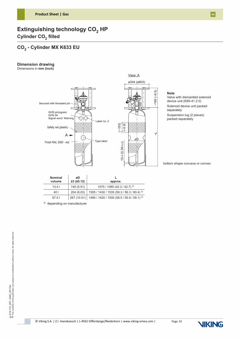
CO2 - Cylinder MX K633 EU
bottom shape concave or convex
Dimension drawingDimensions in mm (inch)
View: A
Nominal volume
øD ±3 (±0.12)
L approx.
13.4 l 140 (5.51) 1075 / 1085 (42.3 / 42.7) 3)
40 l 204 (8.03) 1505 / 1430 / 1535 (59.3 / 56.3 / 60.4) 3)
67.5 l 267 (10.51) 1485 / 1420 / 1500 (58.5 / 55.9 / 59.1) 3)
3) depending on manufacturer
~L
øD
(~5.
9)(~
150)
A
NoteValve with dismantled solenoiddevice unit (K85-41.2.0)Solenoid device unit packed separatelySuspension lug (2 pieces)packed separately
© Viking S.A. | Z.I. Haneboesch | L-4562 Differdange/Niederkorn | www.viking-emea.com |
Product Sheet | Gas
Page 11
214-
131_
001
/ AI0
2_20
15en
The
cont
ents
of t
his
publ
icat
ion
are
subj
ect t
o m
odifi
catio
ns w
ithou
t not
ice.
All
right
s re
serv
ed.
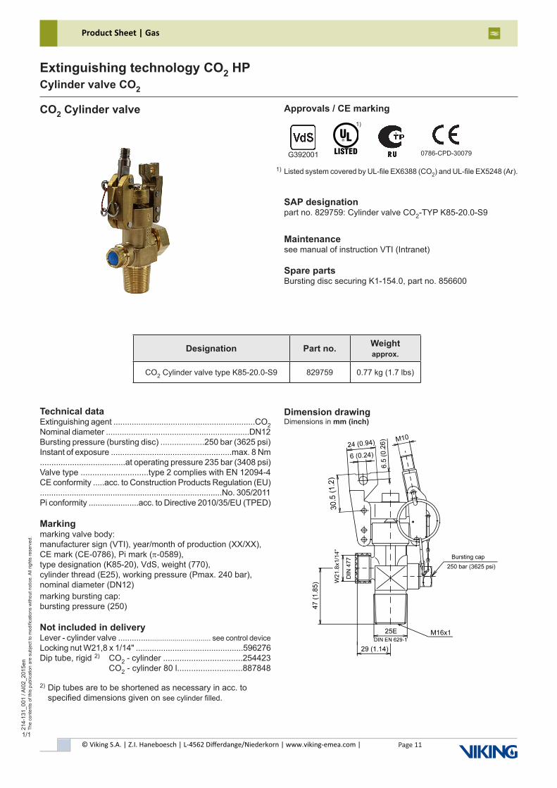
Extinguishing technology CO2 HPCylinder valve CO2
1/1
CO2 Cylinder valve Approvals / CE marking
SAP designationpart no. 829759: Cylinder valve CO2-TYP K85-20.0-S9
Maintenancesee manual of instruction VTI (Intranet)
Spare partsBursting disc securing K1-154.0, part no. 856600
Listed system covered by UL-file EX6388 (CO2) and UL-file EX5248 (Ar).1)
1)
G392001
Technical dataExtinguishing agent ..............................................................CO2Nominal diameter ...............................................................DN12Bursting pressure (bursting disc) ...................250 bar (3625 psi)Instant of exposure .....................................................max. 8 Nm .....................................at operating pressure 235 bar (3408 psi)Valve type .............................type 2 complies with EN 12094-4CE conformity .....acc. to Construction Products Regulation (EU)................................................................................No. 305/2011Pi conformity ......................acc. to Directive 2010/35/EU (TPED)
Markingmarking valve body:manufacturer sign (VTI), year/month of production (XX/XX),CE mark (CE-0786), Pi mark (π-0589),type designation (K85-20), VdS, weight (770),cylinder thread (E25), working pressure (Pmax. 240 bar), nominal diameter (DN12)marking bursting cap:bursting pressure (250)
Not included in deliveryLever - cylinder valve ............................................ see control device Locking nut W21,8 x 1/14" ...............................................596276Dip tube, rigid 2) CO2 - cylinder ..................................254423 CO2 - cylinder 80 l............................887848
2) Dip tubes are to be shortened as necessary in acc. to specified dimensions given on see cylinder filled.
Dimension drawingDimensions in mm (inch)
0786-CPD-30079
Designation Part no. Weightapprox.
CO2 Cylinder valve type K85-20.0-S9 829759 0.77 kg (1.7 lbs)
© Viking S.A. | Z.I. Haneboesch | L-4562 Differdange/Niederkorn | www.viking-emea.com |
Product Sheet | Gas
Page 12
214-
131_
002
/ AI0
2_20
15en
The
cont
ents
of t
his
publ
icat
ion
are
subj
ect t
o m
odifi
catio
ns w
ithou
t not
ice.
All
right
s re
serv
ed.
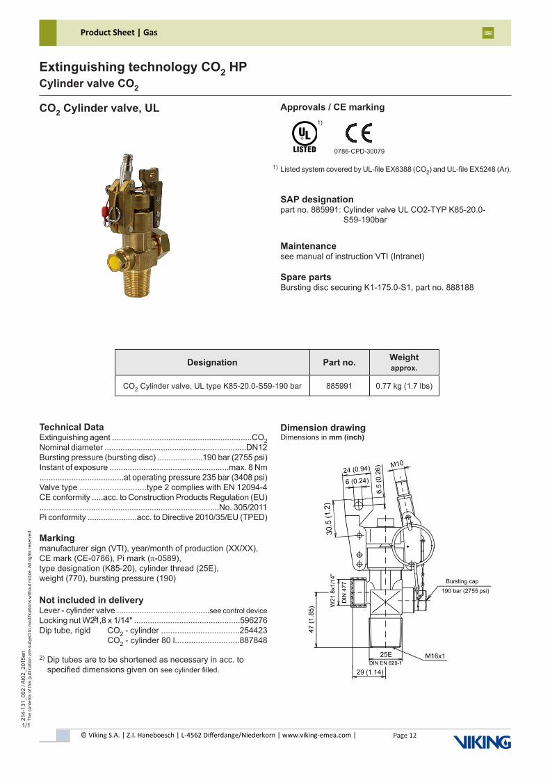
Extinguishing technology CO2 HPCylinder valve CO2
1/1
CO2 Cylinder valve, UL Approvals / CE marking
SAP designationpart no. 885991: Cylinder valve UL CO2-TYP K85-20.0- S59-190bar
Maintenancesee manual of instruction VTI (Intranet)
Spare partsBursting disc securing K1-175.0-S1, part no. 888188
Listed system covered by UL-file EX6388 (CO2) and UL-file EX5248 (Ar). 1)
1)
Technical DataExtinguishing agent ..............................................................CO2Nominal diameter ...............................................................DN12Bursting pressure (bursting disc) ....................190 bar (2755 psi)Instant of exposure .....................................................max. 8 Nm .....................................at operating pressure 235 bar (3408 psi)Valve type .............................type 2 complies with EN 12094-4 CE conformity .....acc. to Construction Products Regulation (EU)................................................................................No. 305/2011Pi conformity ......................acc. to Directive 2010/35/EU (TPED)
Markingmanufacturer sign (VTI), year/month of production (XX/XX),CE mark (CE-0786), Pi mark (π-0589),type designation (K85-20), cylinder thread (25E),weight (770), bursting pressure (190)
Not included in deliveryLever - cylinder valve .........................................see control device Locking nut W21,8 x 1/14" ...............................................596276Dip tube, rigid CO2 - cylinder ..................................254423 CO2 - cylinder 80 l............................887848
2) Dip tubes are to be shortened as necessary in acc. to specified dimensions given on see cylinder filled.
2)
Dimension drawingDimensions in mm (inch)
0786-CPD-30079
Designation Part no. Weightapprox.
CO2 Cylinder valve, UL type K85-20.0-S59-190 bar 885991 0.77 kg (1.7 lbs)
© Viking S.A. | Z.I. Haneboesch | L-4562 Differdange/Niederkorn | www.viking-emea.com |
Product Sheet | Gas
Page 13
214-
131_
004
/ AI0
0_20
16en
The
cont
ents
of t
his
publ
icat
ion
are
subj
ect t
o m
odifi
catio
ns w
ithou
t not
ice.
All
right
s re
serv
ed.
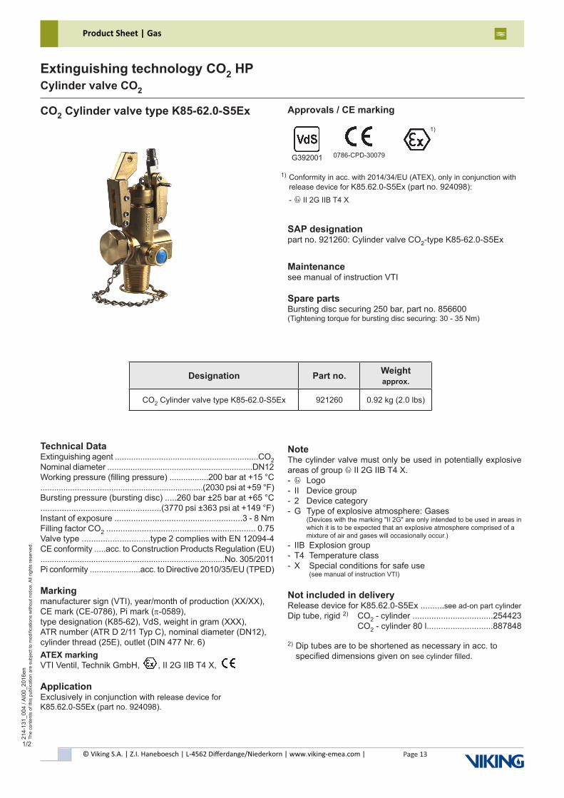
Extinguishing technology CO2 HPCylinder valve CO2
1/2
CO2 Cylinder valve type K85-62.0-S5Ex Approvals / CE marking
SAP designationpart no. 921260: Cylinder valve CO2-type K85-62.0-S5Ex
Maintenancesee manual of instruction VTI
Spare partsBursting disc securing 250 bar, part no. 856600(Tightening torque for bursting disc securing: 30 - 35 Nm)
G392001 0786-CPD-30079
Designation Part no. Weightapprox.
CO2 Cylinder valve type K85-62.0-S5Ex 921260 0.92 kg (2.0 lbs)
1)
Conformity in acc. with 2014/34/EU (ATEX), only in conjunction withrelease device for K85.62.0-S5Ex (part no. 924098):- x II 2G IIB T4 X
1)
Technical DataExtinguishing agent ..............................................................CO2Nominal diameter ...............................................................DN12Working pressure (filling pressure) .................200 bar at +15 °C.......................................................................(2030 psi at +59 °F)Bursting pressure (bursting disc) .....260 bar ±25 bar at +65 °C...................................................(3770 psi ±363 psi at +149 °F)Instant of exposure ......................................................3 - 8 NmFilling factor CO2 ............................................................... 0.75Valve type .............................type 2 complies with EN 12094-4CE conformity .....acc. to Construction Products Regulation (EU)................................................................................No. 305/2011Pi conformity ......................acc. to Directive 2010/35/EU (TPED)
Markingmanufacturer sign (VTI), year/month of production (XX/XX),CE mark (CE-0786), Pi mark (π-0589),type designation (K85-62), VdS, weight in gram (XXX),ATR number (ATR D 2/11 Typ C), nominal diameter (DN12),cylinder thread (25E), outlet (DIN 477 Nr. 6)ATEX markingVTI Ventil, Technik GmbH, , II 2G IIB T4 X,
ApplicationExclusively in conjunction with release device forK85.62.0-S5Ex (part no. 924098).
NoteThe cylinder valve must only be used in potentially explosive areas of group x II 2G IIB T4 X.- x Logo- II Device group- 2 Device category- G Type of explosive atmosphere: Gases (Devices with the marking "II 2G" are only intended to be used in areas in which it is to be expected that an explosive atmosphere comprised of a mixture of air and gases will occasionally occur.)- IIB Explosion group- T4 Temperature class- X Special conditions for safe use (see manual of instruction VTI)
Not included in deliveryRelease device for K85.62.0-S5Ex ..........see ad-on part cylinderDip tube, rigid 2) CO2 - cylinder ..................................254423 CO2 - cylinder 80 l............................887848
2) Dip tubes are to be shortened as necessary in acc. to specified dimensions given on see cylinder filled.
© Viking S.A. | Z.I. Haneboesch | L-4562 Differdange/Niederkorn | www.viking-emea.com |
Product Sheet | Gas
Page 14
214-
131_
004
/ AI0
0_20
16en
The
cont
ents
of t
his
publ
icat
ion
are
subj
ect t
o m
odifi
catio
ns w
ithou
t not
ice.
All
right
s re
serv
ed.
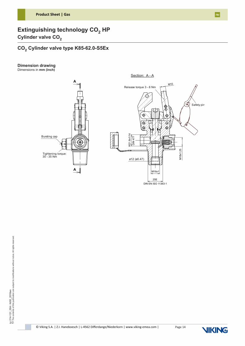
Extinguishing technology CO2 HPCylinder valve CO2
2/2
Dimension drawingDimensions in mm (inch)
Section: A - A
CO2 Cylinder valve type K85-62.0-S5Ex
Tightening torque:30 - 35 Nm
Bursting cap
Safety pin
Release torque 3 - 8 Nm
ø12 (ø0.47)
© Viking S.A. | Z.I. Haneboesch | L-4562 Differdange/Niederkorn | www.viking-emea.com |
Product Sheet | Gas
Page 15
214-
131_
003
/ AI0
0_20
17en
The
cont
ents
of t
his
publ
icat
ion
are
subj
ect t
o m
odifi
catio
ns w
ithou
t not
ice.
All
right
s re
serv
ed.
Extinguishing technology CO2 HPCylinder valve CO2
1/2
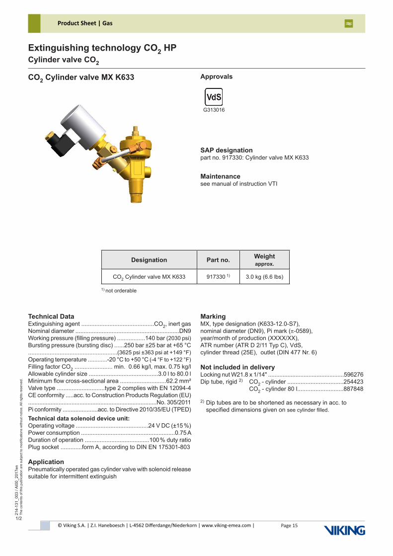
CO2 Cylinder valve MX K633 Approvals
SAP designationpart no. 917330: Cylinder valve MX K633
Maintenancesee manual of instruction VTI
G313016
Designation Part no. Weightapprox.
CO2 Cylinder valve MX K633 917330 1) 3.0 kg (6.6 lbs)
Technical DataExtinguishing agent ............................................CO2, inert gasNominal diameter ...............................................................DN9Working pressure (filling pressure) .................140 bar (2030 psi)Bursting pressure (bursting disc) ......250 bar ±25 bar at +65 °C......................................................(3625 psi ±363 psi at +149 °F)Operating temperature ............-20 °C to +50 °C (-4 °F to +122 °F)Filling factor CO2 ....................... min. 0.66 kg/l, max. 0.75 kg/lAllowable cylinder size ..........................................3.0 l to 80.0 lMinimum flow cross-sectional area ............................62.2 mm²Valve type .............................type 2 complies with EN 12094-4CE conformity .....acc. to Construction Products Regulation (EU)................................................................................No. 305/2011Pi conformity ......................acc. to Directive 2010/35/EU (TPED)Technical data solenoid device unit:Operating voltage ............................................24 V DC (±15 %)Power consumption .........................................................0.75 ADuration of operation .......................................100 % duty ratioPlug socket .............form A, according to DIN EN 175301-803
ApplicationPneumatically operated gas cylinder valve with solenoid releasesuitable for intermittent extinguish
MarkingMX, type designation (K633-12.0-S7),nominal diameter (DN9), Pi mark (π-0589),year/month of production (XXXX/XX),ATR number (ATR D 2/11 Typ C), VdS,cylinder thread (25E), outlet (DIN 477 Nr. 6)
Not included in deliveryLocking nut W21.8 x 1/14" ...............................................596276Dip tube, rigid 2) CO2 - cylinder ..................................254423 CO2 - cylinder 80 l............................887848
2) Dip tubes are to be shortened as necessary in acc. to specified dimensions given on see cylinder filled.
1) not orderable
© Viking S.A. | Z.I. Haneboesch | L-4562 Differdange/Niederkorn | www.viking-emea.com |
Product Sheet | Gas
Page 16
214-
131_
003
/ AI0
0_20
17en
The
cont
ents
of t
his
publ
icat
ion
are
subj
ect t
o m
odifi
catio
ns w
ithou
t not
ice.
All
right
s re
serv
ed.
Extinguishing technology CO2 HPCylinder valve CO2
2/2
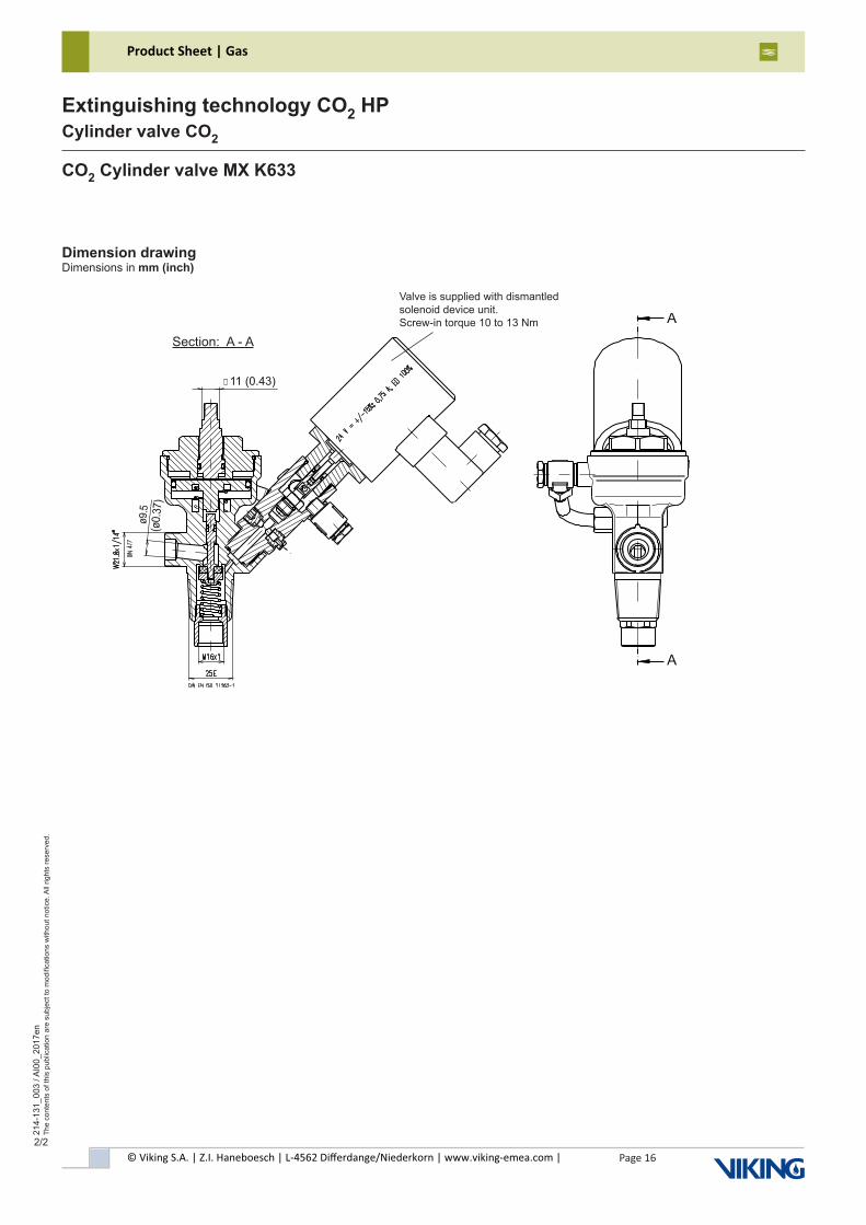
Dimension drawingDimensions in mm (inch)
Section: A - A
CO2 Cylinder valve MX K633
Valve is supplied with dismantledsolenoid device unit.Screw-in torque 10 to 13 Nm A
A
© Viking S.A. | Z.I. Haneboesch | L-4562 Differdange/Niederkorn | www.viking-emea.com |
Product Sheet | Gas
Page 17
214-
140_
001
/ AI0
1_20
15en
The
cont
ents
of t
his
publ
icat
ion
are
subj
ect t
o m
odifi
catio
ns w
ithou
t not
ice.
All
right
s re
serv
ed.
Extinguishing technology CO2 HPCO2 cylinder accessories
1/1
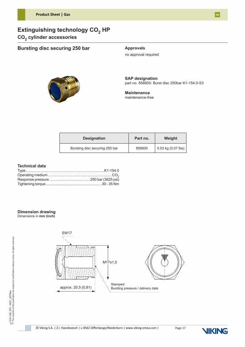
Bursting disc securing 250 bar Approvalsno approval required
SAP designationpart no. 856600: Burst disc 250bar K1-154.0-S3
Maintenancemaintenance-free
Technical dataType .............................................................................K1-154.0Operating medium ...............................................................CO2Response pressure .........................................250 bar (3625 psi)Tightening torque ........................................................30 - 35 Nm
Dimension drawingDimensions in mm (inch)
Designation Part no. Weight
Bursting disc securing 250 bar 856600 0.03 kg (0.07 lbs)
approx. 20,5 (0,81)Stamped:Bursting pressure / delivery date
SW17
M17x1,5
© Viking S.A. | Z.I. Haneboesch | L-4562 Differdange/Niederkorn | www.viking-emea.com |
Product Sheet | Gas
Page 18
214-
210_
001
/ AI0
1_20
15en
The
cont
ents
of t
his
publ
icat
ion
are
subj
ect t
o m
odifi
catio
ns w
ithou
t not
ice.
All
right
s re
serv
ed.
Extinguishing technology CO2 HPAd-on part cylinder CO2 HP
1/2
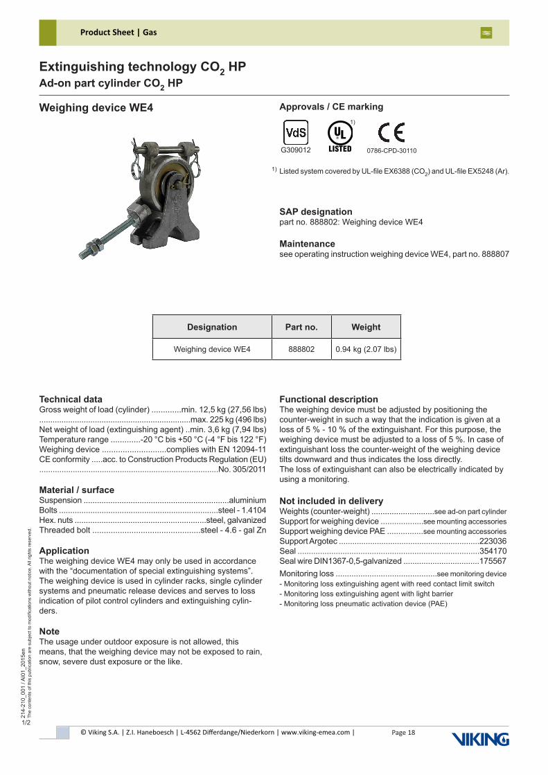
Weighing device WE4 Approvals / CE marking
SAP designationpart no. 888802: Weighing device WE4
Maintenancesee operating instruction weighing device WE4, part no. 888807
Listed system covered by UL-file EX6388 (CO2) and UL-file EX5248 (Ar).
1)
G309012 0786-CPD-30110
1)
Technical dataGross weight of load (cylinder) .............min. 12,5 kg (27,56 lbs)....................................................................max. 225 kg (496 lbs)Net weight of load (extinguishing agent) ..min. 3,6 kg (7,94 lbs)Temperature range .............-20 °C bis +50 °C (-4 °F bis 122 °F)Weighing device ............................complies with EN 12094-11CE conformity .....acc. to Construction Products Regulation (EU)................................................................................No. 305/2011
Material / surfaceSuspension .................................................................aluminiumBolts .......................................................................steel - 1.4104Hex. nuts ...........................................................steel, galvanizedThreaded bolt ...............................................steel - 4.6 - gal Zn
ApplicationThe weighing device WE4 may only be used in accordance with the “documentation of special extinguishing systems”. The weighing device is used in cylinder racks, single cylinder systems and pneumatic release devices and serves to loss indication of pilot control cylinders and extinguishing cylin-ders.
NoteThe usage under outdoor exposure is not allowed, this means, that the weighing device may not be exposed to rain, snow, severe dust exposure or the like.
Functional descriptionThe weighing device must be adjusted by positioning the counter-weight in such a way that the indication is given at a loss of 5 % - 10 % of the extinguishant. For this purpose, the weighing device must be adjusted to a loss of 5 %. In case of extinguishant loss the counter-weight of the weighing device tilts downward and thus indicates the loss directly.The loss of extinguishant can also be electrically indicated by using a monitoring.
Not included in deliveryWeights (counter-weight) ............................see ad-on part cylinder Support for weighing device ...................see mounting accessories Support weighing device PAE ................see mounting accessoriesSupport Argotec ...............................................................223036Seal .................................................................................354170Seal wire DIN1367-0,5-galvanized ..................................175567Monitoring loss .............................................see monitoring device - Monitoring loss extinguishing agent with reed contact limit switch- Monitoring loss extinguishing agent with light barrier- Monitoring loss pneumatic activation device (PAE)
Designation Part no. Weight
Weighing device WE4 888802 0.94 kg (2.07 lbs)
© Viking S.A. | Z.I. Haneboesch | L-4562 Differdange/Niederkorn | www.viking-emea.com |
Product Sheet | Gas
Page 19
214-
210_
001
/ AI0
1_20
15en
The
cont
ents
of t
his
publ
icat
ion
are
subj
ect t
o m
odifi
catio
ns w
ithou
t not
ice.
All
right
s re
serv
ed.
Extinguishing technology CO2 HPAd-on part cylinder CO2 HP
2/2
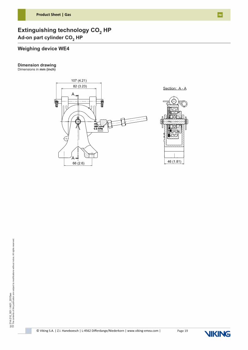
Section: A - A
Dimension drawingDimensions in mm (inch)
Weighing device WE4
© Viking S.A. | Z.I. Haneboesch | L-4562 Differdange/Niederkorn | www.viking-emea.com |
Product Sheet | Gas
Page 20
214-
210_
002
/ AI0
1_20
15en
The
cont
ents
of t
his
publ
icat
ion
are
subj
ect t
o m
odifi
catio
ns w
ithou
t not
ice.
All
right
s re
serv
ed.
Extinguishing technology CO2 HPAd-on part cylinder CO2 HP
1/2
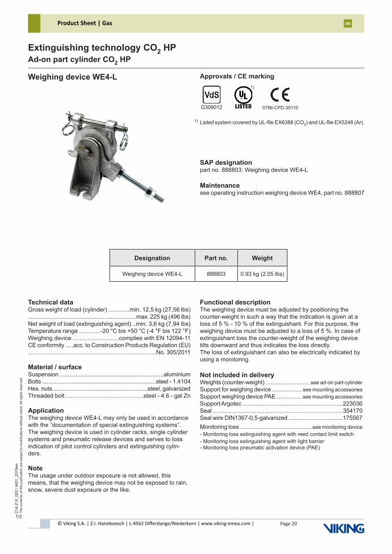
Weighing device WE4-L Approvals / CE marking
SAP designationpart no. 888803: Weighing device WE4-L
Maintenancesee operating instruction weighing device WE4, part no. 888807
Listed system covered by UL-file EX6388 (CO2) and UL-file EX5248 (Ar).
1)
G309012 0786-CPD-30110
1)
Technical dataGross weight of load (cylinder) .............min. 12,5 kg (27,56 lbs)....................................................................max. 225 kg (496 lbs)Net weight of load (extinguishing agent) ..min. 3,6 kg (7,94 lbs)Temperature range .............-20 °C bis +50 °C (-4 °F bis 122 °F)Weighing device ............................complies with EN 12094-11CE conformity .....acc. to Construction Products Regulation (EU)................................................................................No. 305/2011
Material / surfaceSuspension .................................................................aluminiumBolts .......................................................................steel - 1.4104Hex. nuts ...........................................................steel, galvanizedThreaded bolt ...............................................steel - 4.6 - gal Zn
ApplicationThe weighing device WE4-L may only be used in accordance with the “documentation of special extinguishing systems”. The weighing device is used in cylinder racks, single cylinder systems and pneumatic release devices and serves to loss indication of pilot control cylinders and extinguishing cylin-ders.
NoteThe usage under outdoor exposure is not allowed, this means, that the weighing device may not be exposed to rain, snow, severe dust exposure or the like.
Functional descriptionThe weighing device must be adjusted by positioning the counter-weight in such a way that the indication is given at a loss of 5 % - 10 % of the extinguishant. For this purpose, the weighing device must be adjusted to a loss of 5 %. In case of extinguishant loss the counter-weight of the weighing device tilts downward and thus indicates the loss directly.The loss of extinguishant can also be electrically indicated by using a monitoring.
Not included in deliveryWeights (counter-weight) ............................see ad-on part cylinderSupport for weighing device ...................see mounting accessories Support weighing device PAE ................see mounting accessories Support Argotec ...............................................................223036Seal .................................................................................354170Seal wire DIN1367-0,5-galvanized ..................................175567Monitoring loss .............................................see monitoring device- Monitoring loss extinguishing agent with reed contact limit switch- Monitoring loss extinguishing agent with light barrier- Monitoring loss pneumatic activation device (PAE)
Designation Part no. Weight
Weighing device WE4-L 888803 0.93 kg (2.05 lbs)
© Viking S.A. | Z.I. Haneboesch | L-4562 Differdange/Niederkorn | www.viking-emea.com |
Product Sheet | Gas
Page 21
214-
210_
002
/ AI0
1_20
15en
The
cont
ents
of t
his
publ
icat
ion
are
subj
ect t
o m
odifi
catio
ns w
ithou
t not
ice.
All
right
s re
serv
ed.
Extinguishing technology CO2 HPAd-on part cylinder CO2 HP
2/2
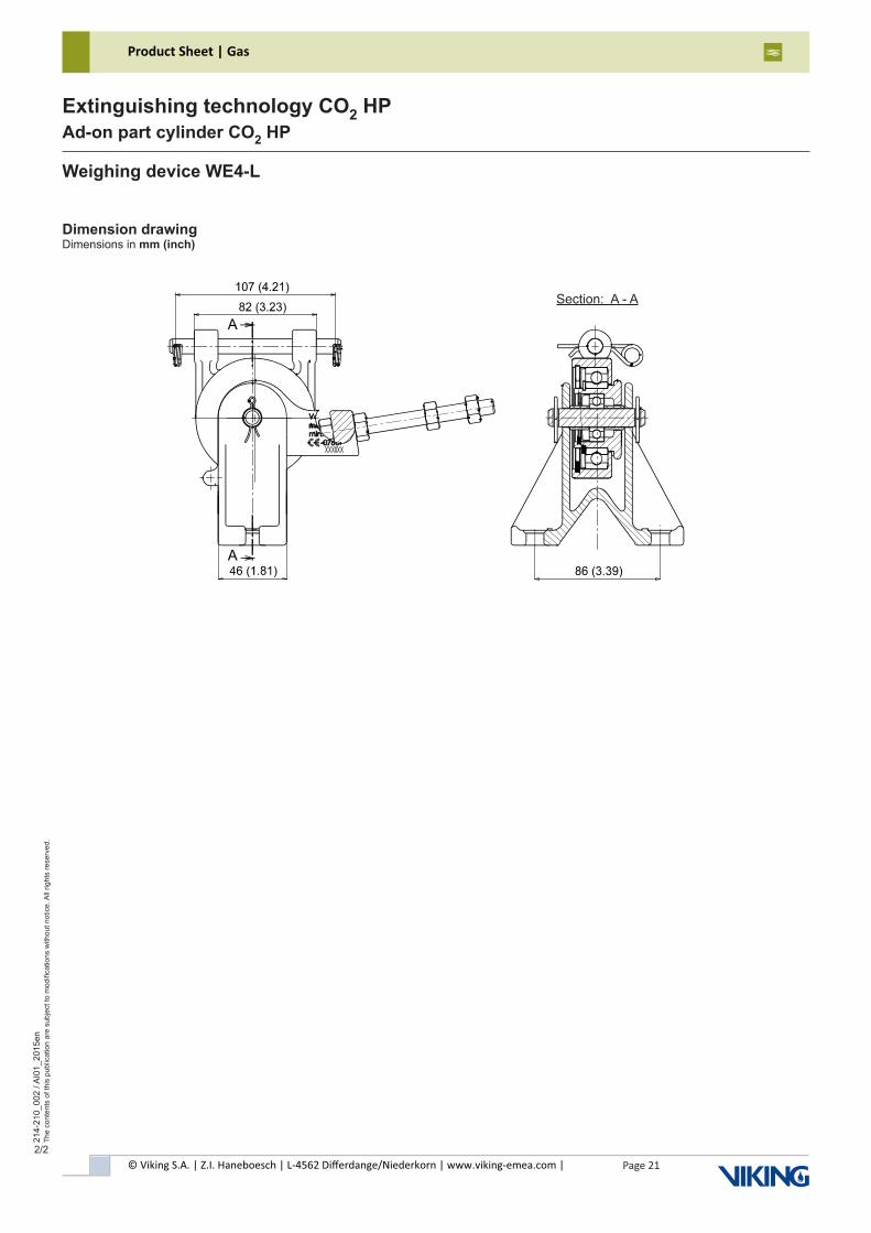
Section: A - A
Dimension drawingDimensions in mm (inch)
Weighing device WE4-L
© Viking S.A. | Z.I. Haneboesch | L-4562 Differdange/Niederkorn | www.viking-emea.com |
Product Sheet | Gas
Page 22
214-
210_
003
/ AI0
1_20
15en
The
cont
ents
of t
his
publ
icat
ion
are
subj
ect t
o m
odifi
catio
ns w
ithou
t not
ice.
All
right
s re
serv
ed.
Extinguishing technology CO2 HPAd-on part cylinder CO2 HP
1/1
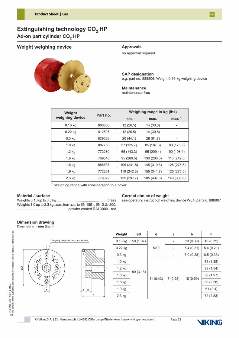
Weight weighing device Approvalsno approval required
SAP designatione.g. part no. 888806: Weight 0,16 kg weighing device
Maintenancemaintenance-free
Material / surfaceWeights 0.16 up to 0.3 kg ....................................................brassWeights 1.0 up to 2.3 kg ..cast iron acc. to EN 1561, EN-GJL-200,...................................................powder coated RAL3000 - red
Dimension drawingDimensions in mm (inch)
Correct choice of weightsee operating instruction weighing device WE4, part no. 888807
1) Weighing range with consideration to a cover
Weight weighing device Part no.
Weighing range in kg (lbs)min. max. max. 1)
0.16 kg 888806 12 (26.5) 14 (30.8) -
0.22 kg 812597 12 (26.5) 14 (30.8) -
0.3 kg 829528 20 (44.1) 28 (61.7) -
1.0 kg 887753 57 (125.7) 85 (187.3) 80 (176.3)
1.2 kg 772280 65 (143.3) 95 (209.4) 90 (198.4)
1.6 kg 769548 95 (209.5) 130 (286.6) 110 (242.5)
1.8 kg 885587 105 (231.5) 145 (319.6) 125 (275.5)
1.9 kg 772291 110 (242.6) 155 (341.7) 125 (275.5)
2.3 kg 778372 135 (297.7) 185 (407.8) 140 (308.6)
Weight øD d a b h
0.16 kg 50 (1.97)
M10
- 10 (0.39) 10 (0.39)
0.22 kg
80 (3.15)
- 5.4 (0.21) 5.4 (0.21)
0.3 kg - 7.0 (0.28) 8.5 (0.33)
1.0 kg
11 (0.43) 7 (0.28) 15 (0.59)
35 (1.38)
1.2 kg 39 (1.54)
1.6 kg 50 (1.97)
1.8 kg 58 (2.28)
1.9 kg 61 (2.4)
2.3 kg 72 (2.83)
© Viking S.A. | Z.I. Haneboesch | L-4562 Differdange/Niederkorn | www.viking-emea.com |
Product Sheet | Gas
Page 23
214-
210_
004
/ AI0
0_20
15en
The
cont
ents
of t
his
publ
icat
ion
are
subj
ect t
o m
odifi
catio
ns w
ithou
t not
ice.
All
right
s re
serv
ed.
Extinguishing technology CO2 HPAd-on part cylinder CO2 HP
1/1
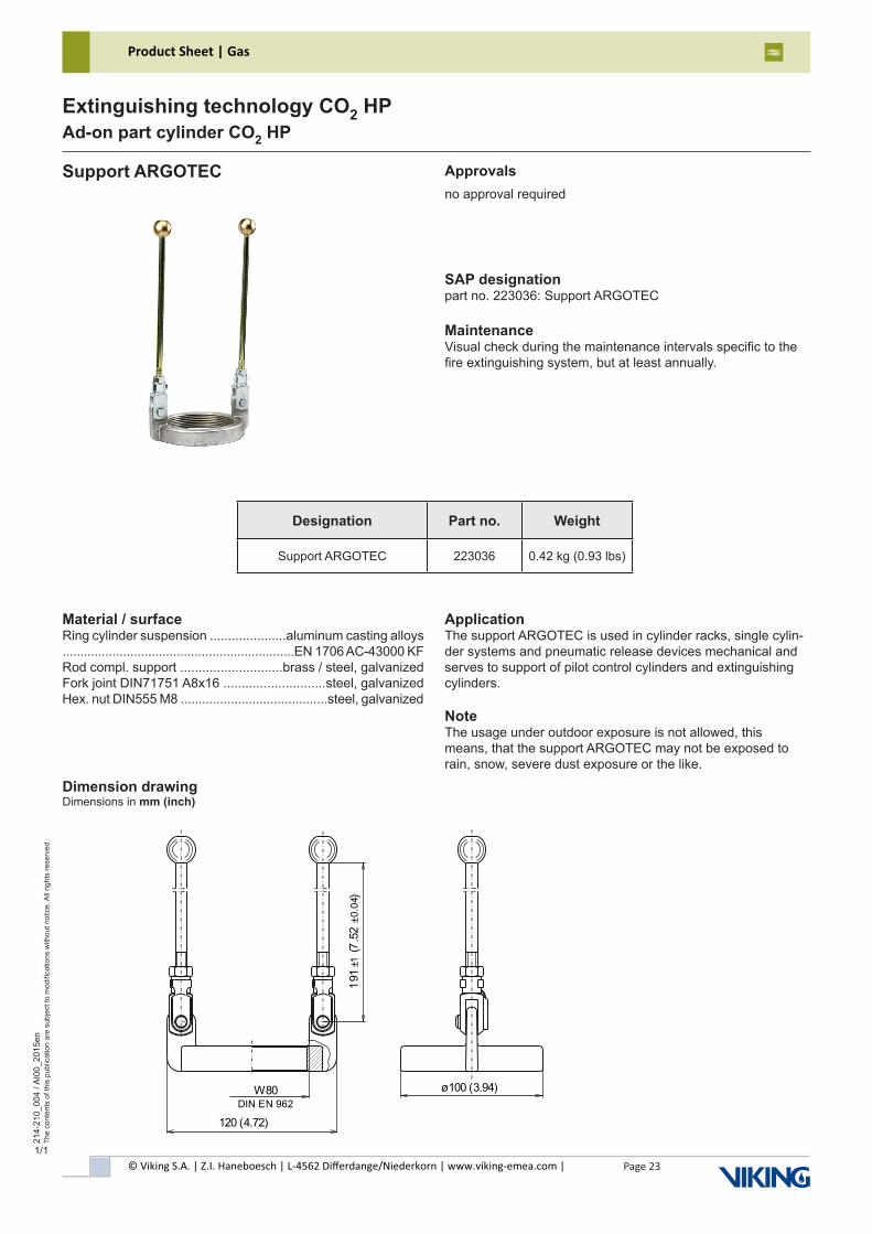
Support ARGOTEC Approvalsno approval required
SAP designationpart no. 223036: Support ARGOTEC
MaintenanceVisual check during the maintenance intervals specific to thefire extinguishing system, but at least annually.
Dimension drawingDimensions in mm (inch)
Designation Part no. Weight
Support ARGOTEC 223036 0.42 kg (0.93 lbs)
Material / surfaceRing cylinder suspension .....................aluminum casting alloys.................................................................EN 1706 AC-43000 KFRod compl. support ............................brass / steel, galvanizedFork joint DIN71751 A8x16 ............................steel, galvanizedHex. nut DIN555 M8 .........................................steel, galvanized
ApplicationThe support ARGOTEC is used in cylinder racks, single cylin-der systems and pneumatic release devices mechanical and serves to support of pilot control cylinders and extinguishing cylinders.
NoteThe usage under outdoor exposure is not allowed, this means, that the support ARGOTEC may not be exposed to rain, snow, severe dust exposure or the like.
W80 ø100 (3.94)
191
(7.5
2)
±1±0
.04
120 (4.72) DIN EN 962
© Viking S.A. | Z.I. Haneboesch | L-4562 Differdange/Niederkorn | www.viking-emea.com |
Product Sheet | Gas
Page 24
214-
210_
005
/ AI0
1_20
17en
The
cont
ents
of t
his
publ
icat
ion
are
subj
ect t
o m
odifi
catio
ns w
ithou
t not
ice.
All
right
s re
serv
ed.
Extinguishing technology CO2 HPAd-on part cylinder CO2 HP
1/2
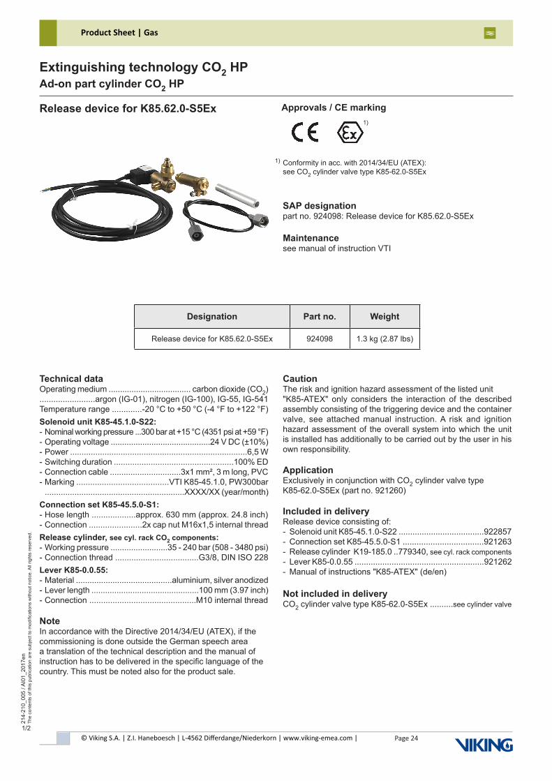
Release device for K85.62.0-S5Ex Approvals / CE marking
SAP designationpart no. 924098: Release device for K85.62.0-S5Ex
Maintenancesee manual of instruction VTI
Technical dataOperating medium .................................... carbon dioxide (CO2)........................argon (IG-01), nitrogen (IG-100), IG-55, IG-541Temperature range .............-20 °C to +50 °C (-4 °F to +122 °F)Solenoid unit K85-45.1.0-S22:- Nominal working pressure ...300 bar at +15 °C (4351 psi at +59 °F)- Operating voltage ............................................24 V DC (±10%)- Power .............................................................................6,5 W- Switching duration ....................................................100% ED- Connection cable ...............................3x1 mm², 3 m long, PVC- Marking ........................................VTI K85-45.1.0, PW300bar .............................................................XXXX/XX (year/month)Connection set K85-45.5.0-S1:- Hose length ...................approx. 630 mm (approx. 24.8 inch)- Connection .......................2x cap nut M16x1,5 internal threadRelease cylinder, see cyl. rack CO2 components:- Working pressure .........................35 - 240 bar (508 - 3480 psi)- Connection thread ....................................G3/8, DIN ISO 228Lever K85-0.0.55:- Material ..........................................aluminium, silver anodized- Lever length ...............................................100 mm (3.97 inch)- Connection ..............................................M10 internal thread
NoteIn accordance with the Directive 2014/34/EU (ATEX), if thecommissioning is done outside the German speech areaa translation of the technical description and the manual ofinstruction has to be delivered in the specific language of thecountry. This must be noted also for the product sale.
CautionThe risk and ignition hazard assessment of the listed unit "K85-ATEX" only considers the interaction of the described assembly consisting of the triggering device and the container valve, see attached manual instruction. A risk and ignition hazard assessment of the overall system into which the unit is installed has additionally to be carried out by the user in his own responsibility.
ApplicationExclusively in conjunction with CO2 cylinder valve typeK85-62.0-S5Ex (part no. 921260)
Included in deliveryRelease device consisting of:- Solenoid unit K85-45.1.0-S22 .....................................922857- Connection set K85-45.5.0-S1 ...................................921263- Release cylinder K19-185.0 ..779340, see cyl. rack components- Lever K85-0.0.55 ........................................................921262- Manual of instructions "K85-ATEX" (de/en)
Not included in deliveryCO2 cylinder valve type K85-62.0-S5Ex ..........see cylinder valve
Designation Part no. Weight
Release device for K85.62.0-S5Ex 924098 1.3 kg (2.87 lbs)
1)
Conformity in acc. with 2014/34/EU (ATEX):see CO2 cylinder valve type K85-62.0-S5Ex
1)
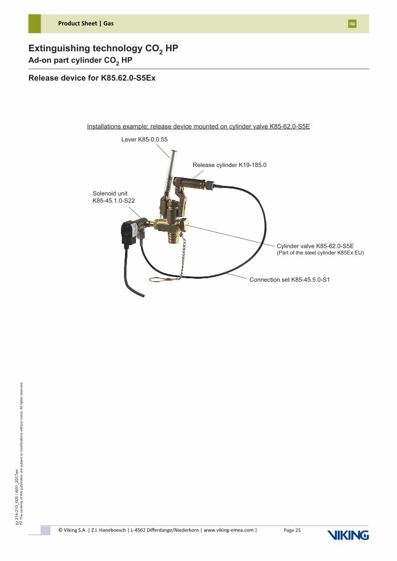
© Viking S.A. | Z.I. Haneboesch | L-4562 Differdange/Niederkorn | www.viking-emea.com |
Product Sheet | Gas
Page 25
214-
210_
005
/ AI0
1_20
17en
The
cont
ents
of t
his
publ
icat
ion
are
subj
ect t
o m
odifi
catio
ns w
ithou
t not
ice.
All
right
s re
serv
ed.
Extinguishing technology CO2 HPAd-on part cylinder CO2 HP
2/2
Installations example: release device mounted on cylinder valve K85-62.0-S5E
Release device for K85.62.0-S5Ex
Solenoid unitK85-45.1.0-S22
Connection set K85-45.5.0-S1
Release cylinder K19-185.0
Lever K85-0.0.55
Cylinder valve K85-62.0-S5E (Part of the steel cylinder K85Ex EU)
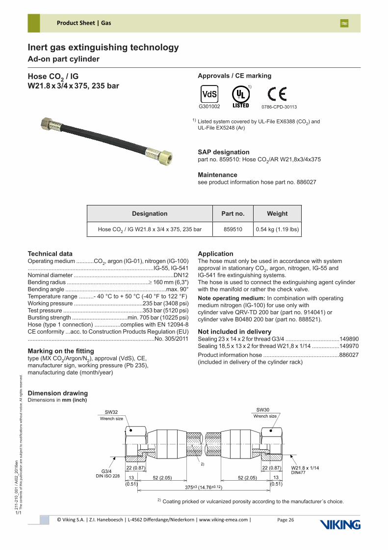
© Viking S.A. | Z.I. Haneboesch | L-4562 Differdange/Niederkorn | www.viking-emea.com |
Product Sheet | Gas
Page 26
211-
210_
001
/ AI0
2_20
16en
The
cont
ents
of t
his
publ
icat
ion
are
subj
ect t
o m
odifi
catio
ns w
ithou
t not
ice.
All
right
s re
serv
ed.
Inert gas extinguishing technologyAd-on part cylinder
1/1
Hose CO2 / IGW21.8 x 3/4 x 375, 235 bar
Approvals / CE marking
SAP designationpart no. 859510: Hose CO2/AR W21,8x3/4x375
Maintenancesee product information hose part no. 886027
Listed system covered by UL-File EX6388 (CO2) and UL-File EX5248 (Ar)
1)
G301002 0786-CPD-30113
1)
Designation Part no. Weight
Hose CO2 / IG W21.8 x 3/4 x 375, 235 bar 859510 0.54 kg (1.19 lbs)
Technical dataOperating medium ...........CO2, argon (IG-01), nitrogen (IG-100)...............................................................................IG-55, IG-541Nominal diameter ...............................................................DN12Bending radius ....................................................≥ 160 mm (6,3")Bending angle ................................................................max. 90°Temperature range .........- 40 °C to + 50 °C (-40 °F to 122 °F)Working pressure ...........................................235 bar (3408 psi)Test pressure ..................................................353 bar (5120 psi)Bursting strength ...................................min. 705 bar (10225 psi)Hose (type 1 connection) ................complies with EN 12094-8CE conformity ...acc. to Construction Products Regulation (EU)................................................................................No. 305/2011
Marking on the fittingtype (MX CO2/Argon/N2), approval (VdS), CE,manufacturer sign, working pressure (Pb 235),manufacturing date (month/year)
Dimension drawingDimensions in mm (inch)
ApplicationThe hose must only be used in accordance with systemapproval in stationary CO2, argon, nitrogen, IG-55 andIG-541 fire extinguishing systems.The hose is used to connect the extinguishing agent cylinder with the manifold or rather the check valve.Note operating medium: In combination with operatingmedium nitrogen (IG-100) for use only with cylinder valve QRV-TD 200 bar (part no. 914041) orcylinder valve B0480 200 bar (part no. 888521).
Not included in deliverySealing 23 x 14 x 2 for thread G3/4 ..................................149890Sealing 18,5 x 13 x 2 for thread W21,8 x 1/14 .................149970Product information hose ...............................................886027(included in delivery of the cylinder rack)
Coating pricked or vulcanized porosity according to the manufacturer´s choice.2)
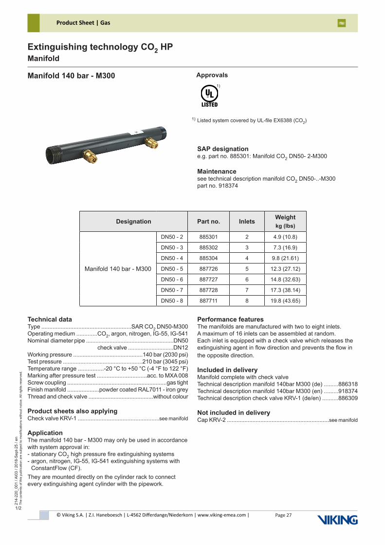
© Viking S.A. | Z.I. Haneboesch | L-4562 Differdange/Niederkorn | www.viking-emea.com |
Product Sheet | Gas
Page 27
214-
220_
001
/ AI0
3 / 2
018-
Sep
t-25
/ en
The
cont
ents
of t
his
publ
icat
ion
are
subj
ect t
o m
odifi
catio
ns w
ithou
t not
ice.
All
right
s re
serv
ed.
Extinguishing technology CO2 HPManifold
1/2
Manifold 140 bar - M300 Approvals
SAP designatione.g. part no. 885301: Manifold CO2 DN50- 2-M300
Maintenancesee technical description manifold CO2 DN50-..-M300part no. 918374
Listed system covered by UL-file EX6388 (CO2)
1)
1)
Technical dataType ........................................................SAR CO2 DN50-M300Operating medium .............CO2, argon, nitrogen, IG-55, IG-541Nominal diameter pipe ........................................................DN50 check valve .............................DN12Working pressure ............................................140 bar (2030 psi)Test pressure ..................................................210 bar (3045 psi)Temperature range ................-20 °C to +50 °C (-4 °F to 122 °F)Marking after pressure test ...............................acc. to MXA 008Screw coupling ...............................................................gas tightFinish manifold ....................powder coated RAL7011 - iron greyThread and check valve .........................................without colour
Product sheets also applyingCheck valve KRV-1 ...................................................see manifold
ApplicationThe manifold 140 bar - M300 may only be used in accordance with system approval in:- stationary CO2 high pressure fire extinguishing systems- argon, nitrogen, IG-55, IG-541 extinguishing systems with ConstantFlow (CF).They are mounted directly on the cylinder rack to connect every extinguishing agent cylinder with the pipework.
Performance featuresThe manifolds are manufactured with two to eight inlets.A maximum of 16 inlets can be assembled at random.Each inlet is equipped with a check valve which releases the extinguishing agent in flow direction and prevents the flow in the opposite direction.
Included in deliveryManifold complete with check valveTechnical description manifold 140bar M300 (de) .........886318Technical description manifold 140bar M300 (en) .........918374Technical description check valve KRV-1 (de/en) ..........886309
Not included in deliveryCap KRV-2 ................................................................see manifold
Designation Part no. Inlets Weightkg (lbs)
Manifold 140 bar - M300
DN50 - 2 885301 2 4.9 (10.8)
DN50 - 3 885302 3 7.3 (16.9)
DN50 - 4 885304 4 9.8 (21.61)
DN50 - 5 887726 5 12.3 (27.12)
DN50 - 6 887727 6 14.8 (32.63)
DN50 - 7 887728 7 17.3 (38.14)
DN50 - 8 887711 8 19.8 (43.65)
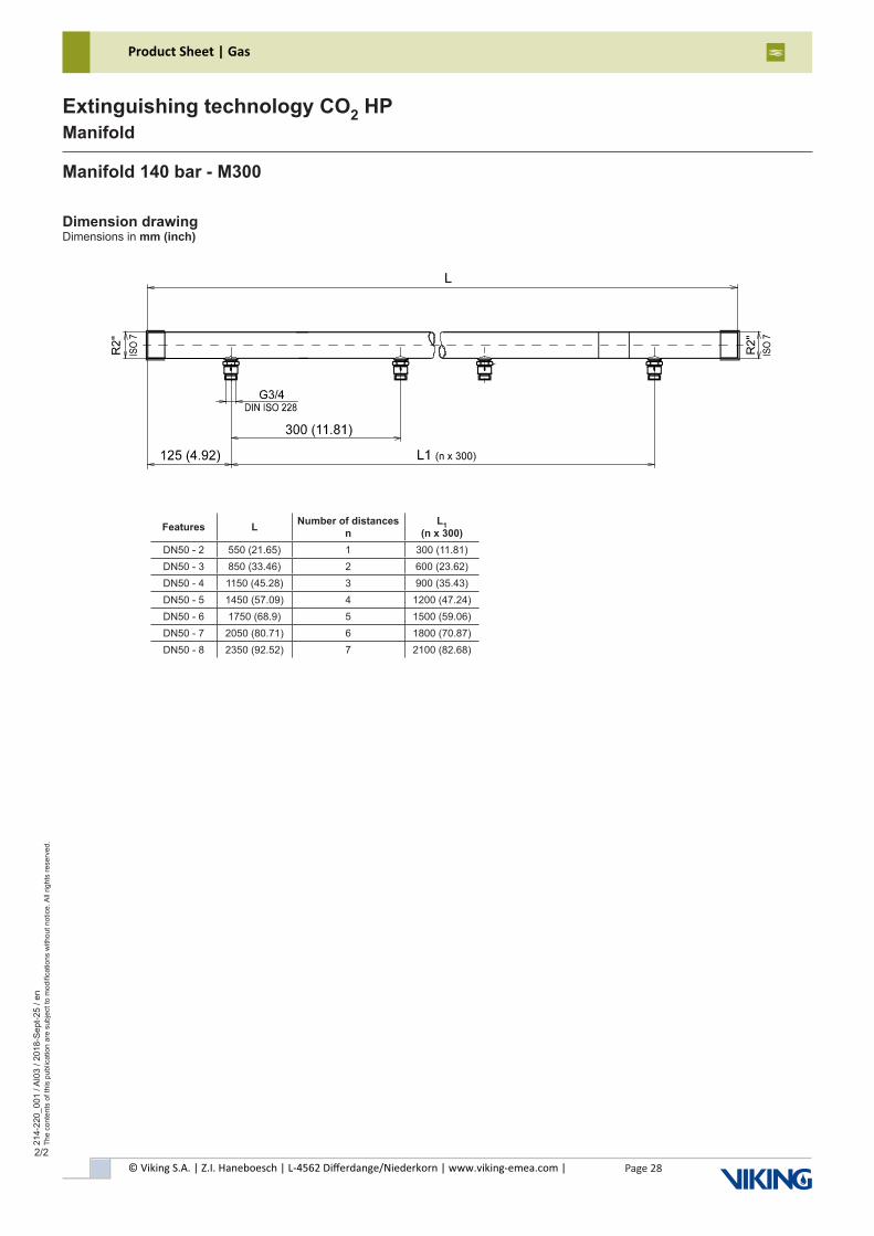
© Viking S.A. | Z.I. Haneboesch | L-4562 Differdange/Niederkorn | www.viking-emea.com |
Product Sheet | Gas
Page 28
214-
220_
001
/ AI0
3 / 2
018-
Sep
t-25
/ en
The
cont
ents
of t
his
publ
icat
ion
are
subj
ect t
o m
odifi
catio
ns w
ithou
t not
ice.
All
right
s re
serv
ed.
Extinguishing technology CO2 HPManifold
2/2
Dimension drawingDimensions in mm (inch)
Manifold 140 bar - M300
Features L Number of distances n
L1 (n x 300)
DN50 - 2 550 (21.65) 1 300 (11.81)DN50 - 3 850 (33.46) 2 600 (23.62)DN50 - 4 1150 (45.28) 3 900 (35.43)DN50 - 5 1450 (57.09) 4 1200 (47.24)DN50 - 6 1750 (68.9) 5 1500 (59.06)DN50 - 7 2050 (80.71) 6 1800 (70.87)DN50 - 8 2350 (92.52) 7 2100 (82.68)
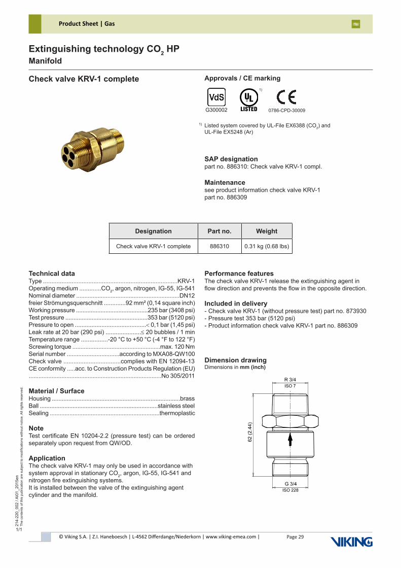
© Viking S.A. | Z.I. Haneboesch | L-4562 Differdange/Niederkorn | www.viking-emea.com |
Product Sheet | Gas
Page 29
214-
220_
002
/ AI0
1_20
15en
The
cont
ents
of t
his
publ
icat
ion
are
subj
ect t
o m
odifi
catio
ns w
ithou
t not
ice.
All
right
s re
serv
ed.
Extinguishing technology CO2 HPManifold
1/1
Check valve KRV-1 complete Approvals / CE marking
SAP designationpart no. 886310: Check valve KRV-1 compl.
Maintenancesee product information check valve KRV-1part no. 886309
Listed system covered by UL-File EX6388 (CO2) and UL-File EX5248 (Ar)
1)
G300002 0786-CPD-30009
1)
Technical dataType ................................................................................KRV-1Operating medium .............CO2, argon, nitrogen, IG-55, IG-541Nominal diameter ...............................................................DN12freier Strömungsquerschnitt .............92 mm² (0,14 square inch)Working pressure ............................................235 bar (3408 psi)Test pressure ..................................................353 bar (5120 psi)Pressure to open ...........................................< 0,1 bar (1,45 psi)Leak rate at 20 bar (290 psi) .....................≤ 20 bubbles / 1 minTemperature range ................-20 °C to +50 °C (-4 °F to 122 °F)Screwing torque ......................................................max. 120 NmSerial number ................................according to MXA08-QW100Check valve ..................................complies with EN 12094-13CE conformity .....acc. to Construction Products Regulation (EU).................................................................................No 305/2011
Material / SurfaceHousing ..............................................................................brassBall ........................................................................stainless steelSealing ...................................................................thermoplastic
NoteTest certificate EN 10204-2.2 (pressure test) can be ordered separately upon request from QW/OD.
ApplicationThe check valve KRV-1 may only be used in accordance with system approval in stationary CO2, argon, IG-55, IG-541 and nitrogen fire extinguishing systems.It is installed between the valve of the extinguishing agent cylinder and the manifold.
Performance featuresThe check valve KRV-1 release the extinguishing agent in flow direction and prevents the flow in the opposite direction.
Included in delivery- Check valve KRV-1 (without pressure test) part no. 873930- Pressure test 353 bar (5120 psi)- Product information check valve KRV-1 part no. 886309
Dimension drawingDimensions in mm (inch)
Designation Part no. Weight
Check valve KRV-1 complete 886310 0.31 kg (0.68 lbs)

© Viking S.A. | Z.I. Haneboesch | L-4562 Differdange/Niederkorn | www.viking-emea.com |
Product Sheet | Gas
Page 30
214-
240_
001
/ AI0
2_20
16en
The
cont
ents
of t
his
publ
icat
ion
are
subj
ect t
o m
odifi
catio
ns w
ithou
t not
ice.
All
right
s re
serv
ed.
Extinguishing technology CO2 HPCylinder rack CO2 components
1/2
Number of cylinder Part no. 3) Number of release weightsWeightapprox. kg (lbs)
2 768520 2 77 (170)
3 768532 2 86 (190)
4 768544 3 101 (223)
5 768556 3 126 (278)
6 768568 4 142 (313)
7 768570 4 150 (331)
8 768581 5 165 (364)
9 773830 5 190 (419)
10 773842 6 206 (454)
11 773854 6 215 (474)
12 773866 7 228 (503)
13 773878 7 252 (556)
14 773880 8 266 (586)
15 773891 8 275 (606)
16 773908 9 291 (642)
Cylinder rack CO2 - master actuation - M300 Approvals
SAP designatione.g. part no. 768520: Battery CO2-M300-master- 2 cyl.
Maintenancesee operating instruction battery CO2-master actuationpart no. 875408
Part of the system approval:- CO2 extinguishing system HD-1 (S398010) / HD-2 (S398011)
Listed system covered by UL-File EX6388 (CO2)
1)
2)1)
2)
Technical dataOperating medium ...............................................................CO2Working pressure ............................................140 bar (2030 psi)Test pressure ...................................................210 bar (3045 psi)Temperature range ................-20 °C to +40 °C (-4 °F to 104 °F)........................tropical filling: -20 °C to +50 °C (-4 °F to 122 °F) Cylinder rack ...............to accommodate of steel cylinder 67,5 l
ApplicationThe battery CO2- master actuation is used in accordance with the “documentation of special extinguishing systems” in fixed fire extinguishing systems using a gas as extinguishant.The battery is designed modular and is used to accommodate up to 16 cylinders. The integrated non-electrical control device is used to open the extinguishing cylinders in the event of fire.
Not included: cylinder with valve
3) Cylinder with valve are not included in delivery, see on page 2
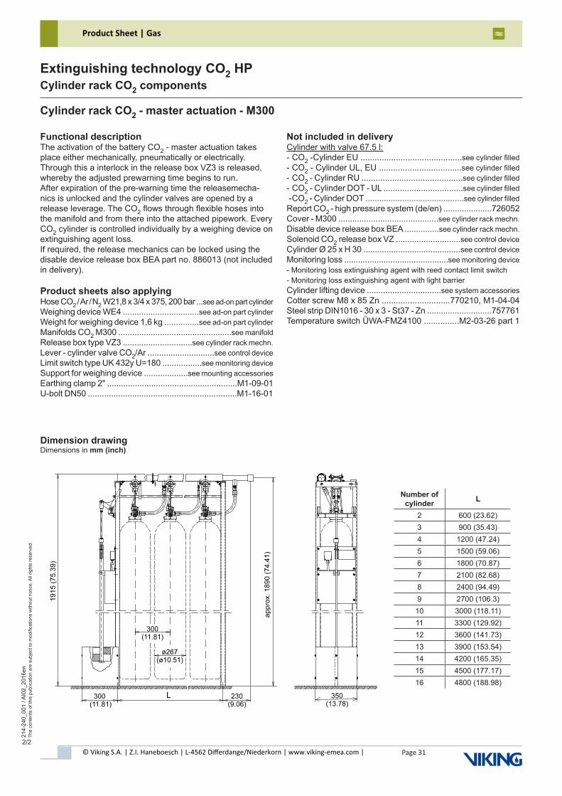
© Viking S.A. | Z.I. Haneboesch | L-4562 Differdange/Niederkorn | www.viking-emea.com |
Product Sheet | Gas
Page 31
214-
240_
001
/ AI0
2_20
16en
The
cont
ents
of t
his
publ
icat
ion
are
subj
ect t
o m
odifi
catio
ns w
ithou
t not
ice.
All
right
s re
serv
ed.
Extinguishing technology CO2 HPCylinder rack CO2 components
2/2
Dimension drawingDimensions in mm (inch)
Functional descriptionThe activation of the battery CO2 - master actuation takes place either mechanically, pneumatically or electrically. Through this a interlock in the release box VZ3 is released, whereby the adjusted prewarning time begins to run.After expiration of the pre-warning time the releasemecha-nics is unlocked and the cylinder valves are opened by a release leverage. The CO2 flows through flexible hoses into the manifold and from there into the attached pipework. Every CO2 cylinder is controlled individually by a weighing device on extinguishing agent loss.If required, the release mechanics can be locked using the disable device release box BEA part no. 886013 (not included in delivery).
Product sheets also applyingHose CO2 / Ar / N2 W21,8 x 3/4 x 375, 200 bar ...see ad-on part cylinderWeighing device WE4 .................................see ad-on part cylinder Weight for weighing device 1,6 kg ...............see ad-on part cylinder Manifolds CO2 M300 .................................................see manifoldRelease box type VZ3 ..............................see cylinder rack mechn.Lever - cylinder valve CO2/Ar .............................see control device Limit switch type UK 432y U=180 .................see monitoring device Support for weighing device ...................see mounting accessories Earthing clamp 2" ........................................................M1-09-01U-bolt DN50 ................................................................M1-16-01
Not included in deliveryCylinder with valve 67.5 l:- CO2 -Cylinder EU ...........................................see cylinder filled - CO2 - Cylinder UL, EU ...................................see cylinder filled - CO2 - Cylinder RU ...........................................see cylinder filled - CO2 - Cylinder DOT - UL ..................................see cylinder filled - CO2 - Cylinder DOT ...........................................see cylinder filled Report CO2 - high pressure system (de/en) .....................726052Cover - M300 ...........................................see cylinder rack mechn.Disable device release box BEA ...............see cylinder rack mechn.Solenoid CO2 release box VZ ............................see control deviceCylinder Ø 25 x H 30 ..........................................see control device Monitoring loss .............................................see monitoring device - Monitoring loss extinguishing agent with reed contact limit switch- Monitoring loss extinguishing agent with light barrierCylinder lifting device ................................see system accessories Cotter screw M8 x 85 Zn .............................770210, M1-04-04Steel strip DIN1016 - 30 x 3 - St37 - Zn ............................757761Temperature switch ÜWA-FMZ4100 ...............M2-03-26 part 1
Cylinder rack CO2 - master actuation - M300
Number of cylinder L
2 600 (23.62)3 900 (35.43)4 1200 (47.24)5 1500 (59.06)6 1800 (70.87)7 2100 (82.68)8 2400 (94.49)9 2700 (106.3)10 3000 (118.11)11 3300 (129.92)12 3600 (141.73)13 3900 (153.54)14 4200 (165.35)15 4500 (177.17)16 4800 (188.98)
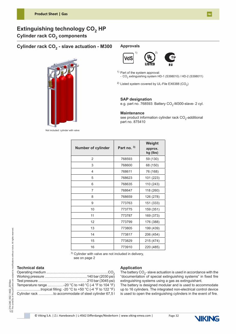
© Viking S.A. | Z.I. Haneboesch | L-4562 Differdange/Niederkorn | www.viking-emea.com |
Product Sheet | Gas
Page 32
214-
240_
002
/ AI0
2_20
16en
The
cont
ents
of t
his
publ
icat
ion
are
subj
ect t
o m
odifi
catio
ns w
ithou
t not
ice.
All
right
s re
serv
ed.
Extinguishing technology CO2 HPCylinder rack CO2 components
1/2
Number of cylinder Part no. 3)Weightapprox. kg (lbs)
2 768593 59 (130)
3 768600 68 (150)
4 768611 76 (168)
5 768623 101 (223)
6 768635 110 (243)
7 768647 118 (260)
8 768659 126 (278)
9 773763 151 (333)
10 773775 159 (351)
11 773787 169 (373)
12 773799 176 (388)
13 773805 199 (439)
14 773817 206 (454)
15 773829 215 (474)
16 773910 220 (485)
Cylinder rack CO2 - slave actuation - M300
SAP designatione.g. part no. 768593: Battery CO2-M300-slave- 2 cyl.
Maintenancesee product information cylinder rack CO2-additionalpart no. 875410
Technical dataOperating medium ...............................................................CO2Working pressure ............................................140 bar (2030 psi)Test pressure ...................................................210 bar (3045 psi)Temperature range ................-20 °C to +40 °C (-4 °F to 104 °F)........................tropical filling: -20 °C to +50 °C (-4 °F to 122 °F) Cylinder rack ...............to accommodate of steel cylinder 67,5 l
ApplicationThe battery CO2- slave actuation is used in accordance with the “documentation of special extinguishing systems” in fixed fire extinguishing systems using a gas as extinguishant.The battery is designed modular and is used to accommodate up to 16 cylinders. The integrated non-electrical control device is used to open the extinguishing cylinders in the event of fire.
Approvals
Part of the system approval:- CO2 extinguishing system HD-1 (S398010) / HD-2 (S398011)
Listed system covered by UL-File EX6388 (CO2)
1)
2)1)
2)
3) Cylinder with valve are not included in delivery, see on page 2
Not included: cylinder with valve
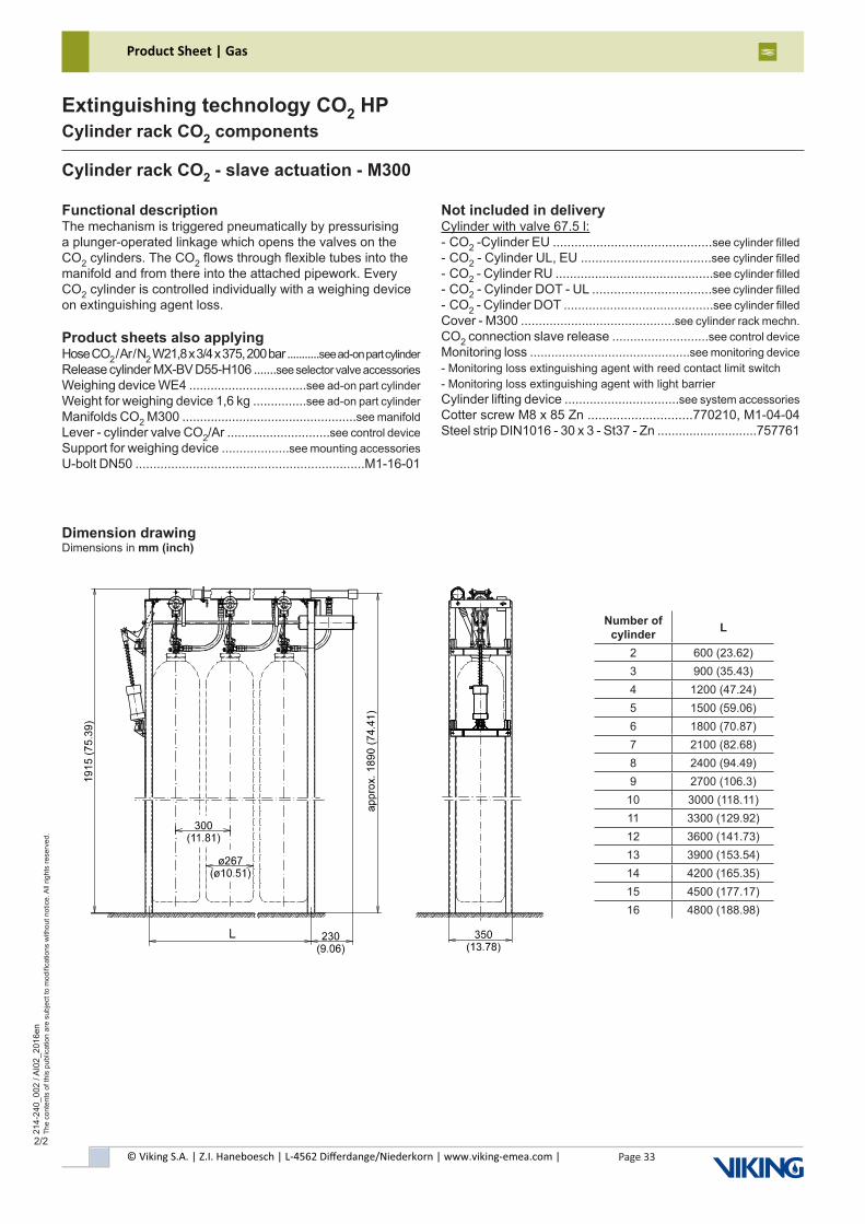
© Viking S.A. | Z.I. Haneboesch | L-4562 Differdange/Niederkorn | www.viking-emea.com |
Product Sheet | Gas
Page 33
214-
240_
002
/ AI0
2_20
16en
The
cont
ents
of t
his
publ
icat
ion
are
subj
ect t
o m
odifi
catio
ns w
ithou
t not
ice.
All
right
s re
serv
ed.
Extinguishing technology CO2 HPCylinder rack CO2 components
2/2
Cylinder rack CO2 - slave actuation - M300
Dimension drawingDimensions in mm (inch)
Functional descriptionThe mechanism is triggered pneumatically by pressurising a plunger-operated linkage which opens the valves on the CO2 cylinders. The CO2 flows through flexible tubes into the manifold and from there into the attached pipework. Every CO2 cylinder is controlled individually with a weighing device on extinguishing agent loss.
Product sheets also applyingHose CO2 / Ar / N2 W21,8 x 3/4 x 375, 200 bar ...........see ad-on part cylinder Release cylinder MX-BV D55-H106 .......see selector valve accessories Weighing device WE4 .................................see ad-on part cylinderWeight for weighing device 1,6 kg ...............see ad-on part cylinderManifolds CO2 M300 .................................................see manifold Lever - cylinder valve CO2/Ar .............................see control device Support for weighing device ...................see mounting accessories U-bolt DN50 ................................................................M1-16-01
Not included in deliveryCylinder with valve 67.5 l:- CO2 -Cylinder EU ............................................see cylinder filled - CO2 - Cylinder UL, EU ....................................see cylinder filled - CO2 - Cylinder RU ............................................see cylinder filled - CO2 - Cylinder DOT - UL .................................see cylinder filled - CO2 - Cylinder DOT ..........................................see cylinder filled Cover - M300 ...........................................see cylinder rack mechn. CO2 connection slave release ...........................see control deviceMonitoring loss .............................................see monitoring device- Monitoring loss extinguishing agent with reed contact limit switch- Monitoring loss extinguishing agent with light barrierCylinder lifting device ................................see system accessories Cotter screw M8 x 85 Zn .............................770210, M1-04-04Steel strip DIN1016 - 30 x 3 - St37 - Zn ............................757761
Number of cylinder L
2 600 (23.62)3 900 (35.43)4 1200 (47.24)5 1500 (59.06)6 1800 (70.87)7 2100 (82.68)8 2400 (94.49)9 2700 (106.3)10 3000 (118.11)11 3300 (129.92)12 3600 (141.73)13 3900 (153.54)14 4200 (165.35)15 4500 (177.17)16 4800 (188.98)

© Viking S.A. | Z.I. Haneboesch | L-4562 Differdange/Niederkorn | www.viking-emea.com |
Product Sheet | Gas
Page 34
214-
240_
003
/ AI0
2_20
16en
The
cont
ents
of t
his
publ
icat
ion
are
subj
ect t
o m
odifi
catio
ns w
ithou
t not
ice.
All
right
s re
serv
ed.
Extinguishing technology CO2 HPCylinder rack CO2 components
1/2
Number of cylinder Part no. 2) Number of release weightsWeightapprox. kg (lbs)
2 872948 2 79 (174)
3 872950 2 88 (194)
4 872961 3 103 (227)
5 872973 3 128 (282)
6 872985 4 144 (318)
7 872997 4 152 (335)
8 873000 5 167 (368)
9 873011 5 192 (423)
10 873023 6 208 (459)
11 873035 6 217 (478)
12 873047 7 231 (509)
13 873059 7 254 (560)
14 873060 8 268 (591)
15 873072 8 277 (611)
16 873084 9 293 (646)
Cylinder rack CO2 - master actuation - M300R Approvals
SAP designatione.g. part no. 872948: Battery CO2-M300R-master- 2 cyl.
Maintenancesee operating instruction battery CO2-master actuationpart no. 875408
Technical dataOperating medium ...............................................................CO2Working pressure ............................................140 bar (2030 psi)Test pressure ...................................................210 bar (3045 psi)Temperature range ................-20 °C to +40 °C (-4 °F to 104 °F)........................tropical filling: -20 °C to +50 °C (-4 °F to 122 °F) Cylinder rack ...............to accommodate of steel cylinder 67,5 l
ApplicationThe battery CO2- master actuation is used in accordance with the “documentation of special extinguishing systems” in fixed fire extinguishing systems using a gas as extinguishant.The battery is designed modular and is used to accommodate up to 16 cylinders. The integrated non-electrical control device is used to open the extinguishing cylinders in the event of fire.
2) Cylinder with valve are not included in delivery, see on page 2
Not included: cylinder with valve
Part of the system approval:- CO2 extinguishing system HD-1 (S398010)
1)
1)
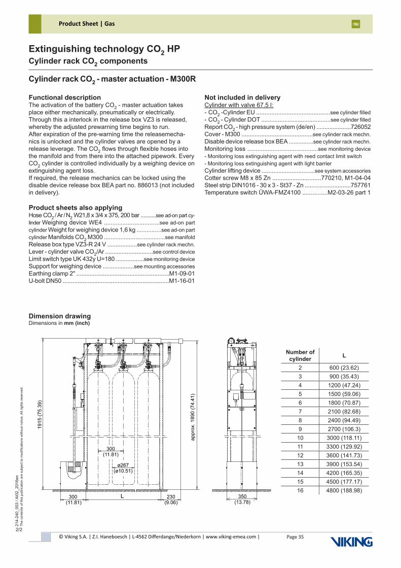
© Viking S.A. | Z.I. Haneboesch | L-4562 Differdange/Niederkorn | www.viking-emea.com |
Product Sheet | Gas
Page 35
214-
240_
003
/ AI0
2_20
16en
The
cont
ents
of t
his
publ
icat
ion
are
subj
ect t
o m
odifi
catio
ns w
ithou
t not
ice.
All
right
s re
serv
ed.
Extinguishing technology CO2 HPCylinder rack CO2 components
2/2
Cylinder rack CO2 - master actuation - M300R
Dimension drawingDimensions in mm (inch)
Functional descriptionThe activation of the battery CO2 - master actuation takes place either mechanically, pneumatically or electrically. Through this a interlock in the release box VZ3 is released, whereby the adjusted prewarning time begins to run.After expiration of the pre-warning time the releasemecha-nics is unlocked and the cylinder valves are opened by a release leverage. The CO2 flows through flexible hoses into the manifold and from there into the attached pipework. Every CO2 cylinder is controlled individually by a weighing device on extinguishing agent loss.If required, the release mechanics can be locked using the disable device release box BEA part no. 886013 (not included in delivery).
Product sheets also applyingHose CO2 / Ar / N2 W21,8 x 3/4 x 375, 200 bar ...........see ad-on part cy-linder Weighing device WE4 .................................see ad-on part cylinder Weight for weighing device 1,6 kg ...............see ad-on part cylinder Manifolds CO2 M300 .....................................see manifold Release box type VZ3-R 24 V ..................see cylinder rack mechn. Lever - cylinder valve CO2/Ar .............................see control device Limit switch type UK 432y U=180 .................see monitoring device Support for weighing device ...................see mounting accessories Earthing clamp 2" ........................................................M1-09-01U-bolt DN50 ................................................................M1-16-01
Not included in deliveryCylinder with valve 67.5 l:- CO2 -Cylinder EU ............................................see cylinder filled - CO2 - Cylinder DOT ..........................................see cylinder filled Report CO2 - high pressure system (de/en) .....................726052Cover - M300 ...........................................see cylinder rack mechn.Disable device release box BEA ...............see cylinder rack mechn. Monitoring loss ..........................................see monitoring device - Monitoring loss extinguishing agent with reed contact limit switch- Monitoring loss extinguishing agent with light barrierCylinder lifting device ................................see system accessories Cotter screw M8 x 85 Zn .............................770210, M1-04-04Steel strip DIN1016 - 30 x 3 - St37 - Zn ............................757761Temperature switch ÜWA-FMZ4100 ...............M2-03-26 part 1
Number of cylinder L
2 600 (23.62)3 900 (35.43)4 1200 (47.24)5 1500 (59.06)6 1800 (70.87)7 2100 (82.68)8 2400 (94.49)9 2700 (106.3)
10 3000 (118.11)11 3300 (129.92)12 3600 (141.73)13 3900 (153.54)14 4200 (165.35)15 4500 (177.17)16 4800 (188.98)

© Viking S.A. | Z.I. Haneboesch | L-4562 Differdange/Niederkorn | www.viking-emea.com |
Product Sheet | Gas
Page 36
214-
240_
004
/ AI0
1_20
15en
The
cont
ents
of t
his
publ
icat
ion
are
subj
ect t
o m
odifi
catio
ns w
ithou
t not
ice.
All
right
s re
serv
ed.
Extinguishing technology CO2 HPCylinder rack CO2 components
1/2
Number of cylinder Part no. 2) Number of release weightsWeightapprox. kg (lbs)
2 886528 2 77 (170)
3 886529 2 86 (190)
4 886530 3 102 (225)
5 886531 3 125 (276)
6 886532 4 141 (311)
7 886533 4 151 (333)
8 886534 5 167 (368)
9 886535 5 188 (415)
10 886536 6 206 (454)
11 886537 6 217 (478)
12 886539 7 232 (512)
13 886541 7 251 (553)
14 886542 8 267 (589)
15 886543 8 278 (613)
16 886544 9 295 (650)
Cylinder rack CO2 - master actuation -M300 - 80 l
Approvals
SAP designatione.g. part no 886528: Battery CO2-M300-master- 2-80l-cyl.
Maintenancesee operating instruction battery CO2-master actuationpart no. 875408
Listed system covered by UL-File EX6388 (CO2)1)
1) Note:Cylinder rackswithout VdS approval
Technical dataOperating medium ...............................................................CO2Working pressure ............................................140 bar (2030 psi)Test pressure ...................................................210 bar (3045 psi)Temperature range ................-20 °C to +40 °C (-4 °F to 104 °F)........................tropical filling: -20 °C to +50 °C (-4 °F to 122 °F) Cylinder rack ......to accommodate of steel cylinder 80 l / 80,5 l
ApplicationThe battery CO2- master actuation is used in accordance with the “documentation of special extinguishing systems” in fixed fire extinguishing systems using a gas as extinguishant.The battery is designed modular and is used to accommodate up to 16 cylinders. The integrated non-electrical control device is used to open the extinguishing cylinders in the event of fire.
2) Cylinder with valve are not included in delivery, see on page 2
Not included: cylinder with valve

© Viking S.A. | Z.I. Haneboesch | L-4562 Differdange/Niederkorn | www.viking-emea.com |
Product Sheet | Gas
Page 37
214-
240_
004
/ AI0
1_20
15en
The
cont
ents
of t
his
publ
icat
ion
are
subj
ect t
o m
odifi
catio
ns w
ithou
t not
ice.
All
right
s re
serv
ed.
Extinguishing technology CO2 HPCylinder rack CO2 components
2/2
Dimension drawingDimensions in mm (inch)
Functional descriptionThe activation of the battery CO2 - master actuation takes place either mechanically, pneumatically or electrically. Through this a interlock in the release box VZ3 is released, whereby the adjusted prewarning time begins to run.After expiration of the pre-warning time the releasemecha-nics is unlocked and the cylinder valves are opened by a release leverage. The CO2 flows through flexible hoses into the manifold and from there into the attached pipework. Every CO2 cylinder is controlled individually by a weighing device on extinguishing agent loss.If required, the release mechanics can be locked using the disable device release box BEA part no. 886013 (not included in delivery).
Product sheets also applyingHose CO2 / Ar / N2 W21,8 x 3/4 x 375, 200 bar ...........see ad-on part cylinder Weighing device WE4 .................................see ad-on part cylinder Weight for weighing device 1,8 kg ...............see ad-on part cylinder Manifolds CO2 M300 ...............................................see manifold Release box type VZ3 .............................see cylinder rack mechn. Lever - cylinder valve CO2/Ar .............................see control device Limit switch type UK 432y U=180 .................see monitoring device Support for weighing device ...................see mounting accessories Earthing clamp 2" ........................................................M1-09-01U-bolt DN50 ................................................................M1-16-01
Not included in deliveryCylinder with valve 80 l / 80,5 l:- CO2 -Cylinder EU .............................................see cylinder filled- CO2 - Cylinder UL, EU .....................................see cylinder filled - CO2 - Cylinder DOT - UL ................................see cylinder filled - CO2 - Cylinder DOT .........................................see cylinder filled Report CO2 - high pressure system (de/en) .....................726052Cover - M300 ...........................................see cylinder rack mechn. Disable device release box BEA ...............see cylinder rack mechn.Solenoid CO2 release box VZ ............................see control device Cylinder Ø 25 x H 30 ..........................................see control device Monitoring loss .............................................see monitoring device- Monitoring loss extinguishing agent with reed contact limit switch- Monitoring loss extinguishing agent with light barrierCylinder lifting device ................................see system accessories Cotter screw M8 x 85 Zn .............................770210, M1-04-04Steel strip DIN1016 - 30 x 3 - St37 - Zn ............................757761Temperature switch ÜWA-FMZ4100 ...............M2-03-26 part 1
Cylinder rack CO2 - master actuation -M300 - 80 l
Number of cylinder L
2 600 (23.62)3 900 (35.43)4 1200 (47.24)5 1500 (59.06)6 1800 (70.87)7 2100 (82.68)8 2400 (94.49)9 2700 (106.3)10 3000 (118.11)11 3300 (129.92)12 3600 (141.73)13 3900 (153.54)14 4200 (165.35)15 4500 (177.17)16 4800 (188.98)

© Viking S.A. | Z.I. Haneboesch | L-4562 Differdange/Niederkorn | www.viking-emea.com |
Product Sheet | Gas
Page 38
214-
240_
005
/ AI0
1_20
15en
The
cont
ents
of t
his
publ
icat
ion
are
subj
ect t
o m
odifi
catio
ns w
ithou
t not
ice.
All
right
s re
serv
ed.
Extinguishing technology CO2 HPCylinder rack CO2 components
1/2
Number of cylinder Part no. 2)Weightapprox. kg (lbs)
2 886545 61 (135)
3 886546 71 (157)
4 886547 79 (174)
5 886548 105 (232)
6 886549 114 (251)
7 886550 122 (269)
8 886552 131 (288)
9 886553 157 (346)
10 886554 165 (364)
11 886555 175 (386)
12 886556 182 (401)
13 886557 207 (456)
14 886558 214 (472)
15 886559 223 (492)
16 886560 228 (503)
Cylinder rack CO2 - slave actuation -M300 - 80 l
Approvals
Listed system covered by UL-File EX6388 (CO2)1)
1) Note:Cylinder rackswithout VdS approval
SAP designatione.g. part no. 886545: Battery CO2-M300-slave- 2-80l-cyl.
Maintenancesee product information cylinder rack CO2-additionalpart no. 875410
Technical dataOperating medium ...............................................................CO2Working pressure ............................................140 bar (2030 psi)Test pressure ...................................................210 bar (3045 psi)Temperature range ................-20 °C to +40 °C (-4 °F to 104 °F)........................tropical filling: -20 °C to +50 °C (-4 °F to 122 °F) Cylinder rack ..........to accommodate of steel cylinder 80 l / 80,5 l
ApplicationThe battery CO2- slave actuation is used in accordance with the “documentation of special extinguishing systems” in fixed fire extinguishing systems using a gas as extinguishant.The battery is designed modular and is used to accommodate up to 16 cylinders. The integrated non-electrical control device is used to open the extinguishing cylinders in the event of fire.
2) Cylinder with valve are not included in delivery, see on page 2
Not included: cylinder with valve
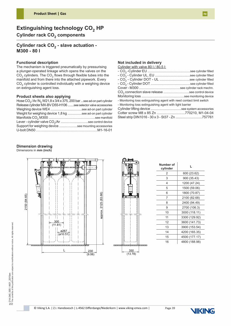
© Viking S.A. | Z.I. Haneboesch | L-4562 Differdange/Niederkorn | www.viking-emea.com |
Product Sheet | Gas
Page 39
214-
240_
005
/ AI0
1_20
15en
The
cont
ents
of t
his
publ
icat
ion
are
subj
ect t
o m
odifi
catio
ns w
ithou
t not
ice.
All
right
s re
serv
ed.
Extinguishing technology CO2 HPCylinder rack CO2 components
2/2
Cylinder rack CO2 - slave actuation -M300 - 80 l
Dimension drawingDimensions in mm (inch)
Functional descriptionThe mechanism is triggered pneumatically by pressurising a plunger-operated linkage which opens the valves on the CO2 cylinders. The CO2 flows through flexible tubes into the manifold and from there into the attached pipework. Every CO2 cylinder is controlled individually with a weighing device on extinguishing agent loss.
Product sheets also applyingHose CO2 / Ar / N2 W21,8 x 3/4 x 375, 200 bar ...see ad-on part cylinder Release cylinder MX-BV D55-H106 .......see selector valve accessories Weighing device WE4 .................................see ad-on part cylinder Weight for weighing device 1,8 kg ...............see ad-on part cylinder Manifolds CO2 M300 .................................................see manifold Lever - cylinder valve CO2/Ar .............................see control device Support for weighing device ...................see mounting accessories U-bolt DN50 ................................................................M1-16-01
Not included in deliveryCylinder with valve 80 l / 80,5 l:- CO2 -Cylinder EU ............................................see cylinder filled - CO2 - Cylinder UL, EU ....................................see cylinder filled - CO2 - Cylinder DOT - UL ...............................see cylinder filled - CO2 - Cylinder DOT .........................................see cylinder filled Cover - M300 ...........................................see cylinder rack mechn. CO2 connection slave release ...........................see control device Monitoring loss .............................................see monitoring device- Monitoring loss extinguishing agent with reed contact limit switch- Monitoring loss extinguishing agent with light barrierCylinder lifting device ................................see system accessories Cotter screw M8 x 85 Zn .............................770210, M1-04-04Steel strip DIN1016 - 30 x 3 - St37 - Zn ............................757761
Number of cylinder L
2 600 (23.62)3 900 (35.43)4 1200 (47.24)5 1500 (59.06)6 1800 (70.87)7 2100 (82.68)8 2400 (94.49)9 2700 (106.3)10 3000 (118.11)11 3300 (129.92)12 3600 (141.73)13 3900 (153.54)14 4200 (165.35)15 4500 (177.17)16 4800 (188.98)
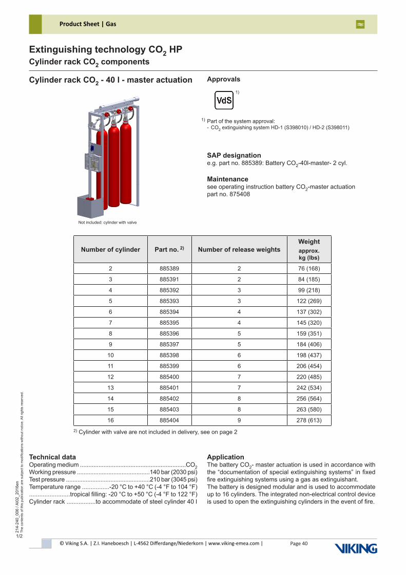
© Viking S.A. | Z.I. Haneboesch | L-4562 Differdange/Niederkorn | www.viking-emea.com |
Product Sheet | Gas
Page 40
214-
240_
006
/ AI0
2_20
16en
The
cont
ents
of t
his
publ
icat
ion
are
subj
ect t
o m
odifi
catio
ns w
ithou
t not
ice.
All
right
s re
serv
ed.
Extinguishing technology CO2 HPCylinder rack CO2 components
1/2
Number of cylinder Part no. 2) Number of release weightsWeightapprox. kg (lbs)
2 885389 2 76 (168)
3 885391 2 84 (185)
4 885392 3 99 (218)
5 885393 3 122 (269)
6 885394 4 137 (302)
7 885395 4 145 (320)
8 885396 5 159 (351)
9 885397 5 184 (406)
10 885398 6 198 (437)
11 885399 6 206 (454)
12 885400 7 220 (485)
13 885401 7 242 (534)
14 885402 8 256 (564)
15 885403 8 263 (580)
16 885404 9 278 (613)
Cylinder rack CO2 - 40 l - master actuation
SAP designatione.g. part no. 885389: Battery CO2-40l-master- 2 cyl.
Maintenancesee operating instruction battery CO2-master actuationpart no. 875408
Technical dataOperating medium ...............................................................CO2Working pressure ............................................140 bar (2030 psi)Test pressure ...................................................210 bar (3045 psi)Temperature range ................-20 °C to +40 °C (-4 °F to 104 °F)........................tropical filling: -20 °C to +50 °C (-4 °F to 122 °F) Cylinder rack .................to accommodate of steel cylinder 40 l
ApplicationThe battery CO2- master actuation is used in accordance with the “documentation of special extinguishing systems” in fixed fire extinguishing systems using a gas as extinguishant.The battery is designed modular and is used to accommodate up to 16 cylinders. The integrated non-electrical control device is used to open the extinguishing cylinders in the event of fire.
Approvals
Part of the system approval:- CO2 extinguishing system HD-1 (S398010) / HD-2 (S398011)
1)
2) Cylinder with valve are not included in delivery, see on page 2
Not included: cylinder with valve
1)
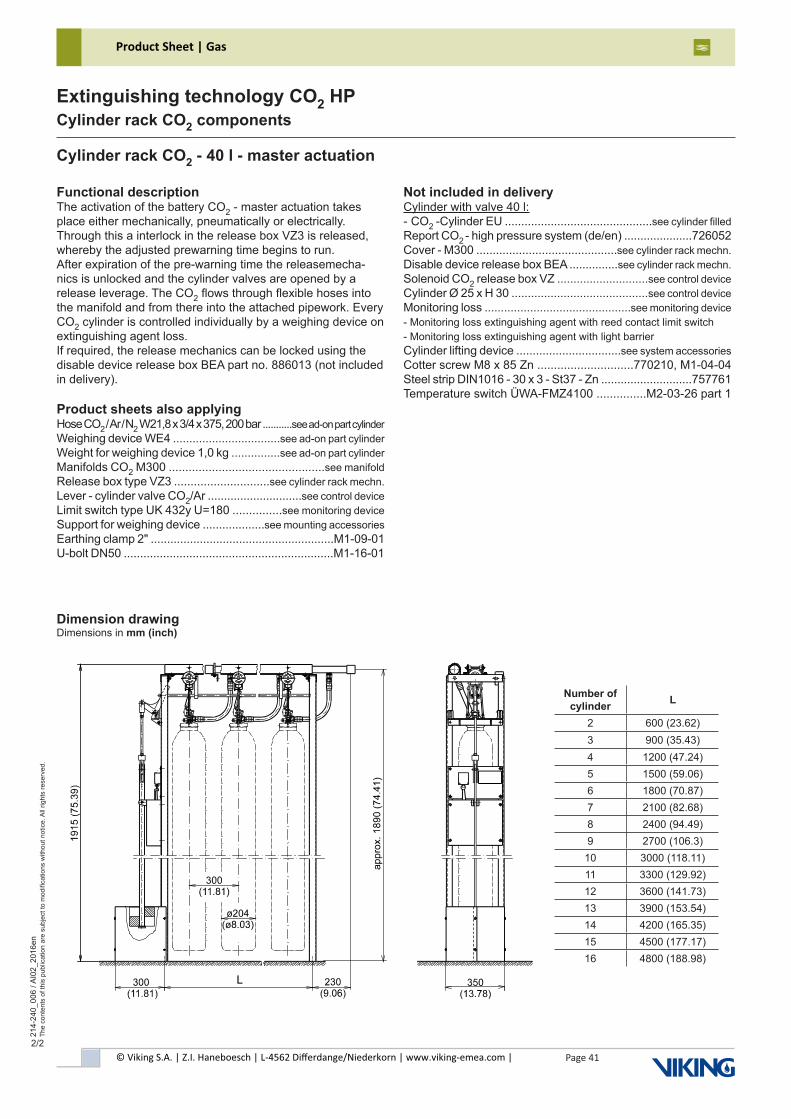
© Viking S.A. | Z.I. Haneboesch | L-4562 Differdange/Niederkorn | www.viking-emea.com |
Product Sheet | Gas
Page 41
214-
240_
006
/ AI0
2_20
16en
The
cont
ents
of t
his
publ
icat
ion
are
subj
ect t
o m
odifi
catio
ns w
ithou
t not
ice.
All
right
s re
serv
ed.
Extinguishing technology CO2 HPCylinder rack CO2 components
2/2
Cylinder rack CO2 - 40 l - master actuation
Dimension drawingDimensions in mm (inch)
Functional descriptionThe activation of the battery CO2 - master actuation takes place either mechanically, pneumatically or electrically. Through this a interlock in the release box VZ3 is released, whereby the adjusted prewarning time begins to run.After expiration of the pre-warning time the releasemecha-nics is unlocked and the cylinder valves are opened by a release leverage. The CO2 flows through flexible hoses into the manifold and from there into the attached pipework. Every CO2 cylinder is controlled individually by a weighing device on extinguishing agent loss.If required, the release mechanics can be locked using the disable device release box BEA part no. 886013 (not included in delivery).
Product sheets also applyingHose CO2 / Ar / N2 W21,8 x 3/4 x 375, 200 bar ...........see ad-on part cylinder Weighing device WE4 .................................see ad-on part cylinder Weight for weighing device 1,0 kg ...............see ad-on part cylinder Manifolds CO2 M300 ...............................................see manifold Release box type VZ3 .............................see cylinder rack mechn. Lever - cylinder valve CO2/Ar .............................see control device Limit switch type UK 432y U=180 ...............see monitoring device Support for weighing device ...................see mounting accessories Earthing clamp 2" ........................................................M1-09-01U-bolt DN50 ................................................................M1-16-01
Not included in deliveryCylinder with valve 40 l:- CO2 -Cylinder EU .............................................see cylinder filledReport CO2 - high pressure system (de/en) .....................726052Cover - M300 ...........................................see cylinder rack mechn. Disable device release box BEA ...............see cylinder rack mechn.Solenoid CO2 release box VZ ............................see control deviceCylinder Ø 25 x H 30 ..........................................see control deviceMonitoring loss .............................................see monitoring device- Monitoring loss extinguishing agent with reed contact limit switch- Monitoring loss extinguishing agent with light barrierCylinder lifting device ................................see system accessories Cotter screw M8 x 85 Zn .............................770210, M1-04-04Steel strip DIN1016 - 30 x 3 - St37 - Zn ............................757761Temperature switch ÜWA-FMZ4100 ...............M2-03-26 part 1
Number of cylinder L
2 600 (23.62)3 900 (35.43)4 1200 (47.24)5 1500 (59.06)6 1800 (70.87)7 2100 (82.68)8 2400 (94.49)9 2700 (106.3)10 3000 (118.11)11 3300 (129.92)12 3600 (141.73)13 3900 (153.54)14 4200 (165.35)15 4500 (177.17)16 4800 (188.98)

© Viking S.A. | Z.I. Haneboesch | L-4562 Differdange/Niederkorn | www.viking-emea.com |
Product Sheet | Gas
Page 42
214-
240_
007
/ AI0
2_20
16en
The
cont
ents
of t
his
publ
icat
ion
are
subj
ect t
o m
odifi
catio
ns w
ithou
t not
ice.
All
right
s re
serv
ed.
Extinguishing technology CO2 HPCylinder rack CO2 components
1/2
Number of cylinder Part no. 2)Weightapprox. kg (lbs)
2 885405 58 (128)
3 885407 66 (146)
4 885408 74 (163)
5 885409 97 (214)
6 885410 105 (232)
7 885411 113 (249)
8 885412 120 (265)
9 885413 145 (320)
10 885414 152 (335)
11 885415 160 (353)
12 885416 167 (368)
13 885417 189 (417)
14 885419 196 (432)
15 885421 203 (448)
16 885422 211 (465)
Cylinder rack CO2 - 40 l - slave actuation
SAP designatione.g. part no. 885405: Battery CO2-40l-slave- 2 cyl.
Maintenancesee product information cylinder rack CO2-additionalpart no. 875410
Technical dataOperating medium ...............................................................CO2Working pressure ............................................140 bar (2030 psi)Test pressure ...................................................210 bar (3045 psi)Temperature range ................-20 °C to +40 °C (-4 °F to 104 °F)........................tropical filling: -20 °C to +50 °C (-4 °F to 122 °F) Cylinder rack ..................to accommodate of steel cylinder 40 l
ApplicationThe battery CO2- slave actuation is used in accordance with the “documentation of special extinguishing systems” in fixed fire extinguishing systems using a gas as extinguishant.The battery is designed modular and is used to accommodate up to 16 cylinders. The integrated non-electrical control device is used to open the extinguishing cylinders in the event of fire.
Approvals
2) Cylinder with valve are not included in delivery, see on page 2
Not included: cylinder with valve
Part of the system approval:- CO2 extinguishing system HD-1 (S398010) / HD-2 (S398011)
1)
1)
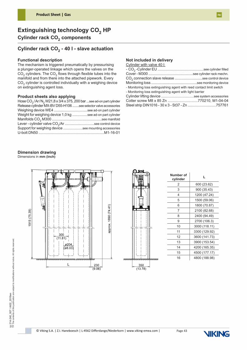
© Viking S.A. | Z.I. Haneboesch | L-4562 Differdange/Niederkorn | www.viking-emea.com |
Product Sheet | Gas
Page 43
214-
240_
007
/ AI0
2_20
16en
The
cont
ents
of t
his
publ
icat
ion
are
subj
ect t
o m
odifi
catio
ns w
ithou
t not
ice.
All
right
s re
serv
ed.
Extinguishing technology CO2 HPCylinder rack CO2 components
2/2
Cylinder rack CO2 - 40 l - slave actuation
Dimension drawingDimensions in mm (inch)
Functional descriptionThe mechanism is triggered pneumatically by pressurising a plunger-operated linkage which opens the valves on the CO2 cylinders. The CO2 flows through flexible tubes into the manifold and from there into the attached pipework. Every CO2 cylinder is controlled individually with a weighing device on extinguishing agent loss.
Product sheets also applyingHose CO2 / Ar / N2 W21,8 x 3/4 x 375, 200 bar ...see ad-on part cylinder Release cylinder MX-BV D55-H106 .......see selector valve accessories Weighing device WE4 .................................see ad-on part cylinder Weight for weighing device 1,0 kg ...............see ad-on part cylinder Manifolds CO2 M300 .................................................see manifoldLever - cylinder valve CO2/Ar .............................see control deviceSupport for weighing device ...................see mounting accessoriesU-bolt DN50 ................................................................M1-16-01
Not included in deliveryCylinder with valve 40 l:- CO2 -Cylinder EU .............................................see cylinder filledCover - M300 ............................................see cylinder rack mechn.CO2 connection slave release ...........................see control deviceMonitoring loss .............................................see monitoring device- Monitoring loss extinguishing agent with reed contact limit switch- Monitoring loss extinguishing agent with light barrierCylinder lifting device ................................see system accessoriesCotter screw M8 x 85 Zn .............................770210, M1-04-04Steel strip DIN1016 - 30 x 3 - St37 - Zn ............................757761
Number of cylinder L
2 600 (23.62)3 900 (35.43)4 1200 (47.24)5 1500 (59.06)6 1800 (70.87)7 2100 (82.68)8 2400 (94.49)9 2700 (106.3)10 3000 (118.11)11 3300 (129.92)12 3600 (141.73)13 3900 (153.54)14 4200 (165.35)15 4500 (177.17)16 4800 (188.98)
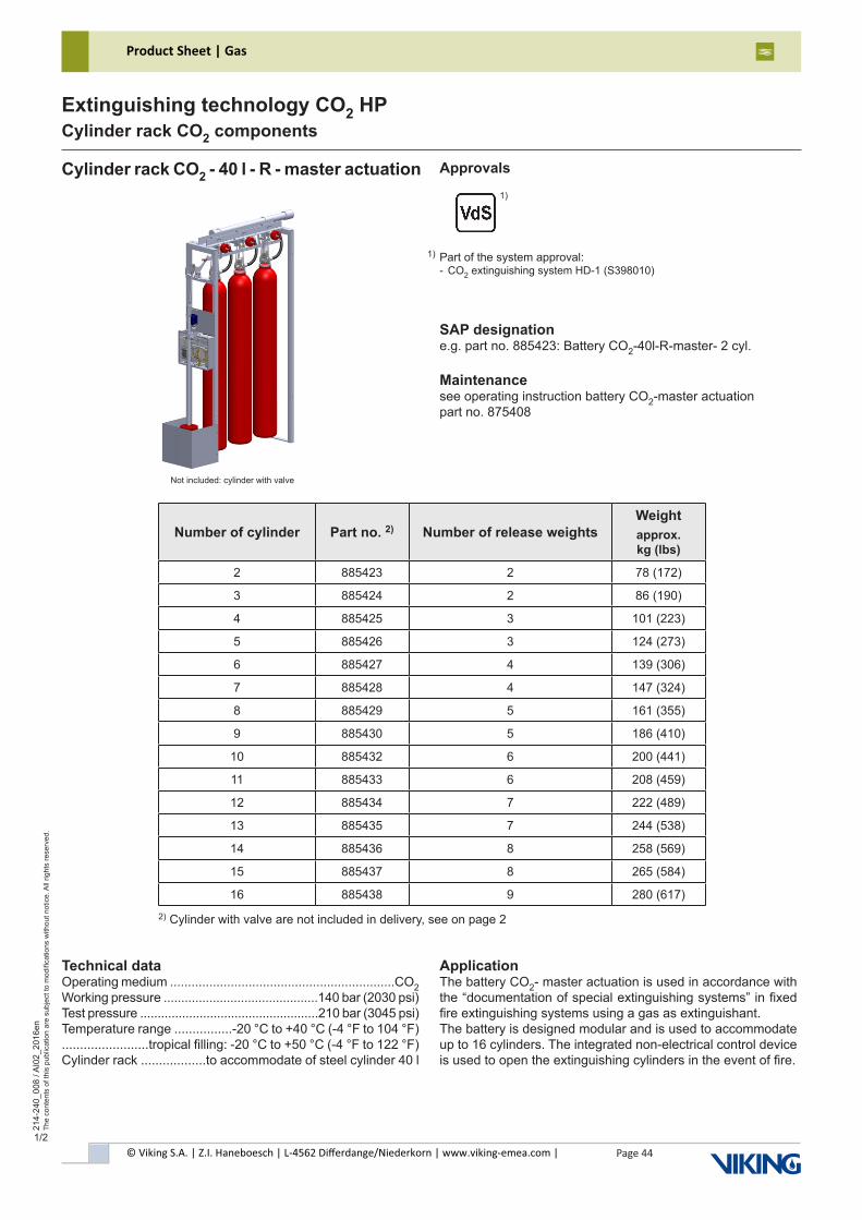
© Viking S.A. | Z.I. Haneboesch | L-4562 Differdange/Niederkorn | www.viking-emea.com |
Product Sheet | Gas
Page 44
214-
240_
008
/ AI0
2_20
16en
The
cont
ents
of t
his
publ
icat
ion
are
subj
ect t
o m
odifi
catio
ns w
ithou
t not
ice.
All
right
s re
serv
ed.
Extinguishing technology CO2 HPCylinder rack CO2 components
1/2
Number of cylinder Part no. 2) Number of release weightsWeightapprox. kg (lbs)
2 885423 2 78 (172)
3 885424 2 86 (190)
4 885425 3 101 (223)
5 885426 3 124 (273)
6 885427 4 139 (306)
7 885428 4 147 (324)
8 885429 5 161 (355)
9 885430 5 186 (410)
10 885432 6 200 (441)
11 885433 6 208 (459)
12 885434 7 222 (489)
13 885435 7 244 (538)
14 885436 8 258 (569)
15 885437 8 265 (584)
16 885438 9 280 (617)
Cylinder rack CO2 - 40 l - R - master actuation
SAP designatione.g. part no. 885423: Battery CO2-40l-R-master- 2 cyl.
Maintenancesee operating instruction battery CO2-master actuationpart no. 875408
Technical dataOperating medium ...............................................................CO2Working pressure ............................................140 bar (2030 psi)Test pressure ...................................................210 bar (3045 psi)Temperature range ................-20 °C to +40 °C (-4 °F to 104 °F)........................tropical filling: -20 °C to +50 °C (-4 °F to 122 °F) Cylinder rack ..................to accommodate of steel cylinder 40 l
ApplicationThe battery CO2- master actuation is used in accordance with the “documentation of special extinguishing systems” in fixed fire extinguishing systems using a gas as extinguishant.The battery is designed modular and is used to accommodate up to 16 cylinders. The integrated non-electrical control device is used to open the extinguishing cylinders in the event of fire.
Approvals
2) Cylinder with valve are not included in delivery, see on page 2
Not included: cylinder with valve
Part of the system approval:- CO2 extinguishing system HD-1 (S398010)
1)
1)
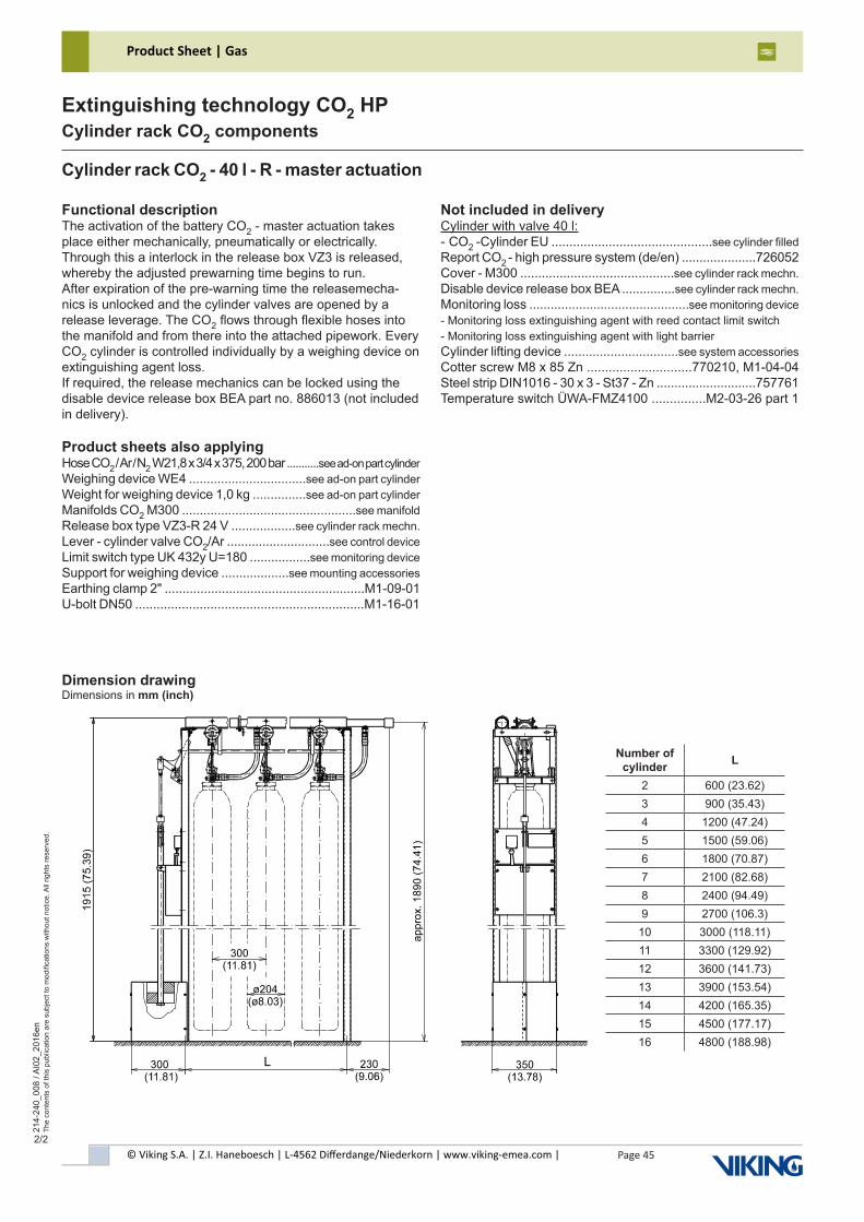
© Viking S.A. | Z.I. Haneboesch | L-4562 Differdange/Niederkorn | www.viking-emea.com |
Product Sheet | Gas
Page 45
214-
240_
008
/ AI0
2_20
16en
The
cont
ents
of t
his
publ
icat
ion
are
subj
ect t
o m
odifi
catio
ns w
ithou
t not
ice.
All
right
s re
serv
ed.
Extinguishing technology CO2 HPCylinder rack CO2 components
2/2
Cylinder rack CO2 - 40 l - R - master actuation
Dimension drawingDimensions in mm (inch)
Functional descriptionThe activation of the battery CO2 - master actuation takes place either mechanically, pneumatically or electrically. Through this a interlock in the release box VZ3 is released, whereby the adjusted prewarning time begins to run.After expiration of the pre-warning time the releasemecha-nics is unlocked and the cylinder valves are opened by a release leverage. The CO2 flows through flexible hoses into the manifold and from there into the attached pipework. Every CO2 cylinder is controlled individually by a weighing device on extinguishing agent loss.If required, the release mechanics can be locked using the disable device release box BEA part no. 886013 (not included in delivery).
Product sheets also applyingHose CO2 / Ar / N2 W21,8 x 3/4 x 375, 200 bar ...........see ad-on part cylinderWeighing device WE4 .................................see ad-on part cylinderWeight for weighing device 1,0 kg ...............see ad-on part cylinderManifolds CO2 M300 .................................................see manifoldRelease box type VZ3-R 24 V ..................see cylinder rack mechn.Lever - cylinder valve CO2/Ar .............................see control deviceLimit switch type UK 432y U=180 .................see monitoring deviceSupport for weighing device ...................see mounting accessoriesEarthing clamp 2" ........................................................M1-09-01U-bolt DN50 ................................................................M1-16-01
Not included in deliveryCylinder with valve 40 l:- CO2 -Cylinder EU .............................................see cylinder filledReport CO2 - high pressure system (de/en) .....................726052Cover - M300 ...........................................see cylinder rack mechn.Disable device release box BEA ...............see cylinder rack mechn.Monitoring loss .............................................see monitoring device- Monitoring loss extinguishing agent with reed contact limit switch- Monitoring loss extinguishing agent with light barrierCylinder lifting device ................................see system accessoriesCotter screw M8 x 85 Zn .............................770210, M1-04-04Steel strip DIN1016 - 30 x 3 - St37 - Zn ............................757761Temperature switch ÜWA-FMZ4100 ...............M2-03-26 part 1
Number of cylinder L
2 600 (23.62)3 900 (35.43)4 1200 (47.24)5 1500 (59.06)6 1800 (70.87)7 2100 (82.68)8 2400 (94.49)9 2700 (106.3)10 3000 (118.11)11 3300 (129.92)12 3600 (141.73)13 3900 (153.54)14 4200 (165.35)15 4500 (177.17)16 4800 (188.98)
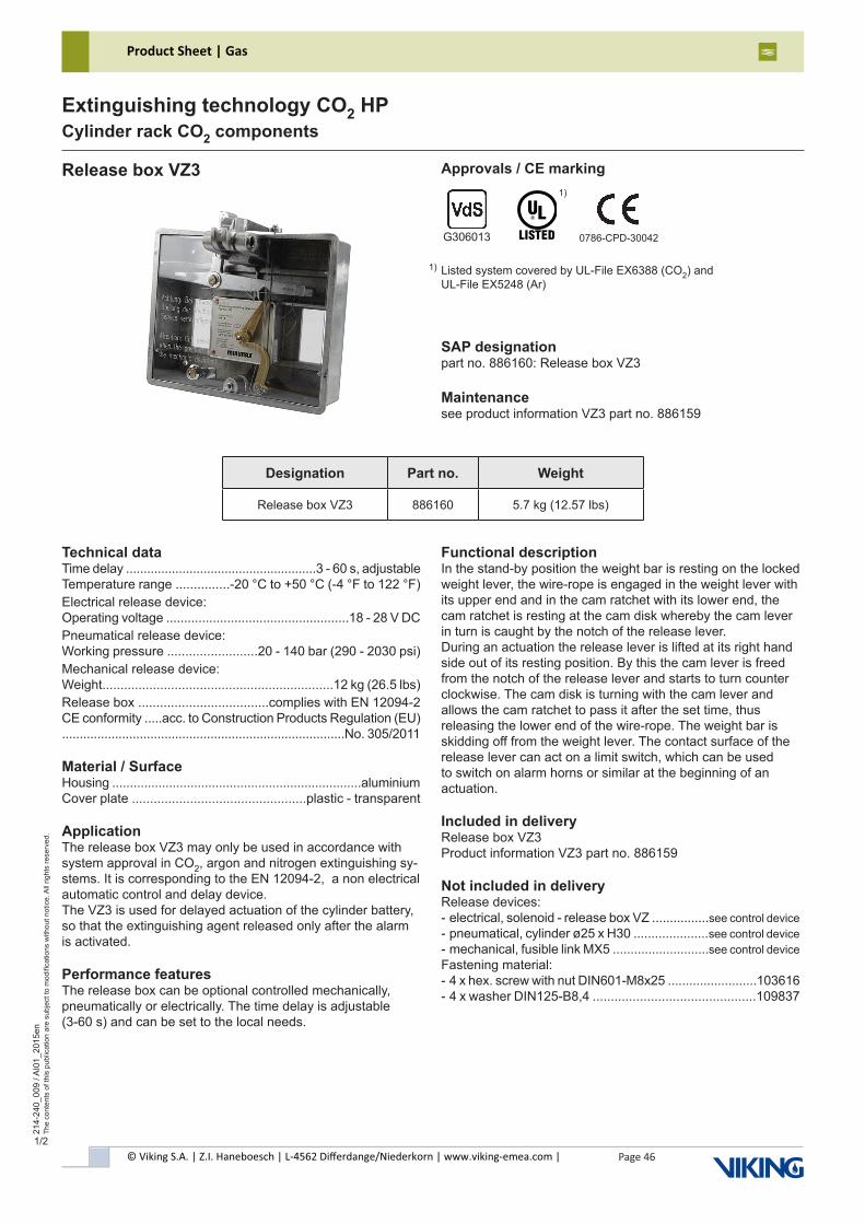
© Viking S.A. | Z.I. Haneboesch | L-4562 Differdange/Niederkorn | www.viking-emea.com |
Product Sheet | Gas
Page 46
214-
240_
009
/ AI0
1_20
15en
The
cont
ents
of t
his
publ
icat
ion
are
subj
ect t
o m
odifi
catio
ns w
ithou
t not
ice.
All
right
s re
serv
ed.
Extinguishing technology CO2 HPCylinder rack CO2 components
1/2
Release box VZ3 Approvals / CE marking
SAP designationpart no. 886160: Release box VZ3
Maintenancesee product information VZ3 part no. 886159
Listed system covered by UL-File EX6388 (CO2) and UL-File EX5248 (Ar)
1)
G306013 0786-CPD-30042
1)
Technical dataTime delay ......................................................3 - 60 s, adjustableTemperature range ...............-20 °C to +50 °C (-4 °F to 122 °F)Electrical release device:Operating voltage ...................................................18 - 28 V DCPneumatical release device:Working pressure .........................20 - 140 bar (290 - 2030 psi)Mechanical release device:Weight................................................................12 kg (26.5 lbs)Release box ....................................complies with EN 12094-2CE conformity .....acc. to Construction Products Regulation (EU)................................................................................No. 305/2011
Material / SurfaceHousing ......................................................................aluminiumCover plate ................................................plastic - transparent
ApplicationThe release box VZ3 may only be used in accordance with system approval in CO2, argon and nitrogen extinguishing sy-stems. It is corresponding to the EN 12094-2, a non electrical automatic control and delay device.The VZ3 is used for delayed actuation of the cylinder battery, so that the extinguishing agent released only after the alarm is activated.
Performance featuresThe release box can be optional controlled mechanically, pneumatically or electrically. The time delay is adjustable(3-60 s) and can be set to the local needs.
Functional descriptionIn the stand-by position the weight bar is resting on the locked weight lever, the wire-rope is engaged in the weight lever with its upper end and in the cam ratchet with its lower end, the cam ratchet is resting at the cam disk whereby the cam lever in turn is caught by the notch of the release lever.During an actuation the release lever is lifted at its right hand side out of its resting position. By this the cam lever is freed from the notch of the release lever and starts to turn counterclockwise. The cam disk is turning with the cam lever and allows the cam ratchet to pass it after the set time, thus releasing the lower end of the wire-rope. The weight bar is skidding off from the weight lever. The contact surface of the release lever can act on a limit switch, which can be used to switch on alarm horns or similar at the beginning of an actuation.
Included in deliveryRelease box VZ3Product information VZ3 part no. 886159
Not included in deliveryRelease devices:- electrical, solenoid - release box VZ ................see control device- pneumatical, cylinder ø25 x H30 .....................see control device- mechanical, fusible link MX5 ...........................see control deviceFastening material:- 4 x hex. screw with nut DIN601-M8x25 .........................103616- 4 x washer DIN125-B8,4 .............................................109837
Designation Part no. Weight
Release box VZ3 886160 5.7 kg (12.57 lbs)
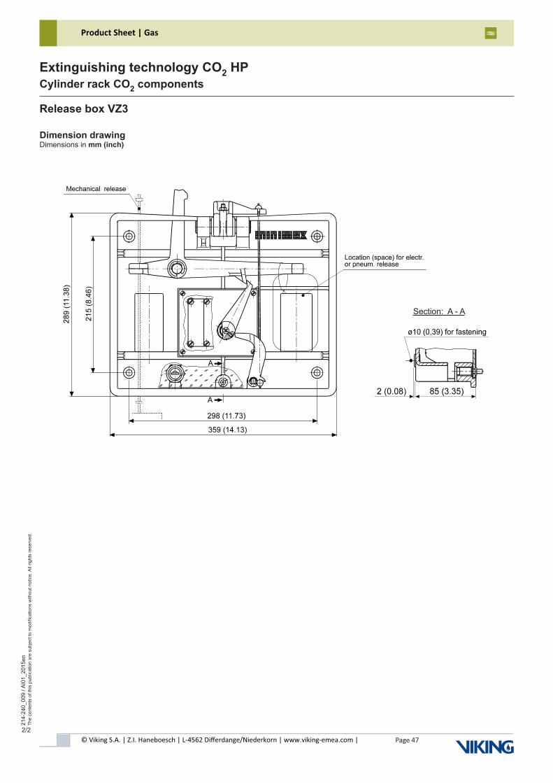
© Viking S.A. | Z.I. Haneboesch | L-4562 Differdange/Niederkorn | www.viking-emea.com |
Product Sheet | Gas
Page 47
214-
240_
009
/ AI0
1_20
15en
The
cont
ents
of t
his
publ
icat
ion
are
subj
ect t
o m
odifi
catio
ns w
ithou
t not
ice.
All
right
s re
serv
ed.
Extinguishing technology CO2 HPCylinder rack CO2 components
2/2
Section: A - A
Dimension drawingDimensions in mm (inch)
Release box VZ3
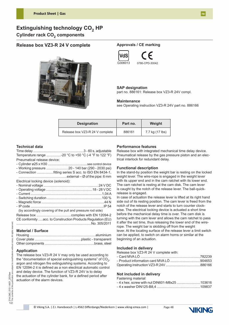
© Viking S.A. | Z.I. Haneboesch | L-4562 Differdange/Niederkorn | www.viking-emea.com |
Product Sheet | Gas
Page 48
214-
240_
010
/ AI0
1_20
15en
The
cont
ents
of t
his
publ
icat
ion
are
subj
ect t
o m
odifi
catio
ns w
ithou
t not
ice.
All
right
s re
serv
ed.
Extinguishing technology CO2 HPCylinder rack CO2 components
1/2
Release box VZ3-R 24 V complete Approvals / CE marking
SAP designationpart no. 886161: Release box VZ3-R 24V compl.
Maintenancesee Operating instruction VZ3-R 24V part no. 886166
G306013 0786-CPD-30042
Technical dataTime delay ......................................................3 - 60 s, adjustableTemperature range ...............-20 °C to +50 °C (-4 °F to 122 °F)Pneumatical release device:- Cylinder ø25 x H30 ..........................................see control device- Working pressure .......................20 - 140 bar (290 - 2030 psi)- Connection .................fitting series S acc. to ISO EN 8434-1, ...................................................external – Ø of the pipe: 6 mmElectrical locking device (solenoid):- Nominal voltage ..........................................................24 V DC- Operating voltage .................................................18 - 28 V DC- Current ...........................................................................1,04 A- Switching duration ..........................................................100 %- Magnetic force ..................................................................44 N- IP code .............................................................................IP 54 (by accordingly covering of the pull and pressure rod side)Release box ....................................complies with EN 12094-2CE conformity .....acc. to Construction Products Regulation (EU)................................................................................No. 305/2011
Material / SurfaceHousing ......................................................................aluminiumCover plate ................................................plastic - transparentOther components .....................................................brass, steel
ApplicationThe release box VZ3-R 24 V may only be used according to the “documentation of special extinguishing systems” of CO2, argon and nitrogen fire extinguishing systems. According to EN 12094-2 it is defined as a non electrical automatic control and delay device. The function of VZ3-R 24V is to delay the actuation of the cylinder bank, for a defined period after actuation of the alarm devices.
Performance featuresRelease box with integrated mechanical time delay device.Pneumatical release by the gas pressure piston and an elec-trical interlock for redundant delay.
Functional descriptionIn the stand-by position the weight bar is resting on the locked weight lever. The wire-rope is engaged in the weight lever with its upper end and in the cam ratchet with its lower end. The cam ratchet is resting at the cam disk. The cam lever is caught by the notch of the release lever. The ball-quick-release is engaged.In case of actuation the release lever is lifted at its right hand side out of its resting position. The cam lever is freed from the notch of the release lever and starts to turn counter clock-wise. The electrical locking device is actuated a short time before the mechanical delay time is over. The cam disk is turning with the cam lever and allows the cam ratchet to pass it after the set time, thus releasing the lower end of the wire-rope. The weight bar is skidding off from the weightlever. At the locating surface of the release lever a limit switch can be applied, to switch on alarm horns or similar at the beginning of an actuation.
Included in deliveryRelease box VZ3-R 24 V complete with:- Card MVA LÖ ..............................................................782239- Product information card MVA LÖ ...............................904653Operating instruction VZ3-R 24V .....................................886166
Not included in deliveryFastening material:- 4 x hex. screw with nut DIN601-M8x25 .........................103616- 4 x washer DIN125-B8,4 .............................................109837
Designation Part no. Weight
Release box VZ3-R 24 V complete 886161 7.7 kg (17 lbs)
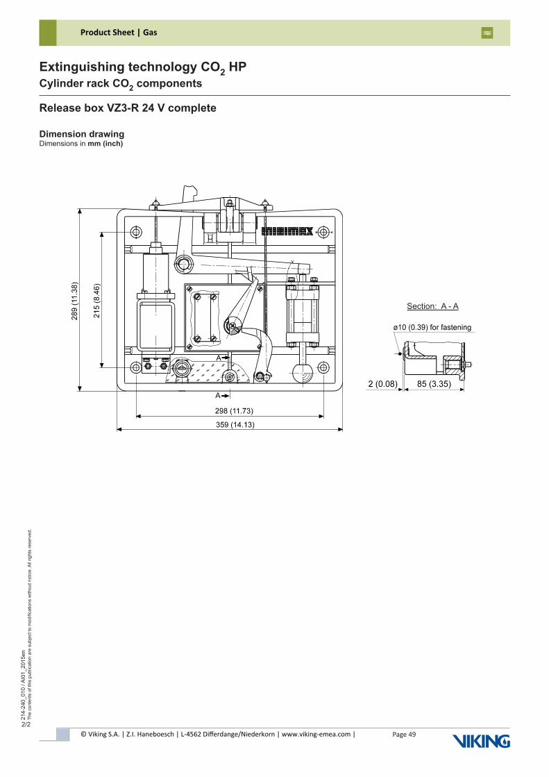
© Viking S.A. | Z.I. Haneboesch | L-4562 Differdange/Niederkorn | www.viking-emea.com |
Product Sheet | Gas
Page 49
214-
240_
010
/ AI0
1_20
15en
The
cont
ents
of t
his
publ
icat
ion
are
subj
ect t
o m
odifi
catio
ns w
ithou
t not
ice.
All
right
s re
serv
ed.
Extinguishing technology CO2 HPCylinder rack CO2 components
2/2
Release box VZ3-R 24 V complete
Dimension drawingDimensions in mm (inch)
Section:A-A
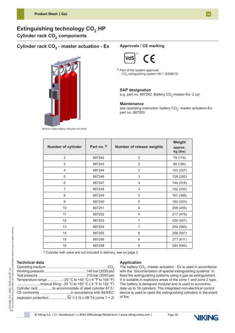
© Viking S.A. | Z.I. Haneboesch | L-4562 Differdange/Niederkorn | www.viking-emea.com |
Product Sheet | Gas
Page 50
214-
240_
011
/ AI0
3 / 2
018-
July
-20
/ en
The
cont
ents
of t
his
publ
icat
ion
are
subj
ect t
o m
odifi
catio
ns w
ithou
t not
ice.
All
right
s re
serv
ed.
Extinguishing technology CO2 HPCylinder rack CO2 components
1/2
Number of cylinder Part no. 2) Number of release weightsWeightapprox. kg (lbs)
2 887242 2 79 (174)
3 887243 2 88 (194)
4 887244 3 103 (227)
5 887246 3 128 (282)
6 887247 4 144 (318)
7 887248 4 152 (335)
8 887249 5 167 (368)
9 887250 5 192 (423)
10 887251 6 208 (459)
11 887252 6 217 (478)
12 887253 7 230 (507)
13 887254 7 254 (560)
14 887255 8 268 (591)
15 887256 8 277 (611)
16 887258 9 293 (646)
Cylinder rack CO2 - master actuation - Ex
SAP designatione.g. part no. 887242: Battery CO2-master-Ex- 2 cyl.
Maintenancesee operating instruction battery CO2- master actuation-Expart no. 887200
Technical dataOperating medium ...............................................................CO2Working pressure ............................................140 bar (2030 psi)Test pressure ...................................................210 bar (3045 psi)Temperature range ................-20 °C to +40 °C (-4 °F to 104 °F)........................tropical filling: -20 °C to +50 °C (-4 °F to 122 °F) Cylinder rack ..............to accommodate of steel cylinder 67,5 l CE conformity ...............................in accordance with 94/9/ECexplosion protection ..................x II 2 G c IIB T4 (zone 1 + 2)
ApplicationThe battery CO2- master actuation - Ex is used in accordance with the “documentation of special extinguishing systems” in fixed fire extinguishing systems using a gas as extinguishant. It is suitable in explosive areas of the zone 1 and zone 2 type. The battery is designed modular and is used to accommo-date up to 16 cylinders. The integrated non-electrical control device is used to open the extinguishing cylinders in the event of fire.
Approvals / CE marking
2) Cylinder with valve are not included in delivery, see on page 2
Nicht im Lieferumfang: Flaschen mit Ventil
Part of the system approval:- CO2 extinguishing system HD-1 (S398010)
1)
1)
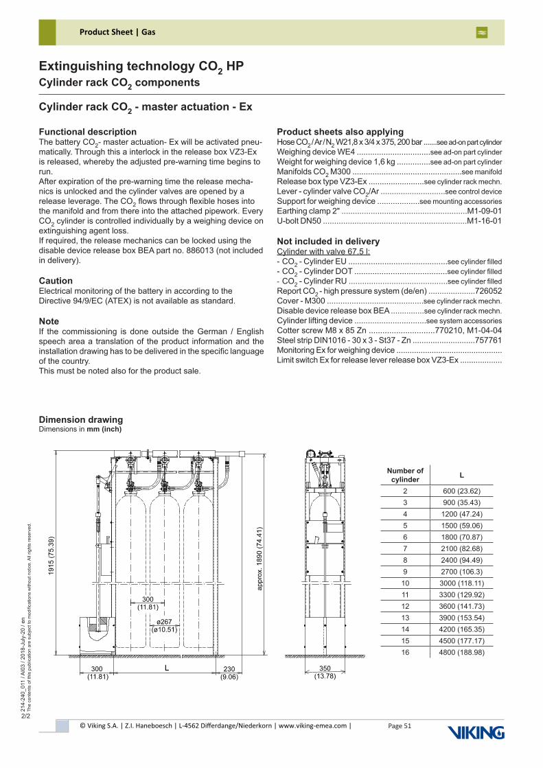
© Viking S.A. | Z.I. Haneboesch | L-4562 Differdange/Niederkorn | www.viking-emea.com |
Product Sheet | Gas
Page 51
214-
240_
011
/ AI0
3 / 2
018-
July
-20
/ en
The
cont
ents
of t
his
publ
icat
ion
are
subj
ect t
o m
odifi
catio
ns w
ithou
t not
ice.
All
right
s re
serv
ed.
Extinguishing technology CO2 HPCylinder rack CO2 components
2/2
Dimension drawingDimensions in mm (inch)
Functional descriptionThe battery CO2- master actuation- Ex will be activated pneu-matically. Through this a interlock in the release box VZ3-Ex is released, whereby the adjusted pre-warning time begins to run.After expiration of the pre-warning time the release mecha-nics is unlocked and the cylinder valves are opened by a release leverage. The CO2 flows through flexible hoses into the manifold and from there into the attached pipework. Every CO2 cylinder is controlled individually by a weighing device on extinguishing agent loss.If required, the release mechanics can be locked using the disable device release box BEA part no. 886013 (not included in delivery).
CautionElectrical monitoring of the battery in according to the Directive 94/9/EC (ATEX) is not available as standard.
NoteIf the commissioning is done outside the German / English speech area a translation of the product information and the installation drawing has to be delivered in the specific language of the country.This must be noted also for the product sale.
Product sheets also applyingHose CO2 / Ar / N2 W21,8 x 3/4 x 375, 200 bar .......see ad-on part cylinderWeighing device WE4 .................................see ad-on part cylinderWeight for weighing device 1,6 kg ...............see ad-on part cylinderManifolds CO2 M300 .................................................see manifoldRelease box type VZ3-Ex .........................see cylinder rack mechn.Lever - cylinder valve CO2/Ar .............................see control deviceSupport for weighing device ...................see mounting accessoriesEarthing clamp 2" ........................................................M1-09-01U-bolt DN50 ................................................................M1-16-01
Not included in deliveryCylinder with valve 67.5 l:- CO2 - Cylinder EU ............................................see cylinder filled- CO2 - Cylinder DOT .........................................see cylinder filled- CO2 - Cylinder RU ............................................see cylinder filledReport CO2 - high pressure system (de/en) .....................726052Cover - M300 ...........................................see cylinder rack mechn.Disable device release box BEA ...............see cylinder rack mechn.Cylinder lifting device ................................see system accessoriesCotter screw M8 x 85 Zn .............................770210, M1-04-04Steel strip DIN1016 - 30 x 3 - St37 - Zn ............................757761Monitoring Ex for weighing device ................................................Limit switch Ex for release lever release box VZ3-Ex ...................
Cylinder rack CO2 - master actuation - Ex
Number of cylinder L
2 600 (23.62)3 900 (35.43)4 1200 (47.24)5 1500 (59.06)6 1800 (70.87)7 2100 (82.68)8 2400 (94.49)9 2700 (106.3)10 3000 (118.11)11 3300 (129.92)12 3600 (141.73)13 3900 (153.54)14 4200 (165.35)15 4500 (177.17)16 4800 (188.98)

© Viking S.A. | Z.I. Haneboesch | L-4562 Differdange/Niederkorn | www.viking-emea.com |
Product Sheet | Gas
Page 52
214-
240_
012
/ AI0
3 / 2
018-
July
-20
/ en
The
cont
ents
of t
his
publ
icat
ion
are
subj
ect t
o m
odifi
catio
ns w
ithou
t not
ice.
All
right
s re
serv
ed.
Extinguishing technology CO2 HPCylinder rack CO2 components
1/2
Number of cylinder Part no. 2)Weightapprox. kg (lbs)
2 887259 55 (121)
3 887260 64 (141)
4 887261 72 (159)
5 887262 97 (214)
6 887263 106 (234)
7 887264 114 (251)
8 887265 122 (269)
9 887266 147 (324)
10 887267 155 (342)
11 887268 165 (364)
12 887271 172 (379)
13 887272 195 (430)
14 887273 202 (445)
15 887274 211 (465)
16 887275 216 (476)
Cylinder rack CO2 - slave actuation - Ex
SAP designatione.g. part no. 887259: Battery CO2-slave-EX- 2 cyl.
Maintenancesee product information cylinder rack CO2-additional-Expart no. 887278
Technical dataOperating medium ...............................................................CO2Working pressure ............................................140 bar (2030 psi)Test pressure ...................................................210 bar (3045 psi)Temperature range ................-20 °C to +40 °C (-4 °F to 104 °F)........................tropical filling: -20 °C to +50 °C (-4 °F to 122 °F) Cylinder rack ...............to accommodate of steel cylinder 67,5 CE conformity ...............................in accordance with 94/9/ECexplosion protection ..................x II 2 G c IIB T4 (zone 1 + 2)
ApplicationThe battery CO2- slave actuation - Ex is used in accordance with the “documentation of special extinguishing systems” in fixed fire extinguishing systems using a gas as extinguishant.It is suitable in explosive areas of the zone 1 and zone 2 type.The battery is designed modular and is used to accommodate up to 16 cylinders. The integrated non-electrical control device is used to open the extinguishing cylinders in the event of fire.
Approvals / CE marking
2) Cylinder with valve are not included in delivery, see on page 2
Not included: cylinder with valve
Part of the system approval:- CO2 extinguishing system HD-1 (S398010)
1)
1)
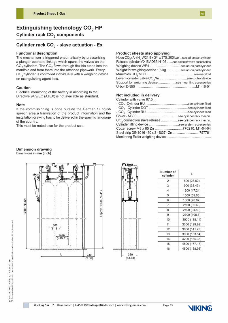
© Viking S.A. | Z.I. Haneboesch | L-4562 Differdange/Niederkorn | www.viking-emea.com |
Product Sheet | Gas
Page 53
214-
240_
012
/ AI0
3 / 2
018-
July
-20
/ en
The
cont
ents
of t
his
publ
icat
ion
are
subj
ect t
o m
odifi
catio
ns w
ithou
t not
ice.
All
right
s re
serv
ed.
Extinguishing technology CO2 HPCylinder rack CO2 components
2/2
Cylinder rack CO2 - slave actuation - Ex
Dimension drawingDimensions in mm (inch)
Functional descriptionThe mechanism is triggered pneumatically by pressurising a plunger-operated linkage which opens the valves on the CO2 cylinders. The CO2 flows through flexible tubes into the manifold and from there into the attached pipework. Every CO2 cylinder is controlled individually with a weighing device on extinguishing agent loss.
CautionElectrical monitoring of the battery in according to the Directive 94/9/EC (ATEX) is not available as standard.
NoteIf the commissioning is done outside the German / English speech area a translation of the product information and the installation drawing has to be delivered in the specific language of the country.This must be noted also for the product sale.
Product sheets also applyingHose CO2 / Ar / N2 W21,8 x 3/4 x 375, 200 bar ...see ad-on part cylinderRelease cylinder MX-BV D55-H106 .......see selector valve accessoriesWeighing device WE4 .................................see ad-on part cylinderWeight for weighing device 1,6 kg ...............see ad-on part cylinderManifolds CO2 M300 .................................................see manifoldLever - cylinder valve CO2/Ar .............................see control deviceSupport for weighing device ...................see mounting accessoriesU-bolt DN50 ................................................................M1-16-01
Not included in deliveryCylinder with valve 67.5 l:- CO2 -Cylinder EU .............................................see cylinder filled- CO2 - Cylinder DOT .........................................see cylinder filled- CO2 - Cylinder RU ............................................see cylinder filledCover - M300 ............................................see cylinder rack mechn.CO2 connection slave release ..................see cylinder rack mechn.Cylinder lifting device ................................see system accessoriesCotter screw M8 x 85 Zn .............................770210, M1-04-04Steel strip DIN1016 - 30 x 3 - St37 - Zn .............................757761Monitoring Ex for weighing device ................................................
Number of cylinder L
2 600 (23.62)3 900 (35.43)4 1200 (47.24)5 1500 (59.06)6 1800 (70.87)7 2100 (82.68)8 2400 (94.49)9 2700 (106.3)10 3000 (118.11)11 3300 (129.92)12 3600 (141.73)13 3900 (153.54)14 4200 (165.35)15 4500 (177.17)16 4800 (188.98)
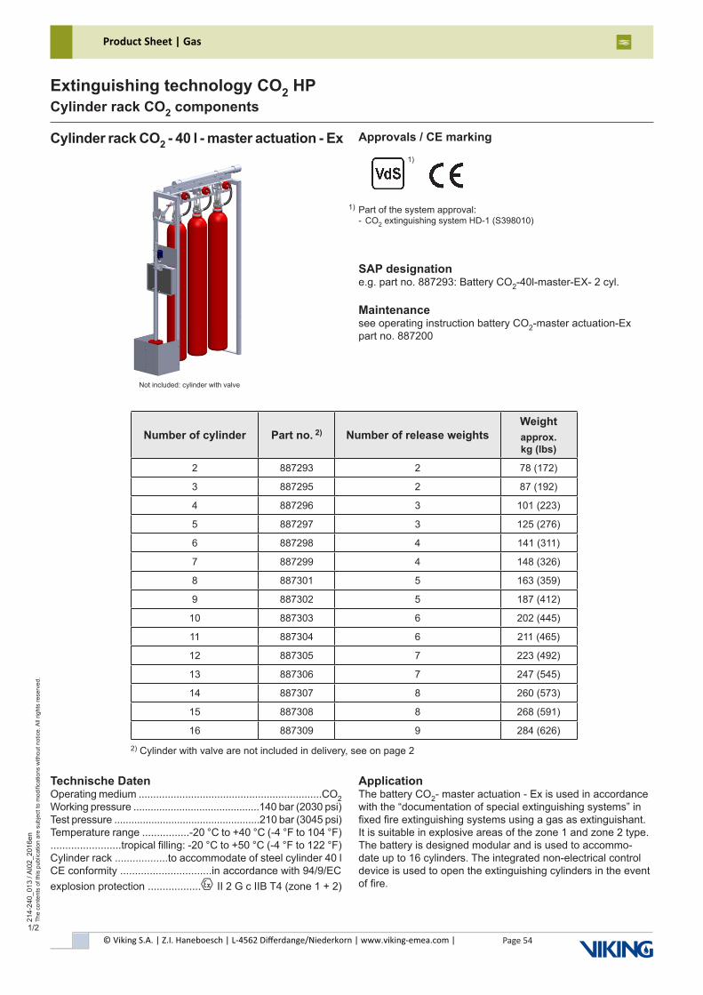
© Viking S.A. | Z.I. Haneboesch | L-4562 Differdange/Niederkorn | www.viking-emea.com |
Product Sheet | Gas
Page 54
214-
240_
013
/ AI0
2_20
16en
The
cont
ents
of t
his
publ
icat
ion
are
subj
ect t
o m
odifi
catio
ns w
ithou
t not
ice.
All
right
s re
serv
ed.
Extinguishing technology CO2 HPCylinder rack CO2 components
1/2
Number of cylinder Part no. 2) Number of release weightsWeightapprox. kg (lbs)
2 887293 2 78 (172)
3 887295 2 87 (192)
4 887296 3 101 (223)
5 887297 3 125 (276)
6 887298 4 141 (311)
7 887299 4 148 (326)
8 887301 5 163 (359)
9 887302 5 187 (412)
10 887303 6 202 (445)
11 887304 6 211 (465)
12 887305 7 223 (492)
13 887306 7 247 (545)
14 887307 8 260 (573)
15 887308 8 268 (591)
16 887309 9 284 (626)
Cylinder rack CO2 - 40 l - master actuation - Ex
SAP designatione.g. part no. 887293: Battery CO2-40l-master-EX- 2 cyl.
Maintenancesee operating instruction battery CO2-master actuation-Expart no. 887200
Technische DatenOperating medium ...............................................................CO2Working pressure ............................................140 bar (2030 psi)Test pressure ...................................................210 bar (3045 psi)Temperature range ................-20 °C to +40 °C (-4 °F to 104 °F)........................tropical filling: -20 °C to +50 °C (-4 °F to 122 °F) Cylinder rack ..................to accommodate of steel cylinder 40 l CE conformity ...............................in accordance with 94/9/ECexplosion protection ..................x II 2 G c IIB T4 (zone 1 + 2)
ApplicationThe battery CO2- master actuation - Ex is used in accordance with the “documentation of special extinguishing systems” in fixed fire extinguishing systems using a gas as extinguishant. It is suitable in explosive areas of the zone 1 and zone 2 type. The battery is designed modular and is used to accommo-date up to 16 cylinders. The integrated non-electrical control device is used to open the extinguishing cylinders in the event of fire.
Approvals / CE marking
2) Cylinder with valve are not included in delivery, see on page 2
Not included: cylinder with valve
Part of the system approval:- CO2 extinguishing system HD-1 (S398010)
1)
1)
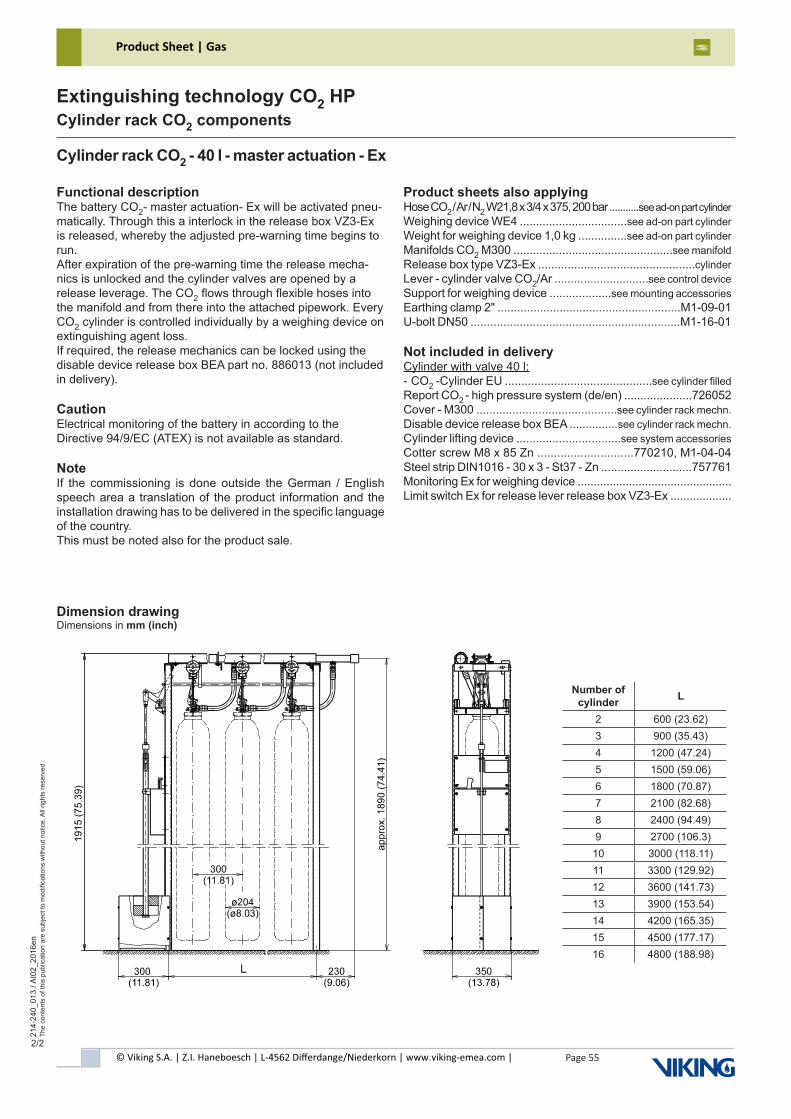
© Viking S.A. | Z.I. Haneboesch | L-4562 Differdange/Niederkorn | www.viking-emea.com |
Product Sheet | Gas
Page 55
214-
240_
013
/ AI0
2_20
16en
The
cont
ents
of t
his
publ
icat
ion
are
subj
ect t
o m
odifi
catio
ns w
ithou
t not
ice.
All
right
s re
serv
ed.
Extinguishing technology CO2 HPCylinder rack CO2 components
2/2
Cylinder rack CO2 - 40 l - master actuation - Ex
Dimension drawingDimensions in mm (inch)
Functional descriptionThe battery CO2- master actuation- Ex will be activated pneu-matically. Through this a interlock in the release box VZ3-Ex is released, whereby the adjusted pre-warning time begins to run.After expiration of the pre-warning time the release mecha-nics is unlocked and the cylinder valves are opened by a release leverage. The CO2 flows through flexible hoses into the manifold and from there into the attached pipework. Every CO2 cylinder is controlled individually by a weighing device on extinguishing agent loss.If required, the release mechanics can be locked using the disable device release box BEA part no. 886013 (not included in delivery).
CautionElectrical monitoring of the battery in according to the Directive 94/9/EC (ATEX) is not available as standard.
NoteIf the commissioning is done outside the German / English speech area a translation of the product information and the installation drawing has to be delivered in the specific language of the country.This must be noted also for the product sale.
Product sheets also applyingHose CO2 / Ar / N2 W21,8 x 3/4 x 375, 200 bar ...........see ad-on part cylinderWeighing device WE4 .................................see ad-on part cylinderWeight for weighing device 1,0 kg ...............see ad-on part cylinderManifolds CO2 M300 .................................................see manifoldRelease box type VZ3-Ex ................................................cylinderLever - cylinder valve CO2/Ar .............................see control deviceSupport for weighing device ...................see mounting accessoriesEarthing clamp 2" ........................................................M1-09-01U-bolt DN50 ................................................................M1-16-01
Not included in deliveryCylinder with valve 40 l:- CO2 -Cylinder EU .............................................see cylinder filledReport CO2 - high pressure system (de/en) .....................726052Cover - M300 ...........................................see cylinder rack mechn.Disable device release box BEA ...............see cylinder rack mechn.Cylinder lifting device ................................see system accessoriesCotter screw M8 x 85 Zn .............................770210, M1-04-04Steel strip DIN1016 - 30 x 3 - St37 - Zn ............................757761Monitoring Ex for weighing device ................................................Limit switch Ex for release lever release box VZ3-Ex ...................
Number of cylinder L
2 600 (23.62)3 900 (35.43)4 1200 (47.24)5 1500 (59.06)6 1800 (70.87)7 2100 (82.68)8 2400 (94.49)9 2700 (106.3)10 3000 (118.11)11 3300 (129.92)12 3600 (141.73)13 3900 (153.54)14 4200 (165.35)15 4500 (177.17)16 4800 (188.98)
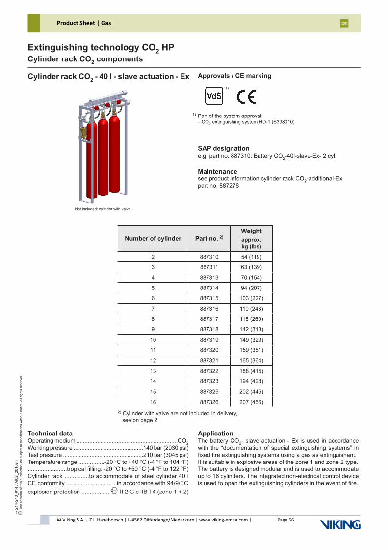
© Viking S.A. | Z.I. Haneboesch | L-4562 Differdange/Niederkorn | www.viking-emea.com |
Product Sheet | Gas
Page 56
214-
240_
014
/ AI0
2_20
16en
The
cont
ents
of t
his
publ
icat
ion
are
subj
ect t
o m
odifi
catio
ns w
ithou
t not
ice.
All
right
s re
serv
ed.
Extinguishing technology CO2 HPCylinder rack CO2 components
1/2
Number of cylinder Part no. 2)Weightapprox. kg (lbs)
2 887310 54 (119)
3 887311 63 (139)
4 887313 70 (154)
5 887314 94 (207)
6 887315 103 (227)
7 887316 110 (243)
8 887317 118 (260)
9 887318 142 (313)
10 887319 149 (329)
11 887320 159 (351)
12 887321 165 (364)
13 887322 188 (415)
14 887323 194 (428)
15 887325 202 (445)
16 887326 207 (456)
Cylinder rack CO2 - 40 l - slave actuation - Ex
SAP designatione.g. part no. 887310: Battery CO2-40l-slave-Ex- 2 cyl.
Maintenancesee product information cylinder rack CO2-additional-Expart no. 887278
Technical dataOperating medium ...............................................................CO2Working pressure ............................................140 bar (2030 psi)Test pressure ...................................................210 bar (3045 psi)Temperature range ................-20 °C to +40 °C (-4 °F to 104 °F)........................tropical filling: -20 °C to +50 °C (-4 °F to 122 °F) Cylinder rack ...............to accommodate of steel cylinder 40 l CE conformity ...............................in accordance with 94/9/ECexplosion protection ..................x II 2 G c IIB T4 (zone 1 + 2)
ApplicationThe battery CO2- slave actuation - Ex is used in accordance with the “documentation of special extinguishing systems” in fixed fire extinguishing systems using a gas as extinguishant.It is suitable in explosive areas of the zone 1 and zone 2 type.The battery is designed modular and is used to accommodate up to 16 cylinders. The integrated non-electrical control device is used to open the extinguishing cylinders in the event of fire.
Approvals / CE marking
2) Cylinder with valve are not included in delivery, see on page 2
Not included: cylinder with valve
Part of the system approval:- CO2 extinguishing system HD-1 (S398010)
1)
1)
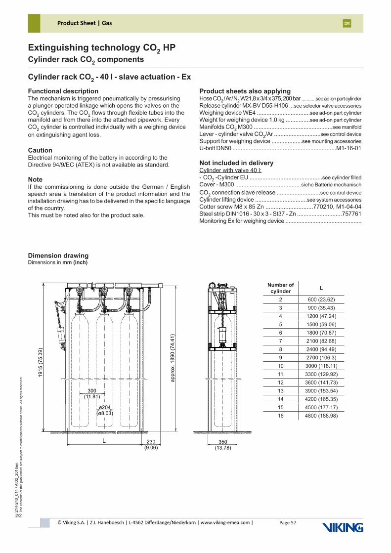
© Viking S.A. | Z.I. Haneboesch | L-4562 Differdange/Niederkorn | www.viking-emea.com |
Product Sheet | Gas
Page 57
214-
240_
014
/ AI0
2_20
16en
The
cont
ents
of t
his
publ
icat
ion
are
subj
ect t
o m
odifi
catio
ns w
ithou
t not
ice.
All
right
s re
serv
ed.
Extinguishing technology CO2 HPCylinder rack CO2 components
2/2
Cylinder rack CO2 - 40 l - slave actuation - Ex
Dimension drawingDimensions in mm (inch)
Functional descriptionThe mechanism is triggered pneumatically by pressurising a plunger-operated linkage which opens the valves on the CO2 cylinders. The CO2 flows through flexible tubes into the manifold and from there into the attached pipework. Every CO2 cylinder is controlled individually with a weighing device on extinguishing agent loss.
CautionElectrical monitoring of the battery in according to the Directive 94/9/EC (ATEX) is not available as standard.
NoteIf the commissioning is done outside the German / English speech area a translation of the product information and the installation drawing has to be delivered in the specific language of the country.This must be noted also for the product sale.
Product sheets also applyingHose CO2 / Ar / N2 W21,8 x 3/4 x 375, 200 bar ...........see ad-on part cylinderRelease cylinder MX-BV D55-H106 ...see selector valve accessoriesWeighing device WE4 .................................see ad-on part cylinderWeight for weighing device 1,0 kg ...............see ad-on part cylinderManifolds CO2 M300 .................................................see manifoldLever - cylinder valve CO2/Ar .............................see control deviceSupport for weighing device ...................see mounting accessoriesU-bolt DN50 ................................................................M1-16-01
Not included in deliveryCylinder with valve 40 l:- CO2 -Cylinder EU .............................................see cylinder filledCover - M300 .........................................siehe Batterie mechanischCO2 connection slave release ...........................see control deviceCylinder lifting device ................................see system accessoriesCotter screw M8 x 85 Zn .............................770210, M1-04-04Steel strip DIN1016 - 30 x 3 - St37 - Zn ............................757761Monitoring Ex for weighing device ................................................
Number of cylinder L
2 600 (23.62)3 900 (35.43)4 1200 (47.24)5 1500 (59.06)6 1800 (70.87)7 2100 (82.68)8 2400 (94.49)9 2700 (106.3)10 3000 (118.11)11 3300 (129.92)12 3600 (141.73)13 3900 (153.54)14 4200 (165.35)15 4500 (177.17)16 4800 (188.98)
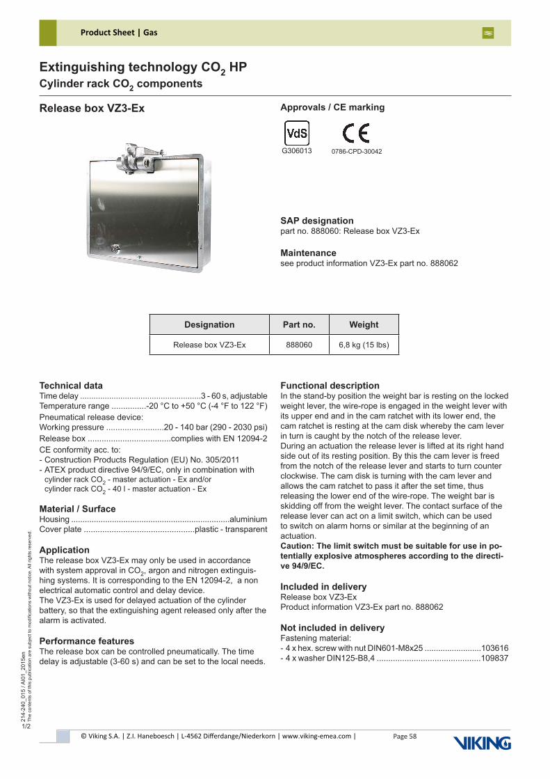
© Viking S.A. | Z.I. Haneboesch | L-4562 Differdange/Niederkorn | www.viking-emea.com |
Product Sheet | Gas
Page 58
214-
240_
015
/ AI0
1_20
15en
The
cont
ents
of t
his
publ
icat
ion
are
subj
ect t
o m
odifi
catio
ns w
ithou
t not
ice.
All
right
s re
serv
ed.
Extinguishing technology CO2 HPCylinder rack CO2 components
1/2
Release box VZ3-Ex Approvals / CE marking
SAP designationpart no. 888060: Release box VZ3-Ex
Maintenancesee product information VZ3-Ex part no. 888062
G306013 0786-CPD-30042
Technical dataTime delay ......................................................3 - 60 s, adjustableTemperature range ...............-20 °C to +50 °C (-4 °F to 122 °F)Pneumatical release device:Working pressure .........................20 - 140 bar (290 - 2030 psi)Release box ....................................complies with EN 12094-2CE conformity acc. to:- Construction Products Regulation (EU) No. 305/2011- ATEX product directive 94/9/EC, only in combination with cylinder rack CO2 - master actuation - Ex and/or cylinder rack CO2 - 40 l - master actuation - Ex
Material / SurfaceHousing ......................................................................aluminiumCover plate ................................................plastic - transparent
ApplicationThe release box VZ3-Ex may only be used in accordance with system approval in CO2, argon and nitrogen extinguis-hing systems. It is corresponding to the EN 12094-2, a non electrical automatic control and delay device.The VZ3-Ex is used for delayed actuation of the cylinder battery, so that the extinguishing agent released only after the alarm is activated.
Performance featuresThe release box can be controlled pneumatically. The time delay is adjustable (3-60 s) and can be set to the local needs.
Functional descriptionIn the stand-by position the weight bar is resting on the locked weight lever, the wire-rope is engaged in the weight lever with its upper end and in the cam ratchet with its lower end, the cam ratchet is resting at the cam disk whereby the cam lever in turn is caught by the notch of the release lever.During an actuation the release lever is lifted at its right hand side out of its resting position. By this the cam lever is freed from the notch of the release lever and starts to turn counterclockwise. The cam disk is turning with the cam lever and allows the cam ratchet to pass it after the set time, thus releasing the lower end of the wire-rope. The weight bar is skidding off from the weight lever. The contact surface of the release lever can act on a limit switch, which can be used to switch on alarm horns or similar at the beginning of an actuation.Caution: The limit switch must be suitable for use in po-tentially explosive atmospheres according to the directi-ve 94/9/EC.
Included in deliveryRelease box VZ3-ExProduct information VZ3-Ex part no. 888062
Not included in deliveryFastening material:- 4 x hex. screw with nut DIN601-M8x25 .........................103616- 4 x washer DIN125-B8,4 .............................................109837
Designation Part no. Weight
Release box VZ3-Ex 888060 6,8 kg (15 lbs)
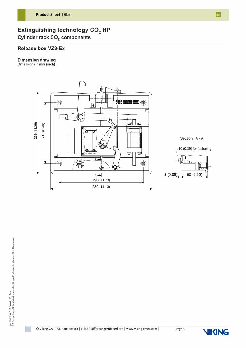
© Viking S.A. | Z.I. Haneboesch | L-4562 Differdange/Niederkorn | www.viking-emea.com |
Product Sheet | Gas
Page 59
214-
240_
015
/ AI0
1_20
15en
The
cont
ents
of t
his
publ
icat
ion
are
subj
ect t
o m
odifi
catio
ns w
ithou
t not
ice.
All
right
s re
serv
ed.
Extinguishing technology CO2 HPCylinder rack CO2 components
2/2
Release box VZ3-Ex
Section: A - A
Dimension drawingDimensions in mm (inch)
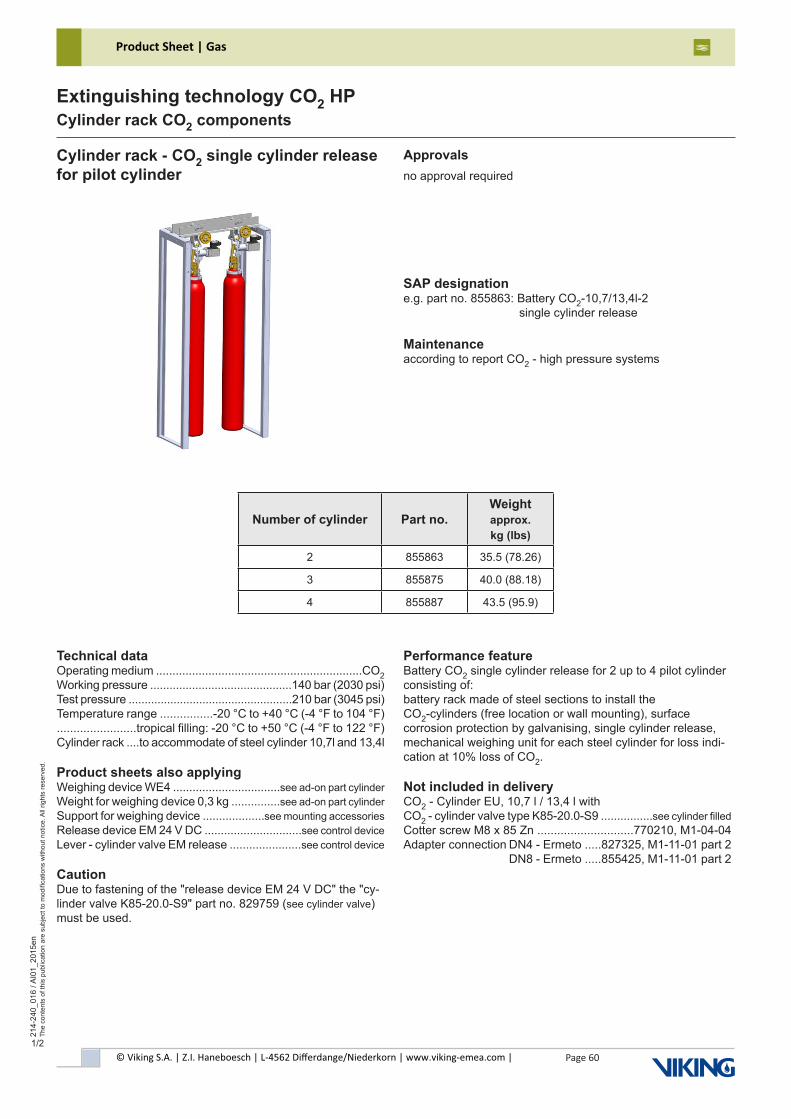
© Viking S.A. | Z.I. Haneboesch | L-4562 Differdange/Niederkorn | www.viking-emea.com |
Product Sheet | Gas
Page 60
214-
240_
016
/ AI0
1_20
15en
The
cont
ents
of t
his
publ
icat
ion
are
subj
ect t
o m
odifi
catio
ns w
ithou
t not
ice.
All
right
s re
serv
ed.
Extinguishing technology CO2 HPCylinder rack CO2 components
1/2
Cylinder rack - CO2 single cylinder releasefor pilot cylinder
SAP designatione.g. part no. 855863: Battery CO2-10,7/13,4l-2 single cylinder release
Maintenanceaccording to report CO2 - high pressure systems
Technical dataOperating medium ...............................................................CO2Working pressure ............................................140 bar (2030 psi)Test pressure ...................................................210 bar (3045 psi)Temperature range ................-20 °C to +40 °C (-4 °F to 104 °F)........................tropical filling: -20 °C to +50 °C (-4 °F to 122 °F) Cylinder rack ....to accommodate of steel cylinder 10,7l and 13,4l
Product sheets also applyingWeighing device WE4 .................................see ad-on part cylinderWeight for weighing device 0,3 kg ...............see ad-on part cylinderSupport for weighing device ...................see mounting accessoriesRelease device EM 24 V DC ..............................see control deviceLever - cylinder valve EM release ......................see control device
CautionDue to fastening of the "release device EM 24 V DC" the "cy-linder valve K85-20.0-S9" part no. 829759 (see cylinder valve) must be used.
Performance featureBattery CO2 single cylinder release for 2 up to 4 pilot cylinder consisting of:battery rack made of steel sections to install theCO2-cylinders (free location or wall mounting), surface corrosion protection by galvanising, single cylinder release, mechanical weighing unit for each steel cylinder for loss indi-cation at 10% loss of CO2.
Not included in deliveryCO2 - Cylinder EU, 10,7 l / 13,4 l withCO2 - cylinder valve type K85-20.0-S9 ................see cylinder filledCotter screw M8 x 85 Zn .............................770210, M1-04-04Adapter connection DN4 - Ermeto .....827325, M1-11-01 part 2 DN8 - Ermeto .....855425, M1-11-01 part 2
Approvalsno approval required
Number of cylinder Part no.Weightapprox.kg (lbs)
2 855863 35.5 (78.26)
3 855875 40.0 (88.18)
4 855887 43.5 (95.9)
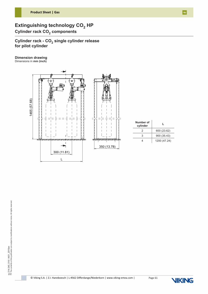
© Viking S.A. | Z.I. Haneboesch | L-4562 Differdange/Niederkorn | www.viking-emea.com |
Product Sheet | Gas
Page 61
214-
240_
016
/ AI0
1_20
15en
The
cont
ents
of t
his
publ
icat
ion
are
subj
ect t
o m
odifi
catio
ns w
ithou
t not
ice.
All
right
s re
serv
ed.
Extinguishing technology CO2 HPCylinder rack CO2 components
2/2
Dimension drawingDimensions in mm (inch)
Cylinder rack - CO2 single cylinder releasefor pilot cylinder
Number of cylinder L
2 600 (23.62)
3 900 (35.43)
4 1200 (47.24)
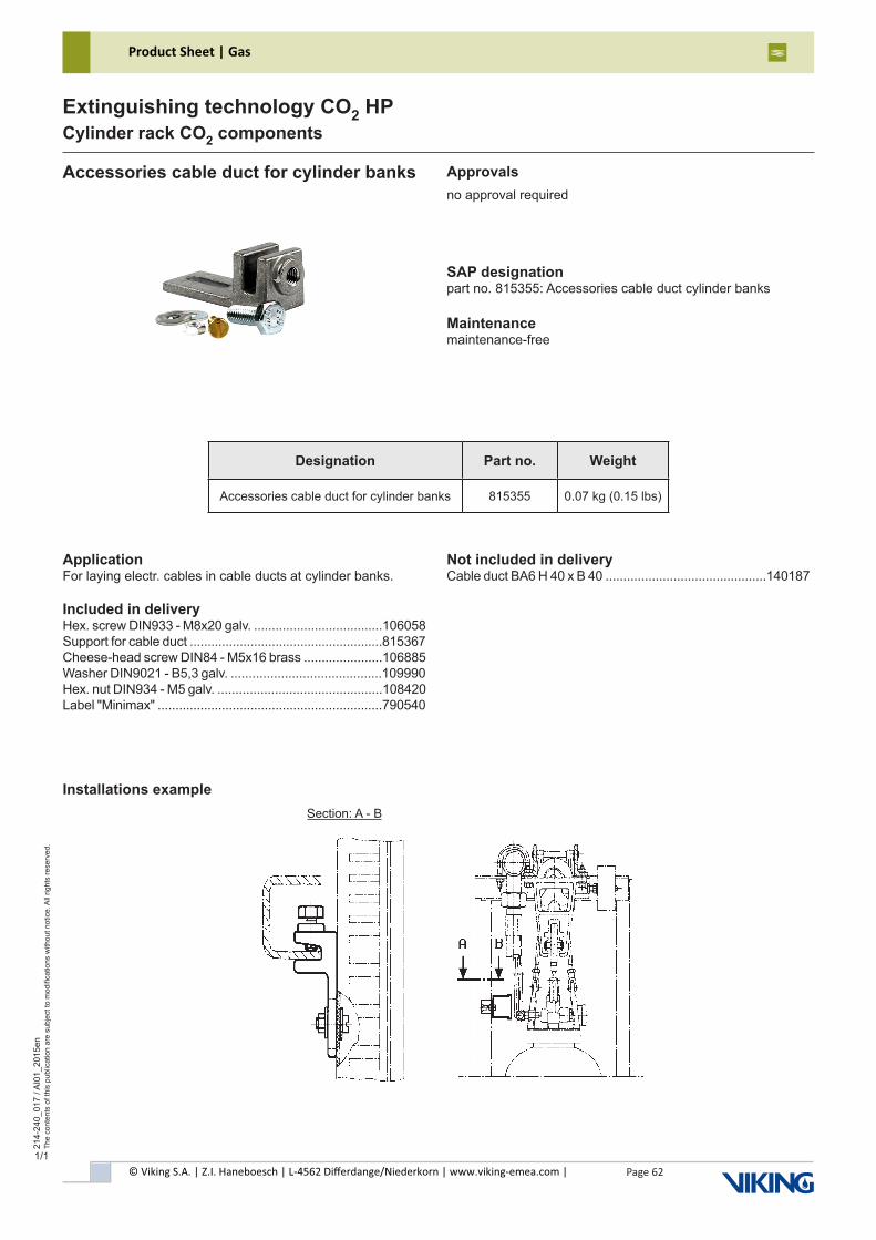
© Viking S.A. | Z.I. Haneboesch | L-4562 Differdange/Niederkorn | www.viking-emea.com |
Product Sheet | Gas
Page 62
214-
240_
017
/ AI0
1_20
15en
The
cont
ents
of t
his
publ
icat
ion
are
subj
ect t
o m
odifi
catio
ns w
ithou
t not
ice.
All
right
s re
serv
ed.
Extinguishing technology CO2 HPCylinder rack CO2 components
1/1
Accessories cable duct for cylinder banks
SAP designationpart no. 815355: Accessories cable duct cylinder banks
Maintenancemaintenance-free
Approvalsno approval required
ApplicationFor laying electr. cables in cable ducts at cylinder banks.
Included in deliveryHex. screw DIN933 - M8x20 galv. ....................................106058Support for cable duct ......................................................815367Cheese-head screw DIN84 - M5x16 brass ......................106885Washer DIN9021 - B5,3 galv. ..........................................109990Hex. nut DIN934 - M5 galv. ..............................................108420Label "Minimax" ...............................................................790540
Not included in deliveryCable duct BA6 H 40 x B 40 .............................................140187
Installations exampleSection: A - B
Designation Part no. Weight
Accessories cable duct for cylinder banks 815355 0.07 kg (0.15 lbs)

© Viking S.A. | Z.I. Haneboesch | L-4562 Differdange/Niederkorn | www.viking-emea.com |
Product Sheet | Gas
Page 63
214-
240_
018
/ AI0
1_20
15en
The
cont
ents
of t
his
publ
icat
ion
are
subj
ect t
o m
odifi
catio
ns w
ithou
t not
ice.
All
right
s re
serv
ed.
Extinguishing technology CO2 HPCylinder rack CO2 components
1/2
Disable device release box BEA Approvals / CE marking
SAP designationpart no. 886013: Disable device release box BEA
Maintenancesee product information disable device release box BEApart no. 886012
G302024 0786-CPD-30006
Technical dataTemperature range ................-20 °C to +50 °C (-4 °F to 122 °F)Material housing .....................................................aluminium blocking pin ........................................stainless steelLock .....................................................................see M1-01-07Vibration ................according to EN 12094-6 for wall installationDisable device release box ..............complies with EN 12094-6CE conformity .....acc. to Construction Products Regulation (EU)................................................................................No. 305/2011
Markingmanufacturer (MX), type (BEA), approval sign (VdS), CE, serial number
ApplicationThe disable device release box may only be used according to the “documentation of special extinguishing systems” of CO2, argon and nitrogen fire extinguishing systems.According to EN 12094-6 it is defined as a non electrical disable device to lock Argotec® cylinder banks. It prevents the extinguishing agent to be released. For repair or mainte-nance work in the protected area, when the system can be activated unintentionally or people can not leave the area within the pre - warning time, the extinguishing system must be blocked.
Functional descriptionThe blocking pin is moved from the operation position to the isolation position through pushing the handle bar to the left side. The blocking pin rise now above the weight lever of the release box. It prevents the weight lever from tipping over when the extinguishing system is activated.The extinguishing agent cylinders will not open automatically when the release box is blocked with the disable device.The disable device release box must be locked in the operati-on and in the isolation position with the lock.Only a authorize person from the customer is allowed to ac-tuate the disable device or instruct someone to do this.
Included in deliveryDisable device release box BEA compl. with lock and faste-ning materialProduct information disable device release box BEApart no. 886012
Not included in deliveryThe following must be ordered separately for monitoring of each position (operation / isolation):Limit switch system monitoring I88-SU1Zw .....................7632612 x Cheese-head screw DIN84-M4x25 brass ..................1067452 x Washer DIN125-B 4,3 brass ......................................109734
Designation Part no. Weight
Disable device release box BEA 886013 0.55 kg (1.21 lbs)
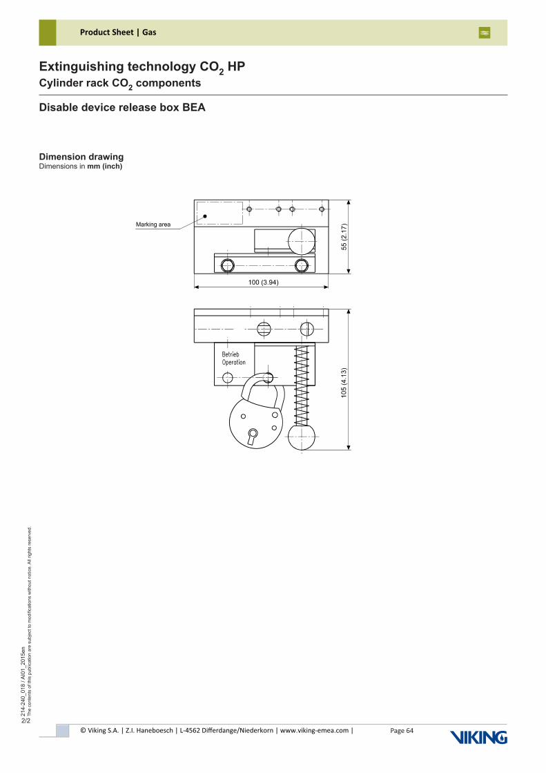
© Viking S.A. | Z.I. Haneboesch | L-4562 Differdange/Niederkorn | www.viking-emea.com |
Product Sheet | Gas
Page 64
214-
240_
018
/ AI0
1_20
15en
The
cont
ents
of t
his
publ
icat
ion
are
subj
ect t
o m
odifi
catio
ns w
ithou
t not
ice.
All
right
s re
serv
ed.
Extinguishing technology CO2 HPCylinder rack CO2 components
2/2
Disable device release box BEA
Dimension drawingDimensions in mm (inch)
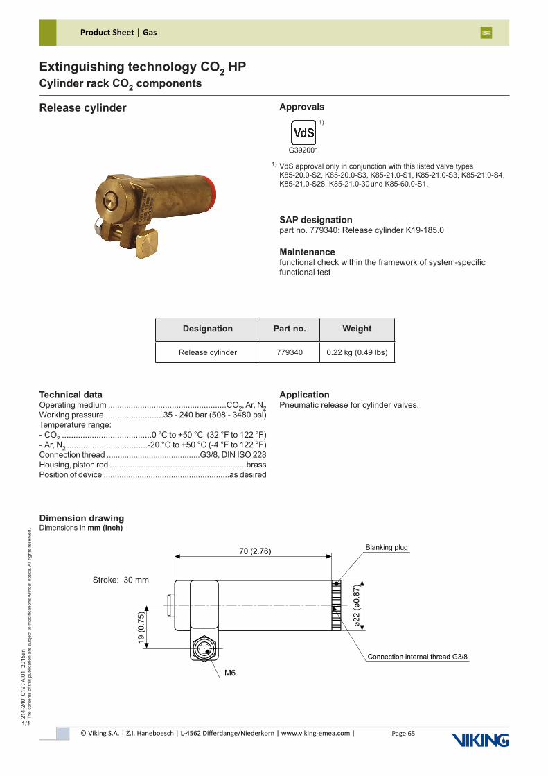
© Viking S.A. | Z.I. Haneboesch | L-4562 Differdange/Niederkorn | www.viking-emea.com |
Product Sheet | Gas
Page 65
214-
240_
019
/ AI0
1_20
15en
The
cont
ents
of t
his
publ
icat
ion
are
subj
ect t
o m
odifi
catio
ns w
ithou
t not
ice.
All
right
s re
serv
ed.
Extinguishing technology CO2 HPCylinder rack CO2 components
1/1
Release cylinder Approvals
SAP designationpart no. 779340: Release cylinder K19-185.0
Maintenancefunctional check within the framework of system-specific functional test
G392001
Technical dataOperating medium ....................................................CO2, Ar, N2Working pressure .........................35 - 240 bar (508 - 3480 psi)Temperature range:- CO2 .......................................0 °C to +50 °C (32 °F to 122 °F)- Ar, N2 ...................................-20 °C to +50 °C (-4 °F to 122 °F)Connection thread ..........................................G3/8, DIN ISO 228Housing, piston rod .............................................................brassPosition of device ........................................................as desired
ApplicationPneumatic release for cylinder valves.
VdS approval only in conjunction with this listed valve types K85-20.0-S2, K85-20.0-S3, K85-21.0-S1, K85-21.0-S3, K85-21.0-S4, K85-21.0-S28, K85-21.0-30 und K85-60.0-S1.
1)
1)
Dimension drawingDimensions in mm (inch)
Stroke: 30 mm
Designation Part no. Weight
Release cylinder 779340 0.22 kg (0.49 lbs)
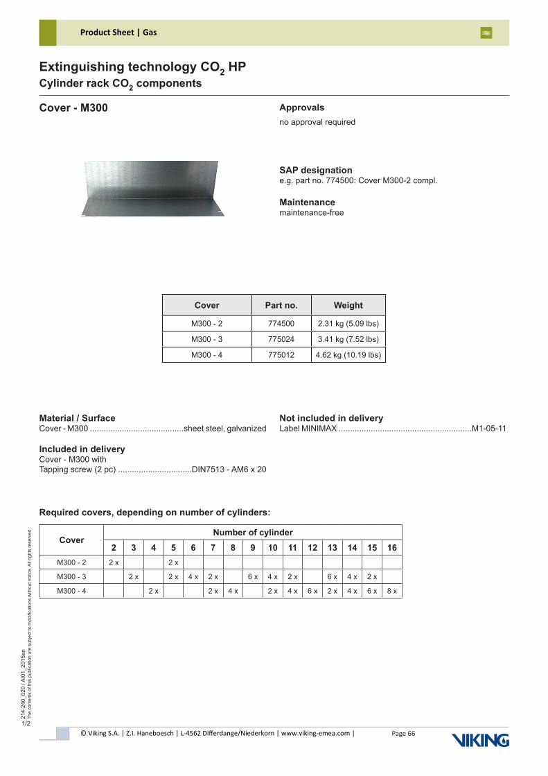
© Viking S.A. | Z.I. Haneboesch | L-4562 Differdange/Niederkorn | www.viking-emea.com |
Product Sheet | Gas
Page 66
214-
240_
020
/ AI0
1_20
15en
The
cont
ents
of t
his
publ
icat
ion
are
subj
ect t
o m
odifi
catio
ns w
ithou
t not
ice.
All
right
s re
serv
ed.
Extinguishing technology CO2 HPCylinder rack CO2 components
1/2
Cover - M300
SAP designatione.g. part no. 774500: Cover M300-2 compl.
Maintenancemaintenance-free
Approvalsno approval required
Material / SurfaceCover - M300 .........................................sheet steel, galvanized
Included in deliveryCover - M300 withTapping screw (2 pc) ................................DIN7513 - AM6 x 20
Not included in deliveryLabel MINIMAX ..........................................................M1-05-11
Required covers, depending on number of cylinders:
Cover Part no. Weight
M300 - 2 774500 2.31 kg (5.09 lbs)
M300 - 3 775024 3.41 kg (7.52 lbs)
M300 - 4 775012 4.62 kg (10.19 lbs)
CoverNumber of cylinder
2 3 4 5 6 7 8 9 10 11 12 13 14 15 16M300 - 2 2 x 2 x
M300 - 3 2 x 2 x 4 x 2 x 6 x 4 x 2 x 6 x 4 x 2 x
M300 - 4 2 x 2 x 4 x 2 x 4 x 6 x 2 x 4 x 6 x 8 x
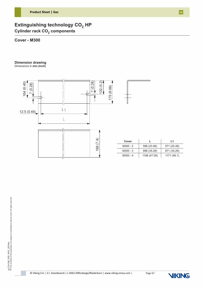
© Viking S.A. | Z.I. Haneboesch | L-4562 Differdange/Niederkorn | www.viking-emea.com |
Product Sheet | Gas
Page 67
214-
240_
020
/ AI0
1_20
15en
The
cont
ents
of t
his
publ
icat
ion
are
subj
ect t
o m
odifi
catio
ns w
ithou
t not
ice.
All
right
s re
serv
ed.
Extinguishing technology CO2 HPCylinder rack CO2 components
2/2
Dimension drawingDimensions in mm (inch)
Cover - M300
Cover L L1M300 - 2 596 (23.46) 571 (22.48)
M300 - 3 896 (35.28) 871 (34.29)
M300 - 4 1196 (47.09) 1171 (46.1)
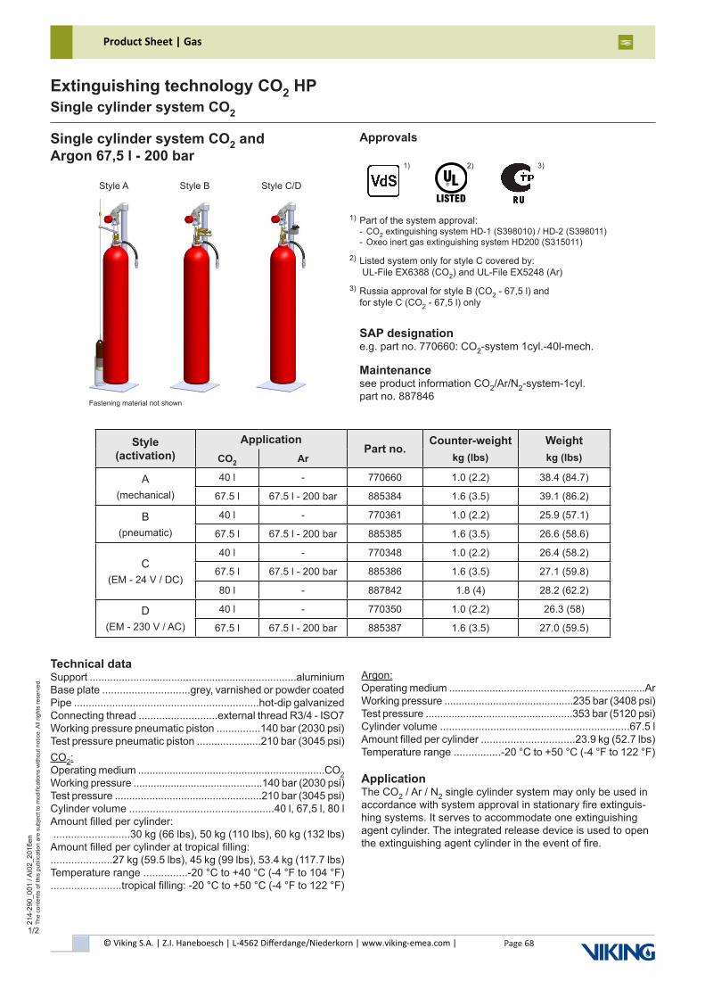
© Viking S.A. | Z.I. Haneboesch | L-4562 Differdange/Niederkorn | www.viking-emea.com |
Product Sheet | Gas
Page 68
214-
290_
001
/ AI0
2_20
16en
The
cont
ents
of t
his
publ
icat
ion
are
subj
ect t
o m
odifi
catio
ns w
ithou
t not
ice.
All
right
s re
serv
ed.
Extinguishing technology CO2 HPSingle cylinder system CO2
1/2
Single cylinder system CO2 andArgon 67,5 l - 200 bar
Approvals
Listed system only for style C covered by: UL-File EX6388 (CO2) and UL-File EX5248 (Ar)
2)
2)
Part of the system approval:- CO2 extinguishing system HD-1 (S398010) / HD-2 (S398011)- Oxeo inert gas extinguishing system HD200 (S315011)
1)
1)
SAP designatione.g. part no. 770660: CO2-system 1cyl.-40l-mech.
Maintenancesee product information CO2/Ar/N2-system-1cyl.part no. 887846
Technical dataSupport .......................................................................aluminiumBase plate ..............................grey, varnished or powder coatedPipe ...............................................................hot-dip galvanizedConnecting thread ...........................external thread R3/4 - ISO7Working pressure pneumatic piston ...............140 bar (2030 psi)Test pressure pneumatic piston ......................210 bar (3045 psi)CO2:Operating medium .................................................................CO2Working pressure .............................................140 bar (2030 psi)Test pressure ...................................................210 bar (3045 psi)Cylinder volume .................................................40 l, 67,5 l, 80 lAmount filled per cylinder: ..........................30 kg (66 lbs), 50 kg (110 lbs), 60 kg (132 lbs)Amount filled per cylinder at tropical filling:.....................27 kg (59.5 lbs), 45 kg (99 lbs), 53.4 kg (117.7 lbs)Temperature range ...............-20 °C to +40 °C (-4 °F to 104 °F)........................tropical filling: -20 °C to +50 °C (-4 °F to 122 °F)
Argon:Operating medium ....................................................................ArWorking pressure .............................................235 bar (3408 psi)Test pressure ...................................................353 bar (5120 psi)Cylinder volume ................................................................67.5 lAmount filled per cylinder ................................23.9 kg (52.7 lbs)Temperature range ................-20 °C to +50 °C (-4 °F to 122 °F)
ApplicationThe CO2 / Ar / N2 single cylinder system may only be used in accordance with system approval in stationary fire extinguis-hing systems. It serves to accommodate one extinguishing agent cylinder. The integrated release device is used to open the extinguishing agent cylinder in the event of fire.
Russia approval for style B (CO2 - 67,5 l) andfor style C (CO2 - 67,5 l) only
3)
3)
Fastening material not shown
Style A Style B Style C/D
Style (activation)
ApplicationPart no.
Counter-weightkg (lbs)
Weightkg (lbs)CO2 Ar
A(mechanical)
40 l - 770660 1.0 (2.2) 38.4 (84.7)
67.5 l 67.5 l - 200 bar 885384 1.6 (3.5) 39.1 (86.2)
B(pneumatic)
40 l - 770361 1.0 (2.2) 25.9 (57.1)
67.5 l 67.5 l - 200 bar 885385 1.6 (3.5) 26.6 (58.6)
C(EM - 24 V / DC)
40 l - 770348 1.0 (2.2) 26.4 (58.2)
67.5 l 67.5 l - 200 bar 885386 1.6 (3.5) 27.1 (59.8)
80 l - 887842 1.8 (4) 28.2 (62.2)
D(EM - 230 V / AC)
40 l - 770350 1.0 (2.2) 26.3 (58)
67.5 l 67.5 l - 200 bar 885387 1.6 (3.5) 27.0 (59.5)
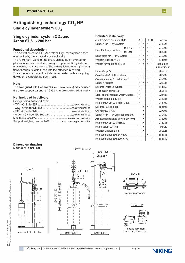
© Viking S.A. | Z.I. Haneboesch | L-4562 Differdange/Niederkorn | www.viking-emea.com |
Product Sheet | Gas
Page 69
214-
290_
001
/ AI0
2_20
16en
The
cont
ents
of t
his
publ
icat
ion
are
subj
ect t
o m
odifi
catio
ns w
ithou
t not
ice.
All
right
s re
serv
ed.
Extinguishing technology CO2 HPSingle cylinder system CO2
2/2
Single cylinder system CO2 andArgon 67,5 l - 200 bar
Functional descriptionThe activation of the CO2/Ar-system 1 cyl. takes place either mechanically, pneumatically or electrically.The rocker arm valve of the extinguishing agent cylinder or pilot cylinder is opened via a weight, a pneumatic cylinder or an electrical release device. The extinguishing agent (CO2/Ar) flows through flexible tubes into the attached pipework.The extinguishing agent cylinder is controlled with a weighing device on extinguishing agent loss.
NoteThe safe guard with limit switch (see control device) may be used the base support part no. 77 3982 is to be ordered additionally.
Not included in deliveryExtinguishing agent cylinder:- CO2 - Cylinder EU .............................................see cylinder filled- CO2 - Cylinder UL, EU ......................................see cylinder filled- CO2 - Cylinder RU ............................................see cylinder filled- Argon - Cylinder EU 200 bar .............................see cylinder filledMonitoring loss PAE ......................................see monitoring deviceSupport weighing device PAE .................see mounting accessories
Style B, C, D
Style B
pneumatic activation
Style C, D
electric activation24 V / DC, 230 V / AC
Included in delivery
Style A
mechanical activation
Dimension drawingDimensions in mm (inch)
• = Components for style A B C D Part no.Support for 1 - cyl. system • • • • 774925
Pipe for 1 - cyl. systemto 67.5 l • • • • 779303for 80 l • 885281
Base plate for 1 - cyl. system • • • • 779297Weighing device WE4 • • • • 871695Weight for weighing device • • • • see ad-on
part cylinderHose CO2 / Ar • • • • 859510Adapter G3/4 - R3/4 PB365 • • • • 887706Accessories for 1 - cyl. system • • • • 779492Support Argotec • • • • 223036Lever for release cylinder • 841859Rope catch complete • 359647Steel box for release weight, simple • 225483Weight complete 12 kg • 778086Hex. screw DIN933-M8x10-8.8 • 215102Lever for EM release • • • 885603Cylinder D25-H30 • 227303Support for 1 - cyl. release pneum. • 779480Accessories release device EM / VM • 778293Hex. screw DIN933-M5x20 • 215035Hex. nut DIN934-M5 • 108420Washer DIN125-B5,3 • 760326Release device EM 24 V DC • 885738Release device EM 230 V AC • 885739
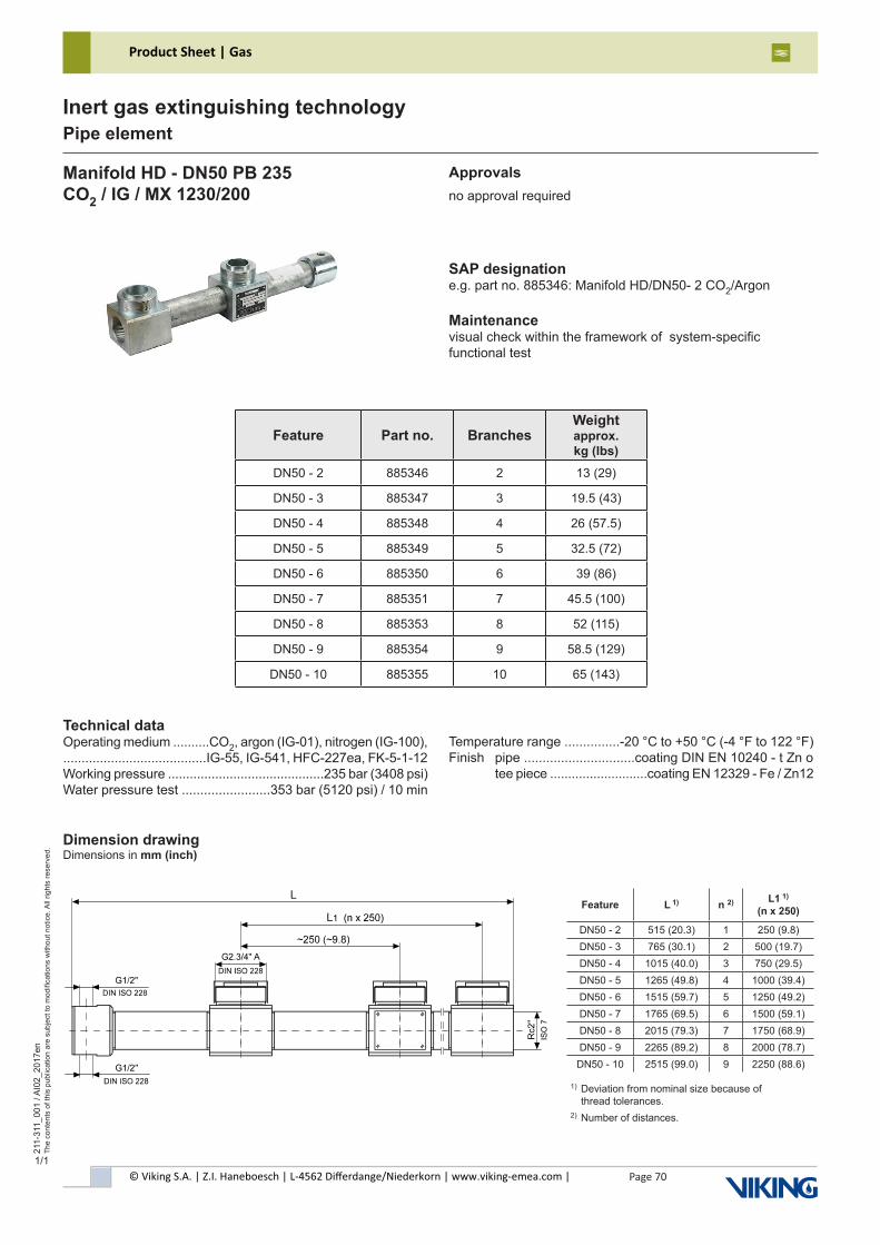
© Viking S.A. | Z.I. Haneboesch | L-4562 Differdange/Niederkorn | www.viking-emea.com |
Product Sheet | Gas
Page 70
211-
311_
001
/ AI0
2_20
17en
The
cont
ents
of t
his
publ
icat
ion
are
subj
ect t
o m
odifi
catio
ns w
ithou
t not
ice.
All
right
s re
serv
ed.
Inert gas extinguishing technologyPipe element
1/1
Manifold HD - DN50 PB 235CO2 / IG / MX 1230/200
Approvalsno approval required
SAP designatione.g. part no. 885346: Manifold HD/DN50- 2 CO2/Argon
Maintenancevisual check within the framework of system-specificfunctional test
Feature Part no. BranchesWeight approx. kg (lbs)
DN50 - 2 885346 2 13 (29)
DN50 - 3 885347 3 19.5 (43)
DN50 - 4 885348 4 26 (57.5)
DN50 - 5 885349 5 32.5 (72)
DN50 - 6 885350 6 39 (86)
DN50 - 7 885351 7 45.5 (100)
DN50 - 8 885353 8 52 (115)
DN50 - 9 885354 9 58.5 (129)
DN50 - 10 885355 10 65 (143)
Technical dataOperating medium ..........CO2, argon (IG-01), nitrogen (IG-100),.......................................IG-55, IG-541, HFC-227ea, FK-5-1-12Working pressure ...........................................235 bar (3408 psi)Water pressure test ........................353 bar (5120 psi) / 10 min
Dimension drawingDimensions in mm (inch)
Feature L 1) n 2) L1 1)
(n x 250)
DN50 - 2 515 (20.3) 1 250 (9.8)DN50 - 3 765 (30.1) 2 500 (19.7)DN50 - 4 1015 (40.0) 3 750 (29.5)DN50 - 5 1265 (49.8) 4 1000 (39.4)DN50 - 6 1515 (59.7) 5 1250 (49.2)DN50 - 7 1765 (69.5) 6 1500 (59.1)DN50 - 8 2015 (79.3) 7 1750 (68.9)DN50 - 9 2265 (89.2) 8 2000 (78.7)
DN50 - 10 2515 (99.0) 9 2250 (88.6)
Temperature range ...............-20 °C to +50 °C (-4 °F to 122 °F)Finish pipe ..............................coating DIN EN 10240 - t Zn o tee piece ...........................coating EN 12329 - Fe / Zn12
1) Deviation from nominal size because of thread tolerances.2) Number of distances.
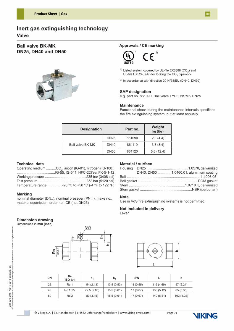
© Viking S.A. | Z.I. Haneboesch | L-4562 Differdange/Niederkorn | www.viking-emea.com |
Product Sheet | Gas
Page 71
211-
320_
001
/ AI0
1 / 2
018-
Sep
t-25
/ en
The
cont
ents
of t
his
publ
icat
ion
are
subj
ect t
o m
odifi
catio
ns w
ithou
t not
ice.
All
right
s re
serv
ed.
Inert gas extinguishing technologyValve
1/1
Ball valve BK-MKDN25, DN40 and DN50
SAP designatione.g. part no. 861090: Ball valve TYPE BK/MK DN25
MaintenanceFunctional check during the maintenance intervals specific tothe fire extinguishing system, but at least annually.
Technical dataOperating medium ..........CO2, argon (IG-01), nitrogen (IG-100),.......................................IG-55, IG-541, HFC-227ea, FK-5-1-12Working pressure ..........................................235 bar (3408 psi)Test pressure ..................................................353 bar (5120 psi)Temperature range ...............-20 °C to +50 °C (-4 °F to 122 °F)
Markingnominal diameter (DN..), nominal pressuer (PN...), make no.,material description, order no., CE (not DN25)
Material / surfaceHousing DN25 ...........................................1.0570, galvanized DN40, DN50 ..............1.0460.01, aluminium coatingBall ...........................................................................1.4006.05Ball gasket .............................................................POM gasketStem .........................................................1.0718 K, galvanizedStem gasket .....................................................NBR (perbunan)
NoteUse in VdS fire extinguishing systems is not permitted.
Not included in deliveryLever
Designation Part no. Weightkg (lbs)
Ball valve BK-MK
DN25 861090 2.0 (4.4)
DN40 861119 3.8 (8.4)
DN50 861120 5.6 (12.4)
Dimension drawingDimensions in mm (inch)
DN Rc ISO 7/1 h1 h2 SW L b
25 Rc 1 54 (2.13) 13.5 (0.53) 14 (0.55) 119 (4.69) 57 (2.24)
40 Rc 1.1/2 72.5 (2.85) 15.5 (0.61) 17 (0.67) 130 (5.12) 85 (3.35)
50 Rc 2 80 (3.15) 15.5 (0.61) 17 (0.67) 140 (5.51) 102 (4.02)
Approvals / CE marking
1) Listed system covered by UL-file EX6388 (CO2) and UL-file EX5248 (Ar) for locking the CO2 pipework
2) in accordance with directive 2014/68/EU (DN40, DN50)
1) 2)
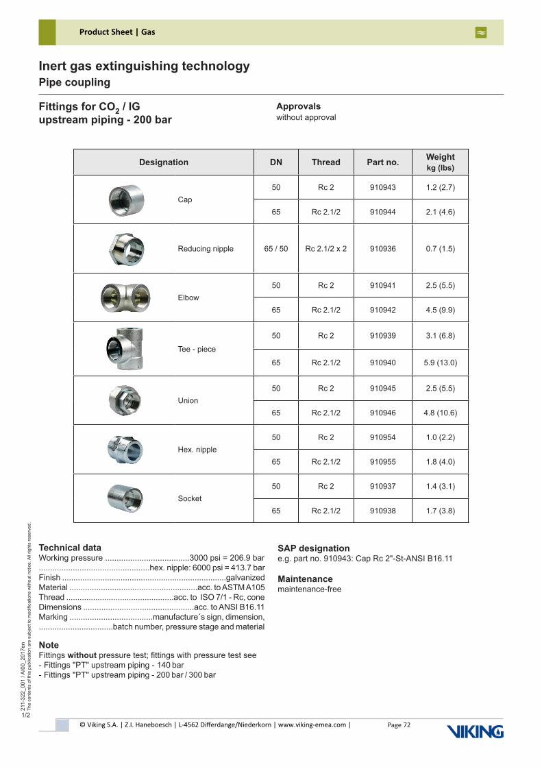
© Viking S.A. | Z.I. Haneboesch | L-4562 Differdange/Niederkorn | www.viking-emea.com |
Product Sheet | Gas
Page 72
211-
322_
001
/ AI0
0_20
17en
The
cont
ents
of t
his
publ
icat
ion
are
subj
ect t
o m
odifi
catio
ns w
ithou
t not
ice.
All
right
s re
serv
ed.
Inert gas extinguishing technologyPipe coupling
1/2
Fittings for CO2 / IGupstream piping - 200 bar
Approvalswithout approval
SAP designatione.g. part no. 910943: Cap Rc 2"-St-ANSI B16.11
Maintenancemaintenance-free
Technical dataWorking pressure .....................................3000 psi = 206.9 bar.................................................hex. nipple: 6000 psi = 413.7 barFinish .........................................................................galvanizedMaterial .........................................................acc. to ASTM A105Thread ................................................acc. to ISO 7/1 - Rc, coneDimensions .................................................acc. to ANSI B16.11Marking .....................................manufacture´s sign, dimension,.................................batch number, pressure stage and material
NoteFittings without pressure test; fittings with pressure test see- Fittings "PT" upstream piping - 140 bar- Fittings "PT" upstream piping - 200 bar / 300 bar
Designation DN Thread Part no. Weightkg (lbs)
Cap50 Rc 2 910943 1.2 (2.7)
65 Rc 2.1/2 910944 2.1 (4.6)
Reducing nipple 65 / 50 Rc 2.1/2 x 2 910936 0.7 (1.5)
Elbow50 Rc 2 910941 2.5 (5.5)
65 Rc 2.1/2 910942 4.5 (9.9)
Tee - piece
50 Rc 2 910939 3.1 (6.8)
65 Rc 2.1/2 910940 5.9 (13.0)
Union50 Rc 2 910945 2.5 (5.5)
65 Rc 2.1/2 910946 4.8 (10.6)
Hex. nipple50 Rc 2 910954 1.0 (2.2)
65 Rc 2.1/2 910955 1.8 (4.0)
Socket50 Rc 2 910937 1.4 (3.1)
65 Rc 2.1/2 910938 1.7 (3.8)
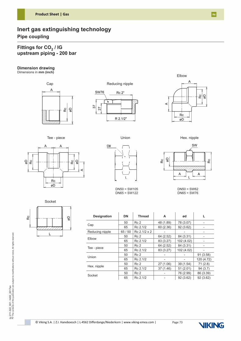
© Viking S.A. | Z.I. Haneboesch | L-4562 Differdange/Niederkorn | www.viking-emea.com |
Product Sheet | Gas
Page 73
211-
322_
001
/ AI0
0_20
17en
The
cont
ents
of t
his
publ
icat
ion
are
subj
ect t
o m
odifi
catio
ns w
ithou
t not
ice.
All
right
s re
serv
ed.
Inert gas extinguishing technologyPipe coupling
2/2
Fittings for CO2 / IGupstream piping - 200 bar
Dimension drawingDimensions in mm (inch)
Cap Reducing nipple
Elbow
Tee - piece Union
Socket
DN50 = SW105DN65 = SW122
Hex. nipple
DN50 = SW62DN65 = SW76
Designation DN Thread A ød L
Cap50 Rc 2 48 (1.89) 78 (3.07) -65 Rc 2.1/2 60 (2.36) 92 (3.62) -
Reducing nipple 65 / 50 Rc 2.1/2 x 2 - - -
Elbow50 Rc 2 64 (2.52) 84 (3.31) -65 Rc 2.1/2 83 (3.27) 102 (4.02) -
Tee - piece50 Rc 2 64 (2.52) 84 (3.31) -65 Rc 2.1/2 83 (3.27) 102 (4.02) -
Union50 Rc 2 - - 91 (3.58)65 Rc 2.1/2 - - 120 (4.72)
Hex. nipple50 Rc 2 27 (1.06) 39 (1.54) 71 (2.8)65 Rc 2.1/2 37 (1.46) 51 (2.01) 94 (3.7)
Socket50 Rc 2 - 76 (2.99) 86 (3.39)65 Rc 2.1/2 - 92 (3.62) 92 (3.62)
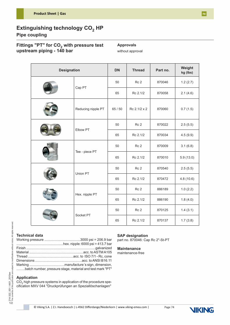
© Viking S.A. | Z.I. Haneboesch | L-4562 Differdange/Niederkorn | www.viking-emea.com |
Product Sheet | Gas
Page 74
214-
322_
001
/ AI0
1_20
15en
The
cont
ents
of t
his
publ
icat
ion
are
subj
ect t
o m
odifi
catio
ns w
ithou
t not
ice.
All
right
s re
serv
ed.
Extinguishing technology CO2 HPPipe coupling
1/2
Fittings "PT" for CO2 with pressure testupstream piping - 140 bar
Approvalswithout approval
SAP designationpart no. 870046: Cap Rc 2"-St-PT
Maintenancemaintenance-free
Technical dataWorking pressure .....................................3000 psi = 206.9 bar.................................................hex. nipple: 6000 psi = 413.7 barFinish .........................................................................galvanizedMaterial .........................................................acc. to ASTM A105Thread ................................................acc. to ISO 7/1 - Rc, coneDimensions .................................................acc. to ANSI B16.11Marking .....................................manufacture´s sign, dimension,.........batch number, pressure stage, material and test mark "PT"
ApplicationCO2 high pressure systems in application of the procedure spe-cification MXV 044 "Druckprüfungen an Speziallöschanlagen"
Designation DN Thread Part no. Weightkg (lbs)
Cap PT50 Rc 2 870046 1.2 (2.7)
65 Rc 2.1/2 870058 2.1 (4.6)
Reducing nipple PT 65 / 50 Rc 2.1/2 x 2 870060 0.7 (1.5)
Elbow PT50 Rc 2 870022 2.5 (5.5)
65 Rc 2.1/2 870034 4.5 (9.9)
Tee - piece PT
50 Rc 2 870009 3.1 (6.8)
65 Rc 2.1/2 870010 5.9 (13.0)
Union PT50 Rc 2 870540 2.5 (5.5)
65 Rc 2.1/2 870472 4.8 (10.6)
Hex. nipple PT50 Rc 2 886189 1.0 (2.2)
65 Rc 2.1/2 886190 1.8 (4.0)
Socket PT50 Rc 2 870125 1.4 (3.1)
65 Rc 2.1/2 870137 1.7 (3.8)
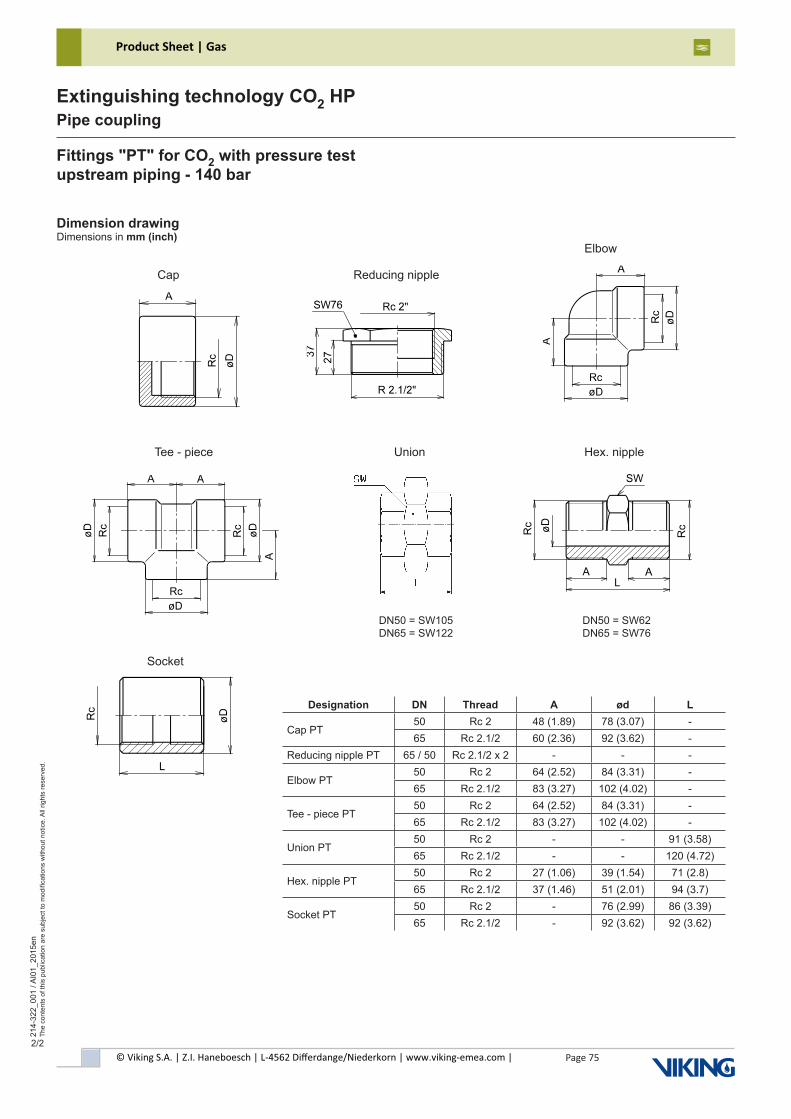
© Viking S.A. | Z.I. Haneboesch | L-4562 Differdange/Niederkorn | www.viking-emea.com |
Product Sheet | Gas
Page 75
214-
322_
001
/ AI0
1_20
15en
The
cont
ents
of t
his
publ
icat
ion
are
subj
ect t
o m
odifi
catio
ns w
ithou
t not
ice.
All
right
s re
serv
ed.
Extinguishing technology CO2 HPPipe coupling
2/2
Fittings "PT" for CO2 with pressure testupstream piping - 140 bar
Dimension drawingDimensions in mm (inch)
Cap Reducing nipple
Elbow
Tee - piece Union
Socket
DN50 = SW105DN65 = SW122
Hex. nipple
DN50 = SW62DN65 = SW76
Designation DN Thread A ød L
Cap PT50 Rc 2 48 (1.89) 78 (3.07) -65 Rc 2.1/2 60 (2.36) 92 (3.62) -
Reducing nipple PT 65 / 50 Rc 2.1/2 x 2 - - -
Elbow PT50 Rc 2 64 (2.52) 84 (3.31) -65 Rc 2.1/2 83 (3.27) 102 (4.02) -
Tee - piece PT50 Rc 2 64 (2.52) 84 (3.31) -65 Rc 2.1/2 83 (3.27) 102 (4.02) -
Union PT50 Rc 2 - - 91 (3.58)65 Rc 2.1/2 - - 120 (4.72)
Hex. nipple PT50 Rc 2 27 (1.06) 39 (1.54) 71 (2.8)65 Rc 2.1/2 37 (1.46) 51 (2.01) 94 (3.7)
Socket PT50 Rc 2 - 76 (2.99) 86 (3.39)65 Rc 2.1/2 - 92 (3.62) 92 (3.62)
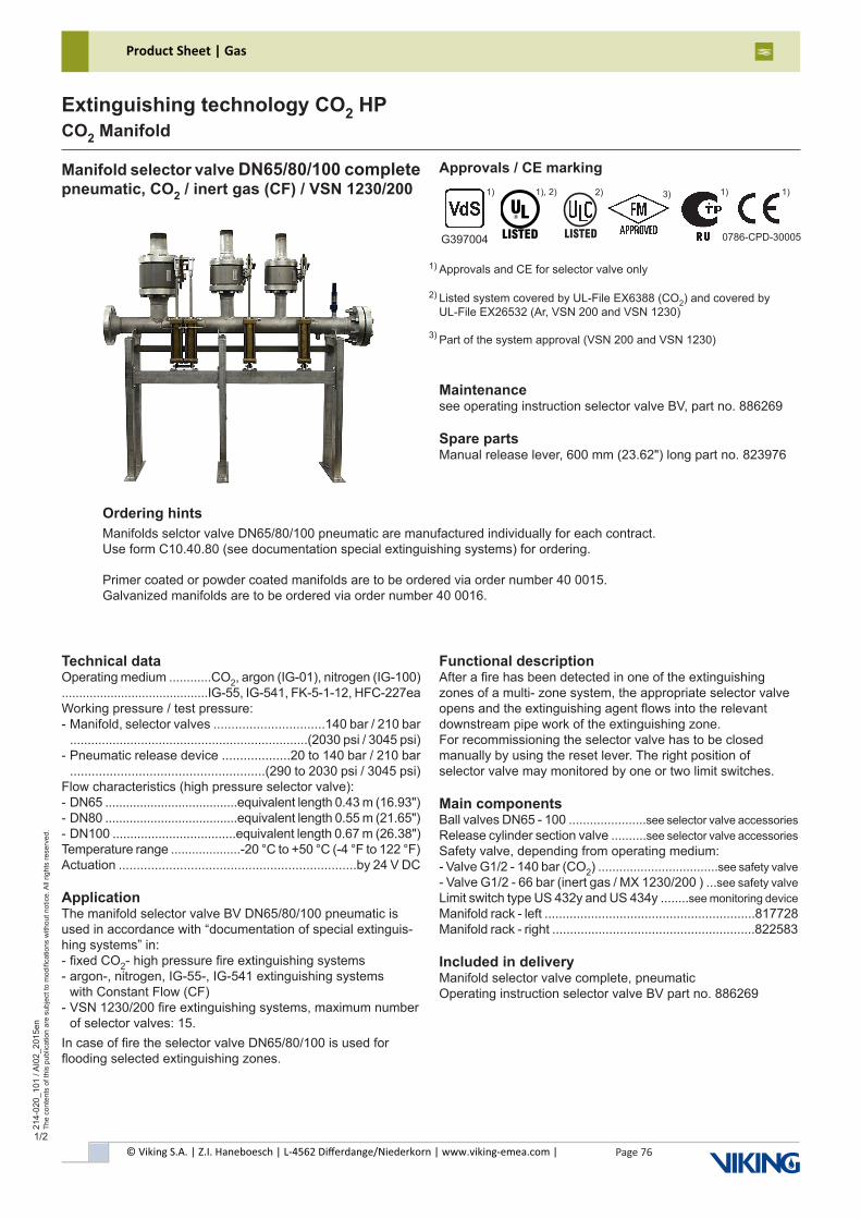
© Viking S.A. | Z.I. Haneboesch | L-4562 Differdange/Niederkorn | www.viking-emea.com |
Product Sheet | Gas
Page 76
214-
020_
101
/ AI0
2_20
15en
The
cont
ents
of t
his
publ
icat
ion
are
subj
ect t
o m
odifi
catio
ns w
ithou
t not
ice.
All
right
s re
serv
ed.
Extinguishing technology CO2 HPCO2 Manifold
1/2
Manifold selector valve DN65/80/100 completepneumatic, CO2 / inert gas (CF) / VSN 1230/200
Maintenancesee operating instruction selector valve BV, part no. 886269
Spare partsManual release lever, 600 mm (23.62") long part no. 823976
Functional descriptionAfter a fire has been detected in one of the extinguishing zones of a multi- zone system, the appropriate selector valve opens and the extinguishing agent flows into the relevant downstream pipe work of the extinguishing zone.For recommissioning the selector valve has to be closedmanually by using the reset lever. The right position of selector valve may monitored by one or two limit switches.
Main componentsBall valves DN65 - 100 ......................see selector valve accessories Release cylinder section valve ..........see selector valve accessories Safety valve, depending from operating medium:- Valve G1/2 - 140 bar (CO2) ..................................see safety valve - Valve G1/2 - 66 bar (inert gas / MX 1230/200 ) ...see safety valve Limit switch type US 432y and US 434y ........see monitoring device Manifold rack - left ...........................................................817728Manifold rack - right .........................................................822583
Included in deliveryManifold selector valve complete, pneumaticOperating instruction selector valve BV part no. 886269
Technical dataOperating medium ............CO2, argon (IG-01), nitrogen (IG-100)..........................................IG-55, IG-541, FK-5-1-12, HFC-227eaWorking pressure / test pressure:- Manifold, selector valves ...............................140 bar / 210 bar ...................................................................(2030 psi / 3045 psi)- Pneumatic release device ...................20 to 140 bar / 210 bar ......................................................(290 to 2030 psi / 3045 psi)Flow characteristics (high pressure selector valve):- DN65 ......................................equivalent length 0.43 m (16.93")- DN80 ......................................equivalent length 0.55 m (21.65")- DN100 ...................................equivalent length 0.67 m (26.38")Temperature range ....................-20 °C to +50 °C (-4 °F to 122 °F)Actuation ..................................................................by 24 V DC
ApplicationThe manifold selector valve BV DN65/80/100 pneumatic is used in accordance with “documentation of special extinguis-hing systems” in:- fixed CO2- high pressure fire extinguishing systems- argon-, nitrogen, IG-55-, IG-541 extinguishing systems with Constant Flow (CF)- VSN 1230/200 fire extinguishing systems, maximum number of selector valves: 15.In case of fire the selector valve DN65/80/100 is used for flooding selected extinguishing zones.
Ordering hintsManifolds selctor valve DN65/80/100 pneumatic are manufactured individually for each contract. Use form C10.40.80 (see documentation special extinguishing systems) for ordering.
Primer coated or powder coated manifolds are to be ordered via order number 40 0015. Galvanized manifolds are to be ordered via order number 40 0016.
Approvals / CE marking
Approvals and CE for selector valve only1)
Listed system covered by UL-File EX6388 (CO2) and covered byUL-File EX26532 (Ar, VSN 200 and VSN 1230)
Part of the system approval (VSN 200 and VSN 1230)
2)
3)
G397004 0786-CPD-30005
1), 2) 1) 1) 1) 3)
������
2)
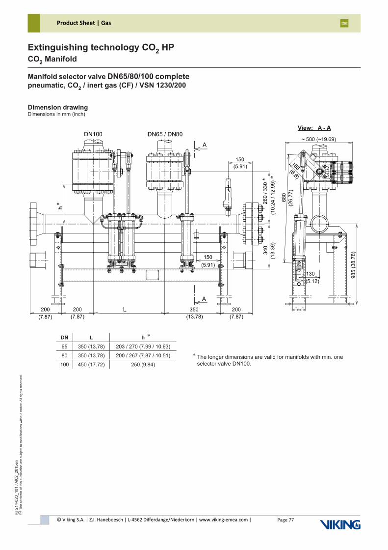
© Viking S.A. | Z.I. Haneboesch | L-4562 Differdange/Niederkorn | www.viking-emea.com |
Product Sheet | Gas
Page 77
214-
020_
101
/ AI0
2_20
15en
The
cont
ents
of t
his
publ
icat
ion
are
subj
ect t
o m
odifi
catio
ns w
ithou
t not
ice.
All
right
s re
serv
ed.
Extinguishing technology CO2 HPCO2 Manifold
2/2
The longer dimensions are valid for manifolds with min. one selector valve DN100.
Dimension drawingDimensions in mm (inch)
*
*
View: A - A
Manifold selector valve DN65/80/100 completepneumatic, CO2 / inert gas (CF) / VSN 1230/200
DN L h65 350 (13.78) 203 / 270 (7.99 / 10.63)
80 350 (13.78) 200 / 267 (7.87 / 10.51)
100 450 (17.72) 250 (9.84)
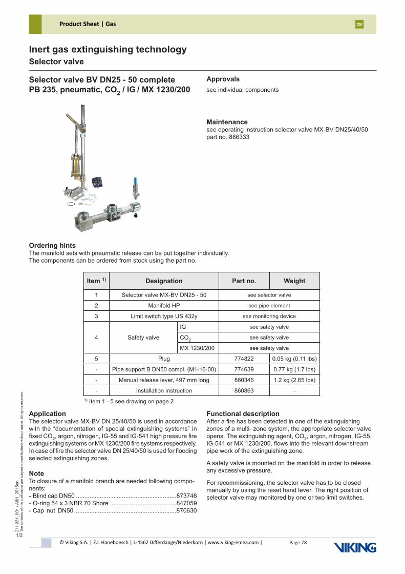
© Viking S.A. | Z.I. Haneboesch | L-4562 Differdange/Niederkorn | www.viking-emea.com |
Product Sheet | Gas
Page 78
211-
331_
001
/ AI0
1_20
15en
The
cont
ents
of t
his
publ
icat
ion
are
subj
ect t
o m
odifi
catio
ns w
ithou
t not
ice.
All
right
s re
serv
ed.
Inert gas extinguishing technologySelector valve
1/2
Selector valve BV DN25 - 50 complete PB 235, pneumatic, CO2 / IG / MX 1230/200
Maintenancesee operating instruction selector valve MX-BV DN25/40/50part no. 886333
ApplicationThe selector valve MX-BV DN 25/40/50 is used in accordance with the “documentation of special extinguishing systems” in fixed CO2, argon, nitrogen, IG-55 and IG-541 high pressure fire extinguishing systems or MX 1230/200 fire systems respectively.In case of fire the selector valve DN 25/40/50 is used for flooding selected extinguishing zones.
NoteTo closure of a manifold branch are needed following compo-nents: - Blind cap DN50 ...........................................................873746- O-ring 54 x 3 NBR 70 Shore .......................................847059- Cap nut DN50 ...........................................................870630
Approvalssee individual components
Functional descriptionAfter a fire has been detected in one of the extinguishing zones of a multi- zone system, the appropriate selector valve opens. The extinguishing agent, CO2, argon, nitrogen, IG-55, IG-541 or MX 1230/200, flows into the relevant downstream pipe work of the extinguishing zone.
A safety valve is mounted on the manifold in order to release any excessive pressure.
For recommissioning, the selector valve has to be closed manually by using the reset hand lever. The right position of selector valve may monitored by one or two limit switches.
Ordering hintsThe manifold sets with pneumatic release can be put together individually.The components can be ordered from stock using the part no.
1) Item 1 - 5 see drawing on page 2
Item 1) Designation Part no. Weight
1 Selector valve MX-BV DN25 - 50 see selector valve
2 Manifold HP see pipe element
3 Limit switch type US 432y see monitoring device
4 Safety valve
IG see safety valve
CO2 see safety valve
MX 1230/200 see safety valve
5 Plug 774822 0.05 kg (0.11 lbs)
- Pipe support B DN50 compl. (M1-16-00) 774639 0.77 kg (1.7 lbs)
- Manual release lever, 497 mm long 860346 1.2 kg (2.65 lbs)
- Installation instruction 860863 -
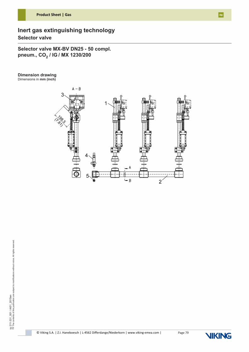
© Viking S.A. | Z.I. Haneboesch | L-4562 Differdange/Niederkorn | www.viking-emea.com |
Product Sheet | Gas
Page 79
211-
331_
001
/ AI0
1_20
15en
The
cont
ents
of t
his
publ
icat
ion
are
subj
ect t
o m
odifi
catio
ns w
ithou
t not
ice.
All
right
s re
serv
ed.
Inert gas extinguishing technologySelector valve
2/2
Dimension drawingDimensions in mm (inch)
Selector valve MX-BV DN25 - 50 compl. pneum., CO2 / IG / MX 1230/200
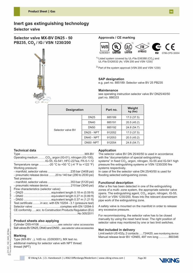
© Viking S.A. | Z.I. Haneboesch | L-4562 Differdange/Niederkorn | www.viking-emea.com |
Product Sheet | Gas
Page 80
211-
331_
102
/ AI0
3_20
16en
The
cont
ents
of t
his
publ
icat
ion
are
subj
ect t
o m
odifi
catio
ns w
ithou
t not
ice.
All
right
s re
serv
ed.
Inert gas extinguishing technologySelector valve
1/2
Selector valve MX-BV DN25 - 50PB235, CO2 / IG / VSN 1230/200
SAP designatione.g. part no. 885189: Selector valve BV 25 PB235
Maintenancesee operating instruction selector valve BV DN25/40/50part no. 886333
Designation Part no. Weight kg (lbs)
Selector valve BV
DN25 885189 17.0 (37.5)
DN40 885191 20.5 (45.2)
DN50 885192 24.8 (54.7)
DN25 - NPT 912052 17.0 (37.5)
DN40 - NPT 912053 20.5 (45.2)
DN50 -NPT 912054 24.8 (54.7)
Technical dataType .................................................................................MX-BVOperating medium .........CO2, argon (IG-01), nitrogen (IG-100),.......................................IG-55, IG-541, HFC-227ea, FK-5-1-12Temperature range ............-20 °C to +50 °C (-4 °F to +122 °F)Working pressure:- manifold, selector valves ............................235 bar (3408 psi)- pneumatic release device ........20 to 140 bar (290 to 2030 psi)Test pressure:- manifold, selector valves ............................353 bar (5120 psi)- pneumatic release device ............................210 bar (3045 psi)Flow characteristics (selector valve):- DN25 ..................................equivalent length 0.18 m (0.59 ft)- DN40 ..................................equivalent length 0.27 m (0.89 ft)- DN50 ..................................equivalent length 0.37 m (1.21 ft)Test certificate .........in acc. with EN 10204 - 3.1 (pressure test)Selector valve ..................................complies with EN 12094-5CE conformity .....acc. to Construction Products Regulation (EU).................................................................................No 305/2011
Product sheets also applyingCylinder D55-H106 .......................see selector valve accessories Ball valves BV DN25, DN40 and DN50 ...see selector valve accessories
MarkingType (MX-BV ..), VdS no. (G393001), MX test no.additonal marking for selector valve with NPT thread:thread (NPT)
ApplicationThe selector valve BV DN 25/40/50 is used in accordance with the “documentation of special extinguishingsystems” in fixed CO2, argon, nitrogen, IG-55 and IG-541 high pressure fire extinguishing systems or VSN 1230/200 fire systems respectively.In case of fire the selector valve DN 25/40/50 is used for flooding selected extinguishing zones.
Functional descriptionAfter a fire has been detected in one of the extinguishing zones of a multi- zone system, the appropriate selector valve opens. The extinguishing agent, CO2, argon, nitrogen, IG-55, IG-541 or VSN 1230/200, flows into the relevant downstream pipe work of the extinguishing zone.
A safety valve is mounted on the manifold in order to release any excessive pressure.
For recommissioning, the selector valve has to be closed manually by using the reset hand lever. The right position of selector valve may monitored by one or two limit switches.
Not included in deliveryLimit switch US 432y, 2 contacts .....724420, see monitoring device Manual release lever BV <DN65, 497 mm long ............860346
Approvals / CE marking
Listed system covered by UL-File EX6388 (CO2) and UL-File EX26532 (Ar, VSN 200 and VSN 1230)
Part of the system approval (VSN 200 and VSN 1230)
1)
2)
0786-CPD-30004G393001
1) 2)
������
1)
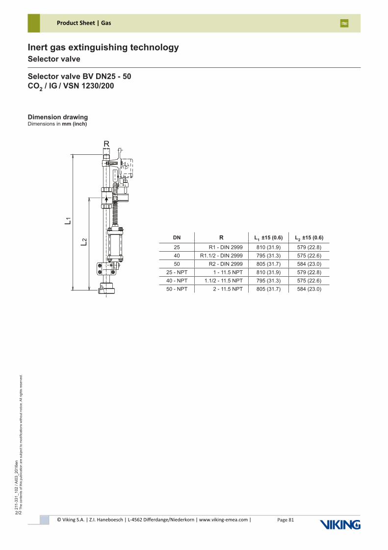
© Viking S.A. | Z.I. Haneboesch | L-4562 Differdange/Niederkorn | www.viking-emea.com |
Product Sheet | Gas
Page 81
211-
331_
102
/ AI0
3_20
16en
The
cont
ents
of t
his
publ
icat
ion
are
subj
ect t
o m
odifi
catio
ns w
ithou
t not
ice.
All
right
s re
serv
ed.
Inert gas extinguishing technologySelector valve
2/2
Selector valve BV DN25 - 50CO2 / IG / VSN 1230/200
Dimension drawingDimensions in mm (inch)
DN R L1 ±15 (0.6) L2 ±15 (0.6)
25 R1 - DIN 2999 810 (31.9) 579 (22.8)40 R1.1/2 - DIN 2999 795 (31.3) 575 (22.6)50 R2 - DIN 2999 805 (31.7) 584 (23.0)
25 - NPT 1 - 11.5 NPT 810 (31.9) 579 (22.8)40 - NPT 1.1/2 - 11.5 NPT 795 (31.3) 575 (22.6)50 - NPT 2 - 11.5 NPT 805 (31.7) 584 (23.0)
L1
L2
R
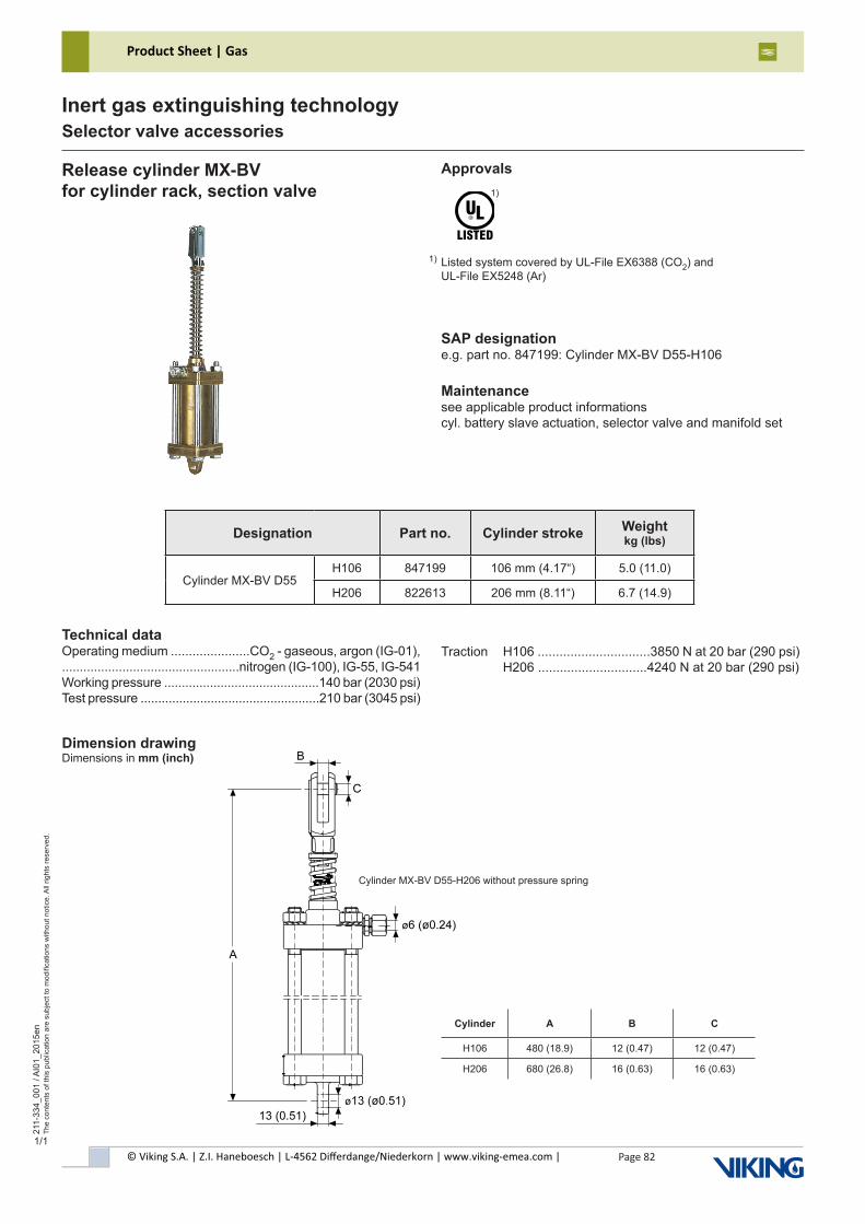
© Viking S.A. | Z.I. Haneboesch | L-4562 Differdange/Niederkorn | www.viking-emea.com |
Product Sheet | Gas
Page 82
211-
334_
001
/ AI0
1_20
15en
The
cont
ents
of t
his
publ
icat
ion
are
subj
ect t
o m
odifi
catio
ns w
ithou
t not
ice.
All
right
s re
serv
ed.
Inert gas extinguishing technologySelector valve accessories
1/1
Release cylinder MX-BVfor cylinder rack, section valve
SAP designatione.g. part no. 847199: Cylinder MX-BV D55-H106
Maintenancesee applicable product informationscyl. battery slave actuation, selector valve and manifold set
Technical dataOperating medium ......................CO2 - gaseous, argon (IG-01),..................................................nitrogen (IG-100), IG-55, IG-541Working pressure ............................................140 bar (2030 psi)Test pressure ...................................................210 bar (3045 psi)
Approvals
Listed system covered by UL-File EX6388 (CO2) and UL-File EX5248 (Ar)
1)
1)
Designation Part no. Cylinder stroke Weight kg (lbs)
Cylinder MX-BV D55H106 847199 106 mm (4.17“) 5.0 (11.0)
H206 822613 206 mm (8.11“) 6.7 (14.9)
Cylinder MX-BV D55-H206 without pressure spring
Dimension drawingDimensions in mm (inch)
Cylinder A B C
H106 480 (18.9) 12 (0.47) 12 (0.47)
H206 680 (26.8) 16 (0.63) 16 (0.63)
Traction H106 ...............................3850 N at 20 bar (290 psi) H206 ..............................4240 N at 20 bar (290 psi)
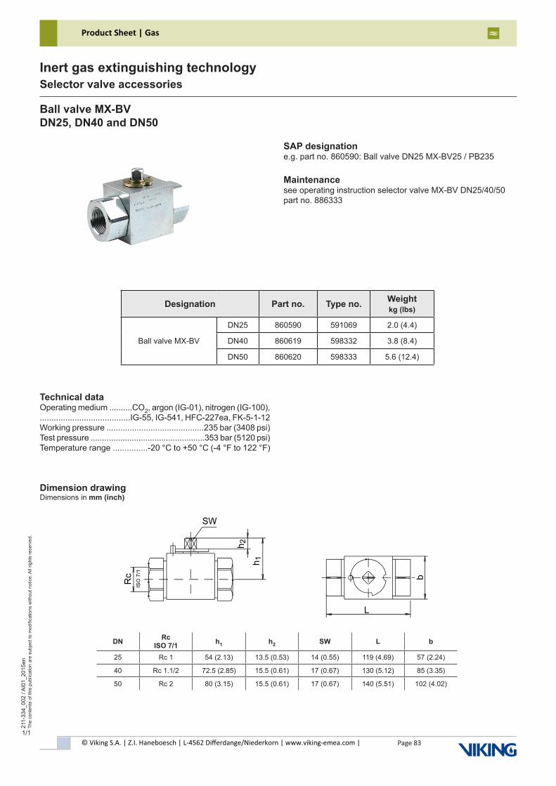
© Viking S.A. | Z.I. Haneboesch | L-4562 Differdange/Niederkorn | www.viking-emea.com |
Product Sheet | Gas
Page 83
211-
334_
002
/ AI0
1_20
15en
The
cont
ents
of t
his
publ
icat
ion
are
subj
ect t
o m
odifi
catio
ns w
ithou
t not
ice.
All
right
s re
serv
ed.
Inert gas extinguishing technologySelector valve accessories
1/1
Ball valve MX-BVDN25, DN40 and DN50
SAP designatione.g. part no. 860590: Ball valve DN25 MX-BV25 / PB235
Maintenancesee operating instruction selector valve MX-BV DN25/40/50part no. 886333
Technical dataOperating medium ..........CO2, argon (IG-01), nitrogen (IG-100),.......................................IG-55, IG-541, HFC-227ea, FK-5-1-12Working pressure ..........................................235 bar (3408 psi)Test pressure ..................................................353 bar (5120 psi)Temperature range ...............-20 °C to +50 °C (-4 °F to 122 °F)
Designation Part no. Type no. Weightkg (lbs)
Ball valve MX-BV
DN25 860590 591069 2.0 (4.4)
DN40 860619 598332 3.8 (8.4)
DN50 860620 598333 5.6 (12.4)
Dimension drawingDimensions in mm (inch)
DN Rc ISO 7/1 h1 h2 SW L b
25 Rc 1 54 (2.13) 13.5 (0.53) 14 (0.55) 119 (4.69) 57 (2.24)
40 Rc 1.1/2 72.5 (2.85) 15.5 (0.61) 17 (0.67) 130 (5.12) 85 (3.35)
50 Rc 2 80 (3.15) 15.5 (0.61) 17 (0.67) 140 (5.51) 102 (4.02)
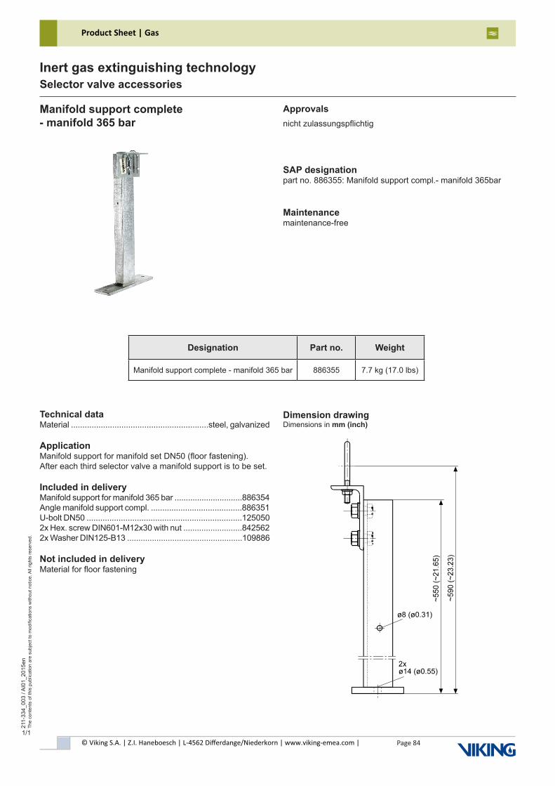
© Viking S.A. | Z.I. Haneboesch | L-4562 Differdange/Niederkorn | www.viking-emea.com |
Product Sheet | Gas
Page 84
211-
334_
003
/ AI0
1_20
15en
The
cont
ents
of t
his
publ
icat
ion
are
subj
ect t
o m
odifi
catio
ns w
ithou
t not
ice.
All
right
s re
serv
ed.
Inert gas extinguishing technologySelector valve accessories
1/1
Manifold support complete- manifold 365 bar
Technical dataMaterial ............................................................steel, galvanized
ApplicationManifold support for manifold set DN50 (floor fastening).After each third selector valve a manifold support is to be set.
Included in deliveryManifold support for manifold 365 bar ..............................886354Angle manifold support compl. ........................................886351U-bolt DN50 ....................................................................1250502x Hex. screw DIN601-M12x30 with nut ..........................8425622x Washer DIN125-B13 ...................................................109886
Not included in deliveryMaterial for floor fastening
Approvalsnicht zulassungspflichtig
Designation Part no. Weight
Manifold support complete - manifold 365 bar 886355 7.7 kg (17.0 lbs)
Dimension drawingDimensions in mm (inch)
SAP designationpart no. 886355: Manifold support compl.- manifold 365bar
Maintenancemaintenance-free
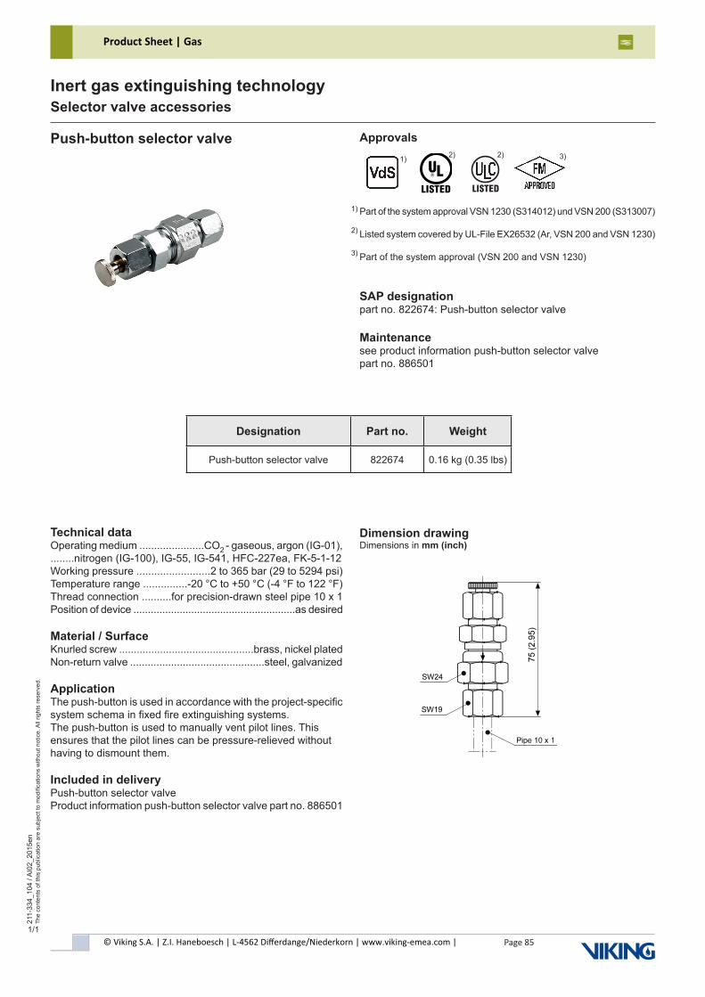
© Viking S.A. | Z.I. Haneboesch | L-4562 Differdange/Niederkorn | www.viking-emea.com |
Product Sheet | Gas
Page 85
211-
334_
104
/ AI0
2_20
15en
The
cont
ents
of t
his
publ
icat
ion
are
subj
ect t
o m
odifi
catio
ns w
ithou
t not
ice.
All
right
s re
serv
ed.
Inert gas extinguishing technologySelector valve accessories
1/1
Push-button selector valve
Technical dataOperating medium ......................CO2 - gaseous, argon (IG-01),........nitrogen (IG-100), IG-55, IG-541, HFC-227ea, FK-5-1-12Working pressure .........................2 to 365 bar (29 to 5294 psi)Temperature range ...............-20 °C to +50 °C (-4 °F to 122 °F)Thread connection ..........for precision-drawn steel pipe 10 x 1Position of device ........................................................as desired
Material / SurfaceKnurled screw ..............................................brass, nickel platedNon-return valve ..............................................steel, galvanized
ApplicationThe push-button is used in accordance with the project-specific system schema in fixed fire extinguishing systems.The push-button is used to manually vent pilot lines. This ensures that the pilot lines can be pressure-relieved without having to dismount them.
Included in deliveryPush-button selector valveProduct information push-button selector valve part no. 886501
Designation Part no. Weight
Push-button selector valve 822674 0.16 kg (0.35 lbs)
Dimension drawingDimensions in mm (inch)
SAP designationpart no. 822674: Push-button selector valve
Maintenancesee product information push-button selector valvepart no. 886501
Approvals
Part of the system approval VSN 1230 (S314012) und VSN 200 (S313007)
Listed system covered by UL-File EX26532 (Ar, VSN 200 and VSN 1230)
Part of the system approval (VSN 200 and VSN 1230)
1)
2)
3)
2) 3)
������
2) 1)
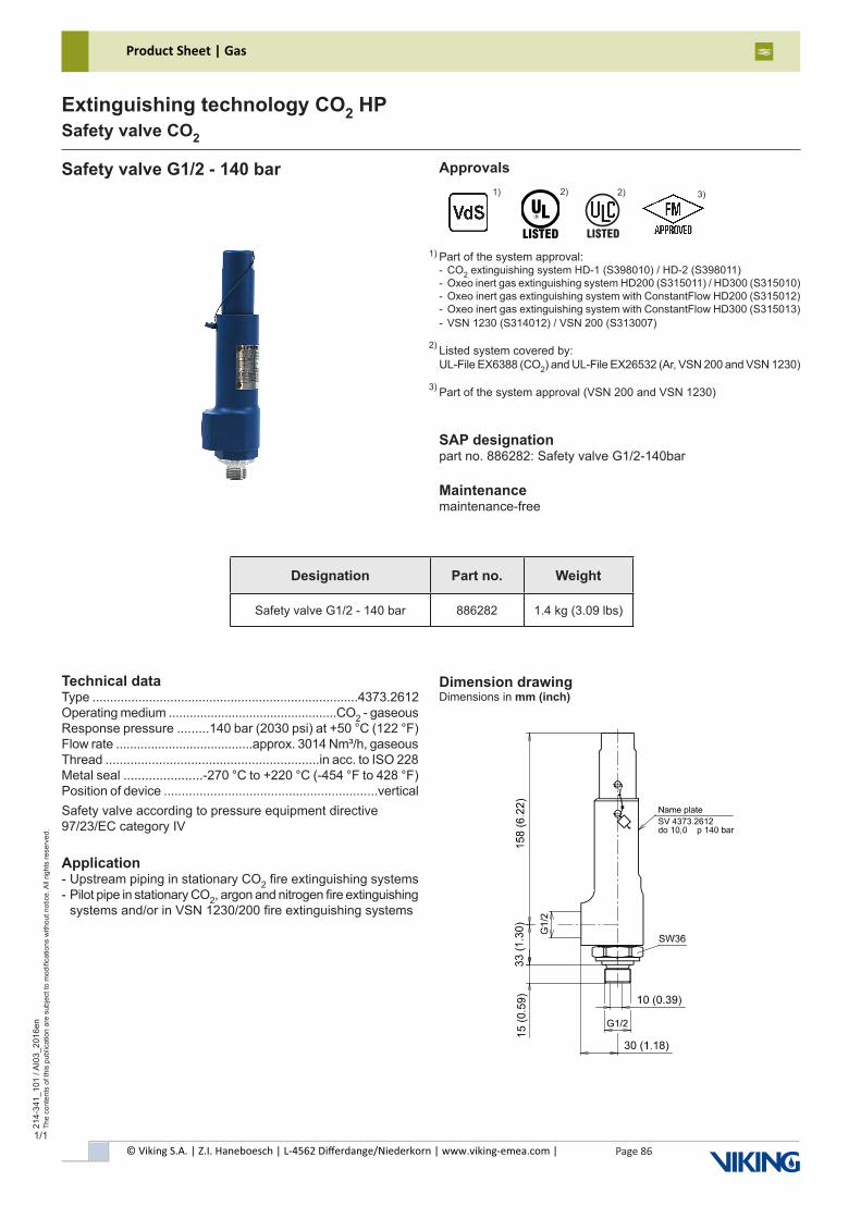
© Viking S.A. | Z.I. Haneboesch | L-4562 Differdange/Niederkorn | www.viking-emea.com |
Product Sheet | Gas
Page 86
214-
341_
101
/ AI0
3_20
16en
The
cont
ents
of t
his
publ
icat
ion
are
subj
ect t
o m
odifi
catio
ns w
ithou
t not
ice.
All
right
s re
serv
ed.
Extinguishing technology CO2 HPSafety valve CO2
1/1
Safety valve G1/2 - 140 bar Approvals
Part of the system approval:- CO2 extinguishing system HD-1 (S398010) / HD-2 (S398011)- Oxeo inert gas extinguishing system HD200 (S315011) / HD300 (S315010)- Oxeo inert gas extinguishing system with ConstantFlow HD200 (S315012)- Oxeo inert gas extinguishing system with ConstantFlow HD300 (S315013)- VSN 1230 (S314012) / VSN 200 (S313007)
Listed system covered by:UL-File EX6388 (CO2) and UL-File EX26532 (Ar, VSN 200 and VSN 1230)
Part of the system approval (VSN 200 and VSN 1230)
1)
2)
SAP designationpart no. 886282: Safety valve G1/2-140bar
Maintenancemaintenance-free
Technical dataType ...........................................................................4373.2612Operating medium ................................................CO2 - gaseousResponse pressure .........140 bar (2030 psi) at +50 °C (122 °F)Flow rate .......................................approx. 3014 Nm³/h, gaseousThread ............................................................in acc. to ISO 228Metal seal ......................-270 °C to +220 °C (-454 °F to 428 °F)Position of device ............................................................verticalSafety valve according to pressure equipment directive97/23/EC category IV
Application- Upstream piping in stationary CO2 fire extinguishing systems- Pilot pipe in stationary CO2, argon and nitrogen fire extinguishing systems and/or in VSN 1230/200 fire extinguishing systems
Dimension drawingDimensions in mm (inch)
Designation Part no. Weight
Safety valve G1/2 - 140 bar 886282 1.4 kg (3.09 lbs)
3)
2)1) 3)
������
2)
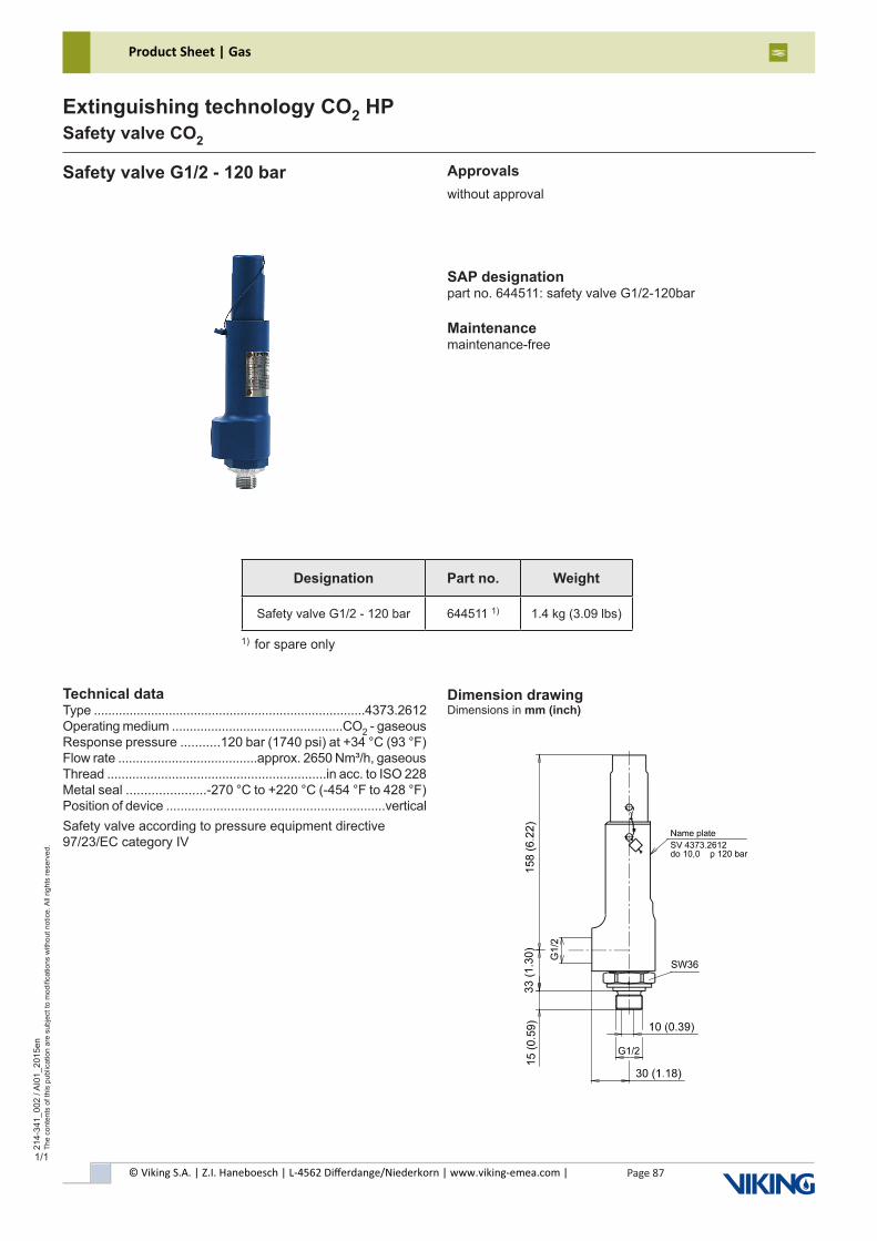
© Viking S.A. | Z.I. Haneboesch | L-4562 Differdange/Niederkorn | www.viking-emea.com |
Product Sheet | Gas
Page 87
214-
341_
002
/ AI0
1_20
15en
The
cont
ents
of t
his
publ
icat
ion
are
subj
ect t
o m
odifi
catio
ns w
ithou
t not
ice.
All
right
s re
serv
ed.
Extinguishing technology CO2 HPSafety valve CO2
1/1
Safety valve G1/2 - 120 bar Approvalswithout approval
SAP designationpart no. 644511: safety valve G1/2-120bar
Maintenancemaintenance-free
Technical dataType ............................................................................4373.2612Operating medium ................................................CO2 - gaseousResponse pressure ...........120 bar (1740 psi) at +34 °C (93 °F)Flow rate .......................................approx. 2650 Nm³/h, gaseousThread .............................................................in acc. to ISO 228Metal seal ......................-270 °C to +220 °C (-454 °F to 428 °F)Position of device .............................................................verticalSafety valve according to pressure equipment directive97/23/EC category IV
Dimension drawingDimensions in mm (inch)
1) for spare only
Designation Part no. Weight
Safety valve G1/2 - 120 bar 644511 1) 1.4 kg (3.09 lbs)
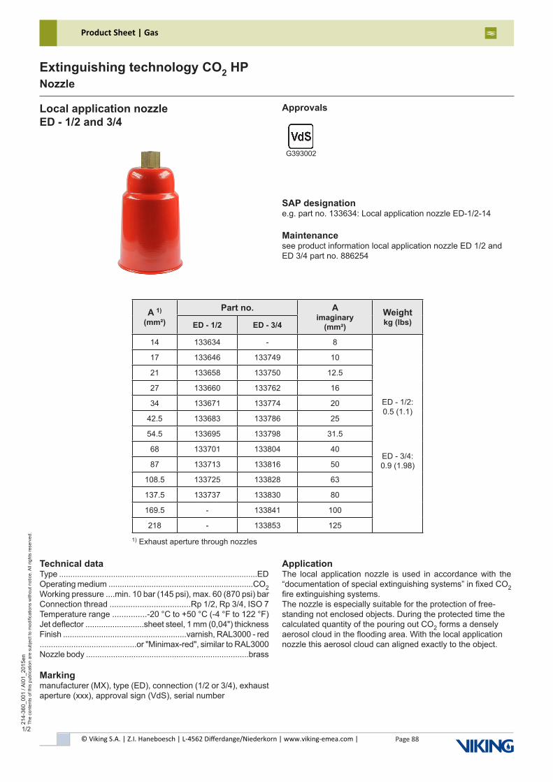
© Viking S.A. | Z.I. Haneboesch | L-4562 Differdange/Niederkorn | www.viking-emea.com |
Product Sheet | Gas
Page 88
214-
360_
001
/ AI0
1_20
15en
The
cont
ents
of t
his
publ
icat
ion
are
subj
ect t
o m
odifi
catio
ns w
ithou
t not
ice.
All
right
s re
serv
ed.
Extinguishing technology CO2 HPNozzle
1/2
A 1) (mm²)
Part no. A imaginary
(mm²)
Weight kg (lbs)ED - 1/2 ED - 3/4
14 133634 - 8
ED - 1/2: 0.5 (1.1)
ED - 3/4: 0.9 (1.98)
17 133646 133749 10
21 133658 133750 12.5
27 133660 133762 16
34 133671 133774 20
42.5 133683 133786 25
54.5 133695 133798 31.5
68 133701 133804 40
87 133713 133816 50
108.5 133725 133828 63
137.5 133737 133830 80
169.5 - 133841 100
218 - 133853 125
Local application nozzle ED - 1/2 and 3/4
Approvals
SAP designatione.g. part no. 133634: Local application nozzle ED-1/2-14
Maintenancesee product information local application nozzle ED 1/2 andED 3/4 part no. 886254
G393002
Technical dataType ........................................................................................EDOperating medium ................................................................CO2Working pressure ....min. 10 bar (145 psi), max. 60 (870 psi) barConnection thread ...................................Rp 1/2, Rp 3/4, ISO 7Temperature range ...............-20 °C to +50 °C (-4 °F to 122 °F)Jet deflector ..........................sheet steel, 1 mm (0,04") thicknessFinish .......................................................varnish, RAL3000 - red...........................................or "Minimax-red", similar to RAL3000Nozzle body ........................................................................brass
Markingmanufacturer (MX), type (ED), connection (1/2 or 3/4), exhaust aperture (xxx), approval sign (VdS), serial number
ApplicationThe local application nozzle is used in accordance with the “documentation of special extinguishing systems” in fixed CO2 fire extinguishing systems.The nozzle is especially suitable for the protection of free-standing not enclosed objects. During the protected time the calculated quantity of the pouring out CO2 forms a densely aerosol cloud in the flooding area. With the local application nozzle this aerosol cloud can aligned exactly to the object.
1) Exhaust aperture through nozzles
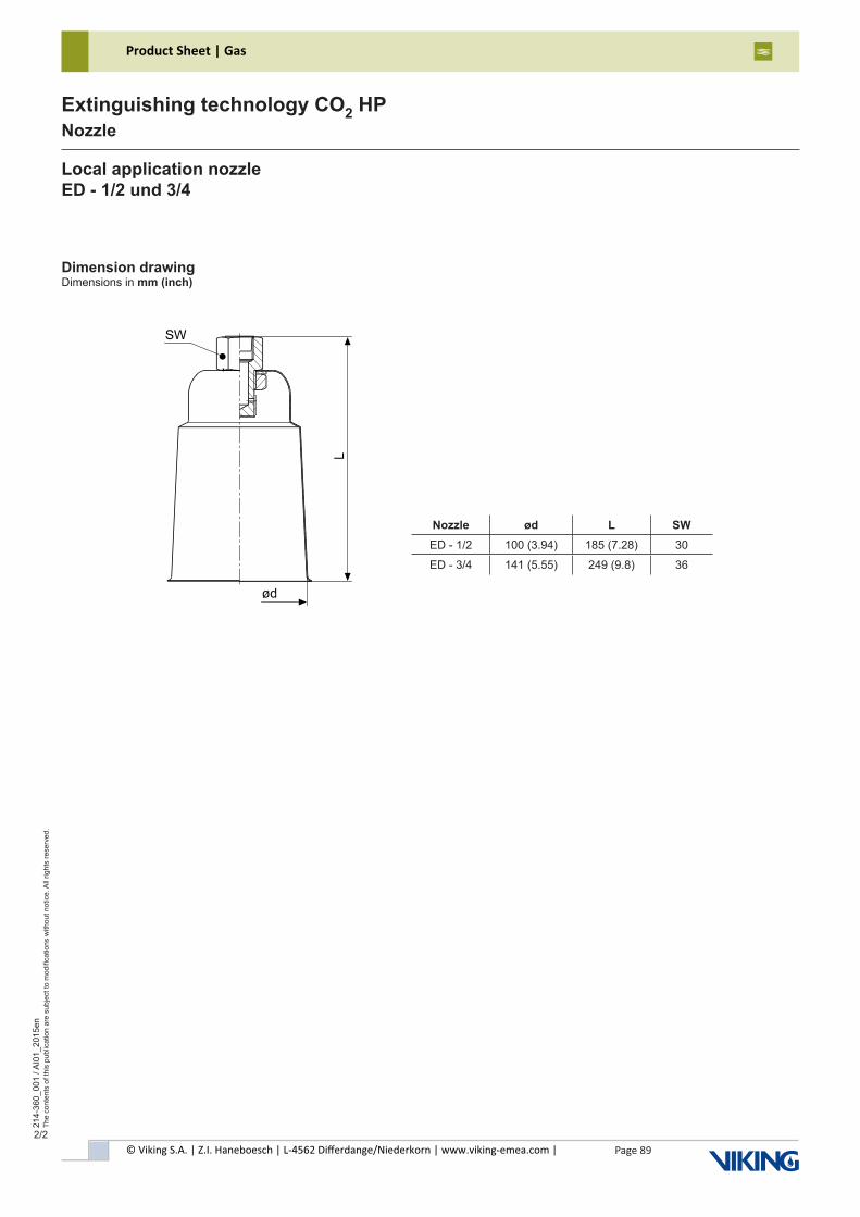
© Viking S.A. | Z.I. Haneboesch | L-4562 Differdange/Niederkorn | www.viking-emea.com |
Product Sheet | Gas
Page 89
214-
360_
001
/ AI0
1_20
15en
The
cont
ents
of t
his
publ
icat
ion
are
subj
ect t
o m
odifi
catio
ns w
ithou
t not
ice.
All
right
s re
serv
ed.
Extinguishing technology CO2 HPNozzle
2/2
Local application nozzle ED - 1/2 und 3/4
Dimension drawingDimensions in mm (inch)
Nozzle ød L SWED - 1/2 100 (3.94) 185 (7.28) 30
ED - 3/4 141 (5.55) 249 (9.8) 36
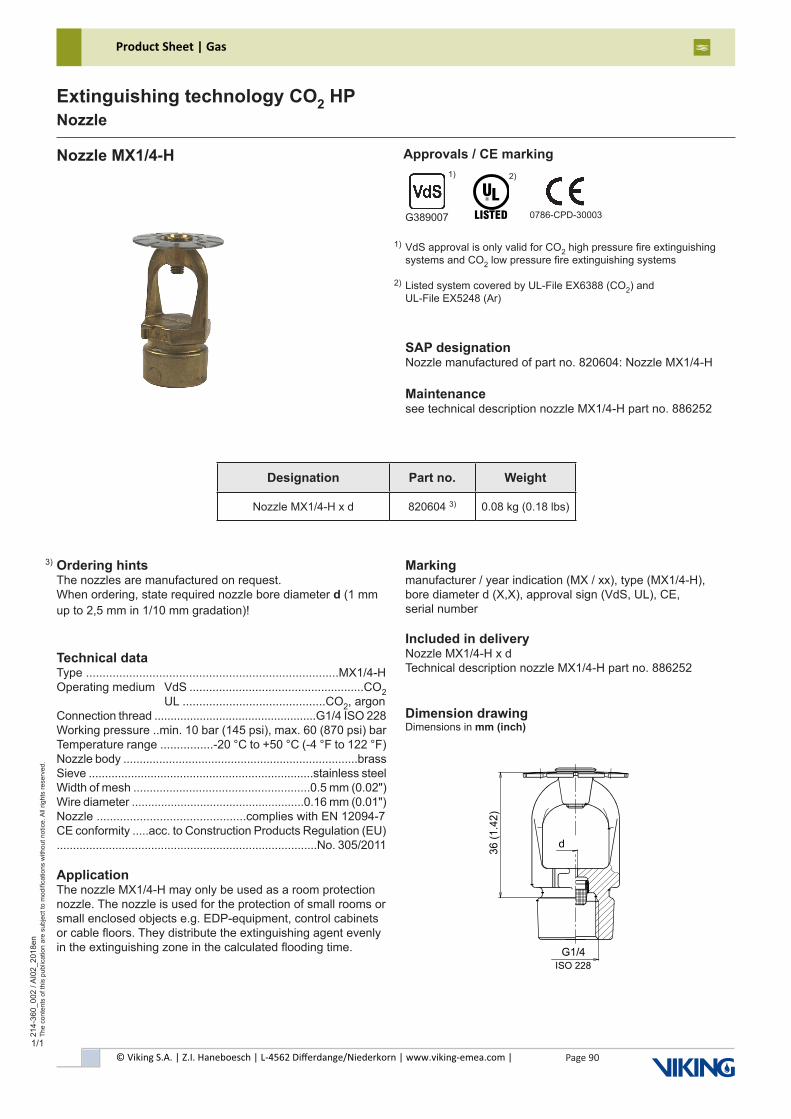
© Viking S.A. | Z.I. Haneboesch | L-4562 Differdange/Niederkorn | www.viking-emea.com |
Product Sheet | Gas
Page 90
214-
360_
002
/ AI0
2_20
18en
The
cont
ents
of t
his
publ
icat
ion
are
subj
ect t
o m
odifi
catio
ns w
ithou
t not
ice.
All
right
s re
serv
ed.
Extinguishing technology CO2 HPNozzle
1/1
Nozzle MX1/4-H Approvals / CE marking
SAP designationNozzle manufactured of part no. 820604: Nozzle MX1/4-H
Maintenancesee technical description nozzle MX1/4-H part no. 886252
Ordering hintsThe nozzles are manufactured on request.When ordering, state required nozzle bore diameter d (1 mm up to 2,5 mm in 1/10 mm gradation)!
Technical dataType ............................................................................MX1/4-HOperating medium VdS .....................................................CO2 UL ...........................................CO2, argonConnection thread ..................................................G1/4 ISO 228Working pressure ..min. 10 bar (145 psi), max. 60 (870 psi) barTemperature range ................-20 °C to +50 °C (-4 °F to 122 °F)Nozzle body ........................................................................brassSieve .....................................................................stainless steelWidth of mesh ......................................................0.5 mm (0.02")Wire diameter .....................................................0.16 mm (0.01")Nozzle .............................................complies with EN 12094-7CE conformity .....acc. to Construction Products Regulation (EU)................................................................................No. 305/2011
ApplicationThe nozzle MX1/4-H may only be used as a room protection nozzle. The nozzle is used for the protection of small rooms or small enclosed objects e.g. EDP-equipment, control cabinets or cable floors. They distribute the extinguishing agent evenly in the extinguishing zone in the calculated flooding time.
3)
Dimension drawingDimensions in mm (inch)
Markingmanufacturer / year indication (MX / xx), type (MX1/4-H),bore diameter d (X,X), approval sign (VdS, UL), CE,serial number
Included in deliveryNozzle MX1/4-H x dTechnical description nozzle MX1/4-H part no. 886252
Designation Part no. Weight
Nozzle MX1/4-H x d 820604 3) 0.08 kg (0.18 lbs)
2)
G389007 0786-CPD-30003
1)
VdS approval is only valid for CO2 high pressure fire extinguishingsystems and CO2 low pressure fire extinguishing systems
Listed system covered by UL-File EX6388 (CO2) andUL-File EX5248 (Ar)
1)
2)
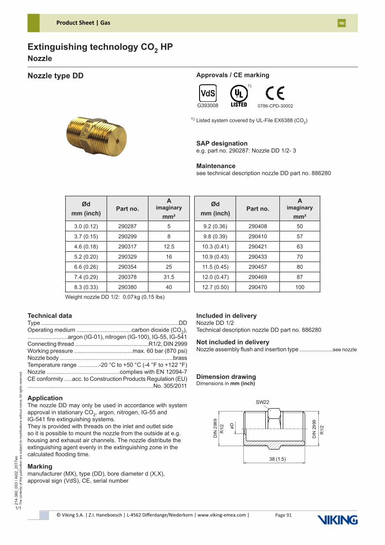
© Viking S.A. | Z.I. Haneboesch | L-4562 Differdange/Niederkorn | www.viking-emea.com |
Product Sheet | Gas
Page 91
214-
360_
003
/ AI0
2_20
17en
The
cont
ents
of t
his
publ
icat
ion
are
subj
ect t
o m
odifi
catio
ns w
ithou
t not
ice.
All
right
s re
serv
ed.
Extinguishing technology CO2 HPNozzle
1/1
Ødmm (inch)
Part no.A
imaginarymm²
Ødmm (inch)
Part no.A
imaginarymm²
3.0 (0.12) 290287 5 9.2 (0.36) 290408 50
3.7 (0.15) 290299 8 9.8 (0.39) 290410 57
4.6 (0.18) 290317 12.5 10.3 (0.41) 290421 63
5.2 (0.20) 290329 16 10.9 (0.43) 290433 70
6.6 (0.26) 290354 25 11.5 (0.45) 290457 80
7.4 (0.29) 290378 31.5 12.0 (0.47) 290469 87
8.3 (0.33) 290380 40 12.7 (0.50) 290470 100
Nozzle type DD Approvals / CE marking
SAP designatione.g. part no. 290287: Nozzle DD 1/2- 3
Maintenancesee technical description nozzle DD part no. 886280
Listed system covered by UL-File EX6388 (CO2)
1)
G393008 0786-CPD-30002
1)
Technical dataType .......................................................................................DDOperating medium ..................................carbon dioxide (CO2),.........................argon (IG-01), nitrogen (IG-100), IG-55, IG-541Connecting thread ...............................................R1/2, DIN 2999Working pressure ....................................max. 60 bar (870 psi)Nozzle body ........................................................................brassTemperature range .............-20 °C to +50 °C (-4 °F to +122 °F)Nozzle .............................................complies with EN 12094-7CE conformity .....acc. to Construction Products Regulation (EU)................................................................................No. 305/2011
ApplicationThe nozzle DD may only be used in accordance with system approval in stationary CO2, argon, nitrogen, IG-55 andIG-541 fire extinguishing systems.They is provided with threads on the inlet and outlet side so it is possible to mount the nozzle from the outside at e.g. housing and exhaust air channels. The nozzle distribute the extinguishing agent evenly in the extinguishing zone in the calculated flooding time.
Markingmanufacturer (MX), type (DD), bore diameter d (X,X),approval sign (VdS), CE, serial number
Dimension drawingDimensions in mm (inch)
Included in deliveryNozzle DD 1/2Technical description nozzle DD part no. 886280
Not included in deliveryNozzle assembly flush and insertion type .....................see nozzle
Weight nozzle DD 1/2: 0,07 kg (0,15 lbs)
R1/
2
SW22
38 (1.5)
øD
DIN
299
9
R1/
2
DIN
299
9
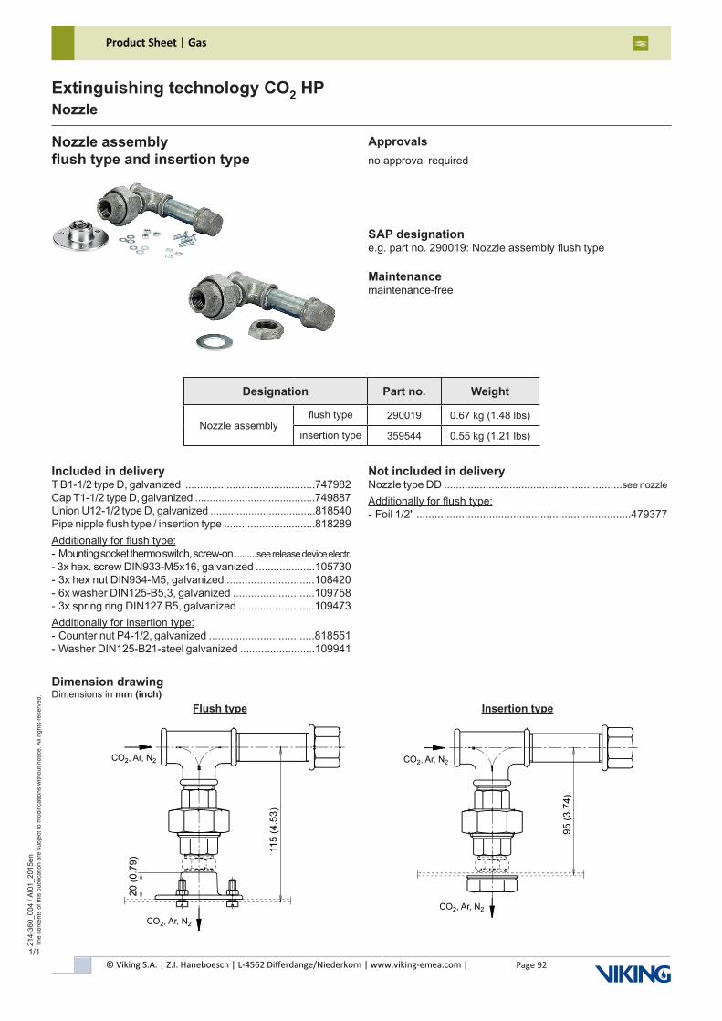
© Viking S.A. | Z.I. Haneboesch | L-4562 Differdange/Niederkorn | www.viking-emea.com |
Product Sheet | Gas
Page 92
214-
360_
004
/ AI0
1_20
15en
The
cont
ents
of t
his
publ
icat
ion
are
subj
ect t
o m
odifi
catio
ns w
ithou
t not
ice.
All
right
s re
serv
ed.
Extinguishing technology CO2 HPNozzle
1/1
Nozzle assemblyflush type and insertion type
Approvalsno approval required
SAP designatione.g. part no. 290019: Nozzle assembly flush type
Maintenancemaintenance-free
Included in deliveryT B1-1/2 type D, galvanized ............................................747982Cap T1-1/2 type D, galvanized .........................................749887Union U12-1/2 type D, galvanized ....................................818540Pipe nipple flush type / insertion type ...............................818289Additionally for flush type:- Mounting socket thermo switch, screw-on .........see release device electr.- 3x hex. screw DIN933-M5x16, galvanized ....................105730- 3x hex nut DIN934-M5, galvanized .............................108420- 6x washer DIN125-B5,3, galvanized ...........................109758- 3x spring ring DIN127 B5, galvanized .........................109473Additionally for insertion type:- Counter nut P4-1/2, galvanized ...................................818551- Washer DIN125-B21-steel galvanized .........................109941
Not included in deliveryNozzle type DD ............................................................see nozzle
Additionally for flush type:- Foil 1/2" .......................................................................479377
Flush type Insertion type
Dimension drawingDimensions in mm (inch)
Designation Part no. Weight
Nozzle assemblyflush type 290019 0.67 kg (1.48 lbs)
insertion type 359544 0.55 kg (1.21 lbs)
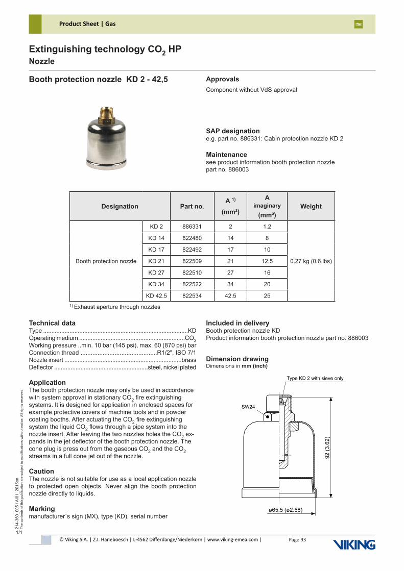
Page 93© Viking S.A. | Z.I. Haneboesch | L-4562 Differdange/Niederkorn | www.viking-emea.com |
Product Sheet | Gas21
4-36
0_00
5 / A
I01_
2015
enTh
e co
nten
ts o
f thi
s pu
blic
atio
n ar
e su
bjec
t to
mod
ifica
tions
with
out n
otic
e. A
ll rig
hts
rese
rved
.
Extinguishing technology CO2 HPNozzle
1/1
Designation Part no.A 1)
(mm²)
A imaginary
(mm²)Weight
Booth protection nozzle
KD 2 886331 2 1.2
0.27 kg (0.6 lbs)
KD 14 822480 14 8
KD 17 822492 17 10
KD 21 822509 21 12.5
KD 27 822510 27 16
KD 34 822522 34 20
KD 42.5 822534 42.5 25
Booth protection nozzle KD 2 - 42,5 ApprovalsComponent without VdS approval
SAP designatione.g. part no. 886331: Cabin protection nozzle KD 2
Maintenancesee product information booth protection nozzlepart no. 886003
1) Exhaust aperture through nozzles
Technical dataType ........................................................................................KDOperating medium ................................................................CO2Working pressure ..min. 10 bar (145 psi), max. 60 (870 psi) barConnection thread .............................................R1/2", ISO 7/1Nozzle insert .......................................................................brassDeflector .........................................................steel, nickel plated
ApplicationThe booth protection nozzle may only be used in accordance with system approval in stationary CO2 fire extinguishing systems. It is designed for application in enclosed spaces for example protective covers of machine tools and in powder coating booths. After actuating the CO2 fire extinguishing system the liquid CO2 flows through a pipe system into the nozzle insert. After leaving the two nozzles holes the CO2 ex-pands in the jet deflector of the booth protection nozzle. The cone plug is press out from the gaseous CO2 and the CO2 streams in a full cone jet out of the nozzle.
CautionThe nozzle is not suitable for use as a local application nozzle to protected open objects. Never align the booth protection nozzle directly to liquids.
Markingmanufacturer´s sign (MX), type (KD), serial number
Included in deliveryBooth protection nozzle KDProduct information booth protection nozzle part no. 886003
Dimension drawingDimensions in mm (inch)
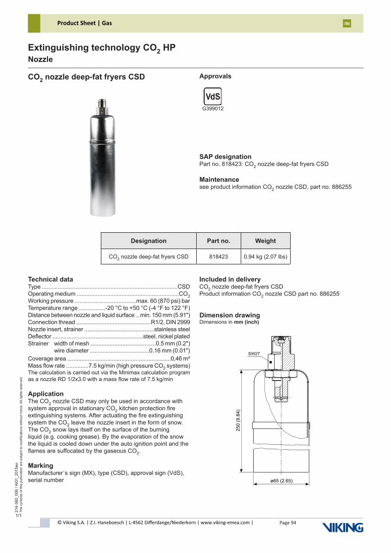
© Viking S.A. | Z.I. Haneboesch | L-4562 Differdange/Niederkorn | www.viking-emea.com |
Product Sheet | Gas
Page 94
214-
360_
006
/ AI0
1_20
15en
The
cont
ents
of t
his
publ
icat
ion
are
subj
ect t
o m
odifi
catio
ns w
ithou
t not
ice.
All
right
s re
serv
ed.
Extinguishing technology CO2 HPNozzle
1/1
CO2 nozzle deep-fat fryers CSD Approvals
SAP designationPart no. 818423: CO2 nozzle deep-fat fryers CSD
Maintenancesee product information CO2 nozzle CSD, part no. 886255
G399012
Technical dataType .....................................................................................CSDOperating medium ................................................................CO2Working pressure ......................................max. 60 (870 psi) barTemperature range ................-20 °C to +50 °C (-4 °F to 122 °F)Distance between nozzle and liquid surface ...min. 150 mm (5.91")Connection thread ...............................................R1/2, DIN 2999Nozzle insert, strainer ............................................stainless steelDeflector .........................................................steel, nickel platedStrainer width of mesh .........................................0.5 mm (0.2") wire diameter .....................................0.16 mm (0.01")Coverage area .................................................................0,46 m²Mass flow rate ..............7.5 kg/min (high pressure CO2 systems)The calculation is carried out via the Minimax calculation program as a nozzle RD 1/2x3.0 with a mass flow rate of 7.5 kg/min
ApplicationThe CO2 nozzle CSD may only be used in accordance with system approval in stationary CO2 kitchen protection fire extinguishing systems. After actuating the fire extinguishing system the CO2 leave the nozzle insert in the form of snow. The CO2 snow lays itself on the surface of the burningliquid (e.g. cooking grease). By the evaporation of the snow the liquid is cooled down under the auto ignition point and the flames are suffocated by the gaseous CO2.
MarkingManufacturer´s sign (MX), type (CSD), approval sign (VdS),serial number
Included in deliveryCO2 nozzle deep-fat fryers CSDProduct information CO2 nozzle CSD part no. 886255
Dimension drawingDimensions in mm (inch)
Designation Part no. Weight
CO2 nozzle deep-fat fryers CSD 818423 0.94 kg (2.07 lbs)
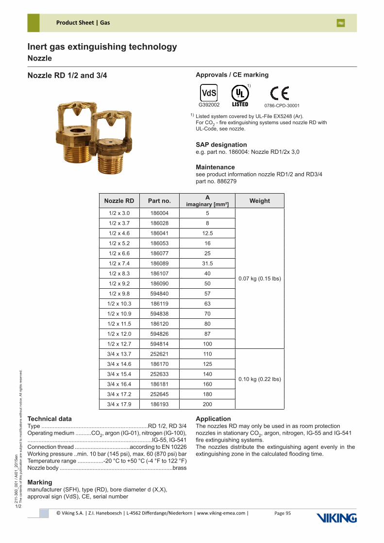
© Viking S.A. | Z.I. Haneboesch | L-4562 Differdange/Niederkorn | www.viking-emea.com |
Product Sheet | Gas
Page 95
211-
360_
001
/ AI0
1_20
15en
The
cont
ents
of t
his
publ
icat
ion
are
subj
ect t
o m
odifi
catio
ns w
ithou
t not
ice.
All
right
s re
serv
ed.
Inert gas extinguishing technologyNozzle
1/2
Nozzle RD 1/2 and 3/4
SAP designatione.g. part no. 186004: Nozzle RD1/2x 3,0
Maintenancesee product information nozzle RD1/2 and RD3/4part no. 886279
Nozzle RD Part no. A imaginary [mm²] Weight
1/2 x 3.0 186004 5
0.07 kg (0.15 lbs)
1/2 x 3.7 186028 8
1/2 x 4.6 186041 12.5
1/2 x 5.2 186053 16
1/2 x 6.6 186077 25
1/2 x 7.4 186089 31.5
1/2 x 8.3 186107 40
1/2 x 9.2 186090 50
1/2 x 9.8 594840 57
1/2 x 10.3 186119 63
1/2 x 10.9 594838 70
1/2 x 11.5 186120 80
1/2 x 12.0 594826 87
1/2 x 12.7 594814 100
3/4 x 13.7 252621 110
0.10 kg (0.22 lbs)
3/4 x 14.6 186170 125
3/4 x 15.4 252633 140
3/4 x 16.4 186181 160
3/4 x 17.2 252645 180
3/4 x 17.9 186193 200
Technical dataType ..................................................................RD 1/2, RD 3/4Operating medium ..........CO2, argon (IG-01), nitrogen (IG-100),...............................................................................IG-55, IG-541Connection thread ...................................according to EN 10226Working pressure ..min. 10 bar (145 psi), max. 60 (870 psi) barTemperature range ................-20 °C to +50 °C (-4 °F to 122 °F)Nozzle body ........................................................................brass
Markingmanufacturer (SFH), type (RD), bore diameter d (X,X),approval sign (VdS), CE, serial number
ApplicationThe nozzles RD may only be used in as room protection nozzles in stationary CO2, argon, nitrogen, IG-55 and IG-541fire extinguishing systems.The nozzles distribute the extinguishing agent evenly in the extinguishing zone in the calculated flooding time.
Approvals / CE marking
0786-CPD-30001
Listed system covered by UL-File EX5248 (Ar).For CO2 - fire extinguishing systems used nozzle RD withUL-Code, see nozzle.
1)
G392002
1)

© Viking S.A. | Z.I. Haneboesch | L-4562 Differdange/Niederkorn | www.viking-emea.com |
Product Sheet | Gas
Page 96
211-
360_
001
/ AI0
1_20
15en
The
cont
ents
of t
his
publ
icat
ion
are
subj
ect t
o m
odifi
catio
ns w
ithou
t not
ice.
All
right
s re
serv
ed.
Inert gas extinguishing technologyNozzle
2/2
Nozzle RD 1/2 and 3/4
Dimension drawingDimensions in mm (inch)
Nozzle RD ød
1/2 x 3.0 3.0 (0.12)1/2 x 3.7 3.7 (0.15)1/2 x 4.6 4.6 (0.18)1/2 x 5.2 5.2 (0.2)1/2 x 6.6 6.6 (0.26)1/2 x 7.4 7.4 (0.29)1/2 x 8.3 8.3 (0.33)1/2 x 9.2 9.2 (0.36)1/2 x 9.8 9.8 (0.39)1/2 x 10.3 10.3 (0.41)1/2 x 10.9 10.9 (0.43)1/2 x 11.5 11.5 (0.45)1/2 x 12.0 12.0 (0.47)1/2 x 12.7 12.7 (0.5)3/4 x 13.7 13.7 (0.54)3/4 x 14.6 14.6 (0.57)3/4 x 15.4 15.4 (0.61)3/4 x 16.4 16.4 (0.65)3/4 x 17.2 17.2 (0.68)3/4 x 17.9 17.9 (0.7)
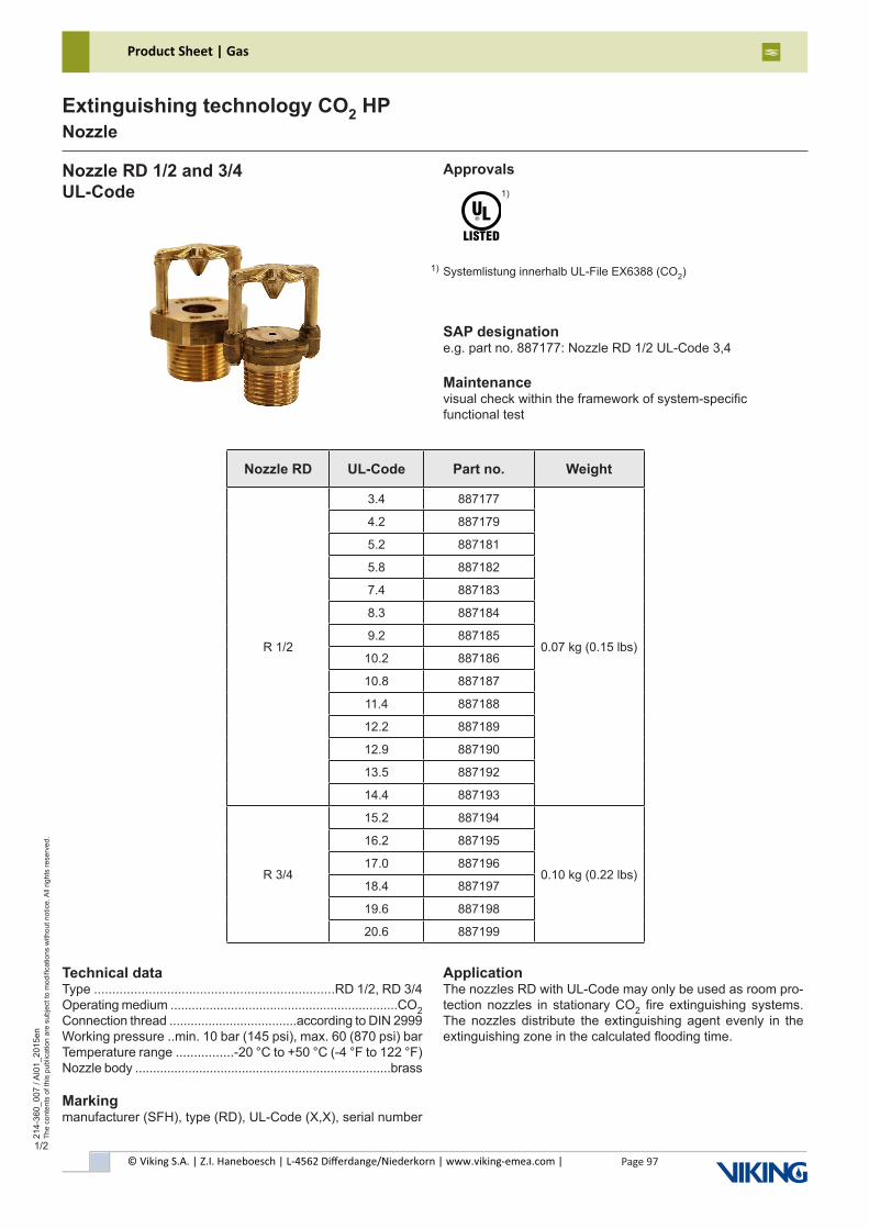
© Viking S.A. | Z.I. Haneboesch | L-4562 Differdange/Niederkorn | www.viking-emea.com |
Product Sheet | Gas
Page 97
214-
360_
007
/ AI0
1_20
15en
The
cont
ents
of t
his
publ
icat
ion
are
subj
ect t
o m
odifi
catio
ns w
ithou
t not
ice.
All
right
s re
serv
ed.
Extinguishing technology CO2 HPNozzle
1/2
Nozzle RD 1/2 and 3/4UL-Code
Approvals
SAP designatione.g. part no. 887177: Nozzle RD 1/2 UL-Code 3,4
Maintenancevisual check within the framework of system-specificfunctional test
Systemlistung innerhalb UL-File EX6388 (CO2)
1)
1)
Technical dataType ..................................................................RD 1/2, RD 3/4Operating medium ................................................................CO2Connection thread ....................................according to DIN 2999Working pressure ..min. 10 bar (145 psi), max. 60 (870 psi) barTemperature range ................-20 °C to +50 °C (-4 °F to 122 °F)Nozzle body ........................................................................brass
Markingmanufacturer (SFH), type (RD), UL-Code (X,X), serial number
ApplicationThe nozzles RD with UL-Code may only be used as room pro-tection nozzles in stationary CO2 fire extinguishing systems. The nozzles distribute the extinguishing agent evenly in the extinguishing zone in the calculated flooding time.
Nozzle RD UL-Code Part no. Weight
R 1/2
3.4 887177
0.07 kg (0.15 lbs)
4.2 887179
5.2 887181
5.8 887182
7.4 887183
8.3 887184
9.2 887185
10.2 887186
10.8 887187
11.4 887188
12.2 887189
12.9 887190
13.5 887192
14.4 887193
R 3/4
15.2 887194
0.10 kg (0.22 lbs)
16.2 887195
17.0 887196
18.4 887197
19.6 887198
20.6 887199
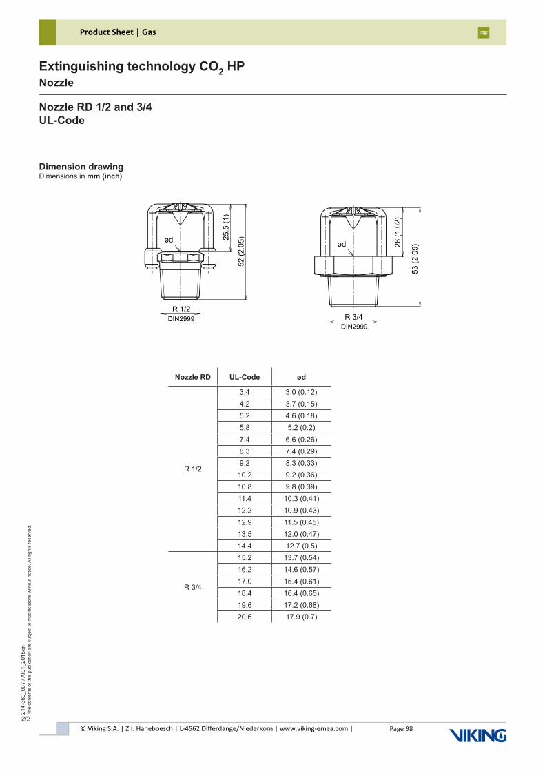
© Viking S.A. | Z.I. Haneboesch | L-4562 Differdange/Niederkorn | www.viking-emea.com |
Product Sheet | Gas
Page 98
214-
360_
007
/ AI0
1_20
15en
The
cont
ents
of t
his
publ
icat
ion
are
subj
ect t
o m
odifi
catio
ns w
ithou
t not
ice.
All
right
s re
serv
ed.
Extinguishing technology CO2 HPNozzle
2/2
Nozzle RD 1/2 and 3/4UL-Code
Dimension drawingDimensions in mm (inch)
Nozzle RD UL-Code ød
R 1/2
3.4 3.0 (0.12)4.2 3.7 (0.15)5.2 4.6 (0.18)5.8 5.2 (0.2)7.4 6.6 (0.26)8.3 7.4 (0.29)9.2 8.3 (0.33)
10.2 9.2 (0.36)10.8 9.8 (0.39)11.4 10.3 (0.41)12.2 10.9 (0.43)12.9 11.5 (0.45)13.5 12.0 (0.47)14.4 12.7 (0.5)
R 3/4
15.2 13.7 (0.54)16.2 14.6 (0.57)17.0 15.4 (0.61)18.4 16.4 (0.65)19.6 17.2 (0.68)20.6 17.9 (0.7)
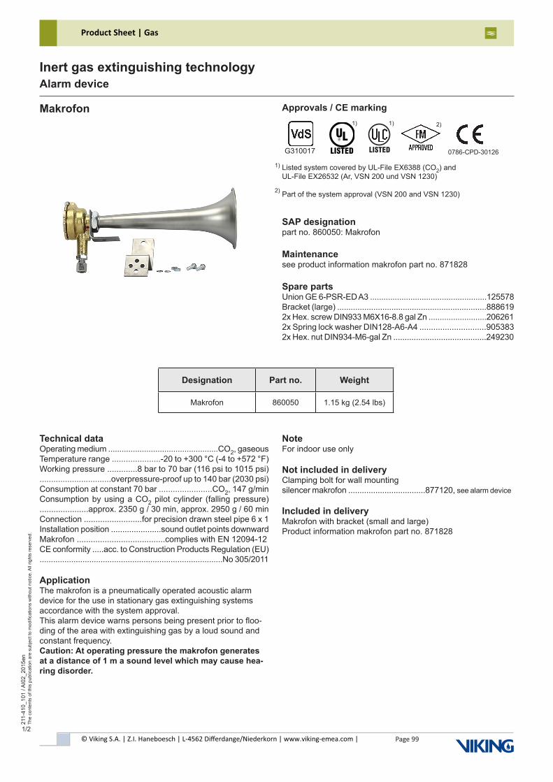
© Viking S.A. | Z.I. Haneboesch | L-4562 Differdange/Niederkorn | www.viking-emea.com |
Product Sheet | Gas
Page 99
211-
410_
101
/ AI0
2_20
15en
The
cont
ents
of t
his
publ
icat
ion
are
subj
ect t
o m
odifi
catio
ns w
ithou
t not
ice.
All
right
s re
serv
ed.
Inert gas extinguishing technologyAlarm device
1/2
Makrofon
SAP designationpart no. 860050: Makrofon
Maintenancesee product information makrofon part no. 871828
Spare partsUnion GE 6-PSR-ED A3 ....................................................125578Bracket (large) ..................................................................8886192x Hex. screw DIN933 M6X16-8.8 gal Zn ..........................2062612x Spring lock washer DIN128-A6-A4 .............................9053832x Hex. nut DIN934-M6-gal Zn .........................................249230
Technical dataOperating medium .................................................CO2, gaseousTemperature range .....................-20 to +300 °C (-4 to +572 °F)Working pressure .............8 bar to 70 bar (116 psi to 1015 psi)...............................overpressure-proof up to 140 bar (2030 psi)Consumption at constant 70 bar .......................CO2, 147 g/minConsumption by using a CO2 pilot cylinder (falling pressure) .....................approx. 2350 g / 30 min, approx. 2950 g / 60 minConnection .........................for precision drawn steel pipe 6 x 1Installation position ......................sound outlet points downwardMakrofon ......................................complies with EN 12094-12CE conformity .....acc. to Construction Products Regulation (EU).................................................................................No 305/2011
ApplicationThe makrofon is a pneumatically operated acoustic alarm device for the use in stationary gas extinguishing systems accordance with the system approval.This alarm device warns persons being present prior to floo-ding of the area with extinguishing gas by a loud sound and constant frequency.Caution: At operating pressure the makrofon generates at a distance of 1 m a sound level which may cause hea-ring disorder.
NoteFor indoor use only
Not included in deliveryClamping bolt for wall mountingsilencer makrofon ..................................877120, see alarm device
Included in deliveryMakrofon with bracket (small and large)Product information makrofon part no. 871828
Approvals / CE marking
Designation Part no. Weight
Makrofon 860050 1.15 kg (2.54 lbs)
Listed system covered by UL-File EX6388 (CO2) andUL-File EX26532 (Ar, VSN 200 und VSN 1230)
Part of the system approval (VSN 200 and VSN 1230)
1)
2)
0786-CPD-30126G310017
1) 2)
������
1)
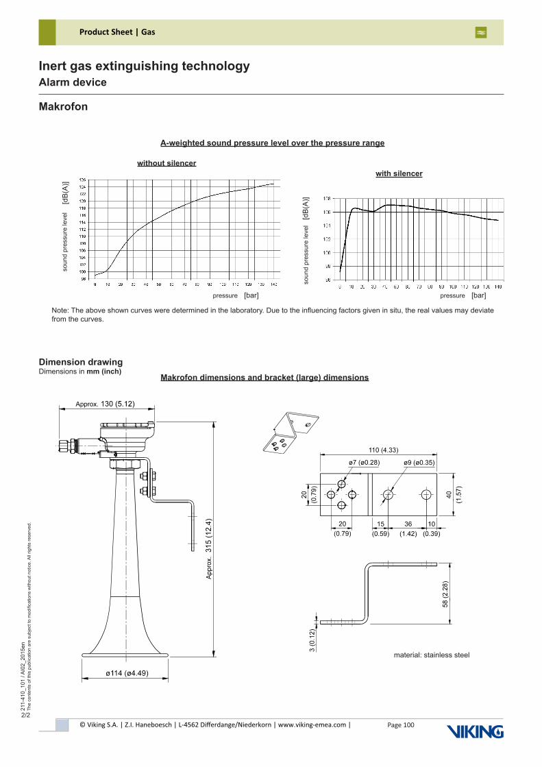
© Viking S.A. | Z.I. Haneboesch | L-4562 Differdange/Niederkorn | www.viking-emea.com |
Product Sheet | Gas
Page 100
211-
410_
101
/ AI0
2_20
15en
The
cont
ents
of t
his
publ
icat
ion
are
subj
ect t
o m
odifi
catio
ns w
ithou
t not
ice.
All
right
s re
serv
ed.
Inert gas extinguishing technologyAlarm device
2/2
Makrofon
Dimension drawingDimensions in mm (inch)
A-weighted sound pressure level over the pressure range
soun
d pr
essu
re le
vel
[dB
(A)]
pressure [bar]so
und
pres
sure
leve
l[d
B(A
)]pressure [bar]
with silencerwithout silencer
Note: The above shown curves were determined in the laboratory. Due to the influencing factors given in situ, the real values may deviate from the curves.
material: stainless steel
Makrofon dimensions and bracket (large) dimensions
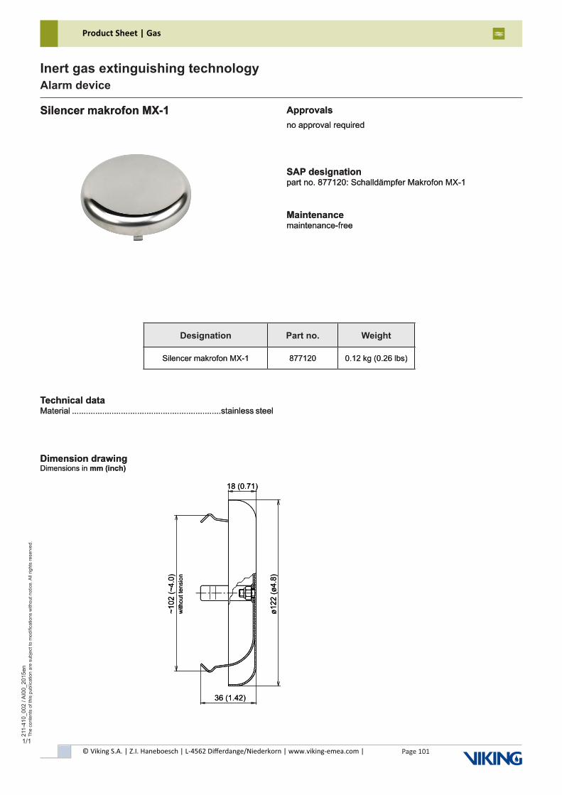
© Viking S.A. | Z.I. Haneboesch | L-4562 Differdange/Niederkorn | www.viking-emea.com |
Product Sheet | Gas
Page 101
211-
410_
002
/ AI0
0_20
15en
The
cont
ents
of t
his
publ
icat
ion
are
subj
ect t
o m
odifi
catio
ns w
ithou
t not
ice.
All
right
s re
serv
ed.
Inert gas extinguishing technologyAlarm device
1/1
Silencer makrofon MX-1
Technical dataMaterial ................................................................stainless steel
Approvalsno approval required
Dimension drawingDimensions in mm (inch)
SAP designationpart no. 877120: Schalldämpfer Makrofon MX-1
Maintenancemaintenance-free
Designation Part no. Weight
Silencer makrofon MX-1 877120 0.12 kg (0.26 lbs)
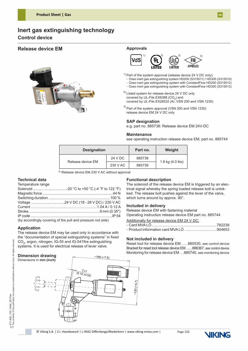
© Viking S.A. | Z.I. Haneboesch | L-4562 Differdange/Niederkorn | www.viking-emea.com |
Product Sheet | Gas
Page 102
211-
420_
103
/ AI0
4_20
17en
The
cont
ents
of t
his
publ
icat
ion
are
subj
ect t
o m
odifi
catio
ns w
ithou
t not
ice.
All
right
s re
serv
ed.
Inert gas extinguishing technologyControl device
1/1
Release device EM Approvals
Technical dataTemperature rangeSolenoid .......... .....................-20 °C to +50 °C (-4 °F to 122 °F)Magnetic force ....................................................................44 NSwitching duration ............................................................100 %Voltage ................................24 V DC (18 - 28 V DC) / 230 V ACCurrent ...............................................................1.04 A / 0.12 AStroke ......................................................................9 mm (0.35")IP code ................................................................................IP 54 (by accordingly covering of the pull and pressure rod side)
ApplicationThe release device EM may be used only in accordance with the “documentation of special extinguishing systems” in fixed CO2, argon, nitrogen, IG-55 and IG-541fire extinguishing systems. It is used for electrical release of lever valve.
SAP designatione.g. part no. 885738: Release device EM 24V-DC
Maintenancesee operating instruction release device EM, part no. 885744
Functional descriptionThe solenoid of the release device EM is triggered by an elec-trical signal whereby the spring loaded release bolt is unlok-ked. The release bolt pushes against the lever of the valve, which turns around by approx. 90°.
Included in deliveryRelease device EM with fastening materialOperating instruction release device EM part no. 885744Additionally for release device EM 24 V DC:- Card MVA LÖ ..............................................................782239- Product information card MVA LÖ ...............................904653
Not included in deliveryReset tool for release device EM ......885530, see control device Bracket for reset tool release device EM .......886367, see control device Monitoring for release device EM ....885740, see monitoring device
Part of the system approval (release device 24 V DC only):- Oxeo inert gas extinguishing system HD200 (S315011) / HD300 (S315010)- Oxeo inert gas extinguishing system with ConstantFlow HD200 (S315012)- Oxeo inert gas extinguishing system with ConstantFlow HD300 (S315013)
Listed system for release device 24 V DC onlycovered by UL-File EX6388 (CO2) and covered by UL-File EX26532 (Ar, VSN 200 and VSN 1230)
Part of the system approval (VSN 200 and VSN 1230)release device EM 24 V DC only
1)
Designation Part no. Weight
Release device EM24 V DC 885738
1.8 kg (4.0 lbs)230 V AC 885739
Dimension drawingDimensions in mm (inch)
2)
3)
2)1) 3)
������
2)
4) Release device EM 230 V AC without approval
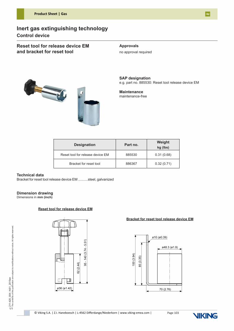
© Viking S.A. | Z.I. Haneboesch | L-4562 Differdange/Niederkorn | www.viking-emea.com |
Product Sheet | Gas
Page 103
211-
420_
004
/ AI0
1_20
15en
The
cont
ents
of t
his
publ
icat
ion
are
subj
ect t
o m
odifi
catio
ns w
ithou
t not
ice.
All
right
s re
serv
ed.
Inert gas extinguishing technologyControl device
1/1
Reset tool for release device EMand bracket for reset tool
Technical dataBracket for reset tool release device EM ..........steel, galvanized
SAP designatione.g. part no. 885530: Reset tool release device EM
Maintenancemaintenance-free
Dimension drawingDimensions in mm (inch)
Approvalsno approval required
Designation Part no. Weightkg (lbs)
Reset tool for release device EM 885530 0.31 (0.68)
Bracket for reset tool 886367 0.32 (0.71)
Reset tool for release device EM
Bracket for reset tool release device EM
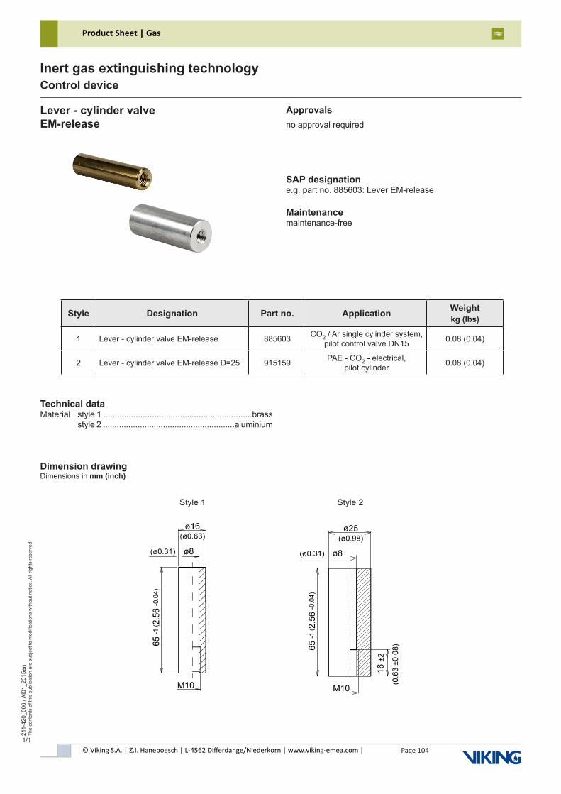
© Viking S.A. | Z.I. Haneboesch | L-4562 Differdange/Niederkorn | www.viking-emea.com |
Product Sheet | Gas
Page 104
211-
420_
006
/ AI0
1_20
15en
The
cont
ents
of t
his
publ
icat
ion
are
subj
ect t
o m
odifi
catio
ns w
ithou
t not
ice.
All
right
s re
serv
ed.
Inert gas extinguishing technologyControl device
1/1
Technical dataMaterial style 1 ................................................................brass style 2 .........................................................aluminium
Lever - cylinder valveEM-release
SAP designatione.g. part no. 885603: Lever EM-release
Maintenancemaintenance-free
Approvalsno approval required
Dimension drawingDimensions in mm (inch)
Style 1 Style 2
Style Designation Part no. Application Weightkg (lbs)
1 Lever - cylinder valve EM-release 885603 CO2 / Ar single cylinder system, pilot control valve DN15 0.08 (0.04)
2 Lever - cylinder valve EM-release D=25 915159 PAE - CO2 - electrical, pilot cylinder 0.08 (0.04)
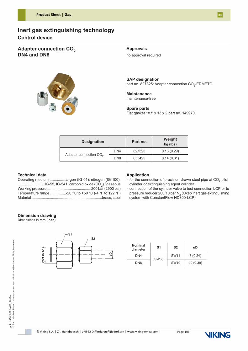
© Viking S.A. | Z.I. Haneboesch | L-4562 Differdange/Niederkorn | www.viking-emea.com |
Product Sheet | Gas
Page 105
211-
420_
007
/ AI0
2_20
17en
The
cont
ents
of t
his
publ
icat
ion
are
subj
ect t
o m
odifi
catio
ns w
ithou
t not
ice.
All
right
s re
serv
ed.
Inert gas extinguishing technologyControl device
1/1
Technical dataOperating medium ................argon (IG-01), nitrogen (IG-100),..........................IG-55, IG-541, carbon dioxide (CO2) / gaseousWorking pressure ...........................................200 bar (2900 psi)Temperature range ...............-20 °C to +50 °C (-4 °F to 122 °F)Material .....................................................................brass, steel
Adapter connection CO2DN4 and DN8
SAP designationpart no. 827325: Adapter connection CO2-ERMETO
Maintenancemaintenance-free
Spare partsFlat gasket 18.5 x 13 x 2 part no. 149970
Approvalsno approval required
Dimension drawingDimensions in mm (inch)
Application- for the connection of precision-drawn steel pipe at CO2 pilot cylinder or extinguishing agent cylinder- connection of the cylinder valve to test connection LCP or to pressure reducer 200/10 bar N2 (Oxeo inert gas extinguishing system with ConstantFlow HD300-LCP)
Designation Part no. Weightkg (lbs)
Adapter connection CO2
DN4 827325 0.13 (0.29)
DN8 855425 0.14 (0.31)
Nominal diameter S1 S2 øD
DN4SW30
SW14 6 (0.24)
DN8 SW19 10 (0.39)
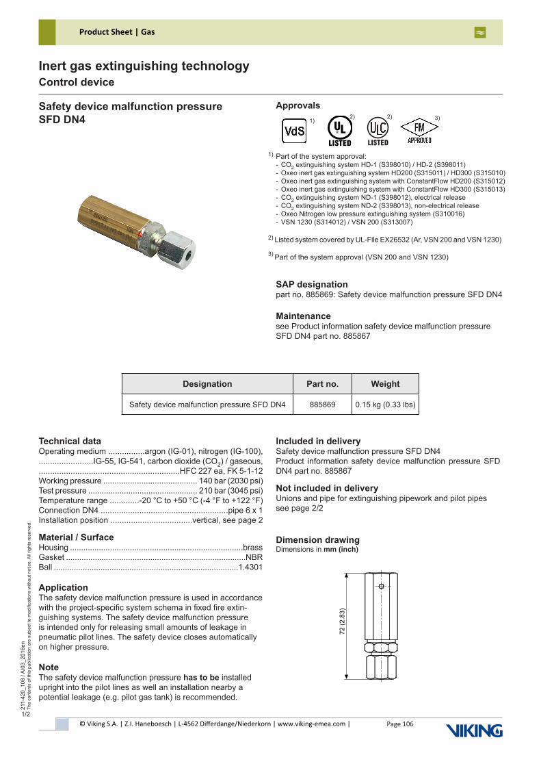
© Viking S.A. | Z.I. Haneboesch | L-4562 Differdange/Niederkorn | www.viking-emea.com |
Product Sheet | Gas
Page 106
211-
420_
108
/ AI0
3_20
16en
The
cont
ents
of t
his
publ
icat
ion
are
subj
ect t
o m
odifi
catio
ns w
ithou
t not
ice.
All
right
s re
serv
ed.
Inert gas extinguishing technologyControl device
1/2
Safety device malfunction pressureSFD DN4
Technical dataOperating medium ................argon (IG-01), nitrogen (IG-100),........................IG-55, IG-541, carbon dioxide (CO2) / gaseous,..............................................................HFC 227 ea, FK 5-1-12Working pressure .......................................... 140 bar (2030 psi)Test pressure ................................................. 210 bar (3045 psi)Temperature range .............-20 °C to +50 °C (-4 °F to +122 °F)Connection DN4 ........................................................pipe 6 x 1Installation position ....................................vertical, see page 2
Material / SurfaceHousing ..............................................................................brassGasket .................................................................................NBRBall ...................................................................................1.4301
ApplicationThe safety device malfunction pressure is used in accordance with the project-specific system schema in fixed fire extin-guishing systems. The safety device malfunction pressure is intended only for releasing small amounts of leakage in pneumatic pilot lines. The safety device closes automatically on higher pressure.
NoteThe safety device malfunction pressure has to be installed upright into the pilot lines as well an installation nearby a potential leakage (e.g. pilot gas tank) is recommended.
SAP designationpart no. 885869: Safety device malfunction pressure SFD DN4
Maintenancesee Product information safety device malfunction pressureSFD DN4 part no. 885867
Included in deliverySafety device malfunction pressure SFD DN4Product information safety device malfunction pressure SFD DN4 part no. 885867
Not included in deliveryUnions and pipe for extinguishing pipework and pilot pipessee page 2/2
Dimension drawingDimensions in mm (inch)
Approvals
Part of the system approval:- CO2 extinguishing system HD-1 (S398010) / HD-2 (S398011)- Oxeo inert gas extinguishing system HD200 (S315011) / HD300 (S315010)- Oxeo inert gas extinguishing system with ConstantFlow HD200 (S315012)- Oxeo inert gas extinguishing system with ConstantFlow HD300 (S315013)- CO2 extinguishing system ND-1 (S398012), electrical release- CO2 extinguishing system ND-2 (S398013), non-electrical release- Oxeo Nitrogen low pressure extinguishing system (S310016)- VSN 1230 (S314012) / VSN 200 (S313007)
1)
Designation Part no. Weight
Safety device malfunction pressure SFD DN4 885869 0.15 kg (0.33 lbs)
Listed system covered by UL-File EX26532 (Ar, VSN 200 and VSN 1230)
Part of the system approval (VSN 200 and VSN 1230)
2) 3)
1) 2) 3)
������
2)
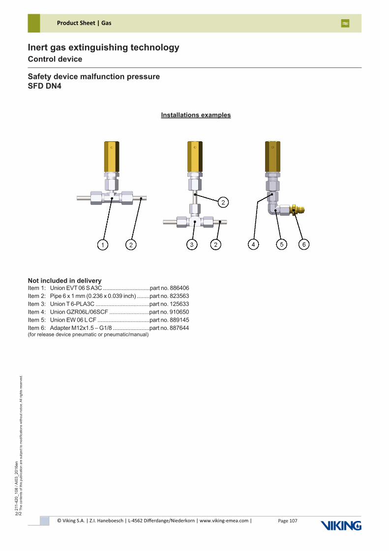
© Viking S.A. | Z.I. Haneboesch | L-4562 Differdange/Niederkorn | www.viking-emea.com |
Product Sheet | Gas
Page 107
211-
420_
108
/ AI0
3_20
16en
The
cont
ents
of t
his
publ
icat
ion
are
subj
ect t
o m
odifi
catio
ns w
ithou
t not
ice.
All
right
s re
serv
ed.
Inert gas extinguishing technologyControl device
2/2
Installations examples
Safety device malfunction pressureSFD DN4
Not included in deliveryItem 1: Union EVT 06 S A3C ..............................part no. 886406Item 2: Pipe 6 x 1 mm (0.236 x 0.039 inch) ........part no. 823563Item 3: Union T 6-PLA3C ..................................part no. 125633Item 4: Union GZR06L/06SCF .........................part no. 910650Item 5: Union EW 06 L CF .................................part no. 889145Item 6: Adapter M12x1.5 – G1/8 .......................part no. 887644(for release device pneumatic or pneumatic/manual)
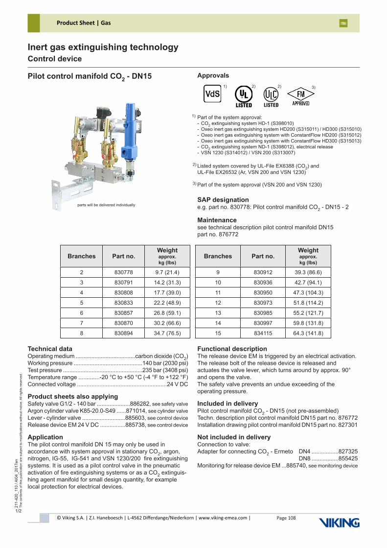
© Viking S.A. | Z.I. Haneboesch | L-4562 Differdange/Niederkorn | www.viking-emea.com |
Product Sheet | Gas
Page 108
211-
420_
110
/ AI0
4_20
17en
The
cont
ents
of t
his
publ
icat
ion
are
subj
ect t
o m
odifi
catio
ns w
ithou
t not
ice.
All
right
s re
serv
ed.
Inert gas extinguishing technologyControl device
1/2
Pilot control manifold CO2 - DN15 Approvals
Technical dataOperating medium ......................................carbon dioxide (CO2)Working pressure ...........................................140 bar (2030 psi)Test pressure ..................................................235 bar (3408 psi)Temperature range .............-20 °C to +50 °C (-4 °F to +122 °F)Connected voltage ........................................................24 V DC
Product sheets also applyingSafety valve G1/2 - 140 bar .....................886282, see safety valve Argon cylinder valve K85-20.0-S49 ......871014, see cylinder valve Lever - cylinder valve ...........................885603, see control device Release device EM 24 V DC ................885738, see control device
ApplicationThe pilot control manifold DN 15 may only be used inaccordance with system approval in stationary CO2, argon, nitrogen, IG-55, IG-541 and VSN 1230/200 fire extinguishing systems. It is used as a pilot control valve in the pneumatic activation of fire extinguishing systems or as a CO2 extinguis-hing agent manifold for small design quantity, for example local protection for electrical devices.
SAP designatione.g. part no. 830778: Pilot control manifold CO2 - DN15 - 2
Maintenancesee technical description pilot control manifold DN15part no. 876772
Functional descriptionThe release device EM is triggered by an electrical activation. The release bolt of the release device is released and actuates the valve lever, which turns around by approx. 90° and opens the valve.The safety valve prevents an undue exceeding of the operating pressure.
Included in deliveryPilot control manifold CO2 - DN15 (not pre-assembled)Techn. description pilot control manifold DN15 part no. 876772Installation drawing pilot control manifold DN15 part no. 827301
Not included in deliveryConnection to valve:Adapter for connecting CO2 - Ermeto DN4 .................827325 DN8 .................855425Monitoring for release device EM ...885740, see monitoring device
Part of the system approval:- CO2 extinguishing system HD-1 (S398010)- Oxeo inert gas extinguishing system HD200 (S315011) / HD300 (S315010)- Oxeo inert gas extinguishing system with ConstantFlow HD200 (S315012)- Oxeo inert gas extinguishing system with ConstantFlow HD300 (S315013)- CO2 extinguishing system ND-1 (S398012), electrical release- VSN 1230 (S314012) / VSN 200 (S313007)
1)
Branches Part no.Weight approx. kg (lbs)
Branches Part no.Weight approx. kg (lbs)
2 830778 9.7 (21.4) 9 830912 39.3 (86.6)
3 830791 14.2 (31.3) 10 830936 42.7 (94.1)
4 830808 17.7 (39.0) 11 830950 47.3 (104.3)
5 830833 22.2 (48.9) 12 830973 51.8 (114.2)
6 830857 26.8 (59.1) 13 830985 55.2 (121.7)
7 830870 30.2 (66.6) 14 830997 59.8 (131.8)
8 830894 34.7 (76.5) 15 834115 64.3 (141.8)
parts will be delivered individually
Listed system covered by UL-File EX6388 (CO2) andUL-File EX26532 (Ar, VSN 200 and VSN 1230)
Part of the system approval (VSN 200 and VSN 1230)
2)
3)
2)1) 3)
������
2)
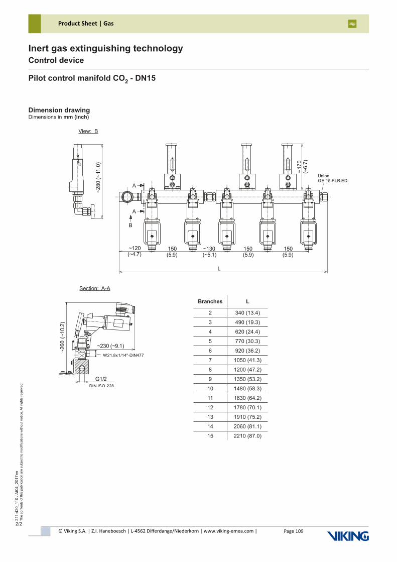
© Viking S.A. | Z.I. Haneboesch | L-4562 Differdange/Niederkorn | www.viking-emea.com |
Product Sheet | Gas
Page 109
211-
420_
110
/ AI0
4_20
17en
The
cont
ents
of t
his
publ
icat
ion
are
subj
ect t
o m
odifi
catio
ns w
ithou
t not
ice.
All
right
s re
serv
ed.
Inert gas extinguishing technologyControl device
2/2
Dimension drawingDimensions in mm (inch)
Pilot control manifold CO2 - DN15
Section: A-A
Branches L
2 340 (13.4)
3 490 (19.3)
4 620 (24.4)
5 770 (30.3)
6 920 (36.2)
7 1050 (41.3)
8 1200 (47.2)
9 1350 (53.2)
10 1480 (58.3)
11 1630 (64.2)
12 1780 (70.1)
13 1910 (75.2)
14 2060 (81.1)
15 2210 (87.0)
View: B
~260
(~1
0.2)
~230 (~9.1)
W21.8x1/14"-DIN477
G1/2DIN ISO 228
~280
(~11
.0)
~120(~4.7)
150(5.9)
150(5.9)
150(5.9)
~130(~5.1)
L
~17
0(~
6.7)
A
A
B
UnionGE 15-PLR-ED
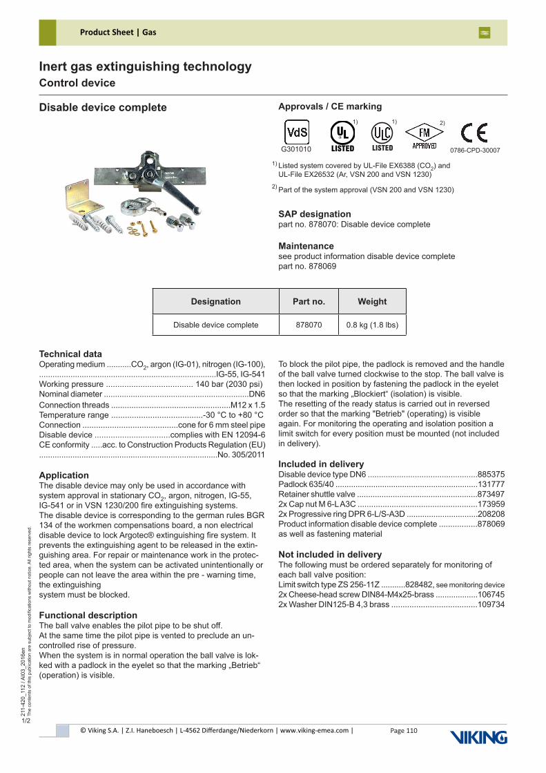
© Viking S.A. | Z.I. Haneboesch | L-4562 Differdange/Niederkorn | www.viking-emea.com |
Product Sheet | Gas
Page 110
211-
420_
112
/ AI0
3_20
16en
The
cont
ents
of t
his
publ
icat
ion
are
subj
ect t
o m
odifi
catio
ns w
ithou
t not
ice.
All
right
s re
serv
ed.
Inert gas extinguishing technologyControl device
1/2
Disable device complete
Technical dataOperating medium ...........CO2, argon (IG-01), nitrogen (IG-100),...............................................................................IG-55, IG-541Working pressure ...................................... 140 bar (2030 psi)Nominal diameter .................................................................DN6Connection threads .....................................................M12 x 1.5Temperature range ........................................-30 °C to +80 °CConnection ..........................................cone for 6 mm steel pipeDisable device .................................complies with EN 12094-6CE conformity .....acc. to Construction Products Regulation (EU)................................................................................No. 305/2011
ApplicationThe disable device may only be used in accordance with system approval in stationary CO2, argon, nitrogen, IG-55,IG-541 or in VSN 1230/200 fire extinguishing systems.The disable device is corresponding to the german rules BGR 134 of the workmen compensations board, a non electrical disable device to lock Argotec® extinguishing fire system. It prevents the extinguishing agent to be released in the extin-guishing area. For repair or maintenance work in the protec-ted area, when the system can be activated unintentionally or people can not leave the area within the pre - warning time, the extinguishingsystem must be blocked.
Functional descriptionThe ball valve enables the pilot pipe to be shut off.At the same time the pilot pipe is vented to preclude an un-controlled rise of pressure.When the system is in normal operation the ball valve is lok-ked with a padlock in the eyelet so that the marking „Betrieb“ (operation) is visible.
SAP designationpart no. 878070: Disable device complete
Maintenancesee product information disable device completepart no. 878069
To block the pilot pipe, the padlock is removed and the handle of the ball valve turned clockwise to the stop. The ball valve is then locked in position by fastening the padlock in the eyelet so that the marking „Blockiert“ (isolation) is visible.The resetting of the ready status is carried out in reversed order so that the marking "Betrieb" (operating) is visible again. For monitoring the operating and isolation position a limit switch for every position must be mounted (not included in delivery).
Included in deliveryDisable device type DN6 .................................................885375Padlock 635/40 ................................................................131777Retainer shuttle valve ......................................................8734972x Cap nut M 6-L A3C .....................................................1739592x Progressive ring DPR 6-L/S-A3D ................................208208Product information disable device complete .................878069as well as fastening material
Not included in deliveryThe following must be ordered separately for monitoring of each ball valve position:Limit switch type ZS 256-11Z ...........828482, see monitoring device 2x Cheese-head screw DIN84-M4x25-brass ...................1067452x Washer DIN125-B 4,3 brass ......................................109734
Designation Part no. Weight
Disable device complete 878070 0.8 kg (1.8 lbs)
Approvals / CE marking
Listed system covered by UL-File EX6388 (CO2) andUL-File EX26532 (Ar, VSN 200 and VSN 1230)
Part of the system approval (VSN 200 and VSN 1230)
1)
2)
0786-CPD-30007G301010
1) 2)
������
1)
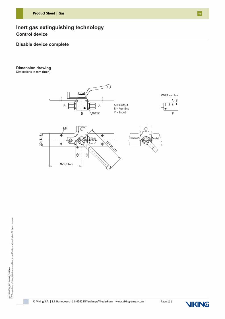
© Viking S.A. | Z.I. Haneboesch | L-4562 Differdange/Niederkorn | www.viking-emea.com |
Product Sheet | Gas
Page 111
211-
420_
112
/ AI0
3_20
16en
The
cont
ents
of t
his
publ
icat
ion
are
subj
ect t
o m
odifi
catio
ns w
ithou
t not
ice.
All
right
s re
serv
ed.
Inert gas extinguishing technologyControl device
2/2
Dimension drawingDimensions in mm (inch)
Disable device complete
A = OutputB = VentingP = Input
P&ID symbol
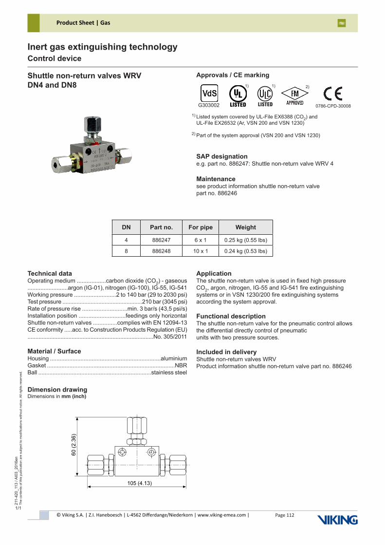
© Viking S.A. | Z.I. Haneboesch | L-4562 Differdange/Niederkorn | www.viking-emea.com |
Product Sheet | Gas
Page 112
211-
420_
113
/ AI0
3_20
16en
The
cont
ents
of t
his
publ
icat
ion
are
subj
ect t
o m
odifi
catio
ns w
ithou
t not
ice.
All
right
s re
serv
ed.
Inert gas extinguishing technologyControl device
1/1
Shuttle non-return valves WRVDN4 and DN8
Technical dataOperating medium ..................carbon dioxide (CO2) - gaseous.........................argon (IG-01), nitrogen (IG-100), IG-55, IG-541Working pressure ..........................2 to 140 bar (29 to 2030 psi)Test pressure ...................................................210 bar (3045 psi)Rate of pressure rise ............................min. 3 bar/s (43,5 psi/s)Installation position .............................feedings only horizontalShuttle non-return valves ...............complies with EN 12094-13CE conformity .....acc. to Construction Products Regulation (EU)................................................................................No. 305/2011
Material / SurfaceHousing .....................................................................aluminiumGasket ................................................................................NBRBall .......................................................................stainless steel
ApplicationThe shuttle non-return valve is used in fixed high pressure CO2, argon, nitrogen, IG-55 and IG-541 fire extinguishingsystems or in VSN 1230/200 fire extinguishing systemsaccording the system approval.
Functional descriptionThe shuttle non-return valve for the pneumatic control allows the differential directly control of pneumaticunits with two pressure sources.
Included in deliveryShuttle non-return valves WRVProduct information shuttle non-return valve part no. 886246
SAP designatione.g. part no. 886247: Shuttle non-return valve WRV 4
Maintenancesee product information shuttle non-return valvepart no. 886246
Approvals / CE marking
DN Part no. For pipe Weight
4 886247 6 x 1 0.25 kg (0.55 lbs)
8 886248 10 x 1 0.24 kg (0.53 lbs)
Dimension drawingDimensions in mm (inch)
Listed system covered by UL-File EX6388 (CO2) andUL-File EX26532 (Ar, VSN 200 and VSN 1230)
Part of the system approval (VSN 200 and VSN 1230)
1)
2)
0786-CPD-30008G303002
1) 2)
������
1)
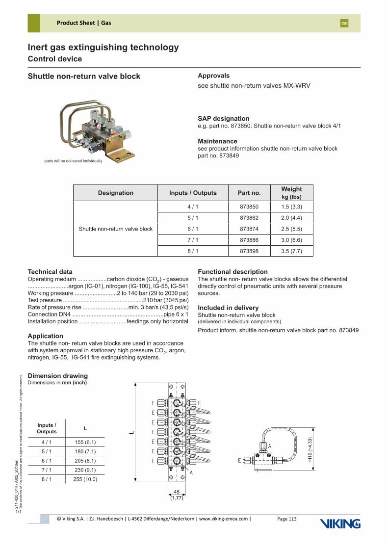
© Viking S.A. | Z.I. Haneboesch | L-4562 Differdange/Niederkorn | www.viking-emea.com |
Product Sheet | Gas
Page 113
211-
420_
014
/ AI0
2_20
16en
The
cont
ents
of t
his
publ
icat
ion
are
subj
ect t
o m
odifi
catio
ns w
ithou
t not
ice.
All
right
s re
serv
ed.
Inert gas extinguishing technologyControl device
1/1
Shuttle non-return valve block
Technical dataOperating medium ..................carbon dioxide (CO2) - gaseous.........................argon (IG-01), nitrogen (IG-100), IG-55, IG-541Working pressure ..........................2 to 140 bar (29 to 2030 psi)Test pressure ...................................................210 bar (3045 psi)Rate of pressure rise ............................min. 3 bar/s (43,5 psi/s)Connection DN4 ........................................................pipe 6 x 1Installation position .............................feedings only horizontal
ApplicationThe shuttle non- return valve blocks are used in accordance with system approval in stationary high pressure CO2, argon, nitrogen, IG-55, IG-541 fire extinguishing systems.
Functional descriptionThe shuttle non- return valve blocks allows the differential directly control of pneumatic units with several pressure sources.
Included in deliveryShuttle non-return valve block(delivered in individual components)
Product inform. shuttle non-return valve block part no. 873849
SAP designatione.g. part no. 873850: Shuttle non-return valve block 4/1
Maintenancesee product information shuttle non-return valve blockpart no. 873849
Approvalssee shuttle non-return valves MX-WRV
Dimension drawingDimensions in mm (inch)
Designation Inputs / Outputs Part no. Weightkg (lbs)
Shuttle non-return valve block
4 / 1 873850 1.5 (3.3)
5 / 1 873862 2.0 (4.4)
6 / 1 873874 2.5 (5.5)
7 / 1 873886 3.0 (6.6)
8 / 1 873898 3.5 (7.7)
Inputs / Outputs L
4 / 1 155 (6.1)
5 / 1 180 (7.1)
6 / 1 205 (8.1)
7 / 1 230 (9.1)
8 / 1 255 (10.0)
parts will be delivered individually
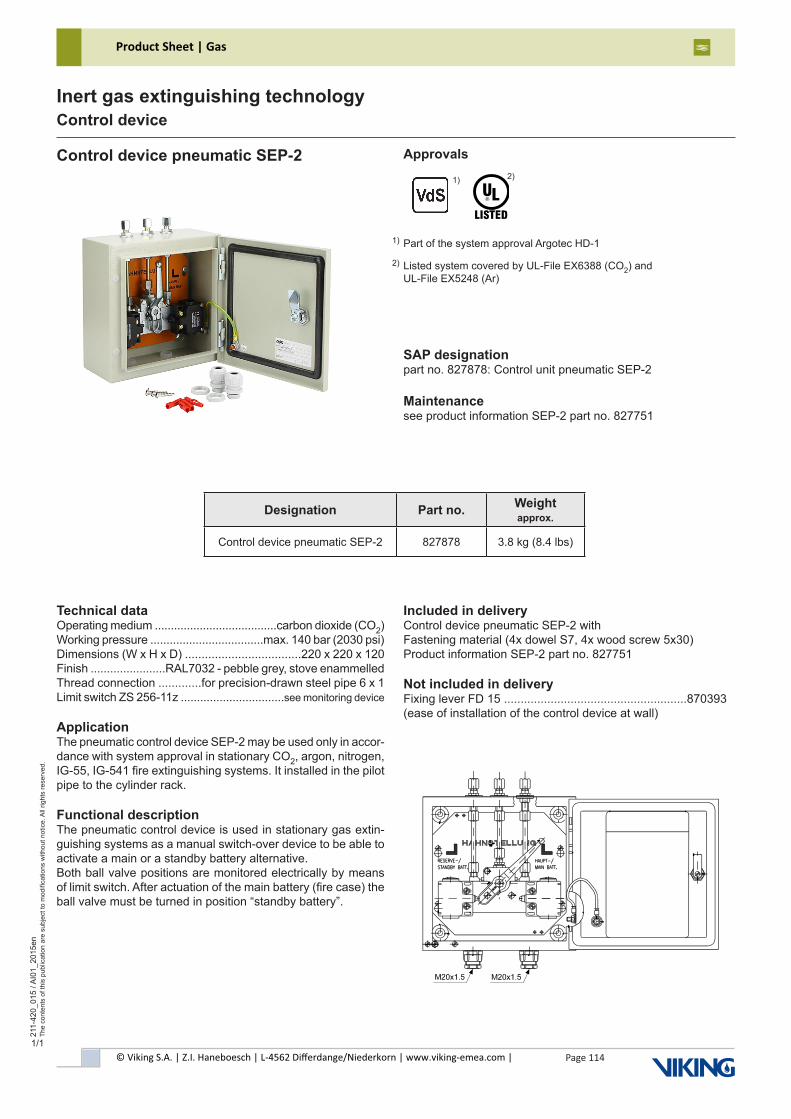
© Viking S.A. | Z.I. Haneboesch | L-4562 Differdange/Niederkorn | www.viking-emea.com |
Product Sheet | Gas
Page 114
211-
420_
015
/ AI0
1_20
15en
The
cont
ents
of t
his
publ
icat
ion
are
subj
ect t
o m
odifi
catio
ns w
ithou
t not
ice.
All
right
s re
serv
ed.
Inert gas extinguishing technologyControl device
1/1
Control device pneumatic SEP-2
Technical dataOperating medium ......................................carbon dioxide (CO2)Working pressure ...................................max. 140 bar (2030 psi)Dimensions (W x H x D) ...................................220 x 220 x 120Finish .......................RAL7032 - pebble grey, stove enammelledThread connection .............for precision-drawn steel pipe 6 x 1Limit switch ZS 256-11z ................................see monitoring device
ApplicationThe pneumatic control device SEP-2 may be used only in accor-dance with system approval in stationary CO2, argon, nitrogen, IG-55, IG-541 fire extinguishing systems. It installed in the pilot pipe to the cylinder rack.
Functional descriptionThe pneumatic control device is used in stationary gas extin-guishing systems as a manual switch-over device to be able to activate a main or a standby battery alternative.Both ball valve positions are monitored electrically by means of limit switch. After actuation of the main battery (fire case) the ball valve must be turned in position “standby battery”.
SAP designationpart no. 827878: Control unit pneumatic SEP-2
Maintenancesee product information SEP-2 part no. 827751
Included in deliveryControl device pneumatic SEP-2 with Fastening material (4x dowel S7, 4x wood screw 5x30)Product information SEP-2 part no. 827751
Not included in deliveryFixing lever FD 15 .......................................................870393(ease of installation of the control device at wall)
Approvals
Part of the system approval Argotec HD-1
Listed system covered by UL-File EX6388 (CO2) andUL-File EX5248 (Ar)
1)
2)1)
2)
Designation Part no. Weightapprox.
Control device pneumatic SEP-2 827878 3.8 kg (8.4 lbs)
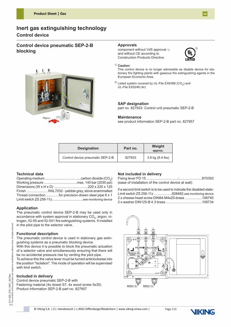
© Viking S.A. | Z.I. Haneboesch | L-4562 Differdange/Niederkorn | www.viking-emea.com |
Product Sheet | Gas
Page 115
211-
420_
016
/ AI0
1_20
15en
The
cont
ents
of t
his
publ
icat
ion
are
subj
ect t
o m
odifi
catio
ns w
ithou
t not
ice.
All
right
s re
serv
ed.
Inert gas extinguishing technologyControl device
1/1
Control device pneumatic SEP-2-Bblocking
Technical dataOperating medium ......................................carbon dioxide (CO2)Working pressure ...................................max. 140 bar (2030 psi)Dimensions (W x H x D) ...................................220 x 220 x 120Finish .......................RAL7032 - pebble grey, stove enammelledThread connection .............for precision-drawn steel pipe 6 x 1Limit switch ZS 256-11z ................................see monitoring device
ApplicationThe pneumatic control device SEP-2-B may be used only in accordance with system approval in stationary CO2, argon, ni-trogen, IG-55 and IG-541 fire extinguishing systems. It installed in the pilot pipe to the selector valve.
Functional descriptionThe pneumatic control device is used in stationary gas extin-guishing systems as a pneumatic blocking device.With this device it is possible to block the pneumatic actuation of a selector valve and simultaneously ensuring that there will be no accidental pressure rise by venting the pilot pipe.To achieve this the valve lever must be turned anticlockwise into the position "Isolation". The mode of operation will be supervised with limit switch.
Included in deliveryControl device pneumatic SEP-2-B withFastening material (4x dowel S7, 4x wood screw 5x30)Product information SEP-2-B part no. 827957
SAP designationpart no. 827933: Control unit pneumatic SEP-2-B
Maintenancesee product information SEP-2-B part no. 827957
Not included in deliveryFixing lever FD 15 ................................::.......................870393(ease of installation of the control device at wall)
if a second limit switch is to be used to indicate the disabled state:Limit switch ZS 256-11z ...................828482,see monitoring device 2 x cheese-head screw DIN84-M4x25-brass ..................1067452 x washer DIN125-B 4.3 brass .....................................109734
Approvalscomponent without VdS approvaland without CE according toConstruction Products Directive
Caution: This control device is no longer admissible as disable device for sta-tionary fire fighting plants with gaseous fire extinguishing agents in the European Economic Area.
Listed system covered by UL-File EX6388 (CO2) andUL-File EX5248 (Ar)
1)
2)1)
2)
Designation Part no. Weightapprox.
Control device pneumatic SEP-2-B 827933 3.8 kg (8.4 lbs)
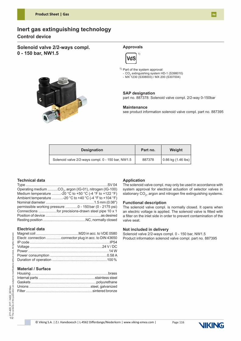
© Viking S.A. | Z.I. Haneboesch | L-4562 Differdange/Niederkorn | www.viking-emea.com |
Product Sheet | Gas
Page 116
211-
420_
017
/ AI0
2_20
16en
The
cont
ents
of t
his
publ
icat
ion
are
subj
ect t
o m
odifi
catio
ns w
ithou
t not
ice.
All
right
s re
serv
ed.
Inert gas extinguishing technologyControl device
1/2
Solenoid valve 2/2-ways compl.0 - 150 bar, NW1.5
Technical dataType ...................................................................................SV 04Operating medium ..........CO2, argon (IG-01), nitrogen (IG-100)Medium temperature .........-20 °C to +50 °C (-4 °F to +122 °F)Ambient temperature ...........-20 °C to +40 °C (-4 °F to +104 °F)Nominal diameter .................................................1.5 mm (0.06")permissible working pressure ............0 - 150 bar (0 - 2175 psi)Connections ..................for precisions-drawn steel pipe 10 x 1Position of device ........................................................as desiredResting position ...........................................NC, normally closed
Electrical dataMagnet coil ...........................................M20 in acc. to VDE 0580Electr. connection ...............connector plug in acc. to DIN 43650IP code ...............................................................................IP54Voltage ........................................................................24 V / DCPower ................................................................................14 WPower consumption ........................................................0.58 ADuration of operation ......................................................100 %
Material / SurfaceHousing ..............................................................................brassInternal parts .........................................................stainless steelGaskets ..................................................................polyurethaneUnions ..............................................................steel, galvanizedFilter ...................................................................sintered bronze
SAP designationpart no. 887378: Solenoid valve compl. 2/2-way 0-150bar
Maintenancesee product information solenoid valve compl. part no. 887395
ApplicationThe solenoid valve compl. may only be used in accordance with system approval for electrical actuation of selector valves in stationary CO2, argon and nitrogen fire extinguishing systems.
Functional descriptionThe solenoid valve compl. is normally closed. It opens when an electric voltage is applied. The solenoid valve is fitted with a filter on the inlet side in order to prevent contamination of the valve seat.
Not included in deliverySolenoid valve 2/2-ways compl. 0 - 150 bar, NW1.5Product information solenoid valve compl. part no. 887395
Approvals
Part of the system approval:- CO2 extinguishing system HD-1 (S398010)- MX 1230 (S308003) / MX 200 (S307004)
1)
1)
Designation Part no. Weight
Solenoid valve 2/2-ways compl. 0 - 150 bar, NW1.5 887378 0.66 kg (1.46 lbs)
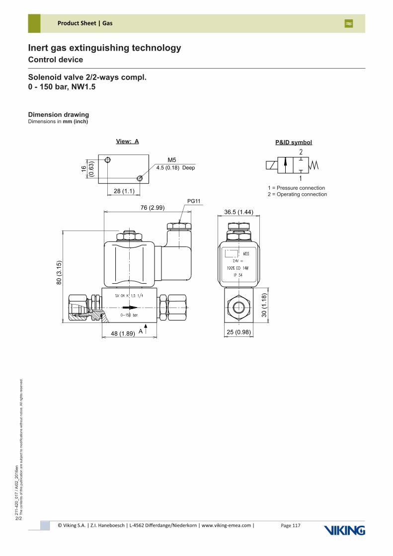
© Viking S.A. | Z.I. Haneboesch | L-4562 Differdange/Niederkorn | www.viking-emea.com |
Product Sheet | Gas
Page 117
211-
420_
017
/ AI0
2_20
16en
The
cont
ents
of t
his
publ
icat
ion
are
subj
ect t
o m
odifi
catio
ns w
ithou
t not
ice.
All
right
s re
serv
ed.
Inert gas extinguishing technologyControl device
2/2
Solenoid valve 2/2-ways compl.0 - 150 bar, NW1.5
Dimension drawingDimensions in mm (inch)
View: A P&ID symbol
1 = Pressure connection2 = Operating connection
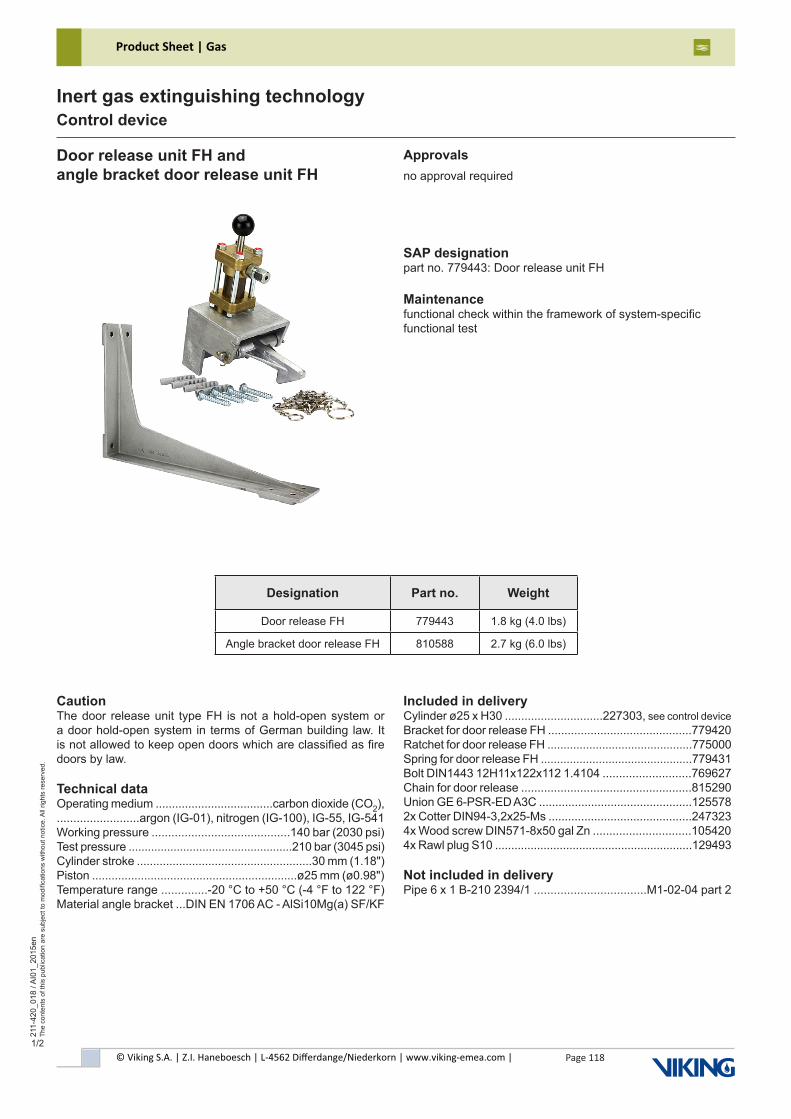
© Viking S.A. | Z.I. Haneboesch | L-4562 Differdange/Niederkorn | www.viking-emea.com |
Product Sheet | Gas
Page 118
211-
420_
018
/ AI0
1_20
15en
The
cont
ents
of t
his
publ
icat
ion
are
subj
ect t
o m
odifi
catio
ns w
ithou
t not
ice.
All
right
s re
serv
ed.
Inert gas extinguishing technologyControl device
1/2
CautionThe door release unit type FH is not a hold-open system or a door hold-open system in terms of German building law. It is not allowed to keep open doors which are classified as fire doors by law.
Technical dataOperating medium ....................................carbon dioxide (CO2),.........................argon (IG-01), nitrogen (IG-100), IG-55, IG-541Working pressure ..........................................140 bar (2030 psi)Test pressure ...................................................210 bar (3045 psi)Cylinder stroke ......................................................30 mm (1.18")Piston ...............................................................ø25 mm (ø0.98")Temperature range ..............-20 °C to +50 °C (-4 °F to 122 °F)Material angle bracket ...DIN EN 1706 AC - AlSi10Mg(a) SF/KF
Door release unit FH andangle bracket door release unit FH
SAP designationpart no. 779443: Door release unit FH
Maintenancefunctional check within the framework of system-specificfunctional test
Approvalsno approval required
Designation Part no. Weight
Door release FH 779443 1.8 kg (4.0 lbs)
Angle bracket door release FH 810588 2.7 kg (6.0 lbs)
Included in deliveryCylinder ø25 x H30 ..............................227303, see control device Bracket for door release FH ............................................779420Ratchet for door release FH .............................................775000Spring for door release FH ...............................................779431Bolt DIN1443 12H11x122x112 1.4104 ...........................769627Chain for door release ....................................................815290Union GE 6-PSR-ED A3C ...............................................1255782x Cotter DIN94-3,2x25-Ms ............................................2473234x Wood screw DIN571-8x50 gal Zn ..............................1054204x Rawl plug S10 .............................................................129493
Not included in deliveryPipe 6 x 1 B-210 2394/1 ..................................M1-02-04 part 2
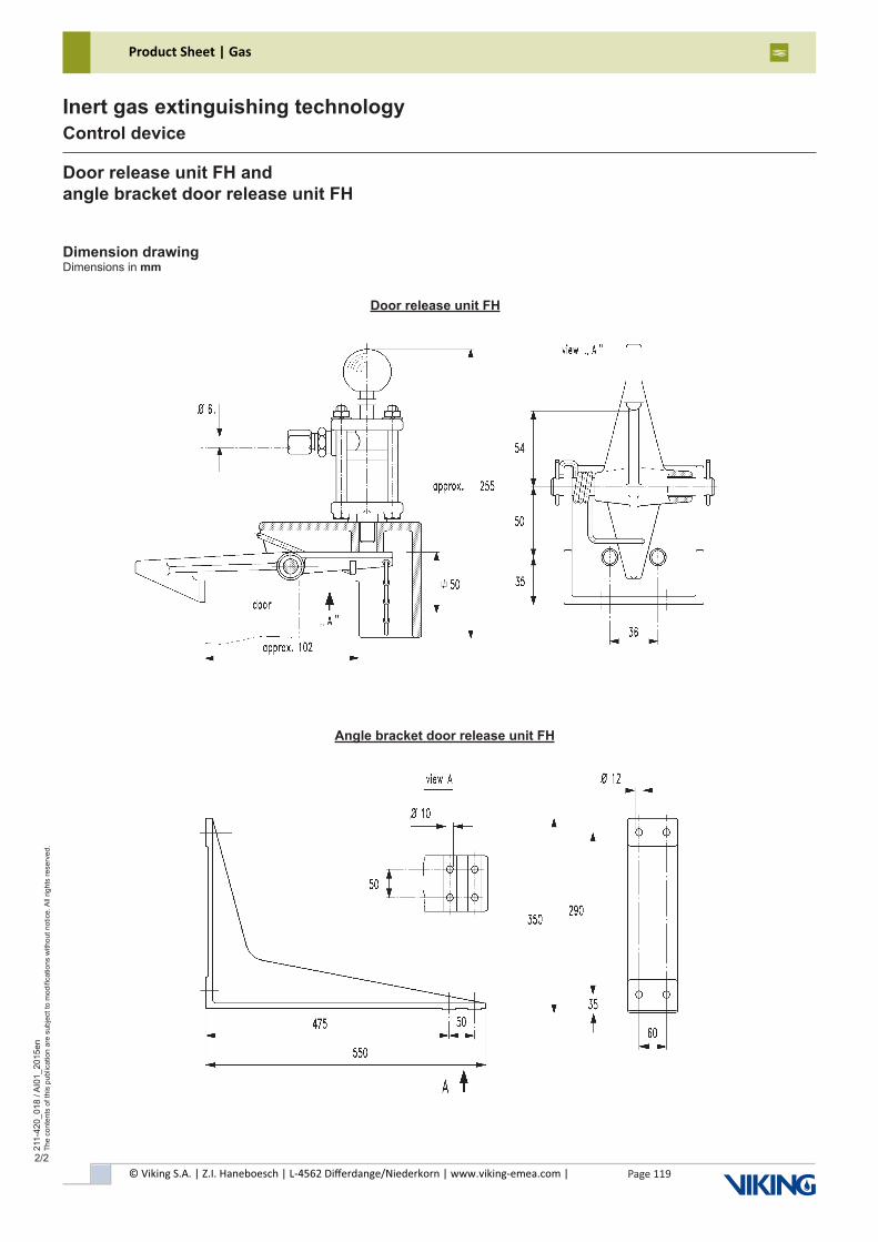
© Viking S.A. | Z.I. Haneboesch | L-4562 Differdange/Niederkorn | www.viking-emea.com |
Product Sheet | Gas
Page 119
211-
420_
018
/ AI0
1_20
15en
The
cont
ents
of t
his
publ
icat
ion
are
subj
ect t
o m
odifi
catio
ns w
ithou
t not
ice.
All
right
s re
serv
ed.
Inert gas extinguishing technologyControl device
2/2
Dimension drawingDimensions in mm
Door release unit FH andangle bracket door release unit FH
Angle bracket door release unit FH
Door release unit FH
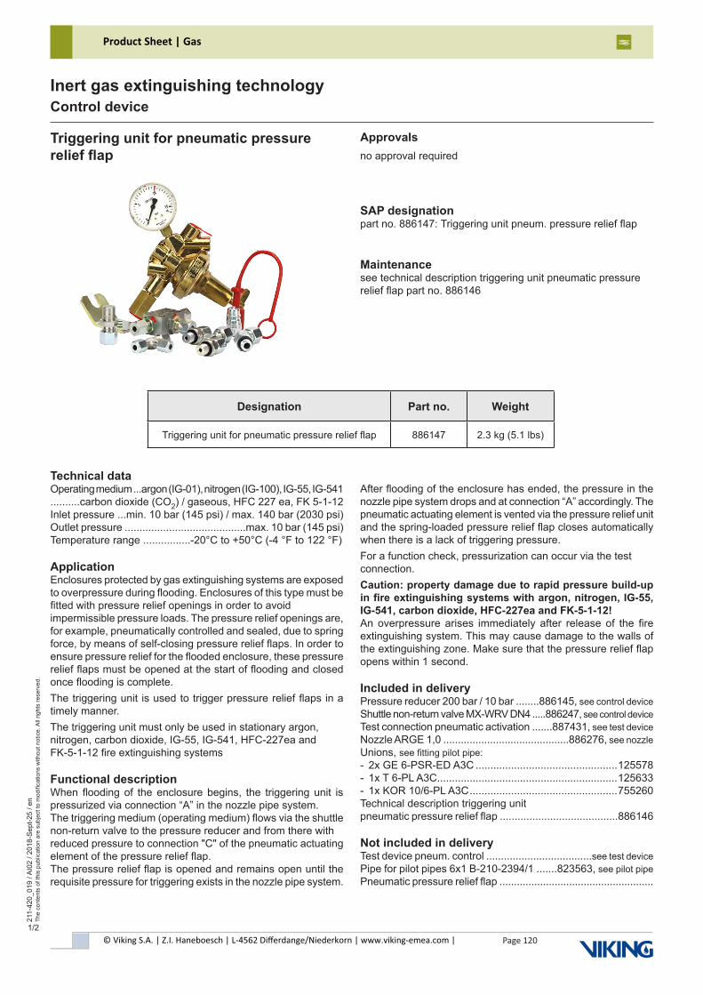
© Viking S.A. | Z.I. Haneboesch | L-4562 Differdange/Niederkorn | www.viking-emea.com |
Product Sheet | Gas
Page 120
211-
420_
019
/ AI0
2 / 2
018-
Sep
t-25
/ en
The
cont
ents
of t
his
publ
icat
ion
are
subj
ect t
o m
odifi
catio
ns w
ithou
t not
ice.
All
right
s re
serv
ed.
Inert gas extinguishing technologyControl device
1/2
Triggering unit for pneumatic pressure relief flap
Technical dataOperating medium ...argon (IG-01), nitrogen (IG-100), IG-55, IG-541..........carbon dioxide (CO2) / gaseous, HFC 227 ea, FK 5-1-12Inlet pressure ...min. 10 bar (145 psi) / max. 140 bar (2030 psi)Outlet pressure .........................................max. 10 bar (145 psi)Temperature range ................-20°C to +50°C (-4 °F to 122 °F)
ApplicationEnclosures protected by gas extinguishing systems are exposed to overpressure during flooding. Enclosures of this type must be fitted with pressure relief openings in order to avoidimpermissible pressure loads. The pressure relief openings are, for example, pneumatically controlled and sealed, due to spring force, by means of self-closing pressure relief flaps. In order to ensure pressure relief for the flooded enclosure, these pressure relief flaps must be opened at the start of flooding and closed once flooding is complete.The triggering unit is used to trigger pressure relief flaps in a timely manner.The triggering unit must only be used in stationary argon, nitrogen, carbon dioxide, IG-55, IG-541, HFC-227ea and FK-5-1-12 fire extinguishing systems
Functional descriptionWhen flooding of the enclosure begins, the triggering unit is pressurized via connection “A” in the nozzle pipe system.The triggering medium (operating medium) flows via the shuttle non-return valve to the pressure reducer and from there withreduced pressure to connection "C" of the pneumatic actuating element of the pressure relief flap.The pressure relief flap is opened and remains open until the requisite pressure for triggering exists in the nozzle pipe system.
SAP designationpart no. 886147: Triggering unit pneum. pressure relief flap
Maintenancesee technical description triggering unit pneumatic pressurerelief flap part no. 886146
After flooding of the enclosure has ended, the pressure in the nozzle pipe system drops and at connection “A” accordingly. The pneumatic actuating element is vented via the pressure relief unit and the spring-loaded pressure relief flap closes automatically when there is a lack of triggering pressure.For a function check, pressurization can occur via the test connection.Caution: property damage due to rapid pressure build-up in fire extinguishing systems with argon, nitrogen, IG-55, IG-541, carbon dioxide, HFC-227ea and FK-5-1-12!An overpressure arises immediately after release of the fire extinguishing system. This may cause damage to the walls of the extinguishing zone. Make sure that the pressure relief flap opens within 1 second.
Included in deliveryPressure reducer 200 bar / 10 bar ........886145, see control device Shuttle non-return valve MX-WRV DN4 .....886247, see control device Test connection pneumatic activation .......887431, see test device Nozzle ARGE 1,0 ...........................................886276, see nozzle Unions, see fitting pilot pipe:- 2x GE 6-PSR-ED A3C ................................................125578- 1x T 6-PL A3C .............................................................125633- 1x KOR 10/6-PL A3C ..................................................755260Technical description triggering unitpneumatic pressure relief flap ........................................886146
Not included in deliveryTest device pneum. control ....................................see test device Pipe for pilot pipes 6x1 B-210-2394/1 .......823563, see pilot pipePneumatic pressure relief flap .....................................................
Approvalsno approval required
Designation Part no. Weight
Triggering unit for pneumatic pressure relief flap 886147 2.3 kg (5.1 lbs)
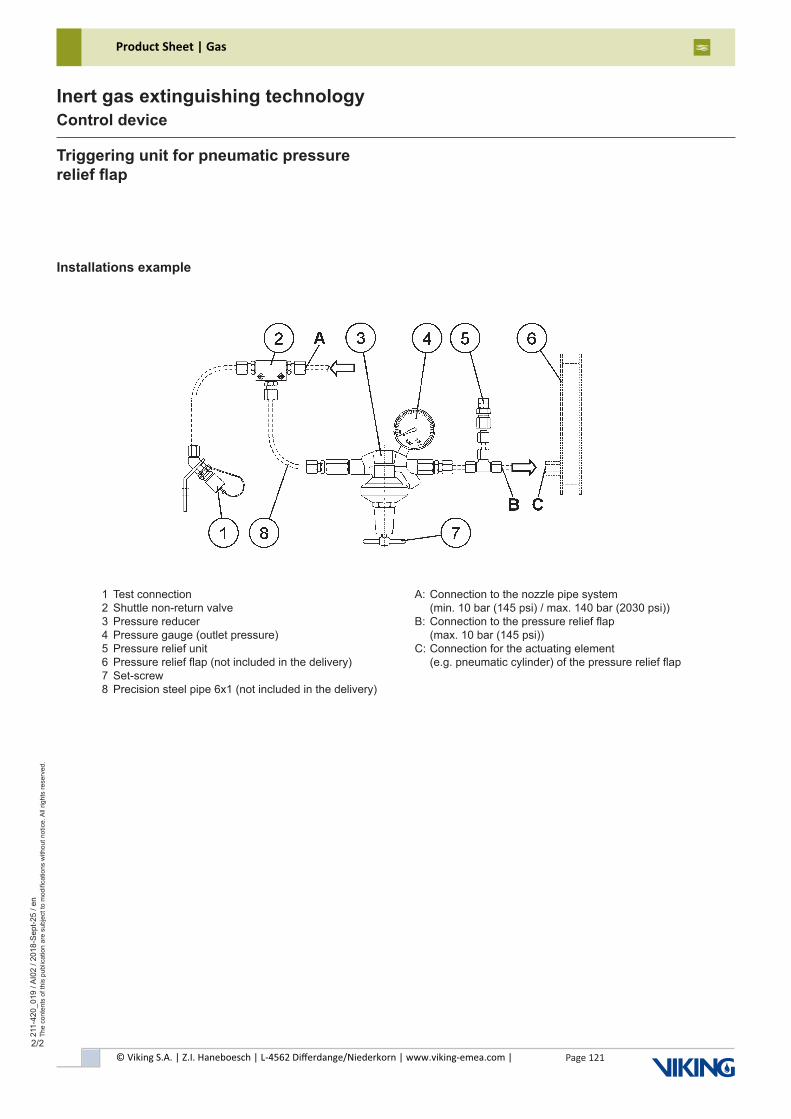
© Viking S.A. | Z.I. Haneboesch | L-4562 Differdange/Niederkorn | www.viking-emea.com |
Product Sheet | Gas
Page 121
211-
420_
019
/ AI0
2 / 2
018-
Sep
t-25
/ en
The
cont
ents
of t
his
publ
icat
ion
are
subj
ect t
o m
odifi
catio
ns w
ithou
t not
ice.
All
right
s re
serv
ed.
Inert gas extinguishing technologyControl device
2/2
Triggering unit for pneumatic pressure relief flap
Installations example
1 Test connection2 Shuttle non-return valve3 Pressure reducer4 Pressure gauge (outlet pressure)5 Pressure relief unit6 Pressure relief flap (not included in the delivery)7 Set-screw8 Precision steel pipe 6x1 (not included in the delivery)
A: Connection to the nozzle pipe system (min. 10 bar (145 psi) / max. 140 bar (2030 psi))B: Connection to the pressure relief flap (max. 10 bar (145 psi))C: Connection for the actuating element (e.g. pneumatic cylinder) of the pressure relief flap
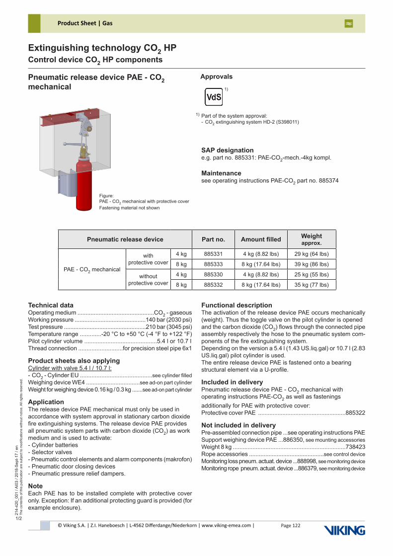
© Viking S.A. | Z.I. Haneboesch | L-4562 Differdange/Niederkorn | www.viking-emea.com |
Product Sheet | Gas
Page 122
214-
420_
001
/ AI0
3 / 2
018-
Sep
t-17
/ en
The
cont
ents
of t
his
publ
icat
ion
are
subj
ect t
o m
odifi
catio
ns w
ithou
t not
ice.
All
right
s re
serv
ed.
Extinguishing technology CO2 HPControl device CO2 HP components
1/2
Technical dataOperating medium ...............................................CO2 - gaseousWorking pressure ............................................140 bar (2030 psi)Test pressure ...................................................210 bar (3045 psi)Temperature range .............-20 °C to +50 °C (-4 °F to +122 °F)Pilot cylinder volume ............................................5.4 l or 10.7 lThread connection ...........................for precision steel pipe 6x1
Product sheets also applyingCylinder with valve 5.4 l / 10.7 l:- CO2 - Cylinder EU ............................................see cylinder filledWeighing device WE4 .................................see ad-on part cylinderWeight for weighing device 0.16 kg / 0.3 kg .......see ad-on part cylinder
ApplicationThe release device PAE mechanical must only be used in accordance with system approval in stationary carbon dioxide fire extinguishing systems. The release device PAE provides all pneumatic system parts with carbon dioxide (CO2) as work medium and is used to activate:- Cylinder batteries- Selector valves- Pneumatic control elements and alarm components (makrofon)- Pneumatic door closing devices- Pneumatic pressure relief dampers.
NoteEach PAE has to be installed complete with protective cover only. Exception: If an additional protecting guard is provided (for example enclosure).
Functional descriptionThe activation of the release device PAE occurs mechanically (weight). Thus the toggle valve on the pilot cylinder is openedand the carbon dioxide (CO2) flows through the connected pipe assembly respectively the hose to the pneumatic system com-ponents of the fire extinguishing system.Depending on the version a 5.4 l (1.43 US.liq.gal) or 10.7 l (2.83 US.liq.gal) pilot cylinder is used.The entire release device PAE is fastened onto a bearingstructural element via a U-profile.
Included in deliveryPneumatic release device PAE - CO2 mechanical withoperating instructions PAE-CO2 as well as fasteningsadditionally for PAE with protective cover:Protective cover PAE ......................................................885322
Not included in deliveryPre-assembled connection pipe ...see operating instructions PAESupport weighing device PAE ...886350, see mounting accessoriesWeight 8 kg .....................................................................738423Rope accessories ..............................................see control deviceMonitoring loss pneum. actuat. device ...888998, see monitoring deviceMonitoring rope pneum. actuat. device ...886379, see monitoring device
Pneumatic release device PAE - CO2mechanical
Approvals
SAP designatione.g. part no. 885331: PAE-CO2-mech.-4kg kompl.
Maintenancesee operating instructions PAE-CO2 part no. 885374
Part of the system approval:- CO2 extinguishing system HD-2 (S398011)
1)
Figure:PAE - CO2 mechanical with protective coverFastening material not shown
1)
Pneumatic release device Part no. Amount filled Weight approx.
PAE - CO2 mechanical
with protective cover
4 kg 885331 4 kg (8.82 lbs) 29 kg (64 lbs)
8 kg 885333 8 kg (17.64 lbs) 39 kg (86 lbs)
without protective cover
4 kg 885330 4 kg (8.82 lbs) 25 kg (55 lbs)
8 kg 885332 8 kg (17.64 lbs) 35 kg (77 lbs)
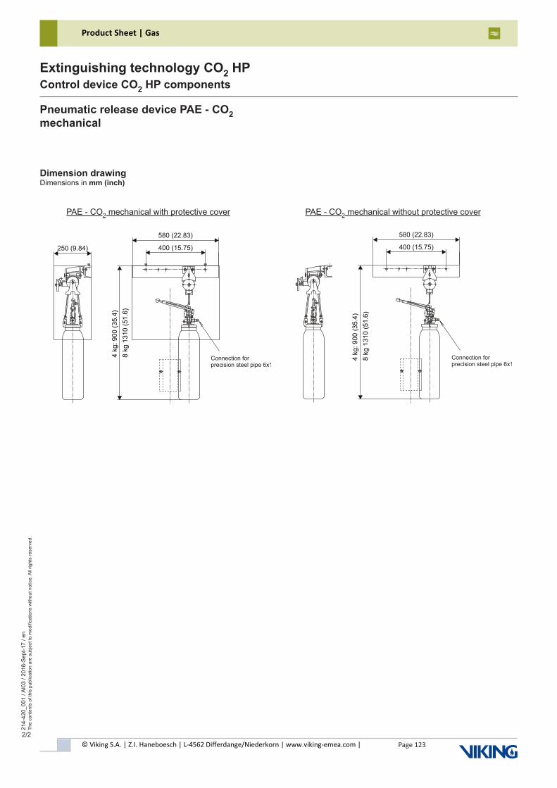
© Viking S.A. | Z.I. Haneboesch | L-4562 Differdange/Niederkorn | www.viking-emea.com |
Product Sheet | Gas
Page 123
214-
420_
001
/ AI0
3 / 2
018-
Sep
t-17
/ en
The
cont
ents
of t
his
publ
icat
ion
are
subj
ect t
o m
odifi
catio
ns w
ithou
t not
ice.
All
right
s re
serv
ed.
Extinguishing technology CO2 HPControl device CO2 HP components
2/2
Pneumatic release device PAE - CO2mechanical
Dimension drawingDimensions in mm (inch)
PAE - CO2 mechanical with protective cover PAE - CO2 mechanical without protective cover
580 (22.83)
400 (15.75)
Connection forprecision steel pipe 6x1
4 k
g:
90
0 (
35
.4)
8 k
g 1
31
0 (
51
.6)
250 (9.84)
580 (22.83)
400 (15.75)
4 k
g:
90
0 (
35
.4)
8 k
g 1
31
0 (
51
.6)
Connection forprecision steel pipe 6x1
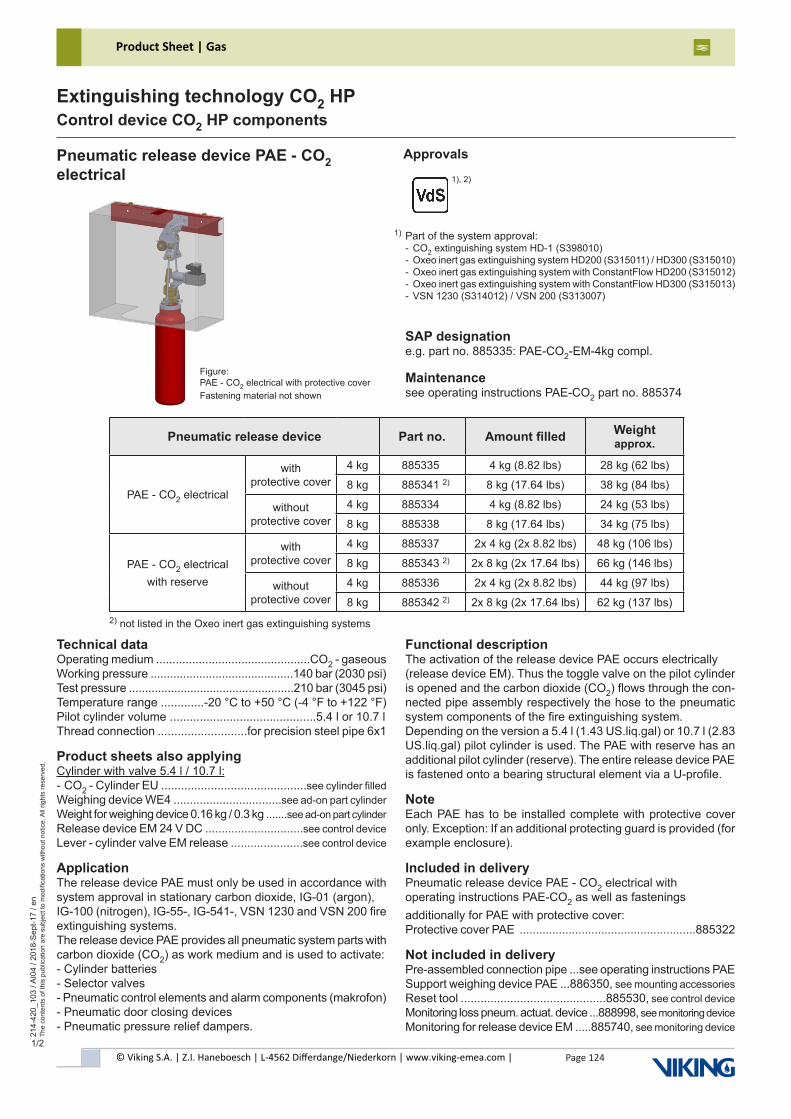
© Viking S.A. | Z.I. Haneboesch | L-4562 Differdange/Niederkorn | www.viking-emea.com |
Product Sheet | Gas
Page 124
214-
420_
103
/ AI0
4 / 2
018-
Sep
t-17
/ en
The
cont
ents
of t
his
publ
icat
ion
are
subj
ect t
o m
odifi
catio
ns w
ithou
t not
ice.
All
right
s re
serv
ed.
Extinguishing technology CO2 HPControl device CO2 HP components
1/2
Part of the system approval:- CO2 extinguishing system HD-1 (S398010)- Oxeo inert gas extinguishing system HD200 (S315011) / HD300 (S315010)- Oxeo inert gas extinguishing system with ConstantFlow HD200 (S315012)- Oxeo inert gas extinguishing system with ConstantFlow HD300 (S315013)- VSN 1230 (S314012) / VSN 200 (S313007)
1)
Technical dataOperating medium ...............................................CO2 - gaseousWorking pressure ............................................140 bar (2030 psi)Test pressure ...................................................210 bar (3045 psi)Temperature range .............-20 °C to +50 °C (-4 °F to +122 °F)Pilot cylinder volume ............................................5.4 l or 10.7 lThread connection ...........................for precision steel pipe 6x1
Product sheets also applyingCylinder with valve 5.4 l / 10.7 l:- CO2 - Cylinder EU ............................................see cylinder filledWeighing device WE4 .................................see ad-on part cylinderWeight for weighing device 0.16 kg / 0.3 kg .......see ad-on part cylinderRelease device EM 24 V DC ..............................see control deviceLever - cylinder valve EM release ......................see control device
ApplicationThe release device PAE must only be used in accordance with system approval in stationary carbon dioxide, IG-01 (argon),IG-100 (nitrogen), IG-55-, IG-541-, VSN 1230 and VSN 200 fire extinguishing systems.The release device PAE provides all pneumatic system parts with carbon dioxide (CO2) as work medium and is used to activate:- Cylinder batteries- Selector valves- Pneumatic control elements and alarm components (makrofon)- Pneumatic door closing devices- Pneumatic pressure relief dampers.
Functional descriptionThe activation of the release device PAE occurs electrically(release device EM). Thus the toggle valve on the pilot cylinder is opened and the carbon dioxide (CO2) flows through the con-nected pipe assembly respectively the hose to the pneumatic system components of the fire extinguishing system.Depending on the version a 5.4 l (1.43 US.liq.gal) or 10.7 l (2.83 US.liq.gal) pilot cylinder is used. The PAE with reserve has an additional pilot cylinder (reserve). The entire release device PAE is fastened onto a bearing structural element via a U-profile.
NoteEach PAE has to be installed complete with protective cover only. Exception: If an additional protecting guard is provided (for example enclosure).
Included in deliveryPneumatic release device PAE - CO2 electrical withoperating instructions PAE-CO2 as well as fasteningsadditionally for PAE with protective cover:Protective cover PAE ......................................................885322
Not included in deliveryPre-assembled connection pipe ...see operating instructions PAESupport weighing device PAE ...886350, see mounting accessoriesReset tool ............................................885530, see control deviceMonitoring loss pneum. actuat. device ...888998, see monitoring deviceMonitoring for release device EM .....885740, see monitoring device
Pneumatic release device PAE - CO2electrical
SAP designatione.g. part no. 885335: PAE-CO2-EM-4kg compl.
Maintenancesee operating instructions PAE-CO2 part no. 885374
Approvals
Figure:PAE - CO2 electrical with protective coverFastening material not shown
Pneumatic release device Part no. Amount filled Weight approx.
PAE - CO2 electrical
with protective cover
4 kg 885335 4 kg (8.82 lbs) 28 kg (62 lbs)
8 kg 885341 2) 8 kg (17.64 lbs) 38 kg (84 lbs)
without protective cover
4 kg 885334 4 kg (8.82 lbs) 24 kg (53 lbs)
8 kg 885338 8 kg (17.64 lbs) 34 kg (75 lbs)
PAE - CO2 electricalwith reserve
with protective cover
4 kg 885337 2x 4 kg (2x 8.82 lbs) 48 kg (106 lbs)
8 kg 885343 2) 2x 8 kg (2x 17.64 lbs) 66 kg (146 lbs)
without protective cover
4 kg 885336 2x 4 kg (2x 8.82 lbs) 44 kg (97 lbs)
8 kg 885342 2) 2x 8 kg (2x 17.64 lbs) 62 kg (137 lbs)
1), 2)
2) not listed in the Oxeo inert gas extinguishing systems
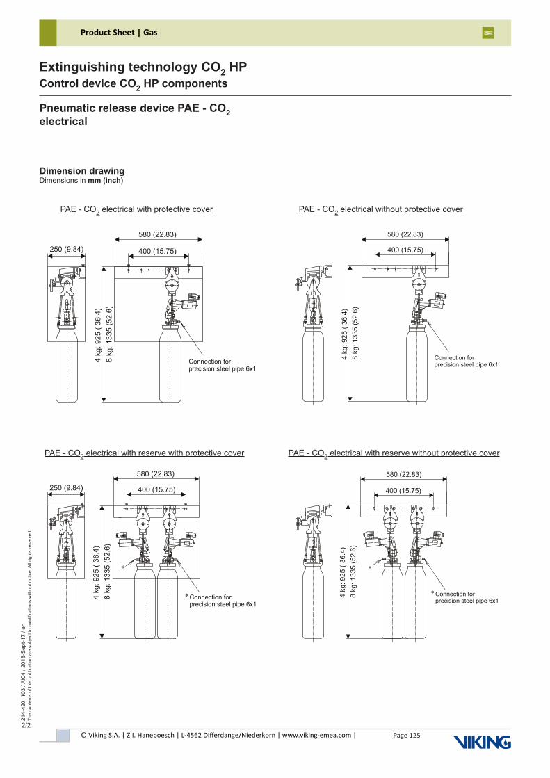
© Viking S.A. | Z.I. Haneboesch | L-4562 Differdange/Niederkorn | www.viking-emea.com |
Product Sheet | Gas
Page 125
214-
420_
103
/ AI0
4 / 2
018-
Sep
t-17
/ en
The
cont
ents
of t
his
publ
icat
ion
are
subj
ect t
o m
odifi
catio
ns w
ithou
t not
ice.
All
right
s re
serv
ed.
Extinguishing technology CO2 HPControl device CO2 HP components
2/2
Dimension drawingDimensions in mm (inch)
Pneumatic release device PAE - CO2electrical
PAE - CO2 electrical with protective cover PAE - CO2 electrical without protective cover
PAE - CO2 electrical with reserve with protective cover PAE - CO2 electrical with reserve without protective cover
580 (22.83)
400 (15.75)
Connection forprecision steel pipe 6x1
4 k
g: 925 (
36.4
)
8 k
g: 1335 (
52.6
)
580 (22.83)
400 (15.75)
Connection forprecision steel pipe 6x1
4 k
g:
92
5 (
36
.4)
8 k
g:
13
35
(5
2.6
)
*
*
250 (9.84)
580 (22.83)
400 (15.75)
Connection forprecision steel pipe 6x1
4 k
g: 925 (
36.4
)
8 k
g: 1335 (
52.6
)
*
*
250 (9.84)
580 (22.83)
400 (15.75)
Connection forprecision steel pipe 6x1
4 k
g: 925 (
36.4
)
8 k
g: 1335 (
52.6
)
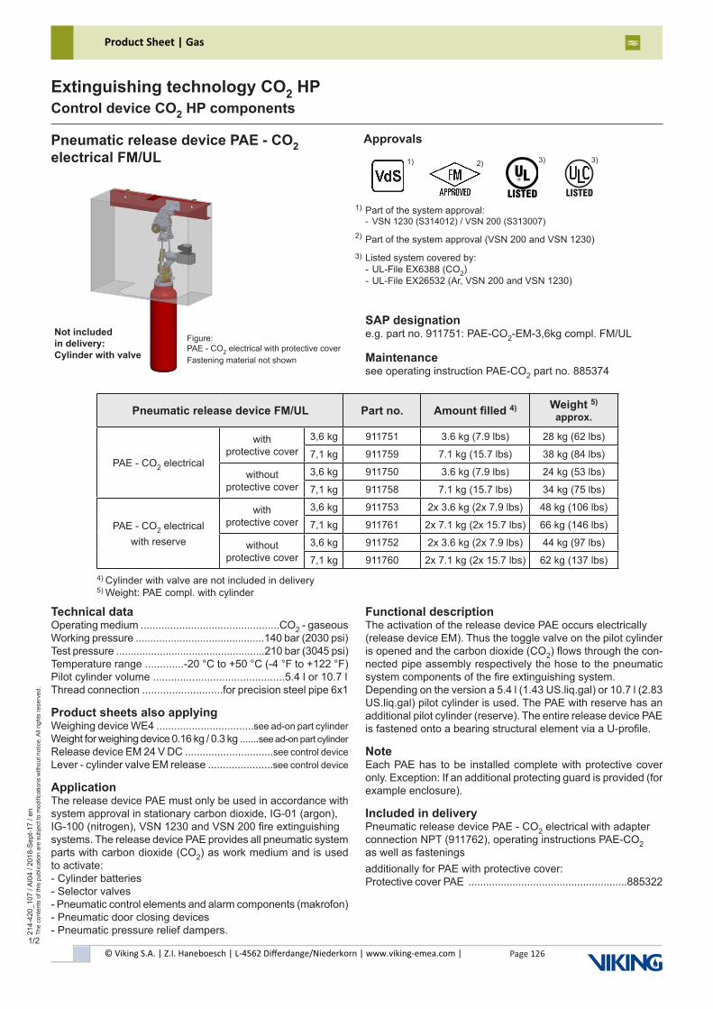
© Viking S.A. | Z.I. Haneboesch | L-4562 Differdange/Niederkorn | www.viking-emea.com |
Product Sheet | Gas
Page 126
214-
420_
107
/ AI0
4 / 2
018-
Sep
t-17
/ en
The
cont
ents
of t
his
publ
icat
ion
are
subj
ect t
o m
odifi
catio
ns w
ithou
t not
ice.
All
right
s re
serv
ed.
Extinguishing technology CO2 HPControl device CO2 HP components
1/2
2) 3)
Part of the system approval:- VSN 1230 (S314012) / VSN 200 (S313007)
Part of the system approval (VSN 200 and VSN 1230)
Listed system covered by:- UL-File EX6388 (CO2)- UL-File EX26532 (Ar, VSN 200 and VSN 1230)
1)
Technical dataOperating medium ...............................................CO2 - gaseousWorking pressure ............................................140 bar (2030 psi)Test pressure ...................................................210 bar (3045 psi)Temperature range .............-20 °C to +50 °C (-4 °F to +122 °F)Pilot cylinder volume ............................................5.4 l or 10.7 lThread connection ...........................for precision steel pipe 6x1
Product sheets also applyingWeighing device WE4 .................................see ad-on part cylinder Weight for weighing device 0.16 kg / 0.3 kg .......see ad-on part cylinderRelease device EM 24 V DC ..............................see control deviceLever - cylinder valve EM release ......................see control device
ApplicationThe release device PAE must only be used in accordance with system approval in stationary carbon dioxide, IG-01 (argon),IG-100 (nitrogen), VSN 1230 and VSN 200 fire extinguishingsystems. The release device PAE provides all pneumatic system parts with carbon dioxide (CO2) as work medium and is used to activate:- Cylinder batteries- Selector valves- Pneumatic control elements and alarm components (makrofon)- Pneumatic door closing devices- Pneumatic pressure relief dampers.
Functional descriptionThe activation of the release device PAE occurs electrically(release device EM). Thus the toggle valve on the pilot cylinder is opened and the carbon dioxide (CO2) flows through the con-nected pipe assembly respectively the hose to the pneumatic system components of the fire extinguishing system.Depending on the version a 5.4 l (1.43 US.liq.gal) or 10.7 l (2.83 US.liq.gal) pilot cylinder is used. The PAE with reserve has an additional pilot cylinder (reserve). The entire release device PAE is fastened onto a bearing structural element via a U-profile.
NoteEach PAE has to be installed complete with protective cover only. Exception: If an additional protecting guard is provided (for example enclosure).
Included in deliveryPneumatic release device PAE - CO2 electrical with adapter connection NPT (911762), operating instructions PAE-CO2 as well as fasteningsadditionally for PAE with protective cover:Protective cover PAE ......................................................885322
Pneumatic release device PAE - CO2electrical FM/UL
SAP designatione.g. part no. 911751: PAE-CO2-EM-3,6kg compl. FM/UL
Maintenancesee operating instruction PAE-CO2 part no. 885374
Approvals3)2)
������
3) 1)
Not includedin delivery:Cylinder with valve
Figure:PAE - CO2 electrical with protective coverFastening material not shown
4) Cylinder with valve are not included in delivery5) Weight: PAE compl. with cylinder
Pneumatic release device FM/UL Part no. Amount filled 4) Weight 5) approx.
PAE - CO2 electrical
with protective cover
3,6 kg 911751 3.6 kg (7.9 lbs) 28 kg (62 lbs)
7,1 kg 911759 7.1 kg (15.7 lbs) 38 kg (84 lbs)
without protective cover
3,6 kg 911750 3.6 kg (7.9 lbs) 24 kg (53 lbs)
7,1 kg 911758 7.1 kg (15.7 lbs) 34 kg (75 lbs)
PAE - CO2 electricalwith reserve
with protective cover
3,6 kg 911753 2x 3.6 kg (2x 7.9 lbs) 48 kg (106 lbs)
7,1 kg 911761 2x 7.1 kg (2x 15.7 lbs) 66 kg (146 lbs)
without protective cover
3,6 kg 911752 2x 3.6 kg (2x 7.9 lbs) 44 kg (97 lbs)
7,1 kg 911760 2x 7.1 kg (2x 15.7 lbs) 62 kg (137 lbs)
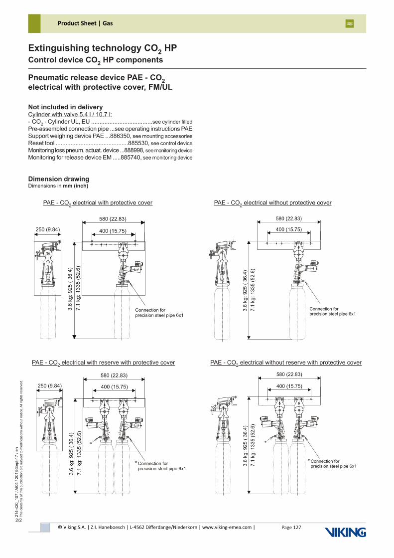
© Viking S.A. | Z.I. Haneboesch | L-4562 Differdange/Niederkorn | www.viking-emea.com |
Product Sheet | Gas
Page 127
214-
420_
107
/ AI0
4 / 2
018-
Sep
t-17
/ en
The
cont
ents
of t
his
publ
icat
ion
are
subj
ect t
o m
odifi
catio
ns w
ithou
t not
ice.
All
right
s re
serv
ed.
Extinguishing technology CO2 HPControl device CO2 HP components
2/2
Dimension drawingDimensions in mm (inch)
Pneumatic release device PAE - CO2electrical with protective cover, FM/UL
Not included in deliveryCylinder with valve 5.4 l / 10.7 l:- CO2 - Cylinder UL, EU .....................................see cylinder filledPre-assembled connection pipe ...see operating instructions PAESupport weighing device PAE ...886350, see mounting accessoriesReset tool ............................................885530, see control deviceMonitoring loss pneum. actuat. device ...888998, see monitoring deviceMonitoring for release device EM .....885740, see monitoring device
PAE - CO2 electrical with protective cover PAE - CO2 electrical without protective cover
580 (22.83)
400 (15.75)
Connection forprecision steel pipe 6x1
3.6
kg
: 9
25
( 3
6.4
)
7.1
kg
: 1
33
5 (
52
.6)
580 (22.83)
400 (15.75)
Connection forprecision steel pipe 6x1
*
*
3.6
kg
: 9
25
( 3
6.4
)
7.1
kg
: 1
33
5 (
52
.6)
PAE - CO2 electrical with reserve with protective cover PAE - CO2 electrical without reserve with protective cover
250 (9.84)
580 (22.83)
400 (15.75)
Connection forprecision steel pipe 6x1
*
*
3.6
kg: 925 (
36.4
)
7.1
kg: 1335 (
52.6
)
250 (9.84)
580 (22.83)
400 (15.75)
Connection forprecision steel pipe 6x1
3.6
kg: 925 (
36.4
)
7.1
kg: 1335 (
52.6
)
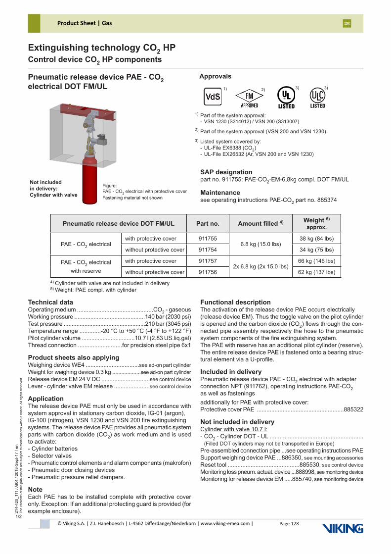
© Viking S.A. | Z.I. Haneboesch | L-4562 Differdange/Niederkorn | www.viking-emea.com |
Product Sheet | Gas
Page 128
214-
420_
111
/ AI0
4 / 2
018-
Sep
t-17
/ en
The
cont
ents
of t
his
publ
icat
ion
are
subj
ect t
o m
odifi
catio
ns w
ithou
t not
ice.
All
right
s re
serv
ed.
Extinguishing technology CO2 HPControl device CO2 HP components
1/2
2) 3)
Part of the system approval:- VSN 1230 (S314012) / VSN 200 (S313007)
Part of the system approval (VSN 200 and VSN 1230)
Listed system covered by:- UL-File EX6388 (CO2)- UL-File EX26532 (Ar, VSN 200 and VSN 1230)
1)
Technical dataOperating medium ...............................................CO2 - gaseousWorking pressure ............................................140 bar (2030 psi)Test pressure ...................................................210 bar (3045 psi)Temperature range .............-20 °C to +50 °C (-4 °F to +122 °F)Pilot cylinder volume .................................10.7 l (2.83 US.liq.gal)Thread connection ...........................for precision steel pipe 6x1
Product sheets also applyingWeighing device WE4 .................................see ad-on part cylinderWeight for weighing device 0.3 kg ...................see ad-on part cylinderRelease device EM 24 V DC ..............................see control deviceLever - cylinder valve EM release ......................see control device
ApplicationThe release device PAE must only be used in accordance with system approval in stationary carbon dioxide, IG-01 (argon),IG-100 (nitrogen), VSN 1230 and VSN 200 fire extinguishingsystems. The release device PAE provides all pneumatic system parts with carbon dioxide (CO2) as work medium and is used to activate:- Cylinder batteries- Selector valves- Pneumatic control elements and alarm components (makrofon)- Pneumatic door closing devices- Pneumatic pressure relief dampers.
NoteEach PAE has to be installed complete with protective cover only. Exception: If an additional protecting guard is provided (for example enclosure).
Functional descriptionThe activation of the release device PAE occurs electrically(release device EM). Thus the toggle valve on the pilot cylinder is opened and the carbon dioxide (CO2) flows through the con-nected pipe assembly respectively the hose to the pneumatic system components of the fire extinguishing system.The PAE with reserve has an additional pilot cylinder (reserve). The entire release device PAE is fastened onto a bearing struc-tural element via a U-profile.
Included in deliveryPneumatic release device PAE - CO2 electrical with adapter connection NPT (911762), operating instructions PAE-CO2 as well as fasteningsadditionally for PAE with protective cover:Protective cover PAE ......................................................885322
Not included in deliveryCylinder with valve 10.7 l:- CO2 - Cylinder DOT - UL ......................................................... (Filled DOT cylinders may not be transported in Europe)Pre-assembled connection pipe ...see operating instructions PAESupport weighing device PAE ...886350, see mounting accessoriesReset tool ............................................885530, see control deviceMonitoring loss pneum. actuat. device ...888998, see monitoring deviceMonitoring for release device EM .....885740, see monitoring device
Pneumatic release device PAE - CO2electrical DOT FM/UL
SAP designationpart no. 911755: PAE-CO2-EM-6,8kg compl. DOT FM/UL
Maintenancesee operating instructions PAE-CO2 part no. 885374
Approvals3)2)
������
3) 1)
Not includedin delivery:Cylinder with valve
Figure:PAE - CO2 electrical with protective coverFastening material not shown
4) Cylinder with valve are not included in delivery5) Weight: PAE compl. with cylinder
Pneumatic release device DOT FM/UL Part no. Amount filled 4) Weight 5) approx.
PAE - CO2 electricalwith protective cover 911755
6.8 kg (15.0 lbs)38 kg (84 lbs)
without protective cover 911754 34 kg (75 lbs)
PAE - CO2 electricalwith reserve
with protective cover 9117572x 6.8 kg (2x 15.0 lbs)
66 kg (146 lbs)
without protective cover 911756 62 kg (137 lbs)
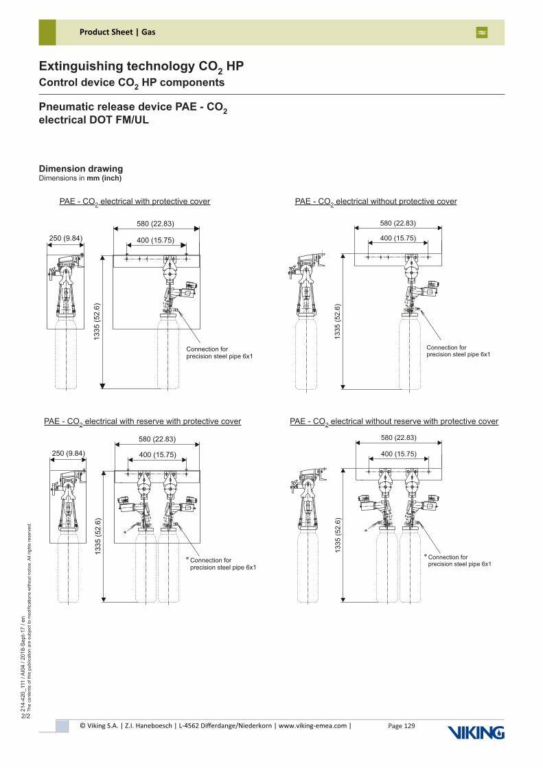
© Viking S.A. | Z.I. Haneboesch | L-4562 Differdange/Niederkorn | www.viking-emea.com |
Product Sheet | Gas
Page 129
214-
420_
111
/ AI0
4 / 2
018-
Sep
t-17
/ en
The
cont
ents
of t
his
publ
icat
ion
are
subj
ect t
o m
odifi
catio
ns w
ithou
t not
ice.
All
right
s re
serv
ed.
Extinguishing technology CO2 HPControl device CO2 HP components
2/2
Pneumatic release device PAE - CO2electrical DOT FM/UL
Dimension drawingDimensions in mm (inch)
PAE - CO2 electrical with protective cover PAE - CO2 electrical without protective cover
580 (22.83)
400 (15.75)
Connection forprecision steel pipe 6x1
13
35
(5
2.6
)
580 (22.83)
400 (15.75)
Connection forprecision steel pipe 6x1
*
*
13
35
(5
2.6
)
PAE - CO2 electrical with reserve with protective cover PAE - CO2 electrical without reserve with protective cover
250 (9.84)
580 (22.83)
400 (15.75)
Connection forprecision steel pipe 6x1
*
*
1335 (
52.6
)
250 (9.84)
580 (22.83)
400 (15.75)
Connection forprecision steel pipe 6x1
1335 (
52.6
)
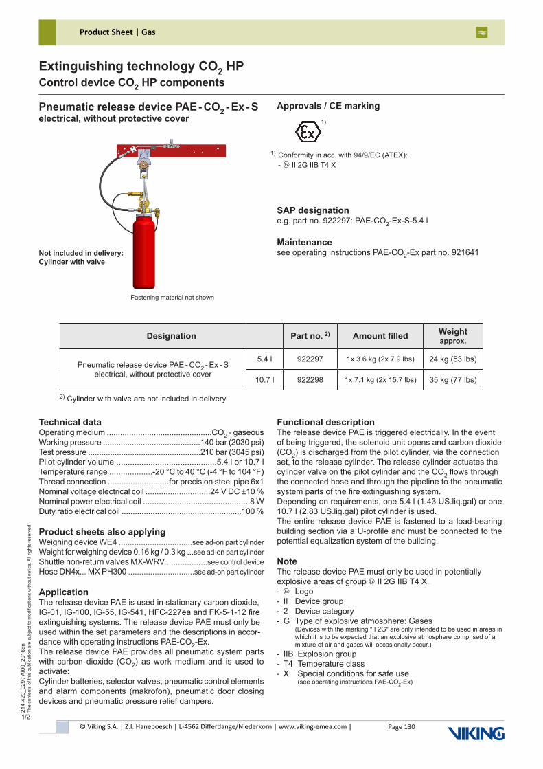
© Viking S.A. | Z.I. Haneboesch | L-4562 Differdange/Niederkorn | www.viking-emea.com |
Product Sheet | Gas
Page 130
214-
420_
029
/ AI0
0_20
16en
The
cont
ents
of t
his
publ
icat
ion
are
subj
ect t
o m
odifi
catio
ns w
ithou
t not
ice.
All
right
s re
serv
ed.
Extinguishing technology CO2 HPControl device CO2 HP components
1/2
Fastening material not shown
Technical dataOperating medium ...............................................CO2 - gaseousWorking pressure ............................................140 bar (2030 psi)Test pressure ...................................................210 bar (3045 psi)Pilot cylinder volume ............................................5.4 l or 10.7 lTemperature range ...................-20 °C to 40 °C (-4 °F to 104 °F)Thread connection ...........................for precision steel pipe 6x1Nominal voltage electrical coil .............................24 V DC ±10 %Nominal power electrical coil ...............................................8 WDuty ratio electrical coil ......................................................100 %
Product sheets also applyingWeighing device WE4 .................................see ad-on part cylinderWeight for weighing device 0.16 kg / 0.3 kg ...see ad-on part cylinderShuttle non-return valves MX-WRV ..................see control deviceHose DN4x... MX PH300 ..............................see ad-on part cylinder
ApplicationThe release device PAE is used in stationary carbon dioxide, IG-01, IG-100, IG-55, IG-541, HFC-227ea and FK-5-1-12 fire extinguishing systems. The release device PAE must only be used within the set parameters and the descriptions in accor-dance with operating instructions PAE-CO2-Ex.The release device PAE provides all pneumatic system parts with carbon dioxide (CO2) as work medium and is used to activate:Cylinder batteries, selector valves, pneumatic control elements and alarm components (makrofon), pneumatic door closing devices and pneumatic pressure relief dampers.
Functional descriptionThe release device PAE is triggered electrically. In the event of being triggered, the solenoid unit opens and carbon dioxide (CO2) is discharged from the pilot cylinder, via the connection set, to the release cylinder. The release cylinder actuates the cylinder valve on the pilot cylinder and the CO2 flows through the connected hose and through the pipeline to the pneumatic system parts of the fire extinguishing system.Depending on requirements, one 5.4 l (1.43 US.liq.gal) or one 10.7 l (2.83 US.liq.gal) pilot cylinder is used.The entire release device PAE is fastened to a load-bearing building section via a U-profile and must be connected to the potential equalization system of the building.
NoteThe release device PAE must only be used in potentially explosive areas of group x II 2G IIB T4 X.- x Logo- II Device group- 2 Device category- G Type of explosive atmosphere: Gases (Devices with the marking "II 2G" are only intended to be used in areas in which it is to be expected that an explosive atmosphere comprised of a mixture of air and gases will occasionally occur.)- IIB Explosion group- T4 Temperature class- X Special conditions for safe use (see operating instructions PAE-CO2-Ex)
Pneumatic release device PAE - CO2 - Ex - Selectrical, without protective cover
SAP designatione.g. part no. 922297: PAE-CO2-Ex-S-5.4 l
Maintenancesee operating instructions PAE-CO2-Ex part no. 921641
Approvals / CE marking
Designation Part no. 2) Amount filled Weight approx.
Pneumatic release device PAE - CO2 - Ex - S electrical, without protective cover
5.4 l 922297 1x 3.6 kg (2x 7.9 lbs) 24 kg (53 lbs)
10.7 l 922298 1x 7.1 kg (2x 15.7 lbs) 35 kg (77 lbs)
2) Cylinder with valve are not included in delivery
1)
Conformity in acc. with 94/9/EC (ATEX):- x II 2G IIB T4 X
1)
Not included in delivery:Cylinder with valve
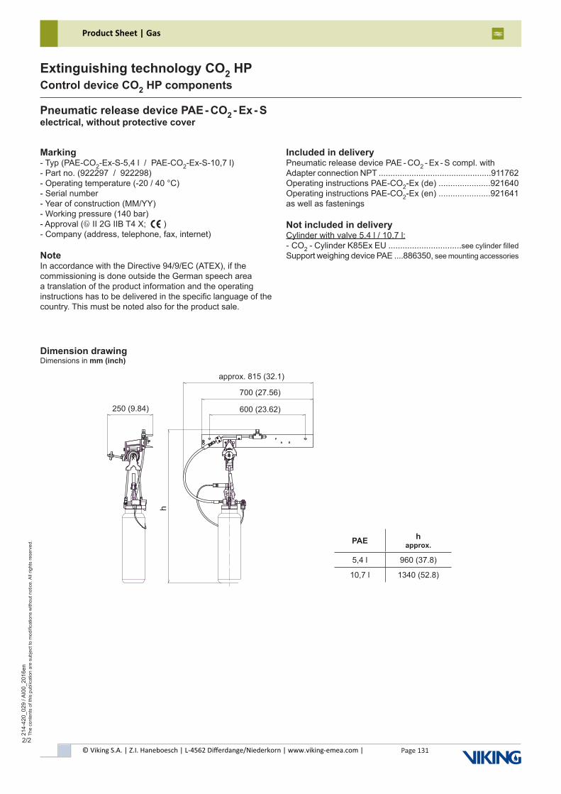
© Viking S.A. | Z.I. Haneboesch | L-4562 Differdange/Niederkorn | www.viking-emea.com |
Product Sheet | Gas
Page 131
214-
420_
029
/ AI0
0_20
16en
The
cont
ents
of t
his
publ
icat
ion
are
subj
ect t
o m
odifi
catio
ns w
ithou
t not
ice.
All
right
s re
serv
ed.
Extinguishing technology CO2 HPControl device CO2 HP components
2/2
Dimension drawingDimensions in mm (inch)
Pneumatic release device PAE - CO2 - Ex - Selectrical, without protective cover
Marking- Typ (PAE-CO2-Ex-S-5,4 l / PAE-CO2-Ex-S-10,7 l)- Part no. (922297 / 922298)- Operating temperature (-20 / 40 °C)- Serial number- Year of construction (MM/YY)- Working pressure (140 bar)- Approval (x II 2G IIB T4 X; e ) - Company (address, telephone, fax, internet)
NoteIn accordance with the Directive 94/9/EC (ATEX), if thecommissioning is done outside the German speech area a translation of the product information and the operating instructions has to be delivered in the specific language of the country. This must be noted also for the product sale.
PAE h approx.
5,4 l 960 (37.8)
10,7 l 1340 (52.8)
600 (23.62)
700 (27.56)
h
approx. 815 (32.1)
250 (9.84)
Blatt
Dokumenten-Nr.
Rev. Änderung
Benennung
modification Schutzvermerk ISO 16016 beachten! Proprietary notice pursuant to ISO 16016 to be observed!
document no.
page
Sprachelanguage
descriptionArtikel-Nr.
Gewichtweight
Werkstoff
Datumdate
UrsprungoriginBearb.progressGepr.checkedFreigabeapproval
Name
materialOberflächefinish
zul. Abweichungallowed tolerance
Maßstabscale
11
1:5
06.08.15
KoehlerMaKoehlerMa
00
PD-Bearbeitung
ES15-062
10.12.15
part no.
Vers. 01
Workflow
Maße in mmdimensions in mm
/
1 mm = 1000 µm = 0.0393701 inch1 mm = 0.00328084 foot 1 L = 0.0353083 cubic foot
1 L = 0.001 m³ = 61.01281 cubic inch 1 bar = 14.50377 psi°F = °C x 1.8 + 32
ISO 1302ISO 13715
DO
K-ID
: 100
0667
71D
IN A
3
PAE-CO2-EX-SPAE-CO2-EX-S
100063269 Blatt
Dokumenten-Nr.
Rev. Änderung
Benennung
modification Schutzvermerk ISO 16016 beachten! Proprietary notice pursuant to ISO 16016 to be observed!
document no.
page
Sprachelanguage
descriptionArtikel-Nr.
Gewichtweight
Werkstoff
Datumdate
UrsprungoriginBearb.progressGepr.checkedFreigabeapproval
Name
materialOberflächefinish
zul. Abweichungallowed tolerance
Maßstabscale
11
1:5
06.08.15
KoehlerMaKoehlerMa
00
PD-Bearbeitung
ES15-062
10.12.15
part no.
Vers. 01
Workflow
Maße in mmdimensions in mm
/
1 mm = 1000 µm = 0.0393701 inch1 mm = 0.00328084 foot 1 L = 0.0353083 cubic foot
1 L = 0.001 m³ = 61.01281 cubic inch 1 bar = 14.50377 psi°F = °C x 1.8 + 32
ISO 1302ISO 13715
DO
K-ID
: 100
0667
71D
IN A
3
PAE-CO2-EX-SPAE-CO2-EX-S
100063269
Included in deliveryPneumatic release device PAE - CO2 - Ex - S compl. withAdapter connection NPT ................................................911762Operating instructions PAE-CO2-Ex (de) ......................921640Operating instructions PAE-CO2-Ex (en) ......................921641as well as fastenings
Not included in deliveryCylinder with valve 5.4 l / 10.7 l:- CO2 - Cylinder K85Ex EU ...............................see cylinder filledSupport weighing device PAE ....886350, see mounting accessories
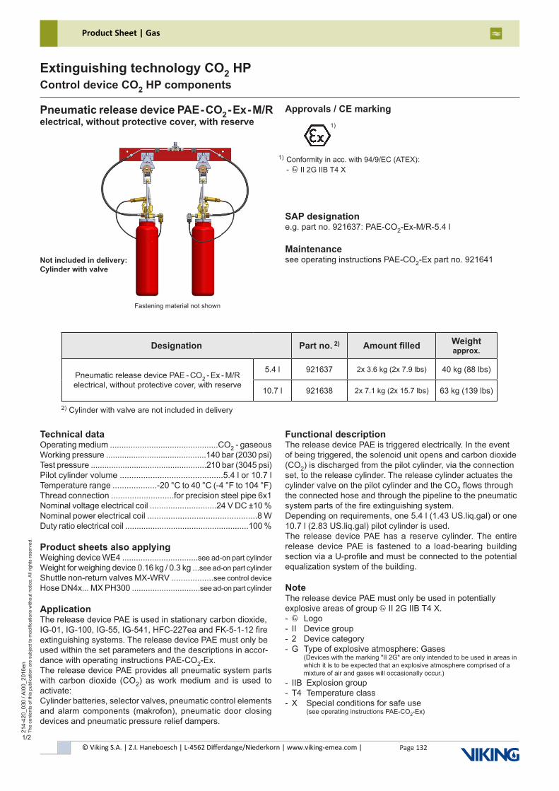
© Viking S.A. | Z.I. Haneboesch | L-4562 Differdange/Niederkorn | www.viking-emea.com |
Product Sheet | Gas
Page 132
214-
420_
030
/ AI0
0_20
16en
The
cont
ents
of t
his
publ
icat
ion
are
subj
ect t
o m
odifi
catio
ns w
ithou
t not
ice.
All
right
s re
serv
ed.
Extinguishing technology CO2 HPControl device CO2 HP components
1/2
Fastening material not shown
Technical dataOperating medium ...............................................CO2 - gaseousWorking pressure ............................................140 bar (2030 psi)Test pressure ...................................................210 bar (3045 psi)Pilot cylinder volume ............................................5.4 l or 10.7 lTemperature range ...................-20 °C to 40 °C (-4 °F to 104 °F)Thread connection ...........................for precision steel pipe 6x1Nominal voltage electrical coil .............................24 V DC ±10 %Nominal power electrical coil ...............................................8 WDuty ratio electrical coil ......................................................100 %
Product sheets also applyingWeighing device WE4 .................................see ad-on part cylinderWeight for weighing device 0.16 kg / 0.3 kg ...see ad-on part cylinderShuttle non-return valves MX-WRV ..................see control deviceHose DN4x... MX PH300 ..............................see ad-on part cylinder
ApplicationThe release device PAE is used in stationary carbon dioxide, IG-01, IG-100, IG-55, IG-541, HFC-227ea and FK-5-1-12 fire extinguishing systems. The release device PAE must only be used within the set parameters and the descriptions in accor-dance with operating instructions PAE-CO2-Ex.The release device PAE provides all pneumatic system parts with carbon dioxide (CO2) as work medium and is used to activate:Cylinder batteries, selector valves, pneumatic control elements and alarm components (makrofon), pneumatic door closing devices and pneumatic pressure relief dampers.
Functional descriptionThe release device PAE is triggered electrically. In the event of being triggered, the solenoid unit opens and carbon dioxide (CO2) is discharged from the pilot cylinder, via the connection set, to the release cylinder. The release cylinder actuates the cylinder valve on the pilot cylinder and the CO2 flows through the connected hose and through the pipeline to the pneumatic system parts of the fire extinguishing system.Depending on requirements, one 5.4 l (1.43 US.liq.gal) or one 10.7 l (2.83 US.liq.gal) pilot cylinder is used.The release device PAE has a reserve cylinder. The entire release device PAE is fastened to a load-bearing building section via a U-profile and must be connected to the potential equalization system of the building.
NoteThe release device PAE must only be used in potentially explosive areas of group x II 2G IIB T4 X.- x Logo- II Device group- 2 Device category- G Type of explosive atmosphere: Gases (Devices with the marking "II 2G" are only intended to be used in areas in which it is to be expected that an explosive atmosphere comprised of a mixture of air and gases will occasionally occur.)- IIB Explosion group- T4 Temperature class- X Special conditions for safe use (see operating instructions PAE-CO2-Ex)
Pneumatic release device PAE - CO2 - Ex - M/Relectrical, without protective cover, with reserve
SAP designatione.g. part no. 921637: PAE-CO2-Ex-M/R-5.4 l
Maintenancesee operating instructions PAE-CO2-Ex part no. 921641
Approvals / CE marking
Designation Part no. 2) Amount filled Weight approx.
Pneumatic release device PAE - CO2 - Ex - M/R electrical, without protective cover, with reserve
5.4 l 921637 2x 3.6 kg (2x 7.9 lbs) 40 kg (88 lbs)
10.7 l 921638 2x 7.1 kg (2x 15.7 lbs) 63 kg (139 lbs)
2) Cylinder with valve are not included in delivery
Not included in delivery:Cylinder with valve
1)
Conformity in acc. with 94/9/EC (ATEX):- x II 2G IIB T4 X
1)
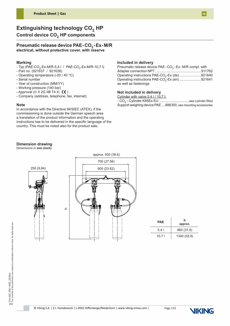
© Viking S.A. | Z.I. Haneboesch | L-4562 Differdange/Niederkorn | www.viking-emea.com |
Product Sheet | Gas
Page 133
214-
420_
030
/ AI0
0_20
16en
The
cont
ents
of t
his
publ
icat
ion
are
subj
ect t
o m
odifi
catio
ns w
ithou
t not
ice.
All
right
s re
serv
ed.
Extinguishing technology CO2 HPControl device CO2 HP components
2/2
Dimension drawingDimensions in mm (inch)
Pneumatic release device PAE - CO2 - Ex - M/Relectrical, without protective cover, with reserve
PAE h approx.
5.4 l 960 (37.8)
10.7 l 1340 (52.8)
600 (23.62)
700 (27.56)
hMarking- Typ (PAE-CO2-Ex-M/R-5,4 l / PAE-CO2-Ex-M/R-10,7 l)- Part no. (921637 / 921638)- Operating temperature (-20 / 40 °C)- Serial number- Year of construction (MM/YY)- Working pressure (140 bar)- Approval (x II 2G IIB T4 X; e ) - Company (address, telephone, fax, internet)
NoteIn accordance with the Directive 94/9/EC (ATEX), if thecommissioning is done outside the German speech area a translation of the product information and the operating instructions has to be delivered in the specific language of the country. This must be noted also for the product sale.
approx. 930 (36.6)
250 (9.84)
Included in deliveryPneumatic release device PAE - CO2 - Ex - M/R compl. withAdapter connection NPT ................................................911762Operating instructions PAE-CO2-Ex (de) ......................921640Operating instructions PAE-CO2-Ex (en) ......................921641as well as fastenings
Not included in deliveryCylinder with valve 5.4 l / 10.7 l:- CO2 - Cylinder K85Ex EU ...............................see cylinder filledSupport weighing device PAE ....886350, see mounting accessories
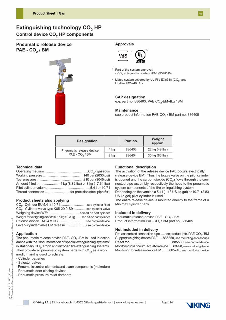
© Viking S.A. | Z.I. Haneboesch | L-4562 Differdange/Niederkorn | www.viking-emea.com |
Product Sheet | Gas
Page 134
214-
420_
015
/ AI0
2_20
16en
The
cont
ents
of t
his
publ
icat
ion
are
subj
ect t
o m
odifi
catio
ns w
ithou
t not
ice.
All
right
s re
serv
ed.
Extinguishing technology CO2 HPControl device CO2 HP components
1/2
Technical dataOperating medium ...............................................CO2 - gaseousWorking pressure ............................................140 bar (2030 psi)Test pressure ...................................................210 bar (3045 psi)Amount filled .........................4 kg (8.82 lbs) or 8 kg (17.64 lbs)Pilot cylinder volume ............................................5.4 l or 10.7 lThread connection ...........................for precision steel pipe 6x1
Product sheets also applyingCO2 - Cylinder EU 5.4 l / 10.7 l .............................see cylinder filledCO2 - Cylinder valve type K85-20.0-S9 ..............see cylinder valveWeighing device WE4 .................................see ad-on part cylinderWeight for weighing device 0.16 kg / 0.3 kg .......see ad-on part cylinderRelease device EM 24 V DC ..............................see control deviceLever - cylinder valve EM release ......................see control device
ApplicationThe pneumatic release device PAE- CO2 -BM is used in accor-dance with the “documentation of special extinguishing systems” in stationary CO2, argon and nitrogen fire extinguishing systems.They provide all pneumatic system parts with CO2 as a work medium and is used to activate:- Cylinder batteries- Selector valves- Pneumatic control elements and alarm components (makrofon)- Pneumatic door closing devices- Pneumatic pressure relief dampers.
Functional descriptionThe activation of the release device PAE occurs electrically(release device EM). Thus the toggle valve on the pilot cylinder is opened and the carbon dioxide (CO2) flows through the con-nected pipe assembly respectively the hose to the pneumatic system components of the fire extinguishing system.Depending on the version a 5.4 l (1.43 US.liq.gal) or 10.7 l (2.83 US.liq.gal) pilot cylinder is used.The entire release device is mounted directly to the frame of a Minimax cylinder bank
Included in deliveryPneumatic release device PAE - CO2 / BMProduct information PAE-CO2 / BM part no. 886405
Not included in deliveryPre-assembled connection pipe .....see product info. PAE-CO2 / BMSupport weighing device PAE .....886350, see mounting accessoriesReset tool ............................................885530, see control deviceMonitoring loss pneum. actuation device ....888998, see monitoring deviceMonitoring for release device EM .........885740, see monitoring device
Pneumatic release devicePAE - CO2 / BM
SAP designatione.g. part no. 886403: PAE CO2-EM-4kg / BM
Maintenancesee product information PAE-CO2 / BM part no. 886405
Approvals
Part of the system approval:- CO2 extinguishing system HD-1 (S398010)
Listed system covered by UL-File EX6388 (CO2) andUL-File EX5248 (Ar)
1)
2)1)
2)
1)
Designation Part no. Weight approx.
Pneumatic release device PAE - CO2 / BM
4 kg 886403 22 kg (49 lbs)
8 kg 886404 30 kg (66 lbs)
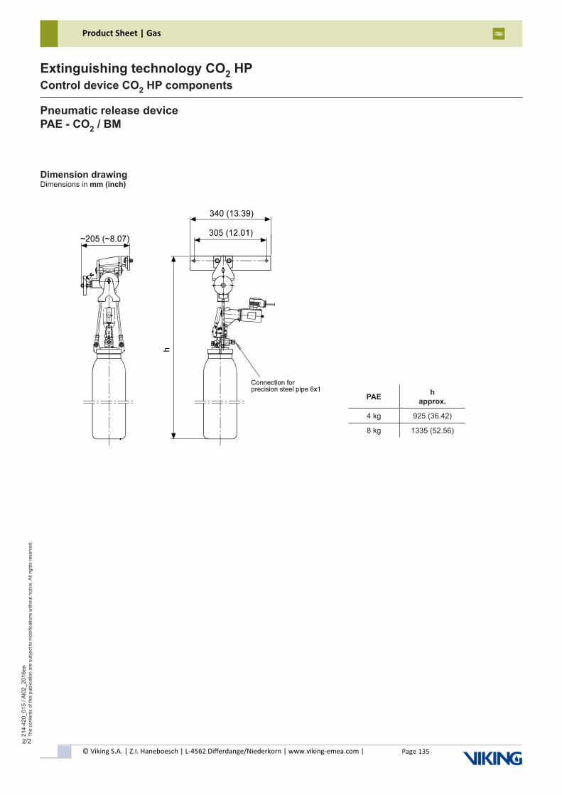
© Viking S.A. | Z.I. Haneboesch | L-4562 Differdange/Niederkorn | www.viking-emea.com |
Product Sheet | Gas
Page 135
214-
420_
015
/ AI0
2_20
16en
The
cont
ents
of t
his
publ
icat
ion
are
subj
ect t
o m
odifi
catio
ns w
ithou
t not
ice.
All
right
s re
serv
ed.
Extinguishing technology CO2 HPControl device CO2 HP components
2/2
Dimension drawingDimensions in mm (inch)
Pneumatic release devicePAE - CO2 / BM
PAE h approx.
4 kg 925 (36.42)
8 kg 1335 (52.56)
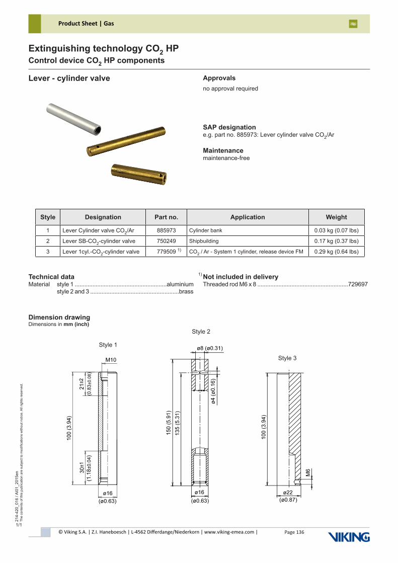
© Viking S.A. | Z.I. Haneboesch | L-4562 Differdange/Niederkorn | www.viking-emea.com |
Product Sheet | Gas
Page 136
214-
420_
016
/ AI0
1_20
15en
The
cont
ents
of t
his
publ
icat
ion
are
subj
ect t
o m
odifi
catio
ns w
ithou
t not
ice.
All
right
s re
serv
ed.
Extinguishing technology CO2 HPControl device CO2 HP components
1/1
Technical dataMaterial style 1 .........................................................aluminium style 2 and 3 .......................................................brass
Not included in deliveryThreaded rod M6 x 8 ........................................................729697
Lever - cylinder valve
SAP designatione.g. part no. 885973: Lever cylinder valve CO2/Ar
Maintenancemaintenance-free
Approvalsno approval required
Dimension drawingDimensions in mm (inch)
1)
1)
Style 3
Style 1
Style 2
Style Designation Part no. Application Weight
1 Lever Cylinder valve CO2/Ar 885973 Cylinder bank 0.03 kg (0.07 lbs)
2 Lever SB-CO2-cylinder valve 750249 Shipbuilding 0.17 kg (0.37 lbs)
3 Lever 1cyl.-CO2-cylinder valve 779509 CO2 / Ar - System 1 cylinder, release device FM 0.29 kg (0.64 lbs)
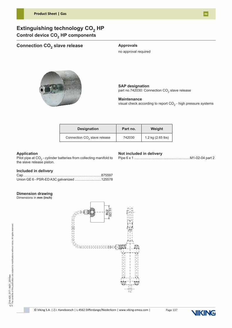
© Viking S.A. | Z.I. Haneboesch | L-4562 Differdange/Niederkorn | www.viking-emea.com |
Product Sheet | Gas
Page 137
214-
420_
017
/ AI0
1_20
15en
The
cont
ents
of t
his
publ
icat
ion
are
subj
ect t
o m
odifi
catio
ns w
ithou
t not
ice.
All
right
s re
serv
ed.
Extinguishing technology CO2 HPControl device CO2 HP components
1/1
ApplicationPilot pipe at CO2 - cylinder batteries from collecting manifold to the slave release piston.
Included in deliveryCap ..................................................................................875597Union GE 6 - PSR-ED A3C galvanized ............................125578
Not included in deliveryPipe 6 x 1 .........................................................M1-02-04 part 2
Connection CO2 slave release
SAP designationpart no.742030: Connection CO2 slave release
Maintenancevisual check according to report CO2 - high pressure systems
Dimension drawingDimensions in mm (inch)
Approvalsno approval required
Designation Part no. Weight
Connection CO2 slave release 742030 1.2 kg (2.65 lbs)
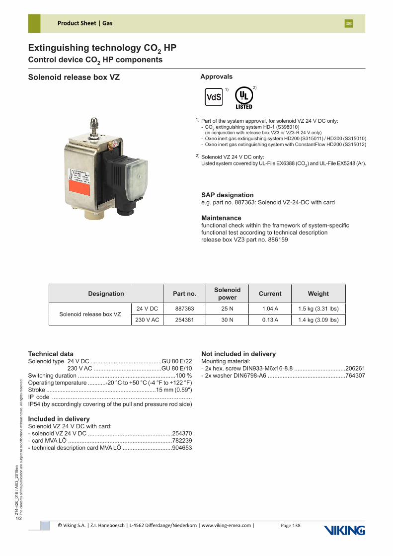
© Viking S.A. | Z.I. Haneboesch | L-4562 Differdange/Niederkorn | www.viking-emea.com |
Product Sheet | Gas
Page 138
214-
420_
018
/ AI0
3_20
18en
The
cont
ents
of t
his
publ
icat
ion
are
subj
ect t
o m
odifi
catio
ns w
ithou
t not
ice.
All
right
s re
serv
ed.
Extinguishing technology CO2 HPControl device CO2 HP components
1/2
Technical dataSolenoid type 24 V DC ...........................................GU 80 E/22 230 V AC .........................................GU 80 E/10Switching duration ...........................................................100 %Operating temperature ...........-20 °C to +50 °C (-4 °F to +122 °F)Stroke ....................................................................15 mm (0.59")IP code ..................................................................................IP54 (by accordingly covering of the pull and pressure rod side)
Included in deliverySolenoid VZ 24 V DC with card:- solenoid VZ 24 V DC ...................................................254370- card MVA LÖ ...............................................................782239- technical description card MVA LÖ ..............................904653
Not included in deliveryMounting material:- 2x hex. screw DIN933-M6x16-8.8 ...............................206261- 2x washer DIN6798-A6 ...............................................764307
Solenoid release box VZ
SAP designatione.g. part no. 887363: Solenoid VZ-24-DC with card
Maintenancefunctional check within the framework of system-specific functional test according to technical descriptionrelease box VZ3 part no. 886159
Approvals
Part of the system approval, for solenoid VZ 24 V DC only:- CO2 extinguishing system HD-1 (S398010) (in conjunction with release box VZ3 or VZ3-R 24 V only) - Oxeo inert gas extinguishing system HD200 (S315011) / HD300 (S315010)- Oxeo inert gas extinguishing system with ConstantFlow HD200 (S315012)
Solenoid VZ 24 V DC only:Listed system covered by UL-File EX6388 (CO2) and UL-File EX5248 (Ar).
1)
2)1)
2)
Designation Part no. Solenoid power Current Weight
Solenoid release box VZ24 V DC 887363 25 N 1.04 A 1.5 kg (3.31 lbs)
230 V AC 254381 30 N 0.13 A 1.4 kg (3.09 lbs)
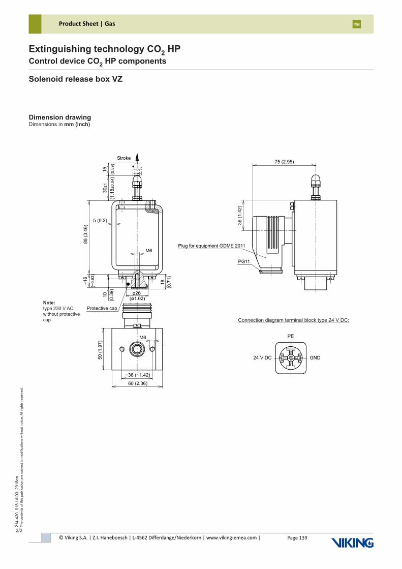
© Viking S.A. | Z.I. Haneboesch | L-4562 Differdange/Niederkorn | www.viking-emea.com |
Product Sheet | Gas
Page 139
214-
420_
018
/ AI0
3_20
18en
The
cont
ents
of t
his
publ
icat
ion
are
subj
ect t
o m
odifi
catio
ns w
ithou
t not
ice.
All
right
s re
serv
ed.
Extinguishing technology CO2 HPControl device CO2 HP components
2/2
Dimension drawingDimensions in mm (inch)
Solenoid release box VZ
Connection diagram terminal block type 24 V DC:
Note:type 230 V AC without protective cap
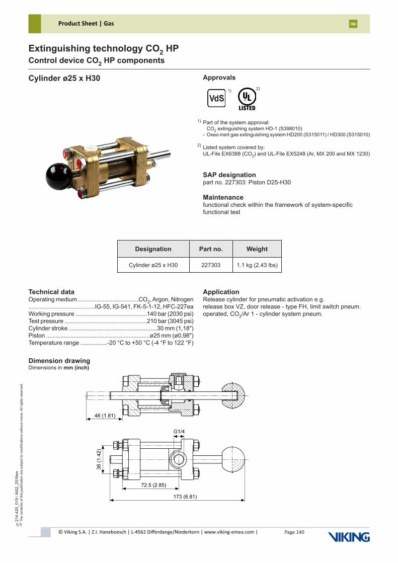
© Viking S.A. | Z.I. Haneboesch | L-4562 Differdange/Niederkorn | www.viking-emea.com |
Product Sheet | Gas
Page 140
214-
420_
019
/ AI0
2_20
16en
The
cont
ents
of t
his
publ
icat
ion
are
subj
ect t
o m
odifi
catio
ns w
ithou
t not
ice.
All
right
s re
serv
ed.
Extinguishing technology CO2 HPControl device CO2 HP components
1/1
Technical dataOperating medium .....................................CO2, Argon, Nitrogen.........................................IG-55, IG-541, FK-5-1-12, HFC-227eaWorking pressure ............................................140 bar (2030 psi)Test pressure ...................................................210 bar (3045 psi)Cylinder stroke ......................................................30 mm (1,18")Piston ................................................................ø25 mm (ø0,98")Temperature range ................-20 °C to +50 °C (-4 °F to 122 °F)
ApplicationRelease cylinder for pneumatic activation e.g.release box VZ, door release - type FH, limit switch pneum. operated, CO2/Ar 1 - cylinder system pneum.
Cylinder ø25 x H30
SAP designationpart no. 227303: Piston D25-H30
Maintenancefunctional check within the framework of system-specificfunctional test
Approvals
Part of the system approval: CO2 extinguishing system HD-1 (S398010)- Oxeo inert gas extinguishing system HD200 (S315011) / HD300 (S315010)
Listed system covered by:UL-File EX6388 (CO2) and UL-File EX5248 (Ar, MX 200 and MX 1230)
1)
2)1)
2)
Dimension drawingDimensions in mm (inch)
Designation Part no. Weight
Cylinder ø25 x H30 227303 1.1 kg (2.43 lbs)
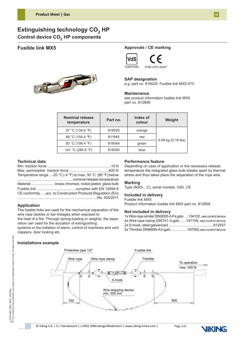
© Viking S.A. | Z.I. Haneboesch | L-4562 Differdange/Niederkorn | www.viking-emea.com |
Product Sheet | Gas
Page 141
214-
420_
020
/ AI0
1_20
15en
The
cont
ents
of t
his
publ
icat
ion
are
subj
ect t
o m
odifi
catio
ns w
ithou
t not
ice.
All
right
s re
serv
ed.
Extinguishing technology CO2 HPControl device CO2 HP components
1/2
Technical dataMin. traction force ..............................................................10 NMax. permissible traction force ......................................400 NTemperature range ...-20 °C (-4 °F) to max. 30 °C (86 °F) below........................................................nominal release temperatureMaterial ........................brass chromed, nickel plated, glass bulbFusible link ......................................complies with EN 12094-9CE conformity .....acc. to Construction Products Regulation (EU)................................................................................No. 305/2011
ApplicationThe fusible links are used for the mechanical separation of the wire rope tackles or bar linkages when exposed tothe heat of a fire. Through spring-loading or weights, the sepa-ration can used for the actuation of extinguishingsystems or the initiation of alarm, control of machines and vent clappers, door looking etc.
Performance featureDepending on case of application or the necessary release temperature the integrated glass bulb breaks apart by thermal stress and thus takes place the separation of the rope wire.
MarkingType (MX5-...C), serial number, VdS, CE
Included in deliveryFusible link MX5Product information fusible link MX5 part no. 812809
Not included in delivery1x Wire rope similar DIN3055-3-Fe galv. ....134122, see control device4x Wire rope clamp DIN741-3-galv. .....197109, see control device2x S-hook, steel galvanized .............................................8129372x Thimble DIN6899-A3-galv. ...............197092,see control device
Fusible link MX5
SAP designatione.g. part no. 816025: Fusible link MX5-57C
Maintenancesee product information fusible link MX5part no. 812809
Approvals / CE marking
G387009 0786-CPD-30047
Installations example
Nominal release temperature Part no. Index of
colour Weight
57 °C (134.6 °F) 816025 orange
0.08 kg (0.18 lbs)68 °C (154.4 °F) 811945 red
93 °C (199.4 °F) 816049 green
141 °C (285.8 °F) 816050 blue
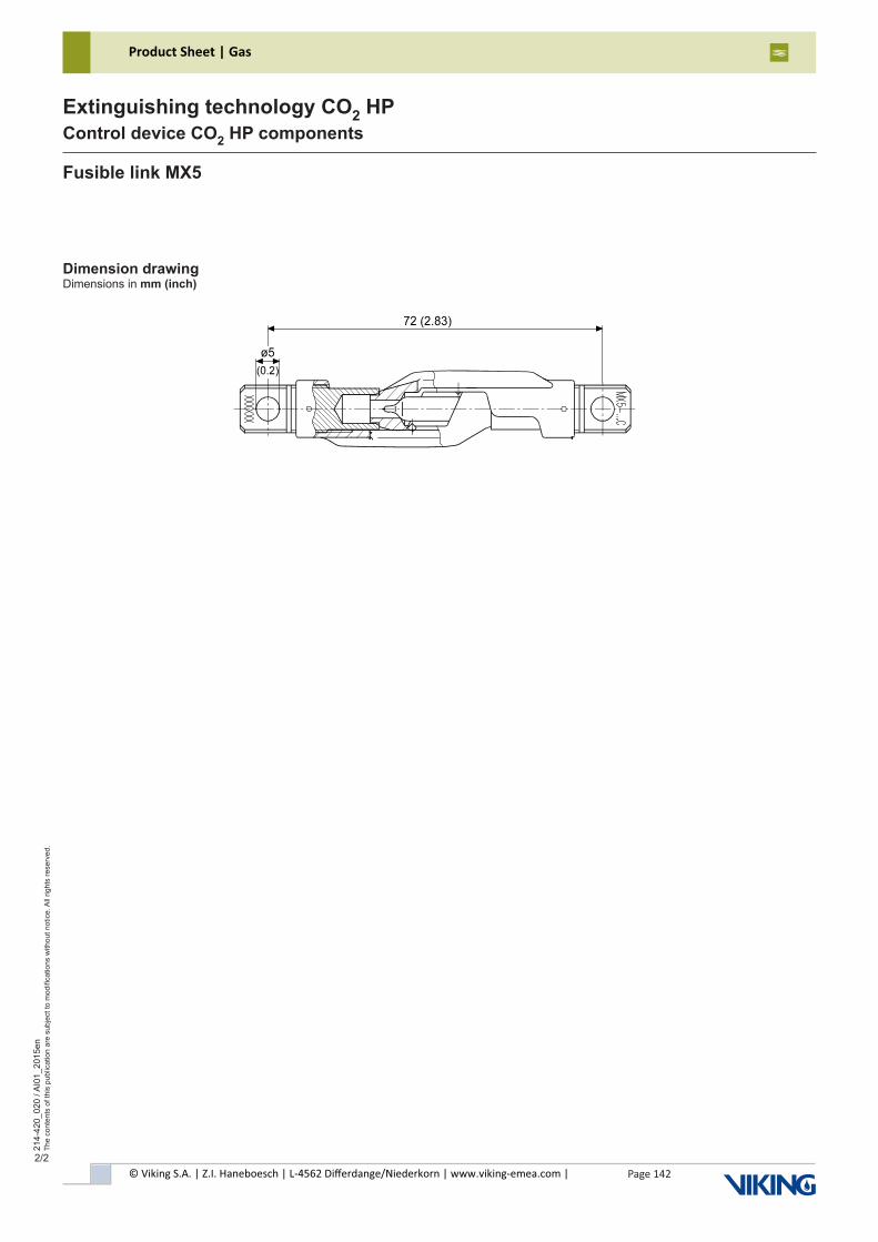
© Viking S.A. | Z.I. Haneboesch | L-4562 Differdange/Niederkorn | www.viking-emea.com |
Product Sheet | Gas
Page 142
214-
420_
020
/ AI0
1_20
15en
The
cont
ents
of t
his
publ
icat
ion
are
subj
ect t
o m
odifi
catio
ns w
ithou
t not
ice.
All
right
s re
serv
ed.
Extinguishing technology CO2 HPControl device CO2 HP components
2/2
Dimension drawingDimensions in mm (inch)
Fusible link MX5
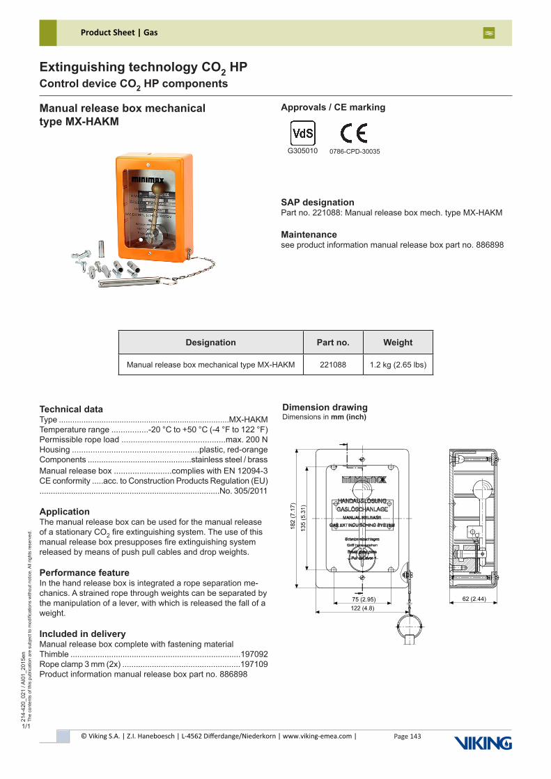
© Viking S.A. | Z.I. Haneboesch | L-4562 Differdange/Niederkorn | www.viking-emea.com |
Product Sheet | Gas
Page 143
214-
420_
021
/ AI0
1_20
15en
The
cont
ents
of t
his
publ
icat
ion
are
subj
ect t
o m
odifi
catio
ns w
ithou
t not
ice.
All
right
s re
serv
ed.
Extinguishing technology CO2 HPControl device CO2 HP components
1/1
Technical dataType ............................................................................MX-HAKMTemperature range ................-20 °C to +50 °C (-4 °F to 122 °F)Permissible rope load .............................................max. 200 NHousing .......................................................plastic, red-orangeComponents ..............................................stainless steel / brassManual release box .........................complies with EN 12094-3CE conformity .....acc. to Construction Products Regulation (EU)................................................................................No. 305/2011
ApplicationThe manual release box can be used for the manual release of a stationary CO2 fire extinguishing system. The use of this manual release box presupposes fire extinguishing system released by means of push pull cables and drop weights.
Performance featureIn the hand release box is integrated a rope separation me-chanics. A strained rope through weights can be separated by the manipulation of a lever, with which is released the fall of a weight.
Included in deliveryManual release box complete with fastening materialThimble ...........................................................................197092Rope clamp 3 mm (2x) ....................................................197109Product information manual release box part no. 886898
Manual release box mechanicaltype MX-HAKM
SAP designationPart no. 221088: Manual release box mech. type MX-HAKM
Maintenancesee product information manual release box part no. 886898
Approvals / CE marking
G305010 0786-CPD-30035
Dimension drawingDimensions in mm (inch)
Designation Part no. Weight
Manual release box mechanical type MX-HAKM 221088 1.2 kg (2.65 lbs)
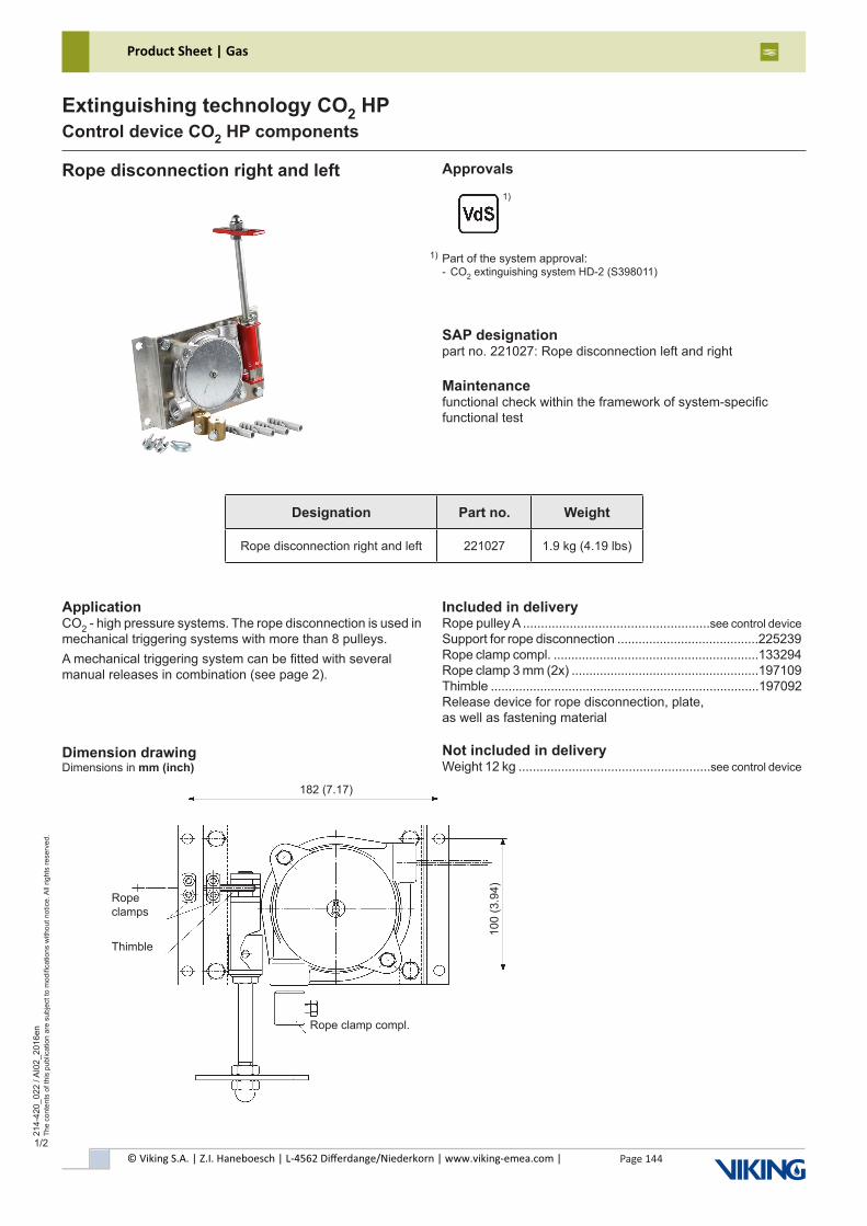
© Viking S.A. | Z.I. Haneboesch | L-4562 Differdange/Niederkorn | www.viking-emea.com |
Product Sheet | Gas
Page 144
214-
420_
022
/ AI0
2_20
16en
The
cont
ents
of t
his
publ
icat
ion
are
subj
ect t
o m
odifi
catio
ns w
ithou
t not
ice.
All
right
s re
serv
ed.
Extinguishing technology CO2 HPControl device CO2 HP components
1/2
ApplicationCO2 - high pressure systems. The rope disconnection is used in mechanical triggering systems with more than 8 pulleys.A mechanical triggering system can be fitted with several manual releases in combination (see page 2).
Included in deliveryRope pulley A ....................................................see control deviceSupport for rope disconnection ........................................225239Rope clamp compl. ..........................................................133294Rope clamp 3 mm (2x) .....................................................197109Thimble ............................................................................197092Release device for rope disconnection, plate,as well as fastening material
Not included in deliveryWeight 12 kg ......................................................see control device
Rope disconnection right and left
SAP designationpart no. 221027: Rope disconnection left and right
Maintenancefunctional check within the framework of system-specific functional test
Dimension drawingDimensions in mm (inch)
Approvals
182 (7.17)
100
(3.9
4)
Rope clamp compl.
Ropeclamps
Thimble
Designation Part no. Weight
Rope disconnection right and left 221027 1.9 kg (4.19 lbs)
Part of the system approval:- CO2 extinguishing system HD-2 (S398011)
1)
1)
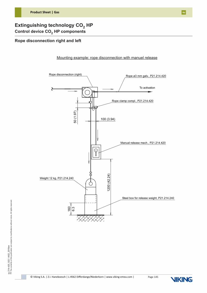
© Viking S.A. | Z.I. Haneboesch | L-4562 Differdange/Niederkorn | www.viking-emea.com |
Product Sheet | Gas
Page 145
214-
420_
022
/ AI0
2_20
16en
The
cont
ents
of t
his
publ
icat
ion
are
subj
ect t
o m
odifi
catio
ns w
ithou
t not
ice.
All
right
s re
serv
ed.
Extinguishing technology CO2 HPControl device CO2 HP components
2/2
Rope disconnection right and left
Mounting example: rope disconnection with manuel release
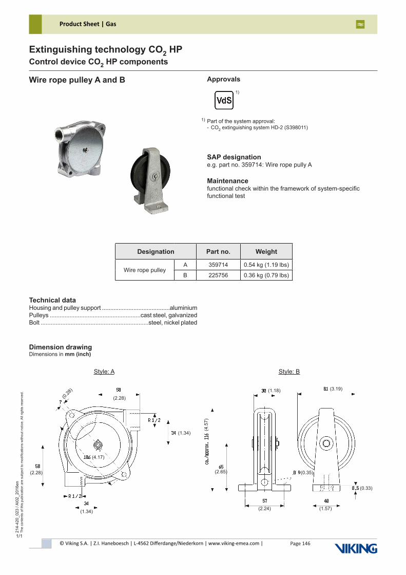
© Viking S.A. | Z.I. Haneboesch | L-4562 Differdange/Niederkorn | www.viking-emea.com |
Product Sheet | Gas
Page 146
214-
420_
023
/ AI0
2_20
16en
The
cont
ents
of t
his
publ
icat
ion
are
subj
ect t
o m
odifi
catio
ns w
ithou
t not
ice.
All
right
s re
serv
ed.
Extinguishing technology CO2 HPControl device CO2 HP components
1/1
Technical dataHousing and pulley support .........................................aluminiumPulleys .......................................................cast steel, galvanizedBolt .................................................................steel, nickel plated
Wire rope pulley A and B
SAP designatione.g. part no. 359714: Wire rope pully A
Maintenancefunctional check within the framework of system-specificfunctional test
Dimension drawingDimensions in mm (inch)
Style: A Style: B
(2.28)
(1.34)
(4.17)
(2.28)(0.28
)
(1.34)
(1.18) (3.19)
(0.33)
(1.57)(2.24)
(0.35)(2.65)
(4.5
7)
Approvals
Designation Part no. Weight
Wire rope pulleyA 359714 0.54 kg (1.19 lbs)
B 225756 0.36 kg (0.79 lbs)
Part of the system approval:- CO2 extinguishing system HD-2 (S398011)
1)
1)
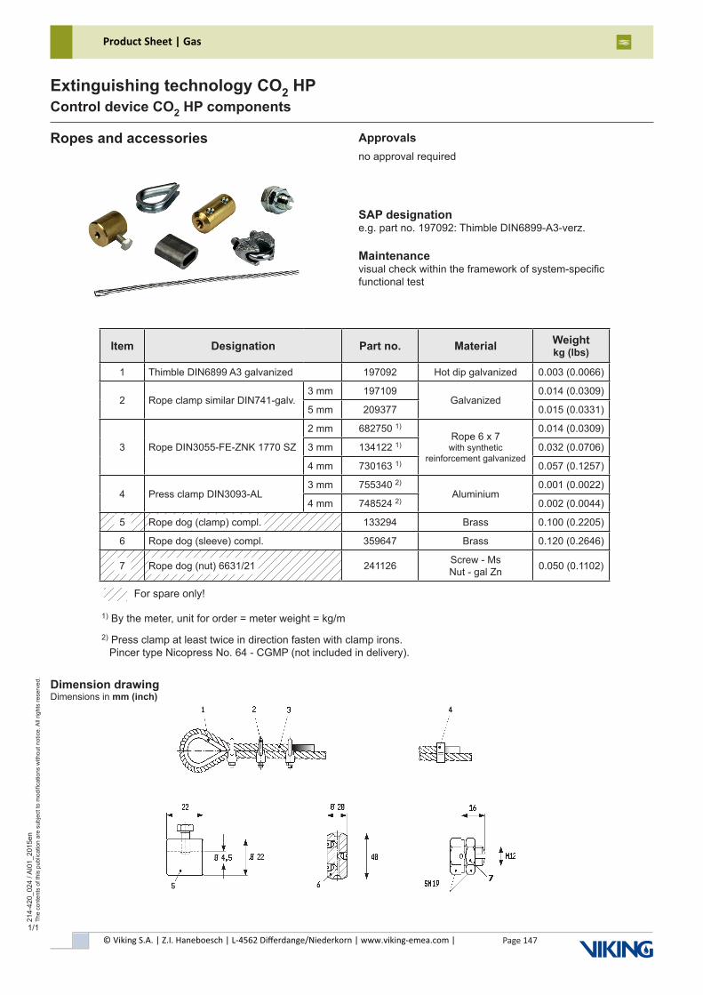
© Viking S.A. | Z.I. Haneboesch | L-4562 Differdange/Niederkorn | www.viking-emea.com |
Product Sheet | Gas
Page 147
214-
420_
024
/ AI0
1_20
15en
The
cont
ents
of t
his
publ
icat
ion
are
subj
ect t
o m
odifi
catio
ns w
ithou
t not
ice.
All
right
s re
serv
ed.
Extinguishing technology CO2 HPControl device CO2 HP components
1/1
Ropes and accessories Approvalsno approval required
1) By the meter, unit for order = meter weight = kg/m
2) Press clamp at least twice in direction fasten with clamp irons. Pincer type Nicopress No. 64 - CGMP (not included in delivery).
Dimension drawingDimensions in mm (inch)
SAP designatione.g. part no. 197092: Thimble DIN6899-A3-verz.
Maintenancevisual check within the framework of system-specificfunctional test
For spare only!
Item Designation Part no. Material Weight kg (lbs)
1 Thimble DIN6899 A3 galvanized 197092 Hot dip galvanized 0.003 (0.0066)
2 Rope clamp similar DIN741-galv.3 mm 197109
Galvanized0.014 (0.0309)
5 mm 209377 0.015 (0.0331)
3 Rope DIN3055-FE-ZNK 1770 SZ
2 mm 682750 1)Rope 6 x 7
with synthetic reinforcement galvanized
0.014 (0.0309)
3 mm 134122 1) 0.032 (0.0706)
4 mm 730163 1) 0.057 (0.1257)
4 Press clamp DIN3093-AL3 mm 755340 2)
Aluminium0.001 (0.0022)
4 mm 748524 2) 0.002 (0.0044)
050 Rope dog (clamp) compl. 133294 Brass 0.100 (0.2205)
6 Rope dog (sleeve) compl. 359647 Brass 0.120 (0.2646)
070 Rope dog (nut) 6631/21 241126 Screw - Ms Nut - gal Zn 0.050 (0.1102)
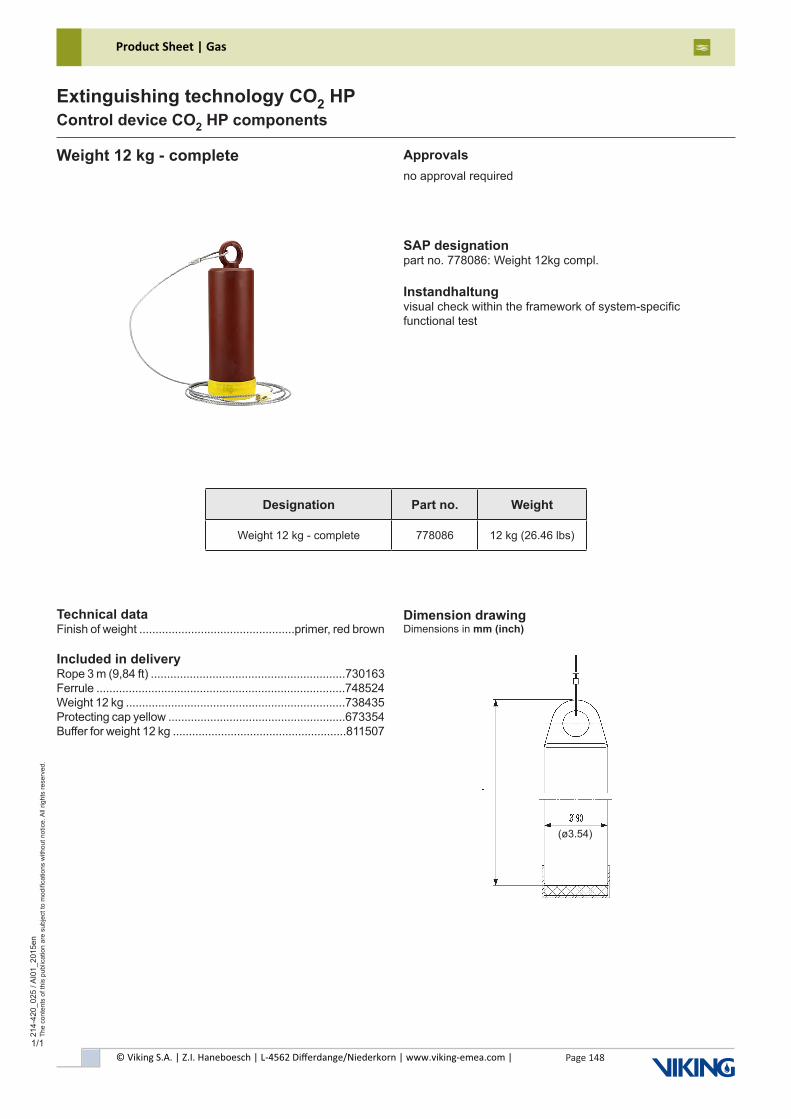
© Viking S.A. | Z.I. Haneboesch | L-4562 Differdange/Niederkorn | www.viking-emea.com |
Product Sheet | Gas
Page 148
214-
420_
025
/ AI0
1_20
15en
The
cont
ents
of t
his
publ
icat
ion
are
subj
ect t
o m
odifi
catio
ns w
ithou
t not
ice.
All
right
s re
serv
ed.
Extinguishing technology CO2 HPControl device CO2 HP components
1/1
Technical dataFinish of weight ................................................primer, red brown
Included in deliveryRope 3 m (9,84 ft) ............................................................730163Ferrule .............................................................................748524Weight 12 kg ....................................................................738435Protecting cap yellow .......................................................673354Buffer for weight 12 kg ......................................................811507
Weight 12 kg - complete
SAP designationpart no. 778086: Weight 12kg compl.
Instandhaltungvisual check within the framework of system-specificfunctional test
Approvalsno approval required
Dimension drawingDimensions in mm (inch)
(ø3.54)
Designation Part no. Weight
Weight 12 kg - complete 778086 12 kg (26.46 lbs)
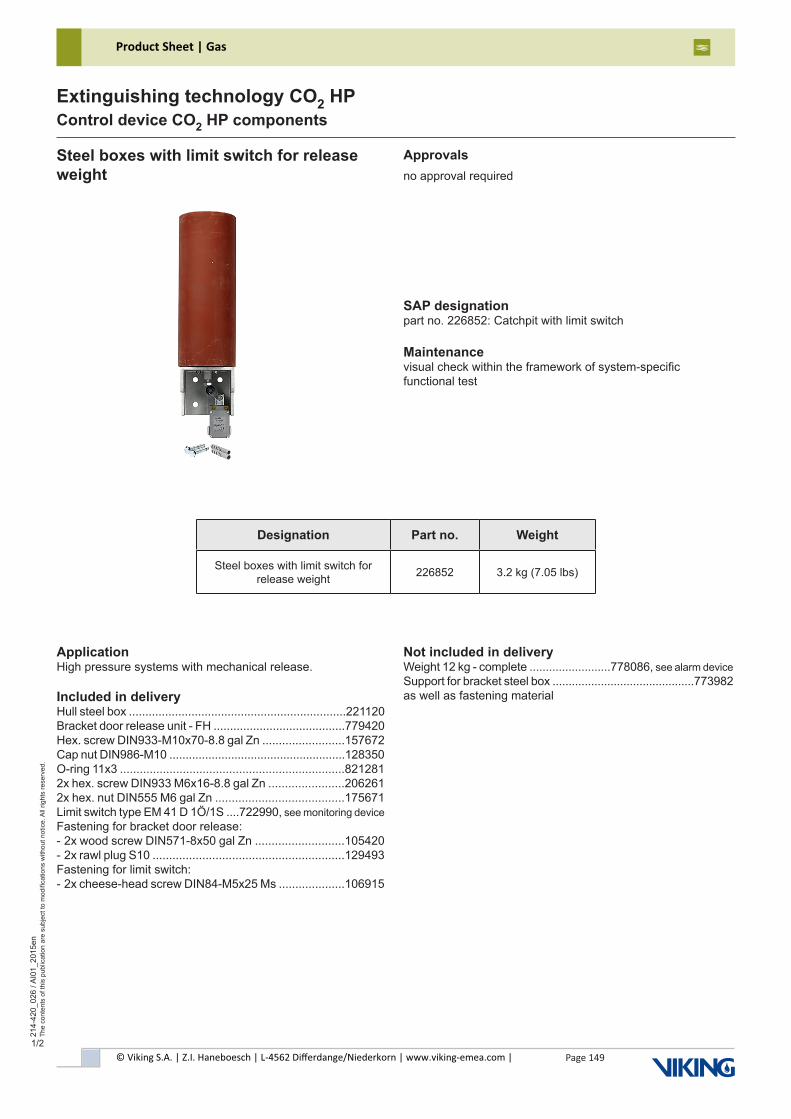
© Viking S.A. | Z.I. Haneboesch | L-4562 Differdange/Niederkorn | www.viking-emea.com |
Product Sheet | Gas
Page 149
214-
420_
026
/ AI0
1_20
15en
The
cont
ents
of t
his
publ
icat
ion
are
subj
ect t
o m
odifi
catio
ns w
ithou
t not
ice.
All
right
s re
serv
ed.
Extinguishing technology CO2 HPControl device CO2 HP components
1/2
ApplicationHigh pressure systems with mechanical release.
Included in deliveryHull steel box ..................................................................221120Bracket door release unit - FH ........................................779420Hex. screw DIN933-M10x70-8.8 gal Zn .........................157672Cap nut DIN986-M10 ......................................................128350O-ring 11x3 ....................................................................8212812x hex. screw DIN933 M6x16-8.8 gal Zn .......................2062612x hex. nut DIN555 M6 gal Zn .......................................175671Limit switch type EM 41 D 1Ö/1S ....722990, see monitoring deviceFastening for bracket door release:- 2x wood screw DIN571-8x50 gal Zn ...........................105420- 2x rawl plug S10 ..........................................................129493Fastening for limit switch:- 2x cheese-head screw DIN84-M5x25 Ms ....................106915
Steel boxes with limit switch for release weight
SAP designationpart no. 226852: Catchpit with limit switch
Maintenancevisual check within the framework of system-specificfunctional test
Approvalsno approval required
Not included in deliveryWeight 12 kg - complete .........................778086, see alarm deviceSupport for bracket steel box ............................................773982as well as fastening material
Designation Part no. Weight
Steel boxes with limit switch for release weight 226852 3.2 kg (7.05 lbs)
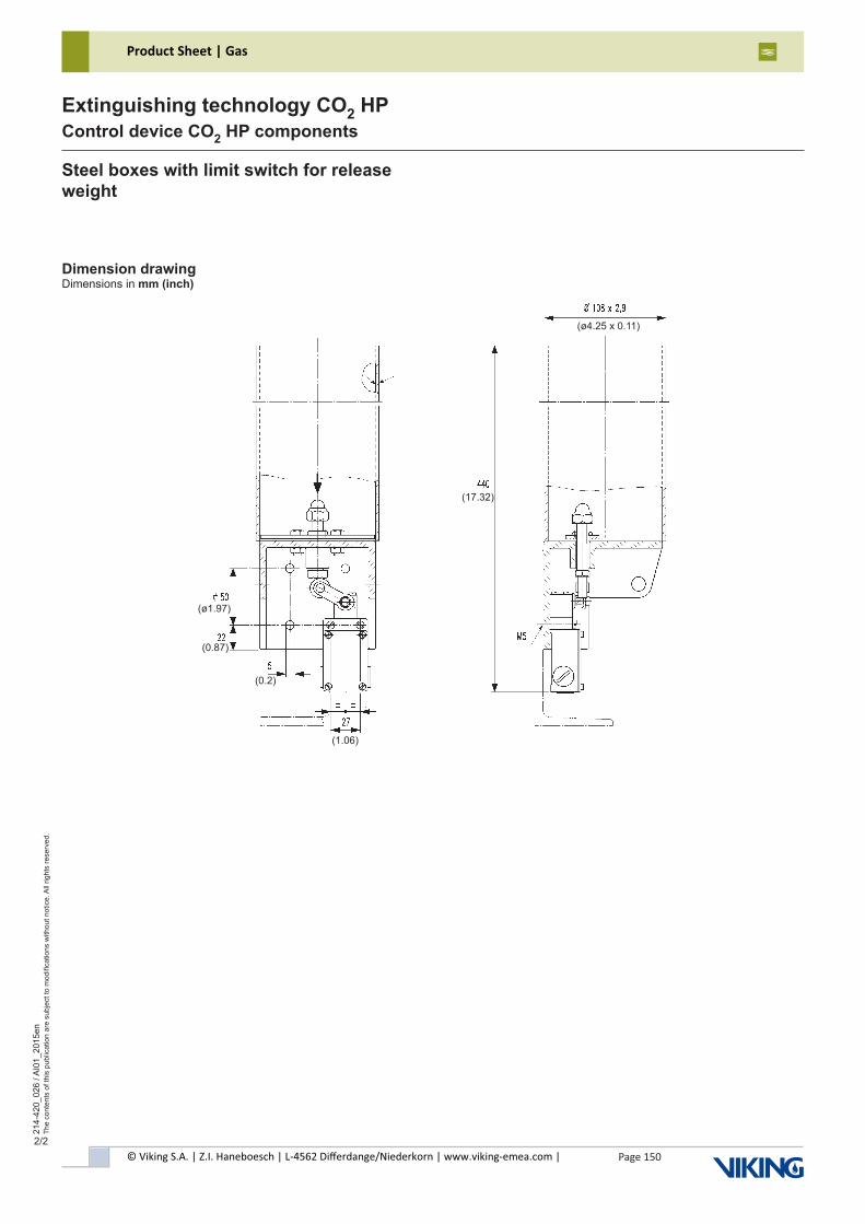
© Viking S.A. | Z.I. Haneboesch | L-4562 Differdange/Niederkorn | www.viking-emea.com |
Product Sheet | Gas
Page 150
214-
420_
026
/ AI0
1_20
15en
The
cont
ents
of t
his
publ
icat
ion
are
subj
ect t
o m
odifi
catio
ns w
ithou
t not
ice.
All
right
s re
serv
ed.
Extinguishing technology CO2 HPControl device CO2 HP components
2/2
Dimension drawingDimensions in mm (inch)
Steel boxes with limit switch for release weight
(ø1.97)
(0.87)
(0.2)
(1.06)
(17.32)
(ø4.25 x 0.11)
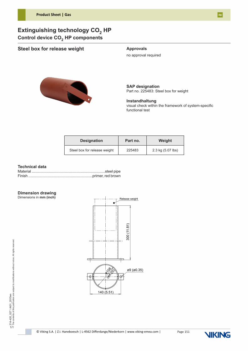
© Viking S.A. | Z.I. Haneboesch | L-4562 Differdange/Niederkorn | www.viking-emea.com |
Product Sheet | Gas
Page 151
214-
420_
027
/ AI0
1_20
15en
The
cont
ents
of t
his
publ
icat
ion
are
subj
ect t
o m
odifi
catio
ns w
ithou
t not
ice.
All
right
s re
serv
ed.
Extinguishing technology CO2 HPControl device CO2 HP components
Technical dataMaterial ........................................................................steel pipeFinish ...............................................................primer, red brown
Steel box for release weight
SAP designationPart no. 225483: Steel box for weight
Instandhaltungvisual check within the framework of system-specificfunctional test
Approvalsno approval required
Dimension drawingDimensions in mm (inch)
Designation Part no. Weight
Steel box for release weight 225483 2.3 kg (5.07 lbs)
1/1
© Viking S.A. | Z.I. Haneboesch | L-4562 Differdange/Niederkorn | www.viking-emea.com |
Product Sheet | Gas
Page 152
214-
420_
031
/ AI0
0_20
18en
The
cont
ents
of t
his
publ
icat
ion
are
subj
ect t
o m
odifi
catio
ns w
ithou
t not
ice.
All
right
s re
serv
ed.
Extinguishing technology CO2 HPControl device CO2 HP components
1/2
Technical dataType ...........................................................................EM-Ex T55Release bolt force ....................................max. 223 N (50.1 lbf)Release bolt stroke .............................................45 mm (1,77")Temperature range ..............-20 °C to +55 °C (-4 °F to +131 °F)Solenoid Ex-release:- Single stroke solenoid type .......................GMCE060K01D01- Nominal voltage ..............................................24 V DC ±10 %- Nominal power ................................................................9.1 W- Rated current .................................................................0.38 A- IP code solenoid body .....................................................IP65 tube ....................................................................IP54- Duration of operation ........................................S1 (100% ED)
Electr. connectionConnection cable:- cable diameter 6 - 12 mm (0.24" - 0.47")- 3-wire with protective earth conductor- heat resistance min. 90 °C (194 °F)Connecting terminals, internal:- 2-pole connecting terminal up to 2.5 mm2 (AWG14),- protective earth connection fine-wire up to 1.5 mm2 (AWG 16) single-wire up to 2.5 mm2 (AWG 14) Connecting terminal, external (equipotential bonding):- protective earth connection up to 4 mm2 (AWG 12)
Material / surfaceHousing ........................brass, nickel-plated and chrome dulledBush .............................brass, nickel-plated and chrome dulledBolt (sleeve) ......................................................................brassSolenoid EM-Ex T55:- Cable gland ...............................................brass, nickel-plated- Terminal box / cover ...................................steel, nickel-plated- Casing / washer ...........................................steel, nickel-plated- Tube / core ...................................................steel, galvanized
ApplicationThe release device EM-Ex T55 is used in stationarycarbon dioxide, IG-01, IG-100 , IG-55, IG-541, HFC-227ea, and FK-5-1-12 fire suppression systems for the direct electric release of pilot cylinder valves and extinguishing agent cylinder valves in areas with explosive atmosphere (zone 1 and 2, group of equip-ment II, category 2 in accordance with directive 2014/34/EU).The release device EM-Ex T55 must only be used incombination with the following levers:- Lever EM-release ..............................................................885603- Lever cylinder valve CO2/Ar ..............................................885973- Lever EM release D=25 ....................................................915159
NoteThe cylinder valve must only be used in potentially explosive areas of group x II 2G Ex IIC T4 Gb X.- x Logo- II Device group- 2 Device category- G Type of explosive atmosphere: Gases (Devices with the marking "II 2G" are only intended to be used in areas in which it is to be expected that an explosive atmosphere comprised of a mixture of air and gases will occasionally occur.)- IIC Explosion group- T4 Temperature class (T4 ≤ 135 °C (275 °F))- Gb Equipment protection level (EPL)- X Special conditions for safe use (see technical description release device EM-Ex T55)
If the commissioning is done outside the German speech area a translation of the technical description has to be delivered in the specific language of the country.
Markingtype (EM-Ex T55), part no. (927600), serial-no., year of construction (MM/YY), operating temperature (-20/+55°C),approval (x II 2G Ex IIC T4 Gb X), CEmanufacturer's data (Minimax GmbH & Co. KG, address,telephone number and telefax number, web address)
Release device EM-Ex T55
SAP designationpart no. 927600: Release device EM-Ex T55
Maintenancesee technical description release device EM-Ex T55part no. 927496
Approvals
Designation Part no. Weight
Release device EM-Ex T55 927600 6.65 kg (14.66 lbs)
Conformity in acc. with 2014/34/EU (ATEX):- x II 2G Ex IIC T4 Gb X
1)
1)
© Viking S.A. | Z.I. Haneboesch | L-4562 Differdange/Niederkorn | www.viking-emea.com |
Product Sheet | Gas
Page 153
214-
420_
031
/ AI0
0_20
18en
The
cont
ents
of t
his
publ
icat
ion
are
subj
ect t
o m
odifi
catio
ns w
ithou
t not
ice.
All
right
s re
serv
ed.
Extinguishing technology CO2 HPControl device CO2 HP components
2/2
Release device EM-Ex T55
Dimension drawingDimensions in mm (inch)
Included in deliveryRelease device EM-Ex T55Manuals:- Techn. description release device EM-Ex T55 (de) ....927495- Techn. description release device EM-Ex T55 (en) ....927496- Declaration of Conformity (de/en) ...............................928182- Operating instruction solenoid EM-Ex T55 (de/en)
Not included in deliveryReset tool release device EM EM ......................see control deviceConnection cable ......................................see electr. connection
Functional descriptionIn case of activation, the solenoid (2) is electrically activated via a fire alarm control panel. This way, the solenoid pulls the locking bolt (3) out of the spring-loaded release bolt (1). The unlocked release bolt actuates the lever (7), thus opening the valve(6). This releases the medium stored in the cylinder (5) which then flows through the hose (4).
Abb. 1: Release device EM-Ex T55, A = tensioned, B = activated
A B
~250 (
~9.8
4)
~325 (~12.8) ~120 (~4.72)
© Viking S.A. | Z.I. Haneboesch | L-4562 Differdange/Niederkorn | www.viking-emea.com |
Product Sheet | Gas
Page 154
211-
430_
104
/ AI0
1_20
17en
The
cont
ents
of t
his
publ
icat
ion
are
subj
ect t
o m
odifi
catio
ns w
ithou
t not
ice.
All
right
s re
serv
ed.
Inert gas extinguishing technologyMonitoring device
1/1
SAP designationpart no. 828482: Limit switch ZS 256-11Z-M20-2219
MaintenanceFunctional check during the maintenance intervals specific tothe fire extinguishing system, but at least annually.
Nominal isolation voltage .................................................500 VPermanent current ..............................................................10 ANominal operation current / voltage ..................4 A (230 V AC); ................................................2,5 A (400 V AC); 1 A (500 V AC)Short-circuit protection ............10 A slow blow, 16 A quick blowActuation force ..............................................................min. 9 NMechn. durability ..................................20x106 switching cyclesOperation speed ...............................max. 1 m/s, min. 0,01 m/sTime on in percent ................................................max. 5000 / h
Technical dataType .......................................................ZS 256-11z-M20-2219Housing ......thermopl. glass fiber concentrated, self-quenchingIP code ...............................................................................IP67Contact material ................................................................silverContacts ..................................................................1 NC, 1 NO..........................................galvanically isolated contact bridgesOperating temperature .......-30 °C to +80 °C (-22 °F to 176 °F)Switch system ..............................................spring control with .......................................twofold brake contacts, forced opener
Limit switch ZS 256-11z
Dimension drawingDimensions in mm (inch)
Circuit diagram:
Designation Part no. Weight
Limit switch ZS 256-11z 828482 0.14 kg (0.2 lbs)
Approvals
Listed system covered by UL-File EX26532 (Ar, VSN 200 and VSN 1230)
Part of the system approval (VSN 200 and VSN 1230)
1) 2)
1) 2)
������
1)
© Viking S.A. | Z.I. Haneboesch | L-4562 Differdange/Niederkorn | www.viking-emea.com |
Product Sheet | Gas
Page 155
211-
430_
105
/ AI0
0_20
15en
The
cont
ents
of t
his
publ
icat
ion
are
subj
ect t
o m
odifi
catio
ns w
ithou
t not
ice.
All
right
s re
serv
ed.
Inert gas extinguishing technologyMonitoring device
1/1
SAP designationpart no. 724420: Limit switch US 432Y-M20-2352 2 contacts
Maintenancesee mounting and wiring instructions of the manufacturer
Actuation force .............................................................max. 7 N(effeciency of the switch way)Operation speed ..............................max. 1 m/s, min. 0.001 m/sTime on in percent.................................................max. 3000 / hMechn. durability .....................................10x106 switching cyclesContact spud durability ..............................2x106 switching cycles ......................................................at 6 A / 400 V AC, cos ϕ = 0.4
Applicationlimit switch pneum. operated, manifold set, selector valve
Included in deliveryLimit switch type US 432y with mounting and wiring instructions
Technical dataType ...............................................................US 432y-M20-2352Housing ........alloy die-cast metal, chrome dulled and varnishedIP code .................................................................................IP65Contact material ...................................................................silverSwitch system .............................................................slow action...........................................................with twofold brake contactsAmbient temperature ..............-20 °C to +60 °C (-4 °F to 140 °F)Nominal isolation voltage ..................................................500 VPermanent current ...............................................................16 ANominal operation current ....................................6 A, 400 V ACShort-circuit protection ...............16 A slow blow, 20 A quick blow
Limit switch Typ US 432y, 2 contacts
Wiring diagram
Dimension drawingDimensions in mm (inch)
contacts shown not operated
changing of the contact type from NC to NO contact and vice versa is adjustable
note: actuate limit switch axially
Designation Part no. Weight
Limit switch type US 432y, 2 contacts 724420 0.31 kg (0.68 lbs)
Approvals
Listed system covered by UL-File EX26532 (Ar, VSN 200 and VSN 1230)
Part of the system approval (VSN 200 and VSN 1230)
1) 2)
1) 2)
������
1)
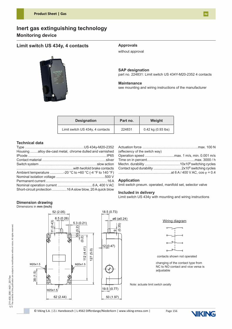
Page 156© Viking S.A. | Z.I. Haneboesch | L-4562 Differdange/Niederkorn | www.viking-emea.com |
Product Sheet | Gas21
1-43
0_00
6 / A
I01_
2017
enTh
e co
nten
ts o
f thi
s pu
blic
atio
n ar
e su
bjec
t to
mod
ifica
tions
with
out n
otic
e. A
ll rig
hts
rese
rved
.
Inert gas extinguishing technologyMonitoring device
1/1
SAP designationpart no. 224831: Limit switch US 434Y-M20-2352 4 contacts
Maintenancesee mounting and wiring instructions of the manufacturer
Actuation force .........................................................max. 100 N(effeciency of the switch way)Operation speed ..............................max. 1 m/s, min. 0.001 m/sTime on in percent.................................................max. 3000 / hMechn. durability .....................................10x106 switching cyclesContact spud durability ..............................2x106 switching cycles ......................................................at 6 A / 400 V AC, cos ϕ = 0.4
Applicationlimit switch pneum. operated, manifold set, selector valve
Included in deliveryLimit switch US 434y with mounting and wiring instructions
Technical dataType ..............................................................US 434y-M20-2352Housing ........alloy die-cast metal, chrome dulled and varnishedIPcode ...................................................................................IP65Contact material ...................................................................silverSwitch system .............................................................slow action............................................................with twofold brake contactsAmbient temperature ..............-20 °C to +60 °C (-4 °F to 140 °F)Nominal isolation voltage ..................................................500 VPermanent current ...............................................................16 ANominal operation current ....................................6 A, 400 V ACShort-circuit protection ...............16 A slow blow, 20 A quick blow
Limit switch US 434y, 4 contacts
Wiring diagram
Dimension drawingDimensions in mm (inch)
contacts shown not operated
Note: actuate limit switch axially
changing of the contact type from NC to NO contact and vice versa is adjustable
Designation Part no. Weight
Limit switch US 434y, 4 contacts 224831 0.42 kg (0.93 lbs)
Approvalswithout approval
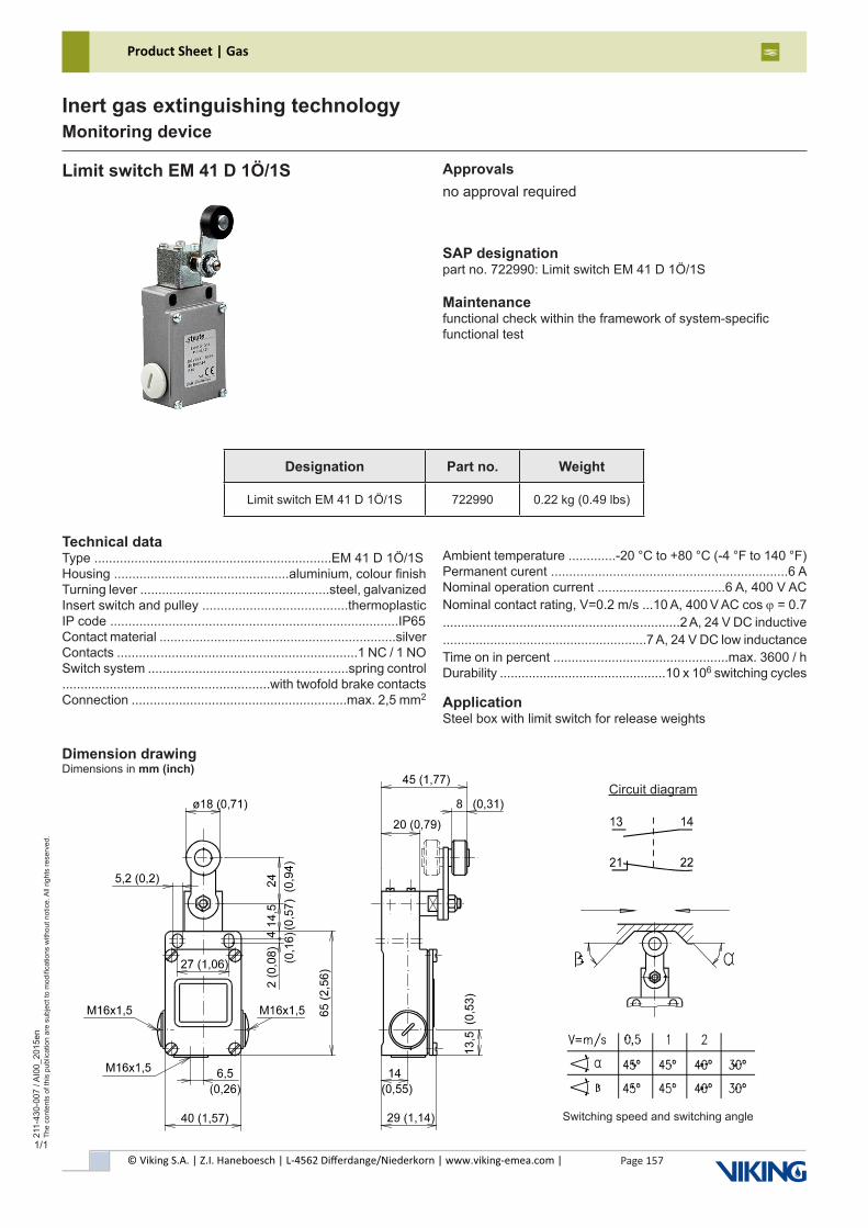
© Viking S.A. | Z.I. Haneboesch | L-4562 Differdange/Niederkorn | www.viking-emea.com |
Product Sheet | Gas
Page 157
211-
430-
007
/ AI0
0_20
15en
The
cont
ents
of t
his
publ
icat
ion
are
subj
ect t
o m
odifi
catio
ns w
ithou
t not
ice.
All
right
s re
serv
ed.
Inert gas extinguishing technologyMonitoring device
1/1
Approvalsno approval required
SAP designationpart no. 722990: Limit switch EM 41 D 1Ö/1S
Maintenancefunctional check within the framework of system-specificfunctional test
Ambient temperature .............-20 °C to +80 °C (-4 °F to 140 °F)Permanent curent .................................................................6 ANominal operation current ...................................6 A, 400 V ACNominal contact rating, V=0.2 m/s ...10 A, 400 V AC cos ϕ = 0.7.................................................................2 A, 24 V DC inductive........................................................7 A, 24 V DC low inductanceTime on in percent ................................................max. 3600 / hDurability ..............................................10 x 106 switching cycles
ApplicationSteel box with limit switch for release weights
Technical dataType .................................................................EM 41 D 1Ö/1SHousing ................................................aluminium, colour finishTurning lever ....................................................steel, galvanizedInsert switch and pulley ........................................thermoplasticIP code ...............................................................................IP65Contact material .................................................................silverContacts ..................................................................1 NC / 1 NOSwitch system .......................................................spring control .........................................................with twofold brake contactsConnection ...........................................................max. 2,5 mm2
Limit switch EM 41 D 1Ö/1S
Circuit diagram
Dimension drawingDimensions in mm (inch)
Switching speed and switching angle
Designation Part no. Weight
Limit switch EM 41 D 1Ö/1S 722990 0.22 kg (0.49 lbs)
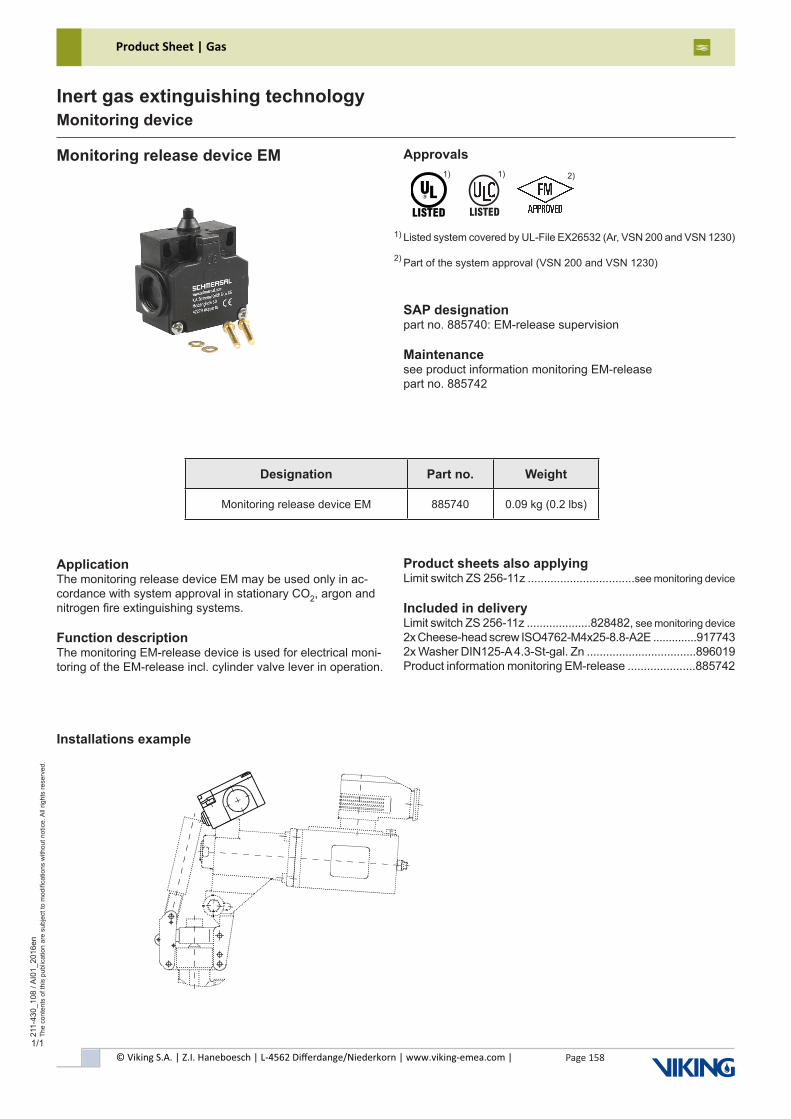
© Viking S.A. | Z.I. Haneboesch | L-4562 Differdange/Niederkorn | www.viking-emea.com |
Product Sheet | Gas
Page 158
211-
430_
108
/ AI0
1_20
16en
The
cont
ents
of t
his
publ
icat
ion
are
subj
ect t
o m
odifi
catio
ns w
ithou
t not
ice.
All
right
s re
serv
ed.
Inert gas extinguishing technologyMonitoring device
1/1
SAP designationpart no. 885740: EM-release supervision
Maintenancesee product information monitoring EM-releasepart no. 885742
Product sheets also applyingLimit switch ZS 256-11z .................................see monitoring device
Included in deliveryLimit switch ZS 256-11z ....................828482, see monitoring device 2x Cheese-head screw ISO4762-M4x25-8.8-A2E ..............9177432x Washer DIN125-A 4.3-St-gal. Zn ..................................896019Product information monitoring EM-release .....................885742
ApplicationThe monitoring release device EM may be used only in ac-cordance with system approval in stationary CO2, argon and nitrogen fire extinguishing systems.
Function descriptionThe monitoring EM-release device is used for electrical moni-toring of the EM-release incl. cylinder valve lever in operation.
Monitoring release device EM
Installations example
Designation Part no. Weight
Monitoring release device EM 885740 0.09 kg (0.2 lbs)
Approvals
Listed system covered by UL-File EX26532 (Ar, VSN 200 and VSN 1230)
Part of the system approval (VSN 200 and VSN 1230)
1) 2)
1) 2)
������
1)
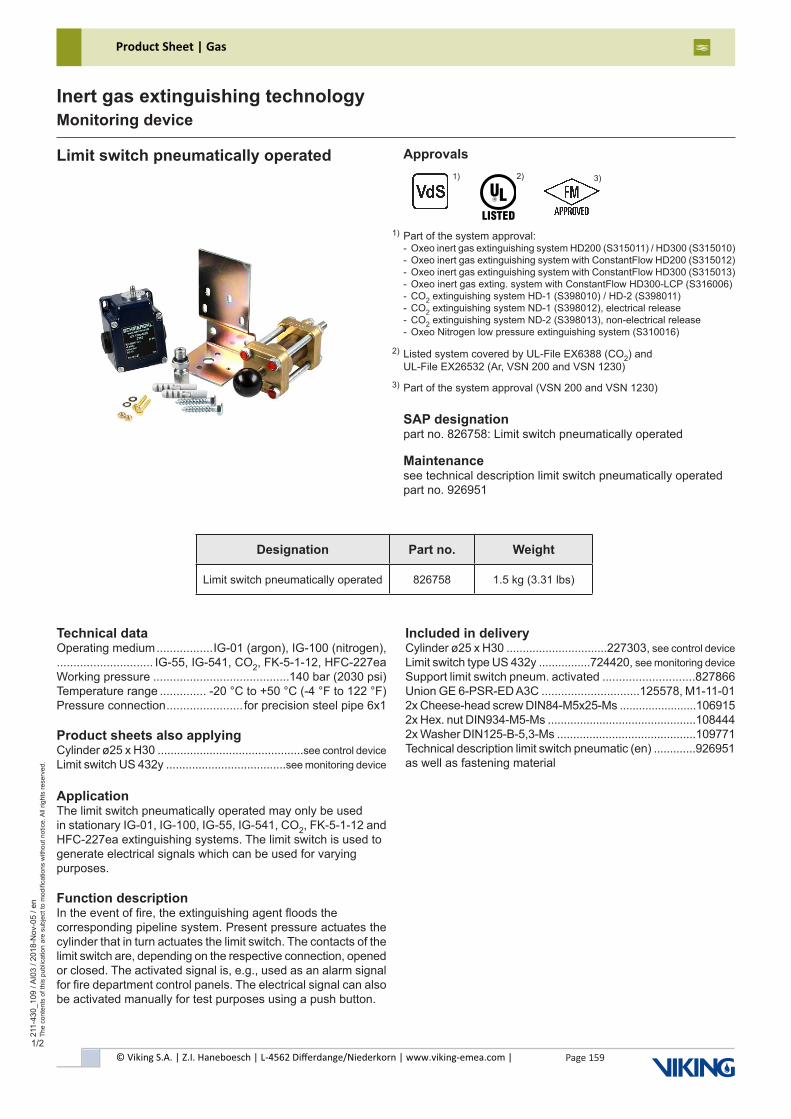
© Viking S.A. | Z.I. Haneboesch | L-4562 Differdange/Niederkorn | www.viking-emea.com |
Product Sheet | Gas
Page 159
211-
430_
109
/ AI0
3 / 2
018-
Nov
-05
/ en
The
cont
ents
of t
his
publ
icat
ion
are
subj
ect t
o m
odifi
catio
ns w
ithou
t not
ice.
All
right
s re
serv
ed.
Inert gas extinguishing technologyMonitoring device
1/2
Approvals
SAP designationpart no. 826758: Limit switch pneumatically operated
Maintenancesee technical description limit switch pneumatically operated part no. 926951
Limit switch pneumatically operated
Part of the system approval:- Oxeo inert gas extinguishing system HD200 (S315011) / HD300 (S315010)- Oxeo inert gas extinguishing system with ConstantFlow HD200 (S315012)- Oxeo inert gas extinguishing system with ConstantFlow HD300 (S315013)- Oxeo inert gas exting. system with ConstantFlow HD300-LCP (S316006)- CO2 extinguishing system HD-1 (S398010) / HD-2 (S398011)- CO2 extinguishing system ND-1 (S398012), electrical release- CO2 extinguishing system ND-2 (S398013), non-electrical release- Oxeo Nitrogen low pressure extinguishing system (S310016)
1)
Listed system covered by UL-File EX6388 (CO2) andUL-File EX26532 (Ar, VSN 200 and VSN 1230)
2)
Part of the system approval (VSN 200 and VSN 1230)3)
Designation Part no. Weight
Limit switch pneumatically operated 826758 1.5 kg (3.31 lbs)
1) 2) 3)
Technical dataOperating medium .................IG-01 (argon), IG-100 (nitrogen), ............................. IG-55, IG-541, CO2, FK-5-1-12, HFC-227eaWorking pressure .........................................140 bar (2030 psi)Temperature range .............. -20 °C to +50 °C (-4 °F to 122 °F)Pressure connection ....................... for precision steel pipe 6x1
Product sheets also applyingCylinder ø25 x H30 .............................................see control device Limit switch US 432y .....................................see monitoring device
ApplicationThe limit switch pneumatically operated may only be usedin stationary IG-01, IG-100, IG-55, IG-541, CO2, FK-5-1-12 and HFC-227ea extinguishing systems. The limit switch is used togenerate electrical signals which can be used for varyingpurposes.
Function descriptionIn the event of fire, the extinguishing agent floods thecorresponding pipeline system. Present pressure actuates the cylinder that in turn actuates the limit switch. The contacts of thelimit switch are, depending on the respective connection, opened or closed. The activated signal is, e.g., used as an alarm signal for fire department control panels. The electrical signal can also be activated manually for test purposes using a push button.
Included in deliveryCylinder ø25 x H30 ...............................227303, see control device Limit switch type US 432y ................724420, see monitoring device Support limit switch pneum. activated ............................827866Union GE 6-PSR-ED A3C ..............................125578, M1-11-012x Cheese-head screw DIN84-M5x25-Ms ........................1069152x Hex. nut DIN934-M5-Ms ..............................................1084442x Washer DIN125-B-5,3-Ms ...........................................109771Technical description limit switch pneumatic (en) .............926951as well as fastening material
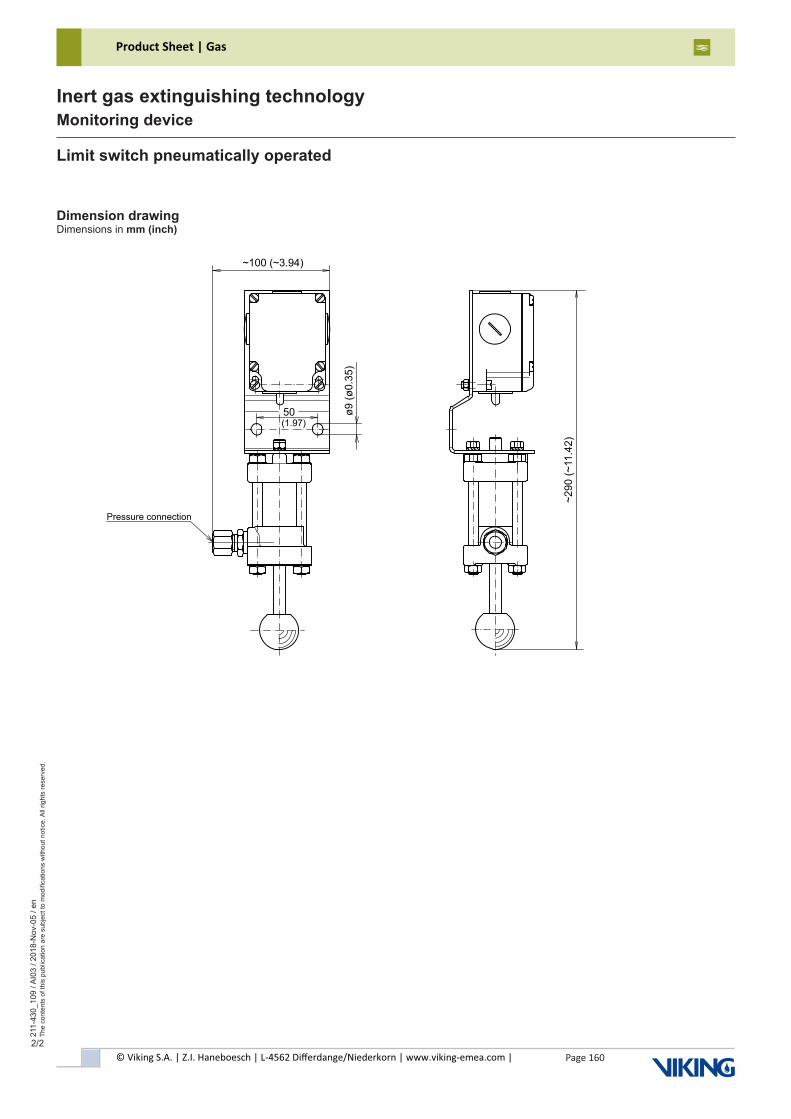
© Viking S.A. | Z.I. Haneboesch | L-4562 Differdange/Niederkorn | www.viking-emea.com |
Product Sheet | Gas
Page 160
211-
430_
109
/ AI0
3 / 2
018-
Nov
-05
/ en
The
cont
ents
of t
his
publ
icat
ion
are
subj
ect t
o m
odifi
catio
ns w
ithou
t not
ice.
All
right
s re
serv
ed.
Inert gas extinguishing technologyMonitoring device
2/2
Dimension drawingDimensions in mm (inch)
(1.97)
~100 (~3.94)
~290 (
~11.4
2)
ø9 (
ø0.3
5)
Pressure connection
50
Limit switch pneumatically operated
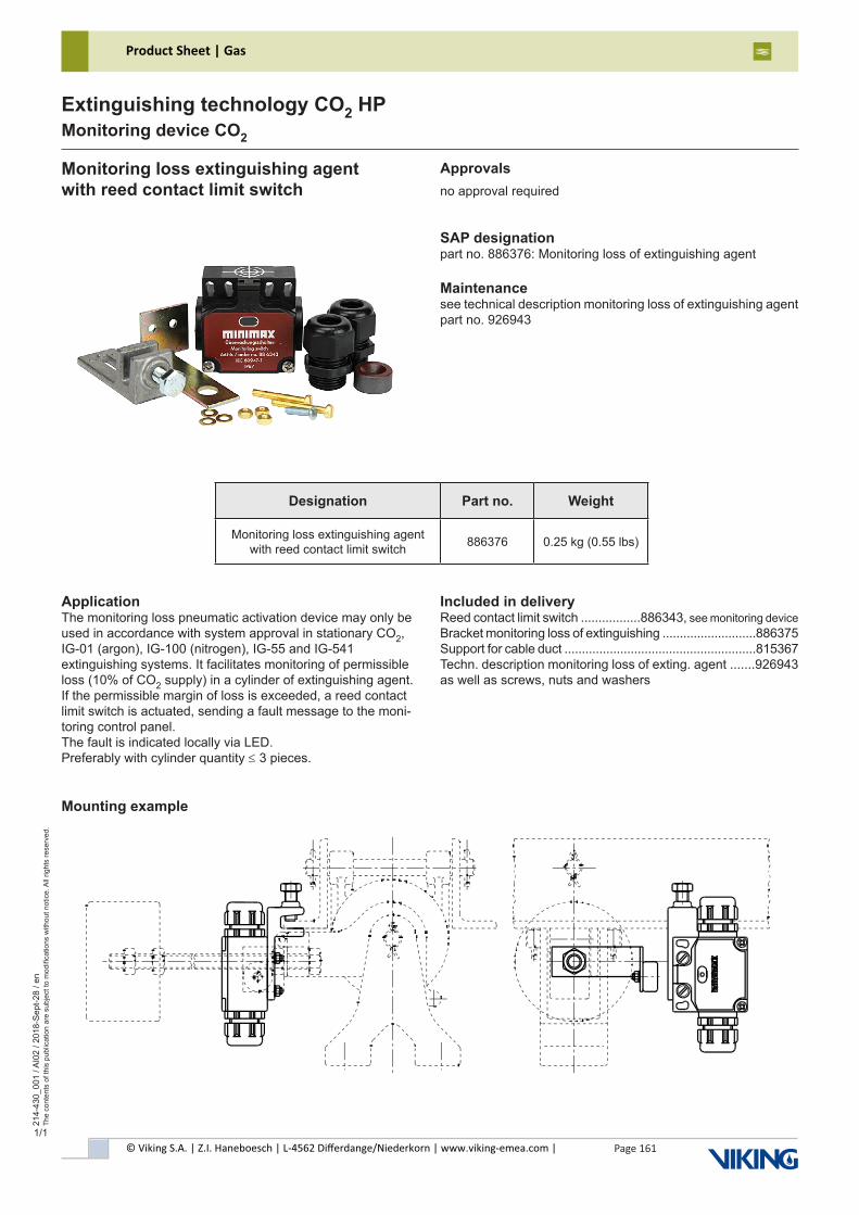
© Viking S.A. | Z.I. Haneboesch | L-4562 Differdange/Niederkorn | www.viking-emea.com |
Product Sheet | Gas
Page 161
214-
430_
001
/ AI0
2 / 2
018-
Sep
t-28
/ en
The
cont
ents
of t
his
publ
icat
ion
are
subj
ect t
o m
odifi
catio
ns w
ithou
t not
ice.
All
right
s re
serv
ed.
Extinguishing technology CO2 HPMonitoring device CO2
1/1
Monitoring loss extinguishing agentwith reed contact limit switch
SAP designationpart no. 886376: Monitoring loss of extinguishing agent
Maintenancesee technical description monitoring loss of extinguishing agentpart no. 926943
ApplicationThe monitoring loss pneumatic activation device may only be used in accordance with system approval in stationary CO2, IG-01 (argon), IG-100 (nitrogen), IG-55 and IG-541 extinguishing systems. It facilitates monitoring of permissible loss (10% of CO2 supply) in a cylinder of extinguishing agent. If the permissible margin of loss is exceeded, a reed contact limit switch is actuated, sending a fault message to the moni-toring control panel.The fault is indicated locally via LED.Preferably with cylinder quantity ≤ 3 pieces.
Mounting example
Included in deliveryReed contact limit switch .................886343, see monitoring deviceBracket monitoring loss of extinguishing ...........................886375Support for cable duct .......................................................815367Techn. description monitoring loss of exting. agent .......926943as well as screws, nuts and washers
Approvalsno approval required
Designation Part no. Weight
Monitoring loss extinguishing agent with reed contact limit switch 886376 0.25 kg (0.55 lbs)
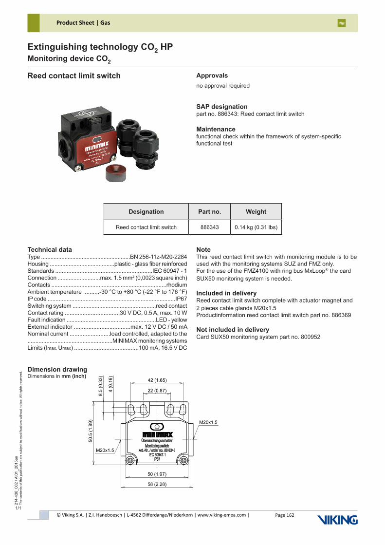
© Viking S.A. | Z.I. Haneboesch | L-4562 Differdange/Niederkorn | www.viking-emea.com |
Product Sheet | Gas
Page 162
214-
430_
002
/ AI0
1_20
15en
The
cont
ents
of t
his
publ
icat
ion
are
subj
ect t
o m
odifi
catio
ns w
ithou
t not
ice.
All
right
s re
serv
ed.
Extinguishing technology CO2 HPMonitoring device CO2
1/1
Reed contact limit switch
SAP designationpart no. 886343: Reed contact limit switch
Maintenancefunctional check within the framework of system-specificfunctional test
Technical dataType .........................................................BN 256-11z-M20-2284Housing .........................................plastic - glass fiber reinforcedStandards ............................................................IEC 60947 - 1Connection ...........................max. 1.5 mm² (0,0023 square inch)Contacts .........................................................................rhodiumAmbient temperature ..........-30 °C to +80 °C (-22 °F to 176 °F)IP code .................................................................................IP67Switching system .....................................................reed contactContact rating ..................................30 V DC, 0.5 A, max. 10 WFault indication .........................................................LED - yellowExternal indicator ...................................max. 12 V DC / 50 mANominal current .........................load controlled, adapted to the ......................................................MINIMAX monitoring systemsLimits (Imax, Umax) ........................................100 mA, 16.5 V DC
NoteThis reed contact limit switch with monitoring module is to be used with the monitoring systems SUZ and FMZ only.For the use of the FMZ4100 with ring bus MxLoop® the cardSUX50 monitoring system is needed.
Included in deliveryReed contact limit switch complete with actuator magnet and 2 pieces cable glands M20x1.5Productinformation reed contact limit switch part no. 886369
Not included in deliveryCard SUX50 monitoring system part no. 800952
Dimension drawingDimensions in mm (inch)
Approvalsno approval required
Designation Part no. Weight
Reed contact limit switch 886343 0.14 kg (0.31 lbs)
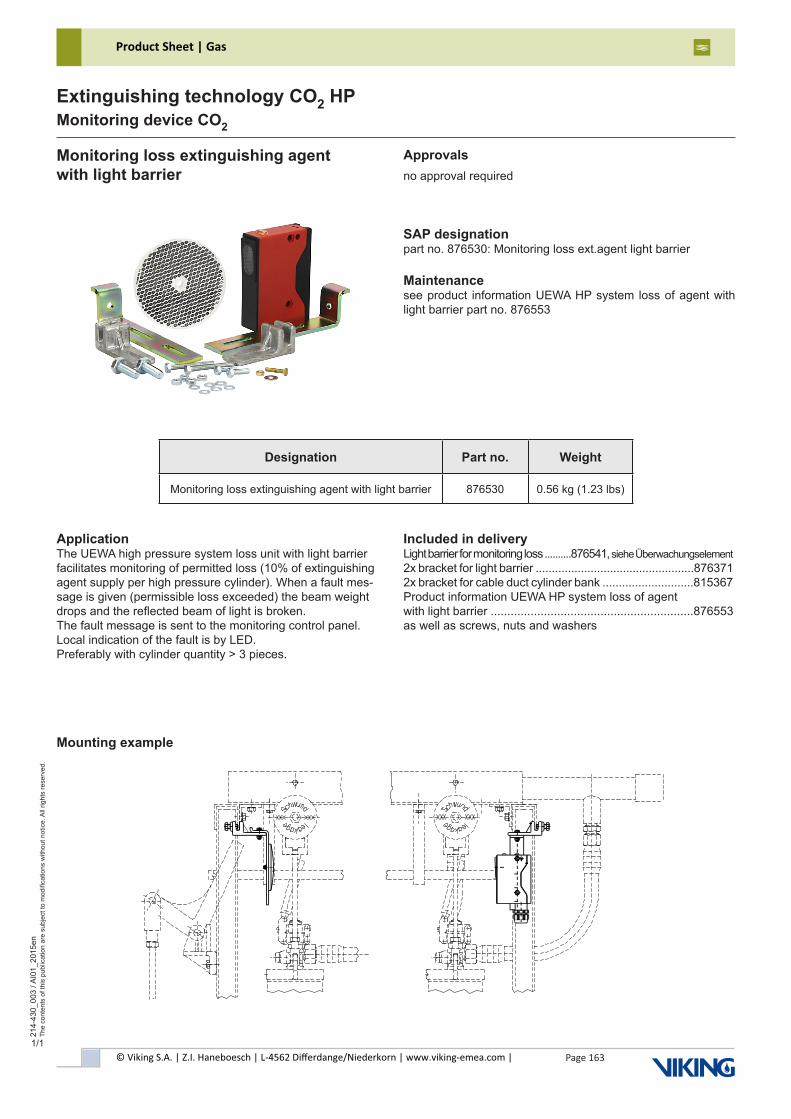
© Viking S.A. | Z.I. Haneboesch | L-4562 Differdange/Niederkorn | www.viking-emea.com |
Product Sheet | Gas
Page 163
214-
430_
003
/ AI0
1_20
15en
The
cont
ents
of t
his
publ
icat
ion
are
subj
ect t
o m
odifi
catio
ns w
ithou
t not
ice.
All
right
s re
serv
ed.
Extinguishing technology CO2 HPMonitoring device CO2
1/1
Monitoring loss extinguishing agentwith light barrier
SAP designationpart no. 876530: Monitoring loss ext.agent light barrier
Maintenancesee product information UEWA HP system loss of agent with light barrier part no. 876553
ApplicationThe UEWA high pressure system loss unit with light barrier facilitates monitoring of permitted loss (10% of extinguishing agent supply per high pressure cylinder). When a fault mes-sage is given (permissible loss exceeded) the beam weight drops and the reflected beam of light is broken.The fault message is sent to the monitoring control panel. Local indication of the fault is by LED.Preferably with cylinder quantity > 3 pieces.
Mounting example
Included in deliveryLight barrier for monitoring loss ..........876541, siehe Überwachungselement2x bracket for light barrier .................................................8763712x bracket for cable duct cylinder bank ............................815367Product information UEWA HP system loss of agentwith light barrier .............................................................876553as well as screws, nuts and washers
Approvalsno approval required
Designation Part no. Weight
Monitoring loss extinguishing agent with light barrier 876530 0.56 kg (1.23 lbs)
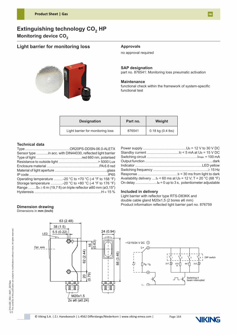
© Viking S.A. | Z.I. Haneboesch | L-4562 Differdange/Niederkorn | www.viking-emea.com |
Product Sheet | Gas
Page 164
214-
430_
004
/ AI0
1_20
15en
The
cont
ents
of t
his
publ
icat
ion
are
subj
ect t
o m
odifi
catio
ns w
ithou
t not
ice.
All
right
s re
serv
ed.
Extinguishing technology CO2 HPMonitoring device CO2
1/1
Light barrier for monitoring loss
SAP designationpart no. 876541: Monitoring loss pneumatic activation
Maintenancefunctional check within the framework of system-specificfunctional test
Technical dataType ..............................................OR20PS-DDSN-06.0-ALETXSensor type ............in acc. with DIN44030, reflected light barrierType of light ...............................................red 660 nm, polarisedResistance to outside light ........................................> 5000 LuxEnclosure material ......................................................PA 6.6 redMaterial of light aperture ......................................................glassIP code .................................................................................IP65Operating temperature .........-20 °C to +70 °C (-4 °F to 158 °F)Storage temperature ............-20 °C to +80 °C (-4 °F to 176 °F)Range ........Sn ≥ 6 m (19,7 ft) on triple reflector ø80 mm (ø3,15")Hysteresis ...................................................................H ≈ 15 %
Power supply ...........................................Ub = 12 V to 30 V DCStandby current ................................I0 < 5 mA at Ub = 15 V DCSwitching circuit ....................................................Imax. = 100 mAOutput function ......................................................................darkIndicator .....................................................................LED yellowSwitching frequency ........................................................≥ 15 HzResponse ........................................tr < 30 ms from light to darkAvailability delivery ....tv < 60 ms at Ub = 12 V; T = 20 °C (68 °F)On delay ......................te = 0 up to 3 s, potentiometer adjustable
Included in deliveryLight barrier with reflector type RTS-D83KK anddouble cable gland M20x1,5 (2 bores ø6 mm)Product information reflected light barrier part no. 876759
Approvalsno approval required
Dimension drawingDimensions in mm (inch)
Designation Part no. Weight
Light barrier for monitoring loss 876541 0.18 kg (0.4 lbs)
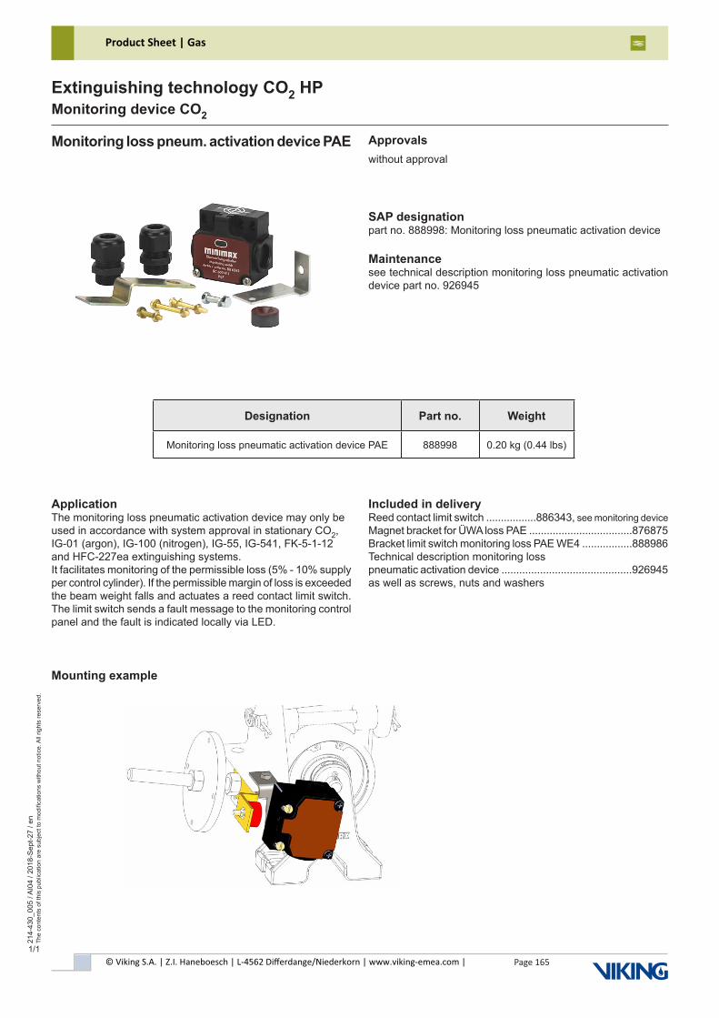
Page 165© Viking S.A. | Z.I. Haneboesch | L-4562 Differdange/Niederkorn | www.viking-emea.com |
Product Sheet | Gas21
4-43
0_00
5 / A
I04
/ 201
8-S
ept-2
7 / e
nTh
e co
nten
ts o
f thi
s pu
blic
atio
n ar
e su
bjec
t to
mod
ifica
tions
with
out n
otic
e. A
ll rig
hts
rese
rved
.
Extinguishing technology CO2 HPMonitoring device CO2
1/1
Monitoring loss pneum. activation device PAE
SAP designationpart no. 888998: Monitoring loss pneumatic activation device
Maintenancesee technical description monitoring loss pneumatic activation device part no. 926945
ApplicationThe monitoring loss pneumatic activation device may only be used in accordance with system approval in stationary CO2, IG-01 (argon), IG-100 (nitrogen), IG-55, IG-541, FK-5-1-12 and HFC-227ea extinguishing systems.It facilitates monitoring of the permissible loss (5% - 10% supply per control cylinder). If the permissible margin of loss is exceeded the beam weight falls and actuates a reed contact limit switch. The limit switch sends a fault message to the monitoring control panel and the fault is indicated locally via LED.
Mounting example
Included in deliveryReed contact limit switch .................886343, see monitoring deviceMagnet bracket for ÜWA loss PAE ...................................876875Bracket limit switch monitoring loss PAE WE4 .................888986Technical description monitoring losspneumatic activation device ............................................926945as well as screws, nuts and washers
Designation Part no. Weight
Monitoring loss pneumatic activation device PAE 888998 0.20 kg (0.44 lbs)
Approvalswithout approval
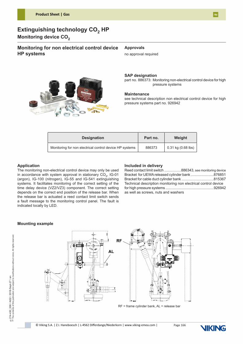
© Viking S.A. | Z.I. Haneboesch | L-4562 Differdange/Niederkorn | www.viking-emea.com |
Product Sheet | Gas
Page 166
214-
430_
006
/ AI0
2 / 2
018-
Sep
t-27
/ en
The
cont
ents
of t
his
publ
icat
ion
are
subj
ect t
o m
odifi
catio
ns w
ithou
t not
ice.
All
right
s re
serv
ed.
Extinguishing technology CO2 HPMonitoring device CO2
1/1
Monitoring for non electrical control device HP systems
SAP designationpart no. 886373: Monitoring non-electrical control device for high pressure systems
Maintenancesee technical description non electrical control device for high pressure systems part no. 926942
ApplicationThe monitoring non-electrical control device may only be used in accordance with system approval in stationary CO2, IG-01 (argon), IG-100 (nitrogen), IG-55 and IG-541 extinguishing systems. It facilitates monitoring of the correct setting of the time delay device (VZ2/VZ3) component. The correct setting depends on the correct end position of the release bar. When the release bar is actuated a reed contact limit switch sends a fault message to the monitoring control panel. The fault is indicated locally by LED.
Mounting example
Included in deliveryReed contact limit switch .................886343, see monitoring deviceBracket for UEWA released cylinder bank .......................876851Bracket for cable duct cylinder bank ................................815367Technical description monitoring non electrical control devicefor high pressure systems .................................................926942as well as screws, nuts and washers
Approvalsno approval required
RF = frame cylinder bank, AL = release bar
Designation Part no. Weight
Monitoring for non electrical control device HP systems 886373 0.31 kg (0.68 lbs)
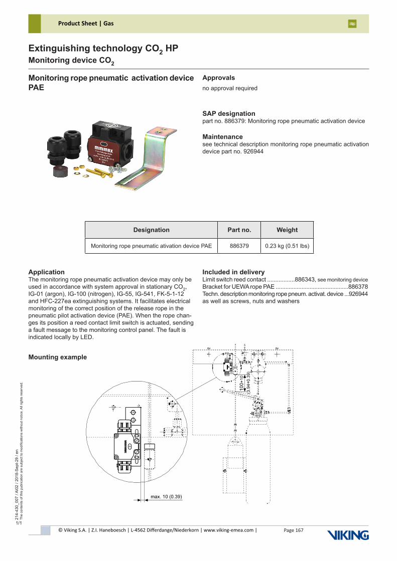
© Viking S.A. | Z.I. Haneboesch | L-4562 Differdange/Niederkorn | www.viking-emea.com |
Product Sheet | Gas
Page 167
214-
430_
007
/ AI0
2 / 2
018-
Sep
t-29
/ en
The
cont
ents
of t
his
publ
icat
ion
are
subj
ect t
o m
odifi
catio
ns w
ithou
t not
ice.
All
right
s re
serv
ed.
Extinguishing technology CO2 HPMonitoring device CO2
1/1
Monitoring rope pneumatic activation device PAE
SAP designationpart no. 886379: Monitoring rope pneumatic activation device
Maintenancesee technical description monitoring rope pneumatic activation device part no. 926944
ApplicationThe monitoring rope pneumatic activation device may only be used in accordance with system approval in stationary CO2, IG-01 (argon), IG-100 (nitrogen), IG-55, IG-541, FK-5-1-12 and HFC-227ea extinguishing systems. It facilitates electrical monitoring of the correct position of the release rope in the pneumatic pilot activation device (PAE). When the rope chan-ges its position a reed contact limit switch is actuated, sending a fault message to the monitoring control panel. The fault is indicated locally by LED.
Mounting example
Included in deliveryLimit switch reed contact .................886343, see monitoring deviceBracket for UEWA rope PAE .............................................886378Techn. description monitoring rope pneum. activat. device ...926944as well as screws, nuts and washers
Approvalsno approval required
Designation Part no. Weight
Monitoring rope pneumatic ativation device PAE 886379 0.23 kg (0.51 lbs)
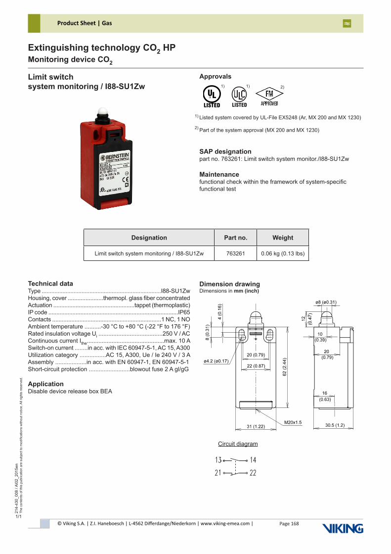
© Viking S.A. | Z.I. Haneboesch | L-4562 Differdange/Niederkorn | www.viking-emea.com |
Product Sheet | Gas
Page 168
214-
430_
008
/ AI0
2_20
15en
The
cont
ents
of t
his
publ
icat
ion
are
subj
ect t
o m
odifi
catio
ns w
ithou
t not
ice.
All
right
s re
serv
ed.
Extinguishing technology CO2 HPMonitoring device CO2
1/1
Limit switchsystem monitoring / I88-SU1Zw
SAP designationpart no. 763261: Limit switch system monitor./I88-SU1Zw
Maintenancefunctional check within the framework of system-specificfunctional test
Technical dataType ...........................................................................I88-SU1ZwHousing, cover ......................thermopl. glass fiber concentratedActuation ...................................................tappet (thermoplastic)IP code .................................................................................IP65Contacts ....................................................................1 NC, 1 NOAmbient temperature ..........-30 °C to +80 °C (-22 °F to 176 °F)Rated insulation voltage Ui .......................................250 V / ACContinuous current Ithe...............................................max. 10 ASwitch-on current ........in acc. with IEC 60947-5-1, AC 15, A300Utilization category ................AC 15, A300, Ue / Ie 240 V / 3 AAssembly ...................in acc. with EN 60947-1, EN 60947-5-1Short-circuit protection .........................blowout fuse 2 A gl/gG
ApplicationDisable device release box BEA
Dimension drawingDimensions in mm (inch)
Circuit diagram
Designation Part no. Weight
Limit switch system monitoring / I88-SU1Zw 763261 0.06 kg (0.13 lbs)
Approvals
Listed system covered by UL-File EX5248 (Ar, MX 200 and MX 1230)
Part of the system approval (MX 200 and MX 1230)
1) 2)
1) 2)
������
1)
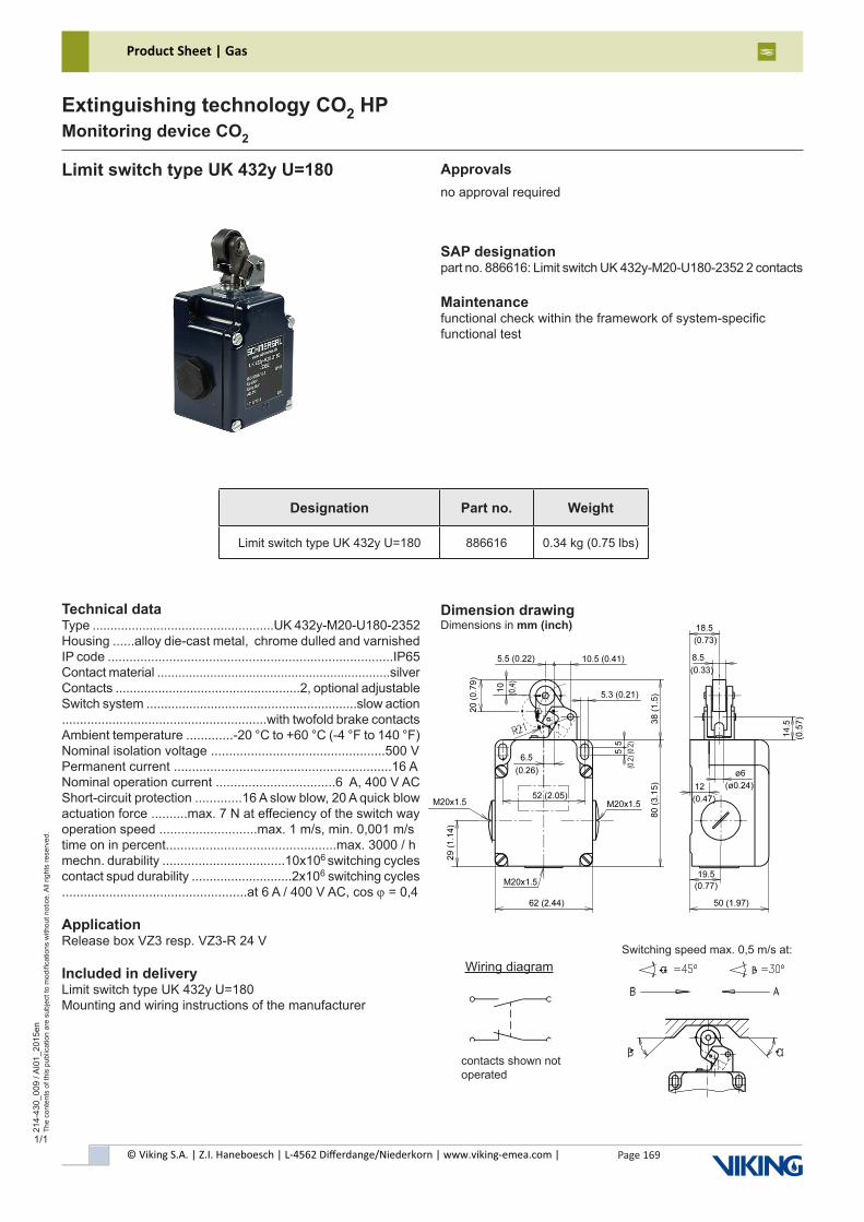
© Viking S.A. | Z.I. Haneboesch | L-4562 Differdange/Niederkorn | www.viking-emea.com |
Product Sheet | Gas
Page 169
214-
430_
009
/ AI0
1_20
15en
The
cont
ents
of t
his
publ
icat
ion
are
subj
ect t
o m
odifi
catio
ns w
ithou
t not
ice.
All
right
s re
serv
ed.
Extinguishing technology CO2 HPMonitoring device CO2
1/1
Limit switch type UK 432y U=180
SAP designationpart no. 886616: Limit switch UK 432y-M20-U180-2352 2 contacts
Maintenancefunctional check within the framework of system-specificfunctional test
Technical dataType ...................................................UK 432y-M20-U180-2352Housing ......alloy die-cast metal, chrome dulled and varnishedIP code ...............................................................................IP65Contact material ..................................................................silverContacts ....................................................2, optional adjustableSwitch system ...........................................................slow action.........................................................with twofold brake contactsAmbient temperature .............-20 °C to +60 °C (-4 °F to 140 °F)Nominal isolation voltage ................................................500 VPermanent current ............................................................16 ANominal operation current .................................6 A, 400 V ACShort-circuit protection .............16 A slow blow, 20 A quick blowactuation force ..........max. 7 N at effeciency of the switch wayoperation speed ...........................max. 1 m/s, min. 0,001 m/stime on in percent...............................................max. 3000 / hmechn. durability ..................................10x106 switching cyclescontact spud durability ............................2x106 switching cycles ...................................................at 6 A / 400 V AC, cos ϕ = 0,4
ApplicationRelease box VZ3 resp. VZ3-R 24 V
Included in deliveryLimit switch type UK 432y U=180Mounting and wiring instructions of the manufacturer
Dimension drawingDimensions in mm (inch)
Wiring diagram
contacts shown not operated
Switching speed max. 0,5 m/s at:
Approvalsno approval required
Designation Part no. Weight
Limit switch type UK 432y U=180 886616 0.34 kg (0.75 lbs)
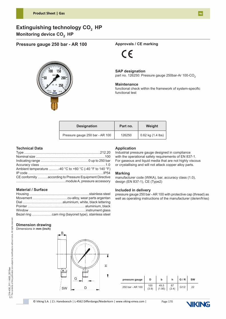
© Viking S.A. | Z.I. Haneboesch | L-4562 Differdange/Niederkorn | www.viking-emea.com |
Product Sheet | Gas
Page 170
214-
430_
011
/ AI0
0_20
15en
The
cont
ents
of t
his
publ
icat
ion
are
subj
ect t
o m
odifi
catio
ns w
ithou
t not
ice.
All
right
s re
serv
ed.
Extinguishing technology CO2 HPMonitoring device CO2 HP
1/1
Pressure gauge 250 bar - AR 100 Approvals / CE marking
SAP designationpart no. 126250: Pressure gauge 250bar-Ar 100-CO2
Maintenancefunctional check within the framework of system-specificfunctional test
Dimension drawingDimensions in mm (inch)
Designation Part no. Weight
Pressure gauge 250 bar - AR 100 126250 0.62 kg (1.4 lbs)
pressure gauge D b h G / R SW
250 bar - AR 100 100 (3.9)
49,5 (1.95)
87 (3.4) G1/2 22SW D
H
G
B
ApplicationIndustrial pressure gauge designed in compliancewith the operational safety requirements of EN 837-1. For gaseous and liquid media that are not highly viscousor crystallising and will not attack copper alloy parts.
Markingmanufacturer code (WIKA), bar, accuracy class (1.0),design (EN 837-1), CE (Type2)
Included in deliverypressure gauge 250 bar - AR 100 with protective cap (thread) as well as operating instructions of the manufacturer (de/en/fr/es)
Technical DataType .................................................................................212.20Nominal size ...........................................................................100Indicating range ...................................................0 up to 250 barAccuracy class .....................................................................1.0Ambient temperature ..........-40 °C to +60 °C (-40 °F to 140 °F)IP code ................................................................................IP54CE conformity ...........according to Pressure Equipment Directive.....................................................module A, pressure accessory
Material / SurfaceHousing ...............................................................stainless steelMovement .....................................cu-alloy, wear parts argentanDial ..........................................aluminium, white, black letteringPointer ............................................................ aluminium, blackWindow ............................................................instrument glassBezel ring .....................cam ring (bayonet type), stainless steel
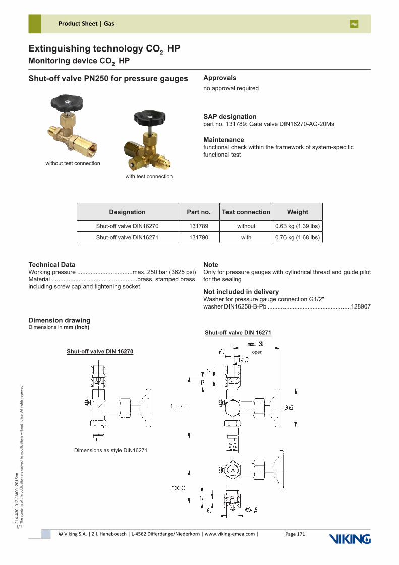
© Viking S.A. | Z.I. Haneboesch | L-4562 Differdange/Niederkorn | www.viking-emea.com |
Product Sheet | Gas
Page 171
214-
430_
012
/ AI0
0_20
15en
The
cont
ents
of t
his
publ
icat
ion
are
subj
ect t
o m
odifi
catio
ns w
ithou
t not
ice.
All
right
s re
serv
ed.
Extinguishing technology CO2 HPMonitoring device CO2 HP
1/1
Shut-off valve PN250 for pressure gauges Approvalsno approval required
SAP designationpart no. 131789: Gate valve DIN16270-AG-20Ms
Maintenancefunctional check within the framework of system-specificfunctional test
Designation Part no. Test connection Weight
Shut-off valve DIN16270 131789 without 0.63 kg (1.39 lbs)
Shut-off valve DIN16271 131790 with 0.76 kg (1.68 lbs)
NoteOnly for pressure gauges with cylindrical thread and guide pilot for the sealing
Not included in deliveryWasher for pressure gauge connection G1/2"washer DIN16258-B-Pb ..................................................128907
Technical DataWorking pressure .................................max. 250 bar (3625 psi)Material ...................................................brass, stamped brassincluding screw cap and tightening socket
without test connection
with test connection
Dimension drawingDimensions in mm (inch)
Dimensions as style DIN16271
open
Shut-off valve DIN 16271
Shut-off valve DIN 16270
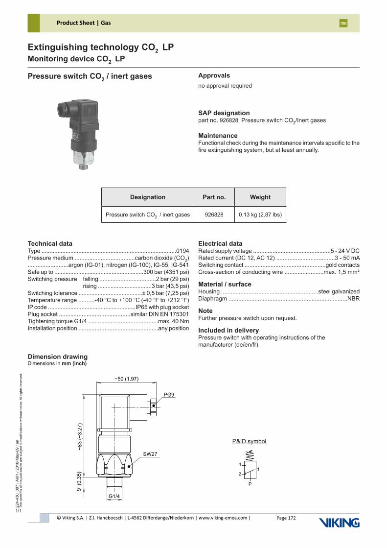
© Viking S.A. | Z.I. Haneboesch | L-4562 Differdange/Niederkorn | www.viking-emea.com |
Product Sheet | Gas
Page 172
224-
430_
007
/ AI0
1 / 2
018-
May
-09
/ en
The
cont
ents
of t
his
publ
icat
ion
are
subj
ect t
o m
odifi
catio
ns w
ithou
t not
ice.
All
right
s re
serv
ed.
Extinguishing technology CO2 LPMonitoring device CO2 LP
Designation Part no. Weight
Pressure switch CO2 / inert gases 926828 0.13 kg (2.87 lbs)
Pressure switch CO2 / inert gases Approvalsno approval required
SAP designationpart no. 926828: Pressure switch CO2/Inert gases
MaintenanceFunctional check during the maintenance intervals specific to thefire extinguishing system, but at least annually.
Technical dataType ....................................................................................0194Pressure medium .....................................carbon dioxide (CO2).........................argon (IG-01), nitrogen (IG-100), IG-55, IG-541Safe up to ........................................................300 bar (4351 psi)Switching pressure falling ...................................2 bar (29 psi) rising ..................................3 bar (43,5 psi)Switching tolerance ........................................± 0,5 bar (7,25 psi)Temperature range ..........-40 °C to +100 °C (-40 °F to +212 °F)IP code .......................................................IP65 with plug socketPlug socket ............................................similar DIN EN 175301Tightening torque G1/4 ...........................................max. 40 NmInstallation position .................................................any position
Electrical dataRated supply voltage ................................................5 - 24 V DCRated current (DC 12, AC 12) ....................................3 - 50 mASwitching contact ..................................................gold contactsCross-section of conducting wire ........................max. 1,5 mm²
Material / surfaceHousing ............................................................steel galvanizedDiaphragm .........................................................................NBR
NoteFurther pressure switch upon request.
Included in deliveryPressure switch with operating instructions of themanufacturer (de/en/fr).
Dimension drawingDimensions in mm (inch)
P&ID symbol
1
P
2
4
G1/4
9
(0.3
5)
~8
3 (
~3
.27
)
~50 (1.97)
SW27
PG9
1/1
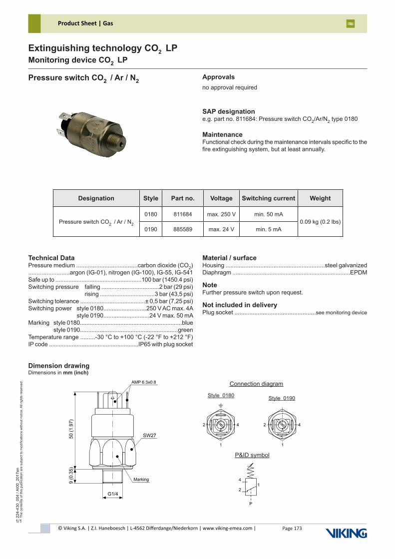
© Viking S.A. | Z.I. Haneboesch | L-4562 Differdange/Niederkorn | www.viking-emea.com |
Product Sheet | Gas
Page 173
224-
430_
004
/ AI0
0_20
17en
The
cont
ents
of t
his
publ
icat
ion
are
subj
ect t
o m
odifi
catio
ns w
ithou
t not
ice.
All
right
s re
serv
ed.
Extinguishing technology CO2 LPMonitoring device CO2 LP
Pressure switch CO2 / Ar / N2 Approvalsno approval required
SAP designatione.g. part no. 811684: Pressure switch CO2/Ar/N2 type 0180
MaintenanceFunctional check during the maintenance intervals specific to thefire extinguishing system, but at least annually.
Designation Style Part no. Voltage Switching current Weight
Pressure switch CO2 / Ar / N2
0180 811684 max. 250 V min. 50 mA0.09 kg (0.2 lbs)
0190 885589 max. 24 V min. 5 mA
Technical DataPressure medium .....................................carbon dioxide (CO2).........................argon (IG-01), nitrogen (IG-100), IG-55, IG-541Safe up to .....................................................100 bar (1450.4 psi)Switching pressure falling ...................................2 bar (29 psi) rising ..................................3 bar (43,5 psi)Switching tolerance ........................................± 0,5 bar (7,25 psi)Switching power style 0180..........................250 V AC max. 4A style 0190............................24 V max. 50 mAMarking style 0180...............................................................blue style 0190............................................................greenTemperature range .........-30 °C to +100 °C (-22 °F to +212 °F)IP code .......................................................IP65 with plug socket
Material / surfaceHousing ............................................................steel galvanizedDiaphragm .........................................................................EPDM
NoteFurther pressure switch upon request.
Not included in deliveryPlug socket .................................................see monitoring device
Dimension drawingDimensions in mm (inch)
P&ID symbol
Connection diagram
Style 0180 Style 0190
1/1
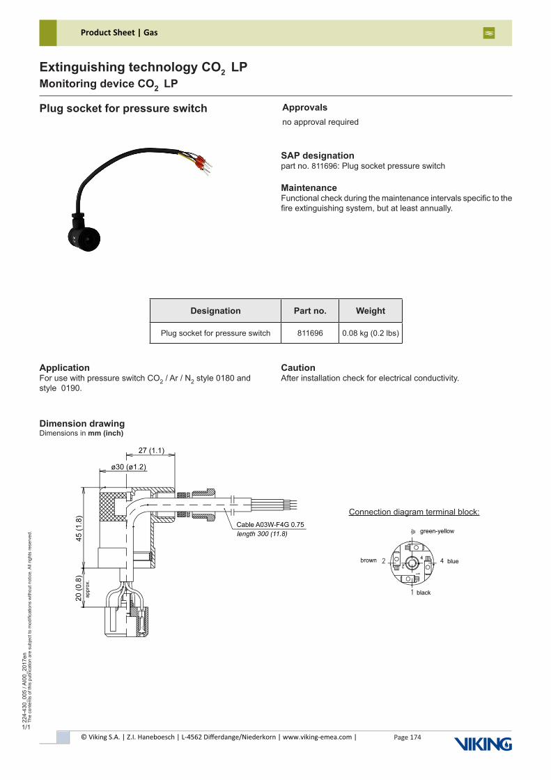
© Viking S.A. | Z.I. Haneboesch | L-4562 Differdange/Niederkorn | www.viking-emea.com |
Product Sheet | Gas
Page 174
224-
430_
005
/ AI0
0_20
17en
The
cont
ents
of t
his
publ
icat
ion
are
subj
ect t
o m
odifi
catio
ns w
ithou
t not
ice.
All
right
s re
serv
ed.
Extinguishing technology CO2 LPMonitoring device CO2 LP
Plug socket for pressure switch
SAP designationpart no. 811696: Plug socket pressure switch
MaintenanceFunctional check during the maintenance intervals specific to thefire extinguishing system, but at least annually.
Dimension drawingDimensions in mm (inch)
Designation Part no. Weight
Plug socket for pressure switch 811696 0.08 kg (0.2 lbs)
ApplicationFor use with pressure switch CO2 / Ar / N2 style 0180 andstyle 0190.
Connection diagram terminal block:
CautionAfter installation check for electrical conductivity.
Approvalsno approval required
1/1
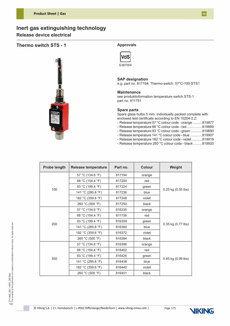
© Viking S.A. | Z.I. Haneboesch | L-4562 Differdange/Niederkorn | www.viking-emea.com |
Product Sheet | Gas
Page 175
211-
440_
001
/ AI0
1_20
15en
The
cont
ents
of t
his
publ
icat
ion
are
subj
ect t
o m
odifi
catio
ns w
ithou
t not
ice.
All
right
s re
serv
ed.
Inert gas extinguishing technologyRelease device electrical
1/2
SAP designatione.g. part no. 817194: Thermo-switch 57°C-100-STS1
Maintenancesee produktinformation temperature switch STS-1part no. 811751
Spare partsSpare glass bulbs 5 mm, individually packed complete withenclosed test certificate according to EN 10204-2.2:- Release temperature 57 °C colour code - orange ..........819877- Release temperature 68 °C colour code - red ................819889- Release temperature 93 °C colour code - green ............819890- Release temperature 141 °C colour code - blue .............819907- Release temperature 182 °C colour code - violet ...........819919- Release temperature 260 °C colour code - black .........819920
Thermo switch STS - 1 Approvals
G387004
Probe length Release temperature Part no. Colour Weight
100
57 °C (134.6 °F) 817194 orange
0.25 kg (0.55 lbs)
68 °C (154.4 °F) 817200 red
93 °C (199.4 °F) 817224 green
141 °C (285.8 °F) 817236 blue
182 °C (359.6 °F) 817248 violet
260 °C (500 °F) 817250 black
200
57 °C (134.6 °F) 816335 orange
0.35 kg (0.77 lbs)
68 °C (154.4 °F) 811738 red
93 °C (199.4 °F) 816359 green
141 °C (285.8 °F) 816360 blue
182 °C (359.6 °F) 816372 violet
260 °C (500 °F) 816384 black
350
57 °C (134.6 °F) 816396 orange
0.45 kg (0.99 lbs)
68 °C (154.4 °F) 816402 red
93 °C (199.4 °F) 816426 green
141 °C (285.8 °F) 816438 blue
182 °C (359.6 °F) 816440 violet
260 °C (500 °F) 816451 black
© Viking S.A. | Z.I. Haneboesch | L-4562 Differdange/Niederkorn | www.viking-emea.com |
Product Sheet | Gas
Page 176
211-
440_
001
/ AI0
1_20
15en
The
cont
ents
of t
his
publ
icat
ion
are
subj
ect t
o m
odifi
catio
ns w
ithou
t not
ice.
All
right
s re
serv
ed.
Inert gas extinguishing technologyRelease device electrical
Probe length L L1 ±3 (±0.12 )
100 100 (3.94) 117 (4.61)
200 200 (7.87) 217 (8.54)
300 350 (13.78) 367 (14.45)
2/2
Thermo switch STS - 1
Technical dataProbe ...........................................................brass, nickel-platedLimit switch STS-1:Type ...................................................................ENM2-SU1Z IWContakts ....................................................................1 NC, 1 NORated insulation voltage Ui .......................................400 V / ACConv. thermal current Ithe ....................................................10 AMax. switch-on current .....AC 15, A300 acc. to IEC 60947-5-1Utilization category ....................AC 15, A300, Ue/Ie 240 V / 3 AShort-circuit protection ....................................melting fuse 2 AAmbient temperature .........-30 °C to + 80 °C (-22 °F to 176 °F)IP code .................................................................................IP65Housing ..................................................................al-die casting
ApplicationThe Thermo-switch STS-1 may only be used in accordance with system approval for activation of fire extinguishing systems. The Thermo switch is used as a electrical fire detection element.
Functional descriptionThe Thermo-switch STS-1 is a electrical fire detection element. Due to its design it can be put with the release part from the outside through walls or housing.At a temperature rise the warmed medium flow through the bores in the housing and heated the glass bulb. After reaching a specific temperature the glass bulb bursts.Through this the pressure spring can relief. The pressure spring push away the rod from the limit switch. Through this the limit switch can operate. The Thermo-switch is made in threelength and six different temperatures. Alternatively one or two cables can be installed.
Included in deliveryThermo switch STS - 1Produktinformation temperature switch STS-1 part no. 811751
Not included in deliveryMounting socket for thermo switch STS .....see release device electr.
Dimension drawingDimensions in mm (inch)
wiring diagram
contacts shown not operated
© Viking S.A. | Z.I. Haneboesch | L-4562 Differdange/Niederkorn | www.viking-emea.com |
Product Sheet | Gas
Page 177
211-
440_
002
/ AI0
1_20
15en
The
cont
ents
of t
his
publ
icat
ion
are
subj
ect t
o m
odifi
catio
ns w
ithou
t not
ice.
All
right
s re
serv
ed.
Inert gas extinguishing technologyRelease device electrical
1/1
SAP designatione.g. part no. 812664: Mounting socket thermo switch screwed
Maintenancemaintenance-free
Mounting socket for thermo switch STS Approvalsno approval required
Technical dataMaterial .....................................................brass, chrome-plated
Not included in deliveryFastening material
Dimension drawingDimensions in mm (inch)
Mounting socket, screw-on Mounting socket, plug-in
Designation Style Part no. Weight
Mounting socket for thermo switch STSscrew-on 812664
0.14 kg (0.31 lbs)plug-in 812640
© Viking S.A. | Z.I. Haneboesch | L-4562 Differdange/Niederkorn | www.viking-emea.com |
Product Sheet | Gas
Page 178
211-
440_
003
/ AI0
1_20
15en
The
cont
ents
of t
his
publ
icat
ion
are
subj
ect t
o m
odifi
catio
ns w
ithou
t not
ice.
All
right
s re
serv
ed.
Inert gas extinguishing technologyRelease device electrical
1/1
SAP designationpart no. 595521: Schlüsselschalter K2
Maintenancefunctional check within the framework of system-specific functional test
Key switch K2
Technical dataHousing type .................................................................MBG 422IP code, housing ...................................................................IP65Standards .......................................................IEC 947 EN 60947Key selector switch:Type ASS21S1 with 2 lock positions, operating angle 1x 45°, key can be removed in left lock position onlyContacts ........................................................2 NO, type 2x AF02Light element ............................with series resistance type ALVIndicator light ...................................................type AML RT red,.................................with light element ALV incl. lamp (L130/9)Contact elementsRated voltage Ue .............................................................440 VRated current Ie ......................................6 A, AC 15, 250 V AC.....................................................................3 A, DC 13, 24 V DCCategory ......................AC 13, DC 15, DIN VDE 0660 part 200Thermal nominal current ...................................................10 AShort-circuit protection ................................................gG 10 AIP code ................................................................................IP20Temperature range ............-25 °C to +60 °C (-13 °F to 140 °F)
Light elements:Rated voltage Ue .............................................................250 VThermal rated power ..........................................................2 WShort-circuit protection ..................................................gG 10 AIP code .................................................................................IP20Temperature range ...........-25 °C to +40 °C (13 °F to 104 °F)
ApplicationTo bridges isolation during control panel test complete in lockable housing, incl. control lamp.
Not included in deliveryFastening material
Dimension drawingDimensions in mm (inch)
Approvalsno approval required
circuit diagram
Designation Part no. Weight
Key switch K2 595521 0.87 kg (1.92 lbs)
© Viking S.A. | Z.I. Haneboesch | L-4562 Differdange/Niederkorn | www.viking-emea.com |
Product Sheet | Gas
Page 179
211-
440_
004
/ AI0
3 / 2
018-
Sep
t-25
/ en
The
cont
ents
of t
his
publ
icat
ion
are
subj
ect t
o m
odifi
catio
ns w
ithou
t not
ice.
All
right
s re
serv
ed.
Inert gas extinguishing technologyRelease device electrical
1/1
SAP designationpart no. 582236: Emergency push-button H compl.
MaintenanceFunctional check during the maintenance intervals specific to the fire extinguishing system, but at least annually.
Emergency push-button H compl.
Technical dataType ....................................................................XAPM1201S9IP code .................................................................................IP65Push-button ...........push-button red, locked in pressed position....................................................unlocked by clockwise rotationContacts .............................................................................2 NOVoltage .....................................................................max. 500 VCurrent ..........................................................max. 8 A at 240 V
ApplicationEmergency shut-downs or switching-on of electrical circuits coherently with the function of a fire-extinguishing system.
Included in deliveryEmergency push-button H ..............................................657443Accessories for emergency push-button compl. ...........814764- safety device, key ring, towing ring, seal, seal wire, label emergency push-button as well as fastening material- techn. description emergency push-button (de/en) ....786038
Dimension drawingDimensions in mm (inch)
Approvalsno approval required
Circuit diagram
Designation Part no. Weight
Emergency push-button H compl. 582236 0.55 kg (1.21 lbs)
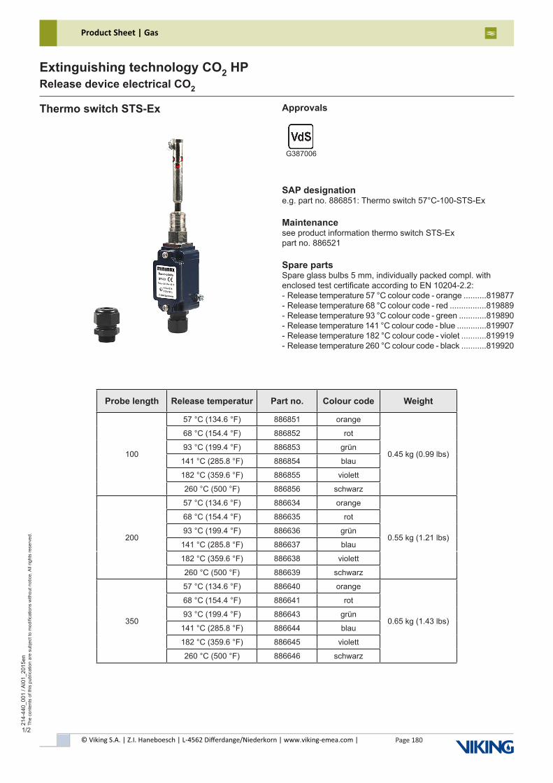
© Viking S.A. | Z.I. Haneboesch | L-4562 Differdange/Niederkorn | www.viking-emea.com |
Product Sheet | Gas
Page 180
214-
440_
001
/ AI0
1_20
15en
The
cont
ents
of t
his
publ
icat
ion
are
subj
ect t
o m
odifi
catio
ns w
ithou
t not
ice.
All
right
s re
serv
ed.
Extinguishing technology CO2 HPRelease device electrical CO2
1/2
Thermo switch STS-Ex
SAP designatione.g. part no. 886851: Thermo switch 57°C-100-STS-Ex
Maintenancesee product information thermo switch STS-Expart no. 886521
Spare partsSpare glass bulbs 5 mm, individually packed compl. withenclosed test certificate according to EN 10204-2.2:- Release temperature 57 °C colour code - orange ..........819877- Release temperature 68 °C colour code - red ................819889- Release temperature 93 °C colour code - green ............819890- Release temperature 141 °C colour code - blue .............819907- Release temperature 182 °C colour code - violet ...........819919- Release temperature 260 °C colour code - black ...........819920
Approvals
G387006
Probe length Release temperatur Part no. Colour code Weight
100
57 °C (134.6 °F) 886851 orange
0.45 kg (0.99 lbs)
68 °C (154.4 °F) 886852 rot
93 °C (199.4 °F) 886853 grün
141 °C (285.8 °F) 886854 blau
182 °C (359.6 °F) 886855 violett
260 °C (500 °F) 886856 schwarz
200
57 °C (134.6 °F) 886634 orange
0.55 kg (1.21 lbs)
68 °C (154.4 °F) 886635 rot
93 °C (199.4 °F) 886636 grün
141 °C (285.8 °F) 886637 blau
182 °C (359.6 °F) 886638 violett
260 °C (500 °F) 886639 schwarz
350
57 °C (134.6 °F) 886640 orange
0.65 kg (1.43 lbs)
68 °C (154.4 °F) 886641 rot
93 °C (199.4 °F) 886643 grün
141 °C (285.8 °F) 886644 blau
182 °C (359.6 °F) 886645 violett
260 °C (500 °F) 886646 schwarz
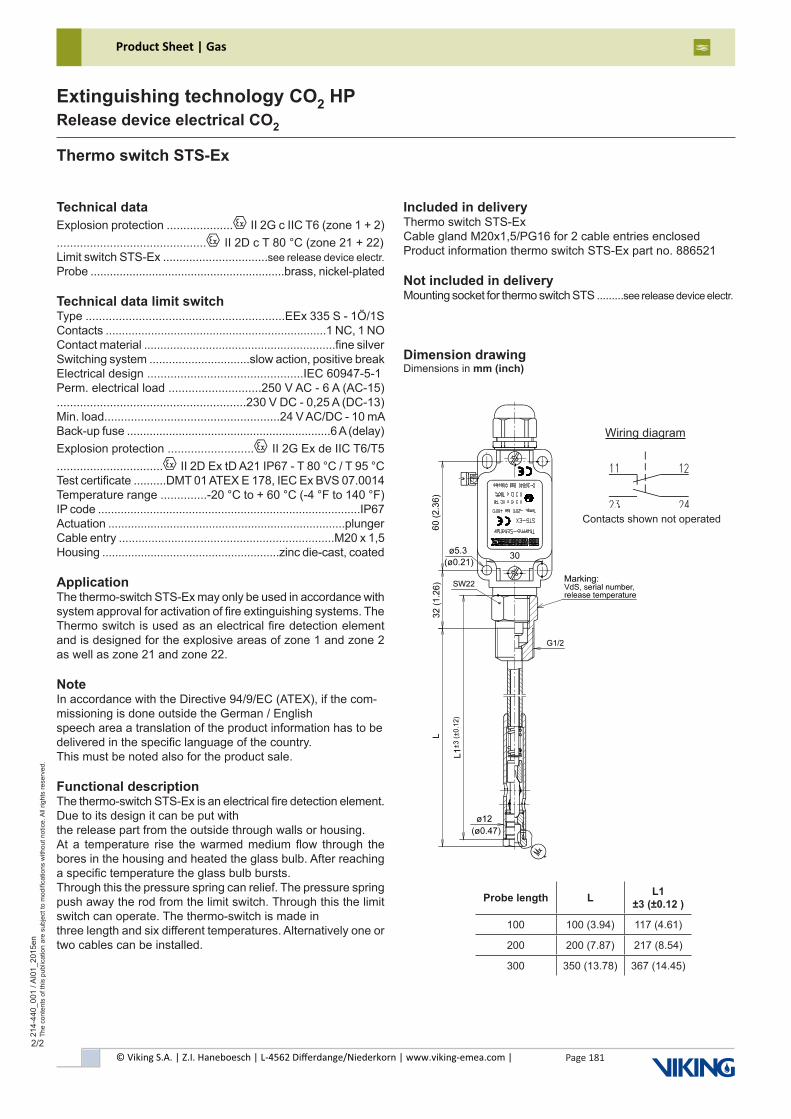
© Viking S.A. | Z.I. Haneboesch | L-4562 Differdange/Niederkorn | www.viking-emea.com |
Product Sheet | Gas
Page 181
214-
440_
001
/ AI0
1_20
15en
The
cont
ents
of t
his
publ
icat
ion
are
subj
ect t
o m
odifi
catio
ns w
ithou
t not
ice.
All
right
s re
serv
ed.
Extinguishing technology CO2 HPRelease device electrical CO2
2/2
Thermo switch STS-Ex
Technical dataExplosion protection ....................x II 2G c IIC T6 (zone 1 + 2).............................................x II 2D c T 80 °C (zone 21 + 22)Limit switch STS-Ex ................................see release device electr.Probe ............................................................brass, nickel-plated
Technical data limit switchType ............................................................EEx 335 S - 1Ö/1SContacts ....................................................................1 NC, 1 NOContact material ...........................................................fine silverSwitching system ...............................slow action, positive breakElectrical design ...............................................IEC 60947-5-1Perm. electrical load ............................250 V AC - 6 A (AC-15).........................................................230 V DC - 0,25 A (DC-13)Min. load.....................................................24 V AC/DC - 10 mABack-up fuse ...............................................................6 A (delay)Explosion protection ..........................x II 2G Ex de IIC T6/T5................................x II 2D Ex tD A21 IP67 - T 80 °C / T 95 °CTest certificate ..........DMT 01 ATEX E 178, IEC Ex BVS 07.0014Temperature range ..............-20 °C to + 60 °C (-4 °F to 140 °F)IP code .................................................................................IP67Actuation .........................................................................plungerCable entry ..................................................................M20 x 1,5Housing .......................................................zinc die-cast, coated
ApplicationThe thermo-switch STS-Ex may only be used in accordance with system approval for activation of fire extinguishing systems. The Thermo switch is used as an electrical fire detection element and is designed for the explosive areas of zone 1 and zone 2 as well as zone 21 and zone 22.
NoteIn accordance with the Directive 94/9/EC (ATEX), if the com-missioning is done outside the German / Englishspeech area a translation of the product information has to be delivered in the specific language of the country.This must be noted also for the product sale.
Functional descriptionThe thermo-switch STS-Ex is an electrical fire detection element. Due to its design it can be put withthe release part from the outside through walls or housing.At a temperature rise the warmed medium flow through the bores in the housing and heated the glass bulb. After reaching a specific temperature the glass bulb bursts.Through this the pressure spring can relief. The pressure spring push away the rod from the limit switch. Through this the limit switch can operate. The thermo-switch is made inthree length and six different temperatures. Alternatively one or two cables can be installed.
Included in deliveryThermo switch STS-ExCable gland M20x1,5/PG16 for 2 cable entries enclosedProduct information thermo switch STS-Ex part no. 886521
Not included in deliveryMounting socket for thermo switch STS .........see release device electr.
Dimension drawingDimensions in mm (inch)
Wiring diagram
Contacts shown not operated
Probe length L L1 ±3 (±0.12 )
100 100 (3.94) 117 (4.61)
200 200 (7.87) 217 (8.54)
300 350 (13.78) 367 (14.45)
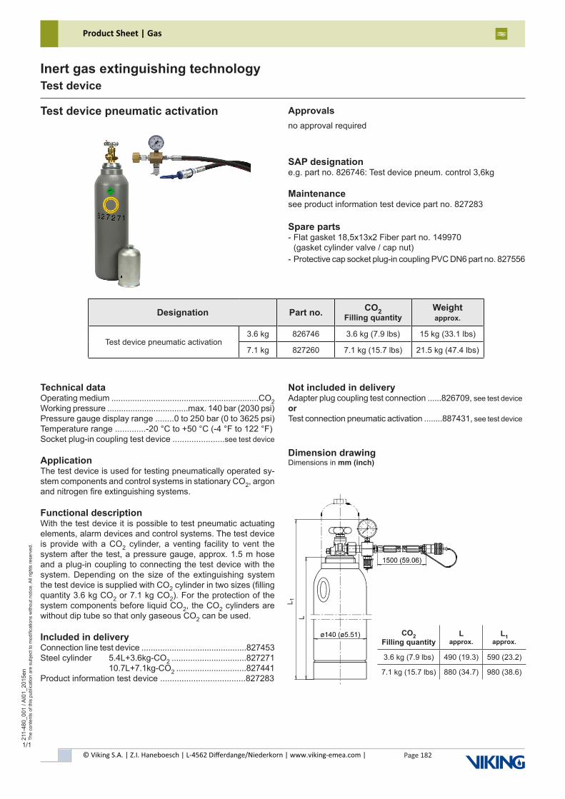
© Viking S.A. | Z.I. Haneboesch | L-4562 Differdange/Niederkorn | www.viking-emea.com |
Product Sheet | Gas
Page 182
211-
480_
001
/ AI0
1_20
15en
The
cont
ents
of t
his
publ
icat
ion
are
subj
ect t
o m
odifi
catio
ns w
ithou
t not
ice.
All
right
s re
serv
ed.
Inert gas extinguishing technologyTest device
CO2 Filling quantity
L approx.
L1 approx.
3.6 kg (7.9 lbs) 490 (19.3) 590 (23.2)
7.1 kg (15.7 lbs) 880 (34.7) 980 (38.6)
1/1
SAP designatione.g. part no. 826746: Test device pneum. control 3,6kg
Maintenancesee product information test device part no. 827283
Spare parts- Flat gasket 18,5x13x2 Fiber part no. 149970 (gasket cylinder valve / cap nut)- Protective cap socket plug-in coupling PVC DN6 part no. 827556
Test device pneumatic activation
Technical dataOperating medium ...............................................................CO2Working pressure ...................................max. 140 bar (2030 psi)Pressure gauge display range ........0 to 250 bar (0 to 3625 psi)Temperature range .............-20 °C to +50 °C (-4 °F to 122 °F)Socket plug-in coupling test device ......................see test device
ApplicationThe test device is used for testing pneumatically operated sy-stem components and control systems in stationary CO2, argon and nitrogen fire extinguishing systems.
Functional descriptionWith the test device it is possible to test pneumatic actuating elements, alarm devices and control systems. The test device is provide with a CO2 cylinder, a venting facility to vent the system after the test, a pressure gauge, approx. 1.5 m hose and a plug-in coupling to connecting the test device with the system. Depending on the size of the extinguishing system the test device is supplied with CO2 cylinder in two sizes (filling quantity 3.6 kg CO2 or 7.1 kg CO2). For the protection of the system components before liquid CO2, the CO2 cylinders are without dip tube so that only gaseous CO2 can be used.
Included in deliveryConnection line test device .............................................827453Steel cylinder 5.4L+3.6kg-CO2 ................................827271 10.7L+7.1kg-CO2 ..............................827441Product information test device ....................................827283
Not included in deliveryAdapter plug coupling test connection ......826709, see test deviceorTest connection pneumatic activation ........887431, see test device
Dimension drawingDimensions in mm (inch)
Approvalsno approval required
Designation Part no. CO2 Filling quantity
Weightapprox.
Test device pneumatic activation3.6 kg 826746 3.6 kg (7.9 lbs) 15 kg (33.1 lbs)
7.1 kg 827260 7.1 kg (15.7 lbs) 21.5 kg (47.4 lbs)
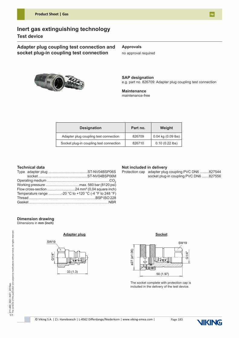
© Viking S.A. | Z.I. Haneboesch | L-4562 Differdange/Niederkorn | www.viking-emea.com |
Product Sheet | Gas
Page 183
211-
480_
002
/ AI0
1_20
15en
The
cont
ents
of t
his
publ
icat
ion
are
subj
ect t
o m
odifi
catio
ns w
ithou
t not
ice.
All
right
s re
serv
ed.
Inert gas extinguishing technologyTest device
Designation Part no. Weight
Adapter plug coupling test connection 826709 0.04 kg (0.09 lbs)
Socket plug-in coupling test connection 826710 0.10 (0.22 lbs)
1/1
SAP designatione.g. part no. 826709: Adapter plug coupling test connection
Maintenancemaintenance-free
Adapter plug coupling test connection andsocket plug-in coupling test connection
Technical dataType adapter plug .......................................ST-NV04BSP06S socket .................................................ST-NV04BSP06MOperating medium ...............................................................CO2Working pressure ..................................max. 560 bar (8120 psi)Flow cross-section ............................24 mm² (0,04 square inch)Temperature range .............-20 °C to +120 °C (-4 °F to 248 °F)Thread ....................................................................BSP ISO 228Gasket .................................................................................NBR
Not included in deliveryProtection cap adapter plug coupling PVC DN6 .........827544 socket plug-in coupling PVC DN6 .......827556
Dimension drawingDimensions in mm (inch)
Approvalsno approval required
The socket complete with protection cap is included in the delivery of the test device.
Adapter plug Socket
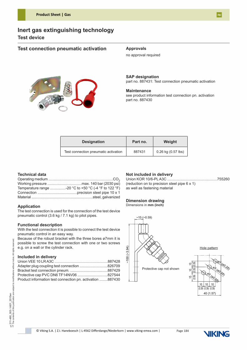
© Viking S.A. | Z.I. Haneboesch | L-4562 Differdange/Niederkorn | www.viking-emea.com |
Product Sheet | Gas
Page 184
211-
480_
003
/ AI0
1_20
15en
The
cont
ents
of t
his
publ
icat
ion
are
subj
ect t
o m
odifi
catio
ns w
ithou
t not
ice.
All
right
s re
serv
ed.
Inert gas extinguishing technologyTest device
Designation Part no. Weight
Test connection pneumatic activation 887431 0.26 kg (0.57 lbs)
1/1
SAP designationpart no. 887431: Test connection pneumatic activation
Maintenancesee product information test connection pn. activationpart no. 887430
Test connection pneumatic activation
Technical dataOperating medium ................................................................CO2Working pressure .................................max. 140 bar (2030 psi)Temperature range ...............-20 °C to +50 °C (-4 °F to 122 °F)Connection ......................................precision steel pipe 10 x 1Material ............................................................steel, galvanized
ApplicationThe test connection is used for the connection of the test device pneumatic control (3.6 kg / 7.1 kg) to pilot pipes.
Functional descriptionWith the test connection it is possible to connect the test device pneumatic control in an easy way.Because of the robust bracket with the three bores ø7mm it is possible to screw the test connection with one or two screws e.g. on a wall or the cylinder rack.
Included in deliveryUnion VEE 10 LR A3C ....................................................887428Adapter plug coupling test connection ...........................826709Bracket test connection pneum. ....................................887429Protective cap PVC DN6 TF14NV06 .............................827544Product information test connection pn. activation ........887430
Dimension drawingDimensions in mm (inch)
Approvalsno approval required
Protective cap not shown
Hole pattern
Not included in deliveryUnion KOR 10/6-PL A3C ................................................755260(reduction on to precision steel pipe 6 x 1)as well as fastening material
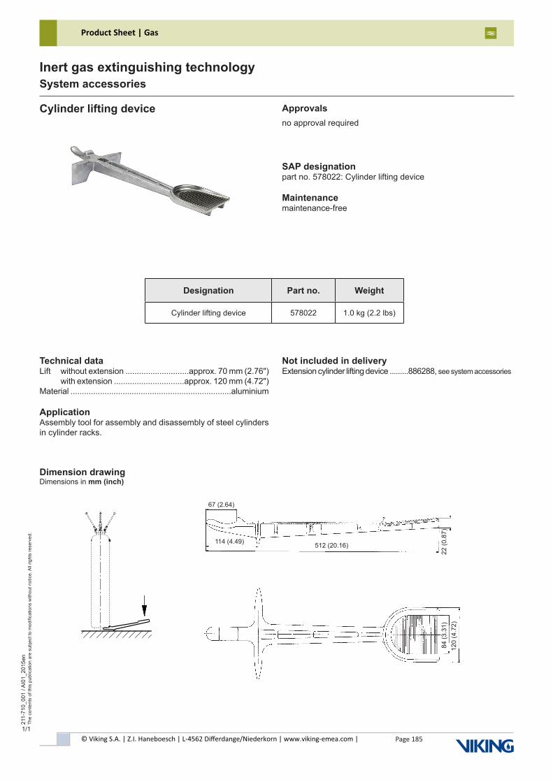
© Viking S.A. | Z.I. Haneboesch | L-4562 Differdange/Niederkorn | www.viking-emea.com |
Product Sheet | Gas
Page 185
211-
710_
001
/ AI0
1_20
15en
The
cont
ents
of t
his
publ
icat
ion
are
subj
ect t
o m
odifi
catio
ns w
ithou
t not
ice.
All
right
s re
serv
ed.
Inert gas extinguishing technologySystem accessories
1/1
SAP designationpart no. 578022: Cylinder lifting device
Maintenancemaintenance-free
Cylinder lifting device
Technical dataLift without extension ............................approx. 70 mm (2.76") with extension ...............................approx. 120 mm (4.72")Material .......................................................................aluminium
ApplicationAssembly tool for assembly and disassembly of steel cylinders in cylinder racks.
Not included in deliveryExtension cylinder lifting device .........886288, see system accessories
Dimension drawingDimensions in mm (inch)
Approvalsno approval required
Designation Part no. Weight
Cylinder lifting device 578022 1.0 kg (2.2 lbs)
114 (4.49)
67 (2.64)
512 (20.16)
22 (0
.87)
84 (3
.31)
120
(4.7
2)
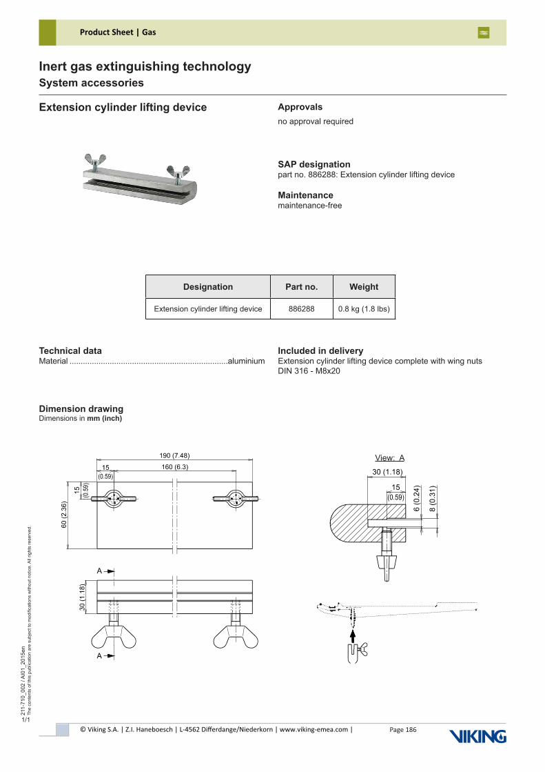
© Viking S.A. | Z.I. Haneboesch | L-4562 Differdange/Niederkorn | www.viking-emea.com |
Product Sheet | Gas
Page 186
211-
710_
002
/ AI0
1_20
15en
The
cont
ents
of t
his
publ
icat
ion
are
subj
ect t
o m
odifi
catio
ns w
ithou
t not
ice.
All
right
s re
serv
ed.
Inert gas extinguishing technologySystem accessories
1/1
SAP designationpart no. 886288: Extension cylinder lifting device
Maintenancemaintenance-free
Extension cylinder lifting device
Technical dataMaterial .......................................................................aluminium
Dimension drawingDimensions in mm (inch)
Approvalsno approval required
Designation Part no. Weight
Extension cylinder lifting device 886288 0.8 kg (1.8 lbs)
View: A
Included in deliveryExtension cylinder lifting device complete with wing nuts DIN 316 - M8x20
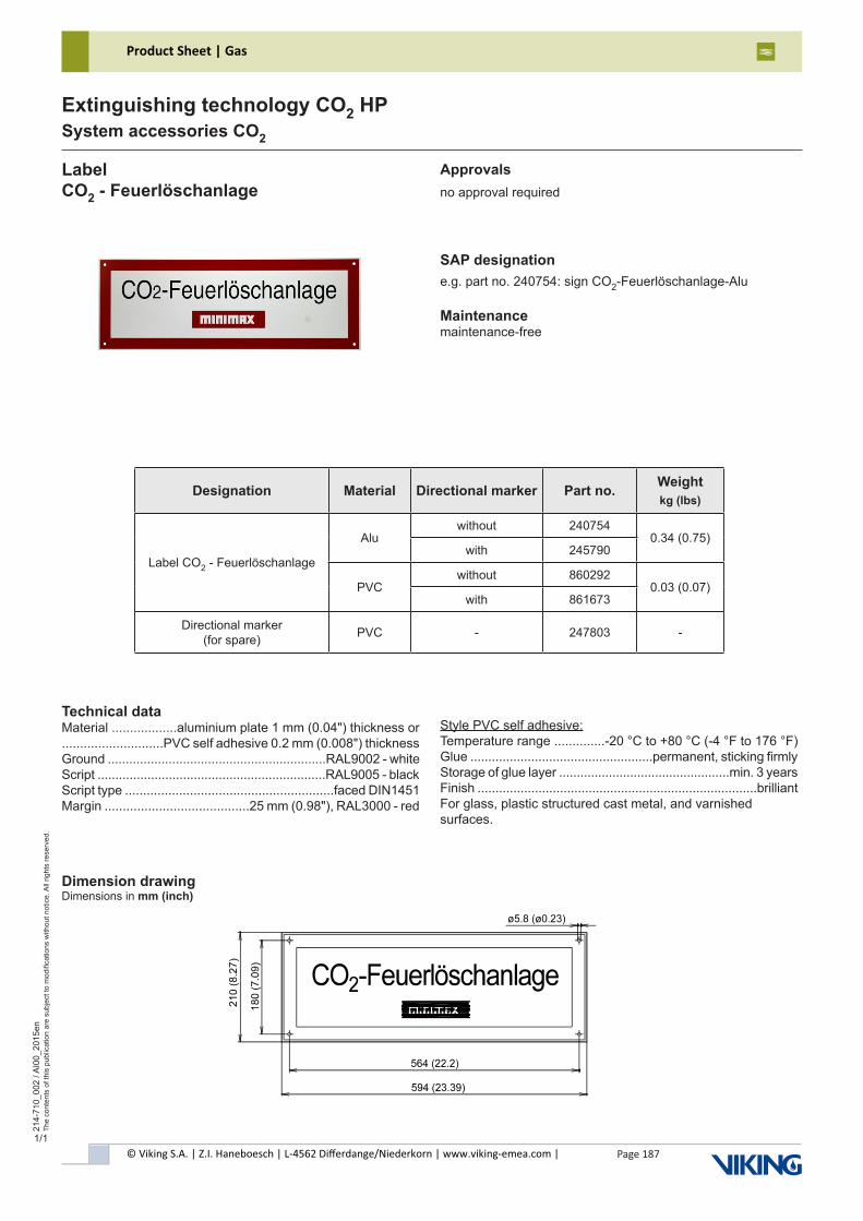
© Viking S.A. | Z.I. Haneboesch | L-4562 Differdange/Niederkorn | www.viking-emea.com |
Product Sheet | Gas
Page 187
214-
710_
002
/ AI0
0_20
15en
The
cont
ents
of t
his
publ
icat
ion
are
subj
ect t
o m
odifi
catio
ns w
ithou
t not
ice.
All
right
s re
serv
ed.
Extinguishing technology CO2 HPSystem accessories CO2
1/1
LabelCO2 - Feuerlöschanlage
Approvalsno approval required
Technical dataMaterial ..................aluminium plate 1 mm (0.04") thickness or............................PVC self adhesive 0.2 mm (0.008") thicknessGround .............................................................RAL9002 - whiteScript ................................................................RAL9005 - blackScript type ..........................................................faced DIN1451Margin ........................................25 mm (0.98"), RAL3000 - red
SAP designatione.g. part no. 240754: sign CO2-Feuerlöschanlage-Alu
Maintenancemaintenance-free
Style PVC self adhesive:Temperature range ..............-20 °C to +80 °C (-4 °F to 176 °F)Glue ...................................................permanent, sticking firmlyStorage of glue layer ................................................min. 3 yearsFinish ..............................................................................brilliantFor glass, plastic structured cast metal, and varnished surfaces.
Dimension drawingDimensions in mm (inch)
Designation Material Directional marker Part no. Weightkg (lbs)
Label CO2 - Feuerlöschanlage
Aluwithout 240754
0.34 (0.75)with 245790
PVCwithout 860292
0.03 (0.07)with 861673
Directional marker (for spare) PVC - 247803 -
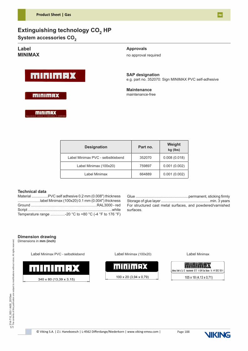
© Viking S.A. | Z.I. Haneboesch | L-4562 Differdange/Niederkorn | www.viking-emea.com |
Product Sheet | Gas
Page 188
214-
710_
003
/ AI0
0_20
15en
The
cont
ents
of t
his
publ
icat
ion
are
subj
ect t
o m
odifi
catio
ns w
ithou
t not
ice.
All
right
s re
serv
ed.
Extinguishing technology CO2 HPSystem accessories CO2
1/1
LabelMINIMAX
Approvalsno approval required
Technical dataMaterial ................PVC self adhesive 0.2 mm (0.008") thickness......................label Minimax (100x20) 0.1 mm (0.004") thicknessGround ................................................................RAL3000 - redScript ..................................................................................whiteTemperature range ..............-20 °C to +80 °C (-4 °F to 176 °F)
SAP designatione.g. part no. 352070: Sign MINIMAX PVC self-adhesive
Maintenancemaintenance-free
Designation Part no. Weightkg (lbs)
Label Minimax PVC - selbstklebend 352070 0.008 (0.018)
Label Minimax (100x20) 759897 0.001 (0.002)
Label Minimax 664889 0.001 (0.002)
Dimension drawingDimensions in mm (inch)
Label Minimax PVC - selbstklebend Label Minimax (100x20) Label Minimax
Glue ....................................................permanent, sticking firmlyStorage of glue layer ................................................min. 3 yearsFor structured cast metal surfaces, and powdered/varnished surfaces.
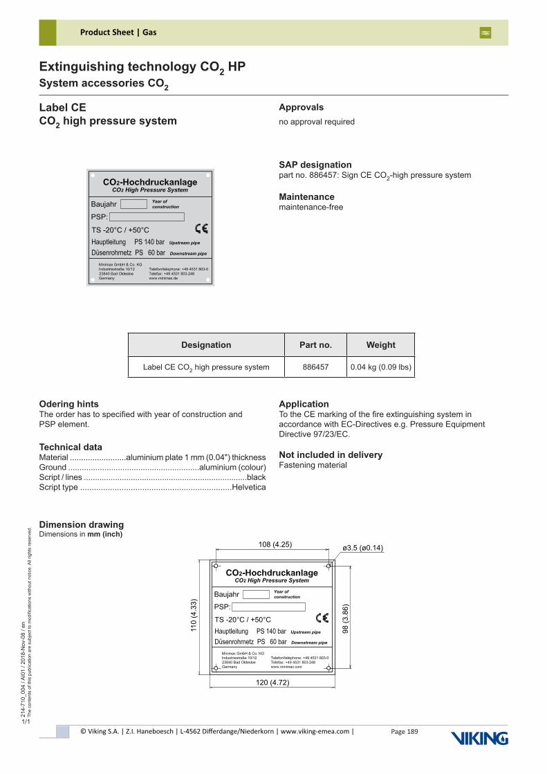
© Viking S.A. | Z.I. Haneboesch | L-4562 Differdange/Niederkorn | www.viking-emea.com |
Product Sheet | Gas
Page 189
214-
710_
004
/ AI0
1 / 2
018-
Nov
-08
/ en
The
cont
ents
of t
his
publ
icat
ion
are
subj
ect t
o m
odifi
catio
ns w
ithou
t not
ice.
All
right
s re
serv
ed.
Extinguishing technology CO2 HPSystem accessories CO2
1/1
Label CECO2 high pressure system
Approvalsno approval required
Odering hintsThe order has to specified with year of construction andPSP element.
Technical dataMaterial .........................aluminium plate 1 mm (0.04") thicknessGround ..........................................................aluminium (colour)Script / lines .........................................................................blackScript type ..................................................................Helvetica
SAP designationpart no. 886457: Sign CE CO2-high pressure system
Maintenancemaintenance-free
ApplicationTo the CE marking of the fire extinguishing system inaccordance with EC-Directives e.g. Pressure Equipment Directive 97/23/EC.
Not included in deliveryFastening material
Dimension drawingDimensions in mm (inch)
Designation Part no. Weight
Label CE CO2 high pressure system 886457 0.04 kg (0.09 lbs)
ø3.5 (ø0.14)
98 (
3.8
6)
120 (4.72)
110 (
4.3
3)
108 (4.25)
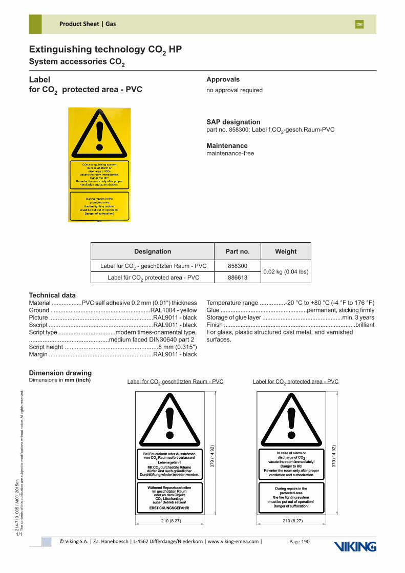
© Viking S.A. | Z.I. Haneboesch | L-4562 Differdange/Niederkorn | www.viking-emea.com |
Product Sheet | Gas
Page 190
214-
710_
005
/ AI0
0_20
15en
The
cont
ents
of t
his
publ
icat
ion
are
subj
ect t
o m
odifi
catio
ns w
ithou
t not
ice.
All
right
s re
serv
ed.
Extinguishing technology CO2 HPSystem accessories CO2
1/1
Labelfor CO2 protected area - PVC
Approvalsno approval required
Technical dataMaterial ..................PVC self adhesive 0.2 mm (0.01") thicknessGround ............................................................RAL1004 - yellowPicture ..............................................................RAL9011 - blackSscript ...............................................................RAL9011 - blackScript type ..................................modern times-onamental type, ...............................................medium faced DIN30640 part 2Script height .......................................................8 mm (0.315")Margin ..............................................................RAL9011 - black
SAP designationpart no. 858300: Label f.CO2-gesch.Raum-PVC
Maintenancemaintenance-free
Temperature range ...............-20 °C to +80 °C (-4 °F to 176 °F)Glue ....................................................permanent, sticking firmlyStorage of glue layer ................................................min. 3 yearsFinish ...............................................................................brilliantFor glass, plastic structured cast metal, and varnishedsurfaces.
Dimension drawingDimensions in mm (inch)
Designation Part no. Weight
Label für CO2 - geschützten Raum - PVC 8583000.02 kg (0.04 lbs)
Label für CO2 protected area - PVC 886613
Label for CO2 geschützten Raum - PVC Label for CO2 protected area - PVC
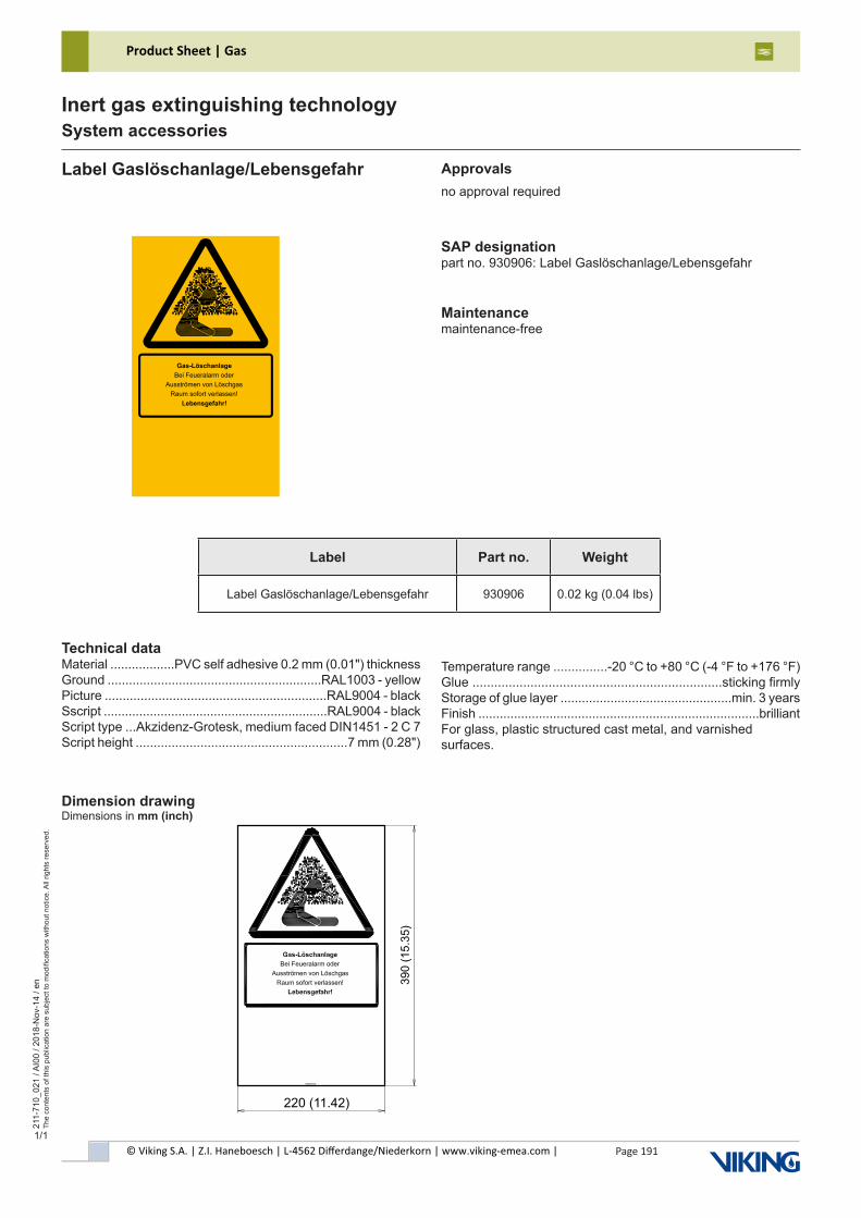
© Viking S.A. | Z.I. Haneboesch | L-4562 Differdange/Niederkorn | www.viking-emea.com |
Product Sheet | Gas
Page 191
211-
710_
021
/ AI0
0 / 2
018-
Nov
-14
/ en
The
cont
ents
of t
his
publ
icat
ion
are
subj
ect t
o m
odifi
catio
ns w
ithou
t not
ice.
All
right
s re
serv
ed.
Inert gas extinguishing technologySystem accessories
1/1
Approvalsno approval required
SAP designationpart no. 930906: Label Gaslöschanlage/Lebensgefahr
Maintenancemaintenance-free
Dimension drawingDimensions in mm (inch)
Gas-Löschanlage
Bei Feueralarm oder
Ausströmen von Löschgas
Raum sofort verlassen!
Lebensgefahr!
Label Part no. Weight
Label Gaslöschanlage/Lebensgefahr 930906 0.02 kg (0.04 lbs)
Label Gaslöschanlage/Lebensgefahr
Technical dataMaterial ..................PVC self adhesive 0.2 mm (0.01") thicknessGround ............................................................RAL1003 - yellowPicture ..............................................................RAL9004 - blackSscript ...............................................................RAL9004 - blackScript type ...Akzidenz-Grotesk, medium faced DIN1451 - 2 C 7Script height ...........................................................7 mm (0.28")
Temperature range ...............-20 °C to +80 °C (-4 °F to +176 °F)Glue .....................................................................sticking firmlyStorage of glue layer ................................................min. 3 yearsFinish ...............................................................................brilliantFor glass, plastic structured cast metal, and varnishedsurfaces.
39
0 (
15
.35
)
220 (11.42)
930906 Rev00
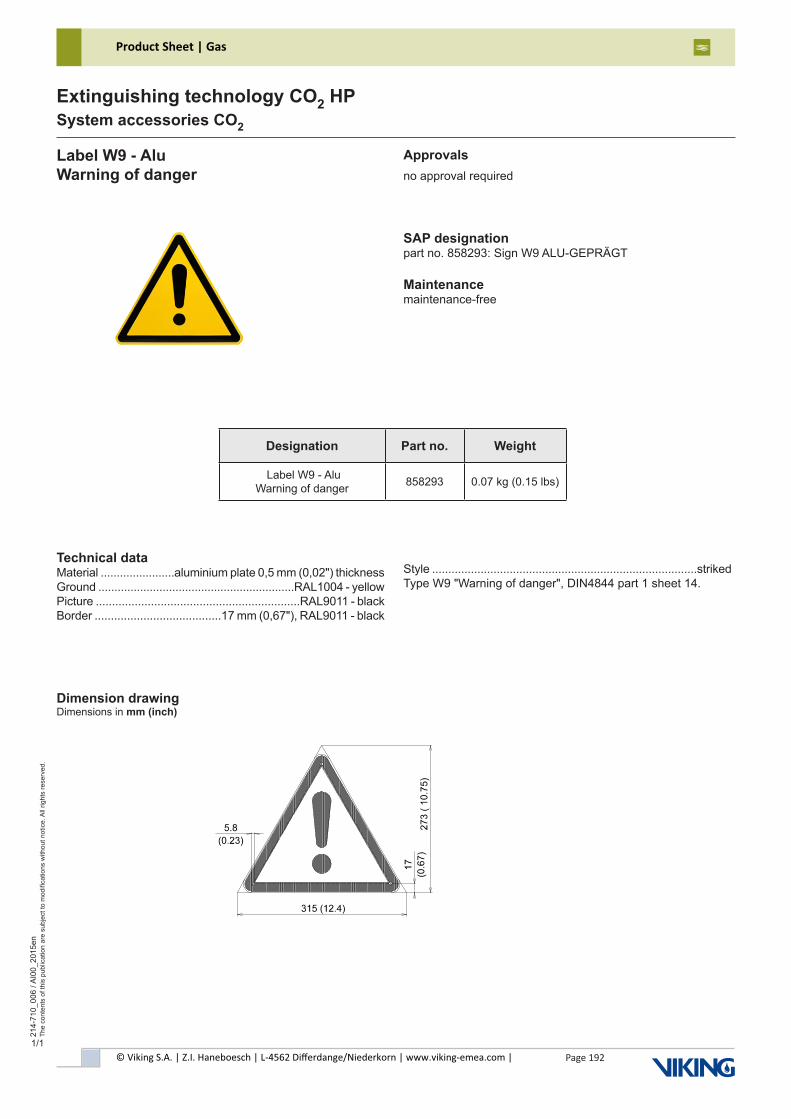
© Viking S.A. | Z.I. Haneboesch | L-4562 Differdange/Niederkorn | www.viking-emea.com |
Product Sheet | Gas
Page 192
214-
710_
006
/ AI0
0_20
15en
The
cont
ents
of t
his
publ
icat
ion
are
subj
ect t
o m
odifi
catio
ns w
ithou
t not
ice.
All
right
s re
serv
ed.
Extinguishing technology CO2 HPSystem accessories CO2
1/1
Label W9 - AluWarning of danger
Approvalsno approval required
Technical dataMaterial .......................aluminium plate 0,5 mm (0,02") thicknessGround .............................................................RAL1004 - yellowPicture ...............................................................RAL9011 - blackBorder .......................................17 mm (0,67"), RAL9011 - black
SAP designationpart no. 858293: Sign W9 ALU-GEPRÄGT
Maintenancemaintenance-free
Style ..................................................................................strikedType W9 "Warning of danger", DIN4844 part 1 sheet 14.
Dimension drawingDimensions in mm (inch)
Designation Part no. Weight
Label W9 - Alu Warning of danger 858293 0.07 kg (0.15 lbs)

© Viking S.A. | Z.I. Haneboesch | L-4562 Differdange/Niederkorn | www.viking-emea.com |
Product Sheet | Gas
Page 193
214-
710_
007
/ AI0
0_20
15en
The
cont
ents
of t
his
publ
icat
ion
are
subj
ect t
o m
odifi
catio
ns w
ithou
t not
ice.
All
right
s re
serv
ed.
Extinguishing technology CO2 HPSystem accessories CO2
1/1
Label - CO2- Alufür CO2- geschützten Raum
Approvalsno approval required
SAP designationpart no.114928: Sign f.CO2-gesch.Raum-Alu
Maintenancemaintenance-free
Dimension drawingDimensions in mm (inch)
Technical dataMaterial ......................aluminium plate 0.5 mm (0.02") thicknessGround ..........................................................RAL1004 - yellowScript ...............................................................RAL9011 - blackScript type ..............................ornamental type, faced DIN1451Script height .......................................................16 mm (0.63")Margin .............................................................RAL9011 - black
Designation Part no. Weight
Label - CO2 - Alu für CO2 - geschützten Raum 114928 0.8 kg (1.76 lbs)
Not included in deliveryFastening material
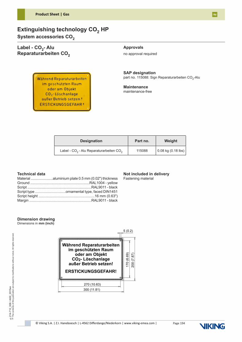
© Viking S.A. | Z.I. Haneboesch | L-4562 Differdange/Niederkorn | www.viking-emea.com |
Product Sheet | Gas
Page 194
214-
710_
008
/ AI0
0_20
15en
The
cont
ents
of t
his
publ
icat
ion
are
subj
ect t
o m
odifi
catio
ns w
ithou
t not
ice.
All
right
s re
serv
ed.
Extinguishing technology CO2 HPSystem accessories CO2
1/1
Label - CO2- AluReparaturarbeiten CO2
Approvalsno approval required
SAP designationpart no. 115088: Sign Reparaturarbeiten CO2-Alu
Maintenancemaintenance-free
Dimension drawingDimensions in mm (inch)
Technical dataMaterial ......................aluminium plate 0.5 mm (0.02") thicknessGround ..........................................................RAL1004 - yellowScript ...............................................................RAL9011 - blackScript type ..............................ornamental type, faced DIN1451Script height .......................................................16 mm (0.63")Margin .............................................................RAL9011 - black
Designation Part no. Weight
Label - CO2 - Alu Reparaturarbeiten CO2 115088 0.08 kg (0.18 lbs)
Not included in deliveryFastening material
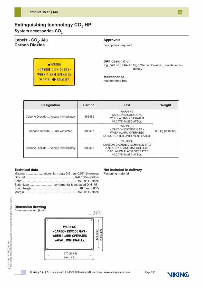
© Viking S.A. | Z.I. Haneboesch | L-4562 Differdange/Niederkorn | www.viking-emea.com |
Product Sheet | Gas
Page 195
214-
710_
009
/ AI0
0_20
15en
The
cont
ents
of t
his
publ
icat
ion
are
subj
ect t
o m
odifi
catio
ns w
ithou
t not
ice.
All
right
s re
serv
ed.
Extinguishing technology CO2 HPSystem accessories CO2
1/1
Labels - CO2- AluCarbon Dioxide
Approvalsno approval required
SAP designatione.g. part no. 886486: Sign "Carbon Dioxide ... vacate imme- diately"
Maintenancemaintenance-free
Dimension drawingDimensions in mm (inch)
Technical dataMaterial ......................aluminium plate 0.5 mm (0.02") thicknessGround ..........................................................RAL1004 - yellowScript ...............................................................RAL9011 - blackScript type ..............................ornamental type, faced DIN1451Script height .......................................................16 mm (0.63")Margin .............................................................RAL9011 - black
Designation Part no. Text Weight
Cabone Dioxide ... vacate immediately 886486
WARNING- CARBON DIOXIDE GAS -WHEN ALARM OPERATES
VACATE IMMEDIATELY.
Cabone Dioxide ... until ventilated 886487
WARNING- CARBON DIOXIDE GAS -WHEN ALARM OPERATES
DO NOT ENTER UNTIL VENTILATED.
0.8 kg (0.18 lbs)
Cabone Dioxide ... vacate immediately 886488
CAUTIONCARBON DIOXIDE DISCHARGE INTO
A NEARBY SPACE MAY COLLECTHERE. WHEN ALARM OPERATES
VACATE IMMEDIATELY.
Not included in deliveryFastening material
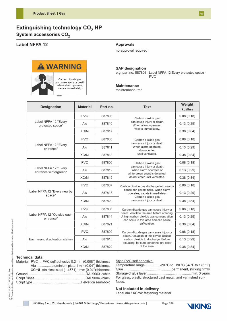
© Viking S.A. | Z.I. Haneboesch | L-4562 Differdange/Niederkorn | www.viking-emea.com |
Product Sheet | Gas
Page 196
214-
720_
010
/ AI0
0_20
15en
The
cont
ents
of t
his
publ
icat
ion
are
subj
ect t
o m
odifi
catio
ns w
ithou
t not
ice.
All
right
s re
serv
ed.
Extinguishing technology CO2 HPSystem accessories CO2
1/2
Label NFPA 12
Designation Material Part no. Text Weightkg (lbs)
Label NFPA 12 "Every protected space"
PVC 887803Carbon dioxide gas
can cause injury or death. When alarm operates, vacate immediately.
0.08 (0.18)
Alu 887810 0.13 (0.29)
XCrNi 887817 0.38 (0.84)
Label NFPA 12 "Every entrance"
PVC 887805 Carbon dioxide gas can cause injury or death.
When alarm operates, do not enter
until ventilated.
0.08 (0.18)
Alu 887811 0.13 (0.29)
XCrNi 887818 0.38 (0.84)
Label NFPA 12 "Every entrance wintergreen"
PVC 887806 Carbon dioxide gas can cause injury or death. When alarm operates or
wintergreen scent is detected, do not enter until ventilated.
0.08 (0.18)
Alu 887812 0.13 (0.29)
XCrNi 887819 0.38 (0.84)
Label NFPA 12 "Every nearby space"
PVC 887807 Carbon dioxide gas discharge into nearby space can collect here. When alarm
operates, vacate immediately. Carbon dioxide gas
can cause injury or death.
0.08 (0.18)
Alu 887813 0.13 (0.29)
XCrNi 887820 0.38 (0.84)
Label NFPA 12 "Outside each entrance"
PVC 887808 Carbon dioxide gas can cause injury or death. Ventilate the area before entering. A high carbon dioxide gas concentration
can occur in this area and can cause suffocation.
0.08 (0.18)
Alu 887814 0.13 (0.29)
XCrNi 887821 0.38 (0.84)
Each manual actuation station
PVC 887809 Carbon dioxide gas can cause injury or death. Actuation of this device causes carbon dioxide to discharge. Before
actuating, be sure personnel are clear of the area.
0.08 (0.18)
Alu 887815 0.13 (0.29)
XCrNi 887822 0.38 (0.84)
Approvalsno approval required
SAP designatione.g. part no. 887803: Label NFPA 12 Every protected space - PVC
Maintenancemaintenance-free
Technical dataMaterial PVC ....PVC self adhesive 0,2 mm (0,008") thickness Alu ................aluminium plate 1 mm (0,04") thickness XCrNi ..stainless steel (1.4571) 1 mm (0,04") thicknessGround .............................................................RAL9003 - whiteScript / lines .....................................................RAL9004 - blackScript type ...................................................Helvetica semi-bold
Style PVC self adhesive:Temperature range ...............-20 °C to +80 °C (-4 °F to 176 °F)Glue ...................................................permanent, sticking firmlyStorage of glue layer................................................min. 3 yearsFor glass, plastic structured cast metal, and varnished sur-faces.
Not included in deliveryLabel Alu / XCrNi: fastening material
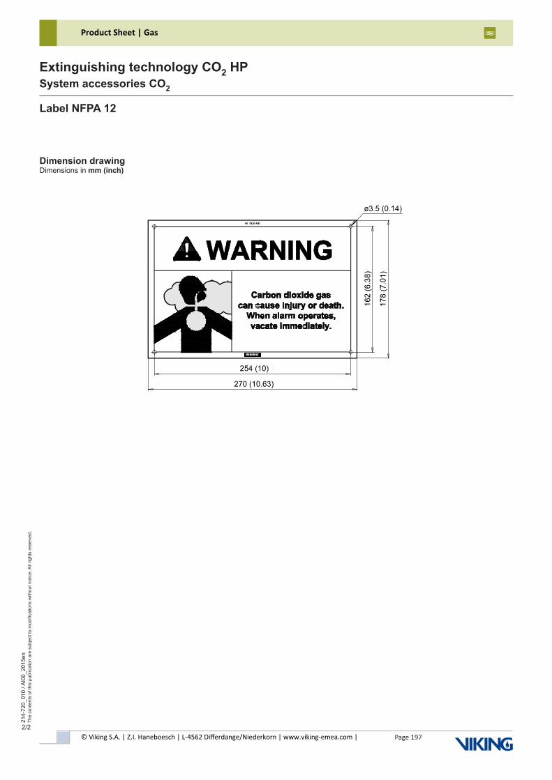
© Viking S.A. | Z.I. Haneboesch | L-4562 Differdange/Niederkorn | www.viking-emea.com |
Product Sheet | Gas
Page 197
214-
720_
010
/ AI0
0_20
15en
The
cont
ents
of t
his
publ
icat
ion
are
subj
ect t
o m
odifi
catio
ns w
ithou
t not
ice.
All
right
s re
serv
ed.
Extinguishing technology CO2 HPSystem accessories CO2
2/2
Label NFPA 12
Dimension drawingDimensions in mm (inch)
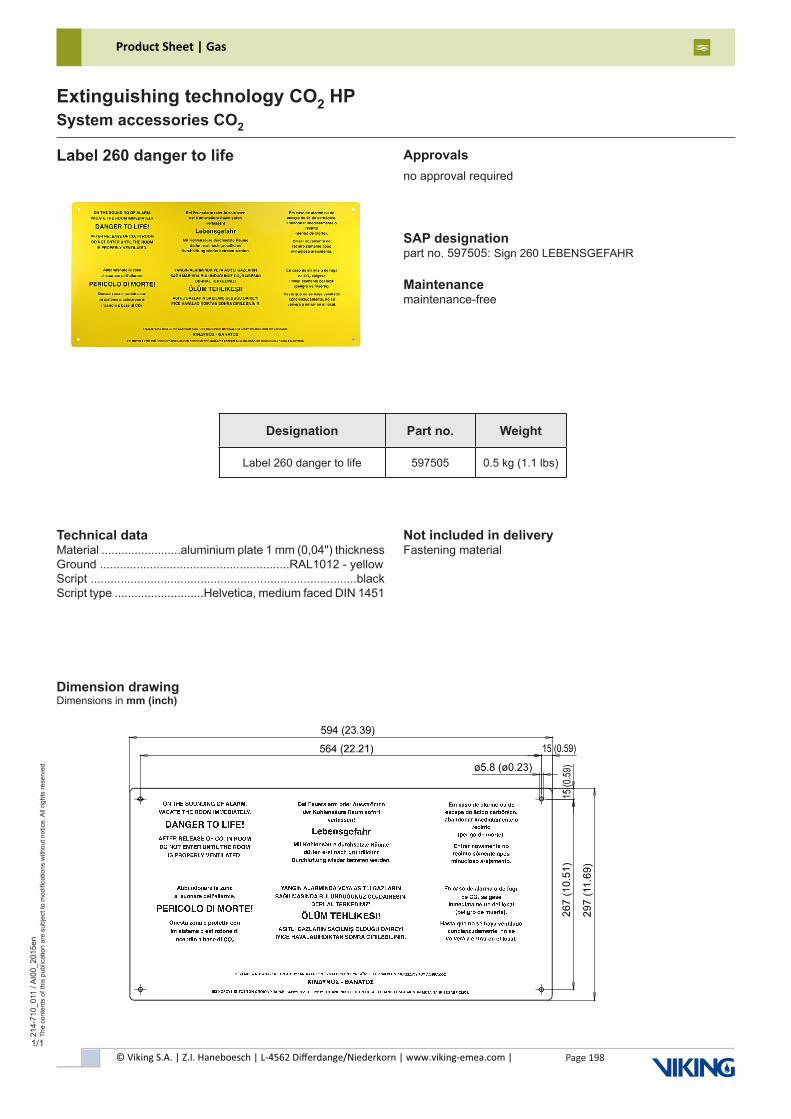
© Viking S.A. | Z.I. Haneboesch | L-4562 Differdange/Niederkorn | www.viking-emea.com |
Product Sheet | Gas
Page 198
214-
710_
011
/ AI0
0_20
15en
The
cont
ents
of t
his
publ
icat
ion
are
subj
ect t
o m
odifi
catio
ns w
ithou
t not
ice.
All
right
s re
serv
ed.
Extinguishing technology CO2 HPSystem accessories CO2
1/1
Label 260 danger to life
Designation Part no. Weight
Label 260 danger to life 597505 0.5 kg (1.1 lbs)
Technical dataMaterial ........................aluminium plate 1 mm (0,04") thicknessGround .........................................................RAL1012 - yellowScript ................................................................................blackScript type ...........................Helvetica, medium faced DIN 1451
Approvalsno approval required
SAP designationpart no. 597505: Sign 260 LEBENSGEFAHR
Maintenancemaintenance-free
Not included in deliveryFastening material
Dimension drawingDimensions in mm (inch)
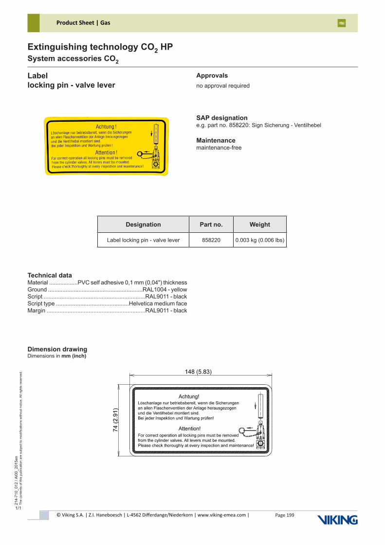
© Viking S.A. | Z.I. Haneboesch | L-4562 Differdange/Niederkorn | www.viking-emea.com |
Product Sheet | Gas
Page 199
214-
710_
012
/ AI0
0_20
15en
The
cont
ents
of t
his
publ
icat
ion
are
subj
ect t
o m
odifi
catio
ns w
ithou
t not
ice.
All
right
s re
serv
ed.
Extinguishing technology CO2 HPSystem accessories CO2
1/1
Labellocking pin - valve lever
Designation Part no. Weight
Label locking pin - valve lever 858220 0.003 kg (0.006 lbs)
Technical dataMaterial ..................PVC self adhesive 0,1 mm (0,04") thicknessGround ...........................................................RAL1004 - yellowScript ...............................................................RAL9011 - blackScript type .............................................Helvetica medium faceMargin .............................................................RAL9011 - black
Dimension drawingDimensions in mm (inch)
Approvalsno approval required
SAP designatione.g. part no. 858220: Sign Sicherung - Ventilhebel
Maintenancemaintenance-free
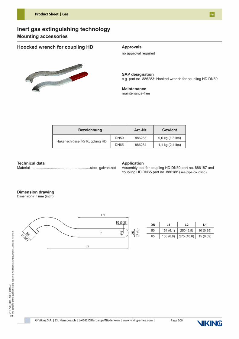
© Viking S.A. | Z.I. Haneboesch | L-4562 Differdange/Niederkorn | www.viking-emea.com |
Product Sheet | Gas
Page 200
211-
720_
002
/ AI0
1_20
15en
The
cont
ents
of t
his
publ
icat
ion
are
subj
ect t
o m
odifi
catio
ns w
ithou
t not
ice.
All
right
s re
serv
ed.
Inert gas extinguishing technologyMounting accessories
1/1
SAP designatione.g. part no. 886283: Hooked wrench for coupling HD DN50
Maintenancemaintenance-free
Hoocked wrench for coupling HD
Technical dataMaterial .............................................................steel, galvanized
Dimension drawingDimensions in mm (inch)
Approvalsno approval required
Bezeichnung Art.-Nr. Gewicht
Hakenschlüssel für Kupplung HDDN50 886283 0,6 kg (1,3 lbs)
DN65 886284 1,1 kg (2,4 lbs)
DN L1 L2 L1
50 154 (6.1) 250 (9.8) 10 (0.39)
65 153 (6.0) 275 (10.8) 15 (0.59)
ApplicationAssembly tool for coupling HD DN50 part no. 886187 and coupling HD DN65 part no. 886188 (see pipe coupling).
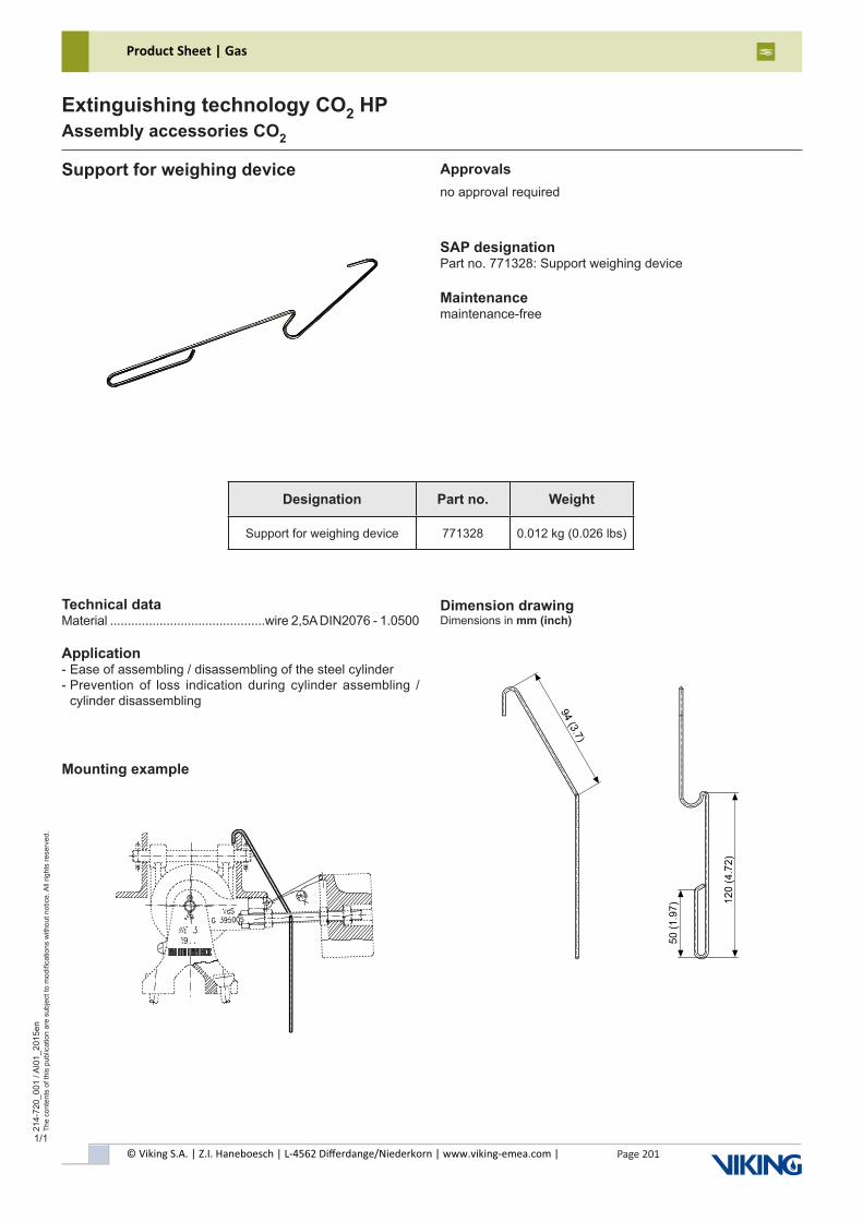
© Viking S.A. | Z.I. Haneboesch | L-4562 Differdange/Niederkorn | www.viking-emea.com |
Product Sheet | Gas
Page 201
214-
720_
001
/ AI0
1_20
15en
The
cont
ents
of t
his
publ
icat
ion
are
subj
ect t
o m
odifi
catio
ns w
ithou
t not
ice.
All
right
s re
serv
ed.
Extinguishing technology CO2 HPAssembly accessories CO2
1/1
Support for weighing device Approvalsno approval required
SAP designationPart no. 771328: Support weighing device
Maintenancemaintenance-free
Technical dataMaterial ............................................wire 2,5A DIN2076 - 1.0500
Application- Ease of assembling / disassembling of the steel cylinder- Prevention of loss indication during cylinder assembling / cylinder disassembling
Dimension drawingDimensions in mm (inch)
Mounting example
Designation Part no. Weight
Support for weighing device 771328 0.012 kg (0.026 lbs)
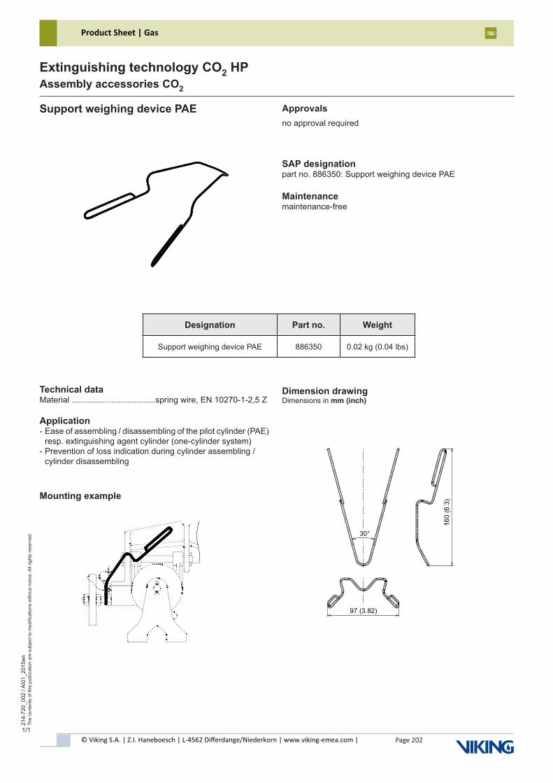
© Viking S.A. | Z.I. Haneboesch | L-4562 Differdange/Niederkorn | www.viking-emea.com |
Product Sheet | Gas
Page 202
214-
720_
002
/ AI0
1_20
15en
The
cont
ents
of t
his
publ
icat
ion
are
subj
ect t
o m
odifi
catio
ns w
ithou
t not
ice.
All
right
s re
serv
ed.
Extinguishing technology CO2 HPAssembly accessories CO2
1/1
Support weighing device PAE Approvalsno approval required
SAP designationpart no. 886350: Support weighing device PAE
Maintenancemaintenance-free
Technical dataMaterial ....................................spring wire, EN 10270-1-2,5 Z
Application- Ease of assembling / disassembling of the pilot cylinder (PAE) resp. extinguishing agent cylinder (one-cylinder system)- Prevention of loss indication during cylinder assembling / cylinder disassembling
Mounting example
Dimension drawingDimensions in mm (inch)
Designation Part no. Weight
Support weighing device PAE 886350 0.02 kg (0.04 lbs)
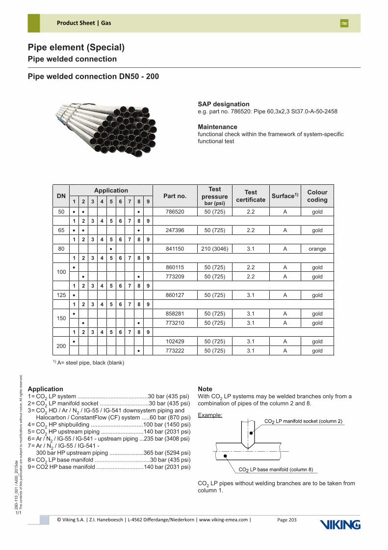
© Viking S.A. | Z.I. Haneboesch | L-4562 Differdange/Niederkorn | www.viking-emea.com |
Product Sheet | Gas
Page 203
280-
110_
001
/ AI0
0_20
15de
The
cont
ents
of t
his
publ
icat
ion
are
subj
ect t
o m
odifi
catio
ns w
ithou
t not
ice.
All
right
s re
serv
ed.
Pipe element (Special)Pipe welded connection
1/1
Pipe welded connection DN50 - 200
SAP designatione.g. part no. 786520: Pipe 60,3x2,3 St37.0-A-50-2458
Maintenancefunctional check within the framework of system-specificfunctional test
DNApplication
Part no.Test
pressure bar (psi)
Test certificate Surface1) Colour
coding1 2 3 4 5 6 7 8 9
50 • • • 786520 50 (725) 2.2 A gold1 2 3 4 5 6 7 8 9
65 • • • 247396 50 (725) 2.2 A gold1 2 3 4 5 6 7 8 9
80 • 841150 210 (3046) 3.1 A orange1 2 3 4 5 6 7 8 9
100• 860115 50 (725) 2.2 A gold
• • 773209 50 (725) 2.2 A gold1 2 3 4 5 6 7 8 9
125 • 860127 50 (725) 3.1 A gold1 2 3 4 5 6 7 8 9
150• 858281 50 (725) 3.1 A gold
• • 773210 50 (725) 3.1 A gold1 2 3 4 5 6 7 8 9
200• 102429 50 (725) 3.1 A gold
• 773222 50 (725) 3.1 A gold
Application1 = CO2 LP system ...........................................30 bar (435 psi)2 = CO2 LP manifold socket ..............................30 bar (435 psi)3 = CO2 HD / Ar / N2 / IG-55 / IG-541 downsystem piping and Halocarbon / ConstantFlow (CF) system .....60 bar (870 psi)4 = CO2 HP shipbuilding ................................100 bar (1450 psi)5 = CO2 HP upstream piping ..........................140 bar (2031 psi)6 = Ar / N2 / IG-55 / IG-541 - upstream piping ...235 bar (3408 psi)7 = Ar / N2 / IG-55 / IG-541 - 300 bar HP upstream piping .....................365 bar (5294 psi)8 = CO2 LP base manifold ..................................30 bar (435 psi)9 = CO2 HP base manifold .............................140 bar (2031 psi)
1) A= steel pipe, black (blank)
NoteWith CO2 LP systems may be welded branches only from a combination of pipes of the column 2 and 8.
Example:
CO2 LP pipes without welding branches are to be taken from column 1.
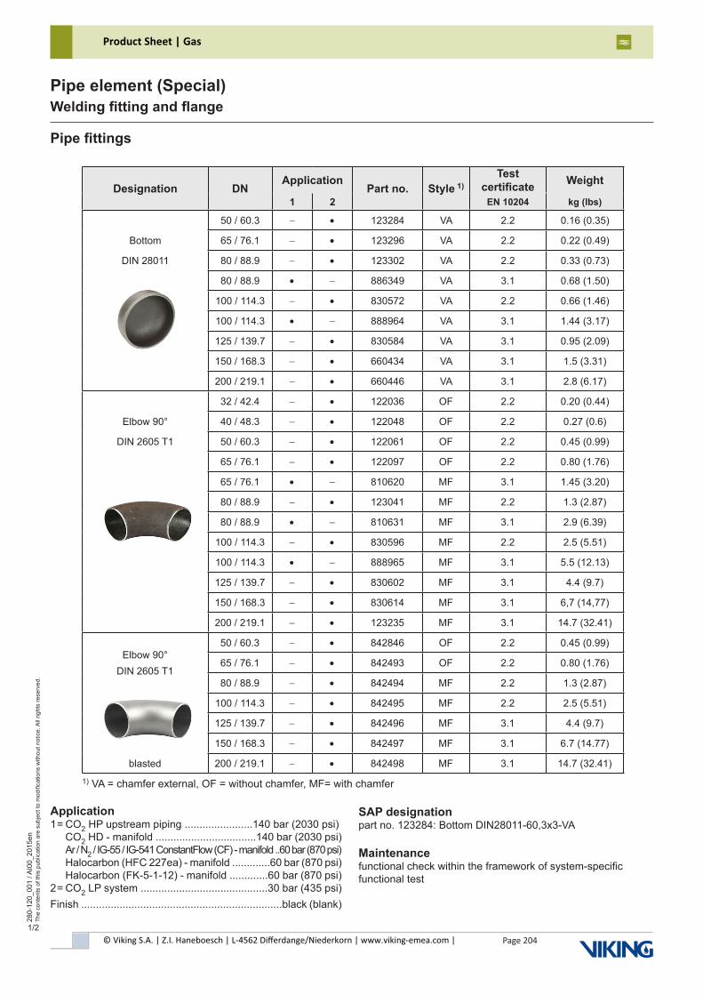
© Viking S.A. | Z.I. Haneboesch | L-4562 Differdange/Niederkorn | www.viking-emea.com |
Product Sheet | Gas
Page 204
280-
120_
001
/ AI0
0_20
15en
The
cont
ents
of t
his
publ
icat
ion
are
subj
ect t
o m
odifi
catio
ns w
ithou
t not
ice.
All
right
s re
serv
ed.
Pipe element (Special)Welding fitting and flange
1/2
Pipe fittings
Designation DNApplication
Part no. Style 1)Test
certificate Weight
1 2 EN 10204 kg (lbs)
50 / 60.3 - • 123284 VA 2.2 0.16 (0.35)
Bottom 65 / 76.1 - • 123296 VA 2.2 0.22 (0.49)
DIN 28011 80 / 88.9 - • 123302 VA 2.2 0.33 (0.73)
80 / 88.9 • - 886349 VA 3.1 0.68 (1.50)
100 / 114.3 - • 830572 VA 2.2 0.66 (1.46)
100 / 114.3 • - 888964 VA 3.1 1.44 (3.17)
125 / 139.7 - • 830584 VA 3.1 0.95 (2.09)
150 / 168.3 - • 660434 VA 3.1 1.5 (3.31)
200 / 219.1 - • 660446 VA 3.1 2.8 (6.17)
32 / 42.4 - • 122036 OF 2.2 0.20 (0.44)
Elbow 90° 40 / 48.3 - • 122048 OF 2.2 0.27 (0.6)
DIN 2605 T1 50 / 60.3 - • 122061 OF 2.2 0.45 (0.99)
65 / 76.1 - • 122097 OF 2.2 0.80 (1.76)
65 / 76.1 • - 810620 MF 3.1 1.45 (3.20)
80 / 88.9 - • 123041 MF 2.2 1.3 (2.87)
80 / 88.9 • - 810631 MF 3.1 2.9 (6.39)
100 / 114.3 - • 830596 MF 2.2 2.5 (5.51)
100 / 114.3 • - 888965 MF 3.1 5.5 (12.13)
125 / 139.7 - • 830602 MF 3.1 4.4 (9.7)
150 / 168.3 - • 830614 MF 3.1 6,7 (14,77)
200 / 219.1 - • 123235 MF 3.1 14.7 (32.41)
Elbow 90°DIN 2605 T1
50 / 60.3 - • 842846 OF 2.2 0.45 (0.99)
65 / 76.1 - • 842493 OF 2.2 0.80 (1.76)
80 / 88.9 - • 842494 MF 2.2 1.3 (2.87)
100 / 114.3 - • 842495 MF 2.2 2.5 (5.51)
125 / 139.7 - • 842496 MF 3.1 4.4 (9.7)
150 / 168.3 - • 842497 MF 3.1 6.7 (14.77)
blasted 200 / 219.1 - • 842498 MF 3.1 14.7 (32.41)
Application 1 = CO2 HP upstream piping .......................140 bar (2030 psi) CO2 HD - manifold ..................................140 bar (2030 psi) Ar / N2 / IG-55 / IG-541 ConstantFlow (CF) - manifold ..60 bar (870 psi) Halocarbon (HFC 227ea) - manifold .............60 bar (870 psi) Halocarbon (FK-5-1-12) - manifold .............60 bar (870 psi)2 = CO2 LP system ...........................................30 bar (435 psi)Finish ....................................................................black (blank)
SAP designationpart no. 123284: Bottom DIN28011-60,3x3-VA
Maintenancefunctional check within the framework of system-specificfunctional test
1) VA = chamfer external, OF = without chamfer, MF= with chamfer
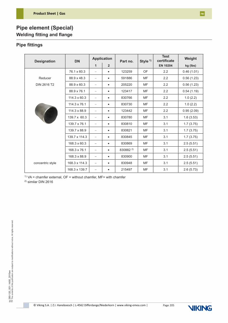
© Viking S.A. | Z.I. Haneboesch | L-4562 Differdange/Niederkorn | www.viking-emea.com |
Product Sheet | Gas
Page 205
280-
120_
001
/ AI0
0_20
15en
The
cont
ents
of t
his
publ
icat
ion
are
subj
ect t
o m
odifi
catio
ns w
ithou
t not
ice.
All
right
s re
serv
ed.
Pipe element (Special)Welding fitting and flange
2/2
Pipe fittings
Designation DNApplication
Part no. Style 1)Test
certificate Weight
1 2 EN 10204 kg (lbs)
76.1 x 60.3 - • 123259 OF 2.2 0.46 (1.01)
Reducer 88.9 x 48.3 - • 591886 MF 2.2 0.56 (1.23)
DIN 2616 T2 88.9 x 60.3 - • 205220 MF 2.2 0.56 (1.23)
88.9 x 76.1 - • 123417 MF 2.2 0.54 (1.19)
114.3 x 60.3 - • 830766 MF 2.2 1.0 (2.2)
114.3 x 76.1 - • 830730 MF 2.2 1.0 (2.2)
114.3 x 88.9 - • 123442 MF 2.2 0.95 (2.09)
139.7 x 60.3 - • 830780 MF 3.1 1.6 (3.53)
139.7 x 76.1 - • 830810 MF 3.1 1.7 (3.75)
139.7 x 88.9 - • 830821 MF 3.1 1.7 (3.75)
139.7 x 114.3 - • 830845 MF 3.1 1.7 (3.75)
168.3 x 60.3 - • 830869 MF 3.1 2.5 (5.51)
168.3 x 76.1 - • 830882 2) MF 3.1 2.5 (5.51)
168.3 x 88.9 - • 830900 MF 3.1 2.5 (5.51)
concentric style 168.3 x 114.3 - • 830948 MF 3.1 2.5 (5.51)
168.3 x 139.7 - • 215497 MF 3.1 2.6 (5.73)
1) VA = chamfer external, OF = without chamfer, MF= with chamfer2) similar DIN 2616
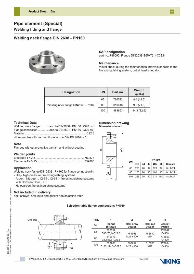
© Viking S.A. | Z.I. Haneboesch | L-4562 Differdange/Niederkorn | www.viking-emea.com |
Product Sheet | Gas
Page 206
280-
120_
003
/ AI0
2_20
17en
The
cont
ents
of t
his
publ
icat
ion
are
subj
ect t
o m
odifi
catio
ns w
ithou
t not
ice.
All
right
s re
serv
ed.
Pipe element (Special)Welding fitting and flange
1/1
Welding neck flange DIN 2638 - PN160
Designation DN Part no. Weightkg (lbs)
Welding neck flange DIN2638 - PN160
65 786592 8.4 (18.5)
80 810618 9.8 (21.6)
100 888963 14.8 (32.6)
SAP designationpart no. 786592: Flange DIN2638-E65x76,1-C22.8
MaintenanceVisual check during the maintenance intervals specific to thefire extinguishing system, but at least annually.
Technical DataWelding neck flange............acc. to DIN2638 - PN160 (2320 psi)Flange connection...............acc. to DIN2501 - PN160 (2320 psi)Material ............................................................................C22.8all assemblies with test certificate acc. to DIN EN 10204 - 3.1
NoteFlanges without protective varnish and without coating.
Welded jointsElectrode TK 2,5 .............................................................759873Electrode TK 3,25 ...........................................................759885
ApplicationWelding neck flange DIN 2638 - PN160 for flange connection in:- CO2- high pressure fire extinguishing systems- Argon-, Nitrogen-, IG-55-, IG-541- fire extinguishing systems with ConstantFlow (CF)- Halocarbon fire extinguishing systems
Not included in deliveryhex. screws, hex. nuts and gasket see selection table
DNPN160
ØD ød b ØK H Screws65 220 26 34 170 82 8 x M24
80 230 26 36 180 86 8 x M24
100 265 30 40 210 100 8 x M27b
H
øk øD
ød
Dimension drawingDimensions in mm
Pos. 1 2 3 4
DN Flange DIN2638
Hex. srew DIN931
Hex. nut DIN934
Gasket PN160
65 786592 E65x76,1–C22.8 789556
M24 x 100786610
M24
773647 C4400
80 810618 E80x88,8–C22.8
773659 C4400
100 888963 E100x114,3–C22.8
888959 M27 x 130
810680 M27
773684 C4400
Selection table flange connections PN160
Steel pipe
12 3
4
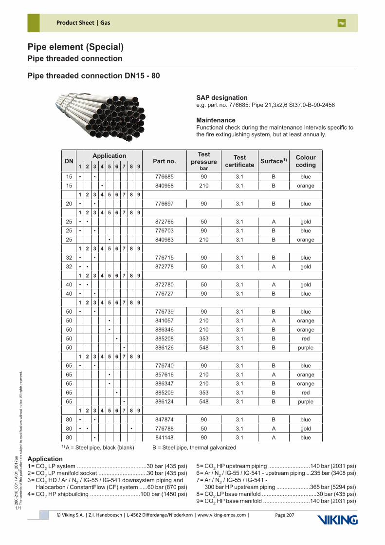
© Viking S.A. | Z.I. Haneboesch | L-4562 Differdange/Niederkorn | www.viking-emea.com |
Product Sheet | Gas
Page 207
280-
210_
001
/ AI0
1_20
17en
The
cont
ents
of t
his
publ
icat
ion
are
subj
ect t
o m
odifi
catio
ns w
ithou
t not
ice.
All
right
s re
serv
ed.
Pipe element (Special)Pipe threaded connection
1/1
Pipe threaded connection DN15 - 80
SAP designatione.g. part no. 776685: Pipe 21,3x2,6 St37.0-B-90-2458
MaintenanceFunctional check during the maintenance intervals specific tothe fire extinguishing system, but at least annually.
DNApplication
Part no.Test
pressure bar
Test certificate Surface1) Colour
coding1 2 3 4 5 6 7 8 9
15 • • 776685 90 3.1 B blue15 • 840958 210 3.1 B orange
1 2 3 4 5 6 7 8 9
20 • • 776697 90 3.1 B blue1 2 3 4 5 6 7 8 9
25 • • 872766 50 3.1 A gold25 • • 776703 90 3.1 B blue25 • 840983 210 3.1 B orange
1 2 3 4 5 6 7 8 9
32 • • 776715 90 3.1 B blue32 • • 872778 50 3.1 A gold
1 2 3 4 5 6 7 8 9
40 • • 872780 50 3.1 A gold40 • • 776727 90 3.1 B blue
1 2 3 4 5 6 7 8 9
50 • • 776739 90 3.1 B blue50 • 841057 210 3.1 A orange50 • 886346 210 3.1 B orange50 • 885208 353 3.1 B red50 • 886126 548 3.1 B purple
1 2 3 4 5 6 7 8 9
65 • • 776740 90 3.1 B blue65 • 857616 210 3.1 A orange65 • 886347 210 3.1 B orange65 • 885209 353 3.1 B red65 • 886124 548 3.1 B purple
1 2 3 4 5 6 7 8 9
80 • • 847874 90 3.1 B blue80 • • • 776788 50 3.1 A gold80 • 841148 90 3.1 A blue
1) A = Steel pipe, black (blank) B = Steel pipe, thermal galvanized
Application1 = CO2 LP system ...........................................30 bar (435 psi)2 = CO2 LP manifold socket ..............................30 bar (435 psi)3 = CO2 HD / Ar / N2 / IG-55 / IG-541 downsystem piping and Halocarbon / ConstantFlow (CF) system .....60 bar (870 psi)4 = CO2 HP shipbuilding ...............................100 bar (1450 psi)
5 = CO2 HP upstream piping ..........................140 bar (2031 psi)6 = Ar / N2 / IG-55 / IG-541 - upstream piping ...235 bar (3408 psi)7 = Ar / N2 / IG-55 / IG-541 - 300 bar HP upstream piping .....................365 bar (5294 psi)8 = CO2 LP base manifold ..................................30 bar (435 psi)9 = CO2 HP base manifold .............................140 bar (2031 psi)
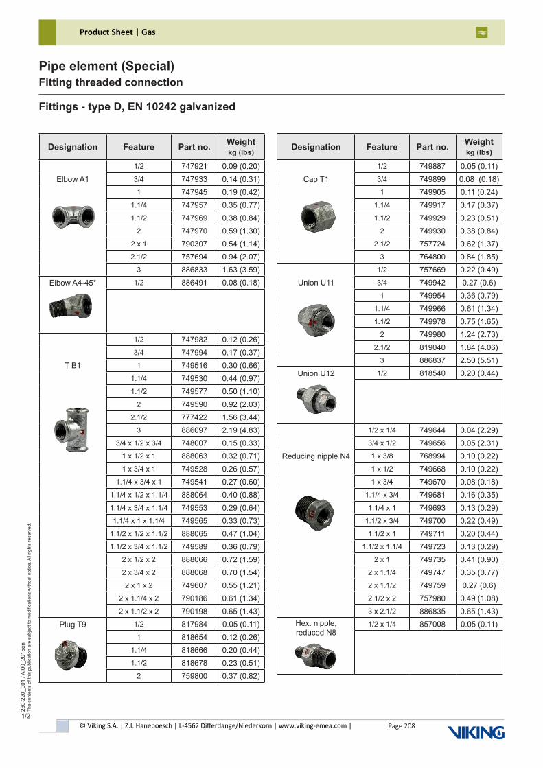
Product Sheet | Gas
© Viking S.A. | Z.I. Haneboesch | L-4562 Differdange/Niederkorn | www.viking-emea.com |
Page 208
280-
220_
001
/ AI0
0_20
15en
The
cont
ents
of t
his
publ
icat
ion
are
subj
ect t
o m
odifi
catio
ns w
ithou
t not
ice.
All
right
s re
serv
ed.
Pipe element (Special)Fitting threaded connection
1/2
Fittings - type D, EN 10242 galvanized
Designation Feature Part no. Weightkg (lbs)
1/2 747921 0.09 (0.20)Elbow A1 3/4 747933 0.14 (0.31)
1 747945 0.19 (0.42)1.1/4 747957 0.35 (0.77)1.1/2 747969 0.38 (0.84)
2 747970 0.59 (1.30)2 x 1 790307 0.54 (1.14)2.1/2 757694 0.94 (2.07)
3 886833 1.63 (3.59)
Elbow A4-45° 1/2 886491 0.08 (0.18)
1/2 747982 0.12 (0.26)3/4 747994 0.17 (0.37)
T B1 1 749516 0.30 (0.66)1.1/4 749530 0.44 (0.97)1.1/2 749577 0.50 (1.10)
2 749590 0.92 (2.03)2.1/2 777422 1.56 (3.44)
3 886097 2.19 (4.83)3/4 x 1/2 x 3/4 748007 0.15 (0.33)
1 x 1/2 x 1 888063 0.32 (0.71)1 x 3/4 x 1 749528 0.26 (0.57)
1.1/4 x 3/4 x 1 749541 0.27 (0.60)1.1/4 x 1/2 x 1.1/4 888064 0.40 (0.88)1.1/4 x 3/4 x 1.1/4 749553 0.29 (0.64)1.1/4 x 1 x 1.1/4 749565 0.33 (0.73)
1.1/2 x 1/2 x 1.1/2 888065 0.47 (1.04)1.1/2 x 3/4 x 1.1/2 749589 0.36 (0.79)
2 x 1/2 x 2 888066 0.72 (1.59)2 x 3/4 x 2 888068 0.70 (1.54)2 x 1 x 2 749607 0.55 (1.21)
2 x 1.1/4 x 2 790186 0.61 (1.34)2 x 1.1/2 x 2 790198 0.65 (1.43)
Plug T9 1/2 817984 0.05 (0.11)1 818654 0.12 (0.26)
1.1/4 818666 0.20 (0.44)1.1/2 818678 0.23 (0.51)
2 759800 0.37 (0.82)
Designation Feature Part no. Weightkg (lbs)
1/2 749887 0.05 (0.11)Cap T1 3/4 749899 0.08 (0.18)
1 749905 0.11 (0.24)1.1/4 749917 0.17 (0.37)1.1/2 749929 0.23 (0.51)
2 749930 0.38 (0.84)2.1/2 757724 0.62 (1.37)
3 764800 0.84 (1.85)1/2 757669 0.22 (0.49)
Union U11 3/4 749942 0.27 (0.6)1 749954 0.36 (0.79)
1.1/4 749966 0.61 (1.34)1.1/2 749978 0.75 (1.65)
2 749980 1.24 (2.73)2.1/2 819040 1.84 (4.06)
3 886837 2.50 (5.51)
Union U12 1/2 818540 0.20 (0.44)
1/2 x 1/4 749644 0.04 (2.29)3/4 x 1/2 749656 0.05 (2.31)
Reducing nipple N4 1 x 3/8 768994 0.10 (0.22)1 x 1/2 749668 0.10 (0.22)1 x 3/4 749670 0.08 (0.18)
1.1/4 x 3/4 749681 0.16 (0.35)1.1/4 x 1 749693 0.13 (0.29)
1.1/2 x 3/4 749700 0.22 (0.49)1.1/2 x 1 749711 0.20 (0.44)
1.1/2 x 1.1/4 749723 0.13 (0.29)2 x 1 749735 0.41 (0.90)
2 x 1.1/4 749747 0.35 (0.77)2 x 1.1/2 749759 0.27 (0.6)2.1/2 x 2 757980 0.49 (1.08)3 x 2.1/2 886835 0.65 (1.43)
Hex. nipple, reduced N8
1/2 x 1/4 857008 0.05 (0.11)
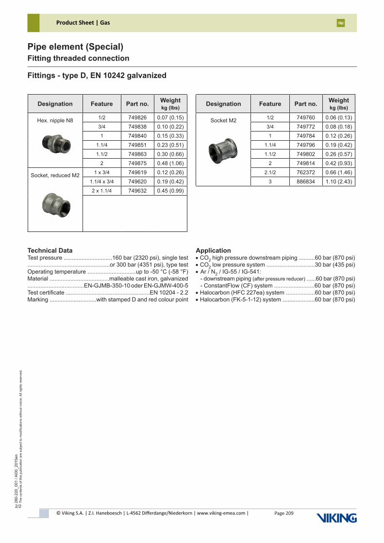
Product Sheet | Gas
© Viking S.A. | Z.I. Haneboesch | L-4562 Differdange/Niederkorn | www.viking-emea.com |
Page 209
280-
220_
001
/ AI0
0_20
15en
The
cont
ents
of t
his
publ
icat
ion
are
subj
ect t
o m
odifi
catio
ns w
ithou
t not
ice.
All
right
s re
serv
ed.
Pipe element (Special)Fitting threaded connection
2/2
Fittings - type D, EN 10242 galvanized
Designation Feature Part no. Weightkg (lbs)
Hex. nipple N8 1/2 749826 0.07 (0.15)3/4 749838 0.10 (0.22)1 749840 0.15 (0.33)
1.1/4 749851 0.23 (0.51)1.1/2 749863 0.30 (0.66)
2 749875 0.48 (1.06)
Socket, reduced M2 1 x 3/4 749619 0.12 (0.26)1.1/4 x 3/4 749620 0.19 (0.42)2 x 1.1/4 749632 0.45 (0.99)
Designation Feature Part no. Weightkg (lbs)
Socket M2 1/2 749760 0.06 (0.13)3/4 749772 0.08 (0.18)1 749784 0.12 (0.26)
1.1/4 749796 0.19 (0.42)1.1/2 749802 0.26 (0.57)
2 749814 0.42 (0.93)2.1/2 762372 0.66 (1.46)
3 886834 1.10 (2.43)
Technical DataTest pressure ..............................160 bar (2320 psi), single test...................................................or 300 bar (4351 psi), type testOperating temperature ..............................up to -50 °C (-58 °F)Material .....................................malleable cast iron, galvanized...................................EN-GJMB-350-10 oder EN-GJMW-400-5Test certificate ....................................................EN 10204 - 2.2Marking .............................with stamped D and red colour point
Application• CO2 high pressure downstream piping ..........60 bar (870 psi)• CO2 low pressure system ..............................30 bar (435 psi)• Ar / N2 / IG-55 / IG-541: - downstream piping (after pressure reducer) ......60 bar (870 psi) - ConstantFlow (CF) system .........................60 bar (870 psi)• Halocarbon (HFC 227ea) system ..................60 bar (870 psi)• Halocarbon (FK-5-1-12) system ....................60 bar (870 psi)
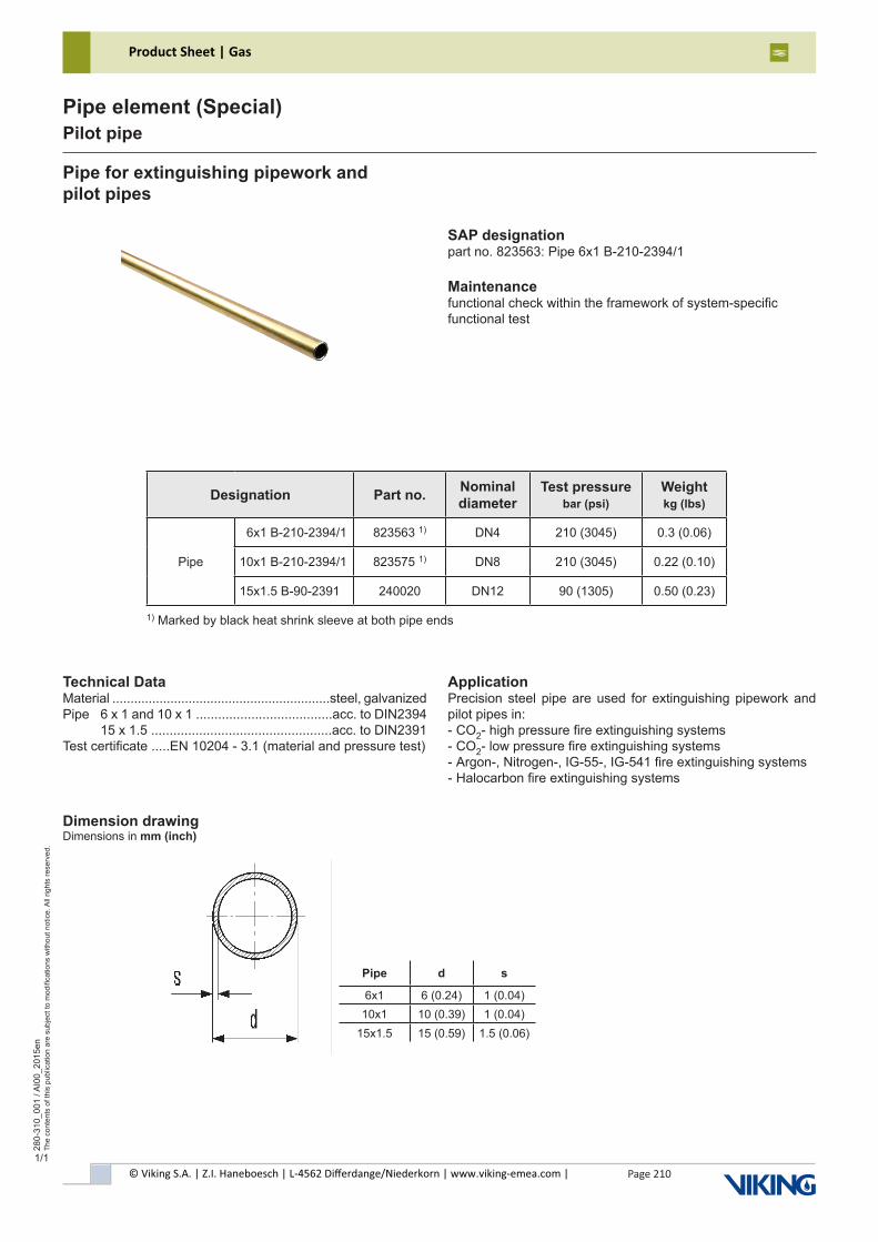
© Viking S.A. | Z.I. Haneboesch | L-4562 Differdange/Niederkorn | www.viking-emea.com |
Product Sheet | Gas
Page 210
280-
310_
001
/ AI0
0_20
15en
The
cont
ents
of t
his
publ
icat
ion
are
subj
ect t
o m
odifi
catio
ns w
ithou
t not
ice.
All
right
s re
serv
ed.
Pipe element (Special)Pilot pipe
1/1
Pipe for extinguishing pipework andpilot pipes
SAP designationpart no. 823563: Pipe 6x1 B-210-2394/1
Maintenancefunctional check within the framework of system-specificfunctional test
Dimension drawingDimensions in mm (inch)
Designation Part no. Nominal diameter
Test pressurebar (psi)
Weightkg (lbs)
16x1 B-210-2394/1 823563 1) DN4 210 (3045) 0.3 (0.06)
Pipe 10x1 B-210-2394/1 823575 1) DN8 210 (3045) 0.22 (0.10)
15x1.5 B-90-2391 240020 DN12 90 (1305) 0.50 (0.23)
Technical DataMaterial ............................................................steel, galvanizedPipe 6 x 1 and 10 x 1 .....................................acc. to DIN2394 15 x 1.5 .................................................acc. to DIN2391Test certificate .....EN 10204 - 3.1 (material and pressure test)
ApplicationPrecision steel pipe are used for extinguishing pipework and pilot pipes in:- CO2- high pressure fire extinguishing systems- CO2- low pressure fire extinguishing systems- Argon-, Nitrogen-, IG-55-, IG-541 fire extinguishing systems- Halocarbon fire extinguishing systems
Pipe d s
6x1 6 (0.24) 1 (0.04)10x1 10 (0.39) 1 (0.04)
15x1.5 15 (0.59) 1.5 (0.06)
1) Marked by black heat shrink sleeve at both pipe ends
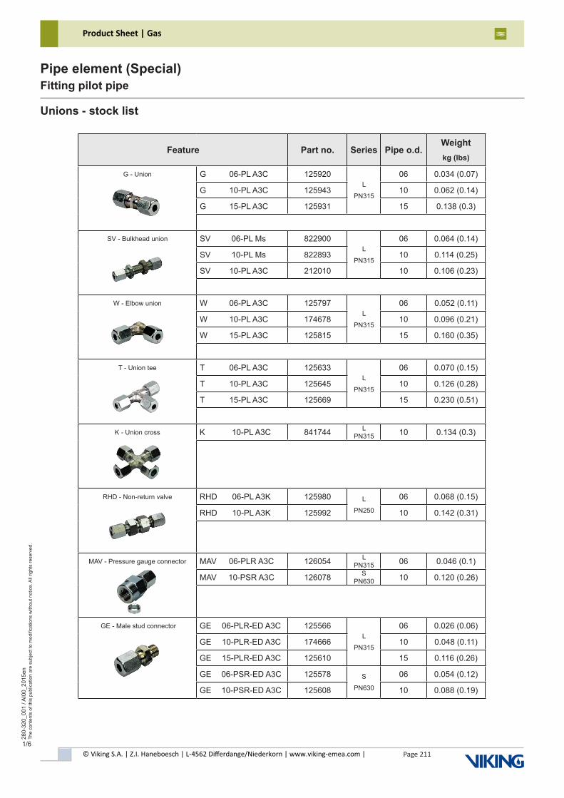
© Viking S.A. | Z.I. Haneboesch | L-4562 Differdange/Niederkorn | www.viking-emea.com |
Product Sheet | Gas
Page 211
280-
320_
001
/ AI0
0_20
15en
The
cont
ents
of t
his
publ
icat
ion
are
subj
ect t
o m
odifi
catio
ns w
ithou
t not
ice.
All
right
s re
serv
ed.
Pipe element (Special)Fitting pilot pipe
1/6
Unions - stock list
Feature Part no. Series Pipe o.d.Weightkg (lbs)
G - Union G 06-PL A3C 125920L
PN315
06 0.034 (0.07)
G 10-PL A3C 125943 10 0.062 (0.14)
G 15-PL A3C 125931 15 0.138 (0.3)
SV - Bulkhead union SV 06-PL Ms 822900L
PN315
06 0.064 (0.14)
SV 10-PL Ms 822893 10 0.114 (0.25)
SV 10-PL A3C 212010 10 0.106 (0.23)
W - Elbow union W 06-PL A3C 125797L
PN315
06 0.052 (0.11)
W 10-PL A3C 174678 10 0.096 (0.21)
W 15-PL A3C 125815 15 0.160 (0.35)
T - Union tee T 06-PL A3C 125633L
PN315
06 0.070 (0.15)
T 10-PL A3C 125645 10 0.126 (0.28)
T 15-PL A3C 125669 15 0.230 (0.51)
K - Union cross K 10-PL A3C 841744 L PN315 10 0.134 (0.3)
RHD - Non-return valve RHD 06-PL A3K 125980 L
PN250
06 0.068 (0.15)
RHD 10-PL A3K 125992 10 0.142 (0.31)
MAV - Pressure gauge connector MAV 06-PLR A3C 126054 L PN315 06 0.046 (0.1)
MAV 10-PSR A3C 126078 S PN630 10 0.120 (0.26)
GE - Male stud connector GE 06-PLR-ED A3C 125566L
PN315
06 0.026 (0.06)
GE 10-PLR-ED A3C 174666 10 0.048 (0.11)
GE 15-PLR-ED A3C 125610 15 0.116 (0.26)
GE 06-PSR-ED A3C 125578 S
PN630
06 0.054 (0.12)
GE 10-PSR-ED A3C 125608 10 0.088 (0.19)
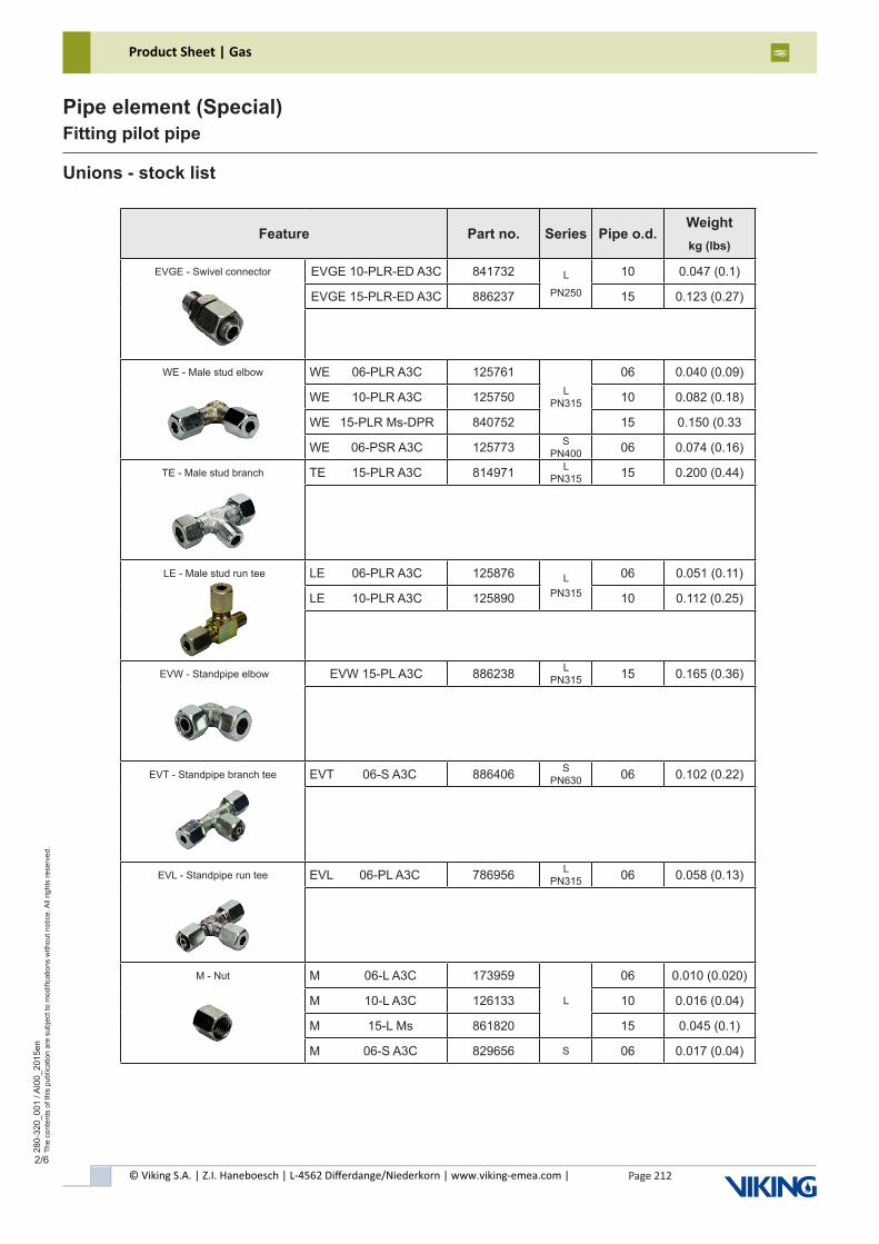
© Viking S.A. | Z.I. Haneboesch | L-4562 Differdange/Niederkorn | www.viking-emea.com |
Product Sheet | Gas
Page 212
280-
320_
001
/ AI0
0_20
15en
The
cont
ents
of t
his
publ
icat
ion
are
subj
ect t
o m
odifi
catio
ns w
ithou
t not
ice.
All
right
s re
serv
ed.
Pipe element (Special)Fitting pilot pipe
2/6
Unions - stock list
Feature Part no. Series Pipe o.d.Weightkg (lbs)
EVGE - Swivel connector EVGE 10-PLR-ED A3C 841732 L
PN250
10 0.047 (0.1)
EVGE 15-PLR-ED A3C 886237 15 0.123 (0.27)
WE - Male stud elbow WE 06-PLR A3C 125761L
PN315
06 0.040 (0.09)
WE 10-PLR A3C 125750 10 0.082 (0.18)
WE 15-PLR Ms-DPR 840752 15 0.150 (0.33
WE 06-PSR A3C 125773 S PN400 06 0.074 (0.16)
TE - Male stud branch TE 15-PLR A3C 814971 L PN315 15 0.200 (0.44)
LE - Male stud run tee LE 06-PLR A3C 125876 LPN315
06 0.051 (0.11)
LE 10-PLR A3C 125890 10 0.112 (0.25)
EVW - Standpipe elbow EVW 15-PL A3C 886238 L PN315 15 0.165 (0.36)
EVT - Standpipe branch tee EVT 06-S A3C 886406 S PN630 06 0.102 (0.22)
EVL - Standpipe run tee EVL 06-PL A3C 786956 L PN315 06 0.058 (0.13)
M - Nut M 06-L A3C 173959
L
06 0.010 (0.020)
M 10-L A3C 126133 10 0.016 (0.04)
M 15-L Ms 861820 15 0.045 (0.1)
M 06-S A3C 829656 S 06 0.017 (0.04)
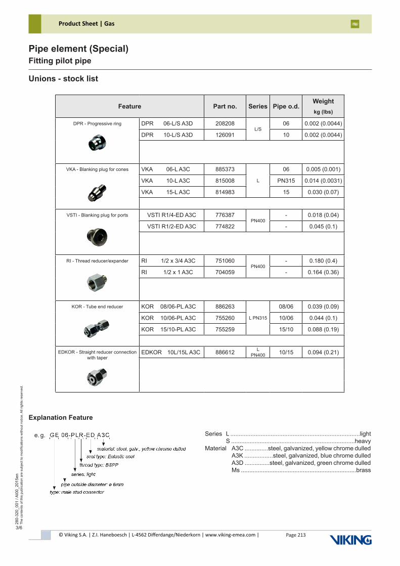
© Viking S.A. | Z.I. Haneboesch | L-4562 Differdange/Niederkorn | www.viking-emea.com |
Product Sheet | Gas
Page 213
280-
320_
001
/ AI0
0_20
15en
The
cont
ents
of t
his
publ
icat
ion
are
subj
ect t
o m
odifi
catio
ns w
ithou
t not
ice.
All
right
s re
serv
ed.
Pipe element (Special)Fitting pilot pipe
3/6
Unions - stock list
Feature Part no. Series Pipe o.d.Weightkg (lbs)
DPR - Progressive ring DPR 06-L/S A3D 208208L/S
06 0.002 (0.0044)
DPR 10-L/S A3D 126091 10 0.002 (0.0044)
VKA - Blanking plug for cones VKA 06-L A3C 885373
L
06 0.005 (0.001)
VKA 10-L A3C 815008 PN315 0.014 (0.0031)
VKA 15-L A3C 814983 15 0.030 (0.07)
VSTI - Blanking plug for ports VSTI R1/4-ED A3C 776387PN400
- 0.018 (0.04)
VSTI R1/2-ED A3C 774822 - 0.045 (0.1)
RI - Thread reducer/expander RI 1/2 x 3/4 A3C 751060PN400
- 0.180 (0.4)
RI 1/2 x 1 A3C 704059 - 0.164 (0.36)
KOR - Tube end reducer KOR 08/06-PL A3C 886263
L PN315
08/06 0.039 (0.09)
KOR 10/06-PL A3C 755260 10/06 0.044 (0.1)
KOR 15/10-PL A3C 755259 15/10 0.088 (0.19)
EDKOR - Straight reducer connection with taper
EDKOR 10L/15L A3C 886612 L PN400 10/15 0.094 (0.21)
Explanation Feature
e. g. Series L .............................................................................light S ..........................................................................heavyMaterial A3C ..............steel, galvanized, yellow chrome dulled A3K .................steel, galvanized, blue chrome dulled A3D ...............steel, galvanized, green chrome dulled Ms .....................................................................brass
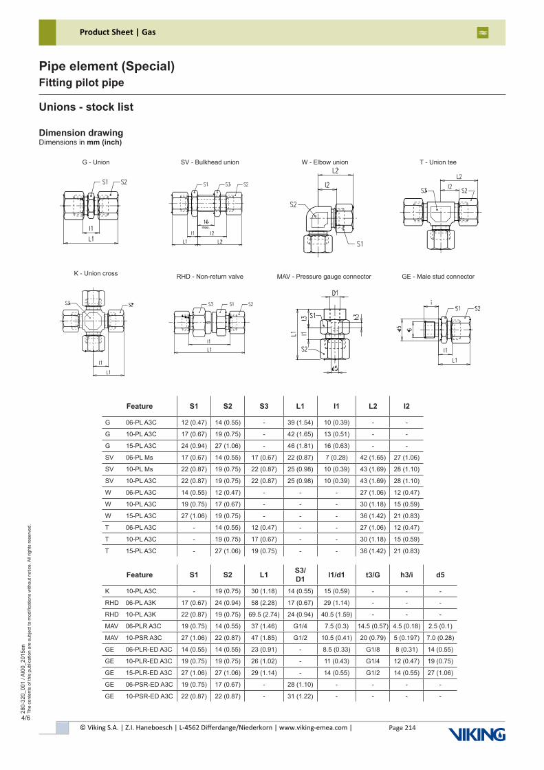
© Viking S.A. | Z.I. Haneboesch | L-4562 Differdange/Niederkorn | www.viking-emea.com |
Product Sheet | Gas
Page 214
280-
320_
001
/ AI0
0_20
15en
The
cont
ents
of t
his
publ
icat
ion
are
subj
ect t
o m
odifi
catio
ns w
ithou
t not
ice.
All
right
s re
serv
ed.
Pipe element (Special)Fitting pilot pipe
4/6
Unions - stock list
G - Union SV - Bulkhead union W - Elbow union T - Union tee
K - Union cross RHD - Non-return valve MAV - Pressure gauge connector GE - Male stud connector
Dimension drawingDimensions in mm (inch)
Feature S1 S2 S3 L1 l1 L2 l2
G 06-PL A3C 12 (0.47) 14 (0.55) - 39 (1.54) 10 (0.39) - -
G 10-PL A3C 17 (0.67) 19 (0.75) - 42 (1.65) 13 (0.51) - -
G 15-PL A3C 24 (0.94) 27 (1.06) - 46 (1.81) 16 (0.63) - -
SV 06-PL Ms 17 (0.67) 14 (0.55) 17 (0.67) 22 (0.87) 7 (0.28) 42 (1.65) 27 (1.06)
SV 10-PL Ms 22 (0.87) 19 (0.75) 22 (0.87) 25 (0.98) 10 (0.39) 43 (1.69) 28 (1.10)
SV 10-PL A3C 22 (0.87) 19 (0.75) 22 (0.87) 25 (0.98) 10 (0.39) 43 (1.69) 28 (1.10)
W 06-PL A3C 14 (0.55) 12 (0.47) - - - 27 (1.06) 12 (0.47)
W 10-PL A3C 19 (0.75) 17 (0.67) - - - 30 (1.18) 15 (0.59)
W 15-PL A3C 27 (1.06) 19 (0.75) - - - 36 (1.42) 21 (0.83)
T 06-PL A3C - 14 (0.55) 12 (0.47) - - 27 (1.06) 12 (0.47)
T 10-PL A3C - 19 (0.75) 17 (0.67) - - 30 (1.18) 15 (0.59)
T 15-PL A3C - 27 (1.06) 19 (0.75) - - 36 (1.42) 21 (0.83)
Feature S1 S2 L1 S3/ D1 l1/d1 t3/G h3/i d5
K 10-PL A3C - 19 (0.75) 30 (1.18) 14 (0.55) 15 (0.59) - - -
RHD 06-PL A3K 17 (0.67) 24 (0.94) 58 (2.28) 17 (0.67) 29 (1.14) - - -
RHD 10-PL A3K 22 (0.87) 19 (0.75) 69.5 (2.74) 24 (0.94) 40.5 (1.59) - - -
MAV 06-PLR A3C 19 (0.75) 14 (0.55) 37 (1.46) G1/4 7.5 (0.3) 14.5 (0.57) 4.5 (0.18) 2.5 (0.1)
MAV 10-PSR A3C 27 (1.06) 22 (0.87) 47 (1.85) G1/2 10.5 (0.41) 20 (0.79) 5 (0.197) 7.0 (0.28)
GE 06-PLR-ED A3C 14 (0.55) 14 (0.55) 23 (0.91) - 8.5 (0.33) G1/8 8 (0.31) 14 (0.55)
GE 10-PLR-ED A3C 19 (0.75) 19 (0.75) 26 (1.02) - 11 (0.43) G1/4 12 (0.47) 19 (0.75)
GE 15-PLR-ED A3C 27 (1.06) 27 (1.06) 29 (1.14) - 14 (0.55) G1/2 14 (0.55) 27 (1.06)
GE 06-PSR-ED A3C 19 (0.75) 17 (0.67) - 28 (1.10) - - - -
GE 10-PSR-ED A3C 22 (0.87) 22 (0.87) - 31 (1.22) - - - -
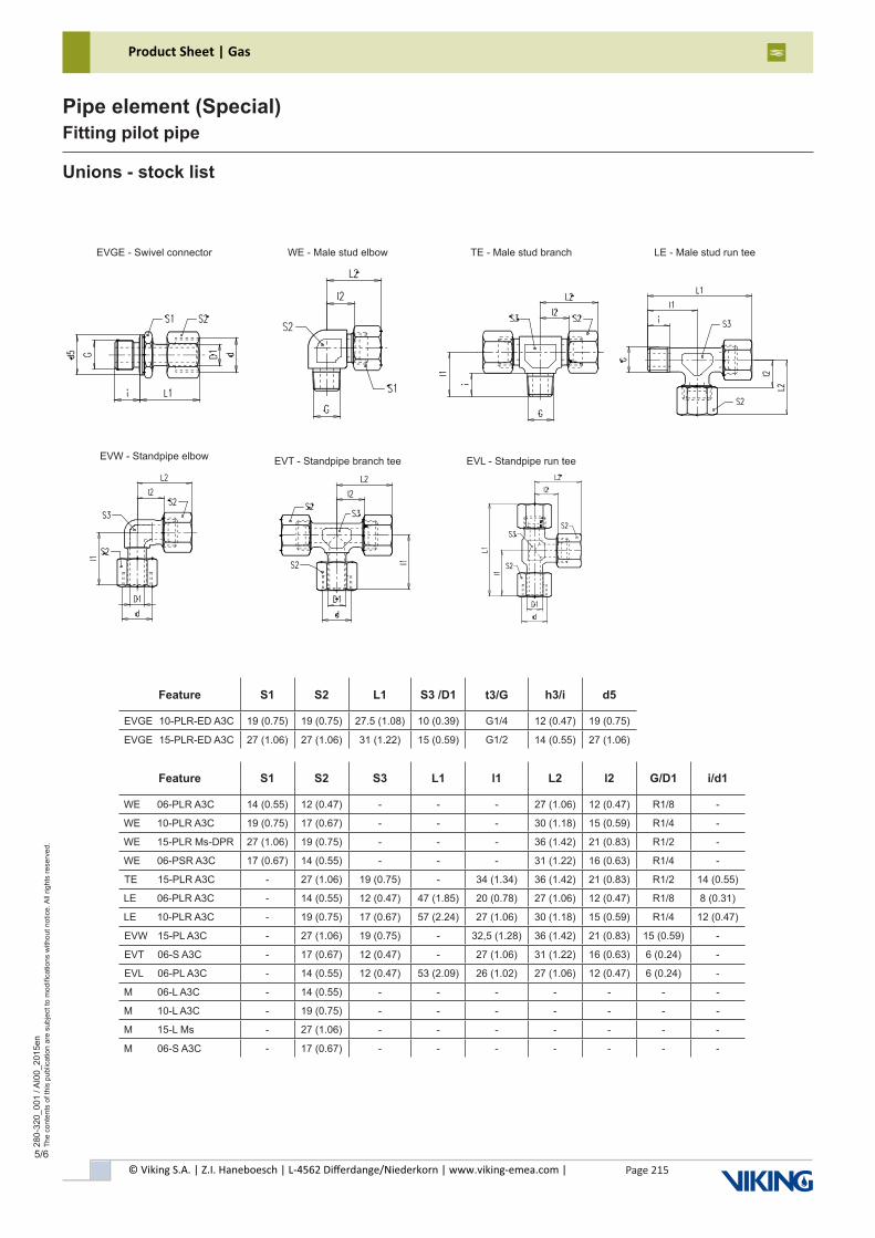
© Viking S.A. | Z.I. Haneboesch | L-4562 Differdange/Niederkorn | www.viking-emea.com |
Product Sheet | Gas
Page 215
280-
320_
001
/ AI0
0_20
15en
The
cont
ents
of t
his
publ
icat
ion
are
subj
ect t
o m
odifi
catio
ns w
ithou
t not
ice.
All
right
s re
serv
ed.
Pipe element (Special)Fitting pilot pipe
5/6
EVGE - Swivel connector WE - Male stud elbow TE - Male stud branch LE - Male stud run tee
EVW - Standpipe elbow EVT - Standpipe branch tee EVL - Standpipe run tee
Unions - stock list
Feature S1 S2 L1 S3 /D1 t3/G h3/i d5
EVGE 10-PLR-ED A3C 19 (0.75) 19 (0.75) 27.5 (1.08) 10 (0.39) G1/4 12 (0.47) 19 (0.75)
EVGE 15-PLR-ED A3C 27 (1.06) 27 (1.06) 31 (1.22) 15 (0.59) G1/2 14 (0.55) 27 (1.06)
Feature S1 S2 S3 L1 l1 L2 l2 G/D1 i/d1
WE 06-PLR A3C 14 (0.55) 12 (0.47) - - - 27 (1.06) 12 (0.47) R1/8 -
WE 10-PLR A3C 19 (0.75) 17 (0.67) - - - 30 (1.18) 15 (0.59) R1/4 -
WE 15-PLR Ms-DPR 27 (1.06) 19 (0.75) - - - 36 (1.42) 21 (0.83) R1/2 -
WE 06-PSR A3C 17 (0.67) 14 (0.55) - - - 31 (1.22) 16 (0.63) R1/4 -
TE 15-PLR A3C - 27 (1.06) 19 (0.75) - 34 (1.34) 36 (1.42) 21 (0.83) R1/2 14 (0.55)
LE 06-PLR A3C - 14 (0.55) 12 (0.47) 47 (1.85) 20 (0.78) 27 (1.06) 12 (0.47) R1/8 8 (0.31)
LE 10-PLR A3C - 19 (0.75) 17 (0.67) 57 (2.24) 27 (1.06) 30 (1.18) 15 (0.59) R1/4 12 (0.47)
EVW 15-PL A3C - 27 (1.06) 19 (0.75) - 32,5 (1.28) 36 (1.42) 21 (0.83) 15 (0.59) -
EVT 06-S A3C - 17 (0.67) 12 (0.47) - 27 (1.06) 31 (1.22) 16 (0.63) 6 (0.24) -
EVL 06-PL A3C - 14 (0.55) 12 (0.47) 53 (2.09) 26 (1.02) 27 (1.06) 12 (0.47) 6 (0.24) -
M 06-L A3C - 14 (0.55) - - - - - - -
M 10-L A3C - 19 (0.75) - - - - - - -
M 15-L Ms - 27 (1.06) - - - - - - -
M 06-S A3C - 17 (0.67) - - - - - - -
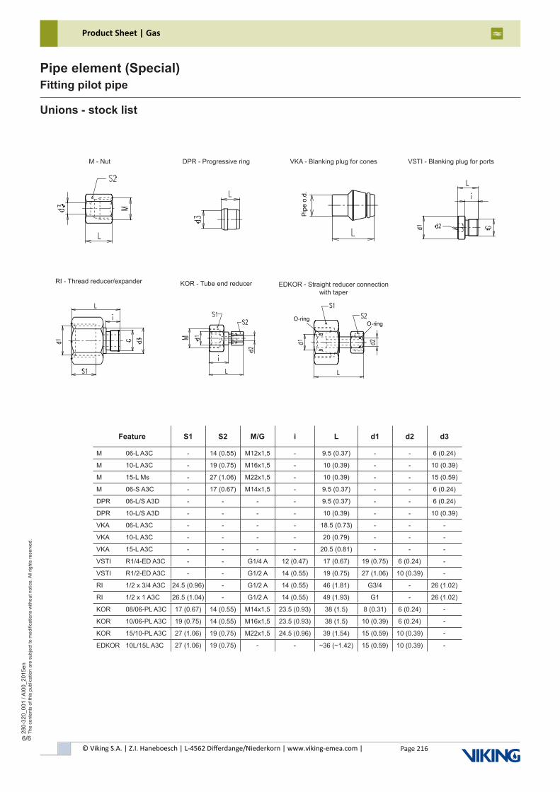
© Viking S.A. | Z.I. Haneboesch | L-4562 Differdange/Niederkorn | www.viking-emea.com |
Product Sheet | Gas
Page 216
280-
320_
001
/ AI0
0_20
15en
The
cont
ents
of t
his
publ
icat
ion
are
subj
ect t
o m
odifi
catio
ns w
ithou
t not
ice.
All
right
s re
serv
ed.
Pipe element (Special)Fitting pilot pipe
6/6
M - Nut DPR - Progressive ring VKA - Blanking plug for cones VSTI - Blanking plug for ports
RI - Thread reducer/expander KOR - Tube end reducer EDKOR - Straight reducer connection with taper
Unions - stock list
Feature S1 S2 M/G i L d1 d2 d3
M 06-L A3C - 14 (0.55) M12x1,5 - 9.5 (0.37) - - 6 (0.24)
M 10-L A3C - 19 (0.75) M16x1,5 - 10 (0.39) - - 10 (0.39)
M 15-L Ms - 27 (1.06) M22x1,5 - 10 (0.39) - - 15 (0.59)
M 06-S A3C - 17 (0.67) M14x1,5 - 9.5 (0.37) - - 6 (0.24)
DPR 06-L/S A3D - - - - 9.5 (0.37) - - 6 (0.24)
DPR 10-L/S A3D - - - - 10 (0.39) - - 10 (0.39)
VKA 06-L A3C - - - - 18.5 (0.73) - - -
VKA 10-L A3C - - - - 20 (0.79) - - -
VKA 15-L A3C - - - - 20.5 (0.81) - - -
VSTI R1/4-ED A3C - - G1/4 A 12 (0.47) 17 (0.67) 19 (0.75) 6 (0.24) -
VSTI R1/2-ED A3C - - G1/2 A 14 (0.55) 19 (0.75) 27 (1.06) 10 (0.39) -
RI 1/2 x 3/4 A3C 24.5 (0.96) - G1/2 A 14 (0.55) 46 (1.81) G3/4 - 26 (1.02)
RI 1/2 x 1 A3C 26.5 (1.04) - G1/2 A 14 (0.55) 49 (1.93) G1 - 26 (1.02)
KOR 08/06-PL A3C 17 (0.67) 14 (0.55) M14x1,5 23.5 (0.93) 38 (1.5) 8 (0.31) 6 (0.24) -
KOR 10/06-PL A3C 19 (0.75) 14 (0.55) M16x1,5 23.5 (0.93) 38 (1.5) 10 (0.39) 6 (0.24) -
KOR 15/10-PL A3C 27 (1.06) 19 (0.75) M22x1,5 24.5 (0.96) 39 (1.54) 15 (0.59) 10 (0.39) -
EDKOR 10L/15L A3C 27 (1.06) 19 (0.75) - - ~36 (~1.42) 15 (0.59) 10 (0.39) -
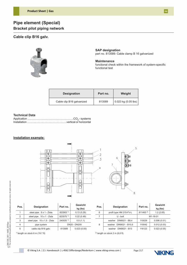
© Viking S.A. | Z.I. Haneboesch | L-4562 Differdange/Niederkorn | www.viking-emea.com |
Product Sheet | Gas
Page 217
280-
330_
001
/ AI0
0_20
15en
The
cont
ents
of t
his
publ
icat
ion
are
subj
ect t
o m
odifi
catio
ns w
ithou
t not
ice.
All
right
s re
serv
ed.
Pipe element (Special)Bracket pilot piping network
1/1
Cable clip B16 galv.
SAP designationpart no. 813589: Cable clamp B 16 galvanized
Maintenancefunctional check within the framework of system-specificfunctional test
Installation example:
Designation Part no. Weight
Cable clip B16 galvanized 813589 0.023 kg (0.05 lbs)
Technical DataApplication ............................................................CO2 - systemsInstallation ....................................................vertical or horizontal
1) length on stock 6 m (19.7 ft)
Pos. Designation Part no.Gewichtkg (lbs)
Pos. Designation Part no.Gewichtkg (lbs)
1 steel pipe 6 x 1 - Zista 823563 1) 0.13 (0.29) 6 profil type HM 315-FV-L 811465 2) 1.2 (2.65)
2 steel pipe 10 x 1 - Zista 823575 1) 0.22 (0.49) 7 U - bolt M1-16-01
3 steel pipe 15 x 1,5 - Zista 240020 1) 0.5 (1.1)
8
washer DIN9021 - B8,4 110029 0.006 (0.01)
4 pipe system DN20 - DN200 washer DIN9021 - B10,5 110042 0.012 (0.03)
5 cable clip B16 galv. 813589 0.023 (0.05) washer DIN9021 - B13 116123 0.023 (0.05)
2) length on stock 2 m (6,6 ft)
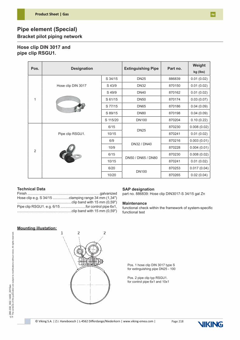
© Viking S.A. | Z.I. Haneboesch | L-4562 Differdange/Niederkorn | www.viking-emea.com |
Product Sheet | Gas
Page 218
280-
330_
002
/ AI0
0_20
15en
The
cont
ents
of t
his
publ
icat
ion
are
subj
ect t
o m
odifi
catio
ns w
ithou
t not
ice.
All
right
s re
serv
ed.
Pipe element (Special)Bracket pilot piping network
1/1
Hose clip DIN 3017 andpipe clip RSGU1.
SAP designationpart no. 886839: Hose clip DIN3017-S 34/15 gal Zn
Maintenancefunctional check within the framework of system-specificfunctional test
Mounting illustation:
Pos. Designation Extinguishing Pipe Part no.Weightkg (lbs)
1
S 34/15 DN25 886839 0.01 (0.02)
Hose clip DIN 3017 S 43/9 DN32 870150 0.01 (0.02)
S 49/9 DN40 870162 0.01 (0.02)
S 61/15 DN50 870174 0.03 (0.07)
S 77/15 DN65 870186 0.04 (0.09)
S 89/15 DN80 870198 0.04 (0.09)
S 115/20 DN100 870204 0.10 (0.22)
2
6/15DN25
870230 0.008 (0.02)
Pipe clip RSGU1. 10/15 870241 0.01 (0.02)
6/9DN32 / DN40
870216 0.003 (0.01)
10/9 870228 0.004 (0.01)
6/15DN50 / DN65 / DN80
870230 0.008 (0.02)
10/15 870241 0.01 (0.02)
6/20DN100
870253 0.017 (0.04)
10/20 870265 0.02 (0.04)
Technical DataFinish ..........................................................................galvanizedHose clip e.g. S 34/15 ................clamping range 34 mm (1,34") ......................................................clip band with 15 mm (0,59")Pipe clip RSGU1. e.g. 6/15 .........................for control pipe 6x1, ......................................................clip band with 15 mm (0,59")
Pos. 1 hose clip DIN 3017 type Sfor extinguishing pipe DN25 - 100
Pos. 2 pipe clip typ RSGU1.for control pipe 6x1 and 10x1
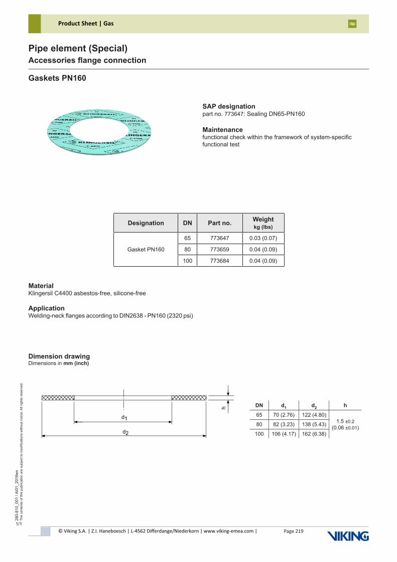
© Viking S.A. | Z.I. Haneboesch | L-4562 Differdange/Niederkorn | www.viking-emea.com |
Product Sheet | Gas
Page 219
280-
810_
001
/ AI0
1_20
16en
The
cont
ents
of t
his
publ
icat
ion
are
subj
ect t
o m
odifi
catio
ns w
ithou
t not
ice.
All
right
s re
serv
ed.
Pipe element (Special)Accessories flange connection
1/1
Gaskets PN160
SAP designationpart no. 773647: Sealing DN65-PN160
Maintenancefunctional check within the framework of system-specificfunctional test
Dimension drawingDimensions in mm (inch)
Designation DN Part no. Weightkg (lbs)
Gasket PN160
65 773647 0.03 (0.07)
80 773659 0.04 (0.09)
100 773684 0.04 (0.09)
MaterialKlingersil C4400 asbestos-free, silicone-free
ApplicationWelding-neck flanges according to DIN2638 - PN160 (2320 psi)
DN d1 d2 h
65 70 (2.76) 122 (4.80)1.5 ±0.2
(0.06 ±0.01)80 82 (3.23) 138 (5.43)
100 106 (4.17) 162 (6.38)
Europe, Middle East & Africa
Viking S.A. | Z.I. Haneboesch, L-4562 Differdange / Niederkorn, Luxembourg | Tel.: +352 58 37 37 - 1, Fax: +352 58 37 36, [email protected]
In all cases the full product datasheet remains the reference documentInformation, photos and drawings are not contractually bindingSubject to modifications without notice
PC1.
4.3.
1/03
18-0
219/
en
For further information, please visitwww.viking-emea.com
BENELUXHinmanweg 11dNL-7575 BE OldenzaalThe NetherlandsTel.: +31 (0)541 573233Fax: +31 (0)541 [email protected]
MIDDLE EASTLOB 19 Office #2506Post Box No. 17531Jebel Ali Free Zone, DubaiUnited Arab EmiratesTel.: +971 (0)4 8895 561Fax: +971 (0)4 8895 [email protected]
CENTRAL & EASTERN EUROPEIndustriestr. 10/12D-23843 Bad OldesloeGermanyTel.: +49 (0)4531 803 8087Fax: +49 (0)4531 803 [email protected]
NORDICStaffans Väg 5S-192 78 SollentunaSwedenTel.: +46 (0)8 594 415 90Fax: +46 (0)8 591 280 [email protected]
FRANCECentre d’Affaires CESCOM4, rue MarconiBP 25180F-57075 Metz Cedex 03FranceTel.: +33 (0)800 10 29 23Fax: +33 (0)800 88 70 [email protected]
POLANDul. Płaskowickiej Filipiny 46/33PL-02 778 WarsawPolandTel.: +48 22 403 57 90Fax: +48 22 403 57 [email protected]
IBÉRICACalle Picos de Europa 4ASan Fernando de HenaresE-28830 Madrid SpainTel.: +34 91 677 8352Fax: +34 91 677 [email protected]
ITALYVia Pavia, 76I-27042 Bressana Bottarone (PV)ItalyTel.: +39 0383 [email protected]
UK & IRELANDUnit 2 - Byram House, Newborn CourtChapel StreetEpworth DN9 1HQUnited KingdomTel.: +44 (0)1427 871 000Fax: +44 (0)1427 873 [email protected]
TURKEYİnönü Cad. Sümer Sok.Zitaş İş Merkezi D2 Blok K:5, D:1234742 Kozyatağı, Kadıköy, İstanbulTurkeyTel.: +90 (0)216 403 18 00Fax: +90 (0)216 403 18 [email protected]
ROMANIA & BULGARIAMODERN Business CenterB-dul Carol I nr. 34-36RO-020922 BucharestRomaniaTel.: +40 21 311 51 [email protected]