Embed Size (px)
Citation preview
T R I M B L E N A V I G A T I O N
SVeeSix-CM3™Embedded GPS Core Module
System DesignerReference Manual
�
645 North Mary AvenueSunnyvale, CA 94088-3642
Part Number 34150-01

No part of this manual may be reproduced in any form or by any means or used to make aderivative work (such as translation, transformation, or adaptation) without writtenpermission from Trimble Navigation.
© Copyright July 1997
Part Number 34150-01
�645 North Mary AvenueSunnyvale, CA 94086Phone: (800) 481-8000FAX: (408) 730-2082
Internet: http://www.trimble.com
U.S. Technical Assistance and Repair1-800-SOS-4-TAC (calls originating in the U.S.)408-481-6940 (calls originating outside of the U.S.)FAX: (408) 481-6020
Europe Technical Assistance and Repair
44-162-285-8421

Limited Warranty
Trimble Navigation Limited warrants the SVeeSix-CM3 against defectsin materials and workmanship for a period of one year from the date offactory sale. During the warranty period, Trimble Navigation Limitedwill, at its option, either repair or replace products which prove to bedefective.
Buyer shall prepay shipping charges for products returned to TrimbleNavigation Limited for warranty service and Trimble NavigationLimited shall pay for return of products to Buyer. However, Buyershall pay all shipping charges, duties, and taxes for products returnedto Trimble Navigation Limited from outside the United States.
This warranty shall not apply to damage resulting from:
■ Improper or inadequate maintenance by Buyer■ Buyer-supplied software or interfacing■ Unauthorized modification or misuse■ Operation outside of the product environmental specifications■ Improper installation, where applicable
No other warranty is expressed or implied. Trimble NavigationLimited specifically disclaims the implied warranties of merchantabilityand fitness for a particular purpose.
Remedies provided herein are Buyer's sole and exclusive remedies.Trimble Navigation Limited shall not be liable for any direct, indirect,special incidental, or consequential damages, whether based oncontract, tort, or any other legal theory.

Table of Contents
PrefaceIntroduction ........................................................................................................................ P-1Conventions Used in This Manual .................................................................................... P-2The Global Positioning System.......................................................................................... P-3
Chapter 1: IntroductionIntroduction ........................................................................................................................ 1-1SVeeSix-CM3 Configurations ............................................................................................ 1-3
Starter Kit...................................................................................................................... 1-3Core Modules............................................................................................................... 1-3Accessories ................................................................................................................... 1-4
The SVeeSix-CM3 GPS Receiver Module ......................................................................... 1-4Antennas.............................................................................................................................. 1-5
Chapter 2: The SVeeSix-CM3 Starter KitIntroduction ........................................................................................................................ 2-1Starter Kit Interface Unit & Receiver Module .................................................................. 2-2Hardware Setup.................................................................................................................. 2-4Power................................................................................................................................... 2-6Removing the SVeeSix-CM3 Receiver Module from Interface Unit............................... 2-8Run the TSIP Interface Program........................................................................................ 2-10
TSIPCHAT Command Window and Report Window ............................................. 2-11
Chapter 3: Configuring the Message Protocol on the SVeeSix-CM3 Starter KitIntroduction ........................................................................................................................ 3-1About the Configuration Program .................................................................................... 3-2Setup the System Hardware .............................................................................................. 3-3Load the Configuration Program ...................................................................................... 3-4
Chapter 4: Hardware Integration
Introduction ........................................................................................................................ 4-1Interface Connectors........................................................................................................... 4-2
I/O Connector Signals................................................................................................. 4-32mm Mating I/O Connectors ..................................................................................... 4-4
Power Requirement ............................................................................................................ 4-5 CM3 Power Requirement............................................................................................ 4-6 +5 VD6 Ripple Specification ....................................................................................... 4-6Serial Interface..................................................................................................................... 4-7One Pulse Per Second......................................................................................................... 4-7Mounting............................................................................................................................. 4-7
SVeeSix-CM3 System Designer's Reference Manual
Chapter 5: Software InterfaceIntroduction ........................................................................................................................ 5-1Startup ................................................................................................................................. 5-2Software Tool Kits .............................................................................................................. 5-2Communicating with the SVeeSix-CM3 Module ............................................................. 5-3Protocol Summary .............................................................................................................. 5 -4
TSIP Data Output ........................................................................................................ 5-4TAIP Data Output........................................................................................................ 5-5NMEA 0183 Data Output............................................................................................ 5-5
Time Operation................................................................................................................... 5-6Effect of GPS Week Number Roll-over on Trimble OEM Receivers .............................. 5-7Differential GPS .................................................................................................................. 5-9
Chapter 6: Operating CharacteristicsIntroduction ........................................................................................................................ 6-1GPS Satellite Message......................................................................................................... 6-2Satellite Acquisition and Time to First Fix........................................................................ 6-3
Cold Start...................................................................................................................... 6-3Warm Start ................................................................................................................... 6-3Garage Search Strategy................................................................................................ 6-4Hot Start ....................................................................................................................... 6-4
Satellite Mask Settings........................................................................................................ 6-5Standard Operating Modes................................................................................................ 6-6
Over-Determined Mode.............................................................................................. 6-6Fix Modes ..................................................................................................................... 6-82D Manual .................................................................................................................... 6-83D Manual .................................................................................................................... 6-8Automatic 3D/ 2D/ 2D CH........................................................................................ 6-9One Satellite Timing .................................................................................................... 6-9
Differential GPS Operating Modes.................................................................................... 6-10DGPS On....................................................................................................................... 6-10DGPS Off ...................................................................................................................... 6-10DGPS Automatic.......................................................................................................... 6-10Differential GPS Operation ......................................................................................... 6-11
Position Accuracy ............................................................................................................... 6-11Selective Availability (SA)........................................................................................... 6-11Differential GPS (DGPS).............................................................................................. 6-12
Coordinate Systems............................................................................................................ 6-12TSIP ............................................................................................................................... 6-13TAIP .............................................................................................................................. 6-13NMEA 0183 .................................................................................................................. 6-13
Performance Characteristics .............................................................................................. 6-14Update Rate.................................................................................................................. 6-14Dynamic Limits............................................................................................................ 6-14Re-Acquisition.............................................................................................................. 6-15
■ Table of Contents
Chapter 6: Operating Characteristics (continued)
GPS Timing ......................................................................................................................... 6-16Serial Time Output....................................................................................................... 6-17Timing Pulse Output (1PPS) ....................................................................................... 6-17Determining the Time Tag of the PPS Timing Pulse................................................. 6-18Time Tagging................................................................................................................ 6-19
Appendix A:Trimble Standard Interface Protocol (TSIP)
Appendix B:TSIP User's Guide
Appendix C:Trimble ASCII Interface Protocol (TAIP)
Appendix D:GPSSK User's Guide
Appendix E:NMEA 0183
Appendix F: Specifications and Mechanical Drawings
Glossary

Preface
Congratulations on your selection of the SVeeSix-CM3. The SVeeSix-CM3 is a compactGPS receiver module that provides accurate, world-wide position, velocity and timecapability to your system.
This manual provides all the information required to integrate and operate the SVeeSix-CM3:
Chapter 1: Introduction
Chapter 2: The SVeeSix-CM3 Starter Kit
Chapter 3: Configuring the SVeeSix-CM3 Receiver Protocol
Chapter 4: Hardware Interface
Chapter 5: Software Interface
Chapter 6: Operating Characteristics
Appendix A: Trimble Standard Interface Protocol (TSIP)
Appendix B: TSIP User's Guide
Appendix C: Trimble ASCII Interface Protocol (TAIP)
Appendix D: GPSSK User's Guide
Appendix E: NMEA 0183
Appendix F: Specifications and Mechanical Drawings
Glossary
You will discover that the SVeeSix-CM3 is easy to integrate and simple to use. Beforeproceeding with Chapter 1, please review this preface for an overview of the GlobalPositioning System.
P-2
SVeeSix-CM3 System Designer Reference Manual
Conventions Used in This Manual
AnnotationsAnnotations, preceded by bullets, are used in this manual to highlight importantinformation.
◆ NOTESpecial notes and tips are prefaced with the ◆ symbol. This information isprovided to assist you in installing and using the SVeeSix starter kit.
❒ Items that should be accounted for or reviewed are prefaced withthe ❒ symbol.
AbbreviationsThe generic terms module, receiver and CM3 are sometimes used to refer to the SVeeSix-CM3 receiver.
The SVeeSix-CM3 Developer's Starter Kit is abbreviated to starter kit.
Differential GPS is abbreviated to DGPS.
The Trimble Standard Interface Protocol is abbreviated to TSIP.
The Trimble ASCII Interface Protocol is abbreviated to TAIP.
P-3
SVeeSix-CM3 System Designer Reference Manual
The Global Positioning System
The Global Positioning System (GPS) is a satellite based navigation system operated andmaintained by the U.S. Department of Defense. GPS consists of a constellation of 24satellites providing world-wide, 24 hour, three dimensional (3-D) coverage. Althoughoriginally conceived for military needs, GPS has a broad array of civilian applicationsincluding surveying, marine, land, aviation, and vehicle navigation. GPS is the mostaccurate technology available for vehicle navigation. There is now virtually 24 hour,world-wide, three dimensional (3-D) GPS coverage which makes GPS fully functionalfor navigation and timing applications.
As a satellite based system, GPS is immune from the limitations of land based systemssuch as Loran. Loran navigation is limited in coverage and is encumbered by adverseweather. In addition, the accuracy of Loran navigation varies with geographic locationand, even under ideal conditions, cannot compare with GPS. By computing the distanceto GPS satellites orbiting the earth, a GPS receiver can calculate an accurate position.This process is called satellite ranging. A 2-D position calculation requires three satelliteranges. A 3-D position calculation, which includes altitude, requires four satelliteranges. GPS receivers can also provide precise time, speed, and course measurementswhich are beneficial for vehicle navigation.
Differential GPS (DGPS) is a sophisticated form of GPS navigation which provides evengreater positioning accuracy. Differential GPS relies on error corrections transmittedfrom a GPS receiver placed at a known location. This receiver, called a referencestation, calculates the error in the satellite range data and outputs corrections for usewith other receivers in the same locale. Differential GPS eliminates virtually all themeasurement error in the satellite ranges and enables a highly accurate positioncalculation.

Chapter 1Introduction
The SVeeSix-CM3 core module is a miniature 6-channel GPS receiver designed for easyintegration. Its compact size and low power consumption make it ideal forapplications ranging from hand-held navigation units to complex GIS instrumentationsystems. The SVeeSix-CM3 receiver features the same high-performance architecturecommon to Trimble's standard SVeeSix series receivers; the SVeeSix architecture usessix channels for tracking up to eight GPS satellites, automatically selecting the satellitesto optimize position and velocity data accuracy. The CM3 is also differential-ready forhigh-accuracy applications.
The CM3 is the third generation of Trimble's popular core modules first introduced in1993. The CM3 features Trimble's latest signal processing code, a high-gain RFpreamplifier for compatibility with the standard GPS antennas, and a CMOS TTL levelone-pulse-per-second output for timing applications.
The SVeeSix-CM3 contains one firmware ROM. The firmware ROM contains the coresignal processing code and the I/O protocol. Trimble offers three protocols for usewith the SVeeSix series of GPS receivers. The SVeeSix-CM3 Starter Kit moduleprovides a software toolkit diskette and the software to configure the receiver foreither TSIP, NMEA, and TAIP protocols.
The system designer can experiment with the different protocols to determine whichbest suits their application. As delivered from the factory, the CM3 modules areconfigured with the TSIP protocol and can be changed via software to output TAIP orNMEA protocols.
SVeeSix-CM3 System Designer Reference Manual
1-2
Introduction (con’t.)
The Trimble Standard Interface Protocol (TSIP) is a powerful binary packet protocolthat allows the system designer maximum configuration control over the GPS receiverfor optimum performance in any number of applications. TSIP supports over 40commands and their associated response packets. TSIP includes commands to uploadtime, initial position, and almanac data to shorten acquisition time.
NMEA 0183 is an industry-standard protocol common to marine applications. NMEAprovides direct compatibility with other NMEA capable devices such as chart plotters,etc. The standard CM3 NMEA protocol supports the GGA and VTG messages.Trimble can provide a custom configuration program for CM3's to output other NMEAmessages as required. Contact a Trimble representative for further information.
The Trimble ASCII Interface Protocol (TAIP) uses printable ASCII characters in a set of16 message types. TAIP is designed for easy integration and can provide position,speed, heading, and time in a single 35 byte message. TAIP allows the user to scheduleautomatic message reports or poll for information.
Chapter 1 - Introduction
1- 3
CM3 Starter Kit Components
The SVeeSix-CM3 is available in a developer's Starter Kit or as individual modules.The Starter Kit includes all the components necessary to quickly test and integrate themodule.
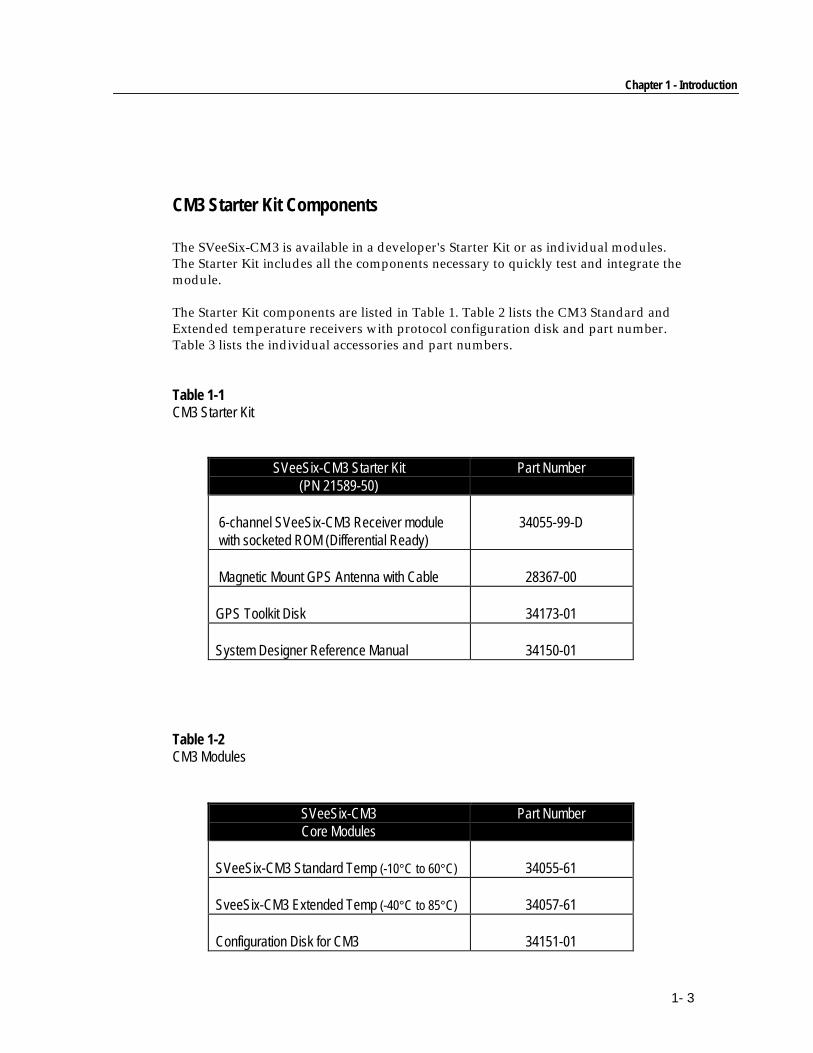
The Starter Kit components are listed in Table 1. Table 2 lists the CM3 Standard andExtended temperature receivers with protocol configuration disk and part number.Table 3 lists the individual accessories and part numbers.
Table 1-1CM3 Starter Kit
SVeeSix-CM3 Starter Kit(PN 21589-50)
Part Number
6-channel SVeeSix-CM3 Receiver module with socketed ROM (Differential Ready)
34055-99-D
Magnetic Mount GPS Antenna with Cable 28367-00
GPS Toolkit Disk 34173-01
System Designer Reference Manual 34150-01
Table 1-2CM3 Modules
SVeeSix-CM3Core Modules
Part Number
SVeeSix-CM3 Standard Temp (-10°C to 60°C) 34055-61
SveeSix-CM3 Extended Temp (-40°C to 85°C) 34057-61
Configuration Disk for CM3 34151-01
SVeeSix-CM3 System Designer Reference Manual
1-4
Table 1-3Accessories
Core Module Accessories Part Number
Hard Mount GPS Antenna 28367-70
Magnetic Mount 28367-00
Rooftop Antenna Kit with 75 foot cable 23726-00
◆ NOTE: Part numbers are subject to change. Confirm part numbers with your Trimblerepresentative when placing your order.
SVeeSix-CM3 Starter Kit GPS Receiver Module
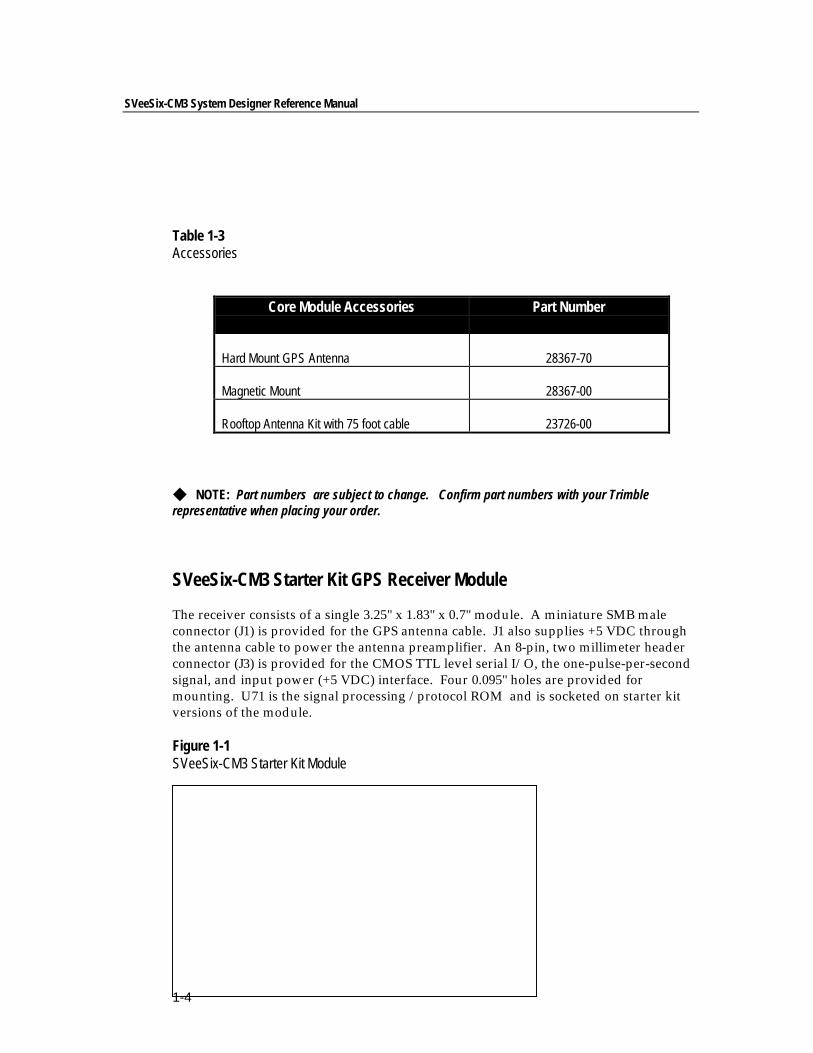
The receiver consists of a single 3.25" x 1.83" x 0.7" module. A miniature SMB maleconnector (J1) is provided for the GPS antenna cable. J1 also supplies +5 VDC throughthe antenna cable to power the antenna preamplifier. An 8-pin, two millimeter headerconnector (J3) is provided for the CMOS TTL level serial I/O, the one-pulse-per-secondsignal, and input power (+5 VDC) interface. Four 0.095" holes are provided formounting. U71 is the signal processing /protocol ROM and is socketed on starter kitversions of the module.
Figure 1-1SVeeSix-CM3 Starter Kit Module
Chapter 1 - Introduction
1- 5
Antennas
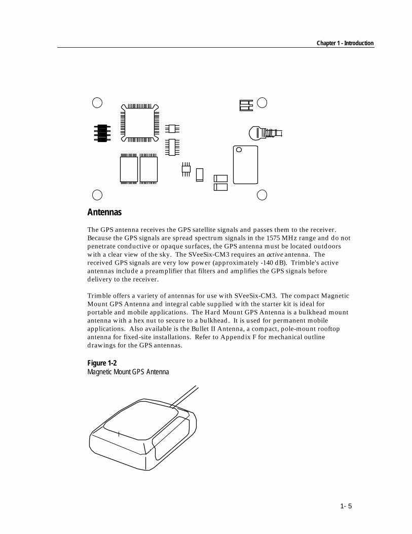
The GPS antenna receives the GPS satellite signals and passes them to the receiver.Because the GPS signals are spread spectrum signals in the 1575 MHz range and do notpenetrate conductive or opaque surfaces, the GPS antenna must be located outdoorswith a clear view of the sky. The SVeeSix-CM3 requires an active antenna. Thereceived GPS signals are very low power (approximately -140 dB). Trimble's activeantennas include a preamplifier that filters and amplifies the GPS signals beforedelivery to the receiver.
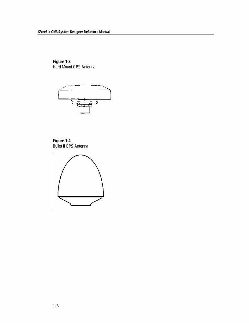
Trimble offers a variety of antennas for use with SVeeSix-CM3. The compact MagneticMount GPS Antenna and integral cable supplied with the starter kit is ideal forportable and mobile applications. The Hard Mount GPS Antenna is a bulkhead mountantenna with a hex nut to secure to a bulkhead. It is used for permanent mobileapplications. Also available is the Bullet II Antenna, a compact, pole-mount rooftopantenna for fixed-site installations. Refer to Appendix F for mechanical outlinedrawings for the GPS antennas.
Figure 1-2Magnetic Mount GPS Antenna
SVeeSix-CM3 System Designer Reference Manual
1-6
Figure 1-3Hard Mount GPS Antenna
Figure 1-4Bullet II GPS Antenna
Chapter 2The SVeeSix-CM3 Starter Kit
Trimble's OEM Starter Kits are differential-ready and contain all the necessary items toeasily evaluate the receiver's features and to begin integration into a users’ specificapplication. The CM3 Starter Kit includes:
❐ Differential-ready CM3 module❐ Software toolkits for the TSIP and TAIP protocols❐ Software to configure the module for TSIP, TAIP or NMEA protocols❐ Metal enclosure that allows the CM3 to be connected to the RS-232 serial port
of a personal computer❐ Magnetic mount antenna with cable❐ Manual
Please take a moment to review the following sections before proceeding withany testing or evaluation of the CM3 Starter Kit.
SVeeSix-CM3 System Designer Reference Manual
2-2
Starter Kit Interface Unit & Receiver Module
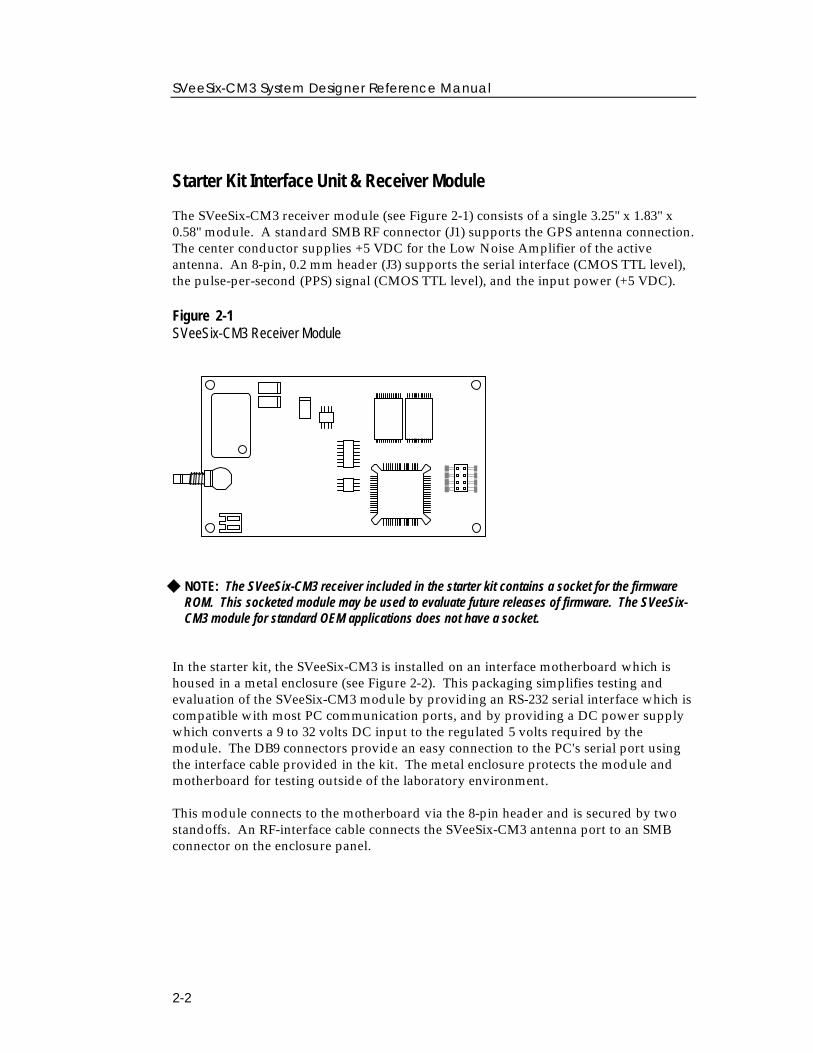
The SVeeSix-CM3 receiver module (see Figure 2-1) consists of a single 3.25" x 1.83" x0.58" module. A standard SMB RF connector (J1) supports the GPS antenna connection.The center conductor supplies +5 VDC for the Low Noise Amplifier of the activeantenna. An 8-pin, 0.2 mm header (J3) supports the serial interface (CMOS TTL level),the pulse-per-second (PPS) signal (CMOS TTL level), and the input power (+5 VDC).
Figure 2-1SVeeSix-CM3 Receiver Module
◆ NOTE: The SVeeSix-CM3 receiver included in the starter kit contains a socket for the firmwareROM. This socketed module may be used to evaluate future releases of firmware. The SVeeSix-CM3 module for standard OEM applications does not have a socket.
In the starter kit, the SVeeSix-CM3 is installed on an interface motherboard which ishoused in a metal enclosure (see Figure 2-2). This packaging simplifies testing andevaluation of the SVeeSix-CM3 module by providing an RS-232 serial interface which iscompatible with most PC communication ports, and by providing a DC power supplywhich converts a 9 to 32 volts DC input to the regulated 5 volts required by themodule. The DB9 connectors provide an easy connection to the PC's serial port usingthe interface cable provided in the kit. The metal enclosure protects the module andmotherboard for testing outside of the laboratory environment.
This module connects to the motherboard via the 8-pin header and is secured by twostandoffs. An RF-interface cable connects the SVeeSix-CM3 antenna port to an SMBconnector on the enclosure panel.
Chapter 2 - The SVeeSix-CM3 Starter Kit
2-3
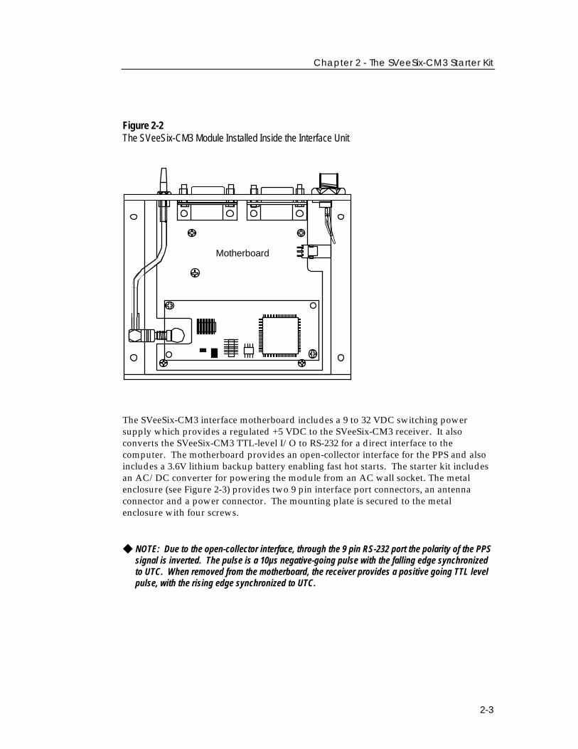
Figure 2-2The SVeeSix-CM3 Module Installed Inside the Interface Unit
Motherboard
The SVeeSix-CM3 interface motherboard includes a 9 to 32 VDC switching powersupply which provides a regulated +5 VDC to the SVeeSix-CM3 receiver. It alsoconverts the SVeeSix-CM3 TTL-level I/O to RS-232 for a direct interface to thecomputer. The motherboard provides an open-collector interface for the PPS and alsoincludes a 3.6V lithium backup battery enabling fast hot starts. The starter kit includesan AC/DC converter for powering the module from an AC wall socket. The metalenclosure (see Figure 2-3) provides two 9 pin interface port connectors, an antennaconnector and a power connector. The mounting plate is secured to the metalenclosure with four screws.
◆ NOTE: Due to the open-collector interface, through the 9 pin RS-232 port the polarity of the PPSsignal is inverted. The pulse is a 10µs negative-going pulse with the falling edge synchronizedto UTC. When removed from the motherboard, the receiver provides a positive going TTL levelpulse, with the rising edge synchronized to UTC.
SVeeSix-CM3 System Designer Reference Manual
2-4
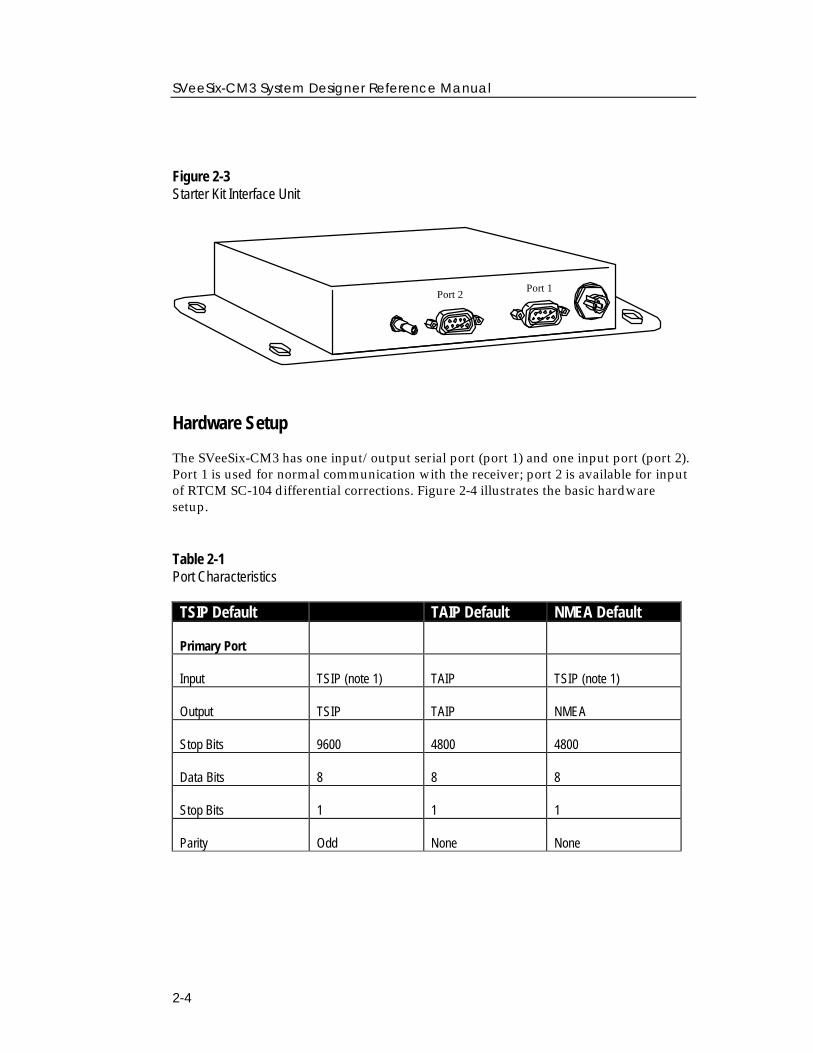
Figure 2-3Starter Kit Interface Unit
Port 2Port 1
Hardware Setup
The SVeeSix-CM3 has one input/output serial port (port 1) and one input port (port 2).Port 1 is used for normal communication with the receiver; port 2 is available for inputof RTCM SC-104 differential corrections. Figure 2-4 illustrates the basic hardwaresetup.
Table 2-1Port Characteristics
TAIP Default NMEA DefaultTSIP Default TAIP Default NMEA Default
Primary Port
Input TSIP (note 1) TAIP TSIP (note 1)
Output TSIP TAIP NMEA
Stop Bits 9600 4800 4800
Data Bits 8 8 8
Stop Bits 1 1 1
Parity Odd None None
Chapter 2 - The SVeeSix-CM3 Starter Kit
2-5
Table 2-1 (con’t.)Port Characteristics
TSIP Default TAIP Default NMEA Default
Secondary Port
Input RTCM SC-104 RTCMSC-104 RTCM SC-104
Output None (off) None (off) None (off)
Stop Bits 4800 4800 4800
Data Bits 8 8 8
Stop Bits 1 1 1
Parity None None None
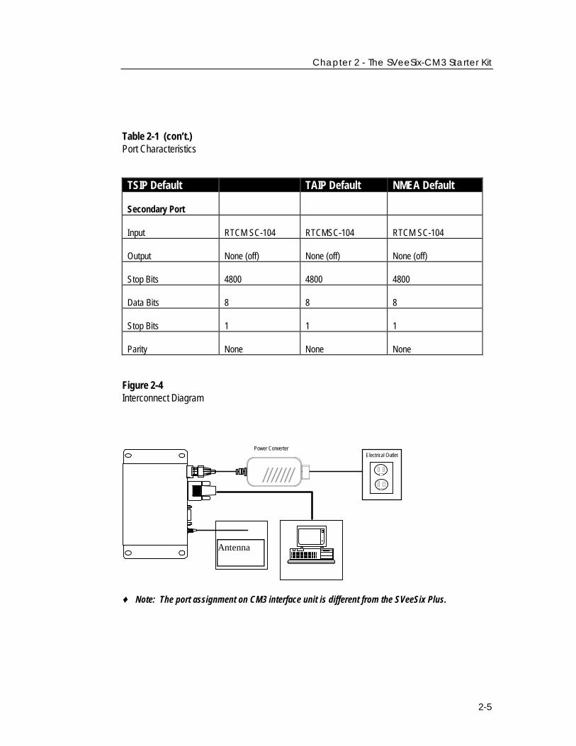
Figure 2-4Interconnect Diagram
Antenna
Power ConverterElectrical Outlet
♦ Note: The port assignment on CM3 interface unit is different from the SVeeSix Plus.
SVeeSix-CM3 System Designer Reference Manual
2-6
1. Connect one end of the 9-pin serial interface cable to port 1. Connect the other endof the cable to COM1 or COM2 of the PC. A 9-pin to 25-pin adapter may be needed onthe cable to adapt the serial interface connection to the PC's 25-pin communicationport if so equipped.
2. Connect the antenna cable to the interface unit. This connection is made by pushingthe antenna cable connector straight onto the SMB connector on the unit (to remove theantenna cable, simply pull the antenna connector straight off of the SMB connector).The SMB connector on the antenna has a positive locking jaw built in, this is to insure asolid connection to the GPS receiver.
3. Place the antenna so that it has a clear view of the sky.
Power
The SVeeSix-CM3 receiver module is designed for embedded applications and requiresa regulated +5.0 VDC input (+4.85 to +5.25 VDC). See Power Requirements in Chapter 4for detailed specifications. In the starter kit, the motherboard includes a DC powerregulator which converts a 9 to 32 VDC input to the regulated 5 VDC required bySVeeSix-CM3. Power can be applied to the starter kit module using one of twooptions: the DC power cable (see Figure 2-5) or the AC/DC power converter (seeFigure 2-6).
The DC power cable is ideal for bench-top or automotive testing environments. Thepower cable is terminated at one end with a 3-pin plastic connector which mates withthe power connector on the metal enclosure. The unterminated end of the cableprovides for easy connection to a DC power supply. Connect the red power lead to asource of DC positive +9 to +32 VDC, and connect the black power lead to ground.This connection supplies power to both the receiver module and the antenna. Thecombined power consumption of the interface unit, the SVeeSix-CM3 and the antennais approximately 2 watts. (The yellow wire is not used; battery back-up is provided bya factory installed lithium battery on the motherboard.)
Chapter 2 - The SVeeSix-CM3 Starter Kit
2-7
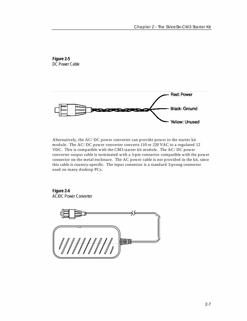
Figure 2-5DC Power Cable
Alternatively, the AC/DC power converter can provide power to the starter kitmodule. The AC/DC power converter converts 110 or 220 VAC to a regulated 12VDC. This is compatible with the CM3 starter kit module. The AC/DC powerconverter output cable is terminated with a 3-pin connector compatible with the powerconnector on the metal enclosure. The AC power cable is not provided in the kit, sincethis cable is country-specific. The input connector is a standard 3-prong connectorused on many desktop PCs.
Figure 2-6AC/DC Power Converter
SVeeSix-CM3 System Designer Reference Manual
2-8
Removing the SVeeSix-CM3 Receiver Module from the Interface Unit
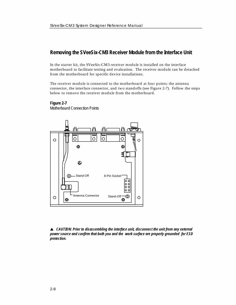
In the starter kit, the SVeeSix-CM3 receiver module is installed on the interfacemotherboard to facilitate testing and evaluation. The receiver module can be detachedfrom the motherboard for specific device installations.
The receiver module is connected to the motherboard at four points: the antennaconnector, the interface connector, and two standoffs (see Figure 2-7). Follow the stepsbelow to remove the receiver module from the motherboard.
Figure 2-7Motherboard Connection Points
Antenna Connector
Stand-Off
Stand-Off
8-Pin Socket
▲ CAUTION: Prior to disassembling the interface unit, disconnect the unit from any externalpower source and confirm that both you and the work surface are properly grounded for ESDprotection.
Chapter 2 - The SVeeSix-CM3 Starter Kit
2-9
1. Remove the four screws which secure the bottom plate to the base of the metalenclosure. Set the bottom plate aside.
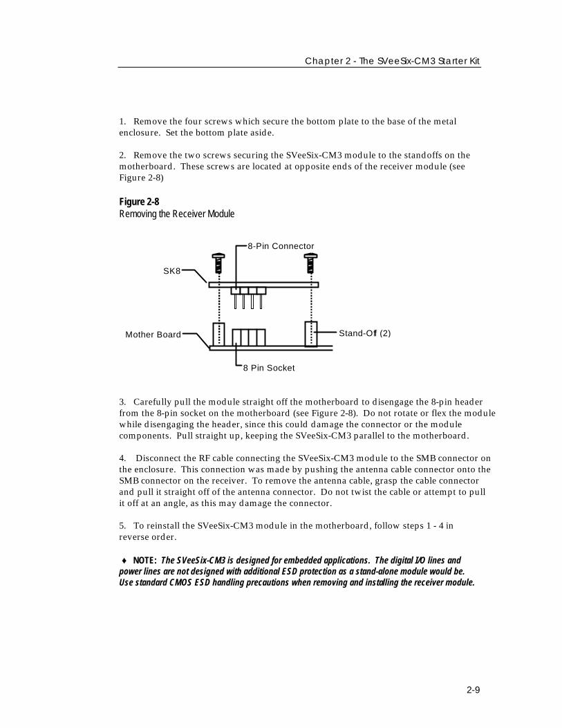
2. Remove the two screws securing the SVeeSix-CM3 module to the standoffs on themotherboard. These screws are located at opposite ends of the receiver module (seeFigure 2-8)
Figure 2-8Removing the Receiver Module
SK8
Mother Board
8 Pin Socket
8-Pin Connector
Stand-Off (2)
3. Carefully pull the module straight off the motherboard to disengage the 8-pin headerfrom the 8-pin socket on the motherboard (see Figure 2-8). Do not rotate or flex the modulewhile disengaging the header, since this could damage the connector or the modulecomponents. Pull straight up, keeping the SVeeSix-CM3 parallel to the motherboard.
4. Disconnect the RF cable connecting the SVeeSix-CM3 module to the SMB connector onthe enclosure. This connection was made by pushing the antenna cable connector onto theSMB connector on the receiver. To remove the antenna cable, grasp the cable connectorand pull it straight off of the antenna connector. Do not twist the cable or attempt to pullit off at an angle, as this may damage the connector.
5. To reinstall the SVeeSix-CM3 module in the motherboard, follow steps 1 - 4 inreverse order.
♦ NOTE: The SVeeSix-CM3 is designed for embedded applications. The digital I/O lines andpower lines are not designed with additional ESD protection as a stand-alone module would be.Use standard CMOS ESD handling precautions when removing and installing the receiver module.
SVeeSix-CM3 System Designer Reference Manual
2-10
Run the TSIP Interface Program
The SVeeSix-CM3 Starter Kit includes a disk containing TSIP interface programs whichrun on a PC-DOS platform. These programs aid system integrators in developing thesoftware interface for the GPS module. The TSIP programs are described in detail inAppendix B, TSIP User's Guide. This section assumes that the SVeeSix-CM3 isconfigured with the TSIP interface protocol and that the TSIPCHAT program isinstalled in a directory on the computer hard disk (see Chapter 3, Configuring theMessage Protocol on the SVeeSix-CM3 Starter Kit).
To monitor the TSIP output and communicate with the GPS module:
1. Turn on the DC power supply.
2. Turn on the PC.
3. Insert the GPS Tool Kit disk in the disk drive.
4. Go to the directory where the GPS toolkit will be installed. In most cases, this willbe the root directory on the C: drive.
◆NOTE: For detailed installation guidelines, read A:\INSTALL.TXT and A:\README.TXT.
5. At the DOS prompt, type A:\INSTALL to create a sub directory called TOOLKITand to install the tool kit files.
6. Type the appropriate path name to execute the TSIPCHAT program (e.g.C:\TOOLKIT\TSIPCHAT). TSIPCHAT provides full access to the TSIP protocol. Itconverts binary TSIP packets into printable ASCII characters and vice versa.
7. After the TSIPCHAT title screen appears, type "?", and the primary TSIPCHATscreen shown in Figure 2-9 is displayed.
Chapter 2 - The SVeeSix-CM3 Starter Kit
2-11
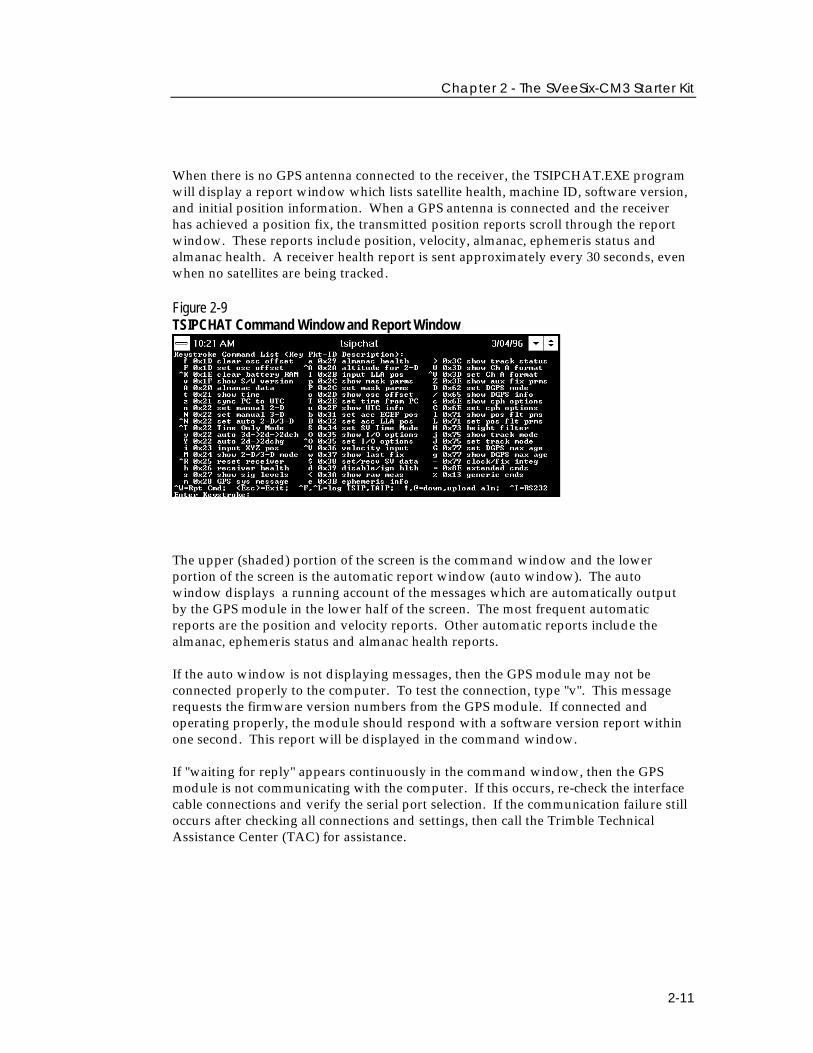
When there is no GPS antenna connected to the receiver, the TSIPCHAT.EXE programwill display a report window which lists satellite health, machine ID, software version,and initial position information. When a GPS antenna is connected and the receiverhas achieved a position fix, the transmitted position reports scroll through the reportwindow. These reports include position, velocity, almanac, ephemeris status andalmanac health. A receiver health report is sent approximately every 30 seconds, evenwhen no satellites are being tracked.
Figure 2-9TSIPCHAT Command Window and Report Window
The upper (shaded) portion of the screen is the command window and the lowerportion of the screen is the automatic report window (auto window). The autowindow displays a running account of the messages which are automatically outputby the GPS module in the lower half of the screen. The most frequent automaticreports are the position and velocity reports. Other automatic reports include thealmanac, ephemeris status and almanac health reports.
If the auto window is not displaying messages, then the GPS module may not beconnected properly to the computer. To test the connection, type "v". This messagerequests the firmware version numbers from the GPS module. If connected andoperating properly, the module should respond with a software version report withinone second. This report will be displayed in the command window.
If "waiting for reply" appears continuously in the command window, then the GPSmodule is not communicating with the computer. If this occurs, re-check the interfacecable connections and verify the serial port selection. If the communication failure stilloccurs after checking all connections and settings, then call the Trimble TechnicalAssistance Center (TAC) for assistance.

Chapter 3Configuring the Message Protocol on theSVeeSix-CM3 Starter Kit
This chapter provides step-by-step instructions for using the Basic operating mode tochange the SVeeSix-CM3 receiver protocol. Additional program features beyond thecontents of this manual may be available. Updates are documented in the READ.MEfile on the program disk.
The SVeeSix-CM3 receiver supports three message protocols: TSIP, TAIP and NMEA.The firmware for all three protocols and the navigation processor firmware arecontained in PROM (read only memory). When purchased in a starter kit, the SVeeSix-CM3 receiver is configured for the TSIP protocol. The unit can be re-configured foreither TAIP or NMEA protocols by using one of the configuration programs stored onthe GPS Software Tool Kit program disk, provided in the starter kit.
TSIP - The Trimble Standard Interface Protocol is a powerful binary packet protocolwhich provides bi-directional communication for optimal performance.
TAIP - The Trimble ASCII Interface Protocol which is a bi-directional ASCII protocoldesigned for easy integration. This protocol can provide position, speed, heading, andtime in a single 35 byte ASCII message.
NMEA 0183 is a National Marine Electronic Association standard which is auni-directional ASCII protocol designed for information transfer between marinenavigation equipment.
See Chapter 5, Software Interface, for a brief overview of the messageprotocols. For a more in-depth descriptions of the protocols andsoftware tools. See appendices A through E.
3-2
SVeeSix-CM3 System Designer Reference Manual
About the Configuration ProgramsThe protocol configuration programs run under DOS, and are in executable form.These three files are on the GPS Software Tool Kit diskette which comes with the CM3Starter Kit. (For use with the standard temperature modules only.)
34055-61.EXE: Will program the CM3 module with the TSIP protocol in/out onPort 1.
34055-63.EXE Will program the CM3 module with the TAIP protocol in/out onPort 1.
34055-62.EXE Will program the CM3 module with the TSIP protocol in andNMEA protocol out on Port 1.
♦ NOTE: Port 2 is RTCM SC-104 in only. No setup is required to use RTCM SC-104 differentialcorrections, however, the secondary serial port characteristics (baud rate, data bits, stop bits andparity) may be reconfigured to match the characteristics of the RTCM SC-104 data source by usingthe 8E-03 packet in TSIP or the AP command in TAIP. Refer to Appendix A or Appendix C for moreinformation on these messages. Table 5-2 summarizes the default characteristics for both theprimary and secondary serial ports. The CM3 units are configured for NMEA 0183 protocol andwill accept TSIP command packet request on Port 1.
3-3
Chapter 3 ■ Configuring the SVeeSix Receiver Protocol
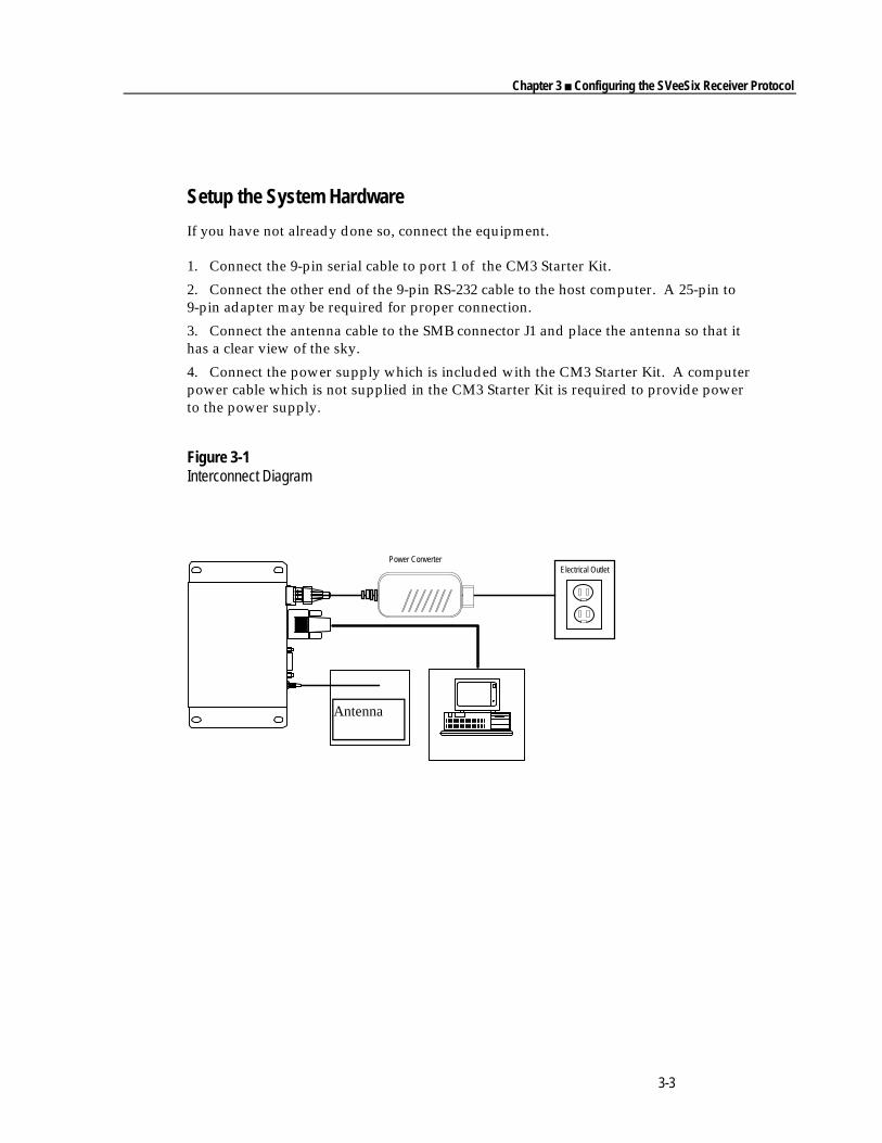
Setup the System Hardware
If you have not already done so, connect the equipment.
1. Connect the 9-pin serial cable to port 1 of the CM3 Starter Kit.
2. Connect the other end of the 9-pin RS-232 cable to the host computer. A 25-pin to9-pin adapter may be required for proper connection.
3. Connect the antenna cable to the SMB connector J1 and place the antenna so that ithas a clear view of the sky.
4. Connect the power supply which is included with the CM3 Starter Kit. A computerpower cable which is not supplied in the CM3 Starter Kit is required to provide powerto the power supply.
Figure 3-1Interconnect Diagram
Antenna
Power ConverterElectrical Outlet
3-4
SVeeSix-CM3 System Designer Reference Manual
Load the Configuration Program
The SVeeSix-CM3 Starter Kit includes the OEM GPS Tool Kit diskette. This diskettecontains the protocol configuration programs. If you have not already done so, loadthese programs onto your hard disk. Then execute the proper configuration file for theparticular protocol desired.
1. Power cycle the receiver to reset the unit.
2. Go to the TK510A directory.
3. Type 34055-XX.EXE. -cY where XX = 61 TSIP, 62 for NMEA and 63 for TAIPprotocols, and the Y denotes the host COM port. i.e., 34055-61.exe -c2 This willprogram the GPS receiver to TSIP in / out via the hosts COM 2 port.
◆NOTE: The SVeeSix-CM3 receiver has a 5 minute time-out feature to prevent accidentalreconfiguration in the field. Power cycle the receiver prior to accessing the Configuration program.This will ensure that program's time-out feature is not activated before you have completed yourselections.
◆NOTE: If you have selected the NMEA or TAIP protocol, you may use ProComm, WindowsTerminal, Win 95 Hyperterm, or the terminal mode in GPSSK to view this data.
Chapter 4Hardware Integration
Integration of the SVeeSix-CM3 can be divided into two categories: hardware andsoftware. Hardware integration includes mounting the GPS module and physicallyconnecting the module to the antenna, the host processor, and the power source.Software integration involves configuring the GPS module to communicate with thehost processor. The magnitude of the software integration varies with the selectedprotocol.
This chapter provides information on hardware integration. For information onsoftware integration, refer to Chapter 5, Software Interface.
Svee-Six-CM3 System Designer Reference Manual
4-2
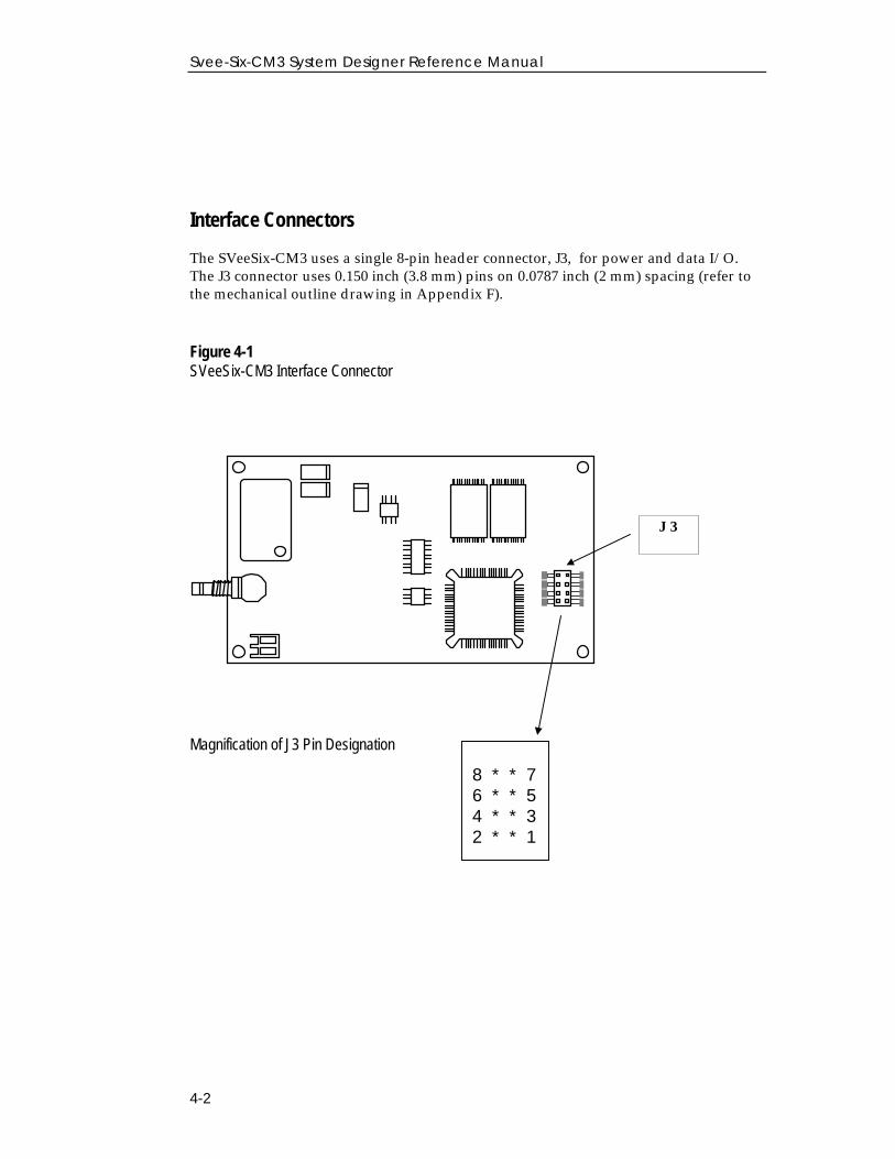
Interface Connectors
The SVeeSix-CM3 uses a single 8-pin header connector, J3, for power and data I/O.The J3 connector uses 0.150 inch (3.8 mm) pins on 0.0787 inch (2 mm) spacing (refer tothe mechanical outline drawing in Appendix F).
Figure 4-1SVeeSix-CM3 Interface Connector
Magnification of J3 Pin Designation
J 3
8 * * 76 * * 54 * * 32 * * 1
Chapter 4 - Hardware Integration
4-3
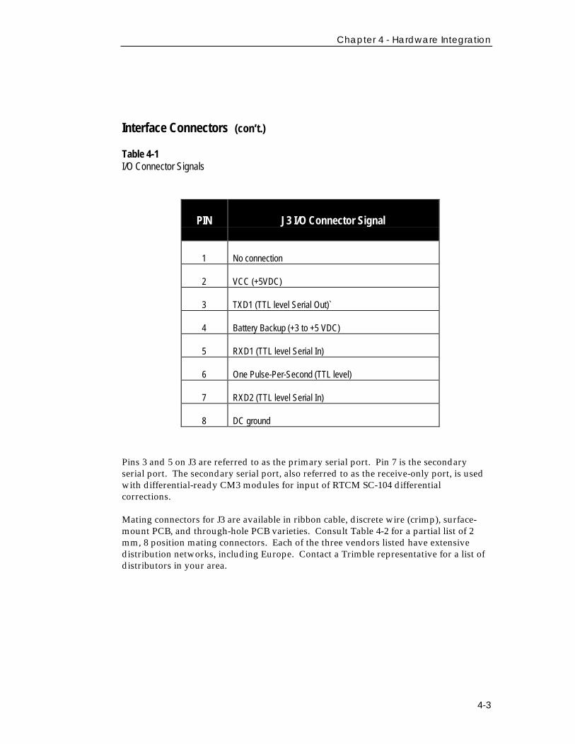
Interface Connectors (con’t.)
Table 4-1I/O Connector SignalsPIN PIN J3 I.O Connector Signal
PIN J3 I/O Connector Signal
1 No connection
2 VCC (+5VDC)
3 TXD1 (TTL level Serial Out)`
4 Battery Backup (+3 to +5 VDC)
5 RXD1 (TTL level Serial In)
6 One Pulse-Per-Second (TTL level)
7 RXD2 (TTL level Serial In)
8 DC ground
Pins 3 and 5 on J3 are referred to as the primary serial port. Pin 7 is the secondaryserial port. The secondary serial port, also referred to as the receive-only port, is usedwith differential-ready CM3 modules for input of RTCM SC-104 differentialcorrections.
Mating connectors for J3 are available in ribbon cable, discrete wire (crimp), surface-mount PCB, and through-hole PCB varieties. Consult Table 4-2 for a partial list of 2mm, 8 position mating connectors. Each of the three vendors listed have extensivedistribution networks, including Europe. Contact a Trimble representative for a list ofdistributors in your area.
Svee-Six-CM3 System Designer Reference Manual
4-4
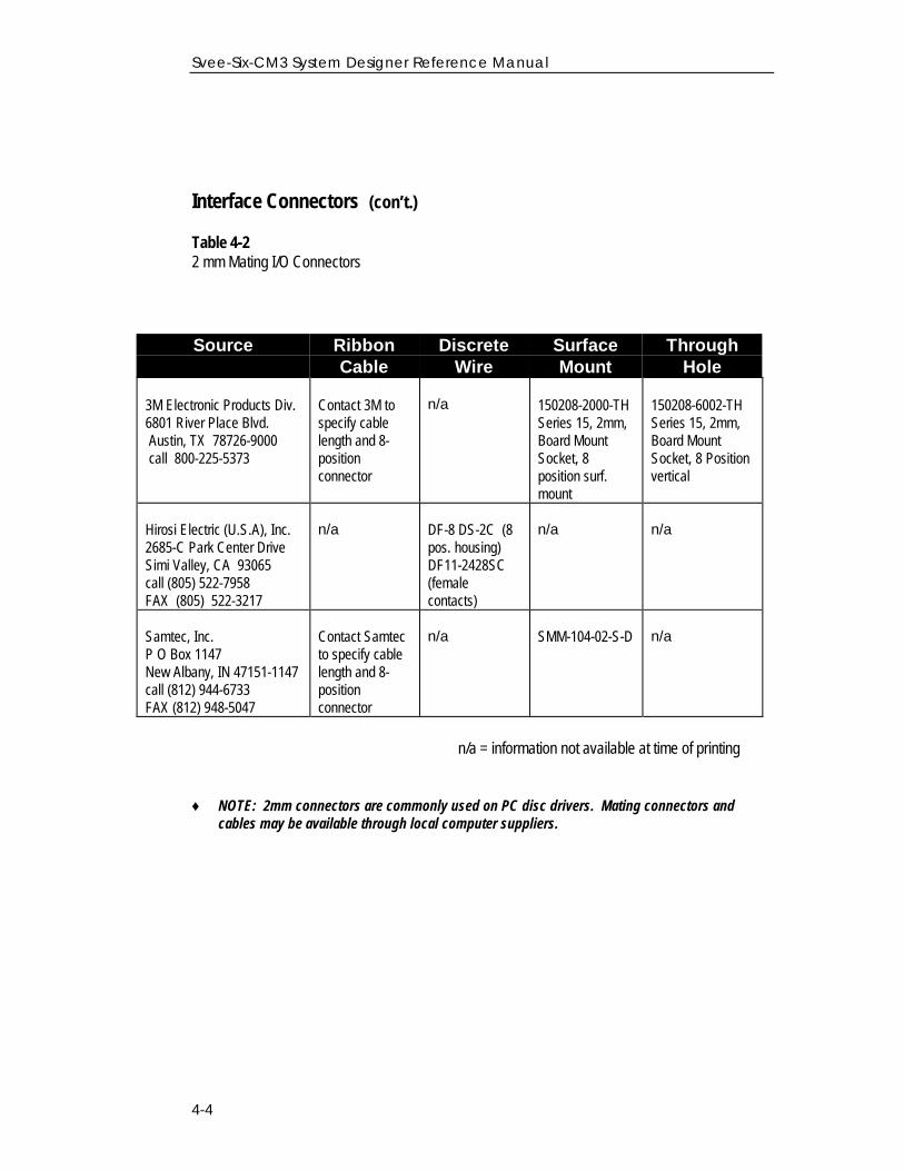
Interface Connectors (con’t.)
Table 4-22 mm Mating I/O Connectors
Source RibbonCable
DiscreteWire
SurfaceMount
ThroughHole
3M Electronic Products Div.6801 River Place Blvd. Austin, TX 78726-9000 call 800-225-5373
Contact 3M tospecify cablelength and 8-positionconnector
n/a 150208-2000-THSeries 15, 2mm,Board MountSocket, 8position surf.mount
150208-6002-THSeries 15, 2mm,Board MountSocket, 8 Positionvertical
Hirosi Electric (U.S.A), Inc.2685-C Park Center DriveSimi Valley, CA 93065call (805) 522-7958FAX (805) 522-3217
n/a DF-8 DS-2C (8pos. housing)DF11-2428SC(femalecontacts)
n/a n/a
Samtec, Inc.P O Box 1147New Albany, IN 47151-1147call (812) 944-6733FAX (812) 948-5047
Contact Samtecto specify cablelength and 8-positionconnector
n/a SMM-104-02-S-D n/a
Source Ribbon Cable Discrete n/a = information not available at time of printing
Ribbon Cable Discrete Wire Surface Mount Through Hole♦ NOTE: 2mm connectors are commonly used on PC disc drivers. Mating connectors and
cables may be available through local computer suppliers.
Chapter 4 - Hardware Integration
4-5
Power Requirement
The SVeeSix-CM3 module requires +5 volts DC (-3%, +5%) at 240 ma, nominalexcluding antenna. The CM3 does not require any special power up or downsequencing. The receiver power is supplied through pin 2 of the J3 I/O connector.Refer to Table 4-3 and to Figure 4-1 for the +5 VDC power specifications.
The CM3 module provides an input for battery back-up (BBU) power to keep themodule's RAM memory alive and power the real-time clock when the receiver's mainpower is turned off. RAM memory is used to store the GPS almanac, ephemeris, anduser configuration data. Though not required, providing BBU power can reduce thetime required at power-on for the SVeeSix-CM3 to acquire GPS satellite signals andcompute position to less than 50 seconds (typical). A 3.5 volt lithium battery willtypically supply back-up power for up to five years.
Svee-Six-CM3 System Designer Reference Manual
4-6
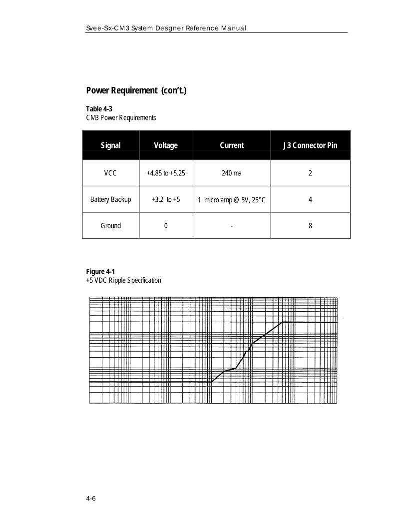
Power Requirement (con’t.)
Table 4-3CM3 Power Requirements
Signal Voltage Current J3 Connector Pin
VCC +4.85 to +5.25 240 ma 2
Battery Backup +3.2 to +5 1 micro amp @ 5V, 25°C 4
Ground 0 - 8
VoltageCurrent J3 Connector Pin
Figure 4-1+5 VDC Ripple Specification
Chapter 4 - Hardware Integration
4-7
Serial Interface
As an embedded design, the CM3 provides direct CMOS compatible TTL level serialI/O. The RX and TX signals on the J3 I/O connector are driven directly by theDUART on the CM3. Interfacing these signals directly to a DUART provides a directserial interface without the expense of RS-232 or RS-422 line drivers.
◆NOTE: The CM3 module serial I/O signals on J3 are at TTL level (0 to +5VDC ); They are notinverted or driven to RS-232 levels. Use the starter kit motherboard supplied with the CM3 starterkit to connect to a RS-232 serial port.
One Pulse Per Second
A one microsecond wide, CMOS compatible TTL level pulse is available on pin 6 of theJ3 I/O connector. This pulse is issued once per second with the rising edge of the pulsesynchronized with UTC. The pulse will be shaped by the distributed impedance of theattached signal line and input circuit. The rising edge is typically less than 20nanoseconds wide. The falling edge should not be used.
The timing accuracy is ± 600 nanoseconds typical (5 microseconds worst case) and isvalid only when computing position fixes, or in a static, one-satellite, time-only mode.Repeatability checks of 10 sets of 100 one second samples taken over a period of 20minutes showed an average variation of approximately 100 nanoseconds (not allowingfor S/A).
Mounting
The CM3 provides four 0.095 inch mounting holes that will accept 3/16 inch round orhex standoffs and #2-56 or M2 mounting screws. Refer to the mechanical outlinedrawing in Appendix F for dimensions and clearances.

Chapter 5Software Interface
This chapter describes the SVeeSix-CM3 software interface and start-up characteristicsfor each of the interface protocols. In addition, a description of the receiver operatingmodes is provided along with a brief discussion of the interface protocols.
When connected to an external GPS antenna, the SVeeSix-CM3 receiver contains all thecircuitry necessary to automatically acquire GPS satellite signals, track up to 8 GPSsatellites and compute and output location, speed, heading, and time.
The SVeeSix-CM3 receiver will automatically begin to search for and track GPS satellitesignals at power-up. The time to first fix from a complete cold start is normally 2 to 4minutes, varying with time required to acquire satellite almanac and ephemeris data.The receiver will respond to commands almost immediately after power-up.
SVeeSix-CM3 System Designer Reference Manual
5-2
Startup
The SVeeSix-CM3 is a complete 6-channel GPS receiver for embedded applications.The receiver will automatically begin to search for and track GPS satellite signals atpower-up. The SVeeSix-CM3 time to first fix from a complete cold start is normally 2to 4 minutes, varying with time required to acquire satellite almanac and ephemerisdata. This time to first fix can typically be shortened to less than 50 seconds if back-uppower is used to power the real-time clock and maintain RAM. The receiver willrespond to commands almost immediately after power-up.
Software Tool Kits
Trimble provides two software developer tool kits to support the two I/O protocolssupplied with the SVeeSix-CM3 Starter Kit. These tool kits contain user-friendlyprograms to communicate with the receiver and include sample source code orreusable routines to aid system integrators in developing their own applications.
If unfamiliar with Trimble's SVeeSix family of GPS receivers and the I/O protocolsavailable, please take a moment to review Appendix B, TSIP User’s Guide or Appendix D,GPSSK User's Guide for TAIP. If a copy of the software tool kit for the I/O protocolchosen was not included, please contact the nearest Trimble representative or call theTechnical Assistance number listed on the front cover of this manual.
Chapter 5 - Software Interface
5-3
Communicating with the SVeeSix-CM3 Module
The SVeeSix-CM3 supports three I/O message protocols. The developer's starter kitincludes configuration software to program the unit for TSIP (Trimble StandardInterface Protocol), TAIP (Trimble ASCII Interface Protocol), and NMEA (NationalMarine Electronics Association). The protocols are discussed at the end of thischapter, and are explained in greater detail in Appendices A through E.
The SVeeSix-CM3 modules are delivered with the TSIP protocol installed. A separateconfiguration disk can be purchased or downloaded from the Trimble FTP: site at
FTP://FTP.trimble.com/pub/sct/embedded/bin/
These files can change the CM3 module to output TSIP, TAIP or NMEA protocols.
♦ NOTE: The standard temperature configuration disk only works with the standard temperaturemodule. Similarly, the extended temperature configuration works with the extended temperatureboard. The extended temperature software configuration will give unpredictable results on theStandard temperature module or vise-versa.
Communication with the SVeeSix-CM3 module is through a CMOS compatible, TTLlevel serial port. This approach makes the SVeeSix-CM3 module software compatiblewith other members of the SVeeSix family of GPS receivers and simplifies systemintegration. If connecting the CM3 to a RS-232 serial port on a PC, use either thestarter kit motherboard or a TTL to RS 232 converter along with the proper interfacecables.
The SVeeSix-CM3 serial port default characteristics are under firmware control and aredifferent for the TSIP, TAIP and NMEA protocols. When running TSIP or TAIP, theport characteristics may be changed by the user. Refer to Table 5-1 for the default portsettings. On differential-ready modules, the secondary serial port factory settings forRTCM SC-104 input are: 4800, 8, 1, None.
SVeeSix-CM3 System Designer Reference Manual
5-4
Communicating with the SVeeSix-CM3 Module (con’t.)
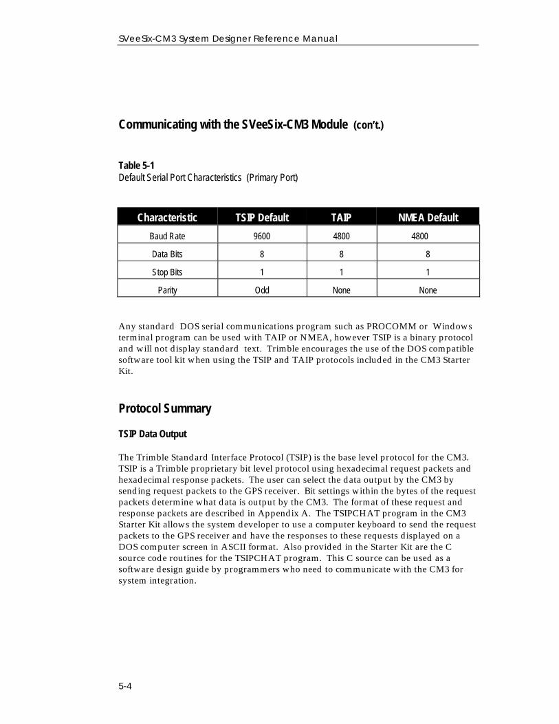
Table 5-1Default Serial Port Characteristics (Primary Port)
Characteristic TSIP Default TAIP Default NMEA Default
Characteristic TSIP Default TAIP NMEA Default
Baud Rate 9600 4800 4800
Data Bits 8 8 8
Stop Bits 1 1 1
Parity Odd None None
Any standard DOS serial communications program such as PROCOMM or Windowsterminal program can be used with TAIP or NMEA, however TSIP is a binary protocoland will not display standard text. Trimble encourages the use of the DOS compatiblesoftware tool kit when using the TSIP and TAIP protocols included in the CM3 StarterKit.
Protocol Summary
TSIP Data Output
The Trimble Standard Interface Protocol (TSIP) is the base level protocol for the CM3.TSIP is a Trimble proprietary bit level protocol using hexadecimal request packets andhexadecimal response packets. The user can select the data output by the CM3 bysending request packets to the GPS receiver. Bit settings within the bytes of the requestpackets determine what data is output by the CM3. The format of these request andresponse packets are described in Appendix A. The TSIPCHAT program in the CM3Starter Kit allows the system developer to use a computer keyboard to send the requestpackets to the GPS receiver and have the responses to these requests displayed on aDOS computer screen in ASCII format. Also provided in the Starter Kit are the Csource code routines for the TSIPCHAT program. This C source can be used as asoftware design guide by programmers who need to communicate with the CM3 forsystem integration.
Chapter 5 - Software Interface
5-5
Protocol Summary (con’t.)
TAIP Data Output
The Trimble ASCII Interface Protocol (TAIP) is a Trimble-specified digitalcommunication interface based on printable ASCII characters over a serial data link.TAIP interface provides the means to configure the SVeeSix-CM3 receiver to outputvarious sentences in response to query or on a scheduled basis. TAIP messages may bescheduled for output at a user specified rate starting on a given epoch from top of thehour. For communication robustness, the protocol optionally supports checksums on allmessages. It also provides the user with the option of tagging all messages with theunit's user specified identification number (ID). This greatly enhances the functionalcapability of the unit in a network environment. This protocol is described in AppendixC.
NMEA 0183 Data Output
The National Marine Electronics Association (NMEA) protocol is an industry standarddata protocol which was developed for the marine industry. Trimble has chosen toadhere stringently to the NMEA 0183 data specification as published by the NMEA.Although the Trimble CM3 supports seven NMEA sentences that contain GPSinformation, the standard CM3 only outputs the GGA and VTG data strings. (Note:Contact your Trimble sales representative if you need access to all or a subset of theother five NMEA sentences). NMEA data is output in standard ASCII sentenceformats. Message identifiers are used to signify what data is contained in eachsentence. Data fields are separated by commas within the NMEA sentence. In theCM3, NMEA is an output only protocol. The NMEA protocol is described in detail inAppendix E.
SVeeSix-CM3 System Designer Reference Manual
5-6
Time Operation
The SVeeSix-CM3 is an excellent source of accurate time for a system such asenvironmental data acquisition or communications networks. The timing functions ofthe receiver are supported by both the TSIP and TAIP I/O protocols. Please refer toReport Packet 41 in Appendix A or the TM message in Appendix C for a description ofthe time function reports for the TSIP and TAIP protocols.
GPS time differs from UTC (Universal Coordinated Time) by a variable number ofseconds. This GPS/UTC offset has two parts: an integer number of seconds called“leap seconds”, and a small sub-microsecond part that tracks the differences betweenthe GPS clock run by “DOD” and the world wide UTC standard.
UTC = (GPS time) - (GPS\UTC offset)
As of June 30, 1997, the GPS\UTC offset was 12 seconds. The offset increases by 1second approximately every 18 months. System designers should plan to read theoffset value as a part of the timing interface to obtain UTC. The GPS week number is inreference to a base week (Week #0), starting January 6, 1980.
The current GPS\UTC offset is contained within the almanac transmitted by the GPSsystem. The SVeeSix-CM3 must have a complete almanac before the offset data isvalid.
Chapter 5 - Software Interface
5-7
Effect of GPS Week Number Roll-over (21/22 August 1999) on TrimbleOEM Receivers
At midnight GMT, on 21/22 August 1999, the GPS week number will "roll-over" from 1023 back to 0. There is no GPS Week Number higher than 1023,and such Week Number Roll-Overs (WNROs) occur every 1024 weeks, or about19 years 8 months. August 1999 is the first roll-over ever for the GPS system.Trimble receivers have numerous protections to prevent this from being acatastrophic event. However, they may benefit from extra care with the firstpower-up after WNRO. Tests of a representative sample of Trimble OEMreceivers revealed only two issues:
1. On previous receivers, an almanac recorded pre-WNRO is not correct afterWNRO. This is only a problem if the receiver has main power off and battery-back power on at the moment of WNRO. After a post-WNRO almanac has beencollected (via a cold start), the receiver's behavior returns to normal.
2. On previous receivers, the TAIP (TM) and NMEA (ZDA) messages, whichreport day-month-year (E.g.: August 23, 1999), will be incorrect after WNRO.Time of day and day of week information will not be affected.
TSIP users will not see any impact on position or time information. However,the reported GPS week number will reset to zero and users of this informationmay need to make a software modification to accommodate this change. Belowis information regarding specific Trimble OEM GPS receivers.
SVeeSix-CM3 System Designer Reference Manual
5-8
Effect of GPS Week Number Roll-over (con’t)
No Effect, Firmware Version 5.06 and Later Versions
No problems with dates or the first fix after WNRO through the year 2015.
One-time Long TTFF, Firmware Version 4.0 through Version 5.04
In these receivers, a pre-WNRO almanac cannot be used post-WNRO. The GPSreceiver is constantly decoding and collecting new almanacs, so the oldalmanac will be promptly replaced during normal operation. The difficultyoccurs when the receiver is powered on for the first time after WNRO. Ifbattery-backed, the receiver wakes up with a pre-WNRO (incorrect) almanacand the receiver will have difficulty finding satellites for a fix. Fortunately, theTrimble OEM receiver is designed to generate a fix even with an incorrectalmanac; however, the process requires more time, perhaps more than tenminutes. Longer-than-normal TTFFs will continue until a full post-WNROalmanac is collected, after which the receiver will have normal behavior. Toprevent long TTFFs again, allow the receiver to track satellites long enough toreplace the almanac (about 15 minutes after first fix). After a full almanac iscollected, TTFF performance will return to normal.
Incorrect Date Message, Firmware Version 4.0 through 5.02
These receivers have the initial long TTFF described in the above paragraph. Inaddition, dates (day-month-year) will be misreported permanently after WNRO.The only standard date messages put out by Trimble OEM receivers are theNMEA-ZDA NMEA-RMC, and TAIP-TM messages. Therefore, only users ofthese specific messages will be affected. All other standard time messages areday-of-week or time-of-day, which will not be in error. Any custom datemessages could also be permanently incorrect starting on 22 August 1999.
♦ NOTE: The CM3 supplied with the starter kit as described in this manual containsversion 5.0 or later firmware and will not be affected by week number roll-over.
Chapter 5 - Software Interface
5-9
Differential GPS
The differential-ready SVeeSix-CM3 module can use differential corrections tocompute a Differential GPS position (DGPS). DGPS can provide positionaccuracy of 2 to 5 meters (1 sigma). The SVeeSix-CM3 supplied with theStarter Kit is differential-ready.
RTCM SC-104 is an industry standard format for differential correctionsavailable from most DGPS reference stations, Coast Guard beacontransmissions, and commercial DGPS subscription services. The SVeeSix-CM3 is fully compatible with RTCM SC-104 versions 1 and 2. A differential-ready SVeeSix-CM3 is configured to accept RTCM SC-104 correction data overthe secondary serial port (J3, pin 7) at 4800 baud, 8 data bits, 1 stop bit andno parity. The DGPS operating mode is set to Automatic which means that theSVeeSix-CM3 will provide differential GPS solutions when valid correction datais available and will output standard GPS solutions when no valid correctiondata is available.
No setup is required to use RTCM SC-104 differential corrections, however,reconfigure the secondary serial port characteristics (baud rate, data bits, stopbits and parity) to match the characteristics of the RTCM SC-104 data sourceusing the 8E-03 packet in TSIP or the AP command in TAIP. Refer to AppendixA or Appendix C for more information on these messages. Table 5-2summarizes the default characteristics for both the primary and secondaryserial ports on differential-ready modules. Notice that units using the NMEA0183 protocol will accept TSIP command packet 8E-03.
Alternatively, use Trimble's TSIP packets 60 and 61, or TAIP messages DC andDD to apply differential corrections through the CM3's primary serial port(J3, pin 5). These messages may be useful in applications which require theuse of a single communications channel between the SVeeSix-CM3 and thesystem. Note that using these messages requires reformatting the RTCM SC-104 differential correction data into the 60/61 or DC/DD message formats.See Appendix A and Appendix C for more information on these messages.
SVeeSix-CM3 System Designer Reference Manual
5-10
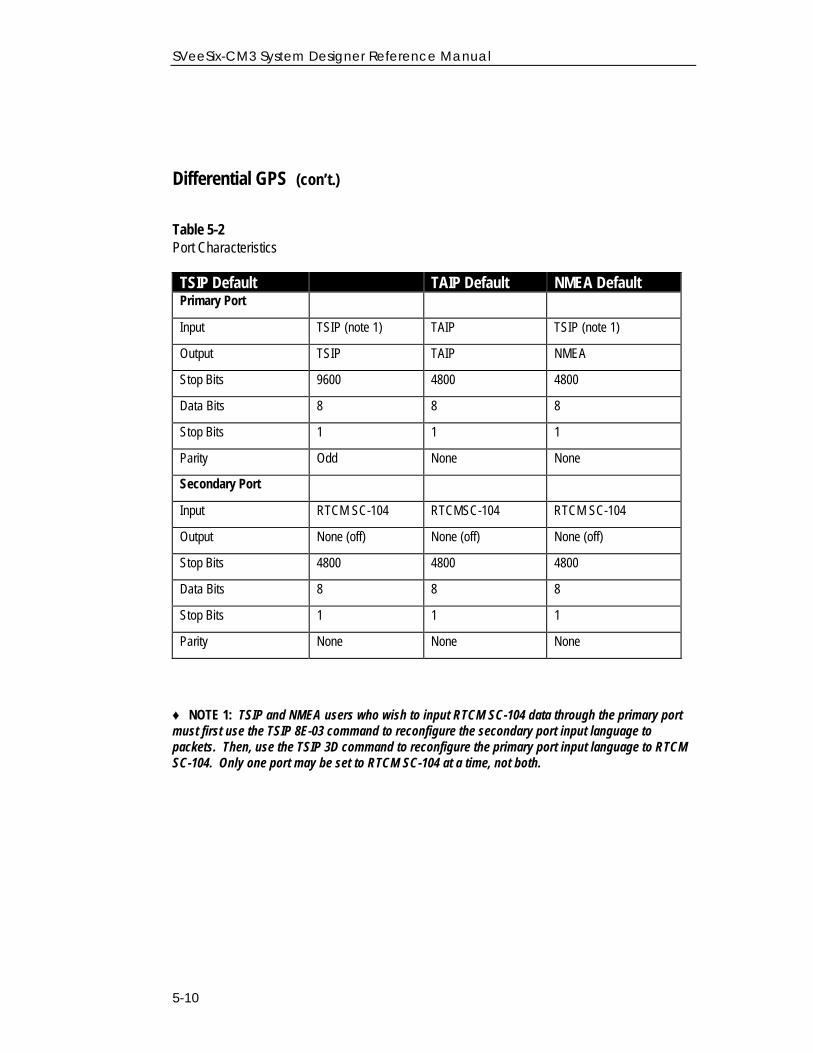
Differential GPS (con’t.)
Table 5-2Port Characteristics
TAIP Default NMEA DefaultTSIP Default TAIP Default NMEA DefaultPrimary Port
Input TSIP (note 1) TAIP TSIP (note 1)
Output TSIP TAIP NMEA
Stop Bits 9600 4800 4800
Data Bits 8 8 8
Stop Bits 1 1 1
Parity Odd None None
Secondary Port
Input RTCM SC-104 RTCMSC-104 RTCM SC-104
Output None (off) None (off) None (off)
Stop Bits 4800 4800 4800
Data Bits 8 8 8
Stop Bits 1 1 1
Parity None None None
♦ NOTE 1: TSIP and NMEA users who wish to input RTCM SC-104 data through the primary portmust first use the TSIP 8E-03 command to reconfigure the secondary port input language topackets. Then, use the TSIP 3D command to reconfigure the primary port input language to RTCMSC-104. Only one port may be set to RTCM SC-104 at a time, not both.
Chapter 6Operating Characteristics
This chapter describes the SVeeSix-CM3 receiver's satellite acquisition and trackingprocesses, performance characteristics and system architecture. This discussionassumes the reader is familiar with a basic theory of operation for the GlobalPositioning System. Before proceeding to the detailed discussion of the satelliteacquisition and tracking process, please review the GPS satellite message descriptionon the next page.
The SVeeSix-CM3 receiver's satellite acquisition and tracking algorithms can achieve aposition solution without any initialization. The receiver automatically selects andtracks the best combination of satellites to compute position and velocity. As satellitesmove out of view, the SVeeSix-CM3 automatically acquires new satellites and includesthem in the solution set as required.
SVeeSix-CM3 System Designer Reference Manual
6-2
GPS Satellite Message
Every GPS satellite transmits the Coarse/Acquisition (C/A) code and satellite datamodulated onto the L1 carrier frequency (1575.42 MHz). The C/A code is a uniquepseudo-random number for each satellite. The satellite data transmitted by eachsatellite includes a satellite almanac for the entire GPS system, its own satelliteephemeris and its own clock correction.
The satellite data is transmitted in 30-second frames. Each frame contains the clockcorrection and ephemeris for that specific satellite, and two pages of the 50-page GPSsystem almanac. The time required to transmit the complete system almanac is 12.5minutes and the time to transmit the satellite ephemeris is 30 seconds.
The system almanac contains information about each of the satellites in theconstellation, ionospheric data, and special system messages. The ephemeris containsdetailed orbital information for a specific satellite. The GPS system almanac is updatedweekly and is typically valid for months. Ephemeris data changes hourly, but is validfor up to four hours. The GPS control segment updates the system almanac weeklyand the ephemeris hourly through three ground-based control stations. During normaloperation, the SVeeSix-CM3 module updates its ephemeris and almanac as needed.
The performance of a GPS receiver at power-on is determined largely by theavailability and accuracy of the satellite ephemeris data and the availability of a GPSsystem almanac.
Chapter 6 - Operating Characteristics
6- 3
Satellite Acquisition and Time to First Fix
Cold Start
The term "cold start" describes the performance of a GPS receiver at power-on when nonavigation data is available. "Cold" signifies that the receiver does not have a currentalmanac, satellite ephemeris, initial position, or time. The cold start search algorithmapplies to an SVeeSix-CM3 which is powered on without the memory backup circuitconnected to a source of DC power. This is the "out of the box" condition of the GPSmodule as received from the factory.
In a cold start condition, the receiver automatically selects a set of six satellites anddedicates an individual tracking channel to search the Doppler range frequency foreach satellite in the set. If none of the six selected satellites are acquired after a pre-determined period of time (time-out), the receiver will select a new search set of sixsatellites and will repeat the process, until the first satellite is acquired. As satellitesare acquired, the receiver automatically collects ephemeris and almanac data. TheSVeeSix-CM3 uses the knowledge gained from acquiring a specific satellite to eliminateother satellites, those below the horizon, from the search set. This strategy speeds theacquisition of additional satellites required to achieve the first position fix.
The cold start search sets are established to ensure that at least three satellites areacquired within the first two time-out periods. As soon as three satellites are found,the receiver will compute an initial position fix. The typical time to first fix, during acold start, is less than 5 minutes.
A complete system almanac is not required to achieve a first position fix. The almanacis used in subsequent warm starts, and to aid in acquiring GPS satellites that come intoview.
Warm Start
In a warm start condition, the receiver has been powered down for a period of time buthas a current almanac, and an initial position (within 3,000 km) stored in memory.
When connected to an external backup battery and power is disconnected, the SVeeSix-CM3 retains the almanac, initial position and time. This aids in satellite acquisition andreduces the time to first fix. When an external back-up battery is not used, the TSIPprotocol allows the almanac, initial position, and time to be uploaded to the receiver toinitiate a warm start.
SVeeSix-CM3 System Designer Reference Manual
6-4
Satellite Acquisition and Time to First Fix (con’t.)
During a warm start, the SVeeSix-CM3 identifies the satellites which are expected to bein view, given the system almanac, the initial position and the approximate time. Thereceiver calculates the elevation and expected Doppler shift for each satellite in thisexpected set and directs the six tracking channels in a parallel search for thesesatellites. If the internal oscillator error is known, the SVeeSix-CM3 compensates forthe offset to optimize the search. If the offset is not known, the search algorithms willbe set wide enough to allow for oscillator tolerance, aging, and temperature errors.
The warm start time to first fix, when the receiver has been powered down for morethan four hours (i.e. the ephemeris data is old) is usually less than 50 seconds (40seconds typical).
Garage Search Strategy
During a warm start search, the SVeeSix-CM3 knows which satellites to search for,based on the system almanac, the initial position (last known position) and the currenttime. In some cases, the receiver may not be able to acquire the expected satellitesignals (e.g. a vehicle parked in a garage or a vessel in a covered berth). Trimble'spatented "garage search" strategy, also known as a split search, is designed for suchsituations.
In this mode, half of the tracking capability of the receiver is dedicated to warm startsearch mode while the other half of the receivers tracking capability is directed to coldstart search mode ( receiver off for more than 36 hours). This strategy minimizes thetime to first fix in cases where the stored almanac, position and time are invalid. Thestored information is flushed from memory, if the cold start search proves effectiveand the warm search fails.
Hot Start
A hot start strategy applies when the SVeeSix-CM3 has been powered down for lessthan four hours, and the almanac, position and ephemeris are valid. The hot startsearch strategy is similar to a warm start, but since the ephemeris data in memory isconsidered current and valid, the acquisition time is typically less than 30 seconds.
Chapter 6 - Operating Characteristics
6- 5
Satellite Mask Settings
Once the SVeeSix-CM3 has acquired and locked onto a set of satellites, which pass themask criteria listed below, and has obtained a valid ephemeris for each satellite, it willoutput regular position, velocity and time reports according to the protocol selected.
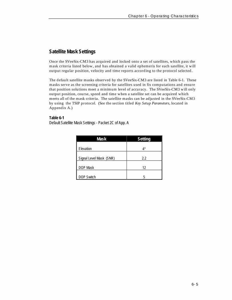
The default satellite masks observed by the SVeeSix-CM3 are listed in Table 6-1. Thesemasks serve as the screening criteria for satellites used in fix computations and ensurethat position solutions meet a minimum level of accuracy. The SVeeSix-CM3 will onlyoutput position, course, speed and time when a satellite set can be acquired whichmeets all of the mask criteria. The satellite masks can be adjusted in the SVeeSix-CM3by using the TSIP protocol. (See the section titled Key Setup Parameters, located inAppendix A.)
Table 6-1Default Satellite Mask Settings - Packet 2C of App. A
Mask SettingMask Setting
Elevation 4°
Signal Level Mask (SNR) 2.2
DOP Mask 12
DOP Switch 5
SVeeSix-CM3 System Designer Reference Manual
6-6
Standard Operating Modes
The allocation of signal-processing channels and output of GPS data are controlled bythree operating modes:
❏ Over-Determined Mode (On or Off)
❏ Fix Modes (2D, 3D, or Automatic 3D / 2D / 2D CH).
❏ 0-D Timing Mode (Stationary timing application)
❏ Over-Determined Mode (On or Off)
Each of these operating modes are described below.
Over-Determined Mode
An over-determined solution employs more than the minimum number of satellitesrequired for the position solution. For a 2D position, an over-determined solutionrequires four or more satellites. An over-determined 3D solution requires 6 to 8satellites. By reducing the relative contribution of each individual satellite to theoverall solution, an over-determined solution moderates the effects of SelectiveAvailability, smoothes the position output and minimizes the jumps caused byconstellation changes.
The best over-determined solution requires a continuous-tracking, 6-channel receiverarchitecture. For 6-channel modules, the default setting for over-determined mode isset to ON. The SVeeSix-CM3 will use up to eight satellites in the position solution aslong as all mask criteria are satisfied. The over-determined solution can be turned offfor TSIP-compatible receivers by issuing the appropriate TSIP command. SeeAppendix A for more information about the TSIP protocol.
Chapter 6 - Operating Characteristics
6- 7
Over-Determined Mode (con’t.)
High 8 mode: (also known as Smart Sequencing) The receiver outputs an all-in-view,over-determined solution. It provides six continuous tracking channels which areallocated based on SNR age of latest measurement. A satellite will receive a continuoustracking channel if it has a low SNR or is much fresher than a satellite which has itsown channel. The channel swapping logic responds quickly to changing conditions,such as every few seconds, so if a weak signal is reacquired from a sequencing satellitethen it will quickly receive its own channel. Safeguards are applied to prevent thereceiver from over-allocating system resources when satellites are quickly obscured,and then reacquired. Prior to first fix, five channels are used to acquire data, with theconstraint of two satellites per channel. After the first fix, only three channels areallowed to acquire data if eight satellites are being tracked. If less than eight satellitesare in the tracked list, then up to four channels are allowed to collect data.
The main advantage of an over-determined solution is the increase in accuracy which isgenerally about a factor of two.
High 6 mode: This mode offers the fastest satellite reacquisition since no channelsequencing is required. Both the High 6 and Best 4 modes have the advantage thatwhen there are no obstructions, measurements can be taken from all satellites in the fixat the same time, and thus, there are no latency induced errors due to vehicle dynamicsor receiver clock non linearity’s. The penalty of High 6 mode is the degradation ofDOP’s and satellite visibility due to tracking only six satellites. The drawback of Best 4is that there is no averaging of measurement errors with this solution.
Best 4 tracking mode: A non over-determined solution. The continuous trackingchannels are allocated based on the Best 4 satellite selection. The selected satellites arecontinuously tracked and satellites not in the selected fix set are moved to thesequencing channels. All sequencing is done on channel 6 which means that there willbe three SV’s on channel 6 when there are eight satellites being tracked.
SVeeSix-CM3 System Designer Reference Manual
6-8
Standard Operating Modes (con’t)
Fix Modes
The SVeeSix-CM3 offers three positioning modes (in order of appearance): 3D Manual,2D Manual, Automatic 3D / 2D / 2D CH. However, Automatic 3D/2D/2D CH is thedefault mode for the SVeeSix-CM3. The positioning mode can be modified in receiversaccepting TSIP commands. See Appendix A for more information on the TSIPprotocol.
◆ NOTE: One Satellite Timing Mode is only used for stationary timing applications.
2D Manual
In 2D Manual mode, the SVeeSix-CM3 will only generate 2-dimensional (2D) positionsolutions (latitude and longitude only), regardless of the number of visible satellites.For 2D solutions, the receiver uses mean sea level as the default altitude. The greaterthe deviation between the actual and default altitudes, the greater the error in the 2Dposition. For TSIP applications, enter local altitude in MSL/HAE via TSIP packet #2A(see Appendix A).
◆ NOTE: 2D Manual mode is not recommended for differential GPS applications, since anydeviation in altitude will cause a significant error in the latitude and longitude. For DGPSapplications, 3D Manual is the recommended positioning mode for the highest level of accuracy.
3D Manual
In 3D Manual mode, the SVeeSix-CM3 will only generate 3-dimensional (3D) positionsolutions (latitude, longitude, and altitude). A 3D solution requires at least four visiblesatellites which pass the mask criteria. If less than four conforming satellites arevisible, the SVeeSix-CM3 will suspend position data outputs. 3D Manual mode isrecommended for differential GPS applications requiring the highest level of accuracy.
Chapter 6 - Operating Characteristics
6- 9
Automatic 3D/ 2D/ 2D CH
The default operating mode for the SVeeSix-CM3 is Automatic 3D/2D /2D CH. Inthis mode, the SVeeSix-CM3 attempts to generate a 3-dimensional (3D) positionsolution, if four or more satellites meeting the mask criteria are visible. If only threesatellites are visible which meet the mask criteria, the SVeeSix-CM3 will automaticallyswitch to 2-dimensional (2D) mode and will use the last calculated altitude, if available,or the default altitude in the position solution. If the DOP is above the DOP mask, orwhen only two satellites are visible the receiver will switch to 2D Clock Hold mode.This mode will .model the trajectory of the receiver clock and use it to predict thebehavior of the same clock for a short time in the future (default is 10 seconds). Thiswill allow a 2D fix with only two satellites, or 3D fix when three satellites are visible.In 3D/2D 2D CH Automatic mode, the PDOP switch is active.
One Satellite Timing
One Satellite Timing mode is only used in stationary timing applications. In this mode,the SVeeSix-CM3 maintains the one pulse-per-second output quality by tracking asingle satellite. A TSIP compatible receiver can be switched to One Satellite Timingmode, after it has achieved its first fix, by issuing the appropriate TSIP command (seeAppendix A). This last calculated position fix is assumed to be current and accurate,or a manual position may be entered.
SVeeSix-CM3 System Designer Reference Manual
6-10
Differential GPS Operating Modes
Differential GPS (DGPS) operation is available on versions of SVeeSix-CM3 with theDGPS option (a differential-ready version of the CM3 module us supplied in the StarterKit). The default mode for this version of the SVeeSix-CM3 is DGPS Automatic. TheTSIP version of the SVeeSix-CM3 DGPS supports three DGPS Modes: On, Off, andAutomatic, and the mode may be changed by issuing the appropriate TSIP command.See Appendix A for information on TSIP commands. The NMEA and TAIP version ofthe SVeeSix-CM3 DGPS supports only the DGPS Automatic mode. The three DGPSoperating modes are described on the next page.
DGPS On
When DGPS On is selected, the SVeeSix-CM3 will only provide differential GPSsolutions. If the source of correction data is interrupted or becomes invalid, theSVeeSix-CM3 will suspend all output of position, course and speed data. When a validsource of correction data is restored, the SVeeSix-CM3 will resume outputtingcorrected data.
DGPS Off
When DGPS Off is selected, the SVeeSix-CM3 will not differentially correct the GPSsolutions, even if a valid source of correction data is supplied. In this mode, thereceiver will only supply standard GPS data.
DGPS Automatic
DGPS Automatic is the default operating mode for the SVeeSix-CM3. In this mode, theSVeeSix-CM3 will provide differential GPS solutions when valid correction data isavailable. If correction data is either unavailable or invalid, the SVeeSix-CM3 willoutput standard GPS solutions. The SVeeSix-CM3 automatically switches betweenDGPS and standard GPS based on the availability of valid correction data.
Chapter 6 - Operating Characteristics
6- 11
Differential GPS Operating Modes (con’t)
Differential GPS Operation
The TSIP, NMEA and TAIP versions of the SVeeSix-CM3 are capable of accepting anddecoding RTCM SC-104 data. RTCM SC-104 is an industry standard protocol fordifferential correction data.
The SVeeSix-CM3 receiver provided in the starter kit is configured to accept RTCM SC-104 correction data over the second serial port (J3, pin 7). Alternatively, you can usethe TSIP packets 60 and 61 or the TAIP DC and DD messages to input differentialcorrections through the primary serial port (J3, pin 5).
Position Accuracy
GPS position accuracy is degraded by atmospheric distortion, satellite and receiverclock errors, and Selective Availability (S/A). Effective models for atmosphericdistortion of satellite signals have been developed to minimize the impact oftropospheric and ionospheric effects. The impact of satellite clock errors is minimizedby incorporating the clock corrections transmitted by each satellite used in the positionsolution. SA is the most significant contributor to position error and cannot beeffectively reduced except with differential GPS.
Selective Availability (S/A)
The U.S. Department of Defense, through a program called Selective Availability,intentionally degrades GPS accuracy for civilian users. The S/A program createsposition errors by modifying the apparent position of each satellite and introducingrandom dither into each satellite's clock.
In extreme cases, all sources of error (natural, DOP, and S/A) can combine to producelarge position errors. The DOD's definition of accuracy under S/A is 100 meters2dRMS (horizontal 2 dimensional, at least 95% of the time).
SVeeSix-CM3 System Designer Reference Manual
6-12
Position Accuracy (con’t.)
Differential GPS (DGPS)
Differential GPS is an effective technique for overcoming the effects of S/A and othersources of position error. DGPS relies on GPS error corrections transmitted by areference station placed at a known location. The reference station compares its GPSposition solution to its precisely surveyed position and calculates the error in eachsatellite's range measurement. The industry standard protocol for GPS correction datais RTCM SC-104.
The GPS corrections are broadcast to mobile GPS receivers in neighboring areas. Themobile receivers incorporate the GPS corrections in their position solution to achieveexcellent accuracy. For marine applications, corrections are typically modulated onmarine radio beacon broadcasts. For land-based applications, the correction data canbe transmitted over FM sub-carrier, cellular telephone or dedicated UHF or VHF radiolinks.
DGPS can reduce position error to under 5 meters, 2 sigma of the time under steadystate conditions. The DGPS accuracy is highly dependent on the quality and age of thedifferential corrections and the proximity of the mobile receiver to the reference site.
Coordinate Systems
Once the SVeeSix-CM3 achieves its first fix, it commences periodic outputs of position,velocity, and time information. This information is output over the serialcommunication channel in a format (TSIP, TAIP, or NMEA 0183) controlled in thefirmware configuration program. The TSIP protocol is defined in Appendix A, theTAIP protocol is described in Appendix C, and the NMEA 0183 protocol is describedin Appendix E.
Chapter 6 - Operating Characteristics
6- 13
TSIP
In the factory default TSIP configuration, position is output as a 3-dimensionalcoordinate (X-Y-Z) format. By sending the appropriate TSIP command, the SVeeSix-CM3 position output can be changed to a latitude-longitude-altitude (LLA) coordinateformat based on the WGS-84 datum (or any of the available datums listed in AppendixA). The TSIP velocity output format is also 3-dimensional. The default format is X-Y-Zwith the option of an East-North-Up (ENU) coordinate format. Time messages andtime tags on other messages default to GPS time, but can be switched to UTC(Universal Coordinated Time) by sending the appropriate TSIP command. The 8Fsuper packet is a convenient position, velocity output. UTM coordinate outputs arealso available in 8F-17 and 8F-18 super packet outputs.
TAIP
The TAIP protocol only supports position outputs in the LLA format. Velocityinformation is output in a speed (scalar component) and heading (directioncomponent) format. In TAIP messages, position reports are GPS time tagged, with theexception of the TM message which is always based on UTC.
NMEA 0183
The NMEA 0183 protocol only supports position outputs in the LLA format. Velocityinformation is output in a speed (scalar component) and heading (directioncomponent) format. In NMEA 0183 messages, time and date information is alwaysbased on UTC.
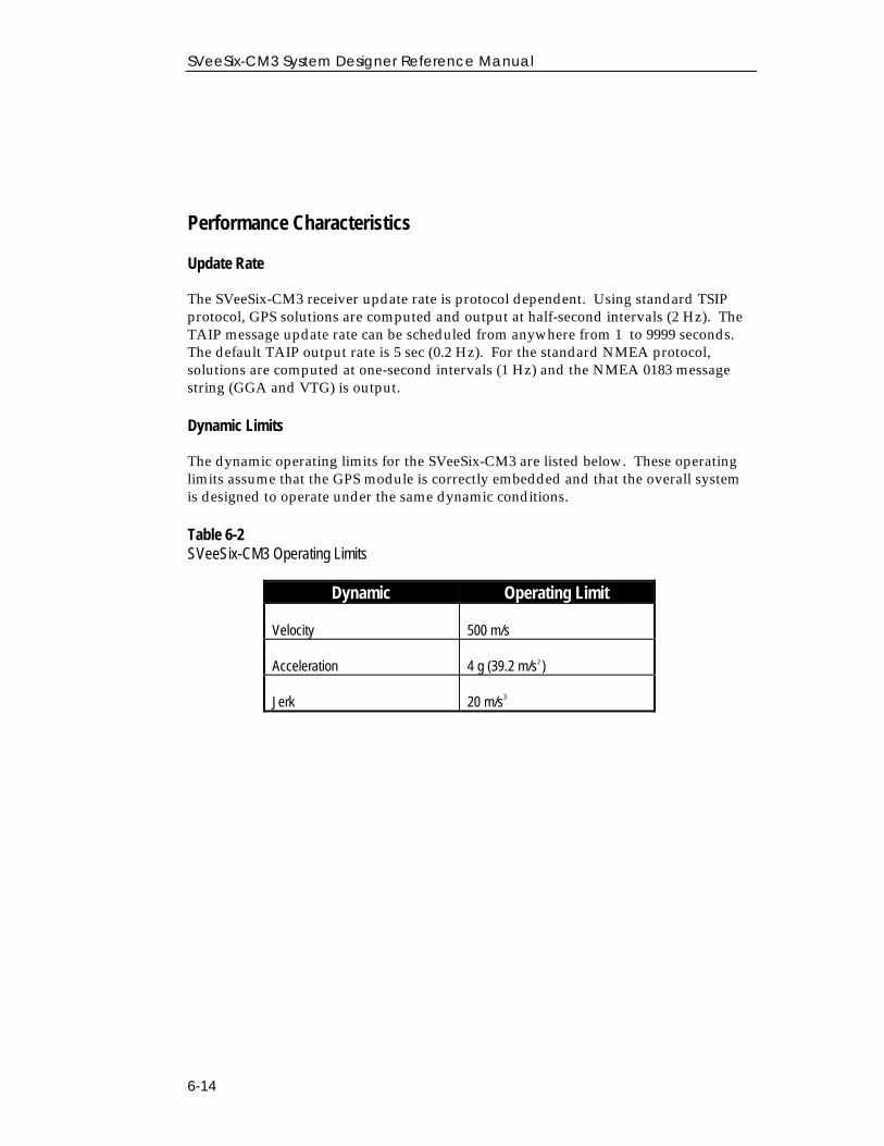
SVeeSix-CM3 System Designer Reference Manual
6-14
Performance Characteristics
Update Rate
The SVeeSix-CM3 receiver update rate is protocol dependent. Using standard TSIPprotocol, GPS solutions are computed and output at half-second intervals (2 Hz). TheTAIP message update rate can be scheduled from anywhere from 1 to 9999 seconds.The default TAIP output rate is 5 sec (0.2 Hz). For the standard NMEA protocol,solutions are computed at one-second intervals (1 Hz) and the NMEA 0183 messagestring (GGA and VTG) is output.
Dynamic Limits
The dynamic operating limits for the SVeeSix-CM3 are listed below. These operatinglimits assume that the GPS module is correctly embedded and that the overall systemis designed to operate under the same dynamic conditions.
Table 6-2SVeeSix-CM3 Operating Limits
Dynamic Operating Limit
Velocity 500 m/s
Acceleration 4 g (39.2 m/s2 )
Jerk 20 m/s3
Dynamic Operating Limit
Chapter 6 - Operating Characteristics
6- 15
Performance Characteristics (con’t.)
Re-Acquisition
When a satellite signal is momentarily interrupted during normal operation, thereceiver continues to search for the lost signal at the satellite's last known Dopplerfrequency. If the lost signal is not re-acquired within 15 seconds, the receiver initiates abroader frequency search. The SVeeSix-CM3 takes advantage of the last knowninformation about the dynamics of the receiver and the satellite to establish the centerfrequency and range for the search. Every 15 seconds, until the lost signal is re-acquired, a new center frequency and search range is computed. Each frequency rangeis searched in 300 Hz increments. The duration of the code search at a given frequencyis approximately one second and switches automatically.
If ephemeris or almanac data is available for the lost satellite, then the satellite'svelocity is factored into the center frequency calculation. The diminished accuracy ofan older almanac is accounted for in the width of the search range. If neither theephemeris or almanac is available, then the Doppler frequency at last lock is searchedfor two minutes. If the satellite has not been re-acquired after two minutes, then themaximum expected Doppler frequency, based on satellite dynamics, is searched.
The search width is also increased, if the current position is not accurately known. Ifthe SVeeSix-CM3 is computing velocity or velocity aiding is provided, then thereceiver's motion is also factored into the Doppler frequency. If velocity information isnot available, then the dynamics code is used to determine the maximum expectedDoppler frequency.
The dynamics code is configured in firmware and is set for the likely application(marine, aviation, or land-based) of the GPS module. The code identifies the typicaldynamic characteristics (velocity and acceleration) for each application. Thisinformation is used to optimize the satellite search algorithms by accounting for theexpected dynamics associated with the application.
Re-acquisition time for a momentary signal blockages is typically under 2 seconds.
SVeeSix-CM3 System Designer Reference Manual
6-16
GPS Timing
In many timing applications, such as time/frequency standards, site synchronizationsystems and event measurement systems, GPS receivers are used to discipline localoscillators.
The GPS constellation consists of 24 orbiting satellites. Each GPS satellite contains ahighly-stable atomic (cesium) clock, which is continuously monitored and corrected bythe GPS control segment. Consequently, the GPS constellation can be considered a setof 24 orbiting clocks with worldwide 24-hour coverage.
A GPS receiver uses the signals from these GPS "clocks" to correct its own internalclock, which is not as stable or accurate as the GPS atomic clocks. A GPS receiver likethe SVeeSix-CM3 outputs a highly accurate timing pulse (PPS) generated by its internalclock, which is constantly corrected using the GPS clocks. This timing pulse issynchronized to UTC within one micro-second (nominal)
In addition to serving as a highly accurate standalone time source, GPS receivers areused to synchronize distant clocks in communication or data networks. Thissynchronization is possible since all GPS satellite clocks are corrected to a commonmaster clock. Therefore, the relative clock error is the same, regardless of whichsatellite or satellites are used. For timing applications requiring a "common clock",GPS is the ideal solution.
GPS time accuracy is bounded by the same major source of error affecting positionaccuracy, Selective Availability. The position and time errors are related by the speedof light. Therefore, a position error of 100 meters corresponds to a time error ofapproximately 333 nano-seconds. The hardware and software implementation affectsthe GPS receiver's PPS accuracy level. The receiver's clocking rate determines the PPSsteering resolution. The SVeeSix-CM3's clocking rate is 1MHz which corresponds to asteering resolution of 1 µs (± 500 ns). Combined with GPS signal errors, the accuracyof the PPS is approximately ± 600 ns.
Chapter 6 - Operating Characteristics
6- 17
GPS Timing (con’t.)
Serial Time Output
Both the TSIP and NMEA protocols include time messages. Refer to Report Packet 41in Appendix A, the TM message in Appendix C, or the ZDA message in Appendix Efor a description of the time reports for each protocol.
Note that GPS time differs from UTC (Universal Coordinated Time) by a variable,integer number of seconds, as described below.
UTC = (GPS time) - (GPS\UTC offset)
As of June 30,1997, the GPS\UTC offset was 12 seconds. The offset has historicallyincreased by 1 second about every 18 months. System designers should plan to readthe offset value as a part of the timing interface to obtain UTC. The GPS week numberis in reference to a base week (Week #0), starting January 6, 1980.
Timing Pulse Output (PPS)
A pulse-per-second (PPS), one microsecond wide pulse is available on the SVeeSix-CM3 9-pin interface connector (pin 9). The pulse is sent once per second and theleading edge of the pulse is synchronized with UTC. The pulse shape is affected by thedistributed capacitance of the attached cabling and input circuit. The leading edge istypically less than 20 nano-seconds wide. The falling edge should never be used fortiming applications.
◆NOTE: The PPS signal output by the SVeeSix-CM3 is generated by an open-collector circuit. Ifthis signal must be furnished to a remote location, the system designer should provide a TTLdriver for the timing pulse.
SVeeSix-CM3 System Designer Reference Manual
6-18
GPS Timing (con’t.)
Determining the Time Tag of the PPS Timing Pulse
Synchronizing to the timing pulse requires both a hardware and software (TSIP)interface. The recommended procedure is described below. 1. Monitor TSIP packet 41. This is an automatic output time packet and is computed
to the milli-second level (TTTTT.ttt), or issue TSIP packet 21 (request for time). 2. Examine the milli-second portion (.ttt) of the time response. Since the response
time of the receiver to queries is variable, the milli-second portion of the time mustbe used to identify the next pulse.
3. If the milli-second portion (.ttt) of the time response is within an "acceptable"window, then the time of the next pulse is TTTTT + 1 seconds. The acceptablewindow is a function of the response time of the receiver and the host system. Agood general rule for the acceptable window is: .125 < .ttt < .875.
4. If the milli-second portion of the time response is outside of the acceptablewindow, repeat the entire synchronization process until an "acceptable" response isobtained.
◆ NOTE: If the receiver repeatably returns a time response which falls outside of the acceptablewindow, issue a soft reset command to break the pattern.
◆ NOTE: If desired, a special software configuration can be installed to output packet 41 everytime a position fix has been computed.
Chapter 6 - Operating Characteristics
6- 19
GPS Timing (con’t.)
Time Tagging
Since the response delay of the GPS receiver is variable, the combination of TSIPpackets 21 and 41 should not be relied upon for time tagging applications. In a worstcase situation, the response delay could be 1.5 seconds. The typical response delay is0.2 seconds. The time in packet 41 is tagged immediately prior to output. Althoughthe delay caused by the serial interface is relatively fixed, the delay between receipt ofpacket 21 and transmission of packet 41 is highly variable. For time taggingapplications, the host system should synchronize to the GPS timing pulse and generatetime tags between pulses on an interrupt basis.
◆NOTE: Although GPS receivers provide numerous benefits when used in timing systems, theyare different than standalone timing receivers. Standalone timing receivers provide importantadded benefits such as event tagging, integrity monitoring, time code generation and faulttolerance. Trimble encourages the OEM to consider these differences when applying GPSreceivers to timing applications.


Appendix ATrimble Standard Interface Protocol (TSIP)
This appendix provides the information needed to make use of TSIP andall of its powerful features, which will greatly enhance overall systemperformance and reduce the total development time required forimplementation. The reference tables beginning on page A-3 will helpyou determine which packets apply to your application. For thoseapplications requiring customization, see page A-15 for a detaileddescription of key setup parameters. Application guidelines are providedfor each TSIP command packet, beginning on page A-25.
The Trimble Standard Interface Protocol (TSIP) provides the systemdesigner with over 75 commands that may be used to configure a GPSreceiver for optimum performance in a variety of applications. TSIPenables the system designer to customize the configuration of a GPSmodule to meet the requirements of a specific application.
A-2
SVeeSix-CM3 System Designer Reference Manual
Interface Scope
The Trimble Standard Interface Protocol which is used in a large number ofTrimble’s receiver designs, was originally designed for the Trimble AdvancedNavigation Sensor (TANS) and is colloquially known as the TANS protocoleven though the protocol applies to many other devices.
The SVeeSix-CM3 Has one bi-directional serial port (primary port), and one inputonly port (auxiliary port). At default, the auxiliary port is setup for RTCM SC-104. The primary port can be configured for bi-directional TSIP or TAIP .NMEA is an output only protocol. This appendix addresses the TSIP option.
The TSIP protocol is based on the transmission of packets of informationbetween the user equipment and the unit. Each packet includes an identificationcode (1 byte, representing 2 hexadecimal digits) that identifies the meaning andformat of the data that follows. Each packet begins and ends with controlcharacters.
This document describes in detail the format of the transmitted data, the packetidentification codes, and all available information over the output channel toallow the user to choose the data required for his particular application. As willbe discussed, the receiver transmits some of the information (position andvelocity solutions, etc.) automatically when it is available, while otherinformation is transmitted only on request.
The TSIPCHAT.EXE utility is part of the GPS Tool Kit, which is designed toexercise many of the TSIP command packets. The system integrator can use thisutility to test the receivers functionality and adaptability to particularapplication using TSIP command packets.
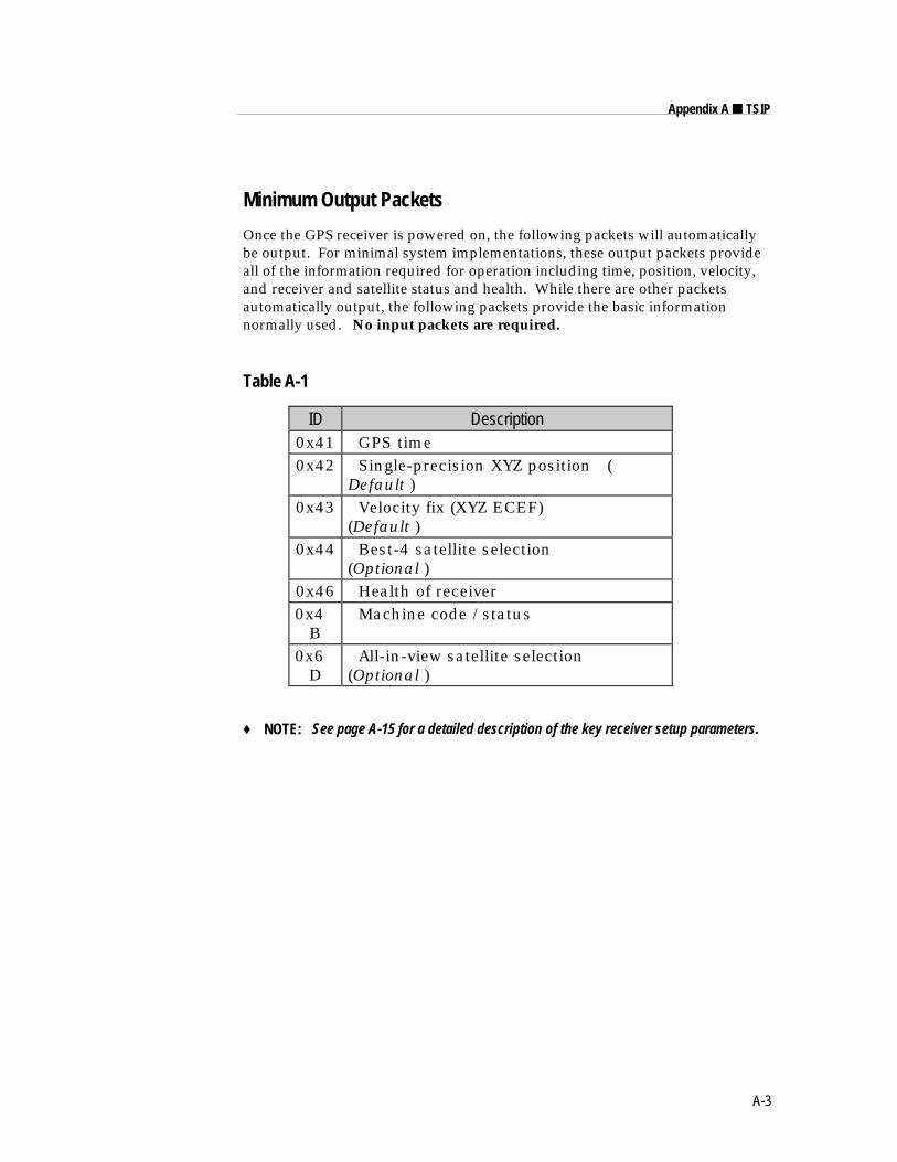
A-3
Appendix A ■ TSIP
Minimum Output Packets
Once the GPS receiver is powered on, the following packets will automaticallybe output. For minimal system implementations, these output packets provideall of the information required for operation including time, position, velocity,and receiver and satellite status and health. While there are other packetsautomatically output, the following packets provide the basic informationnormally used. No input packets are required.
Table A-1
ID Description0x41 GPS time0x42 Single-precision XYZ position (
Default )0x43 Velocity fix (XYZ ECEF)
(Default )0x44 Best-4 satellite selection
(Optional )0x46 Health of receiver0x4
B Machine code /status
0x6D
All-in-view satellite selection(Optional )
♦ NOTE: See page A-15 for a detailed description of the key receiver setup parameters.
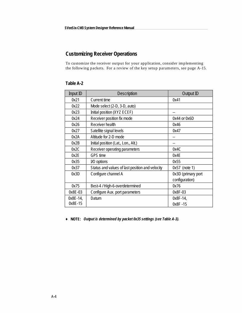
A-4
SVeeSix-CM3 System Designer Reference Manual
Customizing Receiver Operations
To customize the receiver output for your application, consider implementingthe following packets. For a review of the key setup parameters, see page A-15.
Table A-2
Input ID Description Output ID0x21 Current time 0x410x22 Mode select (2-D, 3-D, auto)0x23 Initial position (XYZ ECEF) --0x24 Receiver position fix mode 0x44 or 0x6D0x26 Receiver health 0x460x27 Satellite signal levels 0x470x2A Altitude for 2-D mode --0x2B Initial position (Lat., Lon., Alt.) --0x2C Receiver operating parameters 0x4C0x2E GPS time 0x4E0x35 I/O options 0x550x37 Status and values of last position and velocity 0x57 (note 1)0x3D Configure channel A 0x3D (primary port
configuration)0x75 Best-4 / High-6-overdetermined 0x76
0x8E-03 Configure Aux. port parameters 0x8F-030x8E-14,0x8E-15
Datum 0x8F-14, 0x8F -15
♦ NOTE: Output is determined by packet 0x35 settings (see Table A-3).
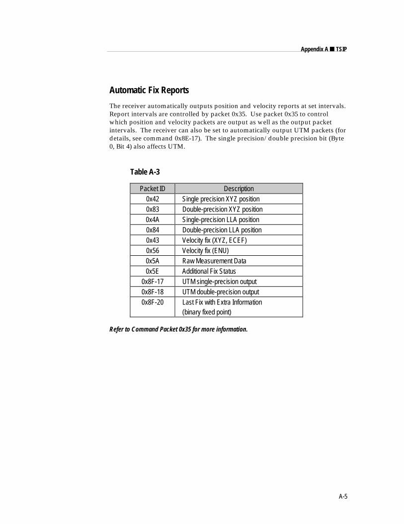
A-5
Appendix A ■ TSIP
Automatic Fix Reports
The receiver automatically outputs position and velocity reports at set intervals.Report intervals are controlled by packet 0x35. Use packet 0x35 to controlwhich position and velocity packets are output as well as the output packetintervals. The receiver can also be set to automatically output UTM packets (fordetails, see command 0x8E-17). The single precision/double precision bit (Byte0, Bit 4) also affects UTM.
Table A-3
Packet ID Description0x42 Single precision XYZ position0x83 Double-precision XYZ position0x4A Single-precision LLA position0x84 Double-precision LLA position0x43 Velocity fix (XYZ, ECEF)0x56 Velocity fix (ENU)0x5A Raw Measurement Data0x5E Additional Fix Status
0x8F-17 UTM single-precision output0x8F-18 UTM double-precision output0x8F-20 Last Fix with Extra Information
(binary fixed point)
Refer to Command Packet 0x35 for more information.
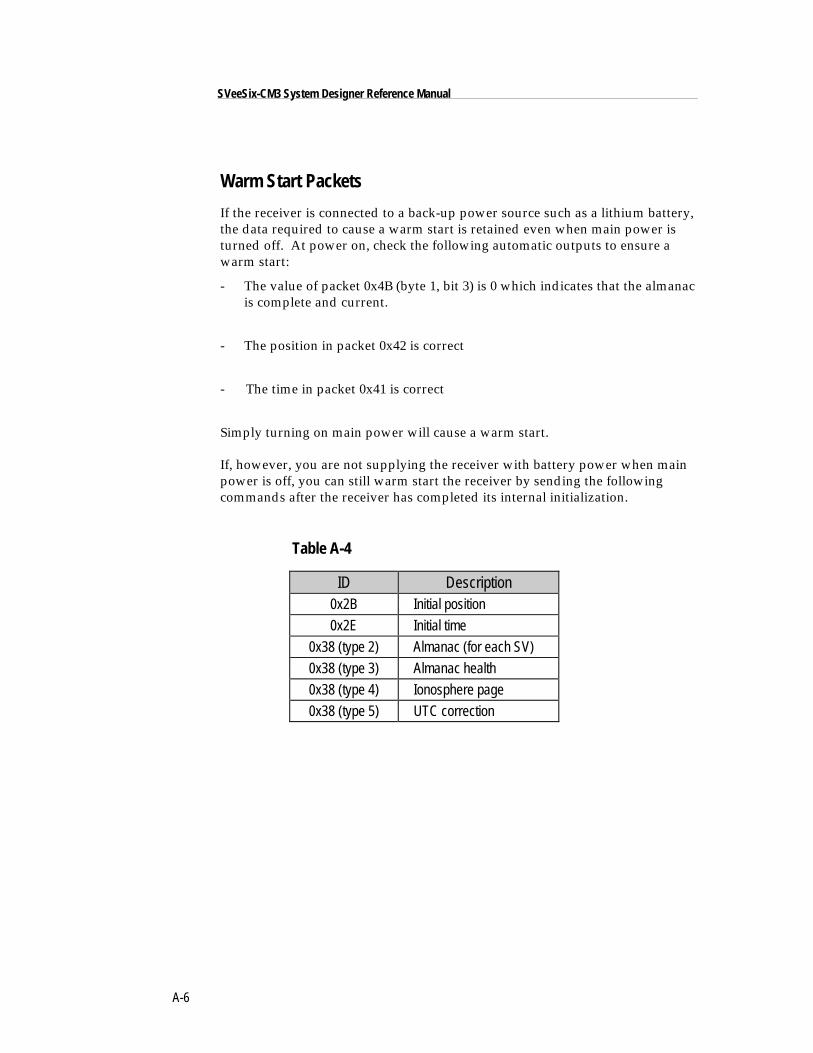
A-6
SVeeSix-CM3 System Designer Reference Manual
Warm Start Packets
If the receiver is connected to a back-up power source such as a lithium battery,the data required to cause a warm start is retained even when main power isturned off. At power on, check the following automatic outputs to ensure awarm start:
- The value of packet 0x4B (byte 1, bit 3) is 0 which indicates that the almanacis complete and current.
- The position in packet 0x42 is correct
- The time in packet 0x41 is correct
Simply turning on main power will cause a warm start.
If, however, you are not supplying the receiver with battery power when mainpower is off, you can still warm start the receiver by sending the followingcommands after the receiver has completed its internal initialization.
Table A-4
ID Description0x2B Initial position
0x2E Initial time
0x38 (type 2) Almanac (for each SV)
0x38 (type 3) Almanac health
0x38 (type 4) Ionosphere page
0x38 (type 5) UTC correction
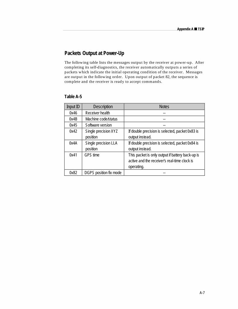
A-7
Appendix A ■ TSIP
Packets Output at Power-Up
The following table lists the messages output by the receiver at power-up. Aftercompleting its self-diagnostics, the receiver automatically outputs a series ofpackets which indicate the initial operating condition of the receiver. Messagesare output in the following order. Upon output of packet 82, the sequence iscomplete and the receiver is ready to accept commands.
Table A-5
Input ID Description Notes0x46 Receiver health --0x4B Machine code/status --0x45 Software version --0x42 Single precision XYZ
position If double precision is selected, packet 0x83 is output instead.
0x4A Single precision LLA position
If double precision is selected, packet 0x84 is output instead.
0x41 GPS time This packet is only output if battery back-up is active and the receiver's real-time clock is operating.
0x82 DGPS position fix mode --
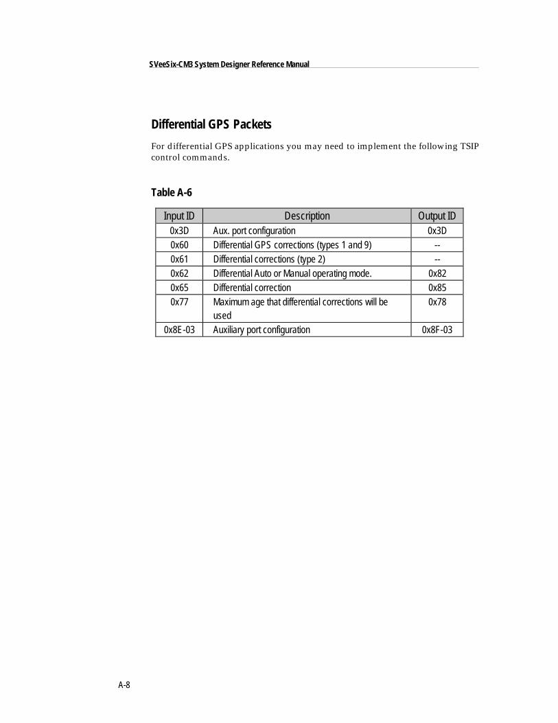
A-8
SVeeSix-CM3 System Designer Reference Manual
Differential GPS Packets
For differential GPS applications you may need to implement the following TSIPcontrol commands.
Table A-6
Input ID Description Output ID0x3D Aux. port configuration 0x3D0x60 Differential GPS corrections (types 1 and 9) --0x61 Differential corrections (type 2) --0x62 Differential Auto or Manual operating mode. 0x820x65 Differential correction 0x850x77 Maximum age that differential corrections will be
used0x78
0x8E-03 Auxiliary port configuration 0x8F-03
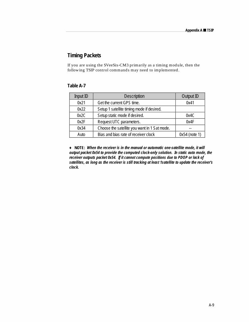
A-9
Appendix A ■ TSIP
Timing Packets
If you are using the SVeeSix-CM3 primarily as a timing module, then thefollowing TSIP control commands may need to implemented.
Table A-7
Input ID Description Output ID0x21 Get the current GPS time. 0x410x22 Setup 1 satellite timing mode if desired.0x2C Setup static mode if desired. 0x4C0x2F Request UTC parameters. 0x4F0x34 Choose the satellite you want in 1 Sat mode. --Auto Bias and bias rate of receiver clock 0x54 (note 1)
♦ NOTE: When the receiver is in the manual or automatic one-satellite mode, it willoutput packet 0x54 to provide the computed clock-only solution. In static auto mode, thereceiver outputs packet 0x54. If it cannot compute positions due to PDOP or lack ofsatellites, as long as the receiver is still tracking at least 1satellite to update the receiver'sclock.
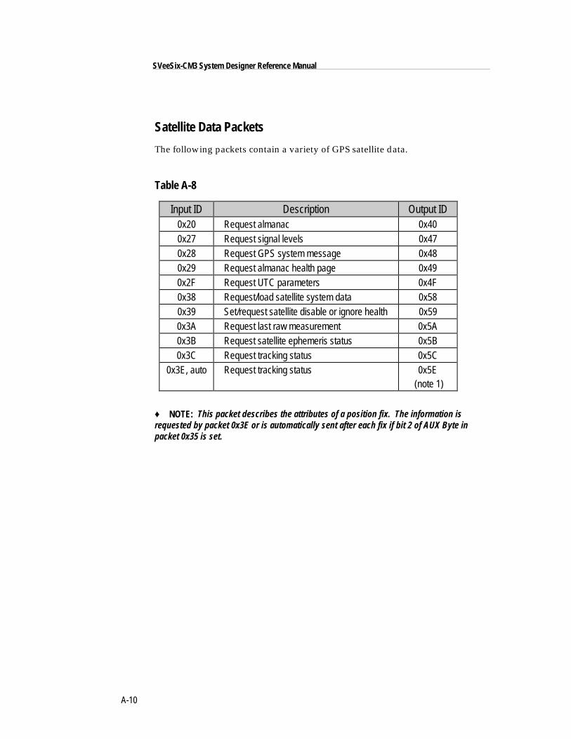
A-10
SVeeSix-CM3 System Designer Reference Manual
Satellite Data Packets
The following packets contain a variety of GPS satellite data.
Table A-8
Input ID Description Output ID0x20 Request almanac 0x400x27 Request signal levels 0x470x28 Request GPS system message 0x480x29 Request almanac health page 0x490x2F Request UTC parameters 0x4F0x38 Request/load satellite system data 0x580x39 Set/request satellite disable or ignore health 0x590x3A Request last raw measurement 0x5A0x3B Request satellite ephemeris status 0x5B0x3C Request tracking status 0x5C
0x3E, auto Request tracking status 0x5E (note 1)
♦ NOTE: This packet describes the attributes of a position fix. The information isrequested by packet 0x3E or is automatically sent after each fix if bit 2 of AUX Byte inpacket 0x35 is set.
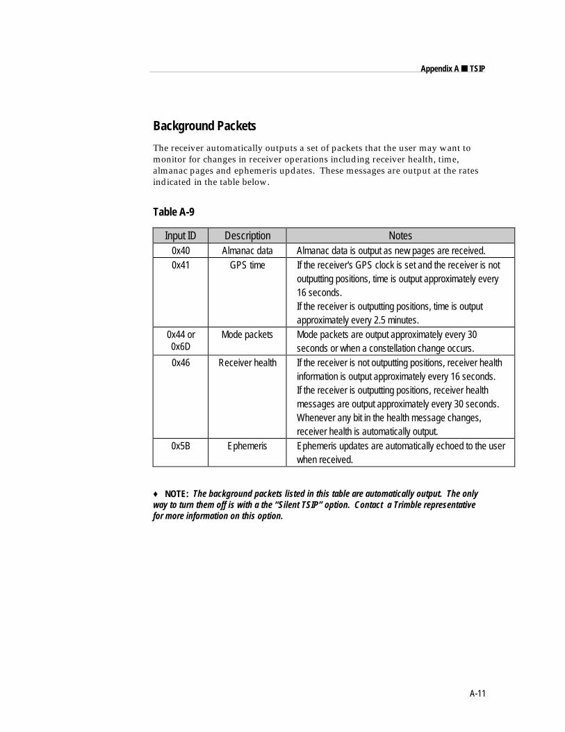
A-11
Appendix A ■ TSIP
Background Packets
The receiver automatically outputs a set of packets that the user may want tomonitor for changes in receiver operations including receiver health, time,almanac pages and ephemeris updates. These messages are output at the ratesindicated in the table below.
Table A-9
Input ID Description Notes0x40 Almanac data Almanac data is output as new pages are received.0x41 GPS time If the receiver's GPS clock is set and the receiver is not
outputting positions, time is output approximately every 16 seconds. If the receiver is outputting positions, time is output approximately every 2.5 minutes.
0x44 or0x6D
Mode packets Mode packets are output approximately every 30 seconds or when a constellation change occurs.
0x46 Receiver health If the receiver is not outputting positions, receiver health information is output approximately every 16 seconds. If the receiver is outputting positions, receiver health messages are output approximately every 30 seconds. Whenever any bit in the health message changes, receiver health is automatically output.
0x5B Ephemeris Ephemeris updates are automatically echoed to the user when received.
♦ NOTE: The background packets listed in this table are automatically output. The onlyway to turn them off is with a the “Silent TSIP” option. Contact a Trimble representativefor more information on this option.
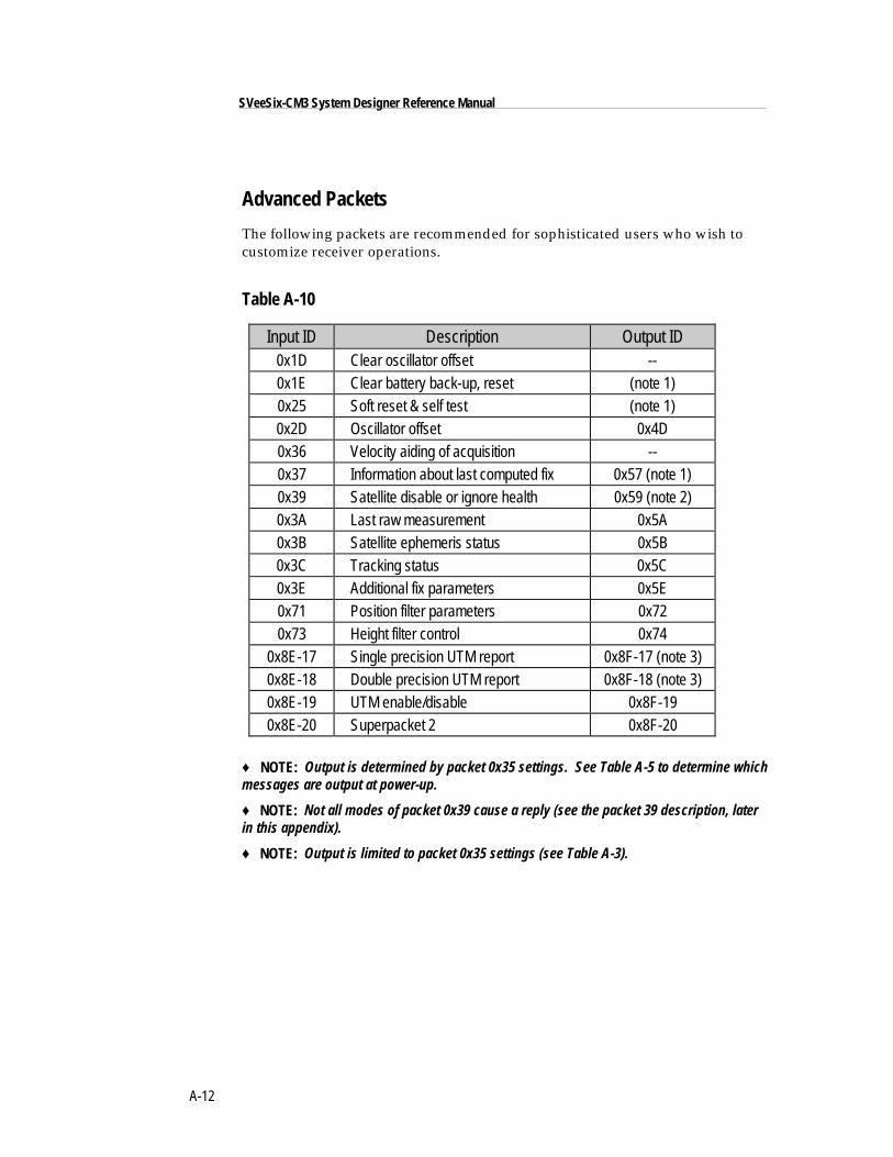
A-12
SVeeSix-CM3 System Designer Reference Manual
Advanced Packets
The following packets are recommended for sophisticated users who wish tocustomize receiver operations.
Table A-10
Input ID Description Output ID0x1D Clear oscillator offset --0x1E Clear battery back-up, reset (note 1)0x25 Soft reset & self test (note 1)0x2D Oscillator offset 0x4D0x36 Velocity aiding of acquisition --0x37 Information about last computed fix 0x57 (note 1)0x39 Satellite disable or ignore health 0x59 (note 2)0x3A Last raw measurement 0x5A0x3B Satellite ephemeris status 0x5B0x3C Tracking status 0x5C0x3E Additional fix parameters 0x5E0x71 Position filter parameters 0x720x73 Height filter control 0x74
0x8E-17 Single precision UTM report 0x8F-17 (note 3)0x8E-18 Double precision UTM report 0x8F-18 (note 3)0x8E-19 UTM enable/disable 0x8F-190x8E-20 Superpacket 2 0x8F-20
♦ NOTE: Output is determined by packet 0x35 settings. See Table A-5 to determine whichmessages are output at power-up.
♦ NOTE: Not all modes of packet 0x39 cause a reply (see the packet 39 description, laterin this appendix).
♦ NOTE: Output is limited to packet 0x35 settings (see Table A-3).
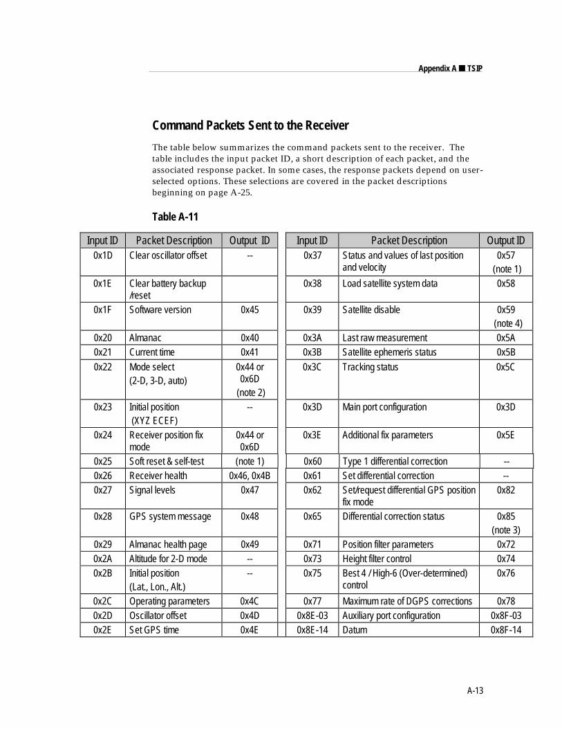
A-13
Appendix A ■ TSIP
Command Packets Sent to the Receiver
The table below summarizes the command packets sent to the receiver. Thetable includes the input packet ID, a short description of each packet, and theassociated response packet. In some cases, the response packets depend on user-selected options. These selections are covered in the packet descriptionsbeginning on page A-25.
Table A-11
Input ID Packet Description Output ID Input ID Packet Description Output ID0x1D Clear oscillator offset -- 0x37 Status and values of last position
and velocity0x57
(note 1)0x1E Clear battery backup
/reset0x38 Load satellite system data 0x58
0x1F Software version 0x45 0x39 Satellite disable 0x59 (note 4)
0x20 Almanac 0x40 0x3A Last raw measurement 0x5A0x21 Current time 0x41 0x3B Satellite ephemeris status 0x5B
0x22 Mode select(2-D, 3-D, auto)
0x44 or0x6D
(note 2)
0x3C Tracking status 0x5C
0x23 Initial position (XYZ ECEF)
-- 0x3D Main port configuration 0x3D
0x24 Receiver position fixmode
0x44 or0x6D
0x3E Additional fix parameters 0x5E
0x25 Soft reset & self-test (note 1) 0x60 Type 1 differential correction --0x26 Receiver health 0x46, 0x4B 0x61 Set differential correction --0x27 Signal levels 0x47 0x62 Set/request differential GPS position
fix mode0x82
0x28 GPS system message 0x48 0x65 Differential correction status 0x85(note 3)
0x29 Almanac health page 0x49 0x71 Position filter parameters 0x720x2A Altitude for 2-D mode -- 0x73 Height filter control 0x740x2B Initial position
(Lat., Lon., Alt.)-- 0x75 Best 4 / High-6 (Over-determined)
control0x76
0x2C Operating parameters 0x4C 0x77 Maximum rate of DGPS corrections 0x780x2D Oscillator offset 0x4D 0x8E-03 Auxiliary port configuration 0x8F-030x2E Set GPS time 0x4E 0x8E-14 Datum 0x8F-14
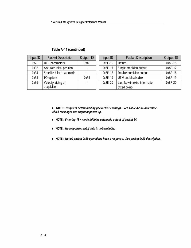
A-14
SVeeSix-CM3 System Designer Reference Manual
Table A-11 (continued)
Input ID Packet Description Output ID Input ID Packet Description Output ID0x2F UTC parameters 0x4F 0x8E-15 Datum 0x8F-150x32 Accurate initial position -- 0x8E-17 Single precision output 0x8F-170x34 Satellite # for 1-sat mode -- 0x8E-18 Double precision output 0x8F-180x35 I/O options 0x55 0x8E-19 UTM enable/disable 0x8F-190x36 Velocity aiding of
acquisition-- 0x8E-20 Last fix with extra information
(fixed point)0x8F-20
♦ NOTE: Output is determined by packet 0x35 settings. See Table A-5 to determinewhich messages are output at power-up.
♦ NOTE: Entering 1SV mode initiates automatic output of packet 54.
♦ NOTE: No response sent if data is not available.
♦ NOTE: Not all packet 0x39 operations have a response. See packet 0x39 description.
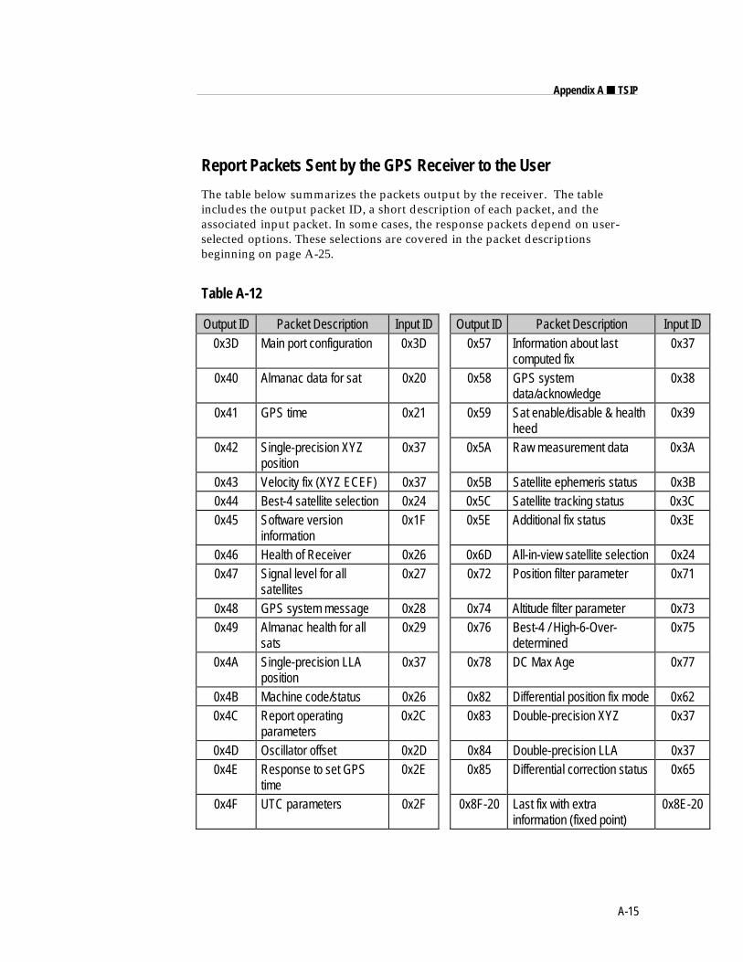
A-15
Appendix A ■ TSIP
Report Packets Sent by the GPS Receiver to the User
The table below summarizes the packets output by the receiver. The tableincludes the output packet ID, a short description of each packet, and theassociated input packet. In some cases, the response packets depend on user-selected options. These selections are covered in the packet descriptionsbeginning on page A-25.
Table A-12
Output ID Packet Description Input ID Output ID Packet Description Input ID0x3D Main port configuration 0x3D 0x57 Information about last
computed fix0x37
0x40 Almanac data for sat 0x20 0x58 GPS systemdata/acknowledge
0x38
0x41 GPS time 0x21 0x59 Sat enable/disable & healthheed
0x39
0x42 Single-precision XYZposition
0x37 0x5A Raw measurement data 0x3A
0x43 Velocity fix (XYZ ECEF) 0x37 0x5B Satellite ephemeris status 0x3B0x44 Best-4 satellite selection 0x24 0x5C Satellite tracking status 0x3C0x45 Software version
information0x1F 0x5E Additional fix status 0x3E
0x46 Health of Receiver 0x26 0x6D All-in-view satellite selection 0x240x47 Signal level for all
satellites0x27 0x72 Position filter parameter 0x71
0x48 GPS system message 0x28 0x74 Altitude filter parameter 0x730x49 Almanac health for all
sats0x29 0x76 Best-4 / High-6-Over-
determined0x75
0x4A Single-precision LLAposition
0x37 0x78 DC Max Age 0x77
0x4B Machine code/status 0x26 0x82 Differential position fix mode 0x620x4C Report operating
parameters0x2C 0x83 Double-precision XYZ 0x37
0x4D Oscillator offset 0x2D 0x84 Double-precision LLA 0x370x4E Response to set GPS
time0x2E 0x85 Differential correction status 0x65
0x4F UTC parameters 0x2F 0x8F-20 Last fix with extrainformation (fixed point)
0x8E-20
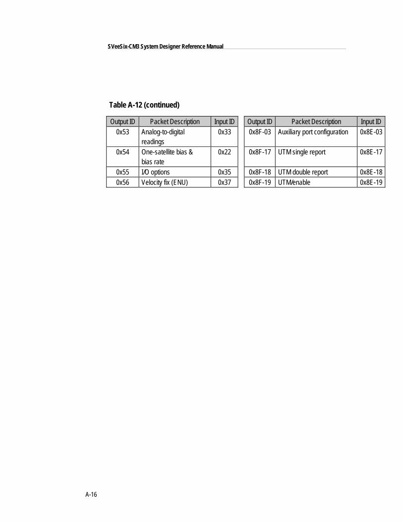
A-16
SVeeSix-CM3 System Designer Reference Manual
Table A-12 (continued)
Output ID Packet Description Input ID Output ID Packet Description Input ID0x53 Analog-to-digital
readings0x33 0x8F-03 Auxiliary port configuration 0x8E-03
0x54 One-satellite bias &bias rate
0x22 0x8F-17 UTM single report 0x8E-17
0x55 I/O options 0x35 0x8F-18 UTM double report 0x8E-180x56 Velocity fix (ENU) 0x37 0x8F-19 UTM/enable 0x8E-19
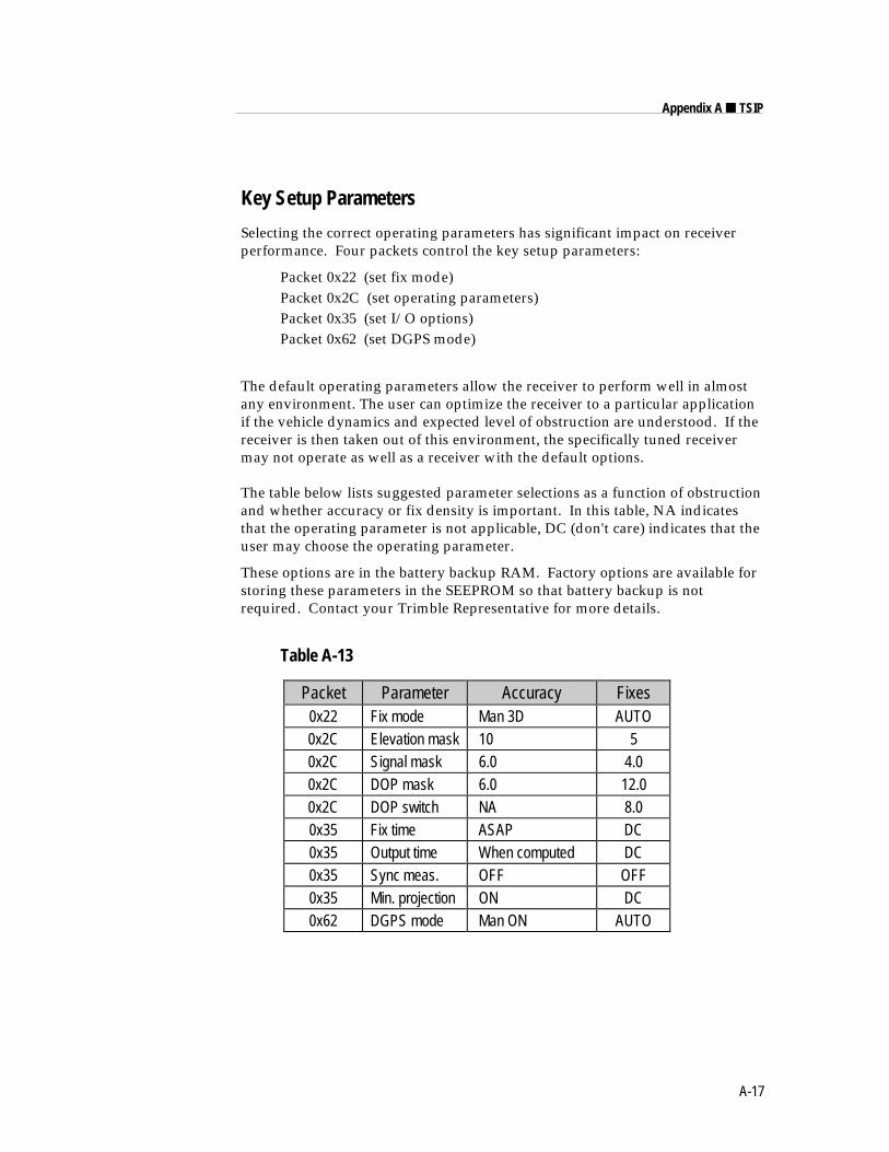
A-17
Appendix A ■ TSIP
Key Setup Parameters
Selecting the correct operating parameters has significant impact on receiverperformance. Four packets control the key setup parameters:
Packet 0x22 (set fix mode)Packet 0x2C (set operating parameters)Packet 0x35 (set I/O options)Packet 0x62 (set DGPS mode)
The default operating parameters allow the receiver to perform well in almostany environment. The user can optimize the receiver to a particular applicationif the vehicle dynamics and expected level of obstruction are understood. If thereceiver is then taken out of this environment, the specifically tuned receivermay not operate as well as a receiver with the default options.
The table below lists suggested parameter selections as a function of obstructionand whether accuracy or fix density is important. In this table, NA indicatesthat the operating parameter is not applicable, DC (don't care) indicates that theuser may choose the operating parameter.
These options are in the battery backup RAM. Factory options are available forstoring these parameters in the SEEPROM so that battery backup is notrequired. Contact your Trimble Representative for more details.
Table A-13
Packet Parameter Accuracy Fixes0x22 Fix mode Man 3D AUTO0x2C Elevation mask 10 50x2C Signal mask 6.0 4.00x2C DOP mask 6.0 12.00x2C DOP switch NA 8.00x35 Fix time ASAP DC0x35 Output time When computed DC0x35 Sync meas. OFF OFF0x35 Min. projection ON DC0x62 DGPS mode Man ON AUTO
A-18
SVeeSix-CM3 System Designer Reference Manual
Key Setup Parameters (continued)
The default values in Table A-13 allow the receiver to operate well under themost varied and demanding conditions. A user may choose to change thedefault parameters if the receiver is only required to perform in a specific orlimited environment. The user should be warned that when the receiver isexposed to operating conditions which are different from the conditionsdescribed by the user setup, then the performance may be degraded.
Initially, the user must consider the environment in which the receiver isexpected to operate. There is a trade-off between how frequently a position fix isoutput versus the absolute accuracy of the fix. The user must decide which takespriority and then make the appropriate selections. This becomes increasinglyimportant when frequent satellite blockages are expected, as in downtown"urban canyon" environments and heavily foliated areas.
Following is a description of the four key packets which control the receiveroperating parameters: packet 0x22, packet 0x2C, packet 0x35 and packet 0x62.
Packet 0x22 - Set Fix ModePacket 22 is used to choose the appropriate position fix mode for yourapplication: 2-D, 3-D or AUTO. The default mode is AUTO 2-D Clock Holdwhere the receiver first attempts to obtain a 3-D solution with a DOP belowboth the DOP mask and DOP switch. If this is not possible, then the receiverattempts to obtain a 2-D solution with a DOP less than the DOP mask. Thismode supplies fairly continuous position fixes even when there is frequentobstruction. This mode is preferable for most land or air applications, wherealtitude changes are occurring and there is occasional obstruction.
The highest accuracy fix mode is 3-D manual, where altitude is alwayscalculated along with the latitude, longitude, and time. However, this requiresfour satellites with a PDOP below the PDOP mask set in packet 2C in order toobtain a position. Normally, this will provide the most accurate solution. Thus,if only 3-D solutions are desired, then the user should request 3-D manualmode. Depending on how the DOP mask is set, this may be restrictive when thereceiver is subjected to frequent obstruction, or when the geometry is poor dueto an incomplete constellation.
Alternatively, if the user only wants a 2-D solution, then 2-D manual should berequested. In this case, the receiver uses either the last altitude obtained in a 3-Dfix, or the altitude supplied by the user. However, any error in the assumedaltitude will effect the accuracy of the latitude and longitude solution.
A-19
Appendix A ■ TSIP
Key Setup Parameters (continued)
Packet 0x22 (con’t.)High accuracy users should avoid this mode and should expect fixes withaccuracy's which are at best as accurate as the supplied altitude. If a marine userenters sea-level as the altitude, then small errors in the horizontal solution willoccur when the sea state is rough or there are high tidal variations. However,these errors may be smaller than the altitude error induced by SA, in which casehorizontal accuracy is improved.
Packet 0x2C - Set Operating ParametersPacket 0x2C defines the extreme conditions under which the receiver will beoperating, and the set of usable satellites based on the satellite geometry at theuser's position. There are four parameters:
(a) Dynamics Code The default is LAND mode, where the receiver assumesa moderate dynamic environment. In this case, the satellite search and re-acquisition routines are optimized for vehicle type environments. In SEAmode, the search and re-acquisition routines assume a low accelerationlow speed environment and will revert to user entered altitude in 2-Dauto. In AIR mode, the search and re-acquisition routines are optimizedfor high acceleration conditions.
(b) Elevation Mask This is the minimum elevation angle for satellites to beused in a solution output by the receiver. Satellites which are near thehorizon are typically more difficult to track due to signal attenuation, andare also generally less accurate due to higher variability in the ionosphericand tropospheric which can cause corruption of the signal, andmultipathing. When there are no obstructions, the receiver can generallytrack a satellite down to near the horizon. However, when this mask is settoo low, the receiver may experience frequent constellation switching dueto low elevation satellites being obscured.
Frequent constellation switching is undesirable because position jumpsmay be experienced when SA is present and DGPS is not available toremove these effects. The benefit of a low elevation mask is that moresatellites are available for use in a solution and a better PDOP may beyielded. The current mask is set to five degrees and provides a reasonabletradeoff of the benefits and drawbacks. High accuracy users may prefer amask angle around ten degrees, where the ionosphere and tropospherebegin to be more predictable.
A-20
SVeeSix-CM3 System Designer Reference Manual
Key Setup Parameters (continued)
Packet 0x2C (con’t.)(c) Signal Level Mask This mask defines the minimum signal strength for a
satellite used in a solution. There is some internal hysteresis on thisthreshold which allows brief excursions below the threshold if lock ismaintained and the signal was previously above the mask. The mask hasbeen set to 2.2 to improved tracking capability. The mask should only belowered cautiously since this mask is also used to minimize the effects ofjammers and reflected signals on the receiver. High accuracy users mayuse a slightly higher mask of 6.0-8.0, since weaker measurements may beslightly noisier and are often caused by reflected signals which provideerroneous ranges.
One should also resist the temptation to set the elevation and SNR maskstoo low. The satellite geometry is sometimes improved considerably byselecting low elevation satellites. They are, however, subject to significantsignal degradation by the greater ionospheric and troposphericattenuation that occurs. They are also subject to more obstruction by thepassing scenery when the receiver is in a moving vehicle. The code phasedata from those satellites is therefore more difficult to decode andtherefore has more noise.
(d) DOP Mask and Switch The DOP mask is the maximum DOP limit for any2-D or 3-D position solution will be made. The DOP switch is the level atwhich the receiver stops attempting a 3-D solution, and tries for a 2-Dsolution when in automatic 2-D, 3-D mode. The switch level has no affecton either manual mode. Raising the DOP mask will generally increase thefix density during obstruction, but the fixes with the higher DOP will beless accurate (especially with SA present). Lowering the mask willimprove the average accuracy at the risk of lowering the fix density.
◆ NOTE: A level of hysteresis in the signal level mask is allowed in the core operatingsoftware. The hysteresis allows the receiver to continue using satellite signals whichfall slightly below the mask and prevents the receiver from incorporating a new signaluntil the signal level slightly exceeds the mask. This feature minimizes constellationchanges caused by temporary fluctuations in signal levels.
A-21
Appendix A ■ TSIP
Key Setup Parameters (continued)
Packet 0x35 - Set I/O OptionsPacket 0x35 is used to control the format and timing of the position and velocityoutput. Bytes 0 and 1 control the message output format (see page A-33). Byte2 contains the five time parameters described below: Time Type, FixComputation Time, Output Time, Synchronized Measurements and MinimizedProjection. Byte 3, the auxiliary byte, controls the output of additional fix data.Byte 3 contains three bits: bit 0 controls the output of raw measurements (Packet0x5A), bit 1 controls whether the raw measurements output in packet 0x5A aredoppler smooth, and bit 2 is the additional fix status bit - setting this bit willcause packet 0x5E to be output with each fix.
(See page A-33 for a complete description of packet 0x35.)
The following descriptions pertain to packet 0x35, byte 2.
(a) Time Type This bit defines whether the time tags associated with aposition fix are in GPS time or UTC time. The default is GPS time.
(b) Fix Computation Time This bit controls the time and frequency ofposition fixes. The default is ASAP which, when a satellite is in a normalcontinuous tracking mode, provides a 2 Hz fix rate and time-of-applicability of the fixes is at 0.25 seconds and 0.75 seconds within eachGPS second.
Alternatively, in the integer second mode, the most recent measurementsare projected to next integer second, and the solution is then valid at thistime. The benefit of this mode is the standard fix time and a 1 Hz outputrate. The drawbacks are that some measurement projection is performedand that the fix may be slightly older than with the default option. Thismode also matches to the output rate of NMEA.
(c) Output Time This bit defines whether fixes are automatically outputwhen computed or only sent in response to a packet 0x37 request. Thedefault is automatic output .
(d) Synchronized Measurements This bit controls whether all satellite rangemeasurements are required to have the same time tag. The default is OFF.Slightly older measurements are tolerated (on the order of 3-5 seconds) toprovide solutions when obstructions make it impossible to obtain exactlyconcurrent measurements from each satellite.
A-22
SVeeSix-CM3 System Designer Reference Manual
Key Setup Parameters (continued)
Packet 0x35 (con’t.)When this bit is ON, all measurements are required to have the same timetag. This only applies to a six-channel receiver, where selected satellitesare tracked continuously on their own channel. This mode is used onlywhen the user application requires all satellite measurements to beidentical to the position time tag. If a satellite is lost which is in theselected set for the solution, then no fix will be made until a new selectionis made.
The Synchronized measurement mode combined with the minimizedprojection timing mode (see next paragraph) allows absolutely nomeasurement projection. However, obstructions may reduce the fixdensity when there are limited satellites. Use this mode cautiously.
(e) Minimized Projection This bit controls the time of the position fix relativeto the time of the satellite range measurements. The default mode is OFF.In this mode, the time of solution is the time at which the GPS position fixis computed. Thus, all measurements are projected by an interval whichis roughly the amount of time it takes to compute the solution. Thisapproach minimizes the latency between the time tag of the computedsolution and the solution output. The drawback is that the measurementprojection (which is only about 100 ms) may induce some error duringhigh accelerations.
Alternatively, when minimized projection is ON, the time of the solutionis the time of the most recent measurements. Thus, if all measurementsare taken at exactly the same time, there is no measurement projection. Ifa selected satellite's measurement time lags the most recent measurement,then it is projected to this time. The difference is that the fix will havemore latency than a fix provided with the above timing option. This is thebest choice for users performing non real-time error analysis, or non real-time DGPS solution-space corrections. This is also the preferable mode forusers integrating GPS with other sensors, where communication lags arethe dominant latencies, and thus the time lag between the applicabilityand availability of the fix is small.
◆ NOTE: When the position filter is ON (default), then minimized projection isautomatically enabled regardless of how this bit is set.
A-23
Appendix A ■ TSIP
Key Setup Parameters (continued)
Packet 0x62 - Set DGPS ModePacket 0x62 is used to set the differential GPS operating mode. The defaultmode is OFF. If differential corrections are available, the recommended modeis DGPS Auto. In this mode, the receiver computes differentially correctedpositions whenever valid corrections are available. Otherwise, the receivercomputes non-differentially corrected positions.
In manual DGPS mode, the receiver only computes solutions if corrections areavailable for the selected satellites. This is the most accurate mode but it is alsothe most selective, since the fix density is dependent on the availability ofcorrections. The applicability of corrections is determined by the maximum agewhich can be set using packet 0x77.
The AUTO mode avoids the fix density problem but opens the possibility ofgoing in and out of DGPS mode, potentially resulting in position and velocityjumps. In differential OFF mode, the receiver will not use corrections even ifthey are valid. If accuracy is critical, use MANUAL mode. If fix density iscritical, AUTO DGPS is the recommended mode.
A-24
SVeeSix-CM3 System Designer Reference Manual
Packet Structure
TSIP packet structure is the same for both commands and reports. The packetformat is:
<DLE> <id> <data string bytes> <DLE> <ETX>
<DLE> is the byte 0x10, <ETX> is the byte 0x03, and <id> is a packetidentifier byte, which can have any value excepting <ETX> and <DLE>. Thebytes in the data string can have any value. To prevent confusion with theframe sequences <DLE> <id> and <DLE> <ETX>, every <DLE> byte in thedata string is preceded by an extra <DLE> byte ('stuffing'). These extra<DLE> bytes must be added ('stuffed') before sending a packet and removed('unstuffed') after receiving the packet (see send_cmd(), tsip_input_proc () inTSIP_IFC.C). Notice that a simple <DLE> <ETX> sequence does notnecessarily signify the end of the packet, as these can be bytes in the middle of adata string. The end of a packet is <ETX> preceded by an odd number of<DLE> bytes.
Multiple-byte numbers (integer, float, and double) follow the ANSI / IEEE Std754 IEEE Standard for binary Floating-Point Arithmetic as illustrated below.They are sent most-significant byte first. This may involve switching the orderof the bytes as they are normally stored in Intel based machines (see bputsingle()and bgetsingle() in TSIP_IFC.C, for an example).
Integer is a 16 bit unsigned number sent in two's complement format.
Single (float, or 4 byte REAL) is sent as a series of four bytes; it has a precisionof 24 significant bits, roughly 6.5 digits.
Double (8 byte REAL) is sent as a series of eight bytes; it has a precision of 52significant bits, a little better than 15 digits.
A-25
Appendix A ■ TSIP
Packet Descriptions
Command Packet 0x1D - Clear Oscillator OffsetThis packet commands the GPS receiver to set or clear the oscillator offset inbattery-backed memory. This is normally used for servicing the unit.
To clear the oscillator offset, one data byte is sent: the ASCII letter 'C' = 0x43.
To set the oscillator offset, four data bytes are sent: the oscillator offset in Hertzas a Single real value.
Command Packet 0x1E - Clear Battery Back-up, then ResetThis packet commands the GPS receiver to clear all battery back-up data and toperform a software reset. This packet contains one data byte equal to the ASCIIletter "K," 0x4B .
CAUTION
All almanac, ephemeris, current position, mode, and communication port setupinformation is lost by the execution of this command. In normal use this packetshould not be sent. It is very helpful to keep a fresh copy of the currentalmanac, which is stored in the file GPSALM.DAT collected by the TSIPCHATcommand "!". This allows near-instantaneous recuperation by the receiver incase of power loss or clearing of battery-backed memory by using theTSIPCHAT command "@" to load it back into the receiver memory.
Command Packet 0x1F - Request Software VersionsThis packet requests information about the version of software running in theNavigation and Signal Processors. This packet contains no data bytes. The GPSreceiver returns packet 0x45.
Command Packet 0x20 - Request AlmanacThis packet requests almanac data for one satellite from the GPS receiver. Thispacket contains one data byte specifying the satellite PRN number. The GPSreceiver returns packet 0x40.
Command Packet 0x21 - Request Current TimeThis packet requests current GPS time. This packet contains no data. The GPSreceiver returns packet 0x41.
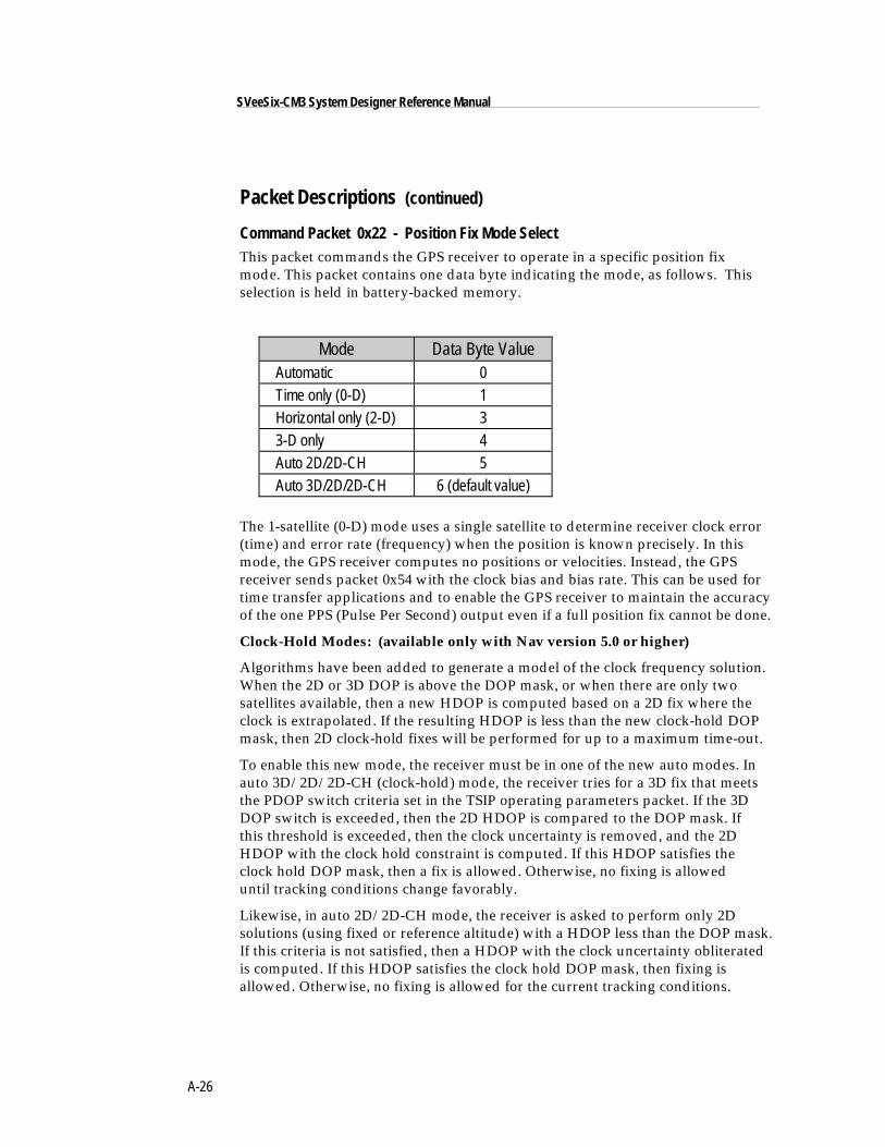
A-26
SVeeSix-CM3 System Designer Reference Manual
Packet Descriptions (continued)
Command Packet 0x22 - Position Fix Mode SelectThis packet commands the GPS receiver to operate in a specific position fixmode. This packet contains one data byte indicating the mode, as follows. Thisselection is held in battery-backed memory.
Mode Data Byte Value Automatic 0 Time only (0-D) 1 Horizontal only (2-D) 3 3-D only 4 Auto 2D/2D-CH 5 Auto 3D/2D/2D-CH 6 (default value)
The 1-satellite (0-D) mode uses a single satellite to determine receiver clock error(time) and error rate (frequency) when the position is known precisely. In thismode, the GPS receiver computes no positions or velocities. Instead, the GPSreceiver sends packet 0x54 with the clock bias and bias rate. This can be used fortime transfer applications and to enable the GPS receiver to maintain the accuracyof the one PPS (Pulse Per Second) output even if a full position fix cannot be done.
Clock-Hold Modes: (available only with Nav version 5.0 or higher)
Algorithms have been added to generate a model of the clock frequency solution.When the 2D or 3D DOP is above the DOP mask, or when there are only twosatellites available, then a new HDOP is computed based on a 2D fix where theclock is extrapolated. If the resulting HDOP is less than the new clock-hold DOPmask, then 2D clock-hold fixes will be performed for up to a maximum time-out.
To enable this new mode, the receiver must be in one of the new auto modes. Inauto 3D/2D/2D-CH (clock-hold) mode, the receiver tries for a 3D fix that meetsthe PDOP switch criteria set in the TSIP operating parameters packet. If the 3DDOP switch is exceeded, then the 2D HDOP is compared to the DOP mask. Ifthis threshold is exceeded, then the clock uncertainty is removed, and the 2DHDOP with the clock hold constraint is computed. If this HDOP satisfies theclock hold DOP mask, then a fix is allowed. Otherwise, no fixing is alloweduntil tracking conditions change favorably.
Likewise, in auto 2D/2D-CH mode, the receiver is asked to perform only 2Dsolutions (using fixed or reference altitude) with a HDOP less than the DOP mask.If this criteria is not satisfied, then a HDOP with the clock uncertainty obliteratedis computed. If this HDOP satisfies the clock hold DOP mask, then fixing isallowed. Otherwise, no fixing is allowed for the current tracking conditions.
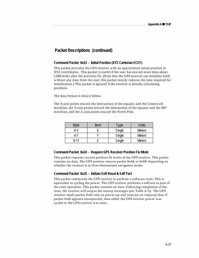
A-27
Appendix A ■ TSIP
Packet Descriptions (continued)
Command Packet 0x23 - Initial Position (XYZ Cartesian ECEF)This packet provides the GPS receiver with an approximate initial position inXYZ coordinates. This packet is useful if the user has moved more than about1,000 miles after the previous fix. (Note that the GPS receiver can initialize itselfwithout any data from the user; this packet merely reduces the time required forinitialization.) This packet is ignored if the receiver is already calculatingpositions.
The data format is shown below.
The X-axis points toward the intersection of the equator and the Greenwichmeridian, the Y-axis points toward the intersection of the equator and the 90omeridian, and the Z-axis points toward the North Pole.
Byte Item Type Units0-3 X Single Meters4-7 Y Single Meters8-11 Z Single Meters
Command Packet 0x24 - Request GPS Receiver Position Fix ModeThis packet requests current position fix mode of the GPS receiver. This packetcontains no data. The GPS receiver returns packet 0x44, or 0x6D depending onwhether the receiver is in Over-determined navigation mode.
Command Packet 0x25 - Initiate Soft Reset & Self TestThis packet commands the GPS receiver to perform a software reset. This isequivalent to cycling the power. The GPS receiver performs a self-test as part ofthe reset operation. This packet contains no data. Following completion of thereset, the receiver will output the startup messages (see Table A-5). The GPSreceiver sends packet 0x45 only on power-up and reset (or on request); thus ifpacket 0x45 appears unrequested, then either the GPS receiver power wascycled or the GPS receiver was reset.
A-28
SVeeSix-CM3 System Designer Reference Manual
Packet Descriptions (continued)
Command Packet 0x26 - Request HealthThis packet requests health and status information from the GPS receiver. Thispacket contains no data. The GPS receiver returns packet 0x46 and 0x4B.
Command Packet 0x27 - Request Signal LevelsThis packet requests signal levels for all satellites currently being tracked. Thispacket contains no data. The GPS receiver returns packet 0x47.
Command Packet 0x28 - Request GPS System MessageThis packet requests the GPS system ASCII message sent with the navigationdata by each satellite. This packet contains no data. The GPS receiver returnspacket 0x48.
Command Packet 0x29 - Request Almanac Health PageThis packet requests the GPS receiver to send the health page from the almanac.This packet contains no data. The GPS receiver returns packet 0x49.
Command Packet 0x2A - Altitude for 2-D ModeThis packet provides the altitude to be used for Manual 2-dimensional(3 satellite) mode. This altitude is also used for Auto 2-D mode when thedynamics code is set to SEA. This packet contains one Single number (4 bytes)specifying the altitude in meters, using the WGS-84 model of the earth or MSLgeoid altitude depending on I/O options (set by packet 0x35). This altitudevalue is held in battery-backed memory.
If a set altitude is not provided, the receiver will use the altitude of the previous3-D fix (altitude-hold mode).
♦ NOTE: Sending packet 0x2A with one data byte equal to 0xFF will cancel altitude-setmode and return to altitude-hold mode without the need to clear battery-backed RAM.
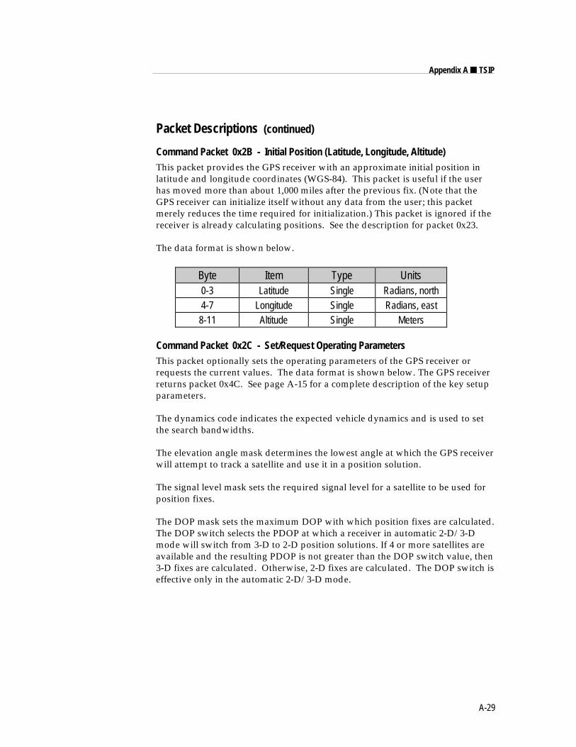
A-29
Appendix A ■ TSIP
Packet Descriptions (continued)
Command Packet 0x2B - Initial Position (Latitude, Longitude, Altitude)This packet provides the GPS receiver with an approximate initial position inlatitude and longitude coordinates (WGS-84). This packet is useful if the userhas moved more than about 1,000 miles after the previous fix. (Note that theGPS receiver can initialize itself without any data from the user; this packetmerely reduces the time required for initialization.) This packet is ignored if thereceiver is already calculating positions. See the description for packet 0x23.
The data format is shown below.
Byte Item Type Units0-3 Latitude Single Radians, north4-7 Longitude Single Radians, east8-11 Altitude Single Meters
Command Packet 0x2C - Set/Request Operating ParametersThis packet optionally sets the operating parameters of the GPS receiver orrequests the current values. The data format is shown below. The GPS receiverreturns packet 0x4C. See page A-15 for a complete description of the key setupparameters.
The dynamics code indicates the expected vehicle dynamics and is used to setthe search bandwidths.
The elevation angle mask determines the lowest angle at which the GPS receiverwill attempt to track a satellite and use it in a position solution.
The signal level mask sets the required signal level for a satellite to be used forposition fixes.
The DOP mask sets the maximum DOP with which position fixes are calculated.The DOP switch selects the PDOP at which a receiver in automatic 2-D/3-Dmode will switch from 3-D to 2-D position solutions. If 4 or more satellites areavailable and the resulting PDOP is not greater than the DOP switch value, then3-D fixes are calculated. Otherwise, 2-D fixes are calculated. The DOP switch iseffective only in the automatic 2-D/3-D mode.
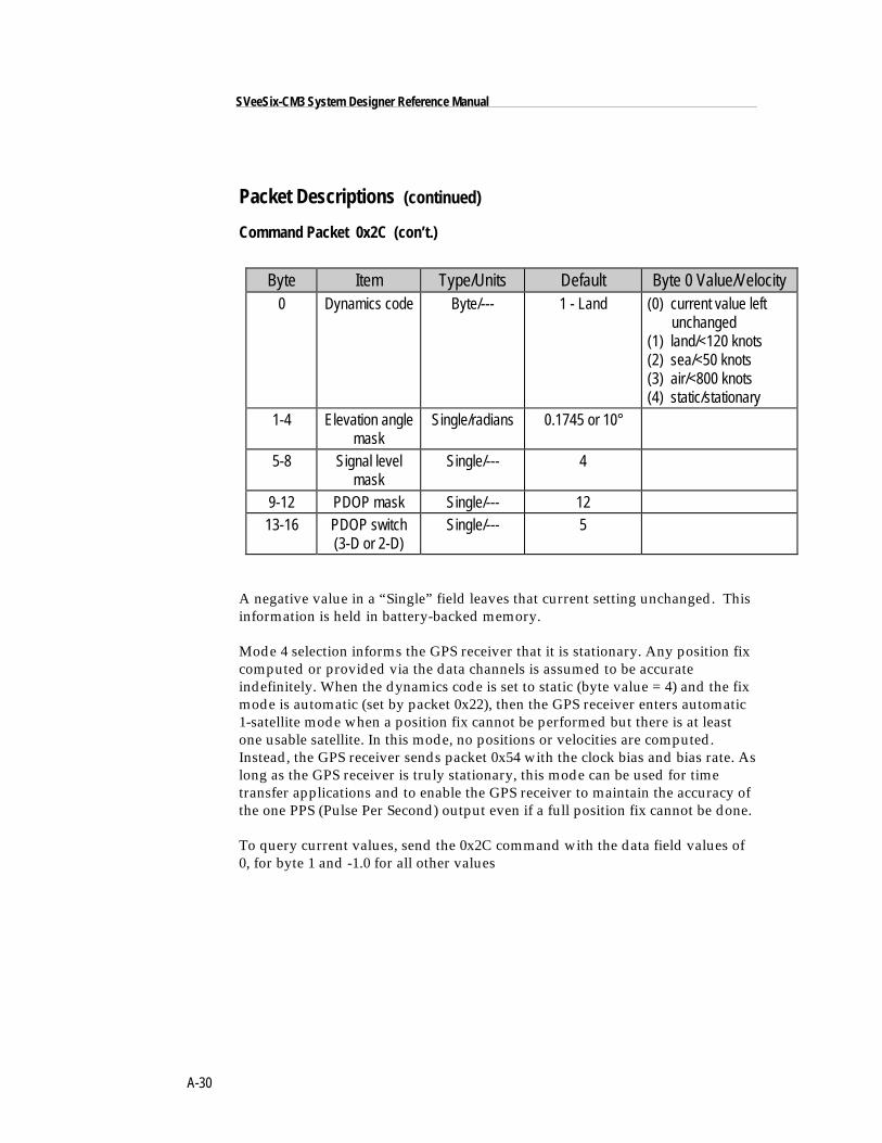
A-30
SVeeSix-CM3 System Designer Reference Manual
Packet Descriptions (continued)
Command Packet 0x2C (con’t.)
Byte Item Type/Units Default Byte 0 Value/Velocity0 Dynamics code Byte/--- 1 - Land (0) current value left
unchanged(1) land/<120 knots(2) sea/<50 knots(3) air/<800 knots(4) static/stationary
1-4 Elevation anglemask
Single/radians 0.1745 or 10°
5-8 Signal levelmask
Single/--- 4
9-12 PDOP mask Single/--- 1213-16 PDOP switch
(3-D or 2-D)Single/--- 5
A negative value in a “Single” field leaves that current setting unchanged. Thisinformation is held in battery-backed memory.
Mode 4 selection informs the GPS receiver that it is stationary. Any position fixcomputed or provided via the data channels is assumed to be accurateindefinitely. When the dynamics code is set to static (byte value = 4) and the fixmode is automatic (set by packet 0x22), then the GPS receiver enters automatic1-satellite mode when a position fix cannot be performed but there is at leastone usable satellite. In this mode, no positions or velocities are computed.Instead, the GPS receiver sends packet 0x54 with the clock bias and bias rate. Aslong as the GPS receiver is truly stationary, this mode can be used for timetransfer applications and to enable the GPS receiver to maintain the accuracy ofthe one PPS (Pulse Per Second) output even if a full position fix cannot be done.
To query current values, send the 0x2C command with the data field values of0, for byte 1 and -1.0 for all other values
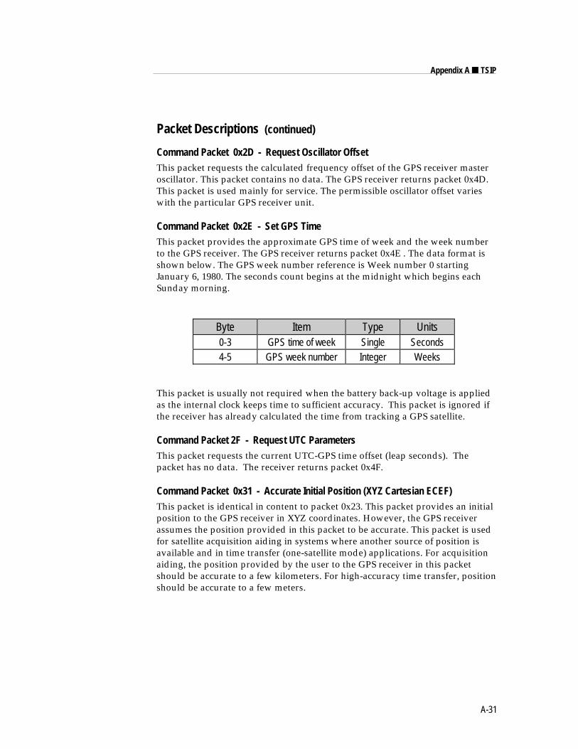
A-31
Appendix A ■ TSIP
Packet Descriptions (continued)
Command Packet 0x2D - Request Oscillator OffsetThis packet requests the calculated frequency offset of the GPS receiver masteroscillator. This packet contains no data. The GPS receiver returns packet 0x4D.This packet is used mainly for service. The permissible oscillator offset varieswith the particular GPS receiver unit.
Command Packet 0x2E - Set GPS TimeThis packet provides the approximate GPS time of week and the week numberto the GPS receiver. The GPS receiver returns packet 0x4E . The data format isshown below. The GPS week number reference is Week number 0 startingJanuary 6, 1980. The seconds count begins at the midnight which begins eachSunday morning.
Byte Item Type Units0-3 GPS time of week Single Seconds4-5 GPS week number Integer Weeks
This packet is usually not required when the battery back-up voltage is appliedas the internal clock keeps time to sufficient accuracy. This packet is ignored ifthe receiver has already calculated the time from tracking a GPS satellite.
Command Packet 2F - Request UTC ParametersThis packet requests the current UTC-GPS time offset (leap seconds). Thepacket has no data. The receiver returns packet 0x4F.
Command Packet 0x31 - Accurate Initial Position (XYZ Cartesian ECEF)This packet is identical in content to packet 0x23. This packet provides an initialposition to the GPS receiver in XYZ coordinates. However, the GPS receiverassumes the position provided in this packet to be accurate. This packet is usedfor satellite acquisition aiding in systems where another source of position isavailable and in time transfer (one-satellite mode) applications. For acquisitionaiding, the position provided by the user to the GPS receiver in this packetshould be accurate to a few kilometers. For high-accuracy time transfer, positionshould be accurate to a few meters.
A-32
SVeeSix-CM3 System Designer Reference Manual
Packet Descriptions (continued)
Command Packet 0x32 - Accurate Initial Position (Latitude, Longitude, Altitude)This packet is identical in content to packet 0x2B. This packet provides the GPSreceiver with an approximate initial position in latitude, longitude, and altitudecoordinates. However, the GPS receiver assumes the position provided in thispacket to be accurate. This packet is used for satellite acquisition aiding insystems where another source of position is available and in time transfer (one-satellite mode) applications. For acquisition aiding, the position provided by theuser to the GPS receiver in this packet should be accurate to a few kilometers.For high-accuracy time transfer, position should be accurate to a few meters.
Command Packet 0x34 - Satellite Number For One-Satellite ModeThis packet allows the user to control the choice of the satellite to be used for theone-satellite mode. This packet contains one byte. If the byte value is 0, the GPSreceiver chooses the usable satellite with the highest elevation above thehorizon. This automatic selection of the highest satellite is the default action,and the GPS receiver does this unless it receives this packet. If the byte value isfrom 1 to 32, the packet specifies the PRN number of the satellite to be used.This selection is not kept in battery-backed memory.
If the receiver is in Over-Determined Clock mode, a value not equal to 0 willdisable this mode. A subsequent value of 0 will return the receiver to Over-determined Clock mode.
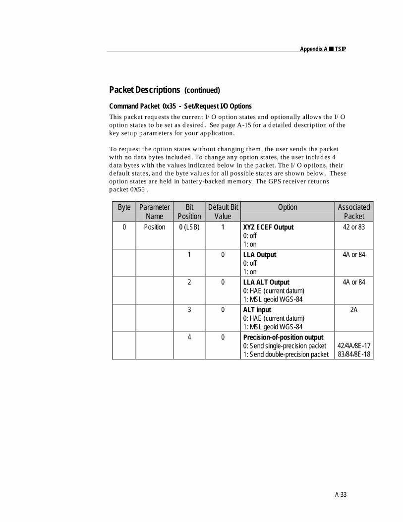
A-33
Appendix A ■ TSIP
Packet Descriptions (continued)
Command Packet 0x35 - Set/Request I/O OptionsThis packet requests the current I/O option states and optionally allows the I/Ooption states to be set as desired. See page A-15 for a detailed description of thekey setup parameters for your application.
To request the option states without changing them, the user sends the packetwith no data bytes included. To change any option states, the user includes 4data bytes with the values indicated below in the packet. The I/O options, theirdefault states, and the byte values for all possible states are shown below. Theseoption states are held in battery-backed memory. The GPS receiver returnspacket 0X55 .
Byte ParameterName
BitPosition
Default BitValue
Option AssociatedPacket
0 Position 0 (LSB) 1 XYZ ECEF Output0: off1: on
42 or 83
1 0 LLA Output0: off1: on
4A or 84
2 0 LLA ALT Output0: HAE (current datum)1: MSL geoid WGS-84
4A or 84
3 0 ALT input0: HAE (current datum)1: MSL geoid WGS-84
2A
4 0 Precision-of-position output0: Send single-precision packet1: Send double-precision packet
42/4A/8E-1783/84/8E-18
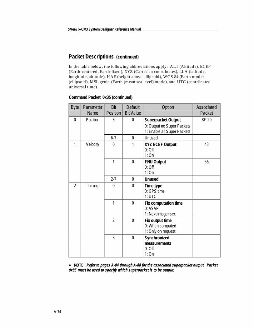
A-34
SVeeSix-CM3 System Designer Reference Manual
Packet Descriptions (continued)
In the table below, the following abbreviations apply: ALT (Altitude), ECEF(Earth-centered, Earth-fixed), XYZ (Cartesian coordinates), LLA (latitude,longitude, altitude), HAE (height above ellipsoid), WGS-84 (Earth model(ellipsoid), MSL geoid (Earth (mean sea level) mode), and UTC (coordinateduniversal time).
Command Packet 0x35 (continued)
Byte ParameterName
BitPosition
DefaultBit Value
Option AssociatedPacket
0 Position 5 0 Superpacket Output0: Output no Super Packets1: Enable all Super Packets
8F-20
6-7 0 Unused1 Velocity 0 1 XYZ ECEF Output
0: Off1: On
43
1 0 ENU Output0: Off1: On
56
2-7 0 Unused2 Timing 0 0 Time type
0: GPS time1: UTC
1 0 Fix computation time0: ASAP1: Next integer sec
2 0 Fix output time0: When computed1: Only on request
3 0 Synchronizedmeasurements0: Off1: On
♦ NOTE: Refer to pages A-84 through A-88 for the associated superpacket output. Packet0x8E must be used to specify which superpacket is to be output.
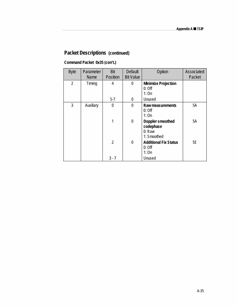
A-35
Appendix A ■ TSIP
Packet Descriptions (continued)
Command Packet 0x35 (con’t.)
Byte ParameterName
BitPosition
DefaultBit Value
Option AssociatedPacket
2 Timing 4 0 Minimize Projection0: Off1: On
5-7 0 Unused3 Auxiliary 0 0 Raw measurements
0: Off1: On
5A
1 0 Doppler smoothedcodephase0: Raw1: Smoothed
5A
2 0 Additional Fix Status0: Off1: On
5E
3 - 7 Unused
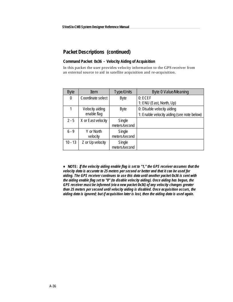
A-36
SVeeSix-CM3 System Designer Reference Manual
Packet Descriptions (continued)
Command Packet 0x36 - Velocity Aiding of AcquisitionIn this packet the user provides velocity information to the GPS receiver froman external source to aid in satellite acquisition and re-acquisition.
Byte Item Type/Units Byte 0 Value/Meaning0 Coordinate select Byte 0: ECEF
1: ENU (East, North, Up)1 Velocity aiding
enable flagByte 0: Disable velocity aiding
1: Enable velocity aiding (see note below)2 - 5 X or East velocity Single
meters/second6 - 9 Y or North
velocitySingle
meters/second10 - 13 Z or Up velocity Single
meters/second
♦ NOTE: If the velocity aiding enable flag is set to "1," the GPS receiver assumes that thevelocity data is accurate to 25 meters per second or better and that it can be used foraiding. The GPS receiver continues to use this data until another packet 0x36 is sent withthe aiding enable flag set to "0" (to disable velocity aiding). Once aiding has begun, theGPS receiver must be informed (via a new packet 0x36) of any velocity changes greaterthan 25 meters per second until velocity aiding is disabled. Once acquisition occurs, theaiding data is ignored; but if acquisition later is lost, then the aiding data is used again.
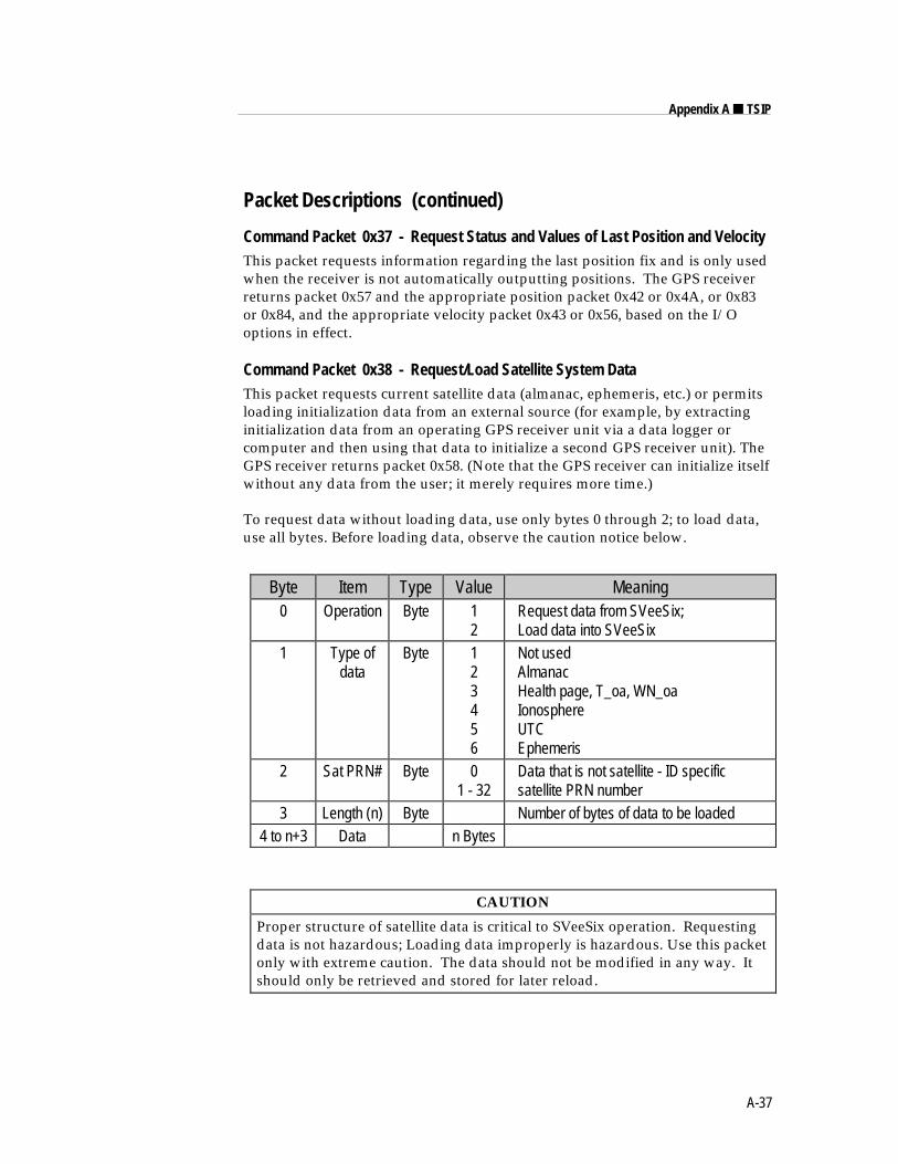
A-37
Appendix A ■ TSIP
Packet Descriptions (continued)
Command Packet 0x37 - Request Status and Values of Last Position and VelocityThis packet requests information regarding the last position fix and is only usedwhen the receiver is not automatically outputting positions. The GPS receiverreturns packet 0x57 and the appropriate position packet 0x42 or 0x4A, or 0x83or 0x84, and the appropriate velocity packet 0x43 or 0x56, based on the I/Ooptions in effect.
Command Packet 0x38 - Request/Load Satellite System DataThis packet requests current satellite data (almanac, ephemeris, etc.) or permitsloading initialization data from an external source (for example, by extractinginitialization data from an operating GPS receiver unit via a data logger orcomputer and then using that data to initialize a second GPS receiver unit). TheGPS receiver returns packet 0x58. (Note that the GPS receiver can initialize itselfwithout any data from the user; it merely requires more time.)
To request data without loading data, use only bytes 0 through 2; to load data,use all bytes. Before loading data, observe the caution notice below.
Byte Item Type Value Meaning0 Operation Byte 1
2 Request data from SVeeSix; Load data into SVeeSix
1 Type ofdata
Byte 123456
Not used Almanac Health page, T_oa, WN_oa Ionosphere UTC Ephemeris
2 Sat PRN# Byte 01 - 32
Data that is not satellite - ID specific satellite PRN number
3 Length (n) Byte Number of bytes of data to be loaded4 to n+3 Data n Bytes
CAUTION
Proper structure of satellite data is critical to SVeeSix operation. Requestingdata is not hazardous; Loading data improperly is hazardous. Use this packetonly with extreme caution. The data should not be modified in any way. Itshould only be retrieved and stored for later reload.
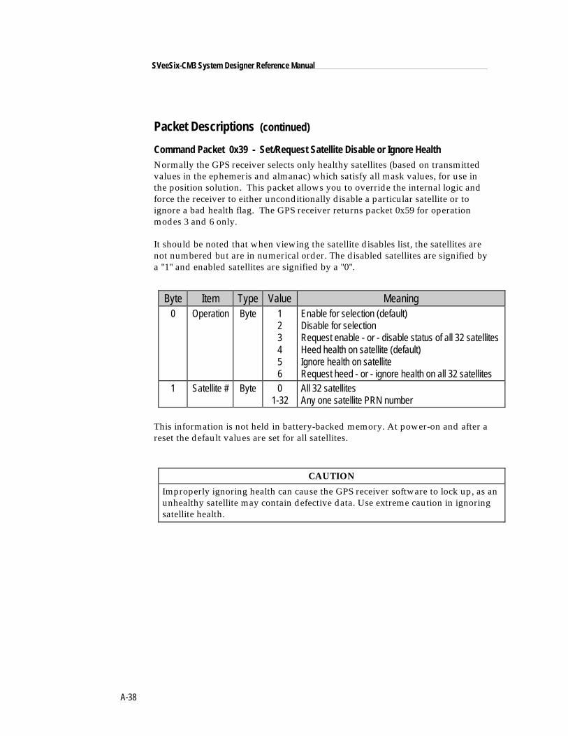
A-38
SVeeSix-CM3 System Designer Reference Manual
Packet Descriptions (continued)
Command Packet 0x39 - Set/Request Satellite Disable or Ignore HealthNormally the GPS receiver selects only healthy satellites (based on transmittedvalues in the ephemeris and almanac) which satisfy all mask values, for use inthe position solution. This packet allows you to override the internal logic andforce the receiver to either unconditionally disable a particular satellite or toignore a bad health flag. The GPS receiver returns packet 0x59 for operationmodes 3 and 6 only.
It should be noted that when viewing the satellite disables list, the satellites arenot numbered but are in numerical order. The disabled satellites are signified bya "1" and enabled satellites are signified by a "0".
Byte Item Type Value Meaning0 Operation Byte 1
23456
Enable for selection (default)Disable for selectionRequest enable - or - disable status of all 32 satellitesHeed health on satellite (default)Ignore health on satelliteRequest heed - or - ignore health on all 32 satellites
1 Satellite # Byte 01-32
All 32 satellitesAny one satellite PRN number
This information is not held in battery-backed memory. At power-on and after areset the default values are set for all satellites.
CAUTION
Improperly ignoring health can cause the GPS receiver software to lock up, as anunhealthy satellite may contain defective data. Use extreme caution in ignoringsatellite health.
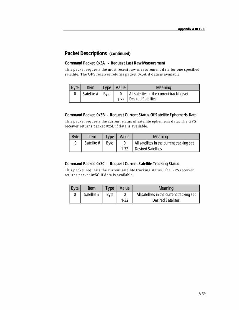
A-39
Appendix A ■ TSIP
Packet Descriptions (continued)
Command Packet 0x3A - Request Last Raw MeasurementThis packet requests the most recent raw measurement data for one specifiedsatellite. The GPS receiver returns packet 0x5A if data is available.
Byte Item Type Value Meaning0 Satellite # Byte 0
1-32All satellites in the current tracking setDesired Satellites
Command Packet 0x3B - Request Current Status Of Satellite Ephemeris DataThis packet requests the current status of satellite ephemeris data. The GPSreceiver returns packet 0x5B if data is available.
Byte Item Type Value Meaning0 Satellite # Byte 0
1-32All satellites in the current tracking setDesired Satellites
Command Packet 0x3C - Request Current Satellite Tracking StatusThis packet requests the current satellite tracking status. The GPS receiverreturns packet 0x5C if data is available.
Byte Item Type Value Meaning0 Satellite # Byte 0
1-32All satellites in the current tracking set
Desired Satellites
A-40
SVeeSix-CM3 System Designer Reference Manual
Packet Descriptions (continued)
Command / Report Packet 0x3D - Primary Port ConfigurationThis packet requests and optionally sets the primary port (port 1) configuration.This configuration includes the baud rate, number of bits, parity, and number ofstop bits and also the language mode. When this packet is used only to requestthe configuration the packet contains no data bytes. When this packet is used toset the configuration, the packet contains the 5 data bytes shown below.
Packet 0x3D is unique in that it is both an input and an output packet. A 0x3Dinput packet, with or without data, is responded to with a 0x3D output packet.The language mode is defined as follows. For transmission, the language modespecifies whether TSIP packets or NMEA are output on primary port. Forreception, the language mode specifies whether packets or RTCM data arereceived on the primary port. See Note 1.
The baud rate for the transmitter and the receiver can be set independently, butfor TSIP, the number of bits, parity, and the stop bits are common betweenthem. The default mode is packets for both transmission and reception at 9,600baud with 8 data bits, odd parity, and one stop bit. For TAIP and NMEA, thedefault factory setting is 4800 baud, 8 data bits, 1 stop bit and no parity.
When the language mode for reception is set to RTCM (SC-104), raw RTCM(SC-104) data is accepted on the primary port for differential GPS corrections.These corrections are used only if the mode is set to Differential Auto or ManualOn with packet 0x62.
♦ NOTE: In most 2 port versions of the receiver, RTCM input for the secondary port is thedefault mode at power-on to allow for direct connection to a radio modem. The defaultspeed is 9600,8,odd,1.
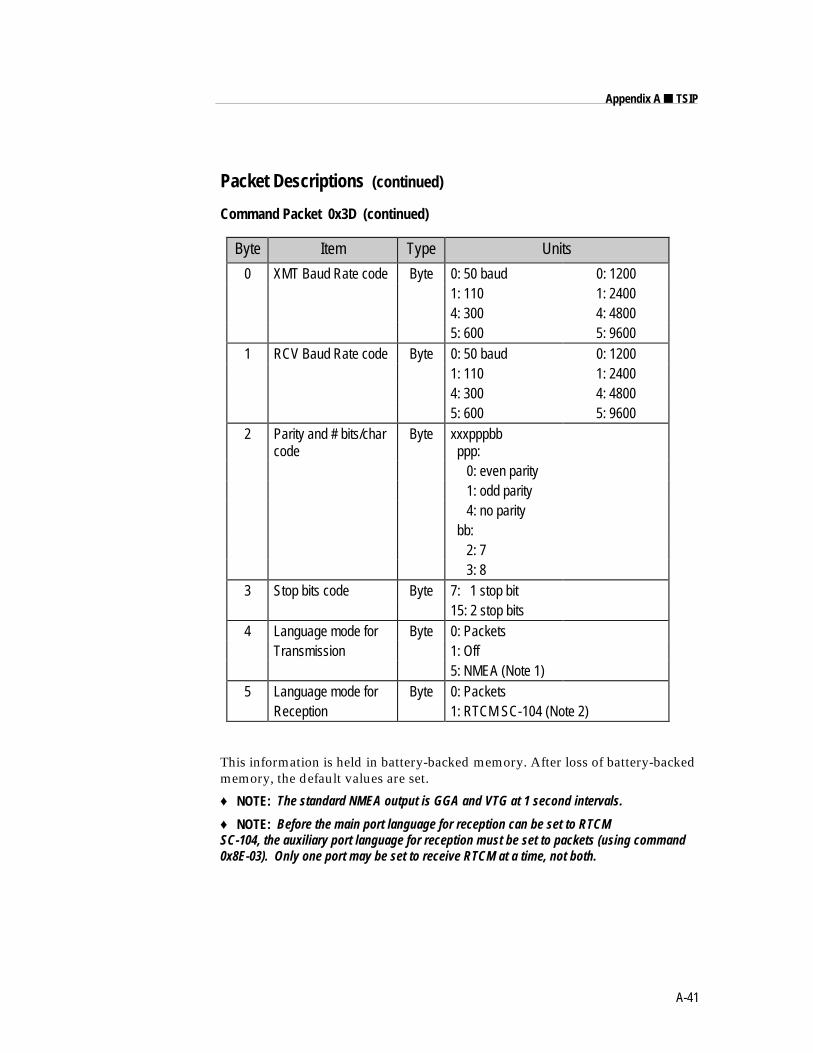
A-41
Appendix A ■ TSIP
Packet Descriptions (continued)
Command Packet 0x3D (continued)
Byte Item Type Units
0 XMT Baud Rate code Byte 0: 50 baud 0: 12001: 110 1: 24004: 300 4: 48005: 600 5: 9600
1 RCV Baud Rate code Byte 0: 50 baud 0: 12001: 110 1: 24004: 300 4: 48005: 600 5: 9600
2 Parity and # bits/charcode
Byte xxxpppbb ppp: 0: even parity 1: odd parity 4: no parity bb: 2: 7 3: 8
3 Stop bits code Byte 7: 1 stop bit15: 2 stop bits
4 Language mode for Byte 0: PacketsTransmission 1: Off
5: NMEA (Note 1)5 Language mode for Byte 0: Packets
Reception 1: RTCM SC-104 (Note 2)
This information is held in battery-backed memory. After loss of battery-backedmemory, the default values are set.
♦ NOTE: The standard NMEA output is GGA and VTG at 1 second intervals.
♦ NOTE: Before the main port language for reception can be set to RTCMSC-104, the auxiliary port language for reception must be set to packets (using command0x8E-03). Only one port may be set to receive RTCM at a time, not both.
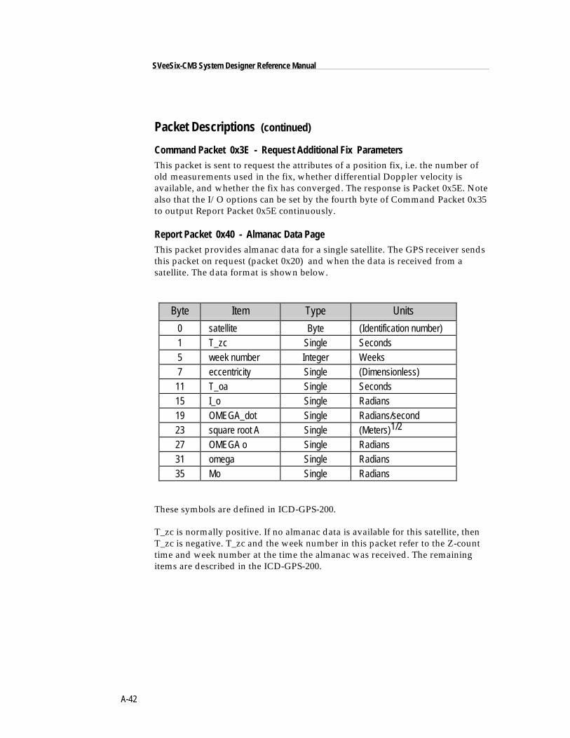
A-42
SVeeSix-CM3 System Designer Reference Manual
Packet Descriptions (continued)
Command Packet 0x3E - Request Additional Fix ParametersThis packet is sent to request the attributes of a position fix, i.e. the number ofold measurements used in the fix, whether differential Doppler velocity isavailable, and whether the fix has converged. The response is Packet 0x5E. Notealso that the I/O options can be set by the fourth byte of Command Packet 0x35to output Report Packet 0x5E continuously.
Report Packet 0x40 - Almanac Data PageThis packet provides almanac data for a single satellite. The GPS receiver sendsthis packet on request (packet 0x20) and when the data is received from asatellite. The data format is shown below.
Byte Item Type Units
0 satellite Byte (Identification number)1 T_zc Single Seconds5 week number Integer Weeks7 eccentricity Single (Dimensionless)11 T_oa Single Seconds15 I_o Single Radians19 OMEGA_dot Single Radians/second23 square root A Single (Meters)1/2
27 OMEGA o Single Radians31 omega Single Radians35 Mo Single Radians
These symbols are defined in ICD-GPS-200.
T_zc is normally positive. If no almanac data is available for this satellite, thenT_zc is negative. T_zc and the week number in this packet refer to the Z-counttime and week number at the time the almanac was received. The remainingitems are described in the ICD-GPS-200.
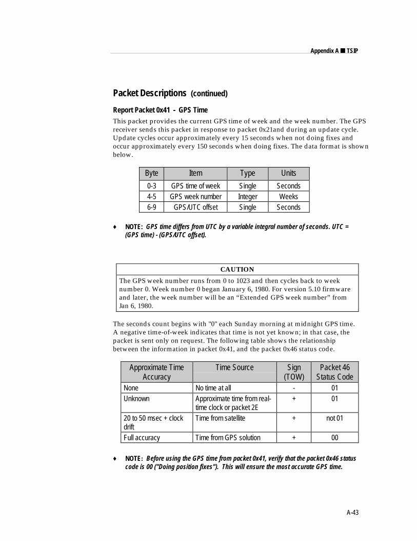
A-43
Appendix A ■ TSIP
Packet Descriptions (continued)
Report Packet 0x41 - GPS TimeThis packet provides the current GPS time of week and the week number. The GPSreceiver sends this packet in response to packet 0x21and during an update cycle.Update cycles occur approximately every 15 seconds when not doing fixes andoccur approximately every 150 seconds when doing fixes. The data format is shownbelow.
Byte Item Type Units
0-3 GPS time of week Single Seconds4-5 GPS week number Integer Weeks6-9 GPS/UTC offset Single Seconds
♦ NOTE: GPS time differs from UTC by a variable integral number of seconds. UTC =(GPS time) - (GPS/UTC offset).
CAUTION
The GPS week number runs from 0 to 1023 and then cycles back to weeknumber 0. Week number 0 began January 6, 1980. For version 5.10 firmwareand later, the week number will be an “Extended GPS week number” fromJan 6, 1980.
The seconds count begins with "0" each Sunday morning at midnight GPS time.A negative time-of-week indicates that time is not yet known; in that case, thepacket is sent only on request. The following table shows the relationshipbetween the information in packet 0x41, and the packet 0x46 status code.
Approximate TimeAccuracy
Time Source Sign(TOW)
Packet 46Status Code
None No time at all - 01Unknown Approximate time from real-
time clock or packet 2E+ 01
20 to 50 msec + clockdrift
Time from satellite + not 01
Full accuracy Time from GPS solution + 00
♦ NOTE: Before using the GPS time from packet 0x41, verify that the packet 0x46 statuscode is 00 ("Doing position fixes"). This will ensure the most accurate GPS time.
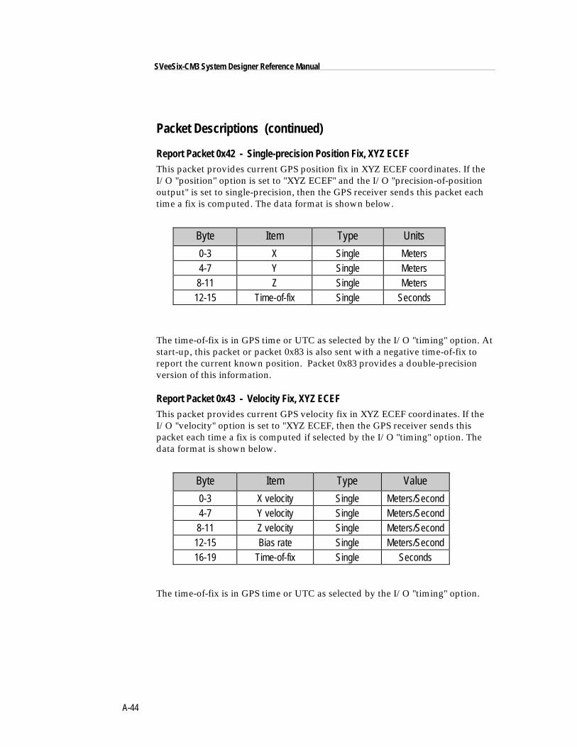
A-44
SVeeSix-CM3 System Designer Reference Manual
Packet Descriptions (continued)
Report Packet 0x42 - Single-precision Position Fix, XYZ ECEFThis packet provides current GPS position fix in XYZ ECEF coordinates. If theI/O "position" option is set to "XYZ ECEF" and the I/O "precision-of-positionoutput" is set to single-precision, then the GPS receiver sends this packet eachtime a fix is computed. The data format is shown below.
Byte Item Type Units
0-3 X Single Meters4-7 Y Single Meters8-11 Z Single Meters
12-15 Time-of-fix Single Seconds
The time-of-fix is in GPS time or UTC as selected by the I/O "timing" option. Atstart-up, this packet or packet 0x83 is also sent with a negative time-of-fix toreport the current known position. Packet 0x83 provides a double-precisionversion of this information.
Report Packet 0x43 - Velocity Fix, XYZ ECEFThis packet provides current GPS velocity fix in XYZ ECEF coordinates. If theI/O "velocity" option is set to "XYZ ECEF, then the GPS receiver sends thispacket each time a fix is computed if selected by the I/O "timing" option. Thedata format is shown below.
Byte Item Type Value
0-3 X velocity Single Meters/Second4-7 Y velocity Single Meters/Second8-11 Z velocity Single Meters/Second
12-15 Bias rate Single Meters/Second16-19 Time-of-fix Single Seconds
The time-of-fix is in GPS time or UTC as selected by the I/O "timing" option.
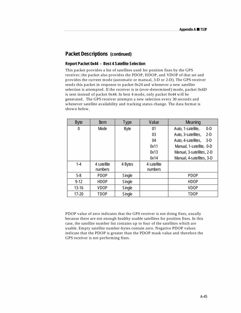
A-45
Appendix A ■ TSIP
Packet Descriptions (continued)
Report Packet 0x44 - Best 4 Satellite SelectionThis packet provides a list of satellites used for position fixes by the GPSreceiver; the packet also provides the PDOP, HDOP, and VDOP of that set andprovides the current mode (automatic or manual, 3-D or 2-D). The GPS receiversends this packet in response to packet 0x24 and whenever a new satelliteselection is attempted. If the receiver is in (over-determined) mode, packet 0x6Dis sent instead of packet 0x44. In best 4 mode, only packet 0x44 will begenerated. The GPS receiver attempts a new selection every 30 seconds andwhenever satellite availability and tracking status change. The data format isshown below.
Byte Item Type Value Meaning0 Mode Byte 01
0304
0x110x130x14
Auto, 1-satellite, 0-DAuto, 3-satellites, 2-DAuto, 4-satellites, 3-D Manual, 1-satellite, 0-D Manual, 3-satellites, 2-D Manual, 4-satellites, 3-D
1-4 4 satellitenumbers
4 Bytes 4 satellitenumbers
5-8 PDOP Single PDOP9-12 HDOP Single HDOP
13-16 VDOP Single VDOP17-20 TDOP Single TDOP
PDOP value of zero indicates that the GPS receiver is not doing fixes, usuallybecause there are not enough healthy usable satellites for position fixes. In thiscase, the satellite number list contains up to four of the satellites which areusable. Empty satellite number-bytes contain zero. Negative PDOP valuesindicate that the PDOP is greater than the PDOP mask value and therefore theGPS receiver is not performing fixes.
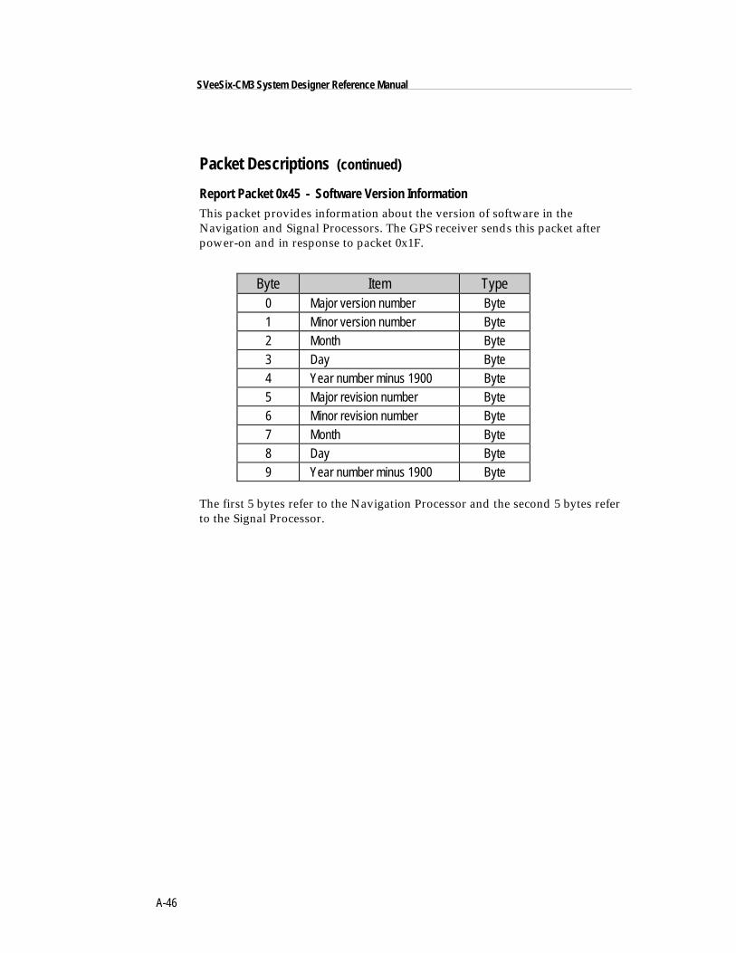
A-46
SVeeSix-CM3 System Designer Reference Manual
Packet Descriptions (continued)
Report Packet 0x45 - Software Version InformationThis packet provides information about the version of software in theNavigation and Signal Processors. The GPS receiver sends this packet afterpower-on and in response to packet 0x1F.
Byte Item Type0 Major version number Byte1 Minor version number Byte2 Month Byte3 Day Byte4 Year number minus 1900 Byte5 Major revision number Byte6 Minor revision number Byte7 Month Byte8 Day Byte9 Year number minus 1900 Byte
The first 5 bytes refer to the Navigation Processor and the second 5 bytes referto the Signal Processor.
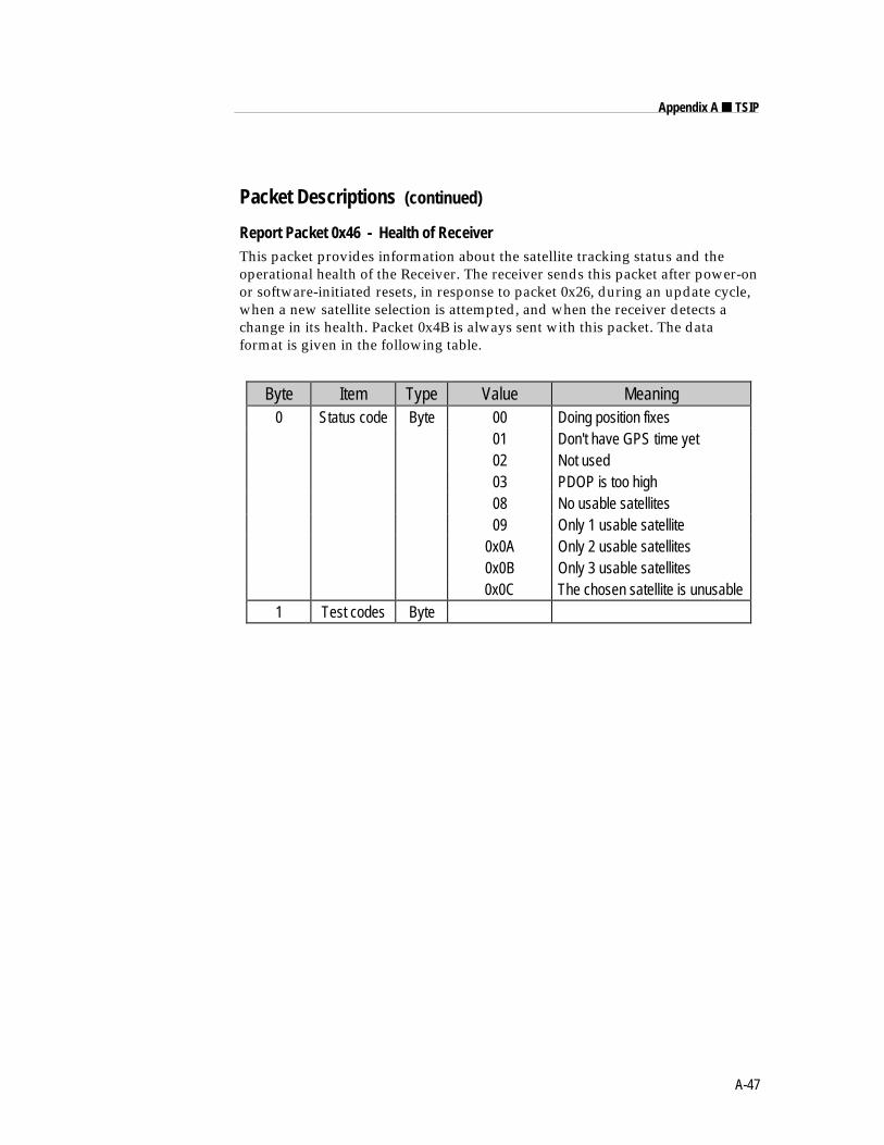
A-47
Appendix A ■ TSIP
Packet Descriptions (continued)
Report Packet 0x46 - Health of ReceiverThis packet provides information about the satellite tracking status and theoperational health of the Receiver. The receiver sends this packet after power-onor software-initiated resets, in response to packet 0x26, during an update cycle,when a new satellite selection is attempted, and when the receiver detects achange in its health. Packet 0x4B is always sent with this packet. The dataformat is given in the following table.
Byte Item Type Value Meaning0 Status code Byte 00 Doing position fixes
01 Don't have GPS time yet02 Not used03 PDOP is too high08 No usable satellites09 Only 1 usable satellite
0x0A Only 2 usable satellites0x0B Only 3 usable satellites0x0C The chosen satellite is unusable
1 Test codes Byte
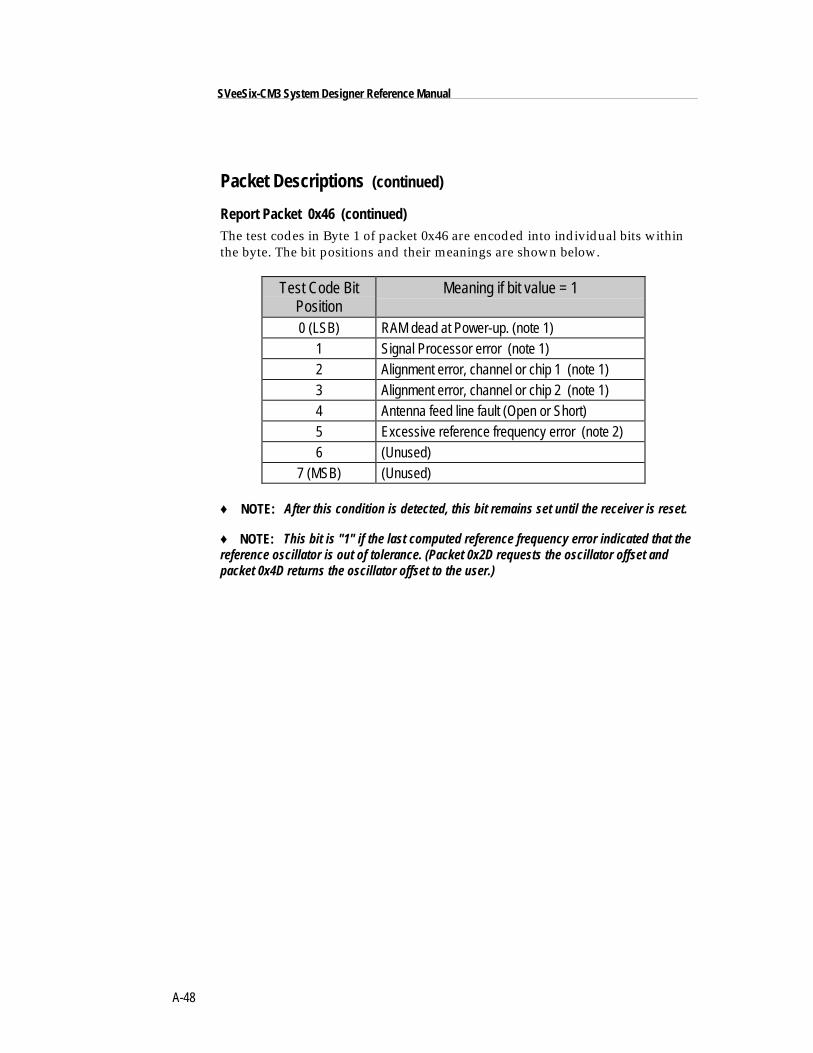
A-48
SVeeSix-CM3 System Designer Reference Manual
Packet Descriptions (continued)
Report Packet 0x46 (continued)The test codes in Byte 1 of packet 0x46 are encoded into individual bits withinthe byte. The bit positions and their meanings are shown below.
Test Code BitPosition
Meaning if bit value = 1
0 (LSB) RAM dead at Power-up. (note 1)1 Signal Processor error (note 1)2 Alignment error, channel or chip 1 (note 1)3 Alignment error, channel or chip 2 (note 1)4 Antenna feed line fault (Open or Short)5 Excessive reference frequency error (note 2)6 (Unused)
7 (MSB) (Unused)
♦ NOTE: After this condition is detected, this bit remains set until the receiver is reset.
♦ NOTE: This bit is "1" if the last computed reference frequency error indicated that thereference oscillator is out of tolerance. (Packet 0x2D requests the oscillator offset andpacket 0x4D returns the oscillator offset to the user.)
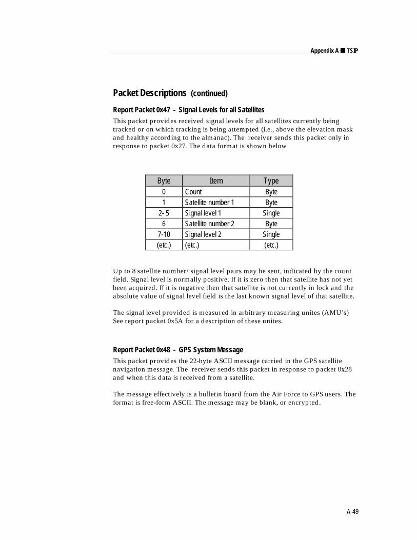
A-49
Appendix A ■ TSIP
Packet Descriptions (continued)
Report Packet 0x47 - Signal Levels for all SatellitesThis packet provides received signal levels for all satellites currently beingtracked or on which tracking is being attempted (i.e., above the elevation maskand healthy according to the almanac). The receiver sends this packet only inresponse to packet 0x27. The data format is shown below
Byte Item Type0 Count Byte1 Satellite number 1 Byte
2- 5 Signal level 1 Single6 Satellite number 2 Byte
7-10 Signal level 2 Single(etc.) (etc.) (etc.)
Up to 8 satellite number/signal level pairs may be sent, indicated by the countfield. Signal level is normally positive. If it is zero then that satellite has not yetbeen acquired. If it is negative then that satellite is not currently in lock and theabsolute value of signal level field is the last known signal level of that satellite.
The signal level provided is measured in arbitrary measuring unites (AMU’s)See report packet 0x5A for a description of these unites.
Report Packet 0x48 - GPS System MessageThis packet provides the 22-byte ASCII message carried in the GPS satellitenavigation message. The receiver sends this packet in response to packet 0x28and when this data is received from a satellite.
The message effectively is a bulletin board from the Air Force to GPS users. Theformat is free-form ASCII. The message may be blank, or encrypted.
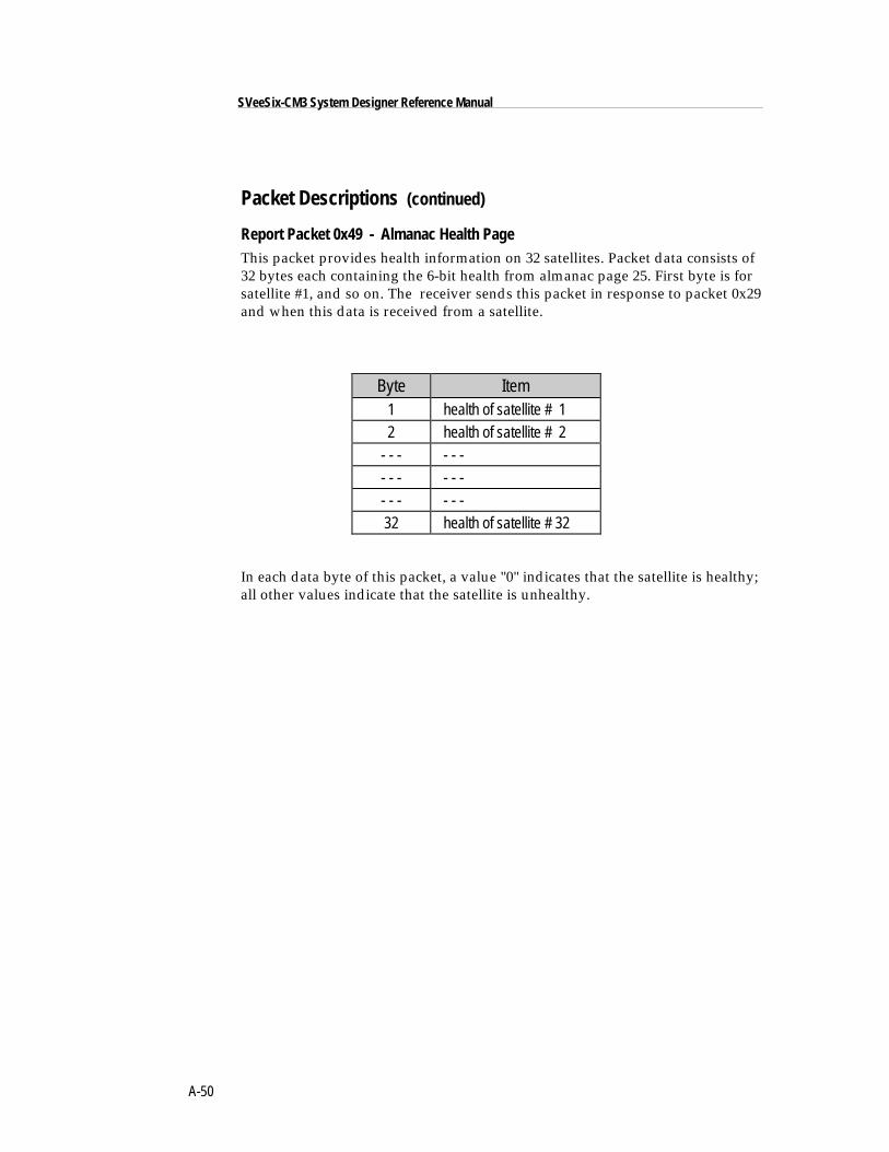
A-50
SVeeSix-CM3 System Designer Reference Manual
Packet Descriptions (continued)
Report Packet 0x49 - Almanac Health PageThis packet provides health information on 32 satellites. Packet data consists of32 bytes each containing the 6-bit health from almanac page 25. First byte is forsatellite #1, and so on. The receiver sends this packet in response to packet 0x29and when this data is received from a satellite.
Byte Item1 health of satellite # 12 health of satellite # 2
- - - - - -- - - - - -- - - - - -32 health of satellite # 32
In each data byte of this packet, a value "0" indicates that the satellite is healthy;all other values indicate that the satellite is unhealthy.
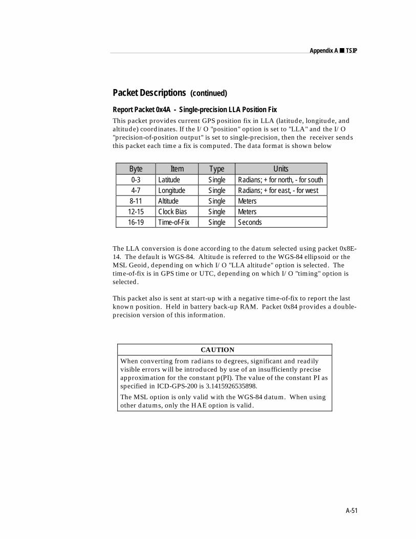
A-51
Appendix A ■ TSIP
Packet Descriptions (continued)
Report Packet 0x4A - Single-precision LLA Position FixThis packet provides current GPS position fix in LLA (latitude, longitude, andaltitude) coordinates. If the I/O "position" option is set to "LLA" and the I/O"precision-of-position output" is set to single-precision, then the receiver sendsthis packet each time a fix is computed. The data format is shown below
Byte Item Type Units0-3 Latitude Single Radians; + for north, - for south4-7 Longitude Single Radians; + for east, - for west8-11 Altitude Single Meters
12-15 Clock Bias Single Meters16-19 Time-of-Fix Single Seconds
The LLA conversion is done according to the datum selected using packet 0x8E-14. The default is WGS-84. Altitude is referred to the WGS-84 ellipsoid or theMSL Geoid, depending on which I/O "LLA altitude" option is selected. Thetime-of-fix is in GPS time or UTC, depending on which I/O "timing" option isselected.
This packet also is sent at start-up with a negative time-of-fix to report the lastknown position. Held in battery back-up RAM. Packet 0x84 provides a double-precision version of this information.
CAUTION
When converting from radians to degrees, significant and readilyvisible errors will be introduced by use of an insufficiently preciseapproximation for the constant p(PI). The value of the constant PI asspecified in ICD-GPS-200 is 3.1415926535898.
The MSL option is only valid with the WGS-84 datum. When usingother datums, only the HAE option is valid.
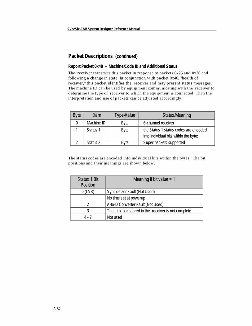
A-52
SVeeSix-CM3 System Designer Reference Manual
Packet Descriptions (continued)
Report Packet 0x4B - Machine/Code ID and Additional StatusThe receiver transmits this packet in response to packets 0x25 and 0x26 andfollowing a change in state. In conjunction with packet 0x46, "health ofreceiver," this packet identifies the receiver and may present status messages.The machine ID can be used by equipment communicating with the receiver todetermine the type of receiver to which the equipment is connected. Then theinterpretation and use of packets can be adjusted accordingly.
Byte Item Type/Value Status/Meaning
0 Machine ID Byte 6-channel receiver
1 Status 1 Byte the Status 1 status codes are encoded into individual bits within the byte:
2 Status 2 Byte Super packets supported
The status codes are encoded into individual bits within the bytes. The bitpositions and their meanings are shown below.
Status 1 BitPosition
Meaning if bit value = 1
0 (LSB) Synthesizer Fault (Not Used)1 No time set at powerup2 A-to-D Converter Fault (Not Used)3 The almanac stored in the receiver is not complete
4 - 7 Not used
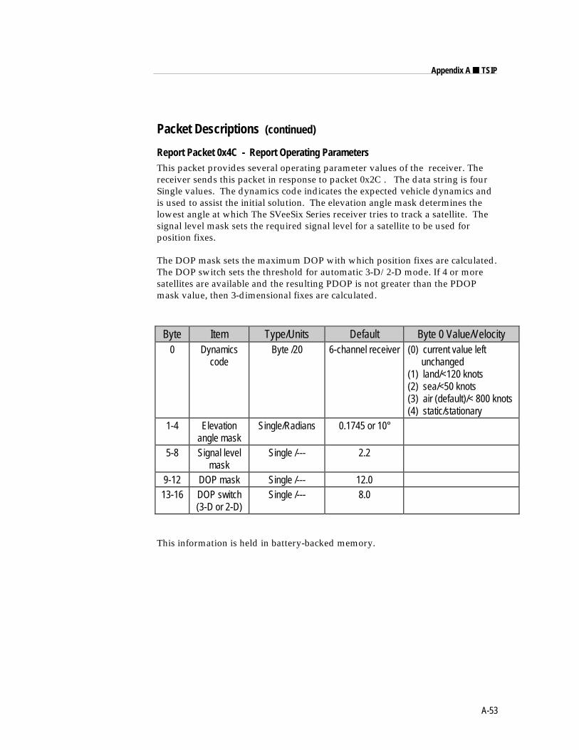
A-53
Appendix A ■ TSIP
Packet Descriptions (continued)
Report Packet 0x4C - Report Operating ParametersThis packet provides several operating parameter values of the receiver. Thereceiver sends this packet in response to packet 0x2C . The data string is fourSingle values. The dynamics code indicates the expected vehicle dynamics andis used to assist the initial solution. The elevation angle mask determines thelowest angle at which The SVeeSix Series receiver tries to track a satellite. Thesignal level mask sets the required signal level for a satellite to be used forposition fixes.
The DOP mask sets the maximum DOP with which position fixes are calculated.The DOP switch sets the threshold for automatic 3-D/2-D mode. If 4 or moresatellites are available and the resulting PDOP is not greater than the PDOPmask value, then 3-dimensional fixes are calculated.
Byte Item Type/Units Default Byte 0 Value/Velocity0 Dynamics
codeByte /20 6-channel receiver (0) current value left
unchanged(1) land/<120 knots(2) sea/<50 knots(3) air (default)/< 800 knots(4) static/stationary
1-4 Elevationangle mask
Single/Radians 0.1745 or 10°
5-8 Signal levelmask
Single /--- 2.2
9-12 DOP mask Single /--- 12.013-16 DOP switch
(3-D or 2-D)Single /--- 8.0
This information is held in battery-backed memory.
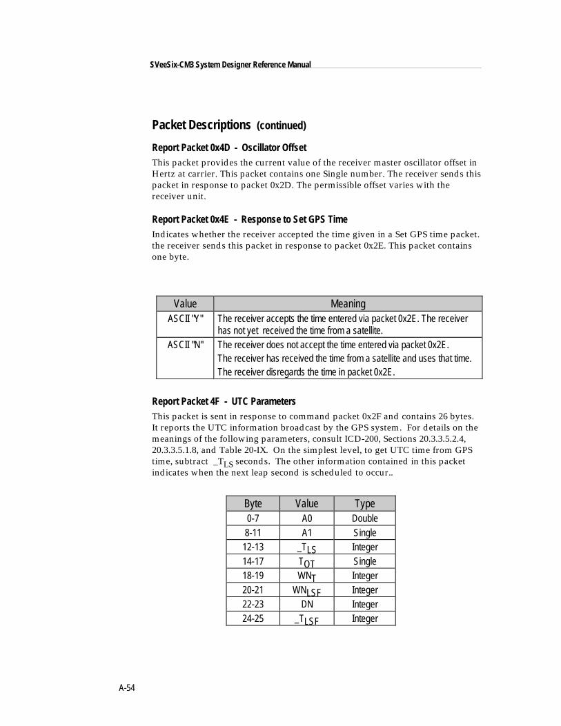
A-54
SVeeSix-CM3 System Designer Reference Manual
Packet Descriptions (continued)
Report Packet 0x4D - Oscillator OffsetThis packet provides the current value of the receiver master oscillator offset inHertz at carrier. This packet contains one Single number. The receiver sends thispacket in response to packet 0x2D. The permissible offset varies with thereceiver unit.
Report Packet 0x4E - Response to Set GPS TimeIndicates whether the receiver accepted the time given in a Set GPS time packet.the receiver sends this packet in response to packet 0x2E. This packet containsone byte.
Value MeaningASCII "Y" The receiver accepts the time entered via packet 0x2E. The receiver
has not yet received the time from a satellite.ASCII "N" The receiver does not accept the time entered via packet 0x2E.
The receiver has received the time from a satellite and uses that time.The receiver disregards the time in packet 0x2E.
Report Packet 4F - UTC ParametersThis packet is sent in response to command packet 0x2F and contains 26 bytes.It reports the UTC information broadcast by the GPS system. For details on themeanings of the following parameters, consult ICD-200, Sections 20.3.3.5.2.4,20.3.3.5.1.8, and Table 20-IX. On the simplest level, to get UTC time from GPStime, subtract _TLS seconds. The other information contained in this packetindicates when the next leap second is scheduled to occur..
Byte Value Type0-7 A0 Double8-11 A1 Single
12-13 _TLS Integer14-17 TOT Single18-19 WNT Integer20-21 WNLSF Integer22-23 DN Integer24-25 _TLSF Integer
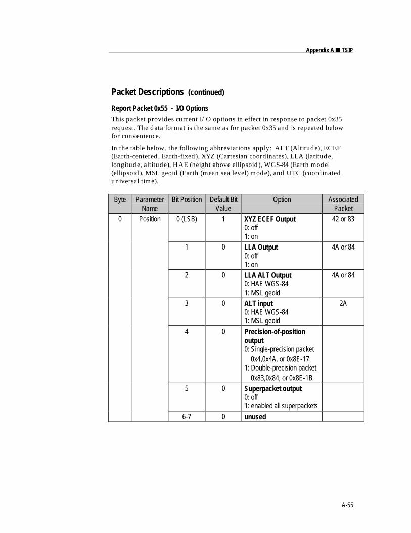
A-55
Appendix A ■ TSIP
Packet Descriptions (continued)
Report Packet 0x55 - I/O OptionsThis packet provides current I/O options in effect in response to packet 0x35request. The data format is the same as for packet 0x35 and is repeated belowfor convenience.
In the table below, the following abbreviations apply: ALT (Altitude), ECEF(Earth-centered, Earth-fixed), XYZ (Cartesian coordinates), LLA (latitude,longitude, altitude), HAE (height above ellipsoid), WGS-84 (Earth model(ellipsoid), MSL geoid (Earth (mean sea level) mode), and UTC (coordinateduniversal time).
Byte ParameterName
Bit Position Default BitValue
Option AssociatedPacket
0 Position 0 (LSB) 1 XYZ ECEF Output0: off1: on
42 or 83
1 0 LLA Output0: off1: on
4A or 84
2 0 LLA ALT Output0: HAE WGS-841: MSL geoid
4A or 84
3 0 ALT input0: HAE WGS-841: MSL geoid
2A
4 0 Precision-of-positionoutput0: Single-precision packet 0x4,0x4A, or 0x8E-17.1: Double-precision packet 0x83,0x84, or 0x8E-1B
5 0 Superpacket output0: off1: enabled all superpackets
6-7 0 unused
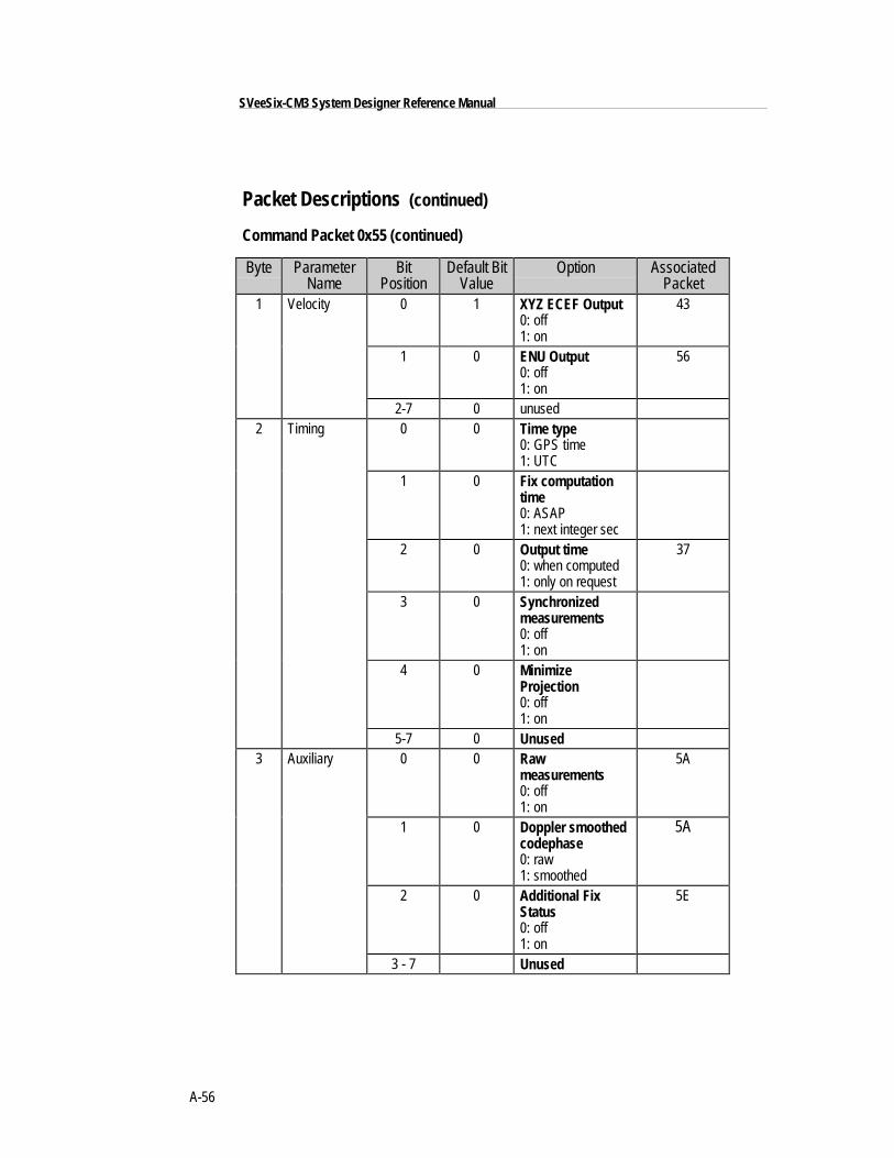
A-56
SVeeSix-CM3 System Designer Reference Manual
Packet Descriptions (continued)
Command Packet 0x55 (continued)
Byte ParameterName
BitPosition
Default BitValue
Option AssociatedPacket
1 Velocity 0 1 XYZ ECEF Output0: off1: on
43
1 0 ENU Output0: off1: on
56
2-7 0 unused2 Timing 0 0 Time type
0: GPS time1: UTC
1 0 Fix computationtime0: ASAP1: next integer sec
2 0 Output time0: when computed1: only on request
37
3 0 Synchronizedmeasurements0: off1: on
4 0 MinimizeProjection0: off1: on
5-7 0 Unused3 Auxiliary 0 0 Raw
measurements0: off1: on
5A
1 0 Doppler smoothedcodephase0: raw1: smoothed
5A
2 0 Additional FixStatus0: off1: on
5E
3 - 7 Unused
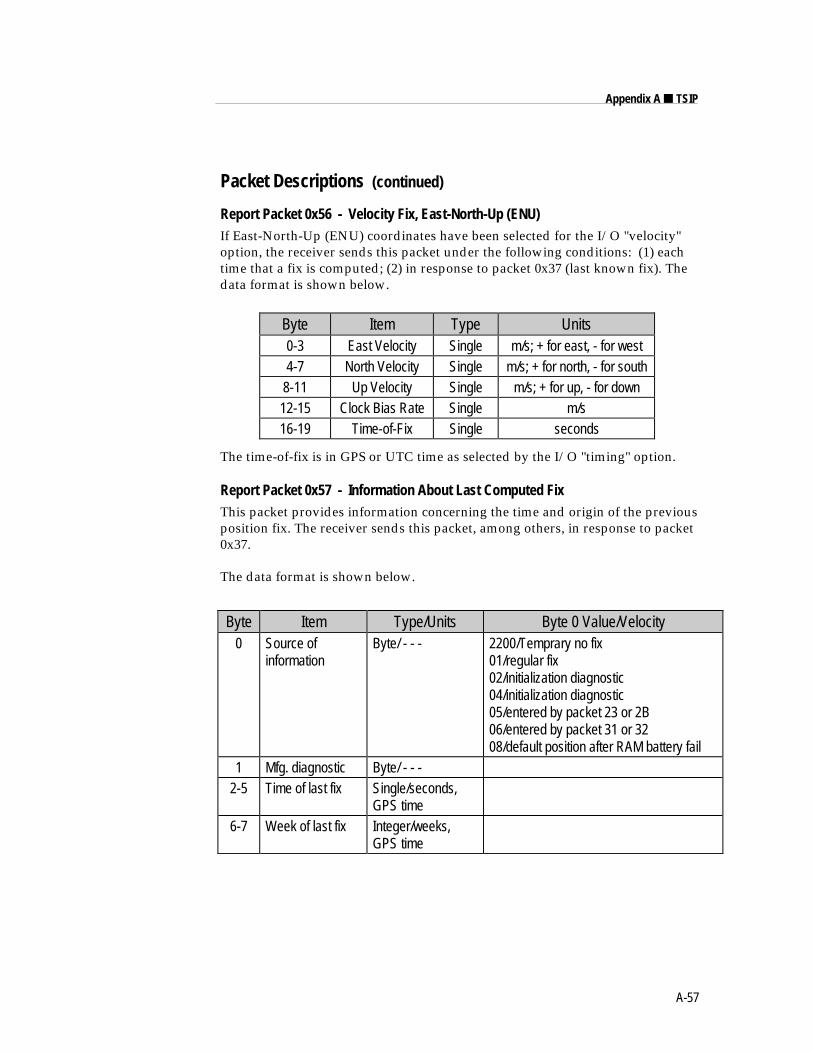
A-57
Appendix A ■ TSIP
Packet Descriptions (continued)
Report Packet 0x56 - Velocity Fix, East-North-Up (ENU)If East-North-Up (ENU) coordinates have been selected for the I/O "velocity"option, the receiver sends this packet under the following conditions: (1) eachtime that a fix is computed; (2) in response to packet 0x37 (last known fix). Thedata format is shown below.
Byte Item Type Units0-3 East Velocity Single m/s; + for east, - for west4-7 North Velocity Single m/s; + for north, - for south
8-11 Up Velocity Single m/s; + for up, - for down12-15 Clock Bias Rate Single m/s16-19 Time-of-Fix Single seconds
The time-of-fix is in GPS or UTC time as selected by the I/O "timing" option.
Report Packet 0x57 - Information About Last Computed FixThis packet provides information concerning the time and origin of the previousposition fix. The receiver sends this packet, among others, in response to packet0x37.
The data format is shown below.
Byte Item Type/Units Byte 0 Value/Velocity0 Source of
informationByte/ - - - 2200/Temprary no fix
01/regular fix02/initialization diagnostic04/initialization diagnostic05/entered by packet 23 or 2B06/entered by packet 31 or 3208/default position after RAM battery fail
1 Mfg. diagnostic Byte/ - - -2-5 Time of last fix Single/seconds,
GPS time6-7 Week of last fix Integer/weeks,
GPS time
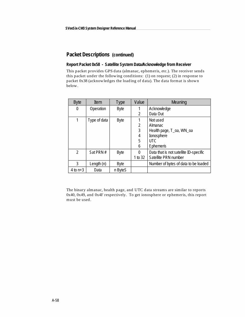
A-58
SVeeSix-CM3 System Designer Reference Manual
Packet Descriptions (continued)
Report Packet 0x58 - Satellite System Data/Acknowledge from ReceiverThis packet provides GPS data (almanac, ephemeris, etc.). The receiver sendsthis packet under the following conditions: (1) on request; (2) in response topacket 0x38 (acknowledges the loading of data). The data format is shownbelow.
Byte Item Type Value Meaning0 Operation Byte 1
2AcknowledgeData Out
1 Type of data Byte 123456
Not usedAlmanacHealth page, T_oa, WN_oaIonosphereUTCEphemeris
2 Sat PRN # Byte 01 to 32
Data that is not satellite ID-specificSatellite PRN number
3 Length (n) Byte Number of bytes of data to be loaded4 to n+3 Data n ByteS
The binary almanac, health page, and UTC data streams are similar to reports0x40, 0x49, and 0x4F respectively. To get ionosphere or ephemeris, this reportmust be used.
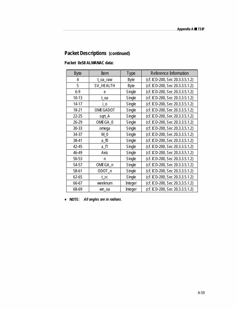
A-59
Appendix A ■ TSIP
Packet Descriptions (continued)
Packet 0x58 ALMANAC data:
Byte Item Type Reference Information4 t_oa_raw Byte (cf. ICD-200, Sec 20.3.3.5.1.2)5 SV_HEALTH Byte (cf. ICD-200, Sec 20.3.3.5.1.2)
6-9 e Single (cf. ICD-200, Sec 20.3.3.5.1.2)10-13 t_oa Single (cf. ICD-200, Sec 20.3.3.5.1.2)14-17 i_o Single (cf. ICD-200, Sec 20.3.3.5.1.2)18-21 OMEGADOT Single (cf. ICD-200, Sec 20.3.3.5.1.2)22-25 sqrt_A Single (cf. ICD-200, Sec 20.3.3.5.1.2)26-29 OMEGA_0 Single (cf. ICD-200, Sec 20.3.3.5.1.2)30-33 omega Single (cf. ICD-200, Sec 20.3.3.5.1.2)34-37 M_0 Single (cf. ICD-200, Sec 20.3.3.5.1.2)38-41 a_f0 Single (cf. ICD-200, Sec 20.3.3.5.1.2)42-45 a_f1 Single (cf. ICD-200, Sec 20.3.3.5.1.2)46-49 Axis Single (cf. ICD-200, Sec 20.3.3.5.1.2)50-53 n Single (cf. ICD-200, Sec 20.3.3.5.1.2)54-57 OMEGA_n Single (cf. ICD-200, Sec 20.3.3.5.1.2)58-61 ODOT_n Single (cf. ICD-200, Sec 20.3.3.5.1.2)62-65 t_zc Single (cf. ICD-200, Sec 20.3.3.5.1.2)66-67 weeknum Integer (cf. ICD-200, Sec 20.3.3.5.1.2)68-69 wn_oa Integer (cf. ICD-200, Sec 20.3.3.5.1.2)
♦ NOTE: All angles are in radians.
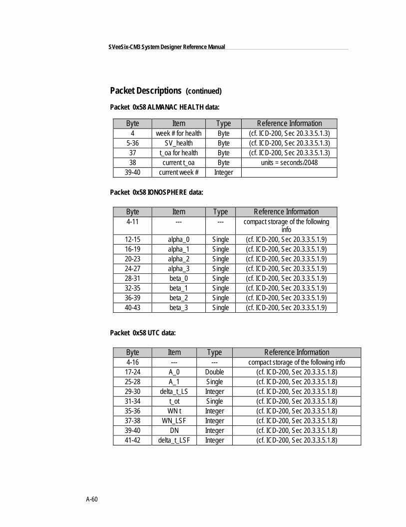
A-60
SVeeSix-CM3 System Designer Reference Manual
Packet Descriptions (continued)
Packet 0x58 ALMANAC HEALTH data:
Byte Item Type Reference Information4 week # for health Byte (cf. ICD-200, Sec 20.3.3.5.1.3)
5-36 SV_health Byte (cf. ICD-200, Sec 20.3.3.5.1.3)37 t_oa for health Byte (cf. ICD-200, Sec 20.3.3.5.1.3)38 current t_oa Byte units = seconds/2048
39-40 current week # Integer
Packet 0x58 IONOSPHERE data:
Byte Item Type Reference Information4-11 --- --- compact storage of the following
info12-15 alpha_0 Single (cf. ICD-200, Sec 20.3.3.5.1.9)16-19 alpha_1 Single (cf. ICD-200, Sec 20.3.3.5.1.9)20-23 alpha_2 Single (cf. ICD-200, Sec 20.3.3.5.1.9)24-27 alpha_3 Single (cf. ICD-200, Sec 20.3.3.5.1.9)28-31 beta_0 Single (cf. ICD-200, Sec 20.3.3.5.1.9)32-35 beta_1 Single (cf. ICD-200, Sec 20.3.3.5.1.9)36-39 beta_2 Single (cf. ICD-200, Sec 20.3.3.5.1.9)40-43 beta_3 Single (cf. ICD-200, Sec 20.3.3.5.1.9)
Packet 0x58 UTC data:
Byte Item Type Reference Information4-16 --- --- compact storage of the following info
17-24 A_0 Double (cf. ICD-200, Sec 20.3.3.5.1.8)25-28 A_1 Single (cf. ICD-200, Sec 20.3.3.5.1.8)29-30 delta_t_LS Integer (cf. ICD-200, Sec 20.3.3.5.1.8)31-34 t_ot Single (cf. ICD-200, Sec 20.3.3.5.1.8)35-36 WN t Integer (cf. ICD-200, Sec 20.3.3.5.1.8)37-38 WN_LSF Integer (cf. ICD-200, Sec 20.3.3.5.1.8)39-40 DN Integer (cf. ICD-200, Sec 20.3.3.5.1.8)41-42 delta_t_LSF Integer (cf. ICD-200, Sec 20.3.3.5.1.8)
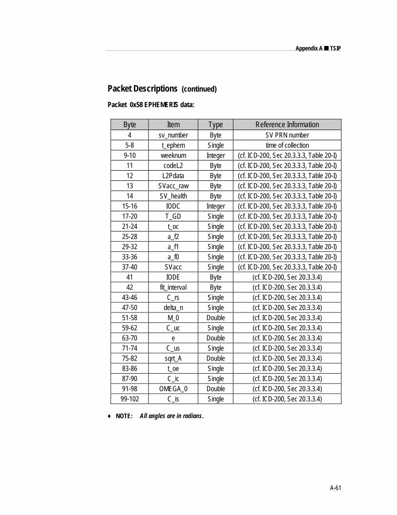
A-61
Appendix A ■ TSIP
Packet Descriptions (continued)
Packet 0x58 EPHEMERIS data:
Byte Item Type Reference Information4 sv_number Byte SV PRN number
5-8 t_ephem Single time of collection9-10 weeknum Integer (cf. ICD-200, Sec 20.3.3.3, Table 20-I)11 codeL2 Byte (cf. ICD-200, Sec 20.3.3.3, Table 20-I)12 L2Pdata Byte (cf. ICD-200, Sec 20.3.3.3, Table 20-I)13 SVacc_raw Byte (cf. ICD-200, Sec 20.3.3.3, Table 20-I)14 SV_health Byte (cf. ICD-200, Sec 20.3.3.3, Table 20-I)
15-16 IODC Integer (cf. ICD-200, Sec 20.3.3.3, Table 20-I)17-20 T_GD Single (cf. ICD-200, Sec 20.3.3.3, Table 20-I)21-24 t_oc Single (cf. ICD-200, Sec 20.3.3.3, Table 20-I)25-28 a_f2 Single (cf. ICD-200, Sec 20.3.3.3, Table 20-I)29-32 a_f1 Single (cf. ICD-200, Sec 20.3.3.3, Table 20-I)33-36 a_f0 Single (cf. ICD-200, Sec 20.3.3.3, Table 20-I)37-40 SVacc Single (cf. ICD-200, Sec 20.3.3.3, Table 20-I)
41 IODE Byte (cf. ICD-200, Sec 20.3.3.4)42 fit_interval Byte (cf. ICD-200, Sec 20.3.3.4)
43-46 C_rs Single (cf. ICD-200, Sec 20.3.3.4)47-50 delta_n Single (cf. ICD-200, Sec 20.3.3.4)51-58 M_0 Double (cf. ICD-200, Sec 20.3.3.4)59-62 C_uc Single (cf. ICD-200, Sec 20.3.3.4)63-70 e Double (cf. ICD-200, Sec 20.3.3.4)71-74 C_us Single (cf. ICD-200, Sec 20.3.3.4)75-82 sqrt_A Double (cf. ICD-200, Sec 20.3.3.4)83-86 t_oe Single (cf. ICD-200, Sec 20.3.3.4)87-90 C_ic Single (cf. ICD-200, Sec 20.3.3.4)91-98 OMEGA_0 Double (cf. ICD-200, Sec 20.3.3.4)99-102 C_is Single (cf. ICD-200, Sec 20.3.3.4)
♦ NOTE: All angles are in radians.
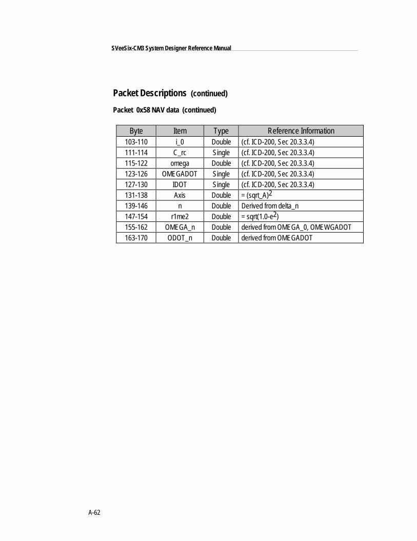
A-62
SVeeSix-CM3 System Designer Reference Manual
Packet Descriptions (continued)
Packet 0x58 NAV data (continued)
Byte Item Type Reference Information103-110 i_0 Double (cf. ICD-200, Sec 20.3.3.4)111-114 C_rc Single (cf. ICD-200, Sec 20.3.3.4)115-122 omega Double (cf. ICD-200, Sec 20.3.3.4)123-126 OMEGADOT Single (cf. ICD-200, Sec 20.3.3.4)127-130 IDOT Single (cf. ICD-200, Sec 20.3.3.4)131-138 Axis Double = (sqrt_A)2
139-146 n Double Derived from delta_n147-154 r1me2 Double = sqrt(1.0-e2)155-162 OMEGA_n Double derived from OMEGA_0, OMEWGADOT163-170 ODOT_n Double derived from OMEGADOT
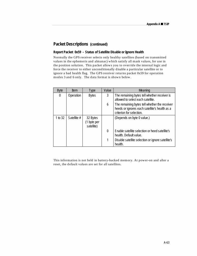
A-63
Appendix A ■ TSIP
Packet Descriptions (continued)
Report Packet 0x59 - Status of Satellite Disable or Ignore HealthNormally the GPS receiver selects only healthy satellites (based on transmittedvalues in the ephemeris and almanac) which satisfy all mask values, for use inthe position solution. This packet allows you to override the internal logic andforce the receiver to either unconditionally disable a particular satellite or toignore a bad health flag. The GPS receiver returns packet 0x59 for operationmodes 3 and 6 only. The data format is shown below.
Byte Item Type Value Meaning0 Operation Bytes 3 The remaining bytes tell whether receiver is
allowed to select each satellite.6 The remaining bytes tell whether the receiver
heeds or ignores each satellite's health as acriterion for selection.
1 to 32 Satellite # 32 Bytes(1 byte persatellite)
(Depends on byte 0 value.)
0 Enable satellite selection or heed satellite'shealth. Default value.
1 Disable satellite selection or ignore satellite'shealth.
This information is not held in battery-backed memory. At power-on and after areset, the default values are set for all satellites.
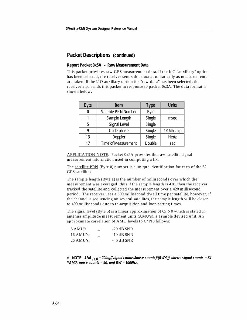
A-64
SVeeSix-CM3 System Designer Reference Manual
Packet Descriptions (continued)
Report Packet 0x5A - Raw Measurement DataThis packet provides raw GPS measurement data. If the I/O "auxiliary" optionhas been selected, the receiver sends this data automatically as measurementsare taken. If the I/O auxiliary option for "raw data" has been selected, thereceiver also sends this packet in response to packet 0x3A. The data format isshown below.
Byte Item Type Units0 Satellite PRN Number Byte -----1 Sample Length Single msec5 Signal Level Single9 Code phase Single 1/16th chip
13 Doppler Single Hertz17 Time of Measurement Double sec
APPLICATION NOTE: Packet 0x5A provides the raw satellite signalmeasurement information used in computing a fix.
The satellite PRN (Byte 0) number is a unique identification for each of the 32GPS satellites.
The sample length (Byte 1) is the number of milliseconds over which themeasurement was averaged. thus if the sample length is 428, then the receivertracked the satellite and collected the measurement over a 428 millisecondperiod. The receiver uses a 500 millisecond dwell time per satellite, however, ifthe channel is sequencing on several satellites, the sample length will be closerto 400 milliseconds due to re-acquisition and loop setting times.
The signal level (Byte 5) is a linear approximation of C/N0 which is stated inantenna amplitude measurement units (AMU's), a Trimble devised unit. Anapproximate correlation of AMU levels to C/N0 follows:
5 AMU's _ -20 dB SNR16 AMU's _ -10 dB SNR26 AMU's _ - 5 dB SNR
♦ NOTE: SNR (±3) = 20log((signal counts/noise counts)*(BW/2)) where: signal counts = 64* AMU; noise counts = 90, and BW = 1000Hz.
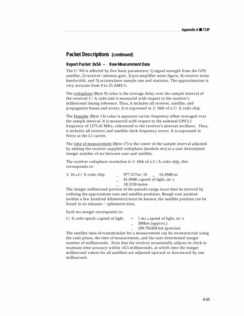
A-65
Appendix A ■ TSIP
Packet Descriptions (continued)
Report Packet 0x5A – Raw Measurement DataThe C/N0 is affected by five basic parameters: 1) signal strength from the GPSsatellite, 2) receiver/antenna gain, 3) pre-amplifier noise figure, 4) receiver noisebandwidth, and 5) accumulator sample rate and statistics. The approximation isvery accurate from 0 to 25 AMU's.
The codephase (Byte 9) value is the average delay over the sample interval ofthe received C/A code and is measured with respect to the receiver'smillisecond timing reference. Thus, it includes all receiver, satellite, andpropagation biases and errors. It is expressed in 1/16th of a C/A code chip.
The Doppler (Byte 13) value is apparent carrier frequency offset averaged overthe sample interval. It is measured with respect to the nominal GPS L1frequency of 1575.42 MHz, referenced to the receiver's internal oscillator. Thus,it includes all receiver and satellite clock frequency errors. It is expressed inHertz at the L1 carrier.
The time of measurement (Byte 17) is the center of the sample interval adjustedby adding the receiver supplied codephase (modulo ms) to a user determinedinteger number of ms between user and satellite.
The receiver codephase resolution is 1/16th of a C/A code chip, thiscorresponds to:
1/16 * C/A code chip _ 977.517ns/16 _ 61.0948 ns_ 61.0948 * speed of light, m/s_ 18.3158 meter
The integer millisecond portion of the pseudo-range must then be derived byutilizing the approximate user and satellite positions. Rough user position(within a few hundred kilometers) must be known; the satellite position can befound in its almanac / ephemeris data.
Each ms integer corresponds to:
C/A code epoch * speed of light = 1 ms * speed of light, m/s_ 300km (approx.)_ 299.792458 km (precise)
The satellite time-of-transmission for a measurement can be reconstructed usingthe code phase, the time of measurement, and the user-determined integernumber of milliseconds. Note that the receiver occasionally adjusts its clock tomaintain time accuracy within ±0.5 milliseconds, at which time the integermillisecond values for all satellites are adjusted upward or downward by onemillisecond.
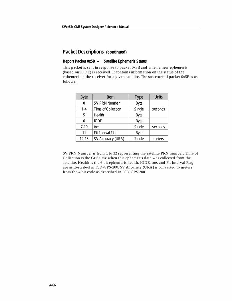
A-66
SVeeSix-CM3 System Designer Reference Manual
Packet Descriptions (continued)
Report Packet 0x5B – Satellite Ephemeris StatusThis packet is sent in response to packet 0x3B and when a new ephemeris(based on IODE) is received. It contains information on the status of theephemeris in the receiver for a given satellite. The structure of packet 0x5B is asfollows.
Byte Item Type Units0 SV PRN Number Byte
1-4 Time of Collection Single seconds5 Health Byte6 IODE Byte
7-10 toe Single seconds11 Fit Interval Flag Byte
12-15 SV Accuracy (URA) Single meters
SV PRN Number is from 1 to 32 representing the satellite PRN number. Time ofCollection is the GPS time when this ephemeris data was collected from thesatellite. Health is the 6-bit ephemeris health. IODE, toe, and Fit Interval Flagare as described in ICD-GPS-200. SV Accuracy (URA) is converted to metersfrom the 4-bit code as described in ICD-GPS-200.
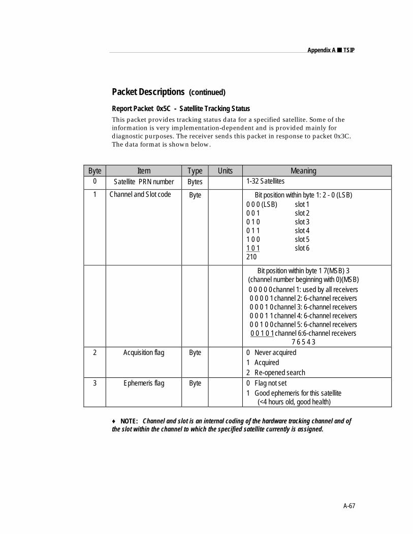
A-67
Appendix A ■ TSIP
Packet Descriptions (continued)
Report Packet 0x5C - Satellite Tracking StatusThis packet provides tracking status data for a specified satellite. Some of theinformation is very implementation-dependent and is provided mainly fordiagnostic purposes. The receiver sends this packet in response to packet 0x3C.The data format is shown below.
Byte Item Type Units Meaning0 Satellite PRN number Bytes 1-32 Satellites
1 Channel and Slot code Byte Bit position within byte 1: 2 - 0 (LSB)0 0 0 (LSB) slot 10 0 1 slot 20 1 0 slot 30 1 1 slot 41 0 0 slot 51 0 1 slot 6210
Bit position within byte 1 7(MSB) 3(channel number beginning with 0)(MSB)0 0 0 0 0channel 1: used by all receivers0 0 0 0 1channel 2: 6-channel receivers0 0 0 1 0channel 3: 6-channel receivers0 0 0 1 1channel 4: 6-channel receivers0 0 1 0 0channel 5: 6-channel receivers0 0 1 0 1channel 6:6-channel receivers
7 6 5 4 32 Acquisition flag Byte 0 Never acquired
1 Acquired2 Re-opened search
3 Ephemeris flag Byte 0 Flag not set1 Good ephemeris for this satellite (<4 hours old, good health)
♦ NOTE: Channel and slot is an internal coding of the hardware tracking channel and ofthe slot within the channel to which the specified satellite currently is assigned.
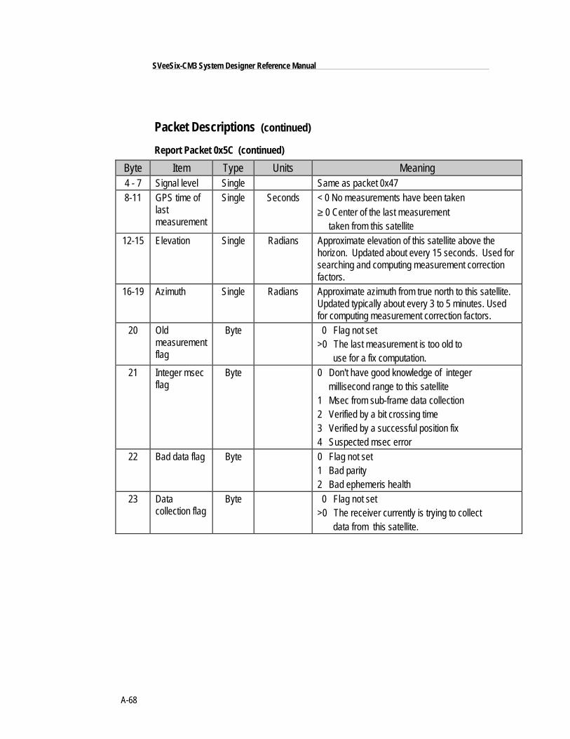
A-68
SVeeSix-CM3 System Designer Reference Manual
Packet Descriptions (continued)
Report Packet 0x5C (continued)
Byte Item Type Units Meaning4 - 7 Signal level Single Same as packet 0x478-11 GPS time of
lastmeasurement
Single Seconds < 0 No measurements have been taken≥ 0 Center of the last measurement taken from this satellite
12-15 Elevation Single Radians Approximate elevation of this satellite above thehorizon. Updated about every 15 seconds. Used forsearching and computing measurement correctionfactors.
16-19 Azimuth Single Radians Approximate azimuth from true north to this satellite.Updated typically about every 3 to 5 minutes. Usedfor computing measurement correction factors.
20 Oldmeasurementflag
Byte 0 Flag not set>0 The last measurement is too old to use for a fix computation.
21 Integer msecflag
Byte 0 Don't have good knowledge of integer millisecond range to this satellite1 Msec from sub-frame data collection2 Verified by a bit crossing time3 Verified by a successful position fix4 Suspected msec error
22 Bad data flag Byte 0 Flag not set1 Bad parity2 Bad ephemeris health
23 Datacollection flag
Byte 0 Flag not set>0 The receiver currently is trying to collect data from this satellite.
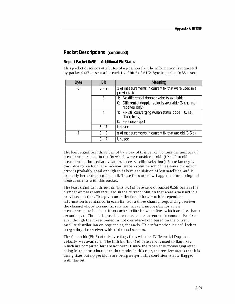
A-69
Appendix A ■ TSIP
Packet Descriptions (continued)
Report Packet 0x5E - Additional Fix StatusThis packet describes attributes of a position fix. The information is requestedby packet 0x3E or sent after each fix if bit 2 of AUX Byte in packet 0x35 is set.
Byte Bit Meaning0 0 – 2 # of measurements in current fix that were used in a
previous fix.3 1: No differential doppler velocity available
0: Differential doppler velocity available (3-channel receiver only)
4 1: Fix still converging (when status code = 0, i.e. doing fixes)0: Fix converged
5 – 7 Unused1 0 – 2 # of measurements in current fix that are old (3-5 s)
3 – 7 Unused
The least significant three bits of byte one of this packet contain the number ofmeasurements used in the fix which were considered old. (Use of an oldmeasurement immediately causes a new satellite selection.) Some latency isdesirable to "self-aid" the receiver, since a solution which has some projectionerror is probably good enough to help re-acquisition of lost satellites, and isprobably better than no fix at all. These fixes are now flagged as containing oldmeasurements with this packet.
The least significant three bits (Bits 0-2) of byte zero of packet 0x5E contain thenumber of measurements used in the current solution that were also used in aprevious solution. This gives an indication of how much independentinformation is contained in each fix. For a three-channel sequencing receiver,the channel allocation and fix rate may make it impossible for a newmeasurement to be taken from each satellite between fixes which are less than asecond apart. Thus, it is possible to re-use a measurement in consecutive fixeseven though the measurement is not considered old based on the currentsatellite distribution on sequencing channels. This information is useful whenintegrating the receiver with additional sensors.
The fourth bit (Bit 3) of this byte flags fixes whether Differential Dopplervelocity was available. The fifth bit (Bit 4) of byte zero is used to flag fixeswhich are computed but are not output since the receiver is converging afterbeing in an approximate position mode. In this case, the receiver states that it isdoing fixes but no positions are being output. This condition is now flaggedwith this bit.
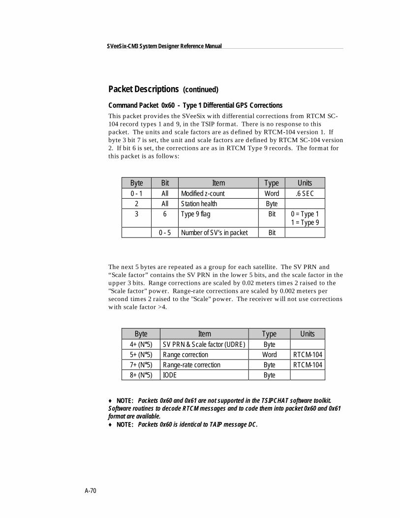
A-70
SVeeSix-CM3 System Designer Reference Manual
Packet Descriptions (continued)
Command Packet 0x60 - Type 1 Differential GPS CorrectionsThis packet provides the SVeeSix with differential corrections from RTCM SC-104 record types 1 and 9, in the TSIP format. There is no response to thispacket. The units and scale factors are as defined by RTCM-104 version 1. Ifbyte 3 bit 7 is set, the unit and scale factors are defined by RTCM SC-104 version2. If bit 6 is set, the corrections are as in RTCM Type 9 records. The format forthis packet is as follows:
Byte Bit Item Type Units0 - 1 All Modified z-count Word .6 SEC
2 All Station health Byte3 6 Type 9 flag Bit 0 = Type 1
1 = Type 90 - 5 Number of SV’s in packet Bit
The next 5 bytes are repeated as a group for each satellite. The SV PRN and“Scale factor” contains the SV PRN in the lower 5 bits, and the scale factor in theupper 3 bits. Range corrections are scaled by 0.02 meters times 2 raised to the"Scale factor" power. Range-rate corrections are scaled by 0.002 meters persecond times 2 raised to the "Scale" power. The receiver will not use correctionswith scale factor >4.
Byte Item Type Units4+ (N*5) SV PRN & Scale factor (UDRE) Byte5+ (N*5) Range correction Word RTCM-1047+ (N*5) Range-rate correction Byte RTCM-1048+ (N*5) IODE Byte
♦ NOTE: Packets 0x60 and 0x61 are not supported in the TSIPCHAT software toolkit.Software routines to decode RTCM messages and to code them into packet 0x60 and 0x61format are available.♦ NOTE: Packets 0x60 is identical to TAIP message DC.
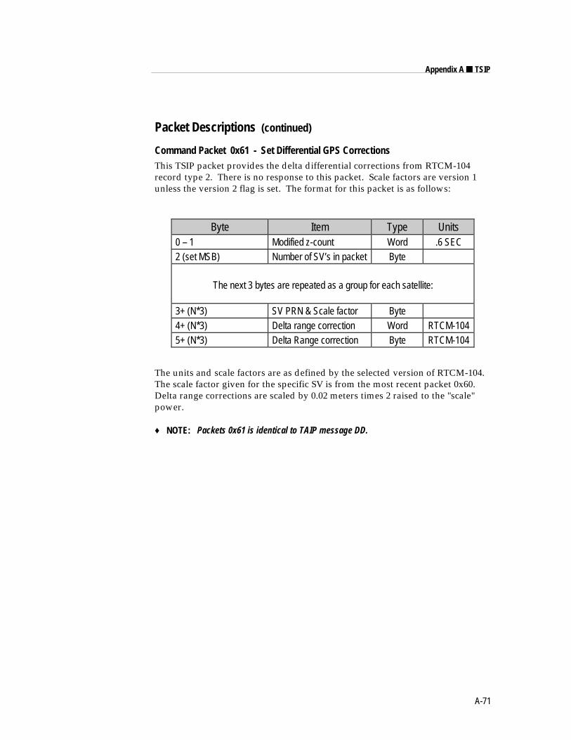
A-71
Appendix A ■ TSIP
Packet Descriptions (continued)
Command Packet 0x61 - Set Differential GPS CorrectionsThis TSIP packet provides the delta differential corrections from RTCM-104record type 2. There is no response to this packet. Scale factors are version 1unless the version 2 flag is set. The format for this packet is as follows:
Byte Item Type Units0 – 1 Modified z-count Word .6 SEC2 (set MSB) Number of SV’s in packet Byte
The next 3 bytes are repeated as a group for each satellite:
3+ (N*3) SV PRN & Scale factor Byte4+ (N*3) Delta range correction Word RTCM-1045+ (N*3) Delta Range correction Byte RTCM-104
The units and scale factors are as defined by the selected version of RTCM-104.The scale factor given for the specific SV is from the most recent packet 0x60.Delta range corrections are scaled by 0.02 meters times 2 raised to the "scale"power.
♦ NOTE: Packets 0x61 is identical to TAIP message DD.
A-72
SVeeSix-CM3 System Designer Reference Manual
Packet Descriptions (continued)
Command Packet 0x62 - Request/Set Differential Position Fix ModeThis packet requests or sets the differential position fix mode of the GPSreceiver. A single data byte is sent.
To request Report Packet 0x82, the data byte is set to contain an unusable value(between 4 and FF)
The following modes can be set:
0 Ignore DGPS (Differential off)
1 Requires DGPS (Differential on) (default)
2 or 3 Use DGPS if available.
“GPS" (mode 0) sets the GPS receiver to do position solutions withoutdifferential corrections, even if the differential corrections are available.
"Requires DGPS" (mode 1) sets the GPS receiver to do position solutions only ifvalid differential correction data are available.
"Use DGPS if available" (data byte value = either 2 or 3): The GPS receiverautomatically sets itself to mode 2 (differential currently off) if the GPS receiveris not receiving differential correction data for all satellites in a constellationwhich meets all other masks; and the GPS receiver automatically sets itself tomode 3 (differential currently on) if the GPS receiver is receiving differentialcorrection data for all satellites in a constellation which meets all other masks.Packet 0x82 which the GPS receiver sends in response to receiving packet 0x62,indicates whether the GPS receiver currently is in mode 2 or 3.
An attempt to set a mode outside this set results in simply requesting packet0x82. The selected mode (manual GPS, manual DGPS, or automatic) is held inbattery-backed memory.
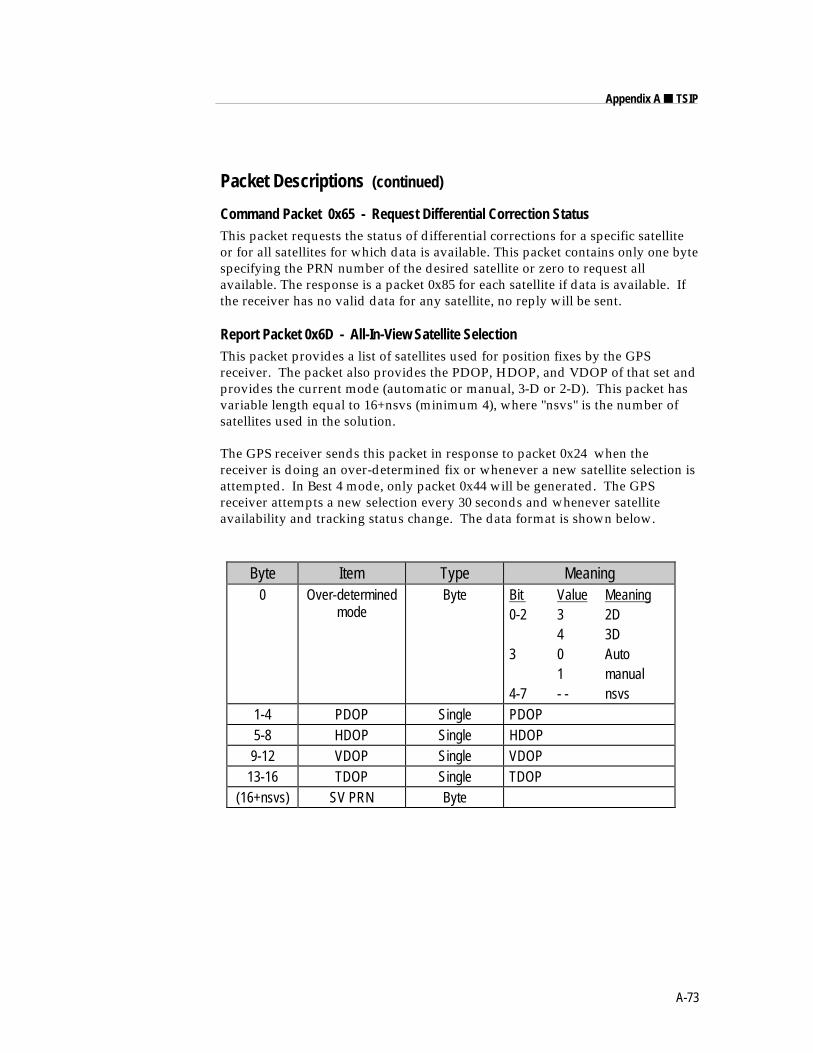
A-73
Appendix A ■ TSIP
Packet Descriptions (continued)
Command Packet 0x65 - Request Differential Correction StatusThis packet requests the status of differential corrections for a specific satelliteor for all satellites for which data is available. This packet contains only one bytespecifying the PRN number of the desired satellite or zero to request allavailable. The response is a packet 0x85 for each satellite if data is available. Ifthe receiver has no valid data for any satellite, no reply will be sent.
Report Packet 0x6D - All-In-View Satellite SelectionThis packet provides a list of satellites used for position fixes by the GPSreceiver. The packet also provides the PDOP, HDOP, and VDOP of that set andprovides the current mode (automatic or manual, 3-D or 2-D). This packet hasvariable length equal to 16+nsvs (minimum 4), where "nsvs" is the number ofsatellites used in the solution.
The GPS receiver sends this packet in response to packet 0x24 when thereceiver is doing an over-determined fix or whenever a new satellite selection isattempted. In Best 4 mode, only packet 0x44 will be generated. The GPSreceiver attempts a new selection every 30 seconds and whenever satelliteavailability and tracking status change. The data format is shown below.
Byte Item Type Meaning0 Over-determined
modeByte Bit Value Meaning
0-2 3 2D4 3D
3 0 Auto1 manual
4-7 - - nsvs1-4 PDOP Single PDOP5-8 HDOP Single HDOP9-12 VDOP Single VDOP
13-16 TDOP Single TDOP(16+nsvs) SV PRN Byte
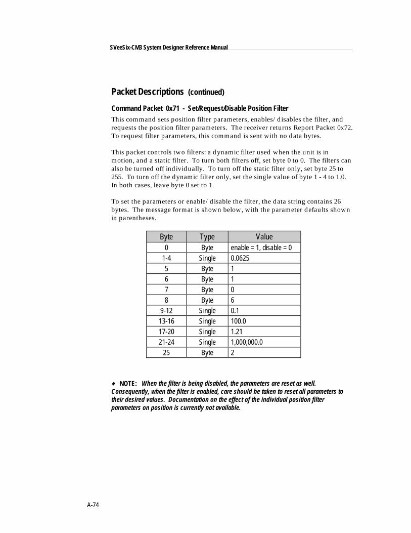
A-74
SVeeSix-CM3 System Designer Reference Manual
Packet Descriptions (continued)
Command Packet 0x71 - Set/Request/Disable Position Filter
This command sets position filter parameters, enables/disables the filter, andrequests the position filter parameters. The receiver returns Report Packet 0x72.To request filter parameters, this command is sent with no data bytes.
This packet controls two filters: a dynamic filter used when the unit is inmotion, and a static filter. To turn both filters off, set byte 0 to 0. The filters canalso be turned off individually. To turn off the static filter only, set byte 25 to255. To turn off the dynamic filter only, set the single value of byte 1 - 4 to 1.0.In both cases, leave byte 0 set to 1.
To set the parameters or enable/disable the filter, the data string contains 26bytes. The message format is shown below, with the parameter defaults shownin parentheses.
Byte Type Value0 Byte enable = 1, disable = 0
1-4 Single 0.06255 Byte 16 Byte 17 Byte 08 Byte 6
9-12 Single 0.113-16 Single 100.017-20 Single 1.2121-24 Single 1,000,000.0
25 Byte 2
♦ NOTE: When the filter is being disabled, the parameters are reset as well.Consequently, when the filter is enabled, care should be taken to reset all parameters totheir desired values. Documentation on the effect of the individual position filterparameters on position is currently not available.
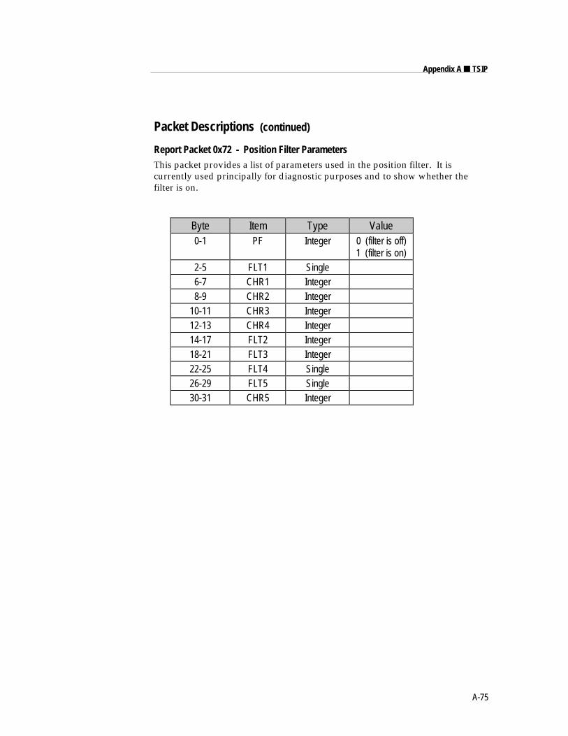
A-75
Appendix A ■ TSIP
Packet Descriptions (continued)
Report Packet 0x72 - Position Filter ParametersThis packet provides a list of parameters used in the position filter. It iscurrently used principally for diagnostic purposes and to show whether thefilter is on.
Byte Item Type Value0-1 PF Integer 0 (filter is off)
1 (filter is on)2-5 FLT1 Single6-7 CHR1 Integer8-9 CHR2 Integer
10-11 CHR3 Integer12-13 CHR4 Integer14-17 FLT2 Integer18-21 FLT3 Integer22-25 FLT4 Single26-29 FLT5 Single30-31 CHR5 Integer
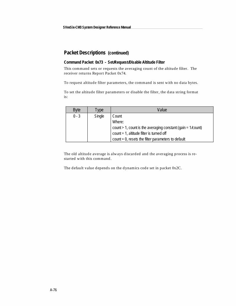
A-76
SVeeSix-CM3 System Designer Reference Manual
Packet Descriptions (continued)
Command Packet 0x73 - Set/Request/Disable Altitude FilterThis command sets or requests the averaging count of the altitude filter. Thereceiver returns Report Packet 0x74.
To request altitude filter parameters, the command is sent with no data bytes.
To set the altitude filter parameters or disable the filter, the data string formatis:
Byte Type Value0 - 3 Single Count
Where:count > 1, count is the averaging constant (gain = 1/count)count = 1, altitude filter is turned offcount = 0, resets the filter parameters to default
The old altitude average is always discarded and the averaging process is re-started with this command.
The default value depends on the dynamics code set in packet 0x2C.
A-77
Appendix A ■ TSIP
Packet Descriptions (continued)
Report Packet 0x74 - Altitude Filter ParameterThis packet provides the parameter used in the altitude filter. The data stringhas one Single, equal to the number of fixes averaged in the altitude filter. If thevalue is -1, the altitude filter is currently disabled.
Command Packet 0x75 - Set/Request / High-8-Overdetermined ModeThis command sets the constellation mode of the receiver. The receiver returnspacket 0x76. (Refer to page 6-7 Over -Determined modes.)
To request a specific mode, the command is sent with no data bytes.
To set the mode, a single data byte is sent. The data byte can have one of threevalues:
0 = Best-4 mode
1 = High-6 (Over-determined) mode
2 = High-8 (over-determined smart sequencing) mode (default)
Report Packet 0x76 - Best-4 / High-6-Overdetermined ModeThis packet shows whether the receiver is in High-8, High 6 mode, or Best 4. Itreturns one byte:
0 = Best-4 mode
1 = High-6 (Over-determined) mode
2 = High-8 (Over-determined smart sequencing) mode (default)
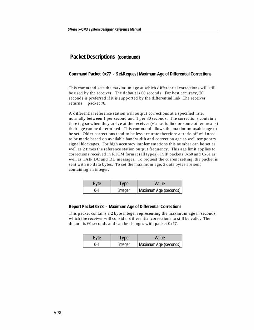
A-78
SVeeSix-CM3 System Designer Reference Manual
Packet Descriptions (continued)
Command Packet 0x77 - Set/Request Maximum Age of Differential Corrections
This command sets the maximum age at which differential corrections will stillbe used by the receiver. The default is 60 seconds. For best accuracy, 20seconds is preferred if it is supported by the differential link. The receiverreturns packet 78.
A differential reference station will output corrections at a specified rate,normally between 1 per second and 1 per 30 seconds. The corrections contain atime tag so when they arrive at the receiver (via radio link or some other means)their age can be determined. This command allows the maximum usable age tobe set. Older corrections tend to be less accurate therefore a trade-off will needto be made based on available bandwidth and correction age as well temporarysignal blockages. For high accuracy implementations this number can be set aswell as 2 times the reference station output frequency. This age limit applies tocorrections received in RTCM format (all types), TSIP packets 0x60 and 0x61 aswell as TAIP DC and DD messages. To request the current setting, the packet issent with no data bytes. To set the maximum age, 2 data bytes are sentcontaining an integer.
Byte Type Value0-1 Integer Maximum Age (seconds)
Report Packet 0x78 - Maximum Age of Differential CorrectionsThis packet contains a 2 byte integer representing the maximum age in secondswhich the receiver will consider differential corrections to still be valid. Thedefault is 60 seconds and can be changes with packet 0x77.
Byte Type Value0-1 Integer Maximum Age (seconds)
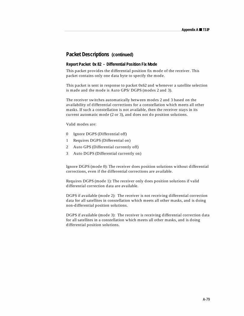
A-79
Appendix A ■ TSIP
Packet Descriptions (continued)
Report Packet 0x 82 - Differential Position Fix ModeThis packet provides the differential position fix mode of the receiver. Thispacket contains only one data byte to specify the mode.
This packet is sent in response to packet 0x62 and whenever a satellite selectionis made and the mode is Auto GPS/DGPS (modes 2 and 3).
The receiver switches automatically between modes 2 and 3 based on theavailability of differential corrections for a constellation which meets all othermasks. If such a constellation is not available, then the receiver stays in itscurrent automatic mode (2 or 3), and does not do position solutions.
Valid modes are:
0 Ignore DGPS (Differential off)
1 Requires DGPS (Differential on)
2 Auto GPS (Differential currently off)
3 Auto DGPS (Differential currently on)
Ignore DGPS (mode 0): The receiver does position solutions without differentialcorrections, even if the differential corrections are available.
Requires DGPS (mode 1): The receiver only does position solutions if validdifferential correction data are available.
DGPS if available (mode 2): The receiver is not receiving differential correctiondata for all satellites in constellation which meets all other masks, and is doingnon-differential position solutions.
DGPS if available (mode 3): The receiver is receiving differential correction datafor all satellites in a constellation which meets all other masks, and is doingdifferential position solutions.
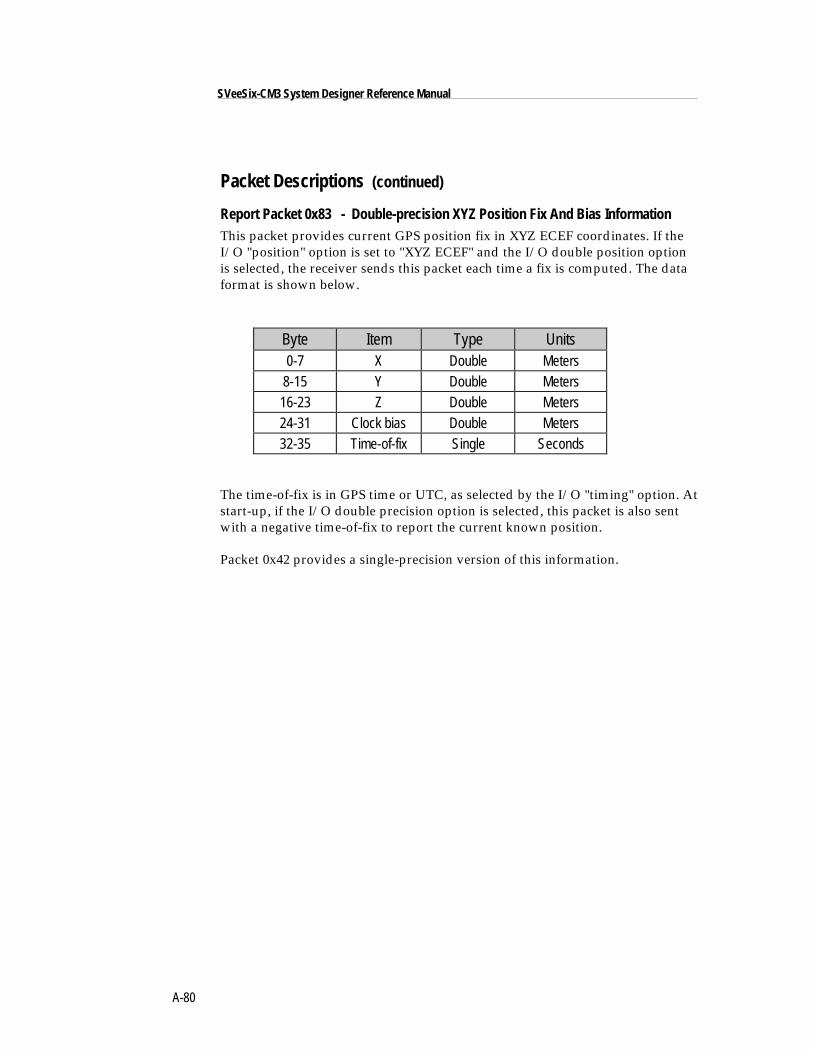
A-80
SVeeSix-CM3 System Designer Reference Manual
Packet Descriptions (continued)
Report Packet 0x83 - Double-precision XYZ Position Fix And Bias InformationThis packet provides current GPS position fix in XYZ ECEF coordinates. If theI/O "position" option is set to "XYZ ECEF" and the I/O double position optionis selected, the receiver sends this packet each time a fix is computed. The dataformat is shown below.
Byte Item Type Units0-7 X Double Meters
8-15 Y Double Meters16-23 Z Double Meters24-31 Clock bias Double Meters32-35 Time-of-fix Single Seconds
The time-of-fix is in GPS time or UTC, as selected by the I/O "timing" option. Atstart-up, if the I/O double precision option is selected, this packet is also sentwith a negative time-of-fix to report the current known position.
Packet 0x42 provides a single-precision version of this information.
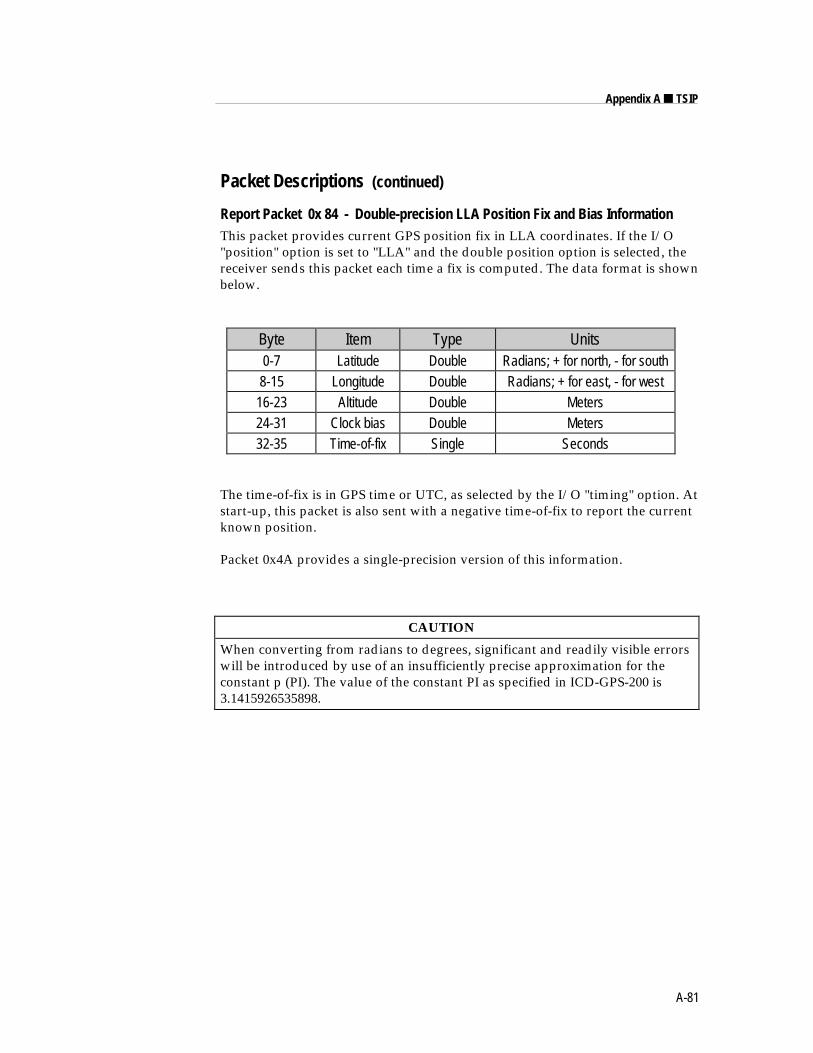
A-81
Appendix A ■ TSIP
Packet Descriptions (continued)
Report Packet 0x 84 - Double-precision LLA Position Fix and Bias InformationThis packet provides current GPS position fix in LLA coordinates. If the I/O"position" option is set to "LLA" and the double position option is selected, thereceiver sends this packet each time a fix is computed. The data format is shownbelow.
Byte Item Type Units0-7 Latitude Double Radians; + for north, - for south8-15 Longitude Double Radians; + for east, - for west
16-23 Altitude Double Meters24-31 Clock bias Double Meters32-35 Time-of-fix Single Seconds
The time-of-fix is in GPS time or UTC, as selected by the I/O "timing" option. Atstart-up, this packet is also sent with a negative time-of-fix to report the currentknown position.
Packet 0x4A provides a single-precision version of this information.
CAUTION
When converting from radians to degrees, significant and readily visible errorswill be introduced by use of an insufficiently precise approximation for theconstant p (PI). The value of the constant PI as specified in ICD-GPS-200 is3.1415926535898.
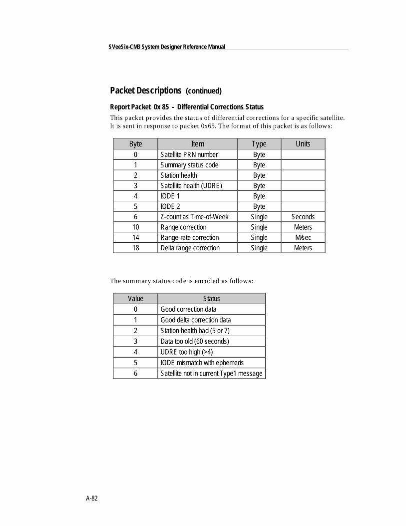
A-82
SVeeSix-CM3 System Designer Reference Manual
Packet Descriptions (continued)
Report Packet 0x 85 - Differential Corrections StatusThis packet provides the status of differential corrections for a specific satellite.It is sent in response to packet 0x65. The format of this packet is as follows:
Byte Item Type Units0 Satellite PRN number Byte1 Summary status code Byte2 Station health Byte3 Satellite health (UDRE) Byte4 IODE 1 Byte5 IODE 2 Byte6 Z-count as Time-of-Week Single Seconds10 Range correction Single Meters14 Range-rate correction Single M/sec18 Delta range correction Single Meters
The summary status code is encoded as follows:
Value Status
0 Good correction data
1 Good delta correction data
2 Station health bad (5 or 7)
3 Data too old (60 seconds)
4 UDRE too high (>4)
5 IODE mismatch with ephemeris
6 Satellite not in current Type1 message
A-83
Appendix A ■ TSIP
Custom OEM Packets
Several packets have been added to the core TSIP protocol to provide additionalcapability for OEM receivers. In OEM packets 0x8E and their 0x8F responses,the first data byte is a sub-code which indicates the superpacket type. Forexample, in packet 0x8E-14, 0x14 is the sub-code that indicates the superpackettype. Therefore the ID code for OEM packets is 2 bytes long followed by thedata.
TSIP SuperpacketsSuperpackets describes those packets which reduce the I/O traffic with thereceiver and facilitate interpretation to a modem or data acquisition device withlimited programming facilities.
♦ NOTE: TSIP Superpackets 0x8F-20 is incorporated into the firmware revisions 4.06 orlater.
There are three versions of the Superpacket: UTM Single precision (0x8F-17),UTM double precision (0x8F-18,and binary fixed point with velocity {0x8F-20).There is a procedure for asking the receiver to automatically send Superpacketsrather than the current position packet (0x4A or 0x84) when a new position iscalculated. The 0x8E-20 command is used to specify which Superpacket(s) areto be automatically output. The packets are:
0x8E-17 Request UTM single precision.0x8E-18 Request UTM double precision0x8E-20 Request last fix information (binary fixed-point)
0x8F-17 Last fix UTM single precision.0x8F-18 Last fix UTM double precision0x8F-20 Last fix with extra information (binary fixed-point)
A-84
SVeeSix-CM3 System Designer Reference Manual
TSIP Superpackets (continued)
Command Packet 0x8E-03 - Set / Request Auxiliary ConfigurationThis packet requests and optionally sets the AUX Port configuration. Thisconfiguration includes the baud rate, number of bits, parity, and number of stopbits and also the language mode. When this packet is used only to request theconfiguration the packet contains no data bytes. When this packet is used to setthe configuration, the packet contains the 6 data bytes shown below.
A 0x8E-03 input packet, with or without data, is responded to with a 0x8F-03output packet. The language mode is defined as follows. For reception, thelanguage mode specifies whether packets or RTCM data are received on theAUX Port.
The baud rate for the transmitter and the receiver can be set independently, butfor TSIP, the number of bits, parity, and the stop bits are common betweenthem. The default mode is RTCM for reception at 4800 baud with 8 data bits, noparity, and one stop bit. For NMEA, the default mode is 4800 baud, 8 data bits,1 stop bit and no parity. These corrections are used only if the mode is set toDifferential Auto or Manual On with packet 0x62.
♦ NOTE: The Auxiliary port on the SVeeSix-CM3 is input only. However packet 0x8E-03requires a valid value for the output language field even though it has no effect It isrecommended that the output language is always set to equal 1 (Off). The 0x8E-03command may be used on the CM3 to change the language mode from RTCM to TSIPpackets. This change must be completed before issuing a 3D command to configure theprimary port to receive RTCM.
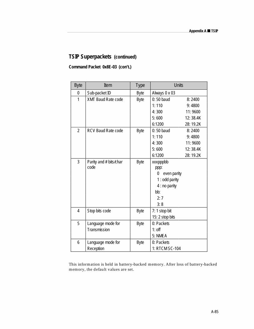
A-85
Appendix A ■ TSIP
TSIP Superpackets (continued)
Command Packet 0x8E-03 (con’t.)
Byte Item Type Units
0 Sub-packet ID Byte Always 0 x 031 XMT Baud Rate code Byte 0: 50 baud 8: 2400
1: 110 9: 48004: 300 11: 96005: 600 12: 38.4K6:1200 28: 19.2K
2 RCV Baud Rate code Byte 0: 50 baud 8: 24001: 110 9: 48004: 300 11: 96005: 600 12: 38.4K6:1200 28: 19.2K
3 Parity and # bits/charcode
Byte xxxpppbb ppp: 0 even parity 1 : odd parity 4 : no parity bb: 2: 7 3: 8
4 Stop bits code Byte 7: 1 stop bit15: 2 stop bits
5 Language mode for Byte 0: PacketsTransmission 1: off
5: NMEA6 Language mode for Byte 0: Packets
Reception 1: RTCM SC-104
This information is held in battery-backed memory. After loss of battery-backedmemory, the default values are set.
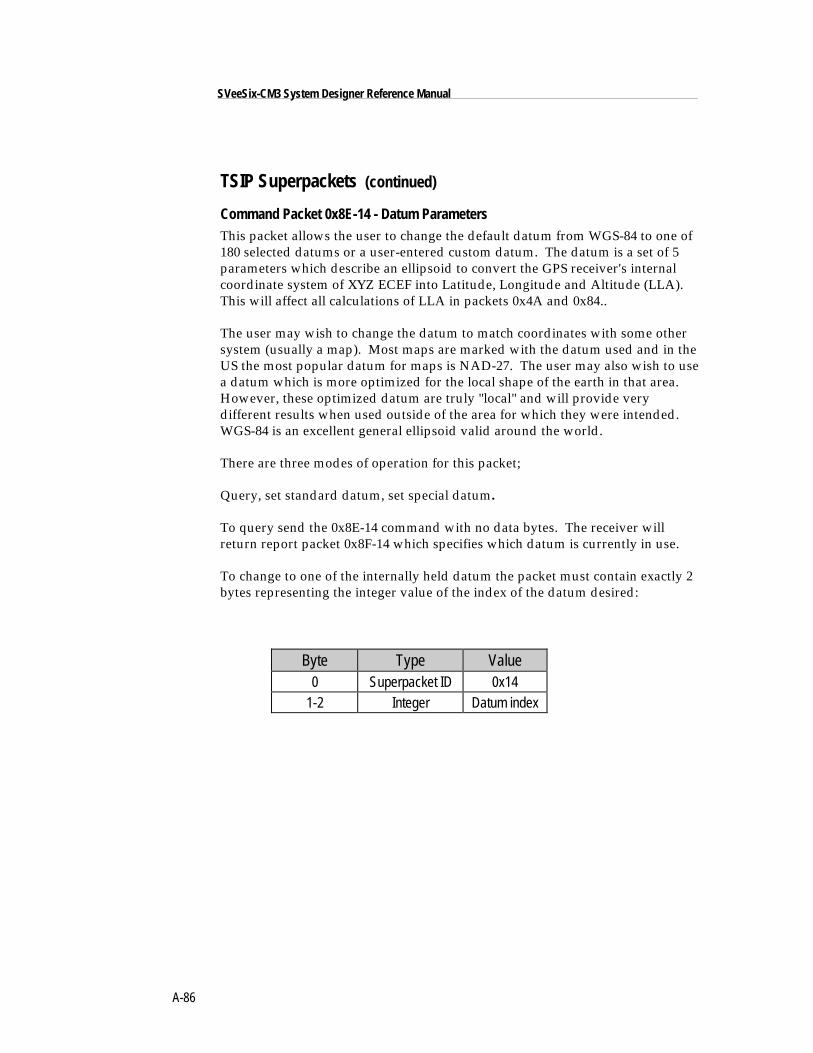
A-86
SVeeSix-CM3 System Designer Reference Manual
TSIP Superpackets (continued)
Command Packet 0x8E-14 - Datum ParametersThis packet allows the user to change the default datum from WGS-84 to one of180 selected datums or a user-entered custom datum. The datum is a set of 5parameters which describe an ellipsoid to convert the GPS receiver's internalcoordinate system of XYZ ECEF into Latitude, Longitude and Altitude (LLA).This will affect all calculations of LLA in packets 0x4A and 0x84..
The user may wish to change the datum to match coordinates with some othersystem (usually a map). Most maps are marked with the datum used and in theUS the most popular datum for maps is NAD-27. The user may also wish to usea datum which is more optimized for the local shape of the earth in that area.However, these optimized datum are truly "local" and will provide verydifferent results when used outside of the area for which they were intended.WGS-84 is an excellent general ellipsoid valid around the world.
There are three modes of operation for this packet;
Query, set standard datum, set special datum.
To query send the 0x8E-14 command with no data bytes. The receiver willreturn report packet 0x8F-14 which specifies which datum is currently in use.
To change to one of the internally held datum the packet must contain exactly 2bytes representing the integer value of the index of the datum desired:
Byte Type Value0 Superpacket ID 0x14
1-2 Integer Datum index
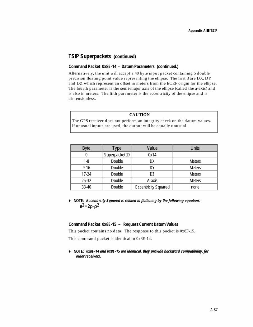
A-87
Appendix A ■ TSIP
TSIP Superpackets (continued)
Command Packet 0x8E-14 - Datum Parameters (continued.)Alternatively, the unit will accept a 40 byte input packet containing 5 doubleprecision floating point value representing the ellipse. The first 3 are DX, DYand DZ which represent an offset in meters from the ECEF origin for the ellipse.The fourth parameter is the semi-major axis of the ellipse (called the a-axis) andis also in meters. The fifth parameter is the eccentricity of the ellipse and isdimensionless.
CAUTIONThe GPS receiver does not perform an integrity check on the datum values.If unusual inputs are used, the output will be equally unusual.
Byte Type Value Units0 Superpacket ID 0x14
1-8 Double DX Meters9-16 Double DY Meters17-24 Double DZ Meters25-32 Double A-axis Meters33-40 Double Eccentricity Squared none
♦ NOTE: Eccentricity Squared is related to flattening by the following equation:e2=2ρ-ρ2
Command Packet 0x8E-15 – Request Current Datum ValuesThis packet contains no data. The response to this packet is 0x8F-15.
This command packet is identical to 0x8E-14.
♦ NOTE: 0x8E-14 and 0x8E-15 are identical, they provide backward compatibility, forolder receivers.
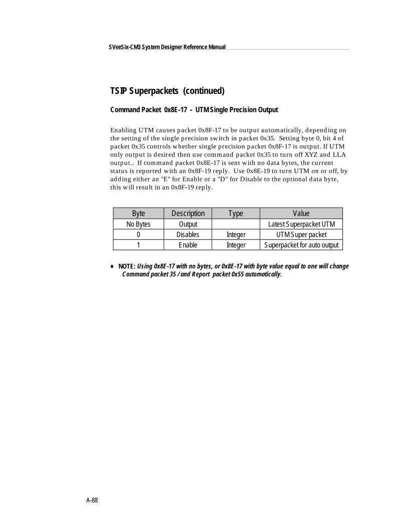
A-88
SVeeSix-CM3 System Designer Reference Manual
TSIP Superpackets (continued)
Command Packet 0x8E-17 - UTM Single Precision Output
Enabling UTM causes packet 0x8F-17 to be output automatically, depending onthe setting of the single precision switch in packet 0x35. Setting byte 0, bit 4 ofpacket 0x35 controls whether single precision packet 0x8F-17 is output. If UTMonly output is desired then use command packet 0x35 to turn off XYZ and LLAoutput.. If command packet 0x8E-17 is sent with no data bytes, the currentstatus is reported with an 0x8F-19 reply. Use 0x8E-19 to turn UTM on or off, byadding either an "E" for Enable or a "D" for Disable to the optional data byte,this will result in an 0x8F-19 reply.
Byte Description Type ValueNo Bytes Output Latest Superpacket UTM
0 Disables Integer UTM Super packet1 Enable Integer Superpacket for auto output
♦ NOTE: Using 0x8E-17 with no bytes, or 0x8E-17 with byte value equal to one will changeCommand packet 35 / and Report packet 0x55 automatically.
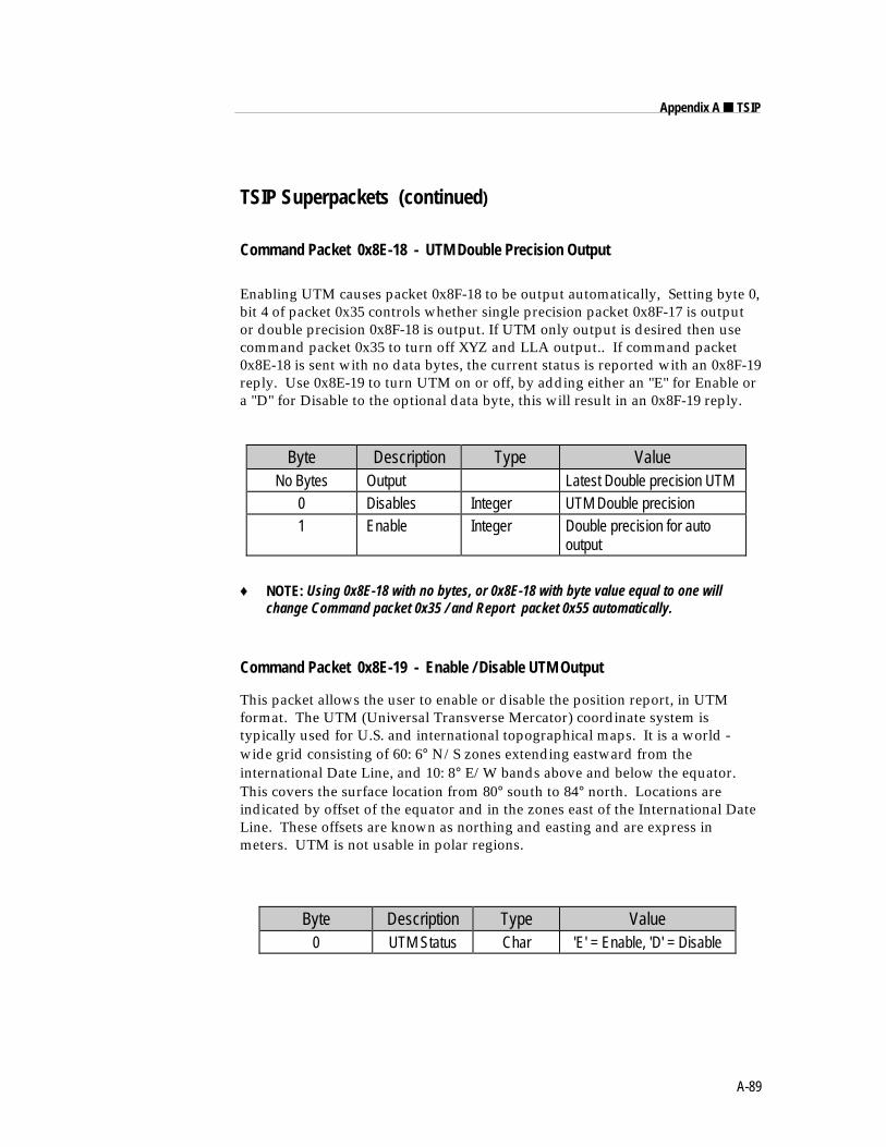
A-89
Appendix A ■ TSIP
TSIP Superpackets (continued)
Command Packet 0x8E-18 - UTM Double Precision Output
Enabling UTM causes packet 0x8F-18 to be output automatically, Setting byte 0,bit 4 of packet 0x35 controls whether single precision packet 0x8F-17 is outputor double precision 0x8F-18 is output. If UTM only output is desired then usecommand packet 0x35 to turn off XYZ and LLA output.. If command packet0x8E-18 is sent with no data bytes, the current status is reported with an 0x8F-19reply. Use 0x8E-19 to turn UTM on or off, by adding either an "E" for Enable ora "D" for Disable to the optional data byte, this will result in an 0x8F-19 reply.
Byte Description Type ValueNo Bytes Output Latest Double precision UTM
0 Disables Integer UTM Double precision1 Enable Integer Double precision for auto
output
♦ NOTE: Using 0x8E-18 with no bytes, or 0x8E-18 with byte value equal to one willchange Command packet 0x35 / and Report packet 0x55 automatically.
Command Packet 0x8E-19 - Enable / Disable UTM Output
This packet allows the user to enable or disable the position report, in UTMformat. The UTM (Universal Transverse Mercator) coordinate system istypically used for U.S. and international topographical maps. It is a world -wide grid consisting of 60: 6° N/S zones extending eastward from theinternational Date Line, and 10: 8° E/W bands above and below the equator.This covers the surface location from 80° south to 84° north. Locations areindicated by offset of the equator and in the zones east of the International DateLine. These offsets are known as northing and easting and are express inmeters. UTM is not usable in polar regions.
Byte Description Type Value0 UTM Status Char 'E' = Enable, 'D' = Disable
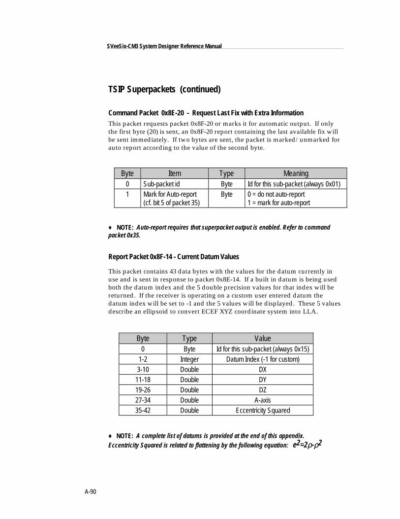
A-90
SVeeSix-CM3 System Designer Reference Manual
TSIP Superpackets (continued)
Command Packet 0x8E-20 - Request Last Fix with Extra InformationThis packet requests packet 0x8F-20 or marks it for automatic output. If onlythe first byte (20) is sent, an 0x8F-20 report containing the last available fix willbe sent immediately. If two bytes are sent, the packet is marked/unmarked forauto report according to the value of the second byte.
Byte Item Type Meaning0 Sub-packet id Byte Id for this sub-packet (always 0x01)1 Mark for Auto-report
(cf. bit 5 of packet 35)Byte 0 = do not auto-report
1 = mark for auto-report
♦ NOTE: Auto-report requires that superpacket output is enabled. Refer to commandpacket 0x35.
Report Packet 0x8F-14 - Current Datum Values
This packet contains 43 data bytes with the values for the datum currently inuse and is sent in response to packet 0x8E-14. If a built in datum is being usedboth the datum index and the 5 double precision values for that index will bereturned. If the receiver is operating on a custom user entered datum thedatum index will be set to -1 and the 5 values will be displayed. These 5 valuesdescribe an ellipsoid to convert ECEF XYZ coordinate system into LLA.
Byte Type Value0 Byte Id for this sub-packet (always 0x15)
1-2 Integer Datum Index (-1 for custom)3-10 Double DX
11-18 Double DY19-26 Double DZ27-34 Double A-axis35-42 Double Eccentricity Squared
♦ NOTE: A complete list of datums is provided at the end of this appendix.Eccentricity Squared is related to flattening by the following equation: e2=2ρ-ρ2
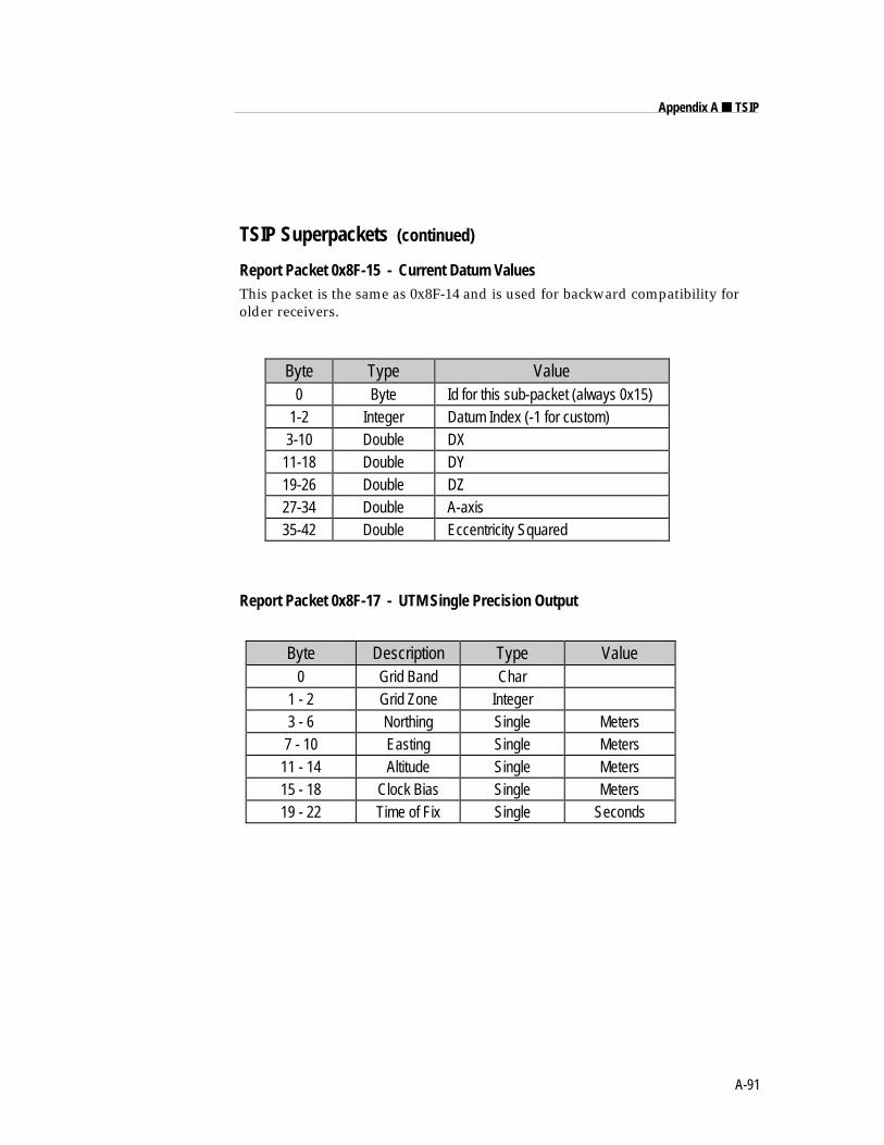
A-91
Appendix A ■ TSIP
TSIP Superpackets (continued)
Report Packet 0x8F-15 - Current Datum ValuesThis packet is the same as 0x8F-14 and is used for backward compatibility forolder receivers.
Byte Type Value0 Byte Id for this sub-packet (always 0x15)
1-2 Integer Datum Index (-1 for custom)3-10 Double DX
11-18 Double DY19-26 Double DZ27-34 Double A-axis35-42 Double Eccentricity Squared
Report Packet 0x8F-17 - UTM Single Precision Output
Byte Description Type Value0 Grid Band Char
1 - 2 Grid Zone Integer3 - 6 Northing Single Meters7 - 10 Easting Single Meters
11 - 14 Altitude Single Meters15 - 18 Clock Bias Single Meters19 - 22 Time of Fix Single Seconds
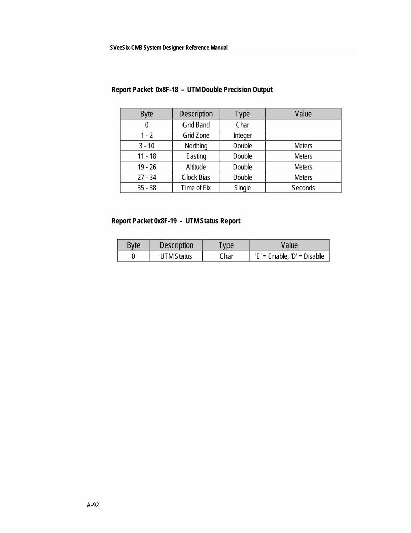
A-92
SVeeSix-CM3 System Designer Reference Manual
Report Packet 0x8F-18 - UTM Double Precision Output
Byte Description Type Value0 Grid Band Char
1 - 2 Grid Zone Integer3 - 10 Northing Double Meters11 - 18 Easting Double Meters19 - 26 Altitude Double Meters27 - 34 Clock Bias Double Meters35 - 38 Time of Fix Single Seconds
Report Packet 0x8F-19 - UTM Status Report
Byte Description Type Value0 UTM Status Char 'E' = Enable, 'D' = Disable
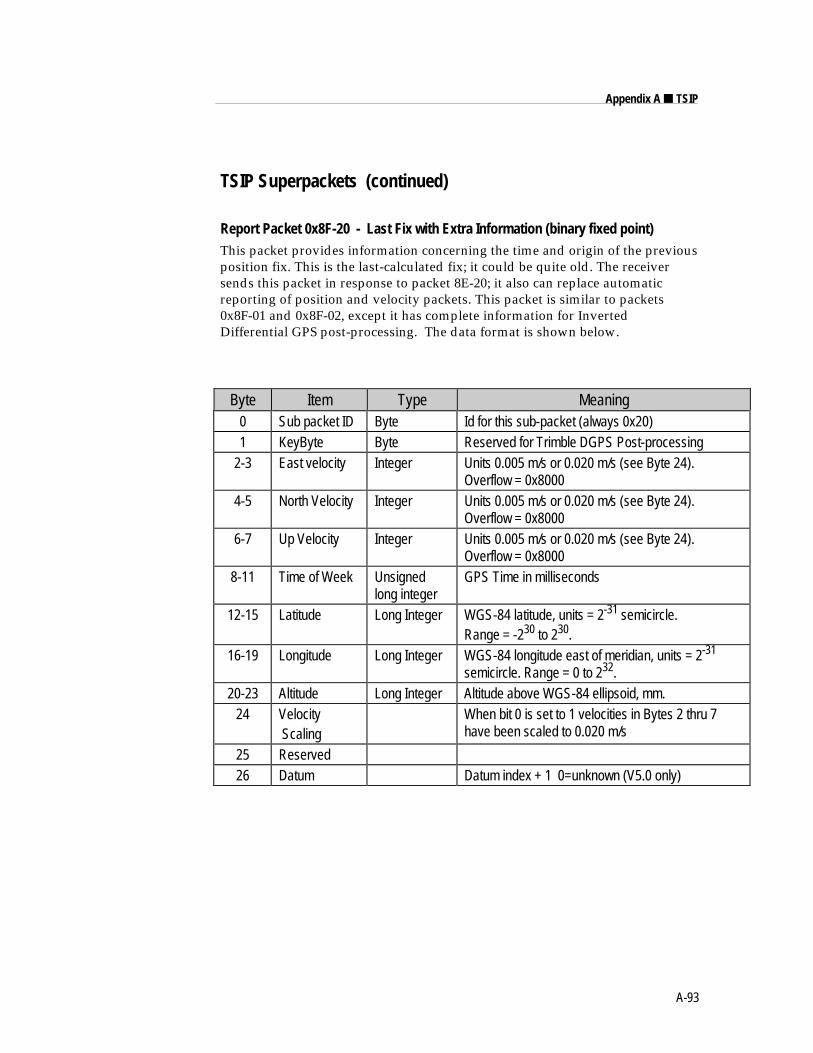
A-93
Appendix A ■ TSIP
TSIP Superpackets (continued)
Report Packet 0x8F-20 - Last Fix with Extra Information (binary fixed point)This packet provides information concerning the time and origin of the previousposition fix. This is the last-calculated fix; it could be quite old. The receiversends this packet in response to packet 8E-20; it also can replace automaticreporting of position and velocity packets. This packet is similar to packets0x8F-01 and 0x8F-02, except it has complete information for InvertedDifferential GPS post-processing. The data format is shown below.
Byte Item Type Meaning0 Sub packet ID Byte Id for this sub-packet (always 0x20)1 KeyByte Byte Reserved for Trimble DGPS Post-processing
2-3 East velocity Integer Units 0.005 m/s or 0.020 m/s (see Byte 24).Overflow = 0x8000
4-5 North Velocity Integer Units 0.005 m/s or 0.020 m/s (see Byte 24).Overflow = 0x8000
6-7 Up Velocity Integer Units 0.005 m/s or 0.020 m/s (see Byte 24).Overflow = 0x8000
8-11 Time of Week Unsignedlong integer
GPS Time in milliseconds
12-15 Latitude Long Integer WGS-84 latitude, units = 2-31 semicircle.Range = -230 to 230.
16-19 Longitude Long Integer WGS-84 longitude east of meridian, units = 2-31
semicircle. Range = 0 to 232.20-23 Altitude Long Integer Altitude above WGS-84 ellipsoid, mm.
24 Velocity Scaling
When bit 0 is set to 1 velocities in Bytes 2 thru 7have been scaled to 0.020 m/s
25 Reserved26 Datum Datum index + 1 0=unknown (V5.0 only)
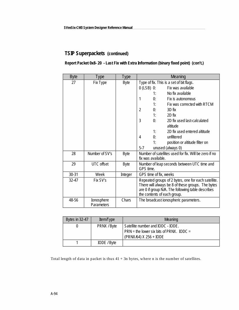
A-94
SVeeSix-CM3 System Designer Reference Manual
TSIP Superpackets (continued)
Report Packet 0x8- 20 - Last Fix with Extra Information (binary fixed point) (con’t.)
Byte Type Type Meaning27 Fix Type Byte Type of fix. This is a set of bit flags.
0 (LSB) 0: Fix was available1: No fix available
1 0: Fix is autonomous1: Fix was corrected with RTCM
2 0: 3D fix1: 2D fix
3 0: 2D fix used last-calculatedaltitude
1: 2D fix used entered altitude4 0: unfiltered
1: position or altitude filter on5-7 unused (always 0)
28 Number of SV’s Byte Number of satellites used for fix. Will be zero if nofix was available.
29 UTC offset Byte Number of leap seconds between UTC time andGPS time.
30-31 Week Integer GPS time of fix, weeks32-47 Fix SV’s Repeated groups of 2 bytes, one for each satellite.
There will always be 8 of these groups. The bytesare 0 if group N/A. The following table describesthe contents of each group.
48-56 IonosphereParameters
Chars The broadcast ionospheric parameters.
Bytes in 32-47 Item/Type Meaning
0 PRNX / Byte Satellite number and IODC - IODE.PRN = the lower six bits of PRNX. IODC =(PRNX/64) X 256 + IODE
1 IODE / Byte
Total length of data in packet is thus 41 + 3n bytes, where n is the number of satellites.
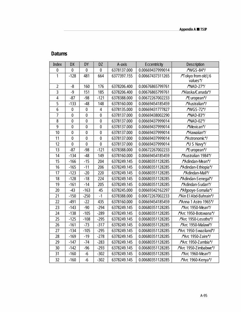
A-95
Appendix A ■ TSIP
Datums
Index DX DY DZ A-axis Eccentricity Description0 0 0 0 6378137.000 0.00669437999014 /*WGS-84*/1 -128 481 664 6377397.155 0.00667437311265 /*Tokyo from old J6
values*/2 -8 160 176 6378206.400 0.00676865799761 /*NAD-27*/3 -9 151 185 6378206.400 0.00676865799761 /*Alaska/Canada*/4 -87 -98 -121 6378388.000 0.00672267002233 /*European*/5 -133 -48 148 6378160.000 0.00669454185459 /*Australian*/6 0 0 4 6378135.000 0.00669431777827 /*WGS-72*/7 0 0 0 6378137.000 0.00669438002290 /*NAD-83*/8 0 0 0 6378137.000 0.00669437999014 /*NAD-02*/9 0 0 0 6378137.000 0.00669437999014 /*Mexican*/
10 0 0 0 6378137.000 0.00669437999014 /*Hawaiian*/11 0 0 0 6378137.000 0.00669437999014 /*Astronomic*/12 0 0 0 6378137.000 0.00669437999014 /*U S Navy*/13 -87 -98 -121 6378388.000 0.00672267002233 /*European*/14 -134 -48 149 6378160.000 0.00669454185459 /*Australian 1984*/15 -166 -15 204 6378249.145 0.00680351128285 /*Adindan-Mean*/16 -165 -11 206 6378249.145 0.00680351128285 /*Adindan-Ethiopia*/17 -123 -20 220 6378249.145 0.00680351128285 /*Adindan-Mali*/18 -128 -18 224 6378249.145 0.00680351128285 /*Adindan-Senegal*/19 -161 -14 205 6378249.145 0.00680351128285 /*Adindan-Sudan*/20 -43 -163 45 6378245.000 0.00669342162297 /*Afgooye-Somalia*/21 -150 -250 -1 6378388.000 0.00672267002233 /*Ain El Abd-Bahrain*/22 -491 -22 435 6378160.000 0.00669454185459 /*Anna 1 Astro 1965*/23 -143 -90 -294 6378249.145 0.00680351128285 /*Arc 1950-Mean*/24 -138 -105 -289 6378249.145 0.00680351128285 /*Arc 1950-Botswana*/25 -125 -108 -295 6378249.145 0.00680351128285 /*Arc 1950-Lesotho*/26 -161 -73 -317 6378249.145 0.00680351128285 /*Arc 1950-Malawi*/27 -134 -105 -295 6378249.145 0.00680351128285 /*Arc 1950-Swaziland*/28 -169 -19 -278 6378249.145 0.00680351128285 /*Arc 1950-Zaire*/29 -147 -74 -283 6378249.145 0.00680351128285 /*Arc 1950-Zambia*/30 -142 -96 -293 6378249.145 0.00680351128285 /*Arc 1950-Zimbabwe*/31 -160 -6 -302 6378249.145 0.00680351128285 /*Arc 1960-Mean*/32 -160 -6 -302 6378249.145 0.00680351128285 /*Arc 1960-Kenya*/
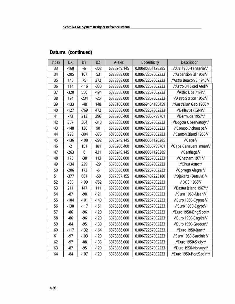
A-96
SVeeSix-CM3 System Designer Reference Manual
Datums (continued)
Index DX DY DZ A-axis Eccentricity Description33 -160 -6 -302 6378249.145 0.00680351128285 /*Arc 1960-Tanzania*/34 -205 107 53 6378388.000 0.00672267002233 /*Ascension Isl 1958*/35 145 75 272 6378388.000 0.00672267002233 /*Astro Beacon E 1945*/36 114 -116 -333 6378388.000 0.00672267002233 /*Astro B4 Sorol Atoll*/37 -320 550 -494 6378388.000 0.00672267002233 /*Astro Dos 71/4*/38 124 -234 -25 6378388.000 0.00672267002233 /*Astro Station 1952*/39 -133 -48 148 6378160.000 0.00669454185459 /*Australian Geo 1966*/40 -127 -769 472 6378388.000 0.00672267002233 /*Bellevue (IGN)*/41 -73 213 296 6378206.400 0.00676865799761 /*Bermuda 1957*/42 307 304 -318 6378388.000 0.00672267002233 /*Bogota Observatory*/43 -148 136 90 6378388.000 0.00672267002233 /*Compo Inchauspe*/44 298 -304 -375 6378388.000 0.00672267002233 /*Canton Island 1966*/45 -136 -108 -292 6378249.145 0.00680351128285 /*Cape*/46 -2 151 181 6378206.400 0.00676865799761 /*Cape Canaveral mean*/47 -263 6 431 6378249.145 0.00680351128285 /*Carthage*/48 175 -38 113 6378388.000 0.00672267002233 /*Chatham 1971*/49 -134 229 -29 6378388.000 0.00672267002233 /*Chua Astro*/50 -206 172 -6 6378388.000 0.00672267002233 /*Corrego Alegre */51 -377 681 -50 6377397.155 0.00667437223180 /*Djakarta (Batavia)*/52 230 -199 -752 6378388.000 0.00672267002233 /*DOS 1968*/53 211 147 111 6378388.000 0.00672267002233 /*Easter Island 1967*/54 -87 -98 -121 6378388.000 0.00672267002233 /*Euro 1950-Mean*/55 -104 -101 -140 6378388.000 0.00672267002233 /*Euro 1950-Cyprus*/56 -130 -117 -151 6378388.000 0.00672267002233 /*Euro 1950-Egypt*/57 -86 -96 -120 6378388.000 0.00672267002233 /*Euro 1950-Eng/Scot*/58 -86 -96 -120 6378388.000 0.00672267002233 /*Euro 1950-Eng/Ire*/59 -84 -95 -130 6378388.000 0.00672267002233 /*Euro 1950-Greece*/60 -117 -132 -164 6378388.000 0.00672267002233 /*Euro 1950-Iran*/61 -97 -103 -120 6378388.000 0.00672267002233 /*Euro 1950-Sardinia*/62 -97 -88 -135 6378388.000 0.00672267002233 /*Euro 1950-Sicily*/63 -87 -95 -120 6378388.000 0.00672267002233 /*Euro 1950-Norway*/64 -84 -107 -120 6378388.000 0.00672267002233 /*Euro 1950-Port/Spain*/
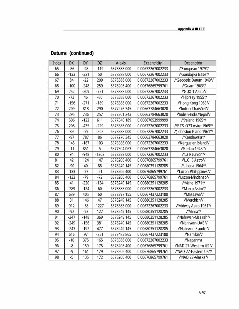
A-97
Appendix A ■ TSIP
Datums (continued)
Index DX DY DZ A-axis Eccentricity Description65 -86 -98 -119 6378388.000 0.00672267002233 /*European 1979*/66 -133 -321 50 6378388.000 0.00672267002233 /*Gandajika Base*/67 84 -22 209 6378388.000 0.00672267002233 /*Geodetic Datum 1949*/68 -100 -248 259 6378206.400 0.00676865799761 /*Guam 1963*/69 252 -209 -751 6378388.000 0.00672267002233 /*GUX 1 Astro*/70 -73 46 -86 6378388.000 0.00672267002233 /*Hjorsey 1955*/71 -156 -271 -189 6378388.000 0.00672267002233 /*Hong Kong 1963*/72 209 818 290 6377276.345 0.00663784663020 /*Indian-Thai/Viet*/73 295 736 257 6377301.243 0.00663784663020 /*Indian-India/Nepal*/74 506 -122 611 6377340.189 0.00667053999999 /*Ireland 1965*/75 208 -435 -229 6378388.000 0.00672267002233 /*ISTS O73 Astro 1969*/76 89 -79 -202 6378388.000 0.00672267002233 /*Johnston Island 1961*/77 -97 787 86 6377276.345 0.00663784663020 /*Kandawala*/78 145 -187 103 6378388.000 0.00672267002233 /*Kerguelen Island*/79 -11 851 5 6377304.063 0.00663784663020 /*Kertau 1948 */80 94 -948 -1262 6378388.000 0.00672267002233 /*La Reunion*/81 42 124 147 6378206.400 0.00676865799761 /*L.C. 5 Astro*/82 -90 40 88 6378249.145 0.00680351128285 /*Liberia 1964*/83 -133 -77 -51 6378206.400 0.00676865799761 /*Luzon-Phillippines*/84 -133 -79 -72 6378206.400 0.00676865799761 /*Luzon-Mindanao*/85 41 -220 -134 6378249.145 0.00680351128285 /*Mahe 1971*/86 -289 -124 60 6378388.000 0.00672267002233 /*Marco Astro*/87 639 405 60 6377397.155 0.00667437223180 /*Massawa*/88 31 146 47 6378249.145 0.00680351128285 /*Merchich*/89 912 -58 1227 6378388.000 0.00672267002233 /*Midway Astro 1961*/90 -92 -93 122 6378249.145 0.00680351128285 /*Minna*/91 -247 -148 369 6378249.145 0.00680351128285 /*Nahrwan-Masirah*/92 -249 -156 381 6378249.145 0.00680351128285 /*Nahrwan-UAE*/93 -243 -192 477 6378249.145 0.00680351128285 /*Nahrwan-Saudia*/94 616 97 -251 6377483.865 0.00667437223180 /*Namibia*/95 -10 375 165 6378388.000 0.00672267002233 /*Naparima96 -8 159 175 6378206.400 0.00676865799761 /*NAD 27-Western US*/97 -9 161 179 6378206.400 0.00676865799761 /*NAD 27-Eastern US*/98 -5 135 172 6378206.400 0.00676865799761 /*NAD 27-Alaska*/
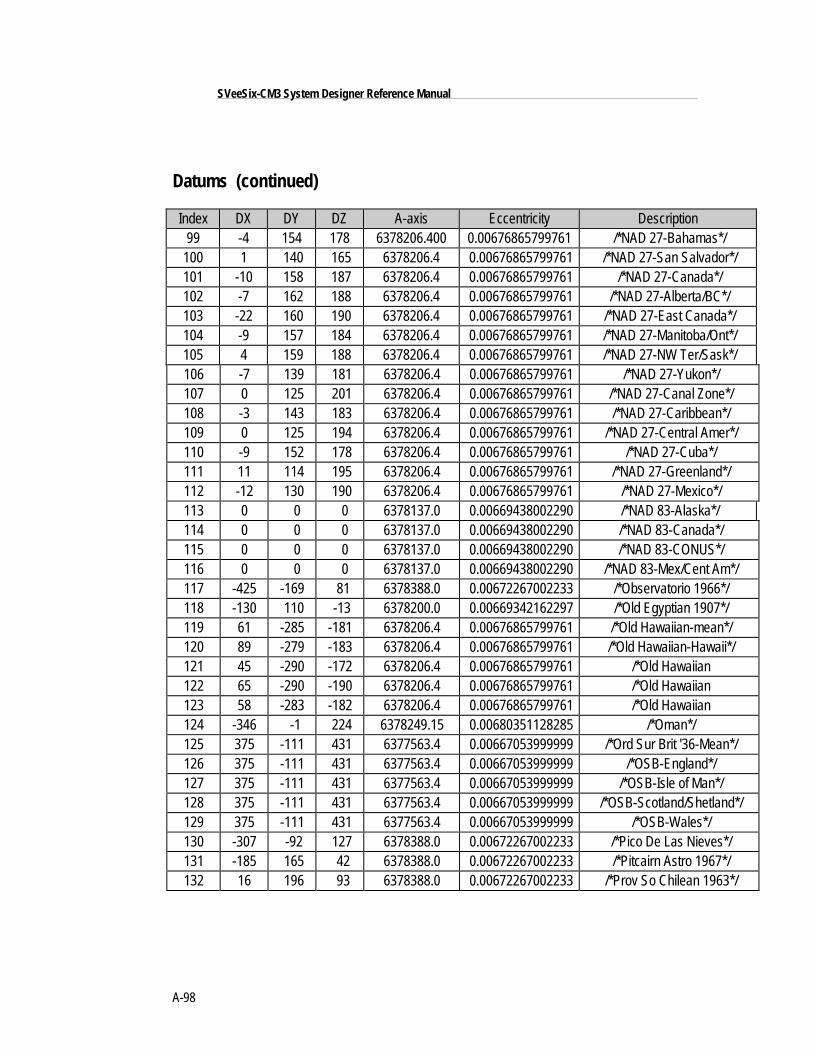
A-98
SVeeSix-CM3 System Designer Reference Manual
Datums (continued)
Index DX DY DZ A-axis Eccentricity Description99 -4 154 178 6378206.400 0.00676865799761 /*NAD 27-Bahamas*/
100 1 140 165 6378206.4 0.00676865799761 /*NAD 27-San Salvador*/101 -10 158 187 6378206.4 0.00676865799761 /*NAD 27-Canada*/102 -7 162 188 6378206.4 0.00676865799761 /*NAD 27-Alberta/BC*/103 -22 160 190 6378206.4 0.00676865799761 /*NAD 27-East Canada*/104 -9 157 184 6378206.4 0.00676865799761 /*NAD 27-Manitoba/Ont*/105 4 159 188 6378206.4 0.00676865799761 /*NAD 27-NW Ter/Sask*/106 -7 139 181 6378206.4 0.00676865799761 /*NAD 27-Yukon*/107 0 125 201 6378206.4 0.00676865799761 /*NAD 27-Canal Zone*/108 -3 143 183 6378206.4 0.00676865799761 /*NAD 27-Caribbean*/109 0 125 194 6378206.4 0.00676865799761 /*NAD 27-Central Amer*/110 -9 152 178 6378206.4 0.00676865799761 /*NAD 27-Cuba*/111 11 114 195 6378206.4 0.00676865799761 /*NAD 27-Greenland*/112 -12 130 190 6378206.4 0.00676865799761 /*NAD 27-Mexico*/113 0 0 0 6378137.0 0.00669438002290 /*NAD 83-Alaska*/114 0 0 0 6378137.0 0.00669438002290 /*NAD 83-Canada*/115 0 0 0 6378137.0 0.00669438002290 /*NAD 83-CONUS*/116 0 0 0 6378137.0 0.00669438002290 /*NAD 83-Mex/Cent Am*/117 -425 -169 81 6378388.0 0.00672267002233 /*Observatorio 1966*/118 -130 110 -13 6378200.0 0.00669342162297 /*Old Egyptian 1907*/119 61 -285 -181 6378206.4 0.00676865799761 /*Old Hawaiian-mean*/120 89 -279 -183 6378206.4 0.00676865799761 /*Old Hawaiian-Hawaii*/121 45 -290 -172 6378206.4 0.00676865799761 /*Old Hawaiian122 65 -290 -190 6378206.4 0.00676865799761 /*Old Hawaiian123 58 -283 -182 6378206.4 0.00676865799761 /*Old Hawaiian124 -346 -1 224 6378249.15 0.00680351128285 /*Oman*/125 375 -111 431 6377563.4 0.00667053999999 /*Ord Sur Brit '36-Mean*/126 375 -111 431 6377563.4 0.00667053999999 /*OSB-England*/127 375 -111 431 6377563.4 0.00667053999999 /*OSB-Isle of Man*/128 375 -111 431 6377563.4 0.00667053999999 /*OSB-Scotland/Shetland*/129 375 -111 431 6377563.4 0.00667053999999 /*OSB-Wales*/130 -307 -92 127 6378388.0 0.00672267002233 /*Pico De Las Nieves*/131 -185 165 42 6378388.0 0.00672267002233 /*Pitcairn Astro 1967*/132 16 196 93 6378388.0 0.00672267002233 /*Prov So Chilean 1963*/
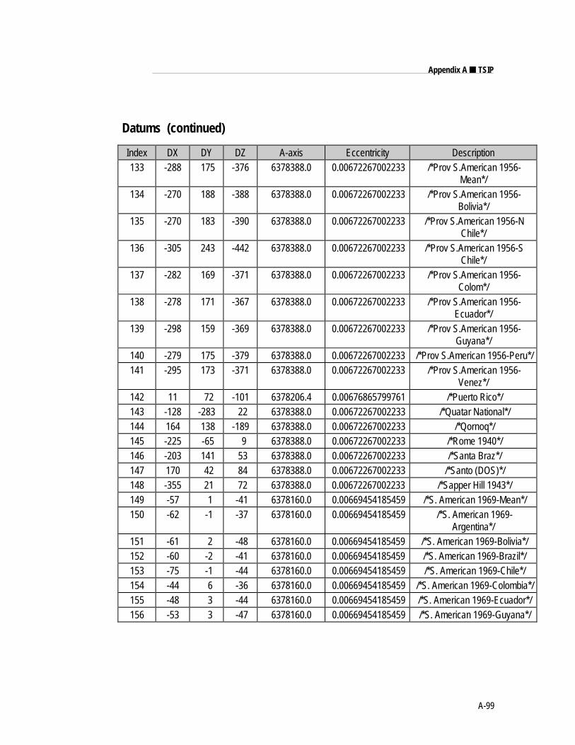
A-99
Appendix A ■ TSIP
Datums (continued)
Index DX DY DZ A-axis Eccentricity Description133 -288 175 -376 6378388.0 0.00672267002233 /*Prov S.American 1956-
Mean*/134 -270 188 -388 6378388.0 0.00672267002233 /*Prov S.American 1956-
Bolivia*/135 -270 183 -390 6378388.0 0.00672267002233 /*Prov S.American 1956-N
Chile*/136 -305 243 -442 6378388.0 0.00672267002233 /*Prov S.American 1956-S
Chile*/137 -282 169 -371 6378388.0 0.00672267002233 /*Prov S.American 1956-
Colom*/138 -278 171 -367 6378388.0 0.00672267002233 /*Prov S.American 1956-
Ecuador*/139 -298 159 -369 6378388.0 0.00672267002233 /*Prov S.American 1956-
Guyana*/140 -279 175 -379 6378388.0 0.00672267002233 /*Prov S.American 1956-Peru*/141 -295 173 -371 6378388.0 0.00672267002233 /*Prov S.American 1956-
Venez*/142 11 72 -101 6378206.4 0.00676865799761 /*Puerto Rico*/143 -128 -283 22 6378388.0 0.00672267002233 /*Quatar National*/144 164 138 -189 6378388.0 0.00672267002233 /*Qornoq*/145 -225 -65 9 6378388.0 0.00672267002233 /*Rome 1940*/146 -203 141 53 6378388.0 0.00672267002233 /*Santa Braz*/147 170 42 84 6378388.0 0.00672267002233 /*Santo (DOS)*/148 -355 21 72 6378388.0 0.00672267002233 /*Sapper Hill 1943*/149 -57 1 -41 6378160.0 0.00669454185459 /*S. American 1969-Mean*/150 -62 -1 -37 6378160.0 0.00669454185459 /*S. American 1969-
Argentina*/151 -61 2 -48 6378160.0 0.00669454185459 /*S. American 1969-Bolivia*/152 -60 -2 -41 6378160.0 0.00669454185459 /*S. American 1969-Brazil*/153 -75 -1 -44 6378160.0 0.00669454185459 /*S. American 1969-Chile*/154 -44 6 -36 6378160.0 0.00669454185459 /*S. American 1969-Colombia*/155 -48 3 -44 6378160.0 0.00669454185459 /*S. American 1969-Ecuador*/156 -53 3 -47 6378160.0 0.00669454185459 /*S. American 1969-Guyana*/
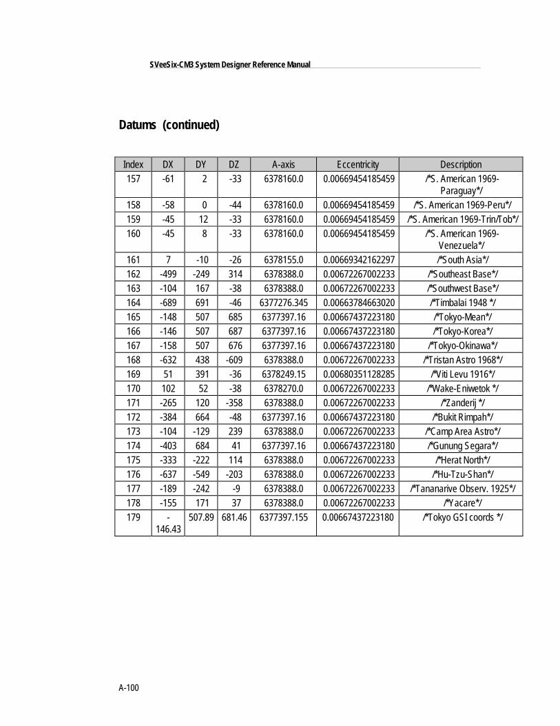
A-100
SVeeSix-CM3 System Designer Reference Manual
Datums (continued)
Index DX DY DZ A-axis Eccentricity Description157 -61 2 -33 6378160.0 0.00669454185459 /*S. American 1969-
Paraguay*/158 -58 0 -44 6378160.0 0.00669454185459 /*S. American 1969-Peru*/159 -45 12 -33 6378160.0 0.00669454185459 /*S. American 1969-Trin/Tob*/160 -45 8 -33 6378160.0 0.00669454185459 /*S. American 1969-
Venezuela*/161 7 -10 -26 6378155.0 0.00669342162297 /*South Asia*/162 -499 -249 314 6378388.0 0.00672267002233 /*Southeast Base*/163 -104 167 -38 6378388.0 0.00672267002233 /*Southwest Base*/164 -689 691 -46 6377276.345 0.00663784663020 /*Timbalai 1948 */165 -148 507 685 6377397.16 0.00667437223180 /*Tokyo-Mean*/166 -146 507 687 6377397.16 0.00667437223180 /*Tokyo-Korea*/167 -158 507 676 6377397.16 0.00667437223180 /*Tokyo-Okinawa*/168 -632 438 -609 6378388.0 0.00672267002233 /*Tristan Astro 1968*/169 51 391 -36 6378249.15 0.00680351128285 /*Viti Levu 1916*/170 102 52 -38 6378270.0 0.00672267002233 /*Wake-Eniwetok */171 -265 120 -358 6378388.0 0.00672267002233 /*Zanderij */172 -384 664 -48 6377397.16 0.00667437223180 /*Bukit Rimpah*/173 -104 -129 239 6378388.0 0.00672267002233 /*Camp Area Astro*/174 -403 684 41 6377397.16 0.00667437223180 /*Gunung Segara*/175 -333 -222 114 6378388.0 0.00672267002233 /*Herat North*/176 -637 -549 -203 6378388.0 0.00672267002233 /*Hu-Tzu-Shan*/177 -189 -242 -9 6378388.0 0.00672267002233 /*Tananarive Observ. 1925*/178 -155 171 37 6378388.0 0.00672267002233 /*Yacare*/179 -
146.43507.89 681.46 6377397.155 0.00667437223180 /*Tokyo GSI coords */
A-101
Appendix A ■ TSIP
Reference Documents
Unless otherwise indicated the issue of each document which was in effect on 1May 1987 is the issue to be used.
SS-GPS-300BSystem Specification for the NAVSTAR Global Positioning System
ICD-GPS-200NAVSTAR GPS Space Segment/Navigation User Interfaces
17035Trimble Advanced Navigation Sensor Specification and User's Manual Rev. AOctober 1990
RTCM (SC-104)RTCM Recommended Standards For Differential NAVSTAR GPS ServiceVersion 2.0. RTCM Special Committee No. 104. Published by the RadioTechnical Commission For Maritime Services Washington D.C. January 1 1990.
GPS - A Guide to the Next UtilityTrimble 1990 - an introduction in non-mathematical terms to the GPS system.
Proceedings - Institute of Navigation Washington DCA series of 3 abstracts published between 1980 & 1986 of papers from theJournal of the Institute of Navigation. Essential source material for any systemdesigner.

Appendix BTSIP User's Guide
This appendix provides explicit instructions for each of the programs contained in theOEM GPS Tool Kit, and guidelines for using the source code as template for integratedsystems applications.
The OEM GPS Tool Kit program disk (PN 34152-01) includes several TSIP interfaceprograms designed to help developer's evaluate and integrate the GPS module andcreate GPS and differential GPS applications. These programs run on a PC-DOSplatform. They are intended as a base upon which to build application specificsoftware, so the source code in ANSI C is included for many of these programs. TheOEM GPS Tool Kit program disk includes the following programs:
❒ TSIPCHAT.EXE reads TSIP reports and prints them to the screen. It also allowsthe user to exercise TSIP commands, by translating keystroke codes into TSIPcommands which are output over the serial port. When data input is required,TSIPCHAT prompts the user for the information. TSIPCHAT can also log TSIPreports in binary format, and can set time on a PC, based on time informationfrom the GPS module.
❒ TSIPPRNT.EXE interprets a binary TSIP data stream, such as logged byTSIPCHAT, and prints it to a file. Source code is provided.
❒ 34055-XX.EXE configures the standard temperature receiver’s protocol to (TAIP,TSIP or NMEA). This file will work only for standard temperature receivers.
34057-XX.EXE configures the extended temperature receiver’s protocol to (TAIP,TSIP or NMEA). This file will work only for extended temperature receivers.
Where XX is the protocol desired: 61=TSIP , 62=NMEA, 63=TAIP
❒ RTCM_MON.EXE monitors a serial port carrying RTCM differential corrections,translates the messages and prints them to the screen.
❒ TCHAT.EXE is a simplified version of TSIPCHAT. It provides a good workingbasis for GPS development. Source code is provided. The program is MicrosoftVisual C and Borland C compatible.
B-2
SVeeSix-CM3 System Designer Reference Manual
TSIPCHAT
TSIPCHAT is a program that provides full visibility into the TSIP interface.
Starting TSIPCHAT
To start the program, type TSIPCHAT.
As TSIPCHAT starts, it displays a list of commands in the upper half of the consolescreen (command window) and a running account of automatic reports not requestedin the bottom half of the screen (auto window). It also sets the serial port to the defaultsettings of 9600 baud, 8-Odd-1.
If the receiver is alive and outputting positions, position reports scroll immediately inthe auto window. If the auto window is empty, type 'v' to test if the receiver isconnected properly to the computer. If the serial port is properly connected, thereceiver responds within a second with the receiver software version numbers;otherwise "waiting for reply" remains on the screen. An auto-report of receiver health issent every 30 seconds, even if satellites are not being tracked.
Report Packets
When a TSIP report packet is issued by the receiver, it is received by TSIPCHAT,translated into a printable form and put on the screen. If the report packet has beenspecifically requested by a command, it is put in the command (upper) window;otherwise, it is reported in the auto (lower) window.
The common automatic reports are the navigation reports: position, velocity, and healthdata. The '^O' command can change the content of these auto-reports or turn them onand off. Other automatic reports include almanac, ephemeris status, and almanachealth page when decoded; and receiver health, machine code status, and satelliteselection at regular intervals.
B-3
Appendix B ■ TSIP User's Guide
TSIPCHAT (continued)
Command Packets
TSIPCHAT uses keystroke codes to send TSIP command packets to the receiver. Forinstance, the keystroke 'v' sends the TSIP command packet 0x1F, requesting a TSIPreport packet 0x45 listing the software versions. A complete list of keystrokes and theirassociated TSIP commands can be called up by the keystroke '?'.
Many TSIP command packets require user-provided data or parameters. For instance, arequest for a satellite almanac report packet requires the satellite identifier (SV PRN). Insuch cases, TSIPCHAT will prompt the user for inputs. For any of the following threetype of prompts, pressing the “<ESCAPE>” key aborts the whole command:
1) prompt for number: to enter a numerical value, type the value and hit <ENTER>. Ifno value is typed, the value entered will be 0.
2) prompt for selection: to select from a number of choices, cycle through the choiceswith the <SPACE BAR> and select with <ENTER>. An index 0 - 9 associated withthe choice is shown in parentheses; this index can be typed in for direct access of thechoice.
3) prompt for confirmation: to confirm when asked, type 'y' or 'Y'. Any otherkeystroke will be 'negative', including just the <enter> key.
B-4
SVeeSix-CM3 System Designer Reference Manual
TSIPCHAT (continued)
Serial Port Control
Use caution when using the “^U” command. Control of the receiver can be lost.
To control the serial port settings on main channel, Channel A of the SVeeSix, use the'^U' command A single port receiver may only have Channel A; when that is reset,control of the receiver may be lost. In such cases the receiver must be hard-reset byclearing the battery backed RAM. ( Remove battery backup power ).
To control the serial port settings on the computer, use the keystroke '^I'. Thiskeystroke does not generate a TSIP packet. It prompts for the parameters for thebuffered serial port. On start-up, the program automatically sets the port parameters to9600 baud, 8-odd-1. If the port parameters are changed from the default during theexecution of TSIPCHAT, upon exit the program asks if the serial port is to be reset to thedefault.
File Storage
TSIPCHAT provides an options for file storage, of the raw binary TSIP stream.
The native binary stream records the data coming off the serial port into a file. To turndata collection on and off, use the keystroke '^F'. The user has the option to append to apreviously existing file. All report packet bytes are recorded into the file, whethertranslatable into packets or not. The recorded binary data stream can be translated intoan ASCII file with the program TSIPPRNT.
B-5
Appendix B ■ TSIP User's Guide
TSIPCHAT (continued)
Quick-Start Almanac Get and Load (con’t.)
A stored almanac can allow the receiver to be "warm-started", reducing time to first fix.If the receiver is started 'cold', with no almanac data in memory, it performs a search forsatellites in the sky, which can take a few minutes. If the receiver has a recent almanacof satellite orbits, fixes begin within a minute. The receiver responds most quickly ifloaded with time, frequency offset, last position, and a recent almanac. There is acommand sequence for getting an almanac from the receiver and storing in a file named'GPSALM.DAT', and a reverse command sequence for reading a file named'GPSALM.DAT' on the computer and loading it into the receiver. These commandsequences use the command packet 0x38 and the report packet 0x58.
The keystroke for the get-and-store sequence is '!', and for the read-and-load sequence is'@'. It is useful to record a fresh almanac every few days. Before storing a new almanacon the PC the receiver must have been operating continuously for about fifteen minutes,otherwise an incomplete almanac will be stored, causing the receiver to go into coldsearch mode. Check the receiver health to see if the message "Almanac not completeand current" is being reported. Once this message is no longer displayed it is safe tosave the Almanac data.
Setting PC Time from the Receiver
TSIPCHAT includes the capability to set the PC clock to UTC time from the GPS satellitesignal. (GPS time differs from UTC time by leap seconds.) The keystroke 'z' requests atime set (command packet 0x21, report packet 0x41). A special sequence is required thefirst time the request is made during execution of the program. The user is promptedfor the local time zone offset and then requested to press 'z' again, at which time thetime set operation is completed. The user time zone offset is '0' for UTC/GMT; 5 forEST, 4 for EDT; 8 for PST, 7 for PDT; and negative numbers if ahead of (east of) GMT.Allowable range is 13 hours, plus or minus. The accuracy of this software method isapproximately ±0.5 seconds.
Exiting TSIPCHAT
To exit the program, hit the <ESCAPE> key.
B-6
SVeeSix-CM3 System Designer Reference Manual
TSIPCHAT (continued)
Source Code
Sample Source code is provided with TSIPPRNT and TCHAT This sample sourceprograms were designed to provide a template for the user interface with the TSIPreceiver. In particular, TSIP_IFC.C contains routines that define the interface with theTSIP receiver. These should be re-used in the system integrator's code.
TSIPCHAT is created by compiling under a Borland compiler with the macrosPORT_INPUT, and BORLAND defined and with the include file TSIPINCL.H. Thefollowing routines must be compiled:
TSIPCHAT.C (main)
TSIP_UTL.C
TSIP_CMD.C
TSIP_RPT.C
TSIP_ALM.C
TSIP_IFC.C
TSIP_SIO.C
TSERIAL.C
B-7
Appendix B ■ TSIP User's Guide
TSIPPRNT
TSIPPRNT translates TSIP report packet byte streams into readable reports. It uses thesame report interface routines as TSIPCHAT, but uses 'printf' rather than 'cprintf' so thatoutput can be redirected to a file.
The command line for console output is:
TSIPPRNT tsip_filename
where tsip_filename is the name of a stream of TSIP report packets collected directlyfrom the receiver output port or from TSIPCHAT. The command line for re-directingoutput to a file is:
TSIPPRNT tsip_filename > ascii_filename
Full source code is provided. TSIPPRNT is created by compiling under any C compilerand with the include file TSIPINCL.H. The following routines must be compiled:
TSIPPRNT.C (main)
TSIP_RPT.C
TSIP_IFC.C
TSIPPRNT code can be easily modified by the user to supply any ASCII output fileformat that is required by adjusting the report interpreter routines in TSIP_RPT.C,provided the necessary information is contained in the binary input file. Software flowfollows that of TSIPCHAT, except with no user-interactive and command features.
B-8
SVeeSix-CM3 System Designer Reference Manual
RTCM_MON
RTCM_MON translates RTCM SC-104 Version 2.0 (Differential GPS correction) bytestreams off a serial port. It is designed to be configured to the same port parameters asthe TSIP receiver. RTCM streams can best be tested by using the TSIP receiver itself as adecoder, using TSIPCHAT and the '/' command (packet 0x65) which returns packet0x85 listing all differential RTCM messages decoded. RTCM_MON is provided in casethe user prefers to use a direct connection to a computer serial port to decode an RTCMstream.
The RTCM_MON command line has no arguments. When listening to the serial port,characters will be printed on the screen. RTCM 6-of-8 bytes are identified by the firsttwo bits (binary 01xxxxxx) and all other bytes are reported as non-RTCM bytes. Oncethe program locks onto the RTCM preamble and framing, it begins to report differentialcorrection messages for each of the satellites.
To exit the program, press <ESCAPE>.
Bit-Slipping
Even though the RTCM bytes are 6 bits of data and fit neatly into a 8-bit byte once thelead bits '01' are attached, some reference receivers do not align the RTCM data onto 8-bit boundaries for the serial link ("bit-slipping"). RTCM_MON automatically searchesfor bit-slipping.
Serial Port Parameters
The default at start-up is 9600 baud, 8-odd-1. The serial port parameters on thecomputer can be adjusted by typing '^I'. The program will prompt for new serial portparameters.
Caution
The RRM source will probably require a null-modemconnection to the PC serial port.
B-9
Appendix B ■ TSIP User's Guide
TCHAT
TCHAT is a simplified version of Tsipchat. That provides a good basis for GPS softwaredevelopment.
The command line syntax is:
TCHAT -c[port number] <optional file name>
where <optional file name> is the name where bytes received directly from the receiverwill be collected.
Full source code is provided. Unlike Tsipchat TCHAT can be compiled under bothMicrosoft and Borland Compilers. It uses the same source code modules as TSIPCHAT.The following modules comprise TCHAT:
TCHAT.C (main)
TSIP_RPT.C
TSIP_IFC.C
TSERIAL.C
Software flow follows the same as TSIPCHAT, except that the display and userinterfaces have been greatly simplified. It is recommended that software developer’sbecome familiar with TCHAT before studying the source code to TSIPCHAT.


Appendix CTrimble ASCII Interface Protocol (TAIP)Trimble ASCII Interface Protocol (TAIP) is a Trimble-specified digital communicationinterface based on printable ASCII characters over a serial data link. TAIP was designedspecifically for vehicle tracking applications but has become common in a number ofother applications because of its ease of use. TAIP supports both scheduled and polledresponses.
TAIP messages may be scheduled for output at a user specified rate starting on a givenepoch from top of the hour. For communication robustness, the protocol optionallysupports checksums on all messages. It also provides the user with the option oftagging all messages with the unit's user specified identification number (ID). Thisgreatly enhances the functional capability of the unit in a network or fleet environment.
Additionally, given the printable ASCII format of all communication, TAIP is ideal foruse with mobile data terminals, seven bit modems and portable computers. Although,sensors incorporating this protocol are shipped from the factory with a specific serialport setting, the port characteristics are fully programmable through TAIP messages.
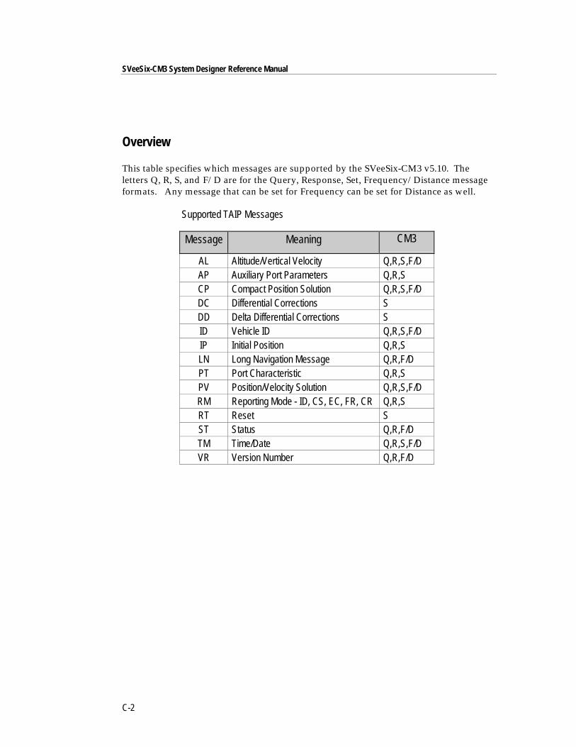
SVeeSix-CM3 System Designer Reference Manual
C-2
Overview
This table specifies which messages are supported by the SVeeSix-CM3 v5.10. Theletters Q, R, S, and F/D are for the Query, Response, Set, Frequency/Distance messageformats. Any message that can be set for Frequency can be set for Distance as well.
Supported TAIP Messages
Message Meaning CM3
AL Altitude/Vertical Velocity Q,R,S,F/DAP Auxiliary Port Parameters Q,R,SCP Compact Position Solution Q,R,S,F/DDC Differential Corrections SDD Delta Differential Corrections SID Vehicle ID Q,R,S,F/DIP Initial Position Q,R,SLN Long Navigation Message Q,R,F/DPT Port Characteristic Q,R,SPV Position/Velocity Solution Q,R,S,F/DRM Reporting Mode - ID, CS, EC, FR, CR Q,R,SRT Reset SST Status Q,R,F/DTM Time/Date Q,R,S,F/DVR Version Number Q,R,F/D
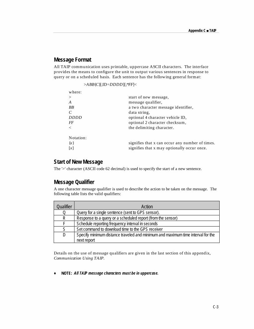
Appendix C ■ TAIP
C-3
Message FormatAll TAIP communication uses printable, uppercase ASCII characters. The interfaceprovides the means to configure the unit to output various sentences in response toquery or on a scheduled basis. Each sentence has the following general format:
>ABB{C}[;ID=DDDD][;*FF]<
where:> start of new message,A message qualifier,BB a two character message identifier,C data string,DDDD optional 4 character vehicle ID,FF optional 2 character checksum,< the delimiting character.
Notation:{x} signifies that x can occur any number of times.[x] signifies that x may optionally occur once.
Start of New MessageThe '>' character (ASCII code 62 decimal) is used to specify the start of a new sentence.
Message QualifierA one character message qualifier is used to describe the action to be taken on the message. Thefollowing table lists the valid qualifiers:
Qualifier ActionQ Query for a single sentence (sent to GPS sensor).R Response to a query or a scheduled report (from the sensor)F Schedule reporting frequency interval in secondsS Set command to download time to the GPS receiverD Specify minimum distance traveled and minimum and maximum time interval for the
next report
Details on the use of message qualifiers are given in the last section of this appendix,Communication Using TAIP.
♦ NOTE: All TAIP message characters must be in uppercase.
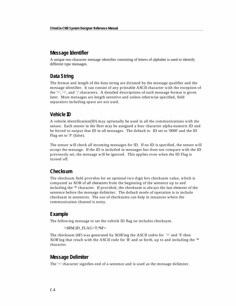
SVeeSix-CM3 System Designer Reference Manual
C-4
Message IdentifierA unique two character message identifier consisting of letters of alphabet is used to identifydifferent type messages.
Data StringThe format and length of the data string are dictated by the message qualifier and themessage identifier. It can consist of any printable ASCII character with the exception ofthe '>', '<', and ';' characters. A detailed descriptions of each message format is givenlater. Most messages are length sensitive and unless otherwise specified, fieldseparators including space are not used.
Vehicle IDA vehicle identification(ID) may optionally be used in all the communications with thesensor. Each sensor in the fleet may be assigned a four character alpha-numeric ID andbe forced to output that ID in all messages. The default is: ID set to '0000' and the IDFlag set to 'F' (false).
The sensor will check all incoming messages for ID. If no ID is specified, the sensor willaccept the message. If the ID is included in messages but does not compare with the IDpreviously set, the message will be ignored. This applies even when the ID Flag isturned off.
ChecksumThe checksum field provides for an optional two digit hex checksum value, which iscomputed as XOR of all characters from the beginning of the sentence up to andincluding the '*' character. If provided, the checksum is always the last element of thesentence before the message delimiter. The default mode of operation is to includechecksum in sentences. The use of checksums can help in instances where thecommunication channel is noisy.
ExampleThe following message to set the vehicle ID flag on includes checksum.
>SRM;ID_FLAG=T;*6F<
The checksum (6F) was generated by XOR'ing the ASCII codes for '>' and 'S' thenXOR'ing that result with the ASCII code for 'R' and so forth, up to and including the '*'character.
Message DelimiterThe '<' character signifies end of a sentence and is used as the message delimiter.
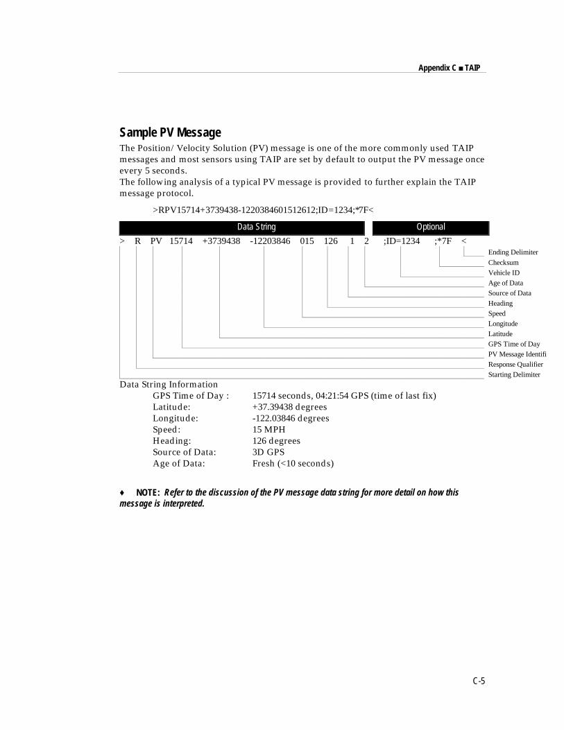
Appendix C ■ TAIP
C-5
Sample PV MessageThe Position/Velocity Solution (PV) message is one of the more commonly used TAIPmessages and most sensors using TAIP are set by default to output the PV message onceevery 5 seconds.The following analysis of a typical PV message is provided to further explain the TAIPmessage protocol.
>RPV15714+3739438-1220384601512612;ID=1234;*7F<
Data String Optional
> R PV 15714 +3739438 -12203846 015 126 1 2 ;ID=1234 ;*7F <Ending Delimiter
ChecksumVehicle IDAge of DataSource of DataHeadingSpeedLongitudeLatitudeGPS Time of DayPV Message IdentifieResponse QualifierStarting Delimiter
Data String InformationGPS Time of Day : 15714 seconds, 04:21:54 GPS (time of last fix)Latitude: +37.39438 degreesLongitude: -122.03846 degreesSpeed: 15 MPHHeading: 126 degreesSource of Data: 3D GPSAge of Data: Fresh (<10 seconds)
♦ NOTE: Refer to the discussion of the PV message data string for more detail on how thismessage is interpreted.
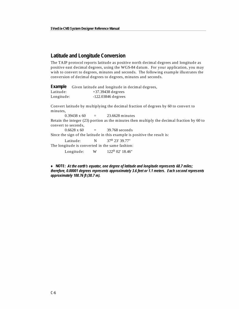
SVeeSix-CM3 System Designer Reference Manual
C-6
Latitude and Longitude ConversionThe TAIP protocol reports latitude as positive north decimal degrees and longitude aspositive east decimal degrees, using the WGS-84 datum. For your application, you maywish to convert to degrees, minutes and seconds. The following example illustrates theconversion of decimal degrees to degrees, minutes and seconds.
Example Given latitude and longitude in decimal degrees,Latitude: +37.39438 degreesLongitude: -122.03846 degrees
Convert latitude by multiplying the decimal fraction of degrees by 60 to convert tominutes,
0.39438 x 60 = 23.6628 minutesRetain the integer (23) portion as the minutes then multiply the decimal fraction by 60 toconvert to seconds,
0.6628 x 60 = 39.768 secondsSince the sign of the latitude in this example is positive the result is:
Latitude: N 37o 23' 39.77"The longitude is converted in the same fashion:
Longitude: W 122o 02' 18.46"
♦ NOTE: At the earth's equator, one degree of latitude and longitude represents 68.7 miles;therefore, 0.00001 degrees represents approximately 3.6 feet or 1.1 meters. Each second representsapproximately 100.76 ft (30.7 m).
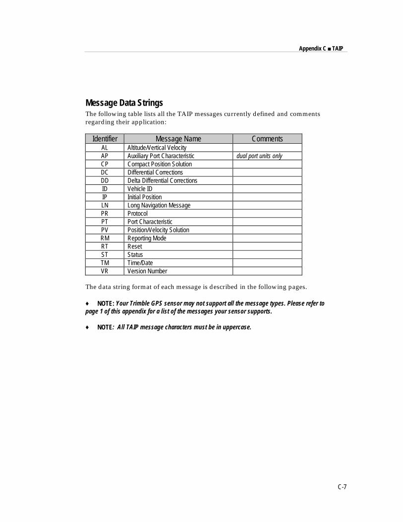
Appendix C ■ TAIP
C-7
Message Data StringsThe following table lists all the TAIP messages currently defined and commentsregarding their application:
Identifier Message Name CommentsAL Altitude/Vertical VelocityAP Auxiliary Port Characteristic dual port units onlyCP Compact Position SolutionDC Differential CorrectionsDD Delta Differential CorrectionsID Vehicle IDIP Initial PositionLN Long Navigation MessagePR ProtocolPT Port CharacteristicPV Position/Velocity SolutionRM Reporting ModeRT ResetST StatusTM Time/DateVR Version Number
The data string format of each message is described in the following pages.
♦ NOTE: Your Trimble GPS sensor may not support all the message types. Please refer topage 1 of this appendix for a list of the messages your sensor supports.
♦ NOTE: All TAIP message characters must be in uppercase.
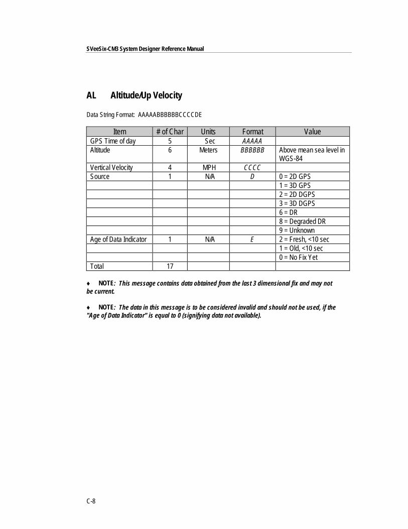
SVeeSix-CM3 System Designer Reference Manual
C-8
AL Altitude/Up Velocity
Data String Format: AAAAABBBBBBCCCCDE
Item # of Char Units Format ValueGPS Time of day 5 Sec AAAAAAltitude 6 Meters BBBBBB Above mean sea level in
WGS-84Vertical Velocity 4 MPH CCCCSource 1 N/A D 0 = 2D GPS
1 = 3D GPS2 = 2D DGPS3 = 3D DGPS6 = DR8 = Degraded DR9 = Unknown
Age of Data Indicator 1 N/A E 2 = Fresh, <10 sec1 = Old, <10 sec0 = No Fix Yet
Total 17
♦ NOTE: This message contains data obtained from the last 3 dimensional fix and may notbe current.
♦ NOTE: The data in this message is to be considered invalid and should not be used, if the"Age of Data Indicator" is equal to 0 (signifying data not available).
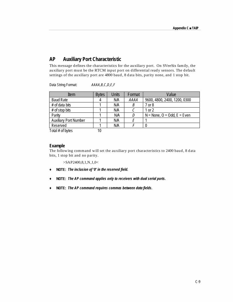
Appendix C ■ TAIP
C-9
AP Auxiliary Port CharacteristicThis message defines the characteristics for the auxiliary port. On SVeeSix family, theauxiliary port must be the RTCM input port on differential ready sensors. The defaultsettings of the auxiliary port are 4800 baud, 8 data bits, parity none, and 1 stop bit.
Data String Format: AAAA,B,C,D,E,F
Item Bytes Units Format ValueBaud Rate 4 N/A AAAA 9600, 4800, 2400, 1200, 0300# of data bits 1 N/A B 7 or 8# of stop bits 1 N/A C 1 or 2Parity 1 N/A D N = None, O = Odd, E = EvenAuxiliary Port Number 1 N/A E 1Reserved 1 N/A F 0
Total # of bytes 10
ExampleThe following command will set the auxiliary port characteristics to 2400 baud, 8 databits, 1 stop bit and no parity.
>SAP2400,8,1,N,1,0<
♦ NOTE: The inclusion of ‘0’ in the reserved field.
♦ NOTE: The AP command applies only to receivers with dual serial ports.
♦ NOTE: The AP command requires commas between data fields.
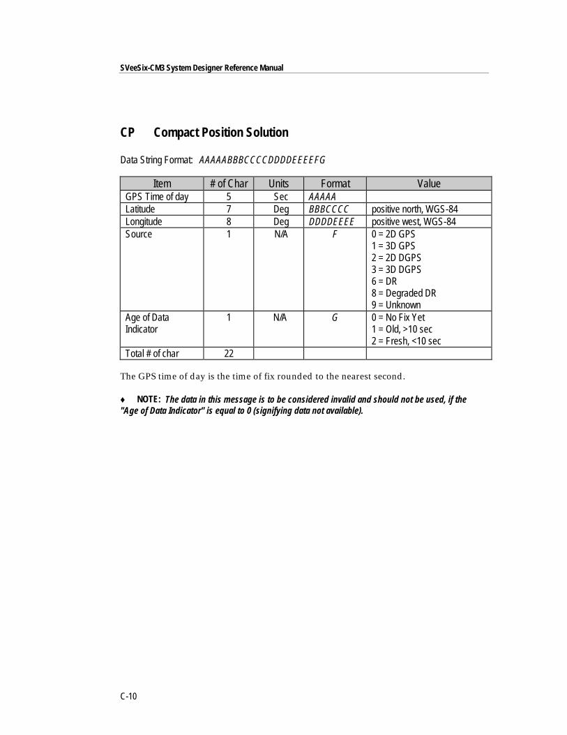
SVeeSix-CM3 System Designer Reference Manual
C-10
CP Compact Position Solution
Data String Format: AAAAABBBCCCCDDDDEEEEFG
Item # of Char Units Format ValueGPS Time of day 5 Sec AAAAALatitude 7 Deg BBBCCCC positive north, WGS-84Longitude 8 Deg DDDDEEEE positive west, WGS-84Source 1 N/A F 0 = 2D GPS
1 = 3D GPS2 = 2D DGPS3 = 3D DGPS6 = DR8 = Degraded DR9 = Unknown
Age of DataIndicator
1 N/A G 0 = No Fix Yet1 = Old, >10 sec2 = Fresh, <10 sec
Total # of char 22
The GPS time of day is the time of fix rounded to the nearest second.
♦ NOTE: The data in this message is to be considered invalid and should not be used, if the"Age of Data Indicator" is equal to 0 (signifying data not available).
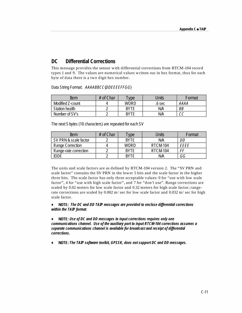
Appendix C ■ TAIP
C-11
DC Differential CorrectionsThis message provides the sensor with differential corrections from RTCM-104 recordtypes 1 and 9. The values are numerical values written out in hex format, thus for eachbyte of data there is a two digit hex number.
Data String Format: AAAABBCC{DDEEEEFFGG}
Item # of Char Type Units FormatModified Z-count 4 WORD .6 sec AAAAStation health 2 BYTE N/A BBNumber of SV’s 2 BYTE N/A CC
The next 5 bytes (10 characters) are repeated for each SV
Item # of Char Type Units FormatSV PRN & scale factor 2 BYTE N/A DDRange Correction 4 WORD RTCM-104 EEEERange-rate correction 2 BYTE RTCM-104 FFIODE 2 BYTE N/A GG
The units and scale factors are as defined by RTCM-104 version 2. The “SV PRN andscale factor” contains the SV PRN in the lower 5 bits and the scale factor in the higherthree bits. The scale factor has only three acceptable values: 0 for “use with low scalefactor”, 4 for “use with high scale factor”, and 7 for “don’t use”. Range corrections arescaled by 0.02 meters for low scale factor and 0.32 meters for high scale factor; range-rate corrections are scaled by 0.002 m/sec for low scale factor and 0.032 m/sec for highscale factor.
♦ NOTE: The DC and DD TAIP messages are provided to enclose differential correctionswithin the TAIP format.
♦ NOTE: Use of DC and DD messages to input corrections requires only onecommunications channel. Use of the auxiliary port to input RTCM-104 corrections assumes aseparate communications channel is available for broadcast and receipt of differentialcorrections.
♦ NOTE: The TAIP software toolkit, GPSSK, does not support DC and DD messages.
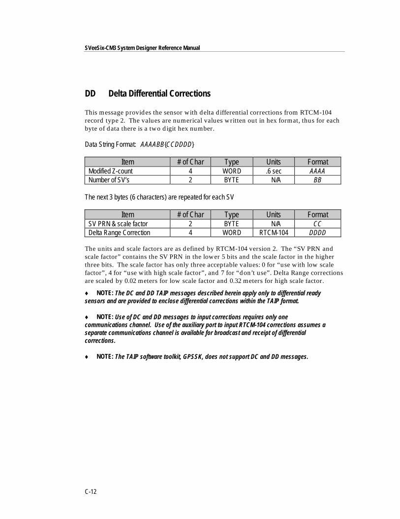
SVeeSix-CM3 System Designer Reference Manual
C-12
DD Delta Differential Corrections
This message provides the sensor with delta differential corrections from RTCM-104record type 2. The values are numerical values written out in hex format, thus for eachbyte of data there is a two digit hex number.
Data String Format: AAAABB{CCDDDD}
Item # of Char Type Units FormatModified Z-count 4 WORD .6 sec AAAANumber of SV’s 2 BYTE N/A BB
The next 3 bytes (6 characters) are repeated for each SV
Item # of Char Type Units FormatSV PRN & scale factor 2 BYTE N/A CCDelta Range Correction 4 WORD RTCM-104 DDDD
The units and scale factors are as defined by RTCM-104 version 2. The “SV PRN andscale factor” contains the SV PRN in the lower 5 bits and the scale factor in the higherthree bits. The scale factor has only three acceptable values: 0 for “use with low scalefactor”, 4 for “use with high scale factor”, and 7 for “don’t use”. Delta Range correctionsare scaled by 0.02 meters for low scale factor and 0.32 meters for high scale factor.
♦ NOTE: The DC and DD TAIP messages described herein apply only to differential readysensors and are provided to enclose differential corrections within the TAIP format.
♦ NOTE: Use of DC and DD messages to input corrections requires only onecommunications channel. Use of the auxiliary port to input RTCM-104 corrections assumes aseparate communications channel is available for broadcast and receipt of differentialcorrections.
♦ NOTE: The TAIP software toolkit, GPSSK, does not support DC and DD messages.
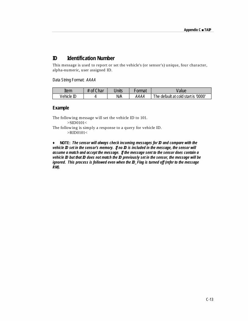
Appendix C ■ TAIP
C-13
ID Identification NumberThis message is used to report or set the vehicle's (or sensor's) unique, four character,alpha-numeric, user assigned ID.
Data String Format: AAAA
Item # of Char Units Format ValueVehicle ID 4 N/A AAAA The default at cold start is '0000'
Example
The following message will set the vehicle ID to 101.>SID0101<
The following is simply a response to a query for vehicle ID.>RID0101<
♦ NOTE: The sensor will always check incoming messages for ID and compare with thevehicle ID set in the sensor's memory. If no ID is included in the message, the sensor willassume a match and accept the message. If the message sent to the sensor does contain avehicle ID but that ID does not match the ID previously set in the sensor, the message will beignored. This process is followed even when the ID_Flag is turned off (refer to the messageRM).
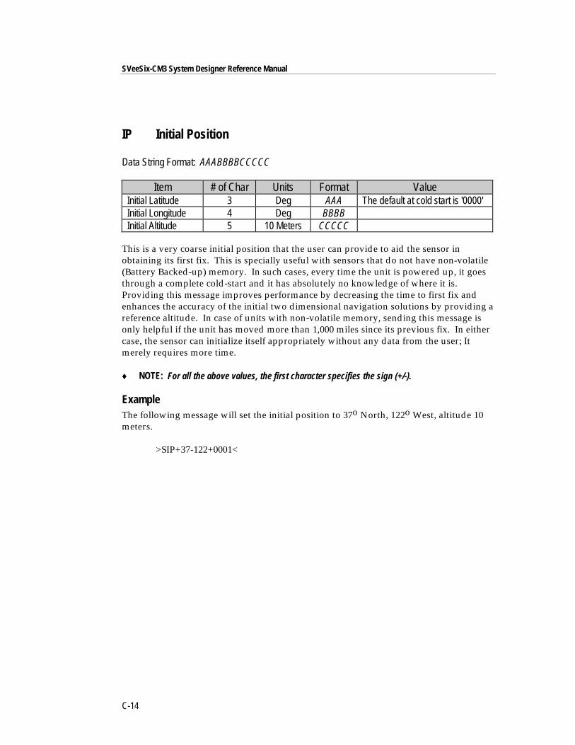
SVeeSix-CM3 System Designer Reference Manual
C-14
IP Initial Position
Data String Format: AAABBBBCCCCC
Item # of Char Units Format ValueInitial Latitude 3 Deg AAA The default at cold start is '0000'Initial Longitude 4 Deg BBBBInitial Altitude 5 10 Meters CCCCC
This is a very coarse initial position that the user can provide to aid the sensor inobtaining its first fix. This is specially useful with sensors that do not have non-volatile(Battery Backed-up) memory. In such cases, every time the unit is powered up, it goesthrough a complete cold-start and it has absolutely no knowledge of where it is.Providing this message improves performance by decreasing the time to first fix andenhances the accuracy of the initial two dimensional navigation solutions by providing areference altitude. In case of units with non-volatile memory, sending this message isonly helpful if the unit has moved more than 1,000 miles since its previous fix. In eithercase, the sensor can initialize itself appropriately without any data from the user; Itmerely requires more time.
♦ NOTE: For all the above values, the first character specifies the sign (+/-).
ExampleThe following message will set the initial position to 37o North, 122o West, altitude 10meters.
>SIP+37-122+0001<
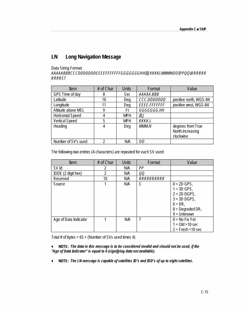
Appendix C ■ TAIP
C-15
LN Long Navigation Message
Data String Format:AAAAABBBCCCDDDDDDDEEEEFFFFFFFGGGGGGGHHIIIJKKKKLMMMNOO{PPQQ}RRRRRRRRRRST
Item # of Char Units Format ValueGPS Time of day 8 Sec AAAAA.BBBLatitude 10 Deg CCC.DDDDDDD positive north, WGS-84Longitude 11 Deg EEEE.FFFFFFF positive west, WGS-84Altitude above MSL 9 Ft GGGGGGG.HHHorizontal Speed 4 MPH III.JVertical Speed 5 MPH KKKK.LHeading 4 Deg MMM.N degrees from True
North increasingclockwise
Number of SV’s used 2 N/A OO
The following two entries (4 characters) are repeated for each SV used:
Item # of Char Units Format ValueSV Id 2 N/A PPIODE (2 digit hex) 2 N/A QQReserved 10 N/A RRRRRRRRRRSource 1 N/A S 0 = 2D GPS,
1 = 3D GPS,2 = 2D DGPS,3 = 3D DGPS,6 = DR,8 = Degraded DR,9 = Unknown
Age of Data Indicator 1 N/A T 0 = No Fix Yet1 = Old >10 sec2 = Fresh <10 sec
Total # of bytes = 65 + (Number of SVs used times 4)
♦ NOTE: The data in this message is to be considered invalid and should not be used, if the"Age of Data Indicator" is equal to 0 (signifying data not available).
♦ NOTE: The LN message is capable of satellites ID’s and IOD’s of up to eight satellites.
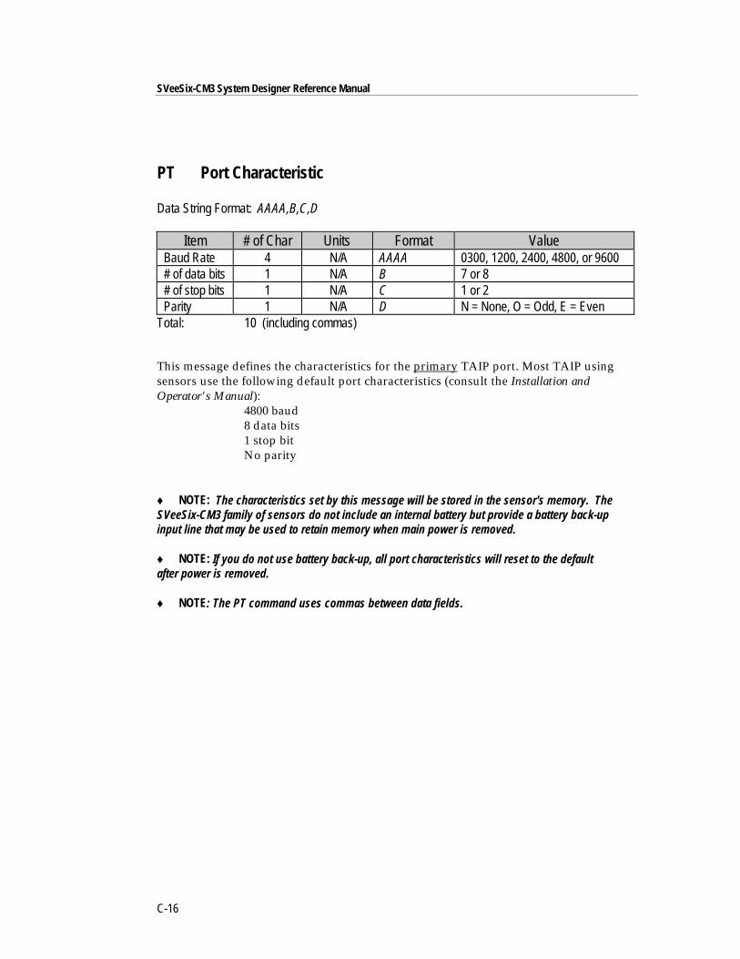
SVeeSix-CM3 System Designer Reference Manual
C-16
PT Port Characteristic
Data String Format: AAAA,B,C,D
Item # of Char Units Format ValueBaud Rate 4 N/A AAAA 0300, 1200, 2400, 4800, or 9600# of data bits 1 N/A B 7 or 8# of stop bits 1 N/A C 1 or 2Parity 1 N/A D N = None, O = Odd, E = Even
Total: 10 (including commas)
This message defines the characteristics for the primary TAIP port. Most TAIP usingsensors use the following default port characteristics (consult the Installation andOperator's Manual):
4800 baud8 data bits1 stop bitNo parity
♦ NOTE: The characteristics set by this message will be stored in the sensor's memory. TheSVeeSix-CM3 family of sensors do not include an internal battery but provide a battery back-upinput line that may be used to retain memory when main power is removed.
♦ NOTE: If you do not use battery back-up, all port characteristics will reset to the defaultafter power is removed.
♦ NOTE: The PT command uses commas between data fields.
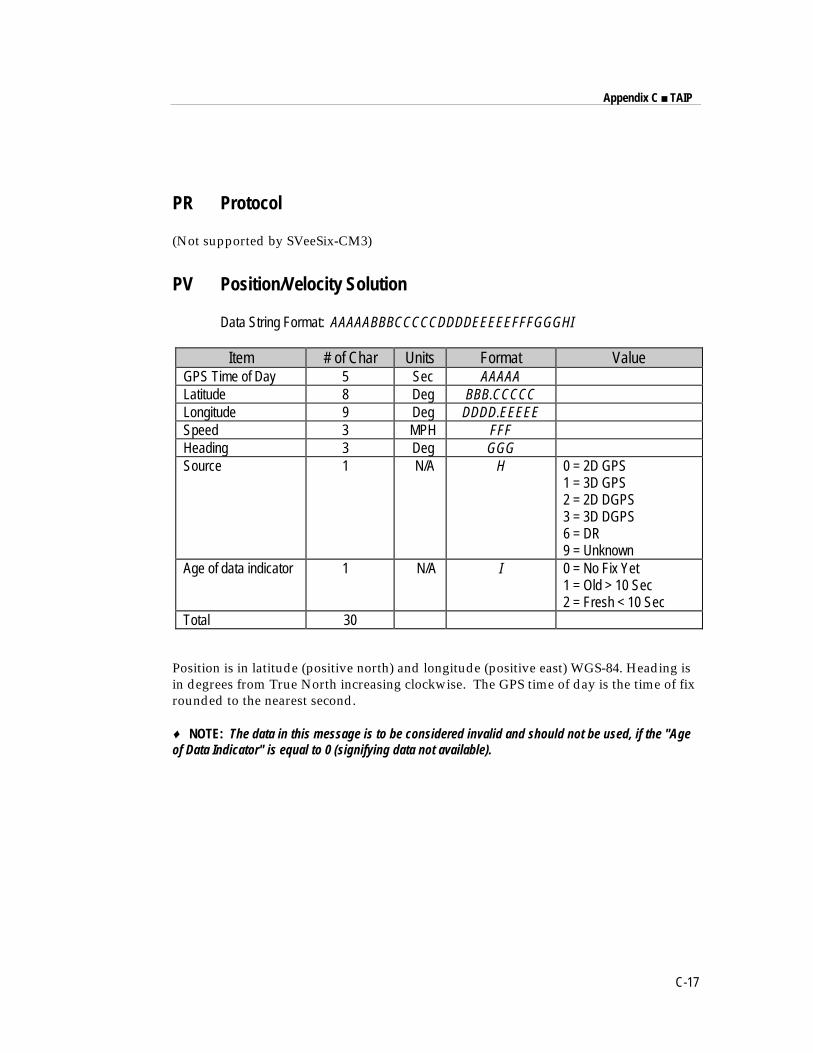
Appendix C ■ TAIP
C-17
PR Protocol
(Not supported by SVeeSix-CM3)
PV Position/Velocity Solution
Data String Format: AAAAABBBCCCCCDDDDEEEEEFFFGGGHI
Item # of Char Units Format ValueGPS Time of Day 5 Sec AAAAALatitude 8 Deg BBB.CCCCCLongitude 9 Deg DDDD.EEEEESpeed 3 MPH FFFHeading 3 Deg GGGSource 1 N/A H 0 = 2D GPS
1 = 3D GPS2 = 2D DGPS3 = 3D DGPS6 = DR9 = Unknown
Age of data indicator 1 N/A I 0 = No Fix Yet1 = Old > 10 Sec2 = Fresh < 10 Sec
Total 30
Position is in latitude (positive north) and longitude (positive east) WGS-84. Heading isin degrees from True North increasing clockwise. The GPS time of day is the time of fixrounded to the nearest second.
♦ NOTE: The data in this message is to be considered invalid and should not be used, if the "Ageof Data Indicator" is equal to 0 (signifying data not available).
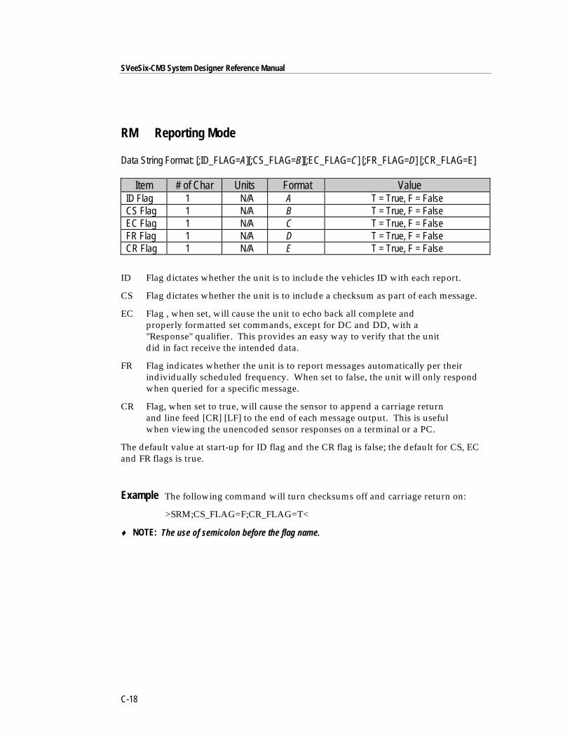
SVeeSix-CM3 System Designer Reference Manual
C-18
RM Reporting Mode
Data String Format: [;ID_FLAG=A][;CS_FLAG=B][;EC_FLAG=C] [;FR_FLAG=D] [;CR_FLAG=E]
Item # of Char Units Format ValueID Flag 1 N/A A T = True, F = FalseCS Flag 1 N/A B T = True, F = FalseEC Flag 1 N/A C T = True, F = FalseFR Flag 1 N/A D T = True, F = FalseCR Flag 1 N/A E T = True, F = False
ID Flag dictates whether the unit is to include the vehicles ID with each report.
CS Flag dictates whether the unit is to include a checksum as part of each message.
EC Flag , when set, will cause the unit to echo back all complete andproperly formatted set commands, except for DC and DD, with a"Response" qualifier. This provides an easy way to verify that the unitdid in fact receive the intended data.
FR Flag indicates whether the unit is to report messages automatically per theirindividually scheduled frequency. When set to false, the unit will only respondwhen queried for a specific message.
CR Flag, when set to true, will cause the sensor to append a carriage returnand line feed [CR] [LF] to the end of each message output. This is usefulwhen viewing the unencoded sensor responses on a terminal or a PC.
The default value at start-up for ID flag and the CR flag is false; the default for CS, ECand FR flags is true.
Example The following command will turn checksums off and carriage return on:
>SRM;CS_FLAG=F;CR_FLAG=T<
♦ NOTE: The use of semicolon before the flag name.
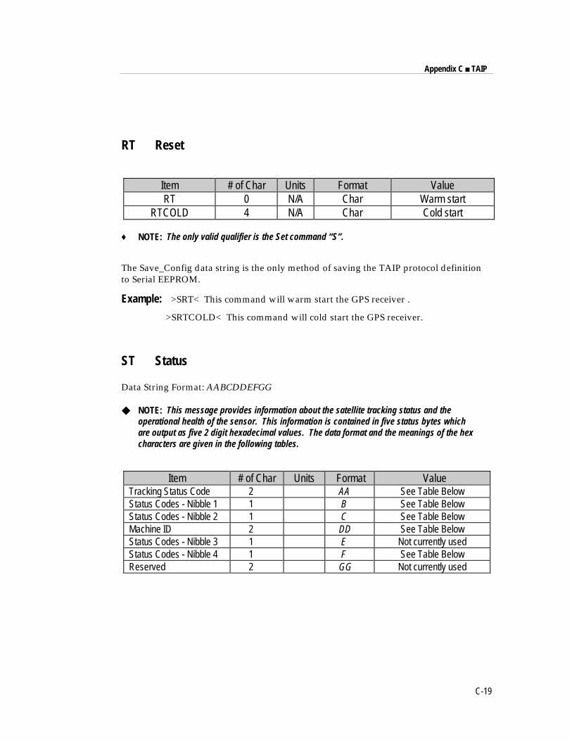
Appendix C ■ TAIP
C-19
RT Reset
Item # of Char Units Format ValueRT 0 N/A Char Warm start
RTCOLD 4 N/A Char Cold start
♦ NOTE: The only valid qualifier is the Set command “S”.
The Save_Config data string is the only method of saving the TAIP protocol definitionto Serial EEPROM.
Example: >SRT< This command will warm start the GPS receiver .
>SRTCOLD< This command will cold start the GPS receiver.
ST Status
Data String Format: AABCDDEFGG
◆ NOTE: This message provides information about the satellite tracking status and theoperational health of the sensor. This information is contained in five status bytes whichare output as five 2 digit hexadecimal values. The data format and the meanings of the hexcharacters are given in the following tables.
Item # of Char Units Format ValueTracking Status Code 2 AA See Table BelowStatus Codes - Nibble 1 1 B See Table BelowStatus Codes - Nibble 2 1 C See Table BelowMachine ID 2 DD See Table BelowStatus Codes - Nibble 3 1 E Not currently usedStatus Codes - Nibble 4 1 F See Table BelowReserved 2 GG Not currently used
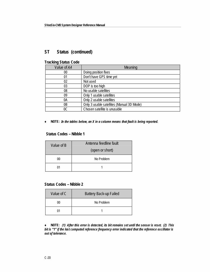
SVeeSix-CM3 System Designer Reference Manual
C-20
ST Status (continued)
Tracking Status CodeValue of AA Meaning
00 Doing position fixes 01 Don’t have GPS time yet 02 Not used 03 DOP is too high 08 No usable satellites 09 Only 1 usable satellites 0A Only 2 usable satellites 0B Only 3 usable satellites (Manual 3D Mode) 0C Chosen satellite is unusable
♦ NOTE: In the tables below, an X in a column means that fault is being reported.
Status Codes – Nibble 1
Value of B Antenna feedline fault
(open or short)
00 No Problem
01 1
Status Codes – Nibble 2
Value of C Battery Back-up Failed
00 No Problem
01 1
♦ NOTE: (1) After this error is detected, its bit remains set until the sensor is reset. (2) Thisbit is “1” if the last computed reference frequency error indicated that the reference oscillator isout of tolerance.

Appendix C ■ TAIP
C-21
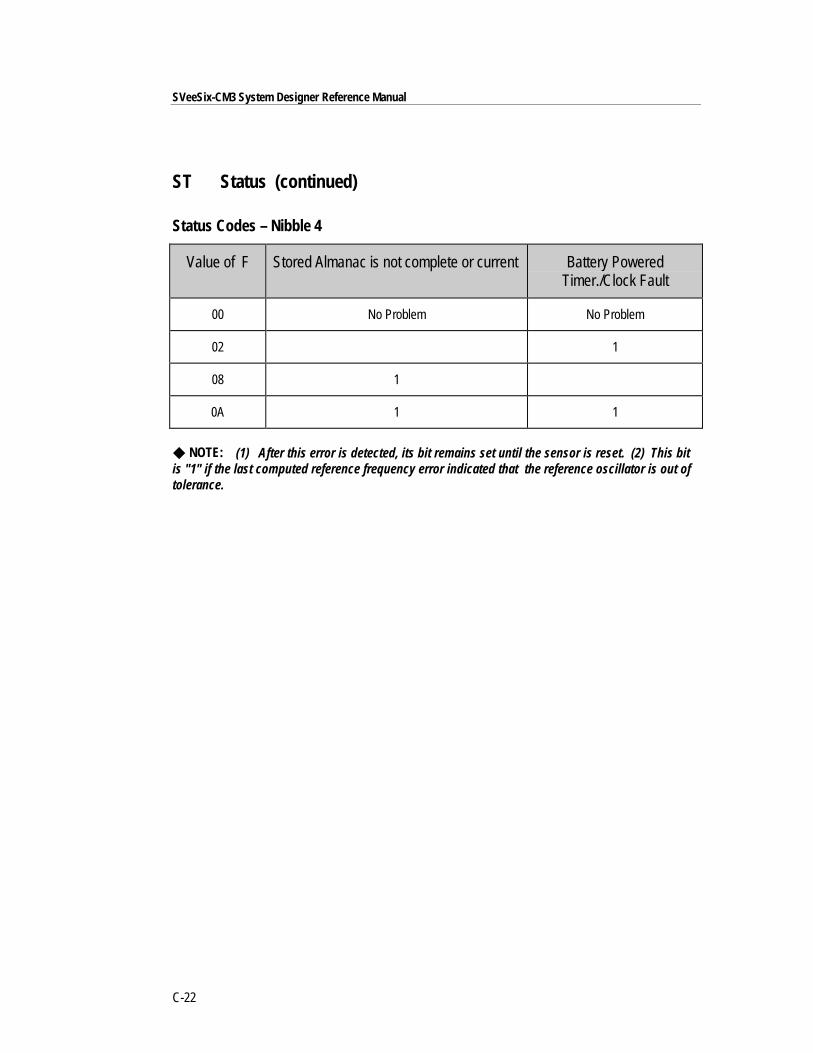
SVeeSix-CM3 System Designer Reference Manual
C-22
ST Status (continued)
Status Codes – Nibble 4
Value of F Stored Almanac is not complete or current Battery PoweredTimer./Clock Fault
00 No Problem No Problem
02 1
08 1
0A 1 1
◆ NOTE: (1) After this error is detected, its bit remains set until the sensor is reset. (2) This bitis "1" if the last computed reference frequency error indicated that the reference oscillator is out oftolerance.
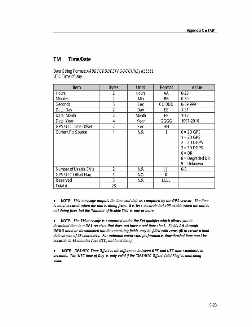
Appendix C ■ TAIP
C-23
TM Time/Date
Data String Format: AABBCCDDDEEFFGGGGHHIJJKLLLLLUTC Time of Day
Item Bytes Units Format ValueHours 2 Hours AA 0-23Minutes 2 Min BB 0-59Seconds 5 Sec CC.DDD 0-59.999Date; Day 2 Day EE 1-31Date; Month 2 Month FF 1-12Date; Year 4 Year GGGG 1997-2016GPS/UTC Time Offset 2 Sec HHCurrent Fix Source 1 N/A I 0 = 2D GPS
1 = 3D GPS2 = 2D DGPS3 = 3D DGPS6 = DR8 = Degraded DR9 = Unknown
Number of Usable SV’s 2 N/A JJ 0-8GPS/UTC Offset Flag 1 N/A KReserved 5 N/A LLLLTotal # 28
♦ NOTE: This message outputs the time and date as computed by the GPS sensor. The timeis most accurate when the unit is doing fixes. It is less accurate but still usable when the unit isnot doing fixes but the 'Number of Usable SVs' is one or more.
♦ NOTE: The TM message is supported under the Set qualifier which allows you todownload time to a GPS receiver that does not have a real-time clock. Fields AA throughGGGG must be downloaded but the remaining fields may be filled with zeros (0) to create a totaldata stream of 28 characters. For optimum warm-start performance, downloaded time must beaccurate to ±5 minutes (use UTC, not local time).
♦ NOTE: GPS/UTC Time Offset is the difference between GPS and UTC time standards inseconds. The 'UTC time of Day' is only valid if the 'GPS/UTC Offset Valid Flag' is indicatingvalid.
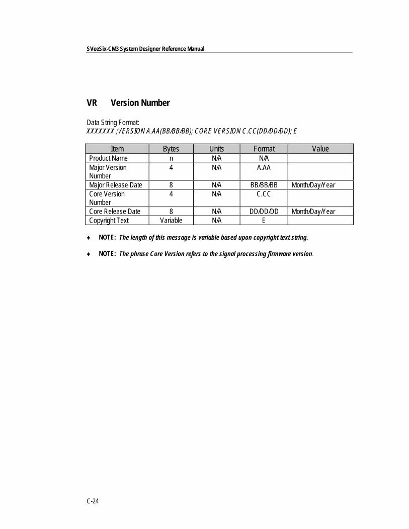
SVeeSix-CM3 System Designer Reference Manual
C-24
VR Version Number
Data String Format:XXXXXXX ;VERSION A.AA(BB/BB/BB); CORE VERSION C.CC(DD/DD/DD); E
Item Bytes Units Format ValueProduct Name n N/A N/AMajor VersionNumber
4 N/A A.AA
Major Release Date 8 N/A BB/BB/BB Month/Day/YearCore VersionNumber
4 N/A C.CC
Core Release Date 8 N/A DD/DD/DD Month/Day/YearCopyright Text Variable N/A E
♦ NOTE: The length of this message is variable based upon copyright text string.
♦ NOTE: The phrase Core Version refers to the signal processing firmware version.
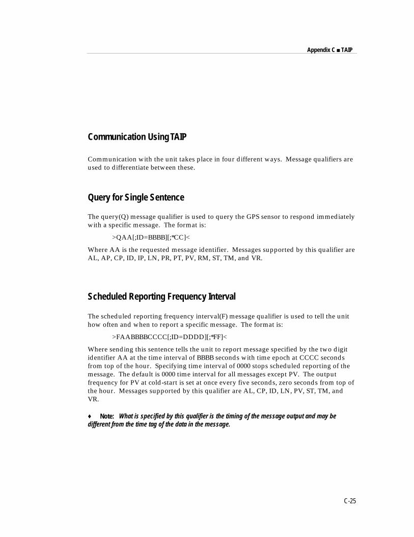
Appendix C ■ TAIP
C-25
Communication Using TAIP
Communication with the unit takes place in four different ways. Message qualifiers areused to differentiate between these.
Query for Single Sentence
The query(Q) message qualifier is used to query the GPS sensor to respond immediatelywith a specific message. The format is:
>QAA[;ID=BBBB][;*CC]<
Where AA is the requested message identifier. Messages supported by this qualifier areAL, AP, CP, ID, IP, LN, PR, PT, PV, RM, ST, TM, and VR.
Scheduled Reporting Frequency Interval
The scheduled reporting frequency interval(F) message qualifier is used to tell the unithow often and when to report a specific message. The format is:
>FAABBBBCCCC[;ID=DDDD][;*FF]<
Where sending this sentence tells the unit to report message specified by the two digitidentifier AA at the time interval of BBBB seconds with time epoch at CCCC secondsfrom top of the hour. Specifying time interval of 0000 stops scheduled reporting of themessage. The default is 0000 time interval for all messages except PV. The outputfrequency for PV at cold-start is set at once every five seconds, zero seconds from top ofthe hour. Messages supported by this qualifier are AL, CP, ID, LN, PV, ST, TM, andVR.
♦ Note: What is specified by this qualifier is the timing of the message output and may bedifferent from the time tag of the data in the message.
SVeeSix-CM3 System Designer Reference Manual
C-26
Scheduled Reporting Distance IntervalThe "D" message qualifier allows you to specify a minimum distance traveled as well asa minimum and maximum time interval for the next report. Units that are stationed at afixed location can be programmed to report only when the unit moves "off station" orafter a certain elapsed time since last report, but no more often than the specifiedminimum time interval. All messages using the F qualifier can use the D qualifier.
The message format used with the D qualifier is shown below:>DAABBBBCCCCEEEEFFFF[;ID=GGGG][;*HH]<ID Meaning > start of message delimiterD the Distance message qualifierAA message to report (i.e. PV means Position Velocity message)BBBB minimum time (seconds) interval between reports (Tinterval)CCCC report epoch (number of seconds from top of the hour)EEEE delta distance (meters) from last reported distanceFFFF maximum time (seconds) interval between reports (Tmax)GGGG optional vehicle identification number (user selected)HH optional checksum < End of message delimiter
♦ Note that if BBBB = 0, then the message output is disabled. If FFFF = 0, maximum timefeature is disabled (the unit will only report if current position is greater than or equal to thedelta distance specified in EEEE).
♦ For example, when the message: >DPV0030000505000900;ID=0105< is sent to the GPSreceiver, it specifies that vehicle number 105 (GGGG = 0105) is to report the Position Velocitymessage (AA = PV) whenever its current position differs from the previously reported positionby at least 500 meters (EEEE = 0500), but no more often than every 30 seconds (BBBB = 0030)or less often than every 15 minutes (FFFF = 0900 seconds). The minimum and maximum time-out reports are to be issued with a 5 second offset (CCCC = 0005) from the top of the hour. Theoptional checksum was not used in this example. The square brackets, [. . .], shown in theformat description above are used to indicate optional data. The brackets themselves are neverincluded in the actual TAIP message string.
Appendix C ■ TAIP
C-27
The Response to query or scheduled reportThe response(R) qualifier carry various types of data between the unit and the userequipment. The format is:
>RAA[{B}][;ID=CCCC][;*DD]<Where AA is the two character message identifier and {B} specifies the data stringwithin the message. For the format of {B}, please refer to the message definitions in theprevious section. Messages supported by the response qualifier are AL, AP, CP, ID, IP,LN, PR, PT, PV, RM, ST, TM, and VR.
The Set QualifierThe set (S) qualifier enables the user equipment to initialize/set-up various types ofdata in the GPS unit. The format is:
>SAA[{B}][;ID=CCCC][;*DD]<
Where AA is the two character message identifier and {B} specifies the data stringwithin the message. For the format of {B}, please refer to the message definitions in theprevious section. Note that all the messages have very specific formats and are lengthdependent. Messages normally supported by the set qualifier are AL, AP, CP, DC, DD,ID, IP, PR, PT, PV, RM, RT and TM.The set qualifier may be used with the AL, CP, or PV message to set more precise initialposition data into the GPS sensor than can be set with the IP message.
SVeeSix-CM3 System Designer Reference Manual
C-28
Sample Communication SessionThe following is a sample communication session to illustrate how message qualifiersare used. Query the sensor for version number for the TAIP firmware:
>QVR<
The sensor responds with a message in the following form:
>RVR SVEESIX-CM3 D;VERSION 4.06 (5/18/94); CORE VERSION 1.17(11/20/93); COPYRIGHT (C) 1991, 1992, 1993, 1994 TRIMBLENAVIGATION,LTD.;*38<
Notice that the sensor identified its product name, firmware version number, core signalprocessing version number, and release dates, then included the checksum for themessage (the default for the CS Flag is TRUE). Also notice that the sensor did respondto our query even though we did not send a checksum.Query the sensor for its ID number:
>QID<
The sensor will respond (assuming factory default settings):
>RID0000;*70<
Set the ID to match the number for a vehicle in your fleet and then tell the sensor toinclude the Vehicle ID in its responses:
>SID1234<
>SRM;ID_FLAG=T<
Most Placer family sensors are set by default to report the PV message once every 5seconds. To schedule the PV message from vehicle 1234 to respond once every 10seconds, starting at 5 seconds after the top of the hour, use the following command:
>FPV00100005;ID=1234<
The sensor will check the ID included in the message for a match with its own and thenreschedule the PV message. At the next scheduled time, the sensor will respond with:
>RPV15714+3739438-1220384601512612;ID=1234;*7F<
Notice that the time given in the message is the time of the last GPS fix (04:21:54 GPS),not necessarily the time of the message response. If the time of last fix is 10 or moreseconds old, the age flag will be set to '1'.
Appendix DGPSSK User's Guide (TAIP)
The TAIP Tool Kit, known as GPSSK is a software package available from TrimbleNavigation to assist users of the Trimble ASCII Interface Protocol (TAIP). GPSSKsupports all Trimble sensors that use TAIP.
GPSSK can be used to setup, diagnose, and monitor your sensor and provides thefollowing capabilities:
❒ Program the GPS sensor for automatic message reporting and verify the successof the programming.
❒ Quickly program Vehicle ID numbers into a fleet of sensors.
❒ Log the GPSSK session with the GPS sensor to disk and replay the data.
❒ On-screen plotting of GPS positions from the sensor.
❒ Poll for and view combinations of TAIP messages.
❒ Set different polling intervals for each message type.
❒ Conduct an interactive terminal session with the GPS sensor.
♦ NOTE: The information about GPSSK in this document is presented as a general overview. TheGPSSK distribution diskette includes a READ.ME file that details the most current information aboutGPSSK functions and on loading and using GPSSK.
The GPSSK program does not support the TAIP messages DC and DD. These messages are usedto input differential corrections to the receiver and are defined as special "TAIP format" versions ofRTCM SC-104 Type 1 and Type 2 messages.
The GPSSK program requires well over 500K RAM. It may not run in a DOS window, and mayrequire removal of TSRs.
D-2
SVeeSix-CM3 System Designer Reference Manual
The GPSSK Files
GPSSK is included on the on 3.5 inch DOS formatted GPS Toolkit diskette. The diskettecontains the following GPSSK related files:
❒ GPSSK.EXE The executable GPSSK program
❒ GPSSK.HLP The on-line, context-sensitive help file
❒ READ.ME Current information about GPSSK
❒ TAIP.C Sample source code for encoding and decoding TAIP
TAIP.C Source FileThe sample source code for encoding and decoding TAIP messages is provided as aguide for the system integrator who is developing a communications controller thathandles TAIP. There is no warranty of any kind on this software. Use it at your ownrisk.
The distribution diskette is not copy protected. Before using GPSSK or installing onyour hard disk, make a working copy and put the original diskette in a safe place.During normal use, GPSSK will save configuration information to the diskette or currentdirectory. Storing the original diskette away will allow you to restore the originalconfiguration should you encounter problems.
Copy the files "GPSSK.EXE" and "GPSSK.HLP" to a hard disk directory.
D-3
Appendix D ■ GPSSK User's Guide
The GPSSK Files (continued)
GPSSK Start-upAt the DOS prompt in the directory containing GPSSK, enter the command:
GPSSK
When the program is finished loading into memory, the GPSSK title page will bedisplayed. The program will then wait for 10 seconds to begin normal execution; youmay bypass the 10 second wait by pressing any key after the title page is displayed.
The function key menu will be displayed on the bottom of the screen. GPSSK isstructured as a hierarchy of menus. The function keys control access to the menus.
To terminate GPSSK, simply back out of the menu structure by pressing <F9> untilGPSSK prompts you to confirm your desire to exit the program.
At start-up, GPSSK will attempt to initialize itself by querying the sensor for some basicinformation. If you wish to abort the sensor initialization process and use GPSSK toreplay stored data, enter <Ctrl>X (hold down the control key and press x). Ifinitialization has been aborted, you must restart GPSSK when you wish to communicatewith the sensor.
On-line HelpOnce GPSSK is running, on-line help is available to assist in performing all the GPSSKoperations. Help is context sensitive and will display information regarding the currentdisplay or menu. A brief overview of GPSSK is available in the main menu's helpscreen.
There are several command line options available. For help with command line options,run GPSSK with the /HELP argument:
GPSSK /HELP
The help available on the GPSSK main menu will explain menu operation and the menuhierarchy.
D-4
SVeeSix-CM3 System Designer Reference Manual
Connecting the GPS Sensor
Consult the Installation and Operator's Manual for information on installation, powerrequirements and cables specific to your Placer family sensor.
Connect the serial port of the sensor to the computer's COM1 or COM2 port. Thedefault serial port settings for GPSSK are:
❒ 4800 baud
❒ 8 data bits
❒ 1 stop bit
❒ no parity
These default settings match the default settings for most Placer family sensors. Consultthe Installation and Operator's Manual for the actual default settings and type of serialport on your sensor.
If the sensor is connected to COM2, start GPSSK by entering the command:
GPSSK /2
◆ NOTE: A null modem may be required when connecting the sensor to a personal computer. Theserial port on your computer is a DTE port (data terminal equipment) designed to connect to a DCEport (data communications equipment). If your sensor's serial port is DTE, you must use a nullmodem adapter.
Appendix ENMEA 0183
This appendix provides a brief overview of the NMEA protocol and describes both thestandard and optional messages offered by the SVeeSix.
NMEA 0183 is an interface protocol created by the National Marine ElectronicsAssociation. The latest release of NMEA 0183 is Version 2.00. This protocol wasoriginally established to allow marine navigation equipment to share information.NMEA 0183 is a simple, yet comprehensive ASCII protocol which defines both thecommunication interface and the data format. Since it is a well established industrystandard, NMEA 0183 has also gained popularity for use in applications other thanmarine electronics.
For those applications requiring output only from the GPS receiver, NMEA 0183 is apopular choice since, in many cases, an NMEA 0183 software application code alreadyexists. The SVeeSix receiver is available with firmware that supports a subset of theNMEA 0183 messages: GGA and VTG. For a nominal fee, Trimble can offer customfirmware with a different selection of messages to meet your application requirements.
For a complete copy of the NMEA 0183 standard, contact:
National Marine Electronics AssociationExecutive DirectorPO Box 50040Mobile, Alabama 36605
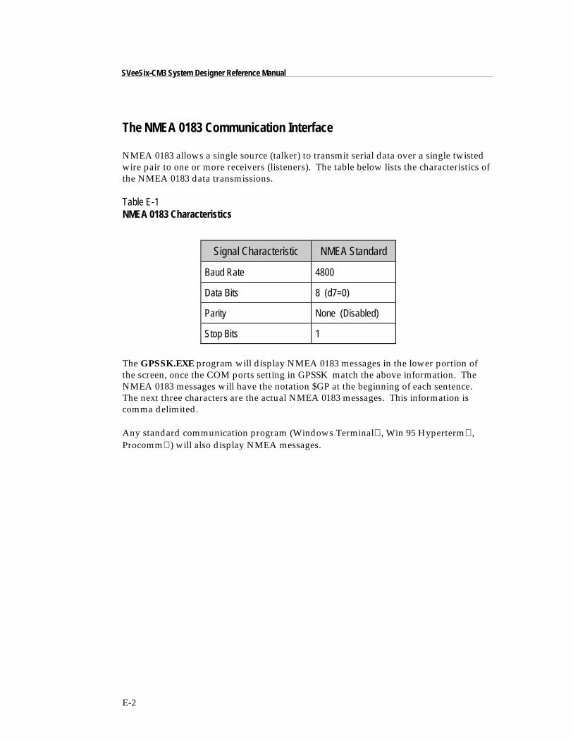
E-2
SVeeSix-CM3 System Designer Reference Manual
The NMEA 0183 Communication Interface
NMEA 0183 allows a single source (talker) to transmit serial data over a single twistedwire pair to one or more receivers (listeners). The table below lists the characteristics ofthe NMEA 0183 data transmissions.
Table E-1NMEA 0183 Characteristics
Signal Characteristic NMEA Standard
Baud Rate 4800
Data Bits 8 (d7=0)
Parity None (Disabled)
Stop Bits 1
The GPSSK.EXE program will display NMEA 0183 messages in the lower portion ofthe screen, once the COM ports setting in GPSSK match the above information. TheNMEA 0183 messages will have the notation $GP at the beginning of each sentence.The next three characters are the actual NMEA 0183 messages. This information iscomma delimited.
Any standard communication program (Windows Terminal, Win 95 Hyperterm,Procomm) will also display NMEA messages.
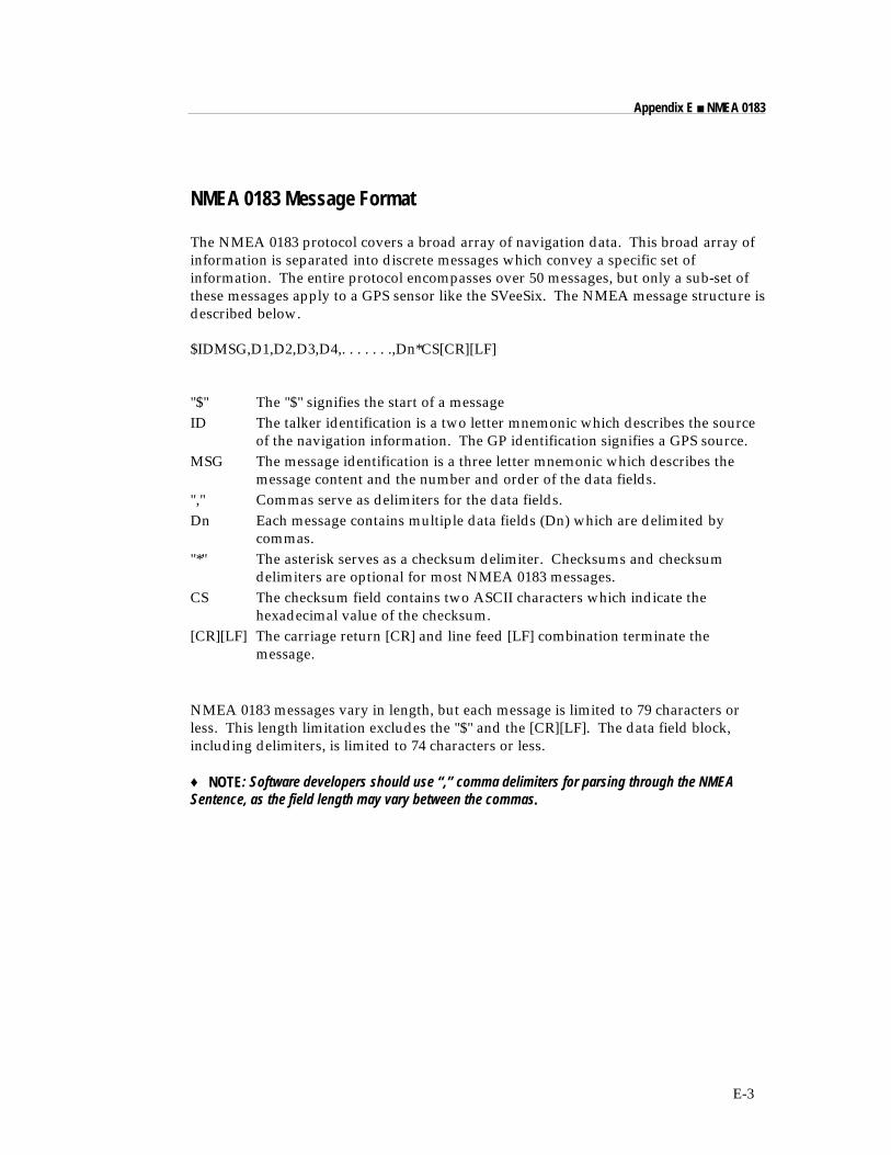
E-3
Appendix E ■ NMEA 0183
NMEA 0183 Message Format
The NMEA 0183 protocol covers a broad array of navigation data. This broad array ofinformation is separated into discrete messages which convey a specific set ofinformation. The entire protocol encompasses over 50 messages, but only a sub-set ofthese messages apply to a GPS sensor like the SVeeSix. The NMEA message structure isdescribed below.
$IDMSG,D1,D2,D3,D4,. . . . . . .,Dn*CS[CR][LF]
"$" The "$" signifies the start of a messageID The talker identification is a two letter mnemonic which describes the source
of the navigation information. The GP identification signifies a GPS source.MSG The message identification is a three letter mnemonic which describes the
message content and the number and order of the data fields."," Commas serve as delimiters for the data fields.Dn Each message contains multiple data fields (Dn) which are delimited by
commas."*" The asterisk serves as a checksum delimiter. Checksums and checksum
delimiters are optional for most NMEA 0183 messages.CS The checksum field contains two ASCII characters which indicate the
hexadecimal value of the checksum.[CR][LF] The carriage return [CR] and line feed [LF] combination terminate the
message.
NMEA 0183 messages vary in length, but each message is limited to 79 characters orless. This length limitation excludes the "$" and the [CR][LF]. The data field block,including delimiters, is limited to 74 characters or less.
♦ NOTE: Software developers should use “,” comma delimiters for parsing through the NMEASentence, as the field length may vary between the commas.
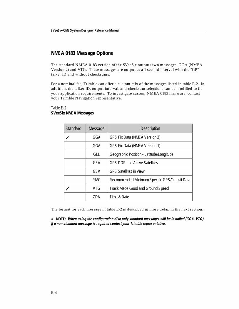
E-4
SVeeSix-CM3 System Designer Reference Manual
NMEA 0183 Message Options
The standard NMEA 0183 version of the SVeeSix outputs two messages: GGA (NMEAVersion 2) and VTG. These messages are output at a 1 second interval with the "GP"talker ID and without checksums.
For a nominal fee, Trimble can offer a custom mix of the messages listed in table E-2. Inaddition, the talker ID, output interval, and checksum selections can be modified to fityour application requirements. To investigate custom NMEA 0183 firmware, contactyour Trimble Navigation representative.
Table E-2SVeeSix NMEA Messages
Standard Message Description
✓ GGA GPS Fix Data (NMEA Version 2)
GGA GPS Fix Data (NMEA Version 1)
GLL Geographic Position - Latitude/Longitude
GSA GPS DOP and Active Satellites
GSV GPS Satellites in View
RMC Recommended Minimum Specific GPS/Transit Data
✓ VTG Track Made Good and Ground Speed
ZDA Time & Date
The format for each message in table E-2 is described in more detail in the next section.
♦ NOTE: When using the configuration disk only standard messages will be installed (GGA, VTG).If a non-standard message is required contact your Trimble representative.
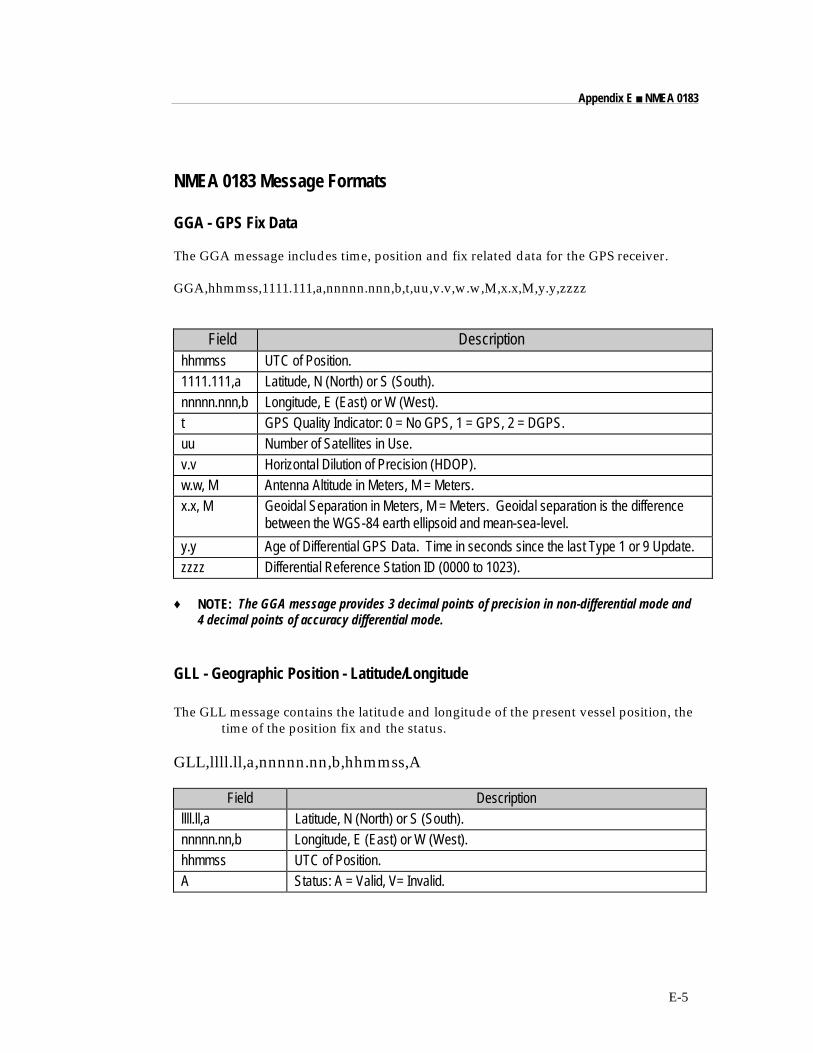
E-5
Appendix E ■ NMEA 0183
NMEA 0183 Message Formats
GGA - GPS Fix Data
The GGA message includes time, position and fix related data for the GPS receiver.
GGA,hhmmss,1111.111,a,nnnnn.nnn,b,t,uu,v.v,w.w,M,x.x,M,y.y,zzzz
Field Descriptionhhmmss UTC of Position.1111.111,a Latitude, N (North) or S (South).nnnnn.nnn,b Longitude, E (East) or W (West).t GPS Quality Indicator: 0 = No GPS, 1 = GPS, 2 = DGPS.uu Number of Satellites in Use.v.v Horizontal Dilution of Precision (HDOP).w.w, M Antenna Altitude in Meters, M = Meters.x.x, M Geoidal Separation in Meters, M = Meters. Geoidal separation is the difference
between the WGS-84 earth ellipsoid and mean-sea-level.
y.y Age of Differential GPS Data. Time in seconds since the last Type 1 or 9 Update.zzzz Differential Reference Station ID (0000 to 1023).
♦ NOTE: The GGA message provides 3 decimal points of precision in non-differential mode and4 decimal points of accuracy differential mode.
GLL - Geographic Position - Latitude/Longitude
The GLL message contains the latitude and longitude of the present vessel position, thetime of the position fix and the status.
GLL,llll.ll,a,nnnnn.nn,b,hhmmss,A
Field Descriptionllll.ll,a Latitude, N (North) or S (South).nnnnn.nn,b Longitude, E (East) or W (West).hhmmss UTC of Position.A Status: A = Valid, V= Invalid.
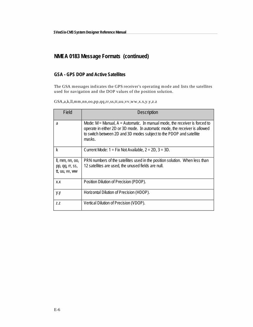
E-6
SVeeSix-CM3 System Designer Reference Manual
NMEA 0183 Message Formats (continued)
GSA - GPS DOP and Active Satellites
The GSA messages indicates the GPS receiver's operating mode and lists the satellitesused for navigation and the DOP values of the position solution.
GSA,a,k,ll,mm,nn,oo,pp,qq,rr,ss,tt,uu,vv,ww,x.x,y.y,z.z
Field Description
a Mode: M = Manual, A = Automatic. In manual mode, the receiver is forced tooperate in either 2D or 3D mode. In automatic mode, the receiver is allowedto switch between 2D and 3D modes subject to the PDOP and satellitemasks.
k Current Mode: 1 = Fix Not Available, 2 = 2D, 3 = 3D.
ll, mm, nn, oo,pp, qq, rr, ss,tt, uu, vv, ww
PRN numbers of the satellites used in the position solution. When less than12 satellites are used, the unused fields are null.
x.x Position Dilution of Precision (PDOP).
y.y Horizontal Dilution of Precision (HDOP).
z.z Vertical Dilution of Precision (VDOP).
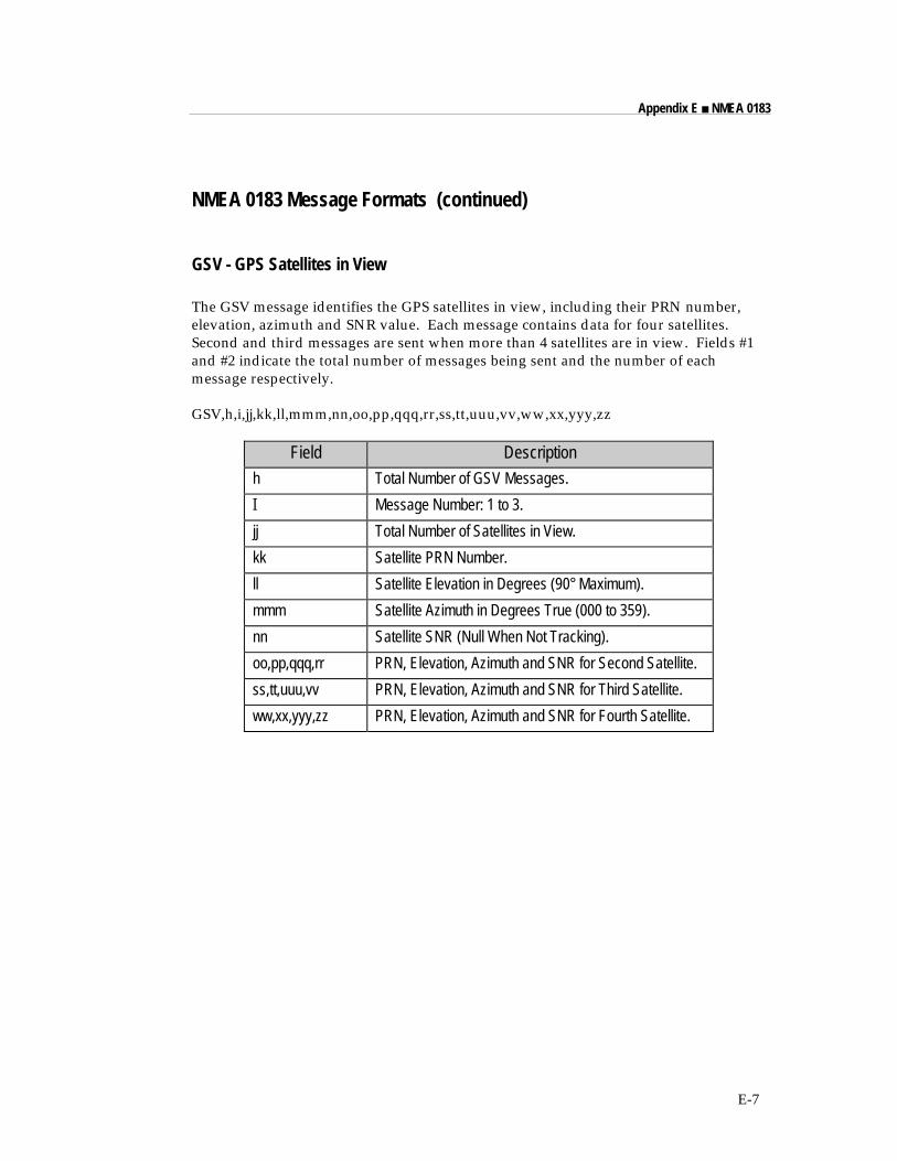
E-7
Appendix E ■ NMEA 0183
NMEA 0183 Message Formats (continued)
GSV - GPS Satellites in View
The GSV message identifies the GPS satellites in view, including their PRN number,elevation, azimuth and SNR value. Each message contains data for four satellites.Second and third messages are sent when more than 4 satellites are in view. Fields #1and #2 indicate the total number of messages being sent and the number of eachmessage respectively.
GSV,h,i,jj,kk,ll,mmm,nn,oo,pp,qqq,rr,ss,tt,uuu,vv,ww,xx,yyy,zz
Field Descriptionh Total Number of GSV Messages.
I Message Number: 1 to 3.
jj Total Number of Satellites in View.
kk Satellite PRN Number.
ll Satellite Elevation in Degrees (90° Maximum).
mmm Satellite Azimuth in Degrees True (000 to 359).
nn Satellite SNR (Null When Not Tracking).
oo,pp,qqq,rr PRN, Elevation, Azimuth and SNR for Second Satellite.
ss,tt,uuu,vv PRN, Elevation, Azimuth and SNR for Third Satellite.
ww,xx,yyy,zz PRN, Elevation, Azimuth and SNR for Fourth Satellite.
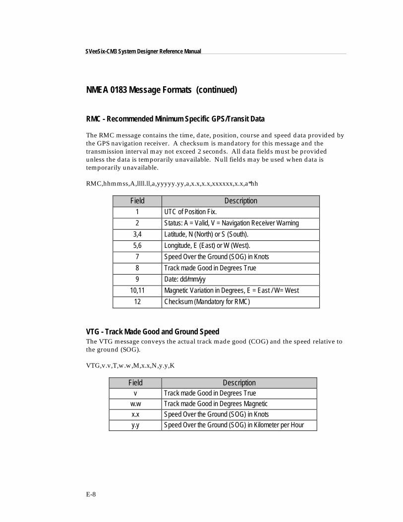
E-8
SVeeSix-CM3 System Designer Reference Manual
NMEA 0183 Message Formats (continued)
RMC - Recommended Minimum Specific GPS/Transit Data
The RMC message contains the time, date, position, course and speed data provided bythe GPS navigation receiver. A checksum is mandatory for this message and thetransmission interval may not exceed 2 seconds. All data fields must be providedunless the data is temporarily unavailable. Null fields may be used when data istemporarily unavailable.
RMC,hhmmss,A,llll.ll,a,yyyyy.yy,a,x.x,x.x,xxxxxx,x.x,a*hh
Field Description1 UTC of Position Fix.
2 Status: A = Valid, V = Navigation Receiver Warning
3,4 Latitude, N (North) or S (South).
5,6 Longitude, E (East) or W (West).
7 Speed Over the Ground (SOG) in Knots
8 Track made Good in Degrees True
9 Date: dd/mm/yy
10,11 Magnetic Variation in Degrees, E = East / W= West
12 Checksum (Mandatory for RMC)
VTG - Track Made Good and Ground SpeedThe VTG message conveys the actual track made good (COG) and the speed relative tothe ground (SOG).
VTG,v.v,T,w.w,M,x.x,N,y.y,K
Field Descriptionv Track made Good in Degrees True
w.w Track made Good in Degrees Magnetic
x.x Speed Over the Ground (SOG) in Knots
y.y Speed Over the Ground (SOG) in Kilometer per Hour
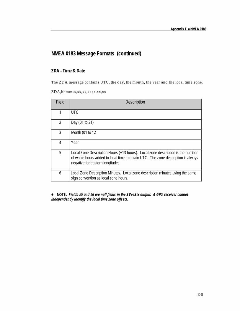
E-9
Appendix E ■ NMEA 0183
NMEA 0183 Message Formats (continued)
ZDA - Time & Date
The ZDA message contains UTC, the day, the month, the year and the local time zone.
ZDA,hhmmss,xx,xx,xxxx,xx,xx
Field Description
1 UTC
2 Day (01 to 31)
3 Month (01 to 12
4 Year
5 Local Zone Description Hours (±13 hours). Local zone description is the numberof whole hours added to local time to obtain UTC. The zone description is alwaysnegative for eastern longitudes.
6 Local Zone Description Minutes. Local zone description minutes using the samesign convention as local zone hours.
♦ NOTE: Fields #5 and #6 are null fields in the SVeeSix output. A GPS receiver cannotindependently identify the local time zone offsets.


Appendix FSpecifications and Mechanical Drawings
The SVeeSix-CM3 module is designed for embedded industrial computing or control,mobile computing or data collection, precision timing, and vehicle tracking applications.The SVeeSix-CM3 offers exceptional performance in even the harshest operatingenvironments. This appendix includes the system specifications and mechanicaldrawings for the SVeeSix-CM3 receiver module and the miniature magnetic mount GPSantenna.

F-2
SVeeSix-CM3 System Designer Reference Manual
GPS Receiver
GeneralL1 frequency (1575.42 MHz), C/A code (Standard Positioning Service), 6-channel,continuous tracking, differential ready
Position Accuracy2 to 5 meters (1 Sigma) steady state conditions (no Selective Availability) withdifferential15 meters (SEP) steady state conditions without differential
Velocity Accuracy0.1 m/sec. (1 Sigma) steady state conditions
Time AccuracyUTC to nearest microsecond with 1 pulse per second available
DatumWGS-84 (220 options plus one custom slot)
Acquisition RateMomentary signal interruption: 2 seconds typicalMomentary power interruption: less than 30 seconds with RAM battery backupCold start: 2 to 5 minutes
DynamicsVelocity: 515 m/sec. (maximum)Acceleration: 4g (39.2 m/sec.2)Jerk: 20 m/sec.3
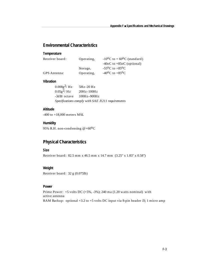
F-3
Appendix F ■ Specifications and Mechanical Drawings
Environmental Characteristics
TemperatureReceiver board: Operating, -10oC to + 60oC (standard)
-40oC to +85oC (optional)Storage, -55oC to +85oC
GPS Antenna: Operating, -40oC to +85oC
Vibration0.008g2/Hz 5Hz–20 Hz0.05g2/Hz 20Hz–100Hz-3dB/octave 100Hz–900HzSpecifications comply with SAE J1211 requirements
Altitude-400 to +18,000 meters MSL
Humidity95% R.H. non-condensing @ +60oC
Physical Characteristics
SizeReceiver board: 82.5 mm x 46.5 mm x 14.7 mm (3.25" x 1.83" x 0.58")
WeightReceiver board: 32 g (0.075lb)
PowerPrime Power: +5 volts DC (+5%, -3%); 240 ma (1.20 watts nominal) withactive antennaRAM Backup: optional +3.2 to +5 volts DC input via 8-pin header J3; 1 micro amp
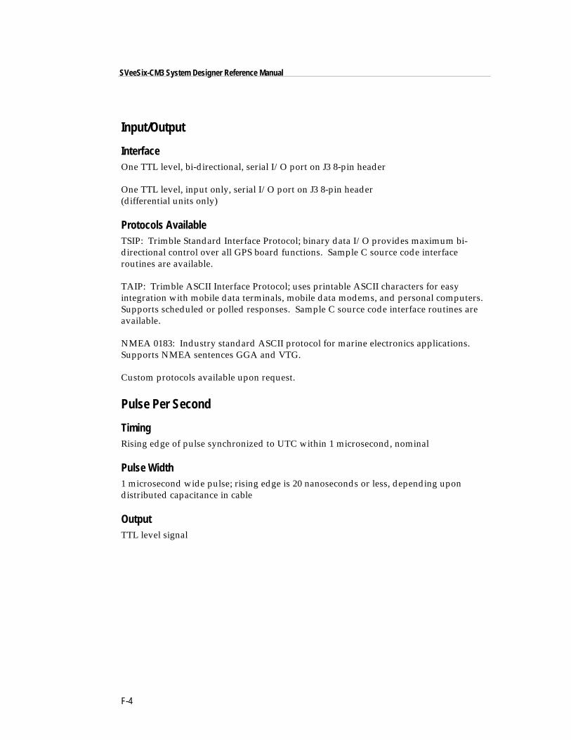
F-4
SVeeSix-CM3 System Designer Reference Manual
Input/Output
InterfaceOne TTL level, bi-directional, serial I/O port on J3 8-pin header
One TTL level, input only, serial I/O port on J3 8-pin header(differential units only)
Protocols AvailableTSIP: Trimble Standard Interface Protocol; binary data I/O provides maximum bi-directional control over all GPS board functions. Sample C source code interfaceroutines are available.
TAIP: Trimble ASCII Interface Protocol; uses printable ASCII characters for easyintegration with mobile data terminals, mobile data modems, and personal computers.Supports scheduled or polled responses. Sample C source code interface routines areavailable.
NMEA 0183: Industry standard ASCII protocol for marine electronics applications.Supports NMEA sentences GGA and VTG.
Custom protocols available upon request.
Pulse Per Second
TimingRising edge of pulse synchronized to UTC within 1 microsecond, nominal
Pulse Width1 microsecond wide pulse; rising edge is 20 nanoseconds or less, depending upondistributed capacitance in cable
OutputTTL level signal
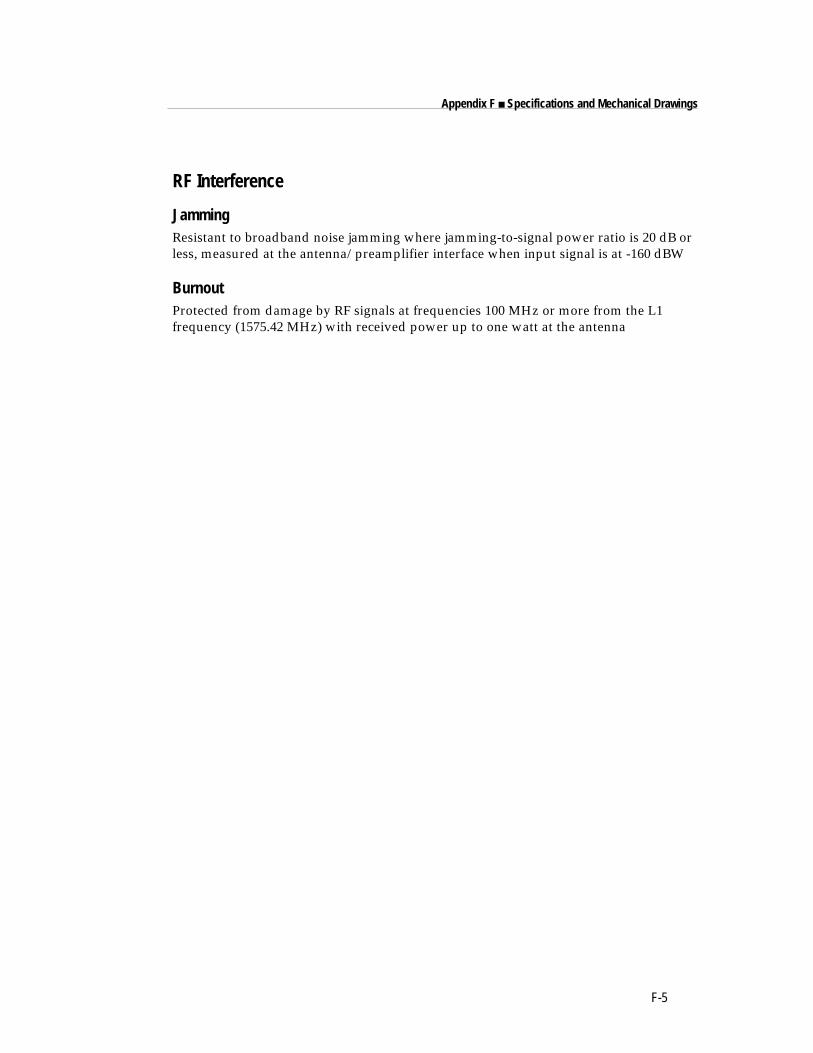
F-5
Appendix F ■ Specifications and Mechanical Drawings
RF Interference
JammingResistant to broadband noise jamming where jamming-to-signal power ratio is 20 dB orless, measured at the antenna/preamplifier interface when input signal is at -160 dBW
BurnoutProtected from damage by RF signals at frequencies 100 MHz or more from the L1frequency (1575.42 MHz) with received power up to one watt at the antenna

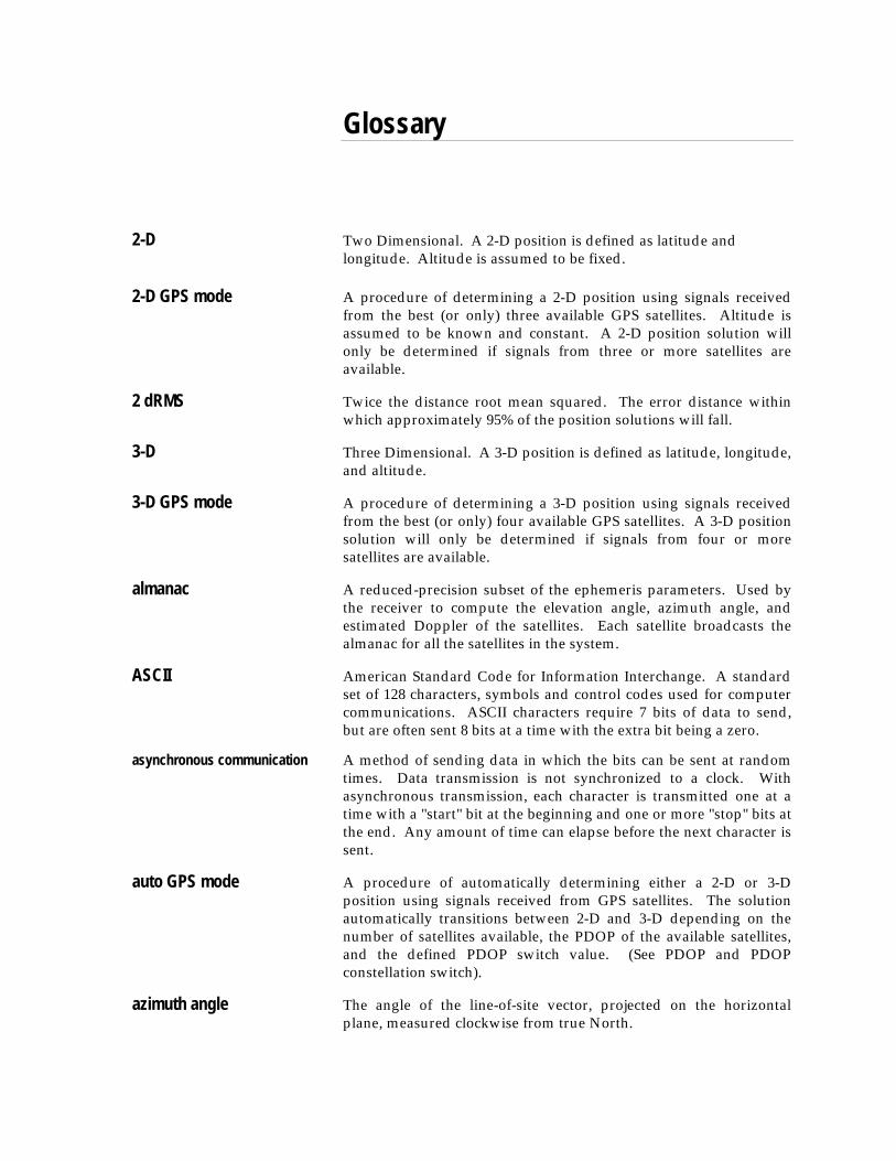
Glossary
2-D Two Dimensional. A 2-D position is defined as latitude andlongitude. Altitude is assumed to be fixed.
2-D GPS mode A procedure of determining a 2-D position using signals receivedfrom the best (or only) three available GPS satellites. Altitude isassumed to be known and constant. A 2-D position solution willonly be determined if signals from three or more satellites areavailable.
2 dRMS Twice the distance root mean squared. The error distance withinwhich approximately 95% of the position solutions will fall.
3-D Three Dimensional. A 3-D position is defined as latitude, longitude,and altitude.
3-D GPS mode A procedure of determining a 3-D position using signals receivedfrom the best (or only) four available GPS satellites. A 3-D positionsolution will only be determined if signals from four or moresatellites are available.
almanac A reduced-precision subset of the ephemeris parameters. Used bythe receiver to compute the elevation angle, azimuth angle, andestimated Doppler of the satellites. Each satellite broadcasts thealmanac for all the satellites in the system.
ASCII American Standard Code for Information Interchange. A standardset of 128 characters, symbols and control codes used for computercommunications. ASCII characters require 7 bits of data to send,but are often sent 8 bits at a time with the extra bit being a zero.
asynchronous communication A method of sending data in which the bits can be sent at randomtimes. Data transmission is not synchronized to a clock. Withasynchronous transmission, each character is transmitted one at atime with a "start" bit at the beginning and one or more "stop" bits atthe end. Any amount of time can elapse before the next character issent.
auto GPS mode A procedure of automatically determining either a 2-D or 3-Dposition using signals received from GPS satellites. The solutionautomatically transitions between 2-D and 3-D depending on thenumber of satellites available, the PDOP of the available satellites,and the defined PDOP switch value. (See PDOP and PDOPconstellation switch).
azimuth angle The angle of the line-of-site vector, projected on the horizontalplane, measured clockwise from true North.
Glossary-2
SVeeSix-CM3 System Designer Reference Manual
bandwidth The range of frequencies occupied by a signal. Also, theinformation carrying capability of a communication channel or line.
baud A measure of the speed of data transmission. Baud and bit rate arethe same for direct equipment interconnections (e.g., via RS-232).Baud and bit rate are not the same for modulated data links,whether wire or radio.
bit Binary digit. The smallest unit of information into which digitaldata can be subdivided and which a computer can hold. Each bithas only two values (e.g., on/off, one/zero, true/false).
bit rate The rate at which bits are transmitted over a communication path.Normally expressed in bits per second (bps).
byte A set of contiguous bits that make up a discrete item of information.A byte usually consists of a series of 8 bits, and represents onecharacter.
C/A code The Coarse/Acquisition code. This is the civilian code madeavailable by the Department of Defense. It is subject to selectiveavailability (SA). Users can reduce the effects of SA by usingdifferential GPS.
carrier The radio signal on which information is carried. The carrier can besensed to determine the presence of a signal.
channel Either a single frequency or a pair of radio frequencies used as acommunication path.
chip The length of time to transmit either a zero or a one in a binarypulse code.
chip rate Number of chips per second (e.g., C/A code = 1.023 MHz).
configuration A set of conditions or parameters that define the structure of anitem. In regards to SVeeSix, a configuration defines the GPSprocessing and characteristics of the RS-232 interface ports. Theterm configuration can also define the hardware components thatcomprise a subsystem or system.
data bits The bits in a byte of data which carry the actual information.
datum Refers to a mathematical model of the earth. Many local datumsmodel the earth for a small region: e.g., Tokyo datum, Alaska,NAD-27 (North America). Others, WGS-84, for example, model thewhole earth.
Glossary-3
■ Glossary
DCE Data Communications Equipment. The equipment that providesthe functions required to establish, maintain, and terminate acommunication connection. Any equipment that connects to DTEusing an RS-232 or CCITT V.24 standard interface.
default setting A preset or initial value that is assumed to be the preferred orappropriate selection for most situations. The Placer GPS sensor isshipped with factory default configuration settings; the settingswere determined by Trimble Navigation.
DGPS see differential GPS
DGPS reference station A device that tracks all GPS satellites in view and calculates andtransmits differential corrections.
differential capable A term used to describe a GPS receiver that is capable of receivingand applying differential GPS corrections.
differential GPS A procedure of correcting GPS solutions to achieve improvedposition accuracy. Differential GPS provides 2 to 5 meter positionaccuracy. Differential accuracy is obtained by applying correctionsdetermined by the stationary Differential GPS Reference Station tothe GPS data collected by the RPU unit on-board the vehicle.
differential processing GPS measurements can be differenced between receivers, satellites,and epochs. Although many combinations are possible, the presentconvention for differential processing of GPS phase measurementsis to take differences between receivers (single difference), thenbetween satellites (double difference), then between measurementepochs (triple difference).
differential relative positioning Determination of relative coordinates of two or more receiverswhich are simultaneously tracking the same satellites. Staticdifferential GPS involves determining baseline vectors betweenpairs of receivers. Also see differential GPS
dilution of precision A scaling factor used to translate measurement or ranging accuracyto position accuracy.
Standard terms for the GPS application are:
GDOP Geometric (three position coordinates plus clock offsetin the solution)
PDOP Position (three coordinates)HDOP Horizontal (two horizontal coordinates)VDOP Vertical (height only)TDOP Time (clock offset only)
DOP see dilution of precision.
Glossary-4
SVeeSix-CM3 System Designer Reference Manual
DOP constellation switch A value, based on PDOP, that defines when the GPSreceiver/processor should switch between 2-D and 3-D GPS modes.The PDOP constellation switch is only active when the GPS mode ofoperation is set to Auto.
Doppler aiding The use of Doppler carrier-phase measurements to smooth code-phase position measurements.
Doppler shift The apparent change in frequency of a received signal due to therate of change of the range between the transmitter and receiver.
earth-centered earth-fixed Cartesian coordinate system where the X direction is theintersection of the prime meridian (Greenwich) with the equator.The vectors rotate with the earth. Z is the direction of the spin axis.
elevation angle The angle between the line of sight vector and the horizontal plane.
elevation mask angle A measure of the minimum elevation angle, above the horizon,above which a GPS satellite must be located before the signals fromthe satellite will be used to compute a GPS location solution.Satellites below the elevation angle are considered unusable. Theelevation mask angle is used to prevent the GPS receiver fromcomputing position solutions using satellites which are likely to beobscured by buildings or mountains.
ellipsoid In geodesy, unless otherwise specified, a mathematical figureformed by revolving an ellipse about its minor axis. It is often usedinterchangeably with spheroid. Two quantities define an ellipsoid;these are usually given as the length of the semimajor axis, a, andthe flattening, f = (a - b)/a, where b is the length of the semiminoraxis.
ephemeris A set of parameters that describe the satellite orbit as a function oftime. It is used by the receiver to compute the position of thesatellite. This information is broadcast by the satellites.
epoch Measurement interval or data frequency, as in making observationsevery 15 seconds. Loading data using 30-second epochs meansloading every other measurement.
firmware A set of software computer/processor instructions that arepermanently or semi-permanently resident in read-only memory.
frequency The number of vibrations per second of an audio or radio signal.Measured in hertz (Hz), kilohertz (kHz), or megahertz (MHz).
GPS frequencies are: L1 = 1575.42 MHz
L2 = 1227.60 MHz
Glossary-5
■ Glossary
GDOP Geometric Dilution of Precision. GDOP describes how much anuncertainty in pseudo-range and time affects the uncertainty in aposition solution. GDOP depends on where the satellites arerelative to the GPS receiver and on GPS clock offsets.
geodetic datum A mathematical model designed to best fit part or all of the geoid. Itis defined by an ellipsoid and the relationship between the ellipsoidand a point on the topographic surface established as the origin ofdatum. This relationship can be defined by six quantities, generally(but not necessarily) the geodetic latitude, longitude, and the heightof the origin, the two components of the deflection of the vertical atthe origin, and the geodetic azimuth of a line from the origin tosome other point. The GPS uses WGS-84.
geoid The actual physical shape of the earth which is hard to describemathematically because of the local surface irregularities and sea-land variations. In geodetic terms it is the particular equipotentialsurface which coincides with mean sea level, and which may beimagined to extend through the continents. This surface iseverywhere perpendicular to the force of gravity.
GPD GPS with differential corrections applied.
GPS Global Positioning System. A constellation of 24 radio navigation(not communication) satellites which transmit signals used (by GPSreceivers) to determine precise location (position, velocity, andtime) solutions. GPS signals are available world-wide, 24 hours aday, in all weather conditions. This system also includes 5 monitorground stations, 1 master control ground station, and 3 uploadground stations.
GPS antenna An antenna designed to receive GPS radio navigation signals.
GPS processor An electronic device that interprets the GPS radio navigation signals(received by a GPS antenna) and determines a location solution.The GPS processor may also be able to apply (and determine)differential GPS corrections.
GPS receiver The combination of a GPS antenna and a GPS processor.
GPS time The length of the second is fixed and is determined by primaryatomic frequency standards. Leap-seconds are not used, as they arein UTC. Therefore, GPS time and UTC differ by a variable wholenumber of seconds.
HDOP Horizontal Dilution of Precision.

Glossary-6
SVeeSix-CM3 System Designer Reference Manual
HOW Handover word. The word in the GPS message that contains timesynchronization information for the transfer from C/A to P-code.
interference Refers to the unwanted occurrences on communication channelsthat are a result of natural or man-made noises and signals, notproperly a part of the signals being transmitted or received.
integrated Doppler A measurement of Doppler shift frequency or phase over time.
IODE Issue Of Data, Ephemeris. Part of the navigation data. It is the issuenumber of the ephemeris information. A new ephemeris is availableusually on the even hour. Especially important for Differential GPSoperation that the IODE change is tracked at both the referencestation and mobile stations.
jamming Interference (in either transmitting or receiving signals) caused byother radio signals at exactly or approximately the same frequency
masks See satellite masks.
maximum DOP A measure of the maximum Dilution of Precision (DOP) that isacceptable in order for the GPS processor to determine a locationsolution (see DOP).
NMEA National Marine Electronics Association. An association thatdefines marine electronic interface standards for the purpose ofserving the public interest.
NMEA 0183 message NMEA 0183 is a standard for interfacing marine electronicsnavigational devices. The standard specifies the message formatused to communicate with marine devices/components.
packet An "envelope" for data, which contains addresses and errorchecking information as well as the data itself.
parity A scheme for detecting certain errors in data transmission. Paritydefines the condition (i.e., even or odd) of the number of items in aset (e.g., bits in a byte).
PDOP Position Dilution of Precision. PDOP is a unitless figure of meritthat describes how an uncertainty in pseudo-range affects positionsolutions.
PRN Pseudo-random noise. Each GPS satellite generates its owndistinctive PRN code, which is modulated onto each carrier. ThePRN code serves as identification of the satellite, as a timing signal,and as a subcarrier for the navigation data.
protocol A formal set of rules that describe a method of communication. Theprotocol governs the format and control of inputs and outputs.
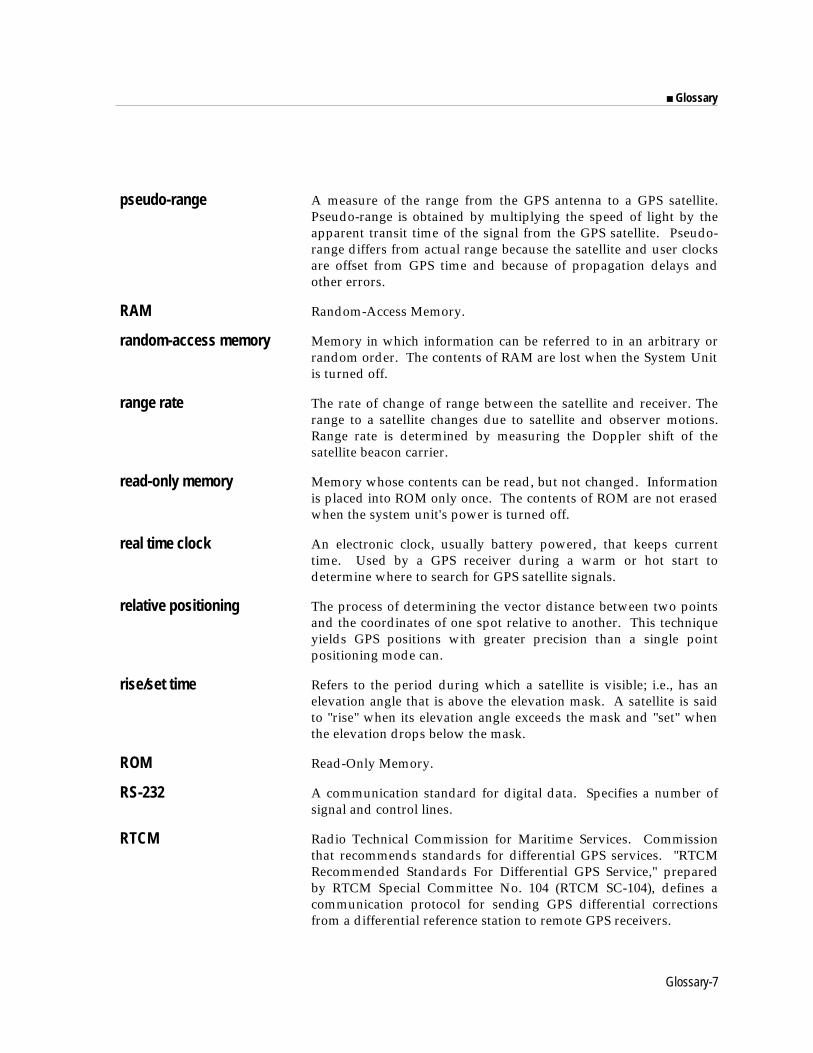
Glossary-7
■ Glossary
pseudo-range A measure of the range from the GPS antenna to a GPS satellite.Pseudo-range is obtained by multiplying the speed of light by theapparent transit time of the signal from the GPS satellite. Pseudo-range differs from actual range because the satellite and user clocksare offset from GPS time and because of propagation delays andother errors.
RAM Random-Access Memory.
random-access memory Memory in which information can be referred to in an arbitrary orrandom order. The contents of RAM are lost when the System Unitis turned off.
range rate The rate of change of range between the satellite and receiver. Therange to a satellite changes due to satellite and observer motions.Range rate is determined by measuring the Doppler shift of thesatellite beacon carrier.
read-only memory Memory whose contents can be read, but not changed. Informationis placed into ROM only once. The contents of ROM are not erasedwhen the system unit's power is turned off.
real time clock An electronic clock, usually battery powered, that keeps currenttime. Used by a GPS receiver during a warm or hot start todetermine where to search for GPS satellite signals.
relative positioning The process of determining the vector distance between two pointsand the coordinates of one spot relative to another. This techniqueyields GPS positions with greater precision than a single pointpositioning mode can.
rise/set time Refers to the period during which a satellite is visible; i.e., has anelevation angle that is above the elevation mask. A satellite is saidto "rise" when its elevation angle exceeds the mask and "set" whenthe elevation drops below the mask.
ROM Read-Only Memory.
RS-232 A communication standard for digital data. Specifies a number ofsignal and control lines.
RTCM Radio Technical Commission for Maritime Services. Commissionthat recommends standards for differential GPS services. "RTCMRecommended Standards For Differential GPS Service," preparedby RTCM Special Committee No. 104 (RTCM SC-104), defines acommunication protocol for sending GPS differential correctionsfrom a differential reference station to remote GPS receivers.
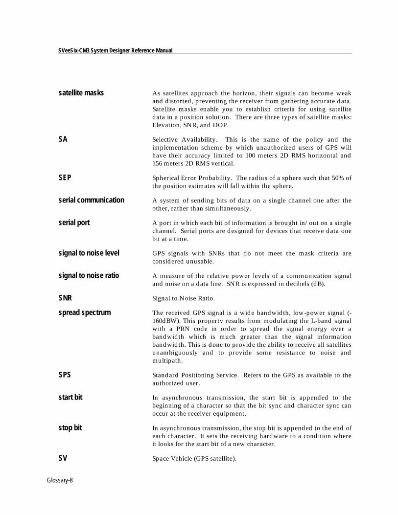
Glossary-8
SVeeSix-CM3 System Designer Reference Manual
satellite masks As satellites approach the horizon, their signals can become weakand distorted, preventing the receiver from gathering accurate data.Satellite masks enable you to establish criteria for using satellitedata in a position solution. There are three types of satellite masks:Elevation, SNR, and DOP.
SA Selective Availability. This is the name of the policy and theimplementation scheme by which unauthorized users of GPS willhave their accuracy limited to 100 meters 2D RMS horizontal and156 meters 2D RMS vertical.
SEP Spherical Error Probability. The radius of a sphere such that 50% ofthe position estimates will fall within the sphere.
serial communication A system of sending bits of data on a single channel one after theother, rather than simultaneously.
serial port A port in which each bit of information is brought in/out on a singlechannel. Serial ports are designed for devices that receive data onebit at a time.
signal to noise level GPS signals with SNRs that do not meet the mask criteria areconsidered unusable.
signal to noise ratio A measure of the relative power levels of a communication signaland noise on a data line. SNR is expressed in decibels (dB).
SNR Signal to Noise Ratio.
spread spectrum The received GPS signal is a wide bandwidth, low-power signal (-160dBW). This property results from modulating the L-band signalwith a PRN code in order to spread the signal energy over abandwidth which is much greater than the signal informationbandwidth. This is done to provide the ability to receive all satellitesunambiguously and to provide some resistance to noise andmultipath.
SPS Standard Positioning Service. Refers to the GPS as available to theauthorized user.
start bit In asynchronous transmission, the start bit is appended to thebeginning of a character so that the bit sync and character sync canoccur at the receiver equipment.
stop bit In asynchronous transmission, the stop bit is appended to the end ofeach character. It sets the receiving hardware to a condition whereit looks for the start bit of a new character.
SV Space Vehicle (GPS satellite).
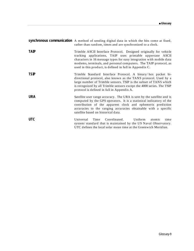
Glossary-9
■ Glossary
synchronous communication A method of sending digital data in which the bits come at fixed,rather than random, times and are synchronized to a clock.
TAIP Trimble ASCII Interface Protocol. Designed originally for vehicletracking applications, TAIP uses printable uppercase ASCIIcharacters in 16 message types for easy integration with mobile datamodems, terminals, and personal computers. The TAIP protocol, asused in this product, is defined in full in Appendix C.
TSIP Trimble Standard Interface Protocol. A binary/hex packet bi-directional protocol, also known as the TANS protocol. Used by alarge number of Trimble sensors. TSIP is the subset of TANS whichis recognized by all Trimble sensors except the 4000 series. The TSIPprotocol is defined in full in Appendix A.
URA Satellite user range accuracy. The URA is sent by the satellite and iscomputed by the GPS operators. It is a statistical indicatory of thecontribution of the apparent clock and ephemeris predictionaccuracies to the ranging accuracies obtainable with a specificsatellite based on historical data.
UTC Universal Time Coordinated. Uniform atomic timesystem/standard that is maintained by the US Naval Observatory.UTC defines the local solar mean time at the Greenwich Meridian.

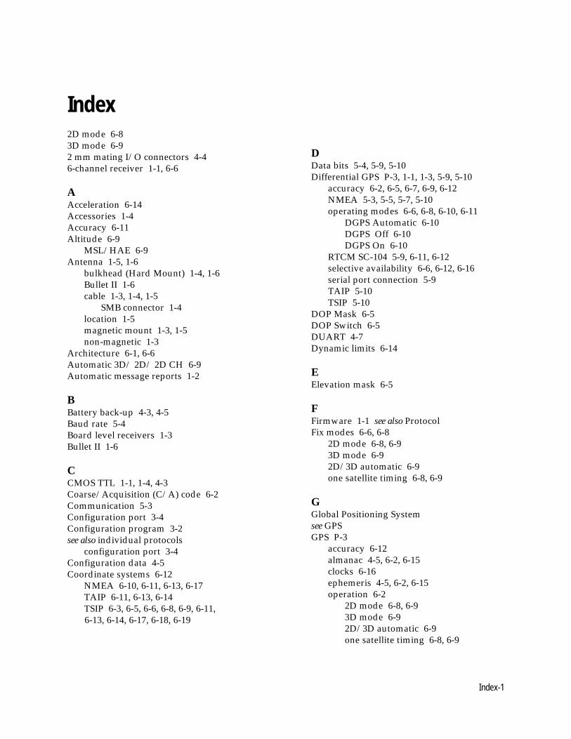
Index-1
Index2D mode 6-83D mode 6-92 mm mating I/O connectors 4-46-channel receiver 1-1, 6-6
AAcceleration 6-14Accessories 1-4Accuracy 6-11Altitude 6-9
MSL/HAE 6-9Antenna 1-5, 1-6
bulkhead (Hard Mount) 1-4, 1-6Bullet II 1-6cable 1-3, 1-4, 1-5
SMB connector 1-4location 1-5magnetic mount 1-3, 1-5non-magnetic 1-3
Architecture 6-1, 6-6Automatic 3D/ 2D/ 2D CH 6-9Automatic message reports 1-2
BBattery back-up 4-3, 4-5Baud rate 5-4Board level receivers 1-3Bullet II 1-6
CCMOS TTL 1-1, 1-4, 4-3Coarse/Acquisition (C/A) code 6-2Communication 5-3Configuration port 3-4Configuration program 3-2see also individual protocols
configuration port 3-4Configuration data 4-5Coordinate systems 6-12
NMEA 6-10, 6-11, 6-13, 6-17TAIP 6-11, 6-13, 6-14TSIP 6-3, 6-5, 6-6, 6-8, 6-9, 6-11,
6-13, 6-14, 6-17, 6-18, 6-19
DData bits 5-4, 5-9, 5-10Differential GPS P-3, 1-1, 1-3, 5-9, 5-10
accuracy 6-2, 6-5, 6-7, 6-9, 6-12NMEA 5-3, 5-5, 5-7, 5-10operating modes 6-6, 6-8, 6-10, 6-11
DGPS Automatic 6-10DGPS Off 6-10DGPS On 6-10
RTCM SC-104 5-9, 6-11, 6-12selective availability 6-6, 6-12, 6-16serial port connection 5-9TAIP 5-10TSIP 5-10
DOP Mask 6-5DOP Switch 6-5DUART 4-7Dynamic limits 6-14
EElevation mask 6-5
FFirmware 1-1 see also ProtocolFix modes 6-6, 6-8
2D mode 6-8, 6-93D mode 6-92D/3D automatic 6-9one satellite timing 6-8, 6-9
GGlobal Positioning Systemsee GPSGPS P-3
accuracy 6-12almanac 4-5, 6-2, 6-15clocks 6-16ephemeris 4-5, 6-2, 6-15operation 6-2
2D mode 6-8, 6-93D mode 6-92D/3D automatic 6-9one satellite timing 6-8, 6-9
Index-2
SVeeSix-CM3 System Designer's Reference Manual
performance 5-8, 6-14, 6-15re-acquisition 6-15satellite masks 6-5selective availability 4-7, 6-12time offset 5-6time to first fix 6-3, 6-4
cold start 6-3garage search strategy 6-4hot start 6-4warm start 6-3
timing 6-16serial time output 6-17synchronization 6-18time tagging 6-19timing pulse output 6-17
UTC 5-6GPSSK 5-2, Appendix DGPS Toolkit Disk 1-3
HHardware integration 4-1see also Installation
interface 4-2, 4-3, 4-4power 4-5, 4-6
IInstallation
configuration software 3-2, 3-4hardware 2-5, 3-3, 4-2
Interface cable 2-2, 2-4connection 2-4, 4-2, 4-3, 4-4
JJerk 6-14
MMask settings 6-5
elevation 6-5DOP Mask 6-5DOP Switch 6-5SNR 6-5
Magnetic mount antenna 1-5see also AntennaMounting 4-7
receiver module 1-4
MSL/HAE 6-9
NNMEA 0183 1-2, 5-4, 5-5
differential GPS operation 5-10output 6-13protocol selection 3-4, 5-4update rate 6-14
OOEM GPS Toolkit Diskette 3-4Operation 6-1
differential GPS modes 6-10, 6-11DGPS Automatic 6-10DGPS Off 6-10DGPS On 6-10
dynamic limits 6-14GPS fix modes 6-8
2D mode 6-83D mode 6-82D/3D /2D CH automatic 6-9one satellite timing 6-8over-determined mode 6-6, 6-7
re-acquisition 6-15update rate 6-14
Over-determined mode 6-6, 6-7
PParity 5-4, 5-9, 5-10Position reports 2-10Power 2-2, 2-3, 2-5, 2-6
consumption 1-1, 2-6connection 2-2, 2-5, 2-8, 2-10input 1-4, 4-3, 4-5, 4-7interface cable 2-2, 2-5, 2-10receiver 4-3, 4-5requirements 4-6
PPS 2-2, 2-3, 6-16, 6-17Protocol 1-1, 1-2, 1-3, 1-4, 2-1, 2-9, 3-1, 3-2, 3-4
communication 5-3configuration program 3-2, 3-4selection 3-4, 5-4
see also individual protocols
Index-3
■ Index
RRAM
configuration data 4-5Re-acquisition 6-15READ.ME file 3-1Receiver 1-3, 1-4
accuracy 6-12 see also GPSarchitecture 6-1, 6-6communication 5-3mounting 4-7output 6-13performance 5-1, 6-14, 6-15operation 6-6power 4-5, 4-6serial interface 4-7
Ribbon cable 4-3, 4-4ROM 1-1, 1-3RS-232 3-3, 4-7, 5-1RS-422 4-7RTCM SC-104 5-9, 5-10, 6-11, 6-12
see also Differential GPS
SS/A 4-7, 6-12Satellite see GPSSatellite masks 6-6Selective Availability 4-7, 6-11Serial interface 1-1, 1-4, 4-2, 4-3, 4-4, 4-7
CMOS TTL level 1-1, 4-3, 4-7one pulse-per-second 1-1, 4-7port characteristics 3-2, 5-4, 5-9
Signal to Noise Ratio 6-5SNR 6-5Software interface 5-1SPDRIVE 2-6Starter kit 1-1, 1-3, 2-1, 2-2, 3-1, 3-4, 5-3, 6-10
protocol configuration 3-1, 3-2Startup 5-2Stop bits 5-4, 5-9
TTAC 2-10TAIP 1-2, 2-1, 3-1, 3-2, 3-4, 5-3, 5-4, 6-11,6-13, 6-14
configuration program 3-4
differential GPS operation 5-9, 5-10output 6-13update rate 6-14
Technical Assistance 2-10Temperature option 1-3Time to first fix 6-3, 6-4
see also GPScold start 6-3garage search strategy 6-4hot start 6-4warm start 6-3
Timing 4-7, 6-16accuracy 4-7operation 5-6
Trimble ASCII Interface Protocolsee TAIPTrimble Standard Interface Protocolsee TSIPTSIP 1-2, 2-1, 2-9, 3-1, 3-2, 3-4, 5-3, 5-4
configuration program 3-4differential GPS operation 5-9, 5-10, 6-6interface program 2-9output 6-13packets 60 and 61 5-9, Appendix Asatellite mask 6-5update rate 6-14
TSIPCHAT 2-9, 2-10command window 2-10configuration 3-4report window 2-10
UUpdate rate 6-14UTC time 5-6, 6-13
see also GPS
WWeek Number Roll-over 5-7, 5-8
VVelocity 6-14


