Embed Size (px)
Citation preview
1
Tekla Structural Designer
2018i Reference Guides (ACI/AISC)
September 2018 (6.1.06)
© 2018 Trimble Solutions Corporation.


3

i
Table of Contents
Analysis Verification Examples ............................................................................................................................ 1
1st Order Linear - Simple Cantilever ............................................................................................................ 1
Problem Definition ......................................................................................................................................... 1
Assumptions ..................................................................................................................................................... 1
Key Results ......................................................................................................................................................... 1
Conclusion ......................................................................................................................................................... 2
1st Order Linear - Simply Supported Square Slab .................................................................................. 2
Problem Definition ......................................................................................................................................... 2
Assumptions ..................................................................................................................................................... 2
Key Results ......................................................................................................................................................... 2
Conclusion ......................................................................................................................................................... 3
1st Order Linear - 3D truss ............................................................................................................................... 3
Problem Definition ......................................................................................................................................... 3
Key Results ......................................................................................................................................................... 3
Conclusion ......................................................................................................................................................... 4
1st Order linear - Thermal Load on Simply Supported Beam ............................................................ 4
Problem Definition ......................................................................................................................................... 4
Assumptions ..................................................................................................................................................... 4
Key Results ......................................................................................................................................................... 4
Conclusion ......................................................................................................................................................... 4
1st Order Nonlinear - Simple Cantilever .................................................................................................... 5
Problem Definition ......................................................................................................................................... 5
Assumptions ..................................................................................................................................................... 5
Key Results ......................................................................................................................................................... 5
Conclusion ......................................................................................................................................................... 5
1st Order Nonlinear - Nonlinear Supports ................................................................................................ 5
Problem Definition ......................................................................................................................................... 5
Assumptions ..................................................................................................................................................... 6
Key Results ......................................................................................................................................................... 6
Conclusion ......................................................................................................................................................... 6
1st Order Nonlinear - Displacement Loading of a Plane Frame ........................................................ 6
Problem Definition ......................................................................................................................................... 6
Assumptions ..................................................................................................................................................... 7
Key Results ......................................................................................................................................................... 7
Conclusion ......................................................................................................................................................... 7
Table of Contents
ii
2nd Order Linear - Simple Cantilever .......................................................................................................... 7
Problem Definition ......................................................................................................................................... 7
Assumptions ..................................................................................................................................................... 8
Key Results ......................................................................................................................................................... 8
Conclusion ......................................................................................................................................................... 8
2nd Order linear - Simply Supported Beam .............................................................................................. 8
Problem Definition ......................................................................................................................................... 8
Assumptions ..................................................................................................................................................... 9
Key Results ......................................................................................................................................................... 9
Conclusion ......................................................................................................................................................... 9
Reference ........................................................................................................................................................... 9
2nd Order Nonlinear - Tension Only Cross Brace ................................................................................... 9
Problem Definition ......................................................................................................................................... 9
Assumptions .................................................................................................................................................. 10
Key Results ...................................................................................................................................................... 10
Conclusion ...................................................................................................................................................... 10
2nd Order Nonlinear - Compression Only Element ............................................................................ 11
Problem Definition ...................................................................................................................................... 11
Assumptions .................................................................................................................................................. 11
Key Results ...................................................................................................................................................... 11
Conclusion ...................................................................................................................................................... 11
1st Order Vibration - Simply Supported Beam ..................................................................................... 11
Problem Definition ...................................................................................................................................... 11
Assumptions .................................................................................................................................................. 11
Key Results ...................................................................................................................................................... 12
Conclusion ...................................................................................................................................................... 12
1st Order Vibration - Bathe and Wilson Eigenvalue Problem ......................................................... 12
Problem Definition ...................................................................................................................................... 12
Assumptions .................................................................................................................................................. 13
Key Results ...................................................................................................................................................... 13
Conclusion ...................................................................................................................................................... 13
References ...................................................................................................................................................... 13
2nd Order Buckling - Euler Strut Buckling .............................................................................................. 13
Problem Definition ...................................................................................................................................... 13
Assumptions .................................................................................................................................................. 14
Key Results ...................................................................................................................................................... 14
Reference Guide - ACI/AISC
iii
Conclusion ...................................................................................................................................................... 14
2nd Order Buckling - Plane Frame ............................................................................................................. 14
Problem Definition ...................................................................................................................................... 14
Assumptions .................................................................................................................................................. 15
Key Results ...................................................................................................................................................... 15
Conclusion ...................................................................................................................................................... 16
References ...................................................................................................................................................... 16
Loading -ASCE ........................................................................................................................................................ 17
ASCE7 Loading ....................................................................................................................................................... 17
Load Cases (ASCE7) ......................................................................................................................................... 17
Loadcase Types (ASCE7) ............................................................................................................................ 17
Self Weight (ASCE7) .................................................................................................................................... 18
Live and Roof Live Loads (ASCE7) .......................................................................................................... 19
Live Load Reductions ............................................................................................................................. 19
Live Load Reduction Factor ................................................................................................................. 19
Roof Live Load Reduction Factor ...................................................................................................... 20
Wind Loads (ASCE7) .................................................................................................................................... 20
The ASCE7 Wind Wizard ....................................................................................................................... 20
Simple Wind Loading ............................................................................................................................. 20
Patterning of Live Loads (ASCE7) ............................................................................................................... 20
Combinations (ASCE7) .................................................................................................................................... 21
Application of Notional Loads in Combinations (ASCE7) ............................................................. 21
The Combinations Generator (ASCE7) ................................................................................................. 21
Combination Generator - Combinations ........................................................................................ 21
Combination Generator - Service ..................................................................................................... 21
Combination Generator - NL .............................................................................................................. 21
Combination Classes (ASCE7) ................................................................................................................. 22
Construction Stage Combination (ASCE7) ..................................................................................... 22
Gravity Combinations (ASCE7) ........................................................................................................... 22
Lateral Combinations (ASCE7) ............................................................................................................ 23
Seismic Combinations (ASCE7) .......................................................................................................... 23
Vibration Mass Combinations (ASCE7) ........................................................................................... 23
Concrete Design - ACI ......................................................................................................................................... 25
Introduction to ACI 318 Design .................................................................................................................. 25
Seismic Design .............................................................................................................................................. 25
Seismic Force Resisting Systems ....................................................................................................... 25
Table of Contents
iv
Materials ..................................................................................................................................................... 27
Beam Design to ACI 318 ................................................................................................................................ 27
Limitations and Exclusions (Beams: ACI 318) ......................................................................................... 27
Slender Beams (Beams: ACI 318) ................................................................................................................ 28
Cover to Reinforcement (Beams: ACI 318) .............................................................................................. 28
Design Parameters for Longitudinal Bars (Beams: ACI 318) ........................................................ 29
Minimum and Maximum Diameter of Reinforcement ................................................................... 29
Minimum Distance between Bars .......................................................................................................... 29
Maximum Spacing of Tension Bars ....................................................................................................... 30
Minimum Area of Reinforcement .......................................................................................................... 30
Maximum Area of Reinforcement ......................................................................................................... 31
Side Skin Reinforcement in Beams (Beams: ACI 318) ......................................................................... 31
Effective Depth of Section (Beams: ACI 318).......................................................................................... 32
Design for Bending (Beams: ACI 318) .................................................................................................. 32
Top Design Moment at Supports (Beams: ACI 318) ....................................................................... 32
Design for Bending for Rectangular Sections (Beams: ACI 318) ................................................ 33
Design for Bending for Flanged Sections (Beams: ACI 318) ........................................................ 35
Design for Shear (Beams: ACI 318) ........................................................................................................ 36
Shear Strength (Beams: ACI 318) ........................................................................................................... 36
Minimum Area of Shear Reinforcement (Beams: ACI 318) .......................................................... 39
Spacing of Shear Reinforcement (Beams: ACI 318) ........................................................................ 39
Deflection Check (Beams: ACI 318) ............................................................................................................ 40
Seismic Design (Beams: ACI 318) ........................................................................................................... 42
Limitations and Assumptions (Beams-seismic: ACI 318)............................................................... 42
ACI 318 Seismic Code Checks for beams that have been implemented in Tekla
Structural Designer ................................................................................................................................. 43
Beams in Moment Resisting Frames (Beams-seismic: ACI 318) ............................................ 46
General Requirements (Beams-seismic: ACI 318) ....................................................................... 47
Flexural Requirements (Beams-seismic: ACI 318) ....................................................................... 48
Transverse Reinforcement (Beams-seismic: ACI 318) ................................................................ 50
Beams not part of a SFRS (Beams-seismic: ACI 318) ................................................................. 53
Requirements when in SDC D - F (Beams-seismic: ACI 318) .................................................. 53
Seismic Cantilevers (Beams-seismic: ACI 318) .............................................................................. 53
Seismic Detailing (Beams: ACI 318) ....................................................................................................... 54
Flexural Reinforcement (Beams-seismic: ACI 318) .......................................................................... 54
Anchorage .................................................................................................................................................. 54
Reference Guide - ACI/AISC
v
Lap Splices.................................................................................................................................................. 54
Confinement Reinforcement for Ductility (Beams-seismic: ACI 318) ....................................... 55
Reinforcement Type ............................................................................................................................... 55
Detailing Regions .................................................................................................................................... 55
Column Design to ACI 318............................................................................................................................ 55
Limitations and Exclusions (Columns: ACI 318)..................................................................................... 55
Materials (Columns: ACI 318) ....................................................................................................................... 56
Concrete ...................................................................................................................................................... 56
Reinforcement .......................................................................................................................................... 56
Cover to Reinforcement (Columns: ACI 318) ......................................................................................... 56
Design Parameters for Longitudinal Bars (Columns: ACI 318) .................................................... 56
Minimum Longitudinal Bar Spacing ..................................................................................................... 57
Maximum Longitudinal Bar Spacing ..................................................................................................... 57
Minimum Longitudinal Total Steel Area1 ........................................................................................... 57
Maximum Longitudinal Total Steel Area ............................................................................................. 57
Ultimate Axial Load Limit (Columns: ACI 318) ....................................................................................... 57
Effective Length Calculations (Columns: ACI 318) ........................................................................... 58
Effective Length Calculations (Columns: ACI 318) ............................................................................... 58
Unsupported Length................................................................................................................................... 58
Effective Length ............................................................................................................................................ 58
No Effective Beams Found ....................................................................................................................... 59
Column Stack Classification (Columns: ACI 318) ............................................................................. 59
Slenderness ratio .......................................................................................................................................... 59
Design Moment Calculations (Columns: ACI 318) ........................................................................... 60
Step 1, minimum moment ........................................................................................................................ 61
Step 2 - member slenderness ................................................................................................................. 61
Step 3 - non-slender column .................................................................................................................. 61
Step 4 - slender member amplifier ....................................................................................................... 61
Step 5 - uniform moment factor ............................................................................................................ 62
Step 6 - moment magnifier ...................................................................................................................... 62
Step 7 - amplified minimum moment.................................................................................................. 62
Step 8 - design moments ......................................................................................................................... 62
Design for Combined Axial and Bending (Columns: ACI 318) ........................................................ 62
Design for Shear (Columns: ACI 318) ................................................................................................... 63
Design Parameters for Shear Design .................................................................................................... 63
Minimum Shear Link Diameter........................................................................................................... 63
Table of Contents
vi
Maximum Span Region Shear Link Spacing .................................................................................. 63
Maximum Support Region Shear Link Spacing ........................................................................... 63
Column Confinement (Columns: ACI 318) .............................................................................................. 63
Seismic Design (Columns: ACI 318) ...................................................................................................... 63
Limitations and Assumptions (Columns-seismic: ACI 318) .......................................................... 63
ACI 318 Seismic Code Checks for columns that have been implemented in Tekla
Structural Designer ................................................................................................................................. 64
Columns in Moment Resisting Frames (Columns-seismic: ACI 318) ................................... 69
General Requirements (Columns-seismic: ACI 318) ................................................................... 69
Flexural Requirements (Columns-seismic: ACI 318) ................................................................... 70
Transverse Reinforcement (Columns-seismic: ACI 318) ........................................................... 72
Seismic Detailing (Columns: ACI 318) .................................................................................................. 75
Flexural Reinforcement (Columns-seismic: ACI 318) ...................................................................... 75
Development Length at the Foundation ........................................................................................ 75
Lap Splices.................................................................................................................................................. 75
Confinement Reinforcement for Ductility (Columns-seismic: ACI 318) ................................... 76
Reinforcement Type ............................................................................................................................... 76
Detailing Regions .................................................................................................................................... 76
Wall Design to ACI 318 .................................................................................................................................. 77
Limitations and Exclusions (Walls: ACI 318) ........................................................................................... 77
Materials (Walls: ACI 318) .............................................................................................................................. 77
Concrete ...................................................................................................................................................... 77
Reinforcement .......................................................................................................................................... 77
Cover to Reinforcement (Walls: ACI 318) ................................................................................................ 77
Design Parameters for Vertical Bars (Walls: ACI 318) ..................................................................... 78
Minimum and Maximum Vertical Bar Diameter ............................................................................... 78
Minimum and Maximum Vertical Loose Bar Spacing .................................................................... 78
Minimum and Maximum Reinforcement Area2 ............................................................................... 79
Design Parameters for Horizontal Bars (Walls: ACI 318) ............................................................... 79
Minimum and Maximum Reinforcement Area1 ............................................................................... 79
Minimum and Maximum Horizontal Bar Spacing ........................................................................... 80
Minimum and Maximum Confinement Bar Spacing ...................................................................... 80
Ultimate Axial Load Limit (Walls: ACI 318) .............................................................................................. 80
Effective Length and Slenderness Calculations (Walls: ACI 318) .................................................... 80
Pre-selection of Bracing Contribution: ............................................................................................ 81
Design Moment Calculations (Walls: ACI 318) ...................................................................................... 81
Reference Guide - ACI/AISC
vii
Design for Shear (Walls: ACI 318) ............................................................................................................... 81
Seismic Design (Walls: ACI 318) ............................................................................................................. 82
Limitations and Assumptions (Walls-seismic: ACI 318) ................................................................. 82
ACI 318 Seismic Code Checks for walls that have been implemented in Tekla
Structural Designer ................................................................................................................................. 83
Seismic Resisting Shear Walls (ACI 318) ......................................................................................... 88
Maximum Recommended Axial Force (Walls-seismic: ACI 318) ........................................... 88
Limiting Height (Walls-seismic: ACI 318) ....................................................................................... 88
Vertical Segment Classification (Walls-seismic: ACI 318) ......................................................... 88
Mid-zone Reinforcement (Walls-seismic: ACI 318) .................................................................... 89
End-zone Reinforcement (Walls-seismic: ACI 318) ..................................................................... 90
Shear Strength (Walls-seismic: ACI 318) ......................................................................................... 90
Slab Design to ACI 318 ................................................................................................................................... 91
Materials (Slabs: ACI 318) .............................................................................................................................. 91
Concrete ...................................................................................................................................................... 91
Reinforcement .......................................................................................................................................... 91
Reinforcement Parameters (Slabs: ACI 318) ........................................................................................... 91
Cover to Reinforcement (Slabs: ACI 318) ................................................................................................ 92
Limiting Reinforcement Parameters (Slabs: ACI 318) ..................................................................... 92
Minimum Clear Spacing ............................................................................................................................ 92
Minimum Area of Reinforcement .......................................................................................................... 93
Maximum Area of Reinforcement ......................................................................................................... 93
Basic Cross Section Design (Slabs: ACI 318) ...................................................................................... 93
Matching Design Moments to Reinforcement Layers ................................................................... 94
Design for Bending (Slabs: ACI 318) .......................................................................................................... 94
Punching Shear Checks (Slabs: ACI 318) ............................................................................................. 94
Punching Shear limitations and assumptions (Slabs: ACI 318) .............................................. 94
Slab shear strength (Slabs: ACI 318) ................................................................................................ 94
Applicability of wall punching checks (Slabs: ACI 318) ............................................................. 95
Columns and Walls not perpendicular to slabs (Slabs: ACI 318) ........................................... 95
Overlapping control perimeters (Slabs: ACI 318) ........................................................................ 95
Punching shear perimeters (Slabs: ACI 318) ...................................................................................... 95
Length of the loaded perimeter u0 (Slabs: ACI 318) ...................................................................... 96
Loaded perimeter for Columns .......................................................................................................... 96
Loaded perimeter for Walls ............................................................................................................... 101
Loaded perimeter for Point Loads .................................................................................................. 101
Table of Contents
viii
Additional Loaded perimeter drops ............................................................................................... 102
The equivalent loaded perimeter .................................................................................................... 102
The equivalent critical perimeter ..................................................................................................... 102
Length of the critical perimeter bo (Slabs: ACI 318) ..................................................................... 103
Critical perimeter without drops...................................................................................................... 103
Modification of control perimeters to take account of slab openings (Slabs: ACI 318) . 104
User Modification of control perimeters ...................................................................................... 104
Basic design procedure (Slabs: ACI 318) ........................................................................................... 105
Check shear stress at perimeter against unreinforced shear resistance .......................... 105
Required shear stress of reinforcement ........................................................................................ 105
Required area of punching shear reinforcement ...................................................................... 105
Calculate the provided area of punching shear reinforcement ........................................... 105
Check area of punching shear reinforcement ............................................................................ 105
Pad and Strip Base Design to ACI 318 .................................................................................................... 106
Checks Performed (Pad and Strip Base: ACI 318) ............................................................................... 106
Foundation Bearing Capacity (Pad and Strip Base: ACI 318) ..................................................... 106
Check for Pad Base Bearing Capacity (ACI 318) ............................................................................. 106
Check for Strip Base Bearing Capacity (ACI 318) ........................................................................... 108
Design for Bending (Pad and Strip Base: ACI 318) ............................................................................ 109
Checks for Limiting Parameters (Pad and Strip Base: ACI 318) ................................................ 109
Limits on bar size and reinforcement quantities ............................................................................ 109
Limits on bar spacing (Pad and Strip Base: ACI 318) .................................................................... 110
Shear Design (Pad and Strip Base: ACI 318) .................................................................................... 110
Pad base shear design check (ACI 318) ............................................................................................. 111
Strip base shear design check (ACI 318) ........................................................................................... 111
Punching Shear Design (Pad and Strip Base: ACI 318) ..................................................................... 111
Check for Transfer Forces at Column Base (Pad and Strip Base: ACI 318) ................................ 112
Check for transfer of horizontal forces by shear friction (Pad and Strip Base: ACI 318) ..... 113
Check for Overturning Forces (Pad and Strip Base: ACI 318) ........................................................ 113
Check for Sliding (Pad and Strip Base: ACI 318) ................................................................................. 114
Check for Uplift (Pad and Strip Base: ACI 318) .................................................................................... 115
Pile Cap Design to ACI 318 ......................................................................................................................... 115
Pile Capacity (Pile Cap: ACI 318) ............................................................................................................... 115
Design for Bending (Pile Cap: ACI 318) .................................................................................................. 115
Shear Design (Pile Cap: ACI 318) .............................................................................................................. 115
Punching Shear Design (Pile Cap: ACI 318) .......................................................................................... 116
Reference Guide - ACI/AISC
ix
Checks for Limiting Parameters (Pile Cap: ACI 318) .......................................................................... 116
References (ACI 318) .......................................................................................................................................... 117
Steel Design to AISC 360 ASD and LRFD ................................................................................................... 119
General ............................................................................................................................................................... 119
Seismic Design (AISC 360) .......................................................................................................................... 119
Deflection checks (AISC 360) ..................................................................................................................... 119
Steel Grade (AISC 360) ................................................................................................................................. 120
Steel Beam Design to AISC 360 ................................................................................................................ 120
Design method (Beams: AISC 360) .......................................................................................................... 120
Steel beam limitations and assumptions (Beams: AISC 360) ......................................................... 121
Section Classification (Beams: AISC 360) ............................................................................................... 122
D2. Axial Tension (Beams: AISC 360) ....................................................................................................... 122
E. Axial Compression (Beams: AISC 360) ............................................................................................... 123
G2. Shear Strength (Beams: AISC 360) ................................................................................................... 123
F2. Flexure (Beams: AISC 360) .................................................................................................................... 123
H1. Combined Forces (Beams: AISC 360) .............................................................................................. 124
DG9. Torsion (Beams: AISC 360) ........................................................................................................... 125
Torsion design - loading (Beams: AISC 360) ................................................................................... 125
Angle of rotation check (Beams: AISC 360) ..................................................................................... 126
Torsion design general checks (Beams: AISC 360) ........................................................................ 126
Web Openings (Beams: AISC 360) ....................................................................................................... 128
Circular Openings as an Equivalent Rectangle ............................................................................... 128
Web Opening design checks ................................................................................................................. 128
Deflections .................................................................................................................................................... 129
Seismic Design Rules (Beams: AISC 360) .......................................................................................... 130
For a moment resisting frame ............................................................................................................... 130
Moment resisting frame with a truss component ......................................................................... 130
For a braced frame .................................................................................................................................... 130
Buckling resistant braced frame ........................................................................................................... 130
Frames containing composite beams ................................................................................................ 131
Composite Beam Design to AISC 360 .................................................................................................... 131
Design method (Composite beams: AISC 360) ................................................................................... 131
Construction stage (Composite beams: AISC 360)........................................................................ 131
Section classification (Composite beams: AISC 360) .................................................................... 131
Shear strength - I3.1b (360-05), I4.2 (360-10) (Composite beams: AISC 360) .................... 131
Table of Contents
x
Strength during construction - I3.1c (360-05), I3.1b (360-10) (Composite beams: AISC
360) .................................................................................................................................................................. 132
Flexure ....................................................................................................................................................... 132
Lateral torsional buckling checks .................................................................................................... 132
Deflection checks (Composite beams: AISC 360) .......................................................................... 132
Composite stage (Composite beams: AISC 360)............................................................................ 132
Equivalent steel section (Composite beams: AISC 360) .............................................................. 132
Shear strength - I3.1b (360-05), I4.2 (360-10) (Composite beams: AISC 360) .................... 133
Strength of composite beams with shear connectors - I3.2 (Composite beams: AISC 360)
.......................................................................................................................................................................... 133
Section classification ............................................................................................................................ 133
Flexure ....................................................................................................................................................... 133
Shear connectors (Composite beams: AISC 360) ........................................................................... 133
Ribs perpendicular ................................................................................................................................ 133
Ribs parallel ............................................................................................................................................. 134
Ribs at other angles .............................................................................................................................. 134
Degree of shear connection .............................................................................................................. 134
Dimensional requirements ................................................................................................................. 135
Serviceability Limit State (SLS) (Composite beams: AISC 360) ...................................................... 136
Section properties (SLS) ...................................................................................................................... 136
Stress checks (SLS) ................................................................................................................................ 137
Natural frequency checks (SLS) ........................................................................................................ 138
Steel Column Design to AISC 360 ............................................................................................................ 138
Design Method (Columns: AISC 360) ...................................................................................................... 138
Section classification (Columns: AISC 360) ........................................................................................... 139
D2. Axial Tension (Columns: AISC 360) .................................................................................................. 139
E. Axial Compression (Columns: AISC 360) ........................................................................................... 139
G2. Shear Strength (Columns: AISC 360) ............................................................................................... 140
F2. Flexure (Columns: AISC 360) ............................................................................................................... 140
H1. Combined Forces (Columns: AISC 360) .......................................................................................... 140
Seismic Design Rules (Columns: AISC 360) ...................................................................................... 141
For a moment resisting frame ............................................................................................................... 141
Moment resisting frame with a truss component ......................................................................... 141
For a braced frame .................................................................................................................................... 141
Buckling resistant braced frame ........................................................................................................... 141
Frames containing composite beams ................................................................................................ 142
Steel Brace Design to AISC 360 ................................................................................................................. 142
Reference Guide - ACI/AISC
xi
Design Method (Braces: AISC 360) .......................................................................................................... 142
Section Classification (Braces: AISC 360) ............................................................................................... 142
D2. Axial Tension (Braces: AISC 360) ....................................................................................................... 142
E. Axial Compression (Braces: AISC 360) ................................................................................................ 142
Seismic Design Rules (Braces: AISC 360) ........................................................................................... 143
For a braced frame .................................................................................................................................... 143
Buckling resistant braced frame ........................................................................................................... 143
Frames containing composite beams ................................................................................................ 143
Truss Member Design to AISC 360 .......................................................................................................... 144
Design Method (Trusses: AISC 360) ........................................................................................................ 144
Design Checks (Trusses: AISC 360) ...................................................................................................... 144
Internal and Side Truss Members ........................................................................................................ 144
Top and Bottom Truss Members ......................................................................................................... 144
Steel Single, Double Angle and Tee Section Design to AISC 360 ................................................ 144
Design Method (Angles and Tees: AISC 360) ...................................................................................... 144
Angle and Tee Limitations (AISC 360) .................................................................................................... 145
Section Axes (Angles and Tees: AISC 360) ............................................................................................ 145
Design Procedure for Single Angles (Angles and Tees: AISC 360) .......................................... 145
Geometric axis design .............................................................................................................................. 146
Principal axis design .................................................................................................................................. 146
Design Procedure for Tee Sections (Angles and Tees: AISC 360) ................................................ 148
Design Procedure for Double Angles (Angles and Tees: AISC 360) ............................................ 148
Deflection of Single Angles (Angles and Tees: AISC 360) ............................................................... 149
References (AISC 360) ....................................................................................................................................... 150
Steel Seismic Design - AISC 341 .................................................................................................................... 153
Steel Seismic Design - AISC 341 ............................................................................................................... 153
Criteria assumed to be met .................................................................................................................... 153
Common (Seismic: AISC 341) ................................................................................................................ 153
OMF (Seismic: AISC 341) ......................................................................................................................... 153
IMF (Seismic: AISC 341) ........................................................................................................................... 154
SMF (Seismic: AISC 341) .......................................................................................................................... 154
OCBF (Seismic: AISC 341) ........................................................................................................................ 155
SCBF ................................................................................................................................................................ 156
Design Philosophy (Seismic: AISC 341) ....................................................................................................... 157
Common seismic requirements ............................................................................................................ 157
Required Strength (Seismic: AISC 341)................................................................................................... 157
Table of Contents
xii
Seismic classification - all members (Seismic: AISC 341) ................................................................. 158
AISC 341-10 classification table ....................................................................................................... 158
AISC 341-05 classification table ....................................................................................................... 160
Seismic checks - Beams ........................................................................................................................... 162
Classification (Beams-seismic: AISC 341)...................................................................................... 162
AISC 341-10 ................................................................................................................................................. 162
AISC 341-05 ................................................................................................................................................. 162
Stability bracing (Beams-seismic: AISC 341) ............................................................................... 163
AISC 341-10 ................................................................................................................................................. 163
AISC 341-05 ................................................................................................................................................. 163
Design for brace forces in SCBF and OCBF (Beams-seismic: AISC 341) ........................... 165
AISC 341-10, V and A braces ................................................................................................................. 165
AISC 341-10, all other braces ................................................................................................................ 166
AISC 341-05, V and A braces ................................................................................................................. 166
Seismic checks - Columns....................................................................................................................... 166
Classification (Seismic: AISC 341) .................................................................................................... 166
AISC 341-10 ................................................................................................................................................. 166
AISC 341-05 ................................................................................................................................................. 167
Column strength (Seismic: AISC 341) ............................................................................................ 167
AISC 341-10, D1.4a Required Strength (Columns-seismic: AISC 341) ................................... 167
AISC 341-10, E3.4a Moment Ratio (Columns-seismic: AISC 341) ............................................ 168
AISC 341-10, F2.3 Analysis (Columns-seismic: AISC 341) ........................................................... 169
AISC 341-05, 8.3 Required Strength (Columns-seismic: AISC 341) ......................................... 170
AISC 341-05, 9.6 Moment Ratio (Columns-seismic: AISC 341) ................................................. 171
Seismic checks - Braces ........................................................................................................................... 171
Classification (Braces-seismic: AISC 341) ...................................................................................... 171
AISC 341-10 ................................................................................................................................................. 171
AISC 341-05 ................................................................................................................................................. 172
Slenderness (Braces-seismic: AISC 341) ........................................................................................ 172
AISC 341-10 ................................................................................................................................................. 172
AISC 341-05 ................................................................................................................................................. 173
Brace strength (Braces-seismic: AISC 341) ................................................................................... 174
AISC 341-10 ................................................................................................................................................. 174
AISC 341-05 ................................................................................................................................................. 175
References (AISC 341) ....................................................................................................................................... 175
1
Analysis Verification Examples
A small number of verification examples are included in this section. Our full automatic test
suite for the Solver contains many hundreds of examples which are run and verified every
time the Solver is enhanced.
These verification examples use SI units unless otherwise stated.
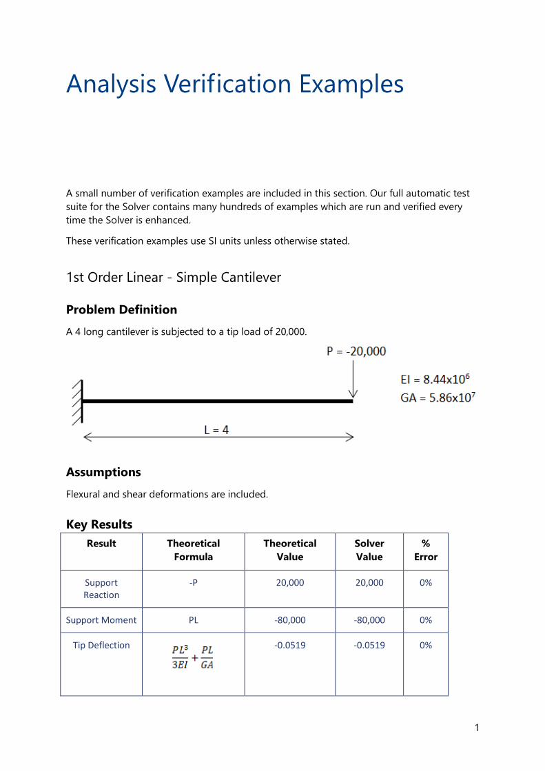
1st Order Linear - Simple Cantilever
Problem Definition
A 4 long cantilever is subjected to a tip load of 20,000.
Assumptions
Flexural and shear deformations are included.
Key Results
Result Theoretical
Formula
Theoretical
Value
Solver
Value
%
Error
Support Reaction
-P 20,000 20,000 0%
Support Moment PL -80,000 -80,000 0%
Tip Deflection
-0.0519 -0.0519 0%
Analysis Verification Examples
2
Conclusion
An exact match is observed between the values reported by the solver and the values
predicted by beam theory.
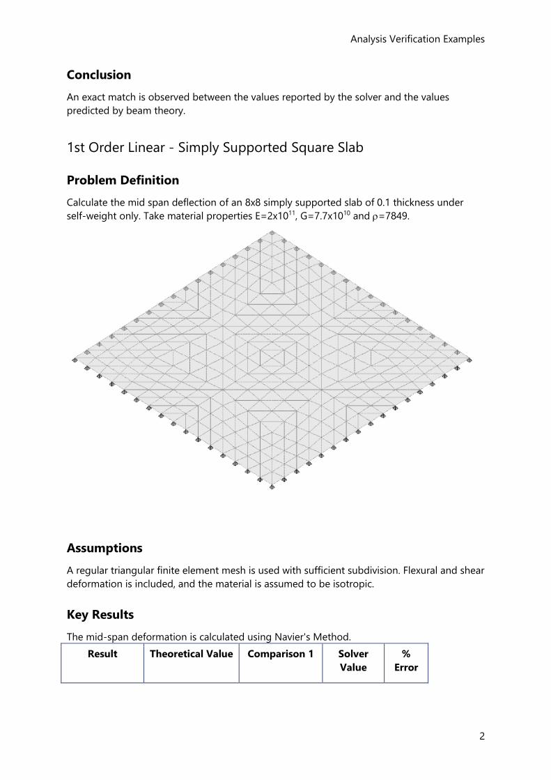
1st Order Linear - Simply Supported Square Slab
Problem Definition
Calculate the mid span deflection of an 8x8 simply supported slab of 0.1 thickness under
self-weight only. Take material properties E=2x10¹¹, G=7.7x10¹⁰ and =7849.
Assumptions
A regular triangular finite element mesh is used with sufficient subdivision. Flexural and shear
deformation is included, and the material is assumed to be isotropic.
Key Results
The mid-span deformation is calculated using Navier's Method.
Result Theoretical Value Comparison 1 Solver
Value
%
Error
Reference Guide - ACI/AISC
3
Mid-span deflection
7.002x10⁻³ 6.990x10⁻³ 7.031x10⁻³ 0.43%
Mid Span Moment
23616 23708 23649 0.14%
Conclusion
An acceptable match is observed between the theoretical values and the solver results. An
acceptable match is also observed between the solver results and those obtained
independently.
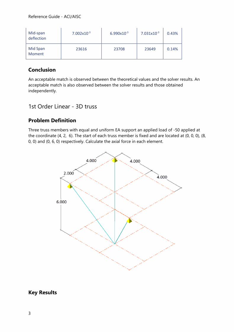
1st Order Linear - 3D truss
Problem Definition
Three truss members with equal and uniform EA support an applied load of -50 applied at
the coordinate (4, 2, 6). The start of each truss member is fixed and are located at (0, 0, 0), (8,
0, 0) and (0, 6, 0) respectively. Calculate the axial force in each element.
Key Results
Analysis Verification Examples
4
The results for this problem are compared against those published by Beer and Johnston and
against another independent analysis package
Result Beer and
Johnston
Comparison 1 Solver
Value
%
Error
(0, 0, 0) - (4, 2, -6) 10.4 10.4 10.4 0%
(8, 0, 0) - (4, 2, -6) 31.2 31.2 31.2 0%
(0, 6, 0) - (4, 2, -6) 22.9 22.9 22.9 0%
Conclusion
An exact match is observed between the values reported by the solver those reported by
Beer and Johnston.
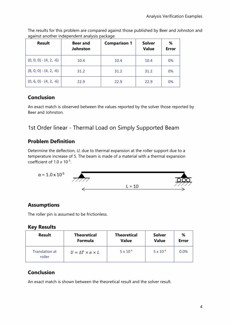
1st Order linear - Thermal Load on Simply Supported Beam
Problem Definition
Determine the deflection, U, due to thermal expansion at the roller support due to a
temperature increase of 5. The beam is made of a material with a thermal expansion
coefficient of 1.0 x 10⁻⁵.
Assumptions
The roller pin is assumed to be frictionless.
Key Results
Result Theoretical
Formula
Theoretical
Value
Solver
Value
%
Error
Translation at roller
5 x 10⁻⁴ 5 x 10⁻⁴ 0.0%
Conclusion
An exact match is shown between the theoretical result and the solver result.
Reference Guide - ACI/AISC
5
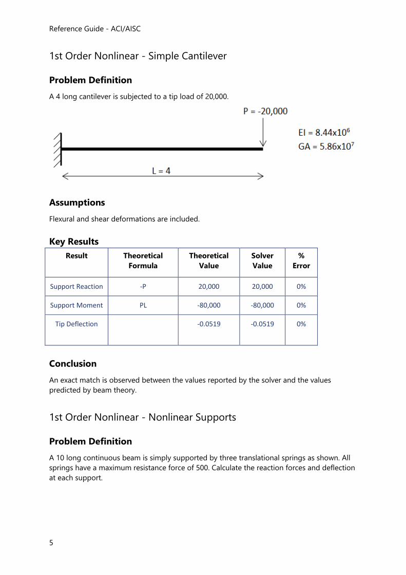
1st Order Nonlinear - Simple Cantilever
Problem Definition
A 4 long cantilever is subjected to a tip load of 20,000.
Assumptions
Flexural and shear deformations are included.
Key Results
Result Theoretical
Formula
Theoretical
Value
Solver
Value
%
Error
Support Reaction -P 20,000 20,000 0%
Support Moment PL -80,000 -80,000 0%
Tip Deflection
-0.0519 -0.0519 0%
Conclusion
An exact match is observed between the values reported by the solver and the values
predicted by beam theory.
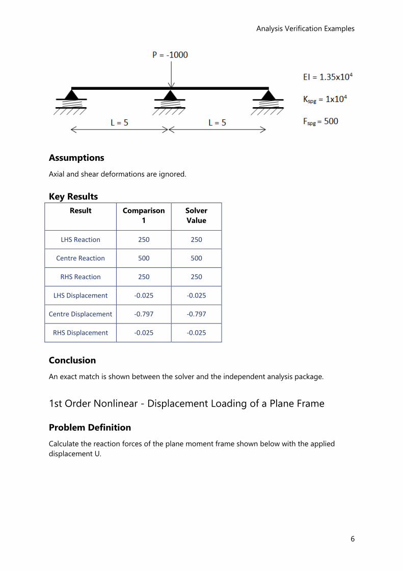
1st Order Nonlinear - Nonlinear Supports
Problem Definition
A 10 long continuous beam is simply supported by three translational springs as shown. All
springs have a maximum resistance force of 500. Calculate the reaction forces and deflection
at each support.
Analysis Verification Examples
6
Assumptions
Axial and shear deformations are ignored.
Key Results
Result Comparison
1
Solver
Value
LHS Reaction 250 250
Centre Reaction 500 500
RHS Reaction 250 250
LHS Displacement -0.025 -0.025
Centre Displacement -0.797 -0.797
RHS Displacement -0.025 -0.025
Conclusion
An exact match is shown between the solver and the independent analysis package.
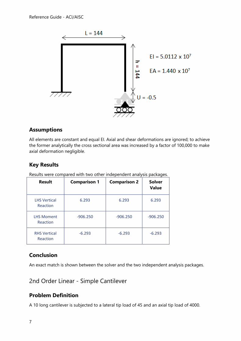
1st Order Nonlinear - Displacement Loading of a Plane Frame
Problem Definition
Calculate the reaction forces of the plane moment frame shown below with the applied
displacement U.
Reference Guide - ACI/AISC
7
Assumptions
All elements are constant and equal EI. Axial and shear deformations are ignored; to achieve
the former analytically the cross sectional area was increased by a factor of 100,000 to make
axial deformation negligible.
Key Results
Results were compared with two other independent analysis packages.
Result Comparison 1 Comparison 2 Solver
Value
LHS Vertical Reaction
6.293 6.293 6.293
LHS Moment Reaction
-906.250 -906.250 -906.250
RHS Vertical Reaction
-6.293 -6.293 -6.293
Conclusion
An exact match is shown between the solver and the two independent analysis packages.
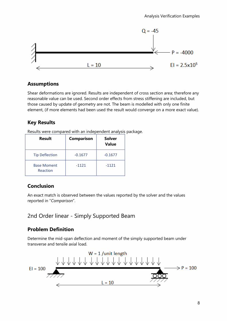
2nd Order Linear - Simple Cantilever
Problem Definition
A 10 long cantilever is subjected to a lateral tip load of 45 and an axial tip load of 4000.
Analysis Verification Examples
8
Assumptions
Shear deformations are ignored. Results are independent of cross section area; therefore any
reasonable value can be used. Second order effects from stress stiffening are included, but
those caused by update of geometry are not. The beam is modelled with only one finite
element, (if more elements had been used the result would converge on a more exact value).
Key Results
Results were compared with an independent analysis package.
Result Comparison Solver
Value
Tip Deflection -0.1677 -0.1677
Base Moment Reaction
-1121 -1121
Conclusion
An exact match is observed between the values reported by the solver and the values
reported in “Comparison”.
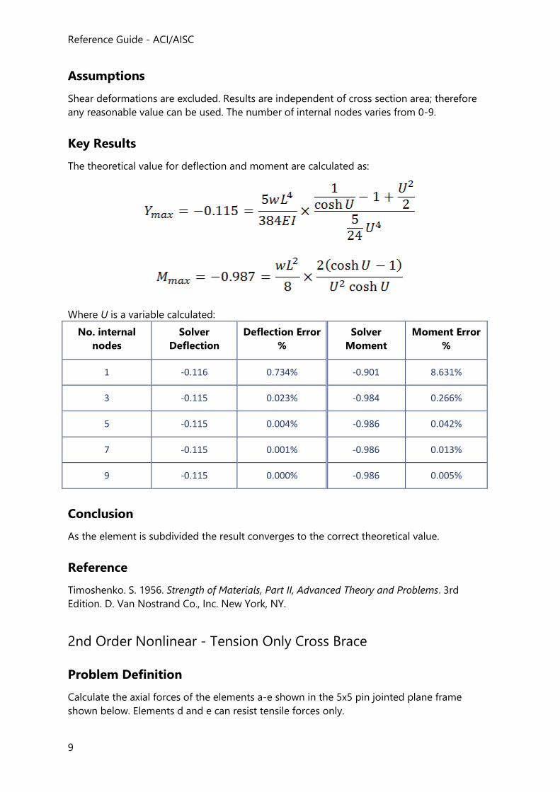
2nd Order linear - Simply Supported Beam
Problem Definition
Determine the mid-span deflection and moment of the simply supported beam under
transverse and tensile axial load.
Reference Guide - ACI/AISC
9
Assumptions
Shear deformations are excluded. Results are independent of cross section area; therefore
any reasonable value can be used. The number of internal nodes varies from 0-9.
Key Results
The theoretical value for deflection and moment are calculated as:
Where U is a variable calculated:
No. internal
nodes
Solver
Deflection
Deflection Error
%
Solver
Moment
Moment Error
%
1 -0.116 0.734% -0.901 8.631%
3 -0.115 0.023% -0.984 0.266%
5 -0.115 0.004% -0.986 0.042%
7 -0.115 0.001% -0.986 0.013%
9 -0.115 0.000% -0.986 0.005%
Conclusion
As the element is subdivided the result converges to the correct theoretical value.
Reference
Timoshenko. S. 1956. Strength of Materials, Part II, Advanced Theory and Problems. 3rd
Edition. D. Van Nostrand Co., Inc. New York, NY.
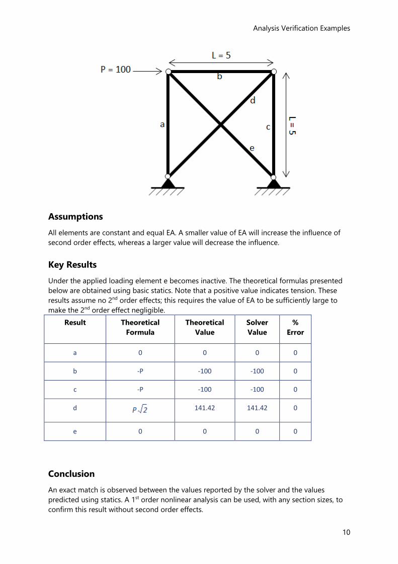
2nd Order Nonlinear - Tension Only Cross Brace
Problem Definition
Calculate the axial forces of the elements a-e shown in the 5x5 pin jointed plane frame
shown below. Elements d and e can resist tensile forces only.
Analysis Verification Examples
10
Assumptions
All elements are constant and equal EA. A smaller value of EA will increase the influence of
second order effects, whereas a larger value will decrease the influence.
Key Results
Under the applied loading element e becomes inactive. The theoretical formulas presented
below are obtained using basic statics. Note that a positive value indicates tension. These
results assume no 2nd order effects; this requires the value of EA to be sufficiently large to
make the 2nd order effect negligible.
Result Theoretical
Formula
Theoretical
Value
Solver
Value
%
Error
a 0 0 0 0
b -P -100 -100 0
c -P -100 -100 0
d
141.42 141.42 0
e 0 0 0 0
Conclusion
An exact match is observed between the values reported by the solver and the values
predicted using statics. A 1st order nonlinear analysis can be used, with any section sizes, to
confirm this result without second order effects.
Reference Guide - ACI/AISC
11
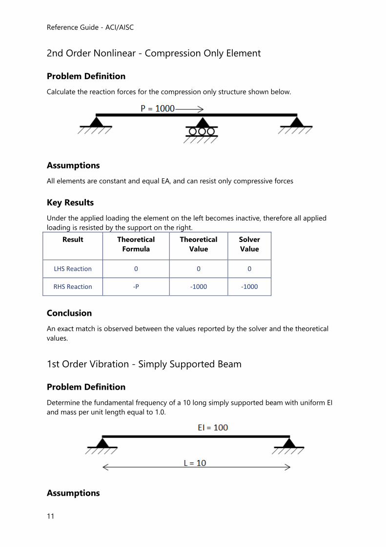
2nd Order Nonlinear - Compression Only Element
Problem Definition
Calculate the reaction forces for the compression only structure shown below.
Assumptions
All elements are constant and equal EA, and can resist only compressive forces
Key Results
Under the applied loading the element on the left becomes inactive, therefore all applied
loading is resisted by the support on the right.
Result Theoretical
Formula
Theoretical
Value
Solver
Value
LHS Reaction 0 0 0
RHS Reaction -P -1000 -1000
Conclusion
An exact match is observed between the values reported by the solver and the theoretical
values.
1st Order Vibration - Simply Supported Beam
Problem Definition
Determine the fundamental frequency of a 10 long simply supported beam with uniform EI
and mass per unit length equal to 1.0.
Assumptions
Analysis Verification Examples
12
Shear deformations are excluded. The number of internal nodes varies from 0-5. Consistent
mass is assumed.
Key Results
The theoretical value for the fundamental frequency is calculated as:
With m is the total mass of the beam.
No. internal
nodes
Solver
Value
% Error
0 1.0955 10.995%
1 0.9909 0.395%
2 0.9878 0.081%
3 0.9872 0.026%
4 0.9871 0.011%
5 0.9870 0.005%
Conclusion
As the element is subdivided the result converges to the correct theoretical value.
1st Order Vibration - Bathe and Wilson Eigenvalue Problem
Problem Definition
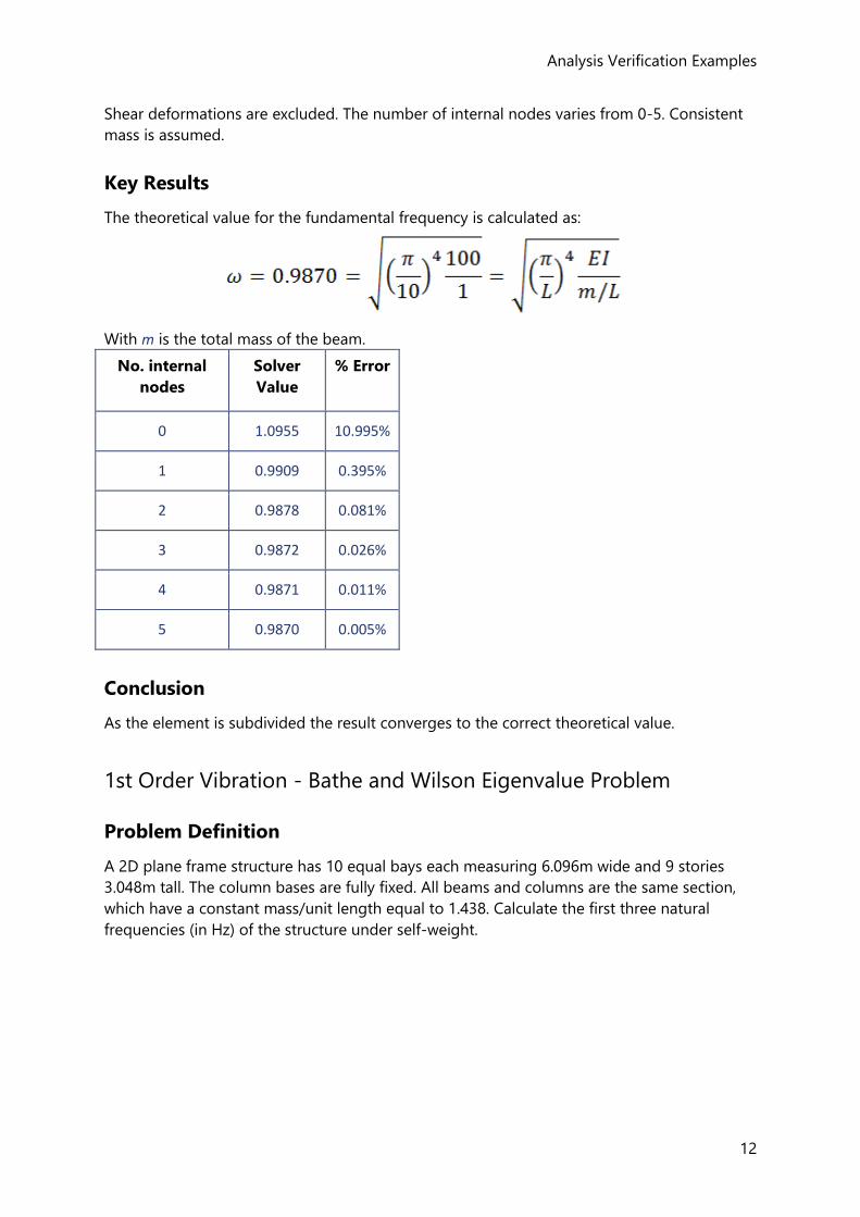
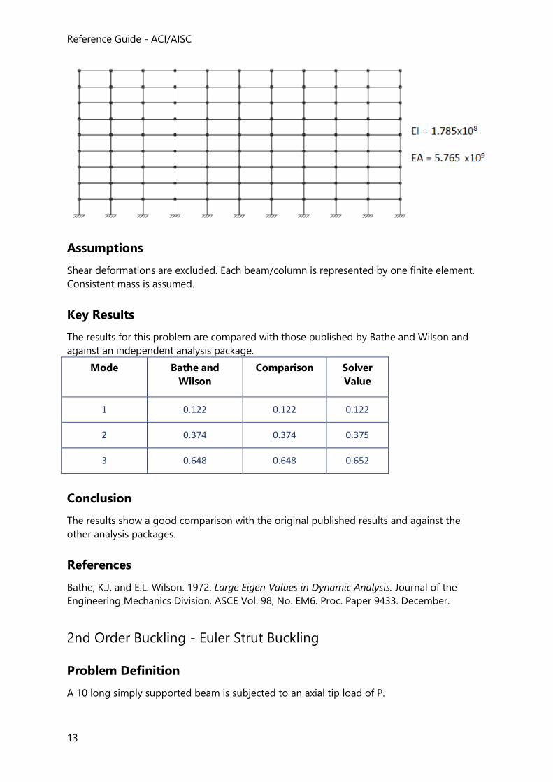
A 2D plane frame structure has 10 equal bays each measuring 6.096m wide and 9 stories
3.048m tall. The column bases are fully fixed. All beams and columns are the same section,
which have a constant mass/unit length equal to 1.438. Calculate the first three natural
frequencies (in Hz) of the structure under self-weight.
Reference Guide - ACI/AISC
13
Assumptions
Shear deformations are excluded. Each beam/column is represented by one finite element.
Consistent mass is assumed.
Key Results
The results for this problem are compared with those published by Bathe and Wilson and
against an independent analysis package.
Mode Bathe and
Wilson
Comparison Solver
Value
1 0.122 0.122 0.122
2 0.374 0.374 0.375
3 0.648 0.648 0.652
Conclusion
The results show a good comparison with the original published results and against the
other analysis packages.
References
Bathe, K.J. and E.L. Wilson. 1972. Large Eigen Values in Dynamic Analysis. Journal of the
Engineering Mechanics Division. ASCE Vol. 98, No. EM6. Proc. Paper 9433. December.
2nd Order Buckling - Euler Strut Buckling
Problem Definition
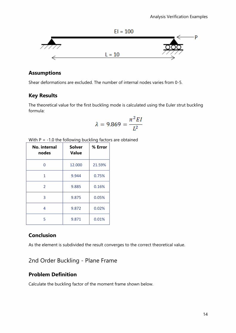
A 10 long simply supported beam is subjected to an axial tip load of P.
Analysis Verification Examples
14
Assumptions
Shear deformations are excluded. The number of internal nodes varies from 0-5.
Key Results
The theoretical value for the first buckling mode is calculated using the Euler strut buckling
formula:
With P = -1.0 the following buckling factors are obtained
No. internal
nodes
Solver
Value
% Error
0 12.000 21.59%
1 9.944 0.75%
2 9.885 0.16%
3 9.875 0.05%
4 9.872 0.02%
5 9.871 0.01%
Conclusion
As the element is subdivided the result converges to the correct theoretical value.
2nd Order Buckling - Plane Frame
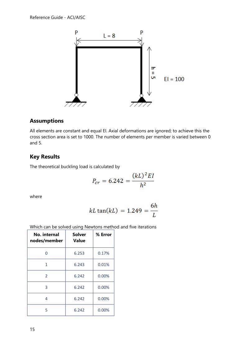
Problem Definition
Calculate the buckling factor of the moment frame shown below.
Reference Guide - ACI/AISC
15
Assumptions
All elements are constant and equal EI. Axial deformations are ignored; to achieve this the
cross section area is set to 1000. The number of elements per member is varied between 0
and 5.
Key Results
The theoretical buckling load is calculated by
where
Which can be solved using Newtons method and five iterations
No. internal
nodes/member
Solver
Value
% Error
0 6.253 0.17%
1 6.243 0.01%
2 6.242 0.00%
3 6.242 0.00%
4 6.242 0.00%
5 6.242 0.00%
Analysis Verification Examples
16
Conclusion
A good match is shown between the solver and theory. The discrepancy decreases as the
level of discretization is increased.
References
Timoshenko, S. and J. M. Gere. 1961. Theory of Elastic Stability. 2nd Edition. McGraw-Hill
Book Company.
17
Loading -ASCE
ASCE7 Loading
This handbook provides a general overview of how loadcases and combinations are created
in Tekla Structural Designer when the head code is set to United States(ACI/AISC). The ASCE7
Combination Generator is also described.
Load Cases (ASCE7)
Loadcase Types (ASCE7)
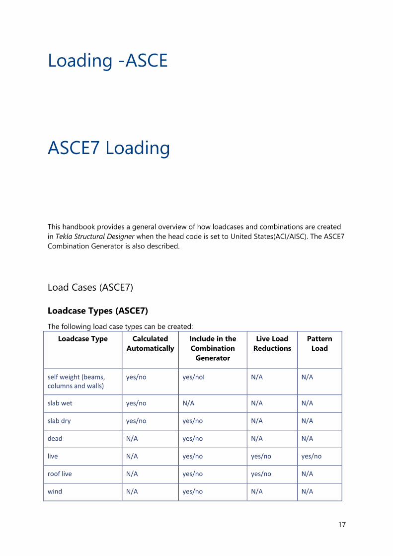
The following load case types can be created:
Loadcase Type Calculated
Automatically
Include in the
Combination
Generator
Live Load
Reductions
Pattern
Load
self weight (beams, columns and walls)
yes/no yes/noI N/A N/A
slab wet yes/no N/A N/A N/A
slab dry yes/no yes/no N/A N/A
dead N/A yes/no N/A N/A
live N/A yes/no yes/no yes/no
roof live N/A yes/no yes/no N/A
wind N/A yes/no N/A N/A
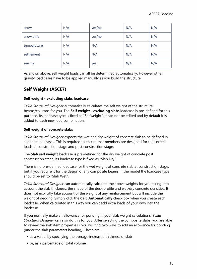
ASCE7 Loading
18
snow N/A yes/no N/A N/A
snow drift N/A yes/no N/A N/A
temperature N/A N/A N/A N/A
settlement N/A N/A N/A N/A
seismic N/A yes N/A N/A
As shown above, self weight loads can all be determined automatically. However other
gravity load cases have to be applied manually as you build the structure.
Self Weight (ASCE7)
Self weight - excluding slabs loadcase
Tekla Structural Designer automatically calculates the self weight of the structural
beams/columns for you. The Self weight - excluding slabs loadcase is pre-defined for this
purpose. Its loadcase type is fixed as “Selfweight”. It can not be edited and by default it is
added to each new load combination.
Self weight of concrete slabs
Tekla Structural Designer expects the wet and dry weight of concrete slab to be defined in
separate loadcases. This is required to ensure that members are designed for the correct
loads at construction stage and post construction stage.
The Slab self weight loadcase is pre-defined for the dry weight of concrete post
construction stage, its loadcase type is fixed as “Slab Dry”.
There is no pre-defined loadcase for the wet weight of concrete slab at construction stage,
but if you require it for the design of any composite beams in the model the loadcase type
should be set to “Slab Wet”.
Tekla Structural Designer can automatically calculate the above weights for you taking into
account the slab thickness, the shape of the deck profile and wet/dry concrete densities. It
does not explicitly take account of the weight of any reinforcement but will include the
weight of decking. Simply click the Calc Automatically check box when you create each
loadcase. When calculated in this way you can’t add extra loads of your own into the
loadcase.
If you normally make an allowance for ponding in your slab weight calculations, Tekla
Structural Designer can also do this for you. After selecting the composite slabs, you are able
to review the slab item properties - you will find two ways to add an allowance for ponding
(under the slab parameters heading). These are:
• as a value, by specifying the average increased thickness of slab
• or, as a percentage of total volume.
Reference Guide - ACI/AISC
19
Using either of these methods the additional load is added as a uniform load over the whole
area of slab.
Live and Roof Live Loads (ASCE7)
Live Load Reductions
Reductions can be applied to roof live and live loads to take account of the unlikelihood of
the whole building being loaded with its full design live load. The reduction is calculated
based on total floor area supported by the design member. Roof live and live load types
each have their own reductions applied in accordance with either Section 4.8 and 4.9 of ASCE
7-05, or Section 4.7 and 4.8 of ASCE 7-10 as appropriate.
Due to the complications associated with live load reduction when considering members at
any angle to the vertical or horizontal, reductions are only applied to:
• Horizontal steel beams with vertical webs (major axis horizontal) which are set to be
“gravity only” pin ended only
• Vertical columns only (both RC and steel)
• Vertical walls only (RC)
Live Load Reduction Factor
The live load reduction factor, R is calculated as follows:
R = (0.25 + 15 / Sqrt(KLL*AT)) - where R <= 1.0 US-units
R = (0.25 + 4.57 / Sqrt(KLL*AT)) metric-units
KLL comes from Table 4-2 in ASCE7-05/ASCE7-10. Essentially:
Interior and exterior cols (no cantilever slabs) KLL= 4
Edge and interior beams (no cantilever slabs) KLL= 2
Interior beams (with cantilever slabs) KLL= 2
Cantilever beams KLL= 1
Edge cols (with cantilever slabs) KLL= 3
Corner cols (with cantilever slabs) KLL= 2
Edge beams (with cantilever slabs) KLL= 1
For all beams and column stacks supporting one floor R ≥ 0.5
For all column stacks supporting two or more floors R ≥ 0.4
ASCE7 Loading
20
As it is not possible to automatically assess where cantilever slabs are and what they are attached to - the KLL factor can be manually specified for individual column and wall stacks and beam spans.
Roof Live Load Reduction Factor
The roof live load reduction factor is calculated as follows:
R = R1*R2
where
R1 = 1.2 - 0.001 * AT , where 1.0 ≥ R1 ≥ 0.6 US-units
= 1.2 - 0.011 * AT metric-units
R2 = 1.0 (conservatively assumes roofs < 18 degs)
Wind Loads (ASCE7)
The ASCE7 Wind Wizard
The Wind Wizard is fully described in the Wind Modeling Engineer’s Handbook.
The Wind Wizard assesses wind loading on your building structure via a choice of methods:
• Directional Procedure Part 1 - Rigid Buildings of All Heights (Chapter 27)
• Envelope Procedure Part 1 - Low-Rise Buildings (Chapter 28)
Wind load cases can then be generated and combined with other actions due to dead and
imposed loads in accordance with Section 2.3.2 of ASCE7-10
in order to run the wind wizard the following assumptions/limitations exist:-
• The shape of the building meets the limitations allowed for in the code.
• It must be a rigid structure.
• The structure must be either enclosed or partially enclosed.
• Parapets and roof overhangs are not explicitly dealt with..
Simple Wind Loading
If use of the Wind Wizard is not appropriate for your structure then wind loads can be
applied via element or structure loads instead.
Patterning of Live Loads (ASCE7)

Reference Guide - ACI/AISC
21
ASCE7 pattern loading for LRFD combinations is as follows:
Code Clase Load Combination Loaded Spans UnLoaded
Spans
LRFD 1.2D + 1.6L + 0.5Lr 1.2D + 1.6L + 0.5Lr
1.2D + 0.5Lr
Combinations (ASCE7)
Once your load cases have been generated as required, you then combine them into load
combinations; these can either be created manually, by clicking Add... - or with the
assistance of The Combinations Generator, by clicking Generate...
Application of Notional Loads in Combinations (ASCE7)
Notional loads are applied to the structure in the building directions 1 and 2 as follows:
• NL Dir1+
• NL Dir1-
• NL Dir2+
• NL Dir2-
When you run the The Combinations Generator you are required to select the NL directions to
add and the factors to be applied as part of the process. Alternatively, you are able to set up
the combinations manually and apply notional loads and factors to each as required.
The Combinations Generator (ASCE7)
Accessed via the Generate... button, this automatically sets up combinations for both
strength and serviceability.
Temperature and settlement load case types not included in the Generator at all - these have to be added manually.
Combination Generator - Combinations
The first page of the generator lists suggested ASD and LRFD combinations (with
appropriate factors).
The “Generate” check boxes are used to select those combinations to be considered.
Combination Generator - Service
This page indicates which combinations are to be checked for serviceability and the service
factors applied.
Combination Generator - NL
ASCE7 Loading
22
The last page is used to set up the notional loads. You can specify NL’s and factors in each of
four directions. For each direction selected a separate NL combination will be generated.
Any combination with wind in is automatically greyed.
Click Finish to see the list of generated combinations.
Combination Classes (ASCE7)
Having created your combinations you classify them as: Construction Stage, Gravity, Lateral,
Seismic or Vibration Mass.
If generated via the Combinations Generator they are classified for you automatically.
Then (where applicable) you indicate whether they are to be checked for strength or service
conditions, or both.
You also have the option to make any of the combinations inactive.
Construction Stage Combination (ASCE7)
A Construction Stage load combination is only required for the purpose of designing any
composite beams within the model. It is distinguished from other combinations by setting its
“Class” to Construction Stage.
Typically this combination would include a loadcase of type “Slab Wet”, (not “Slab Dry”),
other loadcases being included in the combination as required.
The Slab Wet loadcase type should not be included in any other combination.
Gravity Combinations (ASCE7)
These combinations are considered in both the Gravity Sizing and Full Design processes.
They are used in the Gravity Sizing processes as follows:
• Design Concrete (Gravity) - concrete members in the structure are automatically sized
(or checked) for the gravity combinations.
• Design Steel (Gravity) - steel members in the structure are automatically sized (or
checked) for the gravity combinations.
• Design All (Gravity) - all members in the structure are automatically sized (or checked)
for the gravity combinations.
They are also used during the Full Design processes as follows:
• Design Concrete (All) - concrete members in the structure are automatically sized (or
checked) for the gravity combinations.
Reference Guide - ACI/AISC
23
• Design Steel (All) - steel members in the structure are automatically sized (or checked)
for the gravity combinations.
• Design All (All) - all members in the structure are automatically sized (or checked) for
the gravity combinations.
Lateral Combinations (ASCE7)
These combinations are not used in the Gravity Sizing processes.
They are used during the Full Design processes as follows:
• Design Concrete (All) - concrete members in the structure are automatically sized (or
checked) for the lateral combinations.
• Design Steel (All) - steel members in the structure which have not been set as Gravity
Only are automatically sized (or checked) for the lateral combinations.
• Design All (All) - all concrete members and all steel members which have not been set
as Gravity Only are automatically sized (or checked) for the lateral combinations.
Seismic Combinations (ASCE7)
These combinations are only considered during the Full Design process. They are not used in
the Gravity Sizing process.
Vibration Mass Combinations (ASCE7)
For vibration analysis, you are required to set up specific “vibration mass” combinations.
Provided these combinations are active they are always run through the vibration analysis.
It is always assumed that all loads in the load cases in the combination are converted to mass for vibration analysis.
You are permitted to add lumped mass directly to the model.

25
Concrete Design - ACI
Introduction to ACI 318 Design
When the Tekla Structural Designer head code is set to United States(ACI/AISC), you have
the option to specify the Concrete Design Resistance Code as either ACI 318-2008, ACI 318-
2011 or ACI 318-2014. If you are using US Customary Units the design is then performed in
accordance with either ACI 318-08:2008 (Ref. 1), ACI 318-11:2011 (Ref. 2), or ACI 318-14:2014
(Ref. 4). Design can also be performed for metric units in accordance with ACI 318M-11:2011
(Ref. 3), or ACI 318M-14:2014 (Ref. 5)
Unless explicitly noted otherwise, all clauses, figures and tables used in the Reference Guides are from ACI 318-11:2011, these have not yet been updated to reflect the new clause numbering in ACI 318-11:2014.
Seismic Design
Reinforced concrete structures in buildings subjected to earthquake effects are designed
elastically to the strains and displacements both from static and dynamic forces which they
are subjected to. It is recognised that during an earthquake the building and its structural
elements are very likely to be exposed to displacements well into their inelastic range and
special precautions need to be taken as to increase the strength of critical sections in
members which contribute to the building's lateral resistance while also contributing to the
ductile behaviour of the building in order to allow for the dissipation of induced stresses.
In the case of reinforced concrete structures, particular design and detailing requirements
(provisions) need to be fulfilled beyond the conventional design of the elements as to
provide them with ductile response capabilities. Such requirements are mainly addressed to
structural elements part of structural systems built for the purpose of resisting seismic lateral
forces - Seismic Force Resisting Systems [SFRS]. Seismic provisions also apply to reinforced
concrete elements not part of the SFRS when the building is assigned to a higher Seismic
Design Category - SDC D, E or F.
The seismic design checks and detailing requirements of reinforced concrete members in
Tekla Structural Designer are based mainly on ACI318, Chapter 21 - Earthquake-Resisting
Structures.
Seismic Force Resisting Systems
The level of design and detailing required of members that are part of a seismic resisting
structural system can differ depending on the amount of toughness they are intended to
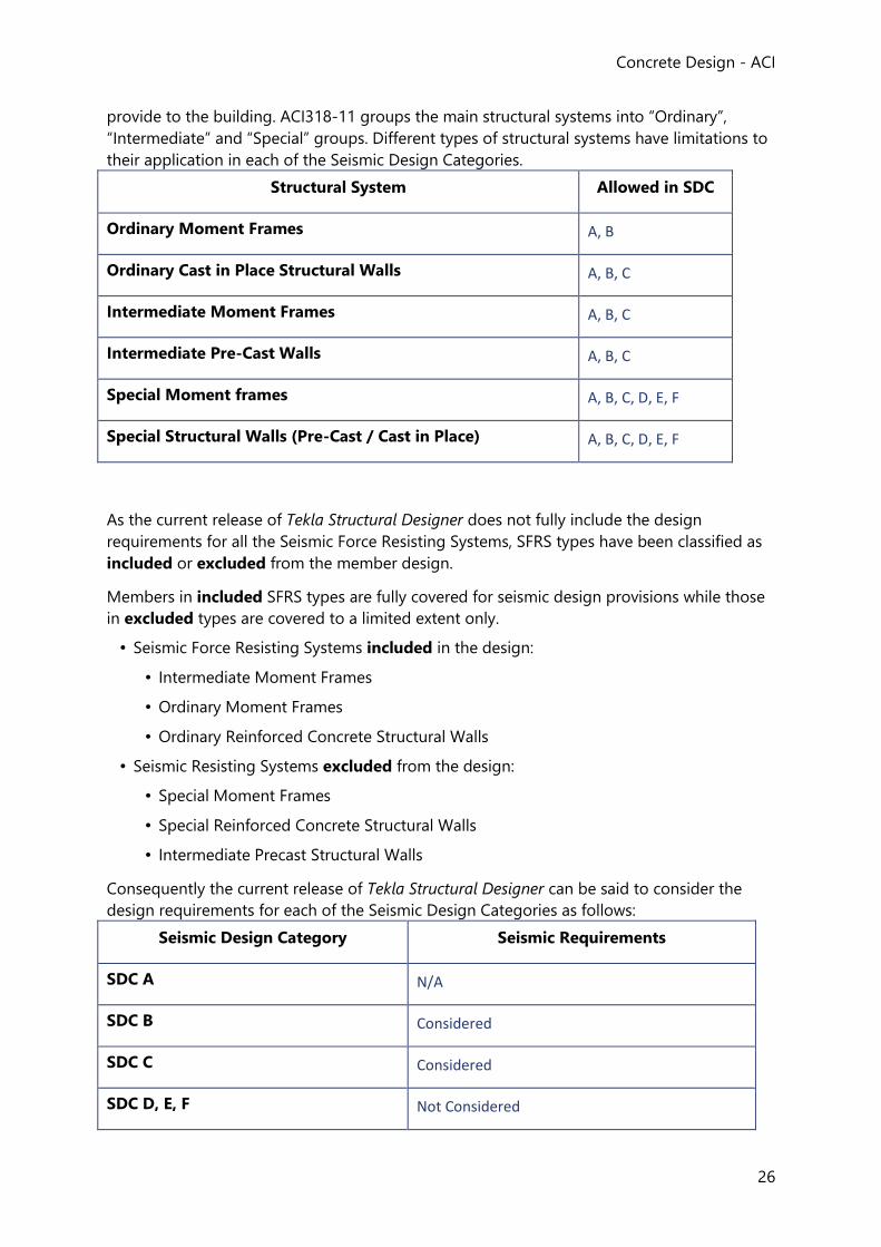
Concrete Design - ACI
26
provide to the building. ACI318-11 groups the main structural systems into “Ordinary”,
“Intermediate” and “Special” groups. Different types of structural systems have limitations to
their application in each of the Seismic Design Categories.
Structural System Allowed in SDC
Ordinary Moment Frames A, B
Ordinary Cast in Place Structural Walls A, B, C
Intermediate Moment Frames A, B, C
Intermediate Pre-Cast Walls A, B, C
Special Moment frames A, B, C, D, E, F
Special Structural Walls (Pre-Cast / Cast in Place) A, B, C, D, E, F
As the current release of Tekla Structural Designer does not fully include the design
requirements for all the Seismic Force Resisting Systems, SFRS types have been classified as
included or excluded from the member design.
Members in included SFRS types are fully covered for seismic design provisions while those
in excluded types are covered to a limited extent only.
• Seismic Force Resisting Systems included in the design:
• Intermediate Moment Frames
• Ordinary Moment Frames
• Ordinary Reinforced Concrete Structural Walls
• Seismic Resisting Systems excluded from the design:
• Special Moment Frames
• Special Reinforced Concrete Structural Walls
• Intermediate Precast Structural Walls
Consequently the current release of Tekla Structural Designer can be said to consider the
design requirements for each of the Seismic Design Categories as follows:
Seismic Design Category Seismic Requirements
SDC A N/A
SDC B Considered
SDC C Considered
SDC D, E, F Not Considered
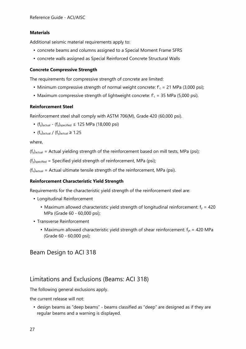
Reference Guide - ACI/AISC
27
Materials
Additional seismic material requirements apply to:
• concrete beams and columns assigned to a Special Moment Frame SFRS
• concrete walls assigned as Special Reinforced Concrete Structural Walls
Concrete Compressive Strength
The requirements for compressive strength of concrete are limited:
• Minimum compressive strength of normal weight concrete: f'c = 21 MPa (3,000 psi);
• Maximum compressive strength of lightweight concrete: f'c = 35 MPa (5,000 psi).
Reinforcement Steel
Reinforcement steel shall comply with ASTM 706(M), Grade 420 (60,000 psi).
• (fy)actual - (fy)specified ≤ 125 MPa (18,000 psi)
• (fu)actual / (fy)actual ≥ 1.25
where,
(fy)actual = Actual yielding strength of the reinforcement based on mill tests, MPa (psi);
(fy)specified = Specified yield strength of reinforcement, MPa (psi);
(fu)actual = Actual ultimate tensile strength of the reinforcement, MPa (psi).
Reinforcement Characteristic Yield Strength
Requirements for the characteristic yield strength of the reinforcement steel are:
• Longitudinal Reinforcement
• Maximum allowed characteristic yield strength of longitudinal reinforcement: fy = 420
MPa (Grade 60 - 60,000 psi);
• Transverse Reinforcement
• Maximum allowed characteristic yield strength of shear reinforcement: fyt = 420 MPa
(Grade 60 - 60,000 psi);
Beam Design to ACI 318
Limitations and Exclusions (Beams: ACI 318)
The following general exclusions apply.
the current release will not:
• design beams as “deep beams” - beams classified as “deep” are designed as if they are
regular beams and a warning is displayed.
Concrete Design - ACI
28
Deep beams according to ACI 318 are: (a) Members with clear spans equal to or less than 4 times overall member depth (b) Members with concentrated loads within twice the member depth from the support
• design beams in lightweight concrete
• design beams with coated reinforcement
• design beams with stainless steel
• design prestressed concrete
• design structures subject to very aggressive exposure
• design watertight structures
material limitations for concrete:
• for structural concrete compressive strength of concrete fc' shall not be less than 17 MPa
(2500psi)
• durability requirements are not implemented
material limitations for reinforcement:
• the values of specified yield strength of reinforcement; fy and fyt used in calculations shall
not exceed 550 MPa (80000psi)
• specified yield strength of non-prestressed reinforcement; fy and fyt shall not exceed 420
MPa (60 000 psi) in design of shear or torsion reinforcement
• wire reinforcement design is not implemented
Slender Beams (Beams: ACI 318)
Spacing of lateral supports for a beam shall not exceed 50*b.1
In the program the lateral supports are taken as the distance between the faces of the
supports, and for simplification, b is taken as the web width bw
IF above check fails then a Warning and a text 'Slender span' or 'Over wide distance between
lateral supports' is displayed.
Effects of lateral eccentricity of load are considered in determining spacing of lateral
supports. 1. ACI 318-08:2008 and ACI 318-11:2011 Section 10.4
Cover to Reinforcement (Beams: ACI 318)
The nominal concrete cover is the distance between the surface of the reinforcement closest
to the nearest concrete surface (including links and surface reinforcement where relevant)
and the nearest concrete surface.
Reference Guide - ACI/AISC
29
You are required to set a minimum value for the nominal cover, cnom, u, for the top, bottom,
sides and ends of each beam in the beam properties.
These values are then checked against the nominal limiting cover, cnom,lim
If cnom,u < MAX(cnom,lim, db) then a warning is displayed in the calculations.
Design Parameters for Longitudinal Bars (Beams: ACI 318)
For each of these parameters, the user defined limits (specified in Design Options > Beam
> Reinforcement Settings) are considered in addition to any ACI code recommendations.
Minimum and Maximum Diameter of Reinforcement
IF torsional reinforcement is required, there shall be at least one longitudinal bar in every
corner of the stirrups. Longitudinal bars shall have a diameter at least 0.042 times the stirrup
spacing, but not less than 9 mm (3/8 in).
The maximum diameters of reinforcement to be used in the various locations is set by the
user.
Standard hooks for stirrups and ties are limited to No.8 bars, db=25mm (1.0in.) and smaller.
And the 90-degree hook with 6db extension is further limited to No. 5, db=16mm (0.625in.)
bars and smaller.
For primary reinforcement there is no limit on bar size.
Minimum Distance between Bars
The minimum clear spacing between parallel bars in a layer, scl,min, is given by;
scl,min ≥ MAX[db, 25mm] metric-units
scl,min ≥ MAX[db, 1in] US-units
Concrete Design - ACI
30
IF the above check fails then a Warning is displayed.
Where parallel reinforcement is placed in two or more layers, bars in the upper layers shall
be placed directly above the bars in the bottom layer with clear distance between layers not
less than 25mm (1in.).
Maximum Spacing of Tension Bars
The spacing of reinforcement closest to the tension face, s is given by; 1
s ≤ MIN[380mm*280MPa/fs-2.5*cc, 300mm*(280MPa/fs)] metric-units
s ≤ MIN[15in*40000psi/fs-2.5*cc, 12in*(40000psi/fs)] US-units
where:
cc = the least distance from surface of reinforcement to the tension face
fs = calculated stress in reinforcement at service load; it shall be permitted to take
= (2/3)*fy*(As,reqd/As,prov)
IF the above check fails then a Warning is displayed
IF torsional reinforcement is required:
the longitudinal reinforcement required for torsion shall be distributed around the
perimeter of the closed stirrups with maximum spacing of 300mm (12 in.) 2
Minimum Area of Reinforcement
The minimum area of longitudinal tension reinforcement, As,min, is given by;3
As,min ≥ MAX[(f'c0.5/(4*fy))*bw*d, 1.4MPa*bw*d/ fy ] metric-units
As,min ≥ MAX[(3*f'c0.5/fy) * bw*d, 200psi * bw*d/ fy ] US-units
where
f'c = specified compressive strength of concrete
fy = specified yield strength of reinforcement
bw = web width; for statically determinate members with a flange in tension
bw = MIN(2*bw, beff) A
d = distance from extreme compression fiber to centroid of longitudinal compression reinforcement
A Assumption; the member is statically determinate in design
Eq. above is to be provided wherever reinforcement is needed, except where such
reinforcement is at least one-third greater than that required by analysis;
IF As,prov < 4/3* As
THEN As,min is calculated as eq. above
ELSE As,min not required
Reference Guide - ACI/AISC
31
IF the above check fails then a Warning is displayed.
Maximum Area of Reinforcement
Net tensile strain in extreme layer of longitudinal tension steel, εt shall not be less than 0.004;
εt ≥ 0.004
As,max ≤ 0.85*(f'c / fy)*β1*bw*d*[0.003/(0.003+0.004)]
A
≤ 0.85*(f'c / fy)*β1*bw*d*(3/7)
where
Ag = the gross area of the concrete section
1 = stress block depth factorB
metric units
= 0.85 for f`c ≤ 28MPa
= 0.85 – 0.05 *[(f'c – 28MPa)/7MPa] for 28MPa < f`c < 55MPa
= 0.65 for f`c ≥ 55MPa
US-units
= min(max(0.85 - 0.05 (f'c - 4 ksi) / 1ksi, 0.65), 0.85)
= 0.85 for f`c ≤ 4000 psi
= 0.85 – 0.05 *[(f'c – 4ksi)/1ksi] for 4000 psi < f`c < 8000psi
= 0.65 for f`c ≥ 8000 psi
A Notes on ACI 318-08 Chap. 6 Section 10.3.5
B ACI 318-08:2008, ACI 318-11:2011 and ACI 318M-11:2011 Section 10.2.7.3
ELSE a Warning is displayed.
1. ACI 318-08:2008, ACI 318-11:2011 and ACI 318M-11:2011 Section 10.6.4
2. ACI 318-08:2008, ACI 318-11:2011 and ACI 318M-11:2011 Section 10.5.6.2
3. ACI 318-08:2008, ACI 318-11:2011 and ACI 318M-11:2011 Section 10.5.1
Side Skin Reinforcement in Beams (Beams: ACI 318)
Where h of a beam or joist exceeds 900mm (36 in.), longitudinal skin (side) reinforcement
shall be uniformly distributed along both side faces of the member.
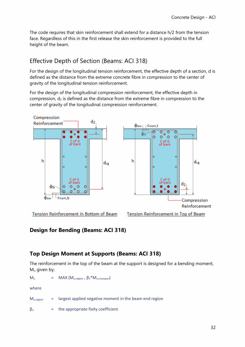
Concrete Design - ACI
32
The code requires that skin reinforcement shall extend for a distance h/2 from the tension
face. Regardless of this in the first release the skin reinforcement is provided to the full
height of the beam.
Effective Depth of Section (Beams: ACI 318)
For the design of the longitudinal tension reinforcement, the effective depth of a section, d is
defined as the distance from the extreme concrete fibre in compression to the center of
gravity of the longitudinal tension reinforcement.
For the design of the longitudinal compression reinforcement, the effective depth in
compression, d2 is defined as the distance from the extreme fibre in compression to the
center of gravity of the longitudinal compression reinforcement.
Design for Bending (Beams: ACI 318)
Top Design Moment at Supports (Beams: ACI 318)
The reinforcement in the top of the beam at the support is designed for a bending moment,
Mu given by;
Mu = MAX (Mu,region , β1*Mu,maxspan)
where
Mu,region = largest applied negative moment in the beam end region
β1 = the appropriate fixity coefficient
Reference Guide - ACI/AISC
33
Mu,maxspan = the maximum positive moment in the beam span (excluding support positions)
Design for Bending for Rectangular Sections (Beams: ACI 318)
Determine if compression reinforcement is needed1;
Nominal strength coefficient of resistance is given;
Rn = Mu / (φ*b*d2)
where
Mu = factored moment at section
d = depth to tension reinforcement
b = width of the compression face of the member
φ = strength reduction factorA
= 0.9 (corresponds to the tension-controlled limit)
A ACI 318-08:2008 and ACI 318-11:2011 Section 9.3
IF Rn ≤ Rnt THEN compression reinforcement is not required.
IF Rn > Rnt THEN compression reinforcement is required.
where
Rnt = Limit value for tension controlled sections without compression reinforcement for different concrete
strength classesA
= ωt *(1-0.59 ωt)* f`c
f`c = compressive strength of concrete
ωt = 0.319*1
1 = stress block depth factorB
metric-units
= 0.85 for f`c ≤ 28MPa
= 0.85 – 0.05 *[(f'c – 28MPa)/7MPa] for 28MPa < f`c < 55MPa
= 0.65 for f`c ≥ 55MPa
US-units
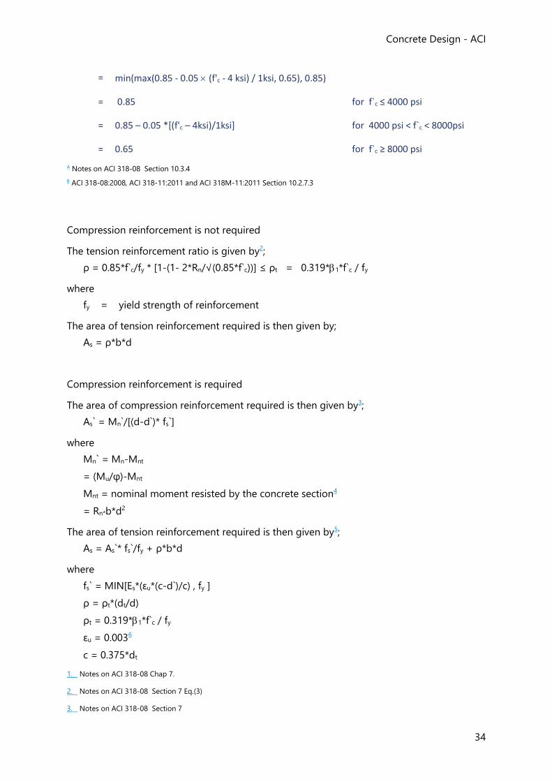
Concrete Design - ACI
34
= min(max(0.85 - 0.05 (f'c - 4 ksi) / 1ksi, 0.65), 0.85)
= 0.85 for f`c ≤ 4000 psi
= 0.85 – 0.05 *[(f'c – 4ksi)/1ksi] for 4000 psi < f`c < 8000psi
= 0.65 for f`c ≥ 8000 psi
A Notes on ACI 318-08 Section 10.3.4
B ACI 318-08:2008, ACI 318-11:2011 and ACI 318M-11:2011 Section 10.2.7.3
Compression reinforcement is not required
The tension reinforcement ratio is given by2;
ρ = 0.85*f`c/fy * [1-(1- 2*Rn/√(0.85*f`c))] ≤ ρt = 0.319*1*f`c / fy
where
fy = yield strength of reinforcement
The area of tension reinforcement required is then given by;
As = ρ*b*d
Compression reinforcement is required
The area of compression reinforcement required is then given by3;
As` = Mn`/[(d-d`)* fs`]
where
Mn` = Mn-Mnt
= (Mu/φ)-Mnt
Mnt = nominal moment resisted by the concrete section4
= Rn*b*d2
The area of tension reinforcement required is then given by5;
As = As`* fs`/fy + ρ*b*d
where
fs` = MIN[Es*(εu*(c-d`)/c) , fy ]
ρ = ρt*(dt/d)
ρt = 0.319*1*f`c / fy
εu = 0.0036
c = 0.375*dt
1. Notes on ACI 318-08 Chap 7.
2. Notes on ACI 318-08 Section 7 Eq.(3)
3. Notes on ACI 318-08 Section 7
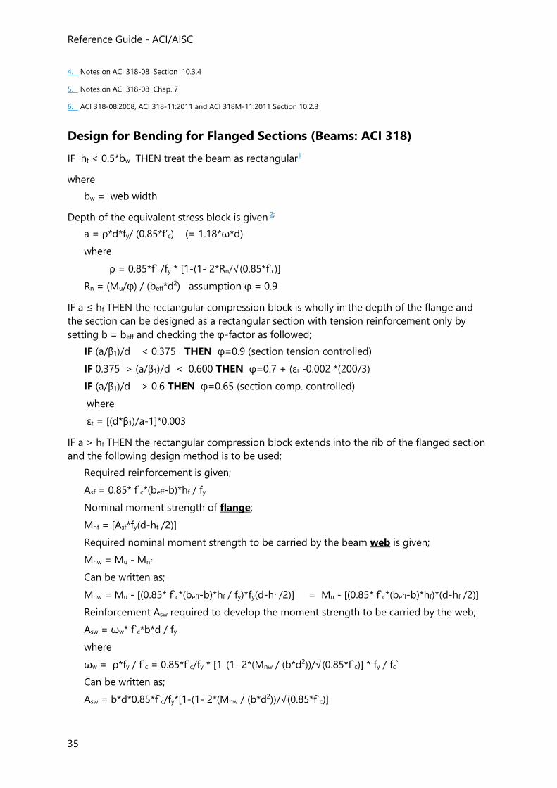
Reference Guide - ACI/AISC
35
4. Notes on ACI 318-08 Section 10.3.4
5. Notes on ACI 318-08 Chap. 7
6. ACI 318-08:2008, ACI 318-11:2011 and ACI 318M-11:2011 Section 10.2.3
Design for Bending for Flanged Sections (Beams: ACI 318)
IF hf < 0.5*bw THEN treat the beam as rectangular1
where
bw = web width
Depth of the equivalent stress block is given 2;
a = ρ*d*fy/ (0.85*f’c) (= 1.18*ω*d)
where
ρ = 0.85*f`c/fy * [1-(1- 2*Rn/√(0.85*f’c)]
Rn = (Mu/φ) / (beff*d2) assumption φ = 0.9
IF a ≤ hf THEN the rectangular compression block is wholly in the depth of the flange and
the section can be designed as a rectangular section with tension reinforcement only by
setting b = beff and checking the φ-factor as followed;
IF (a/β1)/d < 0.375 THEN φ=0.9 (section tension controlled)
IF 0.375 > (a/β1)/d < 0.600 THEN φ=0.7 + (εt -0.002 *(200/3)
IF (a/β1)/d > 0.6 THEN φ=0.65 (section comp. controlled)
where
εt = [(d*β1)/a-1]*0.003
IF a > hf THEN the rectangular compression block extends into the rib of the flanged section
and the following design method is to be used;
Required reinforcement is given;
Asf = 0.85* f`c*(beff-b)*hf / fy
Nominal moment strength of flange;
Mnf = [Asf*fy(d-hf /2)]
Required nominal moment strength to be carried by the beam web is given;
Mnw = Mu - Mnf
Can be written as;
Mnw = Mu - [(0.85* f`c*(beff-b)*hf / fy)*fy(d-hf /2)] = Mu - [(0.85* f`c*(beff-b)*hf)*(d-hf /2)]
Reinforcement Asw required to develop the moment strength to be carried by the web;
Asw = ωw* f`c*b*d / fy
where
ωw = ρ*fy / f`c = 0.85*f`c/fy * [1-(1- 2*(Mnw / (b*d2))/√(0.85*f`c)] * fy / fc`
Can be written as;
Asw = b*d*0.85*f`c/fy*[1-(1- 2*(Mnw / (b*d2))/√(0.85*f`c)]
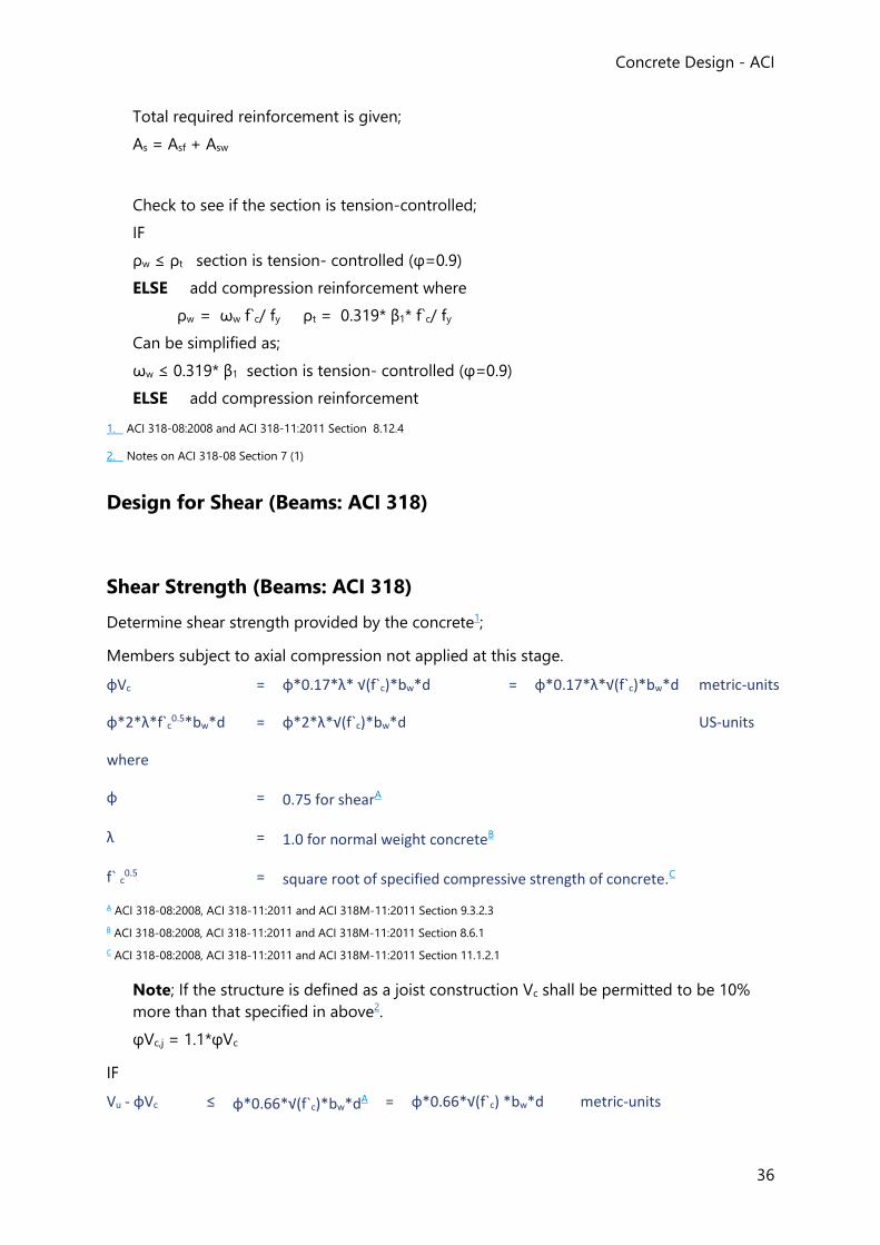
Concrete Design - ACI
36
Total required reinforcement is given;
As = Asf + Asw
Check to see if the section is tension-controlled;
IF
ρw ≤ ρt section is tension- controlled (φ=0.9)
ELSE add compression reinforcement where
ρw = ωw f`c/ fy ρt = 0.319* β1* f`c/ fy
Can be simplified as;
ωw ≤ 0.319* β1 section is tension- controlled (φ=0.9)
ELSE add compression reinforcement
1. ACI 318-08:2008 and ACI 318-11:2011 Section 8.12.4
2. Notes on ACI 318-08 Section 7 (1)
Design for Shear (Beams: ACI 318)
Shear Strength (Beams: ACI 318)
Determine shear strength provided by the concrete1;
Members subject to axial compression not applied at this stage.
φVc = φ*0.17*λ* √(f`c)*bw*d = φ*0.17*λ*√(f`c)*bw*d metric-units
φ*2*λ*f`c0.5*bw*d = φ*2*λ*√(f`c)*bw*d US-units
where
φ = 0.75 for shearA
λ = 1.0 for normal weight concreteB
f` c0.5 = square root of specified compressive strength of concrete.C
A ACI 318-08:2008, ACI 318-11:2011 and ACI 318M-11:2011 Section 9.3.2.3
B ACI 318-08:2008, ACI 318-11:2011 and ACI 318M-11:2011 Section 8.6.1
C ACI 318-08:2008, ACI 318-11:2011 and ACI 318M-11:2011 Section 11.1.2.1
Note; If the structure is defined as a joist construction Vc shall be permitted to be 10%
more than that specified in above2.
φVc,j = 1.1*φVc
IF
Vu - φVc ≤ φ*0.66*√(f`c)*bw*dA = φ*0.66*√(f`c) *bw*d metric-units
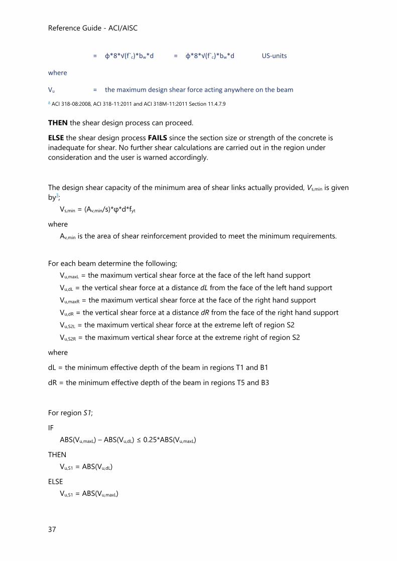
Reference Guide - ACI/AISC
37
= φ*8*√(f`c)*bw*d = φ*8*√(f`c)*bw*d US-units
where
Vu = the maximum design shear force acting anywhere on the beam
A ACI 318-08:2008, ACI 318-11:2011 and ACI 318M-11:2011 Section 11.4.7.9
THEN the shear design process can proceed.
ELSE the shear design process FAILS since the section size or strength of the concrete is
inadequate for shear. No further shear calculations are carried out in the region under
consideration and the user is warned accordingly.
The design shear capacity of the minimum area of shear links actually provided, Vs,min is given
by3;
Vs,min = (Av,min/s)*φ*d*fyt
where
Av,min is the area of shear reinforcement provided to meet the minimum requirements.
For each beam determine the following;
Vu,maxL = the maximum vertical shear force at the face of the left hand support
Vu,dL = the vertical shear force at a distance dL from the face of the left hand support
Vu,maxR = the maximum vertical shear force at the face of the right hand support
Vu,dR = the vertical shear force at a distance dR from the face of the right hand support
Vu,S2L = the maximum vertical shear force at the extreme left of region S2
Vu,S2R = the maximum vertical shear force at the extreme right of region S2
where
dL = the minimum effective depth of the beam in regions T1 and B1
dR = the minimum effective depth of the beam in regions T5 and B3
For region S1;
IF
ABS(Vu,maxL) – ABS(Vu,dL) ≤ 0.25*ABS(Vu,maxL)
THEN
Vu,S1 = ABS(Vu,dL)
ELSE
Vu,S1 = ABS(Vu,maxL)
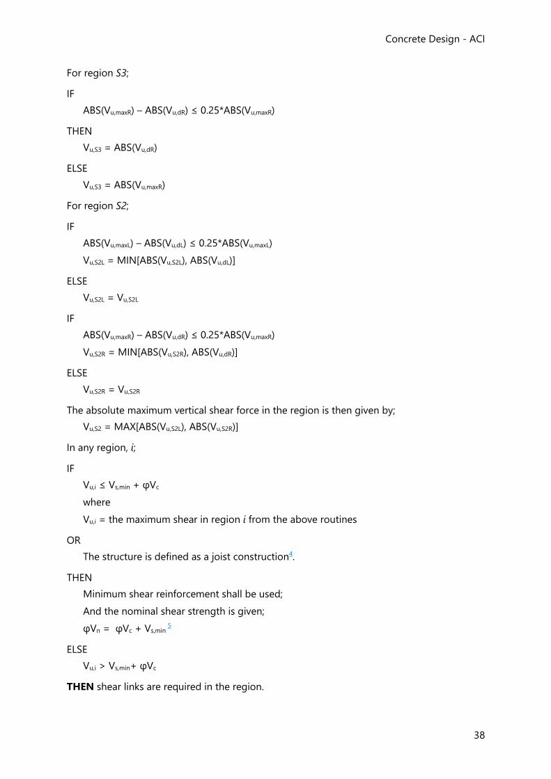
Concrete Design - ACI
38
For region S3;
IF
ABS(Vu,maxR) – ABS(Vu,dR) ≤ 0.25*ABS(Vu,maxR)
THEN
Vu,S3 = ABS(Vu,dR)
ELSE
Vu,S3 = ABS(Vu,maxR)
For region S2;
IF
ABS(Vu,maxL) – ABS(Vu,dL) ≤ 0.25*ABS(Vu,maxL)
Vu,S2L = MIN[ABS(Vu,S2L), ABS(Vu,dL)]
ELSE
Vu,S2L = Vu,S2L
IF
ABS(Vu,maxR) – ABS(Vu,dR) ≤ 0.25*ABS(Vu,maxR)
Vu,S2R = MIN[ABS(Vu,S2R), ABS(Vu,dR)]
ELSE
Vu,S2R = Vu,S2R
The absolute maximum vertical shear force in the region is then given by;
Vu,S2 = MAX[ABS(Vu,S2L), ABS(Vu,S2R)]
In any region, i;
IF
Vu,i ≤ Vs,min + φVc
where
Vu,i = the maximum shear in region i from the above routines
OR
The structure is defined as a joist construction4.
THEN
Minimum shear reinforcement shall be used;
And the nominal shear strength is given;
φVn = φVc + Vs,min 5
ELSE
Vu,i > Vs,min+ φVc
THEN shear links are required in the region.
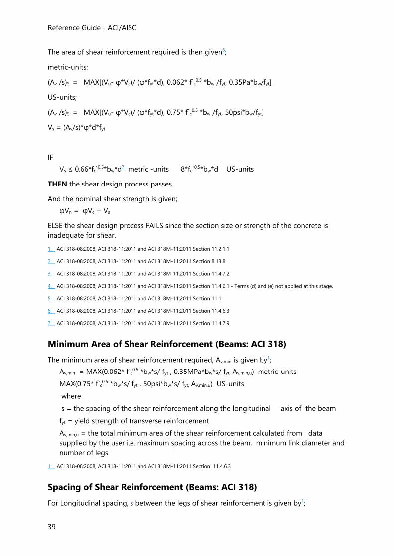
Reference Guide - ACI/AISC
39
The area of shear reinforcement required is then given6;
metric-units;
(Av /s)Si = MAX[(Vu- φ*Vc)/ (φ*fyt*d), 0.062* f`c0.5 *bw /fyt, 0.35Pa*bw/fyt]
US-units;
(Av /s)Si = MAX[(Vu- φ*Vc)/ (φ*fyt*d), 0.75* f`c0.5 *bw /fyt, 50psi*bw/fyt]
Vs = (Av/s)*φ*d*fyt
IF
Vs ≤ 0.66*fc`0.5*bw*d7 metric -units 8*fc`
0.5*bw*d US-units
THEN the shear design process passes.
And the nominal shear strength is given;
φVn = φVc + Vs
ELSE the shear design process FAILS since the section size or strength of the concrete is
inadequate for shear.
1. ACI 318-08:2008, ACI 318-11:2011 and ACI 318M-11:2011 Section 11.2.1.1
2. ACI 318-08:2008, ACI 318-11:2011 and ACI 318M-11:2011 Section 8.13.8
3. ACI 318-08:2008, ACI 318-11:2011 and ACI 318M-11:2011 Section 11.4.7.2
4. ACI 318-08:2008, ACI 318-11:2011 and ACI 318M-11:2011 Section 11.4.6.1 - Terms (d) and (e) not applied at this stage.
5. ACI 318-08:2008, ACI 318-11:2011 and ACI 318M-11:2011 Section 11.1
6. ACI 318-08:2008, ACI 318-11:2011 and ACI 318M-11:2011 Section 11.4.6.3
7. ACI 318-08:2008, ACI 318-11:2011 and ACI 318M-11:2011 Section 11.4.7.9
Minimum Area of Shear Reinforcement (Beams: ACI 318)
The minimum area of shear reinforcement required, Av,min is given by1;
Av,min = MAX(0.062* f`c0.5 *bw*s/ fyt , 0.35MPa*bw*s/ fyt, Av,min,u) metric-units
MAX(0.75* f`c0.5 *bw*s/ fyt , 50psi*bw*s/ fyt, Av,min,u) US-units
where
s = the spacing of the shear reinforcement along the longitudinal axis of the beam
fyt = yield strength of transverse reinforcement
Av,min,u = the total minimum area of the shear reinforcement calculated from data
supplied by the user i.e. maximum spacing across the beam, minimum link diameter and
number of legs
1. ACI 318-08:2008, ACI 318-11:2011 and ACI 318M-11:2011 Section 11.4.6.3
Spacing of Shear Reinforcement (Beams: ACI 318)
For Longitudinal spacing, s between the legs of shear reinforcement is given by1;
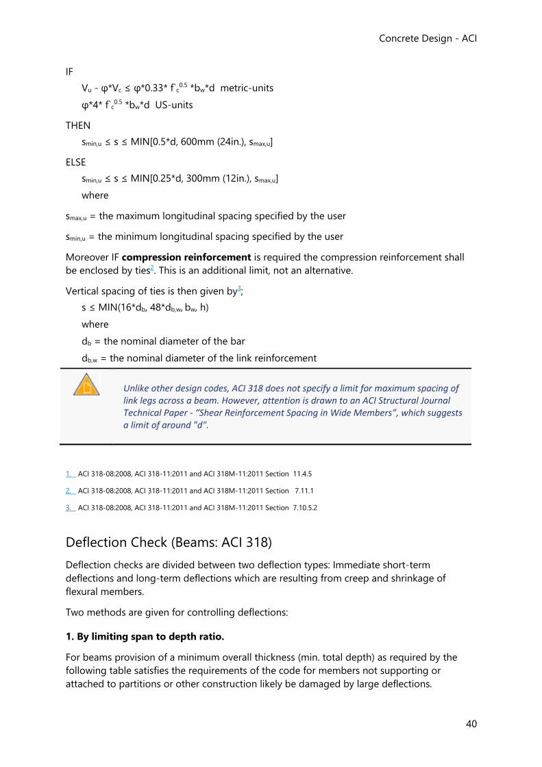
Concrete Design - ACI
40
IF
Vu - φ*Vc ≤ φ*0.33* f`c0.5 *bw*d metric-units
φ*4* f`c0.5 *bw*d US-units
THEN
smin,u ≤ s ≤ MIN[0.5*d, 600mm (24in.), smax,u]
ELSE
smin,u ≤ s ≤ MIN[0.25*d, 300mm (12in.), smax,u]
where
smax,u = the maximum longitudinal spacing specified by the user
smin,u = the minimum longitudinal spacing specified by the user
Moreover IF compression reinforcement is required the compression reinforcement shall
be enclosed by ties2. This is an additional limit, not an alternative.
Vertical spacing of ties is then given by3;
s ≤ MIN(16*db, 48*db,w, bw, h)
where
db = the nominal diameter of the bar
db,w = the nominal diameter of the link reinforcement
Unlike other design codes, ACI 318 does not specify a limit for maximum spacing of link legs across a beam. However, attention is drawn to an ACI Structural Journal Technical Paper - “Shear Reinforcement Spacing in Wide Members”, which suggests a limit of around "d".
1. ACI 318-08:2008, ACI 318-11:2011 and ACI 318M-11:2011 Section 11.4.5
2. ACI 318-08:2008, ACI 318-11:2011 and ACI 318M-11:2011 Section 7.11.1
3. ACI 318-08:2008, ACI 318-11:2011 and ACI 318M-11:2011 Section 7.10.5.2
Deflection Check (Beams: ACI 318)
Deflection checks are divided between two deflection types: Immediate short-term
deflections and long-term deflections which are resulting from creep and shrinkage of
flexural members.
Two methods are given for controlling deflections:
1. By limiting span to depth ratio.
For beams provision of a minimum overall thickness (min. total depth) as required by the
following table satisfies the requirements of the code for members not supporting or
attached to partitions or other construction likely be damaged by large deflections.
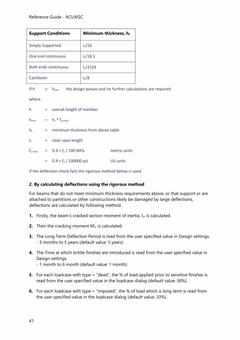
Reference Guide - ACI/AISC
41
Support Conditions Minimum thickness, ht
Simply Supported ln/16
One end continuous ln/18.5
Both ends continuous ln/2126
Cantilever ln/8
If h ≥ hmin the design passes and no further calculations are required
where
h = overall height of member
hmin = ht * fy,mod
ht = minimum thickness from above table
ln = clear span length
fy,mod = 0.4 + fy / 700 MPa metric-units
= 0.4 + fy / 100000 psi US-units
If the deflection check fails the rigorous method below is used.
2. By calculating deflections using the rigorous method
For beams that do not meet minimum thickness requirements above, or that support or are
attached to partitions or other constructions likely be damaged by large deflections,
deflections are calculated by following method.
1. Firstly, the beam’s cracked section moment of inertia, Icr is calculated.
2. Then the cracking moment Mcr is calculated.
3. The Long Term Deflection Period is read from the user specified value in Design settings.
- 3 months to 5 years (default value: 5 years).
4. The Time at which brittle finishes are introduced is read from the user specified value in
Design settings.
- 1 month to 6 month (default value: 1 month).
5. For each loadcase with type = "dead", the % of load applied prior to sensitive finishes is
read from the user specified value in the loadcase dialog (default value: 50%).
6. For each loadcase with type = “imposed”, the % of load which is long term is read from
the user specified value in the loadcase dialog (default value: 33%).
Concrete Design - ACI
42
7. For each span in the element the critical gravity combination is determined from the
analysis. The combination reporting the max relative deflection is the one considered in
the deflection check.
8. The maximum deflections for the different situations below can then be determined:
• Dead load deflection (Δi)d
• Dead and live load deflection (Δi)d
• Live load deflection (Δi)live
• Sustained load deflection (Δi)sus
• Total load deflection (Δi)tot
• Deflection affecting sensitive finishes (Δi)af
The check passes if the calculated deflections are less than the deflection limits specified in
the beam properties.
Seismic Design (Beams: ACI 318)
Limitations and Assumptions (Beams-seismic: ACI 318)
The follows limitations and assumptions apply:
• Seismic design is only performed for beams marked as part of a Seismic Force Resisting
System and for seismic cantilevers.
• Requirements for beams particularly in the case of members not part of any SFRS when
in Seismic Design Categories D through F are not considered in the current release.
• The design and detailing requirements of members part of Special Moment Frames is
beyond scope (some checks are implemented but only due to their existence in lower
toughness systems).
A full list of the code checks that have and have not been implemented is provided in the table below.
• Seismic design checks are mostly based on capacity design obtained from the main
reinforcement provided. This can lead to an over-design of structural members if the
designer does not take steps to minimize excess capacity.
• Beam seismic design and detailing in the current release is based on the beam
rectangular section and takes under consideration the beam reinforcement only. In
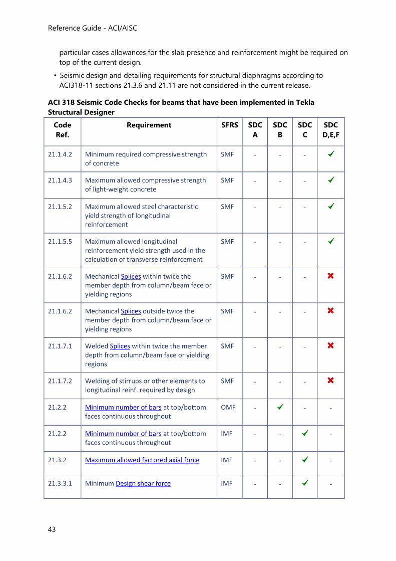
Reference Guide - ACI/AISC
43
particular cases allowances for the slab presence and reinforcement might be required on
top of the current design.
• Seismic design and detailing requirements for structural diaphragms according to
ACI318-11 sections 21.3.6 and 21.11 are not considered in the current release.
ACI 318 Seismic Code Checks for beams that have been implemented in Tekla
Structural Designer
Code
Ref.
Requirement SFRS SDC
A
SDC
B
SDC
C
SDC
D,E,F
21.1.4.2 Minimum required compressive strength of concrete
SMF - - -
21.1.4.3 Maximum allowed compressive strength of light-weight concrete
SMF - - -
21.1.5.2 Maximum allowed steel characteristic yield strength of longitudinal reinforcement
SMF - - -
21.1.5.5 Maximum allowed longitudinal reinforcement yield strength used in the calculation of transverse reinforcement
SMF - - -
21.1.6.2 Mechanical Splices within twice the member depth from column/beam face or yielding regions
SMF - - -
21.1.6.2 Mechanical Splices outside twice the member depth from column/beam face or yielding regions
SMF - - -
21.1.7.1 Welded Splices within twice the member depth from column/beam face or yielding regions
SMF - - -
21.1.7.2 Welding of stirrups or other elements to longitudinal reinf. required by design
SMF - - -
21.2.2 Minimum number of bars at top/bottom faces continuous throughout
OMF -
- -
21.2.2 Minimum number of bars at top/bottom faces continuous throughout
IMF - -
-
21.3.2 Maximum allowed factored axial force IMF - -
-
21.3.3.1 Minimum Design shear force IMF - -
-
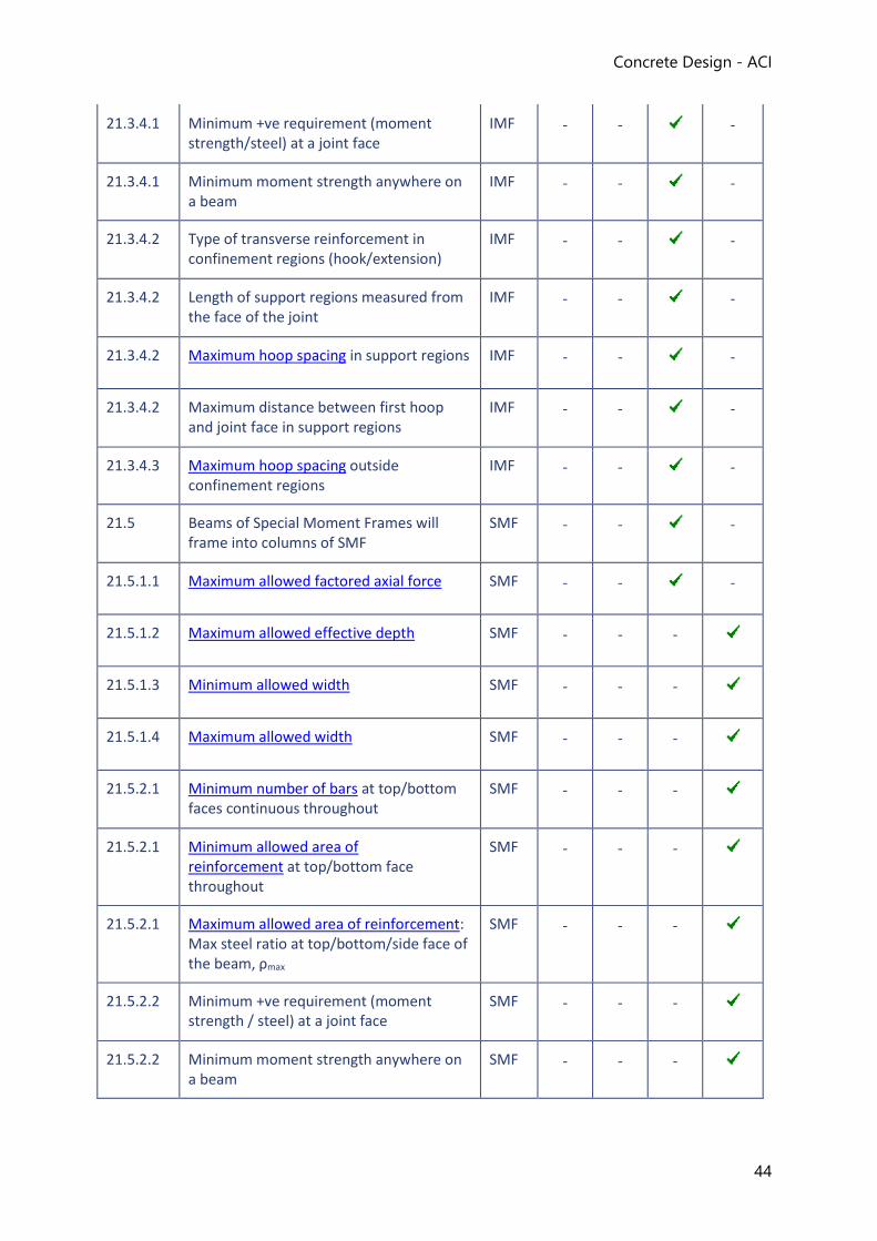
Concrete Design - ACI
44
21.3.4.1 Minimum +ve requirement (moment strength/steel) at a joint face
IMF - -
-
21.3.4.1 Minimum moment strength anywhere on a beam
IMF - -
-
21.3.4.2 Type of transverse reinforcement in confinement regions (hook/extension)
IMF - -
-
21.3.4.2 Length of support regions measured from the face of the joint
IMF - -
-
21.3.4.2 Maximum hoop spacing in support regions IMF - -
-
21.3.4.2 Maximum distance between first hoop and joint face in support regions
IMF - -
-
21.3.4.3 Maximum hoop spacing outside confinement regions
IMF - -
-
21.5 Beams of Special Moment Frames will frame into columns of SMF
SMF - -
-
21.5.1.1 Maximum allowed factored axial force SMF - -
-
21.5.1.2 Maximum allowed effective depth SMF - - -
21.5.1.3 Minimum allowed width SMF - - -
21.5.1.4 Maximum allowed width SMF - - -
21.5.2.1 Minimum number of bars at top/bottom faces continuous throughout
SMF - - -
21.5.2.1 Minimum allowed area of reinforcement at top/bottom face throughout
SMF - - -
21.5.2.1 Maximum allowed area of reinforcement: Max steel ratio at top/bottom/side face of the beam, ρmax
SMF - - -
21.5.2.2 Minimum +ve requirement (moment strength / steel) at a joint face
SMF - - -
21.5.2.2 Minimum moment strength anywhere on a beam
SMF - - -
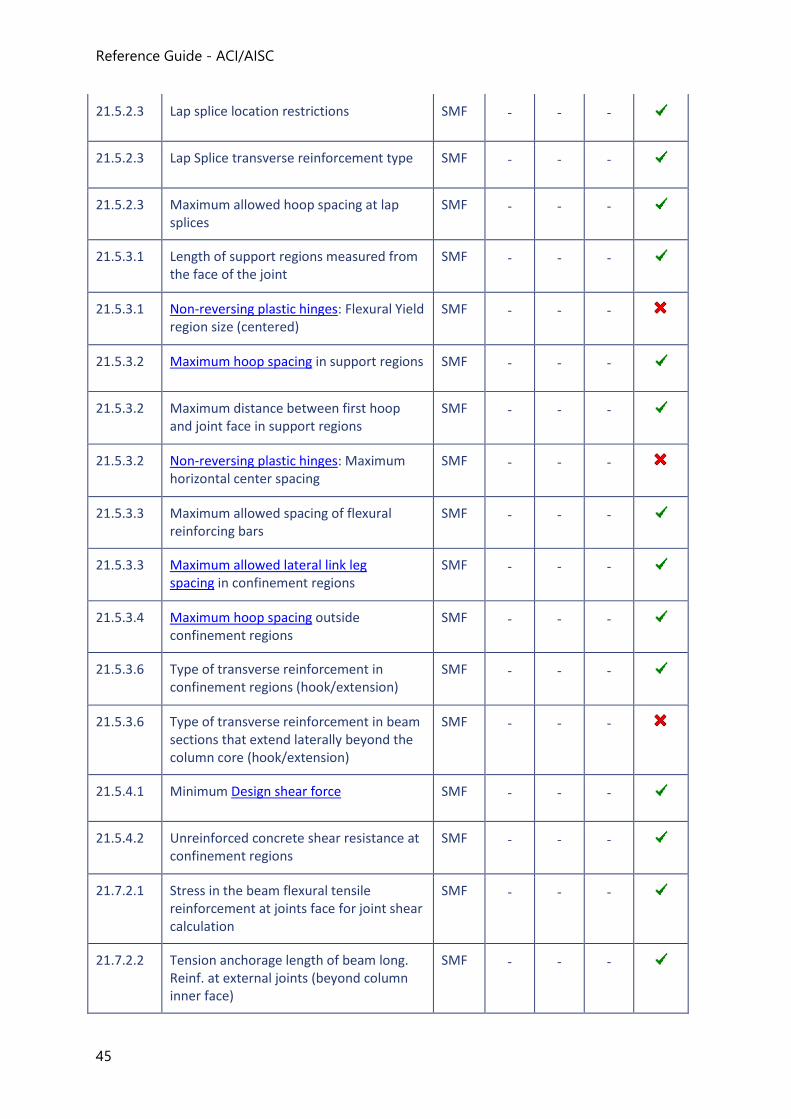
Reference Guide - ACI/AISC
45
21.5.2.3 Lap splice location restrictions SMF - - -
21.5.2.3 Lap Splice transverse reinforcement type SMF - - -
21.5.2.3 Maximum allowed hoop spacing at lap splices
SMF - - -
21.5.3.1 Length of support regions measured from the face of the joint
SMF - - -
21.5.3.1 Non-reversing plastic hinges: Flexural Yield region size (centered)
SMF - - -
21.5.3.2 Maximum hoop spacing in support regions SMF - - -
21.5.3.2 Maximum distance between first hoop and joint face in support regions
SMF - - -
21.5.3.2 Non-reversing plastic hinges: Maximum horizontal center spacing
SMF - - -
21.5.3.3 Maximum allowed spacing of flexural reinforcing bars
SMF - - -
21.5.3.3 Maximum allowed lateral link leg spacing in confinement regions
SMF - - -
21.5.3.4 Maximum hoop spacing outside confinement regions
SMF - - -
21.5.3.6 Type of transverse reinforcement in confinement regions (hook/extension)
SMF - - -
21.5.3.6 Type of transverse reinforcement in beam sections that extend laterally beyond the column core (hook/extension)
SMF - - -
21.5.4.1 Minimum Design shear force SMF - - -
21.5.4.2 Unreinforced concrete shear resistance at confinement regions
SMF - - -
21.7.2.1 Stress in the beam flexural tensile reinforcement at joints face for joint shear calculation
SMF - - -
21.7.2.2 Tension anchorage length of beam long. Reinf. at external joints (beyond column inner face)
SMF - - -
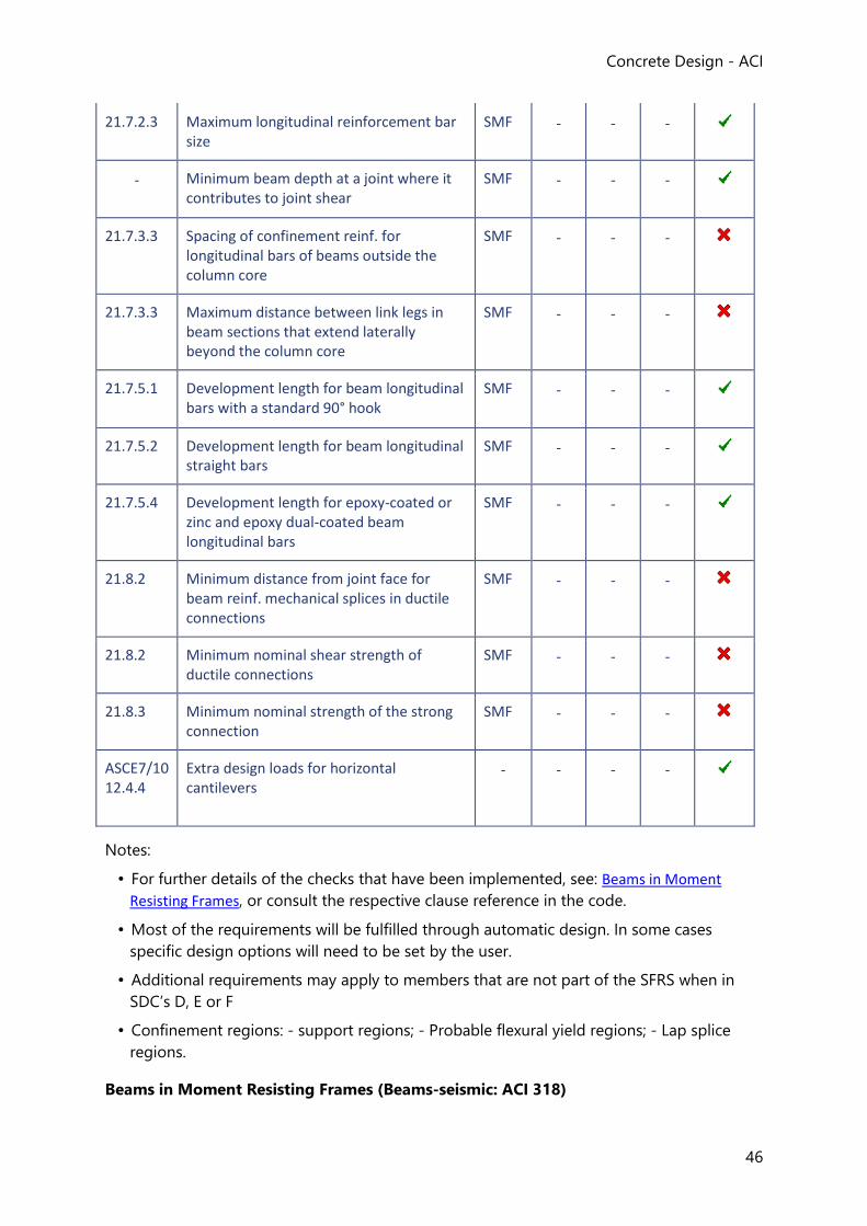
Concrete Design - ACI
46
21.7.2.3 Maximum longitudinal reinforcement bar size
SMF - - -
- Minimum beam depth at a joint where it contributes to joint shear
SMF - - -
21.7.3.3 Spacing of confinement reinf. for longitudinal bars of beams outside the column core
SMF - - -
21.7.3.3 Maximum distance between link legs in beam sections that extend laterally beyond the column core
SMF - - -
21.7.5.1 Development length for beam longitudinal bars with a standard 90° hook
SMF - - -
21.7.5.2 Development length for beam longitudinal straight bars
SMF - - -
21.7.5.4 Development length for epoxy-coated or zinc and epoxy dual-coated beam longitudinal bars
SMF - - -
21.8.2 Minimum distance from joint face for beam reinf. mechanical splices in ductile connections
SMF - - -
21.8.2 Minimum nominal shear strength of ductile connections
SMF - - -
21.8.3 Minimum nominal strength of the strong connection
SMF - - -
ASCE7/10 12.4.4
Extra design loads for horizontal cantilevers
- - - -
Notes:
• For further details of the checks that have been implemented, see: Beams in Moment
Resisting Frames, or consult the respective clause reference in the code.
• Most of the requirements will be fulfilled through automatic design. In some cases
specific design options will need to be set by the user.
• Additional requirements may apply to members that are not part of the SFRS when in
SDC’s D, E or F
• Confinement regions: - support regions; - Probable flexural yield regions; - Lap splice
regions.
Beams in Moment Resisting Frames (Beams-seismic: ACI 318)
Reference Guide - ACI/AISC
47
General Requirements (Beams-seismic: ACI 318)
Maximum allowed factored axial force
Flexural elements with high axial loading values under any load combination are handled in
the seismic design and detailing as compressive members.
If SFRS Type = Ordinary Moment Frame, then no axial compression limit applies.
If SFRS Type = Intermediate Moment Frame or SFRS Type = Special Moment Frame
Pmax = Ag * f’c / 10
where
Pmax = Maximum allowed compression value on the member
Ag = Gross area of the concrete section
f’c = specified compressive strength of concrete
The check passes if;
Pu ≥ Pmax
where
Pu = Maximum factored compressive axial force anywhere in the span considering all load combinations
Maximum allowed effective depth
The maximum allowed effective depth of a beam part of a Special Moment Frame is
proportional to its clear span length to limit the overloading of the adjacent joints and
columns.
If SFRS Type = Special Moment Frame
d ≤ dmax
where
d = Distance between the extreme compression fiber and the longitudinal tension reinforcement centroid
dmax = Maximum allowed distance between the extreme compression fiber and the longitudinal tension reinforcement centroid
dmax = 0.25 * ln
where
ln = Length of the clear span measured from face-to-face of supports
Minimum allowed width
Concrete Design - ACI
48
Beams part of Special Moment Frames in buildings subjected to earthquake effects have a
minimum width limit for their web.
If SFRS Type = Special Moment Frame
bw ≥ bw,min
where
bw = Beam web width
bw,min = Minimum allowed beam web width
= MAX( 0.3 * h, 250 mm) Metric-units
= MAX( 0.3 * h, 10 in) US-units
where
h = Overall depth of the concrete section
Maximum allowed width
Despite not being advisable, beams in Special Moment Frames are allowed to be wider than
the supporting columns up to a fixed limit.
The maximum lateral extension of a beam on each side of the joining column is beyond scope in the current release of Tekla Structural Designer.
Flexural Requirements (Beams-seismic: ACI 318)
Minimum number of bars
The minimum allowed number of bars continuous along the beam span is required to be
checked in the layers closest to the top and bottom faces of any beam in the SFRS.
The number of bars should be ≥ 2.
Maximum allowed bar size
This applies to end regions of beams where the beam reinforcement extends into the
column core. The required development length of reinforcement bars extending into the
column core restricts the minimum size of the column and vice-versa.
If SFRS Type = Special Moment Frame
“Anchorage requirements at the joint of special moment frames limit the maximum bar
size at each end of the beam”
Reference Guide - ACI/AISC
49
Minimum flexural strength
The minimum area of top and bottom steel required at any section of a beam part of a
Moment Resisting Frame needs to comply with flexural strength requirements when
considering earthquake effects.
Note that no seismic design requirements apply to beams that are part of Ordinary Moment
Frames. All other Moment Resisting Frame types have minimum longitudinal moment
requirements.
Minimum allowed area of reinforcement
The minimum allowed area of steel throughout the bottom and top faces of a beam part of a
Special Moment Frame is limited as per ACI 318-11 equation (10-3).
Maximum allowed area of reinforcement
For the purpose of increasing the ductility response of beams in Special Moment Frames the
area of reinforcement both at the top and bottom faces is limited.
If SFRS Type = Special Moment Frame
(As- and As
+) ≤ As,max = 0.025 * bw * d
where
As = Area of non-prestressed longitudinal tension reinforcement
bw = Beam web width
d = Distance from extreme compression fiber to centroid of longitudinal tension reinforcement
No other Moment Resisting Frame type has a maximum area of steel requirement.
Maximum allowed center spacing of longitudinal bars
Limitations on the longitudinal bar spacing apply to beams part of Special Moment Frames.
If SFRS Type = Special Moment Frame, then the maximum allowed center spacing is checked for confinement regions as follows:
scr,max = 350 mm Metric-units
As = 14 in. US-units
where
Concrete Design - ACI
50
scr,max = maximum allowed center spacing
No requirement applies to regions where confinement reinforcement is not required.
No other Moment Resisting Frame type has a maximum allowed spacing of longitudinal bars
requirement.
Non-reversing plastic hinges
Non-reversing plastic hinges are regions along the span of the beam where flexural yielding
is likely to occur.
Non-reversing plastic hinges are beyond scope in the current release of Tekla Structural Designer.
Splices
Restrictions apply to the locations of reinforcement lap splices along the span of a beam part
of Special Moment Frames.
Strength design of mechanical splices and restrictions to the use of welded splices as
required by ACI318-11 apply to Special Moment Frames.
These restrictions are not implemented in the current release of Tekla Structural Designer.
Transverse Reinforcement (Beams-seismic: ACI 318)
Seismic requirements relating to transverse reinforcement take into account properties,
strengths and outcomes which are shear related ignoring any reinforcement intended to deal
with torsional effects.
Design shear force
The design shear force for members subjected to earthquake effects is obtained by
consideration of the minimum required shear strength of the member. The required nominal
shear strength of a flexural member part of a Moment Resisting Frame is checked
considering the sum of shears resultant from the moment strengths due to reverse curvature
bending acting at each end of the beam and from the tributary factored gravity loads.
Beams are checked for shear in three regions:
• Left region, S1;
• Central region, S2;
• Right region, S3.
Reference Guide - ACI/AISC
51
Shear design is performed considering the Major axis shear force only. Shear Force in the
minor axis is checked against the ignorable threshold.
If SFRS Type = Ordinary Moment Frame, then no shear seismic check applies.
If SFRS Type = Intermediate Moment Frame
Ve = ɸMIN(Ve,Mn+Ve,gravity,Ve,2E)
where
ɸ = Strength reduction factor = 1.0
Ve = Minimum design shear force for load combinations including earthquake effects
Ve,gravity = Shear due to factored gravity loads from seismic combinations (including vertical earthquake effects) retaining the sign from analysis
Ve,2E = Maximum shear resultant from seismic combinations, with doubled earthquake effect [i.e.: Ve.non-seismic + Ve.E x 2]
Ve,Mn = Maximum shear associated with the development of reversed curvature bending due to nominal resisting moments at both ends of the member, considering both the clockwise and counter-clockwise cases
If SFRS Type = Special Moment Frame
Ve = ɸ(Ve,Mpr+Ve,gravity)
where
ɸ = Strength reduction factor = 1.0
Ve = Minimum design shear force for load combinations including earthquake effects
Ve,gravity = Shear due to factored gravity loads from seismic combinations (including vertical earthquake effects) retaining the sign from analysis
Ve,Mpr = Maximum shear associated with the development of reversed curvature bending due to the probable flexural moment strength for both the clockwise and counter-clockwise situations, at both ends of the member
Maximum hoop spacing
The maximum allowed horizontal center spacing of hoops in confinement regions of beams
is limited by ACI 318 depending on the type of Seismic Force Resisting System considered.
This check is performed for support regions only, it is beyond scope in the current release of Tekla Structural Designer for other confinement regions.
Concrete Design - ACI
52
Non-reversing plastic hinge regions along the span have the same requirements as support regions, but these are beyond scope in the current release of Tekla Structural Designer.
For Support Regions:
If SFRS Type = Special Moment Frame
The maximum allowed center hoop spacing in support regions, scr,max,sup is calculated as
follows:
According to ACI318-081:
scr,max,sup = MIN(d/4, 8 * db,smallest, 24 * db,w, 300mm) Metric-units
scr,max,sup = MIN(d/4, 8 * db,smallest, 24 * db,w, 12 in.) US-units
According to ACI318-112:
scr,max,sup = MIN(d/4, 6* db,smallest, 150 mm) Metric-units
scr,max,sup = MIN(d/4, 6 * db,smallest, 6 in.) US-units
where
d = Distance from extreme compression fiber to centroid of longitudinal tension reinforcement
db,smallest = Smallest longitudinal reinforcement bar diameter
db,w = Link (hoop) diameter, mm
If SFRS Type = Intermediate Moment Frame
The maximum allowed center hoop spacing in support regions, scr,max,sup is calculated as
follows:
scr,max,sup = MIN(d/4, 8* db,smallest, 24 * db,w, 300mm) Metric-units
scr,max,sup = MIN(d/4, 8 * db,smallest, 24 * db,w, 12 in.) US-units
where
d = Distance from extreme compression fiber to centroid of longitudinal tension reinforcement
db,smallest = Smallest longitudinal reinforcement bar diameter
db,w = Link (hoop) diameter, mm
For Span Regions:
If SFRS Type = Special Moment Frame, or Intermediate Moment Frame
Reference Guide - ACI/AISC
53
The maximum allowed hoops spacing outside confinement regions, scr,max,span is calculated as
follows:
scr,max,span = d/2
Maximum allowed lateral link leg spacing
The clear spacing between link legs at right angles to the span is limited in confinement
reinforcement regions of members part of Special Moment Frames only.
This check is performed for support regions only, it is beyond scope in the current release of Tekla Structural Designer for other confinement regions.
1. ACI318-08 Section 21.5.3.2. This requirement has changed from ACI318-08 to ACI318-11.
2. ACI318-08 Section 21.5.3.2. This requirement has changed from ACI318-08 to ACI318-11.
Beams not part of a SFRS (Beams-seismic: ACI 318)
Requirements when in SDC D - F (Beams-seismic: ACI 318)
When designing members for earthquake effects, beams not part of the SFRS when in
Seismic Design Categories D through F are required to be designed with seismic provisions
all the same.
With the exception of seismic cantilevers, the design of these members for seismic provisions is beyond scope in the current release of Tekla Structural Designer.
Seismic Cantilevers (Beams-seismic: ACI 318)
Horizontal cantilever structural members in structures assigned to Seismic Design Category
D, E or F are required to be designed to the applicable load combinations plus an isolated
minimum net upward force of 0.2* times the dead load.
If a cantilever beam has been marked as a seismic cantilever, then provided the seismic
design category = D, E or F the minimum design moment at the restrained end is checked as
follows:
Calculate minimum positive design moment:
Mmin+ = 0.2 * Me,dead-
where
Mmin+ = Minimum positive design bending moment at the restrained end.
Me,dead- = Critical negative bending moment at the restrained end due to dead loads
only obtained for the considered seismic combination.
Concrete Design - ACI
54
Check the minimum design moment at the restrained end:
Mu+ ≥ Mmin
+
where
Mu+ = Critical negative bending moment at the restrained end due to dead loads
only obtained for the considered seismic combination.
If the check fails the region is designed for Mu+ = M
min+
Seismic Detailing (Beams: ACI 318)
When designing a structure considering earthquake effects numerous seismic detailing
requirements apply to structural beams intended to resist the earthquake induced forces.
The seismic detailing of concrete beams is performed only if the member is assigned to the
SFRS through the In a Seismic Force Resisting System setting in the member properties
window.
Flexural Reinforcement (Beams-seismic: ACI 318)
Longitudinal reinforcement at the top and bottom faces of a beam in any Moment Resisting
Frame are required to have at least two continuous steel bars along the span for structural
integrity and constructability purposes.
Anchorage
Longitudinal reinforcement terminated at a column in beams that are part of Special
Moment Frames shall be anchored within the element confined core for a length measured
from the critical section at the element's face.
Tekla Structural Designer performs the calculation steps for the required development length
at the supports of bars in tension for both the case where straight bars are used and where
hooks are provided.
Lap Splices
Specific seismic requirements apply only to lap splices in flexural members that are part of
Special Moment Frames.
For beams that are part of Special Moment Frames lap splices are not allowed to be located:
• Within joints or within a distance of twice the members depth from the face of a joint
• Within regions where flexural yielding is likely to occur.
The latter requirement to avoid lap splices in regions where flexural yielding is likely to occur is beyond scope in the current release of Tekla Structural Designer.
Reference Guide - ACI/AISC
55
Confinement Reinforcement for Ductility (Beams-seismic: ACI 318)
Reinforcement Type
Confinement reinforcement should consist of hoops, i.e. closed or continuously wound ties
with a seismic hook at each end.
Detailing Regions
Confinement reinforcement is required to be provided over the following confinement
regions in beams that are part of Intermediate and Special Moment Frames. This is not a
requirement for beams that are part of Ordinary Moment Frames
• Support regions:
• These are probable flexural yielding regions flexural yielding regions next to beam-
column joints
Beam-wall moment frames are beyond scope in the current release of Tekla Structural Designer.
• Non-reversing plastic hinge regions:
• These are probable flexural yielding regions outside support regions.
Non-reversing plastic hinge regions are not identified in the current release of Tekla Structural Designer.
• Lap splices:
• Over the full length of lap splices in members that are part of Special Moment Frames Chapter
Column Design to ACI 318
Limitations and Exclusions (Columns: ACI 318)
The following general exclusions apply to the first release:
• Seismic loading and design,
• Consideration of fire resistance. [You are however given full control of the minimum
cover dimension to the reinforcement and are therefore able to take due account of fire
resistance requirements.],
• Lightweight concrete,
• Chamfers,
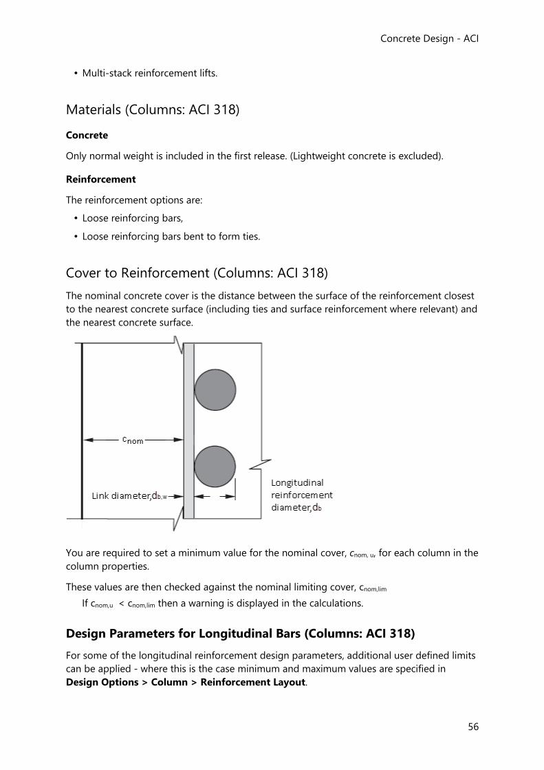
Concrete Design - ACI
56
• Multi-stack reinforcement lifts.
Materials (Columns: ACI 318)
Concrete
Only normal weight is included in the first release. (Lightweight concrete is excluded).
Reinforcement
The reinforcement options are:
• Loose reinforcing bars,
• Loose reinforcing bars bent to form ties.
Cover to Reinforcement (Columns: ACI 318)
The nominal concrete cover is the distance between the surface of the reinforcement closest
to the nearest concrete surface (including ties and surface reinforcement where relevant) and
the nearest concrete surface.
You are required to set a minimum value for the nominal cover, cnom, u, for each column in the
column properties.
These values are then checked against the nominal limiting cover, cnom,lim
If cnom,u < cnom,lim then a warning is displayed in the calculations.
Design Parameters for Longitudinal Bars (Columns: ACI 318)
For some of the longitudinal reinforcement design parameters, additional user defined limits
can be applied - where this is the case minimum and maximum values are specified in
Design Options > Column > Reinforcement Layout.
Reference Guide - ACI/AISC
57
Minimum Longitudinal Bar Spacing
For design to ACI
minimum clear distance ≥ MAX (1.5 * longitudinal db , 1.5in., 1.33*hagg) US units
minimum clear distance ≥ MAX (1.5 * longitudinal db , 40mm, 1.33*hagg) metric units
where
db = bar diameter
hagg = aggregate size
Maximum Longitudinal Bar Spacing
You are given control over this value by specifying an upper limit in Design Options
> Column > Reinforcement Layout.
Minimum Longitudinal Total Steel Area1
For design to ACI
1% * column area
Maximum Longitudinal Total Steel Area
For design to ACI
8% * column area
1. BS EN 1992-1-1:2004 Section 9.5.2(2)
Ultimate Axial Load Limit (Columns: ACI 318)
The strength of a column under truly concentric axial load is
Pno = 0.85*f.c*(Ag-Ast) + fy*Ast
For nonprestressed compression members with tie reinforcement,
φPnmax = 0.80*φ*[0.85*f’c*(Ag-Ast) + fy*Ast]
where
0.85f’c = maximum concrete stress permitted in column design
Ag = gross area of the section (concrete and steel)
fy = yield strength of the reinforcement
Ast = total area of reinforcement in the cross section
Concrete Design - ACI
58
φ = strength reduction factor = 0.65
Effective Length Calculations (Columns: ACI 318)
Effective Length Calculations (Columns: ACI 318)
Unsupported Length
The unsupported length, lu, of a column is the clear distance between lateral supports.
If, at an end of the compression member (stack), no effective beams, flat slab or slab on
beams to include is found, then the clear height includes the (compression member) stack
beyond this restraint, and the same rules apply for finding the end of the clear height at the
end of the next stack (and so on). If there is no stack beyond this restraint (i.e. this is the end
of the column), the clear height ends at the end of the column.
Effective Length
The effective length, le, is calculated automatically from ACI R10.10.1. You have the ability to
override the calculated value.
Tekla Structural Designer will impose the following limits for stacks that are designated as
braced:
0.5 ≤ le / lu ≤ 1
When both ends of an unbraced compression member are hinged (pinned), a “Beyond
Scope” warning is displayed.
The effective length of the stack (compression member) is given by:
le = k * lu
The program uses the bottom end of the stack (compression member) as end 1 and the top
as end 2.
Any beams framing into the end of the compression member (stack) within 45 degrees of
the axis being considered are said to be restraining beams for the stack in that direction. No
adjustment is made to the restraint provided by the beam for the angle (i.e. the full value of
“E * I / l” is used for all beams within 45 degrees of the axis).
A beam is to be considered as a restraining beam in the direction considered if:
-45° < β ≤ 45°
where
β is the angle from the axis in the direction considered to the beam, measured anti-
clockwise when viewed from above (i.e. back along the length of the stack from the end
towards the start).
Fixed Column Base
Reference Guide - ACI/AISC
59
Since in practical structures there is no such thing as a truly fixed end, Tekla Structural
Designer limits ψ ≥ 0.20. This being the practical lower limit suggested in “RC Mechanics” by
McGregor and Wright.
Pinned Column End
In any situation where the end of a column anywhere in the structure is pinned, ψ = 1000.
(This being the upper limit on ψ that is imposed by Tekla Structural Designer.)
No Effective Beams Found
If no effective beams are found to restrain the end of the stack in the direction in question,
then the program will consider whether there is a flat slab restraining the stack at this end. If
a flat slab is found it will either be considered as a restraint, or not, in each direction at each
end of the stack - this is controlled by checking the option Use slab for calculation...
located as a Stiffness setting in the column properties.
If there are no effective beams and there is no flat slab (or any flat slab is not to be
considered), then the program will look for a slab on beams. If a slab on beams is found, this
acts as a restraint at the position. Slabs on beams will only be considered if the “Use slab for
calculation...” option is selected, as is the case for flat slabs.
If no beams and no flat slab or slab on beams is found, then the program will look for the far
end of the stack on the other side of the joint, and look at the restraints there, and so on
until a restraint with an effective beam, flat slab or slab on beams to be considered is found.
If the stack is restrained by a flat slab, then the slab will be considered to act as a beam in
this direction - note that it is one beam in the direction and NOT a beam on each side of the
column. The beam's length is taken as four times its width.
If the stack is restrained by a slab on beams, this will have a zero contribution to the stiffness.
This thoretically has the effect of setting ψ = infinity, though it is limited to 1000 in Tekla
Structural Designer before being used in the calculations.
If the stack is an end stack and there are no supports, beams, flat slabs or slabs on beams
considered to restrain the stack at this end in the direction, the end is therefore free in this
direction and ψ = 1000.
Column Stack Classification (Columns: ACI 318)
Slenderness ratio
The slenderness ratio, k lu/r, of the restrained length (note: not necessarily the stack length –
it will be longer if there is no restraint at either end of the stack) about each axis is calculated
as follows:
(k lu/r)y = k *luy /(√(ly / A))
(k lu/r)z = k* luz/(√(Iz / A))
where
Concrete Design - ACI
60
slenderness ratio = k*lu/r
k is an effective length factor
luy is the unsupported column length in respect of major axis (y axis)
luz is the unsupported column length in respect of minor axis (z axis)
ry is the radius of gyration of the column in the y-direction
rz is the radius of gyration of the column in the z-direction
Iy is the second moment of area of the stack section about the major axis (y axis)
Iz is the second moment of area of the stack section about the major axis (z axis)
Ag is the cross-sectional area of the stack section
For unbraced columns
IF (k lu/r)y ≤ 22
THEN slenderness can be neglected and column can be designed as short column
ELSE, column is considered as slender
IF (k lu/r)z ≤ 22
THEN slenderness can be neglected and column can be designed as short column
ELSE, column is considered as slender
For braced columns
IF (k lu/r)y ≤ MIN((34-12*M1/M2), 40)
THEN slenderness can be neglected and column can be designed as short column
ELSE, column is considered as slender
IF (k lu/r)z ≤ MIN((34-12*M1/M2), 40)
THEN slenderness can be neglected and column can be designed as short column
ELSE, column is considered as slender
where
M1 = the smaller factored end moment on the column, to be taken as positive if member is
bent in single curvature and negative if bent in double curvature
= MIN [ABS(Mtop), ABS(Mbot)]
M2 = the larger factored end moment on the column always taken as positive
= MAX [ABS(Mtop), ABS(Mbot)]
Design Moment Calculations (Columns: ACI 318)
For each combination and for each analysis model (Building Analysis, Grillage Analysis, FE
Analysis) the end moments about the two local member axes, 'major' and 'minor' are
Reference Guide - ACI/AISC
61
established. From these and the local load profile, the moments and axial force at any
position in the member can be established. These moments will be from a first-order or
second-order analysis at user choice - (in making the choice, the value of the 'stability index',
Q should be taken into account).
Note that M2 and M1 are the end moments with M2 being the larger numeric value.
Step 1, minimum moment
Calculate the minimum moment due to non-concentric axial force in each of the two
directions from,
Mmin = Pu*(0.6+0.03*h)] in US units
= Pu*(15+0.03*h)] mm metric units
where
h = the major dimension of the column in the direction under consideration
The max compression force at any design position in the stack under consideration. If stack is in tension set to zero Pu =
Step 2 - member slenderness
It is determined whether the member is slender or not. Note that in the determination for
braced columns M1 and M2 are always the end moments even if lateral loading is present.
Step 3 - non-slender column
Calculate the design moment at the top, bottom and mid-fifth of the column in each
direction taking into account if lateral loads are “significant”, or “not significant”.
As the column is non-slender no further calculations are required to establish design
moments.
Step 4 - slender member amplifier
Calculate the “amplifier” due to buckling about each of the major and minor axes excluding
the uniform moment factor which is dealt with separately,
kns = 1/(1 - (Pu / (0.75*Pc))) >= zero
where
Pc = The critical buckling load
= π²*(EI)/(k*lu)²
where EI can be computed by Eq. (10-14) or Eq (10-15)
Concrete Design - ACI
62
Step 5 - uniform moment factor
If designing to ACI 318-11:
For lateral loads that are “not significant”,
Cm = 0.6 + 0.4 *(M1 / M2) retaining moment signs
Else,
Cm = 1.0
If designing to ACI 318-14:
The moment sign convention is changed in order to “punish” columns in double curvature.
Cm = 0.6 - 0.4 *(M1 / M2)
Step 6 - moment magnifier
Calculate the moment magnifier from Equ. 10.12 as,
ns = MAX [Cm * kns, 1.0]
Step 7 - amplified minimum moment
Calculate the amplified minimum moment as,
Mmin_amp = Mmin * kns
Step 8 - design moments
Calculate the design moment at the top, bottom and mid-fifth of the column in each
direction taking into account if lateral loads are “significant”, or “not significant”.
Design for Combined Axial and Bending (Columns: ACI 318)
Tekla Structural Designer designs the column for an applied axial force and applied bending
about one or both axes of the section. In the case of bi-axial bending, a resultant moment is
created for the combination of the applied moments.
An iterative approach is applied determined from first principles. This involves the calculation
of the neutral axis position (rotation and depth) at which the ratio of the moment limits in
each direction is equal to the ratio of the applied moments and the resultant axial resistance
of the section is equal to the applied axial force.
When the final neutral axis angle has been found, the program then compares the resultant
applied moment with the resultant moment resistance to find the moment utilization ratio:
√(M2major + M2minor) / √((φ*Mmajor,res)2 + (φ*Mminor,res)2) ≤ 1.0
Reference Guide - ACI/AISC
63
where
Mmajor = Moment about the major axis
Mminor = Moment about the minor axis
φ = Strength reduction factor
Mmajor,res = Moment of resistance about the major axis
Mminor,res = Moment of resistance about the minor axis
Design for Shear (Columns: ACI 318)
Design Parameters for Shear Design
For some of the shear design parameters, additional user defined limits can be applied -
where this is the case minimum and maximum values are specified in Design Options
> Column > Reinforcement Layout.
Minimum Shear Link Diameter
For Ties, minimum shear reinforcement size
IF maximum longitudinal bar ≤ 1.27 in. (32.3mm)
shear reinforcement diameter = 0.375 in. (9.5mm)
Minimum shear reinforcement diameter = 0.50 in. (12.7mm)
Maximum Span Region Shear Link Spacing
Controlled by seismic detailing requirements.
Maximum Support Region Shear Link Spacing
Controlled by seismic detailing requirements.
Column Confinement (Columns: ACI 318)
The ACI requirement is that every alternate longitudinal bar should be restrained by a link
corner or bar tie, and no bar should have more than 6" (150 mm) clear distance from a
restrained bar.
Seismic Design (Columns: ACI 318)
Limitations and Assumptions (Columns-seismic: ACI 318)
The follows limitations and assumptions apply:
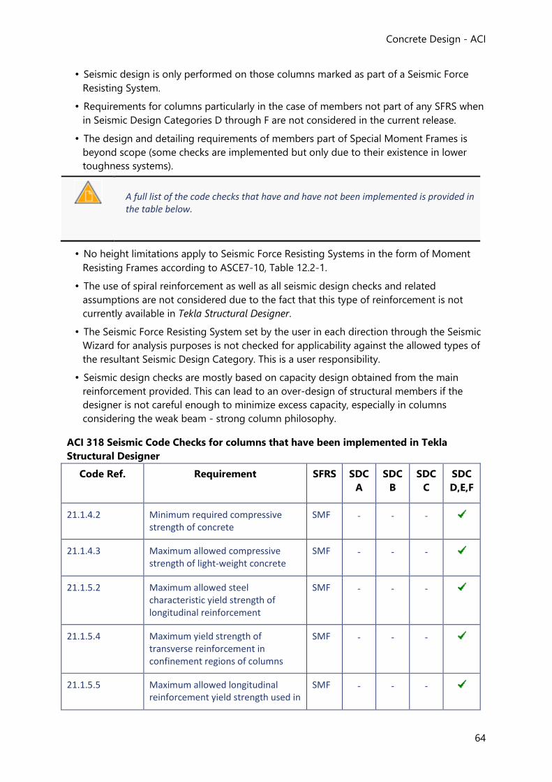
Concrete Design - ACI
64
• Seismic design is only performed on those columns marked as part of a Seismic Force
Resisting System.
• Requirements for columns particularly in the case of members not part of any SFRS when
in Seismic Design Categories D through F are not considered in the current release.
• The design and detailing requirements of members part of Special Moment Frames is
beyond scope (some checks are implemented but only due to their existence in lower
toughness systems).
A full list of the code checks that have and have not been implemented is provided in the table below.
• No height limitations apply to Seismic Force Resisting Systems in the form of Moment
Resisting Frames according to ASCE7-10, Table 12.2-1.
• The use of spiral reinforcement as well as all seismic design checks and related
assumptions are not considered due to the fact that this type of reinforcement is not
currently available in Tekla Structural Designer.
• The Seismic Force Resisting System set by the user in each direction through the Seismic
Wizard for analysis purposes is not checked for applicability against the allowed types of
the resultant Seismic Design Category. This is a user responsibility.
• Seismic design checks are mostly based on capacity design obtained from the main
reinforcement provided. This can lead to an over-design of structural members if the
designer is not careful enough to minimize excess capacity, especially in columns
considering the weak beam - strong column philosophy.
ACI 318 Seismic Code Checks for columns that have been implemented in Tekla
Structural Designer
Code Ref. Requirement SFRS SDC
A
SDC
B
SDC
C
SDC
D,E,F
21.1.4.2 Minimum required compressive strength of concrete
SMF - - -
21.1.4.3 Maximum allowed compressive strength of light-weight concrete
SMF - - -
21.1.5.2 Maximum allowed steel characteristic yield strength of longitudinal reinforcement
SMF - - -
21.1.5.4 Maximum yield strength of transverse reinforcement in confinement regions of columns
SMF - - -
21.1.5.5 Maximum allowed longitudinal reinforcement yield strength used in
SMF - - -
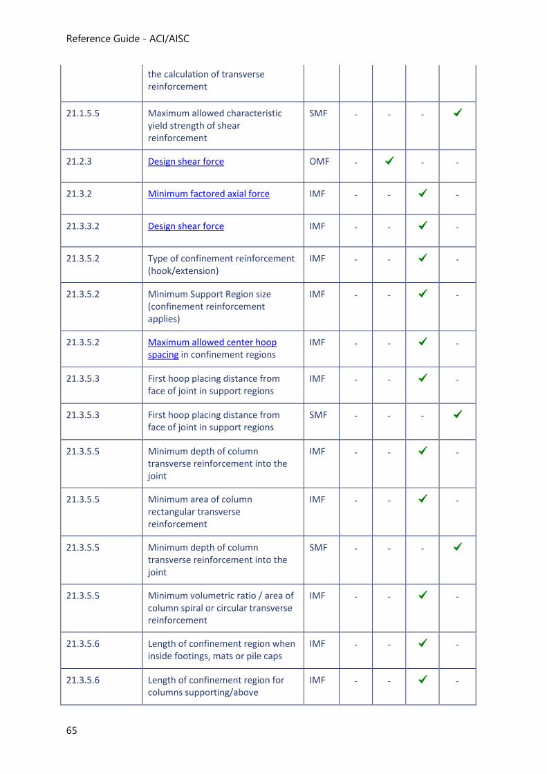
Reference Guide - ACI/AISC
65
the calculation of transverse reinforcement
21.1.5.5 Maximum allowed characteristic yield strength of shear reinforcement
SMF - - -
21.2.3 Design shear force OMF -
- -
21.3.2 Minimum factored axial force IMF - -
-
21.3.3.2 Design shear force IMF - -
-
21.3.5.2 Type of confinement reinforcement (hook/extension)
IMF - -
-
21.3.5.2 Minimum Support Region size (confinement reinforcement applies)
IMF - -
-
21.3.5.2 Maximum allowed center hoop spacing in confinement regions
IMF - -
-
21.3.5.3 First hoop placing distance from face of joint in support regions
IMF - -
-
21.3.5.3 First hoop placing distance from face of joint in support regions
SMF - - -
21.3.5.5 Minimum depth of column transverse reinforcement into the joint
IMF - -
-
21.3.5.5 Minimum area of column rectangular transverse reinforcement
IMF - -
-
21.3.5.5 Minimum depth of column transverse reinforcement into the joint
SMF - - -
21.3.5.5 Minimum volumetric ratio / area of column spiral or circular transverse reinforcement
IMF - -
-
21.3.5.6 Length of confinement region when inside footings, mats or pile caps
IMF - -
-
21.3.5.6 Length of confinement region for columns supporting/above
IMF - -
-
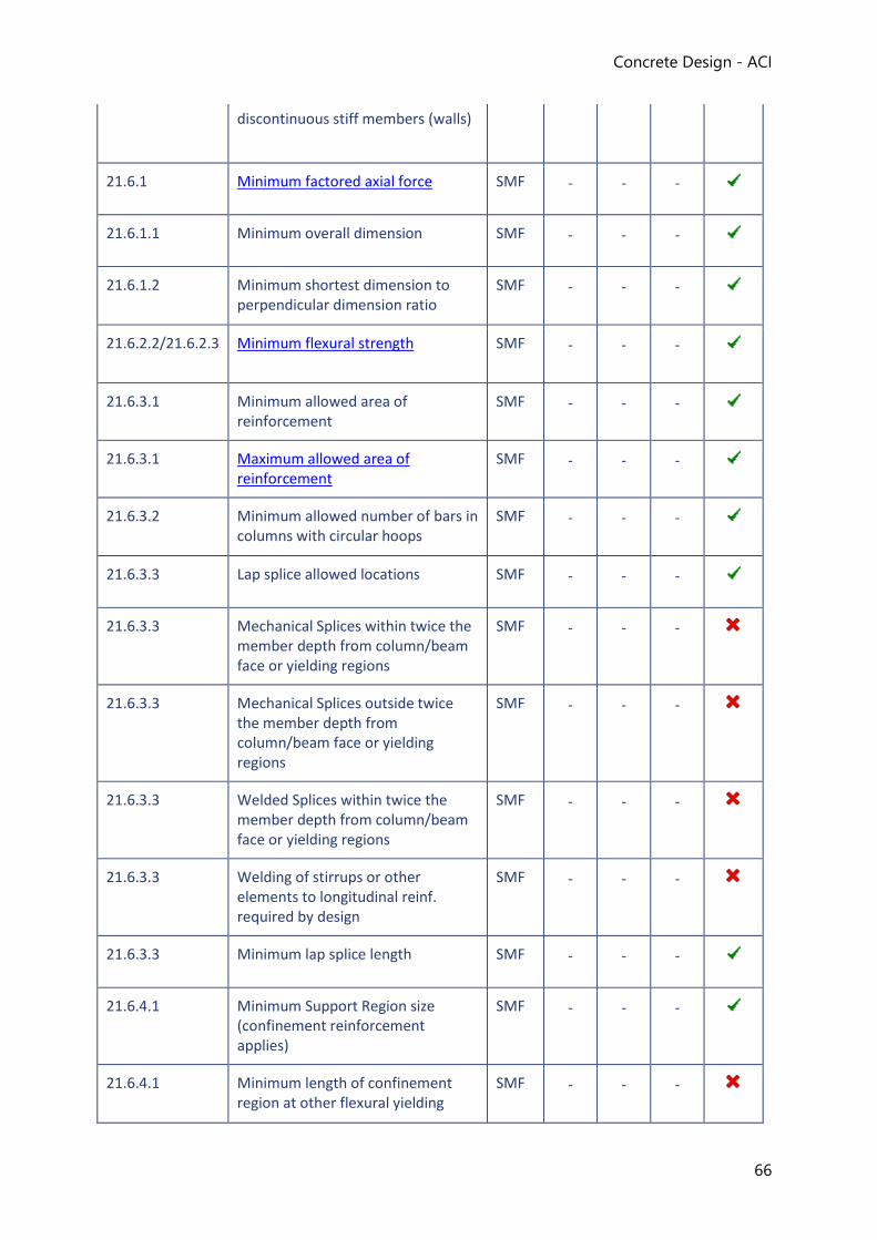
Concrete Design - ACI
66
discontinuous stiff members (walls)
21.6.1 Minimum factored axial force SMF - - -
21.6.1.1 Minimum overall dimension SMF - - -
21.6.1.2 Minimum shortest dimension to perpendicular dimension ratio
SMF - - -
21.6.2.2/21.6.2.3 Minimum flexural strength SMF - - -
21.6.3.1 Minimum allowed area of reinforcement
SMF - - -
21.6.3.1 Maximum allowed area of reinforcement
SMF - - -
21.6.3.2 Minimum allowed number of bars in columns with circular hoops
SMF - - -
21.6.3.3 Lap splice allowed locations SMF - - -
21.6.3.3 Mechanical Splices within twice the member depth from column/beam face or yielding regions
SMF - - -
21.6.3.3 Mechanical Splices outside twice the member depth from column/beam face or yielding regions
SMF - - -
21.6.3.3 Welded Splices within twice the member depth from column/beam face or yielding regions
SMF - - -
21.6.3.3 Welding of stirrups or other elements to longitudinal reinf. required by design
SMF - - -
21.6.3.3 Minimum lap splice length SMF - - -
21.6.4.1 Minimum Support Region size (confinement reinforcement applies)
SMF - - -
21.6.4.1 Minimum length of confinement region at other flexural yielding
SMF - - -
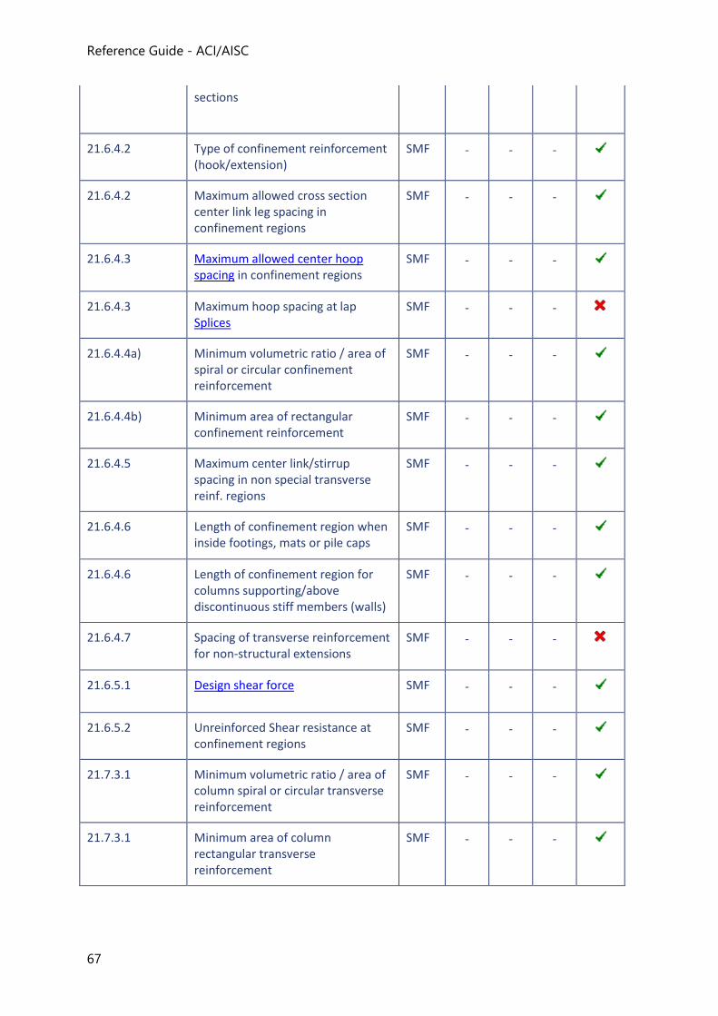
Reference Guide - ACI/AISC
67
sections
21.6.4.2 Type of confinement reinforcement (hook/extension)
SMF - - -
21.6.4.2 Maximum allowed cross section center link leg spacing in confinement regions
SMF - - -
21.6.4.3 Maximum allowed center hoop spacing in confinement regions
SMF - - -
21.6.4.3 Maximum hoop spacing at lap Splices
SMF - - -
21.6.4.4a) Minimum volumetric ratio / area of spiral or circular confinement reinforcement
SMF - - -
21.6.4.4b) Minimum area of rectangular confinement reinforcement
SMF - - -
21.6.4.5 Maximum center link/stirrup spacing in non special transverse reinf. regions
SMF - - -
21.6.4.6 Length of confinement region when inside footings, mats or pile caps
SMF - - -
21.6.4.6 Length of confinement region for columns supporting/above discontinuous stiff members (walls)
SMF - - -
21.6.4.7 Spacing of transverse reinforcement for non-structural extensions
SMF - - -
21.6.5.1 Design shear force SMF - - -
21.6.5.2 Unreinforced Shear resistance at confinement regions
SMF - - -
21.7.3.1 Minimum volumetric ratio / area of column spiral or circular transverse reinforcement
SMF - - -
21.7.3.1 Minimum area of column rectangular transverse reinforcement
SMF - - -
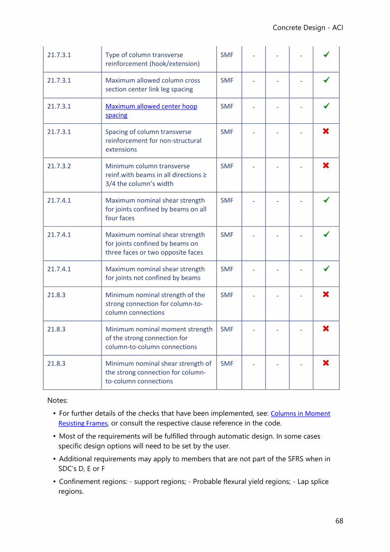
Concrete Design - ACI
68
21.7.3.1 Type of column transverse reinforcement (hook/extension)
SMF - - -
21.7.3.1 Maximum allowed column cross section center link leg spacing
SMF - - -
21.7.3.1 Maximum allowed center hoop spacing
SMF - - -
21.7.3.1 Spacing of column transverse reinforcement for non-structural extensions
SMF - - -
21.7.3.2 Minimum column transverse reinf.with beams in all directions ≥ 3/4 the column’s width
SMF - - -
21.7.4.1 Maximum nominal shear strength for joints confined by beams on all four faces
SMF - - -
21.7.4.1 Maximum nominal shear strength for joints confined by beams on three faces or two opposite faces
SMF - - -
21.7.4.1 Maximum nominal shear strength for joints not confined by beams
SMF - - -
21.8.3 Minimum nominal strength of the strong connection for column-to-column connections
SMF - - -
21.8.3 Minimum nominal moment strength of the strong connection for column-to-column connections
SMF - - -
21.8.3 Minimum nominal shear strength of the strong connection for column-to-column connections
SMF - - -
Notes:
• For further details of the checks that have been implemented, see: Columns in Moment
Resisting Frames, or consult the respective clause reference in the code.
• Most of the requirements will be fulfilled through automatic design. In some cases
specific design options will need to be set by the user.
• Additional requirements may apply to members that are not part of the SFRS when in
SDC’s D, E or F
• Confinement regions: - support regions; - Probable flexural yield regions; - Lap splice
regions.
Reference Guide - ACI/AISC
69
Columns in Moment Resisting Frames (Columns-seismic: ACI 318)
General Requirements (Columns-seismic: ACI 318)
End Fixity
Reinforced concrete columns assigned to Moment Resisting Frames have their end fixities at
the base of the building limited to:
• Fixed base;
• Pinned base;
• Spring base (foundation flexibility).
Minimum factored axial force
Members experiencing axial compression forces higher than the minimum threshold in the
code from any of the load combinations are required to be checked for flexural strength and
to consider flexural detailing within the strong column - weak beam design philosophy
according to their assigned SFRS type.
If SFRS Type = Ordinary Moment Frame, then no No axial compression load requirement
applies.
If SFRS Type = Intermediate Moment Frame, or Special Moment Frame
Pmin = Ag * f’c / 10
where
Pmin = Minimum required axial compression
Ag = Gross area of the concrete section
f’c = Specified compressive strength of concrete
The check passes and the member is designed for seismic provisions as a compressive
member if Pu > Pmin
where
Pu = Largest factored compressive axial force at the top of the stack from any load combination.
This check is no longer required in ACI 318-14.
Maximum recommended axial force
Concrete Design - ACI
70
ACI 318 allows for the maximum design axial load to be as high as 0.8*ɸ*Pn,max, where Pn,max is
the maximum compression resistance of the section composed of concrete and steel.
However in the event of a severe earthquake a full height beam yielding mechanism could
occur inducing higher compression strain on the columns than the one predicted by elastic
design.
Good practice recommends that the maximum compressive strain in a column part of a
Special Moment Frame should remain below the balanced value.
The current release of Tekla Structural Designer does not check if the compressive strain is below the balanced point.
Minimum cross-section dimension
ACI 318 limits the shortest cross-sectional dimension of a column that is part of a Special
Moment Frame to a lower fixed value in any direction measured in a straight line passing
through the section centroid and also to a fraction of the length of the perpendicular
dimension.
If designing to ACI 318-14, there is an additional limit of half the height of the deepest beam
connecting at the joint.
These minimum dimension restrictions are calculated and applied accordingly when the
column that is part of a Special Moment Frame.
Flexural Requirements (Columns-seismic: ACI 318)
Minimum flexural strength
Columns that are part of Special Moment Frames are required by ACI 318 to have a
minimum amount of flexural strength depending on the connecting beams flexural
capacities so as to promote the formation of beam yielding mechanisms in the case of an
earthquake. This is done by establishing a ratio between the beam and column moment
strengths in the moment resisting frame direction.
The design of the main reinforcement in a column is done for the top, middle and bottom
region of the stack and moment capacity is calculated for the factored axial force in each
region for the Major and Minor directions.
If SFRS Type = Special Moment Frame then flexural strength checks are performed at the
joints:
Σ Mnc,l = Mnc,l,bot + Mnc,l,top
Σ Mnc,r = Mnc,r,bot + Mnc,r,top
where
Reference Guide - ACI/AISC
71
Σ Mnc,l , Σ Mnc,r = Sum of the Nominal Flexural Strengths of the columns framing into the joint in the relevant direction.
Mnc,l,bot, Mnc,r,bot = Nominal Moment Strength of the stack below the joint obtained for the axial force value consistent with the minimum Nominal Moment Strength respectively for the left and right sway cases.
Mnc,l,top, Mnc,r,top = Nominal Moment Strength of the stack above converging on the same joint for the axial force value consistent with the minimum Nominal Moment Strength respectively for the left and right sway cases.
The sum of the beam strengths are obtained as follows:
Σ Mnb,l = Mnb,l- + Mnb,l+
Σ Mnb,r = Mnb,r- + Mnb,r+
where
Σ Mnb,l , Σ Mnb,r = Sum of the Nominal Flexural Strengths of the beams framing into the joint in the relevant direction.
Mnb,l- , Mnb,r- = Nominal Moment Strength at the joint from the beam on the left from current reinforcement arrangement respectively for the left and right sway cases.
Mnb,l+ , Mnb,r+ = Nominal Moment Strength at the joint from the beam on the right from current reinforcement arrangement respectively for the left and right sway cases.
The minimum strength ratio between columns and beams in both left and right sway cases is
checked as follows:
Σ Mnc,l ≥ 6/5 * Σ Mnb,l
Σ Mnc,r ≥ 6/5 * Σ Mnb,r
If the check fails the reinforcement in the column is increased and both the conventional
design and seismic design calculations are repeated.
Maximum allowed area of reinforcement
The maximum area of longitudinal reinforcement in columns part of Special Moment Frames
is limited as follows.
If SFRS Type = Special Moment Frame
Then calculate maximum area of steel, As,max as follows::
As,max = 0.06 * Ag
where
As,max = Maximum allowed area of reinforcement
Concrete Design - ACI
72
Ag = Gross area of the concrete section.
Maximum allowed longitudinal bar center spacing
Limitations on the longitudinal bar spacing emerge from the code requirement for maximum
allowed cross-section center link spacing of the confinement reinforcement due to the
method of link leg distribution across the column section.
If SFRS Type = Special Moment Frame
Then check maximum longitudinal reinforcement bar distance, scr,max as follows:
scr,max = 350 mm Metric-units
scr,max = 14 in US-units
In ACI 318-14, scr,max is limited to 200mm for non-circular columns with, Pu > 0.3*Ag*fc OR fc > 70 MPa (10,000 psi).
Non-reversing plastic hinges
Non-reversing plastic hinges are regions along the stack of the column where flexural
yielding is likely to occur.
Non-reversing plastic hinges are beyond scope in the current release of Tekla Structural Designer.
Splices
Columns that are part of Special Moment Frames have restrictions on the allowed locations
of lap splices.
Strength design of mechanical splices and restrictions to the use of welded splices as
required by ACI 318-11 apply to Special Moment Frames
These restrictions are not implemented in the current release of Tekla Structural Designer.
Transverse Reinforcement (Columns-seismic: ACI 318)
Joint shear strength
The calculation of joint shear strength is a requirement of ACI 318 for joints of Special
Moment Frames and it is obtained by considering both the free body diagram of the column
Reference Guide - ACI/AISC
73
and of the joint. The stress in the beam's tensile reinforcement at the joint's face is assumed
as at least η *fy by considering the probable moment strengths of framing beams.
The calculation is performed on the following basis:
• Probable Moment Strengths are obtained from beams in the same direction as the
column's considered direction
• Whether beams in the column SFRS Direction are included in the SFRS or not
• At the top region of stack only
• For both sway right and sway left cases
• Beams with pinned connection are ignored
• Axial stress in beams is assumed to be zero
• Contribution of the slab longitudinal reinforcement in the beam effective flange width is
recommended to be considered, but remains beyond scope in the current release.
Design shear force
The Design Shear Force of a member subjected to flexure as well as axial loading part of a
Moment Resisting Frame is checked taking into consideration the shear from the moment
strengths of the connected flexural members due to reverse curvature bending.
• Shear design for columns is done for the entire stack as a single region and checked for
the minimum requirements from the design code.
• The design is performed independently for both the orthogonal directions.
Minimum area of transverse reinforcement
For columns that are part of Special Moment Frames, the minimum area of transverse
reinforcement required in confinement regions of a column is obtained as below:
For Special Moment Frames the amount of confinement reinforcement in joints with beams on all 4 sides wider than ¾ of the column width is allowed to be reduced to half and the spacing to be relaxed within the depth of the shallowest member - this is beyond scope in the current release of Tekla Structural Designer.
Non-reversing plastic hinge regions along the span have the same requirements as support regions - Non-reversing plastic hinge regions are beyond scope in the current release of Tekla Structural Designer.
For circular columns:
ρs = MAX[ 0.12 * (f’c / fyt) , 0.45 * [(Ag / Ach)-1] * (f’c / fyt)]
where
ρs = ratio of volume of circular reinforcement to total volume of confined concrete core.
Concrete Design - ACI
74
f’c = Specified compressive strength of concrete.
fyt = Specified yield strength of transverse reinforcement.
Ag = Gross area of concrete section.
Ach = Area of concrete member section measured to the outside of the transverse reinforcement.
For other supported column geometries
ACI 318-11
Ash = MAX[0.3 * s * bc * (f’c / fyt) * [(Ag / Ach)-1] , 0.09 * s * bc * (f’c / fyt)]
ACI 318-14
Ash = MAX[0.3 * s * bc * (f’c / fyt) * [(Ag / Ach)-1] , 0.09 * s * bc * (f’c / fyt) , 0.2 * kf * kn * (Pu /(MIN[fyt , 700MPa] * Ach)]
where
Ash = total cross-section of transverse reinforcement, including cross-ties, within spacing s and perpendicular to dimension bc.
s = Center to center spacing of transverse reinforcement along the region's height.
bc = Cross section dimension of the member core measured to the outside of the transverse reinforcement and in the direction perpendicular to the considered reinforcement link legs.
Ag = Gross area of concrete section.
Ach = Area of concrete member section measured to the outside of the transverse reinforcement.
Support regions of columns belonging to any other Moment Resisting Frame type have the
minimum area of transverse reinforcement as per conventional design requirements.
Maximum allowed center hoop spacing
The maximum allowed horizontal center spacing of hoops in confinement regions of
columns part of Moment Resisting Frames is limited as below.
If SFRS Type = Ordinary Moment Frame:
• No spacing requirement applies to support regions when designing for seismic
provisions.
If SFRS Type = Special Moment Frame and the region is a support region:
scr,max,sup = MIN[6 * db,smallest, 0.25 * MIN(c1, c2), 100 mm ≤ 100+((350 – hx)/3) ≤ 150 mm] metric units
Reference Guide - ACI/AISC
75
scr,max,sup = MIN[6 * db,smallest, 0.25 * MIN(c1, c2), 4 in. ≤ 4+((14 - hx)/3) ≤ 6 in.] US units
where
db,smallest = Smallest longitudinal reinforcement bar diameter
c1 = Rectangular or equivalent rectangular column dimension in the direction of the span for which moments are being considered
c2 = Dimension of the column perpendicular to c1
hx = Maximum center-to-center horizontal spacing of crossties at any face of the column
If SFRS Type = Special Moment Frame and the region is not a support region:
scr,max,span = MIN[6 * db,smallest, 150 mm] metric units
scr,max,span = MIN[6 * db,smallest, 6 in.] US units
If SFRS Type = Intermediate Moment Frame and the region is a support region:
scr,max,sup = MIN[8 * db,smallest, 24 *db,w , 1/2 * MIN(c1, c2), 300 mm] metric units
scr,max,sup = MIN[8 * db,smallest, 24 **db,w , 1/2 * MIN(c1, c2), 12 in.] US units
where
db,w = = Link (hoop) diameter
If SFRS Type = Intermediate Moment Frame and the region is not a support region:
• No spacing requirement applies beyond the conventional design requirements.
Seismic Detailing (Columns: ACI 318)
Seismic detailing requirements apply to the reinforced concrete columns with the purpose of
resisting earthquake induced forces.
The seismic detailing of concrete columns is performed only if the member is assigned to the
SFRS through the In a Seismic Force Resisting System setting in the member properties
window.
Flexural Reinforcement (Columns-seismic: ACI 318)
Development Length at the Foundation
Columns that are part of Special Moment Frames shall have their longitudinal reinforcement
extended into supporting footings, foundation mats or pile caps for a length not less than
the full development length in tension.
Lap Splices
Concrete Design - ACI
76
Specific seismic requirements apply only to lap splices in compressive members that are part
of Special Moment Frames.
For columns that are part of Special Moment Frames:
• lap splices are only allowed at the center half of the column
• lap splices regions should be properly confined - hoop spacing should not exceed the
maximum allowed hoop spacing
Both of these requirements are beyond scope in the current release of Tekla Structural Designer.
Confinement Reinforcement for Ductility (Columns-seismic: ACI 318)
Reinforcement Type
Confinement reinforcement in columns at regions where provided should consist of hoops,
i.e. closed or continuously wound ties with a seismic hook at each end.
Confinement reinforcement in the form of spiral reinforcement is beyond scope in the current release of Tekla Structural Designer.
Detailing Regions
Confinement reinforcement is required to be provided over three types of regions along
reinforced concrete columns that are part of Intermediate Moment Frames and Special
Moment Frames:
• Support regions:
• These are probable flexural yielding regions at the top and bottom of the stack next
to column-beam joints;
• Non-reversing plastic hinge regions:
• These are probable flexural yielding regions outside support regions.
Non-reversing plastic hinge regions are not identified in the current release of Tekla Structural Designer.
• Lap splices:
• Confinement reinforcement in the form of hoops is required to be provided over the
length of lap splices in reinforced concrete columns part of Special Moment Frames
Reference Guide - ACI/AISC
77
The requirement for hoop spacing not to exceed the maximum allowed hoop spacing at lap splices is beyond scope in the current release of Tekla Structural Designer.
Chapter
Wall Design to ACI 318
Tekla Structural Designer will design wall panels to resist axial load combined with shear and
bending in each of the two planes of the wall.
The reference codes are ACI 318-08, ACI 318-11, ACI 318M-11 together with the PCA Notes
on ACI 318-08.
Limitations and Exclusions (Walls: ACI 318)
The design of walls is limited to load bearing and shear walls. Other wall types: non-load
bearing, tilt-up and plates that resist in-plane compression are beyond scope.
The following general exclusions also apply to the first release:
• Seismic loading and design,
• Consideration of fire resistance. [You are however given full control of the minimum
cover dimension to the reinforcement and are therefore able to take due account of fire
resistance requirements],
• Lightweight concrete,
• Multi-stack reinforcement lifts.
Materials (Walls: ACI 318)
Concrete
Only normal weight is included in the first release. (Lightweight concrete is excluded).
Reinforcement
The reinforcement options are:
• Loose reinforcing bars,
• Mesh (Standard Meshes)
• Loose reinforcing bars bent to form ties.
Cover to Reinforcement (Walls: ACI 318)
Concrete Design - ACI
78
For 1 layer of reinforcement, the vertical bar is on the center-line of the wall thickness, the
face of the horizontal bar is closest to the critical concrete face.
For 2 layers of reinforcement, the horizontal bars are placed outside the vertical bars at each
face.
The nominal concrete cover is measured to the face of the horz bar or any
link/confinement transverse reinforcement that may be present.
You are required to set a minimum value for the nominal cover for each wall in the wall
properties.
Design Parameters for Vertical Bars (Walls: ACI 318)
For some of the vertical bar parameters, additional user defined limits can be applied - where
this is the case minimum and maximum values are specified in Design Options > Wall >
Reinforcement Layout.
In the following, the concrete area is the gross area of the general wall, or the gross area of the mid zone if one exists. For the end zone the design criteria for a reinforced concrete column element applies.
Minimum and Maximum Vertical Bar Diameter
There are no code provisions, but user defined limits can be applied to the minimum and
maximum bar diameters - specified in Design Options > Wall > Reinforcement Layout
Minimum and Maximum Vertical Loose Bar Spacing
Limiting minimum horizontal spacing of the vertical bars, sv, lim, min is controlled by the
diameters of the 2 adjacent bars and aggregate size1.
sv, lim, min = 0.5*(dbv, i + dbv,(i + 1)) + cgap
where
cgap = min. clear distance bet. bars
cgap = max (1.5*dbv,i , 1.5*dbv, (i+1), 1.33* hagg, 1.5 in.) US units
= max (1.5*dbv,i , 1.5*dbv, (i+1), 1.33* hagg, 38mm) metric units
where
dbv,i and dbv,(i+1)
= the diameters of the two adjacent vertical bars
hagg = aggregate size
Reference Guide - ACI/AISC
79
Limiting maximum horizontal spacing of the vertical bars, sv,lim,max is controlled by the wall
thickness.
sv,lim,max = min (3*hw, 18 in.) US units
= min (3*hw, 450mm) metric units
You are given control over these values by specifying minimum and maximum spacing limits
in Design Options > Wall > Reinforcement Layout.
Minimum and Maximum Reinforcement Area2
The code provisions which control the vertical reinforcement area are,
• Limiting minimum ratio of vertical reinforcement area to gross concrete area, v,lim,min
• Limiting maximum ratio of vertical reinforcement area to gross concrete area, v,lim,max
The controlling values are:
IF dbv ≤ No. 5 (No. 16) with fy ≥ 60,000 psi (420 MPa) OR WWR ≤ W31 or D31
then v,lim,min = 0.0012 else 0.0015 for all other deformed bars
Total minimum area of vertical reinforcement, As,min = v,lim,min*Acg
Total maximum area of vertical reinforcement, As,max = v,lim,max*Acg = 0.08*Acg
where Acg = Gross area of the concrete wall.
Where 2 layers are specified, this should be distributed equally to each face.
You are given further control over the minimum and maximum reinforcement ratio values via
user limits in Design Options > Wall > Reinforcement Layout. These will be used if they
are more onerous than the code limits.
1. Clause 7.6.3
2. 14.3.2
Design Parameters for Horizontal Bars (Walls: ACI 318)
For some of the horizontal bar parameters, additional user defined limits can be applied -
where this is the case minimum and maximum values are specified in Design Options
> Wall > Reinforcement Layout.
Minimum and Maximum Reinforcement Area1
The code provisions which control the horizontal reinforcement area are,
• Limiting minimum ratio of horizontal reinforcement area to gross concrete area, h,lim,min
• Limiting maximum ratio of horizontal reinforcement area to gross concrete area, h,lim,max
The controlling values are:
IF dbv ≤ No. 5 (No. 16) with fy ≥ 60,000 psi (420 MPa) OR WWR ≤ W31 or D31
Concrete Design - ACI
80
THEN h,lim,min = 0.002 ELSE 0.0025 for all other deformed bars
Total minimum area of horizontal reinforcement, As,min = h,lim,min*Acg
Total maximum area of vertical reinforcement, As,max = h,lim,max*Acg = 0.08*Acg
where Acg = Gross area of the concrete wall.
You can select a minimum ratio which will be the start point for the design in Design
Options > Wall > Reinforcement Layout.
Minimum and Maximum Horizontal Bar Spacing
This is identical in principle to min vertical bar spacing.
Minimum and Maximum Confinement Bar Spacing
There are Code provisions that control the maximum spacing:
The recommended values are,
Limiting maximum transverse spacing, sw,lim,max = min (16*dbv , 48*dbw , hw)
1. 14.3.3
Ultimate Axial Load Limit (Walls: ACI 318)
The axial resistance calculations for walls are the same as for columns -see: Ultimate Axial Load Limit (Columns: ACI 318)
Effective Length and Slenderness Calculations (Walls: ACI 318)
The slenderness calculations for walls are generally the same as for columns - see: Effective
Length Calculations (Columns: ACI 318) and Column Stack Classification(Columns: ACI 318), except
that for walls:
Where the criteria for each axis is:
If < lim , section is “non-slender”
Elseif lim , section is “slender”
Since the wall panel has a rectangular plan shape, the calculation can be simplified:
In-plane,
Slenderness, y = l0,y / iy
Radius of gyration, iy = lw/(12)0.5
Effective length, l0,y
Length of wall panel, lw
Reference Guide - ACI/AISC
81
Out-of-plane,
Slenderness, z = l0,z / iz
Radius of gyration, iz = hw/(12)0.5
Effective length, l0,z
Thickness of wall panel, hw
Pre-selection of Bracing Contribution:
The significant parameter within the slenderness criteria is a choice of how a wall (or column)
is contributing to the stability of the structure.
In-plane direction, a wall is usually considered to be a bracing member.
Out-of-plane direction, a wall is usually considered to be braced by other stabilizing
members.
These are the default settings but can be edited.
Design Moment Calculations (Walls: ACI 318)
For each combination, a set of forces are returned from one or more sets of analyses, in the
same way as for columns. For details, see: Column Design to ACI 318> Design Moment Calculations.
Design for Shear (Walls: ACI 318)
In the plane of the wall the s factored shear must be equal to or less than the design shear
strength of the wall
Vu ≤ ΦVn
The design shear strength of the wall is equal to the design shear strength of the concrete
plus that of the shear reinforcing
Vu ≤ ΦVc + ΦVs
The shear strength, Vn, may not be taken greater than 10√f’c hd.
Vn ≤ 10 * f’c0.5 * h * d US units
Vn ≤ 0.83 * f’c0.5 * h * d metric units
where
h = wall thickness
d = 0.8 * lw
lw = length of the wall
Out of plane the shear design calculations are the same whether the design element is a
column or a wall - see: Design for Shear (Columns: ACI 318)
Concrete Design - ACI
82
Seismic Design (Walls: ACI 318)
Limitations and Assumptions (Walls-seismic: ACI 318)
The follows limitations and assumptions apply:
• For design purposes Tekla Structural Designer recognizes walls as isolated elements and
as such the influence of flanges from adjacent walls are not to be considered when
fulfilling seismic design requirements in those elements. Requirements of ACI318-11
section 21.9.5.2 and section 21.9.6.4(b) do not apply.
• Additional requirements for wall piers not part of any SFRS when in Seismic Design
Categories D through F are not considered in the current release.
• Design and/or detailing requirements of Special Reinforced Concrete Structural Walls is
beyond scope (some checks are implemented but only due to their existence in lower
toughness systems).
• The use of spiral reinforcement as well as all seismic design checks and related
assumptions are not considered due to the fact that this type of reinforcement is not
currently available in Tekla Structural Designer.
• Special boundary elements in walls are directly linked with wall end-zones in Tekla
Structural Designer. The current settings do not allow for end-zones of width different
from the width of the wall itself.
• The Seismic Force Resisting System set by the user in each direction through the Seismic
Wizard for analysis purposes is not checked for applicability against the allowed types
from the resultant Seismic Design Category. This is user responsibility.
• Seismic design checks are mostly based on capacity design obtained from the main
reinforcement provided. This can lead to an over-design of structural members if the
designer is not careful enough to minimize excess capacity.
• The seismic design requirements for end-zone reinforcement are beyond scope in the
current release.
• Construction joints are beyond scope in the current release.
• Seismic design provisions specific for beam-wall frames are beyond scope in the current
release.
• Seismic design of walls with openings is beyond scope in the current release.
• Seismic design of wall piers is beyond scope in the current release.
• Seismic design of coupling beams is beyond scope in the current release.
• Seismic detailing requirements apply to Special Reinforced Concrete Structural Walls
these are beyond scope in the current release.
A full list of the code checks that have and have not been implemented is provided in the table below.
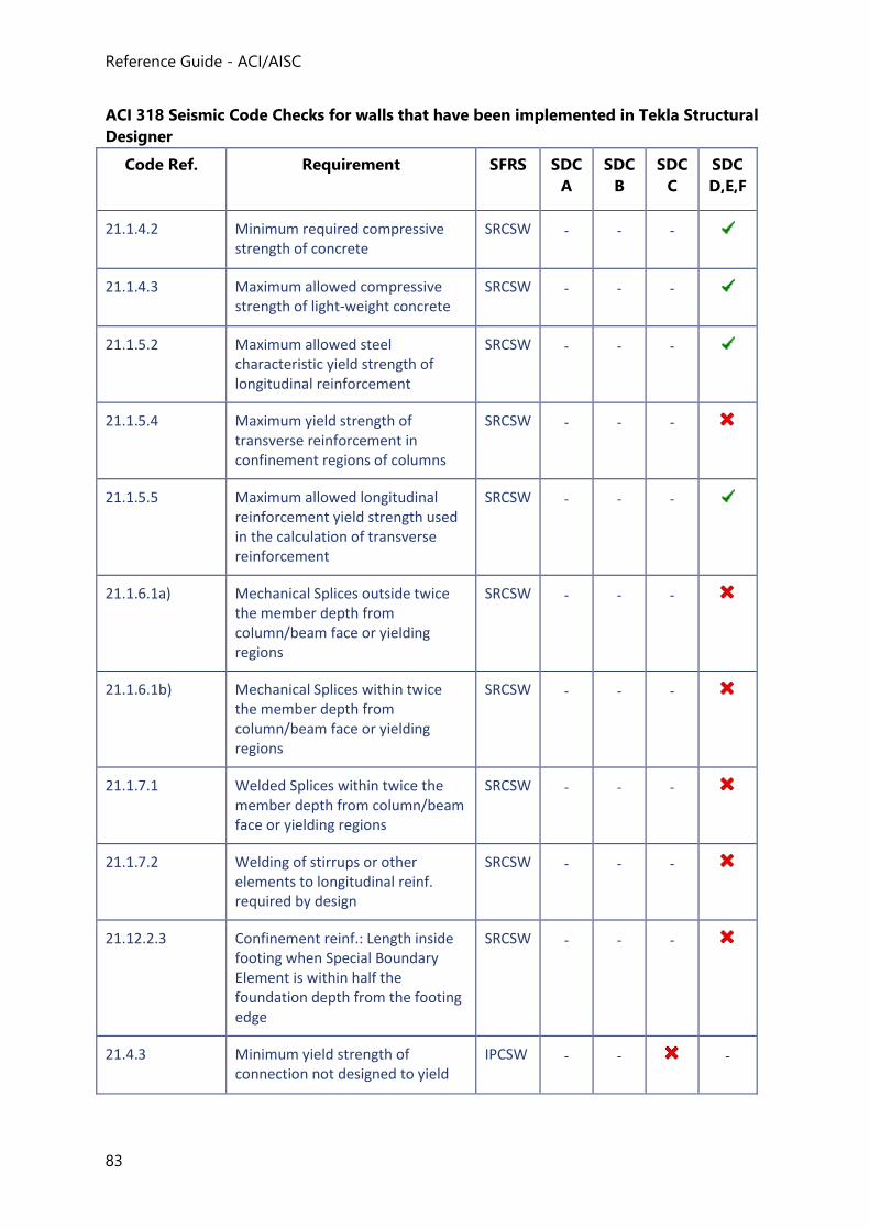
Reference Guide - ACI/AISC
83
ACI 318 Seismic Code Checks for walls that have been implemented in Tekla Structural
Designer
Code Ref. Requirement SFRS SDC
A
SDC
B
SDC
C
SDC
D,E,F
21.1.4.2 Minimum required compressive strength of concrete
SRCSW - - -
21.1.4.3 Maximum allowed compressive strength of light-weight concrete
SRCSW - - -
21.1.5.2 Maximum allowed steel characteristic yield strength of longitudinal reinforcement
SRCSW - - -
21.1.5.4 Maximum yield strength of transverse reinforcement in confinement regions of columns
SRCSW - - -
21.1.5.5 Maximum allowed longitudinal reinforcement yield strength used in the calculation of transverse reinforcement
SRCSW - - -
21.1.6.1a) Mechanical Splices outside twice the member depth from column/beam face or yielding regions
SRCSW - - -
21.1.6.1b) Mechanical Splices within twice the member depth from column/beam face or yielding regions
SRCSW - - -
21.1.7.1 Welded Splices within twice the member depth from column/beam face or yielding regions
SRCSW - - -
21.1.7.2 Welding of stirrups or other elements to longitudinal reinf. required by design
SRCSW - - -
21.12.2.3 Confinement reinf.: Length inside footing when Special Boundary Element is within half the foundation depth from the footing edge
SRCSW - - -
21.4.3 Minimum yield strength of connection not designed to yield
IPCSW - -
-
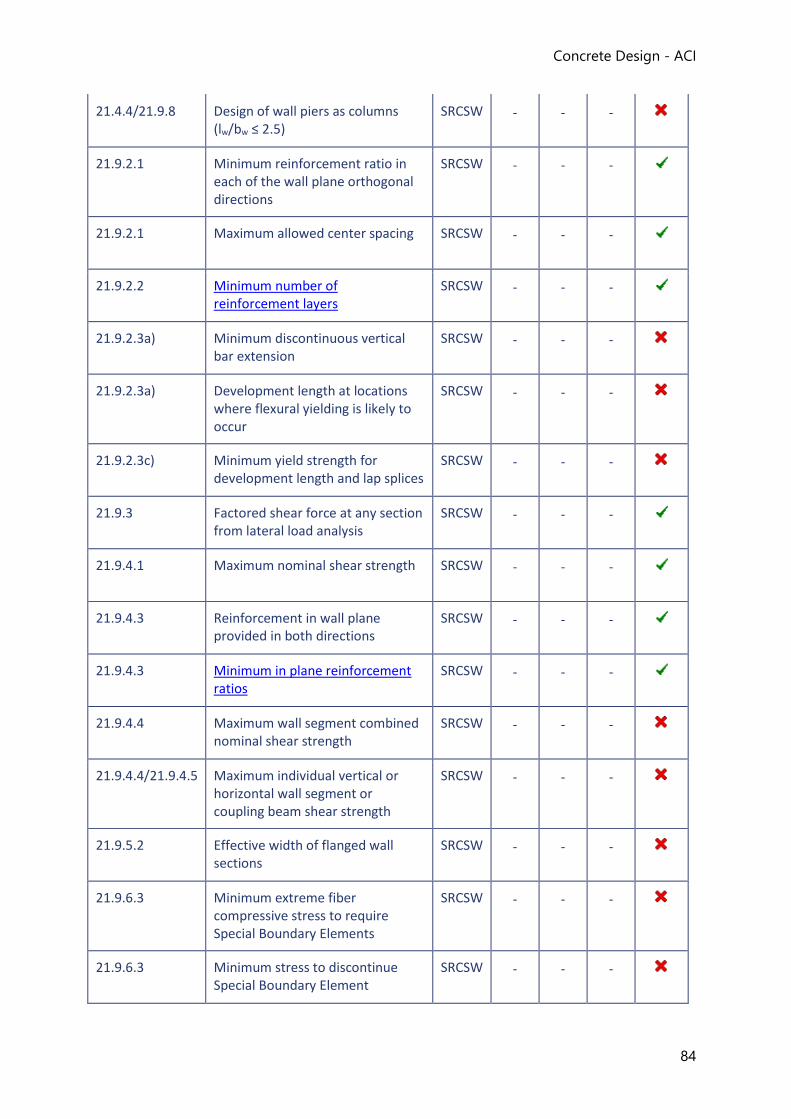
Concrete Design - ACI
84
21.4.4/21.9.8 Design of wall piers as columns (lw/bw ≤ 2.5)
SRCSW - - -
21.9.2.1 Minimum reinforcement ratio in each of the wall plane orthogonal directions
SRCSW - - -
21.9.2.1 Maximum allowed center spacing SRCSW - - -
21.9.2.2 Minimum number of reinforcement layers
SRCSW - - -
21.9.2.3a) Minimum discontinuous vertical bar extension
SRCSW - - -
21.9.2.3a) Development length at locations where flexural yielding is likely to occur
SRCSW - - -
21.9.2.3c) Minimum yield strength for development length and lap splices
SRCSW - - -
21.9.3 Factored shear force at any section from lateral load analysis
SRCSW - - -
21.9.4.1 Maximum nominal shear strength SRCSW - - -
21.9.4.3 Reinforcement in wall plane provided in both directions
SRCSW - - -
21.9.4.3 Minimum in plane reinforcement ratios
SRCSW - - -
21.9.4.4 Maximum wall segment combined nominal shear strength
SRCSW - - -
21.9.4.4/21.9.4.5 Maximum individual vertical or horizontal wall segment or coupling beam shear strength
SRCSW - - -
21.9.5.2 Effective width of flanged wall sections
SRCSW - - -
21.9.6.3 Minimum extreme fiber compressive stress to require Special Boundary Elements
SRCSW - - -
21.9.6.3 Minimum stress to discontinue Special Boundary Element
SRCSW - - -
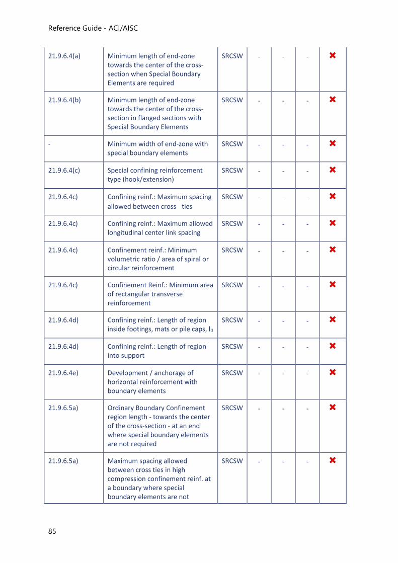
Reference Guide - ACI/AISC
85
21.9.6.4(a) Minimum length of end-zone towards the center of the cross-section when Special Boundary Elements are required
SRCSW - - -
21.9.6.4(b) Minimum length of end-zone towards the center of the cross-section in flanged sections with Special Boundary Elements
SRCSW - - -
- Minimum width of end-zone with special boundary elements
SRCSW - - -
21.9.6.4(c) Special confining reinforcement type (hook/extension)
SRCSW - - -
21.9.6.4c) Confining reinf.: Maximum spacing
allowed between cross ties
SRCSW - - -
21.9.6.4c) Confining reinf.: Maximum allowed longitudinal center link spacing
SRCSW - - -
21.9.6.4c) Confinement reinf.: Minimum volumetric ratio / area of spiral or circular reinforcement
SRCSW - - -
21.9.6.4c) Confinement Reinf.: Minimum area of rectangular transverse reinforcement
SRCSW - - -
21.9.6.4d) Confining reinf.: Length of region inside footings, mats or pile caps, ld
SRCSW - - -
21.9.6.4d) Confining reinf.: Length of region into support
SRCSW - - -
21.9.6.4e) Development / anchorage of horizontal reinforcement with boundary elements
SRCSW - - -
21.9.6.5a) Ordinary Boundary Confinement region length - towards the center of the cross-section - at an end where special boundary elements are not required
SRCSW - - -
21.9.6.5a) Maximum spacing allowed between cross ties in high compression confinement reinf. at a boundary where special boundary elements are not
SRCSW - - -
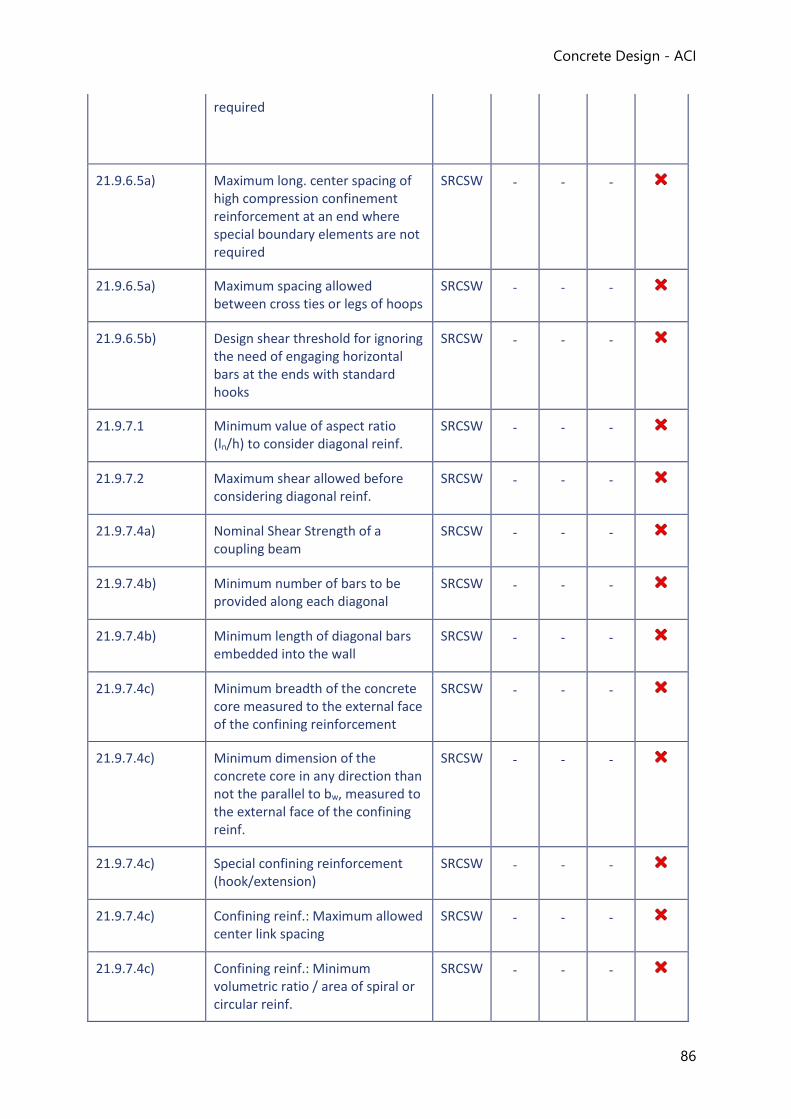
Concrete Design - ACI
86
required
21.9.6.5a) Maximum long. center spacing of high compression confinement reinforcement at an end where special boundary elements are not required
SRCSW - - -
21.9.6.5a) Maximum spacing allowed between cross ties or legs of hoops
SRCSW - - -
21.9.6.5b) Design shear threshold for ignoring the need of engaging horizontal bars at the ends with standard hooks
SRCSW - - -
21.9.7.1 Minimum value of aspect ratio (ln/h) to consider diagonal reinf.
SRCSW - - -
21.9.7.2 Maximum shear allowed before considering diagonal reinf.
SRCSW - - -
21.9.7.4a) Nominal Shear Strength of a coupling beam
SRCSW - - -
21.9.7.4b) Minimum number of bars to be provided along each diagonal
SRCSW - - -
21.9.7.4b) Minimum length of diagonal bars embedded into the wall
SRCSW - - -
21.9.7.4c) Minimum breadth of the concrete core measured to the external face of the confining reinforcement
SRCSW - - -
21.9.7.4c) Minimum dimension of the concrete core in any direction than not the parallel to bw, measured to the external face of the confining reinf.
SRCSW - - -
21.9.7.4c) Special confining reinforcement (hook/extension)
SRCSW - - -
21.9.7.4c) Confining reinf.: Maximum allowed center link spacing
SRCSW - - -
21.9.7.4c) Confining reinf.: Minimum volumetric ratio / area of spiral or circular reinf.
SRCSW - - -
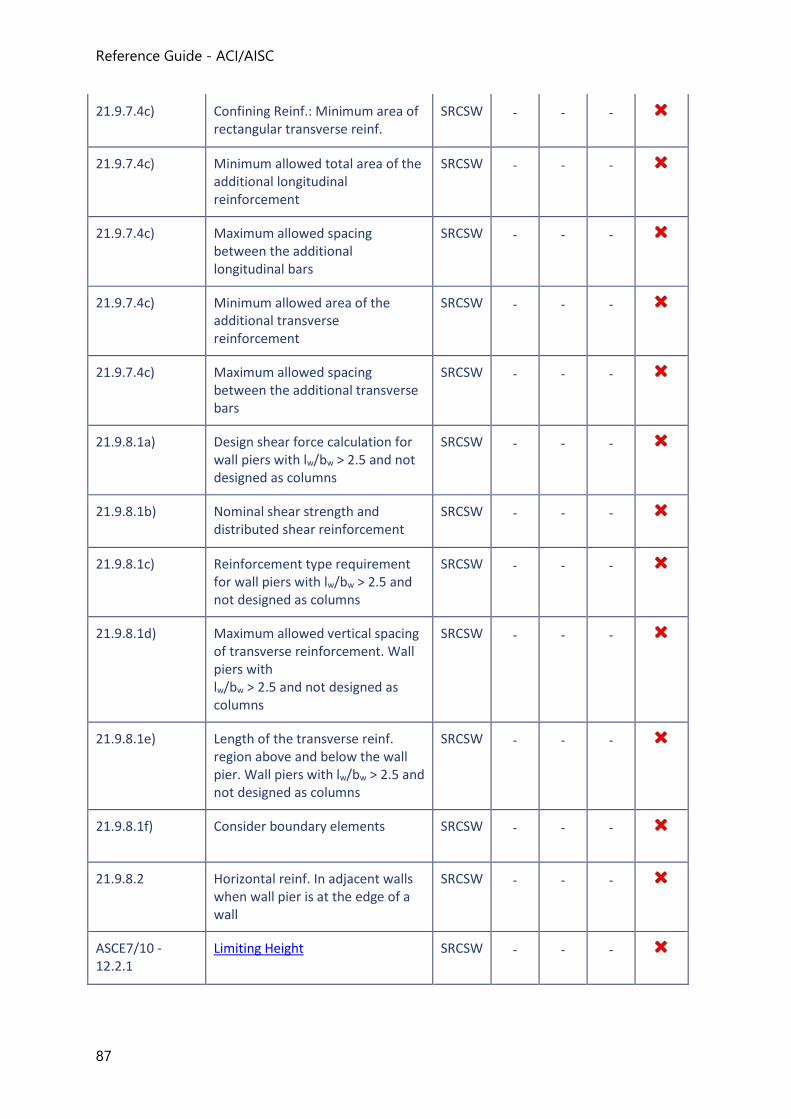
Reference Guide - ACI/AISC
87
21.9.7.4c) Confining Reinf.: Minimum area of rectangular transverse reinf.
SRCSW - - -
21.9.7.4c) Minimum allowed total area of the additional longitudinal reinforcement
SRCSW - - -
21.9.7.4c) Maximum allowed spacing between the additional longitudinal bars
SRCSW - - -
21.9.7.4c) Minimum allowed area of the additional transverse reinforcement
SRCSW - - -
21.9.7.4c) Maximum allowed spacing between the additional transverse bars
SRCSW - - -
21.9.8.1a) Design shear force calculation for wall piers with lw/bw > 2.5 and not designed as columns
SRCSW - - -
21.9.8.1b) Nominal shear strength and distributed shear reinforcement
SRCSW - - -
21.9.8.1c) Reinforcement type requirement for wall piers with lw/bw > 2.5 and not designed as columns
SRCSW - - -
21.9.8.1d) Maximum allowed vertical spacing of transverse reinforcement. Wall piers with lw/bw > 2.5 and not designed as columns
SRCSW - - -
21.9.8.1e) Length of the transverse reinf. region above and below the wall pier. Wall piers with lw/bw > 2.5 and not designed as columns
SRCSW - - -
21.9.8.1f) Consider boundary elements SRCSW - - -
21.9.8.2 Horizontal reinf. In adjacent walls when wall pier is at the edge of a wall
SRCSW - - -
ASCE7/10 - 12.2.1
Limiting Height SRCSW - - -
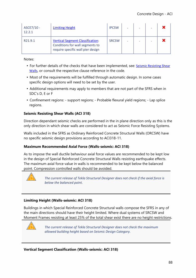
Concrete Design - ACI
88
ASCE7/10 - 12.2.1
Limiting Height IPCSW - - -
R21.9.1 Vertical Segment Classification: Conditions for wall segments to require specific wall pier design
SRCSW - - -
Notes:
• For further details of the checks that have been implemented, see: Seismic Resisting Shear
Walls, or consult the respective clause reference in the code.
• Most of the requirements will be fulfilled through automatic design. In some cases
specific design options will need to be set by the user.
• Additional requirements may apply to members that are not part of the SFRS when in
SDC’s D, E or F
• Confinement regions: - support regions; - Probable flexural yield regions; - Lap splice
regions.
Seismic Resisting Shear Walls (ACI 318)
Direction dependant seismic checks are performed in the in plane direction only as this is the
only direction in which shear walls are considered to act as Seismic Force Resisting Systems.
Walls included in the SFRS as Ordinary Reinforced Concrete Structural Walls (ORCSW) have
no specific seismic design provisions according to ACI318-11.
Maximum Recommended Axial Force (Walls-seismic: ACI 318)
As to impose the wall ductile behaviour axial force values are recommended to be kept low
in the design of Special Reinforced Concrete Structural Walls resisting earthquake effects.
The maximum axial force value in walls is recommended to be kept below the balanced
point. Compression controlled walls should be avoided.
The current release of Tekla Structural Designer does not check if the axial force is below the balanced point.
Limiting Height (Walls-seismic: ACI 318)
Buildings in which Special Reinforced Concrete Structural walls compose the SFRS in any of
the main directions should have their height limited. Where dual systems of SRCSW and
Moment Frames resisting at least 25% of the total shear exist there are no height restrictions.
The current release of Tekla Structural Designer does not check the maximum allowed building height based on Seismic Design Category.
Vertical Segment Classification (Walls-seismic: ACI 318)
Reference Guide - ACI/AISC
89
Isolated vertical segments within a wall - wall with openings - can be classified as wall
segments or wall piers. For Special Reinforced Structural Walls and depending on the
classification of the segment the governing design provisions can be split into provisions for
walls and provisions for wall piers.
This is beyond scope in the current release of Tekla Structural Designer.
Mid-zone Reinforcement (Walls-seismic: ACI 318)
Vertical and horizontal bars in mid-zones of Special Reinforced Concrete Structural Walls are
designed according to the requirements of the following sections.
Minimum number of reinforcement layers
The minimum number of reinforcement layers allowed to be used in a Special Reinforced
Concrete Structural Wall is governed by the amount of in-plane shear sustained by the wall
If the wall thickness bw is greater than 250mm (10 in.) then at least two curtains of
reinforcement are required.
If the wall thickness bw is less than 250mm (10 in.) and the SFRS Type = Special Reinforced
Concrete Structural Wall, then the minimum number of layers is dependent on the maximum
shear force in the panel (ACI 318-11); or the maximum shear force and wall geometry (ACI
318-14). This is checked accordingly.
Additionally, reinforcement is required to be provided in both of the orthogonal directions in
the wall plane. - This requirement is automatically met as Tekla Structural Designer does not
design walls with reinforcement in only one of the orthogonal directions in wall plane.
Minimum in plane reinforcement ratios
The minimum reinforcement ratio required in each of the orthogonal direction in the wall
plane is dependent on the maximum panel factored shear force from analysis for seismic
combinations and calculated as follows:
Grouped bars reinforcing the edges of the walls (end-zones) are not considered for the purpose of calculating reinforcement ratios.
IF SFRS Type = Special Reinforced Concrete Structural Wall then the maximum factored
shear force at the panel is checked:
If Vu > Vu,lim
where
Vu = Maximum factored shear force in the wall panel obtained from the analysis for seismic combinations.
Concrete Design - ACI
90
Vu,lim = Minimum factored shear force in the wall above which horizontal and vertical main reinforcement minimum ratios need to be checked.
Mnc,l,top, Mnc,r,top = Nominal Moment Strength of the stack above converging on the same joint for the axial force value consistent with the minimum Nominal Moment Strength respectively for the left and right sway cases.
Then a check for minimum reinforcement ratio in each orthogonal direction on the wall
plane is performed as follows:
ρl ≥ ρmin
ρt ≥ ρmin
where
ρl, ρt = Respectively the ratio of area of distributed vertical and horizontal reinforcement to gross concrete area perpendicular to each of those reinforcements.
ρmin = Minimum allowed ratio of reinforcement in the wall plane = 0.0025.
Else if Vu ≤ Vu,lim
ρl and ρt are allowed to be taken as the wall design conventional values.
Depending on the overall dimensions of a wall the vertical reinforcement ratio, ρl in Special
Reinforced Concrete Structural Walls is limited to be of the same value or larger than the
horizontal reinforcement ratio, ρt
End-zone Reinforcement (Walls-seismic: ACI 318)
The seismic design requirements for end zone reinforcement are beyond scope in the current release of Tekla Structural Designer.
Shear Strength (Walls-seismic: ACI 318)
Minimum shear strength
The basic design requirement for shear reinforcement in a wall is to have the reduced shear
strength higher or the same as the maximum factored shear force at the considered section
resultant from earthquake combinations. Some level of over-strength is expected when
designing to multiple load combinations.
IF SFRS Type = Special Reinforced Concrete Structural Wall then the following check for
shear strength is performed:
ɸVn ≥ Vu
where
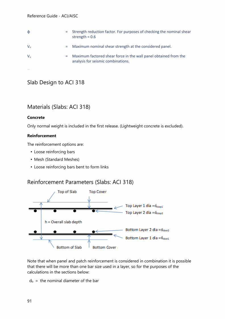
Reference Guide - ACI/AISC
91
ɸ = Strength reduction factor. For purposes of checking the nominal shear strength = 0.6
Vn = Maximum nominal shear strength at the considered panel.
Vu = Maximum factored shear force in the wall panel obtained from the analysis for seismic combinations.
Chapter
Slab Design to ACI 318
Materials (Slabs: ACI 318)
Concrete
Only normal weight is included in the first release. (Lightweight concrete is excluded).
Reinforcement
The reinforcement options are:
• Loose reinforcing bars
• Mesh (Standard Meshes)
• Loose reinforcing bars bent to form links
Reinforcement Parameters (Slabs: ACI 318)
Note that when panel and patch reinforcement is considered in combination it is possible
that there will be more than one bar size used in a layer, so for the purposes of the
calculations in the sections below:
db = the nominal diameter of the bar
Concrete Design - ACI
92
db,top1 = the diameter of the largest longitudinal reinforcing bar in top layer 1 (the bars
nearest to the top surface of the slab)
db,top2 = the diameter of the largest longitudinal reinforcing bar in top layer 2
db,bot1 = the diameter of the largest longitudinal reinforcing bar in bottom layer 1 (the bars
nearest to the bottom surface of the slab)
db,bot2 = the diameter of the largest longitudinal reinforcing bar in bottom layer 2
Slab design will always consider a rectangular section of unit width:
h = overall slab depth
b = unit width
For metric units:
the unit width of slab is 1m, and so the design cross section will always be a
rectangular section where b = 1000mm
For US-customary units:
the unit width of slab is 1ft, and so the design cross section will always be a
rectangular section where b = 12in.
Cover to Reinforcement (Slabs: ACI 318)
Concrete cover as protection of reinforcement against weather and other effects is measured
from the concrete surface to the outermost surface of the steel to which the cover
requirements applies.
You are required to set a minimum value for the nominal cover for each slab panel. These
values for top and bottom cover are specified in the Reinforcement properties section of the
slab panel properties.
This value is then checked against the nominal limiting cover, which depends on the
diameter of the reinforcement.
If the nominal cover is less than the limiting cover then a warning is displayed in the
calculations.
Limiting Reinforcement Parameters (Slabs: ACI 318)
Limiting reinforcement parameters are specified in Design Options > Slab >
Reinforcement Layout.
The parameters applied to “flat slab” design are held separately to those for “beam and slab”
design.
Minimum Clear Spacing
Reference Guide - ACI/AISC
93
The minimum clear spacing between parallel bars in a layer, scl,min, is given by;
scl,min ≥ MAX[[db , 4/3*dg , 1in , scl,u,min] (US units)
scl,min ≥ MAX[[db , 4/3*dg , 25mm , scl,u,min] (metric units)
where
dg = the maximum size of aggregate
scl,u,min = user specified min clear distance between bars
Minimum Area of Reinforcement
For ACI 318-08 and ACI 318-111
For structural slabs of uniform thickness the minimum area of tensile reinforcement in the
direction of the span is:
For US-units:
IF Grade 40 to 50 deformed bars are used
As,min,reqd ≥ b*h*0.0020
IF Grade 50 to 60 deformed bars or welted wire reinforcement are used
As,min,reqd ≥ b*h*0.0018
For metric units:
IF Grade 280 to 350 deformed bars are used
As,min,reqd ≥ b*h*0.0020
IF Grade 350 to 420 deformed bars or welted wire reinforcement are used
As,min,reqd ≥ b*h*0.0018
IF yield stress exceeding 420 MPa
As,min,reqd ≥ b*h* [MAX(0.0014 , 0.0018*420/fy)]
Maximum Area of Reinforcement
The maximum area of longitudinal tension reinforcement is calculated in the same way as for
beams - see: in Beam Design to ACI 318. 1. ACI 318-08:2008 and ACI 318-11:2011 and ACI 318M-11:2011 Section 7.12.2.1 and 10.5.4
Basic Cross Section Design (Slabs: ACI 318)
Regardless of whether design is being carried out for a slab panel or a patch, a unit width of
slab is always designed for a known design force.
h = overall slab depth
b = unit width
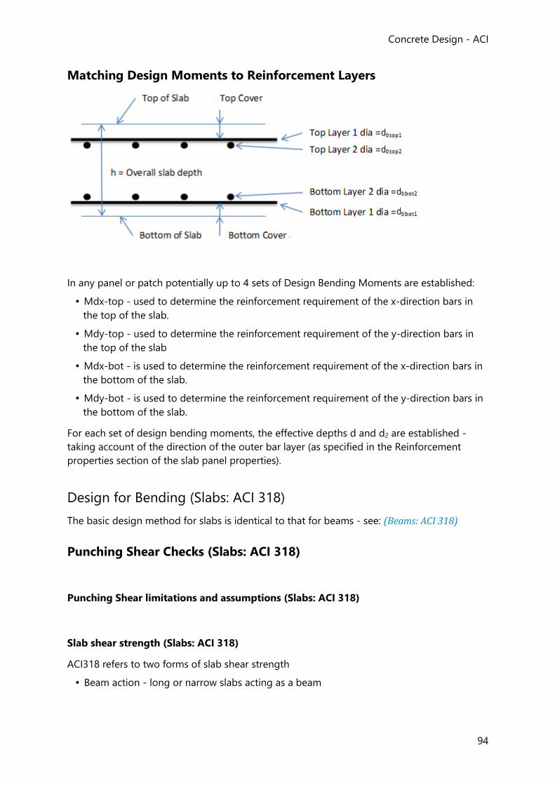
Concrete Design - ACI
94
Matching Design Moments to Reinforcement Layers
In any panel or patch potentially up to 4 sets of Design Bending Moments are established:
• Mdx-top - used to determine the reinforcement requirement of the x-direction bars in
the top of the slab.
• Mdy-top - used to determine the reinforcement requirement of the y-direction bars in
the top of the slab
• Mdx-bot - is used to determine the reinforcement requirement of the x-direction bars in
the bottom of the slab.
• Mdy-bot - is used to determine the reinforcement requirement of the y-direction bars in
the bottom of the slab.
For each set of design bending moments, the effective depths d and d2 are established -
taking account of the direction of the outer bar layer (as specified in the Reinforcement
properties section of the slab panel properties).
Design for Bending (Slabs: ACI 318)
The basic design method for slabs is identical to that for beams - see: (Beams: ACI 318)
Punching Shear Checks (Slabs: ACI 318)
Punching Shear limitations and assumptions (Slabs: ACI 318)
Slab shear strength (Slabs: ACI 318)
ACI318 refers to two forms of slab shear strength
• Beam action - long or narrow slabs acting as a beam
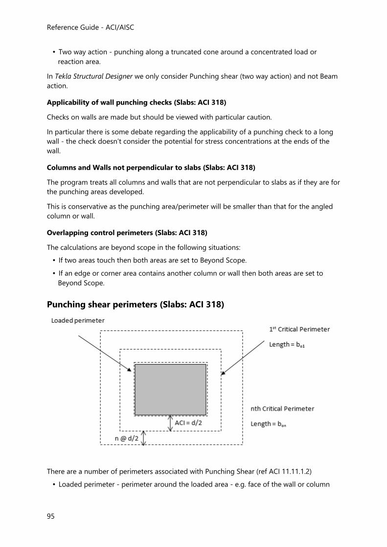
Reference Guide - ACI/AISC
95
• Two way action - punching along a truncated cone around a concentrated load or
reaction area.
In Tekla Structural Designer we only consider Punching shear (two way action) and not Beam
action.
Applicability of wall punching checks (Slabs: ACI 318)
Checks on walls are made but should be viewed with particular caution.
In particular there is some debate regarding the applicability of a punching check to a long
wall - the check doesn’t consider the potential for stress concentrations at the ends of the
wall.
Columns and Walls not perpendicular to slabs (Slabs: ACI 318)
The program treats all columns and walls that are not perpendicular to slabs as if they are for
the punching areas developed.
This is conservative as the punching area/perimeter will be smaller than that for the angled
column or wall.
Overlapping control perimeters (Slabs: ACI 318)
The calculations are beyond scope in the following situations:
• If two areas touch then both areas are set to Beyond Scope.
• If an edge or corner area contains another column or wall then both areas are set to
Beyond Scope.
Punching shear perimeters (Slabs: ACI 318)
There are a number of perimeters associated with Punching Shear (ref ACI 11.11.1.2)
• Loaded perimeter - perimeter around the loaded area - e.g. face of the wall or column
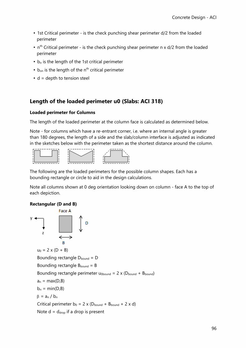
Concrete Design - ACI
96
• 1st Critical perimeter - is the check punching shear perimeter d/2 from the loaded
perimeter
• nth Critical perimeter - is the check punching shear perimeter n x d/2 from the loaded
perimeter
• bo is the length of the 1st critical perimeter
• bon is the length of the nth critical perimeter
• d = depth to tension steel
Length of the loaded perimeter u0 (Slabs: ACI 318)
Loaded perimeter for Columns
The length of the loaded perimeter at the column face is calculated as determined below.
Note - for columns which have a re-entrant corner, i.e. where an internal angle is greater
than 180 degrees, the length of a side and the slab/column interface is adjusted as indicated
in the sketches below with the perimeter taken as the shortest distance around the column.
The following are the loaded perimeters for the possible column shapes. Each has a
bounding rectangle or circle to aid in the design calculations.
Note all columns shown at 0 deg orientation looking down on column - face A to the top of
each depiction.
Rectangular (D and B)
u0 = 2 x (D + B)
Bounding rectangle Dbound = D
Bounding rectangle Bbound = B
Bounding rectangle perimeter u0bound = 2 x (Dbound + Bbound)
an = max(D,B)
bn = min(D,B)
= an / bn
Critical perimeter b0 = 2 x (Dbound + Bbound + 2 x d)
Note d = ddrop if a drop is present
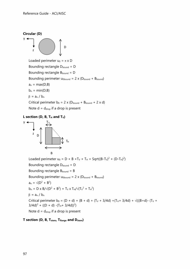
Reference Guide - ACI/AISC
97
Circular (D)
Loaded perimeter u0 = x D
Bounding rectangle Dbound = D
Bounding rectangle Bbound = D
Bounding perimeter u0bound = 2 x (Dbound + Bbound)
an = max(D,B)
bn = min(D,B)
= an / bn
Critical perimeter b0 = 2 x (Dbound + Bbound + 2 x d)
Note d = ddrop if a drop is present
L section (D, B, TH and TV)
Loaded perimeter u0 = D + B +TV + TH + Sqrt((B-TV)2 + (D-TH)2)
Bounding rectangle Dbound = D
Bounding rectangle Bbound = B
Bounding perimeter u0bound = 2 x (Dbound + Bbound)
an = (D2 + B2)
bn = D x B/(D2 + B2) + TV x TH/(TV2 + TH
2)
= an / bn
Critical perimeter b0 = (D + d) + (B + d) + (TV + 3/4d) +(TH+ 3/4d) + (((B+d)- (TV +
3/4d)2 + ((D + d) -(TH+ 3/4d))2)
Note d = ddrop if a drop is present
T section (D, B, Tstem, Tflange and Dstem)
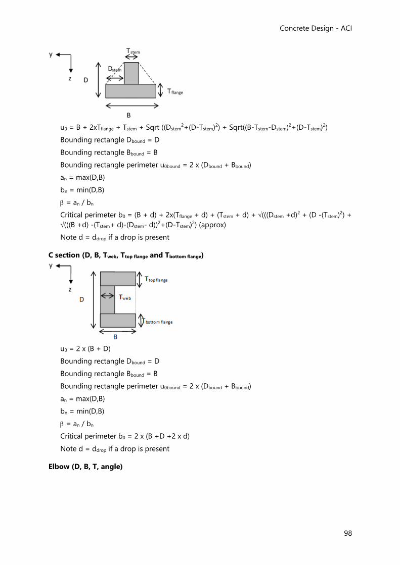
Concrete Design - ACI
98
u0 = B + 2xTflange + Tstem + Sqrt ((Dstem2+(D-Tstem)2) + Sqrt((B-Tstem-Dstem)2+(D-Tstem)2)
Bounding rectangle Dbound = D
Bounding rectangle Bbound = B
Bounding rectangle perimeter u0bound = 2 x (Dbound + Bbound)
an = max(D,B)
bn = min(D,B)
= an / bn
Critical perimeter b0 = (B + d) + 2x(Tflange + d) + (Tstem + d) + (((Dstem +d)2 + (D -(Tstem)2) +
(((B +d) -(Tstem+ d)-(Dstem- d))2+(D-Tstem)2) (approx)
Note d = ddrop if a drop is present
C section (D, B, Tweb, Ttop flange and Tbottom flange)
u0 = 2 x (B + D)
Bounding rectangle Dbound = D
Bounding rectangle Bbound = B
Bounding rectangle perimeter u0bound = 2 x (Dbound + Bbound)
an = max(D,B)
bn = min(D,B)
= an / bn
Critical perimeter b0 = 2 x (B +D +2 x d)
Note d = ddrop if a drop is present
Elbow (D, B, T, angle)
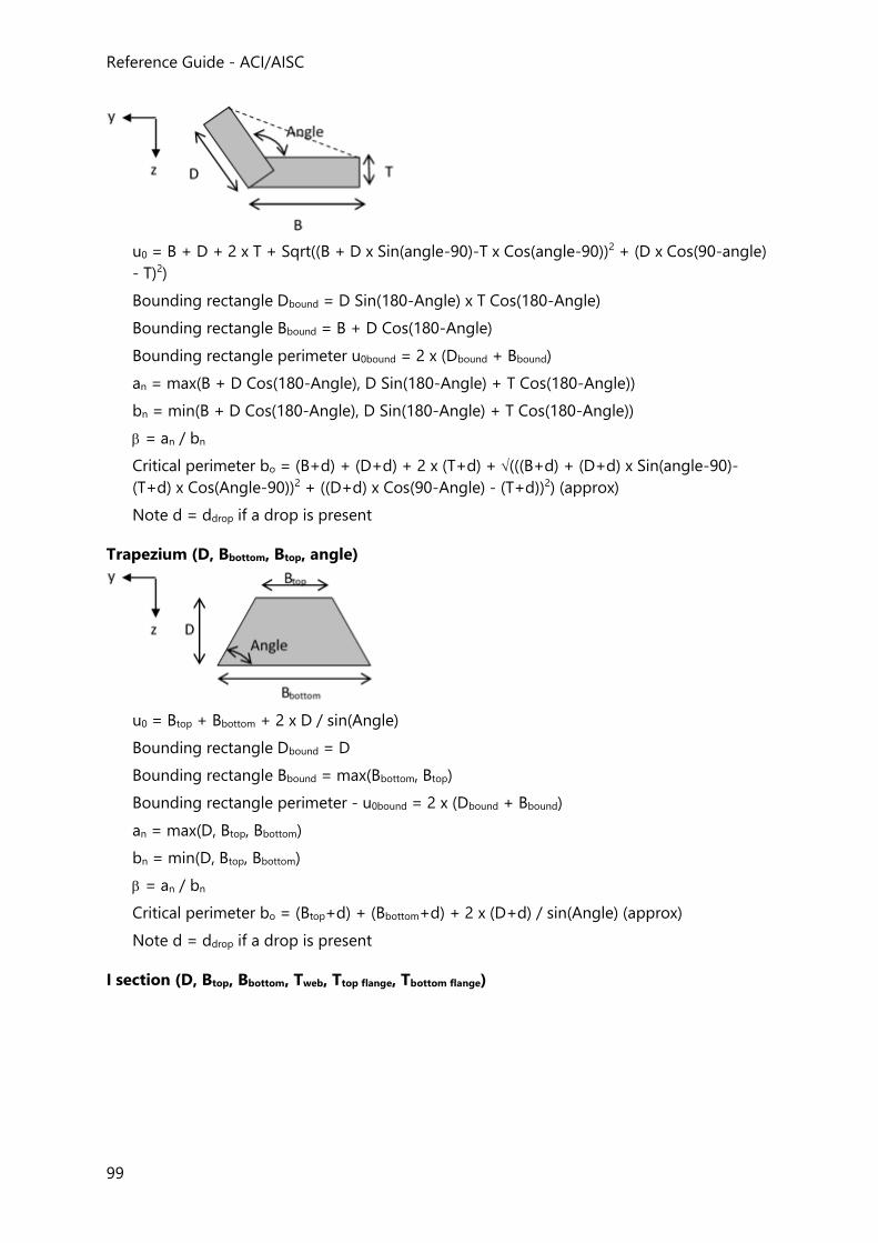
Reference Guide - ACI/AISC
99
u0 = B + D + 2 x T + Sqrt((B + D x Sin(angle-90)-T x Cos(angle-90))2 + (D x Cos(90-angle)
- T)2)
Bounding rectangle Dbound = D Sin(180-Angle) x T Cos(180-Angle)
Bounding rectangle Bbound = B + D Cos(180-Angle)
Bounding rectangle perimeter u0bound = 2 x (Dbound + Bbound)
an = max(B + D Cos(180-Angle), D Sin(180-Angle) + T Cos(180-Angle))
bn = min(B + D Cos(180-Angle), D Sin(180-Angle) + T Cos(180-Angle))
= an / bn
Critical perimeter bo = (B+d) + (D+d) + 2 x (T+d) + (((B+d) + (D+d) x Sin(angle-90)-
(T+d) x Cos(Angle-90))2 + ((D+d) x Cos(90-Angle) - (T+d))2) (approx)
Note d = ddrop if a drop is present
Trapezium (D, Bbottom, Btop, angle)
u0 = Btop + Bbottom + 2 x D / sin(Angle)
Bounding rectangle Dbound = D
Bounding rectangle Bbound = max(Bbottom, Btop)
Bounding rectangle perimeter - u0bound = 2 x (Dbound + Bbound)
an = max(D, Btop, Bbottom)
bn = min(D, Btop, Bbottom)
= an / bn
Critical perimeter bo = (Btop+d) + (Bbottom+d) + 2 x (D+d) / sin(Angle) (approx)
Note d = ddrop if a drop is present
I section (D, Btop, Bbottom, Tweb, Ttop flange, Tbottom flange)
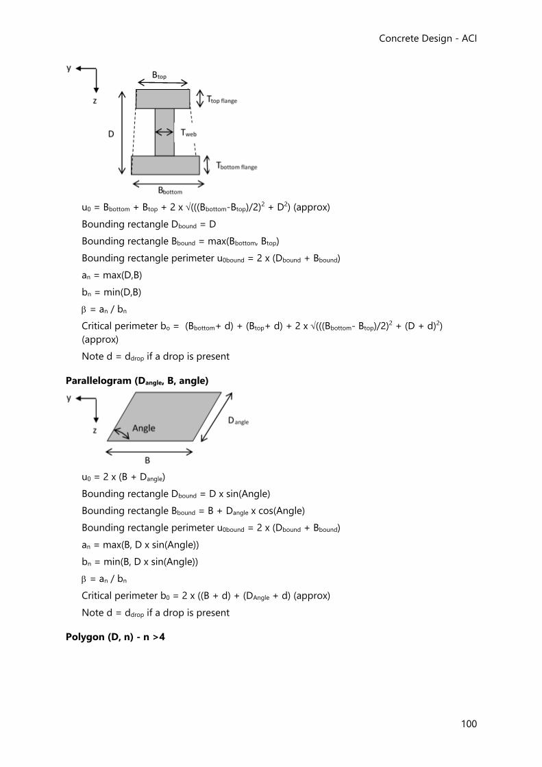
Concrete Design - ACI
100
u0 = Bbottom + Btop + 2 x (((Bbottom-Btop)/2)2 + D2) (approx)
Bounding rectangle Dbound = D
Bounding rectangle Bbound = max(Bbottom, Btop)
Bounding rectangle perimeter u0bound = 2 x (Dbound + Bbound)
an = max(D,B)
bn = min(D,B)
= an / bn
Critical perimeter bo = (Bbottom+ d) + (Btop+ d) + 2 x (((Bbottom- Btop)/2)2 + (D + d)2)
(approx)
Note d = ddrop if a drop is present
Parallelogram (Dangle, B, angle)
u0 = 2 x (B + Dangle)
Bounding rectangle Dbound = D x sin(Angle)
Bounding rectangle Bbound = B + Dangle x cos(Angle)
Bounding rectangle perimeter u0bound = 2 x (Dbound + Bbound)
an = max(B, D x sin(Angle))
bn = min(B, D x sin(Angle))
= an / bn
Critical perimeter b0 = 2 x ((B + d) + (DAngle + d) (approx)
Note d = ddrop if a drop is present
Polygon (D, n) - n >4
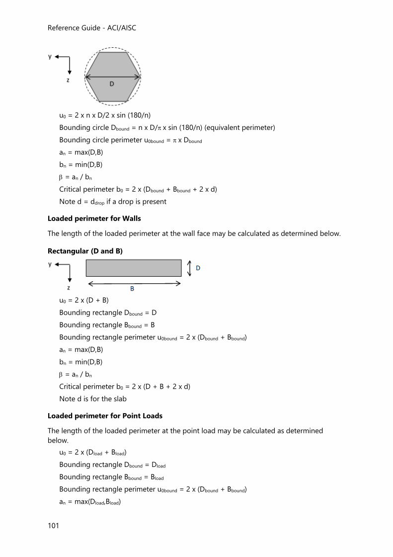
Reference Guide - ACI/AISC
101
u0 = 2 x n x D/2 x sin (180/n)
Bounding circle Dbound = n x D/ x sin (180/n) (equivalent perimeter)
Bounding circle perimeter u0bound = x Dbound
an = max(D,B)
bn = min(D,B)
= an / bn
Critical perimeter b0 = 2 x (Dbound + Bbound + 2 x d)
Note d = ddrop if a drop is present
Loaded perimeter for Walls
The length of the loaded perimeter at the wall face may be calculated as determined below.
Rectangular (D and B)
u0 = 2 x (D + B)
Bounding rectangle Dbound = D
Bounding rectangle Bbound = B
Bounding rectangle perimeter u0bound = 2 x (Dbound + Bbound)
an = max(D,B)
bn = min(D,B)
= an / bn
Critical perimeter b0 = 2 x (D + B + 2 x d)
Note d is for the slab
Loaded perimeter for Point Loads
The length of the loaded perimeter at the point load may be calculated as determined
below.
u0 = 2 x (Dload + Bload)
Bounding rectangle Dbound = Dload
Bounding rectangle Bbound = Bload
Bounding rectangle perimeter u0bound = 2 x (Dbound + Bbound)
an = max(Dload,Bload)
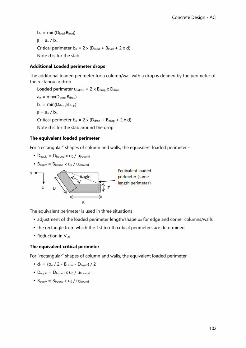
Concrete Design - ACI
102
bn = min(Dload,Bload)
= an / bn
Critical perimeter b0 = 2 x (Dload + Bload + 2 x d)
Note d is for the slab
Additional Loaded perimeter drops
The additional loaded perimeter for a column/wall with a drop is defined by the perimeter of
the rectangular drop
Loaded perimeter u0drop = 2 x Bdrop x Ddrop
an = max(Ddrop,Bdrop)
bn = min(Ddrop,Bdrop)
= an / bn
Critical perimeter b0 = 2 x (Ddrop + Bdrop + 2 x d)
Note d is for the slab around the drop
The equivalent loaded perimeter
For “rectangular” shapes of column and walls, the equivalent loaded perimeter -
• Dequiv = Dbound x u0 / u0bound
• Bequiv = Bbound x u0 / u0bound
The equivalent perimeter is used in three situations
• adjustment of the loaded perimeter length/shape u0 for edge and corner columns/walls
• the rectangle from which the 1st to nth critical perimeters are determined
• Reduction in VEd
The equivalent critical perimeter
For “rectangular” shapes of column and walls, the equivalent loaded perimeter -
• d1 = (bo / 2 - BEquiv - DEquiv) / 2
• Dequiv = Dbound x u0 / u0bound
• Bequiv = Bbound x u0 / u0bound
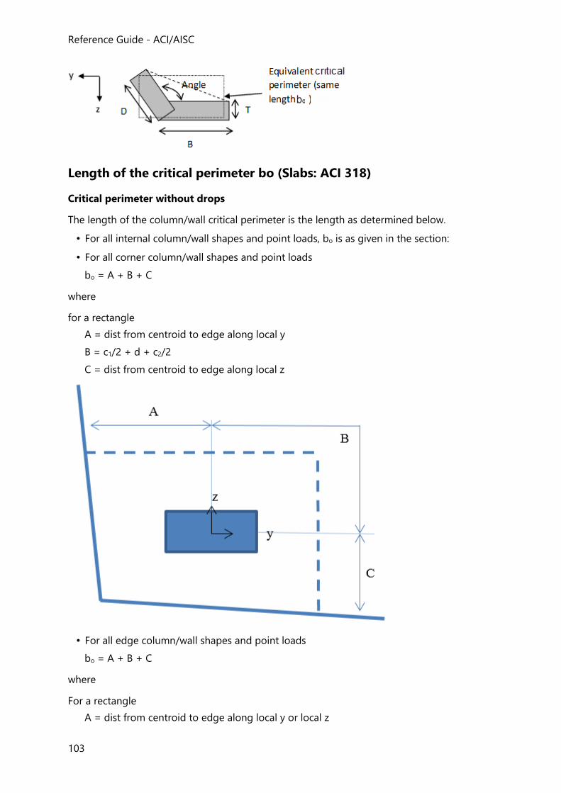
Reference Guide - ACI/AISC
103
Length of the critical perimeter bo (Slabs: ACI 318)
Critical perimeter without drops
The length of the column/wall critical perimeter is the length as determined below.
• For all internal column/wall shapes and point loads, bo is as given in the section:
• For all corner column/wall shapes and point loads
bo = A + B + C
where
for a rectangle
A = dist from centroid to edge along local y
B = c1/2 + d + c2/2
C = dist from centroid to edge along local z
• For all edge column/wall shapes and point loads
bo = A + B + C
where
For a rectangle
A = dist from centroid to edge along local y or local z
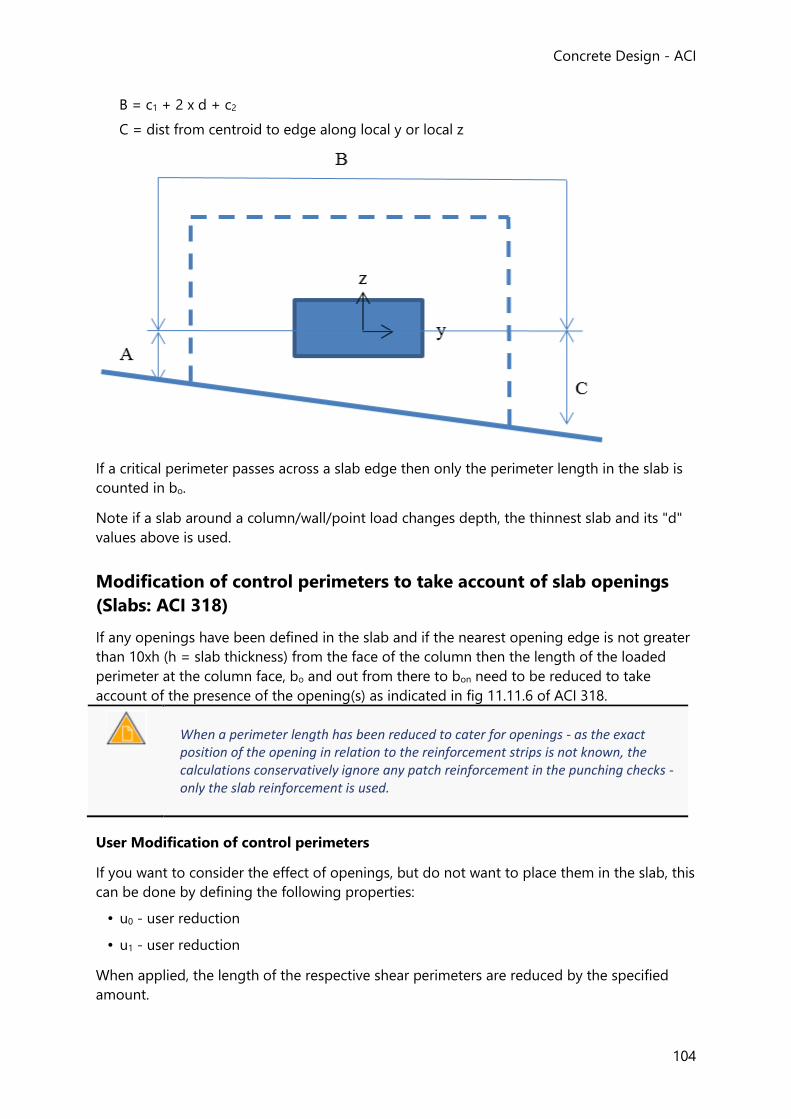
Concrete Design - ACI
104
B = c1 + 2 x d + c2
C = dist from centroid to edge along local y or local z
If a critical perimeter passes across a slab edge then only the perimeter length in the slab is
counted in bo.
Note if a slab around a column/wall/point load changes depth, the thinnest slab and its "d"
values above is used.
Modification of control perimeters to take account of slab openings
(Slabs: ACI 318)
If any openings have been defined in the slab and if the nearest opening edge is not greater
than 10xh (h = slab thickness) from the face of the column then the length of the loaded
perimeter at the column face, bo and out from there to bon need to be reduced to take
account of the presence of the opening(s) as indicated in fig 11.11.6 of ACI 318.
When a perimeter length has been reduced to cater for openings - as the exact position of the opening in relation to the reinforcement strips is not known, the calculations conservatively ignore any patch reinforcement in the punching checks - only the slab reinforcement is used.
User Modification of control perimeters
If you want to consider the effect of openings, but do not want to place them in the slab, this
can be done by defining the following properties:
• u0 - user reduction
• u1 - user reduction
When applied, the length of the respective shear perimeters are reduced by the specified
amount.
Reference Guide - ACI/AISC
105
Basic design procedure (Slabs: ACI 318)
The basic design procedure applied to an internal column is described below:
Check shear stress at perimeter against unreinforced shear resistance
The following check is performed at d/2 and perimeters beyond until the slab thickness is
adequate.
If vu ≤ vn then, the slab thickness is adequate and the calculations stop.
Otherwise, punching shear reinforcement is required.
Required shear stress of reinforcement
vs,reqd = (vu/φ) - MIN (vc , (3 x x (f’c)) 1
where,
Vu = shear force
f = 0.75
vc = MIN (vca , vcb , vcc )2
Required area of punching shear reinforcement
Av / s = vs,reqd x bo / fyt
where
fyt = the design strength of the reinforcement
Av = is the cross sectional area of all legs of reinforcement on one peripheral line
s = the spacing of link legs away from the column faces
bo = length of the 1st critical perimeter
Calculate the provided area of punching shear reinforcement
Av,provided/s = Ns × dsr /s
where
Ns = is the number of the studs/stirrups per perimeter
dsr = is the section area of single stud/stirrup
s = is the spacing between the reinforcement perimeters
Check area of punching shear reinforcement
IF Av,provided / s ≥ Av / sr – the choice of bars (number & diameter) and their spacing are
adequate.
Otherwise, if auto-design is active a new arrangement is tried; the number of bars, and
diameter are increased and the spacing decreased until the check passes. Chapter
1. ACI 318 -11 Equation 11-1 & 11.2
2. ACI 318 -11 Section 11.11.2.1
Concrete Design - ACI
106
Pad and Strip Base Design to ACI 318
Pad and strip bases are designed to resist the applied forces and moments for the three
phenomena of bending, beam shear and punching shear.
Reinforced concrete design checks relating to bases are carried out using Concrete
Combinations in accordance with ACI 318-08.
The soil bearing pressure check and net eccentricity of load are carried out using Soil
Combinations.
•
Checks Performed (Pad and Strip Base: ACI 318)
The checks performed for both directions are:
• Max soil bearing pressure must not exceed allowable bearing pressure.
• Provided steel must be greater than As(min) for both vertical directions.
• Provided bar spacing must be inside the limiting spacing
• Provided bar size must be inside the limiting sizes
• Check for bending moment capacity
• Check for shear capacity - wide beam action at 'd' from column face
• Punching check at 'd/2' from column face - two-way action
• Check for transfer of forces at column base
• Check for transfer of horizontal forces by shear friction theory
• Check for overturning forces - not in the current release
• Check for sliding
• Check for uplift
Foundation Bearing Capacity (Pad and Strip Base: ACI 318)
Check for Pad Base Bearing Capacity (ACI 318)
Bearing capacity calculations are done using service (soil) -combinations.
Reference Guide - ACI/AISC
107
Total base reaction:
T = Fswt + Fsoil + Fdl,sur + Fll,sur - P
Moment about X axis:
Mx,c = Mx,sup - P* ey - tftg* Fy,sup
Moment about Y axis:
My,c = My,sup + P* ex +tftg* Fx,sup
Where:
Lx = Length of foundation in X-direction
Ly = Length of foundation in Y-direction
Af = Lx * Ly = Foundation area
tftg = Depth of foundation
Ds = Depth of soil above the foundation
lx = Length of column/wall in X-direction
ly = Length of column/wall in Y-direction
Ac = cross section of the column/wall segment
ex = eccentricity in X direction.
ey = eccentricity in Y direction.
ρc = density of concrete
ρs = density of soil
Fswt = Af * tftg * ρc = foundation self-weight
Fsoil = (Af - Ac)*Ds* ρs = soil self-weight
Fdl,sur = (Af - Ac)*scdl = Dead load from surcharge
Fll,sur = (Af - Ac)*scll = Live load from surcharge
scdl = Surcharge in dead load case
scll = Surcharge in live load case
P = axial load acting on support in service combinations
Mx,sup = Moment acting on support around X-axis in service comb.
My,sup = Moment acting on support around Y-axis in service comb.
Concrete Design - ACI
108
Fx,sup = Horizontal force acting on support X-direction in service comb.
Fy,sup = Horizontal force acting on support Y-direction in service comb.
Eccentricity of base reaction in X-direction:
eTx = My,c / T
Eccentricity of base reaction in Y-direction:
eTy = Mx,c / T
If abs(eTx) / Lx + abs(eTy) / Ly ≤ 0.167
Then base reaction acts within kern distance - no loss of contact in X-direction, and:
Pad base pressures:
q1 = T/Af – 6* My,c / (Lx*Af) + 6* Mx,c / (Ly*Af)
q2 = T/Af – 6* My,c / (Lx*Af) - 6* Mx,c / (Ly*Af)
q3 = T/Af + 6* My,c / (Lx*Af) + 6* Mx,c / (Ly*Af)
q4 = T/Af + 6* My,c / (Lx*Af) - 6* Mx,c / (Ly*Af)
Max base pressure:
qmax = max (q1, q2, q3, q4)
Else base reaction acts outside kern distance - loss of contact.
In this case the pressure calculations are more complex - in Tekla Structural Designer these
are done using sets of equations presented in an article by Kenneth E. Wilson published in
the Journal of Bridge Engineering in 1997
Check for Strip Base Bearing Capacity (ACI 318)
The principles used in the strip base bearing capacity calculations are similar to those for pad
foundations. Only the direction X is checked (around Y-axis) using segment widths.
If abs(eTx) / Lx ≤ 0.167
Then - no loss of contact, and:
max base pressures for segment:
qmax = T/Af + max[- 6* My,c / (Lx*Af) , 6*My,c / (Lx*Af)]
Else - loss of contact and
max base pressures for segment:
qmax = 2*T/[3* Ly* (Lx /2 - abs(eTx))]
where Ly = segment width
Reference Guide - ACI/AISC
109
Design for Bending (Pad and Strip Base: ACI 318)
Bending design calculations are performed using ultimate load (factored concrete)
combinations.
The basic design method is identical to that for beams - see: in “Beam Design to ACI 318”.
Checks for Limiting Parameters (Pad and Strip Base: ACI 318)
Limiting reinforcement parameters are specified in Design Options > Foundations
> Isolated Foundations > Reinforcement Layout
Limits on bar size and reinforcement quantities
For structural foundations of uniform thickness the minimum area of tensile reinforcement
shall be:
For metric units:
IF Grade 280 to 350 deformed bars are used
As,min,reqd ≥ b*h*0.0020
IF Grade 350 to 420 deformed bars or welted wire reinforcement are used
As,min,reqd ≥ b*h*0.0018
IF yield stress exceeds 420 MPa
As,min,reqd ≥ b*h* [MAX(0.0014 , 0.0018*420/fy)]
For US-units:
IF Grade 40 to 50 deformed bars are used
As,min,reqd ≥ b*h*0.0020
IF Grade 50 to 60 deformed bars or welted wire reinforcement are used
As,min,reqd ≥ b*h*0.0018
IF yield stress exceeds 60000 psi
As,min,reqd ≥ b*h*[MAX(0.0014 , 0.0018*60000/fy)]
where
b = unit width
The maximum area of tensile reinforcement shall be:
As,max ≤ 0.85*(f`c/fy)*β1*b*d*(3/7)
where
Concrete Design - ACI
110
Ag = the gross area of the concrete section
V = stress block depth factorA
A ACI 318-08:2008, ACI 318-11:2011 and ACI 318M-11:2011 Section 10.2.7.3
metric-units
β1 = 0.85 for f`c ≤ 28Mpa
= 0.85 – 0.05 *[(f'c – 28MPa)/7MPa] for 28MPa < f`c < 55Mpa
= 0.65 for f`c ≥ 55MPa
US-units
β1 = min(max(0.85 - 0.05 ´ (f'c - 4 ksi) / 1ksi, 0.65), 0.85)
= 0.85 for f`c ≤ 4000 psi
= 0.85 – 0.05 *[(f'c – 4ksi)/1ksi] for 4000 psi < f`c < 8000psi
= 0.65 for f`c ≥ 8000 psi
Limits on bar spacing (Pad and Strip Base: ACI 318)
The following spacing rules apply to Rebar type reinforcement where the subscript i refers to
the X and Y directions respectively.
The minimum clear spacing between parallel bars in a layer, scl,min, is given by;
scl,min ≥ MAX[db , 4/3*dg , 25mm , scl,u,min ] metric-units
scl,min ≥ MAX[db , 4/3*dg , 1in. , scl,u,min] US-units
where
dg = the maximum size of aggregate
scl,u,min = user specified minimum clear distance between bars
The maximum spacing of the bars, si,max, is given by1,
s,max = MIN(smax,user, 18 in) for US units
= MIN(smax,user, 450 mm) for metric units
1. ACI 318-08:2008, ACI 318-11:2011 and ACI 318M-11:2011 Section 15.10.4
Shear Design (Pad and Strip Base: ACI 318)
Reference Guide - ACI/AISC
111
Pad base shear design check (ACI 318)
The nominal shear strength of the concrete in beam action, vn is given by1
vn = 2*λ*MIN(√(f`c), 100psi)*d
= 0.17*λ*MIN(√(f`c) ,8.3MPa)*d
where
λ = modification factor related to the density of the concrete
λ = 1.0 for normal weight concrete
If
vu ≤ Φshear*vn
Then the foundation thickness is adequate for shear -
Utilization ratio is then;
U-ratio = max [ vu / (Φshear*vn) ]
Else the check has failed, the foundation thickness is inadequate.
If the thickness is inadequate and the auto-design footing depth option is active then the foundation thickness gets increased.
1. ACI 318-08 Sections 11.1.2 and 11.2.1.1 Eqn (11-3)
Strip base shear design check (ACI 318)
The principle of the strip base shear design check is similar to that for the pad base. Only the
direction X is checked (around Y-axis) using segment widths.
Punching Shear Design (Pad and Strip Base: ACI 318)
Punching shear checks are carried out for pad foundations only, using ultimate load
(factored concrete) -combinations.
The punching shear checks for pad bases follow the same basic principle as used for mats.
See: Slab Design - Punching Shear Checks.
The main differences between mat and pad base punching shear checks are:
• Column local axes are always parallel with the pad base edges in the pad base punching
checks.
Concrete Design - ACI
112
• Loads from the column are always above the pad base (one direction).
• No openings can be placed in pad bases.
• No shear reinforcement is used in pad bases.
Check for Transfer Forces at Column Base (Pad and Strip Base: ACI
318)
This check applies when a concrete column is attached to the foundation.
Determinate the bearing strength of the column:
Φ*Pnb,c = Φbearing (0.85*f’c * Ac)
If
Φ*Pnb,c < - Pu
Then check fails
Else determinate the bearing strength of the footing:
Φ*Pnb,f = min[√(A2/Ac), 2] * Φbearing (0.85*f’c * Ac)
where for rectangular columns:
A2 = min{Lx , 2tftg+lx+min[(Lx-lx)/2-abs(ex),2tftg]} * min{Ly , 2tftg+ly+min[(Ly-ly)/2 - abs(ey),2tftg]}
Circular columns are treated as square members with the same area.
If
Φ*Pnb,f < - Pu
Then check fails
Required min. area of dowel bars between column and footing is then:A
As,min = 0.005*Ac
Currently dowel bars are not designed.
The area of the provided column reinforcement As,prov,column is the same as the provided reinforcement of starter/dowel bars.
If
As,min > As,prov,column
Reference Guide - ACI/AISC
113
Then check fails
A ACI 318-08 Section 15.8.2.1
Check for transfer of horizontal forces by shear friction (Pad and
Strip Base: ACI 318)
This check applies when a concrete column is attached to the foundation.
Determinate if the shear-friction design method applicable1:
When surface is not intentionally roughened (conservative assumption)
If Vu ≤ Φshear * Ac min(0.2*f’c , 800psi) for US units
Vu ≤ Φshear * Ac min(0.2*f’c , 5.5MPa) for metric units
where
Vu = max[abs(Fy,sup,u) , abs(Fx,sup,u)]
Then maximum shear transfer is permitted at the base of the column.
Required area of dowel reinforcement:
Avf = Vu / (fy * Φshear *μ)
where
μ = 0.6 when concrete not intentionally roughened (assumption)
μ = 1.0 when concrete intentionally roughened
μ = 1.4 when concrete placed monolithically
Currently dowel bars are not designed.
The area of the provided column reinforcement As,prov,column is the same as the provided
reinforcement of starter/dowel bars.
If
Avf > As,prov,column
Then check fails
1. ACI 318-08 Section 11.6.5
Check for Overturning Forces (Pad and Strip Base: ACI 318)
Concrete Design - ACI
114
Checks for overturning forces are beyond scope in the current release of Tekla Structural Designer.
Check for Sliding (Pad and Strip Base: ACI 318)
The check for sliding is carried out for pad foundations only.
If there is no horizontal force acting on foundation check for sliding is not required.
Resultant Force on foundation:
Hd = √[(Fx,sup)2 + (Fy,sup)
2]
Resultant Force Angle αHd = tan-1 [(Fy,sup / Fx,sup)]
where
Fx,sup = horizontal force acting on support in X-dir. (from analysis)
Fy,sup = horizontal force acting on support in Y-dir. (from analysis)
Resistance to sliding due to base friction:
Hfriction = [-P + Fswt] * tanδ
where
δ = design base friction – user input
Passive pressure coefficient:
Kp = (1+sinΦ’) / (1-sinΦ’)
where
Φ’ = design shear strength of soil – user input
Passive resistance of soil in X direction:
Hxpas = 0.5*Kp*(h2 +2*h*hsoil)*Lx* ρsoil
Passive resistance of soil in Y direction:
Hypas = 0.5*Kp*(h2 +2*h*hsoil)*Ly* ρsoil
Resultant Passive Resistance:
Hres,pas = abs(Hxpas*cos αHd) + abs(Hypas*sin αHd)
Total resistance to sliding:
RH.d = (Hfriction + Hres,pas) / 1.5
Reference Guide - ACI/AISC
115
If
RH.d ≥ Hd
The check for stability against sliding passes
Check for Uplift (Pad and Strip Base: ACI 318)
For combinations producing tension at the support, the tension value is compared to the
stabilizing loads and checked against a factor of safety (FOS). Auto-design can automatically
increment the base size to achieve a passing status. The FOS considered for the uplift check
is specified under Design Options > Concrete > Foundations > Isolated Foundations >
General Parameters (default value = 1.50).
Chapter
Pile Cap Design to ACI 318
The forces acting on a pile cap are applied to the foundation at the foundation level. The
foundation can take axial load and bi-axial shear and moment.
Pile cap design is divided between pile design (pile capacity check) and structural design of
the pile cap which includes bending, shear and punching shear design checks.
Pile Capacity (Pile Cap: ACI 318)
The pile capacity is compared to the axial service load acting on pile:
Pile capacity passes if:
Rc ≥ Pn ≥ - Rt
Where:
Rc = Pile compression capacity (service)
Rt = Pile tension capacity (service)
Pn = Pile load
Design for Bending (Pile Cap: ACI 318)
The pile cap is treated as a beam in bending, where the critical bending moments for the
design for the bottom reinforcement are taken at the face of the column.
The basic design method is identical to that for beams - see: Design for Bending for Rectangular Sections (Beams: ACI 318)
Shear Design (Pile Cap: ACI 318)
Concrete Design - ACI
116
Pile cap shear capacity passes if:
vsu ≤ Φvc and vsu,d ≤ Φvc,d for both sides and both directions
Refer to CRSI Design Handbook 2002 - Chapter 13, page 13-18…13-21
Punching Shear Design (Pile Cap: ACI 318)
Punching shear (two-way shear) checks are performed for the column and the individual
piles.
Columns
The punching shear check is similar to that for pad bases, but with the following difference:
• the shear force at a perimeter uses the value from the column reduced by pile loads
within the perimeter
See: Punching Shear Design (Pad and Strip Base: ACI 318)
Piles
The punching shear check is similar to that for pad bases, but with the following differences:
• variable d is replaced with dred where dred =min (h – “pile penetration depth”, average
reinforcement effective depth)
• no moments act on top of the pile, only axial load considered
See: Punching Shear Design (Pad and Strip Base: ACI 318)
Checks for Limiting Parameters (Pile Cap: ACI 318)
Limiting reinforcement parameters are specified in Design Options > Foundations
> Isolated Foundations > Reinforcement Layout
Check for distance of pile cap overhang
Check pile edge distance “e” for pile “i” in a pile group for both directions:
The check passes if:
min ei
> min (emin , emin,user)
where:
emin = MAX[230mm, 380mm - 0.5 * lp] when Rc ≤ 534 kN Metric
emin = MAX[9in, 15in - 0.5 * lp] when Rc ≤ 120 kips US Customary
emin = MAX[230mm, 530mm - 0.5 * lp] when 534 kN < Rc ≤ 1068 kN Metric
Reference Guide - ACI/AISC
117
emin = MAX[9in, 21in - 0.5 * lp] when 120 kips < Rc ≤ 240 kips US Customary
emin = MAX[230mm, 685mm - 0.5 * lp] when 1068 kN < Rc ≤ 1779 kN Metric
emin = MAX[9in, 27in - 0.5 * lp] when 240 kips < Rc ≤ 400 kips US Customary
emin = MAX[230mm, 760mm - 0.5 * lp] when Rc > 1779 kN Metric
emin = MAX[9in, 30in - 0.5 * lp] when Rc > 400 kips US Customary
lp = least width/diameter of the pile
Check for minimum pile spacing
Check center to center spacing “s” between piles “i” and “j” in a pile group:
The check passes if:
If sij > min(smin , smin,user)
where
smin,user = user input
smin = max (least width of the pile + 0.6m , 0.9m) for metric units
smin = max (least width of the pile + 2ft. , 3 ft) for US customary units1
There is also minimum recommended pile spacing in ACI 543R-10 section 2.1.4: smin = 3 times diameter or width at the cut off level
Check for maximum pile spacing
Check center to center maximum spacing “s” between piles “i” and “j” in a pile group:
The check passes if:
If sij < smax,user
smax,user = user input
Other checks
The remaining checks are identical to those for pad bases -
see: Checks for Limiting Parameters (Pad and Strip Base: ACI 318) 1. CRSI – Design handbook page 13-18
References (ACI 318)
References (ACI 318)
118
1. American Concrete Institute. Building Code Requirements for Structural Concrete (ACI 318-08) and Commentary. ACI 2008.
2. American Concrete Institute. Building Code Requirements for Structural Concrete (ACI 318-11) and Commentary. ACI 2011.
3. American Concrete Institute. Metric Building Code Requirements for Structural Concrete (ACI 318M-11) and Commentary. ACI 2011.
4. American Concrete Institute. Building Code Requirements for Structural Concrete (ACI 318-14) and Commentary. ACI 2014.
5. American Concrete Institute. Metric Building Code Requirements for Structural Concrete (ACI 318M-14) and Commentary. ACI 2014.
119
Steel Design to AISC 360 ASD and
LRFD
Tekla Structural Designer designs steel and composite members to a range of international
codes. This reference guide specifically describes the design methods applied when the AISC
360 ASD or AISC 360 LRFD resistance codes are selected.
General
Seismic Design (AISC 360)
All “Gravity Only Design” members are designed as per the normal AISC Specification rules
for the seismic load combinations.
Additional design rules are required for seismic combinations. These are as per the AISC
Seismic Provisions (AISC 341-05) (Ref. 9), (AISC 341-10) (Ref. 10) or (AISC 341-16) (Ref. 11). These
additional design rules ONLY apply to members in Seismic Load Resisting Systems. These
rules are applied as follows:
• If SDC = A - no additional requirements
• If SDC = D, E or F, apply rules for AISC 341
For each of X and Y directions:
• If SDC = B or C and R <=3 - no additional requirements
• If SDC = B or C and R > 3, apply rules for AISC 341
Deflection checks (AISC 360)
Tekla Structural Designer calculates both relative and absolute deflections. Relative
deflections measure the internal displacement occurring within the length of the member
and take no account of the support settlements or rotations, whereas absolute deflections
are concerned with deflection of the structure as a whole. The absolute deflections are the
ones displayed in the structure deflection graphics. The difference between relative and
absolute deflections is illustrated in the cantilever beam example below.
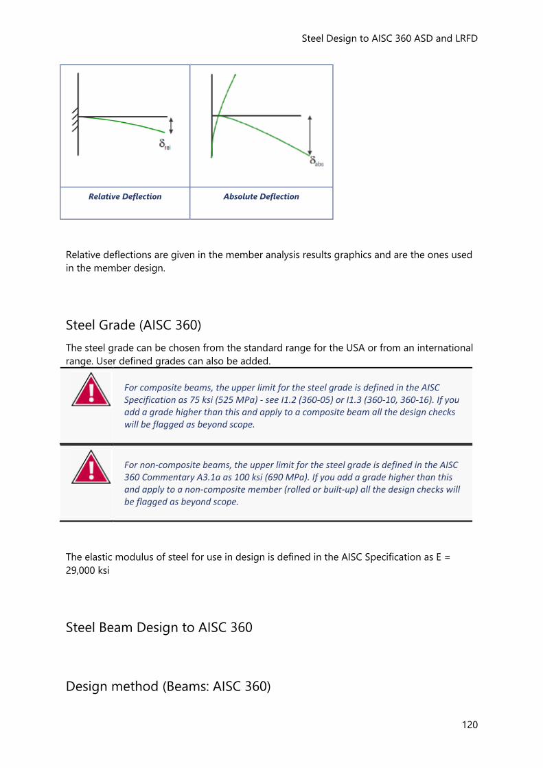
Steel Design to AISC 360 ASD and LRFD
120
Relative Deflection Absolute Deflection
Relative deflections are given in the member analysis results graphics and are the ones used
in the member design.
Steel Grade (AISC 360)
The steel grade can be chosen from the standard range for the USA or from an international
range. User defined grades can also be added.
For composite beams, the upper limit for the steel grade is defined in the AISC Specification as 75 ksi (525 MPa) - see I1.2 (360-05) or I1.3 (360-10, 360-16). If you add a grade higher than this and apply to a composite beam all the design checks will be flagged as beyond scope.
For non-composite beams, the upper limit for the steel grade is defined in the AISC 360 Commentary A3.1a as 100 ksi (690 MPa). If you add a grade higher than this and apply to a non-composite member (rolled or built-up) all the design checks will be flagged as beyond scope.
The elastic modulus of steel for use in design is defined in the AISC Specification as E =
29,000 ksi
Steel Beam Design to AISC 360
Design method (Beams: AISC 360)
Reference Guide - ACI/AISC
121
Either a load and resistance factor design (LRFD) or an allowable strength design (ASD) can
be performed to determine the adequacy of the section for each condition.
The design method employed is consistent with the design parameters specified in the
relevant chapters of the AISC Specification and associated 'Commentary', unless specifically
noted otherwise. As the 2005 (Ref. 1), 2010 (Ref. 2) and 2016(Ref. 3) versions are all supported,
where clauses are specific to a particular version these are indicated as (360-05), (360-10), or
(360-16) as appropriate.
A basic knowledge of the design methods for beams in accordance with the specification is
assumed.
Steel beam limitations and assumptions (Beams: AISC 360)
The following general limitations apply:
• Continuous beams (more than one span) must be co-linear in the plane of the web
within a small tolerance (sloping in elevation is allowed),
• Rolled doubly symmetric prismatic sections, doubly symmetric hollow sections, channel
sections are fully designed, plated beams are also fully designed
• Single angles, double angles and tees are designed, but additional limitations apply, (see
Angle and Tee Limitations)
• Design of beams with web openings is beyond scope.
The following additional limitations apply for plated beams:
• Double and single symmetric I-sections allowed
• Single or multi-span allowed, including cantilever spans
• Design for axial force (tension or compression) or flexure (major or minor) or any
combination of these
• Non-composite only
• Flanges and web all have same grade steel
• No design of curved beams (plan or elevation)
• No auto design
• No torsion design
• No seismic design
The following assumptions apply:
• All supports are considered to provide torsional restraint, that is lateral restraint to both
flanges. This cannot be changed. It is assumed that a beam that is continuous through
the web of a supporting beam or column together with its substantial moment resisting
end plate connections is able to provide such restraint.
• If, at the support, the beam oversails the supporting beam or column then the detail is
assumed to be such that the bottom flange of the beam is well connected to the
supporting member and, as a minimum, has torsional stiffeners provided at the support.
Steel Design to AISC 360 ASD and LRFD
122
• In the Tekla Structural Designer model, when not at supports, coincident restraints to
both flanges are assumed when one or more members frame into the web of the beam
at a particular position and the cardinal point of the centre-line model of the beam lies in
the web. Otherwise, only a top flange or bottom flange restraint is assumed. Should you
judge the actual restraint provided by the in-coming members to be different from to
what has been assumed, you have the flexibility to edit the restraints as required.
• Intermediate lateral restraints to the top or bottom flange are assumed to be capable of
transferring the restraining forces back to an appropriate system of bracing or suitably
rigid part of the structure.
• It is assumed that you will make a rational and “correct” choice for the effective lengths
between restraints for compression buckling. The default value for the effective length
factor of 1.0 may be neither correct nor safe.
Section Classification (Beams: AISC 360)
Cross-section classification is determined using Table B4.1 (360-05), or Tables B4.1a+B4.1b
(360-10).
At every cross section there are two classifications for each element in the section (flange or
web) - one for axial compression and one for bending (flexure).
If axial compression does not exist (0kip or tension), the axial classification is not applicable.
If bending is not present about both axes then the flexure classification is not applicable.
For axial compression the web and flanges are classified as either Compact or Slender and
the worst of the two is the resultant axial classification.
For bending both the web and flange are classified as Compact, Non compact or Slender
and the worst of the two is the resultant flexural classification.
The classification of the section must normally be Compact or Non compact, however
sections which are classified as Slender will be allowed if they are subject to axial load only.
Classification for Plated Beams
Since built-up (plated) beams allow for asymmetric sections, the general approach in flexure
classification for all built-up beams is:
• under major bending the compression flange is classified (both flanges are classified if
double curvature exists, and the worst case is reported)
• under minor bending both flanges are classified
• under biaxial bending, major and minor bending are considered independently and the
worst case is reported
D2. Axial Tension (Beams: AISC 360)
If axial tension exists, tensile yielding and rupture checks are performed at the point of
maximum tension in accordance with Eqns D2.1 and D2.2.
Reference Guide - ACI/AISC
123
In the rupture check the net area Ae is assumed to equal the gross area Ag.
A warning is issued if the slenderness ratio L/r exceeds 300.
E. Axial Compression (Beams: AISC 360)
If axial compression exists, the member is assessed for Flexural Buckling and for Torsional
and Flexural Torsional buckling. The compressive strength is determined in accordance with
Eqns E3.1 and E4.1. For double angles these equations are subject to the modifications of
Section E6.
The member length or member sub lengths between braces are checked for:
• Flexural buckling about major axis - for each unbraced length between adjacent points of
major axis lateral brace and or torsional brace.
• Flexural buckling about minor axis - for each unbraced length between adjacent points of
minor axis lateral brace and or torsional brace.
• Torsional and flexural torsional buckling - for each unbraced length between adjacent
points of torsional brace (this check is not applied to hollow sections.)
For any unbraced length, the required compressive force Pr is taken as the maximum
compressive force in the relevant length.
A warning is issued if the slenderness ratio KL/r exceeds 200.
G2. Shear Strength (Beams: AISC 360)
Shear checks are performed at the point of maximum shear in accordance with Section G2.
Plated beams only
Since built-up (plated) beams allow for asymmetric sections, under minor shear the web
shear coefficient, Cv is calculated for each flange separately and Equation G2-1 taken as:
Vn = 0.6 x Fy x (Aw,top x Cv,top + Aw,btm x Cv,btm)
F2. Flexure (Beams: AISC 360)
The member is assessed for Flexure in accordance with Section F2 to F10 (as appropriate).
The following checks are potentially required:
About the x axis - within the LTB braced length
• Yielding
• Compression flange local buckling
Steel Design to AISC 360 ASD and LRFD
124
• Web local buckling
• Local buckling
• Lateral Torsional Buckling (only required for I and C sections)
About the y axis in the LTB braced length
• Yielding
• Flange local buckling
• Web local buckling
• Local buckling
You can switch off the lateral torsional buckling checks for any unbraced length by indicating
the length is continuously braced. If you use this option you must be able to provide
justification that the unbraced length is adequately braced against lateral torsional buckling.
When the checks are required Tekla Structural Designer assumes a top flange (but not
bottom flange) brace is provided at the position of each incoming beam. You can add or
remove these braces if they don't reflect the actual brace provided by the incoming section.
Each unbraced length which is not defined as being continuously braced is then checked in
accordance with Section F2.
Plated beams only
The following additional checks apply about the x axis:
• Compression flange yielding
• Tension flange yielding
The approach to evaluating the web plastification factors, Rpc and Rpt in Section F4.2 and
F4.4 of 360-10, has been adopted for 360-05 also i.e. the ratio Iyc/Iy is considered as well as
hc/tw but note the following:
• under 360-05 Iyc is taken as the minimum inertia about the y axis of top and bottom
flange (regardless which flange is in compression)
• under 36010 Iyc is taken as the inertia about the y axis of the compression flange being
considered
For flange local buckling about the y axis Equation F6-2 is used for both double and single
symmetric sections, but in the latter case the more slender of the two flanges is assessed i.e.
the higher λ value will be used.
H1. Combined Forces (Beams: AISC 360)
Members subject to axial tension or compression and flexure about one or both axes are
assessed in accordance with Section H1.
Plated beams only
For built-up (plated) beams a Proportioning Limit check applies. In AISC 360-05 and 360-10
this is detailed within the chapter on design for flexure (section F13.2). Load combinations
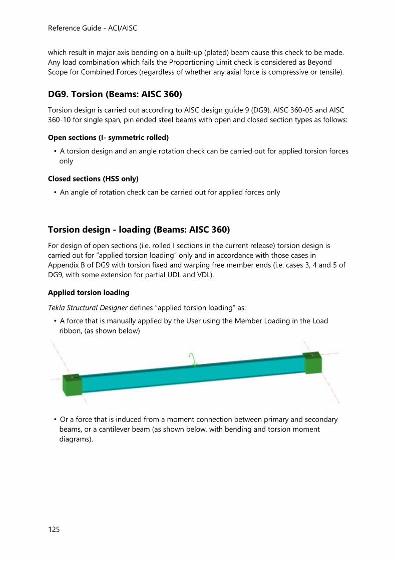
Reference Guide - ACI/AISC
125
which result in major axis bending on a built-up (plated) beam cause this check to be made.
Any load combination which fails the Proportioning Limit check is considered as Beyond
Scope for Combined Forces (regardless of whether any axial force is compressive or tensile).
DG9. Torsion (Beams: AISC 360)
Torsion design is carried out according to AISC design guide 9 (DG9), AISC 360-05 and AISC
360-10 for single span, pin ended steel beams with open and closed section types as follows:
Open sections (I- symmetric rolled)
• A torsion design and an angle rotation check can be carried out for applied torsion forces
only
Closed sections (HSS only)
• An angle of rotation check can be carried out for applied forces only
Torsion design - loading (Beams: AISC 360)
For design of open sections (i.e. rolled I sections in the current release) torsion design is
carried out for “applied torsion loading” only and in accordance with those cases in
Appendix B of DG9 with torsion fixed and warping free member ends (i.e. cases 3, 4 and 5 of
DG9, with some extension for partial UDL and VDL).
Applied torsion loading
Tekla Structural Designer defines “applied torsion loading” as:
• A force that is manually applied by the User using the Member Loading in the Load
ribbon, (as shown below)
• Or a force that is induced from a moment connection between primary and secondary
beams, or a cantilever beam (as shown below, with bending and torsion moment
diagrams).
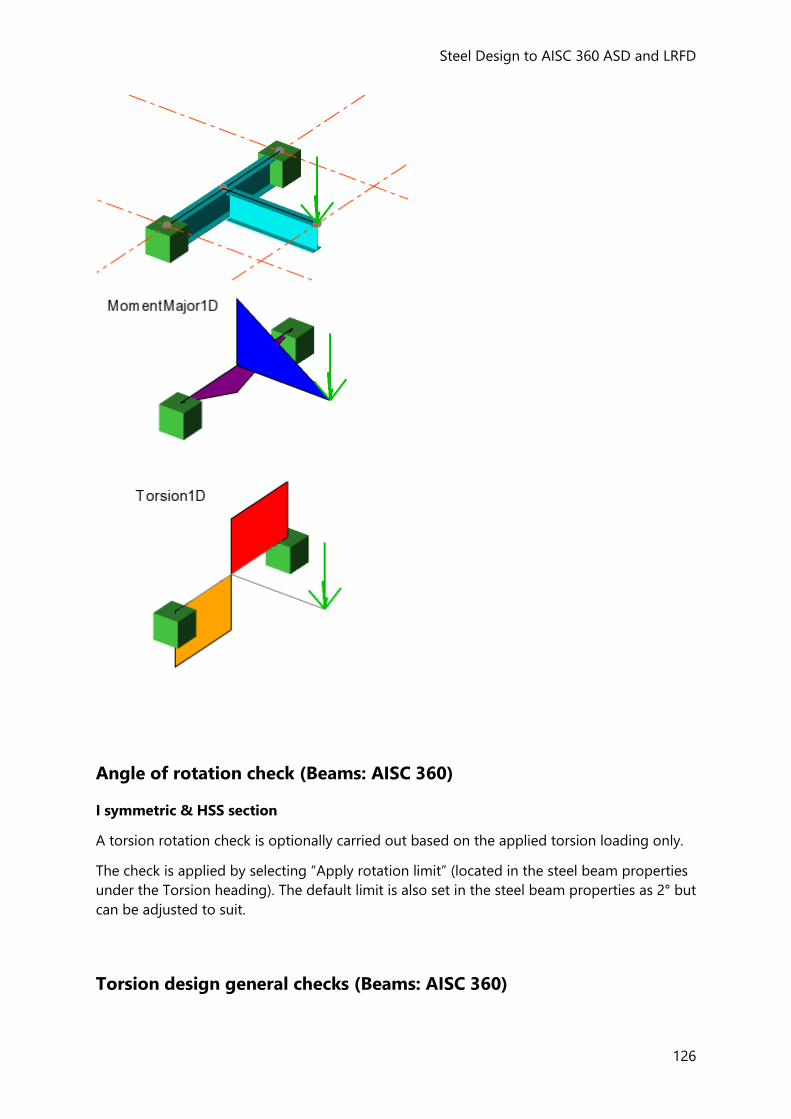
Steel Design to AISC 360 ASD and LRFD
126
Angle of rotation check (Beams: AISC 360)
I symmetric & HSS section
A torsion rotation check is optionally carried out based on the applied torsion loading only.
The check is applied by selecting “Apply rotation limit” (located in the steel beam properties
under the Torsion heading). The default limit is also set in the steel beam properties as 2° but
can be adjusted to suit.
Torsion design general checks (Beams: AISC 360)
Reference Guide - ACI/AISC
127
1. Auto design is not carried out in the current release, only check design (and check design
is only carried out if the “check for torsion” flag is set to on in the Edit dialog or
Properties Window)
2. Lateral restraint amplification factor (in accordance with section 4.7.3 of DG9):
a. It is assumed lateral displacement and twist are not restrained at any load point.
Therefore, in accordance with section 4.7.3 of DG9, by and w will always be amplified in the presence of torsion.
b. To avoid a negative value, Tekla Structural Designer applies a lower limit of 0.001ksi OR N/mm2 to the denominator of the amplification factor,
(Fcre - bx)
c. Fcre =
Fcr,bx
d. Amplification factor = 1.0 when bx = 0.0
3. Both major and minor axis shear buckling are checked if loaded in the relevant axis. A
warning is issued if the buckling limit defined in AISC Sect G2 is exceeded. Torsion design
will, however, be continued - the engineer is expected to deem if the shear buckling
condition is safe.
4. Torsion shear stresses:
a. A cross-section check is carried out at points of interest taken from the load analysis diagram.
5. Combined forces and torsion:
a. HSS - sections
i.) A cross-section check is carried out at points of interest taken from the load analysis diagrams as well as 10th positions along the member. In cases where the final utilisation ratio approaches 1.0 we strongly recommend the engineer
considers other locations, where a more critical location than that chosen in Tekla
Structural Designer may exist.
b. I symmetric
i.) We take the most critical axial stress value across all axial strut lengths to determine Fcr,a
ii.) We take the most critical major bending stress value across all LTB lengths to determine Fcr,bx
Steel Design to AISC 360 ASD and LRFD
128
ii.) In ASD design checks, the value used for Fcr,a and Fcr,bx is Fcr / 1.67 since Fa and
Fb used in DG9 relate to the 1989 ASD Specification where this factor was effectively already taken into account.
Web Openings (Beams: AISC 360)
Circular Openings as an Equivalent Rectangle
Each circular opening is replaced by equivalent rectangular opening, the dimensions of this
equivalent rectangle for use in all subsequent calculations are:
do'= 0.9*opening diameter
lo = 0.45*opening diameter
Web Opening design checks
Common design checks for both composite and non-composite beams
The following design checks are carried out at each opening for both composite and steel
beams.
• Section and opening dimension limit check including the spacing of multiple openings
if applicable.
• Classification check. Non-compact sections are beyond scope.
• Moment-shear interaction check. First the maximum pure flexural and shear strength is
calculated following the guidelines of the Design Guide for the currently selected edition
of the headcode. Then the direct formulas (3-5a and 3-5b) are used to calculate design
shear and bending strength.
• Deflection calculation. As deflection calculations are headcode independent, for
simplicity a single approach is used irrespective of the headcode selected.
Additional design checks for non-composite beams or composite beams at
construction stage
The following additional design checks are carried out at each opening only for non-
composite beams or composite beams at construction stage.
• Lateral torsional buckling. The 'standard' lateral torsional buckling check is run but the
torsional constant is multiplied by a reduction factor according to the design guide.
Strength over the openings should not be the governing UR.
• Buckling of tee-shaped compression zone. The tee which is in compression is
investigated as an axially loaded column following the procedures of selected headcode.
For unreinforced members this is not required when the aspect ratio of the tee is less
than or equal to 4. For reinforced openings, this check is only required for large openings
in regions of high moment.
Additional design checks for composite beams at composite stage
Reference Guide - ACI/AISC
129
The following additional design checks are carried out at each opening only for composite
beams at composite stage.
• Slab reinforcement check. The check of minimum transverse and longitudinal slab
reinforcement ratio to prevent cracking of the slab in the vicinity of the web opening.
• Number of shear connectors above the opening. To limit the effect of bridging a
minimum of two studs per foot is applied to the total number of studs. If this criterion is
already satisfied by normal stud requirements, additional studs are not needed. A
warning is shown when this criteria is not met.
Deflections
The simplified rules in DG2 are for limited cases and therefore have not been implemented.
Instead Tekla Structural Designer uses a first principles approach as per Eurocodes.
The deflection of a beam with web openings will be greater than that of the same beam
without openings. This is due to two effects,
• the reduction in the beam inertia at the positions of openings due to primary bending of
the beam,
• the local deformations at the openings due to Vierendeel effects. This has two
components - that due to shear deformation and that due to local bending of the upper
and lower tee sections at the opening.
The primary bending deflection is established by 'discretising' the member and using a
numerical integration technique based on 'Engineer's Bending Theory' - M/I = E/R = σ/y. In
this way the discrete elements that incorporate all or part of an opening will contribute more
to the total deflection.
The component of deflection due to the local deformations around the opening is
established using a similar process to that used for cellular beams which is in turn based on
the method for castellated beams given in the SCI publication, “Design of castellated beams.
For use with BS 5950 and BS 449".
The method works by applying a 'unit point load' at the position where the deflection is
required and using a 'virtual work technique to estimate the deflection at that position.
For each opening, the deflection due to shear deformation, δs, and that due to local bending,
δbt, is calculated for the upper and lower tee sections at the opening. These are summed for
all openings and added to the result at the desired position from the numerical integration
of primary bending deflection.
Note that in the original source document on castellated sections, there are two additional
components to the deflection. These are due to bending and shear deformation of the web
post. For castellated beams and cellular beams where the openings are very close together
these effects are important and can be significant. For normal beams the openings are likely
to be placed a reasonable distance apart. Thus in many cases these two effects will not be
significant. They are not calculated for such beams but in the event that the openings are
placed close together a warning is given.
Steel Design to AISC 360 ASD and LRFD
130
Seismic Design Rules (Beams: AISC 360)
Additional design rules are required for seismic combinations. These are as per the AISC
Seismic Provisions (AISC 341-05)(Ref. 9). These additional design rules ONLY apply to
members in Seismic Load Resisting Systems.
See “Assumptions/Limitations of the Seismic Provisions” for a list of the assumptions and
limitations that apply with respect to the application of these rules to Tekla Structural
Designer models.
The rules applied depend upon the seismic load resisting system as defined in the AISC
Seismic Provisions and are listed below:
For a moment resisting frame
9.Special Moment Frame (SMF)
• 9.4a. Classification
• 9.8. Max spacing of bracing
10. Intermediate Moment Frame (IMF)
• 10.4a. Classification
• 10.8. Max spacing of bracing
11. Ordinary Moment Frame (OMF)
• 11.4. Classification
Moment resisting frame with a truss component
12. Special Truss Moment Frame (STMF) 1- Beyond Scope
For a braced frame
13. Special Concentrically Braced Frames (SCBF)
• 13.2d. Classification
• 13.4a.(2). Max lat brace spacing
• 13.4a. V and inverted V type
14. Ordinary Concentrically Braced Frames (OCBF)
• 14.2. Classification
• 14.3. Beams with V and inverted V type
• Beams (not columns with no K braces)
• 14.2.(2). Max lat brace spacing
15. Eccentrically Braced Frames (EBF) - Beyond Scope
Buckling resistant braced frame
Reference Guide - ACI/AISC
131
16. Buckling Restrained Braced Frames (BRBF) - Beyond Scope
Frames containing composite beams
Composite Special Concentrically Braced Frames (C-SCBF) - Beyond Scope
Composite Ordinary Braced Frames (C-OBF) - Beyond Scope
Composite Eccentrically Braced Frames (C-EBF) - Beyond Scope 1. Beyond Scope of the current version of Tekla Structural Designer
Composite Beam Design to AISC 360
Design method (Composite beams: AISC 360)
Either a load and resistance factor design (LRFD) or an allowable strength design (ASD) can
be performed to determine the adequacy of the section for each condition.
The design method employed is consistent with the design parameters for simple composite
beams as specified in Chapter I of the AISC Specification and associated 'Commentary',
unless specifically noted otherwise. As the 2005 (Ref. 1), 2010 (Ref. 2) and 2016(Ref. 3) versions
are all supported, where clauses are specific to a particular version these are indicated as
(360-05), (360-10), or (360-16) as appropriate.
A basic knowledge of the design methods for composite beams in accordance with the
specification is assumed.
Construction stage (Composite beams: AISC 360)
At construction stage the beam is acting alone before composite action is achieved and is
unshored.
When you design or check a beam for construction stage loading the following checks are
carried out in accordance with the relevant chapters of the AISC Specification, consistent
with the approach (i.e. LRFD or ASD) used at the composite stage.
Section classification (Composite beams: AISC 360)
Cross-section classification is determined using Table B4.1 (360-05), or Tables B4.1a+B4.1b
(360-10) and must be Compact or Non compact. Sections which are classified as Slender are
beyond the scope of Tekla Structural Designer.
Shear strength - I3.1b (360-05), I4.2 (360-10) (Composite beams: AISC
360)
Steel Design to AISC 360 ASD and LRFD
132
Shear checks are performed at the point of maximum shear based upon the properties of the
steel section alone in accordance with Section G2.
Strength during construction - I3.1c (360-05), I3.1b (360-10)
(Composite beams: AISC 360)
Flexure
Checks are performed at the point of maximum moment along the beam based upon the
properties of the steel section alone in accordance with Section F2.
Lateral torsional buckling checks
When the forms are attached to the top flange then full lateral restraint can be assumed,
irrespective of the angle of the deck. In this case you should indicate the beam is
continuously braced.
In other cases any incoming beams will be automatically identified.
Each sub-length which is not defined as being continuously braced is checked in accordance
with Section F2.
Deflection checks (Composite beams: AISC 360)
Relative deflections are used in the composite beam design. (See: .)
The following deflections are calculated for the loads specified in the construction stage load
combination:
• the Dead load deflections i.e. those due to the beam self weight, the Slab Wet loads and
any other included dead loads,
• the live load deflections i.e. those due to construction live loads,
• the Total load deflection i.e. the sum of the previous items.
The loads are taken as acting on the steel beam alone.
The “Service Factor” (default 1.0), specified against each load case in the construction
combination is applied when calculating the above deflections.
If requested by the user, the total load deflection is compared with either a span-over limit
or an absolute value. The initial default limit is span/200, (as per CC.1.1 of ASCE 7-05(Ref. 7) or
ASCE 7-10(Ref. 8)).
Composite stage (Composite beams: AISC 360)
Tekla Structural Designer performs all checks for the composite stage condition in
accordance with Section I3 unless specifically noted otherwise.
Equivalent steel section (Composite beams: AISC 360)
Reference Guide - ACI/AISC
133
An equivalent steel section is determined for use in the composite stage calculations by
removing the fillet while maintaining the full area of the section. This approach reduces the
number of change points in the calculations while maintaining optimum section properties.
Shear strength - I3.1b (360-05), I4.2 (360-10) (Composite beams: AISC
360)
Shear checks are performed at the point of maximum shear in accordance with Section G2
for the maximum required shear strength, Vr, at the composite stage. The shear check is
performed on the bare beam alone at the composite stage ignoring any contribution from
the concrete slab.
Strength of composite beams with shear connectors - I3.2 (Composite
beams: AISC 360)
Section classification
For section classification purposes the true section is used. Tekla Structural Designer classifies
the section in accordance with Section I3.2a. Only the web of the section is classified - the
bottom flange is in tension and so cannot buckle locally and it is assumed that the top flange
is sufficiently braced by the composite slab.
The classification of the web must be compact so that plastic stress blocks can be used.
Flexure
Checks are performed at the point of maximum moment and the position of application of
each point load as well as all other points of interest along the beam. Flexure is calculated in
accordance with Section I3.2 (360-05/-10). Since the flexural strength at all point loads is
checked then this will inherently satisfy Section I3.2d (6) (360-05) or Section I8.2c (360-10)
which require that “the number of shear connectors placed between any concentrated load
and the nearest point of zero moment shall be sufficient to develop the maximum required
flexural strength at the concentrated load point”.
During the selection process, in auto design mode point loads are taken to be “significant” if
they provide more than 10% of the total shear on the beam. For the final configuration and
for check mode all point loads are checked for flexure.
Shear connectors (Composite beams: AISC 360)
Tekla Structural Designer checks shear connectors to Section I1-3 (360-05), or Section I8
(360-10).
The nominal strength of headed stud shear connectors in a solid slab or a composite slab is
determined in accordance with Section I3.2d (360-05), or Section I3.2d with shear connector
strength from I8.2a (360-10).
Ribs perpendicular
The reduction factor Rp is taken as,
Steel Design to AISC 360 ASD and LRFD
134
Rp = 0.6 for any number of studs and emid-ht < 2 in
= 0.75 for any number of studs and emid-ht >= 2 in
In Tekla Structural Designer you are therefore not required to input the actual value of emid-
ht instead you simply indicate if it is less than 2 in.
Ribs parallel
Rp = 0.75 in all cases
Ribs at other angles
Where the ribs are at an angle r to the beam there is no guidance in the AISC Specification.
The approach adopted by Tekla Structural Designer is to apply a geometric adjustment of the
reduction factors Rg and Rp which for the purposes of this adjustment are combined into one
“k” factor. The combined reduction factor is calculated for perpendicular and parallel
separately and then adjusted as shown below.
ks = k1 * sin2r + k2 * cos2r
Where:
ks = the adjusted value of the combined reduction factor Rg * Rp
k1 = the value of the combined reduction factor Rg * Rp for ribs perpendicular
k2 = the value of the combined reduction factor Rg * Rp for ribs parallel
Degree of shear connection
For efficient design the number of studs should be minimized. If the number provided has an
overall capacity greater than the capacity of the concrete flange or steel beam (whichever is
the lesser) then this is full shear connection. Anything less than this, is partial shear
connection. There are, however, limits on the amount of partial interaction that are
recommended by the AISC Specification – see note “3” (p.16.1-311 of the 2005 Commentary,
or p.16.1-356 of the 2010 Commentary).
For all beams, the number of connectors required for full shear connection is,
Ns = (min(Ts, (Cc1 + Cc2)))/Qn rounded up to the next group size above
Where:
Ts = the tensile yield strength of the steel section
Cc1 = the strength of the concrete flange above the ribs
Cc2 = strength of the concrete in the ribs (zero for perpendicular decks)
Qn = the nominal strength of an individual shear connector
The degree of partial shear connection is given by,
Int = Na * Qn / (min((Cc1 + Cc2), Ts))
Where:
Na = the number of shear connectors provided from the nearer point of support to the
position under consideration
Reference Guide - ACI/AISC
135
The degree of partial shear connection is checked at the point of maximum bending moment
or the position of a point load if at that position the maximum utilization ratio occurs.
To determine the status of the check Tekla Structural Designer applies the following rules:
• If the partial interaction ratio at the position of maximum moment is less than the
absolute minimum interaction ratio (default 25%), then this generates a FAIL status,
• If the partial interaction ratio at the position of maximum utilization ratio when this is at a
different position to the maximum moment, is less than the absolute minimum
interaction ratio, then this generates a WARNING status,
• If the partial interaction ratio at the position of maximum moment, or maximum
utilization ratio if this is different, is greater than the absolute minimum interaction ratio,
then this generates a PASS status,
• If the partial interaction ratio at any point load position that is not the maximum
utilization ratio is less than the absolute minimum interaction ratio, then this does not
affect the status in any way.
• If the partial interaction ratio at any position is less than the advisory minimum
interaction ratio (default 50%) then this is given for information only and does not affect
the status in any way.
Dimensional requirements
The dimensional limits given below are either recommendations or code limits:
• the nominal rib height of the profiled deck, hr should be not greater than 3 in
• the mean width of the ribs of the profiled sheet, wr should be not less than 2 in (for re-
entrant decks the “mean” is taken as the minimum opening at the top of the rib)
• the nominal diameter of stud connectors, dsc should be not greater than ¾ in
• the height of the stud after welding, Hs should be at least 1½ in greater than the nominal
rib height of the profiled deck – see Section I3.2c(b) (360-05), or Section I3.2c(2) (360-10).
• the total depth of the composite slab, dcs should not be less than 3¾ in
• the thickness of concrete above the main flat surface of the top of the ribs of the
sheeting, dcs - hr should not be less than 2 in
• concrete cover, dcs – Hs over the connector should not be less than ½ in – see Section
I3.2c(b) (360-05), or Section I3.2c(2) (360-10).
• the longitudinal spacing should not exceed the lesser of 36 in or 8 * the slab depth,
dcs (see Section 6.2.6.2 of Structural Steel Designer's Handbook. Second Edition(Ref. 5))
• where studs are spaced at greater than 18 in centers puddle welds or other appropriate
means are required to ensure anchorage of deck – see Section I3.2c (360-05), or Section
I3.2c(4) (360-10).
• the clear distance between the edge of a connector and the edge of the steel beam
flange should be not less than ¾ in (as universal good practice).
• Section I8.2d of the AISC Specification (360-10) requires that the minimum edge distance
from the center of an anchor to a free edge in the direction of the shear force shall be 8
Steel Design to AISC 360 ASD and LRFD
136
in for normalweight concrete and 10 in for lightweight concrete. This requirement will
apply only in a limited number of configurations and therefore is not checked.
• the spacing of connectors in the direction of shear i.e. along the beam should be not less
than, 6 * the stud diameter
• the spacing of connectors transverse to direction of shear i.e. across the beam should be
not less than 4 * the stud diameter except for the condition given in the next item
• where rows of studs are staggered, the minimum transverse spacing between
longitudinal lines of studs should be not less than 3 * the stud diameter with the amount
of stagger such that the diagonal distance between studs on adjacent longitudinal lines is
not less than 4 * the stud diameter
• the stud connector diameter should not exceed 2.5 times the flange thickness unless
located directly over the web.
You should confirm that the chosen configuration of decking and studs meet those dimensional requirements that you deem appropriate.
Serviceability Limit State (SLS) (Composite beams: AISC 360)
Section properties (SLS)
In the calculation of the gross moment of inertia of the composite section the steel deck is
ignored as is any concrete in tension. The concrete is converted into an equivalent steel
section using an effective modular ratio based on the proportions of long and short term
loads which are relevant to the particular calculation. Two alternative approaches are given -
see p.16.1-308 in the 2005 Commentary, or p.16.1-353 in the 2010 Commentary for
obtaining these properties.
One (the 'traditional method') calculates the gross uncracked inertia of the transformed
section but uses 75% of the resulting value in the determination of deflections. The other
uses a given formula to determine a 'lower-bound' inertia. While studies have shown that the
simple application of a reduction factor (0.75) is more onerous than the lower-bound
solution, the simpler 'traditional method' is the approach adopted in Tekla Structural
Designer.
Tekla Structural Designer therefore calculates the deflection for the beam based on the
properties as tabulated below.
Loadcase
Type
Properties used
self-weight bare beam
Slab Dry bare beam
Reference Guide - ACI/AISC
137
Dead composite properties calculated using the modular ratio for long term loads*
Live, Roof Live composite properties calculated using the effective modular ratio** appropriate to the long term load percentage for each load.
Wind, Snow, Earthquake
composite properties calculated using the modular ratio for short term loads
Total loads these are calculated from the individual loadcase loads as detailed above.
*The long term modulus is taken as the short term value divided by a factor (for
shrinkage and creep), entered in the Slab properties.
nS = the short term modular ratio
= Es/Ec
nL = the long term modular ratio
= (Es/Ec) * kn
**The effective modular ratio, nE is based on the percentage of load which is considered
long term. These calculations are repeated for each individual load in a loadcase.
The effective modular ratio is given by,
nE = nS + L * (nL – nS)
L = the proportion of the load which is long term
The calculated Slab Dry, Live and Total load deflections (where necessary adjusted for the
effect of partial interaction) are checked against the limits you specify.
All the beam deflections calculated above are “relative” deflections. For an illustration of the difference between relative and absolute deflection see .
Stress checks (SLS)
The Commentary (Section I3.1, paragraph 2 of the 2005 version, Section I3.2, of the 2010
version) suggests that where deflection controls the size of the beam then either it should be
ensured that the beam is elastic at serviceability loading or that the inelastic deformations
are taken into account. Tekla Structural Designer adopts the former approach. This is
confirmed by checking that yield in the beam and crushing in the concrete do not occur at
serviceability loading i.e. a service stress check. If they are found to fail, suggesting
inelasticity at serviceability loading, then a warning will appear on the deflections page and
the service stress results are available to view.
Tekla Structural Designer calculates the worst stresses in the extreme fibres of the steel and
the concrete at serviceability limit state for each load taking into account the proportion
which is long term and that which is short term. These stresses are then summed
algebraically. The partial safety factors for loads are taken as those provided by you for the
Steel Design to AISC 360 ASD and LRFD
138
service condition on the Design Combinations page. The stress checks assume that full
interaction exists between the steel and the concrete at serviceability state.
Natural frequency checks (SLS)
The calculation of the natural frequency of a composite beam can be complex and is
dependent upon the support conditions, the load profile and the properties of the
composite section. In reality the vibration of a composite beam is never in isolation – the
whole floor system (including the slabs and other adjacent beams) will vibrate in various
modes and at various frequencies.
A simple (design model) approach is taken based on uniform loading and pin supports. This
fairly simple calculation is provided to the designer for information only. The calculation can
be too coarse particularly for long span beams and does not consider the response side of
the behavior i.e. the reaction of the building occupants to any particular limiting value for the
floor system under consideration. In such cases the designer will have the option to perform
a Floor Vibration Analysis within the Tekla Structural Designer application.
Simplified approach
The natural frequency is determined from,
NF = 0.18 * (g/NF)
Where:
NF = the maximum static instantaneous deflection (in inches) that would occur under
the effects of Slab Dry loading, and the proportion of dead loads and live loads specified
by the user (as specified on the Natural Frequency page of the Design Wizard). It is based
upon the composite inertia but not modified for the effects of partial interaction.
g = the acceleration due to gravity (386.4 in/s2)
This is not given in the AISC Specification but is taken from Chapter 3 of Steel Design Guide
Series 11. Floor Vibrations due to Human Activity.(Ref. 6) Its formulation is derived from the first
mode of vibration of a simply supported beam subject to a udl.
Steel Column Design to AISC 360
Design Method (Columns: AISC 360)
Either a load and resistance factor design (LRFD) or an allowable strength design (ASD) can
be performed to determine the adequacy of the section for each condition.
The design method employed is consistent with the design parameters specified in the
relevant chapters of the AISC Specification and associated 'Commentary', unless specifically
noted otherwise. As the 2005 (Ref. 1), 2010 (Ref. 2) and 2016(Ref. 3) versions are all supported,
where clauses are specific to a particular version these are indicated as (360-05), (360-10), or
(360-16) as appropriate.
Reference Guide - ACI/AISC
139
A basic knowledge of the design methods for columns in accordance with the specification is
assumed.
Section classification (Columns: AISC 360)
Cross-section classification is determined using Table B4.1 (360-05), or Tables B4.1a+B4.1b
(360-10).
At every cross section there are two classifications for each element in the section (flange or
web) - one for axial compression and one for bending (flexure).
If axial compression does not exist (0kip or tension), the axial classification is NA. If bending
is not present about both axes then the flexure classification is NA.
For axial compression the web and flanges are classified as either Compact or Slender and
the worst of the two is the resultant axial classification.
For bending both the web and flange are classified as Compact, Non compact or Slender
and the worst of the two is the resultant flexural classification.
The classification of the section must normally be Compact or Non compact, however
sections which are classified as Slender will be allowed if they are subject to axial load only.
All unacceptable classifications are either failed in check mode or rejected in design mode.
D2. Axial Tension (Columns: AISC 360)
If axial tension exists, tensile yielding and rupture checks are performed at the point of
maximum tension in accordance with Eqns D2.1 and D2.2.
In the rupture check the net area Ae is assumed to equal the gross area Ag.
A warning is also issued if the slenderness ratio L/r exceeds 300.
E. Axial Compression (Columns: AISC 360)
If axial compression exists, the member is assessed for Flexural Buckling and for Torsional
and Flexural Torsional buckling. The compressive strength is determined in accordance with
Eqns E3.1 and E4.1. For double angles these equations are subject to the modifications of
Section E6.
The member length or member sub lengths between braces are checked for:
• Flexural buckling about major axis - for each sub-length between adjacent points of
major axis lateral bracing and or torsional bracing.
• Flexural buckling about minor axis - for each sub-length between adjacent points of
minor axis lateral bracing and or torsional bracing.
Steel Design to AISC 360 ASD and LRFD
140
• Torsional and flexural torsional buckling - for each sub-length between adjacent points
of torsional bracing (this check is not applied to hollow sections.)
For any sub-length, the required compressive force Pr is taken as the maximum compressive
force in the relevant sub-length.
A warning is also issued if the slenderness ratio KL/r exceeds 200.
G2. Shear Strength (Columns: AISC 360)
Shear checks are performed for the absolute value of shear force normal to the x-x axis and
normal to the y-y axis, Fvx and Fvy, at the point under consideration in accordance with
Section G2.
F2. Flexure (Columns: AISC 360)
The member is assessed for Flexure in accordance with Section F2. The following checks are
potentially required:
About the x axis - within the LTB sub-length
• Yielding
• Compression flange local buckling
• Web local buckling
• Local buckling
• Lateral Torsional Buckling (only required for I and C sections)
About the y axis in the LTB sub-length
• Yielding
• Compression flange local buckling
• Web local buckling
• Local buckling
The lateral torsional buckling checks can be switched off for any sub-length by indicating the
length is continuously braced. If you use this option you must be able to provide justification
that the sub-length is adequately braced against lateral torsional buckling.
When the checks are required you can set the effective length of each sub-beam (the portion
of the beam between one brace and the next) either by giving factors to apply to the
physical length of the beam, or by entering the effective length that you want to use.
H1. Combined Forces (Columns: AISC 360)
Members subject to axial tension or compression and flexure about one or both axes are
assessed in accordance with Section H1.
Reference Guide - ACI/AISC
141
Seismic Design Rules (Columns: AISC 360)
Additional design rules are required for seismic combinations. These are as per the AISC
Seismic Provisions (AISC 341-05) (Ref. 9). These additional design rules ONLY apply to
members in Seismic Load Resisting Systems.
See “Assumptions/Limitations of the Seismic Provisions” for a list of the assumptions and
limitations that apply with respect to the application of these rules to Tekla Structural
Designer models.
The rules applied depend upon the seismic load resisting system as defined in the AISC
Seismic Provisions and are listed below:
For a moment resisting frame
9.Special Moment Frame (SMF)
• 9.4a. Classification
• 9.4. Column strength check
• 9.6. Column/beam moment ratio
10. Intermediate Moment Frame (IMF)
• 10.4a. Classification
• 10.4. Column strength
11. Ordinary Moment Frame (OMF)
• 11.4. Classification
• 11.4. Column strength check
Moment resisting frame with a truss component
12. Special Truss Moment Frame (STMF) 1- Beyond Scope
For a braced frame
13. Special Concentrically Braced Frames (SCBF)
• 13.2d. Classification
• 13.2b. Column strength check
14. Ordinary Concentrically Braced Frames (OCBF)
• 14.2. Classification
• 14.2. Column strength check
15. Eccentrically Braced Frames (EBF) - Beyond Scope
Buckling resistant braced frame
16. Buckling Restrained Braced Frames (BRBF) - Beyond Scope
Steel Design to AISC 360 ASD and LRFD
142
Frames containing composite beams
Composite Special Concentrically Braced Frames (C-SCBF) - Beyond Scope
Composite Ordinary Braced Frames (C-OBF) - Beyond Scope
Composite Eccentrically Braced Frames (C-EBF) - Beyond Scope 1. Beyond Scope of the current version of Tekla Structural Designer
Steel Brace Design to AISC 360
Design Method (Braces: AISC 360)
Tekla Structural Designer allows you to analyze and design a member with pinned end
connections for axial compression, tension and seismic design forces.
Either a load and resistance factor design (LRFD) or an allowable strength design (ASD) can
be performed to determine the adequacy of the section for each condition.
The design method employed is consistent with the design parameters specified in the
relevant chapters of the AISC Specification and associated 'Commentary', unless specifically
noted otherwise. As the 2005 (Ref. 1), 2010 (Ref. 2) and 2016(Ref. 3) versions are all supported,
where clauses are specific to a particular version these are indicated as (360-05), (360-10), or
(360-16) as appropriate.
A basic knowledge of the design methods for braces in accordance with the specification is
assumed.
Section Classification (Braces: AISC 360)
Cross-section classification is determined using Table B4.1 (360-05), or Tables B4.1a+B4.1b
(360-10).
D2. Axial Tension (Braces: AISC 360)
If axial tension exists, tensile yielding and rupture checks are performed at the point of
maximum tension in accordance with Eqns D2.1 and D2.2.
A warning is also issued if the slenderness ratio L/r exceeds 300.
E. Axial Compression (Braces: AISC 360)
If axial compression exists, the member is assessed for Flexural Buckling and for Torsional
and Flexural Torsional buckling. The compressive strength is determined in accordance with
Eqns E3.1 and E4.1. For double angles these equations are subject to the modifications of
Section E6.
Reference Guide - ACI/AISC
143
The member length or member sub lengths between braces are checked for:
• Flexural buckling about major axis - for each braced length between adjacent points of
major axis lateral bracing and or torsional bracing.
• Flexural buckling about minor axis - for each braced length between adjacent points of
minor axis lateral bracing and or torsional bracing.
• Torsional and flexural torsional buckling - for each braced length between adjacent
points of torsional bracing (this check is not applied to hollow sections.)
For any braced length, the required compressive force Pr is taken as the maximum
compressive force in the relevant length.
A warning is also issued if the slenderness ratio KL/r exceeds 200.
Seismic Design Rules (Braces: AISC 360)
Additional design rules are required for seismic combinations. These are as per the AISC
Seismic Provisions (AISC 341-05) (Ref. 9). These additional design rules ONLY apply to
members in Seismic Load Resisting Systems.
See “Assumptions/Limitations of the Seismic Provisions” for a list of the assumptions and
limitations that apply with respect to the application of these rules to Tekla Structural
Designer models.
The rules applied depend upon the seismic load resisting system as defined in the AISC
Seismic Provisions and are listed below:
For a braced frame
13. Special Concentrically Braced Frames (SCBF)
• 13.2d. Classification
• 13.2b. brace required strength
• 13.2a. brace slenderness limit
• 13.2e. built up members - double angles
14. Ordinary Concentrically Braced Frames (OCBF)
• 14.2. Classification
• 14.2. Bracing members, V or A braces
15. Eccentrically Braced Frames (EBF) - Beyond Scope
Buckling resistant braced frame
16. Buckling Restrained Braced Frames (BRBF) - Beyond Scope
Frames containing composite beams
Composite Special Concentrically Braced Frames (C-SCBF) - Beyond Scope
Steel Design to AISC 360 ASD and LRFD
144
Composite Ordinary Braced Frames (C-OBF) - Beyond Scope
Composite Eccentrically Braced Frames (C-EBF) - Beyond Scope
Truss Member Design to AISC 360
Design Method (Trusses: AISC 360)
Unless explicitly stated all truss calculations will adopt either a load and resistance factor
design (LRFD) or an allowable strength design (ASD) as consistent with the design
parameters as specified in the AISC Specification and associated Commentary.
Design Checks (Trusses: AISC 360)
Truss Members can either be defined manually, or the process can be automated using the
Truss Wizard. Irrespective of the method used the resulting Truss Members will be one of
four types:
• Internal
• Side
• Bottom
• Top
Depending on the type, different design procedures are adopted.
Internal and Side Truss Members
The design checks for internal and side truss members are the same as those for braces. With
the exception that seismic forces are not designed for. See: ’Theory and Assumptions’ in the
Braces Chapter.
Top and Bottom Truss Members
The design checks for top and bottom truss members are the same as those for beams. With
the exception that seismic forces are not designed for. See: ’Theory and Assumptions’ in the
General Beams Chapter
Steel Single, Double Angle and Tee Section Design to AISC 360
Design Method (Angles and Tees: AISC 360)
Either a load and resistance factor design (LRFD) or an allowable strength design (ASD) can
be performed to determine the adequacy of the section for each condition.
Reference Guide - ACI/AISC
145
The design method adopted is dictated by the member characteristic type:
“Beam”, “Truss member top” or “Truss member bottom” characteristic:
• Member is designed for axial tension, compression, shear, bending and combined forces
• This is consistent with the method detailed in Steel Beam Design to AISC 360
“Brace”, “Truss internal” or “Truss member side” characteristic:
• Member is designed for axial tension, compression and compression buckling only
• This is consistent with the method detailed in Steel Brace Design to AISC 360
For tees, single angles, and double angles - specific additional Angle and Tee Limitations apply to the above design methods.
A basic knowledge of the design method for angles and tees in accordance with the
specification is assumed.
Angle and Tee Limitations (AISC 360)
• All sections and in particular single angles are assumed to be effectively loaded through
the shear centre such that no additional torsion moments are developed. In addition no
direct allowance is made for 'destabilizing loads'.
• Design excludes bending of the outstand leg of single and double angles loaded
eccentrically e.g. supporting masonry.
Section Axes (Angles and Tees: AISC 360)
For all sections -
• x-x is the axis parallel to the flanges
• y-y is the axis perpendicular to the flanges
• for Single Angles and Double Angles
• y-y parallel to long side (leg) - single angles
• y-y parallel to long side (leg) - double angles with long leg back to back
• y-y parallel to short side (leg) - double angles with short leg back to back
• w-w is the major principal axis for single angles
• z-z is the minor principal axis for single angles
Design Procedure for Single Angles (Angles and Tees: AISC 360)
Single angles with continuous lateral-torsional restraint along the length are permitted to be
designed on the basis of geometric axis (x, y) bending.
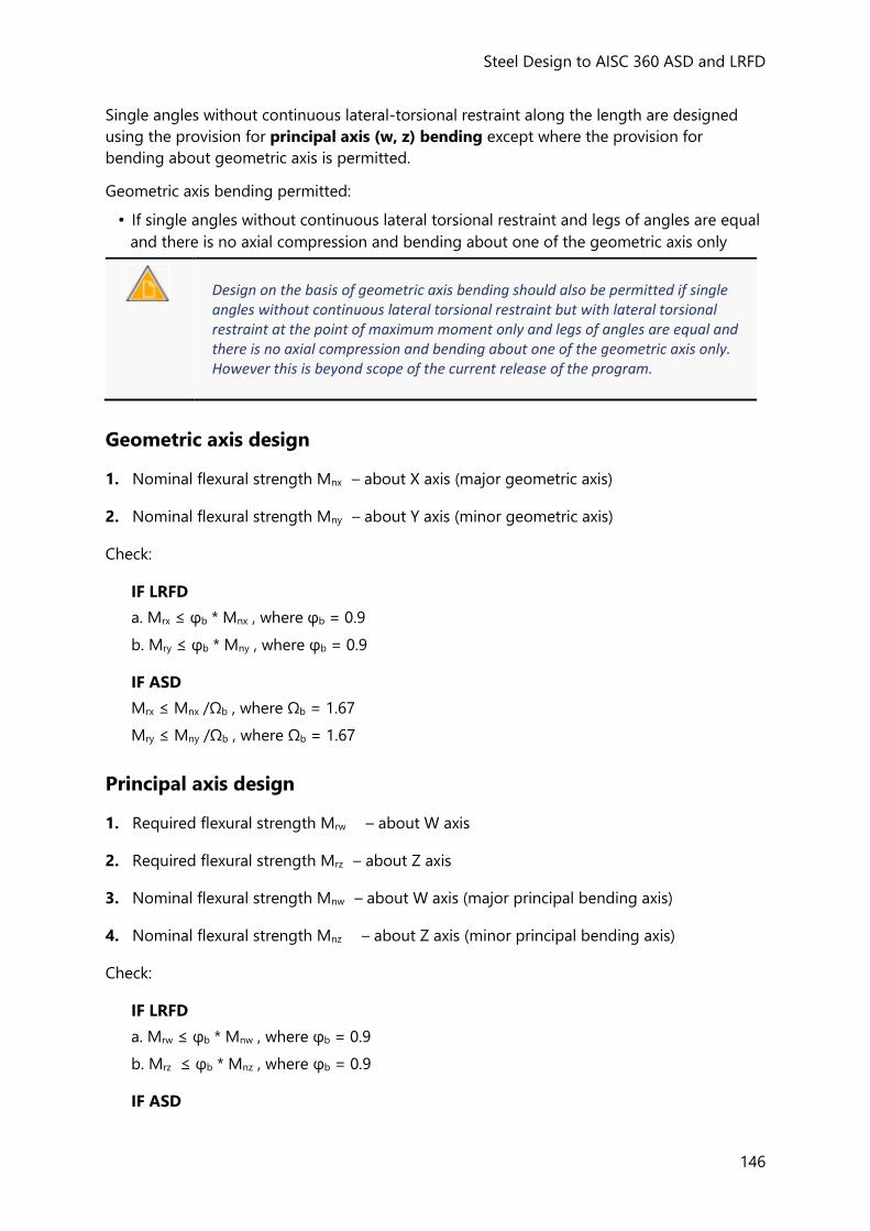
Steel Design to AISC 360 ASD and LRFD
146
Single angles without continuous lateral-torsional restraint along the length are designed
using the provision for principal axis (w, z) bending except where the provision for
bending about geometric axis is permitted.
Geometric axis bending permitted:
• If single angles without continuous lateral torsional restraint and legs of angles are equal
and there is no axial compression and bending about one of the geometric axis only
Design on the basis of geometric axis bending should also be permitted if single angles without continuous lateral torsional restraint but with lateral torsional restraint at the point of maximum moment only and legs of angles are equal and there is no axial compression and bending about one of the geometric axis only. However this is beyond scope of the current release of the program.
Geometric axis design
1. Nominal flexural strength Mnx – about X axis (major geometric axis)
2. Nominal flexural strength Mny – about Y axis (minor geometric axis)
Check:
IF LRFD
a. Mrx ≤ φb * Mnx , where φb = 0.9
b. Mry ≤ φb * Mny , where φb = 0.9
IF ASD
Mrx ≤ Mnx /Ωb , where Ωb = 1.67
Mry ≤ Mny /Ωb , where Ωb = 1.67
Principal axis design
1. Required flexural strength Mrw – about W axis
2. Required flexural strength Mrz – about Z axis
3. Nominal flexural strength Mnw – about W axis (major principal bending axis)
4. Nominal flexural strength Mnz – about Z axis (minor principal bending axis)
Check:
IF LRFD
a. Mrw ≤ φb * Mnw , where φb = 0.9
b. Mrz ≤ φb * Mnz , where φb = 0.9
IF ASD
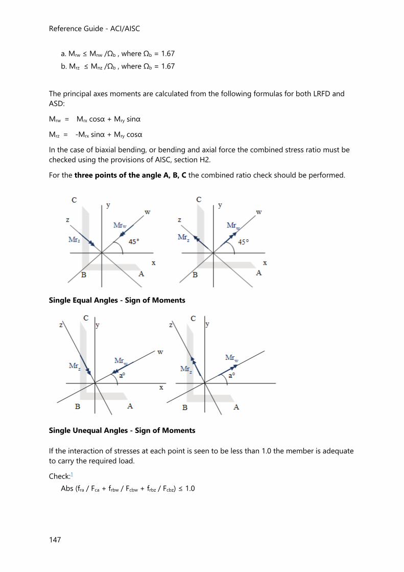
Reference Guide - ACI/AISC
147
a. Mrw ≤ Mnw /Ωb , where Ωb = 1.67
b. Mrz ≤ Mnz /Ωb , where Ωb = 1.67
The principal axes moments are calculated from the following formulas for both LRFD and
ASD:
Mrw = Mrx cosα + Mry sinα
Mrz = -Mrx sinα + Mry cosα
In the case of biaxial bending, or bending and axial force the combined stress ratio must be
checked using the provisions of AISC, section H2.
For the three points of the angle A, B, C the combined ratio check should be performed.
Single Equal Angles - Sign of Moments
Single Unequal Angles - Sign of Moments
If the interaction of stresses at each point is seen to be less than 1.0 the member is adequate
to carry the required load.
Check:1
Abs (fra / Fca + frbw / Fcbw + frbz / Fcbz) ≤ 1.0
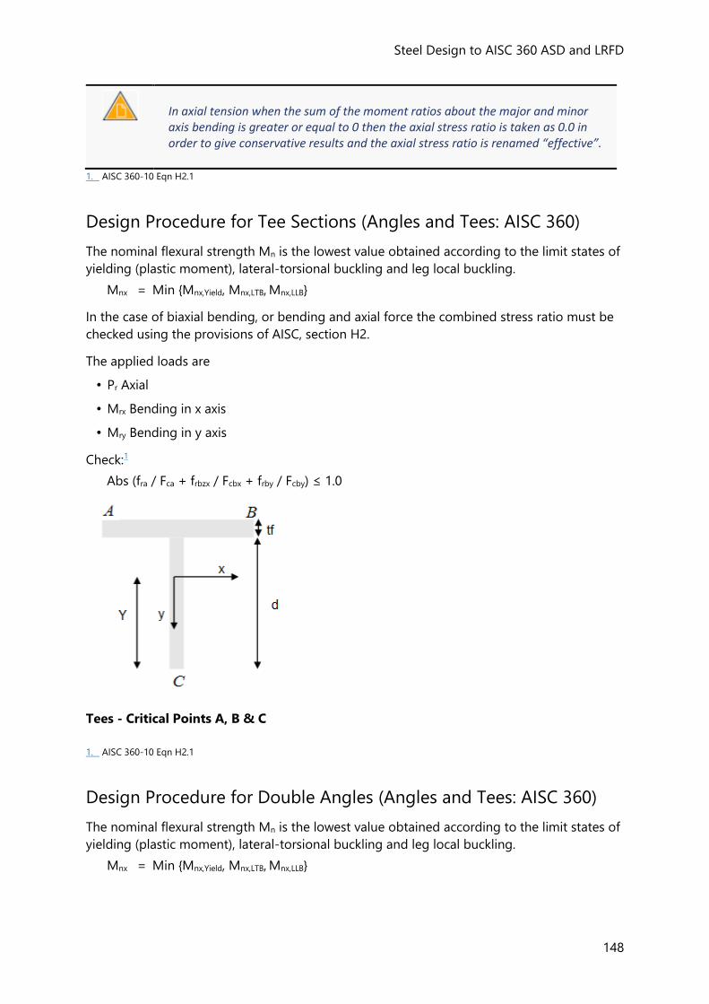
Steel Design to AISC 360 ASD and LRFD
148
In axial tension when the sum of the moment ratios about the major and minor axis bending is greater or equal to 0 then the axial stress ratio is taken as 0.0 in order to give conservative results and the axial stress ratio is renamed “effective”.
1. AISC 360-10 Eqn H2.1
Design Procedure for Tee Sections (Angles and Tees: AISC 360)
The nominal flexural strength Mn is the lowest value obtained according to the limit states of
yielding (plastic moment), lateral-torsional buckling and leg local buckling.
Mnx = Min {Mnx,Yield, Mnx,LTB, Mnx,LLB}
In the case of biaxial bending, or bending and axial force the combined stress ratio must be
checked using the provisions of AISC, section H2.
The applied loads are
• Pr Axial
• Mrx Bending in x axis
• Mry Bending in y axis
Check:1
Abs (fra / Fca + frbzx / Fcbx + frby / Fcby) ≤ 1.0
Tees - Critical Points A, B & C
1. AISC 360-10 Eqn H2.1
Design Procedure for Double Angles (Angles and Tees: AISC 360)
The nominal flexural strength Mn is the lowest value obtained according to the limit states of
yielding (plastic moment), lateral-torsional buckling and leg local buckling.
Mnx = Min {Mnx,Yield, Mnx,LTB, Mnx,LLB}
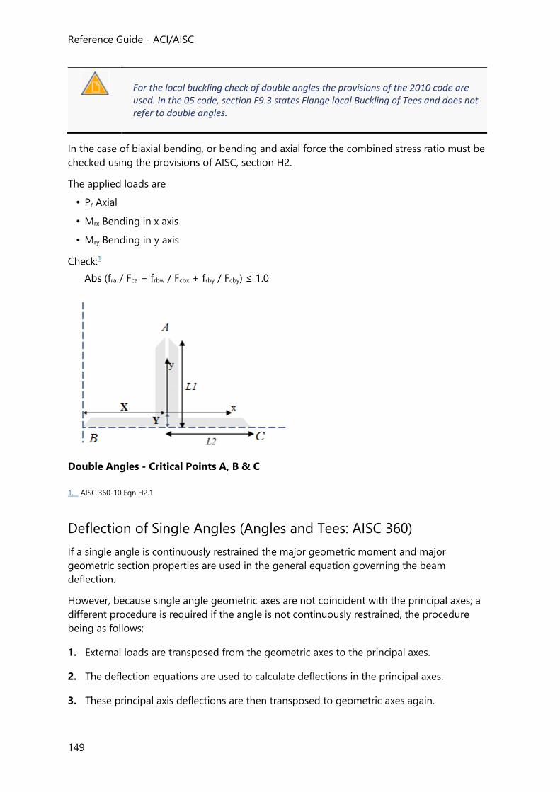
Reference Guide - ACI/AISC
149
For the local buckling check of double angles the provisions of the 2010 code are used. In the 05 code, section F9.3 states Flange local Buckling of Tees and does not refer to double angles.
In the case of biaxial bending, or bending and axial force the combined stress ratio must be
checked using the provisions of AISC, section H2.
The applied loads are
• Pr Axial
• Mrx Bending in x axis
• Mry Bending in y axis
Check:1
Abs (fra / Fca + frbw / Fcbx + frby / Fcby) ≤ 1.0
Double Angles - Critical Points A, B & C
1. AISC 360-10 Eqn H2.1
Deflection of Single Angles (Angles and Tees: AISC 360)
If a single angle is continuously restrained the major geometric moment and major
geometric section properties are used in the general equation governing the beam
deflection.
However, because single angle geometric axes are not coincident with the principal axes; a
different procedure is required if the angle is not continuously restrained, the procedure
being as follows:
1. External loads are transposed from the geometric axes to the principal axes.
2. The deflection equations are used to calculate deflections in the principal axes.
3. These principal axis deflections are then transposed to geometric axes again.
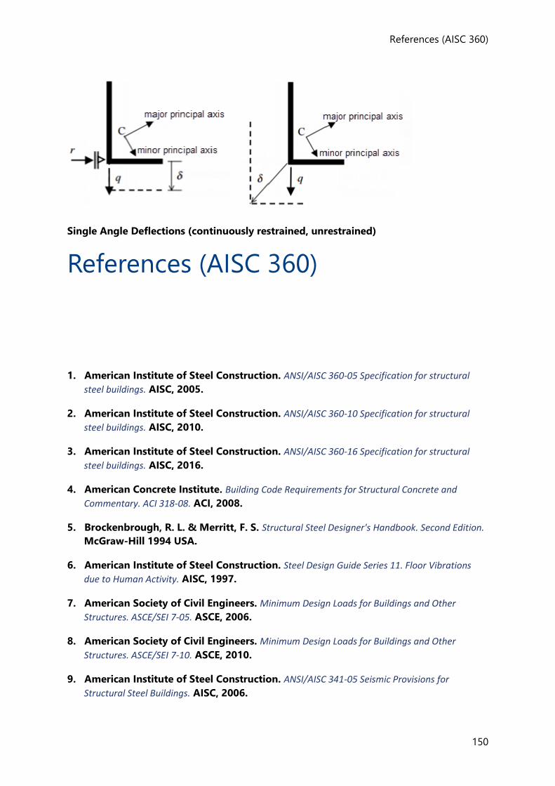
References (AISC 360)
150
Single Angle Deflections (continuously restrained, unrestrained)
References (AISC 360)
1. American Institute of Steel Construction. ANSI/AISC 360-05 Specification for structural
steel buildings. AISC, 2005.
2. American Institute of Steel Construction. ANSI/AISC 360-10 Specification for structural
steel buildings. AISC, 2010.
3. American Institute of Steel Construction. ANSI/AISC 360-16 Specification for structural
steel buildings. AISC, 2016.
4. American Concrete Institute. Building Code Requirements for Structural Concrete and
Commentary. ACI 318-08. ACI, 2008.
5. Brockenbrough, R. L. & Merritt, F. S. Structural Steel Designer's Handbook. Second Edition.
McGraw-Hill 1994 USA.
6. American Institute of Steel Construction. Steel Design Guide Series 11. Floor Vibrations
due to Human Activity. AISC, 1997.
7. American Society of Civil Engineers. Minimum Design Loads for Buildings and Other
Structures. ASCE/SEI 7-05. ASCE, 2006.
8. American Society of Civil Engineers. Minimum Design Loads for Buildings and Other
Structures. ASCE/SEI 7-10. ASCE, 2010.
9. American Institute of Steel Construction. ANSI/AISC 341-05 Seismic Provisions for
Structural Steel Buildings. AISC, 2006.
Reference Guide - ACI/AISC
151
10. American Institute of Steel Construction. ANSI/AISC 341-10 Seismic Provisions for
Structural Steel Buildings. AISC, 2010.
11. American Institute of Steel Construction. ANSI/AISC 341-16 Seismic Provisions for
Structural Steel Buildings. AISC, 2016.

153
Steel Seismic Design - AISC 341
Steel Seismic Design - AISC 341
Additional seismic provisions are required to be applied to members that are part of the
seismic force resisting system (SFRS) of a structure. These provisions are applied in addition
to any standard requirements for structural steel buildings as per AISC 360. The seismic
provisions are contained in AISC 341. Tekla Structural Designer covers non-seismic steel
design to AISC 360-05 (Ref. 1) and AISC 360-10 (Ref. 2) and the purpose of this guide is to
describe the matching seismic design requirements contained in AISC 341-05 (Ref. 3) and
AISC 341-10 (Ref. 4).
Criteria assumed to be met
Seismic design in the current release of Tekla Structural Designer covers only those checks
detailed in later sections and presupposes certain criteria are met e.g. that lateral braces to
beams are sufficiently strong. These presuppositions are noted below.
Common (Seismic: AISC 341)
AISC 341-10
• Column bases are assumed to comply with the requirements of D2.6.
• Steel material grades used in particular members and SFRS type are assumed to comply
with A3.1.
AISC 341-05
• Column bases are assumed to comply with the requirements of 8.5.
• Steel material grades used in particular members and SFRS type are assumed to comply
with 6.1.
OMF (Seismic: AISC 341)
AISC 341-10
• Beam to column connections used in the SFRS are assumed to satisfy the requirements
of E1.6.
AISC 341-05
Steel Seismic Design - AISC 341
154
• Beam to column connections used in the SFRS are assumed to satisfy the requirements
of 11.2.
• Continuity plates are assumed to comply with the requirements of 11.5.
• As per 11.9 column splices are assumed to comply with the requirements of 8.4a.
IMF (Seismic: AISC 341)
AISC 341-10
• The lateral braces themselves will not be designed to meet the additional criteria of
D1.2a & c - it is assumed that the user will check this independently.
• The position of lateral braces will not be checked for the location of points of
concentrated force or positions of plastic hinge per D1.2c.
• The protected zone is assumed to comply with E2.5c.
• Connections used in the SFRS are assumed to satisfy the requirements of E2.6.
AISC 341-05
• Beam to column connections used in the SFRS are assumed to satisfy the requirements
of 10.2.
• Panel zones in beam to column connections used in the SFRS are assumed to satisfy the
requirements of 10.3.
• Continuity plates are assumed to comply with the requirements of 10.5.
• The lateral braces themselves will not be designed to meet the additional criteria of 10.8
- it is assumed that the user will check this independently.
• The position of lateral braces will not be checked for the location of points of
concentrated force or positions of plastic hinge per 10.8.
• As per 10.9 column splices are assumed to comply with the requirements of 8.4a.
SMF (Seismic: AISC 341)
AISC 341-10
• The lateral braces themselves will not be designed to meet the additional criteria of
D1.2b & c - it is assumed that the user will check this independently.
• The position of lateral braces will not be checked for the location of points of
concentrated force or positions of plastic hinge per D1.2c.
• Beam column connections are always assumed braced as per E3.4c(1).
• The protected zone is assumed to comply with E3.5c.
• Connections used in the SFRS are assumed to satisfy the requirements of E3.6.
AISC 341-05
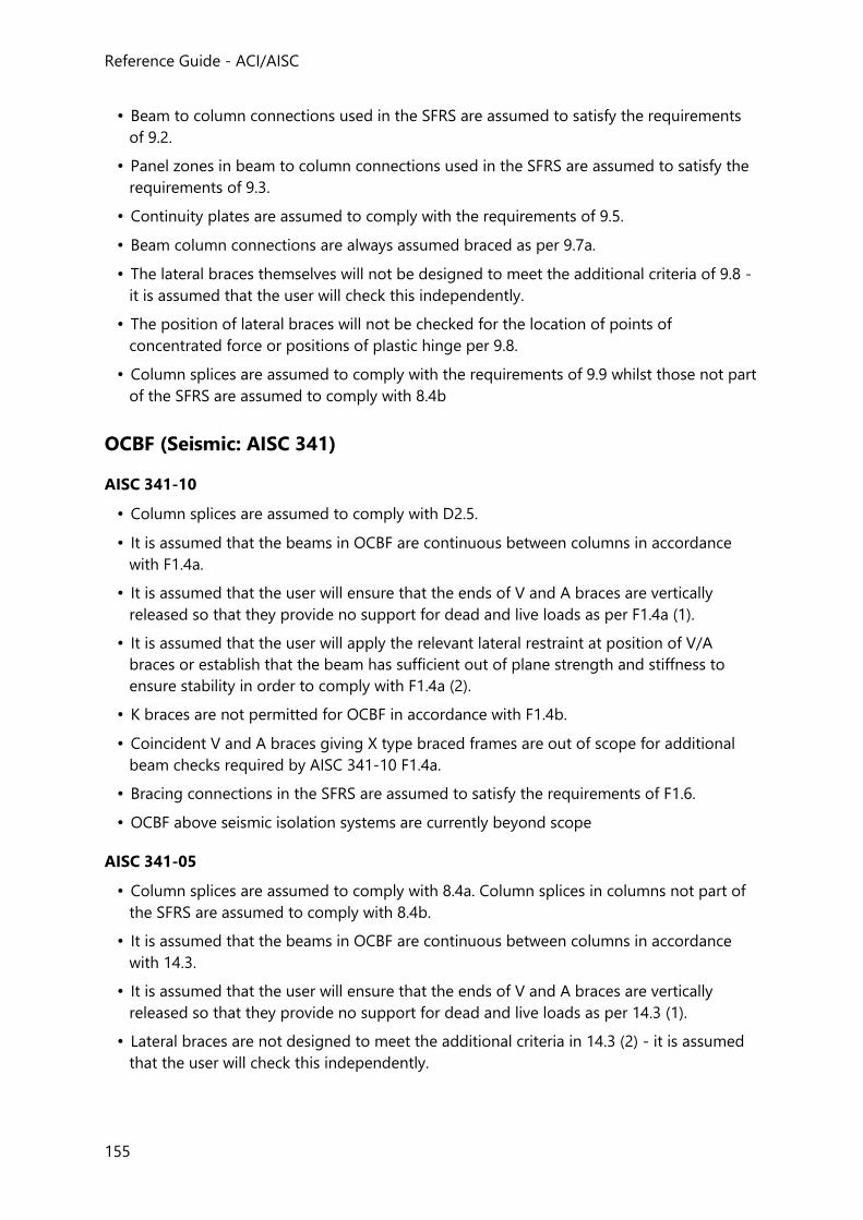
Reference Guide - ACI/AISC
155
• Beam to column connections used in the SFRS are assumed to satisfy the requirements
of 9.2.
• Panel zones in beam to column connections used in the SFRS are assumed to satisfy the
requirements of 9.3.
• Continuity plates are assumed to comply with the requirements of 9.5.
• Beam column connections are always assumed braced as per 9.7a.
• The lateral braces themselves will not be designed to meet the additional criteria of 9.8 -
it is assumed that the user will check this independently.
• The position of lateral braces will not be checked for the location of points of
concentrated force or positions of plastic hinge per 9.8.
• Column splices are assumed to comply with the requirements of 9.9 whilst those not part
of the SFRS are assumed to comply with 8.4b
OCBF (Seismic: AISC 341)
AISC 341-10
• Column splices are assumed to comply with D2.5.
• It is assumed that the beams in OCBF are continuous between columns in accordance
with F1.4a.
• It is assumed that the user will ensure that the ends of V and A braces are vertically
released so that they provide no support for dead and live loads as per F1.4a (1).
• It is assumed that the user will apply the relevant lateral restraint at position of V/A
braces or establish that the beam has sufficient out of plane strength and stiffness to
ensure stability in order to comply with F1.4a (2).
• K braces are not permitted for OCBF in accordance with F1.4b.
• Coincident V and A braces giving X type braced frames are out of scope for additional
beam checks required by AISC 341-10 F1.4a.
• Bracing connections in the SFRS are assumed to satisfy the requirements of F1.6.
• OCBF above seismic isolation systems are currently beyond scope
AISC 341-05
• Column splices are assumed to comply with 8.4a. Column splices in columns not part of
the SFRS are assumed to comply with 8.4b.
• It is assumed that the beams in OCBF are continuous between columns in accordance
with 14.3.
• It is assumed that the user will ensure that the ends of V and A braces are vertically
released so that they provide no support for dead and live loads as per 14.3 (1).
• Lateral braces are not designed to meet the additional criteria in 14.3 (2) - it is assumed
that the user will check this independently.
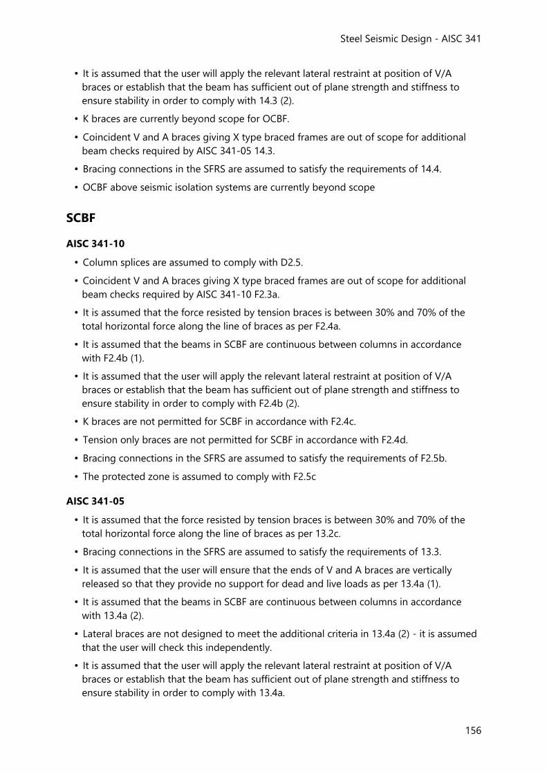
Steel Seismic Design - AISC 341
156
• It is assumed that the user will apply the relevant lateral restraint at position of V/A
braces or establish that the beam has sufficient out of plane strength and stiffness to
ensure stability in order to comply with 14.3 (2).
• K braces are currently beyond scope for OCBF.
• Coincident V and A braces giving X type braced frames are out of scope for additional
beam checks required by AISC 341-05 14.3.
• Bracing connections in the SFRS are assumed to satisfy the requirements of 14.4.
• OCBF above seismic isolation systems are currently beyond scope
SCBF
AISC 341-10
• Column splices are assumed to comply with D2.5.
• Coincident V and A braces giving X type braced frames are out of scope for additional
beam checks required by AISC 341-10 F2.3a.
• It is assumed that the force resisted by tension braces is between 30% and 70% of the
total horizontal force along the line of braces as per F2.4a.
• It is assumed that the beams in SCBF are continuous between columns in accordance
with F2.4b (1).
• It is assumed that the user will apply the relevant lateral restraint at position of V/A
braces or establish that the beam has sufficient out of plane strength and stiffness to
ensure stability in order to comply with F2.4b (2).
• K braces are not permitted for SCBF in accordance with F2.4c.
• Tension only braces are not permitted for SCBF in accordance with F2.4d.
• Bracing connections in the SFRS are assumed to satisfy the requirements of F2.5b.
• The protected zone is assumed to comply with F2.5c
AISC 341-05
• It is assumed that the force resisted by tension braces is between 30% and 70% of the
total horizontal force along the line of braces as per 13.2c.
• Bracing connections in the SFRS are assumed to satisfy the requirements of 13.3.
• It is assumed that the user will ensure that the ends of V and A braces are vertically
released so that they provide no support for dead and live loads as per 13.4a (1).
• It is assumed that the beams in SCBF are continuous between columns in accordance
with 13.4a (2).
• Lateral braces are not designed to meet the additional criteria in 13.4a (2) - it is assumed
that the user will check this independently.
• It is assumed that the user will apply the relevant lateral restraint at position of V/A
braces or establish that the beam has sufficient out of plane strength and stiffness to
ensure stability in order to comply with 13.4a.
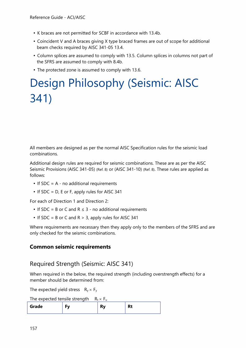
Reference Guide - ACI/AISC
157
• K braces are not permitted for SCBF in accordance with 13.4b.
• Coincident V and A braces giving X type braced frames are out of scope for additional
beam checks required by AISC 341-05 13.4.
• Column splices are assumed to comply with 13.5. Column splices in columns not part of
the SFRS are assumed to comply with 8.4b.
• The protected zone is assumed to comply with 13.6.
Design Philosophy (Seismic: AISC
341)
All members are designed as per the normal AISC Specification rules for the seismic load
combinations.
Additional design rules are required for seismic combinations. These are as per the AISC
Seismic Provisions (AISC 341-05) (Ref. 8) or (AISC 341-10) (Ref. 8). These rules are applied as
follows:
• If SDC = A - no additional requirements
• If SDC = D, E or F, apply rules for AISC 341
For each of Direction 1 and Direction 2:
• If SDC = B or C and R ≤ 3 - no additional requirements
• If SDC = B or C and R > 3, apply rules for AISC 341
Where requirements are necessary then they apply only to the members of the SFRS and are
only checked for the seismic combinations.
Common seismic requirements
Required Strength (Seismic: AISC 341)
When required in the below, the required strength (including overstrength effects) for a
member should be determined from:
The expected yield stress Ry Fy
The expected tensile strength Rt Fu
Grade Fy Ry Rt
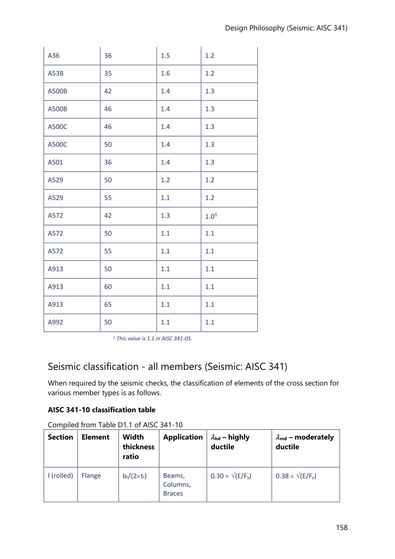
Design Philosophy (Seismic: AISC 341)
158
A36 36 1.5 1.2
A53B 35 1.6 1.2
A500B 42 1.4 1.3
A500B 46 1.4 1.3
A500C 46 1.4 1.3
A500C 50 1.4 1.3
A501 36 1.4 1.3
A529 50 1.2 1.2
A529 55 1.1 1.2
A572 42 1.3 1.0A
A572 50 1.1 1.1
A572 55 1.1 1.1
A913 50 1.1 1.1
A913 60 1.1 1.1
A913 65 1.1 1.1
A992 50 1.1 1.1
A This value is 1.1 in AISC 341-05.
Seismic classification - all members (Seismic: AISC 341)
When required by the seismic checks, the classification of elements of the cross section for
various member types is as follows.
AISC 341-10 classification table
Compiled from Table D1.1 of AISC 341-10
Section Element Width
thickness
ratio
Application hd – highly
ductile
md – moderately
ductile
I (rolled) Flange bf/(2tf) Beams, Columns, Braces
0.30 (E/Fy) 0.38 (E/Fy)
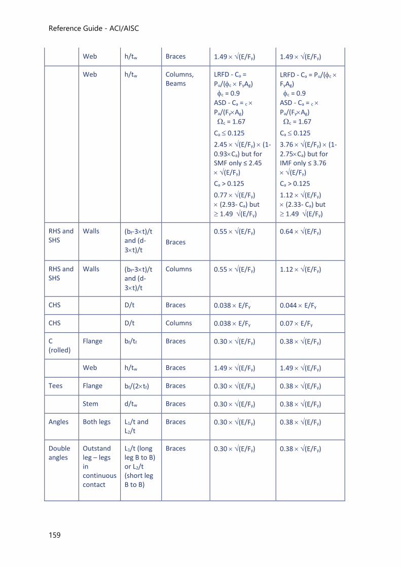
Reference Guide - ACI/AISC
159
Web h/tw Braces 1.49 (E/Fy) 1.49 (E/Fy)
Web h/tw Columns, Beams
LRFD - Ca =
Pu/(c FyAg)
c = 0.9
ASD - Ca = c
Pa/(FyAg)
c = 1.67
Ca 0.125
2.45 (E/Fy) (1-
0.93Ca) but for SMF only ≤ 2.45
(E/Fy)
Ca > 0.125
0.77 (E/Fy)
(2.93- Ca) but
1.49 (E/Fy)
LRFD - Ca = Pu/(c FyAg)
c = 0.9
ASD - Ca = c
Pa/(FyAg)
c = 1.67
Ca 0.125
3.76 (E/Fy) (1-
2.75Ca) but for IMF only ≤ 3.76
(E/Fy)
Ca > 0.125
1.12 (E/Fy)
(2.33- Ca) but
1.49 (E/Fy)
RHS and SHS
Walls (bf-3t)/t and (d-
3t)/t
Braces
0.55 (E/Fy) 0.64 (E/Fy)
RHS and SHS
Walls (bf-3t)/t and (d-
3t)/t
Columns 0.55 (E/Fy) 1.12 (E/Fy)
CHS D/t Braces 0.038 E/Fy 0.044 E/Fy
CHS D/t Columns 0.038 E/Fy 0.07 E/Fy
C (rolled)
Flange bf/tf Braces 0.30 (E/Fy) 0.38 (E/Fy)
Web h/tw Braces 1.49 (E/Fy) 1.49 (E/Fy)
Tees Flange bf/(2tf) Braces 0.30 (E/Fy) 0.38 (E/Fy)
Stem d/tw Braces 0.30 (E/Fy) 0.38 (E/Fy)
Angles Both legs L1/t and L2/t
Braces 0.30 (E/Fy) 0.38 (E/Fy)
Double angles
Outstand leg – legs in continuous contact
L1/t (long leg B to B) or L2/t (short leg B to B)
Braces 0.30 (E/Fy) 0.38 (E/Fy)
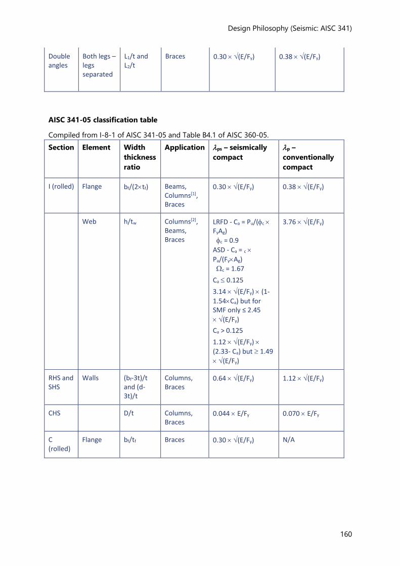
Design Philosophy (Seismic: AISC 341)
160
Double angles
Both legs – legs separated
L1/t and L2/t
Braces 0.30 (E/Fy) 0.38 (E/Fy)
AISC 341-05 classification table
Compiled from I-8-1 of AISC 341-05 and Table B4.1 of AISC 360-05.
Section Element Width
thickness
ratio
Application ps – seismically
compact
p –
conventionally
compact
I (rolled) Flange bf/(2tf) Beams, Columns[1], Braces
0.30 (E/Fy) 0.38 (E/Fy)
Web h/tw Columns[2], Beams, Braces
LRFD - Ca = Pu/(c FyAg)
c = 0.9
ASD - Ca = c
Pa/(FyAg)
c = 1.67
Ca 0.125
3.14 (E/Fy) (1-
1.54Ca) but for SMF only ≤ 2.45
(E/Fy)
Ca > 0.125
1.12 (E/Fy)
(2.33- Ca) but 1.49
(E/Fy)
3.76 (E/Fy)
RHS and SHS
Walls (bf-3t)/t and (d-3t)/t
Columns, Braces
0.64 (E/Fy) 1.12 (E/Fy)
CHS D/t Columns, Braces
0.044 E/Fy 0.070 E/Fy
C (rolled)
Flange bf/tf Braces 0.30 (E/Fy) N/A
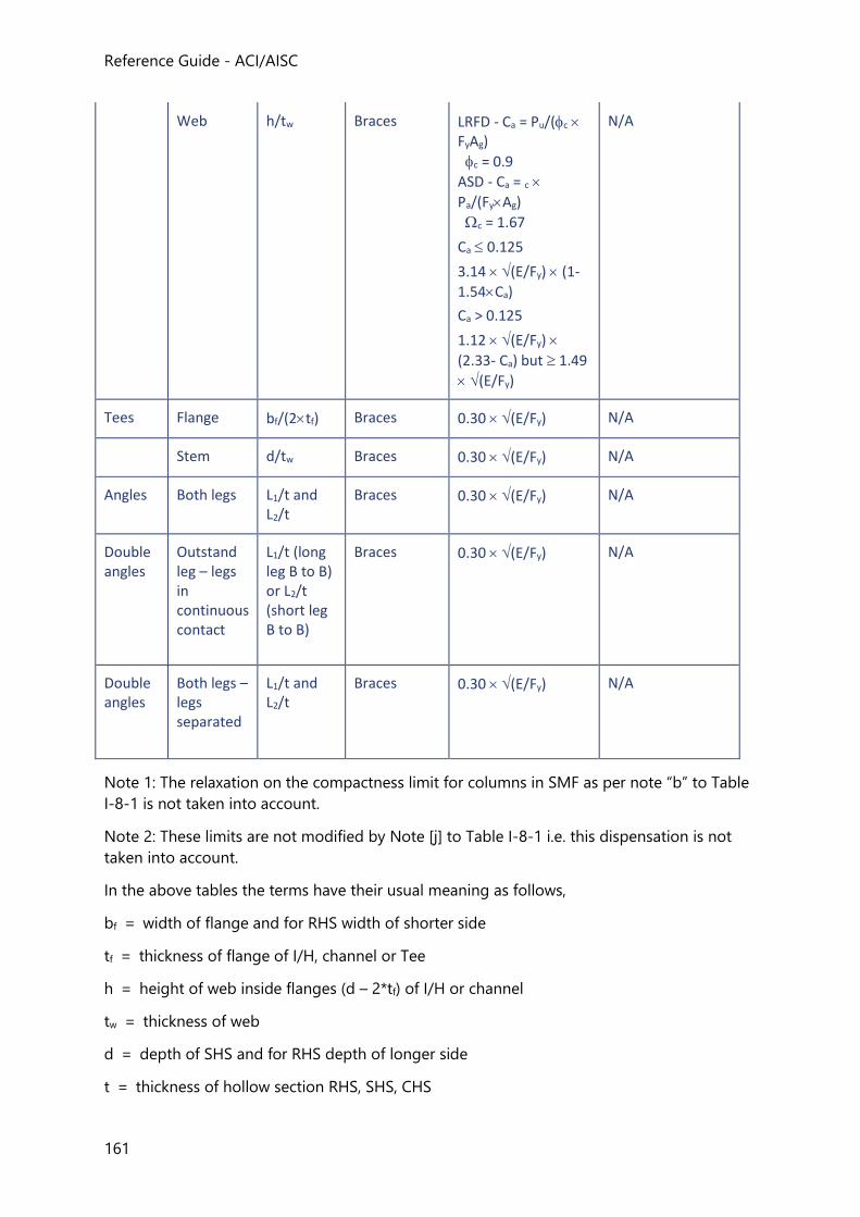
Reference Guide - ACI/AISC
161
Web h/tw Braces LRFD - Ca = Pu/(c FyAg)
c = 0.9
ASD - Ca = c
Pa/(FyAg)
c = 1.67
Ca 0.125
3.14 (E/Fy) (1-
1.54Ca)
Ca > 0.125
1.12 (E/Fy)
(2.33- Ca) but 1.49
(E/Fy)
N/A
Tees Flange bf/(2tf) Braces 0.30 (E/Fy) N/A
Stem d/tw Braces 0.30 (E/Fy) N/A
Angles Both legs L1/t and L2/t
Braces 0.30 (E/Fy) N/A
Double angles
Outstand leg – legs in continuous contact
L1/t (long leg B to B) or L2/t (short leg B to B)
Braces 0.30 (E/Fy) N/A
Double angles
Both legs – legs separated
L1/t and L2/t
Braces 0.30 (E/Fy) N/A
Note 1: The relaxation on the compactness limit for columns in SMF as per note “b” to Table
I-8-1 is not taken into account.
Note 2: These limits are not modified by Note [j] to Table I-8-1 i.e. this dispensation is not
taken into account.
In the above tables the terms have their usual meaning as follows,
bf = width of flange and for RHS width of shorter side
tf = thickness of flange of I/H, channel or Tee
h = height of web inside flanges (d – 2*tf) of I/H or channel
tw = thickness of web
d = depth of SHS and for RHS depth of longer side
t = thickness of hollow section RHS, SHS, CHS
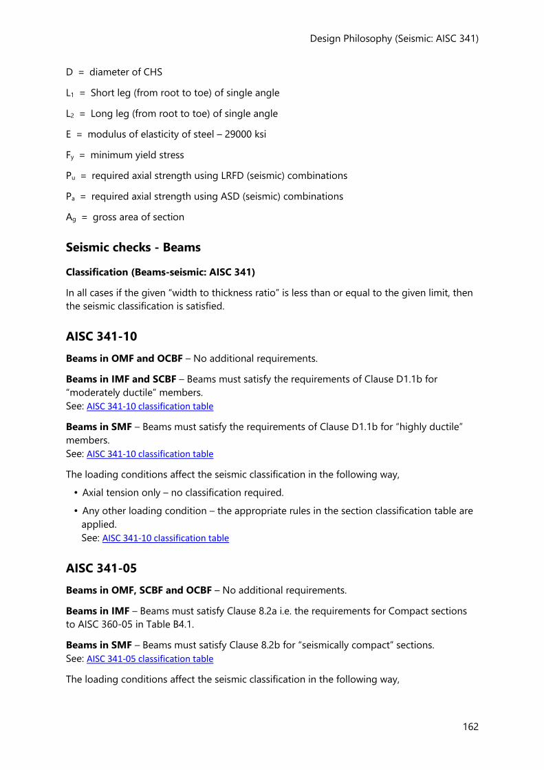
Design Philosophy (Seismic: AISC 341)
162
D = diameter of CHS
L1 = Short leg (from root to toe) of single angle
L2 = Long leg (from root to toe) of single angle
E = modulus of elasticity of steel – 29000 ksi
Fy = minimum yield stress
Pu = required axial strength using LRFD (seismic) combinations
Pa = required axial strength using ASD (seismic) combinations
Ag = gross area of section
Seismic checks - Beams
Classification (Beams-seismic: AISC 341)
In all cases if the given “width to thickness ratio” is less than or equal to the given limit, then
the seismic classification is satisfied.
AISC 341-10
Beams in OMF and OCBF – No additional requirements.
Beams in IMF and SCBF – Beams must satisfy the requirements of Clause D1.1b for
“moderately ductile” members.
See: AISC 341-10 classification table
Beams in SMF – Beams must satisfy the requirements of Clause D1.1b for “highly ductile”
members.
See: AISC 341-10 classification table
The loading conditions affect the seismic classification in the following way,
• Axial tension only – no classification required.
• Any other loading condition – the appropriate rules in the section classification table are
applied.
See: AISC 341-10 classification table
AISC 341-05
Beams in OMF, SCBF and OCBF – No additional requirements.
Beams in IMF – Beams must satisfy Clause 8.2a i.e. the requirements for Compact sections
to AISC 360-05 in Table B4.1.
Beams in SMF – Beams must satisfy Clause 8.2b for “seismically compact” sections.
See: AISC 341-05 classification table
The loading conditions affect the seismic classification in the following way,
Reference Guide - ACI/AISC
163
• Axial tension – no classification required.
• Major axis bending only – applies to beams in SMF only.
• Any other loading condition – apply appropriate rules in the section classification table.
See: AISC 341-05 classification table
Stability bracing (Beams-seismic: AISC 341)
AISC 341-10
Beams in certain SFRS frame types must be provided with “stability bracing” to restrain
lateral torsional buckling. There are two “levels” of requirement; one for ‘Moderately ductile
members and one for “Highly ductile members”. The use of these depends upon the SFRS
frame type as defined below.
Beams in OMF and OCBF – No additional requirements.
Beams in IMF and SCBF – Beams must satisfy Clause D1.2a for “moderately ductile”
members. For SCBF this only applies in the presence of V or A braces.
Beams in SMF – Beams must satisfy Clause D1.2b for “highly ductile” members
Moderately Ductile
Beams shall be braced per D1.2a for moderately ductile members, i.e. maximum spacing per
D1.2a(3)
Lpd = 0.17 (E/Fy) ry
The design condition is,
Lb ≤ Lpd
Lb = the laterally unbraced length of the compression flange taken as the beam length
between locations where both the top flange and bottom flange are restrained for LTB.
Highly Ductile
Beams shall be braced per D1.2b for highly ductile members, i.e. maximum spacing,
Lpd = 0.086 (E/Fy) ry
The design condition is,
Lb ≤ Lpd
In both cases: - The position of lateral braces is not checked for the location of points of concentrated force or positions of plastic hinge - Lateral braces are not designed to meet the additional criteria for strength and stiffness.
AISC 341-05
Design Philosophy (Seismic: AISC 341)
164
OCBF and SCBF
Reference AISC 341-05 14.3 (2) and 13.4a (2) respectively.
For doubly symmetric I sections,
Lpd = (0.12 + 0.076 (M1/M2)) (E/Fy) ry
Where
M1 = the smaller moment at end of unbraced length – min(abs(Ma), abs(Mb))
M2 = the larger moment at end of unbraced length – max(abs(Ma), abs(Mb))
Lateral braces are assumed to meet the strength and stiffness requirements of Equations A-6-7 and A-6-8 of AISC 360-05, Appendix 6.
Lateral braces are assumed to be provided at the intersection of the V/A brace and the beam or the beam has sufficient stiffness to satisfy the criteria in the “User Note” to AISC 341-05, 13.4a. In both cases the program assumes this intersection to be a braced point (with both flanges braced).
OMF
Reference AISC 341-05 11.8 – no additional requirements.
IMF
Reference AISC 341-05 10.8.
Max spacing of coincident restraints along top and bottom flange, continuous bracing is
included while determining unbraced length for each flange,
Lpd = 0.17 (E/Fy) ry
The design condition is,
Lb ≤ Lpd
Lb = the laterally unbraced length of the compression flange taken as the beam length
between locations where both the top flange and bottom flange are restrained for LTB.
The position of lateral braces are not checked for the location of points of concentrated force or positions of plastic hinge.
Lateral braces are not designed to meet the additional criteria for strength and stiffness.
SMF
Reference Guide - ACI/AISC
165
Reference AISC 341-05 9.8.
Max spacing of coincident restraints along the top and bottom flange, continuous bracing is
included while determining the unbraced length for each flange,
Lpd = 0.086 (E/Fy) ry
The design condition is,
Lb ≤ Lpd
Lb = the laterally unbraced length of the compression flange taken as the beam length
between locations where both the top flange and bottom flange are restrained for LTB.
The position of lateral braces are not checked for the location of points of concentrated force or positions of plastic hinge.
Lateral braces are not designed to meet the additional criteria for strength and stiffness.
Design for brace forces in SCBF and OCBF (Beams-seismic: AISC 341)
In both variants of the code the beams in SCBF and OCBF that are configured with “V” or “A”
braces are required to resist a “push-pull” force generated by the brace pair. In general terms
the compression brace is assumed to retain a percentage of its resistance post-buckling and
the tension brace is assumed to have a level of defined “overstrength”.
In meeting the requirements of F1.4 and F2.3, the design of beams is separated into two distinct approaches – those beams with V&A braces at mid-span and those with diagonal braces at their ends. Clearly, frames that are braced using V&A braces have to meet both requirements e.g. in chevron systems but each is checked individually and this is believed to be conservative.
AISC 341-10, V and A braces
OCBF
Reference AISC 341-10 F1.4a.
The lower bound on the force in the tension brace, “The maximum force that can be developed by the system”, according to F1.4a (1) (i) (c) is not applied.
SCBF
Reference AISC 341-10 F2.3.
Design Philosophy (Seismic: AISC 341)
166
AISC 341-10, all other braces
OCBF
No requirements.
SCBF
Reference AISC 341-10 F2.3.
The expected tension strength, the expected compression strength and the expected post
buckling strength are determined in the same way as for V and A braces.
AISC 341-05, V and A braces
OCBF and SCBF
Reference AISC 341-05 14.3 and 13.4a respectively.
Seismic checks - Columns
AISC 341-10 contains special requirements for the strength of columns that are part of the
SFRS, regardless of the type of system (braced frame or moment frame) in which the column
is a part.
The requirements are found in section D1.4a. In addition there are specific requirements for
columns in moment frames and braced frames.
Classification (Seismic: AISC 341)
In all cases if the given “width to thickness ratio” is less than or equal to the given limit, then
the seismic classification is satisfied.
AISC 341-10
Columns in OMF and OCBF – No additional requirements.
Columns in IMF – Columns must satisfy the requirements of Clause D1.1b for “moderately
ductile” members.
See: AISC 341-10 classification table
Columns in SMF and SCBF – Columns must satisfy the requirements of Clause D1.1b for
“highly ductile” members.
See: AISC 341-10 classification table
The loading conditions affect the seismic classification in the following way,
• Axial tension only – no classification required.
• Any other loading condition – the appropriate rules in the section classification table are
applied.
See: AISC 341-10 classification table
Reference Guide - ACI/AISC
167
AISC 341-05
Columns in OMF and OCBF – No additional requirements.
Columns in IMF – Columns must satisfy Clause 8.2a i.e. the requirements for Compact
sections to AISC 360-05 in Table B4.1.
Columns in SMF and SCBF – Columns must satisfy Clause 8.2b for “seismically compact”
sections.
See: AISC 341-05 classification table
The loading conditions affect the seismic classification in the following way,
• Axial tension – no classification required.
• Any other loading condition – the appropriate rules in the section classification table are
applied.
See: AISC 341-05 classification table
Column strength (Seismic: AISC 341)
AISC 341-10, D1.4a Required Strength (Columns-seismic: AISC 341)
This check consists of two analyses of the column - one that uses the 'amplified seismic load'
and a second that uses a 'capacity analysis' as an upper bound. The moments and shears in
the column are ignored and the column is designed for axial load only.
While applying the column strength requirements of D1.4a, it is assumed that there are no loads applied to the column between locations of lateral support. Therefore applied moments are ignored and only the axial strength is considered as permitted in AISC 341-10 D1.4a(2).
While applying the column strength requirements of D1.4a (2), the upper limit on the required strength with respect to overturning uplift as per D1.4a (2) (b) is not applied.
Amplified seismic load
Pamp, the required axial strength (either tension or compression) including the “amplified
seismic load” is given by,
Pamp = Pr + fE/ PE x (o - )
Where;
Pr = the axial force (-ve for tension and +ve for compression) determined from the
analysis of the seismic load combination (LRFD or ASD). This may be the result of a first
or second order analysis.
PE = the axial force (-ve for tension and +ve for compression) determined from the
analysis of the seismic load case(s) associated with the seismic load combination.
Design Philosophy (Seismic: AISC 341)
168
fE = the strength load factor associated with the seismic load in the seismic load
combination (base combination factor x ) (for example, 0.683 in the ASD combination, D
+ 0.75 L + 0.75 Lr + 0.683 E).
= the redundancy factor, 1 when the column is assigned to Direction 1 and 2 when
the column is assigned to Direction 2 (from the Seismic Wizard).
o = the overstrength factor, o1 when the column is assigned to Direction 1 and
o2 when the column is assigned to Direction 2 (from the Seismic Wizard).
The axial force from the load combination including the amplified seismic loads is
calculated by swapping out the component due to the seismic loadcase Eh =
QE and replacing it with the amplified seismic load, Emh = E QE.
Capacity analysis
At any level on a column there can be SFRS members and non-SFRS members. The principle
of this check is that the former might be operating at their “capacity” in an earthquake and
so they are likely to apply more force to the column than the global analysis would indicate.
“Capacity” in this context also includes the possibility that the material is stronger than its
specified yield (typical).
The capacity calculation involves establishing the capacities of the incoming SFRS members
at each node (level) in the column – these might be zero if there are only non-SFRS members
at that level. The capacities so determined are then resolved into the local x-axis of the
column. The capacities are calculated for beams and braces only, not the columns
themselves.
The end result of the capacity analysis is that for each stack there is an axial force, Pcap which
can be compression or tension. This will be included in the results and used in this design
check to D1.4a but will only govern if smaller than that from the “Amplified seismic load”
analysis.
Design condition
For each stack, the required axial strength, Pr (the smaller of Pcap or Pamp) is compared with
the nominal axial strength, Pn, i.e. the design condition is,
Pr ≤ Pn (LRFD) or Pn/ (ASD)
Where
Pn = the nominal axial strength in tension or compression as appropriate to the sign of
Pr
= the resistance factor for tension or compression as appropriate
= the safety factor for tension or compression as appropriate
AISC 341-10, E3.4a Moment Ratio (Columns-seismic: AISC 341)
At each level in a column where an SMF beam connects into the strong axis of the column
(i.e. into the flange), a check is performed for each seismic combination to ensure that the
Reference Guide - ACI/AISC
169
plastic moment capacity of the column is greater than the plastic moment capacity of the
incoming beams.
The design condition is,
Mpcol / Mpbeam > 1.0
The exceptions in E3.4a (a) and (b) are ignored and the check is performed for all SMFs.
Beam column connections are always assumed braced as per E3.4c (1)
All beams with pinned connections are excluded in this calculation. Any beam with a moment connection into the web of the column is ignored even if they are assigned to a SMF. On the other hand, any beam with a moment connection to the column flange is included in the calculation even if they are not assigned to a SMF.
The additional moment due to shear amplification from the location of the plastic hinge to the column centre line (Muv and Mav) is calculated from two components, (i) the shear inferred by the moment at the plastic hinge position based on the expected flexural strength of the beam, (ii) the shear force in the beam at the plastic hinge position from the factored gravity loads in the current seismic combination.
No account of angle of incoming members is taken into account in this calculation.)
AISC 341-10, F2.3 Analysis (Columns-seismic: AISC 341)
This check applies to SCBF type frames only, the procedure being similar to that for 'Column
Strength' to D1.4a.
The approach taken to the “capacity analysis” per F2.3 assumes that the SCBF is reasonably isolated. That is, the influence of the remainder of the structure due to the braces operating at their capacity does not adversely affect the required strength.
Design condition
Moments in the column are permitted to be ignored as per F2.3 (1) and so only the axial
check (compression or tension) is required.
Design Philosophy (Seismic: AISC 341)
170
For each stack, the required axial strength, Pr, is compared with the nominal axial strength,
Pn, i.e. the design condition is,
Pr ≤ Pn (LRFD) or Pn/ (ASD)
Where
Pr = the required axial strength, Pcap
Pn = the nominal axial strength in tension or compression as appropriate to the sign of
Pr
= the resistance factor for tension or compression as appropriate
= the safety factor for tension or compression as appropriate
While applying the column strength requirements of F2.3 (i) and (ii), it is assumed that there are no loads applied to the column between locations of lateral support. Therefore applied moments are ignored and only the axial strength is considered as permitted in AISC 341-10 F2.3 (1).
While applying the column strength requirements of F2.3 (i) and (ii), the upper limits on the required strength per F2.3 (2) (a), (b) and (c) are not applied.
It is assumed that braces do not carry significant gravity forces and therefore a separate analysis with braces omitted, in order to enhance the column gravity forces, is not carried out. [Ref. NEHRP Seismic Design Technical Brief No. 8].
AISC 341-05, 8.3 Required Strength (Columns-seismic: AISC 341)
The calculations for this check are exactly the same as those for the check except that they
are only performed when the required axial force exceeds a certain limit as described below.
Pr > 0.4 c Pn (LRFD)
Pr > 0.4 Pn / c (ASD)
Where
c = 0.90
c = 1.67
Pn = the nominal axial strength of the stack in compression or tension as appropriate to
the sign of Pr
Either,
Pr = Pu
= the maximum axial force in the stack from the current (LRFD) seismic combination
Or,
Pr = Pa
= the maximum axial force in the stack from the current (ASD) seismic combination
Reference Guide - ACI/AISC
171
While applying the column strength requirements of 8.3, the upper limit on the required strength with respect to overturning uplift as per 8.3 (2) (b) is not applied.
AISC 341-05, 9.6 Moment Ratio (Columns-seismic: AISC 341)
At each level in a column where an SMF beam connects into the strong axis of the column
(i.e. into the flange), a check is made to ensure that for each seismic combination the plastic
moment capacity of the column is greater than the plastic moment capacity of the incoming
beams. The calculations for this check are exactly the same as those for the check.
The exceptions in 9.6 (a) and (b) are ignored and the check is performed for all SMFs.
All beams with pinned connections are excluded in this calculation. Any beam with a moment connection into the web of the column is ignored even if they are assigned to a SMF. On the other hand, any beam with a moment connection to the column flange is included in the calculation even if they are not assigned to a SMF.
The additional moment due to shear amplification from the location of the plastic hinge to the column centre line (Muv and Mav) is calculated from two components, (i) the shear inferred by the moment at the plastic hinge position based on the expected flexural strength of the beam, (ii) the shear force in the beam at the plastic hinge position from the factored gravity loads in the current seismic combination. No account of angle of incoming members is taken into account in this calculation..
Seismic checks - Braces
Classification (Braces-seismic: AISC 341)
In all cases if the given “width to thickness ratio” is less than or equal to the given limit, then
the seismic classification is satisfied.
AISC 341-10
Braces in OCBF – As per Clause F1.5a, braces must satisfy the requirements of Clause D1.1b
for “moderately ductile” members.
See: AISC 341-10 classification table
Design Philosophy (Seismic: AISC 341)
172
Braces in SCBF – As per Clause F2.5a, braces must satisfy the requirements of Clause D1.1b
for “highly ductile” members.
See: AISC 341-10 classification table
AISC 341-05
Braces in OCBF – As per Clause 14.2, braces must satisfy the requirements of Clause 8.2b for
'seismically compact' members.
See: AISC 341-05 classification table
Braces in SCBF – As per Clause 13.2d, braces must satisfy Clause 8.2b for “seismically
compact” sections.
See: AISC 341-05 classification table
Slenderness (Braces-seismic: AISC 341)
AISC 341-10
OCBF
In OCBF for V and A braces only, the design condition is checked for both major and minor
axis as per F1.5b,
KL/r ≤ 4 SQRT[E/Fy]
Where
K = the effective length factor for the relevant axis
L = the system length of the brace
r = the radius of gyration of the brace for the relevant direction
E = modulus of elasticity of steel – 29000 ksi
Fy = minimum yield stress.
SCBF
For all braces in SCBF the design condition for both minor and major axis is checked as per
F2.5b (1),
KL/r ≤ 200
Where
K = the effective length factor for the relevant axis
L = the system length of the brace
r = the radius of gyration of the brace for the relevant direction.
For built-up braces i.e. double angles the requirements for interconnection are checked
as per F2.5b (2). The minimum number of connectors required by this clause is two and
thus the maximum interconnection slenderness of the individual angles is based on a
buckling length of one third of the system length, (which is conservative). Thus,
a/ri ≤ 0.4 MAX[KL/r]
Where
Reference Guide - ACI/AISC
173
a = the sub-length of the member between interconnections
= taken as L/3
ri = the minimum radius of gyration of the individual angle, taken as rz
While checking the minimum slenderness of individual elements in built-up members to F2.5b (2), It is assumed the minimum number of shear connectors is provided i.e. two. The shear strength of the connectors is NOT checked against the tensile strength of each element.
The brace net area is NOT checked against the brace gross area as per F2.5b (3) and where this might be an issue suitable reinforcement is assumed to be provided.
AISC 341-05
OCBF
For V and A braces in OCBF the design condition for both minor and major axis is checked as
per 14.2,
KL/r ≤ 4 SQRT[E/Fy]
Where
K = the effective length factor for the relevant axis
L = the system length of the brace
r = the radius of gyration of the brace for the relevant direction.
SCBF
For all braces in SCBF there is a three stage design condition and both minor and major axis
are checked as per 13.2a,
KL/r ≤ 4 SQRT[E/Fy] PASS
KL/r > 200 FAIL
ELSE WARNING
“Brace slenderness satisfies, 4(E/Fy) < KL/r ≤ 200. The available strength of the
associated column is NOT checked as per 13.2a.”
Where all variables are as given above.
For built-up braces i.e. double angles the requirements for interconnection are checked
as per 13.2e. The minimum number of connectors required by this clause is two and thus
the maximum interconnection slenderness of the individual angles is based on a buckling
length of one third of the system length, (this will be conservative). Thus,
a/ri ≤ 0.4 MAX[KL/r]
Where
a = the sub-length of the member between interconnections
Design Philosophy (Seismic: AISC 341)
174
= taken as L/3
ri = the minimum radius of gyration of the individual angle, taken as rz
While checking the minimum slenderness of individual elements in built-up members to 13.2e, it is assumed the minimum number of shear connectors is provided i.e. two. The shear strength of the connectors is NOT checked against the tensile strength of each element.
The brace net area is NOT checked against the brace gross area and where this might be an issue suitable reinforcement is assumed to be provided.
Brace strength (Braces-seismic: AISC 341)
AISC 341-10
OCBF
No additional requirements.
SCBF
Where the effective net area is less than the gross area the provisions of F2.5b (3) apply. This
is more aimed at gusset plate connections where the cross section of the brace is reduced.
The effective net area is specified by the user as a percentage or actual area.
The design condition should be (!),
t Fu Ae ≥ Ry Fy Ag LRFD
Fu Ae/t ≥ Ry Fy Ag/1.5 ASD
Where,
t = resistance factor for tension
t = safety factor for tension
Fu = specified minimum tensile strength of steel
Fy = specified minimum yields stress of steel
Ae = effective area of brace (user input)
Ag = gross area of brace
Ry = the overstrength factor – see Section.
Note that for 50 ksi steel this will always fail but providing there is no reduction in area the
brace is expected to yield. The Commentary in AISC 341 Comm. F2.5b indicates:
“Where there is no reduction in the section, or where the section is reinforced so that the
effective net section is at least as great as the brace gross section, this requirement does
not apply. The purpose of the requirement is to prevent net section fracture prior to
significant ductility; having no reduction in the section is deemed sufficient to ensure this
behavior.”
Reference Guide - ACI/AISC
175
Consequently the design condition in Tekla Structural Designer is presented as follows, and
considers the effective net area provided, Ae.prov, and the effective net area required, Ae.reqd, to
satisfy F2.5b (3),
Ae.reqd = MAX[Ag, (Ry Fy Ag/(Fu t)] LRFD
Ae.reqd = MAX[Ag, (Ry Fy Ag t/(Fu 1.5)] ASD
The design condition then becomes,
Ae.reqd ≤ Ae.prov
AISC 341-05
OCBF
No additional requirements.
SCBF
The calculations for this check are exactly the same as those for the check.
The brace required strength to 13.2b is NOT limited to the "maximum load effect" as per 13.2b (b).
References (AISC 341)
1. American Institute of Steel Construction. ANSI/AISC 360-05 Specification for structural
steel buildings. AISC, 2005.
2. American Institute of Steel Construction. ANSI/AISC 360-10 Specification for structural
steel buildings. AISC, 2010.
3. American Institute of Steel Construction. ANSI/AISC 341-05 Seismic Provisions for
Structural Steel Buildings. AISC, 2006.
4. American Institute of Steel Construction. ANSI/AISC 341-10 Seismic Provisions for
Structural Steel Buildings. AISC, 2010.


