Embed Size (px)
Citation preview
COUPLERS
Coupler is a mechanical device fitted on either ends of the headstock of the rolling stock to connect them with the others to form a train.

TYPES OF COUPLER
TYPES OF COUPLING USED
SCREW COUPLING 4-WHEELER WAGONS
CENTER BUFFER COUPLER WAGONS
TIGHT LOCK COUPLER WITH ANTICLIMBING FEATURE
LHB COACHES, HYBRID COACHES AND ICF COACHES
SCHAKU COUPLERS DEMU/EMU COACHES
SLACK FREE COUPLERS BLC WAGONS
WHAT IS CBC?
The CBC stands for Centre Buffer Coupler. The coupling in CBC is automatic whereas the
uncoupling is being done manually without entering in between the wagons
CBC is combined unit of Draw and Buffing Gear, located at the centre of Body Head Stock.
i. Used as Draw Gear. ii. Used to transmit buffing force
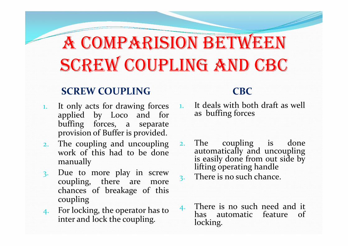
A COMPARISION BETWEEN SCREW COUPLING AND CBC SCREW COUPLING CBC
1. It only acts for drawing forces applied by Loco and for buffing forces, a separate provision of Buffer is provided.
2. The coupling and uncoupling work of this had to be done manually
3. Due to more play in screw coupling, there are more chances of breakage of this coupling
4. For locking, the operator has to inter and lock the coupling.
1. It deals with both draft as well as buffing forces
2. The coupling is done automatically and uncoupling is easily done from out side by lifting operating handle
3. There is no such chance.
4. There is no such need and it has automatic feature of locking.

ADVANTAGES OF CBC Coupler and buffing gear are both located together at the centre
of the Coach/Wagon.
Coupling action between Coach/Wagon is automatic so that more safer for operation.
If leading wagon is derailed due to some reason the CBC
prevents to derail next wagon.
Hauling capacity is increased.
Maintenance cost is less than conventional Draw gear.
.
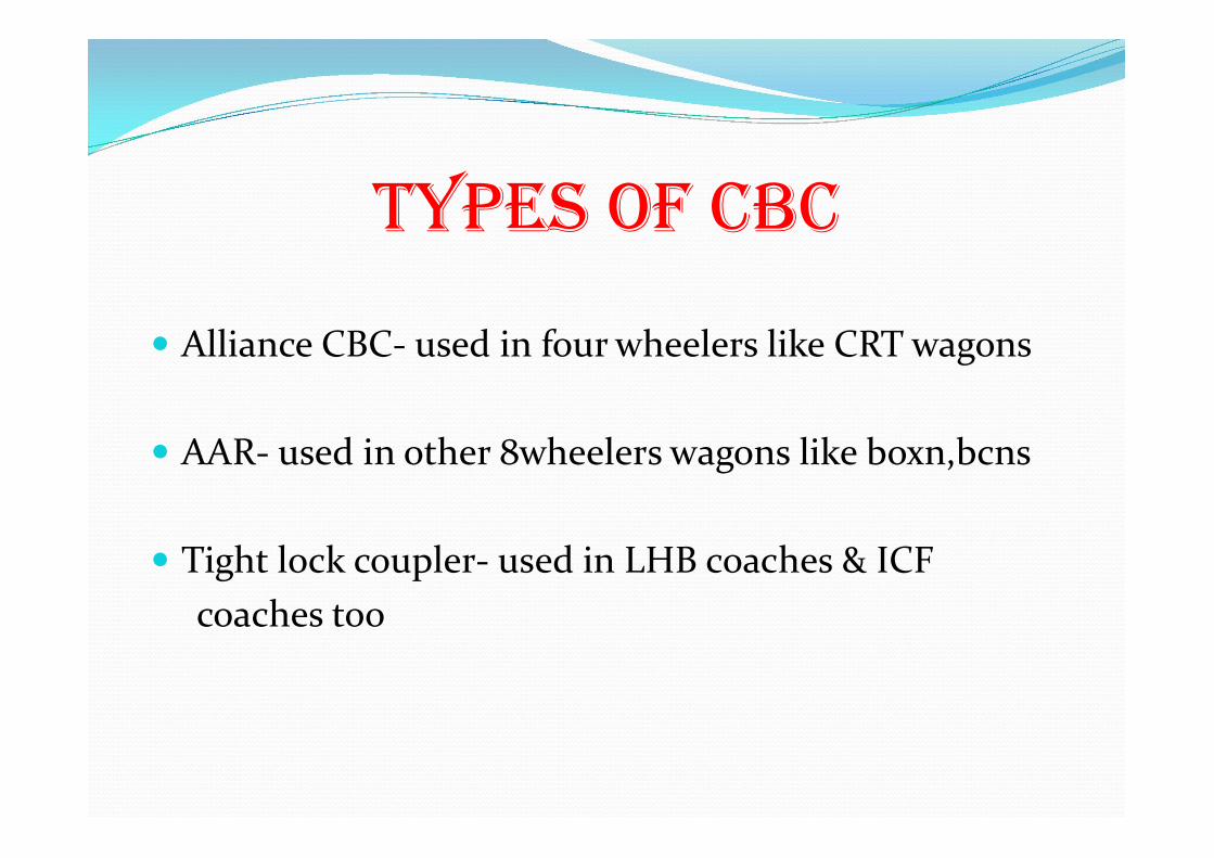
TYPES OF CBC
Alliance CBC- used in four wheelers like CRT wagons
AAR- used in other 8wheelers wagons like boxn,bcns
Tight lock coupler- used in LHB coaches & ICF coaches too

PARTS OF MOST COMMONLY USED AAR CBC
1. Coupler Body 2. Knuckle 3. Knuckle pivot pin with washer 4. Lock piece 5. Knuckle thrower (Kicker in alliance
CBC) 6. Toggle 7. Universal lock lift lever connector 8. Lock lift lever 9. Lock lift hook 10. Lock lift lever rivet 11. Top lifter hole cap 12. Yoke 13. Yoke pin 14. Yoke pin support 15. Striker casting
16. Striker casting wear plate 17. Shank 18. Shank wear plate 19. Yoke support plate 20. Draft gear arrangement with front
follower 21. Safety bracket with anchor plate 22. Uncoupling gear arrangement 23. Back stop 24. Clevis with transition type coupler
body 25. Baby screw coupling for transition
only
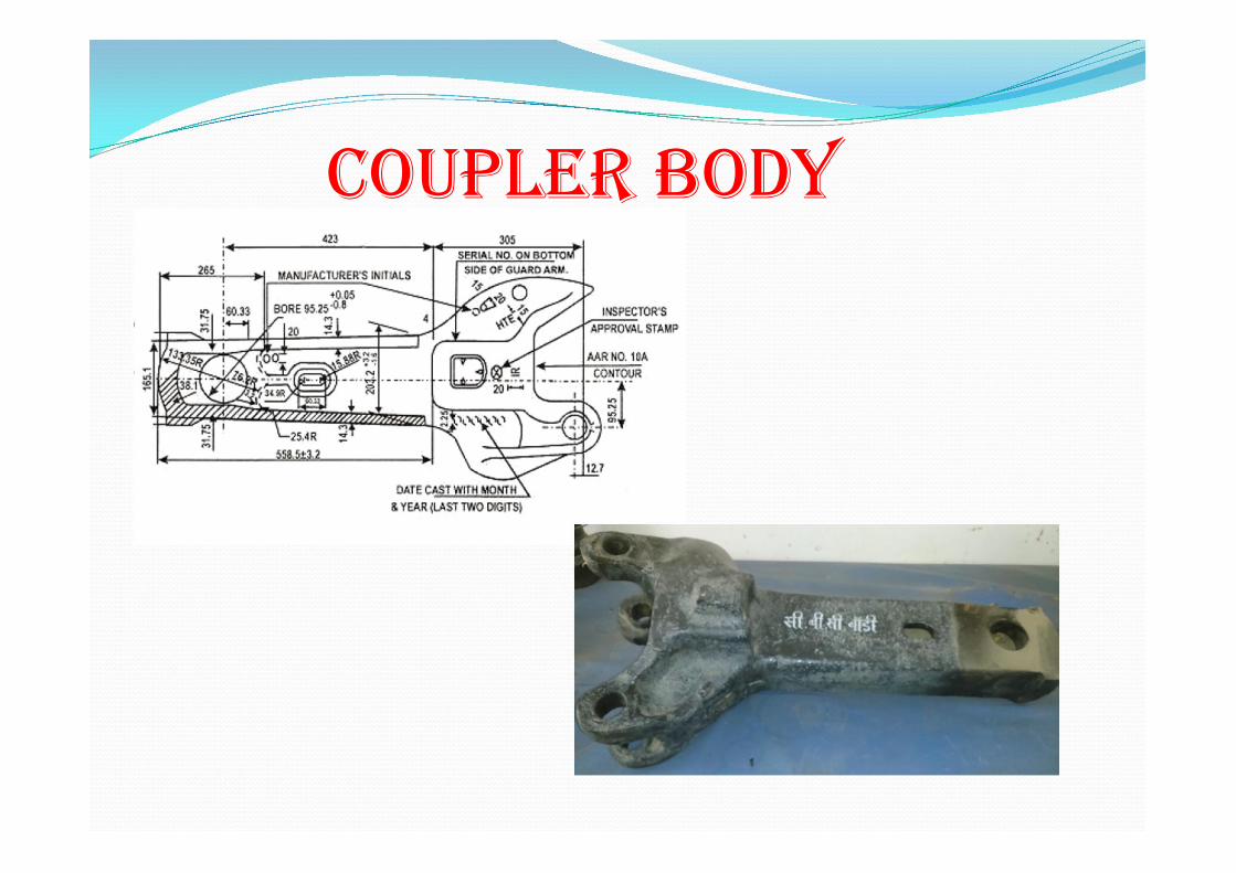
COUPLER BODY
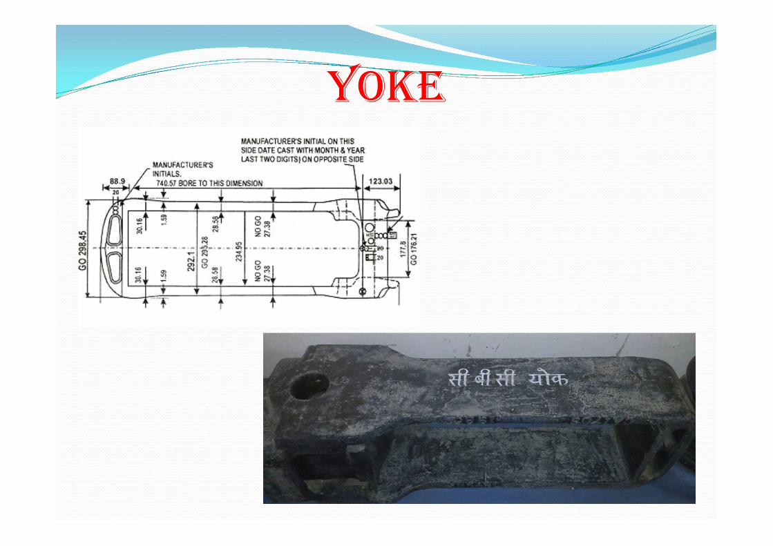
YOkE
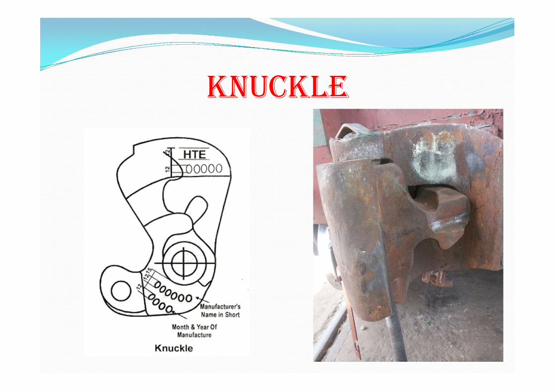
kNUCkLE
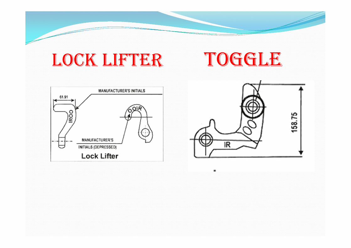
LOCk LIFTER TOGGLE
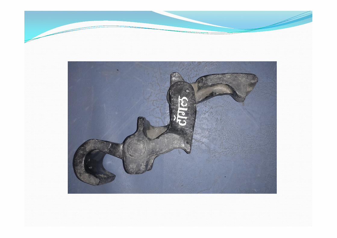
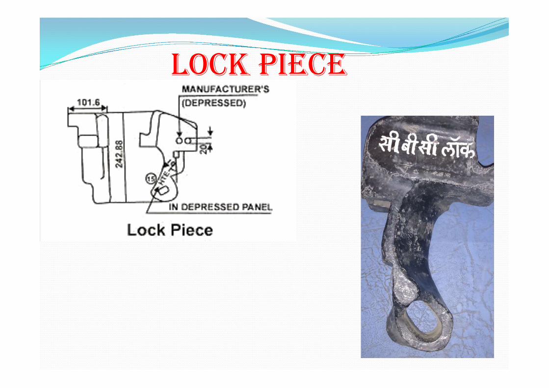
LOCk PIECE
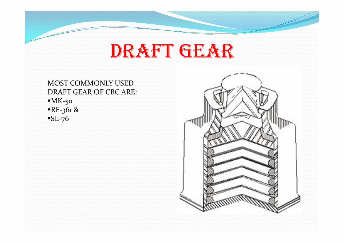
DRAFT GEAR MOST COMMONLY USED DRAFT GEAR OF CBC ARE: MK-50 RF-361 & SL-76
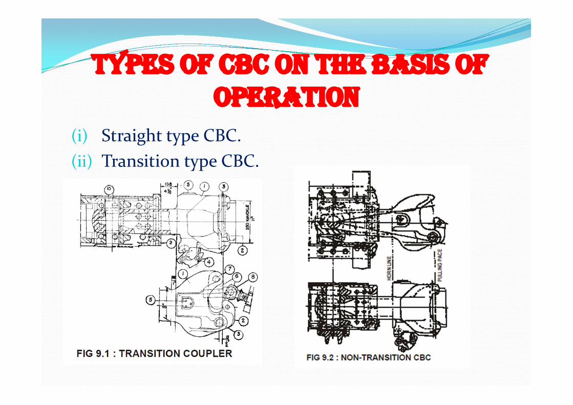
TYPES OF CBC ON THE BASIS OF
OPERATION (i) Straight type CBC. (ii) Transition type CBC. (iii)
INSPECTION OF CBC AT SICk LINE
1. Operating rod 2. Coupler operating mechanism 3. Locking of coupler 4. Buffer height 5. Permissible wear of components 6. Free slack of CBC 7. Anti creep mechanism protection 8. CBC contour condition 9. Knuckle stretch and nose wear
OPERATING ROD:
Operating rod should not be bent and it is fitted in bearing piece of under frame properly with creeper plate
COUPLER OPERATING MECHANISM:
The operating mechanism of the CBC should be in such a way that when we lift the operating handle knuckle should be open
COUPLER LOCkING
After opening the knuckle fully when we push the knuckle gradually the CBC lock should fall and there is a gap of 25mm between coupler body and CBC toggle
BUFFER HEIGHT
It should be within 1105mm-1030mm and measured from middle of striker casting/coupler body.
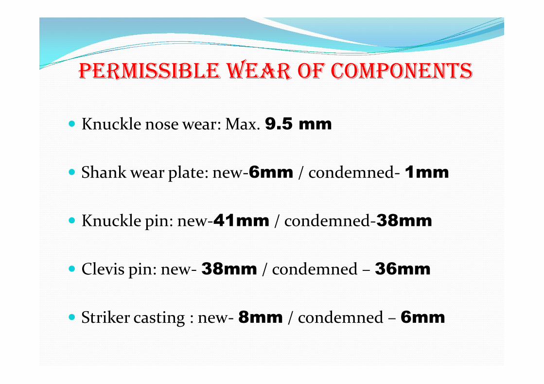
PERMISSIBLE WEAR OF COMPONENTS
Knuckle nose wear: Max. 9.5 mm
Shank wear plate: new-6mm / condemned- 1mm
Knuckle pin: new-41mm / condemned-38mm
Clevis pin: new- 38mm / condemned – 36mm
Striker casting : new- 8mm / condemned – 6mm

FREE SLACk OF CBC
Max. permissible free slack is 25mm. It should occur only when draft gear broken or
defective or headless yoke pin have a groove of more than 12.5mm radius.
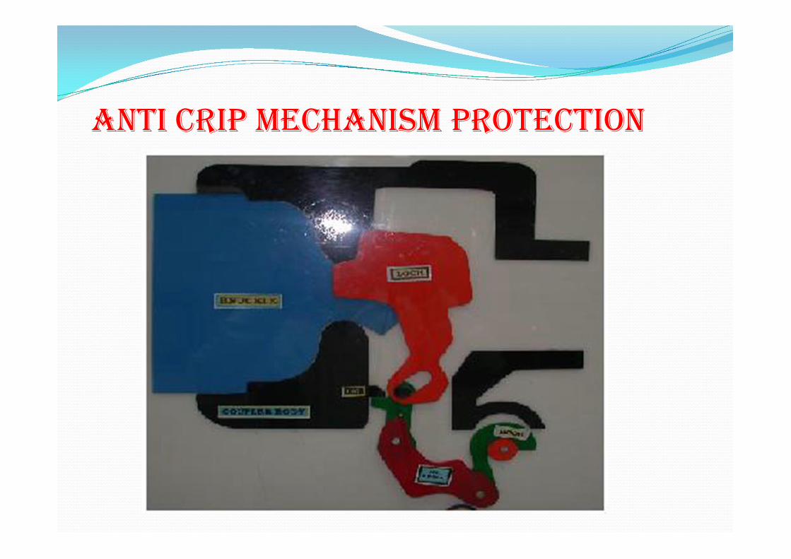
ANTI CRIP MECHANISM PROTECTION
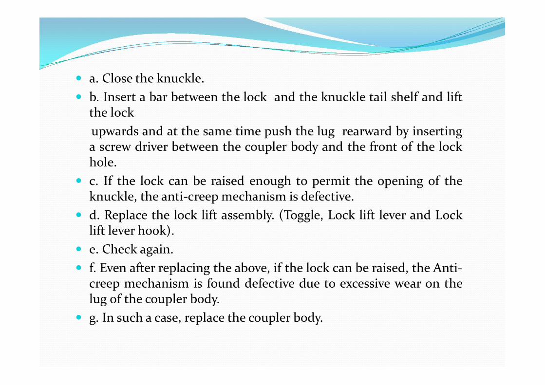
a. Close the knuckle. b. Insert a bar between the lock and the knuckle tail shelf and lift
the lock upwards and at the same time push the lug rearward by inserting
a screw driver between the coupler body and the front of the lock hole.
c. If the lock can be raised enough to permit the opening of the knuckle, the anti-creep mechanism is defective.
d. Replace the lock lift assembly. (Toggle, Lock lift lever and Lock lift lever hook).
e. Check again. f. Even after replacing the above, if the lock can be raised, the Anti-
creep mechanism is found defective due to excessive wear on the lug of the coupler body.
g. In such a case, replace the coupler body.
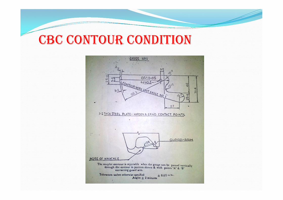
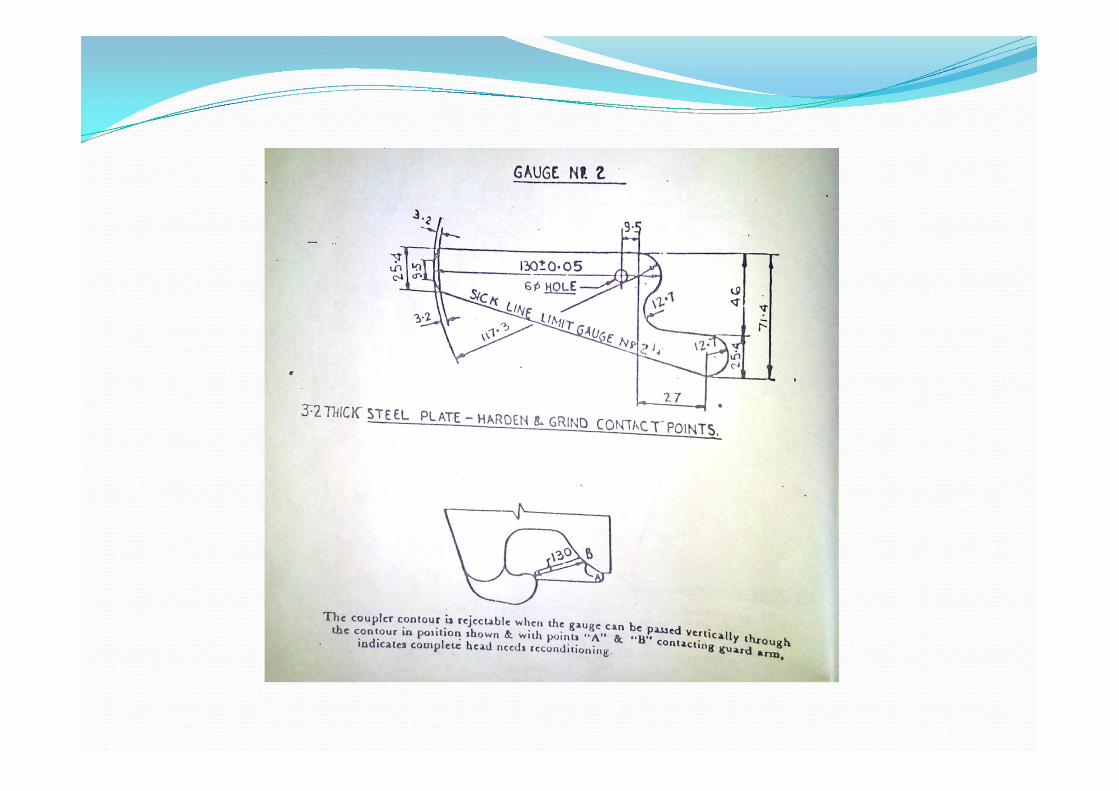
CBC CONTOUR CONDITION
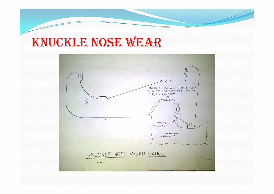
kNUCkLE NOSE WEAR
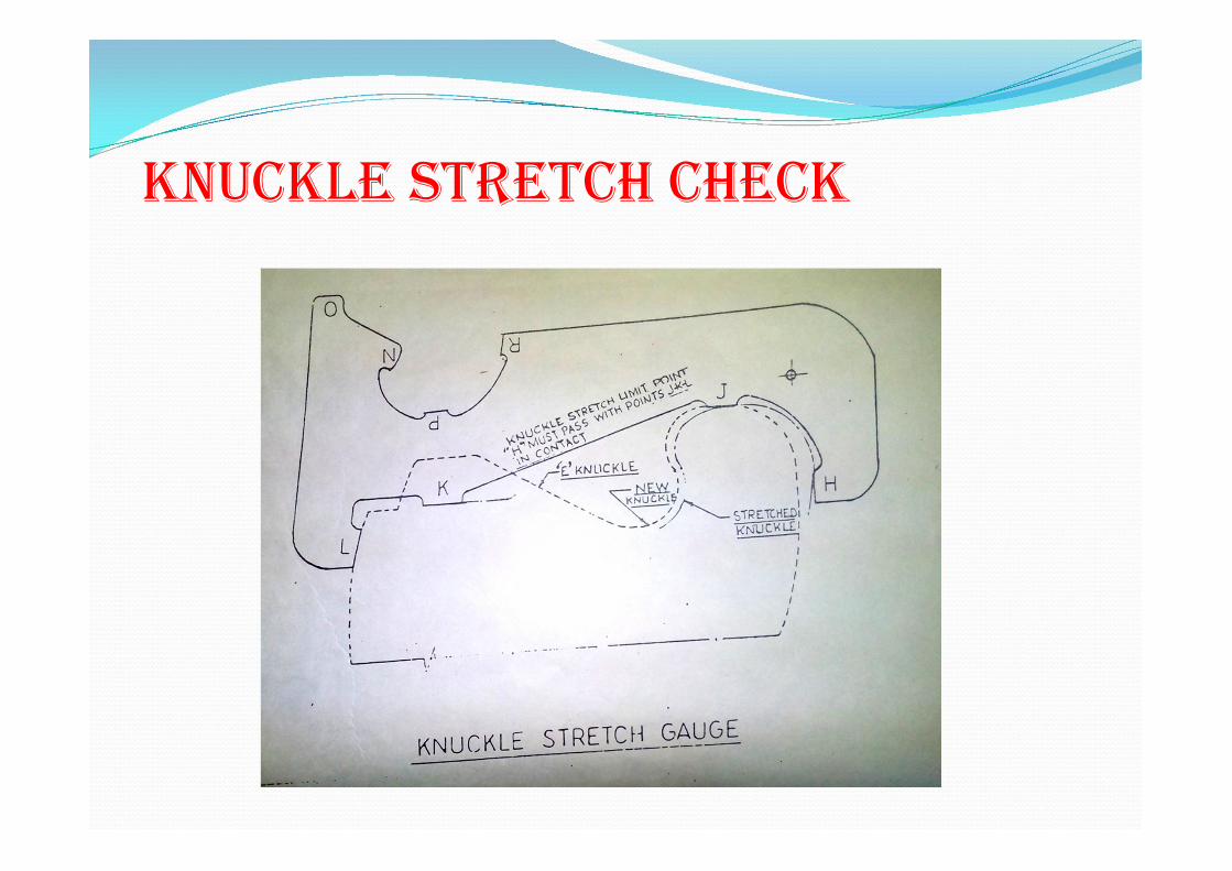
kNUCkLE STRETCH CHECk
DRAWBACkS OF CENTRE BUFFER COUPLER
Trespassers can uncouple the CBC If buffer height difference is more than 65 mm there is
chances of uncoupling of knuckles If anti-creep mechanism of CBC is defective train
parting may occur Uncoupling is difficult in case of a derailment or
accident
‘H’ TYPE TIGHTLOCk COUPLERS
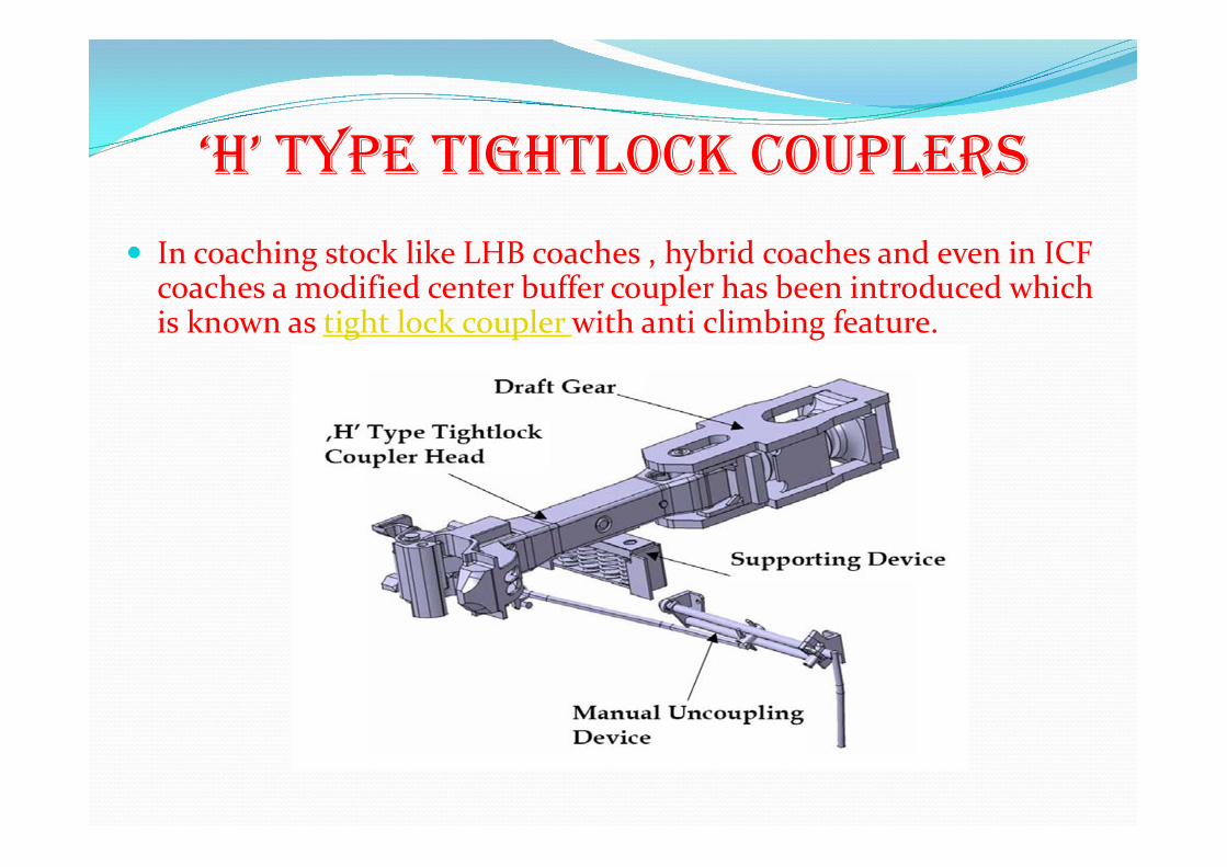
In coaching stock like LHB coaches , hybrid coaches and even in ICF coaches a modified center buffer coupler has been introduced which is known as tight lock coupler with anti climbing feature.

SPECIAL FEATURES OF TIGHT LOCk COUPLER
The centre buffer coupler combines the draw and buffing gear in one. It is able to transmit both the tensile and the compressive forces. Further the tight lock coupler by its ANTICLIMBING FEATURE, hinders the climbing of the vehicles in case of an accident.
There is a lock in operating handle mechanism so no trespassers can operate it.
There is no chance of knuckle opening due to anti climbing feature too. Because the adjacent coaches are connected to each other with a gathering range of 90mm and the shank of the tight lock coupler rest on a supporting device which consist of compression spring. It means both coupler after coupling will move together vertically.
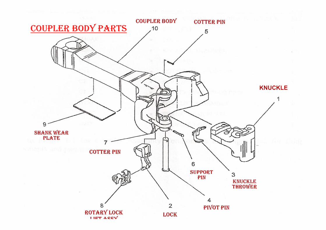
COUPLER BODY PARTS

SUPPORTING DEVICE

DRAFT GEAR
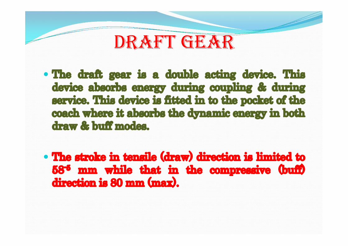
The draft gear is a double acting device. This device absorbs energy during coupling & during service. This device is fitted in to the pocket of the coach where it absorbs the dynamic energy in both draw & buff modes.
The stroke in tensile (draw) direction is limited to
58-5 mm while that in the compressive (buff) direction is 80 mm (max).
DRAFT GEAR

The supporting device comprises of four preloaded compression springs. This device is fitted below the draw bar in the coach pocket & is bolted on to the body of the coach. The coupler head rests on the top wear plate of the supporting device. The complete weight of the coupler is taken by this supporting device.
Height of supporting device including wear plate = 187.5 mm
SUPPORTING DEVICE
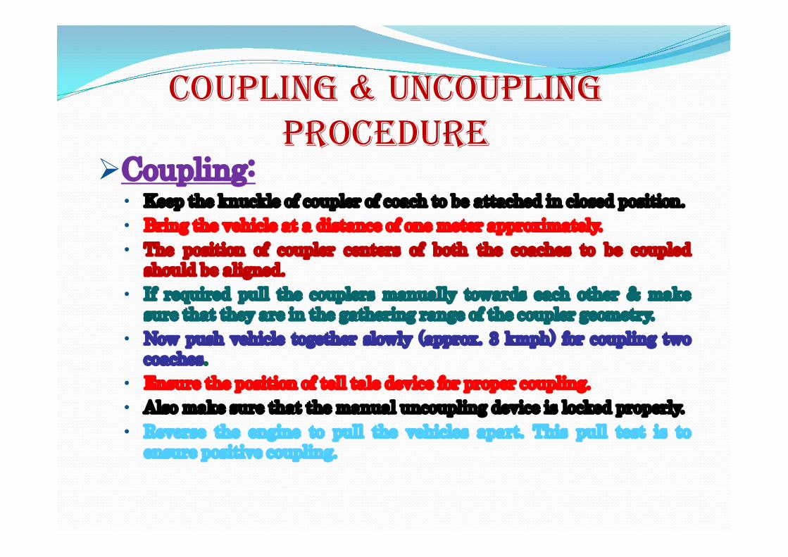
Coupling: • Keep the knuckle of coupler of coach to be attached in closed position. • Bring the vehicle at a distance of one meter approximately. • The position of coupler centers of both the coaches to be coupled
should be aligned. • If required pull the couplers manually towards each other & make
sure that they are in the gathering range of the coupler geometry. • Now push vehicle together slowly (approx. 3 kmph) for coupling two
coaches. • Ensure the position of tell tale device for proper coupling. • Also make sure that the manual uncoupling device is locked properly. • Reverse the engine to pull the vehicles apart. This pull test is to
ensure positive coupling.
COUPLING & UNCOUPLING PROCEDURE
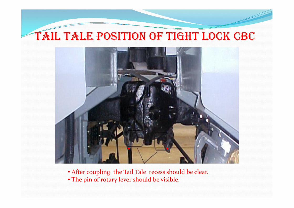
TAIL TALE POSITION OF TIGHT LOCk CBC
• After coupling the Tail Tale recess should be clear. • The pin of rotary lever should be visible.

Un- Coupling : • For un-coupling of the coupler manual
uncoupling device is provided. • First unlock the lock of the handle. • Lift & turn the handle in clockwise direction
(minimum 90°), if required. • Then pull the vehicles apart.

Items Parameter
Gathering range of Coupler Horizontal + 110 mm
Vertical + 90 mm
CBC height under tare condition 1105 mm
Permissible CBC height under tare condition 1090 mm
Permissible CBC height under loaded condition 1030 mm
Permissible knuckle difference between engine & power car knuckle by measuring Tape) 75 mm
Maximum projection of side buffers 650 mm
CBC & BUFFER PARAMETERS
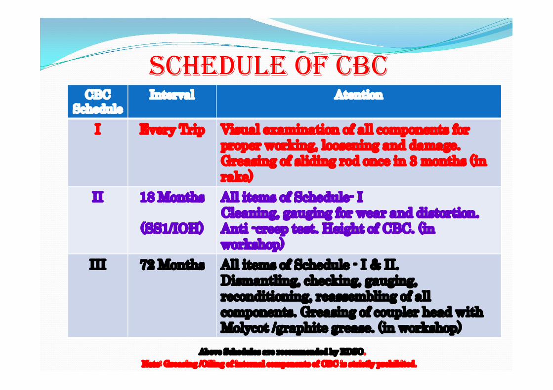
CBC Schedule
Interval Atention
I Every Trip Visual examination of all components for proper working, loosening and damage. Greasing of sliding rod once in 3 months (in rake)
II 18 Months
(SS1/IOH)
All items of Schedule- I Cleaning, gauging for wear and distortion. Anti -creep test. Height of CBC. (in workshop)
III 72 Months All items of Schedule - I & II. Dismantling, checking, gauging, reconditioning, reassembling of all components. Greasing of coupler head with Molycot /graphite grease. (in workshop)
SCHEDULE OF CBC
Above Schedules are recommended by RDSO.
Note: Greasing /Oiling of internal components of CBC is strictly prohibited.
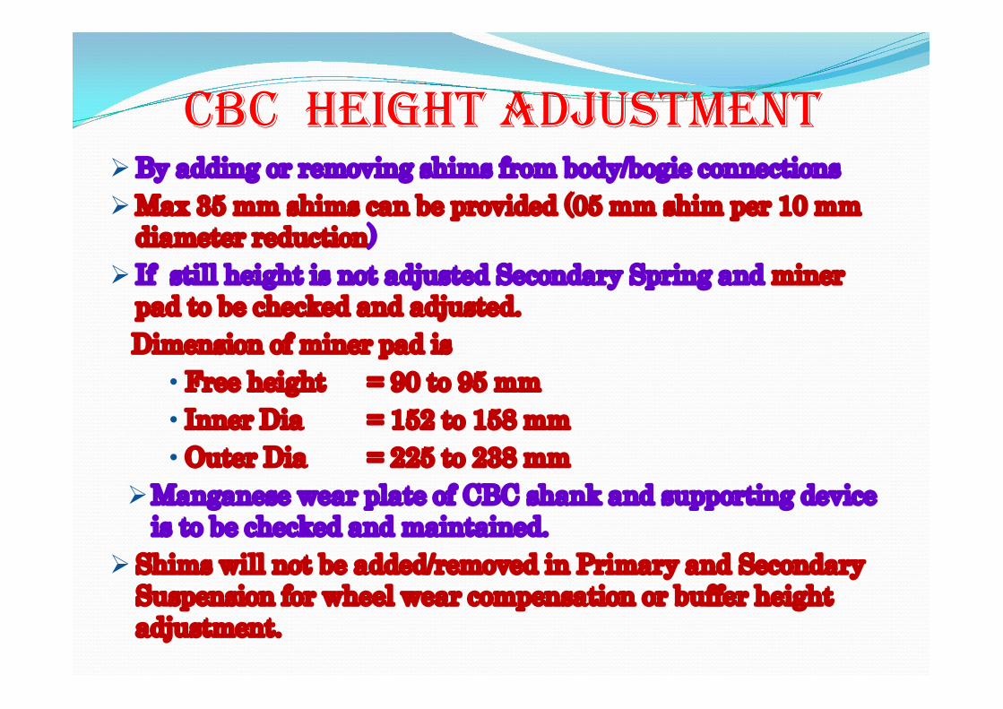
By adding or removing shims from body/bogie connections Max 35 mm shims can be provided (05 mm shim per 10 mm
diameter reduction) If still height is not adjusted Secondary Spring and miner
pad to be checked and adjusted. Dimension of miner pad is
• Free height = 90 to 95 mm • Inner Dia = 152 to 158 mm • Outer Dia = 225 to 238 mm
Manganese wear plate of CBC shank and supporting device is to be checked and maintained.
Shims will not be added/removed in Primary and Secondary Suspension for wheel wear compensation or buffer height adjustment.
CBC HEIGHT ADJUSTMENT

GAUGING OF TIGHT LOCk COUPLER IN SICk LINE OR SHOP
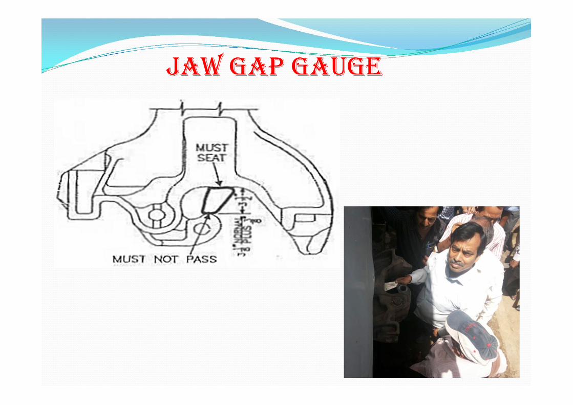
JAW GAP GAUGE
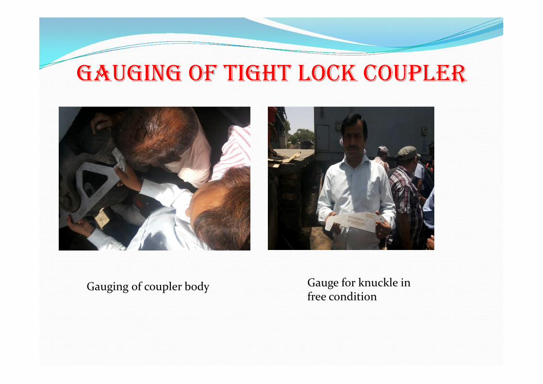
GAUGING OF TIGHT LOCk COUPLER
Gauging of coupler body Gauge for knuckle in free condition
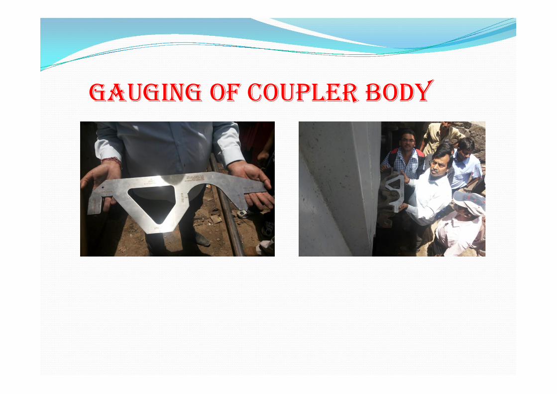
GAUGING OF COUPLER BODY
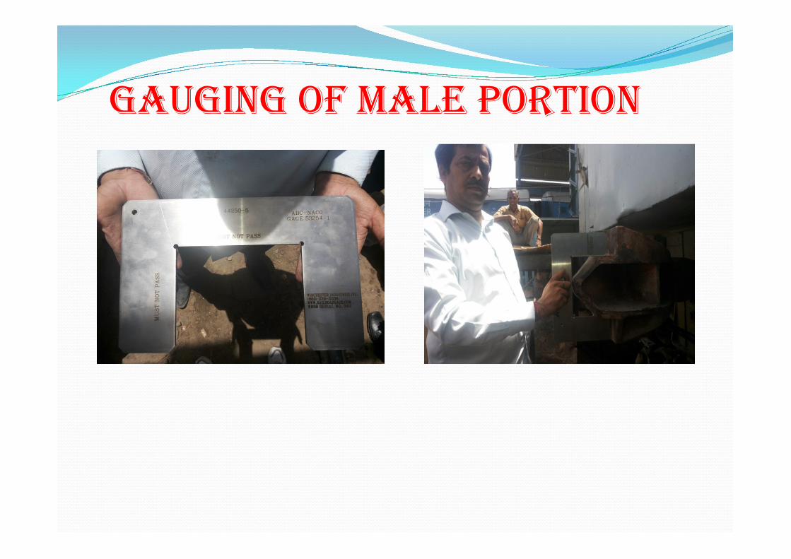
GAUGING OF MALE PORTION

47
ANTI-CREEP CHECk
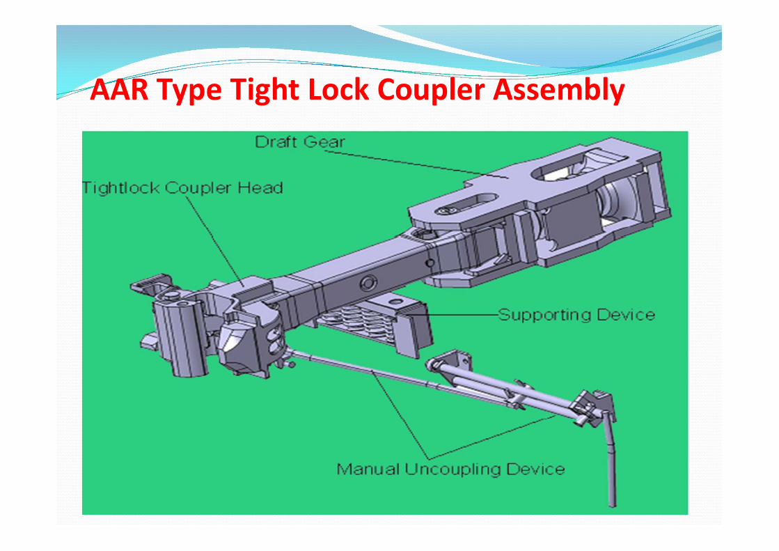
AAR Type Tight Lock Coupler Assembly
INSTRUCTION FOR ExAMINATION/SHUNTING STAFF
Don’t disturb the uncoupling device without any reason.
Ensure proper tightening of the nut bolt of support plate of draft gear and headless pin
Don’t apply grease/oil on knuckle ,Coupler head ,lock and anti creep etc.
Always keep open the Knuckles of both the Power cars/SLR or spare coaches if any.
Always check rest plate ,loosening of bolts and breakage of springs etc.

Tight lock couplers with anticlimbing features are introduced in coaches only and not in locomotives, where the rake attached with locomotives there is a coupling between tight lock coupler and ordinary transition type CBC
If there is a buffer height difference of more than 65mm knuckle may uncouple. To prevent this a restrictor has been provided in tight lock coupler which prevents the lifting of knuckle.

Tight lock coupler with anti climbing feature and transition coupling has been introduced in locomotives too.


