Embed Size (px)
Citation preview
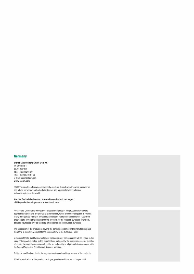
Replacement Filter Elements
Return-Line Filters
Offline and Bypass Filters
Catalogue 9STAUFF Filtration Technology
Pressure Filters
In-Line Filters
Spin-On Filters
Filtration Systems
Please note: Unless otherwise stated, all data and figures in this product catalogue are approximate values and are only valid as references, which are not binding (also in respect to any third parties’ rights of protection) and thus do not release the customer / user from checking and testing the suitability of the products for the foreseen purposes. Therefore, data and figures can only be used in a limited sense for construction purposes.
The application of the products is beyond the control possibilities of the manufacturer and, therefore, is exclusively subject to the responsibility of the customer / user.
In the event that a liability is nevertheless considered, any compensation will be limited to the value of the goods supplied by the manufacturer and used by the customer / user. As a matter of course, the manufacturer guarantees the perfect quality of all products in accordance with the General Terms and Conditions of Business and Sale.
Subject to modifications due to the ongoing development and improvement of the products.
With the publication of this product catalogue, previous editions are no longer valid.
Germany Walter Stauffenberg GmbH & Co. KGIm Ehrenfeld 458791 Werdohl Tel.: +49 2392 91 60Fax: +49 2392 91 61 03E-Mail: [email protected]
STAUFF products and services are globally available through wholly-owned subsidiaries and a tight network of authorised distributors and representatives in all major industrial regions of the world. You can find detailed contact information on the last two pages of this product catalogue or at www.stauff.com.
3www.stauff.com/9/en/#3
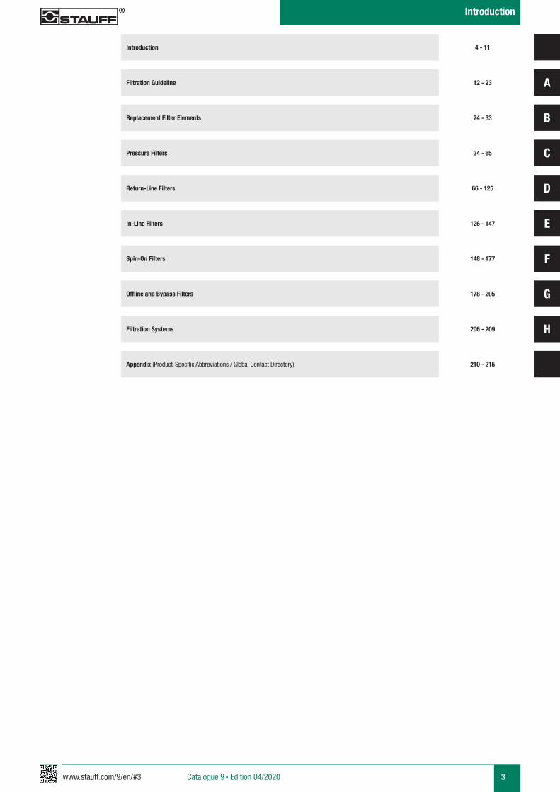
Filtration Guideline
Replacement Filter Elements
Pressure Filters
Return-Line Filters
In-Line Filters
Offline and Bypass Filters
Introduction 4 - 11
12 - 23
24 - 33
34 - 65
66 - 125
126 - 147
148 - 177Spin-On Filters
178 - 205
A
B
C
D
E
F
G
HFiltration Systems 206 - 209
Appendix (Product-Specific Abbreviations / Global Contact Directory) 210 - 215
Catalogue 9 § Edition 04/2020
Introduction
4 www.stauff.com/9/en/#4Catalogue 9 § Edition 04/2020
Introduction
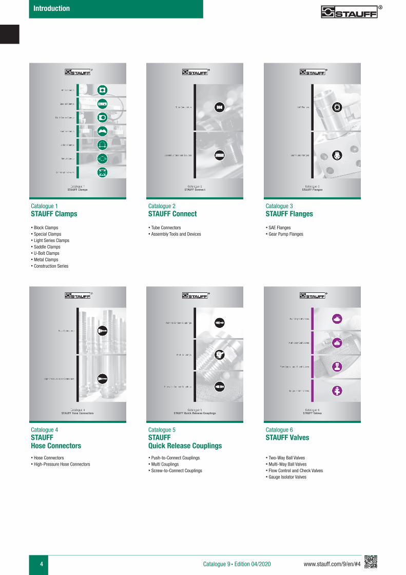
Catalogue 1 STAUFF Clamps
Catalogue 2 STAUFF Connect
Catalogue 3 STAUFF Flanges
Catalogue 4 STAUFF Hose Connectors
Catalogue 5 STAUFF Quick Release Couplings
Catalogue 6 STAUFF Valves
§ Block Clamps§ Special Clamps§ Light Series Clamps§ Saddle Clamps§ U-Bolt Clamps§ Metal Clamps§ Construction Series
§ Tube Connectors§ Assembly Tools and Devices
§ SAE Flanges§ Gear Pump Flanges
§ Hose Connectors§ High-Pressure Hose Connectors
§ Push-to-Connect Couplings§ Multi Couplings § Screw-to-Connect Couplings
§ Two-Way Ball Valves§ Multi-Way Ball Valves§ Flow Control and Check Valves§ Gauge Isolator Valves
5www.stauff.com/9/en/#5 Catalogue 9 § Edition 04/2020
Introduction
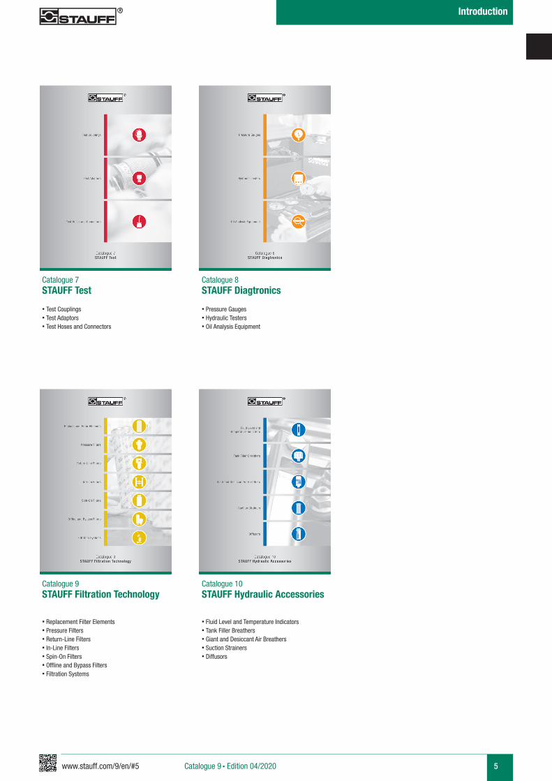
Catalogue 7 STAUFF Test
Catalogue 8 STAUFF Diagtronics
Catalogue 9 STAUFF Filtration Technology
Catalogue 10 STAUFF Hydraulic Accessories
§ Test Couplings § Test Adaptors§ Test Hoses and Connectors
§ Pressure Gauges§ Hydraulic Testers§ Oil Analysis Equipment
§ Replacement Filter Elements§ Pressure Filters§ Return-Line Filters§ In-Line Filters§ Spin-On Filters§ Offline and Bypass Filters§ Filtration Systems
§ Fluid Level and Temperature Indicators§ Tank Filler Breathers§ Giant and Desiccant Air Breathers§ Suction Strainers§ Diffusors
6 www.stauff.com/9/en/#6Catalogue 9 § Edition 04/2020
Introduction
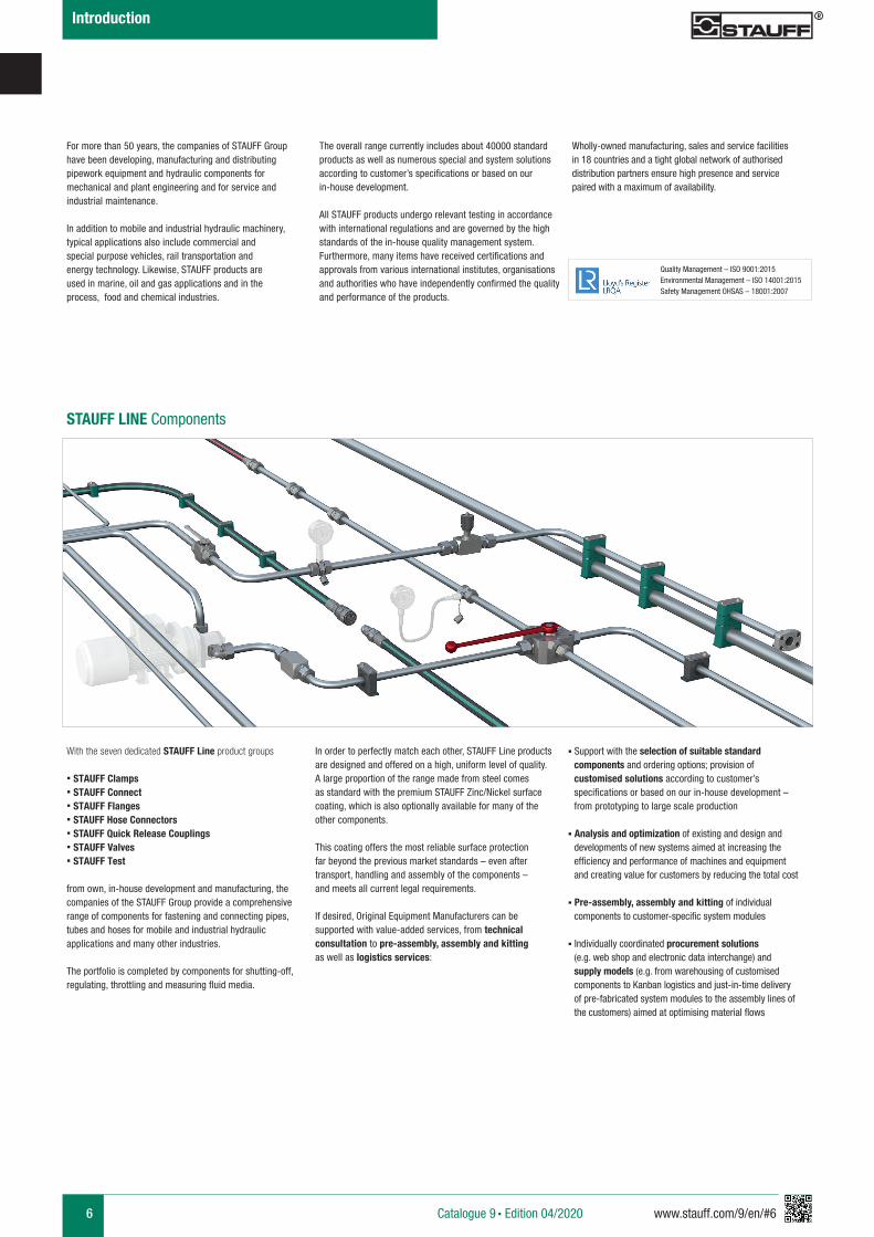
STAUFF LINE Components
With the seven dedicated STAUFF Line product groups
§ STAUFF Clamps§ STAUFF Connect§ STAUFF Flanges§ STAUFF Hose Connectors§ STAUFF Quick Release Couplings § STAUFF Valves § STAUFF Test
from own, in-house development and manufacturing, the companies of the STAUFF Group provide a comprehensive range of components for fastening and connecting pipes, tubes and hoses for mobile and industrial hydraulic applications and many other industries.
The portfolio is completed by components for shutting-off, regulating, throttling and measuring fluid media.
For more than 50 years, the companies of STAUFF Group have been developing, manufacturing and distributing pipework equipment and hydraulic components for mechanical and plant engineering and for service and industrial maintenance.
In addition to mobile and industrial hydraulic machinery, typical applications also include commercial and special purpose vehicles, rail transportation and energy technology. Likewise, STAUFF products are used in marine, oil and gas applications and in the process, food and chemical industries.
The overall range currently includes about 40000 standard products as well as numerous special and system solutions according to customer’s specifications or based on our in-house development.
All STAUFF products undergo relevant testing in accordance with international regulations and are governed by the high standards of the in-house quality management system. Furthermore, many items have received certifications and approvals from various international institutes, organisations and authorities who have independently confirmed the quality and performance of the products.
Wholly-owned manufacturing, sales and service facilities in 18 countries and a tight global network of authorised distribution partners ensure high presence and service paired with a maximum of availability.
In order to perfectly match each other, STAUFF Line products are designed and offered on a high, uniform level of quality. A large proportion of the range made from steel comes as standard with the premium STAUFF Zinc/Nickel surface coating, which is also optionally available for many of the other components.
This coating offers the most reliable surface protection far beyond the previous market standards – even after transport, handling and assembly of the components – and meets all current legal requirements.
If desired, Original Equipment Manufacturers can be supported with value-added services, from technical consultation to pre-assembly, assembly and kitting as well as logistics services:
§ Support with the selection of suitable standard components and ordering options; provision of
customised solutions according to customer’s specifications or based on our in-house development – from prototyping to large scale production
§ Analysis and optimization of existing and design and developments of new systems aimed at increasing the efficiency and performance of machines and equipment
and creating value for customers by reducing the total cost
§ Pre-assembly, assembly and kitting of individual components to customer-specific system modules
§ Individually coordinated procurement solutions (e.g. web shop and electronic data interchange) and supply models (e.g. from warehousing of customised
components to Kanban logistics and just-in-time delivery of pre-fabricated system modules to the assembly lines of the customers) aimed at optimising material flows
Quality Management – ISO 9001:2015 Environmental Management – ISO 14001:2015 Safety Management OHSAS – 18001:2007
7www.stauff.com/9/en/#7 Catalogue 9 § Edition 04/2020
Introduction
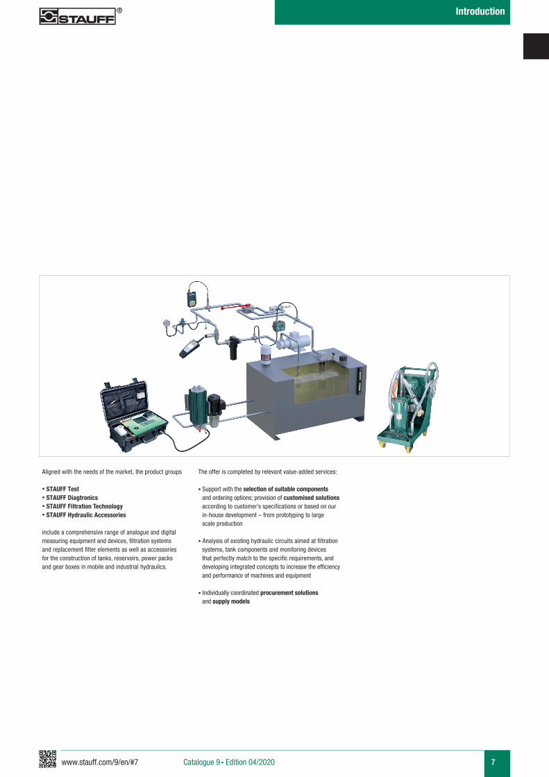
Aligned with the needs of the market, the product groups
§ STAUFF Test§ STAUFF Diagtronics§ STAUFF Filtration Technology§ STAUFF Hydraulic Accessories
include a comprehensive range of analogue and digital measuring equipment and devices, filtration systems and replacement filter elements as well as accessories for the construction of tanks, reservoirs, power packs and gear boxes in mobile and industrial hydraulics.
The offer is completed by relevant value-added services:
§ Support with the selection of suitable components and ordering options; provision of customised solutions according to customer’s specifications or based on our in-house development – from prototyping to large scale production
§ Analysis of existing hydraulic circuits aimed at filtration systems, tank components and monitoring devices that perfectly match to the specific requirements, and developing integrated concepts to increase the efficiency and performance of machines and equipment
§ Individually coordinated procurement solutions and supply models
8 www.stauff.com/9/en/#8Catalogue 9 § Edition 04/2020
Introduction
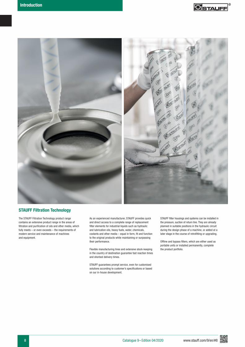
STAUFF Filtration Technology
The STAUFF Filtration Technology product range contains an extensive product range in the areas of filtration and purification of oils and other media, which fully meets – or even exceeds – the requirements of modern service and maintenance of machines and equipment.
As an experienced manufacturer, STAUFF provides quick and direct access to a complete range of replacement filter elements for industrial liquids such as hydraulic and lubrication oils, heavy fuels, water, chemicals, coolants and other media – equal in form, fit and function to the original products while maintaining or surpassing their performance.
Flexible manufacturing lines and extensive stock-keeping in the country of destination guarantee fast reaction times and shortest delivery times.
STAUFF guarantees prompt service, even for customised solutions according to customer’s specifications or based on our in-house development.
STAUFF filter housings and systems can be installed in the pressure, suction of return line. They are already planned in suitable positions in the hydraulic circuit during the design phase of a machine, or added at a later stage in the course of retrofitting or upgrading.
Offline and bypass filters, which are either used as portable units or installed permanently, complete the product portfolio.
9www.stauff.com/9/en/#9 Catalogue 9 § Edition 04/2020
Introduction
10 www.stauff.com/9/en/#10Catalogue 9 § Edition 04/2020
Introduction
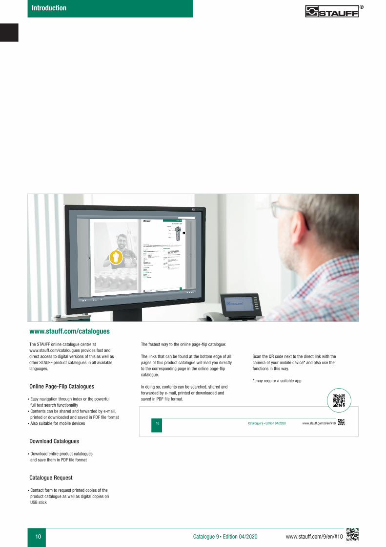
The STAUFF online catalogue centre at www.stauff.com/catalougues provides fast and direct access to digital versions of this as well as other STAUFF product catalogues in all available languages.
www.stauff.com/catalogues
Online Page-Flip Catalogues
§ Easy navigation through index or the powerful full text search functionality§ Contents can be shared and forwarded by e-mail,
printed or downloaded and saved in PDF file format§ Also suitable for mobile devices
Download Catalogues
§ Download entire product catalogues and save them in PDF file format
Catalogue Request
§ Contact form to request printed copies of the product catalogue as well as digital copies on USB stick
The fastest way to the online page-flip catalogue:
The links that can be found at the bottom edge of all pages of this product catalogue will lead you directly to the corresponding page in the online page-flip catalogue.
In doing so, contents can be searched, shared and forwarded by e-mail, printed or downloaded and saved in PDF file format.
Scan the QR code next to the direct link with the camera of your mobile device* and also use the functions in this way.
* may require a suitable app
10 www.stauff.com/9/en/#10Catalogue 9 § Edition 04/2020
11www.stauff.com/9/en/#11 Catalogue 9 § Edition 04/2020
Introduction
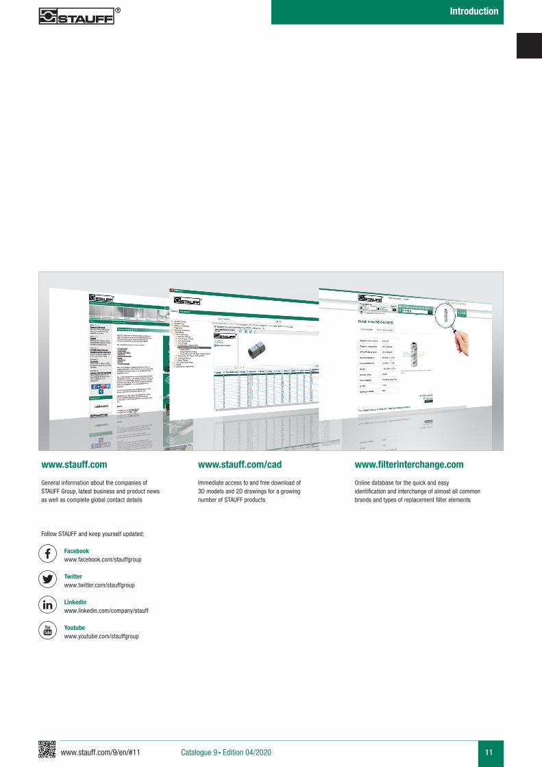
General information about the companies of STAUFF Group, latest business and product news as well as complete global contact details
Immediate access to and free download of 3D models and 2D drawings for a growing number of STAUFF products
www.stauff.com www.stauff.com/cad www.filterinterchange.com
Online database for the quick and easy identification and interchange of almost all common brands and types of replacement filter elements
Follow STAUFF and keep yourself updated:
Facebook www.facebook.com/stauffgroup Twitter www.twitter.com/stauffgroup
Linkedin www.linkedin.com/company/stauff
Youtube www.youtube.com/stauffgroup
A
www.stauff.com/9/en/#13 13Catalogue 9 § Edition 04/2020
Filtration Guideline
Filtration Guideline
Filtration - Why? 15
15
16 - 17
18
Contamination
STAUFF Filter Components
Test Standards and Oil Purity
19
12 - 23
20 - 21
22 - 23
19Short & Curt: Filter Rating
ß-Value and Separations Efficiency
Filtration Terminology
Choice of Filters / Examples of Calculation
A
14 www.stauff.com/9/en/#14Catalogue 9 § Edition 04/2020
Filtration Guideline
A
www.stauff.com/9/en/#15 15
Contamination
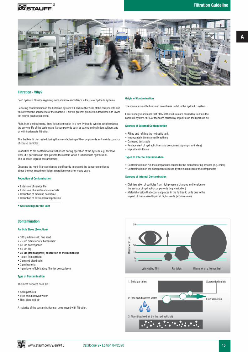
Particle Sizes (Selection)
§ 100 µm table salt, fine sand § 75 µm diameter of a human hair § 60 µm flower pollen § 50 µm fog § 30 µm (from approx.) resolution of the human eye § 15 µm fine particles § 7 µm red blood cells § 2 µm bacteria § 1 µm layer of lubricating film (for comparison)
Type of Contamination
The most frequent ones are:
§ Solid particles § Free and dissolved water § Non-dissolved air
A majority of the contamination can be removed with filtration.
75
30
15
51
Diameter of a human hairParticles
Diam
eter
in µ
m
1. Solid particles
2. Free and dissolved water
3. Non-dissolved air (in the hydraulic oil)
Suspended solids
Flow direction
Origin of Contamination
The main cause of failures and downtimes is dirt in the hydraulic system.
Failure analysis indicate that 80% of the failures are caused by faults in the hydraulic system. 90% of them are caused by impurities in the hydraulic oil.
Sources of External Contamination
§ Filling and refilling the hydraulic tank § Inadequately dimensioned breathers § Damaged tank seals § Replacement of hydraulic lines and components (pumps, cylinders) § Impurities in the air
Types of Internal Contamination
§ Contamination on / in the components caused by the manufacturing process (e.g. chips) § Contamination on the components caused by the installation of the components
Sources of Internal Contamination
§ Disintegration of particles from high pressure changes and tension on the surface of hydraulic components (e.g. cavitation)
§ Material erosion that occurs at places in the hydraulic units due to the impact of pressurised liquid at high speeds (erosion wear)
Filtration - Why?
Good hydraulic filtration is gaining more and more importance in the use of hydraulic systems.
Reducing contamination in the hydraulic system will reduce the wear of the components and thus extend the service life of the machine. This will prevent production downtime and lower the overall production costs. Right from the beginning, there is contamination in a new hydraulic system, which reduces the service life of the system and its components such as valves and cylinders without any or with inadequate filtration. This built-in dirt is created during the manufacturing of the components and mainly consists of coarse particles. In addition to the contamination that arises during operation of the system, e.g. abrasive wear, dirt particles can also get into the system when it is filled with hydraulic oil. This is called ingress contamination. Choosing the right filter contributes significantly to prevent the dangers mentioned above thereby ensuring efficient operation even after many years.
Reduction of Contamination
§ Extension of service life § Extension of maintenance intervals § Reduction of machine downtime § Reduction of environmental pollution
u Cost savings for the user
Lubricating film
Catalogue 9 § Edition 04/2020
Filtration Guideline
A
16 www.stauff.com/9/en/#16
STAUFF Laser Particle Counter LasPaC-II and Bottle Sampler
“Hydraulic System”(valves, cylinders, accumulators, motors ...)
A
B
a h
c
f
egb
a
bc
d
k
e
f
h
i
g
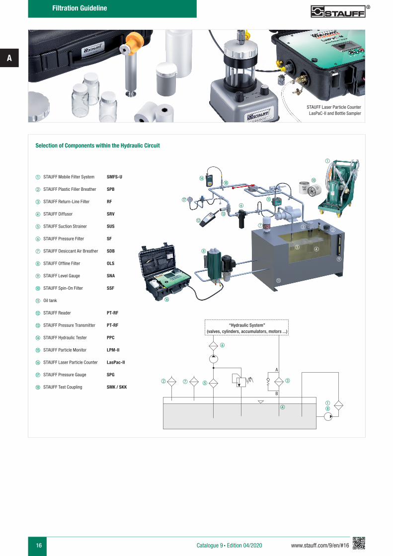
Selection of Components within the Hydraulic Circuit
a STAUFF Mobile Filter System SMFS-U
b STAUFF Plastic Filler Breather SPB
c STAUFF Return-Line Filter RF
d STAUFF Diffusor SRV
e STAUFF Suction Strainer SUS
f STAUFF Pressure Filter SF
g STAUFF Desiccant Air Breather SDB
h STAUFF Offline Filter OLS
i STAUFF Level Gauge SNA
j STAUFF Spin-On Filter SSF
k Oil tank
l STAUFF Reader PT-RF
m STAUFF Pressure Transmitter PT-RF
n STAUFF Hydraulic Tester PPC
o STAUFF Particle Monitor LPM-II
p STAUFF Laser Particle Counter LasPac-II
q STAUFF Pressure Gauge SPG
r STAUFF Test Coupling SMK / SKK
j
Catalogue 9 § Edition 04/2020
Filtration Guideline
d
l
m
n
p
oq
r
A
www.stauff.com/9/en/#17 17
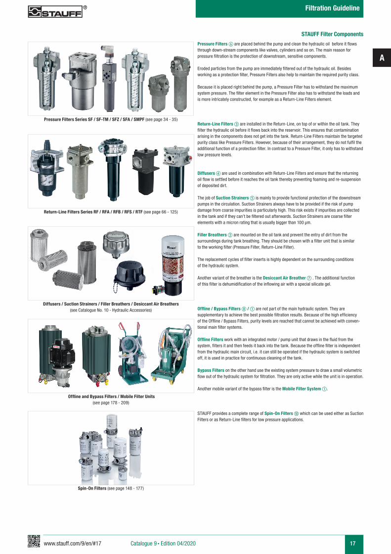
Pressure Filters Series SF / SF-TM / SFZ / SFA / SMPF (see page 34 - 35)
STAUFF Filter Components
Return-Line Filters Series RF / RFA / RFB / RFS / RTF (see page 66 - 125)
Diffusers / Suction Strainers / Filler Breathers / Desiccant Air Breathers(see Catalogue No. 10 - Hydraulic Accessories)
Offline and Bypass Filters / Mobile Filter Units(see page 178 - 209)
Spin-On Filters (see page 148 - 177)
Pressure Filters f are placed behind the pump and clean the hydraulic oil before it flows through down-stream components like valves, cylinders and so on. The main reason for pressure filtration is the protection of downstream, sensitive components. Eroded particles from the pump are immediately filtered out of the hydraulic oil. Besides working as a protection filter, Pressure Filters also help to maintain the required purity class.
Because it is placed right behind the pump, a Pressure Filter has to withstand the maximum system pressure. The filter element in the Pressure Filter also has to withstand the loads and is more intricately constructed, for example as a Return-Line Filters element.
Return-Line Filters c are installed in the Return-Line, on top of or within the oil tank. They filter the hydraulic oil before it flows back into the reservoir. This ensures that contamination arising in the components does not get into the tank. Return-Line Filters maintain the targeted purity class like Pressure Filters. However, because of their arrangement, they do not fulfil the additional function of a protection filter. In contrast to a Pressure Filter, it only has to withstand low pressure levels.
Diffusers d are used in combination with Return-Line Filters and ensure that the returning oil flow is settled before it reaches the oil tank thereby preventing foaming and re-suspension of deposited dirt.
The job of Suction Strainers e is mainly to provide functional protection of the downstream pumps in the circulation. Suction Strainers always have to be provided if the risk of pump damage from coarse impurities is particularly high. This risk exists if impurities are collected in the tank and if they can’t be filtered out afterwards. Suction Strainers are coarse filter elements with a micron rating that is usually bigger than 100 µm.
Filler Breathers b are mounted on the oil tank and prevent the entry of dirt from the surroundings during tank breathing. They should be chosen with a filter unit that is similar to the working filter (Pressure Filter, Return-Line Filter).
The replacement cycles of filter inserts is highly dependent on the surrounding conditions of the hydraulic system.
Another variant of the breather is the Desiccant Air Breather g . The additional function of this filter is dehumidification of the inflowing air with a special silicate gel.
Offline / Bypass Filters h / a are not part of the main hydraulic system. They are supplementary to achieve the best possible filtration results. Because of the high efficiency of the Offline / Bypass Filters, purity levels are reached that cannot be achieved with conven-tional main filter systems.
Offline Filters work with an integrated motor / pump unit that draws in the fluid from the system, filters it and then feeds it back into the tank. Because the offline filter is independent from the hydraulic main circuit, i.e. it can still be operated if the hydraulic system is switched off, it is used in practice for continuous cleaning of the tank.
Bypass Filters on the other hand use the existing system pressure to draw a small volumetric flow out of the hydraulic system for filtration. They are only active while the unit is in operation.
Another mobile variant of the bypass filter is the Mobile Filter System a.
STAUFF provides a complete range of Spin-On Filters j which can be used either as Suction Filters or as Return-Line filters for low pressure applications.
Catalogue 9 § Edition 04/2020
Filtration Guideline
A
18 www.stauff.com/9/en/#18
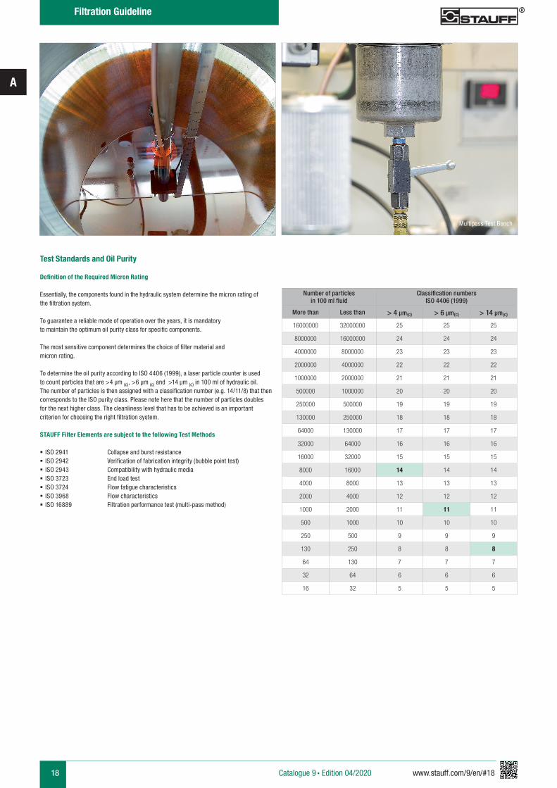
Test Standards and Oil Purity
Definition of the Required Micron Rating
Essentially, the components found in the hydraulic system determine the micron rating of the filtration system. To guarantee a reliable mode of operation over the years, it is mandatory to maintain the optimum oil purity class for specific components. The most sensitive component determines the choice of filter material and micron rating.
To determine the oil purity according to ISO 4406 (1999), a laser particle counter is used to count particles that are >4 µm (c), >6 µm (c) and >14 µm (c) in 100 ml of hydraulic oil. The number of particles is then assigned with a classification number (e.g. 14/11/8) that then corresponds to the ISO purity class. Please note here that the number of particles doubles for the next higher class. The cleanliness level that has to be achieved is an important criterion for choosing the right filtration system.
STAUFF Filter Elements are subject to the following Test Methods
§ ISO 2941 Collapse and burst resistance § ISO 2942 Verification of fabrication integrity (bubble point test) § ISO 2943 Compatibility with hydraulic media § ISO 3723 End load test § ISO 3724 Flow fatigue characteristics § ISO 3968 Flow characteristics § ISO 16889 Filtration performance test (multi-pass method)
Multipass Test Bench
Number of particlesin 100 ml fluid
Classification numbersISO 4406 (1999)
More than Less than > 4 µm(c) > 6 µm(c) > 14 µm(c)
16000000 32000000 25 25 25
8000000 16000000 24 24 24
4000000 8000000 23 23 23
2000000 4000000 22 22 22
1000000 2000000 21 21 21
500000 1000000 20 20 20
250000 500000 19 19 19
130000 250000 18 18 18
64000 130000 17 17 17
32000 64000 16 16 16
16000 32000 15 15 15
8000 16000 14 14 14
4000 8000 13 13 13
2000 4000 12 12 12
1000 2000 11 11 11
500 1000 10 10 10
250 500 9 9 9
130 250 8 8 8
64 130 7 7 7
32 64 6 6 6
16 32 5 5 5
Catalogue 9 § Edition 04/2020
Filtration Guideline
A
www.stauff.com/9/en/#19 19
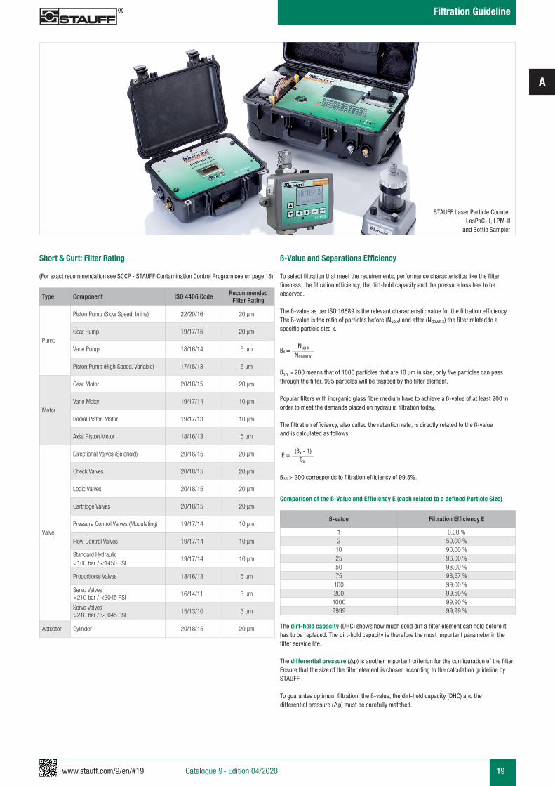
ß-Value and Separations Efficiency
To select filtration that meet the requirements, performance characteristics like the filter fineness, the filtration efficiency, the dirt-hold capacity and the pressure loss has to be observed.
The ß-value as per ISO 16889 is the relevant characteristic value for the filtration efficiency. The ß-value is the ratio of particles before (Nup x) and after (Ndown x) the filter related to a specific particle size x.
ßx = Nup x
Ndown x
ß10 > 200 means that of 1000 particles that are 10 μm in size, only five particles can pass through the filter. 995 particles will be trapped by the filter element.
Popular filters with inorganic glass fibre medium have to achieve a ß-value of at least 200 in order to meet the demands placed on hydraulic filtration today.
The filtration efficiency, also called the retention rate, is directly related to the ß-value and is calculated as follows:
E =
(ßx - 1)
ßx
ß10 > 200 corresponds to filtration efficiency of 99,5%.
ß-value Filtration Efficiency E
1 0,00 %2 50,00 %10 90,00 %25 96,00 %50 98,00 %75 98,67 %100 99,00 %200 99,50 %1000 99,90 %9999 99,99 %
The dirt-hold capacity (DHC) shows how much solid dirt a filter element can hold before it has to be replaced. The dirt-hold capacity is therefore the most important parameter in the filter service life.
The differential pressure (Δp) is another important criterion for the configuration of the filter. Ensure that the size of the filter element is chosen according to the calculation guideline by STAUFF.
To guarantee optimum filtration, the ß-value, the dirt-hold capacity (DHC) and the differential pressure (Δp) must be carefully matched.
Comparison of the ß-Value and Efficiency E (each related to a defined Particle Size)
Type Component ISO 4406 Code Recommended Filter Rating
Pump
Piston Pump (Slow Speed, Inline) 22/20/16 20 µm
Gear Pump 19/17/15 20 µm
Vane Pump 18/16/14 5 µm
Piston Pump (High Speed, Variable) 17/15/13 5 µm
Motor
Gear Motor 20/18/15 20 µm
Vane Motor 19/17/14 10 µm
Radial Piston Motor 19/17/13 10 µm
Axial Piston Motor 18/16/13 5 µm
Valve
Directional Valves (Solenoid) 20/18/15 20 µm
Check Valves 20/18/15 20 µm
Logic Valves 20/18/15 20 µm
Cartridge Valves 20/18/15 20 µm
Pressure Control Valves (Modulating) 19/17/14 10 µm
Flow Control Valves 19/17/14 10 µm
Standard Hydraulic <100 bar / <1450 PSI
19/17/14 10 µm
Proportional Valves 18/16/13 5 µm
Servo Valves <210 bar / <3045 PSI 16/14/11 3 µm
Servo Valves >210 bar / >3045 PSI 15/13/10 3 µm
Actuator Cylinder 20/18/15 20 µm
Short & Curt: Filter Rating
(For exact recommendation see SCCP - STAUFF Contamination Control Program see on page 15)
STAUFF Laser Particle Counter LasPaC-II, LPM-II
and Bottle Sampler
Catalogue 9 § Edition 04/2020
Filtration Guideline
A
20 www.stauff.com/9/en/#20
Filtration Terminology
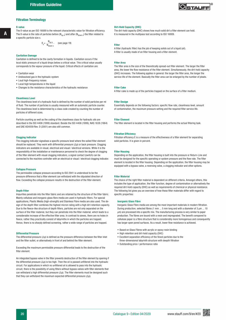
ß-valueThe ß-value as per ISO 16889 is the relevant characteristic value for filtration efficiency. The ß-value is the ratio of particles before (Nup x) and after (Ndown x) the filter related to a specific particle size x.
ßx= Nup x (see page 19)
Ndown x
Cavitation DamageCavitation is defined to be the cavity formation in liquids. Cavitation occurs if the local static pressure of a liquid drops below a critical value. This critical value usually corresponds to the vapour pressure of the liquid. Critical effects of cavitation are:
§ Cavitation wear § Undissolved gas in the hydraulic system § Loud high-frequency noises § Local high temperatures in the liquid § Changes to the resistance characteristics of the hydraulic resistance
Cleanliness LevelThe cleanliness level of a hydraulic fluid is defined by the number of solid particles per ml of fluid. The number of particles is usually measured with an automatic particle counter. The cleanliness level is determined by a class code created by counting the number of particles of different sizes.
Particle counting as well as the coding of the cleanliness class for hydraulic oils are described in the ISO 4406 (1999) standard. Beside the ISO 4406 (1999), NAS 1638 (1964) and SAE AS4059 Rev. D (2001) are also still common.
Clogging IndicatorThe clogging indicator signalises a specific pressure level where the soiled filter element should be replaced. They work with differential pressure (Δp) or back pressure. Clogging indicators are available in visual, electrical and visual / electrical versions. While it is the responsibility of the installation or maintenance personnel to check the degree of clogging of the filter element with visual clogging indicators, a signal contact (switch) can be connected to the machine controller with an electrical or visual / electrical clogging indicator.
Collapse PressureThe permissible collapse pressure according to ISO 2941 is understood to be the pressure difference that a filter element can withstand with the stipulated direction of flow. Exceeding the collapse pressure results in the destruction of the filter element.
Depth FilterImpurities penetrate into the filter fabric and are retained by the structure of the filter fabric. Mainly cellulose and inorganic glass fibre media are used in hydraulic filters. For special applications, Plastic Media (high-strength) and Stainless Fibre media are also used. The de-sign of the depth filter combines the highest micron rating with a high dirt retention capacity. Due to the fleece-like structure of depth filters, particles are not only separated on the surface of the filter material, but they can penetrate into the filter material, which leads to a considerable increase of the effective filter area. In contrast to sieves, there are no holes in fleece, rather they practically consist of labyrinths in which the particles are trapped. Hence, there is no sharply defined screening, rather a wide range of particles are trapped.
Differential PressureThe differential pressure (Δp) is defined as the pressure difference between the filter inlet and the filter outlet, or alternatively in front of and behind the filter element.
Exceeding the maximum permissible pressure differential leads to the destruction of the filter element.
An integrated bypass valve in the filter prevents destruction of the filter element by opening if the differential pressure (Δp) is too high. Then the oil is passed unfiltered into the hydraulic circuit. For applications in which no unfiltered oil is allowed to pass into the hydraulic circuit, there is the possibility of using filters without bypass valves with filter elements thatcan withstand a high differential pressure (Δp). The filter elements must be designed such that they can withstand the maximum expected differential pressure (Δp).
Dirt-Hold Capacity (DHC) The dirt-hold capacity (DHC) shows how much solid dirt a filter element can hold. It is measured in the multipass test according to ISO 16889.
FilterA filter (hydraulic filter) has the job of keeping solids out of a liquid (oil). A filter is usually made of an filter housing and a filter element.
Filter AreaThe filter area is the size of the theoretically spread-out filter element. The larger the filter area, the lower the flow resistance of the filter element. Simultaneously, the dirt-hold capacity (DHC) increases. The following applies in general: the larger the filter area, the longer the service life of the element. Basically the filter area can be enlarged by the number of pleats.
Filter CakeA filter cake is made up of the particles trapped on the surface of a filter medium.
Filter DesignEssentially depends on the following factors: specific flow rate, cleanliness level, amount of contamination, the maximum pressure setting and the required filter service life.
Filter ElementThe filter element is located in the filter housing and performs the actual filtering task.
Filtration EfficiencyFiltration efficiency E is a measure of the effectiveness of a filter element for separating solid particles. It is given in percent.
Filter HousingDepending on the application, the filter housing is built into the pressure or Return-Line and must be designed for the specific operating or system pressure and the flow rate. The filter element is located in the filter housing. Depending on the application, the filter housing may be equipped with a bypass valve, a reversing valve, a clogging indicator and other options.
Filter MaterialThe choice of the right filter material is dependent on different criteria. Amongst others, this includes the type of application, the filter function, degree of contamination or alternatively the required dirt-hold capacity (DHC) as well as requirements of chemical or physical resistance. The following list gives you an overview of how these filter materials differ with regard to specific properties:
Inorganic Glass FibreInorganic Glass Fibre media are among the most important materials in modern filtration. During production, selected fibres (1 mm ... 5 mm long and with a diameter of 3 µm ... 10 µm) are processed into a specific mix. The manufacturing process is very similar to paper production. The fibres are bound with a resin and impregnated. The benefit compared to cellulose paper is a fibre structure that is considerably more homogenous and consequently has larger open pored surfaces. As a result, lower flow resistance is achieved.
§ Based on Glass Fibres with acrylic or epoxy resin binding § High retention and dirt-hold capacity (DHC) § Excellent separation efficiency of the finest particles due to the three-dimensional labyrinth structure with deepth filtration
§ Outstanding price / performance ratio
Catalogue 9 § Edition 04/2020
Filtration Guideline
A
www.stauff.com/9/en/#21 21
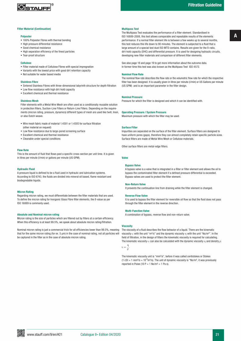
Multipass TestThe Multipass Test evaluates the performance of a filter element. Standardised in ISO 16889-2008, this test allows comparable and repeatable results of the elements performance. If a normal filter element life is between a few weeks up to several months, this test reduces this life down to 90 minutes. The element is subjected to a fluid that a large amount of a special test dust ISO MTD contains. Results are given for the ß-ratio, dirt-hold capacity (DHC) and differential pressure. It is used for designing hydraulic circuits, developing new filter materials and comparison of different filter elements.
See also page 18 and page 19 to get more information about the outcome data. In former time this test was also known as the Multipass Test ISO 4572.
Nominal Flow RateThe nominal flow rate describes the flow rate or the volumetric flow rate for which the respective filter has been designed. It is usually given in litres per minute (l/min) or US Gallons per minute (US GPM) and is an important parameter in the filter design.
Nominal PressurePressure for which the filter is designed and which it can be identified with.
Operating Pressure / System PressureMaximum pressure with which the filter may be used.
Surface FilterImpurities are separated on the surface of the filter element. Surface filters are designed to have uniform pores (gaps), therefore they can almost completely retain specific particle sizes. Surface filters are made of Metal Wire Mesh or Cellulose materials.
Other surface filters are metal-edge filters.
Valve
Bypass ValveA bypass valve is a valve that is integrated in a filter or filter element and allows the oil to bypass the contaminated filter element if a defined pressure differential is exceeded. Bypass valves are used to protect the filter element.
Non-Return ValveIt prevents the continuation line from draining while the filter element is changed.
Reverse Flow ValveIt is used to bypass the filter element for reversible oil flow so that the fluid does not pass through the filter element in the reverse direction.
Multi-Function ValveA combination of bypass, reverse flow and non-return valve.
ViscosityThe viscosity of a fluid describes the flow behavior of a liquid. There are the kinematic viscosity υ with the unit “m²/s” and the dynamic viscosity h with the unit “Ns/m²”. In the field of filtration, in the design of filters the kinematic viscosity is required for calculating. The kinematic viscosity υ can also be calculated with the dynamic viscosity h and density ρ:
υ = h
ρ
The kinematic viscosity unit is “mm²/s”, before it was called centistokes or Stokes (1 cSt = 1 mm²/s = 10-6m²/s). The unit of dynamic viscosity is “Ns/m², it was previously reported in Poise (10 P = 1 Ns/m² = 1 Pa s).
Filter Material (Continuation)
Polyester § 100% Polyester Fibres with thermal bonding § High pressure differential resistance § Good chemical resistance § High separation efficiency of the finest particles § Tear-proof structure
Cellulose § Filter material made of Cellulose Fibres with special impregnation § Variants with the lowest price with good dirt retention capacity § Not suitable for water based media
Stainless Fibre § Sintered Stainless Fibres with three-dimensional labyrinth structure for depth filtration § Low flow resistance with high dirt-hold capacity § Excellent chemical and thermal resistance
Stainless MeshFilter elements with a Metal Wire Mesh are often used as a conditionally reusable solution in protection filters, Suction-Line Filters or Return-Line Filters. Depending on the require-ments (micron rating, pressure, dynamics) different types of mesh are used like twill, linen, or also Dutch weave.
§ Wire mesh fabric made of material 1.4301 or 1.4305 for surface filtration (other material on request)
§ Low flow resistance due to large-pored screening surface § Excellent chemical and thermal resistance § Cleanable under special conditions
Flow RateThis is the amount of fluid that flows past a specific cross-section per unit time. It is given in litres per minute (l/min) or gallons per minute (US GPM).
Hydraulic FluidA pressure liquid is defined to be a fluid used in hydraulic and lubrication systems. According to ISO 6743, the fluids are divided into mineral oil based, flame resistant and biodegredable liquids.
Micron RatingRegarding micron rating, we must differentiate between the filter materials that are used. To define the micron rating for Inorganic Glass Fibre filter elements, the ß-value as per ISO 16889 is commonly used.
Absolute and Nominal micron ratingMicron rating is the size of particles which are filtered out by filters at a certain efficiency. When this efficiency is at least 99.5%, we speak about absolute micron rating/filtration.
Nominal micron rating is just a commercial trick for all efficiencies lower than 99.5%, meaning that for the same micron rating (for ex. 5 µm) in the case of nominal rating, not all particles will be captured in the filter as in the case of absolute micron rating.
Catalogue 9 § Edition 04/2020
Filtration Guideline
A
22 www.stauff.com/9/en/#22
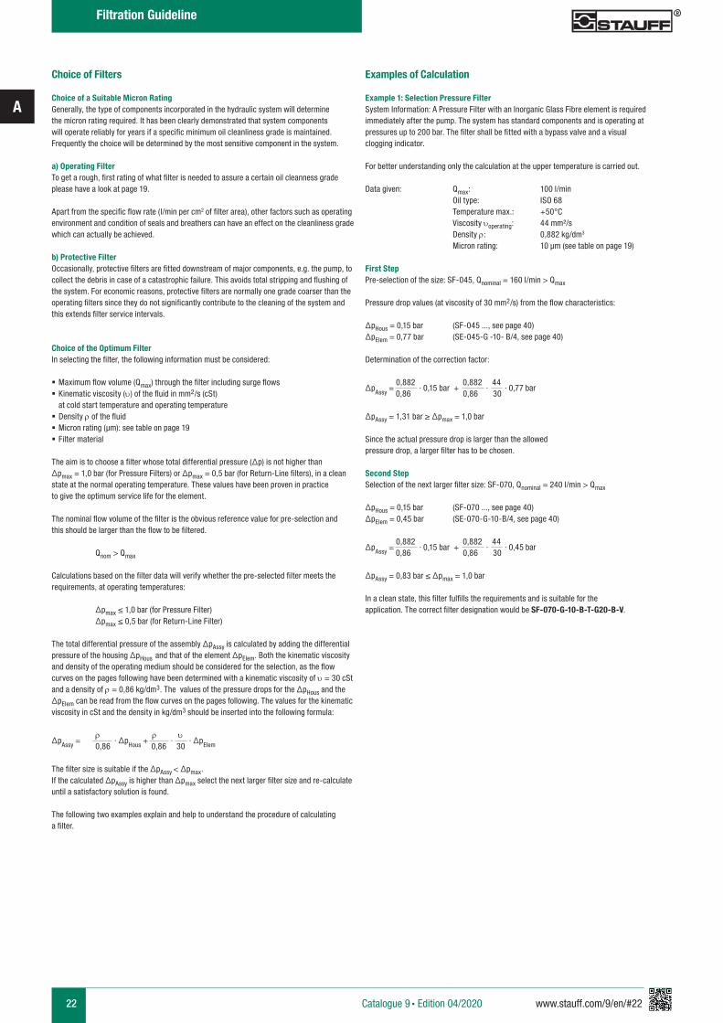
Choice of Filters
Choice of a Suitable Micron RatingGenerally, the type of components incorporated in the hydraulic system will determine the micron rating required. It has been clearly demonstrated that system components will operate reliably for years if a specific minimum oil cleanliness grade is maintained. Frequently the choice will be determined by the most sensitive component in the system.
a) Operating FilterTo get a rough, first rating of what filter is needed to assure a certain oil cleanness grade please have a look at page 19.
Apart from the specific flow rate (l/min per cm2 of filter area), other factors such as operating environment and condition of seals and breathers can have an effect on the cleanliness grade which can actually be achieved.
b) Protective FilterOccasionally, protective filters are fitted downstream of major components, e.g. the pump, to collect the debris in case of a catastrophic failure. This avoids total stripping and flushing of the system. For economic reasons, protective filters are normally one grade coarser than the operating filters since they do not significantly contribute to the cleaning of the system and this extends filter service intervals.
Choice of the Optimum FilterIn selecting the filter, the following information must be considered:
§ Maximum flow volume (Qmax) through the filter including surge flows § Kinematic viscosity (υ) of the fluid in mm2/s (cSt) at cold start temperature and operating temperature
§ Density ρ of the fluid § Micron rating (µm): see table on page 19 § Filter material
The aim is to choose a filter whose total differential pressure (∆p) is not higher than ∆pmax = 1,0 bar (for Pressure Filters) or ∆pmax = 0,5 bar (for Return-Line filters), in a clean state at the normal operating temperature. These values have been proven in practice to give the optimum service life for the element.
The nominal flow volume of the filter is the obvious reference value for pre-selection and this should be larger than the flow to be filtered.
Qnom > Qmax
Calculations based on the filter data will verify whether the pre-selected filter meets the requirements, at operating temperatures:
∆pmax ≤ 1,0 bar (for Pressure Filter) ∆pmax ≤ 0,5 bar (for Return-Line Filter)
The total differential pressure of the assembly ∆pAssy is calculated by adding the differential pressure of the housing ∆pHous and that of the element ∆pElem. Both the kinematic viscosity and density of the operating medium should be considered for the selection, as the flowcurves on the pages following have been determined with a kinematic viscosity of υ = 30 cSt and a density of ρ = 0,86 kg/dm3. The values of the pressure drops for the ∆pHous and the ∆pElem can be read from the flow curves on the pages following. The values for the kinematic viscosity in cSt and the density in kg/dm3 should be inserted into the following formula:
∆pAssy = ρ
∙ ∆pHous + ρ
∙ υ
∙ ∆pElem
0,86 0,86 30 The filter size is suitable if the ∆pAssy < ∆pmax.If the calculated ∆pAssy is higher than ∆pmax select the next larger filter size and re-calculateuntil a satisfactory solution is found.
The following two examples explain and help to understand the procedure of calculating a filter.
Examples of Calculation
Example 1: Selection Pressure Filter System Information: A Pressure Filter with an Inorganic Glass Fibre element is required immediately after the pump. The system has standard components and is operating at pressures up to 200 bar. The filter shall be fitted with a bypass valve and a visual clogging indicator.
For better understanding only the calculation at the upper temperature is carried out.
Data given: Qmax: 100 l/min Oil type: ISO 68 Temperature max.: +50°C Viscosity υoperating: 44 mm²/s Density ρ: 0,882 kg/dm3 Micron rating: 10 µm (see table on page 19)
First StepPre-selection of the size: SF-045, Qnominal = 160 l/min > Qmax
Pressure drop values (at viscosity of 30 mm2/s) from the flow characteristics:
∆pHous = 0,15 bar (SF-045 ..., see page 40)∆pElem = 0,77 bar (SE-045-G -10- B/4, see page 40)
Determination of the correction factor:
∆pAssy = 0,882
∙ 0,15 bar + 0,882
∙ 44
∙ 0,77 bar 0,86 0,86 30
∆pAssy = 1,31 bar ≥ ∆pmax = 1,0 bar Since the actual pressure drop is larger than the allowed pressure drop, a larger filter has to be chosen.
Second StepSelection of the next larger filter size: SF-070, Qnominal = 240 l/min > Qmax
∆pHous = 0,15 bar (SF-070 ..., see page 40)∆pElem = 0,45 bar (SE-070-G-10-B/4, see page 40)
∆pAssy = 0,882
∙ 0,15 bar + 0,882
∙ 44
∙ 0,45 bar 0,86 0,86 30
∆pAssy = 0,83 bar ≤ ∆pmax = 1,0 bar
In a clean state, this filter fulfills the requirements and is suitable for the application. The correct filter designation would be SF-070-G-10-B-T-G20-B-V.
Catalogue 9 § Edition 04/2020
Filtration Guideline
A
www.stauff.com/9/en/#23 23
Example 2: Selection Return-Line FilterSystem Information: A Return-Line filter with a Cellulose element with a micron rating of 10 µm is required to clean the oil. No clogging indicator is required.
Please note: If the system incorporates either accumulators or cylinders, the return flow can dramatically exceed pump flow and the maximum surge flow should be the flow used to calculate the pressure drop through the filter.
Data given: Qmax: 100 l/min Oil type: ISO 68 Temperature max.: +60°C Viscosity υoperating: 29 mm²/s Density ρ: 0,882 kg/dm3 Micron rating: 10 µm (see table on page 19)
First StepPre-selection of the size: RF-030, Qnominal = 110 l/min > Qmax
Pressure drop values (at viscosity of 30 mm2/s) from the flow characteristics:
∆pHous = 0,30 bar (RF-030 ..., see page 72)∆pElem = 0,067 bar (RE-030-N-10-B, see page 72)
Determination of the correction factor (see page 22):
∆pAssy = 0,882
∙ 0,30 bar + 0,882
∙ 29
∙ 0,067 bar 0,86 0,86 30
∆pAssy = 0,37 bar ≤ ∆pmax = 0,5 bar In a clean state, this filter fulfills the requirements and is suitable for the application. No further calculation is necessary. The correct filter designation would be RF-030-N-10-B-G16.
Catalogue 9 § Edition 04/2020
Filtration Guideline
www.stauff.com/9/en/#25
B
25Catalogue 9 § Edition 04/2020
Replacement Filter Elements
Filter Elements
Filter Material – Quality And Properties 26
27
27
28
For Return-Line Filters
For Pressure Filters
For Spin-On-Filters
For Suction Strainers 28
24 - 33
Interchanging STAUFF Filter Elements Order Codes
29
Special Filter Element Solutions 30
Filter Elements For Single, Double and Automatic Filters
32 - 33
31Checklist for the selection of filter housings
26 www.stauff.com/9/en/#26
B
Replacement Filter Elements for Applications involving Hydraulic and Lubrication Oils
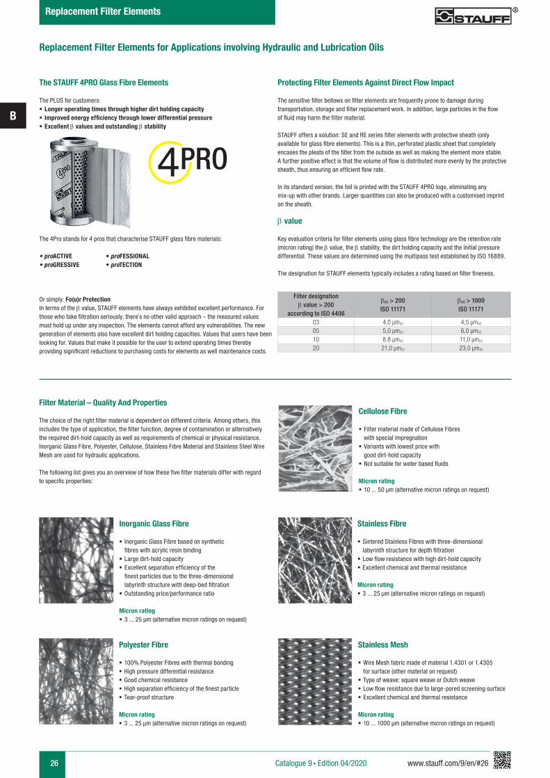
Protecting Filter Elements Against Direct Flow Impact
The sensitive filter bellows on filter elements are frequently prone to damage during transportation, storage and filter replacement work. In addition, large particles in the flow of fluid may harm the filter material.
STAUFF offers a solution: SE and RE series filter elements with protective sheath (only available for glass fibre elements). This is a thin, perforated plastic sheet that completely encases the pleats of the filter from the outside as well as making the element more stable. A further positive effect is that the volume of flow is distributed more evenly by the protective sheath, thus ensuring an efficient flow rate.
In its standard version, the foil is printed with the STAUFF 4PRO logo, eliminating any mix-up with other brands. Larger quantities can also be produced with a customised imprint on the sheath.
The STAUFF 4PRO Glass Fibre Elements
The PLUS for customers: § Longer operating times through higher dirt holding capacity § Improved energy efficiency through lower differential pressure § Excellent b values and outstanding b stability
§
The 4Pro stands for 4 pros that characterise STAUFF glass fibre materials:
• proACTIVE • proFESSIONAL• proGRESSIVE • proTECTION
Or simply: Fo(u)r ProtectionIn terms of the b value, STAUFF elements have always exhibited excellent performance. For those who take filtration seriously, there`s no other valid approach – the measured values must hold up under any inspection. The elements cannot afford any vulnerabilities. The new generation of elements also have excellent dirt holding capacities. Values that users have been looking for. Values that make it possible for the user to extend operating times thereby providing significant reductions to purchasing costs for elements as well maintenance costs.
PRO
b value Key evaluation criteria for filter elements using glass fibre technology are the retention rate (micron rating) the b value, the b stability, the dirt holding capacity and the initial pressure differential. These values are determined using the multipass test established by ISO 16889. The designation for STAUFF elements typically includes a rating based on filter fineness.
Filter designationb value > 200
according to ISO 4406
b(c) > 200ISO 11171
b(c) > 1000ISO 11171
03 4,0 µm(c) 4,5 µm(c)
05 5,0 µm(c) 6,0 µm(c)
10 8,8 µm(c) 11,0 µm(c)
20 21,0 µm(c) 23,0 µm(c)
Filter Material – Quality And Properties
The choice of the right filter material is dependent on different criteria. Among others, this includes the type of application, the filter function, degree of contamination or alternatively the required dirt-hold capacity as well as requirements of chemical or physical resistance.Inorganic Glass Fibre, Polyester, Cellulose, Stainless Fibre Material and Stainless Steel Wire Mesh are used for hydraulic applications.
The following list gives you an overview of how these five filter materials differ with regard to specific properties:
Inorganic Glass Fibre
§ Inorganic Glass Fibre based on synthetic fibres with acrylic resin binding
§ Large dirt-hold capacity § Excellent separation efficiency of the finest particles due to the three-dimensional labyrinth structure with deep-bed filtration
§ Outstanding price/performance ratio
Micron rating § 3 ... 25 µm (alternative micron ratings on request)
Polyester Fibre
§ 100% Polyester Fibres with thermal bonding § High pressure differential resistance § Good chemical resistance § High separation efficiency of the finest particle § Tear-proof structure
Micron rating § 3 ... 25 µm (alternative micron ratings on request)
Stainless Fibre
§ Sintered Stainless Fibres with three-dimensional labyrinth structure for depth filtration
§ Low flow resistance with high dirt-hold capacity § Excellent chemical and thermal resistance
Micron rating § 3 ... 25 µm (alternative micron ratings on request)
Stainless Mesh
§ Wire Mesh fabric made of material 1.4301 or 1.4305 for surface (other material on request)
§ Type of weave: square weave or Dutch weave § Low flow resistance due to large-pored screening surface § Excellent chemical and thermal resistance
Micron rating § 10 ... 1000 µm (alternative micron ratings on request)
Cellulose Fibre
§ Filter material made of Cellulose Fibres with special impregnation
§ Variants with lowest price with good dirt-hold capacity
§ Not suitable for water based fluids
Micron rating § 10 ... 50 µm (alternative micron ratings on request)
Catalogue 9 § Edition 04/2020
Replacement Filter Elements
www.stauff.com/9/en/#27
B
27
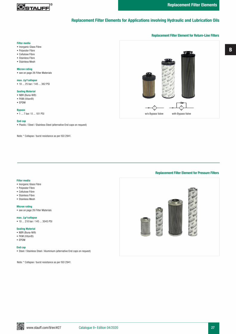
Replacement Filter Element for Return-Line Filters
Filter media § Inorganic Glass Fibre § Polyester Fibre § Cellulose Fibre § Stainless Fibre § Stainless Mesh
Micron rating § see on page 26 Filter Materials
max. Δp*collapse § 10 ... 25 bar / 145 ... 362 PSI
Sealing Material § NBR (Buna-N®) § FKM (Viton®) § EPDM
Bypass § 1 ... 7 bar / 0 ... 101 PSI
End cap § Plastic / Steel / Stainless Steel (alternative End caps on request)
Replacement Filter Elements for Applications involving Hydraulic and Lubrication Oils
Note: * Collapse / burst resistance as per ISO 2941.
Replacement Filter Element for Pressure Filters
Filter media § Inorganic Glass Fibre § Polyester Fibre § Cellulose Fibre § Stainless Fibre § Stainless Mesh
Micron rating § see on page 26 Filter Materials
max. Δp*collapse § 10 ... 210 bar / 145 ... 3045 PSI
Sealing Material § NBR (Buna-N®) § FKM (Viton®) § EPDM
End cap § Steel / Stainless Steel / Aluminium (alternative End caps on request)
w/o Bypass Valve with Bypass Valve
Note: * Collapse / burst resistance as per ISO 2941.
Catalogue 9 § Edition 04/2020
Replacement Filter Elements
28 www.stauff.com/9/en/#28
B
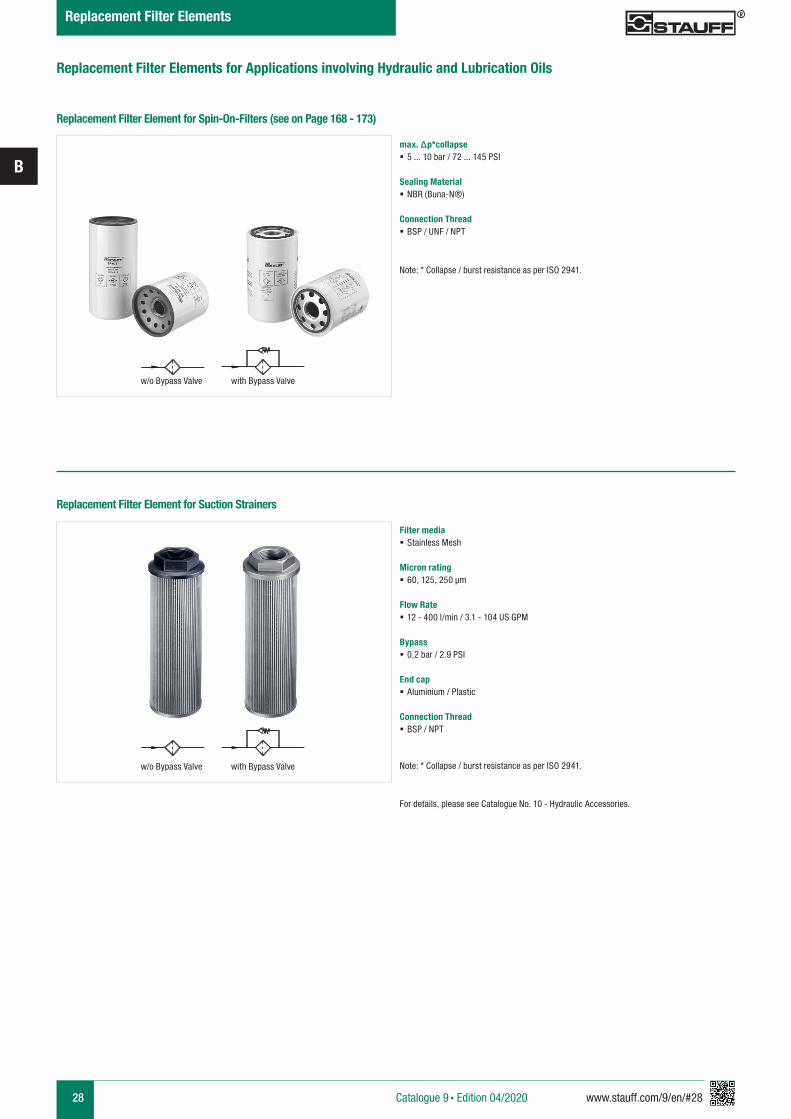
Replacement Filter Elements for Applications involving Hydraulic and Lubrication Oils
Replacement Filter Element for Spin-On-Filters (see on Page 168 - 173)
max. Δp*collapse § 5 ... 10 bar / 72 ... 145 PSI
Sealing Material § NBR (Buna-N®)
Connection Thread § BSP / UNF / NPT
Note: * Collapse / burst resistance as per ISO 2941.
Replacement Filter Element for Suction Strainers
Filter media § Stainless Mesh
Micron rating § 60, 125, 250 μm
Flow Rate § 12 - 400 l/min / 3.1 - 104 US GPM
Bypass § 0,2 bar / 2.9 PSI
End cap § Aluminium / Plastic
Connection Thread § BSP / NPT
Note: * Collapse / burst resistance as per ISO 2941.
For details, please see Catalogue No. 10 - Hydraulic Accessories.
w/o Bypass Valve with Bypass Valve
w/o Bypass Valve with Bypass Valve
Catalogue 9 § Edition 04/2020
Replacement Filter Elements
www.stauff.com/9/en/#29
B
29
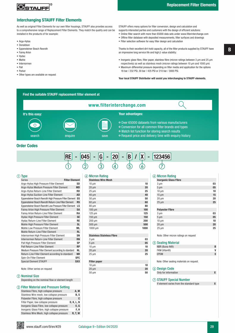
Order Codes
d Micron Rating Inorganic Glass Fibre 3 µm 03 5 µm 05 10 µm 10 15 µm 15 20 µm 20 25 µm 25
Polyester Fibre 3 µm 03 5 µm 05 10 µm 10 20 µm 20 25 µm 25 Note: Other micron ratings on request
e Sealing Material NBR (Buna-N®) B FKM (Viton®) V EPDM E
Note: Other sealing materials on request.
f Design Code Only for information X
g STAUFF Special Number If element varies from the standard type X
d Micron Rating Stainless Wire Mesh 10 µm 10 20 µm 20 25 µm 25 40 µm 40 50 µm 50 60 µm 60 80 µm 80 100 µm 100 125 µm 125 150 µm 150 200 µm 200 500 µm 500 1000 µm 1000
Stainless Stainless Fibre 3 µm 03 5 µm 05 10 µm 10 20 µm 20 25 µm 25 Filter paper 10 µm 10 20 µm 20 50 µm 50
a Type Series Filter Element Argo-Hytos High Pressure Filter Element SD Argo-Hytos Medium Pressure Filter Element MD Argo-Hytos Return-Line Filter Element RD Argo-Hytos Suction-Line Filter Element AD Eppensteiner Bosch Rexroth High Pressure Filter Element SS Eppensteiner Bosch Rexroth Return-Line Filter Element RS Eppensteiner Bosch Rexroth Low Pressure Filter Element LS Fairey Arlon High Pressure Filter Element SA Fairey Arlon Return-Line Filter Element RA Hydac High Pressure Filter Element SE Hydac Return-Line Filter Element RE Mahle High Pressure Filter Element SL Mahle Low Pressure Filter Element ML Mahle Return-Line Filter Element RL Internormen High Pressure Filter Element SN Internormen Return-Line Filter Element RN Pall High Pressure Filter Element SP Pall Return-Line Filter Element RP Medium Pressure Filter Element according to standard NL Return-Line Filter Element according to standard NR Spin-On Filter Element SFC Special Element STAUFF SXX
Note: Other series on request
b Nominal Size Depending on the nominal flow or element length
c Filter Material and Pressure Setting Stainless Fibre, high collapse pressure A, M Stainless Wire mesh, low collapse pressure B, S Polyester Fibre, high collapse pressure C Filter Paper, low collapse pressure D, K, L, N Inorganic Glass Fibre, low collapse pressure E, G Inorganic Glass Fibre, high collapse pressure F, H Stainless Wire Mesh, high collapse pressure R, T, W
fa b c ged
RE - 045 - G - 20 - B / X - 123456
Interchanging STAUFF Filter ElementsAs well as original Filter Elements for our own filter housings, STAUFF also provides access to a comprehensive range of Replacement Filter Elements. They match the quality and can be installed in the products of for example:
§ Argo-Hytos § Donaldson § Eppensteiner Bosch Rexroth § Fairey Arlon § Hydac § Mahle § Internormen § Pall § Parker § Other types are available on request
STAUFF offers many options for filter conversion, design and calculation and supports interested parties and customers with the design of efficient solutions: § Online filter search with more than 65000 data sets under www.filterinterchange.com § Offline filter database with deposited measurements, filter surfaces and drawings § Filter selection software for easy filter design and calculation
Thanks to their excellent dirt-hold capacity, all of the filter products supplied by STAUFF have an impressive long service life and high b value stability:
§ Inorganic glass fibre, filter paper, stainless fibre (micron ratings between 3 µm and 25 µm respectively) as well as stainless mesh (micron ratings between 10 µm and 1000 µm)
§ Maximum differential pressure depending on filter media and application for the options 16 bar / 232 PSI, 30 bar / 435 PSI or 210 bar / 3000 PSI.
Your local STAUFF Distributor will assist you interchanging to STAUFF elements.
Find the suitable STAUFF replacement filter element at
Your advantages:
• Over 65000 datasets from various manufacturers• Conversion for all common filter brands and types• Watch list function for storing search results• Request price and delivery time with enquiry historysearch enquire save
It‘s this easy:
www.filterinterchange.com
Catalogue 9 § Edition 04/2020
Replacement Filter Elements
30 www.stauff.com/9/en/#30
B
Catalogue 9 § Edition 04/2020
Replacement Filter Elements
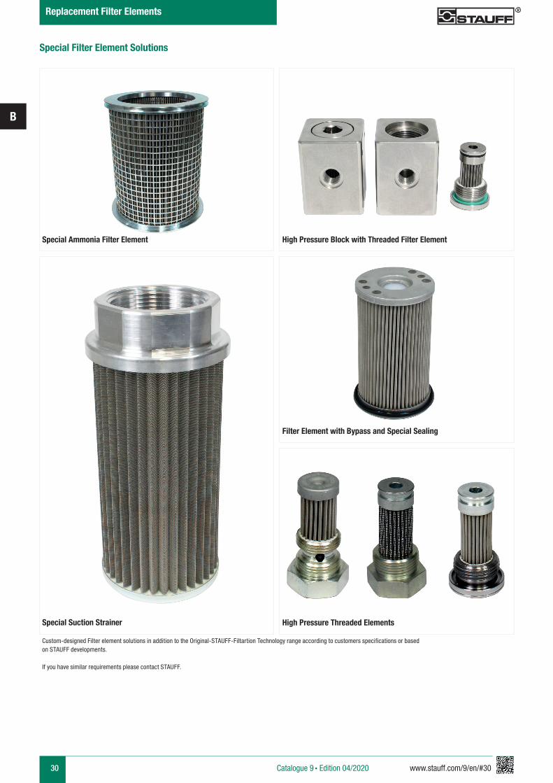
Special Ammonia Filter Element High Pressure Block with Threaded Filter Element
Special Suction Strainer
Filter Element with Bypass and Special Sealing
High Pressure Threaded Elements
Special Filter Element Solutions
Custom-designed Filter element solutions in addition to the Original-STAUFF-Filtartion Technology range according to customers specifications or based on STAUFF developments.
If you have similar requirements please contact STAUFF.
www.stauff.com/9/en/#31
B
31
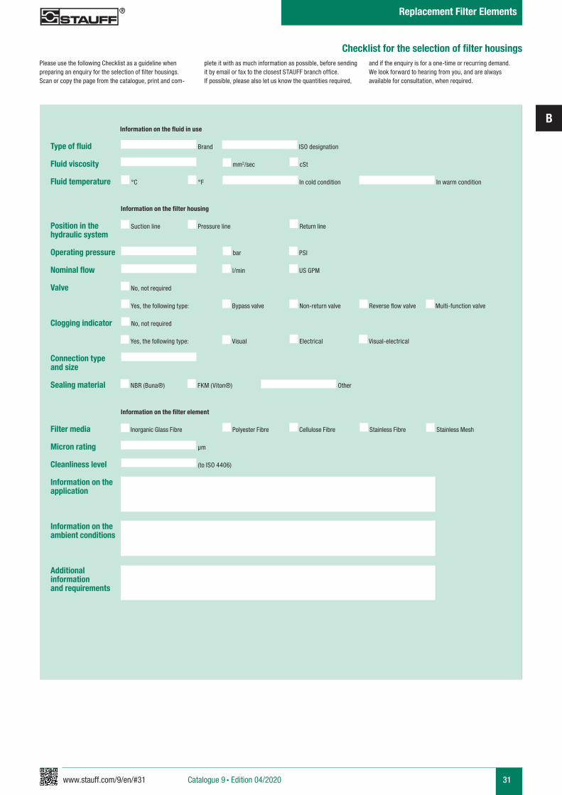
Checklist for the selection of filter housings
Type of fluid
Fluid viscosity
Fluid temperature
Position in the hydraulic system
Operating pressure
Nominal flow
Valve
Clogging indicator
Connection type and size
Sealing material
Filter media
Micron rating
Cleanliness level
Information on the application
Information on the ambient conditions
Additional informationand requirements
mm2/sec cSt
Brand
Suction line Pressure line Return line
Bypass valve
No, not required
Reverse flow valveNon-return valve Multi-function valve
ISO designation
°C °F In cold condition In warm condition
Information on the fluid in use
Information on the filter housing
bar PSI
l/min US GPM
Yes, the following type:
Visual
No, not required
Electrical Visual-electricalYes, the following type:
NBR (Buna®) FKM (Viton®) Other
Information on the filter element
Inorganic Glass Fibre Polyester Fibre Cellulose Fibre Stainless Fibre
µm
(to ISO 4406)
Stainless Mesh
Please use the following Checklist as a guideline when preparing an enquiry for the selection of filter housings. Scan or copy the page from the catalogue, print and com-
plete it with as much information as possible, before sending it by email or fax to the closest STAUFF branch office. If possible, please also let us know the quantities required,
and if the enquiry is for a one-time or recurring demand. We look forward to hearing from you, and are always available for consultation, when required.
Catalogue 9 § Edition 04/2020
Replacement Filter Elements
32 www.stauff.com/9/en/#32
B
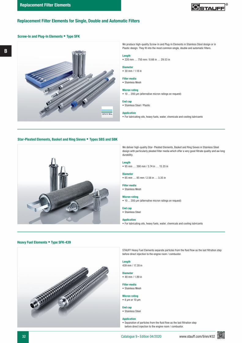
Replacement Filter Elements for Single, Double and Automatic Filters
Screw-In and Plug-In Elements § Type SFK
We produce high-quality Screw-In and Plug-In Elements in Stainless Steel design or in Plastic design. They fit into the most common single, double and automatic filters.
Length § 220 mm … 750 mm / 8.66 in … 29.53 in
Diameter § 30 mm / 1.18 in
Filter media § Stainless Mesh
Micron rating § 10 ... 200 µm (alternative micron ratings on request)
End cap § Stainless Steel / Plastic
Application § For lubricating oils, heavy fuels, water, chemicals and cooling lubricants
Star-Pleated Elements, Basket and Ring Sieves § Types SBS and SBK
We deliver high-quality Star- Pleated Elements, Basket and Ring Sieves in Stainless Steel design with particularly pleated filter media which offer a very good filtrate quality and aw long durability.
Length § 95 mm … 390 mm / 3.74 in … 15.35 in
Diameter § 65 mm … 85 mm / 2.56 in … 3.35 in
Filter media § Stainless Mesh
Micron rating § 10 ... 200 µm (alternative micron ratings on request)
End cap § Stainless Steel
Application § For lubricating oils, heavy fuels, water, chemicals and cooling lubricants
Heavy Fuel Elements § Type SFK-439
STAUFF Heavy Fuel Elements separate particles from the fluid flow as the last filtration step before direct injection to the engine room / combustor.
Length439 mm / 17.28 in
Diameter § 48 mm / 1.89 in
Filter media § Stainless Mesh
Micron rating § 6 μm or 10 μm
End cap § Stainless Steel
Application § Separation of particles from the fluid flow as the last filtration step before direct injection to the engine room / combustor.
Catalogue 9 § Edition 04/2020
Replacement Filter Elements
www.stauff.com/9/en/#33
B
33
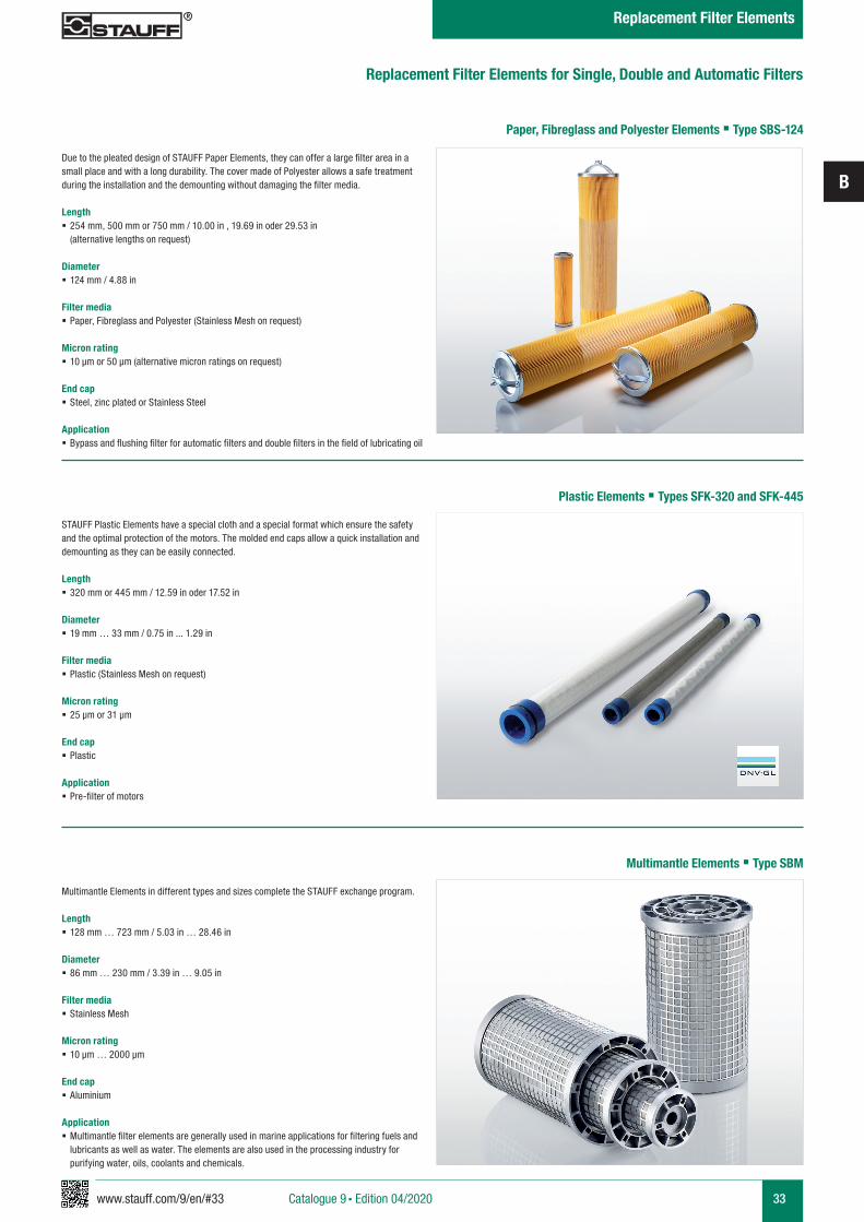
Paper, Fibreglass and Polyester Elements § Type SBS-124
Due to the pleated design of STAUFF Paper Elements, they can offer a large filter area in a small place and with a long durability. The cover made of Polyester allows a safe treatment during the installation and the demounting without damaging the filter media.
Length § 254 mm, 500 mm or 750 mm / 10.00 in , 19.69 in oder 29.53 in (alternative lengths on request)
Diameter § 124 mm / 4.88 in
Filter media § Paper, Fibreglass and Polyester (Stainless Mesh on request)
Micron rating § 10 µm or 50 µm (alternative micron ratings on request)
End cap § Steel, zinc plated or Stainless Steel
Application § Bypass and flushing filter for automatic filters and double filters in the field of lubricating oil
Plastic Elements § Types SFK-320 and SFK-445
STAUFF Plastic Elements have a special cloth and a special format which ensure the safety and the optimal protection of the motors. The molded end caps allow a quick installation and demounting as they can be easily connected.
Length § 320 mm or 445 mm / 12.59 in oder 17.52 in
Diameter § 19 mm … 33 mm / 0.75 in ... 1.29 in
Filter media § Plastic (Stainless Mesh on request)
Micron rating § 25 µm or 31 µm
End cap § Plastic
Application § Pre-filter of motors
Multimantle Elements § Type SBM
Multimantle Elements in different types and sizes complete the STAUFF exchange program.
Length § 128 mm … 723 mm / 5.03 in … 28.46 in
Diameter § 86 mm … 230 mm / 3.39 in … 9.05 in
Filter media § Stainless Mesh
Micron rating § 10 μm … 2000 μm
End cap § Aluminium
Application § Multimantle filter elements are generally used in marine applications for filtering fuels and lubricants as well as water. The elements are also used in the processing industry for purifying water, oils, coolants and chemicals.
Replacement Filter Elements for Single, Double and Automatic Filters
Catalogue 9 § Edition 04/2020
Replacement Filter Elements
www.stauff.com/9/en/#35
C
35Catalogue 9 § Edition 04/2020
Pressure Filters
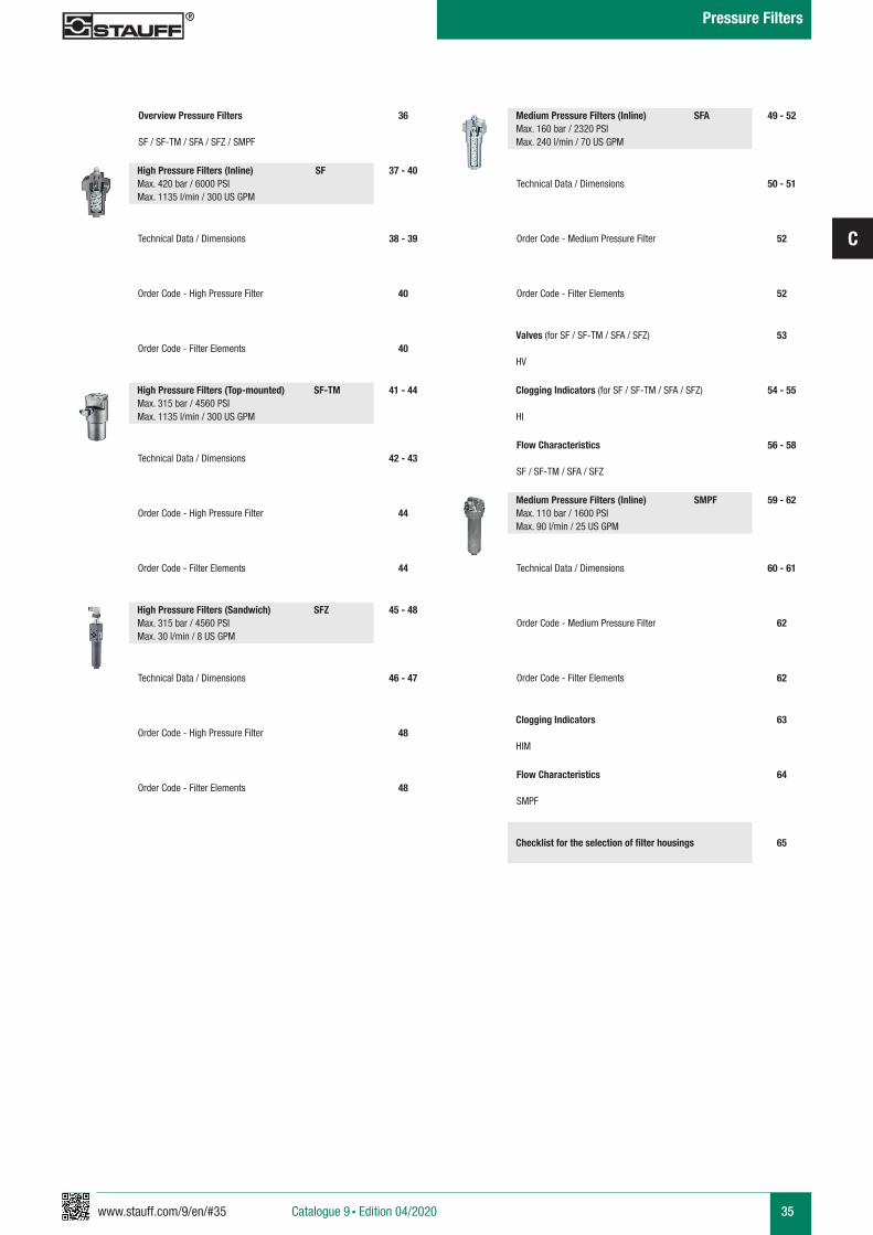
Overview Pressure Filters
SF / SF-TM / SFA / SFZ / SMPF
37 - 40
38 - 39
40
40
Technical Data / Dimensions
Order Code - High Pressure Filter
Order Code - Filter Elements
36
High Pressure Filters (Inline) SFMax. 420 bar / 6000 PSI Max. 1135 l/min / 300 US GPM
41 - 44
42 - 43
44
44
Technical Data / Dimensions
Order Code - High Pressure Filter
Order Code - Filter Elements
High Pressure Filters (Top-mounted) SF-TMMax. 315 bar / 4560 PSI Max. 1135 l/min / 300 US GPM
45 - 48
46 - 47
48
48
Technical Data / Dimensions
Order Code - High Pressure Filter
Order Code - Filter Elements
High Pressure Filters (Sandwich) SFZMax. 315 bar / 4560 PSI Max. 30 l/min / 8 US GPM
49 - 52
50 - 51
52
52
Technical Data / Dimensions
Order Code - Medium Pressure Filter
Order Code - Filter Elements
Medium Pressure Filters (Inline) SFAMax. 160 bar / 2320 PSI Max. 240 l/min / 70 US GPM
53Valves (for SF / SF-TM / SFA / SFZ)
HV
54 - 55Clogging Indicators (for SF / SF-TM / SFA / SFZ)
HI
56 - 58Flow Characteristics
SF / SF-TM / SFA / SFZ
59 - 62
60 - 61
62
62
Technical Data / Dimensions
Order Code - Medium Pressure Filter
Order Code - Filter Elements
Medium Pressure Filters (Inline) SMPFMax. 110 bar / 1600 PSI Max. 90 l/min / 25 US GPM
63Clogging Indicators
HIM
64Flow Characteristics
SMPF
65Checklist for the selection of filter housings
36 www.stauff.com/9/en/#36
C
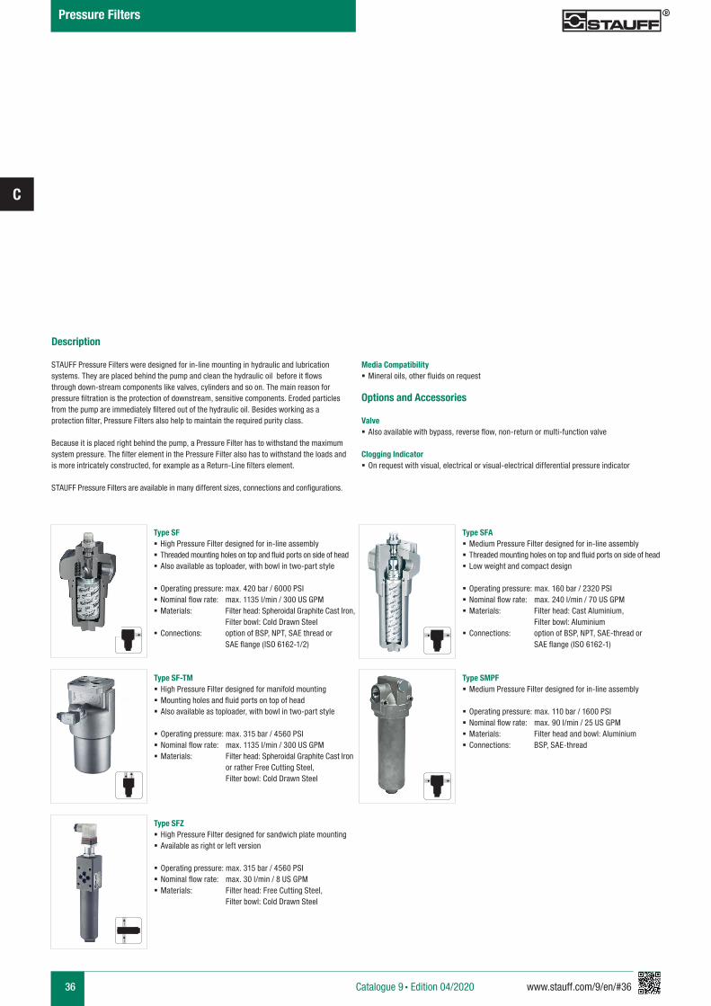
Description
STAUFF Pressure Filters were designed for in-line mounting in hydraulic and lubrication systems. They are placed behind the pump and clean the hydraulic oil before it flows through down-stream components like valves, cylinders and so on. The main reason for pressure filtration is the protection of downstream, sensitive components. Eroded particles from the pump are immediately filtered out of the hydraulic oil. Besides working as a protection filter, Pressure Filters also help to maintain the required purity class.
Because it is placed right behind the pump, a Pressure Filter has to withstand the maximum system pressure. The filter element in the Pressure Filter also has to withstand the loads and is more intricately constructed, for example as a Return-Line filters element.
STAUFF Pressure Filters are available in many different sizes, connections and configurations.
Media Compatibility § Mineral oils, other fluids on request
Options and Accessories
Valve § Also available with bypass, reverse flow, non-return or multi-function valve
Clogging Indicator § On request with visual, electrical or visual-electrical differential pressure indicator
Type SF § High Pressure Filter designed for in-line assembly § Threaded mounting holes on top and fluid ports on side of head § Also available as toploader, with bowl in two-part style
§ Operating pressure: max. 420 bar / 6000 PSI § Nominal flow rate: max. 1135 l/min / 300 US GPM § Materials: Filter head: Spheroidal Graphite Cast Iron, Filter bowl: Cold Drawn Steel
§ Connections: option of BSP, NPT, SAE thread or SAE flange (ISO 6162-1/2)
Type SF-TM § High Pressure Filter designed for manifold mounting § Mounting holes and fluid ports on top of head § Also available as toploader, with bowl in two-part style
§ Operating pressure: max. 315 bar / 4560 PSI § Nominal flow rate: max. 1135 l/min / 300 US GPM § Materials: Filter head: Spheroidal Graphite Cast Iron or rather Free Cutting Steel, Filter bowl: Cold Drawn Steel
Type SFZ § High Pressure Filter designed for sandwich plate mounting § Available as right or left version
§ Operating pressure: max. 315 bar / 4560 PSI § Nominal flow rate: max. 30 l/min / 8 US GPM § Materials: Filter head: Free Cutting Steel, Filter bowl: Cold Drawn Steel
Type SFA § Medium Pressure Filter designed for in-line assembly § Threaded mounting holes on top and fluid ports on side of head § Low weight and compact design
§ Operating pressure: max. 160 bar / 2320 PSI § Nominal flow rate: max. 240 l/min / 70 US GPM § Materials: Filter head: Cast Aluminium, Filter bowl: Aluminium
§ Connections: option of BSP, NPT, SAE-thread or SAE flange (ISO 6162-1)
Type SMPF § Medium Pressure Filter designed for in-line assembly
§ Operating pressure: max. 110 bar / 1600 PSI § Nominal flow rate: max. 90 l/min / 25 US GPM § Materials: Filter head and bowl: Aluminium § Connections: BSP, SAE-thread
Catalogue 9 § Edition 04/2020
Pressure Filters
www.stauff.com/9/en/#37
C
37
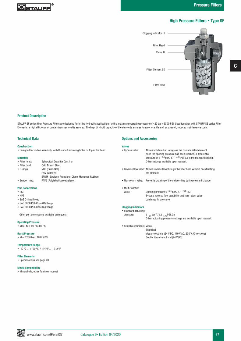
Product Description
STAUFF SF series High Pressure Filters are designed for in-line hydraulic applications, with a maximum operating pressure of 420 bar / 6000 PSI. Used together with STAUFF SE series Filter Elements, a high efficiency of contaminant removal is assured. The high dirt-hold capacity of the elements ensures long service life and, as a result, reduced maintenance costs.
High Pressure Filters § Type SF
Technical Data
Construction § Designed for in-line assembly, with threaded mounting holes on top of the head.
Materials § Filter head: Spheroidal Graphite Cast Iron § Filter bowl: Cold Drawn Steel § O-rings: NBR (Buna-N®)
FKM (Viton®) EPDM (Ethylene-Propylene-Diene-Monomer-Rubber) § Support ring: PTFE (Polytetrafluoroethylene)
Port Connections § BSP § NPT § SAE O-ring thread § SAE 3000 PSI (Code 61) flange § SAE 6000 PSI (Code 62) flange
Other port connections available on request.
Operating Pressure § Max. 420 bar / 6000 PSI
Burst Pressure § Min. 1260 bar / 18275 PSI
Temperature Range § -10 °C ... +100 °C / +14 °F ... +212 °F
Filter Elements § Specifications see page 40
Media Compatibility § Mineral oils, other fluids on request
Clogging Indicator HI
Filter Head
Valve IB
Filter Element SE
Filter Bowl
Options and Accessories
Valves § Bypass valve: Allows unfiltered oil to bypass the contaminated element once the opening pressure has been reached, a differential pressure of 6 + 0,5 bar / 87 + 7.25 PSI ∆p is the standard setting. Other settings available upon request.
§ Reverse flow valve: Allows reverse flow through the filter head without backflushing the element.
§ Non-return valve: Prevents draining of the delivery line during element change.
§ Multi-function valve: Opening pressure 6 +0,5 bar / 87 +7.25 PSI
Bypass, reverse flow capability and non-return valve combined in one valve.
Clogging Indicators § Standard actuating
pressure: 5 -0,5 bar / 72.5
-7.25 PSI ∆p
Other actuating pressure settings are available upon request.
§ Available indicators: Visual Electrical Visual-electrical (24 V DC, 110 V AC, 230 V AC versions) Double Visual-electrical (24 V DC)
Catalogue 9 § Edition 04/2020
Pressure Filters
38 www.stauff.com/9/en/#38
C
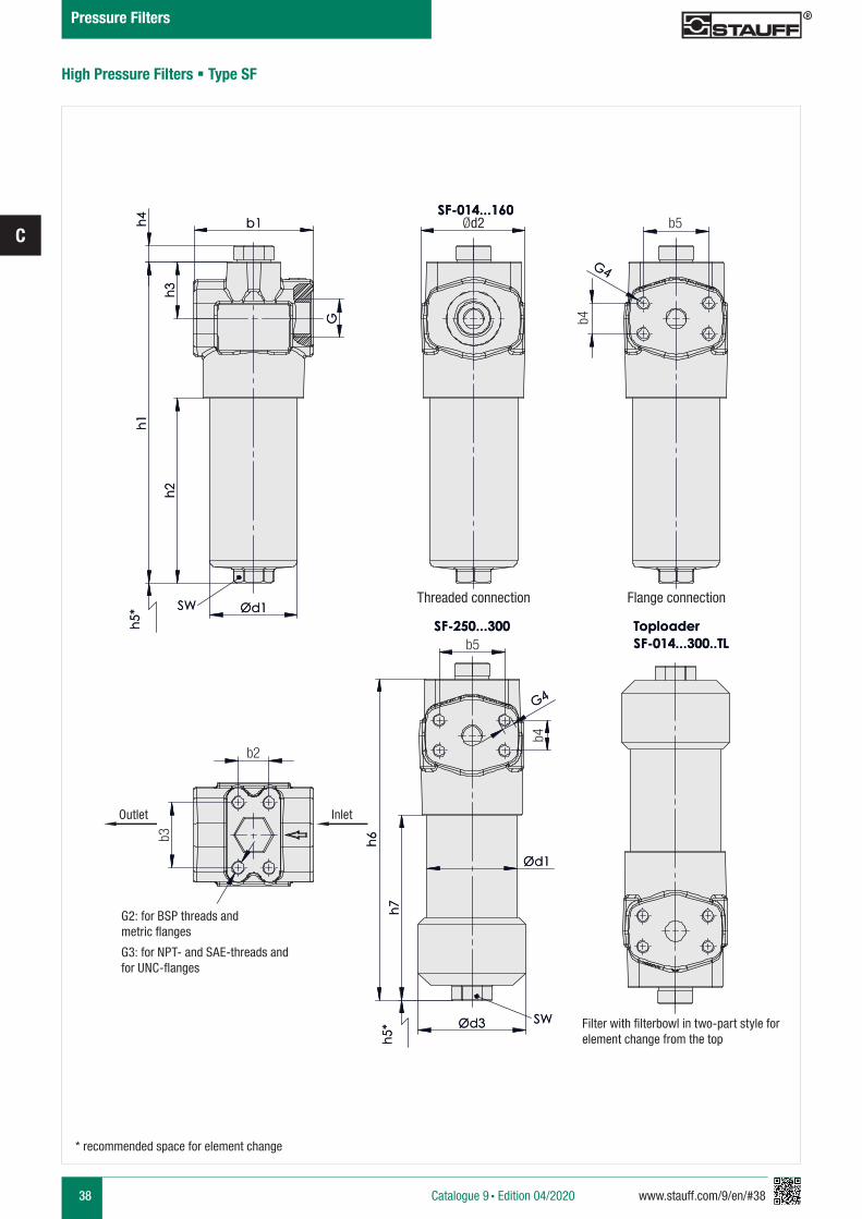
High Pressure Filters § Type SF
* recommended space for element change
Catalogue 9 § Edition 04/2020
Pressure Filters
h3
G
für UNC-Flansche SAE-Gewinde und
G4
G2: für BSP-Gewinde und metrische Flansche
G3: für NPT-Gewinde und
G4
SW
h1
h2
b1 h4
Ød1
Einlass
b3
b4
SF-014...300..TL
h5*
Auslass
h5*
SF-250...300
SF-014...160
Toploader
Filter mit zweiteiligem Filtertopfzum Elementwechsel von oben
Gewindeanschluss
b2
Flanschanschluss
b6
b5
SW Ød3
h7
b6
b5
Ød1
h6
Filter with filterbowl in two-part style for element change from the top
Threaded connection Flange connection
G2: for BSP threads and metric flanges
G3: for NPT- and SAE-threads and for UNC-flanges
InletOutlet
Ød2
b4
b5
b2
b3
b5
b4
www.stauff.com/9/en/#39
C
39
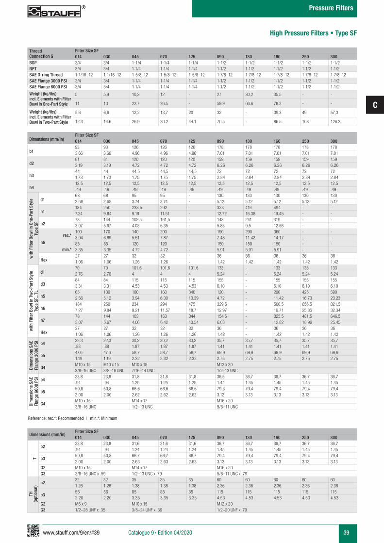
Dimensions (mm/in)Filter Size SF014 030 045 070 125 090 130 160 250 300
b193 93 126 126 126 178 178 178 178 1783.66 3.66 4.96 4.96 4.96 7.01 7.01 7.01 7.01 7.01
d281 81 120 120 120 159 159 159 159 1593.19 3.19 4.72 4.72 4.72 6.26 6.26 6.26 6.26 6.26
h344 44 44,5 44,5 44,5 72 72 72 72 721.73 1.73 1.75 1.75 1.75 2.84 2.84 2.84 2.84 2.84
h412,5 12,5 12,5 12,5 12,5 12,5 12,5 12,5 12,5 12,5.49 .49 .49 .49 .49 .49 .49 .49 .49 .49
with
Filt
er B
owl i
n On
e-Pa
rt S
tyle
Type
SF
d168 68 95 95 - 130 130 130 130 1302.68 2.68 3.74 3.74 - 5.12 5.12 5.12 5.12 5.12
h1184 250 233,5 292 - 323 416 494 - -7.24 9.84 9.19 11.51 - 12.72 16.38 19.45 - -
h278 144 102,5 161,5 - 148 241 319 - -3.07 5.67 4.03 6.35 - 5.83 9.5 12.56 - -
rec.*
h5
min.*
100 170 140 200 - 190 290 360 - -3.94 6.69 5.51 7.87 - 7.48 11.42 14.17 - -85 85 120 120 - 150 150 150 - -3.35 3.35 4.72 4.72 - 5.91 5.91 5.91 - -
Hex27 27 32 32 - 36 36 36 36 361.06 1.06 1.26 1.26 - 1.42 1.42 1.42 1.42 1.42
with
Filt
er B
owl i
n Tw
o-Pa
rt S
tyle
Type
SF.
..TL
d170 70 101,6 101,6 101,6 133 - 133 133 1332.76 2.76 4 4 4 5.24 - 5.24 5.24 5.24
d384 84 115 115 115 155 - 155 155 1553.31 3.31 4.53 4.53 4.53 6.10 - 6.10 6.10 6.10
h565 130 100 160 340 120 - 290 425 5902.56 5.12 3.94 6.30 13.39 4.72 - 11.42 16.73 23.23
h6184 250 234 294 475 329,5 - 500,5 656,5 821,57.27 9.84 9.21 11.57 18.7 12.97 - 19.71 25.85 32.34
h778 144 103 163 344 154,5 - 325,5 481,5 646,53.07 5.67 4.06 6.42 13.54 6.08 - 12.82 18.96 25.45
Hex27 27 32 32 32 36 - 36 36 361.06 1.06 1.26 1.26 1.26 1.42 - 1.42 1.42 1.42
Dim
ensi
ons
SAE
Flan
ge 3
000
PSI
b422,3 22,3 30,2 30,2 30,2 35,7 35,7 35,7 35,7 35,7.88 .88 1.87 1.87 1.87 1.41 1.41 1.41 1.41 1.41
b547,6 47,6 58,7 58,7 58,7 69,9 69,9 69,9 69,9 69,91.19 1.19 2.32 2.32 2.32 2.75 2.75 2.75 2.75 2.75
G4M10 x 15 M10 x 15 M10 x 18 M12 x 20 3/8–16 UNC 3/8–16 UNC 7/16–14 UNC 1/2–13 UNC
Dim
ensi
ons
SAE
Flan
ge 6
000
PSI
b423,8 23,8 31,8 31,8 31,8 36,5 36,7 36,7 36,7 36,7.94 .94 1.25 1.25 1.25 1.44 1.45 1.45 1.45 1.45
b550,8 50,8 66,6 66,6 66,6 79,3 79,4 79,4 79,4 79,42.00 2.00 2.62 2.62 2.62 3.12 3.13 3.13 3.13 3.13
G4M10 x 15 M14 x 17 M16 x 20 3/8–16 UNC 1/2–13 UNC 5/8–11 UNC
Reference: rec.*: Recommended | min.*: Minimum
Thread Connection G
Filter Size SF014 030 045 070 125 090 130 160 250 300
BSP 3/4 3/4 1-1/4 1-1/4 1-1/4 1-1/2 1-1/2 1-1/2 1-1/2 1-1/2NPT 3/4 3/4 1-1/4 1-1/4 1-1/4 1-1/2 1-1/2 1-1/2 1-1/2 1-1/2SAE O-ring Thread 1-1/16–12 1-1/16–12 1-5/8–12 1-5/8–12 1-5/8–12 1-7/8–12 1-7/8–12 1-7/8–12 1-7/8–12 1-7/8–12SAE Flange 3000 PSI 3/4 3/4 1-1/4 1-1/4 1-1/4 1-1/2 1-1/2 1-1/2 1-1/2 1-1/2SAE Flange 6000 PSI 3/4 3/4 1-1/4 1-1/4 1-1/4 1-1/2 1-1/2 1-1/2 1-1/2 1-1/2
Weight (kg/lbs) incl. Elements with Filter Bowl in One-Part Style
5 5,9 10,3 12 - 27 30,2 35,5 - -
11 13 22.7 26.5 - 59.9 66.6 78.3 - -
Weight (kg/lbs)incl. Elements with Filter Bowl in Two-Part Style
5,6 6,6 12,2 13,7 20 32 - 39,3 49 57,3
12.3 14.6 26.9 30.2 44.1 70.5 - 86.5 108 126.3
Dimensions (mm/in)Filter Size SF014 030 045 070 125 090 130 160 250 300
T
b223,8 23,8 31,6 31,6 31,6 36,7 36,7 36,7 36,7 36,7.94 .94 1.24 1.24 1.24 1.45 1.45 1.45 1.45 1.45
b350,8 50,8 66,7 66,7 66,7 79,4 79,4 79,4 79,4 79,42.00 2.00 2.63 2.63 2.63 3.13 3.13 3.13 3.13 3.13
G2 M10 x 15 M14 x 17 M16 x 20G3 3/8–16 UNC x .59 1/2–13 UNC x .79 5/8–11 UNC x .79
TH(o
ptio
nal)
b232 32 35 35 35 60 60 60 60 601.26 1.26 1.38 1.38 1.38 2.36 2.36 2.36 2.36 2.36
b356 56 85 85 85 115 115 115 115 1152.20 2.20 3.35 3.35 3.35 4.53 4.53 4.53 4.53 4.53
G2 M6 x 9 M10 x 15 M12 x 20G3 1/2–28 UNF x .35 3/8–24 UNF x .59 1/2–20 UNF x .79
High Pressure Filters § Type SF
Catalogue 9 § Edition 04/2020
Pressure Filters
40 www.stauff.com/9/en/#40
C
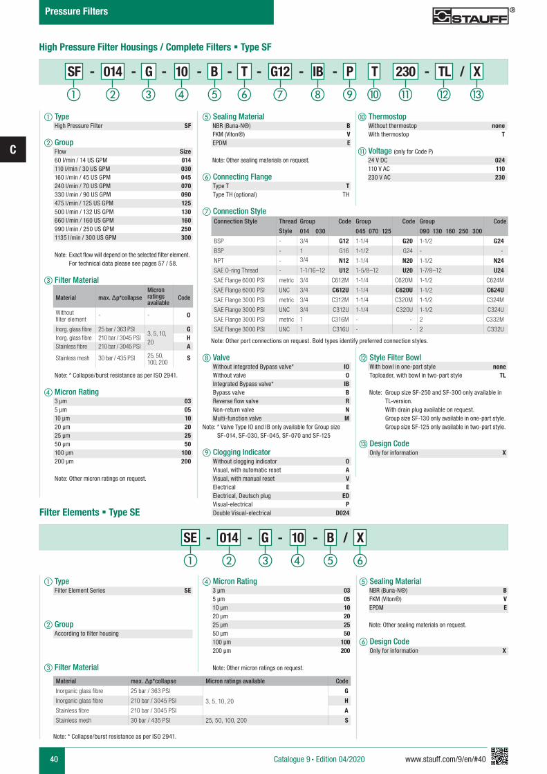
j Thermostop Without thermostop none With thermostop T
k Voltage (only for Code P) 24 V DC 024 110 V AC 110 230 V AC 230
e Sealing Material NBR (Buna-N®) B FKM (Viton®) V EPDM E
Note: Other sealing materials on request.
f Connecting Flange Type T T Type TH (optional) TH
Material max. Δp*collapseMicron ratings available
Code
Without filter element
- - 0
Inorg. glass fibre 25 bar / 363 PSI3, 5, 10, 20
GInorg. glass fibre 210 bar / 3045 PSI HStainless fibre 210 bar / 3045 PSI A
Stainless mesh 30 bar / 435 PSI 25, 50, 100, 200
S
Note: Other port connections on request. Bold types identify preferred connection styles.
g Connection Style
h Valve Without integrated Bypass valve* I0 Without valve 0 Integrated Bypass valve* IB Bypass valve B Reverse flow valve R Non-return valve N Multi-function valve MNote: * Valve Type IO and IB only available for Group size SF-014, SF-030, SF-045, SF-070 and SF-125
i Clogging Indicator Without clogging indicator 0 Visual, with automatic reset A Visual, with manual reset V Electrical E Electrical, Deutsch plug ED Visual-electrical P Double Visual-electrical D024
Connection Style Thread
Style
Group Code Group Code Group Code
014 030 045 070 125 090 130 160 250 300
BSP - 3/4 G12 1-1/4 G20 1-1/2 G24
BSP - 1 G16 1-1/2 G24 - -
NPT - 3/4 N12 1-1/4 N20 1-1/2 N24
SAE O-ring Thread - 1-1/16–12 U12 1-5/8–12 U20 1-7/8–12 U24
SAE Flange 6000 PSI metric 3/4 C612M 1-1/4 C620M 1-1/2 C624M
SAE Flange 6000 PSI UNC 3/4 C612U 1-1/4 C620U 1-1/2 C624U
SAE Flange 3000 PSI metric 3/4 C312M 1-1/4 C320M 1-1/2 C324M
SAE Flange 3000 PSI UNC 3/4 C312U 1-1/4 C320U 1-1/2 C324U
SAE Flange 3000 PSI metric 1 C316M - - 2 C332M
SAE Flange 3000 PSI UNC 1 C316U - - 2 C332U
a Type High Pressure Filter SF
b Group Flow Size 60 l/min / 14 US GPM 014 110 l/min / 30 US GPM 030 160 l/min / 45 US GPM 045 240 l/min / 70 US GPM 070 330 l/min / 90 US GPM 090 475 l/min / 125 US GPM 125 500 l/min / 132 US GPM 130 660 l/min / 160 US GPM 160 990 l/min / 250 US GPM 250 1135 l/min / 300 US GPM 300
Note: Exact flow will depend on the selected filter element. For technical data please see pages 57 / 58.
c Filter Material
Note: * Collapse/burst resistance as per ISO 2941.
d Micron Rating 3 µm 03 5 µm 05 10 µm 10 20 µm 20 25 µm 25 50 µm 50 100 µm 100 200 µm 200 Note: Other micron ratings on request.
High Pressure Filter Housings / Complete Filters § Type SF
e Sealing Material NBR (Buna-N®) B FKM (Viton®) V EPDM E
Note: Other sealing materials on request.
f Design Code Only for information X
d Micron Rating 3 µm 03 5 µm 05 10 µm 10 20 µm 20 25 µm 25 50 µm 50 100 µm 100 200 µm 200
Note: Other micron ratings on request.
a d fecb
SE - 014 - G - 10 - B / X
Material max. Δp*collapse Micron ratings available Code
Inorganic glass fibre 25 bar / 363 PSI
3, 5, 10, 20
G
Inorganic glass fibre 210 bar / 3045 PSI H
Stainless fibre 210 bar / 3045 PSI A
Stainless mesh 30 bar / 435 PSI 25, 50, 100, 200 S
Note: * Collapse/burst resistance as per ISO 2941.
Filter Elements § Type SE
a Type Filter Element Series SE
b Group According to filter housing
c Filter Material
l Style Filter Bowl With bowl in one-part style none Toploader, with bowl in two-part style TL Note: Group size SF-250 and SF-300 only available in TL-version. With drain plug available on request. Group size SF-130 only available in one-part style. Group size SF-125 only available in two-part style.
m Design Code Only for information X
Catalogue 9 § Edition 04/2020
Pressure Filters
a b c e f g h i j k l md
SF - 014 - G - 10 - B - T - G12 - IB - P T 230 - TL / X
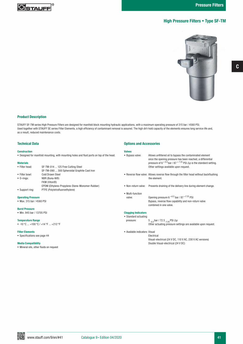
www.stauff.com/9/en/#41
C
41
Product Description
STAUFF SF-TM series High Pressure Filters are designed for manifold block mounting hydraulic applications, with a maximum operating pressure of 315 bar / 4560 PSI. Used together with STAUFF SE series Filter Elements, a high efficiency of contaminant removal is assured. The high dirt-hold capacity of the elements ensures long service life and, as a result, reduced maintenance costs.
Technical Data
Construction § Designed for manifold mounting, with mounting holes and fluid ports on top of the head.
Materials § Filter head: SF-TM-014 ... 125 Free Cutting Steel SF-TM-090 ... 300 Spheroidal Graphite Cast Iron
§ Filter bowl: Cold Drawn Steel § O-rings: NBR (Buna-N®)
FKM (Viton®) EPDM (Ethylene-Propylene-Diene-Monomer-Rubber) § Support ring: PTFE (Polytetrafluoroethylene)
Operating Pressure § Max. 315 bar / 4560 PSI
Burst Pressure § Min. 945 bar / 13705 PSI
Temperature Range § -10 °C ... +100 °C / +14 °F ... +212 °F
Filter Elements § Specifications see page 44
Media Compatibility § Mineral oils, other fluids on request
Options and Accessories
Valves § Bypass valve: Allows unfiltered oil to bypass the contaminated element once the opening pressure has been reached, a differential pressure of 6 + 0,5 bar / 87 + 7.25 PSI ∆p is the standard setting. Other settings available upon request.
§ Reverse flow valve: Allows reverse flow through the filter head without backflushing the element.
§ Non-return valve: Prevents draining of the delivery line during element change.
§ Multi-function valve: Opening pressure 6 +0,5 bar / 87 +7.25 PSI
Bypass, reverse flow capability and non-return valve combined in one valve.
Clogging Indicators § Standard actuating
pressure: 5 -0,5 bar / 72.5
-7.25 PSI ∆p
Other actuating pressure settings are available upon request.
§ Available indicators: Visual Electrical Visual-electrical (24 V DC, 110 V AC, 230 V AC versions) Double Visual-electrical (24 V DC)
High Pressure Filters § Type SF-TM
Catalogue 9 § Edition 04/2020
Pressure Filters
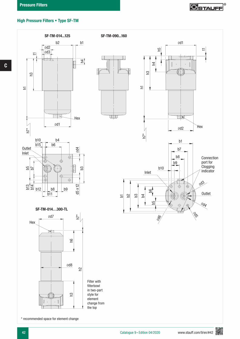
42 www.stauff.com/9/en/#42
C
High Pressure Filters § Type SF-TM
* recommended space for element change
h1
h4
h3
Ød8
SF-TM-014...125 SF-TM-090...160
SF-TM-014…300-TL
Ød7
Hex
h7*
h6h3
h2
b4b10
b12 b8 b9
Ød4
d5 x
t2
b6b15OutletInlet
b11
b3b5b1
3b1
4b7
Ød1
h7*
t1
Hex
b2 Ød1b1Ød2Ød3
Ød2 Hex
h7*
h1
h3
h4h5 t1
b1
b7
b8
b9b10
Connection port for Clogging indicator
Ød3
Ød4
Ød5
Ød6
b1 b2 b3 b4
b6b5
Inlet
Outlet
Filter with filterbowl in two-part style for element change from the top
Catalogue 9 § Edition 04/2020
Pressure Filters
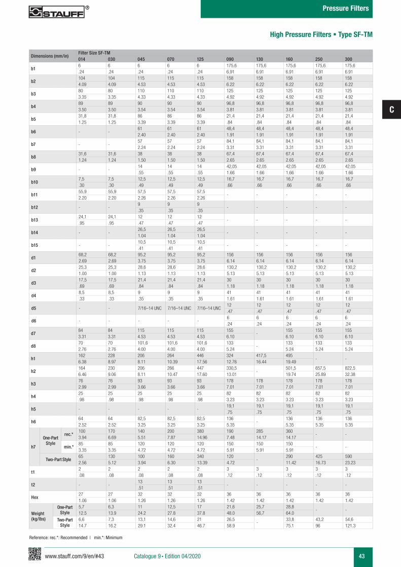
www.stauff.com/9/en/#43
C
43
Dimensions (mm/in)Filter Size SF-TM014 030 045 070 125 090 130 160 250 300
b16 6 6 6 6 175,6 175,6 175,6 175,6 175,6.24 .24 .24 .24 .24 6.91 6.91 6.91 6.91 6.91
b2104 104 115 115 115 158 158 158 158 1584.09 4.09 4.53 4.53 4.53 6.22 6.22 6.22 6.22 6.22
b380 80 110 110 110 125 125 125 125 1253.35 3.35 4.33 4.33 4.33 4.92 4.92 4.92 4.92 4.92
b489 89 90 90 90 96,8 96,8 96,8 96,8 96,83.50 3.50 3.54 3.54 3.54 3.81 3.81 3.81 3.81 3.81
b531,8 31,8 86 86 86 21,4 21,4 21,4 21,4 21,41.25 1.25 3.39 3.39 3.39 .84 .84 .84 .84 .84
b6 - -61 61 61 48,4 48,4 48,4 48,4 48,42.40 2.40 2.40 1.91 1.91 1.91 1.91 1.91
b7 - -57 57 57 84,1 84,1 84,1 84,1 84,12.24 2.24 2.24 3.31 3.31 3.31 3.31 3.31
b831,6 31,6 38 38 38 67,4 67,4 67,4 67,4 67,41.24 1.24 1.50 1.50 1.50 2.65 2.65 2.65 2.65 2.65
b9 - -14 14 14 42,05 42,05 42,05 42,05 42,05.55 .55 .55 1.66 1.66 1.66 1.66 1.66
b107,5 7,5 12,5 12,5 12,5 16,7 16,7 16,7 16,7 16,7.30 .30 .49 .49 .49 .66 .66 .66 .66 .66
b1155,9 55,9 57,5 57,5 57,5
- - - - -2.20 2.20 2.26 2.26 2.26
b12 - -9 9 9
- - - - -.35 .35 .35
b1324,1 24,1 12 12 12
- - - - -.95 .95 .47 .47 .47
b14 - -26,5 26,5 26,5
- - - - -1.04 1.04 1.04
b15 - -10,5 10,5 10,5
- - - - -.41 .41 .41
d168,2 68,2 95,2 95,2 95,2 156 156 156 156 1562.69 2.69 3.75 3.75 3.75 6.14 6.14 6.14 6.14 6.14
d225,3 25,3 28,6 28,6 28,6 130,2 130,2 130,2 130,2 130,21.00 1.00 1.13 1.13 1.13 5.13 5.13 5.13 5.13 5.13
d317,5 17,5 21,4 21,4 21,4 30 30 30 30 30.69 .69 .84 .84 .84 1.18 1.18 1.18 1.18 1.18
d48,5 8,5 9 9 9 41 41 41 41 41.33 .33 .35 .35 .35 1.61 1.61 1.61 1.61 1.61
d5 - - 7/16–14 UNC 7/16–14 UNC 7/16–14 UNC12 12 12 12 12.47 .47 .47 .47 .47
d6 - - - - -6 6 6 6 6.24 .24 .24 .24 .24
d784 84 115 115 115 155
-155 155 155
3.31 3.31 4.53 4.53 4.53 6.10 6.10 6.10 6.10
d870 70 101,6 101,6 101,6 133
-133 133 133
2.76 2.76 4.00 4.00 4.00 5.24 5.24 5.24 5.24
h1162 228 206 264 446 324 417,5 495
- -6.38 8.97 8.11 10.39 17.56 12.76 16.44 19.49
h2164 230 206 266 447 330,5
-501,5 657,5 822,5
6.46 9.06 8.11 10.47 17.60 13.01 19.74 25.89 32.38
h376 76 93 93 93 178 178 178 178 1782.99 2.99 3.66 3.66 3.66 7.01 7.01 7.01 7.01 7.01
h425 25 25 25 25 82 82 82 82 82.98 .98 .98 .98 .98 3.23 3.23 3.23 3.23 3.23
h5 - - - - -19,1 19,1 19,1 19,1 19,1.75 .75 .75 .75 .75
h664 64 82,5 82,5 82,5 136
-136 136 136
2.52 2.52 3.25 3.25 3.25 5.35 5.35 5.35 5.35
h7
One-Part Style
rec.*100 170 140 200 380 190 285 360
- -3.94 6.69 5.51 7.87 14.96 7.48 14.17 14.17
min.*85 85 120 120 120 150 150 150
- -3.35 3.35 4.72 4.72 4.72 5.91 5.91 5.91
Two-Part Style65 130 100 160 340 120
-290 425 590
2.56 5.12 3.94 6.30 13.39 4.72 11.42 16.73 23.23
t12 2 2 2 2 3 3 3 3 3.08 .08 .08 .08 .08 .12 .12 .12 .12 .12
t2 - -13 13 13
- - - - -.51 .51 .51
Hex27 27 32 32 32 36 36 36 36 361.06 1.06 1.26 1.26 1.26 1.42 1.42 1.42 1.42 1.42
Weight (kg/lbs)
One-Part Style
5,7 6,3 11 12,5 17 21,6 25,7 28,8- -
12.5 13.9 24.2 27.8 37.8 48.0 56,7 64.0
Two-Part Style
6,6 7,3 13,1 14,6 21 26,5-
33,8 43,2 54,614.7 16.2 29.1 32.4 46.7 58.9 75.1 96 121.3
High Pressure Filters § Type SF-TM
Reference: rec.*: Recommended | min.*: Minimum
Catalogue 9 § Edition 04/2020
Pressure Filters
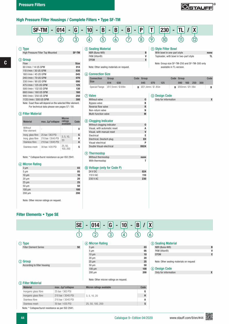
44 www.stauff.com/9/en/#44
C
k Style Filter Bowl With bowl in one-part style none Toploader, with bowl in two-part style TL
Note: Group size SF-TM-250 and SF-TM-300 only available in TL-version.
l Design Code Only for information X
e Sealing Material NBR (Buna-N®) B FKM (Viton®) V EPDM E
Note: Other sealing materials on request.
f Connection Size
g Valve Without valve 0 Bypass valve B Reverse flow valve R Non-return valve N Multi-function valve M
h Clogging Indicator Without clogging indicator 0 Visual, with automatic reset A Visual, with manual reset V Electrical E Electrical, Deutsch plug ED Visual-electrical P Double Visual-electrical D024
i Thermostop Without thermostop none With thermostop T
j Voltage (only for Code P) 24 V DC 024 110 V AC 110 230 V AC 230
Connection Size
Group Code Group Code Group Code
014 030 045 070 125 090 160 250 300
Special Flange Ø17,5mm / Ø.69in B Ø21,4mm / Ø .85in B Ø30mm / Ø1.18in B
High Pressure Filter Housings / Complete Filters § Type SF-TM
Material max. Δp*collapseMicron ratings available
Code
Without filter element
- - 0
Inorg. glass fibre 25 bar / 363 PSI3, 5, 10, 20
GInorg. glass fibre 210 bar / 3045 PSI HStainless fibre 210 bar / 3045 PSI A
Stainless mesh 30 bar / 435 PSI 25, 50, 100, 200
S
a Type High Pressure Filter Top Mounted SF-TM
b Group Flow Size 60 l/min / 14 US GPM 014 110 l/min / 30 US GPM 030 160 l/min / 45 US GPM 045 240 l/min / 70 US GPM 070 330 l/min / 90 US GPM 090 475 l/min / 125 US GPM 125 500 l/min / 132 US GPM 130 660 l/min / 160 US GPM 160 990 l/min / 250 US GPM 250 1135 l/min / 300 US GPM 300 Note: Exact flow will depend on the selected filter element. For technical data please see pages 57 / 58.
c Filter Material
Note: * Collapse/burst resistance as per ISO 2941.
d Micron Rating 3 µm 03 5 µm 05 10 µm 10 20 µm 20 25 µm 25 50 µm 50 100 µm 100 200 µm 200 Note: Other micron ratings on request.
e Sealing Material NBR (Buna-N®) B FKM (Viton®) V EPDM E
Note: Other sealing materials on request
f Design Code Only for information X
d Micron Rating 3 µm 03 5 µm 05 10 µm 10 20 µm 20 25 µm 25 50 µm 50 100 µm 100 200 µm 200
Note: Other micron ratings on request.
Material max. Δp*collapse Micron ratings available Code
Inorganic glass fibre 25 bar / 363 PSI
3, 5, 10, 20
G
Inorganic glass fibre 210 bar / 3045 PSI H
Stainless fibre 210 bar / 3045 PSI A
Stainless mesh 30 bar / 435 PSI 25, 50, 100, 200 S
Note: * Collapse/burst resistance as per ISO 2941.
Filter Elements § Type SE
a Type Filter Element Series SE
b Group According to filter housing
c Filter Material
a b c fed
i lkjhga b c fed
SF-TM - 014 - G - 10 - B - B - B - P T 230 - TL / X
SE - 014 - G - 10 - B / X
Catalogue 9 § Edition 04/2020
Pressure Filters
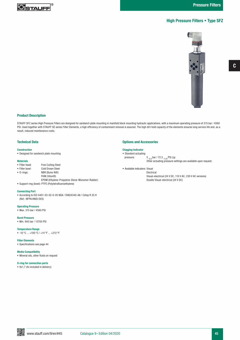
www.stauff.com/9/en/#45
C
45
Product Description
STAUFF SFZ series High Pressure Filters are designed for sandwich plate mounting in manifold block mounting hydraulic applications, with a maximum operating pressure of 315 bar / 4560 PSI. Used together with STAUFF SE series Filter Elements, a high efficiency of contaminant removal is assured. The high dirt-hold capacity of the elements ensures long service life and, as a result, reduced maintenance costs.
Technical Data
Construction § Designed for sandwich plate mounting
Materials § Filter head: Free Cutting Steel § Filter bowl: Cold Drawn Steel § O-rings: NBR (Buna-N®)
FKM (Viton®) EPDM (Ethylene-Propylene-Diene-Monomer-Rubber) § Support ring (bowl): PTFE (Polytetrafluoroethylene)
Connecting Port § According to ISO 4401-03-02-0-05 NG6 / DIN24340-A6 / Cetop R 35 H (Ref.: NFPA/ANSI D03)
Operating Pressure § Max. 315 bar / 4560 PSI
Burst Pressure § Min. 945 bar / 13705 PSI
Temperature Range § -10 °C ... +100 °C / +14 °F ... +212 °F
Filter Elements § Specifications see page 44
Media Compatibility § Mineral oils, other fluids on request
O-ring for connection ports § 9x1,7 (4x included in delivery)
Options and Accessories
Clogging Indicator § Standard actuating
pressure: 5 -0,5 bar / 72.5
-7.25 PSI ∆p
Other actuating pressure settings are available upon request.
§ Available indicators: Visual Electrical Visual-electrical (24 V DC, 110 V AC, 230 V AC versions) Double Visual-electrical (24 V DC)
High Pressure Filters § Type SFZ
Catalogue 9 § Edition 04/2020
Pressure Filters
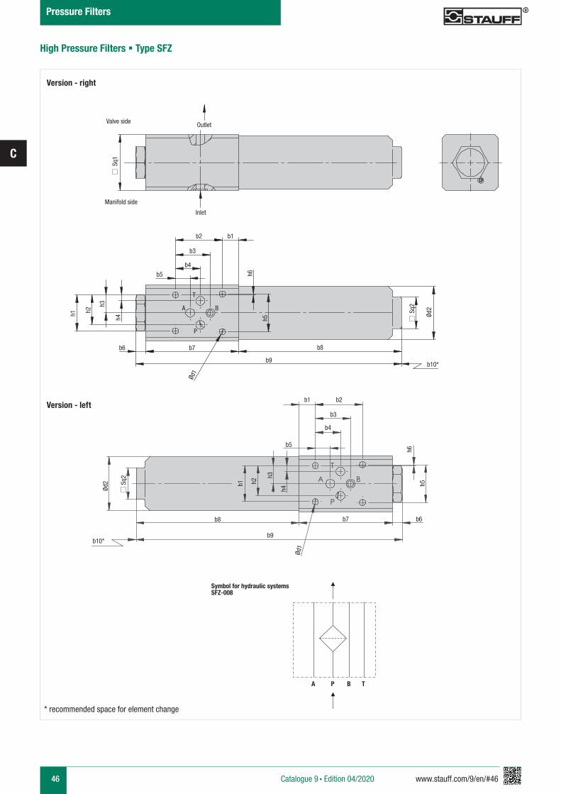
46 www.stauff.com/9/en/#46
C
T
A
P
B
High Pressure Filters § Type SFZ
* recommended space for element change
Outlet
Inlet
Sq1
Sq2
Ød2
Ød1
b1b2
b3
b4b5
b6 b7 b8
b9b10*
b1
h1 h2
h3
h4 h5
h6
Valve side
Manifold side
Version - right
Version - left
T
BA
P
Sq2
Ød2
b2
b3
b4
b5
h6
h5
b6
h1 h2
h3
h4
b7b8
b9b10*
Ød1
Symbol for hydraulic systemsSFZ-008
A P B T
Catalogue 9 § Edition 04/2020
Pressure Filters
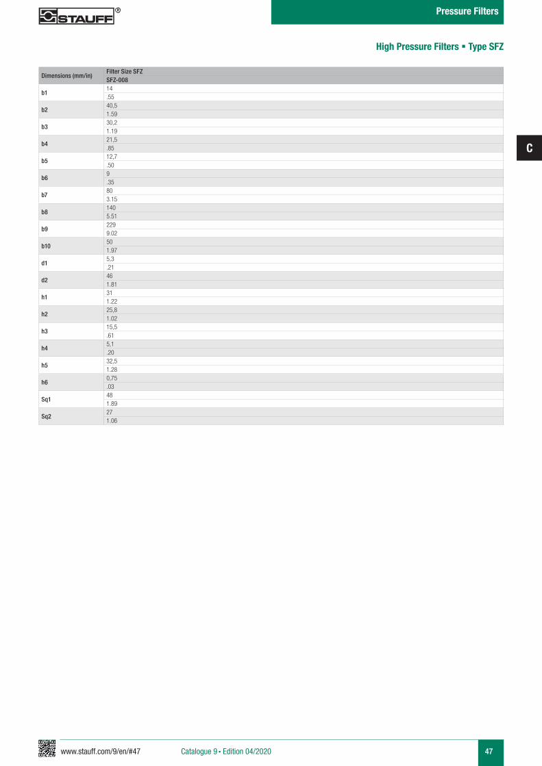
www.stauff.com/9/en/#47
C
47
Dimensions (mm/in)Filter Size SFZSFZ-008
b114.55
b240,51.59
b330,21.19
b421,5.85
b512,7.50
b69.35
b7803.15
b81405.51
b92299.02
b10501.97
d15,3.21
d2461.81
h1311.22
h225,81.02
h315,5.61
h45,1.20
h532,51.28
h60,75.03
Sq1481.89
Sq2271.06
High Pressure Filters § Type SFZ
Catalogue 9 § Edition 04/2020
Pressure Filters
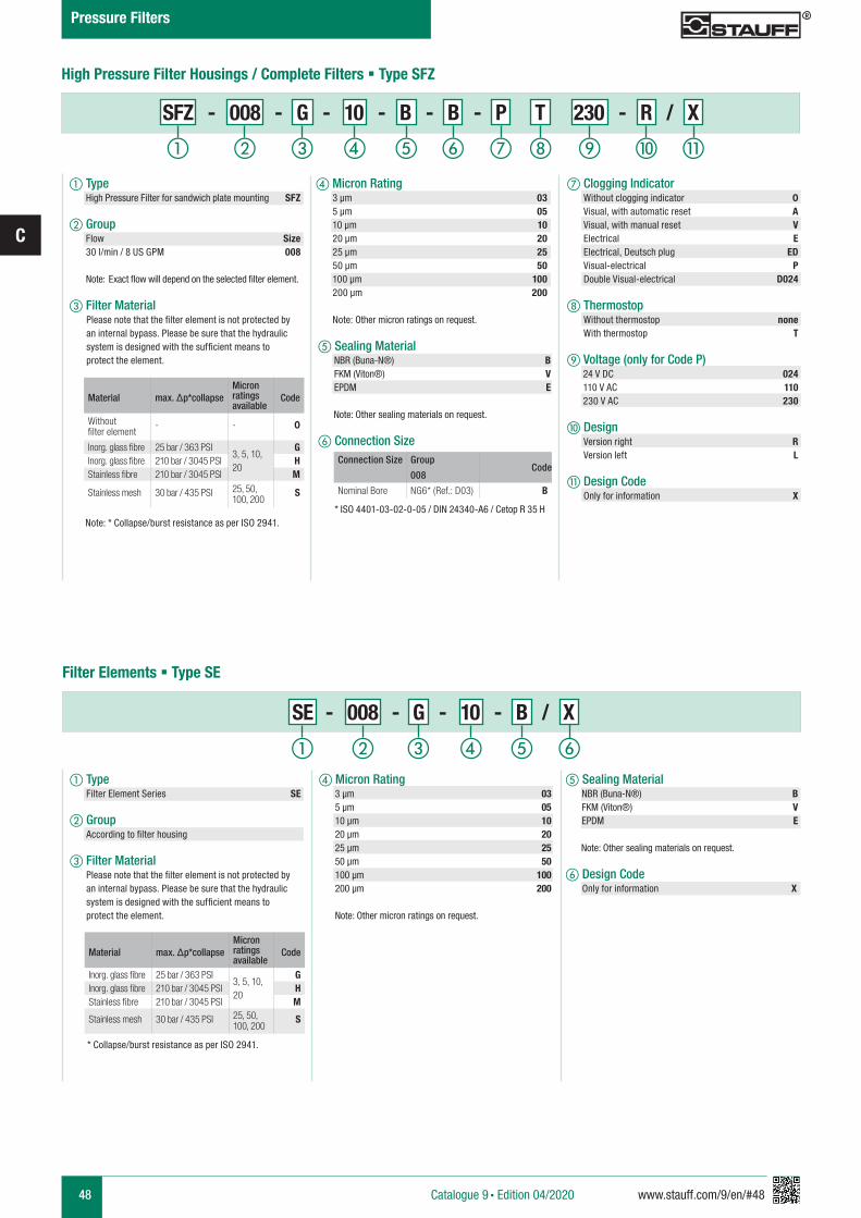
48 www.stauff.com/9/en/#48
C
e Sealing Material NBR (Buna-N®) B FKM (Viton®) V EPDM E
Note: Other sealing materials on request.
f Connection Size
* ISO 4401-03-02-0-05 / DIN 24340-A6 / Cetop R 35 H
Connection Size GroupCode
008
Nominal Bore NG6* (Ref.: D03) B
High Pressure Filter Housings / Complete Filters § Type SFZ
Material max. Δp*collapseMicron ratings available
Code
Without filter element
- - 0
Inorg. glass fibre 25 bar / 363 PSI3, 5, 10, 20
GInorg. glass fibre 210 bar / 3045 PSI HStainless fibre 210 bar / 3045 PSI M
Stainless mesh 30 bar / 435 PSI 25, 50, 100, 200
S
a Type High Pressure Filter for sandwich plate mounting SFZ
b Group Flow Size 30 l/min / 8 US GPM 008
Note: Exact flow will depend on the selected filter element.
c Filter Material
Note: * Collapse/burst resistance as per ISO 2941.
i kjhga c fed
e Sealing Material NBR (Buna-N®) B FKM (Viton®) V EPDM E
Note: Other sealing materials on request.
f Design Code Only for information X
d Micron Rating 3 µm 03 5 µm 05 10 µm 10 20 µm 20 25 µm 25 50 µm 50 100 µm 100 200 µm 200
Note: Other micron ratings on request.
* Collapse/burst resistance as per ISO 2941.
Filter Elements § Type SE
a Type Filter Element Series SE
b Group According to filter housing
c Filter Material
Material max. Δp*collapseMicron ratings available
Code
Inorg. glass fibre 25 bar / 363 PSI3, 5, 10, 20
GInorg. glass fibre 210 bar / 3045 PSI HStainless fibre 210 bar / 3045 PSI M
Stainless mesh 30 bar / 435 PSI 25, 50, 100, 200
S
a b c fed
b
g Clogging Indicator Without clogging indicator 0 Visual, with automatic reset A Visual, with manual reset V Electrical E Electrical, Deutsch plug ED Visual-electrical P Double Visual-electrical D024
h Thermostop Without thermostop none With thermostop T
i Voltage (only for Code P) 24 V DC 024 110 V AC 110 230 V AC 230
d Micron Rating 3 µm 03 5 µm 05 10 µm 10 20 µm 20 25 µm 25 50 µm 50 100 µm 100 200 µm 200 Note: Other micron ratings on request.
j Design Version right R Version left L
k Design Code Only for information X
Please note that the filter element is not protected by an internal bypass. Please be sure that the hydraulic system is designed with the sufficient means to protect the element.
Please note that the filter element is not protected by an internal bypass. Please be sure that the hydraulic system is designed with the sufficient means to protect the element.
SFZ - 008 - G - 10 - B - B - P T 230 - R / X
SE - 008 - G - 10 - B / X
Catalogue 9 § Edition 04/2020
Pressure Filters
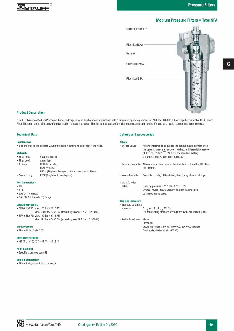
www.stauff.com/9/en/#49
C
49
Product Description
STAUFF SFA series Medium Pressure Filters are designed for in-line hydraulic applications with a maximum operating pressure of 160 bar / 2320 PSI. Used together with STAUFF SE series Filter Elements, a high efficiency of contamination removal is assured. The dirt-hold capacity of the elements ensures long service life, and as a result, reduced maintenance costs.
Technical Data
Construction § Designed for in-line assembly, with threaded mounting holes on top of the head.
Materials § Filter head: Cast Aluminium § Filter bowl: Aluminium § O-rings: NBR (Buna-N®)
FKM (Viton®) EPDM (Ethylene-Propylene-Diene-Monomer-Rubber) § Support ring: PTFE (Polytetrafluoroethylene)
Port Connections § BSP § NPT § SAE O-ring thread § SAE 3000 PSI (Code 61) flange
Operating Pressure § SFA-014/030: Max. 160 bar / 2320 PSI
Max. 190 bar / 2755 PSI (according to ANSI T2.6.1. R2-2001) § SFA-045/070: Max. 150 bar / 2175 PSI
Max. 171 bar / 2480 PSI (according to ANSI T2.6.1. R2-2001)
Burst Pressure § Min. 480 bar / 6960 PSI
Temperature Range § -10 °C ... +100 °C / +14 °F ... +212 °F
Filter Elements § Specifications see page 52
Media Compatibility § Mineral oils, other fluids on request
Options and Accessories
Valves § Bypass valve: Allows unfiltered oil to bypass the contaminated element once the opening pressure has been reached, a differential pressure of 6 + 0,5 bar / 87 + 7.25 PSI ∆p is the standard setting. Other settings available upon request.
§ Reverse flow valve: Allows reverse flow through the filter head without backflushing the element.
§ Non-return valve: Prevents draining of the delivery line during element change.
§ Multi-function valve: Opening pressure 6 +0,5 bar / 87 +7.25 PSI
Bypass, reverse flow capability and non-return valve combined in one valve.
Clogging Indicators § Standard actuating
pressure: 5 -0,5 bar / 72.5
-7.25 PSI ∆p
Other actuating pressure settings are available upon request.
§ Available indicators: Visual Electrical Visual-electrical (24 V DC, 110 V AC, 230 V AC versions) Double Visual-electrical (24 V DC)
Clogging Indicator HI
Filter Head SHA
Valve HV
Filter Element SE
Filter Bowl SBA
Medium Pressure Filters § Type SFA
Catalogue 9 § Edition 04/2020
Pressure Filters
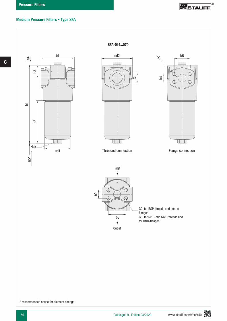
50 www.stauff.com/9/en/#50
C
Medium Pressure Filters § Type SFA
G2: for BSP threads and metric flangesG3: for NPT- and SAE-threads and for UNC-flanges
Threaded connection Flange connection
h5*
b3
b2
h1
h2
h4
h3
b1
G
Ød1Hex
Ød2 b5
b4
G4
SFA-014...070
* recommended space for element change
Inlet
Outlet
Catalogue 9 § Edition 04/2020
Pressure Filters
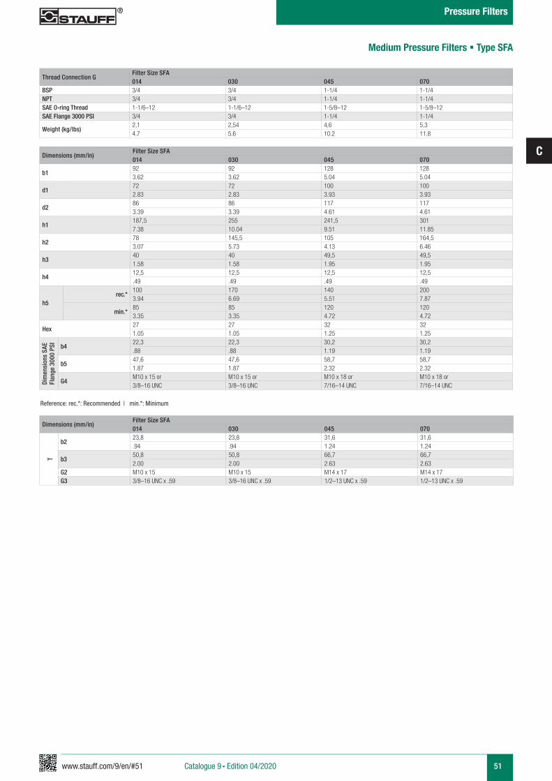
www.stauff.com/9/en/#51
C
51
Thread Connection GFilter Size SFA014 030 045 070
BSP 3/4 3/4 1-1/4 1-1/4NPT 3/4 3/4 1-1/4 1-1/4SAE O-ring Thread 1-1/6–12 1-1/6–12 1-5/8–12 1-5/8–12SAE Flange 3000 PSI 3/4 3/4 1-1/4 1-1/4
Weight (kg/lbs) 2,1 2,54 4,6 5,34.7 5.6 10.2 11.8
Dimensions (mm/in)Filter Size SFA014 030 045 070
b192 92 128 1283.62 3.62 5.04 5.04
d172 72 100 1002.83 2.83 3.93 3.93
d286 86 117 1173.39 3.39 4.61 4.61
h1187,5 255 241,5 3017.38 10.04 9.51 11.85
h278 145,5 105 164,53.07 5.73 4.13 6.46
h3 40 40 49,5 49,51.58 1.58 1.95 1.95
h412,5 12,5 12,5 12,5.49 .49 .49 .49
h5rec.*
100 170 140 2003.94 6.69 5.51 7.87
min.*85 85 120 1203.35 3.35 4.72 4.72
Hex27 27 32 321.05 1.05 1.25 1.25
Dim
ensi
ons
SAE
Flan
ge 3
000
PSI
b422,3 22,3 30,2 30,2.88 .88 1.19 1.19
b547,6 47,6 58,7 58,71.87 1.87 2.32 2.32
G4M10 x 15 or M10 x 15 or M10 x 18 or M10 x 18 or3/8–16 UNC 3/8–16 UNC 7/16–14 UNC 7/16–14 UNC
Reference: rec.*: Recommended | min.*: Minimum
Medium Pressure Filters § Type SFA
Dimensions (mm/in)Filter Size SFA014 030 045 070
T
b223,8 23,8 31,6 31,6.94 .94 1.24 1.24
b350,8 50,8 66,7 66,72.00 2.00 2.63 2.63
G2 M10 x 15 M10 x 15 M14 x 17 M14 x 17G3 3/8–16 UNC x .59 3/8–16 UNC x .59 1/2–13 UNC x .59 1/2–13 UNC x .59
Catalogue 9 § Edition 04/2020
Pressure Filters
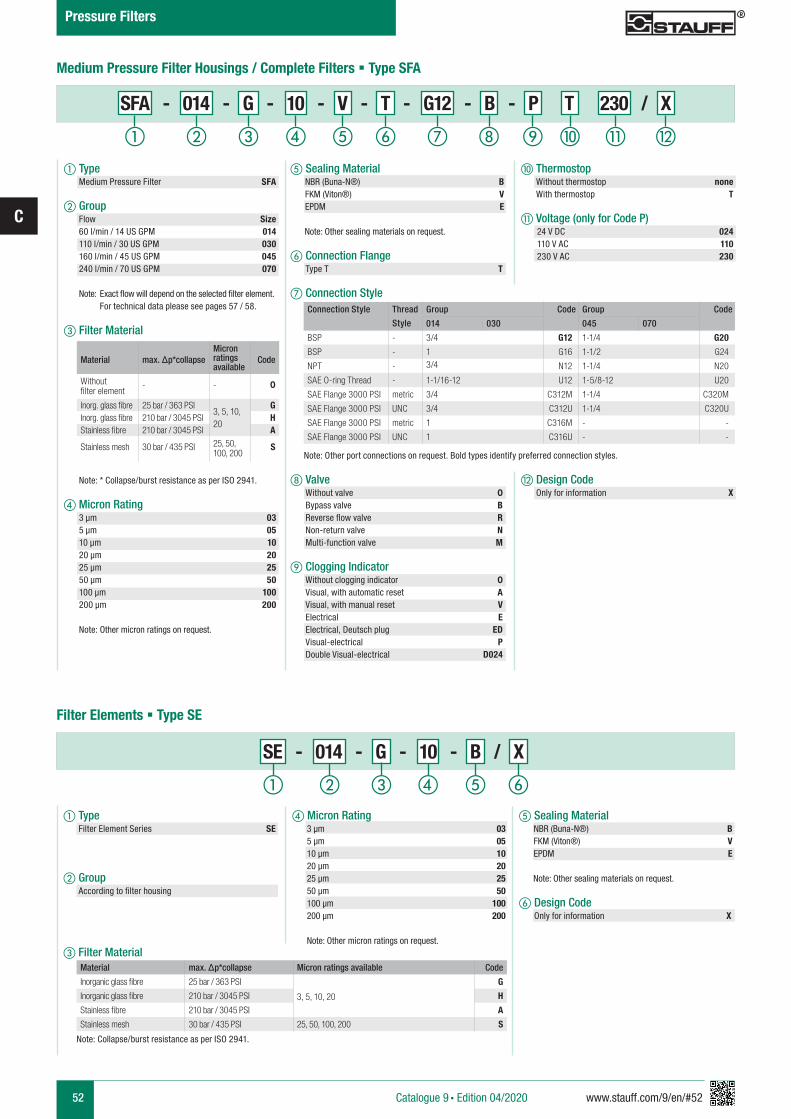
52 www.stauff.com/9/en/#52
C
e Sealing Material NBR (Buna-N®) B FKM (Viton®) V EPDM E
Note: Other sealing materials on request.
f Connection Flange Type T T
g Connection Style
h Valve Without valve 0 Bypass valve B Reverse flow valve R Non-return valve N Multi-function valve M
i Clogging Indicator Without clogging indicator 0 Visual, with automatic reset A Visual, with manual reset V Electrical E Electrical, Deutsch plug ED Visual-electrical P Double Visual-electrical D024
Medium Pressure Filter Housings / Complete Filters § Type SFA
Material max. Δp*collapseMicron ratings available
Code
Without filter element
- - 0
Inorg. glass fibre 25 bar / 363 PSI3, 5, 10, 20
GInorg. glass fibre 210 bar / 3045 PSI HStainless fibre 210 bar / 3045 PSI A
Stainless mesh 30 bar / 435 PSI 25, 50, 100, 200
S
a Type Medium Pressure Filter SFA
b Group Flow Size 60 l/min / 14 US GPM 014 110 l/min / 30 US GPM 030 160 l/min / 45 US GPM 045 240 l/min / 70 US GPM 070
Note: Exact flow will depend on the selected filter element. For technical data please see pages 57 / 58.
c Filter Material
Note: * Collapse/burst resistance as per ISO 2941.
d Micron Rating 3 µm 03 5 µm 05 10 µm 10 20 µm 20 25 µm 25 50 µm 50 100 µm 100 200 µm 200 Note: Other micron ratings on request.
e Sealing Material NBR (Buna-N®) B FKM (Viton®) V EPDM E
Note: Other sealing materials on request.
f Design Code Only for information X
d Micron Rating 3 µm 03 5 µm 05 10 µm 10 20 µm 20 25 µm 25 50 µm 50 100 µm 100 200 µm 200
Note: Other micron ratings on request.
a d fecb
SE - 014 - G - 10 - B / X
Material max. Δp*collapse Micron ratings available Code
Inorganic glass fibre 25 bar / 363 PSI
3, 5, 10, 20
G
Inorganic glass fibre 210 bar / 3045 PSI H
Stainless fibre 210 bar / 3045 PSI A
Stainless mesh 30 bar / 435 PSI 25, 50, 100, 200 S
Note: Collapse/burst resistance as per ISO 2941.
Filter Elements § Type SE
a Type Filter Element Series SE
b Group According to filter housing
c Filter Material
j Thermostop Without thermostop none With thermostop T
k Voltage (only for Code P) 24 V DC 024 110 V AC 110 230 V AC 230
Note: Other port connections on request. Bold types identify preferred connection styles.
l Design Code Only for information X
i lkjhga b c fed
Connection Style Thread
Style
Group Code Group Code
014 030 045 070
BSP - 3/4 G12 1-1/4 G20
BSP - 1 G16 1-1/2 G24
NPT - 3/4 N12 1-1/4 N20
SAE O-ring Thread - 1-1/16-12 U12 1-5/8-12 U20
SAE Flange 3000 PSI metric 3/4 C312M 1-1/4 C320M
SAE Flange 3000 PSI UNC 3/4 C312U 1-1/4 C320U
SAE Flange 3000 PSI metric 1 C316M - -
SAE Flange 3000 PSI UNC 1 C316U - -
SFA - 014 - G - 10 - V - T - G12 - B - P T 230 / X
Catalogue 9 § Edition 04/2020
Pressure Filters
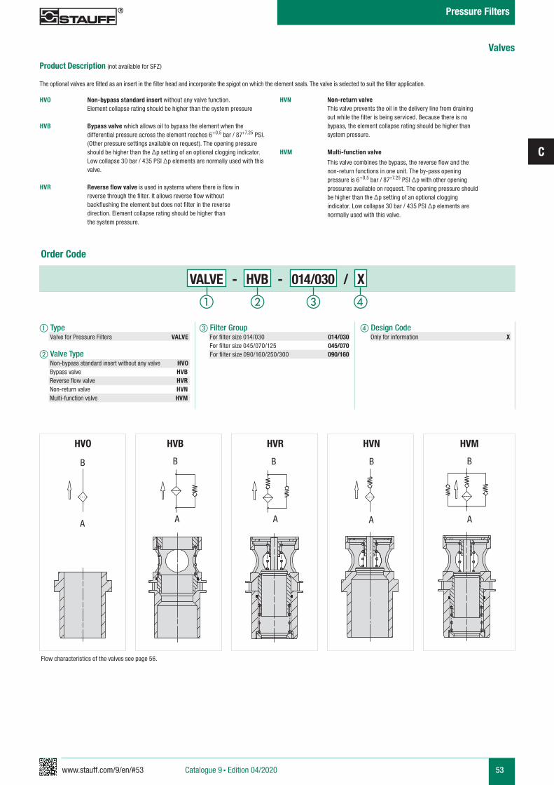
www.stauff.com/9/en/#53
C
53
Order Code
Product Description (not available for SFZ)
The optional valves are fitted as an insert in the filter head and incorporate the spigot on which the element seals. The valve is selected to suit the filter application.
HVO Non-bypass standard insert without any valve function. Element collapse rating should be higher than the system pressure
HVB Bypass valve which allows oil to bypass the element when the differential pressure across the element reaches 6+0,5 bar / 87+7.25 PSI. (Other pressure settings available on request). The opening pressure should be higher than the Δp setting of an optional clogging indicator. Low collapse 30 bar / 435 PSI Δp elements are normally used with this valve.
HVR Reverse flow valve is used in systems where there is flow in reverse through the filter. It allows reverse flow without backflushing the element but does not filter in the reverse direction. Element collapse rating should be higher than the system pressure.
Flow characteristics of the valves see page 56.
HVO HVB HVR HVN HVM
B
A
B
A
B
A
B
A
B
A
HVN Non-return valve This valve prevents the oil in the delivery line from draining out while the filter is being serviced. Because there is no bypass, the element collapse rating should be higher than system pressure.
HVM Multi-function valve
This valve combines the bypass, the reverse flow and the non-return functions in one unit. The by-pass opening pressure is 6+0,5 bar / 87+7.25 PSI Δp with other opening pressures available on request. The opening pressure should be higher than the Δp setting of an optional clogging indicator. Low collapse 30 bar / 435 PSI Δp elements are normally used with this valve.
a Type Valve for Pressure Filters VALVE
b Valve Type Non-bypass standard insert without any valve HV0
Bypass valve HVB Reverse flow valve HVR Non-return valve HVN Multi-function valve HVM
c Filter Group For filter size 014/030 014/030 For filter size 045/070/125 045/070 For filter size 090/160/250/300 090/160
d Design Code Only for information X
Valves
a b dc
VALVE - HVB - 014/030 / X
Catalogue 9 § Edition 04/2020
Pressure Filters
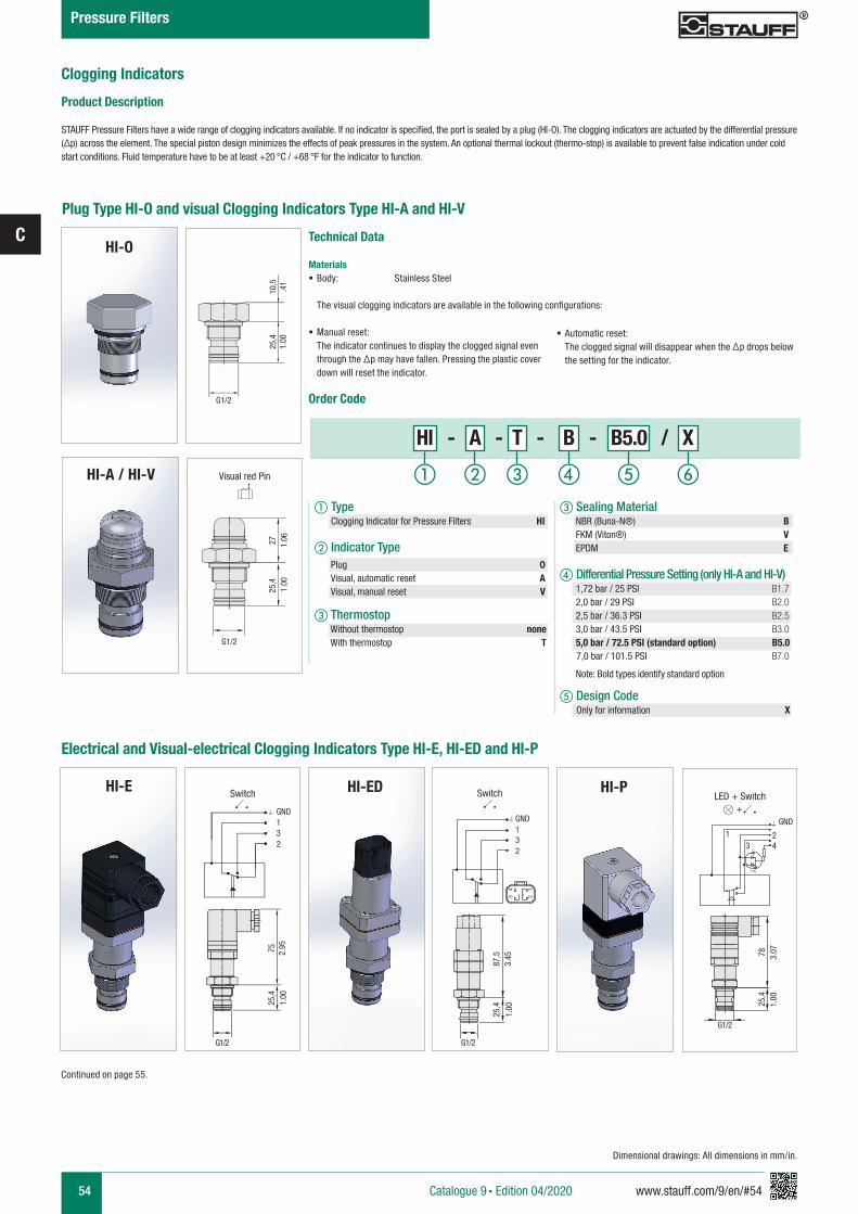
54 www.stauff.com/9/en/#54
C
Catalogue 9 § Edition 04/2020
Pressure Filters
Dimensional drawings: All dimensions in mm/in.
Clogging Indicators
Product Description
STAUFF Pressure Filters have a wide range of clogging indicators available. If no indicator is specified, the port is sealed by a plug (HI-O). The clogging indicators are actuated by the differential pressure (Δp) across the element. The special piston design minimizes the effects of peak pressures in the system. An optional thermal lockout (thermo-stop) is available to prevent false indication under cold start conditions. Fluid temperature have to be at least +20 °C / +68 °F for the indicator to function.
Plug Type HI-O and visual Clogging Indicators Type HI-A and HI-V
Technical Data
Materials § Body: Stainless Steel The visual clogging indicators are available in the following configurations:
§ Manual reset: The indicator continues to display the clogged signal even through the Δp may have fallen. Pressing the plastic cover down will reset the indicator.
Order Code
a Type Clogging Indicator for Pressure Filters HI
b Indicator Type
c Thermostop Without thermostop none With thermostop T
c Sealing Material NBR (Buna-N®) B FKM (Viton®) V EPDM E
d Differential Pressure Setting (only HI-A and HI-V) 1,72 bar / 25 PSI B1.7 2,0 bar / 29 PSI B2.0 2,5 bar / 36.3 PSI B2.5 3,0 bar / 43.5 PSI B3.0 5,0 bar / 72.5 PSI (standard option) B5.0 7,0 bar / 101.5 PSI B7.0 Note: Bold types identify standard option
e Design Code Only for information X
Plug 0Visual, automatic reset AVisual, manual reset V
Electrical and Visual-electrical Clogging Indicators Type HI-E, HI-ED and HI-P
§ Automatic reset: The clogged signal will disappear when the Δp drops below the setting for the indicator.
Continued on page 55.
G1/2
25,4
10,5
1.00
.41
1.00
25,4
G1/2
27 1.06
Visual red Pin
HI-O
HI-A / HI-V
G
Y(R)
GND1 2
3 4
G1/2
G1/2
1.00
25,4
87,5
3.45
14
23
GND132
1.00
25,4
78 3.07
LED + SwitchSwitch
G1/2
1.00
25,4
75 2.95
GND132
Switch
+
HI-E HI-ED HI-P
a b c fed
HI - A - T - B - B5.0 / X
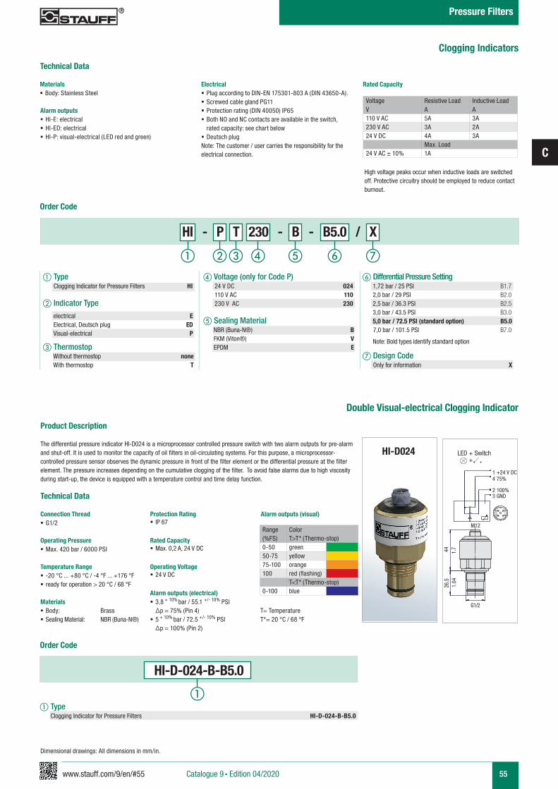
www.stauff.com/9/en/#55
C
55Catalogue 9 § Edition 04/2020
Pressure Filters
HI-D024
Product Description
The differential pressure indicator HI-D024 is a microprocessor controlled pressure switch with two alarm outputs for pre-alarm and shut-off. It is used to monitor the capacity of oil filters in oil-circulating systems. For this purpose, a microprocessor-controlled pressure sensor observes the dynamic pressure in front of the filter element or the differential pressure at the filter element. The pressure increases depending on the cumulative clogging of the filter. To avoid false alarms due to high viscosity during start-up, the device is equipped with a temperature control and time delay function.
Technical Data
Connection Thread § G1/2
Operating Pressure § Max. 420 bar / 6000 PSI
Temperature Range § -20 °C ... +80 °C / -4 °F ... +176 °F § ready for operation > 20 °C / 68 °F
Materials § Body: Brass § Sealing Material: NBR (Buna-N®)
Protection Rating § IP 67
Rated Capacity § Max. 0,2 A, 24 V DC
Operating Voltage § 24 V DC
Alarm outputs (electrical) § 3,8 + 10% bar / 55.1 +/- 10% PSI ∆p = 75% (Pin 4)
§ 5 + 10% bar / 72.5 +/- 10% PSI ∆p = 100% (Pin 2)
Clogging Indicators
Technical Data
Order Code
a Type Clogging Indicator for Pressure Filters HI
b Indicator Type
c Thermostop Without thermostop none With thermostop T
f Differential Pressure Setting 1,72 bar / 25 PSI B1.7 2,0 bar / 29 PSI B2.0 2,5 bar / 36.3 PSI B2.5 3,0 bar / 43.5 PSI B3.0 5,0 bar / 72.5 PSI (standard option) B5.0 7,0 bar / 101.5 PSI B7.0 Note: Bold types identify standard option
g Design Code Only for information X
electrical EElectrical, Deutsch plug EDVisual-electrical P
Rated Capacity
High voltage peaks occur when inductive loads are switched off. Protective circuitry should be employed to reduce contact burnout.
Voltage V
Resistive LoadA
Inductive LoadA
110 V AC 5A 3A230 V AC 3A 2A24 V DC 4A 3A
Max. Load24 V AC ± 10% 1A
d Voltage (only for Code P) 24 V DC 024 110 V AC 110 230 V AC 230
e Sealing Material NBR (Buna-N®) B FKM (Viton®) V EPDM E
Order Code
aa Type Clogging Indicator for Pressure Filters HI-D-024-B-B5.0
HI-D-024-B-B5.0
Double Visual-electrical Clogging Indicator
Alarm outputs (visual)
Range (%FS)
ColorT>T* (Thermo-stop)
0-50 green50-75 yellow75-100 orange100 red (flashing)
T<T* (Thermo-stop)0-100 blue
Dimensional drawings: All dimensions in mm/in.
T= TemperatureT*= 20 °C / 68 °F
v
G1/2
1.04
26,5
1.744
4 75%
2 100%3 GND
123 4
LED + Switch
M12
+
1 +24 V DC
HI - P T 230 - B - B5.0 / X
a b c f ged
Electrical § Plug according to DIN-EN 175301-803 A (DIN 43650-A). § Screwed cable gland PG11 § Protection rating (DIN 40050) IP65 § Both NO and NC contacts are available in the switch, rated capacity: see chart below
§ Deutsch plugNote: The customer / user carries the responsibility for the electrical connection.
Alarm outputs § HI-E: electrical § HI-ED: electrical § HI-P: visual-electrical (LED red and green)
Materials § Body: Stainless Steel
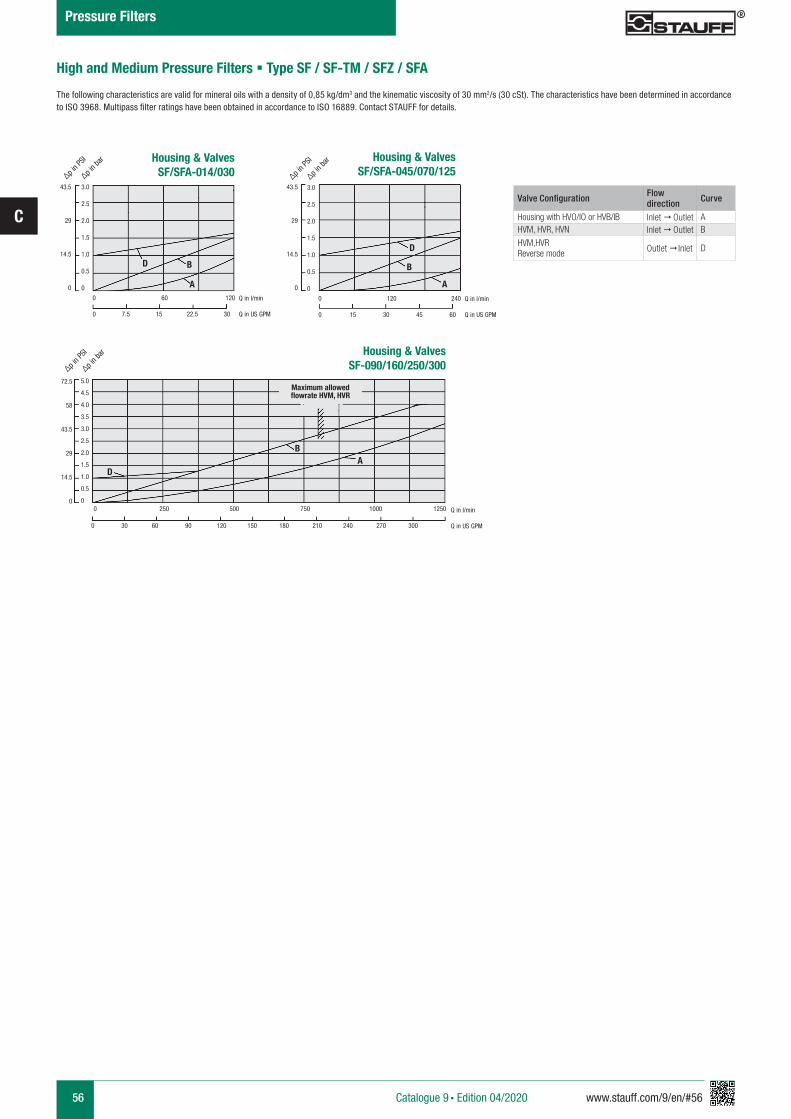
56 www.stauff.com/9/en/#56
C
High and Medium Pressure Filters § Type SF / SF-TM / SFZ / SFA
The following characteristics are valid for mineral oils with a density of 0,85 kg/dm3 and the kinematic viscosity of 30 mm2/s (30 cSt). The characteristics have been determined in accordance to ISO 3968. Multipass filter ratings have been obtained in accordance to ISO 16889. Contact STAUFF for details.
Housing & ValvesSF/SFA-014/030
0 60 120
0 7.5 15 22.5 30
43.5
29
14.5
0
∆p in P
SI
∆p in b
ar
Q in l/min
Q in US GPM
3.0
2.5
2.0
1.5
1.0
0.5
0 A
BD
Housing & ValvesSF/SFA-045/070/125
0 120 240
0 15 30 45 60
43.5
29
14.5
0
∆p in P
SI
∆p in b
ar
3.0
2.5
2.0
1.5
1.0
0.5
0 A
B
D
Q in l/min
Q in US GPM
Valve Configuration Flow direction Curve
Housing with HVO/IO or HVB/IB Inlet " Outlet AHVM, HVR, HVN Inlet " Outlet B
HVM,HVRReverse mode Outlet " Inlet D
Housing & ValvesSF-090/160/250/300
0 250 500 750 1000 1250
72.5
58
43.5
29
14.5
0
∆p in P
SI
∆p in b
ar
Q in l/min
Q in US GPM
5.0
4.5
4.0
3.5
3.0
2.5
2.0
1.5
1.0
0.5
0
AB
D
0 30 60 90 120 150 180 210 240 270 300
Maximum allowed flowrate HVM, HVR
Catalogue 9 § Edition 04/2020
Pressure Filters
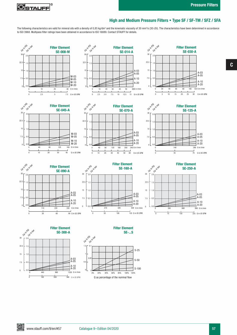
www.stauff.com/9/en/#57
C
57
High and Medium Pressure Filters § Type SF / SF-TM / SFZ / SFA
The following characteristics are valid for mineral oils with a density of 0,85 kg/dm3 and the kinematic viscosity of 30 mm2/s (30 cSt). The characteristics have been determined in accordance to ISO 3968. Multipass filter ratings have been obtained in accordance to ISO 16889. Contact STAUFF for details.
∆p in PS
I
∆p in ba
r
M-10M-20
M-03M-05
30
22.5
15
7.5
0
2.0
1.5
1.0
0.5
0.0
Q in l/min
Q in US GPM0 2.5 5 7.5
0 10 20 30
∆p in PS
I
∆p in ba
r
S-50
S-100
S-25
Filter Element SE-...S
0.1
0.05
0
1.5
1
0.5
0
0% 20% 40% 60% 80% 100% 120%
Q as percentage of the nominal flow
M-10M-20
M-03M-05
Q in l/min
Q in US GPM
∆p in PS
I
∆p in ba
r
A-10
A-20
A-03A-05
Filter Element SE-014-A
Filter Element SE-008-M
30
22.5
15
7.5
0
2.0
1.5
1.0
0.5
0.0
Q in l/min
Q in US GPM0 2.5 5.0 7.5 10 12.5 15
0 10 20 30 40 50 60
∆p in PS
I
∆p in ba
r
A-10A-20
A-03A-05
Filter Element SE-030-A
30
22.5
15
7.5
0
2.0
1.5
1.0
0.5
0.0
Q in l/min
Q in US GPM0 5 10 15 20 25 30
0 20 40 60 80 100 120
∆p in PS
I
∆p in ba
r
Filter Element SE-045-A
30
22.5
15
7.5
0
2.0
1.5
1.0
0.5
0.0
0 10 20 30 40
0 40 80 120 160
∆p in PS
I
∆p in ba
r
A-10A-20
A-03A-05
Filter Element SE-070-A
30
22.5
15
7.5
0
2.0
1.5
1.0
0.5
0.0
Q in l/min
Q in US GPM0 10 20 30 40 50 60
0 40 80 120 160 200 240
∆p in PS
I
∆p in ba
r
A-10A-20
A-03A-05
Filter Element SE-125-A
30
22.5
15
7.5
0
2.0
1.5
1.0
0.5
0.0
Q in l/min
Q in US GPM0 35 70
0 140 280
∆p in PS
I
∆p in ba
r
A-10A-20
A-03A-05
Filter Element SE-090-A
30
22.5
15
7.5
0
2.0
1.5
1.0
0.5
0.0
Q in l/min
Q in US GPM0 30 60 90
0 110 220 330
A-03A-05
A-10A-20
Filter Element SE-160-A
A-03A-05
A-10A-20
Filter Element SE-300-A
A-03A-05
A-10 A-20
Filter Element SE-250-A
30
22.5
15
7.5
0
30
22.5
15
7.5
0
30
22.5
15
7.5
0
2.0
1.5
1.0
0.5
0.0
2.0
1.5
1.0
0.5
0.0
2.0
1.5
1.0
0.5
0.0
∆p in PS
I
∆p in ba
r
∆p in PS
I
∆p in ba
r
∆p in PS
I
∆p in ba
r
0 210 420 630
0 50 100 150
0 330 660 990
0 75 150 225
0 440 880 1320
0 100 200 300
Q in l/min
Q in US GPM
Q in l/min
Q in US GPM
Q in l/min
Q in US GPM
Catalogue 9 § Edition 04/2020
Pressure Filters
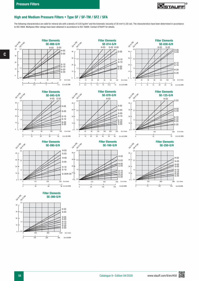
58 www.stauff.com/9/en/#58
C
High and Medium Pressure Filters § Type SF / SF-TM / SFZ / SFA
The following characteristics are valid for mineral oils with a density of 0,85 kg/dm3 and the kinematic viscosity of 30 mm2/s (30 cst). The characteristics have been determined in accordance to ISO 3968. Multipass filter ratings have been obtained in accordance to ISO 16889. Contact STAUFF for details.
H-03 G-03 H-05
G-05
H-10G-10
H-20G-20
Filter Elements SE-014-G/H
Filter Elements SE-008-G/H
0 10 20 30 40 50 60
0 2.5 5 7.5 10 12.5 15
H-03 G-03
G-05
H-05
H-10G-10H-20G-20
Filter Elements SE-045-G/H
0 40 80 120 160
0 10 20 30 40
H-03 G-03H-05G-05
H-10G-10
H-20G-20
Filter Elements SE-030-G/H
0 20 40 60 80 100 120
0 5 10 15 20 25 30
40
30
20
10
0
3.0
2.0
1.0
0.0
∆p in P
SI
∆p in b
ar
40
30
20
10
0
3.0
2.0
1.0
0.0
∆p in P
SI
∆p in b
ar
40
30
20
10
0
3.0
2.0
1.0
0.0
∆p in P
SI
∆p in b
ar
Q in l/min
Q in US GPM
Q in l/min
Q in US GPM
Q in l/min
Q in US GPM
H-03
H-05
G-03G-05H-10
G-10H-20G-20
Filter Elements SE-070-G/H
0 40 80 120 160 200 240
0 10 20 30 40 50 60
H-03G-03
G-05
H-05
H-10G-10
G-20/H-20
Filter Elements SE-090-G/H
0 110 220 330
0 30 60 90
H-03G-03
H-05G-05
H-10G-10H-20G-20
Filter ElementsSE-125-G/H
0 140 280
0 35 70
40
30
20
10
0
3.0
2.0
1.0
0.0
∆p in P
SI
∆p in b
ar
40
30
20
10
0
3.0
2.0
1.0
0.0
∆p in P
SI
∆p in b
ar
40
30
20
10
0
3.0
2.0
1.0
0.0
∆p in P
SI
∆p in b
ar
40
30
20
10
0
3.0
2.0
1.0
0.0
∆p in P
SI
∆p in b
ar
40
30
20
10
0
3.0
2.0
1.0
0.0
∆p in P
SI
∆p in b
ar
Q in l/min
Q in US GPM
Q in l/min
Q in US GPM
Q in l/min
Q in US GPM
H-03
G-03H-05G-05
H-10G-10H-20G-20
Filter Elements SE-160-G/H
0 210 420 630 0 330 660 990
0 50 100 150 0 75 150 225
H-03G-03H-05G-05H-10G-10H-20G-20
Filter Elements SE-250-G/H
Q in l/min
Q in US GPM
Q in l/min
Q in US GPM
40
30
20
10
0
3.0
2.0
1.0
0.0
∆p in P
SI
∆p in b
ar
0 100 200 300
Filter Elements SE-300-G/H
0 440 880 1320
H-03G-03
H-05G-05H-10G-10H-20G-20
Q in l/min
Q in US GPM
H-03
H-10
G-05
G-20
G-03
G-10
H-05
H-20
0 10 20 30
0 2.5 5 7.5
40
30
20
10
0
3.0
2.0
1.0
0.0
∆p in P
SI
∆p in b
ar
Q in l/min
Q in US GPM
Catalogue 9 § Edition 04/2020
Pressure Filters
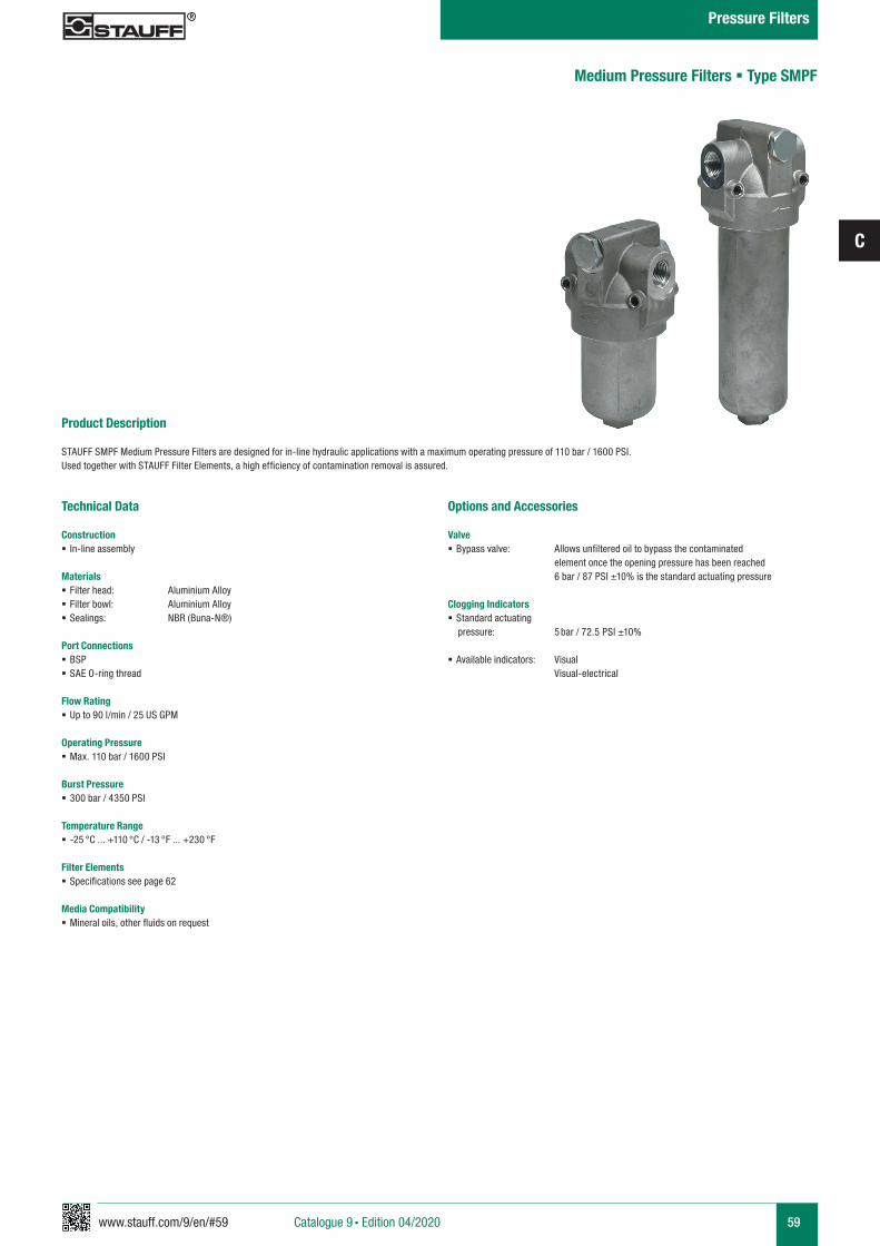
www.stauff.com/9/en/#59
C
59
Product Description
STAUFF SMPF Medium Pressure Filters are designed for in-line hydraulic applications with a maximum operating pressure of 110 bar / 1600 PSI. Used together with STAUFF Filter Elements, a high efficiency of contamination removal is assured.
Technical Data
Construction § In-line assembly
Materials § Filter head: Aluminium Alloy § Filter bowl: Aluminium Alloy § Sealings: NBR (Buna-N®)
Port Connections § BSP § SAE O-ring thread
Flow Rating § Up to 90 l/min / 25 US GPM
Operating Pressure § Max. 110 bar / 1600 PSI
Burst Pressure § 300 bar / 4350 PSI
Temperature Range § -25 °C ... +110 °C / -13 °F ... +230 °F
Filter Elements § Specifications see page 62
Media Compatibility § Mineral oils, other fluids on request
Options and Accessories
Valve § Bypass valve: Allows unfiltered oil to bypass the contaminated
element once the opening pressure has been reached 6 bar / 87 PSI ±10% is the standard actuating pressure
Clogging Indicators § Standard actuating
pressure: 5 bar / 72.5 PSI ±10% § Available indicators: Visual
Visual-electrical
Medium Pressure Filters § Type SMPF
Catalogue 9 § Edition 04/2020
Pressure Filters
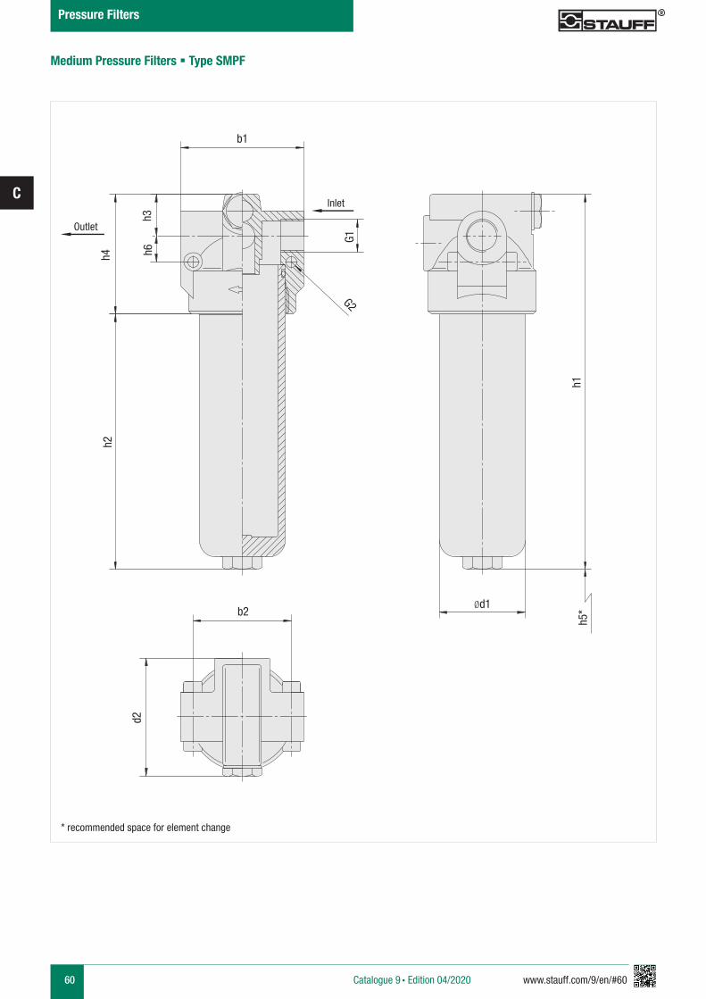
60 www.stauff.com/9/en/#60
C
Medium Pressure Filters § Type SMPF
b1
G1
Ød1b2
d2
h4h2
h1
h3h6
h5*
G2
* recommended space for element change
Inlet
Outlet
Catalogue 9 § Edition 04/2020
Pressure Filters
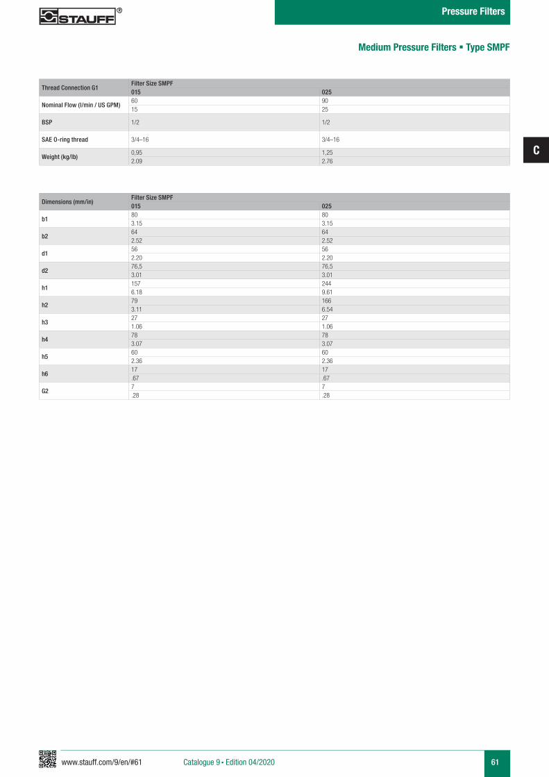
www.stauff.com/9/en/#61
C
61
Dimensions in mm (inch)
Medium Pressure Filters § Type SMPF
Thread Connection G1Filter Size SMPF015 025
Nominal Flow (l/min / US GPM)60 9015 25
BSP 1/2 1/2
SAE O-ring thread 3/4–16 3/4–16
Weight (kg/lb)0,95 1,252.09 2.76
Dimensions (mm/in)Filter Size SMPF015 025
b180 803.15 3.15
b264 642.52 2.52
d156 562.20 2.20
d276,5 76,53.01 3.01
h1157 2446.18 9.61
h279 1663.11 6.54
h327 271.06 1.06
h4 78 783.07 3.07
h560 602.36 2.36
h617 17.67 .67
G27 7.28 .28
Catalogue 9 § Edition 04/2020
Pressure Filters
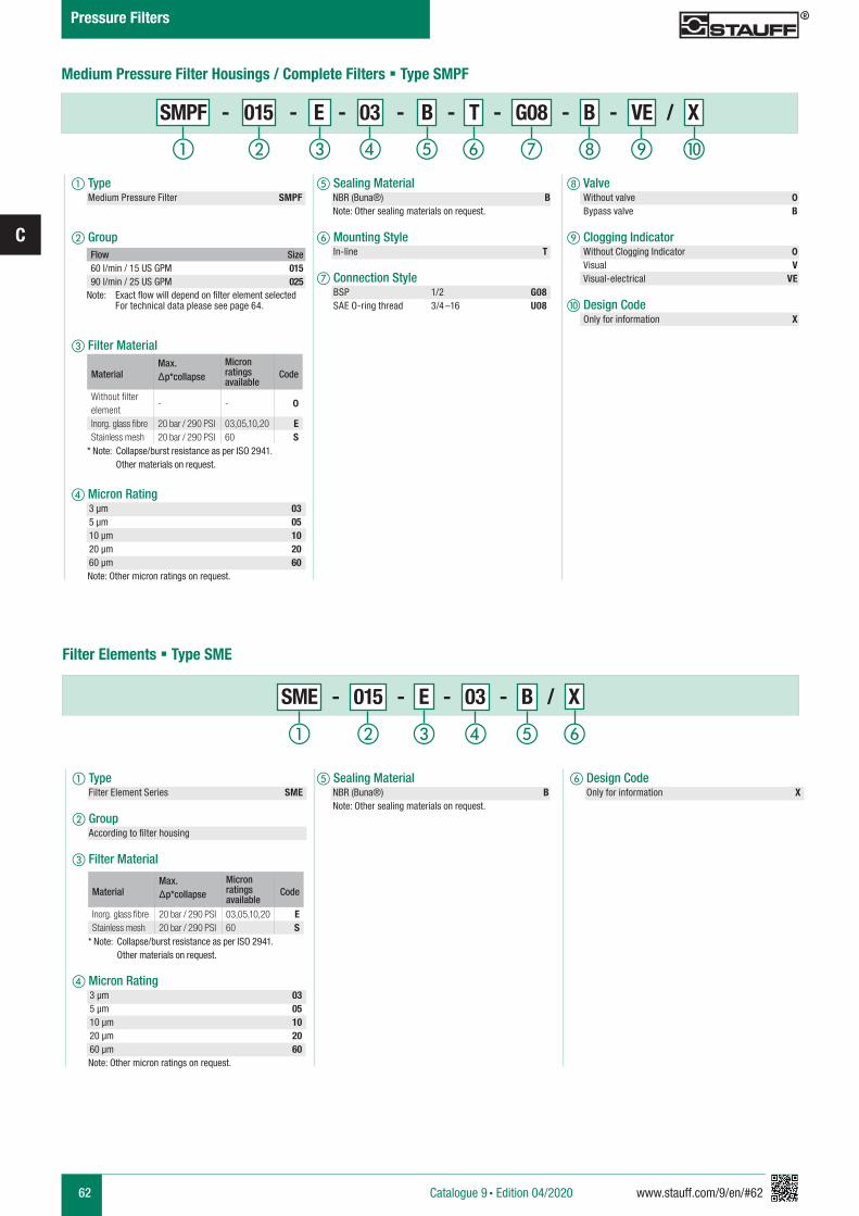
62 www.stauff.com/9/en/#62
C
a Type Medium Pressure Filter SMPF
b Group
c Filter Material
d Micron Rating3 µm 035 µm 0510 µm 1020 µm 2060 µm 60
Note: Other micron ratings on request.
h Valve Without valve 0 Bypass valve B i Clogging Indicator Without Clogging Indicator 0 Visual V Visual-electrical VE
j Design Code Only for information X
e Sealing Material NBR (Buna®) B Note: Other sealing materials on request.
f Mounting Style In-line T
g Connection Style BSP 1/2 G08 SAE O-ring thread 3/4 –16 U08
Flow Size60 l/min / 15 US GPM 01590 l/min / 25 US GPM 025
Note: Exact flow will depend on filter element selected For technical data please see page 64.
Medium Pressure Filter Housings / Complete Filters § Type SMPF
i jhga b fec d
SMPF - 015 - E - 03 - B - T - G08 - B - VE / X
SME - 015 - E - 03 - B / X
a b c fed
Filter Elements § Type SME
MaterialMax. Δp*collapse
Micron ratings available
Code
Without filter element
- - 0
Inorg. glass fibre 20 bar / 290 PSI 03,05,10,20 EStainless mesh 20 bar / 290 PSI 60 S
* Note: Collapse/burst resistance as per ISO 2941. Other materials on request.
a Type Filter Element Series SME
b Group According to filter housing
c Filter Material
d Micron Rating3 µm 035 µm 0510 µm 1020 µm 2060 µm 60
Note: Other micron ratings on request.
f Design Code Only for information X
e Sealing Material NBR (Buna®) B Note: Other sealing materials on request.
MaterialMax. Δp*collapse
Micron ratings available
Code
Inorg. glass fibre 20 bar / 290 PSI 03,05,10,20 EStainless mesh 20 bar / 290 PSI 60 S
* Note: Collapse/burst resistance as per ISO 2941. Other materials on request.
Catalogue 9 § Edition 04/2020
Pressure Filters
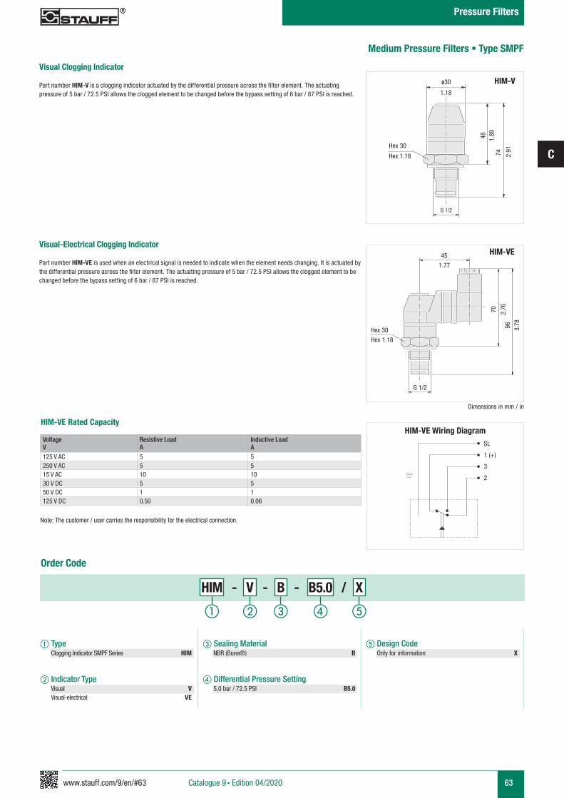
www.stauff.com/9/en/#63
C
63
HIM-VE Rated Capacity
Medium Pressure Filters § Type SMPF
HIM-VE Wiring Diagram
ø30 HIM-V
HIM-VE
1.18
48 1.89
74 2.91
70 2.76
96 3.78
Hex 30
G 1/2
G 1/2
Hex 1.18
Hex 30
SL
1 (+)
3
2
Hex 1.18
1.77
45
Dimensions in mm / in
Visual Clogging Indicator
Part number HIM-V is a clogging indicator actuated by the differential pressure across the filter element. The actuating pressure of 5 bar / 72.5 PSI allows the clogged element to be changed before the bypass setting of 6 bar / 87 PSI is reached.
Visual-Electrical Clogging Indicator
Part number HIM-VE is used when an electrical signal is needed to indicate when the element needs changing. It is actuated by the differential pressure across the filter element. The actuating pressure of 5 bar / 72.5 PSI allows the clogged element to be changed before the bypass setting of 6 bar / 87 PSI is reached.
Voltage V
Resistive LoadA
Inductive LoadA
125 V AC 5 5250 V AC 5 515 V AC 10 1030 V DC 5 550 V DC 1 1125 V DC 0.50 0.06
HIM - V - B - B5.0 / X
a Type Clogging Indicator SMPF Series HIM
b Indicator Type Visual V Visual-electrical VE
e Design Code Only for information X
c Sealing Material NBR (Buna®) B
d Differential Pressure Setting 5,0 bar / 72.5 PSI B5.0
Order Code
a b c ed
Note: The customer / user carries the responsibility for the electrical connection.
Catalogue 9 § Edition 04/2020
Pressure Filters
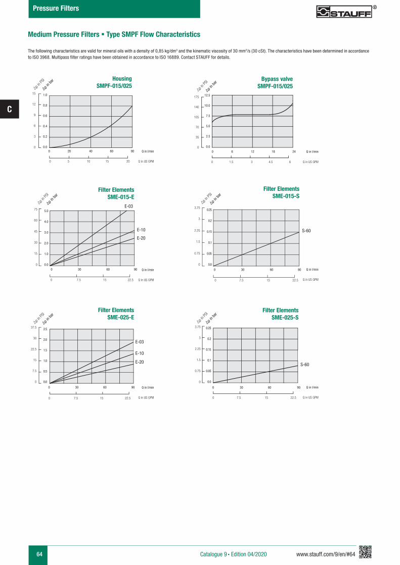
64 www.stauff.com/9/en/#64
C
HousingSMPF-015/025
0 20 40 60 80
0 5 10 15 20
1.0
0.8
0.6
0.4
0.2
0.0
15
12
9
6
3
0
∆p in P
SI
∆p in b
ar
Q in l/min
Q in US GPM
Filter ElementsSME-015-E
0 30 60 90
0 7.5 15 22.5
5.0
4.0
3.0
2.0
1.0
0.0
75
60
45
30
15
0
∆p in P
SI
∆p in b
ar
Q in l/min
Q in US GPM
Filter ElementsSME-015-S
0 30 60 90
0 7.5 15 22.5
0.25
0.2
0.15
0.1
0.05
0.0
3.75
3
2.25
1.5
0.75
0
∆p in P
SI
∆p in b
ar
Q in l/min
Q in US GPM
Filter ElementsSME-025-S
0 30 60 90
0 7.5 15 22.5
0.25
0.2
0.15
0.1
0.05
0.0
3.75
3
2.25
1.5
0.75
0
∆p in P
SI
∆p in b
ar
Q in l/min
Q in US GPM
Filter ElementsSME-025-E
0 30 60 90
0 7.5 15 22.5
2.5
2.0
1.5
1.0
0.5
0.0
37.5
30
22.5
15
7.5
0
∆p in P
SI
∆p in b
ar
Q in l/min
Q in US GPM
Bypass valveSMPF-015/025
0 6 12 18 24
0 1.5 3 4.5 6
12.5
10.0
7.5
5.0
2.5
0.0
175
140
105
70
35
0
∆p in P
SI
∆p in b
ar
Q in l/min
Q in US GPM
E-03
E-10 S-60
S-60
E-20
E-03
E-10
E-20
Medium Pressure Filters § Type SMPF Flow Characteristics
The following characteristics are valid for mineral oils with a density of 0,85 kg/dm3 and the kinematic viscosity of 30 mm2/s (30 cSt). The characteristics have been determined in accordance to ISO 3968. Multipass filter ratings have been obtained in accordance to ISO 16889. Contact STAUFF for details.
Catalogue 9 § Edition 04/2020
Pressure Filters
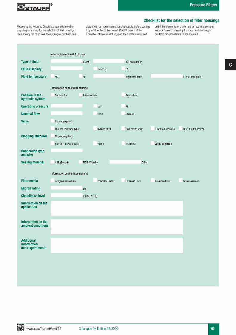
www.stauff.com/9/en/#65
C
65Catalogue 9 § Edition 04/2020
Checklist for the selection of filter housings
Type of fluid
Fluid viscosity
Fluid temperature
Position in the hydraulic system
Operating pressure
Nominal flow
Valve
Clogging indicator
Connection type and size
Sealing material
Filter media
Micron rating
Cleanliness level
Information on the application
Information on the ambient conditions
Additional informationand requirements
mm2/sec cSt
Brand
Suction line Pressure line Return line
Bypass valve
No, not required
Reverse flow valveNon-return valve Multi-function valve
ISO designation
°C °F In cold condition In warm condition
Information on the fluid in use
Information on the filter housing
bar PSI
l/min US GPM
Yes, the following type:
Visual
No, not required
Electrical Visual-electricalYes, the following type:
NBR (Buna®) FKM (Viton®) Other
Information on the filter element
Inorganic Glass Fibre Polyester Fibre Cellulose Fibre Stainless Fibre
µm
(to ISO 4406)
Stainless Mesh
Please use the following Checklist as a guideline when preparing an enquiry for the selection of filter housings. Scan or copy the page from the catalogue, print and com-
plete it with as much information as possible, before sending it by email or fax to the closest STAUFF branch office. If possible, please also let us know the quantities required,
and if the enquiry is for a one-time or recurring demand. We look forward to hearing from you, and are always available for consultation, when required.
Pressure Filters
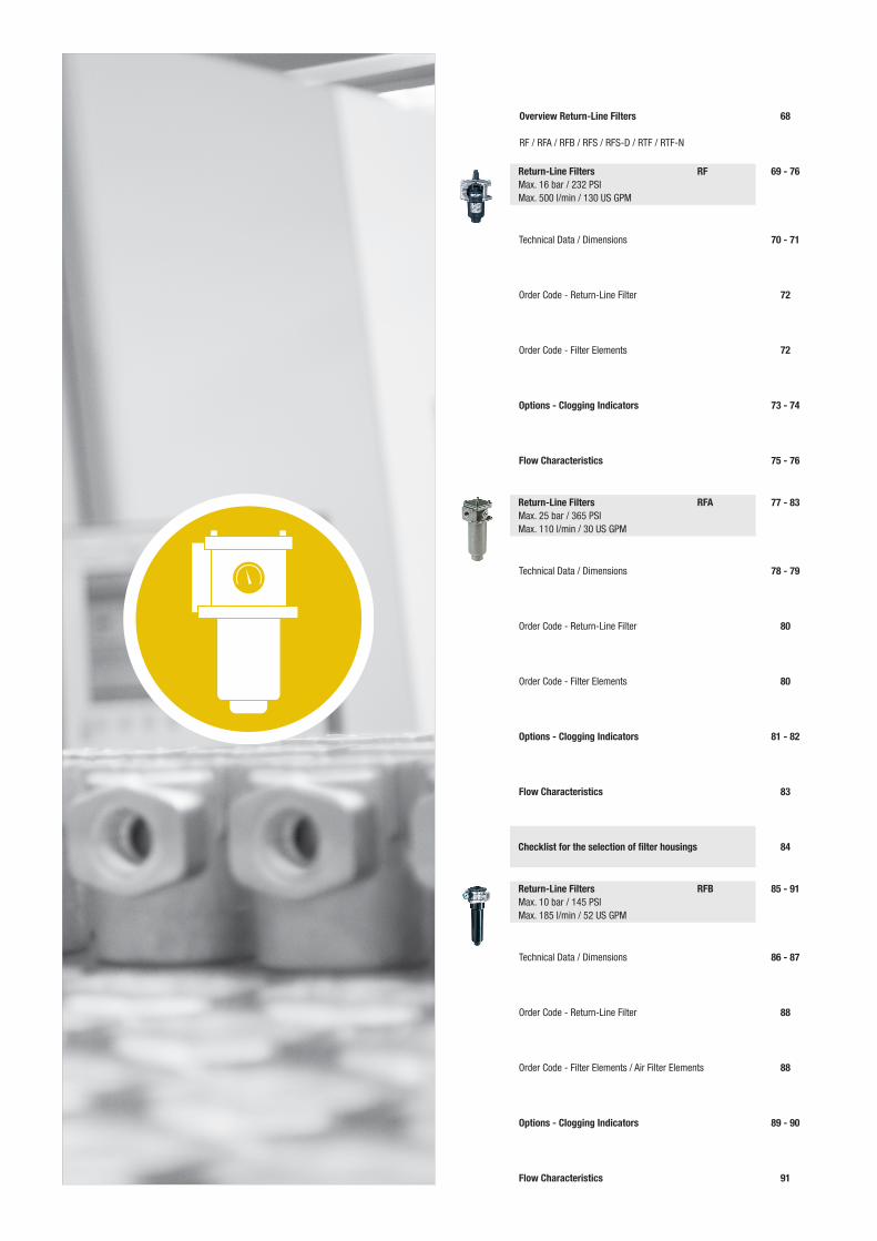
Overview Return-Line Filters
RF / RFA / RFB / RFS / RFS-D / RTF / RTF-N
69 - 76
70 - 71
72
72
Technical Data / Dimensions
Order Code - Return-Line Filter
Order Code - Filter Elements
68
Return-Line Filters RFMax. 16 bar / 232 PSI Max. 500 l/min / 130 US GPM
73 - 74Options - Clogging Indicators
75 - 76Flow Characteristics
77 - 83
78 - 79
80
80
Technical Data / Dimensions
Order Code - Return-Line Filter
Order Code - Filter Elements
Return-Line Filters RFAMax. 25 bar / 365 PSI Max. 110 l/min / 30 US GPM
81 - 82Options - Clogging Indicators
83Flow Characteristics
85 - 91
86 - 87
88
88
Technical Data / Dimensions
Order Code - Return-Line Filter
Order Code - Filter Elements / Air Filter Elements
Return-Line Filters RFBMax. 10 bar / 145 PSIMax. 185 l/min / 52 US GPM
89 - 90Options - Clogging Indicators
91Flow Characteristics
84Checklist for the selection of filter housings
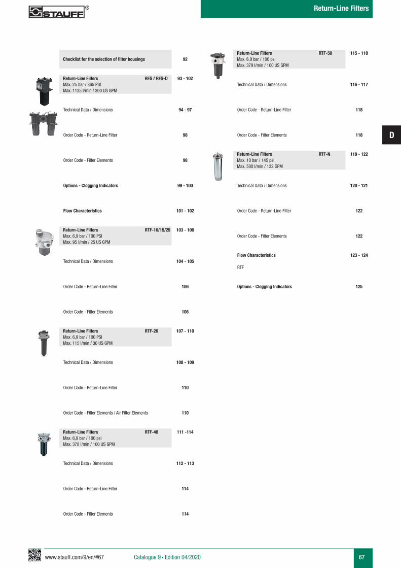
www.stauff.com/9/en/#67
D
67Catalogue 9 § Edition 04/2020
Return-Line Filters
93 - 102
94 - 97
98
98
Technical Data / Dimensions
Order Code - Return-Line Filter
Order Code - Filter Elements
Return-Line Filters RFS / RFS-DMax. 25 bar / 365 PSI Max. 1135 l/min / 300 US GPM
99 - 100Options - Clogging Indicators
101 - 102Flow Characteristics
103 - 106
104 - 105
106
106
Technical Data / Dimensions
Order Code - Return-Line Filter
Order Code - Filter Elements
Return-Line Filters RTF-10/15/25Max. 6,9 bar / 100 PSIMax. 95 l/min / 25 US GPM
107 - 110
108 - 109
110
110
Technical Data / Dimensions
Order Code - Return-Line Filter
Order Code - Filter Elements / Air Filter Elements
Return-Line Filters RTF-20Max. 6,9 bar / 100 PSIMax. 115 l/min / 30 US GPM
111 -114
112 - 113
114
114
Technical Data / Dimensions
Order Code - Return-Line Filter
Order Code - Filter Elements
Return-Line Filters RTF-40Max. 6,9 bar / 100 psi Max. 378 l/min / 100 US GPM
115 - 118
116 - 117
118
118
Technical Data / Dimensions
Order Code - Return-Line Filter
Order Code - Filter Elements
Return-Line Filters RTF-50Max. 6,9 bar / 100 psi Max. 379 l/min / 100 US GPM
119 - 122
120 - 121
122
122
Technical Data / Dimensions
Order Code - Return-Line Filter
Order Code - Filter Elements
Return-Line Filters RTF-NMax. 10 bar / 145 psiMax. 500 l/min / 132 GPM
125Options - Clogging Indicators
123 - 124Flow Characteristics
RTF
92Checklist for the selection of filter housings
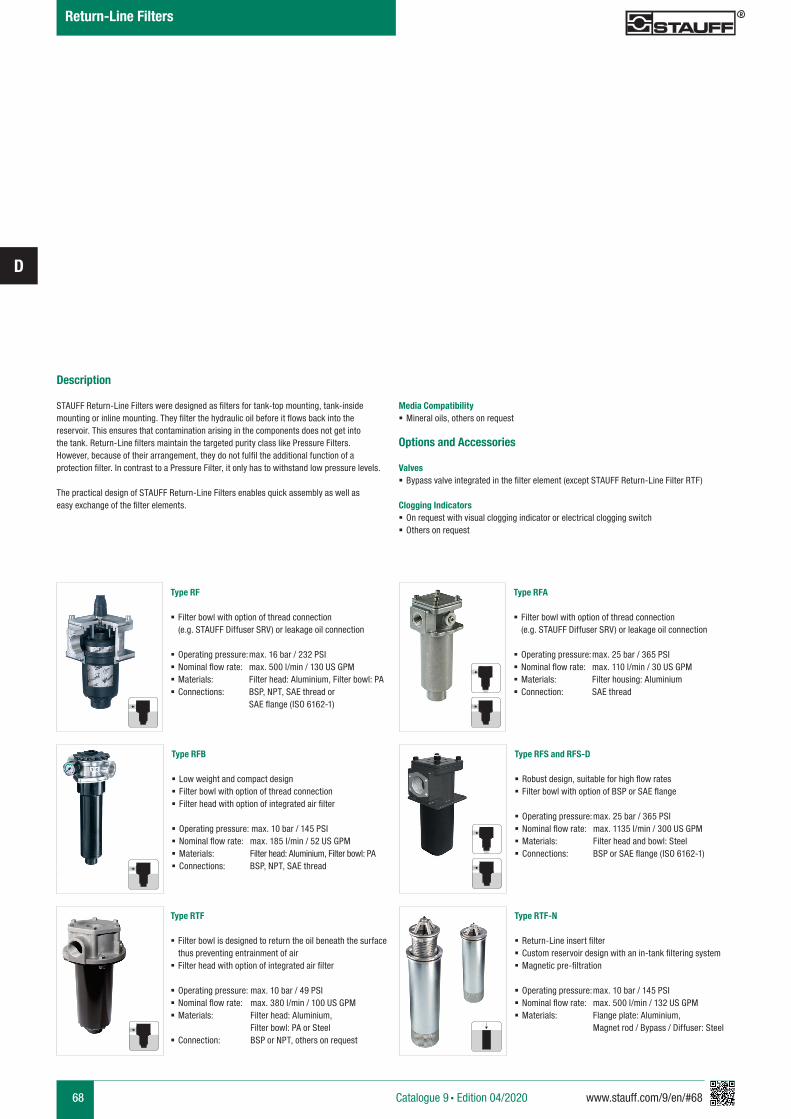
68 www.stauff.com/9/en/#68
D
Description
STAUFF Return-Line Filters were designed as filters for tank-top mounting, tank-inside mounting or inline mounting. They filter the hydraulic oil before it flows back into the reservoir. This ensures that contamination arising in the components does not get into the tank. Return-Line filters maintain the targeted purity class like Pressure Filters. However, because of their arrangement, they do not fulfil the additional function of a protection filter. In contrast to a Pressure Filter, it only has to withstand low pressure levels.
The practical design of STAUFF Return-Line Filters enables quick assembly as well as easy exchange of the filter elements.
Media Compatibility § Mineral oils, others on request
Options and Accessories
Valves § Bypass valve integrated in the filter element (except STAUFF Return-Line Filter RTF)
Clogging Indicators § On request with visual clogging indicator or electrical clogging switch § Others on request
Type RF
§ Filter bowl with option of thread connection (e.g. STAUFF Diffuser SRV) or leakage oil connection
§ Operating pressure: max. 16 bar / 232 PSI § Nominal flow rate: max. 500 l/min / 130 US GPM § Materials: Filter head: Aluminium, Filter bowl: PA § Connections: BSP, NPT, SAE thread or SAE flange (ISO 6162-1)
Type RFA
§ Filter bowl with option of thread connection (e.g. STAUFF Diffuser SRV) or leakage oil connection
§ Operating pressure: max. 25 bar / 365 PSI § Nominal flow rate: max. 110 l/min / 30 US GPM § Materials: Filter housing: Aluminium § Connection: SAE thread
Type RFB
§ Low weight and compact design § Filter bowl with option of thread connection § Filter head with option of integrated air filter
§ Operating pressure: max. 10 bar / 145 PSI § Nominal flow rate: max. 185 l/min / 52 US GPM § Materials: Filter head: Aluminium, Filter bowl: PA § Connections: BSP, NPT, SAE thread
Type RFS and RFS-D
§ Robust design, suitable for high flow rates § Filter bowl with option of BSP or SAE flange
§ Operating pressure: max. 25 bar / 365 PSI § Nominal flow rate: max. 1135 l/min / 300 US GPM § Materials: Filter head and bowl: Steel § Connections: BSP or SAE flange (ISO 6162-1)
Type RTF
§ Filter bowl is designed to return the oil beneath the surface thus preventing entrainment of air
§ Filter head with option of integrated air filter
§ Operating pressure: max. 10 bar / 49 PSI § Nominal flow rate: max. 380 l/min / 100 US GPM § Materials: Filter head: Aluminium, Filter bowl: PA or Steel
§ Connection: BSP or NPT, others on request
Type RTF-N
§ Return-Line insert filter § Custom reservoir design with an in-tank filtering system § Magnetic pre-filtration
§ Operating pressure: max. 10 bar / 145 PSI § Nominal flow rate: max. 500 l/min / 132 US GPM § Materials: Flange plate: Aluminium, Magnet rod / Bypass / Diffuser: Steel
Catalogue 9 § Edition 04/2020
Return-Line Filters
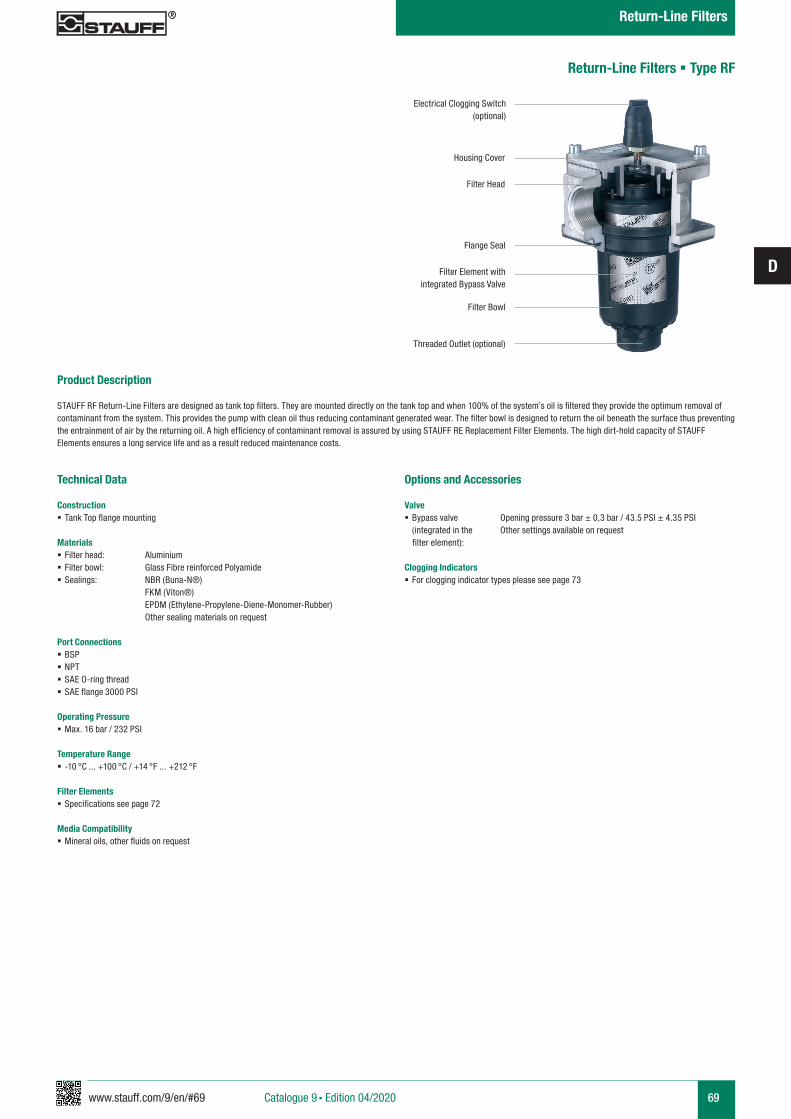
www.stauff.com/9/en/#69
D
69
Return-Line Filters § Type RF
Product Description STAUFF RF Return-Line Filters are designed as tank top filters. They are mounted directly on the tank top and when 100% of the system’s oil is filtered they provide the optimum removal of contaminant from the system. This provides the pump with clean oil thus reducing contaminant generated wear. The filter bowl is designed to return the oil beneath the surface thus preventing the entrainment of air by the returning oil. A high efficiency of contaminant removal is assured by using STAUFF RE Replacement Filter Elements. The high dirt-hold capacity of STAUFF Elements ensures a long service life and as a result reduced maintenance costs.
Technical Data
Construction § Tank Top flange mounting
Materials § Filter head: Aluminium § Filter bowl: Glass Fibre reinforced Polyamide § Sealings: NBR (Buna-N®)
FKM (Viton®) EPDM (Ethylene-Propylene-Diene-Monomer-Rubber) Other sealing materials on request
Port Connections § BSP § NPT § SAE O-ring thread § SAE flange 3000 PSI
Operating Pressure § Max. 16 bar / 232 PSI
Temperature Range § -10 °C ... +100 °C / +14 °F ... +212 °F
Filter Elements § Specifications see page 72
Media Compatibility § Mineral oils, other fluids on request
Options and Accessories
Valve § Bypass valve Opening pressure 3 bar ± 0,3 bar / 43.5 PSI ± 4.35 PSI (integrated in the Other settings available on request
filter element):
Clogging Indicators § For clogging indicator types please see page 73
Electrical Clogging Switch (optional)
Housing Cover
Filter Head
Flange Seal
Filter Element with integrated Bypass Valve
Filter Bowl
Threaded Outlet (optional)
Catalogue 9 § Edition 04/2020
Return-Line Filters
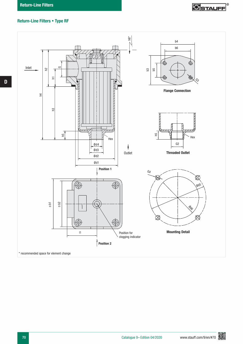
70 www.stauff.com/9/en/#70
D
Return-Line Filters § Type RF
* recommended space for element change
Flange Connection
Mounting Detail
Threaded Outlet
Position for clogging indicator
Position 1
Position 2
h4
h2
h1h3
h5G
Ød1
Ød2
Ød3
Ød4
b1 b2
l1
G4
Ød6
Ød5
G2
h5
G3
b3 b5
b4
b6
HexHex
h6*
Inlet
Outlet
Catalogue 9 § Edition 04/2020
Return-Line Filters
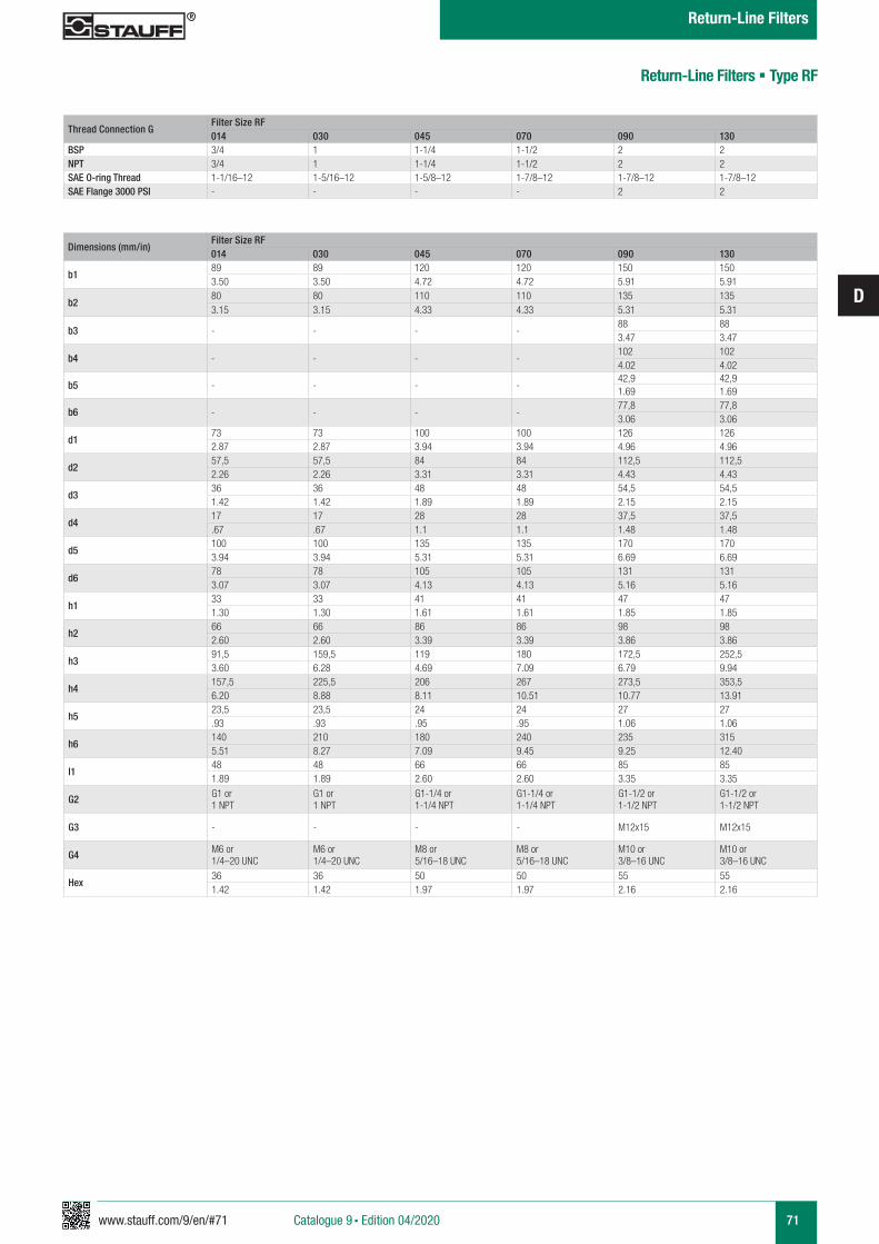
www.stauff.com/9/en/#71
D
71
Return-Line Filters § Type RF
Thread Connection GFilter Size RF014 030 045 070 090 130
BSP 3/4 1 1-1/4 1-1/2 2 2NPT 3/4 1 1-1/4 1-1/2 2 2SAE O-ring Thread 1-1/16–12 1-5/16–12 1-5/8–12 1-7/8–12 1-7/8–12 1-7/8–12SAE Flange 3000 PSI - - - - 2 2
Dimensions (mm/in)Filter Size RF014 030 045 070 090 130
b189 89 120 120 150 1503.50 3.50 4.72 4.72 5.91 5.91
b280 80 110 110 135 1353.15 3.15 4.33 4.33 5.31 5.31
b3 - - - -88 883.47 3.47
b4 - - - -102 1024.02 4.02
b5 - - - -42,9 42,91.69 1.69
b6 - - - -77,8 77,83.06 3.06
d173 73 100 100 126 1262.87 2.87 3.94 3.94 4.96 4.96
d257,5 57,5 84 84 112,5 112,52.26 2.26 3.31 3.31 4.43 4.43
d336 36 48 48 54,5 54,51.42 1.42 1.89 1.89 2.15 2.15
d417 17 28 28 37,5 37,5.67 .67 1.1 1.1 1.48 1.48
d5100 100 135 135 170 1703.94 3.94 5.31 5.31 6.69 6.69
d678 78 105 105 131 1313.07 3.07 4.13 4.13 5.16 5.16
h133 33 41 41 47 471.30 1.30 1.61 1.61 1.85 1.85
h266 66 86 86 98 982.60 2.60 3.39 3.39 3.86 3.86
h391,5 159,5 119 180 172,5 252,53.60 6.28 4.69 7.09 6.79 9.94
h4157,5 225,5 206 267 273,5 353,56.20 8.88 8.11 10.51 10.77 13.91
h523,5 23,5 24 24 27 27.93 .93 .95 .95 1.06 1.06
h6140 210 180 240 235 3155.51 8.27 7.09 9.45 9.25 12.40
I148 48 66 66 85 851.89 1.89 2.60 2.60 3.35 3.35
G2 G1 or 1 NPT
G1 or 1 NPT
G1-1/4 or 1-1/4 NPT
G1-1/4 or 1-1/4 NPT
G1-1/2 or 1-1/2 NPT
G1-1/2 or 1-1/2 NPT
G3 - - - - M12x15 M12x15
G4 M6 or 1/4–20 UNC
M6 or 1/4–20 UNC
M8 or5/16–18 UNC
M8 or5/16–18 UNC
M10 or3/8–16 UNC
M10 or3/8–16 UNC
Hex36 36 50 50 55 551.42 1.42 1.97 1.97 2.16 2.16
Catalogue 9 § Edition 04/2020
Return-Line Filters
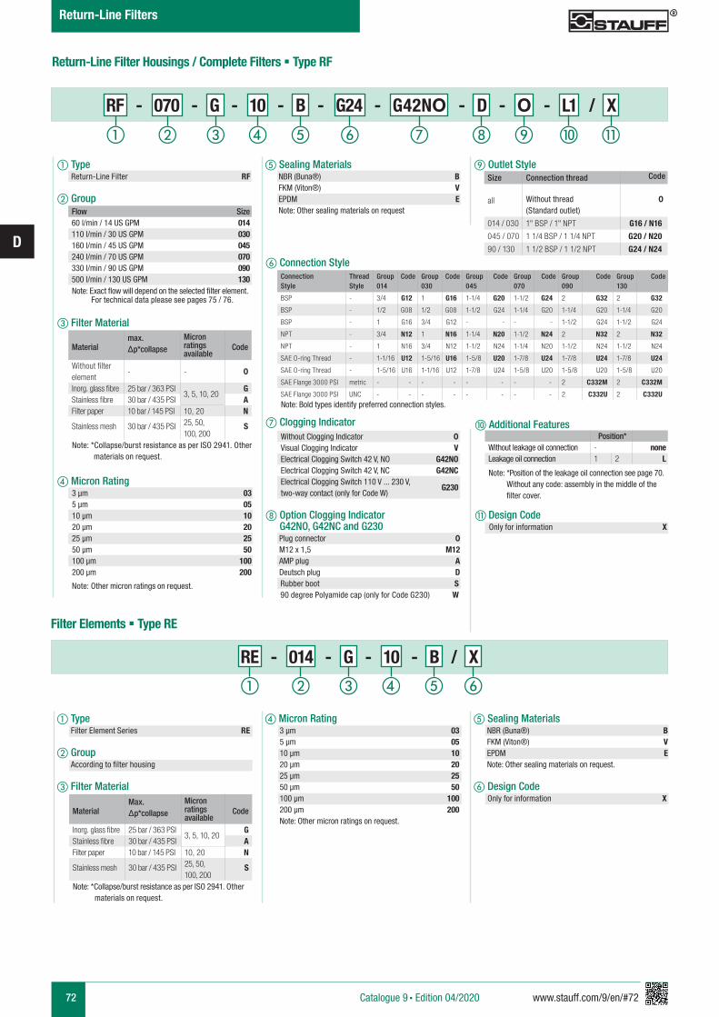
72 www.stauff.com/9/en/#72
D
Return-Line Filter Housings / Complete Filters § Type RF
f Connection Style
g Clogging Indicator
h Option Clogging Indicator G42NO, G42NC and G230 Plug connector 0 M12 x 1,5 M12 AMP plug A Deutsch plug D Rubber boot S 90 degree Polyamide cap (only for Code G230) W
j Additional Features
k Design Code Only for information X
e Sealing Materials NBR (Buna®) B FKM (Viton®) V EPDM E Note: Other sealing materials on request
i Outlet Style
Flow Size60 l/min / 14 US GPM 014110 l/min / 30 US GPM 030160 l/min / 45 US GPM 045240 l/min / 70 US GPM 070330 l/min / 90 US GPM 090500 l/min / 130 US GPM 130
Note: Exact flow will depend on the selected filter element. For technical data please see pages 75 / 76.
Without Clogging Indicator 0Visual Clogging Indicator VElectrical Clogging Switch 42 V, NO G42NOElectrical Clogging Switch 42 V, NC G42NCElectrical Clogging Switch 110 V ... 230 V, two-way contact (only for Code W)
G230
Position*Without leakage oil connection - noneLeakage oil connection 1 2 L
Note: *Position of the leakage oil connection see page 70. Without any code: assembly in the middle of the filter cover.
Materialmax. Δp*collapse
Micron ratings available
Code
Without filter element
- - 0
Inorg. glass fibre 25 bar / 363 PSI3, 5, 10, 20
GStainless fibre 30 bar / 435 PSI AFilter paper 10 bar / 145 PSI 10, 20 N
Stainless mesh 30 bar / 435 PSI 25, 50, 100, 200
S
Note: *Collapse/burst resistance as per ISO 2941. Other materials on request.
d Micron Rating 3 µm 03 5 µm 05 10 µm 10 20 µm 20 25 µm 25 50 µm 50 100 µm 100 200 µm 200 Note: Other micron ratings on request.
e Sealing Materials NBR (Buna®) B FKM (Viton®) V EPDM E Note: Other sealing materials on request.
f Design Code Only for information X
RE - 014 - G - 10 - B / X
a Type Filter Element Series RE
b Group According to filter housing
c Filter Material
Filter Elements § Type RE
MaterialMax. Δp*collapse
Micron ratings available
Code
Inorg. glass fibre 25 bar / 363 PSI3, 5, 10, 20
GStainless fibre 30 bar / 435 PSI AFilter paper 10 bar / 145 PSI 10, 20 N
Stainless mesh 30 bar / 435 PSI 25, 50, 100, 200
S
Note: *Collapse/burst resistance as per ISO 2941. Other materials on request.
a Type Return-Line Filter RF
b Group
c Filter Material
d Micron Rating 3 µm 03 5 µm 05 10 µm 10 20 µm 20 25 µm 25 50 µm 50 100 µm 100 200 µm 200 Note: Other micron ratings on request.
RF - 070 - G - 10 - B - G24 - G42NO - D - O - L1 / X
ihga b c fed j k
a b c fed
Connection Style
Thread Style
Group014
Code Group030
Code Group045
Code Group070
Code Group090
Code Group130
Code
BSP - 3/4 G12 1 G16 1-1/4 G20 1-1/2 G24 2 G32 2 G32
BSP - 1/2 G08 1/2 G08 1-1/2 G24 1-1/4 G20 1-1/4 G20 1-1/4 G20
BSP - 1 G16 3/4 G12 - - - - 1-1/2 G24 1-1/2 G24
NPT - 3/4 N12 1 N16 1-1/4 N20 1-1/2 N24 2 N32 2 N32
NPT - 1 N16 3/4 N12 1-1/2 N24 1-1/4 N20 1-1/2 N24 1-1/2 N24
SAE O-ring Thread - 1-1/16 U12 1-5/16 U16 1-5/8 U20 1-7/8 U24 1-7/8 U24 1-7/8 U24
SAE O-ring Thread - 1-5/16 U16 1-1/16 U12 1-7/8 U24 1-5/8 U20 1-5/8 U20 1-5/8 U20
SAE Flange 3000 PSI metric - - - - - - - - 2 C332M 2 C332M
SAE Flange 3000 PSI UNC - - - - - - - - 2 C332U 2 C332UNote: Bold types identify preferred connection styles.
Catalogue 9 § Edition 04/2020
Return-Line Filters
Size Connection thread Code
all Without thread (Standard outlet)
0
014 / 030 1" BSP / 1" NPT G16 / N16
045 / 070 1 1/4 BSP / 1 1/4 NPT G20 / N20
90 / 130 1 1/2 BSP / 1 1/2 NPT G24 / N24

www.stauff.com/9/en/#73
D
73
Return-Line Filters § Type RF
Electrical Clogging Switch
The switch is used where an electrical signal is needed to indicate when the element needs to be changed. The switch can turn on a light, or shut the machine down, or any further function controlled by an electric signal. The switching pressure is 2,5 bar / 36.25 PSI and this allows the element to be changed before the bypass setting of 3 bar / 43.5 PSI is reached.
Order Code
Limit-Switch - G42NO - S - M10 - B2.5
a Type Limit-Switch
b Connector Type
c Plug Type M12 Five-Pin Connector according to IEC 61076-2-101 M12 AMP-Junior-Timer Plug A DEUTSCH Plug DT04-2P D Rubber boot S 90 degree Polyamide cap W (only for Connector Type G230)
d Thread Type M10 x 1 M10
e Pressure Setting 2,5 bar / 36.3 PSI B2.5Electrical Clogging Switch 42 V, NO G42NO
Electrical Clogging Switch 42 V, NC G42NCElectrical Clogging Switch 110 V ... 230 V, two-way contact (only for Plug Type W)
G230
Dimensional drawings: All dimensions in mm/in.
a b c ed
Standard type with plug connector and rubber cap. Available with DEUTSCH DT04-2P plug (industrial standard), AMP Junior Timer plug (industrial standard) and five-pin circular connector M12, A-coded, according to IEC 61076-2-101.
Catalogue 9 § Edition 04/2020
Return-Line Filters
Dimensions Plug Type
WM12 S
3 11 21 2
A
61,5
(2.4
2)
9 (.3
5)
M10x1
D
21 21
71 (2
.80)
9 (.3
5)
M10x1
60 (2
.36)
9 (.3
5)
M10x1
9 (.3
5)
76 (2
.98)
M10x1
9 (.3
5)
74 (2
.91)
M10x1
P4
1
2
Note: The customer / user carries the responsibility for the electrical connection.
Limit-Switch G42NO+NC Limit-Switch G230Switching Capacity 100 VA 1000 VAVoltage 10…42 VAC 10…250 VACCurrent 10mA…4ASwitching Accuracy ± 0,5 bar at room temp. and new stateSwitching Frequency 200/minmax. Pressure Ramp Rate ≤ 1 bar/msDegree of Protection IP65 (plug type S and W), IP67 (plug type M12, A, D)Temperature Range -30°C … +100°C -40°C … +100°C
Technical Data
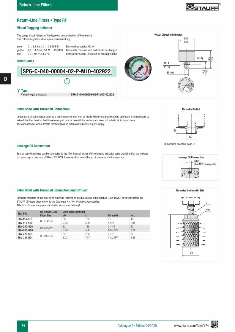
74 www.stauff.com/9/en/#74
D
Size SRVfor Return-Line Filter Size
Dimensions (mm/in)øD L Thread G Hex
SRV-114-G16RF-014/030
60 139 G1 46SRV-114-N16 2.36 5.47 1 NPT 1.81SRV-200-G20
RF-045/07082 139 G1-1/4 60
SRV-200-N20 3.23 5.47 1-1/4 NPT 2.36SRV-227-G24
RF-090/13082 200 G1-1/2 60
SRV-227-N24 3.23 7.87 1-1/2 NPT 2.36
Filter Bowl with Threaded Connection
Under some circumstances such as a tall reservoir or one with oil levels which vary greatly during operation, it is necessary to extend the filter bowl so that the returning oil returns beneath the surface and does not entrain air in the process. The optional bowl with a female thread allows an extension to be fitted quite simply.
Leakage Oil Connection
Seal or case drain lines can be connected to the filter through either of the clogging indicator ports providing that the leakage oil can accept a pressure of 3 bar / 43.5 PSI. It ensures that no unfiltered oil can return to the reservoir.
Filter Bowl with Threaded Connection and Diffuser
Diffusers mounted to the filter bowl minimise foaming and reduce noise of high Return-Line flows. For further details on STAUFF Diffusers please refer to the Calatogue No. 10 - Hydraulic Accessories.Attention: Connection pipe not included in scope of delivery!
Threaded Outlet with SRV
G
Hex
ØD
L
Leakage Oil ConnectionG1/4
(1/4 NPT on request)
Threaded Outlet
Dimensions see table page 71
G2
h5
Return-Line Filters § Type RF
Catalogue 9 § Edition 04/2020
Return-Line Filters
Visual Clogging Indicator
The gauge visually displays the degree of contamination of the element.The colored segments allow quick visual checking.
green 0 ... 2,5 bar / 0 … 36.25 PSI Element has service life leftyellow 2,5 ... 3,0 bar / 36.25 ... 43.5 PSI Element is contaminated and should be changed red >3,0 bar / >43.5 PSI Bypass valve open, unfiltered oil passing to tank
Ø40
14
M10x1
1.58
.39
.69
1.75
.51
10
17,5
44,5
0
1
2
3
bar
Visual Clogging Indicator
SPG-C-040-00004-02-P-M10-402922
Order Codes
a Type Visual Clogging Indicator SPG-C-040-00004-02-P-M10-402922
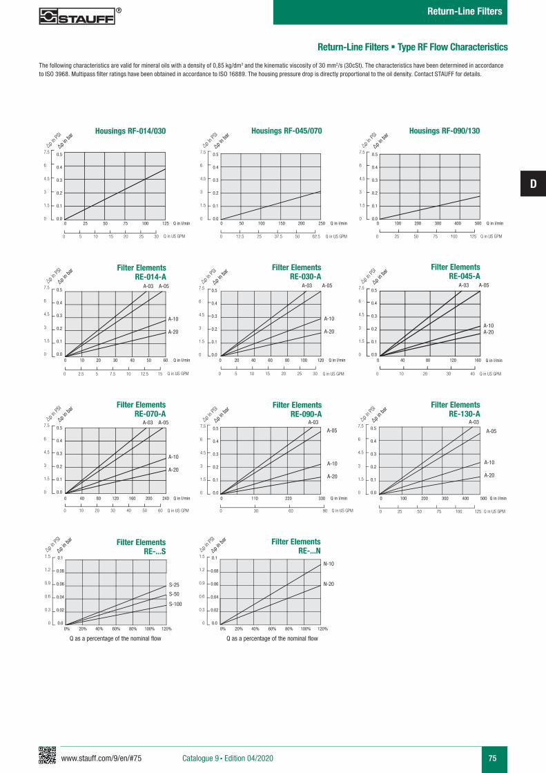
www.stauff.com/9/en/#75
D
75
Housings RF-014/030
0 25 50 75 100 125
0 5 10 15 20 25 30
0.5
0.4
0.3
0.2
0.1
0.0
7.5
6
4.5
3
1.5
0
∆p in b
ar
∆p in P
SI
0.5
0.4
0.3
0.2
0.1
0.0
7.5
6
4.5
3
1.5
0
∆p in b
ar
∆p in P
SI
0.5
0.4
0.3
0.2
0.1
0.0
7.5
6
4.5
3
1.5
0
∆p in b
ar
∆p in P
SI
0.5
0.4
0.3
0.2
0.1
0.0
7.5
6
4.5
3
1.5
0
∆p in b
ar
∆p in P
SI
0.5
0.4
0.3
0.2
0.1
0.0
7.5
6
4.5
3
1.5
0
∆p in b
ar
∆p in P
SI
0.5
0.4
0.3
0.2
0.1
0.0
7.5
6
4.5
3
1.5
0
∆p in b
ar
∆p in P
SI
0.5
0.4
0.3
0.2
0.1
0.0
7.5
6
4.5
3
1.5
0
∆p in b
ar
∆p in P
SI
0.5
0.4
0.3
0.2
0.1
0.0
7.5
6
4.5
3
1.5
0
∆p in b
ar
∆p in P
SI
0.5
0.4
0.3
0.2
0.1
0.0
7.5
6
4.5
3
1.5
0
∆p in b
ar
∆p in P
SI
Housings RF-045/070
0 50 100 150 200 250
0 12.5 25 37.5 50 62.5
Filter ElementsRE-...S
0% 20% 40% 60% 80% 100% 120% 0% 20% 40% 60% 80% 100% 120%
Filter ElementsRE-...N
Housings RF-090/130
0 100 200 300 400 500
0 25 50 75 100 125
Filter Elements RE-014-A
0 10 20 30 40 50 60
0 2.5 5 7.5 10 12.5 15
A-10
A-20
A-03 A-05
Filter Elements RE-070-A
0 40 80 120 160 200 240
0 10 20 30 40 50 60
A-10
A-20
N-10
N-20S-25
S-50
S-100
0.1
0.08
0.06
0.04
0.02
0.0
0.1
0.08
0.06
0.04
0.02
0.0
1.5
1.2
0.9
0.6
0.3
0
1.5
1.2
0.9
0.6
0.3
0
∆p in b
ar
∆p in P
SI
∆p in b
ar
∆p in P
SI
Q as a percentage of the nominal flow Q as a percentage of the nominal flow
Q in l/min
Q in US GPM
Q in l/min
Q in US GPM
Q in l/min
Q in US GPM
Q in l/min
Q in US GPM
Q in l/min
Q in US GPM
Q in l/min
Q in US GPM
Q in l/min
Q in US GPM
Q in l/min
Q in US GPM
Q in l/min
Q in US GPM
A-03 A-05
Filter Elements RE-030-A
0 20 40 60 80 100 120
0 5 10 15 20 25 30
A-10
A-20
A-03 A-05
Filter Elements RE-130-A
0 100 200 300 400 500
0 25 50 75 100 125
A-10
A-20
A-03
A-05
Filter Elements RE-090-A
0 110 220 330
0 30 60 90
A-10
A-20
A-03
A-05
Filter Elements RE-045-A
0 40 80 120 160
0 10 20 30 40
A-10A-20
A-03 A-05
Return-Line Filters § Type RF Flow Characteristics
The following characteristics are valid for mineral oils with a density of 0,85 kg/dm3 and the kinematic viscosity of 30 mm2/s (30cSt). The characteristics have been determined in accordance to ISO 3968. Multipass filter ratings have been obtained in accordance to ISO 16889. The housing pressure drop is directly proportional to the oil density. Contact STAUFF for details.
Catalogue 9 § Edition 04/2020
Return-Line Filters
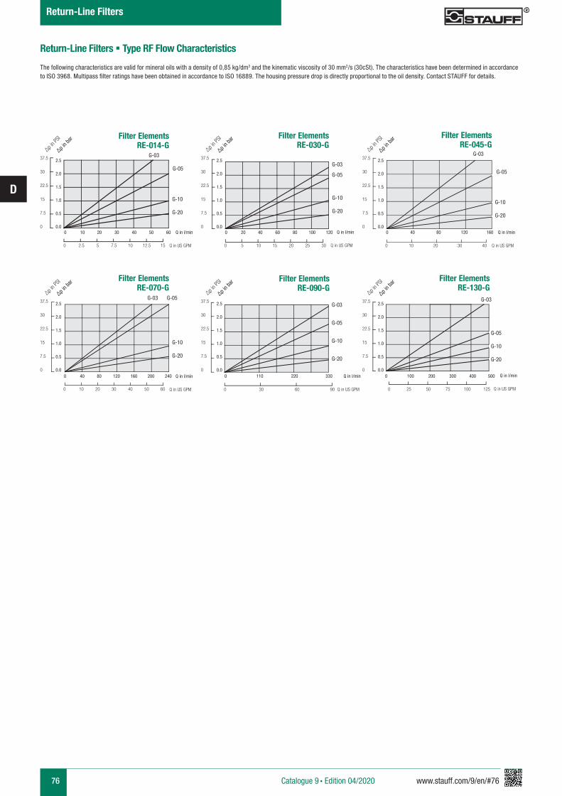
76 www.stauff.com/9/en/#76
D
Return-Line Filters § Type RF Flow Characteristics
The following characteristics are valid for mineral oils with a density of 0,85 kg/dm3 and the kinematic viscosity of 30 mm2/s (30cSt). The characteristics have been determined in accordance to ISO 3968. Multipass filter ratings have been obtained in accordance to ISO 16889. The housing pressure drop is directly proportional to the oil density. Contact STAUFF for details.
Filter Elements RE-014-G
0 10 20 30 40 50 60
0 2.5 5 7.5 10 12.5 15
G-10
G-20
G-03
G-05
Q in l/min
Q in US GPM
Q in l/min
Q in US GPM
Q in l/min
Q in US GPM
Q in l/min
Q in US GPM
Q in l/min
Q in US GPM
Q in l/min
Q in US GPM
Filter Elements RE-030-G
0 20 40 60 80 100 120
0 5 10 15 20 25 30
G-10
G-20
G-03
G-05
Filter Elements RE-045-G
0 40 80 120 160
0 10 20 30 40
G-10
G-20
G-03
G-05
Filter Elements RE-070-G
0 40 80 120 160 200 240
0 10 20 30 40 50 60
G-10
G-20
G-03 G-05
Filter Elements RE-130-G
0 100 200 300 400 500
0 25 50 75 100 125
G-05
G-10
G-20
G-03
Filter Elements RE-090-G
0 110 220 330
0 30 60 90
G-03
G-05
G-10
G-20
2.5
2.0
1.5
1.0
0.5
0.0
37.5
30
22.5
15
7.5
0
∆p in b
ar
∆p in P
SI
2.5
2.0
1.5
1.0
0.5
0.0
37.5
30
22.5
15
7.5
0
∆p in b
ar
∆p in P
SI
2.5
2.0
1.5
1.0
0.5
0.0
37.5
30
22.5
15
7.5
0
∆p in b
ar
∆p in P
SI
2.5
2.0
1.5
1.0
0.5
0.0
37.5
30
22.5
15
7.5
0
∆p in b
ar
∆p in P
SI
2.5
2.0
1.5
1.0
0.5
0.0
37.5
30
22.5
15
7.5
0
∆p in b
ar
∆p in P
SI
2.5
2.0
1.5
1.0
0.5
0.0
37.5
30
22.5
15
7.5
0
∆p in b
ar
∆p in P
SI
Catalogue 9 § Edition 04/2020
Return-Line Filters
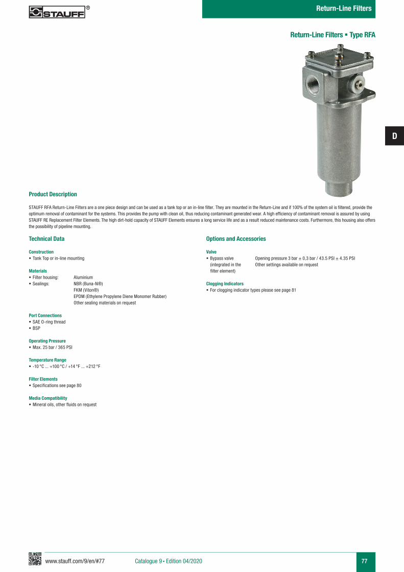
www.stauff.com/9/en/#77
D
77
Product Description
STAUFF RFA Return-Line Filters are a one piece design and can be used as a tank top or an in-line filter. They are mounted in the Return-Line and if 100% of the system oil is filtered, provide the optimum removal of contaminant for the systems. This provides the pump with clean oil, thus reducing contaminant generated wear. A high efficiency of contaminant removal is assured by using STAUFF RE Replacement Filter Elements. The high dirt-hold capacity of STAUFF Elements ensures a long service life and as a result reduced maintenance costs. Furthermore, this housing also offers the possibility of pipeline mounting.
Return-Line Filters § Type RFA
Technical Data
Construction § Tank Top or in-line mounting
Materials § Filter housing: Aluminium § Sealings: NBR (Buna-N®)
FKM (Viton®) EPDM (Ethylene Propylene Diene Monomer Rubber) Other sealing materials on request
Port Connections § SAE O-ring thread § BSP
Operating Pressure § Max. 25 bar / 365 PSI
Temperature Range § -10 °C ... +100 °C / +14 °F ... +212 °F
Filter Elements § Specifications see page 80
Media Compatibility § Mineral oils, other fluids on request
Options and Accessories
Valve § Bypass valve Opening pressure 3 bar ± 0,3 bar / 43.5 PSI ± 4.35 PSI (integrated in the Other settings available on request
filter element)
Clogging Indicators § For clogging indicator types please see page 81
Catalogue 9 § Edition 04/2020
Return-Line Filters
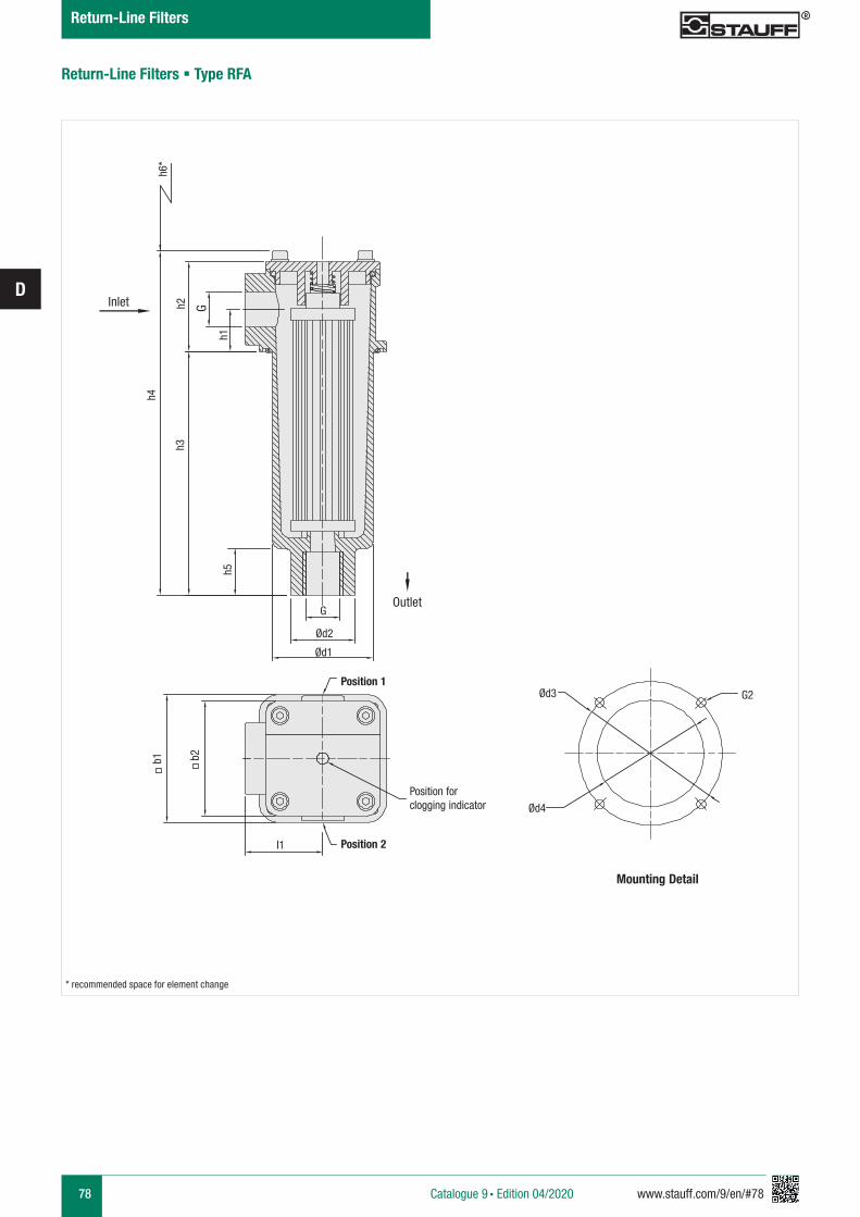
78 www.stauff.com/9/en/#78
D
Return-Line Filters § Type RFA
h1
h4
h2h3
h5
Ød3 G2
Ød4
Ød2
Ød1
G
b1 b2
I1
Position forclogging indicator
Mounting Detail
G
Position 1
Position 2
h6*
* recommended space for element change
Inlet
Outlet
Catalogue 9 § Edition 04/2020
Return-Line Filters
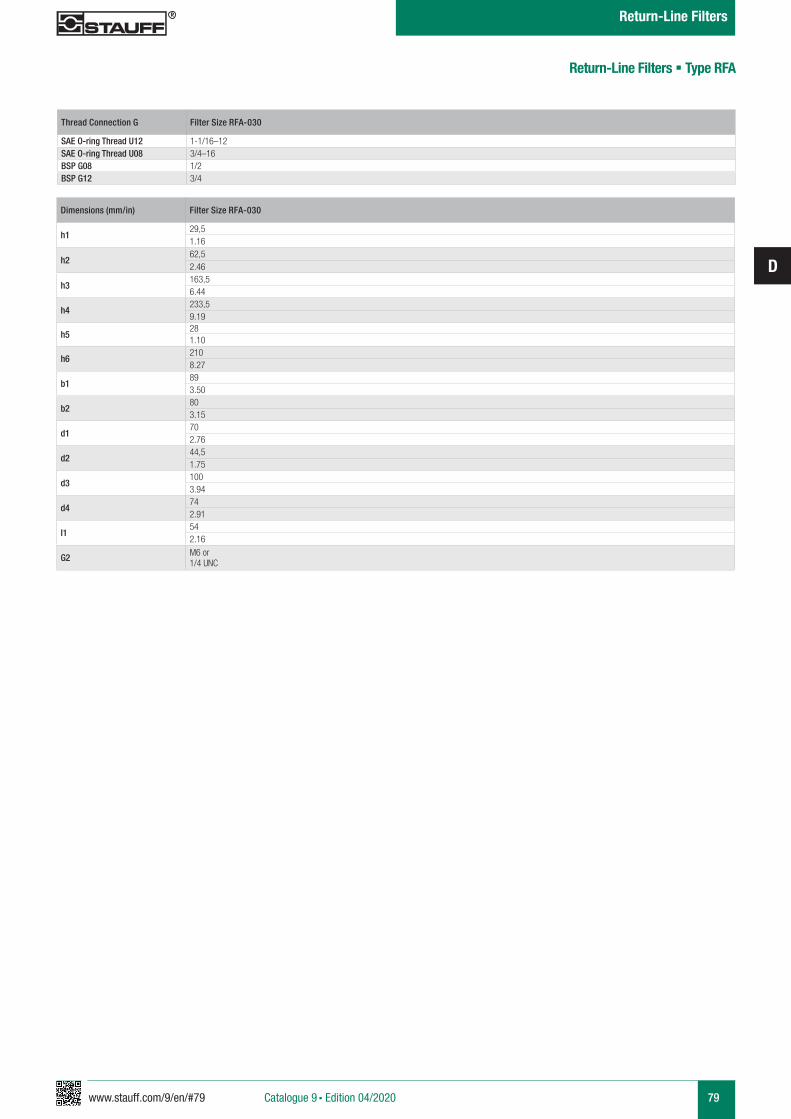
www.stauff.com/9/en/#79
D
79
Return-Line Filters § Type RFA
Thread Connection G Filter Size RFA-030
SAE O-ring Thread U12 1-1/16–12SAE O-ring Thread U08 3/4–16BSP G08 1/2BSP G12 3/4
Dimensions (mm/in) Filter Size RFA-030
h129,51.16
h262,52.46
h3163,56.44
h4233,59.19
h5281.10
h62108.27
b1893.50
b2803.15
d1702.76
d244,51.75
d31003.94
d4742.91
I1542.16
G2 M6 or 1/4 UNC
Catalogue 9 § Edition 04/2020
Return-Line Filters
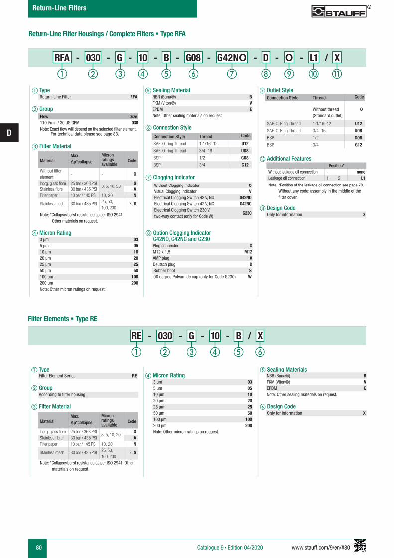
80 www.stauff.com/9/en/#80
D
Return-Line Filter Housings / Complete Filters § Type RFA
f Connection Style
g Clogging Indicator
e Sealing Material NBR (Buna®) B FKM (Viton®) V EPDM E Note: Other sealing materials on request
i Outlet Style
Flow Size110 l/min / 30 US GPM 030Note: Exact flow will depend on the selected filter element. For technical data please see page 83. Connection Style Thread Code
SAE-O-ring Thread 1-1/16–12 U12
SAE-O-ring Thread 3/4–16 U08
BSP 1/2 G08
BSP 3/4 G12Material
Max. Δp*collapse
Micron ratings available
Code
Without filter element
- - 0
Inorg. glass fibre 25 bar / 363 PSI3, 5, 10, 20
GStainless fibre 30 bar / 435 PSI AFilter paper 10 bar / 145 PSI 10, 20 N
Stainless mesh 30 bar / 435 PSI 25, 50, 100, 200
B, S
Note: *Collapse/burst resistance as per ISO 2941. Other materials on request.
Position*Without leakage oil connection - noneLeakage oil connection 1 2 L1
Note: *Position of the leakage oil connection see page 78. Without any code: assembly in the middle of the filter cover.
j Additional Features
k Design Code Only for information X
a Type Return-Line Filter RFA
b Group
c Filter Material
d Micron Rating 3 µm 03 5 µm 05 10 µm 10 20 µm 20 25 µm 25 50 µm 50 100 µm 100 200 µm 200 Note: Other micron ratings on request.
Without Clogging Indicator 0Visual Clogging Indicator VElectrical Clogging Switch 42 V, NO G42NOElectrical Clogging Switch 42 V, NC G42NCElectrical Clogging Switch 230 V, two-way contact (only for Code W)
G230
RFA - 030 - G - 10 - B - G08 - G42NO - D - O - L1 / X
h Option Clogging Indicator G42NO, G42NC and G230 Plug connector 0 M12 x 1,5 M12 AMP plug A Deutsch plug D Rubber boot S 90 degree Polyamide cap (only for Code G230) W
ihga b c fed j k
d Micron Rating 3 µm 03 5 µm 05 10 µm 10 20 µm 20 25 µm 25 50 µm 50 100 µm 100 200 µm 200 Note: Other micron ratings on request.
e Sealing Materials NBR (Buna®) B FKM (Viton®) V EPDM E Note: Other sealing materials on request.
f Design Code Only for information X
RE - 030 - G - 10 - B / X
a Type Filter Element Series RE
b Group According to filter housing
c Filter Material
Filter Elements § Type RE
MaterialMax. Δp*collapse
Micron ratings available
Code
Inorg. glass fibre 25 bar / 363 PSI3, 5, 10, 20
GStainless fibre 30 bar / 435 PSI AFilter paper 10 bar / 145 PSI 10, 20 N
Stainless mesh 30 bar / 435 PSI 25, 50, 100, 200
B, S
Note: *Collapse/burst resistance as per ISO 2941. Other materials on request.
a b c fed
Catalogue 9 § Edition 04/2020
Return-Line Filters
Connection Style Thread Code
Without thread (Standard outlet)
0
SAE-O-Ring Thread 1-1/16–12 U12
SAE-O-Ring Thread 3/4–16 U08
BSP 1/2 G08
BSP 3/4 G12

www.stauff.com/9/en/#81
D
81Catalogue 9 § Edition 04/2020
Return-Line Filters
Dimensional drawings: All dimensions in mm/in.
Return-Line Filters § Type RFA
Electrical Clogging Switch
The switch is used where an electrical signal is needed to indicate when the element needs to be changed. The switch can turn on a light, or shut the machine down, or any further function controlled by an electric signal. The switching pressure is 2,5 bar / 36.25 PSI and this allows the element to be changed before the bypass setting of 3 bar / 43.5 PSI is reached.
Order Code
Limit-Switch - G42NO - S - M10 - B2.5
a Type Limit-Switch
b Connector Type
c Plug Type M12 Five-Pin Connector according to IEC 61076-2-101 M12 AMP-Junior-Timer Plug A DEUTSCH Plug DT04-2P D Rubber boot S 90 degree Polyamide cap W (only for Connector Type G230)
d Thread Type M10 x 1 M10
e Pressure Setting 2,5 bar / 36.3 PSI B2.5Electrical Clogging Switch 42 V, NO G42NO
Electrical Clogging Switch 42 V, NC G42NCElectrical Clogging Switch 110 V ... 230 V, two-way contact (only for Plug Type W)
G230
a b c ed
Standard type with plug connector and rubber cap. Available with DEUTSCH DT04-2P plug (industrial standard), AMP Junior Timer plug (industrial standard) and five-pin circular connector M12, A-coded, according to IEC 61076-2-101.
Dimensions Plug Type
WM12 S
3 11 21 2
A
61,5
(2.4
2)
9 (.3
5)
M10x1
D
21 21
71 (2
.80)
9 (.3
5)
M10x1
60 (2
.36)
9 (.3
5)
M10x1
9 (.3
5)
76 (2
.98)
M10x1
9 (.3
5)
74 (2
.91)
M10x1
P4
1
2
Note: The customer / user carries the responsibility for the electrical connection.
Limit-Switch G42NO+NC Limit-Switch G230Switching Capacity 100 VA 1000 VAVoltage 10…42 VAC 10…250 VACCurrent 10mA…4ASwitching Accuracy ± 0,5 bar at room temp. and new stateSwitching Frequency 200/minmax. Pressure Ramp Rate ≤ 1 bar/msDegree of Protection IP65 (plug type S and W), IP67 (plug type M12, A, D)Temperature Range -30°C … +100°C -40°C … +100°C
Technical Data
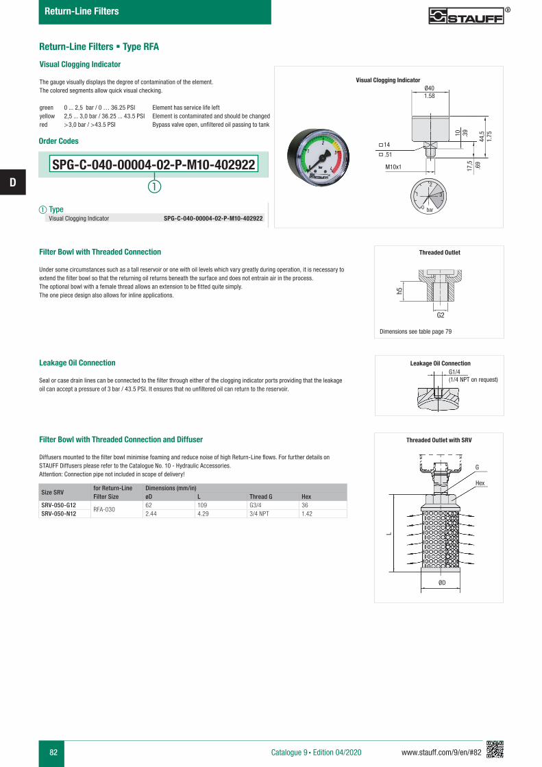
82 www.stauff.com/9/en/#82
D
Return-Line Filters § Type RFA
Size SRVfor Return-Line Filter Size
Dimensions (mm/in)øD L Thread G Hex
SRV-050-G12RFA-030
62 109 G3/4 36SRV-050-N12 2.44 4.29 3/4 NPT 1.42
Filter Bowl with Threaded Connection
Under some circumstances such as a tall reservoir or one with oil levels which vary greatly during operation, it is necessary to extend the filter bowl so that the returning oil returns beneath the surface and does not entrain air in the process. The optional bowl with a female thread allows an extension to be fitted quite simply. The one piece design also allows for inline applications.
Leakage Oil Connection Seal or case drain lines can be connected to the filter through either of the clogging indicator ports providing that the leakage oil can accept a pressure of 3 bar / 43.5 PSI. It ensures that no unfiltered oil can return to the reservoir.
Filter Bowl with Threaded Connection and Diffuser
Diffusers mounted to the filter bowl minimise foaming and reduce noise of high Return-Line flows. For further details on STAUFF Diffusers please refer to the Catalogue No. 10 - Hydraulic Accessories.Attention: Connection pipe not included in scope of delivery!
Threaded Outlet with SRV
G
Hex
ØD
L
G1/4
(1/4 NPT on request)
Threaded Outlet
Dimensions see table page 79
G2
h5
Catalogue 9 § Edition 04/2020
Return-Line Filters
Visual Clogging Indicator
The gauge visually displays the degree of contamination of the element.The colored segments allow quick visual checking.
green 0 ... 2,5 bar / 0 … 36.25 PSI Element has service life leftyellow 2,5 ... 3,0 bar / 36.25 ... 43.5 PSI Element is contaminated and should be changed red >3,0 bar / >43.5 PSI Bypass valve open, unfiltered oil passing to tank
Ø40
14
M10x1
1.58
.39
.69
1.75
.51
10
17,5
44,5
0
1
2
3
bar
Visual Clogging Indicator
SPG-C-040-00004-02-P-M10-402922
Order Codes
a Type Visual Clogging Indicator SPG-C-040-00004-02-P-M10-402922
Leakage Oil Connection
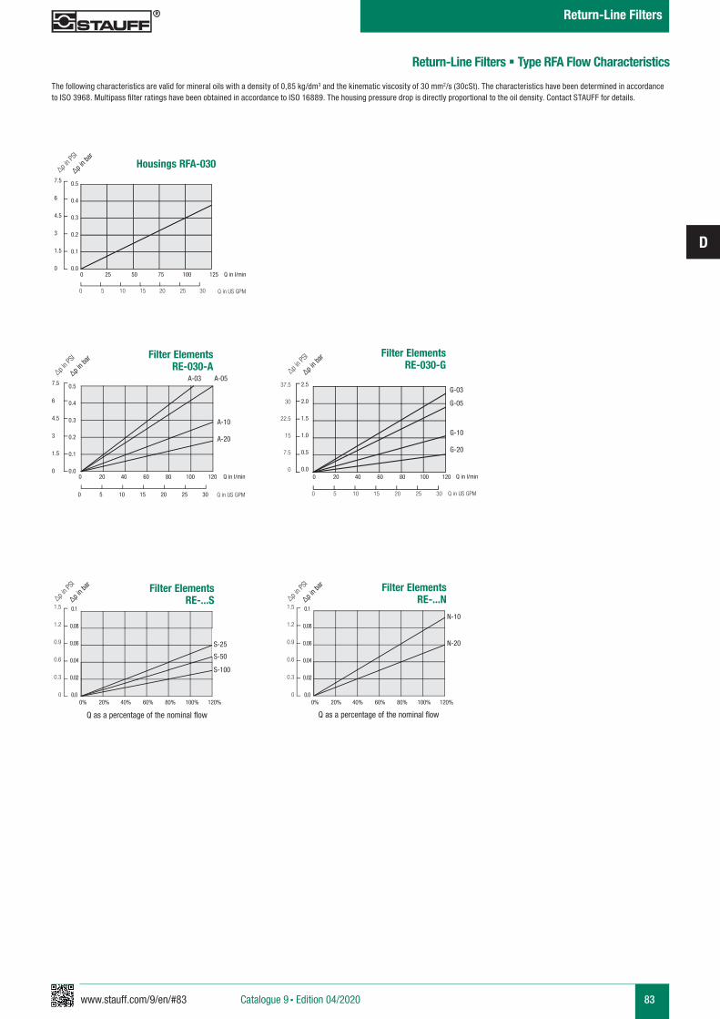
www.stauff.com/9/en/#83
D
83
0.1
0.08
0.06
0.04
0.02
0.0
1.5
1.2
0.9
0.6
0.3
0
∆p in b
ar
∆p in P
SI
0.1
0.08
0.06
0.04
0.02
0.0
1.5
1.2
0.9
0.6
0.3
0
∆p in b
ar
∆p in P
SIFilter ElementsRE-...S
0% 20% 40% 60% 80% 100% 120%
Filter ElementsRE-...N
0% 20% 40% 60% 80% 100% 120%
N-10
N-20S-25
S-50
S-100
Q as a percentage of the nominal flow Q as a percentage of the nominal flow
Housings RFA-030
0 25 50 75 100 125
0 5 10 15 20 25 30
0.5
0.4
0.3
0.2
0.1
0.0
7.5
6
4.5
3
1.5
0
∆p in b
ar
∆p in P
SI
Q in l/min
Q in US GPM
Q in l/min
Q in US GPM
Filter Elements RE-030-A
0 20 40 60 80 100 120
0 5 10 15 20 25 30
A-10
A-20
A-03 A-05
Q in l/min
Q in US GPM
Filter Elements RE-030-G
0 20 40 60 80 100 120
0 5 10 15 20 25 30
2.5
2.0
1.5
1.0
0.5
0.0
G-10
G-20
G-03
G-05
∆p in b
ar
∆p in P
SI
37.5
30
22.5
15
7.5
0
0.5
0.4
0.3
0.2
0.1
0.0
7.5
6
4.5
3
1.5
0
∆p in b
ar
∆p in P
SI
Return-Line Filters § Type RFA Flow Characteristics
The following characteristics are valid for mineral oils with a density of 0,85 kg/dm3 and the kinematic viscosity of 30 mm2/s (30cSt). The characteristics have been determined in accordance to ISO 3968. Multipass filter ratings have been obtained in accordance to ISO 16889. The housing pressure drop is directly proportional to the oil density. Contact STAUFF for details.
Catalogue 9 § Edition 04/2020
Return-Line Filters

84 www.stauff.com/9/en/#84
D
Checklist for the selection of filter housings
Type of fluid
Fluid viscosity
Fluid temperature
Position in the hydraulic system
Operating pressure
Nominal flow
Valve
Clogging indicator
Connection type and size
Sealing material
Filter media
Micron rating
Cleanliness level
Information on the application
Information on the ambient conditions
Additional informationand requirements
mm2/sec cSt
Brand
Suction line Pressure line Return line
Bypass valve
No, not required
Reverse flow valveNon-return valve Multi-function valve
ISO designation
°C °F In cold condition In warm condition
Information on the fluid in use
Information on the filter housing
bar PSI
l/min US GPM
Yes, the following type:
Visual
No, not required
Electrical Visual-electricalYes, the following type:
NBR (Buna®) FKM (Viton®) Other
Information on the filter element
Inorganic Glass Fibre Polyester Fibre Cellulose Fibre Stainless Fibre
µm
(to ISO 4406)
Stainless Mesh
Please use the following Checklist as a guideline when preparing an enquiry for the selection of filter housings. Scan or copy the page from the catalogue, print and com-
plete it with as much information as possible, before sending it by email or fax to the closest STAUFF branch office. If possible, please also let us know the quantities required,
and if the enquiry is for a one-time or recurring demand. We look forward to hearing from you, and are always available for consultation, when required.
Catalogue 9 § Edition 04/2020
Return-Line Filters
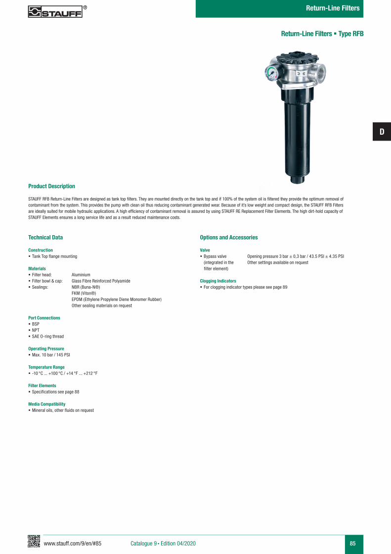
www.stauff.com/9/en/#85
D
85
Product Description
STAUFF RFB Return-Line Filters are designed as tank top filters. They are mounted directly on the tank top and if 100% of the system oil is filtered they provide the optimum removal of contaminant from the system. This provides the pump with clean oil thus reducing contaminant generated wear. Because of it’s low weight and compact design, the STAUFF RFB Filters are ideally suited for mobile hydraulic applications. A high efficiency of contaminant removal is assured by using STAUFF RE Replacement Filter Elements. The high dirt-hold capacity of STAUFF Elements ensures a long service life and as a result reduced maintenance costs.
Return-Line Filters § Type RFB
Technical Data
Construction § Tank Top flange mounting
Materials § Filter head: Aluminium § Filter bowl & cap: Glass Fibre Reinforced Polyamide § Sealings: NBR (Buna-N®)
FKM (Viton®) EPDM (Ethylene Propylene Diene Monomer Rubber) Other sealing materials on request
Port Connections § BSP § NPT § SAE O-ring thread
Operating Pressure § Max. 10 bar / 145 PSI
Temperature Range § -10 °C ... +100 °C / +14 °F ... +212 °F
Filter Elements § Specifications see page 88
Media Compatibility § Mineral oils, other fluids on request
Options and Accessories
Valve § Bypass valve Opening pressure 3 bar ± 0,3 bar / 43.5 PSI ± 4.35 PSI (integrated in the Other settings available on request
filter element)
Clogging Indicators § For clogging indicator types please see page 89
Catalogue 9 § Edition 04/2020
Return-Line Filters
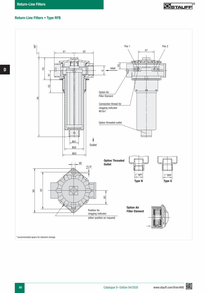
86 www.stauff.com/9/en/#86
D
b7b2b1
1” BSP1” NPT
Ød1
Ød2
Ød3
h4
h3
h2h1
G
h5
Option AirFilter Element
Connection thread for
clogging indicatorM10x1
Option threaded outlet
Type N Type G
Option AirFilter Element
Return-Line Filters § Type RFB
b4 b3
b5
b6
Position forclogging indicator
(other position on request)
* recommended space for element change
h6*
3,5
.14
Option ThreadedOutlet
Pos 1 Pos 2
Outlet
Catalogue 9 § Edition 04/2020
Return-Line Filters
Inlet
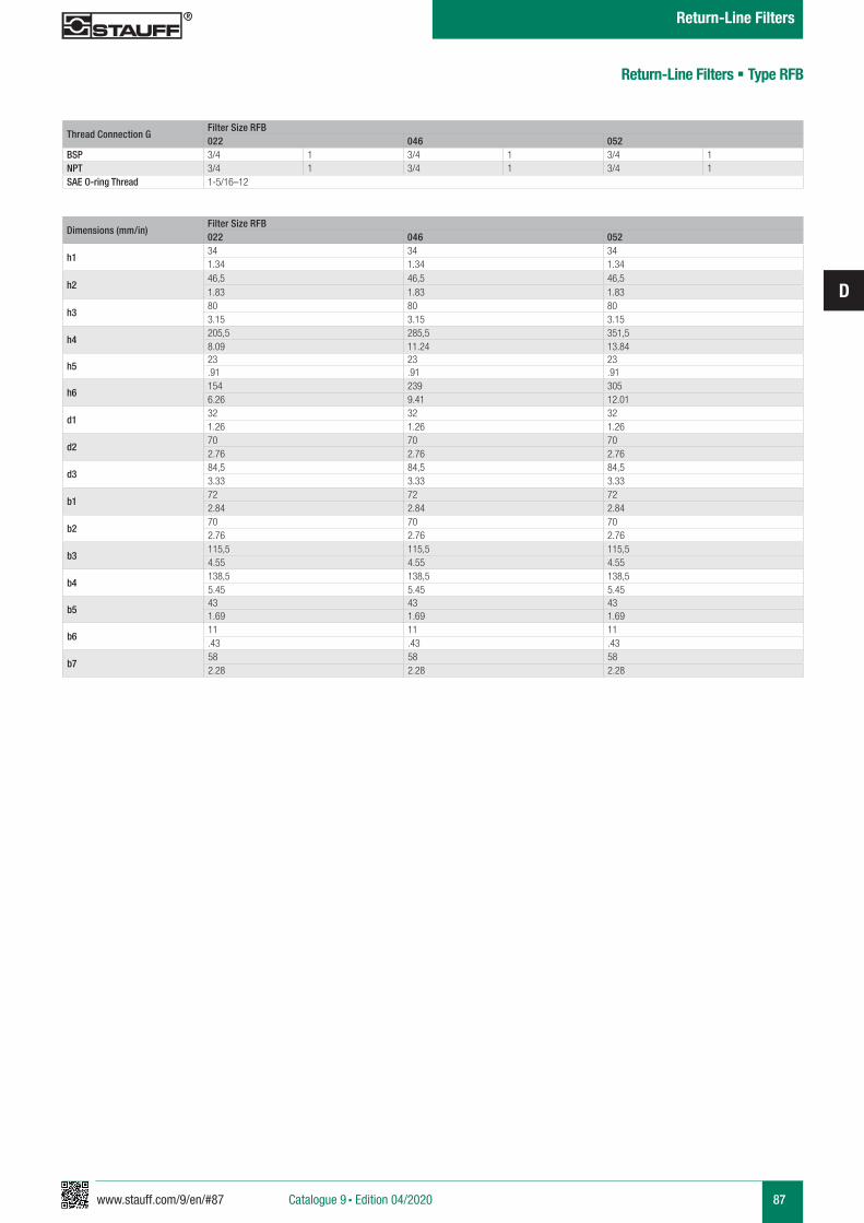
www.stauff.com/9/en/#87
D
87
Return-Line Filters § Type RFB
Thread Connection GFilter Size RFB022 046 052
BSP 3/4 1 3/4 1 3/4 1NPT 3/4 1 3/4 1 3/4 1SAE O-ring Thread 1-5/16–12
Dimensions (mm/in)Filter Size RFB022 046 052
h134 34 341.34 1.34 1.34
h246,5 46,5 46,51.83 1.83 1.83
h380 80 803.15 3.15 3.15
h4205,5 285,5 351,58.09 11.24 13.84
h523 23 23.91 .91 .91
h6154 239 3056.26 9.41 12.01
d132 32 321.26 1.26 1.26
d270 70 702.76 2.76 2.76
d384,5 84,5 84,53.33 3.33 3.33
b172 72 722.84 2.84 2.84
b270 70 702.76 2.76 2.76
b3115,5 115,5 115,54.55 4.55 4.55
b4138,5 138,5 138,55.45 5.45 5.45
b543 43 431.69 1.69 1.69
b611 11 11.43 .43 .43
b758 58 582.28 2.28 2.28
Catalogue 9 § Edition 04/2020
Return-Line Filters
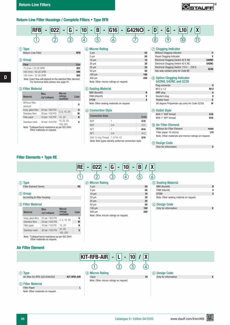
88 www.stauff.com/9/en/#88
D
Return-Line Filter Housings / Complete Filters § Type RFB
d Micron Rating 3 µm 03 5 µm 05 10 µm 10 20 µm 20 25 µm 25 50 µm 50 100 µm 100 200 µm 200 Note: Other micron ratings on request.
a Type Filter Element Series RE
b Group According to filter housing
c Filter Material
RE - 022 - G - 10 - B / X
KIT-RFB-AIR - L - 10 / X
Air Filter Element
MaterialMax. Δp*collapse
Micron ratings available
Code
Inorg. glass fibre 25 bar / 363 PSI3, 5, 10, 20
GStainless fibre 30 bar / 435 PSI MFilter paper 10 bar / 145 PSI 10, 20 N
Stainless mesh 30 bar / 435 PSI 25, 50, 100, 200
S
Note: *Collapse/burst resistance as per ISO 2941. Other materials on request.
d Design Code Only for information X
a Type Air filter for RFB-022/046/052 KIT-RFB-AIR
b Filter Material Filter Paper L
Note: Other materials on request.
a Type Return-Line Filter RFB
b Group
c Filter Material
f Connection Style
j Air Filter Element Without Air Filter Element none Filter paper 10 micron L10 Note: Other materials and micron ratings on request.
k Design Code Only for information X
e Sealing Material NBR (Buna®) B FKM (Viton®) V EPDM E Note: Other sealing materials on request.
i Outlet Style With 1” BSP thread G16 With 1” NPT thread N16
Flow Size75 l/min / 22 US GPM 022165 l/min / 46 US GPM 046185 l/min / 52 US GPM 052
Note: Exact flow will depend on the selected filter element. For technical data please see page 91.
MaterialMax. Δp*collapse
Micron ratings available
Code
Without filter element
- - 0
Inorg. glass fibre 25 bar / 363 PSI3, 5, 10, 20
GStainless fibre 30 bar / 435 PSI MFilter paper 10 bar / 145 PSI 10, 20 N
Stainless mesh 30 bar / 435 PSI 10, 25, 50, 100, 200
S
Note: *Collapse/burst resistance as per ISO 2941. Other materials on request.
Connection Style Code
BSP 1 G16
BSP 3/4 G12
NPT 1 N16
NPT 3/4 N12
SAE-O-ring Thread 1-5/16–12 U16Note: Bold types identify preferred connection style.
Filter Elements § Type RE
e Sealing Material NBR (Buna®) B FKM (Viton®) V EPDM E Note: Other sealing material on request.
f Design Code Only for information X
Without Clogging Indicator 0Visual Clogging Indicator VElectrical Clogging Switch 42 V, NO G42NOElectrical Clogging Switch 42 V, NC G42NCElectrical Clogging Switch 110 V ... 230 V, two-way contact (only for Code W)
G230
c Micron Rating 10µm 10 Note: Other micron ratings on request.
RFB - 022 - G - 10 - B - G16 - G42NO - D - G - L10 / X
h Option Clogging Indicator G42NO, G42NC and G230
Plug connector 0 M12 x 1,5 M12 AMP plug A Deutsch plug D Rubber boot S 90 degree Polyamide cap (only for Code G230) W
ihga b c fed j k
a b c fed
a b c d
g Clogging Indicatord Micron Rating 3 µm 03 5 µm 05 10 µm 10 20 µm 20 25 µm 25 50 µm 50 100 µm 100 200 µm 200 Note: Other micron ratings on request.
Catalogue 9 § Edition 04/2020
Return-Line Filters
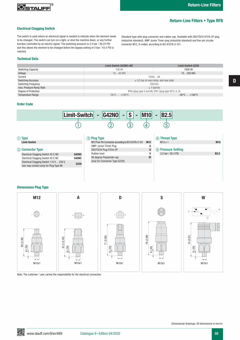
www.stauff.com/9/en/#89
D
89Catalogue 9 § Edition 04/2020
Return-Line Filters
Dimensional drawings: All dimensions in mm/in.
Return-Line Filters § Type RFB
Electrical Clogging Switch
The switch is used where an electrical signal is needed to indicate when the element needs to be changed. The switch can turn on a light, or shut the machine down, or any further function controlled by an electric signal. The switching pressure is 2,5 bar / 36.25 PSI and this allows the element to be changed before the bypass setting of 3 bar / 43.5 PSI is reached.
Order Code
Limit-Switch - G42NO - S - M10 - B2.5
a Type Limit-Switch
b Connector Type
c Plug Type M12 Five-Pin Connector according to IEC 61076-2-101 M12 AMP-Junior-Timer Plug A DEUTSCH Plug DT04-2P D Rubber boot S 90 degree Polyamide cap W (only for Connector Type G230)
d Thread Type M10 x 1 M10
e Pressure Setting 2,5 bar / 36.3 PSI B2.5Electrical Clogging Switch 42 V, NO G42NO
Electrical Clogging Switch 42 V, NC G42NCElectrical Clogging Switch 110 V ... 230 V, two-way contact (only for Plug Type W)
G230
a b c ed
Standard type with plug connector and rubber cap. Available with DEUTSCH DT04-2P plug (industrial standard), AMP Junior Timer plug (industrial standard) and five-pin circular connector M12, A-coded, according to IEC 61076-2-101.
Dimensions Plug Type
WM12 S
3 11 21 2
A
61,5
(2.4
2)
9 (.3
5)
M10x1
D
21 21
71 (2
.80)
9 (.3
5)
M10x1
60 (2
.36)
9 (.3
5)
M10x1
9 (.3
5)
76 (2
.98)
M10x1
9 (.3
5)
74 (2
.91)
M10x1
P4
1
2
Note: The customer / user carries the responsibility for the electrical connection.
Limit-Switch G42NO+NC Limit-Switch G230Switching Capacity 100 VA 1000 VAVoltage 10…42 VAC 10…250 VACCurrent 10mA…4ASwitching Accuracy ± 0,5 bar at room temp. and new stateSwitching Frequency 200/minmax. Pressure Ramp Rate ≤ 1 bar/msDegree of Protection IP65 (plug type S and W), IP67 (plug type M12, A, D)Temperature Range -30°C … +100°C -40°C … +100°C
Technical Data
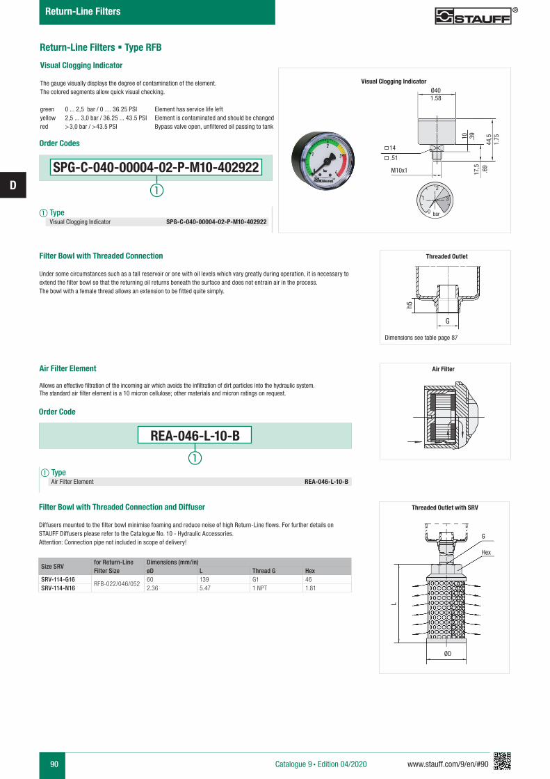
90 www.stauff.com/9/en/#90
D
Return-Line Filters § Type RFB
Catalogue 9 § Edition 04/2020
Return-Line Filters
Air Filter
REA-046-L-10-B
Order Code
a Type Air Filter Element REA-046-L-10-B
Size SRVfor Return-Line Filter Size
Dimensions (mm/in)øD L Thread G Hex
SRV-114-G16RFB-022/046/052
60 139 G1 46SRV-114-N16 2.36 5.47 1 NPT 1.81
Filter Bowl with Threaded Connection
Under some circumstances such as a tall reservoir or one with oil levels which vary greatly during operation, it is necessary to extend the filter bowl so that the returning oil returns beneath the surface and does not entrain air in the process. The bowl with a female thread allows an extension to be fitted quite simply.
Air Filter Element Allows an effective filtration of the incoming air which avoids the infiltration of dirt particles into the hydraulic system. The standard air filter element is a 10 micron cellulose; other materials and micron ratings on request.
Filter Bowl with Threaded Connection and Diffuser
Diffusers mounted to the filter bowl minimise foaming and reduce noise of high Return-Line flows. For further details on STAUFF Diffusers please refer to the Catalogue No. 10 - Hydraulic Accessories.Attention: Connection pipe not included in scope of delivery!
Threaded Outlet with SRV
G
Hex
ØD
L
Threaded Outlet
Dimensions see table page 87
G
h5
Visual Clogging Indicator
The gauge visually displays the degree of contamination of the element.The colored segments allow quick visual checking.
green 0 ... 2,5 bar / 0 … 36.25 PSI Element has service life leftyellow 2,5 ... 3,0 bar / 36.25 ... 43.5 PSI Element is contaminated and should be changed red >3,0 bar / >43.5 PSI Bypass valve open, unfiltered oil passing to tank
Ø40
14
M10x1
1.58
.39
.69
1.75
.51
10
17,5
44,5
0
1
2
3
bar
Visual Clogging Indicator
SPG-C-040-00004-02-P-M10-402922
Order Codes
a Type Visual Clogging Indicator SPG-C-040-00004-02-P-M10-402922
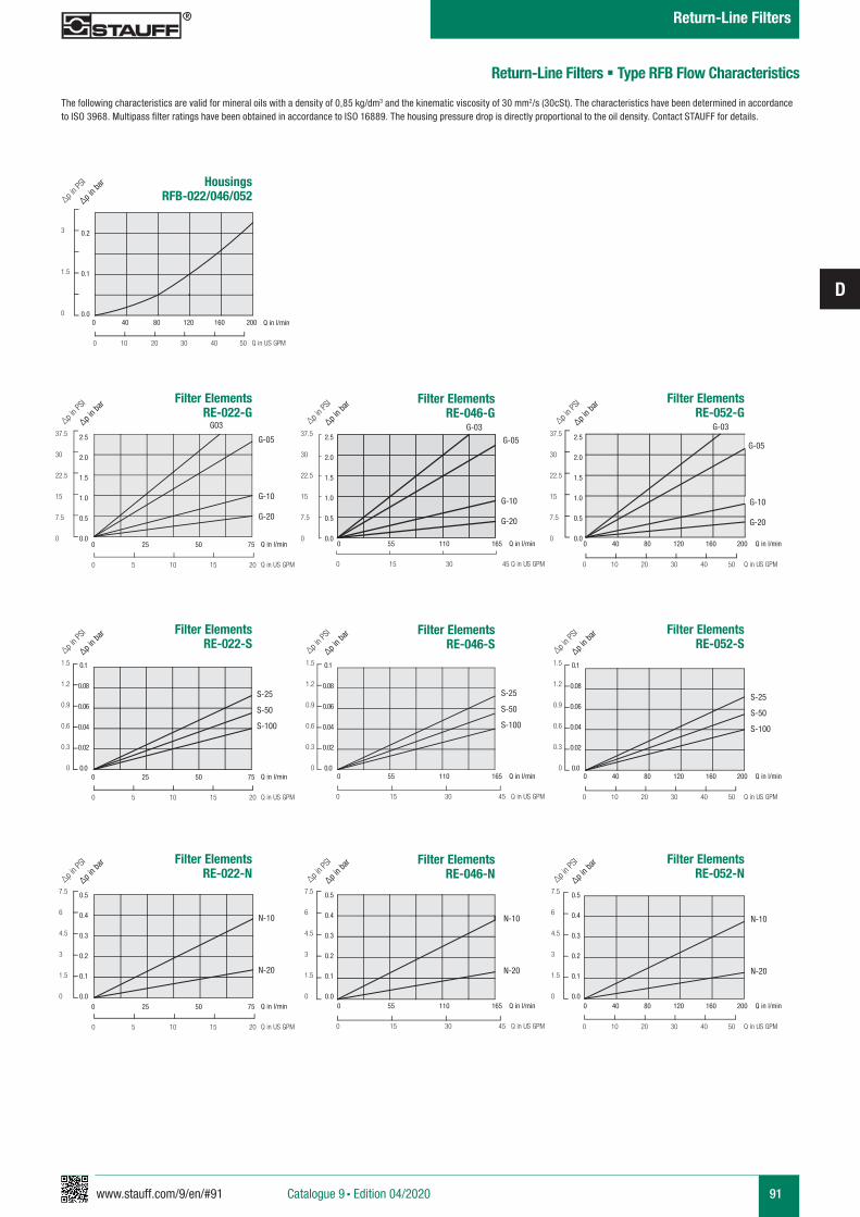
www.stauff.com/9/en/#91
D
91
Filter Elements RE-022-G
0 25 50 75
0 5 10 15 20
G-10
G-20
Q in l/min
Q in US GPM
Q in l/min
Q in US GPM
Q in l/min
Q in US GPM
G03
G-05
Filter Elements RE-052-G
0 40 80 120 160 200
0 10 20 30 40 50
G-10
G-20
G-03
G-05
Filter Elements RE-046-G
0 55 110 165
0 15 30 45
0 25 50 75
0 5 10 15 20
Q in l/min
Q in US GPM
Q in l/min
Q in US GPM
Q in l/min
Q in US GPM
0 40 80 120 160 200
0 10 20 30 40 50
0 55 110 165
0 15 30 45
0 25 50 75
0 5 10 15 20
Q in l/min
Q in US GPM
Q in l/min
Q in US GPM
Q in l/min
Q in US GPM
0 40 80 120 160 200
0 10 20 30 40 50
0 55 110 165
0 15 30 45
G-10
G-20
G-03
G-05
Filter Elements RE-022-S
S-25
S-50
S-100
Filter Elements RE-052-S
S-25
S-50
S-100
Filter Elements RE-046-S
S-25
S-50
S-100
Filter Elements RE-022-N
N-10
N-20
Filter Elements RE-052-N
Filter Elements RE-046-N
Housings RFB-022/046/052
0 40 80 120 160 200
0 10 20 30 40 50
0.2
0.1
0.0
3
1.5
0 Q in l/min
Q in US GPM
N-10
N-20
N-10
N-20
2.5
2.0
1.5
1.0
0.5
0.0
37.5
30
22.5
15
7.5
0
∆p in b
ar
∆p in P
SI
2.5
2.0
1.5
1.0
0.5
0.0
37.5
30
22.5
15
7.5
0
∆p in b
ar
∆p in P
SI
2.5
2.0
1.5
1.0
0.5
0.0
37.5
30
22.5
15
7.5
0
∆p in b
ar
∆p in P
SI
∆p in b
ar
∆p in P
SI
1.5
1.2
0.9
0.6
0.3
0
0.1
0.08
0.06
0.04
0.02
0.0
∆p in b
ar
∆p in P
SI
1.5
1.2
0.9
0.6
0.3
0
0.1
0.08
0.06
0.04
0.02
0.0
∆p in b
ar
∆p in P
SI
1.5
1.2
0.9
0.6
0.3
0
0.1
0.08
0.06
0.04
0.02
0.0
∆p in b
ar
∆p in P
SI
0.5
0.4
0.3
0.2
0.1
0.0
7.5
6
4.5
3
1.5
0
∆p in b
ar
∆p in P
SI
0.5
0.4
0.3
0.2
0.1
0.0
7.5
6
4.5
3
1.5
0
∆p in b
ar
∆p in P
SI
0.5
0.4
0.3
0.2
0.1
0.0
7.5
6
4.5
3
1.5
0
∆p in b
ar
∆p in P
SI
Return-Line Filters § Type RFB Flow Characteristics
The following characteristics are valid for mineral oils with a density of 0,85 kg/dm3 and the kinematic viscosity of 30 mm2/s (30cSt). The characteristics have been determined in accordance to ISO 3968. Multipass filter ratings have been obtained in accordance to ISO 16889. The housing pressure drop is directly proportional to the oil density. Contact STAUFF for details.
Catalogue 9 § Edition 04/2020
Return-Line Filters
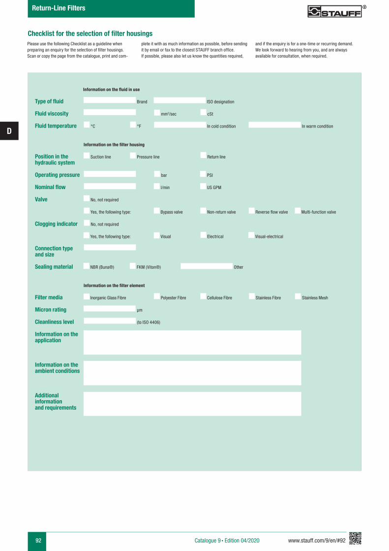
92 www.stauff.com/9/en/#92
D
Checklist for the selection of filter housings
Type of fluid
Fluid viscosity
Fluid temperature
Position in the hydraulic system
Operating pressure
Nominal flow
Valve
Clogging indicator
Connection type and size
Sealing material
Filter media
Micron rating
Cleanliness level
Information on the application
Information on the ambient conditions
Additional informationand requirements
mm2/sec cSt
Brand
Suction line Pressure line Return line
Bypass valve
No, not required
Reverse flow valveNon-return valve Multi-function valve
ISO designation
°C °F In cold condition In warm condition
Information on the fluid in use
Information on the filter housing
bar PSI
l/min US GPM
Yes, the following type:
Visual
No, not required
Electrical Visual-electricalYes, the following type:
NBR (Buna®) FKM (Viton®) Other
Information on the filter element
Inorganic Glass Fibre Polyester Fibre Cellulose Fibre Stainless Fibre
µm
(to ISO 4406)
Stainless Mesh
Please use the following Checklist as a guideline when preparing an enquiry for the selection of filter housings. Scan or copy the page from the catalogue, print and com-
plete it with as much information as possible, before sending it by email or fax to the closest STAUFF branch office. If possible, please also let us know the quantities required,
and if the enquiry is for a one-time or recurring demand. We look forward to hearing from you, and are always available for consultation, when required.
Catalogue 9 § Edition 04/2020
Return-Line Filters
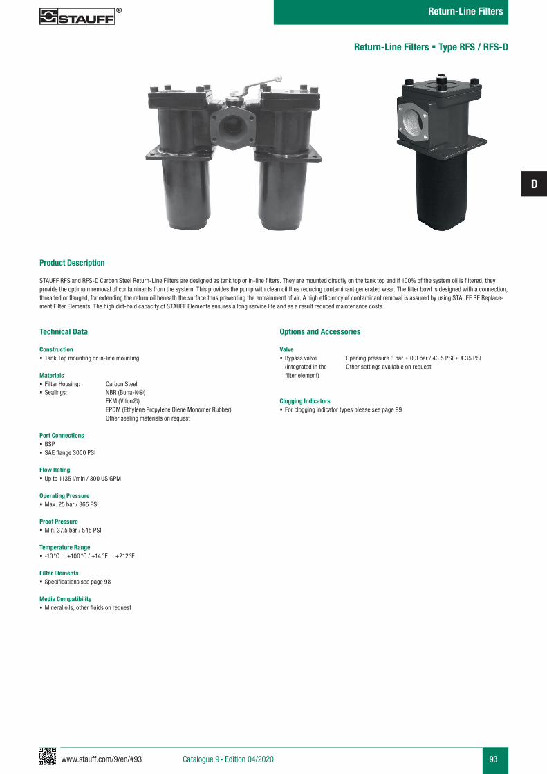
www.stauff.com/9/en/#93
D
93
Return-Line Filters § Type RFS / RFS-D
Product Description STAUFF RFS and RFS-D Carbon Steel Return-Line Filters are designed as tank top or in-line filters. They are mounted directly on the tank top and if 100% of the system oil is filtered, they provide the optimum removal of contaminants from the system. This provides the pump with clean oil thus reducing contaminant generated wear. The filter bowl is designed with a connection, threaded or flanged, for extending the return oil beneath the surface thus preventing the entrainment of air. A high efficiency of contaminant removal is assured by using STAUFF RE Replace-ment Filter Elements. The high dirt-hold capacity of STAUFF Elements ensures a long service life and as a result reduced maintenance costs.
Technical Data
Construction § Tank Top mounting or in-line mounting
Materials § Filter Housing: Carbon Steel § Sealings: NBR (Buna-N®)
FKM (Viton®) EPDM (Ethylene Propylene Diene Monomer Rubber) Other sealing materials on request Port Connections § BSP § SAE flange 3000 PSI
Flow Rating § Up to 1135 l/min / 300 US GPM
Operating Pressure § Max. 25 bar / 365 PSI
Proof Pressure § Min. 37,5 bar / 545 PSI
Temperature Range § -10 ºC ... +100 ºC / +14 °F ... +212 ºF
Filter Elements § Specifications see page 98
Media Compatibility § Mineral oils, other fluids on request
Options and Accessories
Valve § Bypass valve Opening pressure 3 bar ± 0,3 bar / 43.5 PSI ± 4.35 PSI (integrated in the Other settings available on request
filter element)
Clogging Indicators § For clogging indicator types please see page 99
Catalogue 9 § Edition 04/2020
Return-Line Filters
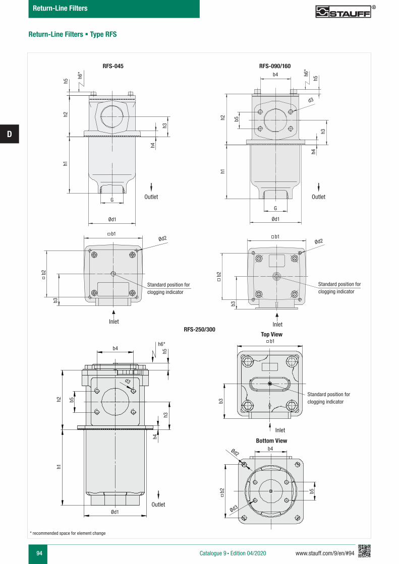
94 www.stauff.com/9/en/#94
D
Return-Line Filters § Type RFS
Ød1
Ød2Ød2
b3
b3
h3
h4
h1h2
h5
Top View
Bottom View
Standard position forclogging indicator
Standard position forclogging indicator
b1
Ød1
h4
h3
h1h2 b5
d3
h5
h6*
b4
RFS-250/300
RFS-045 RFS-090/160
h6*
b2 b2
Standard position forclogging indicator
Inlet Inlet
Inlet
b1
G
G
* recommended space for element change
Outlet Outlet
Catalogue 9 § Edition 04/2020
Return-Line Filters
Outlet
h2h1
b5
h3
h4
Ød1
b3
b4Ød2
b2
Ød3
b5
d3
h6*
h5
b4b1
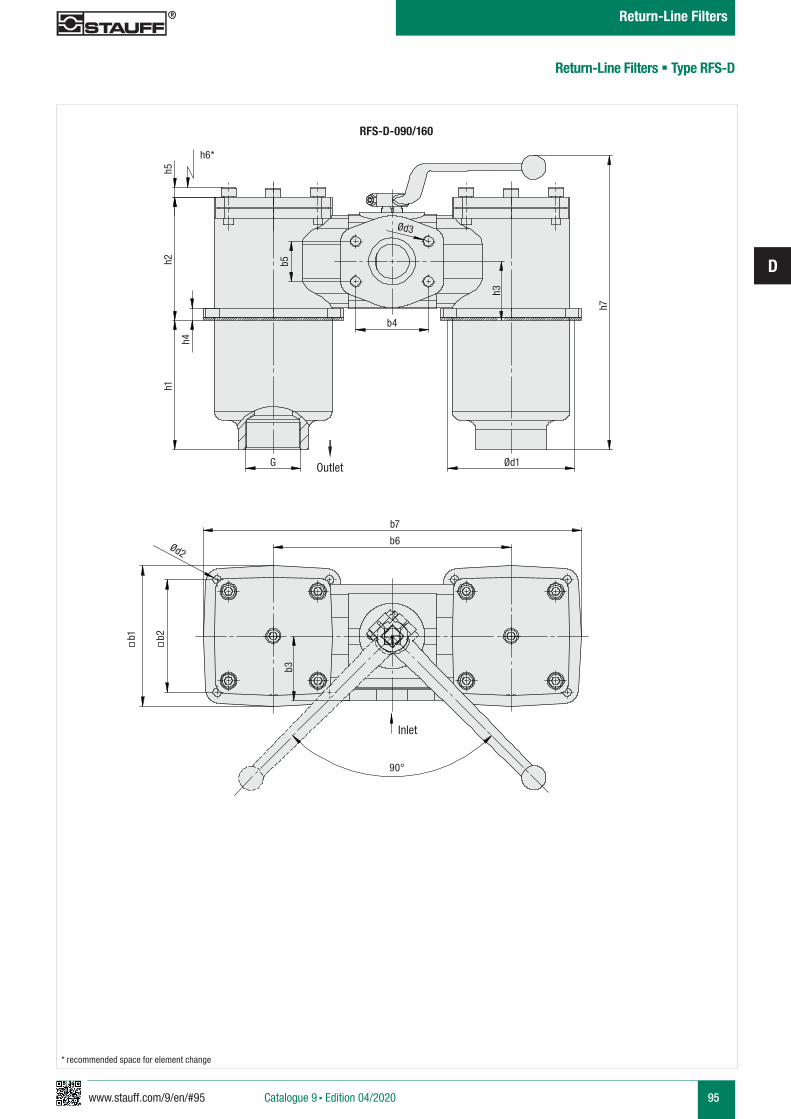
www.stauff.com/9/en/#95
D
95
Return-Line Filters § Type RFS-D
Catalogue 9 § Edition 04/2020
Return-Line Filters
RFS-D-090/160
Outlet
Inlet
* recommended space for element change
G
h1h2
h4
h5h6*
b5
b4
h3
h7
Ød1
b7
b6
b2
Ød2
b3
90°
Ød3
b1
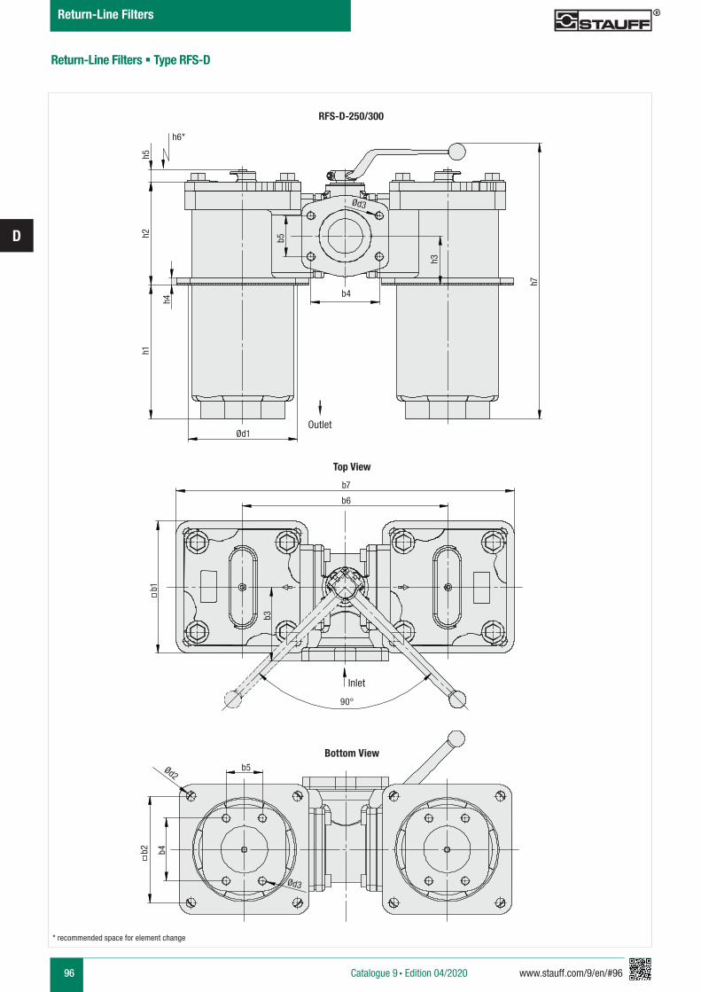
96 www.stauff.com/9/en/#96
D
Catalogue 9 § Edition 04/2020
Return-Line Filters
Return-Line Filters § Type RFS-D
RFS-D-250/300
Top View
Bottom View
Outlet
Inlet
* recommended space for element change
Ød1
h6*h5
h2h1
h4
b5
b4
h3
h7
b1
b7
b6
b3
90°
b5Ød2
b2 b4
Ød3
Ød3
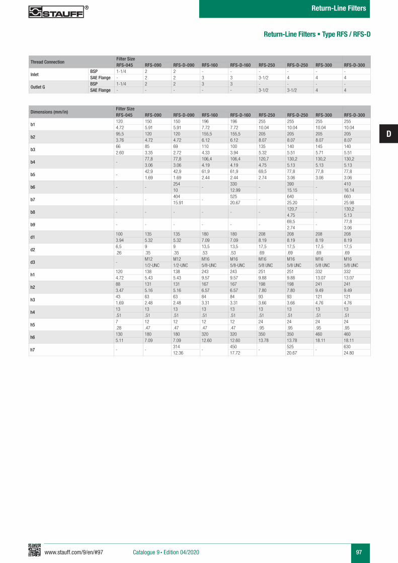
www.stauff.com/9/en/#97
D
97Catalogue 9 § Edition 04/2020
Return-Line Filters
Return-Line Filters § Type RFS / RFS-D
Dimensions (mm/in)Filter SizeRFS-045 RFS-090 RFS-D-090 RFS-160 RFS-D-160 RFS-250 RFS-D-250 RFS-300 RFS-D-300
b1120 150 150 196 196 255 255 255 2554.72 5.91 5.91 7.72 7.72 10.04 10.04 10.04 10.04
b295,5 120 120 155,5 155,5 205 205 205 2053.76 4.72 4.72 6.12 6.12 8.07 8.07 8.07 8.07
b366 85 69 110 100 135 140 145 1402.60 3.35 2.72 4.33 3.94 5.32 5.51 5.71 5.51
b4 -77,8 77,8 106,4 106,4 120,7 130,2 130,2 130,23.06 3.06 4.19 4.19 4.75 5.13 5.13 5.13
b5 -42,9 42,9 61,9 61,9 69,5 77,8 77,8 77,81.69 1.69 2.44 2.44 2.74 3.06 3.06 3.06
b6 - -254
-330
-390
-410
10 12.99 15.15 16.14
b7 - -404
-525
-640
-660
15.91 20.67 25.20 25.98
b8 - - - - - -120,7
-130,2
4.75 5.13
b9 - - - - - -69,5
-77,8
2.74 3.06
d1100 135 135 180 180 208 208 208 2083.94 5.32 5.32 7.09 7.09 8.19 8.19 8.19 8.19
d26,5 9 9 13,5 13,5 17,5 17,5 17,5 17,5.26 .35 .35 .53 .53 .69 .69 .69 .69
d3 -M12 M12 M16 M16 M16 M16 M16 M161/2-UNC 1/2-UNC 5/8-UNC 5/8-UNC 5/8 UNC 5/8 UNC 5/8 UNC 5/8 UNC
h1120 138 138 243 243 251 251 332 3324.72 5.43 5.43 9.57 9.57 9.88 9.88 13.07 13.07
h288 131 131 167 167 198 198 241 2413.47 5.16 5.16 6.57 6.57 7.80 7.80 9.49 9.49
h343 63 63 84 84 93 93 121 1211.69 2.48 2.48 3.31 3.31 3.66 3.66 4.76 4.76
h413 13 13 13 13 13 13 13 13.51 .51 .51 .51 .51 .51 .51 .51 .51
h57 12 12 12 12 24 24 24 24.28 .47 .47 .47 .47 .95 .95 .95 .95
h6130 180 180 320 320 350 350 460 4605.11 7.09 7.09 12.60 12.60 13.78 13.78 18.11 18.11
h7 - -314
-450
-525
-630
12.36 17.72 20.67 24.80
Thread ConnectionFilter SizeRFS-045 RFS-090 RFS-D-090 RFS-160 RFS-D-160 RFS-250 RFS-D-250 RFS-300 RFS-D-300
InletBSP 1-1/4 2 2 - - - - - -SAE Flange - 2 2 3 3 3-1/2 4 4 4
Outlet GBSP 1-1/4 2 2 3 3 - - - -SAE Flange - - - - - 3-1/2 3-1/2 4 4
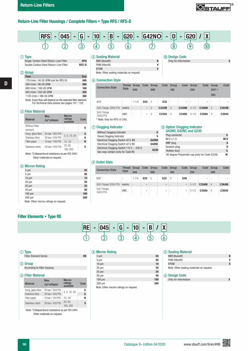
98 www.stauff.com/9/en/#98
D
Return-Line Filter Housings / Complete Filters § Type RFS / RFS-D
d Micron Rating 3 µm 03 5 µm 05 10 µm 10 20 µm 20 25 µm 25 50 µm 50 100 µm 100 200 µm 200 Note: Other micron ratings on request.
e Sealing Material NBR (Buna®) B FKM (Viton®) V EPDM E Note: Other sealing materials on request.
f Design Code Only for information X
RE - 045 - G - 10 - B / X
a Type Filter Element Series RE
b Group According to filter housing
c Filter Material
Filter Elements § Type RE
f Connection Style
* Note: Only for RFS-D-250. g Clogging Indicator
j Design Code Only for information X
e Sealing Material NBR (Buna®) B FKM (Viton®) V EPDM E Note: Other sealing materials on request.
Flow Size170 l/min / 45 US GPM (not for RFS-D) 045340 l/min / 90 US GPM 090600 l/min / 160 US GPM 160945 l/min / 250 US GPM 2501135 l/min / 300 US GPM 300
Note: Exact flow will depend on the selected filter element. For technical data please see pages 101 / 102.
MaterialMax. Δp*collapse
Micron ratings available
Code
Inorg. glass fibre 25 bar / 363 PSI3, 5, 10, 20
GStainless fibre 30 bar / 435 PSI AFilter paper 10 bar / 145 PSI 10, 20 N
Stainless mesh 30 bar / 435 PSI 25, 50, 100, 200
S
Note: *Collapse/burst resistance as per ISO 2941. Other materials on request.
a Type Single Carbon Steel Return-Line Filter RFS Double Carbon Steel Return-Line Filter RFS-D
b Group
c Filter Material
d Micron Rating 3 µm 03 5 µm 05 10 µm 10 20 µm 20 25 µm 25 50 µm 50 100 µm 100 200 µm 200 Note: Other micron ratings on request.
MaterialMax. Δp*collapse
Micron ratings available
Code
Without filter element
- - 0
Inorg. glass fibre 25 bar / 363 PSI3, 5, 10, 20
GStainless fibre 30 bar / 435 PSI AFilter paper 10 bar / 145 PSI 10, 20 N
Stainless mesh 30 bar / 435 PSI 25, 50, 100, 200
S
Note: *Collapse/burst resistance as per ISO 2941. Other materials on request.
Without Clogging Indicator 0Visual Clogging Indicator VElectrical Clogging Switch 42 V, NO G42NOElectrical Clogging Switch 42 V, NC G42NCElectrical Clogging Switch 110 V ... 230 V, two-way contact (only for Code W)
G230
RFS - 045 - G - 10 - B - G20 - G42NO - D - G20 / X
h Option Clogging Indicator G42NO, G42NC and G230 Plug connector 0 M12 x 1,5 M12 AMP plug A Deutsch plug D Rubber boot S 90 degree Polyamide cap (only for Code G230) W
ihga b c fed j
a b c fed
Connection StyleThreadStyle
Group Code Group Code Group Code Group Code Group Code
045 090 160 250 250* /
300
BSP - 1-1/4 G20 2 G32 - - - - - -
SAE Flange 3000 PSI metric - - 2 C332M 3 C348M 3-1/2 C356M 4 C364M
SAE Flange3000 PSI UNC - - 2 C332U 3 C348U 3-1/2 C356U 4 C364U
Catalogue 9 § Edition 04/2020
Return-Line Filters
i Outlet Style
Connection StyleThreadStyle
Group Code Group Code Group Code Group Code Group Code
045 090 160 250 300
BSP - 1-1/4 G20 2 G32 3 G48 - - - -
SAE Flange 3000 PSI metric - - - - - - 3-1/2 C356M 4 C364M
SAE Flange3000 PSI UNC - - - - - - 3-1/2 C356U 4 C364U

www.stauff.com/9/en/#99
D
99Catalogue 9 § Edition 04/2020
Return-Line Filters
Dimensional drawings: All dimensions in mm/in.
Return-Line Filters § Type RFS / RFS-D
Electrical Clogging Switch
The switch is used where an electrical signal is needed to indicate when the element needs to be changed. The switch can turn on a light, or shut the machine down, or any further function controlled by an electric signal. The switching pressure is 2,5 bar / 36.25 PSI and this allows the element to be changed before the bypass setting of 3 bar / 43.5 PSI is reached.
Order Code
Limit-Switch - G42NO - S - M10 - B2.5
a Type Limit-Switch
b Connector Type
c Plug Type M12 Five-Pin Connector according to IEC 61076-2-101 M12 AMP-Junior-Timer Plug A DEUTSCH Plug DT04-2P D Rubber boot S 90 degree Polyamide cap W (only for Connector Type G230)
d Thread Type M10 x 1 M10
e Pressure Setting 2,5 bar / 36.3 PSI B2.5Electrical Clogging Switch 42 V, NO G42NO
Electrical Clogging Switch 42 V, NC G42NCElectrical Clogging Switch 110 V ... 230 V, two-way contact (only for Plug Type W)
G230
a b c ed
Standard type with plug connector and rubber cap. Available with DEUTSCH DT04-2P plug (industrial standard), AMP Junior Timer plug (industrial standard) and five-pin circular connector M12, A-coded, according to IEC 61076-2-101.
Dimensions Plug Type
WM12 S
3 11 21 2
A
61,5
(2.4
2)
9 (.3
5)
M10x1
D
21 21
71 (2
.80)
9 (.3
5)
M10x1
60 (2
.36)
9 (.3
5)
M10x1
9 (.3
5)
76 (2
.98)
M10x1
9 (.3
5)
74 (2
.91)
M10x1
P4
1
2
Note: The customer / user carries the responsibility for the electrical connection.
Limit-Switch G42NO+NC Limit-Switch G230Switching Capacity 100 VA 1000 VAVoltage 10…42 VAC 10…250 VACCurrent 10mA…4ASwitching Accuracy ± 0,5 bar at room temp. and new stateSwitching Frequency 200/minmax. Pressure Ramp Rate ≤ 1 bar/msDegree of Protection IP65 (plug type S and W), IP67 (plug type M12, A, D)Temperature Range -30°C … +100°C -40°C … +100°C
Technical Data
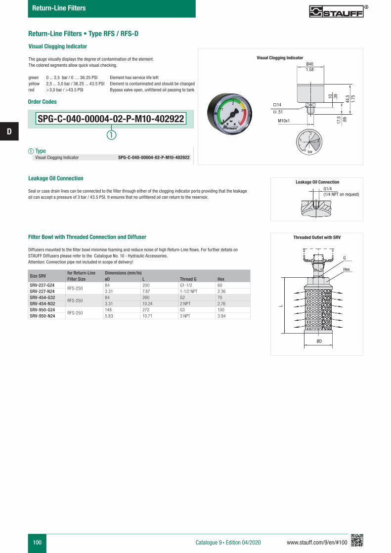
100 www.stauff.com/9/en/#100
D
Return-Line Filters § Type RFS / RFS-D
Catalogue 9 § Edition 04/2020
Return-Line Filters
Size SRVfor Return-Line Filter Size
Dimensions (mm/in)øD L Thread G Hex
SRV-227-G24RFS-250
84 200 G1-1/2 60SRV-227-N24 3.31 7.87 1-1/2 NPT 2.36SRV-454-G32
RFS-25084 260 G2 70
SRV-454-N32 3.31 10.24 2 NPT 2.76SRV-950-G24
RFS-250148 272 G3 100
SRV-950-N24 5.83 10.71 3 NPT 3.94
Leakage Oil Connection Seal or case drain lines can be connected to the filter through either of the clogging indicator ports providing that the leakage oil can accept a pressure of 3 bar / 43.5 PSI. It ensures that no unfiltered oil can return to the reservoir.
Filter Bowl with Threaded Connection and Diffuser
Diffusers mounted to the filter bowl minimise foaming and reduce noise of high Return-Line flows. For further details on STAUFF Diffusers please refer to the Catalogue No. 10 - Hydraulic Accessories.Attention: Connection pipe not included in scope of delivery!
Threaded Outlet with SRV
G
Hex
ØD
L
G1/4
(1/4 NPT on request)
Leakage Oil Connection
Visual Clogging Indicator
The gauge visually displays the degree of contamination of the element.The colored segments allow quick visual checking.
green 0 ... 2,5 bar / 0 … 36.25 PSI Element has service life leftyellow 2,5 ... 3,0 bar / 36.25 ... 43.5 PSI Element is contaminated and should be changed red >3,0 bar / >43.5 PSI Bypass valve open, unfiltered oil passing to tank
Ø40
14
M10x1
1.58
.39
.69
1.75
.51
10
17,5
44,5
0
1
2
3
bar
Visual Clogging Indicator
SPG-C-040-00004-02-P-M10-402922
Order Codes
a Type Visual Clogging Indicator SPG-C-040-00004-02-P-M10-402922
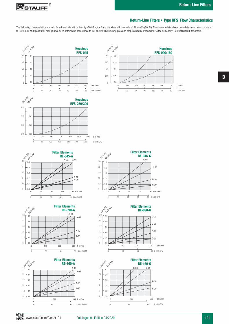
www.stauff.com/9/en/#101
D
101
Return-Line Filters § Type RFS Flow Characteristics
The following characteristics are valid for mineral oils with a density of 0,85 kg/dm3 and the kinematic viscosity of 30 mm2/s (30cSt). The characteristics have been determined in accordance to ISO 3968. Multipass filter ratings have been obtained in accordance to ISO 16889. The housing pressure drop is directly proportional to the oil density. Contact STAUFF for details.
HousingsRFS-045∆p i
n PSI
∆p in ba
r
0 40 80 120 160 200 240
0 10 20 30 40 50 60
Q in l/min
Q in US GPM
HousingsRFS-250/300∆p i
n PSI
∆p in ba
r
0 240 480 720 960 1200 1440
0 60 120 180 240 300 360
1.12
0.75
0.37
0.00
Q in l/min
Q in US GPM
0,07
0,05
0,02
0,00
0,4
0,3
0,2
0,1
0,0
6.0
4.5
3.0
1.5
0
0.5
0.4
0.3
0.2
0.1
0.0
7.5
6
4.5
3
1.5
0
∆p in b
ar
∆p in P
SI
Q in l/min
Q in US GPM
Filter Elements RE-090-A
0 110 220 330
0 30 60 90
A-10
A-20
A-03
A-05
Q in l/min
Q in US GPM
Filter Elements RE-090-G
0 110 220 330
0 30 60 90
G-03
G-05
G-10
G-20
2.5
2.0
1.5
1.0
0.5
0.0
37.5
30
22.5
15
7.5
0
∆p in b
ar
∆p in P
SI
0.5
0.4
0.3
0.2
0.1
0.0
7.5
6
4.5
3
1.5
0
∆p in b
ar
∆p in P
SI
Q in l/min
Q in US GPM
Filter Elements RE-045-A
A-10A-20
A-03 A-05
Q in l/min
Q in US GPM
Filter Elements RE-045-G
0 40 80 120 160
0 10 20 30 40
G-10
G-20
G-03
G-05
2.5
2.0
1.5
1.0
0.5
0.0
37.5
30
22.5
15
7.5
0
∆p in b
ar
∆p in P
SI
0 40 80 120 160
0 10 20 30 40
Q in l/min
Q in US GPM
Filter Elements RE-160-A
A-10
A-20
Q in l/min
Q in US GPM
Filter Elements RE-160-G
0.5
0.4
0.3
0.2
0.1
0.0
7.5
6
4.5
3
1.5
0
∆p in b
ar
∆p in P
SI
1
0.8
0.6
0.4
0.2
0.0
15
12
9
6
3
0
∆p in b
ar
∆p in P
SI
0 330 660 0 330 660
0 80 160 0 80 160
G-03 G-05
G-10
G-20
A-03
A-05
HousingsRFS-090/160∆p i
n PSI
∆p in ba
r
0 120 240 360 480 600 720
0 30 60 90 120 150 180
Q in l/min
Q in US GPM
0,2
0,15
0,1
0,05
0,0
3.0
2.25
1.5
0.75
0
Catalogue 9 § Edition 04/2020
Return-Line Filters
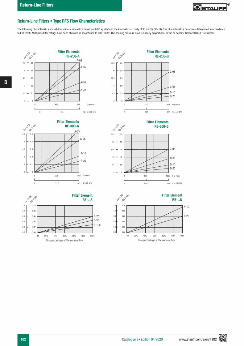
102 www.stauff.com/9/en/#102
D
Return-Line Filters § Type RFS Flow Characteristics
The following characteristics are valid for mineral oils with a density of 0,85 kg/dm3 and the kinematic viscosity of 30 mm2/s (30cSt). The characteristics have been determined in accordance to ISO 3968. Multipass filter ratings have been obtained in accordance to ISO 16889. The housing pressure drop is directly proportional to the oil density. Contact STAUFF for details.
∆p in P
SI
∆p in ba
r Filter Elements
RE-250-A
A-10
A-20
A-05
7.5
6
4.5
3
1.5
0
0.5
0.4
0.3
0.2
0.1
0
Q in l/min
Q in US GPM0 125 250
0 475 950
A-03∆p i
n PSI
∆p in ba
r Filter Elements
RE-250-G
0 125 250
0 475 950
G-10G-20
G-05
37.5
30
22.5
15
7.5
0
2.5
2.0
1.5
1.0
0.5
0
Q in l/min
Q in US GPM
G-03
∆p in P
SI
∆p in ba
r
0 171.5 343
0 650 1300
A-10
A-20
A-05
Filter Elements RE-300-A
7.5
6
4.5
3
1.5
0
0.5
0.4
0.3
0.2
0.1
0
Q in l/min
Q in US GPM
A-03 ∆p in P
SI
∆p in ba
r
0 171.5 343
0 650 1300
G-10G-20
G-05
Filter Elements RE-300-G
37.5
30
22.5
15
7.5
0
2.5
2.0
1.5
1.0
0.5
0
Q in l/min
Q in US GPM
G-03
∆p in P
SI
∆p in ba
r
S-50
S-100
S-25
Filter Element RE-...S
1.5
1.2
0.9
0.6
0.3
0.0
0.10
0.08
0.06
0.04
0.02
0.00
0% 20% 40% 60% 80% 100% 120%
Q as percentage of the nominal flow
∆p in P
SI
∆p in ba
r
0% 20% 40% 60% 80% 100% 120%
N-20
N-10
Filter Element RE-...N
1.5
1.2
0.9
0.6
0.3
0.0
0.10
0.08
0.06
0.04
0.02
0.00
Q as percentage of the nominal flow
Catalogue 9 § Edition 04/2020
Return-Line Filters
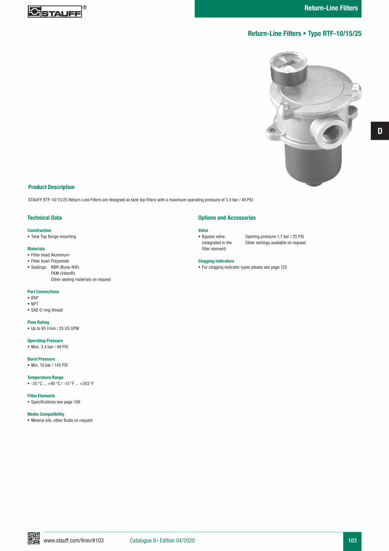
www.stauff.com/9/en/#103
D
103
Product Description STAUFF RTF-10/15/25 Return-Line Filters are designed as tank top filters with a maximum operating pressure of 3,4 bar / 49 PSI.
Return-Line Filters § Type RTF-10/15/25
Technical Data
Construction § Tank Top flange mounting
Materials § Filter head: Aluminium § Filter bowl: Polyamide § Sealings: NBR (Buna-N®) FKM (Viton®) Other sealing materials on request
Port Connections § BSP § NPT § SAE O-ring thread
Flow Rating § Up to 95 l/min / 25 US GPM
Operating Pressure § Max. 3,4 bar / 49 PSI
Burst Pressure § Min. 10 bar / 145 PSI
Temperature Range § -25 °C ... +95 °C / -13 °F ... +203 °F
Filter Elements § Specifications see page 106
Media Compatibility § Mineral oils, other fluids on request
Options and Accessories
Valve § Bypass valve: Opening pressure 1,7 bar / 25 PSI (integrated in the Other settings available on request filter element)
Clogging Indicators § For clogging indicator types please see page 125
Catalogue 9 § Edition 04/2020
Return-Line Filters
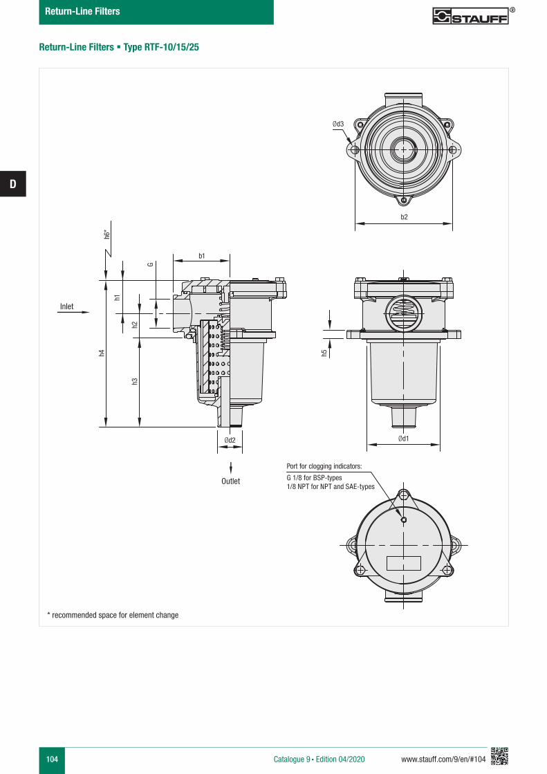
104 www.stauff.com/9/en/#104
D
Return-Line Filters § Type RTF-10/15/25
b1
h1
h5
h2h3
h4h6
*
G
Port for clogging indicators:
G 1/8 for BSP-types 1/8 NPT for NPT and SAE-types
Ød3
b2
Ød1Ød2
* recommended space for element change
Inlet
Outlet
Catalogue 9 § Edition 04/2020
Return-Line Filters
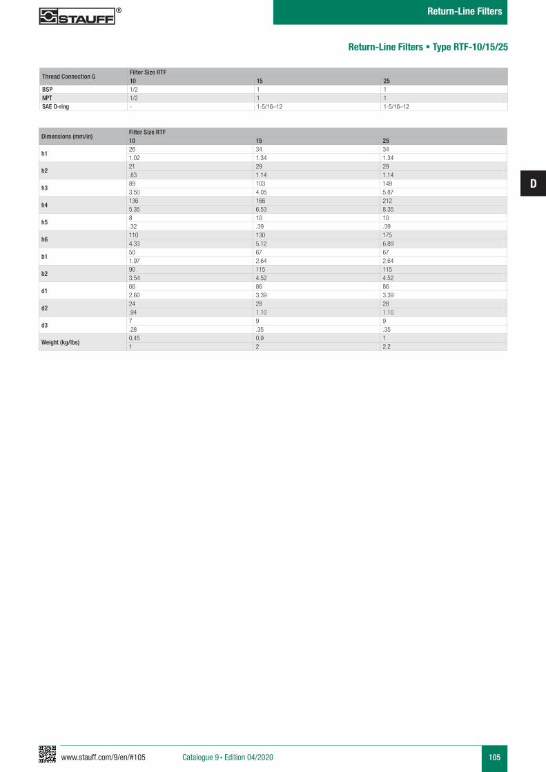
www.stauff.com/9/en/#105
D
105
Return-Line Filters § Type RTF-10/15/25
Dimensions (mm/in)Filter Size RTF10 15 25
h126 34 341.02 1.34 1.34
h221 29 29.83 1.14 1.14
h389 103 1493.50 4.05 5.87
h4136 166 2125.35 6.53 8.35
h58 10 10.32 .39 .39
h6110 130 1754.33 5.12 6.89
b150 67 671.97 2.64 2.64
b290 115 1153.54 4.52 4.52
d166 86 862.60 3.39 3.39
d224 28 28.94 1.10 1.10
d37 9 9.28 .35 .35
Weight (kg/lbs)0,45 0,9 11 2 2.2
Thread Connection GFilter Size RTF10 15 25
BSP 1/2 1 1NPT 1/2 1 1SAE O-ring - 1-5/16–12 1-5/16–12
Catalogue 9 § Edition 04/2020
Return-Line Filters
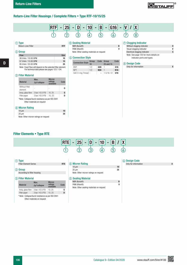
106 www.stauff.com/9/en/#106
D
Return-Line Filter Housings / Complete Filters § Type RTF-10/15/25
d Micron Rating 10 µm 10 25 µm 25 Note: Other micron ratings on request
e Sealing Material NBR (Buna®) B FKM (Viton®) V Note: Other sealing materials on request
f Design Code Only for information X
RTE - 25 - D - 10 - B / X
a Type Filter Element Series RTE
b Group According to filter housing
c Filter Material
Filter Elements § Type RTE
a Type Return-Line Filter RTF
b Group
c Filter Material
d Micron Rating 10 µm 10 25 µm 25 Note: Other micron ratings on request
f Connection Style
RTF - 25 - D - 10 - B - G16 - V / X
e Sealing Material NBR (Buna®) B FKM (Viton®) V Note: Other sealing materials on request
g Clogging Indicator Without clogging indicator 0 Visual clogging indicator V
Electrical clogging indicator E Note: See page 125 for more details on indicator ports and types.
h Design Code Only for information X
MaterialMax. Δp*collapse
Micron ratings available
Code
Without filter element
- - 0
Inorg. glass fibre 3 bar / 43.5 PSI 10, 25 GFilter paper 3 bar / 43.5 PSI 10, 25 D
*Note: Collapse/burst resistance as per ISO 2941 Other materials on request
MaterialMax. Δp*collapse
Micron ratings available
Code
Inorg. glass fibre 3 bar / 43.5 PSI 10, 25 GFilter paper 3 bar / 43.5 PSI 10, 25 D
* Note: Collapse/burst resistance as per ISO 2941 Other materials on request
Flow Size38 l/min / 10 US GPM 1057 l/min / 15 US GPM 1595 l/min / 25 US GPM 25
Note: Exact flow will depend on the selected filter element. For technical data please see pages 123 / 124.
hga b c fed
a b c fed
Connection StyleGroup Code Group Code10 25 and 15
BSP 1/2 G08 1 G16NPT 1/2 N08 1 N16SAE O-ring Thread - - 1-5/16–12 U16
Catalogue 9 § Edition 04/2020
Return-Line Filters
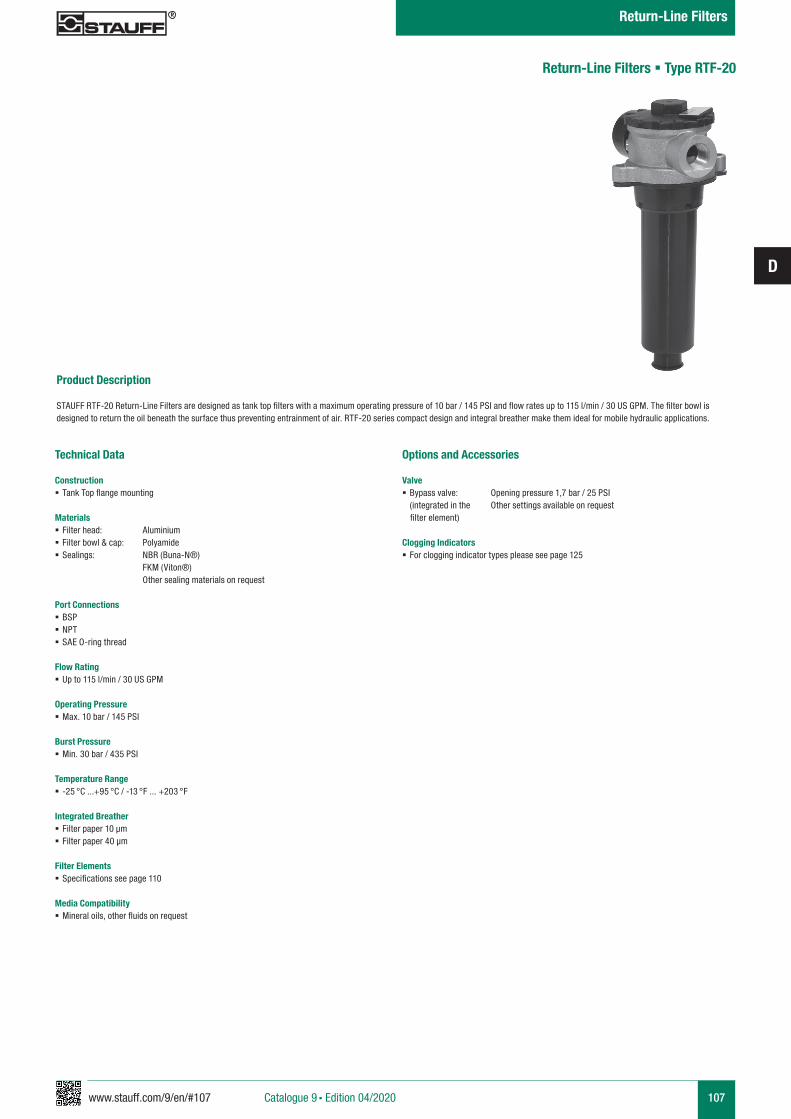
www.stauff.com/9/en/#107
D
107
Product Description STAUFF RTF-20 Return-Line Filters are designed as tank top filters with a maximum operating pressure of 10 bar / 145 PSI and flow rates up to 115 l/min / 30 US GPM. The filter bowl is designed to return the oil beneath the surface thus preventing entrainment of air. RTF-20 series compact design and integral breather make them ideal for mobile hydraulic applications.
Technical Data
Construction § Tank Top flange mounting
Materials § Filter head: Aluminium § Filter bowl & cap: Polyamide § Sealings: NBR (Buna-N®)
FKM (Viton®) Other sealing materials on request
Port Connections § BSP § NPT § SAE O-ring thread
Flow Rating § Up to 115 l/min / 30 US GPM
Operating Pressure § Max. 10 bar / 145 PSI
Burst Pressure § Min. 30 bar / 435 PSI
Temperature Range § -25 °C ...+95 °C / -13 °F ... +203 °F
Integrated Breather § Filter paper 10 µm § Filter paper 40 µm
Filter Elements § Specifications see page 110
Media Compatibility § Mineral oils, other fluids on request
Options and Accessories
Valve § Bypass valve: Opening pressure 1,7 bar / 25 PSI
(integrated in the Other settings available on request filter element)
Clogging Indicators § For clogging indicator types please see page 125
Return-Line Filters § Type RTF-20
Catalogue 9 § Edition 04/2020
Return-Line Filters
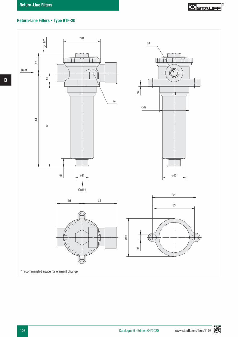
108 www.stauff.com/9/en/#108
D
Return-Line Filters § Type RTF-20
Ød4
Ød2
Ød1
b1 b2
b4
b3
G2
G1
h2
h1
h6
h5
b5
Ød3
h4
h3h7
*
Ød5
* recommended space for element change
Inlet
Outlet
Catalogue 9 § Edition 04/2020
Return-Line Filters
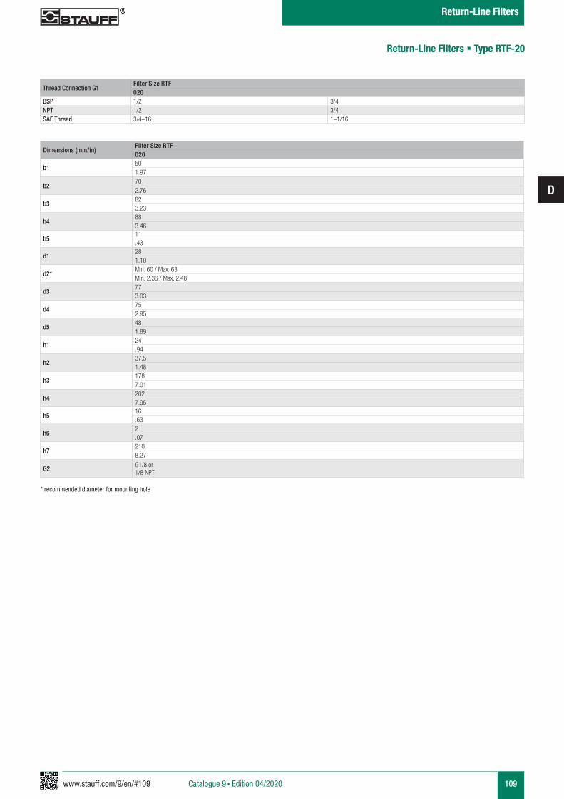
www.stauff.com/9/en/#109
D
109
Dimensions (mm/in)Filter Size RTF020
b1501.97
b2702.76
b3823.23
b4883.46
b511.43
d1281.10
d2*Min. 60 / Max. 63Min. 2.36 / Max. 2.48
d3773.03
d4752.95
d5481.89
h124.94
h237,51.48
h31787.01
h42027.95
h516.63
h62.07
h72108.27
G2 G1/8 or 1/8 NPT
* recommended diameter for mounting hole
Return-Line Filters § Type RTF-20
Thread Connection G1Filter Size RTF020
BSP 1/2 3/4NPT 1/2 3/4SAE Thread 3/4–16 1–1/16
Catalogue 9 § Edition 04/2020
Return-Line Filters
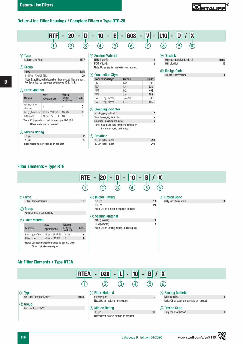
110 www.stauff.com/9/en/#110
D
MaterialMax. Δp*collapse
Micron ratings available
Code
Without filter element
- - 0
Inorg. glass fibre 25 bar / 363 PSI 10, 20 GFilter paper 10 bar / 145 PSI 10 D
*Note: Collapse/burst resistance as per ISO 2941 Other materials on request
Return-Line Filter Housings / Complete Filters § Type RTF-20
a Type Return-Line Filter RTF
b Group
c Filter Material
d Micron Rating 10 µm 10 20 µm 20 Note: Other micron ratings on request
f Connection Style
g Clogging Indicator No clogging indicator 0 Visual clogging indicator V
Electrical clogging indicator E Note: See page 125 for more details on indicator ports and types.
h Breather 10 µm Filter Paper L10 40 µm Filter Paper L40
j Design Code Only for information X
e Sealing Material NBR (Buna®) B FKM (Viton®) V Note: Other sealing materials on request
i Dipstick Without dipstick (standard) none With dipstick D
Flow Size115 l/min / 30 US GPM 20
Note: Exact flow will depend on the selected filter element. For technical data please see pages 123 / 124..
RTF - 20 - D - 10 - B - G08 - V - L10 - D / X
d Micron Rating 10 µm 10 20 µm 20 Note: Other micron ratings on request
e Sealing Material NBR (Buna®) B FKM (Viton®) V Note: Other sealing materials on request
f Design Code Only for information X
RTE - 20 - D - 10 - B / X
a Type Filter Element Series RTE
b Group According to filter housing
c Filter Material
Filter Elements § Type RTE
MaterialMax. Δp*collapse
Micron ratings available
Code
Inorg. glass fibre 25 bar / 363 PSI 10, 20 GFilter paper 10 bar / 145 PSI 10 D
*Note: Collapse/burst resistance as per ISO 2941 Other materials on request
Air Filter Elements § Type RTEA
RTEA - 020 - L - 10 - B / X
a Type Air Filter Element Series RTEA
b Group Air filter for RTF-20
c Filter Material Filter Paper L
Note: Other materials on request
d Micron Rating 10 µm 10 Note: Other micron ratings on request
e Sealing Material NBR (Buna®) B Note: Other sealing materials on request
f Design Code Only for information X
ihga b c fed j
a b c fed
a b c fed
Connection Style Thread CodeBSP 1/2 G08BSP 3/4 G12NPT 1/2 N08NPT 3/4 N12SAE O-ring Thread 3/4–16 U08SAE O-ring Thread 1-1/16–12 U12
Catalogue 9 § Edition 04/2020
Return-Line Filters
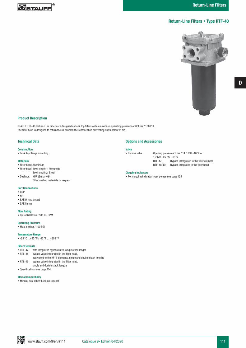
www.stauff.com/9/en/#111
D
111
Product Description STAUFF RTF-40 Return-Line Filters are designed as tank top filters with a maximum operating pressure of 6,9 bar / 100 PSI. The filter bowl is designed to return the oil beneath the surface thus preventing entrainment of air.
Return-Line Filters § Type RTF-40
Technical Data
Construction § Tank Top flange mounting
Materials § Filter head: Aluminium § Filter bowl: Bowl length 1: Polyamide Bowl length 2: Steel
§ Sealings: NBR (Buna-N®) Other sealing materials on request
Port Connections § BSP § NPT § SAE O-ring thread § SAE flange
Flow Rating § Up to 378 l/min / 100 US GPM
Operating Pressure § Max. 6,9 bar / 100 PSI
Temperature Range § -25 °C ...+95 °C / -13 °F ... +203 °F
Filter Elements § RTE-47 with integrated bypass valve, single stack length § RTE-48 bypass valve integrated in the filter head, equivalent to the HF-4 elements, single and double stack lengths
§ RTE-49 bypass valve integrated in the filter head, single and double stack lengths
§ Specifications see page 114
Media Compatibility § Mineral oils, other fluids on request
Options and Accessories
Valve § Bypass valve: Opening pressures 1 bar / 14.5 PSI ±10 % or 1,7 bar / 25 PSI ±10 % RTF-47: Bypass intergrated in the filter element RTF-48/49: Bypass integrated in the filter head
Clogging Indicators § For clogging indicator types please see page 125
Catalogue 9 § Edition 04/2020
Return-Line Filters
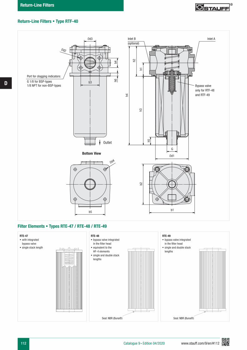
112 www.stauff.com/9/en/#112
D
Return-Line Filters § Type RTF-40
b3
G
Ød1
b5 b1
Ød4
Ød3
Ød2
b4 h2
h1h3
h5
h4
b2
h6
Inlet B(optional)
Inlet A
Bottom View
Port for clogging indicators:
G 1/8 for BSP-types 1/8 NPT for non-BSP-types
RTE-47 § with integrated bypass valve
§ single stack length
Filter Elements § Types RTE-47 / RTE-48 / RTE-49
RTE-48 § bypass valve integrated in the filter head
§ equivalent to the HF-4 elements
§ single and double stack lengths
Seal: NBR (Buna®)
RTE-49 § bypass valve integrated in the filter head
§ single and double stack lengths
Seal: NBR (Buna®)
Bypass valveonly for RTF-48 and RTF-49
Outlet
Catalogue 9 § Edition 04/2020
Return-Line Filters
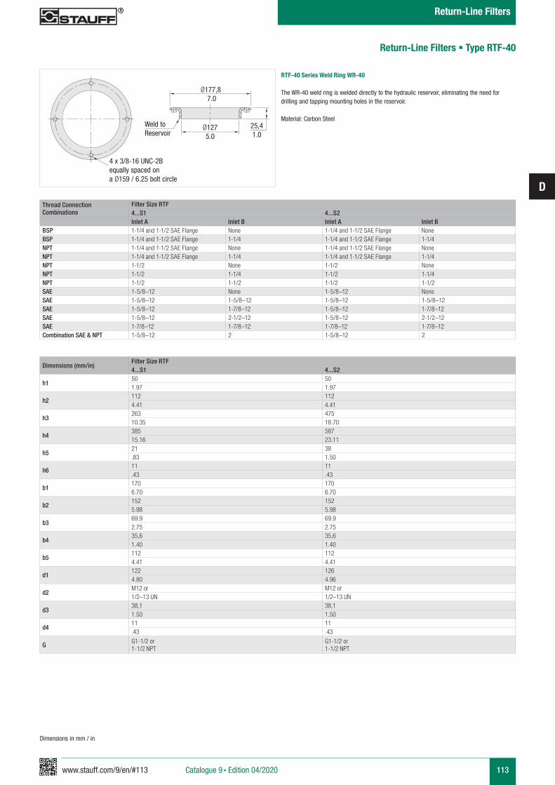
www.stauff.com/9/en/#113
D
113
RTF-40 Series Weld Ring WR-40
The WR-40 weld ring is welded directly to the hydraulic reservoir, eliminating the need for drilling and tapping mounting holes in the reservoir.
Material: Carbon Steel
Ø177,8 7.0
Ø1275.0
4 x 3/8-16 UNC-2Bequally spaced on a Ø159 / 6.25 bolt circle
25,41.0
Weld toReservoir
Return-Line Filters § Type RTF-40
Dimensions (mm/in)Filter Size RTF4...S1 4...S2
h150 501.97 1.97
h2112 1124.41 4.41
h3263 47510.35 18.70
h4385 58715.16 23.11
h521 38.83 1.50
h611 11.43 .43
b1170 1706.70 6.70
b2152 1525.98 5.98
b369.9 69.92.75 2.75
b435,6 35,61.40 1.40
b5112 1124.41 4.41
d1122 1264.80 4.96
d2M12 or M12 or1/2–13 UN 1/2–13 UN
d338,1 38,11.50 1.50
d411 11.43 .43
G G1-1/2 or1-1/2 NPT
G1-1/2 or1-1/2 NPT
Thread Connection Combinations
Filter Size RTF4...S1 4...S2Inlet A Inlet B Inlet A Inlet B
BSP 1-1/4 and 1-1/2 SAE Flange None 1-1/4 and 1-1/2 SAE Flange NoneBSP 1-1/4 and 1-1/2 SAE Flange 1-1/4 1-1/4 and 1-1/2 SAE Flange 1-1/4NPT 1-1/4 and 1-1/2 SAE Flange None 1-1/4 and 1-1/2 SAE Flange NoneNPT 1-1/4 and 1-1/2 SAE Flange 1-1/4 1-1/4 and 1-1/2 SAE Flange 1-1/4NPT 1-1/2 None 1-1/2 NoneNPT 1-1/2 1-1/4 1-1/2 1-1/4NPT 1-1/2 1-1/2 1-1/2 1-1/2SAE 1-5/8–12 None 1-5/8–12 NoneSAE 1-5/8–12 1-5/8–12 1-5/8–12 1-5/8–12SAE 1-5/8–12 1-7/8–12 1-5/8–12 1-7/8–12SAE 1-5/8–12 2-1/2–12 1-5/8–12 2-1/2–12SAE 1-7/8–12 1-7/8–12 1-7/8–12 1-7/8–12Combination SAE & NPT 1-5/8–12 2 1-5/8–12 2
Dimensions in mm / in
Catalogue 9 § Edition 04/2020
Return-Line Filters
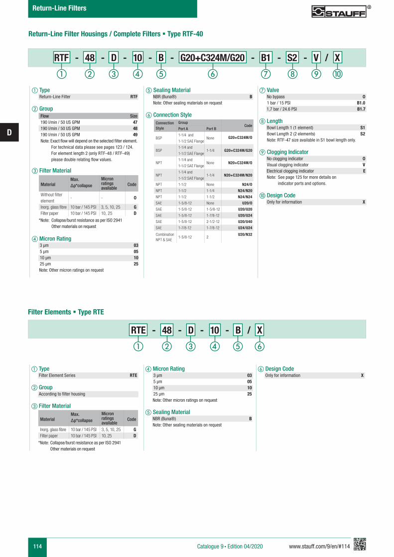
114 www.stauff.com/9/en/#114
D
Return-Line Filter Housings / Complete Filters § Type RTF-40
d Micron Rating 3 µm 03 5 µm 05 10 µm 10 25 µm 25 Note: Other micron ratings on request
e Sealing Material NBR (Buna®) B Note: Other sealing materials on request
f Design Code Only for information X
RTE - 48 - D - 10 - B / X
a Type Filter Element Series RTE
b Group According to filter housing
c Filter Material
Filter Elements § Type RTE
a Type Return-Line Filter RTF
b Group
c Filter Material
d Micron Rating 3 µm 03 5 µm 05 10 µm 10 25 µm 25 Note: Other micron ratings on request
e Sealing Material NBR (Buna®) B Note: Other sealing materials on request
f Connection Style
RTF - 48 - D - 10 - B - G20+C324M/G20 - B1 - S2 - V / X
g Valve No bypass 0 1 bar / 15 PSI B1.0
1,7 bar / 24.6 PSI B1.7
h Length Bowl Length 1 (1 element) S1 Bowl Length 2 (2 elements) S2 Note: RTF-47 size available in S1 bowl length only.
i Clogging Indicator No clogging indicator 0 Visual clogging indicator V
Electrical clogging indicator E Note: See page 125 for more details on indicator ports and options.
j Design Code Only for information X
Connection Style
GroupCode
Port A Port B
BSP1-1/4 and
1-1/2 SAE FlangeNone G20+C324M/O
BSP1-1/4 and
1-1/2 SAE Flange1-1/4 G20+C324M/G20
NPT1-1/4 and
1-1/2 SAE FlangeNone N20+C324M/O
NPT1-1/4 and
1-1/2 SAE Flange1-1/4 N20+C324M/N20
NPT 1-1/2 None N24/O
NPT 1-1/2 1-1/4 N24/N20
NPT 1-1/2 1-1/2 N24/N24
SAE 1-5/8-12 None U20/O
SAE 1-5/8-12 1-5/8-12 U20/U20
SAE 1-5/8-12 1-7/8-12 U20/U24
SAE 1-5/8-12 2-1/2-12 U20/U40
SAE 1-7/8-12 1-7/8-12 U24/U24
CombinationNPT & SAE
1-5/8-12 2U20/N32
MaterialMax. Δp*collapse
Micron ratings available
Code
Without filter element
- - 0
Inorg. glass fibre 10 bar / 145 PSI 3, 5, 10, 25 GFilter paper 10 bar / 145 PSI 10, 25 D
*Note: Collapse/burst resistance as per ISO 2941 Other materials on request
MaterialMax. Δp*collapse
Micron ratings available
Code
Inorg. glass fibre 10 bar / 145 PSI 3, 5, 10, 25 GFilter paper 10 bar / 145 PSI 10, 25 D
*Note: Collapse/burst resistance as per ISO 2941 Other materials on request
Flow Size190 l/min / 50 US GPM 47190 l/min / 50 US GPM 48190 l/min / 50 US GPM 49
Note: Exact flow will depend on the selected filter element. For technical data please see pages 123 / 124. For element length 2 (only RTF-48 / RTF-49) please double relating flow values.
ihga b c fed j
a b c fed
Catalogue 9 § Edition 04/2020
Return-Line Filters
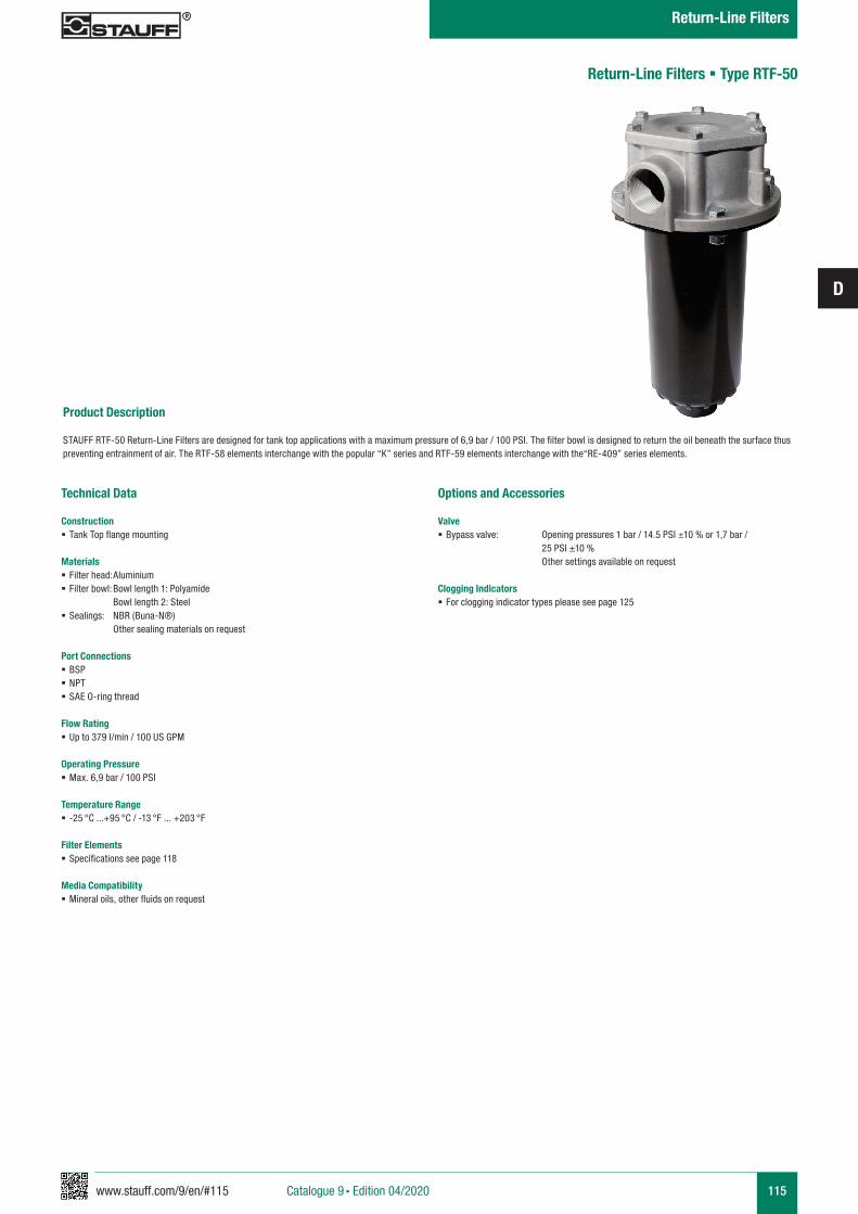
www.stauff.com/9/en/#115
D
115
Product Description STAUFF RTF-50 Return-Line Filters are designed for tank top applications with a maximum pressure of 6,9 bar / 100 PSI. The filter bowl is designed to return the oil beneath the surface thus preventing entrainment of air. The RTF-58 elements interchange with the popular “K” series and RTF-59 elements interchange with the“RE-409” series elements.
Return-Line Filters § Type RTF-50
Technical Data
Construction § Tank Top flange mounting
Materials § Filter head: Aluminium § Filter bowl: Bowl length 1: Polyamide Bowl length 2: Steel
§ Sealings: NBR (Buna-N®) Other sealing materials on request
Port Connections § BSP § NPT § SAE O-ring thread
Flow Rating § Up to 379 l/min / 100 US GPM
Operating Pressure § Max. 6,9 bar / 100 PSI
Temperature Range § -25 °C ...+95 °C / -13 °F ... +203 °F
Filter Elements § Specifications see page 118
Media Compatibility § Mineral oils, other fluids on request
Options and Accessories
Valve § Bypass valve: Opening pressures 1 bar / 14.5 PSI ±10 % or 1,7 bar / 25 PSI ±10 % Other settings available on request
Clogging Indicators § For clogging indicator types please see page 125
Catalogue 9 § Edition 04/2020
Return-Line Filters
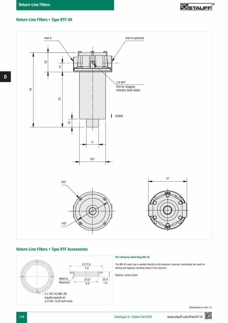
116 www.stauff.com/9/en/#116
D
Return-Line Filters § Type RTF-50
h1
h4
h2
h3
h5
Ød1
b3
b1
Inlet A
1/8 NPTPort for clogging indicator (both sides)
Inlet B (optional)
G
Ød3
Ød2
Return-Line Filters § Type RTF Accessories
RTF-50 Series Weld Ring WR-40
The WR-40 weld ring is welded directly to the hydraulic reservoir, eliminating the need for drilling and tapping mounting holes in the reservoir.
Material: Carbon Steel
Dimensions in mm / in
Ø177,8 7.0
Ø1275.0
4 x 3/8-16 UNC-2Bequally spaced on a Ø159 / 6.25 bolt circle
25,41.0
Weld toReservoir
Outlet
Catalogue 9 § Edition 04/2020
Return-Line Filters
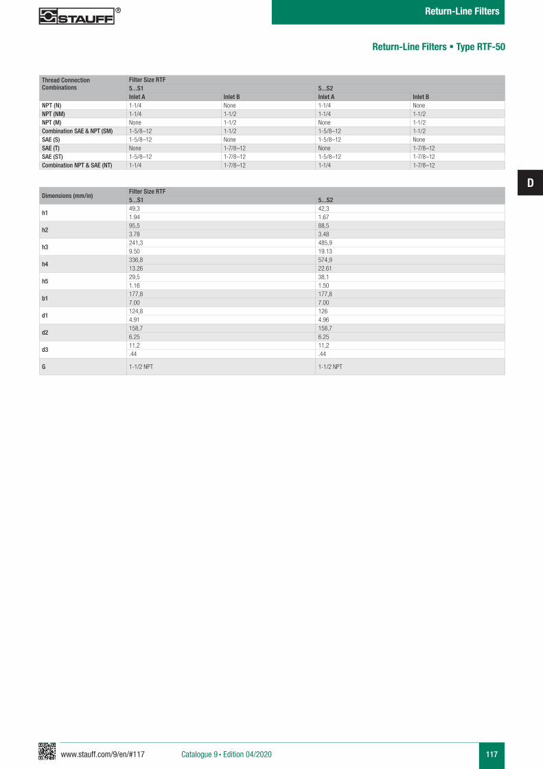
www.stauff.com/9/en/#117
D
117
Thread Connection Combinations
Filter Size RTF5...S1 5...S2Inlet A Inlet B Inlet A Inlet B
NPT (N) 1-1/4 None 1-1/4 NoneNPT (NM) 1-1/4 1-1/2 1-1/4 1-1/2NPT (M) None 1-1/2 None 1-1/2Combination SAE & NPT (SM) 1-5/8–12 1-1/2 1-5/8–12 1-1/2SAE (S) 1-5/8–12 None 1-5/8–12 NoneSAE (T) None 1-7/8–12 None 1-7/8–12SAE (ST) 1-5/8–12 1-7/8–12 1-5/8–12 1-7/8–12Combination NPT & SAE (NT) 1-1/4 1-7/8–12 1-1/4 1-7/8–12
Return-Line Filters § Type RTF-50
Dimensions (mm/in)Filter Size RTF5...S1 5...S2
h149,3 42,31.94 1.67
h295,5 88,53.78 3.48
h3241,3 485,99.50 19.13
h4336,8 574,913.26 22.61
h529,5 38,11.16 1.50
b1177,8 177,87.00 7.00
d1124,8 1264.91 4.96
d2158,7 158,76.25 6.25
d311,2 11,2.44 .44
G 1-1/2 NPT 1-1/2 NPT
Catalogue 9 § Edition 04/2020
Return-Line Filters
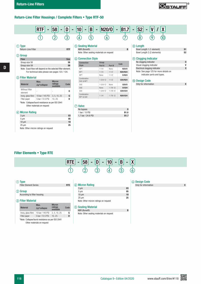
118 www.stauff.com/9/en/#118
D
Return-Line Filter Housings / Complete Filters § Type RTF-50
d Micron Rating 3 µm 03 5 µm 05 10 µm 10 25 µm 25 Note: Other micron ratings on request
e Sealing Material NBR (Buna®) B Note: Other sealing materials on request
f Design Code Only for information X
RTE - 58 - D - 10 - B - X
a Type Filter Element Series RTE
b Group According to filter housing
c Filter Material
Filter Elements § Type RTE
a Type Return-Line Filter RTF
b Group
c Filter Material
d Micron Rating 3 µm 03 5 µm 05 10 µm 10 25 µm 25 Note: Other micron ratings on request
e Sealing Material NBR (Buna®) B Note: Other sealing materials on request
f Connection Style
g Valve No bypass 0 1 bar / 15 PSI B1.0
1,7 bar / 24.6 PSI B1.7
RTF - 58 - D - 10 - B - N20/O - B1.7 - S2 - V / X
h Length Bowl Length 1 (1 element) S1 Bowl Length 2 (2 elements) S2
i Clogging Indicator No clogging indicator 0 Visual clogging indicator V
Electrical clogging indicator E Note: See page 125 for more details on indicator ports and types.
j Design Code Only for information X
Connection Style
GroupCode
Port A Port B
NPT 1-1/4 None N20/O
NPT 1-1/4 1-1/2 N20/N24
NPT None 1-1/2 O/N24
CombinationSAE & NPT
1-5/8-12 1-1/2 U20/N24
SAE 1-5/8-12 None U20/O
SAE None 1-7/8-12 O/U24
SAE 1-5/8-12 1-7/8-12 U20/U24
CombinationNPT & SAE
1-1/4 1-7/8-12 N20/U24
MaterialMax. Δp*collapse
Micron ratings available
Code
Without filter element
- - 0
Inorg. glass fibre 10 bar / 145 PSI 3, 5, 10, 25 GFilter paper 5 bar / 72.5 PSI 10, 25 D
*Note: Collapse/burst resistance as per ISO 2941 Other materials on request
MaterialMax. Δp*collapse
Micron ratings available
Code
Inorg. glass fibre 10 bar / 145 PSI 3, 5, 10, 25 GFilter paper 5 bar / 72.5 PSI 10, 25 D
*Note: Collapse/burst resistance as per ISO 2941 Other materials on request
Flow SizeGroup size 58 58Group size 59 59
Note: Exact flow will depend on the selected filter element. For technical data please see pages 123 / 124.
ihga b c fed j
a b c fed
Catalogue 9 § Edition 04/2020
Return-Line Filters
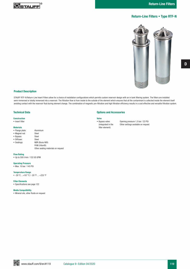
www.stauff.com/9/en/#119
D
119
Product Description STAUFF RTF-N Return-Line Insert Filters allow for a choice of installation configurations which permits custom reservoir design with an in tank filtering system. The filters are installed semi-immersed or totally immersed into a reservoir. The filtration flow is from inside to the outside of the element which ensures that all the contaminant is collected inside the element itself avoiding contact with the reservoir fluid during element change. The combination of magnetic pre-filtration and high filtration efficiency results in a cost effective and versatile filtration system.
Return-Line Filters § Type RTF-N
Technical Data
Construction § Insert filter
Materials § Flange plate: Aluminium § Magnet rod: Steel § Bypass: Steel § Diffuser: Steel § Sealings: NBR (Buna-N®)
FKM (Viton®) Other sealing materials on request
Flow Rating § Up to 500 l/min / 132 US GPM
Operating Pressure § Max. 10 bar / 145 PSI
Temperature Range § -29 °C ...+107 °C / -20 °F ... +225 °F
Filter Elements § Specifications see page 122
Media Compatibility § Mineral oils, other fluids on request
Options and Accessories
Valve § Bypass valve: Opening pressure 1,5 bar / 22 PSI
(integrated in the Other settings available on request filter element)
Catalogue 9 § Edition 04/2020
Return-Line Filters
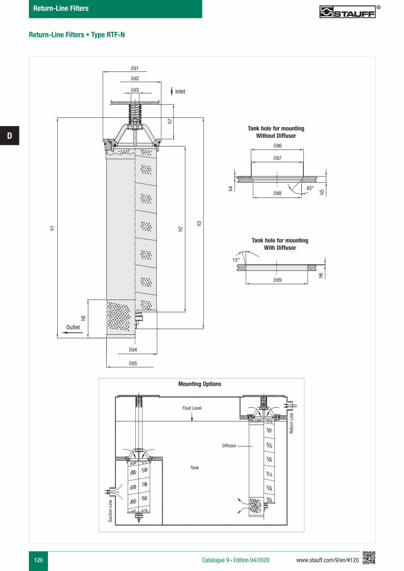
120 www.stauff.com/9/en/#120
D
Return-Line Filters § Type RTF-N
h1
h8
Ød1
Ød2
Ød3
h2
h3
Ød4
Ød5
h7
Tank hole for mountingWithout Diffusor
Ød8
Ød6
Ød7
h5
h4 45°
Tank hole for mountingWith Diffusor
Ød9
h6
15°
Suct
ion-
Line
Retu
rn-L
ine
Fluid Level
Tank
Mounting Options
Diffusor
Inlet
Outlet
Catalogue 9 § Edition 04/2020
Return-Line Filters
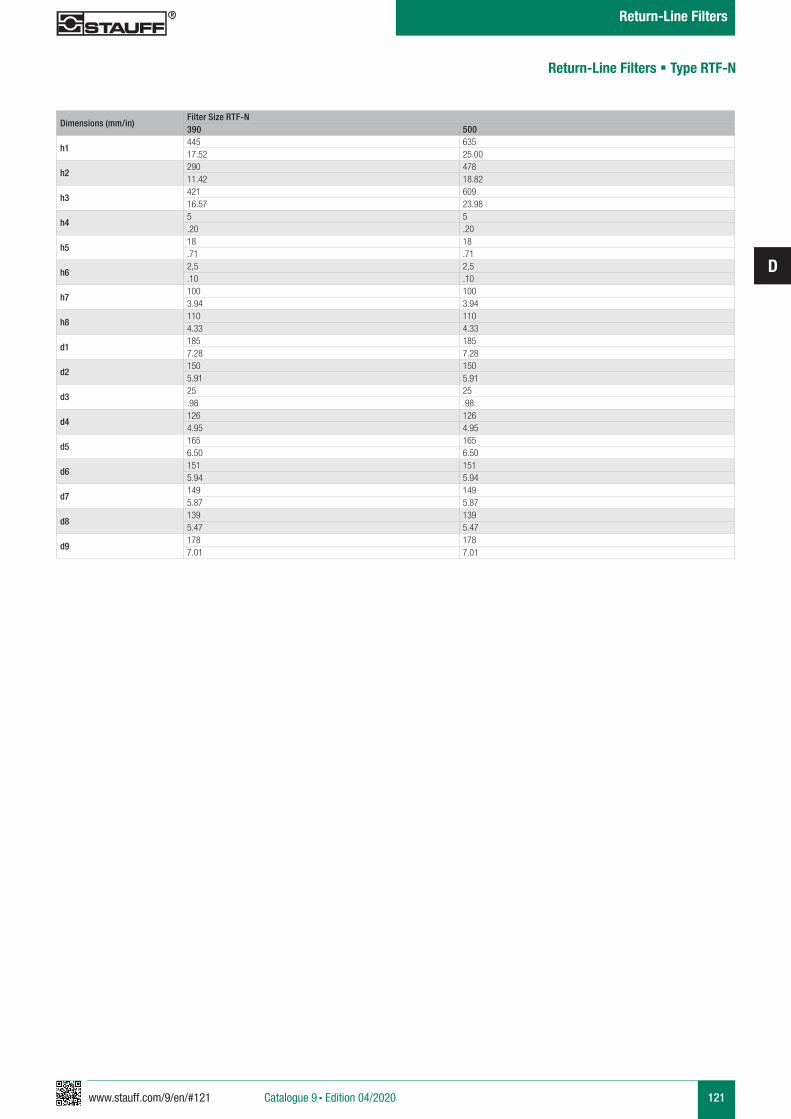
www.stauff.com/9/en/#121
D
121
Return-Line Filters § Type RTF-N
Dimensions (mm/in)Filter Size RTF-N390 500
h1445 63517.52 25.00
h2290 47811.42 18.82
h3421 60916.57 23.98
h45 5.20 .20
h518 18.71 .71
h62,5 2,5.10 .10
h7100 1003.94 3.94
h8110 1104.33 4.33
d1185 1857.28 7.28
d2150 1505.91 5.91
d325 25.98 .98
d4126 1264.95 4.95
d5165 1656.50 6.50
d6151 1515.94 5.94
d7149 1495.87 5.87
d8139 1395.47 5.47
d9178 1787.01 7.01
Catalogue 9 § Edition 04/2020
Return-Line Filters
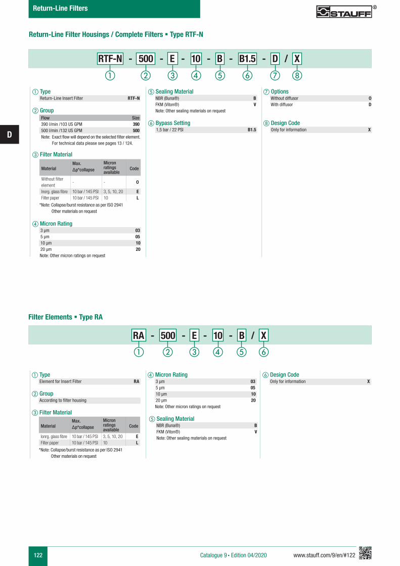
122 www.stauff.com/9/en/#122
D
Return-Line Filter Housings / Complete Filters § Type RTF-N
d Micron Rating 3 µm 03 5 µm 05 10 µm 10 20 µm 20 Note: Other micron ratings on request
e Sealing Material NBR (Buna®) B FKM (Viton®) V Note: Other sealing materials on request
RA - 500 - E - 10 - B / X
a Type Element for Insert Filter RA
b Group According to filter housing
c Filter Material
Filter Elements § Type RA
a Type Return-Line Insert Filter RTF-N
b Group
c Filter Material
d Micron Rating 3 µm 03 5 µm 05 10 µm 10 20 µm 20 Note: Other micron ratings on request
e Sealing Material NBR (Buna®) B FKM (Viton®) V Note: Other sealing materials on request
f Bypass Setting 1,5 bar / 22 PSI B1.5
RTF-N - 500 - E - 10 - B - B1.5 - D / X
g Options Without diffusor 0 With diffusor D
h Design Code Only for information X
MaterialMax. Δp*collapse
Micron ratings available
Code
Without filter element
- - 0
Inorg. glass fibre 10 bar / 145 PSI 3, 5, 10, 20 EFilter paper 10 bar / 145 PSI 10 L
*Note: Collapse/burst resistance as per ISO 2941 Other materials on request
MaterialMax. Δp*collapse
Micron ratings available
Code
Ionrg. glass fibre 10 bar / 145 PSI 3, 5, 10, 20 EFilter paper 10 bar / 145 PSI 10 L
*Note: Collapse/burst resistance as per ISO 2941 Other materials on request
Flow Size390 l/min /103 US GPM 390500 l/min /132 US GPM 500
Note: Exact flow will depend on the selected filter element. For technical data please see pages 13 / 124.
f Design Code Only for information X
hga b c fed
a b c fed
Catalogue 9 § Edition 04/2020
Return-Line Filters
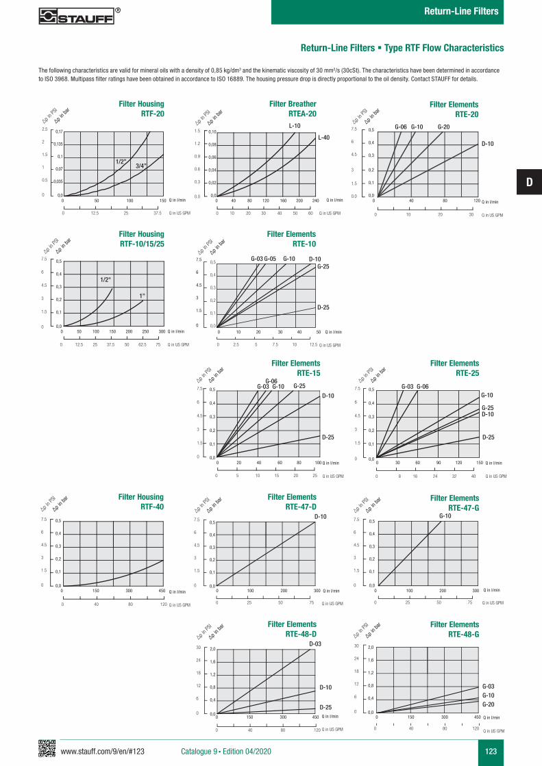
www.stauff.com/9/en/#123
D
123
Return-Line Filters § Type RTF Flow Characteristics
The following characteristics are valid for mineral oils with a density of 0,85 kg/dm3 and the kinematic viscosity of 30 mm2/s (30cSt). The characteristics have been determined in accordance to ISO 3968. Multipass filter ratings have been obtained in accordance to ISO 16889. The housing pressure drop is directly proportional to the oil density. Contact STAUFF for details.
Filter HousingRTF-20
0 12.5 25 37.5
2.5
2
1.5
1
0.5
0
0,17
0,135
0,1
0,07
0,035
0,0Q in l/min
Q in US GPM
0 50 100 150
1/2”3/4”
∆p in P
SI
∆p in ba
r
∆p in P
SI
∆p in ba
r Filter Housing
RTF-10/15/25
0 12.5 25 37.5 50 62.5 75
7.5
6
4.5
3
1.5
0
0,5
0,4
0,3
0,2
0,1
0,0Q in l/min
Q in US GPM
0 50 100 150 200 250 300
1/2"
1"
∆p in P
SI
∆p in ba
r
∆p in P
SI
∆p in ba
r Filter Elements
RTE-15
0 5 10 15 20 25 0 8 16 24 32 40
7.5
6
4.5
3
1.5
0
7.5
6
4.5
3
1.5
0
0,5
0,4
0,3
0,2
0,1
0,0
0,5
0,4
0,3
0,2
0,1
0,0Q in l/min
Q in US GPM
Q in l/min
Q in US GPM
0 20 40 60 80 100 0 30 60 90 120 150
G-03 G-10 G-03 G-06G-25
G-25D-10
G-06
D-10 G-10
D-25 D-25
Filter ElementsRTE-25
Filter BreatherRTEA-20
Q in l/min
Q in US GPM
L-10
L-40
0 10 20 30 40 50 60
1.5
1.2
0.9
0.6
0.3
0.0
0,10
0,08
0,06
0,04
0,02
0,0 0 40 80 120 160 200 240
∆p in P
SI
∆p in ba
r
Q in l/min
Q in US GPM
G-06 G-10 G-20
D-10
0 10 20 30
7.5
6
4.5
3
1.5
0.0
0,5
0,4
0,3
0,2
0,1
0,0 0 40 80 120
∆p in P
SI
∆p in ba
r Filter Elements
RTE-20
0 2.5 5 7.5 10 12.5
7.5
6
4.5
3
1.5
0
0,5
0,4
0,3
0,2
0,1
0,0 Q in l/min
Q in US GPM
0 10 20 30 40 50
D-10G-25
D-25
G-10G-05G-03∆p i
n PSI
∆p in ba
r Filter Elements
RTE-10
Filter HousingRTF-40
0 40 80 120
7.5
6
4.5
3
1.5
0
0,5
0,4
0,3
0,2
0,1
0,0Q in l/min
Q in US GPM
0 150 300 450
∆p in P
SI
∆p in ba
r
Filter ElementsRTE-48-D
30
24
18
12
6
0
2,0
1,6
1,2
0,8
0,4
0,0
0 40 80 120
Q in l/min
Q in US GPM
0 150 300 450
D-03
D-10
D-25
Filter ElementsRTE-47-D
0 25 50 75
7.5
6
4.5
3
1.5
0
0,5
0,4
0,3
0,2
0,1
0,0 Q in l/min
Q in US GPM
0 100 200 300
D-10∆p i
n PSI
∆p in ba
r
∆p in P
SI
∆p in ba
r Filter Elements
RTE-48-G30
24
18
12
6
0
2,0
1,6
1,2
0,8
0,4
0,0
0 40 80 120
Q in l/min
Q in US GPM
0 150 300 450
G-03G-10G-20
∆p in P
SI
∆p in ba
r
Filter ElementsRTE-47-G
0 25 50 75
7.5
6
4.5
3
1.5
0
0,5
0,4
0,3
0,2
0,1
0,0 Q in l/min
Q in US GPM
0 100 200 300
G-10∆p i
n PSI
∆p in ba
r
Catalogue 9 § Edition 04/2020
Return-Line Filters
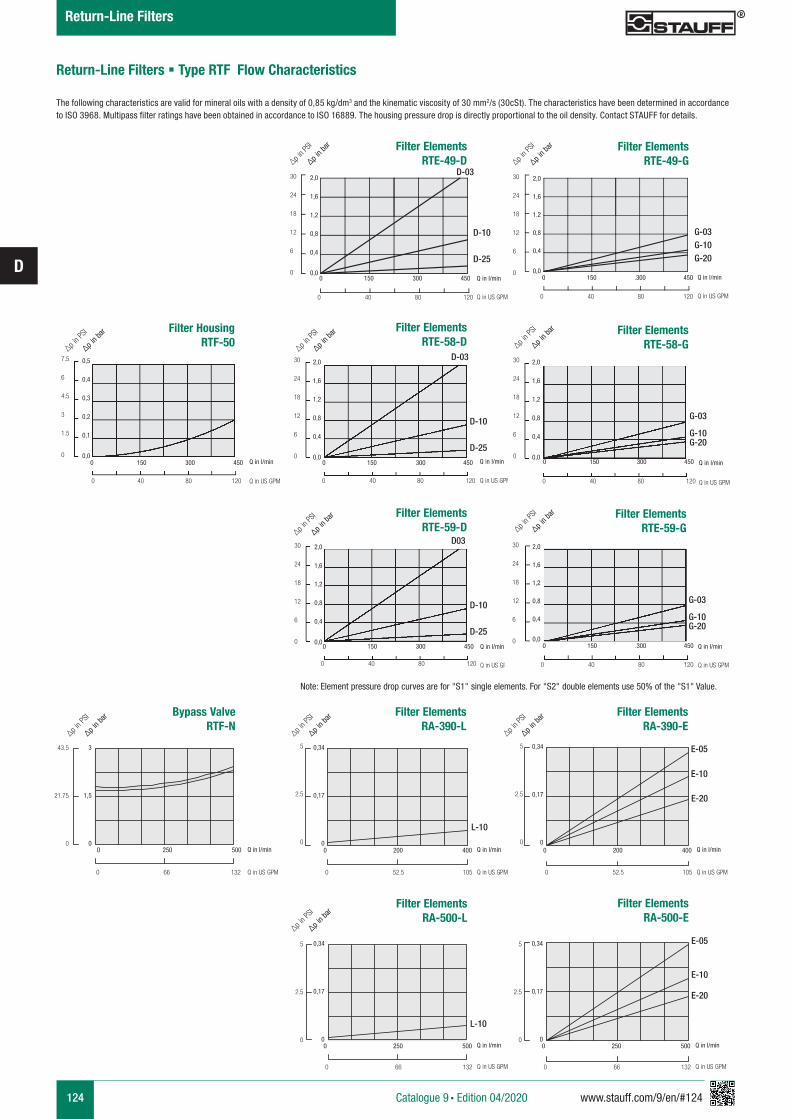
124 www.stauff.com/9/en/#124
D
Return-Line Filters § Type RTF Flow Characteristics
The following characteristics are valid for mineral oils with a density of 0,85 kg/dm3 and the kinematic viscosity of 30 mm2/s (30cSt). The characteristics have been determined in accordance to ISO 3968. Multipass filter ratings have been obtained in accordance to ISO 16889. The housing pressure drop is directly proportional to the oil density. Contact STAUFF for details.
Filter HousingRTF-50
∆p in P
SI
∆p in ba
r Filter Elements
RTE-58-D∆p i
n PSI
∆p in ba
r
7.5
6
4.5
3
1.5
0
0,5
0,4
0,3
0,2
0,1
0,0
0 40 80 120
Q in l/min
Q in US GPM
0 150 300 450
30
24
18
12
6
0
2,0
1,6
1,2
0,8
0,4
0,0
0 40 80 120
Q in l/min
Q in US GPM
0 150 300 450
D-03
Filter ElementsRTE-59-D∆p i
n PSI
∆p in ba
r
0 40 80 120
30
24
18
12
6
0
2,0
1,6
1,2
0,8
0,4
0,0Q in l/min
Q in US GPM
0 150 300 450
D03
D-10
D-25
D-10
D-25
Note: Element pressure drop curves are for "S1" single elements. For "S2" double elements use 50% of the "S1" Value.
Filter ElementsRTE-59-G∆p i
n PSI
∆p in ba
r
0 40 80 120
30
24
18
12
6
0
2,0
1,6
1,2
0,8
0,4
0,0Q in l/min
Q in US GPM
0 150 .300 450
Filter ElementsRTE-58-G∆p i
n PSI
∆p in ba
r
30
24
18
12
6
0
2,0
1,6
1,2
0,8
0,4
0,0
0 40 80 120
Q in l/min
Q in US GPM
0 150 300 450
G-03
G-10G-20
G-03
G-10G-20
Bypass ValveRTF-N
0 250 500
0 66 132
3
1,5
0
43.5
21.75
0
∆p in P
SI
∆p in ba
r
L-10
Filter ElementsRA-390-L
Filter ElementsRA-390-E
E-20
E-10
E-05
Filter ElementsRA-500-L
L-10
E-20
Filter ElementsRA-500-E
E-10
E-05
∆p in P
SI
∆p in ba
r
∆p in P
SI
∆p in ba
r
∆p in P
SI
∆p in ba
r
0 200 400
0 52.5 105
0,34
0,17
0
5
2.5
0Q in l/min
Q in US GPM
0 250 500
0 66 132
0,34
0,17
0
5
2.5
0Q in l/min
Q in US GPM
0 250 500
0 66 132
0,34
0,17
0
5
2.5
0Q in l/min
Q in US GPM
0 200 400
0 52.5 105
0,34
0,17
0
5
2.5
0Q in l/min
Q in US GPM
Q in l/min
Q in US GPM
Filter ElementsRTE-49-D
D-03
D-10
D-25
∆p in P
SI
∆p in ba
r
0 40 80 120
30
24
18
12
6
0
2,0
1,6
1,2
0,8
0,4
0,0Q in l/min
Q in US GPM
0 150 300 450
Filter ElementsRTE-49-G
G-03G-10G-20
∆p in P
SI
∆p in ba
r
0 40 80 120
30
24
18
12
6
0
2,0
1,6
1.2
0,8
0,4
0,0Q in l/min
Q in US GPM
0 150 .300 450
Catalogue 9 § Edition 04/2020
Return-Line Filters
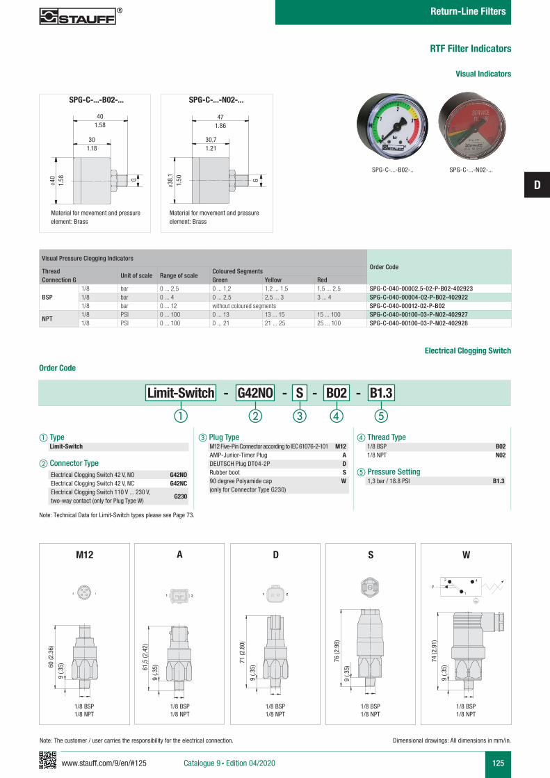
www.stauff.com/9/en/#125
D
125
RTF Filter Indicators
Visual Pressure Clogging IndicatorsOrder Code
Thread Connection G
Unit of scale Range of scaleColoured SegmentsGreen Yellow Red
BSP1/8 bar 0 ... 2,5 0 ... 1,2 1,2 ... 1,5 1,5 ... 2,5 SPG-C-040-00002.5-02-P-B02-4029231/8 bar 0 ... 4 0 ... 2,5 2,5 ... 3 3 ... 4 SPG-C-040-00004-02-P-B02-4029221/8 bar 0 ... 12 without coloured segments SPG-C-040-00012-02-P-B02
NPT1/8 PSI 0 ... 100 0 ... 13 13 ... 15 15 ... 100 SPG-C-040-00100-03-P-N02-4029271/8 PSI 0 ... 100 0 ... 21 21 ... 25 25 ... 100 SPG-C-040-00100-03-P-N02-402928
Visual Indicators
SPG-C-...-B02-.. SPG-C-...-N02-...
SPG-C-...-N02-...
471.86
30,71.21
G
Ø38
,11.
50
Material for movement and pressure element: Brass
SPG-C-...-B02-...
401.58
301.18
G
Ø40 1.58
Material for movement and pressure element: Brass
Catalogue 9 § Edition 04/2020
Return-Line Filters
Order Code
Limit-Switch - G42NO - S - B02 - B1.3
a Type Limit-Switch
b Connector Type
c Plug Type M12 Five-Pin Connector according to IEC 61076-2-101 M12 AMP-Junior-Timer Plug A DEUTSCH Plug DT04-2P D Rubber boot S 90 degree Polyamide cap W (only for Connector Type G230)
d Thread Type 1/8 BSP B02 1/8 NPT N02
e Pressure Setting 1,3 bar / 18.8 PSI B1.3
Electrical Clogging Switch 42 V, NO G42NOElectrical Clogging Switch 42 V, NC G42NCElectrical Clogging Switch 110 V ... 230 V, two-way contact (only for Plug Type W)
G230
Dimensional drawings: All dimensions in mm/in.
a b c ed
Electrical Clogging Switch
1/8 BSP1/8 NPT
1/8 BSP1/8 NPT
1/8 BSP1/8 NPT
1/8 BSP1/8 NPT
1/8 BSP1/8 NPT
WM12 S
3 11 21 2
A
61,5
(2.4
2)
9 (.3
5)
D
21 21
71 (2
.80)
9 (.3
5)60 (2
.36)
9 (.3
5)
9 (.3
5)
76 (2
.98)
9 (.3
5)
74 (2
.91)
P4
1
2
Note: The customer / user carries the responsibility for the electrical connection.
Note: Technical Data for Limit-Switch types please see Page 73.
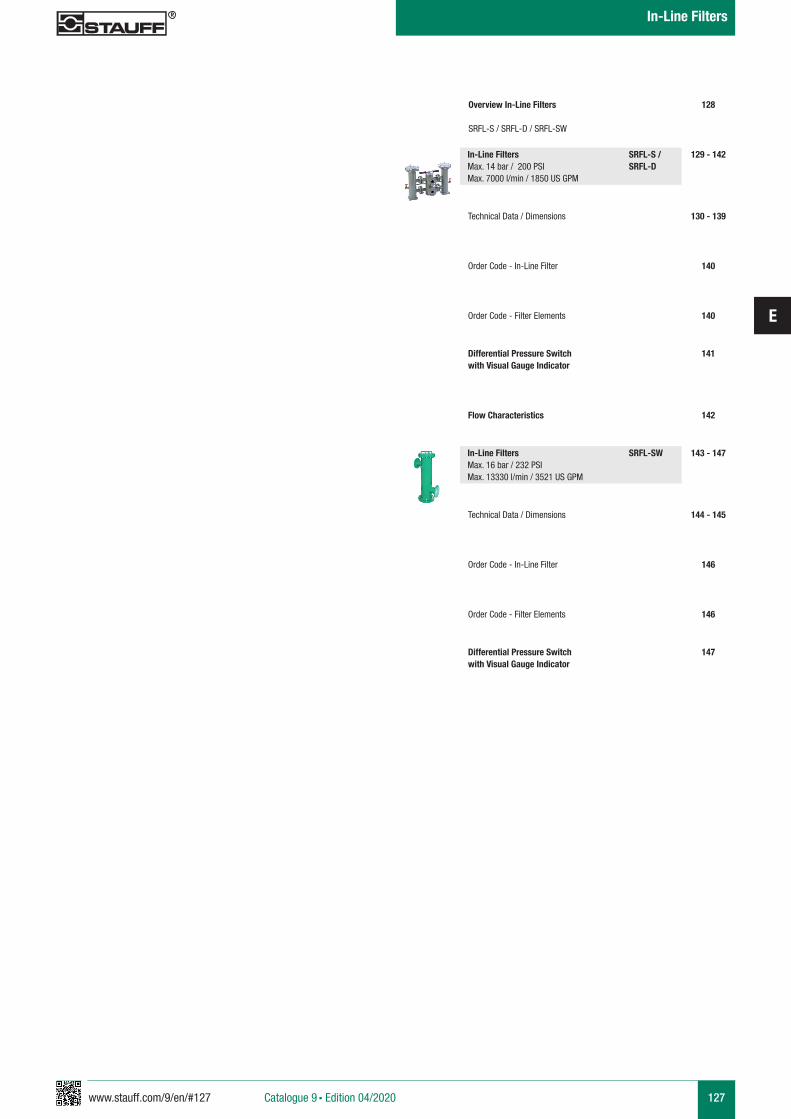
www.stauff.com/9/en/#127
E
127Catalogue 9 § Edition 04/2020
In-Line Filters
Overview In-Line Filters
SRFL-S / SRFL-D / SRFL-SW
129 - 142
130 - 139
140
140
Technical Data / Dimensions
Order Code - In-Line Filter
Order Code - Filter Elements
128
In-Line Filters SRFL-S / Max. 14 bar / 200 PSI SRFL-DMax. 7000 l/min / 1850 US GPM
141Differential Pressure Switch with Visual Gauge Indicator
142Flow Characteristics
143 - 147
144 - 145
146
146
Technical Data / Dimensions
Order Code - In-Line Filter
Order Code - Filter Elements
In-Line Filters SRFL-SW Max. 16 bar / 232 PSI Max. 13330 l/min / 3521 US GPM
147Differential Pressure Switch with Visual Gauge Indicator
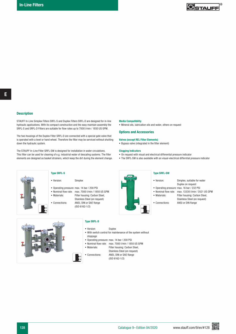
128 www.stauff.com/9/en/#128
E
Type SRFL-S
§ Version: Simplex
§ Operating pressure: max. 14 bar / 200 PSI § Nominal flow rate: max. 7000 l/min / 1850 US GPM § Materials: Filter housing: Carbon Steel, Stainless Steel (on request)
§ Connections: ANSI, DIN or SAE flange (ISO 6162-1/2)
Type SRFL-D
§ Version: Duplex § With switch control for maintenance of the system without stoppage
§ Operating pressure: max. 14 bar / 200 PSI § Nominal flow rate: max. 7000 l/min / 1850 US GPM § Materials: Filter housing: Carbon Steel, Stainless Steel (on request)
§ Connections: ANSI, DIN or SAE flange (ISO 6162-1/2)
Type SRFL-SW
§ Version: Simplex, suitable for water Duplex on request
§ Operating pressure: max. 16 bar / 232 PSI § Nominal flow rate: max. 13330 l/min / 3521 US GPM § Materials: Filter housing: Carbon Steel, Stainless Steel (on request)
§ Connections: ANSI or DIN flange
Description
STAUFF In-Line Simplex Filters SRFL-S and Duplex Filters SRFL-D are designed for in-line hydraulic applications. With its compact construction and the easy maintain assembly the SRFL-S and SRFL-D Filters are suitable for flow rates up to 7000 l/min / 1850 US GPM.
The two housings of the Duplex Filter SRFL-D are connected with a special gate valve that is operated with a level or hand wheel. Therefore the filter may be serviced without shutting down the hydraulic system.
The STAUFF In-Line Filter SRFL-SW is designed for installation in water circulations. This filter can be used for cleaning of e.g. industrial water of descaling systems. The filter elements are designed as basket strainers, which keep the dirt during the element change.
Media Compatibility § Mineral oils, lubrication oils and water, others on request
Options and Accessories
Valves (except REL Filter Elements) § Bypass valve (integrated in the filter element)
Clogging Indicators § On request with visual and electrical differential pressure indicator § The SRFL-SW is also available with an visual-electrical differntial pressure indicator
Catalogue 9 § Edition 04/2020
In-Line Filters
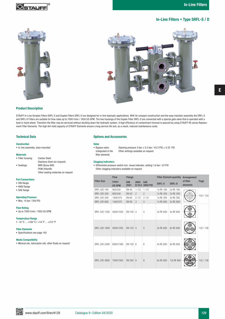
www.stauff.com/9/en/#129
E
129
Product Description
STAUFF In-Line Simplex Filters SRFL-S and Duplex Filters SRFL-D are designed for in-line hydraulic applications. With its compact construction and the easy maintain assembly the SRFL-S and SRFL-D Filters are suitable for flow rates up to 7000 l/min / 1850 US GPM. The two housings of the Duplex Filter SRFL-D are connected with a special gate valve that is operated with a level or hand wheel. Therefore the filter may be serviced without shutting down the hydraulic system. A high efficiency of contaminant removal is assured by using STAUFF RE series Replace-ment Filter Elements. The high dirt-hold capacity of STAUFF Elements ensure a long service life and, as a result, reduced maintenance costs.
Technical Data
Construction § In-line assembly, base mounted
Materials § Filter housing: Carbon Steel
Stainless Steel (on request) § Sealings: NBR (Buna-N®)
FKM (Viton®) Other sealing materials on request
Port Connections § DIN flange § ANSI flange § SAE flange
Operating Pressure § Max. 14 bar / 200 PSI
Flow Rating § Up to 7000 l/min / 1850 US GPM
Temperature Range § -10 °C ... +100 °C / +14 °F ... +212 °F
Filter Elements § Specifications see page 140
Media Compatibility § Mineral oils, lubrication oils, other fluids on request
In-Line Filters § Type SRFL-S / D
Filter Size
Flow Flange Filter Element quantity Arrangement of filter elements
Pagel/min/US GPM
DIN2501
ANSIB 16.5
SAE3000 PSI SRFL-S SRFL-D
SRFL-S/D-160 900/240 DN 40 1-1/2 1-1/2 1x RE-160 2x RE-160
130 / 134SRFL-S/D-200 900/240 DN 50 2 2 1x RE-200 2x RE-200
SRFL-S/D-300 1400/370 DN 65 2-1/2 2-1/2 1x RE-300 2x RE-300
SRFL-S/D-600 1400/370 DN 80 3 3 1x RE-600 2x RE-600
SRFL-S/D-1200 4000/1050 DN 100 4 4 2x RE-600 4x RE-600
132 / 136SRFL-S/D-1800 4000/1050 DN 125 5 5 3x RE-600 6x RE-600
SRFL-S/D-2400 6000/1580 DN 150 6 6 4x RE-600 8x RE-600
SRFL-S/D-3600 7000/1850 DN 200 8 8 6x RE-600 12x RE-600 132 / 138
Options and Accessories
Valve § Bypass valve: Opening pressure 3 bar ± 0,3 bar / 43.5 PSI ± 4.35 PSI
(integrated in the Other settings available on request filter element)
Clogging Indicators § Differential pressure switch incl. visual indicator, setting 1,6 bar / 23 PSI
Other clogging indicators available on request
Catalogue 9 § Edition 04/2020
In-Line Filters
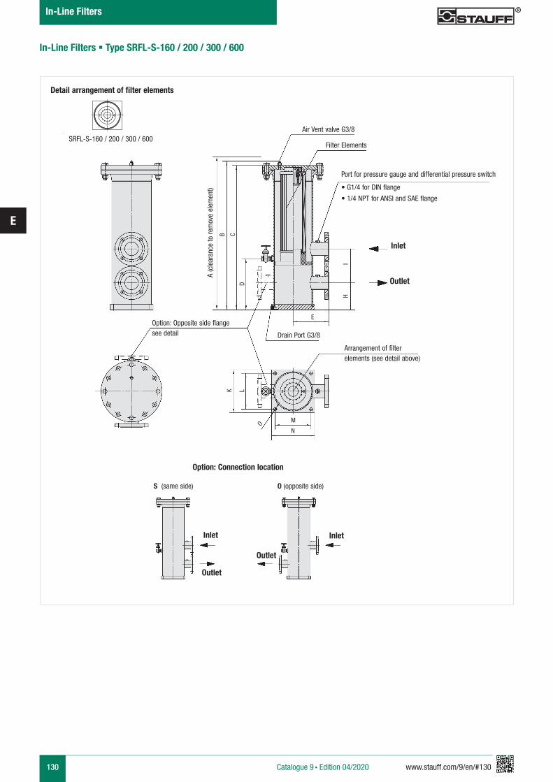
130 www.stauff.com/9/en/#130
E
Air Vent valve G3/8
Inlet
Outlet
Filter Elements
Option: Opposite side flangesee detail
Port for pressure gauge and differential pressure switch
• G1/4 for DIN flange
• 1/4 NPT for ANSI and SAE flange
Arrangement of filterelements (see detail above)
A (c
lear
ance
to re
mov
e el
emen
t)
E
M
N
L
O
KB C
D
IH
Drain Port G3/8
In-Line Filters § Type SRFL-S-160 / 200 / 300 / 600
Detail arrangement of filter elements
SRFL-S-160 / 200 / 300 / 600
Option: Connection location
Inlet Inlet
Outlet
Outlet
S (same side) O (opposite side)
Catalogue 9 § Edition 04/2020
In-Line Filters

www.stauff.com/9/en/#131
E
131
Flange ConnectionFilter Size SRFL-S160 200 300 600
DIN DN 40 DN 50 DN 65 DN 80ANSI 1-1/2 2 2-1/2 3SAE 1-1/2 2 2-1/2 3
Dimensions (mm/in)Filter Size SRFL-S160 200 300 600
A885,8 1045,8 1248,7 2126,734.87 41.17 49.16 83.73
B607,6 688,7 828,6 1267,623.92 27.12 32.63 49.91
C584 664 803,9 1242,922.99 26.14 31.65 48.93
D214 214 285 2858.43 8.43 11.22 11.22
E148 148 198 1985.83 5.83 7.80 7.80
H130 140 150 1605.12 5.51 5.91 6.30
I155 190 190 2206.10 7.48 7.48 8.66
K150 150 240 2405.91 5.91 9.45 9.45
L125 125 200 2004.92 4.92 7.87 7.87
M125 125 200 2004.92 4.92 7.87 7.87
N150 150 240 2405.91 5.91 9.45 9.45
O11 11 18 18.43 .43 .71 .71
Total Oil Capacity (l/gal)6,0 7,1 22,2 37,11.59 1.86 5.87 9.80
Weight (kg/lbs)14,5 15,9 29 34,532 35 64 76
Filter ElementsDesignation RE-160 ... RE-200 ... RE-300 ... RE-600 ...Quantity 1 x 1 1 x 1 1 x 1 1 x 1
In-Line Filters § Type SRFL-S-160 / 200 / 300 / 600
Catalogue 9 § Edition 04/2020
In-Line Filters
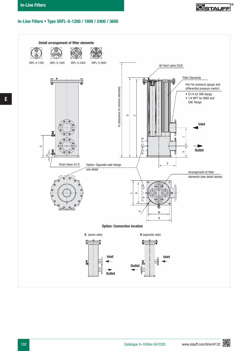
132 www.stauff.com/9/en/#132
E
Detail arrangement of filter elements
Air Vent valve G3/8
Inlet
Outlet
Filter Elements
A (c
lear
ance
to re
mov
e el
emen
t)
E
B C
IH
SRFL-S-1200 SRFL-S-1800 SRFL-S-2400 SRFL-S-3600
Option: Opposite side flangesee detail
Drain Valve G1/2
Arrangement of filterelements (see detail above)
M
N
L
OK
D
R
Port for pressure gauge and differential pressure switch
• G1/4 for DIN flange • 1/4 NPT for ANSI and SAE flange
In-Line Filters § Type SRFL-S-1200 / 1800 / 2400 / 3600
Catalogue 9 § Edition 04/2020
In-Line Filters
Option: Connection location
Inlet Inlet
Outlet
Outlet
S (same side) O (opposite side)
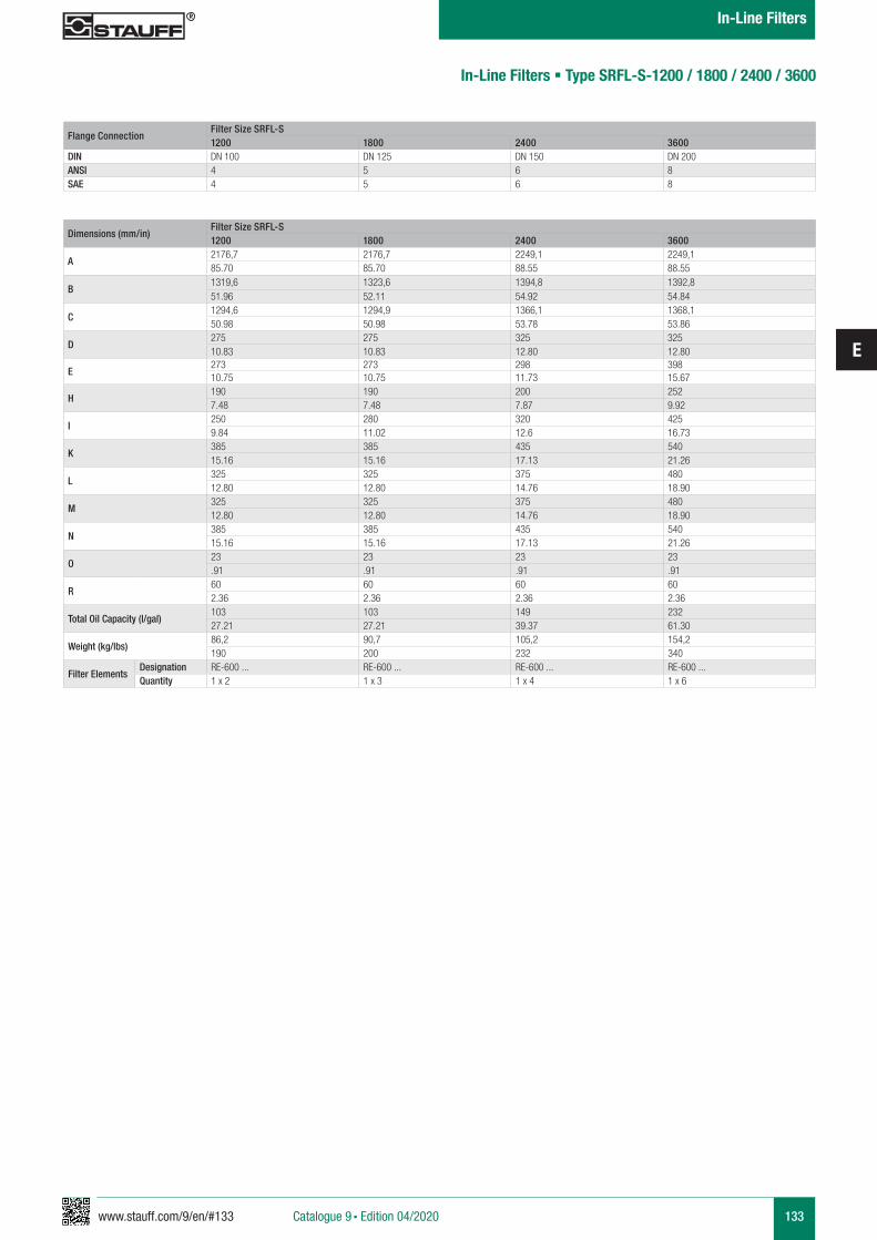
www.stauff.com/9/en/#133
E
133
Flange ConnectionFilter Size SRFL-S1200 1800 2400 3600
DIN DN 100 DN 125 DN 150 DN 200ANSI 4 5 6 8 SAE 4 5 6 8
Dimensions (mm/in)Filter Size SRFL-S1200 1800 2400 3600
A2176,7 2176,7 2249,1 2249,185.70 85.70 88.55 88.55
B1319,6 1323,6 1394,8 1392,851.96 52.11 54.92 54.84
C1294,6 1294,9 1366,1 1368,150.98 50.98 53.78 53.86
D275 275 325 32510.83 10.83 12.80 12.80
E273 273 298 39810.75 10.75 11.73 15.67
H190 190 200 2527.48 7.48 7.87 9.92
I250 280 320 4259.84 11.02 12.6 16.73
K385 385 435 54015.16 15.16 17.13 21.26
L325 325 375 48012.80 12.80 14.76 18.90
M325 325 375 48012.80 12.80 14.76 18.90
N385 385 435 54015.16 15.16 17.13 21.26
O23 23 23 23.91 .91 .91 .91
R60 60 60 602.36 2.36 2.36 2.36
Total Oil Capacity (l/gal)103 103 149 23227.21 27.21 39.37 61.30
Weight (kg/lbs)86,2 90,7 105,2 154,2190 200 232 340
Filter ElementsDesignation RE-600 ... RE-600 ... RE-600 ... RE-600 ...Quantity 1 x 2 1 x 3 1 x 4 1 x 6
In-Line Filters § Type SRFL-S-1200 / 1800 / 2400 / 3600
Catalogue 9 § Edition 04/2020
In-Line Filters
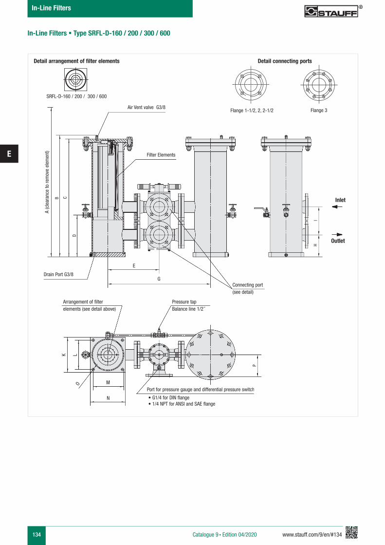
134 www.stauff.com/9/en/#134
E
Detail arrangement of filter elements Detail connecting ports
Air Vent valve G3/8Flange 1-1/2, 2, 2-1/2 Flange 3
Inlet
Outlet
Filter Elements
A (c
lear
ance
to re
mov
e el
emen
t)
Connecting port(see detail)
Arrangement of filterelements (see detail above)
Pressure tapBalance line 1/2 �
B C
D
IH
SRFL-D-160 / 200 / 300 / 600
Port for pressure gauge and differential pressure switch
• G1/4 for DIN flange • 1/4 NPT for ANSI and SAE flange
M
N
L
P
O
K
Drain Port G3/8
In-Line Filters § Type SRFL-D-160 / 200 / 300 / 600
E
G
Catalogue 9 § Edition 04/2020
In-Line Filters

www.stauff.com/9/en/#135
E
135
Flange ConnectionFilter Size SRFL-D160 200 300 600
DIN DN 40 DN 50 DN 65 DN 80ANSI 1-1/2 2 2-1/2 3
Dimensions (mm/in)Filter Size SRFL-D160 200 300 600
A885,8 1045,8 1248,7 2126,734.87 41.17 49.16 83.73
B607,6 688,7 828,6 1267,623.92 27.12 32.63 49.91
C584 642 803,9 1242,922.99 25.28 31.65 48.93
D214 214 285 2858.43 8.43 11.22 11.22
E260 300 350 37510.24 11.81 13.78 14.76
G520 600 700 75020.47 23.62 27.56 29.53
H130 140 150 1605.12 5.51 5.91 6.30
I155 190 190 2206.10 7.48 7.48 8.66
K150 150 240 2405.91 5.91 9.45 9.45
L125 125 200 2004.92 4.92 7.87 7.87
M125 125 200 2004.92 4.92 7.87 7.87
N150 150 240 2405.91 5.91 9.45 9.45
O11 11 18 18.43 .43 .71 .71
P110 150 150 1754.33 5.91 5.91 6.89
Total Oil Capacity (l/gal)6 7,1 22,2 37,11.59 1.86 5.87 9.80
Weight (kg/lbs)43 56,7 84 10495 125 185 230
Filter ElementsDesignation RE-160 ... RE-200 ... RE-300 ... RE-600 ...Quantity 2 x 1 2 x 1 2 x 1 2 x 1
In-Line Filters § Type SRFL-D-160 / 200 / 300 / 600
Catalogue 9 § Edition 04/2020
In-Line Filters
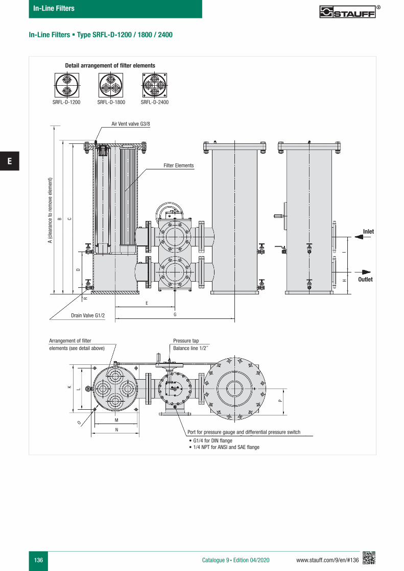
136 www.stauff.com/9/en/#136
E
In-Line Filters § Type SRFL-D-1200 / 1800 / 2400
Detail arrangement of filter elements
SRFL-D-1200 SRFL-D-1800 SRFL-D-2400
Air Vent valve G3/8
Filter Elements
Drain Valve G1/2
Arrangement of filterelements (see detail above)
Pressure tapBalance line 1/2 �
A (c
lear
ance
to re
mov
e el
emen
t)
B C
D
R
E
G
Port for pressure gauge and differential pressure switch • G1/4 for DIN flange • 1/4 NPT for ANSI and SAE flange
M
N
L
P
O
K
Inlet
Outlet
IH
Catalogue 9 § Edition 04/2020
In-Line Filters
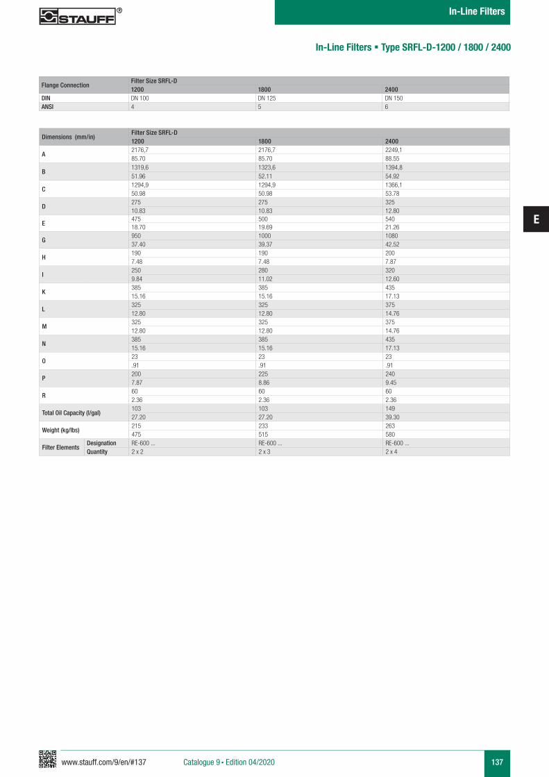
www.stauff.com/9/en/#137
E
137
In-Line Filters § Type SRFL-D-1200 / 1800 / 2400
Flange ConnectionFilter Size SRFL-D1200 1800 2400
DIN DN 100 DN 125 DN 150ANSI 4 5 6
Dimensions (mm/in)Filter Size SRFL-D1200 1800 2400
A2176,7 2176,7 2249,185.70 85.70 88.55
B1319,6 1323,6 1394,851.96 52.11 54.92
C1294,9 1294,9 1366,150.98 50.98 53.78
D275 275 32510.83 10.83 12.80
E475 500 54018.70 19.69 21.26
G950 1000 108037.40 39.37 42.52
H190 190 2007.48 7.48 7.87
I250 280 3209.84 11.02 12.60
K385 385 43515.16 15.16 17.13
L325 325 37512.80 12.80 14.76
M325 325 37512.80 12.80 14.76
N385 385 43515.16 15.16 17.13
O23 23 23.91 .91 .91
P200 225 2407.87 8.86 9.45
R60 60 602.36 2.36 2.36
Total Oil Capacity (l/gal)103 103 14927.20 27.20 39.30
Weight (kg/lbs)215 233 263475 515 580
Filter ElementsDesignation RE-600 ... RE-600 ... RE-600 ...Quantity 2 x 2 2 x 3 2 x 4
Catalogue 9 § Edition 04/2020
In-Line Filters
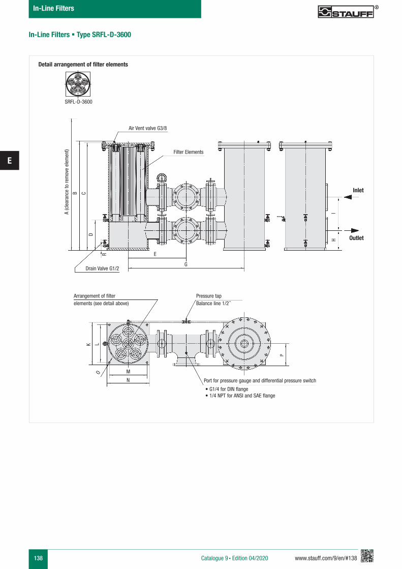
138 www.stauff.com/9/en/#138
E
Detail arrangement of filter elements
Arrangement of filterelements (see detail above)
Pressure tapBalance line 1/2 �
Port for pressure gauge and differential pressure switch
• G1/4 for DIN flange • 1/4 NPT for ANSI and SAE flange
M
N
L
P
O
K
Inlet
Outlet
IH
Air Vent valve G3/8
Filter Elements
Drain Valve G1/2
A (c
lear
ance
to re
mov
e el
emen
t)
B CD
R E
G
SRFL-D-3600
In-Line Filters § Type SRFL-D-3600
Catalogue 9 § Edition 04/2020
In-Line Filters
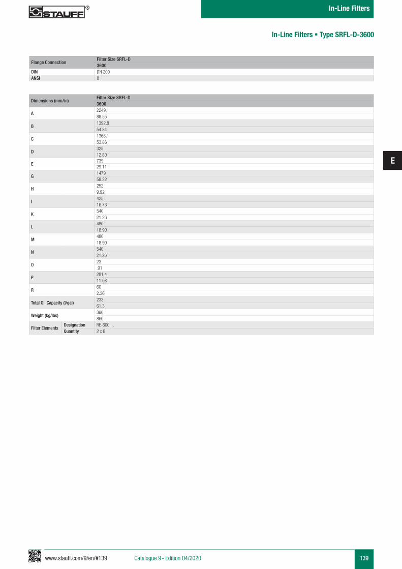
www.stauff.com/9/en/#139
E
139
Flange ConnectionFilter Size SRFL-D3600
DIN DN 200ANSI 8
Dimensions (mm/in)Filter Size SRFL-D3600
A2249,188.55
B1392,854.84
C1368,153.86
D32512.80
E73929.11
G147958.22
H2529.92
I42516.73
K54021.26
L48018.90
M48018.90
N54021.26
O23.91
P281,411.08
R602.36
Total Oil Capacity (l/gal)23361.3
Weight (kg/lbs)390860
Filter ElementsDesignation RE-600 ...Quantity 2 x 6
In-Line Filters § Type SRFL-D-3600
Catalogue 9 § Edition 04/2020
In-Line Filters
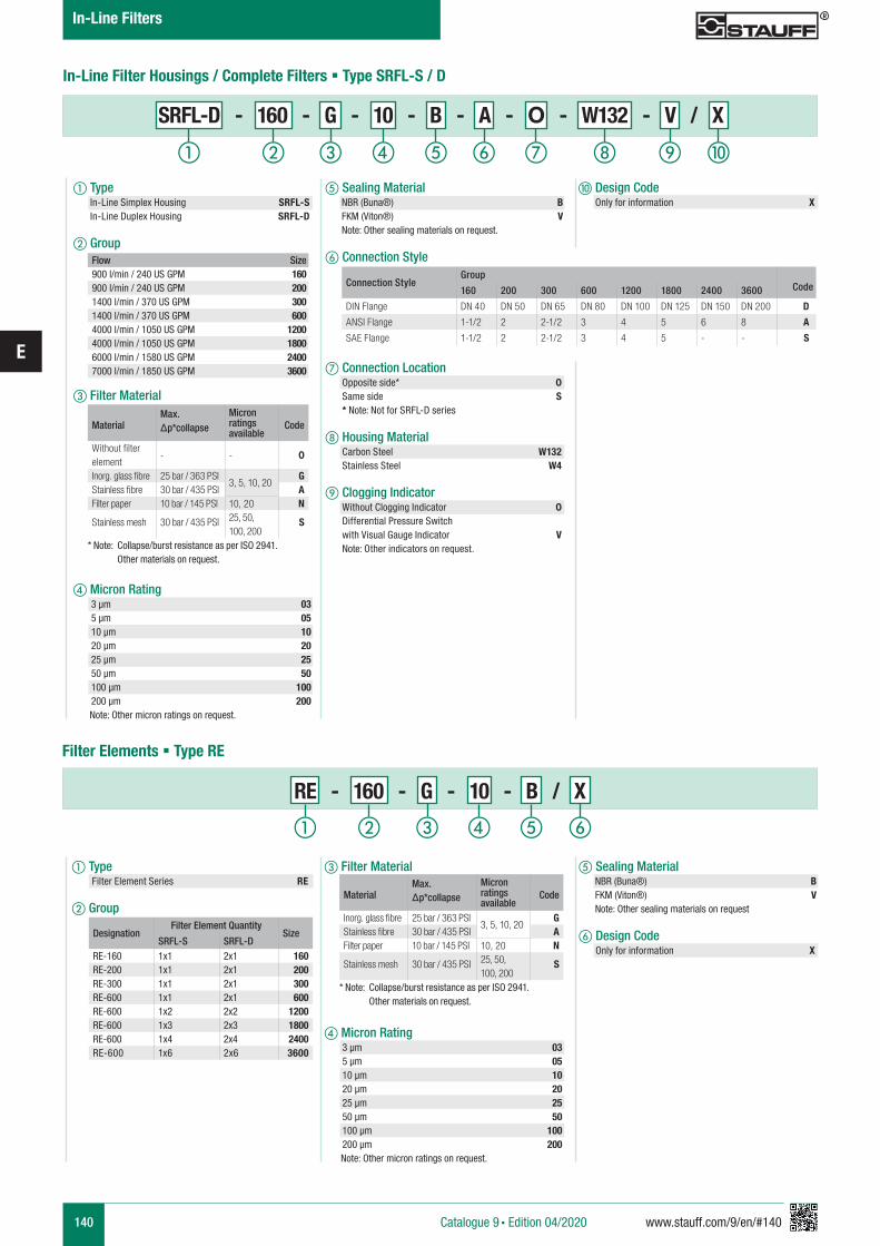
140 www.stauff.com/9/en/#140
E
In-Line Filter Housings / Complete Filters § Type SRFL-S / D
Flow Size900 l/min / 240 US GPM 160900 l/min / 240 US GPM 2001400 l/min / 370 US GPM 3001400 l/min / 370 US GPM 6004000 l/min / 1050 US GPM 12004000 l/min / 1050 US GPM 18006000 l/min / 1580 US GPM 24007000 l/min / 1850 US GPM 3600
MaterialMax. Δp*collapse
Micron ratings available
Code
Without filter element
- - 0
Inorg. glass fibre 25 bar / 363 PSI3, 5, 10, 20
GStainless fibre 30 bar / 435 PSI AFilter paper 10 bar / 145 PSI 10, 20 N
Stainless mesh 30 bar / 435 PSI 25, 50, 100, 200
S
* Note: Collapse/burst resistance as per ISO 2941. Other materials on request.
Connection StyleGroup
Code160 200 300 600 1200 1800 2400 3600
DIN Flange DN 40 DN 50 DN 65 DN 80 DN 100 DN 125 DN 150 DN 200 D
ANSI Flange 1-1/2 2 2-1/2 3 4 5 6 8 A
SAE Flange 1-1/2 2 2-1/2 3 4 5 - - S
SRFL-D - 160 - G - 10 - B - A - O - W132 - V / X
e Sealing Material NBR (Buna®) B FKM (Viton®) V Note: Other sealing materials on request.
f Connection Style
g Connection Location Opposite side* 0 Same side S * Note: Not for SRFL-D series
h Housing Material Carbon Steel W132 Stainless Steel W4
i Clogging Indicator Without Clogging Indicator 0 Differential Pressure Switch with Visual Gauge Indicator V Note: Other indicators on request.
j Design Code Only for information X
a Type In-Line Simplex Housing SRFL-S In-Line Duplex Housing SRFL-D
b Group
c Filter Material
d Micron Rating 3 µm 03 5 µm 05 10 µm 10 20 µm 20 25 µm 25 50 µm 50 100 µm 100 200 µm 200 Note: Other micron ratings on request.
i jhga b c fed
Filter Elements § Type RE
a Type Filter Element Series RE
b Group
e Sealing Material NBR (Buna®) B FKM (Viton®) V Note: Other sealing materials on request
f Design Code Only for information X
c Filter Material
d Micron Rating 3 µm 03 5 µm 05 10 µm 10 20 µm 20 25 µm 25 50 µm 50 100 µm 100 200 µm 200 Note: Other micron ratings on request.
RE - 160 - G - 10 - B / X
DesignationFilter Element Quantity
SizeSRFL-S SRFL-D
RE-160 1x1 2x1 160RE-200 1x1 2x1 200RE-300 1x1 2x1 300RE-600 1x1 2x1 600RE-600 1x2 2x2 1200RE-600 1x3 2x3 1800RE-600 1x4 2x4 2400RE-600 1x6 2x6 3600
MaterialMax. Δp*collapse
Micron ratings available
Code
Inorg. glass fibre 25 bar / 363 PSI3, 5, 10, 20
GStainless fibre 30 bar / 435 PSI AFilter paper 10 bar / 145 PSI 10, 20 N
Stainless mesh 30 bar / 435 PSI 25, 50, 100, 200
S
* Note: Collapse/burst resistance as per ISO 2941. Other materials on request.
a b c fed
Catalogue 9 § Edition 04/2020
In-Line Filters
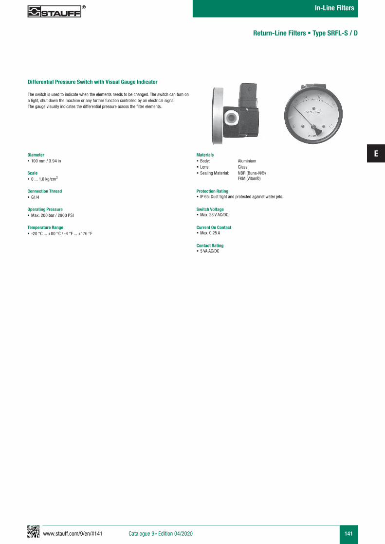
www.stauff.com/9/en/#141
E
141
Return-Line Filters § Type SRFL-S / D
Differential Pressure Switch with Visual Gauge Indicator
The switch is used to indicate when the elements needs to be changed. The switch can turn on a light, shut down the machine or any further function controlled by an electrical signal. The gauge visually indicates the differential pressure across the filter elements.
Diameter § 100 mm / 3.94 in
Scale § 0 ... 1,6 kg/cm2
Connection Thread § G1/4
Operating Pressure § Max. 200 bar / 2900 PSI
Temperature Range § -20 °C ... +80 °C / -4 °F ... +176 °F
Materials § Body: Aluminium § Lens: Glass § Sealing Material: NBR (Buna-N®)
FKM (Viton®)
Protection Rating § IP 65: Dust tight and protected against water jets.
Switch Voltage § Max. 28 V AC/DC
Current On Contact § Max. 0,25 A
Contact Rating § 5 VA AC/DC
Catalogue 9 § Edition 04/2020
In-Line Filters
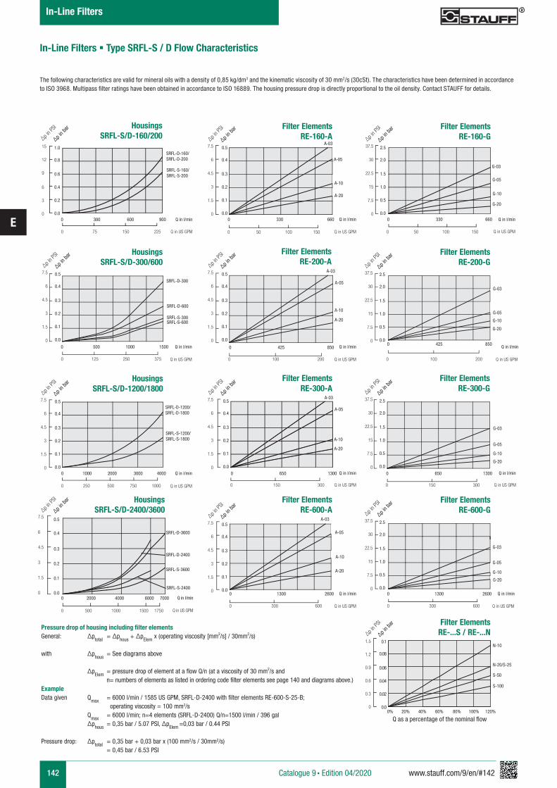
142 www.stauff.com/9/en/#142
E
In-Line Filters § Type SRFL-S / D Flow Characteristics
The following characteristics are valid for mineral oils with a density of 0,85 kg/dm3 and the kinematic viscosity of 30 mm2/s (30cSt). The characteristics have been determined in accordance to ISO 3968. Multipass filter ratings have been obtained in accordance to ISO 16889. The housing pressure drop is directly proportional to the oil density. Contact STAUFF for details.
SRFL-D-160/SRFL-D-200
SRFL-S-160/SRFL-S-200
HousingsSRFL-S/D-160/200
0 75 150 225
15
12
9
6
3
0
1.0
0.8
0.6
0.4
0.2
0.00 300 600 900
∆p in P
SI
∆p in b
ar
Q in l/min
Q in US GPM
HousingsSRFL-S/D-2400/3600
0 500 1000 1500 1750
7.5
6
4.5
3
1.5
0
0.5
0.4
0.3
0.2
0.1
0.00 2000 4000 6000 7000
∆p in P
SI
∆p in b
ar
Filter ElementsRE-160-A
0 50 100 150
7.5
6
4.5
3
1.5
0
7.5
6
4.5
3
1.5
0
7.5
6
4.5
3
1.5
0
7.5
6
4.5
3
1.5
0
7.5
6
4.5
3
1.5
0
7.5
6
4.5
3
1.5
0
0.5
0.4
0.3
0.2
0.1
0.0
0.5
0.4
0.3
0.2
0.1
0.0
0.5
0.4
0.3
0.2
0.1
0.0
0.5
0.4
0.3
0.2
0.1
0.0
0.5
0.4
0.3
0.2
0.1
0.0
0.5
0.4
0.3
0.2
0.1
0.0
0 330 660
∆p in P
SI
∆p in b
ar
∆p in P
SI
∆p in b
ar
∆p in P
SI
∆p in b
ar
∆p in P
SI
∆p in b
ar
∆p in P
SI
∆p in b
ar
∆p in P
SI
∆p in b
ar
Q in l/min
Q in US GPM
SRFL-D-1200/SRFL-D-1800
SRFL-S-1200/SRFL-S-1800
HousingsSRFL-S/D-1200/1800
0 250 500 750 1000
Q in l/min
Q in US GPM
SRFL-D-300
SRFL-D-600
SRFL-S-300SRFL-S-600
SRFL-D-2400
A-03
A-05
A-10
A-20
Filter ElementsRE-300-A
A-03
A-05
A-10
A-20
Filter ElementsRE-200-A
Filter ElementsRE-600-A
A-03
A-05
A-10
A-20
Filter ElementsRE-160-G
0 330 660
37.5
30
22.5
15
7.5
0
2.5
2.0
1.5
1.0
0.5
0.0
∆p in P
SI
∆p in b
ar
37.5
30
22.5
15
7.5
0
2.5
2.0
1.5
1.0
0.5
0.0
∆p in P
SI
∆p in b
ar
37.5
30
22.5
15
7.5
0
2.5
2.0
1.5
1.0
0.5
0.0
∆p in P
SI
∆p in b
ar
37.5
30
22.5
15
7.5
0
2.5
2.0
1.5
1.0
0.5
0.0
∆p in P
SI
∆p in b
ar
Q in l/min
Q in US GPM
G-05
G-20
0 50 100 150
Filter ElementsRE-200-G
0 425 8500 425 850
0% 20% 40% 60% 80% 100% 120%
Q in l/minQ in l/min
Q in US GPMQ in US GPM
G-03
G-05
G-10
G-20
0 100 2000 100 200
Filter ElementsRE-...S / RE-...N
1.5
1.2
0.9
0.6
0.3
0
0.1
0.08
0.06
0.04
0.02
0.0
∆p in P
SI
∆p in b
ar
N-20/S-25
S-50
N-10
S-100
Filter ElementsRE-300-G
0 650 13000 650 1300
0 1300 26000 1300 2600
Q in l/minQ in l/min
Q in US GPMQ in US GPM
G-03
G-05
G-10
G-20
0 150 3000 150 300
Filter ElementsRE-600-G
Q in l/minQ in l/min
Q in US GPMQ in US GPM
G-03
G-05
G-10
G-20
0 300 6000 300 600
A-03
A-05
A-10
A-20
HousingsSRFL-S/D-300/600
0 125 250 375
0 500 1000 1500
0 1000 2000 3000 4000
Q in l/min
Q in US GPM
Q in l/min
Q in US GPM
SRFL-S-2400
SRFL-D-3600
SRFL-S-3600
G-10
G-03
Pressure drop of housing including filter elementsGeneral: ∆ptotal = ∆phous + ∆pElem x (operating viscosity [mm2/s] / 30mm2/s)
with ∆phous = See diagrams above ∆pElem = pressure drop of element at a flow Q/n (at a viscosity of 30 mm2/s and n= numbers of elements as listed in ordering code filter elements see page 140 and diagrams above.)ExampleData given Qmax = 6000 l/min / 1585 US GPM, SRFL-D-2400 with filter elements RE-600-S-25-B; operating viscosity = 100 mm2/s Qmax = 6000 l/min; n=4 elements (SRFL-D-2400) Q/n=1500 l/min / 396 gal ∆phous = 0,35 bar / 5.07 PSI, ∆pElem =0,03 bar / 0.44 PSI
Pressure drop: ∆ptotal = 0,35 bar + 0,03 bar x (100 mm2/s / 30mm2/s) = 0,45 bar / 6.53 PSI
Q as a percentage of the nominal flow
Catalogue 9 § Edition 04/2020
In-Line Filters
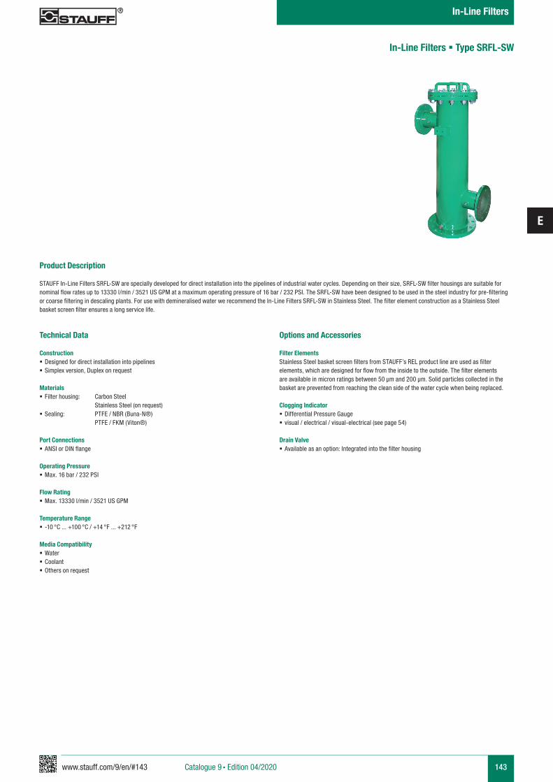
www.stauff.com/9/en/#143
E
143
Product Description
STAUFF In-Line Filters SRFL-SW are specially developed for direct installation into the pipelines of industrial water cycles. Depending on their size, SRFL-SW filter housings are suitable for nominal flow rates up to 13330 l/min / 3521 US GPM at a maximum operating pressure of 16 bar / 232 PSI. The SRFL-SW have been designed to be used in the steel industry for pre-filtering or coarse filtering in descaling plants. For use with demineralised water we recommend the In-Line Filters SRFL-SW in Stainless Steel. The filter element construction as a Stainless Steel basket screen filter ensures a long service life.
Technical Data
Construction § Designed for direct installation into pipelines § Simplex version, Duplex on request
Materials § Filter housing: Carbon Steel Stainless Steel (on request)
§ Sealing: PTFE / NBR (Buna-N®) PTFE / FKM (Viton®)
Port Connections § ANSI or DIN flange
Operating Pressure § Max. 16 bar / 232 PSI
Flow Rating § Max. 13330 l/min / 3521 US GPM
Temperature Range § -10 °C ... +100 °C / +14 °F ... +212 °F
Media Compatibility § Water § Coolant § Others on request
Options and Accessories
Filter ElementsStainless Steel basket screen filters from STAUFF’s REL product line are used as filter elements, which are designed for flow from the inside to the outside. The filter elements are available in micron ratings between 50 µm and 200 µm. Solid particles collected in the basket are prevented from reaching the clean side of the water cycle when being replaced.
Clogging Indicator § Differential Pressure Gauge § visual / electrical / visual-electrical (see page 54)
Drain Valve § Available as an option: Integrated into the filter housing
In-Line Filters § Type SRFL-SW
Catalogue 9 § Edition 04/2020
In-Line Filters
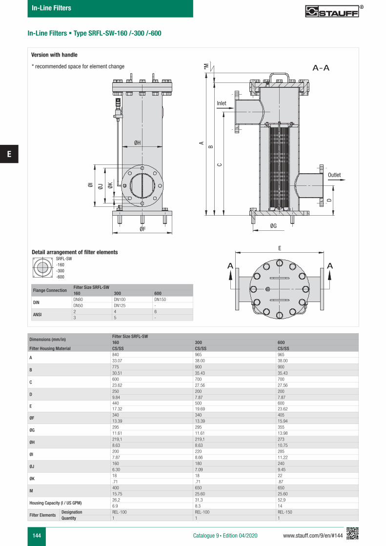
144 www.stauff.com/9/en/#144
E
Detail arrangement of filter elementsSRFL-SW-160 -300 -600
In-Line Filters § Type SRFL-SW-160 /-300 /-600
Version with handle
* recommended space for element change
Flange ConnectionFilter Size SRFL-SW160 300 600
DINDN80 DN100 DN150DN50 DN125 -
ANSI2 4 63 5 -
Dimensions (mm/in)Filter Size SRFL-SW160 300 600
Filter Housing Material CS/SS CS/SS CS/SS
A840 965 96533.07 38.00 38.00
B775 900 90030.51 35.43 35.43
C600 700 70023.62 27.56 27.56
D250 200 2009.84 7.87 7.87
E440 500 60017.32 19.69 23.62
ØF340 340 40513.39 13.39 15.94
ØG295 295 35511.61 11.61 13.98
ØH219,1 219,1 2738.63 8.63 10.75
ØI200 220 2857.87 8.66 11.22
ØJ160 180 2406.30 7.09 9.45
ØK18 18 22.71 .71 .87
M400 650 65015.75 25.60 25.60
Housing Capacity (l / US GPM)26,2 31,3 52,96.9 8.3 14
Filter ElementsDesignation REL-100 REL-100 REL-150Quantity 1 1 1
ØI ØJ ØK
ØF
ØH
ØG
D
C
B
A
Inlet
Outlet
*M A-A
E
A A
Catalogue 9 § Edition 04/2020
In-Line Filters
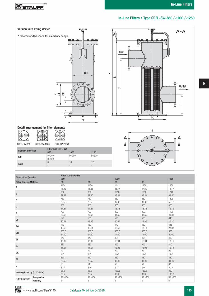
www.stauff.com/9/en/#145
E
145
In-Line Filters § Type SRFL-SW-850 /-1000 /-1250
Version with lifting device
* recommended space for element change
Dimensions (mm/in)Filter Size SRFL-SW850 1000 1250
Filter Housing Material CS SS CS SS
A1154 1150 1442 1450 195045.43 45.28 56.77 57.09 76.77
B962 950 1250 1250 174037.87 37.40 49.21 49.21 68.50
C750 750 950 950 140029.53 29.53 37.40 37.40 55.12
D300 300 350 350 40011.81 11.81 13.78 13.78 15.75
E700 700 800 800 110027.56 27.56 31.50 31.50 43.31
ØF520 505 520 505 64020.47 19.88 20.47 19.88 25.20
ØG470 460 470 460 58518.50 18.11 18.50 18.11 23.03
ØH355,6 355,6 355,6 355,6 50814.00 14.00 14.00 14.00 20.00
ØI340 340 405 405 46013.39 13.39 15.94 15.94 18.11
ØJ295 295 355 355 41011.61 11.61 13.98 13.98 16.14
ØK22 22 26 26 26.87 .87 1.02 1.02 1.02
M650 650 850 850 85025.59 25.59 33.46 33.46 33.46
L55 51 55 51 822.17 2.01 2.17 2.01 3.23
Housing Capacity (l / US GPM)96,5 96,5 138,6 138,6 39225.5 25.5 36.6 36.6 103.6
Filter ElementsDesignation REL-150 REL-150 REL-250 REL-250 REL-250Quantity 2 2 3 3 5
Flange ConnectionFilter Size SRFL-SW850 1000 1250
DINDN200 DN250 DN300DN150 - -
ANSI8 10 12- - -
Detail arrangement for filter elements
SRFL-SW-850 SRFL-SW-1000 SRFL-SW-1250
ØI ØJ ØK
ØF
ØH
ØG
D
CB
A
Inlet
Outlet
*M
A-A
L
E
A A
Catalogue 9 § Edition 04/2020
In-Line Filters
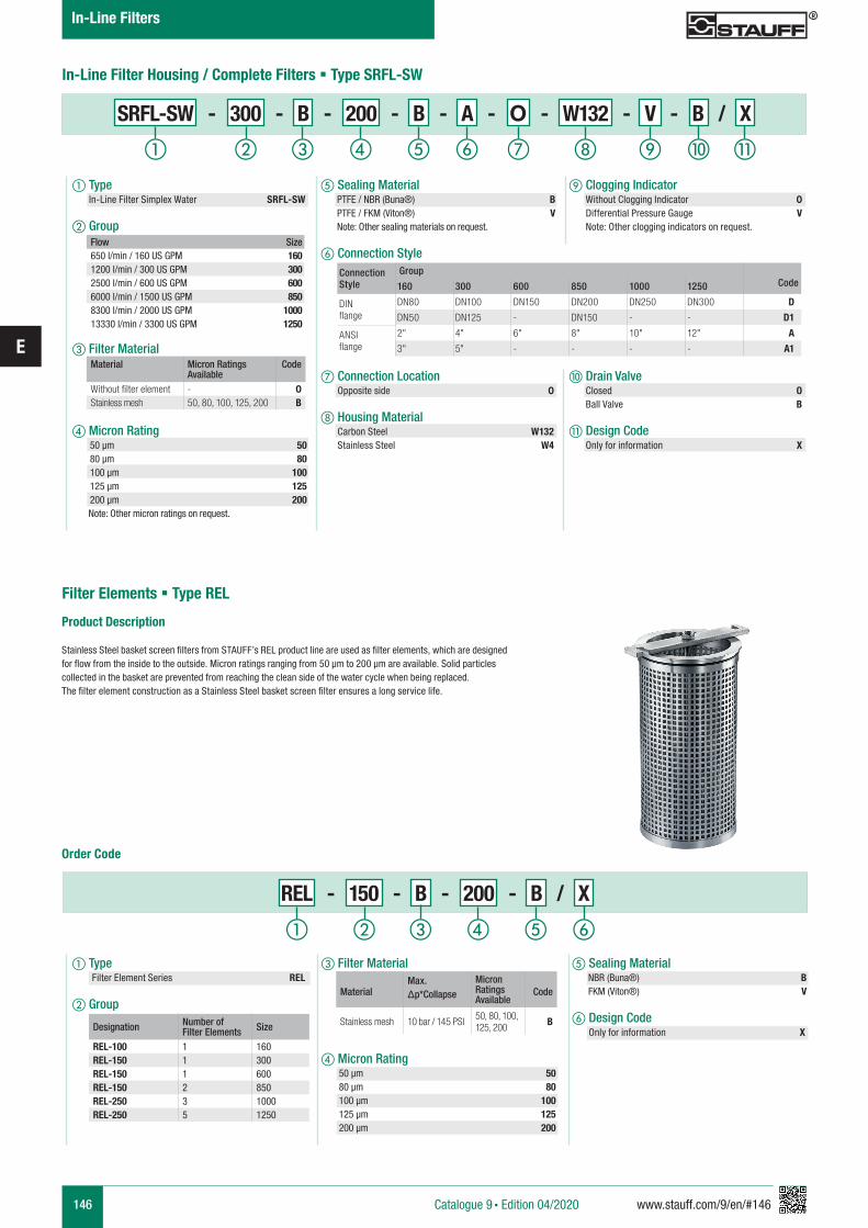
146 www.stauff.com/9/en/#146
E
In-Line Filter Housing / Complete Filters § Type SRFL-SW
Flow Size650 l/min / 160 US GPM 1601200 l/min / 300 US GPM 3002500 l/min / 600 US GPM 6006000 l/min / 1500 US GPM 8508300 l/min / 2000 US GPM 100013330 l/min / 3300 US GPM 1250
Material Micron Ratings Available
Code
Without filter element - 0Stainless mesh 50, 80, 100, 125, 200 B
Connection Style
GroupCode160 300 600 850 1000 1250
DIN flange
DN80 DN100 DN150 DN200 DN250 DN300 D
DN50 DN125 - DN150 - - D1
ANSI flange
2" 4" 6" 8" 10" 12" A
3" 5" - - - - A1
e Sealing Material PTFE / NBR (Buna®) B PTFE / FKM (Viton®) V Note: Other sealing materials on request.
f Connection Style
g Connection Location Opposite side 0
h Housing Material Carbon Steel W132 Stainless Steel W4
a Type In-Line Filter Simplex Water SRFL-SW
b Group
c Filter Material
d Micron Rating
50 µm 50 80 µm 80 100 µm 100 125 µm 125 200 µm 200 Note: Other micron ratings on request.
Product Description
Stainless Steel basket screen filters from STAUFF’s REL product line are used as filter elements, which are designed for flow from the inside to the outside. Micron ratings ranging from 50 µm to 200 µm are available. Solid particles collected in the basket are prevented from reaching the clean side of the water cycle when being replaced. The filter element construction as a Stainless Steel basket screen filter ensures a long service life.
Order Code
i Clogging Indicator Without Clogging Indicator 0 Differential Pressure Gauge V Note: Other clogging indicators on request.
j Drain Valve Closed O Ball Valve B
k Design Code Only for information X
ihga b c fed j k
SRFL-SW - 300 - B - 200 - B - A - O - W132 - V - B / X
REL - 150 - B - 200 - B / X
a b c fed
Filter Elements § Type REL
a Type Filter Element Series REL
b Group
e Sealing Material NBR (Buna®) B FKM (Viton®) V
f Design Code Only for information X
c Filter Material
d Micron Rating 50 µm 50 80 µm 80 100 µm 100 125 µm 125 200 µm 200
Designation Number of Filter Elements Size
REL-100 1 160REL-150 1 300REL-150 1 600REL-150 2 850REL-250 3 1000REL-250 5 1250
MaterialMax. Δp*Collapse
Micron Ratings Available
Code
Stainless mesh 10 bar / 145 PSI 50, 80, 100, 125, 200 B
Catalogue 9 § Edition 04/2020
In-Line Filters
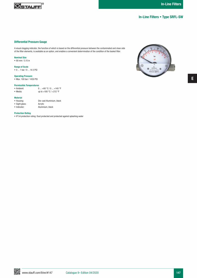
www.stauff.com/9/en/#147
E
147
Differential Pressure Gauge
A visual clogging indicator, the function of which is based on the differential pressure between the contaminated and clean side of the filter elements, is available as an option, and enables a convenient determination of the condition of the basket filter.
Nominal Size § 80 mm / 3.15 in
Range of Scale § 0 ... 1 bar / 0 ... 14.5 PSI
Operating Pressure § Max. 100 bar / 1450 PSI
Permissible Temperatures § Ambient: 0 ... +60 °C / 0 ... +140 °F § Media: up to +100 °C / +212 °F
Material § Housing: Die-cast Aluminium, black § Sight glass: Acrylic § Indicator: Aluminium, black
Protection Rating § IP 54 protection rating: Dust protected and protected against splashing water
In-Line Filters § Type SRFL-SW
Catalogue 9 § Edition 04/2020
In-Line Filters
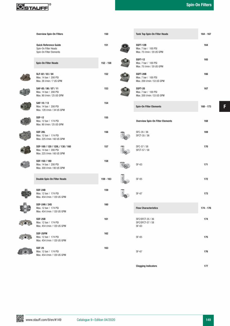
www.stauff.com/9/en/#149
F
149Catalogue 9 § Edition 04/2020
Spin-On Filters
Overview Spin-On Filters
152 - 158
152SLF-02 / 03 / 04Max. 14 bar / 200 PSIMax. 26 l/min / 7 US GPM
150
Spin-On Filter Heads
Quick Reference GuideSpin-On Filter HeadsSpin-On Filter Elements
151
153SAF-05 / 06 / 07 / 11Max. 14 bar / 200 PSIMax. 90 l/min / 25 US GPM
154SAF-10 / 13Max. 14 bar / 200 PSIMax. 128 l/min / 34 US GPM
155SSF-12Max. 12 bar / 174 PSIMax. 90 l/min / 25 US GPM
156SSF-20LMax. 12 bar / 174 PSIMax. 225 l/min / 60 US GPM
157SSF-100 / 120 / 120L / 130 / 160Max. 14 bar / 200 PSIMax. 225 l/min / 60 US GPM
158SSF-150 / 180Max. 14 bar / 200 PSIMax. 300 l/min / 80 US GPM
159 - 163
159SSF-24BMax. 12 bar / 174 PSIMax. 454 l/min / 120 US GPM
Double Spin-On Filter Heads
160SSF-24N / 24SMax. 12 bar / 174 PSIMax. 454 l/min / 120 US GPM
161SSF-25BMax. 12 bar / 174 PSIMax. 454 l/min / 120 US GPM
162SSF-25FMMax. 12 bar / 174 PSIMax. 454 l/min / 120 US GPM
163SSF-25Max. 12 bar / 174 PSIMax. 454 l/min / 120 US GPM
177Clogging Indicators
164 - 167
164SSFT-12BMax. 7 bar / 100 PSIMax. 75 l/min / 20 US GPM
Tank Top Spin-On Filter Heads
165SSFT-12Max. 7 bar / 100 PSIMax. 75 l/min / 20 US GPM
166SSFT-20BMax. 7 bar / 100 PSIMax. 200 l/min / 53 US GPM
167SSFT-20Max. 7 bar / 100 PSIMax. 200 l/min / 53 US GPM
168 - 173
169SFC-35 / 36SFCT-35 / 36
Spin-On Filter Elements
170SFC-57 / 58SFCT-57 / 58
171SF-63
172SF-65
173SF-67
Overview Spin-On Filter Elements 168
174 - 176Flow Characteristics
174SFC/SFCT-35 / 36SFC/SFCT-57 / 58SF-63
175SF-65
176SF-67
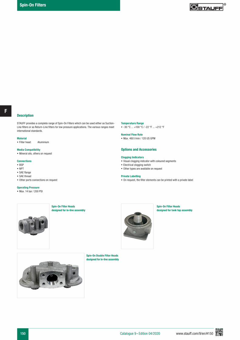
150 www.stauff.com/9/en/#150
FDescription
STAUFF provides a complete range of Spin-On Filters which can be used either as Suction-Line filters or as Return-Line filters for low pressure applications. The various ranges meet international standards.
Material § Filter head: Aluminium
Media Compatibility § Mineral oils, others on request
Connections § BSP § NPT § SAE flange § SAE thread § Other ports connections on request
Operating Pressure § Max. 14 bar / 200 PSI
Options and Accessories
Clogging Indicators § Visual clogging indicator with coloured segments § Electrical clogging switch § Other types are available on request
Private Labelling § On request, the filter elements can be printed with a private label
Spin-On Filter Heads designed for in-line assembly
Spin-On Filter Heads designed for tank top assembly
Spin-On Double Filter Heads designed for in-line assembly
Temperature Range § -30 °C ... +100 °C / -22 °F ... +212 °F
Nominal Flow Rate § Max. 460 l/min / 120 US GPM
Catalogue 9 § Edition 04/2020
Spin-On Filters
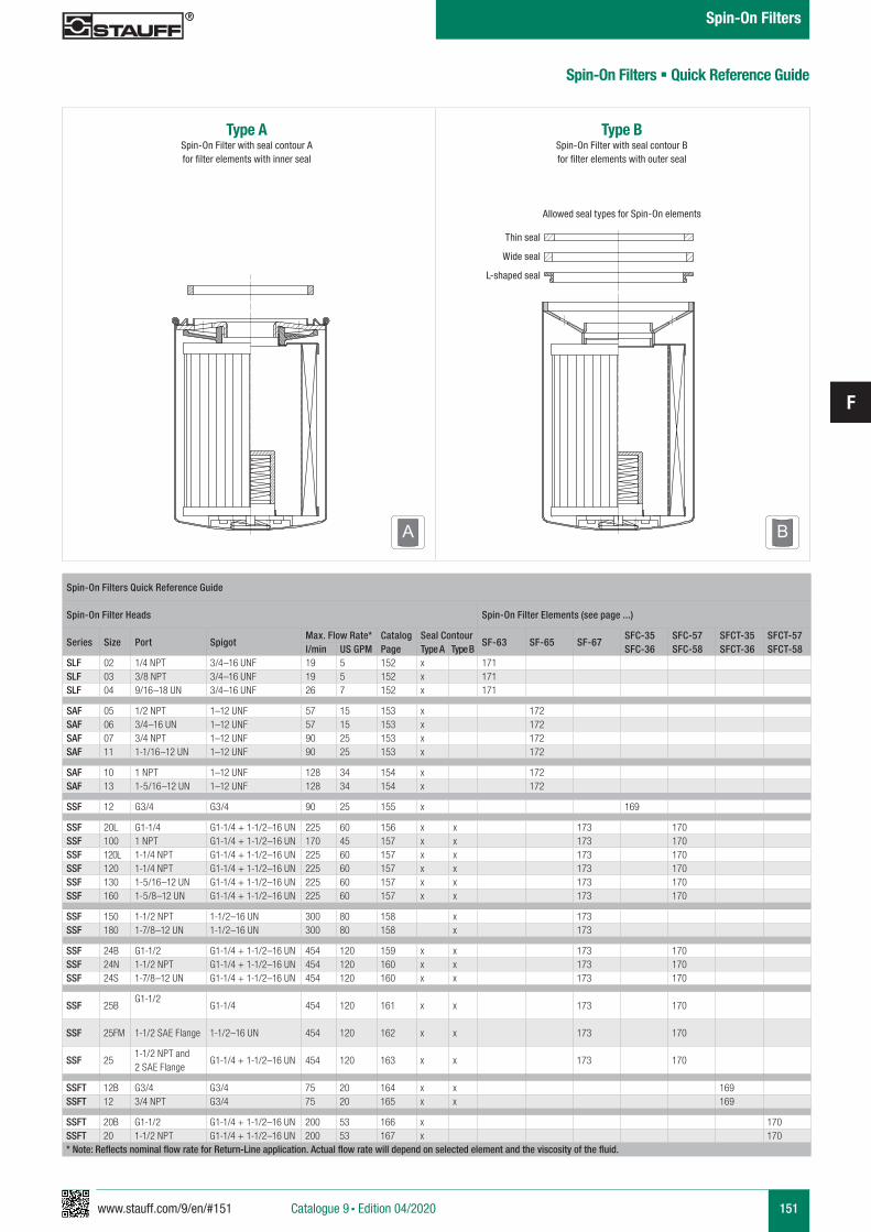
www.stauff.com/9/en/#151
F
151
Type ASpin-On Filter with seal contour A for filter elements with inner seal
Spin-On Filters Quick Reference Guide
Spin-On Filter Heads Spin-On Filter Elements (see page ...)
Series Size Port SpigotMax. Flow Rate* Catalog
PageSeal Contour
SF-63 SF-65 SF-67SFC-35SFC-36
SFC-57SFC-58
SFCT-35SFCT-36
SFCT-57SFCT-58l/min US GPM Type A Type B
SLF 02 1/4 NPT 3/4–16 UNF 19 5 152 x 171SLF 03 3/8 NPT 3/4–16 UNF 19 5 152 x 171SLF 04 9/16–18 UN 3/4–16 UNF 26 7 152 x 171
SAF 05 1/2 NPT 1–12 UNF 57 15 153 x 172SAF 06 3/4–16 UN 1–12 UNF 57 15 153 x 172SAF 07 3/4 NPT 1–12 UNF 90 25 153 x 172SAF 11 1-1/16–12 UN 1–12 UNF 90 25 153 x 172
SAF 10 1 NPT 1–12 UNF 128 34 154 x 172SAF 13 1-5/16–12 UN 1–12 UNF 128 34 154 x 172
SSF 12 G3/4 G3/4 90 25 155 x 169
SSF 20L G1-1/4 G1-1/4 + 1-1/2–16 UN 225 60 156 x x 173 170SSF 100 1 NPT G1-1/4 + 1-1/2–16 UN 170 45 157 x x 173 170SSF 120L 1-1/4 NPT G1-1/4 + 1-1/2–16 UN 225 60 157 x x 173 170SSF 120 1-1/4 NPT G1-1/4 + 1-1/2–16 UN 225 60 157 x x 173 170SSF 130 1-5/16–12 UN G1-1/4 + 1-1/2–16 UN 225 60 157 x x 173 170SSF 160 1-5/8–12 UN G1-1/4 + 1-1/2–16 UN 225 60 157 x x 173 170
SSF 150 1-1/2 NPT 1-1/2–16 UN 300 80 158 x 173SSF 180 1-7/8–12 UN 1-1/2–16 UN 300 80 158 x 173
SSF 24B G1-1/2 G1-1/4 + 1-1/2–16 UN 454 120 159 x x 173 170SSF 24N 1-1/2 NPT G1-1/4 + 1-1/2–16 UN 454 120 160 x x 173 170SSF 24S 1-7/8–12 UN G1-1/4 + 1-1/2–16 UN 454 120 160 x x 173 170
SSF 25BG1-1/2
G1-1/4 454 120 161 x x 173 170
SSF 25FM 1-1/2 SAE Flange 1-1/2–16 UN 454 120 162 x x 173 170
SSF 251-1/2 NPT and 2 SAE Flange
G1-1/4 + 1-1/2–16 UN 454 120 163 x x 173 170
SSFT 12B G3/4 G3/4 75 20 164 x x 169SSFT 12 3/4 NPT G3/4 75 20 165 x x 169
SSFT 20B G1-1/2 G1-1/4 + 1-1/2–16 UN 200 53 166 x 170SSFT 20 1-1/2 NPT G1-1/4 + 1-1/2–16 UN 200 53 167 x 170* Note: Reflects nominal flow rate for Return-Line application. Actual flow rate will depend on selected element and the viscosity of the fluid.
Spin-On Filters § Quick Reference Guide
Type BSpin-On Filter with seal contour B for filter elements with outer seal
Allowed seal types for Spin-On elements
Thin seal
Wide seal
L-shaped seal
A B
Catalogue 9 § Edition 04/2020
Spin-On Filters
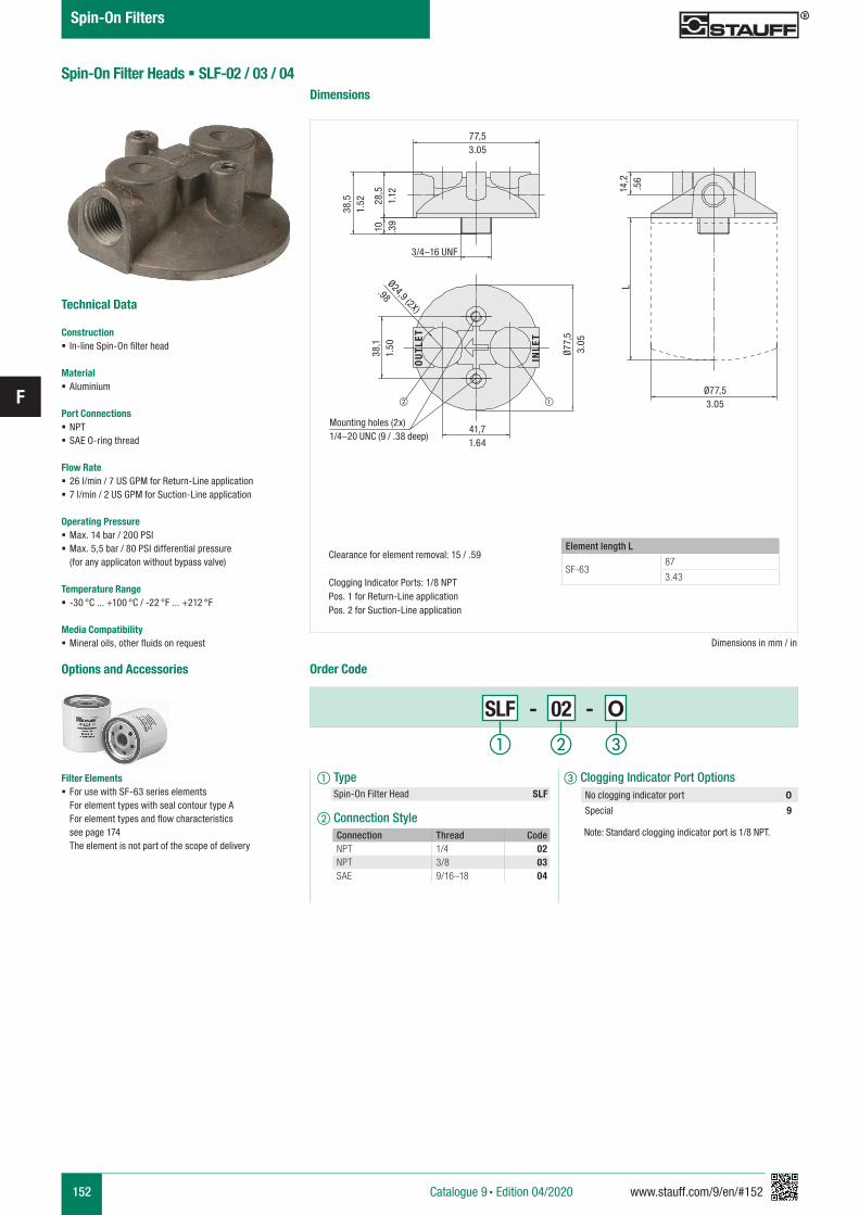
152 www.stauff.com/9/en/#152
F
Spin-On Filter Heads § SLF-02 / 03 / 04
Technical Data
Construction § In-line Spin-On filter head
Material § Aluminium
Port Connections § NPT § SAE O-ring thread
Flow Rate § 26 l/min / 7 US GPM for Return-Line application § 7 l/min / 2 US GPM for Suction-Line application
Operating Pressure § Max. 14 bar / 200 PSI § Max. 5,5 bar / 80 PSI differential pressure (for any applicaton without bypass valve)
Temperature Range § -30 °C ... +100 °C / -22 °F ... +212 °F
Media Compatibility § Mineral oils, other fluids on request
Options and Accessories
Filter Elements § For use with SF-63 series elements
For element types with seal contour type A For element types and flow characteristics see page 174 The element is not part of the scope of delivery
Order Code
Element length L
SF-6387
3.43
a Type Spin-On Filter Head SLF
b Connection Style
SLF - 02 - O
c Clogging Indicator Port Options
Note: Standard clogging indicator port is 1/8 NPT.Connection Thread Code
NPT 1/4 02NPT 3/8 03SAE 9/16–18 04
No clogging indicator port 0
Special 9
Dimensions
3/4–16 UNF
Mounting holes (2x)1/4–20 UNC (9 / .38 deep)
Clearance for element removal: 15 / .59
Clogging Indicator Ports: 1/8 NPTPos. 1 for Return-Line applicationPos. 2 for Suction-Line application
OU
TLET
INLE
T
77,53.05
Ø77,53.05
41,71.64
14,2
.56
28,5
1.12
10 .39
38,5
1.52
38,1
1.50
Ø24,9 (2X)
.98
L
Dimensions in mm / in
Ø77,
53.
05
a b c
Catalogue 9 § Edition 04/2020
Spin-On Filters
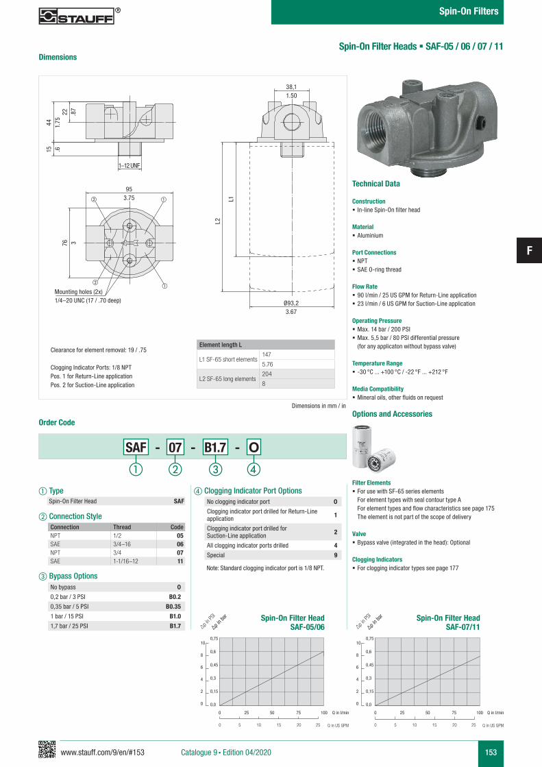
www.stauff.com/9/en/#153
F
153
Element length L
L1 SF-65 short elements147
5.76
L2 SF-65 long elements204
8
d Clogging Indicator Port Options
Note: Standard clogging indicator port is 1/8 NPT.
No clogging indicator port 0
Clogging indicator port drilled for Return-Line application 1
Clogging indicator port drilled for Suction-Line application 2
All clogging indicator ports drilled 4
Special 9
Mounting holes (2x)1/4–20 UNC (17 / .70 deep)
Clearance for element removal: 19 / .75
Clogging Indicator Ports: 1/8 NPTPos. 1 for Return-Line applicationPos. 2 for Suction-Line application
Spin-On Filter Heads § SAF-05 / 06 / 07 / 11
Technical Data
Construction § In-line Spin-On filter head
Material § Aluminium
Port Connections § NPT § SAE O-ring thread
Flow Rate § 90 l/min / 25 US GPM for Return-Line application § 23 l/min / 6 US GPM for Suction-Line application
Operating Pressure § Max. 14 bar / 200 PSI § Max. 5,5 bar / 80 PSI differential pressure (for any applicaton without bypass valve)
Temperature Range § -30 °C ... +100 °C / -22 °F ... +212 °F
Media Compatibility § Mineral oils, other fluids on request
Options and Accessories
Filter Elements § For use with SF-65 series elements
For element types with seal contour type A For element types and flow characteristics see page 175 The element is not part of the scope of delivery
Valve § Bypass valve (integrated in the head): Optional
Clogging Indicators § For clogging indicator types see page 177
Order Code
Dimensions
Dimensions in mm / in
SAF - 07 - B1.7 - O
a Type Spin-On Filter Head SAF
b Connection Style
c Bypass Options
Connection Thread CodeNPT 1/2 05SAE 3/4–16 06NPT 3/4 07SAE 1-1/16–12 11
No bypass 0
0,2 bar / 3 PSI B0.2
0,35 bar / 5 PSI B0.35
1 bar / 15 PSI B1.0
1,7 bar / 25 PSI B1.7
1–12 UNF
38,11.50
953.75
Ø93,23.67
22 .87
L1
44 1.75
76 3
15 .6
L2
Spin-On Filter HeadSAF-05/06
Spin-On Filter HeadSAF-07/11
0,75
0,6
0,45
0,3
0,15
0,0
0,75
0,6
0,45
0,3
0,15
0,0
10
8
6
4
2
0
10
8
6
4
2
0
∆p in b
ar
∆p in P
SI
∆p in b
ar
∆p in P
SI
Q in l/min
Q in US GPM
Q in l/min
Q in US GPM
0 25 50 75 100 0 25 50 75 100
0 5 10 15 20 25 0 5 10 15 20 25
a b c d
Catalogue 9 § Edition 04/2020
Spin-On Filters
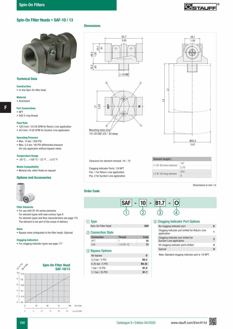
154 www.stauff.com/9/en/#154
F
Spin-On Filter Heads § SAF-10 / 13
Technical Data
Construction § In-line Spin-On filter head
Material § Aluminium
Port Connections § NPT § SAE O-ring thread
Flow Rate § 128 l/min / 34 US GPM for Return-Line application § 30 l/min / 8 US GPM for Suction-Line application
Operating Pressure § Max. 14 bar / 200 PSI § Max. 5,5 bar / 80 PSI differential pressure (for any applicaton without bypass valve)
Temperature Range § -30 °C ... +100 °C / -22 °F ... +212 °F
Media Compatibility § Mineral oils, other fluids on request
Options and Accessories
Filter Elements § For use with SF-65 series elements
For element types with seal contour type A For element types and flow characteristics see page 175 The element is not part of the scope of delivery
Valve § Bypass valve (integrated in the filter head): Optional
Clogging Indicators § For clogging indicator types see page 177
Dimensions
Dimensions in mm / in
Order Code
SAF - 10 - B1.7 - O
a Type Spin-On Filter Head SAF
b Connection Style
c Bypass Options
Connection Thread CodeNPT 1 10SAE 1-5/16–12 13
No bypass 0
0,2 bar / 3 PSI B0.2
0,35 bar / 5 PSI B0.35
1 bar / 15 PSI B1.0
1,7 bar / 25 PSI B1.7
1–12 UNF
OUT
IN
38,11.50
92,73.65
Ø93,23.67
L1
23,1
.91
L2
46,5
1.83
16,5
.65
77 3.03
Element length L
L1 SF-65 short element147
5.76
L2 SF-65 long element204
8
Mounting holes (2x)1/4–20 UNC (23 / .94 deep)
Clearance for element removal: 19 / .75
Clogging Indicator Ports: 1/8 NPTPos. 1 for Return-Line applicationPos. 2 for Suction-Line application
d Clogging Indicator Port Options
Note: Standard clogging indicator port is 1/8 NPT.
No clogging indicator port 0
Clogging indicator port drilled for Return-Line application 1
Clogging indicator port drilled for Suction-Line application 2
All clogging indicator ports drilled 4
Special 9
Spin-On Filter HeadSAF-10/13
0,75
0,6
0,45
0,3
0,15
0,0
10
8
6
4
2
0
∆p in b
ar
∆p in P
SI
Q in l/min
Q in US GPM
0 25 50 75 100
0 5 10 15 20 25
a b c d
Catalogue 9 § Edition 04/2020
Spin-On Filters
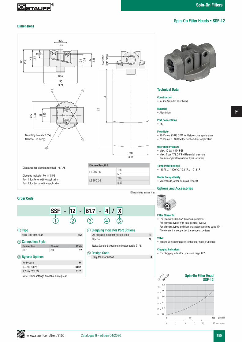
www.stauff.com/9/en/#155
F
155
953.74
G3/4
3751.46
Ø973.81
46 1.81
22 .87
63 2.48
38 1.50
L2
L1
Spin-On Filter Heads § SSF-12
Technical Data
Construction § In-line Spin-On filter head
Material § Aluminium
Port Connections § BSP
Flow Rate § 90 l/min / 25 US GPM for Return-Line application § 23 l/min / 6 US GPM for Suction-Line application
Operating Pressure § Max. 12 bar / 174 PSI § Max. 5 bar / 72.5 PSI differential pressure (for any applicaton without bypass valve)
Temperature Range § -30 °C ... +100 °C / -22 °F ... +212 °F
Media Compatibility § Mineral oils, other fluids on request
Options and Accessories
Filter Elements § For use with SFC-35/36 series elements
For element types with seal contour type A For element types and flow characteristics see page 174 The element is not part of the scope of delivery
Valve § Bypass valve (integrated in the filter head): Optional
Clogging Indicators § For clogging indicator types see page 177
Dimensions
Order Code
a Type Spin-On Filter Head SSF
b Connection Style
c Bypass Options
Connection Thread CodeBSP 3/4 12
No bypass 0
0,2 bar / 3 PSI B0.2
1,7 bar / 25 PSI B1.7
d Clogging Indicator Port Options
Note: Standard clogging indicator port is G1/8.
e Design Code Only for information X
All clogging indicator ports drilled 4
Special 9
Dimensions in mm / in
Element length L
L1 SFC-35145
5.70
L2 SFC-36210
8.27
Mounting holes M8 (2x)M8 (15 / .59 deep)
Clearance for element removal: 19 / .75
Clogging Indicator Ports: G1/8Pos. 1 for Return-Line applicationPos. 2 for Suction-Line application
Spin-On Filter HeadSSF-12
0,75
0,6
0,45
0,3
0,15
0,0
10
8
6
4
2
0
∆p in b
ar
∆p in P
SI
Q in l/min
Q in US GPM
0 50 100
0 5 10 15 20 25
Ø77
3.03
Note: Other settings available on request.
a b c d e
SSF - 12 - B1.7 - 4 / X
3/4”
BSP
bo
th s
ides
34 1.34 37 1.46
Catalogue 9 § Edition 04/2020
Spin-On Filters
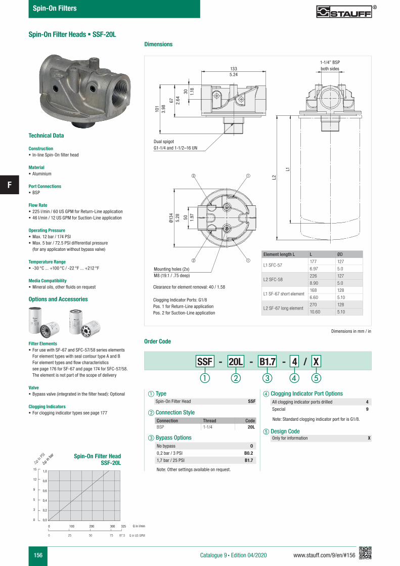
156 www.stauff.com/9/en/#156
F
Spin-On Filter Heads § SSF-20L
Technical Data
Construction § In-line Spin-On filter head
Material § Aluminium
Port Connections § BSP
Flow Rate § 225 l/min / 60 US GPM for Return-Line application § 46 l/min / 12 US GPM for Suction-Line application
Operating Pressure § Max. 12 bar / 174 PSI § Max. 5 bar / 72.5 PSI differential pressure (for any applicaton without bypass valve)
Temperature Range § -30 °C ... +100 °C / -22 °F ... +212 °F
Media Compatibility § Mineral oils, other fluids on request
Options and Accessories
Filter Elements § For use with SF-67 and SFC-57/58 series elements
For element types with seal contour type A and B For element types and flow characteristics see page 176 for SF-67 and page 174 for SFC-57/58. The element is not part of the scope of delivery
Valve § Bypass valve (integrated in the filter head): Optional
Clogging Indicators § For clogging indicator types see page 177
Dimensions
Dimensions in mm / in
Order Code
a Type Spin-On Filter Head SSF
b Connection Style
c Bypass Options
Connection Thread CodeBSP 1-1/4 20L
No bypass 0
0,2 bar / 3 PSI B0.2
1,7 bar / 25 PSI B1.7
1335.24
1-1/4” BSPboth sides
L2
L1
101
3.98
50 1.97
67 2.64
30 1.18
Element length L L ØD
L1 SFC-57177 127
6.97 5.0
L2 SFC-58226 127
8.90 5.0
L1 SF-67 short element168 128
6.60 5.10
L2 SF-67 long element270 128
10.60 5.10
Dual spigotG1-1/4 and 1-1/2–16 UN
Clearance for element removal: 40 / 1.58
Clogging Indicator Ports: G1/8Pos. 1 for Return-Line applicationPos. 2 for Suction-Line application
Mounting holes (2x)M8 (19.1 / .75 deep)
d Clogging Indicator Port Options
Note: Standard clogging indicator port for is G1/8.
e Design Code Only for information X
All clogging indicator ports drilled 4
Special 9
Spin-On Filter HeadSSF-20L
1,0
0,8
0,6
0,4
0,2
0,0
15
12
9
5
3
0
∆p in b
ar
∆p in P
SI
Q in l/min
Q in US GPM
0 100 200 300 325
0 25 50 75 87.5
Note: Other settings available on request.
Ø134
5.28
a b c d e
SSF - 20L - B1.7 - 4 / X
Catalogue 9 § Edition 04/2020
Spin-On Filters
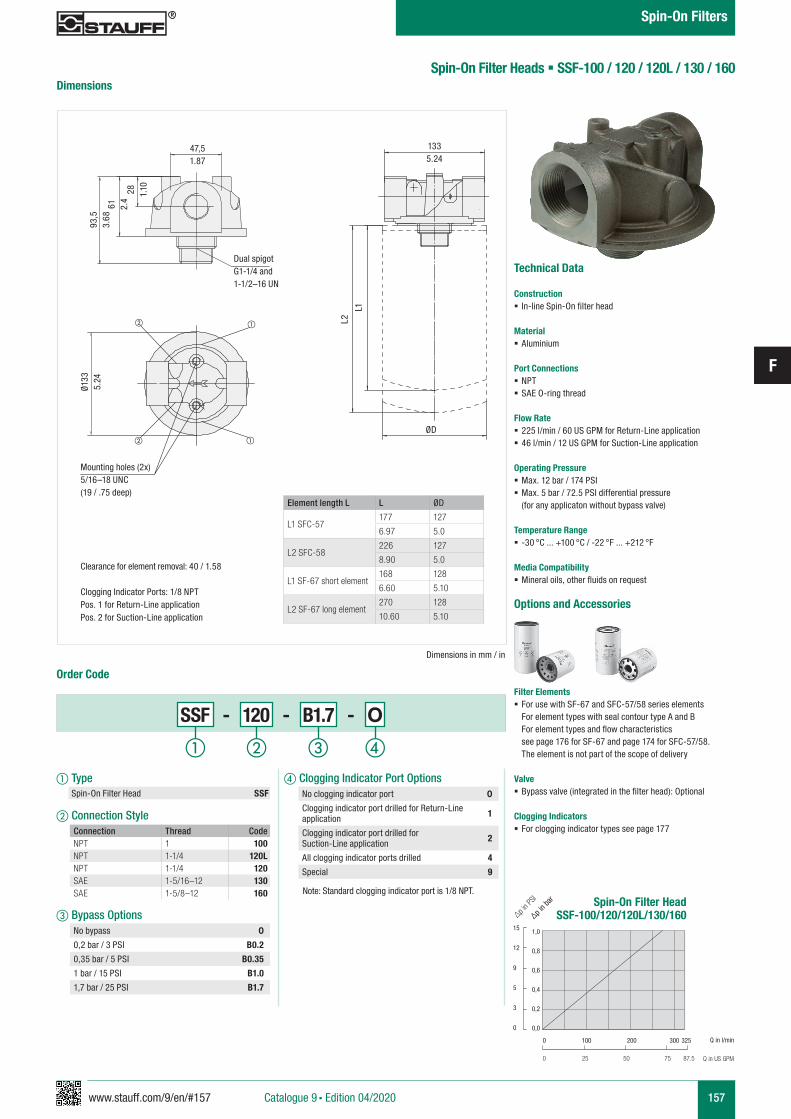
www.stauff.com/9/en/#157
F
157
d Clogging Indicator Port Options
Note: Standard clogging indicator port is 1/8 NPT.
No clogging indicator port 0
Clogging indicator port drilled for Return-Line application 1
Clogging indicator port drilled for Suction-Line application 2
All clogging indicator ports drilled 4
Special 9
Spin-On Filter Heads § SSF-100 / 120 / 120L / 130 / 160
Technical Data
Construction § In-line Spin-On filter head
Material § Aluminium
Port Connections § NPT § SAE O-ring thread
Flow Rate § 225 l/min / 60 US GPM for Return-Line application § 46 l/min / 12 US GPM for Suction-Line application
Operating Pressure § Max. 12 bar / 174 PSI § Max. 5 bar / 72.5 PSI differential pressure (for any applicaton without bypass valve)
Temperature Range § -30 °C ... +100 °C / -22 °F ... +212 °F
Media Compatibility § Mineral oils, other fluids on request
Options and Accessories
Filter Elements § For use with SF-67 and SFC-57/58 series elements
For element types with seal contour type A and B For element types and flow characteristics see page 176 for SF-67 and page 174 for SFC-57/58. The element is not part of the scope of delivery
Valve § Bypass valve (integrated in the filter head): Optional
Clogging Indicators § For clogging indicator types see page 177
Dimensions
Dimensions in mm / in
Order Code
SSF - 120 - B1.7 - O
a Type Spin-On Filter Head SSF
b Connection Style
c Bypass Options
Connection Thread CodeNPT 1 100NPT 1-1/4 120LNPT 1-1/4 120SAE 1-5/16–12 130SAE 1-5/8–12 160
No bypass 0
0,2 bar / 3 PSI B0.2
0,35 bar / 5 PSI B0.35
1 bar / 15 PSI B1.0
1,7 bar / 25 PSI B1.7
47,51.87
1335.24
ØD
L2
L1
28 1.10
61 2.4
93,5
3.68
Dual spigotG1-1/4 and 1-1/2–16 UN
Clearance for element removal: 40 / 1.58
Clogging Indicator Ports: 1/8 NPTPos. 1 for Return-Line applicationPos. 2 for Suction-Line application
Mounting holes (2x)5/16–18 UNC (19 / .75 deep)
Spin-On Filter HeadSSF-100/120/120L/130/160
1,0
0,8
0,6
0,4
0,2
0,0
15
12
9
5
3
0
∆p in b
ar
∆p in P
SI
Q in l/min
Q in US GPM
0 100 200 300 325
0 25 50 75 87.5
Ø133
5.24
Element length L L ØD
L1 SFC-57177 127
6.97 5.0
L2 SFC-58226 127
8.90 5.0
L1 SF-67 short element168 128
6.60 5.10
L2 SF-67 long element270 128
10.60 5.10
a b c d
Catalogue 9 § Edition 04/2020
Spin-On Filters
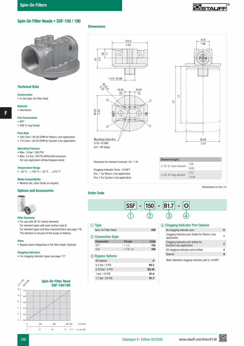
158 www.stauff.com/9/en/#158
F
Spin-On Filter Heads § SSF-150 / 180
Technical Data
Construction § In-line Spin-On filter head
Material § Aluminium
Port Connections § NPT § SAE O-ring thread
Flow Rate § 300 l/min / 80 US GPM for Return-Line application § 113 l/min / 30 US GPM for Suction-Line application
Operating Pressure § Max. 14 bar / 200 PSI § Max. 5,5 bar / 80 PSI differential pressure (for any applicaton without bypass valve)
Temperature Range § -30 °C ... +100 °C / -22 °F ... +212 °F
Media Compatibility § Mineral oils, other fluids on request
Options and Accessories
Filter Elements § For use with SF-67 series elements
For element types with seal contour type B For element types and flow characteristics see page 176 The element is not part of the scope of delivery
Valve § Bypass valve (integrated in the filter head): Optional
Clogging Indicators § For clogging indicator types see page 177
Dimensions
Order Code
Dimensions in mm / in
SSF - 150 - B1.7 - O
a Type Spin-On Filter Head SSF
b Connection Style
c Bypass Options
Connection Thread CodeNPT 1-1/2 150SAE 1-7/8–12 180
No bypass 0
0,2 bar / 3 PSI B0.2
0,35 bar / 5 PSI B0.35
1 bar / 15 PSI B1.0
1,7 bar / 25 PSI B1.7
47,81.88
1-1/2–16 UN
19,05.75
19,05.75
28 1.1
133,45.24
61 2.4
L2
L1
OU
T
IN
Ø133,4
5.24
Element length L
L1 SF-67 short element168
6.60
L2 SF-67 long element270
10.60
Clearance for element removal: 30 / 1.18
Clogging Indicator Ports: 1/8 NPTPos. 1 for Return-Line applicationPos. 2 for Suction-Line application
Mounting holes (6x)5/16–18 UNC (22 / .88 deep)
d Clogging Indicator Port Options
Note: Standard clogging indicator port is 1/8 NPT.
No clogging indicator port 0
Clogging indicator port drilled for Return-Line application 1
Clogging indicator port drilled for Suction-Line application 2
All clogging indicator ports drilled 4
Special 9
Ø1285.10
Spin-On Filter HeadSSF-150/180
1,0
0,8
0,6
0,4
0,2
0,0
15
12
9
5
3
0
∆p in b
ar
∆p in P
SI
Q in l/min
Q in US GPM
0 100 200 300 325
0 25 50 75 87.5
Ø133
5.24
a b c d
Catalogue 9 § Edition 04/2020
Spin-On Filters
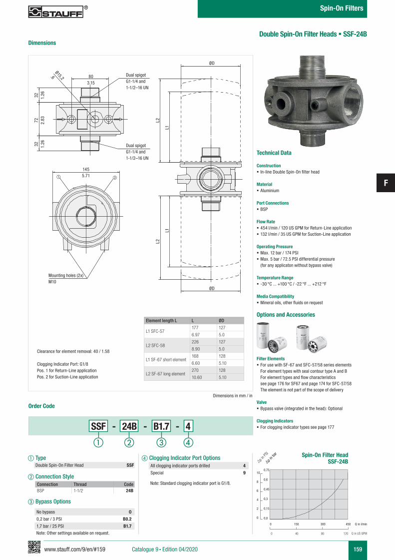
www.stauff.com/9/en/#159
F
159
Double Spin-On Filter Heads § SSF-24B
Technical Data
Construction § In-line Double Spin-On filter head
Material § Aluminium
Port Connections § BSP
Flow Rate § 454 l/min / 120 US GPM for Return-Line application § 132 l/min / 35 US GPM for Suction-Line application
Operating Pressure § Max. 12 bar / 174 PSI § Max. 5 bar / 72.5 PSI differential pressure (for any applicaton without bypass valve)
Temperature Range § -30 °C ... +100 °C / -22 °F ... +212 °F
Media Compatibility § Mineral oils, other fluids on request
Options and Accessories
Filter Elements § For use with SF-67 and SFC-57/58 series elements
For element types with seal contour type A and B For element types and flow characteristics see page 176 for SF67 and page 174 for SFC-57/58 The element is not part of the scope of delivery
Valve § Bypass valve (integrated in the head): Optional
Clogging Indicators § For clogging indicator types see page 177
Dimensions
Dimensions in mm / in
Order Code
SSF - 24B - B1.7 - 4
a Type Double Spin-On Filter Head SSF
b Connection Style
c Bypass Options
Connection Thread CodeBSP 1-1/2 24B
No bypass 0
0,2 bar / 3 PSI B0.2
1,7 bar / 25 PSI B1.7
d Clogging Indicator Port Options
Note: Standard clogging indicator port is G1/8.
All clogging indicator ports drilled 4
Special 9
ØD
ØD
Ø15,2.6
1455.71
803.15
L2
L1
L2
L1
32 1.26
72 2.83
32 1.26
Element length L L ØD
L1 SFC-57177 127
6.97 5.0
L2 SFC-58226 127
8.90 5.0
L1 SF-67 short element168 128
6.60 5.10
L2 SF-67 long element270 128
10.60 5.10
Clearance for element removal: 40 / 1.58
Clogging Indicator Port: G1/8Pos. 1 for Return-Line applicationPos. 2 for Suction-Line application
Dual spigotG1-1/4 and 1-1/2–16 UN
Dual spigotG1-1/4 and 1-1/2–16 UN
Mounting holes (2x)M10
Spin-On Filter HeadSSF-24B
0,75
0,6
0,45
0,3
0,15
0,0
10
8
6
4
2
0
∆p in b
ar
∆p in P
SI
Q in l/min
Q in US GPM
0 150 300 450
0 40 80 120Note: Other settings available on request.
a b c d
Catalogue 9 § Edition 04/2020
Spin-On Filters
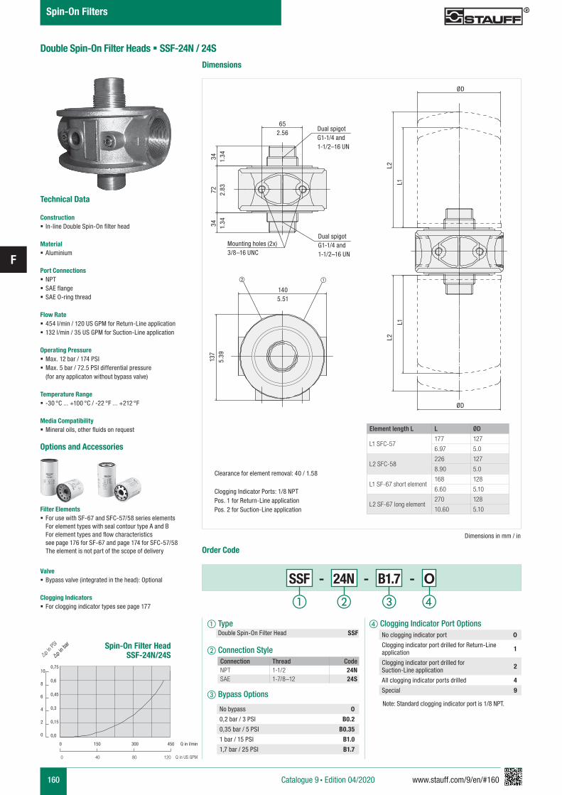
160 www.stauff.com/9/en/#160
F
Double Spin-On Filter Heads § SSF-24N / 24S
Technical Data
Construction § In-line Double Spin-On filter head
Material § Aluminium
Port Connections § NPT § SAE flange § SAE O-ring thread
Flow Rate § 454 l/min / 120 US GPM for Return-Line application § 132 l/min / 35 US GPM for Suction-Line application
Operating Pressure § Max. 12 bar / 174 PSI § Max. 5 bar / 72.5 PSI differential pressure (for any applicaton without bypass valve)
Temperature Range § -30 °C ... +100 °C / -22 °F ... +212 °F
Media Compatibility § Mineral oils, other fluids on request
Options and Accessories
Filter Elements § For use with SF-67 and SFC-57/58 series elements
For element types with seal contour type A and B For element types and flow characteristics see page 176 for SF-67 and page 174 for SFC-57/58 The element is not part of the scope of delivery
Valve § Bypass valve (integrated in the head): Optional
Clogging Indicators § For clogging indicator types see page 177
Dimensions
Dimensions in mm / in
ØD
ØD
1405.51
652.56
L1L1
34 1.34
137
5.39
72 2.83
34 1.34
L2L2
Element length L L ØD
L1 SFC-57177 127
6.97 5.0
L2 SFC-58226 127
8.90 5.0
L1 SF-67 short element168 128
6.60 5.10
L2 SF-67 long element270 128
10.60 5.10
Order Code
SSF - 24N - B1.7 - O
a Type Double Spin-On Filter Head SSF
b Connection Style
c Bypass Options
Connection Thread CodeNPT 1-1/2 24NSAE 1-7/8–12 24S
No bypass 0
0,2 bar / 3 PSI B0.2
0,35 bar / 5 PSI B0.35
1 bar / 15 PSI B1.0
1,7 bar / 25 PSI B1.7
Clearance for element removal: 40 / 1.58
Clogging Indicator Ports: 1/8 NPTPos. 1 for Return-Line applicationPos. 2 for Suction-Line application
Dual spigotG1-1/4 and 1-1/2–16 UN
Dual spigotG1-1/4 and 1-1/2–16 UN
Mounting holes (2x)3/8–16 UNC
d Clogging Indicator Port Options
Note: Standard clogging indicator port is 1/8 NPT.
No clogging indicator port 0
Clogging indicator port drilled for Return-Line application 1
Clogging indicator port drilled for Suction-Line application 2
All clogging indicator ports drilled 4
Special 9
Spin-On Filter HeadSSF-24N/24S
0,75
0,6
0,45
0,3
0,15
0,0
10
8
6
4
2
0
∆p in b
ar
∆p in P
SI
Q in l/min
Q in US GPM
0 150 300 450
0 40 80 120
a b c d
Catalogue 9 § Edition 04/2020
Spin-On Filters
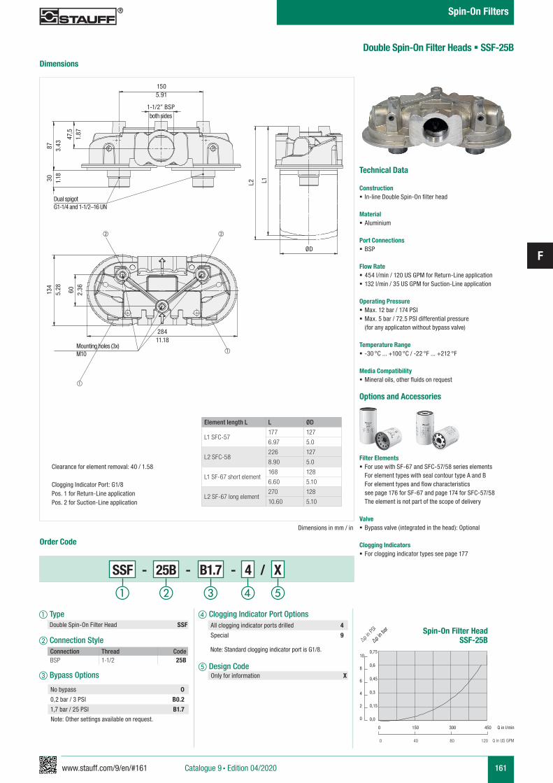
www.stauff.com/9/en/#161
F
161
Technical Data
Construction § In-line Double Spin-On filter head
Material § Aluminium
Port Connections § BSP
Flow Rate § 454 l/min / 120 US GPM for Return-Line application § 132 l/min / 35 US GPM for Suction-Line application
Operating Pressure § Max. 12 bar / 174 PSI § Max. 5 bar / 72.5 PSI differential pressure (for any applicaton without bypass valve)
Temperature Range § -30 °C ... +100 °C / -22 °F ... +212 °F
Media Compatibility § Mineral oils, other fluids on request
Options and Accessories
Filter Elements § For use with SF-67 and SFC-57/58 series elements
For element types with seal contour type A and B For element types and flow characteristics see page 176 for SF-67 and page 174 for SFC-57/58 The element is not part of the scope of delivery
Valve § Bypass valve (integrated in the head): Optional
Clogging Indicators § For clogging indicator types see page 177
Double Spin-On Filter Heads § SSF-25B
Dimensions
Dimensions in mm / in
Order Code
a Type Double Spin-On Filter Head SSF
b Connection Style
c Bypass Options
Connection Thread CodeBSP 1-1/2 25B
No bypass 0
0,2 bar / 3 PSI B0.2
1,7 bar / 25 PSI B1.7
d Clogging Indicator Port Options
Note: Standard clogging indicator port is G1/8.
e Design Code Only for information X
All clogging indicator ports drilled 4
Special 9
ØD
1505.91
Dual spigotG1-1/4 and 1-1/2–16 UN
Mounting holes (3x)M10
L1
47,5
1.87
87 3.43
30 1.18
134
5.28 60 2.36
L2
Element length L L ØD
L1 SFC-57177 127
6.97 5.0
L2 SFC-58226 127
8.90 5.0
L1 SF-67 short element168 128
6.60 5.10
L2 SF-67 long element270 128
10.60 5.10
Clearance for element removal: 40 / 1.58
Clogging Indicator Port: G1/8Pos. 1 for Return-Line applicationPos. 2 for Suction-Line application
Spin-On Filter HeadSSF-25B
0,75
0,6
0,45
0,3
0,15
0,0
10
8
6
4
2
0
∆p in b
ar
∆p in P
SI
Q in l/min
Q in US GPM
0 150 300 450
0 40 80 120
Note: Other settings available on request.
a b c d
1-1/2” BSPboth sides
28411.18
e
SSF - 25B - B1.7 - 4 / X
Catalogue 9 § Edition 04/2020
Spin-On Filters
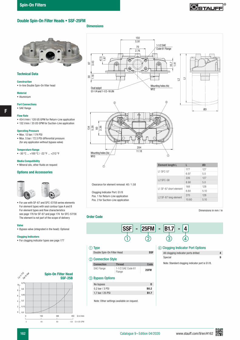
162 www.stauff.com/9/en/#162
F
Technical Data
Construction § In-line Double Spin-On filter head
Material § Aluminium
Port Connections § SAE flange
Flow Rate § 454 l/min / 120 US GPM for Return-Line application § 132 l/min / 35 US GPM for Suction-Line application
Operating Pressure § Max. 12 bar / 174 PSI § Max. 5 bar / 72.5 PSI differential pressure (for any applicaton without bypass valve)
Temperature Range § -30 °C ... +100 °C / -22 °F ... +212 °F
Media Compatibility § Mineral oils, other fluids on request
Options and Accessories
Filter Elements § For use with SF-67 and SFC-57/58 series elements
For element types with seal contour type A and B For element types and flow characteristics see page 176 for SF-67 and page 174 for SFC-57/58 The element is not part of the scope of delivery
Valve § Bypass valve (integrated in the head): Optional
Clogging Indicators § For clogging indicator types see page 177
Double Spin-On Filter Heads § SSF-25FMDimensions
Spin-On Filter HeadSSF-25B
0,75
0,6
0,45
0,3
0,15
0,0
10
8
6
4
2
0
∆p in b
ar
∆p in P
SI
Q in l/min
Q in US GPM
0 150 300 450
0 40 80 120
Dimensions in mm / in
Order Code
SSF - 25FM - B1.7 - 4
a Type Double Spin-On Filter Head SSF
b Connection Style
c Bypass Options
Connection Thread CodeSAE Flange 1-1/2 SAE Code 61
Flange 25FM
No bypass O
0,2 bar / 3 PSI B0.2
1,7 bar / 25 PSI B1.7
d Clogging Indicator Port Options
Note: Standard clogging indicator port is G1/8.
All clogging indicator ports drilled 4
Special 9
Element length L L ØD
L1 SFC-57177 127
6.97 5.0
L2 SFC-58226 127
8.90 5.0
L1 SF-67 short element168 128
6.60 5.10
L2 SF-67 long element270 128
10.60 5.10
Clearance for element removal: 40 / 1.58
Clogging Indicator Port: G1/8Pos. 1 for Return-Line applicationPos. 2 for Suction-Line application
Note: Other settings available on request.
a b c d
ØD
1505.91
Dual spigotG1-1/4 and 1-1/2–16 UN
Mounting holes (4x)M12
Mounting holes (3x)M10
L1
47,5
1.87
87 3.43
30 1.18
134
5.28 60 2.36
L2
702.76
1-1/2 SAE Code 61 Flange
28411.18
35,7
1.41
Catalogue 9 § Edition 04/2020
Spin-On Filters
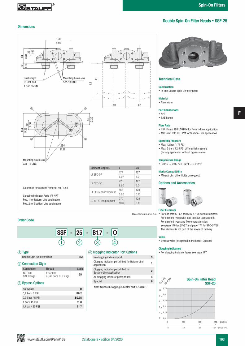
www.stauff.com/9/en/#163
F
163
Double Spin-On Filter Heads § SSF-25Dimensions
Order Code
SSF - 25 - B1.7 - O
a Type Double Spin-On Filter Head SSF
b Connection Style
c Bypass Options
Connection Thread CodeNPT and SAE Flange
1-1/2 and 2 SAE Code 61 Flange 25
No bypass 0
0,2 bar / 3 PSI B0.2
0,35 bar / 5 PSI B0.35
1 bar / 15 PSI B1.0
1,7 bar / 25 PSI B1.7
Dimensions in mm / in
ØDØD
Dual spigotG1-1/4 and 1-1/2–16 UN
Mounting holes (4x)1/2–13 UNC
Mounting holes (3x) 3/8–16 UNC
28411.18
1505.91
36 1.42
84 3.31
32 1.26
60 2.36
56 2.20
L1
L2
134
5.28
Element length L L ØD
L1 SFC-57177 127
6.97 5.0
L2 SFC-58226 127
8.90 5.0
L1 SF-67 short element168 128
6.60 5.10
L2 SF-67 long element270 128
10.60 5.10
Clearance for element removal: 40 / 1.58
Clogging Indicator Port: 1/8 NPTPos. 1 for Return-Line applicationPos. 2 for Suction-Line application
d Clogging Indicator Port Options
Note: Standard clogging indicator port is 1/8 NPT.
No clogging indicator port 0
Clogging indicator port drilled for Return-Line application 1
Clogging indicator port drilled for Suction-Line application 2
All clogging indicator ports drilled 4
Special 9
Technical Data
Construction § In-line Double Spin-On filter head
Material § Aluminium
Port Connections § NPT § SAE flange
Flow Rate § 454 l/min / 120 US GPM for Return-Line application § 132 l/min / 35 US GPM for Suction-Line application
Operating Pressure § Max. 12 bar / 174 PSI § Max. 5 bar / 72.5 PSI differential pressure (for any applicaton without bypass valve)
Temperature Range § -30 °C ... +100 °C / -22 °F ... +212 °F
Media Compatibility § Mineral oils, other fluids on request
Options and Accessories
Filter Elements § For use with SF-67 and SFC-57/58 series elements
For element types with seal contour type A and B For element types and flow characteristics see page 176 for SF-67 and page 174 for SFC-57/58 The element is not part of the scope of delivery
Valve § Bypass valve (integrated in the head): Optional
Clogging Indicators § For clogging indicator types see page 177
Spin-On Filter HeadSSF-25
0,75
0,6
0,45
0,3
0,15
0,0
10
8
6
4
2
0
∆p in b
ar
∆p in P
SI
Q in l/min
Q in US GPM
0 150 300 450
0 40 80 120
a b c d
Catalogue 9 § Edition 04/2020
Spin-On Filters
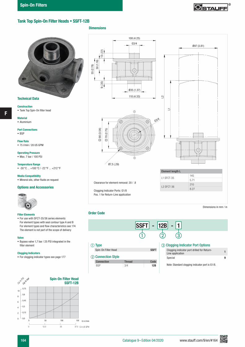
164 www.stauff.com/9/en/#164
F
Tank Top Spin-On Filter Heads § SSFT-12B
Technical Data
Construction § Tank Top Spin-On filter head
Material § Aluminium
Port Connections § BSP
Flow Rate § 75 l/min / 20 US GPM
Operating Pressure § Max. 7 bar / 100 PSI
Temperature Range § -30 °C ... +100 °C / -22 °F ... +212 °F
Media Compatibility § Mineral oils, other fluids on request
Options and Accessories
Filter Elements § For use with SFCT-35/36 series elements
For element types with seal contour type A and B For element types and flow characteristics see 174 The element is not part of the scope of delivery
Valve § Bypass valve 1,7 bar / 25 PSI integrated in the
filter element
Clogging Indicators § For clogging indicator types see page 177
Dimensions
Order Code
SSFT - 12B - 1
a Type Spin-On Filter Head SSFT
b Connection StyleConnection Thread CodeBSP 3/4 12B
c Clogging Indicator Port Options
Note: Standard clogging indicator port is G1/8.
Clogging indicator port drilled for Return-Line application 1
Special 9
Dimensions in mm / in
Element length L
L1 SFCT-35145
5.71
L2 SFCT-36210
8.27
Spin-On Filter HeadSSFT-12B
0,75
0,6
0,45
0,3
0,15
0,0
10
8
6
4
2
0
∆p in b
ar
∆p in P
SI
Q in l/min
Q in US GPM
0 50 100 150
0 12.5 25 37.5
a b c
Catalogue 9 § Edition 04/2020
Spin-On Filters
Ø97 (3.81)
Ø35 (1.37)
110 (4.33) L2
L1
o 7
0 (2
.75)
o 9
0 (3
.54)
30 (1
.18)
9 (.3
5)
Clearance for element removal: 20 / .8
Clogging Indicator Ports: G1/8Pos. 1 for Return-Line application
Ø7,5 (.29)
G3/4
G3/4
108 (4.25)
13 (.
51)
55 (2
.78)
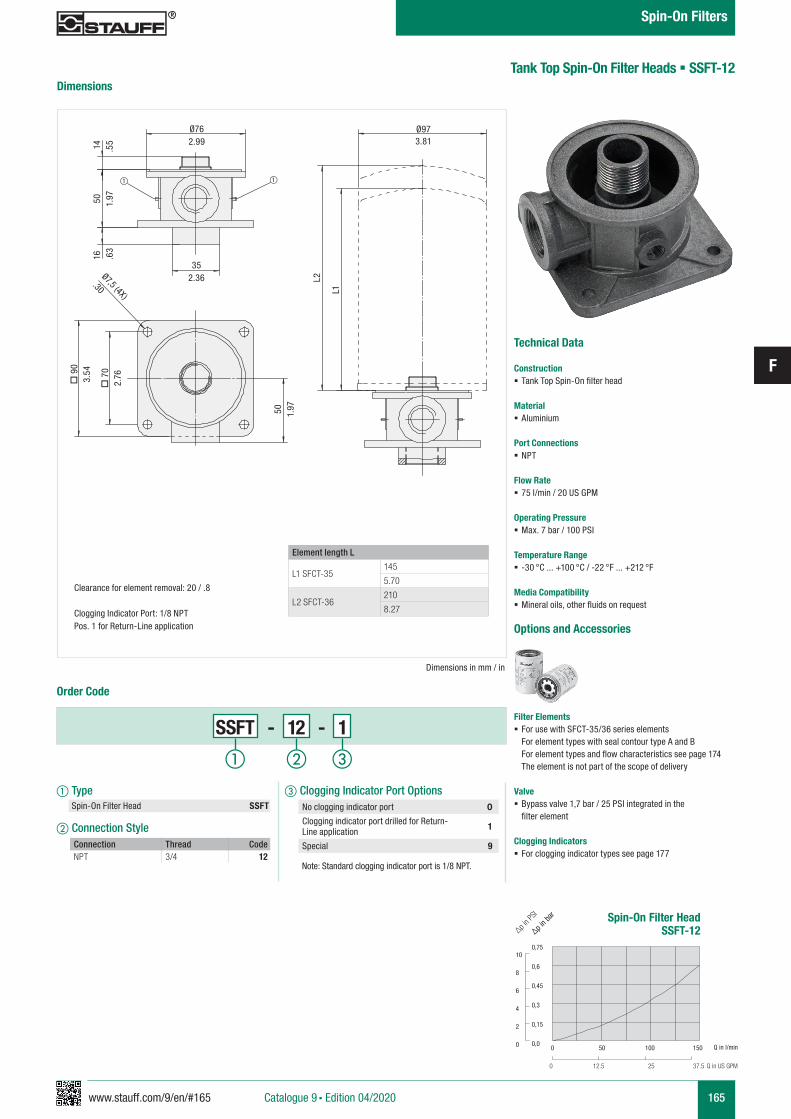
www.stauff.com/9/en/#165
F
165
Tank Top Spin-On Filter Heads § SSFT-12
Technical Data
Construction § Tank Top Spin-On filter head
Material § Aluminium
Port Connections § NPT
Flow Rate § 75 l/min / 20 US GPM
Operating Pressure § Max. 7 bar / 100 PSI
Temperature Range § -30 °C ... +100 °C / -22 °F ... +212 °F
Media Compatibility § Mineral oils, other fluids on request
Options and Accessories
Filter Elements § For use with SFCT-35/36 series elements
For element types with seal contour type A and B For element types and flow characteristics see page 174 The element is not part of the scope of delivery
Valve § Bypass valve 1,7 bar / 25 PSI integrated in the
filter element
Clogging Indicators § For clogging indicator types see page 177
Spin-On Filter HeadSSFT-12
0,75
0,6
0,45
0,3
0,15
0,0
10
8
6
4
2
0
∆p in b
ar
∆p in P
SI
Q in l/min
Q in US GPM
0 50 100 150
0 12.5 25 37.5
Dimensions
Order Code
SSFT - 12 - 1
a Type Spin-On Filter Head SSFT
b Connection StyleConnection Thread CodeNPT 3/4 12
c Clogging Indicator Port Options
Note: Standard clogging indicator port is 1/8 NPT.
No clogging indicator port 0
Clogging indicator port drilled for Return-Line application 1
Special 9
Dimensions in mm / in
Ø973.81
Ø762.99
352.36 L2
L1
14 .55
50 1.97
Ø7,5 (4X)
.30
o 9
03.
54
o 7
02.
76
50 1.97
16 .63
Element length L
L1 SFCT-35145
5.70
L2 SFCT-36210
8.27
Clearance for element removal: 20 / .8
Clogging Indicator Port: 1/8 NPTPos. 1 for Return-Line application
a b c
Catalogue 9 § Edition 04/2020
Spin-On Filters
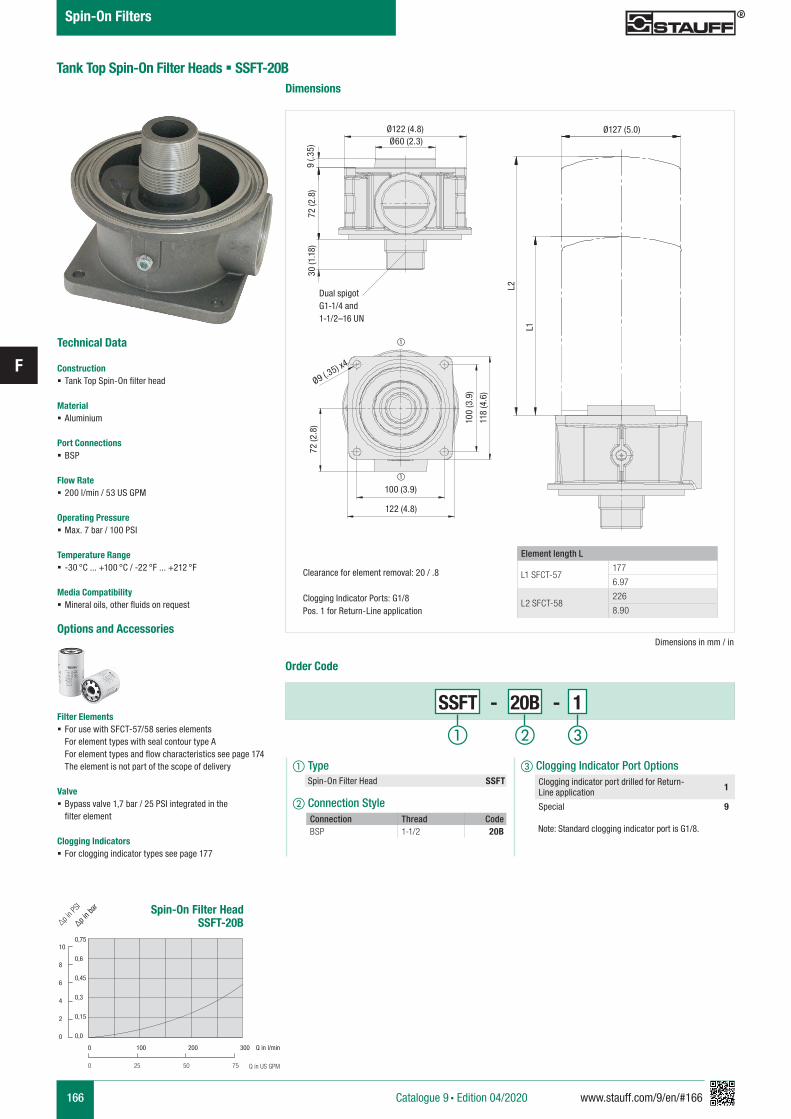
166 www.stauff.com/9/en/#166
F
Tank Top Spin-On Filter Heads § SSFT-20B
Technical Data
Construction § Tank Top Spin-On filter head
Material § Aluminium
Port Connections § BSP
Flow Rate § 200 l/min / 53 US GPM
Operating Pressure § Max. 7 bar / 100 PSI
Temperature Range § -30 °C ... +100 °C / -22 °F ... +212 °F
Media Compatibility § Mineral oils, other fluids on request
Options and Accessories
Filter Elements § For use with SFCT-57/58 series elements
For element types with seal contour type A For element types and flow characteristics see page 174 The element is not part of the scope of delivery
Valve § Bypass valve 1,7 bar / 25 PSI integrated in the
filter element
Clogging Indicators § For clogging indicator types see page 177
Dimensions
Order Code
SSFT - 20B - 1
a Type Spin-On Filter Head SSFT
b Connection StyleConnection Thread CodeBSP 1-1/2 20B
c Clogging Indicator Port Options
Note: Standard clogging indicator port is G1/8.
Clogging indicator port drilled for Return-Line application 1
Special 9
Dimensions in mm / in
Ø127 (5.0)
L2
L1
72 (2
.8)
30 (1
.18)
9 (.3
5)72
(2.8
)
Element length L
L1 SFCT-57177
6.97
L2 SFCT-58226
8.90
Clearance for element removal: 20 / .8
Clogging Indicator Ports: G1/8Pos. 1 for Return-Line application
Spin-On Filter HeadSSFT-20B
0,75
0,6
0,45
0,3
0,15
0,0
10
8
6
4
2
0
∆p in b
ar
∆p in P
SI
Q in l/min
Q in US GPM
0 100 200 300
0 25 50 75
a b c
Catalogue 9 § Edition 04/2020
Spin-On Filters
Ø9 (.35) x4
Ø60 (2.3)Ø122 (4.8)
100
(3.9
)
118
(4.6
)
122 (4.8)
100 (3.9)
Dual spigotG1-1/4 and 1-1/2–16 UN
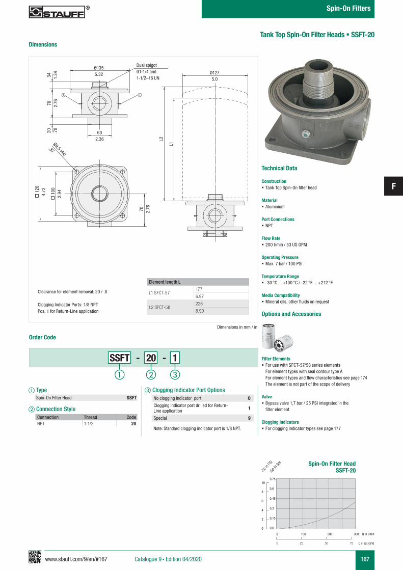
www.stauff.com/9/en/#167
F
167
Tank Top Spin-On Filter Heads § SSFT-20
Technical Data
Construction § Tank Top Spin-On filter head
Material § Aluminium
Port Connections § NPT
Flow Rate § 200 l/min / 53 US GPM
Operating Pressure § Max. 7 bar / 100 PSI
Temperature Range § -30 °C ... +100 °C / -22 °F ... +212 °F
Media Compatibility § Mineral oils, other fluids on request
Options and Accessories
Filter Elements § For use with SFCT-57/58 series elements
For element types with seal contour type A For element types and flow characteristics see page 174 The element is not part of the scope of delivery
Valve § Bypass valve 1,7 bar / 25 PSI integrated in the
filter element
Clogging Indicators § For clogging indicator types see page 177
Spin-On Filter HeadSSFT-20
0,75
0,6
0,45
0,3
0,15
0,0
10
8
6
4
2
0
∆p in b
ar
∆p in P
SI
Q in l/min
Q in US GPM
0 100 200 300
0 25 50 75
Dimensions
Order Code
SSFT - 20 - 1
a Type Spin-On Filter Head SSFT
b Connection StyleConnection Thread CodeNPT 1-1/2 20
c Clogging Indicator Port Options
Note: Standard clogging indicator port is 1/8 NPT.
No clogging indicator port 0
Clogging indicator port drilled for Return-Line application 1
Special 9
Dimensions in mm / in
Ø9,5 (4x)
.37
Ø1275.0
602.36
Ø1355.32
70 2.76
o 1
003.
94
o 1
204.
72
L2
L1
34 1.34
70 2.76
20 .78
Element length L
L1 SFCT-57177
6.97
L2 SFCT-58226
8.90
Clearance for element removal: 20 / .8
Clogging Indicator Ports: 1/8 NPTPos. 1 for Return-Line application
Dual spigotG1-1/4 and 1-1/2–16 UN
a b c
Catalogue 9 § Edition 04/2020
Spin-On Filters
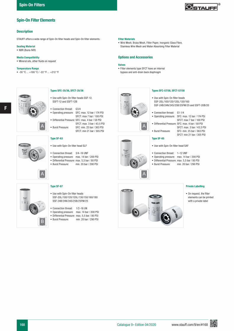
168 www.stauff.com/9/en/#168
F
Spin-On Filter Elements
Types SFC-35/36, SFCT-35/36
§ Use with Spin-On filter heads SSF-12, SSFT-12 and SSFT-12B
§ Connection thread: G3/4 § Operating pressure: SFC: max. 12 bar / 174 PSI SFCT: max 7 bar / 100 PSI
§ Differential Pressure: SFC: max. 4 bar / 58 PSI SFCT: max. 3 bar / 43,5 PSI
§ Burst Pressure: SFC: min. 25 bar / 363 PSI SFCT: min 21 bar / 305 PSI
A
Types SFC-57/58, SFCT-57/58
§ Use with Spin-On filter heads SSF-20L/100/120/120L/130/160 SSF-24B/24N/24S/25B/25FM/25 and SSFT-20B/20
§ Connection thread: G1-1/4 § Operating pressure: SFC: max. 12 bar / 174 PSI SFCT: max 7 bar / 100 PSI
§ Differential Pressure: SFC: max. 4 bar / 58 PSI SFCT: max. 3 bar / 43,5 PSI
§ Burst Pressure: SFC: min. 25 bar / 363 PSI SFCT: min 21 bar / 305 PSI
A
Type SF-63
§ Use with Spin-On filter head SLF
§ Connection thread: 3/4–16 UNF § Operating pressure: max. 14 bar / 200 PSI § Differential Pressure: max. 5,5 bar / 80 PSI § Burst Pressure: min. 20 bar / 290 PSI
A
Type SF-65
§ Use with Spin-On filter head SAF
§ Connection thread: 1–12 UNF § Operating pressure: max. 14 bar / 200 PSI § Differential Pressure: max. 5,5 bar / 80 PSI § Burst Pressure: min. 20 bar / 290 PSI
A
Type SF-67
§ Use with Spin-On filter heads SSF-20L/100/120/120L/130/150/160/180 SSF-24B/24N/24S/25B/25FM/25
§ Connection thread: 1/2–16 UN § Operating pressure: max. 14 bar / 200 PSI § Differential Pressure: max. 5,5 bar / 80 PSI § Burst Pressure: min. 20 bar / 290 PSIB
Description
STAUFF offers a wide range of Spin-On filter heads and Spin-On filter elements.
Sealing Material § NBR (Buna-N®)
Media Compatibility § Mineral oils, other fluids on request
Temperature Range § -30 °C ... +100 °C / -22 °F ... +212 °F
Filter Materials § Wire Mesh, Brass Mesh, Filter Paper, Inorganic Glass Fibre, Stainless Wire Mesh and Water Absorbing Filter Material
Options and Accessories
Valves § Filter elements type SFCT have an internal bypass and anti-drain back diaphragm
Private Labelling
§ On request, the filter elements can be printed with a private label
Catalogue 9 § Edition 04/2020
Spin-On Filters
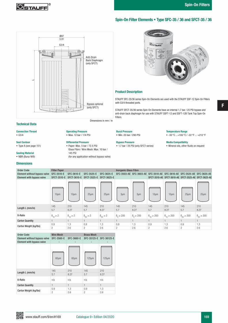
www.stauff.com/9/en/#169
F
169
Order CodeElement without bypass valveElement with bypass valve
Filter Paper Inorganic Glass FibreSFC-3510-E SFC-3610-E SFC-3525-E SFC-3625-E SFC-3503-AE SFC-3603-AE SFC-3510-AE SFC-3610-AE SFC-3525-AE SFC-3625-AESFCT-3510-E SFCT-3610-E SFCT-3525-E SFCT-3625-E SFCT-3510-AE SFCT-3610-AE SFCT-3525-AE SFCT-3625-AE
Length L (mm/in)145 210 145 210 145 210 145 210 145 2105.7 8.27 5.7 8.27 5.7 8.27 5.7 8.27 5.7 8.27
ß-Ratio ß10 ≥ 2 ß
10 ≥ 2 ß25
≥ 2 ß25
≥ 2 ß3 ≥ 200 ß
3 ≥ 200 ß
10 ≥ 200 ß
10 ≥ 200 ß
25 ≥ 200 ß
25 ≥ 200
Carton Quantity 1 1 1 1 1 1 1 1 1 1
Carton Weight (kg/lbs)0,9 1,3 0,9 1,3 0,9 1,3 0,9 1,3 0,9 1,32 2.6 2 2.6 2 2.6 2 2.6 2 2.6
Spin-On Filter Elements § Type SFC-35 / 36 and SFCT-35 / 36
Product Description
STAUFF SFC-35/36 series Spin-On Elements are used with the STAUFF SSF-12 Spin-On Filters with G3/4 threaded ports.
STAUFF SFCT-35/36 series Spin-On Elements have an internal 1,7 bar / 25 PSI bypass and anti-drain back diaphragm for use with STAUFF SSFT-12 and SSFT-12B Tank Top Spin-On Filters.
Dimensions in mm / in
LØ973.81
G3/4
10µm 10µm 25µm 25µm 3µm 3µm 10µm 10µm 25µm 25µm
Dimensions
Order CodeElement without bypass valveElement with bypass valve
Wire Mesh Brass MeshSFC-3560-E SFC-3660-E SFC-35125-E SFC-36125-E
- - - -
Length L (mm/in)145 210 145 2105.7 8.27 5.7 8.27
ß-Ratio n/a n/a n/a n/a
Carton Quantity 1 1 1 1
Carton Weight (kg/lbs)0,9 1,3 0,9 1,32 2.6 2 2.6
60µm 60µm 125µm 125µm
Technical Data
Connection Thread § G3/4
Seal Contour § Type A (see page 151)
Sealing Material § NBR (Buna-N®)
Operating Pressure § Max. 12 bar / 174 PSI
Differential Pressure § Paper: Max. 5 bar / 72.5 PSI Glass Fibre / Wire Mesh: Max. 10 bar / 145 PSI
(for any application without bypass valve)
Burst Pressure § Min. 20 bar / 290 PSI
Bypass Pressure § 1,7 bar / 25 PSI (only SFCT-series)
Temperature Range § -30 °C ...+100 °C / -22 °F ... +212 °F
Media Compatibility § Mineral oils, other fluids on request
Anti-DrainBack Diaphragm(only SFCT)
Bypass optional(only SFCT)
Catalogue 9 § Edition 04/2020
Spin-On Filters
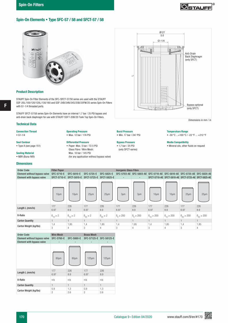
170 www.stauff.com/9/en/#170
F
Order CodeElement without bypass valveElement with bypass valve
Filter Paper Inorganic Glass FibreSFC-5710-E SFC-5810-E SFC-5725-E SFC-5825-E SFC-5703-AE SFC-5803-AE SFC-5710-AE SFC-5810-AE SFC-5725-AE SFC-5825-AESFCT-5710-E SFCT-5810-E SFCT-5725-E SFCT-5825-E - - SFCT-5710-AE SFCT-5810-AE SFCT-5725-AE SFCT-5825-AE
Length L (mm/in)177 226 177 226 177 226 177 226 177 2266.97 8.9 6.97 8.9 6.97 8.9 6.97 8.9 6.97 8.9
ß-Ratio ß10
≥ 2 ß10
≥ 2 ß25
≥ 2 ß25
≥ 2 ß3 ≥ 200 ß
3 ≥ 200 ß
10 ≥ 200 ß
10 ≥ 200 ß
25 ≥ 200 ß
25 ≥ 200
Carton Quantity 1 1 1 1 1 1 1 1 1 1
Carton Weight (kg/lbs)1,4 1,85 1,4 1,85 1,4 1,85 1,4 1,85 1,4 1,853 4 3 4 3 4 3 4 3 4
Spin-On Elements § Type SFC-57 / 58 and SFCT-57 / 58
60µm 60µm 125µm 125µm
Order CodeElement without bypass valveElement with bypass valve
Wire Mesh Brass MeshSFC-5760-E SFC-5860-E SFC-57125-E SFC-58125-E
- - - -
Length L (mm/in)177 226 177 2266.97 8.9 6.97 8.9
ß-Ratio n/a n/a n/a n/a
Carton Quantity 1 1 1 1
Carton Weight (kg/lbs)0,9 1,3 0,9 1,32 2.6 2 2.6
Technical Data
Connection Thread § G1-1/4
Seal Contour § Type A (see page 151)
Sealing Material § NBR (Buna-N®)
Operating Pressure § Max. 12 bar / 174 PSI
Differential Pressure § Paper: Max. 5 bar / 72.5 PSI Glass Fibre / Wire Mesh: Max. 10 bar / 145 PSI
(for any application without bypass valve)
Burst Pressure § Min. 17 bar / 247 PSI
Bypass Pressure § 1,7 bar / 25 PSI
(only SFCT-series)
Temperature Range § -30 °C ...+100 °C / -22 °F ... +212 °F
Media Compatibility § Mineral oils, other fluids on request
Dimensions in mm / in
L
Ø1275.0
G1-1/4
Product Description
STAUFF Spin-On Filter Elements of the SFC-/SFCT-57/58 series are used with the STAUFF SSF-20L/100/120/120L/130/160 and SSF-24B/24N/24S/25B/25FM/25 series Spin-On Filters with G1-1/4 threaded ports.
STAUFF SFCT-57/58 series Spin-On Elements have an internal 1,7 bar / 25 PSI bypass and anti-drain back diaphragm for use with STAUFF SSFT-20B/20 Tank Top Spin-On Filters.
Dimensions
Anti-DrainBack Diaphragm(only SFCT)
Bypass optional(only SFCT)
Catalogue 9 § Edition 04/2020
Spin-On Filters
3µm 3µm 10µm 10µm 25µm 25µm 10µm 10µm 25µm 25µm
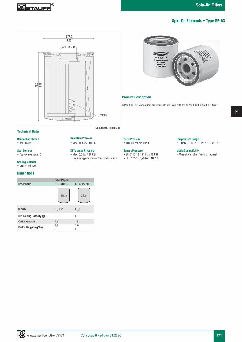
www.stauff.com/9/en/#171
F
171
Spin-On Elements § Type SF-63
Filter PaperOrder Code SF-6310-18 SF-6325-10
ß-Ratio ß10
≥ 2 ß25
≥ 2
Dirt Holding Capacity (g) 6 6
Carton Quantity 12 12
Carton Weight (kg/lbs)3,6 3,68 8
10µm 25µm
Dimensions
Product Description
STAUFF SF-63-series Spin-On Elements are used with the STAUFF SLF Spin-On Filters.
Dimensions in mm / in
Ø77,53.05
3/4–16 UNF
Technical Data
Connection Thread § 3/4–16 UNF
Seal Contour § Type A (see page 151)
Sealing Material § NBR (Buna-N®)
Operating Pressure
§ Max. 14 bar / 200 PSI
Differential Pressure § Max. 5,5 bar / 80 PSI(for any application without bypass valve)
Burst Pressure § Min. 20 bar / 290 PSI
Bypass Pressure § SF-6310-18 1,24 bar / 18 PSI § SF-6325-10 0,70 bar / 10 PSI
Temperature Range § -30 °C ... +100 °C / -22 °F ... +212 °F
Media Compatibility § Mineral oils, other fluids on request
73,2
2.88
Catalogue 9 § Edition 04/2020
Spin-On Filters
Bypass
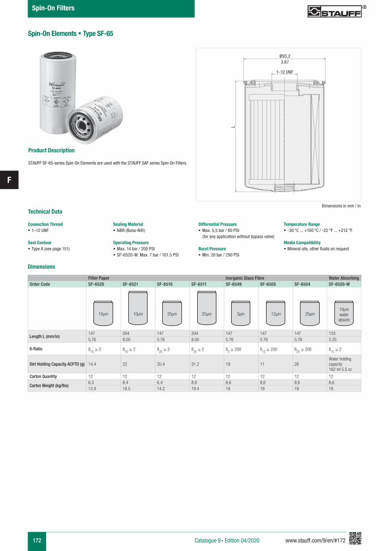
172 www.stauff.com/9/en/#172
F
Spin-On Elements § Type SF-65
Product Description
STAUFF SF-65-series Spin-On Elements are used with the STAUFF SAF series Spin-On Filters.
Dimensions
Filter Paper Inorganic Glass Fibre Water AbsorbingOrder Code SF-6520 SF-6521 SF-6510 SF-6511 SF-6549 SF-6505 SF-6504 SF-6520-W
Length L (mm/in)147 204 147 204 147 147 147 1335.76 8.00 5.76 8.00 5.76 5.76 5.76 5.25
ß-Ratio ß10 ≥ 2 ß
10 ≥ 2 ß
25 ≥ 2 ß
25 ≥ 2 ß
3 ≥ 200 ß
12 ≥ 200 ß
25 ≥ 200 ß
10 ≥ 2
Dirt Holding Capacity ACFTD (g) 14.4 22 20.4 31.2 19 11 26Water holding capacity162 ml 5.5 oz
Carton Quantity 12 12 12 12 12 12 12 12
Carton Weight (kg/lbs)6,3 8,4 6,4 8,8 8,6 8,6 8,6 8,613.9 18.5 14.2 19.4 19 19 19 19
10µm 10µm 25µm 25µm 3µm 12µm 25µm
10µm water absorb
L
Ø93,23.67
Dimensions in mm / in
1–12 UNF
Technical Data
Connection Thread § 1–12 UNF
Seal Contour § Type A (see page 151)
Sealing Material § NBR (Buna-N®)
Operating Pressure § Max. 14 bar / 200 PSI § SF-6520-W: Max. 7 bar / 101.5 PSI
Differential Pressure § Max. 5,5 bar / 80 PSI(for any application without bypass valve)
Burst Pressure § Min. 20 bar / 290 PSI
Temperature Range § -30 °C ... +100 °C / -22 °F ... +212 °F
Media Compatibility § Mineral oils, other fluids on request
Catalogue 9 § Edition 04/2020
Spin-On Filters
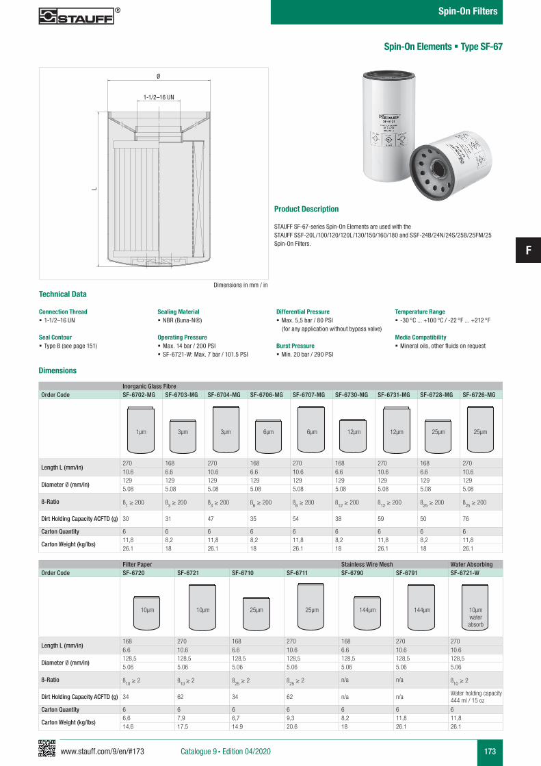
www.stauff.com/9/en/#173
F
173
Spin-On Elements § Type SF-67
Product Description
STAUFF SF-67-series Spin-On Elements are used with the STAUFF SSF-20L/100/120/120L/130/150/160/180 and SSF-24B/24N/24S/25B/25FM/25 Spin-On Filters.
Filter Paper Stainless Wire Mesh Water AbsorbingOrder Code SF-6720 SF-6721 SF-6710 SF-6711 SF-6790 SF-6791 SF-6721-W
Length L (mm/in)168 270 168 270 168 270 2706.6 10.6 6.6 10.6 6.6 10.6 10.6
Diameter Ø (mm/in)128,5 128,5 128,5 128,5 128,5 128,5 128,55.06 5.06 5.06 5.06 5.06 5.06 5.06
ß-Ratio ß10 ≥ 2 ß10
≥ 2 ß25
≥ 2 ß25
≥ 2 n/a n/a ß10
≥ 2
Dirt Holding Capacity ACFTD (g) 34 62 34 62 n/a n/a Water holding capacity444 ml / 15 oz
Carton Quantity 6 6 6 6 6 6 6
Carton Weight (kg/lbs)6,6 7,9 6,7 9,3 8,2 11,8 11,814.6 17.5 14.9 20.6 18 26.1 26.1
10µm 10µm 25µm 25µm 144µm 144µm 10µm water absorb
L
Ø
1-1/2–16 UN
Inorganic Glass FibreOrder Code SF-6702-MG SF-6703-MG SF-6704-MG SF-6706-MG SF-6707-MG SF-6730-MG SF-6731-MG SF-6728-MG SF-6726-MG
Length L (mm/in)270 168 270 168 270 168 270 168 27010.6 6.6 10.6 6.6 10.6 6.6 10.6 6.6 10.6
Diameter Ø (mm/in)129 129 129 129 129 129 129 129 1295.08 5.08 5.08 5.08 5.08 5.08 5.08 5.08 5.08
ß-Ratio ß1 ≥ 200 ß
3 ≥ 200 ß
3 ≥ 200 ß
6 ≥ 200 ß
6 ≥ 200 ß
12 ≥ 200 ß
12 ≥ 200 ß
25 ≥ 200 ß
25 ≥ 200
Dirt Holding Capacity ACFTD (g) 30 31 47 35 54 38 59 50 76
Carton Quantity 6 6 6 6 6 6 6 6 6
Carton Weight (kg/lbs)11,8 8,2 11,8 8,2 11,8 8,2 11,8 8,2 11,826.1 18 26.1 18 26.1 18 26.1 18 26.1
1µm 3µm 3µm 6µm 6µm 12µm 12µm 25µm 25µm
Dimensions
Technical Data
Connection Thread § 1-1/2–16 UN
Seal Contour § Type B (see page 151)
Sealing Material § NBR (Buna-N®)
Operating Pressure § Max. 14 bar / 200 PSI § SF-6721-W: Max. 7 bar / 101.5 PSI
Differential Pressure § Max. 5,5 bar / 80 PSI(for any application without bypass valve)
Burst Pressure § Min. 20 bar / 290 PSI
Temperature Range § -30 °C ... +100 °C / -22 °F ... +212 °F
Media Compatibility § Mineral oils, other fluids on request
Dimensions in mm / in
Catalogue 9 § Edition 04/2020
Spin-On Filters
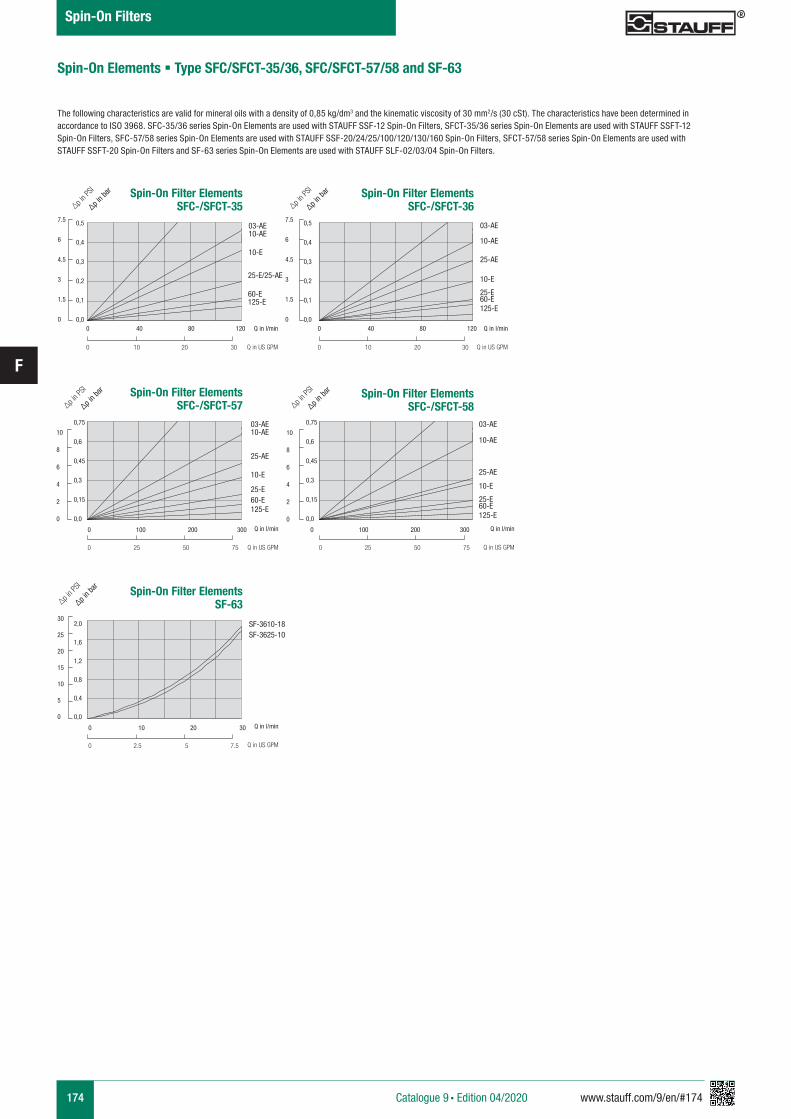
174 www.stauff.com/9/en/#174
F
Spin-On Elements § Type SFC/SFCT-35/36, SFC/SFCT-57/58 and SF-63
The following characteristics are valid for mineral oils with a density of 0,85 kg/dm3 and the kinematic viscosity of 30 mm2/s (30 cSt). The characteristics have been determined in accordance to ISO 3968. SFC-35/36 series Spin-On Elements are used with STAUFF SSF-12 Spin-On Filters, SFCT-35/36 series Spin-On Elements are used with STAUFF SSFT-12 Spin-On Filters, SFC-57/58 series Spin-On Elements are used with STAUFF SSF-20/24/25/100/120/130/160 Spin-On Filters, SFCT-57/58 series Spin-On Elements are used with STAUFF SSFT-20 Spin-On Filters and SF-63 series Spin-On Elements are used with STAUFF SLF-02/03/04 Spin-On Filters.
Spin-On Filter ElementsSF-63
0 10 20 30
0 2.5 5 7.5
30
25
20
15
10
5
0
2,0
1,6
1,2
0,8
0,4
0,0
∆p in b
ar
∆p in P
SI
SF-3610-18SF-3625-10
Spin-On Filter ElementsSFC-/SFCT-57
Spin-On Filter ElementsSFC-/SFCT-58
Spin-On Filter ElementsSFC-/SFCT-35
Spin-On Filter ElementsSFC-/SFCT-36
Q in l/min
Q in US GPM
Catalogue 9 § Edition 04/2020
Spin-On Filters
0 100 200 300
0 25 50 75 0 25 50 75
0,75
0,6
0,45
0,3
0,15
0,0
10
8
6
4
2
0
10
8
6
4
2
0
∆p in b
ar
∆p in P
SI
Q in l/min
Q in US GPM
03-AE10-AE
25-AE
10-E
25-E60-E125-E
∆p in b
ar
∆p in P
SI
Q in l/min
Q in US GPM
03-AE
10-AE
25-AE
0,75
0,6
0,45
0,3
0,15
0,0
0 40 80 120
0 10 20 30
0,5
0,4
0,3
0,2
0,1
0,0
0,5
0,4
0,3
0,2
0,1
0,0
7.5
6
4.5
3
1.5
0
7.5
6
4.5
3
1.5
0
∆p in b
ar
∆p in P
SI
Q in l/min
Q in US GPM
03-AE 10-AE
10-E
25-E/25-AE
60-E125-E
0 40 80 120
0 10 20 30
∆p in b
ar
∆p in P
SI
10-AE
25-AE
10-E
25-E60-E125-E
Q in l/min
Q in US GPM
0 100 200 300
10-E
25-E60-E125-E
03-AE
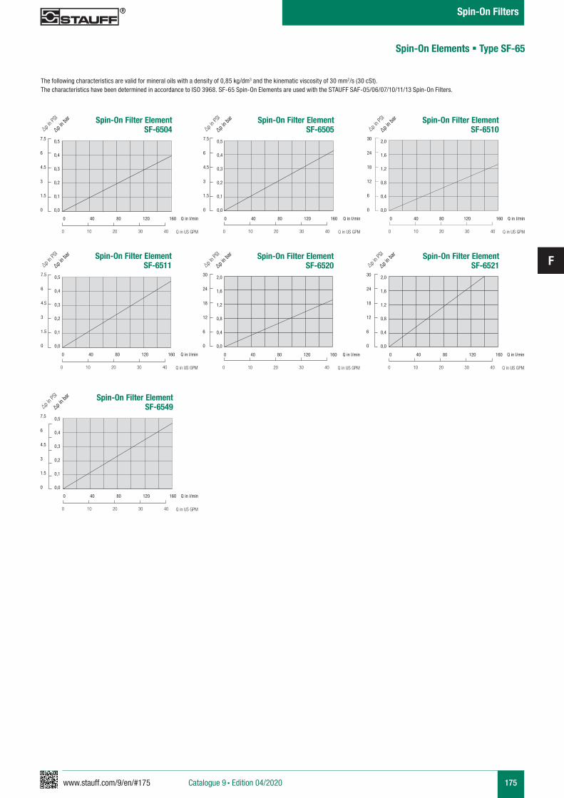
www.stauff.com/9/en/#175
F
175
Spin-On Elements § Type SF-65
The following characteristics are valid for mineral oils with a density of 0,85 kg/dm3 and the kinematic viscosity of 30 mm2/s (30 cSt). The characteristics have been determined in accordance to ISO 3968. SF-65 Spin-On Elements are used with the STAUFF SAF-05/06/07/10/11/13 Spin-On Filters.
Spin-On Filter ElementSF-6511
0,5
0,4
0,3
0,2
0,1
0,0
7.5
6
4.5
3
1.5
0
∆p in b
ar
∆p in P
SI
Q in l/min
Q in US GPM
0 40 80 120 160
0 10 20 30 40
Spin-On Filter ElementSF-6505
0,5
0,4
0,3
0,2
0,1
0,0
7.5
6
4.5
3
1.5
0
∆p in b
ar
∆p in P
SI
Q in l/min
Q in US GPM
0 40 80 120 160
0 10 20 30 40
Spin-On Filter ElementSF-6549
0,5
0,4
0,3
0,2
0,1
0,0
7.5
6
4.5
3
1.5
0
∆p in b
ar
∆p in P
SI
Q in l/min
Q in US GPM
0 40 80 120 160
0 10 20 30 40
Spin-On Filter ElementSF-6504
0,5
0,4
0,3
0,2
0,1
0,0
7.5
6
4.5
3
1.5
0
∆p in b
ar
∆p in P
SI
Q in l/min
Q in US GPM
0 40 80 120 160
0 10 20 30 40
Spin-On Filter ElementSF-6520
2,0
1,6
1,2
0,8
0,4
0,0
30
24
18
12
6
0
∆p in b
ar
∆p in P
SI
Q in l/min
Q in US GPM
0 40 80 120 160
0 10 20 30 40
Spin-On Filter ElementSF-6521
2,0
1,6
1,2
0,8
0,4
0,0
30
24
18
12
6
0
∆p in b
ar
∆p in P
SI
Q in l/min
Q in US GPM
0 40 80 120 160
0 10 20 30 40
Spin-On Filter ElementSF-6510
2,0
1,6
1,2
0,8
0,4
0,0
30
24
18
12
6
0
∆p in b
ar
∆p in P
SI
Q in l/min
Q in US GPM
0 40 80 120 160
0 10 20 30 40
Catalogue 9 § Edition 04/2020
Spin-On Filters
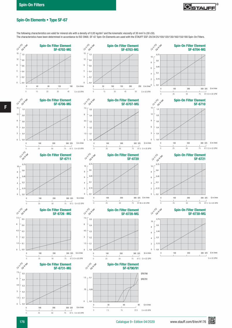
176 www.stauff.com/9/en/#176
F
Spin-On Elements § Type SF-67
The following characteristics are valid for mineral oils with a density of 0,85 kg/dm3 and the kinematic viscosity of 30 mm2/s (30 cSt). The characteristics have been determined in accordance to ISO 3968. SF-67 Spin-On Elements are used with the STAUFF SSF-20/24/25/100/120/130/160/150/180 Spin-On Filters.
Spin-On Filter ElementSF-6711
0,75
0,6
0,45
0,3
0,15
0,0
10
8
6
4
2
0
Q in l/min
Q in US GPM
0 100 200 300 325
0 25 50 75 87.5
Spin-On Filter ElementSF-6710
1,0
0,8
0,6
0,4
0,4
0,0
15
12
9
6
3
0
Q in l/min
Q in US GPM
0 100 200 300 325
0 25 50 75 87.5
Spin-On Filter ElementSF-6721
0,75
0,6
0,45
0,3
0,15
0,0
10
8
6
4
2
0
Q in l/min
Q in US GPM
0 100 200 300 325
0 25 50 75 87.5
Spin-On Filter ElementSF-6720
0,75
0,6
0,45
0,3
0,15
0,0
10
8
6
4
2
0
∆p in P
SI
Q in l/min
Q in US GPM
0 100 200 300 325
0 25 50 75 87.5
0,5
0,4
0,3
0,2
0,1
0,0
7.5
6
4.5
3
1.5
0
0 100 200 300 325
0 25 50 75 87.5
Spin-On Filter Element SF-6731-MG∆p i
n bar
∆p in P
SI
Q in l/min
Q in US GPM
1,0
0,8
0,6
0,4
0,4
0,0
15
12
9
6
3
0
0 100 200 300 325
0 25 50 75 87.5
Spin-On Filter Element SF-6706-MG∆p i
n bar
∆p in P
SI
Q in l/min
Q in US GPM
Spin-On Filter Element SF-6702-MG
1,0
0,8
0,6
0,4
0,2
0,0
15
12
9
5
3
0
∆p in b
ar
∆p in P
SI
Q in l/min
Q in US GPM
0 40 80 120 160
0 10 20 30 40
Spin-On Filter Element SF-6703-MG
1,0
0,8
0,6
0,4
0,2
0,0
15
12
9
5
3
0
∆p in b
ar
∆p in P
SI
Q in l/min
Q in US GPM
0 50 100 150 200 250
0 15 30 45 50
0,5
0,4
0,3
0,2
0,1
0,0
7.5
6
4.5
3
1.5
0
0 100 200 300 325
0 25 50 75 87.5
Spin-On Filter Element SF-6728-MG∆p i
n bar
∆p in P
SI
Q in l/min
Q in US GPM
0,5
0,4
0,3
0,2
0,1
0,0
7.5
6
4.5
3
1.5
0
0 100 200 300 325
0 25 50 75 87.5
Spin-On Filter Element SF-6707-MG∆p i
n bar
∆p in P
SI
Q in l/min
Q in US GPM
0,5
0,4
0,3
0,2
0,1
0,0
7.5
6
4.5
3
1.5
0
0 100 200 300 325
0 25 50 75 87.5
Spin-On Filter ElementSF-6726 -MG∆p i
n bar
∆p in P
SI
Q in l/min
Q in US GPM
0,75
0,6
0,45
0,3
0,15
0,0
0 100 200 300 325
Spin-On Filter ElementSF-6730-MG
10
8
6
4
2
0
∆p in b
ar
∆p in P
SI
Q in l/min
Q in US GPM
10
8
6
4
2
0
0,75
0,6
0,45
0,3
0,15
0,0
0 100 200 300 325
0 25 50 75 87.5
Spin-On Filter ElementSF-6704-MG∆p i
n bar
∆p in P
SI
Q in l/min
Q in US GPM
Spin-On Filter Element SF-6790/91
0,1
0,05
0,0
1.5
.75
0
∆p in b
ar
∆p in P
SI
Q in l/min
Q in US GPM
0 30 60 90
0 7.5 15 22.5
SF6790
SF6791
∆p in b
ar∆p i
n PSI
∆p in b
ar
∆p in P
SI
∆p in b
ar
∆p in b
ar
∆p in P
SI
Catalogue 9 § Edition 04/2020
Spin-On Filters
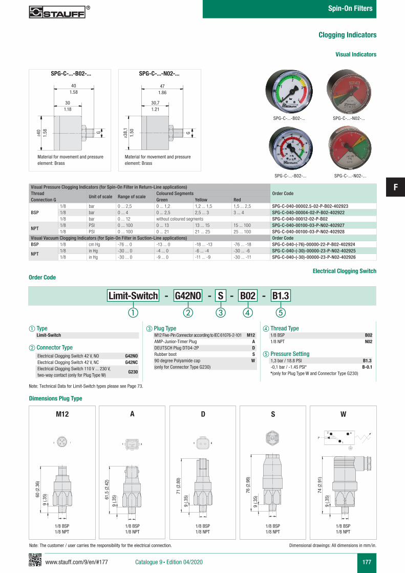
www.stauff.com/9/en/#177
F
177
Clogging Indicators
Catalogue 9 § Edition 04/2020
Spin-On Filters
Visual Pressure Clogging Indicators (for Spin-On Filter in Return-Line applications)Order CodeThread
Connection GUnit of scale Range of scale
Coloured SegmentsGreen Yellow Red
BSP1/8 bar 0 ... 2,5 0 ... 1,2 1,2 ... 1,5 1,5 ... 2,5 SPG-C-040-00002.5-02-P-B02-4029231/8 bar 0 ... 4 0 ... 2,5 2,5 ... 3 3 ... 4 SPG-C-040-00004-02-P-B02-4029221/8 bar 0 ... 12 without coloured segments SPG-C-040-00012-02-P-B02
NPT1/8 PSI 0 ... 100 0 ... 13 13 ... 15 15 ... 100 SPG-C-040-00100-03-P-N02-4029271/8 PSI 0 ... 100 0 ... 21 21 ... 25 25 ... 100 SPG-C-040-00100-03-P-N02-402928
Visual Vacuum Clogging Indicators (for Spin-On Filter in Suction-Line applications) Order CodeBSP 1/8 cm Hg -76 ... 0 -13 ... 0 -18 ... -13 -76 ... -18 SPG-C-040-(-76)-00000-22-P-B02-402924
NPT1/8 in Hg -30 ... 0 -4 ... 0 -6 ... -4 -30 ... -6 SPG-C-040-(-30)-00000-23-P-N02-4029251/8 in Hg -30 ... 0 -9 ... 0 -11 ... -9 -30 ... -11 SPG-C-040-(-30)-00000-23-P-N02-402926
Visual Indicators
SPG-C-...-B02-... SPG-C-...-N02-...
SPG-C-...-N02-...
471.86
30,71.21
G
Ø38
,11.
50
Material for movement and pressure element: Brass
SPG-C-...-B02-...
401.58
301.18
G
Ø40 1.58
Material for movement and pressure element: Brass
Order Code
Limit-Switch - G42NO - S - B02 - B1.3
a Type Limit-Switch
b Connector Type
c Plug Type M12 Five-Pin Connector according to IEC 61076-2-101 M12 AMP-Junior-Timer Plug A DEUTSCH Plug DT04-2P D Rubber boot S 90 degree Polyamide cap W (only for Connector Type G230)
d Thread Type 1/8 BSP B02 1/8 NPT N02
e Pressure Setting 1,3 bar / 18.8 PSI B1.3 -0,1 bar / -1.45 PSI* B-0.1 *(only for Plug Type W and Connector Type G230)
Electrical Clogging Switch 42 V, NO G42NOElectrical Clogging Switch 42 V, NC G42NCElectrical Clogging Switch 110 V ... 230 V, two-way contact (only for Plug Type W)
G230
Dimensional drawings: All dimensions in mm/in.
a b c ed
Electrical Clogging Switch
SPG-C-...-B02-... SPG-C-...-N02-...
Dimensions Plug Type
WM12 S
3 11 21 2
A
61,5
(2.4
2)
9 (.3
5)
D
21 21
71 (2
.80)
9 (.3
5)60 (2
.36)
9 (.3
5)
9 (.3
5)
76 (2
.98)
9 (.3
5)
74 (2
.91)
P4
1
2
Note: The customer / user carries the responsibility for the electrical connection.
1/8 BSP1/8 NPT
1/8 BSP1/8 NPT
1/8 BSP1/8 NPT
1/8 BSP1/8 NPT
1/8 BSP1/8 NPT
Note: Technical Data for Limit-Switch types please see Page 73.
www.stauff.com/9/en/#179
G
179Catalogue 9 § Edition 04/2020
Offline and Bypass Filters
Overview Offline and Bypass Filters
183 - 188
180
Offline Filters OLS
Offline and Bypass Filters Replacement Elements 182
184 - 187
188
188
Technical Data / Dimensions
Order Code - Offline Filter
Order Code - Filter Elements
189 - 194Water Absorbing Offline Filters OLSW
190 - 193
194
194
Technical Data / Dimensions
Order Code - Water Absorbing Offline Filter
Order Code - Filter Elements
183Overview
189Overview
194Order Code - Pre-Filter Elements
195 - 198Heated Offline Filters OLSH
196 - 197
198
198
Technical Data / Dimensions
Order Code - Offline Filter
Order Code - Filter Elements
195Overview
199 - 202Bypass Filters BPS
200 - 201
201
201
Technical Data / Dimensions
Order Code - Bypass Filter
Order Code - Filter Elements
199Overview
202Hydraulic Symbols / Flow Characteristics for OLS / BPS
204 - 205Mini Water Vac SMWV
204 -205
205
Technical Data / Dimensions
Order Code - Offline Filter
204Overview
STAUFF System 181
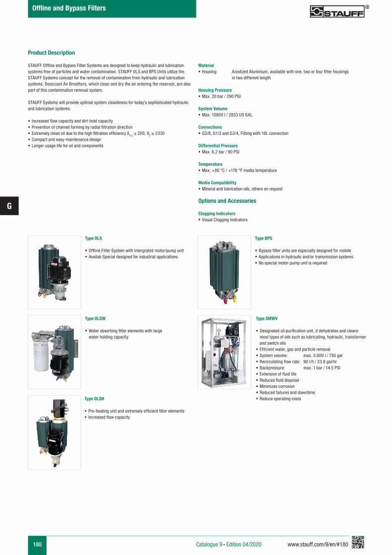
180 www.stauff.com/9/en/#180
G
Catalogue 9 § Edition 04/2020
Offline and Bypass Filters
Product Description
STAUFF Offline and Bypass Filter Systems are designed to keep hydraulic and lubrication systems free of particles and water contamination. STAUFF OLS and BPS Units utilize the STAUFF Systems concept for the removal of contamination from hydraulic and lubrication systems. Desiccant Air Breathers, which clean and dry the air entering the reservoir, are also part of this contamination removal system. STAUFF Systems will provide optimal system cleanliness for today’s sophisticated hydraulic and lubrication systems.
§ Increased flow capacity and dirt-hold capacity § Prevention of channel forming by radial filtration direction § Extremely clean oil due to the high filtration efficiency ß0,5 ≥ 200, ß2 ≥ 2330 § Compact and easy-maintenance design § Longer usage life for oil and components
Material § Housing: Anodized Aluminium, available with one, two or four filter housings in two different length
Housing Pressure § Max. 20 bar / 290 PSI
System Volume § Max. 10800 l / 2853 US GAL
Connections § G3/8, G1/2 and G3/4, Fitting with 18L connection
Differential Pressure § Max. 6,2 bar / 90 PSI
Temperature § Max. +80 °C / +176 °F media temperature
Media Compatibility § Mineral and lubrication oils, others on request
Options and Accessories
Clogging Indicators § Visual Clogging Indicators
Type OLS
§ Offline Filter System with intergrated motor/pump unit § Availab Special designed for industrial applications
Type OLSW
§ Water absorbing filter elements with large water holding capacity
Type OLSH
§ Pre-heating unit and extremely efficient filter elements § Increased flow capacity
Type SMWV
§ Designated oil purification unit, it dehydrates and cleans most types of oils such as lubricating, hydraulic, transformer and switch oils
§ Efficient water, gas and particle removal § System volume: max. 3.000 l / 795 gal § Recirculating flow rate: 90 l/h / 23.8 gal/hr § Backpressure: max. 1 bar / 14.5 PSI § Extension of fluid life § Reduces fluid disposal § Minimizes corrosion § Reduced failures and downtime § Reduce operating costs
Type BPS
§ Bypass filter units are especially designed for mobile § Applications in hydraulic and/or transmission systems § No special motor-pump unit is required
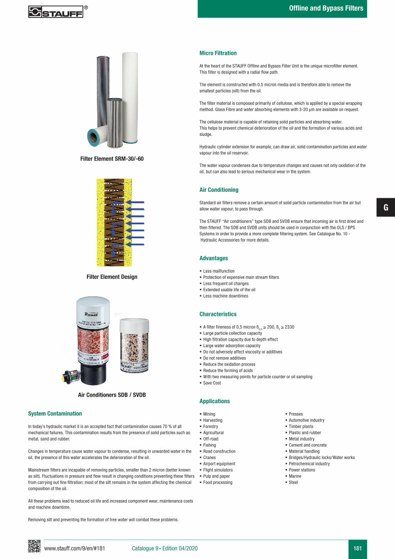
www.stauff.com/9/en/#181
G
181
Micro Filtration
At the heart of the STAUFF Offline and Bypass Filter Unit is the unique microfilter element. This filter is designed with a radial flow path.
The element is constructed with 0,5 micron media and is therefore able to remove the smallest particles (silt) from the oil.
The filter material is composed primarily of cellulose, which is applied by a special wrapping method. Glass Fibre and water absorbing elements with 3-20 µm are available on request.
The cellulose material is capable of retaining solid particles and absorbing water. This helps to prevent chemical deterioration of the oil and the formation of various acids and sludge.
Hydraulic cylinder extension for example, can draw air, solid contamination particles and water vapour into the oil reservoir.
The water vapour condenses due to temperature changes and causes not only oxidation of the oil, but can also lead to serious mechanical wear in the system.
Air Conditioning
Standard air filters remove a certain amount of solid particle contamination from the air but allow water vapour, to pass through.
The STAUFF “Air conditioners” type SDB and SVDB ensure that incoming air is first dried and then filtered. The SDB and SVDB units should be used in conjunction with the OLS / BPS Systems in order to provide a more complete filtering system. See Catalogue No. 10 - Hydraulic Accessories for more details.
Advantages
§ Less mailfunction § Protection of expensive main stream filters § Less frequent oil changes § Extended usable life of the oil § Less machine downtimes
Characteristics
§ A filter fineness of 0,5 micron ß0,5 ≥ 200, ß2 ≥ 2330 § Large particle collection capacity § High filtration capacity due to depth effect § Large water adsorption capacity § Do not adversely affect viscosity or additives § Do not remove additives § Reduce the oxidation process § Reduce the forming of acids § With two measuring points for particle counter or oil sampling § Save Cost
System Contamination
In today’s hydraulic market it is an accepted fact that contamination causes 70 % of all mechanical failures. This contamination results from the presence of solid particles such as metal, sand and rubber.
Changes in temperature cause water vapour to condense, resulting in unwanted water in the oil, the presence of this water accelerates the deterioration of the oil.
Mainstream filters are incapable of removing particles, smaller than 2 micron (better known as silt). Fluctuations in pressure and flow result in changing conditions preventing these filters from carrying out fine filtration; most of the silt remains in the system affecting the chemical composition of the oil.
All these problems lead to reduced oil life and increased component wear, maintenance costs and machine downtime.
Removing silt and preventing the formation of free water will combat these problems.
Filter Element Design
Filter Element SRM-30/-60
Air Conditioners SDB / SVDBApplications
§ Mining § Harvesting § Forestry § Agricultural § Off-road § Fishing § Road construction § Cranes § Airport equipment § Flight simulators § Pulp and paper § Food processing
§ Presses § Automotive industry § Timber plants § Plastic and rubber § Metal industry § Cement and concrete § Material handling § Bridges/Hydraulic locks/Water works § Petrochemical industry § Power stations § Marine § Steel
Catalogue 9 § Edition 04/2020
Offline and Bypass Filters
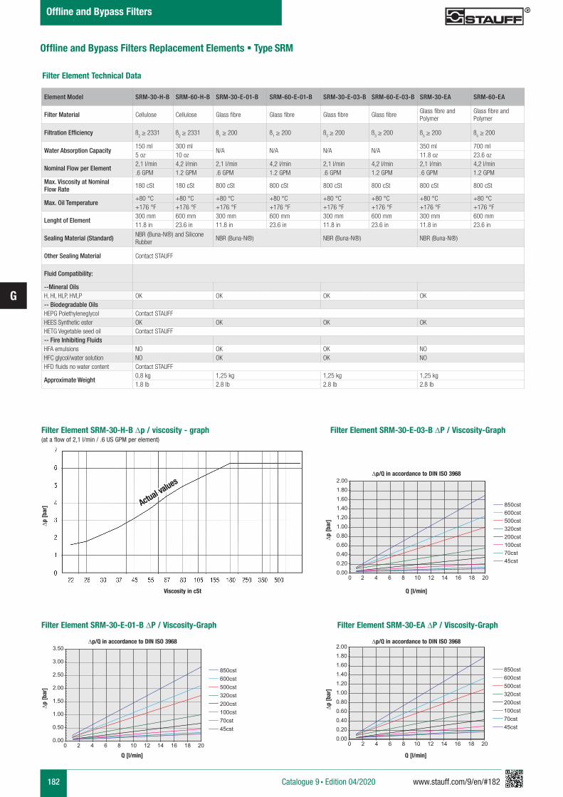
182 www.stauff.com/9/en/#182
G
Filter Element Technical Data
0.000.200.400.600.801.001.201.401.601.802.00
0 2 4 6 8 10 12 14 16 18 20
850cst600cst500cst320cst200cst100cst70cst45cst
0.00
0.50
1.00
1.50
2.00
2.50
3.00
3.50
0 2 4 6 8 10 12 14 16 18 20
850cst600cst500cst320cst200cst100cst70cst45cst
0.000.200.400.600.801.001.201.401.601.802.00
0 2 4 6 8 10 12 14 16 18 20
850cst600cst500cst320cst200cst100cst70cst45cst
∆p [b
ar]
Q [l/min]
∆p/Q in accordance to DIN ISO 3968
0.000.200.400.600.801.001.201.401.601.802.00
0 2 4 6 8 10 12 14 16 18 20
850cst600cst500cst320cst200cst100cst70cst45cst
0.00
0.50
1.00
1.50
2.00
2.50
3.00
3.50
0 2 4 6 8 10 12 14 16 18 20
850cst600cst500cst320cst200cst100cst70cst45cst
0.000.200.400.600.801.001.201.401.601.802.00
0 2 4 6 8 10 12 14 16 18 20
850cst600cst500cst320cst200cst100cst70cst45cst
∆p [b
ar]
Q [l/min]
∆p/Q in accordance to DIN ISO 3968
Filter Element SRM-30-E-01-B ∆P / Viscosity-Graph Filter Element SRM-30-EA ∆P / Viscosity-Graph
0.000.200.400.600.801.001.201.401.601.802.00
0 2 4 6 8 10 12 14 16 18 20
850cst600cst500cst320cst200cst100cst70cst45cst
0.00
0.50
1.00
1.50
2.00
2.50
3.00
3.50
0 2 4 6 8 10 12 14 16 18 20
850cst600cst500cst320cst200cst100cst70cst45cst
0.000.200.400.600.801.001.201.401.601.802.00
0 2 4 6 8 10 12 14 16 18 20
850cst600cst500cst320cst200cst100cst70cst45cst
∆p [b
ar]
Q [l/min]
∆p/Q in accordance to DIN ISO 3968
Element Model SRM-30-H-B SRM-60-H-B SRM-30-E-01-B SRM-60-E-01-B SRM-30-E-03-B SRM-60-E-03-B SRM-30-EA SRM-60-EA
Filter Material Cellulose Cellulose Glass fibre Glass fibre Glass fibre Glass fibreGlass fibre and Polymer
Glass fibre and Polymer
Filtration Efficiency ß2 ≥ 2331 ß
2 ≥ 2331 ß
1 ≥ 200 ß
1 ≥ 200 ß
3 ≥ 200 ß
3 ≥ 200 ß
5 ≥ 200 ß
5 ≥ 200
Water Absorption Capacity150 ml 300 ml
N/A N/A N/A N/A350 ml 700 ml
5 oz 10 oz 11.8 oz 23.6 oz
Nominal Flow per Element2,1 l/min 4,2 l/min 2,1 l/min 4,2 l/min 2,1 l/min 4,2 l/min 2,1 l/min 4,2 l/min.6 GPM 1.2 GPM .6 GPM 1.2 GPM .6 GPM 1.2 GPM .6 GPM 1.2 GPM
Max. Viscosity at Nominal Flow Rate 180 cSt 180 cSt 800 cSt 800 cSt 800 cSt 800 cSt 800 cSt 800 cSt
Max. Oil Temperature+80 °C +80 °C +80 °C +80 °C +80 °C +80 °C +80 °C +80 °C+176 °F +176 °F +176 °F +176 °F +176 °F +176 °F +176 °F +176 °F
Lenght of Element300 mm 600 mm 300 mm 600 mm 300 mm 600 mm 300 mm 600 mm11.8 in 23.6 in 11.8 in 23.6 in 11.8 in 23.6 in 11.8 in 23.6 in
Sealing Material (Standard) NBR (Buna-N®) and Silicone Rubber
NBR (Buna-N®) NBR (Buna-N®) NBR (Buna-N®)
Other Sealing Material Contact STAUFF
Fluid Compatibility:
--Mineral OilsH, HI, HLP, HVLP OK OK OK OK-- Biodegradable OilsHEPG Polethyleneglycol Contact STAUFFHEES Synthetic ester OK OK OK OKHETG Vegetable seed oil Contact STAUFF-- Fire Inhibiting FluidsHFA emulsions NO OK OK NOHFC glycol/water solution NO OK OK NOHFD fluids no water content Contact STAUFF
Approximate Weight0,8 kg 1,25 kg 1,25 kg 1,25 kg1.8 lb 2.8 lb 2.8 lb 2.8 lb
Offline and Bypass Filters Replacement Elements § Type SRM
Filter Element SRM-30-H-B ∆p / viscosity - graph (at a flow of 2,1 l/min / .6 US GPM per element)
Actual values
Actual values
Viscosity in cSt
Actual values
∆p [b
ar]
Filter Element SRM-30-E-03-B ∆P / Viscosity-Graph
Catalogue 9 § Edition 04/2020
Offline and Bypass Filters
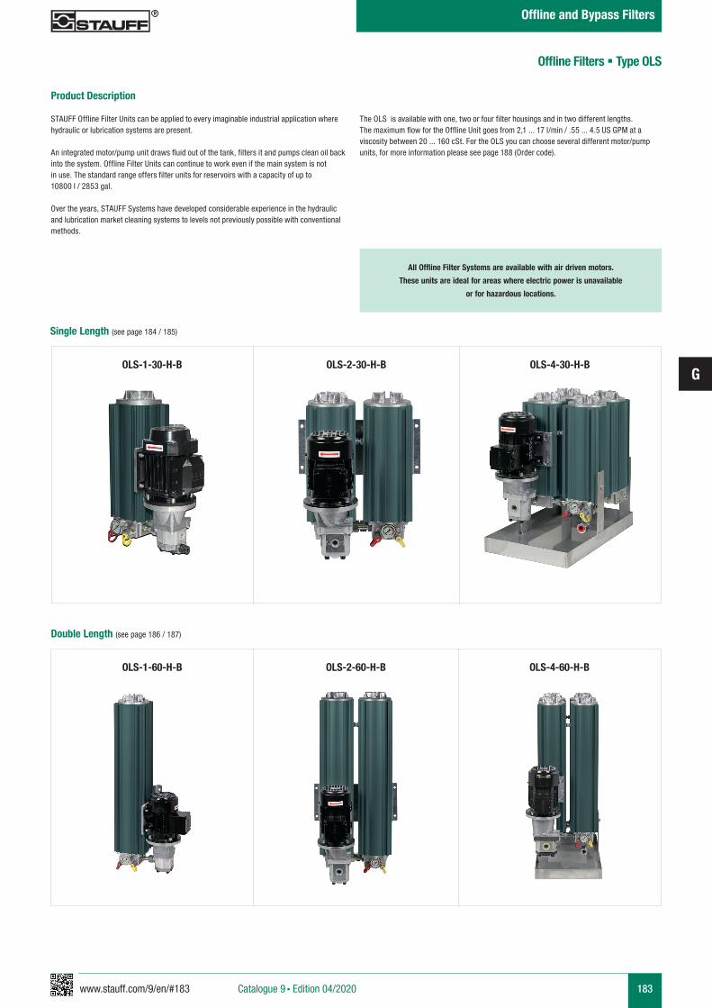
www.stauff.com/9/en/#183
G
183
OLS-1-60-H-B OLS-2-60-H-B OLS-4-60-H-B
Product Description
STAUFF Offline Filter Units can be applied to every imaginable industrial application where hydraulic or lubrication systems are present.
An integrated motor/pump unit draws fluid out of the tank, filters it and pumps clean oil back into the system. Offline Filter Units can continue to work even if the main system is not in use. The standard range offers filter units for reservoirs with a capacity of up to 10800 l / 2853 gal.
Over the years, STAUFF Systems have developed considerable experience in the hydraulic and lubrication market cleaning systems to levels not previously possible with conventional methods.
The OLS is available with one, two or four filter housings and in two different lengths. The maximum flow for the Offline Unit goes from 2,1 ... 17 l/min / .55 ... 4.5 US GPM at a viscosity between 20 ... 160 cSt. For the OLS you can choose several different motor/pump units, for more information please see page 188 (Order code).
All Offline Filter Systems are available with air driven motors.
These units are ideal for areas where electric power is unavailable
or for hazardous locations.
OLS-1-30-H-B OLS-2-30-H-B OLS-4-30-H-B
Offline Filters § Type OLS
Single Length (see page 184 / 185)
Double Length (see page 186 / 187)
Catalogue 9 § Edition 04/2020
Offline and Bypass Filters
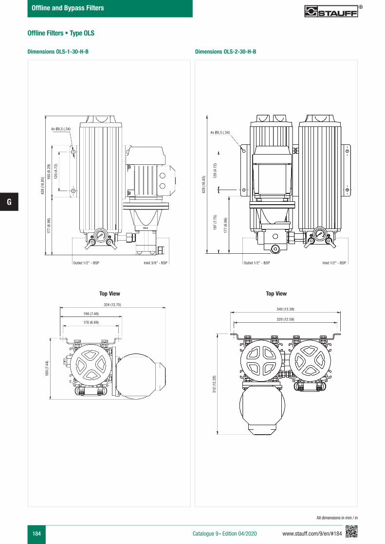
184 www.stauff.com/9/en/#184
G
Offline Filters § Type OLS
All dimensions in mm / in
Dimensions OLS-1-30-H-B Dimensions OLS-2-30-H-B
Catalogue 9 § Edition 04/2020
Offline and Bypass Filters
324 (12.75)
170 (6.69)
190 (7.48)
189
(7.4
4)42
8 (1
6.85
)
177
(6.9
6)16
0 (6
.29)
120
(4.7
2)
4x Ø8,5 (.34)
Outlet 1/2” - BSP Inlet 3/8” - BSP
428
(16.
85)
197
(7.7
5)
340 (13.38)
320 (12.59)
312
(12.
28)
177
(6.9
6)
120
(4.7
2)
4x Ø8,5 (.34)
Outlet 1/2” - BSP Inlet 1/2” - BSP
Top ViewTop View
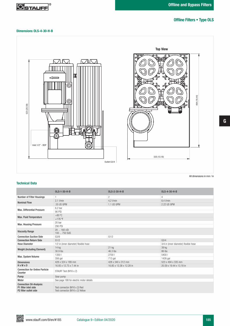
www.stauff.com/9/en/#185
G
185
Offline Filters § Type OLS
Technical Data
Dimensions OLS-4-30-H-B
OLS-1-30-H-B OLS-2-30-H-B OLS-4-30-H-B
Number of Filter Housings 1 2 4
Nominal Flow2,1 l/min 4,2 l/min 8,4 l/min.55 US GPM 1.1 US GPM 2.22 US GPM
Max. Differential Pressure6,2 bar90 PSI
Max. Fluid Temperature+80 ºC+176 ºF
Max. Housing Pressure20 bar290 PSI
Viscosity Range 20 ... 160 cSt 100 ... 750 SUS
Connection Suction Side G3/8 G1/2Connection Return Side G1/2 G3/4Hose Diameter 1/2 in (inner diameter) flexible hose 3/4 in (inner diameter) flexible hose
Weight (Including Element)14 kg 21 kg 39 kg30.9 lbs 46.3 lbs 86 lbs
Max. System Volume1350 l 2700 l 5400 l356 gal 713 gal 1426 gal
DimensionsH x W x D
428 x 324 x 189 mm 428 x 340 x 312 mm 523 x 494 x 335 mm16.85 x 12.75 x 7.44 in 16.85 x 13.38 x 12.28 in 20.59 x 19.44 x 13.18 in
Connection for Online Particle Counter STAUFF Test (M16 x 2)
Pump Gear pumpMotor See page 188 for electric motor details
Connection Oil-Analysis:P1 filter inlet sideP2 filter outlet side
Test connector (M16 x 2) RedTest connector (M16 x 2) Yellow
All dimensions in mm / in
Top View
523
(20.
59)
Catalogue 9 § Edition 04/2020
Offline and Bypass Filters
Inlet 1/2” - BSP
Outlet G3/4
335 (13.18)
494
(19.
44)
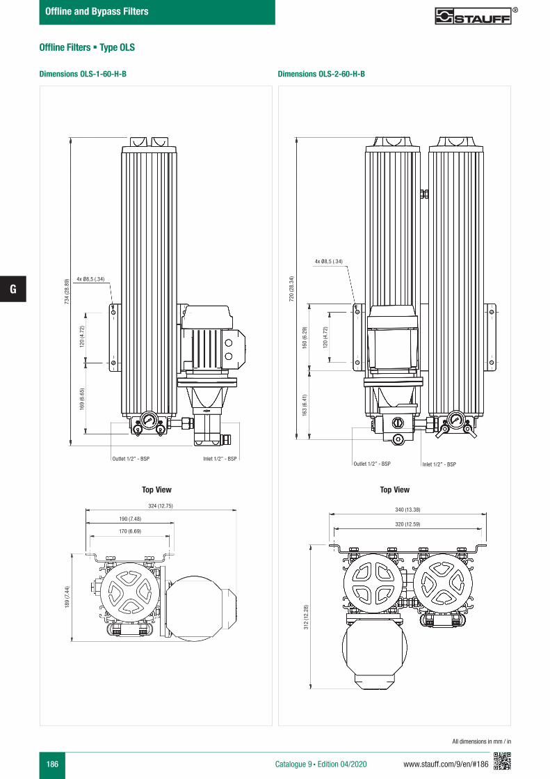
186 www.stauff.com/9/en/#186
G
Offline Filters § Type OLS
All dimensions in mm / in
Dimensions OLS-2-60-H-BDimensions OLS-1-60-H-B
Catalogue 9 § Edition 04/2020
Offline and Bypass Filters
734
(28.
89) 4x Ø8,5 (.34)
Outlet 1/2” - BSP Inlet 1/2” - BSP
169
(6.6
5)12
0 (4
.72)
720
(28.
34)
4x Ø8,5 (.34)
163
(6.4
1)16
0 (6
.29)
120
(4.7
2)
Outlet 1/2” - BSP Inlet 1/2” - BSP
340 (13.38)
320 (12.59)
312
(12.
28)
Top View
324 (12.75)
170 (6.69)
190 (7.48)
189
(7.4
4)
Top View
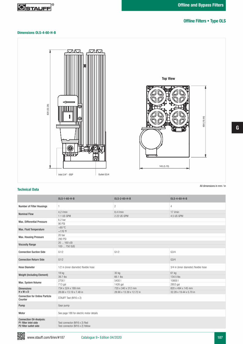
www.stauff.com/9/en/#187
G
187
All dimensions in mm / in
OLS-1-60-H-B OLS-2-60-H-B OLS-4-60-H-B
Number of Filter Housings 1 2 4
Nominal Flow4,2 l/min 8,4 l/min 17 l/min1.1 US GPM 2.22 US GPM 4.5 US GPM
Max. Differential Pressure6,2 bar90 PSI
Max. Fluid Temperature+80 ºC+176 ºF
Max. Housing Pressure20 bar290 PSI
Viscosity Range20 ... 160 cSt100 ... 750 SUS
Connection Suction Side G1/2 G1/2 G3/4
Connection Return Side G1/2 G3/4
Hose Diameter 1/2 in (inner diameter) flexible hose 3/4 in (inner diameter) flexible hose
Weight (Including Element)18 kg 30 kg 61 kg39.7 lbs 66.1 lbs 134.5 lbs
Max. System Volume2700 l 5400 l 10800 l713 gal 1426 gal 2853 gal
DimensionsH x W x D
734 x 324 x 189 mm 720 x 340 x 312 mm 820 x 494 x 145 mm28.66 x 13.19 x 7.48 in 28.90 x 13.39 x 12.72 in 32.28 x 19.44 x 5.70 in
Connection for Online Particle Counter STAUFF Test (M16 x 2)
Pump Gear pump
Motor See page 188 for electric motor details
Connection Oil-Analysis:P1 filter inlet sideP2 filter outlet side
Test connector (M16 x 2) RedTest connector (M16 x 2) Yellow
Technical Data
Dimensions OLS-4-60-H-B
Offline Filters § Type OLS
Top View
Catalogue 9 § Edition 04/2020
Offline and Bypass Filters
820
(32.
28)
Outlet G3/4Inlet 3/4” - BSP
145 (5.70)
494
(19.
44)
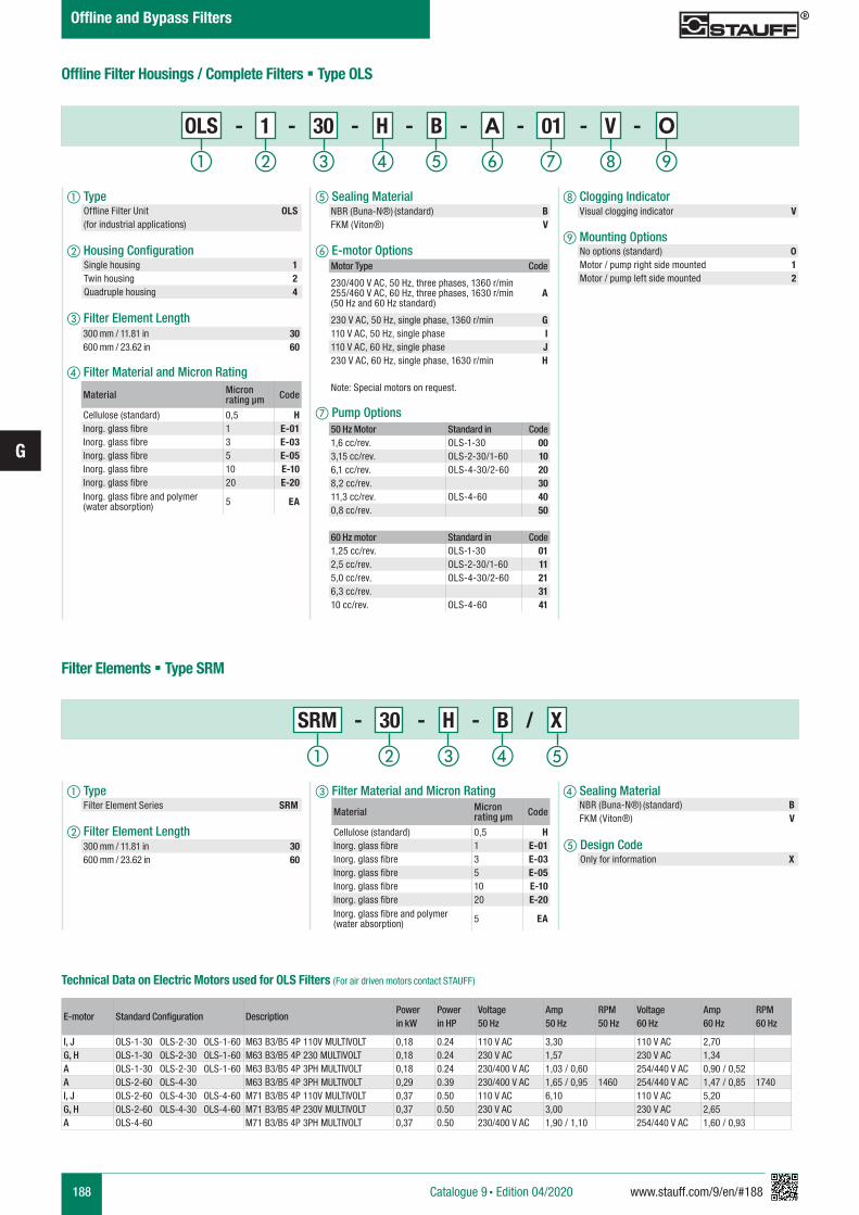
188 www.stauff.com/9/en/#188
G
a Type Filter Element Series SRM
b Filter Element Length
c Filter Material and Micron Rating d Sealing Material
h Clogging Indicator
i Mounting Options
e Sealing Material
f E-motor Options
g Pump Options
a Type Offline Filter Unit OLS (for industrial applications)
b Housing Configuration
c Filter Element Length
d Filter Material and Micron Rating
Filter Elements § Type SRM
Single housing 1Twin housing 2Quadruple housing 4
Material Micron rating µm Code
Cellulose (standard) 0,5 HInorg. glass fibre 1 E-01Inorg. glass fibre 3 E-03Inorg. glass fibre 5 E-05Inorg. glass fibre 10 E-10Inorg. glass fibre 20 E-20Inorg. glass fibre and polymer (water absorption) 5 EA
NBR (Buna-N®) (standard) BFKM (Viton®) V
Motor Type Code
230/400 V AC, 50 Hz, three phases, 1360 r/min 255/460 V AC, 60 Hz, three phases, 1630 r/min(50 Hz and 60 Hz standard)
A
230 V AC, 50 Hz, single phase, 1360 r/min G110 V AC, 50 Hz, single phase I110 V AC, 60 Hz, single phase J230 V AC, 60 Hz, single phase, 1630 r/min H
Note: Special motors on request.
50 Hz Motor Standard in Code1,6 cc/rev. OLS-1-30 003,15 cc/rev. OLS-2-30/1-60 106,1 cc/rev. OLS-4-30/2-60 208,2 cc/rev. 3011,3 cc/rev. OLS-4-60 400,8 cc/rev. 50
60 Hz motor Standard in Code1,25 cc/rev. OLS-1-30 012,5 cc/rev. OLS-2-30/1-60 115,0 cc/rev. OLS-4-30/2-60 216,3 cc/rev. 3110 cc/rev. OLS-4-60 41
Visual clogging indicator V
No options (standard) 0Motor / pump right side mounted 1Motor / pump left side mounted 2
Technical Data on Electric Motors used for OLS Filters (For air driven motors contact STAUFF)
E-motor Standard Configuration DescriptionPower in kW
Power in HP
Voltage 50 Hz
Amp 50 Hz
RPM 50 Hz
Voltage 60 Hz
Amp 60 Hz
RPM 60 Hz
I, J OLS-1-30 OLS-2-30 OLS-1-60 M63 B3/B5 4P 110V MULTIVOLT 0,18 0.24 110 V AC 3,30 110 V AC 2,70G, H OLS-1-30 OLS-2-30 OLS-1-60 M63 B3/B5 4P 230 MULTIVOLT 0,18 0.24 230 V AC 1,57 230 V AC 1,34A OLS-1-30 OLS-2-30 OLS-1-60 M63 B3/B5 4P 3PH MULTIVOLT 0,18 0.24 230/400 V AC 1,03 / 0,60 254/440 V AC 0,90 / 0,52A OLS-2-60 OLS-4-30 M63 B3/B5 4P 3PH MULTIVOLT 0,29 0.39 230/400 V AC 1,65 / 0,95 1460 254/440 V AC 1,47 / 0,85 1740I, J OLS-2-60 OLS-4-30 OLS-4-60 M71 B3/B5 4P 110V MULTIVOLT 0,37 0.50 110 V AC 6,10 110 V AC 5,20G, H OLS-2-60 OLS-4-30 OLS-4-60 M71 B3/B5 4P 230V MULTIVOLT 0,37 0.50 230 V AC 3,00 230 V AC 2,65A OLS-4-60 M71 B3/B5 4P 3PH MULTIVOLT 0,37 0.50 230/400 V AC 1,90 / 1,10 254/440 V AC 1,60 / 0,93
NBR (Buna-N®) (standard) BFKM (Viton®) V
Offline Filter Housings / Complete Filters § Type OLS
Material Micron rating µm Code
Cellulose (standard) 0,5 HInorg. glass fibre 1 E-01Inorg. glass fibre 3 E-03Inorg. glass fibre 5 E-05Inorg. glass fibre 10 E-10Inorg. glass fibre 20 E-20Inorg. glass fibre and polymer (water absorption) 5 EA
ihga b c fed
OLS - 1 - 30 - H - B - A - 01 - V - O
a b c d
300 mm / 11.81 in 30600 mm / 23.62 in 60
300 mm / 11.81 in 30600 mm / 23.62 in 60
Catalogue 9 § Edition 04/2020
Offline and Bypass Filters
e
SRM - 30 - H - B / X
e Design Code Only for information X
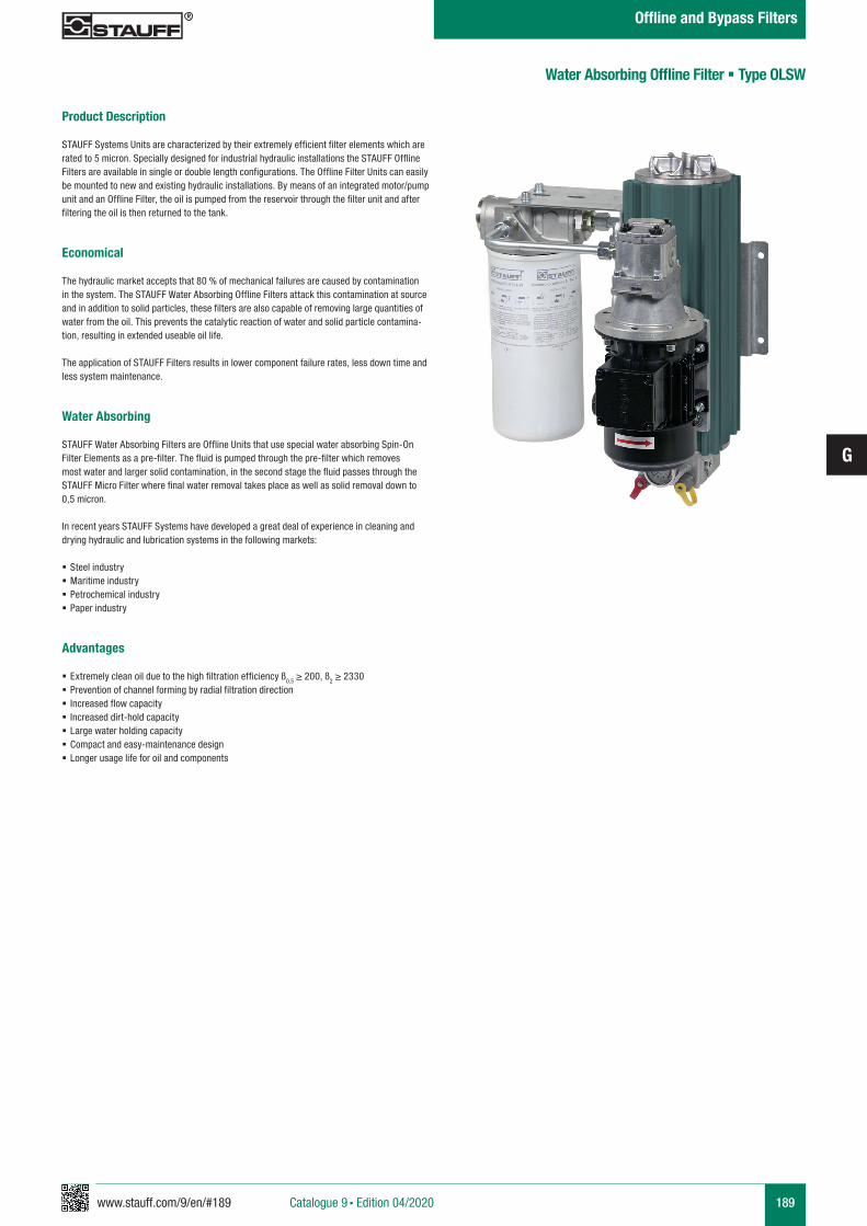
www.stauff.com/9/en/#189
G
189
Product Description
STAUFF Systems Units are characterized by their extremely efficient filter elements which are rated to 5 micron. Specially designed for industrial hydraulic installations the STAUFF Offline Filters are available in single or double length configurations. The Offline Filter Units can easily be mounted to new and existing hydraulic installations. By means of an integrated motor/pump unit and an Offline Filter, the oil is pumped from the reservoir through the filter unit and after filtering the oil is then returned to the tank.
Economical
The hydraulic market accepts that 80 % of mechanical failures are caused by contamination in the system. The STAUFF Water Absorbing Offline Filters attack this contamination at source and in addition to solid particles, these filters are also capable of removing large quantities of water from the oil. This prevents the catalytic reaction of water and solid particle contamina-tion, resulting in extended useable oil life.
The application of STAUFF Filters results in lower component failure rates, less down time and less system maintenance.
Water Absorbing
STAUFF Water Absorbing Filters are Offline Units that use special water absorbing Spin-On Filter Elements as a pre-filter. The fluid is pumped through the pre-filter which removes most water and larger solid contamination, in the second stage the fluid passes through the STAUFF Micro Filter where final water removal takes place as well as solid removal down to 0,5 micron.
In recent years STAUFF Systems have developed a great deal of experience in cleaning and drying hydraulic and lubrication systems in the following markets:
§ Steel industry § Maritime industry § Petrochemical industry § Paper industry
Advantages
§ Extremely clean oil due to the high filtration efficiency ß0,5 ≥ 200, ß2 ≥ 2330 § Prevention of channel forming by radial filtration direction § Increased flow capacity § Increased dirt-hold capacity § Large water holding capacity § Compact and easy-maintenance design § Longer usage life for oil and components
Water Absorbing Offline Filter § Type OLSW
Catalogue 9 § Edition 04/2020
Offline and Bypass Filters
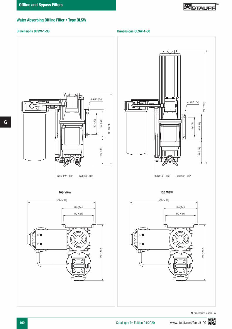
190 www.stauff.com/9/en/#190
G
Water Absorbing Offline Filter § Type OLSW
All dimensions in mm / in
Dimensions OLSW-1-60Dimensions OLSW-1-30
Catalogue 9 § Edition 04/2020
Offline and Bypass Filters
4x Ø8,5 (.34)
120
(4.7
2)
160
(6.2
9)14
9 (5
.86)
401
(15.
78)
Outlet 1/2” - BSP Inlet 3/8” - BSP
379 (14.92)
190 (7.48)
170 (6.69)
313
(12.
32)
4x Ø8,5 (.34)
706
(27.
79)
160
(6.2
9)
120
(4.7
2)
149
(5.8
6)
Top ViewTop View
Outlet 1/2” - BSP Inlet 1/2” - BSP
379 (14.92)
190 (7.48)
170 (6.69)
313
(12.
32)
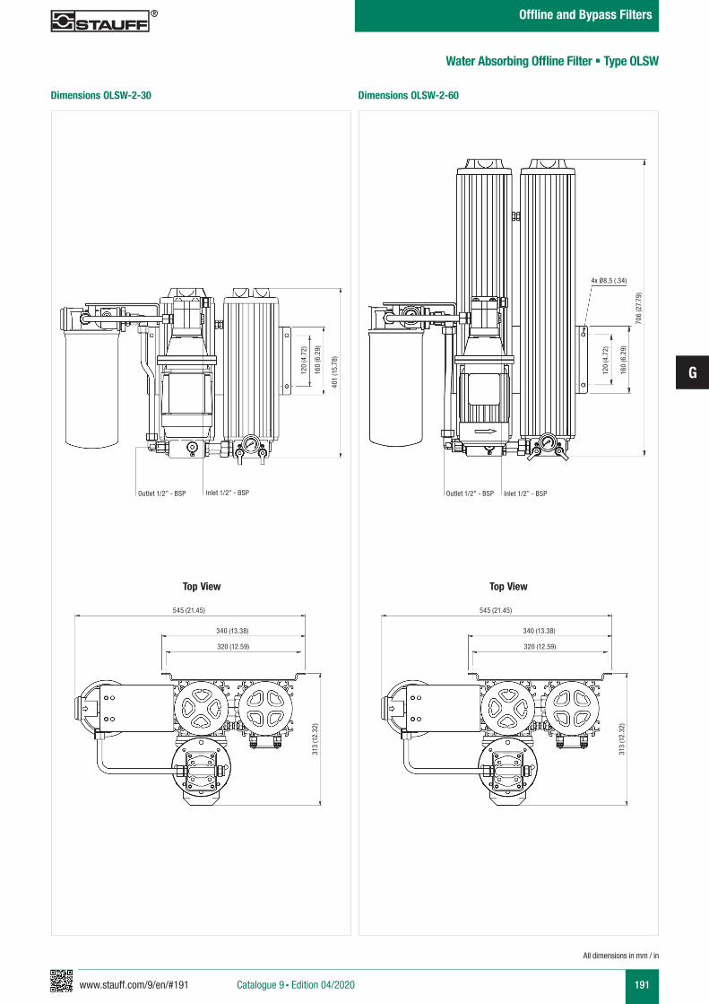
www.stauff.com/9/en/#191
G
191
Water Absorbing Offline Filter § Type OLSW
Dimensions OLSW-2-60Dimensions OLSW-2-30
All dimensions in mm / in
Catalogue 9 § Edition 04/2020
Offline and Bypass Filters
120
(4.7
2)
160
(6.2
9)
401
(15.
78)
Outlet 1/2” - BSP Inlet 1/2” - BSP
Top View
545 (21.45)
340 (13.38)
320 (12.59)
313
(12.
32)
Top View
545 (21.45)
340 (13.38)
320 (12.59)
313
(12.
32)
706
(27.
79)
4x Ø8,5 (.34)
120
(4.7
2)
160
(6.2
9)
Outlet 1/2” - BSP Inlet 1/2” - BSP
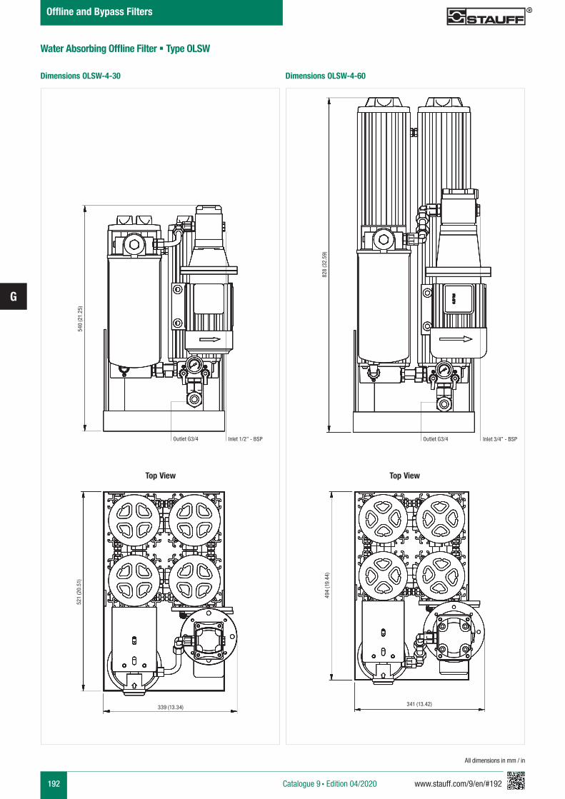
192 www.stauff.com/9/en/#192
G
Water Absorbing Offline Filter § Type OLSW
Dimensions OLSW-4-60Dimensions OLSW-4-30
All dimensions in mm / in
Catalogue 9 § Edition 04/2020
Offline and Bypass Filters
Top View
540
(21.
25)
Outlet G3/4 Inlet 1/2” - BSP
521
(20.
51)
339 (13.34)
828
(32.
59)
Outlet G3/4 Inlet 3/4” - BSP
Top View
494
(19.
44)
341 (13.42)
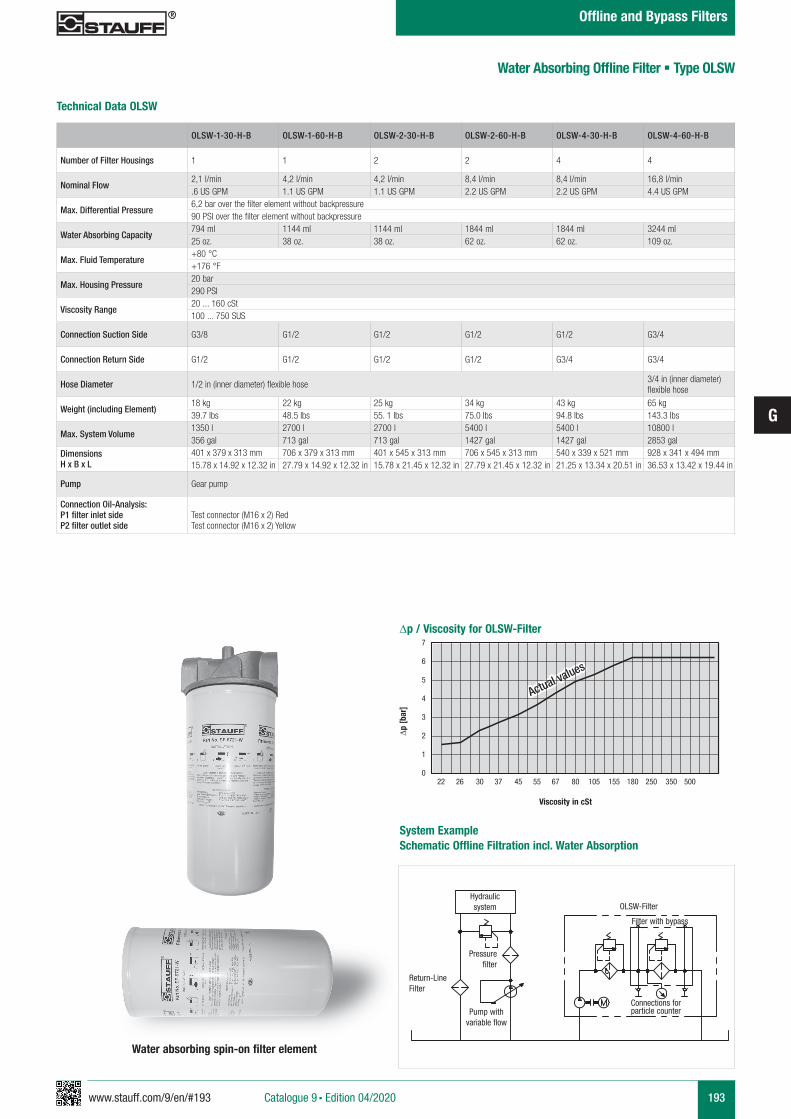
www.stauff.com/9/en/#193
G
193
Actual values
Actual values
Technical Data OLSW
Water absorbing spin-on filter element
Hydraulicsystem
Pressure filter
Return-LineFilter
Pump with variable flow
Filter with bypass
OLSW-Filter
Connections for particle counter
System Example Schematic Offline Filtration incl. Water Absorption
∆p [b
ar]
Viscosity in cSt
7
6
5
4
3
2
1
022 26 30 37 45 55 67 80 105 155 180 250 350 500
∆p / Viscosity for OLSW-Filter
Water Absorbing Offline Filter § Type OLSW
OLSW-1-30-H-B OLSW-1-60-H-B OLSW-2-30-H-B OLSW-2-60-H-B OLSW-4-30-H-B OLSW-4-60-H-B
Number of Filter Housings 1 1 2 2 4 4
Nominal Flow2,1 l/min 4,2 l/min 4,2 l/min 8,4 l/min 8,4 l/min 16,8 l/min.6 US GPM 1.1 US GPM 1.1 US GPM 2.2 US GPM 2.2 US GPM 4.4 US GPM
Max. Differential Pressure6,2 bar over the filter element without backpressure90 PSI over the filter element without backpressure
Water Absorbing Capacity794 ml 1144 ml 1144 ml 1844 ml 1844 ml 3244 ml25 oz. 38 oz. 38 oz. 62 oz. 62 oz. 109 oz.
Max. Fluid Temperature+80 °C+176 °F
Max. Housing Pressure20 bar290 PSI
Viscosity Range20 ... 160 cSt100 ... 750 SUS
Connection Suction Side G3/8 G1/2 G1/2 G1/2 G1/2 G3/4
Connection Return Side G1/2 G1/2 G1/2 G1/2 G3/4 G3/4
Hose Diameter 1/2 in (inner diameter) flexible hose 3/4 in (inner diameter) flexible hose
Weight (including Element)18 kg 22 kg 25 kg 34 kg 43 kg 65 kg 39.7 Ibs 48.5 Ibs 55. 1 Ibs 75.0 Ibs 94.8 Ibs 143.3 Ibs
Max. System Volume1350 l 2700 l 2700 l 5400 l 5400 l 10800 l356 gal 713 gal 713 gal 1427 gal 1427 gal 2853 gal
DimensionsH x B x L
401 x 379 x 313 mm 706 x 379 x 313 mm 401 x 545 x 313 mm 706 x 545 x 313 mm 540 x 339 x 521 mm 928 x 341 x 494 mm15.78 x 14.92 x 12.32 in 27.79 x 14.92 x 12.32 in 15.78 x 21.45 x 12.32 in 27.79 x 21.45 x 12.32 in 21.25 x 13.34 x 20.51 in 36.53 x 13.42 x 19.44 in
Pump Gear pump
Connection Oil-Analysis:P1 filter inlet sideP2 filter outlet side
Test connector (M16 x 2) RedTest connector (M16 x 2) Yellow
Catalogue 9 § Edition 04/2020
Offline and Bypass Filters
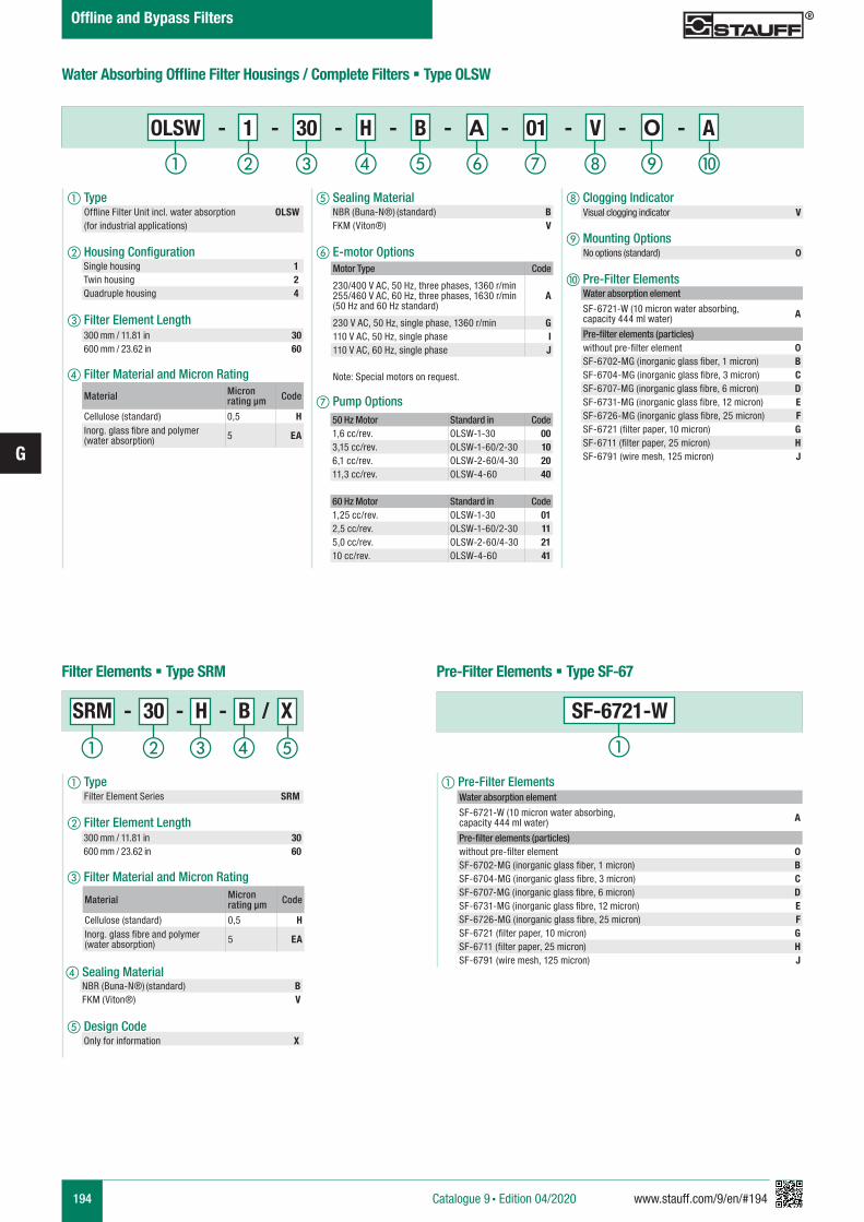
194 www.stauff.com/9/en/#194
G
e Sealing Material
f E-motor Options
g Pump Options
h Clogging Indicator
i Mounting Options j Pre-Filter Elements
a Type Offline Filter Unit incl. water absorption OLSW (for industrial applications)
b Housing Configuration
c Filter Element Length
d Filter Material and Micron Rating
Water Absorbing Offline Filter Housings / Complete Filters § Type OLSW
Water absorption element
SF-6721-W (10 micron water absorbing, capacity 444 ml water) A
Pre-filter elements (particles)without pre-filter element 0SF-6702-MG (inorganic glass fiber, 1 micron) BSF-6704-MG (inorganic glass fibre, 3 micron) CSF-6707-MG (inorganic glass fibre, 6 micron) DSF-6731-MG (inorganic glass fibre, 12 micron) ESF-6726-MG (inorganic glass fibre, 25 micron) FSF-6721 (filter paper, 10 micron) GSF-6711 (filter paper, 25 micron) HSF-6791 (wire mesh, 125 micron) J
NBR (Buna-N®) (standard) BFKM (Viton®) V
Motor Type Code
230/400 V AC, 50 Hz, three phases, 1360 r/min255/460 V AC, 60 Hz, three phases, 1630 r/min (50 Hz and 60 Hz standard)
A
230 V AC, 50 Hz, single phase, 1360 r/min G110 V AC, 50 Hz, single phase I110 V AC, 60 Hz, single phase J
Note: Special motors on request.
Visual clogging indicator V
No options (standard) 0
Material Micron rating µm Code
Cellulose (standard) 0,5 HInorg. glass fibre and polymer (water absorption) 5 EA
50 Hz Motor Standard in Code1,6 cc/rev. OLSW-1-30 003,15 cc/rev. OLSW-1-60/2-30 106,1 cc/rev. OLSW-2-60/4-30 2011,3 cc/rev. OLSW-4-60 40
60 Hz Motor Standard in Code1,25 cc/rev. OLSW-1-30 012,5 cc/rev. OLSW-1-60/2-30 115,0 cc/rev. OLSW-2-60/4-30 2110 cc/rev. OLSW-4-60 41
Pre-Filter Elements § Type SF-67Filter Elements § Type SRM
a Pre-Filter Elements
SF-6721-W
a Type Filter Element Series SRM
b Filter Element Length
c Filter Material and Micron Rating
d Sealing Material NBR (Buna-N®) (standard) BFKM (Viton®) V
Material Micron rating µm Code
Cellulose (standard) 0,5 HInorg. glass fibre and polymer (water absorption) 5 EA
ihga b c fed j
OLSW - 1 - 30 - H - B - A - 01 - V - O - A
a b c d
Single housing 1Twin housing 2Quadruple housing 4
300 mm / 11.81 in 30600 mm / 23.62 in 60
300 mm / 11.81 in 30600 mm / 23.62 in 60
Catalogue 9 § Edition 04/2020
Offline and Bypass Filters
e Design Code Only for information X
e
SRM - 30 - H - B / X
Water absorption element
SF-6721-W (10 micron water absorbing, capacity 444 ml water) A
Pre-filter elements (particles)without pre-filter element 0SF-6702-MG (inorganic glass fiber, 1 micron) BSF-6704-MG (inorganic glass fibre, 3 micron) CSF-6707-MG (inorganic glass fibre, 6 micron) DSF-6731-MG (inorganic glass fibre, 12 micron) ESF-6726-MG (inorganic glass fibre, 25 micron) FSF-6721 (filter paper, 10 micron) GSF-6711 (filter paper, 25 micron) HSF-6791 (wire mesh, 125 micron) J
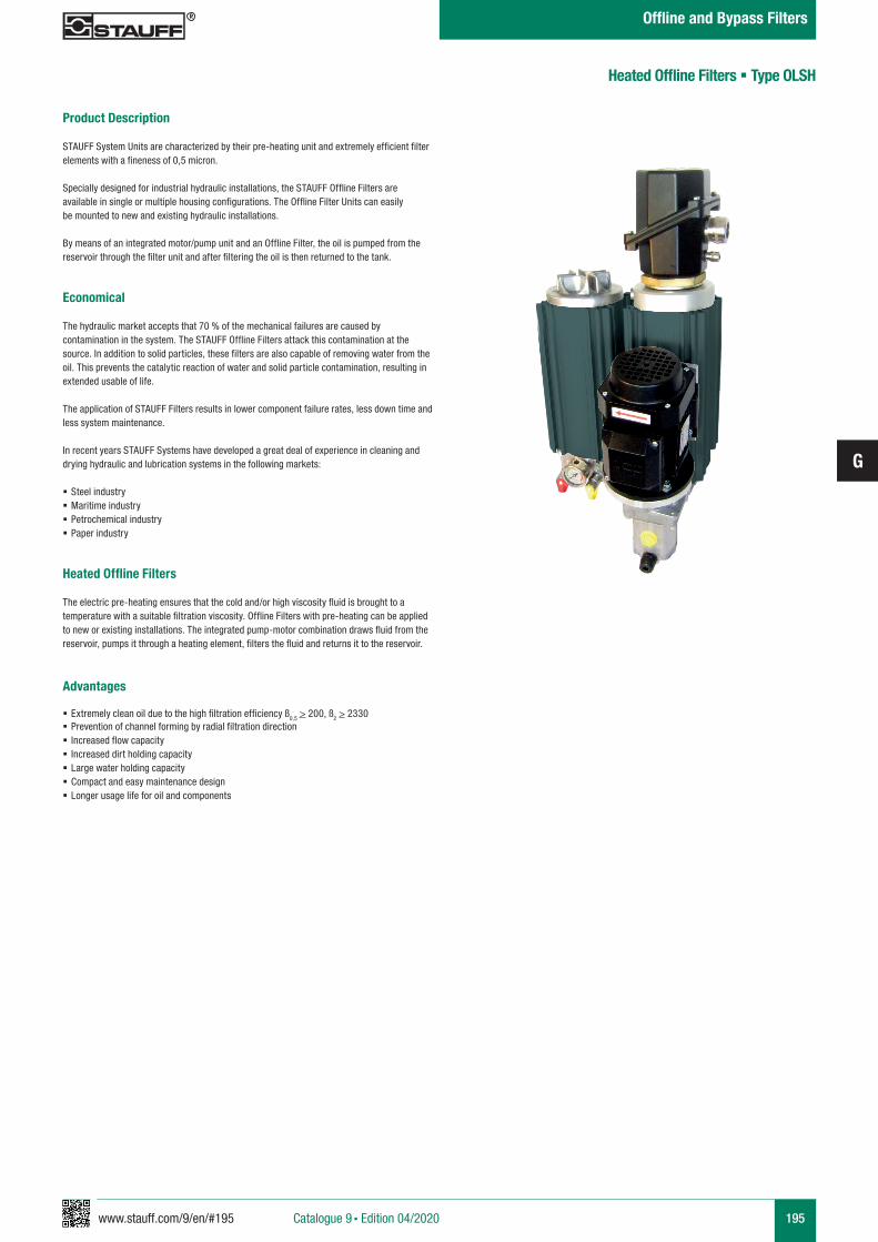
www.stauff.com/9/en/#195
G
195
Product Description
STAUFF System Units are characterized by their pre-heating unit and extremely efficient filter elements with a fineness of 0,5 micron.
Specially designed for industrial hydraulic installations, the STAUFF Offline Filters are available in single or multiple housing configurations. The Offline Filter Units can easily be mounted to new and existing hydraulic installations.
By means of an integrated motor/pump unit and an Offline Filter, the oil is pumped from the reservoir through the filter unit and after filtering the oil is then returned to the tank.
Economical
The hydraulic market accepts that 70 % of the mechanical failures are caused by contamination in the system. The STAUFF Offline Filters attack this contamination at the source. In addition to solid particles, these filters are also capable of removing water from the oil. This prevents the catalytic reaction of water and solid particle contamination, resulting in extended usable of life.
The application of STAUFF Filters results in lower component failure rates, less down time and less system maintenance.
In recent years STAUFF Systems have developed a great deal of experience in cleaning and drying hydraulic and lubrication systems in the following markets:
§ Steel industry § Maritime industry § Petrochemical industry § Paper industry
Heated Offline Filters
The electric pre-heating ensures that the cold and/or high viscosity fluid is brought to a temperature with a suitable filtration viscosity. Offline Filters with pre-heating can be applied to new or existing installations. The integrated pump-motor combination draws fluid from the reservoir, pumps it through a heating element, filters the fluid and returns it to the reservoir.
Advantages
§ Extremely clean oil due to the high filtration efficiency ß0,5 > 200, ß2 > 2330 § Prevention of channel forming by radial filtration direction § Increased flow capacity § Increased dirt holding capacity § Large water holding capacity § Compact and easy maintenance design § Longer usage life for oil and components
Heated Offline Filters § Type OLSH
Catalogue 9 § Edition 04/2020
Offline and Bypass Filters
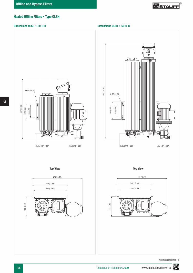
196 www.stauff.com/9/en/#196
G
Heated Offline Filters § Type OLSH
All dimensions in mm / in
Dimensions OLSH-1-60-H-BDimensions OLSH-1-30-H-B
Catalogue 9 § Edition 04/2020
Offline and Bypass Filters
567
(22.
32)
120
(4.7
2)
160
(6.2
9)
4x Ø8,5 (.34)
Outlet 1/2” - BSP Inlet 3/8” - BSP
475 (18.70)
340 (13.38)
320 (12.59)
188
(7.4
0)
Top View Top View
475 (18.70)
340 (13.38)
320 (12.59)
188
(7.4
0)
869
(34.
21)
4x Ø8,5 (.34)
160
(6.2
9)
120
(4.7
2)
Outlet 1/2” - BSP Inlet 1/2” - BSP
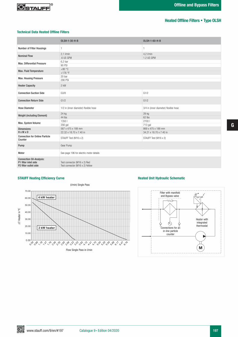
www.stauff.com/9/en/#197
G
197
Technical Data Heated Offline Filters
OLSH-1-30-H-B OLSH-1-60-H-B
Number of Filter Housings 1 1
Nominal Flow2,1 l/min 4,2 l/min.6 US GPM 1.2 US GPM
Max. Differential Pressure6,2 bar90 PSI
Max. Fluid Temperature+80 °C+176 °F
Max. Housing Pressure20 bar290 PSI
Heater Capacity 2 kW
Connection Suction Side G3/8 G1/2
Connection Return Side G1/2 G1/2
Hose Diameter 1/2 in (inner diameter) flexible hose 3/4 in (inner diameter) flexible hose
Weight (including Element)24 kg 28 kg44 lbs 62 lbs
Max. System Volume1350 l 2700 l356 gal 713 gal
DimensionsH x W x D
567 x 475 x 188 mm 869 x 475 x 188 mm22.32 x 18.70 x 7.40 in 34.21 x 18.70 x 7.40 in
Connection for Online Particle Counter STAUFF Test (M16 x 2) STAUFF Test (M16 x 2)
Pump Gear Pump
Motor See page 196 for electric motor details
Connection Oil-Analysis:P1 filter inlet sideP2 filter outlet side
Test connector (M16 x 2) RedTest connector (M16 x 2) Yellow
STAUFF Heating Efficiency Curve
(l/min) Single Pass
∆T H
eate
r in
ºC
Flow Single Pass in l/min
Filter with manifoldand Bypass valve
Connections for anin-line particle
counter
Heater withintegratedthermostat
Heated Unit Hydraulic Schematic
Heated Offline Filters § Type OLSH
Catalogue 9 § Edition 04/2020
Offline and Bypass Filters
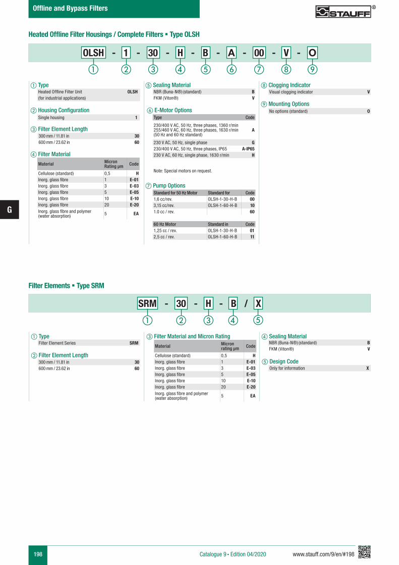
198 www.stauff.com/9/en/#198
G
a Type Filter Element Series SRM
b Filter Element Length
c Filter Material and Micron Rating d Sealing Material
e Sealing Material
f E-Motor Options
g Pump Options
h Clogging Indicator
i Mounting Options
a Type Heated Offline Filter Unit OLSH (for industrial applications)
b Housing Configuration
c Filter Element Length
d Filter Material
Type Code
230/400 V AC, 50 Hz, three phases, 1360 r/min255/460 V AC, 60 Hz, three phases, 1630 r/min(50 Hz and 60 Hz standard)
A
230 V AC, 50 Hz, single phase G230/400 V AC, 50 Hz, three phases, IP65 A-IP65230 V AC, 60 Hz, single phase, 1630 r/min H
Note: Special motors on request.
Standard for 50 Hz Motor Standard for Code1,6 cc/rev. OLSH-1-30-H-B 003,15 cc/rev. OLSH-1-60-H-B 101.0 cc / rev. 60
60 Hz Motor Standard in Code1,25 cc / rev. OLSH-1-30-H-B 012,5 cc / rev. OLSH-1-60-H-B 11
Visual clogging indicator V
Heated Offline Filter Housings / Complete Filters § Type OLSH
Filter Elements § Type SRM
NBR (Buna-N®) (standard) BFKM (Viton®) V
NBR (Buna-N®) (standard) BFKM (Viton®) V
No options (standard) 0
Material Micron Rating µm Code
Cellulose (standard) 0,5 HInorg. glass fibre 1 E-01Inorg. glass fibre 3 E-03Inorg. glass fibre 5 E-05Inorg. glass fibre 10 E-10Inorg. glass fibre 20 E-20Inorg. glass fibre and polymer (water absorption) 5 EA
Material Micron rating µm Code
Cellulose (standard) 0,5 HInorg. glass fibre 1 E-01Inorg. glass fibre 3 E-03Inorg. glass fibre 5 E-05Inorg. glass fibre 10 E-10Inorg. glass fibre 20 E-20Inorg. glass fibre and polymer (water absorption) 5 EA
OLSH - 1 - 30 - H - B - A - 00 - V - O
Single housing 1
300 mm / 11.81 in 30600 mm / 23.62 in 60
300 mm / 11.81 in 30600 mm / 23.62 in 60
Catalogue 9 § Edition 04/2020
Offline and Bypass Filters
e Design Code Only for information X
SRM - 30 - H - B / X
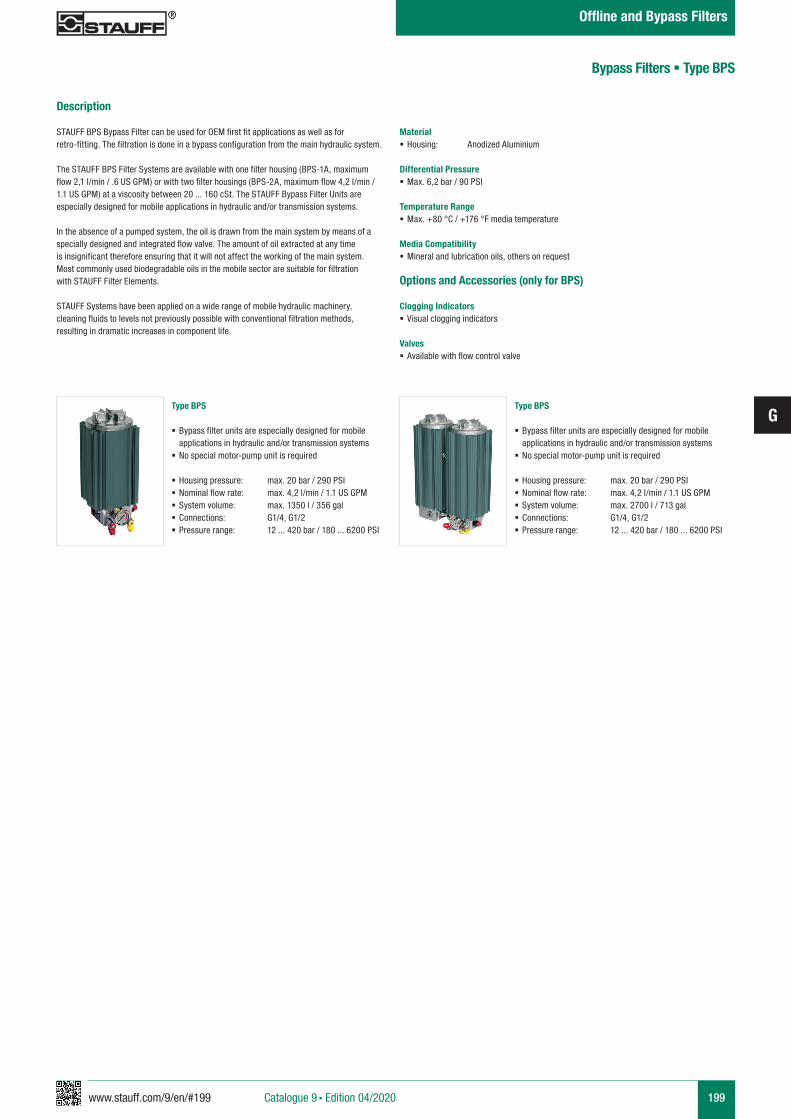
www.stauff.com/9/en/#199
G
199
Bypass Filters § Type BPS
Description
STAUFF BPS Bypass Filter can be used for OEM first fit applications as well as for retro-fitting. The filtration is done in a bypass configuration from the main hydraulic system.
The STAUFF BPS Filter Systems are available with one filter housing (BPS-1A, maximum flow 2,1 l/min / .6 US GPM) or with two filter housings (BPS-2A, maximum flow 4,2 l/min / 1.1 US GPM) at a viscosity between 20 ... 160 cSt. The STAUFF Bypass Filter Units are especially designed for mobile applications in hydraulic and/or transmission systems.
In the absence of a pumped system, the oil is drawn from the main system by means of aspecially designed and integrated flow valve. The amount of oil extracted at any time is insignificant therefore ensuring that it will not affect the working of the main system. Most commonly used biodegradable oils in the mobile sector are suitable for filtration with STAUFF Filter Elements.
STAUFF Systems have been applied on a wide range of mobile hydraulic machinery,cleaning fluids to levels not previously possible with conventional filtration methods, resulting in dramatic increases in component life.
Material § Housing: Anodized Aluminium
Differential Pressure § Max. 6,2 bar / 90 PSI
Temperature Range § Max. +80 °C / +176 °F media temperature
Media Compatibility § Mineral and lubrication oils, others on request
Options and Accessories (only for BPS)
Clogging Indicators § Visual clogging indicators
Valves § Available with flow control valve
Catalogue 9 § Edition 04/2020
Offline and Bypass Filters
Type BPS
§ Bypass filter units are especially designed for mobile applications in hydraulic and/or transmission systems
§ No special motor-pump unit is required
§ Housing pressure: max. 20 bar / 290 PSI § Nominal flow rate: max. 4,2 l/min / 1.1 US GPM § System volume: max. 1350 l / 356 gal § Connections: G1/4, G1/2 § Pressure range: 12 ... 420 bar / 180 ... 6200 PSI
Type BPS
§ Bypass filter units are especially designed for mobile applications in hydraulic and/or transmission systems
§ No special motor-pump unit is required
§ Housing pressure: max. 20 bar / 290 PSI § Nominal flow rate: max. 4,2 l/min / 1.1 US GPM § System volume: max. 2700 l / 713 gal § Connections: G1/4, G1/2 § Pressure range: 12 ... 420 bar / 180 ... 6200 PSI
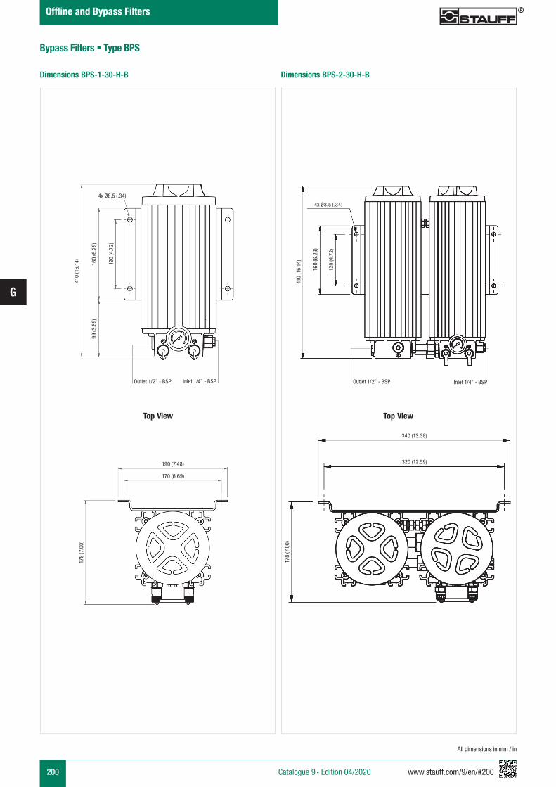
200 www.stauff.com/9/en/#200
G
All dimensions in mm / in
Dimensions BPS-2-30-H-BDimensions BPS-1-30-H-B
Bypass Filters § Type BPS
Catalogue 9 § Edition 04/2020
Offline and Bypass Filters
Top View Top View
410
(16.
14)
4x Ø8,5 (.34)
Outlet 1/2” - BSP Inlet 1/4” - BSP
99 (3
.89)
160
(6.2
9)
120
(4.7
2)
178
(7.0
0)
190 (7.48)
170 (6.69)
4x Ø8,5 (.34)
410
(16.
14)
160
(6.2
9)
120
(4.7
2)
Outlet 1/2” - BSP Inlet 1/4” - BSP
340 (13.38)
320 (12.59)
178
(7.0
0)
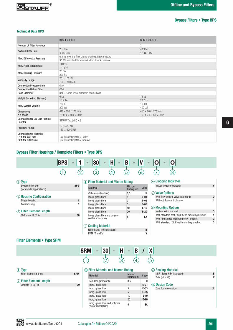
www.stauff.com/9/en/#201
G
201
d Filter Material and Micron Rating
e Sealing Material
f Clogging Indicator
g Valve Options
h Mounting Options
a Type Bypass Filter Unit BPS (for mobile applications)
b Housing Configuration
c Filter Element Length
a Type Filter Element Series SRM
b Filter Element Length
c Filter Material and Micron Rating
d Sealing Material
Bypass Filters § Type BPS
Technical Data BPS
BPS-1-30-H-B BPS-2-30-H-B
Number of Filter Housings 1 2
Nominal Flow Rate2,1 l/min 4,2 l/min.6 US GPM 1.1 US GPM
Max. Differential Pressure6,2 bar over the filter element without back pressure90 PSI over the filter element without back pressure
Max. Fluid Temperature+80 °C+176 °F
Max. Housing Pressure20 bar290 PSI
Viscosity Range20 ... 160 cSt100 ... 750 SUS
Connection Pressure Side G1/4Connection Return Side G1/2Hose Diameter 3/8 ... 1/2 in (inner diameter) flexible hose
Weight (including Element)6 kg 13 kg13.2 lbs 28.7 lbs
Max. System Volume750 l 1500 l200 gal 400 gal
DimensionsH x W x D
410 x 190 x 178 mm 410 x 340 x 178 mm16.14 x 7.48 x 7.00 in 16.14 x 13.38 x 7.00 in
Connection for On-Line Particle Counter STAUFF Test (M16 x 2)
Pressure Range12 ... 420 bar180 ... 6200 PSI
Connection Oil-Analysis:P1 filter inlet sideP2 filter outlet side
Test connector (M16 x 2) RedTest connector (M16 x 2) Yellow
Bypass Filter Housings / Complete Filters § Type BPS
No bracket (standard) 0With standard foot / bulk head mounting bracket 1With “bulk head mounting only” bracket 2With standard ‘OLS’ wall mounting bracket 3
With flow control valve (standard) 0Without flow control valve 1
BPS - 1 - 30 - H - B - V - O - O
Filter Elements § Type SRM
SRM - 30 - H - B / X
300 mm / 11.81 in 30
NBR (Buna-N®) (standard) BFKM (Viton®) V
NBR (Buna-N®) (standard) BFKM (Viton®) V
Visual clogging indicator VMaterial Micron
Rating µm Code
Cellulose (standard) 0,5 HInorg. glass fibre 1 E-01Inorg. glass fibre 3 E-03Inorg. glass fibre 5 E-05Inorg. glass fibre 10 E-10Inorg. glass fibre 20 E-20Inorg. glass fibre and polymer (water absorption) 5 EA
Material Micron Rating µm Code
Cellulose (standard) 0,5 HInorg. glass fibre 1 E-01Inorg. glass fibre 3 E-03Inorg. glass fibre 5 E-05Inorg. glass fibre 10 E-10Inorg. glass fibre 20 E-20Inorg. glass fibre and polymer (water absorption) 5 EA
300 mm / 11.81 in 30
Single housing 1Twin housing 2
Catalogue 9 § Edition 04/2020
Offline and Bypass Filters
e Design Code Only for information X
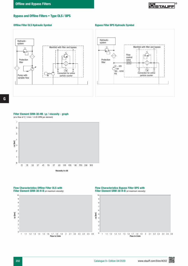
202 www.stauff.com/9/en/#202
G
Offline Filter OLS Hydraulic Symbol
Filter Element SRM-30-HB ∆p / viscosity - graph (at a flow of 2,1 l/min / .6 US GPM per element)
Hydraulic-system
Protection filter
Pump with variable flow
M
Manifold with filter and bypass
Hydraulic-system
Protection filter
Flowcontrolvalve
12 ... 420 bar180 ... 6200PSI
Manifold with filter and bypass
Connection for online particle counter
Connection for online particle counter
Actual values
Actual values
Flow Characteristics Offline Filter OLS withFilter Element SRM-30-H-B (at maximum viscosity)
Flow in l/minFlow in l/min 1 1.1 1.2 1.3 1.4 1.5 1.6 1.7 1.8 1.9 2 2.1 2.2 2.3 2.4 2.5 2.6 1 1.1 1.2 1.3 1.4 1.5 1.6 1.7 1.8 1.9 2 2.1 2.2 2.3 2.4 2.5 2.6
∆p [b
ar]
10
9
8
7
6
5
4
3
2
1
0
10
9
8
7
6
5
4
3
2
1
0
Bypass Filter BPS Hydraulic Symbol
Bypass and Offline Filters § Type OLS / BPS
Viscosity in cSt
Actual values
∆p [b
ar]
∆p [b
ar]
Flow Characteristics Bypass Filter BPS withFilter Element SRM-30-H-B (at maximum viscosity)
Catalogue 9 § Edition 04/2020
Offline and Bypass Filters
www.stauff.com/9/en/#203
G
203
Offline and Bypass Filters
Catalogue 9 § Edition 04/2020
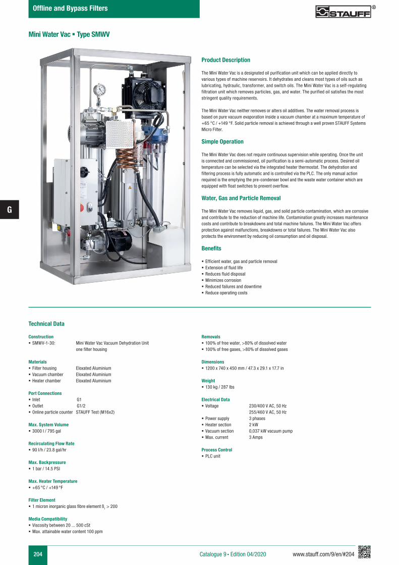
204 www.stauff.com/9/en/#204
G
Product Description
The Mini Water Vac is a designated oil purification unit which can be applied directly to various types of machine reservoirs. It dehydrates and cleans most types of oils such as lubricating, hydraulic, transformer, and switch oils. The Mini Water Vac is a self-regulatingfiltration unit which removes particles, gas, and water. The purified oil satisfies the most stringent quality requirements.
The Mini Water Vac neither removes or alters oil additives. The water removal process is based on pure vacuum evaporation inside a vacuum chamber at a maximum temperature of +65 °C / +149 °F. Solid particle removal is achieved through a well proven STAUFF Systems Micro Filter.
Simple Operation
The Mini Water Vac does not require continuous supervision while operating. Once the unit is connected and commissioned, oil purification is a semi-automatic process. Desired oil temperature can be selected via the integrated heater thermostat. The dehydration and filtering process is fully automatic and is controlled via the PLC. The only manual action required is the emptying the pre-condenser bowl and the waste water container which are equipped with float switches to prevent overflow.
Water, Gas and Particle Removal
The Mini Water Vac removes liquid, gas, and solid particle contamination, which are corrosive and contribute to the reduction of machine life. Contamination greatly increases maintenance costs and contribute to breakdowns and total machine failures. The Mini Water Vac offers protection against malfunctions, breakdowns or total failures. The Mini Water Vac also protects the environment by reducing oil consumption and oil disposal.
Benefits § Efficient water, gas and particle removal § Extension of fluid life § Reduces fluid disposal § Minimizes corrosion § Reduced failures and downtime § Reduce operating costs
Mini Water Vac § Type SMWV
Technical Data
Construction § SMWV-1-30: Mini Water Vac Vacuum Dehydration Unit one filter housing
Materials § Filter housing Eloxated Aluminium § Vacuum chamber Eloxated Aluminium § Heater chamber Eloxated Aluminium
Port Connections § Inlet G1 § Outlet G1/2 § Online particle counter STAUFF Test (M16x2)
Max. System Volume § 3000 l / 795 gal
Recirculating Flow Rate § 90 l/h / 23.8 gal/hr
Max. Backpressure § 1 bar / 14.5 PSI
Max. Heater Temperature § +65 °C / +149 °F
Filter Element § 1 micron inorganic glass fibre element ß1 > 200
Media Compatibility § Viscosity between 20 ... 500 cSt § Max. attainable water content 100 ppm
Removals § 100% of free water, >80% of dissolved water § 100% of free gases, >80% of dissolved gases
Dimensions § 1200 x 740 x 450 mm / 47.3 x 29.1 x 17.7 in
Weight § 130 kg / 287 lbs
Electrical Data § Voltage 230/400 V AC, 50 Hz 255/460 V AC, 50 Hz
§ Power supply 3 phases § Heater section 2 kW § Vacuum section 0,037 kW vacuum pump § Max. current 3 Amps
Process Control § PLC unit
Catalogue 9 § Edition 04/2020
Offline and Bypass Filters
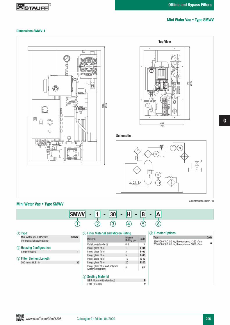
www.stauff.com/9/en/#205
G
205
f E-motor Optionsa Type Mini Water Vac Oil Purifier SMWV (for industrial applications)
b Housing Configuration
c Filter Element Length
All dimensions in mm / in
Dimensions SMWV-1
Mini Water Vac § Type SMWV
Schematic
Mini Water Vac § Type SMWV
SMWV - 1 - 30 - H - B - A
..
M
M
..
M
NBR (Buna-N®) (standard) BFKM (Viton®) V
300 mm / 11.81 in 30
740
29.1
3
45017.72
1200
47.2
4
Top View
Material Micron Rating µm Code
Cellulose (standard) 0,5 HInorg. glass fibre 1 E-01Inorg. glass fibre 3 E-03Inorg. glass fibre 5 E-05Inorg. glass fibre 10 E-10Inorg. glass fibre 20 E-20Inorg. glass fibre and polymer (water absorption) 5 EA
Type Code
230/400 V AC, 50 Hz, three phases, 1360 r/min255/460 V AC, 60 Hz, three phases, 1630 r/min A
d Filter Material and Micron Rating
e Sealing Material
a b c fed
Single housing 1
Catalogue 9 § Edition 04/2020
Offline and Bypass Filters
www.stauff.com/9/en/#207
H
207Catalogue 9 § Edition 04/2020
Filtration Systems
Filtration Systems
STAUFF Europe Filter Systems 208
209
209
STAUFF America Filter Systems
STAUFF Australia Filter Systems
208 - 209
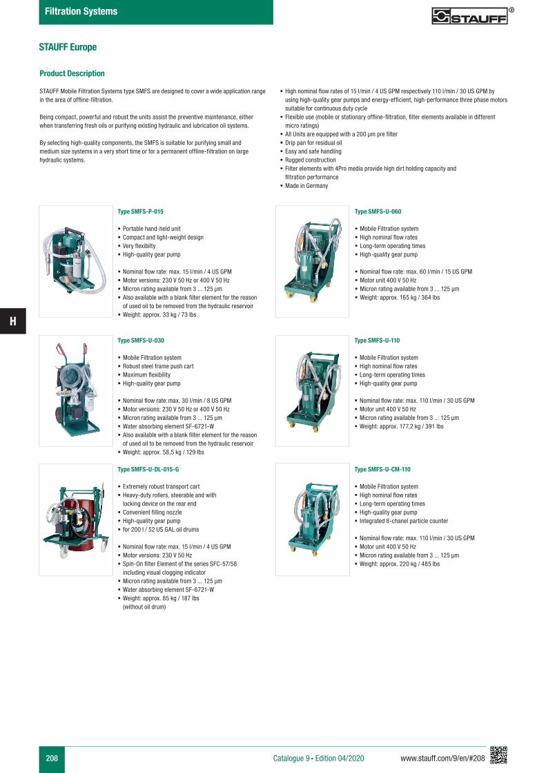
208 www.stauff.com/9/en/#208
H
Type SMFS-P-015
§ Portable hand-held unit § Compact and light-weight design § Very flexibilty § High-quality gear pump
§ Nominal flow rate: max. 15 l/min / 4 US GPM § Motor versions: 230 V 50 Hz or 400 V 50 Hz § Micron rating available from 3 ... 125 µm § Also available with a blank filter element for the reason of used oil to be removed from the hydraulic reservoir
§ Weight: approx. 33 kg / 73 lbs
Type SMFS-U-030
§ Mobile Filtration system § Robust steel frame push cart § Maximum flexibility § High-quality gear pump
§ Nominal flow rate: max. 30 l/min / 8 US GPM § Motor versions: 230 V 50 Hz or 400 V 50 Hz § Micron rating available from 3 ... 125 µm § Water absorbing element SF-6721-W § Also available with a blank filter element for the reason of used oil to be removed from the hydraulic reservoir
§ Weight: approx. 58,5 kg / 129 lbs
Type SMFS-U-060
§ Mobile Filtration system § High nominal flow rates § Long-term operating times § High-quality gear pump
§ Nominal flow rate: max. 60 l/min / 15 US GPM § Motor unit 400 V 50 Hz § Micron rating available from 3 ... 125 µm § Weight: approx. 165 kg / 364 lbs
Type SMFS-U-110
§ Mobile Filtration system § High nominal flow rates § Long-term operating times § High-quality gear pump
§ Nominal flow rate: max. 110 l/min / 30 US GPM § Motor unit 400 V 50 Hz § Micron rating available from 3 ... 125 µm § Weight: approx. 177,2 kg / 391 lbs
Type SMFS-U-CM-110
§ Mobile Filtration system § High nominal flow rates § Long-term operating times § High-quality gear pump § Integrated 8-chanel particle counter
§ Nominal flow rate: max. 110 l/min / 30 US GPM § Motor unit 400 V 50 Hz § Micron rating available from 3 ... 125 µm § Weight: approx. 220 kg / 485 lbs
Type SMFS-U-DL-015-G
§ Extremely robust transport cart § Heavy-duty rollers, steerable and with locking device on the rear end
§ Convenient filling nozzle § High-quality gear pump § for 200 l / 52 US GAL oil drums
§ Nominal flow rate: max. 15 l/min / 4 US GPM § Motor versions: 230 V 50 Hz § Spin-On filter Element of the series SFC-57/58 including visual clogging indicator
§ Micron rating available from 3 ... 125 µm § Water absorbing element SF-6721-W § Weight: approx. 85 kg / 187 lbs (without oil drum)
STAUFF Europe
Product Description
STAUFF Mobile Filtration Systems type SMFS are designed to cover a wide application range in the area of offline-filtration.
Being compact, powerful and robust the units assist the preventive maintenance, either when transferring fresh oils or purifying existing hydraulic and lubrication oil systems.
By selecting high-quality components, the SMFS is suitable for purifying small and medium size systems in a very short time or for a permanent offline-filtration on large hydraulic systems.
§ High nominal flow rates of 15 l/min / 4 US GPM respectively 110 l/min / 30 US GPM by using high-quality gear pumps and energy-efficient, high-performance three phase motors suitable for continuous duty cycle
§ Flexible use (mobile or stationary offline-filtration, filter elements available in different micro ratings)
§ All Units are equipped with a 200 µm pre filter § Drip pan for residual oil § Easy and safe handling § Rugged construction § Filter elements with 4Pro media provide high dirt holding capacity and filtration performance
§ Made in Germany
Catalogue 9 § Edition 04/2020
Filtration Systems
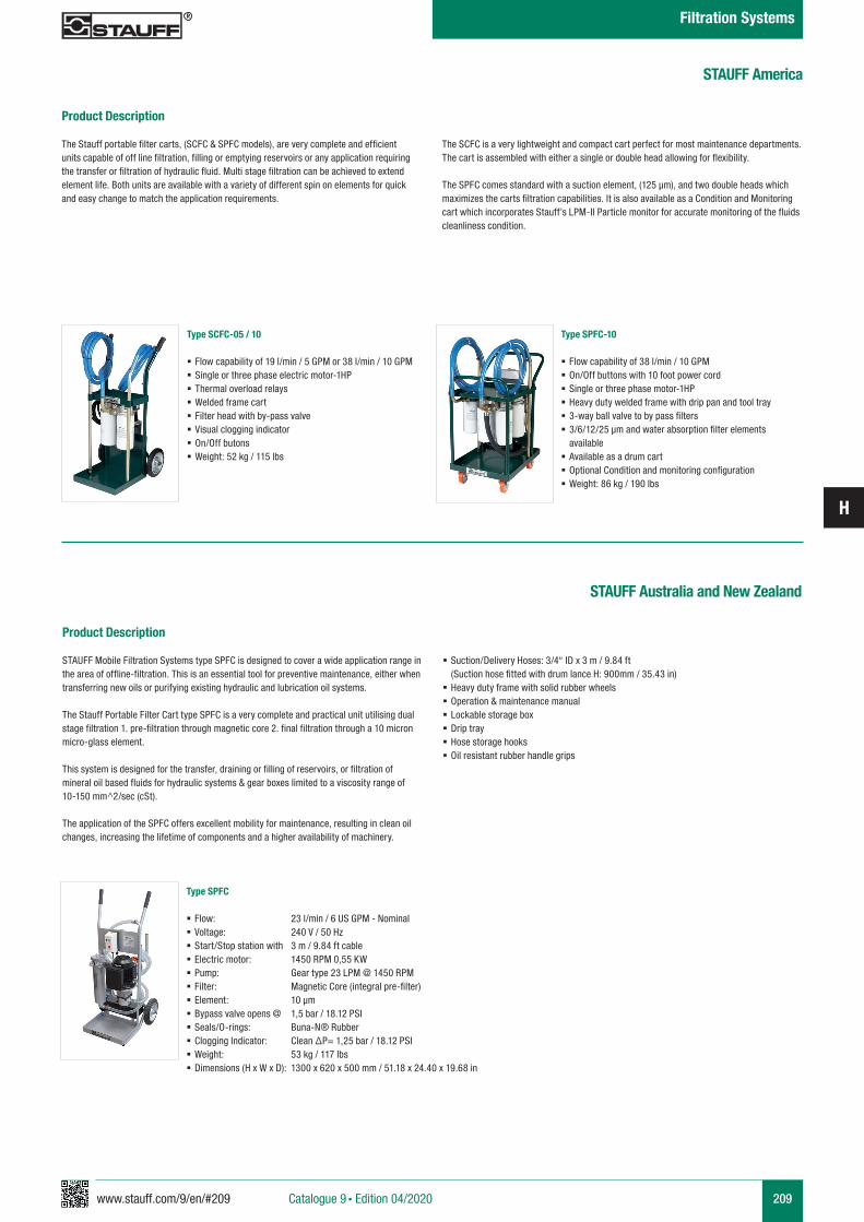
www.stauff.com/9/en/#209
H
209
STAUFF America
Product Description
The Stauff portable filter carts, (SCFC & SPFC models), are very complete and efficient units capable of off line filtration, filling or emptying reservoirs or any application requiring the transfer or filtration of hydraulic fluid. Multi stage filtration can be achieved to extend element life. Both units are available with a variety of different spin on elements for quick and easy change to match the application requirements.
The SCFC is a very lightweight and compact cart perfect for most maintenance departments. The cart is assembled with either a single or double head allowing for flexibility.
The SPFC comes standard with a suction element, (125 µm), and two double heads which maximizes the carts filtration capabilities. It is also available as a Condition and Monitoring cart which incorporates Stauff’s LPM-II Particle monitor for accurate monitoring of the fluids cleanliness condition.
Type SCFC-05 / 10
§ Flow capability of 19 l/min / 5 GPM or 38 l/min / 10 GPM § Single or three phase electric motor-1HP § Thermal overload relays § Welded frame cart § Filter head with by-pass valve § Visual clogging indicator § On/Off butons § Weight: 52 kg / 115 lbs
Type SPFC-10
§ Flow capability of 38 l/min / 10 GPM § On/Off buttons with 10 foot power cord § Single or three phase motor-1HP § Heavy duty welded frame with drip pan and tool tray § 3-way ball valve to by pass filters § 3/6/12/25 µm and water absorption filter elements available
§ Available as a drum cart § Optional Condition and monitoring configuration § Weight: 86 kg / 190 lbs
STAUFF Australia and New Zealand
Product Description
STAUFF Mobile Filtration Systems type SPFC is designed to cover a wide application range in the area of offline-filtration. This is an essential tool for preventive maintenance, either when transferring new oils or purifying existing hydraulic and lubrication oil systems.
The Stauff Portable Filter Cart type SPFC is a very complete and practical unit utilising dual stage filtration 1. pre-filtration through magnetic core 2. final filtration through a 10 micron micro-glass element.
This system is designed for the transfer, draining or filling of reservoirs, or filtration of mineral oil based fluids for hydraulic systems & gear boxes limited to a viscosity range of 10-150 mm^2/sec (cSt). The application of the SPFC offers excellent mobility for maintenance, resulting in clean oil changes, increasing the lifetime of components and a higher availability of machinery.
§ Suction/Delivery Hoses: 3/4“ ID x 3 m / 9.84 ft (Suction hose fitted with drum lance H: 900mm / 35.43 in)
§ Heavy duty frame with solid rubber wheels § Operation & maintenance manual § Lockable storage box § Drip tray § Hose storage hooks § Oil resistant rubber handle grips
Type SPFC
§ Flow: 23 l/min / 6 US GPM - Nominal § Voltage: 240 V / 50 Hz § Start/Stop station with 3 m / 9.84 ft cable § Electric motor: 1450 RPM 0,55 KW § Pump: Gear type 23 LPM @ 1450 RPM § Filter: Magnetic Core (integral pre-filter) § Element: 10 µm § Bypass valve opens @ 1,5 bar / 18.12 PSI § Seals/O-rings: Buna-N® Rubber § Clogging Indicator: Clean ΔP= 1,25 bar / 18.12 PSI § Weight: 53 kg / 117 lbs § Dimensions (H x W x D): 1300 x 620 x 500 mm / 51.18 x 24.40 x 19.68 in
Catalogue 9 § Edition 04/2020
Filtration Systems
www.stauff.com/9/en/#211 211Catalogue 9 § Edition 04/2020
Appendix
Product-Specific Abbreviations
Global Contact Directory
214 - 215
212 - 213
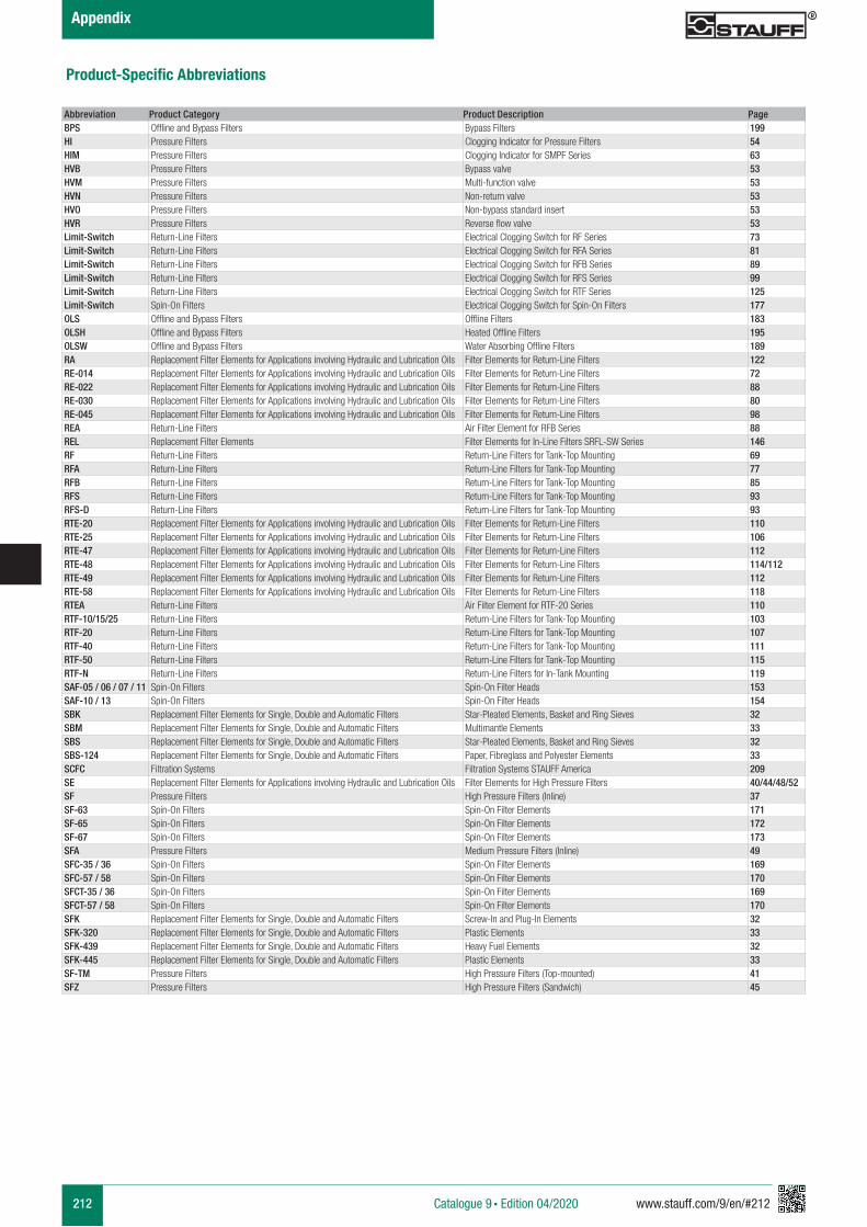
212 www.stauff.com/9/en/#212
Appendix
Catalogue 9 § Edition 04/2020
Product-Specific Abbreviations
Abbreviation Product Category Product Description PageBPS Offline and Bypass Filters Bypass Filters 199HI Pressure Filters Clogging Indicator for Pressure Filters 54HIM Pressure Filters Clogging Indicator for SMPF Series 63HVB Pressure Filters Bypass valve 53HVM Pressure Filters Multi-function valve 53HVN Pressure Filters Non-return valve 53HVO Pressure Filters Non-bypass standard insert 53HVR Pressure Filters Reverse flow valve 53Limit-Switch Return-Line Filters Electrical Clogging Switch for RF Series 73Limit-Switch Return-Line Filters Electrical Clogging Switch for RFA Series 81Limit-Switch Return-Line Filters Electrical Clogging Switch for RFB Series 89Limit-Switch Return-Line Filters Electrical Clogging Switch for RFS Series 99Limit-Switch Return-Line Filters Electrical Clogging Switch for RTF Series 125Limit-Switch Spin-On Filters Electrical Clogging Switch for Spin-On Filters 177OLS Offline and Bypass Filters Offline Filters 183OLSH Offline and Bypass Filters Heated Offline Filters 195OLSW Offline and Bypass Filters Water Absorbing Offline Filters 189RA Replacement Filter Elements for Applications involving Hydraulic and Lubrication Oils Filter Elements for Return-Line Filters 122RE-014 Replacement Filter Elements for Applications involving Hydraulic and Lubrication Oils Filter Elements for Return-Line Filters 72RE-022 Replacement Filter Elements for Applications involving Hydraulic and Lubrication Oils Filter Elements for Return-Line Filters 88RE-030 Replacement Filter Elements for Applications involving Hydraulic and Lubrication Oils Filter Elements for Return-Line Filters 80RE-045 Replacement Filter Elements for Applications involving Hydraulic and Lubrication Oils Filter Elements for Return-Line Filters 98REA Return-Line Filters Air Filter Element for RFB Series 88REL Replacement Filter Elements Filter Elements for In-Line Filters SRFL-SW Series 146RF Return-Line Filters Return-Line Filters for Tank-Top Mounting 69RFA Return-Line Filters Return-Line Filters for Tank-Top Mounting 77RFB Return-Line Filters Return-Line Filters for Tank-Top Mounting 85RFS Return-Line Filters Return-Line Filters for Tank-Top Mounting 93RFS-D Return-Line Filters Return-Line Filters for Tank-Top Mounting 93RTE-20 Replacement Filter Elements for Applications involving Hydraulic and Lubrication Oils Filter Elements for Return-Line Filters 110RTE-25 Replacement Filter Elements for Applications involving Hydraulic and Lubrication Oils Filter Elements for Return-Line Filters 106RTE-47 Replacement Filter Elements for Applications involving Hydraulic and Lubrication Oils Filter Elements for Return-Line Filters 112RTE-48 Replacement Filter Elements for Applications involving Hydraulic and Lubrication Oils Filter Elements for Return-Line Filters 114/112RTE-49 Replacement Filter Elements for Applications involving Hydraulic and Lubrication Oils Filter Elements for Return-Line Filters 112RTE-58 Replacement Filter Elements for Applications involving Hydraulic and Lubrication Oils Filter Elements for Return-Line Filters 118RTEA Return-Line Filters Air Filter Element for RTF-20 Series 110RTF-10/15/25 Return-Line Filters Return-Line Filters for Tank-Top Mounting 103RTF-20 Return-Line Filters Return-Line Filters for Tank-Top Mounting 107RTF-40 Return-Line Filters Return-Line Filters for Tank-Top Mounting 111RTF-50 Return-Line Filters Return-Line Filters for Tank-Top Mounting 115RTF-N Return-Line Filters Return-Line Filters for In-Tank Mounting 119SAF-05 / 06 / 07 / 11 Spin-On Filters Spin-On Filter Heads 153SAF-10 / 13 Spin-On Filters Spin-On Filter Heads 154SBK Replacement Filter Elements for Single, Double and Automatic Filters Star-Pleated Elements, Basket and Ring Sieves 32SBM Replacement Filter Elements for Single, Double and Automatic Filters Multimantle Elements 33SBS Replacement Filter Elements for Single, Double and Automatic Filters Star-Pleated Elements, Basket and Ring Sieves 32SBS-124 Replacement Filter Elements for Single, Double and Automatic Filters Paper, Fibreglass and Polyester Elements 33SCFC Filtration Systems Filtration Systems STAUFF America 209SE Replacement Filter Elements for Applications involving Hydraulic and Lubrication Oils Filter Elements for High Pressure Filters 40/44/48/52SF Pressure Filters High Pressure Filters (Inline) 37SF-63 Spin-On Filters Spin-On Filter Elements 171SF-65 Spin-On Filters Spin-On Filter Elements 172SF-67 Spin-On Filters Spin-On Filter Elements 173SFA Pressure Filters Medium Pressure Filters (Inline) 49SFC-35 / 36 Spin-On Filters Spin-On Filter Elements 169SFC-57 / 58 Spin-On Filters Spin-On Filter Elements 170SFCT-35 / 36 Spin-On Filters Spin-On Filter Elements 169SFCT-57 / 58 Spin-On Filters Spin-On Filter Elements 170SFK Replacement Filter Elements for Single, Double and Automatic Filters Screw-In and Plug-In Elements 32SFK-320 Replacement Filter Elements for Single, Double and Automatic Filters Plastic Elements 33SFK-439 Replacement Filter Elements for Single, Double and Automatic Filters Heavy Fuel Elements 32SFK-445 Replacement Filter Elements for Single, Double and Automatic Filters Plastic Elements 33SF-TM Pressure Filters High Pressure Filters (Top-mounted) 41SFZ Pressure Filters High Pressure Filters (Sandwich) 45
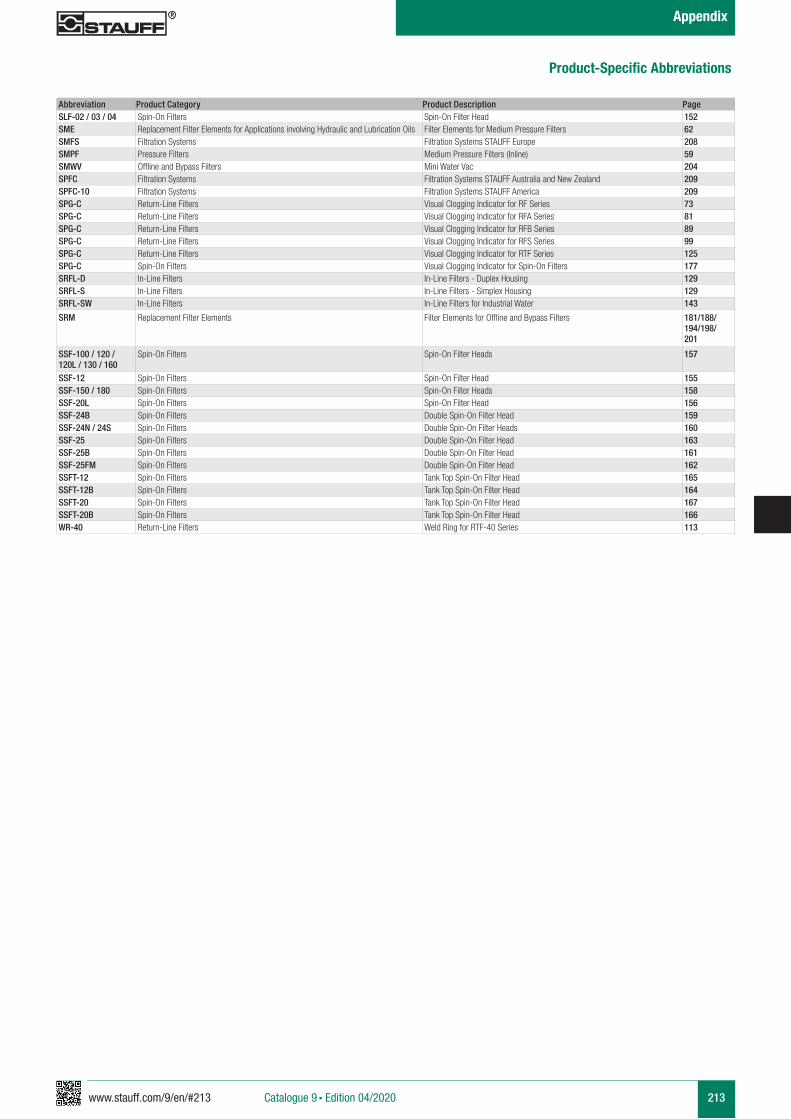
www.stauff.com/9/en/#213 213
Appendix
Catalogue 9 § Edition 04/2020
Product-Specific Abbreviations
Abbreviation Product Category Product Description PageSLF-02 / 03 / 04 Spin-On Filters Spin-On Filter Head 152SME Replacement Filter Elements for Applications involving Hydraulic and Lubrication Oils Filter Elements for Medium Pressure Filters 62SMFS Filtration Systems Filtration Systems STAUFF Europe 208SMPF Pressure Filters Medium Pressure Filters (Inline) 59SMWV Offline and Bypass Filters Mini Water Vac 204SPFC Filtration Systems Filtration Systems STAUFF Australia and New Zealand 209SPFC-10 Filtration Systems Filtration Systems STAUFF America 209SPG-C Return-Line Filters Visual Clogging Indicator for RF Series 73SPG-C Return-Line Filters Visual Clogging Indicator for RFA Series 81SPG-C Return-Line Filters Visual Clogging Indicator for RFB Series 89SPG-C Return-Line Filters Visual Clogging Indicator for RFS Series 99SPG-C Return-Line Filters Visual Clogging Indicator for RTF Series 125SPG-C Spin-On Filters Visual Clogging Indicator for Spin-On Filters 177SRFL-D In-Line Filters In-Line Filters - Duplex Housing 129SRFL-S In-Line Filters In-Line Filters - Simplex Housing 129SRFL-SW In-Line Filters In-Line Filters for Industrial Water 143
SRM Replacement Filter Elements Filter Elements for Offline and Bypass Filters 181/188/ 194/198/201
SSF-100 / 120 / 120L / 130 / 160
Spin-On Filters Spin-On Filter Heads 157
SSF-12 Spin-On Filters Spin-On Filter Head 155SSF-150 / 180 Spin-On Filters Spin-On Filter Heads 158SSF-20L Spin-On Filters Spin-On Filter Head 156SSF-24B Spin-On Filters Double Spin-On Filter Head 159SSF-24N / 24S Spin-On Filters Double Spin-On Filter Heads 160SSF-25 Spin-On Filters Double Spin-On Filter Head 163SSF-25B Spin-On Filters Double Spin-On Filter Head 161SSF-25FM Spin-On Filters Double Spin-On Filter Head 162SSFT-12 Spin-On Filters Tank Top Spin-On Filter Head 165SSFT-12B Spin-On Filters Tank Top Spin-On Filter Head 164SSFT-20 Spin-On Filters Tank Top Spin-On Filter Head 167SSFT-20B Spin-On Filters Tank Top Spin-On Filter Head 166WR-40 Return-Line Filters Weld Ring for RTF-40 Series 113
214 www.stauff.com/9/en/#214Catalogue 9 § Edition 04/2020
Appendix
Global Contact Directory
STAUFF products and services are globally available through wholly-owned subsidiaries and a tight network of authorised distributors and representatives in all major industrial regions of the world.
Contact information on this page may be subject to changes and additions over time.Frequently updated and complete contact information can always be found at www.stauff.com.
Germany
Walter Stauffenberg GmbH & Co. KGIm Ehrenfeld 458791 WerdohlTel.: +49 2392 91 60Fax: +49 2392 91 61 03E-Mail: [email protected]
Neuenrade-Küntrop Logistics CentreWasserburgstraße 3558809 Neuenrade
Plettenberg-Ohle Production Site Lennestraße 258840 Plettenberg
EuropeFrance
STAUFF S.A.S.230, Avenue du Grain d’OrZ.I. de Vineuil - Blois Sud41354 Vineuil-cedexTel.: +33 2 54 50 55 50Fax: +33 2 54 42 29 19E-Mail: [email protected]
Ireland
STAUFF UK Ltd.Block B, 9 Ferguson DriveKnockmore Hill Industrial EstateLisburn, County Antrim, BT28 2EXTel.: +44 2892 60 69 00Fax: +44 2892 60 26 88E-Mail: [email protected]
Italy
STAUFF Italia s.r.lVia Borima 21 (Frazione Borima)23867 Suello (LC)
Tel.: +39 031 65 84 94Fax: +39 031 65 50 05E-Mail: [email protected]
Poland
STAUFF Polska Sp. z o.o.Miszewko 43 A80-297 Banino
Tel.: +48 58 660 11 60Fax: +48 58 629 79 52E-Mail: [email protected]
Russian Federation
STAUFF LLC Building 119, Leninskaya SlobodaMoscow, 115280Tel.: +7 495 276 16 50Fax: +7 495 276 16 51E-Mail: [email protected] Further branch offices in Engels, Volzhskiy, Magnitogorsk, Nizhny Novgorod and St. Petersburg.
United Kingdon
STAUFF UK Ltd.500, Carlisle Street EastOff Downgate DriveSheffield, S4 8BSTel.: +44 114 251 85 18Fax: +44 114 251 85 19E-Mail: [email protected]
STAUFF UK Ltd.Badentoy AvenueBadentoy Industrial EstatePortlethen, Aberdeen, AB12 4YBTel.: +44 1224 78 61 66Fax: +44 1224 78 61 77E-Mail: [email protected]
STAUFF UK Ltd.Unit 9, Southampton Trade ParkThird Avenue, MillbrookSouthampton, SO15 0ADTel: +44 2380 69 87 00Fax: +44 2380 69 87 01E-Mail: [email protected]
North AmericaCanada
STAUFF Canada Ltd.866 Milner AvenueScarboroughOntario M1B 5N7Tel.: +1 416 282 46 08Fax: +1 416 282 30 39E-Mail: [email protected]
United States
STAUFF Corporation7 Wm. Demarest PlaceWaldwick, 07463-1542New JerseyTel.: +1 201 444 78 00Fax: +1 201 444 78 52E-Mail: [email protected]
Further branch office in Canton, Michigan.
Brazil
STAUFF Brasil Ltda.Avenida Gupê 10767Galpão 2 - Bloco ABarueri, São Paulo, CEP 06422-120Tel.: +55 11 47 72 72 00Fax: +55 11 47 72 72 10E-Mail: [email protected]
South America
Meinerzhagen Production SiteNeugrünenthal58540 Meinerzhagen
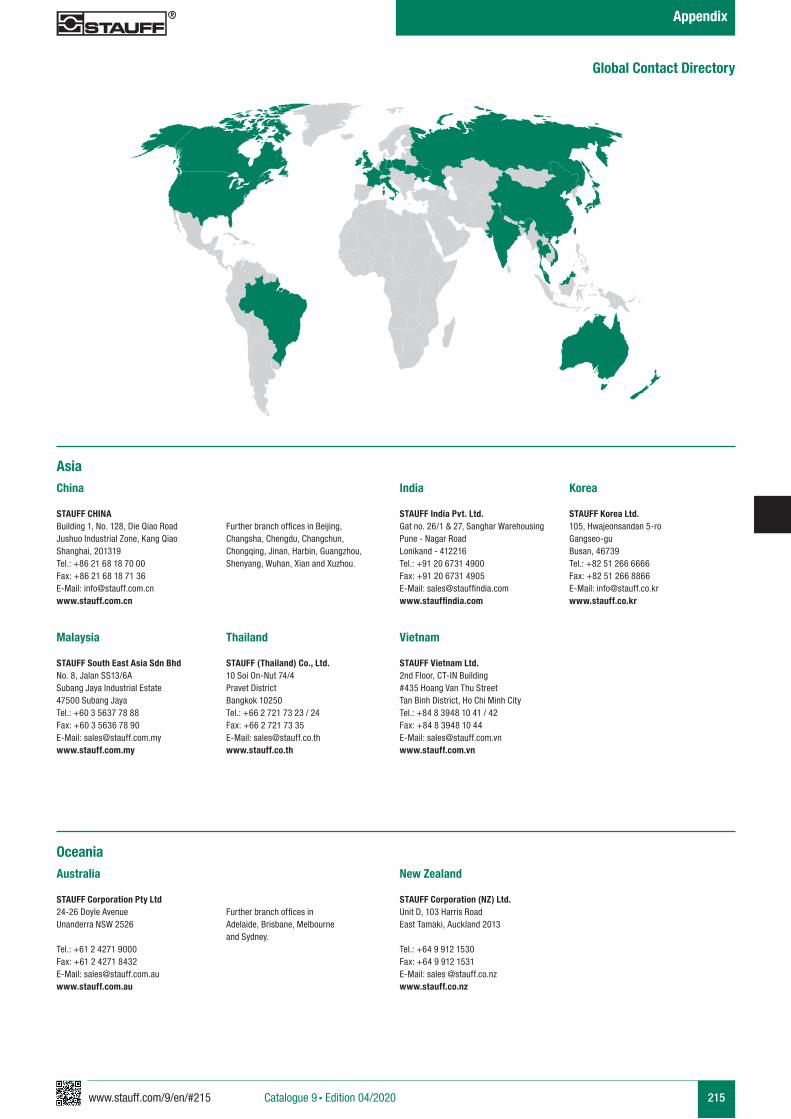
www.stauff.com/9/en/#215 215Catalogue 9 § Edition 04/2020
Appendix
AsiaChina
STAUFF CHINABuilding 1, No. 128, Die Qiao RoadJushuo Industrial Zone, Kang QiaoShanghai, 201319Tel.: +86 21 68 18 70 00Fax: +86 21 68 18 71 36E-Mail: [email protected]
Further branch offices in Beijing, Changsha, Chengdu, Changchun, Chongqing, Jinan, Harbin, Guangzhou, Shenyang, Wuhan, Xian and Xuzhou.
India
STAUFF India Pvt. Ltd.Gat no. 26/1 & 27, Sanghar WarehousingPune - Nagar RoadLonikand - 412216Tel.: +91 20 6731 4900Fax: +91 20 6731 4905E-Mail: [email protected]
Korea
STAUFF Korea Ltd.105, Hwajeonsandan 5-roGangseo-guBusan, 46739Tel.: +82 51 266 6666Fax: +82 51 266 8866E-Mail: [email protected]
Malaysia
STAUFF South East Asia Sdn BhdNo. 8, Jalan SS13/6ASubang Jaya Industrial Estate47500 Subang JayaTel.: +60 3 5637 78 88Fax: +60 3 5636 78 90E-Mail: [email protected]
Thailand
STAUFF (Thailand) Co., Ltd.10 Soi On-Nut 74/4Pravet DistrictBangkok 10250Tel.: +66 2 721 73 23 / 24Fax: +66 2 721 73 35E-Mail: [email protected]
Vietnam
STAUFF Vietnam Ltd.2nd Floor, CT-IN Building#435 Hoang Van Thu StreetTan Binh District, Ho Chi Minh CityTel.: +84 8 3948 10 41 / 42Fax: +84 8 3948 10 44E-Mail: [email protected]
OceaniaAustralia
STAUFF Corporation Pty Ltd24-26 Doyle AvenueUnanderra NSW 2526
Tel.: +61 2 4271 9000Fax: +61 2 4271 8432E-Mail: [email protected]
Further branch offices in Adelaide, Brisbane, Melbourne and Sydney.
New Zealand
STAUFF Corporation (NZ) Ltd.Unit D, 103 Harris RoadEast Tamaki, Auckland 2013
Tel.: +64 9 912 1530Fax: +64 9 912 1531E-Mail: sales @stauff.co.nzwww.stauff.co.nz
Global Contact Directory
Catalogue 9
STAUFF Filtration Technology
Germany Walter Stauffenberg GmbH & Co. KG Im Ehrenfeld 458791 Werdohl Tel.: +49 2392 91 60Fax: +49 2392 91 61 03E-Mail: [email protected]
STAUFF products and services are globally available through wholly-owned subsidiaries and a tight network of authorised distributors and representatives in all major industrial regions of the world. You can find detailed contact information on the last two pages of this product catalogue or at
www.stauff.com
Catalogue 9 STAUFF Filtration Technology § English § 9910000429 § 04/2020
Filtration Guideline
Replacement Filter Elements
Pressure Filters
Return-Line Filters
In-Line Filters
Offline and Bypass Filters
Introduction
Spin-On Filters
Filtration Systems
Appendix