Embed Size (px)
Citation preview
Open Access.© 2019 C. Kurien and A. Kumar Srivastava, published by Sciendo. This work is licensed under the Creative CommonsAttribution-NonCommercial-NoDerivatives 4.0 License
Mechanics and Mechanical Engineering 2019; 23:70–75
Research Article
Caneon Kurien* and Ajay Kumar Srivastava
Case study on the effectiveness of conditionmonitoring techniques for fault diagnosis ofpumps in thermal power planthttps://doi.org/10.2478/mme-2019-0010Received Mar 27, 2018; revised Oct 02, 2018; accepted Nov 20, 2018
Abstract:A case study was carried out to investigate the ef-fectiveness of conditionmonitoring techniques in the earlyfailure detection of pumps in a thermal power plant. Var-ious condition monitoring techniques used in this casestudy involved vibration analysis, motor current signa-ture analysis, noise monitoring and wear debris analy-sis. These techniques were applied on the three pumps,namely boiler feed water pump, auxiliary cooling waterpump and condensate extraction pump, which have towork continuously for the operation of the thermal powerplant. Vibration analysis of the auxiliary cooling waterpump showed that there is a rising trend in the accelera-tion values at its driving and non-driving end indicatingthe deterioration of bearings. Motor current index rangeof all the pumps was found to be within acceptable limits.Wear debris analysis of lubricant in the hydraulic couplingof boiler feed water pump indicated the presence of sand,dirt and low alloy steel sliding wear particles in it. Condi-tion monitoring techniques have been proved to be an ef-fective technique in early failure detection of pumps.
Keywords:Maintenance, monitoring, spectrum, vibration,wear
1 IntroductionCondition monitoring is a maintenance technique for thediagnosis of defects in machineries, while it is in workingmode so that its operationwill not be interrupted [1]. It acts
*Corresponding Author: Caneon Kurien:Mechanical EngineeringDepartment, University of Petroleum and Energy Studies, School ofEngineering, Dehradun 248007, Uttarakhand, India;Email: [email protected] Kumar Srivastava:Mechanical Engineering Department,University of Petroleum and Energy Studies, School of Engineering,Dehradun 248007, Uttarakhand, India
as an effective tool in the forecasting of maintenance andalso avoids the chances of catastrophic failure [2]. Ther-mal power plants require continuous operation of a num-ber of pumps for effective generation of electricity. Variouspumps used in thermal power plants include boiler feedwater pump, condensate extraction pump, auxiliary cool-ing water pump, ash disposal pump, seal oil pump andvarious other pumps [3]. Major condition monitoring tech-niques used in pumps are vibrationmonitoring,motor cur-rent signature analysis, noise monitoring and wear debrisanalysis [4].
Vibrations are produced due to the excitation forcesgenerated in the machines during the operation [5]. Ma-jor reasons for vibrations in the pumps include rotor im-balance, shaft misalignment, bearing damage, wear ringdislocation, electrical and hydraulic defects. Vibrations inthe bodywill be in axial, horizontal and vertical directions,which make it mandatory to measure the amplitude of vi-brations in all three directions at the testing point [6]. Theamplitude is expressed in terms of displacement, velocityand acceleration depending upon the frequency and oper-ating speed of the machinery [7]. Vibrations are measuredin terms of displacementwhen the speed range is less than600 rpm and occurs mostly in dynamic stress conditions.When the operating speed ranges from 600 to 60000 rpm,the vibrations are expressed in terms of velocity, since itis developed under conditions of fatigue. In cases whenhigher frequencies are produced by forces and the speedis above 60000 rpm, vibrations are measured in terms ofacceleration [8]. Vibration analyzers are used for pickingup the characteristic vibration spectrum of machines andit also applies the fast Fourier transform technique to con-vert the original time signal [9]. The sensors are attachedto the testing points and the data related to variation invibration level is captured by the sensors, and it is sent tothe analyzers where the spectrum is generated for analysispurpose.
Motor current signature analysis (MCSA) involves themonitoring of current in the induction motor by the anal-ysis of the current spectrum for spotting the fault frequen-
Case study on the effectiveness of condition monitoring techniques for fault diagnosis | 71
Table 1: Vibration readings of ACW pump before and after maintenance
Reading Point Horizontal (mm/sec) Vertical (mm/sec) Axial (mm/sec) Acceleration (g)Before After Before After Before After Before After
Motor non-driving end (NDE) 2.31 2.21 2.27 2.23 2.19 2.54 0.88 0.86Motor driving end (DE) 2.67 2.43 2.15 2.37 2.52 2.29 0.93 0.77
Pump non-driving end (NDE) 3.43 2.21 2.25 1.67 2.14 1.45 2.73 0.71Pump driving end (DE) 4.22 2.35 2.56 1.23 2.02 1.13 1.62 0.63
cies [10]. Higher resistance spots are developed in the loca-tion of faults,which give rise to harmonic fluxes inducing acurrent component in the stator winding [11]. This currentcomponent results in supply current modulation at polepass frequency. Hall effect current sensor is used for cap-turing the current modulation by clamping it with the cir-cuit and the readings are transferred to fast Fourier trans-form analyzer for generating the spectrum. In industries,thenoise levelsmust be continuouslymonitored andmain-tained within limits in order to avoid its adverse effects onworkers [12]. Noise levels aremonitored byusing the acous-tic and ultrasonic noise meters.[13] Wear debris analysis iscarried out to determine the concentration of wear parti-cles in the lubricants used [14]. It is carried out by takinga sample of lubrication oil and subjecting it to ferrogra-phy for separating the wear debris and contaminant parti-cles [15]. Then, the contamination levels are determined byusing the particle count test [16]. Presence of the wear par-ticles will also lead to corrosion of the components in thecoupling [17, 18]. In this paper, a detailed study on the ef-fectiveness of these condition monitoring techniques wascarried out by applying these to the three pumps, namelyboiler feed water pump, condensate extraction pump andauxiliary cooling water pump.
2 Condition Monitoring Analysis ofPumps
The condition monitoring of pumps was carried out byemploying five techniques, namely vibration analysis, mo-tor current signature analysis and noise monitoring usingacoustic and ultrasonic noise meters.
2.1 Auxiliary Cooling Water (ACW) Pump
Auxiliary cooling water pump was used for pumping cool-ing water to the plate heat exchangers for cooling theEquipment cooling water (raw water). The cooling water
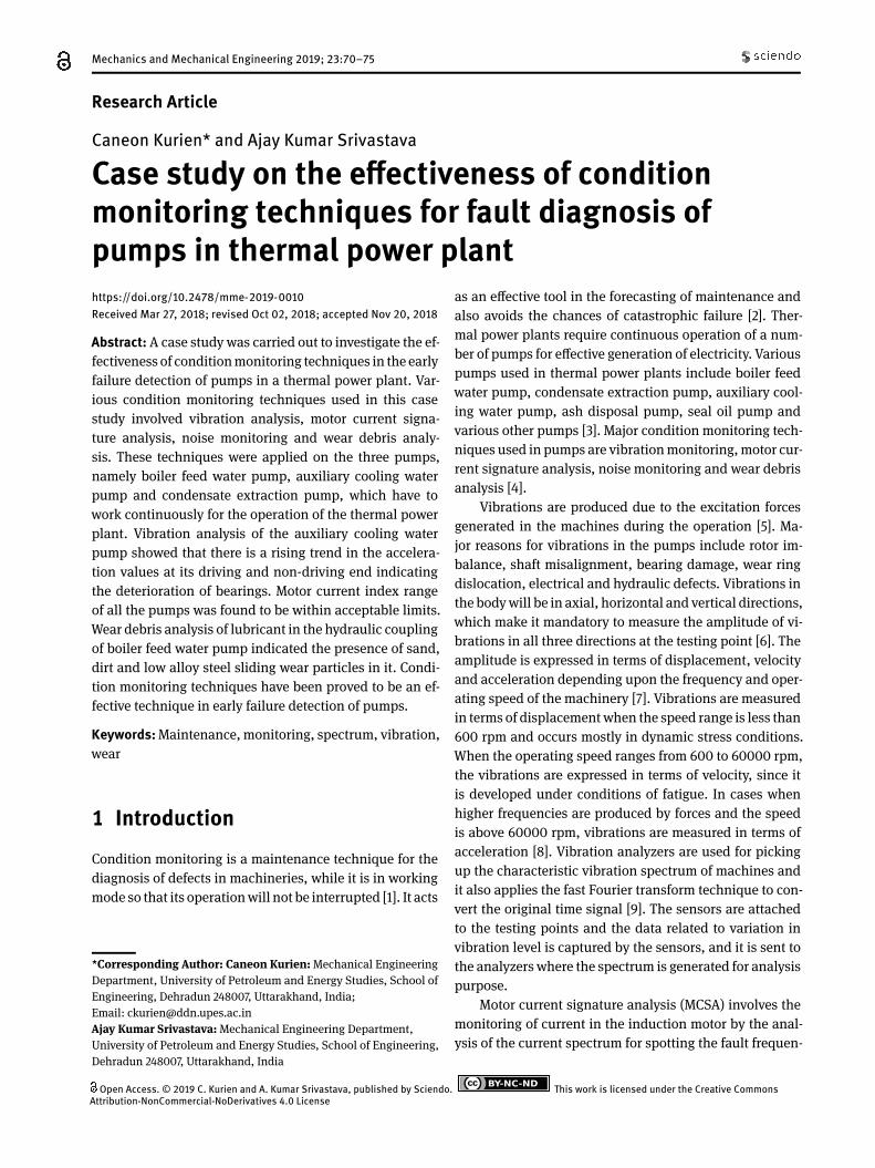
used in ACWpumpswas sea water and it was taken by tap-ping the condenser piping. A bypass was taken from thecooling water pumped by the CW pumps. Vibration read-ings were taken from points as shown in Figure 1.
Figure 1: Vibration reading points of ACW pump
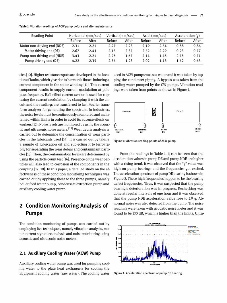
From the readings in Table 1, it can be seen that theacceleration values in pump DE and pump NDE are higherwith a rising trend. It was observed that the “g” value washigh on pump bearings and the frequencies got excited.The acceleration spectrumof pumpDEbearing is shown inFigure 2. These high frequencies happen to be the bearingdefect frequencies. Thus, it was suspected that the pumpbearing’s deterioration was in progress. Rechecking wasdone at regular intervals of one hour and it was observedthat the pump NDE acceleration value rose to 2.9 g. Ab-normal noise was also detected from the pump. The noisereadings were taken with acoustic noise meter and it wasfound to be 130 dB, which is higher than the limits. Ultra-
Figure 2: Acceleration spectrum of pump DE bearing
72 | C. Kurien and A. Kumar Srivastava
sonic noise meter was then used to detect the exact loca-tion of the noise source and to find the intensity of theflaw. Ultrasonic noise meter detected sounds of continu-ous hitting over shaft and it showed intensity level of 8LEDs, which is supposed to be in limits of 5 LEDs. Loose-ness of bearing or wear ring in the pump was suspectedwith inference from the observed readings. Since motorvibration readings were well within limits, there was noneedofmaintenance onmotor and electrical side.Mechan-ical maintenance of the pump had to be carried out.
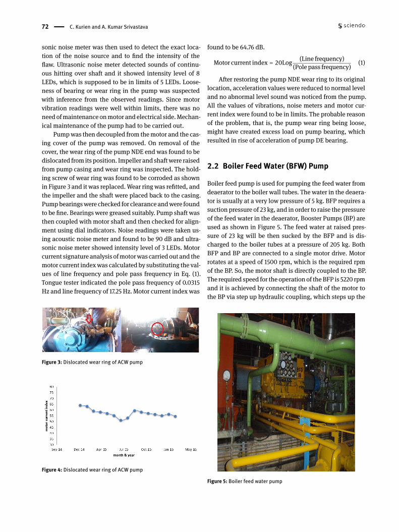
Pumpwas then decoupled from themotor and the cas-ing cover of the pump was removed. On removal of thecover, the wear ring of the pump NDE end was found to bedislocated from its position. Impeller and shaftwere raisedfrom pump casing and wear ring was inspected. The hold-ing screw of wear ring was found to be corroded as shownin Figure 3 and it was replaced.Wear ring was refitted, andthe impeller and the shaft were placed back to the casing.Pumpbearingswere checked for clearance andwere foundto be fine. Bearings were greased suitably. Pump shaft wasthen coupled with motor shaft and then checked for align-ment using dial indicators. Noise readings were taken us-ing acoustic noise meter and found to be 90 dB and ultra-sonic noise meter showed intensity level of 3 LEDs. Motorcurrent signature analysis ofmotorwas carried out and themotor current indexwas calculated by substituting the val-ues of line frequency and pole pass frequency in Eq. (1).Tongue tester indicated the pole pass frequency of 0.0315Hz and line frequency of 17.25 Hz. Motor current index was
Figure 3: Dislocated wear ring of ACW pump
Figure 4: Dislocated wear ring of ACW pump
found to be 64.76 dB.
Motor current index = 20Log (Line frequency)(Pole pass frequency) (1)
After restoring the pump NDE wear ring to its originallocation, acceleration values were reduced to normal leveland no abnormal level sound was noticed from the pump.All the values of vibrations, noise meters and motor cur-rent index were found to be in limits. The probable reasonof the problem, that is, the pump wear ring being loose,might have created excess load on pump bearing, whichresulted in rise of acceleration of pump DE bearing.
2.2 Boiler Feed Water (BFW) Pump
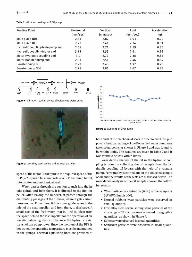
Boiler feed pump is used for pumping the feed water fromdeaerator to the boiler wall tubes. The water in the deaera-tor is usually at a very low pressure of 5 kg. BFP requires asuction pressure of 23 kg, and in order to raise the pressureof the feed water in the deaerator, Booster Pumps (BP) areused as shown in Figure 5. The feed water at raised pres-sure of 23 kg will be then sucked by the BFP and is dis-charged to the boiler tubes at a pressure of 205 kg. BothBFP and BP are connected to a single motor drive. Motorrotates at a speed of 1500 rpm, which is the required rpmof the BP. So, the motor shaft is directly coupled to the BP.The required speed for the operation of theBFP is 5220 rpmand it is achieved by connecting the shaft of the motor tothe BP via step up hydraulic coupling, which steps up the
Figure 5: Boiler feed water pump
Case study on the effectiveness of condition monitoring techniques for fault diagnosis | 73
Table 2: Vibration readings of BFW pump
Reading Point Horizontal(mm/sec)
Vertical(mm/sec)
Axial(mm/sec)
Acceleration(g)
Main pump NDE 2.31 2.82 1.93 0.72Main pump DE 2.22 2.41 2.34 0.91Hydraulic coupling-Main pump end 2.34 2.71 2.19 0.80Hydraulic coupling-Motor end 3.12 2.53 2.61 0.93Motor-Hydraulic coupling end 3.0 2.77 2.38 0.85Motor-Booster pump end 2.81 2.51 2.46 0.89Booster pump DE 2.23 2.48 1.97 0.73Booster pump NDE 2.78 2.85 2.67 0.83
Figure 6: Vibration reading points of boiler feed water pump
Figure 7: Low alloy steel severe sliding wear particles
speed of the motor (1500 rpm) to the required speed of theBFP (5220 rpm). The main parts of a BFP are pump barrel,rotor, stator and mechanical seal.
Water passes through the suction branch into the in-take spiral, and from there, it is directed to the first im-peller. After leaving the impeller, it passes through thedistributing passages of the diffuser, where it gets certainpressure rise. From there, it flows over guide vanes to theinlet of the next impeller, and from there, to discharge. Asmall part of the feed water, that is, 10% is taken fromthe space behind the last impeller for the operation of au-tomatic balancing device to balance the hydraulic axialthrust of the pump rotor. Since the medium of the BFP ishot water, the operating temperature must be maintainedin the pumps. Thermal equalizing lines are provided at
Figure 8:MCI trend of BPW pump
both ends of themechanical seals in order tomeet this pur-pose. Vibration readings of theBoiler feedwater pumpwastaken from points as shown in Figure 6 and was found tobe within limits. The readings are given in Table 2 and itwas found to be well within limits.
Wear debris analysis of the oil in the hydraulic cou-pling is done by collecting the oil sample from the hy-draulic coupling oil bypass with the help of a vacuumpump. Ferrography is carried out on the collected sampleof oil and the results of the tests are discussed below. Thewear debris analysis of the oil sample showed the follow-ing results:
• Wear particle concentration (WPC) of the sample is3.5 WPC (limit is 100).
• Normal rubbing wear particles were observed insmall quantities.
• Low alloy steel severe sliding wear particles of thesize range of 24 microns were observed in negligiblequantities, as shown in Figure 7.
• Spheres were observed in small quantities.• Sand/dirt particles were observed in small quanti-ties.
74 | C. Kurien and A. Kumar Srivastava
Table 3: Vibration readings of BFW pump
Reading Point Horizontal(mm/sec)
Vertical(mm/sec)
Axial(mm/sec)
Acceleration(g)
Motor non-driving end (NDE) 2.21 1.95 1.86 0.92Motor driving end (DE) 2.82 2.37 2.53 0.97Pump driving end (DE) 2.93 2.74 2.51 0.87
Motor current signature analysis of motor was carriedout and the motor current index was calculated to be 61.72dB, when the line frequency was found to be 15.9 and polepass frequencywas found to be 0.0125. The trend ofMCI fora period of two years is shown in Figure 8. Noise monitor-ing of the boiler feed water pump was measured using anacoustic noise meter (110dB) and an ultrasonic noise me-ter (3–5 LEDs). The noise reading and theMCI index valueswere found to be well within limits.
2.3 Condensate Extraction Pump (CEP)
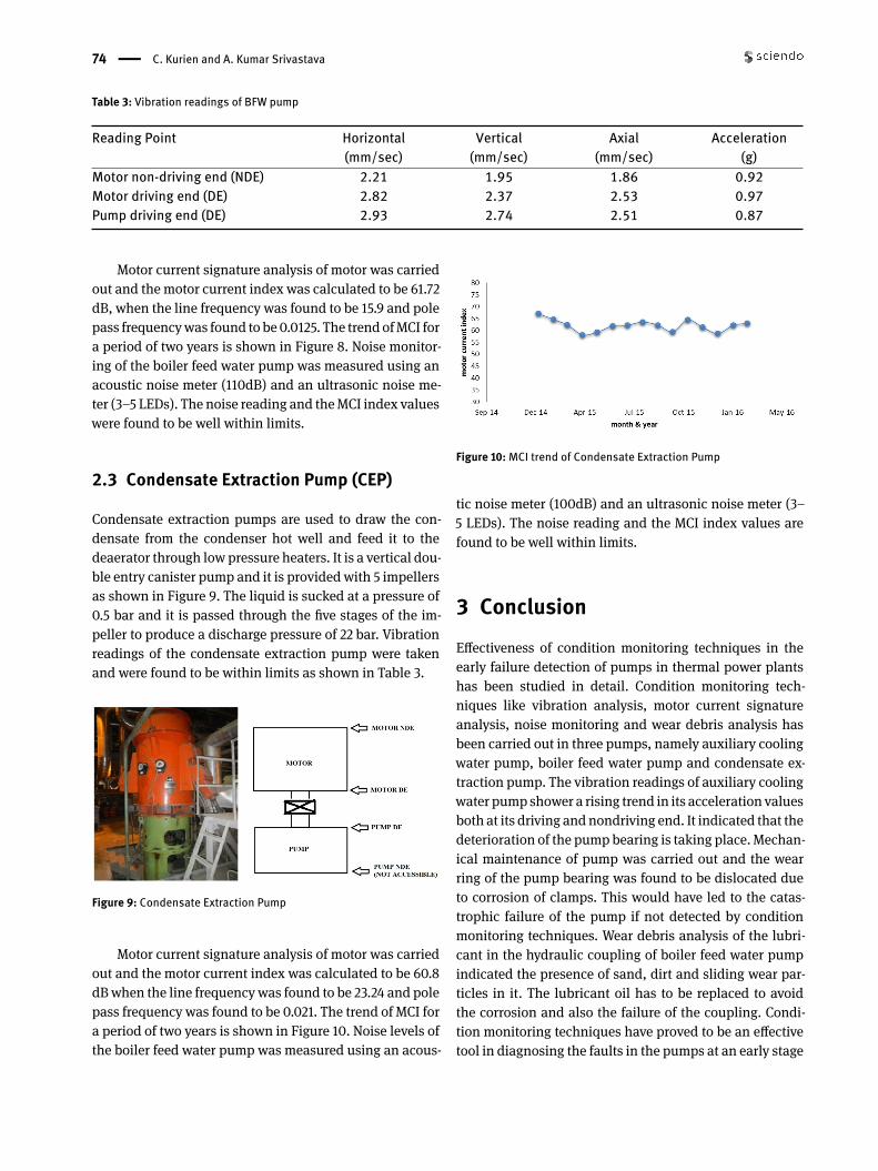
Condensate extraction pumps are used to draw the con-densate from the condenser hot well and feed it to thedeaerator through low pressure heaters. It is a vertical dou-ble entry canister pump and it is providedwith 5 impellersas shown in Figure 9. The liquid is sucked at a pressure of0.5 bar and it is passed through the five stages of the im-peller to produce a discharge pressure of 22 bar. Vibrationreadings of the condensate extraction pump were takenand were found to be within limits as shown in Table 3.
Figure 9: Condensate Extraction Pump
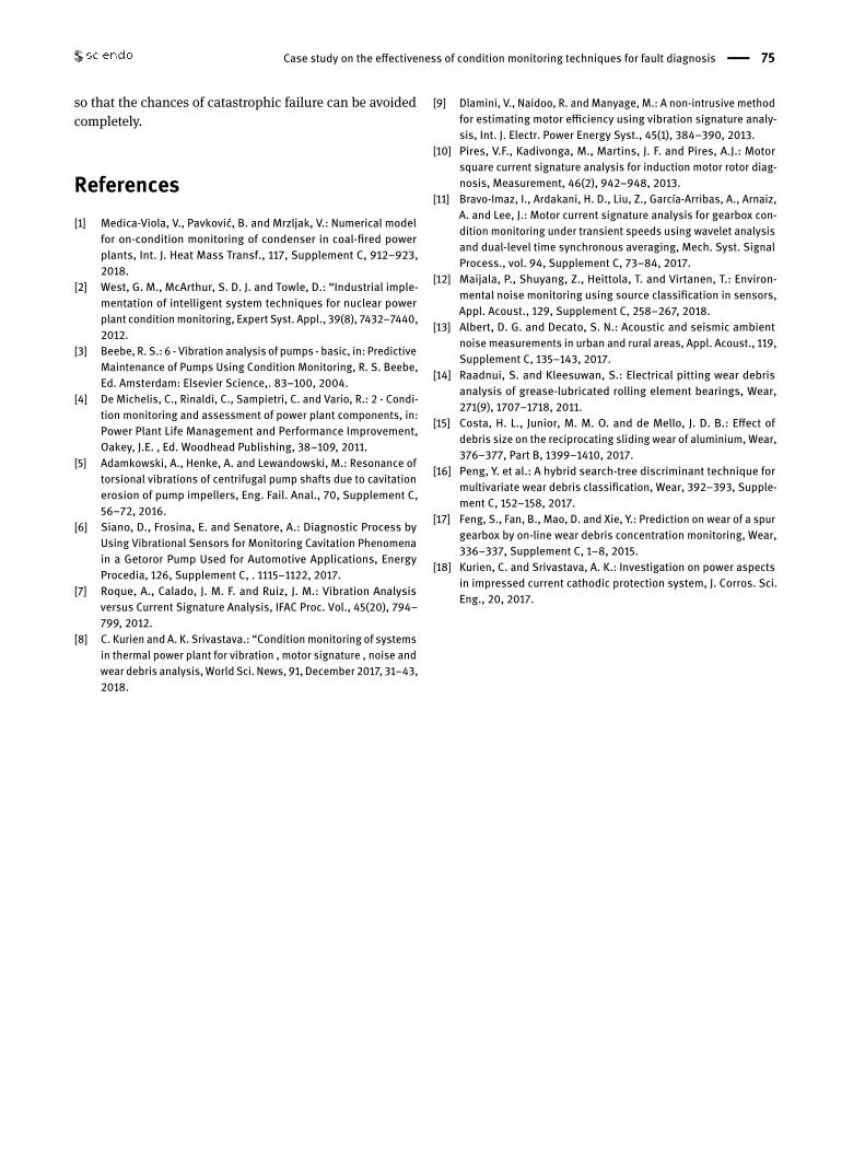
Motor current signature analysis of motor was carriedout and the motor current index was calculated to be 60.8dBwhen the line frequencywas found to be 23.24 and polepass frequency was found to be 0.021. The trend of MCI fora period of two years is shown in Figure 10. Noise levels ofthe boiler feed water pump was measured using an acous-
Figure 10:MCI trend of Condensate Extraction Pump
tic noise meter (100dB) and an ultrasonic noise meter (3–5 LEDs). The noise reading and the MCI index values arefound to be well within limits.
3 ConclusionEffectiveness of condition monitoring techniques in theearly failure detection of pumps in thermal power plantshas been studied in detail. Condition monitoring tech-niques like vibration analysis, motor current signatureanalysis, noise monitoring and wear debris analysis hasbeen carried out in three pumps, namely auxiliary coolingwater pump, boiler feed water pump and condensate ex-traction pump. The vibration readings of auxiliary coolingwater pump shower a rising trend in its acceleration valuesboth at its driving andnondriving end. It indicated that thedeterioration of the pump bearing is taking place. Mechan-ical maintenance of pump was carried out and the wearring of the pump bearing was found to be dislocated dueto corrosion of clamps. This would have led to the catas-trophic failure of the pump if not detected by conditionmonitoring techniques. Wear debris analysis of the lubri-cant in the hydraulic coupling of boiler feed water pumpindicated the presence of sand, dirt and sliding wear par-ticles in it. The lubricant oil has to be replaced to avoidthe corrosion and also the failure of the coupling. Condi-tion monitoring techniques have proved to be an effectivetool in diagnosing the faults in the pumps at an early stage
Case study on the effectiveness of condition monitoring techniques for fault diagnosis | 75
so that the chances of catastrophic failure can be avoidedcompletely.
References[1] Medica-Viola, V., Pavković, B. and Mrzljak, V.: Numerical model
for on-condition monitoring of condenser in coal-fired powerplants, Int. J. Heat Mass Transf., 117, Supplement C, 912–923,2018.
[2] West, G. M., McArthur, S. D. J. and Towle, D.: “Industrial imple-mentation of intelligent system techniques for nuclear powerplant conditionmonitoring, Expert Syst. Appl., 39(8), 7432–7440,2012.
[3] Beebe, R. S.: 6 - Vibration analysis of pumps - basic, in: PredictiveMaintenance of Pumps Using Condition Monitoring, R. S. Beebe,Ed. Amsterdam: Elsevier Science,. 83–100, 2004.
[4] De Michelis, C., Rinaldi, C., Sampietri, C. and Vario, R.: 2 - Condi-tion monitoring and assessment of power plant components, in:Power Plant Life Management and Performance Improvement,Oakey, J.E. , Ed. Woodhead Publishing, 38–109, 2011.
[5] Adamkowski, A., Henke, A. and Lewandowski, M.: Resonance oftorsional vibrations of centrifugal pump shafts due to cavitationerosion of pump impellers, Eng. Fail. Anal., 70, Supplement C,56–72, 2016.
[6] Siano, D., Frosina, E. and Senatore, A.: Diagnostic Process byUsing Vibrational Sensors for Monitoring Cavitation Phenomenain a Getoror Pump Used for Automotive Applications, EnergyProcedia, 126, Supplement C, . 1115–1122, 2017.
[7] Roque, A., Calado, J. M. F. and Ruiz, J. M.: Vibration Analysisversus Current Signature Analysis, IFAC Proc. Vol., 45(20), 794–799, 2012.
[8] C. Kurien and A. K. Srivastava.: “Conditionmonitoring of systemsin thermal power plant for vibration , motor signature , noise andwear debris analysis,World Sci. News, 91, December 2017, 31–43,2018.
[9] Dlamini, V., Naidoo, R. andManyage, M.: A non-intrusive methodfor estimating motor eflciency using vibration signature analy-sis, Int. J. Electr. Power Energy Syst., 45(1), 384–390, 2013.
[10] Pires, V.F., Kadivonga, M., Martins, J. F. and Pires, A.J.: Motorsquare current signature analysis for induction motor rotor diag-nosis, Measurement, 46(2), 942–948, 2013.
[11] Bravo-Imaz, I., Ardakani, H. D., Liu, Z., García-Arribas, A., Arnaiz,A. and Lee, J.: Motor current signature analysis for gearbox con-dition monitoring under transient speeds using wavelet analysisand dual-level time synchronous averaging, Mech. Syst. SignalProcess., vol. 94, Supplement C, 73–84, 2017.
[12] Maijala, P., Shuyang, Z., Heittola, T. and Virtanen, T.: Environ-mental noise monitoring using source classification in sensors,Appl. Acoust., 129, Supplement C, 258–267, 2018.
[13] Albert, D. G. and Decato, S. N.: Acoustic and seismic ambientnoise measurements in urban and rural areas, Appl. Acoust., 119,Supplement C, 135–143, 2017.
[14] Raadnui, S. and Kleesuwan, S.: Electrical pitting wear debrisanalysis of grease-lubricated rolling element bearings, Wear,271(9), 1707–1718, 2011.
[15] Costa, H. L., Junior, M. M. O. and de Mello, J. D. B.: Effect ofdebris size on the reciprocating sliding wear of aluminium, Wear,376–377, Part B, 1399–1410, 2017.
[16] Peng, Y. et al.: A hybrid search-tree discriminant technique formultivariate wear debris classification, Wear, 392–393, Supple-ment C, 152–158, 2017.
[17] Feng, S., Fan, B., Mao, D. and Xie, Y.: Prediction on wear of a spurgearbox by on-line wear debris concentration monitoring, Wear,336–337, Supplement C, 1–8, 2015.
[18] Kurien, C. and Srivastava, A. K.: Investigation on power aspectsin impressed current cathodic protection system, J. Corros. Sci.Eng., 20, 2017.


