Embed Size (px)
Citation preview
User's ManualK6PM-TH
Thermal ConditionMonitoring Device
Appendices
Index
Installation and Wiring
Outline
Monitoring and Setting with the EtherNet/IP
Communications
Monitoring the Temperature in Control Panel with the Main Unit and the Software Tool
Initial Settings
Troubleshooting
Monitoring and Setting with the Modbus TCP
1
2
3
4
5
6
7
8
I
H231-E1-03

CopyrightsMicrosoft product screen shots reprinted with permission from Microsoft Corporation.
All rights reserved. No part of this publication may be reproduced, stored in a retrieval system, or transmitted, in any form, or by any means, mechanical, electronic, photocopying, recording, or otherwise, without the prior written permission of OMRON.
No patent liability is assumed with respect to the use of the information contained herein. Moreover, because OMRON is constantly striving to improve its high-quality products, the information contained in this manual is subject to change without notice. Every precaution has been taken in the preparation of this manual. Neverthe-less, OMRON assumes no responsibility for errors or omissions. Neither is any liability assumed for damages resulting from the use of the information contained in this publication.
NOTE
• Microsoft, Windows is either registered trademarks or trademarks of Microsoft Corporation in the United States and other countries.
• ODVA, CIP, CompoNet, DeviceNet, and EtherNet/IP are trademarks of ODVA.• Modbus is a registered trademark of Schneider Electric.
Other company names and product names in this document are the trademarks or registered trademarks of their respective companies.
Trademarks

1
Preface
K6PM-TH Thermal Condition Monitoring Device User’s Manual (H231)
Preface
Thank you for purchasing the K6PM-TH Thermal Condition Monitoring Device. This manual describes how to use the K6PM-TH.Read this manual thoroughly and be sure you understand it before attempting to use the K6PM-TH cor-rectly according to the information provided. Keep this manual in a safe place for easy reference.
PDF version of this manual can be downloaded from the OMRON website. (http://www.omron.com)
Terms and Conditions Agreement
2 K6PM-TH Thermal Condition Monitoring Device User’s Manual (H231)
Terms and Conditions Agreement
Exclusive WarrantyOmron’s exclusive warranty is that the Products will be free from defects in materials and workman-ship for a period of twelve months from the date of sale by Omron (or such other period expressed in writing by Omron). Omron disclaims all other warranties, express or implied.
LimitationsOMRON MAKES NO WARRANTY OR REPRESENTATION, EXPRESS OR IMPLIED, ABOUT NON-INFRINGEMENT, MERCHANTABILITY OR FITNESS FOR A PARTICULAR PURPOSE OF THE PRODUCTS. BUYER ACKNOWLEDGES THAT IT ALONE HAS DETERMINED THAT THE PRODUCTS WILL SUITABLY MEET THE REQUIREMENTS OF THEIR INTENDED USE.Omron further disclaims all warranties and responsibility of any type for claims or expenses based on infringement by the Products or otherwise of any intellectual property right.
Buyer RemedyOmron’s sole obligation hereunder shall be, at Omron’s election, to (i) replace (in the form originally shipped with Buyer responsible for labor charges for removal or replacement thereof) the non-com-plying Product, (ii) repair the non-complying Product, or (iii) repay or credit Buyer an amount equal to the purchase price of the non-complying Product; provided that in no event shall Omron be responsible for warranty, repair, indemnity or any other claims or expenses regarding the Products unless Omron’s analysis confirms that the Products were properly handled, stored, installed and maintained and not subject to contamination, abuse, misuse or inappropriate modification. Return of any Products by Buyer must be approved in writing by Omron before shipment. Omron Companies shall not be liable for the suitability or unsuitability or the results from the use of Products in combi-nation with any electrical or electronic components, circuits, system assemblies or any other materi-als or substances or environments. Any advice, recommendations or information given orally or in writing, are not to be construed as an amendment or addition to the above warranty.
See http://www.omron.com/global/ or contact your Omron representative for published information.
OMRON COMPANIES SHALL NOT BE LIABLE FOR SPECIAL, INDIRECT, INCIDENTAL, OR CON-SEQUENTIAL DAMAGES, LOSS OF PROFITS OR PRODUCTION OR COMMERCIAL LOSS IN ANY WAY CONNECTED WITH THE PRODUCTS, WHETHER SUCH CLAIM IS BASED IN CONTRACT, WARRANTY, NEGLIGENCE OR STRICT LIABILITY.
Further, in no event shall liability of Omron Companies exceed the individual price of the Product on which liability is asserted.
Warranty, Limitations of Liability
Warranties
Limitation on Liability; Etc
3
Terms and Conditions Agreement
K6PM-TH Thermal Condition Monitoring Device User’s Manual (H231)
Omron Companies shall not be responsible for conformity with any standards, codes or regulationswhich apply to the combination of the Product in the Buyer’s application or use of the Product. AtBuyer’s request, Omron will provide applicable third party certification documents identifying ratingsand limitations of use which apply to the Product. This information by itself is not sufficient for a com-plete determination of the suitability of the Product in combination with the end product, machine, sys-tem, or other application or use. Buyer shall be solely responsible for determining appropriateness ofthe particular Product with respect to Buyer’s application, product or system. Buyer shall take applica-tion responsibility in all cases. NEVER USE THE PRODUCT FOR AN APPLICATION INVOLVING SERIOUS RISK TO LIFE ORPROPERTY OR IN LARGE QUANTITIES WITHOUT ENSURING THAT THE SYSTEM AS A WHOLEHAS BEEN DESIGNED TO ADDRESS THE RISKS, AND THAT THE OMRON PRODUCT(S) ISPROPERLY RATED AND INSTALLED FOR THE INTENDED USE WITHIN THE OVERALL EQUIP-MENT OR SYSTEM.
Omron Companies shall not be responsible for the user’s programming of a programmable Product, orany consequence thereof.
Data presented in Omron Company websites, catalogs and other materials is provided as a guide forthe user in determining suitability and does not constitute a warranty. It may represent the result ofOmron’s test conditions, and the user must correlate it to actual application requirements. Actual perfor-mance is subject to the Omron’s Warranty and Limitations of Liability.
Product specifications and accessories may be changed at any time based on improvements and otherreasons. It is our practice to change part numbers when published ratings or features are changed, orwhen significant construction changes are made. However, some specifications of the Product may bechanged without any notice. When in doubt, special part numbers may be assigned to fix or establishkey specifications for your application. Please consult with your Omron’s representative at any time toconfirm actual specifications of purchased Product.
Information presented by Omron Companies has been checked and is believed to be accurate; how-ever, no responsibility is assumed for clerical, typographical or proofreading errors or omissions.
Application Considerations
Suitability of Use
Programmable Products
Disclaimers
Performance Data
Change in Specifications
Errors and Omissions
Safety Precautions
4 K6PM-TH Thermal Condition Monitoring Device User’s Manual (H231)
Safety Precautions
The following notation is used in this manual to provide precautions required to ensure safe usage of the K6PM-TH Thermal Condition Monitoring Device.
The safety precautions that are provided are extremely important to safety. Always read and heed the information provided in all safety precautions. The following notation is used.
Definition of Precautionary Information
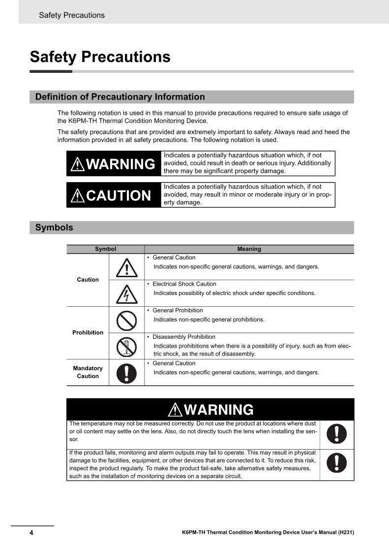
WARNINGIndicates a potentially hazardous situation which, if not avoided, could result in death or serious injury. Additionally there may be significant property damage.
CAUTIONIndicates a potentially hazardous situation which, if not avoided, may result in minor or moderate injury or in prop-erty damage.
Symbols
Symbol Meaning
Caution
• General CautionIndicates non-specific general cautions, warnings, and dangers.
• Electrical Shock CautionIndicates possibility of electric shock under specific conditions.
Prohibition
• General ProhibitionIndicates non-specific general prohibitions.
• Disassembly ProhibitionIndicates prohibitions when there is a possibility of injury, such as from elec-tric shock, as the result of disassembly.
Mandatory Caution
• General CautionIndicates non-specific general cautions, warnings, and dangers.
WARNINGThe temperature may not be measured correctly. Do not use the product at locations where dust or oil content may settle on the lens. Also, do not directly touch the lens when installing the sen-sor.
If the product fails, monitoring and alarm outputs may fail to operate. This may result in physical damage to the facilities, equipment, or other devices that are connected to it. To reduce this risk, inspect the product regularly. To make the product fail-safe, take alternative safety measures, such as the installation of monitoring devices on a separate circuit.
5
Safety Precautions
K6PM-TH Thermal Condition Monitoring Device User’s Manual (H231)
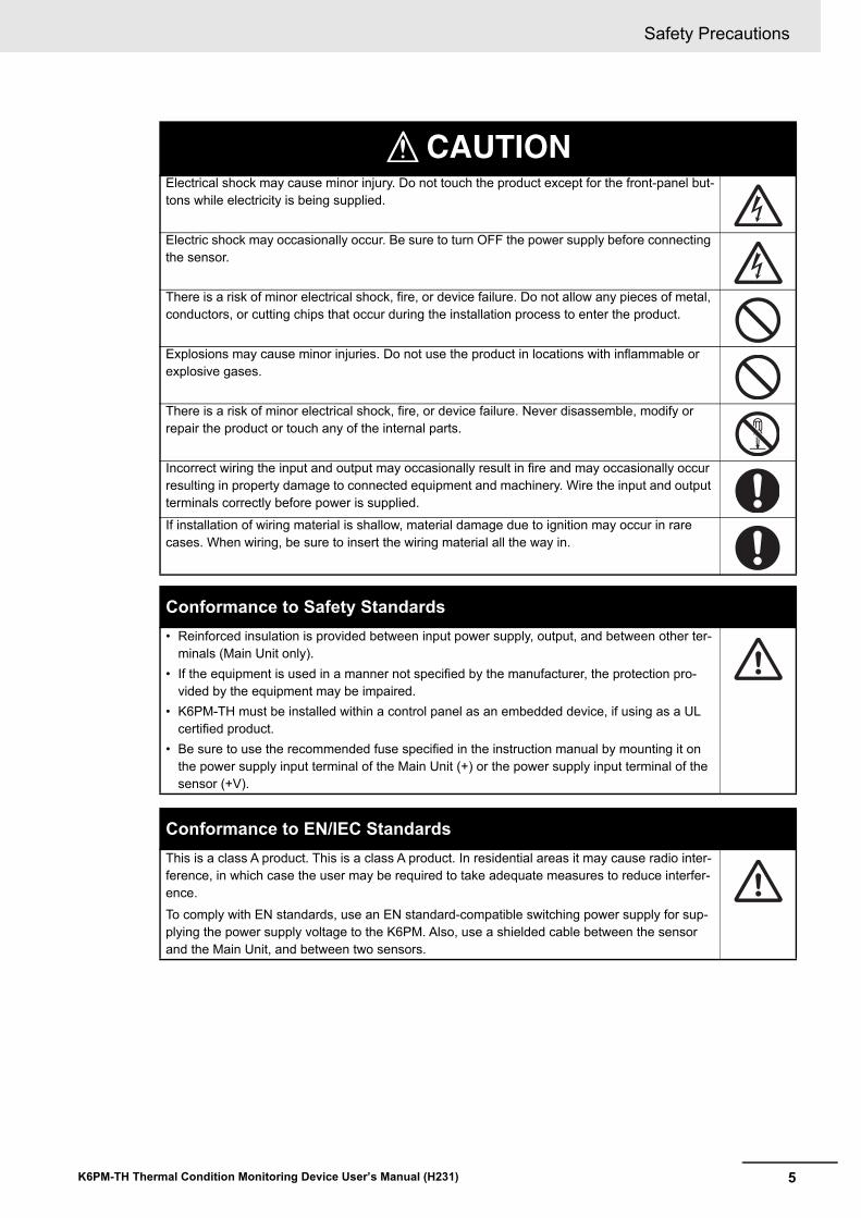
CAUTIONElectrical shock may cause minor injury. Do not touch the product except for the front-panel but-tons while electricity is being supplied.
Electric shock may occasionally occur. Be sure to turn OFF the power supply before connecting the sensor.
There is a risk of minor electrical shock, fire, or device failure. Do not allow any pieces of metal, conductors, or cutting chips that occur during the installation process to enter the product.
Explosions may cause minor injuries. Do not use the product in locations with inflammable or explosive gases.
There is a risk of minor electrical shock, fire, or device failure. Never disassemble, modify or repair the product or touch any of the internal parts.
Incorrect wiring the input and output may occasionally result in fire and may occasionally occur resulting in property damage to connected equipment and machinery. Wire the input and output terminals correctly before power is supplied.
If installation of wiring material is shallow, material damage due to ignition may occur in rare cases. When wiring, be sure to insert the wiring material all the way in.
Conformance to Safety Standards• Reinforced insulation is provided between input power supply, output, and between other ter-
minals (Main Unit only).• If the equipment is used in a manner not specified by the manufacturer, the protection pro-
vided by the equipment may be impaired.• K6PM-TH must be installed within a control panel as an embedded device, if using as a UL
certified product.• Be sure to use the recommended fuse specified in the instruction manual by mounting it on
the power supply input terminal of the Main Unit (+) or the power supply input terminal of the sensor (+V).
Conformance to EN/IEC StandardsThis is a class A product. This is a class A product. In residential areas it may cause radio inter-ference, in which case the user may be required to take adequate measures to reduce interfer-ence.To comply with EN standards, use an EN standard-compatible switching power supply for sup-plying the power supply voltage to the K6PM. Also, use a shielded cable between the sensor and the Main Unit, and between two sensors.
Precautions for Safe Use
6 K6PM-TH Thermal Condition Monitoring Device User’s Manual (H231)
Precautions for Safe Use
Be sure to observe the following precautions to prevent malfunction or adverse affects on the perfor-mance or functionality of the product. Not doing so may occasionally result in unexpected events. Do not handle the K6PM-TH in ways that exceed the ratings.
Common for the Main Unit and Sensor(1) Do not use or store the product in the following locations:
• Locations subject to water or oil• Outdoor or locations subject to direct sunlight• Locations subject to dust or corrosive gases (particularly sulfurizing gases, ammonia, etc.)• Locations subject to rapid temperature changes• Locations prone to icing and dew condensation• Locations subject to excessive vibration or shock• Locations subject to rain and wind damage• Locations subject to influence of static electricity and noise• Locations subject to bugs and small animals
(2) Use and store the product in a location where the ambient temperature and humidity are within the specified ranges. If applicable, provide forced cooling.
(3) Check terminal polarity when wiring and wire all connections correctly.(4) Do not wire the input and output terminals incorrectly.(5) Be sure the power voltage is within the rated range.(6) In order to prevent inductive noise, wire the lines connected to the product separately from power
lines carrying high voltages or currents. Also, do not wire in parallel with or on the same cables as power lines. Other measures for reducing noise are to separate from ducts including noisy lines.
(7) Do not use the product near radio wave receivers. Doing so may cause incoming radio wave inter-ference.
(8) When discarding the product, properly dispose of it as industrial waste.(9) The maximum terminal temperature is 80°C. Use wires with a heat resistance of 80°C min to wire
the terminals.(10) Don't use because it may be damaged inside the product when the product fall by mistake.(11) Confirm the wiring the input and output terminals correctly before power is supplied.(12) Do not bend a wire past its natural bending radius or pull on it with excessive force. Doing so may
cause the wire disconnection.(13) Use the cable within the length that is rated in the specification requirements for the wiring between
the sensor and the product. As for the requirements on the cable distance, refer to 2-3-3 I/O Wiring on page 2-17.
(14) Do not connect or disconnect the cables between the sensor and the product while power is being supplied. Doing so may result in malfunction or failure of the product.
(15) Do not place heavy objects on the cables between the sensor and the Product, and do not apply excessive force to bend or pull the cables. Doing so may cause a failure.
(16) When using the arrival prediction function, make sure multiple targets with different heat-emitting tendencies are not included in the segment, and at the same time, make sure the ambient tem-perature does not change rapidly due to the effect of the air-cooling fan, or the opening/closing of the control panel door, in order to correctly measure the arrival prediction.
(17) Do not install the product at a location where the sensor unit may be shaken due to vibrations or impact.
(18) Use this product inside the control panel to prevent external noise.
7
Precautions for Safe Use
K6PM-TH Thermal Condition Monitoring Device User’s Manual (H231)
(19) Use the wire given in this manual.(20) When wiring, wire by enough length.
Main Unit Only(1) Mount the product in the correct direction for installation.(2) Make sure the crimp terminals for wiring are of the specified size.(3) Do not connect anything to terminals that are not being used.(4) The alarm output function is a function for the output of an alarm when the set threshold value is
exceeded. Do not use this function for control, etc.(5) Make sure the LCD and the LEDs for output indicators operate correctly. Depending on the appli-
cation environment, the indicators and other plastic parts may wear prematurely and become diffi-cult to see. Check and replace these parts regularly.
(6) Be sure to use power terminals carefully, because power supply terminals have hazardous voltage.(7) Do not wire anything to the release holes.(8) Do not tilt or twist a flat-blade screwdriver while it is inserted into a release hole on the terminal
block. The terminal block may be damaged.(9) Insert a flat-blade screwdriver into the release holes at an angle. The terminal block may be dam-
aged if you insert the screwdriver straight in.(10) Do not allow the flat-blade screwdriver to fall out while it is inserted into a release hole.(11) The terminal block may be damaged if you insert a flat-blade screwdriver in the release hole with
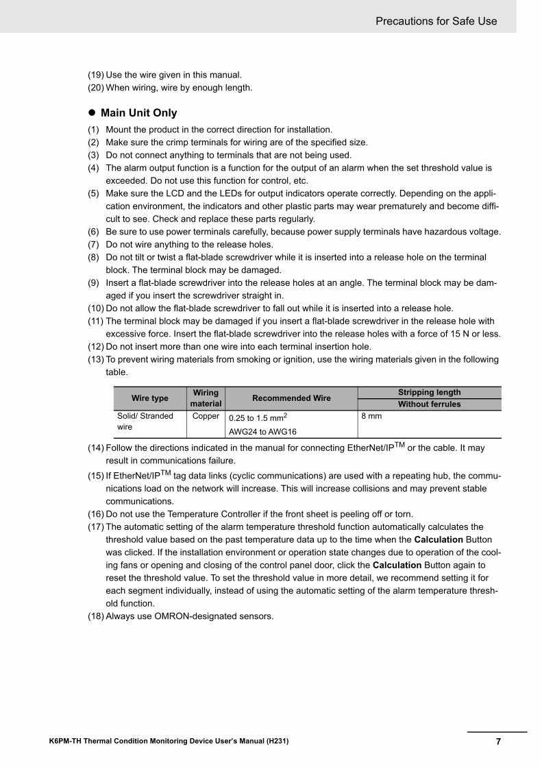
excessive force. Insert the flat-blade screwdriver into the release holes with a force of 15 N or less.(12) Do not insert more than one wire into each terminal insertion hole.(13) To prevent wiring materials from smoking or ignition, use the wiring materials given in the following
table.
(14) Follow the directions indicated in the manual for connecting EtherNet/IPTM or the cable. It may result in communications failure.
(15) If EtherNet/IPTM tag data links (cyclic communications) are used with a repeating hub, the commu-nications load on the network will increase. This will increase collisions and may prevent stable communications.
(16) Do not use the Temperature Controller if the front sheet is peeling off or torn.(17) The automatic setting of the alarm temperature threshold function automatically calculates the
threshold value based on the past temperature data up to the time when the Calculation Button was clicked. If the installation environment or operation state changes due to operation of the cool-ing fans or opening and closing of the control panel door, click the Calculation Button again to reset the threshold value. To set the threshold value in more detail, we recommend setting it for each segment individually, instead of using the automatic setting of the alarm temperature thresh-old function.
(18) Always use OMRON-designated sensors.
Wire type Wiring material Recommended Wire
Stripping lengthWithout ferrules
Solid/ Stranded wire
Copper 0.25 to 1.5 mm2 AWG24 to AWG16
8 mm
Precautions for Safe Use
8 K6PM-TH Thermal Condition Monitoring Device User’s Manual (H231)
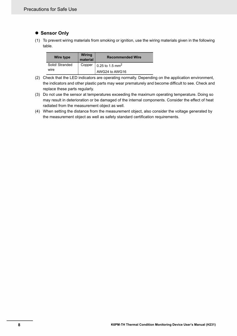
Sensor Only(1) To prevent wiring materials from smoking or ignition, use the wiring materials given in the following
table.
(2) Check that the LED indicators are operating normally. Depending on the application environment, the indicators and other plastic parts may wear prematurely and become difficult to see. Check and replace these parts regularly.
(3) Do not use the sensor at temperatures exceeding the maximum operating temperature. Doing so may result in deterioration or be damaged of the internal components. Consider the effect of heat radiated from the measurement object as well.
(4) When setting the distance from the measurement object, also consider the voltage generated by the measurement object as well as safety standard certification requirements.
Wire type Wiring material Recommended Wire
Solid/ Stranded wire
Copper 0.25 to 1.5 mm2
AWG24 to AWG16
9
Precautions for Correct Use
K6PM-TH Thermal Condition Monitoring Device User’s Manual (H231)
Precautions for Correct Use
Observe the following operating methods to prevent failure and malfunction.
Common for the Main Unit and Sensor(1) When cleaning the product, do not use thinners or solvents. Use commercial alcohol.(2) Confirm that wire does not stick up after wiring of stranded cable.(3) Do not install the product near equipment that generates high frequencies or surges.(4) Read this manual carefully before using the product.(5) Install product so that the load doesn't span the product body.(6) Only a professional with an understanding of electricity and electric devices must handle it.(7) Do not install the product close contact with the heating element.(8) During periodic inspection, installation of an additional sensor, or adjustment of sensor position,
use the product after ensuring that correct operation can be performed.(9) Do not use the product as a safety apparatus, or for the rescue of human lives.
Main Unit Only(1) Use the power supply voltage, input power, and other power supplies and transformers with suit-
able capacities and rated outputs.(2) If you wire crossovers and connect terminal blocks in parallel, a large current will flow. Make sure
that the current does not exceed 10 A.(3) The terminal block may be damaged if the recommended tool is not used. Use the recommended
flat-blade screwdriver to operate the release holes.(4) Do not bend the communications cables past its natural bending radius or pull on it with excessive
force. Do not place heavy objects on top of the communications cables or other wiring lines. Doing so may cause the wire disconnection.
(5) Refer to the status information of the product on the data link communications and refer to the received data only in case of no errors occur with the product.
(6) Use a power supply that will reach the rated voltage within 1 second after the power is turned ON.
Sensor Only(1) Note that if the sensor is tilted and installed, the measurement range will also tilt.(2) The sensor must be installed in a specific direction. Check the measurement range before install-
ing the sensor, and install the sensor in the correct direction.(3) The measurement range differs depending on the distance from the object to be measured up to
the sensor. Be sure to check the measurement range before installing the sensor.(4) The sensor is a special product. Do not use it for any other purposes. Otherwise, failure may occur.(5) When installing the sensor, make sure there is no obstacle between the measurement target and
the sensor as this could result in incorrect measurement of the temperature.(6) Do not use the alarm output function for control. This function can be used only to detect abnormal
conditions and to output the alarm.(7) When cleaning during periodic inspection, lightly wipe the surface with a dry, soft cloth. Also, do not
directly spray the cleaning solution on the sensor.(8) Do not forcibly remove the product. When power is supplied to the devices after re-installing the
product, it may result in incorrect operation or device damage.(9) The easy-positioning magnet is for the purpose of seeking the detected position. In the case of
using the product permanently, be sure to use it after it is mounted by screws.(10) When the product is installed vertically or upside down, ensure that the sensor does not fall off.
Precautions for Correct Use
10 K6PM-TH Thermal Condition Monitoring Device User’s Manual (H231)
(11) Refer to 2-2-3 Installation of the Infrared Thermal Sensor on page 2-5 to install the sensor cor-rectly. If the sensor is not correctly installed, the temperature may not be measured properly.
(12) Do not disassemble the sensor. It may not operate correctly.(13) Be careful of incorrect wiring or short circuit for wiring.(14) In the case of insertion and removal of connector, be sure to do it by holding the connector with
hands.(15) Do not remove the connector with holding the cable.(16) Do not wire with wet hands. It may result in operation failure or product damage when power is
being supplied to the product.(17) When fitting the connector, be sure to do it with hands, not to use tools. It may result in damages if
the tool like plier is used.(18) When removing the connector from the sensor, make sure that water or dirt does not adhere to the
mating face of the connector. It may result in faulty contact at the connector.(19) Install cables to avoid any force is applied to the connector. In case the any force is applied to the
connector, it causes that the performance of protection structure becomes incapable.(20) Do not mount the way that the force is directly applied to the fitting part of the connector or the root
part of the cable connection. It may result in connector damage or cable disconnection.(21) Do not use the connector as a scaffold or put heavy objects on it. It may result in connector dam-
age.(22) Fix the sensor with screws before using it. In case of using unfixed one, it is in the condition that
force is easily applied to the cable, and the cable may be broken.(23) Make sure that the DIP switches are set as intended before you close the DIP switches cover.(24) To increase the accuracy of temperature measurement, install the sensor at a distance where the
measurement object is as close to the center of view as possible and can be imaged as large as possible.

11
Manual Structure
K6PM-TH Thermal Condition Monitoring Device User’s Manual (H231)
Manual Structure
From the viewpoint of making it easier to read "Infrared thermal sensor" in the figures and text, it may be simply abbreviated as "sensor" at some places.
Abbreviated Indicators
Revision History
12 K6PM-TH Thermal Condition Monitoring Device User’s Manual (H231)
Revision History
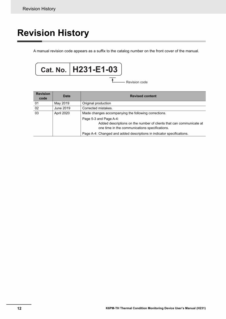
A manual revision code appears as a suffix to the catalog number on the front cover of the manual.
Revision code Date Revised content
01 May 2019 Original production02 June 2019 Corrected mistakes.03 April 2020 Made changes accompanying the following corrections.
Page 5-3 and Page A-4:Added descriptions on the number of clients that can communicate at one time in the communications specifications.
Page A-4: Changed and added descriptions in indicator specifications.
H231-E1-03Revision code
Cat. No.
1
2
3
4
5
6
7
A
I
4
5
6
7
A
I
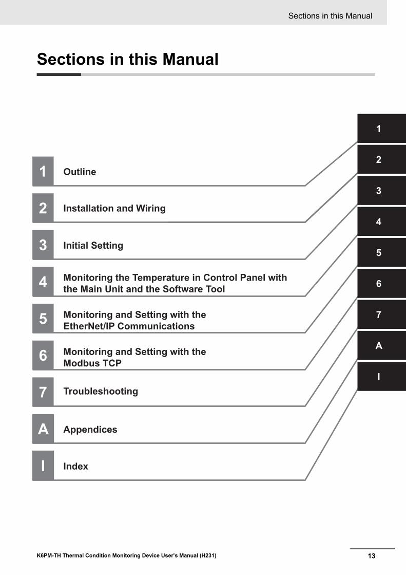
Outline
Installation and Wiring
Initial Setting
Monitoring the Temperature in Control Panel with the Main Unit and the Software Tool
Monitoring and Setting with theEtherNet/IP Communications
Troubleshooting
Monitoring and Setting with theModbus TCP
Appendices
Index
3
1
2
13
Sections in this Manual
K6PM-TH Thermal Condition Monitoring Device User’s Manual (H231)
Sections in this Manual
CONTENTS
14 K6PM-TH Thermal Condition Monitoring Device User’s Manual (H231)
CONTENTS
Preface ......................................................................................................................1
Terms and Conditions Agreement ..........................................................................2Warranty, Limitations of Liability .................................................................................................................. 2Application Considerations .......................................................................................................................... 3Disclaimers .................................................................................................................................................. 3
Safety Precautions ...................................................................................................4Definition of Precautionary Information........................................................................................................ 4Symbols ....................................................................................................................................................... 4
Precautions for Safe Use.........................................................................................6
Precautions for Correct Use....................................................................................9
Manual Structure .................................................................................................... 11Abbreviated Indicators ............................................................................................................................... 11
Revision History .....................................................................................................12
Sections in this Manual .........................................................................................13
CONTENTS..............................................................................................................14
Section 1 Outline1-1 Overview and Features ......................................................................................................... 1-2
1-1-1 Outline......................................................................................................................................... 1-21-1-2 Features...................................................................................................................................... 1-3
1-2 Mechanism of Temperature Measurement and Monitoring ............................................... 1-41-2-1 Input ............................................................................................................................................ 1-41-2-2 Measurement, Monitoring and Output......................................................................................... 1-5
1-3 List of Models and System Configurations......................................................................... 1-61-3-1 List of Models .............................................................................................................................. 1-61-3-2 System Configurations................................................................................................................ 1-7
1-4 Part Names and Functions ................................................................................................... 1-91-4-1 Main Unit ..................................................................................................................................... 1-91-4-2 Operating Modes of the Main Unit ............................................................................................ 1-121-4-3 Operation Flow on the Main Unit Front-Panel........................................................................... 1-131-4-4 Infrared Thermal Sensor ........................................................................................................... 1-16
1-5 Procedure............................................................................................................................. 1-18
Section 2 Installation and Wiring2-1 Dimensions ............................................................................................................................ 2-2
2-1-1 Main Unit ..................................................................................................................................... 2-22-1-2 Infrared Thermal Sensor ............................................................................................................. 2-2
2-2 Installation.............................................................................................................................. 2-32-2-1 Precautions at Installation........................................................................................................... 2-32-2-2 Installing the Main Unit................................................................................................................ 2-32-2-3 Installation of the Infrared Thermal Sensor ................................................................................. 2-52-2-4 Position Registration of the Infrared Thermal Sensor ................................................................. 2-9
15
CONTENTS
K6PM-TH Thermal Condition Monitoring Device User’s Manual (H231)
2-3 Wiring ................................................................................................................................... 2-102-3-1 How to Connect to the Push-In Plus Terminal Blocks............................................................... 2-102-3-2 Diagram of Terminal Description............................................................................................... 2-152-3-3 I/O Wiring.................................................................................................................................. 2-172-3-4 Ethernet Wiring ......................................................................................................................... 2-17
Section 3 Initial Setting3-1 Installation and Uninstallation, Starting up ........................................................................ 3-2
3-1-1 Installing the Software Tool......................................................................................................... 3-23-1-2 Uninstalling the Software Tool .................................................................................................... 3-6
3-2 IP Address Setting................................................................................................................. 3-73-2-1 IP Address Setting of Your PC .................................................................................................... 3-73-2-2 Setting the IP Address of the Main Units with the Software Tool ................................................ 3-9
3-3 Registering the Sensor Position (Setting sensor screen) ............................................... 3-153-4 Registering the Initial Settings and Sensor Configuration of the Main Unit
(Setting K6PM screen) ........................................................................................................ 3-18
Section 4 Monitoring the Temperature in Control Panel with the Main Unit and the Software Tool
4-1 Method of Monitoring the Temperature in the Control Panel ............................................ 4-24-1-1 Overview of Temperature Monitoring.......................................................................................... 4-24-1-2 Display on the Main Unit after Registration of Sensor Configuration.......................................... 4-24-1-3 Monitoring with the Main Unit ..................................................................................................... 4-34-1-4 Monitoring Using Software Tools ................................................................................................ 4-5
4-2 Functions of Monitoring the Temperature in the Control Panel...................................... 4-134-2-1 Functions of Monitoring the Temperature in Control Panel with the Main Unit and the
Software Tool ............................................................................................................................ 4-134-2-2 Operation Example of an Alarm................................................................................................ 4-174-2-3 Automatic Saving Log Files ...................................................................................................... 4-19
4-3 Alarm Threshold Setting..................................................................................................... 4-234-4 Procedure for Taking Actions When an Alarm Occurs .................................................... 4-25
Section 5 Monitoring and Setting with the EtherNet/IP Communi-cations
5-1 Outline .................................................................................................................................... 5-25-1-1 What is Monitoring Using EtherNet/IP? ...................................................................................... 5-25-1-2 EtherNet/IP Communications Specifications .............................................................................. 5-3
5-2 Monitoring Using the Tag Data Link .................................................................................... 5-45-2-1 Connection Setting ..................................................................................................................... 5-45-2-2 Setting the Assembly Object....................................................................................................... 5-75-2-3 Assigning the Assembly Instance ............................................................................................... 5-7
5-3 Monitoring and Setting Using the CIP Message Communications and Examples of Communications Instructions ....................................................................................... 5-105-3-1 Services Supported by Objects in Main Units........................................................................... 5-105-3-2 Main Unit Monitor Object (Class ID: 374 hex) ......................................................................... 5-105-3-3 K6PM-TH Sensor Monitor Object (Class ID: 375 hex) ............................................................. 5-125-3-4 K6PM-TH Sensor Temperature Monitor Object (Class ID: 376 hex) ........................................ 5-145-3-5 Main Unit Setting Object (Class ID: 377 hex) ........................................................................... 5-175-3-6 K6PM-TH Sensor Alarm Setting Object (Class ID: 378 hex) .................................................... 5-205-3-7 Identity Object (Class ID: 01 hex) ............................................................................................. 5-225-3-8 TCP/IP Interface Object (Class ID: F5 hex).............................................................................. 5-24
CONTENTS
16 K6PM-TH Thermal Condition Monitoring Device User’s Manual (H231)
5-3-9 Examples of CIP Message Communications Instruction .......................................................... 5-27
Section 6 Monitoring and Setting with the Modbus TCP6-1 Outline .................................................................................................................................... 6-26-2 Function Codes ..................................................................................................................... 6-3
6-2-1 Function Code List ...................................................................................................................... 6-36-2-2 03 hex: Reading of Multiple Registers ........................................................................................ 6-36-2-3 06 hex: Operation Command...................................................................................................... 6-56-2-4 10 hex: Writing of Multiple Registers........................................................................................... 6-66-2-5 Exception Code List .................................................................................................................... 6-7
6-3 Register Address Lists.......................................................................................................... 6-86-3-1 Main Unit Monitor ........................................................................................................................ 6-86-3-2 K6PM-TH Sensor Temperature Monitor (1 to 31) ....................................................................... 6-96-3-3 Main Unit Setting....................................................................................................................... 6-126-3-4 Product Information................................................................................................................... 6-146-3-5 IP Address................................................................................................................................. 6-146-3-6 K6PM-TH Sensor Alarm Setting (1 to 31) ................................................................................. 6-156-3-7 Operation Command................................................................................................................. 6-18
Section 7 Troubleshooting7-1 Main Unit ................................................................................................................................ 7-27-2 Using the Software Tool........................................................................................................ 7-67-3 Using EtherNet Communications ........................................................................................ 7-7
Appendices
A-1 Specifications ........................................................................................................................A-2A-1-1 Main Unit Specifications..............................................................................................................A-2A-1-2 Infrared Thermal Sensor .............................................................................................................A-6A-1-3 Software Tool ..............................................................................................................................A-9
A-2 Screen Flow of the Software Tool ......................................................................................A-12A-3 Tag Data Link Connection Setting Procedures.................................................................A-13
A-3-1 Preface......................................................................................................................................A-13A-3-2 Using the CS/CJ-series.............................................................................................................A-13A-3-3 Using the NJ/NX-series.............................................................................................................A-26
A-4 Expansion Error Code of the CIP Message Communications.........................................A-36A-4-1 General Status ..........................................................................................................................A-36A-4-2 Additional Status When General Status Is 01 hex ....................................................................A-38
Index
1 - 1
1
K6PM-TH Thermal Condition Monitoring Device User’s Manual (H231)
This section describes an overview of the K6PM-TH Motor Condition Monitoring Device.
1-1 Overview and Features . . . . . . . . . . . . . . . . . . . . . . . . . . . . . . . . . . . . . . . . . 1-21-1-1 Outline . . . . . . . . . . . . . . . . . . . . . . . . . . . . . . . . . . . . . . . . . . . . . . . . . . . . . . . 1-21-1-2 Features . . . . . . . . . . . . . . . . . . . . . . . . . . . . . . . . . . . . . . . . . . . . . . . . . . . . . . 1-3
1-2 Mechanism of Temperature Measurement and Monitoring . . . . . . . . . . . . 1-41-2-1 Input . . . . . . . . . . . . . . . . . . . . . . . . . . . . . . . . . . . . . . . . . . . . . . . . . . . . . . . . . 1-41-2-2 Measurement, Monitoring and Output . . . . . . . . . . . . . . . . . . . . . . . . . . . . . . . 1-5
1-3 List of Models and System Configurations . . . . . . . . . . . . . . . . . . . . . . . . . 1-61-3-1 List of Models . . . . . . . . . . . . . . . . . . . . . . . . . . . . . . . . . . . . . . . . . . . . . . . . . . 1-61-3-2 System Configurations . . . . . . . . . . . . . . . . . . . . . . . . . . . . . . . . . . . . . . . . . . . 1-7
1-4 Part Names and Functions . . . . . . . . . . . . . . . . . . . . . . . . . . . . . . . . . . . . . . 1-91-4-1 Main Unit . . . . . . . . . . . . . . . . . . . . . . . . . . . . . . . . . . . . . . . . . . . . . . . . . . . . . . 1-91-4-2 Operating Modes of the Main Unit . . . . . . . . . . . . . . . . . . . . . . . . . . . . . . . . . 1-121-4-3 Operation Flow on the Main Unit Front-Panel . . . . . . . . . . . . . . . . . . . . . . . . . 1-131-4-4 Infrared Thermal Sensor . . . . . . . . . . . . . . . . . . . . . . . . . . . . . . . . . . . . . . . . . 1-16
1-5 Procedure . . . . . . . . . . . . . . . . . . . . . . . . . . . . . . . . . . . . . . . . . . . . . . . . . . . 1-18
Outline
1 Outline
1 - 2 K6PM-TH Thermal Condition Monitoring Device User’s Manual (H231)
1-1 Overview and Features
This section describes an overview and features of the Main Unit.
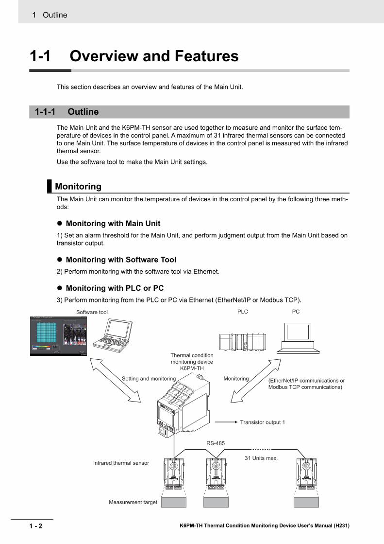
The Main Unit and the K6PM-TH sensor are used together to measure and monitor the surface tem-perature of devices in the control panel. A maximum of 31 infrared thermal sensors can be connected to one Main Unit. The surface temperature of devices in the control panel is measured with the infrared thermal sensor.Use the software tool to make the Main Unit settings.
The Main Unit can monitor the temperature of devices in the control panel by the following three meth-ods:
Monitoring with Main Unit1) Set an alarm threshold for the Main Unit, and perform judgment output from the Main Unit based on transistor output.
Monitoring with Software Tool2) Perform monitoring with the software tool via Ethernet.
Monitoring with PLC or PC3) Perform monitoring from the PLC or PC via Ethernet (EtherNet/IP or Modbus TCP).
1-1-1 Outline
Monitoring
Setting and monitoring Monitoring
Infrared thermal sensor
RS-485
Measurement target
31 Units max.
Transistor output 1
Software tool PC
(EtherNet/IP communications or
Modbus TCP communications)
Thermal condition
monitoring device
K6PM-TH
PLC
1 - 3
1 Outline
K6PM-TH Thermal Condition Monitoring Device User’s Manual (H231)
1-1 Overview
and Features
1
1-1-2 Features
• Individual alarm determination can be performed in two levels of threshold 1 and threshold 2 for the measurement temperature of the target in the field of view of each infrared thermal sensor.
• If an individual alarm occurs in any of the infrared thermal sensors connected to the Main Unit, tran-sistor output can be performed as a comprehensive alarm.
• With the help of the arrival prediction function of the Main Unit, it is possible to predict the tempera-ture that will be finally reached from the temperature at the time of startup, and alarm determination can be performed based on this predicted value.
• It is possible to monitor each measured value and the alarm status of each infrared thermal sensor from the PLC or PC. EtherNet/IP (tag data link or CIP communications) or Modbus TCP can be used as the communications method.
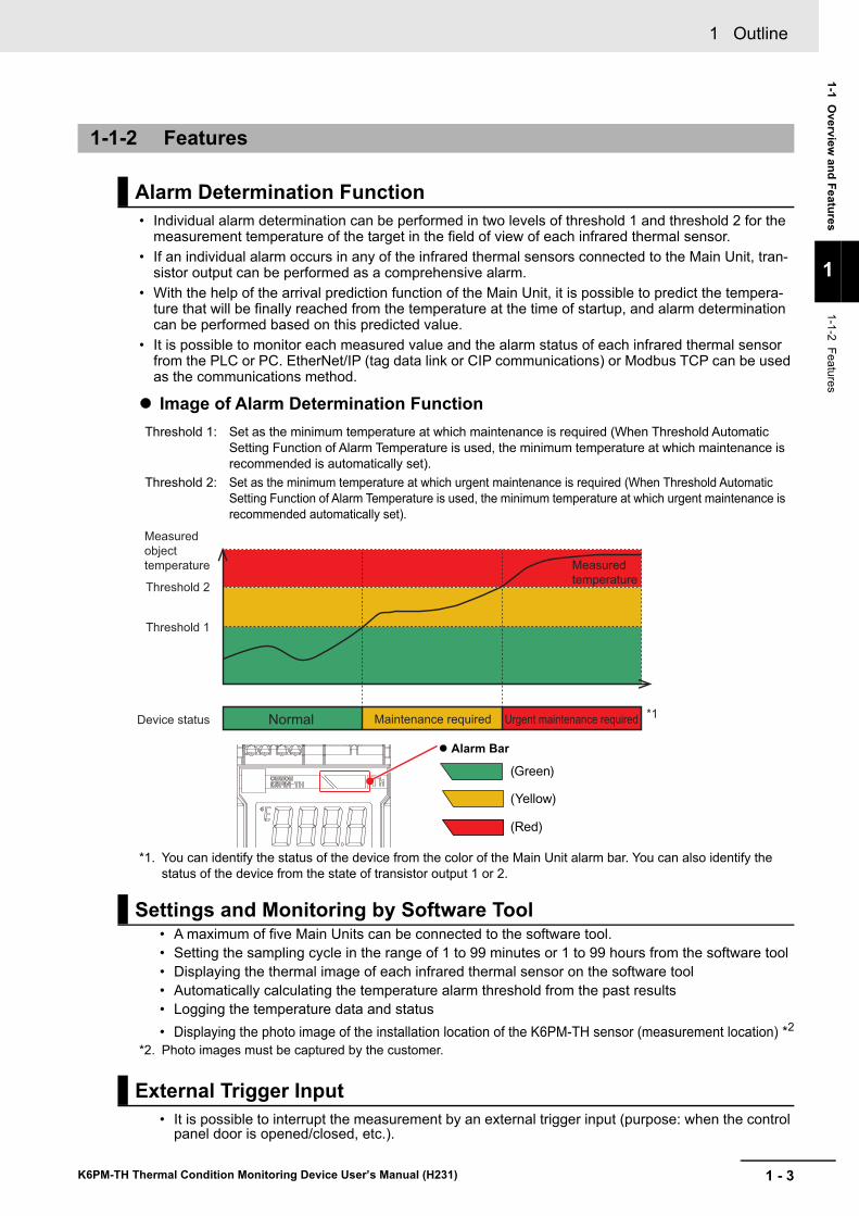
Image of Alarm Determination Function
*1. You can identify the status of the device from the color of the Main Unit alarm bar. You can also identify the status of the device from the state of transistor output 1 or 2.
• A maximum of five Main Units can be connected to the software tool.• Setting the sampling cycle in the range of 1 to 99 minutes or 1 to 99 hours from the software tool• Displaying the thermal image of each infrared thermal sensor on the software tool• Automatically calculating the temperature alarm threshold from the past results• Logging the temperature data and status• Displaying the photo image of the installation location of the K6PM-TH sensor (measurement location) *2
*2. Photo images must be captured by the customer.
• It is possible to interrupt the measurement by an external trigger input (purpose: when the control panel door is opened/closed, etc.).
1-1-2 Features
Alarm Determination Function
Threshold 1: Set as the minimum temperature at which maintenance is required (When Threshold Automatic Setting Function of Alarm Temperature is used, the minimum temperature at which maintenance is recommended is automatically set).
Threshold 2: Set as the minimum temperature at which urgent maintenance is required (When Threshold Automatic Setting Function of Alarm Temperature is used, the minimum temperature at which urgent maintenance is recommended automatically set).
Settings and Monitoring by Software Tool
External Trigger Input
Normal Maintenance required Urgent maintenance required
Threshold 1
Threshold 2
Measured
object
temperature
Device status*1
Measured
temperature
� Alarm Bar
(Green)
(Yellow)
(Red)
1 Outline
1 - 4 K6PM-TH Thermal Condition Monitoring Device User’s Manual (H231)
1-2 Mechanism of Temperature Measure-ment and Monitoring
This section shows each model and the model configuration of the Main Unit and the infrared thermal sensor.
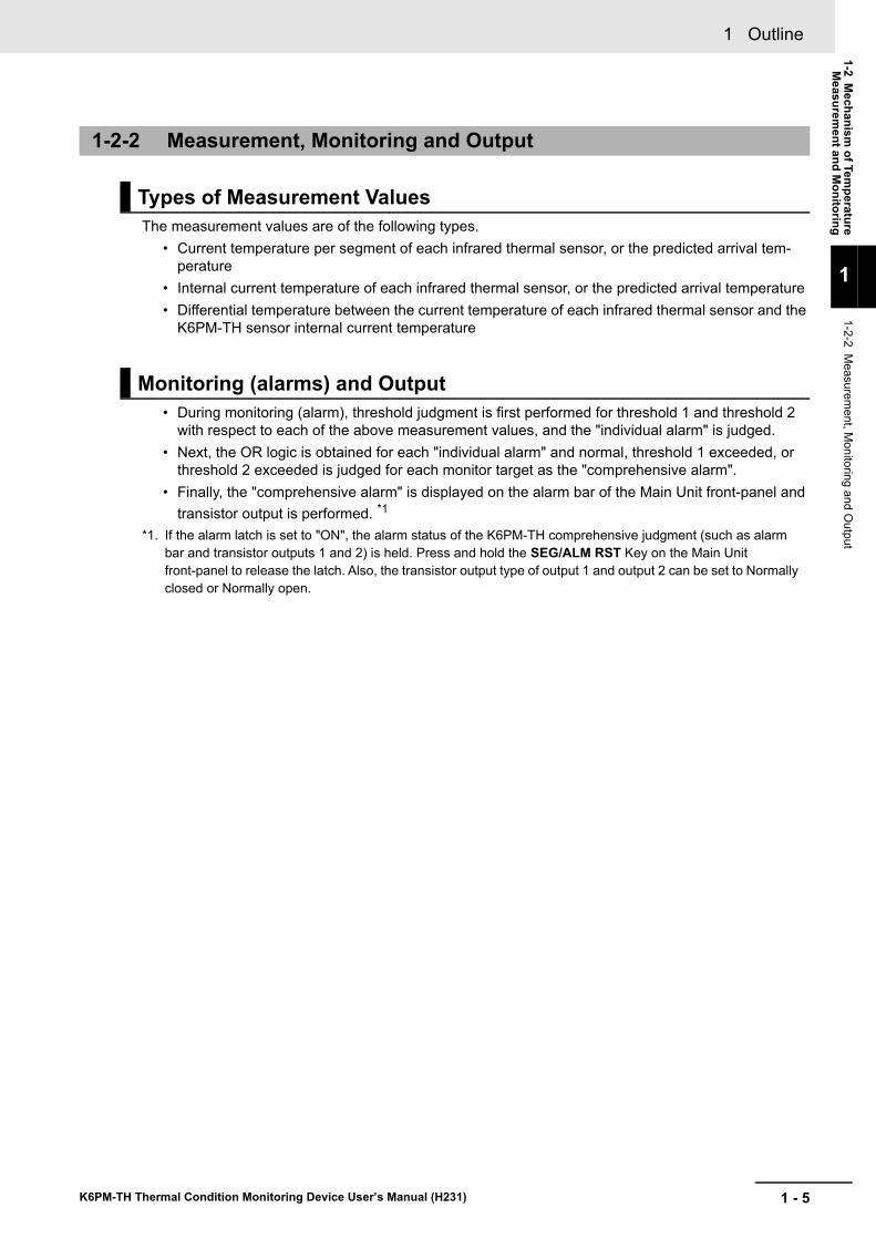
The measurement field of view of an infrared thermal sensor is made of the following elements.
With one segment as 8 pixels × 8 pixels, the measurement field of view is made of 16 segments per infrared thermal sensor.
In the Main Unit, the alarm threshold is set in the "segment" unit rather than the pixel unit or the infrared thermal sensor unit, and alarm determination is performed.
1-2-1 Input
Measurement Field of View of Infrared Thermal Sensor
*2. Normal open output is selectable
*1. Alarm latch is selectable
Infrared
thermal
sensor
Monitoring
OR logic of
each
measured
value
Individual alarm by
measurement
value
Alarm bar Transistor output
K6PM device error
and K6PM sensor
error
External trigger input
Measurement starts when the contact turns ON
Software tool
and/or
Ethernet
PLC etc.
External trigger input
Measurement
start
ON
Measurement
stop
OFF
Current
temperature
per segment
(31 Units max.)
(Input) (Measurement and monitoring processes) (output)
Threshold 2
Threshold 1
Threshold 2
Threshold 1
Exceeded
judgment
Exceeded
judgment
Exceeded
judgment
Exceeded
judgment
Lit green
Lit yellow
Lit red
Not lit
Output 1 *2 Output 2 *2 Output 3
ON
OFF
OFF
OFF
OFF
OFF OFF
ON ON
ON ON
ON
Comprehensive
alarm output as
a device
Threshold 2exceeded *1
Threshold 1exceeded *1
Normal
Differential
temperature per
segment from the
K6PM sensor
internal
temperature
Main Unit
Infrared thermal sensor
Black frame: Temperature measurement pixel
Gray frame: 1 segment = 8 × 8 pixels
Measurement field of view of 1 infrared
thermal sensor = 4 × 4 segments = 16
segments (32 × 32 pixels = 1,024 pixels)
1 - 5
1 Outline
K6PM-TH Thermal Condition Monitoring Device User’s Manual (H231)
1-2 Mechanism
of Temperature
Measurem
ent and Monitoring
1
1-2-2 Measurem
ent, Monitoring and O
utput
The measurement values are of the following types.• Current temperature per segment of each infrared thermal sensor, or the predicted arrival tem-
perature• Internal current temperature of each infrared thermal sensor, or the predicted arrival temperature• Differential temperature between the current temperature of each infrared thermal sensor and the
K6PM-TH sensor internal current temperature
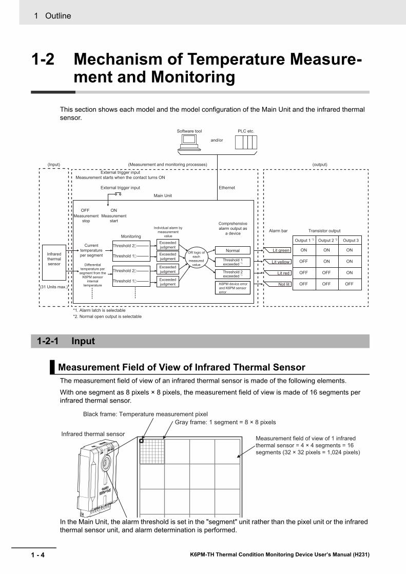
• During monitoring (alarm), threshold judgment is first performed for threshold 1 and threshold 2 with respect to each of the above measurement values, and the "individual alarm" is judged.
• Next, the OR logic is obtained for each "individual alarm" and normal, threshold 1 exceeded, or threshold 2 exceeded is judged for each monitor target as the "comprehensive alarm".
• Finally, the "comprehensive alarm" is displayed on the alarm bar of the Main Unit front-panel and transistor output is performed. *1
*1. If the alarm latch is set to "ON", the alarm status of the K6PM-TH comprehensive judgment (such as alarm bar and transistor outputs 1 and 2) is held. Press and hold the SEG/ALM RST Key on the Main Unit front-panel to release the latch. Also, the transistor output type of output 1 and output 2 can be set to Normally closed or Normally open.
1-2-2 Measurement, Monitoring and Output
Types of Measurement Values
Monitoring (alarms) and Output
1 Outline
1 - 6 K6PM-TH Thermal Condition Monitoring Device User’s Manual (H231)
1-3 List of Models and System Configu-rations
This section shows each model and the model configuration of the Main Unit and the infrared thermal sensor.
Main Unit
1-3-1 List of Models
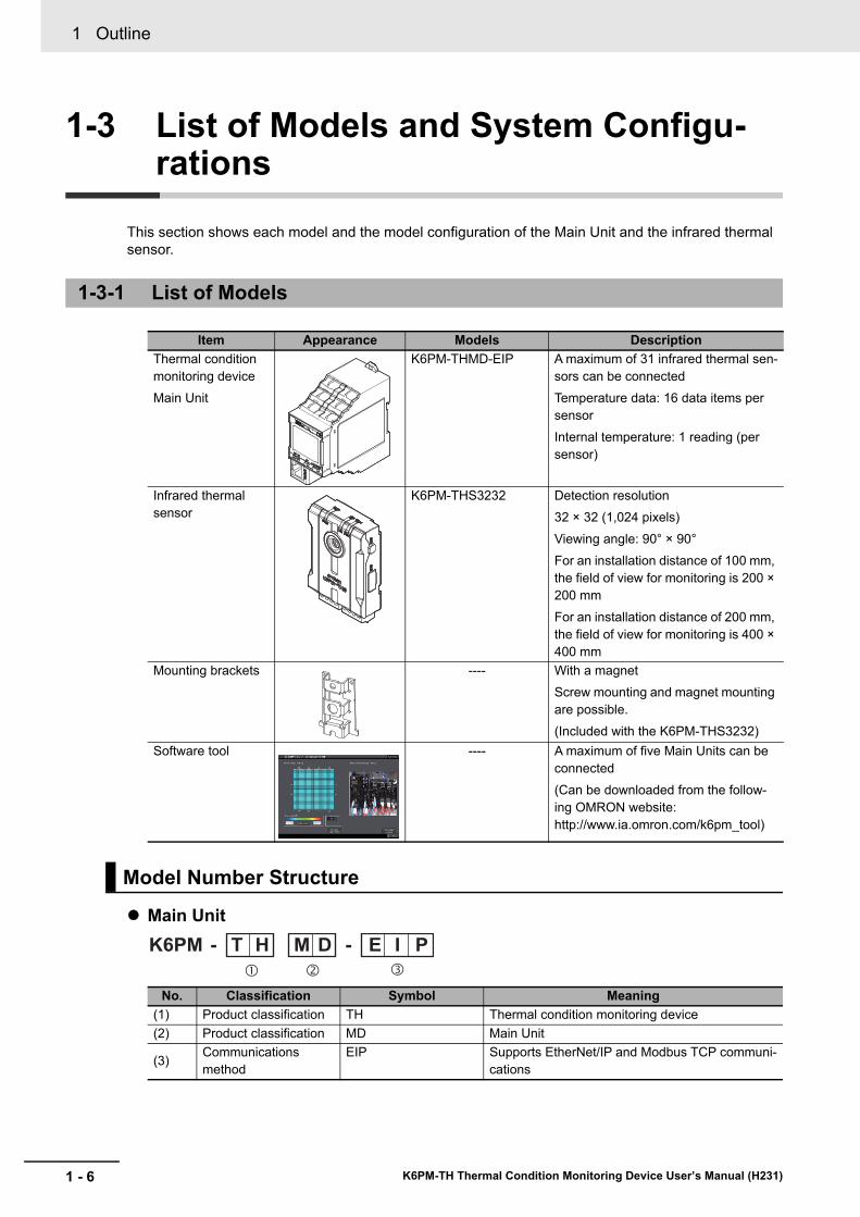
Item Appearance Models DescriptionThermal condition monitoring deviceMain Unit
K6PM-THMD-EIP A maximum of 31 infrared thermal sen-sors can be connectedTemperature data: 16 data items per sensorInternal temperature: 1 reading (per sensor)
Infrared thermal sensor
K6PM-THS3232 Detection resolution32 × 32 (1,024 pixels)Viewing angle: 90° × 90°For an installation distance of 100 mm, the field of view for monitoring is 200 × 200 mmFor an installation distance of 200 mm, the field of view for monitoring is 400 × 400 mm
Mounting brackets ---- With a magnetScrew mounting and magnet mounting are possible.(Included with the K6PM-THS3232)
Software tool ---- A maximum of five Main Units can be connected(Can be downloaded from the follow-ing OMRON website: http://www.ia.omron.com/k6pm_tool)
Model Number Structure
No. Classification Symbol Meaning(1) Product classification TH Thermal condition monitoring device(2) Product classification MD Main Unit
(3) Communications method
EIP Supports EtherNet/IP and Modbus TCP communi-cations
K6PM�
T H E I PM D� �
--
1 - 7
1 Outline
K6PM-TH Thermal Condition Monitoring Device User’s Manual (H231)
1-3 List of Models and System
Configurations
1
1-3-2 System C
onfigurations
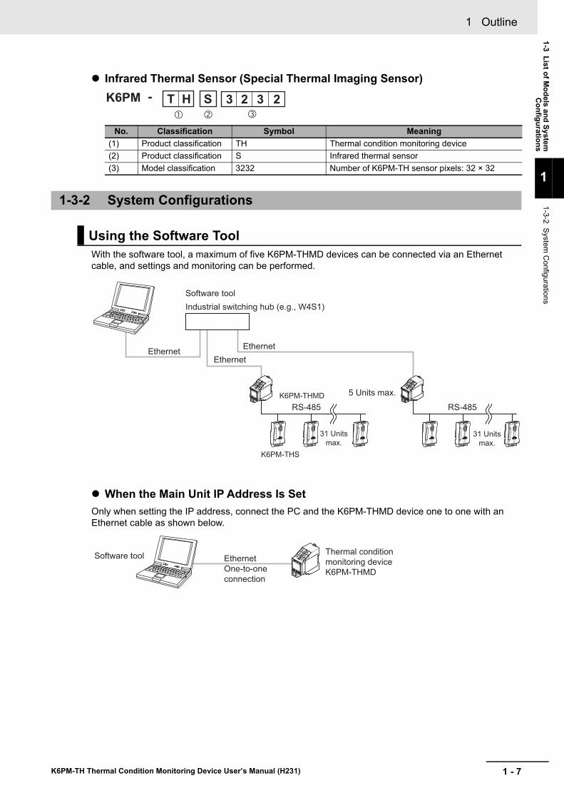
Infrared Thermal Sensor (Special Thermal Imaging Sensor)
With the software tool, a maximum of five K6PM-THMD devices can be connected via an Ethernet cable, and settings and monitoring can be performed.
When the Main Unit IP Address Is SetOnly when setting the IP address, connect the PC and the K6PM-THMD device one to one with an Ethernet cable as shown below.
No. Classification Symbol Meaning(1) Product classification TH Thermal condition monitoring device(2) Product classification S Infrared thermal sensor(3) Model classification 3232 Number of K6PM-TH sensor pixels: 32 × 32
1-3-2 System Configurations
Using the Software Tool
-K6PM T H S 3 2 3 2� � �
Software tool
5 Units max.
Ethernet
Industrial switching hub (e.g., W4S1)
Ethernet
Ethernet
K6PM-THMD
K6PM-THS
31 Units
max.31 Units
max.
RS-485 RS-485
Software toolThermal condition
monitoring device
K6PM-THMD
Ethernet
One-to-one
connection
1 Outline
1 - 8 K6PM-TH Thermal Condition Monitoring Device User’s Manual (H231)
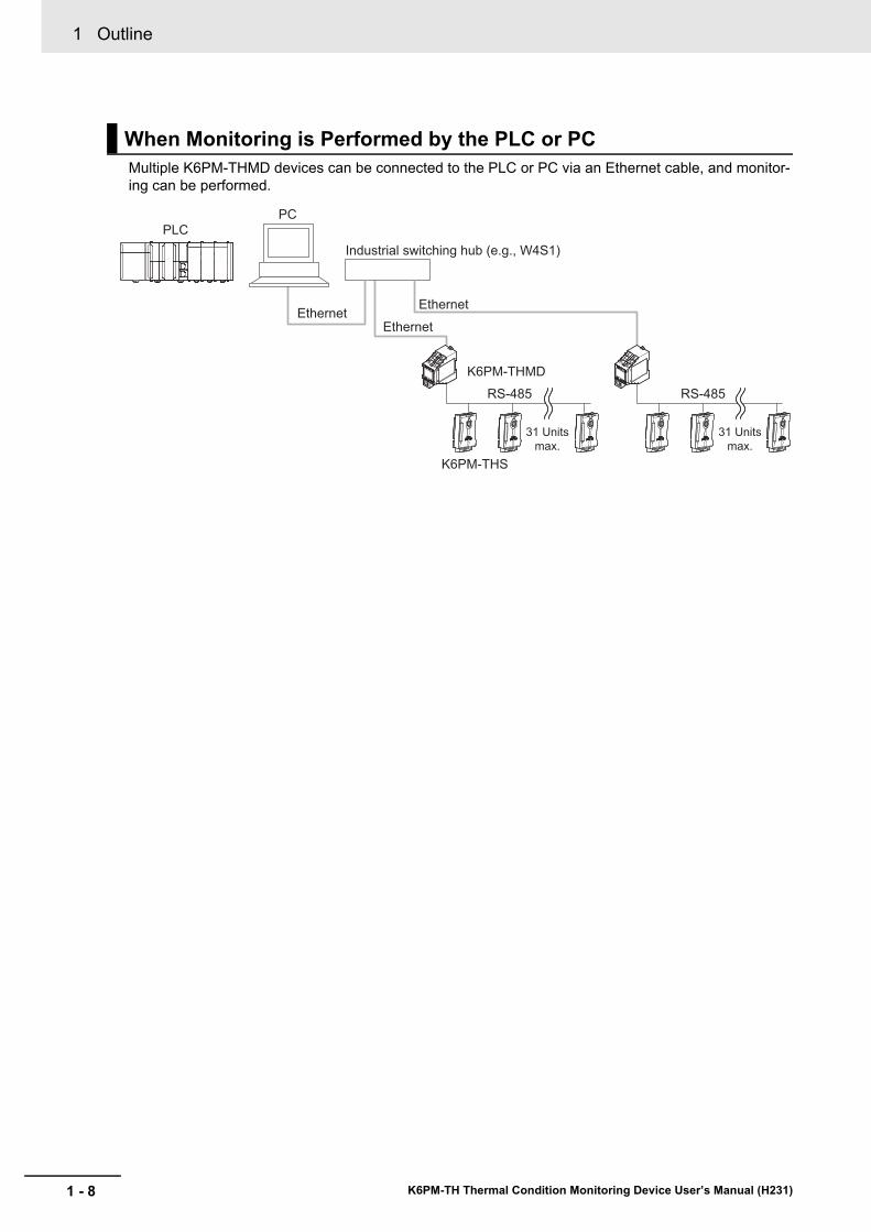
Multiple K6PM-THMD devices can be connected to the PLC or PC via an Ethernet cable, and monitor-ing can be performed.
When Monitoring is Performed by the PLC or PC
Ethernet
Industrial switching hub (e.g., W4S1)
Ethernet
Ethernet
PC
PLC
K6PM-THMD
31 Units
max.
31 Units
max.
RS-485 RS-485
K6PM-THS
1 - 9
1 Outline
K6PM-TH Thermal Condition Monitoring Device User’s Manual (H231)
1-4 Part Nam
es and Functions
1
1-4-1 Main U
nit
1-4 Part Names and Functions
This section describes the name and functions of each part of the Main Unit and the infrared thermal sensor.
1-4-1 Main Unit
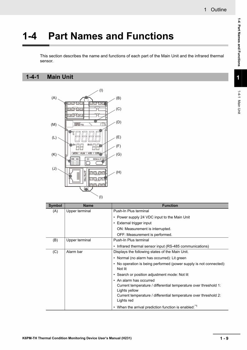
Symbol Name Function(A) Upper terminal Push-In Plus terminal
• Power supply 24 VDC input to the Main Unit• External trigger input
ON: Measurement is interrupted.OFF: Measurement is performed.
(B) Upper terminal Push-In Plus terminal• Infrared thermal sensor input (RS-485 communications)
(C) Alarm bar Displays the following states of the Main Unit.• Normal (no alarm has occurred): Lit green• No operation is being performed (power supply is not connected):
Not lit• Search or position adjustment mode: Not lit• An alarm has occurred
Current temperature / differential temperature over threshold 1: Lights yellowCurrent temperature / differential temperature over threshold 2: Lights red
• When the arrival prediction function is enabled:*1
(A)
(I)
(I)
(B)
(C)
(D)
(E)
(F)
(G)
(H)
(M)
(L)
(J)
(K)
1 Outline
1 - 10 K6PM-TH Thermal Condition Monitoring Device User’s Manual (H231)
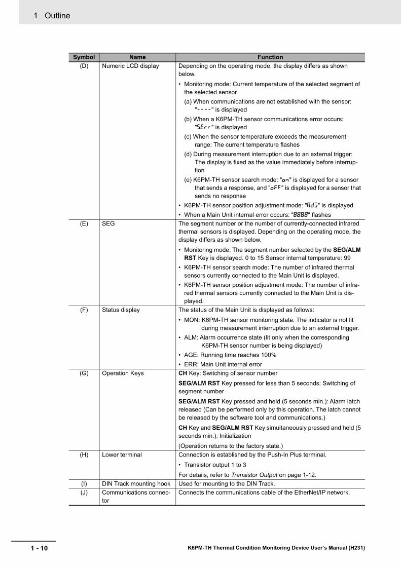
(D) Numeric LCD display Depending on the operating mode, the display differs as shown below.• Monitoring mode: Current temperature of the selected segment of
the selected sensor(a) When communications are not established with the sensor:
"----" is displayed(b) When a K6PM-TH sensor communications error occurs:
"serr" is displayed(c) When the sensor temperature exceeds the measurement
range: The current temperature flashes(d) During measurement interruption due to an external trigger:
The display is fixed as the value immediately before interrup-tion
(e) K6PM-TH sensor search mode: "on" is displayed for a sensor that sends a response, and "off" is displayed for a sensor that sends no response
• K6PM-TH sensor position adjustment mode: "adj" is displayed• When a Main Unit internal error occurs: "8888" flashes
(E) SEG The segment number or the number of currently-connected infrared thermal sensors is displayed. Depending on the operating mode, the display differs as shown below.• Monitoring mode: The segment number selected by the SEG/ALM
RST Key is displayed. 0 to 15 Sensor internal temperature: 99• K6PM-TH sensor search mode: The number of infrared thermal
sensors currently connected to the Main Unit is displayed.• K6PM-TH sensor position adjustment mode: The number of infra-
red thermal sensors currently connected to the Main Unit is dis-played.
(F) Status display The status of the Main Unit is displayed as follows:• MON: K6PM-TH sensor monitoring state. The indicator is not lit
during measurement interruption due to an external trigger.• ALM: Alarm occurrence state (lit only when the corresponding
K6PM-TH sensor number is being displayed)• AGE: Running time reaches 100%• ERR: Main Unit internal error
(G) Operation Keys CH Key: Switching of sensor numberSEG/ALM RST Key pressed for less than 5 seconds: Switching of segment numberSEG/ALM RST Key pressed and held (5 seconds min.): Alarm latch released (Can be performed only by this operation. The latch cannot be released by the software tool and communications.)CH Key and SEG/ALM RST Key simultaneously pressed and held (5 seconds min.): Initialization(Operation returns to the factory state.)
(H) Lower terminal Connection is established by the Push-In Plus terminal.• Transistor output 1 to 3For details, refer to Transistor Output on page 1-12.
(I) DIN Track mounting hook Used for mounting to the DIN Track.(J) Communications connec-
torConnects the communications cable of the EtherNet/IP network.
Symbol Name Function
1 - 11
1 Outline
K6PM-TH Thermal Condition Monitoring Device User’s Manual (H231)
1-4 Part Nam
es and Functions
1
1-4-1 Main U
nit
Indicator Specifications
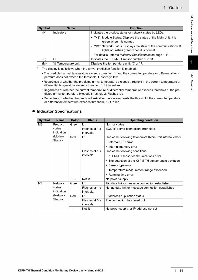
(K) Indicators Indicates the product status or network status by LEDs.• "MS": Module Status. Displays the status of the Main Unit. It is
green when it is normal.• "NS": Network Status. Displays the state of the communications. It
lights or flashes green when it is normal.For details, refer to Indicator Specifications on page 1-11.
(L) CH Indicates the K6PM-TH sensor number. 1 to 31.(M) °e Temperature unit Displays the temperature unit. °C or °F.
*1. The display is as follows when the arrival prediction function is enabled.• The predicted arrival temperature exceeds threshold 1, and the current temperature or differential tem-
perature does not exceed the threshold: Flashes yellow• Regardless of whether the predicted arrival temperature exceeds threshold 1, the current temperature or
differential temperature exceeds threshold 1: Lit in yellow• Regardless of whether the current temperature or differential temperature exceeds threshold 1, the pre-
dicted arrival temperature exceeds threshold 2: Flashes red• Regardless of whether the predicted arrival temperature exceeds the threshold, the current temperature
or differential temperature exceeds threshold 2: Lit in red
Symbol Name Color Status Operating conditionMS Product
status indication (Module Status}
Green Lit. Normal statusFlashes at 1-s intervals.
BOOTP server connection error state
Red Lit. One of the following fatal errors (Main Unit internal error)• Internal CPU error• Internal memory error
Flashes at 1-s intervals.
One of the following conditions• K6PM-TH sensor communications error• The detection of the K6PM-TH sensor angle deviation• Sensor type error• Temperature measurement range exceeded• Running time error
-- Not lit. No power supplyNS Network
status indication (Network Status)
Green Lit. Tag data link or message connection establishedFlashes at 1-s intervals.
No tag data link or message connection established
Red Lit. IP address duplication statusFlashes at 1-s intervals.
The connection has timed out
-- Not lit. No power supply, or IP address not set
Symbol Name Function
1 Outline
1 - 12 K6PM-TH Thermal Condition Monitoring Device User’s Manual (H231)
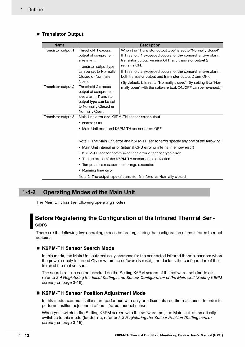
Transistor Output
The Main Unit has the following operating modes.
There are the following two operating modes before registering the configuration of the infrared thermal sensors.
K6PM-TH Sensor Search ModeIn this mode, the Main Unit automatically searches for the connected infrared thermal sensors when the power supply is turned ON or when the software is reset, and decides the configuration of the infrared thermal sensors.The search results can be checked on the Setting K6PM screen of the software tool (for details, refer to 3-4 Registering the Initial Settings and Sensor Configuration of the Main Unit (Setting K6PM screen) on page 3-18).
K6PM-TH Sensor Position Adjustment ModeIn this mode, communications are performed with only one fixed infrared thermal sensor in order to perform position adjustment of the infrared thermal sensor.
When you switch to the Setting K6PM screen with the software tool, the Main Unit automatically switches to this mode (for details, refer to 3-3 Registering the Sensor Position (Setting sensor screen) on page 3-15).
Name DescriptionTransistor output 1 Threshold 1 excess
output of comprehen-sive alarm.Transistor output type can be set to Normally Closed or Normally Open.
When the "Transistor output type" is set to "Normally closed": If threshold 1 exceeded occurs for the comprehensive alarm, transistor output remains OFF and transistor output 2 remains ON.If threshold 2 exceeded occurs for the comprehensive alarm, both transistor output and transistor output 2 turn OFF.(By default, it is set to "Normally closed". By setting it to "Nor-mally open" with the software tool, ON/OFF can be reversed.)Transistor output 2 Threshold 2 excess
output of comprehen-sive alarm. Transistor output type can be set to Normally Closed or Normally Open.
Transistor output 3 Main Unit error and K6PM-TH sensor error output• Normal: ON• Main Unit error and K6PM-TH sensor error: OFF
Note 1: The Main Unit error and K6PM-TH sensor error specify any one of the following:• Main Unit internal error (internal CPU error or internal memory error)• K6PM-TH sensor communications error or sensor type error• The detection of the K6PM-TH sensor angle deviation• Temperature measurement range exceeded• Running time errorNote 2: The output type of transistor 3 is fixed as Normally closed.
1-4-2 Operating Modes of the Main Unit
Before Registering the Configuration of the Infrared Thermal Sen-sors
1 - 13
1 Outline
K6PM-TH Thermal Condition Monitoring Device User’s Manual (H231)
1-4 Part Nam
es and Functions
1
1-4-3 Operation Flow
on the Main U
nit Front-Panel
After the configuration of the infrared thermal sensors has been registered by using the software tool or communications, switching to the following monitoring mode occurs automatically.
Monitoring ModeIn this mode, the measurement and monitoring processes (such as alarm determination, etc.) are carried out based on the registered sensor configuration. When you click the Register Button on the Setting K6PM screen of the software tool, the Main Unit automatically switches to this mode (for details, refer to 3-4 Registering the Initial Settings and Sensor Configuration of the Main Unit (Set-ting K6PM screen) on page 3-18).
The flow of operation in the K6PM device screen after the power is turned on or a software reset varies depending on whether or not the infrared thermal sensor configuration has been registered (including the first time the device is used).For details on how to register the configuration of the infrared thermal sensors, refer to 3-4 Registering the Initial Settings and Sensor Configuration of the Main Unit (Setting K6PM screen) on page 3-18.
After Registering the Configuration of the Infrared Thermal Sensors
1-4-3 Operation Flow on the Main Unit Front-Panel
1 Outline
1 - 14 K6PM-TH Thermal Condition Monitoring Device User’s Manual (H231)
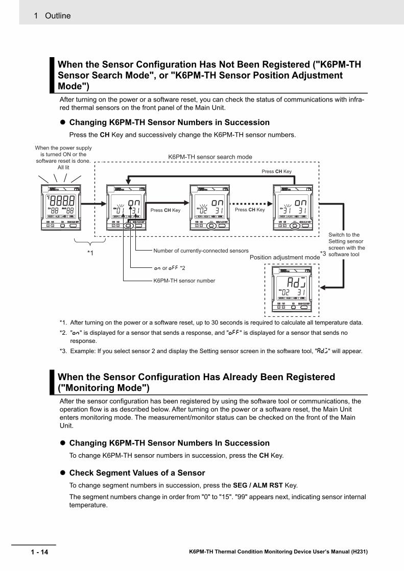
After turning on the power or a software reset, you can check the status of communications with infra-red thermal sensors on the front panel of the Main Unit.
Changing K6PM-TH Sensor Numbers in SuccessionPress the CH Key and successively change the K6PM-TH sensor numbers.
*1. After turning on the power or a software reset, up to 30 seconds is required to calculate all temperature data.*2. "on" is displayed for a sensor that sends a response, and "off" is displayed for a sensor that sends no
response.*3. Example: If you select sensor 2 and display the Setting sensor screen in the software tool, "adj" will appear.
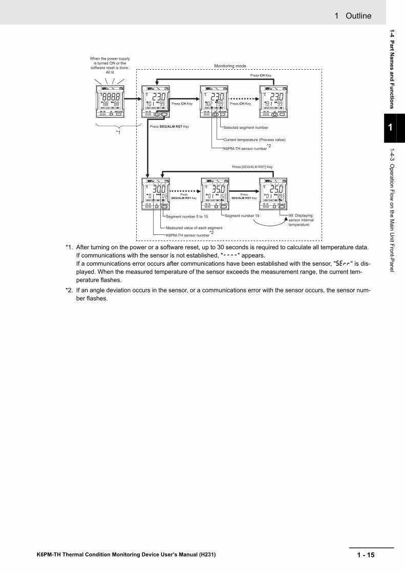
After the sensor configuration has been registered by using the software tool or communications, the operation flow is as described below. After turning on the power or a software reset, the Main Unit enters monitoring mode. The measurement/monitor status can be checked on the front of the Main Unit.
Changing K6PM-TH Sensor Numbers In SuccessionTo change K6PM-TH sensor numbers in succession, press the CH Key.
Check Segment Values of a SensorTo change segment numbers in succession, press the SEG / ALM RST Key.The segment numbers change in order from "0" to "15". "99" appears next, indicating sensor internal temperature.
When the Sensor Configuration Has Not Been Registered ("K6PM-TH Sensor Search Mode", or "K6PM-TH Sensor Position Adjustment Mode")
When the Sensor Configuration Has Already Been Registered ("Monitoring Mode")
*1 Number of currently-connected sensors
on or off *2
K6PM-TH sensor search mode
Position adjustment mode*3
Press CH Key
K6PM-TH sensor number
Switch to the Setting sensor screen with the software tool
When the power supply is turned ON or the
software reset is done.All lit
Press CH Key
Press CH Key
1 - 15
1 Outline
K6PM-TH Thermal Condition Monitoring Device User’s Manual (H231)
1-4 Part Nam
es and Functions
1
1-4-3 Operation Flow
on the Main U
nit Front-Panel
*1. After turning on the power or a software reset, up to 30 seconds is required to calculate all temperature data. If communications with the sensor is not established, "----" appears.If a communications error occurs after communications have been established with the sensor, "serr" is dis-played. When the measured temperature of the sensor exceeds the measurement range, the current tem-perature flashes.
*2. If an angle deviation occurs in the sensor, or a communications error with the sensor occurs, the sensor num-ber flashes.
K6PM-TH sensor number*2
K6PM-TH sensor number*2
Selected segment number
Press CH Key
Monitoring mode
Segment number 0 to 15
Press SEG/ALM RST Key
Press [SEG/ALM RST] Key
Press
SEG/ALM RST Key
Press
SEG/ALM RST Key
Current temperature (Process value)
Measured value of each segment
Segment number 15
*1
When the power supply
is turned ON or the
software reset is done.
All lit
Press CH Key
Press CH Key
99: Displaying
sensor internal
temperature
1 Outline
1 - 16 K6PM-TH Thermal Condition Monitoring Device User’s Manual (H231)
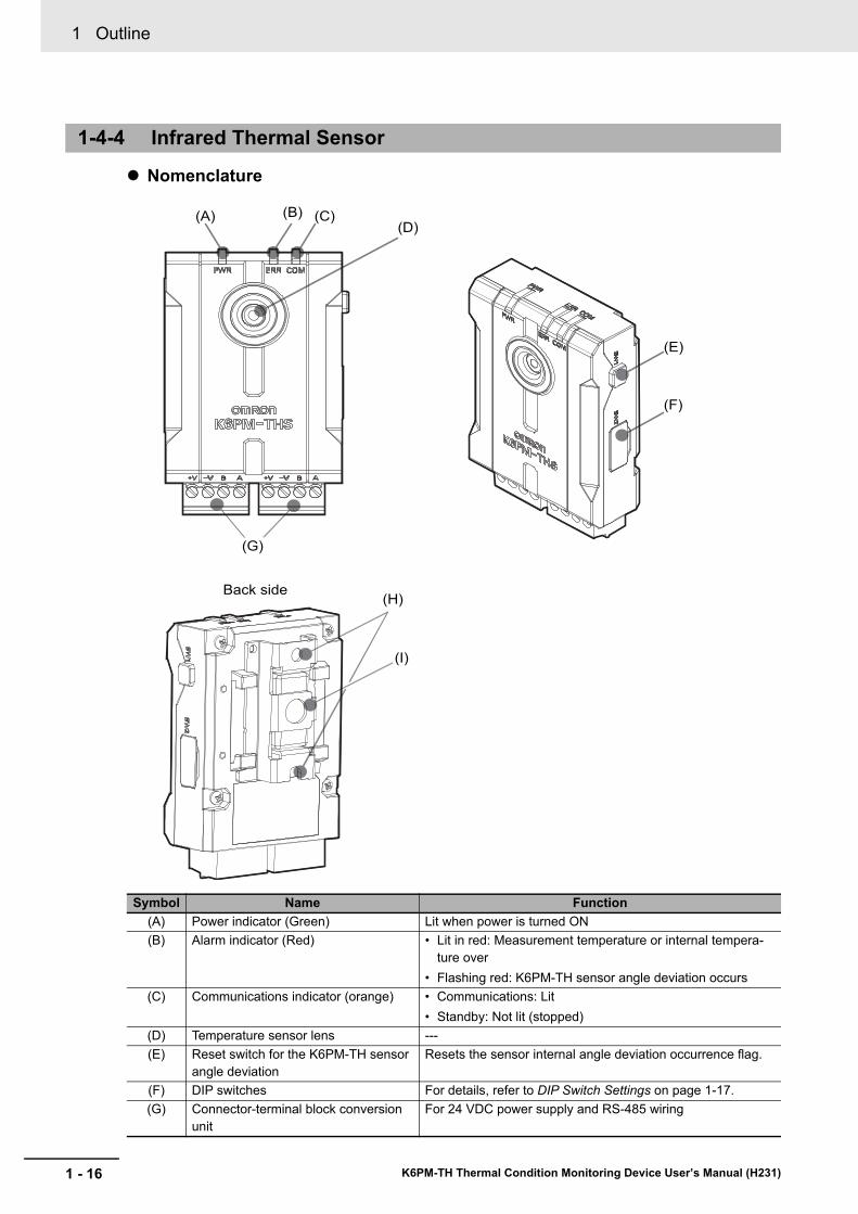
Nomenclature
1-4-4 Infrared Thermal Sensor
Symbol Name Function(A) Power indicator (Green) Lit when power is turned ON(B) Alarm indicator (Red) • Lit in red: Measurement temperature or internal tempera-
ture over• Flashing red: K6PM-TH sensor angle deviation occurs
(C) Communications indicator (orange) • Communications: Lit• Standby: Not lit (stopped)
(D) Temperature sensor lens ---(E) Reset switch for the K6PM-TH sensor
angle deviationResets the sensor internal angle deviation occurrence flag.
(F) DIP switches For details, refer to DIP Switch Settings on page 1-17.(G) Connector-terminal block conversion
unitFor 24 VDC power supply and RS-485 wiring
(D)
(H)
(I)
(G)
Back side
(F)
(E)
(C)(A) (B)
1 - 17
1 Outline
K6PM-TH Thermal Condition Monitoring Device User’s Manual (H231)
1-4 Part Nam
es and Functions
1
1-4-4 Infrared Thermal Sensor
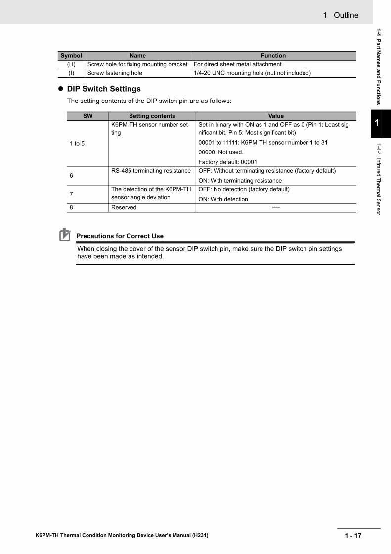
DIP Switch SettingsThe setting contents of the DIP switch pin are as follows:
Precautions for Correct Use
When closing the cover of the sensor DIP switch pin, make sure the DIP switch pin settings have been made as intended.
(H) Screw hole for fixing mounting bracket For direct sheet metal attachment(I) Screw fastening hole 1/4-20 UNC mounting hole (nut not included)
SW Setting contents Value
1 to 5
K6PM-TH sensor number set-ting
Set in binary with ON as 1 and OFF as 0 (Pin 1: Least sig-nificant bit, Pin 5: Most significant bit)00001 to 11111: K6PM-TH sensor number 1 to 3100000: Not used.Factory default: 00001
6RS-485 terminating resistance OFF: Without terminating resistance (factory default)
ON: With terminating resistance
7The detection of the K6PM-TH sensor angle deviation
OFF: No detection (factory default)ON: With detection
8 Reserved. ----
Symbol Name Function
1 Outline
1 - 18 K6PM-TH Thermal Condition Monitoring Device User’s Manual (H231)
1-5 Procedure
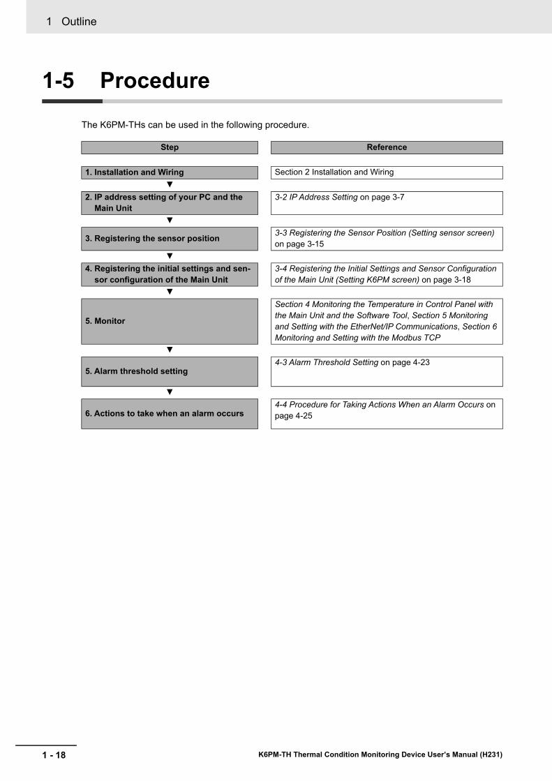
The K6PM-THs can be used in the following procedure.
Step Reference
1. Installation and Wiring Section 2 Installation and Wiring▼
2. IP address setting of your PC and the Main Unit
3-2 IP Address Setting on page 3-7
▼
3. Registering the sensor position 3-3 Registering the Sensor Position (Setting sensor screen) on page 3-15
▼4. Registering the initial settings and sen-
sor configuration of the Main Unit3-4 Registering the Initial Settings and Sensor Configuration of the Main Unit (Setting K6PM screen) on page 3-18
▼
5. Monitor
Section 4 Monitoring the Temperature in Control Panel with the Main Unit and the Software Tool, Section 5 Monitoring and Setting with the EtherNet/IP Communications, Section 6 Monitoring and Setting with the Modbus TCP
▼
5. Alarm threshold setting4-3 Alarm Threshold Setting on page 4-23
▼
6. Actions to take when an alarm occurs4-4 Procedure for Taking Actions When an Alarm Occurs on page 4-25
2 - 1
2
K6PM-TH Thermal Condition Monitoring Device User’s Manual (H231)
This section describes the installation and wiring of the Main Units.
2-1 Dimensions . . . . . . . . . . . . . . . . . . . . . . . . . . . . . . . . . . . . . . . . . . . . . . . . . . . 2-22-1-1 Main Unit . . . . . . . . . . . . . . . . . . . . . . . . . . . . . . . . . . . . . . . . . . . . . . . . . . . . . . 2-22-2-1 Precautions at Installation . . . . . . . . . . . . . . . . . . . . . . . . . . . . . . . . . . . . . . . . . 2-3
2-2 Installation . . . . . . . . . . . . . . . . . . . . . . . . . . . . . . . . . . . . . . . . . . . . . . . . . . . 2-32-2-1 Precautions at Installation . . . . . . . . . . . . . . . . . . . . . . . . . . . . . . . . . . . . . . . . . 2-32-2-2 Installing the Main Unit . . . . . . . . . . . . . . . . . . . . . . . . . . . . . . . . . . . . . . . . . . . 2-32-2-3 Installation of the Infrared Thermal Sensor . . . . . . . . . . . . . . . . . . . . . . . . . . . . 2-52-2-4 Position Registration of the Infrared Thermal Sensor . . . . . . . . . . . . . . . . . . . . 2-9
2-3 Wiring . . . . . . . . . . . . . . . . . . . . . . . . . . . . . . . . . . . . . . . . . . . . . . . . . . . . . . 2-102-3-1 How to Connect to the Push-In Plus Terminal Blocks . . . . . . . . . . . . . . . . . . . 2-102-3-2 Diagram of Terminal Description . . . . . . . . . . . . . . . . . . . . . . . . . . . . . . . . . . . 2-152-3-3 I/O Wiring . . . . . . . . . . . . . . . . . . . . . . . . . . . . . . . . . . . . . . . . . . . . . . . . . . . . 2-172-3-4 Ethernet Wiring . . . . . . . . . . . . . . . . . . . . . . . . . . . . . . . . . . . . . . . . . . . . . . . . 2-17
Installation and Wiring
2 Installation and Wiring
2 - 2 K6PM-TH Thermal Condition Monitoring Device User’s Manual (H231)
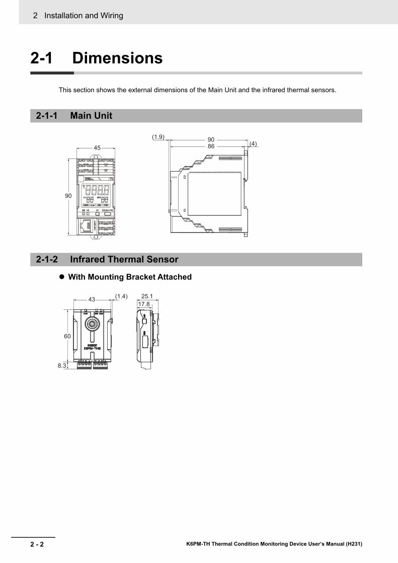
2-1 Dimensions
This section shows the external dimensions of the Main Unit and the infrared thermal sensors.
With Mounting Bracket Attached
2-1-1 Main Unit
2-1-2 Infrared Thermal Sensor
(4)(1.9)
9086
90
45
60
8.3
43(1.4) 25.1
17.8
2 - 3
2 Installation and Wiring
K6PM-TH Thermal Condition Monitoring Device User’s Manual (H231)
2-2 Installation
2
2-2-1 Precautions at Installation
2-2 Installation
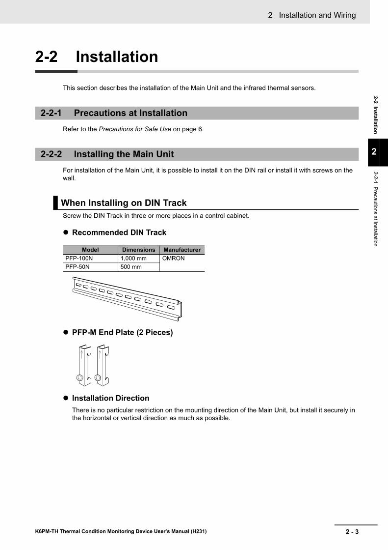
This section describes the installation of the Main Unit and the infrared thermal sensors.
Refer to the Precautions for Safe Use on page 6.
For installation of the Main Unit, it is possible to install it on the DIN rail or install it with screws on the wall.
Screw the DIN Track in three or more places in a control cabinet.
Recommended DIN Track
PFP-M End Plate (2 Pieces)
Installation DirectionThere is no particular restriction on the mounting direction of the Main Unit, but install it securely in the horizontal or vertical direction as much as possible.
2-2-1 Precautions at Installation
2-2-2 Installing the Main Unit
When Installing on DIN Track
Model Dimensions ManufacturerPFP-100N 1,000 mm OMRONPFP-50N 500 mm
2 Installation and Wiring
2 - 4 K6PM-TH Thermal Condition Monitoring Device User’s Manual (H231)
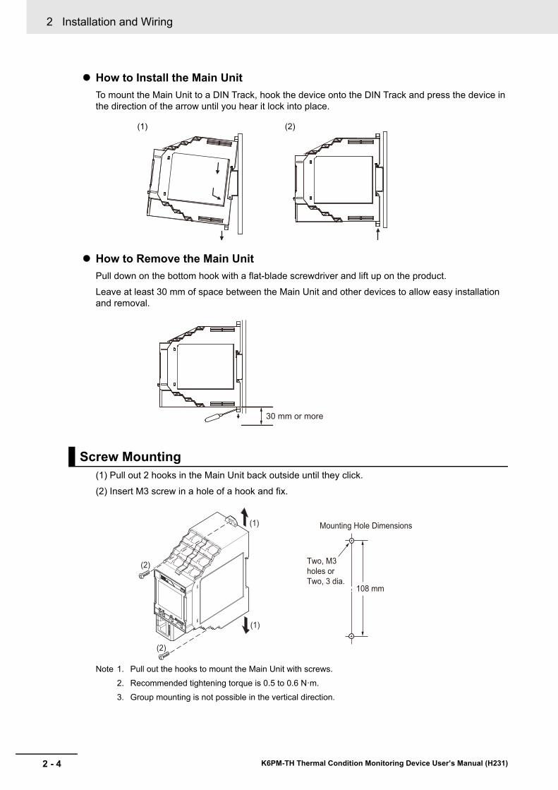
How to Install the Main UnitTo mount the Main Unit to a DIN Track, hook the device onto the DIN Track and press the device in the direction of the arrow until you hear it lock into place.
How to Remove the Main UnitPull down on the bottom hook with a flat-blade screwdriver and lift up on the product.Leave at least 30 mm of space between the Main Unit and other devices to allow easy installation and removal.
(1) Pull out 2 hooks in the Main Unit back outside until they click.
(2) Insert M3 screw in a hole of a hook and fix.
Note 1. Pull out the hooks to mount the Main Unit with screws.2. Recommended tightening torque is 0.5 to 0.6 N·m.3. Group mounting is not possible in the vertical direction.
Screw Mounting
(1) (2)
30 mm or more
(1)
(1)
(2)
(2)
108 mm
Mounting Hole Dimensions
Two, M3
holes or
Two, 3 dia.
2 - 5
2 Installation and Wiring
K6PM-TH Thermal Condition Monitoring Device User’s Manual (H231)
2-2 Installation
2
2-2-3 Installation of the Infrared Thermal Sensor
This section describes how to install the infrared thermal sensors.
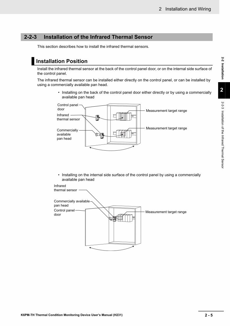
Install the infrared thermal sensor at the back of the control panel door, or on the internal side surface of the control panel.
The infrared thermal sensor can be installed either directly on the control panel, or can be installed by using a commercially available pan head.
2-2-3 Installation of the Infrared Thermal Sensor
Installation Position
Measurement target range
Measurement target range
Measurement target range
Infrared
thermal sensor
Control panel
door
Control panel
door
Commercially
available
pan head
Infrared
thermal sensor
Commercially available
pan head
• Installing on the back of the control panel door either directly or by using a commercially available pan head
• Installing on the internal side surface of the control panel by using a commercially available pan head
2 Installation and Wiring
2 - 6 K6PM-TH Thermal Condition Monitoring Device User’s Manual (H231)
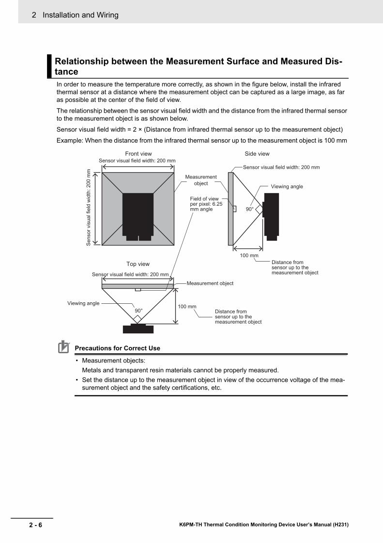
In order to measure the temperature more correctly, as shown in the figure below, install the infrared thermal sensor at a distance where the measurement object can be captured as a large image, as far as possible at the center of the field of view.The relationship between the sensor visual field width and the distance from the infrared thermal sensor to the measurement object is as shown below.
Sensor visual field width = 2 × (Distance from infrared thermal sensor up to the measurement object) Example: When the distance from the infrared thermal sensor up to the measurement object is 100 mm
Precautions for Correct Use
• Measurement objects:Metals and transparent resin materials cannot be properly measured.
• Set the distance up to the measurement object in view of the occurrence voltage of the mea-surement object and the safety certifications, etc.
Relationship between the Measurement Surface and Measured Dis-tance
90°
Sensor visual field width: 200 mm
Se
nso
r vis
ua
l fie
ld w
idth
: 2
00
mm
Sensor visual field width: 200 mm
90°
Measurement
object
Front view
Top view
Side view
Viewing angle
Viewing angle
Field of view per pixel: 6.25 mm angle
Sensor visual field width: 200 mm
Distance from sensor up to the measurement object
Distance from sensor up to the measurement object
100 mm
100 mm
Measurement object
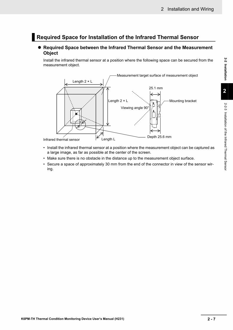
2 - 7
2 Installation and Wiring
K6PM-TH Thermal Condition Monitoring Device User’s Manual (H231)
2-2 Installation
2
2-2-3 Installation of the Infrared Thermal Sensor
Required Space between the Infrared Thermal Sensor and the Measurement Object Install the infrared thermal sensor at a position where the following space can be secured from the measurement object.
• Install the infrared thermal sensor at a position where the measurement object can be captured as a large image, as far as possible at the center of the screen.
• Make sure there is no obstacle in the distance up to the measurement object surface.• Secure a space of approximately 30 mm from the end of the connector in view of the sensor wir-
ing.
Required Space for Installation of the Infrared Thermal Sensor
Infrared thermal sensor
Measurement target surface of measurement object
Mounting bracket
Depth 25.6 mm
25.1 mm
Length 2 × L
Length L
Length 2 × L
Viewing angle 90°
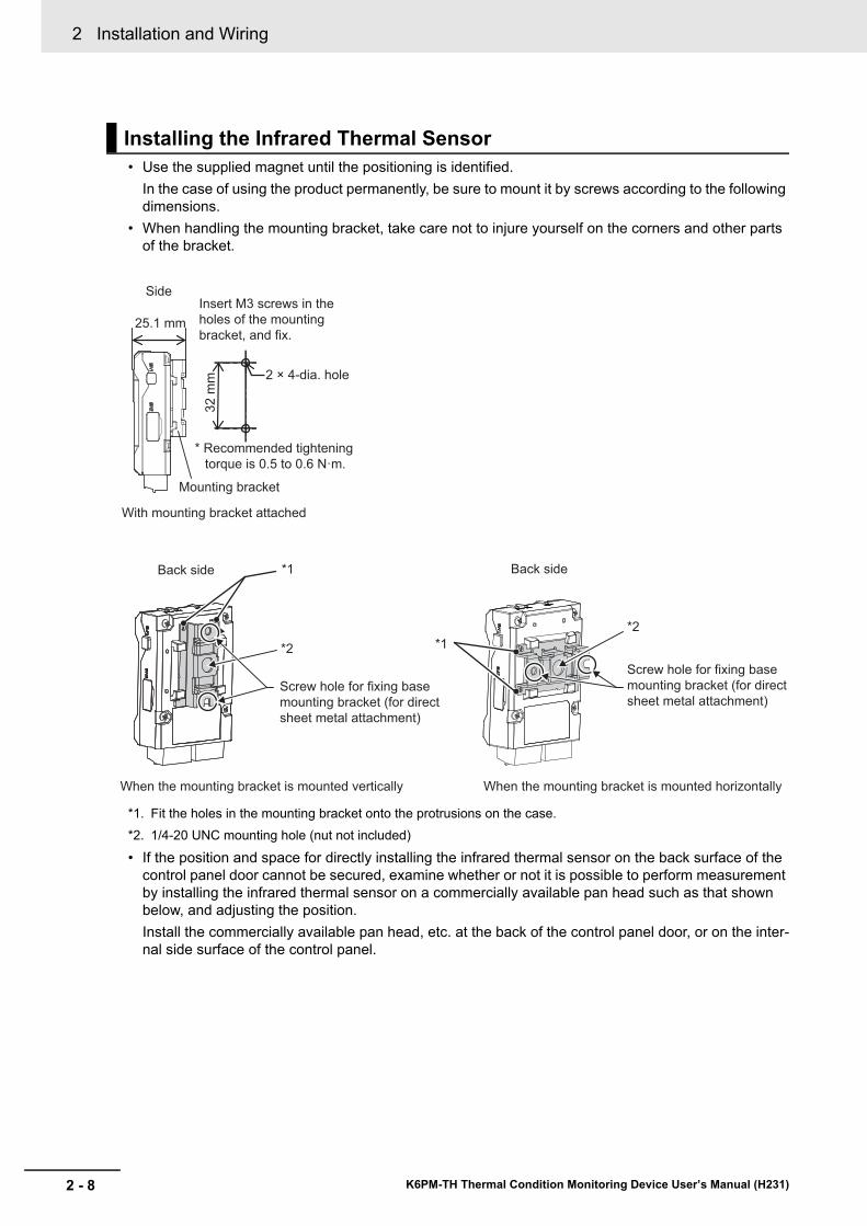
2 Installation and Wiring
2 - 8 K6PM-TH Thermal Condition Monitoring Device User’s Manual (H231)
• Use the supplied magnet until the positioning is identified.In the case of using the product permanently, be sure to mount it by screws according to the following dimensions.
• When handling the mounting bracket, take care not to injure yourself on the corners and other parts of the bracket.
*1. Fit the holes in the mounting bracket onto the protrusions on the case.*2. 1/4-20 UNC mounting hole (nut not included)
• If the position and space for directly installing the infrared thermal sensor on the back surface of the control panel door cannot be secured, examine whether or not it is possible to perform measurement by installing the infrared thermal sensor on a commercially available pan head such as that shown below, and adjusting the position.Install the commercially available pan head, etc. at the back of the control panel door, or on the inter-nal side surface of the control panel.
Installing the Infrared Thermal Sensor
When the mounting bracket is mounted horizontally
Back side
Side
Back side
25.1 mm
With mounting bracket attached
When the mounting bracket is mounted vertically
Mounting bracket
2 × 4-dia. hole
32
mm
*1
*1
Screw hole for fixing base
mounting bracket (for direct
sheet metal attachment)
Screw hole for fixing base
mounting bracket (for direct
sheet metal attachment)
*2
Insert M3 screws in the
holes of the mounting
bracket, and fix.
* Recommended tightening
torque is 0.5 to 0.6 N·m.
*2
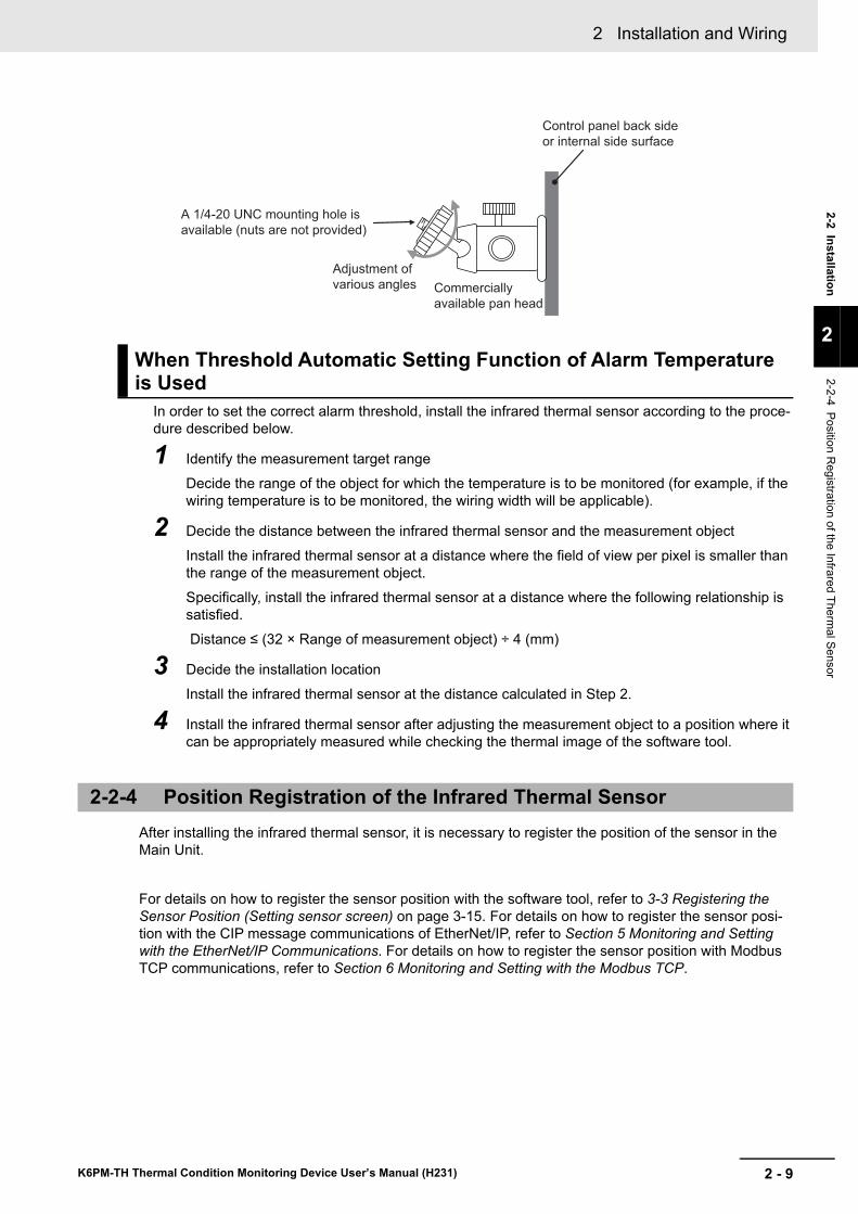
2 - 9
2 Installation and Wiring
K6PM-TH Thermal Condition Monitoring Device User’s Manual (H231)
2-2 Installation
2
2-2-4 Position Registration of the Infrared Therm
al Sensor
In order to set the correct alarm threshold, install the infrared thermal sensor according to the proce-dure described below.
1 Identify the measurement target rangeDecide the range of the object for which the temperature is to be monitored (for example, if the wiring temperature is to be monitored, the wiring width will be applicable).
2 Decide the distance between the infrared thermal sensor and the measurement object
Install the infrared thermal sensor at a distance where the field of view per pixel is smaller than the range of the measurement object.Specifically, install the infrared thermal sensor at a distance where the following relationship is satisfied. Distance ≤ (32 × Range of measurement object) ÷ 4 (mm)
3 Decide the installation location
Install the infrared thermal sensor at the distance calculated in Step 2.
4 Install the infrared thermal sensor after adjusting the measurement object to a position where it can be appropriately measured while checking the thermal image of the software tool.
After installing the infrared thermal sensor, it is necessary to register the position of the sensor in the Main Unit.
For details on how to register the sensor position with the software tool, refer to 3-3 Registering the Sensor Position (Setting sensor screen) on page 3-15. For details on how to register the sensor posi-tion with the CIP message communications of EtherNet/IP, refer to Section 5 Monitoring and Setting with the EtherNet/IP Communications. For details on how to register the sensor position with Modbus TCP communications, refer to Section 6 Monitoring and Setting with the Modbus TCP.
When Threshold Automatic Setting Function of Alarm Temperature is Used
2-2-4 Position Registration of the Infrared Thermal Sensor
Commercially
available pan head
Adjustment of
various angles
Control panel back side
or internal side surface
A 1/4-20 UNC mounting hole is
available (nuts are not provided)
2 Installation and Wiring
2 - 10 K6PM-TH Thermal Condition Monitoring Device User’s Manual (H231)
2-3 Wiring
This section describes the wiring of the Main Units.
This section describes how to connect the Main Units to the Push-In Plus terminal blocks.All terminals of the Main Unit are Push-In Plus terminals.
Precautions for Safe Use
• To prevent wire materials from smoking or igniting, use the wiring materials given in the fol-lowing table.
• Make sure the crimp terminals for wiring are of the specified size.• Do not insert more than one wire into each terminal insertion hole.• Do not connect anything to terminals that are not being used.• Do not wire anything to the release holes.• Do not tilt or twist a flat-blade screwdriver while it is inserted into a release hole on the ter-
minal block. The terminal block may be damaged.• Insert a flat-blade screwdriver into the release holes at an angle. The terminal block may
be damaged if you insert the screwdriver straight in.• Do not allow the flat-blade screwdriver to fall out while it is inserted into a release hole.• Do not place product wiring in parallel with or in the same path as high-voltage or high-cur-
rent lines. Keep wiring separate from high voltages and power lines that draw large cur-rents.
• Do not bend a wire past its natural bending radius or pull on it with excessive force. Doing so may cause the wire disconnection.
• When wiring the terminals, allow some leeway in the wire length.
Precautions for Correct Use
• When you are finished with wiring, make sure that no stranded wire comes loose.• If you wire crossovers and connect terminal blocks in parallel, a large current will flow. Make
sure that the current does not exceed 10 A.• The terminal block may be damaged if the recommended tool is not used. Use the recom-
mended flat-blade screwdriver to operate the release holes.
2-3-1 How to Connect to the Push-In Plus Terminal Blocks
Recommended Wire Stripping length(Without Ferrules)
0.25 to 1.5 mm2 (AWG24 to AWG16) 8 mm
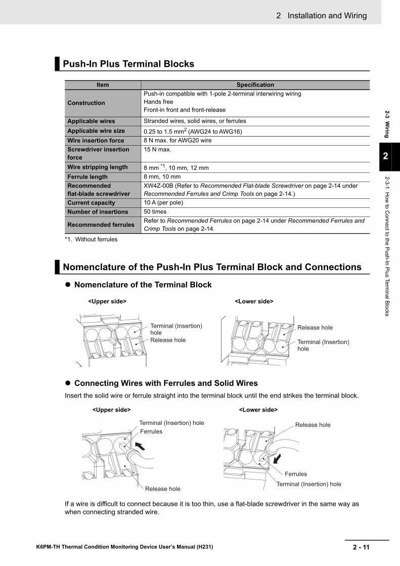
2 - 11
2 Installation and Wiring
K6PM-TH Thermal Condition Monitoring Device User’s Manual (H231)
2-3 Wiring
2
2-3-1 How
to Connect to the Push-In Plus Term
inal Blocks
Nomenclature of the Terminal Block
Connecting Wires with Ferrules and Solid WiresInsert the solid wire or ferrule straight into the terminal block until the end strikes the terminal block.
If a wire is difficult to connect because it is too thin, use a flat-blade screwdriver in the same way as when connecting stranded wire.
Push-In Plus Terminal Blocks
Item Specification
ConstructionPush-in compatible with 1-pole 2-terminal interwiring wiringHands freeFront-in front and front-release
Applicable wires Stranded wires, solid wires, or ferrulesApplicable wire size 0.25 to 1.5 mm2 (AWG24 to AWG16)Wire insertion force 8 N max. for AWG20 wireScrewdriver insertion force
15 N max.
Wire stripping length 8 mm *1, 10 mm, 12 mm
*1. Without ferrules
Ferrule length 8 mm, 10 mmRecommended flat-blade screwdriver
XW4Z-00B (Refer to Recommended Flat-blade Screwdriver on page 2-14 under Recommended Ferrules and Crimp Tools on page 2-14.)
Current capacity 10 A (per pole)Number of insertions 50 times
Recommended ferrules Refer to Recommended Ferrules on page 2-14 under Recommended Ferrules and Crimp Tools on page 2-14.
Nomenclature of the Push-In Plus Terminal Block and Connections
Terminal (Insertion)hole
Release hole Terminal (Insertion)hole
Release hole
<Upper side> <Lower side>
Ferrules
Terminal (Insertion) hole
Release hole
Ferrules
Terminal (Insertion) hole
Release hole
<Upper side> <Lower side>
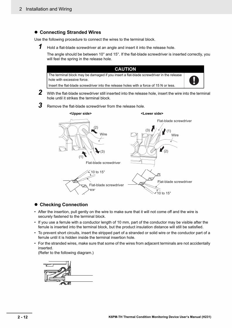
2 Installation and Wiring
2 - 12 K6PM-TH Thermal Condition Monitoring Device User’s Manual (H231)
Connecting Stranded WiresUse the following procedure to connect the wires to the terminal block.
1 Hold a flat-blade screwdriver at an angle and insert it into the release hole.
The angle should be between 10° and 15°. If the flat-blade screwdriver is inserted correctly, you will feel the spring in the release hole.
2 With the flat-blade screwdriver still inserted into the release hole, insert the wire into the terminal hole until it strikes the terminal block.
3 Remove the flat-blade screwdriver from the release hole.
Checking Connection• After the insertion, pull gently on the wire to make sure that it will not come off and the wire is
securely fastened to the terminal block.• If you use a ferrule with a conductor length of 10 mm, part of the conductor may be visible after the
ferrule is inserted into the terminal block, but the product insulation distance will still be satisfied.• To prevent short circuits, insert the stripped part of a stranded or solid wire or the conductor part of a
ferrule until it is hidden inside the terminal insertion hole.• For the stranded wires, make sure that some of the wires from adjacent terminals are not accidentally
inserted.(Refer to the following diagram.)
CAUTIONThe terminal block may be damaged if you insert a flat-blade screwdriver in the release hole with excessive force.Insert the flat-blade screwdriver into the release holes with a force of 15 N or less.
Wire
(1)
(3)
(2)
Flat-blade screwdriver
Wire
(1)(3)
(2)
Flat-blade screwdriver
10 to 15°
10 to 15°
Flat-blade screwdriverFlat-blade screwdriver
<Upper side> <Lower side>
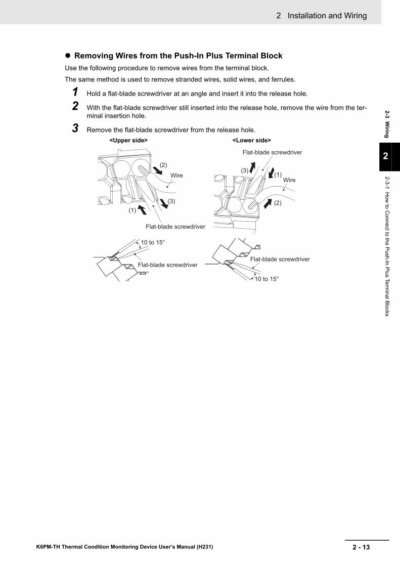
2 - 13
2 Installation and Wiring
K6PM-TH Thermal Condition Monitoring Device User’s Manual (H231)
2-3 Wiring
2
2-3-1 How
to Connect to the Push-In Plus Term
inal Blocks
Removing Wires from the Push-In Plus Terminal BlockUse the following procedure to remove wires from the terminal block.The same method is used to remove stranded wires, solid wires, and ferrules.
1 Hold a flat-blade screwdriver at an angle and insert it into the release hole.
2 With the flat-blade screwdriver still inserted into the release hole, remove the wire from the ter-minal insertion hole.
3 Remove the flat-blade screwdriver from the release hole.
Wire
(1)
(3)
(2)
Flat-blade screwdriver
(1)
(2)
(3)
Wire
Flat-blade screwdriver
10 to 15°
10 to 15°
Flat-blade screwdriverFlat-blade screwdriver
<Upper side> <Lower side>
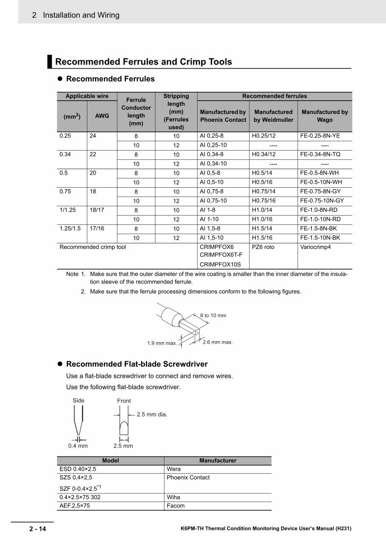
2 Installation and Wiring
2 - 14 K6PM-TH Thermal Condition Monitoring Device User’s Manual (H231)
Recommended Ferrules
Note 1. Make sure that the outer diameter of the wire coating is smaller than the inner diameter of the insula-tion sleeve of the recommended ferrule.
2. Make sure that the ferrule processing dimensions conform to the following figures.
Recommended Flat-blade ScrewdriverUse a flat-blade screwdriver to connect and remove wires.
Use the following flat-blade screwdriver.
Recommended Ferrules and Crimp Tools
Applicable wire Ferrule Conductor
length(mm)
Stripping length(mm)
(Ferrules used)
Recommended ferrules
(mm2) AWG Manufactured by Phoenix Contact
Manufactured by Weidmuller
Manufactured by Wago
0.25 24 8 10 AI 0,25-8 H0.25/12 FE-0.25-8N-YE10 12 AI 0,25-10 ---- ----
0.34 22 8 10 AI 0,34-8 H0.34/12 FE-0.34-8N-TQ10 12 AI 0,34-10 ---- ----
0.5 20 8 10 AI 0,5-8 H0.5/14 FE-0.5-8N-WH10 12 AI 0,5-10 H0.5/16 FE-0.5-10N-WH
0.75 18 8 10 AI 0,75-8 H0.75/14 FE-0.75-8N-GY10 12 AI 0,75-10 H0.75/16 FE-0.75-10N-GY
1/1.25 18/17 8 10 AI 1-8 H1.0/14 FE-1.0-8N-RD10 12 AI 1-10 H1.0/16 FE-1.0-10N-RD
1.25/1.5 17/16 8 10 AI 1,5-8 H1.5/14 FE-1.5-8N-BK10 12 AI 1,5-10 H1.5/16 FE-1.5-10N-BK
Recommended crimp tool CRIMPFOX6 CRIMPFOX6T-FCRIMPFOX10S
PZ6 roto Variocrimp4
Model ManufacturerESD 0.40×2.5 WeraSZS 0,4×2,5
SZF 0-0.4×2.5*1
Phoenix Contact
0.4×2.5×75 302 WihaAEF.2,5×75 Facom
8 to 10 mm
1.9 mm max. 2.6 mm max.
Side
0.4 mm
2.5 mm dia.
2.5 mm
Front
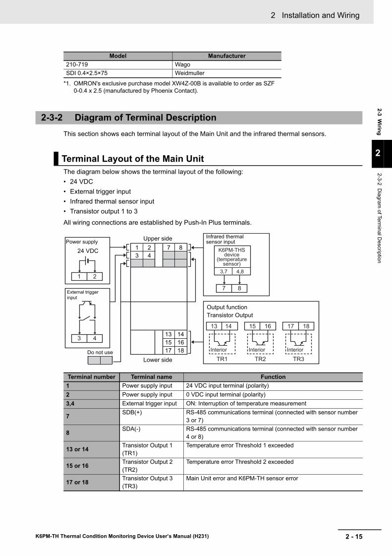
2 - 15
2 Installation and Wiring
K6PM-TH Thermal Condition Monitoring Device User’s Manual (H231)
2-3 Wiring
2
2-3-2 Diagram
of Terminal D
escription
This section shows each terminal layout of the Main Unit and the infrared thermal sensors.
The diagram below shows the terminal layout of the following:• 24 VDC• External trigger input• Infrared thermal sensor input• Transistor output 1 to 3All wiring connections are established by Push-In Plus terminals.
210-719 WagoSDI 0.4×2.5×75 Weidmuller
*1. OMRON's exclusive purchase model XW4Z-00B is available to order as SZF 0-0.4 x 2.5 (manufactured by Phoenix Contact).
2-3-2 Diagram of Terminal Description
Terminal Layout of the Main Unit
Terminal number Terminal name Function1 Power supply input 24 VDC input terminal (polarity)2 Power supply input 0 VDC input terminal (polarity)3,4 External trigger input ON: Interruption of temperature measurement
7 SDB(+) RS-485 communications terminal (connected with sensor number 3 or 7)
8 SDA(-) RS-485 communications terminal (connected with sensor number 4 or 8)
13 or 14 Transistor Output 1 (TR1)
Temperature error Threshold 1 exceeded
15 or 16 Transistor Output 2 (TR2)
Temperature error Threshold 2 exceeded
17 or 18 Transistor Output 3 (TR3)
Main Unit error and K6PM-TH sensor error
Model Manufacturer
1 2
7 8
13
TR1
Interior
14
K6PM-THSdevice
(temperaturesensor)
3,7 4,8
3 4
15
TR2
Interior
16 17
TR3
Interior
18
1 2 7 8
3 4
13 14
15 16
17 18
Transistor Output
Power supply
24 VDC
Do not use
Output function
Upper side
Lower side
External trigger
input
Infrared thermalsensor input
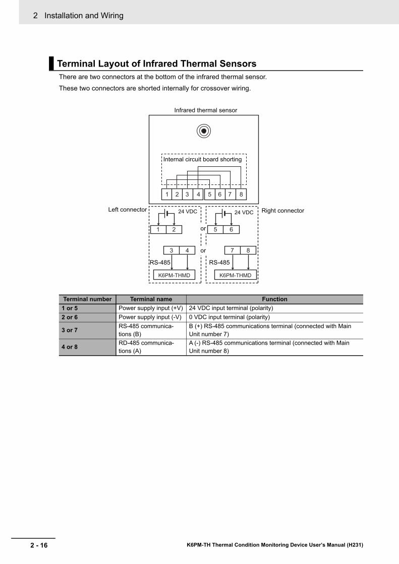
2 Installation and Wiring
2 - 16 K6PM-TH Thermal Condition Monitoring Device User’s Manual (H231)
There are two connectors at the bottom of the infrared thermal sensor.
These two connectors are shorted internally for crossover wiring.
Terminal Layout of Infrared Thermal Sensors
Terminal number Terminal name Function1 or 5 Power supply input (+V) 24 VDC input terminal (polarity)2 or 6 Power supply input (-V) 0 VDC input terminal (polarity)
3 or 7 RS-485 communica-tions (B)
B (+) RS-485 communications terminal (connected with Main Unit number 7)
4 or 8 RD-485 communica-tions (A)
A (-) RS-485 communications terminal (connected with Main Unit number 8)
1 2 5 6
3 4 7 8
K6PM-THMD K6PM-THMD
1 2 3 4 5 6 7 8
Internal circuit board shorting
Left connector Right connector
Infrared thermal sensor
24 VDC 24 VDC
or
or
RS-485 RS-485
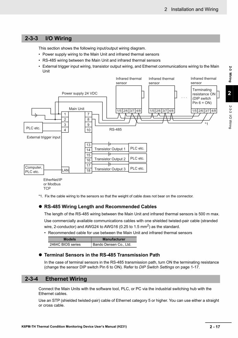
2 - 17
2 Installation and Wiring
K6PM-TH Thermal Condition Monitoring Device User’s Manual (H231)
2-3 Wiring
2
2-3-3 I/O W
iring
This section shows the following input/output wiring diagram.• Power supply wiring to the Main Unit and infrared thermal sensors• RS-485 wiring between the Main Unit and infrared thermal sensors• External trigger input wiring, transistor output wiring, and Ethernet communications wiring to the Main
Unit
*1. Fix the cable wiring to the sensors so that the weight of cable does not bear on the connector.
RS-485 Wiring Length and Recommended CablesThe length of the RS-485 wiring between the Main Unit and infrared thermal sensors is 500 m max.
Use commercially available communications cables with one shielded twisted-pair cable (stranded wire, 2-conductor) and AWG24 to AWG16 (0.25 to 1.5 mm2) as the standard.• Recommended cable for use between the Main Unit and infrared thermal sensors
Terminal Sensors in the RS-485 Transmission PathIn the case of terminal sensors in the RS-485 transmission path, turn ON the terminating resistance (change the sensor DIP switch Pin 6 to ON). Refer to DIP Switch Settings on page 1-17.
Connect the Main Units with the software tool, PLC, or PC via the industrial switching hub with the Ethernet cables.
Use an STP (shielded twisted-pair) cable of Ethernet category 5 or higher. You can use either a straight or cross cable.
2-3-3 I/O Wiring
Models Manufacturer2464C BIOS series Bando Densen Co., Ltd.
2-3-4 Ethernet Wiring
Transistor Output 1
1
2
3
4
7
8
9
10
LAN
15
16
17
18
13
14 PLC etc.
PLC etc.
PLC etc.
· · ·
Infrared thermal
sensor
3/7 4/81/5 2/6
Infrared thermal
sensor
Infrared thermal
sensor
3/7 4/81/5 2/6 3/7 4/81/5 2/6
External trigger input
Main Unit
Power supply 24 VDC
PLC etc.
Transistor Output 2
Transistor Output 3
RS-485
*1
Terminating
resistance ON
(DIP switch
Pin 6 = ON)
Computer,
PLC etc.
EtherNet/IP
or Modbus
TCP
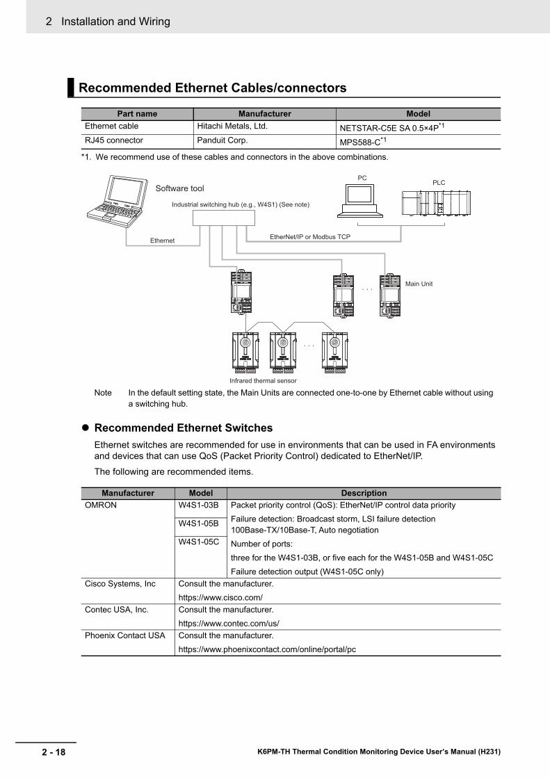
2 Installation and Wiring
2 - 18 K6PM-TH Thermal Condition Monitoring Device User’s Manual (H231)
Note In the default setting state, the Main Units are connected one-to-one by Ethernet cable without using a switching hub.
Recommended Ethernet SwitchesEthernet switches are recommended for use in environments that can be used in FA environments and devices that can use QoS (Packet Priority Control) dedicated to EtherNet/IP.The following are recommended items.
Recommended Ethernet Cables/connectors
Part name Manufacturer ModelEthernet cable Hitachi Metals, Ltd. NETSTAR-C5E SA 0.5×4P*1
*1. We recommend use of these cables and connectors in the above combinations.
RJ45 connector Panduit Corp. MPS588-C*1
Manufacturer Model DescriptionOMRON W4S1-03B Packet priority control (QoS): EtherNet/IP control data priority
Failure detection: Broadcast storm, LSI failure detection 100Base-TX/10Base-T, Auto negotiationNumber of ports:three for the W4S1-03B, or five each for the W4S1-05B and W4S1-05CFailure detection output (W4S1-05C only)
W4S1-05B
W4S1-05C
Cisco Systems, Inc Consult the manufacturer.https://www.cisco.com/
Contec USA, Inc. Consult the manufacturer.https://www.contec.com/us/
Phoenix Contact USA Consult the manufacturer.https://www.phoenixcontact.com/online/portal/pc
Software tool
Industrial switching hub (e.g., W4S1) (See note)
PCPLC
EtherNet/IP or Modbus TCPEthernet
· · ·
· · ·
Infrared thermal sensor
Main Unit
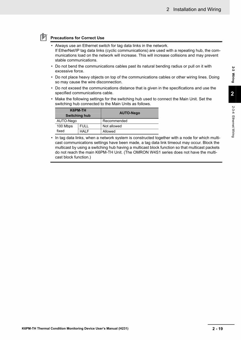
2 - 19
2 Installation and Wiring
K6PM-TH Thermal Condition Monitoring Device User’s Manual (H231)
2-3 Wiring
2
2-3-4 Ethernet Wiring
Precautions for Correct Use
• Always use an Ethernet switch for tag data links in the network.If EtherNet/IP tag data links (cyclic communications) are used with a repeating hub, the com-munications load on the network will increase. This will increase collisions and may prevent stable communications.
• Do not bend the communications cables past its natural bending radius or pull on it with excessive force.
• Do not place heavy objects on top of the communications cables or other wiring lines. Doing so may cause the wire disconnection.
• Do not exceed the communications distance that is given in the specifications and use the specified communications cable.
• Make the following settings for the switching hub used to connect the Main Unit. Set the switching hub connected to the Main Units as follows.
• In tag data links, when a network system is constructed together with a node for which multi-cast communications settings have been made, a tag data link timeout may occur. Block the multicast by using a switching hub having a multicast block function so that multicast packets do not reach the main K6PM-TH Unit. (The OMRON W4S1 series does not have the multi-cast block function.)
K6PM-THAUTO-Nego
Switching hubAUTO-Nego Recommended100 Mbps fixed
FULL Not allowedHALF Allowed

2 Installation and Wiring
2 - 20 K6PM-TH Thermal Condition Monitoring Device User’s Manual (H231)
3 - 1
3
K6PM-TH Thermal Condition Monitoring Device User’s Manual (H231)
This section describes the initial settings of the Main Units using the software tool.
3-1 Installation and Uninstallation, Starting up . . . . . . . . . . . . . . . . . . . . . . . . . 3-23-1-1 Installing the Software Tool . . . . . . . . . . . . . . . . . . . . . . . . . . . . . . . . . . . . . . . . 3-23-1-2 Uninstalling the Software Tool . . . . . . . . . . . . . . . . . . . . . . . . . . . . . . . . . . . . . . 3-6
3-2 IP Address Setting . . . . . . . . . . . . . . . . . . . . . . . . . . . . . . . . . . . . . . . . . . . . . 3-73-2-1 IP Address Setting of Your PC . . . . . . . . . . . . . . . . . . . . . . . . . . . . . . . . . . . . . 3-73-2-2 Setting the IP Address of the Main Units with the Software Tool . . . . . . . . . . . 3-9
3-3 Registering the Sensor Position (Setting sensor screen) . . . . . . . . . . . . 3-153-4 Registering the Initial Settings and Sensor Configuration of the Main Unit
(Setting K6PM screen) . . . . . . . . . . . . . . . . . . . . . . . . . . . . . . . . . . . . . . . . . 3-18
Initial Setting
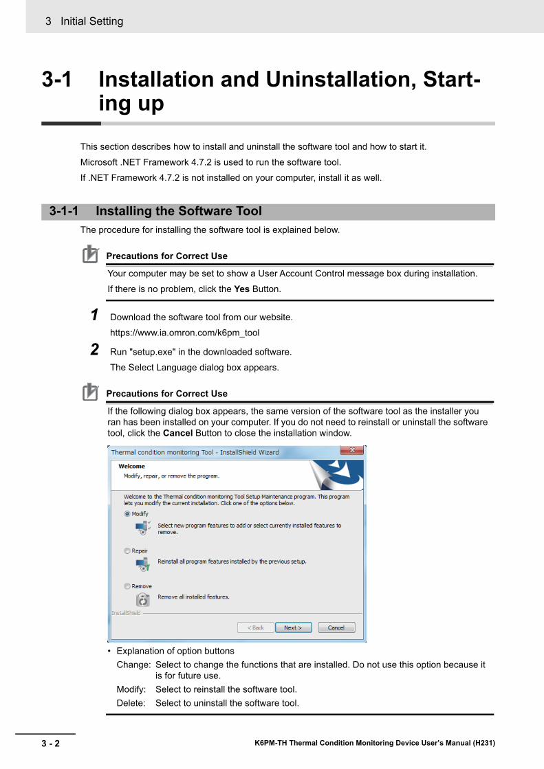
3 Initial Setting
3 - 2 K6PM-TH Thermal Condition Monitoring Device User’s Manual (H231)
3-1 Installation and Uninstallation, Start-ing up
This section describes how to install and uninstall the software tool and how to start it.
Microsoft .NET Framework 4.7.2 is used to run the software tool.If .NET Framework 4.7.2 is not installed on your computer, install it as well.
The procedure for installing the software tool is explained below.
Precautions for Correct Use
Your computer may be set to show a User Account Control message box during installation.If there is no problem, click the Yes Button.
1 Download the software tool from our website.https://www.ia.omron.com/k6pm_tool
2 Run "setup.exe" in the downloaded software.The Select Language dialog box appears.
Precautions for Correct Use
If the following dialog box appears, the same version of the software tool as the installer you ran has been installed on your computer. If you do not need to reinstall or uninstall the software tool, click the Cancel Button to close the installation window.
• Explanation of option buttonsChange: Select to change the functions that are installed. Do not use this option because it
is for future use.Modify: Select to reinstall the software tool.Delete: Select to uninstall the software tool.
3-1-1 Installing the Software Tool
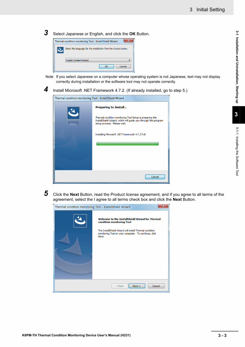
3 - 3
3 Initial Setting
K6PM-TH Thermal Condition Monitoring Device User’s Manual (H231)
3-1 Installation and Uninstallation, Starting up
3
3-1-1 Installing the Software Tool
3 Select Japanese or English, and click the OK Button.
Note If you select Japanese on a computer whose operating system is not Japanese, text may not display correctly during installation or the software tool may not operate correctly.
4 Install Microsoft .NET Framework 4.7.2. (If already installed, go to step 5.)
5 Click the Next Button, read the Product license agreement, and if you agree to all terms of the agreement, select the I agree to all terms check box and click the Next Button.
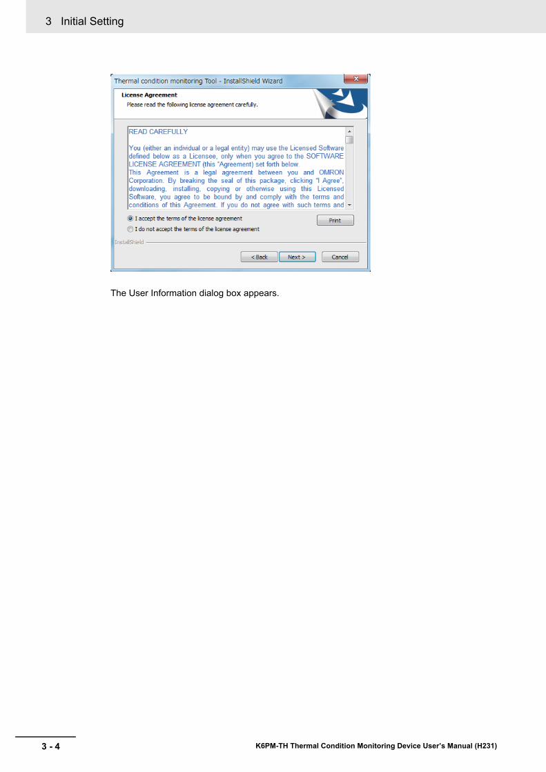
3 Initial Setting
3 - 4 K6PM-TH Thermal Condition Monitoring Device User’s Manual (H231)
The User Information dialog box appears.

3 - 5
3 Initial Setting
K6PM-TH Thermal Condition Monitoring Device User’s Manual (H231)
3-1 Installation and Uninstallation, Starting up
3
3-1-1 Installing the Software Tool
6 Register your user information, enter the license key, and click the Next Button.
The license key is included with the K6PM-THMD-EIP (Main Unit).
The Confirm Registration message box appears.
7 Make sure the registered information is correct, and click the Yes Button.
The Ready to Install dialog box appears
8 Click the Install Button.
Installation of the software tool starts.
When installation is completed, the message below appears in the Installation Wizard.
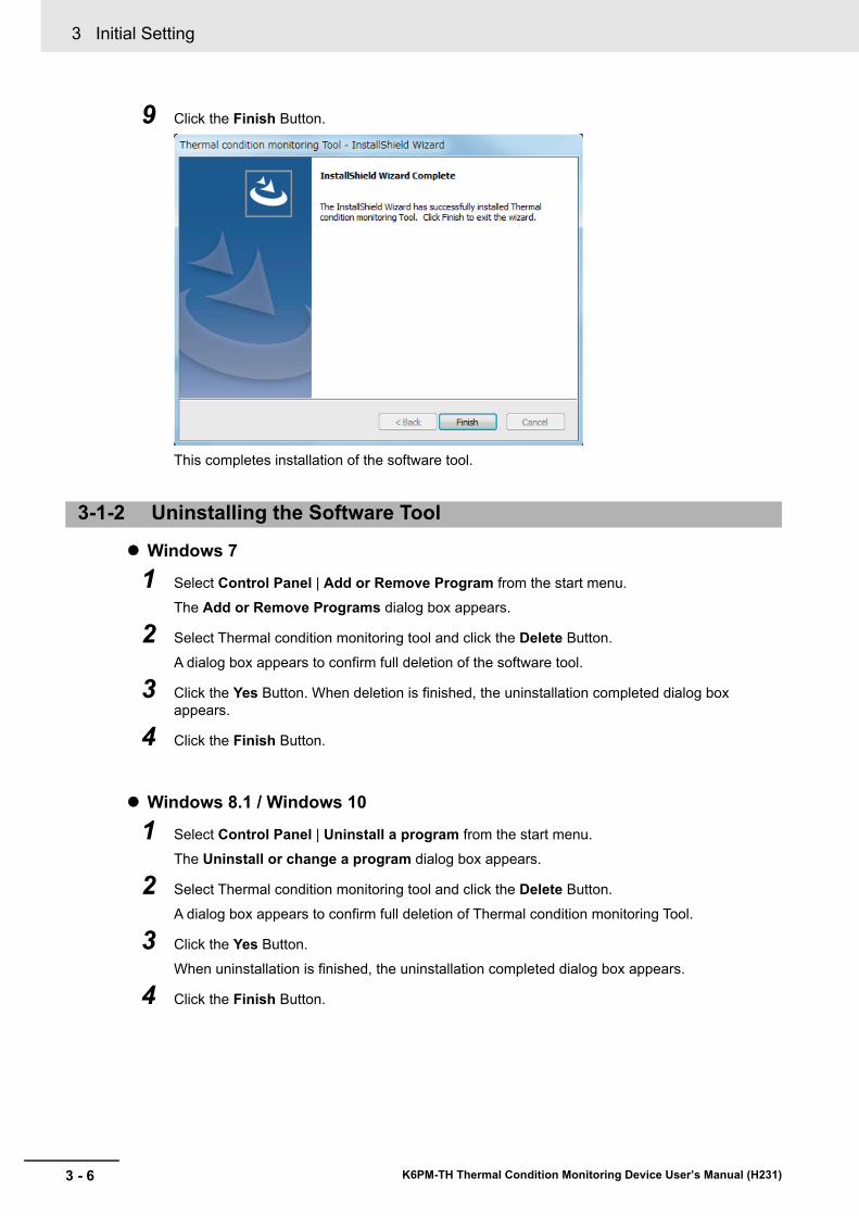
3 Initial Setting
3 - 6 K6PM-TH Thermal Condition Monitoring Device User’s Manual (H231)
9 Click the Finish Button.
This completes installation of the software tool.
Windows 7
1 Select Control Panel | Add or Remove Program from the start menu.The Add or Remove Programs dialog box appears.
2 Select Thermal condition monitoring tool and click the Delete Button.
A dialog box appears to confirm full deletion of the software tool.
3 Click the Yes Button. When deletion is finished, the uninstallation completed dialog box appears.
4 Click the Finish Button.
Windows 8.1 / Windows 10
1 Select Control Panel | Uninstall a program from the start menu.The Uninstall or change a program dialog box appears.
2 Select Thermal condition monitoring tool and click the Delete Button.
A dialog box appears to confirm full deletion of Thermal condition monitoring Tool.
3 Click the Yes Button.When uninstallation is finished, the uninstallation completed dialog box appears.
4 Click the Finish Button.
3-1-2 Uninstalling the Software Tool
3 - 7
3 Initial Setting
K6PM-TH Thermal Condition Monitoring Device User’s Manual (H231)
3-2 IP Address Setting
3
3-2-1 IP Address Setting of Your PC
3-2 IP Address Setting
This section describes the setting of the IP address of your PC and each IP address of the Main Units.
Before starting this tool and monitoring and logging the Main Unit, it is necessary to set the IP address of the computer to the IP address of the same segment as the Main Unit. It shows the procedure.Note that when setting only the Main Unit with an automatic connection, it is not necessary to set the IP address on the computer side.
For the initial setting of K6PM-TH, refer to 3-2-2 Setting the IP Address of the Main Units with the Soft-ware Tool on page 3-9.
Windows 7
1 Select Start | Control Panel | Network and Internet | Network and Sharing Center | Change Adapter Settings.
2 Right-click Local Area Connection and select Properties.
3 Select Internet Protocol Version 4 (TCP / IPv4) and click Properties.Check “Use next IP address” and manually set the IP address of the computer.
Windows 8.1
1 Right-click Start.
2 Select Network connection.
3 Right-click Ethernet, and click Properties.
4 Select Internet Protocol Version 4 (TCP / IPv4) and click Properties.Check “Use next IP address” and manually set the IP address of the computer.
Windows 10
1 Click Start and select Windows System Tools | Control Panel.
2 Select Network and Internet | Network and Sharing Center | Change Adapter Settings.
3 Right-click Ethernet and click Properties.
4 Select Internet Protocol Version 4 (TCP / IPv4) and click Properties.Check “Use next IP address” and manually set the IP address of the computer.
3-2-1 IP Address Setting of Your PC
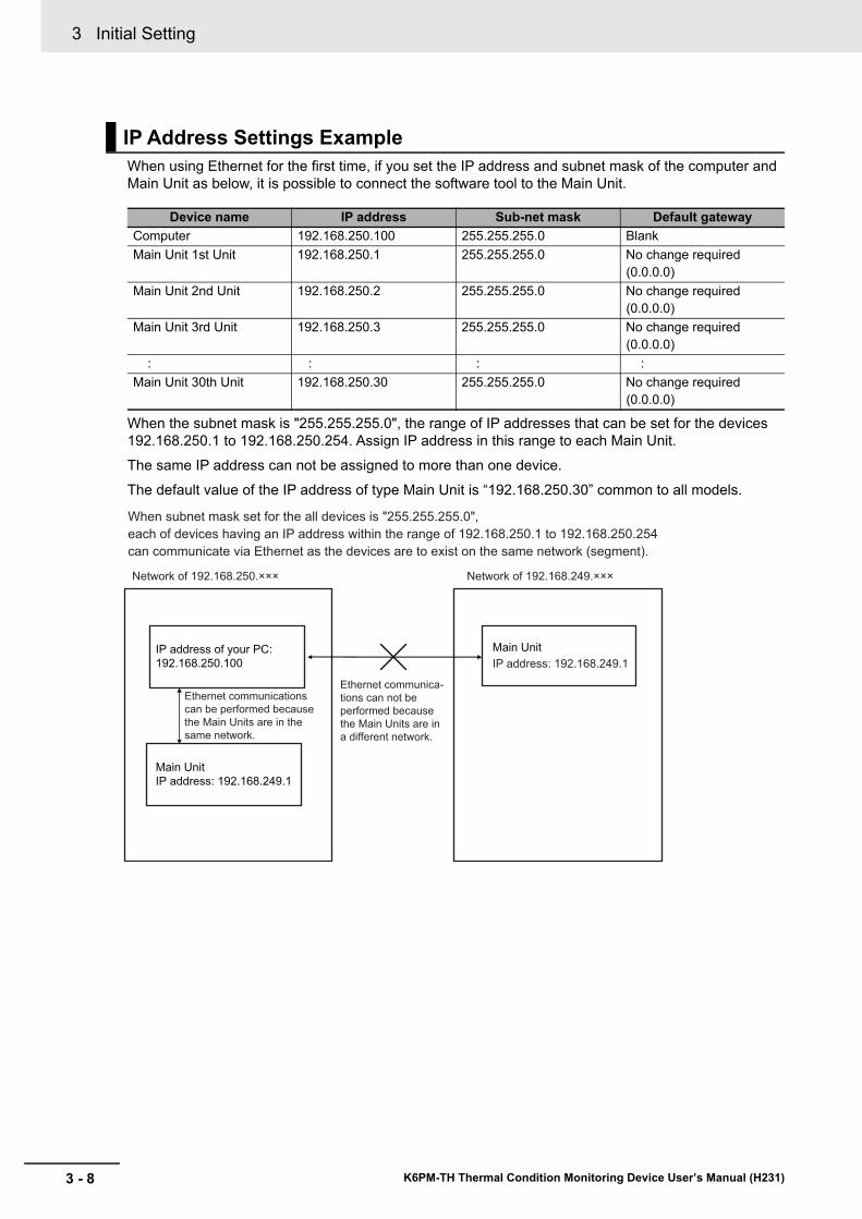
3 Initial Setting
3 - 8 K6PM-TH Thermal Condition Monitoring Device User’s Manual (H231)
When using Ethernet for the first time, if you set the IP address and subnet mask of the computer and Main Unit as below, it is possible to connect the software tool to the Main Unit.
When the subnet mask is "255.255.255.0", the range of IP addresses that can be set for the devices 192.168.250.1 to 192.168.250.254. Assign IP address in this range to each Main Unit.The same IP address can not be assigned to more than one device.The default value of the IP address of type Main Unit is “192.168.250.30” common to all models.
IP Address Settings Example
Device name IP address Sub-net mask Default gatewayComputer 192.168.250.100 255.255.255.0 BlankMain Unit 1st Unit 192.168.250.1 255.255.255.0 No change required
(0.0.0.0)Main Unit 2nd Unit 192.168.250.2 255.255.255.0 No change required
(0.0.0.0)Main Unit 3rd Unit 192.168.250.3 255.255.255.0 No change required
(0.0.0.0) : : : :Main Unit 30th Unit 192.168.250.30 255.255.255.0 No change required
(0.0.0.0)
When subnet mask set for the all devices is "255.255.255.0",
each of devices having an IP address within the range of 192.168.250.1 to 192.168.250.254
can communicate via Ethernet as the devices are to exist on the same network (segment).
Network of 192.168.249.×××
IP address: 192.168.249.1
Network of 192.168.250.×××
Main Unit
IP address: 192.168.249.1
Main UnitIP address of your PC:
192.168.250.100
Ethernet communications
can be performed because
the Main Units are in the
same network.
Ethernet communica-
tions can not be
performed because
the Main Units are in
a different network.
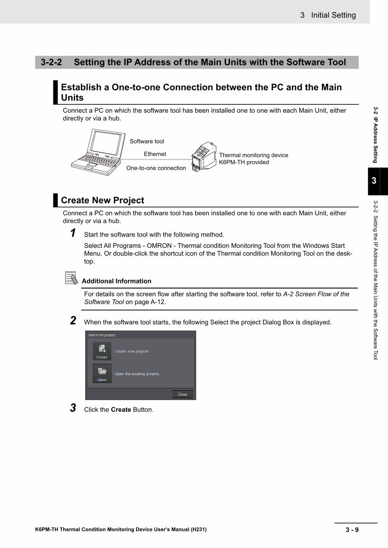
3 - 9
3 Initial Setting
K6PM-TH Thermal Condition Monitoring Device User’s Manual (H231)
3-2 IP Address Setting
3
3-2-2 Setting the IP Address of the Main U
nits with the Softw
are Tool
Connect a PC on which the software tool has been installed one to one with each Main Unit, either directly or via a hub.
Connect a PC on which the software tool has been installed one to one with each Main Unit, either directly or via a hub.
1 Start the software tool with the following method. Select All Programs - OMRON - Thermal condition Monitoring Tool from the Windows Start Menu. Or double-click the shortcut icon of the Thermal condition Monitoring Tool on the desk-top.
Additional Information
For details on the screen flow after starting the software tool, refer to A-2 Screen Flow of the Software Tool on page A-12.
2 When the software tool starts, the following Select the project Dialog Box is displayed.
3 Click the Create Button.
3-2-2 Setting the IP Address of the Main Units with the Software Tool
Establish a One-to-one Connection between the PC and the Main Units
Create New Project
Software tool
One-to-one connection
Ethernet Thermal monitoring device
K6PM-TH provided
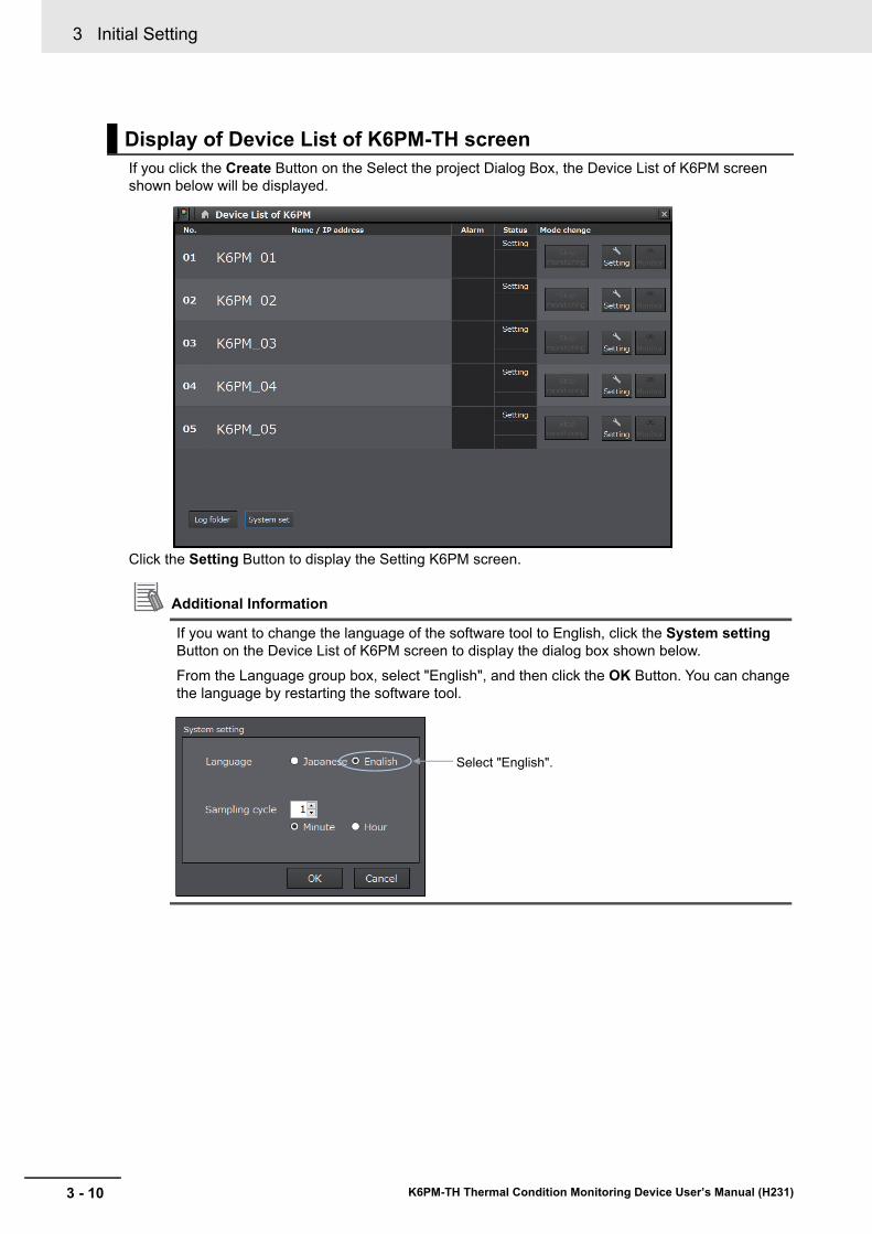
3 Initial Setting
3 - 10 K6PM-TH Thermal Condition Monitoring Device User’s Manual (H231)
If you click the Create Button on the Select the project Dialog Box, the Device List of K6PM screen shown below will be displayed.
Click the Setting Button to display the Setting K6PM screen.
Additional Information
If you want to change the language of the software tool to English, click the System setting Button on the Device List of K6PM screen to display the dialog box shown below.From the Language group box, select "English", and then click the OK Button. You can change the language by restarting the software tool.
Display of Device List of K6PM-TH screen
Select "English".
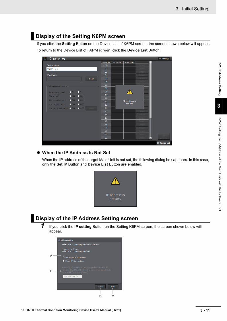
3 - 11
3 Initial Setting
K6PM-TH Thermal Condition Monitoring Device User’s Manual (H231)
3-2 IP Address Setting
3
3-2-2 Setting the IP Address of the Main U
nits with the Softw
are Tool
If you click the Setting Button on the Device List of K6PM screen, the screen shown below will appear.
To return to the Device List of K6PM screen, click the Device List Button.
When the IP Address Is Not SetWhen the IP address of the target Main Unit is not set, the following dialog box appears. In this case, only the Set IP Button and Device List Button are enabled.
1 If you click the IP setting Button on the Setting K6PM screen, the screen shown below will appear.
Display of the Setting K6PM screen
Display of the IP Address Setting screen
A
D C
B
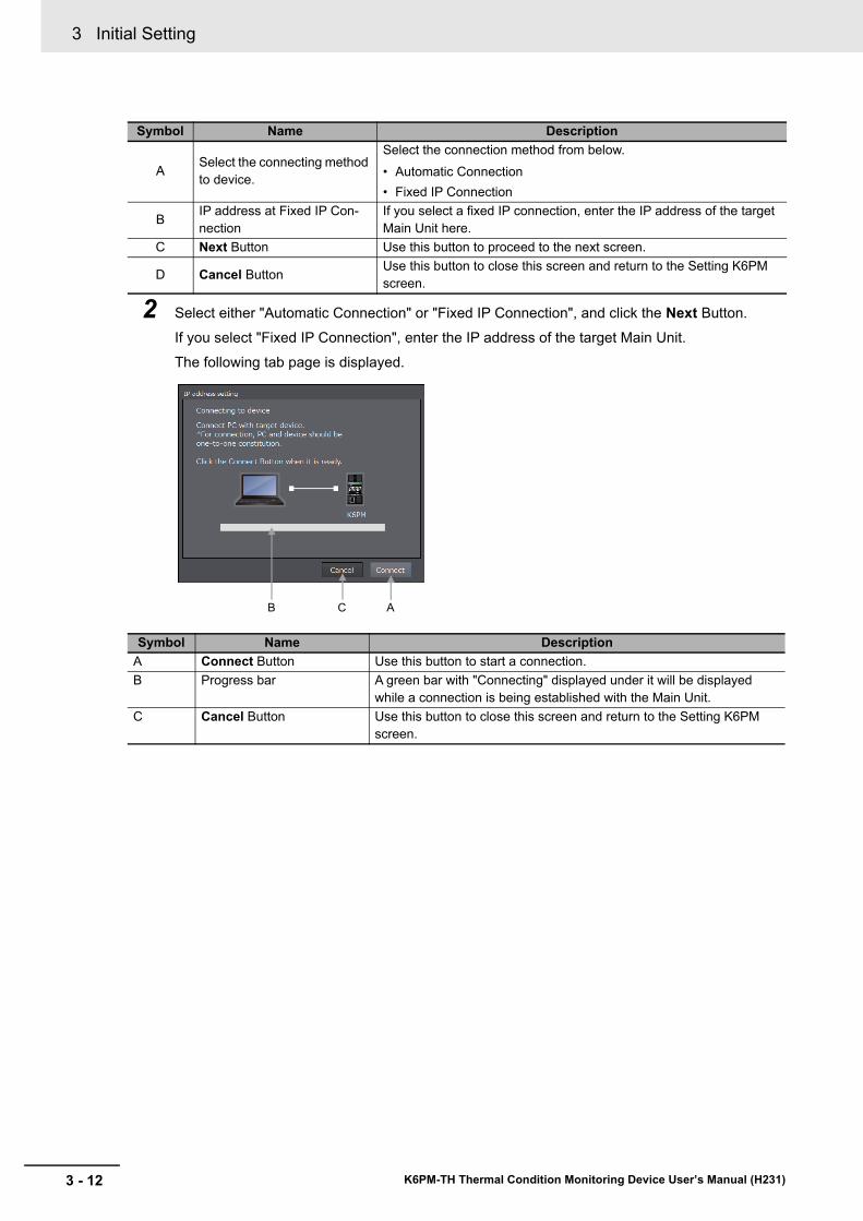
3 Initial Setting
3 - 12 K6PM-TH Thermal Condition Monitoring Device User’s Manual (H231)
2 Select either "Automatic Connection" or "Fixed IP Connection", and click the Next Button.If you select "Fixed IP Connection", enter the IP address of the target Main Unit.The following tab page is displayed.
Symbol Name Description
A Select the connecting method to device.
Select the connection method from below.• Automatic Connection• Fixed IP Connection
B IP address at Fixed IP Con-nection
If you select a fixed IP connection, enter the IP address of the target Main Unit here.
C Next Button Use this button to proceed to the next screen.
D Cancel Button Use this button to close this screen and return to the Setting K6PM screen.
Symbol Name DescriptionA Connect Button Use this button to start a connection.B Progress bar A green bar with "Connecting" displayed under it will be displayed
while a connection is being established with the Main Unit.C Cancel Button Use this button to close this screen and return to the Setting K6PM
screen.
ACB
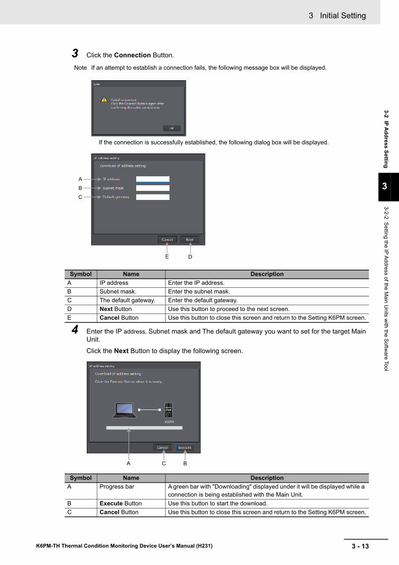
3 - 13
3 Initial Setting
K6PM-TH Thermal Condition Monitoring Device User’s Manual (H231)
3-2 IP Address Setting
3
3-2-2 Setting the IP Address of the Main U
nits with the Softw
are Tool
3 Click the Connection Button.
Note If an attempt to establish a connection fails, the following message box will be displayed.
If the connection is successfully established, the following dialog box will be displayed.
4 Enter the IP address, Subnet mask and The default gateway you want to set for the target Main Unit.Click the Next Button to display the following screen.
Symbol Name DescriptionA IP address Enter the IP address.B Subnet mask. Enter the subnet mask.C The default gateway. Enter the default gateway.D Next Button Use this button to proceed to the next screen.E Cancel Button Use this button to close this screen and return to the Setting K6PM screen.
Symbol Name DescriptionA Progress bar A green bar with "Downloading" displayed under it will be displayed while a
connection is being established with the Main Unit.B Execute Button Use this button to start the download.C Cancel Button Use this button to close this screen and return to the Setting K6PM screen.
A
B
E D
C
BA C
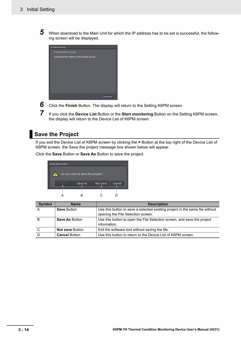
3 Initial Setting
3 - 14 K6PM-TH Thermal Condition Monitoring Device User’s Manual (H231)
5 When download to the Main Unit for which the IP address has to be set is successful, the follow-ing screen will be displayed.
6 Click the Finish Button. The display will return to the Setting K6PM screen.
7 If you click the Device List Button or the Start monitoring Button on the Setting K6PM screen, the display will return to the Device List of K6PM screen.
If you exit the Device List of K6PM screen by clicking the × Button at the top right of the Device List of K6PM screen, the Save the project message box shown below will appear.
Click the Save Button or Save As Button to save the project.
Save the Project
Symbol Name DescriptionA Save Button Use this button to save a selected existing project in the same file without
opening the File Selection screen.B Save As Button Use this button to open the File Selection screen, and save the project
information.C Not save Button Exit the software tool without saving the file.D Cancel Button Use this button to return to the Device List of K6PM screen.
DB CA
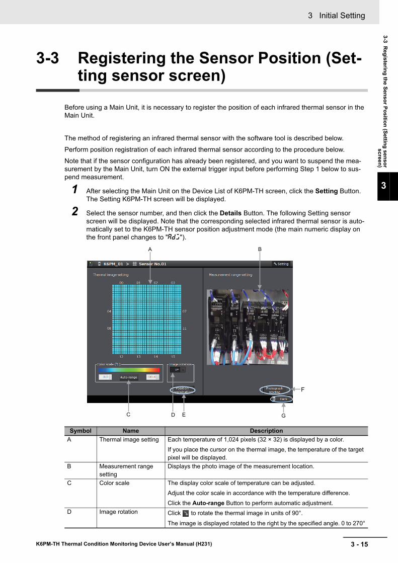
3 - 15
3 Initial Setting
K6PM-TH Thermal Condition Monitoring Device User’s Manual (H231)
3-3 Registering the Sensor Position (Setting sensor
screen)
3
3-3 Registering the Sensor Position (Set-ting sensor screen)
Before using a Main Unit, it is necessary to register the position of each infrared thermal sensor in the Main Unit.
The method of registering an infrared thermal sensor with the software tool is described below.Perform position registration of each infrared thermal sensor according to the procedure below.
Note that if the sensor configuration has already been registered, and you want to suspend the mea-surement by the Main Unit, turn ON the external trigger input before performing Step 1 below to sus-pend measurement.
1 After selecting the Main Unit on the Device List of K6PM-TH screen, click the Setting Button. The Setting K6PM-TH screen will be displayed.
2 Select the sensor number, and then click the Details Button. The following Setting sensor screen will be displayed. Note that the corresponding selected infrared thermal sensor is auto-matically set to the K6PM-TH sensor position adjustment mode (the main numeric display on the front panel changes to "adj").
Symbol Name DescriptionA Thermal image setting Each temperature of 1,024 pixels (32 × 32) is displayed by a color.
If you place the cursor on the thermal image, the temperature of the target pixel will be displayed.
B Measurement range setting
Displays the photo image of the measurement location.
C Color scale The display color scale of temperature can be adjusted.Adjust the color scale in accordance with the temperature difference.Click the Auto-range Button to perform automatic adjustment.
D Image rotation Click to rotate the thermal image in units of 90°.The image is displayed rotated to the right by the specified angle. 0 to 270°
GC D E
A B
F
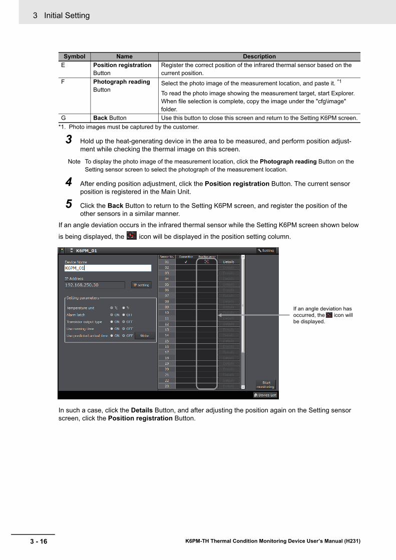
3 Initial Setting
3 - 16 K6PM-TH Thermal Condition Monitoring Device User’s Manual (H231)
*1. Photo images must be captured by the customer.
3 Hold up the heat-generating device in the area to be measured, and perform position adjust-ment while checking the thermal image on this screen.
Note To display the photo image of the measurement location, click the Photograph reading Button on the Setting sensor screen to select the photograph of the measurement location.
4 After ending position adjustment, click the Position registration Button. The current sensor position is registered in the Main Unit.
5 Click the Back Button to return to the Setting K6PM screen, and register the position of the other sensors in a similar manner.
If an angle deviation occurs in the infrared thermal sensor while the Setting K6PM screen shown below
is being displayed, the icon will be displayed in the position setting column.
In such a case, click the Details Button, and after adjusting the position again on the Setting sensor screen, click the Position registration Button.
E Position registration Button
Register the correct position of the infrared thermal sensor based on the current position.
F Photograph reading Button
Select the photo image of the measurement location, and paste it. *1
To read the photo image showing the measurement target, start Explorer. When file selection is complete, copy the image under the "cfg\image" folder.
G Back Button Use this button to close this screen and return to the Setting K6PM screen.
Symbol Name Description
If an angle deviation has
occurred, the icon will
be displayed.
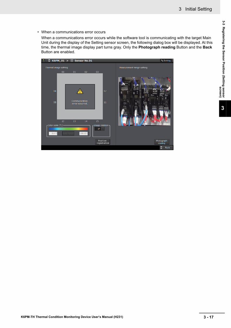
3 - 17
3 Initial Setting
K6PM-TH Thermal Condition Monitoring Device User’s Manual (H231)
3-3 Registering the Sensor Position (Setting sensor
screen)
3
• When a communications error occursWhen a communications error occurs while the software tool is communicating with the target Main Unit during the display of the Setting sensor screen, the following dialog box will be displayed. At this time, the thermal image display part turns gray. Only the Photograph reading Button and the Back Button are enabled.
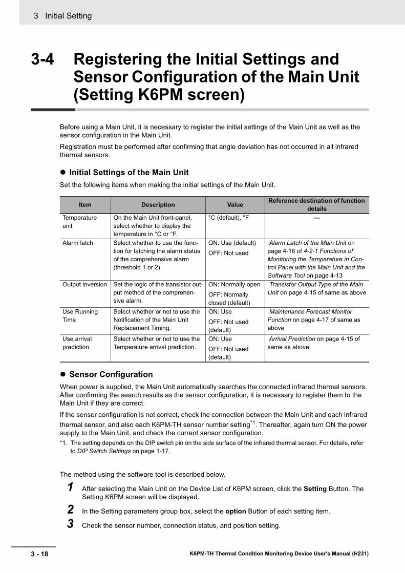
3 Initial Setting
3 - 18 K6PM-TH Thermal Condition Monitoring Device User’s Manual (H231)
3-4 Registering the Initial Settings and Sensor Configuration of the Main Unit (Setting K6PM screen)
Before using a Main Unit, it is necessary to register the initial settings of the Main Unit as well as the sensor configuration in the Main Unit.Registration must be performed after confirming that angle deviation has not occurred in all infrared thermal sensors.
Initial Settings of the Main UnitSet the following items when making the initial settings of the Main Unit.
Sensor ConfigurationWhen power is supplied, the Main Unit automatically searches the connected infrared thermal sensors. After confirming the search results as the sensor configuration, it is necessary to register them to the Main Unit if they are correct.If the sensor configuration is not correct, check the connection between the Main Unit and each infrared thermal sensor, and also each K6PM-TH sensor number setting*1. Thereafter, again turn ON the power supply to the Main Unit, and check the current sensor configuration.*1. The setting depends on the DIP switch pin on the side surface of the infrared thermal sensor. For details, refer
to DIP Switch Settings on page 1-17.
The method using the software tool is described below.
1 After selecting the Main Unit on the Device List of K6PM screen, click the Setting Button. The Setting K6PM screen will be displayed.
2 In the Setting parameters group box, select the option Button of each setting item.
3 Check the sensor number, connection status, and position setting.
Item Description Value Reference destination of function details
Temperature unit
On the Main Unit front-panel, select whether to display the temperature in °C or °F.
°C (default), °F ---
Alarm latch Select whether to use the func-tion for latching the alarm status of the comprehensive alarm (threshold 1 or 2).
ON: Use (default)OFF: Not used
Alarm Latch of the Main Unit on page 4-16 of 4-2-1 Functions of Monitoring the Temperature in Con-trol Panel with the Main Unit and the Software Tool on page 4-13
Output inversion Set the logic of the transistor out-put method of the comprehen-sive alarm.
ON: Normally openOFF: Normally closed (default)
Transistor Output Type of the Main Unit on page 4-15 of same as above
Use Running Time
Select whether or not to use the Notification of the Main Unit Replacement Timing.
ON: UseOFF: Not used (default)
Maintenance Forecast Monitor Function on page 4-17 of same as above
Use arrivalprediction
Select whether or not to use the Temperature arrival prediction.
ON: UseOFF: Not used (default)
Arrival Prediction on page 4-15 of same as above
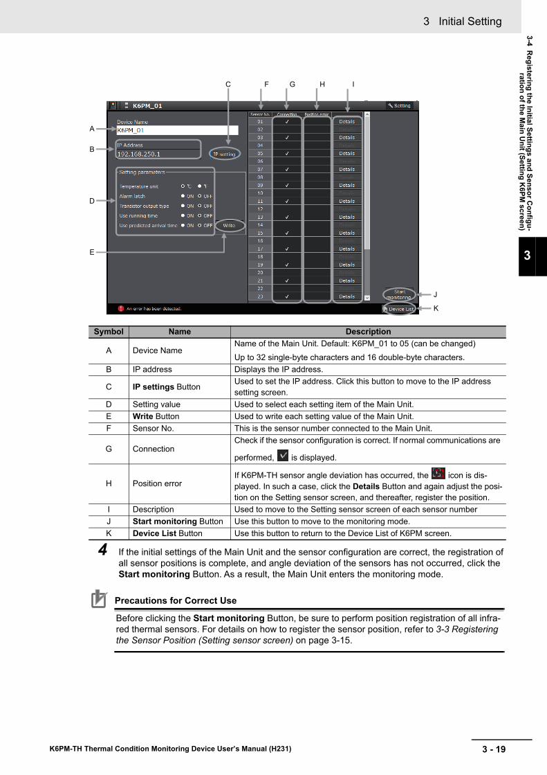
3 - 19
3 Initial Setting
K6PM-TH Thermal Condition Monitoring Device User’s Manual (H231)
3-4 Registering the Initial Settings and Sensor C
onfigu-ration of the M
ain Unit (Setting K
6PM screen)
3
4 If the initial settings of the Main Unit and the sensor configuration are correct, the registration of all sensor positions is complete, and angle deviation of the sensors has not occurred, click the Start monitoring Button. As a result, the Main Unit enters the monitoring mode.
Precautions for Correct Use
Before clicking the Start monitoring Button, be sure to perform position registration of all infra-red thermal sensors. For details on how to register the sensor position, refer to 3-3 Registering the Sensor Position (Setting sensor screen) on page 3-15.
Symbol Name Description
A Device NameName of the Main Unit. Default: K6PM_01 to 05 (can be changed)Up to 32 single-byte characters and 16 double-byte characters.
B IP address Displays the IP address.
C IP settings Button Used to set the IP address. Click this button to move to the IP address setting screen.
D Setting value Used to select each setting item of the Main Unit.E Write Button Used to write each setting value of the Main Unit.F Sensor No. This is the sensor number connected to the Main Unit.
G ConnectionCheck if the sensor configuration is correct. If normal communications are
performed, is displayed.
H Position errorIf K6PM-TH sensor angle deviation has occurred, the icon is dis-played. In such a case, click the Details Button and again adjust the posi-tion on the Setting sensor screen, and thereafter, register the position.
I Description Used to move to the Setting sensor screen of each sensor numberJ Start monitoring Button Use this button to move to the monitoring mode.K Device List Button Use this button to return to the Device List of K6PM screen.
D
B
A
C
E
F G H
K
J
I

3 Initial Setting
3 - 20 K6PM-TH Thermal Condition Monitoring Device User’s Manual (H231)
4 - 1
4
K6PM-TH Thermal Condition Monitoring Device User’s Manual (H231)
This section describes the details of monitoring the temperature in the control panel with the Main Unit and the software tool.
4-1 Method of Monitoring the Temperature in the Control Panel . . . . . . . . . . 4-24-1-1 Overview of Temperature Monitoring . . . . . . . . . . . . . . . . . . . . . . . . . . . . . . . . 4-24-1-2 Display on the Main Unit after Registration of Sensor Configuration . . . . . . . . 4-24-1-3 Monitoring with the Main Unit . . . . . . . . . . . . . . . . . . . . . . . . . . . . . . . . . . . . . . 4-34-1-4 Monitoring Using Software Tools . . . . . . . . . . . . . . . . . . . . . . . . . . . . . . . . . . . 4-5
4-2 Functions of Monitoring the Temperature in the Control Panel . . . . . . . 4-134-2-1 Functions of Monitoring the Temperature in Control Panel with the Main Unit
and the Software Tool . . . . . . . . . . . . . . . . . . . . . . . . . . . . . . . . . . . . . . . . . . . 4-134-2-2 Operation Example of an Alarm . . . . . . . . . . . . . . . . . . . . . . . . . . . . . . . . . . . 4-174-2-3 Automatic Saving Log Files . . . . . . . . . . . . . . . . . . . . . . . . . . . . . . . . . . . . . . 4-19
4-3 Alarm Threshold Setting . . . . . . . . . . . . . . . . . . . . . . . . . . . . . . . . . . . . . . . 4-234-4 Procedure for Taking Actions When an Alarm Occurs . . . . . . . . . . . . . . . 4-25
Monitoring the Temperature in Control Panel with the Main Unit and the Software Tool
4 Monitoring the Temperature in Control Panel with the Main Unit and the Software Tool
4 - 2 K6PM-TH Thermal Condition Monitoring Device User’s Manual (H231)
4-1 Method of Monitoring the Tempera-ture in the Control Panel
This section describes how to monitor the temperature inside the control panel.
When temperature monitoring is performed with the Main Unit by using an infrared thermal sensor, the following measurement levels are present.
The methods that can be used for checking are as described below.
When the configuration of the infrared thermal sensor is registered in the Main Unit by the software tool or communications, the Main Unit shifts to the monitoring mode at that point of time, and the measure-ment and monitoring of the Main Unit starts automatically (there is no need to particularly perform the "Start" operation for measurement and monitoring).
At the same time, logging is started by the software tool.At this time, the measured value is displayed on the numeric display on the Main Unit front-panel.
4-1-1 Overview of Temperature Monitoring
Measurement levelMethods for checking
Main Unit Software tool CommunicationsTemperature of each seg-ment and sensor internal temperature
The segment display of each sensor can be switched on the Main Unit front-panel.
Can be checked on the Monitoring sensor Screen.
• EtherNet/IP tag data link communications
• EtherNet/IP CIP mes-sage communications
• Modbus TCP communi-cations
Differential temperature per segment from the K6PM-TH sensor internal temperature
Not supported
Temperature of each infra-red thermal sensor
Not supported The past maximum value can be monitored on the Monitoring K6PM Screen.
Not supported
Temperature of each pixel Not supported The temperature can be displayed when the cursor is placed on the thermal image on the Monitoring sensor Screen.
• EtherNet/IP CIP mes-sage communications
• Modbus TCP communi-cations
Alarms of each Main Unit(Alarms of all infrared ther-mal sensors connected to the Main Unit)
You can check if an alarm has occurred on the alarm bar and by transistor out-put.
The occurrence of an alarm can be checked on the Device List of K6PM Screen.
The occurrence of an alarm can be checked from the Main Unit status.
4-1-2 Display on the Main Unit after Registration of Sensor Configura-tion
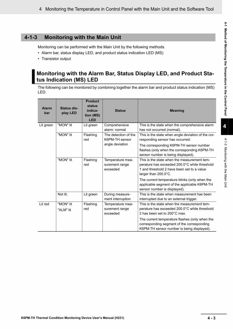
4 - 3
4 Monitoring the Temperature in Control Panel with the Main Unit and the Software Tool
K6PM-TH Thermal Condition Monitoring Device User’s Manual (H231)
4-1 Method of M
onitoring the Temperature in the C
ontrol Panel
4
4-1-3 Monitoring w
ith the Main U
nit
Monitoring can be performed with the Main Unit by the following methods.• Alarm bar, status display LED, and product status indication LED (MS)• Transistor output
The following can be monitored by combining together the alarm bar and product status indication (MS) LED.
4-1-3 Monitoring with the Main Unit
Monitoring with the Alarm Bar, Status Display LED, and Product Sta-tus Indication (MS) LED
Alarm bar
Status dis-play LED
Product status indica-
tion (MS) LED
Status Meaning
Lit green "MON" lit Lit green Comprehensive alarm: normal
This is the state when the comprehensive alarm has not occurred (normal).
"MON" lit Flashing red
The detection of the K6PM-TH sensor angle deviation
This is the state when angle deviation of the cor-responding sensor has occurred.The corresponding K6PM-TH sensor number flashes (only when the corresponding K6PM-TH sensor number is being displayed).
"MON" lit Flashing red
Temperature mea-surement range exceeded
This is the state when the measurement tem-perature has exceeded 200.0°C while threshold 1 and threshold 2 have been set to a value larger than 200.0°C.The current temperature blinks (only when the applicable segment of the applicable K6PM-TH sensor number is displayed).
Not lit. Lit green During measure-ment interruption
This is the state when measurement has been interrupted due to an external trigger.
Lit red "MON" lit"ALM" lit
Flashing red
Temperature mea-surement range exceeded
This is the state when the measurement tem-perature has exceeded 200.0°C while threshold 2 has been set to 200°C max.The current temperature flashes (only when the corresponding segment of the corresponding K6PM-TH sensor number is being displayed).
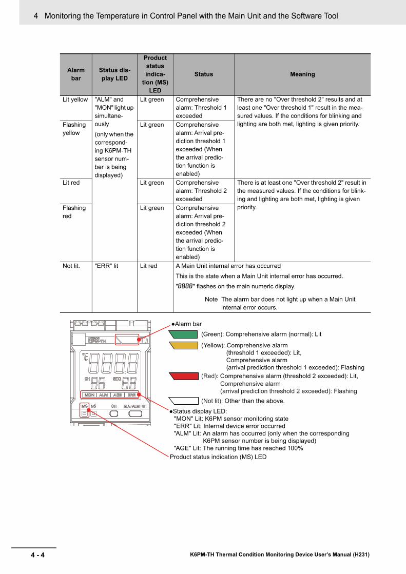
4 Monitoring the Temperature in Control Panel with the Main Unit and the Software Tool
4 - 4 K6PM-TH Thermal Condition Monitoring Device User’s Manual (H231)
Lit yellow "ALM" and "MON" light up simultane-ously(only when the correspond-ing K6PM-TH sensor num-ber is being displayed)
Lit green Comprehensive alarm: Threshold 1 exceeded
There are no "Over threshold 2" results and at least one "Over threshold 1" result in the mea-sured values. If the conditions for blinking and lighting are both met, lighting is given priority.Flashing
yellowLit green Comprehensive
alarm: Arrival pre-diction threshold 1 exceeded (When the arrival predic-tion function is enabled)
Lit red Lit green Comprehensive alarm: Threshold 2 exceeded
There is at least one "Over threshold 2" result in the measured values. If the conditions for blink-ing and lighting are both met, lighting is given priority.Flashing
redLit green Comprehensive
alarm: Arrival pre-diction threshold 2 exceeded (When the arrival predic-tion function is enabled)
Not lit. "ERR" lit Lit red A Main Unit internal error has occurredThis is the state when a Main Unit internal error has occurred."8888" flashes on the main numeric display.
Note The alarm bar does not light up when a Main Unit internal error occurs.
Alarm bar
Status dis-play LED
Product status indica-
tion (MS) LED
Status Meaning
●Status display LED:
"MON" Lit: K6PM sensor monitoring state
"ERR" Lit: Internal device error occurred
"ALM" Lit: An alarm has occurred (only when the corresponding
K6PM sensor number is being displayed)
"AGE" Lit: The running time has reached 100%
●Alarm bar
(Green): Comprehensive alarm (normal): Lit
(Yellow): Comprehensive alarm
(threshold 1 exceeded): Lit,
Comprehensive alarm
(arrival prediction threshold 1 exceeded): Flashing
(Red): Comprehensive alarm (threshold 2 exceeded): Lit,
Comprehensive alarm
(arrival prediction threshold 2 exceeded): Flashing
(Not lit): Other than the above.
Product status indication (MS) LED
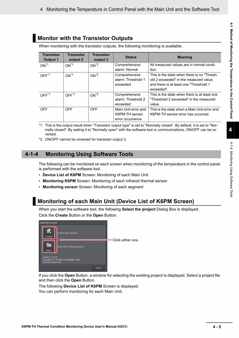
4 - 5
4 Monitoring the Temperature in Control Panel with the Main Unit and the Software Tool
K6PM-TH Thermal Condition Monitoring Device User’s Manual (H231)
4-1 Method of M
onitoring the Temperature in the C
ontrol Panel
4
4-1-4 Monitoring U
sing Software Tools
When monitoring with the transistor outputs, the following monitoring is available.
The following can be monitored on each screen when monitoring of the temperature in the control panel is performed with the software tool.• Device List of K6PM Screen: Monitoring of each Main Unit• Monitoring K6PM Screen: Monitoring of each infrared thermal sensor• Monitoring sensor Screen: Monitoring of each segment
When you start the software tool, the following Select the project Dialog Box is displayed.Click the Create Button or the Open Button.
If you click the Open Button, a window for selecting the existing project is displayed. Select a project file and then click the Open Button.The following Device List of K6PM Screen is displayed.You can perform monitoring for each Main Unit.
Monitor with the Transistor Outputs
Transistor Output 1
Transistor output 2
Transistor output 3 Status Meaning
ON*1
*1. This is the output result when "Transistor output type" is set to "Normally closed". By default, it is set to "Nor-mally closed". By setting it to "Normally open" with the software tool or communications, ON/OFF can be re-versed.
ON*1 ON*2
*2. ON/OFF cannot be reversed for transistor output 3.
Comprehensive alarm: Normal
All measured values are in normal condi-tion.
OFF*1 ON*1 ON*2 Comprehensive alarm: Threshold 1 exceeded
This is the state when there is no "Thresh-old 2 exceeded" in the measured value, and there is at least one "Threshold 1 exceeded".
OFF*1 OFF*1 ON*2 Comprehensive alarm: Threshold 2 exceeded
This is the state when there is at least one "Threshold 2 exceeded" in the measured value.
OFF OFF OFF Main Unit error and K6PM-TH sensor error occurrence
This is the state when a Main Unit error and K6PM-TH sensor error has occurred.
4-1-4 Monitoring Using Software Tools
Monitoring of each Main Unit (Device List of K6PM Screen)
Click either one.
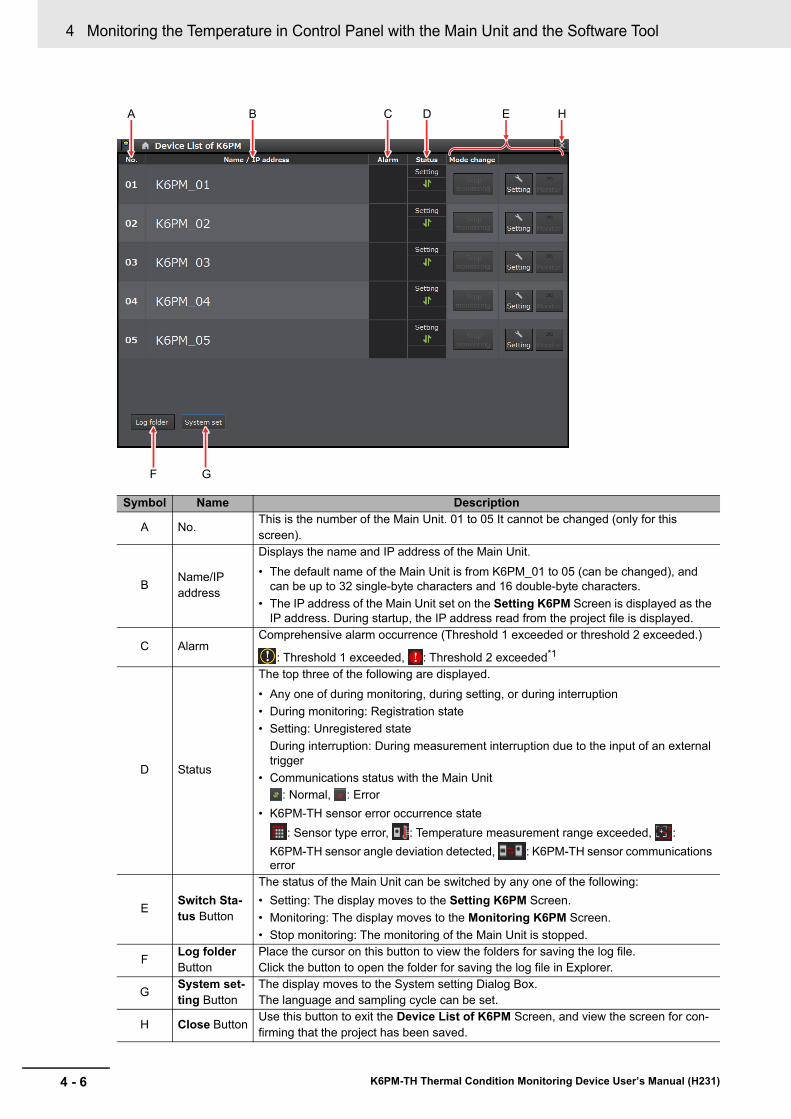
4 Monitoring the Temperature in Control Panel with the Main Unit and the Software Tool
4 - 6 K6PM-TH Thermal Condition Monitoring Device User’s Manual (H231)
Symbol Name Description
A No. This is the number of the Main Unit. 01 to 05 It cannot be changed (only for this screen).
B Name/IP address
Displays the name and IP address of the Main Unit.• The default name of the Main Unit is from K6PM_01 to 05 (can be changed), and
can be up to 32 single-byte characters and 16 double-byte characters.• The IP address of the Main Unit set on the Setting K6PM Screen is displayed as the
IP address. During startup, the IP address read from the project file is displayed.
C AlarmComprehensive alarm occurrence (Threshold 1 exceeded or threshold 2 exceeded.)
: Threshold 1 exceeded, : Threshold 2 exceeded*1
D Status
The top three of the following are displayed.• Any one of during monitoring, during setting, or during interruption• During monitoring: Registration state• Setting: Unregistered state
During interruption: During measurement interruption due to the input of an external trigger
• Communications status with the Main Unit: Normal, : Error
• K6PM-TH sensor error occurrence state: Sensor type error, : Temperature measurement range exceeded, :
K6PM-TH sensor angle deviation detected, : K6PM-TH sensor communications error
E Switch Sta-tus Button
The status of the Main Unit can be switched by any one of the following:• Setting: The display moves to the Setting K6PM Screen.• Monitoring: The display moves to the Monitoring K6PM Screen.• Stop monitoring: The monitoring of the Main Unit is stopped.
F Log folder Button
Place the cursor on this button to view the folders for saving the log file.Click the button to open the folder for saving the log file in Explorer.
G System set-ting Button
The display moves to the System setting Dialog Box.The language and sampling cycle can be set.
H Close Button Use this button to exit the Device List of K6PM Screen, and view the screen for con-firming that the project has been saved.
A B C D E H
F G
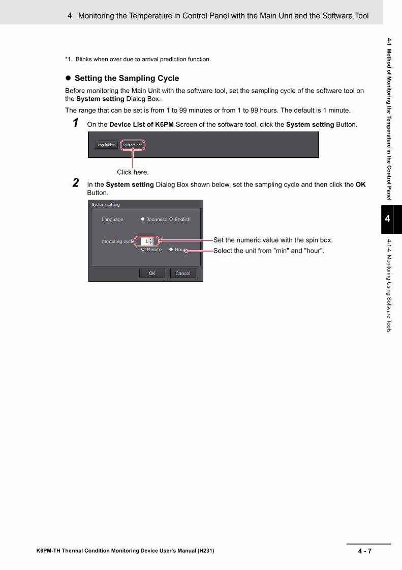
4 - 7
4 Monitoring the Temperature in Control Panel with the Main Unit and the Software Tool
K6PM-TH Thermal Condition Monitoring Device User’s Manual (H231)
4-1 Method of M
onitoring the Temperature in the C
ontrol Panel
4
4-1-4 Monitoring U
sing Software Tools
Setting the Sampling CycleBefore monitoring the Main Unit with the software tool, set the sampling cycle of the software tool on the System setting Dialog Box.The range that can be set is from 1 to 99 minutes or from 1 to 99 hours. The default is 1 minute.
1 On the Device List of K6PM Screen of the software tool, click the System setting Button.
2 In the System setting Dialog Box shown below, set the sampling cycle and then click the OK Button.
*1. Blinks when over due to arrival prediction function.
Click here.
Set the numeric value with the spin box.
Select the unit from "min" and "hour".
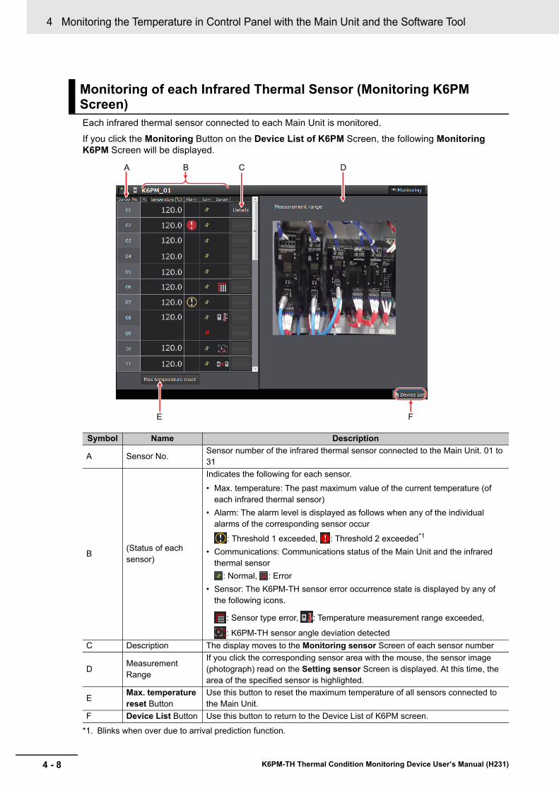
4 Monitoring the Temperature in Control Panel with the Main Unit and the Software Tool
4 - 8 K6PM-TH Thermal Condition Monitoring Device User’s Manual (H231)
Each infrared thermal sensor connected to each Main Unit is monitored.If you click the Monitoring Button on the Device List of K6PM Screen, the following Monitoring K6PM Screen will be displayed.
Monitoring of each Infrared Thermal Sensor (Monitoring K6PM Screen)
Symbol Name Description
A Sensor No. Sensor number of the infrared thermal sensor connected to the Main Unit. 01 to 31
B (Status of each sensor)
Indicates the following for each sensor.• Max. temperature: The past maximum value of the current temperature (of
each infrared thermal sensor)• Alarm: The alarm level is displayed as follows when any of the individual
alarms of the corresponding sensor occur
: Threshold 1 exceeded, : Threshold 2 exceeded*1
• Communications: Communications status of the Main Unit and the infrared thermal sensor
: Normal, : Error• Sensor: The K6PM-TH sensor error occurrence state is displayed by any of
the following icons.
: Sensor type error, : Temperature measurement range exceeded,
: K6PM-TH sensor angle deviation detected
*1. Blinks when over due to arrival prediction function.
C Description The display moves to the Monitoring sensor Screen of each sensor number
D Measurement Range
If you click the corresponding sensor area with the mouse, the sensor image (photograph) read on the Setting sensor Screen is displayed. At this time, the area of the specified sensor is highlighted.
E Max. temperature reset Button
Use this button to reset the maximum temperature of all sensors connected to the Main Unit.
F Device List Button Use this button to return to the Device List of K6PM screen.
A B C D
FE
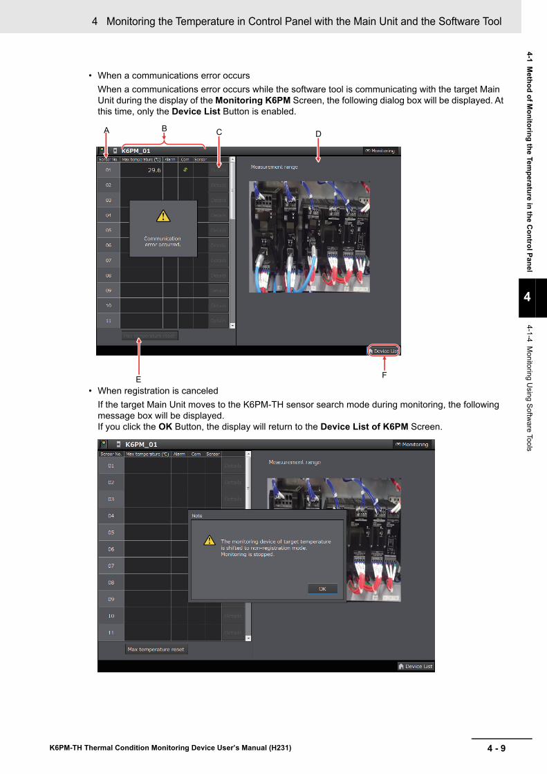
4 - 9
4 Monitoring the Temperature in Control Panel with the Main Unit and the Software Tool
K6PM-TH Thermal Condition Monitoring Device User’s Manual (H231)
4-1 Method of M
onitoring the Temperature in the C
ontrol Panel
4
4-1-4 Monitoring U
sing Software Tools
• When a communications error occursWhen a communications error occurs while the software tool is communicating with the target Main Unit during the display of the Monitoring K6PM Screen, the following dialog box will be displayed. At this time, only the Device List Button is enabled.
• When registration is canceledIf the target Main Unit moves to the K6PM-TH sensor search mode during monitoring, the following message box will be displayed.If you click the OK Button, the display will return to the Device List of K6PM Screen.
A B C D
FE
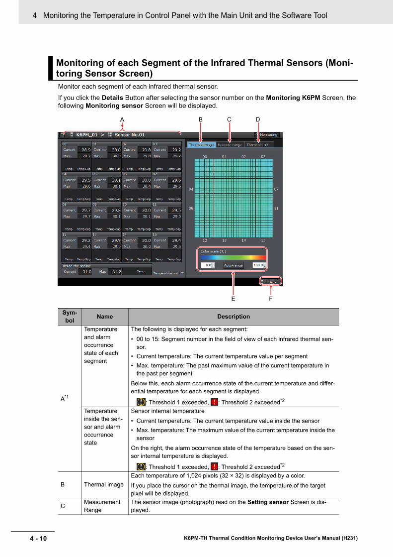
4 Monitoring the Temperature in Control Panel with the Main Unit and the Software Tool
4 - 10 K6PM-TH Thermal Condition Monitoring Device User’s Manual (H231)
Monitor each segment of each infrared thermal sensor.If you click the Details Button after selecting the sensor number on the Monitoring K6PM Screen, the following Monitoring sensor Screen will be displayed.
Monitoring of each Segment of the Infrared Thermal Sensors (Moni-toring Sensor Screen)
Sym-bol Name Description
A*1
Temperature and alarm occurrence state of each segment
The following is displayed for each segment:• 00 to 15: Segment number in the field of view of each infrared thermal sen-
sor.• Current temperature: The current temperature value per segment• Max. temperature: The past maximum value of the current temperature in
the past per segmentBelow this, each alarm occurrence state of the current temperature and differ-ential temperature for each segment is displayed.
: Threshold 1 exceeded, : Threshold 2 exceeded*2
Temperature inside the sen-sor and alarm occurrence state
Sensor internal temperature• Current temperature: The current temperature value inside the sensor• Max. temperature: The maximum value of the current temperature inside the
sensorOn the right, the alarm occurrence state of the temperature based on the sen-sor internal temperature is displayed.
: Threshold 1 exceeded, : Threshold 2 exceeded*2
B Thermal imageEach temperature of 1,024 pixels (32 × 32) is displayed by a color.If you place the cursor on the thermal image, the temperature of the target pixel will be displayed.
C Measurement Range
The sensor image (photograph) read on the Setting sensor Screen is dis-played.
A B C D
FE
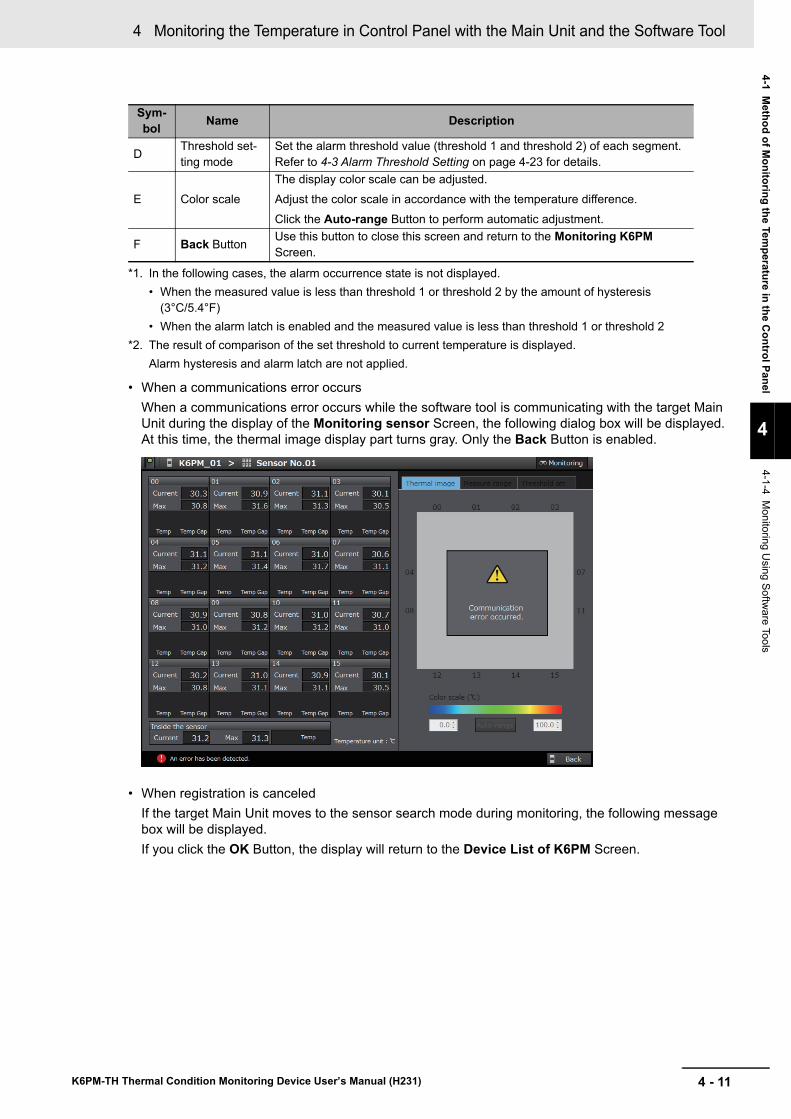
4 - 11
4 Monitoring the Temperature in Control Panel with the Main Unit and the Software Tool
K6PM-TH Thermal Condition Monitoring Device User’s Manual (H231)
4-1 Method of M
onitoring the Temperature in the C
ontrol Panel
4
4-1-4 Monitoring U
sing Software Tools
• When a communications error occursWhen a communications error occurs while the software tool is communicating with the target Main Unit during the display of the Monitoring sensor Screen, the following dialog box will be displayed. At this time, the thermal image display part turns gray. Only the Back Button is enabled.
• When registration is canceledIf the target Main Unit moves to the sensor search mode during monitoring, the following message box will be displayed.If you click the OK Button, the display will return to the Device List of K6PM Screen.
D Threshold set-ting mode
Set the alarm threshold value (threshold 1 and threshold 2) of each segment. Refer to 4-3 Alarm Threshold Setting on page 4-23 for details.
E Color scaleThe display color scale can be adjusted.Adjust the color scale in accordance with the temperature difference.Click the Auto-range Button to perform automatic adjustment.
F Back Button Use this button to close this screen and return to the Monitoring K6PM Screen.
*1. In the following cases, the alarm occurrence state is not displayed.• When the measured value is less than threshold 1 or threshold 2 by the amount of hysteresis
(3°C/5.4°F)• When the alarm latch is enabled and the measured value is less than threshold 1 or threshold 2
*2. The result of comparison of the set threshold to current temperature is displayed.Alarm hysteresis and alarm latch are not applied.
Sym-bol Name Description
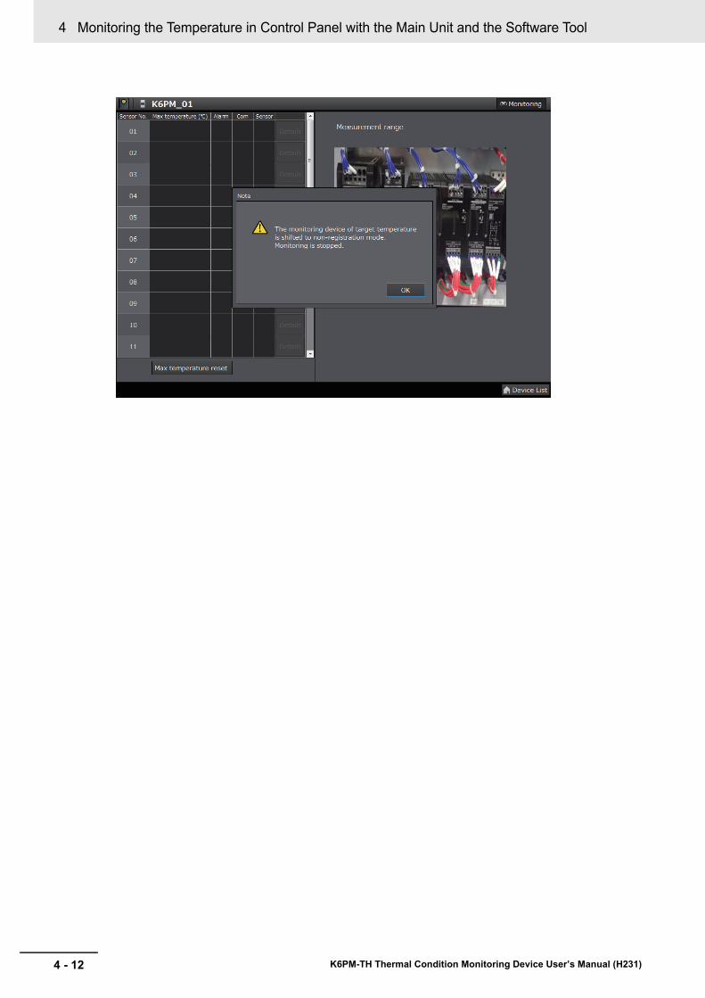
4 Monitoring the Temperature in Control Panel with the Main Unit and the Software Tool
4 - 12 K6PM-TH Thermal Condition Monitoring Device User’s Manual (H231)
4 - 13
4 Monitoring the Temperature in Control Panel with the Main Unit and the Software Tool
K6PM-TH Thermal Condition Monitoring Device User’s Manual (H231)
4-2 Functions of Monitoring the Tem
perature in the Control Panel
4
4-2-1 Functions of Monitoring the Tem
perature in Control Panel w
ith the Main U
nit and the Software Tool
4-2 Functions of Monitoring the Tem-perature in the Control Panel
This section describes each function related to monitoring of temperature inside the control panel.
This section describes each function of monitoring the temperature in the control panel with the Main Unit and the software tool.
If the infrared thermal sensor drops or gets tilted, it will not be possible to perform correct temperature monitoring.Therefore, it is possible to register the correct position of each connected infrared thermal sensor in the Main Unit, and if a deviation of the installation angle of the K6PM-TH sensor occurs, the user can be notified about the same.
In the factory default settings, this function of the infrared thermal sensors is disabled. To enable this function, change the DIP switch Pin 7 on the side surface of the infrared thermal sensor to ON (with detection).
Note Since the K6PM-TH sensor angle deviation notification function detects the change in the angle in the direction of gravity, the change cannot be detected for movement in the horizontal direction and rotation performed with the direction of gravity as an axis.
How to Register the K6PM-TH Sensor LocationRegister the sensor position by either one of the following methods:• On the Setting sensor Screen of the software tool, click the Position registration Button for
each sensor.• Register the sensor position by communications.• Long-press the K6PM-TH sensor angle deviation reset switch on the side of the sensor for at least
3 seconds.
K6PM-TH Sensor Angle Deviation Notification MethodThe K6PM-TH sensor angle deviation can be checked by any of the following methods:• Display the angle deviation for each sensor on the Setting K6PM Screen of the software tool.• Display the angle deviation for each sensor on the Monitoring K6PM Screen of the software tool.• Display the angle deviation as a Main Unit error and K6PM-TH sensor error for each Main Unit on
the Device List of K6PM Screen of the software tool.• The bit indicating the K6PM-TH sensor angle deviation error for the sensor status turns ON. It can
be read through communications.• The product status (MS) LED on the Main Unit blinks red.• The alarm or other indicator on the sensor blinks.
4-2-1 Functions of Monitoring the Temperature in Control Panel with the Main Unit and the Software Tool
K6PM-TH Sensor Position Registration, and K6PM-TH Sensor Angle Deviation Notification
4 Monitoring the Temperature in Control Panel with the Main Unit and the Software Tool
4 - 14 K6PM-TH Thermal Condition Monitoring Device User’s Manual (H231)
In the Main Unit, the temperature alarm includes the individual alarm and the comprehensive alarm.
Individual AlarmAn individual alarm is an alarm for each of the following measured values. It includes threshold 1 exceeded and threshold 2 exceeded.• Current temperature per segment of each infrared thermal sensor
(The predicted arrival temperature when "Use predicted arrival time" is set to ON on the Setting K6PM Screen)
• Differential temperature between the current temperature per segment of each infrared thermal sensor and the sensor internal temperature
• Current value of the sensor internal temperature of each infrared thermal sensor(The predicted arrival temperature when "Use predicted arrival time" is set to ON on the Setting K6PM Screen)
Whether threshold 1 or threshold 2 exceeded has occurred for each of the above individual alarms can be checked by the following methods.• Monitoring sensor Screen of the software tool
Whether threshold 1 exceeded or threshold 2 exceeded has occurred for any of the above individual alarms can be checked by the following methods for each infrared thermal sensor.• Monitoring K6PM Screen of the software tool• Each bit of the K6PM-TH sensor alarm status per sensor turns ON. It can be read through com-
munications.
Comprehensive AlarmA comprehensive alarm is an alarm that occurs for each Main Unit.Threshold 1 exceeded occurs for the comprehensive alarm if there is no "Threshold 2 exceeded" in the measured value of the individual alarm of all connected infrared thermal sensors, and there is at least one "Threshold 1 exceeded". Similarly, if there is at least one "Threshold 2 exceeded", then threshold 2 exceeded occurs for the comprehensive alarm.
Whether threshold 1 exceeded or threshold 2 exceeded has occurred for the comprehensive alarm can be checked by the following methods.• Alarm bar on the Main Unit front-panel and transistor output 1 and 2• Device List of K6PM Screen of the software tool• The bit indicating the comprehensive temperature alarm (threshold 1 exceeded) or the compre-
hensive temperature alarm (threshold 2) for the Main Unit status turns ON. It can be read through communications.
Whether or not the alarm is based on the arrival prediction can be judged from whether the front alarm bar is flashing (arrival prediction during flashing).
Temperature Alarm
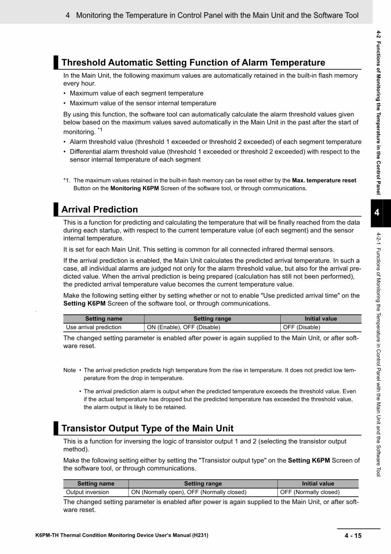
4 - 15
4 Monitoring the Temperature in Control Panel with the Main Unit and the Software Tool
K6PM-TH Thermal Condition Monitoring Device User’s Manual (H231)
4-2 Functions of Monitoring the Tem
perature in the Control Panel
4
4-2-1 Functions of Monitoring the Tem
perature in Control Panel w
ith the Main U
nit and the Software Tool
In the Main Unit, the following maximum values are automatically retained in the built-in flash memory every hour.• Maximum value of each segment temperature• Maximum value of the sensor internal temperature
By using this function, the software tool can automatically calculate the alarm threshold values given below based on the maximum values saved automatically in the Main Unit in the past after the start of monitoring. *1
• Alarm threshold value (threshold 1 exceeded or threshold 2 exceeded) of each segment temperature• Differential alarm threshold value (threshold 1 exceeded or threshold 2 exceeded) with respect to the
sensor internal temperature of each segment
*1. The maximum values retained in the built-in flash memory can be reset either by the Max. temperature reset Button on the Monitoring K6PM Screen of the software tool, or through communications.
This is a function for predicting and calculating the temperature that will be finally reached from the data during each startup, with respect to the current temperature value (of each segment) and the sensor internal temperature.It is set for each Main Unit. This setting is common for all connected infrared thermal sensors.If the arrival prediction is enabled, the Main Unit calculates the predicted arrival temperature. In such a case, all individual alarms are judged not only for the alarm threshold value, but also for the arrival pre-dicted value. When the arrival prediction is being prepared (calculation has still not been performed), the predicted arrival temperature value becomes the current temperature value.
Make the following setting either by setting whether or not to enable "Use predicted arrival time" on the Setting K6PM Screen of the software tool, or through communications.
0
The changed setting parameter is enabled after power is again supplied to the Main Unit, or after soft-ware reset.
Note • The arrival prediction predicts high temperature from the rise in temperature. It does not predict low tem-perature from the drop in temperature.
• The arrival prediction alarm is output when the predicted temperature exceeds the threshold value. Even if the actual temperature has dropped but the predicted temperature has exceeded the threshold value, the alarm output is likely to be retained.
This is a function for inversing the logic of transistor output 1 and 2 (selecting the transistor output method).Make the following setting either by setting the "Transistor output type" on the Setting K6PM Screen of the software tool, or through communications.
The changed setting parameter is enabled after power is again supplied to the Main Unit, or after soft-ware reset.
Threshold Automatic Setting Function of Alarm Temperature
Arrival Prediction
Setting name Setting range Initial valueUse arrival prediction ON (Enable), OFF (Disable) OFF (Disable)
Transistor Output Type of the Main Unit
Setting name Setting range Initial valueOutput inversion ON (Normally open), OFF (Normally closed) OFF (Normally closed)
4 Monitoring the Temperature in Control Panel with the Main Unit and the Software Tool
4 - 16 K6PM-TH Thermal Condition Monitoring Device User’s Manual (H231)
This function is used to latch the alarm status of the comprehensive alarm (threshold 1 or 2).
Even if the measured value drops by as much as the amount of hysteresis (3°C/5.4°F) from the thresh-old values threshold 1 or threshold 2 after the comprehensive alarm (threshold 1 or 2) occurs, the sta-tus of the comprehensive alarm (alarm bar and transistor output 1 and 2) is retained (alarm latch).The alarm latch is released by pressing and holding (for 5 seconds min.) the SEG/ALM RST Key on the Main Unit front-panel.Make the following setting either by enabling the "Alarm latch" on the Setting K6PM Screen of the soft-ware tool, or through communications.
The changed setting parameter is enabled after power is again supplied to the Main Unit, or after soft-ware reset.
This is a function for temporarily interrupting the measurement by an external trigger input of an exter-nal contact.Temperature measurement is stopped while the external trigger input is ON.Temperature measurement is performed while the external trigger input is OFF.
During measurement interruption due to an external trigger input, the temperature display on the Main Unit front-panel is fixed to the value immediately before interruption, and the "MON" LED is not lit.Application example:When an infrared thermal sensor is installed, the temperature monitor target may be deviated due to opening or closing of the door. Therefore, stop temperature measurement by turning ON the external trigger input. Restart measurement by turning OFF the external trigger input after installation is com-plete.
Note When measurement interruption or restart is performed as a result of an external trigger input, the mea-surement is interrupted or restarted immediately, and the status display "MON" lights up or goes out after communications with the temperature sensor is checked. Therefore, depending on the number of con-nected temperature sensors, it may take time for the "MON" LED to light up or go out as a result of ON/OFF of the external trigger input (approximately 30 seconds when 31 temperature sensors are connected).
Alarm Latch of the Main Unit
Setting name Setting range Initial valueAlarm latch ON (Enable), OFF (Disable) ON (Enable)
External Trigger Input of the Main Unit
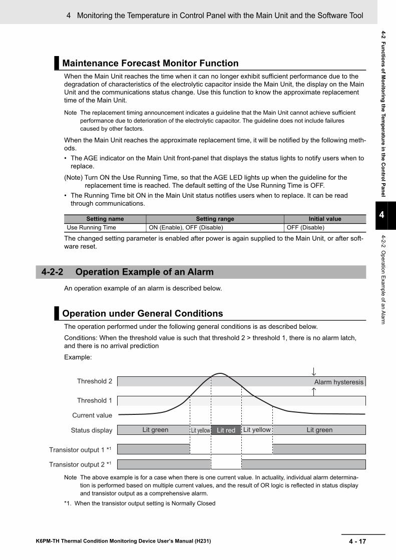
4 - 17
4 Monitoring the Temperature in Control Panel with the Main Unit and the Software Tool
K6PM-TH Thermal Condition Monitoring Device User’s Manual (H231)
4-2 Functions of Monitoring the Tem
perature in the Control Panel
4
4-2-2 Operation Exam
ple of an Alarm
When the Main Unit reaches the time when it can no longer exhibit sufficient performance due to the degradation of characteristics of the electrolytic capacitor inside the Main Unit, the display on the Main Unit and the communications status change. Use this function to know the approximate replacement time of the Main Unit.
Note The replacement timing announcement indicates a guideline that the Main Unit cannot achieve sufficient performance due to deterioration of the electrolytic capacitor. The guideline does not include failures caused by other factors.
When the Main Unit reaches the approximate replacement time, it will be notified by the following meth-ods.• The AGE indicator on the Main Unit front-panel that displays the status lights to notify users when to
replace.
(Note) Turn ON the Use Running Time, so that the AGE LED lights up when the guideline for the replacement time is reached. The default setting of the Use Running Time is OFF.
• The Running Time bit ON in the Main Unit status notifies users when to replace. It can be read through communications.
The changed setting parameter is enabled after power is again supplied to the Main Unit, or after soft-ware reset.
An operation example of an alarm is described below.
The operation performed under the following general conditions is as described below.Conditions: When the threshold value is such that threshold 2 > threshold 1, there is no alarm latch, and there is no arrival prediction
Example:
Note The above example is for a case when there is one current value. In actuality, individual alarm determina-tion is performed based on multiple current values, and the result of OR logic is reflected in status display and transistor output as a comprehensive alarm.
*1. When the transistor output setting is Normally Closed
Maintenance Forecast Monitor Function
Setting name Setting range Initial valueUse Running Time ON (Enable), OFF (Disable) OFF (Disable)
4-2-2 Operation Example of an Alarm
Operation under General Conditions
Threshold 2 Alarm hysteresis
Current value
Status display Lit green Lit redLit yellow Lit yellow
Transistor output 1 *1
Transistor output 2 *1
Threshold 1
Lit green
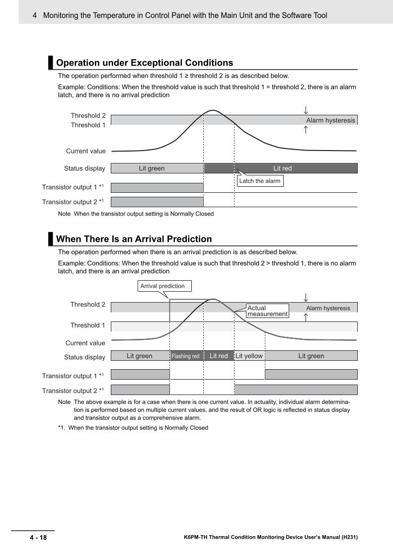
4 Monitoring the Temperature in Control Panel with the Main Unit and the Software Tool
4 - 18 K6PM-TH Thermal Condition Monitoring Device User’s Manual (H231)
The operation performed when threshold 1 ≥ threshold 2 is as described below.
Example: Conditions: When the threshold value is such that threshold 1 = threshold 2, there is an alarm latch, and there is no arrival prediction
Note When the transistor output setting is Normally Closed
The operation performed when there is an arrival prediction is as described below.Example: Conditions: When the threshold value is such that threshold 2 > threshold 1, there is no alarm latch, and there is an arrival prediction
Note The above example is for a case when there is one current value. In actuality, individual alarm determina-tion is performed based on multiple current values, and the result of OR logic is reflected in status display and transistor output as a comprehensive alarm.
*1. When the transistor output setting is Normally Closed
Operation under Exceptional Conditions
When There Is an Arrival Prediction
Alarm hysteresis
Lit green Lit red
Threshold 2
Threshold 1
Current value
Status display
Transistor output 1 *1
Transistor output 2 *1
Latch the alarm
Threshold 2Alarm hysteresis
Threshold 1
Current value
Status display Lit green Lit redFlashing red Lit yellow Lit green
Arrival prediction
Actual measurement
Transistor output 1 *1
Transistor output 2 *1
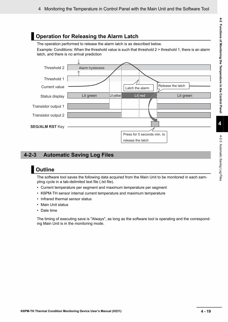
4 - 19
4 Monitoring the Temperature in Control Panel with the Main Unit and the Software Tool
K6PM-TH Thermal Condition Monitoring Device User’s Manual (H231)
4-2 Functions of Monitoring the Tem
perature in the Control Panel
4
4-2-3 Automatic Saving Log Files
The operation performed to release the alarm latch is as described below.Example: Conditions: When the threshold value is such that threshold 2 > threshold 1, there is an alarm latch, and there is no arrival prediction
The software tool saves the following data acquired from the Main Unit to be monitored in each sam-pling cycle in a tab-delimited text file (.txt file).• Current temperature per segment and maximum temperature per segment• K6PM-TH sensor internal current temperature and maximum temperature• Infrared thermal sensor status• Main Unit status• Date time
The timing of executing save is "Always", as long as the software tool is operating and the correspond-ing Main Unit is in the monitoring mode.
Operation for Releasing the Alarm Latch
4-2-3 Automatic Saving Log Files
Outline
Threshold 2 Alarm hysteresis
Threshold 1
Current value
Status display Lit green Lit yellow Lit green
Transistor output 1
Transistor output 2
SEG/ALM RST Key
Press for 5 seconds min. to
release the latch
Latch the alarmRelease the latch
Lit red
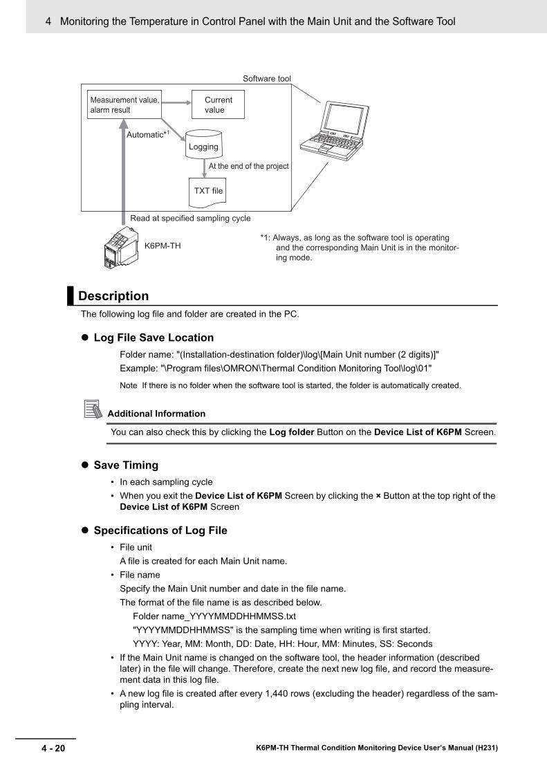
4 Monitoring the Temperature in Control Panel with the Main Unit and the Software Tool
4 - 20 K6PM-TH Thermal Condition Monitoring Device User’s Manual (H231)
The following log file and folder are created in the PC.
Log File Save LocationFolder name: "(Installation-destination folder)\log\[Main Unit number (2 digits)]"Example: "\Program files\OMRON\Thermal Condition Monitoring Tool\log\01"
Note If there is no folder when the software tool is started, the folder is automatically created.
Additional Information
You can also check this by clicking the Log folder Button on the Device List of K6PM Screen.
Save Timing• In each sampling cycle• When you exit the Device List of K6PM Screen by clicking the × Button at the top right of the
Device List of K6PM Screen
Specifications of Log File• File unit
A file is created for each Main Unit name.• File name
Specify the Main Unit number and date in the file name.The format of the file name is as described below.
Folder name_YYYYMMDDHHMMSS.txt"YYYYMMDDHHMMSS" is the sampling time when writing is first started.YYYY: Year, MM: Month, DD: Date, HH: Hour, MM: Minutes, SS: Seconds
• If the Main Unit name is changed on the software tool, the header information (described later) in the file will change. Therefore, create the next new log file, and record the measure-ment data in this log file.
• A new log file is created after every 1,440 rows (excluding the header) regardless of the sam-pling interval.
Description
Measurement value,
alarm result
K6PM-TH
Read at specified sampling cycle
Current
value
Logging
TXT file
Automatic*1
Software tool
At the end of the project
*1: Always, as long as the software tool is operating
and the corresponding Main Unit is in the monitor-
ing mode.
4 - 21
4 Monitoring the Temperature in Control Panel with the Main Unit and the Software Tool
K6PM-TH Thermal Condition Monitoring Device User’s Manual (H231)
4-2 Functions of Monitoring the Tem
perature in the Control Panel
4
4-2-3 Automatic Saving Log Files
• File FormatThe data is saved in the following format.The data is tag-delimited.First row: Project nameSecond row: Main Unit name (header information)Third row: IP address (header information)Fourth row: Serial No. (header information)
The serial number obtained from the Main Unit is output.Fifth row: Temperature unit (header information)
"C" is output for Celsius, and "F" for Fahrenheit.Sixth row: Item name (header information)
4 Monitoring the Temperature in Control Panel with the Main Unit and the Software Tool
4 - 22 K6PM-TH Thermal Condition Monitoring Device User’s Manual (H231)
MeasureTime\tK6PMStatus\tSensor1Status\tSensor1CurrentVal[0]\tSensor1MaxVal[0].... ....Sensor1CurrentVal[15]\tSensor1MaxVal[15]\tSensor1InnerVal.......(The output format is same as the Japanese notation hereinafter.)"\t" indicates a tab.
Seventh row and thereafter: Measurement dataThe following items are output. The sensor status and temperature data for all sensors is output in one row.
(1) Measurement date and timeOutput in the display format corresponding to the locale set in the PC.
(2) Main Unit statusThe double-byte data of the Main Unit status that is maintained in the Main Unit is output in hexa-decimal.For the detailed content of each bit, refer to "Main Unit status" in 5-3-2 Main Unit Monitor Object (Class ID: 374 hex) on page 5-10.
(3) K6PM-TH sensor statusThe double-byte data of the K6PM-TH sensor status that is maintained in the Main Unit is output in hexadecimal.For the detailed content of each bit, refer to "K6PM-TH sensor status per sensor" in 5-3-2 Main Unit Monitor Object (Class ID: 374 hex) on page 5-10.
(4) Temperature dataThe current temperature per segment and the maximum temperature per segment measured by the Main Unit is output in the order of the segment number, and the internal temperature is output in the end.
Note 1. When a communications error occurs with respect to the Main Unit, only (1) Measurement date and time is output.
2. During measurement interruption due to an external trigger, the entire (4) Temperature data is output with the values immediately before interruption being retained.
• Maximum number of rows of the log file1,440 rows. If it exceeds the maximum number of lines, create a new log file and save the log.
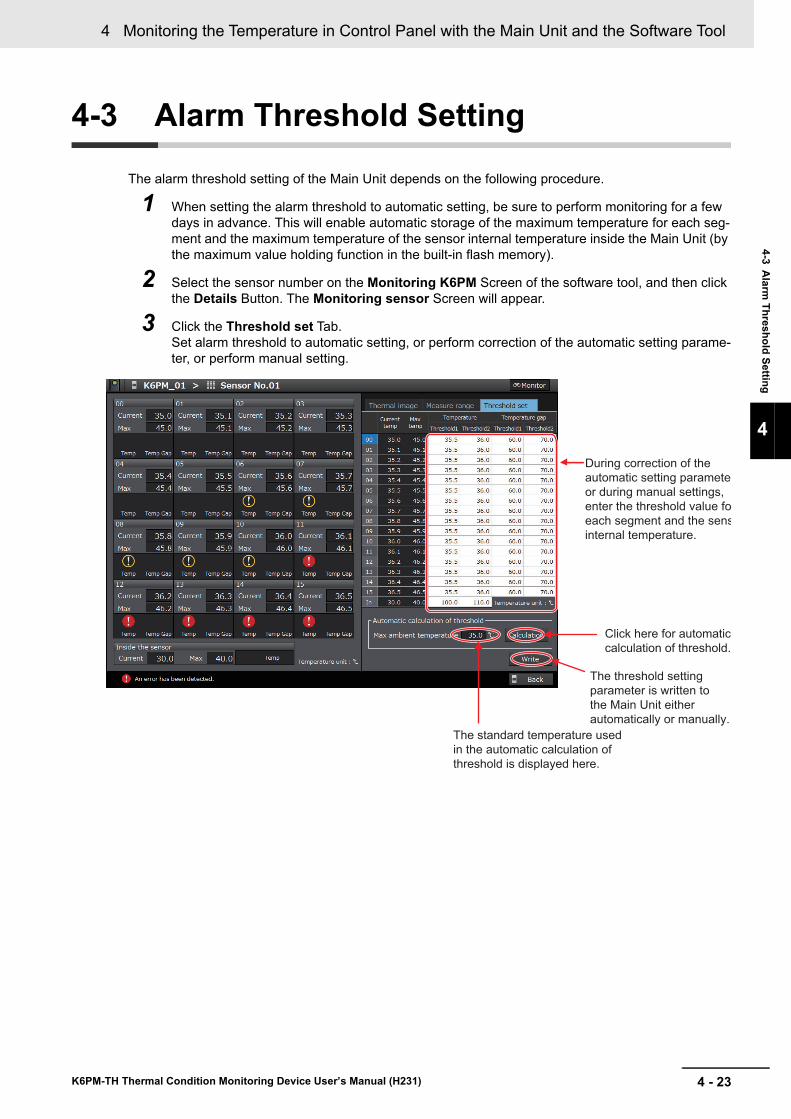
4 - 23
4 Monitoring the Temperature in Control Panel with the Main Unit and the Software Tool
K6PM-TH Thermal Condition Monitoring Device User’s Manual (H231)
4-3 Alarm
Threshold Setting
4
4-3 Alarm Threshold Setting
The alarm threshold setting of the Main Unit depends on the following procedure.
1 When setting the alarm threshold to automatic setting, be sure to perform monitoring for a few days in advance. This will enable automatic storage of the maximum temperature for each seg-ment and the maximum temperature of the sensor internal temperature inside the Main Unit (by the maximum value holding function in the built-in flash memory).
2 Select the sensor number on the Monitoring K6PM Screen of the software tool, and then click the Details Button. The Monitoring sensor Screen will appear.
3 Click the Threshold set Tab.Set alarm threshold to automatic setting, or perform correction of the automatic setting parame-ter, or perform manual setting.
During correction of the
automatic setting paramete
or during manual settings,
enter the threshold value fo
each segment and the sens
internal temperature.
The threshold setting
parameter is written to
the Main Unit either
automatically or manually.
The standard temperature used
in the automatic calculation of
threshold is displayed here.
Click here for automatic
calculation of threshold.
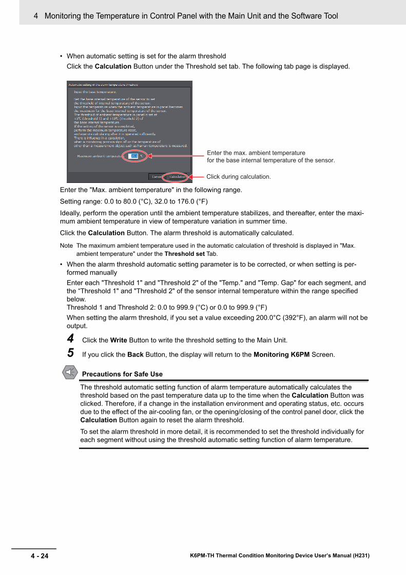
4 Monitoring the Temperature in Control Panel with the Main Unit and the Software Tool
4 - 24 K6PM-TH Thermal Condition Monitoring Device User’s Manual (H231)
• When automatic setting is set for the alarm thresholdClick the Calculation Button under the Threshold set tab. The following tab page is displayed.
Enter the "Max. ambient temperature" in the following range.Setting range: 0.0 to 80.0 (°C), 32.0 to 176.0 (°F)Ideally, perform the operation until the ambient temperature stabilizes, and thereafter, enter the maxi-mum ambient temperature in view of temperature variation in summer time.
Click the Calculation Button. The alarm threshold is automatically calculated.
Note The maximum ambient temperature used in the automatic calculation of threshold is displayed in "Max. ambient temperature" under the Threshold set Tab.
• When the alarm threshold automatic setting parameter is to be corrected, or when setting is per-formed manuallyEnter each "Threshold 1" and "Threshold 2" of the "Temp." and "Temp. Gap" for each segment, and the “Threshold 1" and "Threshold 2" of the sensor internal temperature within the range specified below.Threshold 1 and Threshold 2: 0.0 to 999.9 (°C) or 0.0 to 999.9 (°F)When setting the alarm threshold, if you set a value exceeding 200.0°C (392°F), an alarm will not be output.
4 Click the Write Button to write the threshold setting to the Main Unit.
5 If you click the Back Button, the display will return to the Monitoring K6PM Screen.
Precautions for Safe Use
The threshold automatic setting function of alarm temperature automatically calculates the threshold based on the past temperature data up to the time when the Calculation Button was clicked. Therefore, if a change in the installation environment and operating status, etc. occurs due to the effect of the air-cooling fan, or the opening/closing of the control panel door, click the Calculation Button again to reset the alarm threshold.To set the alarm threshold in more detail, it is recommended to set the threshold individually for each segment without using the threshold automatic setting function of alarm temperature.
Enter the max. ambient temperature
for the base internal temperature of the sensor.
Click during calculation.
4 - 25
4 Monitoring the Temperature in Control Panel with the Main Unit and the Software Tool
K6PM-TH Thermal Condition Monitoring Device User’s Manual (H231)
4-4 Procedure for Taking Actions W
hen an Alarm
Occurs
4
4-4 Procedure for Taking Actions When an Alarm Occurs
Follow the procedure described below to take action when an alarm occurs.
1 On the Device List of K6PM Screen, identify the Main Unit in which an alarm has occurred, and after selecting the Main Unit, click the Monitoring Button.
2 On the Monitoring K6PM Screen, identify the sensor in which an alarm has occurred, and then check its "Max. temperature".
3 Select the sensor number, and then click the Details Button.
4 On the Monitoring sensor Screen, identify the segment in which an alarm has occurred, and then check its "Current temp." and "Max. temperature".
5 Check the log file of each Main Unit that is saved automatically by the logging function of the software tool, and understand the temperature changes of each segment based on the time.
6 Identify the corresponding location of the segment in which an alarm has occurred from the pho-tograph.
7 Take action for the corresponding location.

4 Monitoring the Temperature in Control Panel with the Main Unit and the Software Tool
4 - 26 K6PM-TH Thermal Condition Monitoring Device User’s Manual (H231)

5 - 1
5
K6PM-TH Thermal Condition Monitoring Device User’s Manual (H231)
Main Units can also be monitored or set using EtherNet/IP compatible devices. This section describes how to monitor using the EtherNet/IP.
5-1 Outline . . . . . . . . . . . . . . . . . . . . . . . . . . . . . . . . . . . . . . . . . . . . . . . . . . . . . . . 5-25-1-1 What is Monitoring Using EtherNet/IP? . . . . . . . . . . . . . . . . . . . . . . . . . . . . . . 5-25-1-2 EtherNet/IP Communications Specifications . . . . . . . . . . . . . . . . . . . . . . . . . . 5-3
5-2 Monitoring Using the Tag Data Link . . . . . . . . . . . . . . . . . . . . . . . . . . . . . . . 5-45-2-1 Connection Setting . . . . . . . . . . . . . . . . . . . . . . . . . . . . . . . . . . . . . . . . . . . . . . 5-45-2-2 Setting the Assembly Object . . . . . . . . . . . . . . . . . . . . . . . . . . . . . . . . . . . . . . . 5-75-2-3 Assigning the Assembly Instance . . . . . . . . . . . . . . . . . . . . . . . . . . . . . . . . . . . 5-7
5-3 Monitoring and Setting Using the CIP Message Communications and Examples of Communications Instructions . . . . . . . . . . . . . . . . . . . . . . . 5-105-3-1 Services Supported by Objects in Main Units . . . . . . . . . . . . . . . . . . . . . . . . . 5-105-3-2 Main Unit Monitor Object (Class ID: 374 hex) . . . . . . . . . . . . . . . . . . . . . . . . . 5-105-3-3 K6PM-TH Sensor Monitor Object (Class ID: 375 hex) . . . . . . . . . . . . . . . . . . 5-125-3-4 K6PM-TH Sensor Temperature Monitor Object (Class ID: 376 hex) . . . . . . . 5-145-3-5 Main Unit Setting Object (Class ID: 377 hex) . . . . . . . . . . . . . . . . . . . . . . . . . 5-175-3-6 K6PM-TH Sensor Alarm Setting Object (Class ID: 378 hex) . . . . . . . . . . . . . 5-205-3-7 Identity Object (Class ID: 01 hex) . . . . . . . . . . . . . . . . . . . . . . . . . . . . . . . . . . 5-225-3-8 TCP/IP Interface Object (Class ID: F5 hex) . . . . . . . . . . . . . . . . . . . . . . . . . . 5-245-3-9 Examples of CIP Message Communications Instruction . . . . . . . . . . . . . . . . 5-27
Monitoring and Setting with the EtherNet/IP Communications
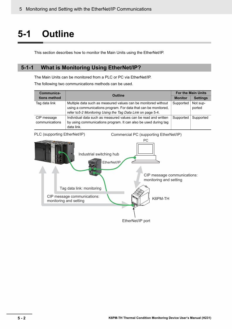
5 Monitoring and Setting with the EtherNet/IP Communications
5 - 2 K6PM-TH Thermal Condition Monitoring Device User’s Manual (H231)
5-1 Outline
This section describes how to monitor the Main Units using the EtherNet/IP.
The Main Units can be monitored from a PLC or PC via EtherNet/IP.The following two communications methods can be used.
5-1-1 What is Monitoring Using EtherNet/IP?
Communica-tions method Outline
For the Main UnitsMonitor Settings
Tag data link Multiple data such as measured values can be monitored without using a communications program. For data that can be monitored, refer to5-2 Monitoring Using the Tag Data Link on page 5-4.
Supported Not sup-ported
CIP message communications
Individual data such as measured values can be read and written by using communications program. It can also be used during tag data link.
Supported Supported
PC
PLC (supporting EtherNet/IP) Commercial PC (supporting EtherNet/IP)
Industrial switching hub
Tag data link: monitoring
CIP message communications: monitoring and setting
CIP message communications:
monitoring and setting
EtherNet/IP
EtherNet/IP port
K6PM-TH
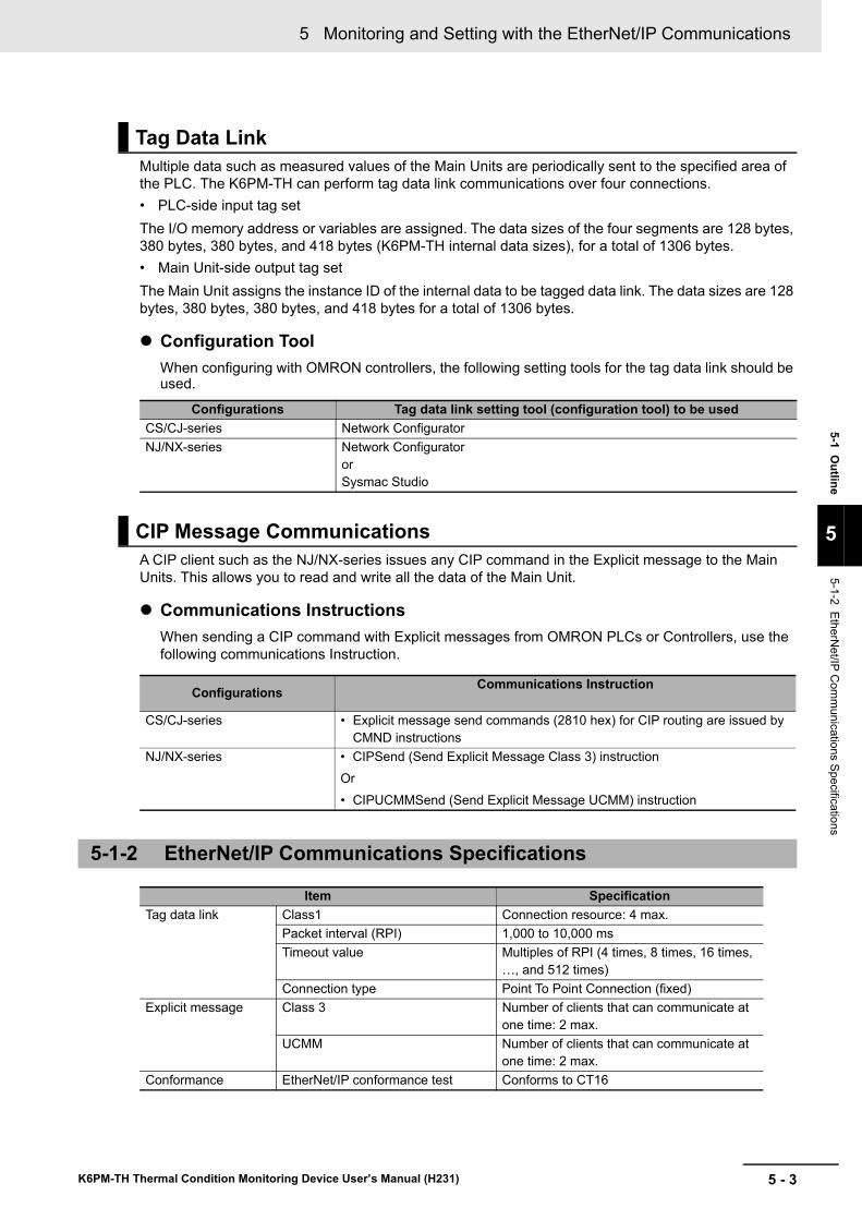
5 - 3
5 Monitoring and Setting with the EtherNet/IP Communications
K6PM-TH Thermal Condition Monitoring Device User’s Manual (H231)
5-1 Outline
5
5-1-2 EtherNet/IP C
omm
unications Specifications
Multiple data such as measured values of the Main Units are periodically sent to the specified area of the PLC. The K6PM-TH can perform tag data link communications over four connections.• PLC-side input tag setThe I/O memory address or variables are assigned. The data sizes of the four segments are 128 bytes, 380 bytes, 380 bytes, and 418 bytes (K6PM-TH internal data sizes), for a total of 1306 bytes.• Main Unit-side output tag setThe Main Unit assigns the instance ID of the internal data to be tagged data link. The data sizes are 128 bytes, 380 bytes, 380 bytes, and 418 bytes for a total of 1306 bytes.
Configuration ToolWhen configuring with OMRON controllers, the following setting tools for the tag data link should be used.
A CIP client such as the NJ/NX-series issues any CIP command in the Explicit message to the Main Units. This allows you to read and write all the data of the Main Unit.
Communications InstructionsWhen sending a CIP command with Explicit messages from OMRON PLCs or Controllers, use the following communications Instruction.
Tag Data Link
Configurations Tag data link setting tool (configuration tool) to be usedCS/CJ-series Network ConfiguratorNJ/NX-series Network Configurator
orSysmac Studio
CIP Message Communications
Configurations Communications Instruction
CS/CJ-series • Explicit message send commands (2810 hex) for CIP routing are issued by CMND instructions
NJ/NX-series • CIPSend (Send Explicit Message Class 3) instructionOr• CIPUCMMSend (Send Explicit Message UCMM) instruction
5-1-2 EtherNet/IP Communications Specifications
Item SpecificationTag data link Class1 Connection resource: 4 max.
Packet interval (RPI) 1,000 to 10,000 msTimeout value Multiples of RPI (4 times, 8 times, 16 times,
…, and 512 times)Connection type Point To Point Connection (fixed)
Explicit message Class 3 Number of clients that can communicate at one time: 2 max.
UCMM Number of clients that can communicate at one time: 2 max.
Conformance EtherNet/IP conformance test Conforms to CT16
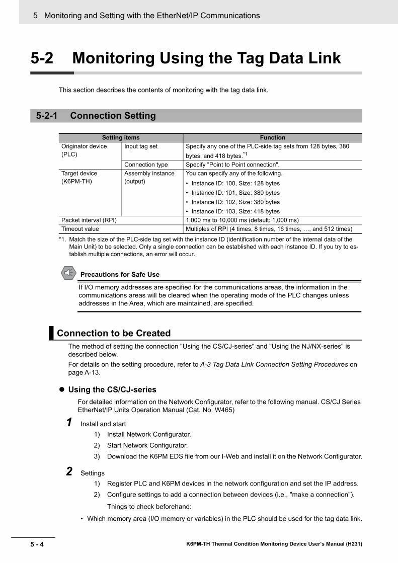
5 Monitoring and Setting with the EtherNet/IP Communications
5 - 4 K6PM-TH Thermal Condition Monitoring Device User’s Manual (H231)
5-2 Monitoring Using the Tag Data Link
This section describes the contents of monitoring with the tag data link.
Precautions for Safe Use
If I/O memory addresses are specified for the communications areas, the information in the communications areas will be cleared when the operating mode of the PLC changes unless addresses in the Area, which are maintained, are specified.
The method of setting the connection "Using the CS/CJ-series" and "Using the NJ/NX-series" is described below.For details on the setting procedure, refer to A-3 Tag Data Link Connection Setting Procedures on page A-13.
Using the CS/CJ-seriesFor detailed information on the Network Configurator, refer to the following manual. CS/CJ Series EtherNet/IP Units Operation Manual (Cat. No. W465)
1 Install and start1) Install Network Configurator.2) Start Network Configurator.3) Download the K6PM EDS file from our I-Web and install it on the Network Configurator.
2 Settings1) Register PLC and K6PM devices in the network configuration and set the IP address.2) Configure settings to add a connection between devices (i.e., "make a connection").
Things to check beforehand:
• Which memory area (I/O memory or variables) in the PLC should be used for the tag data link.
5-2-1 Connection Setting
Setting items FunctionOriginator device (PLC)
Input tag set Specify any one of the PLC-side tag sets from 128 bytes, 380 bytes, and 418 bytes.*1
*1. Match the size of the PLC-side tag set with the instance ID (identification number of the internal data of the Main Unit) to be selected. Only a single connection can be established with each instance ID. If you try to es-tablish multiple connections, an error will occur.
Connection type Specify "Point to Point connection".Target device (K6PM-TH)
Assembly instance (output)
You can specify any of the following.• Instance ID: 100, Size: 128 bytes• Instance ID: 101, Size: 380 bytes• Instance ID: 102, Size: 380 bytes• Instance ID: 103, Size: 418 bytes
Packet interval (RPI) 1,000 ms to 10,000 ms (default: 1,000 ms)Timeout value Multiples of RPI (4 times, 8 times, 16 times, …, and 512 times)
Connection to be Created
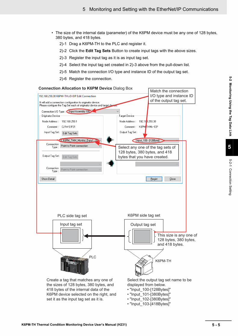
5 - 5
5 Monitoring and Setting with the EtherNet/IP Communications
K6PM-TH Thermal Condition Monitoring Device User’s Manual (H231)
5-2 Monitoring U
sing the Tag Data Link
5
5-2-1 Connection Setting
• The size of the internal data (parameter) of the K6PM device must be any one of 128 bytes, 380 bytes, and 418 bytes.
2)-1 Drag a K6PM-TH to the PLC and register it.
2)-2 Click the Edit Tag Sets Button to create input tags with the above sizes.
2)-3 Register the input tag as it is as input tag set.
2)-4 Select the input tag set created in 2)-3 above from the pull-down list.
2)-5 Match the connection I/O type and instance ID of the output tag set.
2)-6 Register the connection.
Connection Allocation to K6PM Device Dialog Box
PLC side tag set K6PM side tag set
This size is any one of 128 bytes, 380 bytes, and 418 bytes.
Output tag setInput tag set
PLCK6PM-TH
Select any one of the tag sets of
128 bytes, 380 bytes, and 418
bytes that you have created.
Create a tag that matches any one of
the sizes of 128 bytes, 380 bytes, and
418 bytes of the internal data of the
K6PM device selected on the right, and
set it as the input tag set as it is.
Select the output tag set name to be
displayed from below.
• "Input_100-[128Bytes]"
• "Input_101-[380Bytes]"
• "Input_102-[380Bytes]"
• "Input_103-[418Bytes]"
Match the connection
I/O type and instance ID
of the output tag set.
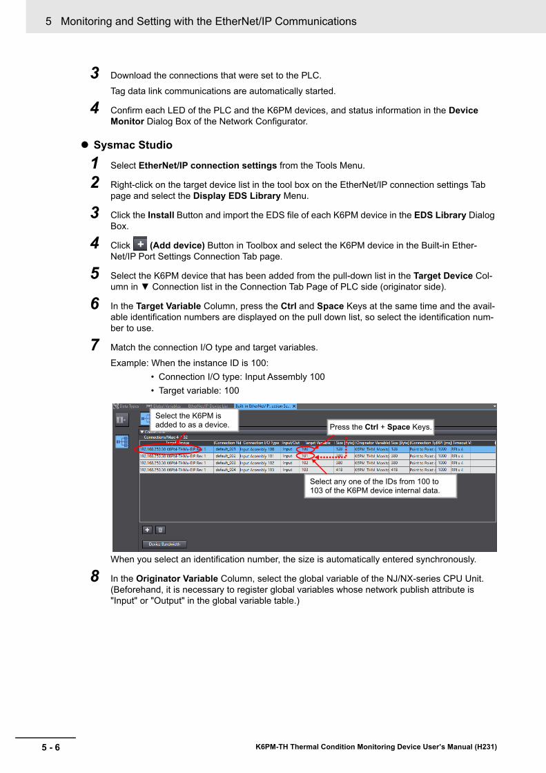
5 Monitoring and Setting with the EtherNet/IP Communications
5 - 6 K6PM-TH Thermal Condition Monitoring Device User’s Manual (H231)
3 Download the connections that were set to the PLC.
Tag data link communications are automatically started.
4 Confirm each LED of the PLC and the K6PM devices, and status information in the Device Monitor Dialog Box of the Network Configurator.
Sysmac Studio
1 Select EtherNet/IP connection settings from the Tools Menu.
2 Right-click on the target device list in the tool box on the EtherNet/IP connection settings Tab page and select the Display EDS Library Menu.
3 Click the Install Button and import the EDS file of each K6PM device in the EDS Library Dialog Box.
4 Click (Add device) Button in Toolbox and select the K6PM device in the Built-in Ether- Net/IP Port Settings Connection Tab page.
5 Select the K6PM device that has been added from the pull-down list in the Target Device Col-umn in ▼ Connection list in the Connection Tab Page of PLC side (originator side).
6 In the Target Variable Column, press the Ctrl and Space Keys at the same time and the avail-able identification numbers are displayed on the pull down list, so select the identification num-ber to use.
7 Match the connection I/O type and target variables.Example: When the instance ID is 100:
• Connection I/O type: Input Assembly 100• Target variable: 100
When you select an identification number, the size is automatically entered synchronously.
8 In the Originator Variable Column, select the global variable of the NJ/NX-series CPU Unit. (Beforehand, it is necessary to register global variables whose network publish attribute is "Input" or "Output" in the global variable table.)
Select the K6PM is added to as a device. Press the Ctrl + Space Keys.
Select any one of the IDs from 100 to 103 of the K6PM device internal data.
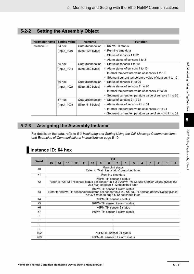
5 - 7
5 Monitoring and Setting with the EtherNet/IP Communications
K6PM-TH Thermal Condition Monitoring Device User’s Manual (H231)
5-2 Monitoring U
sing the Tag Data Link
5
5-2-2 Setting the Assembly O
bject
For details on the data, refer to 5-3 Monitoring and Setting Using the CIP Message Communications and Examples of Communications Instructions on page 5-10.
5-2-2 Setting the Assembly Object
Parameter name Setting value Remarks FunctionInstance ID 64 hex
(Input_100)Output connection (Size: 128 bytes)
• K6PM-TH status • Running time data • Status of sensors 1 to 31• Alarm status of sensors 1 to 31
65 hex(Input_101)
Output connection (Size: 380 bytes)
• Status of sensors 1 to 10• Alarm status of sensors 1 to 10• Internal temperature value of sensors 1 to 10• Segment current temperature value of sensors 1 to 10
66 hex(Input_102)
Output connection (Size: 380 bytes)
• Status of sensors 11 to 20• Alarm status of sensors 11 to 20• Internal temperature value of sensors 11 to 20• Segment current temperature value of sensors 11 to 20
67 hex(Input_103)
Output connection (Size: 418 bytes)
• Status of sensors 21 to 31• Alarm status of sensors 21 to 31• Internal temperature value of sensors 21 to 31• Segment current temperature value of sensors 21 to 31
5-2-3 Assigning the Assembly Instance
Instance ID: 64 hex
WordBit
15 14 13 12 11 10 9 8 7 6 5 4 3 2 1 0
+0 Main Unit statusRefer to "Main Unit status" described later.
+1 Running time data
+2K6PM-TH sensor 1 status
Refer to "K6PM-TH sensor status per sensor" in 5-3-3 K6PM-TH Sensor Monitor Object (Class ID: 375 hex) on page 5-12 described later.
+3K6PM-TH sensor 1 alarm status
Refer to "K6PM-TH sensor alarm status per sensor" in 5-3-3 K6PM-TH Sensor Monitor Object (Class ID: 375 hex) on page 5-12 described later.
+4 K6PM-TH sensor 2 status+5 K6PM-TH sensor 2 alarm status+6 K6PM-TH sensor 3 status+7 K6PM-TH sensor 3 alarm status: :: :: :: :
+62 K6PM-TH sensor 31 status+63 K6PM-TH sensor 31 alarm status
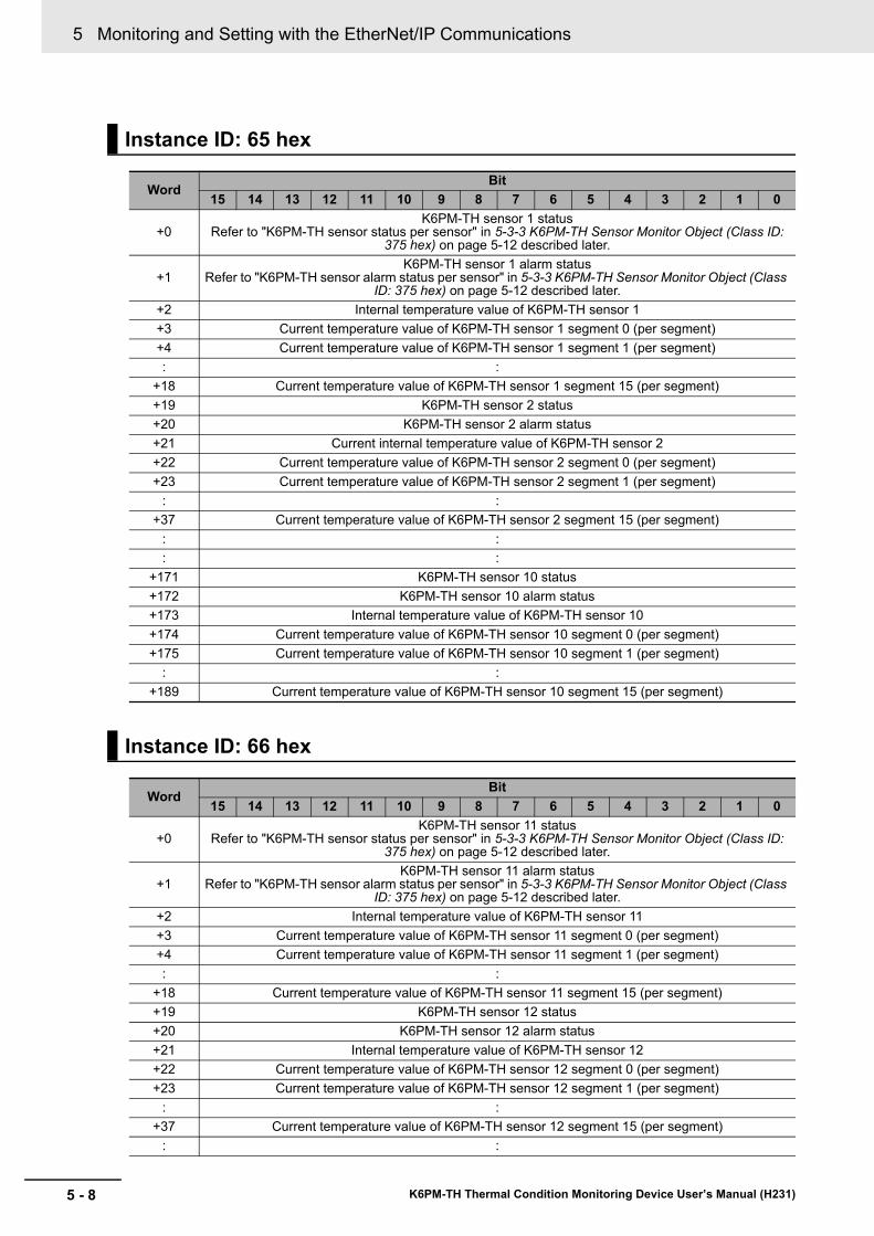
5 Monitoring and Setting with the EtherNet/IP Communications
5 - 8 K6PM-TH Thermal Condition Monitoring Device User’s Manual (H231)
Instance ID: 65 hex
WordBit
15 14 13 12 11 10 9 8 7 6 5 4 3 2 1 0
+0K6PM-TH sensor 1 status
Refer to "K6PM-TH sensor status per sensor" in 5-3-3 K6PM-TH Sensor Monitor Object (Class ID: 375 hex) on page 5-12 described later.
+1K6PM-TH sensor 1 alarm status
Refer to "K6PM-TH sensor alarm status per sensor" in 5-3-3 K6PM-TH Sensor Monitor Object (Class ID: 375 hex) on page 5-12 described later.
+2 Internal temperature value of K6PM-TH sensor 1+3 Current temperature value of K6PM-TH sensor 1 segment 0 (per segment)+4 Current temperature value of K6PM-TH sensor 1 segment 1 (per segment): :
+18 Current temperature value of K6PM-TH sensor 1 segment 15 (per segment)+19 K6PM-TH sensor 2 status+20 K6PM-TH sensor 2 alarm status+21 Current internal temperature value of K6PM-TH sensor 2+22 Current temperature value of K6PM-TH sensor 2 segment 0 (per segment)+23 Current temperature value of K6PM-TH sensor 2 segment 1 (per segment)
: :+37 Current temperature value of K6PM-TH sensor 2 segment 15 (per segment)
: :: :
+171 K6PM-TH sensor 10 status+172 K6PM-TH sensor 10 alarm status+173 Internal temperature value of K6PM-TH sensor 10+174 Current temperature value of K6PM-TH sensor 10 segment 0 (per segment)+175 Current temperature value of K6PM-TH sensor 10 segment 1 (per segment)
: :+189 Current temperature value of K6PM-TH sensor 10 segment 15 (per segment)
Instance ID: 66 hex
WordBit
15 14 13 12 11 10 9 8 7 6 5 4 3 2 1 0
+0K6PM-TH sensor 11 status
Refer to "K6PM-TH sensor status per sensor" in 5-3-3 K6PM-TH Sensor Monitor Object (Class ID: 375 hex) on page 5-12 described later.
+1K6PM-TH sensor 11 alarm status
Refer to "K6PM-TH sensor alarm status per sensor" in 5-3-3 K6PM-TH Sensor Monitor Object (Class ID: 375 hex) on page 5-12 described later.
+2 Internal temperature value of K6PM-TH sensor 11+3 Current temperature value of K6PM-TH sensor 11 segment 0 (per segment)+4 Current temperature value of K6PM-TH sensor 11 segment 1 (per segment): :
+18 Current temperature value of K6PM-TH sensor 11 segment 15 (per segment)+19 K6PM-TH sensor 12 status+20 K6PM-TH sensor 12 alarm status+21 Internal temperature value of K6PM-TH sensor 12+22 Current temperature value of K6PM-TH sensor 12 segment 0 (per segment)+23 Current temperature value of K6PM-TH sensor 12 segment 1 (per segment)
: :+37 Current temperature value of K6PM-TH sensor 12 segment 15 (per segment)
: :
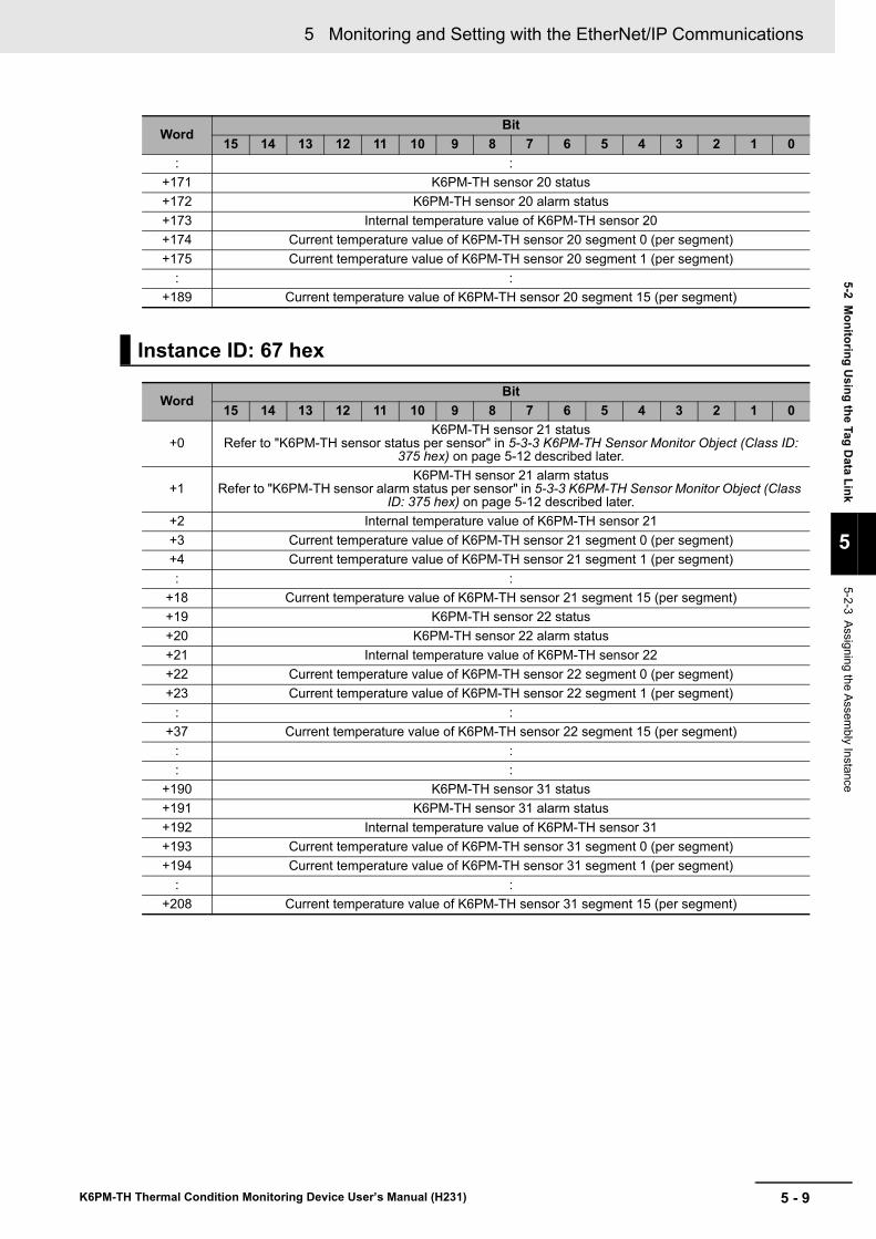
5 - 9
5 Monitoring and Setting with the EtherNet/IP Communications
K6PM-TH Thermal Condition Monitoring Device User’s Manual (H231)
5-2 Monitoring U
sing the Tag Data Link
5
5-2-3 Assigning the Assembly Instance
: :+171 K6PM-TH sensor 20 status+172 K6PM-TH sensor 20 alarm status+173 Internal temperature value of K6PM-TH sensor 20+174 Current temperature value of K6PM-TH sensor 20 segment 0 (per segment)+175 Current temperature value of K6PM-TH sensor 20 segment 1 (per segment)
: :+189 Current temperature value of K6PM-TH sensor 20 segment 15 (per segment)
Instance ID: 67 hex
WordBit
15 14 13 12 11 10 9 8 7 6 5 4 3 2 1 0
+0K6PM-TH sensor 21 status
Refer to "K6PM-TH sensor status per sensor" in 5-3-3 K6PM-TH Sensor Monitor Object (Class ID: 375 hex) on page 5-12 described later.
+1K6PM-TH sensor 21 alarm status
Refer to "K6PM-TH sensor alarm status per sensor" in 5-3-3 K6PM-TH Sensor Monitor Object (Class ID: 375 hex) on page 5-12 described later.
+2 Internal temperature value of K6PM-TH sensor 21+3 Current temperature value of K6PM-TH sensor 21 segment 0 (per segment)+4 Current temperature value of K6PM-TH sensor 21 segment 1 (per segment): :
+18 Current temperature value of K6PM-TH sensor 21 segment 15 (per segment)+19 K6PM-TH sensor 22 status+20 K6PM-TH sensor 22 alarm status+21 Internal temperature value of K6PM-TH sensor 22+22 Current temperature value of K6PM-TH sensor 22 segment 0 (per segment)+23 Current temperature value of K6PM-TH sensor 22 segment 1 (per segment)
: :+37 Current temperature value of K6PM-TH sensor 22 segment 15 (per segment)
: :: :
+190 K6PM-TH sensor 31 status+191 K6PM-TH sensor 31 alarm status+192 Internal temperature value of K6PM-TH sensor 31+193 Current temperature value of K6PM-TH sensor 31 segment 0 (per segment)+194 Current temperature value of K6PM-TH sensor 31 segment 1 (per segment)
: :+208 Current temperature value of K6PM-TH sensor 31 segment 15 (per segment)
WordBit
15 14 13 12 11 10 9 8 7 6 5 4 3 2 1 0
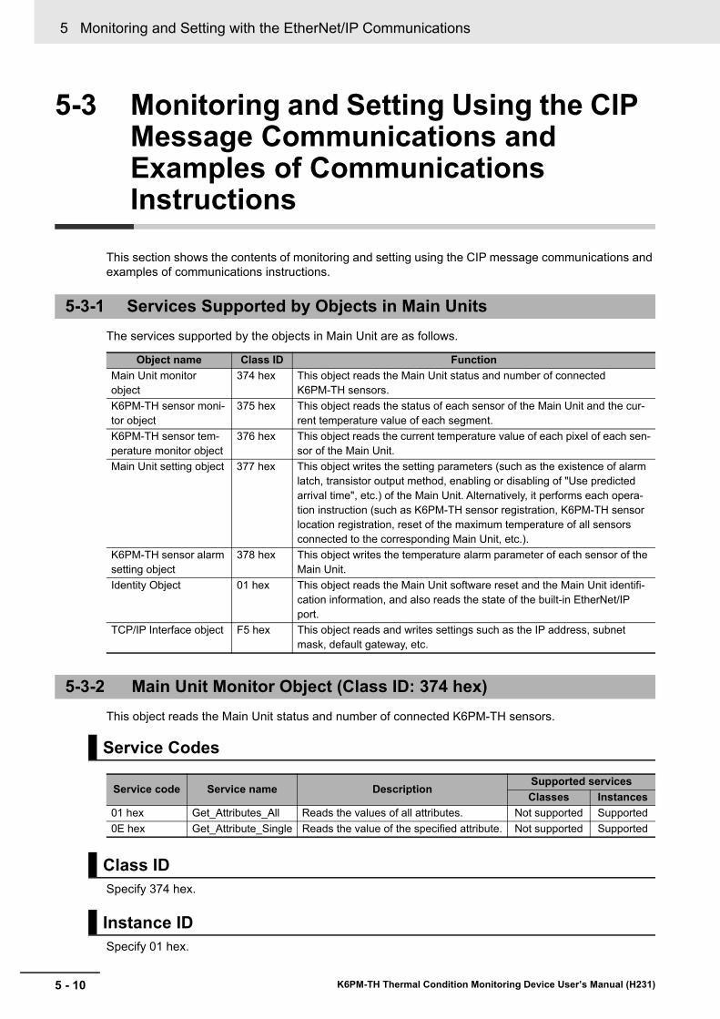
5 Monitoring and Setting with the EtherNet/IP Communications
5 - 10 K6PM-TH Thermal Condition Monitoring Device User’s Manual (H231)
5-3 Monitoring and Setting Using the CIP Message Communications and Examples of Communications Instructions
This section shows the contents of monitoring and setting using the CIP message communications and examples of communications instructions.
The services supported by the objects in Main Unit are as follows.
This object reads the Main Unit status and number of connected K6PM-TH sensors.
Specify 374 hex.
Specify 01 hex.
5-3-1 Services Supported by Objects in Main Units
Object name Class ID FunctionMain Unit monitor object
374 hex This object reads the Main Unit status and number of connected K6PM-TH sensors.
K6PM-TH sensor moni-tor object
375 hex This object reads the status of each sensor of the Main Unit and the cur-rent temperature value of each segment.
K6PM-TH sensor tem-perature monitor object
376 hex This object reads the current temperature value of each pixel of each sen-sor of the Main Unit.
Main Unit setting object 377 hex This object writes the setting parameters (such as the existence of alarm latch, transistor output method, enabling or disabling of "Use predicted arrival time", etc.) of the Main Unit. Alternatively, it performs each opera-tion instruction (such as K6PM-TH sensor registration, K6PM-TH sensor location registration, reset of the maximum temperature of all sensors connected to the corresponding Main Unit, etc.).
K6PM-TH sensor alarm setting object
378 hex This object writes the temperature alarm parameter of each sensor of the Main Unit.
Identity Object 01 hex This object reads the Main Unit software reset and the Main Unit identifi-cation information, and also reads the state of the built-in EtherNet/IP port.
TCP/IP Interface object F5 hex This object reads and writes settings such as the IP address, subnet mask, default gateway, etc.
5-3-2 Main Unit Monitor Object (Class ID: 374 hex)
Service Codes
Service code Service name DescriptionSupported servicesClasses Instances
01 hex Get_Attributes_All Reads the values of all attributes. Not supported Supported0E hex Get_Attribute_Single Reads the value of the specified attribute. Not supported Supported
Class ID
Instance ID
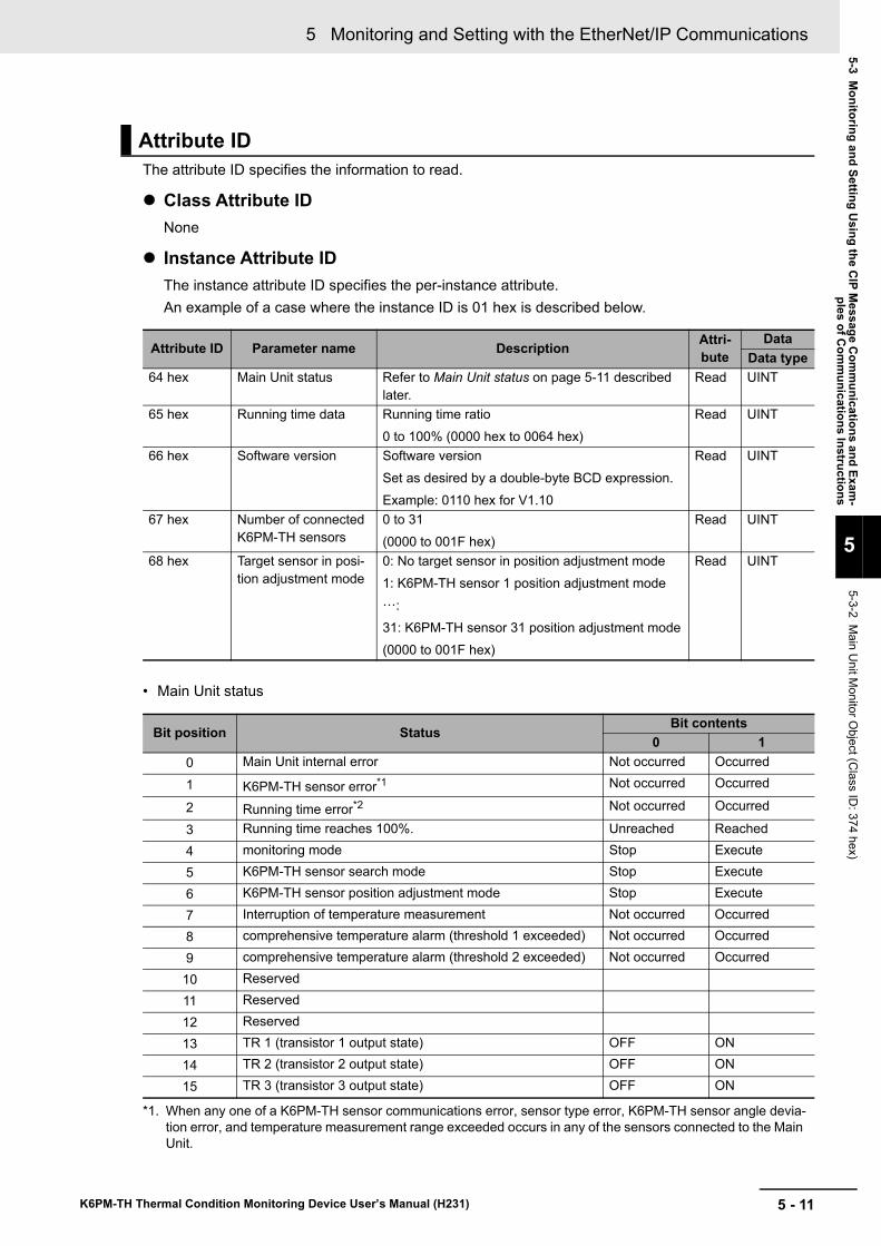
5 - 11
5 Monitoring and Setting with the EtherNet/IP Communications
K6PM-TH Thermal Condition Monitoring Device User’s Manual (H231)
5-3 Monitoring and Setting U
sing the CIP M
essage Com
munications and Exam
-ples of C
omm
unications Instructions
5
5-3-2 Main U
nit Monitor O
bject (Class ID
: 374 hex)
The attribute ID specifies the information to read.
Class Attribute IDNone
Instance Attribute IDThe instance attribute ID specifies the per-instance attribute.An example of a case where the instance ID is 01 hex is described below.
• Main Unit status
Attribute ID
Attribute ID Parameter name Description Attri-bute
DataData type
64 hex Main Unit status Refer to Main Unit status on page 5-11 described later.
Read UINT
65 hex Running time data Running time ratio0 to 100% (0000 hex to 0064 hex)
Read UINT
66 hex Software version Software versionSet as desired by a double-byte BCD expression.Example: 0110 hex for V1.10
Read UINT
67 hex Number of connected K6PM-TH sensors
0 to 31(0000 to 001F hex)
Read UINT
68 hex Target sensor in posi-tion adjustment mode
0: No target sensor in position adjustment mode1: K6PM-TH sensor 1 position adjustment mode···:31: K6PM-TH sensor 31 position adjustment mode(0000 to 001F hex)
Read UINT
Bit position StatusBit contents
0 10 Main Unit internal error Not occurred Occurred
1 K6PM-TH sensor error*1
*1. When any one of a K6PM-TH sensor communications error, sensor type error, K6PM-TH sensor angle devia-tion error, and temperature measurement range exceeded occurs in any of the sensors connected to the Main Unit.
Not occurred Occurred
2 Running time error*2 Not occurred Occurred
3 Running time reaches 100%. Unreached Reached4 monitoring mode Stop Execute5 K6PM-TH sensor search mode Stop Execute6 K6PM-TH sensor position adjustment mode Stop Execute7 Interruption of temperature measurement Not occurred Occurred8 comprehensive temperature alarm (threshold 1 exceeded) Not occurred Occurred9 comprehensive temperature alarm (threshold 2 exceeded) Not occurred Occurred10 Reserved11 Reserved12 Reserved13 TR 1 (transistor 1 output state) OFF ON14 TR 2 (transistor 2 output state) OFF ON15 TR 3 (transistor 3 output state) OFF ON
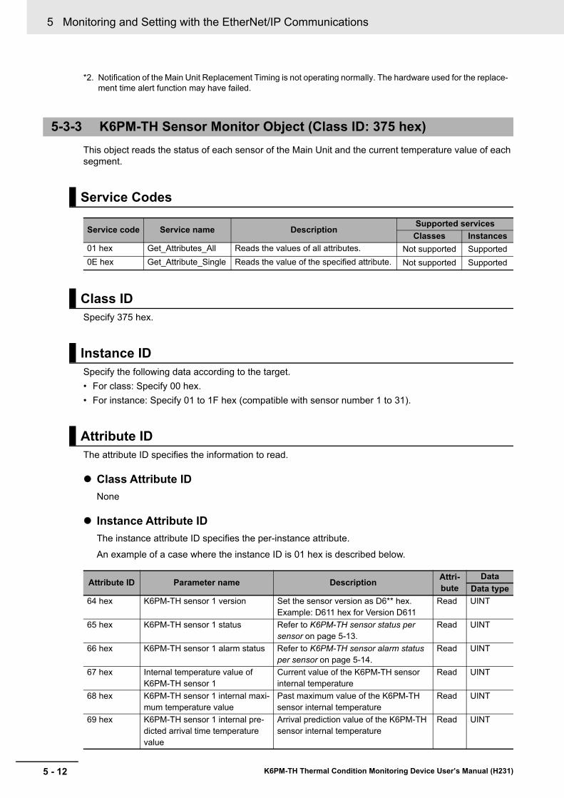
5 Monitoring and Setting with the EtherNet/IP Communications
5 - 12 K6PM-TH Thermal Condition Monitoring Device User’s Manual (H231)
This object reads the status of each sensor of the Main Unit and the current temperature value of each segment.
Specify 375 hex.
Specify the following data according to the target.• For class: Specify 00 hex.• For instance: Specify 01 to 1F hex (compatible with sensor number 1 to 31).
The attribute ID specifies the information to read.
Class Attribute IDNone
Instance Attribute IDThe instance attribute ID specifies the per-instance attribute.An example of a case where the instance ID is 01 hex is described below.
*2. Notification of the Main Unit Replacement Timing is not operating normally. The hardware used for the replace-ment time alert function may have failed.
5-3-3 K6PM-TH Sensor Monitor Object (Class ID: 375 hex)
Service Codes
Service code Service name DescriptionSupported servicesClasses Instances
01 hex Get_Attributes_All Reads the values of all attributes. Not supported Supported0E hex Get_Attribute_Single Reads the value of the specified attribute. Not supported Supported
Class ID
Instance ID
Attribute ID
Attribute ID Parameter name Description Attri-bute
DataData type
64 hex K6PM-TH sensor 1 version Set the sensor version as D6** hex.Example: D611 hex for Version D611
Read UINT
65 hex K6PM-TH sensor 1 status Refer to K6PM-TH sensor status per sensor on page 5-13.
Read UINT
66 hex K6PM-TH sensor 1 alarm status Refer to K6PM-TH sensor alarm status per sensor on page 5-14.
Read UINT
67 hex Internal temperature value of K6PM-TH sensor 1
Current value of the K6PM-TH sensor internal temperature
Read UINT
68 hex K6PM-TH sensor 1 internal maxi-mum temperature value
Past maximum value of the K6PM-TH sensor internal temperature
Read UINT
69 hex K6PM-TH sensor 1 internal pre-dicted arrival time temperature value
Arrival prediction value of the K6PM-TH sensor internal temperature
Read UINT
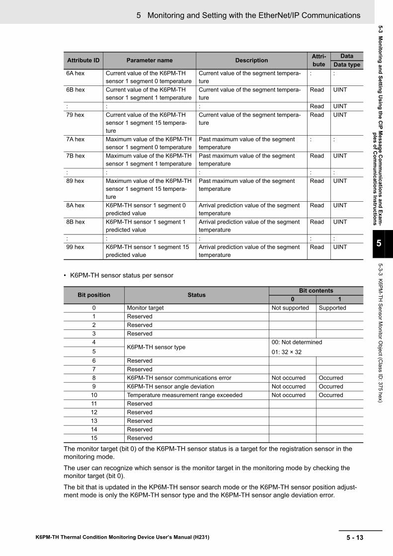
5 - 13
5 Monitoring and Setting with the EtherNet/IP Communications
K6PM-TH Thermal Condition Monitoring Device User’s Manual (H231)
5-3 Monitoring and Setting U
sing the CIP M
essage Com
munications and Exam
-ples of C
omm
unications Instructions
5
5-3-3 K6PM-TH
Sensor Monitor O
bject (Class ID
: 375 hex)
• K6PM-TH sensor status per sensor
The monitor target (bit 0) of the K6PM-TH sensor status is a target for the registration sensor in the monitoring mode.The user can recognize which sensor is the monitor target in the monitoring mode by checking the monitor target (bit 0).
The bit that is updated in the KP6M-TH sensor search mode or the K6PM-TH sensor position adjust-ment mode is only the K6PM-TH sensor type and the K6PM-TH sensor angle deviation error.
6A hex Current value of the K6PM-TH sensor 1 segment 0 temperature
Current value of the segment tempera-ture
: :
6B hex Current value of the K6PM-TH sensor 1 segment 1 temperature
Current value of the segment tempera-ture
Read UINT
: : : Read UINT79 hex Current value of the K6PM-TH
sensor 1 segment 15 tempera-ture
Current value of the segment tempera-ture
Read UINT
7A hex Maximum value of the K6PM-TH sensor 1 segment 0 temperature
Past maximum value of the segment temperature
: :
7B hex Maximum value of the K6PM-TH sensor 1 segment 1 temperature
Past maximum value of the segment temperature
Read UINT
: : : : :89 hex Maximum value of the K6PM-TH
sensor 1 segment 15 tempera-ture
Past maximum value of the segment temperature
Read UINT
8A hex K6PM-TH sensor 1 segment 0 predicted value
Arrival prediction value of the segment temperature
Read UINT
8B hex K6PM-TH sensor 1 segment 1 predicted value
Arrival prediction value of the segment temperature
Read UINT
: : : : :99 hex K6PM-TH sensor 1 segment 15
predicted valueArrival prediction value of the segment temperature
Read UINT
Bit position StatusBit contents
0 10 Monitor target Not supported Supported1 Reserved2 Reserved3 Reserved4
K6PM-TH sensor type00: Not determined01: 32 × 325
6 Reserved7 Reserved8 K6PM-TH sensor communications error Not occurred Occurred9 K6PM-TH sensor angle deviation Not occurred Occurred
10 Temperature measurement range exceeded Not occurred Occurred11 Reserved12 Reserved13 Reserved14 Reserved15 Reserved
Attribute ID Parameter name Description Attri-bute
DataData type
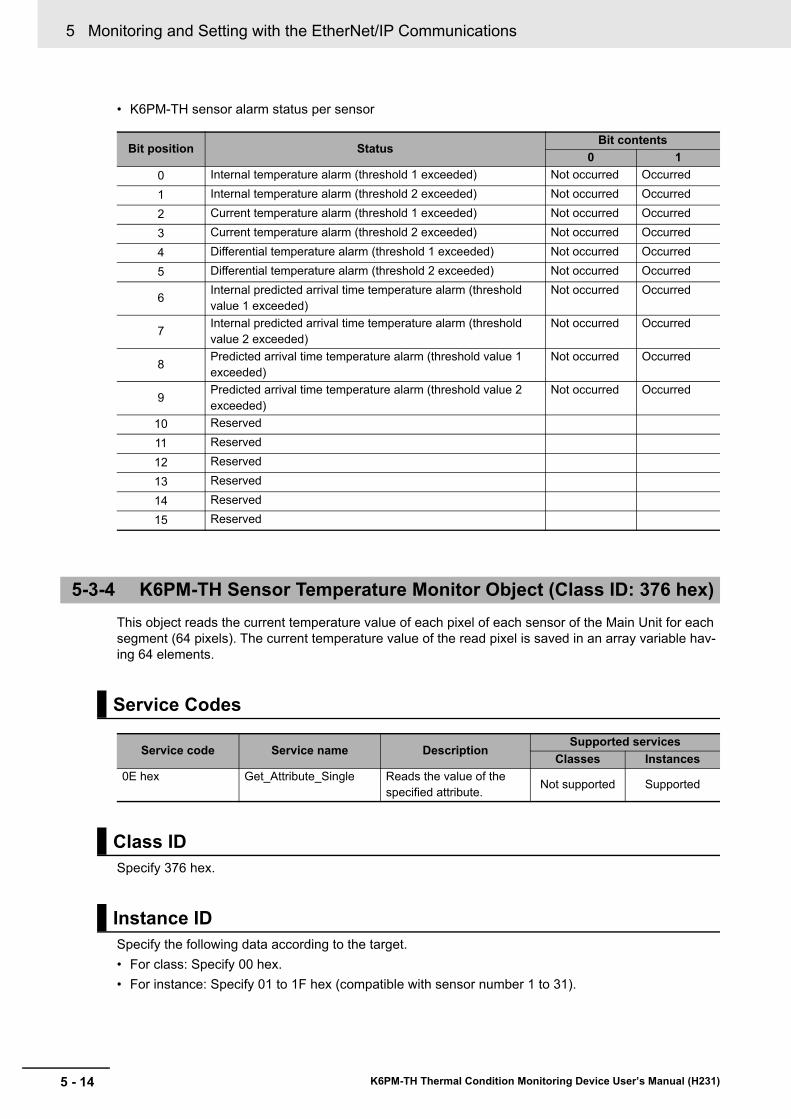
5 Monitoring and Setting with the EtherNet/IP Communications
5 - 14 K6PM-TH Thermal Condition Monitoring Device User’s Manual (H231)
• K6PM-TH sensor alarm status per sensor
This object reads the current temperature value of each pixel of each sensor of the Main Unit for each segment (64 pixels). The current temperature value of the read pixel is saved in an array variable hav-ing 64 elements.
Specify 376 hex.
Specify the following data according to the target.• For class: Specify 00 hex.• For instance: Specify 01 to 1F hex (compatible with sensor number 1 to 31).
Bit position StatusBit contents
0 10 Internal temperature alarm (threshold 1 exceeded) Not occurred Occurred1 Internal temperature alarm (threshold 2 exceeded) Not occurred Occurred2 Current temperature alarm (threshold 1 exceeded) Not occurred Occurred3 Current temperature alarm (threshold 2 exceeded) Not occurred Occurred4 Differential temperature alarm (threshold 1 exceeded) Not occurred Occurred5 Differential temperature alarm (threshold 2 exceeded) Not occurred Occurred
6 Internal predicted arrival time temperature alarm (threshold value 1 exceeded)
Not occurred Occurred
7 Internal predicted arrival time temperature alarm (threshold value 2 exceeded)
Not occurred Occurred
8 Predicted arrival time temperature alarm (threshold value 1 exceeded)
Not occurred Occurred
9 Predicted arrival time temperature alarm (threshold value 2 exceeded)
Not occurred Occurred
10 Reserved11 Reserved12 Reserved13 Reserved14 Reserved15 Reserved
5-3-4 K6PM-TH Sensor Temperature Monitor Object (Class ID: 376 hex)
Service Codes
Service code Service name DescriptionSupported services
Classes Instances0E hex Get_Attribute_Single Reads the value of the
specified attribute. Not supported Supported
Class ID
Instance ID
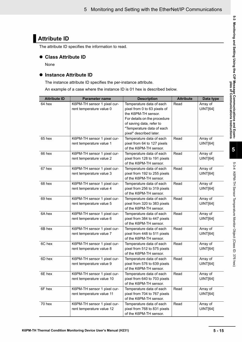
5 - 15
5 Monitoring and Setting with the EtherNet/IP Communications
K6PM-TH Thermal Condition Monitoring Device User’s Manual (H231)
5-3 Monitoring and Setting U
sing the CIP M
essage Com
munications and Exam
-ples of C
omm
unications Instructions
5
5-3-4 K6PM-TH
Sensor Temperature M
onitor Object (C
lass ID: 376 hex)
The attribute ID specifies the information to read.
Class Attribute IDNone
Instance Attribute IDThe instance attribute ID specifies the per-instance attribute.An example of a case where the instance ID is 01 hex is described below.
Attribute ID
Attribute ID Parameter name Description Attribute Data type64 hex K6PM-TH sensor 1 pixel cur-
rent temperature value 0Temperature data of each pixel from 0 to 63 pixels of the K6PM-TH sensor.For details on the procedure of saving data, refer to "Temperature data of each pixel" described later.
Read Array of UINT[64]
65 hex K6PM-TH sensor 1 pixel cur-rent temperature value 1
Temperature data of each pixel from 64 to 127 pixels of the K6PM-TH sensor.
Read Array of UINT[64]
66 hex K6PM-TH sensor 1 pixel cur-rent temperature value 2
Temperature data of each pixel from 128 to 191 pixels of the K6PM-TH sensor.
Read Array of UINT[64]
67 hex K6PM-TH sensor 1 pixel cur-rent temperature value 3
Temperature data of each pixel from 192 to 255 pixels of the K6PM-TH sensor.
Read Array of UINT[64]
68 hex K6PM-TH sensor 1 pixel cur-rent temperature value 4
Temperature data of each pixel from 256 to 319 pixels of the K6PM-TH sensor.
Read Array of UINT[64]
69 hex K6PM-TH sensor 1 pixel cur-rent temperature value 5
Temperature data of each pixel from 320 to 383 pixels of the K6PM-TH sensor.
Read Array of UINT[64]
6A hex K6PM-TH sensor 1 pixel cur-rent temperature value 6
Temperature data of each pixel from 384 to 447 pixels of the K6PM-TH sensor.
Read Array of UINT[64]
6B hex K6PM-TH sensor 1 pixel cur-rent temperature value 7
Temperature data of each pixel from 448 to 511 pixels of the K6PM-TH sensor.
Read Array of UINT[64]
6C hex K6PM-TH sensor 1 pixel cur-rent temperature value 8
Temperature data of each pixel from 512 to 575 pixels of the K6PM-TH sensor.
Read Array of UINT[64]
6D hex K6PM-TH sensor 1 pixel cur-rent temperature value 9
Temperature data of each pixel from 576 to 639 pixels of the K6PM-TH sensor.
Read Array of UINT[64]
6E hex K6PM-TH sensor 1 pixel cur-rent temperature value 10
Temperature data of each pixel from 640 to 703 pixels of the K6PM-TH sensor.
Read Array of UINT[64]
6F hex K6PM-TH sensor 1 pixel cur-rent temperature value 11
Temperature data of each pixel from 704 to 767 pixels of the K6PM-TH sensor.
Read Array of UINT[64]
70 hex K6PM-TH sensor 1 pixel cur-rent temperature value 12
Temperature data of each pixel from 768 to 831 pixels of the K6PM-TH sensor.
Read Array of UINT[64]
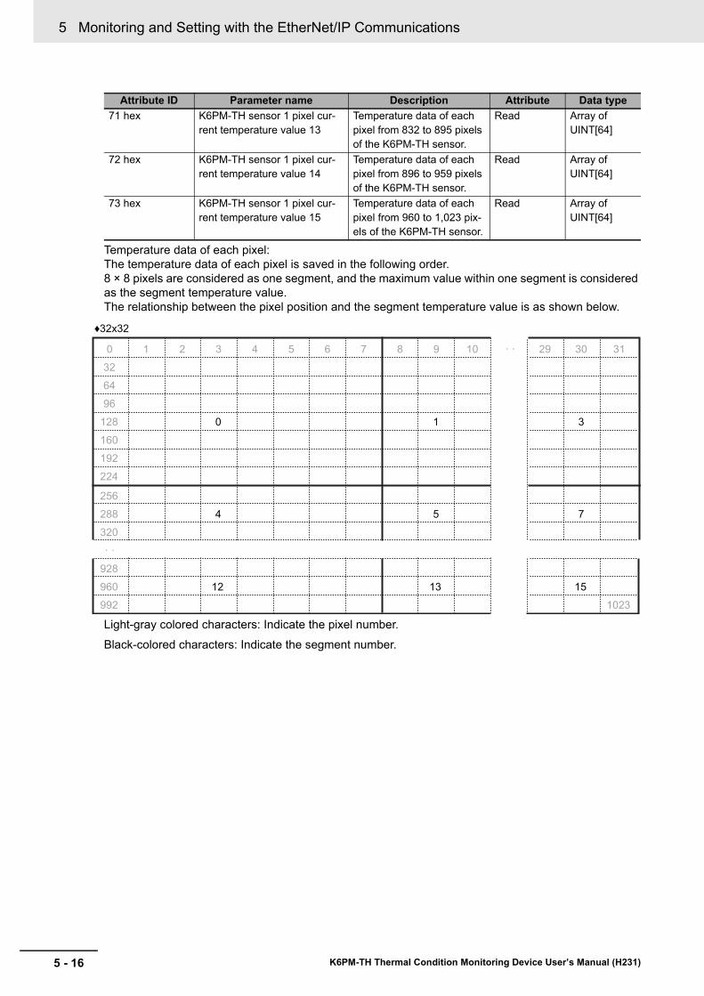
5 Monitoring and Setting with the EtherNet/IP Communications
5 - 16 K6PM-TH Thermal Condition Monitoring Device User’s Manual (H231)
Temperature data of each pixel:The temperature data of each pixel is saved in the following order.8 × 8 pixels are considered as one segment, and the maximum value within one segment is considered as the segment temperature value.The relationship between the pixel position and the segment temperature value is as shown below.
Light-gray colored characters: Indicate the pixel number.Black-colored characters: Indicate the segment number.
71 hex K6PM-TH sensor 1 pixel cur-rent temperature value 13
Temperature data of each pixel from 832 to 895 pixels of the K6PM-TH sensor.
Read Array of UINT[64]
72 hex K6PM-TH sensor 1 pixel cur-rent temperature value 14
Temperature data of each pixel from 896 to 959 pixels of the K6PM-TH sensor.
Read Array of UINT[64]
73 hex K6PM-TH sensor 1 pixel cur-rent temperature value 15
Temperature data of each pixel from 960 to 1,023 pix-els of the K6PM-TH sensor.
Read Array of UINT[64]
Attribute ID Parameter name Description Attribute Data type
0 1 2 3 4 5 6 7 8 9 10 · · 29 30 31
32
64
96
128 0 1 3
160
192
224
256
288 4 5 7
320
· ·
928
960 12 13 15
992 1023
♦32x32
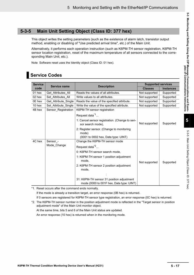
5 - 17
5 Monitoring and Setting with the EtherNet/IP Communications
K6PM-TH Thermal Condition Monitoring Device User’s Manual (H231)
5-3 Monitoring and Setting U
sing the CIP M
essage Com
munications and Exam
-ples of C
omm
unications Instructions
5
5-3-5 Main U
nit Setting Object (C
lass ID: 377 hex)
This object writes the setting parameters (such as the existence of alarm latch, transistor output method, enabling or disabling of "Use predicted arrival time", etc.) of the Main Unit.Alternatively, it performs each operation instruction (such as K6PM-TH sensor registration, K6PM-TH sensor location registration, reset of the maximum temperature of all sensors connected to the corre-sponding Main Unit, etc.).
Note Software reset uses the Identity object (Class ID: 01 hex).
5-3-5 Main Unit Setting Object (Class ID: 377 hex)
Service Codes
Service code Service name Description
Supported servicesClasses Instances
01 hex Get_Attributes_All Reads the values of all attributes. Not supported Supported02 hex Set_Attributes_All Write values to all attributes. Not supported Supported0E hex Get_Attribute_Single Reads the value of the specified attribute. Not supported Supported10 hex Set_Attribute_Single Write the value of the specified attribute. Not supported Supported4B hex Sensor_Registration K6PM-TH sensor registration
Request data*1...1: Cancel sensor registration. (Change to sen-
sor search mode),2: Register sensor. (Change to monitoring
mode)(0001 to 0002 hex, Data type: UINT)
*1. Reset occurs after the command ends normally.If the mode is already a transition target, an error response (0B hex) is returned.If 0 sensors are registered for K6PM-TH sensor type registration, an error response (0C hex) is returned.
Not supported Supported
4C hex Sensor_-Mode_Change
Change the K6PM-TH sensor mode
Request data*2...0: K6PM-TH sensor search mode,1: K6PM-TH sensor 1 position adjustment
mode,2: K6PM-TH sensor 2 position adjustment
mode,:
31: K6PM-TH sensor 31 position adjustment mode (0000 to 001F hex, Data type: UINT)
*2. The K6PM-TH sensor number in the position adjustment mode is reflected in the "Target sensor in position adjustment mode" of the Main Unit monitor object.At the same time, bits 5 and 6 of the Main Unit status are updated.An error response (10 hex) is returned when in the monitoring mode.
Not supported Supported
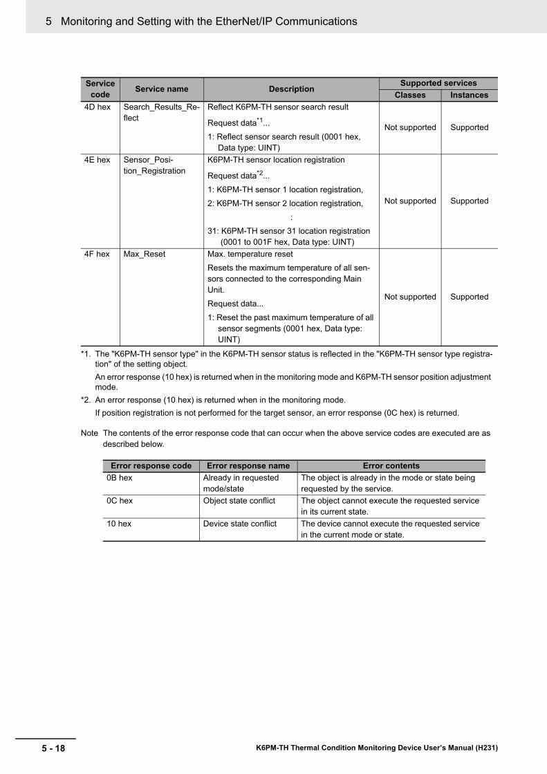
5 Monitoring and Setting with the EtherNet/IP Communications
5 - 18 K6PM-TH Thermal Condition Monitoring Device User’s Manual (H231)
Note The contents of the error response code that can occur when the above service codes are executed are as described below.
Service code Service name Description
Supported servicesClasses Instances
4D hex Search_Results_Re-flect
Reflect K6PM-TH sensor search result
Request data*1...1: Reflect sensor search result (0001 hex,
Data type: UINT)
*1. The "K6PM-TH sensor type" in the K6PM-TH sensor status is reflected in the "K6PM-TH sensor type registra-tion" of the setting object.An error response (10 hex) is returned when in the monitoring mode and K6PM-TH sensor position adjustment mode.
Not supported Supported
4E hex Sensor_Posi-tion_Registration
K6PM-TH sensor location registration
Request data*2...1: K6PM-TH sensor 1 location registration,2: K6PM-TH sensor 2 location registration,
:31: K6PM-TH sensor 31 location registration
(0001 to 001F hex, Data type: UINT)
*2. An error response (10 hex) is returned when in the monitoring mode.If position registration is not performed for the target sensor, an error response (0C hex) is returned.
Not supported Supported
4F hex Max_Reset Max. temperature resetResets the maximum temperature of all sen-sors connected to the corresponding Main Unit.Request data...1: Reset the past maximum temperature of all
sensor segments (0001 hex, Data type: UINT)
Not supported Supported
Error response code Error response name Error contents0B hex Already in requested
mode/stateThe object is already in the mode or state being requested by the service.
0C hex Object state conflict The object cannot execute the requested service in its current state.
10 hex Device state conflict The device cannot execute the requested service in the current mode or state.
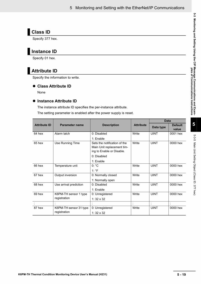
5 - 19
5 Monitoring and Setting with the EtherNet/IP Communications
K6PM-TH Thermal Condition Monitoring Device User’s Manual (H231)
5-3 Monitoring and Setting U
sing the CIP M
essage Com
munications and Exam
-ples of C
omm
unications Instructions
5
5-3-5 Main U
nit Setting Object (C
lass ID: 377 hex)
Specify 377 hex.
Specify 01 hex.
Specify the information to write.
Class Attribute IDNone
Instance Attribute IDThe instance attribute ID specifies the per-instance attribute.The setting parameter is enabled after the power supply is reset.
Class ID
Instance ID
Attribute ID
Attribute ID Parameter name Description AttributeData
Data type Default value
64 hex Alarm latch 0: Disabled1: Enable
Write UINT 0001 hex
65 hex Use Running Time Sets the notification of the Main Unit replacement tim-ing to Enable or Disable.0: Disabled1: Enable
Write UINT 0000 hex
66 hex Temperature unit 0: °C1: °F
Write UINT 0000 hex
67 hex Output inversion 0: Normally closed1: Normally open
Write UINT 0000 hex
68 hex Use arrival prediction 0: Disabled1: Enable
Write UINT 0000 hex
69 hex K6PM-TH sensor 1 type registration
0: Unregistered1: 32 x 32
Write UINT 0000 hex
: : : : : :87 hex K6PM-TH sensor 31 type
registration0: Unregistered1: 32 x 32
Write UINT 0000 hex
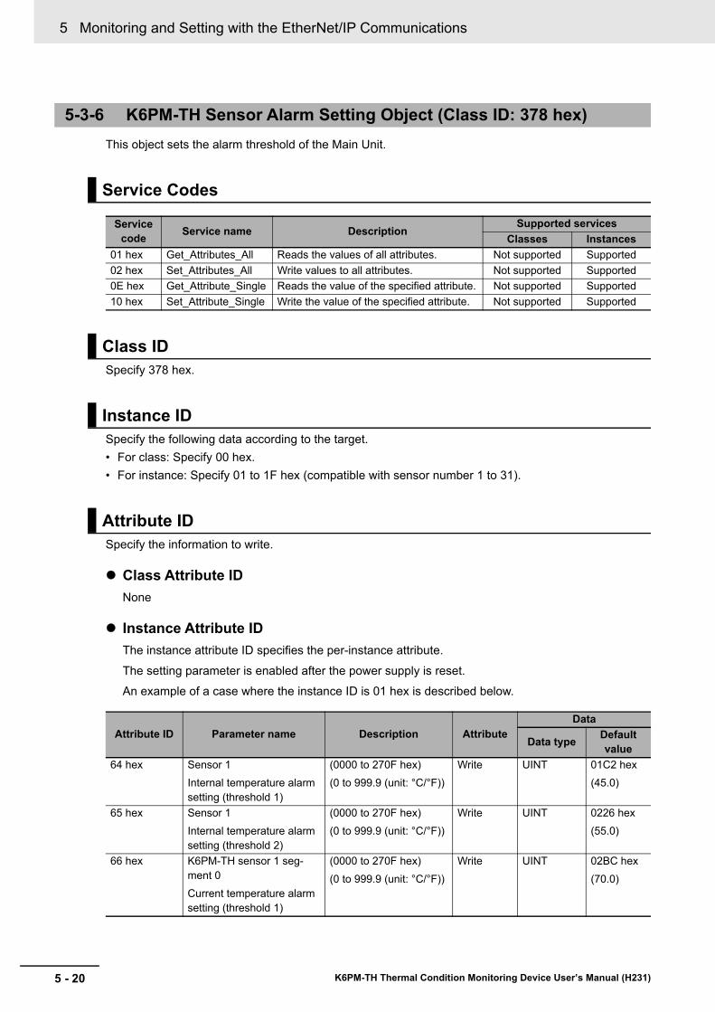
5 Monitoring and Setting with the EtherNet/IP Communications
5 - 20 K6PM-TH Thermal Condition Monitoring Device User’s Manual (H231)
This object sets the alarm threshold of the Main Unit.
Specify 378 hex.
Specify the following data according to the target.• For class: Specify 00 hex.• For instance: Specify 01 to 1F hex (compatible with sensor number 1 to 31).
Specify the information to write.
Class Attribute IDNone
Instance Attribute IDThe instance attribute ID specifies the per-instance attribute.
The setting parameter is enabled after the power supply is reset.An example of a case where the instance ID is 01 hex is described below.
5-3-6 K6PM-TH Sensor Alarm Setting Object (Class ID: 378 hex)
Service Codes
Service code Service name Description
Supported servicesClasses Instances
01 hex Get_Attributes_All Reads the values of all attributes. Not supported Supported02 hex Set_Attributes_All Write values to all attributes. Not supported Supported0E hex Get_Attribute_Single Reads the value of the specified attribute. Not supported Supported10 hex Set_Attribute_Single Write the value of the specified attribute. Not supported Supported
Class ID
Instance ID
Attribute ID
Attribute ID Parameter name Description AttributeData
Data type Default value
64 hex Sensor 1Internal temperature alarm setting (threshold 1)
(0000 to 270F hex)(0 to 999.9 (unit: °C/°F))
Write UINT 01C2 hex(45.0)
65 hex Sensor 1Internal temperature alarm setting (threshold 2)
(0000 to 270F hex)(0 to 999.9 (unit: °C/°F))
Write UINT 0226 hex(55.0)
66 hex K6PM-TH sensor 1 seg-ment 0Current temperature alarm setting (threshold 1)
(0000 to 270F hex)(0 to 999.9 (unit: °C/°F))
Write UINT 02BC hex(70.0)
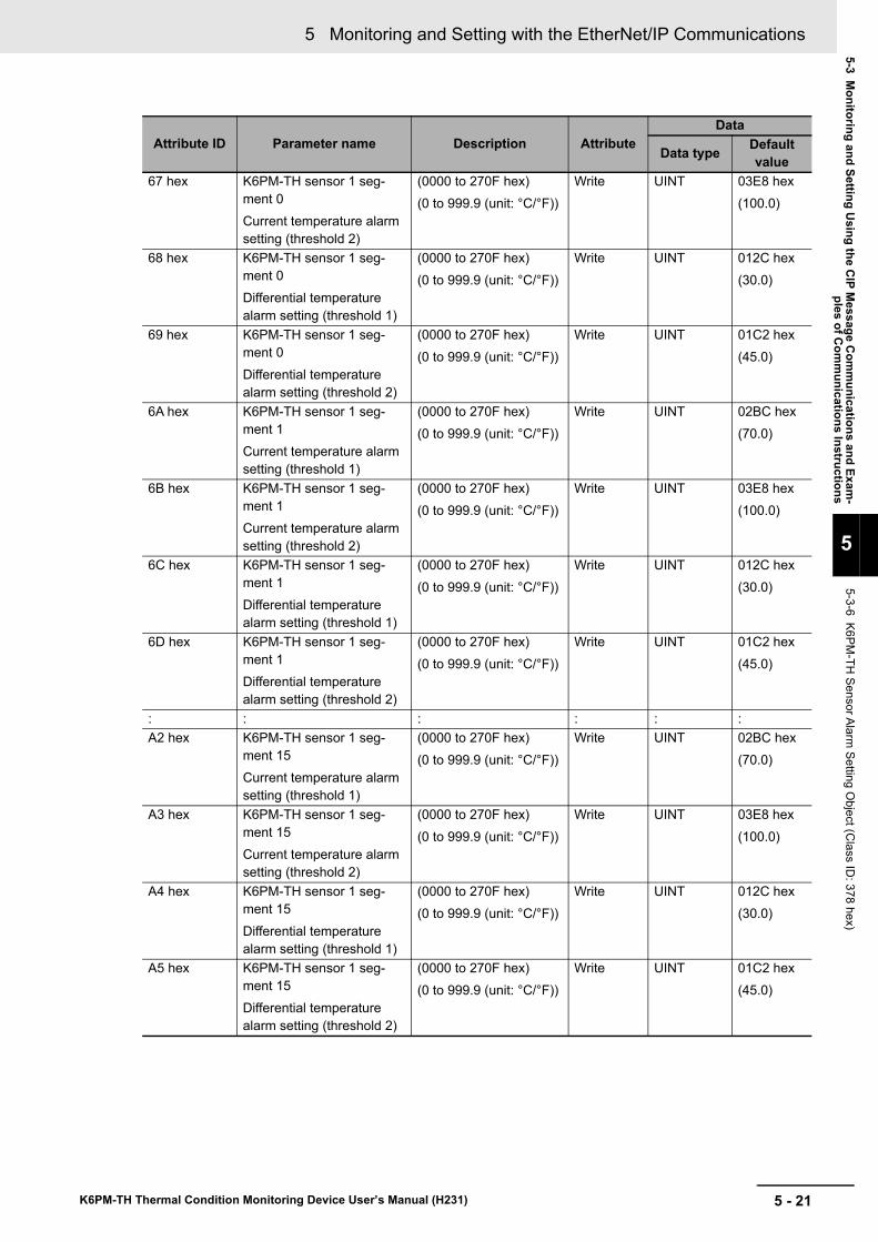
5 - 21
5 Monitoring and Setting with the EtherNet/IP Communications
K6PM-TH Thermal Condition Monitoring Device User’s Manual (H231)
5-3 Monitoring and Setting U
sing the CIP M
essage Com
munications and Exam
-ples of C
omm
unications Instructions
5
5-3-6 K6PM-TH
Sensor Alarm Setting O
bject (Class ID
: 378 hex)
67 hex K6PM-TH sensor 1 seg-ment 0Current temperature alarm setting (threshold 2)
(0000 to 270F hex)(0 to 999.9 (unit: °C/°F))
Write UINT 03E8 hex(100.0)
68 hex K6PM-TH sensor 1 seg-ment 0Differential temperature alarm setting (threshold 1)
(0000 to 270F hex)(0 to 999.9 (unit: °C/°F))
Write UINT 012C hex(30.0)
69 hex K6PM-TH sensor 1 seg-ment 0Differential temperature alarm setting (threshold 2)
(0000 to 270F hex)(0 to 999.9 (unit: °C/°F))
Write UINT 01C2 hex(45.0)
6A hex K6PM-TH sensor 1 seg-ment 1Current temperature alarm setting (threshold 1)
(0000 to 270F hex)(0 to 999.9 (unit: °C/°F))
Write UINT 02BC hex(70.0)
6B hex K6PM-TH sensor 1 seg-ment 1Current temperature alarm setting (threshold 2)
(0000 to 270F hex)(0 to 999.9 (unit: °C/°F))
Write UINT 03E8 hex(100.0)
6C hex K6PM-TH sensor 1 seg-ment 1Differential temperature alarm setting (threshold 1)
(0000 to 270F hex)(0 to 999.9 (unit: °C/°F))
Write UINT 012C hex(30.0)
6D hex K6PM-TH sensor 1 seg-ment 1Differential temperature alarm setting (threshold 2)
(0000 to 270F hex)(0 to 999.9 (unit: °C/°F))
Write UINT 01C2 hex(45.0)
: : : : : :A2 hex K6PM-TH sensor 1 seg-
ment 15Current temperature alarm setting (threshold 1)
(0000 to 270F hex)(0 to 999.9 (unit: °C/°F))
Write UINT 02BC hex(70.0)
A3 hex K6PM-TH sensor 1 seg-ment 15Current temperature alarm setting (threshold 2)
(0000 to 270F hex)(0 to 999.9 (unit: °C/°F))
Write UINT 03E8 hex(100.0)
A4 hex K6PM-TH sensor 1 seg-ment 15Differential temperature alarm setting (threshold 1)
(0000 to 270F hex)(0 to 999.9 (unit: °C/°F))
Write UINT 012C hex(30.0)
A5 hex K6PM-TH sensor 1 seg-ment 15Differential temperature alarm setting (threshold 2)
(0000 to 270F hex)(0 to 999.9 (unit: °C/°F))
Write UINT 01C2 hex(45.0)
Attribute ID Parameter name Description AttributeData
Data type Default value
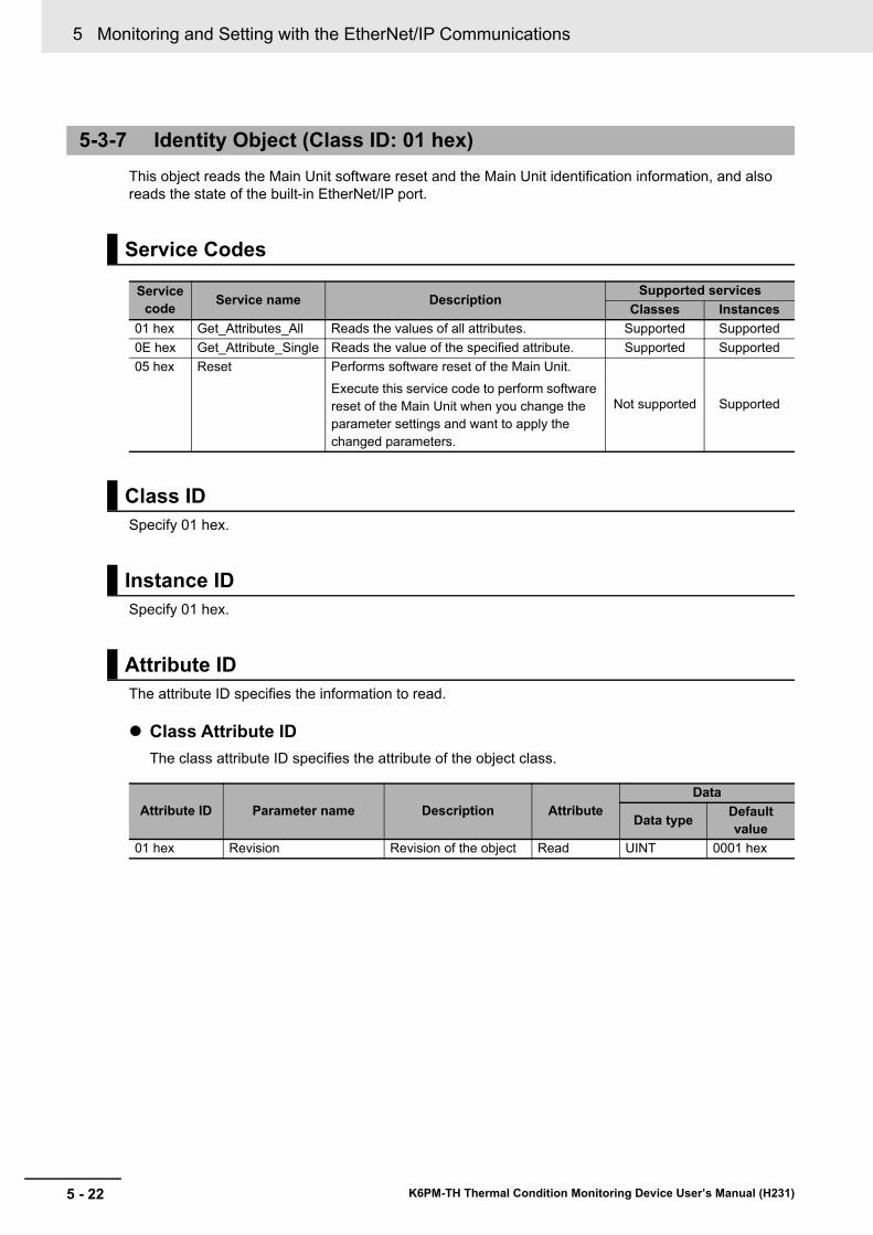
5 Monitoring and Setting with the EtherNet/IP Communications
5 - 22 K6PM-TH Thermal Condition Monitoring Device User’s Manual (H231)
This object reads the Main Unit software reset and the Main Unit identification information, and also reads the state of the built-in EtherNet/IP port.
Specify 01 hex.
Specify 01 hex.
The attribute ID specifies the information to read.
Class Attribute IDThe class attribute ID specifies the attribute of the object class.
5-3-7 Identity Object (Class ID: 01 hex)
Service Codes
Service code Service name Description
Supported servicesClasses Instances
01 hex Get_Attributes_All Reads the values of all attributes. Supported Supported0E hex Get_Attribute_Single Reads the value of the specified attribute. Supported Supported05 hex Reset Performs software reset of the Main Unit.
Execute this service code to perform software reset of the Main Unit when you change the parameter settings and want to apply the changed parameters.
Not supported Supported
Class ID
Instance ID
Attribute ID
Attribute ID Parameter name Description AttributeData
Data type Default value
01 hex Revision Revision of the object Read UINT 0001 hex
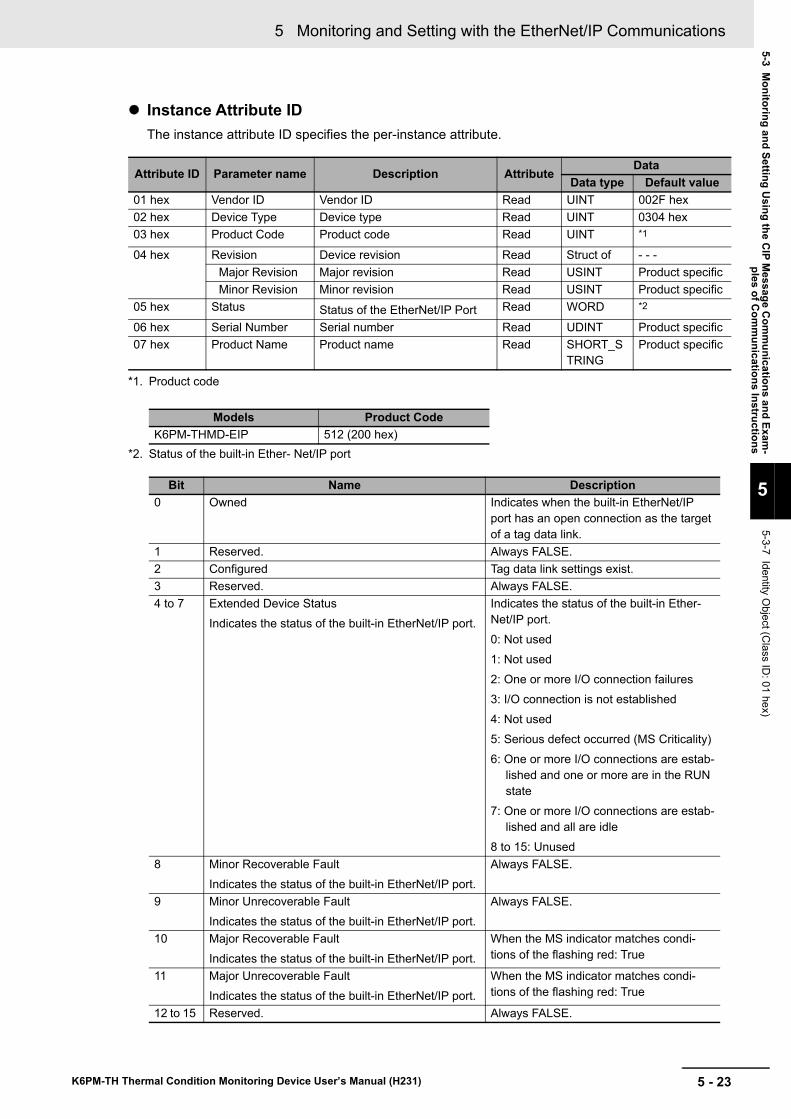
5 - 23
5 Monitoring and Setting with the EtherNet/IP Communications
K6PM-TH Thermal Condition Monitoring Device User’s Manual (H231)
5-3 Monitoring and Setting U
sing the CIP M
essage Com
munications and Exam
-ples of C
omm
unications Instructions
5
5-3-7 Identity Object (C
lass ID: 01 hex)
Instance Attribute IDThe instance attribute ID specifies the per-instance attribute.
*2. Status of the built-in Ether- Net/IP port
Attribute ID Parameter name Description AttributeData
Data type Default value01 hex Vendor ID Vendor ID Read UINT 002F hex02 hex Device Type Device type Read UINT 0304 hex03 hex Product Code Product code Read UINT *1
*1. Product code
04 hex Revision Device revision Read Struct of - - -Major Revision Major revision Read USINT Product specificMinor Revision Minor revision Read USINT Product specific
05 hex Status Status of the EtherNet/IP Port Read WORD *2
06 hex Serial Number Serial number Read UDINT Product specific07 hex Product Name Product name Read SHORT_S
TRINGProduct specific
Models Product CodeK6PM-THMD-EIP 512 (200 hex)
Bit Name Description0 Owned Indicates when the built-in EtherNet/IP
port has an open connection as the target of a tag data link.
1 Reserved. Always FALSE.2 Configured Tag data link settings exist.3 Reserved. Always FALSE.4 to 7 Extended Device Status
Indicates the status of the built-in EtherNet/IP port. Indicates the status of the built-in Ether-Net/IP port.0: Not used1: Not used2: One or more I/O connection failures3: I/O connection is not established4: Not used5: Serious defect occurred (MS Criticality)6: One or more I/O connections are estab-
lished and one or more are in the RUN state
7: One or more I/O connections are estab-lished and all are idle
8 to 15: Unused8 Minor Recoverable Fault
Indicates the status of the built-in EtherNet/IP port.Always FALSE.
9 Minor Unrecoverable Fault Indicates the status of the built-in EtherNet/IP port.
Always FALSE.
10 Major Recoverable Fault Indicates the status of the built-in EtherNet/IP port.
When the MS indicator matches condi-tions of the flashing red: True
11 Major Unrecoverable Fault Indicates the status of the built-in EtherNet/IP port.
When the MS indicator matches condi-tions of the flashing red: True
12 to 15 Reserved. Always FALSE.
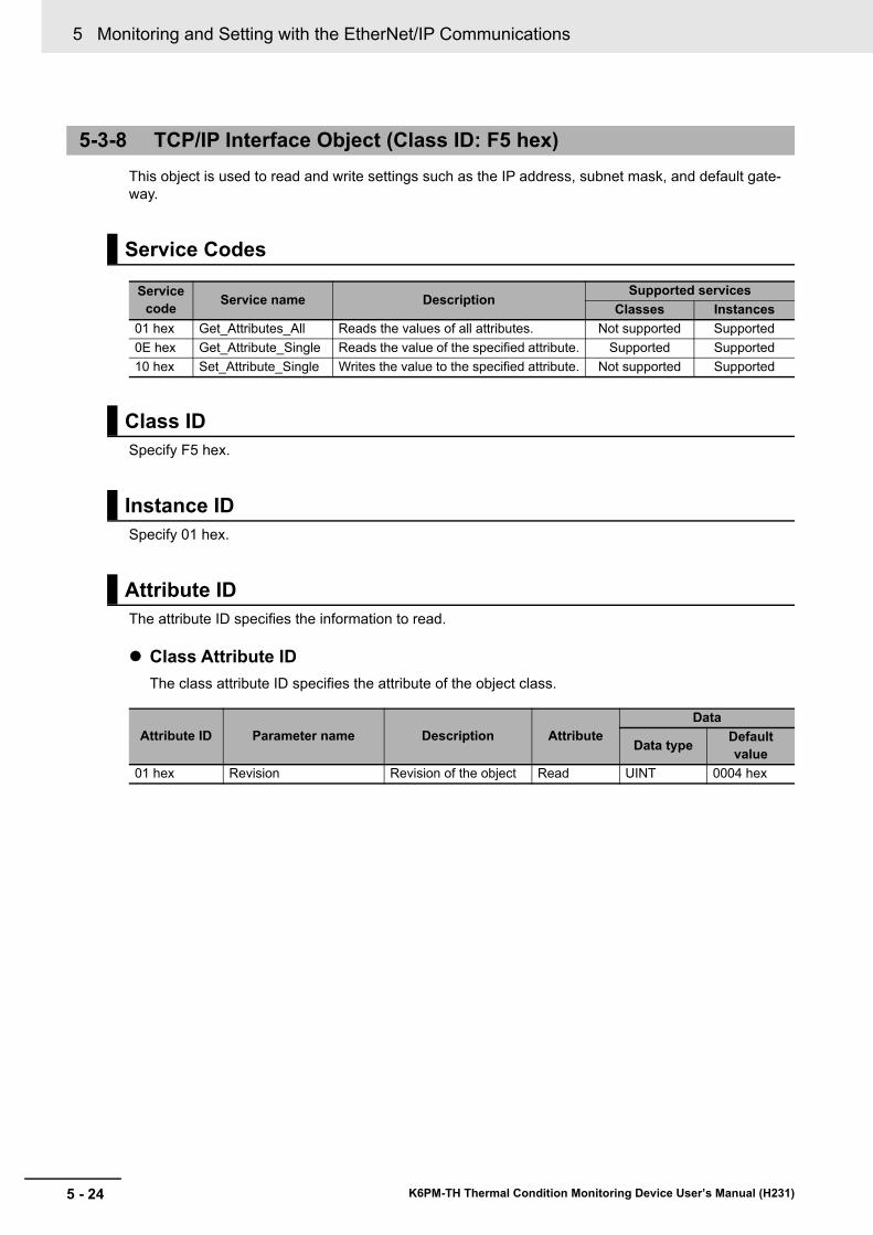
5 Monitoring and Setting with the EtherNet/IP Communications
5 - 24 K6PM-TH Thermal Condition Monitoring Device User’s Manual (H231)
This object is used to read and write settings such as the IP address, subnet mask, and default gate-way.
Specify F5 hex.
Specify 01 hex.
The attribute ID specifies the information to read.
Class Attribute IDThe class attribute ID specifies the attribute of the object class.
5-3-8 TCP/IP Interface Object (Class ID: F5 hex)
Service Codes
Service code Service name Description
Supported servicesClasses Instances
01 hex Get_Attributes_All Reads the values of all attributes. Not supported Supported0E hex Get_Attribute_Single Reads the value of the specified attribute. Supported Supported10 hex Set_Attribute_Single Writes the value to the specified attribute. Not supported Supported
Class ID
Instance ID
Attribute ID
Attribute ID Parameter name Description AttributeData
Data type Default value
01 hex Revision Revision of the object Read UINT 0004 hex
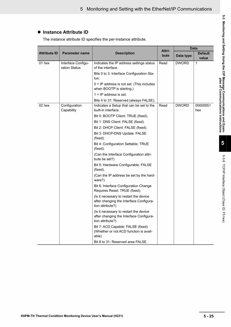
5 - 25
5 Monitoring and Setting with the EtherNet/IP Communications
K6PM-TH Thermal Condition Monitoring Device User’s Manual (H231)
5-3 Monitoring and Setting U
sing the CIP M
essage Com
munications and Exam
-ples of C
omm
unications Instructions
5
5-3-8 TCP/IP Interface O
bject (Class ID
: F5 hex)
Instance Attribute IDThe instance attribute ID specifies the per-instance attribute.
Attribute ID Parameter name Description Attri-bute
Data
Data type Default value
01 hex Interface Configu-ration Status
Indicates the IP address settings status of the interface.Bits 0 to 3: Interface Configuration Sta-tus:0 = IP address is not set. (This includes when BOOTP is starting.)1 = IP address is set.Bits 4 to 31: Reserved (always FALSE).
Read DWORD 1
02 hex Configuration Capability
Indicates a Setup that can be set to the built-in interface.Bit 0: BOOTP Client: TRUE (fixed).Bit 1: DNS Client: FALSE (fixed).Bit 2: DHCP Client: FALSE (fixed).Bit 3: DHCP-DNS Update: FALSE (fixed).Bit 4: Configuration Settable: TRUE (fixed).(Can the Interface Configuration attri-bute be set?)Bit 5: Hardware Configurable: FALSE (fixed).(Can the IP address be set by the hard-ware?)Bit 6: Interface Configuration Change Requires Reset: TRUE (fixed).(Is it necessary to restart the device after changing the Interface Configura-tion attribute?)(Is it necessary to restart the device after changing the Interface Configura-tion attribute?)Bit 7: ACD Capable: FALSE (fixed)(Whether or not ACD function is avail-able)Bit 8 to 31: Reserved area FALSE.
Read DWORD 00000051 hex
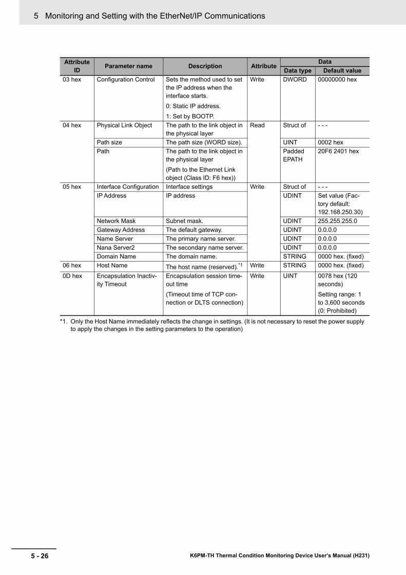
5 Monitoring and Setting with the EtherNet/IP Communications
5 - 26 K6PM-TH Thermal Condition Monitoring Device User’s Manual (H231)
Attribute ID Parameter name Description Attribute
DataData type Default value
03 hex Configuration Control Sets the method used to set the IP address when the interface starts.0: Static IP address.1: Set by BOOTP.
Write DWORD 00000000 hex
04 hex Physical Link Object The path to the link object in the physical layer
Read Struct of - - -
Path size The path size (WORD size). UINT 0002 hexPath The path to the link object in
the physical layer(Path to the Ethernet Link object (Class ID: F6 hex))
Padded EPATH
20F6 2401 hex
05 hex Interface Configuration Interface settings Write Struct of - - -IP Address IP address UDINT Set value (Fac-
tory default: 192.168.250.30)
Network Mask Subnet mask. UDINT 255.255.255.0Gateway Address The default gateway. UDINT 0.0.0.0Name Server The primary name server. UDINT 0.0.0.0Nana Server2 The secondary name server. UDINT 0.0.0.0Domain Name The domain name. STRING 0000 hex. (fixed)
06 hex Host Name The host name (reserved).*1
*1. Only the Host Name immediately reflects the change in settings. (It is not necessary to reset the power supply to apply the changes in the setting parameters to the operation)
Write STRING 0000 hex. (fixed)
0D hex Encapsulation Inactiv-ity Timeout
Encapsulation session time-out time(Timeout time of TCP con-nection or DLTS connection)
Write UINT 0078 hex (120 seconds) Setting range: 1 to 3,600 seconds (0: Prohibited)
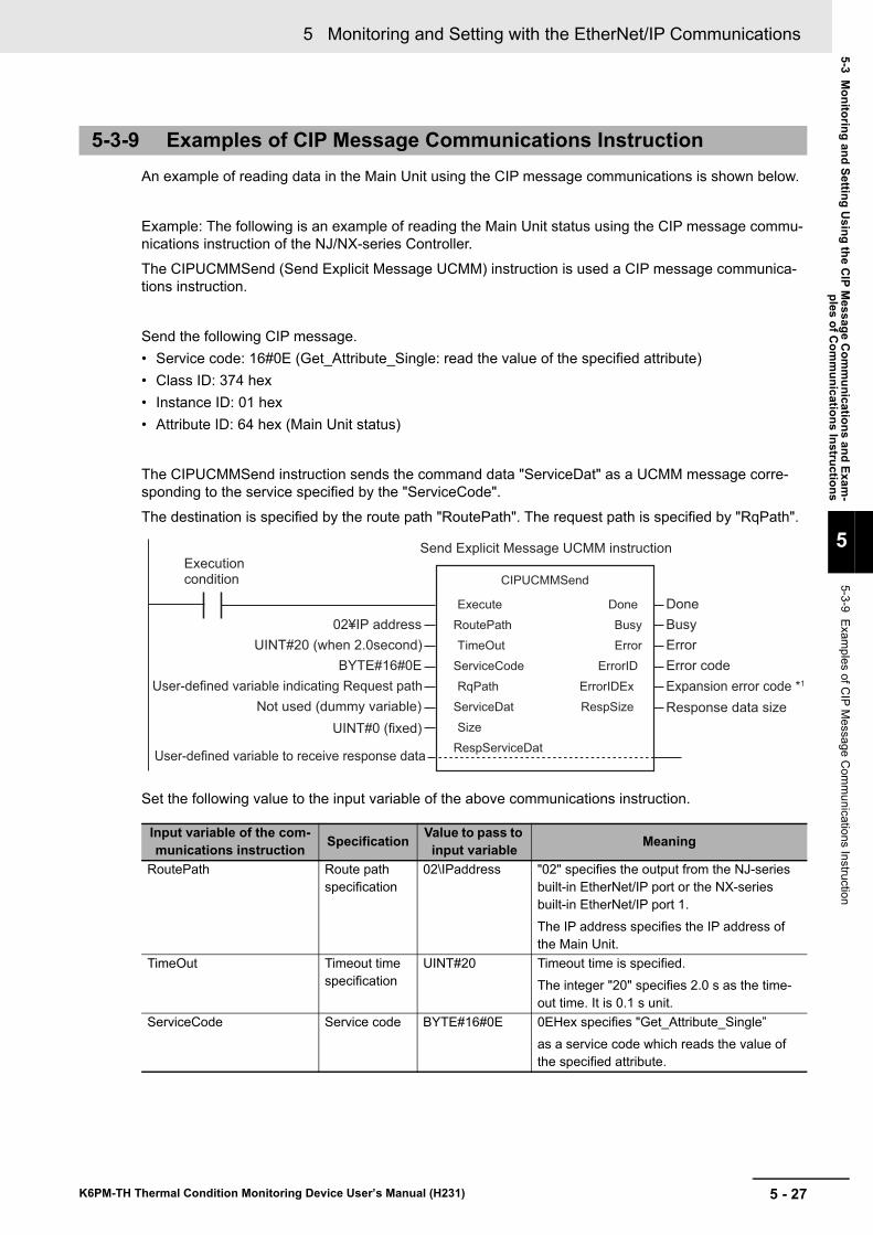
5 - 27
5 Monitoring and Setting with the EtherNet/IP Communications
K6PM-TH Thermal Condition Monitoring Device User’s Manual (H231)
5-3 Monitoring and Setting U
sing the CIP M
essage Com
munications and Exam
-ples of C
omm
unications Instructions
5
5-3-9 Examples of C
IP Message C
omm
unications Instruction
An example of reading data in the Main Unit using the CIP message communications is shown below.
Example: The following is an example of reading the Main Unit status using the CIP message commu-nications instruction of the NJ/NX-series Controller.The CIPUCMMSend (Send Explicit Message UCMM) instruction is used a CIP message communica-tions instruction.
Send the following CIP message.• Service code: 16#0E (Get_Attribute_Single: read the value of the specified attribute)• Class ID: 374 hex• Instance ID: 01 hex• Attribute ID: 64 hex (Main Unit status)
The CIPUCMMSend instruction sends the command data "ServiceDat" as a UCMM message corre-sponding to the service specified by the "ServiceCode".
The destination is specified by the route path "RoutePath". The request path is specified by "RqPath".
Set the following value to the input variable of the above communications instruction.
5-3-9 Examples of CIP Message Communications Instruction
Input variable of the com-munications instruction Specification Value to pass to
input variable Meaning
RoutePath Route path specification
02\IPaddress "02" specifies the output from the NJ-series built-in EtherNet/IP port or the NX-series built-in EtherNet/IP port 1.The IP address specifies the IP address of the Main Unit.
TimeOut Timeout time specification
UINT#20 Timeout time is specified.The integer "20" specifies 2.0 s as the time-out time. It is 0.1 s unit.
ServiceCode Service code BYTE#16#0E 0EHex specifies "Get_Attribute_Single”as a service code which reads the value of the specified attribute.
CIPUCMMSend
Execute Done
RoutePath Busy
TimeOut Error
ServiceCode ErrorID
RqPath ErrorIDEx
ServiceDat RespSize
Size
RespServiceDat
02¥IP address
UINT#20 (when 2.0second)
BYTE#16#0E
Not used (dummy variable)
UINT#0 (fixed)
User-defined variable to receive response data
User-defined variable indicating Request path
Done
Busy
Error
Error code
Expansion error code *1
Response data size
Execution condition
Send Explicit Message UCMM instruction
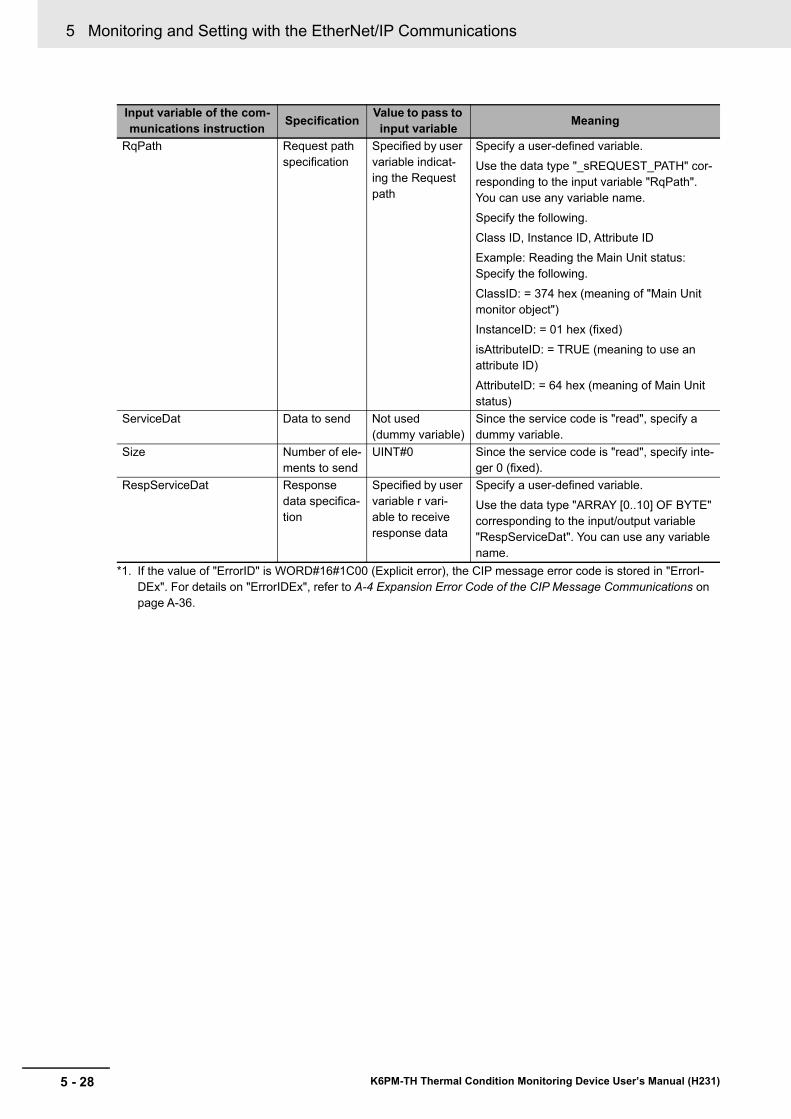
5 Monitoring and Setting with the EtherNet/IP Communications
5 - 28 K6PM-TH Thermal Condition Monitoring Device User’s Manual (H231)
*1. If the value of "ErrorID" is WORD#16#1C00 (Explicit error), the CIP message error code is stored in "ErrorI-DEx". For details on "ErrorIDEx", refer to A-4 Expansion Error Code of the CIP Message Communications on page A-36.
RqPath Request path specification
Specified by user variable indicat-ing the Request path
Specify a user-defined variable.Use the data type "_sREQUEST_PATH" cor-responding to the input variable "RqPath". You can use any variable name.Specify the following.Class ID, Instance ID, Attribute IDExample: Reading the Main Unit status: Specify the following.ClassID: = 374 hex (meaning of "Main Unit monitor object")InstanceID: = 01 hex (fixed)isAttributeID: = TRUE (meaning to use an attribute ID)AttributeID: = 64 hex (meaning of Main Unit status)
ServiceDat Data to send Not used (dummy variable)
Since the service code is "read", specify a dummy variable.
Size Number of ele-ments to send
UINT#0 Since the service code is "read", specify inte-ger 0 (fixed).
RespServiceDat Response data specifica-tion
Specified by user variable r vari-able to receive response data
Specify a user-defined variable.Use the data type "ARRAY [0..10] OF BYTE" corresponding to the input/output variable "RespServiceDat". You can use any variable name.
Input variable of the com-munications instruction Specification Value to pass to
input variable Meaning
6 - 1
6
K6PM-TH Thermal Condition Monitoring Device User’s Manual (H231)
Main Units can also be monitored or set using Modbus TCP compatible devices. This section describes how to monitor using the EtherNet/IP.
6-1 Outline . . . . . . . . . . . . . . . . . . . . . . . . . . . . . . . . . . . . . . . . . . . . . . . . . . . . . . . 6-26-2 Function Codes . . . . . . . . . . . . . . . . . . . . . . . . . . . . . . . . . . . . . . . . . . . . . . . 6-3
6-2-1 Function Code List . . . . . . . . . . . . . . . . . . . . . . . . . . . . . . . . . . . . . . . . . . . . . . 6-36-2-2 03 hex: Reading of Multiple Registers . . . . . . . . . . . . . . . . . . . . . . . . . . . . . . . 6-36-2-3 06 hex: Operation Command . . . . . . . . . . . . . . . . . . . . . . . . . . . . . . . . . . . . . . 6-56-2-4 10 hex: Writing of Multiple Registers . . . . . . . . . . . . . . . . . . . . . . . . . . . . . . . . 6-66-2-5 Exception Code List . . . . . . . . . . . . . . . . . . . . . . . . . . . . . . . . . . . . . . . . . . . . . 6-7
6-3 Register Address Lists . . . . . . . . . . . . . . . . . . . . . . . . . . . . . . . . . . . . . . . . . 6-86-3-1 Main Unit Monitor . . . . . . . . . . . . . . . . . . . . . . . . . . . . . . . . . . . . . . . . . . . . . . . 6-86-3-2 K6PM-TH Sensor Temperature Monitor (1 to 31) . . . . . . . . . . . . . . . . . . . . . . . 6-96-3-3 Main Unit Setting . . . . . . . . . . . . . . . . . . . . . . . . . . . . . . . . . . . . . . . . . . . . . . 6-126-3-4 Product Information . . . . . . . . . . . . . . . . . . . . . . . . . . . . . . . . . . . . . . . . . . . . 6-146-3-5 IP Address . . . . . . . . . . . . . . . . . . . . . . . . . . . . . . . . . . . . . . . . . . . . . . . . . . . . 6-146-3-6 K6PM-TH Sensor Alarm Setting (1 to 31) . . . . . . . . . . . . . . . . . . . . . . . . . . . . 6-156-3-7 Operation Command . . . . . . . . . . . . . . . . . . . . . . . . . . . . . . . . . . . . . . . . . . . 6-18
Monitoring and Setting with the Modbus TCP
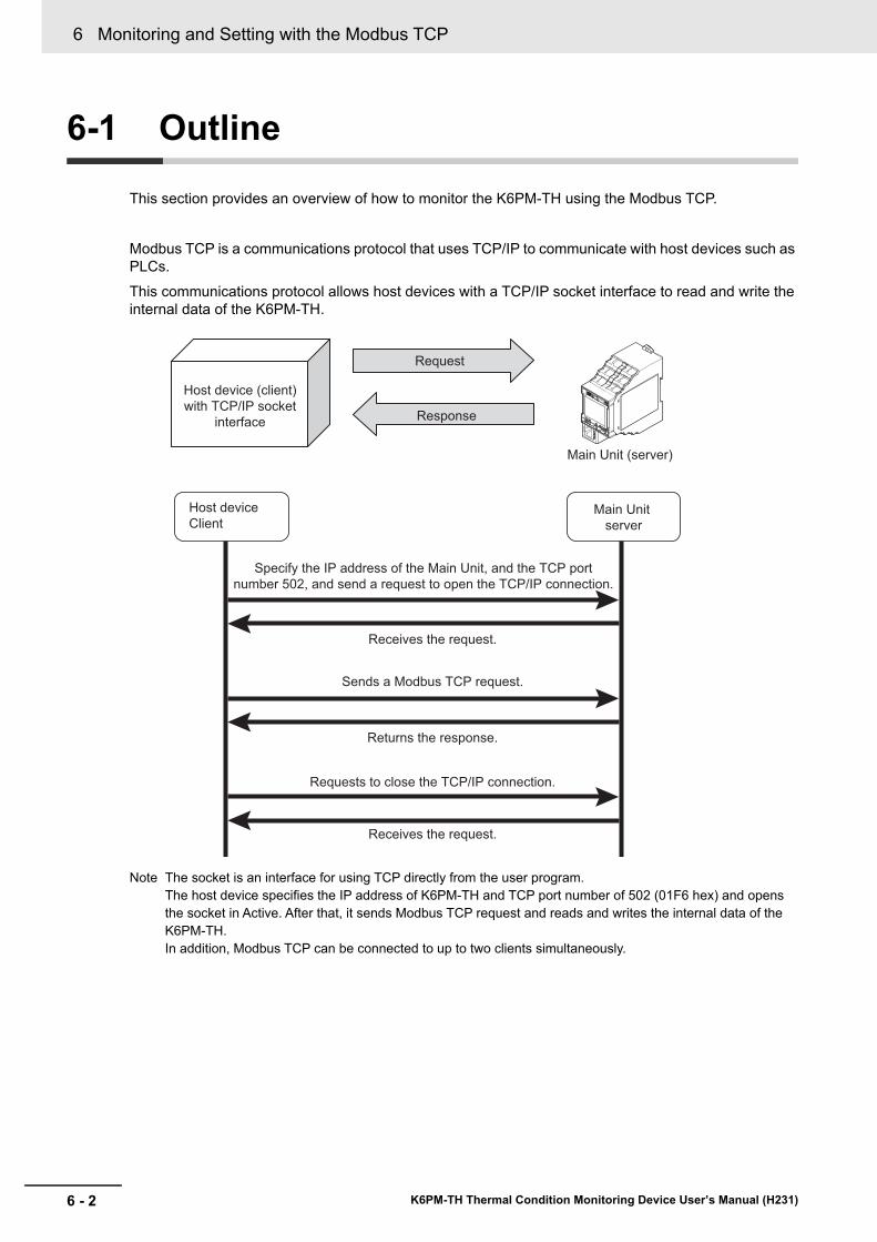
6 Monitoring and Setting with the Modbus TCP
6 - 2 K6PM-TH Thermal Condition Monitoring Device User’s Manual (H231)
6-1 Outline
This section provides an overview of how to monitor the K6PM-TH using the Modbus TCP.
Modbus TCP is a communications protocol that uses TCP/IP to communicate with host devices such as PLCs.This communications protocol allows host devices with a TCP/IP socket interface to read and write the internal data of the K6PM-TH.
Note The socket is an interface for using TCP directly from the user program.The host device specifies the IP address of K6PM-TH and TCP port number of 502 (01F6 hex) and opens the socket in Active. After that, it sends Modbus TCP request and reads and writes the internal data of the K6PM-TH.In addition, Modbus TCP can be connected to up to two clients simultaneously.
Request
Response
Main Unit (server)
Specify the IP address of the Main Unit, and the TCP port
number 502, and send a request to open the TCP/IP connection.
Receives the request.
Sends a Modbus TCP request.
Returns the response.
Requests to close the TCP/IP connection.
Receives the request.
Main Unit
server
Host device
Client
Host device (client)
with TCP/IP socket
interface
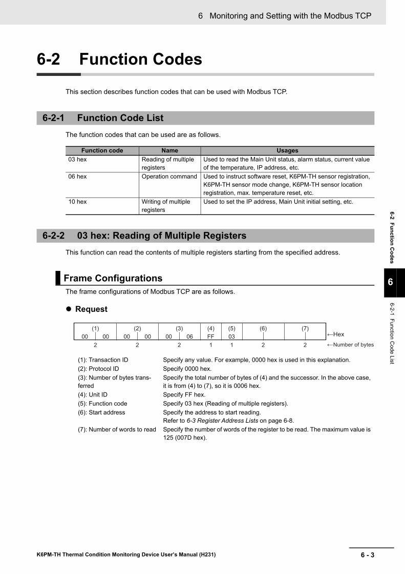
6 - 3
6 Monitoring and Setting with the Modbus TCP
K6PM-TH Thermal Condition Monitoring Device User’s Manual (H231)
6-2 Function Codes
6
6-2-1 Function Code List
6-2 Function Codes
This section describes function codes that can be used with Modbus TCP.
The function codes that can be used are as follows.
This function can read the contents of multiple registers starting from the specified address.
The frame configurations of Modbus TCP are as follows.
Request
6-2-1 Function Code List
Function code Name Usages03 hex Reading of multiple
registersUsed to read the Main Unit status, alarm status, current value of the temperature, IP address, etc.
06 hex Operation command Used to instruct software reset, K6PM-TH sensor registration, K6PM-TH sensor mode change, K6PM-TH sensor location registration, max. temperature reset, etc.
10 hex Writing of multiple registers
Used to set the IP address, Main Unit initial setting, etc.
6-2-2 03 hex: Reading of Multiple Registers
Frame Configurations
(1): Transaction ID Specify any value. For example, 0000 hex is used in this explanation.(2): Protocol ID Specify 0000 hex.(3): Number of bytes trans-ferred
Specify the total number of bytes of (4) and the successor. In the above case, it is from (4) to (7), so it is 0006 hex.
(4): Unit ID Specify FF hex.(5): Function code Specify 03 hex (Reading of multiple registers).(6): Start address Specify the address to start reading.
Refer to 6-3 Register Address Lists on page 6-8.(7): Number of words to read Specify the number of words of the register to be read. The maximum value is
125 (007D hex).
(1) (2) (3) (4) (5) (6) (7)
2 2 2 1 1 2 2
00 00 00 00 00 06 FF 03
←Number of bytes
←Hex
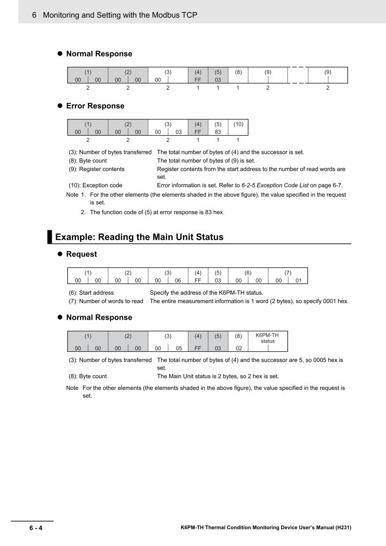
6 Monitoring and Setting with the Modbus TCP
6 - 4 K6PM-TH Thermal Condition Monitoring Device User’s Manual (H231)
Normal Response
Error Response
Note 1. For the other elements (the elements shaded in the above figure), the value specified in the request is set.
2. The function code of (5) at error response is 83 hex.
Request
Normal Response
Note For the other elements (the elements shaded in the above figure), the value specified in the request is set.
(3): Number of bytes transferred The total number of bytes of (4) and the successor is set.(8): Byte count The total number of bytes of (9) is set.(9): Register contents Register contents from the start address to the number of read words are
set.(10): Exception code Error information is set. Refer to 6-2-5 Exception Code List on page 6-7.
Example: Reading the Main Unit Status
(6): Start address Specify the address of the K6PM-TH status.(7): Number of words to read The entire measurement information is 1 word (2 bytes), so specify 0001 hex.
(3): Number of bytes transferred The total number of bytes of (4) and the successor are 5, so 0005 hex is set.
(8): Byte count The Main Unit status is 2 bytes, so 2 hex is set.
(1) (2) (3) (4) (5) (8) (9)
2 2 2 1 1 1 2
(9)
2
00 00 00 00 00 FF 03
(1) (2) (3) (4) (5) (10)
2 2 2 1 1 1
00 00 00 00 00 03 FF 83
(1) (2) (3) (4) (5) (6) (7)
00 00 00 00 00 00 00 0100 06 FF 03
(1) (2) (3) (4) (5) (8) K6PM-TH status
00 00 00 00 00 05 FF 03 02
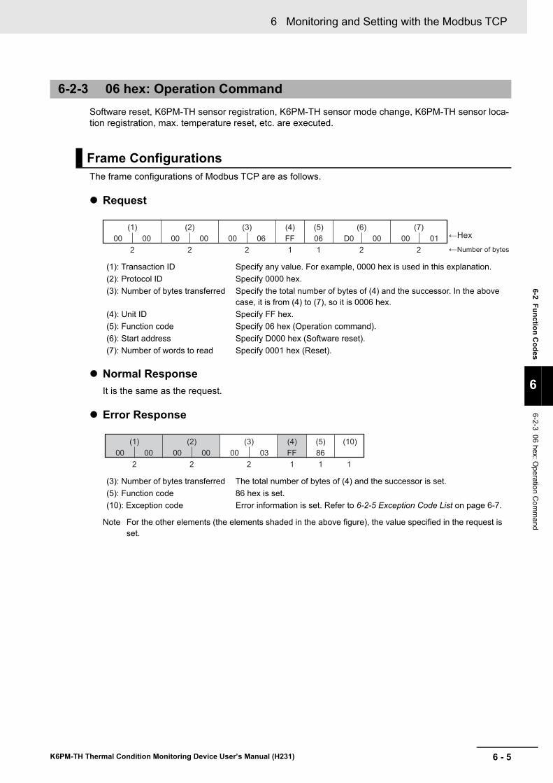
6 - 5
6 Monitoring and Setting with the Modbus TCP
K6PM-TH Thermal Condition Monitoring Device User’s Manual (H231)
6-2 Function Codes
6
6-2-3 06 hex: Operation C
omm
and
Software reset, K6PM-TH sensor registration, K6PM-TH sensor mode change, K6PM-TH sensor loca-tion registration, max. temperature reset, etc. are executed.
The frame configurations of Modbus TCP are as follows.
Request
Normal ResponseIt is the same as the request.
Error Response
Note For the other elements (the elements shaded in the above figure), the value specified in the request is set.
6-2-3 06 hex: Operation Command
Frame Configurations
(1): Transaction ID Specify any value. For example, 0000 hex is used in this explanation.(2): Protocol ID Specify 0000 hex.(3): Number of bytes transferred Specify the total number of bytes of (4) and the successor. In the above
case, it is from (4) to (7), so it is 0006 hex.(4): Unit ID Specify FF hex.(5): Function code Specify 06 hex (Operation command).(6): Start address Specify D000 hex (Software reset).(7): Number of words to read Specify 0001 hex (Reset).
(3): Number of bytes transferred The total number of bytes of (4) and the successor is set.(5): Function code 86 hex is set.(10): Exception code Error information is set. Refer to 6-2-5 Exception Code List on page 6-7.
(1) (2) (3) (4) (5) (6) (7)
2 2 2 1 1 2 2
00 00 00 00 00 06 FF 06
←Number of bytes
←HexD0 00 00 01
(1) (2) (3) (4) (5) (10)
2 2 2 1 1 1
00 00 00 00 00 03 FF 86
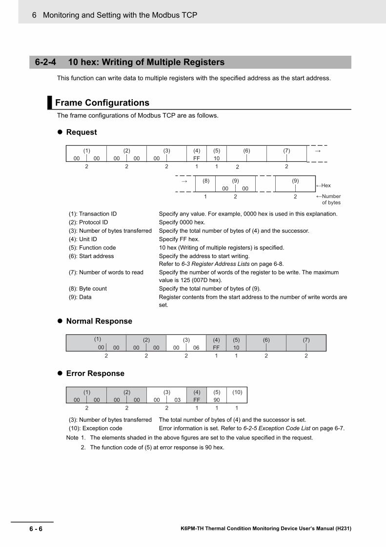
6 Monitoring and Setting with the Modbus TCP
6 - 6 K6PM-TH Thermal Condition Monitoring Device User’s Manual (H231)
This function can write data to multiple registers with the specified address as the start address.
The frame configurations of Modbus TCP are as follows.
Request
Normal Response
Error Response
Note 1. The elements shaded in the above figures are set to the value specified in the request.2. The function code of (5) at error response is 90 hex.
6-2-4 10 hex: Writing of Multiple Registers
Frame Configurations
(1): Transaction ID Specify any value. For example, 0000 hex is used in this explanation.(2): Protocol ID Specify 0000 hex.(3): Number of bytes transferred Specify the total number of bytes of (4) and the successor.(4): Unit ID Specify FF hex.(5): Function code 10 hex (Writing of multiple registers) is specified.(6): Start address Specify the address to start writing.
Refer to 6-3 Register Address Lists on page 6-8.(7): Number of words to read Specify the number of words of the register to be write. The maximum
value is 125 (007D hex).(8): Byte count Specify the total number of bytes of (9).(9): Data Register contents from the start address to the number of write words are
set.
(3): Number of bytes transferred The total number of bytes of (4) and the successor is set.(10): Exception code Error information is set. Refer to 6-2-5 Exception Code List on page 6-7.
(8) (9)
1 2
(9)
2
(1) (2) (3) (4) (5) (6) (7) →
→
2 2 2 1 1 22
00 00 00 00
00 00
00 FF 10
←Hex
←Number
of bytes
(1) (2) (3) (4) (5) (6) (7)
2 2 2 1 1 2 2
00 00 00 00 00 06 FF 10
(1) (2) (3) (4) (5) (10)
2 2 2 1 1 1
00 00 00 00 00 03 FF 90
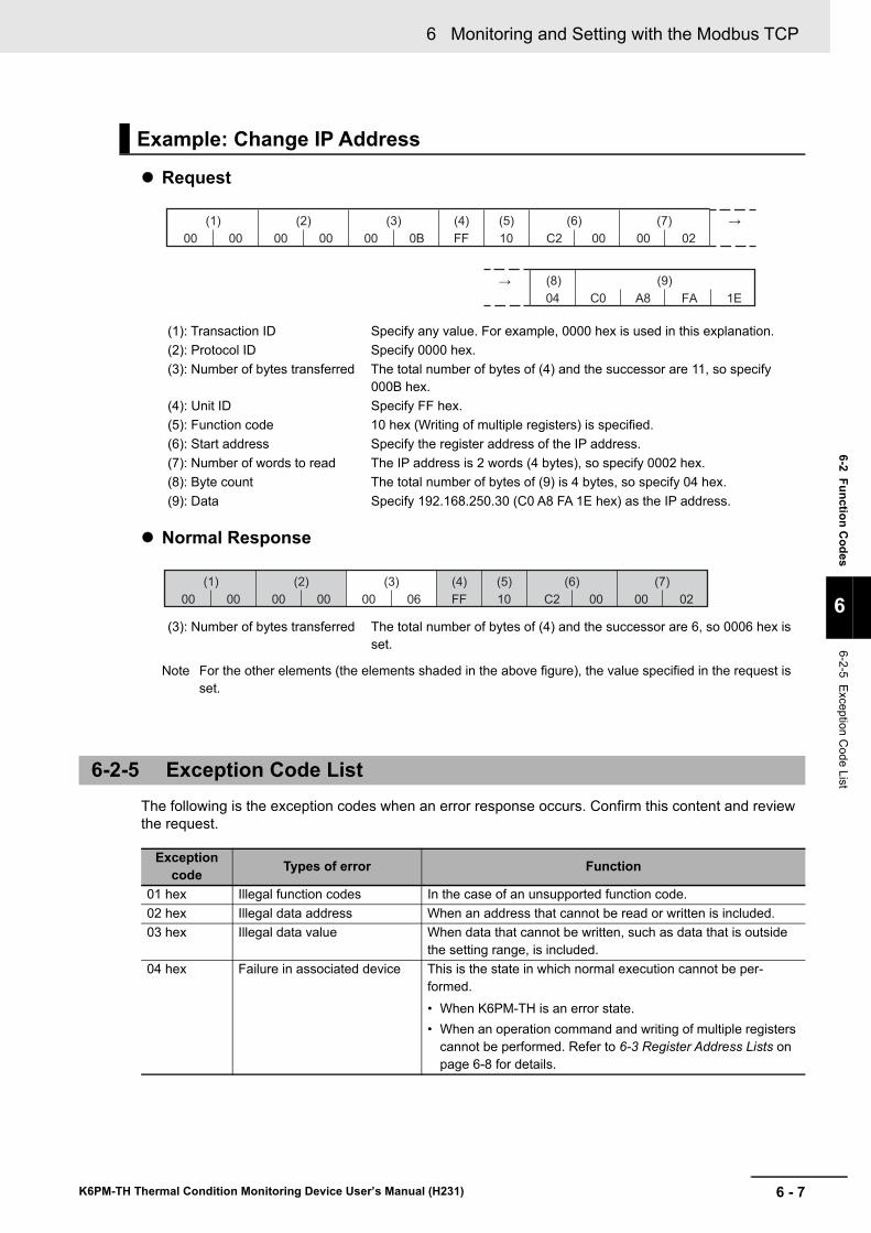
6 - 7
6 Monitoring and Setting with the Modbus TCP
K6PM-TH Thermal Condition Monitoring Device User’s Manual (H231)
6-2 Function Codes
6
6-2-5 Exception Code List
Request
Normal Response
Note For the other elements (the elements shaded in the above figure), the value specified in the request is set.
The following is the exception codes when an error response occurs. Confirm this content and review the request.
Example: Change IP Address
(1): Transaction ID Specify any value. For example, 0000 hex is used in this explanation.(2): Protocol ID Specify 0000 hex.(3): Number of bytes transferred The total number of bytes of (4) and the successor are 11, so specify
000B hex.(4): Unit ID Specify FF hex.(5): Function code 10 hex (Writing of multiple registers) is specified.(6): Start address Specify the register address of the IP address.(7): Number of words to read The IP address is 2 words (4 bytes), so specify 0002 hex.(8): Byte count The total number of bytes of (9) is 4 bytes, so specify 04 hex.(9): Data Specify 192.168.250.30 (C0 A8 FA 1E hex) as the IP address.
(3): Number of bytes transferred The total number of bytes of (4) and the successor are 6, so 0006 hex is set.
6-2-5 Exception Code List
Exception code Types of error Function
01 hex Illegal function codes In the case of an unsupported function code.02 hex Illegal data address When an address that cannot be read or written is included.03 hex Illegal data value When data that cannot be written, such as data that is outside
the setting range, is included.04 hex Failure in associated device This is the state in which normal execution cannot be per-
formed.• When K6PM-TH is an error state.• When an operation command and writing of multiple registers
cannot be performed. Refer to 6-3 Register Address Lists on page 6-8 for details.
(8) (9)
(1) (2) (3) (4) (5) (6) (7) →
→
00 00 00 00
C004 A8 FA 1E
00 0B C2 00 00 02FF 10
(1) (2) (3) (4) (5) (6) (7)
00 00 00 00 C2 00 00 0200 06 FF 10
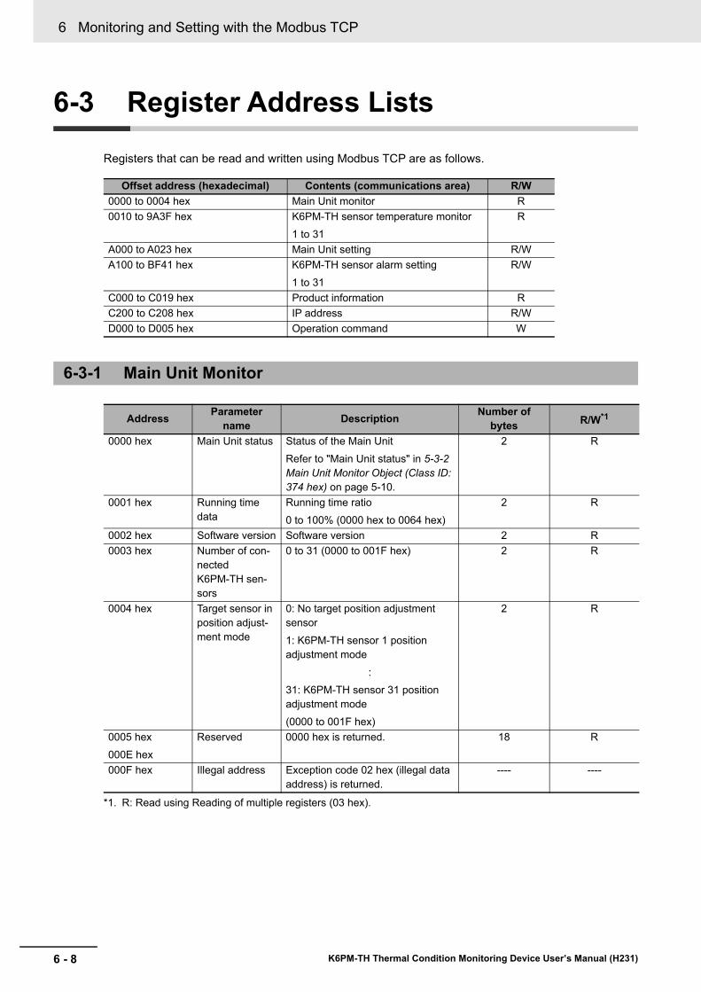
6 Monitoring and Setting with the Modbus TCP
6 - 8 K6PM-TH Thermal Condition Monitoring Device User’s Manual (H231)
6-3 Register Address Lists
Registers that can be read and written using Modbus TCP are as follows.
Offset address (hexadecimal) Contents (communications area) R/W0000 to 0004 hex Main Unit monitor R0010 to 9A3F hex K6PM-TH sensor temperature monitor
1 to 31R
A000 to A023 hex Main Unit setting R/WA100 to BF41 hex K6PM-TH sensor alarm setting
1 to 31R/W
C000 to C019 hex Product information RC200 to C208 hex IP address R/WD000 to D005 hex Operation command W
6-3-1 Main Unit Monitor
Address Parameter name Description Number of
bytes R/W*1
*1. R: Read using Reading of multiple registers (03 hex).
0000 hex Main Unit status Status of the Main UnitRefer to "Main Unit status" in 5-3-2 Main Unit Monitor Object (Class ID: 374 hex) on page 5-10.
2 R
0001 hex Running time data
Running time ratio0 to 100% (0000 hex to 0064 hex)
2 R
0002 hex Software version Software version 2 R0003 hex Number of con-
nected K6PM-TH sen-sors
0 to 31 (0000 to 001F hex) 2 R
0004 hex Target sensor in position adjust-ment mode
0: No target position adjustment sensor1: K6PM-TH sensor 1 position adjustment mode
:31: K6PM-TH sensor 31 position adjustment mode(0000 to 001F hex)
2 R
0005 hex000E hex
Reserved 0000 hex is returned. 18 R
000F hex Illegal address Exception code 02 hex (illegal data address) is returned.
---- ----
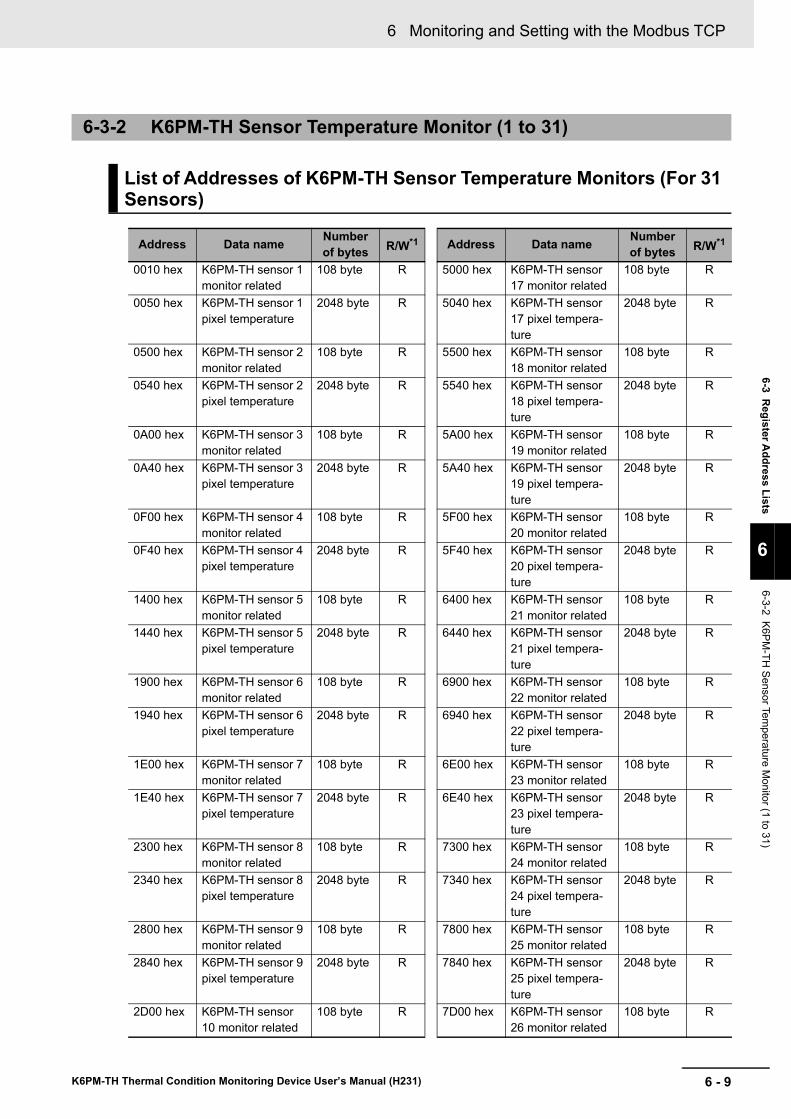
6 - 9
6 Monitoring and Setting with the Modbus TCP
K6PM-TH Thermal Condition Monitoring Device User’s Manual (H231)
6-3 Register A
ddress Lists
6
6-3-2 K6PM-TH
Sensor Temperature M
onitor (1 to 31)
6-3-2 K6PM-TH Sensor Temperature Monitor (1 to 31)
List of Addresses of K6PM-TH Sensor Temperature Monitors (For 31 Sensors)
Address Data name Number of bytes R/W*1 Address Data name Number
of bytes R/W*1
0010 hex K6PM-TH sensor 1 monitor related
108 byte R 5000 hex K6PM-TH sensor 17 monitor related
108 byte R
0050 hex K6PM-TH sensor 1 pixel temperature
2048 byte R 5040 hex K6PM-TH sensor 17 pixel tempera-ture
2048 byte R
0500 hex K6PM-TH sensor 2 monitor related
108 byte R 5500 hex K6PM-TH sensor 18 monitor related
108 byte R
0540 hex K6PM-TH sensor 2 pixel temperature
2048 byte R 5540 hex K6PM-TH sensor 18 pixel tempera-ture
2048 byte R
0A00 hex K6PM-TH sensor 3 monitor related
108 byte R 5A00 hex K6PM-TH sensor 19 monitor related
108 byte R
0A40 hex K6PM-TH sensor 3 pixel temperature
2048 byte R 5A40 hex K6PM-TH sensor 19 pixel tempera-ture
2048 byte R
0F00 hex K6PM-TH sensor 4 monitor related
108 byte R 5F00 hex K6PM-TH sensor 20 monitor related
108 byte R
0F40 hex K6PM-TH sensor 4 pixel temperature
2048 byte R 5F40 hex K6PM-TH sensor 20 pixel tempera-ture
2048 byte R
1400 hex K6PM-TH sensor 5 monitor related
108 byte R 6400 hex K6PM-TH sensor 21 monitor related
108 byte R
1440 hex K6PM-TH sensor 5 pixel temperature
2048 byte R 6440 hex K6PM-TH sensor 21 pixel tempera-ture
2048 byte R
1900 hex K6PM-TH sensor 6 monitor related
108 byte R 6900 hex K6PM-TH sensor 22 monitor related
108 byte R
1940 hex K6PM-TH sensor 6 pixel temperature
2048 byte R 6940 hex K6PM-TH sensor 22 pixel tempera-ture
2048 byte R
1E00 hex K6PM-TH sensor 7 monitor related
108 byte R 6E00 hex K6PM-TH sensor 23 monitor related
108 byte R
1E40 hex K6PM-TH sensor 7 pixel temperature
2048 byte R 6E40 hex K6PM-TH sensor 23 pixel tempera-ture
2048 byte R
2300 hex K6PM-TH sensor 8 monitor related
108 byte R 7300 hex K6PM-TH sensor 24 monitor related
108 byte R
2340 hex K6PM-TH sensor 8 pixel temperature
2048 byte R 7340 hex K6PM-TH sensor 24 pixel tempera-ture
2048 byte R
2800 hex K6PM-TH sensor 9 monitor related
108 byte R 7800 hex K6PM-TH sensor 25 monitor related
108 byte R
2840 hex K6PM-TH sensor 9 pixel temperature
2048 byte R 7840 hex K6PM-TH sensor 25 pixel tempera-ture
2048 byte R
2D00 hex K6PM-TH sensor 10 monitor related
108 byte R 7D00 hex K6PM-TH sensor 26 monitor related
108 byte R
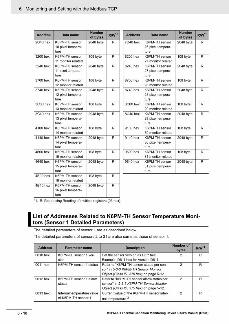
6 Monitoring and Setting with the Modbus TCP
6 - 10 K6PM-TH Thermal Condition Monitoring Device User’s Manual (H231)
The detailed parameters of sensor 1 are as described below.The detailed parameters of sensors 2 to 31 are also same as those of sensor 1.
2D40 hex K6PM-TH sensor 10 pixel tempera-ture
2048 byte R 7D40 hex K6PM-TH sensor 26 pixel tempera-ture
2048 byte R
3200 hex K6PM-TH sensor 11 monitor related
108 byte R 8200 hex K6PM-TH sensor 27 monitor related
108 byte R
3240 hex K6PM-TH sensor 11 pixel tempera-ture
2048 byte R 8240 hex K6PM-TH sensor 27 pixel tempera-ture
2048 byte R
3700 hex K6PM-TH sensor 12 monitor related
108 byte R 8700 hex K6PM-TH sensor 28 monitor related
108 byte R
3740 hex K6PM-TH sensor 12 pixel tempera-ture
2048 byte R 8740 hex K6PM-TH sensor 28 pixel tempera-ture
2048 byte R
3C00 hex K6PM-TH sensor 13 monitor related
108 byte R 8C00 hex K6PM-TH sensor 29 monitor related
108 byte R
3C40 hex K6PM-TH sensor 13 pixel tempera-ture
2048 byte R 8C40 hex K6PM-TH sensor 29 pixel tempera-ture
2048 byte R
4100 hex K6PM-TH sensor 14 monitor related
108 byte R 9100 hex K6PM-TH sensor 30 monitor related
108 byte R
4140 hex K6PM-TH sensor 14 pixel tempera-ture
2048 byte R 9140 hex K6PM-TH sensor 30 pixel tempera-ture
2048 byte R
4600 hex K6PM-TH sensor 15 monitor related
108 byte R 9600 hex K6PM-TH sensor 31 monitor related
108 byte R
4640 hex K6PM-TH sensor 15 pixel tempera-ture
2048 byte R 9640 hex K6PM-TH sensor 31 pixel tempera-ture
2048 byte R
4B00 hex K6PM-TH sensor 16 monitor related
108 byte R
4B40 hex K6PM-TH sensor 16 pixel tempera-ture
2048 byte R
*1. R: Read using Reading of multiple registers (03 hex).
List of Addresses Related to K6PM-TH Sensor Temperature Moni-tors (Sensor 1 Detailed Parameters)
Address Parameter name Description Number of bytes R/W*1
0010 hex K6PM-TH sensor 1 ver-sion
Set the sensor version as D6** hex.Example: D611 hex for Version D611
2 R
0011 hex K6PM-TH sensor 1 status Refer to "K6PM-TH sensor status per sen-sor" in 5-3-3 K6PM-TH Sensor Monitor Object (Class ID: 375 hex) on page 5-12.
2 R
0012 hex K6PM-TH sensor 1 alarm status
Refer to "K6PM-TH sensor alarm status per sensor" in 5-3-3 K6PM-TH Sensor Monitor Object (Class ID: 375 hex) on page 5-12.
2 R
0013 hex Internal temperature value of K6PM-TH sensor 1
Current value of the K6PM-TH sensor inter-nal temperature*2
2 R
Address Data name Number of bytes R/W*1 Address Data name Number
of bytes R/W*1
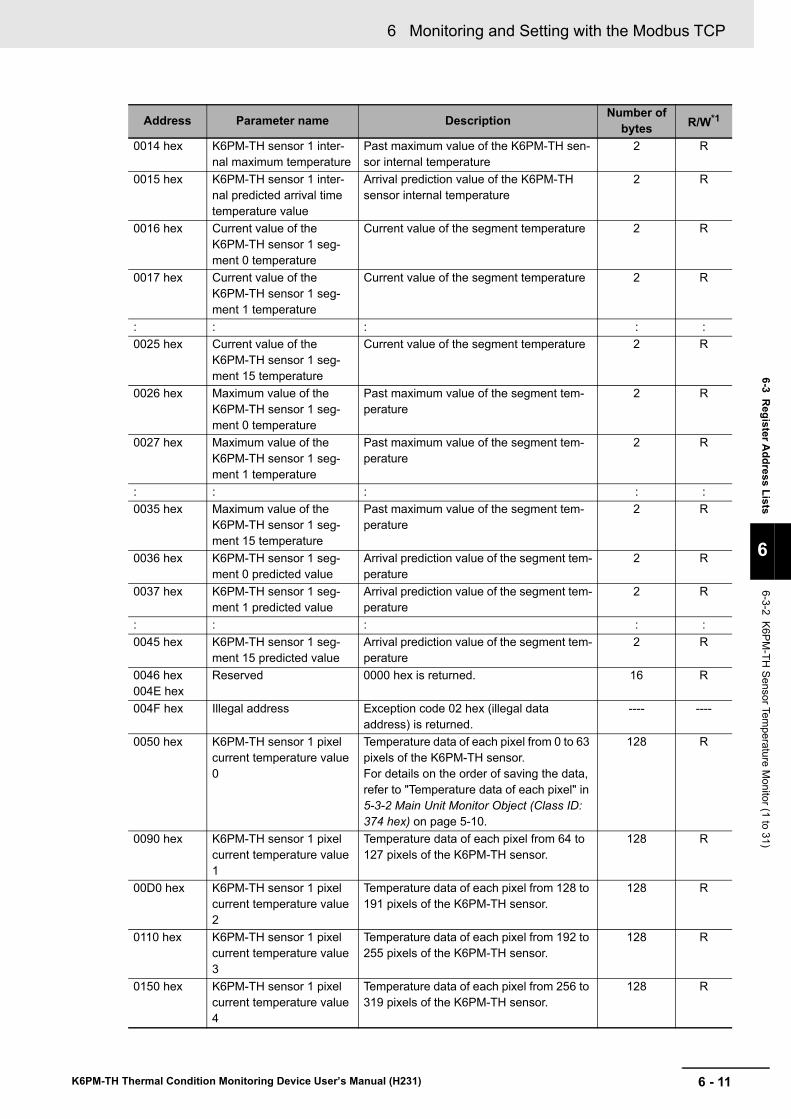
6 - 11
6 Monitoring and Setting with the Modbus TCP
K6PM-TH Thermal Condition Monitoring Device User’s Manual (H231)
6-3 Register A
ddress Lists
6
6-3-2 K6PM-TH
Sensor Temperature M
onitor (1 to 31)
0014 hex K6PM-TH sensor 1 inter-nal maximum temperature
Past maximum value of the K6PM-TH sen-sor internal temperature
2 R
0015 hex K6PM-TH sensor 1 inter-nal predicted arrival time temperature value
Arrival prediction value of the K6PM-TH sensor internal temperature
2 R
0016 hex Current value of the K6PM-TH sensor 1 seg-ment 0 temperature
Current value of the segment temperature 2 R
0017 hex Current value of the K6PM-TH sensor 1 seg-ment 1 temperature
Current value of the segment temperature 2 R
: : : : :0025 hex Current value of the
K6PM-TH sensor 1 seg-ment 15 temperature
Current value of the segment temperature 2 R
0026 hex Maximum value of the K6PM-TH sensor 1 seg-ment 0 temperature
Past maximum value of the segment tem-perature
2 R
0027 hex Maximum value of the K6PM-TH sensor 1 seg-ment 1 temperature
Past maximum value of the segment tem-perature
2 R
: : : : :0035 hex Maximum value of the
K6PM-TH sensor 1 seg-ment 15 temperature
Past maximum value of the segment tem-perature
2 R
0036 hex K6PM-TH sensor 1 seg-ment 0 predicted value
Arrival prediction value of the segment tem-perature
2 R
0037 hex K6PM-TH sensor 1 seg-ment 1 predicted value
Arrival prediction value of the segment tem-perature
2 R
: : : : :0045 hex K6PM-TH sensor 1 seg-
ment 15 predicted valueArrival prediction value of the segment tem-perature
2 R
0046 hex004E hex
Reserved 0000 hex is returned. 16 R
004F hex Illegal address Exception code 02 hex (illegal data address) is returned.
---- ----
0050 hex K6PM-TH sensor 1 pixel current temperature value 0
Temperature data of each pixel from 0 to 63 pixels of the K6PM-TH sensor.For details on the order of saving the data, refer to "Temperature data of each pixel" in 5-3-2 Main Unit Monitor Object (Class ID: 374 hex) on page 5-10.
128 R
0090 hex K6PM-TH sensor 1 pixel current temperature value 1
Temperature data of each pixel from 64 to 127 pixels of the K6PM-TH sensor.
128 R
00D0 hex K6PM-TH sensor 1 pixel current temperature value 2
Temperature data of each pixel from 128 to 191 pixels of the K6PM-TH sensor.
128 R
0110 hex K6PM-TH sensor 1 pixel current temperature value 3
Temperature data of each pixel from 192 to 255 pixels of the K6PM-TH sensor.
128 R
0150 hex K6PM-TH sensor 1 pixel current temperature value 4
Temperature data of each pixel from 256 to 319 pixels of the K6PM-TH sensor.
128 R
Address Parameter name Description Number of bytes R/W*1
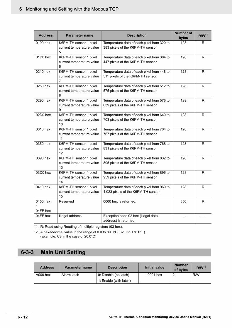
6 Monitoring and Setting with the Modbus TCP
6 - 12 K6PM-TH Thermal Condition Monitoring Device User’s Manual (H231)
0190 hex K6PM-TH sensor 1 pixel current temperature value 5
Temperature data of each pixel from 320 to 383 pixels of the K6PM-TH sensor.
128 R
01D0 hex K6PM-TH sensor 1 pixel current temperature value 6
Temperature data of each pixel from 384 to 447 pixels of the K6PM-TH sensor.
128 R
0210 hex K6PM-TH sensor 1 pixel current temperature value 7
Temperature data of each pixel from 448 to 511 pixels of the K6PM-TH sensor.
128 R
0250 hex K6PM-TH sensor 1 pixel current temperature value 8
Temperature data of each pixel from 512 to 575 pixels of the K6PM-TH sensor.
128 R
0290 hex K6PM-TH sensor 1 pixel current temperature value 9
Temperature data of each pixel from 576 to 639 pixels of the K6PM-TH sensor.
128 R
02D0 hex K6PM-TH sensor 1 pixel current temperature value 10
Temperature data of each pixel from 640 to 703 pixels of the K6PM-TH sensor.
128 R
0310 hex K6PM-TH sensor 1 pixel current temperature value 11
Temperature data of each pixel from 704 to 767 pixels of the K6PM-TH sensor.
128 R
0350 hex K6PM-TH sensor 1 pixel current temperature value 12
Temperature data of each pixel from 768 to 831 pixels of the K6PM-TH sensor.
128 R
0390 hex K6PM-TH sensor 1 pixel current temperature value 13
Temperature data of each pixel from 832 to 895 pixels of the K6PM-TH sensor.
128 R
03D0 hex K6PM-TH sensor 1 pixel current temperature value 14
Temperature data of each pixel from 896 to 959 pixels of the K6PM-TH sensor.
128 R
0410 hex K6PM-TH sensor 1 pixel current temperature value 15
Temperature data of each pixel from 960 to 1,023 pixels of the K6PM-TH sensor.
128 R
0450 hex:04FE hex
Reserved 0000 hex is returned. 350 R
04FF hex Illegal address Exception code 02 hex (illegal data address) is returned.
---- ----
*1. R: Read using Reading of multiple registers (03 hex).*2. A hexadecimal value in the range of 0.0 to 80.0°C (32.0 to 176.0°F).
(Example: C8 in the case of 20.0°C)
6-3-3 Main Unit Setting
Address Parameter name Description Initial value Number of bytes R/W*1
A000 hex Alarm latch 0: Disable (no latch)1: Enable (with latch)
0001 hex 2 R/W
Address Parameter name Description Number of bytes R/W*1
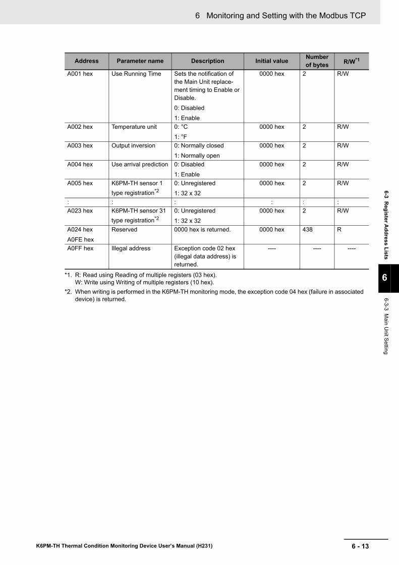
6 - 13
6 Monitoring and Setting with the Modbus TCP
K6PM-TH Thermal Condition Monitoring Device User’s Manual (H231)
6-3 Register A
ddress Lists
6
6-3-3 Main U
nit Setting
A001 hex Use Running Time Sets the notification of the Main Unit replace-ment timing to Enable or Disable.0: Disabled1: Enable
0000 hex 2 R/W
A002 hex Temperature unit 0: °C1: °F
0000 hex 2 R/W
A003 hex Output inversion 0: Normally closed1: Normally open
0000 hex 2 R/W
A004 hex Use arrival prediction 0: Disabled1: Enable
0000 hex 2 R/W
A005 hex K6PM-TH sensor 1 type registration*2
0: Unregistered1: 32 x 32
0000 hex 2 R/W
: : : : : :A023 hex K6PM-TH sensor 31
type registration*20: Unregistered1: 32 x 32
0000 hex 2 R/W
A024 hexA0FE hex
Reserved 0000 hex is returned. 0000 hex 438 R
A0FF hex Illegal address Exception code 02 hex (illegal data address) is returned.
---- ---- ----
*1. R: Read using Reading of multiple registers (03 hex).W: Write using Writing of multiple registers (10 hex).
*2. When writing is performed in the K6PM-TH monitoring mode, the exception code 04 hex (failure in associated device) is returned.
Address Parameter name Description Initial value Number of bytes R/W*1
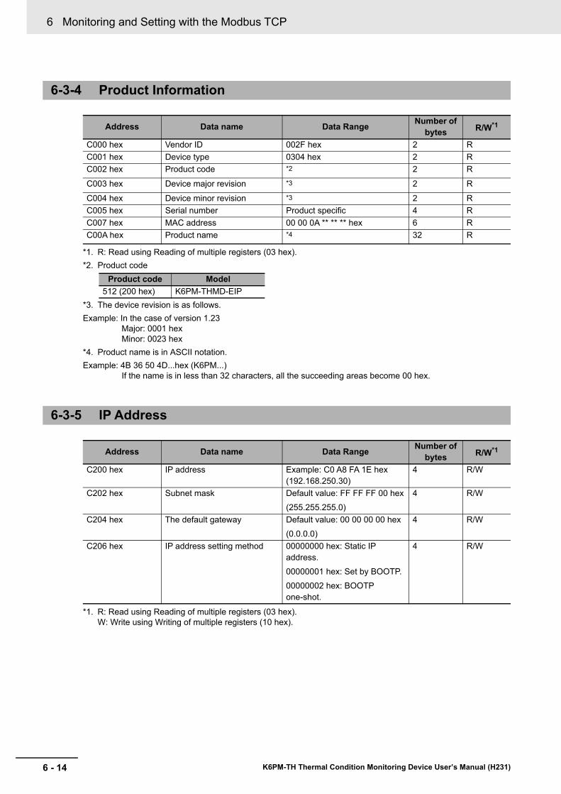
6 Monitoring and Setting with the Modbus TCP
6 - 14 K6PM-TH Thermal Condition Monitoring Device User’s Manual (H231)
6-3-4 Product Information
Address Data name Data Range Number of bytes R/W*1
*1. R: Read using Reading of multiple registers (03 hex).
C000 hex Vendor ID 002F hex 2 RC001 hex Device type 0304 hex 2 RC002 hex Product code *2
*2. Product code
2 R
C003 hex Device major revision *3
*3. The device revision is as follows.Example: In the case of version 1.23
Major: 0001 hexMinor: 0023 hex
2 R
C004 hex Device minor revision *3 2 RC005 hex Serial number Product specific 4 RC007 hex MAC address 00 00 0A ** ** ** hex 6 RC00A hex Product name *4
*4. Product name is in ASCII notation.Example: 4B 36 50 4D...hex (K6PM...)
If the name is in less than 32 characters, all the succeeding areas become 00 hex.
32 R
6-3-5 IP Address
Address Data name Data Range Number of bytes R/W*1
*1. R: Read using Reading of multiple registers (03 hex).W: Write using Writing of multiple registers (10 hex).
C200 hex IP address Example: C0 A8 FA 1E hex (192.168.250.30)
4 R/W
C202 hex Subnet mask Default value: FF FF FF 00 hex(255.255.255.0)
4 R/W
C204 hex The default gateway Default value: 00 00 00 00 hex(0.0.0.0)
4 R/W
C206 hex IP address setting method 00000000 hex: Static IP address.00000001 hex: Set by BOOTP.00000002 hex: BOOTP one-shot.
4 R/W
Product code Model512 (200 hex) K6PM-THMD-EIP
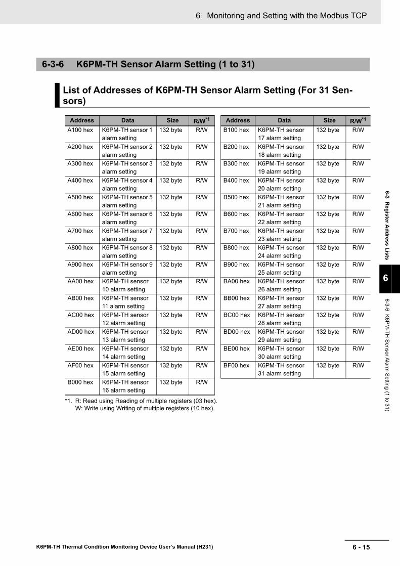
6 - 15
6 Monitoring and Setting with the Modbus TCP
K6PM-TH Thermal Condition Monitoring Device User’s Manual (H231)
6-3 Register A
ddress Lists
6
6-3-6 K6PM-TH
Sensor Alarm Setting (1 to 31)
6-3-6 K6PM-TH Sensor Alarm Setting (1 to 31)
List of Addresses of K6PM-TH Sensor Alarm Setting (For 31 Sen-sors)
Address Data Size R/W*1
*1. R: Read using Reading of multiple registers (03 hex).W: Write using Writing of multiple registers (10 hex).
Address Data Size R/W*1
A100 hex K6PM-TH sensor 1 alarm setting
132 byte R/W B100 hex K6PM-TH sensor 17 alarm setting
132 byte R/W
A200 hex K6PM-TH sensor 2 alarm setting
132 byte R/W B200 hex K6PM-TH sensor 18 alarm setting
132 byte R/W
A300 hex K6PM-TH sensor 3 alarm setting
132 byte R/W B300 hex K6PM-TH sensor 19 alarm setting
132 byte R/W
A400 hex K6PM-TH sensor 4 alarm setting
132 byte R/W B400 hex K6PM-TH sensor 20 alarm setting
132 byte R/W
A500 hex K6PM-TH sensor 5 alarm setting
132 byte R/W B500 hex K6PM-TH sensor 21 alarm setting
132 byte R/W
A600 hex K6PM-TH sensor 6 alarm setting
132 byte R/W B600 hex K6PM-TH sensor 22 alarm setting
132 byte R/W
A700 hex K6PM-TH sensor 7 alarm setting
132 byte R/W B700 hex K6PM-TH sensor 23 alarm setting
132 byte R/W
A800 hex K6PM-TH sensor 8 alarm setting
132 byte R/W B800 hex K6PM-TH sensor 24 alarm setting
132 byte R/W
A900 hex K6PM-TH sensor 9 alarm setting
132 byte R/W B900 hex K6PM-TH sensor 25 alarm setting
132 byte R/W
AA00 hex K6PM-TH sensor 10 alarm setting
132 byte R/W BA00 hex K6PM-TH sensor 26 alarm setting
132 byte R/W
AB00 hex K6PM-TH sensor 11 alarm setting
132 byte R/W BB00 hex K6PM-TH sensor 27 alarm setting
132 byte R/W
AC00 hex K6PM-TH sensor 12 alarm setting
132 byte R/W BC00 hex K6PM-TH sensor 28 alarm setting
132 byte R/W
AD00 hex K6PM-TH sensor 13 alarm setting
132 byte R/W BD00 hex K6PM-TH sensor 29 alarm setting
132 byte R/W
AE00 hex K6PM-TH sensor 14 alarm setting
132 byte R/W BE00 hex K6PM-TH sensor 30 alarm setting
132 byte R/W
AF00 hex K6PM-TH sensor 15 alarm setting
132 byte R/W BF00 hex K6PM-TH sensor 31 alarm setting
132 byte R/W
B000 hex K6PM-TH sensor 16 alarm setting
132 byte R/W
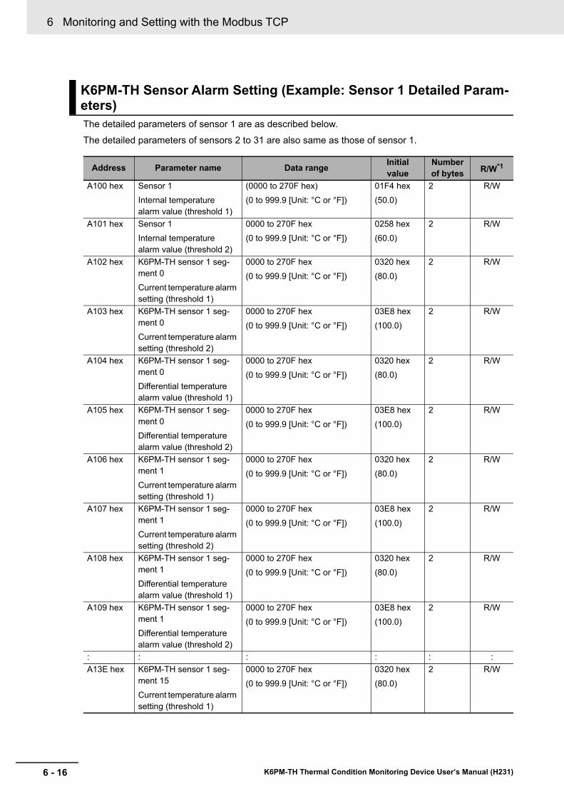
6 Monitoring and Setting with the Modbus TCP
6 - 16 K6PM-TH Thermal Condition Monitoring Device User’s Manual (H231)
The detailed parameters of sensor 1 are as described below.The detailed parameters of sensors 2 to 31 are also same as those of sensor 1.
K6PM-TH Sensor Alarm Setting (Example: Sensor 1 Detailed Param-eters)
Address Parameter name Data range Initial value
Number of bytes R/W*1
A100 hex Sensor 1Internal temperature alarm value (threshold 1)
(0000 to 270F hex)(0 to 999.9 [Unit: °C or °F])
01F4 hex(50.0)
2 R/W
A101 hex Sensor 1Internal temperature alarm value (threshold 2)
0000 to 270F hex(0 to 999.9 [Unit: °C or °F])
0258 hex(60.0)
2 R/W
A102 hex K6PM-TH sensor 1 seg-ment 0Current temperature alarm setting (threshold 1)
0000 to 270F hex(0 to 999.9 [Unit: °C or °F])
0320 hex(80.0)
2 R/W
A103 hex K6PM-TH sensor 1 seg-ment 0Current temperature alarm setting (threshold 2)
0000 to 270F hex(0 to 999.9 [Unit: °C or °F])
03E8 hex(100.0)
2 R/W
A104 hex K6PM-TH sensor 1 seg-ment 0Differential temperature alarm value (threshold 1)
0000 to 270F hex(0 to 999.9 [Unit: °C or °F])
0320 hex(80.0)
2 R/W
A105 hex K6PM-TH sensor 1 seg-ment 0Differential temperature alarm value (threshold 2)
0000 to 270F hex(0 to 999.9 [Unit: °C or °F])
03E8 hex(100.0)
2 R/W
A106 hex K6PM-TH sensor 1 seg-ment 1Current temperature alarm setting (threshold 1)
0000 to 270F hex(0 to 999.9 [Unit: °C or °F])
0320 hex(80.0)
2 R/W
A107 hex K6PM-TH sensor 1 seg-ment 1Current temperature alarm setting (threshold 2)
0000 to 270F hex(0 to 999.9 [Unit: °C or °F])
03E8 hex(100.0)
2 R/W
A108 hex K6PM-TH sensor 1 seg-ment 1Differential temperature alarm value (threshold 1)
0000 to 270F hex(0 to 999.9 [Unit: °C or °F])
0320 hex(80.0)
2 R/W
A109 hex K6PM-TH sensor 1 seg-ment 1Differential temperature alarm value (threshold 2)
0000 to 270F hex(0 to 999.9 [Unit: °C or °F])
03E8 hex(100.0)
2 R/W
: : : : : :A13E hex K6PM-TH sensor 1 seg-
ment 15Current temperature alarm setting (threshold 1)
0000 to 270F hex(0 to 999.9 [Unit: °C or °F])
0320 hex(80.0)
2 R/W
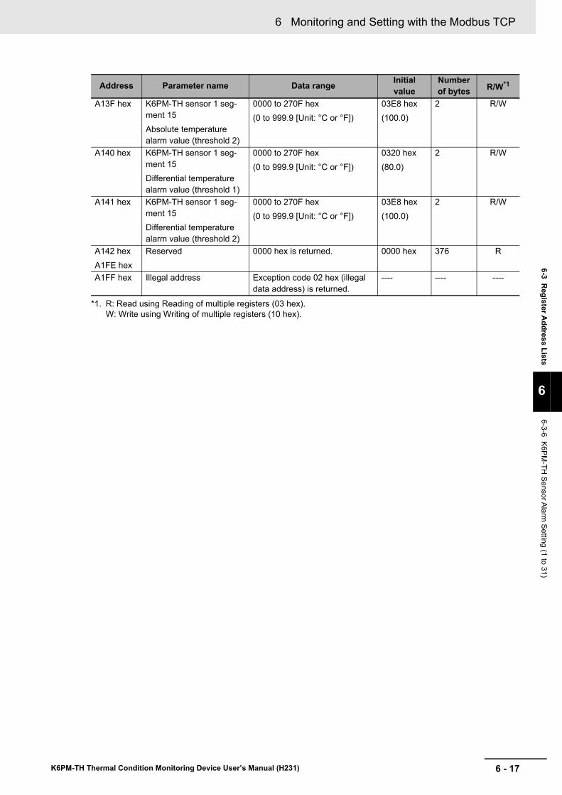
6 - 17
6 Monitoring and Setting with the Modbus TCP
K6PM-TH Thermal Condition Monitoring Device User’s Manual (H231)
6-3 Register A
ddress Lists
6
6-3-6 K6PM-TH
Sensor Alarm Setting (1 to 31)
A13F hex K6PM-TH sensor 1 seg-ment 15Absolute temperature alarm value (threshold 2)
0000 to 270F hex(0 to 999.9 [Unit: °C or °F])
03E8 hex(100.0)
2 R/W
A140 hex K6PM-TH sensor 1 seg-ment 15Differential temperature alarm value (threshold 1)
0000 to 270F hex(0 to 999.9 [Unit: °C or °F])
0320 hex(80.0)
2 R/W
A141 hex K6PM-TH sensor 1 seg-ment 15Differential temperature alarm value (threshold 2)
0000 to 270F hex(0 to 999.9 [Unit: °C or °F])
03E8 hex(100.0)
2 R/W
A142 hexA1FE hex
Reserved 0000 hex is returned. 0000 hex 376 R
A1FF hex Illegal address Exception code 02 hex (illegal data address) is returned.
---- ---- ----
*1. R: Read using Reading of multiple registers (03 hex).W: Write using Writing of multiple registers (10 hex).
Address Parameter name Data range Initial value
Number of bytes R/W*1
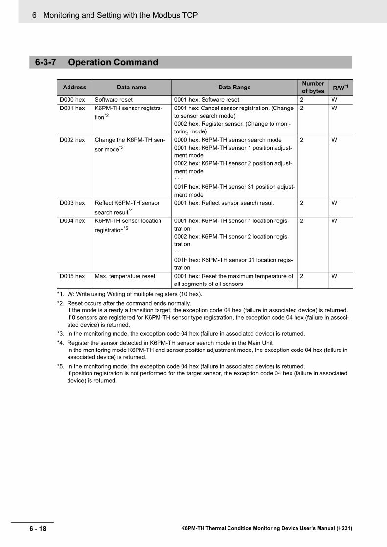
6 Monitoring and Setting with the Modbus TCP
6 - 18 K6PM-TH Thermal Condition Monitoring Device User’s Manual (H231)
6-3-7 Operation Command
Address Data name Data Range Number of bytes R/W*1
*1. W: Write using Writing of multiple registers (10 hex).
D000 hex Software reset 0001 hex: Software reset 2 WD001 hex K6PM-TH sensor registra-
tion*2
*2. Reset occurs after the command ends normally.If the mode is already a transition target, the exception code 04 hex (failure in associated device) is returned.If 0 sensors are registered for K6PM-TH sensor type registration, the exception code 04 hex (failure in associ-ated device) is returned.
0001 hex: Cancel sensor registration. (Change to sensor search mode)0002 hex: Register sensor. (Change to moni-toring mode)
2 W
D002 hex Change the K6PM-TH sen-sor mode*3
*3. In the monitoring mode, the exception code 04 hex (failure in associated device) is returned.
0000 hex: K6PM-TH sensor search mode0001 hex: K6PM-TH sensor 1 position adjust-ment mode0002 hex: K6PM-TH sensor 2 position adjust-ment mode· · ·001F hex: K6PM-TH sensor 31 position adjust-ment mode
2 W
D003 hex Reflect K6PM-TH sensor search result*4
*4. Register the sensor detected in K6PM-TH sensor search mode in the Main Unit.In the monitoring mode K6PM-TH and sensor position adjustment mode, the exception code 04 hex (failure in associated device) is returned.
0001 hex: Reflect sensor search result 2 W
D004 hex K6PM-TH sensor location registration*5
*5. In the monitoring mode, the exception code 04 hex (failure in associated device) is returned.If position registration is not performed for the target sensor, the exception code 04 hex (failure in associated device) is returned.
0001 hex: K6PM-TH sensor 1 location regis-tration0002 hex: K6PM-TH sensor 2 location regis-tration· · ·001F hex: K6PM-TH sensor 31 location regis-tration
2 W
D005 hex Max. temperature reset 0001 hex: Reset the maximum temperature of all segments of all sensors
2 W
7 - 1
7
K6PM-TH Thermal Condition Monitoring Device User’s Manual (H231)
This section describes troubleshooting when using the Main Units.
7-1 Main Unit . . . . . . . . . . . . . . . . . . . . . . . . . . . . . . . . . . . . . . . . . . . . . . . . . . . . . 7-27-2 Using the Software Tool . . . . . . . . . . . . . . . . . . . . . . . . . . . . . . . . . . . . . . . . 7-67-3 Using EtherNet Communications . . . . . . . . . . . . . . . . . . . . . . . . . . . . . . . . . 7-7
Troubleshooting
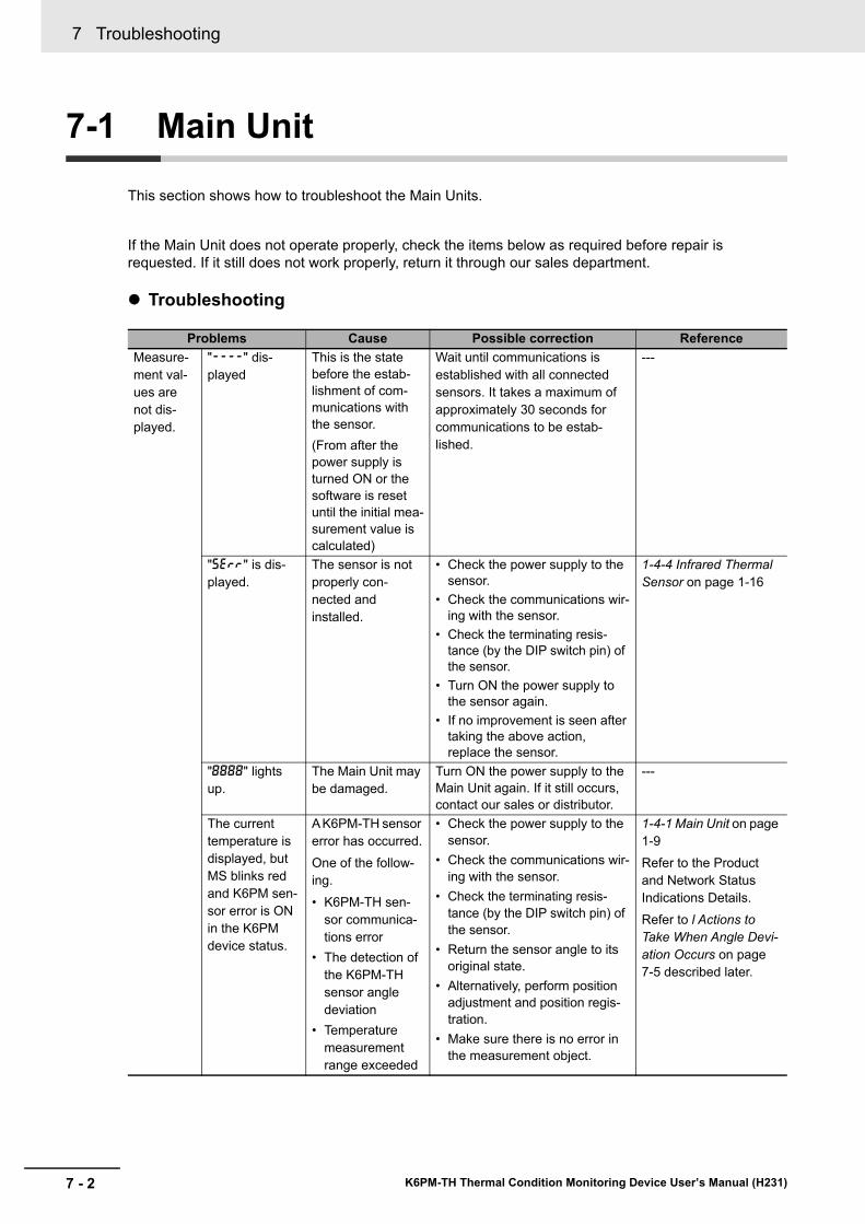
7 Troubleshooting
7 - 2 K6PM-TH Thermal Condition Monitoring Device User’s Manual (H231)
7-1 Main Unit
This section shows how to troubleshoot the Main Units.
If the Main Unit does not operate properly, check the items below as required before repair is requested. If it still does not work properly, return it through our sales department.
Troubleshooting
Problems Cause Possible correction ReferenceMeasure-ment val-ues are not dis-played.
"----" dis-played
This is the state before the estab-lishment of com-munications with the sensor.(From after the power supply is turned ON or the software is reset until the initial mea-surement value is calculated)
Wait until communications is established with all connected sensors. It takes a maximum of approximately 30 seconds for communications to be estab-lished.
---
"serr" is dis-played.
The sensor is not properly con-nected and installed.
• Check the power supply to the sensor.
• Check the communications wir-ing with the sensor.
• Check the terminating resis-tance (by the DIP switch pin) of the sensor.
• Turn ON the power supply to the sensor again.
• If no improvement is seen after taking the above action, replace the sensor.
1-4-4 Infrared Thermal Sensor on page 1-16
"8888" lights up.
The Main Unit may be damaged.
Turn ON the power supply to the Main Unit again. If it still occurs, contact our sales or distributor.
---
The current temperature is displayed, but MS blinks red and K6PM sen-sor error is ON in the K6PM device status.
A K6PM-TH sensor error has occurred.One of the follow-ing.• K6PM-TH sen-
sor communica-tions error
• The detection of the K6PM-TH sensor angle deviation
• Temperature measurement range exceeded
• Check the power supply to the sensor.
• Check the communications wir-ing with the sensor.
• Check the terminating resis-tance (by the DIP switch pin) of the sensor.
• Return the sensor angle to its original state.
• Alternatively, perform position adjustment and position regis-tration.
• Make sure there is no error in the measurement object.
1-4-1 Main Unit on page 1-9Refer to the Product and Network Status Indications Details.Refer to l Actions to Take When Angle Devi-ation Occurs on page 7-5 described later.
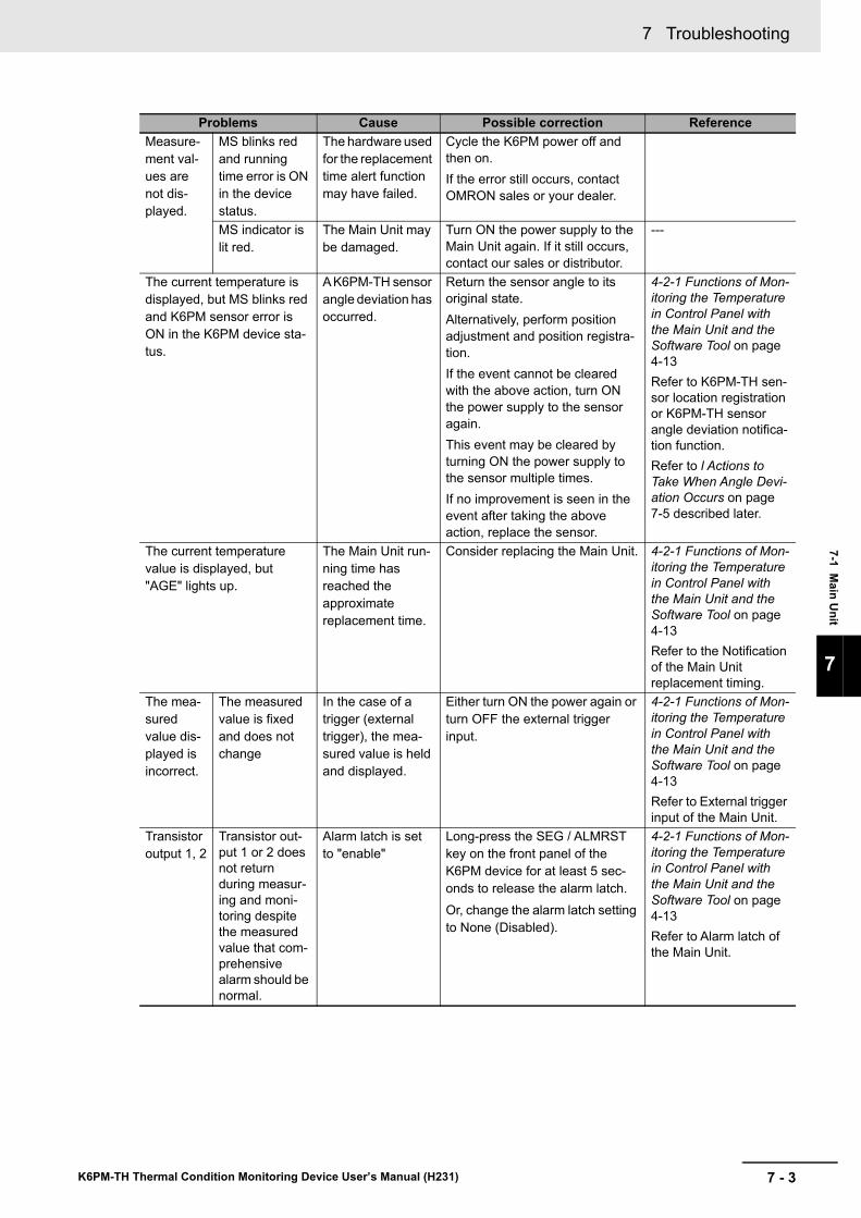
7 - 3
7 Troubleshooting
K6PM-TH Thermal Condition Monitoring Device User’s Manual (H231)
7-1 Main U
nit
7
Measure-ment val-ues are not dis-played.
MS blinks red and running time error is ON in the device status.
The hardware used for the replacement time alert function may have failed.
Cycle the K6PM power off and then on.If the error still occurs, contact OMRON sales or your dealer.
MS indicator is lit red.
The Main Unit may be damaged.
Turn ON the power supply to the Main Unit again. If it still occurs, contact our sales or distributor.
---
The current temperature is displayed, but MS blinks red and K6PM sensor error is ON in the K6PM device sta-tus.
A K6PM-TH sensor angle deviation has occurred.
Return the sensor angle to its original state.Alternatively, perform position adjustment and position registra-tion.If the event cannot be cleared with the above action, turn ON the power supply to the sensor again.This event may be cleared by turning ON the power supply to the sensor multiple times.If no improvement is seen in the event after taking the above action, replace the sensor.
4-2-1 Functions of Mon-itoring the Temperature in Control Panel with the Main Unit and the Software Tool on page 4-13Refer to K6PM-TH sen-sor location registration or K6PM-TH sensor angle deviation notifica-tion function.Refer to l Actions to Take When Angle Devi-ation Occurs on page 7-5 described later.
The current temperature value is displayed, but "AGE" lights up.
The Main Unit run-ning time has reached the approximate replacement time.
Consider replacing the Main Unit. 4-2-1 Functions of Mon-itoring the Temperature in Control Panel with the Main Unit and the Software Tool on page 4-13Refer to the Notification of the Main Unit replacement timing.
The mea-sured value dis-played is incorrect.
The measured value is fixed and does not change
In the case of a trigger (external trigger), the mea-sured value is held and displayed.
Either turn ON the power again or turn OFF the external trigger input.
4-2-1 Functions of Mon-itoring the Temperature in Control Panel with the Main Unit and the Software Tool on page 4-13Refer to External trigger input of the Main Unit.
Transistor output 1, 2
Transistor out-put 1 or 2 does not return during measur-ing and moni-toring despite the measured value that com-prehensive alarm should be normal.
Alarm latch is set to "enable"
Long-press the SEG / ALMRST key on the front panel of the K6PM device for at least 5 sec-onds to release the alarm latch.Or, change the alarm latch setting to None (Disabled).
4-2-1 Functions of Mon-itoring the Temperature in Control Panel with the Main Unit and the Software Tool on page 4-13Refer to Alarm latch of the Main Unit.
Problems Cause Possible correction Reference
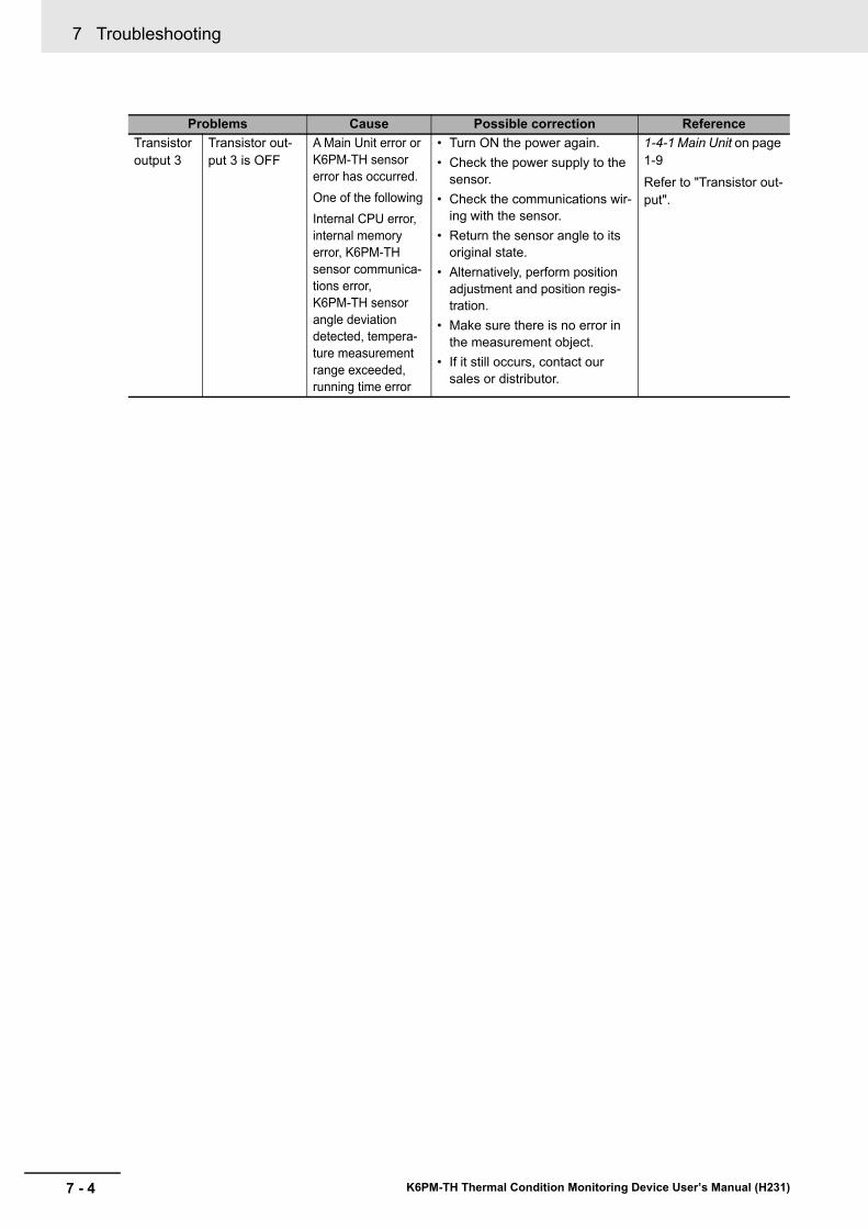
7 Troubleshooting
7 - 4 K6PM-TH Thermal Condition Monitoring Device User’s Manual (H231)
Transistor output 3
Transistor out-put 3 is OFF
A Main Unit error or K6PM-TH sensor error has occurred.One of the followingInternal CPU error, internal memory error, K6PM-TH sensor communica-tions error, K6PM-TH sensor angle deviation detected, tempera-ture measurement range exceeded, running time error
• Turn ON the power again.• Check the power supply to the
sensor.• Check the communications wir-
ing with the sensor.• Return the sensor angle to its
original state.• Alternatively, perform position
adjustment and position regis-tration.
• Make sure there is no error in the measurement object.
• If it still occurs, contact our sales or distributor.
1-4-1 Main Unit on page 1-9Refer to "Transistor out-put".
Problems Cause Possible correction Reference
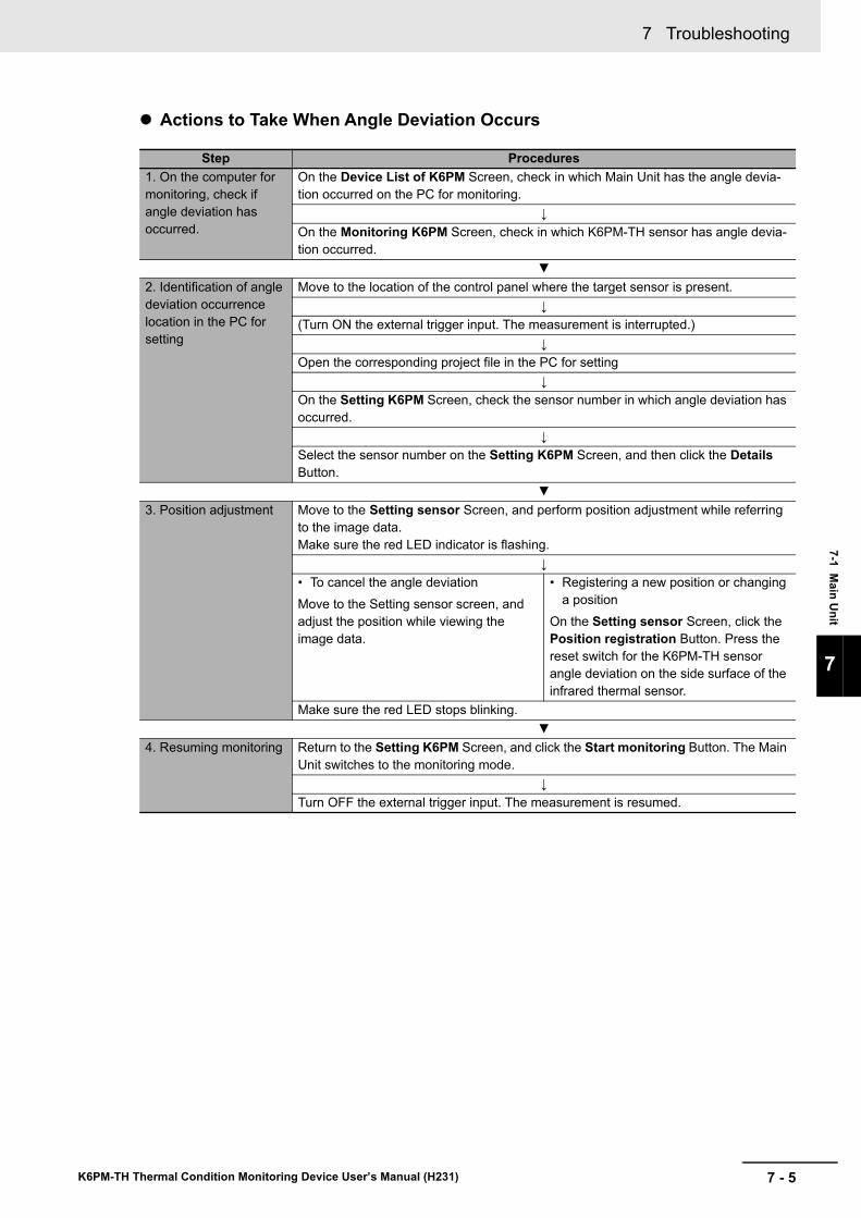
7 - 5
7 Troubleshooting
K6PM-TH Thermal Condition Monitoring Device User’s Manual (H231)
7-1 Main U
nit
7
Actions to Take When Angle Deviation Occurs
Step Procedures1. On the computer for monitoring, check if angle deviation has occurred.
On the Device List of K6PM Screen, check in which Main Unit has the angle devia-tion occurred on the PC for monitoring.
↓On the Monitoring K6PM Screen, check in which K6PM-TH sensor has angle devia-tion occurred.
▼2. Identification of angle deviation occurrence location in the PC for setting
Move to the location of the control panel where the target sensor is present.↓
(Turn ON the external trigger input. The measurement is interrupted.)↓
Open the corresponding project file in the PC for setting↓
On the Setting K6PM Screen, check the sensor number in which angle deviation has occurred.
↓Select the sensor number on the Setting K6PM Screen, and then click the Details Button.
▼3. Position adjustment Move to the Setting sensor Screen, and perform position adjustment while referring
to the image data.Make sure the red LED indicator is flashing.
↓• To cancel the angle deviationMove to the Setting sensor screen, and adjust the position while viewing the image data.
• Registering a new position or changing a position
On the Setting sensor Screen, click the Position registration Button. Press the reset switch for the K6PM-TH sensor angle deviation on the side surface of the infrared thermal sensor.
Make sure the red LED stops blinking.▼
4. Resuming monitoring Return to the Setting K6PM Screen, and click the Start monitoring Button. The Main Unit switches to the monitoring mode.
↓Turn OFF the external trigger input. The measurement is resumed.
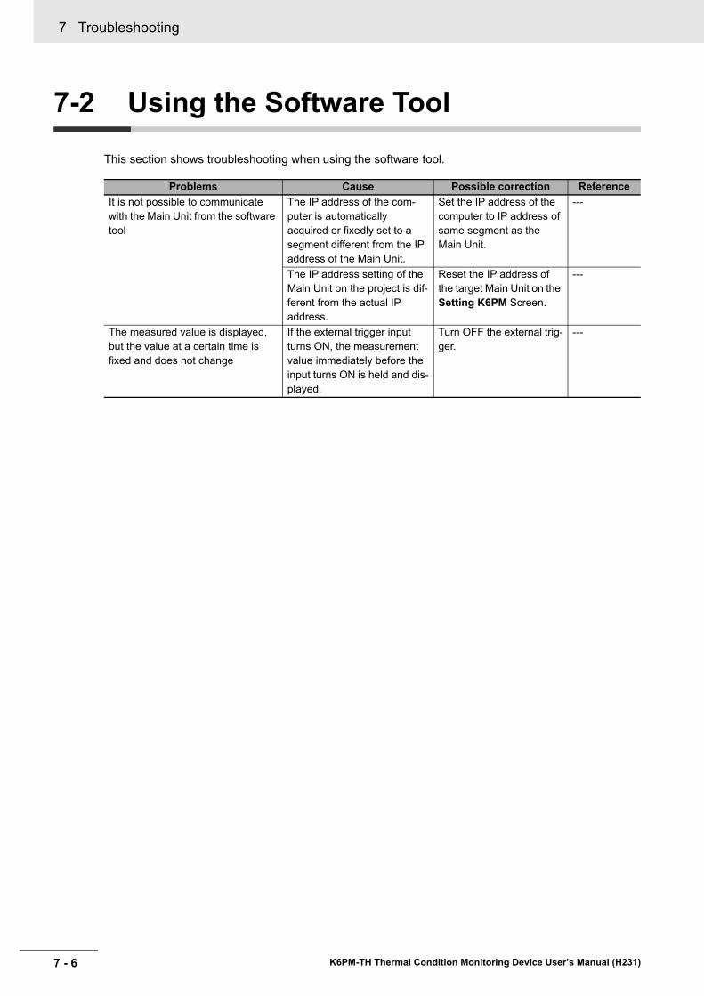
7 Troubleshooting
7 - 6 K6PM-TH Thermal Condition Monitoring Device User’s Manual (H231)
7-2 Using the Software Tool
This section shows troubleshooting when using the software tool.
Problems Cause Possible correction ReferenceIt is not possible to communicate with the Main Unit from the software tool
The IP address of the com-puter is automatically acquired or fixedly set to a segment different from the IP address of the Main Unit.
Set the IP address of the computer to IP address of same segment as the Main Unit.
---
The IP address setting of the Main Unit on the project is dif-ferent from the actual IP address.
Reset the IP address of the target Main Unit on the Setting K6PM Screen.
---
The measured value is displayed, but the value at a certain time is fixed and does not change
If the external trigger input turns ON, the measurement value immediately before the input turns ON is held and dis-played.
Turn OFF the external trig-ger.
---
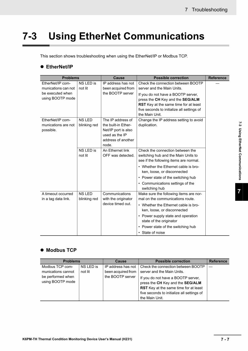
7 - 7
7 Troubleshooting
K6PM-TH Thermal Condition Monitoring Device User’s Manual (H231)
7-3 Using EtherN
et Com
munications
7
7-3 Using EtherNet Communications
This section shows troubleshooting when using the EtherNet/IP or Modbus TCP.
EtherNet/IP
Modbus TCP
Problems Cause Possible correction ReferenceEtherNet/IP com-munications can not be executed when using BOOTP mode
NS LED is not lit
IP address has not been acquired from the BOOTP server
Check the connection between BOOTP server and the Main Units.If you do not have a BOOTP server, press the CH Key and the SEG/ALM RST Key at the same time for at least five seconds to initialize all settings of the Main Unit.
---
EtherNet/IP com-munications are not possible.
NS LED blinking red
The IP address of the built-in Ether-Net/IP port is also used as the IP address of another node.
Change the IP address setting to avoid duplication.
NS LED is not lit
An Ethernet link OFF was detected.
Check the connection between the switching hub and the Main Units to see if the following items are normal.• Whether the Ethernet cable is bro-
ken, loose, or disconnected• Power state of the switching hub• Communications settings of the
switching hubA timeout occurred in a tag data link.
NS LED blinking red
Communications with the originator device timed out.
Make sure the following items are nor-mal on the communications route.• Whether the Ethernet cable is bro-
ken, loose, or disconnected• Power supply state and operation
state of the originator• Power state of the switching hub• State of noise
Problems Cause Possible correction ReferenceModbus TCP com-munications cannot be performed when using BOOTP mode
NS LED is not lit
IP address has not been acquired from the BOOTP server
Check the connection between BOOTP server and the Main Units.If you do not have a BOOTP server, press the CH Key and the SEG/ALM RST Key at the same time for at least five seconds to initialize all settings of the Main Unit.
---

7 Troubleshooting
7 - 8 K6PM-TH Thermal Condition Monitoring Device User’s Manual (H231)
A - 1
A
K6PM-TH Thermal Condition Monitoring Device User’s Manual (H231)
This section describes the specifications of the Main Units.
A-1 Specifications . . . . . . . . . . . . . . . . . . . . . . . . . . . . . . . . . . . . . . . . . . . . . . . . . A-2 A-1-1 Main Unit Specifications . . . . . . . . . . . . . . . . . . . . . . . . . . . . . . . . . . . . . . . . . . A-2A-1-2 Infrared Thermal Sensor . . . . . . . . . . . . . . . . . . . . . . . . . . . . . . . . . . . . . . . . . . A-6A-1-3 Software Tool . . . . . . . . . . . . . . . . . . . . . . . . . . . . . . . . . . . . . . . . . . . . . . . . . . A-9
A-2 Screen Flow of the Software Tool . . . . . . . . . . . . . . . . . . . . . . . . . . . . . . . . A-12A-3 Tag Data Link Connection Setting Procedures . . . . . . . . . . . . . . . . . . . . . A-13
A-3-1 Preface . . . . . . . . . . . . . . . . . . . . . . . . . . . . . . . . . . . . . . . . . . . . . . . . . . . . . . A-13A-3-2 Using the CS/CJ-series . . . . . . . . . . . . . . . . . . . . . . . . . . . . . . . . . . . . . . . . . A-13A-3-3 Using the NJ/NX-series . . . . . . . . . . . . . . . . . . . . . . . . . . . . . . . . . . . . . . . . . A-26
A-4 Expansion Error Code of the CIP Message Communications . . . . . . . . . A-36A-4-1 General Status . . . . . . . . . . . . . . . . . . . . . . . . . . . . . . . . . . . . . . . . . . . . . . . . A-36A-4-2 Additional Status When General Status Is 01 hex . . . . . . . . . . . . . . . . . . . . . A-38
Appendices
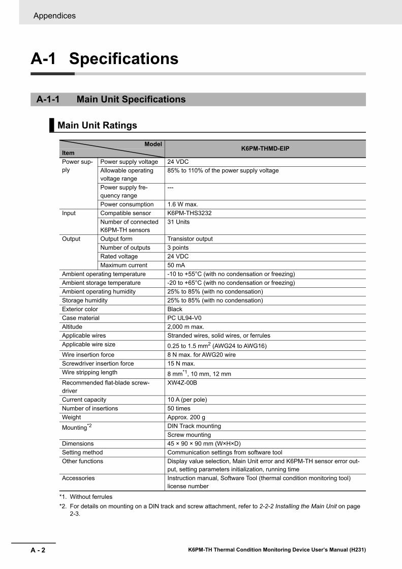
Appendices
A - 2 K6PM-TH Thermal Condition Monitoring Device User’s Manual (H231)
A-1 Specifications
A-1-1 Main Unit Specifications
Main Unit Ratings
ModelK6PM-THMD-EIP
ItemPower sup-ply
Power supply voltage 24 VDCAllowable operating voltage range
85% to 110% of the power supply voltage
Power supply fre-quency range
---
Power consumption 1.6 W max.Input Compatible sensor K6PM-THS3232
Number of connected K6PM-TH sensors
31 Units
Output Output form Transistor outputNumber of outputs 3 pointsRated voltage 24 VDCMaximum current 50 mA
Ambient operating temperature -10 to +55°C (with no condensation or freezing)Ambient storage temperature -20 to +65°C (with no condensation or freezing)Ambient operating humidity 25% to 85% (with no condensation)Storage humidity 25% to 85% (with no condensation)Exterior color BlackCase material PC UL94-V0Altitude 2,000 m max.Applicable wires Stranded wires, solid wires, or ferrulesApplicable wire size 0.25 to 1.5 mm2 (AWG24 to AWG16)Wire insertion force 8 N max. for AWG20 wireScrewdriver insertion force 15 N max.Wire stripping length 8 mm*1, 10 mm, 12 mm
*1. Without ferrules
Recommended flat-blade screw-driver
XW4Z-00B
Current capacity 10 A (per pole)Number of insertions 50 timesWeight Approx. 200 g
Mounting*2
*2. For details on mounting on a DIN track and screw attachment, refer to 2-2-2 Installing the Main Unit on page 2-3.
DIN Track mountingScrew mounting
Dimensions 45 × 90 × 90 mm (W×H×D)Setting method Communication settings from software toolOther functions Display value selection, Main Unit error and K6PM-TH sensor error out-
put, setting parameters initialization, running timeAccessories Instruction manual, Software Tool (thermal condition monitoring tool)
license number
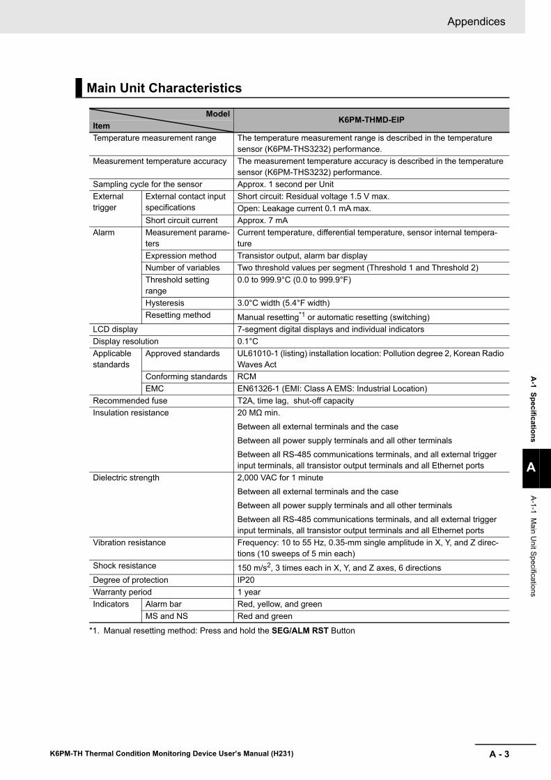
A - 3
Appendices
K6PM-TH Thermal Condition Monitoring Device User’s Manual (H231)
A-1 Specifications
A
A-1-1 Main U
nit Specifications
Main Unit Characteristics
ModelK6PM-THMD-EIP
ItemTemperature measurement range The temperature measurement range is described in the temperature
sensor (K6PM-THS3232) performance.Measurement temperature accuracy The measurement temperature accuracy is described in the temperature
sensor (K6PM-THS3232) performance.Sampling cycle for the sensor Approx. 1 second per UnitExternal trigger
External contact input specifications
Short circuit: Residual voltage 1.5 V max.Open: Leakage current 0.1 mA max.
Short circuit current Approx. 7 mAAlarm Measurement parame-
tersCurrent temperature, differential temperature, sensor internal tempera-ture
Expression method Transistor output, alarm bar displayNumber of variables Two threshold values per segment (Threshold 1 and Threshold 2)Threshold setting range
0.0 to 999.9°C (0.0 to 999.9°F)
Hysteresis 3.0°C width (5.4°F width)Resetting method Manual resetting*1 or automatic resetting (switching)
*1. Manual resetting method: Press and hold the SEG/ALM RST Button
LCD display 7-segment digital displays and individual indicatorsDisplay resolution 0.1°CApplicable standards
Approved standards UL61010-1 (listing) installation location: Pollution degree 2, Korean Radio Waves Act
Conforming standards RCMEMC EN61326-1 (EMI: Class A EMS: Industrial Location)
Recommended fuse T2A, time lag, shut-off capacityInsulation resistance 20 MΩ min.
Between all external terminals and the caseBetween all power supply terminals and all other terminalsBetween all RS-485 communications terminals, and all external trigger input terminals, all transistor output terminals and all Ethernet ports
Dielectric strength 2,000 VAC for 1 minuteBetween all external terminals and the caseBetween all power supply terminals and all other terminalsBetween all RS-485 communications terminals, and all external trigger input terminals, all transistor output terminals and all Ethernet ports
Vibration resistance Frequency: 10 to 55 Hz, 0.35-mm single amplitude in X, Y, and Z direc-tions (10 sweeps of 5 min each)
Shock resistance 150 m/s2, 3 times each in X, Y, and Z axes, 6 directionsDegree of protection IP20Warranty period 1 yearIndicators Alarm bar Red, yellow, and green
MS and NS Red and green
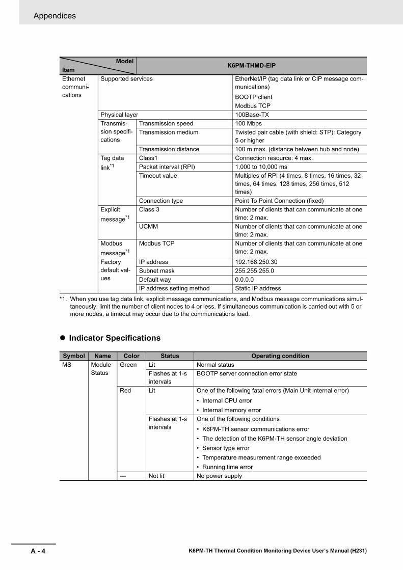
Appendices
A - 4 K6PM-TH Thermal Condition Monitoring Device User’s Manual (H231)
Indicator Specifications
ModelK6PM-THMD-EIP
ItemEthernet communi-cations
Supported services EtherNet/IP (tag data link or CIP message com-munications)BOOTP clientModbus TCP
Physical layer 100Base-TXTransmis-sion specifi-cations
Transmission speed 100 MbpsTransmission medium Twisted pair cable (with shield: STP): Category
5 or higherTransmission distance 100 m max. (distance between hub and node)
Tag data link*1
*1. When you use tag data link, explicit message communications, and Modbus message communications simul-taneously, limit the number of client nodes to 4 or less. If simultaneous communication is carried out with 5 or more nodes, a timeout may occur due to the communications load.
Class1 Connection resource: 4 max.Packet interval (RPI) 1,000 to 10,000 msTimeout value Multiples of RPI (4 times, 8 times, 16 times, 32
times, 64 times, 128 times, 256 times, 512 times)
Connection type Point To Point Connection (fixed)Explicit message*1
Class 3 Number of clients that can communicate at one time: 2 max.
UCMM Number of clients that can communicate at one time: 2 max.
Modbus message*1
Modbus TCP Number of clients that can communicate at one time: 2 max.
Factory default val-ues
IP address 192.168.250.30Subnet mask 255.255.255.0Default way 0.0.0.0IP address setting method Static IP address
Symbol Name Color Status Operating conditionMS Module
StatusGreen Lit Normal status
Flashes at 1-s intervals
BOOTP server connection error state
Red Lit One of the following fatal errors (Main Unit internal error)• Internal CPU error• Internal memory error
Flashes at 1-s intervals
One of the following conditions• K6PM-TH sensor communications error• The detection of the K6PM-TH sensor angle deviation• Sensor type error• Temperature measurement range exceeded• Running time error
--- Not lit No power supply
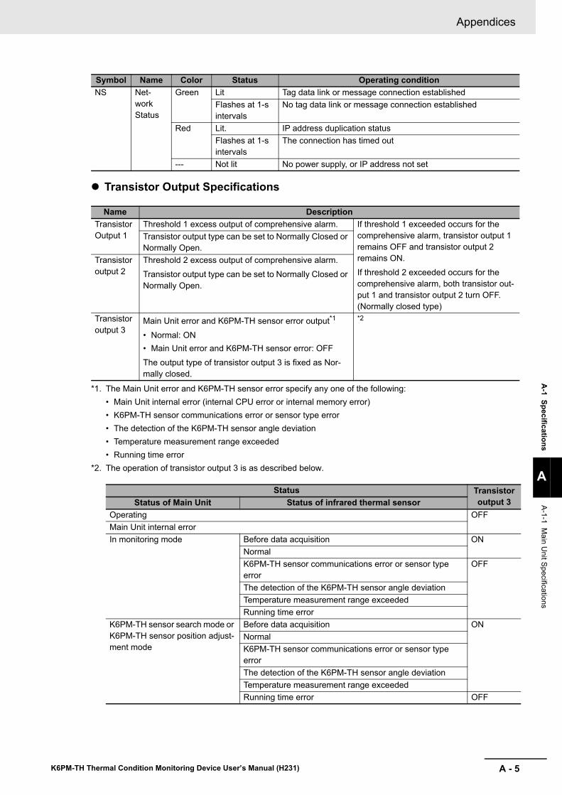
A - 5
Appendices
K6PM-TH Thermal Condition Monitoring Device User’s Manual (H231)
A-1 Specifications
A
A-1-1 Main U
nit Specifications
Transistor Output Specifications
NS Net-work Status
Green Lit Tag data link or message connection establishedFlashes at 1-s intervals
No tag data link or message connection established
Red Lit. IP address duplication statusFlashes at 1-s intervals
The connection has timed out
--- Not lit No power supply, or IP address not set
Name DescriptionTransistor Output 1
Threshold 1 excess output of comprehensive alarm. If threshold 1 exceeded occurs for the comprehensive alarm, transistor output 1 remains OFF and transistor output 2 remains ON.If threshold 2 exceeded occurs for the comprehensive alarm, both transistor out-put 1 and transistor output 2 turn OFF. (Normally closed type)
Transistor output type can be set to Normally Closed or Normally Open.
Transistor output 2
Threshold 2 excess output of comprehensive alarm.Transistor output type can be set to Normally Closed or Normally Open.
Transistor output 3
Main Unit error and K6PM-TH sensor error output*1
• Normal: ON• Main Unit error and K6PM-TH sensor error: OFFThe output type of transistor output 3 is fixed as Nor-mally closed.
*1. The Main Unit error and K6PM-TH sensor error specify any one of the following:• Main Unit internal error (internal CPU error or internal memory error)• K6PM-TH sensor communications error or sensor type error• The detection of the K6PM-TH sensor angle deviation• Temperature measurement range exceeded• Running time error
*2
*2. The operation of transistor output 3 is as described below.
Status Transistor output 3Status of Main Unit Status of infrared thermal sensor
Operating OFFMain Unit internal errorIn monitoring mode Before data acquisition ON
NormalK6PM-TH sensor communications error or sensor type error
OFF
The detection of the K6PM-TH sensor angle deviationTemperature measurement range exceededRunning time error
K6PM-TH sensor search mode or K6PM-TH sensor position adjust-ment mode
Before data acquisition ONNormalK6PM-TH sensor communications error or sensor type errorThe detection of the K6PM-TH sensor angle deviationTemperature measurement range exceededRunning time error OFF
Symbol Name Color Status Operating condition
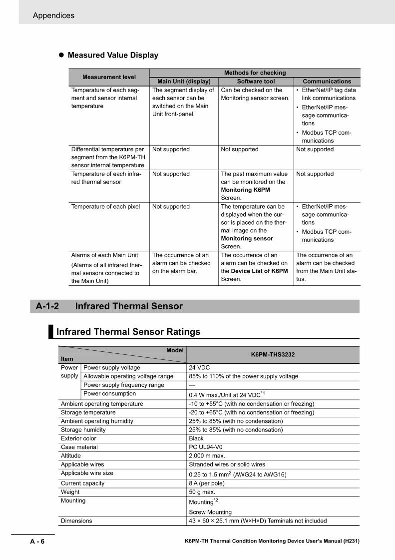
Appendices
A - 6 K6PM-TH Thermal Condition Monitoring Device User’s Manual (H231)
Measured Value Display
Measurement levelMethods for checking
Main Unit (display) Software tool CommunicationsTemperature of each seg-ment and sensor internal temperature
The segment display of each sensor can be switched on the Main Unit front-panel.
Can be checked on the Monitoring sensor screen.
• EtherNet/IP tag data link communications
• EtherNet/IP mes-sage communica-tions
• Modbus TCP com-munications
Differential temperature per segment from the K6PM-TH sensor internal temperature
Not supported Not supported Not supported
Temperature of each infra-red thermal sensor
Not supported The past maximum value can be monitored on the Monitoring K6PM Screen.
Not supported
Temperature of each pixel Not supported The temperature can be displayed when the cur-sor is placed on the ther-mal image on the Monitoring sensor Screen.
• EtherNet/IP mes-sage communica-tions
• Modbus TCP com-munications
Alarms of each Main Unit(Alarms of all infrared ther-mal sensors connected to the Main Unit)
The occurrence of an alarm can be checked on the alarm bar.
The occurrence of an alarm can be checked on the Device List of K6PM Screen.
The occurrence of an alarm can be checked from the Main Unit sta-tus.
A-1-2 Infrared Thermal Sensor
Infrared Thermal Sensor Ratings
ModelK6PM-THS3232
ItemPower supply
Power supply voltage 24 VDCAllowable operating voltage range 85% to 110% of the power supply voltagePower supply frequency range ---Power consumption 0.4 W max./Unit at 24 VDC*1
Ambient operating temperature -10 to +55°C (with no condensation or freezing)Storage temperature -20 to +65°C (with no condensation or freezing)Ambient operating humidity 25% to 85% (with no condensation)Storage humidity 25% to 85% (with no condensation)Exterior color BlackCase material PC UL94-V0Altitude 2,000 m max.Applicable wires Stranded wires or solid wiresApplicable wire size 0.25 to 1.5 mm2 (AWG24 to AWG16)Current capacity 8 A (per pole)Weight 50 g max.Mounting Mounting*2
Screw MountingDimensions 43 × 60 × 25.1 mm (W×H×D) Terminals not included

A - 7
Appendices
K6PM-TH Thermal Condition Monitoring Device User’s Manual (H231)
A-1 Specifications
A
A-1-2 Infrared Thermal Sensor
Accessories*3 Instruction manual, mounting bracket, magnet (for positioning)*4
*1. The power consumption increases according to the number of connected devices. Take note of the choice of wiring and the wiring diameter.
*2. A 1/4-20 UNC mounting hole is available (nuts are not provided).*3. The pan head is sold separately.*4. Use magnet mounting for positioning the sensor.
ModelK6PM-THS3232
Item
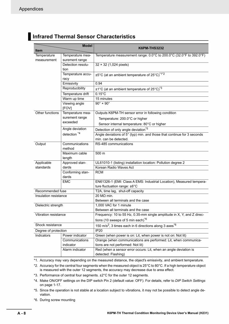
Appendices
A - 8 K6PM-TH Thermal Condition Monitoring Device User’s Manual (H231)
Infrared Thermal Sensor CharacteristicsModel K6PM-THS3232Item
Temperature measurement
Temperature mea-surement range
Temperature measurement range: 0.0°C to 200.0°C (32.0°F to 392.0°F)
Detection resolu-tion
32 × 32 (1,024 pixels)
Temperature accu-racy
±5°C (at an ambient temperature of 25°C)*1*2
*1. Accuracy may vary depending on the measured distance, the object's emissivity, and ambient temperature.*2. Accuracy for the central four segments when the measured object is 25°C to 80°C. If a high temperature object
is measured with the outer 12 segments, the accuracy may decrease due to area effect.
Emissivity 0.94Reproducibility ±1°C (at an ambient temperature of 25°C)*3
*3. Performance of central four segments. ±2°C for the outer 12 segments.
Temperature drift 0.15°CWarm up time 15 minutesViewing angle [FOV]
90° × 90°
Other functions Temperature mea-surement range exceeded
Outputs K6PM-TH sensor error in following conditionTemperature: 200.0°C or higherSensor internal temperature: 80°C or higher
Angle deviation detection *4
*4. Make ON/OFF settings on the DIP switch Pin 2 (default value: OFF). For details, refer to DIP Switch Settings on page 1-17.
Detection of only angle deviation*5
*5. Since the operation is not stable at a location subject to vibrations, it may not be possible to detect angle de-viation.
Angle deviations of 5° (typ) min. and those that continue for 3 seconds min. can be detected.
Output Communications method
RS-485 communications
Maximum cable length
500 m
Applicable standards
Approved stan-dards
UL61010-1 (listing) installation location: Pollution degree 2Korean Radio Waves Act
Conforming stan-dards
RCM
EMC EN61326-1 (EMI: Class A EMS: Industrial Location), Measured tempera-ture fluctuation range: ±6°C
Recommended fuse T2A, time lag, shut-off capacityInsulation resistance 20 MΩ min.
Between all terminals and the caseDielectric strength 1,000 VAC for 1 minute
Between all terminals and the caseVibration resistance Frequency: 10 to 55 Hz, 0.35-mm single amplitude in X, Y, and Z direc-
tions (10 sweeps of 5 min each)*6
*6. During screw mounting
Shock resistance 150 m/s2, 3 times each in 6 directions along 3 axes*6
Degree of protection IP20Indicators Power indicator Green (when power is on: Lit, when power is not on: Not lit)
Communications indicator
Orange (when communications are performed: Lit, when communica-tions are not performed: Not lit)
Alarm indicator Red (when a sensor error occurs: Lit, when an angle deviation is detected: Flashing)
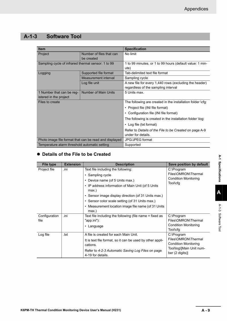
A - 9
Appendices
K6PM-TH Thermal Condition Monitoring Device User’s Manual (H231)
A-1 Specifications
A
A-1-3 Software Tool
Details of the File to be Created
A-1-3 Software Tool
Item SpecificationProject Number of files that can
be createdNo limit
Sampling cycle of infrared thermal sensor: 1 to 99 1 to 99 minutes, or 1 to 99 hours (default value: 1 min-ute)
Logging Supported file format Tab-delimited text file formatMeasurement interval Sampling cycleLog file unit A new file for every 1,440 rows (excluding the header)
regardless of the sampling interval1 Number that can be reg-istered in the project
Number of Main Units 5 Units max.
Files to create The following are created in the installation folder \cfg:• Project file (INI file format)• Configuration file (INI file format)The following is created in the installation folder \log:• Log file (txt format)Refer to Details of the File to be Created on page A-9 under for details.
Photo image file format that can be read and displayed JPG/JPEG formatTemperature alarm threshold automatic setting Supported
File type Extension Description Save position by defaultProject file .ini Text file including the following:
• Sampling cycle• Device name (of 5 Units max.)• IP address information of Main Unit (of 5 Units
max.)• Sensor image display direction (of 31 Units max.)• Sensor color scale setting (of 31 Units max.)• Measurement location image file name (of 31 Units
max.)
C:\Program Files\OMRON\Thermal Condition Monitoring Tool\cfg
Configuration file
.ini Text file including the following (file name = fixed as "app.ini"):• Language
C:\Program Files\OMRON\Thermal Condition Monitoring Tool\cfg
Log file .txt A file is created for each Main Unit.It is text file format, so it can be used by other appli-cations.Refer to 4-2-3 Automatic Saving Log Files on page 4-19 for details.
C:\Program Files\OMRON\Thermal Condition Monitoring Tool\log\[Main Unit num-ber (2 digits)]
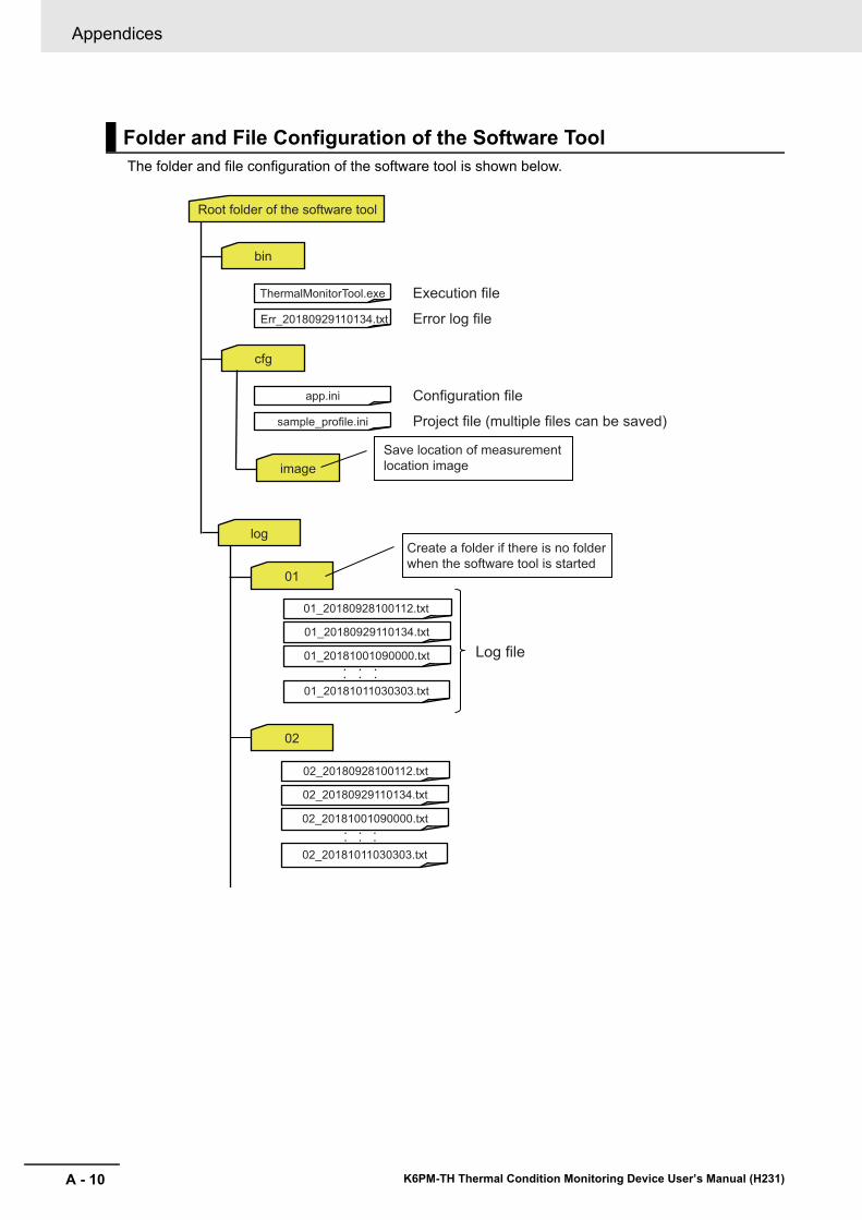
Appendices
A - 10 K6PM-TH Thermal Condition Monitoring Device User’s Manual (H231)
The folder and file configuration of the software tool is shown below.
Folder and File Configuration of the Software Tool
Root folder of the software tool
log
01_20180928100112.txt
01_20180929110134.txt
01_20181001090000.txt
01
02
01_20181011030303.txt
Log file
bin
ThermalMonitorTool.exe
Err_20180929110134.txt
Execution file
Error log file
Create a folder if there is no folder
when the software tool is started
02_20180928100112.txt
02_20180929110134.txt
02_20181001090000.txt
02_20181011030303.txt
cfg
app.ini
sample_profile.ini
Configuration file
Project file (multiple files can be saved)
image
Save location of measurement
location image
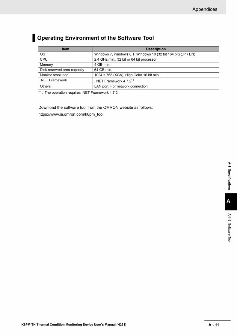
A - 11
Appendices
K6PM-TH Thermal Condition Monitoring Device User’s Manual (H231)
A-1 Specifications
A
A-1-3 Software Tool
Download the software tool from the OMRON website as follows:
https://www.ia.omron.com/k6pm_tool
Operating Environment of the Software Tool
Item DescriptionOS Windows 7, Windows 8.1, Windows 10 (32 bit / 64 bit) (JP / EN)CPU 2.4 GHz min., 32 bit or 64 bit processorMemory 4 GB min.Disk reserved area capacity 64 GB min.Monitor resolution 1024 × 768 (XGA), High Color 16 bit min..NET Framework . NET Framework 4.7.2*1
*1. The operation requires .NET Framework 4.7.2.
Others LAN port: For network connection
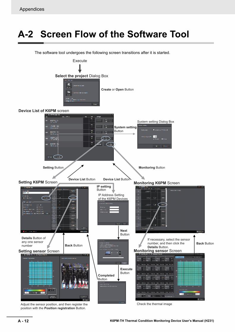
Appendices
A - 12 K6PM-TH Thermal Condition Monitoring Device User’s Manual (H231)
A-2 Screen Flow of the Software ToolThe software tool undergoes the following screen transitions after it is started.
Device List of K6PM screen
Setting Button
Execute
Setting K6PM Screen
Setting sensor Screen
Monitoring K6PM Screen
Monitoring sensor Screen
Details Button of
any one sensor
number
Check the thermal imageAdjust the sensor position, and then register the
position with the Position registration Button.
If necessary, select the sensor
number, and then click the
Details Button.
Monitoring Button
System setting
Button
IP Address Setting
of the K6PM Devices
System setting Dialog Box
Create or Open Button
Select the project Dialog Box
Device List Button
IP setting Button
Back Button
Completed
Button
Device List Button
Back Button
Next Button
Execute
Button
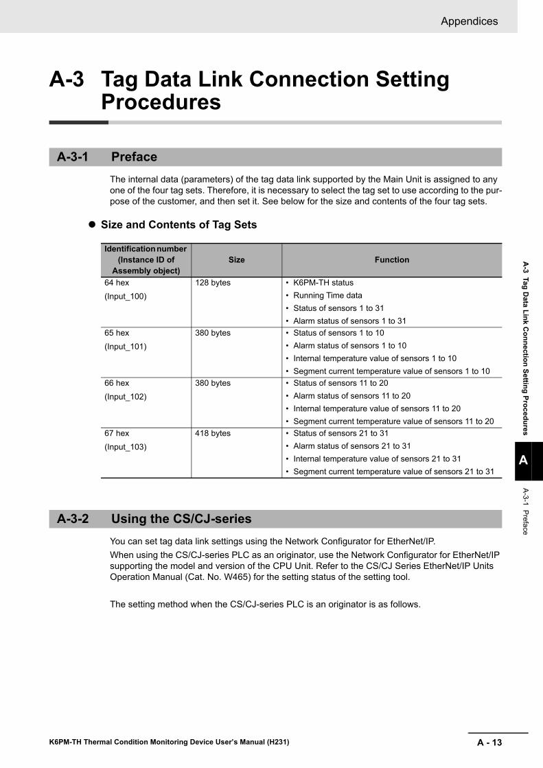
A - 13
Appendices
K6PM-TH Thermal Condition Monitoring Device User’s Manual (H231)
A-3 Tag D
ata Link Connection Setting Procedures
A
A-3-1 Preface
A-3 Tag Data Link Connection Setting Procedures
The internal data (parameters) of the tag data link supported by the Main Unit is assigned to any one of the four tag sets. Therefore, it is necessary to select the tag set to use according to the pur-pose of the customer, and then set it. See below for the size and contents of the four tag sets.
Size and Contents of Tag Sets
You can set tag data link settings using the Network Configurator for EtherNet/IP.When using the CS/CJ-series PLC as an originator, use the Network Configurator for EtherNet/IP supporting the model and version of the CPU Unit. Refer to the CS/CJ Series EtherNet/IP Units Operation Manual (Cat. No. W465) for the setting status of the setting tool.
The setting method when the CS/CJ-series PLC is an originator is as follows.
A-3-1 Preface
Identification number (Instance ID of
Assembly object)Size Function
64 hex(Input_100)
128 bytes • K6PM-TH status• Running Time data• Status of sensors 1 to 31• Alarm status of sensors 1 to 31
65 hex(Input_101)
380 bytes • Status of sensors 1 to 10• Alarm status of sensors 1 to 10• Internal temperature value of sensors 1 to 10• Segment current temperature value of sensors 1 to 10
66 hex(Input_102)
380 bytes • Status of sensors 11 to 20• Alarm status of sensors 11 to 20• Internal temperature value of sensors 11 to 20• Segment current temperature value of sensors 11 to 20
67 hex(Input_103)
418 bytes • Status of sensors 21 to 31• Alarm status of sensors 21 to 31• Internal temperature value of sensors 21 to 31• Segment current temperature value of sensors 21 to 31
A-3-2 Using the CS/CJ-series
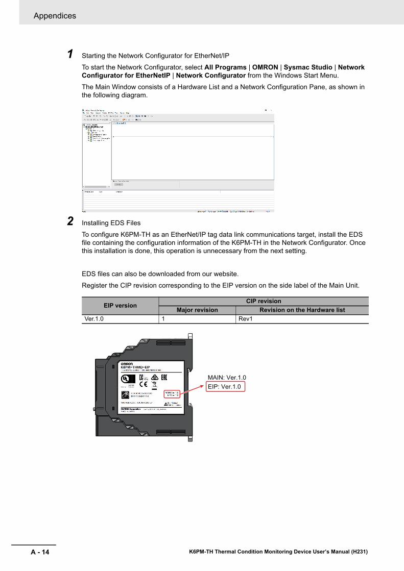
Appendices
A - 14 K6PM-TH Thermal Condition Monitoring Device User’s Manual (H231)
1 Starting the Network Configurator for EtherNet/IP
To start the Network Configurator, select All Programs | OMRON | Sysmac Studio | Network Configurator for EtherNetIP | Network Configurator from the Windows Start Menu.The Main Window consists of a Hardware List and a Network Configuration Pane, as shown in the following diagram.
2 Installing EDS Files
To configure K6PM-TH as an EtherNet/IP tag data link communications target, install the EDS file containing the configuration information of the K6PM-TH in the Network Configurator. Once this installation is done, this operation is unnecessary from the next setting.
EDS files can also be downloaded from our website.Register the CIP revision corresponding to the EIP version on the side label of the Main Unit.
EIP versionCIP revision
Major revision Revision on the Hardware listVer.1.0 1 Rev1
EIP: Ver.1.0
MAIN: Ver.1.0
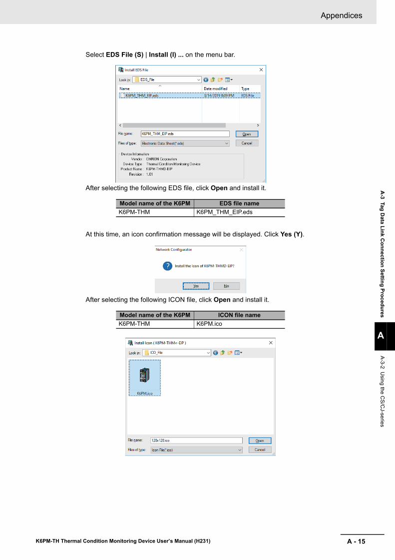
A - 15
Appendices
K6PM-TH Thermal Condition Monitoring Device User’s Manual (H231)
A-3 Tag D
ata Link Connection Setting Procedures
A
A-3-2 Using the C
S/CJ-series
Select EDS File (S) | Install (I) ... on the menu bar.
After selecting the following EDS file, click Open and install it.
At this time, an icon confirmation message will be displayed. Click Yes (Y).
After selecting the following ICON file, click Open and install it.
Model name of the K6PM EDS file nameK6PM-THM K6PM_THM_EIP.eds
Model name of the K6PM ICON file nameK6PM-THM K6PM.ico
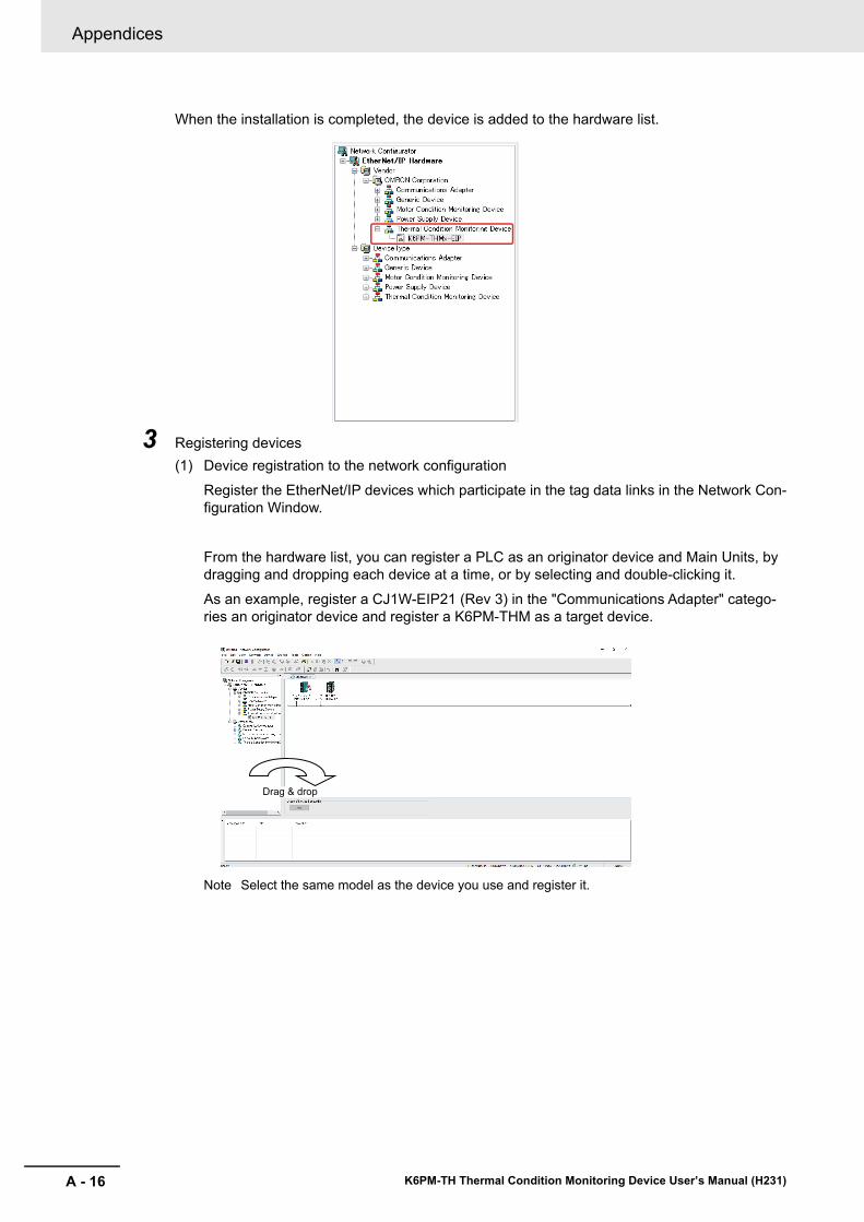
Appendices
A - 16 K6PM-TH Thermal Condition Monitoring Device User’s Manual (H231)
When the installation is completed, the device is added to the hardware list.
3 Registering devices(1) Device registration to the network configuration
Register the EtherNet/IP devices which participate in the tag data links in the Network Con-figuration Window.
From the hardware list, you can register a PLC as an originator device and Main Units, by dragging and dropping each device at a time, or by selecting and double-clicking it.As an example, register a CJ1W-EIP21 (Rev 3) in the "Communications Adapter" catego-ries an originator device and register a K6PM-THM as a target device.
Note Select the same model as the device you use and register it.
Drag & drop
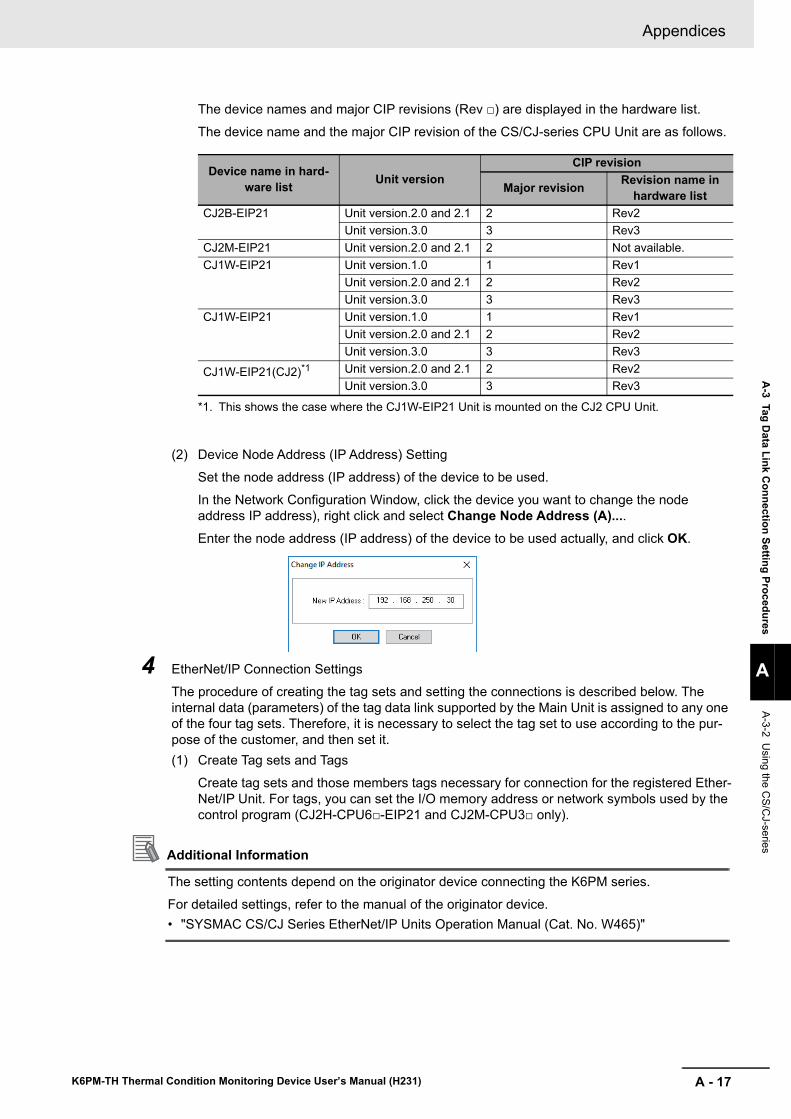
A - 17
Appendices
K6PM-TH Thermal Condition Monitoring Device User’s Manual (H231)
A-3 Tag D
ata Link Connection Setting Procedures
A
A-3-2 Using the C
S/CJ-series
The device names and major CIP revisions (Rev □) are displayed in the hardware list.
The device name and the major CIP revision of the CS/CJ-series CPU Unit are as follows.
(2) Device Node Address (IP Address) Setting
Set the node address (IP address) of the device to be used.In the Network Configuration Window, click the device you want to change the node address IP address), right click and select Change Node Address (A)....Enter the node address (IP address) of the device to be used actually, and click OK.
4 EtherNet/IP Connection SettingsThe procedure of creating the tag sets and setting the connections is described below. The internal data (parameters) of the tag data link supported by the Main Unit is assigned to any one of the four tag sets. Therefore, it is necessary to select the tag set to use according to the pur-pose of the customer, and then set it.(1) Create Tag sets and Tags
Create tag sets and those members tags necessary for connection for the registered Ether-Net/IP Unit. For tags, you can set the I/O memory address or network symbols used by the control program (CJ2H-CPU6□-EIP21 and CJ2M-CPU3□ only).
Additional Information
The setting contents depend on the originator device connecting the K6PM series.For detailed settings, refer to the manual of the originator device.• "SYSMAC CS/CJ Series EtherNet/IP Units Operation Manual (Cat. No. W465)"
Device name in hard-ware list Unit version
CIP revision
Major revision Revision name in hardware list
CJ2B-EIP21 Unit version.2.0 and 2.1 2 Rev2Unit version.3.0 3 Rev3
CJ2M-EIP21 Unit version.2.0 and 2.1 2 Not available.CJ1W-EIP21 Unit version.1.0 1 Rev1
Unit version.2.0 and 2.1 2 Rev2Unit version.3.0 3 Rev3
CJ1W-EIP21 Unit version.1.0 1 Rev1Unit version.2.0 and 2.1 2 Rev2Unit version.3.0 3 Rev3
CJ1W-EIP21(CJ2)*1
*1. This shows the case where the CJ1W-EIP21 Unit is mounted on the CJ2 CPU Unit.
Unit version.2.0 and 2.1 2 Rev2Unit version.3.0 3 Rev3
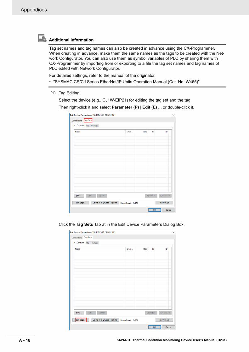
Appendices
A - 18 K6PM-TH Thermal Condition Monitoring Device User’s Manual (H231)
Additional Information
Tag set names and tag names can also be created in advance using the CX-Programmer. When creating in advance, make them the same names as the tags to be created with the Net-work Configurator. You can also use them as symbol variables of PLC by sharing them with CX-Programmer by importing from or exporting to a file the tag set names and tag names of PLC edited with Network Configurator.
For detailed settings, refer to the manual of the originator.• "SYSMAC CS/CJ Series EtherNet/IP Units Operation Manual (Cat. No. W465)"
(1) Tag Editing
Select the device (e.g., CJ1W-EIP21) for editing the tag set and the tag.Then right-click it and select Parameter (P) | Edit (E) ... or double-click it.
Click the Tag Sets Tab at in the Edit Device Parameters Dialog Box.
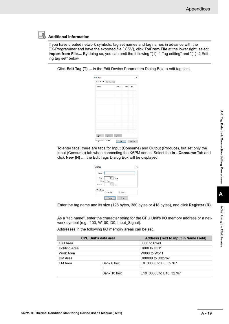
A - 19
Appendices
K6PM-TH Thermal Condition Monitoring Device User’s Manual (H231)
A-3 Tag D
ata Link Connection Setting Procedures
A
A-3-2 Using the C
S/CJ-series
Additional Information
If you have created network symbols, tag set names and tag names in advance with the CX-Programmer and have the exported file (.CSV), click To/From File at the lower right, select Import from File.... By doing so, you can omit the following "(1) -1 Tag editing" and "(1) -2 Edit-ing tag set" below.
Click Edit Tag (T) ... in the Edit Device Parameters Dialog Box to edit tag sets.
To enter tags, there are tabs for Input (Consume) and Output (Produce), but set only the Input (Consume) tab when connecting the K6PM series. Select the In - Consume Tab and click New (N) ..., the Edit Tags Dialog Box will be displayed.
Enter the tag name and its size (128 bytes, 380 bytes or 418 bytes), and click Register (R).
As a "tag name", enter the character string for the CPU Unit's I/O memory address or a net-work symbol (e.g., 100, W100, D0, Input_Signal).Addresses in the following I/O memory areas can be set.
CPU Unit’s data area Address (Text to input in Name Field)CIO Area 0000 to 6143Holding Area H000 to H511Work Area W000 to W511DM Area D00000 to D32767EM Area Bank 0 hex E0_00000 to E0_32767
: :Bank 18 hex E18_00000 to E18_32767
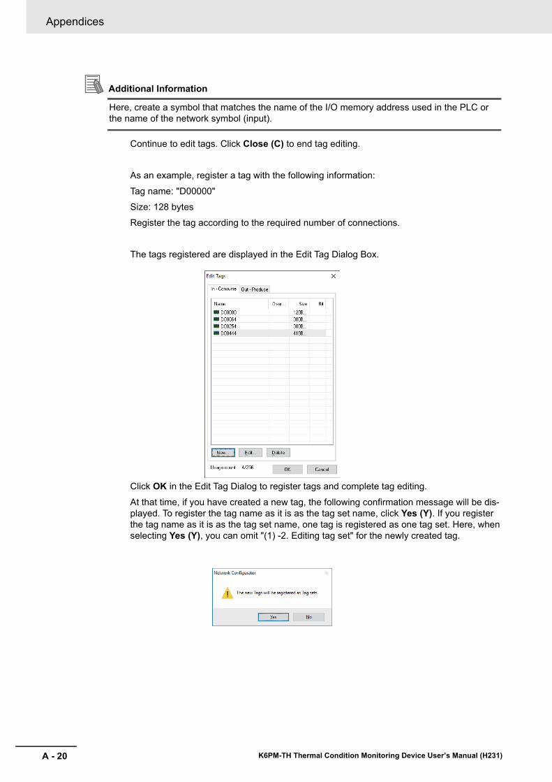
Appendices
A - 20 K6PM-TH Thermal Condition Monitoring Device User’s Manual (H231)
Additional Information
Here, create a symbol that matches the name of the I/O memory address used in the PLC or the name of the network symbol (input).
Continue to edit tags. Click Close (C) to end tag editing.
As an example, register a tag with the following information:
Tag name: "D00000"Size: 128 bytesRegister the tag according to the required number of connections.
The tags registered are displayed in the Edit Tag Dialog Box.
Click OK in the Edit Tag Dialog to register tags and complete tag editing.
At that time, if you have created a new tag, the following confirmation message will be dis-played. To register the tag name as it is as the tag set name, click Yes (Y). If you register the tag name as it is as the tag set name, one tag is registered as one tag set. Here, when selecting Yes (Y), you can omit "(1) -2. Editing tag set" for the newly created tag.
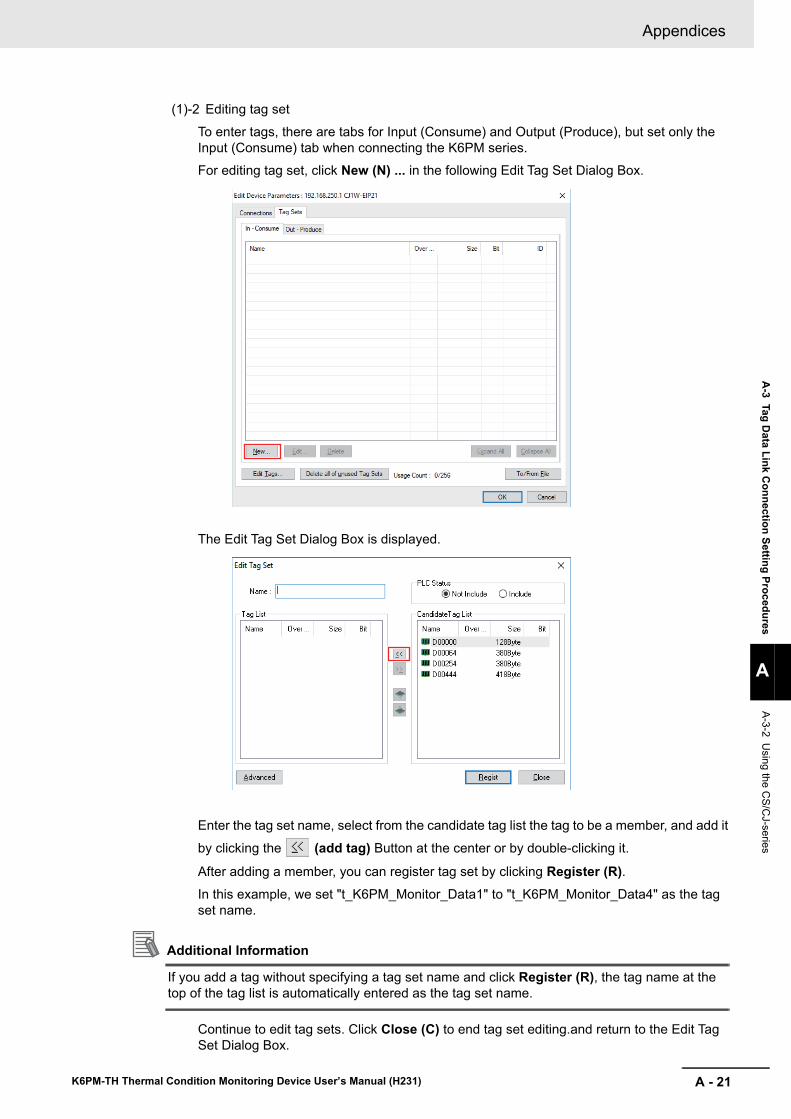
A - 21
Appendices
K6PM-TH Thermal Condition Monitoring Device User’s Manual (H231)
A-3 Tag D
ata Link Connection Setting Procedures
A
A-3-2 Using the C
S/CJ-series
(1)-2 Editing tag set
To enter tags, there are tabs for Input (Consume) and Output (Produce), but set only the Input (Consume) tab when connecting the K6PM series.For editing tag set, click New (N) ... in the following Edit Tag Set Dialog Box.
The Edit Tag Set Dialog Box is displayed.
Enter the tag set name, select from the candidate tag list the tag to be a member, and add it
by clicking the (add tag) Button at the center or by double-clicking it.
After adding a member, you can register tag set by clicking Register (R).In this example, we set "t_K6PM_Monitor_Data1" to "t_K6PM_Monitor_Data4" as the tag set name.
Additional Information
If you add a tag without specifying a tag set name and click Register (R), the tag name at the top of the tag list is automatically entered as the tag set name.
Continue to edit tag sets. Click Close (C) to end tag set editing.and return to the Edit Tag Set Dialog Box.
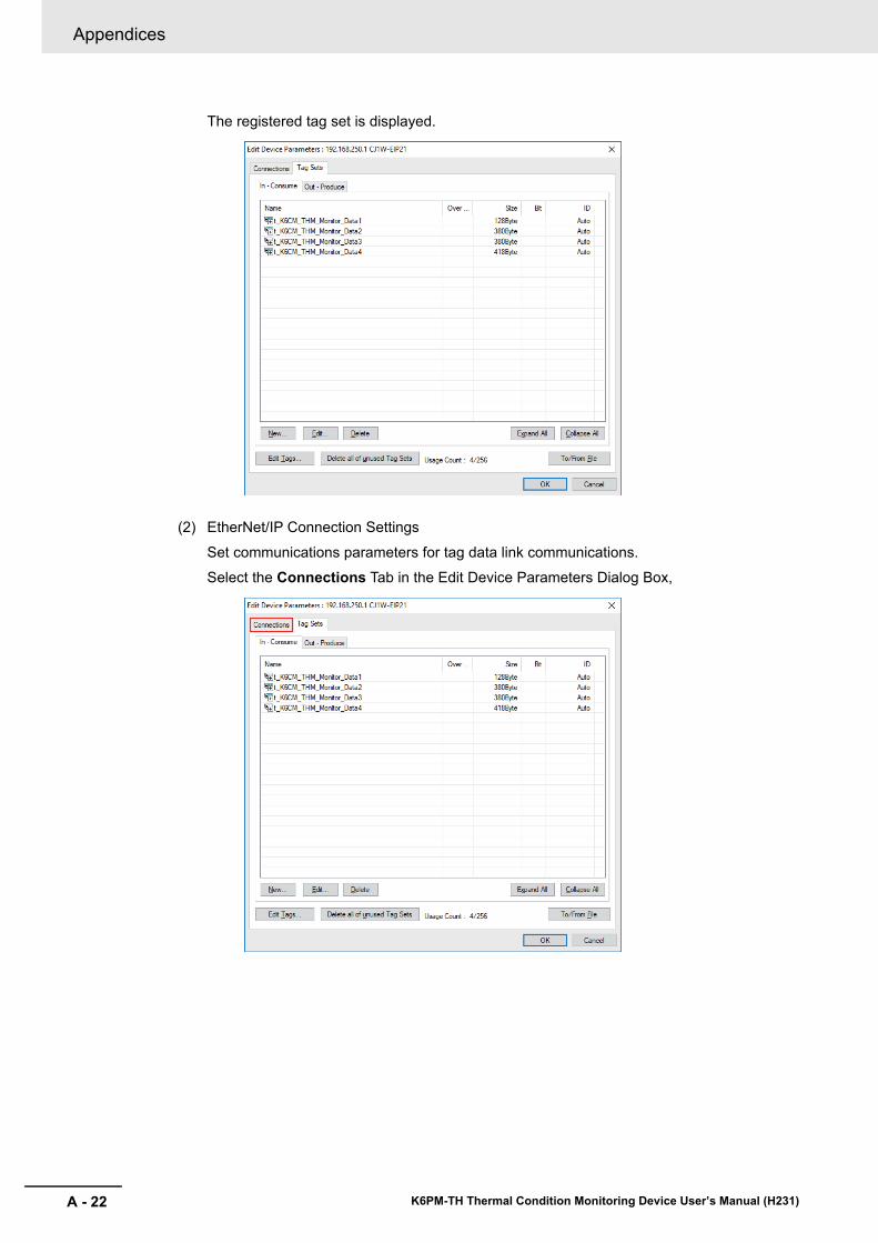
Appendices
A - 22 K6PM-TH Thermal Condition Monitoring Device User’s Manual (H231)
The registered tag set is displayed.
(2) EtherNet/IP Connection Settings
Set communications parameters for tag data link communications.Select the Connections Tab in the Edit Device Parameters Dialog Box,
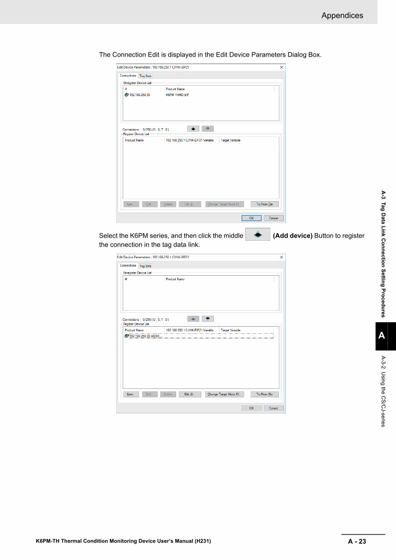
A - 23
Appendices
K6PM-TH Thermal Condition Monitoring Device User’s Manual (H231)
A-3 Tag D
ata Link Connection Setting Procedures
A
A-3-2 Using the C
S/CJ-series
The Connection Edit is displayed in the Edit Device Parameters Dialog Box.
Select the K6PM series, and then click the middle (Add device) Button to register the connection in the tag data link.
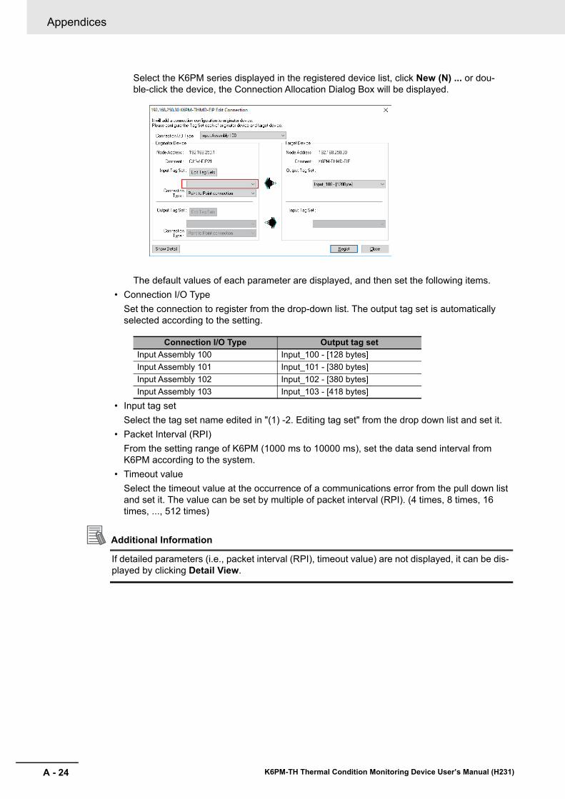
Appendices
A - 24 K6PM-TH Thermal Condition Monitoring Device User’s Manual (H231)
Select the K6PM series displayed in the registered device list, click New (N) ... or dou-ble-click the device, the Connection Allocation Dialog Box will be displayed.
The default values of each parameter are displayed, and then set the following items.• Connection I/O Type
Set the connection to register from the drop-down list. The output tag set is automatically selected according to the setting.
• Input tag setSelect the tag set name edited in "(1) -2. Editing tag set" from the drop down list and set it.
• Packet Interval (RPI)From the setting range of K6PM (1000 ms to 10000 ms), set the data send interval from K6PM according to the system.
• Timeout valueSelect the timeout value at the occurrence of a communications error from the pull down list and set it. The value can be set by multiple of packet interval (RPI). (4 times, 8 times, 16 times, ..., 512 times)
Additional Information
If detailed parameters (i.e., packet interval (RPI), timeout value) are not displayed, it can be dis-played by clicking Detail View.
Connection I/O Type Output tag setInput Assembly 100 Input_100 - [128 bytes]Input Assembly 101 Input_101 - [380 bytes]Input Assembly 102 Input_102 - [380 bytes]Input Assembly 103 Input_103 - [418 bytes]
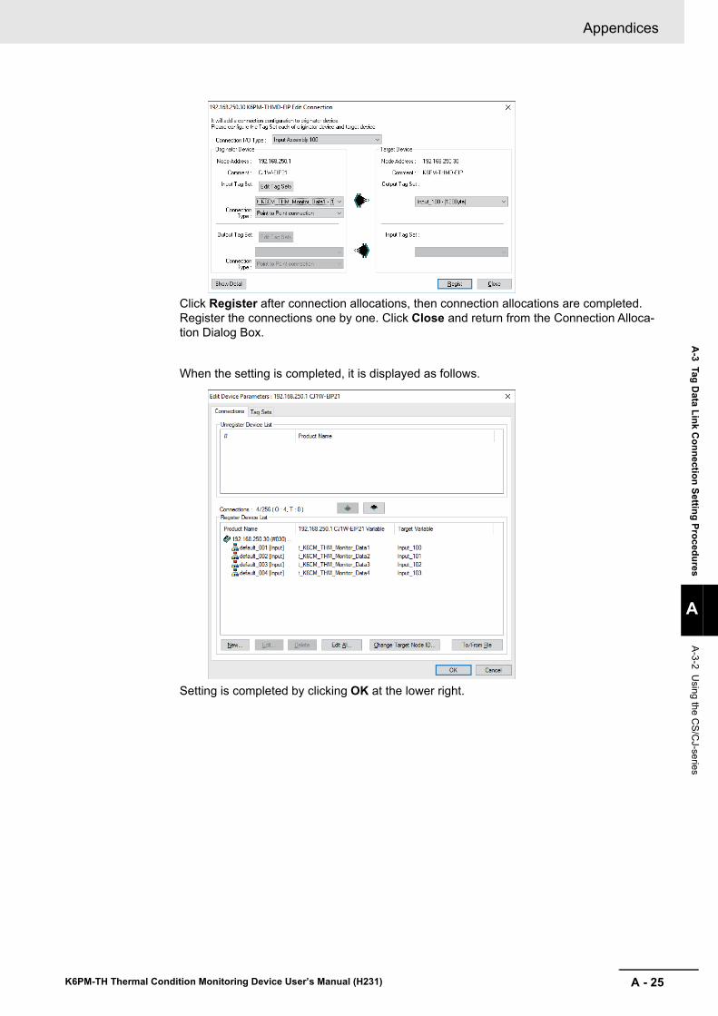
A - 25
Appendices
K6PM-TH Thermal Condition Monitoring Device User’s Manual (H231)
A-3 Tag D
ata Link Connection Setting Procedures
A
A-3-2 Using the C
S/CJ-series
Click Register after connection allocations, then connection allocations are completed. Register the connections one by one. Click Close and return from the Connection Alloca-tion Dialog Box.
When the setting is completed, it is displayed as follows.
Setting is completed by clicking OK at the lower right.
Appendices
A - 26 K6PM-TH Thermal Condition Monitoring Device User’s Manual (H231)
5 Downloading settings
Connect online to the originator device and download the configuration settings.(The EtherNet/IP tag data link communications setting of the K6PM series is fixed, so you do not need to download it to the K6PM.)(1) Online
Select the communications interface to use from Option (O) | Select Interface (I) on the menu bar. (This operation is unnecessary if interface is not changed after interface setting.)
Then, select Network (N) | Connection (C) ... on the menu bar or click (Online button) to go online to the EtherNet/IP network.After online, select the originator device (PLC) to download, right click it and select Param-eter (P) | Download (D) and download it.
Additional Information
For details on online and download operations, refer to the manual of the originator device.For detailed settings, refer to the manual of the originator device.• "SYSMAC CS/CJ Series EtherNet/IP Units Operation Manual (Cat. No. W465)"
With the Sysmac Studio Ver.1.10 or higher, tag data link (EtherNet/IP connection) setting is possi-ble when using NJ/NX-series PLC as a tag data link originator.
Creating Network Variables (Input)Create Input area in the PLC to receive Input data from K6PM devices.The setting method for the NJ/NX-series PLC is shown below.
1 Starting the SysmacStudio
Start the SysmacStudio in one of the following ways.• Double-click the shortcut icon of Sysmac Studio on the desktop.
• To start the Sysmac Studio, select All Programs | OMRON | Sysmac Studio | Sysmac Stu-dio from the Windows Start Menu.
A-3-3 Using the NJ/NX-series

A - 27
Appendices
K6PM-TH Thermal Condition Monitoring Device User’s Manual (H231)
A-3 Tag D
ata Link Connection Setting Procedures
A
A-3-3 Using the N
J/NX-series
2 Creating Project File
Click New Project in the upper left in the start page.To edit an existing project file, click Open Project and select the saved project.
Enter the Project name, author, and comment in the Project Properties Dialog Box, select the device category, the device (PLC model) to use and its version, and then click the Create But-ton. (Only the project name is required.)
When you finish setting Project Properties, the following screen will be displayed.
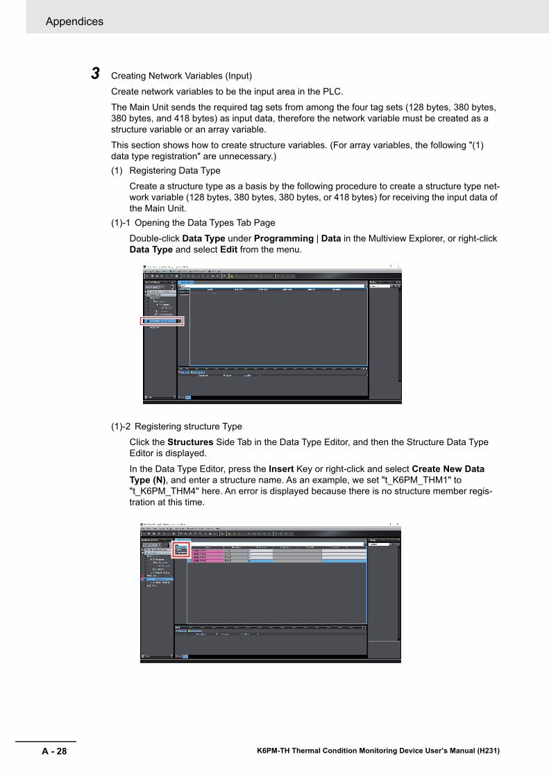
Appendices
A - 28 K6PM-TH Thermal Condition Monitoring Device User’s Manual (H231)
3 Creating Network Variables (Input)
Create network variables to be the input area in the PLC.The Main Unit sends the required tag sets from among the four tag sets (128 bytes, 380 bytes, 380 bytes, and 418 bytes) as input data, therefore the network variable must be created as a structure variable or an array variable.
This section shows how to create structure variables. (For array variables, the following "(1) data type registration" are unnecessary.)(1) Registering Data Type
Create a structure type as a basis by the following procedure to create a structure type net-work variable (128 bytes, 380 bytes, 380 bytes, or 418 bytes) for receiving the input data of the Main Unit.
(1)-1 Opening the Data Types Tab PageDouble-click Data Type under Programming | Data in the Multiview Explorer, or right-click Data Type and select Edit from the menu.
(1)-2 Registering structure TypeClick the Structures Side Tab in the Data Type Editor, and then the Structure Data Type Editor is displayed.
In the Data Type Editor, press the Insert Key or right-click and select Create New Data Type (N), and enter a structure name. As an example, we set "t_K6PM_THM1" to "t_K6PM_THM4" here. An error is displayed because there is no structure member regis-tration at this time.
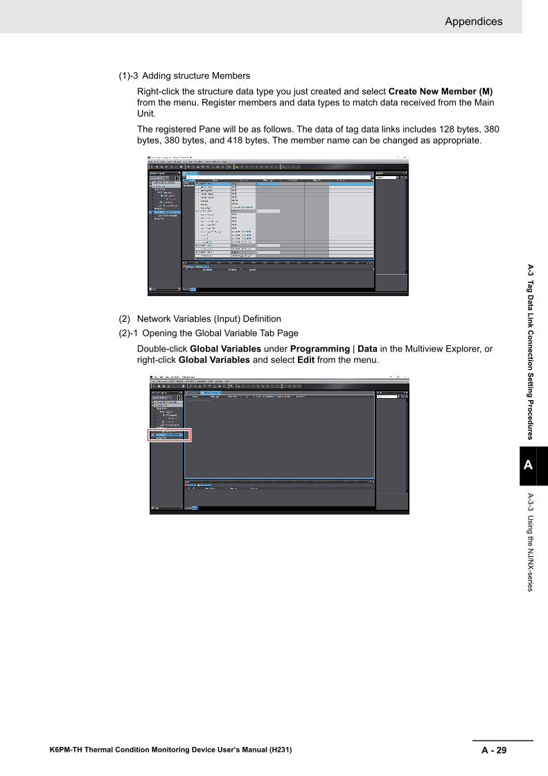
A - 29
Appendices
K6PM-TH Thermal Condition Monitoring Device User’s Manual (H231)
A-3 Tag D
ata Link Connection Setting Procedures
A
A-3-3 Using the N
J/NX-series
(1)-3 Adding structure Members
Right-click the structure data type you just created and select Create New Member (M) from the menu. Register members and data types to match data received from the Main Unit.The registered Pane will be as follows. The data of tag data links includes 128 bytes, 380 bytes, 380 bytes, and 418 bytes. The member name can be changed as appropriate.
(2) Network Variables (Input) Definition(2)-1 Opening the Global Variable Tab Page
Double-click Global Variables under Programming | Data in the Multiview Explorer, or right-click Global Variables and select Edit from the menu.
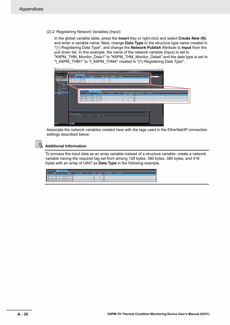
Appendices
A - 30 K6PM-TH Thermal Condition Monitoring Device User’s Manual (H231)
(2)-2 Registering Network Variables (Input)
In the global variable table, press the Insert Key or right-click and select Create New (N), and enter a variable name. Next, change Data Type to the structure type name created in "(1) Registering Data Type", and change the Network Publish Attribute to Input from the pull down list. In this example, the name of the network variable (input) is set to "K6PM_THM_Monitor_Data1" to "K6PM_THM_Monitor_Data4" and the data type is set to "t_K6PM_THM1" to "t_K6PM_THM4" created in "(1) Registering Data Type".
Associate the network variables created here with the tags used in the EtherNet/IP connection settings described below.
Additional Information
To process the input data as an array variable instead of a structure variable, create a network variable having the required tag set from among 128 bytes, 380 bytes, 380 bytes, and 418 bytes with an array of UINT as Data Type in the following example.
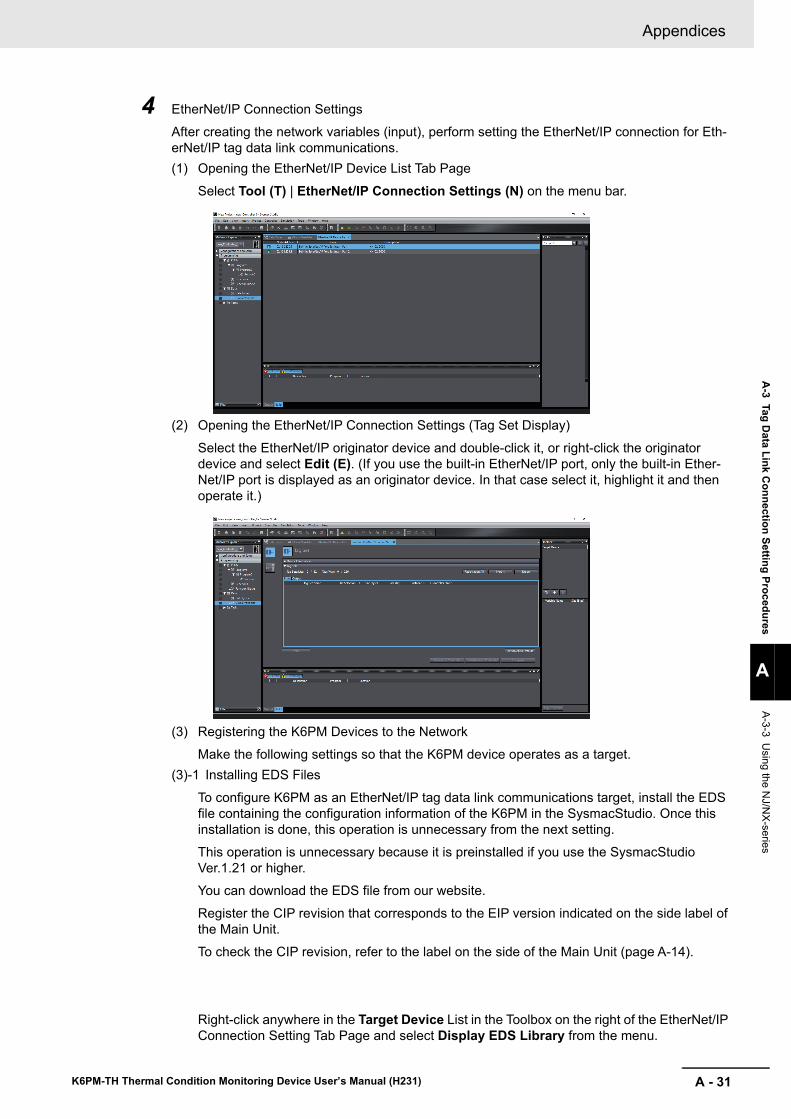
A - 31
Appendices
K6PM-TH Thermal Condition Monitoring Device User’s Manual (H231)
A-3 Tag D
ata Link Connection Setting Procedures
A
A-3-3 Using the N
J/NX-series
4 EtherNet/IP Connection Settings
After creating the network variables (input), perform setting the EtherNet/IP connection for Eth-erNet/IP tag data link communications.(1) Opening the EtherNet/IP Device List Tab Page
Select Tool (T) | EtherNet/IP Connection Settings (N) on the menu bar.
(2) Opening the EtherNet/IP Connection Settings (Tag Set Display)
Select the EtherNet/IP originator device and double-click it, or right-click the originator device and select Edit (E). (If you use the built-in EtherNet/IP port, only the built-in Ether-Net/IP port is displayed as an originator device. In that case select it, highlight it and then operate it.)
(3) Registering the K6PM Devices to the NetworkMake the following settings so that the K6PM device operates as a target.
(3)-1 Installing EDS Files
To configure K6PM as an EtherNet/IP tag data link communications target, install the EDS file containing the configuration information of the K6PM in the SysmacStudio. Once this installation is done, this operation is unnecessary from the next setting.This operation is unnecessary because it is preinstalled if you use the SysmacStudio Ver.1.21 or higher. You can download the EDS file from our website.
Register the CIP revision that corresponds to the EIP version indicated on the side label of the Main Unit. To check the CIP revision, refer to the label on the side of the Main Unit (page A-14).
Right-click anywhere in the Target Device List in the Toolbox on the right of the EtherNet/IP Connection Setting Tab Page and select Display EDS Library from the menu.
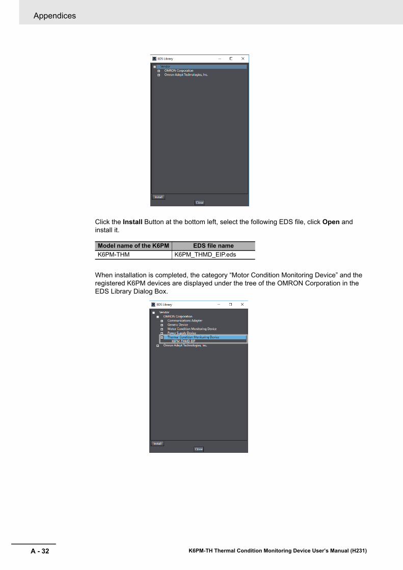
Appendices
A - 32 K6PM-TH Thermal Condition Monitoring Device User’s Manual (H231)
Click the Install Button at the bottom left, select the following EDS file, click Open and install it.
When installation is completed, the category “Motor Condition Monitoring Device” and the registered K6PM devices are displayed under the tree of the OMRON Corporation in the EDS Library Dialog Box.
Model name of the K6PM EDS file nameK6PM-THM K6PM_THMD_EIP.eds
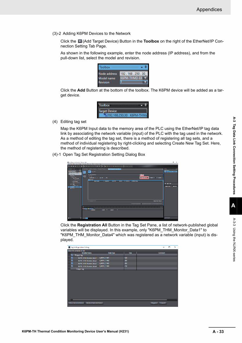
A - 33
Appendices
K6PM-TH Thermal Condition Monitoring Device User’s Manual (H231)
A-3 Tag D
ata Link Connection Setting Procedures
A
A-3-3 Using the N
J/NX-series
(3)-2 Adding K6PM Devices to the Network
Click the (Add Target Device) Button in the Toolbox on the right of the EtherNet/IP Con-nection Setting Tab Page.As shown in the following example, enter the node address (IP address), and from the pull-down list, select the model and revision.
Click the Add Button at the bottom of the toolbox. The K6PM device will be added as a tar-get device.
(4) Editing tag set
Map the K6PM Input data to the memory area of the PLC using the EtherNet/IP tag data link by associating the network variable (input) of the PLC with the tag used in the network. As a method of editing the tag set, there is a method of registering all tag sets, and a method of individual registering by right-clicking and selecting Create New Tag Set. Here, the method of registering is described.
(4)-1 Open Tag Set Registration Setting Dialog Box
Click the Registration All Button in the Tag Set Pane, a list of network-published global variables will be displayed. In this example, only "K6PM_THM_Monitor_Data1" to "K6PM_THM_Monitor_Data4" which was registered as a network variable (input) is dis-played.
ClickClickClick
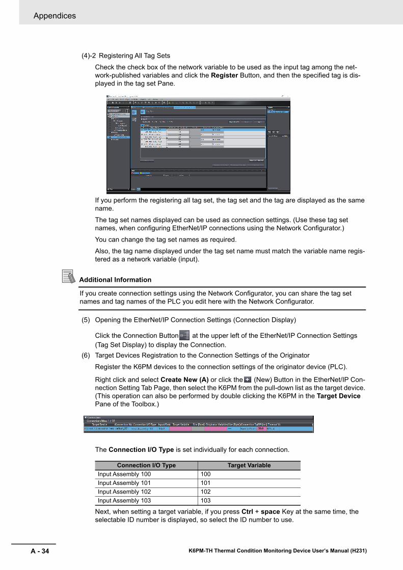
Appendices
A - 34 K6PM-TH Thermal Condition Monitoring Device User’s Manual (H231)
(4)-2 Registering All Tag Sets
Check the check box of the network variable to be used as the input tag among the net-work-published variables and click the Register Button, and then the specified tag is dis-played in the tag set Pane.
If you perform the registering all tag set, the tag set and the tag are displayed as the same name.
The tag set names displayed can be used as connection settings. (Use these tag set names, when configuring EtherNet/IP connections using the Network Configurator.)You can change the tag set names as required.Also, the tag name displayed under the tag set name must match the variable name regis-tered as a network variable (input).
Additional Information
If you create connection settings using the Network Configurator, you can share the tag set names and tag names of the PLC you edit here with the Network Configurator.
(5) Opening the EtherNet/IP Connection Settings (Connection Display)
Click the Connection Button at the upper left of the EtherNet/IP Connection Settings (Tag Set Display) to display the Connection.
(6) Target Devices Registration to the Connection Settings of the OriginatorRegister the K6PM devices to the connection settings of the originator device (PLC).
Right click and select Create New (A) or click the (New) Button in the EtherNet/IP Con-nection Setting Tab Page, then select the K6PM from the pull-down list as the target device. (This operation can also be performed by double clicking the K6PM in the Target Device Pane of the Toolbox.)
The Connection I/O Type is set individually for each connection.
Next, when setting a target variable, if you press Ctrl + space Key at the same time, the selectable ID number is displayed, so select the ID number to use.
Connection I/O Type Target VariableInput Assembly 100 100Input Assembly 101 101Input Assembly 102 102Input Assembly 103 103
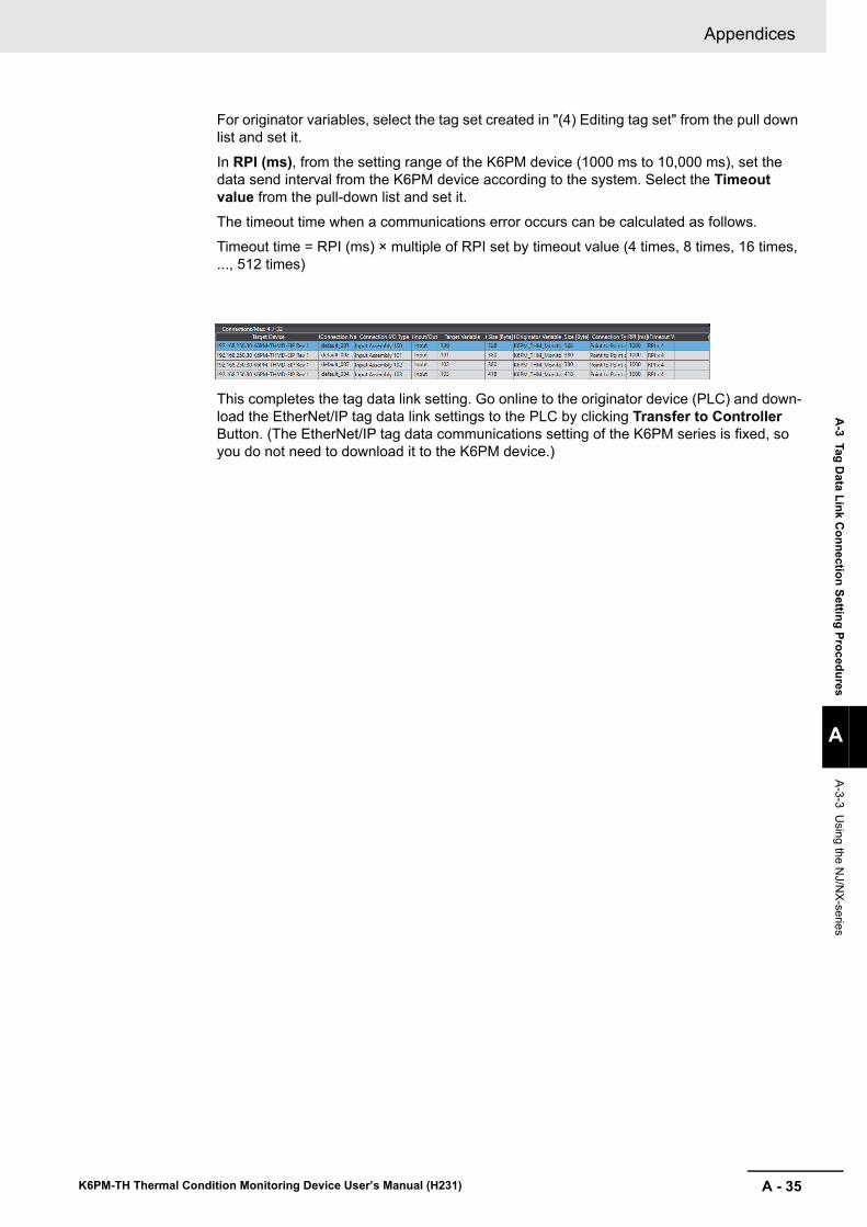
A - 35
Appendices
K6PM-TH Thermal Condition Monitoring Device User’s Manual (H231)
A-3 Tag D
ata Link Connection Setting Procedures
A
A-3-3 Using the N
J/NX-series
For originator variables, select the tag set created in "(4) Editing tag set" from the pull down list and set it.
In RPI (ms), from the setting range of the K6PM device (1000 ms to 10,000 ms), set the data send interval from the K6PM device according to the system. Select the Timeout value from the pull-down list and set it.The timeout time when a communications error occurs can be calculated as follows.
Timeout time = RPI (ms) × multiple of RPI set by timeout value (4 times, 8 times, 16 times, ..., 512 times)
This completes the tag data link setting. Go online to the originator device (PLC) and down-load the EtherNet/IP tag data link settings to the PLC by clicking Transfer to Controller Button. (The EtherNet/IP tag data communications setting of the K6PM series is fixed, so you do not need to download it to the K6PM device.)
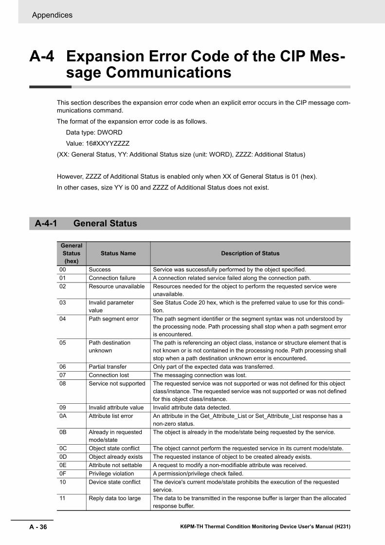
Appendices
A - 36 K6PM-TH Thermal Condition Monitoring Device User’s Manual (H231)
A-4 Expansion Error Code of the CIP Mes-sage Communications
This section describes the expansion error code when an explicit error occurs in the CIP message com-munications command.The format of the expansion error code is as follows.
Data type: DWORDValue: 16#XXYYZZZZ
(XX: General Status, YY: Additional Status size (unit: WORD), ZZZZ: Additional Status)
However, ZZZZ of Additional Status is enabled only when XX of General Status is 01 (hex).In other cases, size YY is 00 and ZZZZ of Additional Status does not exist.
A-4-1 General Status
General Status (hex)
Status Name Description of Status
00 Success Service was successfully performed by the object specified.01 Connection failure A connection related service failed along the connection path.02 Resource unavailable Resources needed for the object to perform the requested service were
unavailable.03 Invalid parameter
valueSee Status Code 20 hex, which is the preferred value to use for this condi-tion.
04 Path segment error The path segment identifier or the segment syntax was not understood by the processing node. Path processing shall stop when a path segment error is encountered.
05 Path destination unknown
The path is referencing an object class, instance or structure element that is not known or is not contained in the processing node. Path processing shall stop when a path destination unknown error is encountered.
06 Partial transfer Only part of the expected data was transferred.07 Connection lost The messaging connection was lost.08 Service not supported The requested service was not supported or was not defined for this object
class/instance. The requested service was not supported or was not defined for this object class/instance.
09 Invalid attribute value Invalid attribute data detected.0A Attribute list error An attribute in the Get_Attribute_List or Set_Attribute_List response has a
non-zero status.0B Already in requested
mode/stateThe object is already in the mode/state being requested by the service.
0C Object state conflict The object cannot perform the requested service in its current mode/state.0D Object already exists The requested instance of object to be created already exists.0E Attribute not settable A request to modify a non-modifiable attribute was received.0F Privilege violation A permission/privilege check failed.10 Device state conflict The device's current mode/state prohibits the execution of the requested
service.11 Reply data too large The data to be transmitted in the response buffer is larger than the allocated
response buffer.
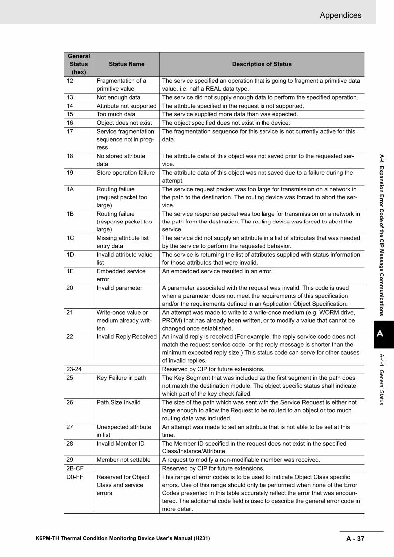
A - 37
Appendices
K6PM-TH Thermal Condition Monitoring Device User’s Manual (H231)
A-4 Expansion Error C
ode of the CIP M
essage Com
munications
A
A-4-1 General Status
12 Fragmentation of a primitive value
The service specified an operation that is going to fragment a primitive data value, i.e. half a REAL data type.
13 Not enough data The service did not supply enough data to perform the specified operation.14 Attribute not supported The attribute specified in the request is not supported.15 Too much data The service supplied more data than was expected.16 Object does not exist The object specified does not exist in the device.17 Service fragmentation
sequence not in prog-ress
The fragmentation sequence for this service is not currently active for this data.
18 No stored attribute data
The attribute data of this object was not saved prior to the requested ser-vice.
19 Store operation failure The attribute data of this object was not saved due to a failure during the attempt.
1A Routing failure (request packet too large)
The service request packet was too large for transmission on a network in the path to the destination. The routing device was forced to abort the ser-vice.
1B Routing failure (response packet too large)
The service response packet was too large for transmission on a network in the path from the destination. The routing device was forced to abort the service.
1C Missing attribute list entry data
The service did not supply an attribute in a list of attributes that was needed by the service to perform the requested behavior.
1D Invalid attribute value list
The service is returning the list of attributes supplied with status information for those attributes that were invalid.
1E Embedded service error
An embedded service resulted in an error.
20 Invalid parameter A parameter associated with the request was invalid. This code is used when a parameter does not meet the requirements of this specification and/or the requirements defined in an Application Object Specification.
21 Write-once value or medium already writ-ten
An attempt was made to write to a write-once medium (e.g. WORM drive, PROM) that has already been written, or to modify a value that cannot be changed once established.
22 Invalid Reply Received An invalid reply is received (For example, the reply service code does not match the request service code, or the reply message is shorter than the minimum expected reply size.) This status code can serve for other causes of invalid replies.
23-24 Reserved by CIP for future extensions.25 Key Failure in path The Key Segment that was included as the first segment in the path does
not match the destination module. The object specific status shall indicate which part of the key check failed.
26 Path Size Invalid The size of the path which was sent with the Service Request is either not large enough to allow the Request to be routed to an object or too much routing data was included.
27 Unexpected attribute in list
An attempt was made to set an attribute that is not able to be set at this time.
28 Invalid Member ID The Member ID specified in the request does not exist in the specified Class/Instance/Attribute.
29 Member not settable A request to modify a non-modifiable member was received.2B-CF Reserved by CIP for future extensions.D0-FF Reserved for Object
Class and service errors
This range of error codes is to be used to indicate Object Class specific errors. Use of this range should only be performed when none of the Error Codes presented in this table accurately reflect the error that was encoun-tered. The additional code field is used to describe the general error code in more detail.
General Status (hex)
Status Name Description of Status
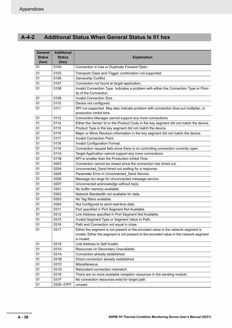
Appendices
A - 38 K6PM-TH Thermal Condition Monitoring Device User’s Manual (H231)
A-4-2 Additional Status When General Status Is 01 hex
General Status (hex)
Additional Status (hex)
Explanation
01 0100 Connection in Use or Duplicate Forward Open.
01 0103 Transport Class and Trigger combination not supported.01 0106 Ownership Conflict.01 0107 Connection not found at target application.01 0108 Invalid Connection Type. Indicates a problem with either the Connection Type or Prior-
ity of the Connection.01 0109 Invalid Connection Size.01 0110 Device not configured.01 0111 RPI not supported. May also indicate problem with connection time-out multiplier, or
production inhibit time.01 0113 Connection Manager cannot support any more connections.01 0114 Either the Vendor Id or the Product Code in the key segment did not match the device.01 0115 Product Type in the key segment did not match the device.01 0116 Major or Minor Revision information in the key segment did not match the device.01 0117 Invalid Connection Point.01 0118 Invalid Configuration Format.01 0119 Connection request fails since there is no controlling connection currently open.01 011A Target Application cannot support any more connections.01 011B RPI is smaller than the Production Inhibit Time.01 0203 Connection cannot be closed since the connection has timed out.01 0204 Unconnected_Send timed out waiting for a response.01 0205 Parameter Error in Unconnected_Send Service.01 0206 Message too large for Unconnected message service.01 0207 Unconnected acknowledge without reply.01 0301 No buffer memory available.01 0302 Network Bandwidth not available for data.01 0303 No Tag filters available.01 0304 Not Configured to send real-time data.01 0311 Port specified in Port Segment Not Available.01 0312 Link Address specified in Port Segment Not Available.01 0315 Invalid Segment Type or Segment Value in Path.01 0316 Path and Connection not equal in close.01 0317 Either the segment is not present or the encoded value in the network segment is
invalid. Either the segment is not present or the encoded value in the network segment is invalid.
01 0318 Link Address to Self Invalid.01 0319 Resources on Secondary Unavailable.01 031A Connection already established.01 031B Direct connection already established.01 031C Miscellaneous.01 031D Redundant connection mismatch.01 031E There are no more available reception resources in the sending module.01 031F No connection resources exist for target path.01 0320- 07FF unused.

I - 1
I
K6PM-TH Thermal Condition Monitoring Device User’s Manual (H231)
Index
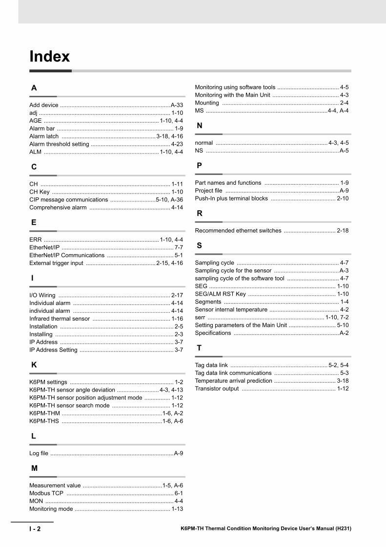
I - 2 K6PM-TH Thermal Condition Monitoring Device User’s Manual (H231)
Index
A
Add device ....................................................................A-33adj ................................................................................. 1-10AGE ....................................................................... 1-10, 4-4Alarm bar ........................................................................ 1-9Alarm latch .......................................................... 3-18, 4-16Alarm threshold setting ................................................. 4-23ALM ....................................................................... 1-10, 4-4
C
CH ................................................................................ 1-11CH Key ......................................................................... 1-10CIP message communications ............................5-10, A-36Comprehensive alarm .................................................. 4-14
E
ERR ....................................................................... 1-10, 4-4EtherNet/IP ..................................................................... 7-7EtherNet/IP Communications ......................................... 5-1External trigger input ........................................... 2-15, 4-16
I
I/O Wiring ..................................................................... 2-17Individual alarm ............................................................ 4-14individual alarm ............................................................ 4-14Infrared thermal sensor ................................................ 1-16Installation ...................................................................... 2-5Installing ......................................................................... 2-3IP Address ...................................................................... 3-7IP Address Setting .......................................................... 3-7
K
K6PM settings ................................................................ 1-2K6PM-TH sensor angle deviation .......................... 4-3, 4-13K6PM-TH sensor position adjustment mode ................ 1-12K6PM-TH sensor search mode .................................... 1-12K6PM-THM ..............................................................1-6, A-2K6PM-THS ..............................................................1-6, A-6
L
Log file ............................................................................A-9
M
Measurement value .................................................1-5, A-6Modbus TCP .................................................................. 6-1MON ............................................................................... 4-4Monitoring mode ........................................................... 1-13
Monitoring using software tools ...................................... 4-5Monitoring with the Main Unit ......................................... 4-3Mounting ........................................................................ 2-4MS ...........................................................................4-4, A-4
N
normal ..................................................................... 4-3, 4-5NS ..................................................................................A-5
P
Part names and functions .............................................. 1-9Project file ......................................................................A-9Push-In plus terminal blocks ........................................ 2-10
R
Recommended ethernet switches ................................ 2-18
S
Sampling cycle ............................................................... 4-7Sampling cycle for the sensor ........................................A-3sampling cycle of the software tool ................................ 4-7SEG .............................................................................. 1-10SEG/ALM RST Key ...................................................... 1-10Segments ....................................................................... 1-4Sensor internal temperature ........................................... 4-2serr ........................................................................ 1-10, 7-2Setting parameters of the Main Unit ............................. 5-10Specifications .................................................................A-2
T
Tag data link ............................................................ 5-2, 5-4Tag data link communications ........................................ 5-3Temperature arrival prediction ...................................... 3-18Transistor output .......................................................... 1-12


Authorized Distributor:
In the interest of product improvement, specifications are subject to change without notice.
Cat. No. H231-E1-03 0420
© OMRON Corporation 2019-2020 All Rights Reserved.
OMRON Corporation Industrial Automation Company
OMRON ELECTRONICS LLC2895 Greenspoint Parkway, Suite 200 Hoffman Estates, IL 60169 U.S.A.Tel: (1) 847-843-7900/Fax: (1) 847-843-7787
Regional HeadquartersOMRON EUROPE B.V.Wegalaan 67-69, 2132 JD HoofddorpThe NetherlandsTel: (31)2356-81-300/Fax: (31)2356-81-388
Contact: www.ia.omron.comKyoto, JAPAN
OMRON ASIA PACIFIC PTE. LTD.No. 438A Alexandra Road # 05-05/08 (Lobby 2), Alexandra Technopark, Singapore 119967Tel: (65) 6835-3011/Fax: (65) 6835-2711
OMRON (CHINA) CO., LTD.Room 2211, Bank of China Tower, 200 Yin Cheng Zhong Road, PuDong New Area, Shanghai, 200120, ChinaTel: (86) 21-5037-2222/Fax: (86) 21-5037-2200


