Embed Size (px)
Citation preview

This article appeared in a journal published by Elsevier. The attachedcopy is furnished to the author for internal non-commercial researchand education use, including for instruction at the authors institution
and sharing with colleagues.
Other uses, including reproduction and distribution, or selling orlicensing copies, or posting to personal, institutional or third party
websites are prohibited.
In most cases authors are permitted to post their version of thearticle (e.g. in Word or Tex form) to their personal website orinstitutional repository. Authors requiring further information
regarding Elsevier’s archiving and manuscript policies areencouraged to visit:
http://www.elsevier.com/authorsrights

Author's personal copy
Buckling analysis of rectangular functionally graded plates undervarious edge conditions using Fourier series expansion
Matin Latifi a, Fatemeh Farhatnia a,*, Mahmoud Kadkhodaei b
a Faculty of Mechanical Engineering, Islamic Azad University (IAU), Branch of Khomeinishahr, Boulevard Manzariye, Khomeinishahr, Isfahan 84181-48499,IranbDepartment of Mechanical Engineering, Isfahan University of Technology, Isfahan 84156-83111, Iran
a r t i c l e i n f o
Article history:Received 9 September 2011Accepted 27 January 2013Available online 19 February 2013
Keywords:BucklingFunctionally graded materialStokes’ transformation methodClassical plate theoryFourier seriesRectangular plate
a b s t r a c t
In this paper, the buckling problem of thin rectangular functionally graded plates subjected to propor-tional biaxial compressive loadings with arbitrary edge supports is investigated. Classical plate theory(CPT) based on the physical neutral plane is applied to derive the stability equations. Mechanicalproperties of the FGM plate are assumed to vary continuously along its thickness according to a powerlaw function. The displacement function is considered to be in the form of a double Fourier series whosederivatives are determined using Stokes’ transformation. The advantage of this method is capability ofconsidering any possible combination of boundary conditions with no necessity to be satisfied in theFourier series. To give generality to the problem, the plate is assumed to be elastically restrained bymeans of rotational and translational springs at the four edges. Numerical examples are presented, andthe effects of the plate aspect ratio, the FGM power index, and the loading proportionality factor on thebuckling load of an FGM plate with different usual boundary conditions are studied. The present resultsare compared with those have been previously reported by other analytical and numerical methods, andvery good agreement is seen between the findings indicating validity and accuracy of the proposedapproach in the buckling analysis of FGM plates.
� 2013 Elsevier Masson SAS. All rights reserved.
1. Introduction
To improve the mechanical properties of composites and toovercome problems arising in composite structures such asdelamination in high thermal gradients, functionally graded ma-terials (FGM) have been proposed. Briefly, FGM are compositematerials with an inhomogeneous structure that comprise a spatialgradation in structure and/or composition, tailored for a specificperformance or function. For the first time in an industrial appli-cation, Japanese scientists proposed FGM for thermal barriers inaerospace structures (Yamanouchi et al., 1990; Koizomi et al., 1997).The common type of FGM is a continuous composite of metals andrefractory ceramics. By continuous change in the volume fraction ofceramic and metal, the FGM properties vary smoothly through aspecified coordinate direction. Nowadays, FGM plates of variousshapes under various loading and support conditions are one of themain parts of engineering structures.
There are several researches on the stability analysis of isotropic,composite, and functionally graded material plates. Reddy (2000)suggested a theoretical and numerical approach to obtain Naviersolution for FG plates. Numerical results based on FEM utilized toshow the influence of FG model on plate response. Leissa and Kang(2001) investigated the stability and vibration of isotropic platesunder varying in-plane compressive loads. The boundary condi-tions were at least two opposite simply supported edges. Javaheriand Eslami (2002) investigated the buckling of rectangular FGMplates with four simply supported edges. They exploited the energymethod to study the influence of geometrical and material pa-rameters on the critical loads. Chen and Liew (2004) studiedbuckling of FG rectangular plates based on Mindlin’s plateassumption under several in-plane compressive loadings by using amesh-free method. Shufrin and Eisenburger (2005) investigatedthe buckling and vibration of isotropic plates with the use of thefirst- and higher-order shear deformation plate theories utilizingKantorovich method. Shariat and Eslami (2005) analysed thermo-mechanical buckling of thick functionally graded plates based onthe third order shear deformation plate theory. They obtainedclosed form results for a simply supported rectangular plate. Theirfindings showed that higher temperature gradients across thethickness cause the plate to buckle at higher temperatures. Ni et al.
* Corresponding author. Tel.: þ98 0311 3660011 14; fax: þ98 311 3660088.E-mail addresses: [email protected] (M. Latifi), [email protected],
[email protected] (F. Farhatnia), [email protected] (M. Kadkhodaei).
Contents lists available at SciVerse ScienceDirect
European Journal of Mechanics A/Solids
journal homepage: www.elsevier .com/locate/ejmsol
0997-7538/$ e see front matter � 2013 Elsevier Masson SAS. All rights reserved.http://dx.doi.org/10.1016/j.euromechsol.2013.01.008
European Journal of Mechanics A/Solids 41 (2013) 16e27
Author's personal copy
(2005) studied rectangular laminated composite plates using ahigher order shear deformation theory. In their research, the platewas supported by elastic beams under the edges. They utilized pb-2Ritz method to obtain the buckling characteristics of the plate.Ungbhakorn and Singhatanadgid (2006) used an extended Kant-orovich method to investigate the buckling problem of rectangularlaminated composite plates with different edge supports. Theyutilized the principle of minimum total potential energy along witha separable displacement function to obtain a set of governing or-dinary differential equations. By using the initial arbitrary trialfunction, they found the buckling load and mode shapes of lami-nated unidirectional and cross-ply symmetrical plates with anycombinations of simple, clamped, and free supports. Morimoto andTanigava (2006) analysed buckling of inhomogeneous orthotropicplates based on classical plate theory and Von-Karmanmodel. Theylinearized the equations and decoupled the resultant forces andmoments from strain components and bending curvatures,respectively. Hosseini-Hashemi et al. (2008) presented an analyt-ical approach for the buckling of isotropic rectangular Mindlinplates. The boundary conditions were assumed to be consisting oftwo simply supported edges for the opposite sides along witharbitrary conditions for the two other sides. They obtained theshape modes of six different boundary conditions when the plate issubjected to uniaxial and/or biaxial compressive loadings.Matsunaga (2008) considered the buckling and vibration of FGplates according to 2D higher order shear deformation theory. Hederived the governing equations through Hamilton’s principal us-ing the method of power series expansion of displacement com-ponents. By integrating the 3D governing equations in the thicknessdirection, themodal transverse stresseswere obtained. In his study,the edges were assumed to be simply supported. Chen et al. (2009)investigated buckling and vibration of FGM plates subjected to aninitial stress based on a higher order shear deformation theory.Zhao et al. (2009) investigated thermal buckling of FG plates usingthe first order shear deformation theory. For solving the governingequations, they employed the element-free kp-Ritz method.Najafizadeh and Mahdavian (2010) studied the buckling of simplysupported FG rectangular plates under non-uniformly distributedin-plane compressive loadings by utilizing Galerkin method.Zenkour and Mashat (2010) investigated on thermal buckling of FGplates under uniform and non-uniform temperature gradient usingsinusoidal shear deformation plate theory (SPT). They studied theinfluence of geometrical parameters on critical temperature.Mohammadi and Saidi (2010) investigated buckling of thin rect-angular functionally graded plates under in-plane biaxial loadingsusing Levy solution. The boundary conditions of the plate weresimply supported along two opposite edges and arbitrary along theother ones. In another work, Naderi and Saidi (2011) studied pre-buckling of Mindlin functionally graded rectangular plates. Theyconsidered two approaches about pre-buckling behaviour of plates.In one approach, the plate cannot remain flat under external in-plane loads and, in the other one, the plate remains flat in thepre-buckling configuration.
When investigating various arbitrary edge constraints, directsolution of the governing differential equations is a difficult job.Moreover, prediction of an admissible displacement functioncapable of satisfying any arbitrary boundary conditions in an in-verse method is totally complicated. The use of Fourier seriesexpansion method is an effective method in such cases since thederivatives of the series are independently defined based on Stokes’transformation (Bromwich, 1955; Budiansky and Diprima, 1960).Chung (1981) exploited the Fourier series with Stokes’ trans-formation to analyse circular cylindrical shells based on Sander’sshell equations under arbitrary boundary conditions. Al-Hassaniet al. (1997) investigated the buckling problem of composite
tubes with various boundary conditions based on Flugge shelltheory. The tubes were exposed to different types of loadings. Theyassumed the modal forms to be in form of simple Fourier serieswith Stokes’ transformation. Their results were in good agreementwith other theoretical and experimental results. Kim and Kim(2001) studied the vibration of an EulereBernoulli beam withgenerally restrained boundary conditions by the same approach.The beam edges were assumed to be connected to translational androtational springs. Khalili et al. (2005) studied static and dynamicbehaviour of multi-layered laminated composite plates under va-riety of edge conditions using Fourier expansion method withStokes’ transformation. Shao and Ma (2007) used this method toanalyse the vibration behaviour of laminated cylindrical shells witharbitrary boundary conditions based one Love’s shell theory. Ansariand Darvizeh (2008) investigated vibrations of functionally gradedshells under different edge constraints. They used the axial de-pendency in the form of Fourier series with Stokes’ transformationfor studying the modal forms. Material properties were assumed tobe temperature-dependent and graded in the thickness directionaccording to different volume fraction functions based on powerlaw, sigmoid, and exponential distributions. To the authors’knowledge, stability analysis of plates under arbitrary boundaryconditions has not been carried out using Fourier expansion serieswith Stokes’ transformation.
In the present study, buckling of thin rectangular FGM plates isanalysed using double Fourier series method and Stokes’ trans-formation. The plate has arbitrary edge constraints and is subjectedto proportional biaxial compressive loadings. Based on classicalplate theory and considering large deformations, the equilibriumequations are derived. Since the functionally graded materialproperties do not have symmetry about the middle plane, thestability equations are developed in reference to the physicalneutral plane so that the resultant forces and moments areexpressed only as a function of stretching and curvature in thereference plane, respectively. Mechanical properties of the FGMplate are assumed to vary continuously along its thickness ac-cording to a power law function. For an FGM plate with differentusual boundary conditions, the influence of the plate aspect ratio,the FGM power index, and the loading proportionality factor on thebuckling load is studied in some numerical examples. The obtainedresults are compared with the available ones found by the energymethod, Levy solution, and the finite element method. There arevery good agreements between the findings indicating the validityand accuracy of the proposed approach in the buckling analysis ofFGM plates.
2. Formulation of the problem
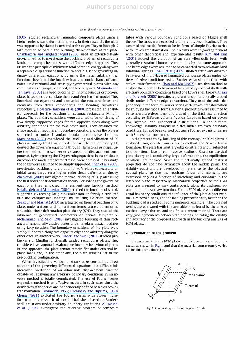
It is assumed that the FGM plate is a mixture of a ceramic and ametal, as shown in Fig. 1, and that the material continuously variesin the thickness direction.
Fig. 1. Coordinate system of rectangular FG plate.
M. Latifi et al. / European Journal of Mechanics A/Solids 41 (2013) 16e27 17

Author's personal copy
Variation of the Young modulus through the plate thickness isconsidered as:
EðzÞ ¼ Em þ ðEc � EmÞ�zhþ 0:5
�kk � 0
vðzÞ ¼ constant(1)
where Em and Ec respectively denote the Young moduli of metal (inthe lower surface) and ceramic (in the upper surface), and k is theFGM power index. In FG structures, the distribution of constructingmaterials is not symmetric about to middle surface. Consequently,stretching-bending coupling effect exists in the governing equa-tions based on the middle plane thin plate theory. The governingequations derived based on the physical neutral plane where is notlocated at the mid-thickness, have the simple forms as those ofclassical thin plate theory for homogeneous isotropic materials. Theposition of this plane (z0) from the middle surface is introduced byZhang and Zhou (2008):
z0 ¼
Zh2�h2
zEðzÞdz
Zh2�h2
EðzÞdz
(2)
The kinematical strainedisplacement relations in any arbitraryplane parallel to the neutral surface are as follows:
8<:
εxεyεxy
9=; ¼
8><>:
εð0Þx
εð0Þy
εð0Þxy
9>=>;þ ðz� z0Þ
8><>:
εð1Þx
εð1Þy
εð1Þxy
9>=>; (3)
where {ε(0)} and {ε(1)} are the in-plane strains and the plate cur-vatures, respectively. As the material is isotropic in the xey planeand only the modulus of elasticity E varies with z, the stressestrainrelations are (Shanmugam and Wang, 2006):
8<:
sxsysxy
9=; ¼ �
Qij�8<:
εxεyεxy
9=; i; j ¼ 1;2;6 (4)
or:
8<:
sxsysxy
9=; ¼
24Q11 Q12 0Q21 Q22 00 0 Q66
350B@8><>:
εð0Þx
εð0Þy
εð0Þxy
9>=>;þ ðz� z0Þ
8><>:
εð1Þx
εð1Þy
εð1Þxy
9>=>;1CA(5)
½Q �is the reduced stiffness matrix and Qij’s are defined as follows(Abrate, 2008):
Q11 ¼ EðzÞ1� n2
Q12 ¼ nQ11
Q66 ¼ Q11 � Q12
Q22 ¼ Q11 Q21 ¼ Q12
(6)
For plane stress condition, the resultant in-plane forces (Nx, Ny,Nxy) and moments (Mx, My, Mxy) can be obtained by integrating thecorresponding stresses as (Venstel and Krauthammer, 2001):
0@8<:
NxNyNxy
9=;;
8<:
MxMyMxy
9=;1A ¼
Zh2�h2
8<:
sxsysxy
9=;ð1; zÞdz (7)
The equation above may be expressed in terms of the in-planestrains and curvatures by using Equations (3)e(6):
0@8<:
NxNyNxy
9=;;
8<:
MxMyMxy
9=;1A ¼
0B@½A�
8><>:
εð0Þx
εð0Þy
εð0Þxy
9>=>;; ½D�
8><>:
εð1Þx
εð1Þy
εð1Þxy
9>=>;1CA (8)
Matrices [A] and [D] represent in-plane and bending couplings,respectively and are defined in terms of the reduced stiffness ma-trix Q as follows (Abrate, 2008):
�Aij;Dij
� ¼Zh2�h2
Qijð1; ðz� z0ÞÞ2dz i; j ¼ 1;2;6 (9)
Thus the components of matrices [A] and [D] are determined asfollows:
�Aij;Dij
� ¼ ðA11;D11Þ241 n 0n 1 00 0 1� n
35 i; j ¼ 1;2;6 (10)
where
D11 ¼ h�1� n2
��Emh2
12
1þ 9
ðkþ 1Þðkþ 2Þðkþ 3Þ
þ ðEc � EmÞh24
1� 6k
ðkþ 1Þðkþ 2Þðkþ 3Þ
� z0hkðEc � EmÞ
ðkþ 1Þðkþ 2Þ þ z20
Em þ ðEc � EmÞ
kþ 1
�(11a)
A11 ¼ h1� n2
Em þ Ec � Em
kþ 1
(11b)
It is seen that coefficients A11 and D11 depended on the platethickness, FGM power index, Young modulus of ceramic and metal,and Poisson’s ratio. Consequently, seeing Equation (8), there is notany coupling between either the resultant forces and the curvaturesor the resultant moments and the in-plane strains. As a result,buckling equations of the FGM plate can be derived like those of anisotropic one (Abrate, 2008) in the form of:
D11v4w=vx4 þ 2ðD12 þ 2D66Þv4w=vx2vy2 þ D22v
4w=vy4
¼ Nxv2w=vx2 þ 2Nxyv
2w=vxvyþ Nyv2w=vy2 (15)
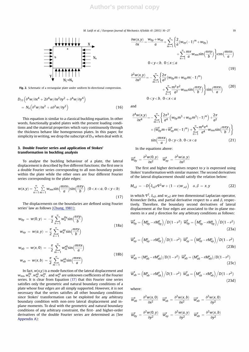
For the sake of brevity, the details for derivation of bucklingequation are omitted. One can find more details in Brush andAlmroth (1975). Solution of Equation (15) makes the ability ofanalysing all linear and non-linear equilibrium configurations ofthe plate. Transition from the pre-buckled state (linear configura-tion) to the buckled one (non-linear configuration) is the bifurca-tion point (Brush and Almroth, 1975). In the present work, it isassumed that no in-plane shear force Nxy exists and that the rela-tion a ¼ Ny/Nx holds for the axial forces. Such a biaxial compressiveloading is shown in Fig. 2. Accordingly, the resultant bucklingequation takes the form:
M. Latifi et al. / European Journal of Mechanics A/Solids 41 (2013) 16e2718
Author's personal copy
D11
�v4w=vx4 þ 2v4w=vx2vy2 þ v4w=vy4
�¼ Nx
�v2w=vx2 þ av2w=vy2
�(16)
This equation is similar to a classical buckling equation. In otherwords, functionally graded plates with the present loading condi-tions and the material properties which vary continuously throughthe thickness behave like homogeneous plates. In this paper, forsimplicity inwriting, we drop the subscript ofD11 when deal with it.
3. Double Fourier series and application of Stokes’transformation in buckling analysis
To analyse the buckling behaviour of a plate, the lateraldisplacement is described by five different functions; the first one isa double Fourier series corresponding to all non-boundary pointswithin the plate while the other ones are four different Fourierseries corresponding to the plate edges:
wðx;yÞ ¼ PNn¼1
PNm¼1
wmnsin�mpx
a
�sin�npy
b
�ð0<x<a; 0<y<bÞ
(17)
The displacements on the boundaries are defined using Fourierseries’ law as follows (Chung, 1981):
w0y ¼ wð0; yÞ ¼ �p
2
XNn¼1
w0yn sin
�npyb
�
way ¼ wða; yÞ ¼ p
2
XNn¼1
wayn sin
�npyb
� (18a)
wx0 ¼ wðx;0Þ ¼ �p
2
XNm¼1
wx0m sin
�mpxa
�
wxb ¼ wðx;bÞ ¼ p
2
XNm¼1
wxbm sin
�mpxa
� (18b)
In fact,w(x,y) is a mode function of the lateral displacement andwmn,w
0yn ;wx0
m ;wayn ; and wxb
n are unknown coefficients of the Fourierseries. It is clear from Equation (17) that this Fourier sine seriessatisfies only the geometric and natural boundary conditions of aplate whose four edges are all simply supported. However, it is notnecessary that the series satisfies all other boundary conditionssince Stokes’ transformation can be exploited for any arbitraryboundary condition with non-zero lateral displacement and in-plane moments. To deal with the geometric and natural boundaryconditions of any arbitrary constraint, the first- and higher-orderderivatives of the double Fourier series are determined as (SeeAppendix A):
vwðx;yÞvx
¼w0yþway
aþXNm¼1
(2a
�wayð�1Þmþw0y
�
þXNn¼1
mp
awmnsin
�npyb
�)cos�mpx
a
�0<y<b; 0�x�a
(19)
v2wðx;yÞvx2
¼�XNm¼1
(2pa2�w0ymþwaymð�1Þm�
þXNn¼1
m2p2
a2wmnsin
�npyb
�)sin�mpx
a
�0<y<b; 0<x<a
(20)
and
v4wðx;yÞvx4
¼�XNm¼1
(2p3
a4
�w0ym
3þwaym3ð�1Þm�þ2pa2
��wx0ymþw
xaymð�1Þm�þXN
n¼1
m4p4
a4wmnsin
�npyb
�)
sin�mpx
a
�0<y<b; 0<x<a (21)
In the equations above:
wx0y ¼ v2wð0; yÞ
vx2w
xay ¼ v2wða; yÞ
vx2
The first and higher derivatives respect to y is expressed usingStokes’ transformationwith similar manner. The second derivativesof the lateral displacement should satisfy the relation below:
Mab ¼ �D�dabvV
2wþ ð1� vÞw;ab
�a;b ¼ x; y (22)
in which V2, dab, and w,ab are two dimensional Laplacian operator,Kronecker Delta, and partial derivative respect to a and b, respec-tively. Therefore, the boundary second derivatives of lateraldisplacement at the four edges are associated to the in-plane mo-ments in x and y direction for any arbitrary conditions as follows:
wx0y ¼
�Mx
0y�nMy0y
�.D�1�n2
�w
y0y ¼
�My
0y�nMx0y
�.D�1�n2
�(23a)
wxay ¼
�Mx
ay�nMyay
�.D�1�n2
�w
yay ¼
�My
ay�nMxay
�.D�1�n2
�(23b)
wxx0 ¼
�Mx
x0�nMyx0
��D�1�n2
�w
yx0 ¼
�My
x0�nMxx0
��D�1�n2
�(23c)
wxxb ¼
�Mx
xb�nMyxb
�.D�1�n2
�w
yxb ¼
�My
xb�nMxxb
�.D�1�n2
�(23d)
where:
wxx0 ¼ v2wðx;0Þ
vx2w
xxb ¼ v2wðx; bÞ
vx2w
yx0 ¼ v2wðx;0Þ
vy2
wy0y ¼ v2wð0; yÞ
vy2w
yay ¼ v2wða; yÞ
vy2w
yxb ¼ v2wðx; bÞ
vy2
Fig. 2. Schematic of a rectangular plate under uniform bi-directional compression.
M. Latifi et al. / European Journal of Mechanics A/Solids 41 (2013) 16e27 19
Author's personal copy
In relations above, Mx0y;M
xay;M
xx0;M
xxb;M
y0y;M
yay;M
yx0; and My
xbdenote the bending moments along the edges. The superscriptdenotes the axis of applied bending moment and the subscriptsreveal the considered boundary edge.
Consequently, substitution of Equation (17) through (21) intoEquation (16), wmn is written in terms of twelve unknown bound-ary quantities ðMx
0y;Mxay;M
xx0;M
xxb;M
y0y;M
yay;M
yx0;M
yxb;w0y;w0y;
w0y;w0yÞ for various boundary conditions:
wmn ¼ Pmn1w0y þ ð�1ÞmPmn1way þ Pmn2wx0 þ ð�1ÞnPmn2wxb
þ Pmn3Mx0y þ ð�1ÞmPmn3M
xay þ Pmn4M
yx0
þ ð�1ÞnPmn4Myxb þ Pmn5M
xx0 þ ð�1ÞnPmn5M
xxb
þ Pmn6My0y þ ð�1ÞmPmn6M
yay
(24)where:
Pmn1 ¼ 1Jmn
Dp4m3
a4� Dp4mn2
a2b2þ p2mNx
a2
Pmn2 ¼ 1Jmn
Dp4n3
b4� Dp4nm2
a2b2þ p2naNx
b2
(25a)
Pmn3 ¼ 1Jmn
�p4ma4�1� n2
�� np4ma2b2
�1� n2
�
Pmn4 ¼ 1Jmn
�p4nb4�1� n2
�� np4na2b2
�1� n2
�(25b)
Pmn5 ¼ 1Jmn
�np4nb4�1� n2
�þ p4na2b2
�1� n2
�
Pmn6 ¼ 1Jmn
�np4ma4�1� n2
�þ p4ma2b2
�1� n2
�(25c)
Jmn ¼2Dp4m2n2
a2b2� p2m2Nx
a2� p2n2aNx
b2� Dp4m4
a2� Dp4n4
b2
(25d)
4. Boundary conditions
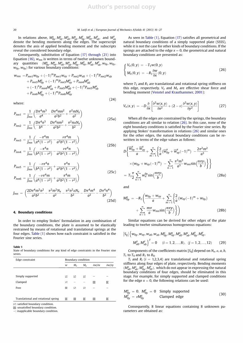
In order to employ Stokes’ formulation in any combination ofthe boundary conditions, the plate is assumed to be elasticallyrestrained by means of rotational and translational springs at thefour edges. Table (1) shows how each constraint is satisfied in theFourier sine series.
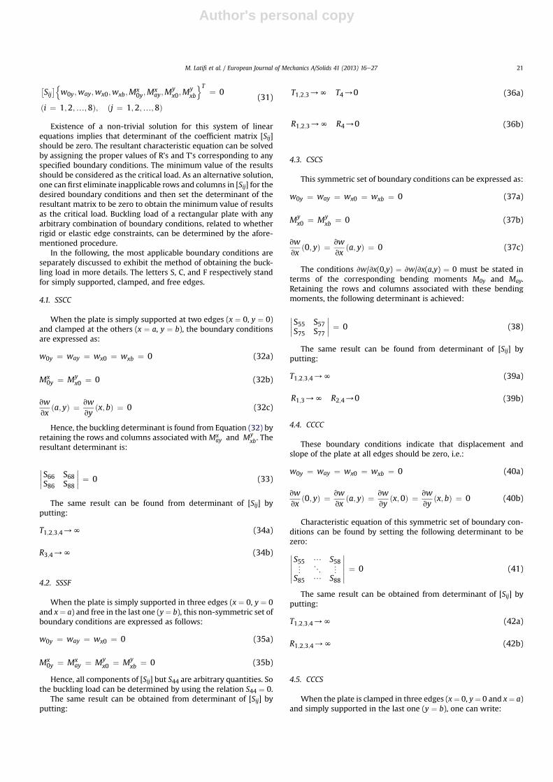
As seen in Table (1), Equation (17) satisfies all geometrical andnatural boundary conditions of a simply supported plate (SSSS),while it is not the case for other kinds of boundary conditions. If thesprings are attached to the edge x ¼ 0, the geometrical and naturalboundary conditions are presented as:
8<:
Vxð0; yÞ ¼ �T1wð0; yÞ
Mxð0; yÞ ¼ �R1vwvx
ð0; yÞ(26)
where T1 and R1 are translational and rotational spring stiffness onthis edge, respectively. Vx and Mx are effective shear force andbending moment (Venstel and Krauthammer, 2001):
Vxðx; yÞ ¼ �Dv
vx
"v2wðx; yÞ
vx2þ ð2� vÞ v
2wðx; yÞvy2
#(27)
When all the edges are constrained by the springs, the boundaryconditions are all similar to relation (26). In this case, none of theeight boundary conditions is satisfied by the Fourier sine series. Byapplying Stokes’ transformation in relations (26) and similar onesfor the other edges, the natural boundary conditions can be re-written in terms of the edge values as follows:
D
(w
x0y þw
xay
aþXNm¼1
(2a
�w
x0y þw
xayð�1Þm� � 2p2m2
a3
��w0y þwayð�1Þm� �XNn¼1
p3m3
a3wmnsin
�npyb
�))
¼ T1p
2
XNn¼1
w0yn sin
�npyb
�(28a)
and
Mx0y ¼ �R1
w0y þway
aþXNm¼1
(2a
�wayð�1Þm þw0y
�
þXNn¼1
mp
awmnsin
�npyb
�)!(28b)
Similar equations can be derived for other edges of the plateleading to twelve simultaneous homogeneous equations:
�Sij�n
w0y;way;wx0;wxb;Mx0y;M
xay;M
xx0;M
xxb;M
y0y;M
yay;
Myx0;M
yxb
oT¼ 0 ði ¼ 1;2;.;8Þ; ðj ¼ 1;2;.;12Þ (29)
Components of the coefficients matrix [Sij] depend on Nx, a, a, b,T1 to T4 and R1 to R4.
Ti and Ri (i ¼ 1,2,3,4) are translational and rotational springstiffness along four edges of plate, respectively. Bending momentsðMx
x0;Mxxb;M
y0y;M
yayÞ; which do not appear in expressing the natural
boundary conditions of four edges, should be eliminated in thisstage. For example, for simply supported and clamped conditionsfor the edge x ¼ 0, the following relations can be used:
Mx0y ¼ 0; My
0y ¼ 0 Simply supported
My0y ¼ vMx
0y Clamped edge(30)
Consequently, 8 linear equations containing 8 unknown pa-rameters are obtained as:
Table 1State of boundary conditions for any kind of edge constraints in the Fourier sineseries.
Edge constraint Boundary condition
w Mx My vw/vx vw/vy
Simply supported e e
Clamped e e
Free e e
Translational and rotational spring
: satisfied boundary condition.: unsatisfied boundary condition.
e: inapplicable boundary condition.
M. Latifi et al. / European Journal of Mechanics A/Solids 41 (2013) 16e2720
Author's personal copy
�Sij�n
w0y;way;wx0;wxb;Mx0y;M
xay;M
yx0;M
yxb
oT ¼ 0
ði ¼ 1;2;.;8Þ; ðj ¼ 1;2;.;8Þ(31)
Existence of a non-trivial solution for this system of linearequations implies that determinant of the coefficient matrix [Sij]should be zero. The resultant characteristic equation can be solvedby assigning the proper values of R’s and T’s corresponding to anyspecified boundary conditions. The minimum value of the resultsshould be considered as the critical load. As an alternative solution,one can first eliminate inapplicable rows and columns in [Sij] for thedesired boundary conditions and then set the determinant of theresultant matrix to be zero to obtain the minimum value of resultsas the critical load. Buckling load of a rectangular plate with anyarbitrary combination of boundary conditions, related to whetherrigid or elastic edge constraints, can be determined by the afore-mentioned procedure.
In the following, the most applicable boundary conditions areseparately discussed to exhibit the method of obtaining the buck-ling load in more details. The letters S, C, and F respectively standfor simply supported, clamped, and free edges.
4.1. SSCC
When the plate is simply supported at two edges (x ¼ 0, y ¼ 0)and clamped at the others (x ¼ a, y ¼ b), the boundary conditionsare expressed as:
w0y ¼ way ¼ wx0 ¼ wxb ¼ 0 (32a)
Mx0y ¼ My
x0 ¼ 0 (32b)
vwvx
ða; yÞ ¼ vwvy
ðx;bÞ ¼ 0 (32c)
Hence, the buckling determinant is found from Equation (32) byretaining the rows and columns associated with Mx
ay and Myxb. The
resultant determinant is:
S66 S68S86 S88
¼ 0 (33)
The same result can be found from determinant of [Sij] byputting:
T1;2;3;4/N (34a)
R3;4/N (34b)
4.2. SSSF
When the plate is simply supported in three edges (x ¼ 0, y ¼ 0and x¼ a) and free in the last one (y¼ b), this non-symmetric set ofboundary conditions are expressed as follows:
w0y ¼ way ¼ wx0 ¼ 0 (35a)
Mx0y ¼ Mx
ay ¼ Myx0 ¼ My
xb ¼ 0 (35b)
Hence, all components of [Sij] but S44 are arbitrary quantities. Sothe buckling load can be determined by using the relation S44 ¼ 0.
The same result can be obtained from determinant of [Sij] byputting:
T1;2;3/N T4/0 (36a)
R1;2;3/N R4/0 (36b)
4.3. CSCS
This symmetric set of boundary conditions can be expressed as:
w0y ¼ way ¼ wx0 ¼ wxb ¼ 0 (37a)
Myx0 ¼ My
xb ¼ 0 (37b)
vwvx
ð0; yÞ ¼ vwvx
ða; yÞ ¼ 0 (37c)
The conditions vw/vx(0,y) ¼ vw/vx(a,y) ¼ 0 must be stated interms of the corresponding bending moments M0y and May.Retaining the rows and columns associated with these bendingmoments, the following determinant is achieved:
S55 S57S75 S77
¼ 0 (38)
The same result can be found from determinant of [Sij] byputting:
T1;2;3;4/N (39a)
R1;3/N R2;4/0 (39b)
4.4. CCCC
These boundary conditions indicate that displacement andslope of the plate at all edges should be zero, i.e.:
w0y ¼ way ¼ wx0 ¼ wxb ¼ 0 (40a)
vwvx
ð0; yÞ ¼ vwvx
ða; yÞ ¼ vwvy
ðx;0Þ ¼ vwvy
ðx; bÞ ¼ 0 (40b)
Characteristic equation of this symmetric set of boundary con-ditions can be found by setting the following determinant to bezero: S55 / S58« 1 «
S85 / S88
¼ 0 (41)
The same result can be obtained from determinant of [Sij] byputting:
T1;2;3;4/N (42a)
R1;2;3;4/N (42b)
4.5. CCCS
When the plate is clamped in three edges (x¼ 0, y¼ 0 and x¼ a)and simply supported in the last one (y ¼ b), one can write:
M. Latifi et al. / European Journal of Mechanics A/Solids 41 (2013) 16e27 21
Author's personal copy
w0y ¼ way ¼ wx0 ¼ wxb ¼ 0 (43a)
vwvx
ð0; yÞ ¼ vwvx
ða; yÞ ¼ vwvy
ðx;0Þ ¼ Myxb ¼ 0 (43b)
Due to selection of sinus expansion series as the displacementfield, the first three relations in Equation (43b) are not satisfied.Thus the fifth to the seventh rows and columns of [Sij], which areassociated with the bending moments along the three clampededges, should be retained to obtain the buckling load from theequation below: S55 / S57« 1 «
S75 / S77
¼ 0 (44)
The same result can be found from determinant of [Sij] byputting:
T1;2;3;4/N (45a)
R1;2;3/N (45b)
4.6. SSCS and SSSC
When the plate is simply supported at three edges (x ¼ 0, y ¼ 0and y ¼ b) and clamped at the last one (x ¼ a), this non-symmetricset of boundary conditions are expressed as follows:
w0y ¼ way ¼ wx0 ¼ wxb ¼ 0 (46a)
Mx0y ¼ My
x0 ¼ Myxb ¼ vw
vxða; yÞ ¼ 0 (46b)
Hence, all components of the coefficient matrix but S66 arearbitrary quantities. So the buckling load can be determined usingthe relation S66 ¼ 0. The same result can be obtained from deter-minant of [Sij] by putting:
T1;2;3;4/N (47a)
R3/N R1;2;4/0 (47b)
For the last boundary condition, SSSC, the buckling load can befound through the same procedure leading to the relation S88 ¼ 0.
5. Presentation of the results
Numerical investigation is performed to show the validity andaccuracy of Stokes’ transformation in calculating buckling loads.The results are compared with those have been reported to beobtained by the energy method (Javaheri and Eslami, 2002), Levysolution (Mohammadi and Saidi, 2010), and the finite elementmethod (Latifi, 2010). The constituent materials considered hereare Alumina (as ceramic) and Aluminium (as metal). The Young’smoduli of Aluminium and Alumina are Em ¼ 70 GPa andEc ¼ 380 GPa, respectively, and Poisson’s ratio is 0.3 throughout thewhole plate. Referring to Fig. 1, the plate thickness is h ¼ 5 mm andthe length along y-axis is b ¼ 0.5 m. Some arbitrary values for theFGM power index (k ¼ 0, 1, 2, 5), aspect ratio (b/a ¼ 1, 1.5, 2, 2.5, 3),and the load proportionality factor (a ¼ �1, 0, 1) are selected tostudy buckling behaviour of the FGM plate at different conditions.
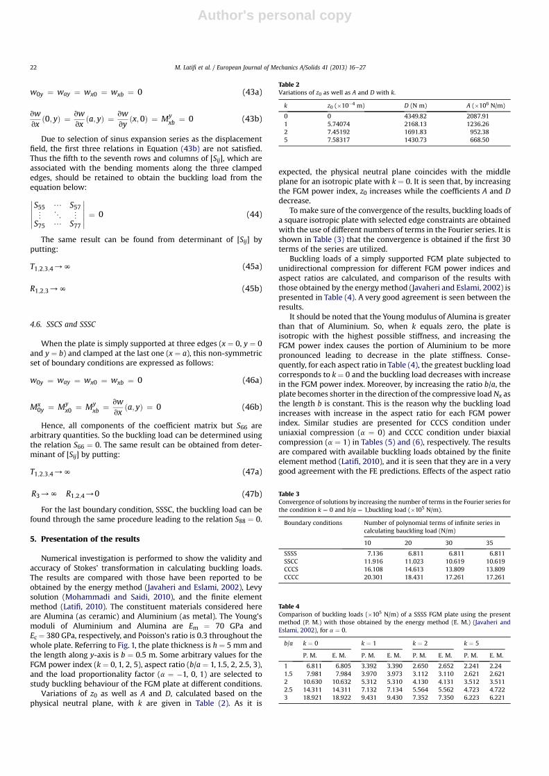
Variations of z0 as well as A and D, calculated based on thephysical neutral plane, with k are given in Table (2). As it is
expected, the physical neutral plane coincides with the middleplane for an isotropic plate with k ¼ 0. It is seen that, by increasingthe FGM power index, z0 increases while the coefficients A and Ddecrease.
To make sure of the convergence of the results, buckling loads ofa square isotropic plate with selected edge constraints are obtainedwith the use of different numbers of terms in the Fourier series. It isshown in Table (3) that the convergence is obtained if the first 30terms of the series are utilized.
Buckling loads of a simply supported FGM plate subjected tounidirectional compression for different FGM power indices andaspect ratios are calculated, and comparison of the results withthose obtained by the energymethod (Javaheri and Eslami, 2002) ispresented in Table (4). A very good agreement is seen between theresults.
It should be noted that the Young modulus of Alumina is greaterthan that of Aluminium. So, when k equals zero, the plate isisotropic with the highest possible stiffness, and increasing theFGM power index causes the portion of Aluminium to be morepronounced leading to decrease in the plate stiffness. Conse-quently, for each aspect ratio in Table (4), the greatest buckling loadcorresponds to k ¼ 0 and the buckling load decreases with increasein the FGM power index. Moreover, by increasing the ratio b/a, theplate becomes shorter in the direction of the compressive loadNx asthe length b is constant. This is the reason why the buckling loadincreases with increase in the aspect ratio for each FGM powerindex. Similar studies are presented for CCCS condition underuniaxial compression (a ¼ 0) and CCCC condition under biaxialcompression (a ¼ 1) in Tables (5) and (6), respectively. The resultsare compared with available buckling loads obtained by the finiteelement method (Latifi, 2010), and it is seen that they are in a verygood agreement with the FE predictions. Effects of the aspect ratio
Table 2Variations of z0 as well as A and D with k.
k z0 (�10�4 m) D (N m) A (�106 N/m)
0 0 4349.82 2087.911 5.74074 2168.13 1236.262 7.45192 1691.83 952.385 7.58317 1430.73 668.50
Table 3Convergence of solutions by increasing the number of terms in the Fourier series forthe condition k ¼ 0 and b/a ¼ 1,buckling load (�105 N/m).
Boundary conditions Number of polynomial terms of infinite series incalculating bauckling load (N/m)
10 20 30 35
SSSS 7.136 6.811 6.811 6.811SSCC 11.916 11.023 10.619 10.619CCCS 16.108 14.613 13.809 13.809CCCC 20.301 18.431 17.261 17.261
Table 4Comparison of buckling loads (�105 N/m) of a SSSS FGM plate using the presentmethod (P. M.) with those obtained by the energy method (E. M.) (Javaheri andEslami, 2002), for a ¼ 0.
b/a k ¼ 0 k ¼ 1 k ¼ 2 k ¼ 5
P. M. E. M. P. M. E. M. P. M. E. M. P. M. E. M.
1 6.811 6.805 3.392 3.390 2.650 2.652 2.241 2.241.5 7.981 7.984 3.970 3.973 3.112 3.110 2.621 2.6212 10.630 10.632 5.312 5.310 4.130 4.131 3.512 3.5112.5 14.311 14.311 7.132 7.134 5.564 5.562 4.723 4.7223 18.921 18.922 9.431 9.430 7.352 7.350 6.223 6.221
M. Latifi et al. / European Journal of Mechanics A/Solids 41 (2013) 16e2722

Author's personal copy
and the FGM power index on the buckling load are the same aswhat were shown in Table (4).
Buckling loads of an isotropic plate (k¼ 0) for two different edgeconstraints are shown in Table (7), and the results are comparedwith those reported to be obtained by Levy solution (Mohammadiand Saidi, 2010).
Two different aspect ratios are investigated for each boundarycondition, and uniaxial as well as biaxial compressive load isstudied for each aspect ratio. The shown good agreement betweenthe results indicates validity of the current approach in bucklinganalysis of FGM plates. It is clear that increase in a makes more
Table 5Comparison of buckling load (�105 N/m) from the present method (P. M.) with FEMresults (Latifi, 2010), for CCCS plate, a ¼ 0.
b/a k ¼ 0 k ¼ 1 k ¼ 2 k ¼ 5
P. M. FEM P. M. FEM P. M. FEM P. M. FEM
1 13.809 13.819 6.887 6.879 5.372 5.370 4.539 4.5411.5 20.632 20.639 10.292 10.298 8.028 8.026 6.781 6.7832 31.904 31.909 15.920 15.923 12.418 12.413 10.482 10.4832.5 46.846 46.840 23.387 23.389 18.240 18.244 15.384 15.3843 65.211 65.215 32.575 32.572 25.403 25.400 21.404 21.402
Table 6Comparison of buckling load (�105 N/m) from the present method (P. M.) with FEMresults (Latifi, 2010), for CCCC plate, a ¼ 1.
b/a k ¼ 0 k ¼ 1 k ¼ 2 k ¼ 5
P. M. FEM P. M. FEM P. M. FEM P. M. FEM
1 9.112 9.11 4.541 4.54 3.542 3.54 2.993 2.9911.5 15.88 15.878 7.921 7.923 6.182 6.181 5.522 5.5252 26.821 26.82 13.374 13.372 10.431 10.431 8.82 8.8242.5 41.471 41.47 20.67 20.672 16.131 16.132 13.64 13.6423 58.982 58.984 29.41 29.411 22.94 22.941 19.401 19.403
Table 7Comparison of dimensionless buckling loads (�Nxb
2/D) obtained by the presentmethod (P. M.) with those reported to be found by Levy solution (L. S.) (Mohammadiand Saidi, 2010) for k ¼ 0.
Boundary condition b/a a P. M. L. S.
SSSS 1 0 15.422 15.4211 12.337 12.337
2 0 39.48 39.4781 19.733 19.732
SCSC 1 0 18.976 18.9771 14.617 14.617
2 0 75.911 75.9101 37.799 37.800
Table 8Variation of the buckling load (�105 N/m) for different boundary conditions, k ¼ 0.
Boundarycondition
a b/a
1 1.5 2 2.5 3
SSSF �1 3.31 5.141 8.028 11.809 16.4530 2.392 4.497 7.442 11.243 15.8851 1.796 3.869 6.755 10.461 14.982
SSSS �1 14.209 14.367 14.17 17.033 21.2710 6.811 7.981 10.632 14.311 18.9211 3.411 5.524 8.501 12.333 17.023
SSSC �1 16.025 18.505 15.981 18.192 22.1270 8.261 9.542 11.662 15.077 19.5191 4.542 6.348 9.127 12.83 17.425
SSCS �1 16.024 18.122 22.153 29.194 38.3560 8.262 11.874 17.71 25.419 34.91 4.541 8.698 14.699 22.477 31.994
SSCC �1 18.308 20.676 23.661 30.235 39.1510 10.619 13.201 18.605 26.093 35.4391 5.545 9.353 15.151 22.811 32.354
CSCS �1 18.433 28.531 38.093 52.449 70.5450 11.531 19.382 31.054 46.201 64.681 7.207 14.581 25.87 40.008 57.371
CCCS �1 20.44 31.258 39.679 53.558 71.4020 13.809 20.632 31.904 46.846 65.2111 7.377 14.851 26.1 40.408 57.771
CCCC �1 25.612 34.579 41.583 54.848 72.3740 17.261 22.432 33.04 47.66 65.841 9.112 15.88 26.821 41.471 58.982
Table 9Variation of the buckling load (�105 N/m) for different boundary conditions, k ¼ 1.
Boundarycondition
a b/a
1 1.5 2 2.5 3
SSSF �1 1.651 2.563 4.003 5.889 8.2050 1.192 2.243 3.711 5.6 7.9231 0.896 1.93 3.37 5.219 7.476
SSSS �1 7.088 7.166 7.069 8.498 10.6120 3.392 3.97 5.311 7.132 9.4311 1.697 2.752 4.242 6.141 8.484
SSSC �1 7.993 9.232 7.972 9.076 11.0390 4.888 4.76 5.818 7.522 9.7381 2.264 3.167 4.553 6.411 8.693
SSCS �1 7.993 9.039 11.051 14.568 19.1430 4.121 5.923 8.835 12.682 17.481 2.264 4.339 7.333 11.215 15.968
SSCC �1 9.132 10.314 11.804 15.086 19.5390 5.297 6.584 9.282 13.019 17.6481 2.765 4.666 7.558 11.382 16.098
CSCS �1 9.191 14.233 19.001 26.155 35.240 5.752 9.663 15.489 23.03 32.2511 3.356 7.147 12.838 19.991 25.533
CCCS �1 10.195 15.594 19.801 26.739 35.6690 6.886 10.292 15.92 23.387 32.5751 3.679 7.407 13.038 20.29 28.833
CCCC �1 12.773 17.251 20.751 27.383 36.1540 8.608 11.18 16.473 23.761 33.611 4.541 7.921 13.374 20.67 29.410
Table 10Variation of the buckling load (�105 N/m) for different boundary conditions, k ¼ 2.
Boundarycondition
a b/a
1 1.5 2 2.5 3
SSSF �1 1.288 1.999 3.122 4.592 6.3990 0.931 1.755 2.899 4.372 6.1811 0.699 1.505 2.628 4.07 5.829
SSSS �1 5.529 5.588 5.513 6.627 8.2750 2.65 3.112 4.134 5.564 7.3521 1.32 2.151 3.31 4.821 6.621
SSSC �1 6.235 7.2 6.218 7.078 8.6090 3.809 3.713 4.537 5.866 7.5941 1.766 2.47 3.551 4.992 6.779
SSCS �1 6.234 7.05 8.619 11.361 14.9280 3.225 4.619 6.891 9.892 13.5831 1.766 3.384 5.719 8.746 12.452
SSCC �1 7.123 8.045 9.206 11.765 15.2370 4.131 5.136 7.239 10.153 13.7921 2.157 3.639 5.895 8.877 12.554
CSCS �1 7.169 11.123 14.828 20.423 27.4830 4.48 7.541 12.08 17.975 25.1911 2.269 5.438 10.001 15.46 22.144
CCCS �1 7.952 12.165 15.445 20.855 27.8160 5.372 8.028 12.418 18.24 25.4031 2.871 5.778 10.165 15.76 22.444
CCCC �1 9.964 13.457 16.186 21.357 28.1940 6.715 8.721 12.852 18.542 26.2221 3.542 6.182 10.431 16.131 22.94
M. Latifi et al. / European Journal of Mechanics A/Solids 41 (2013) 16e27 23

Author's personal copy
applied compression resulting in decrease in the buckling load ofthe plate. By increasing the ratio b/a, the plate becomes shorter inthe direction of the compressive load Nx as the length b is constant.This is the reason why the buckling load increases with increase inthe aspect ratio for each load proportionality factor.
A summary of the obtained buckling loads for different aspectratios, the FGM power indices, and loading directions at varioususual boundary conditions is given in Tables (8)e(11). All the be-haviours affected by k, b/a, and a are the same as those were shownin the previous Tables. As it is expected, boundary conditions have asignificant effect on the results, and more constraining the plateedges gives rise to increase in the buckling load.
Dimensionless displacement (relative to the maximum lateraldisplacement) contours of a square plate (b/a ¼ 1) in differentboundary conditions for various load proportionality factors areshown in Figs. 3e7. Fig. 3 shows that the contours are similar forthe different load proportionality factors and that the highestdeflections occur near the free edge. However, Figs. 4e7 showthat two halves of the plate deflect in opposite directions for thecase a ¼ �1 when none of the edges are free. Moreover, thecontours for the cases a ¼ 0 and a ¼ 1 are still similar for anycombination of boundary conditions. It should be noted that theamount of dimensionless displacement is regardless of the FGMpower index.
Table 11Variation of the buckling load (�105 N/m) for different boundary conditions, k ¼ 5.
Boundary condition a b/a
1 1.5 2 2.5 3
SSSF �1 1.087 1.689 2.638 3.881 5.4050 0.752 1.484 2.452 3.775 5.2211 0.59 1.27 2.218 3.434 4.916
SSSS �1 4.667 4.716 4.653 5.593 6.9830 2.241 2.621 3.511 4.723 6.2231 1.121 1.823 2.793 4.05 5.6
SSSC �1 5.264 6.077 5.248 5.973 7.2640 3.216 3.134 3.829 4.95 6.4081 1.491 2.085 2.997 4.213 5.721
SSCS �1 5.264 5.957 7.276 9.586 12.5920 2.715 3.9 5.817 8.347 11.4571 1.491 2.857 4.828 7.381 10.503
SSCC �1 6.015 6.791 7.771 9.929 12.8520 3.489 4.337 6.111 8.568 11.4571 1.821 3.072 4.977 7.491 10.588
CSCS �1 6.054 9.376 12.516 17.224 23.1550 3.791 6.372 10.218 15.211 21.311 2.211 4.46 8.342 13.086 18.941
CCCS �1 6.714 10.271 13.036 17.589 23.4360 4.539 6.781 10.482 15.384 21.4041 2.425 4.88 8.582 13.286 18.941
CCCC �1 8.414 11.361 13.661 18.012 23.7550 5.671 7.38 10.871 15.681 22.1711 2.993 5.222 8.82 13.64 19.401
Fig. 3. Comparison of displacement contours in SSSF edge condition for various amounts of (a).
Fig. 4. Comparison of displacement contours in SSSC edge condition for various amounts of (a).
M. Latifi et al. / European Journal of Mechanics A/Solids 41 (2013) 16e2724

Author's personal copy
6. Conclusion remarks
In this paper, a buckling analysis is carried out for thin rectan-gular FGM plates by using Fourier expansion method and Stokes’transformation. The advantage of this approach is its capability ofdealing with various boundary conditions using a general Fourierseries to determinate the critical load. For this aim, the plate edgesare all assumed to be restrained by means of some rotational andtranslational linear springs. The plate is considered to be underproportional biaxial compression, and its Young modulus isassumed to continuously vary along the thickness according to apower law function. The convergence of the Fourier series methodis evaluated. It is apparent that the precision of solution is respon-sive to the number of truncated terms from the infinitive Fourierseries. In the present work, a good convergence is achieved for thefirst 30 terms. Variations of the buckling load with the plate aspect
ratio, the FGM power index, and the loading proportionality factorfor different usual boundary conditions are investigated. As it isexpected, it is found that shortening the plate in the direction ofuniaxial compressive load gives rise to increase in the buckling load.Also the buckling load increases by more constraining the plateedges. Comparison of the results with those has been previouslyobtained by other analytical and numerical methods shows a verygood agreement between the findings, and this indicates the val-idity and accuracy of this approach in the buckling analysis of FGMplates. The present method can be extended to buckling as well asvibration analysis of other structures such as beams and shells.
Appendix A
In solving any boundary value problem, derivatives of theresponse function are needed to apply the geometric and natural
Fig. 5. Comparison of displacement contours in SSCC edge condition for various amounts of (a).
Fig. 6. Comparison of displacement contours in CCCS edge condition for various amounts of (a).
Fig. 7. Comparison of displacement contours in CCCC edge condition for various amounts of (a).
M. Latifi et al. / European Journal of Mechanics A/Solids 41 (2013) 16e27 25
Author's personal copy
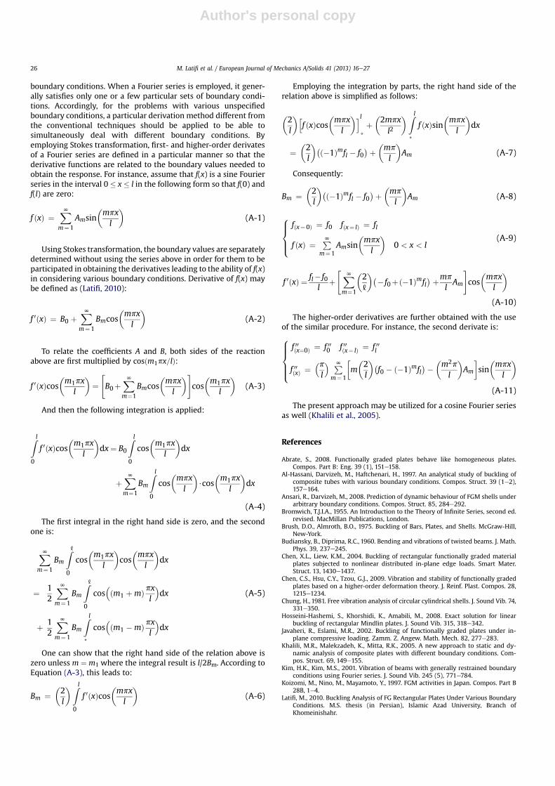
boundary conditions. When a Fourier series is employed, it gener-ally satisfies only one or a few particular sets of boundary condi-tions. Accordingly, for the problems with various unspecifiedboundary conditions, a particular derivation method different fromthe conventional techniques should be applied to be able tosimultaneously deal with different boundary conditions. Byemploying Stokes transformation, first- and higher-order derivatesof a Fourier series are defined in a particular manner so that thederivative functions are related to the boundary values needed toobtain the response. For instance, assume that f(x) is a sine Fourierseries in the interval 0 � x � l in the following form so that f(0) andf(l) are zero:
f ðxÞ ¼XNm¼1
Amsinmpxl
(A-1)
Using Stokes transformation, the boundary values are separatelydetermined without using the series above in order for them to beparticipated in obtaining the derivatives leading to the ability of f(x)in considering various boundary conditions. Derivative of f(x) maybe defined as (Latifi, 2010):
f 0ðxÞ ¼ B0 þXNm¼1
Bmcosmpxl
(A-2)
To relate the coefficients A and B, both sides of the reactionabove are first multiplied by cosðm1px=lÞ:
f 0ðxÞcosm1px
l
¼"B0þ
XNm¼1
Bmcosmpxl
#cosm1px
l
(A-3)
And then the following integration is applied:
Z l0
f 0ðxÞcosm1px
l
dx¼ B0
Z l0
cosm1px
l
dx
þXNm¼1
Bm
Z l0
cosmpxl
$cos
m1px
l
dx
(A-4)
The first integral in the right hand side is zero, and the secondone is:
XNm¼1
Bm
Z[0
cosm1px
l
cosmpxl
dx
¼ 12
XNm¼1
Bm
Z[0
cos�ðm1 þmÞpx
l
�dx
þ 12
XNm¼1
Bm
Z l+
cos�ðm1 �mÞpx
l
�dx
(A-5)
One can show that the right hand side of the relation above iszero unless m ¼ m1 where the integral result is l/2Bm. According toEquation (A-3), this leads to:
Bm ¼2l
Z l0
f 0ðxÞcosmpxl
(A-6)
Employing the integration by parts, the right hand side of therelation above is simplified as follows:
2l
hf ðxÞcos
mpxl
il+þ2mpxl2
Z l+
f ðxÞsinmpxl
dx
¼2l
�ð�1Þmfl � f0�þ mp
l
Am (A-7)
Consequently:
Bm ¼2l
�ð�1Þmfl � f0�þ mp
l
Am (A-8)
8>><>>:
fðx¼0Þ ¼ f0 fðx¼ lÞ ¼ fl
f ðxÞ ¼ PNm¼1
Amsinmpxl
0 < x < l
(A-9)
f 0ðxÞ ¼ fl� f0l
þ"XNm¼1
2[
�� f0þð�1Þmfl� þmp
lAm
#cosmpxl
(A-10)
The higher-order derivatives are further obtained with the useof the similar procedure. For instance, the second derivate is:8>>><>>>:
f 00ðx¼0Þ ¼ f 000 f 00ðx¼ lÞ ¼ f 00l
f 00ðxÞ ¼�pl
� PNm¼1
�m2l
�f0 � ð�1Þmfl
�� m2p
l
Am
�sinmpxl
(A-11)
The present approach may be utilized for a cosine Fourier seriesas well (Khalili et al., 2005).
References
Abrate, S., 2008. Functionally graded plates behave like homogeneous plates.Compos. Part B: Eng. 39 (1), 151e158.
Al-Hassani, Darvizeh, M., Haftchenari, H., 1997. An analytical study of buckling ofcomposite tubes with various boundary conditions. Compos. Struct. 39 (1e2),157e164.
Ansari, R., Darvizeh, M., 2008. Prediction of dynamic behaviour of FGM shells underarbitrary boundary conditions. Compos. Struct. 85, 284e292.
Bromwich, T.J.I.A., 1955. An Introduction to the Theory of Infinite Series, second ed.revised. MacMillan Publications, London.
Brush, D.O., Almroth, B.O., 1975. Buckling of Bars, Plates, and Shells. McGraw-Hill,New-York.
Budiansky, B., Diprima, R.C., 1960. Bending and vibrations of twisted beams. J. Math.Phys. 39, 237e245.
Chen, X.L., Liew, K.M., 2004. Buckling of rectangular functionally graded materialplates subjected to nonlinear distributed in-plane edge loads. Smart Mater.Struct. 13, 1430e1437.
Chen, C.S., Hsu, C.Y., Tzou, G.J., 2009. Vibration and stability of functionally gradedplates based on a higher-order deformation theory. J. Reinf. Plast. Compos. 28,1215e1234.
Chung, H., 1981. Free vibration analysis of circular cylindrical shells. J. Sound Vib. 74,331e350.
Hosseini-Hashemi, S., Khorshidi, K., Amabili, M., 2008. Exact solution for linearbuckling of rectangular Mindlin plates. J. Sound Vib. 315, 318e342.
Javaheri, R., Eslami, M.R., 2002. Buckling of functionally graded plates under in-plane compressive loading. Zamm. Z. Angew. Math. Mech. 82, 277e283.
Khalili, M.R., Malekzadeh, K., Mitta, R.K., 2005. A new approach to static and dy-namic analysis of composite plates with different boundary conditions. Com-pos. Struct. 69, 149e155.
Kim, H.K., Kim, M.S., 2001. Vibration of beams with generally restrained boundaryconditions using Fourier series. J. Sound Vib. 245 (5), 771e784.
Koizomi, M., Nino, M., Mayamoto, Y., 1997. FGM activities in Japan. Compos. Part B28B, 1e4.
Latifi, M., 2010. Buckling Analysis of FG Rectangular Plates Under Various BoundaryConditions. M.S. thesis (in Persian), Islamic Azad University, Branch ofKhomeinishahr.
M. Latifi et al. / European Journal of Mechanics A/Solids 41 (2013) 16e2726

Author's personal copy
Leissa, A.W., Kang, J.H., 2001. Exact Solution for the Free Vibration and Buckling ofRectangular Plates with Linearly Varying In-plane Loading on Two OppositeSimply Supported Edges. ASME. AD-23785.
Matsunaga, H., 2008. Free vibration and stability of functionally graded plates ac-cording toa2-Dhigher-orderdeformation theory. Compos.Struct.82 (4),499e512.
Mohammadi, M., Saidi, A.R., 2010. Levy solution for buckling analysis of functionallygraded rectangular plates. Appl. Compos. Mater. 17, 81e93.
Morimoto, M., Tanigava, Y., 2006. Linear buckling analysis of orthotropic in ho-mogeneous rectangular plates under uniform in-plane compression. Acta Mech.87, 219e229.
Naderi, A., Saidi, A.R., 2011. Exact solution for stability analysis of moderately thickfunctionally graded sector plates on elastic foundation. Compos. Struct. 93,629e638.
Najafizadeh, M.M., Mahdavian, M., 2010. Superposition buckling analyses of rect-angular plates composed of functionally graded materials subjected to non-uniform distributed in-plane loading. J. Mech. Eng. Sci. 224, 1e9.
Ni, Q.Q., Xi, J., Ivamoto, M., 2005. Buckling analysis of composite laminated plateswith arbitrary edge supports. Compos. Struct. 69, 209e217.
Reddy, J.N., 2000. Analysis of functionally graded plates. Int. J. Num. Meth. Eng. 47(1e3), 663e684.
Shanmugam, N.E., Wang, C.M., 2006. Analysis and Design of Plated Structures. In:Stability, vol. 1. Woodhead Publishing Limited, Cambridge England.
Shao, L.S., Ma, G.W., 2007. Free vibration analysis of laminated cylindrical shells byusing Fourier series expansion method. J. Thermoplast. Compos. Mater. 20,551e573.
Shariat, B.A.S., Eslami, M.R., 2005. Buckling of thick functionally graded plates undermechanical and thermal loads. Compos. Struct. 78, 433e439.
Shufrin, I., Eisenburger, M., 2005. Stability and vibration of shear deformableplates- first order and higher order analysis. Int. J. Solids Struct. 42,1225e1251.
Ungbhakorn, V., Singhatanadgid, P., 2006. Buckling analysis of symmetricallylaminated composite plates by the extended Kantorovich method. Compos.Struct. 73, 120e128.
Venstel, V., Krauthammer, T., 2001. Thin Plates and Shells: Theory, Analysis andApplications. Marcel Dekker, Inc., New York.
Yamanouchi, M., Koizumi, M., Hirai, M.T., Shiota, I., 1990. Functionally gradientmaterials in Japan. In: Proceedings of the 1st International Symposium onFunctionally Gradient Materials, Japan.
Zenkour, A.M., Mashat, D.S., 2010. Thermal buckling analysis of ceramic-metalfunctionally graded plates. J. Nat. Sci. 9, 968e978.
Zhang, D.G., Zhou, Y.H., 2008. A theoretical analysis of FGM thin plates based onphysical neutral surface. Computational Mater. Sci. 44, 716e720.
Zhao, X., Lee, Y.Y., Liew, K.M., 2009. Mechanical and thermal buckling analysis offunctionally graded plates. Compos. Struct. 90, 161e171.
M. Latifi et al. / European Journal of Mechanics A/Solids 41 (2013) 16e27 27


