Embed Size (px)
Citation preview

7Bridging andSwitching
CERTIFICATION OBJECTIVES
7.01 Bridges and Switches
7.02 Functions of Bridging and Switching
7.03 The Spanning Tree Protocol
7.04 1900 and 2950 Configuration
✓ Two-Minute Drill
Q&A Self Test
CertPrs8 / CCNA Cisco Certified Network Associate Study Guide / Deal / 222934-9 / Chapter 7Blind Folio 7:1
D:\omh\CertPrs8\934-9\ch07.vpMonday, August 04, 2003 11:53:05 AM
Color profile: Generic CMYK printer profileComposite Default screen

Bridges and switches are both layer-2 devices, functioning at the data link layer of the OSIReference Model. Even though they are both layer-2 devices and have many similaritiesbetween them, they also have many differences. With advancements in hardware and
technology, switches perform faster and have many more features. However, the basic functionsof these two devices are the same. This chapter covers the functions of bridges and switches, theSpanning Tree Protocol (STP), and basic switch configuration tasks on Cisco’s Catalyst 1900and 2950.
CERTIFICATION OBJECTIVE 7.01
Bridges and SwitchesThe main function of bridges and switches is to solve bandwidth, or collision, problems.Remember that in Ethernet, multiple devices can share the same segment, so there isa chance that more than one device might try to transmit at the same time, creating acollision and a retransmission. The more devices you have in a shared medium the morelikely collisions will occur. This doesn’t mean that Ethernet is a bad data link layertopology; it’s just the way it functions.
In the old days of networking you used hubs to connect devices together, orused 10Base5 or 10Base2 cabling (where you would have many devices on one wire).If you experienced constant or excessive amounts of collisions, you could use bridges(and later on, switches) to break up the user devices to multiple segments, where eachsegment would have fewer users, and thus fewer collisions. You could also use a routerto perform this function; however, the disadvantage of a router is that it costs a lot morethan a bridge or switch. This section provides a brief overview of bridges and switches.
Bridging Versus SwitchingEven though bridges and switches both operate at layer 2, there are many differencesbetween them, as Table 7-1 shows.
Perhaps the biggest difference between the bridges and switches is performance.Bridges switch in software, providing a frame rate of about 50,000 frames per second(fps). Switches, on the other hand, perform their switching in hardware, using ASICs(application-specific integrated circuits). ASICs are specialized processors, and in theswitching world, they are built to do one thing: switch frames very fast. As an example,
2 Chapter 7: Bridging and Switching
CertPrs8 / CCNA Cisco Certified Network Associate Study Guide / Deal / 222934-9 / Chapter 7
D:\omh\CertPrs8\934-9\ch07.vpMonday, August 04, 2003 11:53:05 AM
Color profile: Generic CMYK printer profileComposite Default screen

the 1900 switch has a frame rate of 500,000 fps and can handle all ports at theirmaximum speed. Please note that the 1900 is a low-end switch. On Cisco’s higher-endswitches, the frame rate is in the millions of frames per second.
Methods of SwitchingAnother difference between bridges and switches is how they switch frames. Theswitching method affects how a layer-2 device receives, processes, and forwards aframe. Bridges support only one switching method, store-and-forward, while switchesmight support one, two, or three different switching methods. The three switchingmethods supported by layer-2 devices include the following:
■ Store-and-forward
■ Cut-through
■ Fragment-free
The following sections cover these three switching methods.
Store-and-ForwardStore-and-forward switching is the most basic form of switching. With store-and-forwardswitching, the layer-2 device must pull in the entire frame into the buffer of the portand check the CRC (checksum) of the frame before the layer-2 device will performany additional processing of the frame. When checking the CRC, the layer-2 devicewill calculate a CRC value just as the source device did, and compare this value to
Bridges and Switches 3
CertPrs8 / CCNA Cisco Certified Network Associate Study Guide / Deal / 222934-9 / Chapter 7
Functions Bridges Switches
Form of switching Software Hardware (in ASICs)
Method of switching Store and forward Store and forward,cut-through, fragment-free
Ports 2–16 Possibly hundreds
Duplexing Half Half and full
Collision/bandwidth domains 1 per port 1 per port
Broadcast domains 1 1 per VLAN
STP instances 1 1 per VLAN
TABLE 7-1
Bridge and SwitchComparison
D:\omh\CertPrs8\934-9\ch07.vpMonday, August 04, 2003 11:53:05 AM
Color profile: Generic CMYK printer profileComposite Default screen

4 Chapter 7: Bridging and Switching
CertPrs8 / CCNA Cisco Certified Network Associate Study Guide / Deal / 222934-9 / Chapter 7
what was included in the frame. If they are the same, then the frame is good and thelayer-2 device can start processing the frame, including the forwarding the frame outthe correct destination port. If they are different, the layer-2 device will drop the frame.
Bridges support only a store-and-forward switching method. All switches supportstore-and-forward. However, some switches, like the 1900 series, may support anadditional switching method(s); but this is dependent on the actual switch model.
Cut-ThroughSome switches, like the 1900, support cut-through switching. With cut-through switching,the switch reads only the very first part of the frame before making a switching decision.Once the switch device reads the destination MAC address (eight-byte preamble andsix-byte MAC address), it begins forwarding the frame (even though the frame may stillbe coming into the interface). One advantage of cut-through switching over store-and-forward is that it is much faster. Its biggest problem, though, is that the switch may beswitching bad frames.
Most vendors solve this problem by supporting a dynamic switching method.When performing cut-through switching, the switch will still examine the CRC ofthe frame as it is being switched, looking for bad frames. Even though the frame maybe bad, it is still switched. However, the switch keeps a count of these bad frames. Ifover a certain period of time the switch reaches a certain threshold of switching badframes, the switch will dynamically switch its method from cut-through to store-and-forward. This function, though, is entirely dependent on whether or not the vendorincluded this function in its switching model. The 1900 supports this function.
Fragment-FreeThe default switching method of the 1900 is fragment-free switching. Fragment-freeswitching is a modified form of cut-through switching. Whereas cut-through switchingreads up to the destination MAC address field in the frame before making a switchingdecision, fragment-free switching makes sure that the frame is at least 64 bytes beforeswitching it (64 bytes is the minimum legal size of an Ethernet frame). The goal offragment-free switching is to reduce the number of Ethernet runt frames (frames smallerthan 64 bytes) that are being switched. Sometimes fragment-free switching is also calledmodified cut-through or runtless switching.
Even with fragment-free switching, a switch could still be switching corrupt frames(frames with a bad CRC), since the switch is checking only the first 64 bytes, and theCRC is at the end of the frame. To overcome this problem, many vendors implementdynamic switching methods, as discussed in the last section. At least with fragment-free switching, most collisions typically create runts, and this switching method wouldprevent the forwarding of these frames, unlike cut-through switching.
D:\omh\CertPrs8\934-9\ch07.vpMonday, August 04, 2003 11:53:05 AM
Color profile: Generic CMYK printer profileComposite Default screen

Bridges and Switches 5
CertPrs8 / CCNA Cisco Certified Network Associate Study Guide / Deal / 222934-9 / Chapter 7
Even though the 2950 doesn’t support cut-through and fragment-free switching,like the 1900, it still switches frames faster. This is because the 2950 has muchfaster ASICs than the 1900 switch. Therefore, you shouldn’t judge a switchby its switching method, but by a combination of factors, such as price,performance, and features.
Switch ConnectionsDuplexing affects how a device can send and receive frames. There are two modesto duplexing: half and full. With half-duplex, the device can either send or receive—it cannot do both simultaneously. Half-duplex connections are used in shared-medium,like 10Base2, 10Base5, and Ethernet hubs. In this environment, one device sends whileall other devices in the collision domain listen for and receive the frame. In a sharedenvironment like this, you can typically get 40–60 percent utilization out of yourEthernet segment. Please note, however, that every situation is different and thesenumbers are under normal, or average, conditions.
If your utilization in a half-duplex environment starts eclipsing the 40–60percent utilization range, or your collisions exceed 2 percent of total traffic,you should consider either using full-duplex, increasing the speed of the link(like using Fast or Gigabit Ethernet), or breaking up the collision domain withswitches.
Full-duplex, unlike half-duplex, allows a device to send and receive framessimultaneously. However, this will work only if there are two devices on the connection,like a PC connected to a switch, or a switch connected to a router. This is called apoint-to-point connection. You cannot use a hub in a full-duplex connection. Inorder to set up a full-duplex connection, both devices need to support full-duplexing.Table 7-2 compares half- and full-duplex connections.
Store-and-forwardswitching pulls in the whole frame, checksthe CRC, and then switches the frame.Bridges support only this mode, as doesthe 2950 switch. Cut-through switchingswitches a frame as soon as it sees the
destination MAC address in the frame(first 14 bytes). Fragment-free switchingwill switch a frame after the switch sees atleast 64 bytes, which prevents the switchingof runt frames. This is the default switchingmethod for the 1900 series.
D:\omh\CertPrs8\934-9\ch07.vpMonday, August 04, 2003 11:53:05 AM
Color profile: Generic CMYK printer profileComposite Default screen

6 Chapter 7: Bridging and Switching
CertPrs8 / CCNA Cisco Certified Network Associate Study Guide / Deal / 222934-9 / Chapter 7
As Table 7-2 points out, one main advantage that full-duplex connections haveover half-duplex ones is that full-duplex connections do not experience collisions.Basically, the transmit circuit on one side is wired to the receive circuit on the otherside, and vice versa. In this situation, the NIC (network interface controller), orEthernet card, disables the collision detection mechanism, since it isn’t needed. Full-duplex connections are supported with the following media types: 10BaseT, 100BaseTX,100BaseTX, 100BaseFX, and Gigabit Ethernet. Connections using 10Base5, 10BaseFL,and 10Base2 support only half-duplexing. Please note that some older 10BaseT NICsmay not support full-duplex. An example of this is the 10BaseT interfaces on Cisco 2500series routers.
When dealing with bridges and switches, bridges support only half-duplexconnections, while most switches support both. For instance, the 1900 and 2950switches support both connection types. Most switches will autosense the duplexingand appropriately configure it.
CERTIFICATION OBJECTIVE 7.02
Functions of Bridging and SwitchingWith all of these differences between bridges and switches, they are still, at heart, bothlayer-2 devices and perform the same three basic network functions:
■ Learning They learn what device is connected to which port.
■ Forwarding They intelligently switch frames to the port or ports where thedestination is located.
■ Removing layer-2 loops They remove loops with the Spanning TreeProtocol (STP), so that frames don’t continually circle around the network.
These functions are functions of transparent bridges. There are other types of bridging,including source route bridging, source route transparent bridging, and source route
Half-Duplex Full-Duplex
Send and/or receive Send or receive Send and receive
Connection type Hub, 10Base2, 10Base5 Point-to-point
Collisions Yes No
TABLE 7-2
Half-Duplexand Full-DuplexComparison
D:\omh\CertPrs8\934-9\ch07.vpMonday, August 04, 2003 11:53:05 AM
Color profile: Generic CMYK printer profileComposite Default screen

translational bridging, that appear in mixed media networks, such as Ethernet, TokenRing, and FDDI. However, since the CCNA exam focuses on transparent bridging,and Token Ring and FDDI are, for the most part, dead technologies, this book focuseson transparent bridging.
The term transparent appropriately describes a transparently bridged network: thedevices connected to the network are unaware that the bridge, or switch, is a part ofthe network and is forwarding frames to destinations. Basically, transparent-bridgenetworks physically look like a bunch of stars connected together. However, transparentbridges give the appearance to connected devices that every device in the broadcastdomain is on the same logical segment, as shown in Figure 7-1.
The following sections cover the three mainfunctions of transparent bridges and switches inmore depth. As you go through these sections, I’llbe using the term switch to describe the layer-2device; however, the terms bridge and switch areinterchangeable when it comes to the three mainfunctions.
Learning FunctionOne of the three main functions of a transparent switch is to learn which device isconnected to each of the active ports of the switch. As a frame comes into the port ofa switch, the switch examines the source MAC address of the frame and compares it toits switch table, commonly referred to as a CAM (content addressable memory) tableor port address table. In the old days of bridging, CAM was a special form of high-speed
Functions of Bridging and Switching 7
CertPrs8 / CCNA Cisco Certified Network Associate Study Guide / Deal / 222934-9 / Chapter 7
FIGURE 7-1
Physical andlogical descriptionsof a transparentlybridged network
The three main functionsof a bridge/switch are learn, forward, andremove loops.
D:\omh\CertPrs8\934-9\ch07.vpMonday, August 04, 2003 11:53:06 AM
Color profile: Generic CMYK printer profileComposite Default screen

memory to facilitate the switching function in a bridge when it had to forward a frameout the correct destination port. Today, switches use RAM to store the MAC addresses,but the term CAM is still commonly used.
When the switch receives a frame on a port, and as it examines the source MACaddress in the frame and doesn’t see a corresponding entry in the CAM table, theswitch will add the address to the table, including the source port number. If the addressis already in the CAM table, the switch compares the incoming port with the portalready in the table. If they are different, the switch updates the CAM table with thenew port information. This is important because you might have moved the device fromone port to another port, and you want the switch to learn where the new locationis and have the switch forward frames to the device correctly (not to the old port).
Anytime the switch updates an entry in the CAM table, the switch also resets thetimer for the specific entry. Switches use timers to age out old information in the CAMtable, allowing room for new addresses. Each switch has different default timers forthe aging process. Aging is important because once a CAM table is full, the switchwill not be able to learn any new addresses. A switch will also reset the timer for anentry in the CAM table if it sees traffic from a source MAC address that is in the CAMtable. In this manner, devices that are constantly sending information will alwaysremain in the CAM table and devices that are not sending traffic will eventually beaged out of the table (removed from the table).
The CAM table can be built statically or dynamically. By default, when you turnon a switch, the CAM table is empty unless you have configured a static entry in it.As traffic flows through the switch, the switch will begin building its CAM table. Thisdynamic building process is a very nice feature. In the old days of bridging, there usedto be two kinds of bridges: learning and non-learning. Learning bridges function asI have just described—they dynamically learn addressing locations by examining thesource MAC addresses in the Ethernet frames.
Non-learning bridges, by contrast, do not havea dynamic learning function. Instead, you muststatically configure each device’s MAC addressand the port it is connected to. Of course, if youhad 1,000 devices in your non-learning bridgednetwork, you would be very busy building andmaintaining this table, which would be anarduous task. Today, switches support bothfunctions. Normally, you would use static
configurations for security purposes. The discussion of static configurations is donein the later section “MAC Address and Port Security.”
8 Chapter 7: Bridging and Switching
CertPrs8 / CCNA Cisco Certified Network Associate Study Guide / Deal / 222934-9 / Chapter 7
Bridges place learnedsource MAC addresses and theircorresponding ports in a CAM orport address table. This feature isused to intelligently forward frames.
D:\omh\CertPrs8\934-9\ch07.vpMonday, August 04, 2003 11:53:06 AM
Color profile: Generic CMYK printer profileComposite Default screen

Forwarding FunctionThe second major function of a switch is to forward traffic intelligently. Whenever aframe comes into a port on the switch, the switch not only examines the source MACaddress so that it can perform its learning function, it also examines the destinationMAC address to perform its forwarding function. It examines the destination MACaddress and compares this address to the addresses in its CAM table to determine whichinterface it should use when forwarding the frame to the destination.
If the destination address is found in the CAM table, the forwarding process is easy:the switch forwards the frame out the port for the corresponding CAM entry. If theswitch examines the destination address and finds that the destination is associatedwith the same port as the source of the frame, the switch will drop the frame. In thissituation, you might have a hub connected to this port of the switch, and both thesource and destination are connected to this hub. Given this, the switch shouldn’tforward any frames between these two machines to other switch segments, since thiswould be wasting bandwidth in your network. As you can see, the switch is intelligentlyforwarding traffic.
Frame TypesThere are three different destination types: unicast, broadcast, and multicast. Dependingon the type of destination address, there are certain situations where the switch willhave to flood the frame out all of its ports (with the exception of the port the framewas received on). Here are the three frame types that are always flooded:
■ Broadcast address Destination MAC address of FFFF.FFFF.FFFFF
■ Multicast address Destination MAC addresses between 0100.5E00.0000and 0100.5E7F.FFFF
■ Unknown unicast destination MAC addresses The MAC address is notfound in the CAM table
With a unicast, the source device sends a separate copy of each frame to eachdestination. So, as an example, if the switch needs to send the same informationto 50 different destinations, the device would have to create 50 frames, with 50different destination MAC addresses. When a switch receives a frame with a unicastaddress as the destination, the switch looks for the address in its CAM table in orderto make a switching decision. If the switch doesn’t have the address in its CAM table,the switch will flood the frame out all of its other ports.
Functions of Bridging and Switching 9
CertPrs8 / CCNA Cisco Certified Network Associate Study Guide / Deal / 222934-9 / Chapter 7
D:\omh\CertPrs8\934-9\ch07.vpMonday, August 04, 2003 11:53:06 AM
Color profile: Generic CMYK printer profileComposite Default screen

It’s important to remember that you are dealing with a transparent bridge whendealing with the forwarding process. Therefore, if the switch doesn’t know where thedestination is, and obviously the source is assuming that the device is on same the“logical” segment, the switch will have to flood the frame to ensure that the destination,if it is somewhere in the broadcast domain, will receive the source’s frame. This process,hopefully, won’t happen every time. When the destination receives the frame, thedestination will probably send a response frame to the source. Through the switch’slearning process, it now knows where the destination is located, and any further framessent from the source to the destination can be intelligently forwarded instead of flooded.
One issue with this process, however, is that if your CAM table is filled to capacityand your switch can’t add new entries to the table, the switch will always flood trafficto these destinations that it couldn’t fit into the CAM table. Therefore, it is veryimportant that when you buy a switch, you buy one that will be able to handle thenumber of devices that you’ll have in your switched network. You’ll be creating problemsif you have 2,000 devices in your switched network but your CAM table on each switchcan hold only 1,000 entries. In this situation, the switches will be flooding traffic forhalf of the destinations, creating serious bandwidth and performance problems in yournetwork.
A broadcast is a frame that is sent to all devices in a broadcast domain. As an example,if a source device needed to send the same information to 50 destinations, the sourcewould create only one frame, and every destination would process this frame usingthe destination MAC address of FFFF.FFFF.FFFF. Remember to think of the switchednetwork as a logical bus, where it appears that everyone is on the same piece of wire.Therefore, when a switch receives a broadcast, it needs to ensure that all machineswill receive it, and thus the switch will flood this frame to make sure all devices receivethe broadcast.
A multicast is a frame sent to a group of devices, where the group consists of devicesinterested in the receiving the multicast stream. This group can contain no devices,all devices, or some devices in the broadcast domain. The problem of using unicastframes to disseminate certain types of information is that it can negatively impactthe performance of your network. For instance, imagine that you have a networkwhere ten devices wish to receive a specific multicast stream, like a real-time videopresentation. One solution would be to have the multicast server use unicasts andsend ten copies of the same information to each destination. Of course, if the multimediastream is running at 5 Mbps, then this would require the server to generate 50 Mbpsworth of traffic.
Another solution would be to use a broadcast. In this situation, the multicastserver generates only one stream of information. The problem with this is that theswitched infrastructure would flood this traffic to every destination, including theten devices that are interested in seeing it. This solution wastes a lot of bandwidth.
10 Chapter 7: Bridging and Switching
CertPrs8 / CCNA Cisco Certified Network Associate Study Guide / Deal / 222934-9 / Chapter 7
D:\omh\CertPrs8\934-9\ch07.vpMonday, August 04, 2003 11:53:06 AM
Color profile: Generic CMYK printer profileComposite Default screen

The third solution is to use multicast frames.With multicasting, switches can learn whichdevices want to receive multicast traffic, andtherefore forward the multicast frames to onlythose devices that want to see the multicasttraffic. This topic is beyond the scope of thisbook, but it is covered in Cisco’s Switchingexam for the CCNP and CCDP certifications.
If you have a large multicast solution deployment, you will definitely wantto make sure that your switches supported advanced multicast features thatallow them to intelligently forward multicast traffic instead of having to floodit. You want to have the switch forward multicast frames to end-stations thatare running a multicast application that need to see them—you don’t wantyour switch to flood multicasts to all end-stations.
ExampleTo better understand what happens when a switch forwards rather than floods, take alook at an example shown in Figure 7-2. This example shows a hub and a switch, withvarious PCs connected to these two devices.
Let’s assume that the switch was just turned on, which means that its CAMtable is empty. PC-A generates a frame destined for PC-C. When the switchreceives the frame, it looks in its CAM table and does not see the source MACaddress (0000.0A01.AAAA), so it adds it along with port 1. It also examines thedestination MAC address (0000.0A01.CCCC) and does not see this address in itsCAM table, so the switch floods the frame out all of its remaining ports: 2, 3, and 4.
In this example, the switch did not need to do this because PC-C is connected tothe same hub as PC-A; however, the switch doesn’t know this yet. This is an exampleof flooding an unknown destination unicast address. Figure 7-3 shows an example ofthe switch adding the entry to its CAM table and flooding the frame. You can see fromthis figure that the switch now has one entry in its CAM table (PC-A’s) as well as theflooding process that it was performed. Since the destination, PC-C, is connected tothe same hub as PC-A, it obviously receives the frame.
PC-C now responds back to PC-A with a unicast frame: the source MAC addressis 0000.0A01.CCCC and the destination MAC address is 0000.0A01.AAAA. Theswitch performs its learning process, and since PC-C’s MAC address is not in itsCAM table, it adds it, as is shown in Figure 7-4. Now the switch has two entries inits CAM table: PC-A’s and PC-C’s. To perform the forwarding process, the switchexamines the destination MAC address, 0000.0A01.AAAA. It finds a match in its
Functions of Bridging and Switching 11
CertPrs8 / CCNA Cisco Certified Network Associate Study Guide / Deal / 222934-9 / Chapter 7
The three types of framesthat are always flooded by bridges andswitches are multicasts, broadcasts,and unknown destination unicasts.
D:\omh\CertPrs8\934-9\ch07.vpMonday, August 04, 2003 11:53:06 AM
Color profile: Generic CMYK printer profileComposite Default screen

12 Chapter 7: Bridging and Switching
CertPrs8 / CCNA Cisco Certified Network Associate Study Guide / Deal / 222934-9 / Chapter 7
FIGURE 7-3 Adding PC-A’s MAC address to the CAM table
FIGURE 7-2 Transparent bridge forwarding example
D:\omh\CertPrs8\934-9\ch07.vpMonday, August 04, 2003 11:53:06 AM
Color profile: Generic CMYK printer profileComposite Default screen

CAM table and finds that the destination MAC address is associated with the sameport as the source MAC address. Therefore, the switch drops the frame: It does notforward it out of any of its ports, as can be seen from Figure 7-4.
PC-B now sends a unicast frame to PC-F: These PCs are connected to differentports of the switch. When the switch receives the frame from PC-B, it again performs itslearning process. Since PC-B is not in its CAM table, Switch A adds 0000.0A01.BBBBalong with port 1 to its table. Now the switch performs its forwarding function: Sincethe destination MAC address 0000.0A01.FFFF is not in the CAM table, the switchfloods the frame. This process can be seen in Figure 7-5.
The switch now has three MAC addresses in its CAM table. PC-F receives theframe and responds with an answer to PC-B. The switch again performs its learningfunction: since 0000.0A01.FFFF is not in its CAM table, it adds it. Now the switchperforms its forwarding function. It sees 0000.0A01.BBBB in its CAM table with theport number of 1 and therefore forwards the frame out of port 1 only. This process canbe seen in Figure 7-6.
In this last example, PC-E generates a broadcast (FFFF.FFFF.FFFF). Whenthe switch receives the broadcast frame, it performs its learning function byadding 0000.0A01.EEEE to its CAM table. The switch then floods the frame,since it is a broadcast. This process can be seen in Figure 7-7.
Functions of Bridging and Switching 13
CertPrs8 / CCNA Cisco Certified Network Associate Study Guide / Deal / 222934-9 / Chapter 7
FIGURE 7-4 Adding PC-C’s MAC address to the CAM table
D:\omh\CertPrs8\934-9\ch07.vpMonday, August 04, 2003 11:53:07 AM
Color profile: Generic CMYK printer profileComposite Default screen

14 Chapter 7: Bridging and Switching
CertPrs8 / CCNA Cisco Certified Network Associate Study Guide / Deal / 222934-9 / Chapter 7
FIGURE 7-5 Adding PC-B’s MAC address to the CAM table
FIGURE 7-6 Forwarding PC-F’s traffic out of Port 1 only
D:\omh\CertPrs8\934-9\ch07.vpMonday, August 04, 2003 11:53:07 AM
Color profile: Generic CMYK printer profileComposite Default screen

From this simple example, you can see the role of the switch is not a complicatedone. First, the switch examines the source MAC address in the frame and updates theCAM table if necessary. Second, the switch examines the destination MAC addressin the frame and makes a forwarding decision. As you will see in the next section, theswitch’s function becomes more complicated when there is more than one bridge inthe network, and there are layer-2 loops between the bridges.
LoopsAt the backbone of your network, or at least where you have critical resources, you’llprobably incorporate some type of redundancy in your design. This might includeredundancy with your switches at layer-2, creating layer-2 loops in your network as isshown in Figure 7-8. The problem with loops in your network is that when the switchfloods certain types of traffic, such as broadcasts or multicasts, you don’t want this trafficgoing around and around the loop forever, creating high utilization problems.
Plus, for unknown destinations, as the frame is going around the loop, theswitches update their CAM tables with the source address, which eventually showsup as connected to another connected switch, creating confusion about where the
Functions of Bridging and Switching 15
CertPrs8 / CCNA Cisco Certified Network Associate Study Guide / Deal / 222934-9 / Chapter 7
FIGURE 7-7 PC-E generates a broadcast
D:\omh\CertPrs8\934-9\ch07.vpMonday, August 04, 2003 11:53:07 AM
Color profile: Generic CMYK printer profileComposite Default screen

source device really is located. For example, if a device is connected to Switch 3, whenthe device generates a frame, Switch 3 adds the source MAC address to its CAM tableand notes that it is connected to the incoming port. If Switch 3 doesn’t know wherethe destination is located, it will flood the frame to Switches 1 and 2 on its two uplinkports. If both Switches 1 and 2 don’t know where the destination is, they also floodthe frame across the link between them, and then will flood it back to Switch 3. Thispresents a problem: When Switch 3 receives these flooded frames and performs itslearning function, it now looks as if the device is connected to not the original port,but one of the two uplink ports to Switch 1 or 2.
The Spanning Tree Protocol (STP) is used to prevent these problems from occurring.STP removes loops in your network but still allows for redundancy. Actually, the loopremoval process is done in software—you don’t have to physically disconnect wiresbetween your switches to remove the loops. The following section covers the basicsof STP.
CERTIFICATION OBJECTIVE 7.03
The Spanning Tree ProtocolThe main function of the Spanning Tree Protocol (STP) is to remove layer-2 loops fromyour topology. DEC, now a part of Compaq/HP, originally developed STP. IEEE enhancedthe initial implementation of STP, giving us the 802.1d standard. The two differentimplementations of STP, DEC and 802.1d, are not compatible with each other—youneed to make sure that all of your devices either support one or the other. All of Cisco’s
16 Chapter 7: Bridging and Switching
CertPrs8 / CCNA Cisco Certified Network Associate Study Guide / Deal / 222934-9 / Chapter 7
FIGURE 7-8
Looped layer-2topology
D:\omh\CertPrs8\934-9\ch07.vpMonday, August 04, 2003 11:53:08 AM
Color profile: Generic CMYK printer profileComposite Default screen

switches use IEEE’s 802.1d protocol, which is enabled, by default, on the switches. Ifyou have a mixed-vendor environment where some devices are running 802.1d andothers are running DEC’s STP, then you may run into layer-2 looping problems.
Bridge Protocol Data UnitsFor STP to function, the switches need to share information. What they share are bridgeprotocol data units (BPDUs), which are sent out as multicast information that only otherlayer-2 devices are listening to. Switches will use BPDUs to learn the topology of thenetwork: what device is connected to other devices, and if there are any layer-2 loopsbased on this topology.
If any loops are found, the switches will disable a port or ports in the topology toensure that there are no loops. In other words, from one device to any other devicein the switched network, only one path can be taken. If there are any changes in thelayer-2 network, such as when a link goes down, a new link is added, a new switchis added, or a switch fails, the switches will share this information, causing the STPalgorithm to be re-executed and a new loop-free topology is created.
BPDUs are sent out every two seconds. This helps speed up convergence. Convergenceis a term used in networking to describe the amount of time it takes to deal with changesand have the network back up and running. The shorter the time period to find andfix problems, the quicker your network is back on line. Setting the BPDU advertisementtime to two seconds allows changes to be very quickly shared with all the other switchesin the network, reducing the amount of time any disruption would create.
BPDUs contain a lot of information to help the switches determine the topologyand any loops that result from that topology. For instance, each bridge has a uniqueidentifier, called a bridge or switch ID. This is typically the priority of the switch andthe MAC address of the switch itself. When switches advertise a BPDU, they placetheir switch ID in the BPDU so that a receiving switch can tell which switches it isreceiving topology information from. The following sections cover the steps that occurwhile STP is being executed in a layer-2 network.
The Spanning Tree Protocol 17
CertPrs8 / CCNA Cisco Certified Network Associate Study Guide / Deal / 222934-9 / Chapter 7
Most bridges and switchesuse IEEE’s 802.1d protocol to removeloops. BPDUs are used to share information,and these are sent out as multicasts every
two seconds. The BPDU containsthe bridge’s or switch’s ID, made upof a priority value and the its MACaddress.
D:\omh\CertPrs8\934-9\ch07.vpMonday, August 04, 2003 11:53:08 AM
Color profile: Generic CMYK printer profileComposite Default screen

Root BridgeThe term Spanning Tree Protocol describes the process that is used. The STP algorithmis similar to how link state routing protocols, such as OSPF, ensure that no layer-3 loopsare created. (Link state routing protocols are discussed in Chapters 9 and 11.) A spanningtree is first created. Basically, a spanning tree is an inverted tree. At the top of the treeis the root, or what is referred to in STP as the root bridge or switch. From the root switch,there are branches (physical Ethernet connections) connecting to other switches, andbranches from these switches to other switches, and so on.
Take a look at a physical topology of a network to demonstrate a spanning tree,shown in Figure 7-9. When STP is run, a logical tree structure is built, like that shownin Figure 7-10. As you can see from Figure 7-10, SwitchA is the root switch and isat the top of the tree. Underneath it are two branches connecting to SwitchB andSwitchC. These two switches are connected to SwitchE, creating a loop. SwitchB isalso connected to SwitchD. At this point, STP is still running, and a loop still exists.As STP runs, the switches will determine, out of the four switches, SwitchA, SwitchB,SwitchC, and SwitchE, which port on these switches will be disabled in software inorder to remove the loop.
Actually, the very first step in STP is to elect the root switch. BPDUs are used forthe election process. As was mentioned earlier, when a device advertises a BPDU, itputs its switch ID in the BPDU. The switch ID is used to elect the root switch. The
18 Chapter 7: Bridging and Switching
CertPrs8 / CCNA Cisco Certified Network Associate Study Guide / Deal / 222934-9 / Chapter 7
FIGURE 7-9
Physical layer-2looped topology
D:\omh\CertPrs8\934-9\ch07.vpMonday, August 04, 2003 11:53:08 AM
Color profile: Generic CMYK printer profileComposite Default screen

switch with the lowest switch ID is chosen as root. The switch ID is made up of twocomponents:
■ The switch’s priority, which defaults to 32,768 on Cisco switches (two bytesin length)
■ The switch’s MAC address (six bytes in length)
With Cisco’s switches, the default priority is 32,768, which is defined by IEEE 802.1d.Assuming that all your switches are Cisco switches, the switch with the lowest MACaddress will be chosen as the root switch. You can override the election process bychanging the priority value assigned to a switch. If you want one switch to be the root,assign it a priority value that is lower than 32,768. Through the sharing of the BPDUs,the switches will figure out which switch has the lowest switch ID, and that switch ischosen as the root switch. Please note that this election process is taking place almostsimultaneously on each switch, where each switch will come up with the same result.
For Catalyst switches that implement VLANs (which are discussed in Chapter 8),the switches will have a different switch ID per VLAN, and a separate instance of STPper VLAN. Each VLAN has its own root switch (which can be the same switch forall VLANs, or different switches for each VLAN). And within each VLAN, STP willrun and remove loops in that particular VLAN. Cisco calls this concept per-VLANSTP (PVST). This topic is beyond the scope of this chapter but is covered in Cisco’sSwitching exam for the CCNP and CCDP certifications.
The Spanning Tree Protocol 19
CertPrs8 / CCNA Cisco Certified Network Associate Study Guide / Deal / 222934-9 / Chapter 7
FIGURE 7-10
Logical layer-2STP topology
D:\omh\CertPrs8\934-9\ch07.vpMonday, August 04, 2003 11:53:08 AM
Color profile: Generic CMYK printer profileComposite Default screen

This election process of the root switch takesplace each time there is a topology change in thenetwork, such as the root switch failing, or theaddition of a new switch. All the other switchesin the layer-2 topology expect to see BPDUs fromthe root switch within the maximum age time,which defaults to 20 seconds. If the switches don’t
see a BPDU message from the root within this period, they assume that the root switchhas failed and will begin a new election process to choose a new root bridge.
Root PortAfter the root switch is elected, every other switch in the network needs to choose asingle port on itself that it will use to reach the root. This port is called the root port. Forsome switches, like SwitchD in Figure 7-10, this is very easy—it has only one port it canuse to access the switched topology. However, other switches, like SwitchB, SwitchC,and SwitchE in Figure 7-10, might have two or more ports that they can use to reachthe root switch. If there are multiple ports to choose from, an intelligent method needsto be used to choose the best port. With STP, there are a few factors that are taken intoconsideration when choosing a root port. It is important to point out that the root switchitself will never have a root port—it’s the root, so it doesn’t need a port to reach itself.
First, each port is assigned a cost, called a port cost. The lower the cost, the morepreferable the port is. The cost is an inverse reflection of the bandwidth of the port.There are actually two sets of costs for 802.1d’s implementation of STP—one for theold method of calculation and one for the new, as is shown in Table 7-3. Cisco’s 1900switch uses the old 802.1d port cost values, while Cisco’s other switches, includingthe 2950, 3500, 3550, 4000, 5500, 6000, and 6500 switches, use the newer cost values.Switches always prefer lower-cost ports over higher-cost ones. Each port also has apriority assigned to it, called a port priority value, which defaults to 32. Again, switcheswill prefer a lower priority value over a higher one.
20 Chapter 7: Bridging and Switching
CertPrs8 / CCNA Cisco Certified Network Associate Study Guide / Deal / 222934-9 / Chapter 7
The switch with the lowestswitch (bridge) ID is chosen as the rootswitch.
Connection Type New Cost Value Old Cost Value
10Gb 2 1
1Gb 4 1
100Mb 19 10
10Mb 100 100
TABLE 7-3
Port Costsfor STP
D:\omh\CertPrs8\934-9\ch07.vpMonday, August 04, 2003 11:53:08 AM
Color profile: Generic CMYK printer profileComposite Default screen
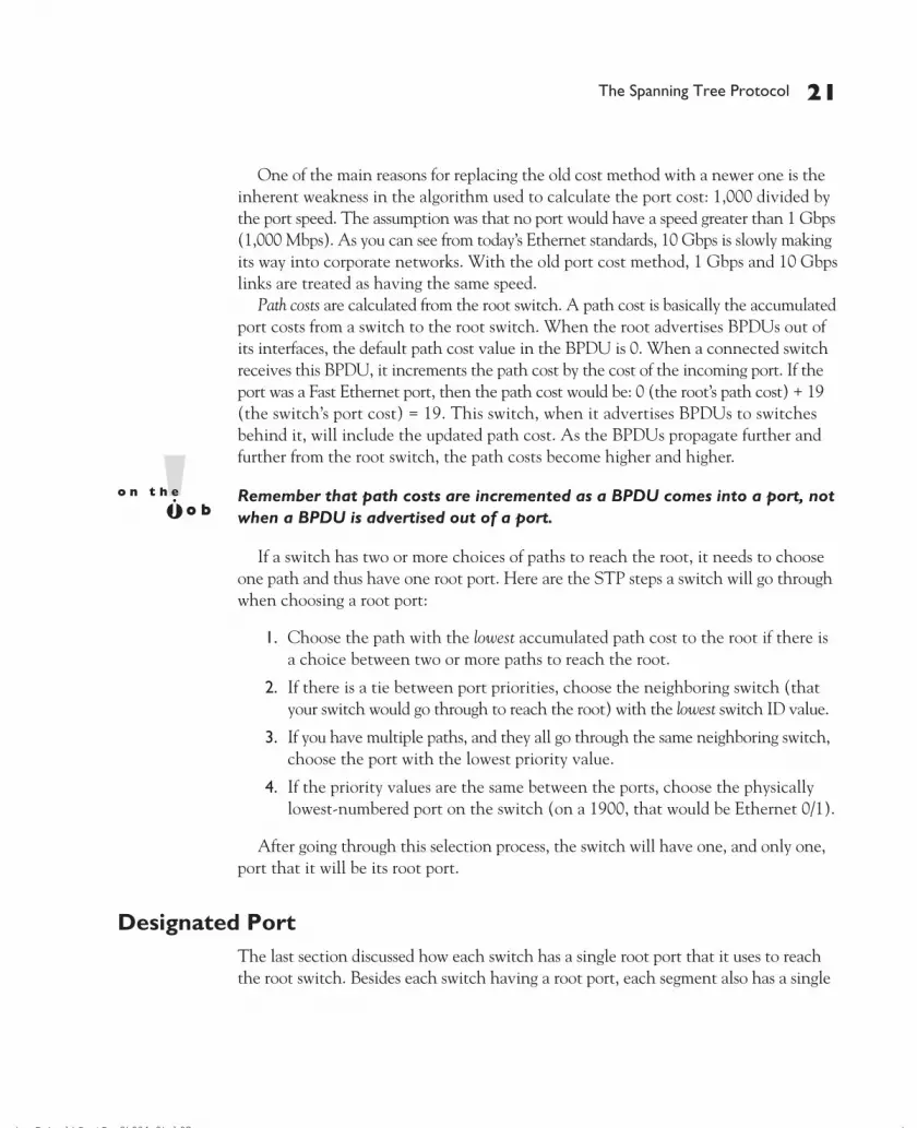
One of the main reasons for replacing the old cost method with a newer one is theinherent weakness in the algorithm used to calculate the port cost: 1,000 divided bythe port speed. The assumption was that no port would have a speed greater than 1 Gbps(1,000 Mbps). As you can see from today’s Ethernet standards, 10 Gbps is slowly makingits way into corporate networks. With the old port cost method, 1 Gbps and 10 Gbpslinks are treated as having the same speed.
Path costs are calculated from the root switch. A path cost is basically the accumulatedport costs from a switch to the root switch. When the root advertises BPDUs out ofits interfaces, the default path cost value in the BPDU is 0. When a connected switchreceives this BPDU, it increments the path cost by the cost of the incoming port. If theport was a Fast Ethernet port, then the path cost would be: 0 (the root’s path cost) + 19(the switch’s port cost) = 19. This switch, when it advertises BPDUs to switchesbehind it, will include the updated path cost. As the BPDUs propagate further andfurther from the root switch, the path costs become higher and higher.
Remember that path costs are incremented as a BPDU comes into a port, notwhen a BPDU is advertised out of a port.
If a switch has two or more choices of paths to reach the root, it needs to chooseone path and thus have one root port. Here are the STP steps a switch will go throughwhen choosing a root port:
1. Choose the path with the lowest accumulated path cost to the root if there isa choice between two or more paths to reach the root.
2. If there is a tie between port priorities, choose the neighboring switch (thatyour switch would go through to reach the root) with the lowest switch ID value.
3. If you have multiple paths, and they all go through the same neighboring switch,choose the port with the lowest priority value.
4. If the priority values are the same between the ports, choose the physicallylowest-numbered port on the switch (on a 1900, that would be Ethernet 0/1).
After going through this selection process, the switch will have one, and only one,port that it will be its root port.
Designated PortThe last section discussed how each switch has a single root port that it uses to reachthe root switch. Besides each switch having a root port, each segment also has a single
The Spanning Tree Protocol 21
CertPrs8 / CCNA Cisco Certified Network Associate Study Guide / Deal / 222934-9 / Chapter 7
D:\omh\CertPrs8\934-9\ch07.vpMonday, August 04, 2003 11:53:08 AM
Color profile: Generic CMYK printer profileComposite Default screen

port that is uses to reach the root. This port is called a designated port. For instance,imagine that there is a segment with two switches connected to it. Either one or theother switch will forward traffic from this segment (a LAN connection) to the rest ofthe network.
The third step in running STP is to elect a designated port on a single switch foreach segment in the network. The switch (and its port) that is chosen should have thebest path to the root switch. Here are the steps that are taken by switches in determiningwhich port on which switch will be chosen as the designated port.
1. The connected switch on the segment with the lowest accumulated path costto the root bridge will be used.
2. If there is a tie in accumulated path costs between two switches, then theswitch with the lowest switch ID will be chosen.
3. If it happens that it is the same switch, but with two separate connectionsto the LAN segment, the switch port with the lowest priority is chosen.
4. If there is still a tie (the priorities of the ports on this switch are the same),then the physically lowest numbered port on the switch is chosen.
After going through these steps for each segment, each segment will have a singledesignated port that it will use to reach the root switch. Sometimes the switch thatcontains the designated port is called a designated switch. This term is misleading, sinceit is a port on the switch that is responsible for forwarding traffic. There may be twosegments a switch is connected to, but it may be the designated switch for only oneof those segments; another switch may provide the designated port for the secondsegment.
Interestingly enough, every active port on the root switch is a designated port.This makes sense because the cost of the attached network segments to reach theroot is 0, the lowest accumulated cost value. In other words, each of these LANsegments is directly attached to the root switch, so in reality, it costs nothing forthe segment to reach the root switch itself.
Port StatesThere are five different states that a port can be in when it is participating in STP:
■ Blocked
■ Listening
■ Learning
22 Chapter 7: Bridging and Switching
CertPrs8 / CCNA Cisco Certified Network Associate Study Guide / Deal / 222934-9 / Chapter 7
D:\omh\CertPrs8\934-9\ch07.vpMonday, August 04, 2003 11:53:09 AM
Color profile: Generic CMYK printer profileComposite Default screen

■ Forwarding
■ Disabled
Of the five states, only the first four are used when the algorithm is running.The following sections cover the different port states for STP.
BlockingPorts will go into a blocking state under one of three conditions:
■ Election of a root switch (for instance, when you turn on all the switchesin a network)
■ When a switch receives a BPDU on a port that indicates a better path tothe root switch than the port the switch is currently using to reach the root
■ If a port is not a root port or a designated port
A port in a blocked state will remain there for 20 seconds by default (the maximumage timer). During this state, the port is only listening to and processing BPDUs onits interfaces. Any other frames that the switch receives on a blocked port are dropped.In a blocking state, the switch is attempting to figure out which port is going to be theroot port, which ports on the switch need to be designated ports, and which ports willremain in a blocked state to break up any loops. After the 20 seconds have expired,the port will then move to the listening state.
ListeningAfter the 20-second timer expires, a root port or a designated port will move to a listeningstate. Any other port will remain in a blocked state. During the listening state, the portis still listening for BPDUs and double-checking the layer-2 topology. Again, the onlytraffic that is being processed in this state consists of BPDUs; all other traffic is dropped.A port will stay in this state for the length of the forward delay timer. The default for thisvalue is 15 seconds.
LearningFrom a listening state, a port moves into a learning state. During the learning state, theport is still listening for and processing BPDUs on the port; however, unlike while in thelistening state, the port begins to process user frames. When processing user frames,the switch is examining the source addresses in the frames and updating its CAM table,but the switch is still not forwarding these frames out destination ports. Ports stay inthis state for the length of the forward delay time (which defaults to 15 seconds).
The Spanning Tree Protocol 23
CertPrs8 / CCNA Cisco Certified Network Associate Study Guide / Deal / 222934-9 / Chapter 7
D:\omh\CertPrs8\934-9\ch07.vpMonday, August 04, 2003 11:53:09 AM
Color profile: Generic CMYK printer profileComposite Default screen

ForwardingFinally, after the forward delay timer expires, ports that were in a learning state areplaced in a forwarding state. In a forwarding state, the port will process BPDUs, updateits CAM table with frames that it receives, and forward user traffic through the port.
DisabledThe disabled state is a special port state. A port in a disabled state is not participatingin STP. This could be because the port has been manually shut down by an administrator,manually removed from STP, disabled because of security issues, or rendered nonfunctionalbecause of a lack of a physical-layer signal (such as the patch cable being unplugged).
Layer-2 ConvergenceAs you have noticed in the last section, STP goes through a staged process, which slowsdown convergence. For switches, convergence occurs once STP has completed: a rootswitch is elected, root and designated ports have been chosen, the root and designatedports have been placed in a forwarding state, and all other ports have been placed in ablocked state.
If a port has to go through all four states, convergence takes 50 seconds: 20 secondsin blocking, 15 seconds in listening, and 15 seconds in learning. If a port doesn’t haveto go through the blocking state but starts at a listening state, convergence takesonly 30 seconds. This typically occurs when the root port is still valid, but anothertopology change has occurred. Remember that during this time period (until the portreaches a forwarding state), no user traffic is forwarded through the port. So, if a userwas performing a telnet session, and STP was being recalculated, the telnet session,from the user’s perspective, would appear stalled, or the connection would appear lost.Obviously, a user will notice this type of disruption.
Therefore, the faster that convergence takes place, the less disruption that this willcause for your users. You can reduce the two timers to reduce your convergence time,
24 Chapter 7: Bridging and Switching
CertPrs8 / CCNA Cisco Certified Network Associate Study Guide / Deal / 222934-9 / Chapter 7
There are four majorport states in STP: blocking (20 seconds),listening (15 seconds), learning (15 seconds),and forwarding. It can take 30–50 secondsfor STP convergence to take place.
In blocking and listening states, onlyBPDUs are processed. In a learningstate, the CAM table is being built.In a forwarding state, user framesare moved between ports.
D:\omh\CertPrs8\934-9\ch07.vpMonday, August 04, 2003 11:53:09 AM
Color profile: Generic CMYK printer profileComposite Default screen

but this can create more problems if you aren’t aware of what you are doing when youchange them. For user ports, you can use the PortFast feature to speed up convergence.PortFast should be used only on ports that will not create layer-2 loops, such as portsconnected to PCs, servers, and routers (sometimes referred to as a user, or edge, ports).
A port with PortFast enabled is always placed in a forwarding state—this is eventrue whenever STP is running and the root and designated ports are going through
their different states. So, when STP is running,PortFast ports on the same switch can stillforward traffic among themselves, limiting yourSTP disruption somewhat. However, if thesedevices wanted to talk to devices connected toother switches, they would have to wait untilSTP completed and the root and designatedports had moved into a forwarding state.
Rapid Spanning Tree ProtocolThe 802.1d standard was designed back when waiting for 30–50 seconds for convergencewasn’t a problem. However, in today’s networks, this can cause serious performanceproblems for networks that use real-time applications, like Voice over IP (VoIP). Toovercome these issues, Cisco developed proprietary bridging features called PortFast(discussed in the last section), UplinkFast, and BackboneFast. The problem with thesefeatures is that they are proprietary to Cisco.
The Rapid Spanning Tree Protocol (RSTP) is an IEEE standard, 802.1w, that isinteroperable with 802.1d and an extension to it. With RSTP, there are only three portstates: discarding, learning, and forwarding. A port in a discarding state is basicallythe grouping of 802.1d’s blocking, listening, and disabled states. The following sectionscover some of the enhancements included in RSTP.
Additional Port RolesWith RSTP, there are still root and designated ports, performing the same roles asthose in 802.1d. However, RSTP adds two additional port types: alternate ports andbackup ports. These two ports are similar to the ports in a blocking state in 802.1d.An alternate port is a port that has an alternative path or paths to the root but is currentlyin a discarding state. A backup port is a port on a segment that could be used to reachthe root port, but there is already an active designated port for the segment. The bestway to look at this is that an alternate port is a secondary, unused root port, and abackup port is a secondary, unused designated port.
The Spanning Tree Protocol 25
CertPrs8 / CCNA Cisco Certified Network Associate Study Guide / Deal / 222934-9 / Chapter 7
STP convergence hasoccurred when all root and designatedports are in a forwarding state and allother ports are in a blocking state.
D:\omh\CertPrs8\934-9\ch07.vpMonday, August 04, 2003 11:53:09 AM
Color profile: Generic CMYK printer profileComposite Default screen

Given these new port roles, RSTP calculates the final spanning tree topology thesame way as 802.1d. Some of the nomenclature was changed and extended, and thisis used to enhance convergence times, as you will see later on in the RSTP section.
BPDUsThe 802.1w standard has introduced a change with BPDUs. Some additional flags wereadded to the BPDUs, so that switches could share information about the role of theport the BPDU is exiting. This can help a neighboring switch converge faster whenchanges occur in the network.
In 802.1d, if a switch didn’t see a root BPDU within the maximum age time (20seconds), STP would run, a new root switch would be elected, and a new loop-freetopology would be created. This is a time-consuming process. With 802.1w, if a hellois not received in three expected hello periods (six seconds), STP information can beaged out instantly and the switch considers that its neighbor is lost and actions shouldbe taken. This is different from 802.1d, where the switch had to miss the BPDUs fromthe root—here, if the switch misses three consecutive hellos from a neighbor, actionsare immediately taken.
Convergence FeaturesThe 802.1w standard includes new convergence features that are very similar to Cisco’sproprietary UplinkFast and BackboneFast features. The first feature, which is likeCisco’s BackboneFast feature, allows a switch to accept inferior BPDUs.
Look at Figure 7-11 to understand the inferior BPDU feature. In this example, theroot bridge is SwitchA. Both of the ports on SwitchB and SwitchC directly connectedto the root are root ports. For the segment between SwitchB and SwitchC, SwitchBprovides the designated port and SwitchC provides a backup port (a secondary wayof reaching the root for the segment). SwitchB also knows that its designated portis also an alternative port (a secondary way for the switch to reach the root), viaSwitchC from SwitchC’s BPDUs.
Following the example in Figure 7-11, the link between the root and SwitchB fails.SwitchB can detect this by either missing three hellos from the root port or detecting aphysical layer failure. If you were running 802.1d, SwitchB would see an inferior rootBPDU (worse cost value) coming via SwitchC, and therefore all ports would haveto go through a blocking, listening, and learning state, which would take 50 seconds toconverge. With the inferior BPDU feature, assuming that SwitchB knows that SwitchChas an alternative port for their directly connected segment, then SwitchB can notifySwitchC to take its alternative port and change it to a designated port, and SwitchBwill change its designated port to a root port. This process takes only a few seconds,if even that.
26 Chapter 7: Bridging and Switching
CertPrs8 / CCNA Cisco Certified Network Associate Study Guide / Deal / 222934-9 / Chapter 7
D:\omh\CertPrs8\934-9\ch07.vpMonday, August 04, 2003 11:53:09 AM
Color profile: Generic CMYK printer profileComposite Default screen

The second convergence feature introduced in 802.1w is rapid transition. Rapidtransition includes two new components: edge ports and link types. An edge port isa port connected to a non-layer-2 device, such as a PC, server, or router. RSTP withrapid transition of edge ports to a forwarding state is the same as Cisco’s proprietaryPortFast feature. Changes in the state of these ports does not affect RSTP in orderto cause a recalculation, and changes in other port types will keep these ports in aforwarding state.
Rapid transition can only take place in RTSP for edge ports and links that arepoint-to-point. The link type is automatically determined in terms of the duplexingof the connection. Switches make the assumption that if the port is configured forfull-duplex between the two switches, the port can rapidly transition to a differentstate without having to wait for any timers to expire. If they are half-duplex, thenthis feature won’t work by default, but you can manually enable it for point-to-pointhalf-duplex switch links.
Let’s take a look at an example of rapidtransition of point-to-point links by usingthe topology in Figure 7-12. The topology inFigure 7-12 is the same as 7-11. In this example,however, the link between SwitchA (the root)and SwitchC fails. When this happens, SwitchCcan no longer reach SwitchA on its root port.However, looking at the BPDUs it has beenreceiving from SwitchA and SwitchB, SwitchC
knows that the root is reachable via SwitchB and that SwitchB provides the designatedport (which is in a forwarding state) for the segment between SwitchB and SwitchC.SwitchC, knowing this, changes the state of the backup port to a root port and placesit immediately into a forwarding state, notifying SwitchB of the change. This updatetypically takes less than a second, assuming that the failure of the segment betweenthe root and SwitchC is a physical link failure, instead of three missed consecutivehello BPDUs.
The Spanning Tree Protocol 27
CertPrs8 / CCNA Cisco Certified Network Associate Study Guide / Deal / 222934-9 / Chapter 7
FIGURE 7-11
Accepting inferiorBPDUs
For the CCNA exam, youshould be aware of the concepts of RSTP.The actual configuration and tuning ofit is beyond the scope of this book andis covered in Cisco’s Switching exam.
D:\omh\CertPrs8\934-9\ch07.vpMonday, August 04, 2003 11:53:09 AM
Color profile: Generic CMYK printer profileComposite Default screen

Simple STP ExampleTo grow more familiar with the workings of 802.1d STP, let’s look at an example of STPin action. I’ll use the network shown in Figure 7-13 as a starting point and make theassumption that these switches do not support RSTP, but only 802.1d STP. The portson each switch are labeled with a letter and a number. The letter is the port designator,and the number is the cost of the port as a BPDU enters the port.
28 Chapter 7: Bridging and Switching
CertPrs8 / CCNA Cisco Certified Network Associate Study Guide / Deal / 222934-9 / Chapter 7
FIGURE 7-13 STP example network
FIGURE 7-12
Rapid transitionexample
D:\omh\CertPrs8\934-9\ch07.vpMonday, August 04, 2003 11:53:10 AM
Color profile: Generic CMYK printer profileComposite Default screen

Electing the Root SwitchThe first thing that occurs once all these switches are booted up is the election of theroot switch. The switches share BPDUs with each other to elect the root. In this example,all of the switches are using the default priority (32,768). Remember that the switchwith the lowest switch ID is elected as root. Since all of the switches have the samepriority, the switch with the lowest MAC address, which is Switch 1, is chosen as theroot switch. Based on the election process, the new network topology looks like thatshown in Figure 7-14.
Choosing Root Ports for Each SwitchAfter the root switch is elected, each non-root switch must choose one of its ports thatit will use to reach the root, called the root port. Let’s take this one switch at a time sothat you can see the decision process in detail. With Switch 1, which is the root switch,there are no root ports—if you recall, all ports on the root are designated ports.
Switch 2 has two ports to use to reach the root: E and F. When Switch 1 generatesits BPDUs on ports I and J, the original path cost is set to 0. As these BPDUs arereceived by other switches, the receiving switch increments the path cost by the costof the port that the BPDU was received on. As the BPDU comes into port E, Switch 2increments the path cost to 20 and for port F, 10. The first check that Switch 2 makes
The Spanning Tree Protocol 29
CertPrs8 / CCNA Cisco Certified Network Associate Study Guide / Deal / 222934-9 / Chapter 7
FIGURE 7-14 Root switch election
D:\omh\CertPrs8\934-9\ch07.vpMonday, August 04, 2003 11:53:10 AM
Color profile: Generic CMYK printer profileComposite Default screen

is to compare the path costs. Port F has the best path cost and therefore is chosen asthe root port, which is shown as “RP” in Figure 7-15.
Switch 3 also has two paths to reach the root: via ports C and D. Port C’saccumulated path cost is 10, while D’s cost is 70. Therefore, port C is chosen as theroot port. Switch 4 also has two ports to use to access the root: H and G. Port H hasan accumulated path cost of 30, while G has a cost of 50, causing Switch 4 to chooseport H as the root port. Switch 5’s two ports, A and B, have accumulated path costsof 10 and 40, respectively, causing Switch 5 to choose Port A as the root port.
Note that all the switches in the network are simultaneously running STP andfiguring out for themselves who the root switch is and which port on themselvesshould be the root port. This is also true for choosing a designated port on a segment,discussed in the next section.
Choosing Designated Ports for Each SegmentAfter the root ports are chosen, each switch will figure out, on a segment-by-segmentbasis, if its connected port to the segment should be a designated port. Remember that thedesignated port on a segment is responsible for moving traffic back and forth betweenthe segment and the switch. The segments themselves, of course, are completely unawareof this process of choosing a designated port—the switches are figuring this out.
30 Chapter 7: Bridging and Switching
CertPrs8 / CCNA Cisco Certified Network Associate Study Guide / Deal / 222934-9 / Chapter 7
FIGURE 7-15 Root ports
D:\omh\CertPrs8\934-9\ch07.vpMonday, August 04, 2003 11:53:10 AM
Color profile: Generic CMYK printer profileComposite Default screen

When choosing a designated port, the first thing that is examined is the accumulatedpath cost for the switch (connected to the segment) to reach the root. For two switchesconnected to the same segment, the switch with the lowest accumulated path costwill be the designated switch for that segment and its port connected to that segmentbecomes a designated port.
Going back to our network example, let’s start with the easiest segments: B and C.For Switch 1, the accumulated path cost for LAN Segment B is 0, Switch 2 is 20, andSwitch 5 is 10. Since the root bridge (Switch 1) has the lowest accumulated path cost,its local port (J) becomes the designated port for LAN Segment B. This process is alsotrue for LAN Segment C—the root switch has the lowest accumulated path cost (0),making port I on Switch 1 the designated port for LAN Segment C.
LAN Segment A has two choices: Switch 3’s D port and Bridge 4’s H port. Switch 3has the lower accumulated path cost: 10 versus Switch 4’s 30. Therefore, Switch 3’s Dport becomes the designated port for LAN Segment A.
LAN Segment D also has two choices for a designated port: Switch 5’s B port andSwitch 4’s G port. Switch 5 has an accumulated path cost of 10, and Switch 4 has a costof 30. Therefore Switch 5’s B port becomes the designated port for LAN Segment D.
Figure 7-16 shows the updated STP topology for our network, where “DP” representsthe designated ports for the LAN segments:
The Spanning Tree Protocol 31
CertPrs8 / CCNA Cisco Certified Network Associate Study Guide / Deal / 222934-9 / Chapter 7
FIGURE 7-16 Root and designated ports
D:\omh\CertPrs8\934-9\ch07.vpMonday, August 04, 2003 11:53:10 AM
Color profile: Generic CMYK printer profileComposite Default screen

Changing Port StatesAfter the designated ports are chosen, the switches will move their root and designatedports through the various states: blocking, listening, learning, and forwarding, whereasany other ports will remain in a blocked state. Figure 7-17 shows the ports in a blockedstate, designated by an “X”. Remember that on Switch 2, only Port F (the root port) isin a forwarding state: Port E will remain in a blocked state. In this example, two portsare left in a blocked state: Switch 2’s E port and Switch 4’s G port.
STP guarantees only a layer-2 loop-free topology—it does not guarantee anoptimal topology! For example, in the network shown in Figure 7-17, networkingdevices on LAN Segment A would have to go through Switches 1, 3, and 5 inorder to reach LAN Segment D, since Switch 4’s G port is in a blocked state.
32 Chapter 7: Bridging and Switching
CertPrs8 / CCNA Cisco Certified Network Associate Study Guide / Deal / 222934-9 / Chapter 7
FIGURE 7-17 Ports in a blocked state
D:\omh\CertPrs8\934-9\ch07.vpMonday, August 04, 2003 11:53:10 AM
Color profile: Generic CMYK printer profileComposite Default screen

CERTIFICATION OBJECTIVE 7.01
1900 and 2950 ConfigurationChapter 5 covered some of the basics on configuring your 1900 and 2950 switches.This chapter expands upon these commands, including a quick overview of the 1900and 2950 basic configuration process, configuring their interfaces, and manipulatingconfiguration files. Configuration of STP is discussed in Chapter 8.
Default ConfigurationIf you recall from Chapter 5, the 1900 switch requires the Enterprise Edition softwarein order to access the IOS CLI; otherwise, you are restricted to the menu-based interfacefor configuring the switch. This shouldn’t be an issue unless you have a very old 1900,which might or might not be able to be upgraded, depending on the model number ofthe 1900. The 2950 switch, however, comes only with an IOS CLI. Both switches,nevertheless, share the same default configuration when you receive a brand new switchdirectly from Cisco. Here is the default configuration of the switches:
■ All ports are enabled.
■ The 10BaseT ports on the 1900 are set to half-duplex; the two 100Mb portsare set for autonegotiating of the duplexing.
■ All ports on the 2950 are set to autosensing for duplexing and speed.
■ The 1900 default switching method is fragment free (the 2950 supports onlystore-and-forward switching).
■ CDP is enabled on all ports.
■ STP is enabled on all ports.
■ The switches are not password protected.
■ No IP addressing information is configured on the switches.
As you can see from this list, there are certain things that you will want to configurein order to manage your switch, as well as to optimize its configuration.
1900 and 2950 Configuration 33
CertPrs8 / CCNA Cisco Certified Network Associate Study Guide / Deal / 222934-9 / Chapter 7
D:\omh\CertPrs8\934-9\ch07.vpMonday, August 04, 2003 11:53:11 AM
Color profile: Generic CMYK printer profileComposite Default screen

Quick ReviewWhen you log into the 1900 switch, you are taken into the menu system. Type in “K”to access User EXEC mode. On the 2950, you are immediately taken to this mode. Ifyou are not sure which switch model you are logged into, you can use the show versioncommand. Here is the output of this command for the 1900 switch:
> show versionCisco Catalyst 1900/2820 Enterprise Edition SoftwareVersion V9.00.00(12) written from 172.16.1.11Copyright (c) Cisco Systems, Inc. 1993-1999Switch uptime is 0day(s) 0hour(s) 15minute(s) 59second(s)cisco Catalyst 1900 (486sxl) processor with 2048K/1024K bytes
of memoryHardware board revision is 1Upgrade Status: No upgrade currently in progress.Config File Status: No configuration upload/download is
in progress27 Fixed Ethernet/IEEE 802.3 interface(s)Base Ethernet Address: 00-E0-1E-86-37-AD
This contains the version of software running, the amount ofRAM/flash, the types of interfaces, and the MAC address of theswitch.
In this example, the switch is a 1924, based on the number of Ethernet interfaces(“27 Fixed Ethernet/IEEE 802.3 interface(s)”), and is running theEnterprise Edition software. Here is an example of this command on a 2950:
Switch# show versionCisco Internetwork Operating System SoftwareIOS (tm) C2950 Software (C2950-I6Q4L2-M), Version 12.1(9)EA1,
RELEASE SOFTWARE (fc1)Copyright (c) 1986-2002 by cisco Systems, Inc.Compiled Wed 24-Apr-02 06:57 by antoninoImage text-base: 0x80010000, data-base: 0x804E8000
ROM: Bootstrap program is CALHOUN boot loaderSwitch uptime is 19 minutesSystem returned to ROM by power-onSystem image file is "flash:c2950-i6q4l2-mz.121-9.EA1.bin"
cisco WS-C2950-24 (RC32300) processor (revision E0) with20815K bytes of memory.
34 Chapter 7: Bridging and Switching
CertPrs8 / CCNA Cisco Certified Network Associate Study Guide / Deal / 222934-9 / Chapter 7
D:\omh\CertPrs8\934-9\ch07.vpMonday, August 04, 2003 11:53:11 AM
Color profile: Generic CMYK printer profileComposite Default screen

Processor board ID FHK0629Y004Last reset from system-resetRunning Standard Image24 FastEthernet/IEEE 802.3 interface(s)32K bytes of flash-simulated non-volatile configuration memory.Base ethernet MAC Address: 00:0A:41:BF:0A:40Motherboard assembly number: 73-5781-10Power supply part number: 34-0965-01Motherboard serial number: FOC06270NZLPower supply serial number: PHI062504VDModel revision number: E0Motherboard revision number: B0Model number: WS-C2950-24System serial number: FHK0629Y004Configuration register is 0xF
This switch is a 2950 with 24 interfaces: “24 FastEthernet/IEEE 802.3interface(s)”.
Entering Configuration ModeRemember that both of these switches support three basic modes: User EXEC, PrivilegeEXEC, and Configuration modes. To make configurations on your switch, you need tobe in Configuration mode:
> enable# configure terminal(config)#
As you can see, this is just like the IOS-based routers. In this code example, theswitch happened to be a 1900. The 2950 and routers put the device name in theirprompts, which default to Switch and Router respectively. The 1900 has no defaultname. To assign a name on any IOS device, use the hostname Configuration modecommand.
IP ConfigurationAs was mentioned in the introduction of this section, the switches have no IPconfiguration on them. Configuring IP addressing on your switches was coveredin Chapter 5. Here is a quick code example of configuring IP on these two devices:
1900(config)# ip address IP_address subnet_mask1900(config)# ip default-gateway router’s_IP_address
1900 and 2950 Configuration 35
CertPrs8 / CCNA Cisco Certified Network Associate Study Guide / Deal / 222934-9 / Chapter 7
D:\omh\CertPrs8\934-9\ch07.vpMonday, August 04, 2003 11:53:11 AM
Color profile: Generic CMYK printer profileComposite Default screen

2950(config)# interface vlan12950(config-vlan)# ip address IP_address subnet_mask2950(config-vlan)# exit2950(config)# ip default-gateway router’s_IP_address
To verify your IP configuration on a 1900, use the show ip command:
1900# show ipIP Address:192.168.1.12Subnet Mask:255.255.255.0Default Gateway:192.168.1.1Management VLAN: 1Domain name: dealgroup.comName server 1:192.168.1.77Name server 2:HTTP server :DisabledHTTP port : 80RIP :Enabled
On the 2950, use the show ip interface brief command to verify your IPconfiguration:
Switch# show ip interface brief
Interface IP-Address OK? Method Status ProtocolVlan1 192.168.1.13 YES manual up upFastEthernet0/1 unassigned YES unset down down<--output omitted-->
7.01. The CD contains a multimedia demonstration overview of the 1900and the 2950.
Basic Interface ConfigurationThe 1900 and the 2950 use the same nomenclature for identity interfaces:
(config)# interface type 0/port_number
The 1900 has two types of interfaces: ethernet and fastethernet. The 2950also has two types: fastethernet and gigabitethernet.
For the 1912, there are 12 10BaseT ports (e0/1-e012) on the front of theswitch, 1 AUI (e0/25) port on the rear, and 2 100BaseTX/FX ports on the front
36 Chapter 7: Bridging and Switching
CertPrs8 / CCNA Cisco Certified Network Associate Study Guide / Deal / 222934-9 / Chapter 7
D:\omh\CertPrs8\934-9\ch07.vpMonday, August 04, 2003 11:53:11 AM
Color profile: Generic CMYK printer profileComposite Default screen

(fa0/26-fa0/27). For the 1924, there are 24 10BaseT ports (e0/1-e024), 1AUIport (e0/25), and 2 100BaseTX/FX ports (fa0/26-fa0/27).
The 2950 comes in many models. The most popular is the 2950T-24 model, withcomes with 24 10/100BaseTX interfaces (fa0/1-fa0-24) on the front of the switch.Unlike on routers, interface numbers on the switches begin with 1. Even though youmust specify a module number of “0” for the switches, the two switches I mentioned arenot modular. The 2820, a sister switch of the 1900, is modular, with slots 0, 1, and 2.
Accessing an InterfaceTo enter an interface, you use the same interface Global Configuration mode commandas you would use on a Cisco router:
(config)# interface ethernet|fastethernet|gigabit 0/port_#(config-if)#
Notice that this command took you into Interface Subconfiguration mode. In thismode, any changes made on an interface affect only that particular interface. Plus,if you enter a Global Configuration mode command, the switch will typically executeat the Global mode and return you here after executing the command.
Configuring Interface DuplexingYou can manually configure the duplexing on an switch’s interface with the duplexInterface Subconfiguration mode command. On the 1900, use the following syntax:
1900(config)# interface ethernet|fastethernet 0/port_number1900(config-if)# duplex auto|full|half|full-flow-control
Remember the default duplex settings on the 1900. One unique duplex setting isfull-flow-control. This allows the interface and the connected device to sharecongestion information to implement flow control. Even though IEEE includes thisfor full-duplexing in its standard, not every vendor has implemented it, and for thosevendors that have implemented it, the implementation might be slightly differentfrom vendor to vendor.
To set the duplexing on the 2950 switch, use the following syntax:
2950(config)# interface fastethernet|gigabit 0/port_#2950(config-if)# duplex auto|full|half
The 2950 doesn’t support the flow control configuration that the 1900 does.
1900 and 2950 Configuration 37
CertPrs8 / CCNA Cisco Certified Network Associate Study Guide / Deal / 222934-9 / Chapter 7
D:\omh\CertPrs8\934-9\ch07.vpMonday, August 04, 2003 11:53:11 AM
Color profile: Generic CMYK printer profileComposite Default screen

Unlike the 1900, the 2950 switches can autosense the speed of the connection(for the 10/100 ports). For these ports, you can hard-code the speed with thefollowing syntax:
2950(config)# interface fastethernet|gigabit 0/port_#2950(config-if)# speed 10|100|auto
Along with every network vendor, I recommend that you not use autosensingfor an interface. The problem with autosensing is that the IEEE standard forthis function isn’t very specific and leaves some wiggle room for the vendorswhen implementing it. Of course, this can create conflicts between vendorswhen autosensing is trying to negotiate the duplexing and/or speed of theconnection. Sometimes, one side might end up 100 half-duplex and the otherside 100 full-duplex, creating massive number of collisions. You can use theshow interfaces command to help troubleshoot this problem. Therefore,always manually configure the duplexing and speed of your autosensinginterfaces.
Verifying Interface ConfigurationOnce you have configured the duplexing and/or speed of your interface, you can verifyits configuration with this command:
> show interface [ethernet|fastethernet|gigabit 0/port_#]
The output of the 1900 command is different from the IOS router’s output:
1900> show interface ethernet 0/1Ethernet 0/1 is Suspended-no-linkbeatHardware is Built-in 10Base-TAddress is 00E0.1EA3.BC12MTU 1500 bytes, BW 10000 Kbits802.1d STP State: Blocking Forward Transitions: 3Port monitoring: DisabledUnknown unicast flooding: DisabledUnregistered multicast flooding: DisabledDescription:Duplex setting: Half duplexBack pressure: Disabled
Receive Statistics Transmit Statistics------------------------------ ------------------------------Total good frames 0 Total frames 0Total octets 0 Total octets 0
38 Chapter 7: Bridging and Switching
CertPrs8 / CCNA Cisco Certified Network Associate Study Guide / Deal / 222934-9 / Chapter 7
D:\omh\CertPrs8\934-9\ch07.vpMonday, August 04, 2003 11:53:11 AM
Color profile: Generic CMYK printer profileComposite Default screen

Broadcast/multicast frames 0 Broadcast/multicast frames 0Broadcast/multicast octets 0 Broadcast/multicast octets 0Good frames forwarded 0 Deferrals 0Frames filtered 0 Single collisions 0Runt frames 0 Multiple collisions 0No buffer discards 0 Excessive collisions 0
Queue full discards 0Errors: Errors:FCS errors 0 Late collisions 0Alignment errors 0 Excessive deferrals 0Giant frames 0 Jabber errors 0Address violations 0 Other transmit errors 0
With this command, you can see the duplex configuration (half), STP mode(blocking), and statistics and error information about the interface. If you have aduplex-mismatch between your switch interface and a connected device, you willprobably see an excessive number of collisions, especially late collisions, as well asan excessive number of FCS (frame checksum) errors. Remember my warning aboutautosensing an interface’s configuration.
The output of this command looks like the following on a 2950 switch:
Switch# show interface fastethernet 0/2FastEthernet0/2 is up, line protocol is upHardware is Fast Ethernet, address is 000a.41bf.0a42 (bia 000a.41bf.0a42)MTU 1500 bytes, BW 10000 Kbit, DLY 1000 usec,
reliability 255/255, txload 1/255, rxload 1/255Encapsulation ARPA, loopback not setKeepalive set (10 sec)Half-duplex, 10Mb/sinput flow-control is off, output flow-control is offARP type: ARPA, ARP Timeout 04:00:00Last input never, output 00:00:01, output hang neverLast clearing of "show interface" counters neverInput queue: 0/75/0/0 (size/max/drops/flushes); Total output drops: 0Queueing strategy: fifoOutput queue :0/40 (size/max)5 minute input rate 0 bits/sec, 0 packets/sec5 minute output rate 2000 bits/sec, 1 packets/sec
530 packets input, 42856 bytes, 0 no bufferReceived 187 broadcasts, 0 runts, 0 giants, 0 throttles0 input errors, 0 CRC, 0 frame, 0 overrun, 0 ignored0 watchdog, 57 multicast, 0 pause input0 input packets with dribble condition detected3653 packets output, 276663 bytes, 0 underruns
1900 and 2950 Configuration 39
CertPrs8 / CCNA Cisco Certified Network Associate Study Guide / Deal / 222934-9 / Chapter 7
D:\omh\CertPrs8\934-9\ch07.vpMonday, August 04, 2003 11:53:11 AM
Color profile: Generic CMYK printer profileComposite Default screen

0 output errors, 0 collisions, 2 interface resets0 babbles, 0 late collision, 0 deferred0 lost carrier, 0 no carrier, 0 PAUSE output0 output buffer failures, 0 output buffers swapped out
As you can see from the preceding output, it is similar to the output of a Ciscorouter. In this example, you can see that the duplexing is half and the speed of theinterface is 10 Mbps.
7.02. The CD contains a multimedia demonstration of configuring interfaceson a 1900 and the 2950.
EXERCISE 7-1ON THE CD
Basic Interface ConfigurationThese last few sections dealt with interface configurations. This exercise will help youreinforce this material for the 1900 and 2950 switches. You’ll perform this lab usingBoson’s NetSim™ simulator. You can find a picture of the network diagram for thesimulator in the Introduction of this book. After starting up the simulator, click onthe LabNavigator button. Next, double-click on Exercise 7-1 and click on the Load Labbutton. This will load the lab configuration based on Chapter 5’s exercises.
1. On the 1900-1 switch, set the inter-switch connections to full-duplex.
At the top of the simulator in the menu bar, click on the eSwitches icon andchoose 1900-1. Access configuration mode: enable and configureterminal. Enter the first uplink interface: interface fa0/26. Set theduplexing: duplex full. Exit the interface: exit. Enter the second uplinkinterface: interface fa0/27. Set the duplexing: duplex full. Exitconfiguration mode: end. Verify the configuration: show interface
40 Chapter 7: Bridging and Switching
CertPrs8 / CCNA Cisco Certified Network Associate Study Guide / Deal / 222934-9 / Chapter 7
Use the duplex commandto configure the duplexing on both switchesand the speed command on the 2950 to
set the speed. Also, know how to lookat the output of the show interfacescommand to do basic troubleshooting.
D:\omh\CertPrs8\934-9\ch07.vpMonday, August 04, 2003 11:53:11 AM
Color profile: Generic CMYK printer profileComposite Default screen

fa0/26. Make sure the duplexing is set correctly and the status of theinterface is okay.
2. On both the 2950 (2950-1 and 2950-2) switches, set the 1900 switch connectionto 100 Mbps and full-duplex.
At the top of the simulator in the menu bar, click on the eSwitches icon andchoose 2950-1. Use the interface fa0/1 command to enter the 1900interface connection. Assign the speed with this command: speed 100. Setthe duplexing: duplex full. Exit configuration mode: end. Verify theconfiguration: show interface fa0/1. Make sure the duplexing andspeed are set correctly and the status of the interface is okay. Save theconfiguration: copy running-config startup-config. At the top ofthe simulator in the menu bar, click on the eSwitches icon and choose 2950-2.Use the interface fa0/1 command to enter the 1900 interface connection.Assign the speed with this command: speed 100. Set the duplexing: duplexfull. Exit configuration mode: end. Verify the configuration: showinterface fa0/1. Make sure the duplexing and speed are set correctly andthe status of the interface is okay. Save the configuration: copy running-config startup-config.
3. Test connectivity with the ping command.
From the 1900-1, use ping 192.168.1.4 and ping 192.168.1.3.From the 2950-1 and 2950-2 switches, use ping 192.168.1.5. The pingshould be successful.
Now you should be more comfortable with configuring switch interfaces. In thenext section, you will be presented with examining and manipulating the CAM table,as well as setting up port security.
MAC Addresses and Port SecurityIf you recall, one of the three main functions of a switch is to learn which devices areassociated with which interfaces. This information is stored in a port address, or CAM,table. On both switches, you can view the CAM table with the show mac-address-table command. Here is an example of the use of this command on a 1900 switch:
1900> show mac-address-tableNumber of permanent addresses :1
1900 and 2950 Configuration 41
CertPrs8 / CCNA Cisco Certified Network Associate Study Guide / Deal / 222934-9 / Chapter 7
D:\omh\CertPrs8\934-9\ch07.vpMonday, August 04, 2003 11:53:11 AM
Color profile: Generic CMYK printer profileComposite Default screen

Number of restricted static addresses :0Number of dynamic addresses :4Address Dest Interface Type Source Interface List-----------------------------------------------------------------0000.0C7A.1210 FastEthernet0/26 Dynamic All0000.0C7A.341A FastEthernet0/26 Dynamic All0000.0C7A.17AB Ethernet0/1 Dynamic All0000.0C7A.E139 Ethernet0/2 Dynamic All0000.0C7A.BCE1 Ethernet0/3 Permanent All
In this example, there are five entries in the CAM table. One is a staticallyconfigured entry, and the other four are dynamically learned entries. As anexample, 0000.0C7A.1210 is connected to fa0/26 and was dynamically learned.The 1900 can store up to 1,024 MAC addresses in its CAM table. An importantthing to remember when designing your switched network is the number of devicesthat will be in the layer-2 network—you want to ensure that the switches you purchasesupport a CAM size to accommodate all of your devices. You definitely don’t wantyour switches to be flooding traffic because your CAM tables are too small and can’tlearn additional entries.
Here is an example of the same command on a 2950 switch:
2950> show mac-address-tableMac Address Table------------------------------------------
Vlan Mac Address Type Ports---- ----------- ---- -----
1 0008.7422.6d4a DYNAMIC Fa0/21 0040.3399.b033 DYNAMIC Fa0/2
Total Mac Addresses for this criterion: 2
In this example, there are two entries inthe CAM table, both of which were learneddynamically and are connected to fa0/2.The 2950 switches can hold up to 8,192 entriesin their CAM tables.
To clear dynamically learned entries from theCAM table, use the clear mac-address-table command from Privilege EXEC mode.
42 Chapter 7: Bridging and Switching
CertPrs8 / CCNA Cisco Certified Network Associate Study Guide / Deal / 222934-9 / Chapter 7
Be familiar with the outputof the show mac-address-tablecommand.
D:\omh\CertPrs8\934-9\ch07.vpMonday, August 04, 2003 11:53:12 AM
Color profile: Generic CMYK printer profileComposite Default screen

Static MAC AddressesBesides having the switches learn MAC addresses dynamically, you can create staticentries also. You may want to do this for security reasons. If a user moves their connectionfrom one switch port to another, their traffic won’t be forwarded correctly if you hadstatically configured their address to the old port. For traffic to flow correctly again, youwould have to change the old entry to reflect the user’s new interface. You may want todo this to ensure that the user doesn’t unplug their connection from one port and connectit to another port, where the user might have access to more networking resources.
Unlike dynamic entries in a CAM table, static entries do not age out. This is trueeven if you reboot the switch (assuming your configuration has been saved). Also, ifyou have a static entry for a device and you move that device to a different port, eventhough the switch will see the change, the static entry will always override the learningfunction of the switch.
On a 1900 switch, use the following command to create a static entry in theCAM table:
1900(config)# mac-address-table permanent MAC_address interface
This command is straightforward. You need to specify the MAC address of thedevice in question, along with the interface associated with the device.
The 2950 command is slightly different:
2950(config)# mac-address-table static MAC_address vlan VLAN_#interface type module/port_#
Besides specifying the MAC address of the device, and the interface where thedevice is located, you must also specify the VLAN that the device is located in. (VLANsare discussed in Chapter 8.) With either of the two switches, use the show mac-address-table to view your new entries.
7.03. The CD contains a multimedia demonstration of configuring static CAMentries on the 1900 and on the 2950.
Port Security on the 1900The 1900 supports both static and dynamic port security. This allows you to restrictaccess to or from a particular MAC address. Use this command to set up static portsecurity on a 1900 switch:
1900(config)# mac-address-table restricted static MAC_addresssource_port list_of_allowed_interfaces
1900 and 2950 Configuration 43
CertPrs8 / CCNA Cisco Certified Network Associate Study Guide / Deal / 222934-9 / Chapter 7
D:\omh\CertPrs8\934-9\ch07.vpMonday, August 04, 2003 11:53:12 AM
Color profile: Generic CMYK printer profileComposite Default screen

Here is a simple example of this command:
1900(config)# mac-address-table restricted static 0000.0C7A.4444ethernet0/1 ethernet0/2
In this example, any devices connected to ethernet0/2 can access thedevice 0000.0C7A.4444, which is connected to ethernet0/1—any other trafficis prohibited from reaching this device. Use the show mac-address-table toview your new restricted entries.
The problem of using the preceding configuration is that you must manually secureeach MAC address that requires security. A better approach is to use dynamic portsecurity, also called sticky learning. With sticky learning, the switch can learn up toa maximum of 132 MAC addresses associated with each port. It then converts theseentries into static entries with the mac-address-table permanent command.If you reboot your switch, the static entries are still used. Note that sticky learningis really used to initially create the static entries and then is no longer used.
To enable this feature, use the following configuration:
1900(config)# interface ethernet|fastethernet 0/port_#1900(config-if)# port secure1900(config-if)# port secure max-mac-count value
The first command on the interface enables the feature. The second commandrestricts the number of addresses that the sticky feature can learn. The default is 132;but you can change it to anything in the range 1–132.
After you have enabled port security, you may want to change your security options:
1900(config)# address-violation suspend|ignore|disable
Notice that this command is executed from Global Configuration mode. Here areyour three options:
■ suspend Suspend the port until the violation is fixed, then automaticallyreenable the port (the default value)
■ disable Shut down the port; the port can be reenabled only with the noshutdown command
■ ignore Generate a security violation alert
To remove sticky learning from an interface, perform the following:
1900(config)# interface ethernet|fastethernet 0/port_#1900(config-if)# port secure max-mac-count 1321900(config-if)# no port secure
44 Chapter 7: Bridging and Switching
CertPrs8 / CCNA Cisco Certified Network Associate Study Guide / Deal / 222934-9 / Chapter 7
D:\omh\CertPrs8\934-9\ch07.vpMonday, August 04, 2003 11:53:12 AM
Color profile: Generic CMYK printer profileComposite Default screen

First, you must reset the maximum number ofsecure addresses back to 132. Second, you needto disable port security. One often forgotten itemis to remove the sticky learned addresses that theswitch converted to mac-address-tablepermanent entries in the CAM table. To dothis, view your configuration with the showrunning-config command and for each one
of these commands, negate the command by preceding it with the no parameter.Once you have enabled port security, you can verify it with this command:
1900> show mac-address-table securityAction upon address violation : Suspend
Addressing Address TableInterface Security Size Clear Address------------------------------------------------------Ethernet 0/1 Enabled 1 YesEthernet 0/2 Disabled N/A NoEthernet 0/3 Disabled N/A No
In this example, the security violation, when it occurs, causes the interface to besuspended. Only one interface has port security enabled: e0/1, and sticky learningis allowed to learn a maximum of one address associated with this interface beforedisabling this feature on the interface.
7.04. The CD contains a multimedia demonstration of configuring portsecurity on a 1900.
Port Security on the 2950The 2950 formerly used the mac-address-table secure and port-securitycommands to set up port security, but this was replaced in IOS 12.1(6)EA2 with theswitchport port-security command. This book will focus on the new syntax:
2950(config)# interface fastethernet|gigabit 0/port_#2950(config-if)# switchport mode access2950(config-if)# switchport port-security2950(config-if)# switchport port-security maximum value2950(config-if)# switchport port-security violationprotect|restrict|shutdown2950(config-if)# switchport port-security mac-address MAC_address2950(config-if)# switchport port-security mac-address sticky
1900 and 2950 Configuration 45
CertPrs8 / CCNA Cisco Certified Network Associate Study Guide / Deal / 222934-9 / Chapter 7
Make sure you arefamiliar with the basic configurationof port security on the 1900, as wellas its removal.
D:\omh\CertPrs8\934-9\ch07.vpMonday, August 04, 2003 11:53:12 AM
Color profile: Generic CMYK printer profileComposite Default screen

As you can see, it is a little more complicated than the old method. First, you mustenter the appropriate interface where you want to set up restricted security. The firstcommand, switchport mode access, defines the interface as a host port insteadof a trunk port (trunking is explained in Chapter 8). The second command on theinterface, switchport port-security, enables port security. The third command,switchport port-security maximum, specifies the maximum number ofdevices that can be associated with the interface. This defaults to 1 and can range 1–132.The third command on the interface specifies what should occur if there is a securityviolation—the MAC address is seen connected to a different port. There are threeoptions:
■ protect When the number of secure addresses reaches the maximumnumber allowed, any additionally learned addresses will be dropped. Thisreally applies only if you have enabled the sticky option, discussed in thenext paragraph.
■ restrict Causes the switch to generate a security violation alert.
■ shutdown Causes the switch to generate an alert and to disable the interface.The only way to reenable the interface is to use the no shutdown command.
The last two commands in the preceding code listing affect how the switch learnsthe secure MAC addresses on the interface. The first one has you specify the exactMAC address that is allowed to be associated with this interface. The second one usesthe sticky feature, which allows the switch to dynamically learn the MAC address(es)associated with the interface and convert these dynamic entries to static entries. Theinterface will learn MAC addresses only up to the maximum configured value forthat interface. After you save your configuration, and when you reboot your switch, thesticky-learned addresses appear as statically secure addresses. Basically, sticky learninglets you avoid having to configure the MAC addresses associated with the interface.
To verify your configuration, use the show port interface command:
2950# show port interface fa0/2Port Security : EnabledPort status : SecureUpViolation mode : RestrictMaximum MAC Addresses : 132Total MAC Addresses : 1Configured MAC Addresses : 1Aging time : 0 minsAging type : AbsoluteSecureStatic address aging : DisabledSecurity Violation count : 0
46 Chapter 7: Bridging and Switching
CertPrs8 / CCNA Cisco Certified Network Associate Study Guide / Deal / 222934-9 / Chapter 7
D:\omh\CertPrs8\934-9\ch07.vpMonday, August 04, 2003 11:53:12 AM
Color profile: Generic CMYK printer profileComposite Default screen

In this example, you can see that port security is disabled. However, if it wereenabled, the violation mode would be restrict and there would be one staticallyconfigured MAC address.
7.05. The CD contains a multimedia demonstration of configuring portsecurity on a 2950.
EXERCISE 7-2ON THE CD
CAM TablesThese last few sections deal with the CAM table and port security. This exercise willhelp you become more familiar with the CAM table on the 1900-1 switch. You’ll performthis lab using Boson’s NetSim™ simulator. You can find a picture of the network diagramfor the simulator in the Introduction of this book. After starting up the simulator, clickon the LabNavigator button. Next, double-click on Exercise 7-2 and click on the LoadLab button. This will load the lab configuration based on Exercise 7-1.
1. On the 1900-1 switch, access Privilege EXEC mode and examine the CAMtable. If there are any entries, clear them.
At the top of the simulator in the menu bar, click on the eSwitches icon andchoose 1900-1. Enter Privilege EXEC mode: enable. View the CAM table:show mac-address-table. Clear the CAM table: clear mac-address-table.
2. On the 1900-1, ping Host1. Examine the CAM table. What is the MACaddress of Host1? What interface is it associated with?
Use the ping 192.168.1.10 command. View the CAM table: show mac-address-table. The MAC address is __________ (this will be differentfor each PC NetSim™ is installed on). The interface is ethernet0/1.
Backing Up and Restoring Your 1900’s ConfigurationThe 2950 uses the same commands to back up and restore configuration files. (For moreinformation on these commands, see Chapters 5 and 6.) The 1900, however, uses aslightly different syntax. First, the 1900 automatically saves its configuration from RAMto NVRAM within 30 seconds of your executing a command. Normally this takes onlyone or two seconds; however, if you have made any changes on your switch, wait atleast 30 seconds before powering it off.
1900 and 2950 Configuration 47
CertPrs8 / CCNA Cisco Certified Network Associate Study Guide / Deal / 222934-9 / Chapter 7
D:\omh\CertPrs8\934-9\ch07.vpMonday, August 04, 2003 11:53:12 AM
Color profile: Generic CMYK printer profileComposite Default screen

The 1900 does support additional commands to manipulate its configuration file.If you want to back up your configuration file to a TFTP server, use this command:
1900# copy nvram tftp://IP_address_of_TFTP_server/file_name
To restore your configuration, just reverse the two parameters in the precedingcopy command:
1900# copy tftp://IP_address_of_TFTP_server/file_name nvram
Here’s a quick example of backing up and restoring the 1900’s configuration file:
1900# copy nvram tftp://172.16.1.128/switch.cfgConfiguration upload is successfully completed1900#1900# copy tftp://172.16.1.128/switch.cfg nvramTFTP successfully downloaded configuration file1900#
To set your 1900 back to its factory defaults,erase its configuration file by using the deletenvram command. On a Cisco router or the 2950switch, the corresponding command is erasestartup-config.
7.06. The CD contains is a multimedia demonstration of manipulatingconfiguration files on the 1900.
CERTIFICATION SUMMARYSwitches switch in hardware using ASICs and support both full- and half-duplex. Full-duplex allows you to send and receive simultaneously but requires a point-to-pointconnection. There are three switching modes: store-and-forward (reads whole frame),cut-through (reads up to the destination MAC address), fragment-free (reads the first 64bytes).
48 Chapter 7: Bridging and Switching
CertPrs8 / CCNA Cisco Certified Network Associate Study Guide / Deal / 222934-9 / Chapter 7
Remember how to backup (copy nvram tftp:), restore (copytftp: nvram), and delete (delete nvram)the configuration file on the 1900.
D:\omh\CertPrs8\934-9\ch07.vpMonday, August 04, 2003 11:53:13 AM
Color profile: Generic CMYK printer profileComposite Default screen

Bridges have three main functions: learn, forward, and remove loops. They learn byplacing source MAC addresses and associated bridge ports in a port address or CAMtable. They will flood traffic if the destination address is a multicast, broadcast, orunknown destination. IEEE’s 802.1d STP is used to remove loops.
BPDUs are used by STP to learn about other neighboring switches. These aregenerated every two seconds as multicasts. When building the STP, a root switch iselected—the one with the lowest switch or bridge ID. The switch ID is composed ofa priority and the switch’s MAC address. Each switch chooses a root port to reach thebridge—the one with the lowest accumulated path cost. Each segment has one porton one switch that becomes a designated port, which is used to forward traffic to andfrom the segment. This is typically the port on the switch with the lowest accumulatedpath cost. There are five port states: blocking (20 seconds), listening (15 seconds),learning (15 seconds), and forwarding. PortFast puts a port immediately into forwardingmode and should be used only on non-switch-to-switch ports.
All ports are enabled on Cisco’s switches by default. CDP and STP is enabled. Usethe ip address and ip default-gateway commands to configure IP addressinginformation. Use the duplex command to change the duplexing of an interface. Usethe show mac-address-table command to examine the CAM table. With portsecurity, you can dynamically learn up to 132 addresses per port. On the 1900, use theport secure Interface command to enable this feature. On the 1900, use the deletenvram command to erase its configuration.
1900 and 2950 Configuration 49
CertPrs8 / CCNA Cisco Certified Network Associate Study Guide / Deal / 222934-9 / Chapter 7
D:\omh\CertPrs8\934-9\ch07.vpMonday, August 04, 2003 11:53:13 AM
Color profile: Generic CMYK printer profileComposite Default screen

✓TWO-MINUTE DRILL
Bridges and Switches❑ With store-and-forward switching, the layer-2 device must pull the entire frame
into port and check the CRC before any additional processing of the frame isdone. With cut-through switching, the switch reads up to and including thedestination MAC address in the frame before switching the frame. Fragment-free switching makes sure that the frame is at least 64 bytes before switching it.The default switching method on the 1900 is fragment-free; on the 2950, it’sstore-and-forward.
❑ In half-duplex connections, a device can either send or receive. In full-duplex connections, a device can simultaneously send and receive. Full-duplexconnections don’t experience collisions and therefore have the collisiondetection mechanism in the NIC disabled.
❑ Bridges switch frames in software, use store-and-forward switching, use half-duplex connections and support 2–16 ports. Switches switch frames in hardware(ASICs), use multiple switching methods, support both half- and full-duplexconnections, and can support hundreds of ports.
Functions of Bridging and Switching❑ The three main functions of layer-2 devices are: learning, forwarding, and
removing loops.
❑ During the learning process, layer-2 devices add the source MAC address ofthe frame and the incoming port number to the port address, or CAM, table.
❑ Three types of frames are flooded: broadcast (all devices), multicast (a groupof devices), and unknown (one device) destination.
The Spanning Tree Protocol❑ STP is defined in 802.1d. It removes loops from your network. The switch
with the lowest switch ID (priority + MAC address) is elected as root. Eachswitch chooses the best path to the root, and this port is called a root port.Each segment needs a switch port to access the rest of the network—this portis called a designated port.
50 Chapter 7: Bridging and Switching
CertPrs8 / CCNA Cisco Certified Network Associate Study Guide / Deal / 222934-9 / Chapter 7
D:\omh\CertPrs8\934-9\ch07.vpMonday, August 04, 2003 11:53:14 AM
Color profile: Generic CMYK printer profileComposite Default screen

❑ BPDUs are used to elect root switches and to share topology information. BPDUsare multicasts that are advertised every two seconds.
❑ There are five STP port states: blocking (only processing BPDUs—20 seconds),listening (only processing BPDUs—15 seconds), learning (processing BPDUsand building the CAM table—15 seconds), forwarding (processing BPDUs,building the CAM table, and forwarding user traffic), disabled (the port is notenabled). Root and designated ports will eventually move into a forwardingstate, which can take between 30 and 50 seconds.
❑ RTSP supports two additional port types: alternate (secondary to a root port)and backup (secondary to a designated port).
1900 and 2950 Configuration❑ Default configuration: all ports enabled, 1900 10BaseT ports are half-duplex
and all other ports on the 1900 and 2950 are autosensing, STP is enabled, CDPis enabled, and there is no IP addressing configured.
❑ Assign duplexing and speed: duplex and speed. Use show interfacesto verify.
❑ To view the CAM table: show mac-address-table.
❑ Configuring port security on the 1900’s interfaces: port secure, portsecure max-mac-count. The default maximum for addresses associatedwith an interface is 132. There are three options for address violations: suspend(default), disable, and ignore.
❑ Configuring port security on the 2950’s interfaces: switchport port-security, switchport port-security maximum, and switchportport-security violation.
Two-Minute Drill 51
CertPrs8 / CCNA Cisco Certified Network Associate Study Guide / Deal / 222934-9 / Chapter 7
D:\omh\CertPrs8\934-9\ch07.vpMonday, August 04, 2003 11:53:14 AM
Color profile: Generic CMYK printer profileComposite Default screen

SELF TESTThe following Self Test questions will help you measure your understanding of the material presentedin this chapter. Read all the choices carefully, as there may be more than one correct answer. Chooseall correct answers for each question.
Bridges and Switches
1. Which of the following is true concerning bridges?
A. They switch frames in hardware.B. They support half- and full-duplexing.C. They support one collision domain for the entire bridge.D. They do only store-and-forward switching.
2. With _________ switching, the switch reads the destination MAC address of the frame andimmediately starts forwarding the frame.
A. Store-and-forwardB. Cut-throughC. Fragment-freeD. Runtless
3. Which of the following is true concerning full-duplexing?
A. It can either send or receive frames, but not both simultaneously.B. It can be used with hubs.C. It can be used with 10Base5 cabling.D. It uses point-to-point connections.
Functions of Bridging and Switching
4. Which is not one of the three main functions of a layer-2 device?
A. LearningB. ForwardingC. ListeningD. Removing loops
52 Chapter 7: Bridging and Switching
CertPrs8 / CCNA Cisco Certified Network Associate Study Guide / Deal / 222934-9 / Chapter 7
D:\omh\CertPrs8\934-9\ch07.vpMonday, August 04, 2003 11:53:14 AM
Color profile: Generic CMYK printer profileComposite Default screen

5. During the learning function, the switch places addresses and ports in a(n) _________ table.
A. IP addressB. learningC. CAMD. memory
6. Which type of traffic is sent to a group of devices?
A. MulticastB. UnicastC. BroadcastD. Groupcast
7. Which type of traffic is not flooded?
A. MulticastB. Known unicastC. BroadcastD. Unknown unicast
The Spanning Tree Protocol
8. BPDU stands for ____________.
A. Bridge Protocol Description UnicastB. Bridge Protocol Data UnitC. Bridge Protocol Description UnitD. Bridge Protocol Data Unicast
9. BPDUs are generated every __________ seconds.
10. The root switch is the one elected with the __________ __________.
A. Lowest MAC addressB. Highest MAC addressC. Lowest switch IDD. Highest switch ID
Self Test 53
CertPrs8 / CCNA Cisco Certified Network Associate Study Guide / Deal / 222934-9 / Chapter 7
D:\omh\CertPrs8\934-9\ch07.vpMonday, August 04, 2003 11:53:15 AM
Color profile: Generic CMYK printer profileComposite Default screen

11. The switch port that is chosen to forward traffic for a segment is called a __________.
A. Root portB. Alternate portC. Backup portD. Designated port
12. Which is true concerning a port in a listening state? (Choose all correct answers.)
A. It remains there for 15 seconds.B. It forwards BPDUs and builds the CAM table.C. It remains there for 20 seconds.D. It forwards BPDUs.
1900 and 2950 Configuration
13. Enter the 1900 switch command to set an interface to autosense the duplexing: _________.
14. Enter the switch command to view the CAM table: ___________.
15. Which 1900 command enables port security?
A. port security
B. switchport security
C. port secure
D. switchport port-security
54 Chapter 7: Bridging and Switching
CertPrs8 / CCNA Cisco Certified Network Associate Study Guide / Deal / 222934-9 / Chapter 7
D:\omh\CertPrs8\934-9\ch07.vpMonday, August 04, 2003 11:53:15 AM
Color profile: Generic CMYK printer profileComposite Default screen

SELF TEST ANSWERS
Bridges and Switches
1. D. Bridges support only the store-and-forward switching method.� A and B are done by switches, not bridges. C is incorrect because each port on a bridgeor switch is a separate collision domain.
2. B. With cut-through switching, the switch reads the destination MAC address of theframe and immediately starts forwarding the frame.With A, the entire frame is read and the CRC is checked before further processing. C and� D are the same thing—once the first 64 bytes of the frame are read, the switch beginsto forward it.
3. D. Full duplex connections require point-to-point connections and cannot involve hubs.� A, B, and C are true of half-duplex connections.
Functions of Bridging and Switching
4. C. Listening is a port state, not one of the three main functions of a layer-2 device.� A, B, and D are the three main functions of a layer-2 device.
5. C. During the learning function, the switch places addresses and ports in a CAMtable—another term is port address table.� A, B and D are not terms used to describe this table.
6. A. Multicast traffic is sent to a group of devices.� B is sent to a single device, and C is sent to all devices. D is a nonexistent traffic type.
7. B. Unicast traffic is not flooded if the destination MAC address is in the CAM table.� A, C, and D traffic is always flooded, to maintain the transparency of the layer-2 device.
The Spanning Tree Protocol
8. B. BPDU stands for Bridge Protocol Data Unit.� A and C are incorrect because of the word description, and the fact that BPDUs usemulticasts, which also makes D incorrect.
9. � BPDUs are generated every two seconds.
10. C. The switch with the lowest switch ID is elected as the root switch.� A and D are incorrect because the decision is based on the switch ID, which includesthe switch’s priority and MAC address. D is incorrect because it is the lowest, not the highest.
Self Test Answers 55
CertPrs8 / CCNA Cisco Certified Network Associate Study Guide / Deal / 222934-9 / Chapter 7
D:\omh\CertPrs8\934-9\ch07.vpMonday, August 04, 2003 11:53:15 AM
Color profile: Generic CMYK printer profileComposite Default screen

11. D. The switch port that is chosen to forward traffic for a segment is called a designated port.� A is the port that the switch uses to reach the root. B is used in RSTP and is a secondaryroot port, and C is used in RSTP and is a secondary designated port.
12. A and D. In a listening state, the port processes and forwards BPDUs. A port stays in thelistening state for 15 seconds.� B occurs in the learning state. C is the time period for the blocking state.
1900 and 2950 Configuration
13. � Use the duplex auto command on the interface to set duplexing to autosensing.
14. � Use the show mac-address-table command to view the CAM table on either switch.
15. C. The port secure command enables port security on a 1900 switch.� D is used on the 2950 switch. A and B are nonexistent commands.
56 Chapter 7: Bridging and Switching
CertPrs8 / CCNA Cisco Certified Network Associate Study Guide / Deal / 222934-9 / Chapter 7
D:\omh\CertPrs8\934-9\ch07.vpMonday, August 04, 2003 11:53:15 AM
Color profile: Generic CMYK printer profileComposite Default screen