Embed Size (px)
Citation preview

© Copyright 2013 Hewlett-Packard GmbH – Peter Mattei 1
HP LAN SWITCHING INSTALLATION AND ADMINISTRATIONGino AnticonaMarzo, 2016

© Copyright 2013 Hewlett-Packard GmbH – Peter Mattei 2
To take full advantage of this course, it is recommended a good understanding of:• Ethernet, Fast Ethernet, Gigabit Ethernet and
10Gigabit Ethernet• Ethernet Switching, including VLANs, STP, RSTP
and MSTP• IPv4 Basics and Routing including RIP and OSPF• Security Basics, including 802.1X• Network Management basics, including SNMP and
RMON
RECOMMENDED PREPARATION

© Copyright 2013 Hewlett-Packard GmbH – Peter Mattei 3
Upon successful completion of this course, you will be able to:• Describe the product portfolio, its members and
its features• Know the Command Line Interface and how to
manage the configuration file• Configure and maintain the following features:
COURSE OBJECTIVES
• Basic System Management
• Ports and Port Groups• Link Aggregation
Groups• VLANs• MSTP and RRPP
• IPv4 Basics• IPv4 Routing• IPv4 Multicast Routing• Quality of Service• Security• Network Management• IRF
© Copyright 2013 Hewlett-Packard GmbH – Peter Mattei 4
AGENDA
Module TopicPortfolio Overview Switches Portfolio OverviewModule 1 Basic System Management
LabModule 2 Ports and Link
AggregationLab
Module 3 VLANsLab
Module 4 MSTP and RRPPLab
Module 5 IPv4 BasicsLab

© Copyright 2013 Hewlett-Packard GmbH – Peter Mattei 5
AGENDA (CONTINUED)
Module TopicModule 6 IPv4 Routing
LabModule 7 IPv4 Multicast Routing
LabModule 8 Quality of Service
LabModule 9 Security
LabModule 10 Network Management
LabModule 11 IRFv2
Lab
© Copyright 2013 Hewlett-Packard GmbH – Peter Mattei 6
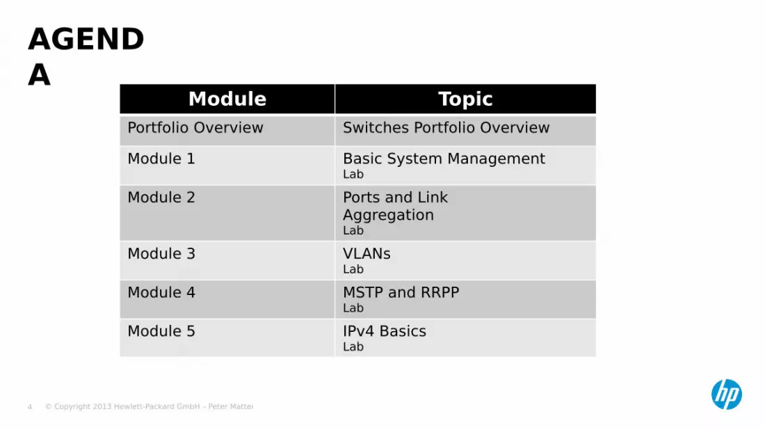
COURSE FLOW Day 1 Day 2
AM
• Portfolio Overview• Basic System
Management
• MSTP and RRPP• LAB 5
Break• Port Configuration• LAB 2• LAB 3
• LAB 5• IPv4 Basics• LAB6
Lunch
PM
• VLANs • IPv4 RoutingBreak
• LAB 4 • LAB 7
© Copyright 2013 Hewlett-Packard GmbH – Peter Mattei 7
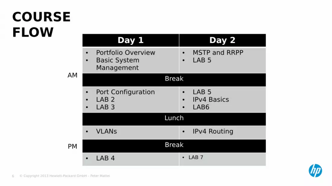
COURSE FLOW (CONTINUED) Day 3 Day 4
AM
• IPv4 Multicast Routing • SecurityBreak
• LAB 8 • LAB 10Lunch
PM
• QoS: Quality of Service • Network ManagementBreak
• LAB 9 • LAB 11
Day 5
AM• IRFv2
Break• LAB 12

© Copyright 2013 Hewlett-Packard GmbH – Peter Mattei 8
HP A-SERIES SWITCHES PORTFOLIO

© Copyright 2013 Hewlett-Packard GmbH – Peter Mattei 9
• Portfolio• Common Features• A5500EI Series Switches• A5800 Series Switches• A7500E Series Switches• A9500E Series Switches• A12500 Series Switches
AGENDA

© Copyright 2013 Hewlett-Packard GmbH – Peter Mattei 10
IT OF THE FUTURE WILL BE BUILT ON A CONVERGED INFRASTRUCTURE
© Copyright 2013 Hewlett-Packard GmbH – Peter Mattei 11
HP NETWORKING

© Copyright 2013 Hewlett-Packard GmbH – Peter Mattei 12
• Edge to Core, Enterprise to SMBHP NETWORKING PORTFOLIO

© Copyright 2013 Hewlett-Packard GmbH – Peter Mattei 13
HP A-SERIES SWITCHES COMMON FEATURES

© Copyright 2013 Hewlett-Packard GmbH – Peter Mattei 14
• Comware v5 (VERIFICAR)• Full layer 2, Layer 3, Management and Security
Feature set• Full IPv6 Support• IRF Technology• Support for Open Application Modules• Unified management platform: IMC
COMMON FEATURES

© Copyright 2013 Hewlett-Packard GmbH – Peter Mattei 15
• Fifth generation OS means proven reliability.• Advanced Modular Architecture allows for simple
• Addition of features implying fast expansión and update• Debugging and troubleshooting• Integration with different hardware platforms
• Common to all H3C Routers, Layer 3 switches and Wireless Controllers• Makes the learning curve for network managers and
Administrator shorter.• Support for IPv6 gives investment protection by allowing
customers to be prepared for the most important shift coming in the networking industry.
COMWARE V5 (EDITAR)

© Copyright 2013 Hewlett-Packard GmbH – Peter Mattei 16
• Layer 2 Features for Enterprise LAN and MAN Service Providers
• IPv4 and IPv6 Routing Protocols• MPLS and MPLS L2 and L3 VPNs
• Multi-CE (VRF Lite) in A5500-EI, A5800 and S5820X Series
• PE and 6PE in A7500E, A9500E and A12500 Series
• Complete LAN and MAN QoS Features and Applications
• Carrier Class Security Features• Management, Diagnostics and Troubleshooting Tools
FEATURE SET

© Copyright 2013 Hewlett-Packard GmbH – Peter Mattei 17
• IPv6 Address Management support• IPv6 Standard Routing Protocols:
• RIPng, OSPFv3,• ISISv6, VRRPv6,• BGP4+
• IPv6/IPv4 Tunnel Technologies:• GRE, Manual• 6to4, ISATAP• 6PE (IPv6 MPLS VPNs – Chassis
Switches)
IPv6 SUPPORT

© Copyright 2013 Hewlett-Packard GmbH – Peter Mattei 18
• IRF: Intelligent Resilient Framework• IRFv2 allows a group of switches of the same family to
form a single switching system. Similar to the presence of an SRPUs in a chasis, one
device in the system acts as the Master and the rest as slaves.
The master performs: System management Routing protocol execution and route calculation Routing information distribution to the other
devices
IRFv2 (VERIFICAR)
© Copyright 2013 Hewlett-Packard GmbH – Peter Mattei 19
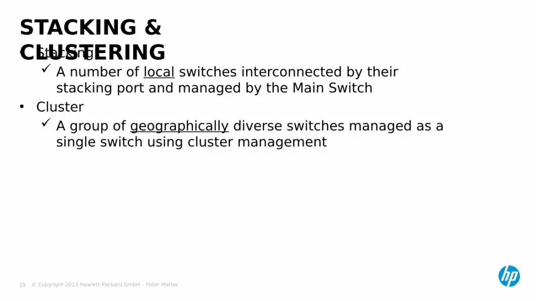
• Stacking A number of local switches interconnected by their
stacking port and managed by the Main Switch• Cluster
A group of geographically diverse switches managed as a single switch using cluster management
STACKING & CLUSTERING
© Copyright 2013 Hewlett-Packard GmbH – Peter Mattei 20
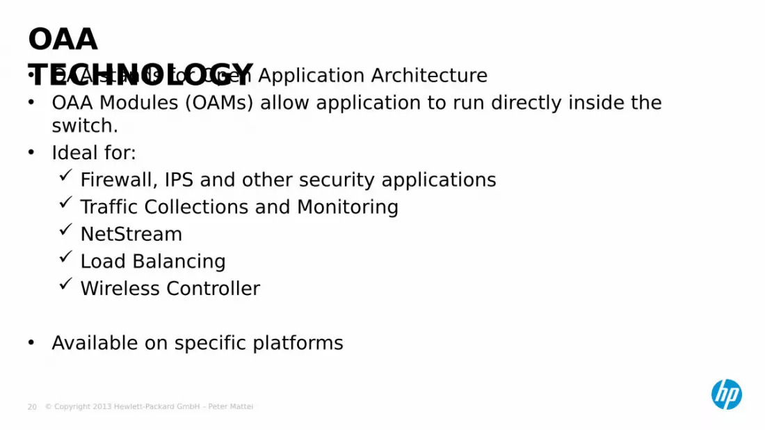
• OAA stands for Open Application Architecture• OAA Modules (OAMs) allow application to run directly inside the
switch.• Ideal for:
Firewall, IPS and other security applications Traffic Collections and Monitoring NetStream Load Balancing Wireless Controller
• Available on specific platforms
OAA TECHNOLOGY

© Copyright 2013 Hewlett-Packard GmbH – Peter Mattei 21
• Flexible, distributed and hierarchal deployment model• Multi-User Role-based management• Multiple network topology views• Easy-to-use performance management features• Centralized report management• View of current topologies and bulk deployment of virtual
LANs (VLANs)• Access control list (ACL) management• Network Traffic Analysis (NTA) including NetStream and
sFlow
IMC: INTELLIGENT MANAGEMENT CENTER

© Copyright 2013 Hewlett-Packard GmbH – Peter Mattei 22
A5500-SI SERIES

© Copyright 2013 Hewlett-Packard GmbH – Peter Mattei 23
• Introduccion• A5500-SI Models• Expansion Modules
A5500-SI SERIES

© Copyright 2013 Hewlett-Packard GmbH – Peter Mattei 24
• Low cost Gigabit switch• Basic IPv4 and IPv6 services and routing• Basic Stacking = Clustering• Perfect fit for high speed Workstation access at the
lowest cost• Note the SI does not support IRF
A5500-SI SERIES - INTRODUCTION
© Copyright 2013 Hewlett-Packard GmbH – Peter Mattei 25
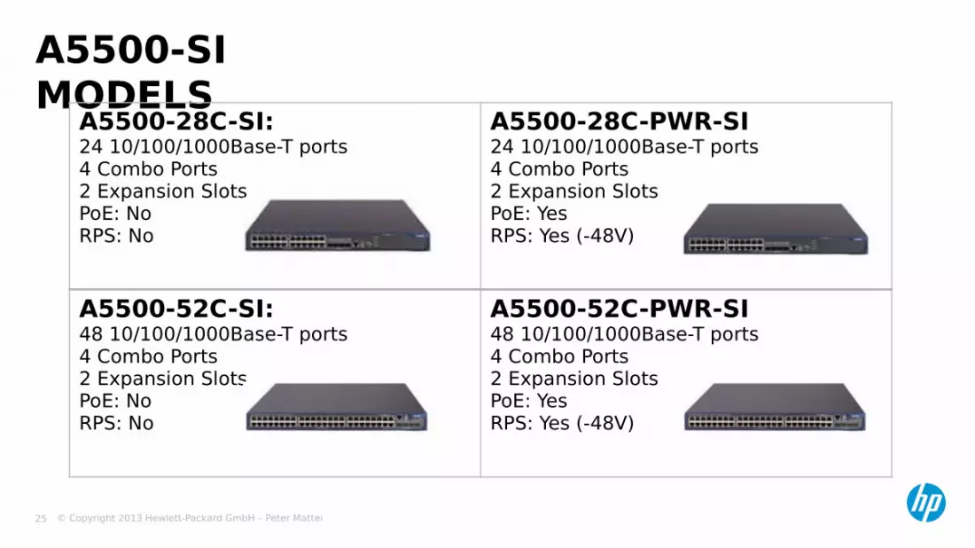
A5500-SI MODELS
A5500-28C-SI:24 10/100/1000Base-T ports4 Combo Ports2 Expansion SlotsPoE: NoRPS: No
A5500-28C-PWR-SI24 10/100/1000Base-T ports4 Combo Ports2 Expansion SlotsPoE: YesRPS: Yes (-48V)
A5500-52C-SI:48 10/100/1000Base-T ports4 Combo Ports2 Expansion SlotsPoE: NoRPS: No
A5500-52C-PWR-SI48 10/100/1000Base-T ports4 Combo Ports2 Expansion SlotsPoE: YesRPS: Yes (-48V)

© Copyright 2013 Hewlett-Packard GmbH – Peter Mattei 26
• 2 Expansion Slots• 1-port 10GE XFP interface module• 2-port 10GE XFP interface module• 1-port 10GE CX4 interface module
EXPANSION MODULES
© Copyright 2013 Hewlett-Packard GmbH – Peter Mattei 27
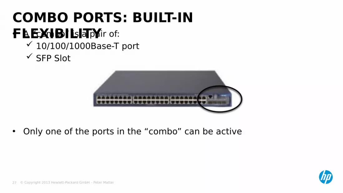
• A “combo” is a pair of: 10/100/1000Base-T port SFP Slot
• Only one of the ports in the “combo” can be active
COMBO PORTS: BUILT-IN FLEXIBILITY

© Copyright 2013 Hewlett-Packard GmbH – Peter Mattei 28
A5500-EI SERIES
© Copyright 2013 Hewlett-Packard GmbH – Peter Mattei 29
• Introduction• A5500-EI Models and their Ports, Slots and Power options• Hardware Modules
A5500-EI SERIES

© Copyright 2013 Hewlett-Packard GmbH – Peter Mattei 30
• Strong feature set Multiple VLAN types both for LAN and MAN All standard routing protocols IPv6 ready IRFv2 for up to 4 devices
A5500-EI INTRODUCTION
© Copyright 2013 Hewlett-Packard GmbH – Peter Mattei 31
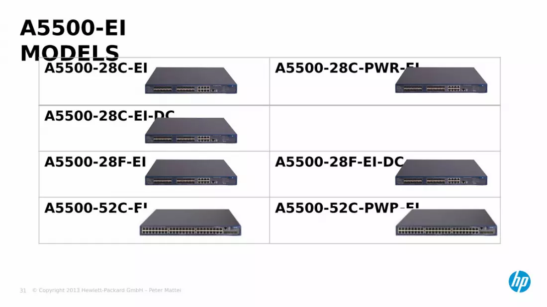
A5500-EI MODELS
A5500-28C-EI A5500-28C-PWR-EI
A5500-28C-EI-DC
A5500-28F-EI A5500-28F-EI-DC
A5500-52C-EI A5500-52C-PWR-EI
© Copyright 2013 Hewlett-Packard GmbH – Peter Mattei 32
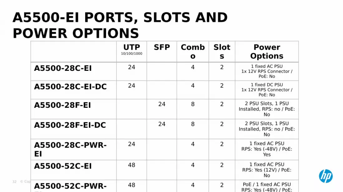
A5500-EI PORTS, SLOTS AND POWER OPTIONS
UTP10/100/1000
SFP Combo
Slots
Power Options
A5500-28C-EI 24 4 2 1 fixed AC PSU1x 12V RPS Connector /
PoE: No
A5500-28C-EI-DC 24 4 2 1 fixed DC PSU1x 12V RPS Connector /
PoE: No
A5500-28F-EI 24 8 2 2 PSU Slots, 1 PSU Installed, RPS: no / PoE:
No
A5500-28F-EI-DC 24 8 2 2 PSU Slots, 1 PSU Installed, RPS: no / PoE:
No
A5500-28C-PWR-EI
24 4 2 1 fixed AC PSURPS: Yes (-48V) / PoE:
Yes
A5500-52C-EI 48 4 2 1 fixed AC PSURPS: Yes (12V) / PoE:
No
A5500-52C-PWR-EI
48 4 2 PoE / 1 fixed AC PSURPS: Yes (-48V) / PoE:
Yes

© Copyright 2013 Hewlett-Packard GmbH – Peter Mattei 33
2 Expansion Slots• 1-port 10GE XFP interface module• 2-port 10GE XFP interface module• 2-port 10GE CX4 interface module
EXPANSION MODULES
Same as A5500-SI

© Copyright 2013 Hewlett-Packard GmbH – Peter Mattei 34
A5800 SERIES
© Copyright 2013 Hewlett-Packard GmbH – Peter Mattei 35
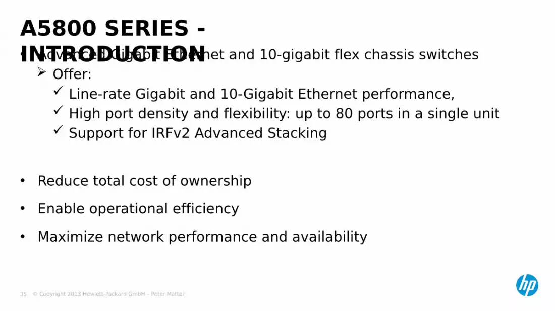
• Advanced Gigabit Ethernet and 10-gigabit flex chassis switches Offer:
Line-rate Gigabit and 10-Gigabit Ethernet performance, High port density and flexibility: up to 80 ports in a single unit Support for IRFv2 Advanced Stacking
• Reduce total cost of ownership• Enable operational efficiency • Maximize network performance and availability
A5800 SERIES - INTRODUCTION
© Copyright 2013 Hewlett-Packard GmbH – Peter Mattei 36
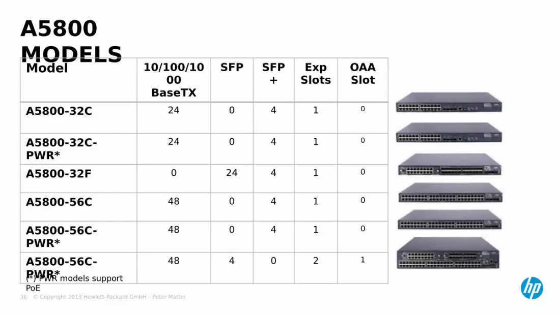
A5800 MODELSModel 10/100/10
00 BaseTX
SFP SFP+
Exp Slots
OAASlot
A5800-32C 24 0 4 1 0
A5800-32C-PWR*
24 0 4 1 0
A5800-32F 0 24 4 1 0
A5800-56C 48 0 4 1 0
A5800-56C-PWR*
48 0 4 1 0
A5800-56C-PWR*
48 4 0 2 1
(*) PWR models support PoE

© Copyright 2013 Hewlett-Packard GmbH – Peter Mattei 37
• 2-port 10GbE XFP interface module• 4-port 10GbE XFP interface module• 2-port 10GbE SFP+ interface module• 4-port 10GbE SFP+ interface module• 16-port GbE 10/100/1000Base-T Electrical
Module• 16-port GbE SFP Optical Module
A5800 INTERFACE MODULES
© Copyright 2013 Hewlett-Packard GmbH – Peter Mattei 38
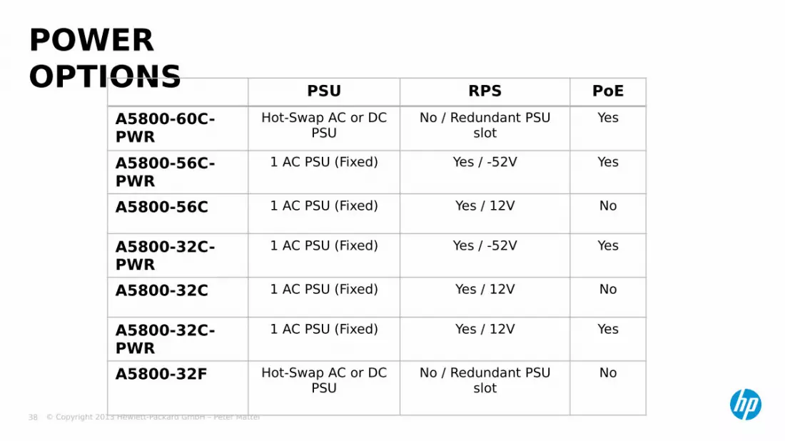
POWER OPTIONS PSU RPS PoE
A5800-60C-PWR
Hot-Swap AC or DC PSU
No / Redundant PSU slot
Yes
A5800-56C-PWR
1 AC PSU (Fixed) Yes / -52V Yes
A5800-56C 1 AC PSU (Fixed) Yes / 12V No
A5800-32C-PWR
1 AC PSU (Fixed) Yes / -52V Yes
A5800-32C 1 AC PSU (Fixed) Yes / 12V No
A5800-32C-PWR
1 AC PSU (Fixed) Yes / 12V Yes
A5800-32F Hot-Swap AC or DC PSU
No / Redundant PSU slot
No

© Copyright 2013 Hewlett-Packard GmbH – Peter Mattei 39
A5820X SERIES
© Copyright 2013 Hewlett-Packard GmbH – Peter Mattei 40
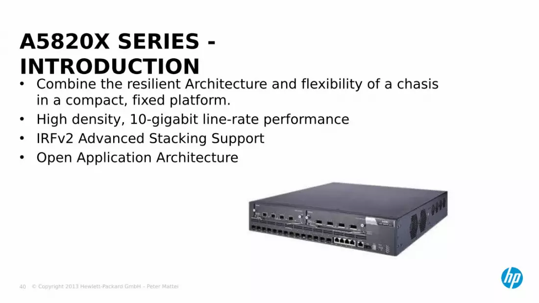
• Combine the resilient Architecture and flexibility of a chasis in a compact, fixed platform.
• High density, 10-gigabit line-rate performance• IRFv2 Advanced Stacking Support• Open Application Architecture
A5820X SERIES - INTRODUCTION
© Copyright 2013 Hewlett-Packard GmbH – Peter Mattei 41
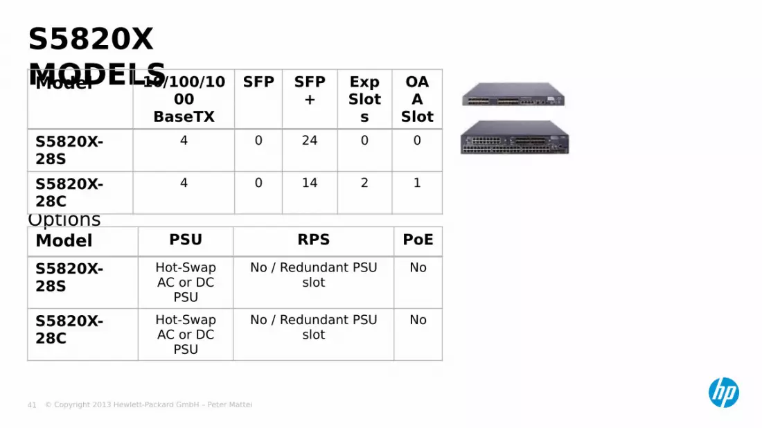
Power Options
S5820X MODELSModel 10/100/10
00 BaseTX
SFP SFP+
Exp Slot
s
OAA
SlotS5820X-28S
4 0 24 0 0
S5820X-28C
4 0 14 2 1
Model PSU RPS PoES5820X-28S
Hot-SwapAC or DC
PSU
No / Redundant PSU slot
No
S5820X-28C
Hot-SwapAC or DC
PSU
No / Redundant PSU slot
No
© Copyright 2013 Hewlett-Packard GmbH – Peter Mattei 42
• 2-port 10GbE XFP Interface Module
• 4-port 10GbE XFP Interface Module
• 2-port 10GbE SFP+ Interface Module
• 4-port 10GbE SFP+ Interface Module
S5820X INTERFACE MODULES

© Copyright 2013 Hewlett-Packard GmbH – Peter Mattei 43
A7500E SERIES
© Copyright 2013 Hewlett-Packard GmbH – Peter Mattei 44
• Modular Switches from 2 to 10 interface module slots.• Ideal for convergence and edge network of a metropolitan area
network (MAN), core and convergence networks of a campus network, and wiring closets
• Offer the industry’s most cost-effective wire-speed 10-gigabit
ports.
A7500E SERIES - INTRODUCTION

© Copyright 2013 Hewlett-Packard GmbH – Peter Mattei 45
CHASSIS MODELS
S7520E 2 I/O Slots2 Management Slots
S7503E-S
3 Slots for CombinedFabric + I/O Modules
S7503E 3 I/O Slots2 Management Slots
S7506E 6 I/O Slots2 Management Slots
S7506E-V
6 I/O Slots2 Management Slots
V= Vertical Slots
S7510 10 I/O Slots2 Management Slots
© Copyright 2013 Hewlett-Packard GmbH – Peter Mattei 46
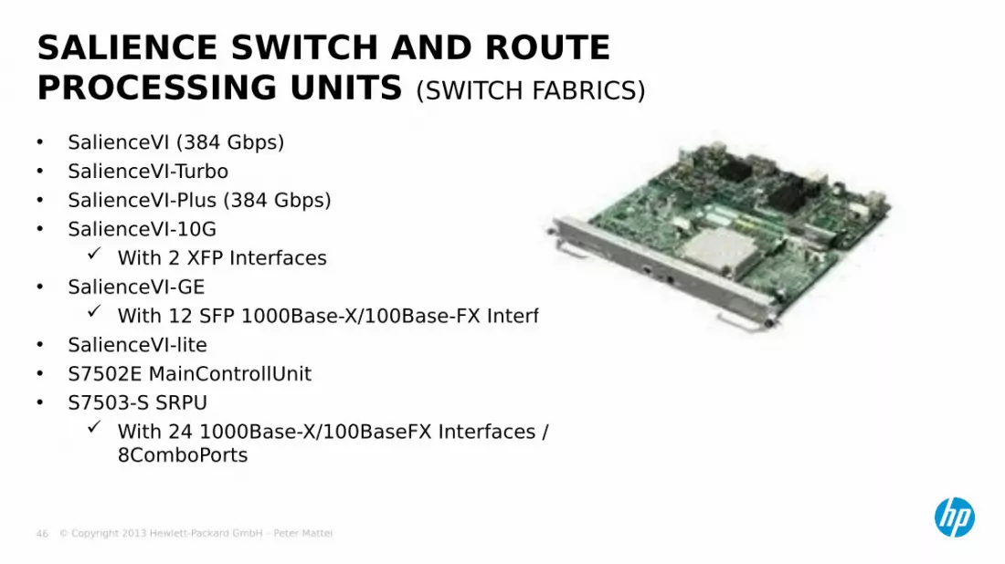
• SalienceVI (384 Gbps)• SalienceVI-Turbo• SalienceVI-Plus (384 Gbps)• SalienceVI-10G
With 2 XFP Interfaces• SalienceVI-GE
With 12 SFP 1000Base-X/100Base-FX Interfaces• SalienceVI-lite • S7502E MainControllUnit• S7503-S SRPU
With 24 1000Base-X/100BaseFX Interfaces / 8ComboPorts
SALIENCE SWITCH AND ROUTE PROCESSING UNITS (SWITCH FABRICS)

© Copyright 2013 Hewlett-Packard GmbH – Peter Mattei 47
• Wide variety of SA, SC and EA Modules Several combinations of Gigabit and 10 Gigabit Ethernet ports
• SA: Access Modules for fow cost, access layer connections• SC: Standard Modules for full local L2 switching and IPv4/IPv6
Routing at the aggregation and core layers• SD: Modules for most Enterprise requirements includes MPLS and
VPLS• EA: Advanced Modules for advanced applications like MPLS VPNs
with increased table capacity
INTERFACE MODULES

© Copyright 2013 Hewlett-Packard GmbH – Peter Mattei 48
• All chassis accept AC and DC PSUs
• PoE Is supported by all chassis, using the
rigth PSU 2 SA and 1 SC Interface Modules
support PoE• LSQ1FV48SA: 48-port
10/100/1000Base-TX• LSQ1GV48SA: 48-port
10/100/1000Base-TX• LSQ1GV48SC: 48-port
10/100/1000Base-TX Requirement:
• HP DIMM for PoE Master and Slave Power Management option must be installed in these modules to enable PoE
POWER OPTIONS

© Copyright 2013 Hewlett-Packard GmbH – Peter Mattei 49
A9500E SERIES
S950SE S9508E-V S9512ESwitching capacity
720/1920 Gbps 1440/3840 Gbps 1440/3840 Gbps
Troughput 360/600 Mbps 576/960 Mbps 864/1440 Mbps
Line card slots
5 8 12
SRPU slots 2 2 2
SRPU models LSR1SRP2C2 LSR1SRP2C1
© Copyright 2013 Hewlett-Packard GmbH – Peter Mattei 50
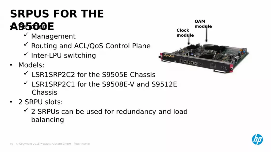
• Function: Management Routing and ACL/QoS Control Plane Inter-LPU switching
• Models: LSR1SRP2C2 for the S9505E Chassis LSR1SRP2C1 for the S9508E-V and S9512E
Chassis• 2 SRPU slots:
2 SRPUs can be used for redundancy and load balancing
SRPUS FOR THE A9500E Clock
module
OAM module

© Copyright 2013 Hewlett-Packard GmbH – Peter Mattei 51
INTERFACE MODULESLSRM1XP4LEC1
4-port 10 Gigabit Ethernet optical line cards (XFP,LC)
LSRM1XP4LEB1LSRM1XP2LEC1
2-port 10 Gigabit Ethernet optical line cards (XFP,LC)
LSRM1XP2LEB1LSRM1XP16LEB1
16-port 10 Gigabit Ethernet optical line cards
LSRM1XP48LEC1
48-port Gigabit Ethernet wire-speed optical line cards (LC)
LSRM1XP48LEB1LSRM2GV48REB1
48-port Gigabit Ethernet non-wire speed electrical (copper) line cards (24 : 1 oversubscription) (RJ-45)
LSRM1GT48LEC1
48-port Gigabit Ethernet wire-speed electrical (copper) line cards (RJ-45)
LSRM2GT48LEB1LSRM1GP24LEB1
24-port Gigabit Ethernet optical line cards (LC)
LSRM1GP24LEC1LSRM1GT24LEC1
24-port Gigabit Ethernet electrical (copper) line cards (RJ-45)
LSRM2GT24LEB1

© Copyright 2013 Hewlett-Packard GmbH – Peter Mattei 52
POWER SUPPLIES (PSUS) FOR THE A9500E

© Copyright 2013 Hewlett-Packard GmbH – Peter Mattei 53
A12500 SERIES

© Copyright 2013 Hewlett-Packard GmbH – Peter Mattei 54
• HP’s next-generation large core / data center switching platform At terabit-speed switch:• One of the most powerful switches on the market,• Provides the highest levels of performance and scalability to
meet the robust demands of data center and large enterprise core network deployments.
Built on the most advanced technology and Architecture Supports 40-gigabit, 100-gigabit and Fiber Channel over Ethernet
(FCoE). Fully distributed switching and distributed architecture to
eliminate virtually all service interruptions Low energy consumption:• Safe• Green
A12500 SERIES - INTRODUCTION
© Copyright 2013 Hewlett-Packard GmbH – Peter Mattei 55
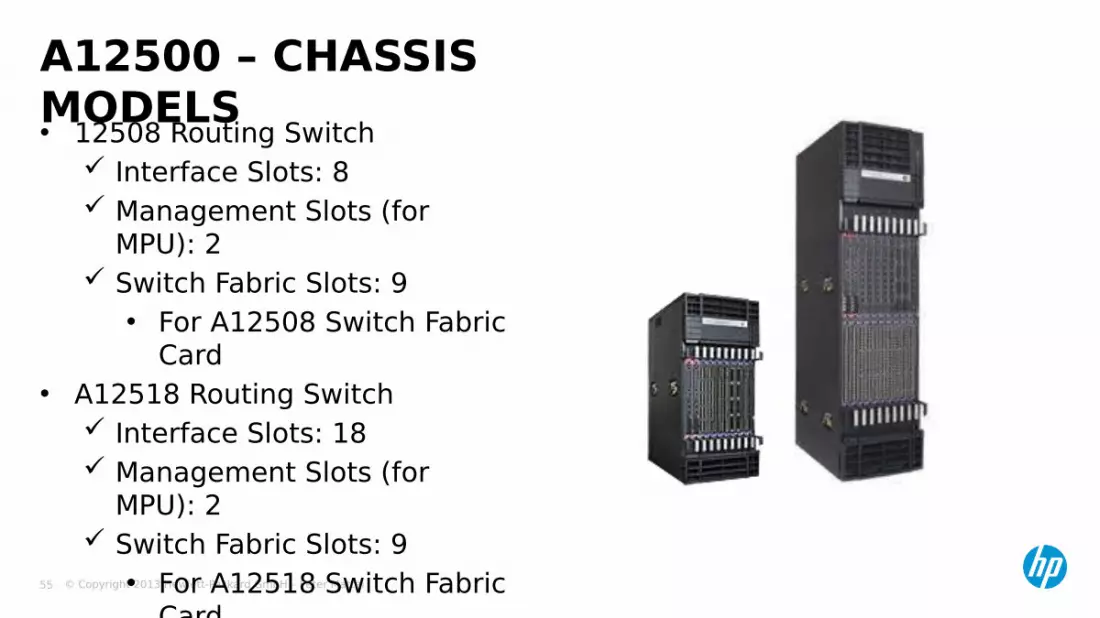
• 12508 Routing Switch Interface Slots: 8 Management Slots (for
MPU): 2 Switch Fabric Slots: 9
• For A12508 Switch Fabric Card
• A12518 Routing Switch Interface Slots: 18 Management Slots (for
MPU): 2 Switch Fabric Slots: 9
• For A12518 Switch Fabric Card
A12500 – CHASSIS MODELS

© Copyright 2013 Hewlett-Packard GmbH – Peter Mattei 56
S12508 - CHASSIS VIEW

© Copyright 2013 Hewlett-Packard GmbH – Peter Mattei 57
MPU: LST1MRPNC1
Item SpecificationCPU MPC8548, MPC8544 (OAM CPU)Flash/Boot ROM/ NVRAM/CF card
128 MB/4MB/1MB/Default 256 MB
DRAM (DDR 2) 1 GB, expandable to 2 GB Physical dimensions (W x D)
400 x 467 mm (15.75 x 18.39 in.)
Max. power consumption 60 W
© Copyright 2013 Hewlett-Packard GmbH – Peter Mattei 58
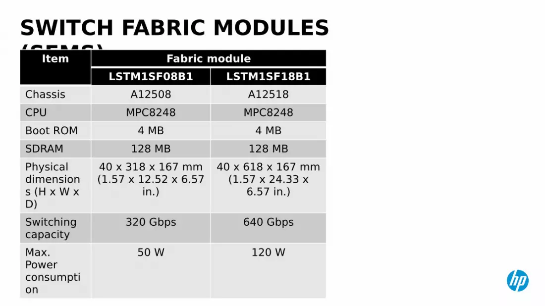
SWITCH FABRIC MODULES (SFMS)Item Fabric module
LSTM1SF08B1 LSTM1SF18B1Chassis A12508 A12518CPU MPC8248 MPC8248Boot ROM 4 MB 4 MBSDRAM 128 MB 128 MBPhysical dimensions (H x W x D)
40 x 318 x 167 mm(1.57 x 12.52 x 6.57
in.)
40 x 618 x 167 mm(1.57 x 24.33 x
6.57 in.)
Switching capacity
320 Gbps 640 Gbps
Max. Power consumption
50 W 120 W
© Copyright 2013 Hewlett-Packard GmbH – Peter Mattei 59
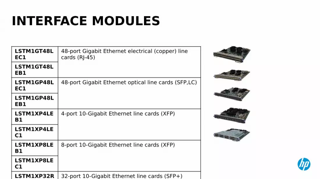
INTERFACE MODULES
LSTM1GT48LEC1
48-port Gigabit Ethernet electrical (copper) line cards (RJ-45)
LSTM1GT48LEB1LSTM1GP48LEC1
48-port Gigabit Ethernet optical line cards (SFP,LC)
LSTM1GP48LEB1LSTM1XP4LEB1
4-port 10-Gigabit Ethernet line cards (XFP)
LSTM1XP4LEC1LSTM1XP8LEB1
8-port 10-Gigabit Ethernet line cards (XFP)
LSTM1XP8LEC1LSTM1XP32REB1
32-port 10-Gigabit Ethernet line cards (SFP+) (Future)
LSTM1XP32REC1
© Copyright 2013 Hewlett-Packard GmbH – Peter Mattei 60
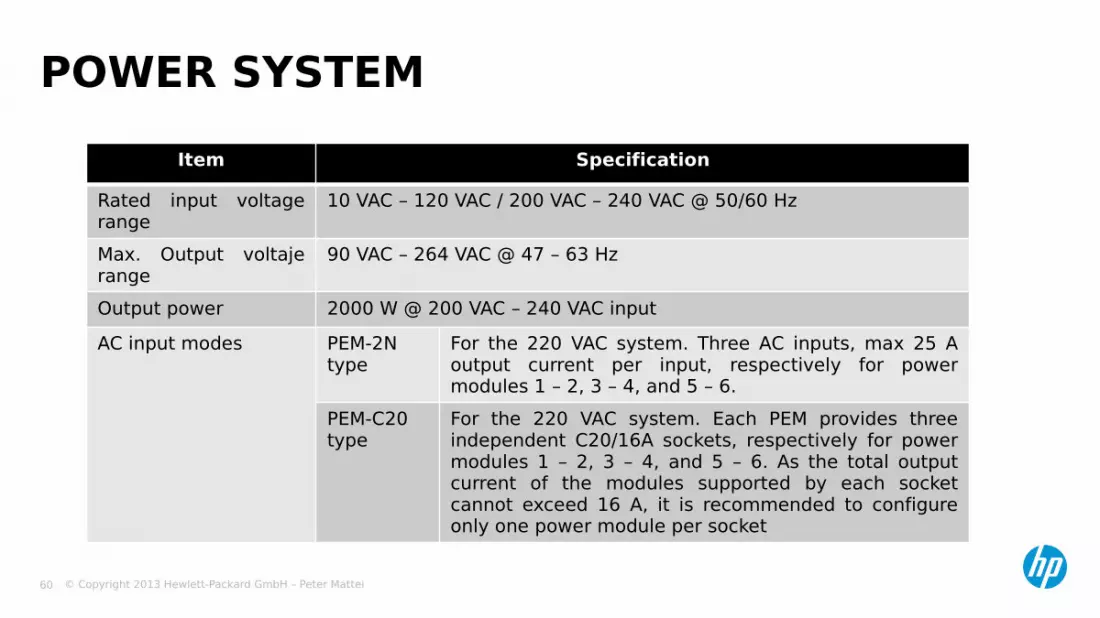
POWER SYSTEMItem Specification
Rated input voltage range
10 VAC – 120 VAC / 200 VAC – 240 VAC @ 50/60 Hz
Max. Output voltaje range
90 VAC – 264 VAC @ 47 – 63 Hz
Output power 2000 W @ 200 VAC – 240 VAC inputAC input modes PEM-2N
typeFor the 220 VAC system. Three AC inputs, max 25 A output current per input, respectively for power modules 1 – 2, 3 – 4, and 5 – 6.
PEM-C20 type
For the 220 VAC system. Each PEM provides three independent C20/16A sockets, respectively for power modules 1 – 2, 3 – 4, and 5 – 6. As the total output current of the modules supported by each socket cannot exceed 16 A, it is recommended to configure only one power module per socket
© Copyright 2013 Hewlett-Packard GmbH – Peter Mattei 61
SYSTEM MANAGEMENT

© Copyright 2013 Hewlett-Packard GmbH – Peter Mattei 62
• User Interface and CLI• Telnet• SSH• Managing the
Configuration File
GETTING STARTED

© Copyright 2013 Hewlett-Packard GmbH – Peter Mattei 63
USER INTERFACE AND CLI
© Copyright 2013 Hewlett-Packard GmbH – Peter Mattei 64
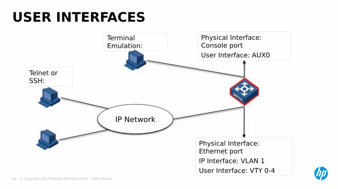
USER INTERFACES
IP Network
Physical Interface: Console portUser Interface: AUX0
Physical Interface: Ethernet portIP Interface: VLAN 1User Interface: VTY 0-4
Telnet or SSH:
Terminal Emulation:

© Copyright 2013 Hewlett-Packard GmbH – Peter Mattei 65
Run Hyperterminal and set the communications parametersDefault console speedTurn on the switchUsing the Configuration Cable (provided with the switch), Connect your serial port to the console port of the active switch fabric.Observe the startup process.
CONSOLE LOGIN
© Copyright 2013 Hewlett-Packard GmbH – Peter Mattei 66
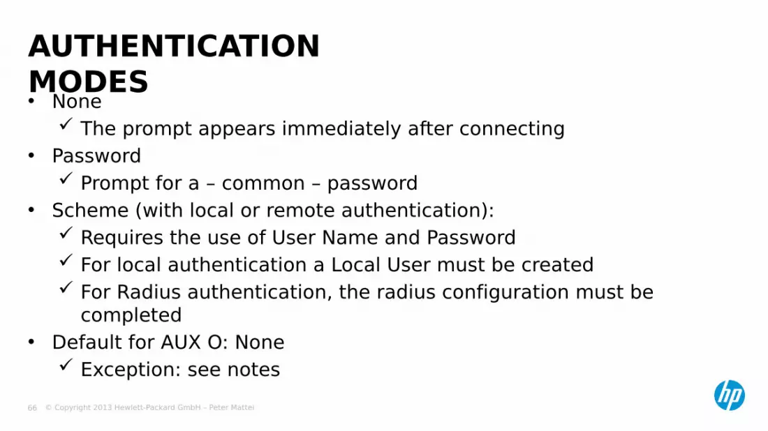
• None The prompt appears immediately after connecting
• Password Prompt for a – common – password
• Scheme (with local or remote authentication): Requires the use of User Name and Password For local authentication a Local User must be created For Radius authentication, the radius configuration must be
completed• Default for AUX O: None
Exception: see notes
AUTHENTICATION MODES
© Copyright 2013 Hewlett-Packard GmbH – Peter Mattei 67
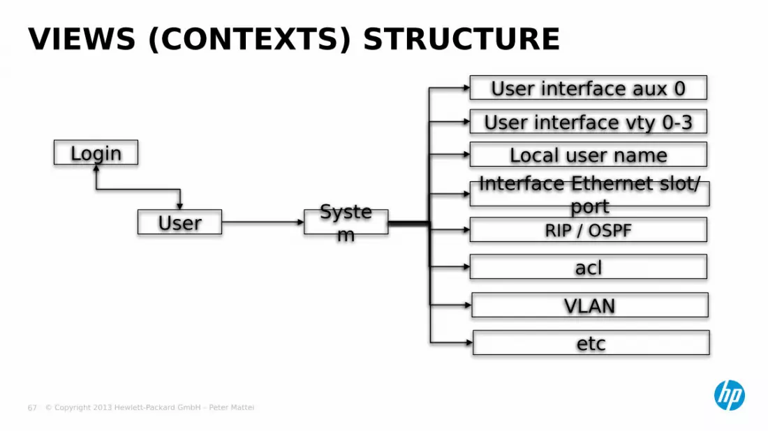
VIEWS (CONTEXTS) STRUCTURE
Login
User System
User interface aux 0User interface vty 0-3
Local user nameInterface Ethernet slot/
portRIP / OSPF
aclVLAN
etc

© Copyright 2013 Hewlett-Packard GmbH – Peter Mattei 68
• Commands are classified into 4 privilege levels Visit 0 Monitor 1 Configuration 2 Administrator 3
• Users need to have the right privilege level to execute a certain command
CLI COMMAND PRIVILEGE LEVELS

© Copyright 2013 Hewlett-Packard GmbH – Peter Mattei 69
• Privilege level is granted: by user interface
[switch-ui-aux0] user privilege level 3
by user[switch-luser-name] user privilege level 3
in real time[switch] super 3
USER PRIVILEGE LEVEL

© Copyright 2013 Hewlett-Packard GmbH – Peter Mattei 70
• Entering system view<switch> system-view
• Configuring the Super password[switch] super password [simple/cipher] super007
• Changing the system prompt[switch] sysname CoreSw[CoreSw]
• Exiting system view[switch] quit<Ctrl-z>
BASIC CONFIGURATION
© Copyright 2013 Hewlett-Packard GmbH – Peter Mattei 71
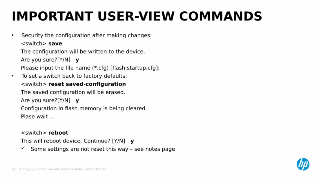
• Security the configuration after making changes:<switch> saveThe configuration will be written to the device.Are you sure?[Y/N] yPlease input the file name (*.cfg) [flash:startup.cfg]:
• To set a switch back to factory defaults:<switch> reset saved-configurationThe saved configuration will be erased.Are you sure?[Y/N] yConfiguration in flash memory is being cleared.Plase wait …
<switch> rebootThis will reboot device. Continue? [Y/N] y Some settings are not reset this way – see notes page
IMPORTANT USER-VIEW COMMANDS

© Copyright 2013 Hewlett-Packard GmbH – Peter Mattei 72
• The CLI provides full and partial online help Enter ? In any view to list all commands in that view Enter a command followed by ? for all posible parameters
<switch> interface ? Enter a character string followed immediately by ? for a
list of all commands starting with that string.<switch> p?
Enter the first letters of a keyword of a command and press <Tab> If no other keywords begin with these letters, then
this unique keyword will be displayed automatically• During the output of multiple-screen displays, use:
<spacebar> for next page<Enter> for next line
CLI HELP

© Copyright 2013 Hewlett-Packard GmbH – Peter Mattei 73
• User commands are stored in a history buffer Can be retrieved and re-executed later
By default the last 10 commands are stored
• To retrieve the command history: Use the display history command
Display the entire buffer Use the up arrow key or <Ctrl+P>
Retrieve the previous command in the buffer
Use the down arrow key or <Ctrl+N> Retrieve the next command in the
buffer
CLI COMMAND HISTORY
© Copyright 2013 Hewlett-Packard GmbH – Peter Mattei 74
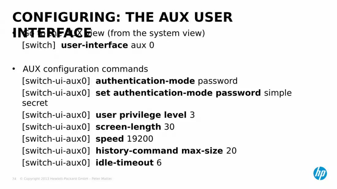
• Go to the AUX view (from the system view)[switch] user-interface aux 0
• AUX configuration commands[switch-ui-aux0] authentication-mode password[switch-ui-aux0] set authentication-mode password simple secret[switch-ui-aux0] user privilege level 3[switch-ui-aux0] screen-length 30[switch-ui-aux0] speed 19200[switch-ui-aux0] history-command max-size 20[switch-ui-aux0] idle-timeout 6
CONFIGURING: THE AUX USER INTERFACE

© Copyright 2013 Hewlett-Packard GmbH – Peter Mattei 75
• Configure authentication mode = Scheme[switch] user-interface aux 0[switch-ui-aux0] authentication-mode scheme[switch-ui-aux0] quit[switch] user-interface vty 0 4[switch-ui-vty0-4] authentication-mode scheme[switch-ui-vty0-4] quit
• Create and configure a local user[switch] local-user admin[switch-luser-admin] password simple admin[switch-luser-admin] service-type terminal telnet[switch-luser-admin] user privilege level 3
CONFIGURING LOCAL USERS

© Copyright 2013 Hewlett-Packard GmbH – Peter Mattei 76
TELNET
© Copyright 2013 Hewlett-Packard GmbH – Peter Mattei 77
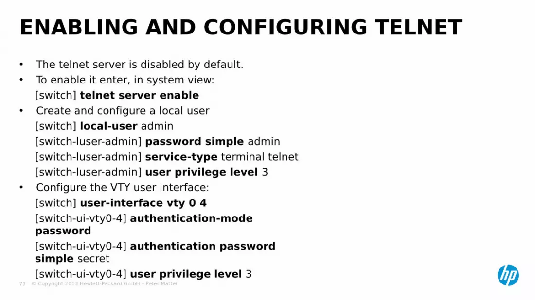
• The telnet server is disabled by default.• To enable it enter, in system view:
[switch] telnet server enable• Create and configure a local user
[switch] local-user admin[switch-luser-admin] password simple admin[switch-luser-admin] service-type terminal telnet[switch-luser-admin] user privilege level 3
• Configure the VTY user interface:[switch] user-interface vty 0 4[switch-ui-vty0-4] authentication-mode password[switch-ui-vty0-4] authentication password simple secret[switch-ui-vty0-4] user privilege level 3
ENABLING AND CONFIGURING TELNET

© Copyright 2013 Hewlett-Packard GmbH – Peter Mattei 78
SSH

© Copyright 2013 Hewlett-Packard GmbH – Peter Mattei 79
Comware v5 Switches can act as SSH server and clientSSH Server: SSHv1 and SSHv2SSH Client: SSHv2 only
SSH: SECURE SHELL

© Copyright 2013 Hewlett-Packard GmbH – Peter Mattei 80
• In system view, enable SSHssh server enable
• Configure the user interface for SSH, in vty user-interface view Set the Login authentication method to scheme
Authentication-mode scheme Specify support for SSH only
protocol inbound ssh• Configure the RSA keys (system view)
public-key local create rsa• Export the RSA key pair
public-key local export rsa { openssh | ssh1 | ssh2 }{ filename }
CONFIGURING THE SSH SERVER
© Copyright 2013 Hewlett-Packard GmbH – Peter Mattei 81
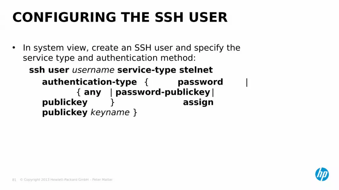
• In system view, create an SSH user and specify the service type and authentication method:
ssh user username service-type stelnetauthentication-type { password |
{ any | password-publickey |publickey } assign publickey keyname }
CONFIGURING THE SSH USER
© Copyright 2013 Hewlett-Packard GmbH – Peter Mattei 82
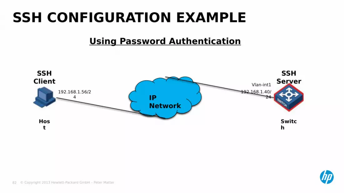
Using Password Authentication
SSH CONFIGURATION EXAMPLE
IP Network
SSH Client
SSH Server
Switch
Host
192.168.1.56/24
Vlan-int1192.168.1.40/
24

© Copyright 2013 Hewlett-Packard GmbH – Peter Mattei 83
• Generate and RSA key pair and enable SSH server.[Switch] public-key local create rsa[Switch] ssh server enable
• Set the authentication mode for the user interface to AAA and enable the user interface to support SSH.[Switch] user-interface vty 0 4[Switch-ui-vty0-4] authentication-mode scheme[Switch-ui-vty0-4] protocol inbound ssh
• Create local user “client001”, set the user command privilege level to 3 and specify the service type for user client001 as Stelnet[Switch] local-user client001[Switch-luser-client001] password simple aabbcc[Switch-luser-client001] service-type ssh level 3[Switch] ssh user client001 service-type stelnet authentication-type password
SSH CONFIGURATION EXAMPLE (SERVER)

© Copyright 2013 Hewlett-Packard GmbH – Peter Mattei 84
SSH CONFIGURATION EXAMPLE (PUTTY CLIENT)

© Copyright 2013 Hewlett-Packard GmbH – Peter Mattei 85
MANAGING THE CONFIGURATION FILE

© Copyright 2013 Hewlett-Packard GmbH – Peter Mattei 86
• Directory Operationsmkdirrmdirpwddircd
• Memory Operationsfixdiskformat
• Device Operationsmountdismount
• File Operationsdelete [/unreserved]undeletereset recycle-bin [/force]morerenamecopymovedirexecute
FILE SYSTEM COMMANDS
© Copyright 2013 Hewlett-Packard GmbH – Peter Mattei 87
• Flash: Integrated in every Switch Fabric, Management Module or
stackable switch Refered as: flash:/
• CF: Compact Flash card Supplementary storage device Available in all S7900E Switch Fabrics and Management Modules,
advanced routers, firewalls and switches Refered as: cf:/ Or if there is more than one: cfa:/ and cfb/
STORAGE DEVICES

© Copyright 2013 Hewlett-Packard GmbH – Peter Mattei 88
Example<Sysname> dir /allDirectory of flash:/0 -rw- 6985954 Apr 26 2015 21:06:29
mainup.bin1 -
rwh 1842 Apr 27 2015 04:37:17 private-data.txt
2 -rw-
1518 Apr 26 2015 12:05:38 config.cfg
3 -rw- 2045 May 04 2015 15:50:01 backcfg.cfg
4 -rwh
428 Apr 27 2015 16:41:21 hostkey
5 -rwh
572 Apr 27 2015 16:41:31 serverkey
6 -rw- 2737556 Oct 12 2015 01:31:44 [a.app]
64389 KB total (16166 KB free)
−[ ] indicates this file is in the recycle bin.

© Copyright 2013 Hewlett-Packard GmbH – Peter Mattei 89
• Save the current configuration to the specified configuration dile (any view)
save [ file-name ] [ /safely ] file-name:
File name, whose suffix must be .cfg. If no filename is specified, the system saves the configuration file in an interactive way.
safely: Sets the configuration saving mode to safe. If this
argument is not specified, the configuration file is saved in fast mode.
This argument is not accepted if there is no configuration file present
CONFIGURATION FILE
© Copyright 2013 Hewlett-Packard GmbH – Peter Mattei 90
• Erase the configuration file saved in the storage devicereset saved-configuration
• Specify a configuration file for next startupstartup saved-configuration cfgfile
• Backup / restore the startup configuration file (for next startup) using a filename you specify. TFTP is used for these operationsbackup startup-configuration to dest-addr [ dest-filename ]restore startup-configuration from src-addr src-filename
• Note: that if the .cfg extension is not added the configuration is not saved and an error will appear.
CONFIGURATION FILE (2)
© Copyright 2013 Hewlett-Packard GmbH – Peter Mattei 91
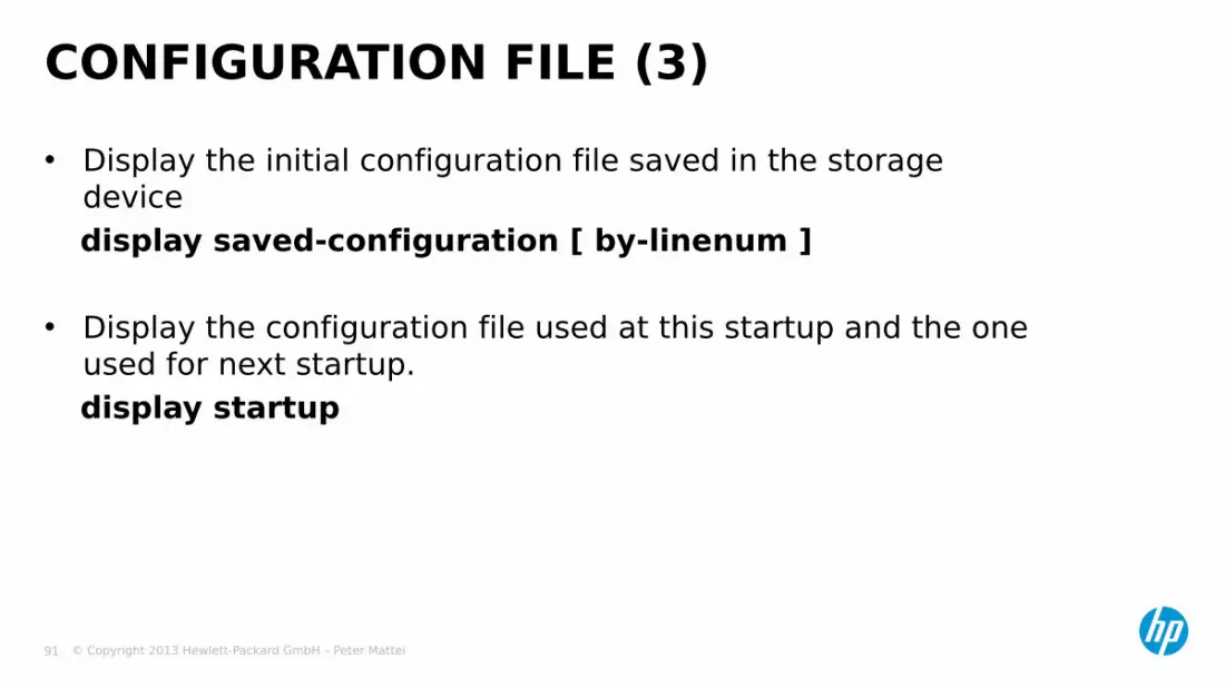
• Display the initial configuration file saved in the storage device display saved-configuration [ by-linenum ]
• Display the configuration file used at this startup and the one used for next startup.display startup
CONFIGURATION FILE (3)

© Copyright 2013 Hewlett-Packard GmbH – Peter Mattei 92
A-SERIES CTRL KEYSA-Series –
CTRLComment
? Use instead to find next keywordCTRL+O Undo debug allCTRL+G Display current-configCTRL+L Display IP routing-tableCTRL+C Stop display, stops pingCTRL+K Kill/abort Telnet, SSH, FTP sesiónCTRL+E Cursor to End of lineCTRL+A Cursor to beginning of lineCTRL+X Erase LineCTRL+W Erase Word backwardCTRL+D Delete carácter under cursor

© Copyright 2013 Hewlett-Packard GmbH – Peter Mattei 93
TFTP AND FTP

© Copyright 2013 Hewlett-Packard GmbH – Peter Mattei 94
• In system view, reference an access control list (ACL) to the TFTP servertftp-server acl acl-number
• Configure the source address or interface of the TFTP clienttftp client source { interface interface-type interface-number | ip source-ip-address }
• Download or upload a file in IPv4 networktftp server-address { get | put | sget } source-filename [ destination-filename ] [ source { interface interface-type interface-number | ip source-ip-address } ]
CONFIGURING THE TFTP CLIENT
© Copyright 2013 Hewlett-Packard GmbH – Peter Mattei 95
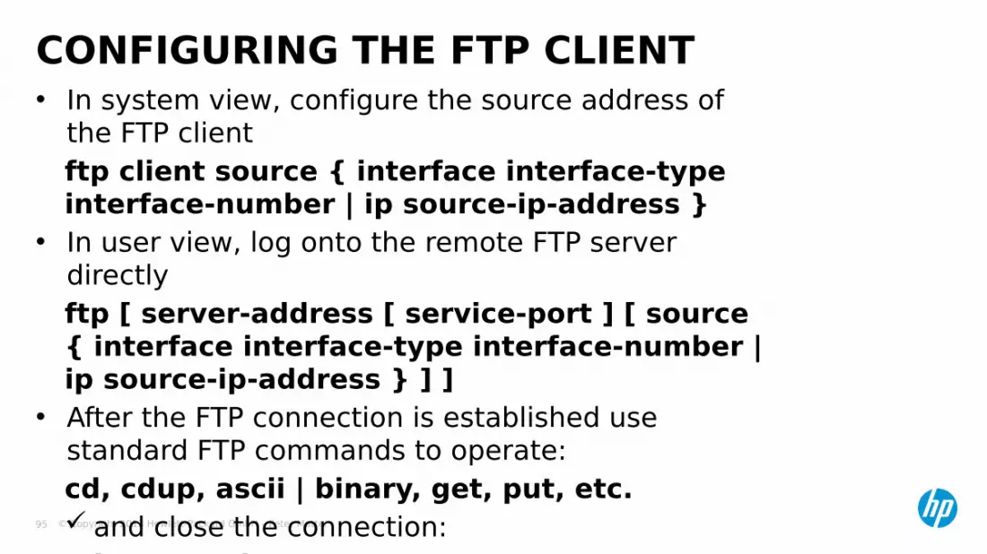
• In system view, configure the source address of the FTP client ftp client source { interface interface-type interface-number | ip source-ip-address }
• In user view, log onto the remote FTP server directlyftp [ server-address [ service-port ] [ source { interface interface-type interface-number | ip source-ip-address } ] ]
• After the FTP connection is established use standard FTP commands to operate:cd, cdup, ascii | binary, get, put, etc. and close the connection:
bye or quit
CONFIGURING THE FTP CLIENT

© Copyright 2013 Hewlett-Packard GmbH – Peter Mattei 96
• In system view, enable the FTP serverftp server enable
• Optionally, configure the idle-timeout timer and set the update modeftp timeout minutesftp update { fast | normal }
• Configure local users for FTP Create a local user and enter its view
local-user user-name Assign a password to the user
password { simple | cipher } password Assign the FTP service to the user
service-type ftp Specify the directory an FTP user can Access
work-directory directory-name Set the priority level of the FTP user
level level
CONFIGURING THE FTP SERVER

© Copyright 2013 Hewlett-Packard GmbH – Peter Mattei 97
SOFTWAREUPGRADE
© Copyright 2013 Hewlett-Packard GmbH – Peter Mattei 98
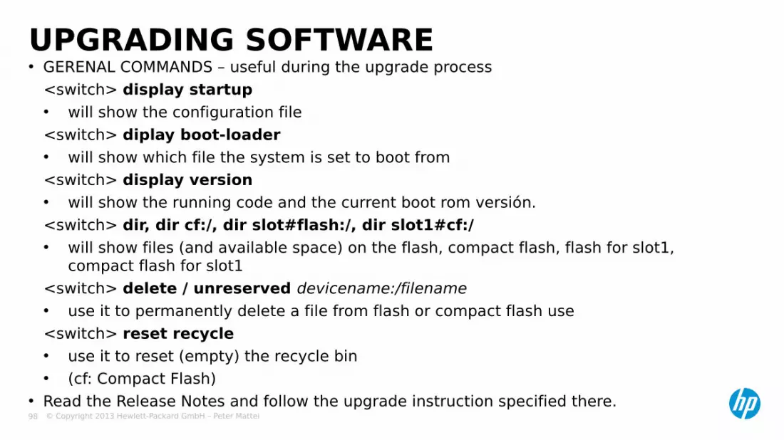
• GERENAL COMMANDS – useful during the upgrade process<switch> display startup• will show the configuration file<switch> diplay boot-loader• will show which file the system is set to boot from<switch> display version• will show the running code and the current boot rom versión.<switch> dir, dir cf:/, dir slot#flash:/, dir slot1#cf:/• will show files (and available space) on the flash, compact flash, flash for slot1,
compact flash for slot1<switch> delete / unreserved devicename:/filename• use it to permanently delete a file from flash or compact flash use<switch> reset recycle• use it to reset (empty) the recycle bin• (cf: Compact Flash)
• Read the Release Notes and follow the upgrade instruction specified there.
UPGRADING SOFTWARE

© Copyright 2013 Hewlett-Packard GmbH – Peter Mattei 99
Step 1: Download the software to the switch using FTP commands.• <H3C> ftp 202.10.10.53• Trying …• Press CTRL+K to abort• Connected• 220 WFTPD 2.0 service (by Texas Imperial Software) ready for new user• User(none):S5500• 331 Give me your password, please• Password• 230 Logged in sucessfully• [ftp] get S5500-EI.bin• [ftp] get S5500-EI.btm• [ftp] bye
UPGRADING SOFTWARE - EXAMPLE
IP Network
FTP Server
FTP Client
Ethernet port
202.10.10.53
PCSwitc
h

© Copyright 2013 Hewlett-Packard GmbH – Peter Mattei 100
Step 2: Update the BootROM program on the switch• <H3C> bootrom update file S5500-EI.btm slot 1• This command will update BootRom file, Continue? [Y/N]y• Updating BootRom, please wait…Step 3: Update the host software on the switch• <H3C> boot-loader file S5500-EI.bin slot all mai• <H3C> display boot-loader• Slot 1• The current boot app is: flash:/ S5500-EI.bin• Tha main boot app is: flash:/ S5500-EI.bin• The backup boot app is: flash:/ S5500-Elbak.bin• Step 4: Restart the switch• <H3C> reboot
UPGRADING SOFTWARE - EXAMPLE

© Copyright 2013 Hewlett-Packard GmbH – Peter Mattei 101
PORTS AND BRIDGE
AGGREGATION
© Copyright 2013 Hewlett-Packard GmbH – Peter Mattei 102
• Port Configuration and Port Groups
• Link Aggregation
PORTS AND LINK AGGREGATION

© Copyright 2013 Hewlett-Packard GmbH – Peter Mattei 103
PORT GROUPS AND PORT CONFIGURATION
© Copyright 2013 Hewlett-Packard GmbH – Peter Mattei 104
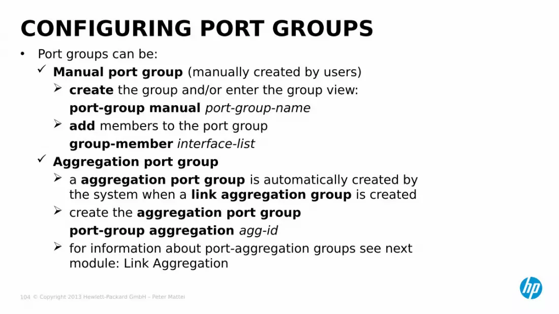
• Port groups can be: Manual port group (manually created by users)
create the group and/or enter the group view:port-group manual port-group-name
add members to the port groupgroup-member interface-list
Aggregation port group a aggregation port group is automatically created by
the system when a link aggregation group is created create the aggregation port group
port-group aggregation agg-id for information about port-aggregation groups see next
module: Link Aggregation
CONFIGURING PORT GROUPS

© Copyright 2013 Hewlett-Packard GmbH – Peter Mattei 105
• Enter Ethernet port viewinterface interface-type interface-number
• Or enter port group viewport-group manual port-group-name
Set the dúplex mode duplex { auto* | full | half }
Set the transmission rate speed { 10 | 100 | 1000 | auto* } Enable flow control flow-control Shut down the Ethernet port shutdown
CONFIGURING BASIC PORT PARAMETERS

© Copyright 2013 Hewlett-Packard GmbH – Peter Mattei 106
• Display the current state of a specified port and related informationdisplay interface [ interface-type [ interface-number ] ]
• Display a summary of a specified portdisplay brief interface [ interface-type [ interface-number] ] [ | {begin | include | exclude} text ]
• Display the current ports of a specified typedisplay port { hybrid | trunk }
• Display the information about a manual port group or all the port groups display port-group manual [all | name port-group-name]
MAINTAINING AND DISPLAYING AN ETHERNET PORT
© Copyright 2013 Hewlett-Packard GmbH – Peter Mattei 107
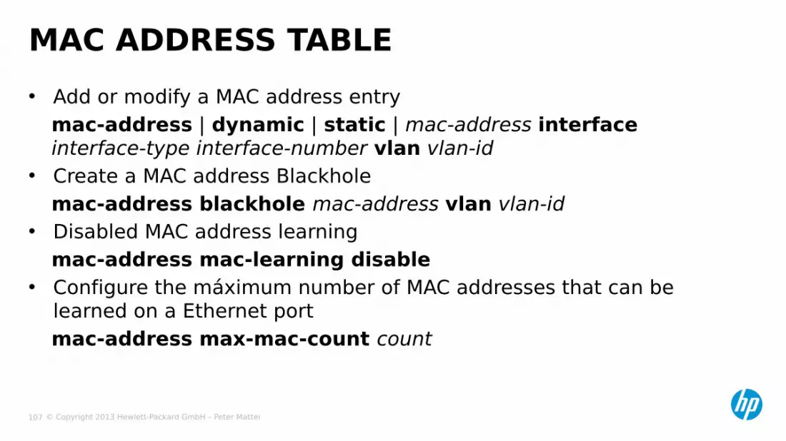
• Add or modify a MAC address entrymac-address | dynamic | static | mac-address interface interface-type interface-number vlan vlan-id
• Create a MAC address Blackholemac-address blackhole mac-address vlan vlan-id
• Disabled MAC address learningmac-address mac-learning disable
• Configure the máximum number of MAC addresses that can be learned on a Ethernet portmac-address max-mac-count count
MAC ADDRESS TABLE

© Copyright 2013 Hewlett-Packard GmbH – Peter Mattei 108
LINK AGGREGATION

© Copyright 2013 Hewlett-Packard GmbH – Peter Mattei 109
• Aggregated link (Aggregation Group) A set of Ethernet link between the same pair of devices that
behave like a single link.
LACP: Link Aggregation Control Protocol dynamic configuration aggregated link consistency link failure recovery
LINK AGGREGATION

© Copyright 2013 Hewlett-Packard GmbH – Peter Mattei 110
ARCHITECTUREMAC Client
(Switch engine, LLC, IP, IPX, etc.)
Aggregator
LACP
MAC(Port i1)Phy
(Port i1)
Phy(Port iN)
MAC(Port iN)
LinkAggregation
Sublayer

© Copyright 2013 Hewlett-Packard GmbH – Peter Mattei 111
• Static Aggregation Mode Created manually Member ports are LACP-disabled
• Dynamic Aggregation Mode Created manually After you add a port to a static aggregation, LACP
is enabled on it automatically
LINK AGGREGATION MODES

© Copyright 2013 Hewlett-Packard GmbH – Peter Mattei 112
• Create the aggregation groupIn system viewinterface bridge-aggregation number
• Go to the interface view of each port and add it to the aggregation groupport link-aggregation group number
CONFIGURING A STATIC AGGREGATION GROUP
© Copyright 2013 Hewlett-Packard GmbH – Peter Mattei 113
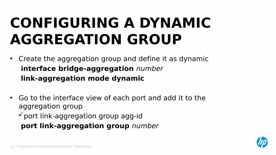
• Create the aggregation group and define it as dynamicinterface bridge-aggregation numberlink-aggregation mode dynamic
• Go to the interface view of each port and add it to the aggregation groupport link-aggregation group agg-idport link-aggregation group number
CONFIGURING A DYNAMIC AGGREGATION GROUP

© Copyright 2013 Hewlett-Packard GmbH – Peter Mattei 114
VLANS

© Copyright 2013 Hewlett-Packard GmbH – Peter Mattei 115
Port-based VLANsProtocol-based VLANsIP-subnet-based VLANsMAC Address-bases VLANsVoice VLANBasic QinQ
VLAN TYPES

© Copyright 2013 Hewlett-Packard GmbH – Peter Mattei 116
PORT-BASEDVLANS

© Copyright 2013 Hewlett-Packard GmbH – Peter Mattei 117
• A VLAN is a logically defined Layer 2 Broadcast domain A broadcast frame sent by a device in a VLAN is never
sent outside of the VLAN• Users can be grouped together into VLAN’s regardless of
their physical location on the network• A user in one VLAN is not able to communicate directly with
a user in another VLAN Communication between VLAN’s only via a router
• VLAN’s provide for security and bandwidth management• The 802.1Q standard defines a Tag used to identify VLAN
traffic
VLAN TECHNOLOGY OVERVIEW

© Copyright 2013 Hewlett-Packard GmbH – Peter Mattei 118
• A port-based VLAN contains a group of bridge ports with unspecified protocol type
• The default VLAN (VID 1) that is included in each switch is port-based
• Two or more port-based VLAN’s can overlap, provided that 802.1Q tagging is used
PORT BASED VLAN’S
© Copyright 2013 Hewlett-Packard GmbH – Peter Mattei 119
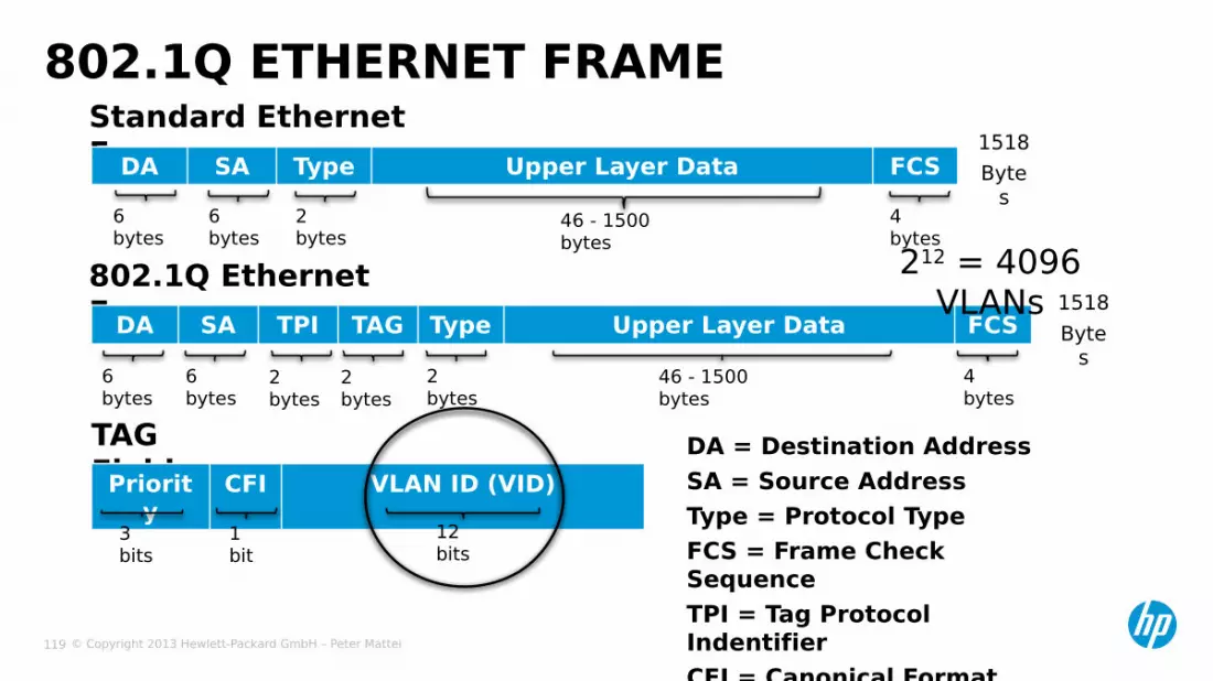
Standard Ethernet Frame
802.1Q ETHERNET FRAME
DA SA Type Upper Layer Data FCS
6 bytes
6 bytes
2 bytes
4 bytes
46 - 1500 bytes
1518 Byte
s
802.1Q Ethernet FrameDA SA TPI TAG Type Upper Layer Data FCS
6 bytes
6 bytes
2 bytes
2 bytes
2 bytes
46 - 1500 bytes
4 bytes
1518 Byte
s
212 = 4096 VLANs
TAG FieldPriorit
yCFI VLAN ID (VID)
3 bits
1 bit
12 bits
DA = Destination AddressSA = Source AddressType = Protocol TypeFCS = Frame Check SequenceTPI = Tag Protocol IndentifierCFI = Canonical Format Indicator

© Copyright 2013 Hewlett-Packard GmbH – Peter Mattei 120
• IEEE 802.1p: Standard for traffic class and dynamic multicast filtering services
in bridged LANs:• Address the issue of separate queuing for time-critical frames• Provides for CoS definitions within Layer 2 frames• Allows means of dynamic configuration and distribution
mechanisms e.g. GVRP
IEEE 802.1P
TAG FieldPriorit
yCFI VLAN ID (VID)
3 bits
1 bit
12 bits
23 = 8 Priorities

© Copyright 2013 Hewlett-Packard GmbH – Peter Mattei 121
• Example VLAN Operation
VLAN TAGGING MECHANISM

© Copyright 2013 Hewlett-Packard GmbH – Peter Mattei 122
PORT LINK TYPEUntagged VLANs Tagged VLANs
Access 1 -Trunk 1 ManyHybrid Many ManyAccessQinQ
Presented in the Basic QinQ sub-Module
• By default all ports are Access Ports• Change Port Link Type
port link-type | access |hybrid | trunk |

© Copyright 2013 Hewlett-Packard GmbH – Peter Mattei 123
− By default: VLAN 1
− Access Port:• Only one untagged VLAN (default
VLAN)port access vlan vlan-id
− Trunk or Hybrid Port:• Configure the default VLAN for the
Trunk portport trunk pvid vlan vlan-idport hybrid pvid vlan vlan-id
DEFAULT VLAN

© Copyright 2013 Hewlett-Packard GmbH – Peter Mattei 124
• Inbound FrameUntagged
Tag with PVID VLANTaggedIf VLAN ID = PVID VLAN•then Receive for Forwarding•else Drop
• Outbound FrameRemove the PVID VLAN Tag
PACKET HANDLING: ACCESS PORTS Incomin
gFrames
TaggedPacket ?
Tagvalue
equal toPVID?
Drop
Tag with PVID
Forward
No
No
Yes
Yes

© Copyright 2013 Hewlett-Packard GmbH – Peter Mattei 125
PACKET HANDLING: TRUNK AND HYBRID PORTS• Inbound Frame
UntaggedIf PVID VLAN is
permitted• then Tag with PVID VLAN•else Drop
TaggedIf VLAN-ID is permitted •then Receive for Forwarding•else Drop
Incoming
Frames
Forward
Tag with PVID
Drop
DropTaggedFrame ?
PVIDVLAN
Permitted?
Framevlan
permitted?
No
Yes
NoNo
Yes
Yes

© Copyright 2013 Hewlett-Packard GmbH – Peter Mattei 126
PACKET HANDLING: TRUNK AND HYBRID PORTS• Outbound
If Tag = PVID VLANthen•Remove log Else & if VLAN ID
is permitted:•keep the packet
send the packet
Hybrid Ports:can be configured to
keep or remove tags
FramesTo be
transmited
FrameTag
equal toPVID?
VLANpermitted
?
Drop
ForwardRemove tag
PVIDVLAN
Permitted?
OutgoingFrames
No
No
No
Yes
Yes
Yes
© Copyright 2013 Hewlett-Packard GmbH – Peter Mattei 127
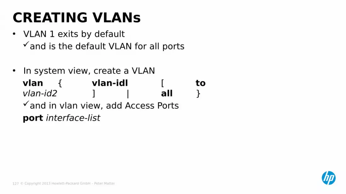
• VLAN 1 exits by defaultand is the default VLAN for all ports
• In system view, create a VLANvlan { vlan-idl [ tovlan-id2 ] | all }and in vlan view, add Access Portsport interface-list
CREATING VLANs
© Copyright 2013 Hewlett-Packard GmbH – Peter Mattei 128
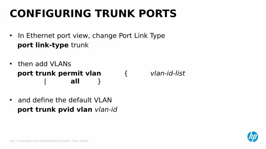
• In Ethernet port view, change Port Link Typeport link-type trunk
• then add VLANsport trunk permit vlan { vlan-id-list
| all }
• and define the default VLANport trunk pvid vlan vlan-id
CONFIGURING TRUNK PORTS

© Copyright 2013 Hewlett-Packard GmbH – Peter Mattei 129
CONFIGURING HYBRID PORTS• In system view, change Port Link Type
port link-type hybrid
• Then add VLANsport hybrid vlan vlan-id-list {tagged |
untagged}
• And define the default VLANport trunk pvid vlan vlan-id

© Copyright 2013 Hewlett-Packard GmbH – Peter Mattei 130
Accessor
HybridPort
Trunk port
HYBRID PORTS APPLICATION
Accessor
HybridPort
Accessor
HybridPort
Accessor
HybridPort
Tagged Frames
Core Switch(es)
Edge Switches
© Copyright 2013 Hewlett-Packard GmbH – Peter Mattei 131
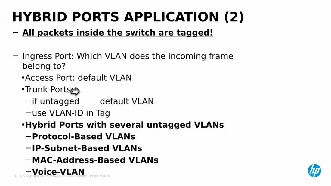
− All packets inside the switch are tagged!
− Ingress Port: Which VLAN does the incoming frame belong to?•Access Port: default VLAN•Trunk Ports:−if untagged default VLAN−use VLAN-ID in Tag•Hybrid Ports with several untagged VLANs−Protocol-Based VLANs−IP-Subnet-Based VLANs−MAC-Address-Based VLANs−Voice-VLAN
HYBRID PORTS APPLICATION (2)
© Copyright 2013 Hewlett-Packard GmbH – Peter Mattei 132
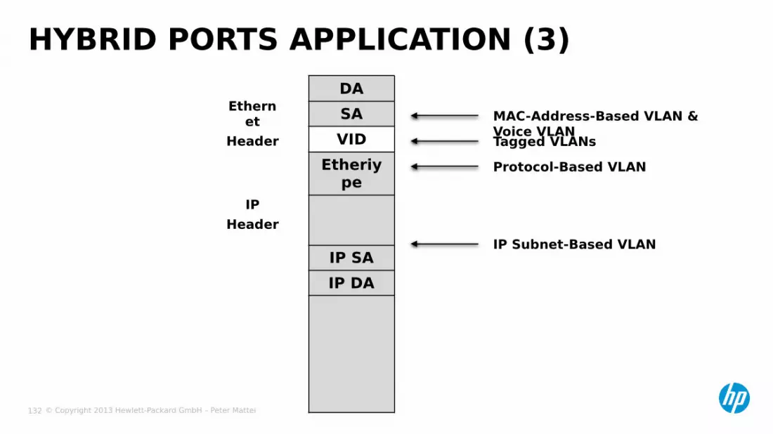
HYBRID PORTS APPLICATION (3)DASAVID
Etheriype
IP SAIP DA
MAC-Address-Based VLAN & Voice VLANTagged VLANsProtocol-Based VLAN
IP Subnet-Based VLAN
Ethernet
Header
IPHeader

© Copyright 2013 Hewlett-Packard GmbH – Peter Mattei 133
PROTOCOL-BASEDVLANS
© Copyright 2013 Hewlett-Packard GmbH – Peter Mattei 134
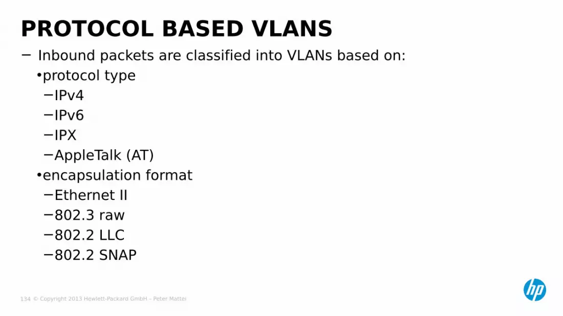
− Inbound packets are classified into VLANs based on:•protocol type−IPv4−IPv6−IPX−AppleTalk (AT)•encapsulation format−Ethernet II−802.3 raw−802.2 LLC−802.2 SNAP
PROTOCOL BASED VLANS

© Copyright 2013 Hewlett-Packard GmbH – Peter Mattei 135
protocol-vlan {protocol-index} {at |ipv4 |ipv6 |ipx {ethernetii | llc | raw | snap} |mode {
ethernetii etype etype-id |llc { dsap dsap-id [ ssap ssap-id ]
| ssap ssap-id } |snap etype etype-id }
}
ENCAPSULATION-PROTOCOL TEMPLATE

© Copyright 2013 Hewlett-Packard GmbH – Peter Mattei 136
• IPv6[switch-vlan00] protocol-vlan 100 ipv6
• IPX over LLC[switch-vlan01] protocol-vlan 101 ipx llc
• Appletalk[switch-vlan02] protocol-vlan 102 at
• NBX over Ethernet[switch-vlan03] protocol-vlan 103 mode ethernetii etype 0x8868
EXAMPLES

© Copyright 2013 Hewlett-Packard GmbH – Peter Mattei 137
[SWA] vlan 2[SWA-vlan2] port gigabit 1/1/10[SWA-vlan2] protocol-vlan mode ethernetii etype 0800[SWA-vlan2] protocol-vlan mode ethernetii etype 0806[SWA-vlan2] vlan 3[SWA-vlan3] port gigabit 1/1/11[SWA-vlan3] protocol-vlan ipv6[SWA-vlan3] interface gigabit 1/1/1[SWA-gigabit1/1/1] port link-type hybrid[SWA-gigabit1/1/1] undo port hybrid vlan 1[SWA-gigabit1/1/1] port hybrid vlan 2 3 untagged[SWA-gigabit1/1/1] port hybrid protocol-vlan vlan 2 all[SWA-gigabit1/1/1] port hybrid protocol-vlan vlan 3 all
ASSIGNING PROTOCOL-BASE VLANS• Example: G1/1/1
G1/1/10
G1/1/11
VLAN 2 IP & ARP Untagged
VLAN 3 IPv6 Untagged

© Copyright 2013 Hewlett-Packard GmbH – Peter Mattei 138
IP-SUBNET-BASEDVLANS

© Copyright 2013 Hewlett-Packard GmbH – Peter Mattei 139
• VLAN is assigned based on the Source IP Subnet• When a frame arrives on a port with IP-Subnet-Based VLANs
configured: If untagged:
−The packet is treated according to the subnets configured.
−If the source subnet is not configured, the packet will be treated following other rules.
Is tagged: the packet is treated according to the Port-Based VLANs configured.
IP SUBNET-BASED VLANS
© Copyright 2013 Hewlett-Packard GmbH – Peter Mattei 140
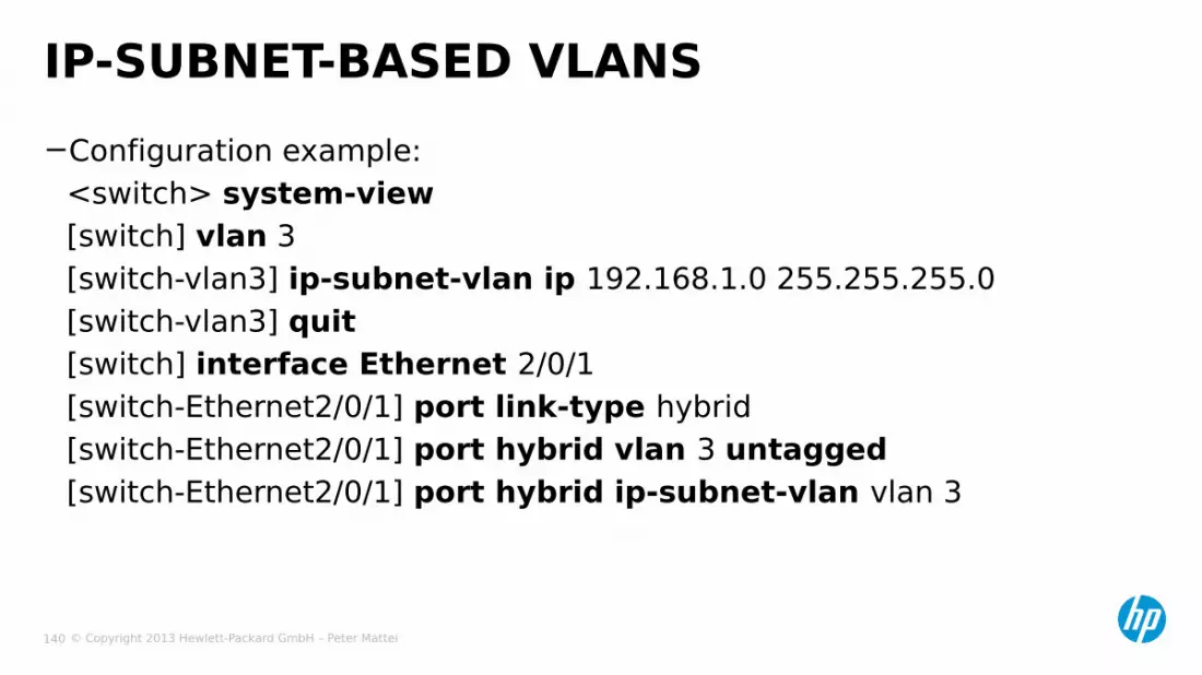
−Configuration example:<switch> system-view[switch] vlan 3[switch-vlan3] ip-subnet-vlan ip 192.168.1.0 255.255.255.0[switch-vlan3] quit[switch] interface Ethernet 2/0/1[switch-Ethernet2/0/1] port link-type hybrid[switch-Ethernet2/0/1] port hybrid vlan 3 untagged[switch-Ethernet2/0/1] port hybrid ip-subnet-vlan vlan 3
IP-SUBNET-BASED VLANS

© Copyright 2013 Hewlett-Packard GmbH – Peter Mattei 141
MAC-ADDRESS-BASEDVLANS

© Copyright 2013 Hewlett-Packard GmbH – Peter Mattei 142
• VLAN is assigned based on the Source MAC Address
• When a frame arrives on a port with MAC-Address-Based VLANs configured: If untagged: the packet is treated according to the MAC
Address VLANs configured.−If the source MAC address is not configured, the packet
will be treated following other rules. If tagged: the packet is treated according to the Port-
Based VLANs configured.
MAC-ADDRESS-BASED VLANS

© Copyright 2013 Hewlett-Packard GmbH – Peter Mattei 143
−In system view, associate MAC address with a (existing) VLANmac-vlan mac-address mac-addr [mask mac-mask] vlan vlan-id [priority priority]
CONFIGURING MAC-ADDRESS-BASED VLANS
© Copyright 2013 Hewlett-Packard GmbH – Peter Mattei 144
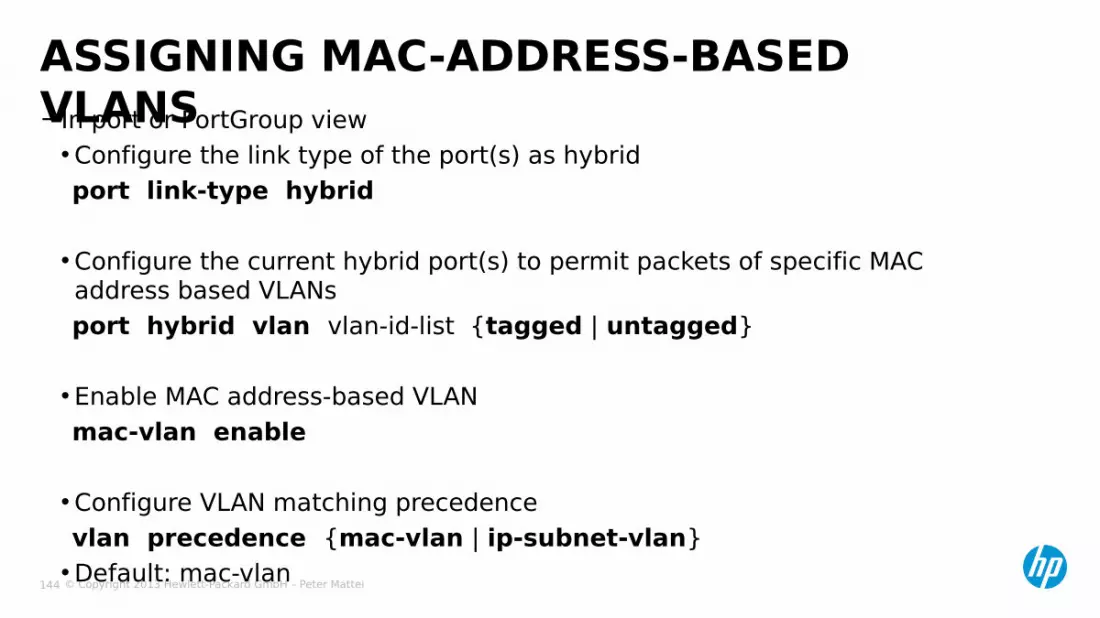
−In port or PortGroup view•Configure the link type of the port(s) as hybridport link-type hybrid
•Configure the current hybrid port(s) to permit packets of specific MAC address based VLANsport hybrid vlan vlan-id-list {tagged | untagged}
• Enable MAC address-based VLANmac-vlan enable
•Configure VLAN matching precedencevlan precedence {mac-vlan | ip-subnet-vlan}•Default: mac-vlan
ASSIGNING MAC-ADDRESS-BASED VLANS

© Copyright 2013 Hewlett-Packard GmbH – Peter Mattei 145
VOICE VLAN
© Copyright 2013 Hewlett-Packard GmbH – Peter Mattei 146
− A special VLAN to switch all voice devices are connected.
− Pros:• QoS can be applied in a simple way• Multicast traffic does not need to be routed
− Modes (how ports are added to the voice VLAN):• Automatic (default)• Manual – NOT Covered in this course
VOICE VLAN

© Copyright 2013 Hewlett-Packard GmbH – Peter Mattei 147
− There is a default OUI List• 3Com phones OUI 00e0-bb00-0000 is in that list
− This list can be edited:• adding OUIs:
voice vlan mac-address oui mask oui-mask [description text]
CONFIGURING THE OUI LIST
© Copyright 2013 Hewlett-Packard GmbH – Peter Mattei 148
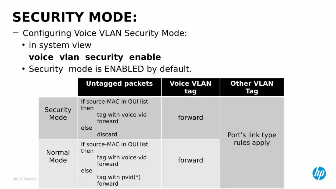
− Configuring Voice VLAN Security Mode:• in system view
voice vlan security enable• Security mode is ENABLED by default.
SECURITY MODE:
Untagged packets Voice VLAN tag
Other VLAN Tag
SecurityMode
If source-MAC in OUI list then tag with voice-vid forwardelse discard
forward
Port’s link type rules apply
NormalMode
If source-MAC in OUI list then tag with voice-vid forwardelse tag with pvid(*) forward
forward

© Copyright 2013 Hewlett-Packard GmbH – Peter Mattei 149
− In system view•Optional first steps−configure the aging time of the voice VLANvoice vlan aging minutes−Enable the security mode of the voice VLANvoice vlan security enable•If needed add OUIs to the OUI table:voice vlan mac-address oui mask oui-mask [ description text ]•Enable the global voice VLAN featurevoice vlan vlan-id enable
− In Ethernet port view, enable the voice VLAN feature on the portvoice vlan enable
CONFIGURING AN AUTO-VOICE VLAN
© Copyright 2013 Hewlett-Packard GmbH – Peter Mattei 150
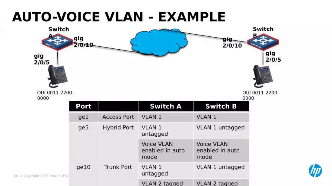
AUTO-VOICE VLAN - EXAMPLESwitch A
Switch Bgig
2/0/10gig 2/0/10
gig 2/0/5
gig 2/0/5
OUI 0011-2200-0000
OUI 0011-2200-0000
Port Switch A Switch Bge1 Access Port VLAN 1 VLAN 1ge5 Hybrid Port VLAN 1
untaggedVLAN 1 untagged
Voice VLAN enabled in auto mode
Voice VLAN enabled in auto mode
ge10 Trunk Port VLAN 1 untagged
VLAN 1 untagged
VLAN 2 tagged VLAN 2 tagged
© Copyright 2013 Hewlett-Packard GmbH – Peter Mattei 151
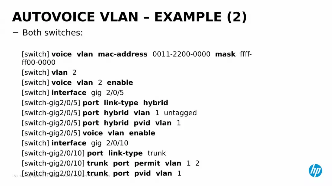
− Both switches:
[switch] voice vlan mac-address 0011-2200-0000 mask ffff-ff00-0000[switch] vlan 2[switch] voice vlan 2 enable[switch] interface gig 2/0/5[switch-gig2/0/5] port link-type hybrid[switch-gig2/0/5] port hybrid vlan 1 untagged[switch-gig2/0/5] port hybrid pvid vlan 1[switch-gig2/0/5] voice vlan enable[switch] interface gig 2/0/10[switch-gig2/0/10] port link-type trunk[switch-gig2/0/10] trunk port permit vlan 1 2[switch-gig2/0/10] trunk port pvid vlan 1
AUTOVOICE VLAN – EXAMPLE (2)

© Copyright 2013 Hewlett-Packard GmbH – Peter Mattei 152
BASIC QINQ
© Copyright 2013 Hewlett-Packard GmbH – Peter Mattei 153
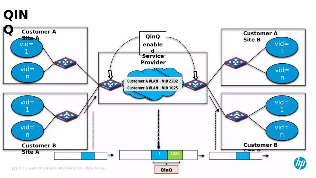
QINQ
vid= 1
vid= n
vid= 1
vid= n
vid=1
vid=1
vid= n
vid= n
Customer A Site A
Customer B Site B
Customer A Site B
Customer B Site A
QinQenable
dService Provider

© Copyright 2013 Hewlett-Packard GmbH – Peter Mattei 154
BASIC QINQCustomer’s
Site AService Provider’s MAN Customer’s Site
B
vid=106
vid=107
vid=106
vid=106
VLAN 1004
Eth1/0/1
Sw A
Sw B
Eth1/0/1
Gig2/0/1
SP-Sw 1
SP-Sw 2
Gig2/0/1
[sp-sw1] vlan 1004[sp-sw1-vlan-1004] port ethernet 1/0/1[sp-sw1-vlan-1004] quit[sp-sw1] interface ethernet 1/0/1[sp-sw1-int-gig1/0/1] qinq enable

© Copyright 2013 Hewlett-Packard GmbH – Peter Mattei 155
BASIC QINQCustomer’s Site A
vid=106
vid=106
Sw A
Service Provider’s MAN
SP-Sw1
trunk access+
qinq

© Copyright 2013 Hewlett-Packard GmbH – Peter Mattei 156
LAYER 2 TOPOLOGY PROTOCOLS

© Copyright 2013 Hewlett-Packard GmbH – Peter Mattei 157
− RSTP− MSTP− SmartLink− RRPPP
LAYER 2 TOPOLOGY MANAGEMENTTECHNOLOGIES

© Copyright 2013 Hewlett-Packard GmbH – Peter Mattei 158
RSTP
© Copyright 2013 Hewlett-Packard GmbH – Peter Mattei 159
− Evolution− Goals− IDs and Priorities− RSTP BPDUs− Bridge Roles− Port Roles− Port States− Configuration
RSTP REVIEW
© Copyright 2013 Hewlett-Packard GmbH – Peter Mattei 160
− Evolution:• IEEE 802.1D-1998 included the original STP
specification• IEEE 802.1w was an addendum to that standard
specifying the Rapid Spanning Tree Protocol• In IEEE 802.1D-2004 the original STP was replaced
by the RSTP specification (Section 17)
RSTP: RAPID SPANNING TREE PROTOCOL

© Copyright 2013 Hewlett-Packard GmbH – Peter Mattei 161
− The Rapid Spanning Tree Algorithm Protocol• Configures the Port State of each Bridge Port
• Provides for fault tolerance by automatic reconfiguration of the active topology
• Does not require initial configuration of bridge and bridge ports.
RSTP GOAL

© Copyright 2013 Hewlett-Packard GmbH – Peter Mattei 162
− Bridge ID:• Identifier for bridges• Must be unique• Composed by
− A configurable part: Bridge Priority− A fixed – unique – part: MAC address of the STP enfity within the bridge
− Port ID:• Identifier for bridges ports• Must be unique between ports of the same bridge • Composed by
− A configure part: Bridge Priority• In HP A-Series switches: 128 by default• If Ethernet ports (on a device) have the same priority value, the specific priority of
a port depends on the index number of the port.− A fixed – unique – part: MAC address of the STP enfity within the bridge
IDS AND PRIORITIES

© Copyright 2013 Hewlett-Packard GmbH – Peter Mattei 163
− Root Bridge• The bridge with the best (lowest) Bridge Identifier is
selected as the Root Bridge
− Designated Bridge • The Bridge connected to a certain LAN with the lowest
path cost to the Root Bridge
BRIDGE ROLES

© Copyright 2013 Hewlett-Packard GmbH – Peter Mattei 164
−Root Port•1 port per switch (other than the Root Bridge) that•provides that lowest cost path to the Root Bridge
−Designated Port•1 port per LAN (LAN segment) that•provides that lowest cost path to the Root Bridge
−Alternate Port•an alternative for a Root Port
−Backup Port•a backup for a Designated Port
−Disabled Port
RSTP PORT ROLES

© Copyright 2013 Hewlett-Packard GmbH – Peter Mattei 165
−Configuration Messages• transport: spanning tree priority vectors
−Spanning tree priority vectors• comprise the following:
−Root Bridge Identifier−Root Path Cost−Bridge Identifier (of the transmitting bridge)−Port Identifier, of the transmitting port−Port Identifier, of the receiving port (where relevant)
−Compulation is done at each port by comparing• port priority vector
−Stored by the bridge for each one of its ports• message priority vector
−Received at that port in a Configuration Message
CONFIGURATION MESSAGES AND PRIORITY VECTORS
© Copyright 2013 Hewlett-Packard GmbH – Peter Mattei 166
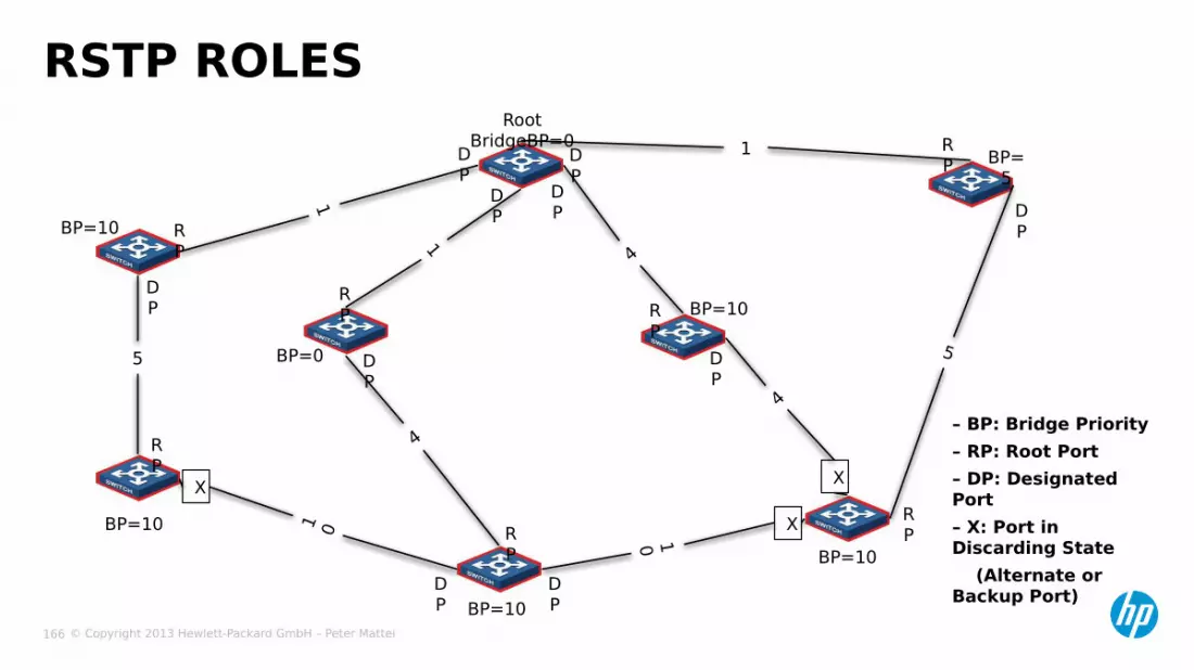
RSTP ROLES
5
1
1
1 0 10
5
4
1
4
4
XX
X
BP=10BP=10
BP=10
BP=10
RP
RP
RP
RP
RP
DP
DP
DP
DP D
P
– BP: Bridge Priority – RP: Root Port – DP: Designated Port – X: Port in Discarding State (Alternate or Backup Port)
DP
DP
DP
DP
RP
RP
BP=0
BP=10
BP=5
Root BridgeBP=0D
P
© Copyright 2013 Hewlett-Packard GmbH – Peter Mattei 167
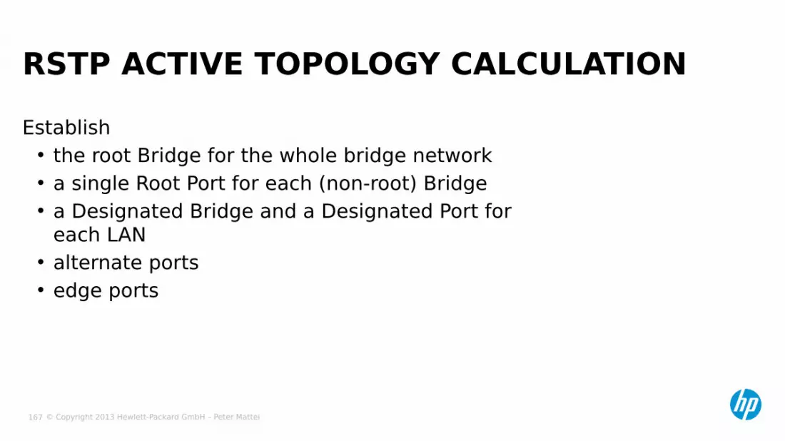
Establish• the root Bridge for the whole bridge network• a single Root Port for each (non-root) Bridge• a Designated Bridge and a Designated Port for
each LAN• alternate ports• edge ports
RSTP ACTIVE TOPOLOGY CALCULATION
© Copyright 2013 Hewlett-Packard GmbH – Peter Mattei 168
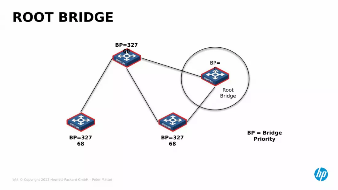
ROOT BRIDGEBP=327
68
BP=32768
BP=32768
Root Bridge
BP=0
BP = Bridge Priority
© Copyright 2013 Hewlett-Packard GmbH – Peter Mattei 169
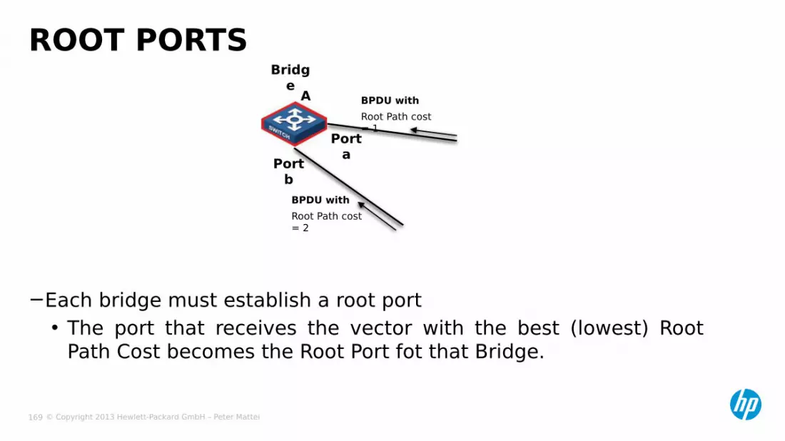
−Each bridge must establish a root port• The port that receives the vector with the best (lowest) Root
Path Cost becomes the Root Port fot that Bridge.
ROOT PORTSBridg
eA
Port b
Port a
BPDU withRoot Path cost = 1
BPDU withRoot Path cost = 2

© Copyright 2013 Hewlett-Packard GmbH – Peter Mattei 170
DESIGNATED BRIDGE AND DESIGNATED PORT Bridge A
BP: 16384
Bridge BBP:
32768
Port b
Port a
Designated
Portfor LAN x
Designated
Bridgefor LAN x
LAN x

© Copyright 2013 Hewlett-Packard GmbH – Peter Mattei 171
ALTERNATE PORTS AND BACKUP PORTS
X
LAN x
LAN y
Port a
Port b
Port c Port
dAlternate PortState: Discarding
Bridge ABP:
32768
Bridge BBP:
16384
To ROOT
DP for LAN y
DP for LAN x
RP for Br B
RP for Br ADB for
LAN x and y
© Copyright 2013 Hewlett-Packard GmbH – Peter Mattei 172
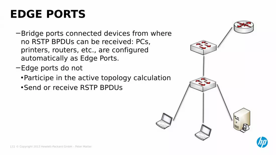
EDGE PORTS−Bridge ports connected devices from where
no RSTP BPDUs can be received: PCs, printers, routers, etc., are configured automatically as Edge Ports.
−Edge ports do not•Participe in the active topology calculation •Send or receive RSTP BPDUs

© Copyright 2013 Hewlett-Packard GmbH – Peter Mattei 173
PORT STATES
Role StateRoot Port Forwarding
Designated Port ForwardingAlternate Port ForwardingBackup Port DiscardingEdge Port Forwarding
© Copyright 2013 Hewlett-Packard GmbH – Peter Mattei 174
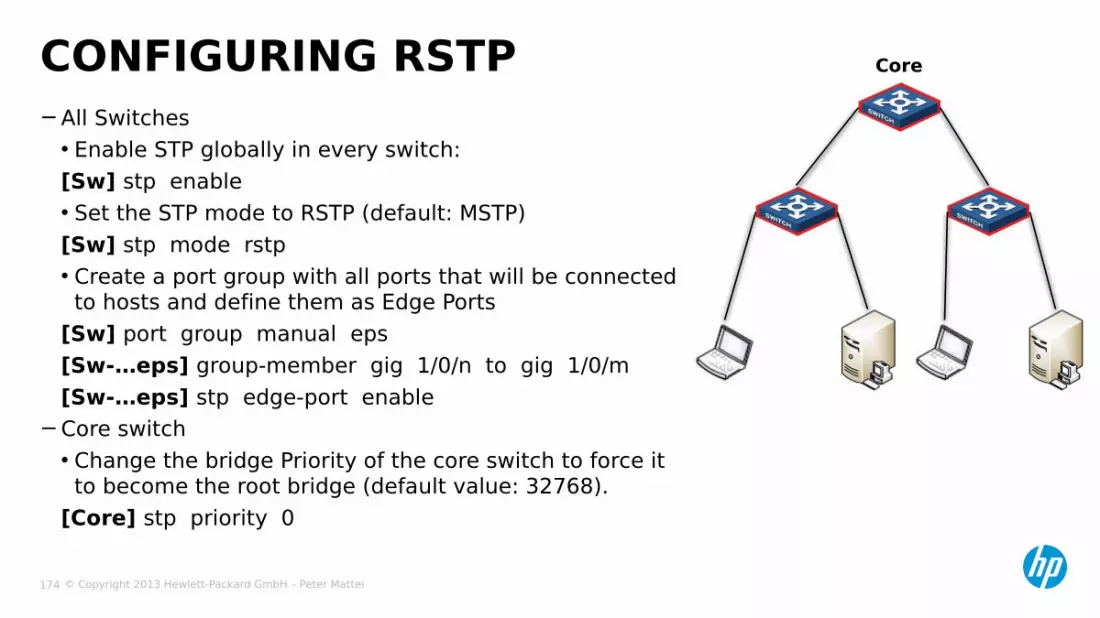
−All Switches• Enable STP globally in every switch:[Sw] stp enable• Set the STP mode to RSTP (default: MSTP)[Sw] stp mode rstp• Create a port group with all ports that will be connected to hosts and define them as Edge Ports
[Sw] port group manual eps[Sw-…eps] group-member gig 1/0/n to gig 1/0/m[Sw-…eps] stp edge-port enable
−Core switch• Change the bridge Priority of the core switch to force it to become the root bridge (default value: 32768).
[Core] stp priority 0
CONFIGURING RSTP Core

© Copyright 2013 Hewlett-Packard GmbH – Peter Mattei 175
MSTP

© Copyright 2013 Hewlett-Packard GmbH – Peter Mattei 176
−Evolution−Regions−Trees: CST, IST, CIST, MSTI−Single región−Instances−Root Bridges−Configuration
MSTP
© Copyright 2013 Hewlett-Packard GmbH – Peter Mattei 177
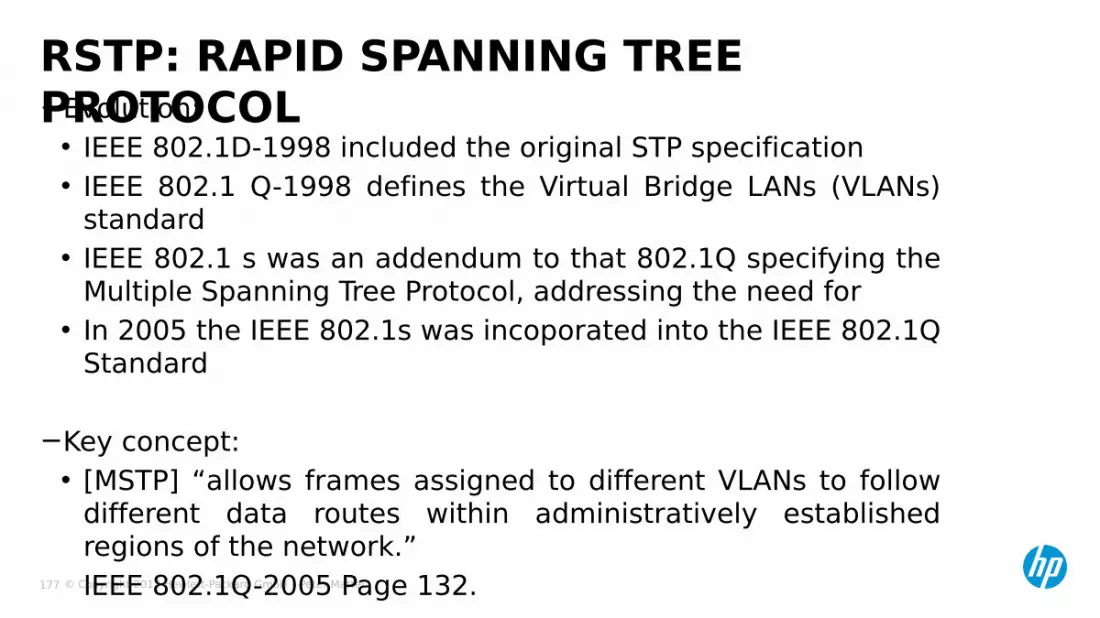
−Evolution:• IEEE 802.1D-1998 included the original STP specification• IEEE 802.1 Q-1998 defines the Virtual Bridge LANs (VLANs)
standard• IEEE 802.1 s was an addendum to that 802.1Q specifying the
Multiple Spanning Tree Protocol, addressing the need for • In 2005 the IEEE 802.1s was incoporated into the IEEE 802.1Q
Standard
−Key concept:• [MSTP] “allows frames assigned to different VLANs to follow
different data routes within administratively established regions of the network.”IEEE 802.1Q-2005 Page 132.
RSTP: RAPID SPANNING TREE PROTOCOL

© Copyright 2013 Hewlett-Packard GmbH – Peter Mattei 178
REGIONS
RegA
RegB
RegC
RegD
© Copyright 2013 Hewlett-Packard GmbH – Peter Mattei 179
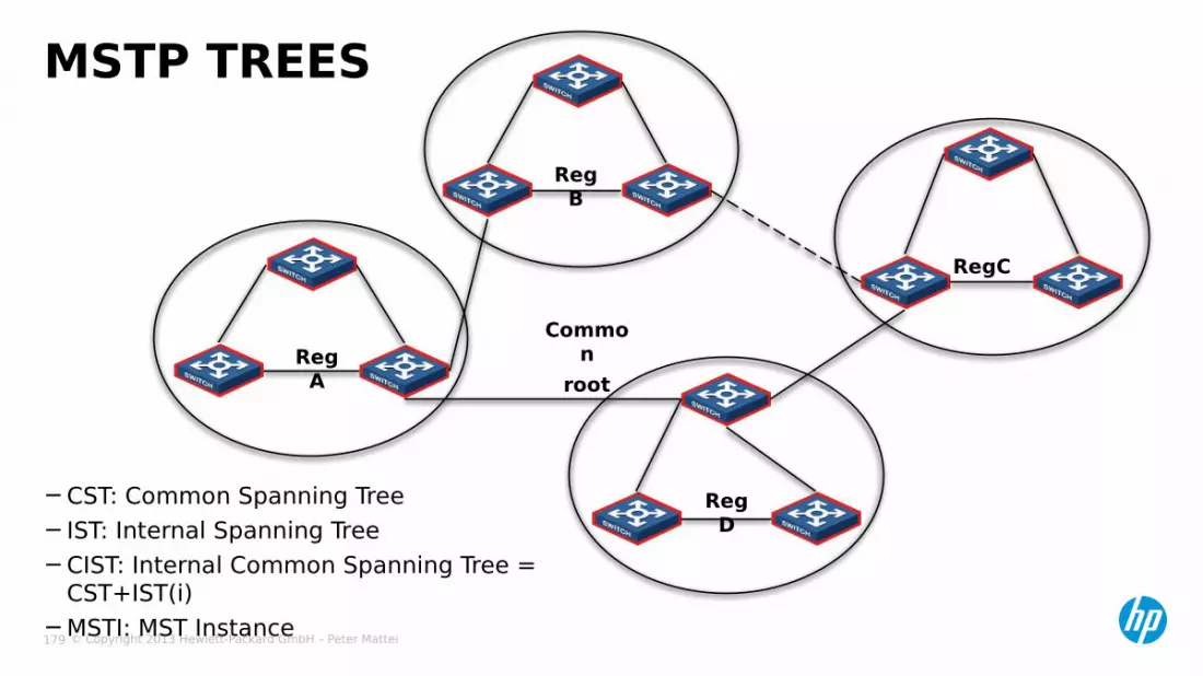
−CST: Common Spanning Tree−IST: Internal Spanning Tree−CIST: Internal Common Spanning Tree =
CST+IST(i)−MSTI: MST Instance
MSTP TREES
RegA
RegB
RegC
RegD
Common
root

© Copyright 2013 Hewlett-Packard GmbH – Peter Mattei 180
MSTISCore
Switch ACore
Switch B
RegA
Primary Root
Secondary Root
VLANs
Instance 1
Core Switch A Core Switch B 1 and 2
Instance 2
Core Switch B Core Switch A 3 and 4

© Copyright 2013 Hewlett-Packard GmbH – Peter Mattei 181
−All Switches
SINGLE REGION CONFIGURATION(COMMON PARAMETERS)
CSw A
CSw B
AccSw1
AccSw2
AccSw3
AccSwN
[Sw] stp region-configuration[Sw-stp-reg…] region-name reg1[Sw-stp-reg…] revision-level 0[Sw-stp-reg…] instance 1 vlan 2 3[Sw-stp-reg…] instance 2 vlan 4 5[Sw-stp-reg…] active region-configuration[Sw-stp-reg…] quit[Sw] stp enable

© Copyright 2013 Hewlett-Packard GmbH – Peter Mattei 182
−Core Switch A[CSwA] stp instance 1 root primary[CSwA] stp instance 2 root secondary
−Core Switch B[CSwB] stp instance 1 root secondary[CSwB] stp instance 2 root primary
−Verify[Sw] display stp root[Sw] display stp [brief]
SINGLE REGION CONFIGURATION(INDIVIDUAL SETTINGS)
CSw A
CSw B
AccSw1
AccSw2
AccSw3
AccSwN

© Copyright 2013 Hewlett-Packard GmbH – Peter Mattei 183
−To configure a port’s cost (for a certain instance)stp { instance instance-id } cost cost
−To configure a port’s path cost standardstp pathcost-standard { dot1d-1998 | dot1d | legacy }• default: legacy
• It is advisable to add BPDU guard and loop/root protection options to harden the MSTP/STP Configuration.
OTHER USEFUL COMMANDS

© Copyright 2013 Hewlett-Packard GmbH – Peter Mattei 184
LINK SPEED VS. PATH COSTLink
speedDuplex state 802.1D-
1998IEEE
802.1tLegac
y0 - 65535 200,000,000 200,000
10 Mbps Single PortAggregated Link 2 portsAggregated Link 3 portsAggregated Link 4 ports
100100100100
2,000,0001,000,000666,666500,000
2,0001,8001,6001,400
100 Mbps Single PortAggregated Link 2 portsAggregated Link 3 portsAggregated Link 4 ports
19191919
200,000100,00066,66650,000
200180160140
1000 Mbps Single PortAggregated Link 2 portsAggregated Link 3 portsAggregated Link 4 ports
4444
20,00010,0006,6665,000
20181614
10 Gbps Single PortAggregated Link 2 portsAggregated Link 3 portsAggregated Link 4 ports
2222
2,0001,000666500
2111

© Copyright 2013 Hewlett-Packard GmbH – Peter Mattei 185
STP REVIEW EXERCISE
LEARINING CHECKPlease Find:−The Root Switch−On all other
switches:•The Root Port
−On all segments• Designated Ports• Discarded Ports
− Assume− Cost of all links is equal
= 4− Switches Priority 32768
50 priority 0
S6
S4
S2
S3
S1
S5
G1/0/2
G1/0/2
G1/0/2
G1/0/2 G1/0/2
G1/0/2
G1/0/1
G1/0/3
G1/0/3 G1/0/1
G1/0/1
G1/0/1
G1/0/1
G1/0/3G1/0
/1
© Copyright 2013 Hewlett-Packard GmbH – Peter Mattei 186
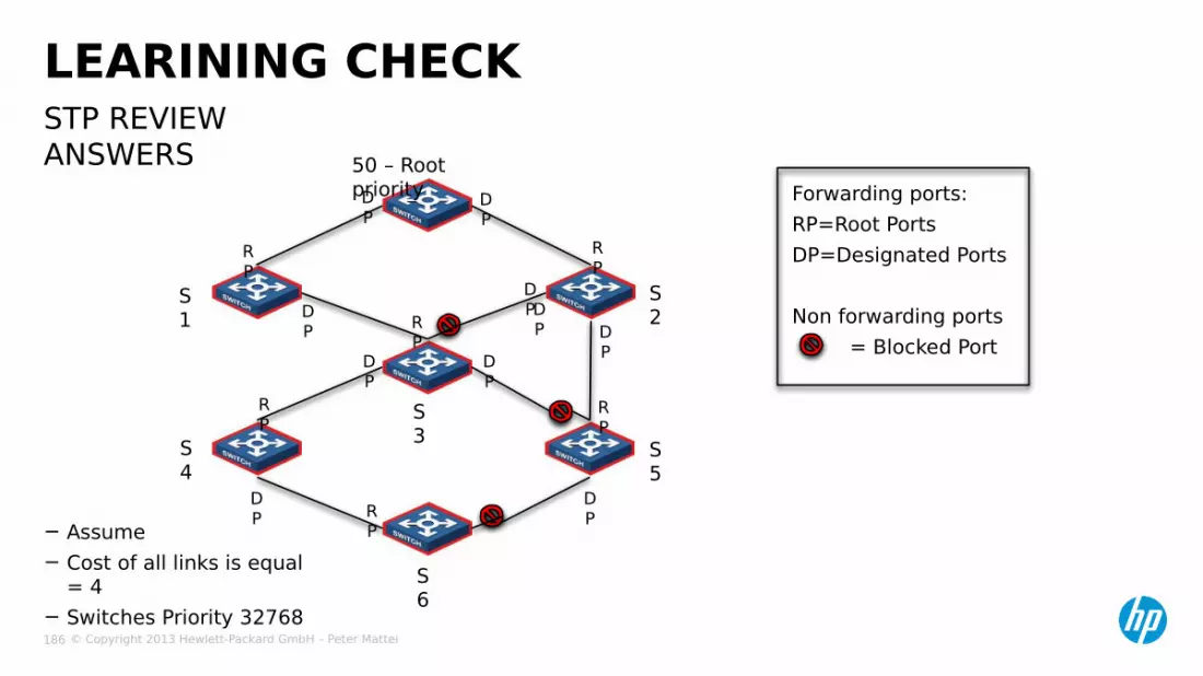
STP REVIEW ANSWERS
LEARINING CHECK
50 – Root priority
S6
S4
S2
S3
S1
S5
RP
RP
RP
RP
RP
DP
DP
DP
DPDP
DP
DP
DP
DP
DP
RP
− Assume− Cost of all links is equal
= 4− Switches Priority 32768
Forwarding ports:RP=Root PortsDP=Designated Ports
Non forwarding ports = Blocked Port

© Copyright 2013 Hewlett-Packard GmbH – Peter Mattei 187
SMART

© Copyright 2013 Hewlett-Packard GmbH – Peter Mattei 188
− SmartLink Overview− SmartLink
Configuration
AGENDA

© Copyright 2013 Hewlett-Packard GmbH – Peter Mattei 189
OVERVIEW GE2/0/
1
GE2/0/1
GE2/0/3
GE2/0/1
GE2/0/1
GE2/0/2
GE2/0/2
GE2/0/2
GE2/0/1
GE2/0/3
GE2/0/2
GE2/0/2Sw
C1
Sw A
Sw B1
Sw B2
Sw C2
Smart Link Group
Port in Standby

© Copyright 2013 Hewlett-Packard GmbH – Peter Mattei 190
−Consists of only two member ports:• Master Port• Slave Port
−In normal operation:• Master Port state = active• Slave Por state = standby
−If Master Port link fails (disconnected, disabled by DLDP, etc.)• Slave Port transitions to active
−Master Preemption Mode:• If configured: upon Master Port Link recovery, Master Port
returns to active state• If not configured: after Master Port Link recovery, Master
port stays in standy mode
SMART LINK GROUP
© Copyright 2013 Hewlett-Packard GmbH – Peter Mattei 191
− Flush message• Used by a smart link group to notify other devices to refresh
their MAC address forwarding entries and ARP/ND entries when link switchover occurs in the smart link group.
• Flush messages are common unicast data packets, and will be dropped by a blocked receiving port.
FLUSH MESSAGES

© Copyright 2013 Hewlett-Packard GmbH – Peter Mattei 192
− Transmit control VLAN• Used for transmitting Flush messages.• When link switchover occurs, the device broadcast Flush
messages within the transmit control VLAN.
− Receive control VLAN• The devices receive and process Flush messages in the
receive control VLAN and refresh their MAC address forwarding entries and ARP/ND entries.
TRANSMIT AND RECEIVE CONTROL VLANS

© Copyright 2013 Hewlett-Packard GmbH – Peter Mattei 193
− Protected VLAN• a SmartLink group controls the forwarding state of some
data VLANs, which are referred to as protected VLANs.• different SmartLink groups on a port control different
protected VLANs.• the state of the port in a protected VLAN is determined by
the state of the port in the SmartLink group.− Load sharing mechanism• smartLink con forward traffic of different VLANs in
different smart link groups.• to implement load sharing, you can assign a port to
multiple smart link groups making sure that the state of the port is defferent in these smart link groups. In this way, traffic of different VLANs can be forwarded along different paths.
• you can configure protected VLANs for a SmartLink group by referencing MSTIs.
PROTECTED VLAN AND LOAD SHARING
© Copyright 2013 Hewlett-Packard GmbH – Peter Mattei 194
− Before configuring a port as a smart link group member:• Shut down the port to prevent loops.
− You can bring up the port only after completing the smart link group configuration.• Disable STPand RRPP on the ports you want to add to the
smart link group• Make sure that the ports are not member ports of any
aggregation group or Service loopback group.
SMARTLINK CONFIGURATION PREREQUISITES

© Copyright 2013 Hewlett-Packard GmbH – Peter Mattei 195
− In system view• Create a smart link group and enter smart link
group viewsmart-link group group-id
− In smart link group view• Configure protected VLANs for the smart linkp
groupprotected-vlan reference-instance instance-id-list
• Specify the master and slave ports for the smart link groupport interface-type interface-number masterport interface-type interface-number slave
• Enable role preemption (optional)preemption mode role
• Enable Flush update in the specified control VLANflush enable { control-vlan vlan-id }
STEPS
© Copyright 2013 Hewlett-Packard GmbH – Peter Mattei 196
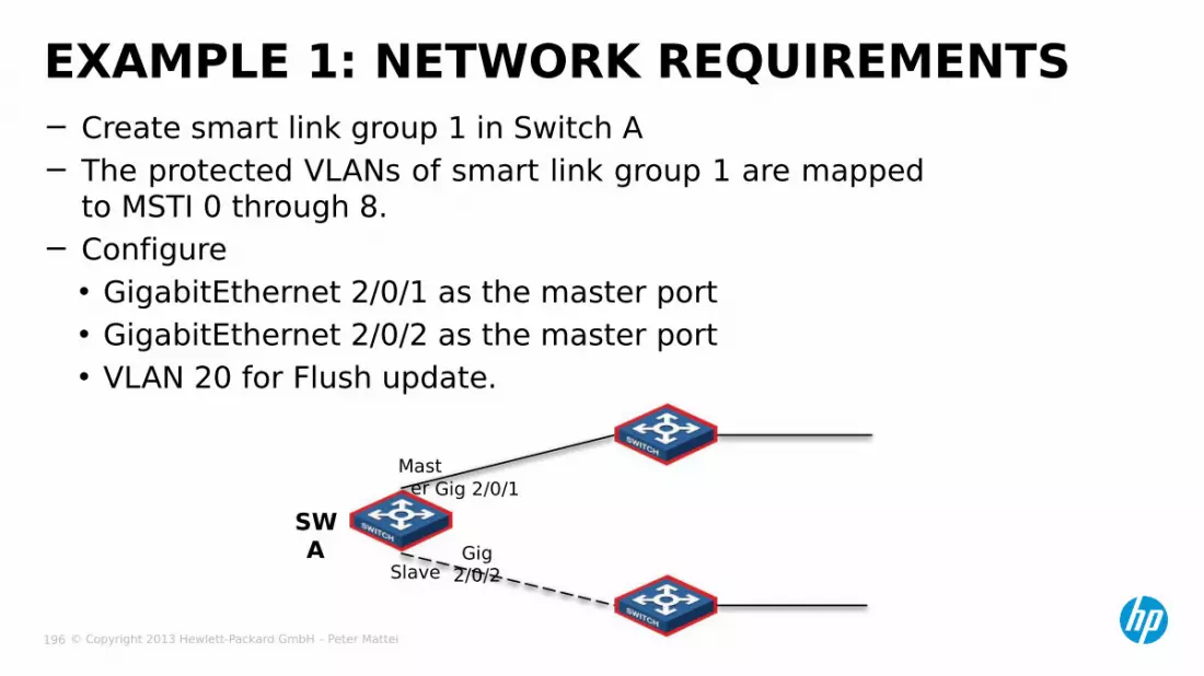
− Create smart link group 1 in Switch A− The protected VLANs of smart link group 1 are mapped
to MSTI 0 through 8.− Configure• GigabitEthernet 2/0/1 as the master port• GigabitEthernet 2/0/2 as the master port• VLAN 20 for Flush update.
EXAMPLE 1: NETWORK REQUIREMENTS
Gig 2/0/2
Gig 2/0/1Mast
er
Slave
SWA
© Copyright 2013 Hewlett-Packard GmbH – Peter Mattei 197
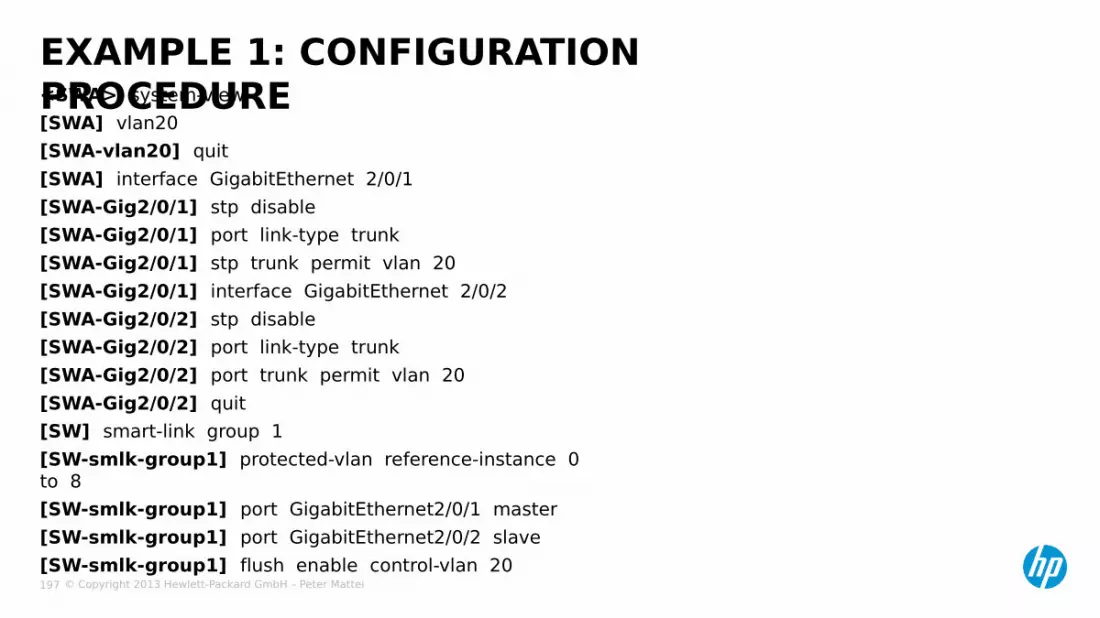
<SWA> system-view[SWA] vlan20[SWA-vlan20] quit[SWA] interface GigabitEthernet 2/0/1[SWA-Gig2/0/1] stp disable[SWA-Gig2/0/1] port link-type trunk [SWA-Gig2/0/1] stp trunk permit vlan 20[SWA-Gig2/0/1] interface GigabitEthernet 2/0/2[SWA-Gig2/0/2] stp disable[SWA-Gig2/0/2] port link-type trunk [SWA-Gig2/0/2] port trunk permit vlan 20[SWA-Gig2/0/2] quit[SW] smart-link group 1[SW-smlk-group1] protected-vlan reference-instance 0 to 8[SW-smlk-group1] port GigabitEthernet2/0/1 master[SW-smlk-group1] port GigabitEthernet2/0/2 slave[SW-smlk-group1] flush enable control-vlan 20
EXAMPLE 1: CONFIGURATION PROCEDURE

© Copyright 2013 Hewlett-Packard GmbH – Peter Mattei 198
EXAMPLE 2: NETWORK REQUIREMENTSGE2/0/
1
GE2/0/1
GE2/0/3
GE2/0/1
GE2/0/1
GE2/0/2
GE2/0/2
GE2/0/2
GE2/0/1
GE2/0/3
GE2/0/2
GE2/0/2Sw
C
Sw A
Sw B Sw D
Sw E
• Both Switch C and Switch E are dually uplinked to Switch A.
© Copyright 2013 Hewlett-Packard GmbH – Peter Mattei 199
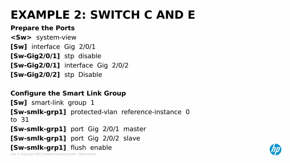
Prepare the Ports<Sw> system-view[Sw] interface Gig 2/0/1[Sw-Gig2/0/1] stp disable[Sw-Gig2/0/1] interface Gig 2/0/2[Sw-Gig2/0/2] stp Disable
Configure the Smart Link Group[Sw] smart-link group 1[Sw-smlk-grp1] protected-vlan reference-instance 0 to 31[Sw-smlk-grp1] port Gig 2/0/1 master[Sw-smlk-grp1] port Gig 2/0/2 slave[Sw-smlk-grp1] flush enable
EXAMPLE 2: SWITCH C AND E
© Copyright 2013 Hewlett-Packard GmbH – Peter Mattei 200
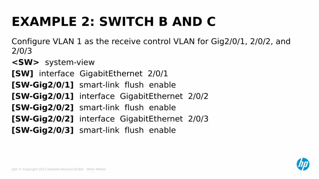
Configure VLAN 1 as the receive control VLAN for Gig2/0/1, 2/0/2, and 2/0/3<SW> system-view[SW] interface GigabitEthernet 2/0/1[SW-Gig2/0/1] smart-link flush enable[SW-Gig2/0/1] interface GigabitEthernet 2/0/2[SW-Gig2/0/2] smart-link flush enable[SW-Gig2/0/2] interface GigabitEthernet 2/0/3[SW-Gig2/0/3] smart-link flush enable
EXAMPLE 2: SWITCH B AND C
© Copyright 2013 Hewlett-Packard GmbH – Peter Mattei 201
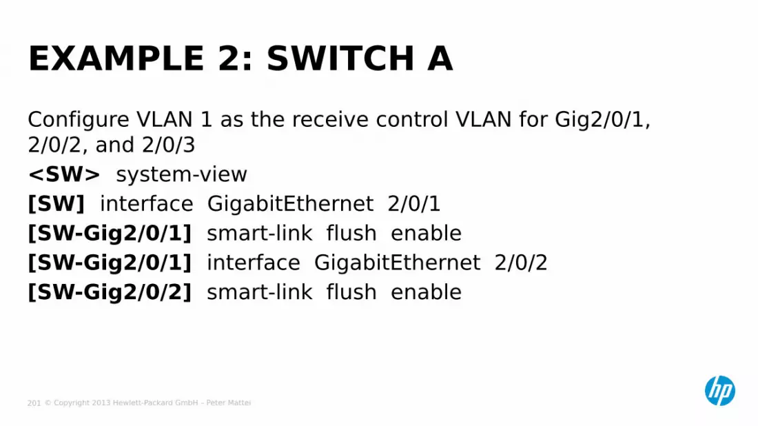
Configure VLAN 1 as the receive control VLAN for Gig2/0/1, 2/0/2, and 2/0/3<SW> system-view[SW] interface GigabitEthernet 2/0/1[SW-Gig2/0/1] smart-link flush enable[SW-Gig2/0/1] interface GigabitEthernet 2/0/2[SW-Gig2/0/2] smart-link flush enable
EXAMPLE 2: SWITCH A

© Copyright 2013 Hewlett-Packard GmbH – Peter Mattei 202
EXAMPLE 3: NETWORK REQUIREMENTS
GE2/0/1
GE2/0/1
GE2/0/1
GE2/0/1
GE2/0/2
GE2/0/2
GE2/0/2
GE2/0/2
Sw C
Sw A
Sw B
Sw D
• VLAN Load Sharing is required

© Copyright 2013 Hewlett-Packard GmbH – Peter Mattei 203
Create VLANs and configure VLAN-to-MSTI mappings<SwC> system-view[SwC] vlan 1 to 200[SwC] stp región-configuration[SwC-mst-region] instance 0 vlan 1 to 100[SwC-mst-region] instance 0 vlan 101 to 200[SwC-mst-region] active region-configuration
EXAMPLE 3: SWITCH C / PART 1
© Copyright 2013 Hewlett-Packard GmbH – Peter Mattei 204
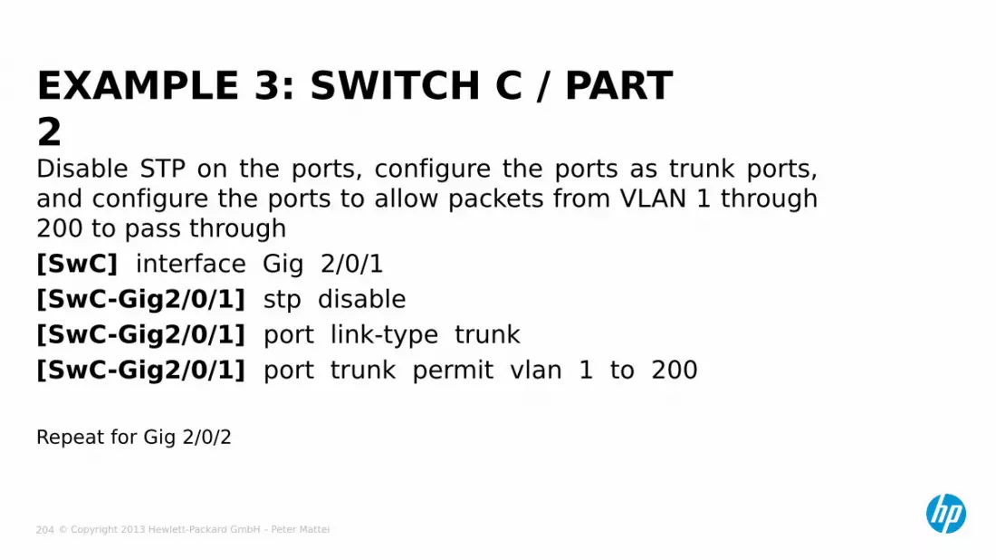
Disable STP on the ports, configure the ports as trunk ports, and configure the ports to allow packets from VLAN 1 through 200 to pass through[SwC] interface Gig 2/0/1[SwC-Gig2/0/1] stp disable[SwC-Gig2/0/1] port link-type trunk[SwC-Gig2/0/1] port trunk permit vlan 1 to 200
Repeat for Gig 2/0/2
EXAMPLE 3: SWITCH C / PART 2
© Copyright 2013 Hewlett-Packard GmbH – Peter Mattei 205
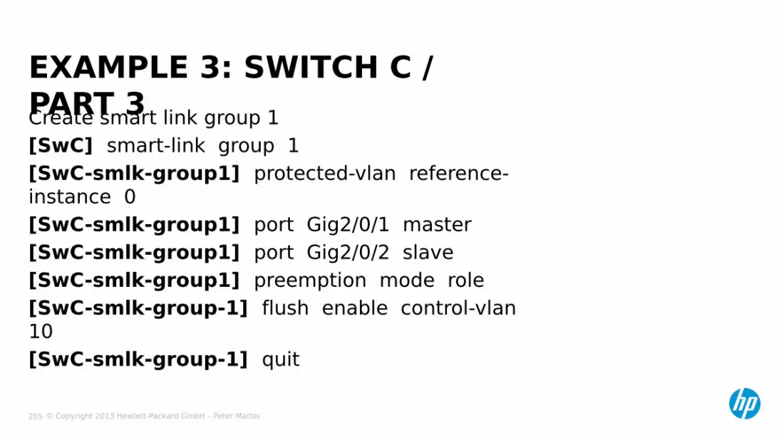
Create smart link group 1[SwC] smart-link group 1[SwC-smlk-group1] protected-vlan reference-instance 0[SwC-smlk-group1] port Gig2/0/1 master[SwC-smlk-group1] port Gig2/0/2 slave[SwC-smlk-group1] preemption mode role[SwC-smlk-group-1] flush enable control-vlan 10[SwC-smlk-group-1] quit
EXAMPLE 3: SWITCH C / PART 3
© Copyright 2013 Hewlett-Packard GmbH – Peter Mattei 206
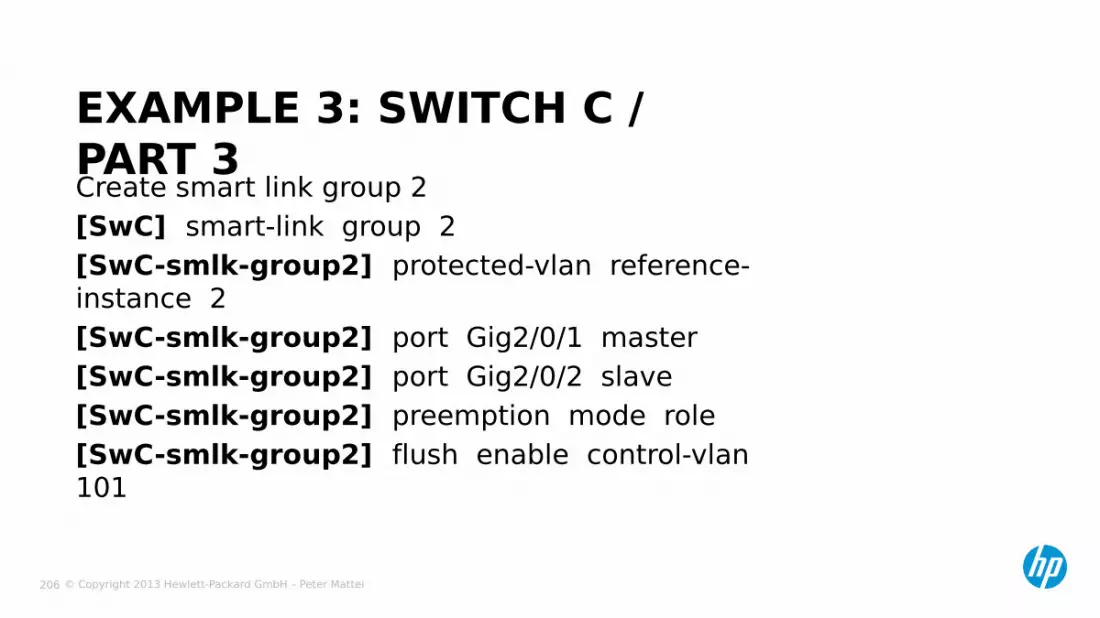
Create smart link group 2[SwC] smart-link group 2[SwC-smlk-group2] protected-vlan reference-instance 2[SwC-smlk-group2] port Gig2/0/1 master[SwC-smlk-group2] port Gig2/0/2 slave[SwC-smlk-group2] preemption mode role[SwC-smlk-group2] flush enable control-vlan 101
EXAMPLE 3: SWITCH C / PART 3
© Copyright 2013 Hewlett-Packard GmbH – Peter Mattei 207
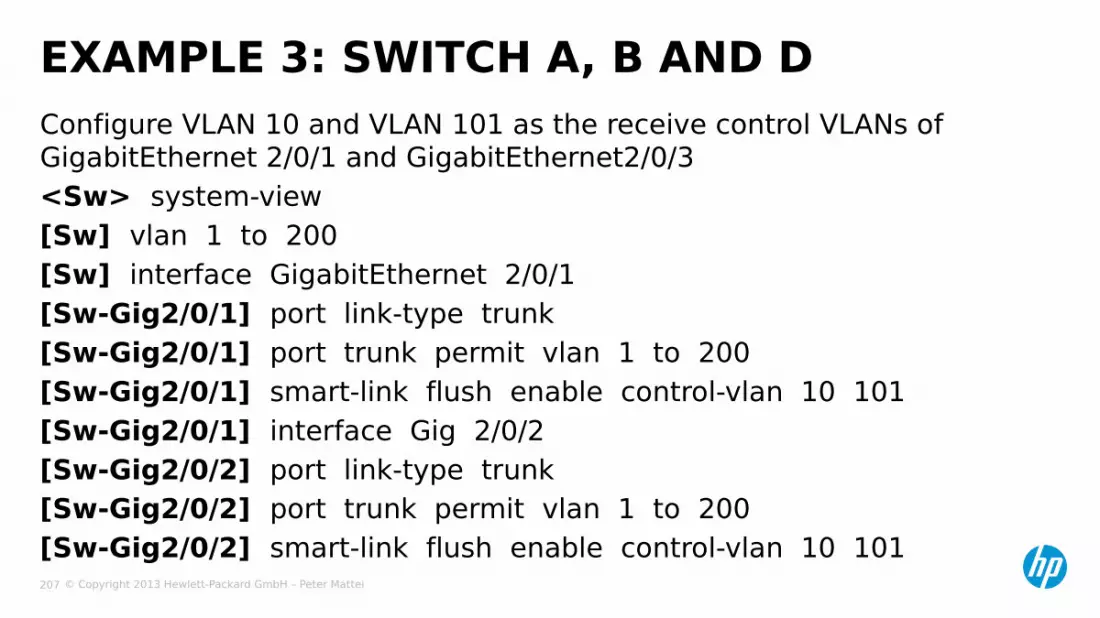
Configure VLAN 10 and VLAN 101 as the receive control VLANs of GigabitEthernet 2/0/1 and GigabitEthernet2/0/3<Sw> system-view[Sw] vlan 1 to 200[Sw] interface GigabitEthernet 2/0/1[Sw-Gig2/0/1] port link-type trunk[Sw-Gig2/0/1] port trunk permit vlan 1 to 200[Sw-Gig2/0/1] smart-link flush enable control-vlan 10 101[Sw-Gig2/0/1] interface Gig 2/0/2[Sw-Gig2/0/2] port link-type trunk[Sw-Gig2/0/2] port trunk permit vlan 1 to 200[Sw-Gig2/0/2] smart-link flush enable control-vlan 10 101
EXAMPLE 3: SWITCH A, B AND D

© Copyright 2013 Hewlett-Packard GmbH – Peter Mattei 208
RRPP

© Copyright 2013 Hewlett-Packard GmbH – Peter Mattei 209
RRPP: RAPID RING PROTECTION PROTOCOL
Ring 1:Primary Ring
Ring 2:SecondaryRing
Domain 1

© Copyright 2013 Hewlett-Packard GmbH – Peter Mattei 210
RRPP NODE MODES
Primary Ring
SecondaryRing
Domain 1 Edg
eNod
eMast
erNode
Transit
NodeAssista
ntEdgeNode
Master
Node

© Copyright 2013 Hewlett-Packard GmbH – Peter Mattei 211
RRPP CONTROL VLAN
Primary Ring
Control VLAN:1500
Secondary Ring
Control VLAN:1501
Domain 1 Edg
eNod
eMast
erNode
Transit
NodeAssista
ntEdgeNode
Master
Node

© Copyright 2013 Hewlett-Packard GmbH – Peter Mattei 212
RRPP PORTDomain
1 Edge
Node
Master
Node
Transit
NodeAssista
ntEdgeNode
Master
Node
Port 1
Port 2
Port 1
Port 1
Port 1
Port 1
Port 2
Port 2
Port 2
Port 2
Port 3
Port 3

© Copyright 2013 Hewlett-Packard GmbH – Peter Mattei 213
SINGLE RINGDomain
1
Master
Node
Transit
Node
PrimaryPort
Transit
Node
Transit
Node
PrimaryPort
PrimaryPort
PrimaryPort
Secondary
Port
Secondary
Port
Secondary
Port
Secondary
Port
© Copyright 2013 Hewlett-Packard GmbH – Peter Mattei 214
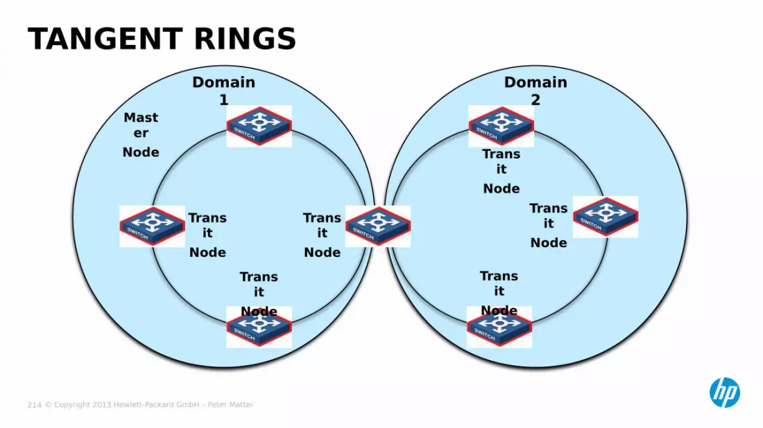
TANGENT RINGSDomain
1Domain
2Mast
erNode
Transit
NodeTrans
itNode
Transit
NodeTrans
itNode
Transit
Node
Transit
Node
© Copyright 2013 Hewlett-Packard GmbH – Peter Mattei 215
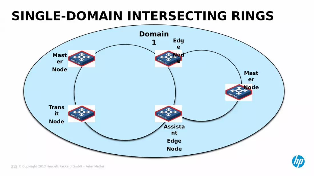
SINGLE-DOMAIN INTERSECTING RINGSDomain
1 Edge
Node
Master
Node
Transit
NodeAssista
ntEdgeNode
Master
Node

© Copyright 2013 Hewlett-Packard GmbH – Peter Mattei 216
DUAL-HOMED RINGSDomain
1 Edge
NodeMast
erNode
Transit
NodeAssista
ntEdgeNode
Master
Node
Master
Node
Ring 1
Ring 2
Ring 3

© Copyright 2013 Hewlett-Packard GmbH – Peter Mattei 217
− Polling Mechanis• Health Packets
− Link Down Alarm Mechanism• Send by Transit Nodes to
the Master Node
− Ring Recovery
RRPP MECHANISMS
Master
Node
Transit
Node
Transit
Node
Transit
Node
Health
Packet
© Copyright 2013 Hewlett-Packard GmbH – Peter Mattei 218
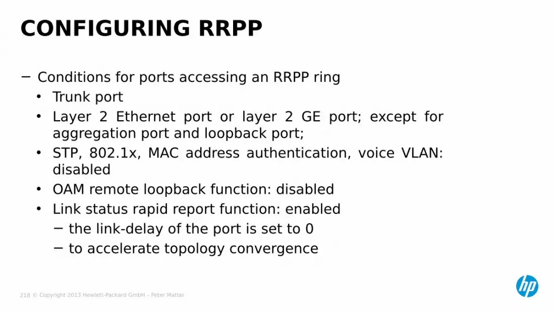
− Conditions for ports accessing an RRPP ring • Trunk port• Layer 2 Ethernet port or layer 2 GE port; except for
aggregation port and loopback port;• STP, 802.1x, MAC address authentication, voice VLAN:
disabled• OAM remote loopback function: disabled• Link status rapid report function: enabled
− the link-delay of the port is set to 0− to accelerate topology convergence
CONFIGURING RRPP
© Copyright 2013 Hewlett-Packard GmbH – Peter Mattei 219
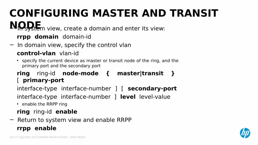
− In system view, create a domain and enter its view:rrpp domain domain-id
− In domain view, specify the control vlancontrol-vlan vlan-id• specify the current device as master or transit node of the ring, and the
primary port and the secondary portring ring-id node-mode { master|transit } [ primary-port interface-type interface-number ] [ secondary-port interface-type interface-number ] level level-value• enable the RRPP ringring ring-id enable
− Return to system view and enable RRPPrrpp enable
CONFIGURING MASTER AND TRANSIT NODE

© Copyright 2013 Hewlett-Packard GmbH – Peter Mattei 220
CONFIGURING EDGE NODE− Create a domain and the control VLAN as before. In
domain view:• Specify the current device as the transit node of the
primary ring:ring primary ring-id node-mode transit [ primary-port interface-type interface-number ] [ secondary-port interface-type interface-number ] level level-value
• Specify the current device as the edge node of a subring:ring sub-ring-id node-mode edge [ common-port interface-type interface-number ] [ edge-port interface-type interface-number ]
• and enable the RRPP ringsring primary-ring-id enable
ring sub-ring-id enable− Return to system view and enable RRPP
rrpp enable
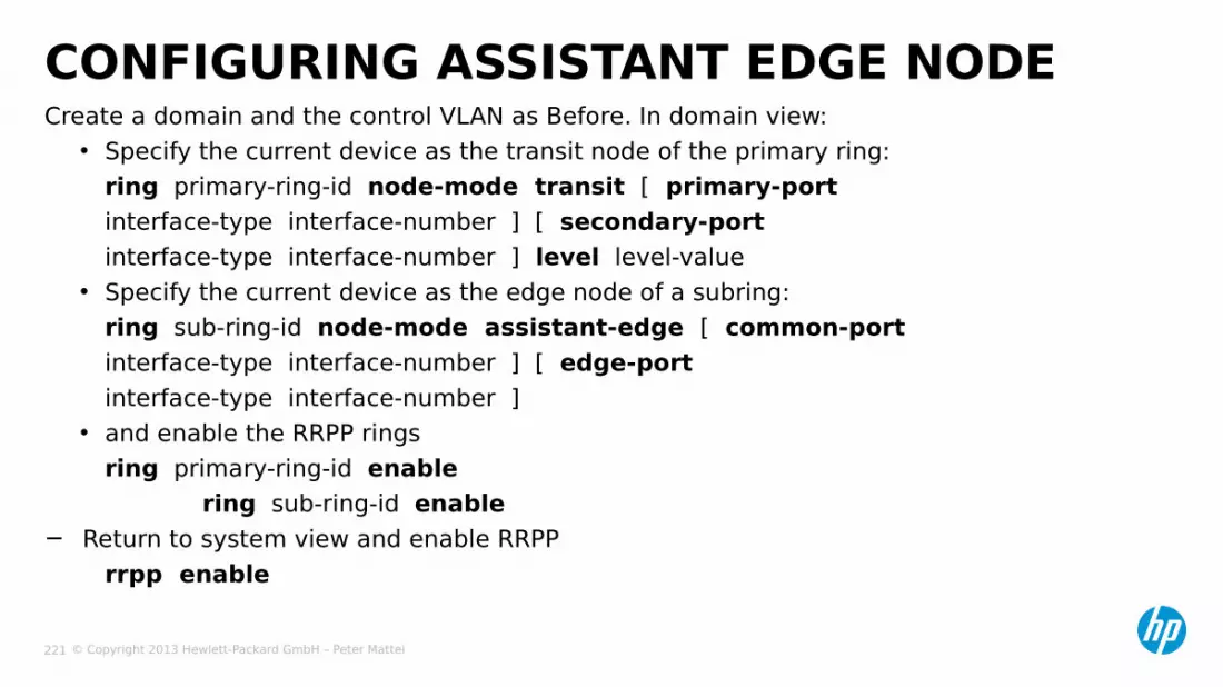
© Copyright 2013 Hewlett-Packard GmbH – Peter Mattei 221
Create a domain and the control VLAN as Before. In domain view:• Specify the current device as the transit node of the primary ring:
ring primary-ring-id node-mode transit [ primary-port interface-type interface-number ] [ secondary-port interface-type interface-number ] level level-value
• Specify the current device as the edge node of a subring:ring sub-ring-id node-mode assistant-edge [ common-port interface-type interface-number ] [ edge-port interface-type interface-number ]
• and enable the RRPP ringsring primary-ring-id enable
ring sub-ring-id enable− Return to system view and enable RRPP
rrpp enable
CONFIGURING ASSISTANT EDGE NODE

© Copyright 2013 Hewlett-Packard GmbH – Peter Mattei 222
− Display brief information about RRPP configurationdisplay rrpp brief
− Display detailed information about RRPP configurationdisplay rrpp verbose domain domain-id [ ring ring-id ]
− Display RRPP statisticsdisplay rrpp statistics domain domain-id [ ring ring-id ]
− Clear RRPP statisticsreset rrpp statistics domain domain-id [ ring ring-id ]
DISPLAYING AND MAINTAINING RRPP
© Copyright 2013 Hewlett-Packard GmbH – Peter Mattei 223
IPv4 SERVICES
© Copyright 2013 Hewlett-Packard GmbH – Peter Mattei 224
− IPv4 Interfaces− DHCP
IPv4 SERVICES

© Copyright 2013 Hewlett-Packard GmbH – Peter Mattei 225
IPv4 INTERFACES
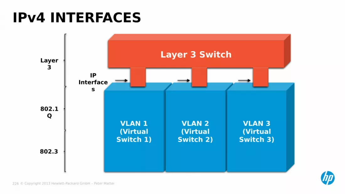
© Copyright 2013 Hewlett-Packard GmbH – Peter Mattei 226
IPv4 INTERFACES
VLAN 1(Virtual
Switch 1)
VLAN 2(Virtual
Switch 2)
VLAN 3(Virtual
Switch 3)
Layer 3 Switch
IP Interface
s
802.1Q
Layer 3
802.3

© Copyright 2013 Hewlett-Packard GmbH – Peter Mattei 227
− Enter the VLAN interface view• interface vlan [vid]
[switch] interface vlan 1
− Configure an IP Address• ip address address [mask / mask-lenght]
[switch-vlan1] ip address 192.168.1.1 255.255.255.0• or
[switch-vlan1] ip address 192.168.1.1 24
− Or enable the DHCP client• ip address dhcp-alloc
[switch-vlan1] ip address dhcp-alloc
CONFIGURING IPv4 INTERFACES

© Copyright 2013 Hewlett-Packard GmbH – Peter Mattei 228
DHCP
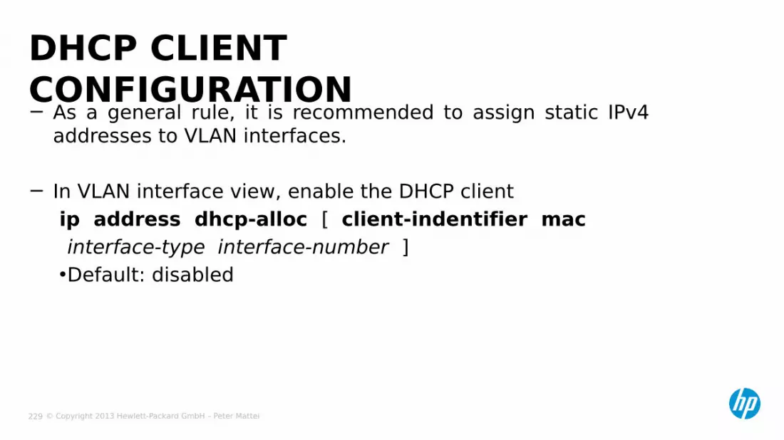
© Copyright 2013 Hewlett-Packard GmbH – Peter Mattei 229
− As a general rule, it is recommended to assign static IPv4 addresses to VLAN interfaces.
− In VLAN interface view, enable the DHCP clientip address dhcp-alloc [ client-indentifier macinterface-type interface-number ]•Default: disabled
DHCP CLIENT CONFIGURATION

© Copyright 2013 Hewlett-Packard GmbH – Peter Mattei 230
− In system view, enable DHCPdhcp enable
− Exclude IP addresses from dynamic allocationdhcp server forbidden-ip low-ip-address [ high-ip-address ]
− In VLAN interface view, enable the DHCP serverdhcp select server global-pool [ subaddress ]
Address Pools− In system view, create an address pool (for dynamic allocation)
dhcp server ip-pool pool-name− In DHCP address pool view, specify an IP address range
network ip-address [ mask-lenght | mask mask ]
CONFIGURING DHCP SERVER

© Copyright 2013 Hewlett-Packard GmbH – Peter Mattei 231
− In DHCP address pool view, specify• and the Default Gateway for the clients
gateway-list ip-address&<1-8>• a domain name suffix for the client
domain-name domain-name• a DNS server list for the clients
dns-list ip-address&<1-8>• option 184 parameters
voice-config ncp-ip ip-addressvoice-config voice-vlan vlan-id { disabled | enable }
Note: ip-address&<1-8>: DNS server IP address, &<1-8> means you can specify up to eight DNS server address separated by spaces.
CONFIGURING DHCP SERVER (2)

© Copyright 2013 Hewlett-Packard GmbH – Peter Mattei 232
−In system view, enable DHCPdhcp enable• and create a DHCP server group and add a server into the group
dhcp relay server-group group-id ip ip-address
−In VLAN interface view, enable the DHCP relay agentdhcp select relay• and correlate the DHCP server group with the current interface
dhcp relay server-select group-id
CONFIGURING DHCP RELAY AGENTDHCP
Clients
DHCP Relay Agent
DHCP Server
IP Network
© Copyright 2013 Hewlett-Packard GmbH – Peter Mattei 233
IPV4 ROUTING
© Copyright 2013 Hewlett-Packard GmbH – Peter Mattei 234
−Static Routes (and Default Route)−OSPF−VRRP−BFD: Bidirectional Forwarding
Detection
IPV4 ROUTING
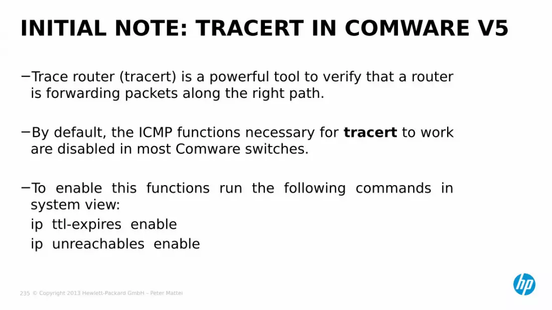
© Copyright 2013 Hewlett-Packard GmbH – Peter Mattei 235
−Trace router (tracert) is a powerful tool to verify that a router is forwarding packets along the right path.
−By default, the ICMP functions necessary for tracert to work are disabled in most Comware switches.
−To enable this functions run the following commands in system view:ip ttl-expires enableip unreachables enable
INITIAL NOTE: TRACERT IN COMWARE V5

© Copyright 2013 Hewlett-Packard GmbH – Peter Mattei 236
STATIC ROUTES
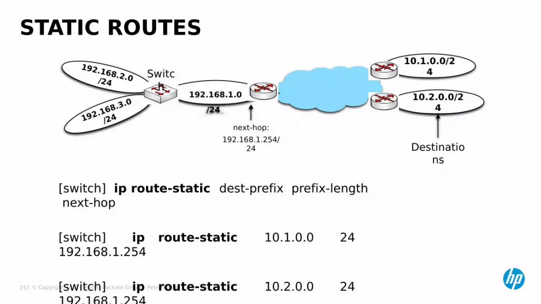
© Copyright 2013 Hewlett-Packard GmbH – Peter Mattei 237
192.168.2.0/24
192.168.3.0
/24
192.168.1.0/24.
10.2.0.0/24
[switch] ip route-static dest-prefix prefix-length next-hop
[switch] ip route-static 10.1.0.0 24 192.168.1.254
[switch] ip route-static 10.2.0.0 24 192.168.1.254
STATIC ROUTES10.1.0.0/2
4Switch
next-hop:192.168.1.254/
24 Destinations
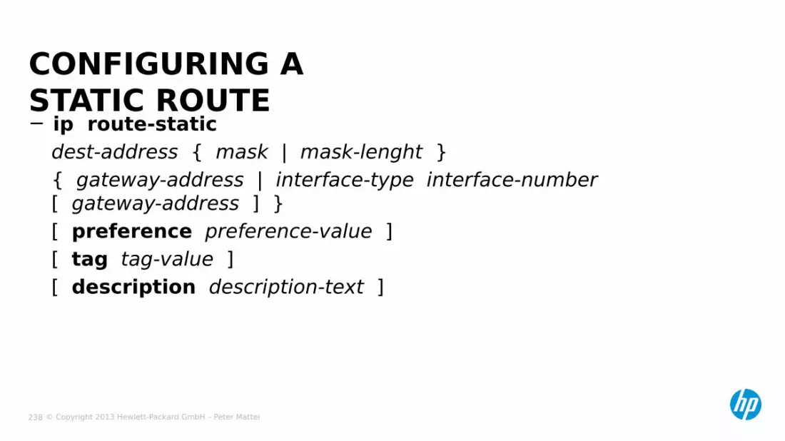
© Copyright 2013 Hewlett-Packard GmbH – Peter Mattei 238
− ip route-staticdest-address { mask | mask-lenght }{ gateway-address | interface-type interface-number [ gateway-address ] }[ preference preference-value ][ tag tag-value ][ description description-text ]
CONFIGURING A STATIC ROUTE
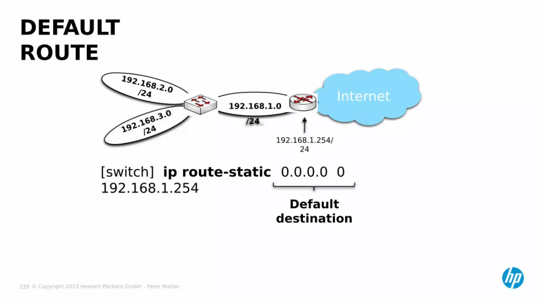
© Copyright 2013 Hewlett-Packard GmbH – Peter Mattei 239
[switch] ip route-static 0.0.0.0 0 192.168.1.254
DEFAULT ROUTE
192.168.2.0/24
192.168.3.0
/24
192.168.1.0/24.
Internet
192.168.1.254/24
Default destination

© Copyright 2013 Hewlett-Packard GmbH – Peter Mattei 240
OSPF

© Copyright 2013 Hewlett-Packard GmbH – Peter Mattei 241
− Elements• Autonomuos System and ASBR• Area and ABR• Transit Areas and Virtual Links• Neighboring Routers, Adjacency and Designated Router
CONFIGURING OSPF

© Copyright 2013 Hewlett-Packard GmbH – Peter Mattei 242
−Autonomous System• “A group of routers exchanging routing information via a
common routing protocol” (RFC 2328).• Abbreviated as AS
−OSPF is an Intro-Autonomous System routing protocol−ASBR: Autonomous System Boundary Router• Communicates an OSPF AS to other Ass• The other Ass can be
−networks managed by the same enfity but running other Routing Protocols (including Static Routes, RIP, IS-IS), or
−network managed by other entities like ISPs, NSPs, etc.−Routing information between Ass can be exchanged using an
Inter-Autonomous System routing protocol like BGP.
AUTONOMOUS SYSTEMS AND ASBR
© Copyright 2013 Hewlett-Packard GmbH – Peter Mattei 243
− Area• “OSPF allows sets of networks to be grouped together.
Such a grouping is called an area.”• Area identifiers: w.x.y.z
− ABR: Area Border Router• A router that attaches to multiple areas
− Backbone Area• Area 0.0.0.0 (or simply Area 0)
− Backbone Routers• All ABRs are backbone routers• Additionally, there can be:
− Routers with all their interfaces connected to the backbone
− ASBRs connected only to the backbone
AREAS AND ABRS
© Copyright 2013 Hewlett-Packard GmbH – Peter Mattei 244
− The backbone needs to be contiguous:• All ABRs need to be connected to the backbone• But the connection does not need to be physical
− Virtual Link• A virtual link is established between two are Border routers
via a non-backbone area and is configured on both ABRs to take effect.
− Transit Area• The area that provides the non-backbone area internal
route for the virtual link is a “transit area”.
TRANSIT AREAS AND VIRTUAL LINKS
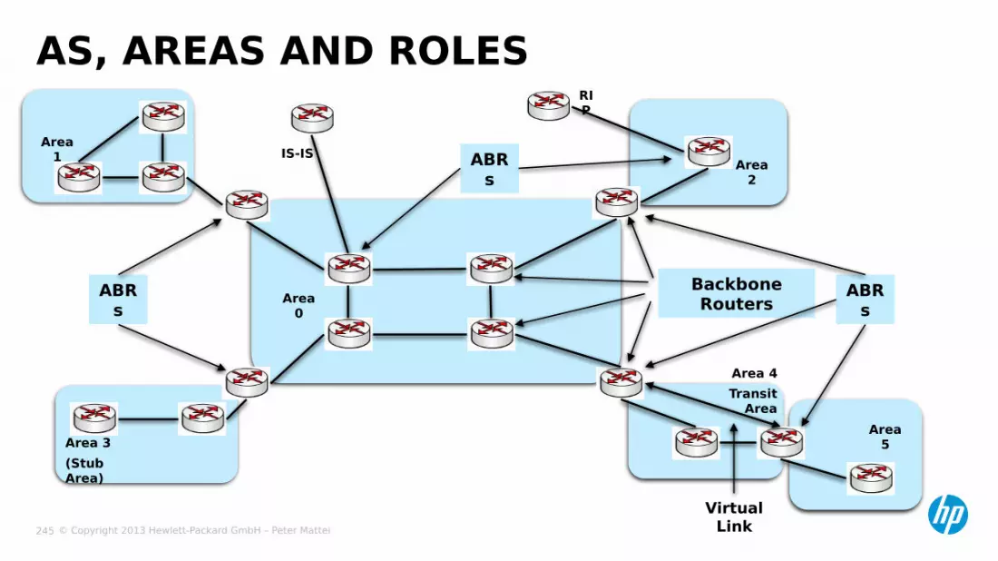
© Copyright 2013 Hewlett-Packard GmbH – Peter Mattei 245
AS, AREAS AND ROLES
Backbone Routers
ABRs
ABRs
ABRs
Virtual Link
Area 4Transit
AreaArea
5
Area 2
Area 1
Area 3(Stub Area)
Area 0
RIP
IS-IS
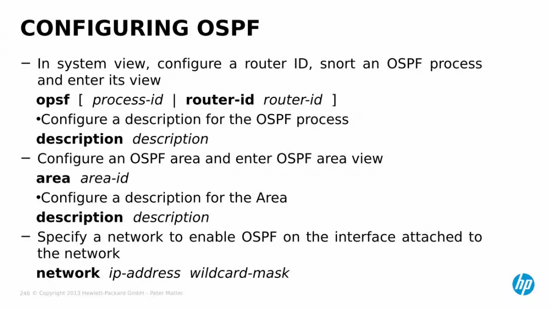
© Copyright 2013 Hewlett-Packard GmbH – Peter Mattei 246
− In system view, configure a router ID, snort an OSPF process and enter its viewopsf [ process-id | router-id router-id ]•Configure a description for the OSPF processdescription description
− Configure an OSPF area and enter OSPF area viewarea area-id•Configure a description for the Areadescription description
− Specify a network to enable OSPF on the interface attached to the networknetwork ip-address wildcard-mask
CONFIGURING OSPF

© Copyright 2013 Hewlett-Packard GmbH – Peter Mattei 247
− In area view, if necessary configure• a cost for the default route advertised to the sub or NSSA area
default-cost cost• a virtual link
vlink-peer router-id
CONFIGURING AREA PARAMETERS

© Copyright 2013 Hewlett-Packard GmbH – Peter Mattei 248
− In VLAN interface view, configure OSPF costospf cost value• The cost value defaults to 1 for VLAN interfaces
− In OSPF process view, configure the máximum number of OSPF routesmaximum-routes { external | inter | intra } number• and/or the maximum number of equivalent load-balanced
routesmaximum load-balancing maximum• and the priority for OSPFpreference [ ase ] [ route-policy route-policy-name ] value
CONFIGURING OTHER OSPF PARAMETERS
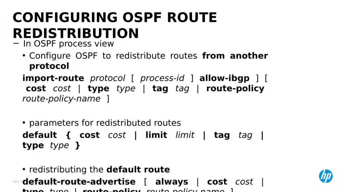
© Copyright 2013 Hewlett-Packard GmbH – Peter Mattei 249
− In OSPF process view• Configure OSPF to redistribute routes from another
protocolimport-route protocol [ process-id ] allow-ibgp ] [ cost cost | type type | tag tag | route-policy route-policy-name ]
• parameters for redistributed routesdefault { cost cost | limit limit | tag tag | type type }
• redistributing the default routedefault-route-advertise [ always | cost cost | type type | route-policy route-policy-name ]
CONFIGURING OSPF ROUTE REDISTRIBUTION
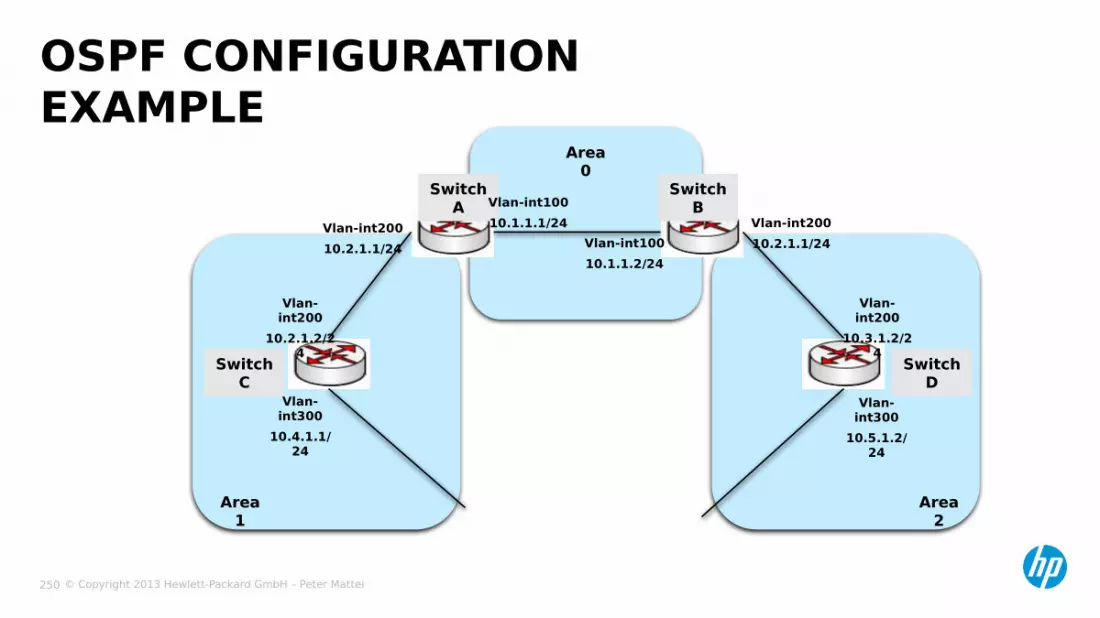
© Copyright 2013 Hewlett-Packard GmbH – Peter Mattei 250
OSPF CONFIGURATION EXAMPLE
Area 1
Area 0
Area 2
Switch A
Switch B
Switch C
Switch D
Vlan-int300
10.4.1.1/24
Vlan-int200
10.2.1.2/24
Vlan-int20010.2.1.1/24
Vlan-int10010.1.1.1/24
Vlan-int10010.1.1.2/24
Vlan-int20010.2.1.1/24
Vlan-int200
10.3.1.2/24
Vlan-int300
10.5.1.2/24

© Copyright 2013 Hewlett-Packard GmbH – Peter Mattei 251
− Switch A[SwitchA] ospf [SwitchA-ospf-1] area 0 [SwitchA-ospf-1-area-0.0.0.0] network 10.1.1.0 0.0.0.255 [SwitchA-ospf-1-area-0.0.0.0] quit [SwitchA-ospf-1] area 1 [SwitchA-ospf-1-area-0.0.0.1] network 10.2.1.0 0.0.0.255 [SwitchA-ospf-1-area-0.0.0.1] quit [SwitchA-ospf-1] quit
− Switch B•similar to Switch A•with: area 0 > network: 10.1.1.0 0.0.0.255•and: area 2 > network: 10.3.1.0 0.0.0.255
OSPF CONFIGURATION EXAMPLE (2)

© Copyright 2013 Hewlett-Packard GmbH – Peter Mattei 252
− Switch C[SwitchC] ospf[SwitchC-ospf-1] area 1[SwitchC-ospf-1-area-0.0.0.1] network 10.2.1.0 0.0.0.255[SwitchC-ospf-1-area-0.0.0.1] network 10.4.1.0 0.0.0.255[SwitchC-ospf-1-area-0.0.0.1] quit[SwitchC-ospf-1] quit
− Switch D• similar to Switch A• with: area 2 >
−network: 10.3.1.0 0.0.0.255 and−network: 10.5.1.0 0.0.0.255
OSPF CONFIGURATION EXAMPLE (3)
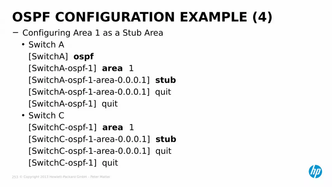
© Copyright 2013 Hewlett-Packard GmbH – Peter Mattei 253
− Configuring Area 1 as a Stub Area• Switch A
[SwitchA] ospf[SwitchA-ospf-1] area 1[SwitchA-ospf-1-area-0.0.0.1] stub[SwitchA-ospf-1-area-0.0.0.1] quit[SwitchA-ospf-1] quit
• Switch C[SwitchC-ospf-1] area 1[SwitchC-ospf-1-area-0.0.0.1] stub[SwitchC-ospf-1-area-0.0.0.1] quit[SwitchC-ospf-1] quit
OSPF CONFIGURATION EXAMPLE (4)

© Copyright 2013 Hewlett-Packard GmbH – Peter Mattei 254
VRRP
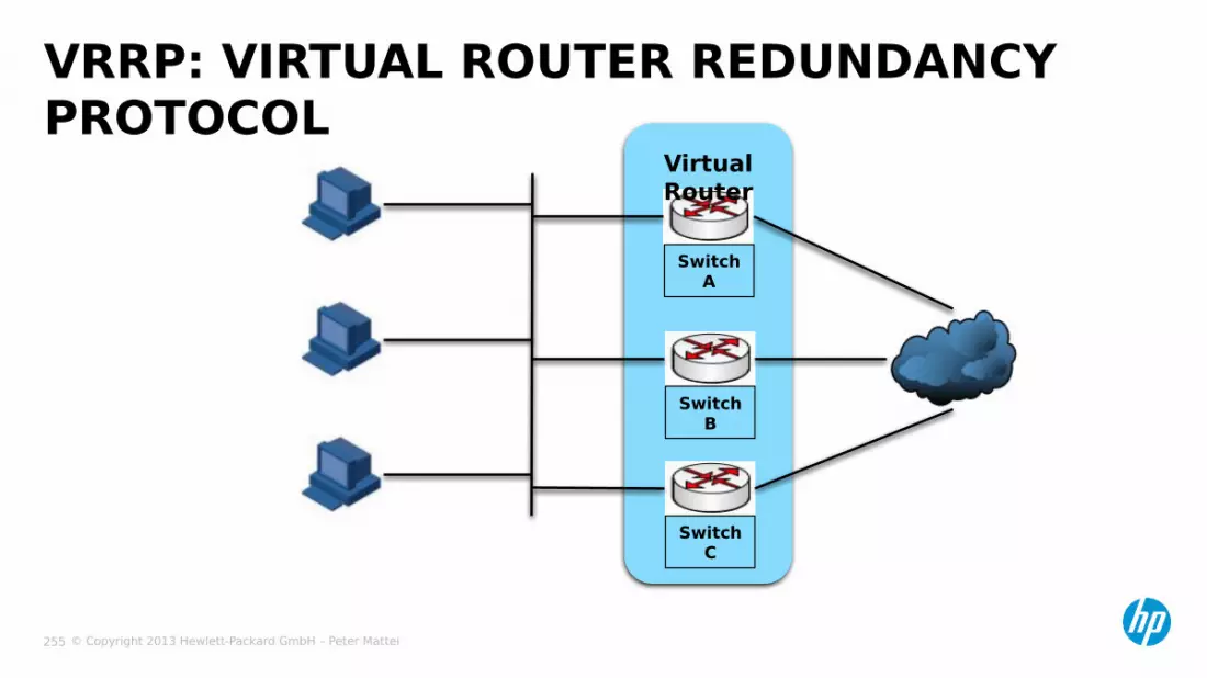
© Copyright 2013 Hewlett-Packard GmbH – Peter Mattei 255
VRRP: VIRTUAL ROUTER REDUNDANCY PROTOCOL
Virtual Router
Switch A
Switch B
Switch C

© Copyright 2013 Hewlett-Packard GmbH – Peter Mattei 256
− VRRP priority• Range: 0-255 (0 and 255 are not configurable)• If a router is the IP address owner: its priority
becomes 255− Working mode• Preemptive• Non-preemptive
− Authentication mode• simple• md5
VRRP PARAMETERS

© Copyright 2013 Hewlett-Packard GmbH – Peter Mattei 257
MASTER / BACKUP Virtual
RouterSwitch A
Master
Switch B
Backup
Switch C
Backup
Virtual IPaddress10.1.1.1/24
Host A
Host B
Host C
10.1.1.2/24
10.1.1.3/24
10.1.1.4/24

© Copyright 2013 Hewlett-Packard GmbH – Peter Mattei 258
LOAD BALANCINGVirtual Router
2
Switch A
Backup
Host A
Host B
Host C
Master
Master
Backup
Backup
Backup
Master
Backup
Backup
Virtual Router
3
Virtual Router
1
Switch B
Switch C
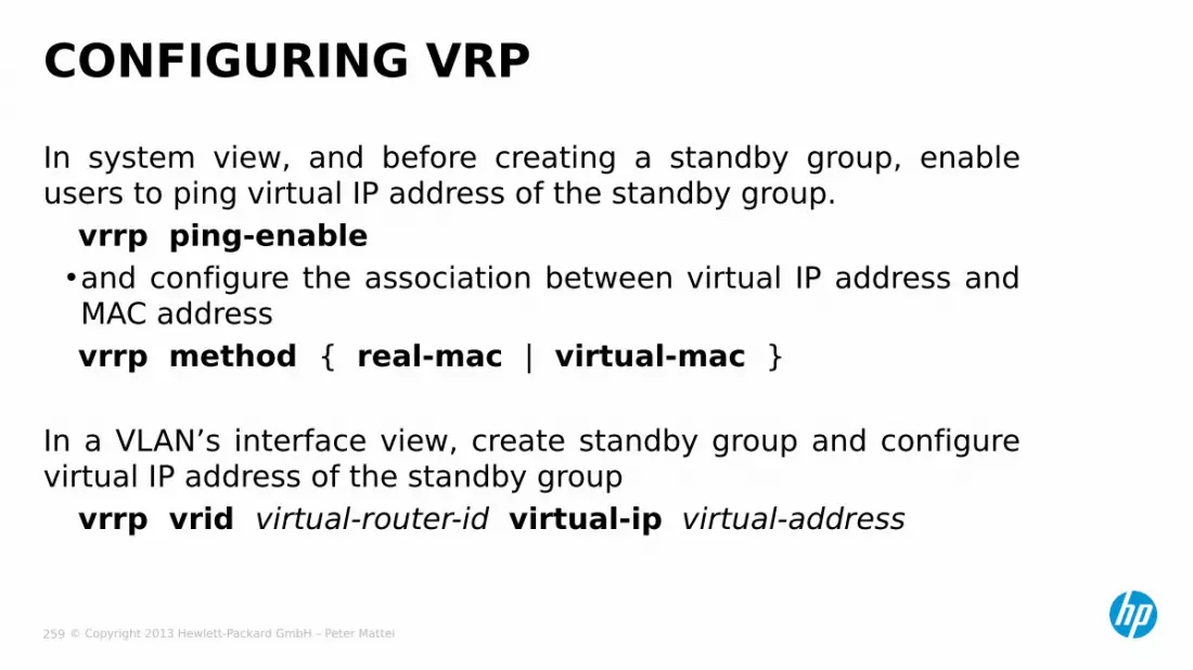
© Copyright 2013 Hewlett-Packard GmbH – Peter Mattei 259
In system view, and before creating a standby group, enable users to ping virtual IP address of the standby group.
vrrp ping-enable•and configure the association between virtual IP address and MAC address vrrp method { real-mac | virtual-mac }
In a VLAN’s interface view, create standby group and configure virtual IP address of the standby group
vrrp vrid virtual-router-id virtual-ip virtual-address
CONFIGURING VRP

© Copyright 2013 Hewlett-Packard GmbH – Peter Mattei 260
−In a VLAN’s interface view,• configure switch priority in the standby group
vrrp vrid virtual-router-id priority priority-value• and configure the switch in the standby group to work in
preemption mode and configure preemption delayvrrp vrid virtual-router-id preempt-mode [ timer delay delay-value ]
• configure the interface to be trackedvrrp vrid virtual-router-id track interface interface-type interface-number [ reduced priority-reduced ]
• configure the authentication mode and authentication key when the standby groups send and receive VRRP packetsvrrp vrid virtual-router-id authentication-mode { md5 | simple } key
CONFIGURING VRRP (2)

© Copyright 2013 Hewlett-Packard GmbH – Peter Mattei 261
BFD: BIDIRECTIONAL FORWARDING
DETECTION

© Copyright 2013 Hewlett-Packard GmbH – Peter Mattei 262
− Bidirectional forwarding Detection (BFD) provides a single mechanism to quickly detect and monitor the connectivity of links in networks.
− To improve network performance, protocols on adjacent devices must quickly detect communication failures to restore the communication through backup paths as soon as possible.
− BFD reduce the failure detection times from the order of a second to the order of tens of milliseconds.
BFD

© Copyright 2013 Hewlett-Packard GmbH – Peter Mattei 263
− BFD provides the following authentication methods:
• Simple: Plain text authentication
• MD5: MD5 (Message Digest 5) authentication
• SHA1: SHA1 (Secure Hash Algorithm 1) authentication
BFD AUTHENTICATION METHODS
© Copyright 2013 Hewlett-Packard GmbH – Peter Mattei 264
− Before a BFD sesión is established, there are two BFD operating modes:• Active mode:
• Passive mode:
−At least one end must opérate in the active mode for a BFD sesión to be established.
BFD SESSION ESTABLISHMENTOPERATION MODES
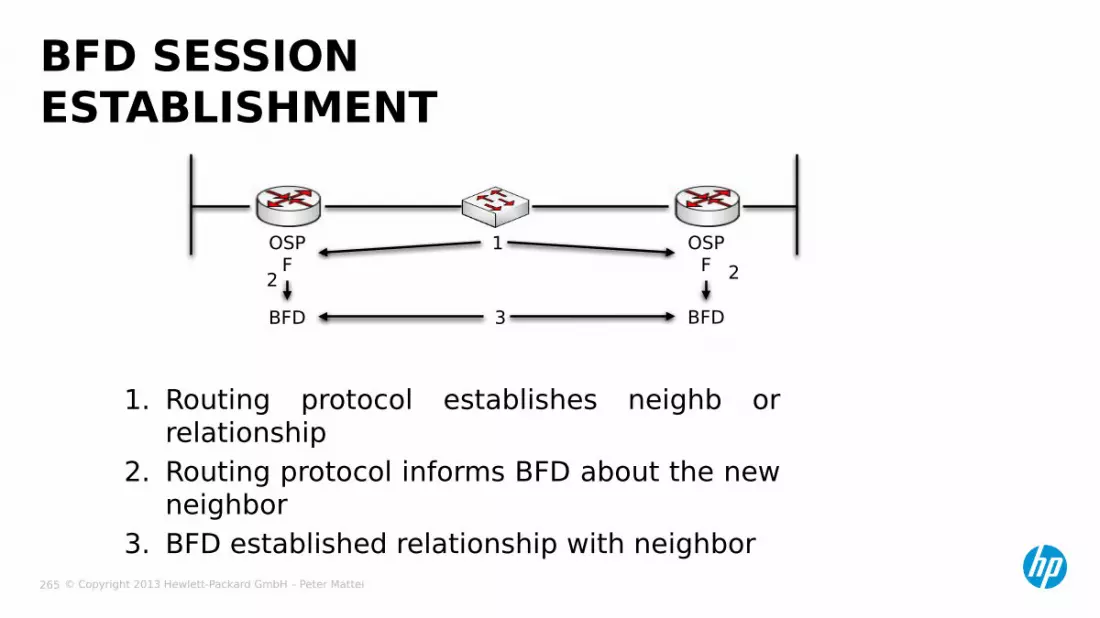
© Copyright 2013 Hewlett-Packard GmbH – Peter Mattei 265
1. Routing protocol establishes neighb or relationship
2. Routing protocol informs BFD about the new neighbor
3. BFD established relationship with neighbor
BFD SESSION ESTABLISHMENT
OSPF
BFD
OSPF
BFD2 2
1
3

© Copyright 2013 Hewlett-Packard GmbH – Peter Mattei 266
− Single-hop Detection:• Detects the IP connectivity between two directly connected
systems.• Single hop means one hop for IP forwarding.
− Multi-hop detection:• Detects any of the paths between two systems.• These paths may have multiple hops and maybe
overlapped.
− Bidirectional detection:• Sends Detection packets at two sides of a bidirectional link
to detected the bidirectional link status, thus to implement a link fault Detection rate in milliseconds.
BFD DETECTION MODES

© Copyright 2013 Hewlett-Packard GmbH – Peter Mattei 267
− Control Packet Mode:• Both ends of the link Exchange BFD control packets to monitor
link status.
BFD SESSION MODES
− Echo Mode:• One end of the link sends Echo packets to the other end,
which then forwards these packets back to the originating end, thereby monitoring link status in both directions.
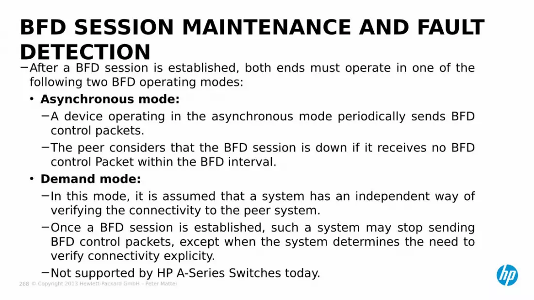
© Copyright 2013 Hewlett-Packard GmbH – Peter Mattei 268
−After a BFD session is established, both ends must operate in one of the following two BFD operating modes:• Asynchronous mode:
−A device operating in the asynchronous mode periodically sends BFD control packets.
−The peer considers that the BFD session is down if it receives no BFD control Packet within the BFD interval.
• Demand mode:−In this mode, it is assumed that a system has an independent way of
verifying the connectivity to the peer system.−Once a BFD session is established, such a system may stop sending
BFD control packets, except when the system determines the need to verify connectivity explicity.
−Not supported by HP A-Series Switches today.
BFD SESSION MAINTENANCE AND FAULT DETECTION
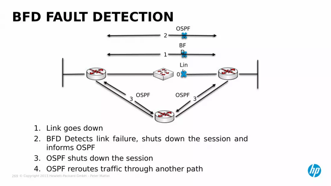
© Copyright 2013 Hewlett-Packard GmbH – Peter Mattei 269
1. Link goes down2. BFD Detects link failure, shuts down the session and
informs OSPF3. OSPF shuts down the session4. OSPF reroutes traffic through another path
BFD FAULT DETECTION
3 3
0
OSPFOSPF
Link
OSPF
BFD1
2

© Copyright 2013 Hewlett-Packard GmbH – Peter Mattei 270
BFD AND OSPF CONFIGURATION EXAMPLE
Layer 2
Switch
OSPF Area 0
Switch A
Switch B
BFD Vlan-Int 10
10.1.0.100/24
Vlan-Int 1010.1.0.102/
24
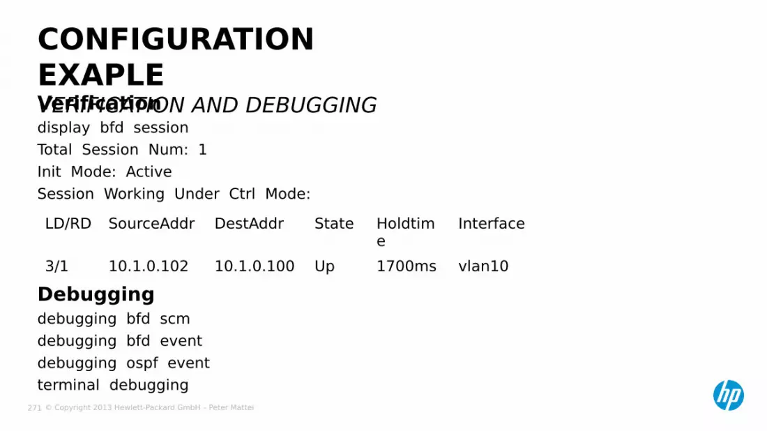
© Copyright 2013 Hewlett-Packard GmbH – Peter Mattei 271
Verification display bfd sessionTotal Session Num: 1Init Mode: ActiveSession Working Under Ctrl Mode:
CONFIGURATION EXAPLEVERIFICATION AND DEBUGGING
Debuggingdebugging bfd scmdebugging bfd eventdebugging ospf eventterminal debugging
LD/RD SourceAddr DestAddr State Holdtime
Interface
3/1 10.1.0.102 10.1.0.100 Up 1700ms vlan10

© Copyright 2013 Hewlett-Packard GmbH – Peter Mattei 272
Switch Aospf area 0 network 10.1.0.0 quit quitinterface vlan 10 ospf bfd enable quit
CONFIGURATION EXAMPLECONFIGURE OSPF BASIC FUNCTIONS
Switch Bospf area 0 network 10.1.0.0 quit quitinterface vlan 10 ospf bfd enable quit

© Copyright 2013 Hewlett-Packard GmbH – Peter Mattei 273
− Switch A and B
bfd session init-mode activeinterface vlan-interface 10
bfd min-transmit-interval 500bfd min-receive-interval 500bfd detect-multiplier 7quit
CONFIGURATION EXAMPLECONFIGURE BFD PARAMETERS
© Copyright 2013 Hewlett-Packard GmbH – Peter Mattei 274
IPv4 MULTICAST
© Copyright 2013 Hewlett-Packard GmbH – Peter Mattei 275
− Multicast Overview− IGMPv2• IGMP Query
− Layer 2 Multicast Management• IGMP Snooping• Multicast VLAN
− PIM-DM
MULTICAST

© Copyright 2013 Hewlett-Packard GmbH – Peter Mattei 276
MULTICASTOVERVIEW

© Copyright 2013 Hewlett-Packard GmbH – Peter Mattei 277
− IP Multicasting:• Enables simultaneous delivery of information to many
receivers in the most efficient, logical way.• Reduces load on source, because it does not have to
produce multiple copies of the same data.• Makes efficient use of network bandwidth and scales well as
number of participants expands.• Works in concert with QoS and RSVP to support real-time
multimedia.
IP MULTICAST TECHNOLOGY

© Copyright 2013 Hewlett-Packard GmbH – Peter Mattei 278
− Multicast IP address ranges:• Class D address: Reserved for multicast• Range: 224.0.0.0 – 239.255.255.255• Reserved address
− All host address on this subnet: 224.0.0.1
− All router address on this subnet: 224.0.0.2
− Simple Network Time Protocol: 224.0.1.1
− RIP-2: 224.0.0.9− OSPF: 224.0.0.5/224.0.0.6
MULTICAST IP ADDRESSES

© Copyright 2013 Hewlett-Packard GmbH – Peter Mattei 279
MULTICAST FLOW
IP Network
Server orMulticast Sender: S
Possible Clients orMulticast Receivers

© Copyright 2013 Hewlett-Packard GmbH – Peter Mattei 280
IGMPV3

© Copyright 2013 Hewlett-Packard GmbH – Peter Mattei 281
− Runs on routers (and Layer 3 Switches)
− Manages the multicast distribution within an IPv4 subnet between• IPv4 routers connected to that
subnet• IPv4 hosts within that subnet
− Goal: to decide if a certain (*,G) traffic needs to be forwarded into the subnet or not.
IGMPV3: INTERNET GROUP MANAGEMENT PROTOCOL
(S,G) traffic
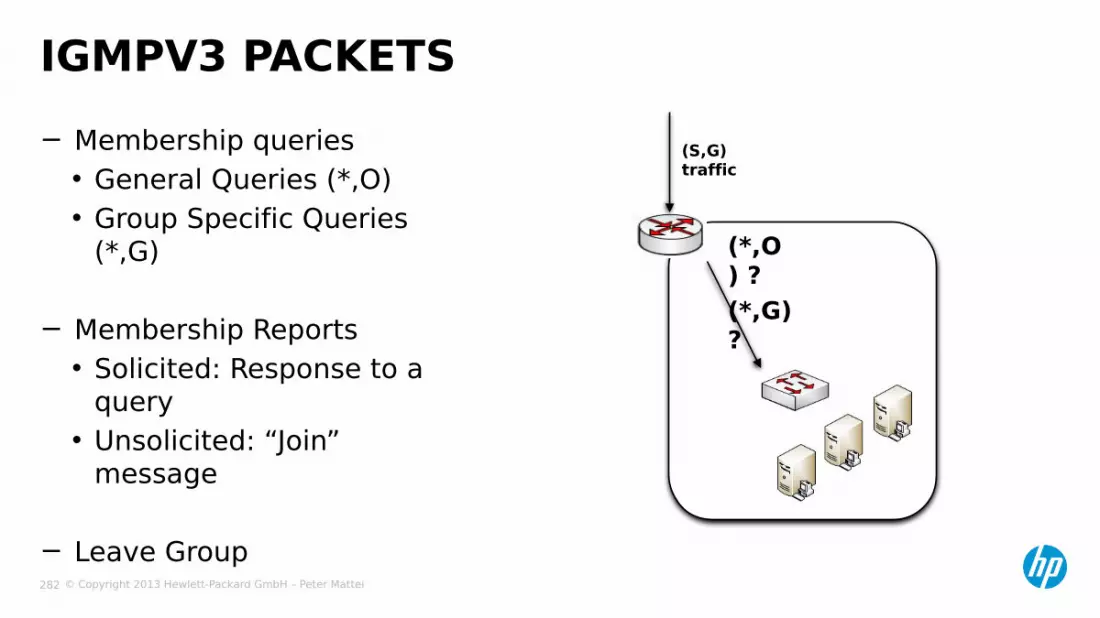
© Copyright 2013 Hewlett-Packard GmbH – Peter Mattei 282
− Membership queries• General Queries (*,O)• Group Specific Queries
(*,G)
− Membership Reports• Solicited: Response to a
query• Unsolicited: “Join”
message
− Leave Group
IGMPV3 PACKETS
(S,G) traffic
(*,O) ?(*,G) ?

© Copyright 2013 Hewlett-Packard GmbH – Peter Mattei 283
− If two or more IGMP routers are attached to the same network, only one of them can be the querier.
− The router with the lowest host IP address on the subnet will automatically become the querier.
− Same authors call the querier in this situation the “Designated Router.”
MULTIPLE ROUTERS(S,G) traffic
(*,*)X
?
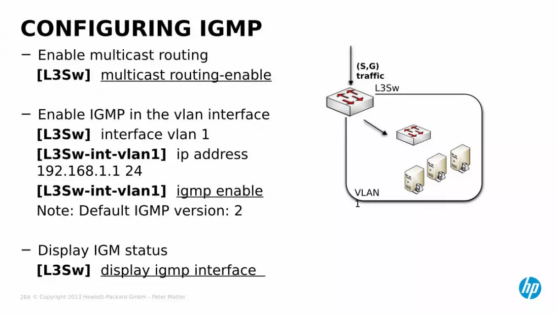
© Copyright 2013 Hewlett-Packard GmbH – Peter Mattei 284
− Enable multicast routing[L3Sw] multicast routing-enable
− Enable IGMP in the vlan interface[L3Sw] interface vlan 1[L3Sw-int-vlan1] ip address 192.168.1.1 24[L3Sw-int-vlan1] igmp enableNote: Default IGMP version: 2
− Display IGM status[L3Sw] display igmp interface
CONFIGURING IGMP(S,G) traffic
L3Sw
VLAN 1

© Copyright 2013 Hewlett-Packard GmbH – Peter Mattei 285
IGMP SNOOPING

© Copyright 2013 Hewlett-Packard GmbH – Peter Mattei 286
− Layer 2 multicast filtering technology
IGMP SNOOPING
L25W
?? ?
L35W

© Copyright 2013 Hewlett-Packard GmbH – Peter Mattei 287
Router Port Member Port
Multicast Traffic
IGMP SNOOPING RELATED PORTS
IP
Multicast
Sender(S)
Layer 3 Switch IGMP
Querier
IGMPSnoopin
g
IGMPSnoopin
g
IGMPSnoopin
g

© Copyright 2013 Hewlett-Packard GmbH – Peter Mattei 288
− Queries• Flood = forward through all ports except for
the receiving port (treat as a broadcast)− Membership reports• Forward through the router port• Update the multicast forwarding table
− Leave Message (group-specific)• Send a group-specific query through the
receiving port to verify if there are other group members
• If no Report is received back− update the multicast forwarding table− if there are no other group members
connected• forward the leave message through the
router port
IGMP SNOOPING MECHANISM
L25W
?? ?
L35W
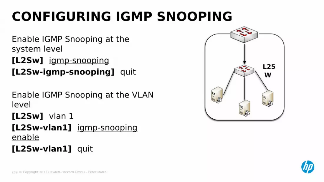
© Copyright 2013 Hewlett-Packard GmbH – Peter Mattei 289
Enable IGMP Snooping at the system level[L2Sw] igmp-snooping[L2Sw-igmp-snooping] quit
Enable IGMP Snooping at the VLAN level[L2Sw] vlan 1[L2Sw-vlan1] igmp-snooping enable[L2Sw-vlan1] quit
CONFIGURING IGMP SNOOPING
L25W

© Copyright 2013 Hewlett-Packard GmbH – Peter Mattei 290
MULTICAST VLAN

© Copyright 2013 Hewlett-Packard GmbH – Peter Mattei 291
c
Multicast packet transmission without
Multicast VLAN
MULTICAST VLAN
1 copySourc
eSourc
e
Switch ALayer 3
Switch ALayer 3
3 copy
Switch BLayer 2
Switch BLayer 2
Host AReceiv
erVLAN
10
Host BReceiv
erVLAN
20
Host CReceiv
erVLAN
30
Host AReceiv
erVLAN
10
Host BReceiv
erVLAN
20
Host CReceiv
erVLAN
30
Multicast packet transmission when Multicast
VLAN in configured
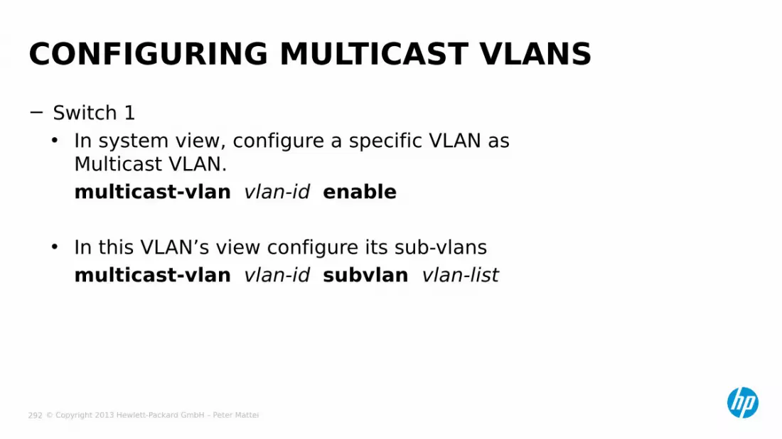
© Copyright 2013 Hewlett-Packard GmbH – Peter Mattei 292
− Switch 1• In system view, configure a specific VLAN as
Multicast VLAN.multicast-vlan vlan-id enable
• In this VLAN’s view configure its sub-vlansmulticast-vlan vlan-id subvlan vlan-list
CONFIGURING MULTICAST VLANS

© Copyright 2013 Hewlett-Packard GmbH – Peter Mattei 293
PIM-DM
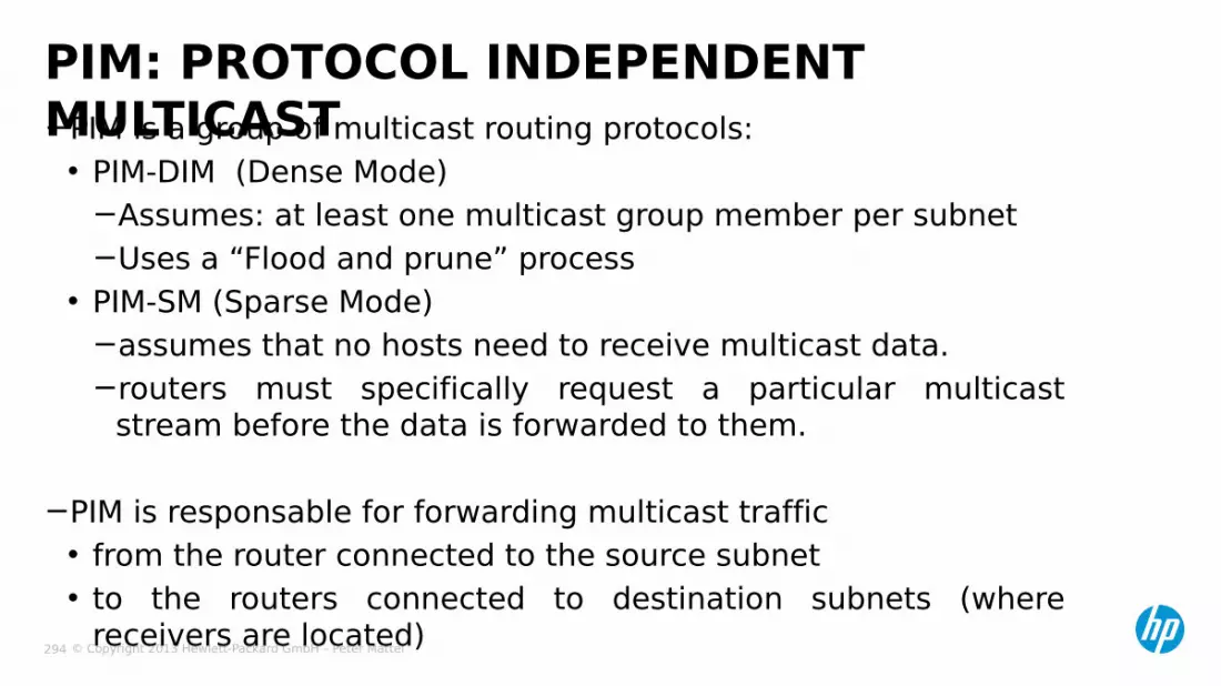
© Copyright 2013 Hewlett-Packard GmbH – Peter Mattei 294
−PIM is a group of multicast routing protocols:• PIM-DIM (Dense Mode)
−Assumes: at least one multicast group member per subnet−Uses a “Flood and prune” process
• PIM-SM (Sparse Mode)−assumes that no hosts need to receive multicast data.−routers must specifically request a particular multicast
stream before the data is forwarded to them.
−PIM is responsable for forwarding multicast traffic• from the router connected to the source subnet• to the routers connected to destination subnets (where
receivers are located)
PIM: PROTOCOL INDEPENDENT MULTICAST

© Copyright 2013 Hewlett-Packard GmbH – Peter Mattei 295
RPF: PREVENTING DUPLICATION
IP Network
Server orMulticast Sender: S
Router A
S0/0
S0/1
Unicast Routing Table
Dest. Interf.S S0/0
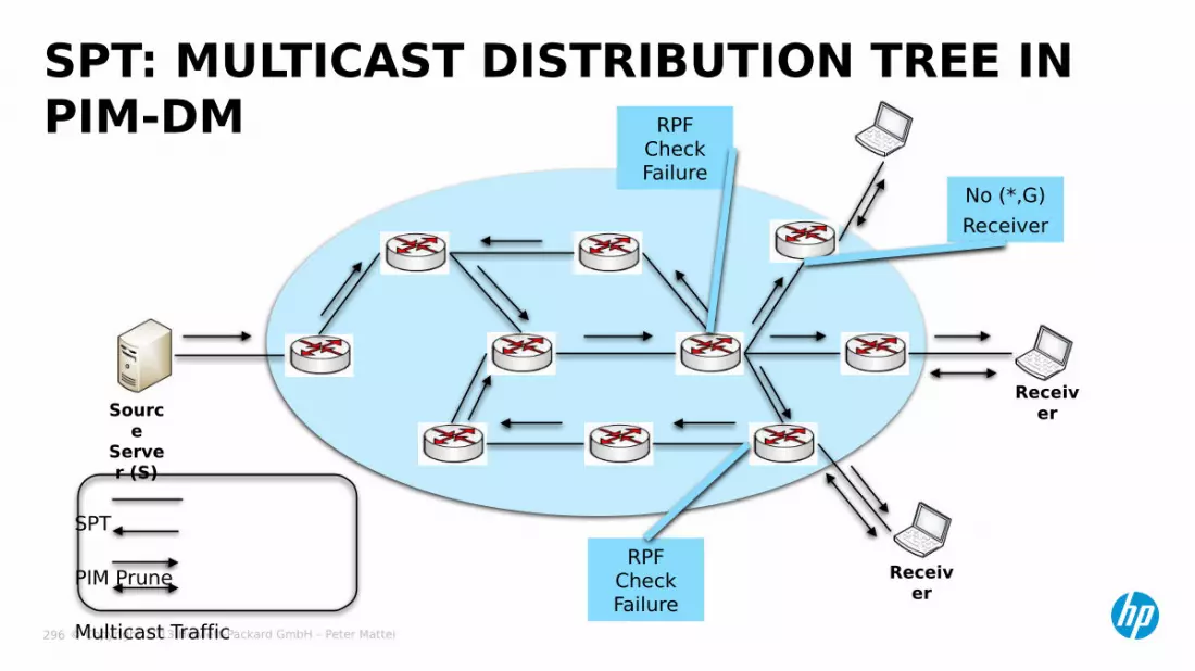
© Copyright 2013 Hewlett-Packard GmbH – Peter Mattei 296
SPT
PIM Prune
Multicast Traffic
IGMP
SPT: MULTICAST DISTRIBUTION TREE IN PIM-DM
Source
Server (S)
Receiver
Receiver
RPF Check Failure
No (*,G)Receiver
RPF Check Failure

© Copyright 2013 Hewlett-Packard GmbH – Peter Mattei 297
SPT: GRAFT
SPT
PIM Prune
Multicast Traffic
IGMP
Source
Server (S)
Receiver
Receiver
New Receiver
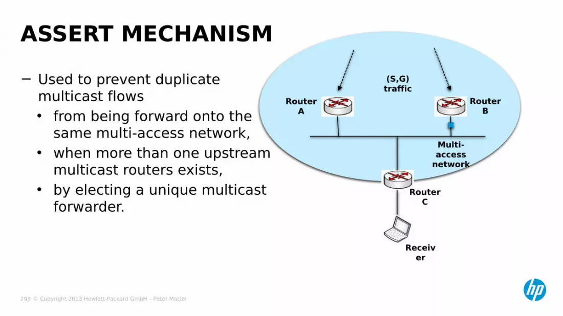
© Copyright 2013 Hewlett-Packard GmbH – Peter Mattei 298
− Used to prevent duplicate multicast flows• from being forward onto the
same multi-access network,• when more than one upstream
multicast routers exists,• by electing a unique multicast
forwarder.
ASSERT MECHANISM
Receiver
Router C
Router A
Router B
Multi-access
network
(S,G) traffic

© Copyright 2013 Hewlett-Packard GmbH – Peter Mattei 299
−Enable multicast routing globally[L3Sw] multicast routing-enable
−Enable PIM-DM on every L3 interface[L3Sw] int vlan 2[L3Sw-int-vlan 2] pim-dm[L3Sw-int-vlan 2] quit[L3Sw] int vlan 1[L3Sw-int-vlan 1] pim-dm• enable IGMP in the vlans where potential clients are located
[L3Sw-int-vlan 1] igmp enable[L3Sw-int-vlan 1] quit
CONFIGURING PIM-DM
VLAN 2
VLAN 1
L35w

© Copyright 2013 Hewlett-Packard GmbH – Peter Mattei 300
MULTICAST PROTOCOLS IN COMWARE V7

© Copyright 2013 Hewlett-Packard GmbH – Peter Mattei 301
− All Comware v7 Switches support:• IGMP v1, v2 and v3• PIM-DM, PIM-SM* and PIM-SSM*• MSDP*• MBGP*
(*) not convered in this course
MULTICAST PROTOCOLS IN COMWARE V7

© Copyright 2013 Hewlett-Packard GmbH – Peter Mattei 302
QUALITY OF SERVICE

© Copyright 2013 Hewlett-Packard GmbH – Peter Mattei 303
− Priority Mapping− Bandwith Management− Congestion (Egress Queue)
Management− Traffic Policies• Traffic Classifiers• Traffic Behaviors• Traffic Policies• QoS Policies Applications
QUALITY OF SERVICE

© Copyright 2013 Hewlett-Packard GmbH – Peter Mattei 304
PRIORITYMAPPING

© Copyright 2013 Hewlett-Packard GmbH – Peter Mattei 305
− Local precedence• is the precedence that the switch assigns to a packet and it is
corresponding to the number of an outbound queue on the port
• local precedence takes effect only on the local switch
− Drop precedence• Is a parameter that is referred to when dropping packets• The higher the drop precedence, the more likely a packet is
dropped
LOCAL AND DROP PRECEDENCE
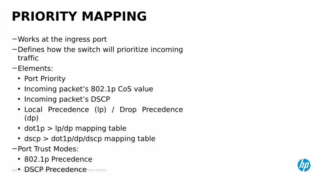
© Copyright 2013 Hewlett-Packard GmbH – Peter Mattei 306
−Works at the ingress port−Defines how the switch will prioritize incoming
traffic−Elements:• Port Priority• Incoming packet’s 802.1p CoS value• Incoming packet’s DSCP• Local Precedence (lp) / Drop Precedence
(dp)• dot1p > lp/dp mapping table• dscp > dot1p/dp/dscp mapping table
−Port Trust Modes:• 802.1p Precedence• DSCP Precedence
PRIORITY MAPPING

© Copyright 2013 Hewlett-Packard GmbH – Peter Mattei 307
• By default, applies to untagged incoming traffic as the basis for dot1p-lp/dp mapping.
− Configuration – in port or port group view:qos priority priority-valueRange: 0-7 / Default: 0
− Example[switch] interface ethernet 2/0/1[switch-Ethernet2/0/1] qos priority 7
PORT PRIORITY

© Copyright 2013 Hewlett-Packard GmbH – Peter Mattei 308
− 802.1p Precedence Trust Mode• It is the default mode• Tagged traffic > 802.1p CoS value• Untagged traffic > Port Priority value
− DSCP Precedence Trust Mode• In port or port group view enter
qos trust dscp
TRUST MODES
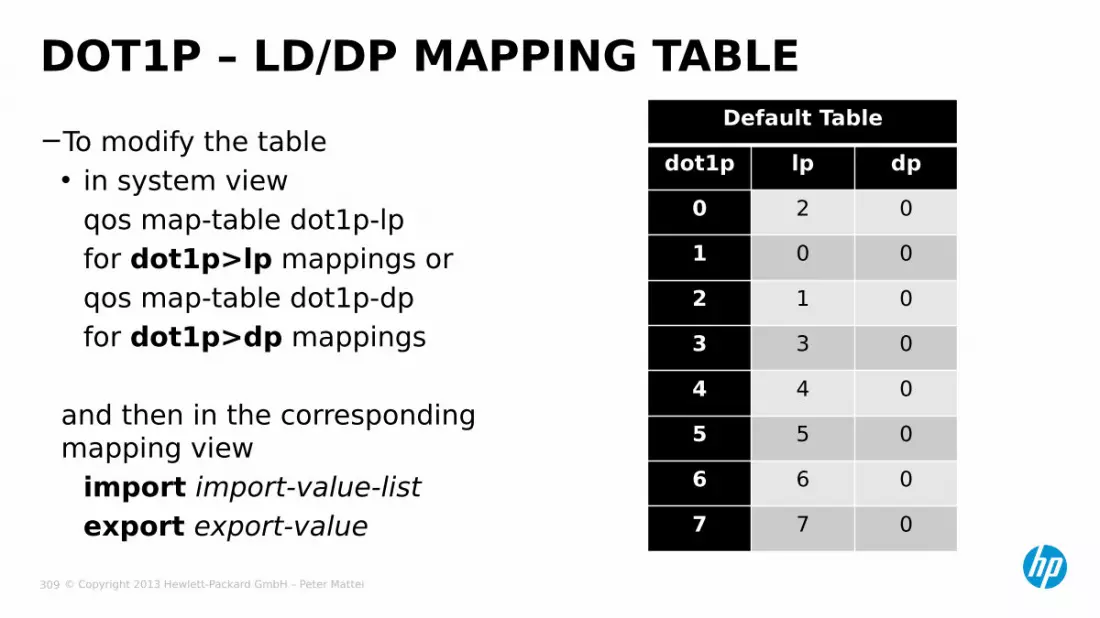
© Copyright 2013 Hewlett-Packard GmbH – Peter Mattei 309
−To modify the table• in system view
qos map-table dot1p-lpfor dot1p>lp mappings orqos map-table dot1p-dpfor dot1p>dp mappings
and then in the corresponding mapping view
import import-value-listexport export-value
DOT1P – LD/DP MAPPING TABLEDefault Table
dot1p lp dp
0 2 01 0 02 1 03 3 04 4 05 5 06 6 07 7 0

© Copyright 2013 Hewlett-Packard GmbH – Peter Mattei 310
−To modify the table use the same commands as with the dot1p table:
qos map-table dscp-xxx•where xxx is lp, dp or dscpimport import-value-listexport export-value
DSCP – LP/DP/DSCP MAPPING TABLEDefault Table
dscp lp dp dscp
0-7 0 0 08-15 1 0 8
16-23 2 0 1624-31 3 0 2432-39 4 0 3240-47 5 0 4048-55 6 0 4856-53 7 0 56

© Copyright 2013 Hewlett-Packard GmbH – Peter Mattei 311
−To display the port priority trust mode of a port enter (in any view)display qos trust interface [ interface-type interface-number ]
−If no port is specified, this command displays the port priority trust modes of all the ports.
−To Display the current mapping tables enter (in any view)display qos map-table [
dot1p-dp |dot1p-lp |dscp-dot1p |dscp-dp |dscp-dscp ]
DISPLAYING PORT PRIORITY MAPPING

© Copyright 2013 Hewlett-Packard GmbH – Peter Mattei 312
BANDWITH AND CONGESTION MANAGEMENT
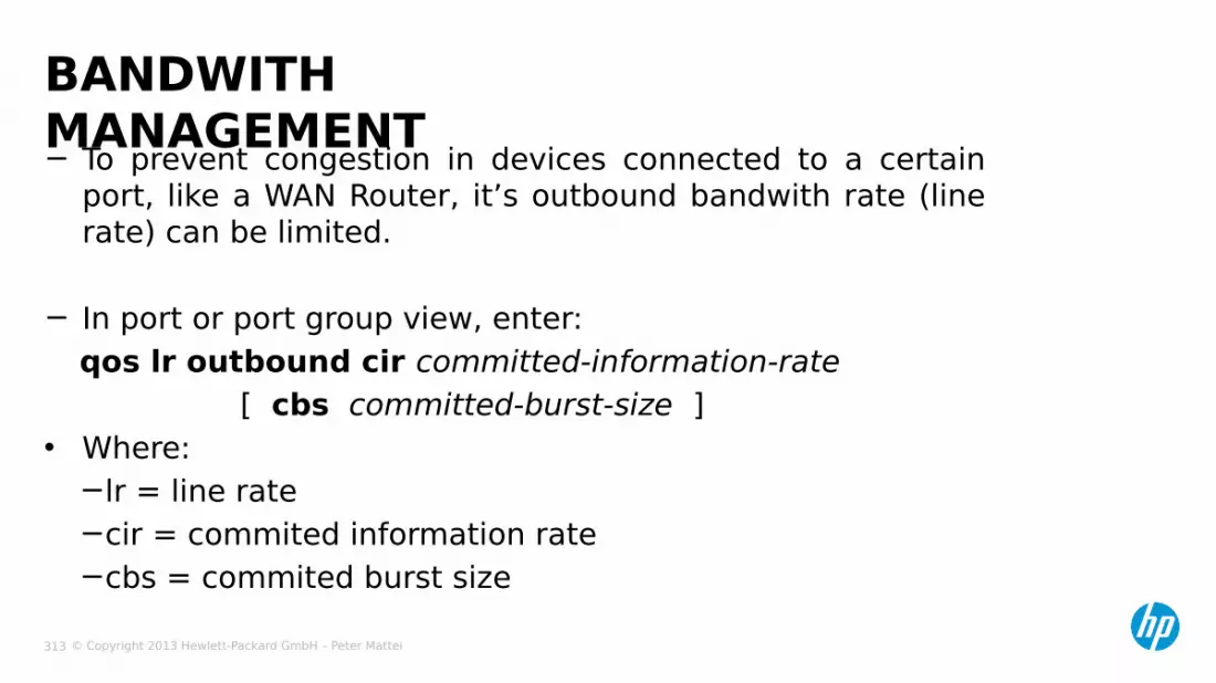
© Copyright 2013 Hewlett-Packard GmbH – Peter Mattei 313
− To prevent congestion in devices connected to a certain port, like a WAN Router, it’s outbound bandwith rate (line rate) can be limited.
− In port or port group view, enter:qos lr outbound cir committed-information-rate
[ cbs committed-burst-size ] • Where:
−lr = line rate−cir = commited information rate−cbs = commited burst size
BANDWITH MANAGEMENT

© Copyright 2013 Hewlett-Packard GmbH – Peter Mattei 314
− Congestion Management refers to how each port’s egress queues are scheduled
− The main three queue scheduling options are:• SP: Strict Priority• WRR: Weighted Round Robin• SP+WRR: a combination of both
CONGESTION MANAGEMENT

© Copyright 2013 Hewlett-Packard GmbH – Peter Mattei 315
− SP: Strict Priority• In port or port group view
qos sp
− WRR: Weighted Round Robin (and SP+WRR)• In port or port group view
qos wrr queue-id group group-id weightschedule-value
− SP+WRR• In port or port group view
qos wrr queue-id group-sp
CONFIGURING CONGESTION MANAGEMENT

© Copyright 2013 Hewlett-Packard GmbH – Peter Mattei 316
[switch] interface GigabitEthernet 1/0/1[switch-Gig1/0/1] qos wrr 7 group sp[switch-Gig1/0/1] qos wrr 6 group sp[switch-Gig1/0/1] qos wrr 5 group sp[switch-Gig1/0/1] qos wrr 4 group sp[switch-Gig1/0/1] qos wrr 3 group 1 weight 2[switch-Gig1/0/1] qos wrr 2 group 1 weight 4[switch-Gig1/0/1] qos wrr 1 group 1 weight 6[switch-Gig1/0/1] qos wrr 0 group 1 weight 8
EXAMPLE: SP+WRR

© Copyright 2013 Hewlett-Packard GmbH – Peter Mattei 317
TRAFFIC POLICIES

© Copyright 2013 Hewlett-Packard GmbH – Peter Mattei 318
− A Policy is a set of Behaviors that must be applied to different Traffic Classes
TRAFFIC POLICIES
Policy P100
Classifier
Behaviour
C1
B1 C5
B7 C12
B3 C45
B50 C20
B1
Apply
Apply
Apply to Ethernet Interface
to VLAN
alabally

© Copyright 2013 Hewlett-Packard GmbH – Peter Mattei 319
TRAFFIC CLASSIFIERS

© Copyright 2013 Hewlett-Packard GmbH – Peter Mattei 320
− Layer 2 parameters• source-mac mac-address• destination-mac mac-address• customer-dot1 p 8021 p-CoS• customer-vlan-id vlan-id-list• service-dot1 p 8021 p-CoS• service-vlan-id vlan-id-list
− Layer 3 parameters• protocol protocol-name (IPv4 or IPv6)• ip-precedence ip-precedence-list• dscp dscp-list
− Layer 2 Type, IP addresses, Layer 4-7 Parameters and complex combinations:• acl access-list-number / acl ipv6 access-list-number
− Default• any
TRAFFIC CLASSIFIERS
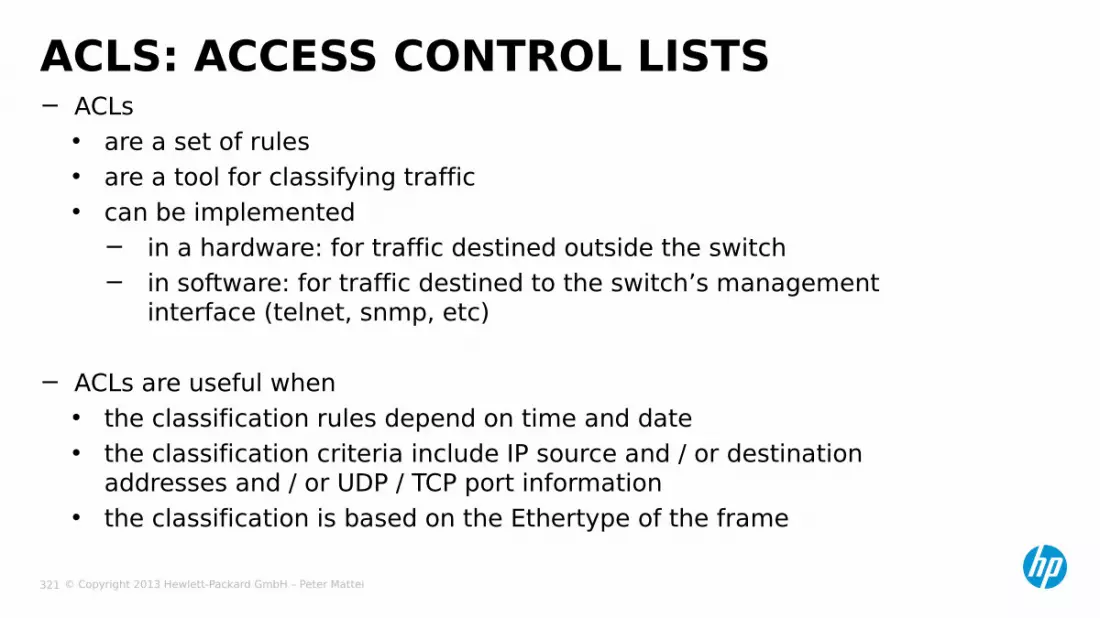
© Copyright 2013 Hewlett-Packard GmbH – Peter Mattei 321
− ACLs• are a set of rules• are a tool for classifying traffic• can be implemented
− in a hardware: for traffic destined outside the switch− in software: for traffic destined to the switch’s management
interface (telnet, snmp, etc)
− ACLs are useful when• the classification rules depend on time and date • the classification criteria include IP source and / or destination
addresses and / or UDP / TCP port information• the classification is based on the Ethertype of the frame
ACLS: ACCESS CONTROL LISTS

© Copyright 2013 Hewlett-Packard GmbH – Peter Mattei 322
Basic IPv6 ACLs and Advanced IPv6 ACLs are identical to the IPv4 versions. They are not covere in this course
ACL TYPESType ACL Numbers Matching CriteriaBasic IPv4 ACL 2000 to 2999 • Source IP address
Advanced IPv4 ACL
3000 to 3999 • Source IP address,• Destination IP address,• Protocol ID,• Other L3 or L4 protocol
header information
Ethernet frame header ACL
4000 to 4999 • Source MAC address,• Destination MAC
address,• 802.1p priority• Ethertype

© Copyright 2013 Hewlett-Packard GmbH – Peter Mattei 323
− Two match orders are available for IPv4 ACLs:• config (default):
− where packets are compared against ACL rules in the order in which they are configured.
• auto:− where depth-firts match is performed.− the term depth-firts match has different meanings for
different type of ACLs.
− Visit the 3Com Switch S7900E Configuration Guide (page 833) for a detailed explanation of the depth first algorithm in the context of each three ACL types.
ACLS MATCH ORDER

© Copyright 2013 Hewlett-Packard GmbH – Peter Mattei 324
− You may create individual time ranges indentified with the same name.• They are regarded as one time range whose active period is
the result of Oring periodic ones, ORing absolute ones, and ANDing periodic and absolute ones.
− Up to 256 time ranges can be defined.
− In system view:time-range time-name { start-time to end-time days [ from time1 date1 ] [ to time2 date2 ] | from time1 date1 [ to time2 date2 ] | to time2 date2 }
− Example:time-range test 8:00 to 18:00 working-day
CREATING A TIME RANGE
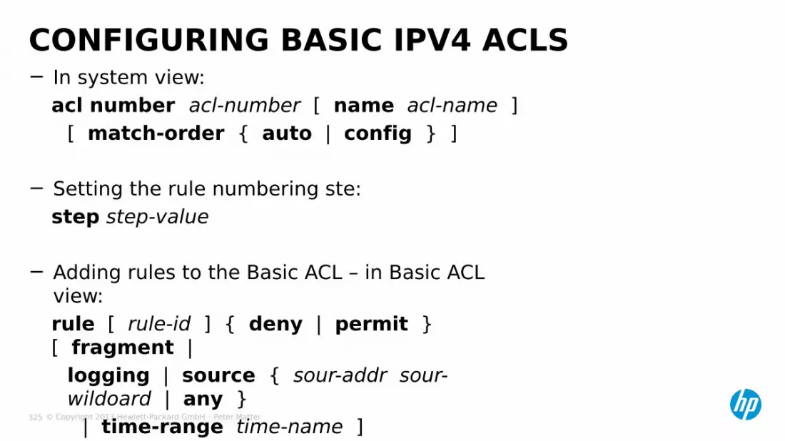
© Copyright 2013 Hewlett-Packard GmbH – Peter Mattei 325
− In system view:acl number acl-number [ name acl-name ]
[ match-order { auto | config } ]
− Setting the rule numbering ste:step step-value
− Adding rules to the Basic ACL – in Basic ACL view:rule [ rule-id ] { deny | permit } [ fragment |
logging | source { sour-addr sour-wildoard | any }
| time-range time-name ]
CONFIGURING BASIC IPV4 ACLS

© Copyright 2013 Hewlett-Packard GmbH – Peter Mattei 326
1. VPN instance
2. Source IP address wildcard first (more zeras)
3. Rule configured first
AUTO MATCH ORDER IN BASIC ACLS

© Copyright 2013 Hewlett-Packard GmbH – Peter Mattei 327
− In system view:acl number acl-number [ name acl-name ] [ match-order { auto | config } ]
− In advanced IPv4 ACL viewstep step-value rule [ rule-id ] { deny | permit } protocol [ destination { dest-addr dest-wildcard | any } |destination-port operator port1 [ port2 ] |dscp dscp|established | fragment | icmp-type(*) { icmp-type icmp-code | icmp-message } | logging |precedence precedence | reflective |source { sour-addr sour-wildcard | any } | source-portoperator port1 [ port2 ] |time-range time-name | tos tos | vpn-instance vpn-instance-name ]
(*)
CONFIGURING ADVANCED IPV4 ACLS
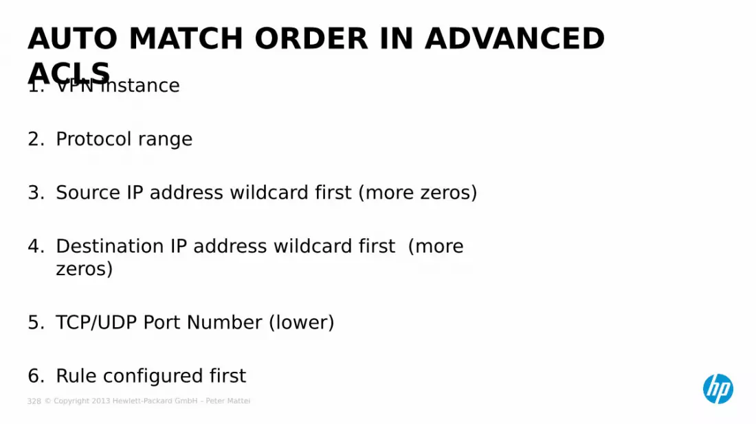
© Copyright 2013 Hewlett-Packard GmbH – Peter Mattei 328
1. VPN instance
2. Protocol range
3. Source IP address wildcard first (more zeros)
4. Destination IP address wildcard first (more zeros)
5. TCP/UDP Port Number (lower)
6. Rule configured first
AUTO MATCH ORDER IN ADVANCED ACLS

© Copyright 2013 Hewlett-Packard GmbH – Peter Mattei 329
− In system view:acl number acl-number [ name acl-name ]
[ match-order { auto | config } ]
− in Ethernet Frame Header ACL view step step-valuerule [ rule-id ] { deny | permit }[ cos vlan-pri |dest-mac dest-addr dest-mask |lsap lsap-code lsap-wildcard |source-mac sour-addr source-mask |time-range time-name |type type-code type-wildcard ]
CONFIGURING ETHERNET FRAME HEADER ACLS
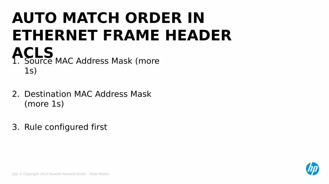
© Copyright 2013 Hewlett-Packard GmbH – Peter Mattei 330
1. Source MAC Address Mask (more 1s)
2. Destination MAC Address Mask (more 1s)
3. Rule configured first
AUTO MATCH ORDER IN ETHERNET FRAME HEADER ACLS

© Copyright 2013 Hewlett-Packard GmbH – Peter Mattei 331
− In system view;traffic classifier classifier-name [ operator { and | or } ]• where the operator specifies the if all the classification rules must
be net (and) or if matching any rule is sufficient (or)• the default operator is and
− In traffic classifier view configure one or more classifications rulesif-match match-criteria
CONFIGURING CLASSIFIERS

© Copyright 2013 Hewlett-Packard GmbH – Peter Mattei 332
TRAFFICBEHAVIORS

© Copyright 2013 Hewlett-Packard GmbH – Peter Mattei 333
− A Traffic Behavior is a list of “actions” that can be executed on a traffic class.
− Behaviors are assigned to classes in a Policy.
TRAFFIC BEHAVIORS
Policy P100
Classifier Behaviour
C1 B1
C5 B7

© Copyright 2013 Hewlett-Packard GmbH – Peter Mattei 334
− Count packets of a traffic classaccouting
− Limit the bandwidth used by a traffic classcar cir commited-information-rate
[ cbs commited-burst-size[ ebs excess-burst-size ] ][ pir pesk-information-rate ][ green action ][ red action ][ yellow action ]
ACTIONS
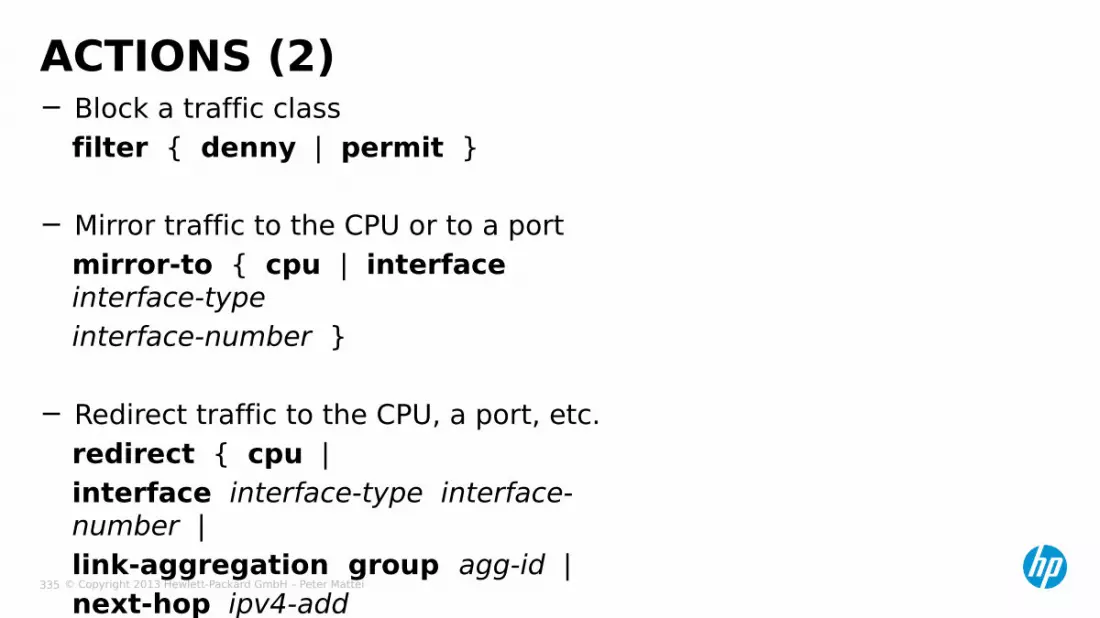
© Copyright 2013 Hewlett-Packard GmbH – Peter Mattei 335
− Block a traffic classfilter { denny | permit }
− Mirror traffic to the CPU or to a portmirror-to { cpu | interface interface-typeinterface-number }
− Redirect traffic to the CPU, a port, etc.redirect { cpu |interface interface-type interface-number |link-aggregation group agg-id |next-hop ipv4-add
ACTIONS (2)

© Copyright 2013 Hewlett-Packard GmbH – Peter Mattei 336
− Configure Selective QinQnest top-most vlan-id vlan-id
− Configure VLAN Mappingremark customer-vlan-id vlan-id-valueremark customer-vlan-id vlan-id-value
− Remark traffic prioritization and precedence valuesremark dot1p 8021premark dscp dscp-valueremark ip-precedence ip-precedence-valueremark local-precedence local-precedenceremark drop-precedence drop-precedence-value
ACTIONS (3)

© Copyright 2013 Hewlett-Packard GmbH – Peter Mattei 337
BEHAVIOR SUPPORT BY MODULE TYPEModule Type
ActionSC SA EA
Inbound Outbound Inbound Outbound Inbound Outbound
Accouting Supported Supported Supported SupportedTP Supported Supported Supported SupportedTraffic filtering Supported Supported Supported SupportedTraffic mirroring Supported Supported SupportedConfiguring the outer VLAN tag SupportedTraffic redirecting Supported Supported SupportedRemarking customer VLAN ID SupportedRemarking the 802.1p precedence
Supported Supported Supported Supported
Remarking the drop precedence Supported Supported SupportedRemarking the DSCP precedence Supported Supported Supported SupportedRemarking the IP precedence Supported Supported Supported SupportedRemarking the local precedence Supported Supported SupportedRemarking outer VLAN ID Supported SupportedRemarking inner VLAN ID Supported
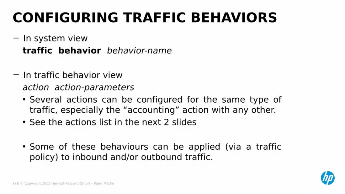
© Copyright 2013 Hewlett-Packard GmbH – Peter Mattei 338
− In system viewtraffic behavior behavior-name
− In traffic behavior viewaction action-parameters• Several actions can be configured for the same type of
traffic, especially the “accounting” action with any other.• See the actions list in the next 2 slides
• Some of these behaviours can be applied (via a traffic policy) to inbound and/or outbound traffic.
CONFIGURING TRAFFIC BEHAVIORS

© Copyright 2013 Hewlett-Packard GmbH – Peter Mattei 339
QOS POLICIES

© Copyright 2013 Hewlett-Packard GmbH – Peter Mattei 340
QOS POLICIES
Policy P100
Classifier Behaviour
C1 B1
C5 B7
Port
VLAN
Global
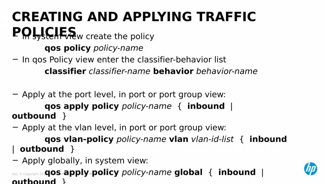
© Copyright 2013 Hewlett-Packard GmbH – Peter Mattei 341
− In system view create the policyqos policy policy-name
− In qos Policy view enter the classifier-behavior listclassifier classifier-name behavior behavior-name
− Apply at the port level, in port or port group view:qos apply policy policy-name { inbound |
outbound }− Apply at the vlan level, in port or port group view:
qos vlan-policy policy-name vlan vlan-id-list { inbound | outbound }− Apply globally, in system view:
qos apply policy policy-name global { inbound | outbound }
CREATING AND APPLYING TRAFFIC POLICIES

© Copyright 2013 Hewlett-Packard GmbH – Peter Mattei 342
QOSAPPLICATIONS

© Copyright 2013 Hewlett-Packard GmbH – Peter Mattei 343
− Create the Traffic Classifier[switch] traffic classifier cl operator oradd its traffic classification rules
− Create the Behavior and add the action[switch] traffic behavior stats1[switch-behavior-stats1] accouting
− Create the Policy[switch] qos policy clstats[switch-behavior-clstats] classifier cl behavior
stats1− Apply the Policy inbound or outbound at the needed context:
global, vlan, port
TRAFFIC STATISTICS

© Copyright 2013 Hewlett-Packard GmbH – Peter Mattei 344
− View the statistics:display qos policy global { inbound | outbound } [ slot slot-id ]
display qos vlan-policy { name policy-name | vlan [ vlan-id ] } { slot slot-id }
display qos policy user-define [ policy-name [ classifier classifier-name ] ]
TRAFFIC STATISTICS (2)

© Copyright 2013 Hewlett-Packard GmbH – Peter Mattei 345
− Create the Traffic Classifier in system view[switch] traffic classifier cl operator or•add its traffic classification rules
− Create the Behavior and add the actions[switch] traffic behavior blk[switch-behavior-blk] filter denny•optionaly add accouting[switch-behavior-blk] accouting
− Create the Policy[switch] qos policy clblk[switch-qospolicy-clblk] classifier cl behavior blk
− Apply the Policy to the needed context: global, vlan, port
TRAFFIC FILTERING

© Copyright 2013 Hewlett-Packard GmbH – Peter Mattei 346
− Create the Traffic Classifier in system viewtraffic classifier cl operator or•add its traffic classification rules
− Create the Behavior and add the actions[switch] traffic behavior mirr[switch-behavior-mirr] mirror-to { cpu | interface interface-type interface-number }
− Create the Policy[switch] qos policy clmrr[switch-qospolicy-clmrr] classifier cl behavior blk
− Apply the Policy to the needed context: global, vlan, port•Note that you Apply the policy to the source of the mirroring and only inbound traffic can be mirrored.
TRAFFIC MIRRORING
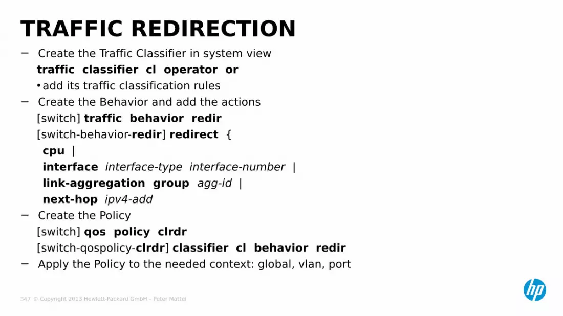
© Copyright 2013 Hewlett-Packard GmbH – Peter Mattei 347
− Create the Traffic Classifier in system viewtraffic classifier cl operator or •add its traffic classification rules
− Create the Behavior and add the actions[switch] traffic behavior redir[switch-behavior-redir] redirect {cpu |interface interface-type interface-number |link-aggregation group agg-id |next-hop ipv4-add
− Create the Policy[switch] qos policy clrdr[switch-qospolicy-clrdr] classifier cl behavior redir
− Apply the Policy to the needed context: global, vlan, port
TRAFFIC REDIRECTION

© Copyright 2013 Hewlett-Packard GmbH – Peter Mattei 348
− Create the ACL to classify the desired trafficacl number 3000rule pertmit UDP source-port eq 5060
− Create the Traffic Classifier in system viewtraffic classifier voice operator orif-match acl 3000
− Create the Behavior and add the actionstraffic behavior remarkremark dscp EF
− Create the Policyqos policy SIP-voiceclassifier voice behavior remark
− Apply the Policyinterface gigabit 1/0/1qos Apply policy SIP-Voice inbound
TRAFFIC REMARK - EXAMPLE

© Copyright 2013 Hewlett-Packard GmbH – Peter Mattei 349
VLAN AND QOS
PROCESSING

© Copyright 2013 Hewlett-Packard GmbH – Peter Mattei 350
• Overall process and its stages
• Ingress process
• Egress process
VLAN AND QOS PROCESSING SUMMARY

© Copyright 2013 Hewlett-Packard GmbH – Peter Mattei 351
VLAN AND QOS PROCESSING
1. Ingress
1.bLP/DP
1.CInboundPolicy
2. Forwarding
2.dCPU
2.AL2 FW
(Dest. MAC)
2.bDest IP
2.cL3FW
3. Egress
3.bVLANID
3.aOutbound
Policy3.dLR
Queue
Sched
3.cLP

© Copyright 2013 Hewlett-Packard GmbH – Peter Mattei 352
INGRESS PROCESS FOR VLAN AND QOS

© Copyright 2013 Hewlett-Packard GmbH – Peter Mattei 353
EGRESS PROCESS FOR VLAN AND QOS

© Copyright 2013 Hewlett-Packard GmbH – Peter Mattei 354
SECURITY

© Copyright 2013 Hewlett-Packard GmbH – Peter Mattei 355
− Device Security• Securing the Console• Securing Telnet• Securing SNMP
− Network Security• AAA: Authentication Authorization and
Accounting• 802.1X• MAC Authentication (RADA)
SECURITY

© Copyright 2013 Hewlett-Packard GmbH – Peter Mattei 356
DEVICE SECURITY

© Copyright 2013 Hewlett-Packard GmbH – Peter Mattei 357
− Physical Security
− Authentication Mode• Password• Schema
− Local− Remote: Radius (see later in this
Module)
SECURING THE CONSOLE

© Copyright 2013 Hewlett-Packard GmbH – Peter Mattei 358
SECURING
TELNET
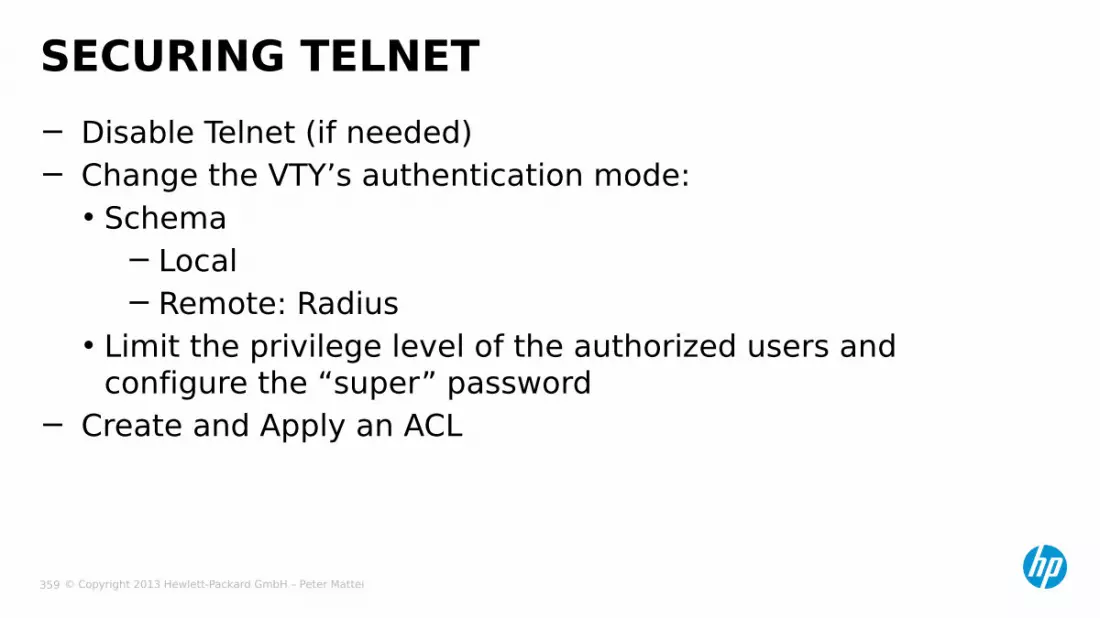
© Copyright 2013 Hewlett-Packard GmbH – Peter Mattei 359
− Disable Telnet (if needed)− Change the VTY’s authentication mode:• Schema
− Local− Remote: Radius
• Limit the privilege level of the authorized users and configure the “super” password
− Create and Apply an ACL
SECURING TELNET

© Copyright 2013 Hewlett-Packard GmbH – Peter Mattei 360
− ACLs can be used:• inbound: to limit the clients
−use Basic ACLs• outbound: to limit the access to telnet servers (other switches)
−use Advanced ACLs to specify authorized destination address− Example
[switch] acl number 2002[switch-acl2002] rule permit source 192.168.254.0 0.0.0.255[switch-acl2002] rule deny source any[switch-acl2002] quit[switch] user-interface vty 0-4[switch-userint0-4] acl 2002 inbound
ACLS FOR TELNET AND SSH: EXAMPLE

© Copyright 2013 Hewlett-Packard GmbH – Peter Mattei 361
SEGURING SNMP

© Copyright 2013 Hewlett-Packard GmbH – Peter Mattei 362
− Limit the IP source address authorize to interact with the agent by creating a Basic ACL
− In system view, modify agent communities including the ACL (only for SNMP v1 and v2)
snmp-agent modify { read | write } community-name [ acl acl-number | mib- view view-name ]
SEGURING SNMP

© Copyright 2013 Hewlett-Packard GmbH – Peter Mattei 363
AAA-RADIUS

© Copyright 2013 Hewlett-Packard GmbH – Peter Mattei 364
AAA: AUTHENTICATION, AUTHORIZATION AND ACCOUNTING− AAA can be applied to any interface to which a user can connect:
Console, Telnet, SSH, FTP and LAN− AAA is a server based authentication strategy that:• Is centralized and standards based: can be used for all the devices in
the LAN/WLAN• Simplifies the authorization database configuration and maintanance,
including backup• Includes accouting to collect Login and usage information that can be
user for security tracking and troubleshooting− The Switch S7900E supports two AAA standards:• RADIUS• HWTACACS (not covered in this course)
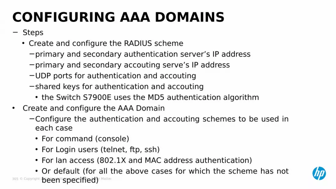
© Copyright 2013 Hewlett-Packard GmbH – Peter Mattei 365
− Steps• Create and configure the RADIUS scheme
−primary and secondary authentication server’s IP address−primary and secondary accouting serve’s IP address−UDP ports for authentication and accouting−shared keys for authentication and accouting• the Switch S7900E uses the MD5 authentication algorithm
• Create and configure the AAA Domain−Configure the authentication and accouting schemes to be used in
each case• For command (console)• For Login users (telnet, ftp, ssh)• For lan access (802.1X and MAC address authentication)• Or default (for all the above cases for which the scheme has not
been specified)
CONFIGURING AAA DOMAINS

© Copyright 2013 Hewlett-Packard GmbH – Peter Mattei 366
802.1X

© Copyright 2013 Hewlett-Packard GmbH – Peter Mattei 367
− Switch S7900E supports the following EAP authentication methods:• EAP-MD5• EAP-TLS• EAP-TLLS• PEAP
− and accepts many users per port in the following modes:• port-based authentication
−If one users is authorized, the rest will pass• MAC-based authentication
−each MAC address is authenticated individually
802.1X: AUTHENTICATION
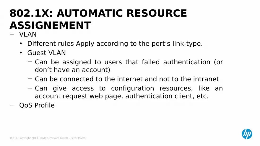
© Copyright 2013 Hewlett-Packard GmbH – Peter Mattei 368
− VLAN• Different rules Apply according to the port’s link-type.• Guest VLAN
− Can be assigned to users that failed authentication (or don’t have an account)
− Can be connected to the internet and not to the intranet− Can give access to configuration resources, like an
account request web page, authentication client, etc.− QoS Profile
802.1X: AUTOMATIC RESOURCE ASSIGNEMENT

© Copyright 2013 Hewlett-Packard GmbH – Peter Mattei 369
− In system view, enable 802.1Xdot1x
− Set authentication methoddot1x authentication-method { chap | eap | pap }
− Set port’s access parametersdot1x port-control { authorized-force | auto |
unauthorized-force } [ interface-list ]dot1x port-method { macbased | portbased }
[ interface interface-list ]dot1x max-user user-number [ interface interface-list ]
CONFIGURING 802.1X
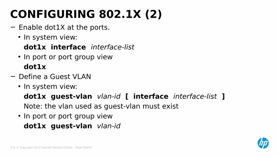
© Copyright 2013 Hewlett-Packard GmbH – Peter Mattei 370
− Enable dot1X at the ports.• In system view:
dot1x interface interface-list• In port or port group view
dot1x− Define a Guest VLAN• In system view:
dot1x guest-vlan vlan-id [ interface interface-list ]Note: the vlan used as guest-vlan must exist
• In port or port group viewdot1x guest-vlan vlan-id
CONFIGURING 802.1X (2)
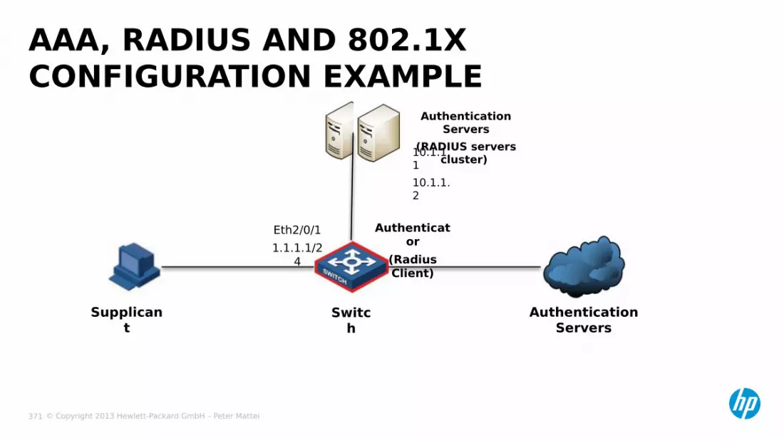
© Copyright 2013 Hewlett-Packard GmbH – Peter Mattei 371
AAA, RADIUS AND 802.1X CONFIGURATION EXAMPLE
Supplicant
Switch
Authentication Servers
Authenticator
(Radius Client)
Authentication Servers
(RADIUS servers cluster)
Eth2/0/11.1.1.1/2
4
10.1.1.110.1.1.2
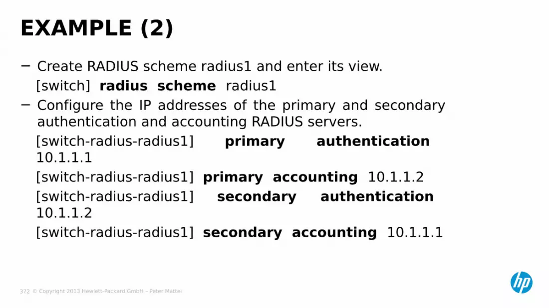
© Copyright 2013 Hewlett-Packard GmbH – Peter Mattei 372
− Create RADIUS scheme radius1 and enter its view.[switch] radius scheme radius1
− Configure the IP addresses of the primary and secondary authentication and accounting RADIUS servers.[switch-radius-radius1] primary authentication 10.1.1.1[switch-radius-radius1] primary accounting 10.1.1.2[switch-radius-radius1] secondary authentication 10.1.1.2[switch-radius-radius1] secondary accounting 10.1.1.1
EXAMPLE (2)
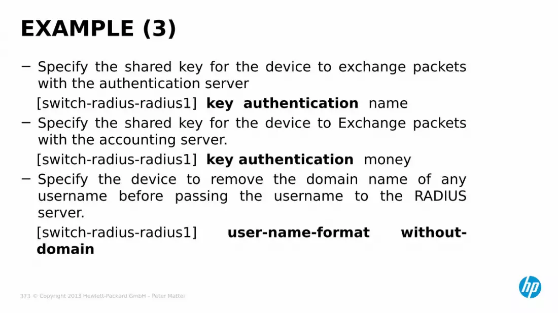
© Copyright 2013 Hewlett-Packard GmbH – Peter Mattei 373
− Specify the shared key for the device to exchange packets with the authentication server[switch-radius-radius1] key authentication name
− Specify the shared key for the device to Exchange packets with the accounting server.[switch-radius-radius1] key authentication money
− Specify the device to remove the domain name of any username before passing the username to the RADIUS server.[switch-radius-radius1] user-name-format without-domain
EXAMPLE (3)
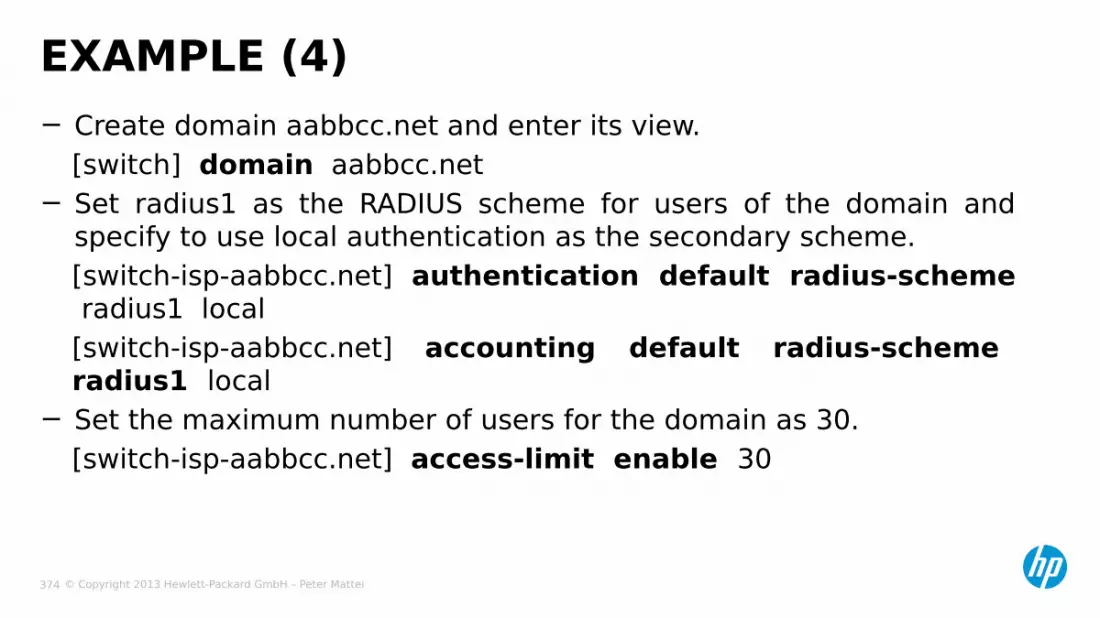
© Copyright 2013 Hewlett-Packard GmbH – Peter Mattei 374
− Create domain aabbcc.net and enter its view.[switch] domain aabbcc.net
− Set radius1 as the RADIUS scheme for users of the domain and specify to use local authentication as the secondary scheme.[switch-isp-aabbcc.net] authentication default radius-scheme radius1 local[switch-isp-aabbcc.net] accounting default radius-scheme radius1 local
− Set the maximum number of users for the domain as 30.[switch-isp-aabbcc.net] access-limit enable 30
EXAMPLE (4)

© Copyright 2013 Hewlett-Packard GmbH – Peter Mattei 375
− Configure aabbcc.net as the default domain.[switch] domain default enable aabbcc.net
− Configure the authentication method[switch] dot1x authentication-method eap
− Enable 802.1x globally[switch] dot1x
− Enable 802.1x for port Ethernet 2/0/1,• Set the port access control method (optional, because this is the default)• And specify port Ethernet 2/0/1 to use VLAN 10 as its guest VLAN[switch] interface Ethernet2/0/1[switch-Ethernet2/0/1] dot1x[switch-Ethernet2/0/1] dot1x port-method macbased[switch-Ethernet2/0/1] dot1x guest-vlan 10
EXAMPLE (5)

© Copyright 2013 Hewlett-Packard GmbH – Peter Mattei 376
MACAUTHENTICATION

© Copyright 2013 Hewlett-Packard GmbH – Peter Mattei 377
− Can be:• RADIUS-based MAC Authentication• Local MAC Authentication
MAC AUTHENTICATION
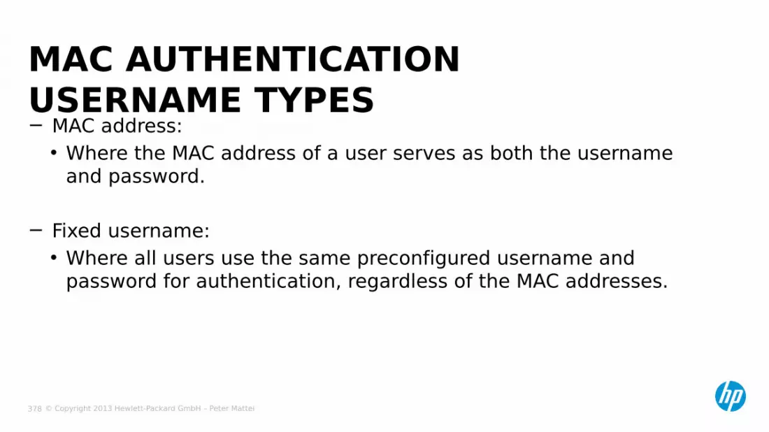
© Copyright 2013 Hewlett-Packard GmbH – Peter Mattei 378
− MAC address:• Where the MAC address of a user serves as both the username
and password.
− Fixed username:• Where all users use the same preconfigured username and
password for authentication, regardless of the MAC addresses.
MAC AUTHENTICATION USERNAME TYPES
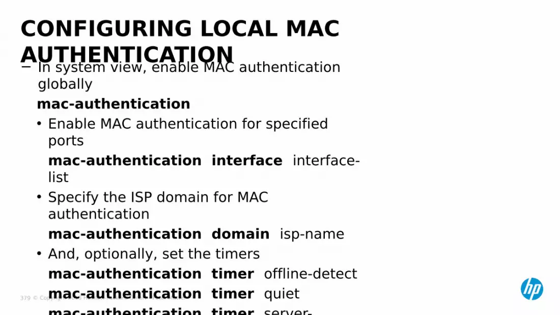
© Copyright 2013 Hewlett-Packard GmbH – Peter Mattei 379
− In system view, enable MAC authentication globallymac-authentication• Enable MAC authentication for specified
portsmac-authentication interface interface-list
• Specify the ISP domain for MAC authentication mac-authentication domain isp-name
• And, optionally, set the timersmac-authentication timer offline-detectmac-authentication timer quietmac-authentication timer server-timeout
CONFIGURING LOCAL MAC AUTHENTICATION

© Copyright 2013 Hewlett-Packard GmbH – Peter Mattei 380
− A supplicant is connected to the device through port GigabitEthernet 1/0/1.
− Local MAC authentication is required on every port to control user access to the internet.
− All users belong to domain aabbcc.net.− Local users use their MAC addresses as the usernames and passwords for
authentication.− Set the offline detect timer to 180 seconds and the quiet timer to 3
minutes.
CONFIGURATION EXAMPLE – USER MODE:MAC ADDRESS
MAC: 00-e0-fc-12-34-56
Supplicant
Authenticator
Gig 1/0/1

© Copyright 2013 Hewlett-Packard GmbH – Peter Mattei 381
− Configure MAC authentication on the device− Add a local user, setting the username and password as 00-e0-fc-12-34-56, the
MAC address of the user.
[sw] local-user 00-e0-fc-12-34-56[sw-luser-00-e0-fc-12-34-56] password simple 00-e0-fc-12-34-56[sw-luser-00-e0-fc-12-34-56] service-type lan-access[sw-luser-00-e0-fc-12-34-56] quit
− Configure ISP domain aabbcc.net, and specify that the users in the domain use local authentication
[sw] domain aabbcc.net[sw-isp-aabbcc.net] authentication lan-access local[sw-isp-aabbcc.net] quit
CONFIGURATION EXAMPLE – 1
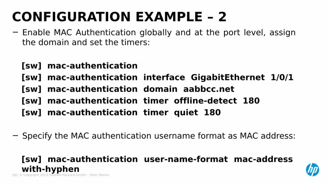
© Copyright 2013 Hewlett-Packard GmbH – Peter Mattei 382
− Enable MAC Authentication globally and at the port level, assign the domain and set the timers:
[sw] mac-authentication[sw] mac-authentication interface GigabitEthernet 1/0/1[sw] mac-authentication domain aabbcc.net[sw] mac-authentication timer offline-detect 180[sw] mac-authentication timer quiet 180
− Specify the MAC authentication username format as MAC address:
[sw] mac-authentication user-name-format mac-address with-hyphen
CONFIGURATION EXAMPLE – 2

© Copyright 2013 Hewlett-Packard GmbH – Peter Mattei 383
NETWORK MANAGEMENT

© Copyright 2013 Hewlett-Packard GmbH – Peter Mattei 384
− Local Port Mirroring− Remote Port Mirroring (RSPAN)− SNMP− LLDP
NETWORK MANAGEMENT

© Copyright 2013 Hewlett-Packard GmbH – Peter Mattei 385
LOCALPORT-MIRRORING

© Copyright 2013 Hewlett-Packard GmbH – Peter Mattei 386
− Implemented by local port mirroring group− The source ports and the destination port (many to one) are in the same local port
mirroring group− Packets passing through the source ports are duplicated and then are forwarded to the
destination port− Supports up to 4 Monitor ports− Cross-VLAN traffic re-directing not supported
LOCAL PORT MIRRORING
Traffic Analyzer
destination port
source port

© Copyright 2013 Hewlett-Packard GmbH – Peter Mattei 387
− In system view, create a local mirroring groupmirroring-group group-id local
− Add source ports (one or more)mirroring-group group-id mirroring-port mirroring-port-list { both | inbound | outbound }
− Add the destination port (only one)mirroring-group group-id monitor-port monitor-port-id
CONFIGURING LOCAL PORT MIRRORING

© Copyright 2013 Hewlett-Packard GmbH – Peter Mattei 388
REMOTE PORT
MIRRORING

© Copyright 2013 Hewlett-Packard GmbH – Peter Mattei 389
REMOTE PORT MIRRORING
source port
Source device
Intermediate device
Destination deviceRemote
mirroring
VLAN
Remotemirrorin
gVLAN
outboundport
destination port
Traffic Analyzer
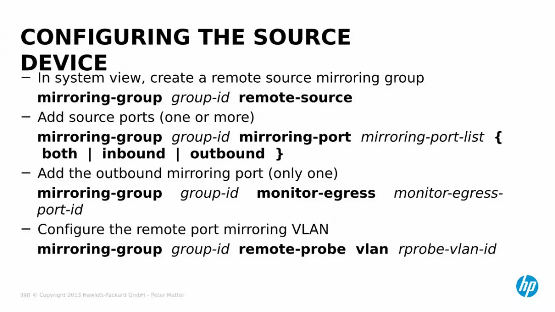
© Copyright 2013 Hewlett-Packard GmbH – Peter Mattei 390
− In system view, create a remote source mirroring groupmirroring-group group-id remote-source
− Add source ports (one or more)mirroring-group group-id mirroring-port mirroring-port-list { both | inbound | outbound }
− Add the outbound mirroring port (only one)mirroring-group group-id monitor-egress monitor-egress-port-id
− Configure the remote port mirroring VLANmirroring-group group-id remote-probe vlan rprobe-vlan-id
CONFIGURING THE SOURCE DEVICE
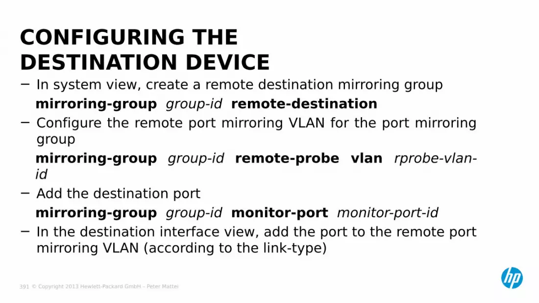
© Copyright 2013 Hewlett-Packard GmbH – Peter Mattei 391
− In system view, create a remote destination mirroring groupmirroring-group group-id remote-destination
− Configure the remote port mirroring VLAN for the port mirroring groupmirroring-group group-id remote-probe vlan rprobe-vlan-id
− Add the destination portmirroring-group group-id monitor-port monitor-port-id
− In the destination interface view, add the port to the remote port mirroring VLAN (according to the link-type)
CONFIGURING THE DESTINATION DEVICE

© Copyright 2013 Hewlett-Packard GmbH – Peter Mattei 392
REMOTE PORT MIRRORING EXAMPLE
Data monitoring
device
Switch 1 Switch 2 Switch 3
Dept 1
Dept 2
Eth2/0/1 Eth2/0/
2
Eth2/0/1
Eth2/0/3 Eth2/0/
2
Eth2/0/1
Eth2/0/2

© Copyright 2013 Hewlett-Packard GmbH – Peter Mattei 393
− Switch A[SwitchA] mirroring-group 1 remote-source[SwitchA] vlan 2 [SwitchA] mirroring-group 1 remote-probe vlan 2[SwitchA] mirroring-group 1 mirroring-port Ethernet 2/0/1 Ethernet 2/0/2 inbound[SwitchA] mirroring-group 1 monitor-egress Ethernet 2/0/3[SwitchA] interface Ethernet 2/0/3[SwitchA-Ethernet2/0/3] port-link-type trunk[SwitchA-Ethernet2/0/3] port trunk permit vlan 2
REMOTE PORT MIRRORING EXAMPLE (2)
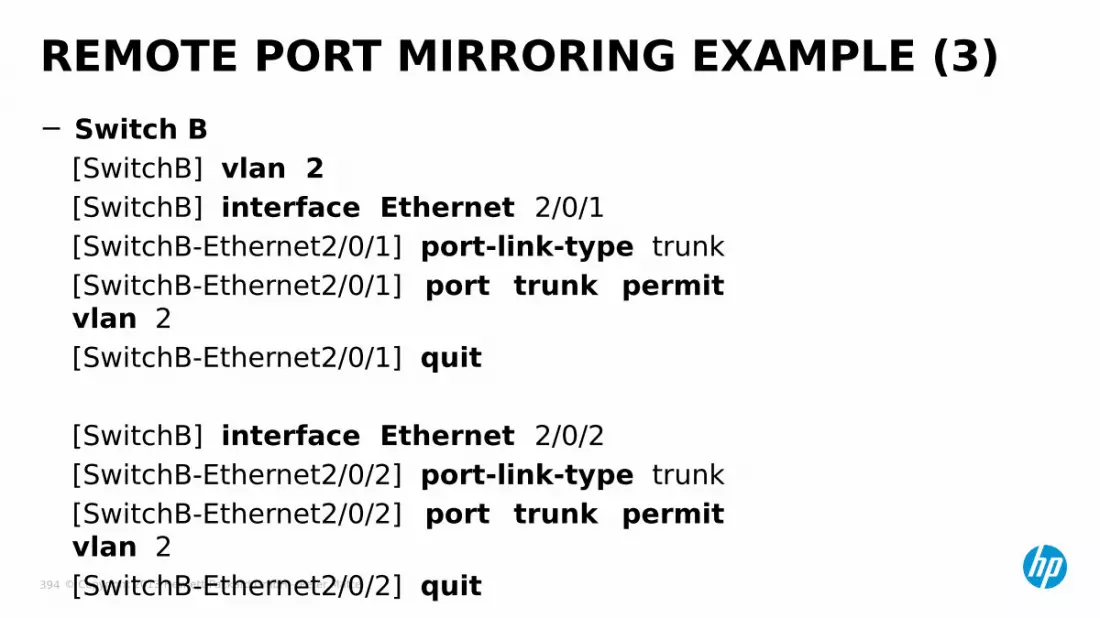
© Copyright 2013 Hewlett-Packard GmbH – Peter Mattei 394
− Switch B[SwitchB] vlan 2[SwitchB] interface Ethernet 2/0/1[SwitchB-Ethernet2/0/1] port-link-type trunk[SwitchB-Ethernet2/0/1] port trunk permit vlan 2[SwitchB-Ethernet2/0/1] quit
[SwitchB] interface Ethernet 2/0/2[SwitchB-Ethernet2/0/2] port-link-type trunk[SwitchB-Ethernet2/0/2] port trunk permit vlan 2[SwitchB-Ethernet2/0/2] quit
REMOTE PORT MIRRORING EXAMPLE (3)
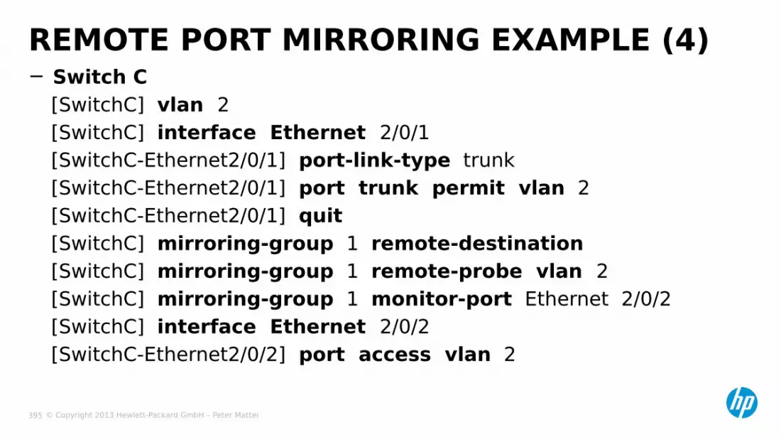
© Copyright 2013 Hewlett-Packard GmbH – Peter Mattei 395
− Switch C[SwitchC] vlan 2[SwitchC] interface Ethernet 2/0/1[SwitchC-Ethernet2/0/1] port-link-type trunk[SwitchC-Ethernet2/0/1] port trunk permit vlan 2[SwitchC-Ethernet2/0/1] quit[SwitchC] mirroring-group 1 remote-destination [SwitchC] mirroring-group 1 remote-probe vlan 2[SwitchC] mirroring-group 1 monitor-port Ethernet 2/0/2[SwitchC] interface Ethernet 2/0/2[SwitchC-Ethernet2/0/2] port access vlan 2
REMOTE PORT MIRRORING EXAMPLE (4)

© Copyright 2013 Hewlett-Packard GmbH – Peter Mattei 396
SNMP
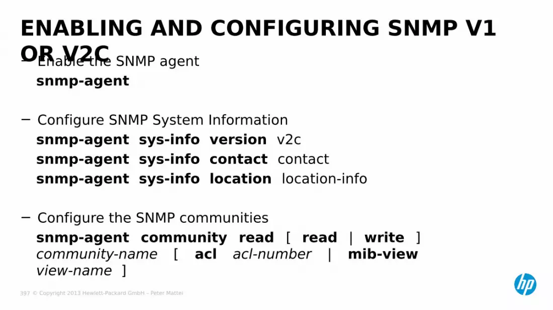
© Copyright 2013 Hewlett-Packard GmbH – Peter Mattei 397
− Enable the SNMP agentsnmp-agent
− Configure SNMP System Informationsnmp-agent sys-info version v2csnmp-agent sys-info contact contactsnmp-agent sys-info location location-info
− Configure the SNMP communitiessnmp-agent community read [ read | write ] community-name [ acl acl-number | mib-view view-name ]
ENABLING AND CONFIGURING SNMP V1 OR V2C
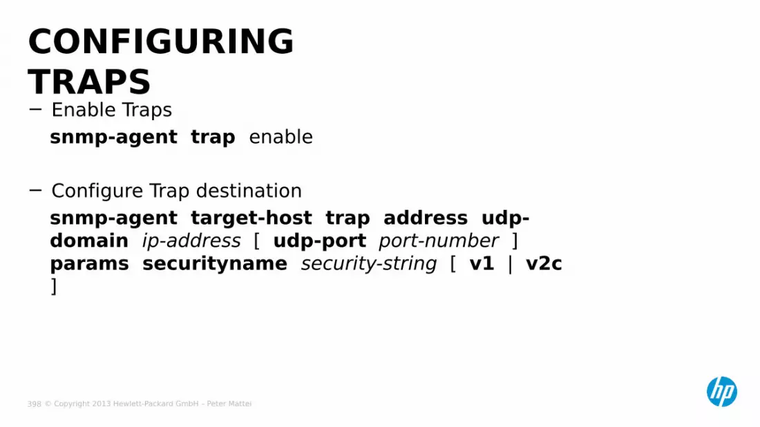
© Copyright 2013 Hewlett-Packard GmbH – Peter Mattei 398
− Enable Trapssnmp-agent trap enable
− Configure Trap destinationsnmp-agent target-host trap address udp-domain ip-address [ udp-port port-number ] params securityname security-string [ v1 | v2c ]
CONFIGURING TRAPS

© Copyright 2013 Hewlett-Packard GmbH – Peter Mattei 399
LLDP

© Copyright 2013 Hewlett-Packard GmbH – Peter Mattei 400
LLDP
Discovery MIBPort Device InfoIPv4 IP-
Phonexxxx
B6 PC xxxxB21 Switch xxxx
Discovery MIBPort Device InfoA19 Switch xxxxC2 IP-
Phonexxxx
D2 IP-Phone
xxxx
F3 IP-PBX xxxx
I’m a switch
I’m a switch
I’m a switch
I’m a switch
I’m a switch
I’m a switchI’m a
switchI’m an
IP-PhoneI’m an
IP-Phone
I’m an IP-
Phone
I’m a PC
I’m an IP-PBX
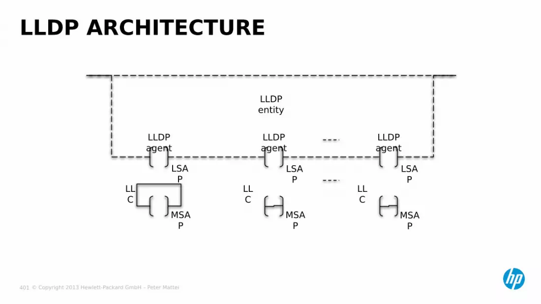
© Copyright 2013 Hewlett-Packard GmbH – Peter Mattei 401
LLDP ARCHITECTURE
MSAP
MSAP
MSAP
LLC
LLC
LLC
LSAP
LSAP
LSAP
LLDP agent
LLDP agent
LLDP agent
LLDP entity

© Copyright 2013 Hewlett-Packard GmbH – Peter Mattei 402
Frame
LLDP FRAME FORMAT
LLDPDU
TLVs
Chassis ID
TLV
Port IDTLV
Time toLive TLV
OptionalTLV
OptionalTLV
End Of LLDPDUTLV
Type Lenght Value

© Copyright 2013 Hewlett-Packard GmbH – Peter Mattei 403
− LLDP is a one-way protocol• It does not use ACKnowledges or Request Reply pairs
− LLDP Agent operational modes• Disabled• Transmit only (TX)• Receive only (RX)• Both transmit and receive (TXRX)
− Each mode can be chosen separately by the transmitter/receiver to meet the different requirements.
LLDP OPERATION
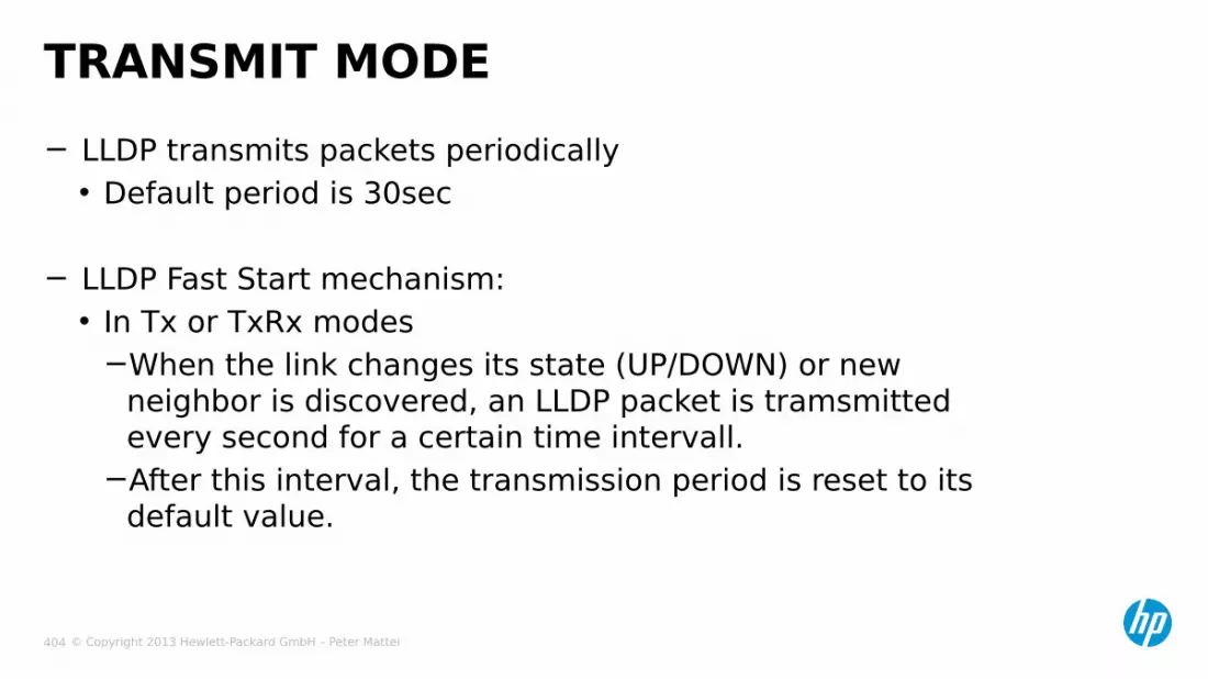
© Copyright 2013 Hewlett-Packard GmbH – Peter Mattei 404
− LLDP transmits packets periodically• Default period is 30sec
− LLDP Fast Start mechanism:• In Tx or TxRx modes
−When the link changes its state (UP/DOWN) or new neighbor is discovered, an LLDP packet is tramsmitted every second for a certain time intervall.
−After this interval, the transmission period is reset to its default value.
TRANSMIT MODE

© Copyright 2013 Hewlett-Packard GmbH – Peter Mattei 405
− After receiving LLDP packets:• Check the validity for the packets and each TLV first, and drop
invalid ones.• After passing the verification, use all the valid TLVs to update the
information in remote system MIB.
− Neighbor information aging• The receiver will age the neighbor’s information based on the TTL
TLV in the packets.• It will refresh TTL after receiving the neighbor’s packets to avoid
the neighbor’s information being aged.• If the TTL is set as zero in the received packets, then it will delete
the neighbor’s information immediately.
RECEIVE MODE

© Copyright 2013 Hewlett-Packard GmbH – Peter Mattei 406
IRFINTELLIGENT
RESILIENTFRAMEWORK
© Copyright 2013 Hewlett-Packard GmbH – Peter Mattei 407
− IRFv2 Overview− Building and
Maintaining IRF
AGENDA

© Copyright 2013 Hewlett-Packard GmbH – Peter Mattei 408
IRFV2 OVERVIEW

© Copyright 2013 Hewlett-Packard GmbH – Peter Mattei 409
− IRF combines multiple devices into a single virtual device− Simplifies management− Low cost− Powerful network expansion capability− High reliability− High performance
ADVANTAGES OF IRF
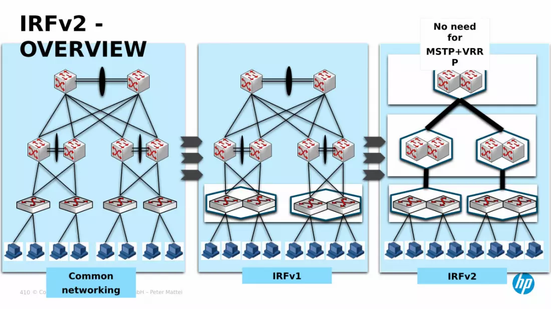
© Copyright 2013 Hewlett-Packard GmbH – Peter Mattei 410
IRFv2 - OVERVIEW
Commonnetworking
IRFv1 IRFv2
No need for
MSTP+VRRP
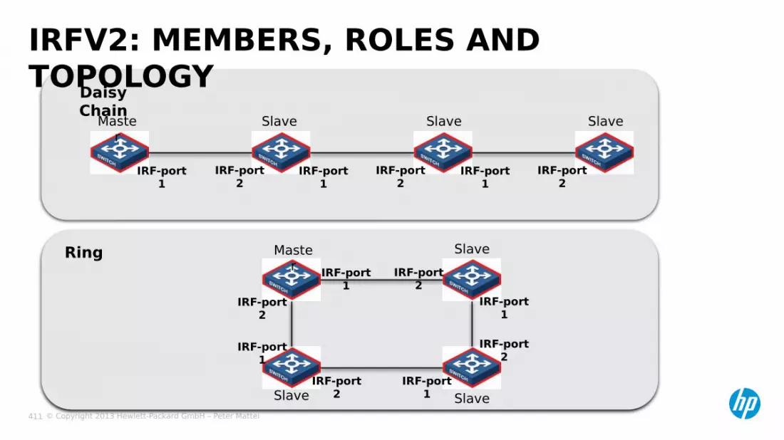
© Copyright 2013 Hewlett-Packard GmbH – Peter Mattei 411
IRFV2: MEMBERS, ROLES AND TOPOLOGYDaisy
ChainMaster
Slave Slave Slave
IRF-port 1
IRF-port 1
IRF-port 1
IRF-port 2
IRF-port 2
IRF-port 2
Ring
IRF-port 1
IRF-port 1
IRF-port 1
IRF-port 1
IRF-port 2
IRF-port 2
IRF-port 2
IRF-port 2
Slave Slave
SlaveMaster

© Copyright 2013 Hewlett-Packard GmbH – Peter Mattei 412
IRFV2 – OVERVIEW (2)

© Copyright 2013 Hewlett-Packard GmbH – Peter Mattei 413
OPERATIONAL PLANES IN STANDALONE SWITCHES
SwitchMGMT
CTRL
FWD
SRPU # 1 MGMT(Master)
CTRL(Active)
FWD-Crossbar(Active)
SRPU # 2 MGMT(Slave)
CTRL(Standby)
FWD-Crossbar(Backup or Load
Sharing)LPU # 1 MGMT
(Proxy)CTRL
(Proxy)FWD
LPU # 2 MGMT(Proxy)
CTRL(Proxy)
FWD
LPU # 3 MGMT(Proxy)
CTRL(Proxy)
FWD
LPU # N MGMT(Proxy)
CTRL(Proxy)
FWD
Stackable Switches
Chassis-based Switches

© Copyright 2013 Hewlett-Packard GmbH – Peter Mattei 414
OPERATIONAL PLANES IN IRFV2
Unit #1MGMT (Master)
CTRL (Active)
FWD
Unit #2MGMT (Slave and Proxy)
CTRL (Standby and Proxy)
FWD
Unit #3MGMT (Slave and Proxy)
CTRL (Standby and Proxy)
FWD
Unit #4MGMT (Slave and Proxy)
CTRL (Standby and Proxy)
FWD
SRPU # 1 MGMT(Master)
CTRL(Active)
FWD-Crossbar(Active)
SRPU # 2 MGMT(Slave)
CTRL(Standby)
FWD-Crossbar(Backup or Load Sharing)
LPU # 1 MGMT(Proxy)
CTRL(Proxy)
FWD
LPU # 2 MGMT(Proxy)
CTRL(Proxy)
FWD
LPU # 3 MGMT(Proxy)
CTRL(Proxy)
FWD
LPU # N MGMT(Proxy)
CTRL(Proxy)
FWD
Chassis #1
Stackable Switches
Chassis-based Switches
SRPU # 1 MGMT(Slave)
CTRL(Standby)
FWD-Crossbar(Active)
SRPU # 2 MGMT(Slave)
CTRL(Standby)
FWD-Crossbar(Backup or Load Sharing)
LPU # 1 MGMT(Proxy)
CTRL(Proxy)
FWD
LPU # 2 MGMT(Proxy)
CTRL(Proxy)
FWD
LPU # 3 MGMT(Proxy)
CTRL(Proxy)
FWD
LPU # N MGMT(Proxy)
CTRL(Proxy)
FWD
Chasis #2
IRF System
IRF System

© Copyright 2013 Hewlett-Packard GmbH – Peter Mattei 415
− IRFv2 systems are connected using any 10 GbE interface:• CX4• SFP+• XFP• XENPAK
− Inexpensive Local Connection cables are available for CX4, SFP+ and XFP ports.
IRFV2 – IRF CONNECTIONS
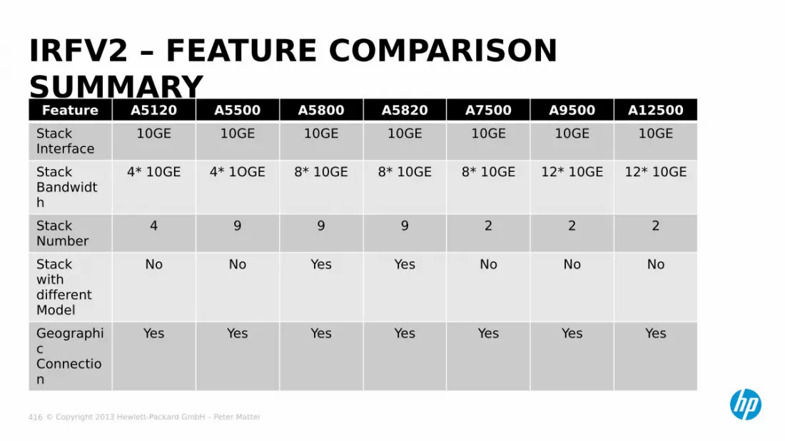
© Copyright 2013 Hewlett-Packard GmbH – Peter Mattei 416
IRFV2 – FEATURE COMPARISON SUMMARY
Feature A5120 A5500 A5800 A5820 A7500 A9500 A12500StackInterface
10GE 10GE 10GE 10GE 10GE 10GE 10GE
StackBandwidth
4* 10GE 4* 1OGE 8* 10GE 8* 10GE 8* 10GE 12* 10GE 12* 10GE
StackNumber
4 9 9 9 2 2 2
Stack with different Model
No No Yes Yes No No No
Geographic Connection
Yes Yes Yes Yes Yes Yes Yes

© Copyright 2013 Hewlett-Packard GmbH – Peter Mattei 417
BUILDING ANDMAINTAINING IRF
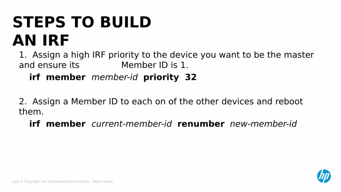
© Copyright 2013 Hewlett-Packard GmbH – Peter Mattei 418
1. Assign a high IRF priority to the device you want to be the master and ensure its Member ID is 1.
irf member member-id priority 32
2. Assign a Member ID to each on of the other devices and reboot them.
irf member current-member-id renumber new-member-id
STEPS TO BUILD AN IRF

© Copyright 2013 Hewlett-Packard GmbH – Peter Mattei 419
3. Configure the IRF-ports in each device, sabe the configuration and turn them off.This step varies slightly between different product families
interface tan-gigabit port-idshutdownirf-port 1/1port group interface ten-gigabit port-idinterface ten-gigabit port-idundo shutdown
NoteOn the A7500, A9500, and A12500 switches, you must specifically enable IRF mode, using the command:chassis convert mode irf – The device reboots automatically to switch its operating mode.(To reverse this command enter the undo chassis convert mode command)
STEPS TO BUILD AN IRF (2)

© Copyright 2013 Hewlett-Packard GmbH – Peter Mattei 420
4. Save the configuration of each device and turn them off.5. Connect the IRF links to build the IRF fabric.• Note: IRF-port 1 of one device must be connected to IRF-port 2 of
the next device. Connecting IRF-ports of the same number will prevent the devices to recognize each other as members of the same IRF.
6. Turn on the unit that needs to be the master (Member-id=1)• Wait until the boot process is complete before turning on the next
device. This will guarantee that this unit will become the master.
7. Repeat the process for each member (turn on and wait). This step is calied “device insertion”. Always turn on a device connected to other devices that are already up and running.
STEPS TO BUILD AN IRF (3)

© Copyright 2013 Hewlett-Packard GmbH – Peter Mattei 421
1. The current master wins, even if a new member has a higher priority. (When a new member is added, IRF merge does not happen.)
2. A member with a higher priority wins.3. A member with the longest system up-time wins. (The
precisión of the system up-time is ten minutes.)
4. A member with the lowest bridge MAC address wins.
IRF MERGE: MASTER ELECTION

© Copyright 2013 Hewlett-Packard GmbH – Peter Mattei 422
− IRF configuration are divided into global configuration and local configuration.
− Global configuration includes Layer 3 interface, IP address, routing protocol, and security features• Effective throughout the fabric
− Local configuration mainly includes the port parameters• Effective for local unit only
CONFIGURATION FILES

© Copyright 2013 Hewlett-Packard GmbH – Peter Mattei 423
IRF SPLIT: MAD
Device inNormal
state
Device inRecovery
state
BrokenIRF Link
BlockedPort

© Copyright 2013 Hewlett-Packard GmbH – Peter Mattei 424
− MAD can be configured to use BFD or LACP as the IRF split detection protocol.
− MAD/LACP:• Uses a distributed Bridge Aggregation interface connected to a 3°
device to exchange MAD information• To support this function LACP has been extended with MAD specify
TLV fields. − MAS/BFD:• A special VLAN with ports in each member must be configured.• And each member device must be configured with an MAD IP
address.• These addresses are invisible for the rest of the network and no
routing interface can be attached to an MAD/BFD enable VLAN.
MAD DETECTION PROTOCOLS
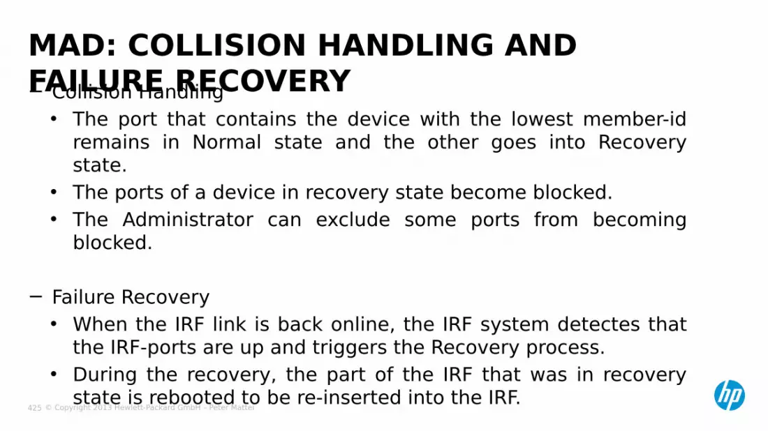
© Copyright 2013 Hewlett-Packard GmbH – Peter Mattei 425
− Collision Handling• The port that contains the device with the lowest member-id
remains in Normal state and the other goes into Recovery state.
• The ports of a device in recovery state become blocked.• The Administrator can exclude some ports from becoming
blocked.
− Failure Recovery• When the IRF link is back online, the IRF system detectes that
the IRF-ports are up and triggers the Recovery process.• During the recovery, the part of the IRF that was in recovery
state is rebooted to be re-inserted into the IRF.
MAD: COLLISION HANDLING AND FAILURE RECOVERY
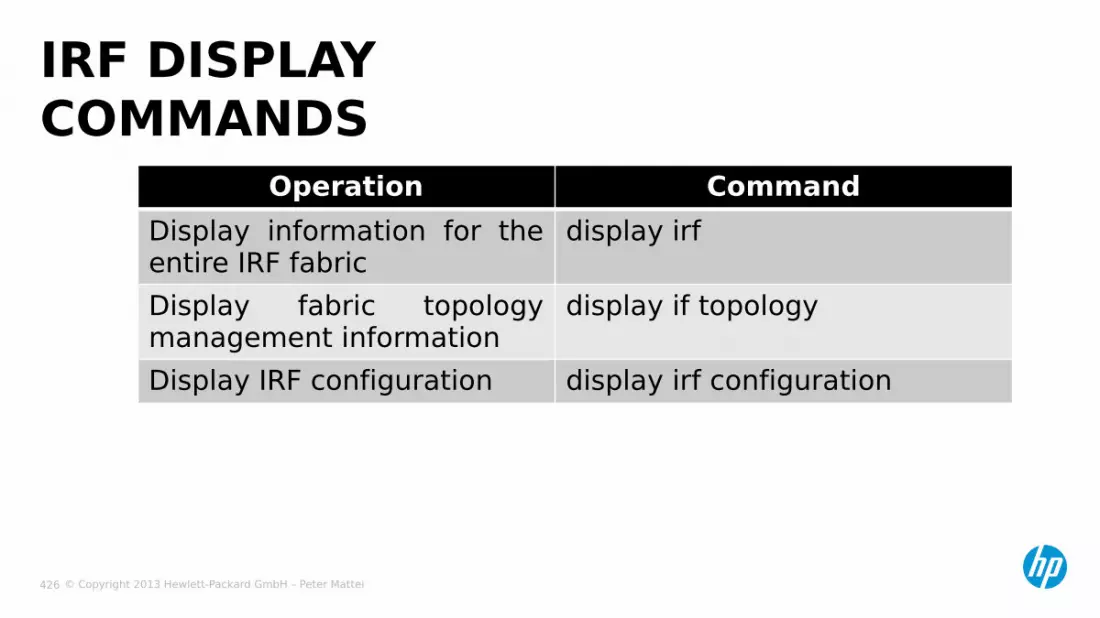
© Copyright 2013 Hewlett-Packard GmbH – Peter Mattei 426
IRF DISPLAY COMMANDS
Operation CommandDisplay information for the entire IRF fabric
display irf
Display fabric topology management information
display if topology
Display IRF configuration display irf configuration
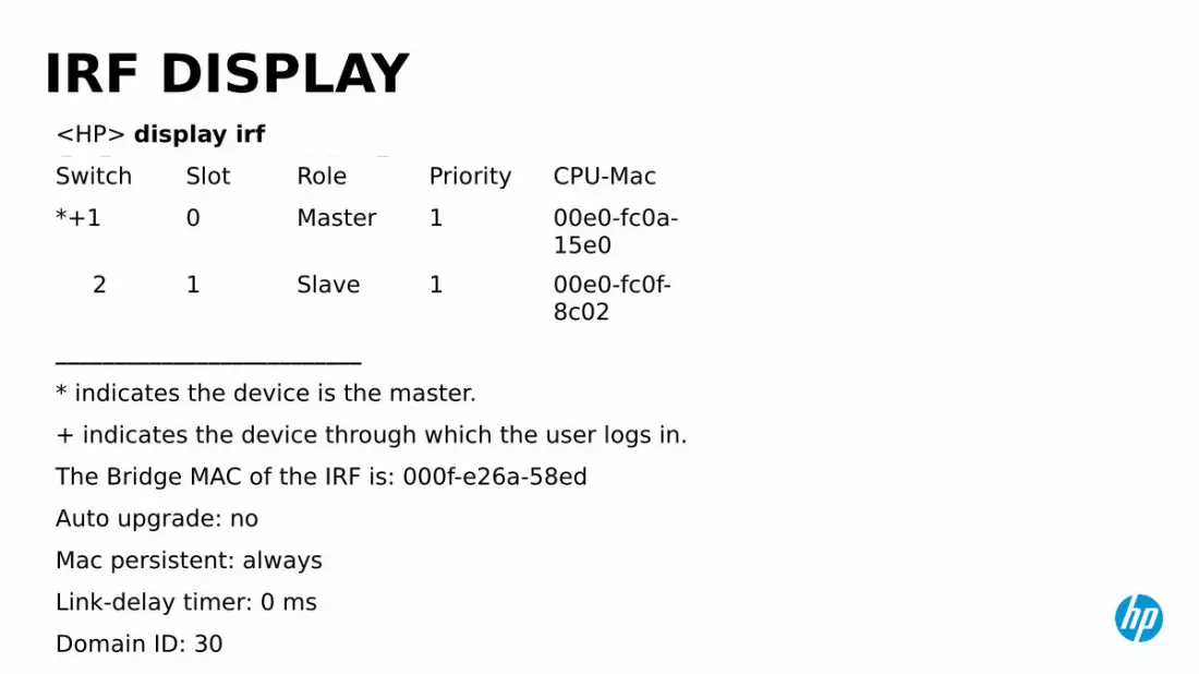
© Copyright 2013 Hewlett-Packard GmbH – Peter Mattei 427
IRF DISPLAY COMMANDS<HP> display irfSwitch Slot Role Priority CPU-Mac*+1 0 Master 1 00e0-fc0a-
15e0 2 1 Slave 1 00e0-fc0f-
8c02__________________________* indicates the device is the master.+ indicates the device through which the user logs in.The Bridge MAC of the IRF is: 000f-e26a-58edAuto upgrade: noMac persistent: alwaysLink-delay timer: 0 msDomain ID: 30
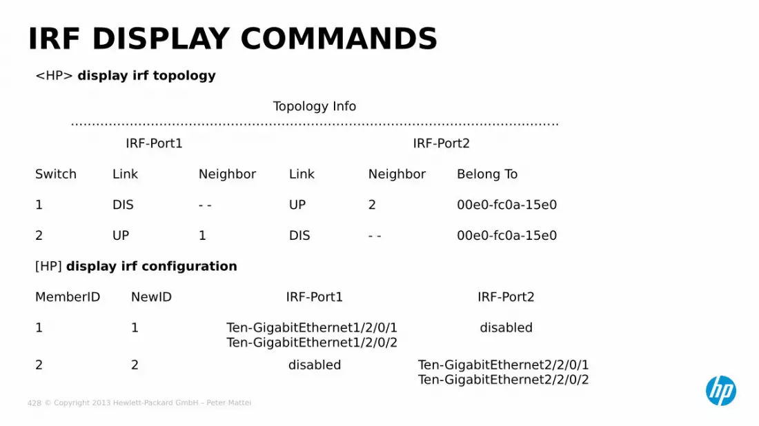
© Copyright 2013 Hewlett-Packard GmbH – Peter Mattei 428
IRF DISPLAY COMMANDS<HP> display irf topology
Topology Info……………………………………………………………………………………………………..
IRF-Port1 IRF-Port2
Switch Link Neighbor Link Neighbor Belong To
1 DIS - - UP 2 00e0-fc0a-15e0
2 UP 1 DIS - - 00e0-fc0a-15e0
[HP] display irf configuration
MemberID NewID IRF-Port1 IRF-Port2
1 1 Ten-GigabitEthernet1/2/0/1Ten-GigabitEthernet1/2/0/2
disabled
2 2 disabled Ten-GigabitEthernet2/2/0/1Ten-GigabitEthernet2/2/0/2