Embed Size (px)
Citation preview
BL Series Operation andMaintenanceManual


1
Owner Name____________________________________________________________________________________________
Address_______________________________________________________________________________________________
City__________________________________________________________________________________________________
State/Province _____________________________________________________ Zip/Postal Code___________________________
Purchased From Company Name_______________________________________________________________________________
Contact Name___________________________________________________________________________________________
Address_______________________________________________________________________________________________
City__________________________________________________________________________________________________
State/Province_____________________________________________________ Zip/Postal Code___________________________
Phone Number ( ________ ) _______________________________________________________________________________
E-mail________________________________________________________________________________________________
Date Purchased__________________________________________________________________________________________
Vehicle Make ___________________________ Vehicle Model_______________________________________________________
Vehicle Year____________________________ Spreader Model_______________________________________________________
Spreader Serial Number_____________________________________________________________________________________
Registration Data SheetRegister your spreader at www.meyerproducts.com

2
Thank You…Thank you for buying your Meyer Spreader. As a new owner of hard-working, mechanical equipment, we strongly urge you to spend quality time with this owner’s manual. It’s easy to use and full of time-saving tips that will enhance your ownership experience. It includes suggestions for faster installation, safe operation and more productive spreading.
We also strongly urge you to register your new Meyer spreader at meyerproducts.com. Registering will only take minutes and the benefits of doing so will last for years. When registered, you will receive timely and accurate communication on operation tips, maintenance, new products, and service bulletins. And in the unlikely event you need warranty work performed, your local servicing dealer will be able to process your claim faster.
Thanks again for your business. You can now look forward to many years of reliable performance. If you have any questions about your Meyer spreader, contact us at: www.meyerproducts.com or call 216-486-1313.
Andy Outcalt, President, Meyer Products, LLC.

3
Table of ContentsRegistration Data Sheet ....................................................................................................................... 1Thank You ........................................................................................................................................... 2Introduction ......................................................................................................................................... 4Safety Definitions & Warnings ..........................................................................................................5-7Safety Decal Locations ....................................................................................................................8-9Vehicle Requirements for Installation ................................................................................................. 10Receiver Mount Installation/Assembly ................................................................................................ 12Spreader Installation/Assembly .......................................................................................................... 13Spreader Component Identification ...............................................................................................14-17Speed Controller ..........................................................................................................................18-21Spreader Operation & Materials Chart................................................................................................ 22Spreader Maintenance ...................................................................................................................... 23Spreader Troubleshooting .................................................................................................................. 24Spreader Calibration .....................................................................................................................26-27Accessories ..................................................................................................................................28-30EC Declaration of Conformity ............................................................................................................. 31Warranty/Contact Meyer ...............................................................................................................34-35

4
Introduction
Snow and ice, despite the beauty it may impart to a bleak winter landscape, poses the dual threat of inconvenience and danger. The environmental conditions associated with snow and ice, not to mention the health hazards and economic loss it may impose, seriously endanger thousands of lives annually. Business and industry suffer, and millions of snowbelt residents may be affected by a single snowstorm.
Meyer Products LLC has published this manual to help you get the maximum performance from your Meyer spreader and familiarize you with the features designed for efficiency and safety; be sure you recognize and understand them. Follow recommended operation and maintenance instructions, so when the storm hits, your Meyer spreader will be ready and you will know how to spread like a pro.
DO NOT EQUIP ANY VEHICLE WITH A SPREADER WITHOUT CONSULTING VEHICLE MANUFACTURERS’ RECOMMENDATIONS.
Vehicles equipped with Meyer spreaders installed may be so equipped as to meet vehicle manufacturers’ specifications and recommended options for material spreading use. Most vehicle manufacturers insist that vehicles which are to be used for ice control be equipped with certain options and accessories, and it is so stated in vehicle manufacturer specifications for snow plow application.
WARNING: Deployment of an air bag while using a Meyer Spreader will not be covered under Meyer Products’ warranty. We also recommend that, for optimum performance, vehicles used for ice control be equipped with:
Four-Wheel Drive
Minimum 60 Amp Alternator or larger
Minimum 70 Amp Battery or larger (550 C.C.A.)
Mud and Snow Tires
Increased Radiator Cooling
Automatic Transmission
Power Brakes
Power Steering
Under the continuing Meyer Product Improvement Plan, Meyer Products LLC reserves the right to change design details and construction without prior notice and without incurring any obligation.

5
Safety Definitions
DANGER Conveyor This decal alerts all to the danger of serious personal injury or death while servicing or cleaning this equipment without first turning off or disconnecting all power sources.
DANGER SpinnerThis decal alerts all to the danger of any person being near the spinner while it is turning where serious personal injury could result if struck by flying debris.
CAUTIONThis decal cautions all to the risk of the tank containing hazardous chemicals. Operators should wear appropriate PPE when contact with chemicals is possible.
CAUTION This decal cautions all to observe general safety procedures when operating, moving, storing, cleaning or servicing this equipment.
CAUTION Empty HopperThis decal cautions all to only lift or move equipment when hopper is empty to prevent the risk of serious personal injury or property damage.
CAUTION Fork LengthThis decal cautions all to make sure fork lift arms extend a minimum of4"(10.2cm) past both brackets before lifting or moving equipment to prevent the risk of serious personal injury or property damage.
These safety alert decals are used to alert you of potential personal injury hazards. Obey all safety messages that follow this symbol to avoid possible injury or death.

6
Safety Definitions & Warnings1 NEVER stand or ride on the spreader. Failure to comply will result in death or serious injury.
2 Keep hands, feet, and clothing away from power driven parts. Failure to comply will result in death or serious injury.
3 Make sure spreader is completely shut off and all movement has stopped before attempting to clean, service or unclog. Failure to comply will result in death or serious injury.
4 NEVER enter hopper while spreader is operating or capable of being operated. Failure to comply will result in death or serious injury.
5NEVER operate or service your spreader without first CAREFULLY reading the Owner’s Manual. It is CRITICAL for your safety to ALWAYS obey EVERY warning in the manual and follow EVERY instruction EXPLICITLY. Failure to comply could result in death or serious injury.
6 Never leave operator’s position without first completely turning off spreader, disengaging PTO, shutting off hydraulic valve and setting vehicle parking brake. Failure to comply will result in death or serious injury.
7 Never operate spreader without all shields, guards, and safety decals in place. Failure to comply will result in death or serious injury.
8 Spreader should only be operated by personnel trained in the safe use and transportation of this equipment.
9 The spreader should NEVER be used for any other purpose other than spreading ice melting or traction products on streets, parking lots and driveways. Failure to comply will result in property damage, death or serious injury.
10Inspect spreader assembly and mounting components and fasteners for wear and damage before and after each use. Worn or damaged components or fasteners could allow spreader to break free from the transport vehicle. Failure to comply will result in death or serious injury.
11
Transport vehicle must not be operated when overloaded. In all cases, the loaded vehicle weight, including the entire spreader system, all aftermarket accessories, driver, passenger, options, nominal fluid levels, and cargo must not exceed the front/rear Gross Axle Weight Rating (GAWR), and total Gross Vehicle Weight Rating (GVWR). These weights ratings are specified on the safety compliance certification label on the driver’s side door opening. Failure to comply will result in death or serious injury.
12 Spreader may tip over or fall. Spreader should be solidly supported when being mounted, dismounted, moved, or stored. Failure to comply will result in death or serious injury.
13 Operator, bystanders and pets should be kept at least 50 feet away from spreader during operation. Failure to comply will result in death or serious injury.
14SAFETY PRECAUTIONS should be used when hydraulic system is operating or being serviced. Hydraulic fluid under pressure can cause a skin injection injury. If you are injured by hydraulic fluid, get medical attention immediately. Failure to comply will result in death or serious injury.
15 Engine exhaust contains lethal fumes. Breathing these fumes, even in low concentrations, can cause death. Never operate engine in an enclosed area without venting the exhaust to the outside. Failure to comply will result in death or serious injury.
�!
�! DANGER
�! WARNING
�! CAUTION
CAUTION
�!
�! DANGER
�! WARNING
�! CAUTION
CAUTION
�!
�! DANGER
�! WARNING
�! CAUTION
CAUTION
�!
�! DANGER
�! WARNING
�! CAUTION
CAUTION
�!
�! DANGER
�! WARNING
�! CAUTION
CAUTION
�!
�! DANGER
�! WARNING
�! CAUTION
CAUTION
�!
�! DANGER
�! WARNING
�! CAUTION
CAUTION
�!
�! DANGER
�! WARNING
�! CAUTION
CAUTION
�!
�! DANGER
�! WARNING
�! CAUTION
CAUTION
SAFETY DEFINITIONS
This is the safety alert symbol. It is used to alert you to potential personal injury hazards. Obey all safety messages that follow this symbol to avoid possible injury or death.
DANGER Indicates an imminently hazardous situation which, if not avoided, will result in death or serious injury.
WARNING Indicates a potentially hazardous situation which, if not avoided, could result in death or serious injury.
CAUTION Indicates an potentially hazardous situation which, if not avoided, may result in minor or moderate injury.
CAUTION used without the safety alert symbol indicates a potentially hazardous situation which, if not avoided, will result in property damage.
�!
�! DANGER
�! WARNING
�! CAUTION
CAUTION
�!
�! DANGER
�! WARNING
�! CAUTION
CAUTION
�!
�! DANGER
�! WARNING
�! CAUTION
CAUTION
�!
�! DANGER
�! WARNING
�! CAUTION
CAUTION
�!
�! DANGER
�! WARNING
�! CAUTION
CAUTION
�!
�! DANGER
�! WARNING
�! CAUTION
CAUTION
�!
�! DANGER
�! WARNING
�! CAUTION
CAUTION
�!
�! DANGER
�! WARNING
�! CAUTION
CAUTION
�!
�! DANGER
�! WARNING
�! CAUTION
CAUTION
�!
�! DANGER
�! WARNING
�! CAUTION
CAUTION
�!
�! DANGER
�! WARNING
�! CAUTION
CAUTION

7
Safety Definitions & Warnings16
Gasoline is highly flammable and gasoline vapor is explosive. Never smoke while working on vehicle or spreader. Keep all open flames away from gasoline tank and lines. Wipe up any spilled gasoline immediately. Failure to comply will result in death or serious injury.
17NEVER operate the spreader gasoline engine without first CAREFULLY reading the Owner’s Manual. It is CRITICAL for your safety to ALWAYS obey EVERY warning in the manual and follow EVERY instruction EXPLICITLY. Failure to comply will result in death or serious injury.
18A driver’s first responsibility is the safe operation of the vehicle and spreader. The most important thing you can do to prevent a crash is to avoid distractions and pay attention to the road. Wait until it is safe to operate mobile communication equipment such as cell phones, two way radios, etc. Failure to comply will result in injury.
19 Vehicle must conform to all local, state, and national regulations regarding the use of reflective markings and flashing lights. Failure to comply will result in injury.
20
Batteries normally produce explosive gases which can cause personnel injury. Therefore, do not allow flames, sparks or lit tobacco to come near the battery. When charging or working near a battery, always cover your face and protect your eyes, and also provide ventilation. Batteries contain sulfuric acid which burns skin, eyes, and clothing. Failure to comply will result in injury.
21 Never transport spreader with spinner in the raised position. Failure to comply will result in property damage.
22 Installation of a Meyer spreader may affect your new vehicle warranty. Before beginning spreader installation verify mounting method is acceptable to your vehicle manufacturer. Failure to comply will result in property damage.
23 Warranty does not apply to a Meyer spreader product which has been negligently or improperly assembled or installed. Failure to comply will result in property damage.
24 CAUTION: To avoid harm to vehicles electrical system always disconnect battery before beginning installation. DO NOT BURN holes or WELD vehicle frame. This may cause frame failure. Failure to comply will result in property damage.
25 CAUTION: To avoid harm to spreader electrical system always disconnect battery before beginning installation or service. Do not operate spreader with a missing, discharged or dead battery. Failure to comply will result in property damage.
26The Meyer spreader electrical system contains several automotive style fuses. If a problem should occur and fuse replacement is necessary, the replacement fuse must be of the same type and amperage as the original. Installing a fuse with a higher rating can damage the system and could cause a fire. Failure to comply will result in property damage.
27 Spreader is not designed to be chassis mounted. Do not support spreader by body jacks alone. Spreader must be installed directly onto truck bed. Failure to comply will result in property damage.
�!
�! DANGER
�! WARNING
�! CAUTION
CAUTION
�!
�! DANGER
�! WARNING
�! CAUTION
CAUTION
�!
�! DANGER
�! WARNING
�! CAUTION
CAUTION
�!
�! DANGER
�! WARNING
�! CAUTION
CAUTION
�!
�! DANGER
�! WARNING
�! CAUTION
CAUTION
�!
�! DANGER
�! WARNING
�! CAUTION
CAUTION
�!
�! DANGER
�! WARNING
�! CAUTION
CAUTION
�!
�! DANGER
�! WARNING
�! CAUTION
CAUTION
�!
�! DANGER
�! WARNING
�! CAUTION
CAUTION
�!
�! DANGER
�! WARNING
�! CAUTION
CAUTION
�!
�! DANGER
�! WARNING
�! CAUTION
CAUTION
�!
�! DANGER
�! WARNING
�! CAUTION
CAUTION
SAFETY DEFINITIONS
This is the safety alert symbol. It is used to alert you to potential personal injury hazards. Obey all safety messages that follow this symbol to avoid possible injury or death.
DANGER Indicates an imminently hazardous situation which, if not avoided, will result in death or serious injury.
WARNING Indicates a potentially hazardous situation which, if not avoided, could result in death or serious injury.
CAUTION Indicates an potentially hazardous situation which, if not avoided, may result in minor or moderate injury.
CAUTION used without the safety alert symbol indicates a potentially hazardous situation which, if not avoided, will result in property damage.
�!
�! DANGER
�! WARNING
�! CAUTION
CAUTION
�!
�! DANGER
�! WARNING
�! CAUTION
CAUTION
�!
�! DANGER
�! WARNING
�! CAUTION
CAUTION
�!
�! DANGER
�! WARNING
�! CAUTION
CAUTION
�!
�! DANGER
�! WARNING
�! CAUTION
CAUTION
8
Safety Decal Locations
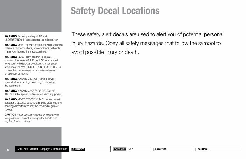
These safety alert decals are used to alert you of potential personal
injury hazards. Obey all safety messages that follow the symbol to
avoid possible injury or death.
5 / 7SAFETY PRECAUTIONS - See pages 5-6 for definitions
�!
�! DANGER
�! WARNING
�! CAUTION
CAUTION
�!
�! DANGER
�! WARNING
�! CAUTION
CAUTION
�!
�! DANGER
�! WARNING
�! CAUTION
CAUTION
�!
�! DANGER
�! WARNING
�! CAUTION
CAUTION
WARNING Before operating READ and UNDERSTAND this operators manual in its entirety.
WARNING NEVER operate equipment while under the influence of alcohol, drugs, or medications that might impair your judgment and reaction time.
WARNING NEVER allow children to operate equipment. ALWAYS CHECK AREAS to be spread to be sure no hazardous conditions or substances are present. ALWAYS INSPECT UNIT FOR DEFECTS: broken, bent, or worn parts, or weakened areas on spreader or mount.
WARNING ALWAYS SHUT OFF vehicle power source before attaching, detaching, or servicing the equipment.
WARNING ALWAYS MAKE SURE PERSONNEL ARE CLEAR of spread pattern when using equipment.
WARNING NEVER EXCEED 45 M.P.H when loaded spreader is attached to vehicle. Braking distances and handling characteristics may be impaired at greater speeds.
CAUTION Never use wet materials or material with foreign debris. This unit is designed to handle clean, dry, free-flowing material.

95 / 7SAFETY PRECAUTIONS - See pages 5-6 for definitions
�!
�! DANGER
�! WARNING
�! CAUTION
CAUTION
�!
�! DANGER
�! WARNING
�! CAUTION
CAUTION
�!
�! DANGER
�! WARNING
�! CAUTION
CAUTION
�!
�! DANGER
�! WARNING
�! CAUTION
CAUTION
CAUTION Never leave material in hopper for long periods of time. All ice melt materials will attract atmospheric moisture and may clump together.
WARNING INSPECT pins and bolts whenever attaching, detaching, and before travel. All factory installed bolts utilize lock nuts however road and operational vibrations might loosen them.
WARNING INSPECT unit periodically for defects. Parts that are broken, worn, or missing musts be replaced immediately. The unit or any part of it should NOT be altered in any way without prior written permission from the manufacturer.
WARNING When using swing mount, NEVER swing spreader with material in hopper!
WARNING NEVER attempt to clear a jammed feed screw with the power on!
WARNING NEVER place hands into hopper or around feed screw and spinner when power is on. Also, keep loose clothing and hair away from moving parts!
CAUTION De-icing materials can be damaging to plant life and concrete. Know what you are spreading and where you are spreading it.
WARNING
WARNING
WARNING
Safety Decal Locations

10
Vehicle Requirements for Installation
5 / 9 / 11SAFETY PRECAUTIONS - See pages 5-6 for definitions
�!
�! DANGER
�! WARNING
�! CAUTION
CAUTION
�!
�! DANGER
�! WARNING
�! CAUTION
CAUTION
�!
�! DANGER
�! WARNING
�! CAUTION
CAUTION
22 / 23
�!
�! DANGER
�! WARNING
�! CAUTION
CAUTION
For installation BL 240 & 400 series spreaders:1. This product line can be installed on any vehicle with a class
3 hitch receiver that will accept a 2" square tube and has a tongue weight rating of at least 500 lbs.
2. If your vehicle is not factory equipped with a hitch, we recommend taking it to a reputable trailer hitch installation shop or your vehicles dealership.
As with any vehicle accessory, please refer to you owners manual to verify that the GVWR (Gross Vehicular Weight Rating) will not be exceeded, especially if this product will be used in conjunction with other mounted equipment. If equipment is mounted to vehicle with other than stock hardware or components, we the manufacturer cannot and will not be held responsible for damages. Also, check your vehicle owner’s manual to be sure that the installation of “aftermarket” accessories will not void the manufacturers’ factory warranty.

11
Notes

12
Receiver Mount Installation / AssemblyINSTALLING RECEIVER MOUNT MODEL: BL 240/400
The Blaster 350/350S/750R/750RS is a dedicated, Class 3, 2", receiver (hitch) mount salt spreader. Prior to installation, be certain that the vehicle receiver is in good working order, is rated for at least a 500 lb. tongue load, and is fastened to the vehicle securely.
CAUTION - The spreader is a large heavy item that should be installed with an assistant. As with any new equipment installation read and understand all instructions prior to starting the job, and do not hurry through it. A correct installation now can save time and money later.CAUTION: Always disconnect battery before beginning installation.
Check contents against the parts list to determine all are correct and included, and also to familiarize yourself with them.
Locknuts are furnished. DO NOT tighten bolts and nuts until installation is complete (unless otherwise specified), then be sure to tighten all attaching parts per specified torque chart.
When ordering parts, furnish Part No., Name and Description. 1. Assemble Hitch Assembly (13) to Spreader Frame (3) using 3/8-16 x 3" Bolt (26), 3/8 Flatwasher (28) and 3/8 Locknut (27).
2. Slide Spreader Assembly into receiver hitch on vehicle and insert Hinge Pin (25) through corresponding hole on receiver and Hitch Assembly (13). Secure Hinge Pin (25) with Linch Pin (29).
3. Tighten all bolts to their required torque using the chart below.
4. ELECTRICAL INSTALLATION. Refer to Figure 1
5 19SAFETY PRECAUTIONS - See pages 5-6 for definitions
�!
�! DANGER
�! WARNING
�! CAUTION
CAUTION
�!
�! DANGER
�! WARNING
�! CAUTION
CAUTION
�!
�! DANGER
�! WARNING
�! CAUTION
CAUTION
22 / 23 / 24 / 25
�!
�! DANGER
�! WARNING
�! CAUTION
CAUTION
Bolt Nut Size
Gr. 2
Gr. 5
Gr. 8
1/4 - 20 4 - 5
5/16 - 18 9 - 11
3/8 - 16 17 - 20 26 - 29
7/16 - 14 42 - 45 60 - 661/2 - 13 64 - 72 90 - 100
5/8 - 11 127 - 141 179 - 198
Torque Chart Foot (lbs.)

13
Spreader Installation / Assembly
5 / 9 / 11 / 12 19SAFETY PRECAUTIONS - See pages 5-6 for definitions
�!
�! DANGER
�! WARNING
�! CAUTION
CAUTION
�!
�! DANGER
�! WARNING
�! CAUTION
CAUTION
�!
�! DANGER
�! WARNING
�! CAUTION
CAUTION
22 / 23 / 24 / 25 / 27
�!
�! DANGER
�! WARNING
�! CAUTION
CAUTION
INSTALLATION INSTRUCTIONS 1. Choose a location for the Speed Control (30) that is convenient for the driver. Make certain speed control (30) is grounded by attaching ground wire to a good vehicle ground.
2. Attach the eyelet end of the 96" red wire (34) to the positive terminal of the battery and route the plug end to the location of the speed control. DO NOT attach to Speed Control (30) at this time.
3 Take the 222" red wire (33) and route the large rubber plug end to the rear of the truck, securely tying to vehicle frame. Be certain wire is clear of any sharp or moving objects or the vehicle’s exhaust system.
CAUTION: Some vehicles are designed to operate with exhaust temperatures as high as 1800°F. This can easily damage any wires which are routed too closely or allowed to come in contact with any portion of the exhaust system. Be certain all wires are securely installed away from the exhaust system.
4. Be certain the motor leads will not be strained when the plug is attached. Plug the 222" red wire (33) into the socket. Secure black wire from socket (31) to a good grounding point on vehicle frame. Clean all rust or undercoating from this area. 5. Attach red wire from motor plug (32) to positive (+) terminal of motor. Tape this connection! Attach black wire to negative (-) terminal of motor. Push plug (32) into the socket (31).
6. Perform the motor run test as described in paragraphs 3 and 4 of the “Caution” above. If the motor operates 222" red wire (33) and 96" red wire (34) can be attached to their respective terminals on the speed control (30).
Meyer Products assumes no responsibility for installations not made in accordance with these instructions.
14
Spreader Component Identification
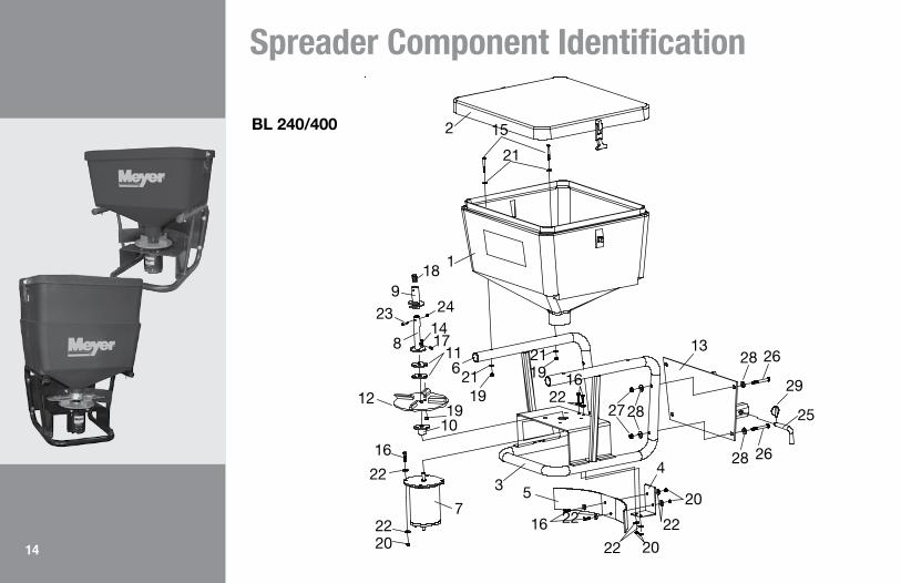
BL 240/400 2 15
21
118
2119
249
23
81417
11621
1919
10
12
16
22
2220
7
3 5
2216
13
4
2216
22
22
20
20
28 26
2827
28 26
29
25

15
Item Part No. Qty. Description 1 31101 1 • 240 Hopper 1 36101 1 • 400 Hopper 2 31102 1 • Hopper Cover 3 34413 1 • 240/400 Spreader Frame 4 34415 1 • Deflector Bracket 5 34401 1 • Deflector 6 34416 2 • Tube Plug 7 36402 1 • Motor 12V D.C. 8 34011 1 • Auger Center Post 9 34302 1 • Brush Auger Rock Salt 10 36152 1 • Spinner Hub Weldment 11 36158 2 • Spinner Mounting Plate 12 36415 1 • Spinner (Poly) 13 34414 1 • 240/400 Hitch Assembly 14 20007 3 • Bolt H 1/4 - 20 x 1-1/2" Gr. 2 15 20010 4 • Bolt H 1/4 - 20 x 2-1/4" Gr. 2 16 20027 8 • Bolt H 5/16 - 18 x 1" Gr. 2 17 21834 1 • Set Screw 3/8-24 x 3/8 18 22728 1 • Set Screw 3/4-10 SS 19 20303 7 • Locknut 1/4 Esna 20 20313 8 • Locknut 5/16 Esna 21 20351 8 • Flatwasher 1/4 22 20352 16 • Flatwasher 5/16 23 22996 1 • Bolt H 1/4-20 x 2" SS 24 22997 1 • Locknut 1/4-20 SS
Item Part No. Qty. Description 08259 1 • 240/400 Hitch Hardware Bag 25 11101 1 •• Hinge Pin 26 20069 4 •• Bolt H 3/8-16 x 3" 27 20314 4 •• Locknut 3/8 28 20353 8 •• Flatwasher 3/8 29 22083 1 •• Linch pin 31104 1 • 240/400 Wiring Kit 30 34405 1 •• Speed Controller 31 36240 1 •• Socket Assy. w/Mtg. Plate 32 36241 1 •• Plug Assembly 33 36242 1 •• Wire, Red 222" 34 36247 1 •• Wire, Red 96"
Spreader Component Identification
BL 240/400
* Parts included in the assembly are indented.GreenVibrator
Motor
Battery
Controller must Grounded
Black Ground
Blue12 VDC Keyed Accessory
Red12 VDC Battery
WhiteMotor Positive Post
Controller
31
32
33
34
+ -
16
Spreader Component Identification
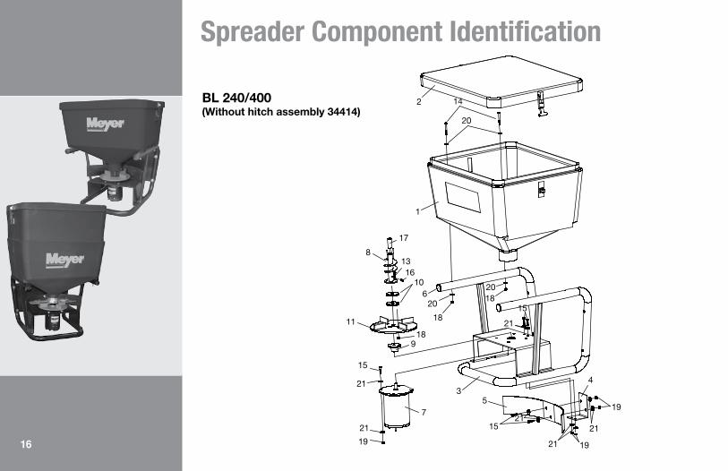
BL 240/400 (Without hitch assembly 34414)
16
Spreader Component Identification
BL 240/400 (Without hitch assembly 34414)
8
1
17
1316
10
11
15
620
18
189
21
21
19
7
35
1521
21 19
21
19
4
21
15
2018
20
2 14

17
Spreader Component Identification
BL 240/400 (Without hitch assembly 34414)
Item Part No. Qty. Description 1 31101 1 • 240 Hopper 1 36101 1 • 400 Hopper 2 31102 1 • Hopper Cover 3 34413 1 • 240/400 Spreader Frame 4 34415 1 • Deflector Bracket 5 34401 1 • Deflector 6 34416 2 • Tube Plug 7 36402 1 • Motor 12V D.C. 8 34004 1 • Auger Weldment 9 36152 1 • Spinner Hub Weldment 10 36158 2 • Spinner Mounting Plate 11 36414 1 • Spinner (Poly) 12 34405 1 • Speed Controller 13 20007 3 • Bolt H 1/4 - 20 x 1-1/2" Gr. 2 14 20010 4 • Bolt H 1/4 - 20 x 2-1/4" Gr. 2 15 20027 8 • Bolt H 5/16 - 18 x 1" Gr. 2 16 21834 1 • Set Screw 3/8-24 x 3/8 17 22728 1 • Set Screw 3/4-10 SS 18 20303 7 • Locknut 1/4 Esna 19 20313 8 • Locknut 5/16 Esna 20 20351 8 • Flatwasher 1/4 21 20352 16 • Flatwasher 5/16

18
GreenVibrator
Motor
Battery
Controller must Grounded
Black Ground
Blue12 VDC Keyed Accessory
Red12 VDC Battery
WhiteMotor Positive Post
Controller
31
32
33
34
+ -
Speed Controller
5 / 6 / 7 / 8 / 13 / 15 / 16 / 17SAFETY PRECAUTIONS - See pages 5-6 for definitions
�!
�! DANGER
�! WARNING
�! CAUTION
CAUTION
�!
�! DANGER
�! WARNING
�! CAUTION
CAUTION
�!
�! DANGER
�! WARNING
�! CAUTION
CAUTION
�!
�! DANGER
�! WARNING
�! CAUTION
CAUTION1 / 2 / 3 / 4
Speed Controller (34405)

19
Speed Controller
5 / 6 / 7 / 8 /13 20SAFETY PRECAUTIONS - See pages 5-6 for definitions
�!
�! DANGER
�! WARNING
�! CAUTION
CAUTION
�!
�! DANGER
�! WARNING
�! CAUTION
CAUTION
�!
�! DANGER
�! WARNING
�! CAUTION
CAUTION
�!
�! DANGER
�! WARNING
�! CAUTION
CAUTION1 / 2 / 3 / 4
The Meyer 34405 Speed Controller is an electronic module powered off the switched ignition circuit +12Vdc and supplying the heavy motor current from the +12Vdc battery circuit. The controller will only function with the ignition key in the ON state. The controller is connected to the spinner motor and vibration motors via a custom wire harness that is designed to handle the high motor currents. The controller can be mounted under the vehicle dash using mounting hardware that is provided in the kit. The controller is weatherproof and can be mounted in areas where it will get wet. The controller includes 5 wires as follows:
1. Ignition wire Blue (power to the controller through switched ignition).
2. Power wire Red (power to the controller directly from 12V battery).
3. Output wire White (connects to the spreader motor positive post).
4. Output wire Green (connects to the option 1 vibrator motor).
5. Ground wire Black (provides ground for the controller).
After all the above connections been made and ignition switch is at on position. When the controller On/Off button located on the front display panel is momentarily depressed once, the LED above the On/Off button will illuminate and the spreader motor will automatically be activated with 5 full power Blasts and then stop, the On/Off LED will remain steady on. The spreader unit is now activated. The spreader unit will be deactivated if the controller On/Off switch is momentarily depressed a second time. The vibrate motor will start and stop when the vibrate button is depressed only when the unit is activated. LED above the vibrate button will be illuminated when the vibrator motor is activated.
General Information

20
Speed Controller
5 / 6 / 7 / 8 / 13 / 15 / 16 / 17SAFETY PRECAUTIONS - See pages 5-6 for definitions
�!
�! DANGER
�! WARNING
�! CAUTION
CAUTION
�!
�! DANGER
�! WARNING
�! CAUTION
CAUTION
�!
�! DANGER
�! WARNING
�! CAUTION
CAUTION
�!
�! DANGER
�! WARNING
�! CAUTION
CAUTION1 / 2 / 3 / 4
Controller Operation
The controller will provide the spreader motor with multiple speed options per following:
I/O (On/Off)
Depress the button once to enable the spreader motor operation. Spreader motor will automatically be activated with 5 full power Blasts and then stop. The GREEN LED located above this switch will illuminate.
I/O (On/Off)
Depress the button a second time and the spreader motor operation will stop. The GREEN LED located above this switch will stop illuminating.
FASTER Once spreader is activated, by depressing the FASTER button momentarily for the first time, the motor will start rotating at the lowest speed. If the button is depressed again, motor will gain speed. Faster button can be depressed momentarily or held depressed to achieve maximum speed. There are ten programmed speed settings that increase the speed in increments of 10%. The GREEN LED located above the I/O button will flash in unison with the speed setting. The fastest speed causes the GREEN LED to flash at a rate of 10 flashes every second.
SLOWER By depressing the SLOWER button, the motor speed will decrease. There are ten programmed speed settings that decrease the speed in increments of 10%. SLOWER button can be depressed momentarily or held depressed to slow down the motor until it comes to a halt. The LED located in the centerwill provide a number for the speed setting. 1 is slowest and 10 is fastest.
VIBRATE (On/Off)
Depress the button once to enable the vibrate motor operation. The GREEN LED located above this switch will illuminate at full intensity.
VIBRATE (On/Off)
Depress the button a second time and the vibrate motor operation will stop. The GREEN LED located above this switch will stop illuminating.

21
Speed Controller
5 / 6 / 7 / 8 /13 20SAFETY PRECAUTIONS - See pages 5-6 for definitions
�!
�! DANGER
�! WARNING
�! CAUTION
CAUTION
�!
�! DANGER
�! WARNING
�! CAUTION
CAUTION
�!
�! DANGER
�! WARNING
�! CAUTION
CAUTION
�!
�! DANGER
�! WARNING
�! CAUTION
CAUTION1 / 2 / 3 / 4
Controller will only be activated while ignition switch is at ON position. If the unit is wired into a keyed power source. There will be one inline fuse located at the incoming power wire harness. This will be a 20A automotive ATO fuse. This spare 20A fuse protects the spreader motor and/or vibrate motor from over current conditions. In the event that the fuse has opened circuited, replacement of the fuse will be required in order to restore the operation. Fuse replacement is facilitated with a pair of needle nosed pliers. The controller also has overload protection built into the circuit board. If an overload occurs the green LED above the I/O button will turn red and will begin to flash. To reset, turn off controller and clear obstruction from spreader then turn controller back on.
Safety Features

22 5 / 6 / 7 / 8 / 9 / 11 / 12 19SAFETY PRECAUTIONS - See pages 5-6 for definitions
�!
�! DANGER
�! WARNING
�! CAUTION
CAUTION
�!
�! DANGER
�! WARNING
�! CAUTION
CAUTION
�!
�! DANGER
�! WARNING
�! CAUTION
CAUTION
22 / 23 / 24 / 25 / 27
�!
�! DANGER
�! WARNING
�! CAUTION
CAUTION1 / 2 / 3 / 4
Spreader Operation
OPERATING THE SPREADER:
Fill Hopper with bagged #1 Rock Salt or Calcium Chloride. Do not use bulk material.
CAUTION: When filling Hopper, make certain there are no large objects contained in the material which could cause the Auger Spinner to bind and stop operation of the Spreader Motor. It is recommended to check for free rotation of the Auger Spinner before operating the Spreader due to possible buildup of material between the Auger and neck of the Hopper.
BL 240/400 Materials Chart
CALCIUM CHLORIDE FLAKES
CALCIUM CHLORIDE PELLETS
ROCK SALT WITH BEET JUICE
ROCK SALT (SMALL
GRANULATION)
ROCK SALT
CALCIUM CHLORIDE
ROCK CHIPS
BAGGED ICE MELT
LAVA ROCK
EARLY CMA
50/50 SAND/SALT MIX
SAND
PEA GRAVEL
SHOULDER GRAVEL
•
•
•
•
•
• Approved material
235 / 6 / 7 / 8 / 9 / 11 / 12 /15 / 16 / 17 19 / 20SAFETY PRECAUTIONS - See pages 5-6 for definitions
�!
�! DANGER
�! WARNING
�! CAUTION
CAUTION
�!
�! DANGER
�! WARNING
�! CAUTION
CAUTION
�!
�! DANGER
�! WARNING
�! CAUTION
CAUTION
22 / 23 / 24 / 25 / 27
�!
�! DANGER
�! WARNING
�! CAUTION
CAUTION1 / 2 / 3 / 4
Spreader Maintenance
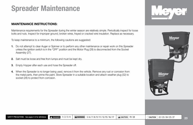
MAINTENANCE INSTRUCTIONS:
Maintenance requirements for the Spreader during the winter season are relatively simple. Periodically inspect for loose bolts and nuts. Inspect for improper ground, broken wires, frayed or cracked wire insulation. Replace as necessary.
To keep maintenance to a minimum, the following cautions are suggested:
1. Do not attempt to clear Auger or Spinner or to perform any other maintenance or repair work on this Spreader unless the ignition switch is in the “OFF” position and the Motor Plug (28) is disconnected from the Socket Assembly (27).
2. Salt must be loose and free from lumps and must be kept dry.
3. Empty Hopper after each use and hose the Spreader off.
4. When the Spreader is no longer being used, remove it from the vehicle. Remove any rust or corrosion from the metal parts, then prime the paint. Store Spreader in a suitable location and attach weather plug (32) to socket (28) to protect from corrosion.

24
Spreader Troubleshooting
5 / 6 / 7 / 8 / 9 / 11 / 12 /15 / 16 / 17 19 / 20SAFETY PRECAUTIONS - See pages 5-6 for definitions
�!
�! DANGER
�! WARNING
�! CAUTION
CAUTION
�!
�! DANGER
�! WARNING
�! CAUTION
CAUTION
�!
�! DANGER
�! WARNING
�! CAUTION
CAUTION
22 / 23 / 24 / 25 / 27
�!
�! DANGER
�! WARNING
�! CAUTION
CAUTION1 / 2 / 3 / 4
If your spreader is not operating properly, take it to your local Meyer Products Distributor for maintenance or service. However, that is not always possible, so below on this page you will find a troubleshooting guide, which can assist you in determining the problem.
WARNING – Before performing any service read and understand all safety guidelines stated in this manual.
BEFORE CALLING YOUR DEALER:
Be sure all electrical connections are clean and tight.
Be sure vehicle power supply is working properly (battery charged)
Check the hopper for a jammed feed screw.
PROBLEM POSSIBLE CAUSE SOLUTION
Motor does not run. • Loose electrical connection. • Check all electrical connections.
Shut Down.
• Auger or spinner jammed • Jammed auger. • Poor electrical connections. • Electrical short.
• Carefully remove jammed material.• Carefully remove jammed material.• Clean or replace connectors.• Look for bare or loose wires.
Material will not feed.
• No material in the hopper. • Material is wet. • Frozen or coarse material. • Auger loose on motor shaft.
• Controller bad.
• Fill hopper.• Replace with dry material.• Replace material.• Tighten setscrew on side if auger. There is a
flat machined into the motor shaft, this set screw must tighten onto that flat.
• Replace controller.

25
�!
�! DANGER
�! WARNING
�! CAUTION
CAUTION
�!
�! DANGER
�! WARNING
�! CAUTION
CAUTION
�!
�! DANGER
�! WARNING
�! CAUTION
CAUTION
�!
�! DANGER
�! WARNING
�! CAUTION
CAUTION
Notes

26
Spreader Calibration
LANE MILE CALIBRATION (US)DISCHARGE RATE (pounds discharged per mile)
A B C TRAVEL SPEED AND COMPUTATION MULTIPLIER
Control Setting
Shaft RPM (Loaded)
Discharge per Revolution (lbs.)
Discharge per Minute (lb) (A x B)
5 mph (C x 12.00)
10 mph (C x 6.00)
15 mph (C x 4.00)
20 mph (C x 3.00)
25 mph (C x 2.40)
30 mph (C x 2.00)
35 mph (C x 1.71)
40 mph (Cx 1.50)
45 mph (C x 1.33)
1
2
3
4
5
6
7
8
9
10
The actual application rate (lbs. per lane mile) on the highway is the discharge rate divided by the number of lanes being treated.
Spreader Calibration ProcedureCalibration is simply calculating the pounds per mile discharged for each control setting at various travel speeds by first counting the number of auger or conveyor shaft revolutions per minute, measuring the weight of salt discharged in one revolution, then multiply the two to obtain discharge per minute, and finally multiplying the discharge per minute by the time it takes to travel 1 mile.
Equipment needed:1. Scale to weigh salt2. Salt collection device3. Marking device4. Watch with second hand
Calibration steps:1. Remove spinner assembly.2. Put partial load of salt in spreader.3. Mark shaft end of auger.4. Count number of shaft revolutions per minute at each spreader control setting, record.5. Collect salt discharged for one revolution, weigh it and deduct the weight of the container. (For greater accuracy, collect salt for several revolutions and divide by that number of revolutions to get the weight for one revolution.)

27
PARKING LOT CALIBRATION (US)DISCHARGE RATE (pounds discharged per square foot)
A B C D E F G H I (lbs. discharged per sq. ft.)
Control Setting
Shaft RPM (Loaded)
Spread Patternwidth (ft.)
Spread Pattern sq. ft. (.5 x B) x (.5 x B) x (3.14)/2
Dischargeper Auger Revolution (lbs.)
Discharge per Minute(lb) (A x C)
5 mph(D x 12.00)
10 mph (D x 6.00)
15 mph (D x 4.00)
20 mph (D x 3.00)
5 mphF/(C x 5280)
10 mphG/(C x 5280)
15 mphH/(C x 5280)
20 mphI/(C x 5280)
1
2
3
4
5
6
7
8
9
10
The actual application rate (lbs. per sq. ft.) on the parking lot.
Spreader Calibration ProcedureCalibration is simply calculating the pounds per mile discharged for each control setting at various travel speeds by first counting the number of auger or conveyor shaft revolutions per minute, measuring the weight of salt discharged in one revolution, then multiply the two to obtain discharge per minute, and finally multiplying the discharge per minute by the time it takes to travel 1 mile.
Equipment needed:1. Scale to weigh salt2. Salt collection device3. Marking device4. Watch with second hand
Calibration steps:1. Remove spinner assembly.2. Put partial load of salt in spreader.3. Mark shaft end of auger.4. Count number of shaft revolutions per minute at each spreader control setting, record.5. Collect salt discharged for one revolution, weigh it and deduct the weight of the container. (For greater accuracy, collect salt for several revolutions and divide by that number of revolutions to get the weight for one revolution.)
Spreader Calibration
28
BL Series Accessories
28
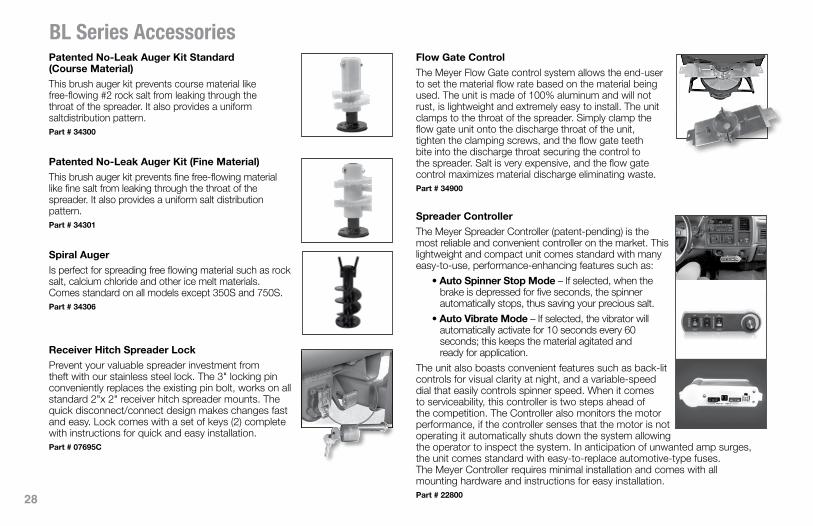
Patented No-Leak Auger Kit Standard (Course Material)This brush auger kit prevents course material like free-flowing #2 rock salt from leaking through the throat of the spreader. It also provides a uniform saltdistribution pattern.Part # 34300
Patented No-Leak Auger Kit (Fine Material)This brush auger kit prevents fine free-flowing material like fine salt from leaking through the throat of the spreader. It also provides a uniform salt distribution pattern.Part # 34301
Spiral AugerIs perfect for spreading free flowing material such as rock salt, calcium chloride and other ice melt materials. Comes standard on all models except 350S and 750S.Part # 34306
Receiver Hitch Spreader LockPrevent your valuable spreader investment from theft with our stainless steel lock. The 3" locking pin conveniently replaces the existing pin bolt, works on all standard 2"x 2" receiver hitch spreader mounts. The quick disconnect/connect design makes changes fast and easy. Lock comes with a set of keys (2) complete with instructions for quick and easy installation. Part # 07695C
Flow Gate ControlThe Meyer Flow Gate control system allows the end-user to set the material flow rate based on the material being used. The unit is made of 100% aluminum and will not rust, is lightweight and extremely easy to install. The unit clamps to the throat of the spreader. Simply clamp the flow gate unit onto the discharge throat of the unit, tighten the clamping screws, and the flow gate teeth bite into the discharge throat securing the control to the spreader. Salt is very expensive, and the flow gate control maximizes material discharge eliminating waste.Part # 34900
Spreader ControllerThe Meyer Spreader Controller (patent-pending) is the most reliable and convenient controller on the market. This lightweight and compact unit comes standard with many easy-to-use, performance-enhancing features such as:
• Auto Spinner Stop Mode – If selected, when the brake is depressed for five seconds, the spinner automatically stops, thus saving your precious salt.
• Auto Vibrate Mode – If selected, the vibrator will automatically activate for 10 seconds every 60 seconds; this keeps the material agitated and ready for application.
The unit also boasts convenient features such as back-lit controls for visual clarity at night, and a variable-speed dial that easily controls spinner speed. When it comes to serviceability, this controller is two steps ahead of the competition. The Controller also monitors the motor performance, if the controller senses that the motor is not operating it automatically shuts down the system allowing the operator to inspect the system. In anticipation of unwanted amp surges, the unit comes standard with easy-to-replace automotive-type fuses. The Meyer Controller requires minimal installation and comes with all mounting hardware and instructions for easy installation.Part # 22800

29
BL Series Accessories
29
Meyer Pro Edge Snow RakeThis Meyer accessory is made from a foam-like poly-ethylene. The squeegee-like head never gets brittle, and doesn't absorb water, so it remains pliable to safely contour to your vehicle and efficiently remove snow. The pliable head also means no more scratching your vehicle's finish. It comes with a long handle so no matter how large your vehicle, the Meyer Pro Edge Snow Rake can reach the area you need to scrape. Part # 38197 Part # 38198 (10/case)
Hotshot Hand-held Crank SpreaderThis professional spreader holds up to 5 lbs. of ice melt products. It's easy to use: set the dial, pull the trigger then rotate the lever in a clockwise position. To stop material output, simply let go of the trigger. Spreads ice-melt, fertilizer or seed for true four-season performance.Part # 38195 Part # 38196 (6/case)
Driveway MarkersMeyer Driveway Markers are 4' long, made of sturdy ¼" fiberglass to withstand winter elements. They are flexible, designed to bend virtually in half and return to their original position. Designed of highly reflective florescent orange along with a specialized reflective tape make them highly visible during a storm or after dark.Part # 03240 (Bundle of 100) Part # 03242 (Insertion Tool)
Meyer Dielectric GreasePrevent your valuable system from the harsh elements of the winter with Meyer’s dielectric grease. Meyer’s dielectric grease is specially formulated to coat and protect electrical connections from deteriorating elements such as salt and road grime. It is recommended to coat all electrical connec-tions prior to winter and each time you re-connect to ensure optimal performance. Grease comes per each, 2.7oz tube.Part # 15632
3-point Hitch 2" Receiver Spreader MountIt is common for the BL-240/400 to be used in many applica-tions. The optional 3-Point Hitch attachment adapts the Meyer BL-240 or BL-400 to any standard 3-point hitch configuration. Perfect for golf courses, universities, institutions and agricultural environments. The spreader inserts into the 2" receiver hitch on the 3-Point Hitch mount. It is easily installed and comes with instructions and hardware. Part # 36500
Spreader Rear Work LightsLighting the work area behind the truck is becoming as important as lighting the work area in front of the truck. Meyer offers two options for rear lighting, a LED and Halogen offering:
• LED Rear Light Package – Includes a LED work light and mounting hardware. The heavy-duty industrial LED work light mounts conveniently to any rear location and brightens up the rear of the truck. The light is fully adjustable and plugs in to a standard trailer hitch power cord.
• Halogen Rear Light Package – Includes a Halogen work light and mounting hardware. The halogen work light conveniently mounts to any rear location and brightens up the rear of the truck. The light is fully adjustable and plugs in to a standard trailer hitch power cord.
Each kit consists of one work light and comes fully assembled with mounting hardware and instructions.Part # 34610 (LED Rear Light Package)
Part # 34609 (Halogen Rear Light Package)

30
Meyer Chain & Cable LubeMaintain Meyer equipment with our aerosol Chain & Cable lube. It is specially formulated to lubricate, preserve and protect chains and cables. This transparent heavy-duty dry film lubricant is formulated with the latest synthetic additives to ensure maximum penetration and protection against corrosion. Once applied, the solvent evaporates leaving behind a film that will not attract dust or wash off. Available in 11 oz. aerosol cans.Part # 15183
Part # 34609 (12 cans/case)
Meyer Sno-Flo Industrial Paint Our specially formulated paint is designed to improve snow-rolling action and withstand the harsh operational environment. Meyer Yellow, Black & White Primer is available in aerosol spray cans (12/case) and Meyer Yellow Brush Paint is available in 1 quart cans (4/case) that can be shipped via UPS.Part # 07181 Brush Yellow
Part # 08755 Brush Yellow (4/1qt cans/case)
Part # 07027 Spray Yellow
Part # 08677 Spray Yellow (12 cans/case)
Part # 07164 Spray Black (12 cans/case)
Part # 08676 Spray Black (12 cans/case)
Part # 07418 Spray White Primer
Part # 08841 Spray White Primer (12 cans/case)
Meyer CoolubeMaintain Meyer equipment with our premium quality, multipurpose, non-soap based grease. Meyer Coolube is specifically formulated to provide better lubrication in harsh conditions, perfect for higher speeds and lower tempera-tures. It holds up over a wider temperature range (-40 degrees Fahrenheit to 440 degrees Fahrenheit) plus it works wet or dry. Available in 14 oz. tubes or 11 oz. aerosol cans. Part # 15181 Tube
Part # 15182 Tube (10 tubes/case)
Part # 15185 Aerosol
Part # 15186 Aerosol (12 cans/case)
BL Series Accessories
30

31
EC Declaration of Conformity

32
Notes

33
Notes

Meyer Products, LLC, warrants to the original purchaser of Meyer® brand products that they will be free from defects in materials orworkmanship, with the exceptions stated below. No person is authorized to change this warranty or to create any additional warrantyon Meyer products.
This warranty runs for a period of one year from the date of purchase on any purchase of a complete BL Spreader Package. If thePackage is registered on-line at www.meyerproducts.com within sixty (60) days of purchase, your warranty for the Package will beextended for a period of one year. All foregoing warranties apply only to an original purchaser of the product if the product is installed by anauthorized Distributor/Sub-Distributor and terminate if the product is sold or otherwise transferred. Some states do not allow limitationson how long an implied warranty lasts, so the above limitation may not apply to you.
• Problems caused by failure to follow the product instructions, failure to maintain the product as described in the Operator’s Manual;• Problems caused by contamination or damage resulting from rust, corrosion, freezing or overheating;• Paint, or expendable spreader parts such as Auger or Spinner• Damage to any vehicle to which the products are mounted;• Damage caused by usage that is not in accordance with product instructions (use of the spreader for any purpose
other than spreading salt/sand is considered misuse and abuse);• Any spreader, or any part, component, or assembly thereof, which has been modified or altered;• Problems caused by using accessories, parts, or components not supplied by Meyer Products;• Cost of tax, freight, transportation or storage charges, environmental charges, solvents, sealants, lubricants
or any other normal shop supplies.• Problems caused by collision, fire, theft, vandalism, riot, explosion, lightning, earthquake, windstorm, hail, water, flood,
or any other Acts of God;• Liability for damage to property, or injury to, or death of any person arising out of the operation, maintenance
or use of the covered product;• Products with missing or altered serial numbers;
The original purchaser’s sole and exclusive remedy against Meyer Products and its Distributors and Sub-Distributors, and Meyer Products’ sole obligation for any and all claims, whether for breach of contract, warranty, tort (including negligence) or otherwise shall be limited to providing, through its authorized Distributor/Sub-Distributor network, all labor and/or parts necessary to correct\ such defects free of charge. Any cost incurred in returning the product to an authorized Meyer Distributor/Sub-Distributor is the responsibility of the original purchaser. ALL EXPRESS AND IMPLIED WARRANTIES FOR THE PRODUCT, INCLUDING, WITHOUT LIMITATION, ANY IMPLIED WARRANTIES OF MERCHANTABILITY AND FITNESS FOR A PARTICULAR PURPOSE, ARE LIMITED IN TIME TO THE TERM OF THE LIMITED WARRANTY PERIOD. NO WARRANTIES, WHETHER EXPRESS OR IMPLIED, WILL APPLY AFTER THE LIMITED WARRANTY PERIOD HAS EXPIRED. Meyer Products disclaims liability beyond the remedies provided for in this limited warranty, and disclaims all liability for incidental, consequential, and special damages, including, without limitation, any liability for third-party claims against you for
Meyer® BL Series Spreader Warranty
Meyer offers a complete line of spreaders for any application and vehicle size. Go to www.MeyerProducts.com for more information.
34

damages, for products not being available for use, or for lost profits. Meyer® Products’ liability will be no more than the amount you paid for the product that is the subject of a claim; this is the maximum amount for which we are responsible. Some states do not allow the exclusion or limitation of incidental or consequential damages, so the above limitation or exclusion may not apply to you. A complete BL Spreader Package consists of the Spreader Assembly, operating controller, Spreader Frame and all related items. Structural elements consist of the Spreader Frame, Mounting and Poly Hopper.
Meyer Products will repair any product that proves to be defective in materials or workmanship. In the event repair is not possible or practical (as determined by Meyer Products in its sole discretion), Meyer Products will either replace the product with a new product of similar model and price, or refund the full purchase price, as determined by Meyer Products.
Customer must keep the complete BL Spreader Package serviced/maintained as recommended by Meyer Products. A written record of service must be maintained, along with receipts for maintenance materials purchased. A copy of the maintenance record and pertinent receipts maybe requested in the event of a claim.
In order to obtain service under this warranty, the original purchaser must:• Use all reasonable means to protect the complete BL Spreader package from further damage;• Return the claimed defective part to the Meyer Distributor/Sub-Distributor from whom the product was purchased or to any
authorized Meyer Distributor/Sub-Distributor, transportation and freight charges prepaid. Only Meyer Distributors/Sub-Distributors are authorized to perform the obligations under this warranty. For the address and telephone number of the Meyer Distributor/ Sub-Distributor nearest you, check the telephone directory, go to www.meyerproducts.com, write us at the address below, or call (216) 486-1313 for assistance;
• Provide maintenance record and receipts for required maintenance, if requested;• Allow inspection of damaged parts and/or complete BL Spreader package if deemed necessary by Meyer Products.• It is the responsibility of the original purchaser to establish the warranty period by verifying the original delivery date.
A bill of sale/sales receipt, cancelled check or some other appropriate payment record may be kept for that purpose.
This warranty gives you specific legal rights, and you may also have other rights which vary from state to state.
How to register your Meyer Blaster Spreader to receive the ROC Solid Warranty Go to www.meyerproducts.com and click on the link to register your plow. Fill out the information on the form as required.
Meyer offers a complete line of spreaders for any application and vehicle size. Go to www.MeyerProducts.com for more information.
35

Dealer/Distributor:
Meyer Products, LLC18513 Euclid Avenue Cleveland, Ohio 44112
216-486-1313www.meyerproducts.com
115 1M© 2015 Meyer Products, LLC FORM# 1-999R1
Meyer Spreaders are protected by one or more of the following patents: 6698997, CA 2,415,540 C, 7588195, 8448882, 8505837, 8523086, 8657208, 6186731, 6,793,154 B2, 6722590, 6715703, 6978952, 6932287, 8505838, 8827002, 5842649, CA 2,435,106 C, 6364598.


