Embed Size (px)
Citation preview

BeginningDirect3D®
GameProgramming
2nd Edition
BeginningDirect3D®
GameProgramming
2nd Edition
Wolfgang F. Engel
© 2003 by Premier Press, a division of Course Technology. All rights reserved. No part of this bookmay be reproduced or transmitted in any form or by any means, electronic or mechanical, includingphotocopying, recording, or by any information storage or retrieval system without written permissionfrom Premier Press, except for the inclusion of brief quotations in a review.
The Premier Press logo and related trade dress are trademarks of Premier Press and may not be used without written permission.
Publisher: Stacy L. Hiquet
Senior Marketing Manager: Martine Edwards
Marketing Manager: Heather Hurley
Associate Marketing Manager: Kristin Eisenzopf
Manager of Editorial Services: Heather Talbot
Acquisitions Editor: Mitzi Foster-Koontz
Project Editor/Copy Editor: Cathleen D. Snyder
Technical Reviewer: André LaMothe
Retail Market Coordinator: Sarah Dubois
Interior Layout: Shawn Morningstar
Cover Designer: Mike Tanamachi
CD-ROM Producer: Brandon Penticuff
Indexer: Katherine Stimson
Proofreader: Lorraine Gunter
DirectDraw, DirectMusic, DirectPlay, DirectSound, DirectX, Microsoft, Visual Basic, Visual C++,Windows, Windows NT, Xbox, and/or other Microsoft products are registered trademarks or trade-marks of Microsoft Corporation in the U.S. and/or other countries. All other trademarks are theproperty of their respective owners.
Important: Premier Press cannot provide software support. Please contact the appropriate softwaremanufacturer’s technical support line or Web site for assistance.
Premier Press and the author have attempted throughout this book to distinguish proprietary trade-marks from descriptive terms by following the capitalization style used by the manufacturer.
Information contained in this book has been obtained by Premier Press from sources believed to bereliable. However, because of the possibility of human or mechanical error by our sources, PremierPress, or others, the Publisher does not guarantee the accuracy, adequacy, or completeness of anyinformation and is not responsible for any errors or omissions or the results obtained from use ofsuch information. Readers should be particularly aware of the fact that the Internet is an ever-chang-ing entity. Some facts may have changed since this book went to press.
ISBN: 1-931841-39-x Library of Congress Catalog Card Number: 2003101212Printed in the United States of America03 04 05 06 07 BH 10 9 8 7 6 5 4 3 2 1
Premier Press, a division of Course Technology25 Thomson PlaceBoston, MA 02210

Für meine Frau Katja und unsere Tochter Anja

Acknowledgments
This book couldn’t have been completed without the help of many people. In particular, I want to thank my parents, who gave me a wonderful and warm child-
hood; my wife, Katja, for being patient with a spare-time author; and our nearly two-year-olddaughter, Anna, for showing me the important things in life.
Additionally I would like to thank those people who also helped to make this book possible:Heather Hurley, Mitzi Koontz, Emi Smith, Cathleen Snyder, Heather Talbot, and AndréLaMothe. Thanks for your patience with me and for a great time at GDC 2003.

About the Author
Wolfgang F. Engel is the editor and coauthor of several programming books. He has also written several online tutorials published on http://www.gamedev.net,http://www.direct3d.info, and other Web sites. He held lectures at GDC 2003 and at Vision Days in Copenhagen. Wolfgang is also a faculty advisor for the Academy of GameEntertainment Technology (http://www.academyofget.com/html/advisors.html).

Contents at a Glance
Introduction . . . . . . . . . . . . . . . . . . . . . . . . . . . . . . . . . . . xx
Part One DirectX Graphics: Don’t Hurt Me . . . . . 1Chapter 1 The History of Direct3D/DirectX Graphics . . . . . . . . . . . 3Chapter 2 Overview of HAL and COM . . . . . . . . . . . . . . . . . . . . . . . 9Chapter 3 Programming Conventions. . . . . . . . . . . . . . . . . . . . . . . . 19Chapter 4 3D Fundamentals, Gouraud Shading,
and Texture-Mapping Basics . . . . . . . . . . . . . . . . . . . . . . . 27Chapter 5 The Basics . . . . . . . . . . . . . . . . . . . . . . . . . . . . . . . . . . . . . 37Chapter 6 First Steps to Animation. . . . . . . . . . . . . . . . . . . . . . . . . . 77
Part TwoKnee-Deep in DirectX Graphics Programming . . . . . . . . . . . 123Chapter 7 Texture-Mapping Fundamentals . . . . . . . . . . . . . . . . . . . 125Chapter 8 Using Multiple Textures . . . . . . . . . . . . . . . . . . . . . . . . . 149
Part ThreeHard-Core DirectXGraphics Programming . . . . . . . . . . . 175Chapter 9 Shader Programming with the
High-Level Shader Language. . . . . . . . . . . . . . . . . . . . . . 177Chapter 10 More Advanced Shader Effects. . . . . . . . . . . . . . . . . . . . 197
Chapter 11 Working with Files . . . . . . . . . . . . . . . . . . . . . . . . . . . . . 227Chapter 12 Using *.md3 Files . . . . . . . . . . . . . . . . . . . . . . . . . . . . . . 253
Part FourAppendixes . . . . . . . . . . . . . . . . . . . 299Appendix A Windows Game Programming Foundation . . . . . . . . . . 301Appendix B C++ Primer . . . . . . . . . . . . . . . . . . . . . . . . . . . . . . . . . . 327Appendix C Mathematics Primer . . . . . . . . . . . . . . . . . . . . . . . . . . . . 353Appendix D Creating a Texture with
D3DXCreateTextureFromFileEx(). . . . . . . . . . . . . . . . . 371Appendix E Game Programming Resources . . . . . . . . . . . . . . . . . . . 375Appendix F What’s on the CD . . . . . . . . . . . . . . . . . . . . . . . . . . . . . 377
Index . . . . . . . . . . . . . . . . . . . . . . . . . . . . . . . . . . . . . . . . 381
ixContents at a Glance
Contents
Letter from the Series Editor . . . . . . . . . . . . . . . . . . . . . . . . . . xix
Introduction . . . . . . . . . . . . . . . . . . . . . . . . . . . . . . . . . . . . . . . . xx
Part OneDirectX Graphics: Don’t Hurt Me . . . . . 1Chapter 1The History of Direct3D/DirectX Graphics. . . . . . . 3DirectX 2.0 . . . . . . . . . . . . . . . . . . . . . . . . . . . . . . . . . . . . . . . . . . . . . . . . . . . . . . 4DirectX 6/7 . . . . . . . . . . . . . . . . . . . . . . . . . . . . . . . . . . . . . . . . . . . . . . . . . . . . . . 5DirectX 8. . . . . . . . . . . . . . . . . . . . . . . . . . . . . . . . . . . . . . . . . . . . . . . . . . . . . . . . 5
Point Sprites . . . . . . . . . . . . . . . . . . . . . . . . . . . . . . . . . . . . . . . . . . . . . . . . . . . . . . . . . 6
3D Textures . . . . . . . . . . . . . . . . . . . . . . . . . . . . . . . . . . . . . . . . . . . . . . . . . . . . . . . . . . 6
Direct3DX Utility Library . . . . . . . . . . . . . . . . . . . . . . . . . . . . . . . . . . . . . . . . . . . . . . 6
Vertex and Pixel Shaders . . . . . . . . . . . . . . . . . . . . . . . . . . . . . . . . . . . . . . . . . . . . . . . 6
DirectX 9. . . . . . . . . . . . . . . . . . . . . . . . . . . . . . . . . . . . . . . . . . . . . . . . . . . . . . . . 7Summary. . . . . . . . . . . . . . . . . . . . . . . . . . . . . . . . . . . . . . . . . . . . . . . . . . . . . . . . 8
Chapter 2Overview of HAL and COM . . . . . . . . . . . . . . . . . . . 9Hardware Abstraction Layer . . . . . . . . . . . . . . . . . . . . . . . . . . . . . . . . . . . . . . . 10Pluggable Software Devices. . . . . . . . . . . . . . . . . . . . . . . . . . . . . . . . . . . . . . . . 13Reference Rasterizer . . . . . . . . . . . . . . . . . . . . . . . . . . . . . . . . . . . . . . . . . . . . . 14Controlling Devices . . . . . . . . . . . . . . . . . . . . . . . . . . . . . . . . . . . . . . . . . . . . . . 14COM . . . . . . . . . . . . . . . . . . . . . . . . . . . . . . . . . . . . . . . . . . . . . . . . . . . . . . . . . . 15Summary. . . . . . . . . . . . . . . . . . . . . . . . . . . . . . . . . . . . . . . . . . . . . . . . . . . . . . . 17
Chapter 3Programming Conventions . . . . . . . . . . . . . . . . . . . 19Accessing COM Objects . . . . . . . . . . . . . . . . . . . . . . . . . . . . . . . . . . . . . . . . . . 20Naming Conventions . . . . . . . . . . . . . . . . . . . . . . . . . . . . . . . . . . . . . . . . . . . . . 22Debugging DirectX. . . . . . . . . . . . . . . . . . . . . . . . . . . . . . . . . . . . . . . . . . . . . . . 24Return Codes . . . . . . . . . . . . . . . . . . . . . . . . . . . . . . . . . . . . . . . . . . . . . . . . . . . 25Summary. . . . . . . . . . . . . . . . . . . . . . . . . . . . . . . . . . . . . . . . . . . . . . . . . . . . . . . 26
Chapter 43D Fundamentals, Gouraud Shading,and Texture-Mapping Basics . . . . . . . . . . . . . . . . . . 273D Fundamentals . . . . . . . . . . . . . . . . . . . . . . . . . . . . . . . . . . . . . . . . . . . . . . . . 28Understanding Vertices . . . . . . . . . . . . . . . . . . . . . . . . . . . . . . . . . . . . . . . . . . . 30Working with Orientation . . . . . . . . . . . . . . . . . . . . . . . . . . . . . . . . . . . . . . . . . 31Understanding Faces . . . . . . . . . . . . . . . . . . . . . . . . . . . . . . . . . . . . . . . . . . . . . 31Understanding Polygons . . . . . . . . . . . . . . . . . . . . . . . . . . . . . . . . . . . . . . . . . . 33Understanding Normals. . . . . . . . . . . . . . . . . . . . . . . . . . . . . . . . . . . . . . . . . . . 33Understanding Normals and Gouraud Shading . . . . . . . . . . . . . . . . . . . . . . . 33Texture-Mapping Basics . . . . . . . . . . . . . . . . . . . . . . . . . . . . . . . . . . . . . . . . . . . 34Summary. . . . . . . . . . . . . . . . . . . . . . . . . . . . . . . . . . . . . . . . . . . . . . . . . . . . . . . 36
Chapter 5The Basics . . . . . . . . . . . . . . . . . . . . . . . . . . . . . . . . . 37Compiling the Examples . . . . . . . . . . . . . . . . . . . . . . . . . . . . . . . . . . . . . . . . . . 38The DirectX Graphics Common Architecture . . . . . . . . . . . . . . . . . . . . . . . . 40The Basic Example . . . . . . . . . . . . . . . . . . . . . . . . . . . . . . . . . . . . . . . . . . . . . . . 41
The ConfirmDevice(), OneTimeSceneInit(), and InitDeviceObjects() Functions . . . 44
The RestoreDeviceObjects() Method . . . . . . . . . . . . . . . . . . . . . . . . . . . . . . . . . . . . 45
The FrameMove() Function . . . . . . . . . . . . . . . . . . . . . . . . . . . . . . . . . . . . . . . . . . . . 53
The Render() Function . . . . . . . . . . . . . . . . . . . . . . . . . . . . . . . . . . . . . . . . . . . . . . . . 53
xiContents

The InvalidateDeviceObjects() Function . . . . . . . . . . . . . . . . . . . . . . . . . . . . . . . . . . 57
The DeleteDeviceObjects() Function . . . . . . . . . . . . . . . . . . . . . . . . . . . . . . . . . . . . 58
The FinalCleanup() Function . . . . . . . . . . . . . . . . . . . . . . . . . . . . . . . . . . . . . . . . . . . 58
The Basic2 Example . . . . . . . . . . . . . . . . . . . . . . . . . . . . . . . . . . . . . . . . . . . . . . 58The InitDeviceObjects() Function . . . . . . . . . . . . . . . . . . . . . . . . . . . . . . . . . . . . . . . 62
The RestoreDeviceObjects() Function . . . . . . . . . . . . . . . . . . . . . . . . . . . . . . . . . . . 62
The Render() Function . . . . . . . . . . . . . . . . . . . . . . . . . . . . . . . . . . . . . . . . . . . . . . . . 64
The InvalidateDeviceObjects() Function . . . . . . . . . . . . . . . . . . . . . . . . . . . . . . . . . . 66
The DeleteDeviceObjects() Function . . . . . . . . . . . . . . . . . . . . . . . . . . . . . . . . . . . . 67
The FinalCleanup() Function . . . . . . . . . . . . . . . . . . . . . . . . . . . . . . . . . . . . . . . . . . . 67
The Basic3 Example . . . . . . . . . . . . . . . . . . . . . . . . . . . . . . . . . . . . . . . . . . . . . . 67The Basic4 Example . . . . . . . . . . . . . . . . . . . . . . . . . . . . . . . . . . . . . . . . . . . . . . 69The Basic5 Example . . . . . . . . . . . . . . . . . . . . . . . . . . . . . . . . . . . . . . . . . . . . . . 75Summary. . . . . . . . . . . . . . . . . . . . . . . . . . . . . . . . . . . . . . . . . . . . . . . . . . . . . . . 76
Chapter 6First Steps to Animation . . . . . . . . . . . . . . . . . . . . . 77Understanding Transformations and Viewports. . . . . . . . . . . . . . . . . . . . . . . . 78
The World Transformation . . . . . . . . . . . . . . . . . . . . . . . . . . . . . . . . . . . . . . . . . . . . . 79
The View Transformation . . . . . . . . . . . . . . . . . . . . . . . . . . . . . . . . . . . . . . . . . . . . . 103
The Projection Transformation. . . . . . . . . . . . . . . . . . . . . . . . . . . . . . . . . . . . . . . . . 110
Working with the Viewport . . . . . . . . . . . . . . . . . . . . . . . . . . . . . . . . . . . . . . . . . . . 112
Depth Buffering. . . . . . . . . . . . . . . . . . . . . . . . . . . . . . . . . . . . . . . . . . . . . . . . . . . . . 116
Additional Resources . . . . . . . . . . . . . . . . . . . . . . . . . . . . . . . . . . . . . . . . . . . . 119Summary. . . . . . . . . . . . . . . . . . . . . . . . . . . . . . . . . . . . . . . . . . . . . . . . . . . . . . 119Part One Quiz. . . . . . . . . . . . . . . . . . . . . . . . . . . . . . . . . . . . . . . . . . . . . . . . . . 120
xii Contents
Part TwoKnee-Deep in DirectX Graphics Programming . . . . . . . . . . . 123Chapter 7Texture-Mapping Fundamentals . . . . . . . . . . . . . . 125What Is the Point of Textures? . . . . . . . . . . . . . . . . . . . . . . . . . . . . . . . . . . . . 126Working with Texture Coordinates . . . . . . . . . . . . . . . . . . . . . . . . . . . . . . . . 129Using Texture-Addressing Modes . . . . . . . . . . . . . . . . . . . . . . . . . . . . . . . . . . 131
Wrap Texture-Addressing Mode . . . . . . . . . . . . . . . . . . . . . . . . . . . . . . . . . . . . . . . 132
Mirror Texture-Addressing Mode. . . . . . . . . . . . . . . . . . . . . . . . . . . . . . . . . . . . . . . 133
Clamp Texture-Addressing Mode . . . . . . . . . . . . . . . . . . . . . . . . . . . . . . . . . . . . . . . 134
Border Color Texture-Addressing Mode . . . . . . . . . . . . . . . . . . . . . . . . . . . . . . . . . 135
Mirroronce Texture-Addressing Mode . . . . . . . . . . . . . . . . . . . . . . . . . . . . . . . . . . . 136
Texture Wrapping. . . . . . . . . . . . . . . . . . . . . . . . . . . . . . . . . . . . . . . . . . . . . . . 136Texture Filtering and Anti-Aliasing. . . . . . . . . . . . . . . . . . . . . . . . . . . . . . . . . 138
Mipmaps . . . . . . . . . . . . . . . . . . . . . . . . . . . . . . . . . . . . . . . . . . . . . . . . . . . . . . . . . . 139
Nearest-Point Sampling. . . . . . . . . . . . . . . . . . . . . . . . . . . . . . . . . . . . . . . . . . . . . . . 140
Linear Texture Filtering . . . . . . . . . . . . . . . . . . . . . . . . . . . . . . . . . . . . . . . . . . . . . . . 141
Anisotropic Filtering . . . . . . . . . . . . . . . . . . . . . . . . . . . . . . . . . . . . . . . . . . . . . . . . . 142
Anti-Aliasing . . . . . . . . . . . . . . . . . . . . . . . . . . . . . . . . . . . . . . . . . . . . . . . . . . . . . . . 143
Alpha Blending. . . . . . . . . . . . . . . . . . . . . . . . . . . . . . . . . . . . . . . . . . . . . . . . . . . . . . 145
Summary. . . . . . . . . . . . . . . . . . . . . . . . . . . . . . . . . . . . . . . . . . . . . . . . . . . . . . 147
Chapter 8Using Multiple Textures . . . . . . . . . . . . . . . . . . . . . 149Multipass Rendering . . . . . . . . . . . . . . . . . . . . . . . . . . . . . . . . . . . . . . . . . . . . . 150Color Operations . . . . . . . . . . . . . . . . . . . . . . . . . . . . . . . . . . . . . . . . . . . . . . . 153
Dark Mapping . . . . . . . . . . . . . . . . . . . . . . . . . . . . . . . . . . . . . . . . . . . . . . . . . . . . . . 154
Animating the Dark Map . . . . . . . . . . . . . . . . . . . . . . . . . . . . . . . . . . . . . . . . . . . . . 157
Blending a Texture with Material Diffuse Color . . . . . . . . . . . . . . . . . . . . . . . . . . . 158
A Dark Map Blended with Material Diffuse Color . . . . . . . . . . . . . . . . . . . . . . . . . 160
xiiiContents

Glow Mapping . . . . . . . . . . . . . . . . . . . . . . . . . . . . . . . . . . . . . . . . . . . . . . . . . . . . . . 161
Detail Mapping . . . . . . . . . . . . . . . . . . . . . . . . . . . . . . . . . . . . . . . . . . . . . . . . . . . . . 163
Alpha Modulation . . . . . . . . . . . . . . . . . . . . . . . . . . . . . . . . . . . . . . . . . . . . . . . . . . . 167
Alpha Operations . . . . . . . . . . . . . . . . . . . . . . . . . . . . . . . . . . . . . . . . . . . . . . . 166Multitexturing Support . . . . . . . . . . . . . . . . . . . . . . . . . . . . . . . . . . . . . . . . . . 168Texture Management . . . . . . . . . . . . . . . . . . . . . . . . . . . . . . . . . . . . . . . . . . . . 169Additional Resources . . . . . . . . . . . . . . . . . . . . . . . . . . . . . . . . . . . . . . . . . . . . 169Summary. . . . . . . . . . . . . . . . . . . . . . . . . . . . . . . . . . . . . . . . . . . . . . . . . . . . . . 170Part Two Quiz . . . . . . . . . . . . . . . . . . . . . . . . . . . . . . . . . . . . . . . . . . . . . . . . . . 170
Part ThreeHard-Core DirectXGraphics Programming . . . . . . . . . . . 175Chapter 9Shader Programming with the High-Level ShaderLanguage . . . . . . . . . . . . . . . . . . . . . . . . . . . . . . . . . 177What You Need to Jump into HLSL . . . . . . . . . . . . . . . . . . . . . . . . . . . . . . . . 179Vertex and Pixel Shader Tasks. . . . . . . . . . . . . . . . . . . . . . . . . . . . . . . . . . . . . 180Common Lighting Formulas Implemented with HLSL . . . . . . . . . . . . . . . . 181
Ambient Lighting . . . . . . . . . . . . . . . . . . . . . . . . . . . . . . . . . . . . . . . . . . . . . . . . . . . . 181
Diffuse Lighting . . . . . . . . . . . . . . . . . . . . . . . . . . . . . . . . . . . . . . . . . . . . . . . . . . . . . 183
Specular Lighting . . . . . . . . . . . . . . . . . . . . . . . . . . . . . . . . . . . . . . . . . . . . . . . . . . . . 186
Self-Shadowing Term . . . . . . . . . . . . . . . . . . . . . . . . . . . . . . . . . . . . . . . . . . . . . . . . . 191
Bump Mapping. . . . . . . . . . . . . . . . . . . . . . . . . . . . . . . . . . . . . . . . . . . . . . . . . . . . . . 192
Point Lights . . . . . . . . . . . . . . . . . . . . . . . . . . . . . . . . . . . . . . . . . . . . . . . . . . . . . . . . 194
Summary. . . . . . . . . . . . . . . . . . . . . . . . . . . . . . . . . . . . . . . . . . . . . . . . . . . . . . 196
Chapter 10More Advanced Shader Effects . . . . . . . . . . . . . . . 197Working with Cube Maps . . . . . . . . . . . . . . . . . . . . . . . . . . . . . . . . . . . . . . . . 198
Generating Cube Maps . . . . . . . . . . . . . . . . . . . . . . . . . . . . . . . . . . . . . . . . . . . . . . . 198
Accessing Cube Maps . . . . . . . . . . . . . . . . . . . . . . . . . . . . . . . . . . . . . . . . . . . . . . . . 199
xiv Contents

Implementation . . . . . . . . . . . . . . . . . . . . . . . . . . . . . . . . . . . . . . . . . . . . . . . . 200Refractive and Reflective Environment Mapping. . . . . . . . . . . . . . . . . . . . . . 202
Dynamic Refractive and Reflective Environment Mapping . . . . . . . . . . . . . . . . . . . 204
Bumped Dynamic Refractive and Reflective Environment Mapping . . . . . . . . . . . . 208
Working with Shadows . . . . . . . . . . . . . . . . . . . . . . . . . . . . . . . . . . . . . . . . . . 211Shadow Volumes . . . . . . . . . . . . . . . . . . . . . . . . . . . . . . . . . . . . . . . . . . . . . . . . . . . . 212
Things to Consider When Using Shadow Volumes . . . . . . . . . . . . . . . . . . . . . . . . . 226
Summary. . . . . . . . . . . . . . . . . . . . . . . . . . . . . . . . . . . . . . . . . . . . . . . . . . . . . . 226
Chapter 11Working with Files . . . . . . . . . . . . . . . . . . . . . . . . . 2273D File Formats . . . . . . . . . . . . . . . . . . . . . . . . . . . . . . . . . . . . . . . . . . . . . . . . 228The X File Format . . . . . . . . . . . . . . . . . . . . . . . . . . . . . . . . . . . . . . . . . . . . . . 229
Header. . . . . . . . . . . . . . . . . . . . . . . . . . . . . . . . . . . . . . . . . . . . . . . . . . . . . . . . . . . . 230
Mesh . . . . . . . . . . . . . . . . . . . . . . . . . . . . . . . . . . . . . . . . . . . . . . . . . . . . . . . . . . . . . 231
MeshMaterialList . . . . . . . . . . . . . . . . . . . . . . . . . . . . . . . . . . . . . . . . . . . . . . . . . . . . 232
Normals. . . . . . . . . . . . . . . . . . . . . . . . . . . . . . . . . . . . . . . . . . . . . . . . . . . . . . . . . . . 235
Textures. . . . . . . . . . . . . . . . . . . . . . . . . . . . . . . . . . . . . . . . . . . . . . . . . . . . . . . . . . . 236
Transformation Matrices. . . . . . . . . . . . . . . . . . . . . . . . . . . . . . . . . . . . . . . . . . . . . . 242
Animation . . . . . . . . . . . . . . . . . . . . . . . . . . . . . . . . . . . . . . . . . . . . . . . . . . . . . . . . . 246
Using X Files . . . . . . . . . . . . . . . . . . . . . . . . . . . . . . . . . . . . . . . . . . . . . . . . . . . 249Extending X Files . . . . . . . . . . . . . . . . . . . . . . . . . . . . . . . . . . . . . . . . . . . . . . . 251Additional Resources . . . . . . . . . . . . . . . . . . . . . . . . . . . . . . . . . . . . . . . . . . . . 252
X File Format . . . . . . . . . . . . . . . . . . . . . . . . . . . . . . . . . . . . . . . . . . . . . . . . . . . . . . 252
Skinned Meshes. . . . . . . . . . . . . . . . . . . . . . . . . . . . . . . . . . . . . . . . . . . . . . . . . . . . . 252
Summary. . . . . . . . . . . . . . . . . . . . . . . . . . . . . . . . . . . . . . . . . . . . . . . . . . . . . . 252
Chapter 12Using *.md3 Files . . . . . . . . . . . . . . . . . . . . . . . . . . 253Files of the Trade . . . . . . . . . . . . . . . . . . . . . . . . . . . . . . . . . . . . . . . . . . . . . . . 254
Animation.cfg. . . . . . . . . . . . . . . . . . . . . . . . . . . . . . . . . . . . . . . . . . . . . . . . . . . . . . . 258
The .skin File . . . . . . . . . . . . . . . . . . . . . . . . . . . . . . . . . . . . . . . . . . . . . . . . . . . . . . . 260
Textures and the Shader File . . . . . . . . . . . . . . . . . . . . . . . . . . . . . . . . . . . . . . . . . . 261
xvContents

Custom Sounds. . . . . . . . . . . . . . . . . . . . . . . . . . . . . . . . . . . . . . . . . . . . . . . . . . . . . 267
The .md3 Format . . . . . . . . . . . . . . . . . . . . . . . . . . . . . . . . . . . . . . . . . . . . . . . . . . . 267
Md3.h. . . . . . . . . . . . . . . . . . . . . . . . . . . . . . . . . . . . . . . . . . . . . . . . . . . . . . . . . . . . . 269
The CharacterEngine Example Program. . . . . . . . . . . . . . . . . . . . . . . . . . . . 271Loading and Animating an .md3 Model . . . . . . . . . . . . . . . . . . . . . . . . . . . . . . . . . . 273
Further Improvements . . . . . . . . . . . . . . . . . . . . . . . . . . . . . . . . . . . . . . . . . . 298Additional Resources . . . . . . . . . . . . . . . . . . . . . . . . . . . . . . . . . . . . . . . . . . . . 298Summary. . . . . . . . . . . . . . . . . . . . . . . . . . . . . . . . . . . . . . . . . . . . . . . . . . . . . . 298
Part FourAppendixes . . . . . . . . . . . . . . . . . . . 299Appendix AWindows Game Programming Foundation. . . . . 301How to Look through a Window. . . . . . . . . . . . . . . . . . . . . . . . . . . . . . . . . . . 302How Windows 95/98/ME/NT/2000/XP Interacts with Your Game . . . . . . . . 302The Components of a Window . . . . . . . . . . . . . . . . . . . . . . . . . . . . . . . . . . . . 303A Window Skeleton . . . . . . . . . . . . . . . . . . . . . . . . . . . . . . . . . . . . . . . . . . . . . 303
Step 1: Define a Window Class . . . . . . . . . . . . . . . . . . . . . . . . . . . . . . . . . . . . . . . . 307
Step 2: Register the Window Class . . . . . . . . . . . . . . . . . . . . . . . . . . . . . . . . . . . . . 311
Step 3: Create a Window of That Class . . . . . . . . . . . . . . . . . . . . . . . . . . . . . . . . . . 311
Step 4: Display the Window . . . . . . . . . . . . . . . . . . . . . . . . . . . . . . . . . . . . . . . . . . . 314
Step 5: Create the Message Loop. . . . . . . . . . . . . . . . . . . . . . . . . . . . . . . . . . . . . . . 315
The Window Procedure . . . . . . . . . . . . . . . . . . . . . . . . . . . . . . . . . . . . . . . . . . . . . . 318
A Window Skeleton Optimized for Games . . . . . . . . . . . . . . . . . . . . . . . . . . 318Windows Resources . . . . . . . . . . . . . . . . . . . . . . . . . . . . . . . . . . . . . . . . . . . . . 322
Appendix BC++ Primer . . . . . . . . . . . . . . . . . . . . . . . . . . . . . . . 327What Is Object-Oriented Programming? . . . . . . . . . . . . . . . . . . . . . . . . . . . 328
Abstraction . . . . . . . . . . . . . . . . . . . . . . . . . . . . . . . . . . . . . . . . . . . . . . . . . . . . . . . . 329
Classes. . . . . . . . . . . . . . . . . . . . . . . . . . . . . . . . . . . . . . . . . . . . . . . . . . . . . . . . . . . . 331
xvi Contents
Encapsulation. . . . . . . . . . . . . . . . . . . . . . . . . . . . . . . . . . . . . . . . . . . . . . . . . . . . . . . 332
Declaring a Class. . . . . . . . . . . . . . . . . . . . . . . . . . . . . . . . . . . . . . . . . . . . . . . . . . . . 333
The Constructor. . . . . . . . . . . . . . . . . . . . . . . . . . . . . . . . . . . . . . . . . . . . . . . . . . . . 337
The Destructor. . . . . . . . . . . . . . . . . . . . . . . . . . . . . . . . . . . . . . . . . . . . . . . . . . . . . 337
Class Hierarchies and Inheritance . . . . . . . . . . . . . . . . . . . . . . . . . . . . . . . . . . . . . . 339
Virtual Functions . . . . . . . . . . . . . . . . . . . . . . . . . . . . . . . . . . . . . . . . . . . . . . . . . . . . 343
Polymorphism . . . . . . . . . . . . . . . . . . . . . . . . . . . . . . . . . . . . . . . . . . . . . . . . . . . . . . 345
Inline Functions . . . . . . . . . . . . . . . . . . . . . . . . . . . . . . . . . . . . . . . . . . . . . . . . . . . . . 345
C++ Enhancements to C . . . . . . . . . . . . . . . . . . . . . . . . . . . . . . . . . . . . . . . . . . . . . 347
Additional Resources . . . . . . . . . . . . . . . . . . . . . . . . . . . . . . . . . . . . . . . . . . . . 352
Appendix CMathematics Primer . . . . . . . . . . . . . . . . . . . . . . . 353Points in 3D. . . . . . . . . . . . . . . . . . . . . . . . . . . . . . . . . . . . . . . . . . . . . . . . . . . . 354Vectors. . . . . . . . . . . . . . . . . . . . . . . . . . . . . . . . . . . . . . . . . . . . . . . . . . . . . . . . 356
Bound Vector. . . . . . . . . . . . . . . . . . . . . . . . . . . . . . . . . . . . . . . . . . . . . . . . . . . . . . . 356
Free Vector . . . . . . . . . . . . . . . . . . . . . . . . . . . . . . . . . . . . . . . . . . . . . . . . . . . . . . . . 357
Unit Vector . . . . . . . . . . . . . . . . . . . . . . . . . . . . . . . . . . . . . . . . . . . . . . . . . . . . . . . . 364
Matrices . . . . . . . . . . . . . . . . . . . . . . . . . . . . . . . . . . . . . . . . . . . . . . . . . . . . . . . 364Multiplication of a Matrix by a Vector . . . . . . . . . . . . . . . . . . . . . . . . . . . . . . . . . . . 366
Matrix Addition and Subtraction . . . . . . . . . . . . . . . . . . . . . . . . . . . . . . . . . . . . . . . 366
Matrix Multiplication. . . . . . . . . . . . . . . . . . . . . . . . . . . . . . . . . . . . . . . . . . . . . . . . . 366
Translation Matrix . . . . . . . . . . . . . . . . . . . . . . . . . . . . . . . . . . . . . . . . . . . . . . . . . . . 367
Scaling Matrix . . . . . . . . . . . . . . . . . . . . . . . . . . . . . . . . . . . . . . . . . . . . . . . . . . . . . . 367
Rotation Matrices . . . . . . . . . . . . . . . . . . . . . . . . . . . . . . . . . . . . . . . . . . . . . . . . . . . 367
Summary. . . . . . . . . . . . . . . . . . . . . . . . . . . . . . . . . . . . . . . . . . . . . . . . . . . . . . 369
Appendix DCreating a Texture withD3DXCreateTextureFromFileEx() . . . . . . . . . . . . 371
xviiContents
Appendix EGame Programming Resources . . . . . . . . . . . . . . 375General . . . . . . . . . . . . . . . . . . . . . . . . . . . . . . . . . . . . . . . . . . . . . . . . . . . . . . . 376DirectX Graphics . . . . . . . . . . . . . . . . . . . . . . . . . . . . . . . . . . . . . . . . . . . . . . . 376
Appendix FWhat’s on the CD. . . . . . . . . . . . . . . . . . . . . . . . . . 377DirectX 9.0 SDK. . . . . . . . . . . . . . . . . . . . . . . . . . . . . . . . . . . . . . . . . . . . . . . . 378ATI RenderMonkey. . . . . . . . . . . . . . . . . . . . . . . . . . . . . . . . . . . . . . . . . . . . . . 378NVIDIA Cg Toolkit . . . . . . . . . . . . . . . . . . . . . . . . . . . . . . . . . . . . . . . . . . . . . . 379Flash Movies . . . . . . . . . . . . . . . . . . . . . . . . . . . . . . . . . . . . . . . . . . . . . . . . . . . 379
Index . . . . . . . . . . . . . . . . . . . . . . . . . . . . . . . . . . . . 381
xviii Contents

xixLetter from the Series Editor
Letter from the Series Editor
The first edition of Beginning Direct 3D Game Programming was such a great success that we thought we would follow it up with a new edition that coversslightly more advanced material, such as shader and vertex programming, and atthe same time update the text for DirectX 9.0. This second edition still starts offslowly and explains the key elements of Direct3D programming, but it takes thematerial a little further and shows you how to create some more advanced effectsbased on shader programming with the new shader programming languages, suchas Microsoft’s High-Level Shader Language (HLSL). Additionally, we thought wewould throw in some new material on Quake 2 and Quake 3 file formats for ani-mated meshes.
If you’re looking for a beginner book on Direct3D and you don’t want to wadethrough a lot of general DirectX coverage or Windows programming, then thisbook is for you.
Sincerely,
André LaMothe
Game Development Series Editor
Introduction
When I finished my first degree in law back in 1993, I was very proud and a little bitexhausted from the long learning period. So I decided to relax by playing a new game byNovaLogic called Comanche.
I started the night of January 11th and finished about three days later with only a few hoursof sleep. With the new experience in my head, I decided to start computer game program-ming. My goal was to program a terrain engine like Comanche. My then-girlfriend—now mywife—looked a little bit confused when a young, recently-graduated lawyer told her that hewas going to be a game programmer.
About two years later, after becoming a member of the Gamedev Forum on CompuServeand reading a few books on game programming by André La Mothe and a good article byPeter Freese on height-mapping engines, I got my own engine up and running underOS/2. I wrote a few articles on OpenGL and OS/2 game programming for German jour-nals, coauthored a German book, and started on Windows game programming.
In 1997, I wrote my first online tutorials on DirectX programming and published them onmy own Web site. After communicating with John Munsch and the other administrators ofhttp://www.gamedev.net, I decided to make my tutorials accessible through their Web siteas well. In the summer of 1998, as a beta-tester of the DirectX 6.0 SDK, I decided to writethe first tutorial on the Direct3D Immediate Mode framework. At that time I usedhttp://www.netit.net as my URL. There was a mailing list with a lot of interested people,and I got a lot of e-mails with positive feedback.
It started to be really fun. In 1999 I fired up my new Web site, at http://www.direct3d.net(now http://www.direct3d.info), with the sole purpose of providing understandable andinstructive tutorials on Direct3D programming.
This was also my goal in writing the first edition of the book—to help readers understandand learn DirectX Graphics programming. Now it’s been more than two years since I wrotethe first edition of the book. Two years is a long time in the real-time graphics industry, andalso in my private life.
In the meantime, my wife and I had a daughter, and this little baby grabs her father evenwhen tight deadlines are looming on the horizon. I wrote an advanced series of articles onvertex and pixel shader programming, which were published at http://www.gamedev.net,and I edited and coauthored a book called ShaderX—Vertex and Pixel Shader Tips and Tricks,
which features advanced shader programming material by 27 authors. The tremendous success of Beginning Direct3D Game Programming and ShaderX led to a number of new chal-lenges. One of them was speaking at the 2003 Game Developers Conference on the topic“Introduction to Shader Programming with HLSL/Cg.” Additionally, I regularly contributeshaders to several ongoing software projects. But let’s get back to business….
Nowadays, there are graphics cards like the ATI RADEON 9800 PRO and the NVIDIAGeForce FX which have a much higher performance rate than the cards of two years ago.Vertex and pixel shaders are an integral part of every upcoming game, and therefore theyare an integral part of the game development process. This fact and a huge number of e-mails led me to rethink the didactical structure of the second edition of this book. First ofall, many e-mails suggested that the explanation on how to install the development environ-ment and the DirectX SDK wasn’t detailed enough in the first edition. Furthermore, the newmust-have features of vertex and pixel shaders add an additional level of complexity to thedevelopment of even the simplest 3D example program. Therefore, this edition of the bookhas an extended introduction to the preparation of a development system, and the firstchapters stick to the fixed-function pipeline to reduce the level of detail. I explain vertexand pixel shader programming later, in Part Three. Unfortunately, Amir Geva was not ableto contribute his chapters on physics and collision detection to this edition. If you are inter-ested in using his collision detection library (ColDet) with DirectX, I would suggest readingthe first edition of the book or going to his Web site, at http://www.photoneffect.com.
I wish you as much fun reading this book as I had writing it. Don’t stop sending me e-mails.As you know, many improvements and new features in the book were implemented with e-mails from you in mind…and getting e-mails is what will drive me to improve this bookfurther in upcoming editions.
Wolf ([email protected])
What You’re Going to LearnThis book covers all of the elements necessary to create a Windows 95/98/Me/NT/2000/XPor short Windows-based Direct3D/DirectX Graphics game for the PC, including:
• 3D graphics and algorithms
• Game programming techniques and data structures
• Using 3D files to construct game worlds
• Programming your own character engine with a character animation system
• DirectX Graphics programming
• And more!
xxiIntroduction

What You Need to KnowThis book assumes that you can program in C with a dash of C++. I will use the less-esotericfeatures of C++, the way the Microsoft guys who programmed the Direct3D ImmediateMode samples in the DirectX SDK did. In case you need a refresher, there’s a decent C++primer in Appendix B, so check it out.
You aren’t taking a stab at graphics/game programming to learn the math. If you can add,subtract, multiply, divide, and maybe square a number, you will be able to understand 90percent of the math and what’s going on in this book. There’s a math primer provided inAppendix C just to be absolutely sure that you won’t miss anything.
How This Book Is OrganizedThis book consists of four parts. The first part will show you the essentials of Direct3D gameprogramming. It deals with the programming conventions, basic algorithms, texture-mappingbasics, 3D math, transformation pipeline, lighting, and depth buffers.
In the second part, you will learn how to use the transformation and lighting pipeline tomap textures onto objects with different effects. All of the buzzwords, such as bump mapping,environment mapping, and procedural textures, are explained, and the effects are shownin sample programs.
In the third part of this book, you’ll deal with file formats and how to integrate them intoyour game engine. The file formats used are the greatly enhanced .X file format, introducedwith the DirectX 8.0 SDK, and the MD3 file format used in most of the games driven by theQuake 3 engine. Additionally, an enhanced MD3 file format is shown in a character engine.
This part of the book also features vertex- and pixel-shader programming from the groundup. It shows you how to use the new High-Level Shader Language (HLSL) from DirectX 9.
The fourth part contains appendixes, which should be useful if you want to refresh yourWindows programming, C++, or math skills.
xxii Introduction
Using the CD-ROMThere is an appendix devoted to using the CD-ROM, but I’ll give you a brief overview here.The companion CD for this book includes all the code in the book, the Microsoft DirectX9.0 SDK for C/C++, and the DirectX 9 Developer Runtime, which you need to install inorder to compile and run the example programs discussed in the book. (See the installa-tion instructions in the following section.) The DirectX SDK contains the run-time files,headers, and libraries you need to compile the book examples, and it provides many example programs for every component of DirectX.
You will find the example code from the book in directories named after the chapters ofthe book. In every example directory, you’ll find the graphics and source files. There’salso a readme.txt file, which provides you with additional information on compiling theapplication.
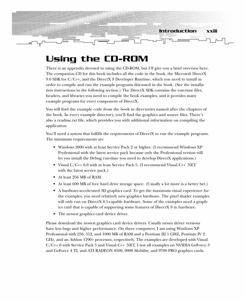
You’ll need a system that fulfills the requirements of DirectX to run the example programs.The minimum requirements are
• Windows 2000 with at least Service Pack 2 or higher. (I recommend Windows XPProfessional with the latest service pack because only the Professional version will let you install the Debug run-time you need to develop DirectX applications.)
• Visual C/C++ 6.0 with at least Service Pack 5. (I recommend Visual C++ .NET with the latest service pack.)
• At least 256 MB of RAM.
• At least 600 MB of free hard drive storage space. (Usually a lot more is a better bet.)
• A hardware-accelerated 3D graphics card. To get the maximum visual experience forthe examples, you need relatively new graphics hardware. The pixel shader exampleswill only run on DirectX 8.1-capable hardware. Some of the examples need a graph-ics card that is capable of supporting some features of DirectX 9 in hardware.
• The newest graphics card device driver.
Please download the newest graphics card device drivers. Usually newer driver versions have less bugs and higher performance. On three computers, I am using Windows XPProfessional with 256, 512, and 1000 MB of RAM and a Pentium III 1 GHZ, Pentium IV 2GHz, and an Athlon 1700+ processor, respectively. The examples are developed with VisualC/C++ 6 with Service Pack 5 and Visual C++ .NET. I test all examples on NVIDIA GeForce 3and GeForce 4 TI, and ATI RADEON 8500, 9000 Mobility, and 9700 PRO graphics cards.
xxiiiIntroduction
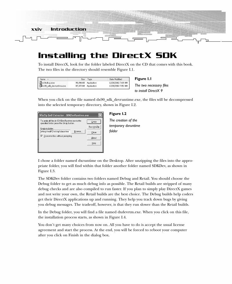
Installing the DirectX SDKTo install DirectX, look for the folder labeled DirectX on the CD that comes with this book.The two files in the directory should resemble Figure I.1.
When you click on the file named dx90_sdk_devruntime.exe, the files will be decompressedinto the selected temporary directory, shown in Figure I.2.
I chose a folder named dxruntime on the Desktop. After unzipping the files into the appro-priate folder, you will find within that folder another folder named SDKDev, as shown inFigure I.3.
The SDKDev folder contains two folders named Debug and Retail. You should choose theDebug folder to get as much debug info as possible. The Retail builds are stripped of manydebug checks and are also compiled to run faster. If you plan to simply play DirectX gamesand not write your own, the Retail builds are the best choice. The Debug builds help codersget their DirectX applications up and running. They help you track down bugs by givingyou debug messages. The tradeoff, however, is that they run slower than the Retail builds.
In the Debug folder, you will find a file named dxdevrtm.exe. When you click on this file,the installation process starts, as shown in Figure I.4.
You don’t get many choices from now on. All you have to do is accept the usual licenseagreement and start the process. At the end, you will be forced to reboot your computerafter you click on Finish in the dialog box.
xxiv Introduction
Figure I.1
The two necessary filesto install DirectX 9
Figure I.2
The creation of thetemporary dxruntimefolder

After the reboot, it might be a good idea to delete the temporary dxruntime folder fromthe Desktop.
The next step to installing DirectX 9 on your computer is to install the SDK. Click on thesecond file with the name dx9sdkcp.exe. Again choose a temporary folder name. I suggestusing the name dx9sdktemp on your Desktop, as shown in Figure I.6.
xxvIntroduction
Figure I.3
The SDKDev directory
Figure I.4
The first steps of the DX9 run-timeinstallation process
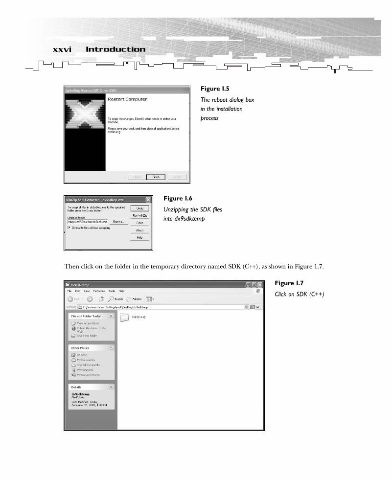
Then click on the folder in the temporary directory named SDK (C++), as shown in Figure 1.7.
xxvi Introduction
Figure I.5
The reboot dialog boxin the installationprocess
Figure I.6
Unzipping the SDK filesinto dx9sdktemp
Figure I.7
Click on SDK (C++)

The contents of this folder look like Figure I.8.
Click on setup.exe to start the installation procedure. During the setup process, you have toaccept the license agreement, and you can choose different components. I suggest using allcomponents and specifying your directory (see Figure I.9). The default directory should beC:\DXSDK. Choosing this directory makes it easier to compile examples developed by others.
After you complete the installation procedure by clicking on Finish in the final dialog boxof the Installation wizard, you can delete the temporary directory dx9sdktemp from yourDesktop.
xxviiIntroduction
Figure I.8
Contents of SDK (C++)
Figure I.9
Choose the appropriatefeatures and thedirectory for theDirectX 9 SDK

After you finish installing DirectX, take a look at all of the directories and get to know thelocation of the libraries, include files, help, and samples (see Figure I.10). You need theselocations to set up the Visual C++ compiler.
You will find the Direct3D programming files in C:\DXSDK\Samples\C++\Direct3D. Theinclude files are in C:\DXSDK9\Include and in C:\DXSDK9\Samples\C++\Common\Include.The library files are in C:\DXSDK9\Lib.
All of the materials and concepts are compatible with all future versions of DirectX, so keepan eye out for updates at http://msdn.microsoft.com/directx.
You also need to install the newest drivers for your video card. You can pick them up on theWeb site of your video card manufacturer. The newest drivers often offer speed and stabilityimprovements and sometimes new features. Take a look at the always-provided readme fileto get the proper installation instructions.
Setting Up Visual C++ 6.0After you have installed DirectX, you need to consider the rest of your software. The mostimportant piece of software is your IDE (Integrated Development Environment), or your com-piler. I suggest that you use the Microsoft Visual C/C++ 6.x or better compiler. It generatesreally good Windows code, and you can get it from your local bookstore or software storefor a couple of bucks. This is the path of least resistance.
xxviii Introduction
Figure I.10
Important directoriesin the DirectX 9SDK
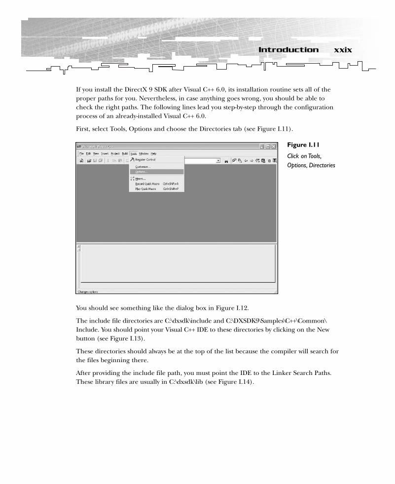
If you install the DirectX 9 SDK after Visual C++ 6.0, its installation routine sets all of theproper paths for you. Nevertheless, in case anything goes wrong, you should be able tocheck the right paths. The following lines lead you step-by-step through the configurationprocess of an already-installed Visual C++ 6.0.
First, select Tools, Options and choose the Directories tab (see Figure I.11).
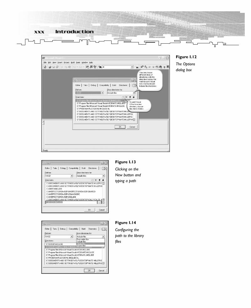
You should see something like the dialog box in Figure I.12.
The include file directories are C:\dxsdk\include and C:\DXSDK9\Samples\C++\Common\Include. You should point your Visual C++ IDE to these directories by clicking on the Newbutton (see Figure I.13).
These directories should always be at the top of the list because the compiler will search forthe files beginning there.
After providing the include file path, you must point the IDE to the Linker Search Paths.These library files are usually in C:\dxsdk\lib (see Figure I.14).
xxixIntroduction
Figure I.11
Click on Tools,Options, Directories
xxx Introduction
Figure I.12
The Options dialog box
Figure I.13
Clicking on theNew button andtyping a path
Figure I.14
Configuring thepath to the libraryfiles
After you have configured Visual C/C++ 6, make sure it is configured correctly by compilingone of the examples in the C:\DXSDK\Samples\C++\Direct3D directory. You might seesomething like the following message if you haven’t configured the include path properly:
d:\book\source\part 1\chapter6\animated objects\objects.cpp(68) : error C2146: syntaxerror : missing ‘;’ before ‘g_Keyboard_pDI’
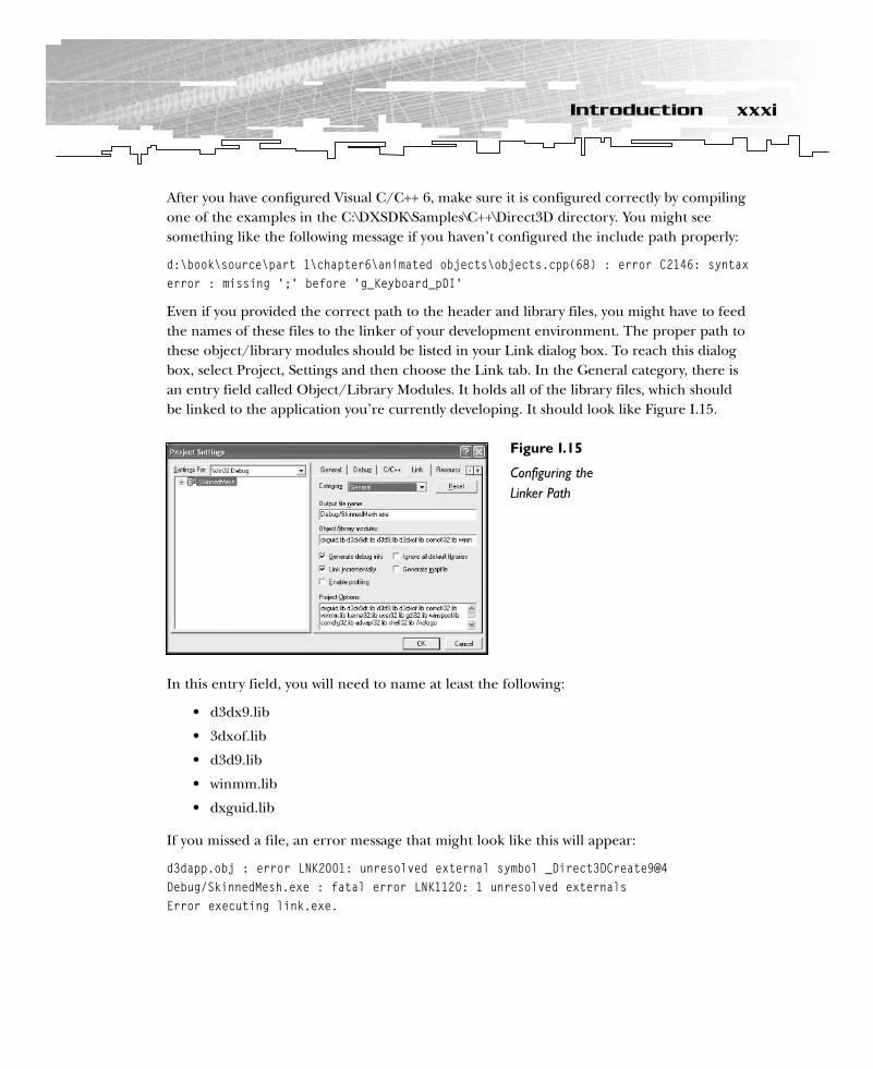
Even if you provided the correct path to the header and library files, you might have to feedthe names of these files to the linker of your development environment. The proper path tothese object/library modules should be listed in your Link dialog box. To reach this dialogbox, select Project, Settings and then choose the Link tab. In the General category, there isan entry field called Object/Library Modules. It holds all of the library files, which shouldbe linked to the application you’re currently developing. It should look like Figure I.15.
In this entry field, you will need to name at least the following:
• d3dx9.lib
• 3dxof.lib
• d3d9.lib
• winmm.lib
• dxguid.lib
If you missed a file, an error message that might look like this will appear:
d3dapp.obj : error LNK2001: unresolved external symbol _Direct3DCreate9@4Debug/SkinnedMesh.exe : fatal error LNK1120: 1 unresolved externalsError executing link.exe.
xxxiIntroduction
Figure I.15
Configuring theLinker Path
Here, d3d9.lib is missing. The unresolved external symbols are part of the COM (Component Object Model ) interfaces of Direct3D. (I will explain COM in detail later in the book.)
You should also check another include path, the one that holds the path to the directoriesof the common include files for the C/C++ compiler. If you change your machine or youare working on another machine with a different DirectX directory, normally you have toadd the common files using Project, Add Files to Project, Files.
Now let’s compile our first project.
1. Fire up your Visual C++ configured development environment.
2. Click on Open Workspace.
3. Choose basics.dsp.
4. Check whether you’ve configured the paths to the directories as described previously.
5. Choose the Build/basics.exe build.
6. When everything works correctly, choose run basics.exe.
That’s it. If something went wrong, reread the sections on installing the DirectX SDK andVisual C++, and consult the provided documentation.
Setting Up Visual C++ .NETSimilar to Visual C/C++ 6, the DirectX 9 SDK will set all paths for you if you install it after youinstall Visual C++ .NET. Nevertheless, in case anything went wrong, this section tells you whatyou have to do if you need to configure DirectX 9 in the Visual C++ .NET IDE manually.
You start by clicking on Tools, Options in the Visual C++ .NET IDE, as shown in Figure I.16.
There is a project section that holds all the paths to the relevant directories, as shown inFigure I.17.
If you have seen the dialog box that is used by Visual C/C++ 6 Studio, you should feel com-fortable because this dialog box uses the same logic. You can see that at the top-right of thedialog box, the Show Directories For drop-down menu offers the different kinds of filesthat you can reference (see Figure I.18).
xxxii Introduction

xxxiiiIntroduction
Figure I.16
Choose the Optionsmenu item
Figure I.17
Choose the Project,VC++ Directoriessection

After you choose a type of file, the referenced directories will appear in the large area inthe middle of the dialog box.
The include file directories are C:\dxsdk\include and C:\DXSDK9\Samples\C++\Common\Include. You should point your Visual C++ .NET IDE to these directories by clicking on theNew button and then on the ellipsis button. A default dialog box will open, allowing you tochoose a directory (see Figure I.19).
xxxiv Introduction
Figure I.18
Choose the type offile to reference
Figure I.19
Choose a directory
Now put this directory at the top of the list by using the arrow buttons.
After you have referenced the directories to the include files, choose the path to C:\dxsdk\libto reference the library files correctly. Don’t forget to bring them to the top of the list usingthe arrow buttons.
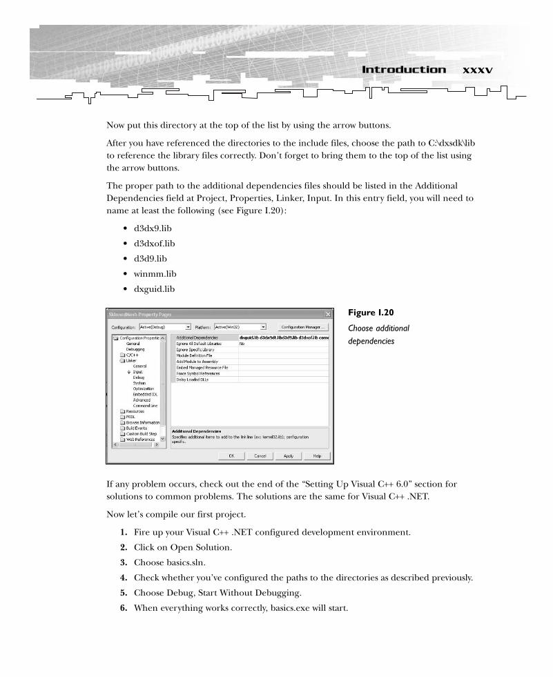
The proper path to the additional dependencies files should be listed in the AdditionalDependencies field at Project, Properties, Linker, Input. In this entry field, you will need toname at least the following (see Figure I.20):
• d3dx9.lib
• d3dxof.lib
• d3d9.lib
• winmm.lib
• dxguid.lib
If any problem occurs, check out the end of the “Setting Up Visual C++ 6.0” section for solutions to common problems. The solutions are the same for Visual C++ .NET.
Now let’s compile our first project.
1. Fire up your Visual C++ .NET configured development environment.
2. Click on Open Solution.
3. Choose basics.sln.
4. Check whether you’ve configured the paths to the directories as described previously.
5. Choose Debug, Start Without Debugging.
6. When everything works correctly, basics.exe will start.
xxxvIntroduction
Figure I.20
Choose additionaldependencies

That’s it. If something went wrong, reread the sections on installing the DirectX SDK andVisual C++ .NET, and study the provided documentation.
DirectX Shader DebuggerTo debug vertex and pixel shaders, you need to install the DirectX shader debugger. This debugger is only provided for Visual C++ .NET. You can find it in the dialog box of the DirectX installation routine, as shown in Figure I.21.
By default, the shader debugger is not selected, so you have to choose it explicitly. If thecomputer only hosts a Visual C/C++ 6 installation, you don’t get this choice at all. The dialog box will look like Figure I.22.
Please note that only Visual C++ .NET users can use the shader debugger.
xxxvi Introduction
Figure I.21
Choose the shaderdebugger byclicking on DirectXExtensions forVisual Studio 7
Figure I.22
Installable DirectXutilities under Visual C/C++ 6
Other ToolsTwo plug-and-play compilers (provided by Intel and Codeplay) can be switched into the Visual C/C++ 6 or Visual C++ .NET IDE. They offer higher performance for game programmers than the compilers provided with these IDEs. However, I don’t recommendthat beginners use these compilers because they overcomplicate some things. You can find more information at http://www.intel.com/software/products/compilers and athttp://www.codeplay.com. While on Intel’s Web site, don’t forget to check out VTune, aprofiler that helps you to optimize your game. These and the Visual C++ compilers fromMicrosoft are the fundamental development tools that the majority of PC game program-mers use nowadays.
Additional ResourcesThe CD-ROM provided with this book includes a directory called Movies. These movies inter-actively show you how to configure the default paths of Visual C/C++ 6 and Visual C++ .NET.
You should visit the Microsoft MSDN site for DirectX (http://msdn.microsoft.com/directx)at regular intervals, and also the mailing list at http://discuss.microsoft.com/SCRIPTS/WA-MSD.EXE?S1=DIRECTXDEV. You can find daily news about the game developer com-munity at http://www.gamedev.net or http://www.flipcode.com. I’ll also provide additionalinformation on http://www.direct3d.info.
xxxviiIntroduction
PART ONE
DirectXGraphics:Don’t Hurt Me

1 The History of Direct3D/DirectX Graphics
2 Overview of HAL and COM
3 Programming Conventions
4 3D Fundamentals, Gouraud Shading,and Texture-Mapping Basics
5 The Basics
6 First Steps to Animation

CHAPTER 1
The Historyof Direct3D/
DirectXGraphics
01 direct3d chap01 6/19/03 5:18 PM Page 3
This chapter covers the history of Direct3D and its functional development over time. It starts with DOS and PC history, and it discusses how three British students changed
the world of 3D programming.
Before Windows, DOS was the most popular operating system for the PC. Games were programmed exclusively in DOS for many years. Game developers resisted developing forWindows because of its unacceptable graphics and audio performance at the time.
The direct access to hardware that DOS afforded came with its own complications, however.DOS games had to support the full range of video and audio hardware. This forced devel-opers to write complex code to support dozens of different configurations just to provideconsistent graphics and audio across all PCs.
In this chapter, you will learn about:
• The history and earlier versions of DirectX, leading up to the current version• The introduction of point sprites and vertex and pixel shaders in DirectX 8• The basics of 3D textures
DirectX 2.0With the advent of DirectX in 1995, Microsoft provided within Windows the performancepreviously available only through DOS, without the complexity of supporting each vendor’sparticular hardware. Now every hardware vendor delivers its product with Windows drivers.
Direct3D, part of DirectX, appeared in 1996 in DirectX 2.0. Direct3D is designed to give accessto the advanced graphics capabilities of 3D hardware accelerators, while promoting deviceindependence and hardware abstraction by providing a common interface to the programmer.Code properly written for Direct3D will work on Direct3D devices now and in the future.
Let’s dive a little bit deeper into history. In the early 1990s, many 3D engines for PCs were builtin Great Britain. There was the well-known Renderware (http://www.renderware.com) andthe BRender from Argonaut (http://www.argonaut.com), which was ported in 1994 to OS/2and a small British company called RenderMorphics. RenderMorphics was founded in 1993 byServan Keondjian, Kate Seekings, and Doug Rabson, and they produced a product calledReality Lab. Keondjian played piano in a band at night and programmed his 3D engine by day.Seekings subsequently upped her credentials with a quick master’s degree in computer graph-ics at Middlesex University. It’s interesting to note that her 3D rendering library, developedwith input from Keondjian and Rabson, was submitted as a school project that she flunked fornot following the assigned specs closely enough. Microsoft spotted the team at the first tradeshow they attended (SIGGRAPH 94), and RenderMorphics was acquired in February 1995.
4 1. The History of Direct3D/DirectX Graphics
After the acquisition of RenderMorphics, Microsoft integrated Reality Lab into its DirectXfamily of APIs (Application Programming Interfaces). The Immediate Mode component ofReality Lab absorbed the standard 3D Windows API of the time, 3-D-DDI, which was createdby Michael Abrash, who later helped create the Quake 1 engine at id Software.
DirectX 6/7Until the advent of DirectX 8.0, Direct3D consisted of two distinct APIs: Retained Mode andImmediate Mode. At the time, the Immediate Mode API was difficult to use, but it was a flexible, low-level API that ran as efficiently as possible. Retained Mode was built on top ofImmediate Mode and provided additional services, such as frame hierarchy and animation.Retained Mode was easier to learn and use than Immediate Mode, but programmers wantedthe added performance and flexibility that Immediate Mode provided. Development of theRetained Mode API has been frozen with the release of DirectX 6.0.
The major changes between Direct3D Immediate Mode versions 6.0 and 7.0 affected the support of hardware-accelerated transformation and lighting and the reorganization of thelights, materials, and viewport objects, which now are set directly by calling the methods ofIDirect3DDevice7. Direct3D 7 dropped the special interface used in Direct3D 6 to access tex-tures. The IDirect3DDrawSurface7 interface also provided an easier way to manage the textures.
DirectX 8The advent of the DirectX 8.0 SDK brought the biggest improvements in the history ofDirect3D. Direct3D got a fundamentally new architecture with version 8.0. The initializa-tion, allocation, and management of data were simplified by the integration of DirectDrawand Direct3D into one interface, called DirectX Graphics, which led to a smaller memoryfootprint and a simpler programming model. It is safe to say that these changes madeDirectX 8 easier to use and more consistent than OpenGL for the first time.
Some of the new features in DirectX 8 included
• Point sprites (hardware-supported sprite objects)• 3D volumetric textures (textures with three dimensions)• An improved Direct3DX library (which provided many useful and highly
optimized routines)• N-patches (which add an algorithm and vertices to a model to get a higher-
tessellated model)• Vertex and pixel shaders (which interface to program the graphics
processor directly)
5DirectX 8
Point SpritesA new feature of DirectX 8 was the ability to use hardware sprites for a particle system togenerate sparks, explosions, rain, snow, and so on. So-called point sprites are supported bytheir own programming interface to help you accomplish this.
3D TexturesWith 3D volumetric textures, you can accomplish exact per-pixel lighting effects, point- andspot-light effects, and atmospheric effects.
Direct3DX Utility LibraryDirectX 8 also enhanced the Direct3DX utility library, which was introduced in DirectX 7.This library provides helper functionality for:
• Enumerating device configurations• Setting up a device• Running full-screen or windowed mode uniformly• Running resizing operations• Calculating vector and matrix operations• Simplifying image-file loading and texture creation• Drawing simple shapes, sprites, and cube maps
With the release of DirectX 8, the utility library offered support for skinned meshes, multi-resolution level-of-detail (LOD) geometry, and higher-order surface data for .X files. TheD3DX image file loader functions now support BMP, TGA, PNG, JPG, DIB, PPM, and DDSfiles. DirectX 8.0 also introduced helper methods to port OpenGL applications to DirectXGraphics, as well as the only higher-order surfaces that are used in current games—N-patches. These are used to tessellate models higher with the help of the graphics processor, which means you send in the data for a low-polygon model and it is tessellated(polygons are added) in the graphics card.
Vertex and Pixel ShadersThe big bang in DirectX 8.0 that changed the overall development process and the appear-ance of modern games was the introduction of vertex and pixel shaders. Whereas DirectX8.0 supported the vertex and pixel shader standards vs_1_1 and ps_1_1, DirectX 8.1 addedthe pixel shader standards ps_1_2, ps_1_3, and ps_1_4. The last pixel shader standard, inparticular, exposed the advanced capabilities of the ATI RADEON 8500–9200 cards, andps_1_4 pointed the syntactical way for the upcoming pixel shader standards in DirectX 9.0,such as ps_2_0, ps_2_x, ps_2_a, and ps_3_0. (ps_2_0 pixel shaders are used in most exam-ples in Chapter 9, “Shader Programming with the High-Level Shader Language.”)
6 1. The History of Direct3D/DirectX Graphics
DirectX 9The overall API has not changed much from DirectX 8.1 to DirectX 9.0. The new versionintroduced new and very much improved vertex shader and pixel shader standards, includ-ing the vs_2_0, vs_2_x, and vs_3_0 vertex shader standards and the ps_2_0, ps_2_x, andps_3_0 pixel shader standards. Although these three pixel shader standards correspond tothree hardware designs, in the past the ps_1_1 standard that was initially designed for theNVIDIA GeForce 3 was adopted by all major graphic card manufacturers, for example.There are now more equivalent software implementations for the vertex and pixel shader2_0 and 3_0 versions, called vs_2_sw, vs_3_sw, ps_2_sw, and ps_3_sw.
To be able to write shaders in the most efficient way, an HLSL (High-Level Shader Language)was introduced in DirectX 9. This HLSL helps you write shaders faster and easier in a C-likesyntax instead of the old assembly syntax. All shader examples in this book use HLSL.
To keep up with OpenGL, a scissor test and line anti-aliasing were introduced with DirectX9.0. The scissor test is performed after the fragment color is computed but before alphatesting. It determines whether the screen coordinates of a value are within the scissor rec-tangle defined by four values, and it discards fragments that are lying outside this rectangle.Additionally, there is a new render state that supports the OpenGL-style sphere map texgen.(Texgen is a nickname for automatic texture-coordinate generation.) Two-sided stencil supportwas implemented to enable programmers to add shadow volumes to occlude geometry.(Please see the two-sided stencil example in Chapter 10, “More Advanced Shader Effects,”which shows the usage of shadow volumes.)
One feature that should soon make it into DirectX 9.0 games is the ability to render fromone pixel shader to multiple render targets. (This is called a G-buffer.) You can then blendup to four render targets in another pass. A feature that is comparable but less useful thanthe multiple render targets is the multi-element texture. The pixel shader can store up tofour textures in one multi-element texture, and it can read them from there. Displacementmaps were added as a new class of higher-order surfaces, but at the time of this writing, itlooks like only the Matrox Parhelia and the ATI RADEON 9700 PRO are supporting themin hardware.
Two long-awaited features of DirectX 9.0 are the support of up to 24-bit color precision andthe ability to change the gamma values depending on your monitor’s gamma support. Thisgamma support uses very simple filters that are applied to data as it leaves a surface andbefore it is rendered on the screen. The so-called gamma controls don’t change the con-tents of the surface itself.
The DirectX 9.0 SDK provides a programming framework that has been used in versionssince DirectX 6 and is used in all examples in this book. Starting with DirectX 8.0, thisframework is called common files. You will find these files in theC:\DXSDK9\Samples\C++\Common directory.
7DirectX 9

The common files give you the direct access you need and encapsulate the details of settingup Direct3D, which is great for your learning curve. You can concentrate on the essentialswhile still being able to see everything on the lowest level. This framework gives you a common ground on which you can implement your individual features. As a beginner, youcan avoid a lot of basic mistakes with the fast and well-tested framework code, allowing you to concentrate on learning. Intermediate and professional programmers might use theframework as a good testing platform, and professional programmers might write their own framework that better suits their needs by looking at the DirectX Graphics commonfiles source code.
SummaryThis chapter showed the long way the DirectX API progressed from its beginning inDirectX 2 to the first really superior incarnation in DirectX 8. Although not many changesto the API interface were made between DirectX 8 and 9, the shader capabilities of moderncards were exposed in several new shader versions. Having a stable API with evolving shadercapabilities is the future of DirectX, which means users of the API don’t have to learn a newAPI each year—which makes learning DirectX 9 a long-term investment.
8 1. The History of Direct3D/DirectX Graphics

CHAPTER 2
Overview of HAL
and COM

This chapter gives you a rough overview of why the HAL (Hardware Abstraction Layer)exists, how it is used, why Microsoft used the COM (Component Object Model) interface
to encapsulate the DirectX code, and how it is accessed from within the application.
Both techniques enable Direct3D to provide maximum speed on different hardware, with acommon interface and backward compatibility in mind. The introduction of both techniquesaddressed the following demands:
• The API needs consistency to be viable.• If hardware doesn’t support some features of Direct3D, there must be fallback
mechanisms.• Interface innovation must be possible with the lowest possible learning curve for
programmers.• All games developed in early versions of DirectX must be guaranteed to run in
future versions of DirectX.
Hardware Abstraction LayerAlong with the graphics card driver provided by the hardware vendor, Direct3D provides avery thin software layer around your graphics card. HAL makes up one part of this thin layer.
If you’ve ever played a game driven by DirectX, you’ve seen HAL. Every game includes adrop-down menu that gives you the option to pick a device or driver. Depending on thegraphics hardware, in DirectX 7.0 games you can choose a HAL, TnLHAL (Transformationand Lighting HAL), RGB, or a reference rasterizer driver from this dialog box. In DirectX8.0/8.1/9.0 games, you might choose between a HAL, a pluggable software device, or a ref-erence rasterizer; or the application might select one automatically. You will find this deviceselection box, called the Direct3D Settings dialog box, in every Direct3D example programdelivered with the DirectX 9.0 SDK (see Figure 2.1). Just start an example and press F2.
Even if a HAL is available, the game will usually switch features on and off, depending onthe features the HAL is able to provide. The process works like this:
1. The game checks the HAL’s capabilities.
2. The game switches features on or off as appropriate.
3. If features are switched off, a fallback method might be implemented, which mightemulate the feature. This usually leads to reduced image quality.
10 2. Overview of HAL and COM

In the past, a HEL (Hardware Emulation Layer) could emulate certain features in software.However, HELs have not been provided since DirectX 8.0. If you want your games to runon ancient hardware, it would make sense to use DirectX 7.0 with its HEL (which is calledan RGB device).
Like its predecessor, DirectX 9 provides an interface to use a HEL written by a softwaredeveloper. This type of HEL is now called a pluggable software device. As far as I know, nobodyhas done that so far, which supports the fact that DirectX 8.0/8.1/9.0 games are verydependent on what the hardware is able to provide.
The overview in Figure 2.2 shows the relationships among the Direct3D API, HAL, and GDI(Graphics Device Interface) APIs.
11Hardware Abstraction Layer
Figure 2.1
Device selection in theDirect3D Settingsdialog box
Figure 2.2
The relationshipbetween DDI, HAL,and GDI
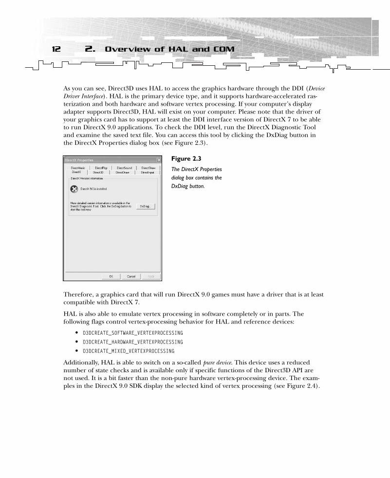
As you can see, Direct3D uses HAL to access the graphics hardware through the DDI (DeviceDriver Interface). HAL is the primary device type, and it supports hardware-accelerated ras-terization and both hardware and software vertex processing. If your computer’s displayadapter supports Direct3D, HAL will exist on your computer. Please note that the driver ofyour graphics card has to support at least the DDI interface version of DirectX 7 to be ableto run DirectX 9.0 applications. To check the DDI level, run the DirectX Diagnostic Tooland examine the saved text file. You can access this tool by clicking the DxDiag button inthe DirectX Properties dialog box (see Figure 2.3).
Therefore, a graphics card that will run DirectX 9.0 games must have a driver that is at leastcompatible with DirectX 7.
HAL is also able to emulate vertex processing in software completely or in parts. Thefollowing flags control vertex-processing behavior for HAL and reference devices:
• D3DCREATE_SOFTWARE_VERTEXPROCESSING
• D3DCREATE_HARDWARE_VERTEXPROCESSING
• D3DCREATE_MIXED_VERTEXPROCESSING
Additionally, HAL is able to switch on a so-called pure device. This device uses a reducednumber of state checks and is available only if specific functions of the Direct3D API arenot used. It is a bit faster than the non-pure hardware vertex-processing device. The exam-ples in the DirectX 9.0 SDK display the selected kind of vertex processing (see Figure 2.4).
12 2. Overview of HAL and COM
Figure 2.3
The DirectX Propertiesdialog box contains theDxDiag button.

HAL has four different methods of vertex processing. These include
• SW VP (Software Vertex Processing)• Mixed VP (Mixed Vertex Processing)• HW VP (Hardware Vertex Processing)• Pure VP (Pure Vertex Processing)
The behaviors of the pluggable software device and the reference device must be identicalto that of the HAL device. Application code to work with the HAL device should work withthe software or reference devices without modification. In fact, the reference device is thereference implementation that sets the standards, and the software device and HAL have tobe measured at its functionality.
You must check the capabilities for each device, of course. The reference rasterizer sup-ports all of the Direct3D 9.0 features, whereas a pluggable software device might not evensupport texturing.
If there’s no hardware accelerator in a user’s machine, attempting to create a HAL devicewill fail.
Pluggable Software DevicesIt is possible to write a hardware emulation layer (now called a pluggable software device)that runs even if the user’s computer hardware doesn’t provide all of the 3D operationsrequired to play the game. Nowadays, the software/game manufacturer must develop thehardware emulation device, whereas in former incarnations of the DirectX run-time envi-ronment, Microsoft provided it as the RGB device. Software devices are loaded by the appli-cation and registered with the Direct3D object. The function to register a pluggablesoftware device is IDirect3D9::RegisterSoftwareDevice. The DirectX 9 DDK (Device Driver Kit)provides more information on how to program a pluggable software device.
13Pluggable Software Devices
Figure 2.4
HAL shows its method of vertexprocessing.
Reference RasterizerThe reference device is supplied only with the installation of the SDK. When an applicationrequests the reference device on a machine on which the SDK is not installed, a NULL reference device is supplied. This NULL reference device does nothing, and all renderingresults in a black screen.
The reference rasterizer supports all Direct3D features. You should only use it to test featuresthat your card doesn’t support. This device is optimized for accuracy, not for speed. Direct3Ddoes not enumerate it by default. The DirectX SDK installer will set the EnumReference value in the HKEY_LOCAL_MACHINE\SOFTWARE\Microsoft\Direct3D\Drivers registry key to anon-zero DWORD value. Hardware, software, and the reference device cannot render to 8-bit render-target surfaces.
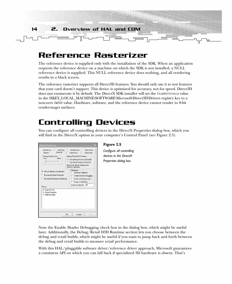
Controlling DevicesYou can configure all controlling devices in the DirectX Properties dialog box, which youwill find in the DirectX option in your computer’s Control Panel (see Figure 2.5).
Note the Enable Shader Debugging check box in the dialog box, which might be usefullater. Additionally, the Debug/Retail D3D Runtime section lets you choose between thedebug and retail builds, which might be useful if you want to jump back and forth betweenthe debug and retail builds to measure retail performance.
With this HAL/pluggable software driver/reference driver approach, Microsoft guaranteesa consistent API on which you can fall back if specialized 3D hardware is absent. That’s
14 2. Overview of HAL and COM
Figure 2.5
Configure all controllingdevices in the DirectXProperties dialog box.
great, isn’t it? OK, what about the other two demands specified in the beginning of thischapter: How does Direct3D handle version changes? Are they easy to learn, and are theyhandled so that they’re transparent to the programmer? This is where the COM interfacedesign of the DirectX SDK helps.
COMIf you’ve used other Microsoft APIs, there’s a good chance that you’re an old COM freakand you can skip over this section. The rest of you must invest a small learning effort, butyou will get a good return on your investment by learning to use the COM interface, whichhas been used by DirectX since its inception.
In COM terms, a software component is simply a chunk of code that provides services throughinterfaces, and an interface is a group of related methods. A COM component is normally a.DLL (Dynamic Link Library) file that can be accessed in a consistent and defined way. Period. It doesn’t sound like something you could write a thousand-page book about, does it?
COM has many advantages. I’d like to highlight three that I think are important forDirect3D programmers like us.
• COM interfaces can never change.• COM is language-independent.• You can only access a COM component’s methods, never its data.
C++ and many other languages are source-based; therefore, they do not have a versioningstrategy. COM was designed to be a binary-based programming model. COM interfaces cannever be modified in any way.
For an example of why COM is necessary, consider this scenario. Non-COM DLL A is pro-duced by software company C, whereas non-COM DLL B is produced by software company D.DLLs A and B might be compatible as long as one of the companies does not change theinterface of its DLL. However, if company D changes the interface of DLL B, it will be incom-patible with DLL A unless company C made the same changes to the interface of DLL A.
This scenario cannot occur with a COM DLL. When a COM object is changed, a completelynew interface with a new name is added to the DLL. Therefore, every COM DLL has tosupport the interfaces since its release. If both companies in the aforementioned scenarioused a COM DLL, a change in the interface of DLL A would lead to the addition of a newinterface to A. Because A would then have two interfaces, DLL B would still be able to con-nect to the old interface.
This is exactly how DirectX implements its interfaces. Direct3D 9.0 or DirectX Graphicssupport the following interfaces:
• IDirect3D
• IDirect3D2
• IDirect3D3
15COM
02 direct3d chap02 6/19/03 5:18 PM Page 15
• IDirect3D7
• IDirect3D8
• IDirect3D9
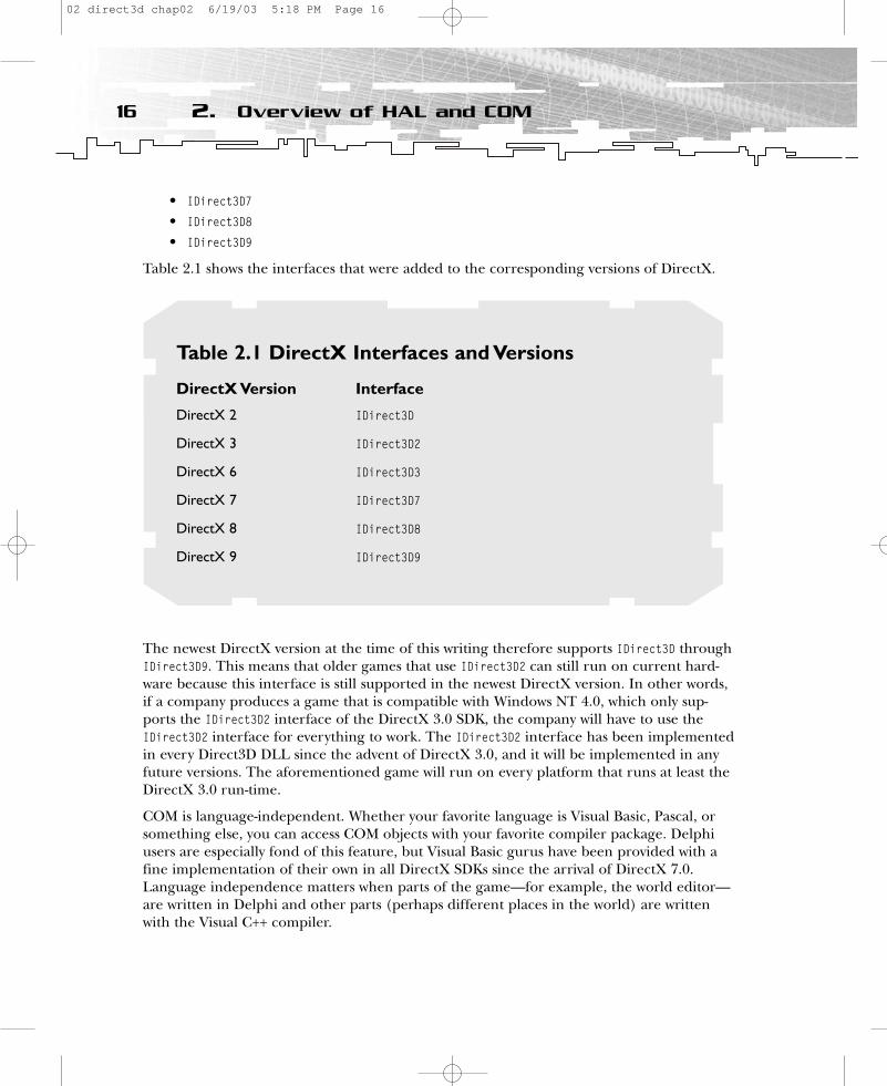
Table 2.1 shows the interfaces that were added to the corresponding versions of DirectX.
The newest DirectX version at the time of this writing therefore supports IDirect3D throughIDirect3D9. This means that older games that use IDirect3D2 can still run on current hard-ware because this interface is still supported in the newest DirectX version. In other words,if a company produces a game that is compatible with Windows NT 4.0, which only sup-ports the IDirect3D2 interface of the DirectX 3.0 SDK, the company will have to use theIDirect3D2 interface for everything to work. The IDirect3D2 interface has been implementedin every Direct3D DLL since the advent of DirectX 3.0, and it will be implemented in anyfuture versions. The aforementioned game will run on every platform that runs at least theDirectX 3.0 run-time.
COM is language-independent. Whether your favorite language is Visual Basic, Pascal, orsomething else, you can access COM objects with your favorite compiler package. Delphiusers are especially fond of this feature, but Visual Basic gurus have been provided with afine implementation of their own in all DirectX SDKs since the arrival of DirectX 7.0.Language independence matters when parts of the game—for example, the world editor—are written in Delphi and other parts (perhaps different places in the world) are writtenwith the Visual C++ compiler.
16 2. Overview of HAL and COM
Table 2.1 DirectX Interfaces and Versions
DirectX Version Interface
DirectX 2 IDirect3D
DirectX 3 IDirect3D2
DirectX 6 IDirect3D3
DirectX 7 IDirect3D7
DirectX 8 IDirect3D8
DirectX 9 IDirect3D9
02 direct3d chap02 6/19/03 5:18 PM Page 16

COM can only be accessed via methods. You cannot access data objects directly. This is agood object-oriented design. As you will see in the next chapter, you can’t call a methoddirectly. Instead, you have to use double indirection through a virtual function table, calledthe v-table or VTBL. These v-tables are also the key to a language-independent interface.With these advantages, COM helps you get language-independent, guaranteed access to thelegacy and current Direct3D interfaces. Now get access!
SummaryThis chapter introduced the ideas behind HAL and COM. HAL is the main device driver ofthe graphics card. If HAL does not support a feature, there must be a fallback mechanismthat gives the user a comparable visual experience. Alternatively, the game should run witha pluggable software device written by the game’s manufacturer.
COM provides a versioning strategy, which guarantees that all games developed in earlierversions of DirectX are guaranteed to run in future versions. It helps you encapsulate dataand provides a consistent interface to different languages.
17Summary
02 direct3d chap02 6/19/03 5:18 PM Page 17

CHAPTER 3
ProgrammingConventions
03 direct3d chap03 6/19/03 5:19 PM Page 19

This chapter introduces the programming conventions that are used throughout thebook. In this chapter, you will learn:
• How to access a COM object• The naming convention (Hungarian notation) used in the DirectX SDK and
throughout this book• Useful debugging tips for Direct3D applications• How and why to use return codes
Accessing COM ObjectsWhen you call a method in a COM component, you have to use a v-table. When you’redeciding whether to develop your code in C or C++, you need to consider a few issues. I’ll start with an example. Suppose you want to set a light in a scene of your world-class 3Dgame. With C, you would use the following line of code:
hr = m_pd3dDevice->lpVtbl->SetLight(m_pd3dDevice, 0, &light );
You call the COM interface methods by passing the this pointer, called lpdd, as the firstparameter of the method and by referencing the interface’s method by using it as a pointerto the interface v-table, which is called lpVtbl here (see Figure 3.1).
Although there are macros that help make C programmers’ lives easier (for example, inddraw.h), C++ is much simpler for using COM objects. COM objects and C++ objects arebinary-compatible so that compilers handle COM interfaces and C++ abstract classes in thesame way. The in-memory layout in C++ of a class instance that inherits from a pure virtualbase class (a class with only methods that are virtual and equal to zero) has the same mem-ory representation as a COM interface. Therefore, in C++ the lpVtbl pointer is implicitlydereferenced, and the parameter is implicitly passed. Thus, the previously described call forC would look like this in C++:
hr = m_pd3dDevice->SetLight(0, &light );
20 3. Programming Conventions
v-table COMobject
Create
Figure 3.1
The v-table
03 direct3d chap03 6/19/03 5:19 PM Page 20
In general, most DirectX calls in C++ look like this:
lpinterface->methodname
As you saw in the Introduction to this book, you have to include a number of importlibraries to compile a DirectX program.
• d3dx9.lib• d3dxof.lib• d3d9.lib• winmm.lib• dxguid.lib
Most of these libraries are import libraries that provide the interface names to the linker ofyour development environment.
Now that you understand that COM objects are collections of interfaces, which are simplymethod pointers and, more specifically, v-tables, you need to see an example of how to workwith COM. There are three things of which you should be aware.
• Direct3D run-time COM objects and DLLs must be registered to and loaded byWindows. The DirectX installer will do this for you.
• You must include the previously mentioned libraries in your Windows project so thatthe wrapper methods you call are linked. (For more information, see the “SettingUp Visual C++ 6.0” and “Setting Up Visual C++ .NET” sections in the Introduction to this book.)
• You must include the proper include files in your source file and in the include pathentry forms of your IDE (for example, Visual C++) so the compiler can see headerinformation, prototypes, and data types for DirectX Graphics. (Again, for moreinformation see the “Setting Up Visual C++ 6.0” and “Setting Up Visual C++ .NET”sections in the Introduction.)
The data type for an IDirect3D9 interface pointer is
LPDIRECT3D9 g_pD3D = NULL;
To create an IDirect3D8 COM object and retrieve an interface pointer for it, you simplyneed to use the Direct3DCreate9() method.
m_pD3D = Direct3DCreate9( D3D_SDK_VERSION );
The only parameter passed to Direct3DCreate9() should be D3D_SDK_VERSION. This informsDirect3D that the correct header files are being used. This value is incremented whenever aheader or other change requires applications to be rebuilt. If the version does not match,Direct3DCreate9() will fail.
The retrieved interface pointer gives you access to the interface of IDirect3D9. You mightcall a method in that interface, for example:
// Create the device
21Accessing COM Objects
03 direct3d chap03 6/19/03 5:19 PM Page 21
hr = m_pD3D->CreateDevice( m_d3dSettings.AdapterOrdinal(), pDeviceInfo->DevType, m_hWndFocus, behaviorFlags, &m_d3dpp, &m_pd3dDevice );
That’s it for COM. You will use COM throughout this book. If you’re wondering about thestrange and cryptic parameter names, read on for an explanation.
Naming ConventionsI use a simple variable tagging scheme that has its roots in the so-called Hungarian notation usedby Microsoft for its own development projects. The name came from its inventor, CharlesSimonyi, a now-legendary Microsoft programmer who happened to be Hungarian. It’s helpful to supply variables in the right format to help others read your code, but it can be confusing topeople who haven’t seen the Hungarian convention.
Table 3.1 shows the prefixes I use and their respective types. You might occasionally comeacross other prefixes, but this table shows the common ones. Hungarian notation simplyconsists of prefixing variables with their types.
Although the variable-naming convention is to prefix the variables with their types, thenaming convention for methods just clarifies readability and the purpose of the method. In all methods, the first letters of subnames are capitalized; an underscore is illegal.
HRESULT ConfirmDevice( D3DCAPS9* pCaps, DWORD dwBehavior, D3DFORMAT adapterFormat, D3DFORMAT backBufferFormat )
HRESULT EnumerateDevices( D3DAdapterInfo* pAdapterInfo, CArrayList* pAdapterFormatList )
As you can see, parameters for functions follow the same naming conventions as normal vari-ables. The parameter pCaps points to a D3DCAPS9 structure. The third and fourth parameters ofConfirmDevice() use the same type to describe a surface format. You can tell that the two para-meters of EnumerateDevices() are not provided by Direct3D because they are not capitalized.
Types and constants begin with an uppercase letter, but you can use underscores in thenames, for example:
#define D3DPRESENT_BACK_BUFFERS_MAX 3L
You must prefix all C++ classes with a capital C, and you must capitalize the first name ofeach subname, for example:
class CD3DMesh{
public:};
22 3. Programming Conventions
03 direct3d chap03 6/19/03 5:19 PM Page 22

The CD3DMesh class handles the loading of .X files. It’s implemented in d3dfile.h of the com-mon files. Why don’t you try it? Take a look at a typical Direct3D application class:
class CMyD3DApplication : public CD3DApplication{
CD3DFont* m_pFont; CUSTOMVERTEX m_QuadVertices[4];LPDIRECT3DTEXTURE9 m_pCustomNormalMap;LPDIRECT3DTEXTURE9 m_pFileBasedNormalMap;D3DXVECTOR3 m_vLight;BOOL m_bUseFileBasedTexture;BOOL m_bShowNormalMap;HRESULT CreateFileBasedNormalMap();
23Naming Conventions
TABLE 3.1 Prefixes and Types in Naming Conventions
Prefix Type Example
w WORD wSpeed
dw DWORD dwHitList
f FLOAT fSpeed
d DOUBLE dDirection
p Pointer pArray
v D3DVECTOR3 vLight
l LONG lPitch
s String sQuestion
sz String terminated by 0 szQuestion
h Handle hResult
I COM interface IDirect3D
m_p Member class pointer m_pFloorVertices
m_f Member class float m_fStartTimeKey
c Constant cText
b BOOL bCheck
03 direct3d chap03 6/19/03 5:19 PM Page 23
HRESULT CreateCustomNormalMap();HRESULT ConfirmDevice( D3DCAPS9*, DWORD, D3DFORMAT );LRESULT MsgProc( HWND hWnd, UINT uMsg, WPARAM wParam, LPARAM lParam );
protected:HRESULT OneTimeSceneInit();HRESULT InitDeviceObjects();HRESULT RestoreDeviceObjects();HRESULT InvalidateDeviceObjects();HRESULT DeleteDeviceObjects();HRESULT Render();HRESULT FrameMove();HRESULT FinalCleanup();
public:CMyD3DApplication();
};
There is a member class pointer on a font class at the beginning of the code. There is alsoanother member in the class, which uses a custom vertex structure for a quad array of vertices.Two member class pointers are pointing to Direct3D texture objects. A light vector is stored inD3DXVECTOR3. If a file-based texture is used, m_bUseFileBasedTexture will indicate this. If the userlikes to see the normal map, the m_bShowNormalMap switch has to be set to TRUE. As you can see inthis class (taken from a file from the common files directory), the Hungarian naming conven-tion is used for all files used in the DirectX SDK.
Debugging DirectXDebugging DirectX applications can be challenging. Following are a few tips to get youstarted.
• Define STRICT at the beginning of your *.cpp file before including windows.h. Thisleads to strict type checking, which will help you find bugs.
• Use the DXDiag utility from the DirectX SDK to report your bugs, but be sure thatyou know exactly what is on your system.
• The DirectX Control Panel allows you to set the debug output level from 0 to 5. Toaccess the Control Panel, select Start, Settings, Control Panel, DirectX, Direct3D. Onthe same tab, you can switch from the retail to debug run-time version or vice versa.
• The D3DX library is a static library. To help you debug, there’s a debug-only dynamiclibrary of D3DX. To use it, link to d3dx9d.lib, which is an import library correspond-ing to the D3DX9D.DLL.
• Using a memory manager can reduce memory allocation and de-allocation prob-lems. Visual C++ provides a memory manager called CRT. On the Internet, you canalso find memory managers that are more suitable for game development. Just do asearch at http://www.flipcode.com or http://www.gamedev.net. BoundsChecker(http://www.compuware.com) is a commercial solution.
24 3. Programming Conventions
03 direct3d chap03 6/19/03 5:19 PM Page 24
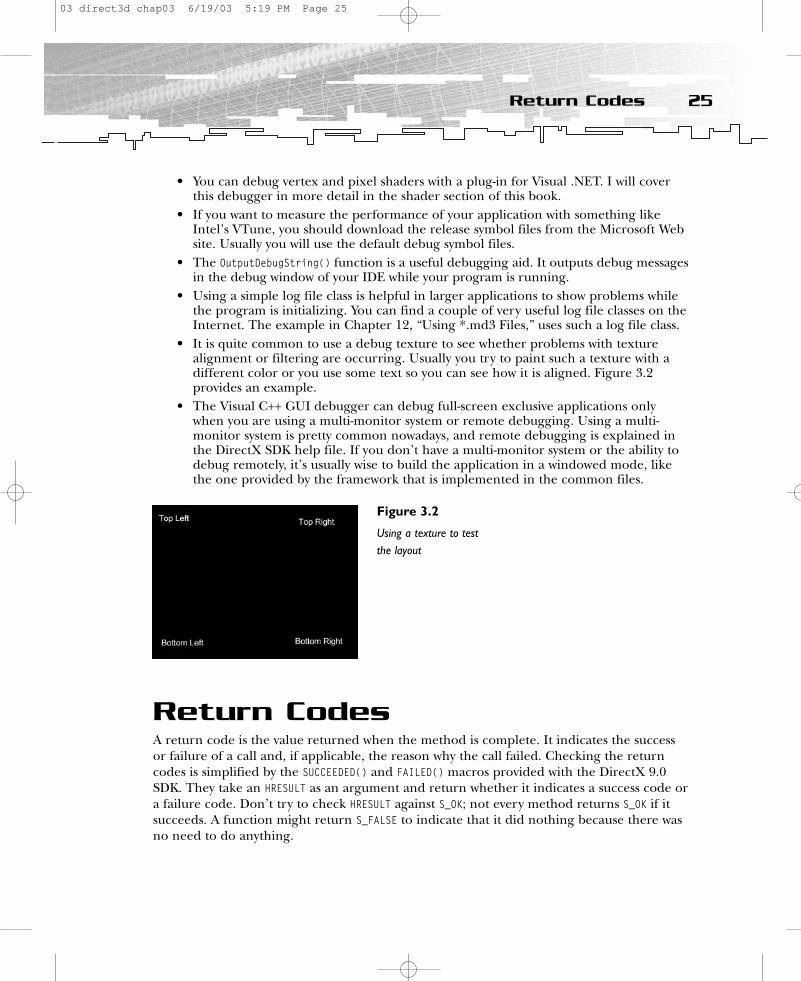
• You can debug vertex and pixel shaders with a plug-in for Visual .NET. I will coverthis debugger in more detail in the shader section of this book.
• If you want to measure the performance of your application with something likeIntel’s VTune, you should download the release symbol files from the Microsoft Website. Usually you will use the default debug symbol files.
• The OutputDebugString() function is a useful debugging aid. It outputs debug messagesin the debug window of your IDE while your program is running.
• Using a simple log file class is helpful in larger applications to show problems whilethe program is initializing. You can find a couple of very useful log file classes on theInternet. The example in Chapter 12, “Using *.md3 Files,” uses such a log file class.
• It is quite common to use a debug texture to see whether problems with texturealignment or filtering are occurring. Usually you try to paint such a texture with adifferent color or you use some text so you can see how it is aligned. Figure 3.2 provides an example.
• The Visual C++ GUI debugger can debug full-screen exclusive applications onlywhen you are using a multi-monitor system or remote debugging. Using a multi-monitor system is pretty common nowadays, and remote debugging is explained inthe DirectX SDK help file. If you don’t have a multi-monitor system or the ability todebug remotely, it’s usually wise to build the application in a windowed mode, likethe one provided by the framework that is implemented in the common files.
Return CodesA return code is the value returned when the method is complete. It indicates the successor failure of a call and, if applicable, the reason why the call failed. Checking the returncodes is simplified by the SUCCEEDED() and FAILED() macros provided with the DirectX 9.0SDK. They take an HRESULT as an argument and return whether it indicates a success code ora failure code. Don’t try to check HRESULT against S_OK; not every method returns S_OK if itsucceeds. A function might return S_FALSE to indicate that it did nothing because there wasno need to do anything.
25Return Codes
Figure 3.2
Using a texture to testthe layout
03 direct3d chap03 6/19/03 5:19 PM Page 25

Because every DirectX method returns an HRESULT, you need to structure your code tocheck for and handle all potential errors. This work is frustrating at first, but it soonbecomes second nature. Having a program that is more resistant to crashing is a goodreward for the work.
SummaryThis chapter should have provided you with some general knowledge of Direct3D program-ming. The rules and the conventions will help you to build examples consistently. Such rulefiles are quite common in game development teams. This might be a starting point to buildup one on your own.
26 3. Programming Conventions
03 direct3d chap03 6/19/03 5:19 PM Page 26
CHAPTER 4
3DFundamentals,
GouraudShading, and
Texture-Mapping
Basics
04 direct3d chap04 6/19/03 5:20 PM Page 27
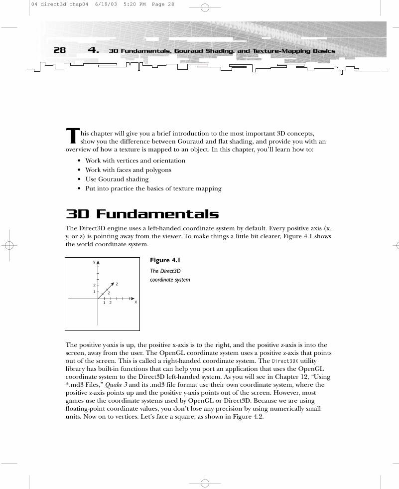
This chapter will give you a brief introduction to the most important 3D concepts, show you the difference between Gouraud and flat shading, and provide you with an
overview of how a texture is mapped to an object. In this chapter, you’ll learn how to:
• Work with vertices and orientation• Work with faces and polygons• Use Gouraud shading• Put into practice the basics of texture mapping
3D FundamentalsThe Direct3D engine uses a left-handed coordinate system by default. Every positive axis (x,y, or z) is pointing away from the viewer. To make things a little bit clearer, Figure 4.1 showsthe world coordinate system.
The positive y-axis is up, the positive x-axis is to the right, and the positive z-axis is into thescreen, away from the user. The OpenGL coordinate system uses a positive z-axis that pointsout of the screen. This is called a right-handed coordinate system. The Direct3DX utilitylibrary has built-in functions that can help you port an application that uses the OpenGLcoordinate system to the Direct3D left-handed system. As you will see in Chapter 12, “Using*.md3 Files,” Quake 3 and its .md3 file format use their own coordinate system, where thepositive z-axis points up and the positive y-axis points out of the screen. However, mostgames use the coordinate systems used by OpenGL or Direct3D. Because we are using floating-point coordinate values, you don’t lose any precision by using numerically smallunits. Now on to vertices. Let’s face a square, as shown in Figure 4.2.
28 4. 3D Fundamentals, Gouraud Shading, and Texture-Mapping Basics
y
x
z
1
1
2
2
2
Figure 4.1
The Direct3Dcoordinate system
04 direct3d chap04 6/19/03 5:20 PM Page 28
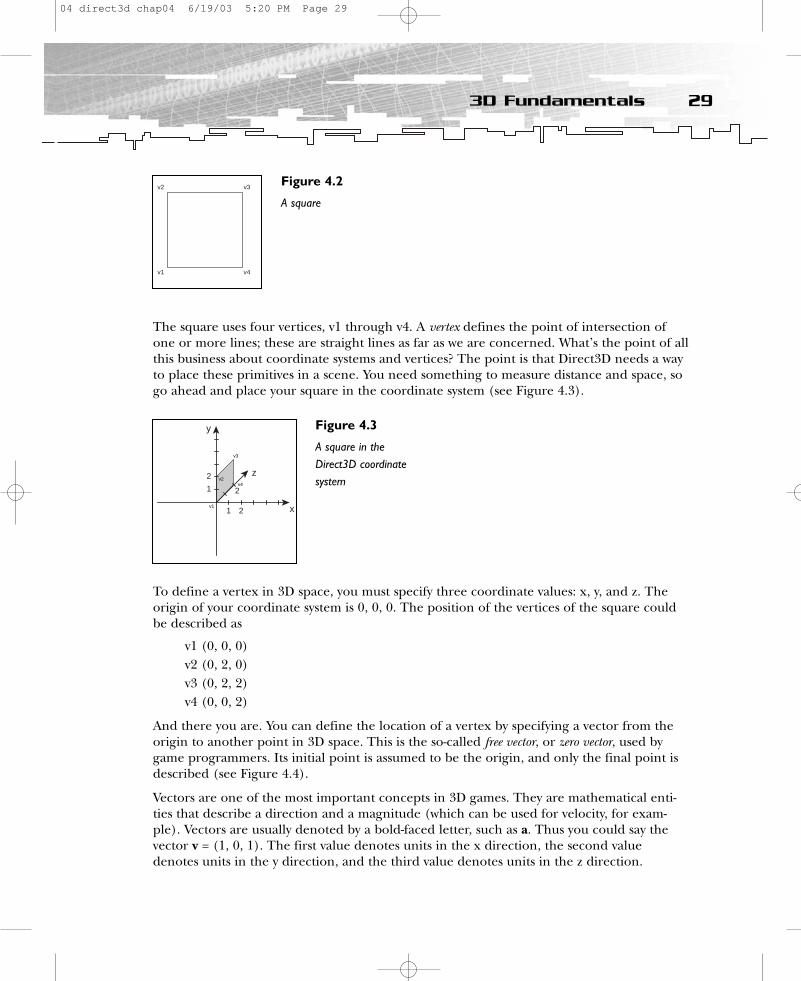
The square uses four vertices, v1 through v4. A vertex defines the point of intersection ofone or more lines; these are straight lines as far as we are concerned. What’s the point of allthis business about coordinate systems and vertices? The point is that Direct3D needs a wayto place these primitives in a scene. You need something to measure distance and space, sogo ahead and place your square in the coordinate system (see Figure 4.3).
To define a vertex in 3D space, you must specify three coordinate values: x, y, and z. Theorigin of your coordinate system is 0, 0, 0. The position of the vertices of the square couldbe described as
v1 (0, 0, 0)v2 (0, 2, 0)v3 (0, 2, 2)v4 (0, 0, 2)
And there you are. You can define the location of a vertex by specifying a vector from theorigin to another point in 3D space. This is the so-called free vector, or zero vector, used bygame programmers. Its initial point is assumed to be the origin, and only the final point isdescribed (see Figure 4.4).
Vectors are one of the most important concepts in 3D games. They are mathematical enti-ties that describe a direction and a magnitude (which can be used for velocity, for exam-ple). Vectors are usually denoted by a bold-faced letter, such as a. Thus you could say thevector v = (1, 0, 1). The first value denotes units in the x direction, the second valuedenotes units in the y direction, and the third value denotes units in the z direction.
293D Fundamentals
v2 v3
v1 v4
Figure 4.2
A square
y
x
z
1
1
2
2
2
v3
v4v2
v1
Figure 4.3
A square in theDirect3D coordinatesystem
04 direct3d chap04 6/19/03 5:20 PM Page 29
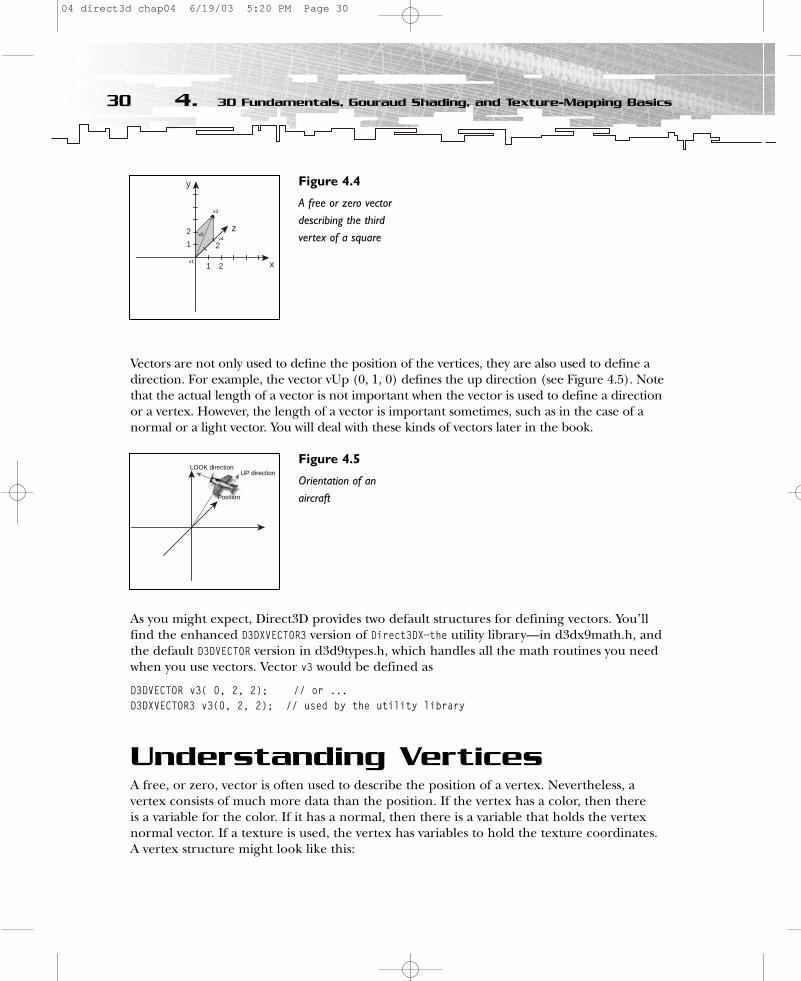
Vectors are not only used to define the position of the vertices, they are also used to define adirection. For example, the vector vUp (0, 1, 0) defines the up direction (see Figure 4.5). Notethat the actual length of a vector is not important when the vector is used to define a directionor a vertex. However, the length of a vector is important sometimes, such as in the case of anormal or a light vector. You will deal with these kinds of vectors later in the book.
As you might expect, Direct3D provides two default structures for defining vectors. You’llfind the enhanced D3DXVECTOR3 version of Direct3DX—the utility library—in d3dx9math.h, andthe default D3DVECTOR version in d3d9types.h, which handles all the math routines you needwhen you use vectors. Vector v3 would be defined as
D3DVECTOR v3( 0, 2, 2); // or ...D3DXVECTOR3 v3(0, 2, 2); // used by the utility library
Understanding VerticesA free, or zero, vector is often used to describe the position of a vertex. Nevertheless, a vertex consists of much more data than the position. If the vertex has a color, then there is a variable for the color. If it has a normal, then there is a variable that holds the vertex normal vector. If a texture is used, the vertex has variables to hold the texture coordinates.A vertex structure might look like this:
30 4. 3D Fundamentals, Gouraud Shading, and Texture-Mapping Basics
v3
y
x
z
1
1
2
2
2v4
v2
v1
Figure 4.4
A free or zero vectordescribing the thirdvertex of a square
UP directionLOOK direction
Position
Figure 4.5
Orientation of anaircraft
04 direct3d chap04 6/19/03 5:20 PM Page 30
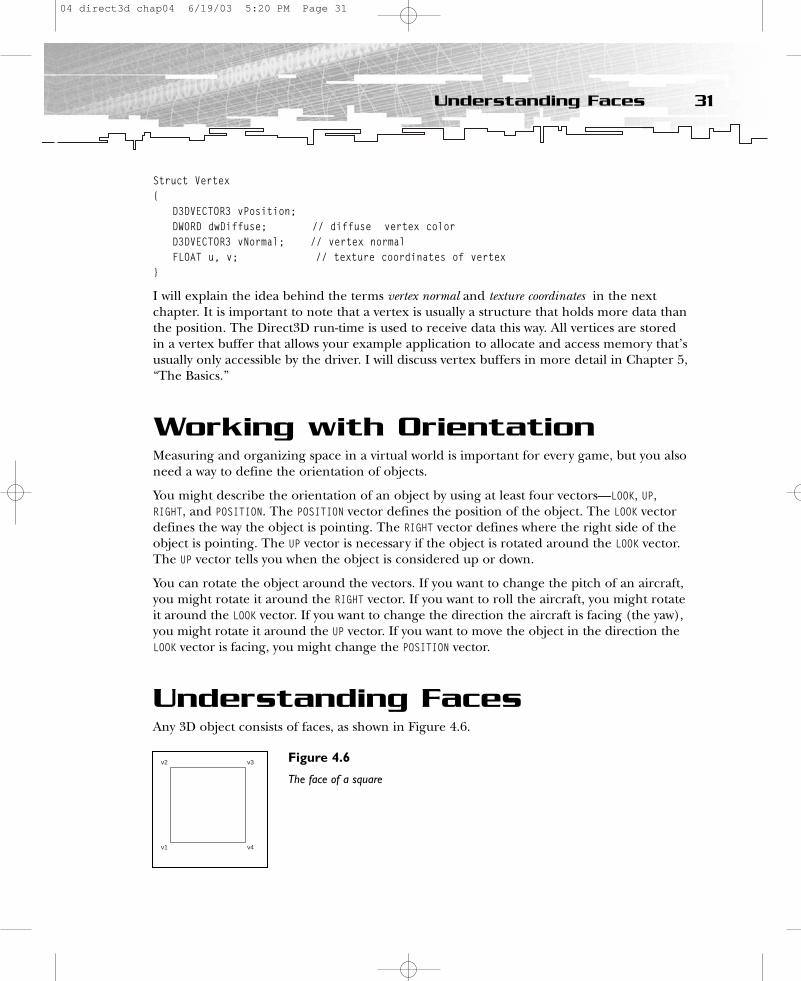
Struct Vertex{
D3DVECTOR3 vPosition;DWORD dwDiffuse; // diffuse vertex colorD3DVECTOR3 vNormal; // vertex normalFLOAT u, v; // texture coordinates of vertex
}
I will explain the idea behind the terms vertex normal and texture coordinates in the nextchapter. It is important to note that a vertex is usually a structure that holds more data thanthe position. The Direct3D run-time is used to receive data this way. All vertices are storedin a vertex buffer that allows your example application to allocate and access memory that’susually only accessible by the driver. I will discuss vertex buffers in more detail in Chapter 5,“The Basics.”
Working with OrientationMeasuring and organizing space in a virtual world is important for every game, but you alsoneed a way to define the orientation of objects.
You might describe the orientation of an object by using at least four vectors—LOOK, UP,RIGHT, and POSITION. The POSITION vector defines the position of the object. The LOOK vectordefines the way the object is pointing. The RIGHT vector defines where the right side of theobject is pointing. The UP vector is necessary if the object is rotated around the LOOK vector.The UP vector tells you when the object is considered up or down.
You can rotate the object around the vectors. If you want to change the pitch of an aircraft,you might rotate it around the RIGHT vector. If you want to roll the aircraft, you might rotateit around the LOOK vector. If you want to change the direction the aircraft is facing (the yaw),you might rotate it around the UP vector. If you want to move the object in the direction theLOOK vector is facing, you might change the POSITION vector.
Understanding FacesAny 3D object consists of faces, as shown in Figure 4.6.
31Understanding Faces
v2 v3
v1 v4
Figure 4.6
The face of a square
04 direct3d chap04 6/19/03 5:20 PM Page 31
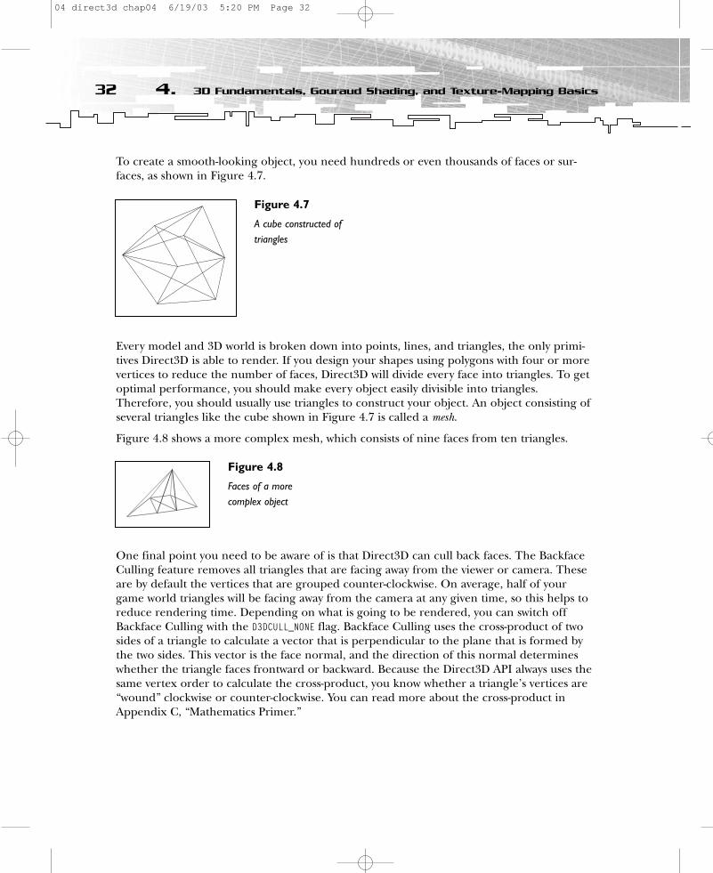
To create a smooth-looking object, you need hundreds or even thousands of faces or sur-faces, as shown in Figure 4.7.
Every model and 3D world is broken down into points, lines, and triangles, the only primi-tives Direct3D is able to render. If you design your shapes using polygons with four or morevertices to reduce the number of faces, Direct3D will divide every face into triangles. To getoptimal performance, you should make every object easily divisible into triangles.Therefore, you should usually use triangles to construct your object. An object consisting ofseveral triangles like the cube shown in Figure 4.7 is called a mesh.
Figure 4.8 shows a more complex mesh, which consists of nine faces from ten triangles.
One final point you need to be aware of is that Direct3D can cull back faces. The BackfaceCulling feature removes all triangles that are facing away from the viewer or camera. Theseare by default the vertices that are grouped counter-clockwise. On average, half of yourgame world triangles will be facing away from the camera at any given time, so this helps toreduce rendering time. Depending on what is going to be rendered, you can switch offBackface Culling with the D3DCULL_NONE flag. Backface Culling uses the cross-product of twosides of a triangle to calculate a vector that is perpendicular to the plane that is formed bythe two sides. This vector is the face normal, and the direction of this normal determineswhether the triangle faces frontward or backward. Because the Direct3D API always uses thesame vertex order to calculate the cross-product, you know whether a triangle’s vertices are“wound” clockwise or counter-clockwise. You can read more about the cross-product inAppendix C, “Mathematics Primer.”
32 4. 3D Fundamentals, Gouraud Shading, and Texture-Mapping Basics
Figure 4.7
A cube constructed oftriangles
Figure 4.8
Faces of a morecomplex object
04 direct3d chap04 6/19/03 5:20 PM Page 32

Understanding PolygonsA polygon can be defined in either 2D or 3D space; in our case, we will refer to polygons asn-sided closed figures defined by at least three vertices. The simplest polygon is a triangle.Direct3D uses triangles to compose most polygons because all three vertices in a triangleare guaranteed to be co-planar; rendering non-planar vertices would be inefficient.
Understanding NormalsNormals are perpendicular vectors that can be used to define the direction a face is pointingor the visible side of a face (see Figure 4.9).
A vertex normal is often perpendicular to a face, and it usually sits upon the vertex as one unitlong. The other type of normal is a face normal. It is usually perpendicular to a face and sits inthe middle of the face. You don’t have to worry about this kind of normal because Direct3Dcalculates them automatically. Vertex normals are important for lighting calculations, as youwill see in Chapter 9, “Shader Programming with the High-Level Shader Language.”Furthermore, face and vertex normals are also important for the shading mode. Whereas facenormals are used for flat shading, for example, vertex normals are used for Gouraud shading.
Understanding Normals andGouraud ShadingThe vertex normal vector is used in Gouraud shading mode (the default shading modesince the advent of Direct3D 6.0) to control lighting and to make some texturing effects. So what’s a shading mode? Shading is the process of performing lighting computations anddetermining pixel colors from them. These pixel colors are later drawn on the object.(More technically, shading is the way the rasterizer “shades” pixels.) Flat shading lights perpolygon or face, and Gouraud shading lights per vertex (see Figure 4.10).
33Understanding Normals and Gouraud Shading
y
x
z2
vertex normal
Figure 4.9
A triangle’s vertexnormals
04 direct3d chap04 6/19/03 5:20 PM Page 33
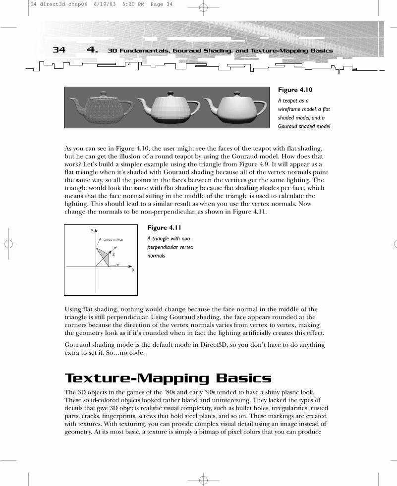
As you can see in Figure 4.10, the user might see the faces of the teapot with flat shading,but he can get the illusion of a round teapot by using the Gouraud model. How does thatwork? Let’s build a simpler example using the triangle from Figure 4.9. It will appear as aflat triangle when it’s shaded with Gouraud shading because all of the vertex normals pointthe same way, so all the points in the faces between the vertices get the same lighting. Thetriangle would look the same with flat shading because flat shading shades per face, whichmeans that the face normal sitting in the middle of the triangle is used to calculate thelighting. This should lead to a similar result as when you use the vertex normals. Nowchange the normals to be non-perpendicular, as shown in Figure 4.11.
Using flat shading, nothing would change because the face normal in the middle of the triangle is still perpendicular. Using Gouraud shading, the face appears rounded at the corners because the direction of the vertex normals varies from vertex to vertex, makingthe geometry look as if it’s rounded when in fact the lighting artificially creates this effect.
Gouraud shading mode is the default mode in Direct3D, so you don’t have to do anythingextra to set it. So…no code.
Texture-Mapping BasicsThe 3D objects in the games of the ’80s and early ’90s tended to have a shiny plastic look.These solid-colored objects looked rather bland and uninteresting. They lacked the types ofdetails that give 3D objects realistic visual complexity, such as bullet holes, irregularities, rustedparts, cracks, fingerprints, screws that hold steel plates, and so on. These markings are createdwith textures. With texturing, you can provide complex visual detail using an image instead ofgeometry. At its most basic, a texture is simply a bitmap of pixel colors that you can produce
34 4. 3D Fundamentals, Gouraud Shading, and Texture-Mapping Basics
Figure 4.10
A teapot as awireframe model, a flatshaded model, and aGouraud shaded model
y
x
z
vertex normal
Figure 4.11
A triangle with non-perpendicular vertexnormals
04 direct3d chap04 6/19/03 5:20 PM Page 34

with the help of Adobe Photoshop or a similar program. In this context, texture refers to a spe-cial kind of image that you can map onto a face or multiple faces (see Figure 4.12).
In Figure 4.12, you can see how a texture map is mapped onto a square. In this case the tex-ture map has to be scaled because the square is bigger than the texture map. In order tomap texels (texture elements) onto primitives, Direct3D requires a uniform address rangefor all texels in a texture. Therefore, it uses a generic addressing scheme in which all texeladdresses are in the range of 0.0 to 1.0, inclusive. The texture space coordinates are repre-sented by u for the horizontal direction and v for the vertical direction. The bottom-rightcorner is (1.0f, 1.0f) and the upper-left corner is (0.0f, 0.0f), regardless of the actual size ofthe texture—even if the texture is wider than it is tall. By assigning texture coordinates out-side that range, you can create certain special texturing effects. You’ll read more about thisconcept in Chapter 7, “Texture-Mapping Fundamentals.”
Texture coordinates are assigned to the vertices of a mesh. Therefore, the coordinates canbe included directly as vertex components, as shown in the vertex structure in the“Understanding Vertices” section.
The square in Figure 4.12 has the same aspect ratio (the ratio of width to height) as the tex-ture. In this case the texture coordinates (0.0, 0.0), (1.0, 0.0), (1.0, 1.0), and (0.0, 1.0) areassigned to the primitve’s vertices, causing Direct3D to stretch the texture over the entiresquare. That might work like this:
cvVertices [0] = {0.0f, 0.0f, 0.5f, 1.0f, 0.0f, 0.0f}; // x, y, z, rhw, tu, tvcvVertices [1] = {1.0f, 0.0f, 0.5f, 1.0f, 1.0f, 0.0f};cvVertices [2] = {1.0f, 1.0f, 0.5f, 1.0f, 1.0f, 1.0f};cvVertices [3] = {0.0f, 1.0f, 0.5f, 1.0f, 0.0f, 1.0f};
This is a typical vertex structure. It consists of the position vector, an RHW (Reciprocal of HomogeneousW ) value, and the tu and tv coordinates of the texture. (I will explain RHW in more detail inChapter 5.) For now I want to concentrate on the last two variables—the texture coordinates. The value 1.0f stretches the textures over the entire object. If you choose to apply the texture to arectangle that’s half as wide instead, you have to decide how to apply it. You can apply the entiretexture to the rectangle, which requires you to change the texture’s aspect ratio; otherwise, the tex-ture will be squashed so that it fits the rectangle. The second option is to apply the left or right halfof the texture to the rectangle. For this option, you have to assign the texture coordinates (0.0, 0.0),(0.5, 0.0), (0.5, 1.0), and (0.0, 1.0) to the vertices.
35Texture-Mapping Basics
Texture Map
Texture Map OriginSquare Face
1
1
0.0f, 0.0fu
v
Figure 4.12
Mapping a texture ontoa square
04 direct3d chap04 6/19/03 5:20 PM Page 35

You can assign parts of a texture to a primitive by using texture coodinates. If you want totexture a triangle, it could work something like Figure 4.13.
That’s the easy part. Now take a look at a more advanced level of texture mapping.Examine the texture of an .md2 file from Quake 2, shown in Figure 4.14.
Figure 4.15 shows the whole knight as an .md2 model.
As you can see, different parts of the texture are mapped on different polygons on thismodel. You can use a specialized program to paint the texture and set the texture coordi-nates on the model. MilkShape 3D is a wonderful tool to develop such models. You canfind it at http://www.swissquake.ch/chumbalum-soft.
SummaryI hope you got the big picture on texture mapping. And now you’re ready to rock…let’s getyour feet wet with DirectX (try to rap that).
36 4. 3D Fundamentals, Gouraud Shading, and Texture-Mapping Basics
Figure 4.13
Mapping parts of atexture onto a triangle
Figure 4.14
The texture of an .md2model
Figure 4.15
A textured .md2 model
04 direct3d chap04 6/19/03 5:20 PM Page 36

CHAPTER 5
The Basics
05 direct3d chap05 6/19/03 5:21 PM Page 37
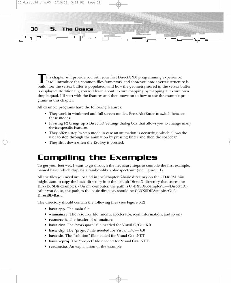
This chapter will provide you with your first DirectX 9.0 programming experience. It will introduce the common files framework and show you how a vertex structure is
built, how the vertex buffer is populated, and how the geometry stored in the vertex bufferis displayed. Additionally, you will learn about texture mapping by mapping a texture on asimple quad. I’ll start with the features and then move on to how to use the example pro-grams in this chapter.
All example programs have the following features:
• They work in windowed and full-screen modes. Press Alt+Enter to switch betweenthese modes.
• Pressing F2 brings up a Direct3D Settings dialog box that allows you to change manydevice-specific features.
• They offer a step-by-step mode in case an animation is occurring, which allows theuser to step through the animation by pressing Enter and then the spacebar.
• They shut down when the Esc key is pressed.
Compiling the ExamplesTo get your feet wet, I want to go through the necessary steps to compile the first example,named basic, which displays a rainbow-like color spectrum (see Figure 5.1).
All the files you need are located in the \chapter 5\basic directory on the CD-ROM. Youmight want to copy the basic directory into the default DirectX directory that stores theDirectX SDK examples. (On my computer, the path is C:\DXSDK\Samples\C++\Direct3D.)After you do so, the path to the basic directory should be C:\DXSDK\Samples\C++\Direct3D\Basic.
The directory should contain the following files (see Figure 5.2).
• basic.cpp. The main file• winmain.rc. The resource file (menu, accelerator, icon information, and so on)• resource.h. The header of winmain.rc• basic.dsw. The “workspace” file needed for Visual C/C++ 6.0• basic.dsp. The “project” file needed for Visual C/C++ 6.0• basic.sln. The “solution” file needed for Visual C++ .NET• basic.vcproj. The “project” file needed for Visual C++ .NET• readme.txt. An explanation of the example
38 5. The Basics
05 direct3d chap05 6/19/03 5:21 PM Page 38
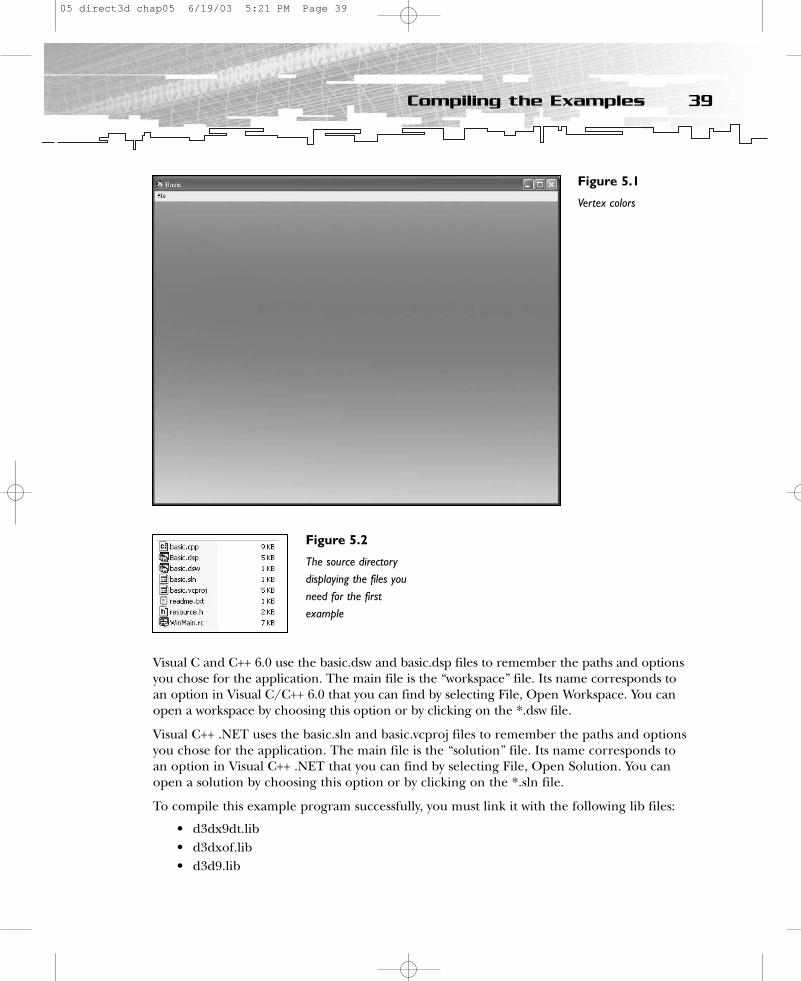
Visual C and C++ 6.0 use the basic.dsw and basic.dsp files to remember the paths and optionsyou chose for the application. The main file is the “workspace” file. Its name corresponds toan option in Visual C/C++ 6.0 that you can find by selecting File, Open Workspace. You canopen a workspace by choosing this option or by clicking on the *.dsw file.
Visual C++ .NET uses the basic.sln and basic.vcproj files to remember the paths and optionsyou chose for the application. The main file is the “solution” file. Its name corresponds toan option in Visual C++ .NET that you can find by selecting File, Open Solution. You canopen a solution by choosing this option or by clicking on the *.sln file.
To compile this example program successfully, you must link it with the following lib files:
• d3dx9dt.lib• d3dxof.lib• d3d9.lib
39Compiling the Examples
Figure 5.1
Vertex colors
Figure 5.2
The source directorydisplaying the files youneed for the firstexample
05 direct3d chap05 6/19/03 5:21 PM Page 39
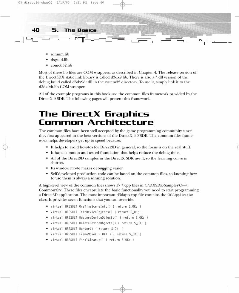
• winmm.lib• dxguid.lib• comctl32.lib
Most of these lib files are COM wrappers, as described in Chapter 4. The release version ofthe Direct3DX static link library is called d3dx9.lib. There is also a *.dll version of thedebug build called d3dx9dt.dll in the system32 directory. To use it, simply link it to thed3dx9dt.lib COM wrapper.
All of the example programs in this book use the common files framework provided by theDirectX 9 SDK. The following pages will present this framework.
The DirectX GraphicsCommon ArchitectureThe common files have been well accepted by the game programming community sincethey first appeared in the beta versions of the DirectX 6.0 SDK. The common files frame-work helps developers get up to speed because:
• It helps to avoid how-tos for Direct3D in general, so the focus is on the real stuff. • It has a common and tested foundation that helps reduce the debug time. • All of the Direct3D samples in the DirectX SDK use it, so the learning curve is
shorter. • Its window mode makes debugging easier. • Self-developed production code can be based on the common files, so knowing how
to use them is always a winning solution.
A high-level view of the common files shows 17 *.cpp files in C:\DXSDK\Samples\C++\Common\Src. These files encapsulate the basic functionality you need to start programminga Direct3D application. The most important d3dapp.cpp file contains the CD3DApplicationclass. It provides seven functions that you can override.
• virtual HRESULT OneTimeSceneInit() { return S_OK; }
• virtual HRESULT InitDeviceObjects() { return S_OK; }
• virtual HRESULT RestoreDeviceObjects() { return S_OK; }
• virtual HRESULT DeleteDeviceObjects() { return S_OK; }
• virtual HRESULT Render() { return S_OK; }
• virtual HRESULT FrameMove( FLOAT ) { return S_OK; }
• virtual HRESULT FinalCleanup() { return S_OK; }
40 5. The Basics
05 direct3d chap05 6/19/03 5:21 PM Page 40
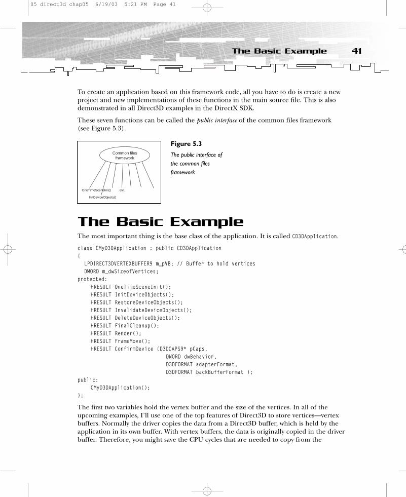
To create an application based on this framework code, all you have to do is create a newproject and new implementations of these functions in the main source file. This is alsodemonstrated in all Direct3D examples in the DirectX SDK.
These seven functions can be called the public interface of the common files framework (see Figure 5.3).
The Basic ExampleThe most important thing is the base class of the application. It is called CD3DApplication.
class CMyD3DApplication : public CD3DApplication{
LPDIRECT3DVERTEXBUFFER9 m_pVB; // Buffer to hold verticesDWORD m_dwSizeofVertices;
protected:HRESULT OneTimeSceneInit();HRESULT InitDeviceObjects();HRESULT RestoreDeviceObjects();HRESULT InvalidateDeviceObjects();HRESULT DeleteDeviceObjects();HRESULT FinalCleanup();HRESULT Render();HRESULT FrameMove();HRESULT ConfirmDevice (D3DCAPS9* pCaps,
DWORD dwBehavior, D3DFORMAT adapterFormat, D3DFORMAT backBufferFormat );
public:CMyD3DApplication();
};
The first two variables hold the vertex buffer and the size of the vertices. In all of theupcoming examples, I’ll use one of the top features of Direct3D to store vertices—vertexbuffers. Normally the driver copies the data from a Direct3D buffer, which is held by theapplication in its own buffer. With vertex buffers, the data is originally copied in the driverbuffer. Therefore, you might save the CPU cycles that are needed to copy from the
41The Basic Example
etc.
InitDeviceObjects()
OneTimeSceneInit()
Common filesframework
Figure 5.3
The public interface ofthe common filesframework
05 direct3d chap05 6/19/03 5:21 PM Page 41
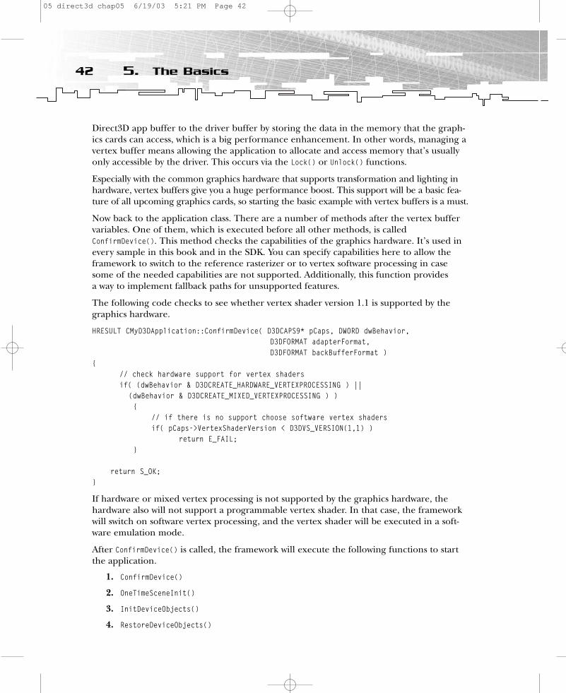
Direct3D app buffer to the driver buffer by storing the data in the memory that the graph-ics cards can access, which is a big performance enhancement. In other words, managing a vertex buffer means allowing the application to allocate and access memory that’s usuallyonly accessible by the driver. This occurs via the Lock() or Unlock() functions.
Especially with the common graphics hardware that supports transformation and lighting inhardware, vertex buffers give you a huge performance boost. This support will be a basic fea-ture of all upcoming graphics cards, so starting the basic example with vertex buffers is a must.
Now back to the application class. There are a number of methods after the vertex buffervariables. One of them, which is executed before all other methods, is calledConfirmDevice(). This method checks the capabilities of the graphics hardware. It’s used inevery sample in this book and in the SDK. You can specify capabilities here to allow theframework to switch to the reference rasterizer or to vertex software processing in casesome of the needed capabilities are not supported. Additionally, this function provides a way to implement fallback paths for unsupported features.
The following code checks to see whether vertex shader version 1.1 is supported by thegraphics hardware.
HRESULT CMyD3DApplication::ConfirmDevice( D3DCAPS9* pCaps, DWORD dwBehavior,D3DFORMAT adapterFormat, D3DFORMAT backBufferFormat )
{// check hardware support for vertex shaders if( (dwBehavior & D3DCREATE_HARDWARE_VERTEXPROCESSING ) ||
(dwBehavior & D3DCREATE_MIXED_VERTEXPROCESSING ) ){
// if there is no support choose software vertex shadersif( pCaps->VertexShaderVersion < D3DVS_VERSION(1,1) )
return E_FAIL;}
return S_OK;}
If hardware or mixed vertex processing is not supported by the graphics hardware, thehardware also will not support a programmable vertex shader. In that case, the frameworkwill switch on software vertex processing, and the vertex shader will be executed in a soft-ware emulation mode.
After ConfirmDevice() is called, the framework will execute the following functions to startthe application.
1. ConfirmDevice()
2. OneTimeSceneInit()
3. InitDeviceObjects()
4. RestoreDeviceObjects()
42 5. The Basics
05 direct3d chap05 6/19/03 5:21 PM Page 42
When the application is running, the following functions are executed in a loop:
• FrameMove()
• Render()
This is the main loop of every framework application. While the program is running, theuser might want to resize the window. In that case, the framework would call
• InvalidateDeviceObjects()
• RestoreDeviceObjects()
If the user wanted to change the device (HAL or REF) by pressing F2 or clicking on File,Change Device, the framework would call
• InvalidateDeviceObjects()
• DeleteDeviceObjects()
• InitDeviceObjects()
• RestoreDeviceObjects()
If the user quits the application, the framework will call
• InvalidateDeviceObjects()
• DeleteDeviceObjects()
• FinalCleanup()
There are matching functional pairs. InvalidateDeviceObjects() destroys what RestoreDeviceObjects() has built up, and DeleteDeviceObjects() destroys whatInitDeviceObjects() has built up. The FinalCleanup() function destroys whatOneTimeSceneInit() has built up. The idea is to give every functional pair its own tasks. TheOneTimeSceneInit()/FinalCleanup() pair is called at the beginning and the end of the lifecy-cle of the game. Both functions are used to load or delete data that is device-independent.A good candidate might be geometry data. OneTimeSceneInit() is invoked once per applica-tion execution cycle for all things that need a permanent initialization. You can load geom-etry data, set up calculated values, and so on. Basically, any one-time resource allocationshould be performed here.
The target of the InitDeviceObjects()/DeleteDeviceObjects() pair is data that isdevice-dependent, like the name implies. If the already-loaded data has to be changedwhen the device changes, it should beloaded here. The following examples,named Basic2, Basic3, and so on, will load,recreate, or destroy their vertex buffers,index buffers, and textures in these functions.
43The Basic Example
NOTEThe word device is used here in thecontext of a “device driver,” mean-ing a piece of software that controlssome hardware or software device inthe system. However,“device” inmost other cases refers to thegraphics card.
05 direct3d chap05 6/19/03 5:21 PM Page 43
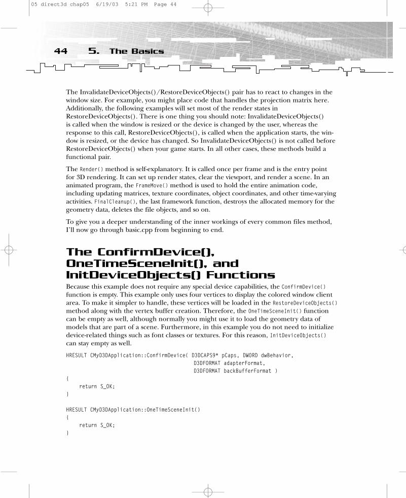
The InvalidateDeviceObjects()/RestoreDeviceObjects() pair has to react to changes in thewindow size. For example, you might place code that handles the projection matrix here.Additionally, the following examples will set most of the render states inRestoreDeviceObjects(). There is one thing you should note: InvalidateDeviceObjects() is called when the window is resized or the device is changed by the user, whereas theresponse to this call, RestoreDeviceObjects(), is called when the application starts, the win-dow is resized, or the device has changed. So InvalidateDeviceObjects() is not called beforeRestoreDeviceObjects() when your game starts. In all other cases, these methods build afunctional pair.
The Render() method is self-explanatory. It is called once per frame and is the entry point for 3D rendering. It can set up render states, clear the viewport, and render a scene. In ananimated program, the FrameMove() method is used to hold the entire animation code,including updating matrices, texture coordinates, object coordinates, and other time-varyingactivities. FinalCleanup(), the last framework function, destroys the allocated memory for thegeometry data, deletes the file objects, and so on.
To give you a deeper understanding of the inner workings of every common files method,I’ll now go through basic.cpp from beginning to end.
The ConfirmDevice(),OneTimeSceneInit(), andInitDeviceObjects() FunctionsBecause this example does not require any special device capabilities, the ConfirmDevice()function is empty. This example only uses four vertices to display the colored window clientarea. To make it simpler to handle, these vertices will be loaded in the RestoreDeviceObjects()method along with the vertex buffer creation. Therefore, the OneTimeSceneInit() functioncan be empty as well, although normally you might use it to load the geometry data of models that are part of a scene. Furthermore, in this example you do not need to initializedevice-related things such as font classes or textures. For this reason, InitDeviceObjects()can stay empty as well.
HRESULT CMyD3DApplication::ConfirmDevice( D3DCAPS9* pCaps, DWORD dwBehavior,D3DFORMAT adapterFormat, D3DFORMAT backBufferFormat )
{return S_OK;
}
HRESULT CMyD3DApplication::OneTimeSceneInit(){
return S_OK;}
44 5. The Basics
05 direct3d chap05 6/19/03 5:21 PM Page 44

HRESULT CMyD3DApplication::InitDeviceObjects(){
return S_OK;}
Please note that all of these functions return an S_OK HRESULT value to show you that every-thing went well.
The RestoreDeviceObjects() MethodThe RestoreDeviceObjects() method is called after InitDeviceObjects() when the applicationstarts. When the user resizes the application window, this method is called after a call toInvalidateDeviceObjects(). Most of the real stuff in the first example happens here.
HRESULT CMyD3DApplication::RestoreDeviceObjects(){
// fill the vertex buffer with the data for a quadVERTEX Vertices[] ={
{ 0.0f, 0.0f, 0.5f, 1.0f, 0x00ff0000, }, // x, y, z, rhw, color{(float)m_d3dsdBackBuffer.Width, 0.0f, 0.5f, 1.0f, 0x00ff0000, },{(float)m_d3dsdBackBuffer.Width, (float)m_d3dsdBackBuffer.Height, 0.5f,
1.0f, 0x0000ff00, },{0.0f, (float)m_d3dsdBackBuffer.Height, 0.5f, 1.0f, 0x0000ffff, },
};
m_dwSizeofVertices = sizeof(Vertices);
// sixth parameter is new in DX9if( FAILED( m_pd3dDevice->CreateVertexBuffer(m_dwSizeofVertices,
D3DUSAGE_WRITEONLY, FVF,D3DPOOL_MANAGED, &m_pVB, NULL ) ) )
return E_FAIL;
VERTEX* pVertices;// DX9: the third parameter has changed from BYTE** to VOID**if( FAILED( m_pVB->Lock( 0, m_dwSizeofVertices, (VOID**)&pVertices, 0 ) ) )
return E_FAIL;memcpy( pVertices, Vertices, m_dwSizeofVertices);m_pVB->Unlock();
return S_OK;}
45The Basic Example
05 direct3d chap05 6/19/03 5:21 PM Page 45

The vertex structure shows the layout of the data that is stored in the vertex buffer later.
// A structure for our custom vertex typestruct VERTEX{
FLOAT x, y, z, rhw; // The transformed position for the vertexDWORD color; // The vertex color
};
// Fixed-Function Vertex structure// In DX8: #define D3DFVF_CUSTOMVERTEX (D3DFVF_XYZRHW|D3DFVF_DIFFUSE)const DWORD FVF = (D3DFVF_XYZRHW | D3DFVF_DIFFUSE);
Four structures are filled with position data, an RHW value, and a color value inRestoreDeviceObjects() (see Figure 5.4).
// fill the vertex buffer with the data for a quadVERTEX Vertices[] ={
{ 0.0f, 0.0f, 0.5f, 1.0f, 0xffff0000, }, // x, y, z, rhw, color{ (float)m_d3dsdBackBuffer.Width, 0.0f, 0.5f, 1.0f, 0xffff0000, },{ (float)m_d3dsdBackBuffer.Width, (float)m_d3dsdBackBuffer.Height, 0.5f,
1.0f, 0xff00ff00, },{ 0.0f, (float)m_d3dsdBackBuffer.Height, 0.5f, 1.0f, 0xff00ffff, },
};
46 5. The Basics
Figure 5.4
Vertex layout of thebasic example
05 direct3d chap05 6/19/03 5:21 PM Page 46

All of the vertices are provided in screen space, as you can see by the usage of the widthand height of the back buffer. The term screen space refers to a frame of reference in whichcoordinates are related directly to 2D locations in the frame or back buffer.
Because it is not necessary to transform the vertices in any way, you do not need anotherframe of reference, such as a world coordinate system or a model coordinate system. This isthe most efficient way to handle these vertices in Direct3D.
No transformation from world, view, or projection space happens, and the first vertex (asthe first member of the vertex array) lies at the top-left of the window’s client area. The vertex’s x, y coordinates are (0.0f, 0.0f). The second member of the vertex array describesthe second vertex, which is positioned in the top-right corner. The third member describesthe third vertex, which lies in the bottom-right corner, and the fourth vertex array memberdescribes the fourth vertex, which lies in the bottom-left corner. Every vertex has a z-valueof 0.5f. Changing this value should not lead to any differences because this example doesn’tuse a z-buffer, as shown in the CMyD3DApplication constructor with:
m_d3dEnumeration.AppUsesDepthBuffer = FALSE
The fourth entry in each line in the aforementioned vertex array is called an RHW value. It shows the Direct3D pipeline in which the vertices are already transformed in homoge-nous space, which is the case here, because they are in screen space. (You’ll learn moreabout this in Chapter 6, “First Steps to Animation.”) The last entry is a color value. As youcan see from the use of 0x, hexadecimal values are used here. This is quite handy becausethe four color values (ARGB) are each represented by a pair of hexadecimal values. The first ff pair stands for alpha, the second pair stands for red, and so on. Therefore, the top-left and top-right corner vertexes should both be red. Most paint programs, such asAdobe Photoshop or Jasc Paint Shop Pro, offer a color selection dialog that shows you the0x values of RGB (see Figure 5.5).
47The Basic Example
Figure 5.5
The Color Picker in Jasc Paint Shop Pro
05 direct3d chap05 6/19/03 5:21 PM Page 47
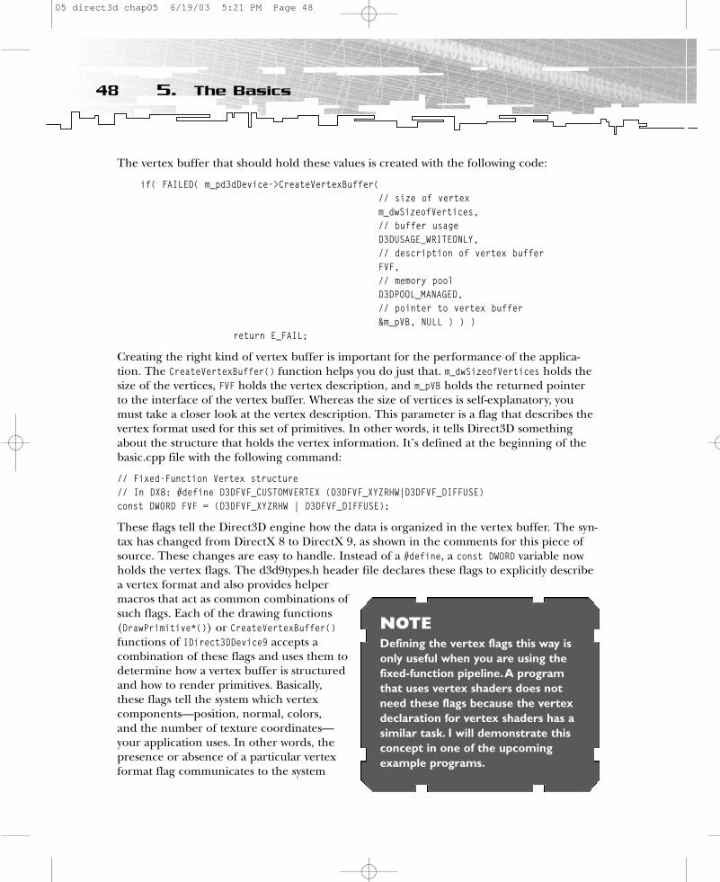
The vertex buffer that should hold these values is created with the following code:
if( FAILED( m_pd3dDevice->CreateVertexBuffer( // size of vertexm_dwSizeofVertices,// buffer usageD3DUSAGE_WRITEONLY, // description of vertex bufferFVF,// memory poolD3DPOOL_MANAGED, // pointer to vertex buffer&m_pVB, NULL ) ) )
return E_FAIL;
Creating the right kind of vertex buffer is important for the performance of the applica-tion. The CreateVertexBuffer() function helps you do just that. m_dwSizeofVertices holds thesize of the vertices, FVF holds the vertex description, and m_pVB holds the returned pointerto the interface of the vertex buffer. Whereas the size of vertices is self-explanatory, youmust take a closer look at the vertex description. This parameter is a flag that describes thevertex format used for this set of primitives. In other words, it tells Direct3D somethingabout the structure that holds the vertex information. It’s defined at the beginning of thebasic.cpp file with the following command:
// Fixed-Function Vertex structure// In DX8: #define D3DFVF_CUSTOMVERTEX (D3DFVF_XYZRHW|D3DFVF_DIFFUSE)const DWORD FVF = (D3DFVF_XYZRHW | D3DFVF_DIFFUSE);
These flags tell the Direct3D engine how the data is organized in the vertex buffer. The syn-tax has changed from DirectX 8 to DirectX 9, as shown in the comments for this piece ofsource. These changes are easy to handle. Instead of a #define, a const DWORD variable nowholds the vertex flags. The d3d9types.h header file declares these flags to explicitly describea vertex format and also provides helpermacros that act as common combinations ofsuch flags. Each of the drawing functions(DrawPrimitive*()) or CreateVertexBuffer()functions of IDirect3DDevice9 accepts a combination of these flags and uses them todetermine how a vertex buffer is structuredand how to render primitives. Basically,these flags tell the system which vertex components—position, normal, colors, and the number of texture coordinates—your application uses. In other words, thepresence or absence of a particular vertexformat flag communicates to the system
48 5. The Basics
NOTEDefining the vertex flags this way isonly useful when you are using thefixed-function pipeline.A programthat uses vertex shaders does notneed these flags because the vertexdeclaration for vertex shaders has asimilar task. I will demonstrate thisconcept in one of the upcomingexample programs.
05 direct3d chap05 6/19/03 5:21 PM Page 48

which vertex component fields are present in memory and which you’ve omitted. By usingonly the needed vertex components, your application can conserve memory and minimizethe processing bandwidth required to render your 3D world.
D3DFVF_XYZRHW tells your system that your game engine has already transformed the verticesso Direct3D doesn’t have to do it. Therefore, Direct3D doesn’t transform your vertices withthe world, view, or projection matrices. The vertices have to be delivered in screen space inthis example program.
Unlike D3DFVF_XYZRHW, the D3DFVF_XYZ flagtells your system that your game has nottransformed vertices and calls for help from Direct3D to do so.
D3DFVF_DIFFUSE indicates that the vertex format includes a diffuse color component.The use of D3DFVF_SPECULAR indicates that thevertex format includes a specular colorcomponent.
Mapping of the vertex input registers isfixed while you are using the fixed-functionpipeline, so specific vertex elements such as position or normals must be placed in specifiedregisters located in the vertex input memory. Therefore, you have to format all the vertexstructures in a specific order, shown here.
1. Position of the transformed/untransformed vertex—float x, y, and z coordinates
2. RHW as the reciprocal of the homogenous w coordinate (only for already transformed vertices)
3. Blending weight values 1–5 floats
4. The vertex normal as float x, y, and z normal coordinates
5. The vertex point size
6. The diffuse color as diffuse RGBA
7. The specular color as specular RGBA
8. Texture coordinate sets 1–8 as float u and v coordinates
For example, your vertex structure could look like this:
typedef struct{
FLOAT x,y,z; // positionDWORD diffuse; // diffuse colorFLOAT u,v; // one pair of texture coordinates
} MYVERTEX;
49The Basic Example
NOTEIt’s a different story when you areusing vertex shaders instead of thefixed-function pipeline. In that case,the vertices have to be delivered inHCLIP space, which means in arange of -1.0f..1.0f. See Chapter 6 for examples of this.
05 direct3d chap05 6/19/03 5:21 PM Page 49

You have to define the flags for this vertex structure as follows:
const DWORD D3DFVF_CUSTOMVERTEX = (D3DFVF_XYZ | D3DFVF_DIFFUSE | D3DFVF_TEX1)
Another sample could be
struct LineVertex{
FLOAT x, y, z; // position};const DWORD LINE_VERTEX = ( D3DFVF_XYZ )
A more complex example might be
typedef struct SObjVertex{
FLOAT x, y, z; // positionFLOAT nx, ny, nz; // normalDWORD diffuse; // diffuse colorDWORD specular; // specular colorFLOAT tu, tv; // first pair of texture coordinatesFLOAT tu2, tv2, tw2; // second pair of texture coordinatesFLOAT tu3, tv3; // third pair of texture coordinatesFLOAT tu4, tv4; // fourth pair of texture coordinates
} SObjVertex;...const DWORD gSObjVertexFVF = (D3DFVF_XYZ | D3DFVF_DIFFUSE | D3DFVF_SPECULAR |
D3DFVF_NORMAL | D3DFVF_TEX4 |D3DFVF_TEXCOORDSIZE2(0) | D3DFVF_TEXCOORDSIZE3(1) |D3DFVF_TEXCOORDSIZE2(2) | D3DFVF_TEXCOORDSIZE2(3));
The D3DFVF_TEX4 flag instructs the Direct3D engine that four texture coordinates will beused. The D3DFVF_TEXCOORDSIZE* flags specify the number of texture coordinate values—twoor three—and their order. For example, the second texture uses three texture coordinatesconsisting of three floating-point values. This might be useful in the case of a cube or volume texture.
Another important concept is the management of resources by Direct3D. With the advent of Direct3D 8.0, a unified resource manager was introduced for textures and geometry. Thisresource manager is used for mipmaps, volume maps, cube maps, and vertex and index buffers.
The resource manager is indicated by the D3DPOOL_MANAGED flag in the CreateVertexBuffer()method call. This flag defines the memory class that holds the vertex buffers. Now, youmight ask why we use different memory classes. There’s memory that is located in yourgraphics card (for example, 128-MB DDRAM II), and there’s memory that is located inyour system memory (for example, 1024-MB RAM). Direct3D can manage your applicationmemory requirements in a way that uses the right memory for the right task, but you haveto give it a sign indicating what you would like to do with the resource. Only resources withthe memory pool D3DPOOL_MANAGED are managed by the resource manager.
50 5. The Basics
05 direct3d chap05 6/19/03 5:21 PM Page 50

Choosing a way to manage the resources (or defining the memory class that holds theresources) is called choosing a pool in Direct3D. There are four different kinds of pools inDirectX 9.
typedef enum _D3DPOOL {D3DPOOL_DEFAULT = 0, // AGP, graphics card memoryD3DPOOL_MANAGED = 1, // AGP, graphics card memory && copy in sys memoryD3DPOOL_SYSTEMMEM = 2, // system memory, re-creatableD3DPOOL_SCRATCH = 3, // system memory, not re-creatableD3DPOOL_FORCE_DWORD = 0x7fffffff
} D3DPOOL;
If you specify a scratch pool, the resource is stored in system memory and cannot be recre-ated when a device is lost. This occurs, for example, when you switch between windowedand full-screen modes or when you change the resolution in one of these modes. Theseresources cannot be accessed by the Direct3D device nor set as textures or render targets.However, they can always be created, locked, and copied. This memory pool was introducedto DirectX 9 because the CreateImageSurface() function was removed from the API.D3DPOOL_SCRATCH, together with CreateOffscreenPlainSurface(), will return a surface that hasidentical characteristics to a surface created by the former CreateImageSurface(). Therefore,it is used mainly for the creation of image surfaces.
If you specify a system pool, the resource is stored in system memory. The advantage of thispool is that the resources do not need to be recreated after the device is lost. Additionally,you can lock and update resources in this pool. Therefore, this pool is recommended fordata that undergoes frequent software processing.
When you specify a managed pool, the resource is stored in AGP/graphics card memory,and a copy is stored in the system memory. The advantage to this kind of pool compared tothe system pool is that the resource is lying inthe AGP/graphics card memory, and a copyof the memory needs to be made only ifchanges are made in the system memory.
When you specify a default pool, theresource is typically stored in graphics cardor AGP memory. This is the most accessiblememory to the rendering device. You mustuse it when the vertex and index buffershave to be updated frequently, because thesystem or managed pools would be too slowwith their ongoing system-to-AGP/graphicscard copies. You must allocate all of thedefault pool resources prior to creating themanaged resources. Not doing so can result
51The Basic Example
NOTEAGP (Accelerated Graphics Port) is a PCI-based interface that wasdesigned specifically for the demandsof 3D graphics applications. The 32-bit AGP channel directly links the graphics controller to the mainmemory.Although the channel runsat only 66 MHz, it supports datatransmission during both the risingand falling ends of the clock cycle,yielding an effective speed of 133 MHz.
05 direct3d chap05 6/19/03 5:21 PM Page 51
in significant performance loss. The disadvantage of a default pool is that it has to be man-aged by the application.
Every pool has its own tasks. You might say that dynamic vertex and index buffers can beupdated more efficiently in a default pool. This might be also the pool of choice for texturesthat do not have to be changed by the application. On the other hand, textures that do haveto be changed frequently can only be accessed via a scratch, system, or managed pool.
If performance does not matter, you are always on the safe side when you use a managedpool. This is the easiest and best way to map memory to devices. The resources are copiedautomatically to device-accessible memory as needed. Managed resources are backed by system memory and do not need to be recreated when a device is lost. Rule of thumb: Use managed unless you know a better way. It works for any class of driver and must be usedwith Unified Memory Architecture mainboards. In these boards, graphics card memory islocated in the same hardware as the system memory or RAM.
This is why I chose the managed pool for the vertex buffer in the CreateVertexBuffer()function we discussed. The fifth parameter of this function returns a pointer to the vertexbuffer. In DirectX 9, the newly introduced sixth parameter is reserved and should be set toNULL. In other words, it has no underlying functionality today, but it might in the nextDirectX release.
After you create the vertex buffer and lock it using Lock(), you can fill it with memcpy().
VERTEX* pVertices;// DX9: the third parameter has changed from BYTE** to VOID**if( FAILED( m_pVB->Lock( 0, m_dwSizeofVertices, (VOID**)&pVertices, 0 ) ) )
return E_FAIL;memcpy( pVertices, Vertices, m_dwSizeofVertices);m_pVB->Unlock();
Locking a resource means granting CPU access to its storage. In addition to granting proces-sor access, any other operations involving that resource are serialized for the duration of alock. Only a single lock for a resource is allowed, even for non-overlapping regions, and noongoing accelerator operations on a surface are allowed while there is an outstanding lockoperation on that surface. The syntax of the Lock() function is
HRESULT Lock(UINT OffsetToLock, // offset into the vertex bufferUINT SizeToLock, // == vertices * SizeOfVertexVOID **ppbData, // pointer to memory bufferDWORD Flags // hints on the usage of the vertex buffer
);
The first parameter lets the programmer provide an offset for the vertex buffer. Togetherwith the second parameter, this allows you to put several models into one vertex buffer andlock only the area where the geometry of a specific model resides, for example.
52 5. The Basics
05 direct3d chap05 6/19/03 5:21 PM Page 52
The size is specified by the number of vertices multiplied by the size of one vertex. The third parameter returns the pointer to a memory buffer. The last parameter lets theprogrammer provide the following hints on how the vertex buffer will be used:
• D3DLOCK_DISCARD. The application overwrites every location in the vertex buffer.• D3DLOCK_READONLY. The application does not write to the vertex buffer.• D3DLOCK_NOOVERWRITE. The data in the vertex buffer is not overwritten.• D3DLOCK_NOSYSLOCK. Enables the possibility of display mode changes during lock().• D3DLOCK_NO_DIRTY_UPDATE. There is no dirty region to the locked vertex buffer.
The D3DLOCK_DISCARD and D3DLOCK_NOOVERWRITE flags are valid only on buffers that are updatedregularly (indicated by the D3DUSAGE_DYNAMIC flag), which is not the case here. TheD3DLOCK_READONLY flag is only useful when the application will not write to the buffer. Thisenables resources stored in non-native formats to save the recompression step when unlock-ing. Therefore, it makes sense to provide 0 as the last parameter here because the programcan’t provide a useful flag that might provide the driver with a hint to optimize the vertexbuffer.
After the vertex buffer is filled with the vertices’ data, it’s unlocked with a call tom_pVB->Unlock();. This is the last step in initializing and restoring the device-dependentobjects. Up until now, the game has gone through the whole initialization process viaConfirmDevice(), OneTimeSceneInit(), InitDeviceObjects(), and RestoreDeviceObjects(). Thenext function call enters into the ongoing rendering loop, which consists of the FrameMove()and Render() function calls.
The FrameMove() FunctionBecause you’re not animating a scene, you don’t need to include any code insideFrameMove(). A lot of things will happen here in the upcoming examples.
HRESULT CMyD3DApplication::FrameMove(){
return S_OK; }
The Render() FunctionThe Render() method is called once per frame and is the entry point for 3D rendering. It can set up render states, clear the render target, and render a scene.
HRESULT CMyD3DApplication::Render(){
// Begin the sceneif( SUCCEEDED( m_pd3dDevice->BeginScene() ) ){
// In DX8: m_pd3dDevice->SetVertexShader( D3DFVF_CUSTOMVERTEX );
53The Basic Example
05 direct3d chap05 6/19/03 5:21 PM Page 53

// Passing an FVF to IDirect3DDevice9::SetFVF specifies a legacy FVF with stream 0.m_pd3dDevice->SetFVF(FVF ); // new in DX9// DX8: only three parameters. In DX9 the third parameter is newm_pd3dDevice->SetStreamSource( 0, m_pVB, 0, sizeof(VERTEX) );m_pd3dDevice->DrawPrimitive( D3DPT_TRIANGLEFAN, 0, 2 );// End the scene.m_pd3dDevice->EndScene();
}return S_OK;
}
Render() calls the BeginScene()/EndScene() pair. The first method is called before you per-form the rendering; the second is called after rendering. BeginScene() causes the system tocheck its internal data structures and the availability and validity of rendering surfaces. Italso sets an internal flag to signal that a scene is in progress. Attempts to call renderingmethods when a scene is not in progress fail, returning D3DERR_SCENE_NOT_IN_SCENE. Whenyour rendering is complete, you need to call EndScene(), which clears the internal flag thatindicates that a scene is in progress, flushes the cached data, and makes sure the renderingsurfaces are okay.
Direct3D can assemble each vertex that isfed into the processing portion of theDirect3D pipeline from one or more datastreams. For example, one data stream canhold the positions and normals, while a second holds color values and a third holdstexture coordinates. The SetStreamSource()function delivers this functionality. The declaration of this method is
HRESULT SetStreamSource(UINT StreamNumber,IDirect3DVertexBuffer9 *pStreamData,UINT OffsetInBytes,UINT Stride
);
The first parameter defines the data stream. Depending on the underlying hardware, therecan be up to 16 different data streams. DirectX 7-compatible hardware will only supportone stream, but newer hardware supports up to 16.
The second parameter provides the stream data. Usually this is a pointer to the vertexbuffer, which is m_pVB here.
When you use a fixed-function pipeline like I have done here, the stride of the vertexstream must match the vertex size computed from the FVF. In this example, that means thatyou must provide the size of the VERTEX structure in the fourth parameter. Therefore, whenyou use the fixed-function pipeline you cannot use one vertex buffer for several streams.
54 5. The Basics
NOTEYou should omit multipleBeginScene()/EndScene() pairs in oneapplication because scene-capturegraphic chips such as the PowerVRKyro and Kyro II (http://www.powervr.com) will not work with multiple pairs.
05 direct3d chap05 6/19/03 5:21 PM Page 54

The Fur demo in the DirectX 9 SDK shows a nice example of how to use streams with vertexshaders. Following is some pseudocode that demonstrates how the demo uses streams:
All passes: stream 0: Position, Normal, Diffuse vertex colorif (finpass)
fin pass stream 1: texture coordinates for finsif (shellpass)
shells pass stream 2: texture coordinates for shells
In every pass, SetStreamSource() sets stream 0to use the position, normal, and diffuse colorvalues. You can choose these values if youadd another pass in which SetStreamSource()sets stream 1 to use a texture coordinate for the fins. Additionally, you can letSetStreamSource() set stream 2 to use a tex-ture coordinate for the shells in a secondpass. Switching on and off the fin and shellpass makes the whole system scalable. Forexample, if the object with fur is far away, itwouldn’t make sense to show its fur becauseit wouldn’t be visible from that distance.
Please note that the new version of SetStreamSource() in DirectX 9 adds the ability to set anoffset, similar to the Lock() function that you used to lock the vertex buffer. This makes iteasier to have several game objects reside in one vertex buffer.
Another change in DirectX 9 is the introduction of the SetFVF() function, which is usedonly for the fixed-function pipeline. If you are using a vertex shader, you must useSetVertexShader() instead. You aren’t using vertex shaders here, so you should use theSetFVF() function. The only parameter to this function is the vertex format.
m_pd3dDevice->SetFVF(FVF ); // new in DX9
The most important function call in Render() goes out to:
m_pd3dDevice->DrawPrimitive( D3DPT_TRIANGLEFAN, 0, 2 );
DrawPrimitive() has changed quite a bit since version 7.0. It renders non-indexed, geometricprimitives of the specified type from the current set of data input streams—in this case,from the one and only data stream declared by SetStreamSource(). Its syntax is
HRESULT DrawPrimitive(D3DPRIMITIVETYPE PrimitiveType,UINT StartVertex,UINT PrimitiveCount
);
The first parameter defines the primitive type you want to use. There are six different primitive types—D3DPT_POINTLIST, D3DPT_LINELIST, D3DPT_LINESTRIP, D3DPT_TRIANGLELIST,D3DPT_TRIANGLESTRIP, and D3DPT_TRIANGLEFAN.
55The Basic Example
NOTEWhen you are using vertex shaderswith a vertex declaration, the strideshould be greater than or equal tothe stream size computed from thedeclaration, which makes it possibleto use one vertex buffer for severalstreams.
05 direct3d chap05 6/19/03 5:21 PM Page 55
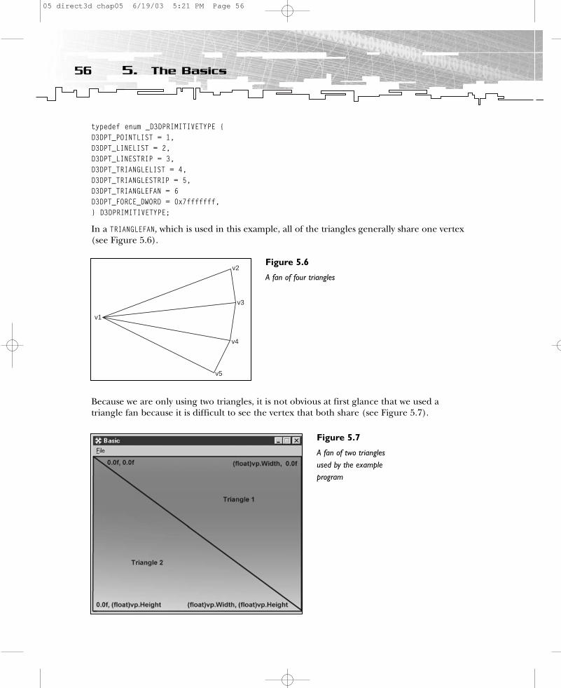
typedef enum _D3DPRIMITIVETYPE { D3DPT_POINTLIST = 1, D3DPT_LINELIST = 2, D3DPT_LINESTRIP = 3, D3DPT_TRIANGLELIST = 4, D3DPT_TRIANGLESTRIP = 5, D3DPT_TRIANGLEFAN = 6 D3DPT_FORCE_DWORD = 0x7fffffff, } D3DPRIMITIVETYPE;
In a TRIANGLEFAN, which is used in this example, all of the triangles generally share one vertex(see Figure 5.6).
Because we are only using two triangles, it is not obvious at first glance that we used a triangle fan because it is difficult to see the vertex that both share (see Figure 5.7).
56 5. The Basics
v1
v2
v3
v4
v5
Figure 5.6
A fan of four triangles
Figure 5.7
A fan of two trianglesused by the exampleprogram
05 direct3d chap05 6/19/03 5:21 PM Page 56
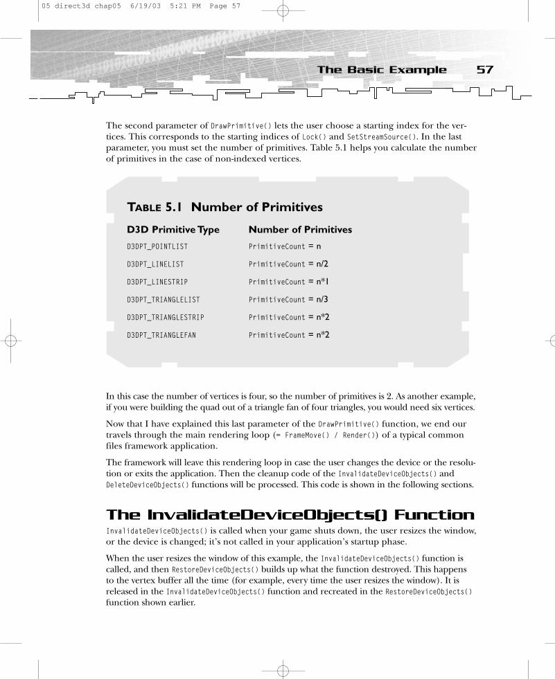
The second parameter of DrawPrimitive() lets the user choose a starting index for the ver-tices. This corresponds to the starting indices of Lock() and SetStreamSource(). In the lastparameter, you must set the number of primitives. Table 5.1 helps you calculate the numberof primitives in the case of non-indexed vertices.
In this case the number of vertices is four, so the number of primitives is 2. As another example,if you were building the quad out of a triangle fan of four triangles, you would need six vertices.
Now that I have explained this last parameter of the DrawPrimitive() function, we end ourtravels through the main rendering loop (= FrameMove() / Render()) of a typical commonfiles framework application.
The framework will leave this rendering loop in case the user changes the device or the resolu-tion or exits the application. Then the cleanup code of the InvalidateDeviceObjects() andDeleteDeviceObjects() functions will be processed. This code is shown in the following sections.
The InvalidateDeviceObjects() FunctionInvalidateDeviceObjects() is called when your game shuts down, the user resizes the window,or the device is changed; it’s not called in your application’s startup phase.
When the user resizes the window of this example, the InvalidateDeviceObjects() function iscalled, and then RestoreDeviceObjects() builds up what the function destroyed. This happens to the vertex buffer all the time (for example, every time the user resizes the window). It isreleased in the InvalidateDeviceObjects() function and recreated in the RestoreDeviceObjects()function shown earlier.
57The Basic Example
TABLE 5.1 Number of Primitives
D3D Primitive Type Number of Primitives
D3DPT_POINTLIST PrimitiveCount = n
D3DPT_LINELIST PrimitiveCount = n/2
D3DPT_LINESTRIP PrimitiveCount = n*1
D3DPT_TRIANGLELIST PrimitiveCount = n/3
D3DPT_TRIANGLESTRIP PrimitiveCount = n*2
D3DPT_TRIANGLEFAN PrimitiveCount = n*2
05 direct3d chap05 6/19/03 5:21 PM Page 57
HRESULT CMyD3DApplication::InvalidateDeviceObjects(){
SAFE_RELEASE( m_pVB );return S_OK;
}
The SAFE_RELEASE macro is defined in dxutil.h, like this:
#define SAFE_RELEASE(p) { if(p) { (p)->Release(); (p)=NULL; } }
It is the standardized release function that every DirectX COM object implements. It releases all system resources occupied by the object.
The DeleteDeviceObjects() FunctionDeleteDeviceObjects() is the functional pair to InitDeviceObjects(). Therefore, it deleteswhat the InitDeviceObjects() function has created. However, because you’re not initializingany device-dependent stuff in InitDeviceObjects(), you don’t have to delete it here.
HRESULT CMyD3DApplication::DeleteDeviceObjects(){
return S_OK;}
The FinalCleanup() FunctionThe last framework call goes out to FinalCleanup(). It’s the last chance to deallocate memoryyou’ve grabbed or to destroy any resources you’ve occupied.
HRESULT CMyD3DApplication::FinalCleanup(){
return S_OK;}
No resources (such as geometry data or textures) were occupied in OneTimeSceneInit()—thematching pair to FinalCleanup()—so there’s nothing to release here.
Tada…you’ve worked through your first Direct3D example. Congratulations!
The Basic2 ExampleThis example demonstrates the following additional features compared to the previousexample:
• How to apply textures to objects• How to use the framework font class
58 5. The Basics
05 direct3d chap05 6/19/03 5:21 PM Page 58
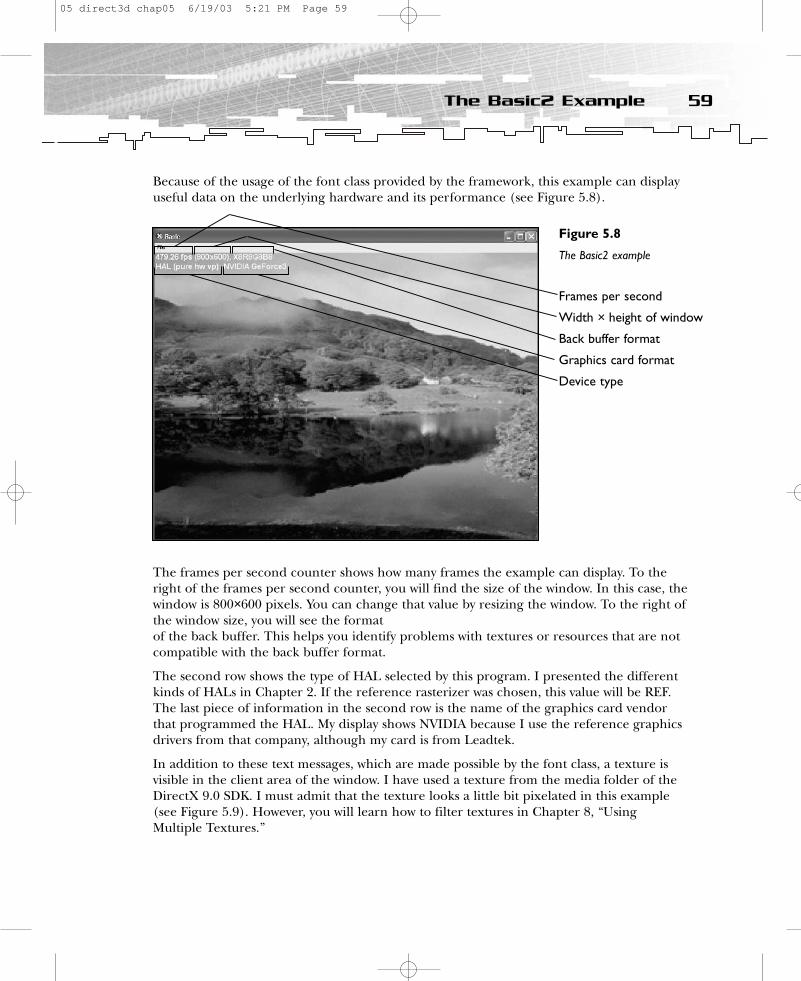
Because of the usage of the font class provided by the framework, this example can displayuseful data on the underlying hardware and its performance (see Figure 5.8).
The frames per second counter shows how many frames the example can display. To theright of the frames per second counter, you will find the size of the window. In this case, thewindow is 800×600 pixels. You can change that value by resizing the window. To the right ofthe window size, you will see the formatof the back buffer. This helps you identify problems with textures or resources that are notcompatible with the back buffer format.
The second row shows the type of HAL selected by this program. I presented the differentkinds of HALs in Chapter 2. If the reference rasterizer was chosen, this value will be REF.The last piece of information in the second row is the name of the graphics card vendorthat programmed the HAL. My display shows NVIDIA because I use the reference graphicsdrivers from that company, although my card is from Leadtek.
In addition to these text messages, which are made possible by the font class, a texture isvisible in the client area of the window. I have used a texture from the media folder of theDirectX 9.0 SDK. I must admit that the texture looks a little bit pixelated in this example(see Figure 5.9). However, you will learn how to filter textures in Chapter 8, “UsingMultiple Textures.”
59The Basic2 Example
Figure 5.8
The Basic2 example
Frames per second
Width × height of window
Back buffer format
Graphics card format
Device type
05 direct3d chap05 6/19/03 5:21 PM Page 59

To use a 2D texture map in a framework example, you must
• Use two additional texture coordinate variables in the vertex structure and fill thevertex buffer with them.
• Create the texture in the InitDeviceObjects() function with D3DUtil_CreateTexture().• Set the texture in the Render() function using SetTexture() with some corresponding
states.• Release the texture in DeleteDeviceObjects() with the SAFE_RELEASE() macro.
To remember these steps, just think of the lifecycle of a texture. You have to create the texture, use it (set it), and delete it (release it) to free occupied memory. Because a texturemust suit the capabilities of the graphics hardware, it is very device-specific. Therefore, thecreation process must occur in a device-specific context. The InitDeviceObjects()/DeleteDeviceObjects() functions are the ideal place to do it.
Using the framework font class in d3dfont.cpp should be even easier than building up thetexture. The following steps allow you to use a font to display text:
1. Create the font class in the constructor of the application class.
2. Call the font class function InitDeviceObjects() in the application class functionInitDeviceObjects().
3. Call the font class function RestoreDeviceObjects() in the application class functionRestoreDeviceObjects().
60 5. The Basics
Figure 5.9
Texture mapping
05 direct3d chap05 6/19/03 5:21 PM Page 60
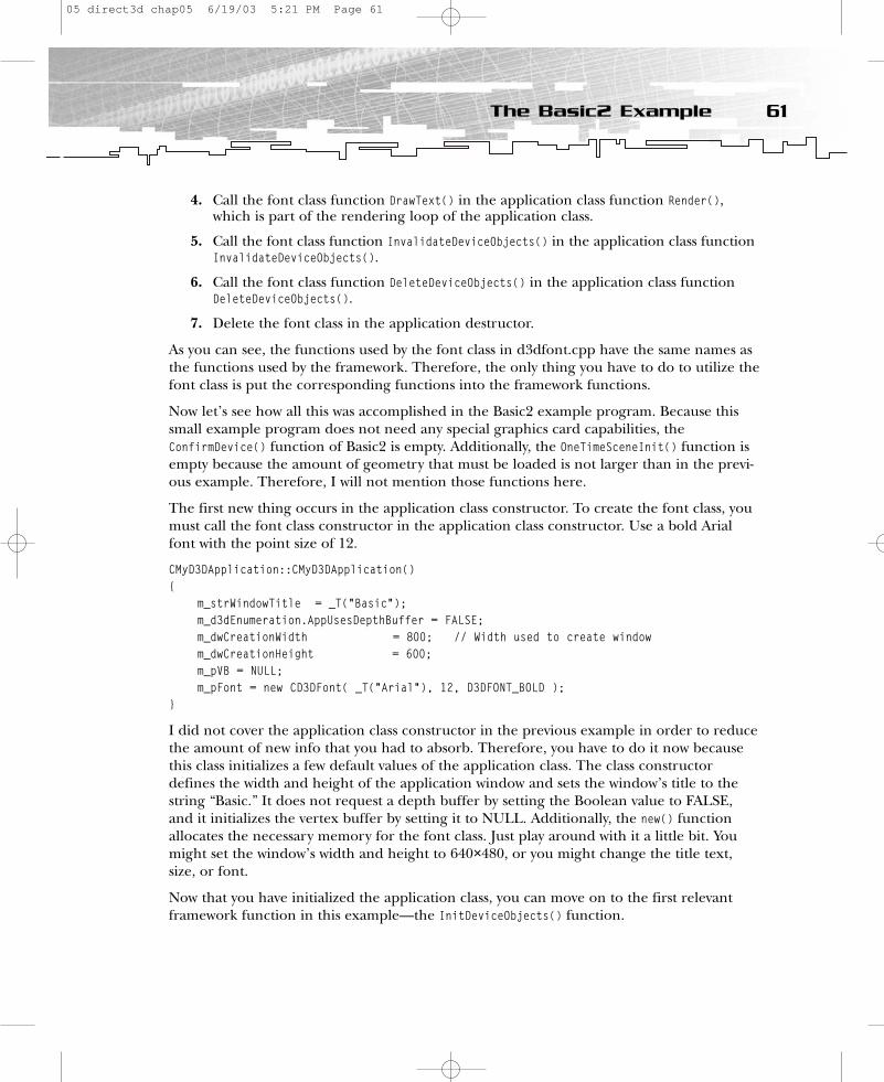
4. Call the font class function DrawText() in the application class function Render(),which is part of the rendering loop of the application class.
5. Call the font class function InvalidateDeviceObjects() in the application class functionInvalidateDeviceObjects().
6. Call the font class function DeleteDeviceObjects() in the application class functionDeleteDeviceObjects().
7. Delete the font class in the application destructor.
As you can see, the functions used by the font class in d3dfont.cpp have the same names asthe functions used by the framework. Therefore, the only thing you have to do to utilize thefont class is put the corresponding functions into the framework functions.
Now let’s see how all this was accomplished in the Basic2 example program. Because thissmall example program does not need any special graphics card capabilities, theConfirmDevice() function of Basic2 is empty. Additionally, the OneTimeSceneInit() function isempty because the amount of geometry that must be loaded is not larger than in the previ-ous example. Therefore, I will not mention those functions here.
The first new thing occurs in the application class constructor. To create the font class, youmust call the font class constructor in the application class constructor. Use a bold Arialfont with the point size of 12.
CMyD3DApplication::CMyD3DApplication(){
m_strWindowTitle = _T(“Basic”);m_d3dEnumeration.AppUsesDepthBuffer = FALSE;m_dwCreationWidth = 800; // Width used to create windowm_dwCreationHeight = 600;m_pVB = NULL;m_pFont = new CD3DFont( _T(“Arial”), 12, D3DFONT_BOLD );
}
I did not cover the application class constructor in the previous example in order to reducethe amount of new info that you had to absorb. Therefore, you have to do it now becausethis class initializes a few default values of the application class. The class constructordefines the width and height of the application window and sets the window’s title to thestring “Basic.” It does not request a depth buffer by setting the Boolean value to FALSE,and it initializes the vertex buffer by setting it to NULL. Additionally, the new() functionallocates the necessary memory for the font class. Just play around with it a little bit. Youmight set the window’s width and height to 640×480, or you might change the title text,size, or font.
Now that you have initialized the application class, you can move on to the first relevantframework function in this example—the InitDeviceObjects() function.
61The Basic2 Example
05 direct3d chap05 6/19/03 5:21 PM Page 61

The InitDeviceObjects() FunctionYou can use the InitDeviceObjects() function to initialize device-dependent objects. Thisfunction is called when the application starts up and the user changes the device by pressingF2. To use the font class, you have to call the font class function InitDeviceObjects().
HRESULT CMyD3DApplication::InitDeviceObjects(){
m_pFont->InitDeviceObjects( m_pd3dDevice );
// Load the texture for the background imageif( FAILED( D3DUtil_CreateTexture( m_pd3dDevice, _T(“Lake.bmp”),
&m_pBackgroundTexture) ) )return D3DAPPERR_MEDIANOTFOUND;
return S_OK;}
To create the background texture, you use the D3DUtil_CreateTexture() utility function. Itaccepts a pointer to the Direct3D device in its first parameter and the name of the texturein its second parameter, and it returns a pointer to an LPDIRECT3DTEXTURE9 texture object inits last parameter. This function does all the complicated initialization steps for you andsearches for a texture with the name you provided. This is very handy. A much more powerful function to create textures is presented in Appendix D, “Creating a Texture withD3DXCreateTextureFromFileEx().”
So far, you have allocated the memory for the font class, created the texture, and provideda handle.
The RestoreDeviceObjects() FunctionThe RestoreDeviceObjects() function did not change much from the first example. It iscalled when the user changes the window size and when the device is changed. The fontclass function RestoreDeviceObjects() is called to handle the functionality necessary to reactto this kind of user interaction.
HRESULT CMyD3DApplication::RestoreDeviceObjects(){// we don`t need any transformation -> position will be delivered in screen coordinates
m_pFont->RestoreDeviceObjects();
// fill the vertex buffer with the new data// Initialize to render a quadVERTEX Vertices[] ={
62 5. The Basics
05 direct3d chap05 6/19/03 5:21 PM Page 62

{ 0.0f, 0.0f, 0.5f, 1.0f, 0.0f, 0.0f, }, // x, y, z, rhw, tu, tv{ (float)m_d3dsdBackBuffer.Width, 0.0f, 0.5f, 1.0f, 1.0f, 0.0f, },{ (float)m_d3dsdBackBuffer.Width, (float)m_d3dsdBackBuffer.Height,
0.5f, 1.0f, 1.0f,1.0f, },{ 0.0f, (float)m_d3dsdBackBuffer.Height, 0.5f, 1.0f, 0.0f,1.0f, },
};
m_dwSizeofVertices = sizeof(Vertices);
// sixth parameter is new in DX9// Create a square for rendering the backgroundif( FAILED( m_pd3dDevice->CreateVertexBuffer(m_dwSizeofVertices,
D3DUSAGE_WRITEONLY, FVF,D3DPOOL_MANAGED, &m_pVB, NULL ) ) )
return E_FAIL;
VERTEX* pVertices;// the third parameter changed from BYTE** to VOID** in DX9
if( FAILED( m_pVB->Lock( 0, m_dwSizeofVertices, (VOID**)&pVertices, 0 ) ) )return E_FAIL;
memcpy( pVertices, Vertices, m_dwSizeofVertices);m_pVB->Unlock();
return S_OK;}
You must change the vertex structure to handle texture mapping.
// A structure for our custom vertex typestruct VERTEX{
FLOAT x, y, z, rhw; // The transformed position for the vertexFLOAT tu, tv; // texture coordinates
};
This example uses two texture coordinates per vertex instead of a color to lay out the texturemap.
{ 0.0f, 0.0f, 0.5f, 1.0f, 0.0f, 0.0f, }, // x, y, z, rhw, tu, tv{ (float)m_d3dsdBackBuffer.Width, 0.0f, 0.5f, 1.0f, 1.0f, 0.0f, },{ (float)m_d3dsdBackBuffer.Width, (float)m_d3dsdBackBuffer.Height,
0.5f, 1.0f, 1.0f,1.0f, },{ 0.0f, (float)m_d3dsdBackBuffer.Height, 0.5f, 1.0f, 0.0f,1.0f, },
The last two values of every vertex are the tu and tv values, which are shortcuts for texturecoordinates u and v. To map texels onto primitives, Direct3D requires a uniform addressrange for all texels in all textures. Therefore, it uses a generic addressing scheme in whichall texel addresses are in the range of 0.0 to 1.0, inclusive.
63The Basic2 Example
05 direct3d chap05 6/19/03 5:21 PM Page 63

The texture is “fixed” to the top-left vertex by using 0.0f for the u value and 0.0f for the vvalue. You use 1.0f for the u value and 1.0f for the v value to fix the bottom-right edge ofthe texture to the bottom-right vertex. As in screen space, the top-left corner is the origin,as shown in Figure 5.10.
The vertex flags reflect the different layout of the vertex structure.
// Fixed-Function Vertex structureconst DWORD FVF = (D3DFVF_XYZRHW | D3DFVF_TEX1);
The Direct3D engine can expect four floating-point values that describe the position of thevertex and one pair of floating-point values that holds the texture coordinates of a texture.
The rest of the RestoreDeviceObjects() function has not changed compared to the previousexample. The vertex buffer is created, locked, and filled in the same way as in the previousexample.
You can skip the framework function, FrameMove(), here because you don’t have to animateanything and therefore it is empty. You can move on to the Render() function of the applica-tion’s main loop.
The Render() FunctionIn this example, the Render() function has two new additions to the previous example. Ithandles the font class drawing code and the mapping of the texture onto the four vertices.
64 5. The Basics
Figure 5.10
Texture layout
05 direct3d chap05 6/19/03 5:21 PM Page 64

// Begin the sceneif( SUCCEEDED( m_pd3dDevice->BeginScene() ) ){
// Set up texture stage states for the backgroundm_pd3dDevice->SetTexture( 0, m_pBackgroundTexture );m_pd3dDevice->SetTextureStageState( 0, D3DTSS_COLORARG1, D3DTA_TEXTURE );m_pd3dDevice->SetTextureStageState( 0, D3DTSS_COLOROP, D3DTOP_SELECTARG1 );
// Passing an FVF to IDirect3DDevice9::SetFVF specifies a legacy FVF with stream 0.m_pd3dDevice->SetFVF(FVF ); m_pd3dDevice->SetStreamSource( 0, m_pVB, 0, sizeof(VERTEX) );m_pd3dDevice->DrawPrimitive( D3DPT_TRIANGLEFAN, 0, 2 );
// Output statisticsm_pFont->DrawText( 2, 0, D3DCOLOR_ARGB(255,255,255,0), m_strFrameStats );m_pFont->DrawText( 2, 20, D3DCOLOR_ARGB(255,255,255,0), m_strDeviceStats );
// End the scene.m_pd3dDevice->EndScene();
}
Compared to the previous example, there are two new code blocks in this example. Thefirst one sets the texture with the main function SetTexture(), and the second one usesDrawText() to position the text and set the text that is later displayed in the client region of the window. I’ll start with the texture mapping code.
The IDirect3DDevice9::SetTexture() method assigns a texture to a given stage for a device.Direct3D provides eight texture stages, which means that you can set up to eight texturesfor one DrawPrimitive() call. (However, you can use more DrawPrimitive() calls, which iscalled multi-pass rendering. One pass equals one DrawPrimitive() call.) You can choose thetexture stage you like by providing its number in the first parameter of SetTexture(). It iscommon to start with the texture stage 0 and to increment this number for every additionaltexture stage for which a texture should be assigned. That’s why the background texture isassigned to the 0 texture stage here.
When an application selects a texture as the current texture, it instructs the Direct3Ddevice to apply the texture to all primitives that are rendered from that time until the current texture is changed again. If each primitive in a 3D scene has its own texture, thetexture must be set before each primitive is drawn, which means just before theDrawPrimitive() function is called.
After you set the texture, you have to set the proper texture stages with the followingSetTextureStageState() calls:
m_pd3dDevice->SetTextureStageState( 0, D3DTSS_COLORARG1, D3DTA_TEXTURE );m_pd3dDevice->SetTextureStageState( 0, D3DTSS_COLOROP, D3DTOP_SELECTARG1);...
65The Basic2 Example
05 direct3d chap05 6/19/03 5:21 PM Page 65

HRESULT SetTextureStageState(DWORD Stage,D3DTEXTURESTAGESTATETYPE Type,DWORD Value
);
SetTextureStageState() is responsible for the color and alpha blending between differentmaterials (textures, color, and alpha values of textures). It provides the Direct3D texture orpixel engine with the chosen operation and arguments. You choose the texture you want touse with the first parameter by providing the texture stage that holds the texture interface.The second parameter is the texture state type you want to use. There are two main types—D3DTSS_COLORx states control the flow of an RGB vector, and D3DTSS_ALPHAx states govern theflow of the scalar alpha through parallel segments of the pixel pipeline. In this example,the second SetTextureStageState() selects the use of a color operation render state by usingD3DTSS_COLOROP. The D3DTOP_SELECTARG1 parameter tells the texturing unit to use the first argu-ment as output. The first SetTextureStageState() call indicates that this first argument is thecolor of the texture set by SetTexture(). You’ll dive deeper into multi-texturing and multi-pass texturing in Part Two of this book.
After you set the texture, the SetFVF(), SetStreamSource(), and DrawPrimitive() functions arecalled in the same way as in the previous example.
After you call these functions, you must call the draw function of the font class usingDrawText(). This is a very handy function that can do all the things necessary to display text.
m_pFont->DrawText( 2, 0, D3DCOLOR_ARGB(255,255,255,0), m_strFrameStats );m_pFont->DrawText( 2, 20, D3DCOLOR_ARGB(255,255,255,0), m_strDeviceStats );
The first two parameters determine the place where the text should be displayed. These xand y values have their origin in the upper-left corner (just like the texture mapping valuesand screen space values provided for the vertices). The next parameter is the text color.The alpha, red, and green channels are set to 255, whereas the blue channel is set to 0. If you lower the alpha value, the characters will become transparent.
The last parameters, m_strFrameStats and m_strDeviceStats, are arrays that are put togetherin d3dapp.cpp. m_strFrameStats shows the frames per second, the width and height of thewindow, and the format of the background buffer, whereas m_strDeviceStats shows thedevice type and description (for example, hw vp, which means hardware vertex processingand the device name). You’ll recall that I explained the content of these arrays at the begin-ning of this section.
The InvalidateDeviceObjects() FunctionInvalidateDeviceObjects() holds the font class function with the same name. It releases thevertex buffer that its functional match (RestoreDeviceObjects()) created.
HRESULT CMyD3DApplication::InvalidateDeviceObjects(){
66 5. The Basics
05 direct3d chap05 6/19/03 5:21 PM Page 66

m_pFont->InvalidateDeviceObjects();SAFE_RELEASE( m_pVB );
return S_OK;}
The DeleteDeviceObjects() FunctionDeleteDeviceObjects() is the functional match to InitDeviceObjects(), and it is used to deletethe objects previously created with InitDeviceObjects().
HRESULT CMyD3DApplication::DeleteDeviceObjects(){
m_pFont->DeleteDeviceObjects();SAFE_RELEASE( m_pBackgroundTexture );
return S_OK;}
The FinalCleanup() FunctionAs usual, the last call goes out to FinalCleanup(). This is where you should redo the thingsthat you started in OneTimeSceneInit().
HRESULT CMyD3DApplication::FinalCleanup(){
return S_OK;}
You haven’t occupied anything in OneTimeSceneInit(), so there is no work to do there.
Now you should have the big picture on how to use texture mapping in Direct3D and howto use the font class provided in d3dfont.cpp. The Basic3 example will present a new kindof primitive to display geometry via Direct3D—a triangle strip.
The Basic3 ExampleThe Basic3 example has only one small change compared to the previous example. Insteadof a triangle fan, it uses a triangle strip as the rendering primitive in DrawPrimitive(). Thisprimitive is more cache-friendly on some newer graphics cards. Therefore, it might performbetter, but you will not see a speed difference by using only four vertices, as in these exam-ple programs. There are only two changes compared to the previous example. First, the values for the vertices are set in a different order in the vertex buffer inRestoreDeviceObjects().
{ 0.0f, 0.0f, 0.5f, 1.0f, 0.0f, 0.0f, },{ (float)m_d3dsdBackBuffer.Width, 0.0f, 0.5f, 1.0f, 1.0f,0.0f, },
67The Basic3 Example
05 direct3d chap05 6/19/03 5:21 PM Page 67
{ 0.0f, (float)m_d3dsdBackBuffer.Height, 0.5f, 1.0f, 0.0f, 1.0f, }, // x, y, z, rhw, tu, tv{ (float)m_d3dsdBackBuffer.Width, (float)m_d3dsdBackBuffer.Height, 0.5f, 1.0f, 1.0f,1.0f,},
This example provides the vertices in the same way that Zorro rips his Z into the forehead ofhis enemies. First the top-left vertex is provided, then the top-right, and then the bottom-leftand bottom- right vertices. Figure 5.11 shows the Z.
The previous example used the following order of vertices for a triangle fan:
{ 0.0f, 0.0f, 0.5f, 1.0f, 0.0f, 0.0f, }, // x, y, z, rhw, tu, tv{ (float)m_d3dsdBackBuffer.Width, 0.0f, 0.5f, 1.0f, 1.0f, 0.0f, },{(float)m_d3dsdBackBuffer.Width, (float)m_d3dsdBackBuffer.Height, 0.5f, 1.0f, 1.0f,1.0f, },{ 0.0f, (float)m_d3dsdBackBuffer.Height, 0.5f, 1.0f, 0.0f,1.0f, },
Here the order of vertices moved around the quad, starting at the top-left, then the top-right,and then the bottom-right. The bottom-left is the last vertex set. This “moving around the cor-ner” behavior is typical for a triangle fan primitive. For example, if you use six vertices, theorder of execution would be top-middle, top-right, bottom-right, bottom-middle, bottom-left,and top-left, whereas the order of execution in a triangle strip would be bottom-left, top-left,top-middle, bottom-middle, top-right, and bottom-right. Note that in a triangle strip any threeconsecutive vertices form a triangle.
In these examples, you only used four vertices that can be set “by hand.” Nowadays, entire3D models commonly consist of thousands of vertices. These models are constructed with
68 5. The Basics
Figure 5.11
Execution order of vertices ordered as triangle strips
Top-right vertex
Top-left vertex
Bottom-left vertex
Bottom-right vertex
05 direct3d chap05 6/19/03 5:21 PM Page 68
the help of 3D modeling programs such as discreet’s 3ds max or Caligari’s trueSpace. It isnot a trivial task to rearrange the vertices produced by such a program from triangle fans totriangle strips or vice versa. This is usually accomplished with the help of primitive libraries.You will find one of these libraries, which reorders all vertices of a model to triangle strips,on the NVIDIA Web site at http://developer.nvidia.com.
The second change to the source of the previous example specifies the correct primitivetype in the DrawPrimitive() call in the Render() function.
HRESULT CMyD3DApplication::Render(){…
m_pd3dDevice->DrawPrimitive (D3DPT_TRIANGLESTRIP, 0, 2);…
return S_OK;}
That’s all for this example. The next example will introduce the idea behind index buffersand will use a new primitive type called indexed triangle lists.
The Basic4 ExampleThe Basic4 example highlights the following Direct3D features:
• Index buffers• Primitive type indexed triangle lists
As usual, I will focus on the new features that are added to the previous example. Usingindex buffers together with indexed primitives will lead to a performance gain on most current graphics cards, compared to using non-indexed primitives.
To use an index buffer in its simplest form, you must complete the following steps:
1. Create and fill the index buffer at the same place where the vertex buffer is created(in this case, RestoreDeviceObjects()).
2. Set the indices in the rendering loop with SetIndices() and use an indexed primitivesuch as an indexed triangle list to display geometry.
3. Release the index buffer at the same place where the vertex buffer is released (inthis case, InvalidateDeviceObjects()).
To be able to use an index buffer, you must declare an index buffer object as a member ofthe application class and initialize it with NULL in the application class constructor.
LPDIRECT3DINDEXBUFFER9 m_pIB;DWORD m_dwSizeofIndices;...CMyD3DApplication::CMyD3DApplication(){
69The Basic4 Example
05 direct3d chap05 6/19/03 5:21 PM Page 69
m_strWindowTitle = _T(“Basic”);m_d3dEnumeration.AppUsesDepthBuffer = FALSE;m_dwCreationWidth = 800; // Width used to create windowm_dwCreationHeight = 600;m_pVB = NULL;m_pIB = NULL;m_pFont = new CD3DFont( _T(“Arial”), 12, D3DFONT_BOLD );
}
The creation of the index buffer occurs in a call to CreateIndexBuffer() in theRestoreDeviceObjects() function.
HRESULT CMyD3DApplication::RestoreDeviceObjects(){
// we don`t need any transformation -> position will be delivered in screen coordinates
m_pFont->RestoreDeviceObjects();
// fill the vertex buffer with the new data// Initialize to render a quadVERTEX Vertices[] ={
{ 0.0f, 0.0f, 0.5f, 1.0f, 0.0f, 0.0f, }, // x, y, z, rhw, tu, tv{ (float)m_d3dsdBackBuffer.Width, 0.0f, 0.5f, 1.0f, 1.0f, 0.0f, },{ (float)m_d3dsdBackBuffer.Width, (float)m_d3dsdBackBuffer.Height, 0.5f,
1.0f, 1.0f,1.0f, },{ 0.0f, (float)m_d3dsdBackBuffer.Height, 0.5f, 1.0f, 0.0f,1.0f, },
};
m_dwSizeofVertices = sizeof(Vertices);
// sixth parameter is new in DX9// Create a square for rendering the backgroundif( FAILED( m_pd3dDevice->CreateVertexBuffer( m_dwSizeofVertices,
D3DUSAGE_WRITEONLY, FVF,D3DPOOL_MANAGED, &m_pVB, NULL ) ) )
return E_FAIL;
VERTEX* pVertices;// the third parameter changed from BYTE** to VOID** in DX9if( FAILED( m_pVB->Lock( 0, m_dwSizeofVertices, (VOID**)&pVertices, 0 ) ) )
return E_FAIL;memcpy( pVertices, Vertices, m_dwSizeofVertices);m_pVB->Unlock();
// Initialize the Index bufferWORD wIndices[] = {0, 1, 2, 0, 2, 3};
70 5. The Basics
05 direct3d chap05 6/19/03 5:21 PM Page 70
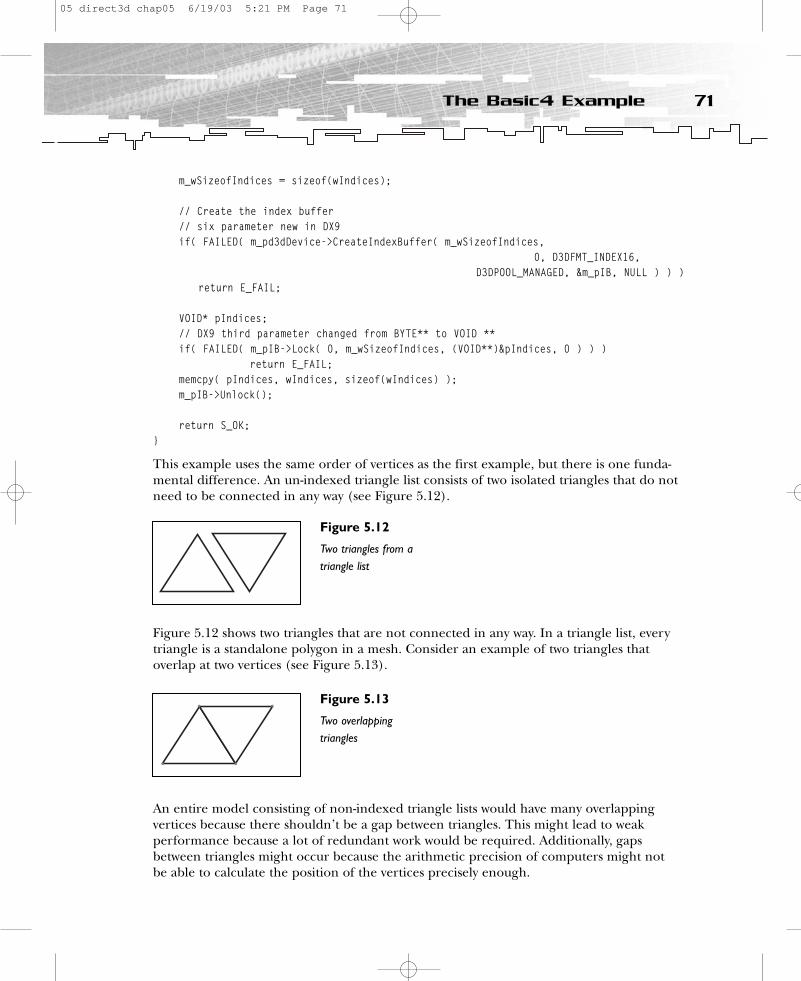
m_wSizeofIndices = sizeof(wIndices);
// Create the index buffer// six parameter new in DX9if( FAILED( m_pd3dDevice->CreateIndexBuffer( m_wSizeofIndices,
0, D3DFMT_INDEX16,D3DPOOL_MANAGED, &m_pIB, NULL ) ) )
return E_FAIL;
VOID* pIndices;// DX9 third parameter changed from BYTE** to VOID **if( FAILED( m_pIB->Lock( 0, m_wSizeofIndices, (VOID**)&pIndices, 0 ) ) )
return E_FAIL;memcpy( pIndices, wIndices, sizeof(wIndices) );m_pIB->Unlock();
return S_OK;}
This example uses the same order of vertices as the first example, but there is one funda-mental difference. An un-indexed triangle list consists of two isolated triangles that do notneed to be connected in any way (see Figure 5.12).
Figure 5.12 shows two triangles that are not connected in any way. In a triangle list, everytriangle is a standalone polygon in a mesh. Consider an example of two triangles that overlap at two vertices (see Figure 5.13).
An entire model consisting of non-indexed triangle lists would have many overlapping vertices because there shouldn’t be a gap between triangles. This might lead to weak performance because a lot of redundant work would be required. Additionally, gapsbetween triangles might occur because the arithmetic precision of computers might not be able to calculate the position of the vertices precisely enough.
71The Basic4 Example
Figure 5.12
Two triangles from atriangle list
Figure 5.13
Two overlappingtriangles
05 direct3d chap05 6/19/03 5:21 PM Page 71
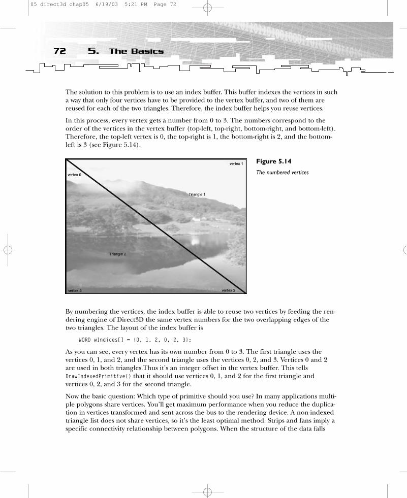
The solution to this problem is to use an index buffer. This buffer indexes the vertices in sucha way that only four vertices have to be provided to the vertex buffer, and two of them are reused for each of the two triangles. Therefore, the index buffer helps you reuse vertices.
In this process, every vertex gets a number from 0 to 3. The numbers correspond to theorder of the vertices in the vertex buffer (top-left, top-right, bottom-right, and bottom-left).Therefore, the top-left vertex is 0, the top-right is 1, the bottom-right is 2, and the bottom-left is 3 (see Figure 5.14).
By numbering the vertices, the index buffer is able to reuse two vertices by feeding the ren-dering engine of Direct3D the same vertex numbers for the two overlapping edges of thetwo triangles. The layout of the index buffer is
WORD wIndices[] = {0, 1, 2, 0, 2, 3};
As you can see, every vertex has its own number from 0 to 3. The first triangle uses the vertices 0, 1, and 2, and the second triangle uses the vertices 0, 2, and 3. Vertices 0 and 2are used in both triangles.Thus it’s an integer offset in the vertex buffer. This tellsDrawIndexedPrimitive() that it should use vertices 0, 1, and 2 for the first triangle and vertices 0, 2, and 3 for the second triangle.
Now the basic question: Which type of primitive should you use? In many applications multi-ple polygons share vertices. You’ll get maximum performance when you reduce the duplica-tion in vertices transformed and sent across the bus to the rendering device. A non-indexedtriangle list does not share vertices, so it’s the least optimal method. Strips and fans imply aspecific connectivity relationship between polygons. When the structure of the data falls
72 5. The Basics
Figure 5.14
The numbered vertices
05 direct3d chap05 6/19/03 5:21 PM Page 72
naturally into strips and fans, this is the most appropriate choice because they minimize thedata sent to the driver.
Additionally, using an index buffer can improve performance if your geometry is reused byindices. If you use more than two indices per vertex, there should be a visible gain. It seemslike indexed triangle strips are slightly faster than indexed triangle lists on some graphicshardware, whereas they have the same speed as indexed triangle lists on other graphicshardware. However, you should measure this very thoroughly in every case.
There are several limitations that can lead to reduced performance. For an overview, it issufficient to differentiate between three kinds of possible restrictions—CPU limited, vertexthroughput limited, and fill rate limited. CPU limited and vertex throughput limited areself-explanatory, and fill rate limited means that the application causes a bottleneck in thearea between the rasterization stage and the end of the Direct3D pipeline. (I will cover the Direct3D pipeline in Chapter 9, “Shader Programming with the High-Level ShaderLanguage.”) Measuring things correctly to find your limitation is a tough task that requiressome experience. Just know that using the right kind of primitive might help to reduce theburden of vertex throughput limitation, although it will not help with the other two limit-ing factors. Now back to the code.
The index buffer is created with a call to CreateIndexBuffer().
HRESULT CreateIndexBuffer(// size of index buffer in bytesUINT Length,// usage flagsDWORD Usage,// index buffer format
D3DFORMAT Format,// memory poolD3DPOOL Pool,// pointer to index bufferIDirect3DIndexBuffer9** ppIndexBuffer,// reserved for future DX versionsHANDLE* pHandle)
This function needs the length of the index buffer as the first parameter, a list of usagehints as the second parameter, and the appreciated format as the third parameter. The flagsthat indicate to the driver the usage of the index buffer are similar to the flags that you canchoose for the CreateVertexBuffer() function. Because you have no special needs here, youcan provide 0 as the parameter. The format parameter lets the user choose between two dif-ferent index buffer formats—16-bit (D3DFMT_INDEX16) and 32-bit (D3DFMT_INDEX32). The largerindex buffer format can store more indices and therefore is able to store the indices ofmodels with a higher number of vertices, but it is slower than the 16-bit format on somegraphics hardware.
73The Basic4 Example
05 direct3d chap05 6/19/03 5:21 PM Page 73
The fourth parameter requires the kind of pool you want to choose. Remember the fourdifferent kinds of pools available in DirectX 9.0 and the rule of thumb that says the managedpool is right in most cases. Therefore, you’ll want to specify a managed pool here.
The fifth parameter returns the pointer to the buffer region that should store the indices.This pointer will fill the buffer area with memcpy() after locking it with the Lock() command,much like the fill process of the vertex buffer.
VOID* pIndices;// DX9 third parameter changed from BYTE** to VOID **if( FAILED( m_pIB->Lock( 0, m_wSizeofIndices, (VOID**)&pIndices, 0 ) ) )
return E_FAIL;memcpy( pIndices, wIndices, sizeof(wIndices) );m_pIB->Unlock();
The sixth parameter is new in DirectX 9.0. You should set it to NULL and reserve it forfuture functionality.
The parameters of the Lock() and Unlock() functions are similar to their vertex buffer equiv-alents. The only difference is that you need to specify the size of the indices as the secondparameter instead of the size of the vertices.
To use the index buffer, you must set it in the Render() function.
HRESULT CMyD3DApplication::Render(){
// Begin the sceneif( SUCCEEDED( m_pd3dDevice->BeginScene() ) ){
// Set up texture stage states for the backgroundm_pd3dDevice->SetTexture( 0, m_pBackgroundTexture );m_pd3dDevice->SetTextureStageState( 0, D3DTSS_COLORARG1, D3DTA_TEXTURE );m_pd3dDevice->SetTextureStageState( 0, D3DTSS_COLOROP, D3DTOP_SELECTARG1 );
// Passing an FVF to IDirect3DDevice9::SetFVF specifies a legacy FVF with stream 0.m_pd3dDevice->SetFVF(FVF ); m_pd3dDevice->SetStreamSource( 0, m_pVB, 0, sizeof(VERTEX) );
m_pd3dDevice->SetIndices( m_pIB ); // new in DX9 only takes one parameter// second parameter new in DX9m_pd3dDevice->DrawIndexedPrimitive( D3DPT_TRIANGLELIST,
0,0, 4, // number of vertices0, 2); // number of primitives
// Output statisticsm_pFont->DrawText( 2, 0, D3DCOLOR_ARGB(255,255,255,0), m_strFrameStats );m_pFont->DrawText( 2, 20, D3DCOLOR_ARGB(255,255,255,0), m_strDeviceStats );
74 5. The Basics
05 direct3d chap05 6/19/03 5:21 PM Page 74
// End the scene.m_pd3dDevice->EndScene();
}
return S_OK;}
You set the index buffer with SetIndices(), which accepts only one parameter—the indexbuffer itself. Because you built up the index buffer in the RestoreDeviceObjects() function,you have to release it in the InvalidateDeviceObjects() function.
HRESULT CMyD3DApplication::InvalidateDeviceObjects(){
m_pFont->InvalidateDeviceObjects();SAFE_RELEASE( m_pVB );SAFE_RELEASE( m_pIB );
return S_OK;}
The rest of the fourth example is the same as the third example. Therefore, you can proceedto the fifth example.
The Basic5 ExampleThe only difference between the previous example and the Basic5 example is the use ofindexed triangle strips. Therefore, you only need to change three things:
• The order of the vertices (strips)• The order of the indices (Zorro’s Z)• The first parameter in DrawIndexedPrimitive() (the primitive type)
The following code sets the vertices in the order of a stripe. You will find it in theRestoreDeviceObjects() function in the example source code.
…{ 0.0f, 0.0f, 0.5f, 1.0f, 0.0f, 0.0f, },{ (float)m_d3dsdBackBuffer.Width, 0.0f, 0.5f, 1.0f, 1.0f,0.0f, },{ 0.0f, (float)m_d3dsdBackBuffer.Height, 0.5f, 1.0f, 0.0f, 1.0f, }, // x, y, z, rhw, tu, tv{(float)m_d3dsdBackBuffer.Width, (float)m_d3dsdBackBuffer.Height, 0.5f, 1.0f, 1.0f,1.0f, },…
This is the same order that you used in the Basic3 example, which used non-indexed trianglestrips. You must change the order of indices to get the Z form, like this:
WORD wIndices[] = {0, 1, 2, 3, 2, 0};
The index numbers 0, 1, 2, and 3 index into the first, second, third, and fourth vertices.The remaining numbers (2 and 0) lead the renderer back to its starting point. After
75The Basic5 Example
05 direct3d chap05 6/19/03 5:21 PM Page 75

preparing the correct vertices and indices, the DrawIndexPrimitive() function has to beinstructed to accept this kind of primitive with the D3DPT_TRIANGLESTRIP flag.
SummarySo that just about wraps up the basics. Ready to move on? In the next chapter, you’ll learnthe first steps to using animation. Sounds like fun, doesn’t it?!
76 5. The Basics
05 direct3d chap05 6/19/03 5:21 PM Page 76
CHAPTER 6
First Steps to
Animation
06 direct3d chap06 6/19/03 5:22 PM Page 77

You might recall that in the last chapter you saw that all samples built with the help ofthe common files in the DirectX SDK are created with overloaded versions of the
CD3DApplication methods.
HRESULT OneTimeSceneInit() { return S_OK; }HRESULT InitDeviceObjects() { return S_OK; }HRESULT RestoreDeviceObjects { return S_OK; }HRESULT DeleteDeviceObjects() { return S_OK; }HRESULT Render() { return S_OK; }HRESULT FrameMove( FLOAT ) { return S_OK; }HRESULT FinalCleanup() { return S_OK; }
You also learned the task of every method in this class. In this chapter, you will step into theworld of animating objects and creating a virtual camera system. You will learn how to:
• Work with transformations• Move objects in a 3D world• Move your camera• Concatenate transformations• Work with projection transformations• Use viewports• Work with the depth buffer
UnderstandingTransformations andViewportsTo best understand how you use transformations to build the impression of real-worldmotion, consider this scenario. Imagine you are standing in your living room with yourvideo camera, taking a video of your girlfriend. She has a position and orientation in theroom, as does the camera you are holding. When she starts moving, you try to follow herwith the camera in your hand. You change the lens properties to get a sharp picture, andperhaps you zoom in or out of the scene to show her smile a little bit better. It can be prettydifficult to handle this situation in real-time, but this is also what you try to handle in real-time graphics.
78 6. First Steps to Animation
06 direct3d chap06 6/19/03 5:22 PM Page 78
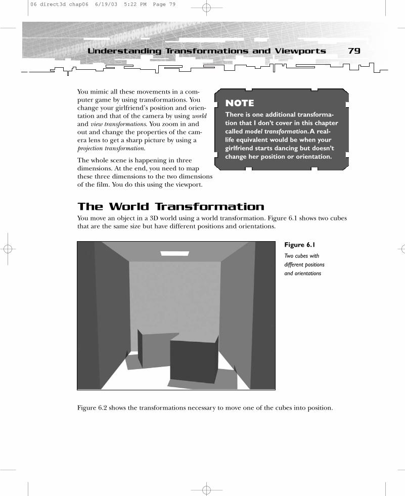
You mimic all these movements in a com-puter game by using transformations. Youchange your girlfriend’s position and orien-tation and that of the camera by using worldand view transformations. You zoom in andout and change the properties of the cam-era lens to get a sharp picture by using aprojection transformation.
The whole scene is happening in threedimensions. At the end, you need to mapthese three dimensions to the two dimensionsof the film. You do this using the viewport.
The World TransformationYou move an object in a 3D world using a world transformation. Figure 6.1 shows two cubesthat are the same size but have different positions and orientations.
Figure 6.2 shows the transformations necessary to move one of the cubes into position.
79Understanding Transformations and Viewports
NOTEThere is one additional transforma-tion that I don’t cover in this chaptercalled model transformation.A real-life equivalent would be when yourgirlfriend starts dancing but doesn’tchange her position or orientation.
Figure 6.1
Two cubes withdifferent positions and orientations
06 direct3d chap06 6/19/03 5:22 PM Page 79

The following steps detail the transformations necessary to move the cubes into place.
1. The cube is standing with its origin in the origin of the world coordinate system. 2. Rotate the cube.3. Move the cube to its new position.
The position for Step 1 comes from the vertex buffer data, which you remember from theprevious chapter. In the case of a static object like this, the data never changes. Therefore,everything always begins with this default position and orientation. The cube is rotated inStep 2 and moved into position in Step 3. All this happens every frame, so each time ascene is displayed, all objects are first moved into their places and oriented correctly.
The order of these steps is very important. If steps 2 and 3 are exchanged, the object mightbehave in an unexpected way. If the cube is moved and then rotated, it will rotate aroundthe center of the world coordinate system instead of around its own geometrical center orits center of gravity, as shown in Figure 6.3.
It is common to transform the vertices of the cubes using a world transformation matrix orshort world matrix. (Please read Appendix C, “Mathematics Primer,” to learn more aboutmatrices.) One of the benefits of using matrices is that you can easily draw several instancesof the same object using one vertex buffer with several different transformation matrixes.The application that displayed the cubes in Figures 6.2 and 6.3 uses only one set of geome-try, which means one vertex buffer. That saves memory and bandwidth because in terms ofthe geometry data sent to the video card, there is only one model.
80 6. First Steps to Animation
Figure 6.2
World transformationsof a cube shown fromabove
Figure 6.3
World transformationsof a cube with steps 2and 3 exchanged
06 direct3d chap06 6/19/03 5:22 PM Page 80
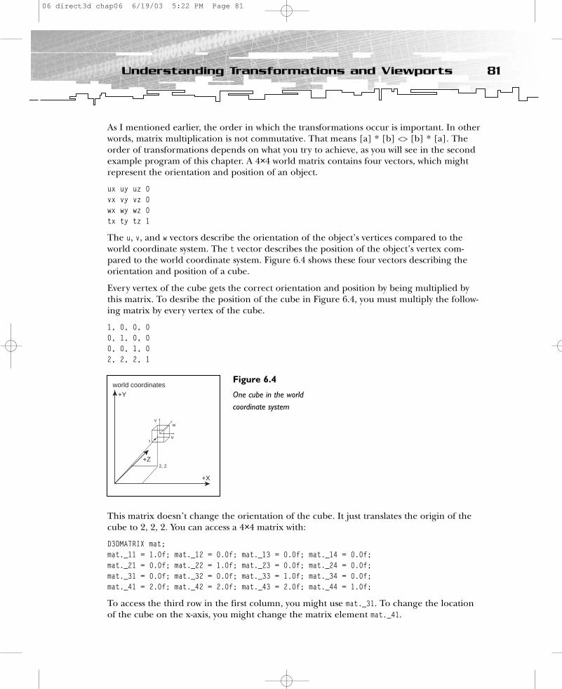
As I mentioned earlier, the order in which the transformations occur is important. In otherwords, matrix multiplication is not commutative. That means [a] * [b] <> [b] * [a]. Theorder of transformations depends on what you try to achieve, as you will see in the secondexample program of this chapter. A 4×4 world matrix contains four vectors, which mightrepresent the orientation and position of an object.
ux uy uz 0 vx vy vz 0 wx wy wz 0 tx ty tz 1
The u, v, and w vectors describe the orientation of the object’s vertices compared to theworld coordinate system. The t vector describes the position of the object’s vertex com-pared to the world coordinate system. Figure 6.4 shows these four vectors describing theorientation and position of a cube.
Every vertex of the cube gets the correct orientation and position by being multiplied bythis matrix. To desribe the position of the cube in Figure 6.4, you must multiply the follow-ing matrix by every vertex of the cube.
1, 0, 0, 00, 1, 0, 00, 0, 1, 02, 2, 2, 1
This matrix doesn’t change the orientation of the cube. It just translates the origin of thecube to 2, 2, 2. You can access a 4×4 matrix with:
D3DMATRIX mat; mat._11 = 1.0f; mat._12 = 0.0f; mat._13 = 0.0f; mat._14 = 0.0f;mat._21 = 0.0f; mat._22 = 1.0f; mat._23 = 0.0f; mat._24 = 0.0f;mat._31 = 0.0f; mat._32 = 0.0f; mat._33 = 1.0f; mat._34 = 0.0f;mat._41 = 2.0f; mat._42 = 2.0f; mat._43 = 2.0f; mat._44 = 1.0f;
To access the third row in the first column, you might use mat._31. To change the locationof the cube on the x-axis, you might change the matrix element mat._41.
81Understanding Transformations and Viewports
+Y
+X
+Z
world coordinates
v
u
w
2, 2
t
Figure 6.4
One cube in the worldcoordinate system
06 direct3d chap06 6/19/03 5:22 PM Page 81

You build up a translation matrix using the D3DXMatrixTranslation() function. Translationcan best be described as a linear change in position. This change can be represented by adelta vector (tx, ty, tz), where tx—or often dx—represents the change in the object’s xposition; ty or dy represents the change in its y position; and tz or dz represents the changein its z position. We don’t have the source code for D3DXMatrixTranslation(), but it mightlook like this:
inline VOID D3DXMatrixTranslation (D3DXMATRIX* m, FLOAT tx, FLOAT ty, FLOAT tz ){
D3DXMatrixIdentity(m ); m._41 = tx; m._42 = ty; m._43 = tz;
}= 1 0 0 00 1 0 00 0 1 0 tx ty tz 1
You build up a rotation matrix using functions provided by Direct3D. A rotation can bedescribed as circular motion around an axis. The incremental angles used to rotate theobject represent rotation from the current orientation. To rotate by 1 degree around the z-axis using the three steps discussed previously, you tell your object to rotate 1 degreearound its z-axis, regardless of its current orientation and how you got that orientation.This is how the real world operates.
D3DXMatrixRotationY() rotates the objects around the y-axis, where fRads equals the desiredamount of rotation. The source of this method could look like this:
VOID D3DXMatrixRotationY( D3DXMATRIX* mat, FLOAT fRads ){
D3DXMatrixIdentity(mat); mat._11 = cosf( fRads );mat._13 = -sinf( fRads );mat._31 = sinf( fRads );mat._33 = cosf( fRads );
}=cosf fRads 0 -sinf fRads 00 0 0 0sinf fRads 0 cosf fRads 00 0 0 0
If you want to rotate an object around its x-axis, you need to use D3DXMatrixRotationX( ),where fRads equals the desired amount of rotation.
VOID D3DXMatrixRotationX( D3DXMATRIX* mat, FLOAT fRads ){
D3DXMatrixIdentity(mat);
82 6. First Steps to Animation
06 direct3d chap06 6/19/03 5:22 PM Page 82
mat._22 = cosf( fRads );mat._23 = sinf( fRads );mat._32 = -sinf( fRads );mat._33 = cosf( fRads );
}=1 0 0 00 cos fRad sin fRads 00 -sin fRads cos fRads 00 0 0 0
D3DXMatrixRotationZ() rotates the objects around the z-axis, where fRads equals the desiredamount of rotation.
VOID D3DXMatrixRotationZ( D3DXMATRIX* mat, FLOAT fRads ){
D3DXMatrixIdentity(mat); mat._11 = cosf( fRads );mat._12 = sinf( fRads );mat._21 = -sinf( fRads );mat._22 = cosf( fRads );
}=cosf fRads sinf fRads 0 0-sinf fRads cos fRads 0 00 0 0 00 0 0 0
Another function that is useful for transformations is D3DXMatrixMultiply(). The prototype of D3DXMatrixMultiply() looks like D3DXMATRIX * D3DXMatrixMultiply (D3DXMATRIX* pOut, CONSTD3DXMATRIX* pM1, CONST D3DMATRIX* pM2). In other words, pOut=pM1*pM2. The return value forthis function is the same value returned in the pOut parameter. This way, you can use theD3DXMatrixMultiply() function as a parameter for another function. Matrix multiplication is the operation by which one matrix is transformed by another. A matrix multiplicationstores the results of the sum of the products of matrix rows and columns.
a b c d A B C De f g h * E F G H =i j k l I J K Lm n o p M N O Pmat._11 = a*A+b*E+c*I+d*M mat._12 = a*B+b*F+c*J+d*N mat._13 = a*C+b*G+c*K+d*O mat._14 = a*D+b*H+c*L+d*Pmat._21 = e*A+f*E+g*I+h*M mat._22 = e*B+f*F+g*J+h*N etc.
83Understanding Transformations and Viewports
06 direct3d chap06 6/19/03 5:22 PM Page 83
A matrix multiplication routine could look like this:
D3DXMATRIX* D3DXMatrixMultiply (D3DXMATRIX* pOut, CONST D3DXMATRIX* pM1, CONST D3DMATRIX* pM2)
{FLOAT pM[16];ZeroMemory( pM, sizeof(D3DXMATRIX) );for( WORD i=0; i<4; i++ )
for( WORD j=0; j<4; j++ ) for( WORD k=0; k<4; k++ )
pM[4*i+j] += pM1[4*i+k] * pM2[4*k+j];memcpy( pOut, pM, sizeof(D3DXMATRIX) );
return (pOut);}
This function might be optimized highly for different processors, but there is an even betterway to multiply matrices.
D3DXMATRIX matRotX, matRotY;matWorld = matTrans * matRotX * matRotY;
This method is possible using the operator overloading C++ feature. You will read moreabout this feature in Appendix B, “C++ Primer.”
Another matrix function that might be useful is D3DXMatrixScaling(). This function acceptsx, y, and z scaling factors and the matrix that should be scaled. The source of this functionmight look like this in C:
D3DXMATRIX * D3DXMatrixScaling (D3DXMATRIX *pOut, FLOAT sx, FLOAT sy,FLOAT sz){
pOut->_11 = sx; pOut->_22 = sy; pOut->_33 = sz;
return pOut;}= sx 0 0 00 sy 0 00 0 sz 00 0 0 0
You can use this function to change the appearance of your geometry. For example, toplace several cubes of different sizes in a scene, just scale the height of the same geometryand place it with different scaling factors in the scene. Using this method, you might useone vertex buffer with the cube geometry several times.
One of the pros of using matrix multiplication is that scaling, rotation, and translation alltake the same amount of time to perform, so the performance of a dedicated transforma-tion engine is predictable and consistent. This allows game developers to make informeddecisions regarding performance and quality.
84 6. First Steps to Animation
06 direct3d chap06 6/19/03 5:22 PM Page 84

So far you have seen how transformations are performed using matrices, but you haven’tseen how Direct3D is involved in matrix transformation. The following line of code providesthe world matrix to Direct3D for further execution:
m_pd3dDevice->SetTransform( D3DTS_WORLD, &m_matWorld );
Using the D3DTS_WORLD flag, it sets the device world-transformation-related state. TheD3DTS_VIEW or D3DTS_PROJECTION flags set the device state regarding the view or projectiontransformation. I will demonstrate this concept later in the chapter.
The 1steps ExampleThe 1steps.exe example program, located in the \1steps directory on the CD-ROM, demonstrates how Direct3D executes the world matrix. It rotates a quad around its y-axis(see Figure 6.5).
The previous chapter showed a similar rectangle with a texture mapped on it, but this timethe rectangle should be animated with the help of Direct3D. To provide this information to the Direct3D engine, you have to change some code. The first step for involving theDirect3D transformation engine is to remove the RHW position flag in the vertex flags.
// A structure for our custom vertex typestruct VERTEX{
FLOAT x, y, z; // The untransformed position for the vertexFLOAT tu, tv;
85Understanding Transformations and Viewports
Figure 6.5
A quad rotated aroundits y-axis
06 direct3d chap06 6/19/03 5:22 PM Page 85

};
// Fixed-Function Vertex structureconst DWORD FVF = (D3DFVF_XYZ | D3DFVF_TEX1);
Without an RHW value, the values in the vertex buffer look like this:
VERTEX Vertices[] ={
{ -1.0f,-1.0f, 0.0f, 1.0f, 1.0f, }, // x, y, z, tu, tv{ 1.0f,-1.0f, 0.0f, 0.0f, 1.0f, },{ 1.0f, 1.0f, 0.0f, 0.0f, 0.0f, },{ -1.0f, 1.0f, 0.0f, 1.0f, 0.0f, },
};
The x and y position values are not chosen in screen space, as in the previous exampleswhere the size of the back buffer was provided. If you use the transformation unit ofDirect3D, the origin of the world lies by default in the middle of the window’s client area.Therefore, -1.0, -1.0 is the bottom-left vertex of the quad; 1.0f, -1.0f is the bottom-right vertex; 1.0f, 1.0f is the top-right vertex; and -1.0f, 1.0f is the top-left vertex. The index buffershows that these vertices are set in the following order:
WORD wIndices[]={3, 2, 0, 2, 1, 0};
In other words, top-left, top-right, bottom-left, top-right, bottom-right, bottom-left. The firsttriangle that is drawn lies in the upper-left corner, and the second one lies in the bottom-right corner.
The main transformation is done in the framework function FrameMove().
HRESULT CMyD3DApplication::FrameMove(){
// rotates the object about the y-axisD3DXMATRIX matRotY;D3DXMatrixRotationY( &matRotY, m_fTime * 1.5f);
D3DXMATRIX matTrans;D3DXMatrixTranslation(&matTrans, 0.0f, 0.0f, 0.0f);
m_pd3dDevice->SetTransform( D3DTS_WORLD, &(matRotY * matTrans)); return S_OK;
}
The utility function D3DXMatrixRotationY() builds up a matrix that rotates around the y-axis.You use the matrix type provided by the Direct3D utility library here. All of the names of variable types provided by this library start with D3DX*. The framework provides the m_fTimevariable. You can call it everywhere in your application, and you will get the time since theapplication started. It starts with the 0.0f. The time variable is multiplied by 1.5f to acceler-ate the rotation a bit. Then, D3DXMatrixTranslation() sets the ._41, ._42, ._42 members of
86 6. First Steps to Animation
06 direct3d chap06 6/19/03 5:22 PM Page 86

the matTrans matrix. To concatenate the rotation and transformation matrices, you multiplythem in such a way that the transformation matrix follows the rotation matrix. The result isprovided to the SetTransform() function, which delivers the world matrix almost directly tothe transformation unit of the hardware, if transformation is supported in the hardware.Otherwise, Direct3D must do software vertex processing.
The Direct3D engine does the rest of the work. What I left out here are the view, projectionmatrix, and usage of the depth buffer. I will present the view and projection transformationslater in this chapter in the sections titled “The View Transformation” and “The ProjectionTransformation,” and I will cover the concept behind depth buffers and how to use them atthe end of this chapter.
To extend the 1steps example, you might copy the following source code into FrameMove().That way you can rotate the quad around its x and y axes.
HRESULT CMyD3DApplication::FrameMove(){
D3DXMATRIX matRotY, matRotX;D3DXMatrixRotationY( &matRotY, m_fTime * 1.5f);D3DXMatrixRotationX( &matRotX, m_fTime * 1.5f);
D3DXMATRIX matTrans;D3DXMatrixTranslation(&matTrans, 0.0f, 0.0f, 0.0f);m_pd3dDevice->SetTransform( D3DTS_WORLD, &(m_RotY * m_RotX * matTrans));
return S_OK;}
As you can see, you concatenate the tworotation matrices by multiplying them.
The 1steps2ExampleThe 1steps2.exe example program, locatedin the \1steps directory on the CD-ROM,shows the importance of the order of transformations (see Figure 6.6).
It uses four viewports that display differentscenes in which different matrices areinvolved in the transformation of the tex-tured quad. This program is heavily inspiredby an example program used in KellyDempski’s Real-Time Rendering Tricks andTechniques in DirectX (Premier Press, 2002).
87Understanding Transformations and Viewports
NOTEThis example also shows the effectof back-face culling.The Direct3Dengine does not process the quad’sback face, which is more efficient.This makes sense, for example, inthe case of a cube, where you don’tsee the back face anyway.There areflags for the SetRenderState() functionthat can alter the behavior of back-face culling. For example, the following line switches off back-face culling:d3dDevice->SetRenderState(D3DRS_CULLMODE, D3DCULL_NONE);
06 direct3d chap06 6/19/03 5:22 PM Page 87
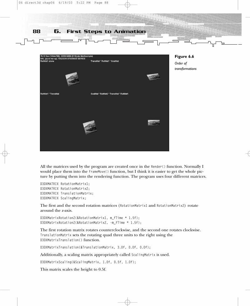
All the matrices used by the program are created once in the Render() function. Normally Iwould place them into the FrameMove() function, but I think it is easier to get the whole pic-ture by putting them into the rendering function. The program uses four different matrices.
D3DXMATRIX RotationMatrix1;D3DXMATRIX RotationMatrix2;D3DXMATRIX TranslationMatrix;D3DXMATRIX ScalingMatrix;
The first and the second rotation matrices (RotationMatrix1 and RotationMatrix2) rotatearound the z-axis.
D3DXMatrixRotationZ(&RotationMatrix1, m_fTime * 1.5f);D3DXMatrixRotationZ(&RotationMatrix2, -m_fTime * 1.5f);
The first rotation matrix rotates counterclockwise, and the second one rotates clockwise.TranslationMatrix sets the rotating quad three units to the right using theD3DXMatrixTranslation() function.
D3DXMatrixTranslation(&TranslationMatrix, 3.0f, 0.0f, 0.0f);
Additionally, a scaling matrix appropriately called ScalingMatrix is used.
D3DXMatrixScaling(&ScalingMatrix, 1.0f, 0.5f, 1.0f);
This matrix scales the height to 0.5f.
88 6. First Steps to Animation
Figure 6.6
Order oftransformations
06 direct3d chap06 6/19/03 5:22 PM Page 88

So far I have described all of the different transformations used by the 1steps2 exampleprogram. The following sections will show you how these transformation matrices producethe output in the viewport.
Top-Left ViewportThe first rotation matrix, RotationMatrix1, is featured in the top-left viewport, in which thequad rotates around the z-axis in the middle of the viewport window. You don’t have to payattention to the order of matrix multiplication because only one matrix is used.
Bottom-Left ViewportThe bottom-left viewport also shows a scene in which the quad rotates around the z-axis.This time it is translated by the TranslationMatrix three units to the right by using theD3DXMatrixTranslation() function. The translation matrix is standing in the multiplicationorder after the first rotation matrix.
Top-Right ViewportThe top-right viewport shows a quad that rotates around the z-axis and the center of theviewport. At the same time, it is scaled in its height relative to the x-axis.
Because the order of the rotation matrix and the translation matrix are changed comparedto the bottom-left viewport, the quad rotates around the z-axis and also around its own z-axis in three units’ distance. By letting the scale matrix follow the other matrices, scalingoccurs relative to the x-axis of the world coordinate system, so the quad changes its heightall the time.
Bottom-Right ViewportThe bottom-right viewport shows a quad that rotates around the center of the viewport inthree units’ distance, but not around its own z-axis. Additionally, it is scaled to half its size.Scaling occurs this way because the scaling matrix is the first matrix used in the order ofmultiplication. Additionally, an anti-rotation matrix prevents the rotation of the quad. Thisis accomplished by using the second rotation matrix, which rotates in the opposite direc-tion of the first rotation matrix. Therefore, the rotations cancel each other. This method ishow a planet might orbit around another planet, for example.
Note that rotating an object in three dimensions by using the three rotation functions men-tioned might result in a lost dimension. This well-known phenomenon is called gimbal lock.Nevertheless, these functions are quite suitable for most games today, in which two and ahalf dimensions are enough. One solution, which involves rotating an object in threedimensions, can be realized with vectors; another solution uses quaternions.
89Understanding Transformations and Viewports
06 direct3d chap06 6/19/03 5:22 PM Page 89
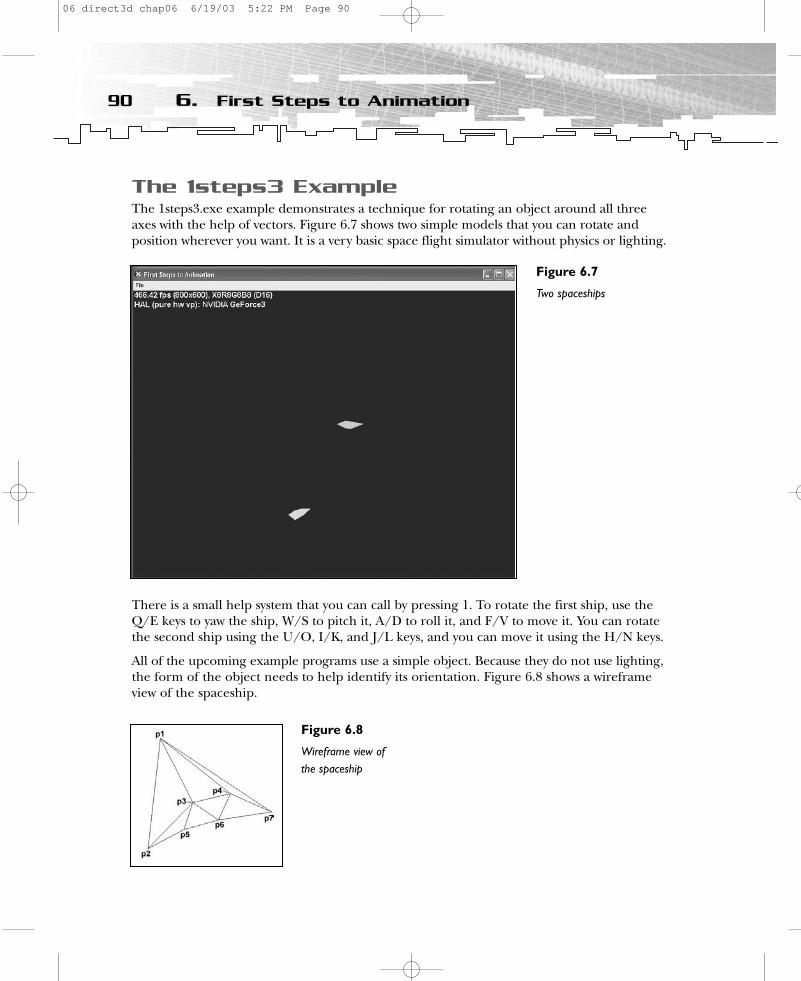
The 1steps3 ExampleThe 1steps3.exe example demonstrates a technique for rotating an object around all threeaxes with the help of vectors. Figure 6.7 shows two simple models that you can rotate andposition wherever you want. It is a very basic space flight simulator without physics or lighting.
There is a small help system that you can call by pressing 1. To rotate the first ship, use theQ/E keys to yaw the ship, W/S to pitch it, A/D to roll it, and F/V to move it. You can rotatethe second ship using the U/O, I/K, and J/L keys, and you can move it using the H/N keys.
All of the upcoming example programs use a simple object. Because they do not use lighting,the form of the object needs to help identify its orientation. Figure 6.8 shows a wireframeview of the spaceship.
90 6. First Steps to Animation
Figure 6.7
Two spaceships
Figure 6.8
Wireframe view of the spaceship
06 direct3d chap06 6/19/03 5:22 PM Page 90
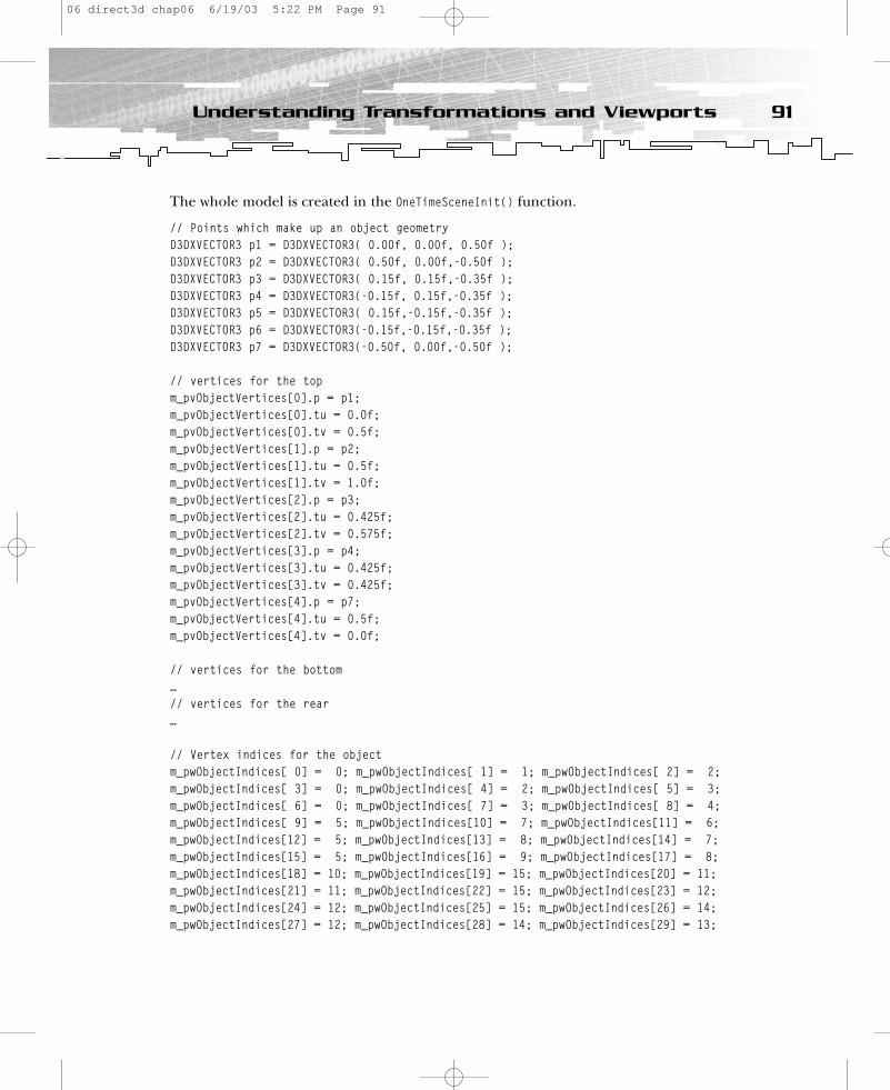
The whole model is created in the OneTimeSceneInit() function.
// Points which make up an object geometryD3DXVECTOR3 p1 = D3DXVECTOR3( 0.00f, 0.00f, 0.50f );D3DXVECTOR3 p2 = D3DXVECTOR3( 0.50f, 0.00f,-0.50f );D3DXVECTOR3 p3 = D3DXVECTOR3( 0.15f, 0.15f,-0.35f );D3DXVECTOR3 p4 = D3DXVECTOR3(-0.15f, 0.15f,-0.35f );D3DXVECTOR3 p5 = D3DXVECTOR3( 0.15f,-0.15f,-0.35f );D3DXVECTOR3 p6 = D3DXVECTOR3(-0.15f,-0.15f,-0.35f );D3DXVECTOR3 p7 = D3DXVECTOR3(-0.50f, 0.00f,-0.50f );
// vertices for the topm_pvObjectVertices[0].p = p1;m_pvObjectVertices[0].tu = 0.0f;m_pvObjectVertices[0].tv = 0.5f;m_pvObjectVertices[1].p = p2;m_pvObjectVertices[1].tu = 0.5f;m_pvObjectVertices[1].tv = 1.0f;m_pvObjectVertices[2].p = p3;m_pvObjectVertices[2].tu = 0.425f;m_pvObjectVertices[2].tv = 0.575f;m_pvObjectVertices[3].p = p4;m_pvObjectVertices[3].tu = 0.425f;m_pvObjectVertices[3].tv = 0.425f;m_pvObjectVertices[4].p = p7;m_pvObjectVertices[4].tu = 0.5f;m_pvObjectVertices[4].tv = 0.0f;
// vertices for the bottom…// vertices for the rear…
// Vertex indices for the objectm_pwObjectIndices[ 0] = 0; m_pwObjectIndices[ 1] = 1; m_pwObjectIndices[ 2] = 2;m_pwObjectIndices[ 3] = 0; m_pwObjectIndices[ 4] = 2; m_pwObjectIndices[ 5] = 3;m_pwObjectIndices[ 6] = 0; m_pwObjectIndices[ 7] = 3; m_pwObjectIndices[ 8] = 4;m_pwObjectIndices[ 9] = 5; m_pwObjectIndices[10] = 7; m_pwObjectIndices[11] = 6;m_pwObjectIndices[12] = 5; m_pwObjectIndices[13] = 8; m_pwObjectIndices[14] = 7;m_pwObjectIndices[15] = 5; m_pwObjectIndices[16] = 9; m_pwObjectIndices[17] = 8;m_pwObjectIndices[18] = 10; m_pwObjectIndices[19] = 15; m_pwObjectIndices[20] = 11;m_pwObjectIndices[21] = 11; m_pwObjectIndices[22] = 15; m_pwObjectIndices[23] = 12;m_pwObjectIndices[24] = 12; m_pwObjectIndices[25] = 15; m_pwObjectIndices[26] = 14;m_pwObjectIndices[27] = 12; m_pwObjectIndices[28] = 14; m_pwObjectIndices[29] = 13;
91Understanding Transformations and Viewports
06 direct3d chap06 6/19/03 5:22 PM Page 91
m_pvObjectVertices[0] and m_pvObjectVertices[5] lie on point 1. m_pvObjectVertices[1] andm_pvObjectVertices[6] lie on point 2. m_pvObjectVertices[3] and m_pvObjectVertices[11] lie onpoint 3, and so on. Every point is declared as a vector with D3DXVECTOR3. The last two variablesof m_pvObjectVertices are the texture coordinates. Most textures, like bitmaps, are two-dimensional arrays of color values. The individual color values are called texture elements, ortexels. Each texel has a texel coordinate—a unique address in the texture. Direct3D programsspecify texel coordinates in terms of u, v values, much like 2D Cartesian coordinates arespecified in terms of x, y coordinates. The address can be thought of as a column and rownumber. Direct3D uses a uniform address range for all texels in all textures. Therefore, ituses a generic addressing scheme in which all texel addresses are in the range of 0.0 to 1.0,inclusive. You set the indices with the following code:
// Vertex indices for the object m_pwObjectIndices[ 0] = 0; m_pwObjectIndices[ 1] = 1; m_pwObjectIndices[ 2] = 2;m_pwObjectIndices[ 3] = 0; m_pwObjectIndices[ 4] = 2; m_pwObjectIndices[ 5] = 3; m_pwObjectIndices[ 6] = 0; m_pwObjectIndices[ 7] = 3; m_pwObjectIndices[ 8] = 4; m_pwObjectIndices[ 9] = 5; m_pwObjectIndices[10] = 7; m_pwObjectIndices[11] = 6; m_pwObjectIndices[12] = 5; m_pwObjectIndices[13] = 8; m_pwObjectIndices[14] = 7; m_pwObjectIndices[15] = 5; m_pwObjectIndices[16] = 9; m_pwObjectIndices[17] = 8; m_pwObjectIndices[18] = 10; m_pwObjectIndices[19] = 15; m_pwObjectIndices[20] = 11; m_pwObjectIndices[21] = 11; m_pwObjectIndices[22] = 15; m_pwObjectIndices[23] = 12; m_pwObjectIndices[24] = 12; m_pwObjectIndices[25] = 15; m_pwObjectIndices[26] = 14; m_pwObjectIndices[27] = 12; m_pwObjectIndices[28] = 14; m_pwObjectIndices[29] = 13;
This piece of code generates the indices for the D3DPT_TRIANGLELIST call inDrawIndexedPrimitive(). As you learned in the first chapter, Direct3D allows you to defineyour polygons in one of two ways—by defining their vertices or by defining indices into alist of vertices. The latter approach is often faster and more flexible because it allowsobjects with multiple polygons to share vertex data.
Our object consists of only seven points, which are used by 15 vertices. Therefore, youindex an average of more than two vertices.
The two objects are defined with the help of the m_pObjects structure, which holds only amatrix variable. To implement collision and other nifty stuff, you might store many morevariables here.
struct Object{
D3DXMATRIX matLocal;};
Three vectors in the matrix keep track of the orientation of the model. These are called theLook, Up, and Right vectors. Figure 6.9 shows all three vectors attached to a model.
In Figure 6.9, you can see the Look, Up, and Right vectors of a plane. The figure is a bitoversimplified because all three vectors should start at the center of the object’s gravity.
92 6. First Steps to Animation
06 direct3d chap06 6/19/03 5:22 PM Page 92
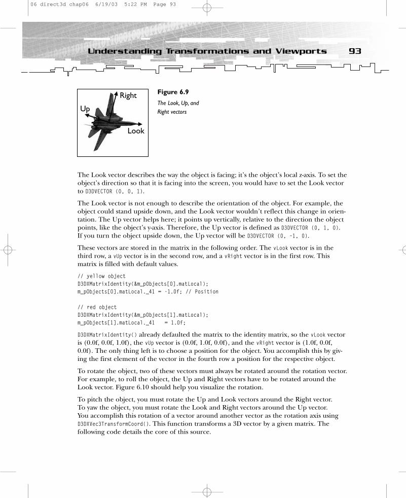
The Look vector describes the way the object is facing; it’s the object’s local z-axis. To set theobject’s direction so that it is facing into the screen, you would have to set the Look vectorto D3DVECTOR (0, 0, 1).
The Look vector is not enough to describe the orientation of the object. For example, theobject could stand upside down, and the Look vector wouldn’t reflect this change in orien-tation. The Up vector helps here; it points up vertically, relative to the direction the objectpoints, like the object’s y-axis. Therefore, the Up vector is defined as D3DVECTOR (0, 1, 0). If you turn the object upside down, the Up vector will be D3DVECTOR (0, –1, 0).
These vectors are stored in the matrix in the following order. The vLook vector is in thethird row, a vUp vector is in the second row, and a vRight vector is in the first row. Thismatrix is filled with default values.
// yellow objectD3DXMatrixIdentity(&m_pObjects[0].matLocal);m_pObjects[0].matLocal._41 = -1.0f; // Position
// red objectD3DXMatrixIdentity(&m_pObjects[1].matLocal);m_pObjects[1].matLocal._41 = 1.0f;
D3DXMatrixIdentity() already defaulted the matrix to the identity matrix, so the vLook vectoris (0.0f, 0.0f, 1.0f), the vUp vector is (0.0f, 1.0f, 0.0f), and the vRight vector is (1.0f, 0.0f,0.0f). The only thing left is to choose a position for the object. You accomplish this by giv-ing the first element of the vector in the fourth row a position for the respective object.
To rotate the object, two of these vectors must always be rotated around the rotation vector.For example, to roll the object, the Up and Right vectors have to be rotated around theLook vector. Figure 6.10 should help you visualize the rotation.
To pitch the object, you must rotate the Up and Look vectors around the Right vector. To yaw the object, you must rotate the Look and Right vectors around the Up vector. You accomplish this rotation of a vector around another vector as the rotation axis usingD3DXVec3TransformCoord(). This function transforms a 3D vector by a given matrix. The following code details the core of this source.
93Understanding Transformations and Viewports
Figure 6.9
The Look, Up, and Right vectorsUp
Right
Look
06 direct3d chap06 6/19/03 5:22 PM Page 93
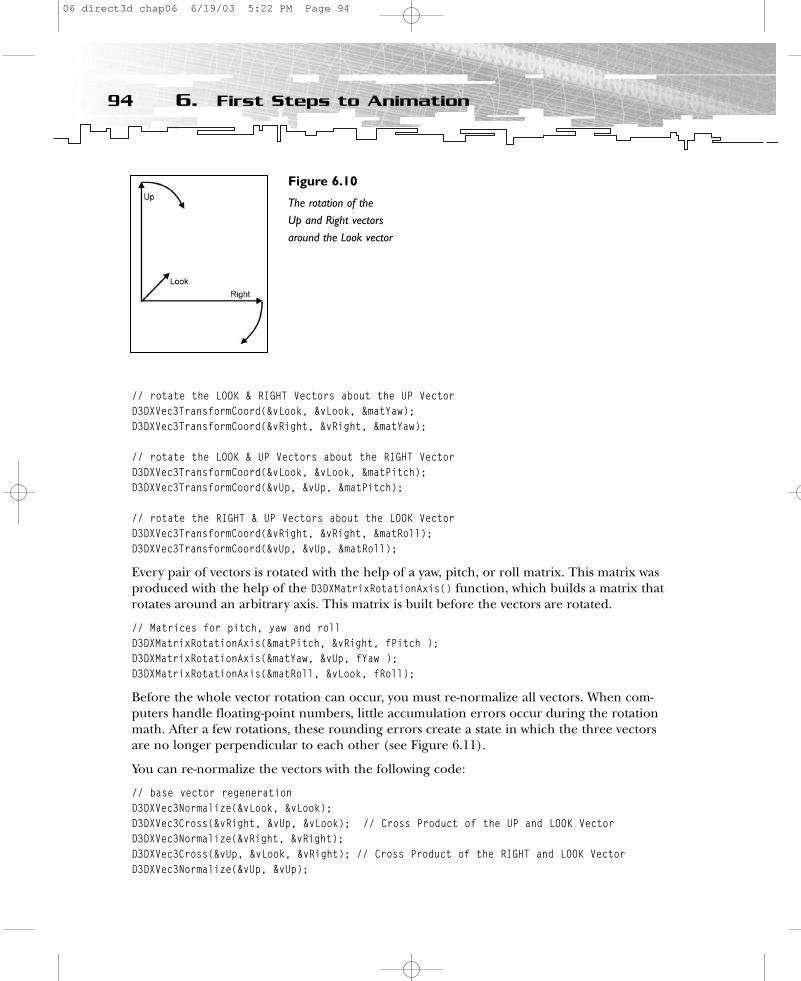
// rotate the LOOK & RIGHT Vectors about the UP VectorD3DXVec3TransformCoord(&vLook, &vLook, &matYaw); D3DXVec3TransformCoord(&vRight, &vRight, &matYaw);
// rotate the LOOK & UP Vectors about the RIGHT VectorD3DXVec3TransformCoord(&vLook, &vLook, &matPitch); D3DXVec3TransformCoord(&vUp, &vUp, &matPitch);
// rotate the RIGHT & UP Vectors about the LOOK VectorD3DXVec3TransformCoord(&vRight, &vRight, &matRoll); D3DXVec3TransformCoord(&vUp, &vUp, &matRoll);
Every pair of vectors is rotated with the help of a yaw, pitch, or roll matrix. This matrix wasproduced with the help of the D3DXMatrixRotationAxis() function, which builds a matrix thatrotates around an arbitrary axis. This matrix is built before the vectors are rotated.
// Matrices for pitch, yaw and rollD3DXMatrixRotationAxis(&matPitch, &vRight, fPitch );D3DXMatrixRotationAxis(&matYaw, &vUp, fYaw ); D3DXMatrixRotationAxis(&matRoll, &vLook, fRoll);
Before the whole vector rotation can occur, you must re-normalize all vectors. When com-puters handle floating-point numbers, little accumulation errors occur during the rotationmath. After a few rotations, these rounding errors create a state in which the three vectorsare no longer perpendicular to each other (see Figure 6.11).
You can re-normalize the vectors with the following code:
// base vector regenerationD3DXVec3Normalize(&vLook, &vLook);D3DXVec3Cross(&vRight, &vUp, &vLook); // Cross Product of the UP and LOOK VectorD3DXVec3Normalize(&vRight, &vRight);D3DXVec3Cross(&vUp, &vLook, &vRight); // Cross Product of the RIGHT and LOOK VectorD3DXVec3Normalize(&vUp, &vUp);
94 6. First Steps to Animation
Figure 6.10
The rotation of the Up and Right vectorsaround the Look vector
06 direct3d chap06 6/19/03 5:22 PM Page 94
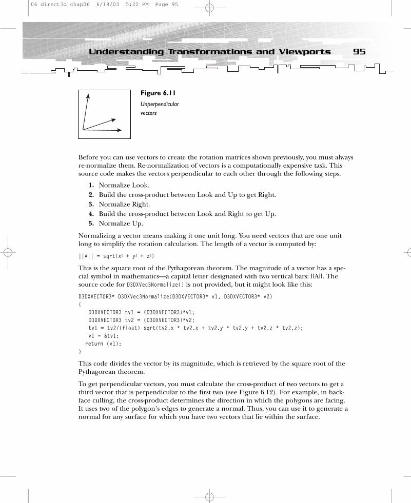
Before you can use vectors to create the rotation matrices shown previously, you must alwaysre-normalize them. Re-normalization of vectors is a computationally expensive task. Thissource code makes the vectors perpendicular to each other through the following steps.
1. Normalize Look.2. Build the cross-product between Look and Up to get Right.3. Normalize Right.4. Build the cross-product between Look and Right to get Up.5. Normalize Up.
Normalizing a vector means making it one unit long. You need vectors that are one unitlong to simplify the rotation calculation. The length of a vector is computed by:
||A|| = sqrt(x2 + y2 + z2)
This is the square root of the Pythagorean theorem. The magnitude of a vector has a spe-cial symbol in mathematics—a capital letter designated with two vertical bars: ||A||. Thesource code for D3DXVec3Normalize() is not provided, but it might look like this:
D3DXVECTOR3* D3DXVec3Normalize(D3DXVECTOR3* v1, D3DXVECTOR3* v2){
D3DXVECTOR3 tv1 = (D3DXVECTOR3)*v1;D3DXVECTOR3 tv2 = (D3DXVECTOR3)*v2;tv1 = tv2/(float) sqrt(tv2.x * tv2.x + tv2.y * tv2.y + tv2.z * tv2.z);v1 = &tv1;
return (v1);}
This code divides the vector by its magnitude, which is retrieved by the square root of thePythagorean theorem.
To get perpendicular vectors, you must calculate the cross-product of two vectors to get athird vector that is perpendicular to the first two (see Figure 6.12). For example, in back-face culling, the cross-product determines the direction in which the polygons are facing. It uses two of the polygon’s edges to generate a normal. Thus, you can use it to generate anormal for any surface for which you have two vectors that lie within the surface.
95Understanding Transformations and Viewports
Figure 6.11
Unperpendicularvectors
06 direct3d chap06 6/19/03 5:22 PM Page 95
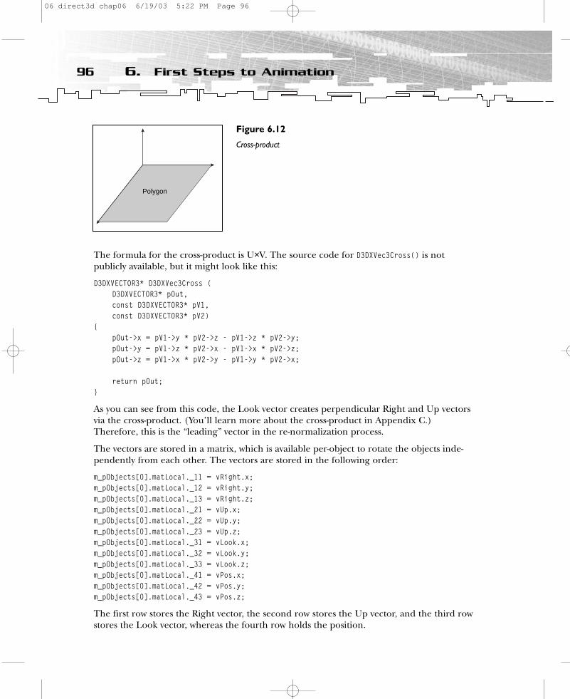
The formula for the cross-product is U×V. The source code for D3DXVec3Cross() is not publicly available, but it might look like this:
D3DXVECTOR3* D3DXVec3Cross (D3DXVECTOR3* pOut,const D3DXVECTOR3* pV1,const D3DXVECTOR3* pV2)
{pOut->x = pV1->y * pV2->z - pV1->z * pV2->y;pOut->y = pV1->z * pV2->x - pV1->x * pV2->z;pOut->z = pV1->x * pV2->y - pV1->y * pV2->x;
return pOut;}
As you can see from this code, the Look vector creates perpendicular Right and Up vectorsvia the cross-product. (You’ll learn more about the cross-product in Appendix C.)Therefore, this is the “leading” vector in the re-normalization process.
The vectors are stored in a matrix, which is available per-object to rotate the objects inde-pendently from each other. The vectors are stored in the following order:
m_pObjects[0].matLocal._11 = vRight.x; m_pObjects[0].matLocal._12 = vRight.y; m_pObjects[0].matLocal._13 = vRight.z;m_pObjects[0].matLocal._21 = vUp.x; m_pObjects[0].matLocal._22 = vUp.y; m_pObjects[0].matLocal._23 = vUp.z;m_pObjects[0].matLocal._31 = vLook.x; m_pObjects[0].matLocal._32 = vLook.y; m_pObjects[0].matLocal._33 = vLook.z;m_pObjects[0].matLocal._41 = vPos.x;m_pObjects[0].matLocal._42 = vPos.y;m_pObjects[0].matLocal._43 = vPos.z;
The first row stores the Right vector, the second row stores the Up vector, and the third rowstores the Look vector, whereas the fourth row holds the position.
96 6. First Steps to Animation
Polygon
Figure 6.12
Cross-product
06 direct3d chap06 6/19/03 5:22 PM Page 96
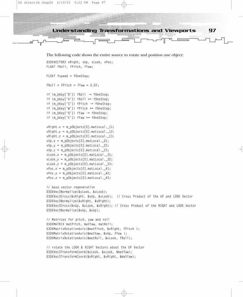
The following code shows the entire source to rotate and position one object:
D3DXVECTOR3 vRight, vUp, vLook, vPos;FLOAT fRoll, fPitch, fYaw;
FLOAT fspeed = fOneStep;
fRoll = fPitch = fYaw = 0.0f;
if (m_bKey[‘D’]) fRoll -= fOneStep;if (m_bKey[‘A’]) fRoll += fOneStep;if (m_bKey[‘S’]) fPitch -= fOneStep;if (m_bKey[‘W’]) fPitch += fOneStep;if (m_bKey[‘Q’]) fYaw -= fOneStep;if (m_bKey[‘E’]) fYaw += fOneStep;
vRight.x = m_pObjects[0].matLocal._11; vRight.y = m_pObjects[0].matLocal._12; vRight.z = m_pObjects[0].matLocal._13;vUp.x = m_pObjects[0].matLocal._21;vUp.y = m_pObjects[0].matLocal._22;vUp.z = m_pObjects[0].matLocal._23;vLook.x = m_pObjects[0].matLocal._31;vLook.y = m_pObjects[0].matLocal._32;vLook.z = m_pObjects[0].matLocal._33;vPos.x = m_pObjects[0].matLocal._41;vPos.y = m_pObjects[0].matLocal._42;vPos.z = m_pObjects[0].matLocal._43;
// base vector regenerationD3DXVec3Normalize(&vLook, &vLook);D3DXVec3Cross(&vRight, &vUp, &vLook); // Cross Product of the UP and LOOK VectorD3DXVec3Normalize(&vRight, &vRight);D3DXVec3Cross(&vUp, &vLook, &vRight); // Cross Product of the RIGHT and LOOK VectorD3DXVec3Normalize(&vUp, &vUp);
// Matrices for pitch, yaw and rollD3DXMATRIX matPitch, matYaw, matRoll;D3DXMatrixRotationAxis(&matPitch, &vRight, fPitch );D3DXMatrixRotationAxis(&matYaw, &vUp, fYaw ); D3DXMatrixRotationAxis(&matRoll, &vLook, fRoll);
// rotate the LOOK & RIGHT Vectors about the UP VectorD3DXVec3TransformCoord(&vLook, &vLook, &matYaw); D3DXVec3TransformCoord(&vRight, &vRight, &matYaw);
97Understanding Transformations and Viewports
06 direct3d chap06 6/19/03 5:22 PM Page 97

// rotate the LOOK & UP Vectors about the RIGHT VectorD3DXVec3TransformCoord(&vLook, &vLook, &matPitch); D3DXVec3TransformCoord(&vUp, &vUp, &matPitch);
// rotate the RIGHT & UP Vectors about the LOOK VectorD3DXVec3TransformCoord(&vRight, &vRight, &matRoll); D3DXVec3TransformCoord(&vUp, &vUp, &matRoll);
// move forwardif (m_bKey[‘R’]) {
vPos.x+=fspeed*vLook.x;vPos.y+=fspeed*vLook.y;vPos.z+=fspeed*vLook.z;
}
// move backif (m_bKey[‘F’]) // Key END {
vPos.x-=fspeed*vLook.x;vPos.y-=fspeed*vLook.y;vPos.z-=fspeed*vLook.z;
}
m_pObjects[0].matLocal._11 = vRight.x; m_pObjects[0].matLocal._12 = vRight.y; m_pObjects[0].matLocal._13 = vRight.z;m_pObjects[0].matLocal._21 = vUp.x; m_pObjects[0].matLocal._22 = vUp.y; m_pObjects[0].matLocal._23 = vUp.z;m_pObjects[0].matLocal._31 = vLook.x; m_pObjects[0].matLocal._32 = vLook.y; m_pObjects[0].matLocal._33 = vLook.z;m_pObjects[0].matLocal._41 = vPos.x;m_pObjects[0].matLocal._42 = vPos.y;m_pObjects[0].matLocal._43 = vPos.z;
This code shows how the vectors are retrieved from the matrix, renormalized, and rotated.Additionally, you move the object in the direction in which the Look vector points byadding the Look vector multiplied by a speed factor to the position data.
Now that you have seen a consistent way to rotate objects in 3D, the 1steps4 example presentsan even more efficient way of doing this by using quaternions.
98 6. First Steps to Animation
06 direct3d chap06 6/19/03 5:22 PM Page 98

The 1steps4 Example The 1steps4.exe example shows a more efficient way to rotate an object in 3D. You can usethe same keys as in the previous example to move the objects. The entire source code toaccomplish this follows.
FLOAT fRoll, fPitch, fYaw;fRoll = fPitch = fYaw = 0.0f;
if (m_bKey[‘D’]) fRoll -= fOneStep;if (m_bKey[‘A’]) fRoll += fOneStep;if (m_bKey[‘S’]) fPitch -= fOneStep;if (m_bKey[‘W’]) fPitch += fOneStep;if (m_bKey[‘Q’]) fYaw -= fOneStep;if (m_bKey[‘E’]) fYaw += fOneStep;
// Update rotation matrixD3DXQUATERNION qR;D3DXMATRIX matRot;D3DXQuaternionRotationYawPitchRoll (&qR, fYaw, fPitch, fRoll);D3DXMatrixRotationQuaternion (&matRot, &qR);D3DXMatrixMultiply (&m_pObjects[0].matLocal, &matRot, &m_pObjects[0].matLocal);
// Update positionD3DXVECTOR3 vLook; // Look vectorvLook.x = m_pObjects[0].matLocal._31; // extract Look vectorvLook.y = m_pObjects[0].matLocal._32;vLook.z = m_pObjects[0].matLocal._33;
// move forwardif (m_bKey[‘R’]) {
m_pObjects[0].matLocal._41 += fOneStep * vLook.x;m_pObjects[0].matLocal._42 += fOneStep * vLook.y;m_pObjects[0].matLocal._43 += fOneStep * vLook.z;
}
// move backif (m_bKey[‘F’]) {
m_pObjects[0].matLocal._41 -= fOneStep * vLook.x;m_pObjects[0].matLocal._42 -= fOneStep * vLook.y;m_pObjects[0].matLocal._43 -= fOneStep * vLook.z;
}
This is really a handy piece of source that rotates the objects. You can reduce the numberof lines even further, but I didn’t do that for clarity’s sake.
99Understanding Transformations and Viewports
06 direct3d chap06 6/19/03 5:22 PM Page 99
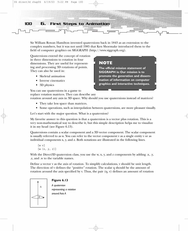
Sir William Rowan Hamilton invented quaternions back in 1843 as an extension to thecomplex numbers, but it was not until 1985 that Ken Shoemake introduced them to thefield of computer graphics on SIGGRAPH (http://www.siggraph.org).
Quaternions extend the concept of rotationin three dimensions to rotation in fourdimensions. They are useful for represent-ing and processing 3D rotations of points.They can also be used in:
• Skeletal animation• Inverse cinematics• 3D physics
You can use quaternions in a game toreplace rotation matrices. They can describe anyrotation around any axis in 3D space. Why should you use quaternions instead of matrices?
• They take less space than matrices.• Some operations, such as interpolation between quaternions, are more pleasant visually.
Let’s start with the major question. What is a quaternion?
My favorite answer to this question is that a quaternion is a vector plus rotation. This is avery non-mathematical way to describe it, but this simple description helps me to visualizeit in my head (see Figure 6.13).
Quaternions contain a scalar component and a 3D vector component. The scalar componentis usually referred to as w. You can refer to the vector component v as a single entity v or asindividual components x, y, and z. Both notations are illustrated in the following lines.
[w v][w (x, y, z)]
With the Direct3D quaternion class, you use the w, x, y, and z components by adding .x, .y,.z, and .w to the variable names.
Define a vector v as the axis of rotation. To simplify calculations, v should be unit length.The direction of v defines the “positive” rotation. The scalar q should be the amount ofrotation around the axis specified by v. Thus, the pair (q, v) defines an amount of rotation
100 6. First Steps to Animation
NOTEThe official mission statement ofSIGGRAPH is: Our mission is to promote the generation and dissem-ination of information on computergraphics and interactive techniques.
A
θ
Figure 6.13
A quaternionrepresenting a rotationaround Axis A
06 direct3d chap06 6/19/03 5:22 PM Page 100

(angular displacement) as a rotation of q radians around the axis specified by v.Unfortunately, q and v are not simply stored directly in the four numbers of the quaternion.The following equation shows how the numbers inside a quaternion q are related to q and v.Both forms of quaternion notation are used.
q = [cos(q/2) sin(q/2)v]q = [cos(q/2) (sin(q/2)vx, sin(q/2)vy, sin(q/2)vz)]
Yaw, pitch, and roll are converted to a quaternion here. This is also referred to as convert-ing from Euler angles to a quaternion. This is quite tricky because the order of operationsmust be correct. Because you can convert the Euler angles to three independent quater-nions by setting the arbitrary axis to the coordinate axes, you can then multiply the threequaternions to obtain the final quaternion.
If you have three Euler angles (yaw, pitch, and roll), you can form three independentquaternions.
Qx = [ cos(yaw/2), (sin(yaw/2), 0, 0)]Qy = [ cos(pitch/2), (0, sin(pitch/2), 0)]Qz = [ cos(roll/2), (0, 0, sin(roll/2))]
You obtain the final quaternion by multiplying Qx * Qy * Qz. Converting the yaw, pitch,and roll to a quaternion is done via the following function:
D3DXQUATERNION * D3DXQuaternionRotationYawPitchRoll (D3DXQUATERNION * pOut,FLOAT yaw,FLOAT pitch,FLOAT roll)
{FLOAT sinY, cosY, sinP, cosP, sinR, cosR;
sinY = sin(0.5f * yaw);cosY = cos(0.5f * yaw);
sinP = sin(0.5f * pitch);cosP = cos(0.5f * pitch);
sinR = sin(0.5f * roll);cosR = cos(0.5f * roll);
pOut->x = cosR * sinP * cosY + sinR * cosP * sinY;pOut->y = cosR * cosP * sinY - sinR * sinP * cosY;pOut->z = sinR * cosP * cosY - cosR * sinP * sinY;pOut->w = cosR * cosP * cosY + sinR * sinP * sinY;
return pOut;}
101Understanding Transformations and Viewports
06 direct3d chap06 6/19/03 5:22 PM Page 101
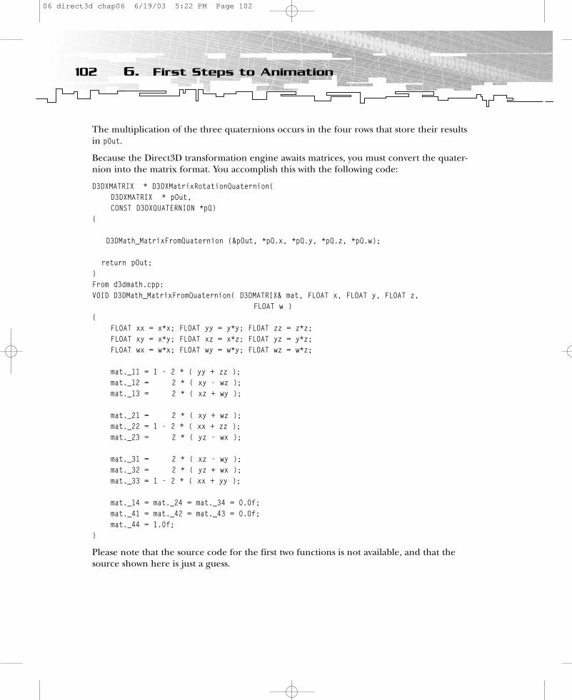
The multiplication of the three quaternions occurs in the four rows that store their resultsin pOut.
Because the Direct3D transformation engine awaits matrices, you must convert the quater-nion into the matrix format. You accomplish this with the following code:
D3DXMATRIX * D3DXMatrixRotationQuaternion(D3DXMATRIX * pOut,CONST D3DXQUATERNION *pQ)
{
D3DMath_MatrixFromQuaternion (&pOut, *pQ.x, *pQ.y, *pQ.z, *pQ.w);
return pOut;}From d3dmath.cpp:VOID D3DMath_MatrixFromQuaternion( D3DMATRIX& mat, FLOAT x, FLOAT y, FLOAT z,
FLOAT w ){
FLOAT xx = x*x; FLOAT yy = y*y; FLOAT zz = z*z;FLOAT xy = x*y; FLOAT xz = x*z; FLOAT yz = y*z;FLOAT wx = w*x; FLOAT wy = w*y; FLOAT wz = w*z;
mat._11 = 1 - 2 * ( yy + zz );mat._12 = 2 * ( xy - wz );mat._13 = 2 * ( xz + wy );
mat._21 = 2 * ( xy + wz );mat._22 = 1 - 2 * ( xx + zz );mat._23 = 2 * ( yz - wx );
mat._31 = 2 * ( xz - wy );mat._32 = 2 * ( yz + wx );mat._33 = 1 - 2 * ( xx + yy );
mat._14 = mat._24 = mat._34 = 0.0f;mat._41 = mat._42 = mat._43 = 0.0f;mat._44 = 1.0f;
}
Please note that the source code for the first two functions is not available, and that thesource shown here is just a guess.
102 6. First Steps to Animation
06 direct3d chap06 6/19/03 5:22 PM Page 102
With regard to world transformations, you have learned how to
• Use matrices to store rotations and transformations of objects• Be aware of the order of matrices• Use orientation vectors to rotate objects in 3D• Use a quaternion built from yaw, pitch, and roll to rotate objects in 3D
I will show you how to create and use all these viewports later in this chapter, in the“Working with the Viewport” section.
An obvious improvement to the examples that does not fit in the scope of the book is theimplementation of time-based physics. You would use this to interpret the user’s input as avelocity in the desired direction. Since you have the ship’s orthogonal orientation basis vectors(Look, Up, and Right), the implementation is a simple one-dimensional physics problem.
Position += deltaTime * InputSpeed * forward
You might use this to achieve damping effects. It looks pretty cool when your ship has some momentum while slowing down or rotating. You might be able to give different shipsdifferent velocities so the user can “feel” the size of the ship by seeing its velocity. A big shipwould be sluggish and a small ship would be very fast.
After reviewing the world transformations, you can go on to the view transformations. Themain challenge in this section is to build a camera class.
The View TransformationView transformations usually describe the position and the orientation of a viewer in ascene. This is normally your position and orientation, looking through the glass of yourmonitor into the scene. Many people use the example of a camera through which you lookinto the scene to describe this transformation. You accomplish a view transformation via aview transformation matrix or a short view matrix. Such a matrix is conceptually differentfrom the world matrix but mechanically the same, meaning that the transformation matri-ces are built the same way for both types of transformations. The main difference between a world and a view matrix is the way the three orientation vectors are stored. Whereas theworld matrix stores them in a row order, the view matrix stores them in a column order.
You use the view matrix to build up a solid camera model that allows the player to see theworld through a different set of eyes. This section outlines two camera models that mightbe useful in games.
• A very efficient camera model provided by Direct3D for games, in which the cameradoes not have to be able to rotate through three dimensions. This model will be use-ful in most situations.
• A sophisticated camera model that allows you to rotate the camera in 3D, which isuseful in flight simulators or space shooters.
103Understanding Transformations and Viewports
06 direct3d chap06 6/19/03 5:22 PM Page 103
The first camera model is provided in Direct3D via the D3DXMatrixLookAtLH() function. Thisfunction awaits the position, the Look vector, and the Up vector, and provides a matrix thatrepresents the position and orientation of the camera. Unfortunately the source code is notavailable for this function, but it might look like the following code.
#define MX_EPS5 1e-5fD3DXMATRIX * D3DXMatrixLookAtLH ( D3DXMATRIX * pOut, const D3DXVECTOR3 * pEye,
const D3DXVECTOR3 * pAt, const D3DXVECTOR3 * pUp)
{// the three orientation vectors of the cameraD3DXVECTOR3 uAxis, vAxis, nAxis;
// create look vector and normalize itnAxis = (*pAt) - (*pEye);if (D3DXVec3Normalize(&nAxis, &nAxis) == NULL) return NULL;
// create up vectorvAxis = (*pUp) - nAxis * D3DXVec3Dot(pUp, &nAxis);
if (D3DXVec3Length(&vAxis) < MX_EPS5){
vAxis.x = - nAxis.y * nAxis.x;vAxis.y = 1.0f - nAxis.y * nAxis.y;vAxis.z = - nAxis.y * nAxis.z;
if (D3DXVec3Length(&vAxis) < MX_EPS5){
vAxis.x = - nAxis.z * nAxis.x;vAxis.y = - nAxis.z * nAxis.y;vAxis.z = 1.0f - nAxis.z * nAxis.z;if (D3DXVec3Length(&vAxis) < MX_EPS5) return NULL;
}}
// normalize up vectorD3DXVec3Normalize(&vAxis, &vAxis);
// create right vectorD3DXVec3Cross(&uAxis, &vAxis, &nAxis);
pOut->_11 = uAxis.x; pOut->_12 = vAxis.x; pOut->_13 = nAxis.x; pOut->_14 = 0.0f;pOut->_21 = uAxis.y; pOut->_22 = vAxis.y; pOut->_23 = nAxis.y; pOut->_24 = 0.0f;pOut->_31 = uAxis.z; pOut->_32 = vAxis.z; pOut->_33 = nAxis.z; pOut->_34 = 0.0f;
104 6. First Steps to Animation
06 direct3d chap06 6/19/03 5:22 PM Page 104
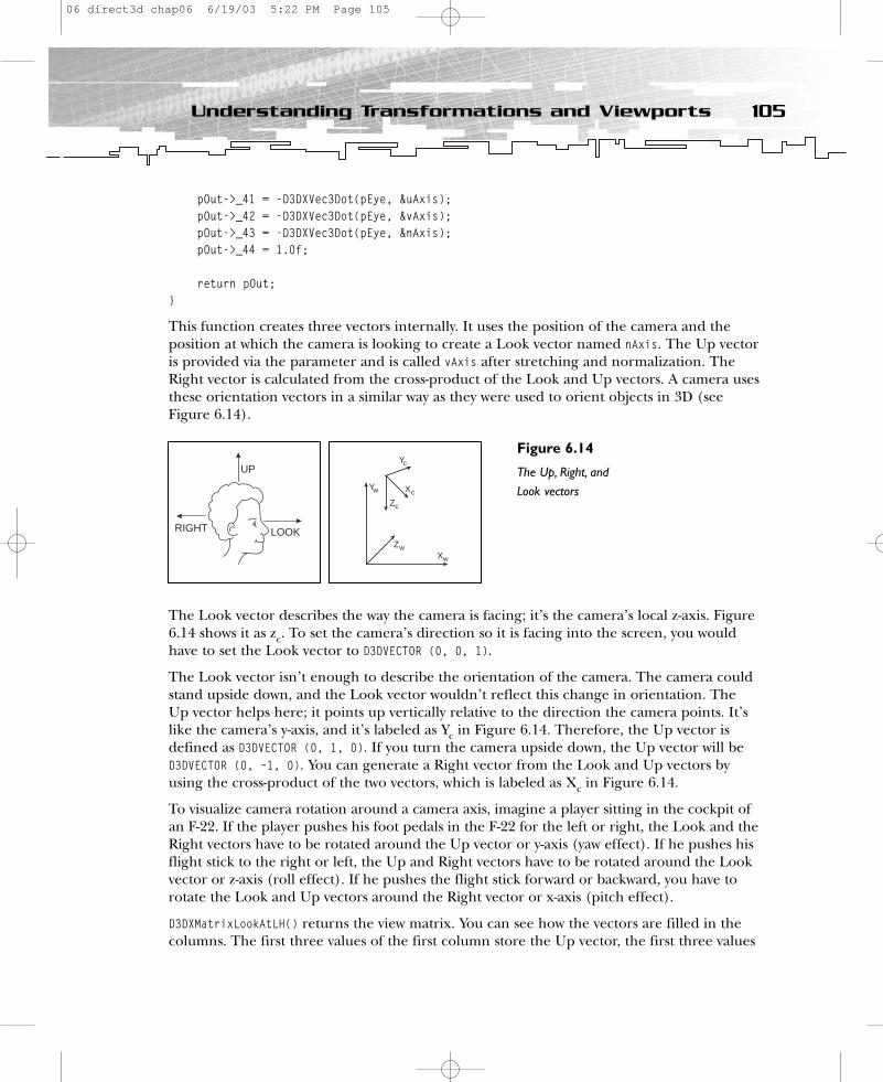
pOut->_41 = -D3DXVec3Dot(pEye, &uAxis);pOut->_42 = -D3DXVec3Dot(pEye, &vAxis);pOut->_43 = -D3DXVec3Dot(pEye, &nAxis);pOut->_44 = 1.0f;
return pOut;}
This function creates three vectors internally. It uses the position of the camera and theposition at which the camera is looking to create a Look vector named nAxis. The Up vectoris provided via the parameter and is called vAxis after stretching and normalization. TheRight vector is calculated from the cross-product of the Look and Up vectors. A camera usesthese orientation vectors in a similar way as they were used to orient objects in 3D (seeFigure 6.14).
The Look vector describes the way the camera is facing; it’s the camera’s local z-axis. Figure6.14 shows it as zc. To set the camera’s direction so it is facing into the screen, you wouldhave to set the Look vector to D3DVECTOR (0, 0, 1).
The Look vector isn’t enough to describe the orientation of the camera. The camera couldstand upside down, and the Look vector wouldn’t reflect this change in orientation. TheUp vector helps here; it points up vertically relative to the direction the camera points. It’slike the camera’s y-axis, and it’s labeled as Yc in Figure 6.14. Therefore, the Up vector isdefined as D3DVECTOR (0, 1, 0). If you turn the camera upside down, the Up vector will beD3DVECTOR (0, –1, 0). You can generate a Right vector from the Look and Up vectors byusing the cross-product of the two vectors, which is labeled as Xc in Figure 6.14.
To visualize camera rotation around a camera axis, imagine a player sitting in the cockpit ofan F-22. If the player pushes his foot pedals in the F-22 for the left or right, the Look and theRight vectors have to be rotated around the Up vector or y-axis (yaw effect). If he pushes hisflight stick to the right or left, the Up and Right vectors have to be rotated around the Lookvector or z-axis (roll effect). If he pushes the flight stick forward or backward, you have torotate the Look and Up vectors around the Right vector or x-axis (pitch effect).
D3DXMatrixLookAtLH() returns the view matrix. You can see how the vectors are filled in thecolumns. The first three values of the first column store the Up vector, the first three values
105Understanding Transformations and Viewports
UP
LOOKRIGHT
Figure 6.14
The Up, Right, andLook vectorsYw
Xw
Zw
Yc
Zc
Xc
06 direct3d chap06 6/19/03 5:22 PM Page 105
of the second column store the Right vector, and the first three values of the third columnstore the Look vector.
D3DXMatrixLookAtLH() is very helpful for building a follow-up camera. The Look vector pointsto the object the camera should follow. The position vector of the camera is moved aroundthis object or positioned behind or in front of it. Pseudocode for the function might looklike this:
static FLOAT tic = -200.0f * rand(); tic += 0.01f;
vLook = m_pObjects[0].vLoc; // position of object that should be in the focus of the cameravPos.z = vLook.z - 5.0f;// position of the cameravPos.x = vLook.x ;vPos.y = vLook.y + (FLOAT)(1.0f + 0.3f * sin(tic * 0.33f)); // slightly up and down move:more lively
D3DXMATRIX view;D3DXMatrixLookAtLH (&view,&vPos, // pEye = Position
&vLook, // pAt&vUp); // pUp
This function is designed for simple uses. For example, it is perfect for a head-mountedtracking display or a follow-up camera, but it won’t help you build a space shooter or flightsimulator camera. Therefore, a second class of camera techniques is more useful for thesetypes of games. There are two implementations—one where the camera is rotated aroundvectors and one where the camera is rotated around arbitrary axes using quaternions. I willstart with the camera class that rotates the camera around its axis.
The 1steps5 ExampleSimilar to the way you can rotate objects in 3D with the help of vectors, which I demon-strated previously, you can rotate a camera with the help of Up, Right, and Look vectors(refer to Figure 6.14). Whereas the camera technique in Figure 6.14 only used two of thevectors to track the camera orientation (Look and Up), this technique uses all three vectors.Rotating the camera around the Look vector means rolling it. Rotating the camera aroundthe Right vector changes the pitch of the camera, and rotating the camera around the Upvector changes its yaw.
This time, you store the vectors in four vector objects instead of a matrix, and the camera ispositioned to face the objects. To control the camera, you use the same technique that youused to control the objects in the 1steps3 example. The source code that is responsible forthe camera should look quite familiar to you, now that you have seen the source code forhow to rotate the object around a vector.
106 6. First Steps to Animation
06 direct3d chap06 6/19/03 5:22 PM Page 106
static D3DXVECTOR3 vCameraLook=D3DXVECTOR3(0.0f,0.0f,1.0); // look vectorstatic D3DXVECTOR3 vCameraUp=D3DXVECTOR3(0.0f,1.0f,0.0f); // up vectorstatic D3DXVECTOR3 vCameraRight=D3DXVECTOR3(1.0f,0.0f,0.0f); // right vectorstatic D3DXVECTOR3 vCameraPos=D3DXVECTOR3(0.0f,0.0f,-5.0f); // position vector
fPitch = fYaw = fRoll = 0.0f;fspeed = fOneStep * 1.5f;
if (m_bKey[VK_UP]) fPitch=-1.0f * m_fElapsedTime; // fPitchif (m_bKey[VK_DOWN]) fPitch=+1.0f * m_fElapsedTime;if (m_bKey[VK_LEFT]) fYaw=+1.0f * m_fElapsedTime; // fYawif (m_bKey[VK_RIGHT]) fYaw=-1.0f * m_fElapsedTime;if (m_bKey[‘C’]) fRoll=-1.0f * m_fElapsedTime; // fRollif (m_bKey[‘X’]) fRoll=+1.0f * m_fElapsedTime;
// camera forwardif (m_bKey[VK_HOME]) // Key HOME {
vCameraPos.x+=fspeed*vCameraLook.x;vCameraPos.y+=fspeed*vCameraLook.y;vCameraPos.z+=fspeed*vCameraLook.z;
}
// camera backif (m_bKey[VK_END]) // Key END {
vCameraPos.x-=fspeed*vCameraLook.x;vCameraPos.y-=fspeed*vCameraLook.y;vCameraPos.z-=fspeed*vCameraLook.z;
}
// base vector regenerationD3DXVec3Normalize(&vCameraLook, &vCameraLook);D3DXVec3Cross(&vCameraRight, &vCameraUp, &vCameraLook); // Cross Product of the UP andLOOK VectorD3DXVec3Normalize(&vCameraRight, &vCameraRight);D3DXVec3Cross(&vCameraUp, &vCameraLook, &vCameraRight); // Cross Product of the RIGHT andLOOK VectorD3DXVec3Normalize(&vCameraUp, &vCameraUp);
// Matrices for pitch, yaw and rollD3DXMatrixRotationAxis(&matPitch, &vCameraRight, fPitch );D3DXMatrixRotationAxis(&matYaw, &vCameraUp, fYaw ); D3DXMatrixRotationAxis(&matRoll, &vCameraLook, fRoll);
107Understanding Transformations and Viewports
06 direct3d chap06 6/19/03 5:22 PM Page 107

// rotate the LOOK & RIGHT Vectors about the UP VectorD3DXVec3TransformCoord(&vCameraLook, &vCameraLook, &matYaw); D3DXVec3TransformCoord(&vCameraRight, &vCameraRight, &matYaw);
// rotate the LOOK & UP Vectors about the RIGHT VectorD3DXVec3TransformCoord(&vCameraLook, &vCameraLook, &matPitch); D3DXVec3TransformCoord(&vCameraUp, &vCameraUp, &matPitch);
// rotate the RIGHT & UP Vectors about the LOOK VectorD3DXVec3TransformCoord(&vCameraRight, &vCameraRight, &matRoll); D3DXVec3TransformCoord(&vCameraUp, &vCameraUp, &matRoll);
D3DXMATRIX view;D3DXMatrixIdentity( &view );view._11 = vCameraRight.x; view._12 = vCameraUp.x; view._13 = vCameraLook.x;view._21 = vCameraRight.y; view._22 = vCameraUp.y; view._23 = vCameraLook.y;view._31 = vCameraRight.z; view._32 = vCameraUp.z; view._33 = vCameraLook.z;view._41 = - D3DXVec3Dot( &vCameraPos, &vCameraRight ); view._42 = - D3DXVec3Dot( &vCameraPos, &vCameraUp );view._43 = - D3DXVec3Dot( &vCameraPos, &vCameraLook );
m_pd3dDevice->SetTransform(D3DTS_VIEW, &view);
You can see how the three orientation vectors and the position vector are stored at thebeginning of the source code snippet. Instead of a matrix, this example holds the orienta-tion and position data in four vectors, which does not make a big difference. The vector re-normalization, creation of rotation matrices, and rotation of two vectors around a rotationvector works the same as in the 1steps3.exe example in the section on world transformations.However, the orientation vectors are stored differently in the view matrix. They are storedin column order, not in row order as in the previous example. Additionally, the position iscalculated with a dot-product from the camera position and one of the three orientationvectors. To move the position of the camera to the origin of the three orientation vectors,the position vector is multiplied by the three orientation vectors and negated.
Now that you have seen how you can rotate a camera around all three axes in 3D by rotatingtwo vectors around a rotation vector, you are prepared to dive into a more sophisticatedexample that does the same thing using a quaternion.
108 6. First Steps to Animation
06 direct3d chap06 6/19/03 5:22 PM Page 108
The 1steps6 ExamplePerhaps you’ve played one of the Tomb Raider titles. (Who can forget Lara Croft, the girlwith the guns?) It was one of the first commercial games that used quaternion rotations toanimate all of the camera movements. A lot of third-person games use a virtual cameraplaced at some distance behind or to the side of the player’s character with quaternions.These days, a quaternion orients most of those cameras.
Similar to the way you used a quaternion to rotate a 3D object in the previous section, youcan use it to rotate a camera. The example 1steps6 is based on the example 1steps4, and ituses a quaternion to rotate the camera. Additionally, the camera can now slide to the left orright and up or down. Here is the main source code snippet:
fRoll = fPitch = fYaw = 0.0f;D3DXVECTOR3 vPos(0.0f, 0.0f, 0.0f);static D3DXMATRIX matView = D3DXMATRIX(1.0f, 0.0f, 0.0f, 0.0f,
0.0f, 1.0f, 0.0f, 0.0f, 0.0f, 0.0f, 1.0f, 0.0f, 0.0f, 0.0f,-5.0f, 1.0f);
// Process keyboard inputif (m_bKey[VK_UP]) fPitch += fOneStep; // Pitch Upif (m_bKey[VK_DOWN]) fPitch -= fOneStep; // Pitch Downif (m_bKey[VK_LEFT]) fYaw += fOneStep; // Turn Leftif (m_bKey[VK_RIGHT]) fYaw -= fOneStep; // Turn Rightif (m_bKey[‘C’]) fRoll += fOneStep; // Rotate Leftif (m_bKey[‘X’]) fRoll -= fOneStep; // Rotate Rightif (m_bKey[VK_HOME]) vPos.z += fOneStep; // Move Forwardif (m_bKey[VK_END]) vPos.z -= fOneStep; // Move Backwardif (m_bKey[VK_NUMPAD4]) vPos.x -= fOneStep; // Slide Leftif (m_bKey[VK_NUMPAD6]) vPos.x += fOneStep; // Slide Rightif (m_bKey[VK_NUMPAD8]) vPos.y += fOneStep; // Slide Downif (m_bKey[VK_NUMPAD2]) vPos.y -= fOneStep; // Slide Up
// Update position and view matricesD3DXMATRIX matR, matTemp;D3DXQuaternionRotationYawPitchRoll (&qR, fYaw, fPitch, fRoll);D3DXMatrixRotationQuaternion (&matR, &qR);D3DXMatrixMultiply (&matView, &matR, &matView);D3DXMatrixTranslation (&matTemp, vPos.x, vPos.y, vPos.z);D3DXMatrixMultiply (&matView, &matTemp, &matView);D3DXMatrixInverse (&matTemp, NULL, &matView);
m_pd3dDevice->SetTransform(D3DTS_VIEW, &matTemp );
109Understanding Transformations and Viewports
06 direct3d chap06 6/19/03 5:22 PM Page 109
This time you use the matView matrix to store the camera’s orientation. As you already know,the third column stores the Look vector of the camera, the second column stores the Up vec-tor, and the first column stores the Right vector. Additionally, you keep track of the camera’sposition change in the vPos variable. The functions are accomplishing the following steps:
1. Build a quaternion from yaw, pitch, and roll with the rotation in it.2. Create a matrix from that quaternion.3. Multiply this rotation matrix by the view matrix.4. Translate the view matrix according to the change of position in vPos.5. Get the inverse of the resulting matrix.6. Provide the matrix to the Direct3D engine.
You already saw the first three steps in the section on world transformations. The result ofthese three steps is a matrix with the rotation in it. The fourth step is setting the camera’sposition. In the fifth step, the code uses a Direct3D utility library function to invert thematrix. Why do you need to invert a matrix? You’re using a quaternion to rotate the camera.These rotations happen around an arbitrary point because the camera will be translated toother points where the rotation will occur. A rotation around an arbitrary point won’t be linear if you don’t invert the rotation matrix. Now, how do you invert the rotation matrix?
You get the inverse of a rotation matrix by negating the rotation angle. A rotation aroundthe origin through an angle A will be canceled by a rotation through an angle –A. If amatrix has an inverse, it is written A-1, and you have A A-1 = A-1 A=I.
Multiplying the matrix A with its inverse matrix results in the identity matrix I. Invertinga rotation matrix is useful for mapping the origin of a rotation around an arbitrary pointonto itself.
This section on view transformations showed you the way the orientation vectors are stored inthe view matrix that is awaited by the SetTransform() function. Furthermore, it showed you atechnique to rotate a camera with the help of three perpendicular vectors that are used to orient the camera. This technique has the disadvantage of requiring you to re-normalize thethree vectors before they are used each time. Such inefficiency does not occur when you use a camera control that uses quaternions to rotate the camera. This seems to be the commontechnique to control cameras nowadays, although quaternions are difficult to understand.
There is still room to improve the camera systems discussed previously. The 1steps7.exeexample, which you can find in the \1steps7 directory on the CD-ROM, implements asimple time-based physics system. You can feel the velocity to rotate or move the ship inwhich you are sitting.
The Projection TransformationThe perspective projection transformation converts the camera’s viewing frustum (the pyramid-like shape that defines what the camera can see) into a cube space, as shown inFigure 6.15. (With a cube-shape geometry, clipping is much easier.)
110 6. First Steps to Animation
06 direct3d chap06 6/19/03 5:22 PM Page 110
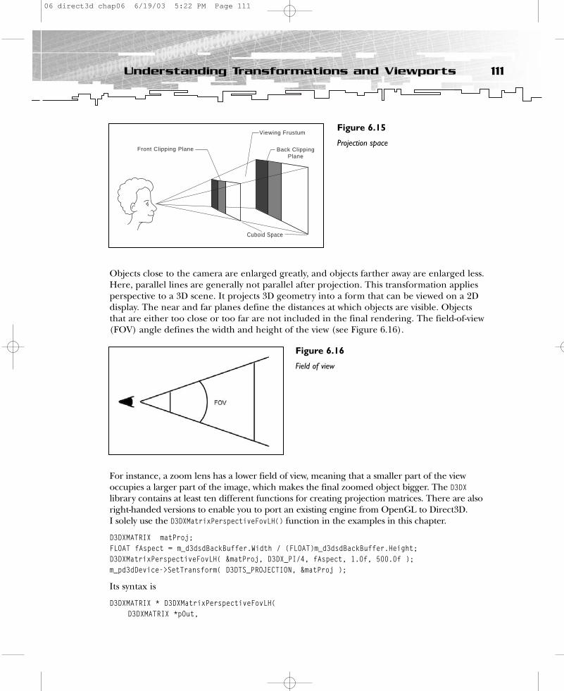
Objects close to the camera are enlarged greatly, and objects farther away are enlarged less.Here, parallel lines are generally not parallel after projection. This transformation appliesperspective to a 3D scene. It projects 3D geometry into a form that can be viewed on a 2Ddisplay. The near and far planes define the distances at which objects are visible. Objectsthat are either too close or too far are not included in the final rendering. The field-of-view(FOV) angle defines the width and height of the view (see Figure 6.16).
For instance, a zoom lens has a lower field of view, meaning that a smaller part of the viewoccupies a larger part of the image, which makes the final zoomed object bigger. The D3DXlibrary contains at least ten different functions for creating projection matrices. There are alsoright-handed versions to enable you to port an existing engine from OpenGL to Direct3D. I solely use the D3DXMatrixPerspectiveFovLH() function in the examples in this chapter.
D3DXMATRIX matProj;FLOAT fAspect = m_d3dsdBackBuffer.Width / (FLOAT)m_d3dsdBackBuffer.Height;D3DXMatrixPerspectiveFovLH( &matProj, D3DX_PI/4, fAspect, 1.0f, 500.0f );m_pd3dDevice->SetTransform( D3DTS_PROJECTION, &matProj );
Its syntax is
D3DXMATRIX * D3DXMatrixPerspectiveFovLH(D3DXMATRIX *pOut,
111Understanding Transformations and Viewports
Viewing Frustum
Back ClippingPlane
Front Clipping Plane
Cuboid Space
Figure 6.15
Projection space
Figure 6.16
Field of view
06 direct3d chap06 6/19/03 5:22 PM Page 111
FLOAT fovY,FLOAT Aspect,FLOAT zn,FLOAT zf
);
The first parameter returns the projection matrix. The second parameter awaits the field ofview in the y direction, in radians. You must provide the height-to-width ratio to the thirdparameter. It is useful to provide the height and width of the back buffer so the size of theobjects are shown correctly if the user changes the size of the window. The last two parame-ters are used for the near and far clipping planes. You must provide a z-value for each. Youshould use a near clipping plane of 1.0f and a far clipping plane of 500.0f to fly aroundwith the objects. You can use the projection matrix for sophisticated things such as solvingdepth-buffer artifacts, rendering high-resolution screenshots, and rejecting unwanted geometry from rendering, but these concepts are outside the scope of this book. In mostcases, a setup for a projection matrix such as the one shown previously is sufficient.
Working with the ViewportAfter you have finished the three transformation steps, the device still needs to determinehow the data is finally mapped to each pixel. You help the device do this by defining a viewport. By default, the viewport is defined by the size of the window in a windowed appli-cation or the resolution of the screen in a full-screen application. Therefore, you oftendon’t need to set it explicitly. However, Direct3D also allows you to specify a portion of thewindow as a viewport. This is useful when you are rendering multiple views in the same window, as shown earlier in this chapter in the 1steps2.exe example. The four viewportswere made visible in Figure 6.17 by painting two white lines.
You define a viewport with the D3DVIEWPORT9 structure.
typedef struct _D3DVIEWPORT9 {DWORD X;DWORD Y;DWORD Width;DWORD Height;float MinZ;float MaxZ;
} D3DVIEWPORT9;
The X, Y, Width, and Height values correspond to the viewport rectangle (see Figure 6.18).
This structure defines the rectangular position of the viewport within the window or screen,as well as two additional members that indicate the depth ranges into which the scene willbe rendered. Direct3D assumes that the x value ranges from -1.0f to 1.0f and that the yvalue ranges from 1.0f to -1.0f. These values indicate the depth range into which the scenewill be rendered, and are not used for clipping. (This change was introduced in DirectX 8;
112 6. First Steps to Animation
06 direct3d chap06 6/19/03 5:22 PM Page 112
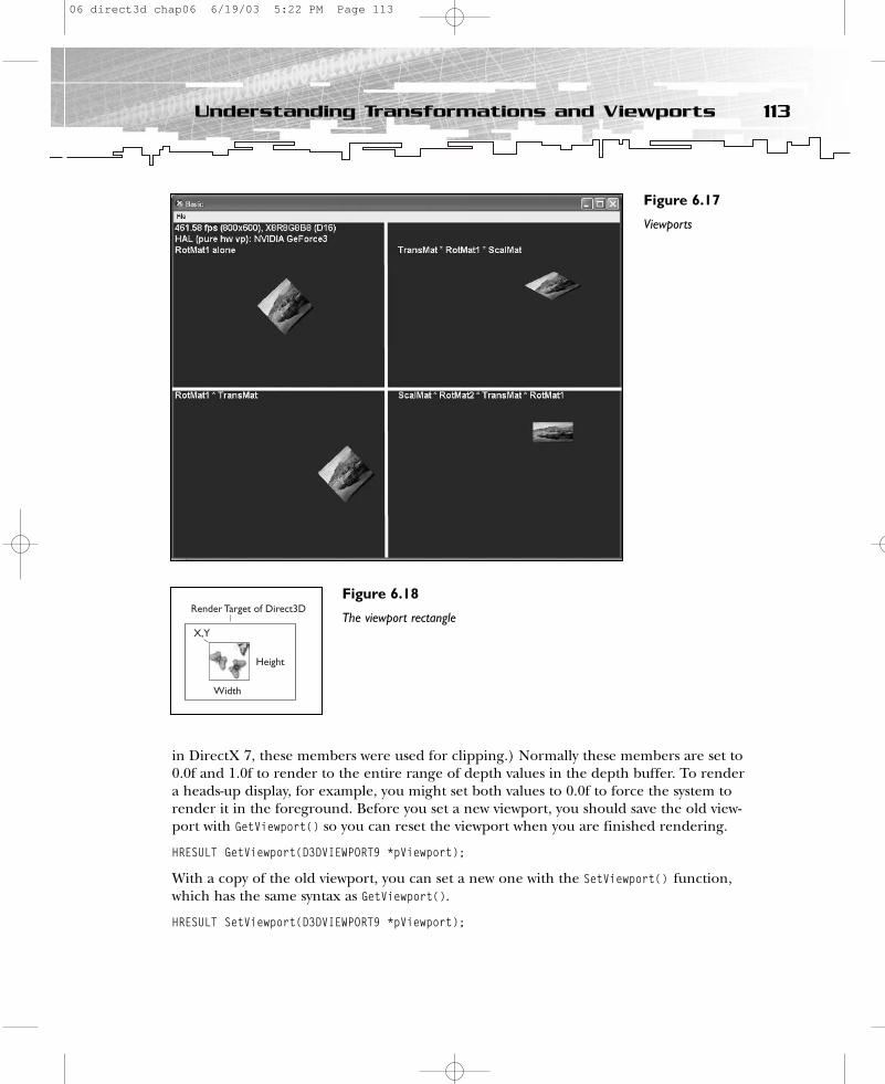
in DirectX 7, these members were used for clipping.) Normally these members are set to0.0f and 1.0f to render to the entire range of depth values in the depth buffer. To render a heads-up display, for example, you might set both values to 0.0f to force the system to render it in the foreground. Before you set a new viewport, you should save the old view-port with GetViewport() so you can reset the viewport when you are finished rendering.
HRESULT GetViewport(D3DVIEWPORT9 *pViewport);
With a copy of the old viewport, you can set a new one with the SetViewport() function,which has the same syntax as GetViewport().
HRESULT SetViewport(D3DVIEWPORT9 *pViewport);
113Understanding Transformations and Viewports
Figure 6.17
Viewports
Render Target of Direct3D
Height
Width
X,Y
Figure 6.18
The viewport rectangle
06 direct3d chap06 6/19/03 5:22 PM Page 113

This defines a new subsection of the window; drawing occurs in that rectangle. If a newviewport is outside the boundaries of the device, SetViewport() will fail. Please note that theaspect (width-to-height ratio) of the viewport rectangle should match the aspect of the projection matrix, or the objects might look squished.
The source code of the example 1steps2 shows the use of four viewports. These viewportsare declared in the application class.
D3DVIEWPORT9 m_RViewport;D3DVIEWPORT9 m_SRTViewport;D3DVIEWPORT9 m_TRViewport;D3DVIEWPORT9 m_RTRSViewport;
The first viewport will hold the view that shows the quad transformed by the rotation matrixonly, as the capital R in the name implies. The second viewport will hold the view thatshows the quad transformed by a scale-rotate-translate matrix, as the capital SRT in thename implies. The third viewport will hold the view that shows the quad transformed by atranslate-rotate matrix, as the capital TR implies. The fourth viewport will hold the view thatshows the quad transformed by a rotate-translate-rotate-scale matrix, as the capital RTRSimplies. The size of the four viewports is set in RestoreDeviceObjects(), which means thatevery change of the window size will recalculate these sizes.
// Setup the sub-viewportsD3DVIEWPORT9 MainViewport;m_pd3dDevice->GetViewport(&MainViewport);
// Each viewport fills a quarter of the windowm_RViewport.Width = m_SRTViewport.Width = m_TRViewport.Width = m_RTRSViewport.Width = MainViewport.Width / 2;m_RViewport.Height = m_SRTViewport.Height = m_TRViewport.Height = m_RTRSViewport.Height = MainViewport.Height / 2;
m_RViewport.Y = m_SRTViewport.Y = 0;m_RViewport.X = m_TRViewport.X = 0;
m_TRViewport.Y = m_RTRSViewport.Y = MainViewport.Height / 2;m_SRTViewport.X = m_RTRSViewport.X = MainViewport.Width / 2;
// Set the full Z range for each viewportm_RViewport.MinZ = m_SRTViewport.MinZ = m_TRViewport.MinZ = m_RTRSViewport.MinZ = 0.0f;
114 6. First Steps to Animation
06 direct3d chap06 6/19/03 5:22 PM Page 114
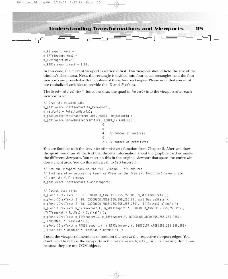
m_RViewport.MaxZ = m_SRTViewport.MaxZ = m_TRViewport.MaxZ = m_RTRSViewport.MaxZ = 1.0f;
In this code, the current viewport is retrieved first. This viewport should hold the size of thewindow’s client area. Next, the rectangle is divided into four equal rectangles, and the fourviewports are provided with the values of these four rectangles. Please note that you mustuse capitalized variables to provide the .X and .Y values.
The DrawPrimitiveIndex() functions draw the quad in Render() into the viewport after eachviewport is set.
// Draw the rotated datam_pd3dDevice->SetViewport(&m_RViewport);m_matWorld = RotationMatrix1;m_pd3dDevice->SetTransform(D3DTS_WORLD, &m_matWorld);m_pd3dDevice->DrawIndexedPrimitive( D3DPT_TRIANGLELIST,
0,0, 4, // number of vertices0, 2); // number of primitives
You are familiar with the DrawIndexedPrimitive() function from Chapter 5. After you drawthe quad, you draw all the text that displays information about the graphics card or marksthe different viewports. You must do this in the original viewport that spans the entire win-dow’s client area. You do this with a call to SetViewport().
// Set the viewport back to the full window. This ensures// that any other processing (such as Clear or the DrawText functions) takes place// over the full window.m_pd3dDevice->SetViewport(&MainViewport);
// Output statisticsm_pFont->DrawText( 2, 0, D3DCOLOR_ARGB(255,255,255,0), m_strFrameStats );m_pFont->DrawText( 2, 20, D3DCOLOR_ARGB(255,255,255,0), m_strDeviceStats );m_pFont->DrawText( 2, 40, D3DCOLOR_ARGB(255,255,255,255), _T(“RotMat1 alone”) );m_pFont->DrawText( m_SRTViewport.X, m_SRTViewport.Y, D3DCOLOR_ARGB(255,255,255,255),_T(“TransMat * RotMat1 * ScalMat”) );m_pFont->DrawText( m_TRViewport.X, m_TRViewport.Y, D3DCOLOR_ARGB(255,255,255,255),_T(“RotMat1 * TransMat”) );m_pFont->DrawText( m_RTRSViewport.X, m_RTRSViewport.Y, D3DCOLOR_ARGB(255,255,255,255),_T(“ScalMat * RotMat2 * TransMat * RotMat1”) );
I used the viewport dimensions to position the text at the respective viewport edges. Youdon’t need to release the viewports in the DeleteDeviceObjects() or FinalCleanup() functionsbecause they are not COM objects.
115Understanding Transformations and Viewports
06 direct3d chap06 6/19/03 5:22 PM Page 115
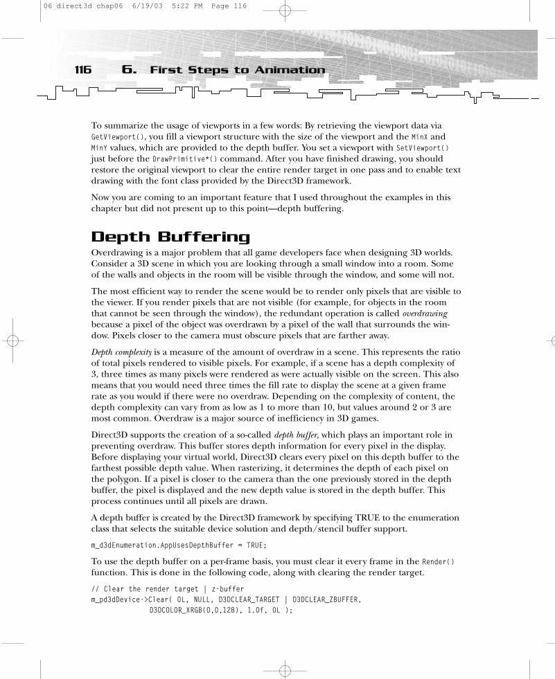
To summarize the usage of viewports in a few words: By retrieving the viewport data viaGetViewport(), you fill a viewport structure with the size of the viewport and the MinX andMinY values, which are provided to the depth buffer. You set a viewport with SetViewport()just before the DrawPrimitive*() command. After you have finished drawing, you shouldrestore the original viewport to clear the entire render target in one pass and to enable textdrawing with the font class provided by the Direct3D framework.
Now you are coming to an important feature that I used throughout the examples in thischapter but did not present up to this point—depth buffering.
Depth BufferingOverdrawing is a major problem that all game developers face when designing 3D worlds.Consider a 3D scene in which you are looking through a small window into a room. Someof the walls and objects in the room will be visible through the window, and some will not.
The most efficient way to render the scene would be to render only pixels that are visible tothe viewer. If you render pixels that are not visible (for example, for objects in the roomthat cannot be seen through the window), the redundant operation is called overdrawingbecause a pixel of the object was overdrawn by a pixel of the wall that surrounds the win-dow. Pixels closer to the camera must obscure pixels that are farther away.
Depth complexity is a measure of the amount of overdraw in a scene. This represents the ratioof total pixels rendered to visible pixels. For example, if a scene has a depth complexity of3, three times as many pixels were rendered as were actually visible on the screen. This alsomeans that you would need three times the fill rate to display the scene at a given framerate as you would if there were no overdraw. Depending on the complexity of content, thedepth complexity can vary from as low as 1 to more than 10, but values around 2 or 3 aremost common. Overdraw is a major source of inefficiency in 3D games.
Direct3D supports the creation of a so-called depth buffer, which plays an important role inpreventing overdraw. This buffer stores depth information for every pixel in the display.Before displaying your virtual world, Direct3D clears every pixel on this depth buffer to thefarthest possible depth value. When rasterizing, it determines the depth of each pixel onthe polygon. If a pixel is closer to the camera than the one previously stored in the depthbuffer, the pixel is displayed and the new depth value is stored in the depth buffer. Thisprocess continues until all pixels are drawn.
A depth buffer is created by the Direct3D framework by specifying TRUE to the enumerationclass that selects the suitable device solution and depth/stencil buffer support.
m_d3dEnumeration.AppUsesDepthBuffer = TRUE;
To use the depth buffer on a per-frame basis, you must clear it every frame in the Render()function. This is done in the following code, along with clearing the render target.
// Clear the render target | z-bufferm_pd3dDevice->Clear( 0L, NULL, D3DCLEAR_TARGET | D3DCLEAR_ZBUFFER,
D3DCOLOR_XRGB(0,0,128), 1.0f, 0L );
116 6. First Steps to Animation
06 direct3d chap06 6/19/03 5:22 PM Page 116
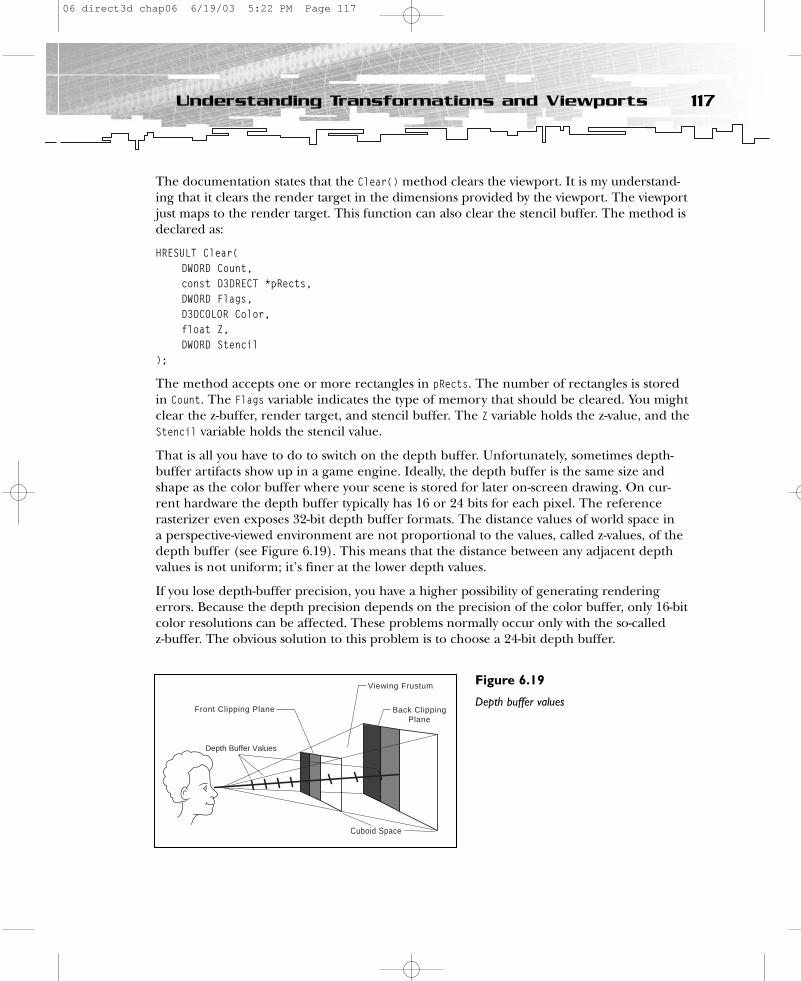
The documentation states that the Clear() method clears the viewport. It is my understand-ing that it clears the render target in the dimensions provided by the viewport. The viewportjust maps to the render target. This function can also clear the stencil buffer. The method isdeclared as:
HRESULT Clear(DWORD Count,const D3DRECT *pRects,DWORD Flags,D3DCOLOR Color,float Z,DWORD Stencil
);
The method accepts one or more rectangles in pRects. The number of rectangles is storedin Count. The Flags variable indicates the type of memory that should be cleared. You mightclear the z-buffer, render target, and stencil buffer. The Z variable holds the z-value, and theStencil variable holds the stencil value.
That is all you have to do to switch on the depth buffer. Unfortunately, sometimes depth-buffer artifacts show up in a game engine. Ideally, the depth buffer is the same size andshape as the color buffer where your scene is stored for later on-screen drawing. On cur-rent hardware the depth buffer typically has 16 or 24 bits for each pixel. The reference rasterizer even exposes 32-bit depth buffer formats. The distance values of world space in a perspective-viewed environment are not proportional to the values, called z-values, of thedepth buffer (see Figure 6.19). This means that the distance between any adjacent depthvalues is not uniform; it’s finer at the lower depth values.
If you lose depth-buffer precision, you have a higher possibility of generating renderingerrors. Because the depth precision depends on the precision of the color buffer, only 16-bitcolor resolutions can be affected. These problems normally occur only with the so-called z-buffer. The obvious solution to this problem is to choose a 24-bit depth buffer.
117Understanding Transformations and Viewports
Viewing Frustum
Back ClippingPlane
Front Clipping Plane
Cuboid Space
Depth Buffer Values
Figure 6.19
Depth buffer values
06 direct3d chap06 6/19/03 5:22 PM Page 117

The w-buffer is another solution provided by Direct3D. The w-buffer reduces the problemsthat z-buffers exhibit with objects in the distance, and has a constant performance for bothnear and far objects. The old DirectX 7.0 SDK provided a very instructive example to show thedifference between a z-buffer and a w-buffer in action; it showed the rendering errors thatoccur when you lose depth-buffer precision in 16-bit color mode. If you try that example, youhave to choose a 16-bit color mode to see the errors occur (see Figure 6.20).
When depth buffering works correctly, you can read a small text passage on the greensquare. Behind the green square is a blue square, which overlaps the text when the z-bufferwith greater distance has lost its precision.
You can set the w-buffer using the SetRenderState() function.
m_pd3dDevice->SetRenderState( D3DRS_ZENABLE, D3DZB_USEW ); // w-buffer
You can check w-buffer support using the following code:
if( d3dCaps.RasterCaps & D3DPRASTERCAPS_WBUFFER)m_bDeviceSupportsW = TRUE;
elsem_bDeviceSupportsW = FALSE;
A w-based depth buffer is often more evenly distributed between the near and far clipplanes than a z-buffer. The key benefit is that the ratio of distances for the near and far clipping planes is no longer an issue. This allows applications to support large maximum
118 6. First Steps to Animation
Figure 6.20
Depth-buffer artifacts
06 direct3d chap06 6/19/03 5:22 PM Page 118

ranges while still getting relatively accurate depth buffering close to the eye point (thepoint where your camera/eye are located). However, a w-based depth buffer isn’t perfectand can sometimes exhibit hidden surface artifacts for near objects. Another drawback tothe w-buffered approach is that w-buffering isn’t supported as widely in hardware as z-buffering. To be on the safe side, use a z-buffer.
Additional ResourcesYou will find a nice and simple COM tutorial at http://www.gamedev.net/reference/articles/article1299.asp.
I’ve found good pages on camera orientation at http://crystal.sourceforge.net.
Three excellent articles on quaternions are
• Shoemake, Ken. “Euler Angle Conversion,” Graphics Gems IV. Ed. Paul S. Heckbert.Toronto: Academic Press Professional. 222–229.
• Void, Sobeit. “Quaternion Powers.”<http://www.gamedev.net/reference/articles/article1095.asp>.
• Downs, Laura. “Using Quaternions to Represent Rotation.”<http.cs.berkeley.edu/~laura/cs184/quat/quaternion.html>.
There are a couple good pages on math stuff at:
• http://www.sisweb.com/math/tables.htm • http://www.swin.edu.au/astronomy/pbourke
The Witchlord Web site at http://www.angelcode.com, which moderates theDirectX/OpenGL/Glide/Genesis3D discussion forum, might also be useful.
If you haven’t already found it, one of the best sites for game programmers ishttp://www.gamasutra.com.
For further reading, I recommend Real-Time Rendering Tricks and Techniques in DirectX(Premier Press, 2002).
SummaryWhew! This chapter walked you through several example programs to teach you how to use world, view, and projection transformations. You were also introduced to viewports anddepth buffering. In the next chapter, you’ll learn about texture mapping and filtering. Are you ready? Let’s move on!
119Summary
06 direct3d chap06 6/19/03 5:22 PM Page 119

Part One QuizQ: What is the purpose of a pluggable software device?
A: If a feature is not supported in HAL, the pluggable software device can take control and emulate the hardware. It’s not provided by the DirectX 9 SDK.
Q: What is the purpose of the reference rasterizer?
A: To test features that your card doesn’t support.
Q: What are the most important COM features for game programmers?
A: • COM interfaces can never change• Language independence• Only access to methods, not data
Q: What is a v-table?
A: A virtual function table references the methods implemented in a COM object. You can’t access COM methods directly.
Q: How do you define the location of a vertex in 3D space?
A: By specifying a vector from the origin to the point where the vertex resides.
Q: How do you define the orientation of an object in 3D space?
A: By using the Look, Up, and Right vectors.
Q: Why do you have to specify face vertices in clockwise order?
A: Direct3D does not draw back faces of objects to gain more speed. By default, it onlydraws faces of objects where the vertices are oriented in clockwise order. This is called back-face culling. Therefore, you must recommend the proper ordering of your vertices.
Q: How are textures mapped on a face?
A: By using a uniform address range for all texels in a texture. The upper-left corner is(0.0f, 0.0f), and the bottom-right corner is (1.0f, 1.0f).
Q: What are the common files?
A: They encapsulate the basic functionality to start a Direct3D game. They are proven codeand well tested.
Q: What is the purpose of the OneTimeSceneInit()/InitDeviceObjects() methods?
A: OneTimeSceneInit() performs all of the functions necessary to load the geometry data ofa scene. It is called only once. InitDeviceObjects() initializes all per-device objects, such asloading texture bits onto a device surface, setting matrices, populating vertex buffers, andsetting render states. It’s called when the application starts or the device is being changed.
120 6. First Steps to Animation
06 direct3d chap06 6/19/03 5:22 PM Page 120

Q: What is the difference between DeleteDeviceObjects() and FinalCleanUp()?
A: DeleteDeviceObjects() is called when the application exits or when the device changes.FinalCleanup() is the last framework call in your application before it exits. It destroys allo-cated memory (for example, for textures) and deletes file objects.
Q: What textures can D3DUtil_CreateTexture() load?
A: Bitmaps from *.bmp, *.jpg, *.png, *.ppm, *.dds, and *.tga files.
Q: What is a viewport?
A: In order for Direct3D to know what frustum to clip to, you need the viewport dimensions.These dimensions are used to clip the perspective projection’s viewing frustum to the cubeshape.
Q: What is the purpose of the BeginScene()/EndScene pair?
A: BeginScene() causes the system to check its internal data structures and the availabilityand validity of rendering surfaces, and it sets the internal flag to signal that a scene is inprogress. EndScene() clears the internal flag that indicates that a scene is in progress, flushesthe cached data, and makes sure the rendering surfaces are okay.
Q: What happens if you set a texture?
A: A call to SetTexture() instructs the Direct3D device to apply the texture to all primitivesthat are rendered from that time until another texture is set or the texture stage is switchedoff.
Q: What is the function of a triangle strip?
A: It creates a series of connected triangles.
Q: What is the function of a vertex flag?
A: It tells Direct3D something about the used vertex structure in which the vertex informa-tion is stored. The presence or absence of a particular vertex format flag communicates tothe system which vertex component fields are present in memory and which you’ve omitted.By using only the needed vertex components, your application can conserve memory andminimize the processing bandwidth required to render the 3D world.
Q: Do you have to use the Direct3D transformation and lighting pipeline?
A: No, you’re free to skip it. Just use the proper vertex flags (_RHW) and the proper vertexstructure.
Q: What is the purpose of the world, view, and projection transformations?
A: The world transformation stage transforms an object from model to world space, theabsolute frame of reference for a 3D world. The view transformation stage transforms your3D world from world space to camera space by placing the camera at the origin and point-ing it directly down its positive z-axis. The projection transformation controls the camera’sinternals. It’s analogous to choosing a lens for the camera.
121Part One Quiz
06 direct3d chap06 6/19/03 5:22 PM Page 121

Q: Why is the use of matrices a good choice in game programming?
A: The performance of a dedicated transform engine is predictable and consistent withmatrices. This allows game developers to make informed decisions regarding performanceand quality.
Q: Building a concept for a camera system in a game is not trivial; it depends on the vehiclein which the player is sitting. A helicopter pilot needs a different camera system than an X-wing fighter pilot.
Q: What is wrong with the default camera control technique provided byD3DXMatrixLookAtLH()?
A: This function is designed for simple uses. For example, it is perfect for a head-mountedtracking display or a follow-up camera, but it won’t help you build a space shooter or flightsimulator camera.
Q: Describe the rotation of the camera using a quaternion.
A: A quaternion is built from yaw, pitch, and roll (Euler angles). It is converted to a matrix,and the matrix is inverted at the end.
Q: Why do you have to use a depth buffer?
A: A z- or w-buffer is used to reduce the problem of overdraw. These buffers hold thedepth of each pixel in the scene. If a pixel is closer to the camera than one previouslystored in the depth buffer, the pixel is displayed and the new depth value is stored in thedepth buffer.
Q: What is the fastest primitive to use?
A: That depends on the primitive data you use. Index primitive types such as indexed trianglelists or indexed triangle strips should be the fastest primitive type in most cases. If fewerthan two of the object’s vertices share an index, you should think about using non-indexedprimitives. The best way to find the fastest primitive in a specific case is to measure the performance.
Q: What can you accomplish by taking the cross-product of two vectors?
A: The result will form a third vector, which is perpendicular to the plane formed by thefirst two vectors. It’s used to determine which way polygons are facing. It might also be usedto derive the plane equation for a plane determined by two intersecting vectors.
122 6. First Steps to Animation
06 direct3d chap06 6/19/03 5:22 PM Page 122

PART TWO
Knee-Deepin DirectXGraphicsProgramming
07 direct3d chap07 6/19/03 5:23 PM Page 123
7 Texture-Mapping Fundamentals
8 Using Multiple Textures
07 direct3d chap07 6/19/03 5:23 PM Page 124

CHAPTER 7
Texture-Mapping
Fundamentals
07 direct3d chap07 6/19/03 5:23 PM Page 125

This chapter will cover texture-mapping techniques that are useful for DirectX 7 andDirectX 8 hardware with the fixed Direct3D multitexturing unit (as opposed to the
programmable pixel shader unit, which will be covered in Chapter 9, “Shader Programmingwith the High-Level Shader Language”). In this chapter, you will learn how to:
• Perform texture color and alpha operations• Use bump mapping• Work with environment mapping• Use texture transformations
What Is the Point of Textures?Before you dive into any source code, I want to answer a main question: Why do we need atexture? Imagine a wall consisting of bricks. You do not want to place every brick, and thentransform and light each one. Instead, you can choose to map a texture on a rectangularpolygon several times (or just once, if the texture is large enough), and the wall will appearto consist of multiple bricks.
As you can see, texture mapping helps you reduce geometry because textures mimic theexistence of geometry. Furthermore, they are useful for including more colors on anobject. Pressing the F1 key in the sample program for this chapter gives you access to anumber of different texture-mapping options, which are detailed in Table 7.1.
Figure 7.1 shows the Border Color addressing mode with the Blending with Frame Bufferoption selected. The sample program frequently uses the most important method for sam-pling textures, SetSamplerState(), which was introduced in DirectX 9. In previous editions of DirectX, the SetTextureStageState() function handled these sampling tasks, as well asadditional tasks. Renaming this function was quite useful. All sampler states set withSetSamplerState() are available with the fixed-function multitexturing unit and with pixelshaders, whereas all the functionality left over from SetTextureStageState() is only usable in conjunction with the multitexturing unit. This chapter and Chapter 8, “Using MultipleTextures,” cover the use of the multitexturing unit because many types of installed graphicshardware still do not support the more advanced pixel shaders. The pixel shader performsthe same tasks as the multitexturing unit in the Direct3D pipeline, and will be its functionalreplacement in the future.
126 7. Texture-Mapping Fundamentals
07 direct3d chap07 6/19/03 5:23 PM Page 126

127What Is the Point of Textures?
Figure 7.1
The example program
TABLE 7.1 Texture-Mapping OptionsOption KeyDark Mapping 1
Animated Dark Mapping 2
Blending with Material Diffuse Color 3
Darkmap with Material Diffuse Color 4
Glow Mapping 5
Detail Mapping 6
Modulate Alpha 7
Blending with Frame Buffer 8
Trilinear Filtering F5
Anisotropic Filtering F6
Clamp Addressing Mode F9
Mirror Once F11
Border Color F12
Exit Menu F1
07 direct3d chap07 6/19/03 5:23 PM Page 127

SetSamplerState() sets the sampler state, including the one used in the tessellator unit tosample displacement maps. (The tessellator is the functional unit in the graphics hardwarethat is used to handle higher-order surfaces like Bezier patches, N-patches, and so on.)These states have been renamed with a D3DSAMP_ prefix to enable compile-time error detec-tion when porting from DirectX 8.x. The states include
• D3DSAMP_ADDRESSU, D3DSAMP_ADDRESSV, D3DSAMP_ADDRESSW• D3DSAMP_BORDERCOLOR
• D3DSAMP_MAGFILTER, D3DSAMP_MINFILTER, D3DSAMP_MIPFILTER• D3DSAMP_MIPMAPLODBIAS
• D3DSAMP_MAXMIPLEVEL
• D3DSAMP_MAXANISOTROPY
SetSamplerState() specifies texture filtering, tiling, clamping, MIPLOD, and so on. With the fixed-function multitexturing unit, the device caps MaxTextureBlendStages andMaxSimultaneousTextures identify the number of texture stages and texture blend stages available to the application. In the case of a GeForce3, there are eight texture-blend stagesavailable, and you can set up to four simultaneous textures. In case of a RADEON 9700PRO, there are eight texture-blend stages available, and you can set up to eight simultane-ous textures. MaxTextureBlendStages denotes how many D3DTSS_ or D3DSAMP_ blend stages thedriver understands, and MaxSimultaneousTextures denotes how many different textures youcan use at a time. These are not the same thing; you might be able to use extra blend stageswithout using extra textures. For example, the Dot3 product lighting performed onDirectX 7 hardware is done with three blend stages and two textures.
The syntax of SetSamplerState() is
HRESULT SetSamplerState(DWORD Sampler,D3DSAMPLERSTATETYPE Type,DWORD Value
);
The first parameter is the number of the texture stage. This should be the same numberyou used in the SetTexture() method. The second parameter is one of the sampler statetypes with the prefix D3DSAMP_. The last parameter needs the value that corresponds to thesampler state. For example, the following code switches on anisotropic filtering for texturestage 0. (I will give you more details about this topic later, in the “Texture Filtering andAnti-Aliasing” section.)
m_pd3dDevice->SetSamplerState( 0, D3DSAMP_MAGFILTER, D3DTEXF_ANISOTROPIC);m_pd3dDevice->SetSamplerState( 0, D3DSAMP_MINFILTER, D3DTEXF_ANISOTROPIC);m_pd3dDevice->SetSamplerState( 0, D3DSAMP_MIPFILTER, D3DTEXF_ANISOTROPIC);m_pd3dDevice->SetSamplerState( 0, D3DSAMP_MAXANISOTROPY, 8);
The SetTextureStageState() function provides additional functionality for using the fixed-function multitexturing unit. However, it won’t work with pixel shaders. The syntax for this function is
128 7. Texture-Mapping Fundamentals
07 direct3d chap07 6/19/03 5:23 PM Page 128
HRESULT SetTextureStageState(DWORD Stage,D3DTEXTURESTAGESTATETYPE Type,DWORD Value);
As you can see, the syntax is exactly the same as it is for the SetSamplerState() function. Thefirst parameter is the number of the texture stage. This should be the same number youused in the SetTexture() method. The second parameter is one of the stage state types withthe prefix D3DTSS_. The last parameter needs the value that corresponds to the stage state.For example, the following code maps the texture colors onto the object unmodified:
m_pd3dDevice->SetTexture( 0, m_pBackgroundTexture );m_pd3dDevice->SetTextureStageState( 0, D3DTSS_COLORARG1, D3DTA_TEXTURE );m_pd3dDevice->SetTextureStageState( 0, D3DTSS_COLOROP, D3DTOP_SELECTARG1 );
The SetTextureStageState() method is useful for handling:
• Different texture coordinates• Color operations• Alpha operations• Bump/environment mapping operations
Please note that these operations are only valid for the fixed-function multitexturing unit ofDirectX 9, not for use in conjunction with pixel shaders. Let’s start by examining texturecoordinates.
Working with TextureCoordinatesA texture associates color values to two coordinates (u,v) of a polygon’s area. This common approach stores color values for each coordinate pair (u=column and v=row) in atwo-dimensional array, so that each one has a unique address. This address is called a texturecoordinate, and it is represented in the texture’s own coordinate space. A single element ofthis array is often called a texel (texture element).
You can access each texel in a texture by specifying its coordinates. To do this, Direct3Dneeds a uniform address range for all of the texels in a texture. Direct3D uses a normalizedaddressing scheme in which texture addresses consist of texel coordinates that map to therange 0.0 to 1.0. This allows you to deal with texture coordinates without worrying aboutthe dimensions for the texture map you’re using. You might assign a texture that looks likea wall of bricks on a rectangular polygon with (0.0f, 0,0f), (1.0f, 0.0f), (1.0f, 1.0f), and (0.0f,1.0f), causing Direct3D to stretch the texture over the entire rectangle. Or, you might onlyapply the left or right half of the texture to the polygon. If you choose to apply the left sideof the texture, assign the texture coordinates (0.0f, 0.0f), (0.5f, 0.0f), (0.5f, 1.0f), and (0.0f,1.0f). Keep an eye on the aspect ratio (the ratio of width to height) of the texture and the
129Working with Texture Coordinates
07 direct3d chap07 6/19/03 5:23 PM Page 129
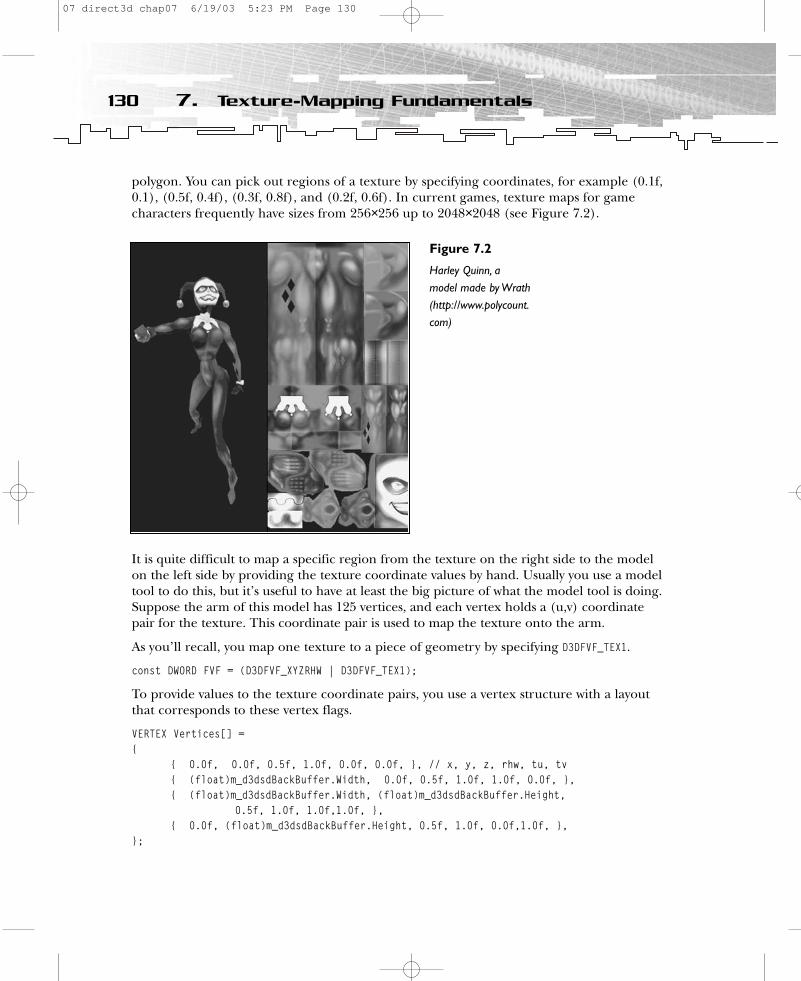
polygon. You can pick out regions of a texture by specifying coordinates, for example (0.1f,0.1), (0.5f, 0.4f), (0.3f, 0.8f), and (0.2f, 0.6f). In current games, texture maps for gamecharacters frequently have sizes from 256×256 up to 2048×2048 (see Figure 7.2).
It is quite difficult to map a specific region from the texture on the right side to the modelon the left side by providing the texture coordinate values by hand. Usually you use a modeltool to do this, but it’s useful to have at least the big picture of what the model tool is doing.Suppose the arm of this model has 125 vertices, and each vertex holds a (u,v) coordinatepair for the texture. This coordinate pair is used to map the texture onto the arm.
As you’ll recall, you map one texture to a piece of geometry by specifying D3DFVF_TEX1.
const DWORD FVF = (D3DFVF_XYZRHW | D3DFVF_TEX1);
To provide values to the texture coordinate pairs, you use a vertex structure with a layoutthat corresponds to these vertex flags.
VERTEX Vertices[] ={
{ 0.0f, 0.0f, 0.5f, 1.0f, 0.0f, 0.0f, }, // x, y, z, rhw, tu, tv{ (float)m_d3dsdBackBuffer.Width, 0.0f, 0.5f, 1.0f, 1.0f, 0.0f, },{ (float)m_d3dsdBackBuffer.Width, (float)m_d3dsdBackBuffer.Height,
0.5f, 1.0f, 1.0f,1.0f, },{ 0.0f, (float)m_d3dsdBackBuffer.Height, 0.5f, 1.0f, 0.0f,1.0f, },
};
130 7. Texture-Mapping Fundamentals
Figure 7.2
Harley Quinn, a model made by Wrath(http://www.polycount.com)
07 direct3d chap07 6/19/03 5:23 PM Page 130

Mapping more than one texture onto the same geometry (in this case, the arm) makessense when you want to achieve special lighting effects, for example. You might use two texture coordinate pairs per vertex with the vertex flag D3DFVF_TEX2.
const DWORD FVF = (D3DFVF_XYZRHW | D3DFVF_TEX2);…VERTEX Vertices[] ={
// x, y, z, rhw, tu, tv, tu2, tv2{ 0.0f, 0.0f, 0.5f, 1.0f, 0.0f, 0.0f, 0.0f, 0.5f,},
…};
You can choose up to eight texture coordinates in this manner (D3DFVF_TEX1 throughD3DFVF_TEX8). The texture coordinate pair is set for a specifc texture with D3DTSS_TEXCOORDINDEX.
m_pd3dDevice->SetTexture( 0, m_pWallTexture); m_pd3dDevice->SetTextureStageState( 0, D3DTSS_TEXCOORDINDEX, 0);…m_pd3dDevice->SetTexture(1, m_pEnvTexture); m_pd3dDevice->SetTextureStageState( 1, D3DTSS_TEXCOORDINDEX, 1 );…
The first texture uses texture coordinate pair #1 of the vertices, and the second texture usestexture coordinate pair #2.
You can also reuse texture coordinate pairs. In the example above, you could set the sametexture coordinate pair to both texture stages.
m_pd3dDevice->SetTexture( 0, m_pWallTexture); m_pd3dDevice->SetTextureStageState( 0, D3DTSS_TEXCOORDINDEX, 0);…m_pd3dDevice->SetTexture(1, m_pEnvTexture); m_pd3dDevice->SetTextureStageState( 1, D3DTSS_TEXCOORDINDEX, 0);…
The second texture stage uses the same texture coordinate pair as the first stage. Therefore,you must only have one texture coordinate pair for each vertex stored in the vertex buffer.This method of reusing texture coordinates reduces the amount of data the Direct3Dengine sends to the graphics card.
Using Texture-AddressingModesChoosing texels of a texture map by setting the texture-coordinate pair of a vertex to avalue between 0.0f and 1.0f is pretty straightforward, but what if you provide texture coordi-nates that lie outside of this range? How values outside the 0.0 to 1.0 range modify the
131Using Texture-Addressing Modes
07 direct3d chap07 6/19/03 5:23 PM Page 131
appearance of the texture depends on the texture-addressing mode you choose. The differ-ent addressing modes are called wrap, mirror, clamp, border color, and mirroronce. Youshould check the capabilities of your graphics card carefully to see which addressing modeis supported. Usually graphics cards support some addressing modes, but not all of them.In the example program that accompanies this chapter, the background texture shows thedifferent texture-addressing modes.
Wrap Texture-Addressing ModeYou might use the wrap texture-addressing mode to repeat the texture on every integerjunction and addressing mode. This is the default mode used by Direct3D. Insert the fol-lowing piece of source into the example application:
VERTEX Vertices[] ={
// x, y, z, rhw, tu, tv{ 0.0f, (float)m_d3dsdBackBuffer.Height, 0.5f, 1.0f, -0.5f, 1.5f, }, { 0.0f, 0.0f, 0.5f, 1.0f, -0.5f, -0.5f, },{ (float)m_d3dsdBackBuffer.Width, (float)m_d3dsdBackBuffer.Height, 0.5f, 1.0f,
1.5f,1.5f, },{ (float)m_d3dsdBackBuffer.Width, 0.0f, 0.5f, 1.0f, 1.5f,-0.5f, },
};
Additionally, you have to switch on the wrap addressing mode using the following codesnippet:
m_pd3dDevice->SetSamplerState( 0, D3DSAMP_ADDRESSU, D3DTADDRESS_WRAP);m_pd3dDevice->SetSamplerState( 0, D3DSAMP_ADDRESSV, D3DTADDRESS_WRAP);
The background texture will be applied three times in the u and v directions, and it shouldlook like Figure 7.3.
If you choose to use the following texture coordinates, the texture will be tiled in anotherway (see Figure 7.4).
VERTEX Vertices[] ={
// x, y, z, rhw, tu, tv{ 0.0f, (float)m_d3dsdBackBuffer.Height, 0.5f, 1.0f, -1.5f, 3.0f, }, { 0.0f, 0.0f, 0.5f, 1.0f, -1.5f, -3.0f, },{ (float)m_d3dsdBackBuffer.Width, (float)m_d3dsdBackBuffer.Height, 0.5f,
1.0f, 1.5f, 3.0f, },{ (float)m_d3dsdBackBuffer.Width, 0.0f, 0.5f, 1.0f, 1.5f, -3.0f, },
};
The upper-left texture starts at -1.5f and is repeated two and a half times to the right andfive times to the bottom.
132 7. Texture-Mapping Fundamentals
07 direct3d chap07 6/19/03 5:23 PM Page 132
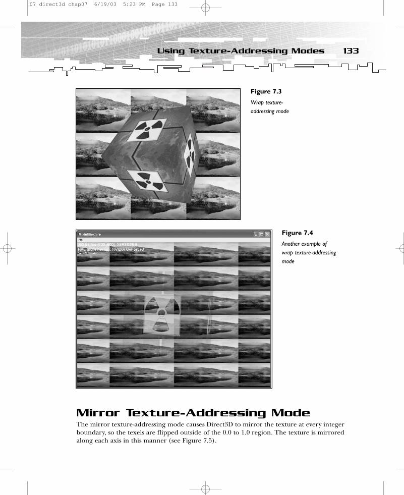
Mirror Texture-Addressing ModeThe mirror texture-addressing mode causes Direct3D to mirror the texture at every integerboundary, so the texels are flipped outside of the 0.0 to 1.0 region. The texture is mirroredalong each axis in this manner (see Figure 7.5).
133Using Texture-Addressing Modes
Figure 7.3
Wrap texture-addressing mode
Figure 7.4
Another example ofwrap texture-addressingmode
07 direct3d chap07 6/19/03 5:23 PM Page 133
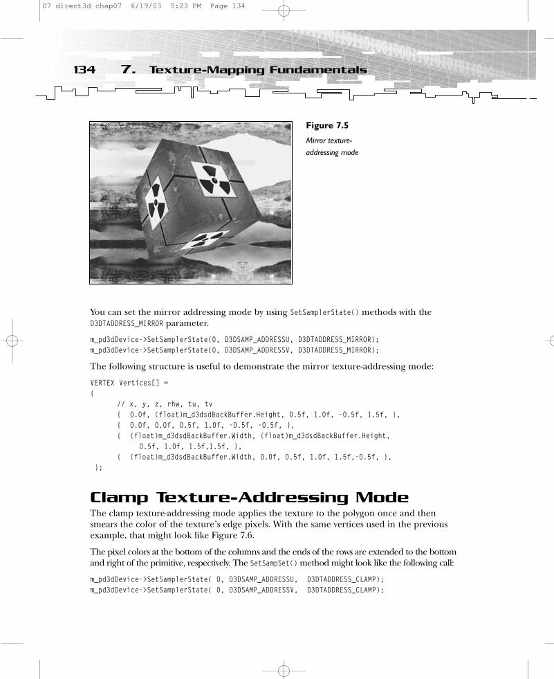
You can set the mirror addressing mode by using SetSamplerState() methods with theD3DTADDRESS_MIRROR parameter.
m_pd3dDevice->SetSamplerState(0, D3DSAMP_ADDRESSU, D3DTADDRESS_MIRROR);m_pd3dDevice->SetSamplerState(0, D3DSAMP_ADDRESSV, D3DTADDRESS_MIRROR);
The following structure is useful to demonstrate the mirror texture-addressing mode:
VERTEX Vertices[] ={
// x, y, z, rhw, tu, tv{ 0.0f, (float)m_d3dsdBackBuffer.Height, 0.5f, 1.0f, -0.5f, 1.5f, }, { 0.0f, 0.0f, 0.5f, 1.0f, -0.5f, -0.5f, },{ (float)m_d3dsdBackBuffer.Width, (float)m_d3dsdBackBuffer.Height,
0.5f, 1.0f, 1.5f,1.5f, },{ (float)m_d3dsdBackBuffer.Width, 0.0f, 0.5f, 1.0f, 1.5f,-0.5f, },
};
Clamp Texture-Addressing ModeThe clamp texture-addressing mode applies the texture to the polygon once and thensmears the color of the texture’s edge pixels. With the same vertices used in the previousexample, that might look like Figure 7.6.
The pixel colors at the bottom of the columns and the ends of the rows are extended to the bottomand right of the primitive, respectively. The SetSampSet() method might look like the following call:
m_pd3dDevice->SetSamplerState( 0, D3DSAMP_ADDRESSU, D3DTADDRESS_CLAMP);m_pd3dDevice->SetSamplerState( 0, D3DSAMP_ADDRESSV, D3DTADDRESS_CLAMP);
134 7. Texture-Mapping Fundamentals
Figure 7.5
Mirror texture-addressing mode
07 direct3d chap07 6/19/03 5:23 PM Page 134
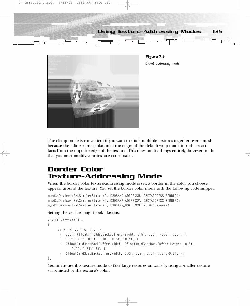
The clamp mode is convenient if you want to stitch multiple textures together over a meshbecause the bilinear interpolation at the edges of the default wrap mode introduces arti-facts from the opposite edge of the texture. This does not fix things entirely, however; to dothat you must modify your texture coordinates.
Border Color Texture-Addressing ModeWhen the border color texture-addressing mode is set, a border in the color you chooseappears around the texture. You set the border color mode with the following code snippet:
m_pd3dDevice->SetSamplerState (0, D3DSAMP_ADDRESSU, D3DTADDRESS_BORDER);m_pd3dDevice->SetSamplerState (0, D3DSAMP_ADDRESSV, D3DTADDRESS_BORDER);m_pd3dDevice->SetSamplerState (0, D3DSAMP_BORDERCOLOR, 0x00aaaaaa);
Setting the vertices might look like this:
VERTEX Vertices[] ={
// x, y, z, rhw, tu, tv{ 0.0f, (float)m_d3dsdBackBuffer.Height, 0.5f, 1.0f, -0.5f, 1.5f, }, { 0.0f, 0.0f, 0.5f, 1.0f, -0.5f, -0.5f, },{ (float)m_d3dsdBackBuffer.Width, (float)m_d3dsdBackBuffer.Height, 0.5f,
1.0f, 1.5f,1.5f, },{ (float)m_d3dsdBackBuffer.Width, 0.0f, 0.5f, 1.0f, 1.5f,-0.5f, },
};
You might use this texture mode to fake large textures on walls by using a smaller texturesurrounded by the texture’s color.
135Using Texture-Addressing Modes
Figure 7.6
Clamp addressing mode
07 direct3d chap07 6/19/03 5:23 PM Page 135
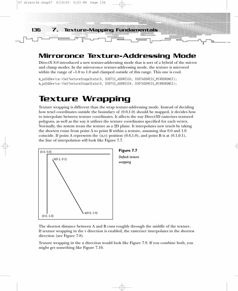
Mirroronce Texture-Addressing ModeDirectX 8.0 introduced a new texture-addressing mode that is sort of a hybrid of the mirrorand clamp modes. In the mirroronce texture-addressing mode, the texture is mirroredwithin the range of –1.0 to 1.0 and clamped outside of this range. This one is cool.
m_pd3dDevice->SetTextureStageState(0, D3DTSS_ADDRESSU, D3DTADDRESS_MIRRORONCE);m_pd3dDevice->SetTextureStageState(0, D3DTSS_ADDRESSV, D3DTADDRESS_MIRRORONCE);
Texture WrappingTexture wrapping is different than the wrap texture-addressing mode. Instead of decidinghow texel coordinates outside the boundary of (0.0,1.0) should be mapped, it decides howto interpolate between texture coordinates. It affects the way Direct3D rasterizes texturedpolygons, as well as the way it utilizes the texture coordinates specified for each vertex.Normally, the system treats the texture as a 2D plane. It interpolates new texels by takingthe shortest route from point A to point B within a texture, assuming that 0.0 and 1.0 coincide. If point A represents the (u,v) position (0.6,1.0), and point B is at (0.1,0.1), the line of interpolation will look like Figure 7.7.
The shortest distance between A and B runs roughly through the middle of the texture. If texture wrapping in the v direction is enabled, the rasterizer interpolates in the shortestdirection (see Figure 7.8).
Texture wrapping in the u direction would look like Figure 7.9. If you combine both, youmight get something like Figure 7.10.
136 7. Texture-Mapping Fundamentals
(0.0, 0.0)
b(0.1, 0.1)
a(0.6, 1.0)(0.0, 1.0)
Figure 7.7
Default texturewrapping
07 direct3d chap07 6/19/03 5:23 PM Page 136
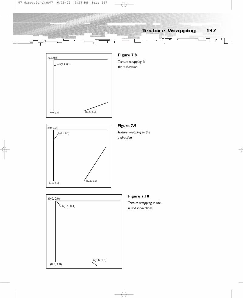
137Texture Wrapping
(0.0, 0.0)
b(0.1, 0.1)
a(0.6, 1.0)(0.0, 1.0)
Figure 7.8
Texture wrapping in the v direction
(0.0, 0.0)
b(0.1, 0.1)
a(0.6, 1.0)(0.0, 1.0)
Figure 7.9
Texture wrapping in theu direction
(0.0, 0.0)
b(0.1, 0.1)
a(0.6, 1.0)(0.0, 1.0)
Figure 7.10
Texture wrapping in theu and v directions
07 direct3d chap07 6/19/03 5:23 PM Page 137

To enable texture wrapping for each stage of the texture pipeline, you must set the renderstate with D3DRS_WRAPx, where x is the desired texture stage (from 0 to 7). To enable the texture-wrapping direction, you include D3DWRAP_U for the u direction and D3DWRAP_V for the v direction.
You can imagine that enabling texture wrapping in one direction causes the system to treata texture as though it were wrapped around a cylinder (see Figure 7.11).
You can see that the shortest route to interpolate the texture is no longer across the middleof the texture. It’s now across the border, where 0.0 and 1.0 exist together. Wrapping in thev direction works for a cylinder that is lying on its side.
Wrapping in both the u and v directions is more complex. In this situation, you can envisionthe texture as a torus or doughnut. You might want to use wrapping in both directions if youmap a texture around a sphere, for example. You can enable it for the first texture stage bycalling:
m_pd3dDevice->SetRenderState( D3DRS_WRAP0, D3DWRAP_U | D3DWRAP_V );
Activating texture wrapping makes texture coordinates outside of the 0.0 and 1.0 rangeinvalid and texture addressing modes unavailable.
Texture Filtering and Anti-AliasingImagine a checkerboard that moves away from the viewer. At some point, the projection of the squares becomes smaller than the pixels on the screen. Naturally, if both black andwhite pixels project to the same pixel, the pixel should appear as some shade of gray. By default a texture mapper will not consider areas, so either black or white pixels will bedrawn, depending on the rounding. This can cause the image to look unnatural and canproduce artifacts.
138 7. Texture-Mapping Fundamentals
(1.0, 0.0)or(0.0 0.0)
b (0.1, 0.1)
a (0.6, 1.0)
Figure 7.11
Texture wrapping in theu direction on a cylinder
07 direct3d chap07 6/19/03 5:23 PM Page 138
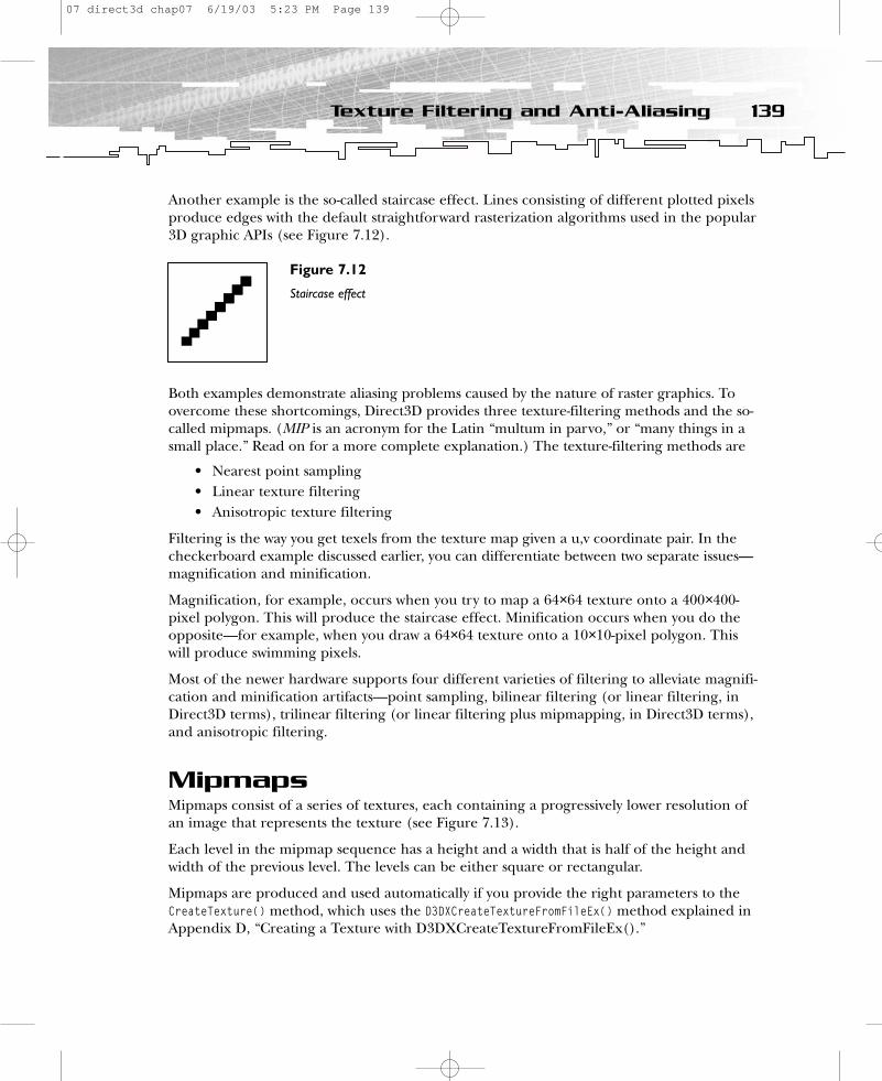
Another example is the so-called staircase effect. Lines consisting of different plotted pixelsproduce edges with the default straightforward rasterization algorithms used in the popular3D graphic APIs (see Figure 7.12).
Both examples demonstrate aliasing problems caused by the nature of raster graphics. Toovercome these shortcomings, Direct3D provides three texture-filtering methods and the so-called mipmaps. (MIP is an acronym for the Latin “multum in parvo,” or “many things in asmall place.” Read on for a more complete explanation.) The texture-filtering methods are
• Nearest point sampling• Linear texture filtering• Anisotropic texture filtering
Filtering is the way you get texels from the texture map given a u,v coordinate pair. In thecheckerboard example discussed earlier, you can differentiate between two separate issues—magnification and minification.
Magnification, for example, occurs when you try to map a 64×64 texture onto a 400×400-pixel polygon. This will produce the staircase effect. Minification occurs when you do theopposite—for example, when you draw a 64×64 texture onto a 10×10-pixel polygon. Thiswill produce swimming pixels.
Most of the newer hardware supports four different varieties of filtering to alleviate magnifi-cation and minification artifacts—point sampling, bilinear filtering (or linear filtering, inDirect3D terms), trilinear filtering (or linear filtering plus mipmapping, in Direct3D terms),and anisotropic filtering.
MipmapsMipmaps consist of a series of textures, each containing a progressively lower resolution ofan image that represents the texture (see Figure 7.13).
Each level in the mipmap sequence has a height and a width that is half of the height andwidth of the previous level. The levels can be either square or rectangular.
Mipmaps are produced and used automatically if you provide the right parameters to theCreateTexture() method, which uses the D3DXCreateTextureFromFileEx() method explained inAppendix D, “Creating a Texture with D3DXCreateTextureFromFileEx().”
139Texture Filtering and Anti-Aliasing
Figure 7.12
Staircase effect
07 direct3d chap07 6/19/03 5:23 PM Page 139
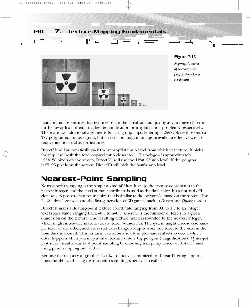
Using mipmaps ensures that textures retain their realism and quality as you move closer orfurther away from them, to alleviate minification or magnification problems, respectively.There are two additional arguments for using mipmaps. Filtering a 256×256 texture onto a2×2 polygon might look great, but it takes too long; mipmaps provide an effective way toreduce memory traffic for textures.
Direct3D will automatically pick the appropriate mip level from which to texture. It picksthe mip level with the texel-to-pixel ratio closest to 1. If a polygon is approximately 128×128 pixels on the screen, Direct3D will use the 128×128 mip level. If the polygon is 95×95 pixels on the screen, Direct3D will pick the 64×64 mip level.
Nearest-Point SamplingNearest-point sampling is the simplest kind of filter. It snaps the texture coordinates to thenearest integer, and the texel at that coordinate is used as the final color. It’s a fast and effi-cient way to process textures in a size that is similar to the polygon’s image on the screen. ThePlayStation 1 console and the first generation of 3D games, such as Descent and Quake, used it.
Direct3D maps a floating-point texture coordinate ranging from 0.0 to 1.0 to an integertexel space value ranging from –0.5 to n–0.5, where n is the number of texels in a givendimension on the texture. The resulting texture index is rounded to the nearest integer,which might introduce inaccuracies at texel boundaries. The system might choose one sam-ple texel or the other, and the result can change abruptly from one texel to the next as theboundary is crossed. This, in turn, can allow visually unpleasant artifacts to occur, whichoften happens when you map a small texture onto a big polygon (magnification). Quake gotpast some visual artifacts of point sampling by choosing a mipmap based on distance andusing point sampling out of that.
Because the majority of graphics hardware today is optimized for linear filtering, applica-tions should avoid using nearest-point sampling whenever possible.
140 7. Texture-Mapping Fundamentals
Figure 7.13
Mipmap (a series of textures withprogressively lowerresolution)
07 direct3d chap07 6/19/03 5:23 PM Page 140
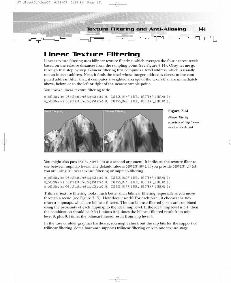
Linear Texture FilteringLinear texture filtering uses bilinear texture filtering, which averages the four nearest texelsbased on the relative distances from the sampling point (see Figure 7.14). Okay, let me gothrough that step by step. Bilinear filtering first computes a texel address, which is usuallynot an integer address. Next, it finds the texel whose integer address is closest to the com-puted address. After that, it computes a weighted average of the texels that are immediatelyabove, below, or to the left or right of the nearest sample point.
You invoke linear texture filtering with:
m_pd3dDevice->SetTextureStageState( 0, D3DTSS_MINFILTER, D3DTEXF_LINEAR );m_pd3dDevice->SetTextureStageState( 0, D3DTSS_MAGFILTER, D3DTEXF_LINEAR );
You might also pass D3DTSS_MIPFILTER as a second argument. It indicates the texture filter touse between mipmap levels. The default value is D3DTEXF_NONE. If you provide D3DTEXF_LINEAR,you are using trilinear texture filtering or mipmap filtering.
m_pd3dDevice->SetTextureStageState( 0, D3DTSS_MAGFILTER, D3DTEXF_LINEAR );m_pd3dDevice->SetTextureStageState( 0, D3DTSS_MINFILTER, D3DTEXF_LINEAR );m_pd3dDevice->SetTextureStageState( 0, D3DTSS_MIPFILTER, D3DTEXF_LINEAR );
Trilinear texture filtering looks much better than bilinear filtering, especially as you movethrough a scene (see Figure 7.15). How does it work? For each pixel, it chooses the twonearest mipmaps, which are bilinear filtered. The two bilinear-filtered pixels are combinedusing the proximity of each mipmap to the ideal mip level. If the ideal mip level is 3.4, thenthe combination should be 0.6 (1 minus 0.4) times the bilinear-filtered result from miplevel 3, plus 0.4 times the bilinear-filtered result from mip level 4.
In the case of older graphics hardware, you might check out the cap bits for the support oftrilinear filtering. Some hardware supports trilinear filtering only in one texture stage.
141Texture Filtering and Anti-Aliasing
Figure 7.14
Bilinear filtering(courtesy of http://www.reactorcritical.com)
07 direct3d chap07 6/19/03 5:23 PM Page 141

Anisotropic FilteringOne of the drawbacks of bilinear and trilinear filtering is that texels are sampled usingsquare sampling areas. If a texture is angled sharply away from you, distortion effects calledanisotropy can occur.
Direct3D measures the anisotropy of a pixel as the elongation—that is, length divided bywidth—of a screen pixel that is inverse-mapped into texture space. Anisotropic filteringsamples more texels when a screen pixel is elongated to reduce the blurriness that the stan-dard linear filtering can produce. The number of texels can be between 16 and 32 from thetexture maps. Using more texels requires an even bigger memory bandwidth and is almostimpossible on traditional rendering systems, unless you use a very expensive memory archi-tecture. Tile-based rendering (used in PowerVR cards) saves a lot of bandwidth and allowsthe implementation of anisotropic filtering.
Anisotropic rendering offers a big visual improvement by giving you better depth detail andan accurate representation of texture maps on polygons that are not parallel to the screen.There are different levels of quality available, depending on the number of pixel samples,or taps. 64-tap anisotropic filtering offers much higher quality than 8-tap anisotropic filter-ing, but it’s also slower. Anisotropic filtering is the latest filtering type to be implemented in3D accelerators. Figure 7.16 shows the visual differences between point sampling, bilinearfiltering, and trilinear filtering.
You can use anisotropic filtering by setting the following SetTextureStageState() methods:
m_pd3dDevice->SetTextureStageState( 0, D3DTSS_MAGFILTER, D3DTEXF_ANISOTROPIC);m_pd3dDevice->SetTextureStageState( 0, D3DTSS_MINFILTER, D3DTEXF_ANISOTROPIC);m_pd3dDevice->SetTextureStageState( 0, D3DTSS_MIPFILTER, D3DTEXF_ANISOTROPIC);m_pd3dDevice->SetTextureStageState( 0, D3DTSS_MAXANISOTROPY, 16);
An ATI Radeon supports a maximum anisotropy level of 16. A GeForce DDR card supports a maximum anisotropy level of 2. You might get the maximum anisotropy level from theDirectX Caps Viewer or by checking the proper flag in the ConfirmDevice() method. You cansee the difference in the sample program by pressing the F5 and F6 keys (see Figure 7.17).
142 7. Texture-Mapping Fundamentals
Figure 7.15
Trilinear/bilinear filtering(courtesy of http://www.reactorcritical.com)
07 direct3d chap07 6/19/03 5:23 PM Page 142
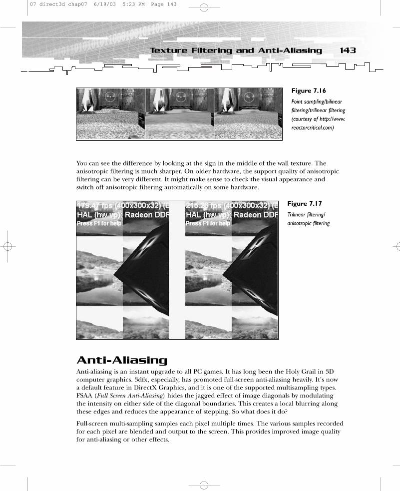
You can see the difference by looking at the sign in the middle of the wall texture. Theanisotropic filtering is much sharper. On older hardware, the support quality of anisotropicfiltering can be very different. It might make sense to check the visual appearance andswitch off anisotropic filtering automatically on some hardware.
Anti-AliasingAnti-aliasing is an instant upgrade to all PC games. It has long been the Holy Grail in 3Dcomputer graphics. 3dfx, especially, has promoted full-screen anti-aliasing heavily. It’s now a default feature in DirectX Graphics, and it is one of the supported multisampling types.FSAA (Full Screen Anti-Aliasing) hides the jagged effect of image diagonals by modulatingthe intensity on either side of the diagonal boundaries. This creates a local blurring alongthese edges and reduces the appearance of stepping. So what does it do?
Full-screen multi-sampling samples each pixel multiple times. The various samples recordedfor each pixel are blended and output to the screen. This provides improved image qualityfor anti-aliasing or other effects.
143Texture Filtering and Anti-Aliasing
Figure 7.16
Point sampling/bilinearfiltering/trilinear filtering(courtesy of http://www.reactorcritical.com)
Figure 7.17
Trilinear filtering/anisotropic filtering
07 direct3d chap07 6/19/03 5:23 PM Page 143
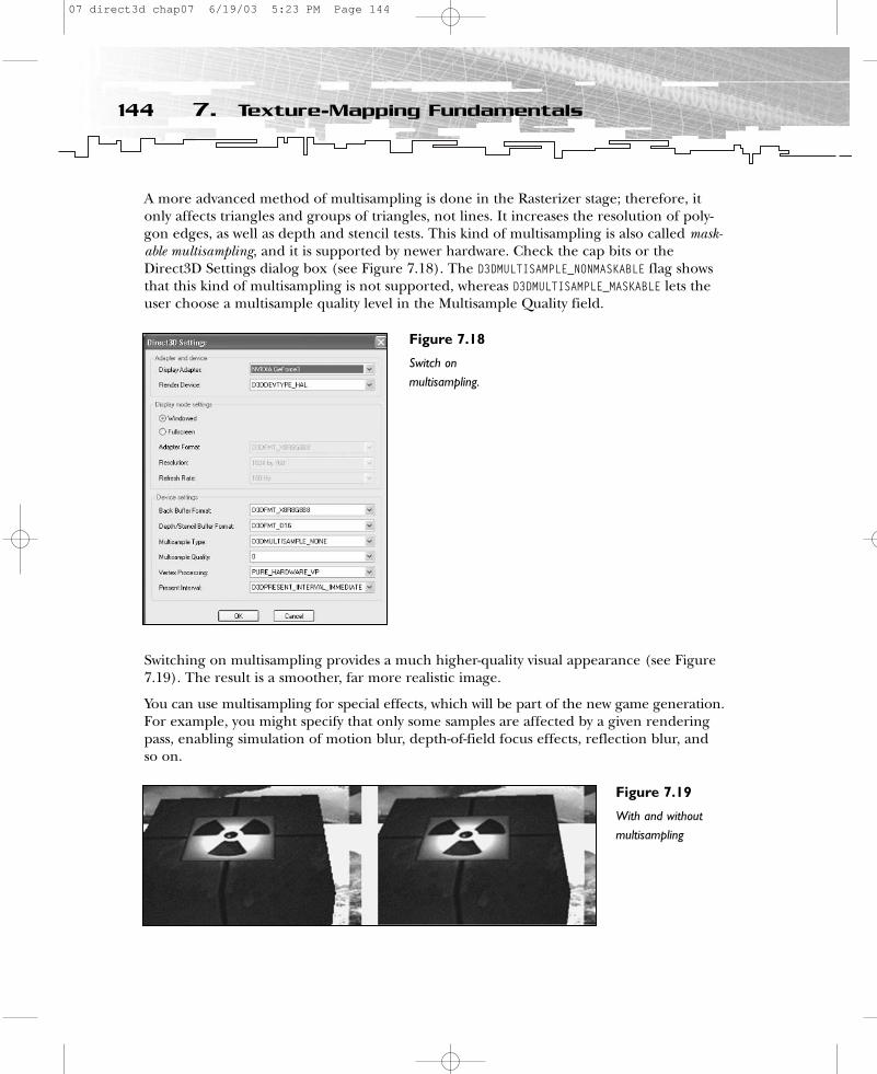
A more advanced method of multisampling is done in the Rasterizer stage; therefore, itonly affects triangles and groups of triangles, not lines. It increases the resolution of poly-gon edges, as well as depth and stencil tests. This kind of multisampling is also called mask-able multisampling, and it is supported by newer hardware. Check the cap bits or theDirect3D Settings dialog box (see Figure 7.18). The D3DMULTISAMPLE_NONMASKABLE flag showsthat this kind of multisampling is not supported, whereas D3DMULTISAMPLE_MASKABLE lets theuser choose a multisample quality level in the Multisample Quality field.
Switching on multisampling provides a much higher-quality visual appearance (see Figure7.19). The result is a smoother, far more realistic image.
You can use multisampling for special effects, which will be part of the new game generation.For example, you might specify that only some samples are affected by a given renderingpass, enabling simulation of motion blur, depth-of-field focus effects, reflection blur, and so on.
144 7. Texture-Mapping Fundamentals
Figure 7.18
Switch onmultisampling.
Figure 7.19
With and withoutmultisampling
07 direct3d chap07 6/19/03 5:23 PM Page 144
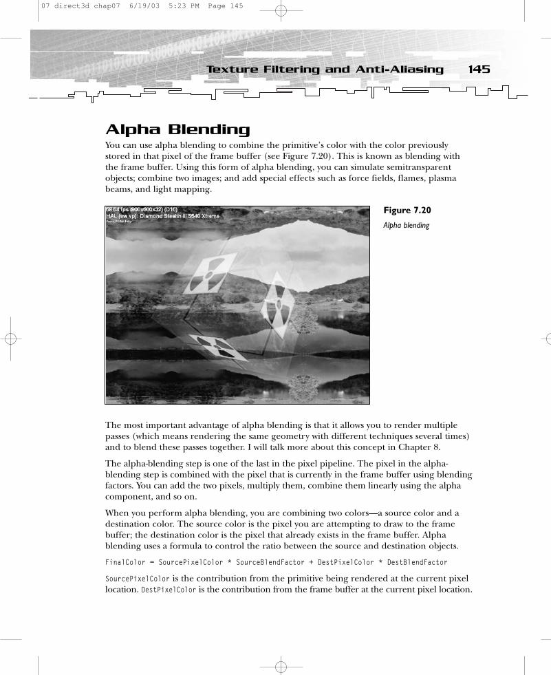
Alpha BlendingYou can use alpha blending to combine the primitive’s color with the color previouslystored in that pixel of the frame buffer (see Figure 7.20). This is known as blending withthe frame buffer. Using this form of alpha blending, you can simulate semitransparentobjects; combine two images; and add special effects such as force fields, flames, plasmabeams, and light mapping.
The most important advantage of alpha blending is that it allows you to render multiplepasses (which means rendering the same geometry with different techniques several times)and to blend these passes together. I will talk more about this concept in Chapter 8.
The alpha-blending step is one of the last in the pixel pipeline. The pixel in the alpha-blending step is combined with the pixel that is currently in the frame buffer using blendingfactors. You can add the two pixels, multiply them, combine them linearly using the alphacomponent, and so on.
When you perform alpha blending, you are combining two colors—a source color and adestination color. The source color is the pixel you are attempting to draw to the framebuffer; the destination color is the pixel that already exists in the frame buffer. Alphablending uses a formula to control the ratio between the source and destination objects.
FinalColor = SourcePixelColor * SourceBlendFactor + DestPixelColor * DestBlendFactor
SourcePixelColor is the contribution from the primitive being rendered at the current pixellocation. DestPixelColor is the contribution from the frame buffer at the current pixel location.
145Texture Filtering and Anti-Aliasing
Figure 7.20
Alpha blending
07 direct3d chap07 6/19/03 5:23 PM Page 145
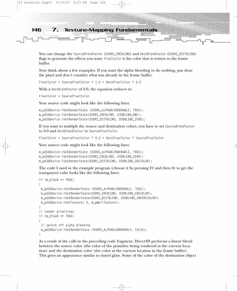
You can change the SourceBlendFactor (D3DRS_SRCBLEND) and DestBlendFactor (D3DRS_DESTBLEND)flags to generate the effects you want. FinalColor is the color that is written to the framebuffer.
Now think about a few examples. If you want the alpha blending to do nothing, just drawthe pixel and don’t consider what was already in the frame buffer.
FinalColor = SourcePixelColor * 1.0 + DestPixelColor * 0.0
With a DestBlendFactor of 0.0, the equation reduces to:
FinalColor = SourcePixelColor
Your source code might look like the following lines:
m_pd3dDevice->SetRenderState (D3DRS_ALPHABLENDENABLE, TRUE);m_pd3dDevice->SetRenderState(D3DRS_SRCBLEND, D3DBLEND_ONE);m_pd3dDevice->SetRenderState(D3DRS_DESTBLEND, D3DBLEND_ZERO);
If you want to multiply the source and destination colors, you have to set SourceBlendFactorto 0.0 and DestBlendFactor to SourcePixelColor.
FinalColor = SourcePixelColor * 0.0 + DestPixelColor * SourcePixelColor
Your source code might look like the following lines:
m_pd3dDevice->SetRenderState (D3DRS_ALPHABLENDENABLE, TRUE);m_pd3dDevice->SetRenderState(D3DRS_SRCBLEND, D3DBLEND_ZERO);m_pd3dDevice->SetRenderState(D3DRS_DESTBLEND, D3DBLEND_SRCCOLOR);
The code I used in the example program (choose it by pressing F1 and then 8) to get thetransparent cube looks like the following lines:
if (m_bTex8 == TRUE){m_pd3dDevice->SetRenderState (D3DRS_ALPHABLENDENABLE, TRUE);m_pd3dDevice->SetRenderState(D3DRS_SRCBLEND, D3DBLEND_SRCCOLOR);m_pd3dDevice->SetRenderState(D3DRS_DESTBLEND, D3DBLEND_INVSRCCOLOR);m_pd3dDevice->SetTexture( 0, m_pWallTexture);
}// render primitivesif (m_bTex8 == TRUE){// switch off alpha blendingm_pd3dDevice->SetRenderState (D3DRS_ALPHABLENDENABLE, FALSE);
}
As a result of the calls in the preceding code fragment, Direct3D performs a linear blendbetween the source color (the color of the primitive being rendered at the current loca-tion) and the destination color (the color at the current location in the frame buffer). This gives an appearance similar to tinted glass. Some of the color of the destination object
146 7. Texture-Mapping Fundamentals
07 direct3d chap07 6/19/03 5:23 PM Page 146

seems to be transmitted through the source object, and the rest of it appears to beabsorbed. The equation looks like the following line:
FinalColor = SourcePixelColor * SourceColor + DestPixelColor * InverseSourceColor
Where InverseSourceColor is
(1 – SourcePixelColorred, 1 – SourcePixelColorgreen, 1 – SourcePixelColorblue, 1 –SourcePixelColoralpha).
There are many alpha-blending factors, which are explained in the DirectX 9.0 SDK docu-mentation. Just search for “blending.”
Alpha blending requires a fair bit of extra math and memory access, so it is worth the effortto turn it on and off by setting ALPHABLENDENABLE to False after the call to Render().
All you have to worry about is whether your graphics hardware supports alpha blending.You can determine this by checking the special caps.
if( (0 == ( pCaps->DestBlendCaps & D3DPBLENDCAPS_INVSRCCOLOR)) &&(0 == ( pCaps->SrcBlendCaps & D3DPBLENDCAPS_SRCCOLOR)) &&
...
D3DPBLENDCAPS_* is the flag to check the capability of the graphics card to support D3DBLEND_*flags. The DestBlendCaps or SrcBlendCaps members of the D3DCAPS8 structure check the capa-bilities of these flags for the D3DRS_DESTBLEND/D3DRS_SRCBLEND parameters.
SummaryThis chapter covered the fundamentals of texture mapping. You learned how texture coor-dinates are used and how they affect the visual appearance with different texture-addressingmodes such as wrap texture-addressing mode and mirror texture-addressing mode. One ofthe most important texture topics is texture filtering. Different filtering methods have different impacts on the visual appearance as well as the application’s performance.Depending on the graphics hardware, you might have to trade texture quality for speed toget suitable performance.
Alpha blending, which was introduced at the end of this chapter, is an efficient way toblend two textures (one as the source texture and one as the destination texture).
So far I have focused only on using one texture. The next chapter will show you how to juggle more than one texture at a time.
147Summary
07 direct3d chap07 6/19/03 5:23 PM Page 147

CHAPTER 8
UsingMultipleTextures
08 direct3d chap08 6/19/03 5:24 PM Page 149
This chapter will cover the color and alpha operations possible with the multitexturingunit. Using the multitexturing unit was the only way to influence the pixel color via
the Direct3D interface until DirectX 8 appeared, with the support of pixel shaders.Nowadays, the legacy multitexturing unit is still used on older graphics hardware which, at the time of this writing, makes up the majority of the games market.
In this chapter, you will learn how to:
• Work with dark mapping• Blend a texture with a material diffuse color• Use a dark map blended with material diffuse color
Multipass RenderingOne of the most interesting features at the time the multitexturing unit was introduced in DirectX 6.0 was the ability to map more than one texture on a polygon at a time. The following lines present this procedure step by step, in pseudocode.
// texture #1m_pd3dDevice->SetTextureStageState( 0, D3DTSS_COLORARG1, D3DTA_TEXTURE ); m_pd3dDevice->SetTextureStageState( 0, D3DTSS_COLOROP, D3DTOP_SELECTARG1);m_pd3dDevice->SetRenderState(D3DRS_ALPHABLENDENABLE, FALSE);m_pd3dDevice->SetTexture( 0, m_pWallTexture); m_pd3dDevice->SetStreamSource( 0, m_pCubeVB, 0, sizeof(CUBEVERTEX) );m_pd3dDevice->SetFVF( FVF_CUBEVERTEX );m_pd3dDevice->SetIndices( m_pCubeIB, 0 );m_pd3dDevice->DrawIndexedPrimitive( D3DPT_TRIANGLELIST, 0, 24, 0, 36/3);// texture #2m_pd3dDevice->SetRenderState(D3DRS_ALPHABLENDENABLE, TRUE);m_pd3dDevice->SetRenderState(D3DRS_SRCBLEND, D3DBLEND_ONE);m_pd3dDevice->SetRenderState(D3DRS_DESTBLEND, D3DBLEND_ONE);m_pd3dDevice->SetTexture(0, m_pDetailTexture); m_pd3dDevice->SetStreamSource( 0, m_pCubeVB, 0, sizeof(CUBEVERTEX) );m_pd3dDevice->SetFVF( FVF_CUBEVERTEX );m_pd3dDevice->SetIndices( m_pCubeIB );m_pd3dDevice->DrawIndexedPrimitive( D3DPT_TRIANGLELIST, 0, 24, 0, 36/3);
This is called multipass rendering, because you use more than one pass to render the textures.In his Course 29 notes at SIGGRAPH ‘98, Brian Hook said that Quake 3 uses 10 passes (see Table 8.1).
150 8. Using Multiple Textures
08 direct3d chap08 6/19/03 5:24 PM Page 150
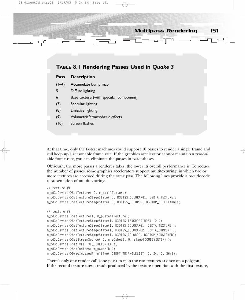
At that time, only the fastest machines could support 10 passes to render a single frame andstill keep up a reasonable frame rate. If the graphics accelerator cannot maintain a reason-able frame rate, you can eliminate the passes in parentheses.
Obviously, the more passes a renderer takes, the lower its overall performance is. To reducethe number of passes, some graphics accelerators support multitexturing, in which two ormore textures are accessed during the same pass. The following lines provide a pseudocoderepresentation of multitexturing.
// texture #1m_pd3dDevice->SetTexture( 0, m_pWallTexture); m_pd3dDevice->SetTextureStageState( 0, D3DTSS_COLORARG1, D3DTA_TEXTURE);m_pd3dDevice->SetTextureStageState( 0, D3DTSS_COLOROP, D3DTOP_SELECTARG1);
// texture #2m_pd3dDevice->SetTexture(1, m_pDetailTexture); m_pd3dDevice->SetTextureStageState(1, D3DTSS_TEXCOORDINDEX, 0 );m_pd3dDevice->SetTextureStageState(1, D3DTSS_COLORARG1, D3DTA_TEXTURE ); m_pd3dDevice->SetTextureStageState(1, D3DTSS_COLORARG2, D3DTA_CURRENT );m_pd3dDevice->SetTextureStageState(1, D3DTSS_COLOROP, D3DTOP_ADDSIGNED);m_pd3dDevice->SetStreamSource( 0, m_pCubeVB, 0, sizeof(CUBEVERTEX) );m_pd3dDevice->SetFVF( FVF_CUBEVERTEX );m_pd3dDevice->SetIndices( m_pCubeIB );m_pd3dDevice->DrawIndexedPrimitive( D3DPT_TRIANGLELIST, 0, 24, 0, 36/3);
There’s only one render call (one pass) to map the two textures at once on a polygon. If the second texture uses a result produced by the texture operation with the first texture,
151Multipass Rendering
TABLE 8.1 Rendering Passes Used in Quake 3
Pass Description
(1–4) Accumulate bump map
5 Diffuse lighting
6 Base texture (with specular component)
(7) Specular lighting
(8) Emissive lighting
(9) Volumetric/atmospheric effects
(10) Screen flashes
08 direct3d chap08 6/19/03 5:24 PM Page 151

it is called texture blending. You can put together the results of up to eight texture passes.This is called a texture-blending cascade (see Figure 8.1).
Before Direct3D 6.0, the pipeline stages determined the texel color and blended it with thecolor of the primitive interpolated from the vertices. Since Direct3D 6.0, you can cascadeup to eight texture operation units to apply multiple textures to a common primitive ineight passes (multipass) or, if the graphics hardware supports it, in a single pass (multitex-turing). The results of each stage are carried over to the next, and the result of the finalstage is rasterized on the polygon.
Most of the current 3D hardware only sup-ports applying two textures at the same timeto a common primitive. Newer hardwarehandles up to 16 texture at once.
Now let’s examine the color operations ofthe SetTextureStageState() method.
152 8. Using Multiple Textures
Texel Color from 1st Texture Diffuse Color
arg1 arg2
op
stage 1
Texel Color from 2nd Texture
arg1 arg2
op
stage 2
Texel Color from 3rd Texture
arg1 arg2
op
stage 3
Final Pixel Color
Figure 8.1
Texture-blendingcascade
CAUTIONOld 3D hardware won’t supportmultitexturing at all; this examplewon’t run on those cards. (You’ll seean informative message box!)
08 direct3d chap08 6/19/03 5:24 PM Page 152

Color OperationsColor operations are set with D3DTSS_COLOROP. An abstract statement using color operationsmight look like the following lines:
m_pd3dDevice->SetTextureStageState( 1, D3DTSS_COLORARG1, arg );m_pd3dDevice->SetTextureStageState( 1, D3DTSS_COLORARG2, arg );m_pd3dDevice->SetTextureStageState( 1, D3DTSS_COLOROP, op);
The ATI RADEON supports the following op parameters, which are located in the D3DTEXTURESTAGESTATETYPE structure.
• D3DTOP_DISABLE
• D3DTOP_SELECTARG1
• D3DTOP_SELECTARG2
• D3DTOP_MODULATE
• D3DTOP_MODULATE2X
• D3DTOP_MODULATE4X
• D3DTOP_ADD
• D3DTOP_ADDSIGNED
• D3DTOP_ADDSIGNED2X
• D3DTOP_SUBTRACT
• D3DTOP_BLENDDIFFUSEALPHA
• D3DTOP_BLENDTEXTUREALPHA
• D3DTOP_BLENDFACTORALPHA
• D3DTOP_BLENDTEXTUREALPHAPM
• D3DTOP_BLENDCURRENTALPHA
• D3DTOP_MODULATEALPHA_ADDCOLOR
• D3DTOP_MODULATEINVALPHA_ADDCOLOR
• D3DTOP_BUMPENVMAP
• D3DTOP_DOTPRODUCT3
• D3DTOP_MULTIPLYADD
• D3DTOP_LERP
Every color operation can accept up to three arguments: D3DTSS_COLORARG0, D3DTSS_COLORARG1,and D3DTSS_COLORARG2. (ATI RADEON supports mapping three textures at once.) You can setthese color arguments to any combination of:
• D3DTA_DIFFUSE. Use the diffuse color interpolated from vertex components duringGouraud shading.
• D3DTA_SPECULAR. Use the specular color interpolated from vertex components duringGouraud shading.
• D3DTA_TFACTOR. Use the texture factor set in a previous call to SetRenderState() withthe D3DRS_TEXTUREFACTOR render-state value.
153Color Operations
08 direct3d chap08 6/19/03 5:24 PM Page 153
• D3DTA_TEXTURE. Use the texture color for this texture stage.• D3DTA_CURRENT. Use the result of the previous blending stage.• D3DTA_TEMP. Use a temporary register color for read or write.
You can bitwise or in one or both of the D3DTA_ALPHAREPLICATE and D3DTA_COMPLEMENT modifierflags to alpha-replicate and/or invert the argument. Read on to examine some real-worldexamples.
Dark MappingMost effects that modify the appearance of a surface are calculated on what’s called a per-vertex basis. This means that the actual calculations are performed for each vertex of atriangle, as opposed to each pixel that gets rendered. Sometimes this technique producesnoticeable artifacts. Think of a large triangle with a light source close to the surface. Aslong as the light is close to one of the triangle’s vertices, you can see the lighting effects onthe triangle. When it moves toward the center of the triangle, the triangle gradually losesthe lighting effect. In the worst case, the light is directly in the middle of the triangle, andyou see a triangle with very little shining on it, instead of a triangle with a bright spot in themiddle. If no light shines on the vertices, the surface properties are not calculated properly.The best way to generate the illusion of pixel-based lighting is to use a texture map of thedesired type of light shining on a dark surface.
Multiplying the colors of two textures is called light mapping. (Sometimes this is also calleddark mapping because it’s often used to darken the texture.) To set a dark map, you mustuse it in the Render() method with the following commands:
// Set texture for the cube m_pd3dDevice->SetTexture( 0, m_pWallTexture); m_pd3dDevice->SetTextureStageState( 0, D3DTSS_TEXCOORDINDEX, 0 );m_pd3dDevice->SetTextureStageState( 0, D3DTSS_COLORARG1, D3DTA_TEXTURE );m_pd3dDevice->SetTextureStageState( 0, D3DTSS_COLOROP, D3DTOP_SELECTARG1 );
// Set the dark mapm_pd3dDevice->SetTexture(1, m_pEnvTexture); m_pd3dDevice->SetTextureStageState( 1, D3DTSS_TEXCOORDINDEX, 0 );m_pd3dDevice->SetTextureStageState( 1, D3DTSS_COLORARG1, D3DTA_TEXTURE );m_pd3dDevice->SetTextureStageState( 1, D3DTSS_COLORARG2, D3DTA_CURRENT );m_pd3dDevice->SetTextureStageState( 1, D3DTSS_COLOROP, D3DTOP_MODULATE );
In more detail:
// first texture operation unit// Associate texture with the first texture stagem_pd3dDevice->SetTexture( 0, m_pWallTexture); // use texture coordinate pair #1m_pd3dDevice->SetTextureStageState( 0, D3DTSS_TEXCOORDINDEX, 0 );// Set the first color argument to the texture associated with this stage
154 8. Using Multiple Textures
08 direct3d chap08 6/19/03 5:24 PM Page 154
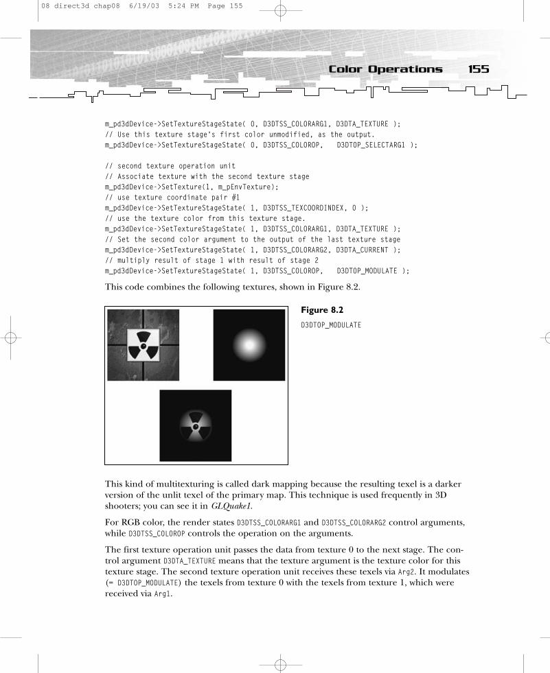
m_pd3dDevice->SetTextureStageState( 0, D3DTSS_COLORARG1, D3DTA_TEXTURE );// Use this texture stage’s first color unmodified, as the output. m_pd3dDevice->SetTextureStageState( 0, D3DTSS_COLOROP, D3DTOP_SELECTARG1 );
// second texture operation unit// Associate texture with the second texture stagem_pd3dDevice->SetTexture(1, m_pEnvTexture); // use texture coordinate pair #1m_pd3dDevice->SetTextureStageState( 1, D3DTSS_TEXCOORDINDEX, 0 );// use the texture color from this texture stage.m_pd3dDevice->SetTextureStageState( 1, D3DTSS_COLORARG1, D3DTA_TEXTURE );// Set the second color argument to the output of the last texture stage m_pd3dDevice->SetTextureStageState( 1, D3DTSS_COLORARG2, D3DTA_CURRENT );// multiply result of stage 1 with result of stage 2m_pd3dDevice->SetTextureStageState( 1, D3DTSS_COLOROP, D3DTOP_MODULATE );
This code combines the following textures, shown in Figure 8.2.
This kind of multitexturing is called dark mapping because the resulting texel is a darkerversion of the unlit texel of the primary map. This technique is used frequently in 3Dshooters; you can see it in GLQuake1.
For RGB color, the render states D3DTSS_COLORARG1 and D3DTSS_COLORARG2 control arguments,while D3DTSS_COLOROP controls the operation on the arguments.
The first texture operation unit passes the data from texture 0 to the next stage. The con-trol argument D3DTA_TEXTURE means that the texture argument is the texture color for thistexture stage. The second texture operation unit receives these texels via Arg2. It modulates(= D3DTOP_MODULATE) the texels from texture 0 with the texels from texture 1, which werereceived via Arg1.
155Color Operations
Figure 8.2
D3DTOP_MODULATE
08 direct3d chap08 6/19/03 5:24 PM Page 155

There are three other modulation operations, as shown in Table 8.2.
The default value for the first texture stage (stage 0) is D3DTOP_MODULATE; for all other stages,the default is D3DTOP_DISABLE.
The SetTexture() method assigns a texture to a given stage for a device. The first parametermust be a number in the range of 0 to 7, inclusive. Pass the texture interface pointer as thesecond parameter. This method increments the reference count of the texture surfacebeing assigned. When the texture is no longer needed, you should set it to NULL at theappropriate stage. If you fail to do this, the surface will not be released, which will result ina memory leak. Since version 6.0, Direct3D is capable of blending up to eight current tex-tures at once.
When your application selects a texture as the current texture, it instructs the Direct3Ddevice to apply the texture to all primitives that are rendered from that time until the cur-rent texture is changed again. If each primitive in a 3D scene has its own texture, you mustset the texture before each primitive is rendered.
The code shown earlier in this chapter showed multitexturing; now take a look at the wholething with multipass rendering.
156 8. Using Multiple Textures
TABLE 8.2 Modulation Operations
Constant Description Short Description
D3DTOP_MODULATE Multiply the components BaseMap * LightMapof the arguments.
D3DTOP_MODULATE2X Multiply the components of BaseMap * LightMap << 1the arguments and shift the products to the left 1 bit(effectively multiplying them by 2) for brightening.
D3DTOP_MODULATE4X Multiply the components of the BaseMap * LightMap << 2arguments and shift the productsto the left 2 bits (effectively multiplying them by 4) forbrightening.
08 direct3d chap08 6/19/03 5:24 PM Page 156
// Set texture for the cube m_pd3dDevice->SetTextureStageState( 0, D3DTSS_COLORARG1, D3DTA_TEXTURE); m_pd3dDevice->SetTextureStageState( 0, D3DTSS_COLOROP, D3DTOP_SELECTARG1); m_pd3dDevice->SetRenderState(D3DRS_ALPHABLENDENABLE, FALSE);m_pd3dDevice->SetTextureStageState( 0, D3DTSS_TEXCOORDINDEX, 0 );m_pd3dDevice->SetTexture( 0, m_pWallTexture); // draw polygon// Set darkmapm_pd3dDevice->SetRenderState(D3DRS_ALPHABLENDENABLE, TRUE);m_pd3dDevice->SetRenderState(D3DRS_SRCBLEND, D3DBLEND_ZERO);m_pd3dDevice->SetRenderState(D3DRS_DESTBLEND, D3DBLEND_SRCCOLOR);m_pd3dDevice->SetTextureStageState( 0, D3DTSS_TEXCOORDINDEX, 0 );m_pd3dDevice->SetTexture(0, m_pEnvTexture); // draw polygon
The alpha-blending formula looks like this:
FinalColor = SourcePixelColor * 0.0 + DestPixelColor * SourcePixelColor
It should mimic the modulate color operation used in the multitexture rendering code.
Animating the Dark MapI created an animated sample with the three modulation types.
// animate darkmap if (i < 40) {
m_pd3dDevice->SetTextureStageState(1, D3DTSS_COLOROP, D3DTOP_MODULATE); } else if (i < 80) {
m_pd3dDevice->SetTextureStageState(1, D3DTSS_COLOROP, D3DTOP_MODULATE2X); } else if (i < 120) {
m_pd3dDevice->SetTextureStageState(1, D3DTSS_COLOROP, D3DTOP_MODULATE4X); } else if (i = 120) {
i = 0; } i++;
This is just a quick hack to show you a simple effect. This effect is not time-based. In thefirst 40 frames SetTextureStage() uses D3DTOP_MODULATE. In the next 40 frames it usesD3DTOP_MODULATE2X, and in the next 40 frames it uses D3DTOP_MODULATE4X. The effect getsbrighter in two steps until 120 frames are shown, and then the whole thing starts again.
157Color Operations
08 direct3d chap08 6/19/03 5:24 PM Page 157

Blending a Texture with Material Diffuse ColorSometimes the sun shines so brightly that the colors on objects get brighter. You can imitatethat effect by blending the texture with the material diffuse color (see Figure 8.3).
How did I get such an effect? A directional light is reflected by a white material. Morereflection means less texture color, so the cube appears white at places where the lightshines directly on its side. You set the material with calls to the following methods:
D3DMATERIAL9 Material;D3DUtil_InitMaterial( Material, 1.0f, 1.0f, 1.0f, 1.0f );m_pd3dDevice->SetMaterial( &Material );
You set a directional light that is located above the cube with SetLight() and LightEnable(0, TRUE).
HRESULT CMyD3DApplication::SetLights(){
if (m_bTex3 == TRUE || m_bTex4 == TRUE){
m_pd3dDevice->SetRenderState(D3DRS_AMBIENT, 0);D3DLIGHT8 light;
D3DUtil_InitLight( light, D3DLIGHT_DIRECTIONAL, 0.0f, -5.0f, -5.0f );
158 8. Using Multiple Textures
Figure 8.3
Light color plus texture color
08 direct3d chap08 6/19/03 5:24 PM Page 158
m_pd3dDevice->SetLight( 0, &light );m_pd3dDevice->LightEnable( 0, TRUE );
}else if (m_bTex7 == TRUE){
m_pd3dDevice->LightEnable( 0, FALSE);// Set the ambient light.m_pd3dDevice->SetRenderState(D3DRS_AMBIENT, 0x00aaffaa);
}return S_OK;
}
The code might look like this:
// Set texture for the cube m_pd3dDevice->SetTexture( 0, m_pWallTexture); m_pd3dDevice->SetTextureStageState( 0, D3DTSS_COLORARG1, D3DTA_TEXTURE );m_pd3dDevice->SetTextureStageState( 0, D3DTSS_COLORARG2, D3DTA_DIFFUSE); m_pd3dDevice->SetTextureStageState( 0, D3DTSS_COLOROP, D3DTOP_ADD);
In more detail:
// Associate texture with the first texture stagem_pd3dDevice->SetTexture( 0, m_pWallTexture); // use the texture color from this texture stage.m_pd3dDevice->SetTextureStageState( 0, D3DTSS_COLORARG1, D3DTA_TEXTURE );// use the diffuse lighting information produced by gouraud shadingm_pd3dDevice->SetTextureStageState( 0, D3DTSS_COLORARG2, D3DTA_DIFFUSE); // add texture color and diffuse colorm_pd3dDevice->SetTextureStageState( 0, D3DTSS_COLOROP, D3DTOP_ADD);
As you can see, this effect only needs one pass, so there’s no multitexture code here. The short description is BaseMap + DiffuseInterpolation.
There are three ways to get a diffuse color in the fixed-function pipeline—from material,diffuse vertex color, or the specular vertex color. (However, there are many more with theprogrammable vertex and pixel shader.) Where the color is taken from depends on theD3DRS_DIFFUSEMATERIALSOURCE parameter in the RenderState() function.
SetRenderState(D3DRS_DIFFUSEMATERIALSOURCE, D3DMCS_MATERIAL);
D3DMCS_MATERIAL selects the color from the current material, D3DMCS_COLOR1 selects the colorfrom the diffuse color variable of the vertex, and D3DMCS_COLOR2 selects the specular colorvariable of the vertex. If you haven’t chosen a color, the default color is opaque white. If you haven’t set a D3DMCS_* parameter, the default color source is the material color.
159Color Operations
08 direct3d chap08 6/19/03 5:24 PM Page 159
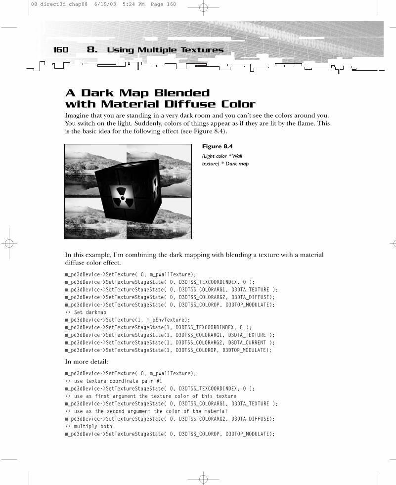
A Dark Map Blended with Material Diffuse ColorImagine that you are standing in a very dark room and you can’t see the colors around you.You switch on the light. Suddenly, colors of things appear as if they are lit by the flame. Thisis the basic idea for the following effect (see Figure 8.4).
In this example, I’m combining the dark mapping with blending a texture with a materialdiffuse color effect.
m_pd3dDevice->SetTexture( 0, m_pWallTexture);m_pd3dDevice->SetTextureStageState( 0, D3DTSS_TEXCOORDINDEX, 0 );m_pd3dDevice->SetTextureStageState( 0, D3DTSS_COLORARG1, D3DTA_TEXTURE );m_pd3dDevice->SetTextureStageState( 0, D3DTSS_COLORARG2, D3DTA_DIFFUSE);m_pd3dDevice->SetTextureStageState( 0, D3DTSS_COLOROP, D3DTOP_MODULATE); // Set darkmap m_pd3dDevice->SetTexture(1, m_pEnvTexture); m_pd3dDevice->SetTextureStageState(1, D3DTSS_TEXCOORDINDEX, 0 );m_pd3dDevice->SetTextureStageState(1, D3DTSS_COLORARG1, D3DTA_TEXTURE );m_pd3dDevice->SetTextureStageState(1, D3DTSS_COLORARG2, D3DTA_CURRENT );m_pd3dDevice->SetTextureStageState(1, D3DTSS_COLOROP, D3DTOP_MODULATE);
In more detail:
m_pd3dDevice->SetTexture( 0, m_pWallTexture);// use texture coordinate pair #1m_pd3dDevice->SetTextureStageState( 0, D3DTSS_TEXCOORDINDEX, 0 );// use as first argument the texture color of this texturem_pd3dDevice->SetTextureStageState( 0, D3DTSS_COLORARG1, D3DTA_TEXTURE );// use as the second argument the color of the materialm_pd3dDevice->SetTextureStageState( 0, D3DTSS_COLORARG2, D3DTA_DIFFUSE);// multiply bothm_pd3dDevice->SetTextureStageState( 0, D3DTSS_COLOROP, D3DTOP_MODULATE);
160 8. Using Multiple Textures
Figure 8.4
(Light color * Walltexture) * Dark map
08 direct3d chap08 6/19/03 5:24 PM Page 160
If there’s no light, the texture color will be multiplied by 0 so the wall texture is not visible.In this case, only the second texture is visible.
// Set darkmap m_pd3dDevice->SetTexture(1, m_pEnvTexture); m_pd3dDevice->SetTextureStageState(1, D3DTSS_TEXCOORDINDEX, 0 );// use the texture color of this stagem_pd3dDevice->SetTextureStageState(1, D3DTSS_COLORARG1, D3DTA_TEXTURE );// use the result of the previous texture stage = tex color X light colorm_pd3dDevice->SetTextureStageState(1, D3DTSS_COLORARG2, D3DTA_CURRENT );// multiply the result of the previus texture with the color of this texturem_pd3dDevice->SetTextureStageState(1, D3DTSS_COLOROP, D3DTOP_MODULATE);
If the first texture is invisible, the multiplication of the 0 value of the first stage with thecolor of the second stage will also result in black. The first texture color fades to black when no light shines on that side of the cube. This might be useful in really dark placeswhere you are not able to see the colors of things because of weak light. You can shortenthe description of this process to (Base Map * Light Color) * Dark Map.
The multipass-rendering version might look like this:
// Set texture for the cube m_pd3dDevice->SetTextureStageState( 0, D3DTSS_COLORARG1, D3DTA_TEXTURE );m_pd3dDevice->SetTextureStageState( 0, D3DTSS_COLORARG2, D3DTA_DIFFUSE);m_pd3dDevice->SetTextureStageState( 0, D3DTSS_COLOROP, D3DTOP_MODULATE); m_pd3dDevice->SetRenderState(D3DRS_ALPHABLENDENABLE, FALSE);m_pd3dDevice->SetTexture( 0, m_pWallTexture);// draw polygon// Set darkmapm_pd3dDevice->SetRenderState(D3DRS_ALPHABLENDENABLE, TRUE);m_pd3dDevice->SetRenderState(D3DRS_SRCBLEND, D3DBLEND_ZERO);m_pd3dDevice->SetRenderState(D3DRS_DESTBLEND, D3DBLEND_SRCCOLOR);m_pd3dDevice->SetTexture(0, m_pEnvTexture); // draw polygon
The alpha-blending part of the process is the same as I used in the dark mapping example.
Glow MappingGlow mapping is the opposite of dark mapping. It’s useful for creating objects that haveglowing parts independent from the base map, such as LEDs, buttons, and lights in build-ings or on spaceships (see Figure 8.5).
The glow map should have no effect on the base map except on the glowing area, so youhave to add the glow effect and not modulate it.
m_pd3dDevice->SetTexture( 0, m_pWallTexture); m_pd3dDevice->SetTextureStageState( 0, D3DTSS_TEXCOORDINDEX, 0 );
161Color Operations
08 direct3d chap08 6/19/03 5:24 PM Page 161
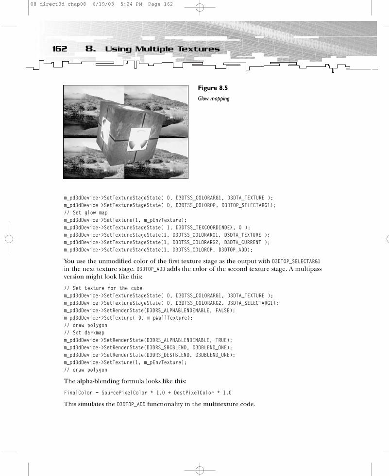
m_pd3dDevice->SetTextureStageState( 0, D3DTSS_COLORARG1, D3DTA_TEXTURE ); m_pd3dDevice->SetTextureStageState( 0, D3DTSS_COLOROP, D3DTOP_SELECTARG1);// Set glow map m_pd3dDevice->SetTexture(1, m_pEnvTexture); m_pd3dDevice->SetTextureStageState( 1, D3DTSS_TEXCOORDINDEX, 0 );m_pd3dDevice->SetTextureStageState(1, D3DTSS_COLORARG1, D3DTA_TEXTURE ); m_pd3dDevice->SetTextureStageState(1, D3DTSS_COLORARG2, D3DTA_CURRENT );m_pd3dDevice->SetTextureStageState(1, D3DTSS_COLOROP, D3DTOP_ADD);
You use the unmodified color of the first texture stage as the output with D3DTOP_SELECTARG1in the next texture stage. D3DTOP_ADD adds the color of the second texture stage. A multipassversion might look like this:
// Set texture for the cube m_pd3dDevice->SetTextureStageState( 0, D3DTSS_COLORARG1, D3DTA_TEXTURE );m_pd3dDevice->SetTextureStageState( 0, D3DTSS_COLORARG2, D3DTA_SELECTARG1);m_pd3dDevice->SetRenderState(D3DRS_ALPHABLENDENABLE, FALSE);m_pd3dDevice->SetTexture( 0, m_pWallTexture); // draw polygon// Set darkmapm_pd3dDevice->SetRenderState(D3DRS_ALPHABLENDENABLE, TRUE);m_pd3dDevice->SetRenderState(D3DRS_SRCBLEND, D3DBLEND_ONE);m_pd3dDevice->SetRenderState(D3DRS_DESTBLEND, D3DBLEND_ONE);m_pd3dDevice->SetTexture(1, m_pEnvTexture); // draw polygon
The alpha-blending formula looks like this:
FinalColor = SourcePixelColor * 1.0 + DestPixelColor * 1.0
This simulates the D3DTOP_ADD functionality in the multitexture code.
162 8. Using Multiple Textures
Figure 8.5
Glow mapping
08 direct3d chap08 6/19/03 5:24 PM Page 162
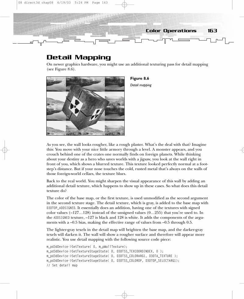
Detail MappingOn newer graphics hardware, you might use an additional texturing pass for detail mapping(see Figure 8.6).
As you see, the wall looks rougher, like a rough plaster. What’s the deal with that? Imaginethis: You move with your nice little armory through a level. A monster appears, and youcrouch behind one of the crates one normally finds on foreign planets. While thinkingabout your destiny as a hero who saves worlds with a jigsaw, you look at the wall right infront of you, which shows a blurred texture. This texture looked perfectly normal at a foot-step’s distance. But if your nose touches the cold, rusted metal that’s always on the walls ofthose foreign-world cellars, the texture blurs.
Back to the real world. You might sharpen the visual appearance of this wall by adding anadditional detail texture, which happens to show up in these cases. So what does this detailtexture do?
The color of the base map, or the first texture, is used unmodified as the second argumentin the second texture stage. The detail texture, which is gray, is added to the base map withD3DTOP_ADDSIGNED. It essentially does an addition, having one of the textures with signedcolor values (–127…128) instead of the unsigned values (0…255) that you’re used to. Inthe ADDSIGNED texture, –127 is black and 128 is white. It adds the components of the argu-ments with a –0.5 bias, making the effective range of values from –0.5 through 0.5.
The lighter-gray texels in the detail map will brighten the base map, and the darker-graytexels will darken it. The wall will show a rougher surface and therefore will appear morerealistic. You use detail mapping with the following source code piece:
m_pd3dDevice->SetTexture( 0, m_pWallTexture); m_pd3dDevice->SetTextureStageState( 0, D3DTSS_TEXCOORDINDEX, 0 );m_pd3dDevice->SetTextureStageState( 0, D3DTSS_COLORARG1, D3DTA_TEXTURE ); m_pd3dDevice->SetTextureStageState( 0, D3DTSS_COLOROP, D3DTOP_SELECTARG1);// Set detail map
163Color Operations
Figure 8.6
Detail mapping
08 direct3d chap08 6/19/03 5:24 PM Page 163
m_pd3dDevice->SetTexture(1, m_pDetailTexture); m_pd3dDevice->SetTextureStageState(1, D3DTSS_TEXCOORDINDEX, 0 );m_pd3dDevice->SetTextureStageState(1, D3DTSS_COLORARG1, D3DTA_TEXTURE ); m_pd3dDevice->SetTextureStageState(1, D3DTSS_COLORARG2, D3DTA_CURRENT );m_pd3dDevice->SetTextureStageState(1, D3DTSS_COLOROP, D3DTOP_ADDSIGNED);
Doing the same thing with multipass rendering looks like this:
m_pd3dDevice->SetTextureStageState( 0, D3DTSS_COLORARG1, D3DTA_TEXTURE ); m_pd3dDevice->SetTextureStageState( 0, D3DTSS_COLOROP, D3DTOP_SELECTARG1);m_pd3dDevice->SetRenderState(D3DRS_ALPHABLENDENABLE, FALSE);m_pd3dDevice->SetTexture( 0, m_pWallTexture); // draw polygon// Set darkmapm_pd3dDevice->SetRenderState(D3DRENDERSTATE_ALPHABLENDENABLE, TRUE);m_pd3dDevice->SetRenderState(D3DRENDERSTATE_SRCBLEND, D3DBLEND_DESTCOLOR);m_pd3dDevice->SetRenderState(D3DRENDERSTATE_DESTBLEND, D3DBLEND_ SRCCOLOR);m_pd3dDevice->SetTexture(1, m_pDetailTexture); // draw polygon
The alpha-blending formula should look like this:
FinalColor = SourcePixelColor * DestPixelColor + DestPixelColor * SourcePixelColor
D3DTOP_ADDSIGNED is not supported on older graphics hardware. MODULATE2X might be areplacement for this blending mode. A suitable formula for MODULATE2X might look like this:
FinalColor = 2 * Arg1 * Arg2FinalColor = Arg1 * Arg2 + Arg2 * Arg1FinalColor = SourcePixelColor * DestPixelColor + DestPixelColor * SourcePixelColor
Don’t forget to switch on and off alpha blending because it is quite expensive computation-ally on older hardware.
Table 8.3 provides a few constants/settings for the color operations that I have not coveredin the source code.
The texture stage operation results in the linear blending of both color operations with the:
• Iterated diffuse alpha• Current iterated texture alpha• Scalar alpha (set with D3DRS_TFACTOR)• Pre-multiplied texture alpha• Alpha that resulted from the previous stage
ATI uses the D3DTOP_BLENDCURRENTALPHA and the D3DTOP_BLENDFACTORALPHA parameters in its oldRADEON 1.3 SDK to show the effect of frosted glass. I haven’t found any real-world examplesfor the other parameters.
164 8. Using Multiple Textures
08 direct3d chap08 6/19/03 5:24 PM Page 164

D3DTOP_MODULATEALPHA_ADDCOLOR modulates the color of the second argument using the alphaof the first argument. Then it adds the result to argument 1.
Result = Arg1RGB + Arg1Alpha * Arg2RGB
D3DTOP_MODULATEINVALPHA_ADDCOLOR uses the inversed alpha to produce a result.
Result = Arg1RGB + (1 - Arg1Alpha)* Arg2RGB
The following two parameters work only with cards with multitexture support for three texture stages. Therefore, they are called triadic texture-blending members.
165Color Operations
TABLE 8.3 Constants and Settings for Additional Color Operations
Constant Description Formula
D3DTOP_BLENDDIFFUSEALPHA Linearly blends this SRGBA = Arg1 * (Alpha) + texture stage using Arg2 * (1 – Alpha)the interpolated alphafrom each vertex.
D3DTOP_BLENDTEXTUREALPHA Linearly blends this SRGBA = Arg1 * (Alpha) +texture stage using the Arg2 * (1 – Alpha)alpha from this stage’s texture.
D3DTOP_BLENDFACTORALPHA Linearly blends this SRGBA = Arg1 * (Alpha) + texture stage using a Arg2 * (1 – Alpha)scalar alpha set with the D3DRS_TEXTUREFACTOR
render state.
D3DTOP_BLENDTEXTUREALPHAPM Linearly blends a SRGBA = Arg1 +texture stage that uses Arg2 * (1 – Alpha)a pre-multiplied alpha.
D3DTOP_BLENDCURRENTALPHA Linearly blends this SRGBA = Arg1 * (Alpha) +texture stage using the Arg2 * (1 – Alpha)alpha taken from the previous texture stage.
08 direct3d chap08 6/19/03 5:24 PM Page 165
D3DTOP_MULTIPLYADD performs a multiply-accumulate operation. It takes the last two arguments,multiplies them, adds them to the remaining input/source argument, and places that intothe result.
Result = Arg1 + Arg2 * Arg3
D3DTOP_LERP linearly interpolates between the second and third source arguments by a pro-portion specified in the first source argument.
Result = (Arg1) * Arg2 + (1-Arg1) * Arg3
Now on to the alpha operations.
Alpha OperationsAs with the color operations, I’ll concentrate on the alpha operations most cards support.An abstract statement using color operations might look like this:
m_pd3dDevice->SetTextureStageState( 1, D3DTSS_ALPHAARG1, arg );m_pd3dDevice->SetTextureStageState( 1, D3DTSS_ALPHAARG2, arg );m_pd3dDevice->SetTextureStageState( 1, D3DTSS_ALPHAOP, op);
The op parameter might be
• D3DTOP_DISABLE
• D3DTOP_SELECTARG1
• D3DTOP_SELECTARG2
• D3DTOP_MODULATE
• D3DTOP_MODULATE2X
• D3DTOP_MODULATE4X
• D3DTOP_ADD
• D3DTOP_ADDSIGNED
• D3DTOP_ADDSIGNED2X
• D3DTOP_SUBTRACT
• D3DTOP_MULTIPLYADD
• D3DTOP_LERP
I explained all of these parameters in the previous section on color operations. The alphaoperations follow the same idea, so it is easy to adopt the same techniques and put them touse here.
Every alpha operation might get up to three arguments (arg)—D3DTSS_ALPHAARG0,D3DTSS_ALPHAARG1, and D3DTSS_ALPHAARG2. You can set these alpha arguments to any combination of:
• D3DTA_DIFFUSE. Use the diffuse color interpolated from vertex components duringGouraud shading.
166 8. Using Multiple Textures
08 direct3d chap08 6/19/03 5:24 PM Page 166

• D3DTA_SPECULAR. Use the specular color interpolated from vertex components duringGouraud shading.
• D3DTA_TFACTOR. Use the texture factor set in a previous call to SetRenderState() withthe D3DRS_TEXTUREFACTOR render-state value.
• D3DTA_TEXTURE. Use the texture color for this texture stage.• D3DTA_CURRENT. Use the result of the previous blending stage.• D3DTA_TEMP. Use a temporary register color for read or write.
You can bitwise or in the D3DTA_COMPLEMENT modifier flag to invert the argument. You knowall of these arguments from the color operations section.
As Direct3D renders a scene, it can integrate color information from several sources—thevertex color, the current material, the texture map, and the color previously written to therender target. It can blend several of these colors. You can use a factor called alpha, whichcan be stored in vertices, materials, and texture maps, to indicate how blending should beweighted. An alpha value of 0 means full transparency; an alpha value of 1 means somelevel of semitransparency.
If you want to fetch alpha from a texture, use D3DTA_TEXTURE as arg. If you want to use analpha that comes from the color component within a vertex (and interpolated across thepolygon), use D3DTA_DIFFUSE as alphaarg and ensure that D3DRS_DIFFUSEMATERIALSOURCE =D3DMCS_COLOR1 (the default value). If you want to use an alpha that comes from the materialcolor, use D3DTA_DIFFUSE as alphaarg and ensure that D3DRS_DIFFUSEMATERIALSOURCE =D3DMCS_MATERIAL is set.
m_pd3dDevice->SetRenderState(D3DRS_DIFFUSEMATERIALSOURCE , D3DMCS_MATERIAL);
If you haven’t set a D3DMCS_x parameter with RenderState(), the material diffuse color is takenas the default. That’s the case in the following example of alpha modulation.
Alpha ModulationYou can simulate the view of a night-sight by modulating a green ambient light with thematerial alpha (see Figure 8.7).
167Alpha Operations
Figure 8.7
Alpha modulation
08 direct3d chap08 6/19/03 5:24 PM Page 167
// Set the ambient light.D3DCOLOR d3dclrAmbientLightColor = D3DRGBA(0.0f,1.0f,0.0f,1.0f);m_pd3dDevice->SetRenderState(D3DRENDERSTATE_AMBIENT, d3dclrAmbientLightColor);
To modulate the ambient color with the texture, you can use the following code:
m_pd3dDevice->SetTexture( 0, D3DTextr_GetSurface(“wall.bmp”));m_pd3dDevice->SetTextureStageState( 0, D3DTSS_COLORARG1, D3DTA_TEXTURE );m_pd3dDevice->SetTextureStageState( 0, D3DTSS_COLORARG2, D3DTA_DIFFUSE );m_pd3dDevice->SetTextureStageState( 0, D3DTSS_COLOROP, D3DTOP_MODULATE );
m_pd3dDevice->SetTextureStageState( 0, D3DTSS_ALPHAARG1, D3DTA_TEXTURE );m_pd3dDevice->SetTextureStageState( 0, D3DTSS_ALPHAARG2, D3DTA_DIFFUSE );m_pd3dDevice->SetTextureStageState( 0, D3DTSS_ALPHAOP, D3DTOP_MODULATE );
SetTexture() associates the texture map with the first stage. The first SetTextureStageState()sets the first color argument to the texture associated with this stage. The second sets thesecond color argument to diffuse lighting information. The color of the base map and the diffuse color are multiplied. The alpha-blending code takes the alpha value from thetexture and multiplies it by the diffuse color. A short description of this process would beBaseMap ∞ DiffuseInterpolation ∞ Alpha ∞ DiffuseInterpolation.
Multitexturing SupportIf a program uses multiple textures at once, you have to check the multitexturing supportof your 3D hardware in ConfirmDevice().
if( pCaps->MaxSimultaneousTextures < 2 )return E_FAIL;
This code checks the maximum number of supported simultaneous texture-blendingstages. It must be higher than 1. If you want to be sure that your multitexturing game issupported on specific hardware, you should check the different texturing possibilities of theuser’s hardware. The sample program provided for this part of the book checks the follow-ing graphic card capabilities.
if( (0 == ( pCaps->DestBlendCaps & D3DPBLENDCAPS_INVSRCCOLOR)) && // alpha blending(0 == ( pCaps->SrcBlendCaps & D3DPBLENDCAPS_SRCCOLOR)) &&(0 == ( pCaps->TextureOpCaps & D3DTEXOPCAPS_ADDSIGNED )) && // texture blending(0 == ( pCaps->TextureOpCaps & D3DTEXOPCAPS_MODULATE )) &&(0 == ( pCaps->TextureOpCaps & D3DTEXOPCAPS_MODULATE2X)) &&(0 == ( pCaps->TextureOpCaps & D3DTEXOPCAPS_MODULATE4X)) &&(0 == ( pCaps->TextureOpCaps & D3DTEXOPCAPS_ADD )) &&(0 == ( pCaps->TextureAddressCaps & D3DPTADDRESSCAPS_CLAMP)) && // texture addressing(0 == ( pCaps->TextureAddressCaps & D3DPTADDRESSCAPS_BORDER )) &&(0 == ( pCaps->TextureAddressCaps & D3DPTADDRESSCAPS_MIRRORONCE)))
return E_FAIL;
168 8. Using Multiple Textures
08 direct3d chap08 6/19/03 5:24 PM Page 168
The first two lines of this code check the support of the alpha-blending parameters thatwere used in the example program. The remaining lines check the hardware support of allother color operations used by the example program.
Texture ManagementIf you only have 64 MB of video texture memory in your graphics hardware, you shouldthink about which textures should be loaded or held in memory. Better yet, you can havean algorithm let your computer think about it. So what’s the task? You need to track theamount of available texture memory and get an overview of the textures that are neededmore often or less often. At the very least, a texture management algorithm has to decidewhich existing texture resources can be reloaded with another texture image and which surfaces should be destroyed and replaced with new texture resources.
Direct3D has an automatic texture-management system. As you learned earlier, you requestits support when you create a texture with CreateTexture() and specify the D3DPOOL_MANAGEDflag for the Pool parameter. You cannot use the D3DPOOL_DEFAULT or D3DPOOL_SYSTEMMEM flagswhen you create a managed texture.
The texture manager tracks textures with a timestamp that identifies when the texture waslast used. It uses the least recently used algorithm to determine which textures should beremoved. Texture priorities are used as tiebreakers when two textures are targeted forremoval from memory. If they have the same priority, the least recently used texture isremoved. If they have the same timestamp, the lower-priority texture is removed first.
You can assign a priority to managed textures by calling the IDirect3DResource8::SetPriority()method for the texture surface. Stay with D3DPOOL_MANAGED until you know more.
Additional ResourcesYou can find one of the best articles on multitexturing with DirectX from Mitchell, Tatro, andBullard at Gamasutra, at http://www.gamasutra.com/features/programming/19981009/multitexturing_01.htm. They have developed a tool to visualize the texture operations…try it. You might find another tool to visualize these operations from NVIDIA, athttp://www.nvidia.com. An interesting article is “Multipass Rendering and the Magic of Alpha Rendering” by Brian Hook in Game Developer magazine, August 1997, page 12. I’ve also found the older examples from ATI at http://www.ati.com very interesting.
Check out the following Web pages for an explanation of anisotropic filtering:
• http://whatis.techtarget.com/definition/0,,sid9_gci870037,00.html• http://www.ping.be/powervr/Anisotropic.htm
169Additional Resources
08 direct3d chap08 6/19/03 5:24 PM Page 169

SummaryThis chapter covered the usage of the multitexturing unit by showing you how to programthe most common effects. Because the support of the multitexturing unit in common hard-ware is inconsistent, it is worth checking the capability bits very carefully.
The market share of DirectX 7 graphic cards will decrease over the next couple of years. If your game does not depend on DirectX 7 graphics hardware, the more flexible pixelshader would be a better way to program these effects.
Part Two QuizQ: Why should you use textures?
A: To simulate a rough or irregular surface or to create the illusion that the object consistsof more polygons.
Q: How does the addressing scheme of Direct3D work?
A: It uses a normalized addressing scheme in which texture addresses consist of texel coordinates that map to the range of 0.0 to 1.0.
Q: Can you use more than one texture coordinate pair per texture?
A: Yes, you can use up to eight texture coordinate pairs for one texture by declaring themin your vertex definition and defining them in your vertex structure.
Q: What do the so-called texture-addressing modes do?
A: You can generate special effects by using texture addresses outside of the 0.0 to 1.0range and by using another texture-addressing mode.
Q: What are the names of the default texture-addressing mode and the other modes?
A: Wrap, mirror, clamp, border, and mirroronce.
Q: What is the purpose of the mirror texture-address mode?
A: It mirrors the texture at every integer boundary so that the texels are flipped outside ofthe 0.0 to 1.0 range.
Q: What is the purpose of the clamp texture-address mode? Why is it useful?
A: It smears the color of the edge pixels to the borders of the window. Bilinear interpolationat the edges sometimes produces artifacts with the wrap mode.
Q: What is the purpose of the border-color address mode? What is its drawback?
A: It sets a border around the texture with the color you’ve chosen so you can fake largertextures on walls, for example. The drawback is that it’s not supported on older hardware.
170 8. Using Multiple Textures
08 direct3d chap08 6/19/03 5:24 PM Page 170
Q: What is the purpose of the newly introduced mirroronce texture-address mode?
A: It mirrors within the range of –1.0 to 1.0; outside of this range, it is clamped. It’s usefulfor volumetric light maps.
Q: What is texture wrapping and why is it useful?
A: It gives the programmer the option to decide how to interpolate between the texturecoordinates. To use a simple example: It’s not always useful to interpolate a texture that iswrapped around a cylinder in the shortest way; it is often more useful to cross the bound-aries of the texture.
Q: What prevents texture wrapping?
A: Texture-addressing modes, because they make texture coordinates outside of the 0.0 to1.0 range invalid.
Q: What are texture filtering and texture anti-aliasing?
A: These are methods to decrease the drawbacks of using raster graphics. They preventstaircase, magnification, and minification problems.
Q: What are mipmaps?
A: These are a series of textures in which every mipmap sequence has a height and widththat is half of the height and width of the previous level. Direct3D will automatically pickthe appropriate mip level from which to texture depending on the width and height of thetextured polygon it has to draw.
Q: What is linear texture filtering?
A: It averages the four nearest texels based on the relative distance from the sampling point.
Q: What is trilinear filtering?
A: It’s bilinear filtering plus mipmaps.
Q: What is anisotropic filtering? What is its purpose?
A: It averages not only the four nearest texels, but also much more, depending on the support of your graphics card and the quality you choose. It also uses mipmaps. It gives youmore depth of detail and a more accurate representation of the texture.
Q: How does full-scene anti-aliasing work?
A: It samples each pixel multiple times. The various samples are blended and output to thescreen. This enables a few interesting special effects, such as motion blur, depth of field,reflection blur, and so on.
Q: What is the formula for alpha blending?
A: FinalColor = SourcePixelColor * SourceBlendFactor + DestPixelColor *DestBlendFactor
171Part Two Quiz
08 direct3d chap08 6/19/03 5:24 PM Page 171

Q: How does alpha blending work?
A: It blends the pixel currently in the pixel pipeline with the pixel already in the framebuffer, depending on the blending factors used.
Q: What are multipass texturing and multitexturing?
A: Multipass texturing uses more than one pass to map textures on a polygon. Multitexturingrenders more than one texture on a single pass on a polygon. The latter is faster.
Q: What is a texture-blending cascade?
A: It’s the result of one texture stage used in the next texture stage. It’s possible to blendthe results of up to eight texture stages.
Q: Why use dark/light mapping?
A: Direct3D lights are generated on a per-vertex basis. Think of a large triangle with a lightsource close to the surface. As long as the light is close to one of the triangle’s vertices, youcan see the lighting effect. If the light is in the middle of the triangle, there’s very littleshining on it. Dark/light maps help to generate the illusion of pixel-based lighting.
Q: How does dark/light mapping work?
A: The colors of two textures are multiplied together.
Q: How can I get a diffuse color?
A: In pseudocode:
switch (D3DRS_DIFFUSEMATERIALSOURDE)case D3DMCS_MATERIAL
use the diffuse color of the materialbreak;case D3DMCS_COLOR1
use the diffuse color of the vertex. If you haven’t chosen one, opaque white is taken.break;case D3DMCS_COLOR2
use the specular color of the vertex. If you haven’t chosen one, opaque white is taken.break;default:
use the diffuse color of the material.
Q: What is the short description of blending a texture with a material diffuse color?
A: BaseMap + DiffuseInterpolation
Q: What is the difference between the glow mapping and dark mapping effects?
A: In glow mapping you add the two textures, whereas you multiply them in dark mapping.
Q: What is the sufficient replacement for D3DTOP_ADDSIGNED?
A: D3DTOP_MODULATE2X.
172 8. Using Multiple Textures
08 direct3d chap08 6/19/03 5:24 PM Page 172
Q: Which color/alpha operation parameters need multitexture support for three texturestages?
A: D3DTOP_MULTIPLYADD: Result = Arg1 + Arg2 * Arg3
D3DTOP_LERP: Result = (Arg1) * Arg2 + (1-Arg1) * Arg3
Q: Where do you get the so-called alpha value for texture-blending operations?
A: From vertices, material, and texture maps. In pseudocode:
switch(D3DRS_DIFFUSEMATERIALSOURCE)case D3DMCS_DIFFUSE:use the alpha from the material color + ALPHAARG2 = D3DTA_DIFFUSE
break;case D3DMCS_COLOR1: (default)use the alpha from the color component within a vertex + ALPHAARG2 = D3DTA_DIFFUSE
break;default:
use the alpha from material color
If you want to use the alpha from the texture, use D3DTA_TEXTURE as the ALPHAARG1.
173Part Two Quiz
08 direct3d chap08 6/19/03 5:24 PM Page 173

PART THREE
Hard-CoreDirectXGraphicsProgramming
09 direct3d chap09 6/19/03 5:25 PM Page 175

9 Shader Programming with the High-Level Shader Language
10 More Advanced Shader Effects
11 Working with Files
12 Using *.md3 Files
09 direct3d chap09 6/19/03 5:25 PM Page 176
CHAPTER 9
ShaderProgramming
with theHigh-Level
ShaderLanguage
09 direct3d chap09 6/19/03 5:25 PM Page 177

This part of the book features a lot of basic information regarding the most commonlighting models and file formats used in current games. Many advanced techniques
that will be used in upcoming games, such as any form of image-based lighting, are basedon using cube environment maps to fake environment reflection.
In the four chapters in this part of the book, you will learn how to:
• Use the new HLSL (High-Level Shader Language) provided with the DirectX 9 SDK toprogram the most common per-pixel lighting models on the vertex and pixel shader
• Use cube environment maps to simulate reflections from the environment• Use the most common shadow technique, called shadow volumes, to simulate real-
time shadows efficiently• Store geometry data for a game using the structure of an X file• Construct a character engine that uses the HLSL shaders developed in this part of
the book and a very enhanced *.md3 file format
With the introduction of the second generation of shader-capable hardware, such as theATI RADEON 9500 and the NVIDIA GeForce FX, several high-level languages for shaderprogramming were released to the public. Until then, shader programming was done onlywith an assembly-like syntax, which was difficult for non-assembly programmers to read.The new C-like languages help programmers learn shader programming faster and makethe shader code easier to read.
All new high-level languages have a similar syntax and provide similar functionality. NVIDIAreleased Cg (C for graphics); Microsoft’s new shader language is HLSL; and the OpenGLARB is driving the development of glslang.
Because of its wide availibility, I have chosen to use HLSL, which is provided with theDirectX 9 SDK, for this introduction to shader programming with a high-level language.The examples in this chapter should run without any changes in a Cg environment andwith minor changes in a glslang environment. For further rapid prototyping of theseshaders, I highly recommend ATI’s RenderMonkey.
In this chapter, you will learn:
• What you need to get started with HLSL• How to accomplish some vertex- and pixel-shader tasks• How to use some of the common lighting formulas implemented with HLSL
178 9. Shader Programming with the High-Level Shader Language
09 direct3d chap09 6/19/03 5:25 PM Page 178
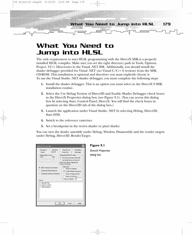
What You Need to Jump into HLSLThe only requirement to start HLSL programming with the DirectX SDK is a properlyinstalled HLSL compiler. Make sure you set the right directory path in Tools, Options,Project, VC++ Directories in the Visual .NET IDE. Additionally, you should install theshader debugger provided for Visual .NET (no Visual C/C++ 6 version) from the SDK CD-ROM. This installation is optional and therefore you must explicitly choose it. To use the Visual Studio .NET shader debugger, you must complete the following steps:
1. Install the shader debugger. This is an option you must select in the DirectX 9 SDKinstallation routine.
2. Select the Use Debug Version of Direct3D and Enable Shader Debugger check boxesin the DirectX Properties dialog box (see Figure 9.1). (You can access this dialogbox by selecting Start, Control Panel, DirectX. You will find the check boxes in question on the Direct3D tab of the dialog box.)
3. Launch the application under Visual Studio .NET by selecting Debug, Direct3D,Start D3D.
4. Switch to the reference rasterizer.
5. Set a breakpoint in the vertex shader or pixel shader.
You can view the shader assembly under Debug, Window, Disassembly and the render targetsunder Debug, Direct3D, RenderTarget.
179What You Need to Jump into HLSL
Figure 9.1
DirectX Propertiesdialog box
09 direct3d chap09 6/19/03 5:25 PM Page 179
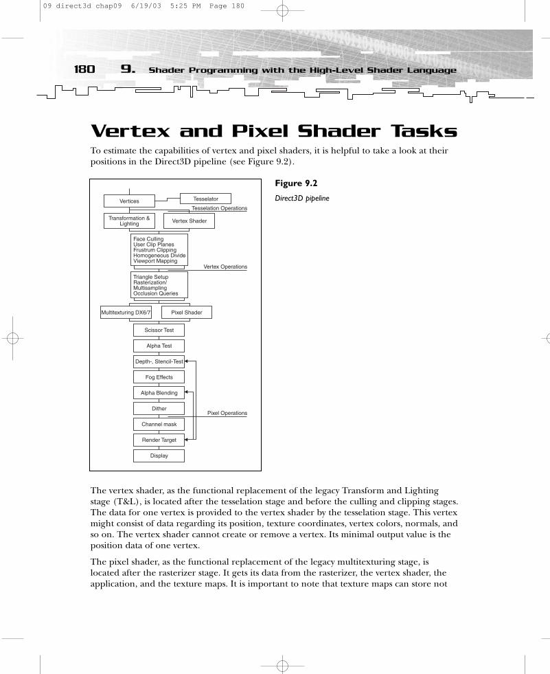
Vertex and Pixel Shader TasksTo estimate the capabilities of vertex and pixel shaders, it is helpful to take a look at theirpositions in the Direct3D pipeline (see Figure 9.2).
The vertex shader, as the functional replacement of the legacy Transform and Lightingstage (T&L), is located after the tesselation stage and before the culling and clipping stages.The data for one vertex is provided to the vertex shader by the tesselation stage. This vertexmight consist of data regarding its position, texture coordinates, vertex colors, normals, andso on. The vertex shader cannot create or remove a vertex. Its minimal output value is theposition data of one vertex.
The pixel shader, as the functional replacement of the legacy multitexturing stage, islocated after the rasterizer stage. It gets its data from the rasterizer, the vertex shader, theapplication, and the texture maps. It is important to note that texture maps can store not
180 9. Shader Programming with the High-Level Shader Language
Figure 9.2
Direct3D pipeline
09 direct3d chap09 6/19/03 5:25 PM Page 180

only color data, but also all kinds of numbers that are useful for calculating algorithms inthe pixel shader. Furthermore, you can write the result of the pixel shader into a rendertarget and set it as the input texture in a second rendering pass. This is called rendering tothe render target. The output of the pixel shader usually consists of a float4 value. If the pixelshader renders in several render targets at once, the output might be up to four float4values. (This is known as MRT, or Multiple Render Targets.)
Common Lighting FormulasImplemented with HLSLTo demonstrate the use of HLSL to program shaders, and also to demonstrate the tasks ofthe vertex and pixel shaders, the following example programs show the implementation ofthe common lighting formulas.
Ambient LightingIn an ambient lighting model, all light beams fall uniformly onto an object from all directions.A lighting model like this, which has no position in space, is also called a global lighting model.(Area lighting is an example of a more advanced global lighting model.)
The ambient lighting component can be described with the following formula:
I = Aintensity * Acolor
The intensity value describes the lighting intensity, and the color value describes the colorof the light. A more complex lighting formula with its ambient terms might look like this:
I = Aintensity * Acolor + Diffuse + Specular
The Diffuse and Specular components are placeholders for the diffuse and specular lightingformulas that you will see in the upcoming examples. All high-level languages supportshader instructions that are written similar to mathematical expressions, such as multi-plication and addition. Therefore, you can write the ambient component in a high-levellanguage as follows:
float4 Acolor = {1.0, 0.15, 0.15, 1.0};float Aintensity = 0.5;return Aintensity * Acolor;
A simplified implementation might look like this:
return float4 (0.5, 0.075, 0.075, 1.0);
It is quite common to pre-bake the intensity and color values into one value. This is done inthe following example programs for simplicity and readability; otherwise, the HLSL compilerwould pre-bake the two constant values together in its output.
181Common Lighting Formulas Implemented with HLSL
09 direct3d chap09 6/19/03 5:25 PM Page 181
The following source code shows a vertex and a pixel shader that display ambient lighting.
float4x4 matWorldViewProj;
struct VS_OUTPUT{
float4 Pos: POSITION;};
VS_OUTPUT VS( float4 Pos: POSITION ){
VS_OUTPUT Out = (VS_OUTPUT) 0; Out.Pos = mul(Pos, matWorldViewProj); // transform Positionreturn Out;
}
float4 PS() : COLOR{
return float4(0.5, 0.075, 0.075, 1.0);}
The VS_OUTPUT structure at the beginning of the source code describes the output values ofthe vertex shader. The vertex shader looks like a C function with the return value VS_OUTPUTand the input value in the variable Pos in parentheses after its name (VS).
The input and output values for the vertex shader use the semantic POSITION, which is iden-tified by a colon (:) that precedes it. Semantics help the HLSL compiler bind the correctshader registers for the data. The semantic in the vertex shader input structure identifiesthe input data to the function as position data. The second semantic identifies the vertexshader return value as position data that will be an input value to the pixel shader. (This isthe only obligatory output value of the vertex shader.) There are several other semantics forthe vertex shader input and output data, as well as the pixel shader input and output data.The following example programs will show a few of them. Please consult the DirectX 9 SDKdocumentation for an overview.
The vertex shader transforms the vertex position using the matWorldViewProj matrix pro-vided by the application as a constant; it then outputs the position values.
The pixel shader also follows the C-function-like approach. Its return value is always float4,and this value is always treated as a color value by the compiler because it is marked with thesemantic COLOR. Contrary to the vertex shader, the pixel shader gets no explicit input valuehere (except the obligatory POSITION) because the parentheses after its name (PS) are empty.
The names of the vertex and pixel shader are also the entry point for the high-level languagecompiler, and you must provide them in its command line.
Figure 9.3 shows the Example program with an ambient lighting model. This program islocated in the Chapter9\Example directory on the CD-ROM.
182 9. Shader Programming with the High-Level Shader Language
09 direct3d chap09 6/19/03 5:25 PM Page 182

The knob on the top of the teapot is not visible when it is turned toward the viewer becausethe light beams are coming uniformly from all directions onto the object, and therefore thewhole teapot is exactly the same color.
Diffuse LightingIn a diffuse lighting model, the location of the light is considered. In other words, light hasposition in space. (This is also known as a positional lighting model.) This is the main differ-ence between the diffuse lighting model and the ambient lighting model, in which light hasno position in space and is therefore treated as global.
Another characteristic of diffuse lighting is that a reflection is independent of the observer’sposition. Therefore, the surface of an object used in a diffuse lighting model reflects equallywell in all directions. This is why diffuse lighting is commonly used to simulate matte surfaces.Figure 9.4 shows the Example2 program located in the Chapter9\Example2 directory on theCD-ROM.
183Common Lighting Formulas Implemented with HLSL
Figure 9.3
Ambient lighting withHLSL shaders
Figure 9.4
Diffuse lighting withHLSL shaders
09 direct3d chap09 6/19/03 5:25 PM Page 183

The diffuse lighting model following Lambert’s law is described with the help of two vectors—the light vector L, which describes the position of light, and the normal vector N,which describes the normal of an object’s vertex (see Figure 9.5).
The diffuse reflection has its peak (cos α = = 1) when L and N are aligned or, in otherwords, when the surface is perpendicular to the light beam. The diffuse reflection dimin-ishes for smaller angles. Therefore, light intensity is directly proportional to cos α.
To implement the diffuse reflection in an efficient way, you use a property of the dot-product of two n-dimensional vectors.
N.L = ||N|| * ||L|| * cos α
If the light and normal vectors are of unit length (normalized), this leads to:
N.L = cos α
When N.L is equal to cos α, you can describe the diffuse lighting component with the dot-product of N and L. This diffuse lighting component is usually added to the ambientlighting component like this:
I = Aintensity * Acolor + Dintensity * Dcolor * N.L + Specular
The example uses the following simplified version:
I = A + D * N.L + Specular
The following source code shows the HLSL vertex and pixel shaders:
float4x4 matWorldViewProj;float4x4 matWorld;float4 vecLightDir;
struct VS_OUTPUT{
184 9. Shader Programming with the High-Level Shader Language
Figure 9.5
Light and normalvectors
09 direct3d chap09 6/19/03 5:25 PM Page 184
float4 Pos : POSITION;float3 Light : TEXCOORD0;float3 Norm : TEXCOORD1;
};
VS_OUTPUT VS(float4 Pos : POSITION, float3 Normal : NORMAL){
VS_OUTPUT Out = (VS_OUTPUT)0; Out.Pos = mul(Pos, matWorldViewProj); // transform PositionOut.Light = vecLightDir; // output light vectorOut.Norm = normalize(mul(Normal, matWorld)); // transform Normal and normalize it
return Out;}
float4 PS(float3 Light: TEXCOORD0, float3 Norm : TEXCOORD1) : COLOR{
float4 diffuse = { 1.0f, 0.0f, 0.0f, 1.0f};float4 ambient = {0.1, 0.0, 0.0, 1.0}; return ambient + diffuse * saturate(dot(Light, Norm));
}
Compared to the previous example, the vertex shader also gets a vertex normal as inputdata. The semantic NORMAL shows the compiler how to bind the data to the vertex shaderregisters. The world-view-projection matrix, the world matrix, and the light vector are pro-vided to the vertex shader via the constants matWorldViewProj, matWorld, vecLightDir. Theapplication provides all these constants to the vertex shader.
The vertex shader VS also outputs the N and L vectors in the variables Light and Norm here.Both vectors are normalized in the vertex shader with the intrinsic function normalize().This function returns the normalized vector v = v/length(v). If the length of v is 0, theresult is indefinite.
The normal vector is transformed when it is multiplied by the world matrix. This is doneusing the function mul(a, b), which performs a matrix multiplication between a and b. If ais a vector, it is treated as a row vector. If b is a vector, it is treated as a column vector. Theinner dimensions acolumns and brows must be equal. The result has the dimensions arows * bcolumns.In this example, mul() gets the position vector as the first parameter (so it is treated as a rowvector) and the transformation matrix, consisting of 16 floating-point values (float4x4), asthe second parameter. Figure 9.6 shows the row vector and the matrix.
You implement the entire lighting formula, consisting of an ambient and a diffuse compo-nent, in the return statement. The diffuse and ambient constant values were defined in thepixel shader to make the source code easier to understand. In a real-world application,these values might be loaded from the 3D model file.
185Common Lighting Formulas Implemented with HLSL
09 direct3d chap09 6/19/03 5:25 PM Page 185
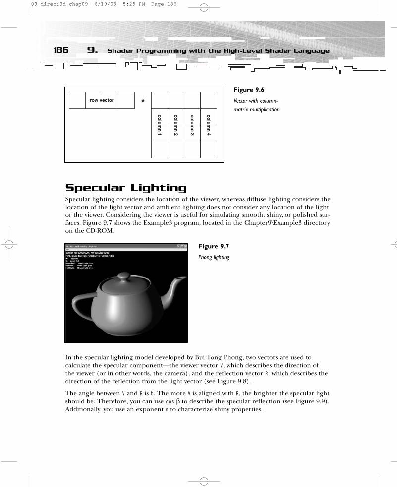
Specular LightingSpecular lighting considers the location of the viewer, whereas diffuse lighting considers thelocation of the light vector and ambient lighting does not consider any location of the lightor the viewer. Considering the viewer is useful for simulating smooth, shiny, or polished sur-faces. Figure 9.7 shows the Example3 program, located in the Chapter9\Example3 directoryon the CD-ROM.
In the specular lighting model developed by Bui Tong Phong, two vectors are used to calculate the specular component—the viewer vector V, which describes the direction of the viewer (or in other words, the camera), and the reflection vector R, which describes thedirection of the reflection from the light vector (see Figure 9.8).
The angle between V and R is b. The more V is aligned with R, the brighter the specular lightshould be. Therefore, you can use cos β to describe the specular reflection (see Figure 9.9).Additionally, you use an exponent n to characterize shiny properties.
186 9. Shader Programming with the High-Level Shader Language
Figure 9.7
Phong lighting
Figure 9.6
Vector with column-matrix multiplication
09 direct3d chap09 6/19/03 5:25 PM Page 186
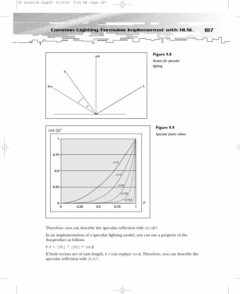
Therefore, you can describe the specular reflection with cos (β)n.
In an implementation of a specular lighting model, you can use a property of thedot-product as follows:
R.V = ||R|| * ||V|| * cos β
If both vectors are of unit length, R.V can replace cos β. Therefore, you can describe thespecular reflection with (R.V)n.
187Common Lighting Formulas Implemented with HLSL
Figure 9.8
Vectors for specularlighting
n=64
n=16
n=8
n=4
n=2
Figure 9.9
Specular power values
09 direct3d chap09 6/19/03 5:25 PM Page 187
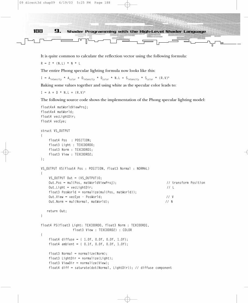
It is quite common to calculate the reflection vector using the following formula:
R = 2 * (N.L) * N * L
The entire Phong specular lighting formula now looks like this:
I = Aintensity * Acolor + Dintensity * Dcolor * N.L + Sintensity * Scolor * (R.V)n
Baking some values together and using white as the specular color leads to:
I = A + D * N.L + (R.V)n
The following source code shows the implementation of the Phong specular lighting model:
float4x4 matWorldViewProj;float4x4 matWorld;float4 vecLightDir;float4 vecEye;
struct VS_OUTPUT{
float4 Pos : POSITION;float3 Light : TEXCOORD0;float3 Norm : TEXCOORD1;float3 View : TEXCOORD2;
};
VS_OUTPUT VS(float4 Pos : POSITION, float3 Normal : NORMAL){
VS_OUTPUT Out = (VS_OUTPUT)0; Out.Pos = mul(Pos, matWorldViewProj); // transform PositionOut.Light = vecLightDir; // Lfloat3 PosWorld = normalize(mul(Pos, matWorld));Out.View = vecEye - PosWorld; // VOut.Norm = mul(Normal, matWorld); // N
return Out;}
float4 PS(float3 Light: TEXCOORD0, float3 Norm : TEXCOORD1, float3 View : TEXCOORD2) : COLOR
{float4 diffuse = { 1.0f, 0.0f, 0.0f, 1.0f};float4 ambient = { 0.1f, 0.0f, 0.0f, 1.0f};
float3 Normal = normalize(Norm);float3 LightDir = normalize(Light);float3 ViewDir = normalize(View); float4 diff = saturate(dot(Normal, LightDir)); // diffuse component
188 9. Shader Programming with the High-Level Shader Language
09 direct3d chap09 6/19/03 5:25 PM Page 188
// R = 2 * (N.L) * N – Lfloat3 Reflect = normalize(2 * diff * Normal - LightDir); float4 specular = pow(saturate(dot(Reflect, ViewDir)), 8); // R.V^n
// I = Acolor + Dcolor * N.L + (R.V)nreturn ambient + diffuse * diff + specular;
}
The vertex shader input values are the position values and a normal vector, much like in theprevious example. Additionally, the vertex shader gets as constants the matWorldViewProjmatrix, the matWorld matrix, the position of the eye in vecEye, and the light vector invecLightDir from the application.
In the vertex shader, the viewer vector V is calculated by subtracting the vertex position inworld space from the eye position. The vertex shader outputs the position, the light, thenormal, and the viewer vector. The vectors are also the input values of the pixel shader.
All three vectors are normalized with normalize() in the pixel shader, whereas in the previ-ous example vectors were normalized in the vertex shader. Normalizing vectors in the pixelshader is quite an expensive task because every pixel shader version has only a restrictednumber of assembly instruction slots available for the output of the HLSL compiler to use.If more instruction slots are used than are available, the compiler will display an error message like this:
error X4532: cannot map expression to pixel shader instruction set
The number of instruction slots available in Direct3D usually corresponds to the number of instruction slots available in the graphics card. The high-level language compiler cannotchoose a suitable shader version on its own; the programmer must do it. If the applicationtargets more than the least common denominator of graphics cards in the target market,the programmer must supply several shader versions.
Table 9.1 provides a list of all vertex and pixelshader versions supported by DirectX 9.
You must check the capability bits to obtainthe maximum number of instructions sup-ported by a specific card. You can do this inthe DirectX Caps viewer or via the D3DCAPS9structure in the application. You usuallycheck the availability of specific shader ver-sions when the application starts up. Theapplication can then choose the proper ver-sion from a list of already-prepared shaders,or it can put together a shader consisting ofalready-prepared shader fragments with thehelp of the shader fragment linker.
189Common Lighting Formulas Implemented with HLSL
NOTEThe examples shown here generallyrequire pixel shader version 2.0 or higher.With some tweaking, youmight implement some of theeffects using a lower shader versionby trading off some image quality,but this is outside the scope of thisbook. In other words, this book doesnot cover fallback paths for oldergraphics hardware.
09 direct3d chap09 6/19/03 5:25 PM Page 189
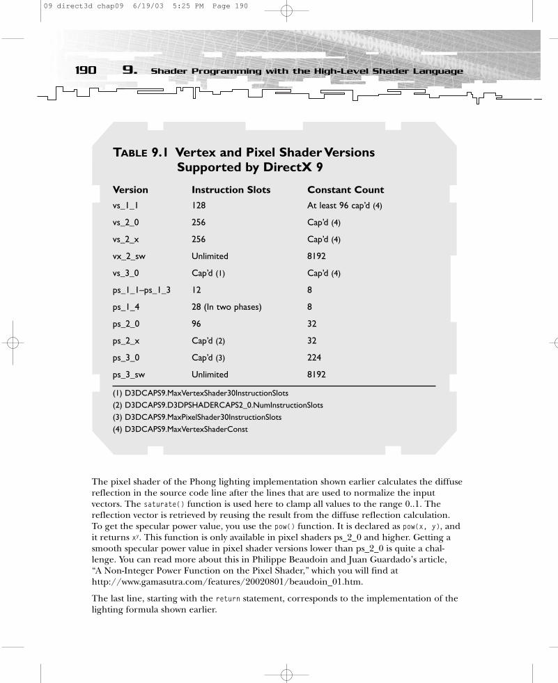
The pixel shader of the Phong lighting implementation shown earlier calculates the diffusereflection in the source code line after the lines that are used to normalize the input vectors. The saturate() function is used here to clamp all values to the range 0..1. Thereflection vector is retrieved by reusing the result from the diffuse reflection calculation. To get the specular power value, you use the pow() function. It is declared as pow(x, y), andit returns xy. This function is only available in pixel shaders ps_2_0 and higher. Getting asmooth specular power value in pixel shader versions lower than ps_2_0 is quite a chal-lenge. You can read more about this in Philippe Beaudoin and Juan Guardado’s article, “A Non-Integer Power Function on the Pixel Shader,” which you will find athttp://www.gamasutra.com/features/20020801/beaudoin_01.htm.
The last line, starting with the return statement, corresponds to the implementation of thelighting formula shown earlier.
190 9. Shader Programming with the High-Level Shader Language
TABLE 9.1 Vertex and Pixel Shader Versions Supported by DirectX 9
Version Instruction Slots Constant Count
vs_1_1 128 At least 96 cap’d (4)
vs_2_0 256 Cap’d (4)
vs_2_x 256 Cap’d (4)
vx_2_sw Unlimited 8192
vs_3_0 Cap’d (1) Cap’d (4)
ps_1_1–ps_1_3 12 8
ps_1_4 28 (In two phases) 8
ps_2_0 96 32
ps_2_x Cap’d (2) 32
ps_3_0 Cap’d (3) 224
ps_3_sw Unlimited 8192
(1) D3DCAPS9.MaxVertexShader30InstructionSlots(2) D3DCAPS9.D3DPSHADERCAPS2_0.NumInstructionSlots(3) D3DCAPS9.MaxPixelShader30InstructionSlots(4) D3DCAPS9.MaxVertexShaderConst
09 direct3d chap09 6/19/03 5:25 PM Page 190
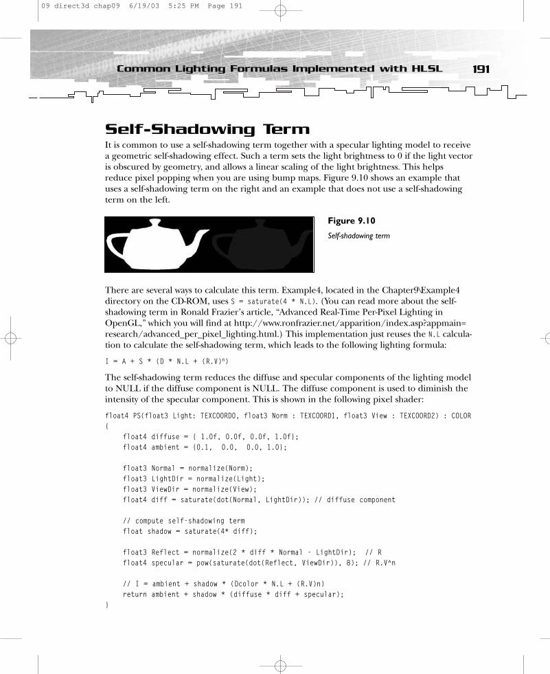
Self-Shadowing TermIt is common to use a self-shadowing term together with a specular lighting model to receivea geometric self-shadowing effect. Such a term sets the light brightness to 0 if the light vectoris obscured by geometry, and allows a linear scaling of the light brightness. This helpsreduce pixel popping when you are using bump maps. Figure 9.10 shows an example thatuses a self-shadowing term on the right and an example that does not use a self-shadowingterm on the left.
There are several ways to calculate this term. Example4, located in the Chapter9\Example4directory on the CD-ROM, uses S = saturate(4 * N.L). (You can read more about the self-shadowing term in Ronald Frazier’s article, “Advanced Real-Time Per-Pixel Lighting inOpenGL,” which you will find at http://www.ronfrazier.net/apparition/index.asp?appmain=research/advanced_per_pixel_lighting.html.) This implementation just reuses the N.L calcula-tion to calculate the self-shadowing term, which leads to the following lighting formula:
I = A + S * (D * N.L + (R.V)n)
The self-shadowing term reduces the diffuse and specular components of the lighting modelto NULL if the diffuse component is NULL. The diffuse component is used to diminish theintensity of the specular component. This is shown in the following pixel shader:
float4 PS(float3 Light: TEXCOORD0, float3 Norm : TEXCOORD1, float3 View : TEXCOORD2) : COLOR{
float4 diffuse = { 1.0f, 0.0f, 0.0f, 1.0f};float4 ambient = {0.1, 0.0, 0.0, 1.0};
float3 Normal = normalize(Norm);float3 LightDir = normalize(Light);float3 ViewDir = normalize(View); float4 diff = saturate(dot(Normal, LightDir)); // diffuse component
// compute self-shadowing termfloat shadow = saturate(4* diff);
float3 Reflect = normalize(2 * diff * Normal - LightDir); // Rfloat4 specular = pow(saturate(dot(Reflect, ViewDir)), 8); // R.V^n
// I = ambient + shadow * (Dcolor * N.L + (R.V)n)return ambient + shadow * (diffuse * diff + specular);
}
191Common Lighting Formulas Implemented with HLSL
Figure 9.10
Self-shadowing term
09 direct3d chap09 6/19/03 5:25 PM Page 191

Bump MappingBump mapping fakes the existence of geometry (grooves, nodges, and bulges). Figure 9.11shows the Example5 program located in the Chapter9\Example5 directory on the CD-ROM.This program gives the viewer the illusion that regions with mountains are higher thanwater regions on Earth.
Whereas a color map stores color values, a bump map is a graphics file (such as *.dds or*.tga) that stores normals that are used instead of the vertex normals to calculate the light-ing. These normals are stored in the most common bump-mapping technique, in what iscalled texture space or tangent space. The light vector is usually handled in object or worldspace, which leads to the problem that the light vector must be transformed into the samespace as the normals in the bump map to obtain proper results. You do this with the helpof a texture or tangent space coordinate system (see Figure 9.12).
The easiest way to obtain such a texture space coordinate system is to use theD3DXComputeNormal() and D3DXComputeTangent() functions provided with the Direct3D utilitylibrary Direct3DX. You can find source code implementations of the functionality covered bythese functions in the NVMeshMender library, which you can download from the NVIDIA Web
192 9. Shader Programming with the High-Level Shader Language
Figure 9.11
Bump mapping
Figure 9.12
Texture spacecoordinate system
09 direct3d chap09 6/19/03 5:25 PM Page 192

site, at http://developer.nvidia.com. Calculating a texture space coordinate system is muchlike calculating the vertex normal. For example, if a vertex shares three triangles, you calcu-late the face normal/face tangent first, and then you add the vectors of all three triangles atthe vertex that connects the triangles to form the vertex normal/vertex tangent. This exam-ple uses the vertex normal instead of a W vector for the texture space coordinate system andcalculates the U vector with the help of the D3DXComputeTangent() function. You retrieve the Vvector by calculating the cross-product of the W and U vectors using the cross() function inthe vertex shader.
struct VS_OUTPUT{
float4 Pos : POSITION;float2 Tex : TEXCOORD0;float3 Light : TEXCOORD1;float3 View : TEXCOORD2;
};
VS_OUTPUT VS(float4 Pos : POSITION, float2 Tex : TEXCOORD, float3 Normal : NORMAL, float3Tangent : TANGENT ){
VS_OUTPUT Out = (VS_OUTPUT)0; Out.Pos = mul(Pos, matWorldViewProj); // transform Position
// compute the 3x3 transform matrix // to transform from world space to tangent spacefloat3x3 worldToTangentSpace;worldToTangentSpace[0] = mul(Tangent, matWorld);worldToTangentSpace[1] = mul(cross(Tangent, Normal), matWorld);worldToTangentSpace[2] = mul(Normal, matWorld);
Out.Tex = Tex.xy;
Out.Light.xyz = mul(worldToTangentSpace, vecLightDir); // Lfloat3 PosWorld = normalize(mul(Pos, matWorld));float3 Viewer = vecEye - PosWorld; // VOut.View = mul(worldToTangentSpace, Viewer);
return Out;}
float4 PS(float2 Tex: TEXCOORD0, float3 Light : TEXCOORD1, float3 View : TEXCOORD2) : COLOR{
float4 color = tex2D(ColorMapSampler, Tex); // fetch color mapfloat3 bumpNormal = 2 * (tex2D(BumpMapSampler, Tex) - 0.5); // bump map
193Common Lighting Formulas Implemented with HLSL
09 direct3d chap09 6/19/03 5:25 PM Page 193

float3 LightDir = normalize(Light); // Lfloat3 ViewDir = normalize(View); // V
float4 diff = saturate(dot(bumpNormal, LightDir)); // diffuse comp.
float shadow = saturate(4 * diff); // compute self-shadowing term
float3 Reflect = normalize(2 * diff * bumpNormal - LightDir); // R
// gloss map in color.w restricts spec reflectionfloat4 spec = min(pow(saturate(dot(Reflect, ViewDir)), 3), color.w);
return 0.2 * color + shadow * (color * diff + spec);}
You create the 3x3 matrix, consisting of the U, V, and W (== N) vectors, in the vertex shaderand use it there to transform L and V to texture space.
Compared to the previous example, the major differences in the pixel shader are the use of a color map and a bump map, which are fetched with tex2D(). The tex2D() function isdeclared as tex2D(s, t), where s is a sampler object and t is a 2D texture coordinate. Pleaseconsult the DirectX 9 documentation for many other texture sampler functions (for example,texCUBE(s, t), which is used to fetch a cube map).
You use the normal from the bump map here, instead of the normal from the vertexthroughout the whole pixel shader. It is fetched from the normal map by biasing (–0.5) andscaling (* 2.0) its values. You must do this because the normal map was stored in an unsignedtexture format with a value range of 0..1 to allow older hardware to operate correctly; therefore, you must expand the normals back to their signed range.
Compared to the previous examples, this pixel shader also restricts the region where a spec-ular reflection might occur on the water regions of the Earth model. This is accomplishedwith the help of the min() function and a gloss map that is stored in the alpha values of thecolor map. min() is defined as min(a, b), and it selects the lesser of a and b.
In the return statement, the ambient term is replaced by an intensity-decreased color valuefrom the color map. This way, if the self-shadowing term reduces the diffuse and specularlighting components, at least a very dark Earth is still visible.
Point LightsExample6 is the last example; it is located in the Chapter9\Example6 directory on the CD-ROM. Example6 adds a per-pixel point light to the previous example. Contrary to theparallel light beams of a directional light source, the light beams of a point light spread outuniformly in all directions from the position of the point light (see Figure 9.13).
194 9. Shader Programming with the High-Level Shader Language
09 direct3d chap09 6/19/03 5:25 PM Page 194
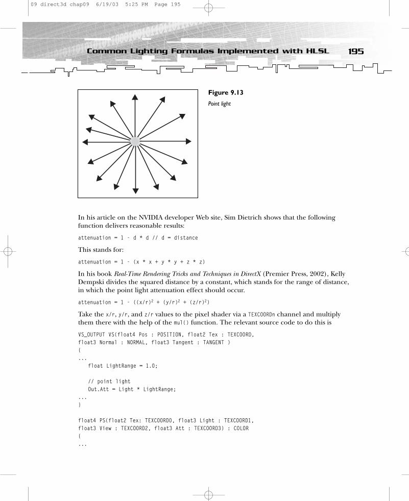
In his article on the NVIDIA developer Web site, Sim Dietrich shows that the followingfunction delivers reasonable results:
attenuation = 1 - d * d // d = distance
This stands for:
attenuation = 1 - (x * x + y * y + z * z)
In his book Real-Time Rendering Tricks and Techniques in DirectX (Premier Press, 2002), KellyDempski divides the squared distance by a constant, which stands for the range of distance,in which the point light attenuation effect should occur.
attenuation = 1 - ((x/r)2 + (y/r)2 + (z/r)2)
Take the x/r, y/r, and z/r values to the pixel shader via a TEXCOORDn channel and multiplythem there with the help of the mul() function. The relevant source code to do this is
VS_OUTPUT VS(float4 Pos : POSITION, float2 Tex : TEXCOORD, float3 Normal : NORMAL, float3 Tangent : TANGENT ){...
float LightRange = 1.0;
// point lightOut.Att = Light * LightRange;
...}
float4 PS(float2 Tex: TEXCOORD0, float3 Light : TEXCOORD1, float3 View : TEXCOORD2, float3 Att : TEXCOORD3) : COLOR{...
195Common Lighting Formulas Implemented with HLSL
Figure 9.13
Point light
09 direct3d chap09 6/19/03 5:25 PM Page 195

// attenuationfloat4 Attenuation = mul(Att, Att);
// colormap * (self-shadow-term * diffuse + ambient) + self-shadow-term * // specularreturn (color * (shadow * diff + ambient) + shadow * spec) * (1 -Attenuation);
}
Decreasing the LightRange parameter increases the range of light, whereas increasing thisvalue leads to a shorter range. The attenuation value is multiplied by itself in the pixelshader because it is more efficient than using the exponent 2. In the last line of the pixelshader, the attenuation value is multiplied by the result of the lighting computation todecrease or increase light intensity depending on the distance of the light source.
SummaryThis chapter covered the syntax and some of the intrinsic functions of HLSL by showingyou how to implement some common lighting formulas. It introduced you to six working(and generally concise) code examples to get you ready to generate your own shaders. Tomove on from here, I recommend that you look at the RenderMonkey examples on ATI’sWeb site (http://www.ati.com) and play around with the source code. You will also find aninteractive RenderMonkey tutorial on my Web site (http://www.direct3d.info).
196 9. Shader Programming with the High-Level Shader Language
09 direct3d chap09 6/19/03 5:25 PM Page 196
CHAPTER 10
MoreAdvanced
ShaderEffects
10 direct3d chap10 6/19/03 5:26 PM Page 197

This chapter features a technique called cube environment mapping, which reflects theenvironment of an object in its surface. Most current graphic cards support this tech-
nique, and it is gaining in popularity. Understanding the idea behind this technique willopen many doors to more advanced gaming techniques that might be implemented in thenext couple years.
This chapter also covers the shadowing technique that, in the next couple years, will beused as the standard for creating realistic depictions of dynamic shadows in a scene.
In this chapter, you’ll learn how to:
• Generate, access, and implement cube maps• Use dynamic refractive and reflective environment mapping• Work with shadows and shadow volumes
Working with Cube MapsOne thing that has been missing in the examples so far is the idea of reflection. Creatingphotorealistic “virtual environments” requires surfaces that are capable of reflecting light asthey would in the natural world. Therefore, the term reflection mapping is sometimes usedinterchangeably with the term environment mapping.
The surfaces of real-life objects are characterized by the degree to which light is absorbed,reflected, or transmitted. To replicate the visual richness of natural objects, the eye mustperceive that light is accurately reflected off objects in real-time, without objectionable arti-facts. The complexity involved in modeling the physical behavior of light by explicitly trac-ing secondary light rays throughout a scene, however, has led to alternative techniques tosimulate realistic reflections. Environment mapping is an efficient technique to computereflections in computer-synthesized environments without tracing a myriad of secondaryrays. By using pre-defined images cast as a geometric map shape that surrounds an object,you can define reflections for a single point in space. The most common pre-definedimages that surround an object are called cube environment maps or simply cube maps. Allrecent graphics cards support them.
Generating Cube MapsConceptually, cube maps represent the environment as six sides of a cube that surroundsone or more of the objects in your scene. To generate a cube map, replace the object onwhich you want to put reflections with a camera at the object’s position, and take snapshots
198 10. More Advanced Shader Effects
10 direct3d chap10 6/19/03 5:26 PM Page 198
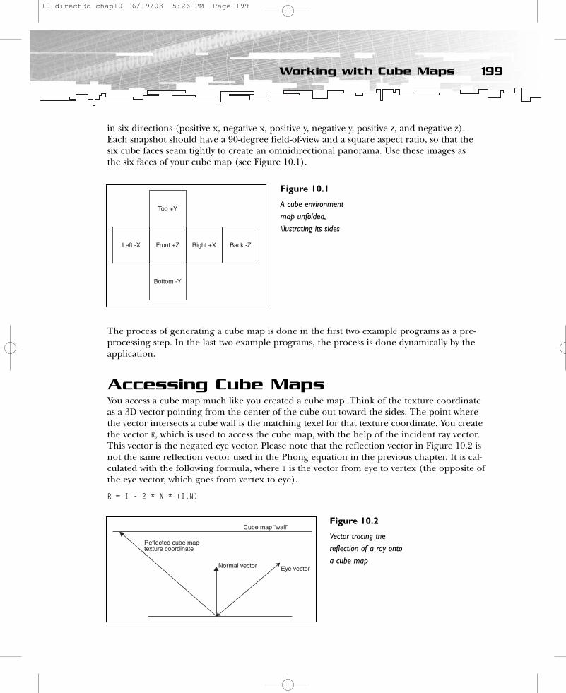
in six directions (positive x, negative x, positive y, negative y, positive z, and negative z).Each snapshot should have a 90-degree field-of-view and a square aspect ratio, so that thesix cube faces seam tightly to create an omnidirectional panorama. Use these images as the six faces of your cube map (see Figure 10.1).
The process of generating a cube map is done in the first two example programs as a pre-processing step. In the last two example programs, the process is done dynamically by theapplication.
Accessing Cube MapsYou access a cube map much like you created a cube map. Think of the texture coordinateas a 3D vector pointing from the center of the cube out toward the sides. The point wherethe vector intersects a cube wall is the matching texel for that texture coordinate. You createthe vector R, which is used to access the cube map, with the help of the incident ray vector.This vector is the negated eye vector. Please note that the reflection vector in Figure 10.2 isnot the same reflection vector used in the Phong equation in the previous chapter. It is cal-culated with the following formula, where I is the vector from eye to vertex (the opposite ofthe eye vector, which goes from vertex to eye).
R = I - 2 * N * (I.N)
199Working with Cube Maps
Figure 10.1
A cube environmentmap unfolded,illustrating its sides
Figure 10.2
Vector tracing thereflection of a ray ontoa cube map
10 direct3d chap10 6/19/03 5:26 PM Page 199
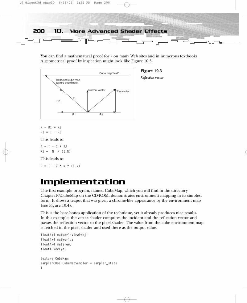
You can find a mathematical proof for R on many Web sites and in numerous textbooks. A geometrical proof by inspection might look like Figure 10.3.
R = R1 + R2R1 = I - R2
This leads to:
R = I - 2 * R2R2 = N * (I.N)
This leads to:
R = I - 2 * N * (I.N)
ImplementationThe first example program, named CubeMap, which you will find in the directoryChapter10\CubeMap on the CD-ROM, demonstrates environment mapping in its simplestform. It shows a teapot that was given a chrome-like appearance by the environment map(see Figure 10.4).
This is the bare-bones application of the technique, yet it already produces nice results. In this example, the vertex shader computes the incident and the reflection vector andpasses the reflection vector to the pixel shader. The value from the cube environment mapis fetched in the pixel shader and used there as the output value.
float4x4 matWorldViewProj;float4x4 matWorld;float4x4 matView;float4 vecEye;
texture CubeMap;samplerCUBE CubeMapSampler = sampler_state{
200 10. More Advanced Shader Effects
Figure 10.3
Reflection vector
10 direct3d chap10 6/19/03 5:26 PM Page 200

Texture = <CubeMap>;MinFilter = Linear;MagFilter = Linear;AddressU = Wrap;AddressV = Wrap;
};
struct VS_OUTPUT{
float4 Pos : POSITION;float3 Reflect: TEXCOORD4;
};
VS_OUTPUT VS(float4 Pos : POSITION, float2 Tex : TEXCOORD, float3 Normal : NORMAL){
VS_OUTPUT Out = (VS_OUTPUT)0; Out.Pos = mul(Pos, matWorldViewProj); // transform Positionfloat3 Norm = normalize(mul(Normal, matWorld));
// get a vector toward the camera/eye -> Vfloat3 PosWorld = normalize(mul(Pos, matWorld));float3 Incident = normalize(PosWorld - vecEye);
// Reflection Vector for cube map: R = I - 2 * N * (I.N)Out.Reflect = normalize(reflect(Incident, Norm));// Out.Reflect = normalize(Incident - 2 * Norm * dot(Incident, Norm));
201Implementation
Figure 10.4
Cube environmentmapping
10 direct3d chap10 6/19/03 5:26 PM Page 201
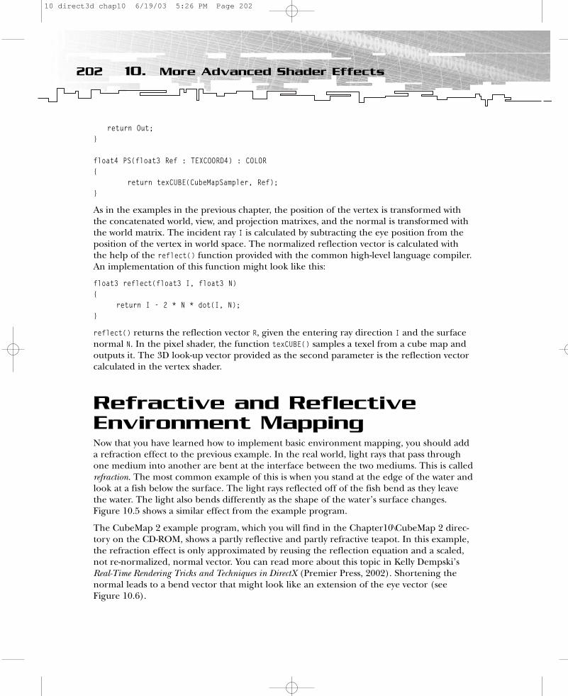
return Out;}
float4 PS(float3 Ref : TEXCOORD4) : COLOR{
return texCUBE(CubeMapSampler, Ref); }
As in the examples in the previous chapter, the position of the vertex is transformed withthe concatenated world, view, and projection matrixes, and the normal is transformed withthe world matrix. The incident ray I is calculated by subtracting the eye position from theposition of the vertex in world space. The normalized reflection vector is calculated withthe help of the reflect() function provided with the common high-level language compiler.An implementation of this function might look like this:
float3 reflect(float3 I, float3 N){
return I - 2 * N * dot(I, N);}
reflect() returns the reflection vector R, given the entering ray direction I and the surfacenormal N. In the pixel shader, the function texCUBE() samples a texel from a cube map andoutputs it. The 3D look-up vector provided as the second parameter is the reflection vectorcalculated in the vertex shader.
Refractive and ReflectiveEnvironment MappingNow that you have learned how to implement basic environment mapping, you should adda refraction effect to the previous example. In the real world, light rays that pass throughone medium into another are bent at the interface between the two mediums. This is calledrefraction. The most common example of this is when you stand at the edge of the water andlook at a fish below the surface. The light rays reflected off of the fish bend as they leavethe water. The light also bends differently as the shape of the water’s surface changes.Figure 10.5 shows a similar effect from the example program.
The CubeMap 2 example program, which you will find in the Chapter10\CubeMap 2 direc-tory on the CD-ROM, shows a partly reflective and partly refractive teapot. In this example,the refraction effect is only approximated by reusing the reflection equation and a scaled,not re-normalized, normal vector. You can read more about this topic in Kelly Dempski’sReal-Time Rendering Tricks and Techniques in DirectX (Premier Press, 2002). Shortening thenormal leads to a bend vector that might look like an extension of the eye vector (seeFigure 10.6).
202 10. More Advanced Shader Effects
10 direct3d chap10 6/19/03 5:26 PM Page 202
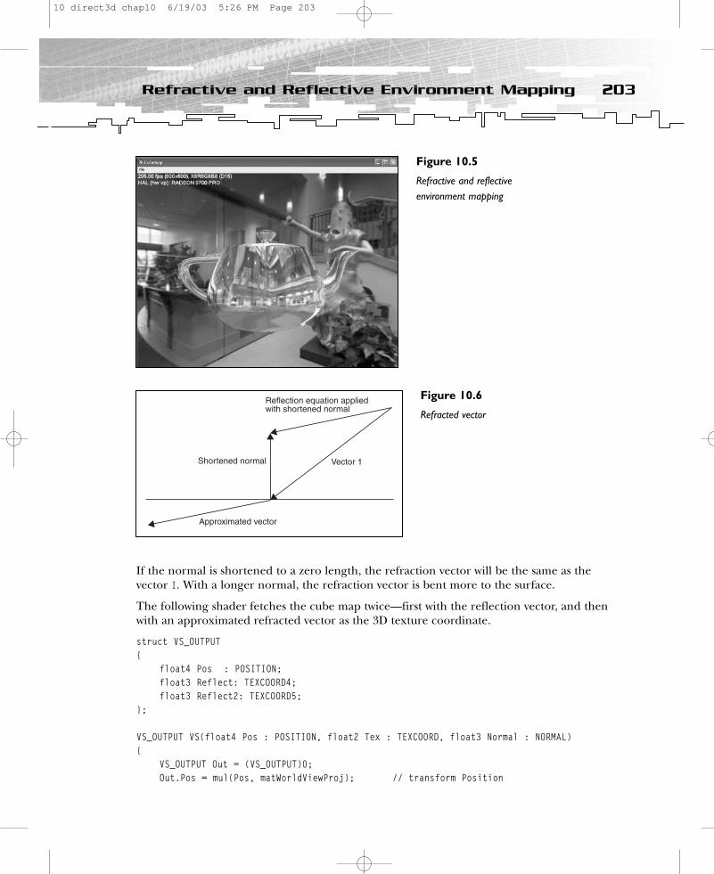
If the normal is shortened to a zero length, the refraction vector will be the same as the vector I. With a longer normal, the refraction vector is bent more to the surface.
The following shader fetches the cube map twice—first with the reflection vector, and thenwith an approximated refracted vector as the 3D texture coordinate.
struct VS_OUTPUT{
float4 Pos : POSITION;float3 Reflect: TEXCOORD4; float3 Reflect2: TEXCOORD5;
};
VS_OUTPUT VS(float4 Pos : POSITION, float2 Tex : TEXCOORD, float3 Normal : NORMAL){
VS_OUTPUT Out = (VS_OUTPUT)0; Out.Pos = mul(Pos, matWorldViewProj); // transform Position
203Refractive and Reflective Environment Mapping
Figure 10.5
Refractive and reflectiveenvironment mapping
Figure 10.6
Refracted vector
10 direct3d chap10 6/19/03 5:26 PM Page 203
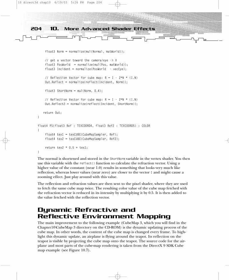
float3 Norm = normalize(mul(Normal, matWorld));
// get a vector toward the camera/eye -> Vfloat3 PosWorld = normalize(mul(Pos, matWorld));float3 Incident = normalize(PosWorld - vecEye);
// Reflection Vector for cube map: R = I - 2*N * (I.N)Out.Reflect = normalize(reflect(Incident, Norm));
float3 ShortNorm = mul(Norm, 0.4);
// Reflection Vector for cube map: R = I - 2*N * (I.N)Out.Reflect2 = normalize(reflect(Incident, ShortNorm));
return Out;}
float4 PS(float3 Ref : TEXCOORD4, float3 Ref2 : TEXCOORD5) : COLOR{
float4 tex1 = texCUBE(CubeMapSampler, Ref); float4 tex2 = texCUBE(CubeMapSampler, Ref2);
return tex2 * 0.5 + tex1;}
The normal is shortened and stored in the ShortNorm variable in the vertex shader. You thenuse this variable with the reflect() function to calculate the refraction vector. Using ahigher value of the constant (near 1.0) results in something that looks very much likereflection, whereas lower values (near zero) are closer to the vector I and might cause azooming effect. Just play around with this value.
The reflection and refraction values are then sent to the pixel shader, where they are usedto fetch the same cube map twice. The resulting color value of the cube map fetched withthe refraction vector is reduced in its intensity by multiplying it by 0.5. It is then added tothe value fetched with the reflection vector.
Dynamic Refractive and Reflective Environment MappingThe main improvement to the following example (CubeMap 3, which you will find in theChapter10\CubeMap 3 directory on the CD-ROM) is the dynamic updating process of thecube map. In other words, the content of the cube map is changed every frame. To high-light this dynamic update, an airplane is flying around the teapot. Its reflection on theteapot is visible by projecting the cube map onto the teapot. The source code for the air-plane and most parts of the cube-map rendering is taken from the DirectX 9 SDK Cubemap example (see Figure 10.7).
204 10. More Advanced Shader Effects
10 direct3d chap10 6/19/03 5:26 PM Page 204
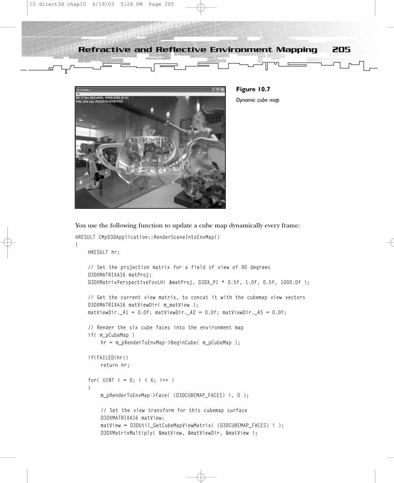
You use the following function to update a cube map dynamically every frame:
HRESULT CMyD3DApplication::RenderSceneIntoEnvMap(){
HRESULT hr;
// Set the projection matrix for a field of view of 90 degreesD3DXMATRIXA16 matProj;D3DXMatrixPerspectiveFovLH( &matProj, D3DX_PI * 0.5f, 1.0f, 0.5f, 1000.0f );
// Get the current view matrix, to concat it with the cubemap view vectorsD3DXMATRIXA16 matViewDir( m_matView );matViewDir._41 = 0.0f; matViewDir._42 = 0.0f; matViewDir._43 = 0.0f;
// Render the six cube faces into the environment mapif( m_pCubeMap )
hr = m_pRenderToEnvMap->BeginCube( m_pCubeMap );
if(FAILED(hr))return hr;
for( UINT i = 0; i < 6; i++ ){
m_pRenderToEnvMap->Face( (D3DCUBEMAP_FACES) i, 0 );
// Set the view transform for this cubemap surfaceD3DXMATRIXA16 matView;matView = D3DUtil_GetCubeMapViewMatrix( (D3DCUBEMAP_FACES) i );D3DXMatrixMultiply( &matView, &matViewDir, &matView );
205Refractive and Reflective Environment Mapping
Figure 10.7
Dynamic cube map
10 direct3d chap10 6/19/03 5:26 PM Page 205

// Render the scene (except for the teapot)RenderScene( &matView, &matProj, FALSE );
}
m_pRenderToEnvMap->End( 0 );return S_OK;
}
The source code shows how the projection matrix is set by the functionD3DXMatrixPerspectiveFovLH(). The camera gets a field of view of 90 degrees, and the aspectratio is set as a square. The next two lines show how the camera is positioned in the centerof the scene. Then the camera is rotated in the six directions of the cube map, and thescene is rendered onto each cube-map face. The RenderScene() function does the rendering;it renders the scene onto the cube map as well as to the output window. The Boolean vari-able bRenderTeapot prevents the teapot from being rendered onto the cube map.
HRESULT CMyD3DApplication::RenderScene( CONST D3DXMATRIXA16 *pView, CONST D3DXMATRIXA16 *pProject,
BOOL bRenderTeapot ){
// Render the Skybox{
D3DXMATRIXA16 matWorld;D3DXMatrixScaling( &matWorld, 10.0f, 10.0f, 10.0f );
D3DXMATRIXA16 matView(*pView);matView._41 = matView._42 = matView._43 = 0.0f;
m_pd3dDevice->SetTransform( D3DTS_WORLD, &matWorld );m_pd3dDevice->SetTransform( D3DTS_VIEW, &matView );m_pd3dDevice->SetTransform( D3DTS_PROJECTION, pProject );
m_pd3dDevice->SetTexture(0, m_pCubeMap);m_pd3dDevice->SetTextureStageState( 0, D3DTSS_COLORARG1, D3DTA_TEXTURE );m_pd3dDevice->SetTextureStageState( 0, D3DTSS_COLOROP, D3DTOP_SELECTARG1 );m_pd3dDevice->SetSamplerState( 0, D3DSAMP_MINFILTER, D3DTEXF_LINEAR );m_pd3dDevice->SetSamplerState( 0, D3DSAMP_MAGFILTER, D3DTEXF_LINEAR );if( (m_d3dCaps.TextureAddressCaps & D3DPTADDRESSCAPS_MIRROR)
== D3DPTADDRESSCAPS_MIRROR ){
m_pd3dDevice->SetSamplerState( 0, D3DSAMP_ADDRESSU, D3DTADDRESS_MIRROR );m_pd3dDevice->SetSamplerState( 0, D3DSAMP_ADDRESSV, D3DTADDRESS_MIRROR );
}
// Always pass Z-test, so we can avoid clearing color and depth buffersm_pd3dDevice->SetRenderState( D3DRS_ZFUNC, D3DCMP_ALWAYS );m_pSkyBox->Render( m_pd3dDevice );
206 10. More Advanced Shader Effects
10 direct3d chap10 6/19/03 5:26 PM Page 206
m_pd3dDevice->SetRenderState( D3DRS_ZFUNC, D3DCMP_LESSEQUAL );}
// Render the Airplane{
m_pd3dDevice->SetTransform( D3DTS_WORLD, &m_matAirplane );m_pd3dDevice->SetTransform( D3DTS_VIEW, pView );m_pd3dDevice->SetTransform( D3DTS_PROJECTION, pProject );
m_pd3dDevice->SetTextureStageState( 0, D3DTSS_COLORARG1, D3DTA_TEXTURE );m_pd3dDevice->SetTextureStageState( 0, D3DTSS_COLOROP, D3DTOP_SELECTARG1 );m_pd3dDevice->SetSamplerState( 0, D3DSAMP_MINFILTER, D3DTEXF_LINEAR );m_pd3dDevice->SetSamplerState( 0, D3DSAMP_MAGFILTER, D3DTEXF_LINEAR );m_pd3dDevice->SetSamplerState( 0, D3DSAMP_ADDRESSU, D3DTADDRESS_WRAP );m_pd3dDevice->SetSamplerState( 0, D3DSAMP_ADDRESSV, D3DTADDRESS_WRAP );
m_pAirplane->Render( m_pd3dDevice );
m_pd3dDevice->SetTransform( D3DTS_WORLD, &m_matWorld);}
// Render the environment-mapped ShinyTeapotif( bRenderTeapot ){
//Rotate the object D3DXMatrixRotationY(&m_matWorld, (float)GetTickCount() / 1000.0f);
D3DXMATRIX mWorldViewProj;D3DXMatrixMultiply(&mWorldViewProj,&m_matWorld, pView);D3DXMatrixMultiply(&mWorldViewProj, &mWorldViewProj, pProject);m_pEffect->SetMatrix( “matWorldViewProj”, &mWorldViewProj );m_pEffect->SetMatrix( “matWorld”, &m_matWorld);m_pEffect->SetMatrix( “matView”, pView);m_pEffect->SetVector( “vecEye”, &m_vEyePos);
UINT nPasses;UINT iPass;
if( m_pEffect != NULL ){
D3DXHANDLE hTechnique = m_pEffect->GetTechniqueByName( “TShader” );m_pEffect->SetTechnique( hTechnique );
m_pEffect->SetTexture(“CubeMap”, m_pCubeMap);m_pEffect->Begin( &nPasses, 0 );
207Refractive and Reflective Environment Mapping
10 direct3d chap10 6/19/03 5:26 PM Page 207

for( iPass = 0; iPass < nPasses; iPass ++ ){
m_pEffect->Pass( iPass );m_pD3DXMesh->DrawSubset( 0 );
}m_pEffect->End();}
}return S_OK;
}
The fixed-function pipeline renders the environment and the airplane. The environment(here the skybox, airplane, and teapot) use their own transformation matrix. The cube mapis rendered from the center of the scene, at the same point where its content is renderedinto it. The airplane flies around the teapot and is rendered with the Render() function ofthe file utility library function in d3dfile.cpp. The teapot is rendered here with the help ofa vertex and pixel shader in an effect file, as with all shader examples in this book.
When RenderScene() is called from within the Render() function, the variable bRenderTeapot isset to TRUE. When the function is called from within the RenderSceneIntoEnvMap() function,this variable is set to FALSE.
Bumped Dynamic Refractive andReflective Environment MappingThe CubeMap 4 example combines the functionality of the bump-mapping example in theprevious chapter with the dynamic reflection/refraction example shown earlier in thischapter. You will find this example program in the Chapter10\CubeMap 4 directory on theCD-ROM. The combination of bump mapping and a dynamically updated cube map leadsto quite a long shader.
struct VS_OUTPUT{
float4 Pos : POSITION;float2 Tex : TEXCOORD0;float3 Light : TEXCOORD1;float3 View : TEXCOORD2;float3 Reflect: TEXCOORD3; float3 Reflect2: TEXCOORD4;
};
VS_OUTPUT VS(float4 Pos : POSITION, float2 Tex : TEXCOORD, float3 Normal : NORMAL, float3 Tangent : TANGENT ){
VS_OUTPUT Out = (VS_OUTPUT)0; Out.Pos = mul(Pos, matWorldViewProj); // transform Position
208 10. More Advanced Shader Effects
10 direct3d chap10 6/19/03 5:26 PM Page 208

// compute the 3x3 transform matrix // to transform from world space to tangent spacefloat3x3 worldToTangentSpace;worldToTangentSpace[0] = mul(Tangent, matWorld);worldToTangentSpace[1] = mul(cross(Tangent, Normal), matWorld);float3 Norm = mul(Normal, matWorld);worldToTangentSpace[2] = Norm;
Out.Tex = Tex.xy;
// output light vectorfloat3 Light = normalize(vecLightDir);Out.Light.xyz = mul(worldToTangentSpace, Light);
// get a vector toward the camera/eye -> Vfloat3 PosWorld = normalize(mul(Pos, matWorld));float3 Incident = normalize(PosWorld - vecEye);
// view vector for bump map float3 Viewer2 = normalize(vecEye - PosWorld); Out.View = mul(worldToTangentSpace, Viewer2);
// Reflection Vector for cube map: R = I - 2*N * (I.N)Out.Reflect = normalize(reflect(Incident, Norm));
float3 ShortNorm = mul(Norm, 0.4);
// Reflection Vector for cube map: R = I - 2*N * (I.N)Out.Reflect2 = normalize(reflect(Incident, ShortNorm));
return Out;}
float4 PS(float2 Tex: TEXCOORD0, float3 Light : TEXCOORD1, float3 View : TEXCOORD2, float3 Ref : TEXCOORD3, float3 Ref2 : TEXCOORD4) : COLOR{
float4 color = tex2D(ColorMapSampler, Tex); // fetch color mapfloat4 bumpNormal = 2 * (tex2D(BumpMapSampler, Tex) - 0.5); // fetch bump mapfloat4 tex1 = texCUBE(CubeMapSampler, Ref); float4 tex2 = texCUBE(CubeMapSampler, Ref2);
// light vector float3 LightDir = normalize(Light);float3 ViewDir = normalize(View);
209Refractive and Reflective Environment Mapping
10 direct3d chap10 6/19/03 5:26 PM Page 209

// diffuse componentfloat4 diff = saturate(dot(bumpNormal, LightDir));
// compute self-shadowing termfloat shadow = saturate(4 * diff);
// compute R vectorfloat3 Reflect = normalize(2 * diff * bumpNormal - LightDir);
// gloss map in color.w used to restrict specular reflection on non-glossy regionsfloat4 spec = min(pow(saturate(dot(Reflect, ViewDir)), 15), color.w);
return 0.2 * color + shadow * ((color * diff + spec)+ ((tex2 * 0.5 + tex1) * 0.05));}
At the beginning of the vertex shader, you create the texture space coordinate system withthe help of the Tangent vector, the Normal vector, and the Binormal vector that is created fromthe cross-product of the Tangent and Normal vectors. The resulting 3×3 matrix is used totransform the light vector L and the viewer vector V in tangent space. Additionally, thereflection vector and the refraction vector are sent to the pixel shader in world space. The return statement should look familiar to you. The result of the reflection/refractionexample is simply added to the result of the bump-mapping example. This example providesyou with several parameters to tweak. Just play around with them. Figure 10.8 shows a shotof this example.
To play with this example, you might put a higher weight on the reflection/refraction part,or use only the self-shadowing term to dump the diffuse and specular lighting componentsand not the reflection/refraction component.
210 10. More Advanced Shader Effects
Figure 10.8
Bumpedreflection/refractioncube mapping
10 direct3d chap10 6/19/03 5:26 PM Page 210

Following are a few tips to help you create an effective implementation of cubic environmentmaps:
• Use one environment map for all objects.• Use static cube maps instead of dynamic ones when possible.• If you need a dynamic cube map, write only every fifth frame.• Cube maps do not work on flat reflective surfaces.• Switch off cube mapping based on distance.
Working with ShadowsAs much as lighting can create a mood in a scene, it’s often the rendered shadows that fur-ther define that mood and give an object more lifelike qualities. Shadows are an importantelement in creating realistic images and in providing the user with visual cues about objectplacement. Furthermore, shadows can be a vital part of the game design. For example, theplayer might be a thief who has to take cover in the shadows to hide.
As hard as it is to create and apply realistic and appropriate lighting to a scene, it can beequally challenging to render convincing shadows. There are several very different tech-niques to create shadows. They all have in common the description of the anatomy of ashadow. A shadowed scene needs a light source that is calculated per-vertex or per-pixel, an object that casts a shadow (called the occluder), and a surface onto which the shadow isbeing cast (called the receiver). Figure 10.9 shows that shadows themselves have two parts—the umbra, which is the hard inner part of the shadow, and the softer penumbra, which iscomposed of the outer and border portions of the shadow.
211Working with Shadows
Figure 10.9
Shadow terminology:light source, occluder,receiver, umbra, andpenumbra
Courtesy of Tomas Akenine-Möller/Eric Haines, Real-Time Rendering, 2nd edition
10 direct3d chap10 6/19/03 5:26 PM Page 211

The penumbra creates the difference between hard and soft shadows. With hard shadows,the shadow ends abruptly and looks unnatural, whereas with soft shadows, the penumbratransitions from the color of the shadow (usually black) to the adjacent pixel color, creatinga more realistic effect.
There are numerous ways to create shadows in a game. I would like to feature one newermethod available in DirectX 8 and in an optimized form on DirectX 9 graphics hardware—shadow volumes with a stencil buffer.
Shadow VolumesShadow volumes should be the preferred technique in the next two years for creating shad-ows in upcoming games. The example Shadow Volume program, which is located in thedirectory Chapter10\Shadow Volume on the CD-ROM, uses the two-sided stencil buffer,introduced in DirectX 9, and falls back to the legacy one-sided stencil buffer on oldergraphics cards (see Figure 10.10).
The example program shows a room in which two boxes are located. The light source islocated under the roof, and both boxes throw shadows. The shadows of the two boxesoccupy a given volume of space. Anything outside of the shadow volume is lit, and anythingwithin the volume is not.
212 10. More Advanced Shader Effects
Figure 10.10
Cornell box with twocubes with shadows
10 direct3d chap10 6/19/03 5:26 PM Page 212
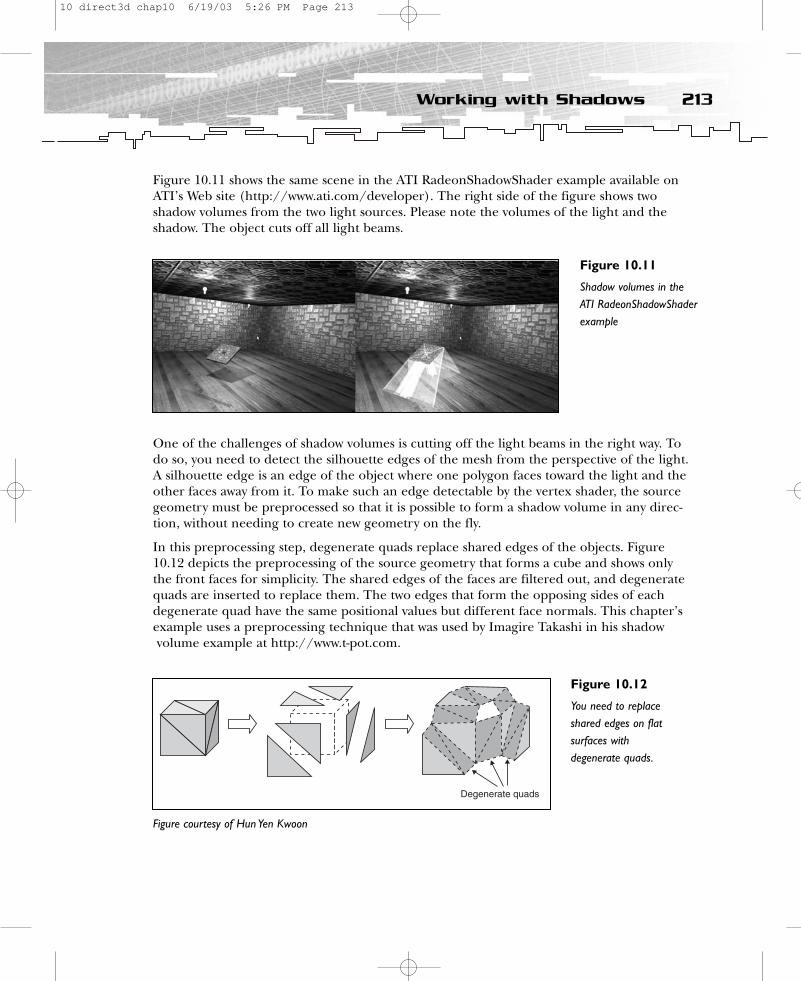
Figure 10.11 shows the same scene in the ATI RadeonShadowShader example available onATI’s Web site (http://www.ati.com/developer). The right side of the figure shows twoshadow volumes from the two light sources. Please note the volumes of the light and theshadow. The object cuts off all light beams.
One of the challenges of shadow volumes is cutting off the light beams in the right way. Todo so, you need to detect the silhouette edges of the mesh from the perspective of the light.A silhouette edge is an edge of the object where one polygon faces toward the light and theother faces away from it. To make such an edge detectable by the vertex shader, the sourcegeometry must be preprocessed so that it is possible to form a shadow volume in any direc-tion, without needing to create new geometry on the fly.
In this preprocessing step, degenerate quads replace shared edges of the objects. Figure10.12 depicts the preprocessing of the source geometry that forms a cube and shows onlythe front faces for simplicity. The shared edges of the faces are filtered out, and degeneratequads are inserted to replace them. The two edges that form the opposing sides of eachdegenerate quad have the same positional values but different face normals. This chapter’sexample uses a preprocessing technique that was used by Imagire Takashi in his shadowvolume example at http://www.t-pot.com.
213Working with Shadows
Figure 10.11
Shadow volumes in theATI RadeonShadowShaderexample
Figure 10.12
You need to replaceshared edges on flatsurfaces withdegenerate quads.
Figure courtesy of Hun Yen Kwoon
10 direct3d chap10 6/19/03 5:26 PM Page 213

I will briefly run through the preprocessing algorithm for you.
1. Step through all the faces in the source mesh.
2. Compute the face normals for each face.
3. Step through the three edges of each face.
4. Insert each edge into a checklist.
5. If two vertices of the same two faces share an edge, follow one of these two steps:
a. If the normals of the faces sharing the edge are not parallel, change the direction of the face.
or
b. Generate a degenerated quad.
First the face normals of all faces are calculated, to see which direction the face points.Then vertices that share one edge are searched; if two vertices of one face share two verticeswith another face, a degenerated quad is inserted. This quad helps the vertex shader createthe shadow volume independent of the location of the light source.
Note that the pre-processing technique used here indiscriminately inserts degenerate quadsinto every shared edge in the preprocessing step. Checking whether a shared edge wouldhave a good chance of becoming a silhouette edge might reduce the polygon count. If ashared edge has almost no chance of becoming a silhouette edge, then there is really noneed to insert a degenerate quad to replace that edge. A simple way to determine thechances of an edge forming part of a silhouette is to test the parallelism of the normals ofthe faces that share it. If the two faces have normals that are almost parallel, then theshared edge is on a flat surface and would have little chance of becoming part of a silhou-ette.
One other thing to note is that the source mesh should be a closed mesh. Any seams orholes (formed by T-junctions, for example) will greatly complicate the silhouette determi-nation algorithm in the vertex shader. Additionally, non-closed front faces will throw thestencil counting off balance.
You can find the Create() function that performs this preprocessing step in theCShadowVolume.cpp file in the Shadow Volume example program located in theChapter10\Shadow Volume directory on the CD-ROM.
HRESULT CShadowVolume::Create( LPDIRECT3DDEVICE9 pd3dDevice, LPD3DXMESH pSrcMesh ){
HRESULT ret = S_OK;SHADOW_VOLUME_VERTEX* pVertices; // local copy of the vertex bufferWORD* pIndices; // local copy of the index bufferDWORD i, j, k, l, face;LPD3DXMESH pMesh;
214 10. More Advanced Shader Effects
10 direct3d chap10 6/19/03 5:26 PM Page 214
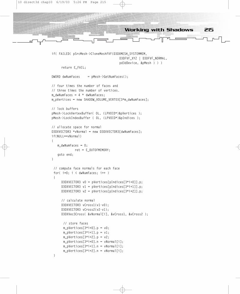
if( FAILED( pSrcMesh->CloneMeshFVF(D3DXMESH_SYSTEMMEM,D3DFVF_XYZ | D3DFVF_NORMAL,pd3dDevice, &pMesh ) ) )
return E_FAIL;
DWORD dwNumFaces = pMesh->GetNumFaces();
// four times the number of faces and // three times the number of vertices.m_dwNumFaces = 4 * dwNumFaces;m_pVertices = new SHADOW_VOLUME_VERTEX[3*m_dwNumFaces];
// lock bufferspMesh->LockVertexBuffer( 0L, (LPVOID*)&pVertices );pMesh->LockIndexBuffer ( 0L, (LPVOID*)&pIndices );
// allocate space for normalD3DXVECTOR3 *vNormal = new D3DXVECTOR3[dwNumFaces];if(NULL==vNormal){
m_dwNumFaces = 0;ret = E_OUTOFMEMORY;
goto end;}
// compute face normals for each facefor( i=0; i < dwNumFaces; i++ ){
D3DXVECTOR3 v0 = pVertices[pIndices[3*i+0]].p;D3DXVECTOR3 v1 = pVertices[pIndices[3*i+1]].p;D3DXVECTOR3 v2 = pVertices[pIndices[3*i+2]].p;
// calculate normalD3DXVECTOR3 vCross1(v1-v0);D3DXVECTOR3 vCross2(v2-v1);D3DXVec3Cross( &vNormal[i], &vCross1, &vCross2 );
// store facesm_pVertices[3*i+0].p = v0;m_pVertices[3*i+1].p = v1;m_pVertices[3*i+2].p = v2;m_pVertices[3*i+0].n = vNormal[i];m_pVertices[3*i+1].n = vNormal[i];m_pVertices[3*i+2].n = vNormal[i];
}
215Working with Shadows
10 direct3d chap10 6/19/03 5:26 PM Page 215

// step through the three edges of each face face = dwNumFaces;for( i = 0 ; i < dwNumFaces; i++ ){
for( j = i + 1; j < dwNumFaces; j++ ){
DWORD id[2][2]; // checklistDWORD cnt=0;
for(k = 0; k < 3; k++){for(l = 0; l < 3; l++){
D3DXVECTOR3 dv;D3DXVec3Subtract( &dv, &pVertices[pIndices[3*i+k]].p,
&pVertices[pIndices[3*j+l]].p);
// if two vertices from two different faces form one edge// put them into checklist and increment counterif( D3DXVec3LengthSq( &dv ) < 0.001f ){
// cnt counts until two …id[cnt][0] = 3*i+k;id[cnt][1] = 3*j+l;cnt++;
}}
}
// if two times two vertices from two faces share one edge …if(2 == cnt){
// if one face has a different direction than the other face …// alternative: check if the face normals are parallel, // if not insert degenerate quad// else exit if statementif(id[1][0] - id[0][0]!=1){
// … adjust direction of faceDWORD tmp = id[0][0];id[0][0] = id[1][0];id[1][0] = tmp; // swap id[0][0] and id[1][0]tmp = id[0][1];id[0][1] = id[1][1];id[1][1] = tmp; // swap id[0][1] and id[1][1]
}
216 10. More Advanced Shader Effects
10 direct3d chap10 6/19/03 5:26 PM Page 216
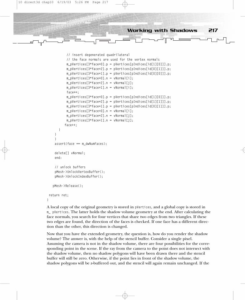
// insert degenerated quadrilateral// the face normals are used for the vertex normalsm_pVertices[3*face+0].p = pVertices[pIndices[id[1][0]]].p;m_pVertices[3*face+2].p = pVertices[pIndices[id[0][1]]].p;m_pVertices[3*face+1].p = pVertices[pIndices[id[0][0]]].p;m_pVertices[3*face+0].n = vNormal[i];m_pVertices[3*face+2].n = vNormal[j];m_pVertices[3*face+1].n = vNormal[i];face++;m_pVertices[3*face+0].p = pVertices[pIndices[id[1][0]]].p;m_pVertices[3*face+2].p = pVertices[pIndices[id[1][1]]].p;m_pVertices[3*face+1].p = pVertices[pIndices[id[0][1]]].p;m_pVertices[3*face+0].n = vNormal[i];m_pVertices[3*face+2].n = vNormal[j];m_pVertices[3*face+1].n = vNormal[j];
face++;}
}}assert(face == m_dwNumFaces);
delete[] vNormal;end:
// unlock bufferspMesh->UnlockVertexBuffer();pMesh->UnlockIndexBuffer();
pMesh->Release();
return ret;}
A local copy of the original geometry is stored in pVertices, and a global copy is stored in m_ pVertices. The latter holds the shadow volume geometry at the end. After calculating theface normals, you search for four vertices that share two edges from two triangles. If thesetwo edges are found, the direction of the faces is checked. If one face has a different direc-tion than the other, this direction is changed.
Now that you have the extended geometry, the question is, how do you render the shadowvolume? The answer is, with the help of the stencil buffer. Consider a single pixel.Assuming the camera is not in the shadow volume, there are four possibilities for the corre-sponding point in the scene. If the ray from the camera to the point does not intersect withthe shadow volume, then no shadow polygons will have been drawn there and the stencilbuffer will still be zero. Otherwise, if the point lies in front of the shadow volume, theshadow polygons will be z-buffered out, and the stencil will again remain unchanged. If the
217Working with Shadows
10 direct3d chap10 6/19/03 5:26 PM Page 217

point lies behind the shadow volume, then the same number of front shadow faces as backfaces will have been rendered, and the stencil will be zero, having been incremented asmany times as decremented. The final possibility is that the point lies inside the shadow volume. In this case, the back face of the shadow volume will be z-buffered out (but not thefront face), so the stencil buffer will be a non-zero value. The result is that portions of theframe buffer lying in shadow will have a non-zero stencil value. To achieve this functionality,the example program performs the following steps:
1. Clear the render target, z-buffer, and stencil buffer.
2. Render the scene into the color buffer and the z-buffer.
3. Disable color-buffer writes and z-buffer writes, activate the stencil buffer, and switchon flat-shading mode.
4. Pass the stencil buffer. When the stencil test passes or fails, increment the stencilbuffer.
5. If the depth test fails:
a. If a two-sided stencil buffer is supported, switch it on.
1) Decrement the second side of the stencil buffer when the depth test fails.
2) Switch off back face culling.
3) Render the shadow volumes, filling up the two-sided stencil buffer, and go toStep 6.
b. If a two-sided stencil buffer is not supported:
1) Render front-facing polygons.
2) Reverse the culling order so the back sides can be written to the stencil buffer.
3) Decrement the stencil buffer. When the depth tests fails, render the back-facingpolygons.
6. Repeat Steps 4 and 5 for every light source.
7. Switch on Gouraud shading, color writes, and z-buffer writes; deactivate the stencilbuffer; and switch off the z-buffer.
8. Where the stencil value is greater than or equal to 1, render your scene into ashadow mask.
9. Alpha blend #8 with #2 (optional).
The key to this and other volumetric stencil buffer effects is the interaction between thestencil buffer and the z-buffer. A scene with a shadow volume is rendered in three stages.First, the scene without the shadow is rendered as usual, using the z-buffer. Next, theshadow is marked out in the stencil buffer. The front faces of the shadow volume are drawnusing invisible polygons, with z-testing enabled, z-writes disabled, and the stencil bufferincremented at every pixel passing the z-test. The back faces of the shadow volume are rendered similarly, but with the stencil value decremented instead.
218 10. More Advanced Shader Effects
10 direct3d chap10 6/19/03 5:26 PM Page 218
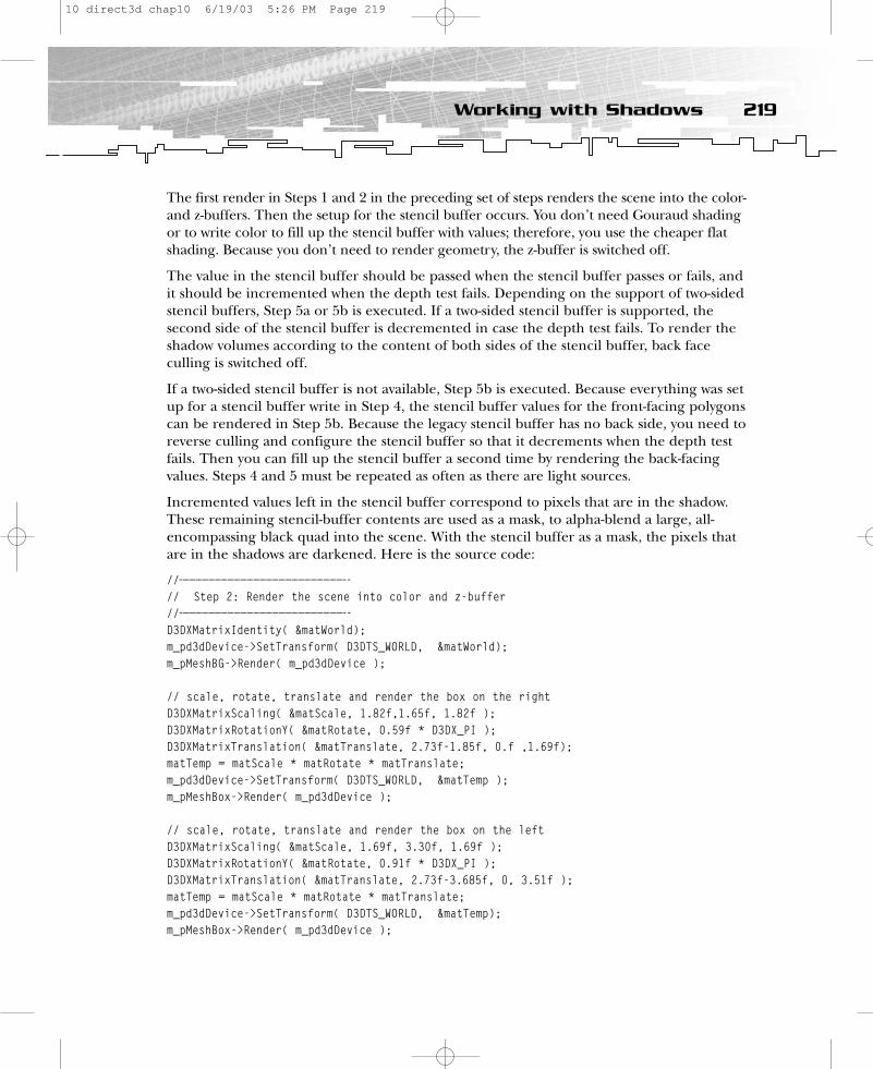
The first render in Steps 1 and 2 in the preceding set of steps renders the scene into the color-and z-buffers. Then the setup for the stencil buffer occurs. You don’t need Gouraud shadingor to write color to fill up the stencil buffer with values; therefore, you use the cheaper flatshading. Because you don’t need to render geometry, the z-buffer is switched off.
The value in the stencil buffer should be passed when the stencil buffer passes or fails, andit should be incremented when the depth test fails. Depending on the support of two-sidedstencil buffers, Step 5a or 5b is executed. If a two-sided stencil buffer is supported, the second side of the stencil buffer is decremented in case the depth test fails. To render theshadow volumes according to the content of both sides of the stencil buffer, back faceculling is switched off.
If a two-sided stencil buffer is not available, Step 5b is executed. Because everything was setup for a stencil buffer write in Step 4, the stencil buffer values for the front-facing polygonscan be rendered in Step 5b. Because the legacy stencil buffer has no back side, you need toreverse culling and configure the stencil buffer so that it decrements when the depth testfails. Then you can fill up the stencil buffer a second time by rendering the back-facing values. Steps 4 and 5 must be repeated as often as there are light sources.
Incremented values left in the stencil buffer correspond to pixels that are in the shadow.These remaining stencil-buffer contents are used as a mask, to alpha-blend a large, all-encompassing black quad into the scene. With the stencil buffer as a mask, the pixels thatare in the shadows are darkened. Here is the source code:
//——————————————————————————-// Step 2: Render the scene into color and z-buffer//——————————————————————————-D3DXMatrixIdentity( &matWorld);m_pd3dDevice->SetTransform( D3DTS_WORLD, &matWorld);m_pMeshBG->Render( m_pd3dDevice );
// scale, rotate, translate and render the box on the rightD3DXMatrixScaling( &matScale, 1.82f,1.65f, 1.82f );D3DXMatrixRotationY( &matRotate, 0.59f * D3DX_PI );D3DXMatrixTranslation( &matTranslate, 2.73f-1.85f, 0.f ,1.69f);matTemp = matScale * matRotate * matTranslate;m_pd3dDevice->SetTransform( D3DTS_WORLD, &matTemp );m_pMeshBox->Render( m_pd3dDevice );
// scale, rotate, translate and render the box on the leftD3DXMatrixScaling( &matScale, 1.69f, 3.30f, 1.69f );D3DXMatrixRotationY( &matRotate, 0.91f * D3DX_PI );D3DXMatrixTranslation( &matTranslate, 2.73f-3.685f, 0, 3.51f );matTemp = matScale * matRotate * matTranslate;m_pd3dDevice->SetTransform( D3DTS_WORLD, &matTemp);m_pMeshBox->Render( m_pd3dDevice );
219Working with Shadows
10 direct3d chap10 6/19/03 5:26 PM Page 219
//——————————————————————————————// —————————————————————————————-// Step 3: Disable color writes, z-buffer writes, activate // stencil buffer, switch on flat shading mode//——————————————————————————————m_pd3dDevice->SetRenderState( D3DRS_ZWRITEENABLE, FALSE );
// prevent the update of the color bufferm_pd3dDevice->SetRenderState( D3DRS_COLORWRITEENABLE, FALSE );
// switch on flat shadingm_pd3dDevice->SetRenderState( D3DRS_SHADEMODE, D3DSHADE_FLAT );
// switch on stencil bufferm_pd3dDevice->SetRenderState( D3DRS_STENCILENABLE, TRUE );
// The comparison function is used to compare the reference // value to a stencil buffer entry. This comparison applies // only to the bits in the reference value and stencil buffer // entry that are set in the stencil mask (set by the // D3DRS_STENCILMASK render state). If TRUE, the stencil test // passes. m_pd3dDevice->SetRenderState(D3DRS_STENCILFUNC, D3DCMP_ALWAYS);
// An int reference value for the stencil test. The default // value is 0.m_pd3dDevice->SetRenderState( D3DRS_STENCILREF, 0x1 );
// Mask applied to the reference value and each stencil buffer // entry to determine the significant bits for the stencil // test. The default mask is 0xFFFFFFFF. m_pd3dDevice->SetRenderState( D3DRS_STENCILMASK, 0xffffffff);m_pd3dDevice->SetRenderState(D3DRS_STENCILWRITEMASK, 0xffffffff);
//——————————————————————————————-// Step 4: pass stencil buffer, when the stencil test passes or // fails//——————————————————————————————-m_pd3dDevice->SetRenderState( D3DRS_STENCILPASS, D3DSTENCILOP_KEEP);m_pd3dDevice->SetRenderState( D3DRS_STENCILFAIL, D3DSTENCILOP_KEEP);
//——————————————————————————————-// Step 5: increment stencil buffer, when the depth test fails//——————————————————————————————-
220 10. More Advanced Shader Effects
10 direct3d chap10 6/19/03 5:26 PM Page 220
m_pd3dDevice->SetRenderState( D3DRS_STENCILZFAIL, D3DSTENCILOP_INCR );
//——————————————————————————————-// Step 6: if the two-sided stencil buffer is supported by // hardware//——————————————————————————————-if( ( m_d3dCaps.StencilCaps & D3DSTENCILCAPS_TWOSIDED ) != 0 ){
// same for the second side of the stencil buffer ...m_pd3dDevice->SetRenderState( D3DRS_TWOSIDEDSTENCILMODE,
TRUE );m_pd3dDevice->SetRenderState( D3DRS_CCW_STENCILFUNC,
D3DCMP_ALWAYS );
//———————————————————————————-// Step 6. a): decrement the second side of the stencil // buffer, when the depth test fails//——————————————————————————————-
m_pd3dDevice->SetRenderState( D3DRS_CCW_STENCILZFAIL, D3DSTENCILOP_DECR );
//———————————————————————————-// Step 6. b): switch off backface culling
//———————————————————————————-m_pd3dDevice->SetRenderState( D3DRS_CULLMODE,
D3DCULL_NONE );
//———————————————————————————-// Step 6. c): Render shadow volume//———————————————————————————-if( m_pEffect != NULL ){
D3DXHANDLE hTechnique = m_pEffect->GetTechniqueByName( “TShader” );
m_pEffect->SetTechnique( hTechnique );m_pEffect->Begin( NULL, 0 );m_pEffect->Pass( 0 );
// scale, rotate and translate the shadow of the // box on the right
D3DXMatrixScaling( &matScale, 1.82f,1.65f, 1.82f);D3DXMatrixRotationY( &matRotate, 0.59f * D3DX_PI);D3DXMatrixTranslation( &matTranslate, 2.73f-1.85f,
0.f , 1.69f );
221Working with Shadows
10 direct3d chap10 6/19/03 5:26 PM Page 221
matWorld = matScale * matRotate * matTranslate;matTemp = matWorld * m_matView * m_matProj;m_pEffect->SetMatrix(“matWorldViewProj”,&matTemp);D3DXMatrixInverse( &matTemp, NULL, &matWorld);D3DXVec3Transform( &vVector, &m_LighPos,&matTemp);m_pEffect->SetVector(“vLightPos”, &vVector);m_pShadowBox->Render( m_pd3dDevice );
// scale, rotate and translate the shadow of the // box on the left
D3DXMatrixScaling( &matScale, 1.69f, 3.30f, 1.69f );D3DXMatrixRotationY( &matRotate, 0.91f * D3DX_PI );D3DXMatrixTranslation(&matTranslate, 2.73f-3.685f,
0, 3.51f );matWorld = matScale * matRotate * matTranslate;matTemp = matWorld * m_matView * m_matProj;m_pEffect->SetMatrix(“matWorldViewProj”,&matTemp);D3DXMatrixInverse( &matTemp, NULL, &matWorld);D3DXVec3Transform( &vVector, &m_LighPos,
&matTemp );m_pEffect->SetVector(“vLightPos”, &vVector );m_pShadowBox->Render( m_pd3dDevice );
m_pEffect->End();}m_pd3dDevice->SetRenderState( D3DRS_TWOSIDEDSTENCILMODE,
FALSE );}
//——————————————————————————————-// Step 7: else if two-sided stencil buffer is not supported // (non-DX9 hardware)//——————————————————————————————-else{//———————————————————————————// Step 7. a): render front-facing polygons//———————————————————————————
if( m_pEffect != NULL ){
D3DXHANDLE hTechnique = m_pEffect->GetTechniqueByName( “TShader” );
m_pEffect->SetTechnique( hTechnique );m_pEffect->Begin( NULL, 0 );m_pEffect->Pass( 0 );
222 10. More Advanced Shader Effects
10 direct3d chap10 6/19/03 5:26 PM Page 222

// scale, rotate and translate the shadow of the box // on the rightD3DXMatrixScaling( &matScale, 1.82f,1.65f, 1.82f );D3DXMatrixRotationY( &matRotate, 0.59f * D3DX_PI );D3DXMatrixTranslation( &matTranslate, 2.73f-1.85f,
0.f , 1.69f );matWorld = matScale * matRotate * matTranslate;matTemp = matWorld * m_matView * m_matProj;m_pEffect->SetMatrix(“matWorldViewProj”, &matTemp);D3DXMatrixInverse( &matTemp, NULL, &matWorld);D3DXVec3Transform( &vVector, &m_LighPos, &matTemp);m_pEffect->SetVector(“vLightPos”, &vVector);m_pShadowBox->Render( m_pd3dDevice );
// scale, rotate and translate the shadow of the // box on the leftD3DXMatrixScaling(&matScale, 1.69f, 3.30f, 1.69f);D3DXMatrixRotationY(&matRotate, 0.91f * D3DX_PI);D3DXMatrixTranslation(&matTranslate, 2.73f-3.685f,
0, 3.51f );matWorld = matScale * matRotate * matTranslate;matTemp = matWorld * m_matView * m_matProj;m_pEffect->SetMatrix(“matWorldViewProj”, &matTemp);D3DXMatrixInverse( &matTemp, NULL, &matWorld);D3DXVec3Transform( &vVector, &m_LighPos, &matTemp );m_pEffect->SetVector(“vLightPos”, &vVector );m_pShadowBox->Render( m_pd3dDevice );
m_pEffect->End();}
//——————————————————————————————-// Step 7. b): reverse culling order so the back sides can be // written to stencil buffer//——————————————————————————————-m_pd3dDevice->SetRenderState( D3DRS_CULLMODE, D3DCULL_CW );
//——————————————————————————————-// Step 7. c): decrement stencil buffer, when depth test fails//——————————————————————————————-
m_pd3dDevice->SetRenderState( D3DRS_STENCILZFAIL, D3DSTENCILOP_DECR );
//——————————————————————————————-// Step 7. d): render back-facing polygons//——————————————————————————————-
223Working with Shadows
10 direct3d chap10 6/19/03 5:26 PM Page 223

if( m_pEffect != NULL ){
D3DXHANDLE hTechnique = m_pEffect->GetTechniqueByName( “TShader” );
m_pEffect->SetTechnique( hTechnique );m_pEffect->Begin( NULL, 0 );m_pEffect->Pass( 0 );
// scale, rotate and translate the shadow of the box on // the rightD3DXMatrixScaling( &matScale, 1.82f,1.65f, 1.82f );D3DXMatrixRotationY( &matRotate, 0.59f * D3DX_PI );D3DXMatrixTranslation(&matTranslate, 2.73f-1.85f, 0.f,
1.69f );matWorld = matScale * matRotate * matTranslate;matTemp = matWorld * m_matView * m_matProj;m_pEffect->SetMatrix(“matWorldViewProj”, &matTemp);D3DXMatrixInverse( &matTemp, NULL, &matWorld);D3DXVec3Transform( &vVector, &m_LighPos, &matTemp);m_pEffect->SetVector(“vLightPos”, &vVector);m_pShadowBox->Render( m_pd3dDevice );
// scale, rotate and translate the shadow of the // box on the leftD3DXMatrixScaling( &matScale, 1.69f, 3.30f, 1.69f );D3DXMatrixRotationY( &matRotate, 0.91f * D3DX_PI );D3DXMatrixTranslation(&matTranslate, 2.73f-3.685f,
0, 3.51f );matWorld = matScale * matRotate * matTranslate;matTemp = matWorld * m_matView * m_matProj;m_pEffect->SetMatrix(“matWorldViewProj”,&matTemp);D3DXMatrixInverse( &matTemp, NULL, &matWorld);D3DXVec3Transform(&vVector, &m_LighPos, &matTemp);m_pEffect->SetVector(“vLightPos”, &vVector );m_pShadowBox->Render( m_pd3dDevice );
m_pEffect->End();}
}
If the new two-sided stencil buffer is not supported, the shadow geometry is drawn twiceper light source, putting pressure on the vertex throughput of the GPU. The two-sided stencil feature was designed to mitigate this situation. The advantage of the two-sided stencil buffer is that it reduces this process to one rendering pass.
224 10. More Advanced Shader Effects
10 direct3d chap10 6/19/03 5:26 PM Page 224

You render the shadow volumes by performing the following steps:
1. Cast a light ray from the light source.
2. To find out whether a vertex is facing the light or pointing away from it, store the dot-product of the light ray and the normal (L.N).
3. Depending on the value of L.N, store 0 or 1 in the variable scale.
4. Reduce the position value of the shadow geometry slightly, so that the shadow does not overlap the edges of the objects.
5. Scale the direction of the light ray and subtract it from the position value. (This process is also called extruding the shadow volume geometry.) When theshadow volume geometry position is not extended in the direction of the lightsource (scale == 0), it is hidden by the object because it is smaller than the object.
The example source code is quite simple.
VS_OUTPUT VS (float4 Pos: POSITION, float3 Normal : NORMAL){
VS_OUTPUT Out = (VS_OUTPUT)0;
// light to vertex ray float4 dir = vLightPos - Pos;
// dot ray and normal float LN = dot( Normal, dir );
// scale is 0 for light facing or 1 for non-light facingfloat scale = (LN >= 0) ? 0.0f : 1.0f;
// reduce position slightly of shadow volume geometryPos.xyz -= 0.001f*Pos;
// reduced position – scale * light directionOut.Pos = mul( Pos - scale * dir, matWorldViewProj );
return Out;}
By commenting out the line that starts with Pos.xyz, you can see how the position is slightly reduced. There are several other ways to implement such a technique. Please consult Eric Lengyel’s article “The Mechanics of Robust Stencil Shadows” athttp://www.gamasutra.com/features/20021011/lengyel_pfv.htm for further ideas.
225Working with Shadows
10 direct3d chap10 6/19/03 5:26 PM Page 225
Things to Consider When Using Shadow VolumesPlease note that the example application does not have to choose a specific light sourcefrom several light sources because there is only one. Additionally, a real-world applicationwould determine the objects that should cast shadows in the visible region to reduce theshadow generation only on the visible objects.
You could further improve this example by using Direct3D’s depth-biasing capabilities toovercome the reduced depth precision with increasing distance from the camera. This leadsto a visible flickering when you are zooming in and out using the W and S keys. DirectX 9.0offers the D3DRS_DEPTHBIAS and D3DRS_SLOPESCALEDEPTHBIAS render states to calculate an offset.This offset is used to position the front capping of the shadow volume behind theoccluder’s front-facing geometries. You accomplish this by adding the offset to the fragment’sinterpolated depth value, which is used to create the final depth value for depth testing. To check out these new capabilities, use the values of D3DPRASTERCAPS_DEPTHBIAS andD3DPRASTERCAPS_SLOPESCALEDEPTHBIAS. If this functionality is not supported, the fallback path is to use the legacy D3DRS_DEPTHBIAS render state.
You can reduce the shadow geometry data set by being more selective regarding the insertion of quads. You might accomplish this by checking the direction of the normal, asdescribed previously. Additionally, a low-polygon model of the occluder might be sufficientto compute the shadow-volume geometry.
Remember that a closed volume mesh is one of the requirements for shadow volumes.Otherwise, any gaps within the mesh would potentially throw the stencil counting off bal-ance, and thus break the shadow-volume implementation. Such a requirement mandatesthe need for modelers and designers to alter their workflow and modeling styles to avoidcompromising the graphics engine.
Another thing to remember is that it is quite complicated to use shadow volumes togetherwith skinned meshes. Chris Brennan describes a solution for this in Direct3D ShaderX: Vertex and Pixel Shader Tips and Tricks (Wordware Publishing, 2002).
SummaryThis chapter covered two very important techniques that are currently used in games andwill likely continue to be used for the next few years. A basic understanding of how cubemaps work will be helpful for understanding more advanced techniques that are currentlybeing developed. The stencil shadow volume technique showed you how you can use thestencil buffer to track regions of a scene. Understanding this concept will also help you withmany other techniques.
226 10. More Advanced Shader Effects
10 direct3d chap10 6/19/03 5:26 PM Page 226

CHAPTER 11
Workingwith Files
11 direct3d chap11 6/19/03 5:27 PM Page 227
There are a lot of file formats out there. However, you can distinguish between file for-mats typically used by graphic artists and formats typically used in game engines. File
formats used by 3D tools include .3ds, .max, and .cof, and they are produced by those tools.These formats have a lot of information in them, and they are not optimized for use in real-time environments like game engines. Games use faster and simpler file formats, which dif-fer between game genres and are generally unique to one game.
One of the most challenging economical considerations in game production is to build aproper workflow for the graphic information that must be exchanged between the 3Dgraphic artist and the game engine programmer. The typical solution to this problem is towrite custom tools, which import, for example, the 3D Studio Max file and export it, aftermodification, in the game engine format.
The game engine formats used in id Software’s Quake series are widely used because manygame companies license the Quake engines. Therefore, I’ll concentrate on the Microsoft Xfile format used in DirectX in this chapter, and Quake 3’s .md3 model format in the follow-ing chapter. I think these are easy to learn. If you know these two formats, you should beable to understand and use other formats as well.
In this chapter, you’ll learn how to:
• Work with 3D file formats
• Use transformation matrices
• Work with X files
3D File Formats3D scene file formats present two fundamental problems—how to store the objects that willmake up the scene, and how to store the relationships between these objects. User-defineddata types are necessary. Scene data requires hierarchical relationships, such as parent,child, and sibling relationships, and associational relationships, such as meshes attached toframes, materials attached to meshes, and so on. In addition, a file format design should berobust enough to handle forward and backward compatibility.
The X file format handles all of these tasks, so it’s a good solution to show the loading of3D models into a game engine in this book.
228 11. Working with Files
11 direct3d chap11 6/19/03 5:27 PM Page 228

The X File FormatThe Direct3D X file format was built for the legacy retained mode of Direct3D andexpanded with the advent of DirectX 6.0 for Immediate Mode. Take a look at how the X file format solves the problems described in the previous section on an abstract level.
• User-defined data types. X files are driven by templates, which can be defined by theuser. A template is the definition of how a data object should be stored. The prede-fined templates are contained in the directory headers rmxftmpl.h in d3dfile.cppand rmxftmpl.x in x:\mssdk\include, and their identification signatures are inrmxfguid.h, which is also included in d3dfile.cpp, one of the common files.
• Hierarchical relationships. Data types allowed by the template are called optionalmembers. These optional members are saved as children of the data object. The chil-dren can be another data object, a reference to an earlier data object, or a binaryobject.
OK, let’s dive into the X file format with a sample—a square, which is located in square.x.To try out and play with the following files, use the MeshViewer provided with the DirectX 9SDK (see Figure 11.1).
And here’s the source:
xof 0303txt 0032
// squareMesh Square {// front face and back face8; // number of vertices1.0; 1.0; 0.0;, // vertice 0
229The X File Format
Figure 11.1
Square.x in the DX9MeshViewer
11 direct3d chap11 6/19/03 5:27 PM Page 229

-1.0; 1.0; 0.0;, // vertice 1-1.0;-1.0; 0.0;, // vertice 21.0;-1.0; 0.0; // vertice 31.0; 1.0; 0.0;, // vertice 41.0;-1.0; 0.0;, // vertice 5
-1.0;-1.0; 0.0;, // vertice 6-1.0; 1.0; 0.0;; // vertice 74; // number of triangles3;0,1,2;, // triangle #13;0,2,3;, // triangle #23;4,5,6;, // triangle #33;4,6,7;; // triangle #4
MeshMaterialList {1; // one material4; // four faces0, // face #0 use material #00, // face #1 use material #00, // face #2 use material #00;; // face #3 use material #0
Material { // material #00.0;1.0;0.0;1.0;; // face color0.0; // power0.0;0.0;0.0;; // specular color0.0;0.0;0.0;; // emissive color
}}
}
HeaderThe magic 4-byte number is xof. The major version number is 03, and the minor versionnumber is 03. The file format is txt for text or bin for a binary format.
Additionally, the legacy *.x file format supported by the legacy Direct3D retained modeuses a template called Header. Its declaration can be found in rmxftmpl.x, like the declara-tion of all other templates.
Other possible file formats are tzip and bzip, which stand for MSZip compressed text orbinary files, respectively. The floating-point data type is set to 0032 instead of 0064.
As you can see in the code, comments are set with either the double slash (as in C++) orthe hash symbol (#).
230 11. Working with Files
11 direct3d chap11 6/19/03 5:27 PM Page 230
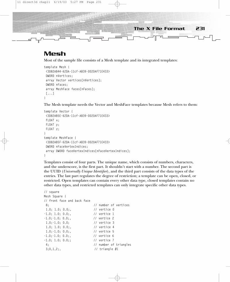
MeshMost of the sample file consists of a Mesh template and its integrated templates:
template Mesh {<3D82AB44-62DA-11cf-AB39-0020AF71E433>DWORD nVertices;array Vector vertices[nVertices];DWORD nFaces;array MeshFace faces[nFaces];[...]
}
The Mesh template needs the Vector and MeshFace templates because Mesh refers to them:
template Vector {<3D82AB5E-62DA-11cf-AB39-0020AF71E433>FLOAT x;FLOAT y;FLOAT z;
}template MeshFace {<3D82AB5F-62DA-11cf-AB39-0020AF71E433>DWORD nFaceVertexIndices;array DWORD faceVertexIndices[nFaceVertexIndices];
}
Templates consist of four parts. The unique name, which consists of numbers, characters,and the underscore, is the first part. It shouldn’t start with a number. The second part isthe UUID (Universally Unique Identifier), and the third part consists of the data types of theentries. The last part regulates the degree of restriction; a template can be open, closed, orrestricted. Open templates can contain every other data type, closed templates contain noother data types, and restricted templates can only integrate specific other data types.
// squareMesh Square {// front face and back face8; // number of vertices1.0; 1.0; 0.0;, // vertice 0
-1.0; 1.0; 0.0;, // vertice 1-1.0;-1.0; 0.0;, // vertice 21.0;-1.0; 0.0; // vertice 31.0; 1.0; 0.0;, // vertice 41.0;-1.0; 0.0;, // vertice 5
-1.0;-1.0; 0.0;, // vertice 6-1.0; 1.0; 0.0;; // vertice 74; // number of triangles3;0,1,2;, // triangle #1
231The X File Format
11 direct3d chap11 6/19/03 5:27 PM Page 231
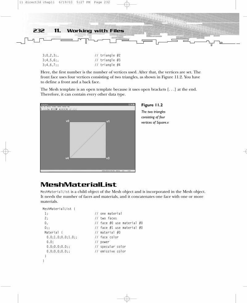
3;0,2,3;, // triangle #23;4,5,6;, // triangle #33;4,6,7;; // triangle #4
Here, the first number is the number of vertices used. After that, the vertices are set. Thefront face uses four vertices consisting of two triangles, as shown in Figure 11.2. You have to define a front and a back face.
The Mesh template is an open template because it uses open brackets [. . .] at the end.Therefore, it can contain every other data type.
MeshMaterialListMeshMaterialList is a child object of the Mesh object and is incorporated in the Mesh object.It needs the number of faces and materials, and it concatenates one face with one or morematerials.
MeshMaterialList {1; // one material2; // two faces0, // face #0 use material #00;; // face #1 use material #0Material { // material #00.0;1.0;0.0;1.0;; // face color0.0; // power0.0;0.0;0.0;; // specular color0.0;0.0;0.0;; // emissive color
}}
232 11. Working with Files
Figure 11.2
The two trianglesconsisting of fourvertices of Square.x
11 direct3d chap11 6/19/03 5:27 PM Page 232
The template in rmxftmpl.x looks like:
template MeshMaterialList {<f6f23f42-7686-11cf-8f52-0040333594a3>DWORD nMaterials;DWORD nFaceIndexes;array DWORD faceIndexes[nFaceIndexes];[Material]
}
The first variable holds the number of materials used by this sample. The second variableholds the number of faces. The square uses the front and back faces, so the variable has tobe set to 2. The concatenation of the materials with the faces happens with the faceIndexesarray. Every face is concatenated with a material by naming the material number. The X filereader knows the proper face by counting the number of faces provided.
Beneath that array, you could integrate Material templates. The MeshMaterialList templateis a restricted template because only specified templates can be integrated.
template Material {<3D82AB4D-62DA-11cf-AB39-0020AF71E433>ColorRGBA faceColor;FLOAT power;ColorRGB specularColor;ColorRGB emissiveColor;[...]
}
This template incorporates the following two templates:
template ColorRGBA {<35FF44E0-6C7C-11cf-8F52-0040333594A3>FLOAT red;FLOAT green;FLOAT blue;FLOAT alpha;
}template ColorRGB {FLOAT red;FLOAT green;FLOAT blue;
}
The Material data object holds the material color, power, specular color, and emissive color.The open brackets show that it can integrate other data objects. You can reference theMaterial data object by MeshMaterialList. The file square2.x shows two referenced Materialdata objects.
xof 0303txt 0032
233The X File Format
11 direct3d chap11 6/19/03 5:27 PM Page 233

Material GreenMat { // material #00.0;1.0;0.0;1.0;;0.0;0.0;0.0;0.0;;0.0;0.0;0.0;;
}Material RedMat { // material #11.0;0.0;0.0;1.0;;0.0;0.0;0.0;0.0;;0.0;0.0;0.0;;
}// squareMesh Square {// front face and back face8; // number of vertices1.0; 1.0; 0.0;, // vertice 0
-1.0; 1.0; 0.0;, // vertice 1-1.0;-1.0; 0.0;, // vertice 21.0;-1.0; 0.0; // vertice 31.0; 1.0; 0.0;, // vertice 41.0;-1.0; 0.0;, // vertice 5
-1.0;-1.0; 0.0;, // vertice 6-1.0; 1.0; 0.0;; // vertice 74; // number of triangles3;0,1,2;, // triangle #13;0,2,3;, // triangle #23;4,5,6;, // triangle #33;4,6,7;; // triangle #4
MeshMaterialList {2; // two material4; // four faces0, // face #0 use material #00, // face #1 use material #01, // face #0 use material #01;; // face #1 use material #0 {GreenMat}{RedMat}
}VertexDuplicationIndices {8;8;0,1,2,3,
234 11. Working with Files
11 direct3d chap11 6/19/03 5:27 PM Page 234
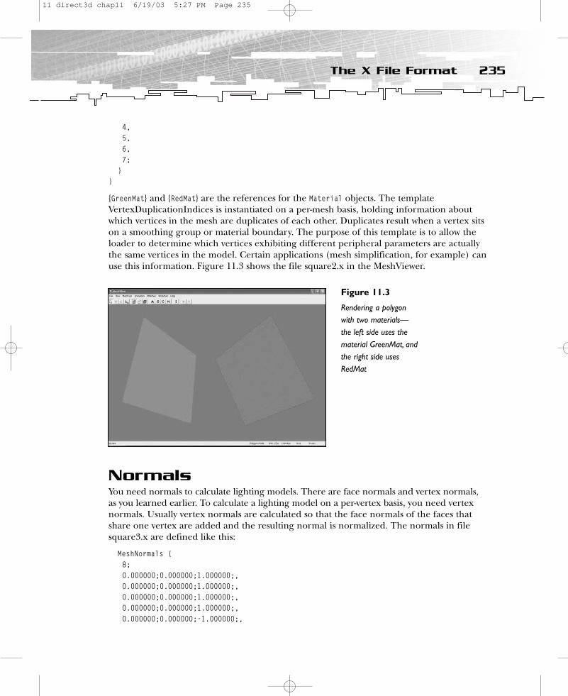
4,5,6,7;
}}
{GreenMat} and {RedMat} are the references for the Material objects. The templateVertexDuplicationIndices is instantiated on a per-mesh basis, holding information aboutwhich vertices in the mesh are duplicates of each other. Duplicates result when a vertex sitson a smoothing group or material boundary. The purpose of this template is to allow theloader to determine which vertices exhibiting different peripheral parameters are actuallythe same vertices in the model. Certain applications (mesh simplification, for example) canuse this information. Figure 11.3 shows the file square2.x in the MeshViewer.
NormalsYou need normals to calculate lighting models. There are face normals and vertex normals,as you learned earlier. To calculate a lighting model on a per-vertex basis, you need vertexnormals. Usually vertex normals are calculated so that the face normals of the faces thatshare one vertex are added and the resulting normal is normalized. The normals in filesquare3.x are defined like this:
MeshNormals {8;0.000000;0.000000;1.000000;,0.000000;0.000000;1.000000;,0.000000;0.000000;1.000000;,0.000000;0.000000;1.000000;,0.000000;0.000000;-1.000000;,
235The X File Format
Figure 11.3
Rendering a polygonwith two materials—the left side uses thematerial GreenMat, andthe right side usesRedMat
11 direct3d chap11 6/19/03 5:27 PM Page 235
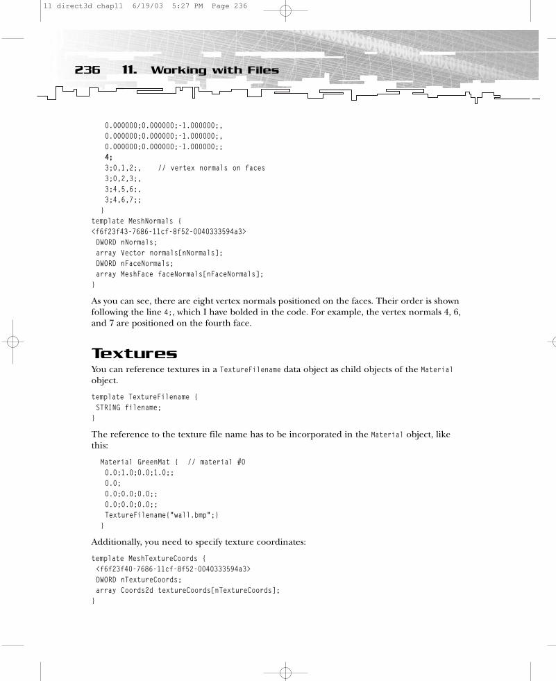
0.000000;0.000000;-1.000000;,0.000000;0.000000;-1.000000;,0.000000;0.000000;-1.000000;;44;;3;0,1,2;, // vertex normals on faces3;0,2,3;,3;4,5,6;,3;4,6,7;;
}template MeshNormals { <f6f23f43-7686-11cf-8f52-0040333594a3>DWORD nNormals;array Vector normals[nNormals];DWORD nFaceNormals;array MeshFace faceNormals[nFaceNormals];
}
As you can see, there are eight vertex normals positioned on the faces. Their order is shownfollowing the line 4;, which I have bolded in the code. For example, the vertex normals 4, 6,and 7 are positioned on the fourth face.
TexturesYou can reference textures in a TextureFilename data object as child objects of the Materialobject.
template TextureFilename {STRING filename;
}
The reference to the texture file name has to be incorporated in the Material object, likethis:
Material GreenMat { // material #00.0;1.0;0.0;1.0;;0.0;0.0;0.0;0.0;;0.0;0.0;0.0;;TextureFilename{“wall.bmp”;}
}
Additionally, you need to specify texture coordinates:
template MeshTextureCoords {<f6f23f40-7686-11cf-8f52-0040333594a3>DWORD nTextureCoords;array Coords2d textureCoords[nTextureCoords];
}
236 11. Working with Files
11 direct3d chap11 6/19/03 5:27 PM Page 236
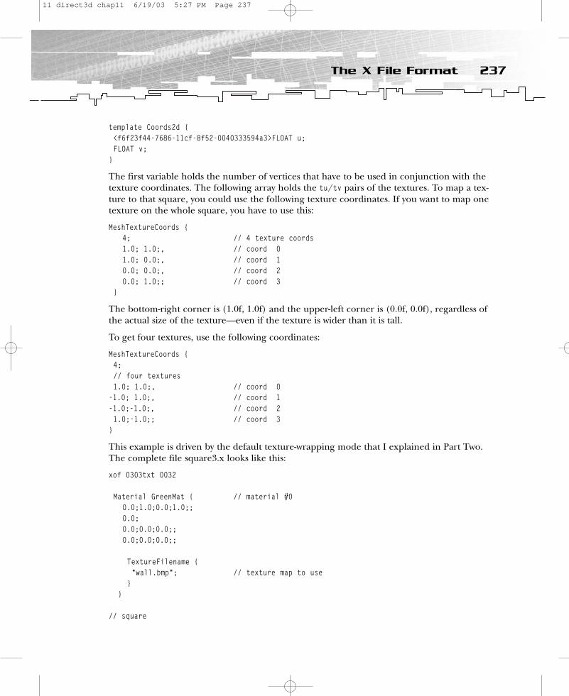
template Coords2d {<f6f23f44-7686-11cf-8f52-0040333594a3>FLOAT u;FLOAT v;
}
The first variable holds the number of vertices that have to be used in conjunction with thetexture coordinates. The following array holds the tu/tv pairs of the textures. To map a tex-ture to that square, you could use the following texture coordinates. If you want to map onetexture on the whole square, you have to use this:
MeshTextureCoords {4; // 4 texture coords1.0; 1.0;, // coord 01.0; 0.0;, // coord 10.0; 0.0;, // coord 20.0; 1.0;; // coord 3
}
The bottom-right corner is (1.0f, 1.0f) and the upper-left corner is (0.0f, 0.0f), regardless ofthe actual size of the texture—even if the texture is wider than it is tall.
To get four textures, use the following coordinates:
MeshTextureCoords {4;// four textures1.0; 1.0;, // coord 0
-1.0; 1.0;, // coord 1-1.0;-1.0;, // coord 21.0;-1.0;; // coord 3
}
This example is driven by the default texture-wrapping mode that I explained in Part Two.The complete file square3.x looks like this:
xof 0303txt 0032
Material GreenMat { // material #00.0;1.0;0.0;1.0;;0.0;0.0;0.0;0.0;;0.0;0.0;0.0;;
TextureFilename {“wall.bmp”; // texture map to use
}}
// square
237The X File Format
11 direct3d chap11 6/19/03 5:27 PM Page 237
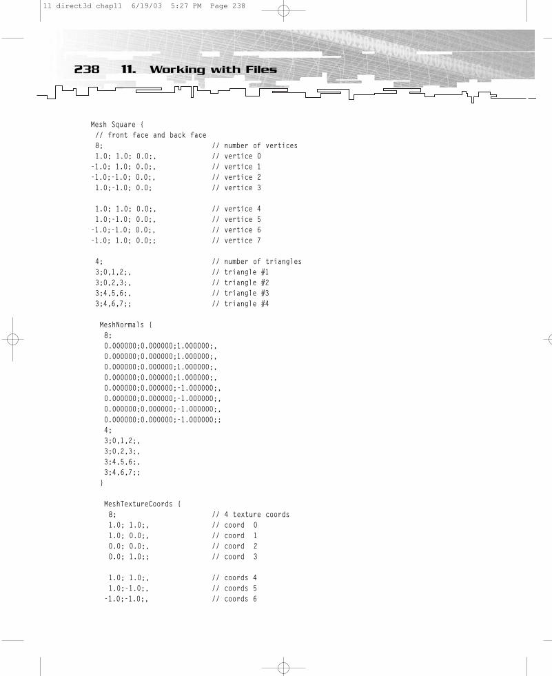
Mesh Square {// front face and back face8; // number of vertices1.0; 1.0; 0.0;, // vertice 0
-1.0; 1.0; 0.0;, // vertice 1-1.0;-1.0; 0.0;, // vertice 21.0;-1.0; 0.0; // vertice 3
1.0; 1.0; 0.0;, // vertice 41.0;-1.0; 0.0;, // vertice 5
-1.0;-1.0; 0.0;, // vertice 6-1.0; 1.0; 0.0;; // vertice 7
4; // number of triangles3;0,1,2;, // triangle #13;0,2,3;, // triangle #23;4,5,6;, // triangle #33;4,6,7;; // triangle #4
MeshNormals {8;0.000000;0.000000;1.000000;,0.000000;0.000000;1.000000;,0.000000;0.000000;1.000000;,0.000000;0.000000;1.000000;,0.000000;0.000000;-1.000000;,0.000000;0.000000;-1.000000;,0.000000;0.000000;-1.000000;,0.000000;0.000000;-1.000000;;4;3;0,1,2;,3;0,2,3;,3;4,5,6;,3;4,6,7;;
}
MeshTextureCoords {8; // 4 texture coords1.0; 1.0;, // coord 01.0; 0.0;, // coord 10.0; 0.0;, // coord 20.0; 1.0;; // coord 3
1.0; 1.0;, // coords 41.0;-1.0;, // coords 5
-1.0;-1.0;, // coords 6
238 11. Working with Files
11 direct3d chap11 6/19/03 5:27 PM Page 238
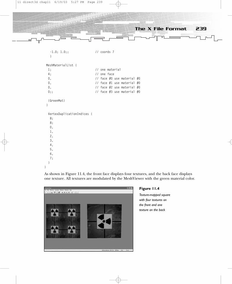
-1.0; 1.0;; // coords 7}
MeshMaterialList {1; // one material4; // one face0, // face #0 use material #00, // face #1 use material #00, // face #2 use material #00;; // face #3 use material #0
{GreenMat}}
VertexDuplicationIndices {8;8;0,1,2,3,4,5,6,7;
}}
As shown in Figure 11.4, the front face displays four textures, and the back face displaysone texture. All textures are modulated by the MeshViewer with the green material color.
239The X File Format
Figure 11.4
Texture-mapped squarewith four textures onthe front and onetexture on the back
11 direct3d chap11 6/19/03 5:27 PM Page 239
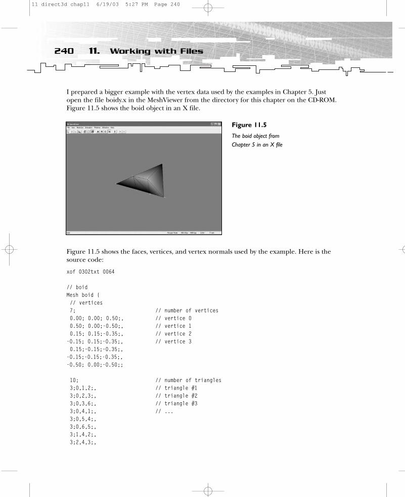
I prepared a bigger example with the vertex data used by the examples in Chapter 5. Justopen the file boidy.x in the MeshViewer from the directory for this chapter on the CD-ROM.Figure 11.5 shows the boid object in an X file.
Figure 11.5 shows the faces, vertices, and vertex normals used by the example. Here is thesource code:
xof 0302txt 0064
// boidMesh boid {// vertices 7; // number of vertices0.00; 0.00; 0.50;, // vertice 00.50; 0.00;-0.50;, // vertice 10.15; 0.15;-0.35;, // vertice 2
-0.15; 0.15;-0.35;, // vertice 30.15;-0.15;-0.35;,
-0.15;-0.15;-0.35;,-0.50; 0.00;-0.50;;
10; // number of triangles3;0,1,2;, // triangle #13;0,2,3;, // triangle #23;0,3,6;, // triangle #33;0,4,1;, // ...3;0,5,4;,3;0,6,5;,3;1,4,2;,3;2,4,3;,
240 11. Working with Files
Figure 11.5
The boid object fromChapter 5 in an X file
11 direct3d chap11 6/19/03 5:27 PM Page 240
3;3,4,5;,3;3,5,6;;
MeshMaterialList {1; // one material10; // ten faces0,0;; // face #1 use material #00,0;; // face #2 use material #00,0;; // face #3 use material #00,0;; // face #4 use material #00,0;; // face #5 use material #00,0;; // face #6 use material #00,0;; // face #7 use material #00,0;; // face #8 use material #00,0;; // face #9 use material #00,0;; // face #10 use material #0
Material { // material #01.0;0.92;0.0;1.0;;1.0;0.0;0.0;0.0;;
0.0;0.0;0.0;;}
MeshNormals { 7;0.000000;0.000000;1.000000;,0.984784;0.000000;0.173785;,0.192491;0.971619;-0.137493;,
-0.185863;0.938163;-0.292070;,0.185863;-0.938163;-0.292070;,
-0.192491;-0.971619;-0.137493;,-0.984784;0.000000;0.173785;;10;3;0,1,2;,3;0,2,3;,3;0,3,6;,3;0,4,1;,3;0,5,4;,3;0,6,5;,3;1,4,2;,3;2,4,3;,3;3,4,5;,3;3,5,6;;
241The X File Format
11 direct3d chap11 6/19/03 5:27 PM Page 241
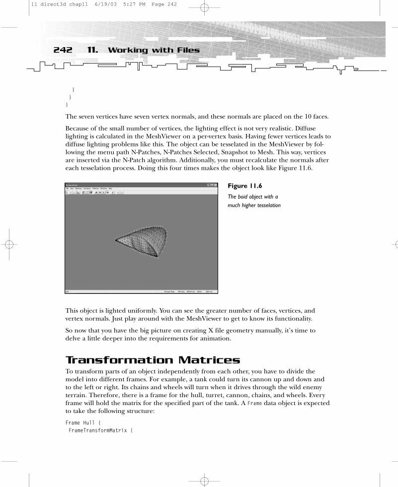
}}
}
The seven vertices have seven vertex normals, and these normals are placed on the 10 faces.
Because of the small number of vertices, the lighting effect is not very realistic. Diffuselighting is calculated in the MeshViewer on a per-vertex basis. Having fewer vertices leads todiffuse lighting problems like this. The object can be tesselated in the MeshViewer by fol-lowing the menu path N-Patches, N-Patches Selected, Snapshot to Mesh. This way, verticesare inserted via the N-Patch algorithm. Additionally, you must recalculate the normals aftereach tesselation process. Doing this four times makes the object look like Figure 11.6.
This object is lighted uniformly. You can see the greater number of faces, vertices, andvertex normals. Just play around with the MeshViewer to get to know its functionality.
So now that you have the big picture on creating X file geometry manually, it’s time todelve a little deeper into the requirements for animation.
Transformation MatricesTo transform parts of an object independently from each other, you have to divide themodel into different frames. For example, a tank could turn its cannon up and down andto the left or right. Its chains and wheels will turn when it drives through the wild enemyterrain. Therefore, there is a frame for the hull, turret, cannon, chains, and wheels. Everyframe will hold the matrix for the specified part of the tank. A Frame data object is expectedto take the following structure:
Frame Hull {FrameTransformMatrix {
242 11. Working with Files
Figure 11.6
The boid object with amuch higher tesselation
11 direct3d chap11 6/19/03 5:27 PM Page 242
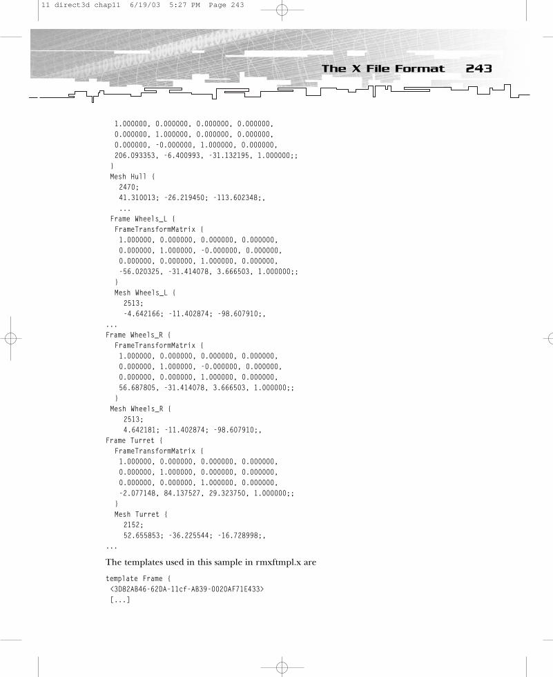
1.000000, 0.000000, 0.000000, 0.000000,0.000000, 1.000000, 0.000000, 0.000000,0.000000, -0.000000, 1.000000, 0.000000,206.093353, -6.400993, -31.132195, 1.000000;;
}Mesh Hull {
2470;41.310013; -26.219450; -113.602348;,...
Frame Wheels_L {FrameTransformMatrix {1.000000, 0.000000, 0.000000, 0.000000,0.000000, 1.000000, -0.000000, 0.000000,0.000000, 0.000000, 1.000000, 0.000000,-56.020325, -31.414078, 3.666503, 1.000000;;
}Mesh Wheels_L {
2513;-4.642166; -11.402874; -98.607910;,
...Frame Wheels_R {
FrameTransformMatrix {1.000000, 0.000000, 0.000000, 0.000000,0.000000, 1.000000, -0.000000, 0.000000,0.000000, 0.000000, 1.000000, 0.000000,56.687805, -31.414078, 3.666503, 1.000000;;
}Mesh Wheels_R {
2513;4.642181; -11.402874; -98.607910;,
Frame Turret {FrameTransformMatrix {1.000000, 0.000000, 0.000000, 0.000000,0.000000, 1.000000, 0.000000, 0.000000,0.000000, 0.000000, 1.000000, 0.000000,-2.077148, 84.137527, 29.323750, 1.000000;;
}Mesh Turret {
2152;52.655853; -36.225544; -16.728998;,
...
The templates used in this sample in rmxftmpl.x are
template Frame {<3D82AB46-62DA-11cf-AB39-0020AF71E433>[...]
243The X File Format
11 direct3d chap11 6/19/03 5:27 PM Page 243

}template FrameTransformMatrix {Matrix4x4 frameMatrix;
}template Matrix4x4 {array FLOAT matrix[16];
}
As an old DirectX Graphics programming freak, you might notice the use of 4×4 matricesas described in Chapter 6. Another simple sample you should look at is the file car.x in the c:\dxsdk\samples\Media directory. Here’s an advanced version of the X file of the sampleprogram boidsy2.x:
xof 0302txt 0064
Frame BOID_Root {FrameTransformMatrix {1.000000, 0.000000, 0.000000, 0.000000,0.000000, 1.000000, 0.000000, 0.000000,0.000000, 0.000000, 1.000000, 0.000000,0.000000, 0.000000, 0.000000, 1.000000;;
}
// boidMesh boid {// vertices 7; // number of vertices0.00; 0.00; 0.50;, // vertice 00.50; 0.00;-0.50;, // vertice 10.15; 0.15;-0.35;, // vertice 2
-0.15; 0.15;-0.35;, // vertice 30.15;-0.15;-0.35;,
-0.15;-0.15;-0.35;,-0.50; 0.00;-0.50;;
10; // number of triangles3;0,1,2;, // triangle #13;0,2,3;, // triangle #23;0,3,6;, // triangle #33;0,4,1;, // ...3;0,5,4;,3;0,6,5;,3;1,4,2;,3;2,4,3;,3;3,4,5;,3;3,5,6;;
244 11. Working with Files
11 direct3d chap11 6/19/03 5:27 PM Page 244

MeshMaterialList {1; // one material10; // ten faces0,0;; // face #1 use material #00,0;; // face #2 use material #00,0;; // face #3 use material #00,0;; // face #4 use material #00,0;; // face #5 use material #00,0;; // face #6 use material #00,0;; // face #7 use material #00,0;; // face #8 use material #00,0;; // face #9 use material #00,0;; // face #10 use material #0
Material { // material #01.0;0.92;0.0;1.0;;1.0;0.0;0.0;0.0;;
0.0;0.0;0.0;;}
MeshNormals { 7;0.000000;0.000000;1.000000;,0.984784;0.000000;0.173785;,0.192491;0.971619;-0.137493;,
-0.185863;0.938163;-0.292070;,0.185863;-0.938163;-0.292070;,
-0.192491;-0.971619;-0.137493;,-0.984784;0.000000;0.173785;;10;3;0,1,2;,3;0,2,3;,3;0,3,6;,3;0,4,1;,3;0,5,4;,3;0,6,5;,3;1,4,2;,3;2,4,3;,3;3,4,5;,3;3,5,6;;}
}}}
245The X File Format
11 direct3d chap11 6/19/03 5:27 PM Page 245
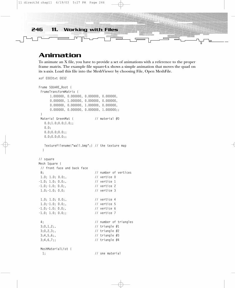
AnimationTo animate an X file, you have to provide a set of animations with a reference to the properframe matrix. The example file square4.x shows a simple animation that moves the quad onits x-axis. Load this file into the MeshViewer by choosing File, Open MeshFile.
xof 0303txt 0032
Frame SQUARE_Root {FrameTransformMatrix {
1.000000, 0.000000, 0.000000, 0.000000,0.000000, 1.000000, 0.000000, 0.000000,0.000000, 0.000000, 1.000000, 0.000000,0.000000, 0.000000, 0.000000, 1.000000;;
}Material GreenMat { // material #0
0.0;1.0;0.0;1.0;;0.0;0.0;0.0;0.0;;0.0;0.0;0.0;;
TextureFilename{“wall.bmp”;} // the texture map}
// squareMesh Square {// front face and back face8; // number of vertices1.0; 1.0; 0.0;, // vertice 0
-1.0; 1.0; 0.0;, // vertice 1-1.0;-1.0; 0.0;, // vertice 21.0;-1.0; 0.0; // vertice 3
1.0; 1.0; 0.0;, // vertice 41.0;-1.0; 0.0;, // vertice 5
-1.0;-1.0; 0.0;, // vertice 6-1.0; 1.0; 0.0;; // vertice 7
4; // number of triangles3;0,1,2;, // triangle #13;0,2,3;, // triangle #23;4,5,6;, // triangle #33;4,6,7;; // triangle #4
MeshMaterialList {1; // one material
246 11. Working with Files
11 direct3d chap11 6/19/03 5:27 PM Page 246
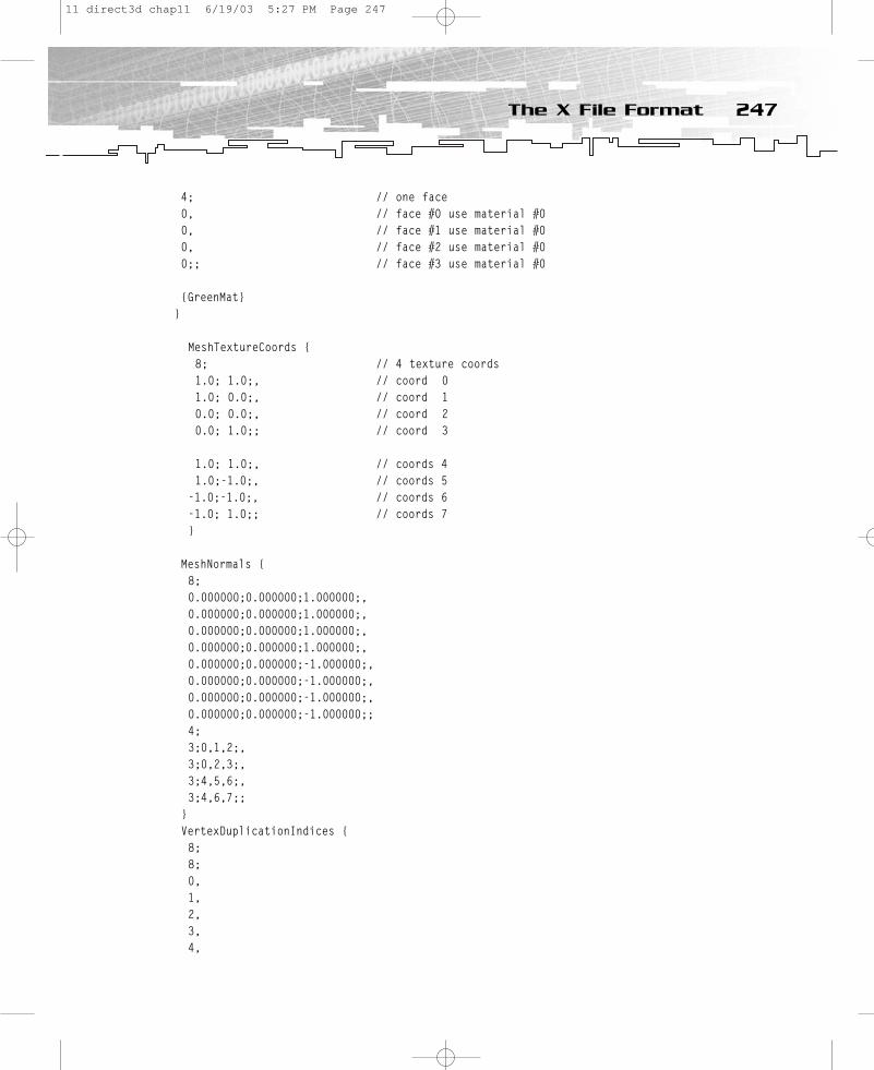
4; // one face0, // face #0 use material #00, // face #1 use material #00, // face #2 use material #00;; // face #3 use material #0
{GreenMat}}
MeshTextureCoords {8; // 4 texture coords1.0; 1.0;, // coord 01.0; 0.0;, // coord 10.0; 0.0;, // coord 20.0; 1.0;; // coord 3
1.0; 1.0;, // coords 41.0;-1.0;, // coords 5
-1.0;-1.0;, // coords 6-1.0; 1.0;; // coords 7}
MeshNormals {8;0.000000;0.000000;1.000000;,0.000000;0.000000;1.000000;,0.000000;0.000000;1.000000;,0.000000;0.000000;1.000000;,0.000000;0.000000;-1.000000;,0.000000;0.000000;-1.000000;,0.000000;0.000000;-1.000000;,0.000000;0.000000;-1.000000;;4;3;0,1,2;,3;0,2,3;,3;4,5,6;,3;4,6,7;;
}VertexDuplicationIndices {8;8;0,1,2,3,4,
247The X File Format
11 direct3d chap11 6/19/03 5:27 PM Page 247

5,6,7;
}}
}
AnimationSet MoveX{Animation {
AnimationKey {4; // Position keys5; // 5 keys0;16;1.0,0.0,0.0,0.0,
0.0,1.0,0.0,0.0,0.0,0.0,1.0,0.0,0.1,0.0,0.0,1.0;;,
80;16;1.0,0.0,0.0,0.0,0.0,1.0,0.0,0.0,0.0,0.0,1.0,0.0,0.2,0.0,0.0,1.0;;,
160;16;1.0,0.0,0.0,0.0,0.0,1.0,0.0,0.0,0.0,0.0,1.0,0.0,0.3,0.0,0.0,1.0;;,
240;16;1.0,0.0,0.0,0.0,0.0,1.0,0.0,0.0,0.0,0.0,1.0,0.0,
0.2,0.0,0.0,1.0;;,320;16;1.0,0.0,0.0,0.0,
0.0,1.0,0.0,0.0,0.0,0.0,1.0,0.0,
0.1,0.0,0.0,1.0;;,}
{SQUARE_Root} }
}
AnimationSet MoveY{Animation {
AnimationKey {4; // Position keys5; // 5 keys0;16;1.0,0.0,0.0,0.0,
0.0,1.0,0.0,0.0,0.0,0.0,1.0,0.0,
248 11. Working with Files
11 direct3d chap11 6/19/03 5:27 PM Page 248
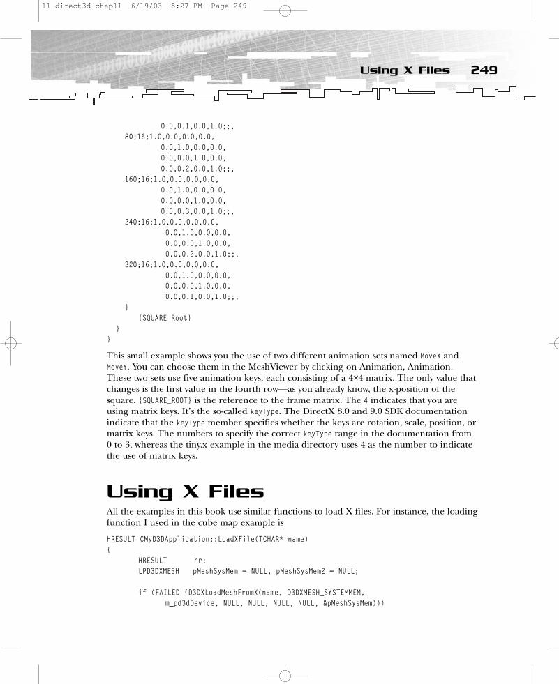
0.0,0.1,0.0,1.0;;,80;16;1.0,0.0,0.0,0.0,
0.0,1.0,0.0,0.0,0.0,0.0,1.0,0.0,0.0,0.2,0.0,1.0;;,
160;16;1.0,0.0,0.0,0.0,0.0,1.0,0.0,0.0,0.0,0.0,1.0,0.0,0.0,0.3,0.0,1.0;;,
240;16;1.0,0.0,0.0,0.0,0.0,1.0,0.0,0.0,0.0,0.0,1.0,0.0,0.0,0.2,0.0,1.0;;,
320;16;1.0,0.0,0.0,0.0,0.0,1.0,0.0,0.0,0.0,0.0,1.0,0.0,0.0,0.1,0.0,1.0;;,
}{SQUARE_Root}
}}
This small example shows you the use of two different animation sets named MoveX andMoveY. You can choose them in the MeshViewer by clicking on Animation, Animation. These two sets use five animation keys, each consisting of a 4×4 matrix. The only value thatchanges is the first value in the fourth row—as you already know, the x-position of thesquare. {SQUARE_ROOT} is the reference to the frame matrix. The 4 indicates that you areusing matrix keys. It’s the so-called keyType. The DirectX 8.0 and 9.0 SDK documentationindicate that the keyType member specifies whether the keys are rotation, scale, position, ormatrix keys. The numbers to specify the correct keyType range in the documentation from 0 to 3, whereas the tiny.x example in the media directory uses 4 as the number to indicatethe use of matrix keys.
Using X FilesAll the examples in this book use similar functions to load X files. For instance, the loadingfunction I used in the cube map example is
HRESULT CMyD3DApplication::LoadXFile(TCHAR* name){
HRESULT hr;LPD3DXMESH pMeshSysMem = NULL, pMeshSysMem2 = NULL;
if (FAILED (D3DXLoadMeshFromX(name, D3DXMESH_SYSTEMMEM, m_pd3dDevice, NULL, NULL, NULL, NULL, &pMeshSysMem)))
249Using X Files
11 direct3d chap11 6/19/03 5:27 PM Page 249
return E_FAIL;
D3DVERTEXELEMENT9 decl[]={
// stream, offset, type, method, semantic type (for example normal), ?{0, 0, D3DDECLTYPE_FLOAT3, D3DDECLMETHOD_DEFAULT, D3DDECLUSAGE_POSITION, 0},{0, 12, D3DDECLTYPE_FLOAT2, D3DDECLMETHOD_DEFAULT, D3DDECLUSAGE_TEXCOORD,
0},{0, 20, D3DDECLTYPE_FLOAT3, D3DDECLMETHOD_DEFAULT, D3DDECLUSAGE_NORMAL, 0},D3DDECL_END()
};
hr = pMeshSysMem->CloneMesh(D3DXMESH_MANAGED, decl, m_pd3dDevice, &pMeshSysMem2);
// compute the normalshr = D3DXComputeNormals(pMeshSysMem2,NULL);if(FAILED(hr))
return E_FAIL;
D3DVERTEXELEMENT9 decl2[]={
// stream, offset, type, method, semantic type (for example normal), ?{0, 0, D3DDECLTYPE_FLOAT4, D3DDECLMETHOD_DEFAULT, D3DDECLUSAGE_POSITION, 0},{0, 16, D3DDECLTYPE_FLOAT2, D3DDECLMETHOD_DEFAULT, D3DDECLUSAGE_TEXCOORD, 0},{0, 24, D3DDECLTYPE_FLOAT3, D3DDECLMETHOD_DEFAULT, D3DDECLUSAGE_NORMAL, 0},D3DDECL_END()
};
hr = pMeshSysMem2->CloneMesh(D3DXMESH_MANAGED, decl2, m_pd3dDevice,&m_pD3DXMesh);
// cleanupSAFE_RELEASE(pMeshSysMem);SAFE_RELEASE(pMeshSysMem2);
return S_OK;}
To load an X file, you use the function D3DXLoadMeshFromX() from the Direct3DX library. Thedeclaration of this function looks like this:
HRESULT D3DXLoadMeshFromX(LPCTSTR pFilename,DWORD Options,LPDIRECT3DDEVICE9 pDevice,LPD3DXBUFFER* ppAdjacency,LPD3DXBUFFER* ppMaterials,
250 11. Working with Files
11 direct3d chap11 6/19/03 5:27 PM Page 250
LPD3DXBUFFER* ppEffectInstances,DWORD* pNumMaterials,LPD3DXMESH* ppMesh
);
The first parameter, pFilename, should get a pointer to the path of the file. The examplesload the *.x file with the help of the Direct3D utility function DXUtil_FindMediaFileCb().
TCHAR strFile[160];DXUtil_FindMediaFileCb(strFile, sizeof(strFile),_T(“teapot.x”));LoadXFile(strFile);
This function searches through the file system to find a file. Options, the second parameterof the D3DXLoadMeshFromX() function, defines the memory pool and some other flags for thevertex and index buffers. The example uses D3DXMESH_SYSTEMMEM, but a better choice mightbe D3DXMESH_MANAGED. The combination D3DXMESH_MANAGED | D3DXMESH_WRITEONLY will not workhere because the function CloneMesh() will also read from the vertex and index buffers.
The third parameter takes the pointer to the device. You don’t need any data on the neigh-bors of faces, so the fourth paramter is set to NULL. Because you also don’t need a pointerto a buffer containing material data or data on effect instances, the next three parametersare NULL. The last parameter returns a pointer to the mesh object that is used to clone themesh and compute normals later. Please note that the D3DXComputeNormal() function, whichis responsible for calculating the normals of the mesh, only accepts a position input valuethat consists of three floats. The two CloneMesh() functions are used to create a clone of theoriginal mesh, which holds the data in the way defined by the D3DVERTEXELEMENT9 structures.The first time the original mesh is cloned to get a data layout that fits the expected data lay-out of the D3DXComputeNormal() function. The second time the already-cloned mesh is clonedagain to get a data layout with a position value consisting of four float values.
Loading non-animated objects is a simple task compared to loading an animated X file.Check out the SkinnedMesh example from the DirectX 9 SDK to see how to load an X filethat uses skinning to animate a figure.
Extending X FilesOne of the most fascinating aspects of the concept behind X files is extensibility. You mightrecall the file rmxftmpl.x, which holds the definitions of the templates. You might define yourown templates in it and make your own X file format this way. For example, a shader templatewith all of the texturing functionality explained in Part Two might be implemented this waywith different parameters and so on. Your files can hold their own shader classes, collisiondetection parameters, physics, specialized animations, paths to sound files, and more.
If you take a look at the following section, you’ll get an idea of what has been done alreadyin this area. I’m sure you’ll be thinking of building your own file format in the next fewhours, with this in mind!
251Extending X Files
11 direct3d chap11 6/19/03 5:27 PM Page 251

Additional ResourcesThis section includes some Web sites you might want to check out to do a little furtherreading on some of the topics covered in this chapter.
X File FormatThe DirectX 9 documenation provides excellent material to search for details. There is alsoan X file dump provided by Rich Thompson at http://www.xmission.com/~legalize/book/snippets/index.html#12.
Skinned MeshesThere is an article at http://www.flipcode.com/articles/article_dx9skinmeshmod.shtml onhow to modularize the skinned mesh example in the DX9 SDK.
You will find an article that explains how skinning works at http://www.gamedev.net/reference/articles/article1835.asp
There is a Spanish Web site that shows a few variations of the skinned mesh example athttp://atc1.aut.uah.es/~infind/Programming/Programming.htm.
Furthermore, there are a few excellent articles on skinning written by Jeff Lander inGameDeveloper magazine. Check out the May 1998 and April 2001 issues.
Additionally, the article from Eike F. Anderson at http://ncca.bournemouth.ac.uk/newhome/alumni/docs/CharacterAnimation.pdf is very helpful. Michael Putz and KlausHufnagl describe a more advanced approach at http://www.cg.tuwien.ac.at/studentwork/CESCG/CESCG-002/MPutzKHufnagl/paper.pdf.
SummaryThis chapter taught you all you ever wanted to know about transformation matrices andMicrosoft’s X file format. Okay, maybe not…but it gave you a good start! And I’m sure youcan’t wait to learn all about the *.md3 file format used by the Quake 3 engine, so turn thepage and let’s move on!
252 11. Working with Files
11 direct3d chap11 6/19/03 5:27 PM Page 252
CHAPTER 12
Using *.md3 Files
12 direct3d chap12 6/19/03 5:32 PM Page 253

This chapter describes the *.md3 file format used by the Quake 3 engine, and containsan example program that demonstrates how to use this format, together with per-pixel
lighting, bump mapping, and an efficient shading system with HLSL shaders.
The .md3 format is an often-used file format, which has been tested extensively and hasproven to be an excellent model format in Quake 3 and many other games. When you diveinto the .md3 format, you’ll dive also into the Quake 3 coding universe. It’s very impressiveto learn how Quake 3 was made by looking at the models, and it doesn’t hurt to take a quicklook at an approved model file spec before you start your own.
Quake 3 uses 800 to 900 faces in the highest level of detail, approximately 500 faces in themiddle level, and 300 faces in the least-detailed level. There is no limit to the number offaces you can use.
These model files store animations in frames with fixed names, different lengths, and dif-ferent speeds for every move. Using key frames is an inexpensive way to handle animations.However, the drawback to key-frame animation is the high amount of memory needed forhigh-tesselated models.
Most of the Quake 3 models own different skins—a.k.a. different texture maps—that can beloaded on demand. You might use the same geometry for a static statue, a soldier, and anofficer with a golden helmet, for example.
Files of the TradeAn .md3 model is normally made of three body parts and the weapon model. So you haveto open three model files and put them together. (If you are using a weapon, you have toopen four.) In Quake 3 they are called head.md3, upper.md3, and lower.md3, as shown inFigure 12.1.
Inside the .md3 files, you can have any number of components. For example, in the DOOMmarine’s head.md3, there is a mesh called h_helmet and one called h_visor. You can applydifferent textures or shader effects to certain components of the model. There’s no limit tothe number of components, but they have to follow the naming convention, which is h_ forhead components, u_ for torso components, and l_ for lower components.
The .md3 files store the character animations in key frames. To visualize key-frame anima-tion, it helps to imagine the use of sprites in old sprite engines. These were long lists of pictures called one after another so the viewer got the impression of a moving object, likein those old celluloid films. The same thing happens in .md3 files with the vertices of poly-
254 12. Using *.MD3 Files
12 direct3d chap12 6/19/03 5:32 PM Page 254

gons. There’s no limit for frames in the engine, but a maximum of 300 might be a goodnumber to keep the rendering fast and the image quality reasonable. Using more wouldlead to quite a large memory footprint. The file that stores the animation data is called animation.cfg, and it directs the call of the key frames.
You can provide three different levels of detail with three different .md3 files for eachmodel. The naming convention of the files used in Quake 3 for the three levels of detail isas follows. For the lowest-detail level, a 2 is placed after the file name; for the middle-detaillevel, a 1 is placed after it; the highest-detail level gets no additional number. So the filenames head.md3, head1.md3, and head2.md3 would be interpreted as highest, middle, andlowest detail, respectively.
The head, torso, and lower body parts are attached to each other by so-called tags. Every tagis just a one-face geometry. The long pointy end of the triangle must face the front. Thebase of the triangle is the actual pivot point. It determines where the respective model willbe rotated. This tag does not have material, so it’s not visible.
There can be three tags in every .md3 model, and the tag name corresponds to its location(see Figure 12.2). The base of the neck is attached to the upper torso with tag_head. At thebase of the spine, the torso is attached to the legs with tag_torso. The weapon is attached tothe hand of the model with tag_weapon. Each model has at least one tag. head.md3 hastag_head; upper.md3 has tag_head, tag_torso, and tag_weapon; and lower.md3 has tag_torso.
255Files of the Trade
Figure 12.1
DOOM marine (originalmodel of Quake 3)
Courtesy of id Software
12 direct3d chap12 6/19/03 5:32 PM Page 255
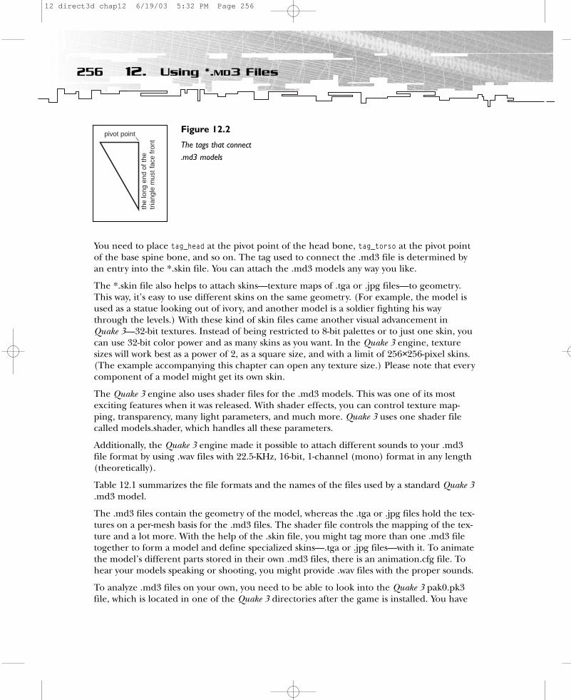
You need to place tag_head at the pivot point of the head bone, tag_torso at the pivot pointof the base spine bone, and so on. The tag used to connect the .md3 file is determined byan entry into the *.skin file. You can attach the .md3 models any way you like.
The *.skin file also helps to attach skins—texture maps of .tga or .jpg files—to geometry.This way, it’s easy to use different skins on the same geometry. (For example, the model isused as a statue looking out of ivory, and another model is a soldier fighting his waythrough the levels.) With these kind of skin files came another visual advancement in Quake 3—32-bit textures. Instead of being restricted to 8-bit palettes or to just one skin, youcan use 32-bit color power and as many skins as you want. In the Quake 3 engine, texturesizes will work best as a power of 2, as a square size, and with a limit of 256×256-pixel skins.(The example accompanying this chapter can open any texture size.) Please note that everycomponent of a model might get its own skin.
The Quake 3 engine also uses shader files for the .md3 models. This was one of its mostexciting features when it was released. With shader effects, you can control texture map-ping, transparency, many light parameters, and much more. Quake 3 uses one shader filecalled models.shader, which handles all these parameters.
Additionally, the Quake 3 engine made it possible to attach different sounds to your .md3file format by using .wav files with 22.5-KHz, 16-bit, 1-channel (mono) format in any length(theoretically).
Table 12.1 summarizes the file formats and the names of the files used by a standard Quake 3.md3 model.
The .md3 files contain the geometry of the model, whereas the .tga or .jpg files hold the tex-tures on a per-mesh basis for the .md3 files. The shader file controls the mapping of the tex-ture and a lot more. With the help of the .skin file, you might tag more than one .md3 filetogether to form a model and define specialized skins—.tga or .jpg files—with it. To animatethe model’s different parts stored in their own .md3 files, there is an animation.cfg file. Tohear your models speaking or shooting, you might provide .wav files with the proper sounds.
To analyze .md3 files on your own, you need to be able to look into the Quake 3 pak0.pk3file, which is located in one of the Quake 3 directories after the game is installed. You have
256 12. Using *.MD3 Files
pivot pointth
e lo
ng e
nd o
f the
tria
ngle
mus
t fac
e fr
ont
Figure 12.2
The tags that connect.md3 models
12 direct3d chap12 6/19/03 5:32 PM Page 256

to rename it pak0.zip and use a Zip utility to see the directories and files. The files for theBiker .md3 model are stored in the following directories:
• The .md3 files, animation.cfg, .tga, and .skin are in models/players/biker.• The models.shader file for all models is in the directory scripts.• The .wav files are in sound/player/biker.
To see the contents of a typical directory that holds a Quake 3 model, you might look at themodels directories. You’ll find at least the following files:
• animation.cfg• head.md3• upper.md3• lower.md3• head_default.skin• upper_default.skin• lower_default.skin• At least one texture map—.tga or .jpg• icon_default.tga (a 64×64-pixel, 24-bit image with an alpha mask)
257Files of the Trade
TABLE 12.1 File Formats Used by a Standard Quake 3 Model
File Format File Names
.md3 file Normally head.md3, upper.md3, and lower.md3
Icon file icon_default.tga
Animation file animation.cfg
Skin file .tga or .jpg
Tag file .skin
Shader file models.shader, for example
Sound file .wav
12 direct3d chap12 6/19/03 5:32 PM Page 257

If you want to use the model in a Capture the Flag mode, you need additional CTF skins aswell.
• head_blue.skin• head_red.skin• upper_blue.skin• upper_red.skin• lower_blue.skin• lower_red.skin• At least two texture maps, one for each color—.tga or .jpg• icon_blue.tga • icon_red.tga
To create your own Quake 3 models, the names of the files must follow these conventions:
• head_charactername.skin• upper_charactername.skin• lower_charactername.skin• The textures for the characters• icon_charactername.tga
Now let’s examine the details of the different files.
Animation.cfgThe animation of Quake 3 models works with the so-called key frames. For this kind of ani-mation, the same model is saved in different positions. The model is drawn as a series ofdifferent models.
In the case of the Quake 3 models, the differ-ent positions of a model are saved in differ-ent vertices and tags. So if a model supports246 different frames, in every .md3 file theremust be 246 different vertex groups in everymesh of the model, as well as 246 differenttags that connect the .md3 files. The torso,for example, often has three tags, so therehas to be 738 (3×246) different tags con-nected with the torso geometry.
Animations in Quake 3 files can generally beany length and any frame rate. The namingconvention must be exactly the same. Theanimation.cfg file of the Biker model lookslike this:
258 12. Using *.MD3 Files
NOTEContrary to key-frame animation, askeleton-based animation systemused in the DirectX X file format,Half-Life, F.A.K.K.2, or the newerUnreal 2 and DOOM III engines worksby giving a model a skeleton, which isset up with joints or bones to deter-mine how the unit will animate. Suchan animation system consumes lessmemory at run time, but requiresmore computational power.
12 direct3d chap12 6/19/03 5:32 PM Page 258
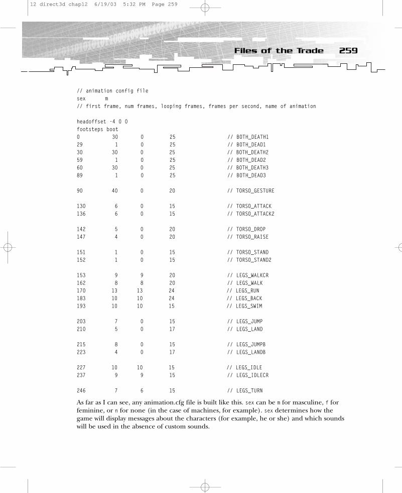
// animation config filesex m// first frame, num frames, looping frames, frames per second, name of animation
headoffset -4 0 0footsteps boot0 30 0 25 // BOTH_DEATH129 1 0 25 // BOTH_DEAD130 30 0 25 // BOTH_DEATH259 1 0 25 // BOTH_DEAD260 30 0 25 // BOTH_DEATH389 1 0 25 // BOTH_DEAD3
90 40 0 20 // TORSO_GESTURE
130 6 0 15 // TORSO_ATTACK136 6 0 15 // TORSO_ATTACK2
142 5 0 20 // TORSO_DROP147 4 0 20 // TORSO_RAISE
151 1 0 15 // TORSO_STAND152 1 0 15 // TORSO_STAND2
153 9 9 20 // LEGS_WALKCR162 8 8 20 // LEGS_WALK170 13 13 24 // LEGS_RUN183 10 10 24 // LEGS_BACK193 10 10 15 // LEGS_SWIM
203 7 0 15 // LEGS_JUMP210 5 0 17 // LEGS_LAND
215 8 0 15 // LEGS_JUMPB223 4 0 17 // LEGS_LANDB
227 10 10 15 // LEGS_IDLE237 9 9 15 // LEGS_IDLECR
246 7 6 15 // LEGS_TURN
As far as I can see, any animation.cfg file is built like this. sex can be m for masculine, f forfeminine, or n for none (in the case of machines, for example). sex determines how thegame will display messages about the characters (for example, he or she) and which soundswill be used in the absence of custom sounds.
259Files of the Trade
12 direct3d chap12 6/19/03 5:32 PM Page 259

There are two optional variables named footsteps and headoffset. Setting the variables boot,normal, energy, mech, or flesh leads to a specific sound for the footsteps of the character.headoffset is the offset of the HUD in x, y, and z coordinates.
Farther down comes the frame-based animation script. The numbers in the first fourcolumns change, but not the number of rows or paragraphs. The first column shows thefirst frame—where the animation with the name after the double-slash starts. The secondcolumn shows the number of frames; it’s the length of the animation. A few animations areso-called looping animations. The third column contains the number of frames that will belooped. The fourth column shows the speed of the animation, and the last column showsthe name of the animation. The names of the animations are the same in every model.
The BOTH_DEATH* animations are for both the legs and upper-torso objects. The last frame ofa death animation is located in the BOTH_DEAD* animation.
The TORSO_* animations are for the—you guessed it—torso object. TORSO_GESTURE can be anylength, and it even has its own sound. TORSO_ATTACK is the attack animation for rangedweapons. In Quake 3, it must be exactly six frames long because it is synced to the weaponfiring. The first frame of the animation is the aim, the second frame is the fire and recoil,and the rest recovers to the first frame. TORSO_ATTACK2 must be a six-frame attack sequenceshowing the attack with the gauntlet. The first frame is the anticipation of the punch, thesecond frame is the punch itself, and the rest is recovery. TORSO_DROP is the first part of theweapon switch; it must be exactly five frames long in Quake 3. The second part of theweapon switch is TORSO_RAISE, which must be five frames long as well. The static pose hold-ing a ranged weapon is animated by TORSO_STAND, whereas TORSO_STAND2 is the static poseholding the gauntlet.
The LEGS_* animations are for the legs. LEGS_WALKCR is the crouch walking cycle. There arewalk (LEGS_WALK), run (LEGS_RUN), swim (LEGS_SWIM), jump forward (LEGS_JUMP), land forward(LEGS_LAND), jump back (LEGS_JUMPB), land back (LEGS_LANDB), and backpedal or run backward cycles (LEGS_BACK). There are idle (LEGS_IDLE), idle for crouching (LEGS_IDLECR),and a turn animation when the player rotates far enough for the legs to rotate (LEGS_TURN).
Usually, all of the animation frames are stored in arrays. You can call the proper animationby providing the frame number to that array.
The .skin FileAll of the necessary tag and texture info is kept in the .skin files provided in your model directory. (Please note that the example program CharacterEngine in theChapter12\CharacterEngine directory uses a different *.skin file format than the originalQuake 3 *.md3 format.) These text files hold the tags to which the model is attached, as wellas the skins. The name of the .skin file corresponds to the name of the .md3 file that usesit. Here are the _default.skin files of the Biker model:
260 12. Using *.MD3 Files
12 direct3d chap12 6/19/03 5:32 PM Page 260

• head_default.skin:tag_head,h_head,models/players/biker/biker_h.tga
• upper_default.skin:tag_head,tag_weapon,u_larm,models/players/biker/biker.tgau_rarm,models/players/biker/biker.tgau_torso,models/players/biker/biker.tgatag_torso,
• lower_default.skin:l_legs,models/players/biker/biker.tgatag_torso,
The head .skin file describes the only tag that is provided with the head.md3 file and thetexture that should be used for the head. The upper .skin file describes three meshes andthree tags; the three meshes should be textured with the same .tga file. The last mesh inlower.md3 will be textured with the biker.tga bitmap file; it holds only one tag.
Textures are located in the same directory where the .md3 files reside. You can also findthe names of the default textures in the .md3 file, as you will see in a few moments. If youwant to use custom textures, they have to be declared in a custom .skin file.
Textures and the Shader FileThe textures used for the .md3 files can have an RGB color depth of 32 bits. In the case ofthe Quake 3 engine, textures should be a power of 2 in width and height, and they shouldbe limited to 256 pixels in either direction. Textures are shaded with the commands of theshader file, which is located in the Scripts directory. (Please note that the example programuses a different shader file format than the original Quake 3 file format.) Every mesh of amodel can have its own texture and shader properties.
The shader file is a text file, like the animation.cfg and the .skin files, which you can manip-ulate with a text editor. It’s written in its own language with a ton of commands. Shadersare simple scripts that the Quake 3 engine uses to determine the properties of the polygonsurfaces and how they are rendered. The most common use of shaders is to control theproperties of walls in levels. Shaders control the texturing of objects by providing com-mands that are similar to the texturing commands of OpenGL, the 3D API that is used inthe Quake series. You’ll find the Direct3D equivalents of these texturing commands in PartTwo of this book. You also might browse around in the models.shader file in the scriptsdirectory of your Quake 3 pak file.
261Files of the Trade
12 direct3d chap12 6/19/03 5:32 PM Page 261
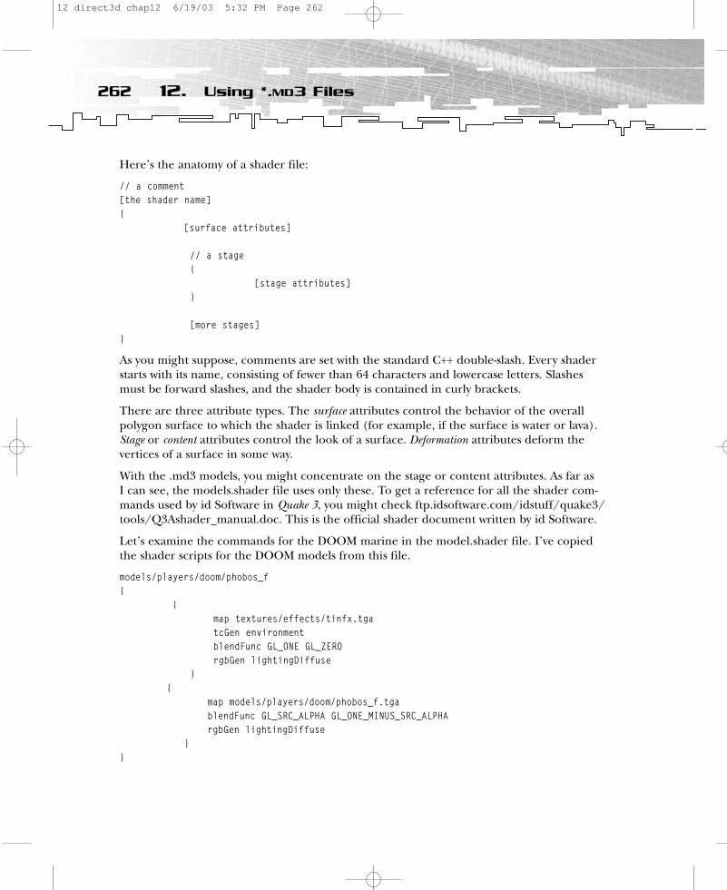
Here’s the anatomy of a shader file:
// a comment[the shader name]{
[surface attributes]
// a stage{
[stage attributes]}
[more stages]}
As you might suppose, comments are set with the standard C++ double-slash. Every shaderstarts with its name, consisting of fewer than 64 characters and lowercase letters. Slashesmust be forward slashes, and the shader body is contained in curly brackets.
There are three attribute types. The surface attributes control the behavior of the overallpolygon surface to which the shader is linked (for example, if the surface is water or lava).Stage or content attributes control the look of a surface. Deformation attributes deform thevertices of a surface in some way.
With the .md3 models, you might concentrate on the stage or content attributes. As far as I can see, the models.shader file uses only these. To get a reference for all the shader com-mands used by id Software in Quake 3, you might check ftp.idsoftware.com/idstuff/quake3/tools/Q3Ashader_manual.doc. This is the official shader document written by id Software.
Let’s examine the commands for the DOOM marine in the model.shader file. I’ve copiedthe shader scripts for the DOOM models from this file.
models/players/doom/phobos_f{
{map textures/effects/tinfx.tgatcGen environmentblendFunc GL_ONE GL_ZERO rgbGen lightingDiffuse
} {
map models/players/doom/phobos_f.tgablendFunc GL_SRC_ALPHA GL_ONE_MINUS_SRC_ALPHArgbGen lightingDiffuse
}}
262 12. Using *.MD3 Files
12 direct3d chap12 6/19/03 5:32 PM Page 262
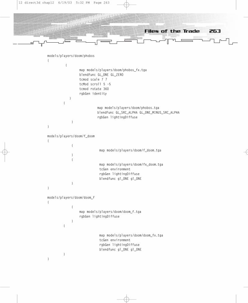
models/players/doom/phobos{
{map models/players/doom/phobos_fx.tgablendFunc GL_ONE GL_ZEROtcmod scale 7 7tcMod scroll 5 –5tcmod rotate 360rgbGen identity
}{
map models/players/doom/phobos.tgablendFunc GL_SRC_ALPHA GL_ONE_MINUS_SRC_ALPHArgbGen lightingDiffuse
}}
models/players/doom/f_doom{
{map models/players/doom/f_doom.tga
}{
map models/players/doom/fx_doom.tgatcGen environmentrgbGen lightingDiffuseblendfunc gl_ONE gl_ONE
}}
models/players/doom/doom_f{
{map models/players/doom/doom_f.tga rgbGen lightingDiffuse
}{
map models/players/doom/doom_fx.tgatcGen environmentrgbGen lightingDiffuseblendfunc gl_ONE gl_ONE
}}
263Files of the Trade
12 direct3d chap12 6/19/03 5:32 PM Page 263
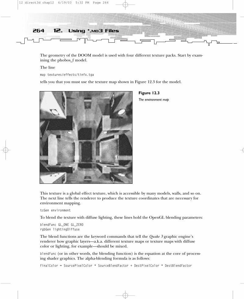
The geometry of the DOOM model is used with four different texture packs. Start by exam-ining the phobos_f model.
The line
map textures/effects/tinfx.tga
tells you that you must use the texture map shown in Figure 12.3 for the model.
This texture is a global effect texture, which is accessible by many models, walls, and so on.The next line tells the renderer to produce the texture coordinates that are necessary forenvironment mapping.
tcGen environment
To blend the texture with diffuse lighting, these lines hold the OpenGL blending parameters:
blendFunc GL_ONE GL_ZEROrgbGen lightingDiffuse
The blend functions are the keyword commands that tell the Quake 3 graphic engine’s renderer how graphic layers—a.k.a. different texture maps or texture maps with diffusecolor or lighting, for example—should be mixed.
blendFunc (or in other words, the blending function) is the equation at the core of process-ing shader graphics. The alpha-blending formula is as follows:
FinalColor = SourcePixelColor * SourceBlendFactor + DestPixelColor * DestBlendFactor
264 12. Using *.MD3 Files
Figure 12.3
The environment map
12 direct3d chap12 6/19/03 5:32 PM Page 264
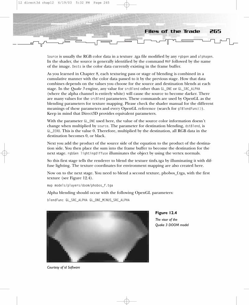
Source is usually the RGB color data in a texture .tga file modified by any rgbgen and alphagen.In the shader, the source is generally identified by the command MAP followed by the nameof the image. Dests is the color data currently existing in the frame buffer.
As you learned in Chapter 8, each texturing pass or stage of blending is combined in acumulative manner with the color data passed to it by the previous stage. How that datacombines depends on the values you choose for the source and destination blends at eachstage. In the Quake 3 engine, any value for srcBlend other than GL_ONE or GL_SRC_ALPHA(where the alpha channel is entirely white) will cause the source to become darker. Thereare many values for the srcBlend parameters. These commands are used by OpenGL as theblending parameters for texture mapping. Please check the shader manual for the differentmeanings of these parameters and every OpenGL reference (search for glBlendFunc()).Keep in mind that Direct3D provides equivalent parameters.
With the parameter GL_ONE used here, the value of the source color information doesn’tchange when multiplied by source. The parameter for destination blending, dstBlend, isGL_ZERO. This is the value 0. Therefore, multiplied by the destination, all RGB data in thedestination becomes 0, or black.
Next you add the product of the source side of the equation to the product of the destina-tion side. You then place the sum into the frame buffer to become the destination for thenext stage. rgbGen lightingdiffuse illuminates the object by using the vertex normals.
So this first stage tells the renderer to blend the texture tinfx.tga by illuminating it with dif-fuse lighting. The texture coordinates for environment mapping are also created here.
Now on to the next stage. You need to blend a second texture, phobos_f.tga, with the firsttexture (see Figure 12.4).
map models/players/doom/phobos_f.tga
Alpha blending should occur with the following OpenGL parameters:
blendFunc GL_SRC_ALPHA GL_ONE_MINUS_SRC_ALPHA
265Files of the Trade
Figure 12.4
The visor of the Quake 3 DOOM model
Courtesy of id Software
12 direct3d chap12 6/19/03 5:32 PM Page 265

These are similar to the following Direct3D parameters:
D3DBLEND_SCRALPHA D3DBLEND_INVSRCALPHA
Check out the multitexturing section in Chapter 8 for a description of these parameters.
The last attribute, rgbGen, tells the renderer to multiply alpha blending by a value generatedby applying Gouraud-shaded directional light to the surface.
Okay, this was a first look at the phobos_f model. Now it’s time to examine the phobos model.
You should blend a texture map called phobos_fx.tga, shown in Figure 12.5, with the GL_ONEand GL_ZERO parameters, which are similar to the D3DBLEND_ONE and D3DBLEND_ZERO commandsin Direct3D.
The command tcMod scale 7 7 resizes (enlarges or shrinks) the texture coordinates by mul-tiplying them by the given factors. The formula scales the stage along the appropriate axisby 1/n. tcMod scale. 0.5 0.5 will double your image, while tcMod scale 2 2 will halve it. tcModscroll continuously scrolls the stage by the given x and y offsets per second. The scrollspeed is measured in textures per second; a texture is the dimension of the texture beingmodified and includes any previous shader modifications to the original .tga. A negative xvalue scrolls the texture to the left. A negative y value scrolls the texture down. So tcModscroll 0.5 –0.5 moves the texture down and to the right at the rate of a half texture eachsecond of travel.
tcMod rotate rotates the stage by the given number of degrees per second. A positive number rotates clockwise; a negative number rotates counterclockwise. The stage here isrotated 360 degrees in a second with tcMod rotate 360. The parameter rgbGen means toleave the RGB values unchanged.
266 12. Using *.MD3 Files
Figure 12.5
The effects texture mapof the DOOM/Phobosmodel of Quake 3
Courtesy of id Software
12 direct3d chap12 6/19/03 5:32 PM Page 266

To sum up, the first stage loads an effect texture, and then scales, scrolls, and rotates it. Inthe next stage, the default texture map phobos.tga is loaded and lit by diffuse lighting. Thistexture map is blended with the map used in the first stage. The destination where the tex-ture map from the first stage resides is multiplied by GL_ONE_MINUS_SRC_ALPHA and added to thesource where the texture map from this stage resides, which is multiplied by GL_SRC_ALPHA.
The whole alpha blending formula looks like this:
FinalColor = SourcePixelColor * GL_SRC_ALPHA + DestPixelColor * GL_ONE_MINUS_SRC_ALPHA
In Direct3D the first parameter corresponds to D3DBLEND_INVSRCALPHA, and the second corre-sponds to D3DBLEND_SRCALPHA.
As you might notice, the shader language in Quake 3 is a very powerful scripting languagethat maps directly onto the OpenGL commands used by the Quake 3 rendering engine.
I hope you got the big picture on using Quake 3 shaders. The example program that accom-panies this chapter uses the DirectX 9 SDK effect file format, which has similar tasks to theoriginal Quake 3 shader file format but is much more advanced.
Custom SoundsYou need to put sounds in the sounds/player/modelname directory. In Quake 3 the .wavfiles should be in the 22.5-KHz, 16-bit, one-channel (mono) format. The Quake 3 engineneeds a specific number of sound files with particular names. These files can be any length,but—as always—performance issues might come up with longer files. If a model doesn’tprovide its custom sound files, the default files are the sound files of the sarge or majormodel, depending on the sex of your model. Table 12.2 lists the sound files required by the Quake 3 engine.
For all the models there are sound files located in the sounds/player/footsteps directory.Depending on the footsteps parameter provided with the animation.cfg file, the proper filesare chosen. There are always four files per chosen footstep sound. If you choose energy inyour animation.cfg file, the files are energy1.wav to energy4.wav.
Let’s move on with the internals of the .md3 file format. To find out more about Quake 3.md3 files, you must now unwrap your scalpel.
The .md3 FormatThe .md3 file format has not been officially documented by id Software until recently. As far as I know, a few points have changed over time, so this explanation might be subjectto change.
There are different ways to build your own .md3 files. For example, http://www.planetquake.com/polycount and other Quake 3 modification Web sites offer free downloads of .md3files. These Web sites always cover a list of tools that you can use for this purpose.
267Files of the Trade
12 direct3d chap12 6/19/03 5:32 PM Page 267
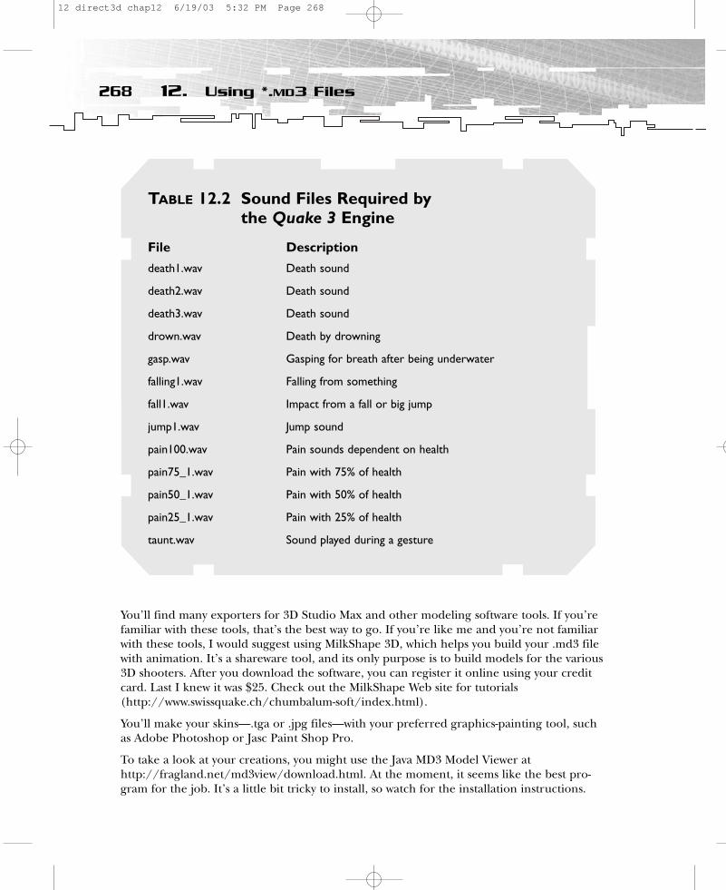
You’ll find many exporters for 3D Studio Max and other modeling software tools. If you’refamiliar with these tools, that’s the best way to go. If you’re like me and you’re not familiarwith these tools, I would suggest using MilkShape 3D, which helps you build your .md3 filewith animation. It’s a shareware tool, and its only purpose is to build models for the various3D shooters. After you download the software, you can register it online using your creditcard. Last I knew it was $25. Check out the MilkShape Web site for tutorials(http://www.swissquake.ch/chumbalum-soft/index.html).
You’ll make your skins—.tga or .jpg files—with your preferred graphics-painting tool, suchas Adobe Photoshop or Jasc Paint Shop Pro.
To take a look at your creations, you might use the Java MD3 Model Viewer athttp://fragland.net/md3view/download.html. At the moment, it seems like the best pro-gram for the job. It’s a little bit tricky to install, so watch for the installation instructions.
268 12. Using *.MD3 Files
TABLE 12.2 Sound Files Required by the Quake 3 Engine
File Description
death1.wav Death sound
death2.wav Death sound
death3.wav Death sound
drown.wav Death by drowning
gasp.wav Gasping for breath after being underwater
falling1.wav Falling from something
fall1.wav Impact from a fall or big jump
jump1.wav Jump sound
pain100.wav Pain sounds dependent on health
pain75_1.wav Pain with 75% of health
pain50_1.wav Pain with 50% of health
pain25_1.wav Pain with 25% of health
taunt.wav Sound played during a gesture
12 direct3d chap12 6/19/03 5:32 PM Page 268
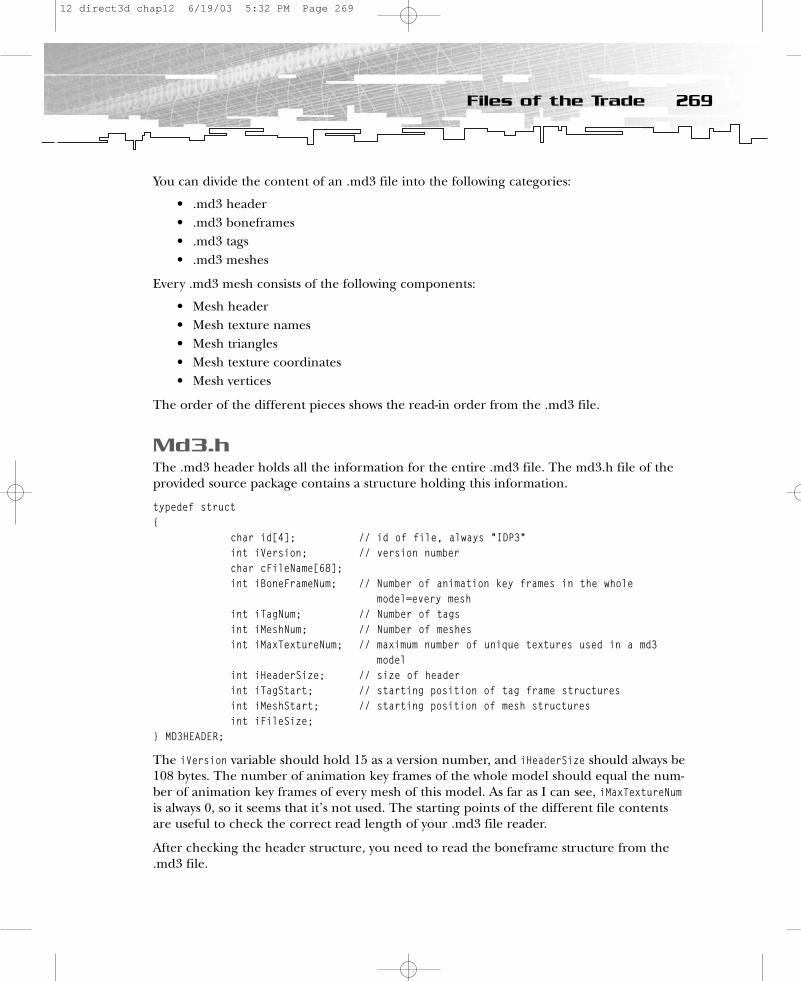
You can divide the content of an .md3 file into the following categories:
• .md3 header• .md3 boneframes• .md3 tags• .md3 meshes
Every .md3 mesh consists of the following components:
• Mesh header• Mesh texture names• Mesh triangles• Mesh texture coordinates• Mesh vertices
The order of the different pieces shows the read-in order from the .md3 file.
Md3.hThe .md3 header holds all the information for the entire .md3 file. The md3.h file of theprovided source package contains a structure holding this information.
typedef struct{
char id[4]; // id of file, always “IDP3”int iVersion; // version numberchar cFileName[68]; int iBoneFrameNum; // Number of animation key frames in the whole
model=every meshint iTagNum; // Number of tagsint iMeshNum; // Number of meshesint iMaxTextureNum; // maximum number of unique textures used in a md3
modelint iHeaderSize; // size of headerint iTagStart; // starting position of tag frame structuresint iMeshStart; // starting position of mesh structuresint iFileSize;
} MD3HEADER;
The iVersion variable should hold 15 as a version number, and iHeaderSize should always be108 bytes. The number of animation key frames of the whole model should equal the num-ber of animation key frames of every mesh of this model. As far as I can see, iMaxTextureNumis always 0, so it seems that it’s not used. The starting points of the different file contentsare useful to check the correct read length of your .md3 file reader.
After checking the header structure, you need to read the boneframe structure from the.md3 file.
269Files of the Trade
12 direct3d chap12 6/19/03 5:32 PM Page 269
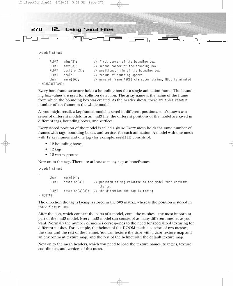
typedef struct{
FLOAT mins[3]; // first corner of the bounding boxFLOAT maxs[3]; // second corner of the bounding box FLOAT position[3]; // position/origin of the bounding box FLOAT scale; // radius of bounding spherechar name[16]; // name of frame ASCII character string, NULL terminated
} MD3BONEFRAME;
Every boneframe structure holds a bounding box for a single animation frame. The bound-ing box values are used for collision detection. The array name is the name of the framefrom which the bounding box was created. As the header shows, there are iBoneFrameNumnumber of key frames in the whole model.
As you might recall, a key-framed model is saved in different positions, so it’s drawn as aseries of different models. In an .md3 file, the different positions of the model are saved indifferent tags, bounding boxes, and vertices.
Every stored position of the model is called a frame. Every mesh holds the same number offrames with tags, bounding boxes, and vertices for each animation. A model with one meshwith 12 key frames and one tag (for example, mesh[12]) consists of:
• 12 bounding boxes• 12 tags• 12 vertex groups
Now on to the tags. There are at least as many tags as boneframes:
typedef struct{
char name[64];FLOAT position[3]; // position of tag relative to the model that contains
the tagFLOAT rotation[3][3]; // the direction the tag is facing
} MD3TAG;
The direction the tag is facing is stored in the 3×3 matrix, whereas the position is stored inthree float values.
After the tags, which connect the parts of a model, come the meshes—the most importantpart of the .md3 model. Every .md3 model can consist of as many different meshes as youwant. Normally the number of meshes corresponds to the need for specialized texturing fordifferent meshes. For example, the helmet of the DOOM marine consists of two meshes,the visor and the rest of the helmet. You can texture the visor with a visor texture map andan environment texture map, and the rest of the helmet with the default texture map.
Now on to the mesh headers, which you need to load the texture names, triangles, texturecoordinates, and vertices of this mesh.
270 12. Using *.MD3 Files
12 direct3d chap12 6/19/03 5:32 PM Page 270
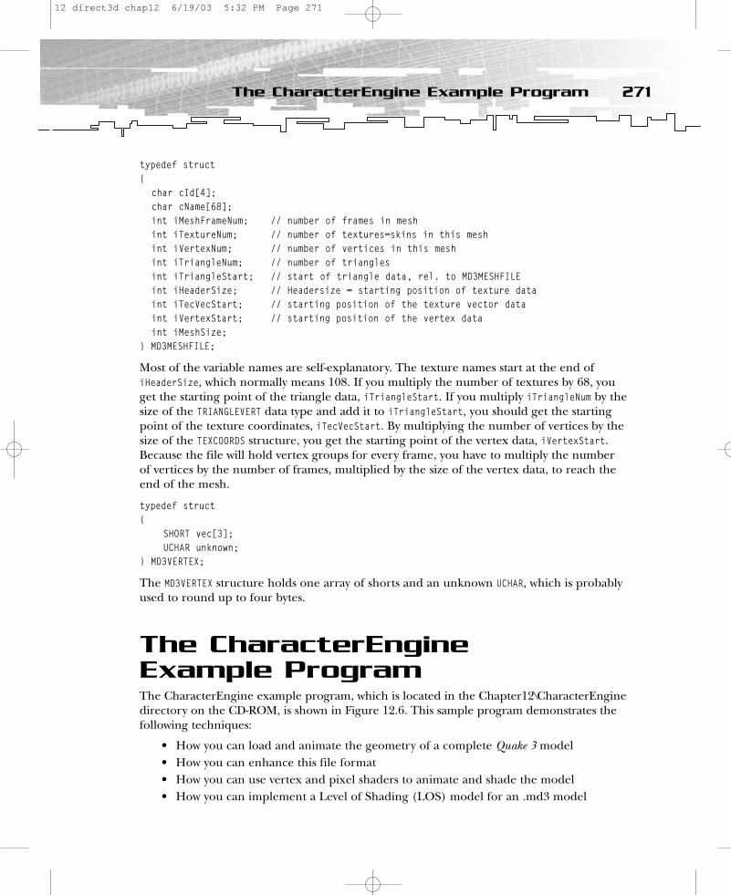
typedef struct{
char cId[4];char cName[68]; int iMeshFrameNum; // number of frames in meshint iTextureNum; // number of textures=skins in this meshint iVertexNum; // number of vertices in this meshint iTriangleNum; // number of trianglesint iTriangleStart; // start of triangle data, rel. to MD3MESHFILEint iHeaderSize; // Headersize = starting position of texture dataint iTecVecStart; // starting position of the texture vector dataint iVertexStart; // starting position of the vertex dataint iMeshSize;
} MD3MESHFILE;
Most of the variable names are self-explanatory. The texture names start at the end ofiHeaderSize, which normally means 108. If you multiply the number of textures by 68, youget the starting point of the triangle data, iTriangleStart. If you multiply iTriangleNum by thesize of the TRIANGLEVERT data type and add it to iTriangleStart, you should get the startingpoint of the texture coordinates, iTecVecStart. By multiplying the number of vertices by thesize of the TEXCOORDS structure, you get the starting point of the vertex data, iVertexStart.Because the file will hold vertex groups for every frame, you have to multiply the numberof vertices by the number of frames, multiplied by the size of the vertex data, to reach theend of the mesh.
typedef struct{
SHORT vec[3];UCHAR unknown;
} MD3VERTEX;
The MD3VERTEX structure holds one array of shorts and an unknown UCHAR, which is probablyused to round up to four bytes.
The CharacterEngine Example ProgramThe CharacterEngine example program, which is located in the Chapter12\CharacterEnginedirectory on the CD-ROM, is shown in Figure 12.6. This sample program demonstrates thefollowing techniques:
• How you can load and animate the geometry of a complete Quake 3 model• How you can enhance this file format• How you can use vertex and pixel shaders to animate and shade the model• How you can implement a Level of Shading (LOS) model for an .md3 model
271The CharacterEngine Example Program
12 direct3d chap12 6/19/03 5:32 PM Page 271
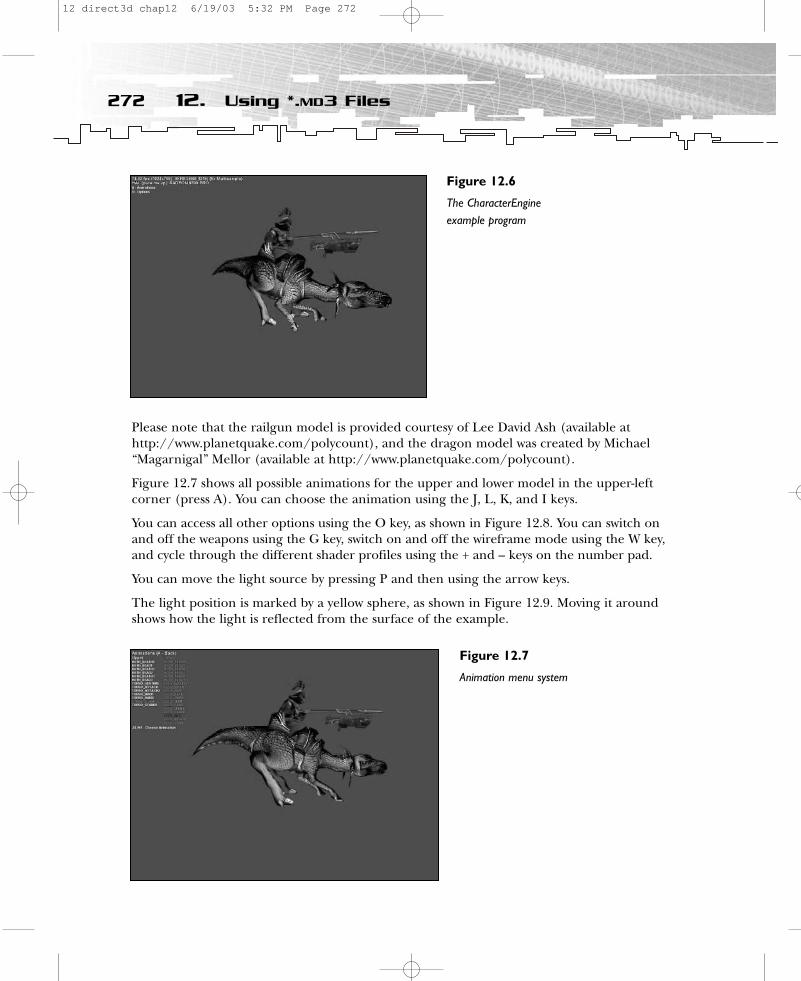
Please note that the railgun model is provided courtesy of Lee David Ash (available athttp://www.planetquake.com/polycount), and the dragon model was created by Michael“Magarnigal” Mellor (available at http://www.planetquake.com/polycount).
Figure 12.7 shows all possible animations for the upper and lower model in the upper-leftcorner (press A). You can choose the animation using the J, L, K, and I keys.
You can access all other options using the O key, as shown in Figure 12.8. You can switch onand off the weapons using the G key, switch on and off the wireframe mode using the W key,and cycle through the different shader profiles using the + and – keys on the number pad.
You can move the light source by pressing P and then using the arrow keys.
The light position is marked by a yellow sphere, as shown in Figure 12.9. Moving it aroundshows how the light is reflected from the surface of the example.
272 12. Using *.MD3 Files
Figure 12.6
The CharacterEngineexample program
Figure 12.7
Animation menu system
12 direct3d chap12 6/19/03 5:32 PM Page 272

The following sections will take you through these features step by step.
Loading and Animating an .md3 ModelYou can find all the code used to load, animate, and shade .md3 files in md3.h andmd3.cpp. The code consists of two classes. The Q3Player class is a level of abstraction abovethe CMD3Model class. It covers all functionality necessary for one model consisting of four.md3 files (in this example, three for the dragon and the rider and one for the weapon).
273The CharacterEngine Example Program
Figure 12.8
The Options menu
Figure 12.9
Movable light source
12 direct3d chap12 6/19/03 5:32 PM Page 273

The methods of the Q3Player class are
class Q3Player{public:
Q3Player();~Q3Player();
VOID LoadPlayerGeometry(TCHAR *path);VOID DeletePlayerGeometry(VOID);
VOID LoadSkins(LPDIRECT3DDEVICE9 m_pd3dDevice, char *path, char *skin);VOID FreeSkins();
VOID LoadPlayerShaders(LPDIRECT3DDEVICE9 m_pd3dDevice, char *cPath, char *cSkin);VOID FreePlayerShaders(LPDIRECT3DDEVICE9 m_pd3dDevice);VOID LoadPlayerShaderProfile(char *pcFileName);
HRESULT CreateVertexNIndexBuffer(LPDIRECT3DDEVICE9 m_pd3dDevice);VOID DeleteVertexNIndexBuffer();
VOID Draw(LPDIRECT3DDEVICE9 m_pd3dDevice);
VOID Update(FLOAT time);VOID LoadAnim(TCHAR *filename);VOID SetLowerAnim(int iAnimNumber);VOID SetUpperAnim(int iAnimNumber);VOID DumpAnimInfo();
VOID LoadWeaponGeometry(char *cPath);VOID DeleteWeaponGeometry();
VOID LoadWeaponSkins(LPDIRECT3DDEVICE9 m_pd3dDevice, char *cPath, char *skin);VOID FreeWeaponSkins();
VOID LoadWeaponShaders(LPDIRECT3DDEVICE9 m_pd3dDevice, char *cPath, char *skin);VOID FreeWeaponShaders(LPDIRECT3DDEVICE9 m_pd3dDevice);VOID LoadWeaponShaderProfile(char *pcFileName);
VOID SetWorldMatrix(D3DXMATRIX &matW) { matWorld=matW;}VOID SetViewProjMatrix(D3DXMATRIX matVP) { matViewProj=matVP; }
CMD3Model md3Lower, md3Upper, md3Head, md3Weapon;
LPDIRECT3DVERTEXDECLARATION9 m_pVertexDeclaration;
274 12. Using *.MD3 Files
12 direct3d chap12 6/19/03 5:32 PM Page 274

private:MD3ANIM playerAnim[25];
int playerAnimLower;int playerAnimUpper;
LPDIRECT3DINDEXBUFFER9 m_pIB;LPDIRECT3DVERTEXBUFFER9 m_pVB;
D3DXMATRIX matViewProj;D3DXMATRIX matWorld;
};
After the constructor and destructor, the LoadPlayerGeometry() and DeletePlayerGeometry()functions load and delete the geometry of the dragon and its rider. All textures are loadedand freed with the LoadSkins() and FreeSkins() functions. Three functions load and free allshader-related items. LoadPlayerShaders() and FreePlayerShaders() load and free all vertexand pixel shaders used by the dragon with its rider, and LoadPlayerShaderProfile() loads theshader profiles. These profiles define for each shader level a specific pair of shaders permesh. CreateVertexNIndexBuffer() and DeleteVertexNIndexBuffer() create and delete the vertex and index buffer. All geometry is written dynamically every frame into one vertexand index buffer. The Draw() function handles all the necessary commands to draw themodel. Update() updates the animation time. LoadAnim() loads all animations from anima-tion.cfg, and the SetLowerAnim() and SetUpperAnim() functions set the specific animations.The last animation function, DumpAnimInfo(), dumps all animation data to the log file. Allfunctions with the word Weapon in their names are equivalent to the player functions. TheSetWorldMatrix() and SetViewProjMatrix() functions deliver the matrices to the main application. The four different .md3 files are stored in the md3Lower, md3Upper, md3Head, andmd3Weapon classes. Please note that this is hard-coded in the Q3Player class. There might be areason to extend the viewer so that it is able to load one .md3 file model or three or more.md3 files. There is only one vertex declaration for all vertex shaders. This declaration corresponds to the vertex buffer. The CMD3Model class handles all the low-level stuff.
The following class shows the low-level functions called by the functions of the Q3Playerclass.
class CMD3Model{public:
CMD3Model();~CMD3Model();
int LoadModelGeometry (TCHAR *filename);VOID DeleteModelGeometry(VOID);VOID DumpGeometryInfo(VOID);
275The CharacterEngine Example Program
12 direct3d chap12 6/19/03 5:32 PM Page 275
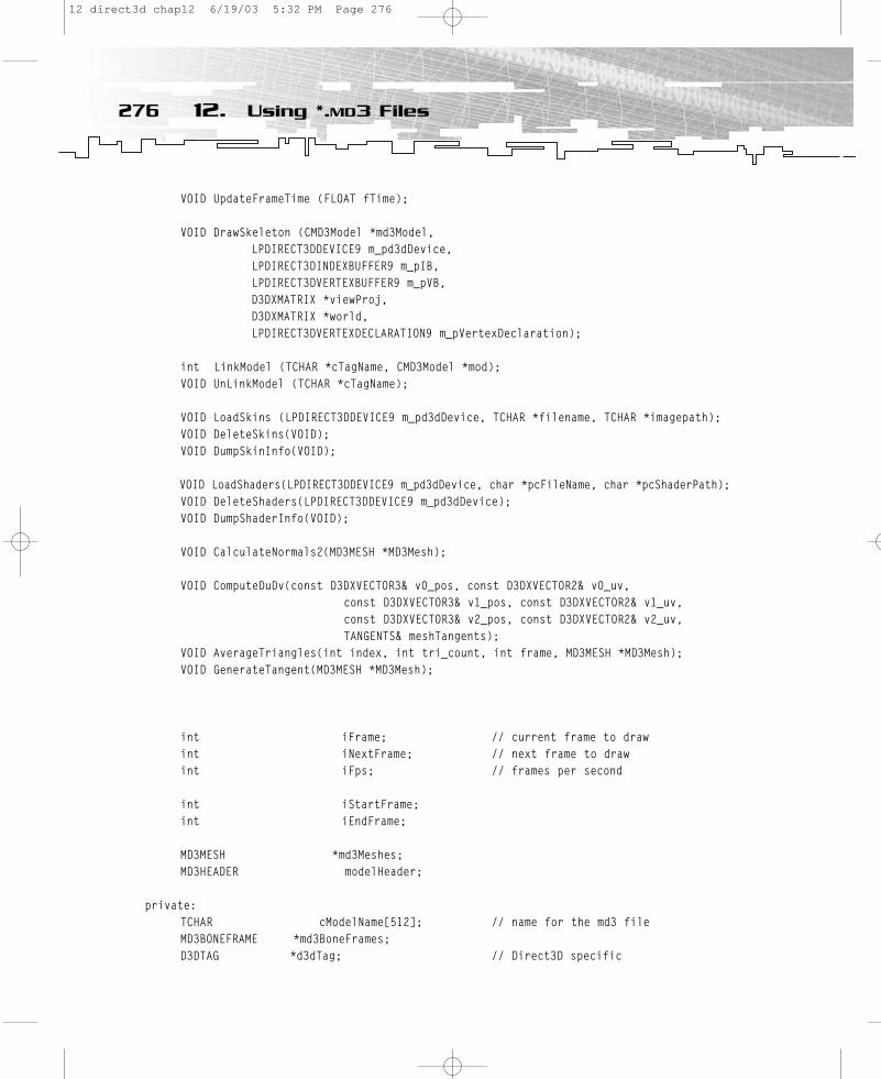
VOID UpdateFrameTime (FLOAT fTime);
VOID DrawSkeleton (CMD3Model *md3Model, LPDIRECT3DDEVICE9 m_pd3dDevice, LPDIRECT3DINDEXBUFFER9 m_pIB, LPDIRECT3DVERTEXBUFFER9 m_pVB, D3DXMATRIX *viewProj, D3DXMATRIX *world,LPDIRECT3DVERTEXDECLARATION9 m_pVertexDeclaration);
int LinkModel (TCHAR *cTagName, CMD3Model *mod);VOID UnLinkModel (TCHAR *cTagName);
VOID LoadSkins (LPDIRECT3DDEVICE9 m_pd3dDevice, TCHAR *filename, TCHAR *imagepath); VOID DeleteSkins(VOID);VOID DumpSkinInfo(VOID);
VOID LoadShaders(LPDIRECT3DDEVICE9 m_pd3dDevice, char *pcFileName, char *pcShaderPath);VOID DeleteShaders(LPDIRECT3DDEVICE9 m_pd3dDevice);VOID DumpShaderInfo(VOID);
VOID CalculateNormals2(MD3MESH *MD3Mesh);
VOID ComputeDuDv(const D3DXVECTOR3& v0_pos, const D3DXVECTOR2& v0_uv,const D3DXVECTOR3& v1_pos, const D3DXVECTOR2& v1_uv,const D3DXVECTOR3& v2_pos, const D3DXVECTOR2& v2_uv,TANGENTS& meshTangents);
VOID AverageTriangles(int index, int tri_count, int frame, MD3MESH *MD3Mesh);VOID GenerateTangent(MD3MESH *MD3Mesh);
int iFrame; // current frame to drawint iNextFrame; // next frame to drawint iFps; // frames per second
int iStartFrame;int iEndFrame;
MD3MESH *md3Meshes;MD3HEADER modelHeader;
private:TCHAR cModelName[512]; // name for the md3 fileMD3BONEFRAME *md3BoneFrames;D3DTAG *d3dTag; // Direct3D specific
276 12. Using *.MD3 Files
12 direct3d chap12 6/19/03 5:32 PM Page 276
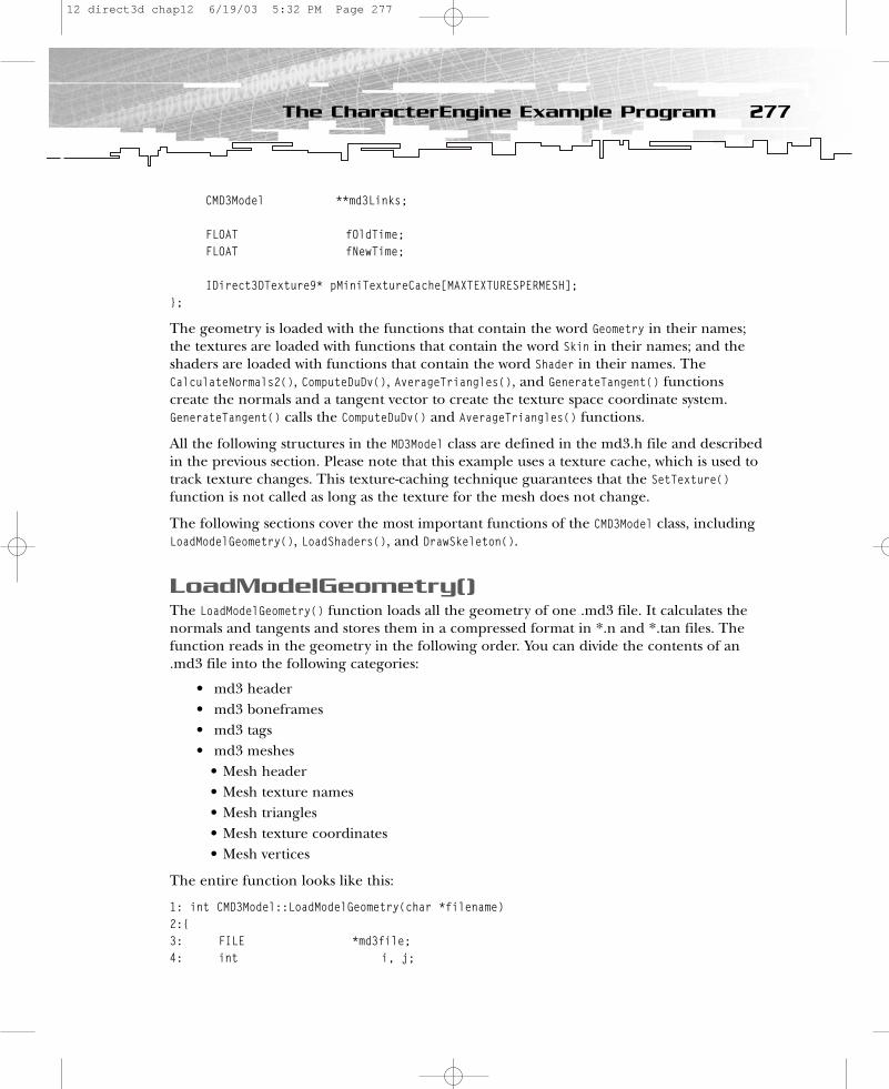
CMD3Model **md3Links;
FLOAT fOldTime;FLOAT fNewTime;
IDirect3DTexture9* pMiniTextureCache[MAXTEXTURESPERMESH];};
The geometry is loaded with the functions that contain the word Geometry in their names;the textures are loaded with functions that contain the word Skin in their names; and theshaders are loaded with functions that contain the word Shader in their names. TheCalculateNormals2(), ComputeDuDv(), AverageTriangles(), and GenerateTangent() functions create the normals and a tangent vector to create the texture space coordinate system.GenerateTangent() calls the ComputeDuDv() and AverageTriangles() functions.
All the following structures in the MD3Model class are defined in the md3.h file and describedin the previous section. Please note that this example uses a texture cache, which is used totrack texture changes. This texture-caching technique guarantees that the SetTexture()function is not called as long as the texture for the mesh does not change.
The following sections cover the most important functions of the CMD3Model class, includingLoadModelGeometry(), LoadShaders(), and DrawSkeleton().
LoadModelGeometry()The LoadModelGeometry() function loads all the geometry of one .md3 file. It calculates thenormals and tangents and stores them in a compressed format in *.n and *.tan files. Thefunction reads in the geometry in the following order. You can divide the contents of an.md3 file into the following categories:
• md3 header• md3 boneframes• md3 tags• md3 meshes
• Mesh header• Mesh texture names• Mesh triangles• Mesh texture coordinates• Mesh vertices
The entire function looks like this:
1: int CMD3Model::LoadModelGeometry(char *filename)2:{3: FILE *md3file;4: int i, j;
277The CharacterEngine Example Program
12 direct3d chap12 6/19/03 5:32 PM Page 277

5:6: // check if file exist7: if ( CheckFile(filename) == 0)8: return -1;9:10: // open file11: md3file = fopen(filename, “rb”);12:13: // copy name14: _tcscpy(cModelName, filename);15:16://17:// read header18://19: fread(&modelHeader, 1, sizeof(MD3HEADER), md3file);20:21: static char ver[4];22: wsprintf(ver, “%c%c%c%c”, modelHeader.id[0], modelHeader.id[1],
modelHeader.id[2], modelHeader.id[3]);23:24: if ( strcmp(ver, “IDP3”) || modelHeader.iVersion != 15)25: {26: fclose(md3file);27: return -2;28: }29: 30://31:// read boneframes32://33: md3BoneFrames = (MD3BONEFRAME *) malloc(sizeof(MD3BONEFRAME) *
modelHeader.iBoneFrameNum);34: fread(md3BoneFrames, sizeof(MD3BONEFRAME), modelHeader.iBoneFrameNum, md3file);35:36://37:// read tags38://39: MD3TAG *tempTag;40: tempTag = (MD3TAG *) malloc(sizeof(MD3TAG) *
modelHeader.iBoneFrameNum * modelHeader.iTagNum);41: d3dTag = (D3DTAG *) malloc(sizeof(D3DTAG) *
modelHeader.iBoneFrameNum * modelHeader.iTagNum);42: fread(tempTag, sizeof(MD3TAG), modelHeader.iBoneFrameNum *
modelHeader.iTagNum, md3file);43:44: for (i=0; i < modelHeader.iBoneFrameNum * modelHeader.iTagNum; i++)45: {
278 12. Using *.MD3 Files
12 direct3d chap12 6/19/03 5:32 PM Page 278

46: _tcscpy (d3dTag[i].name, tempTag[i].name);47: d3dTag[i].matTag(0, 0) = tempTag[i].rotation[0][0];48: d3dTag[i].matTag(0, 1) = tempTag[i].rotation[0][1];49: d3dTag[i].matTag(0, 2) = tempTag[i].rotation[0][2];50: d3dTag[i].matTag(0, 3) = 0.0f;51: d3dTag[i].matTag(1, 0) = tempTag[i].rotation[1][0];52: d3dTag[i].matTag(1, 1) = tempTag[i].rotation[1][1];53: d3dTag[i].matTag(1, 2) = tempTag[i].rotation[1][2];54: d3dTag[i].matTag(1, 3) = 0.0f;55: d3dTag[i].matTag(2, 0) = tempTag[i].rotation[2][0];56: d3dTag[i].matTag(2, 1) = tempTag[i].rotation[2][1];57: d3dTag[i].matTag(2, 2) = tempTag[i].rotation[2][2];58: d3dTag[i].matTag(2, 3) = 0.0f;59: d3dTag[i].matTag(3, 0) = tempTag[i].position[0];60: d3dTag[i].matTag(3, 1) = tempTag[i].position[1];61: d3dTag[i].matTag(3, 2) = tempTag[i].position[2];62: d3dTag[i].matTag(3, 3) = 1.0f;63: }64: delete tempTag;65: 66://67:// init links68://69: md3Links = (CMD3Model **) malloc(sizeof(CMD3Model) *
modelHeader.iTagNum);70: 71: for (i=0; i<modelHeader.iTagNum; i++)72: md3Links[i] = NULL;73:74://75:// read meshes76://77: md3Meshes = (MD3MESH *) malloc(sizeof(MD3MESH) *
modelHeader.iMeshNum);78: 79: LONG lMeshOffset = ftell(md3file);80:81: for (i=0; i<modelHeader.iMeshNum; i++)82: {83: fseek(md3file, lMeshOffset, SEEK_SET);84: fread(&md3Meshes[ i ].meshHeader, sizeof(MD3MESHHEADER), 1, md3file);85:86: // —————————————————————87: md3Meshes[ i ].meshSkins = (MD3SKIN *)
malloc(sizeof(MD3SKIN) * md3Meshes[ i ].meshHeader.iTextureNum);
279The CharacterEngine Example Program
12 direct3d chap12 6/19/03 5:32 PM Page 279
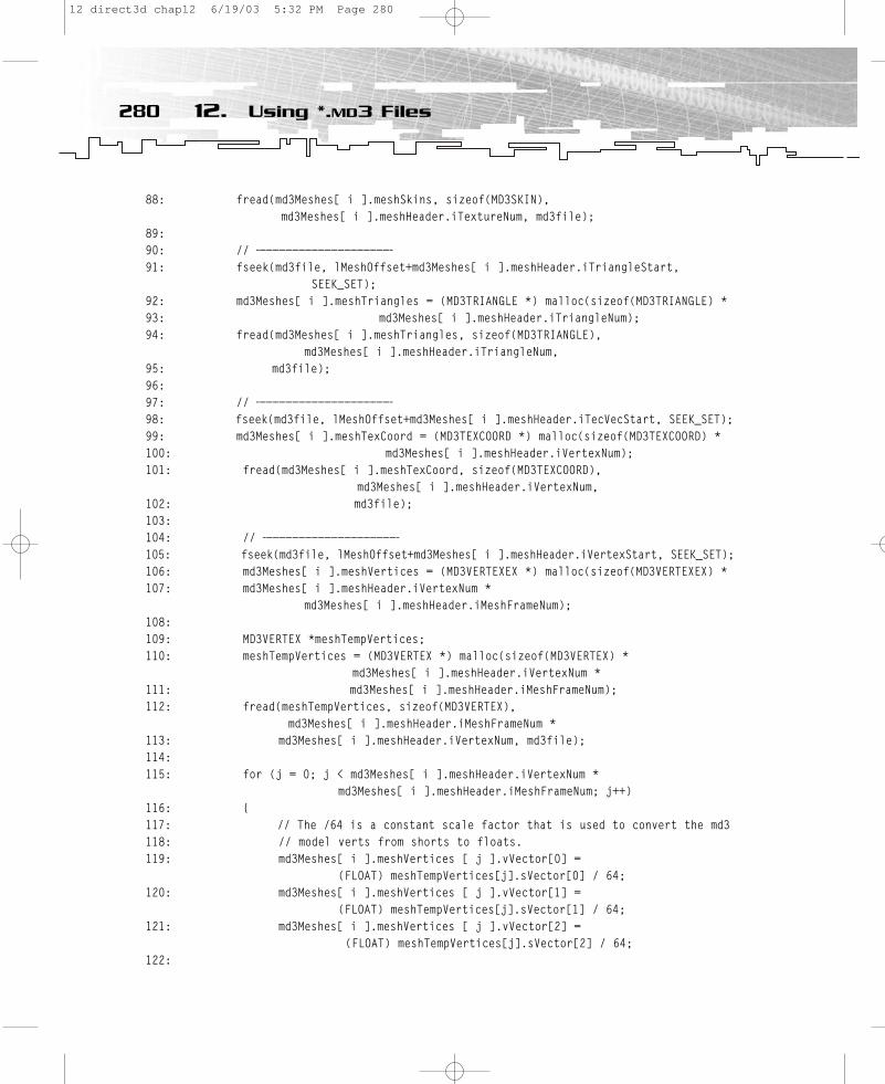
88: fread(md3Meshes[ i ].meshSkins, sizeof(MD3SKIN), md3Meshes[ i ].meshHeader.iTextureNum, md3file);
89:90: // —————————————————————91: fseek(md3file, lMeshOffset+md3Meshes[ i ].meshHeader.iTriangleStart,
SEEK_SET);92: md3Meshes[ i ].meshTriangles = (MD3TRIANGLE *) malloc(sizeof(MD3TRIANGLE) * 93: md3Meshes[ i ].meshHeader.iTriangleNum);94: fread(md3Meshes[ i ].meshTriangles, sizeof(MD3TRIANGLE),
md3Meshes[ i ].meshHeader.iTriangleNum, 95: md3file);96:97: // ————————————————————— 98: fseek(md3file, lMeshOffset+md3Meshes[ i ].meshHeader.iTecVecStart, SEEK_SET);99: md3Meshes[ i ].meshTexCoord = (MD3TEXCOORD *) malloc(sizeof(MD3TEXCOORD) * 100: md3Meshes[ i ].meshHeader.iVertexNum);101: fread(md3Meshes[ i ].meshTexCoord, sizeof(MD3TEXCOORD),
md3Meshes[ i ].meshHeader.iVertexNum, 102: md3file);103:104: // ————————————————————— 105: fseek(md3file, lMeshOffset+md3Meshes[ i ].meshHeader.iVertexStart, SEEK_SET);106: md3Meshes[ i ].meshVertices = (MD3VERTEXEX *) malloc(sizeof(MD3VERTEXEX) * 107: md3Meshes[ i ].meshHeader.iVertexNum *
md3Meshes[ i ].meshHeader.iMeshFrameNum);108:109: MD3VERTEX *meshTempVertices;110: meshTempVertices = (MD3VERTEX *) malloc(sizeof(MD3VERTEX) *
md3Meshes[ i ].meshHeader.iVertexNum * 111: md3Meshes[ i ].meshHeader.iMeshFrameNum);112: fread(meshTempVertices, sizeof(MD3VERTEX),
md3Meshes[ i ].meshHeader.iMeshFrameNum * 113: md3Meshes[ i ].meshHeader.iVertexNum, md3file);114:115: for (j = 0; j < md3Meshes[ i ].meshHeader.iVertexNum *
md3Meshes[ i ].meshHeader.iMeshFrameNum; j++)116: {117: // The /64 is a constant scale factor that is used to convert the md3118: // model verts from shorts to floats.119: md3Meshes[ i ].meshVertices [ j ].vVector[0] =
(FLOAT) meshTempVertices[j].sVector[0] / 64;120: md3Meshes[ i ].meshVertices [ j ].vVector[1] =
(FLOAT) meshTempVertices[j].sVector[1] / 64;121: md3Meshes[ i ].meshVertices [ j ].vVector[2] =
(FLOAT) meshTempVertices[j].sVector[2] / 64;122:
280 12. Using *.MD3 Files
12 direct3d chap12 6/19/03 5:32 PM Page 280

123: /*124: The normal information in the md3 file is stored as two unsigned
chars to save space.125: These chars contain the spherical coordinates of the normal. 126:127: The first byte is longitude and the second byte is latitude. You may find128: This information in mathlib.c in the NormalToLatLong() function 129: in the Quake3 tools source code. 130: */131: // md3Meshes[ i ].meshVertices [ j ].vNormal = 132: // fCalcNormals[meshTempVertices[j].cNormal[0]]
// [meshTempVertices[j].cNormal[1]];133: }134: //—————————————————————————————————-135: //136: // Calculate Normals and Tangents137: // store them in files for faster startup138: //139: //—————————————————————————————————-140: FILE *File;141: DWORD dwNumberOfVertices;142: TCHAR cMeshName[68]; 143: 144: dwNumberOfVertices = md3Meshes[i].meshHeader.iMeshFrameNum *
d3Meshes[i].meshHeader.iVertexNum;145: 146: // allocate memory for tangents147: md3Meshes[i].meshTangents = (TANGENTS *) malloc (sizeof(TANGENTS) *
dwNumberOfVertices);148:149: // Calculate Normals150: // store the normals in a file with the extension *.nor151: // read normals from this file to speed things up152: int z = 0;153:154: // read in for example hunter\ when cModelName stores hunter\head.md3155: while (!(cModelName[z - 1] == ‘\\’))156: cMeshName[z] = cModelName[z++];157:158: // adds to hunter\ for example legs_l: hunter\legs_l160: for (int y = 0; y < strlen(md3Meshes[i].meshHeader.cName); y++)161: cMeshName[z++] = md3Meshes[i].meshHeader.cName[y];162: 163: // saves mesh name in an extra array and adds the terminating \0 164: TCHAR cNormalName[68];165: memcpy (cNormalName, cMeshName, sizeof(cNormalName) );
281The CharacterEngine Example Program
12 direct3d chap12 6/19/03 5:32 PM Page 281
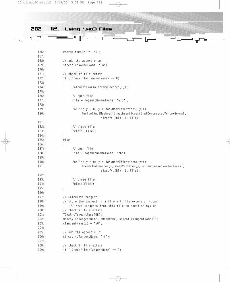
166: cNormalName[z] = ‘\0’;167: 168: // add the appendix .n169: strcat (cNormalName, “.n”);170:171: // check if file exists172: if ( CheckFile(cNormalName) == 0)173: {174: CalculateNormals2(&md3Meshes[i]);175:176: // open file177: File = fopen(cNormalName, “w+b”);178:179: for(int y = 0; y < dwNumberOfVertices; y++) 180: fwrite(&md3Meshes[i].meshVertices[y].uiCompressedVertexNormal,
sizeof(UINT), 1, File);181:182: // close file183: fclose (File);184: }185: else186: {187: // open file188: File = fopen(cNormalName, “rb”);189:190: for(int y = 0; y < dwNumberOfVertices; y++) 191: fread(&md3Meshes[i].meshVertices[y].uiCompressedVertexNormal,
sizeof(UINT), 1, File);192:193: // close file194: fclose(File);195: }196:197: // Calculate tangent198: // store the tangent in a file with the extension *.tan199: // read tangents from this file to speed things up200: // check if file exists201: TCHAR cTangentName[68];202: memcpy (cTangentName, cMeshName, sizeof(cTangentName) );203: cTangentName[z] = ‘\0’;204: 205: // add the appendix .t206: strcat (cTangentName, “.t”);207:208: // check if file exists209: if ( CheckFile(cTangentName) == 0)
282 12. Using *.MD3 Files
12 direct3d chap12 6/19/03 5:32 PM Page 282
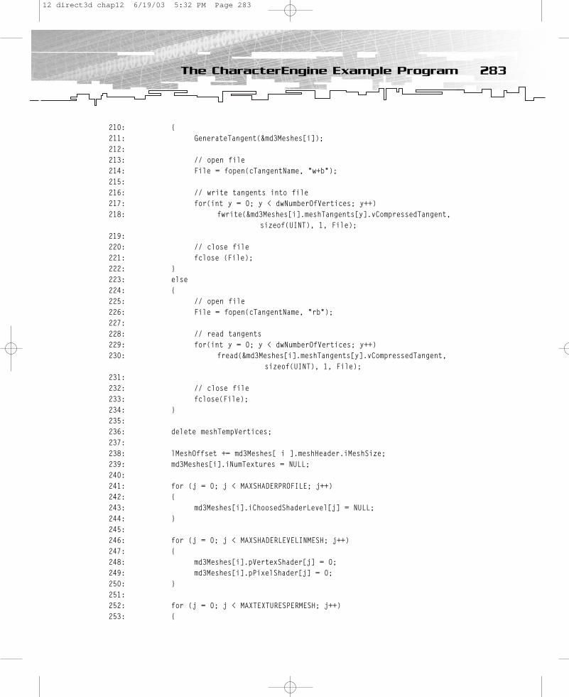
210: {211: GenerateTangent(&md3Meshes[i]);212:213: // open file214: File = fopen(cTangentName, “w+b”);215:216: // write tangents into file217: for(int y = 0; y < dwNumberOfVertices; y++) 218: fwrite(&md3Meshes[i].meshTangents[y].vCompressedTangent,
sizeof(UINT), 1, File);219:220: // close file221: fclose (File);222: }223: else224: {225: // open file226: File = fopen(cTangentName, “rb”);227:228: // read tangents229: for(int y = 0; y < dwNumberOfVertices; y++) 230: fread(&md3Meshes[i].meshTangents[y].vCompressedTangent,
sizeof(UINT), 1, File);231:232: // close file233: fclose(File);234: }235:236: delete meshTempVertices;237:238: lMeshOffset += md3Meshes[ i ].meshHeader.iMeshSize;239: md3Meshes[i].iNumTextures = NULL;240:241: for (j = 0; j < MAXSHADERPROFILE; j++)242: {243: md3Meshes[i].iChoosedShaderLevel[j] = NULL;244: }245: 246: for (j = 0; j < MAXSHADERLEVELINMESH; j++)247: {248: md3Meshes[i].pVertexShader[j] = 0;249: md3Meshes[i].pPixelShader[j] = 0;250: }251:252: for (j = 0; j < MAXTEXTURESPERMESH; j++)253: {
283The CharacterEngine Example Program
12 direct3d chap12 6/19/03 5:32 PM Page 283
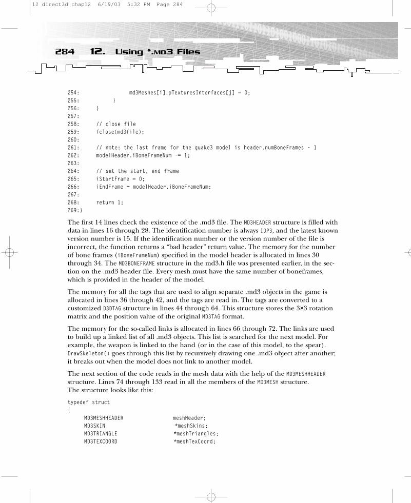
254: md3Meshes[i].pTexturesInterfaces[j] = 0;255: }256: }257:258: // close file259: fclose(md3file);260:261: // note: the last frame for the quake3 model is header.numBoneFrames - 1262: modelHeader.iBoneFrameNum -= 1;263:264: // set the start, end frame265: iStartFrame = 0;266: iEndFrame = modelHeader.iBoneFrameNum;267:268: return 1;269:}
The first 14 lines check the existence of the .md3 file. The MD3HEADER structure is filled withdata in lines 16 through 28. The identification number is always IDP3, and the latest knownversion number is 15. If the identification number or the version number of the file isincorrect, the function returns a “bad header” return value. The memory for the numberof bone frames (iBoneFrameNum) specified in the model header is allocated in lines 30through 34. The MD3BONEFRAME structure in the md3.h file was presented earlier, in the sec-tion on the .md3 header file. Every mesh must have the same number of boneframes,which is provided in the header of the model.
The memory for all the tags that are used to align separate .md3 objects in the game is allocated in lines 36 through 42, and the tags are read in. The tags are converted to a customized D3DTAG structure in lines 44 through 64. This structure stores the 3×3 rotationmatrix and the position value of the original MD3TAG format.
The memory for the so-called links is allocated in lines 66 through 72. The links are used to build up a linked list of all .md3 objects. This list is searched for the next model. Forexample, the weapon is linked to the hand (or in the case of this model, to the spear).DrawSkeleton() goes through this list by recursively drawing one .md3 object after another; it breaks out when the model does not link to another model.
The next section of the code reads in the mesh data with the help of the MD3MESHHEADERstructure. Lines 74 through 133 read in all the members of the MD3MESH structure. The structure looks like this:
typedef struct{
MD3MESHHEADER meshHeader;MD3SKIN *meshSkins;MD3TRIANGLE *meshTriangles;MD3TEXCOORD *meshTexCoord;
284 12. Using *.MD3 Files
12 direct3d chap12 6/19/03 5:32 PM Page 284

MD3VERTEXEX *meshVertices;TANGENTS *meshTangents;int iNumTextures;LPDIRECT3DTEXTURE9 pTexturesInterfaces[MAXTEXTURESPERMESH];LPDIRECT3DVERTEXSHADER9 pVertexShader[MAXSHADERLEVELINMESH];LPDIRECT3DPIXELSHADER9 pPixelShader[MAXSHADERLEVELINMESH];int iChoosedShaderLevel[MAXSHADERPROFILE];
} MD3MESH;
The structure stores the header data, the triangle, texture coordinate and vertex data, the tangents, the interfaces for the texture, and vertex shader and pixel shader data.Additionally, it stores the shader level you chose for this mesh. There are two things youshould note. First, the original vertex data is stored in three 16-bit values. The example program converts this data to 32-bit float values and decompresses it by dividing by 64. This makes the data easier to handle, and it is more instructive for an example program.Nevertheless, a more elegant solution would have been to send the 16-bit values to the vertex shader and decompress the data there. The second thing to note is that the exampleprogram does not use the normals provided with the meshes. It even computes the normalcompletely from scratch using the CalculateNormals2() function. It recalculates the normalsbecause the normals necessary for the example program are not used to calculate per-vertexlighting; they are only used to build up a texture-space coordinate system together with thetangents, in order to transform the light and other vectors into texture space. This wouldnot have worked with the tweaked normals provided with the model.
The normals and tangents are created and stored in their own files in lines 134 through234. Before they are stored, the normals and tangents are compressed to 32-bit int valueswith the help of the QuantiseVector() function. This is done in the CalculateNormals2() andGenerateTangent() functions.
The rest of the code in the source snippet is for housekeeping purposes.
LoadShaders()The LoadShaders() function loads the files with the extension *.sha. These files hold the references to shader files and the level of shading. The content of the lower_default.sha filelooks like this:
lower_mesh01,shaders/ColorNOneTexture.vsh,shaderlevel0lower_mesh02,shaders/ColorNOneTexture.vsh,shaderlevel0l_legs01,shaders/ColorNOneTexture.vsh,shaderlevel0lower_mesh01,shaders/OnlyOneTexture.psh,shaderlevel0lower_mesh02,shaders/OnlyOneTexture.psh,shaderlevel0l_legs01,shaders/OnlyOneTexture.psh,shaderlevel0lower_mesh01,shaders/diffuse.vsh,shaderlevel1lower_mesh02,shaders/diffuse.vsh,shaderlevel1l_legs01,shaders/ColorNOneTexture.vsh,shaderlevel1lower_mesh01,shaders/diffuse.psh,shaderlevel1
285The CharacterEngine Example Program
12 direct3d chap12 6/19/03 5:32 PM Page 285
lower_mesh02,shaders/diffuse.psh,shaderlevel1l_legs01,shaders/OnlyOneTexture.psh,shaderlevel1lower_mesh01,shaders/diffspec.vsh,shaderlevel2lower_mesh02,shaders/diffspec.vsh,shaderlevel2l_legs01,shaders/ColorNOneTexture.vsh,shaderlevel2lower_mesh01,shaders/diffspec.psh,shaderlevel2lower_mesh02,shaders/diffspec.psh,shaderlevel2l_legs01,shaders/OnlyOneTexture.psh,shaderlevel2
The first column (separated by commas) shows the names of the meshes. lower.md3 con-sists of three meshes: lower_mesh01, lower_mesh02, and l_legs01. The entire file must be readfrom right to left. For shader level 0, these three meshes use the vertex shader in the fileColorNOneTexture.vsh and the pixel shader in OnlyOneTexture.psh. In shader level 1, thethree meshes use the vertex shader in diffuse.vsh, the pixel shader in diffuse.psh, and soon. This way, in every shader level, each mesh can get a specific vertex and pixel shader.
Additionally, the dragon_shader.profiles file holds another level of abstraction.
shaderprofile0head01,shaderlevel1lower_mesh01,shaderlevel0lower_mesh02,shaderlevel0l_legs01,shaderlevel0upper_mesh01,shaderlevel1
shaderprofile1head01,shaderlevel1lower_mesh01,shaderlevel0lower_mesh02,shaderlevel0l_legs01,shaderlevel1upper_mesh01,shaderlevel1
shaderprofile2head01,shaderlevel1lower_mesh01,shaderlevel0 lower_mesh02,shaderlevel1l_legs01,shaderlevel1upper_mesh01,shaderlevel1
shaderprofile3head01,shaderlevel1lower_mesh01,shaderlevel1lower_mesh02,shaderlevel1l_legs01,shaderlevel1upper_mesh01,shaderlevel1
286 12. Using *.MD3 Files
12 direct3d chap12 6/19/03 5:32 PM Page 286
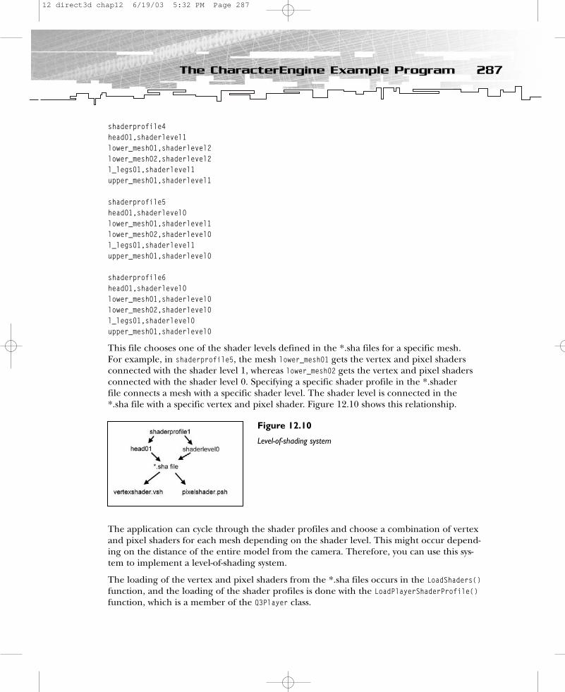
shaderprofile4head01,shaderlevel1lower_mesh01,shaderlevel2lower_mesh02,shaderlevel2l_legs01,shaderlevel1upper_mesh01,shaderlevel1
shaderprofile5head01,shaderlevel0lower_mesh01,shaderlevel1 lower_mesh02,shaderlevel0l_legs01,shaderlevel1upper_mesh01,shaderlevel0
shaderprofile6head01,shaderlevel0lower_mesh01,shaderlevel0lower_mesh02,shaderlevel0l_legs01,shaderlevel0upper_mesh01,shaderlevel0
This file chooses one of the shader levels defined in the *.sha files for a specific mesh. For example, in shaderprofile5, the mesh lower_mesh01 gets the vertex and pixel shaders connected with the shader level 1, whereas lower_mesh02 gets the vertex and pixel shaders connected with the shader level 0. Specifying a specific shader profile in the *.shader file connects a mesh with a specific shader level. The shader level is connected in the *.sha file with a specific vertex and pixel shader. Figure 12.10 shows this relationship.
The application can cycle through the shader profiles and choose a combination of vertexand pixel shaders for each mesh depending on the shader level. This might occur depend-ing on the distance of the entire model from the camera. Therefore, you can use this sys-tem to implement a level-of-shading system.
The loading of the vertex and pixel shaders from the *.sha files occurs in the LoadShaders()function, and the loading of the shader profiles is done with the LoadPlayerShaderProfile()function, which is a member of the Q3Player class.
287The CharacterEngine Example Program
Figure 12.10
Level-of-shading system
12 direct3d chap12 6/19/03 5:32 PM Page 287
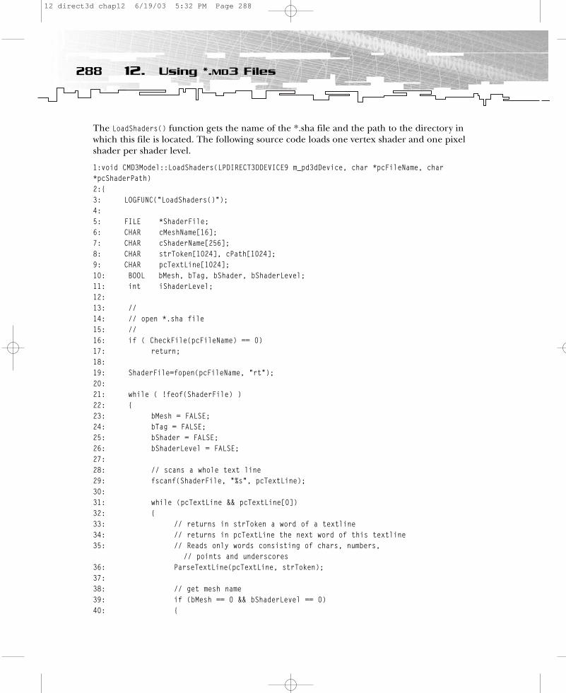
The LoadShaders() function gets the name of the *.sha file and the path to the directory inwhich this file is located. The following source code loads one vertex shader and one pixelshader per shader level.
1:void CMD3Model::LoadShaders(LPDIRECT3DDEVICE9 m_pd3dDevice, char *pcFileName, char*pcShaderPath)2:{3: LOGFUNC(“LoadShaders()”);4:5: FILE *ShaderFile;6: CHAR cMeshName[16];7: CHAR cShaderName[256];8: CHAR strToken[1024], cPath[1024];9: CHAR pcTextLine[1024];10: BOOL bMesh, bTag, bShader, bShaderLevel;11: int iShaderLevel;12:13: //14: // open *.sha file15: //16: if ( CheckFile(pcFileName) == 0)17: return;18:19: ShaderFile=fopen(pcFileName, “rt”);20: 21: while ( !feof(ShaderFile) )22: {23: bMesh = FALSE;24: bTag = FALSE;25: bShader = FALSE;26: bShaderLevel = FALSE;27:28: // scans a whole text line29: fscanf(ShaderFile, “%s”, pcTextLine);30:31: while (pcTextLine && pcTextLine[0])32: {33: // returns in strToken a word of a textline34: // returns in pcTextLine the next word of this textline35: // Reads only words consisting of chars, numbers,
// points and underscores36: ParseTextLine(pcTextLine, strToken);37:38: // get mesh name39: if (bMesh == 0 && bShaderLevel == 0)40: {
288 12. Using *.MD3 Files
12 direct3d chap12 6/19/03 5:32 PM Page 288
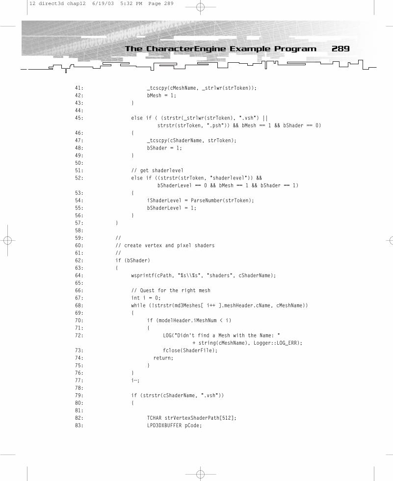
41: _tcscpy(cMeshName, _strlwr(strToken));42: bMesh = 1;43: }44:45: else if ( (strstr(_strlwr(strToken), “.vsh”) ||
strstr(strToken, “.psh”)) && bMesh == 1 && bShader == 0)46: { 47: _tcscpy(cShaderName, strToken); 48: bShader = 1; 49: }50:51: // get shaderlevel52: else if ((strstr(strToken, “shaderlevel”)) &&
bShaderLevel == 0 && bMesh == 1 && bShader == 1)53: {54: iShaderLevel = ParseNumber(strToken);55: bShaderLevel = 1;56: }57: }58:59: //60: // create vertex and pixel shaders61: // 62: if (bShader)63: {64: wsprintf(cPath, “%s\\%s”, “shaders”, cShaderName);65: 66: // Quest for the right mesh67: int i = 0;68: while (!strstr(md3Meshes[ i++ ].meshHeader.cName, cMeshName))69: {70: if (modelHeader.iMeshNum < i)71: {72: LOG(“Didn’t find a Mesh with the Name: “
+ string(cMeshName), Logger::LOG_ERR);73: fclose(ShaderFile);74: return;75: }76: }77: i—;78:79: if (strstr(cShaderName, “.vsh”)) 80: {81:82: TCHAR strVertexShaderPath[512];83: LPD3DXBUFFER pCode;
289The CharacterEngine Example Program
12 direct3d chap12 6/19/03 5:32 PM Page 289

84: HRESULT hr;85:86: DWORD dwFlags = 0;87:88:#if defined( _DEBUG ) || defined( DEBUG )89: dwFlags |= D3DXSHADER_DEBUG;90:#endif91:92: hr = DXUtil_FindMediaFileCb(strVertexShaderPath,
sizeof(strVertexShaderPath), cShaderName);93: hr = D3DXAssembleShaderFromFile(strVertexShaderPath,
NULL, NULL, dwFlags, &pCode, NULL)94: hr = m_pd3dDevice->CreateVertexShader((DWORD*)pCode->GetBufferPointer(), 95: &md3Meshes[i].pVertexShader[iShaderLevel]);96:97: if(!(FAILED(hr)))98: {99: CHAR strData[128];100: wsprintf(strData,”Created Vertex Shader: %s for Mesh: %s with
handle #%d”,101: cShaderName, 102: cMeshName,103: md3Meshes[i].pVertexShader[iShaderLevel]);104: LOG(string(strData), Logger::LOG_DATA);105: }106: else107: {108: LOG (“Could not load Vertex Shader “ + string(cShaderName) + “
for Mesh “ + 109: string(cMeshName), Logger::LOG_ERR);110: md3Meshes[i].pVertexShader[iShaderLevel] = 0;111: }112: }113: if (strstr(cShaderName, “.psh”)) 114: {115: TCHAR strPixelShaderPath[512];116: LPD3DXBUFFER pCode;117: HRESULT hr;118:119: hr = DXUtil_FindMediaFileCb(strPixelShaderPath,
sizeof(strPixelShaderPath), cShaderName);120: hr = D3DXAssembleShaderFromFile(strPixelShaderPath,
NULL, NULL,NULL, &pCode, 121: NULL);122: hr = m_pd3dDevice->CreatePixelShader(
(DWORD*)pCode->GetBufferPointer(),
290 12. Using *.MD3 Files
12 direct3d chap12 6/19/03 5:32 PM Page 290
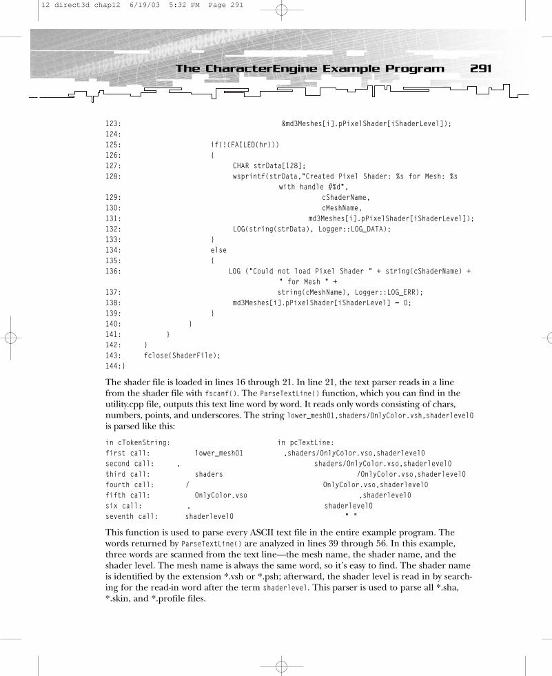
123: &md3Meshes[i].pPixelShader[iShaderLevel]);124:125: if(!(FAILED(hr)))126: {127: CHAR strData[128];128: wsprintf(strData,”Created Pixel Shader: %s for Mesh: %s
with handle #%d”,129: cShaderName, 130: cMeshName,131: md3Meshes[i].pPixelShader[iShaderLevel]);132: LOG(string(strData), Logger::LOG_DATA);133: }134: else135: {136: LOG (“Could not load Pixel Shader “ + string(cShaderName) +
“ for Mesh “ + 137: string(cMeshName), Logger::LOG_ERR);138: md3Meshes[i].pPixelShader[iShaderLevel] = 0;139: }140: }141: } 142: }143: fclose(ShaderFile);144:}
The shader file is loaded in lines 16 through 21. In line 21, the text parser reads in a linefrom the shader file with fscanf(). The ParseTextLine() function, which you can find in theutility.cpp file, outputs this text line word by word. It reads only words consisting of chars,numbers, points, and underscores. The string lower_mesh01,shaders/OnlyColor.vsh,shaderlevel0is parsed like this:
in cTokenString: in pcTextLine:first call: lower_mesh01 ,shaders/OnlyColor.vso,shaderlevel0second call: , shaders/OnlyColor.vso,shaderlevel0third call: shaders /OnlyColor.vso,shaderlevel0fourth call: / OnlyColor.vso,shaderlevel0fifth call: OnlyColor.vso ,shaderlevel0six call: , shaderlevel0seventh call: shaderlevel0 “ “
This function is used to parse every ASCII text file in the entire example program. Thewords returned by ParseTextLine() are analyzed in lines 39 through 56. In this example,three words are scanned from the text line—the mesh name, the shader name, and theshader level. The mesh name is always the same word, so it’s easy to find. The shader nameis identified by the extension *.vsh or *.psh; afterward, the shader level is read in by search-ing for the read-in word after the term shaderlevel. This parser is used to parse all *.sha,*.skin, and *.profile files.
291The CharacterEngine Example Program
12 direct3d chap12 6/19/03 5:32 PM Page 291

Before the vertex or pixel shader is created, the mesh is searched in the .md3 object inlines 68 through 77. The vertex or pixel shader handle and the shader level are stored inthe mesh structure of the type MD3MESH. This example compiles assembly shaders instead ofHLSL shaders, although the HLSL compiler generates the assembly. This way, you can opti-mize the code on the assembly level, in case the HLSL compiler didn’t produce the best-optimized code. To use a vertex or pixel shader without using the effect file format, which Iused in all previous examples, you need to perform the following steps:
• Search for the shader using DXUtil_FindMediaFileCb().• Assemble the file using D3DXAssembleShaderFromFile().• Create the vertex or pixel shader using CreateVertexShader() or CreatePixelShader().• Set the vertex shader declaration using SetVertexDeclaration().• Set the vertex or pixel shader constants using SetVertexShaderConstant*()
or SetPixelShaderConstant*().• Set the vertex or pixel shader using SetVertexShader() or SetPixelShader().
Please note that the LOG() function writes into the file app.log. You can find the entire logging class in the file logger.cpp. Its creator, Paul Nettle, released this file into the publicdomain.
The LoadSkins() function and some of the Load*() functions in the Q3Player class follow thesame pattern.
DrawSkeleton()DrawSkeleton() sets all mesh data of a model in the display buffer by usingDrawIndexedPrimitive(). The function is called recursively with a link to the content of thenext .md3 file. The recursion stops with head.md3 because this model has no link toanother model.
The function provides to the vertex shader the interpolation value, the worldviewprojmatrix, the world matrix, blended position values, two compressed normals, and two compressed tangents.
1:void CMD3Model::DrawSkeleton(CMD3Model *md3Model, LPDIRECT3DDEVICE9 m_pDevice, 2: LPDIRECT3DINDEXBUFFER9 m_pIB, LPDIRECT3DVERTEXBUFFER9 m_pVB, 3: D3DXMATRIX *matViewProj, D3DXMATRIX *matWorld, 4: LPDIRECT3DVERTEXDECLARATION9 m_pVertexDeclaration)5:{6: //——————————————————-7: // draw one of the up to four md3 models 8: // 9: // 1. lower.md310: // 2. upper.md311: // 3. optional: railgun.md312: // 4. head.md313: //——————————————————-
292 12. Using *.MD3 Files
12 direct3d chap12 6/19/03 5:32 PM Page 292
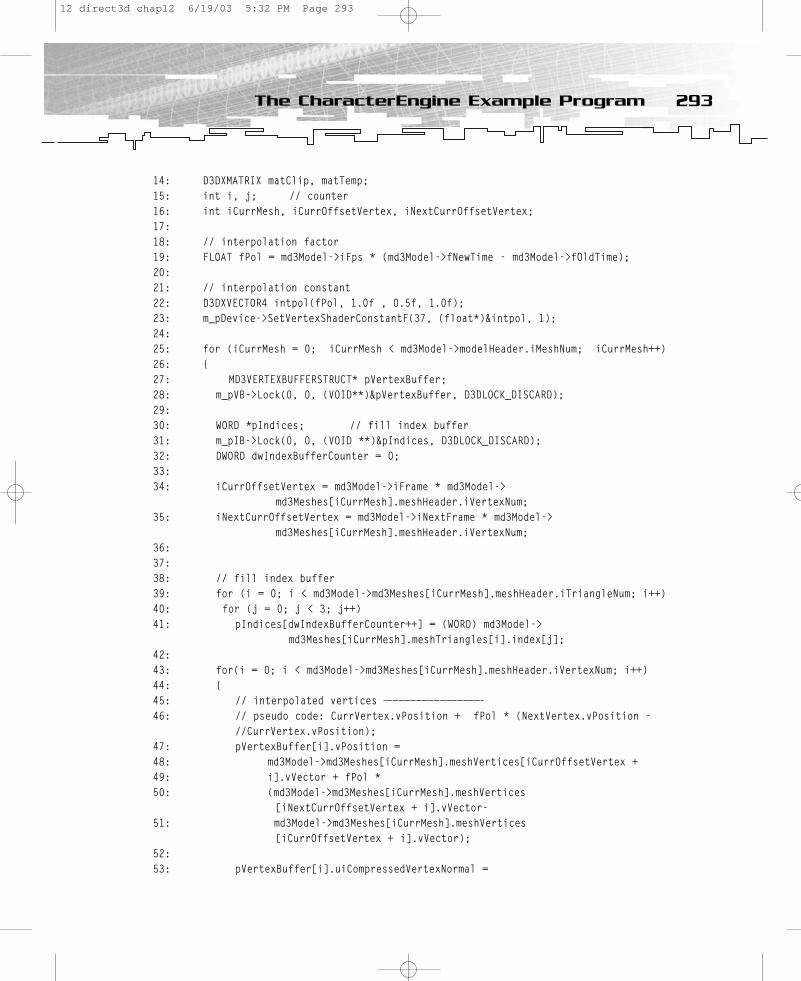
14: D3DXMATRIX matClip, matTemp;15: int i, j; // counter16: int iCurrMesh, iCurrOffsetVertex, iNextCurrOffsetVertex;17:18: // interpolation factor19: FLOAT fPol = md3Model->iFps * (md3Model->fNewTime - md3Model->fOldTime);20:21: // interpolation constant22: D3DXVECTOR4 intpol(fPol, 1.0f , 0.5f, 1.0f);23: m_pDevice->SetVertexShaderConstantF(37, (float*)&intpol, 1);24:25: for (iCurrMesh = 0; iCurrMesh < md3Model->modelHeader.iMeshNum; iCurrMesh++)26: {27: MD3VERTEXBUFFERSTRUCT* pVertexBuffer;28: m_pVB->Lock(0, 0, (VOID**)&pVertexBuffer, D3DLOCK_DISCARD);29:30: WORD *pIndices; // fill index buffer31: m_pIB->Lock(0, 0, (VOID **)&pIndices, D3DLOCK_DISCARD);32: DWORD dwIndexBufferCounter = 0;33:34: iCurrOffsetVertex = md3Model->iFrame * md3Model->
md3Meshes[iCurrMesh].meshHeader.iVertexNum;35: iNextCurrOffsetVertex = md3Model->iNextFrame * md3Model->
md3Meshes[iCurrMesh].meshHeader.iVertexNum;36: 37:38: // fill index buffer39: for (i = 0; i < md3Model->md3Meshes[iCurrMesh].meshHeader.iTriangleNum; i++)40: for (j = 0; j < 3; j++) 41: pIndices[dwIndexBufferCounter++] = (WORD) md3Model->
md3Meshes[iCurrMesh].meshTriangles[i].index[j];42:43: for(i = 0; i < md3Model->md3Meshes[iCurrMesh].meshHeader.iVertexNum; i++) 44: {45: // interpolated vertices —————————————————46: // pseudo code: CurrVertex.vPosition + fPol * (NextVertex.vPosition -
//CurrVertex.vPosition);47: pVertexBuffer[i].vPosition = 48: md3Model->md3Meshes[iCurrMesh].meshVertices[iCurrOffsetVertex + 49: i].vVector + fPol * 50: (md3Model->md3Meshes[iCurrMesh].meshVertices
[iNextCurrOffsetVertex + i].vVector-51: md3Model->md3Meshes[iCurrMesh].meshVertices
[iCurrOffsetVertex + i].vVector);52:53: pVertexBuffer[i].uiCompressedVertexNormal =
293The CharacterEngine Example Program
12 direct3d chap12 6/19/03 5:32 PM Page 293

54: md3Model->md3Meshes[iCurrMesh].meshVertices [iCurrOffsetVertex + i].uiCompressedVertexNormal;
55: pVertexBuffer[i].uiCompressedVertexNormal2 = 56: md3Model->md3Meshes[iCurrMesh].meshVertices
[iNextCurrOffsetVertex + i].uiCompressedVertexNormal;57:58: // texture coordinates ————————————-59: pVertexBuffer[i].vTexCoord = md3Model->
md3Meshes[iCurrMesh].meshTexCoord[i].texvec;60: 61: // tangent vectors62: // two for interpolation63: pVertexBuffer[i].vCompressedTangent = 64: md3Model->md3Meshes[iCurrMesh].meshTangents
[iCurrOffsetVertex + i].vCompressedTangent;65: pVertexBuffer[i].vCompressedTangent2 = 66: md3Model->md3Meshes[iCurrMesh].meshTangents
[iNextCurrOffsetVertex + i].vCompressedTangent;67: }68:69: m_pVB->Unlock();70: m_pIB->Unlock();71:72: // world * view * proj matrix73: D3DXMATRIX matTemp;74: D3DXMatrixMultiply(&matClip, matWorld, matViewProj);75: D3DXMatrixTranspose(&matTemp,&matClip);76: m_pDevice->SetVertexShaderConstantF(8, (float*)&matTemp, 4); 77:78: // world matrix79: D3DXMatrixTranspose(&matTemp, matWorld);80: m_pDevice->SetVertexShaderConstantF(0, (float*)&matTemp, 4); 81:82: m_pDevice->SetVertexDeclaration( m_pVertexDeclaration );83:84: //85: // set vertex shader 86: //87: m_pDevice->SetVertexShader(md3Model->
md3Meshes[iCurrMesh].pVertexShader[md3Model88: ->md3Meshes[iCurrMesh].iChoosedShaderLevel[iShaderProfile]]);89: 90: //91: // texture caching92: //93: if(md3Model->md3Meshes[iCurrMesh].iNumTextures > 0)
294 12. Using *.MD3 Files
12 direct3d chap12 6/19/03 5:32 PM Page 294

94: { 95: for (i = 0; i < md3Model->md3Meshes[iCurrMesh].iNumTextures; i++)96: {97: if( pMiniTextureCache[i] != md3Model->
md3Meshes[iCurrMesh].pTexturesInterfaces[i])98: { 99: pMiniTextureCache[i] = md3Model->
md3Meshes[iCurrMesh].pTexturesInterfaces[i];100: m_pDevice->SetTexture(i, pMiniTextureCache[i] );101: }102: }103: }104:105: //106: // set pixel shader107: //108: m_pDevice->SetPixelShader(md3Model->md3Meshes
[iCurrMesh].pPixelShader[md3Model109: ->md3Meshes[iCurrMesh].iChoosedShaderLevel[iShaderProfile]]);110:111:112:113: // set the vertex buffer114: // == specify the source of stream 0115: m_pDevice->SetStreamSource( 0, m_pVB, 0, sizeof(MD3VERTEXBUFFERSTRUCT));116:117: // set the index buffer118: m_pDevice->SetIndices(m_pIB);119:120: // ... rendering121: m_pDevice->DrawIndexedPrimitive(D3DPT_TRIANGLELIST,122: 0,123: 0,124: // number of vertices125: md3Model->md3Meshes[iCurrMesh].meshHeader.iVertexNum, 126: 0,127: // number of primitives128: md3Model->md3Meshes[iCurrMesh].meshHeader.iTriangleNum);129: }130:131: //132: // interpolate position of tags of lower.md3 (md3lower),
// upper.md3 (md3upper) and optional railgun.md3 (md3weapon)133: // Not: head.md3134: //135: CMD3Model *modelLink;
295The CharacterEngine Example Program
12 direct3d chap12 6/19/03 5:32 PM Page 295
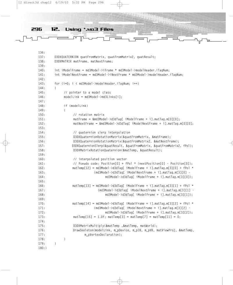
136: 137: D3DXQUATERNION quatFromMatrix, quatFromMatrix2, quatResult;138: D3DXMATRIX matFrame, matNextFrame;139:140: int iModelFrame = md3Model->iFrame * md3Model->modelHeader.iTagNum;141: int iModelNextFrame = md3Model->iNextFrame * md3Model->modelHeader.iTagNum;142:143: for (i=0; i < md3Model->modelHeader.iTagNum; i++)144: {145: // pointer to a model class146: modelLink = md3Model->md3Links[i];147:148: if (modelLink)149: {150: // rotation matrix151: matFrame = &md3Model->d3dTag[ iModelFrame + i].matTag.m[0][0];152: matNextFrame = &md3Model->d3dTag[ iModelNextFrame + i].matTag.m[0][0];153: 154: // quaternion slerp interpolation 155: D3DXQuaternionRotationMatrix(&quatFromMatrix, &matFrame);156: D3DXQuaternionRotationMatrix(&quatFromMatrix2, &matNextFrame);157: D3DXQuaternionSlerp(&quatResult, &quatFromMatrix, &quatFromMatrix2, fPol);158: D3DXMatrixRotationQuaternion(&matTemp, &quatResult);159:160: // interpolated position vector161: // Pseudo code: Position[0] + fPol * (nextPosition[0] - Position[0]);162: matTemp[12] = md3Model->d3dTag[ iModelFrame + i].matTag.m[3][0] + fPol * 163: (md3Model->d3dTag[ iModelNextFrame + i].matTag.m[3][0] - 164: md3Model->d3dTag[ iModelFrame + i].matTag.m[3][0]);165: 166: matTemp[13] = md3Model->d3dTag[ iModelFrame + i].matTag.m[3][1] + fPol * 167: (md3Model->d3dTag[ iModelNextFrame + i].matTag.m[3][1] - 168: md3Model->d3dTag[ iModelFrame + i].matTag.m[3][1]);169: 170: matTemp[14] = md3Model->d3dTag[ iModelFrame + i].matTag.m[3][2] + fPol * 171: (md3Model->d3dTag[ iModelNextFrame + i].matTag.m[3][2] - 172: md3Model->d3dTag[ iModelFrame + i].matTag.m[3][2]);173: matTemp[15] = 1.0f; matTemp[3] = matTemp[7] = matTemp[11] = 0;174:175: D3DXMatrixMultiply(&matTemp ,&matTemp, matWorld);176: DrawSkeleton(modelLink, m_pDevice, m_pIB, m_pVB, matViewProj, &matTemp,177: m_pVertexDeclaration);178: }179: }180:}
296 12. Using *.MD3 Files
12 direct3d chap12 6/19/03 5:32 PM Page 296

The reference to the texture object is cached in the pMiniTextureCache array in lines 93through 103. This reduces the amount of SetTexture() calls.
The position of the models is SLERP-interpolated (Spherical Linear Interpolation) with aquaternion in the lines 150 – 172. This is accomplished by interpolating the position of thetag that links the different parts of the model.
The recursive call of the DrawSkeleton() function occurs in lines 176 and 177.
Please note that the interpolation of the position vector in lines 45 through 51 is done onthe CPU, whereas the interpolation of the compressed normals and tangents is done in thevertex shader (and therefore on the GPU) after decompression. Handling the position val-ues in a similar way would be a nice enhancement of this example. In his article “VertexDecompression in a Shader,” which you can find in Direct3D ShaderX: Vertex and Pixel ShaderTips and Tricks (Wordware, 2002), Dean Calver desribes a technique that compresses theposition value with the help of the bounding box.
HLSL ShadersThe example program uses assembly shaders in ASCII files that are created by the HLSLcompiler fxc.exe from HLSL shaders. Getting an assembly output from the HLSL compilergives the programmer the chance to optimize the shaders and—more importantly—controlthe output from the compiler.
The compiler is called in the custom build menu via:
fxc.exe /T vs_1_1 /E VS /Fc diffuse.vsh $(InputName).fx
This line tells the compiler to create the file diffuse.vsh with the compiler option /Fc diffuse.vsh by using the HLSL file $(InputName).fx. The macro $(InputName).fxinserts the name of the input file. The /E option tells the compiler that the entry point of the HLSL shader is named VS, and the /T option requests a vs_1_1 vertex shader profile.All HLSL shaders are compiled with a similar command line.
diffuseSpecular.fx and diffuseSpecular.fxp are taken straight from the CharacterEngineexample in Chapter 12, located in the Chapter12\CharacterEngine directory (originallyfrom Chapter 9). The HLSL shaders in diffuse.fx and diffuse.fxp are just reduced version of these shaders; I removed the specular lighting code. All other HLSL shaders are reducedversions of the shaders shown in Chapter 9.
Taking a closer look at the assembly shaders created by the HLSL compiler might give youa starting point to learn assembly shader programming. I would like to recommend theassembly shader tutorials I wrote for http://www.gamedev.net. That said, I would like topoint out that learning assembly shader programming is no longer necessary because theavailable HLSL compiler generates fantastic assembly code, and the HLSL C-like syntax iseasier to read.
297The CharacterEngine Example Program
12 direct3d chap12 6/19/03 5:32 PM Page 297

Further ImprovementsThere are a lot of improvements that you could make to this model viewer. An obvious onewould be to reduce the memory footprint of the application. Here is a list of some otherpossible improvements:
• Handle original .md3 position data and decompress it in the vertex shader, or use abetter compression scheme to handle it.
• Perform higher compression of normals and tangents.• Use Cook-Torrance lighting on the helmet and the armor.• Use an energy plasma shader on the weapon.• Use a cartoon shader for the whole model to give it a cartoonish look and feel.
Additional ResourcesYou will find the best .md3 file viewer at http://fragland.net/md3view/index.html.
You will find the best description of the .md3 file format at http://linux.ucla.edu/~phaethon/q3a/formats/md3format.html.
SummaryIn this chapter you learned a wealth of information about the Quake 3 .md3 file format. And now that you’ve reached the end of the book, you should have a pretty good basis forprogramming with Direct3D. But wait—there’s more! Check out the appendixes for somehelpful additional information, including a C++ primer and a mathematics primer. And don’tmiss Appendix E, “Game Programming Resources,” for a list of Web sites you can check outto learn more about some of the topics covered in this book. Happy programming!
298 12. Using *.MD3 Files
12 direct3d chap12 6/19/03 5:32 PM Page 298
PART FOUR
Appendixes
13 direct3d AppA 6/19/03 5:33 PM Page 299

A Windows Game Programming Foundation
B C++ Primer
C Mathematics Primer
D Creating a Texture withD3DXCreateTextureFromFileEx()
E Game Programming Resources
F What’s on the CD
13 direct3d AppA 6/19/03 5:33 PM Page 300
APPENDIX A
WindowsGame
ProgrammingFoundation
13 direct3d AppA 6/19/03 5:33 PM Page 301
What do game programmers have to do with Windows programming? Well… to behonest, not much. I think a game programmer mainly needs to know three topics
for Windows programming:
• How to create a window• How to use the window message procedure• How to use resources (icons, menus, shortcuts, and so on) with the help of
Visual C/C++
There are many articles and books that will help you understand this stuff. Take a look inthe “Additional Resources” section at the end of this appendix for some places to start. Fornow, let’s start investigating some of these topics.
How to Look through a WindowYou are interested in programming a game that can be used in full-screen or windowedmode. I will describe the programming of both modes here, but before you set up the codefor the first window that will present your game output, you have to learn a few generalWindows concepts.
How Windows95/98/Me/NT/2000/XPInteracts with Your GameA DOS game requests such things as resources, input, and output. It doesn’t have to shareresources or ask someone before it takes them. However, a Windows-based game has to waituntil it is sent a message by Windows. This message is passed to your program through aspecial function called by Windows. Once a message is received, your program is expectedto take an appropriate action. Messages arrive randomly, so every Windows game has tocheck for new messages constantly.
Windows not only initiates the activity, it also grants the right to use resources (such as thegraphics card, hard disk, and so on). You must consider this when you program windowedor full-screen applications. There are ways to get full control over the hardware fromWindows, especially for full-screen games. So the resources of your game are only shared in windowed mode.
302 A. Windows Game Programming Foundation
13 direct3d AppA 6/19/03 5:33 PM Page 302

Before you move on to specific aspects of Windows programming, I need to define a fewimportant concepts.
The Components of a WindowEvery window has a border that defines its limits and is used to resize the window. There isalso a title bar, containing the system menu at the far left and the minimize, maximize, andclose boxes at the far right. Figure A.1 shows the FaceMorph example from ATI.
Your world-class game is shown in the client area.
A Window SkeletonNow I want to have you develop a Windows application that provides the necessary featurescommon to all Windows applications. This Windows program will contain two functions:
• WinMain()
• A window procedure such as WndProc()
303A Window Skeleton
System Menu Icon TitleMinimize Box
Maximize Box
Close Box
Border
Menu
Client Area
Figure A.1
Components of a window
13 direct3d AppA 6/19/03 5:33 PM Page 303

The WinMain() function performs the following general steps:
1. Define a window class.
2. Register that class with Windows.
3. Create a window of that class.
4. Display the window.
5. Begin running the message loop.
WinMain() initializes the application by defining a window class, registering that class, andcreating the window. Then it displays the window and enters a message retrieval and dis-patch loop. It terminates the message loop when it receives a WM_QUIT message, and it exitsyour game by returning the value passed in WM_QUIT’s wParam parameter.
Figure A.2 shows the first (somewhat unattractive) example program, called winskel.exe.
Here’s the source:
#include <windows.h> LRESULT CALLBACK WndProc(HWND, UINT, WPARAM, LPARAM); char szWinName[] = “Crusher”; /* name of window class */ int WINAPI WinMain(HINSTANCE hThisInst, HINSTANCE hPrevInst,
LPSTR lpszArgs, int nWinMode) {
HWND hwnd; MSG msg;
/* Step 1: Define a window class. */ WNDCLASS wcl;wcl.hInstance = hThisInst; /* handle to this instance */ wcl.lpszClassName = szWinName; /* window class name */ wcl.lpfnWndProc = WndProc; /* window function */
304 A. Windows Game Programming Foundation
Figure A.2
Window skeleton
13 direct3d AppA 6/19/03 5:33 PM Page 304
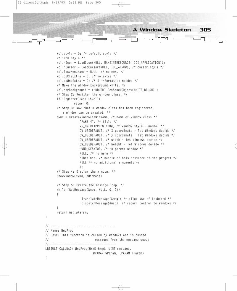
wcl.style = 0; /* default style */ /* icon style */ wcl.hIcon = LoadIcon(NULL, MAKEINTRESOURCE( IDI_APPLICATION));wcl.hCursor = LoadCursor(NULL, IDC_ARROW); /* cursor style */ wcl.lpszMenuName = NULL; /* no menu */ wcl.cbClsExtra = 0; /* no extra */ wcl.cbWndExtra = 0; /* 0 information needed */ /* Make the window background white. */wcl.hbrBackground = (HBRUSH) GetStockObject(WHITE_BRUSH) ; /* Step 2: Register the window class. */ if(!RegisterClass (&wcl))
return 0; /* Step 3: Now that a window class has been registered,
a window can be created. */ hwnd = CreateWindow(szWinName, /* name of window class */
“FAKE 4”, /* title */ WS_OVERLAPPEDWINDOW, /* window style - normal */ CW_USEDEFAULT, /* X coordinate - let Windows decide */ CW_USEDEFAULT, /* y coordinate - let Windows decide */ CW_USEDEFAULT, /* width - let Windows decide */ CW_USEDEFAULT, /* height - let Windows decide */ HWND_DESKTOP, /* no parent window */ NULL, /* no menu */ hThisInst, /* handle of this instance of the program */ NULL /* no additional arguments */ );
/* Step 4: Display the window. */ ShowWindow(hwnd, nWinMode);
/* Step 5: Create the message loop. */ while (GetMessage(&msg, NULL, 0, 0)) {
TranslateMessage(&msg); /* allow use of keyboard */ DispatchMessage(&msg); /* return control to Windows */
} return msg.wParam;
}
//——————————————————————————————————————-// Name: WndProc// Desc: This function is called by Windows and is passed // messages from the message queue//——————————————————————————————————————-LRESULT CALLBACK WndProc(HWND hwnd, UINT message,
WPARAM wParam, LPARAM lParam) {
305A Window Skeleton
13 direct3d AppA 6/19/03 5:33 PM Page 305
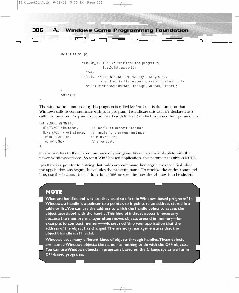
switch (message) {
case WM_DESTROY: /* terminate the program */ PostQuitMessage(0);
break; default: /* Let Windows process any messages not
specified in the preceding switch statement. */ return DefWindowProc(hwnd, message, wParam, lParam);
}return 0;
}
The window function used by this program is called WndProc(). It is the function thatWindows calls to communicate with your program. To indicate this call, it’s declared as acallback function. Program execution starts with WinMain(), which is passed four parameters.
int WINAPI WinMain(HINSTANCE hInstance, // handle to current instanceHINSTANCE hPrevInstance, // handle to previous instanceLPSTR lpCmdLine, // command lineint nCmdShow // show state
);
hInstance refers to the current instance of your game. hPrevInstance is obsolete with thenewer Windows versions. So for a Win32-based application, this parameter is always NULL.
lpCmdLine is a pointer to a string that holds any command line arguments specified whenthe application was begun. It excludes the program name. To retrieve the entire commandline, use the GetCommandLine() function. nCMDShow specifies how the window is to be shown.
306 A. Windows Game Programming Foundation
NOTEWhat are handles and why are they used so often in Windows-based programs? InWindows, a handle is a pointer to a pointer, so it points to an address stored in atable or list.You can use the address to which the handle points to access theobject associated with the handle.This kind of indirect access is necessarybecause the memory manager often moves objects around in memory—forexample, to compact memory—without notifying your application that theaddress of the object has changed.The memory manager ensures that theobject’s handle is still valid.
Windows uses many different kinds of objects through handles.These objects are named Windows objects; the name has nothing to do with the C++ objects.You can use Windows objects in programs based on the C language as well as inC++-based programs.
13 direct3d AppA 6/19/03 5:33 PM Page 306

Table A.1 shows the typical flags.
As usual, take a look at your Win32 documentation provided with Visual C/C++ or athttp://msdn.microsoft.com for more flags. Now let’s work through the five steps needed to show you a window.
Step 1: Define a Window ClassYour Windows program first must register a window class. When you register a window class,you are telling Windows about the form and function of the window you need. The word“class” is not used in its C++ sense; rather, it means style or type.
The hInstance field is assigned the current instance handle as specified in hThisInst. Thename of the window class is pointed by lpszClassName, which points to the string Crusher inthis case. The address of the window function is assigned to lpfnWndProc. No default style isspecified, and the application icon and arrow cursor are used when the mouse is in theclient area. You don’t want to use a menu, but you would like to have a white backgroundin the client area.
You can use different class styles in the WNDCLASS structure. To assign a style to a windowclass, assign the style to the style member of the WNDCLASS structure. Game programmerswon’t use many of these. The more interesting ones are
• CS_NOCLOSE, which disables Close on the window menu.• CS_DROPSHADOW, which enables the drop-shadow effect on a window. This effect is
turned on and off by SPI_SETDROPSHADOW and is supported by the next-generationWindows operating system with the code name Whistler.
The other styles don’t seem to be of any benefit for your purposes.
307A Window Skeleton
TABLE A.1 Typical Flags
Flag Description
SW_HIDE Hides the window and activates another window
SW_MAXIMIZE Maximizes the specified window
SW_MINIMIZE Minimizes the window
SW_RESTORE Restores the window to its original size and position from a maximized or minimized position
13 direct3d AppA 6/19/03 5:33 PM Page 307
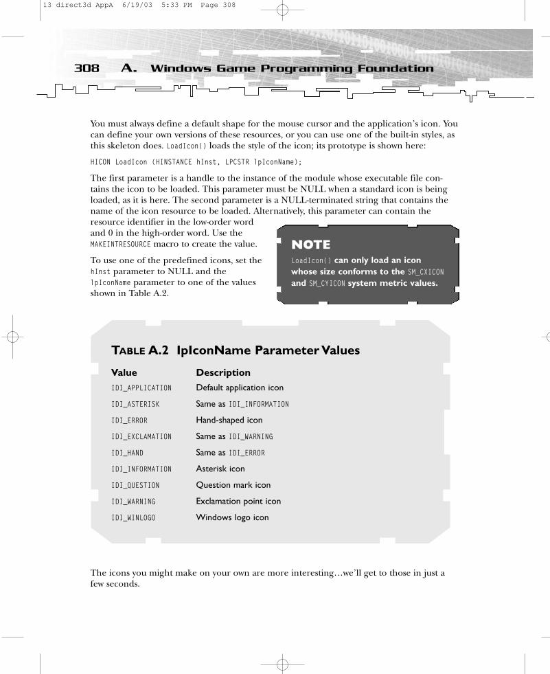
You must always define a default shape for the mouse cursor and the application’s icon. Youcan define your own versions of these resources, or you can use one of the built-in styles, asthis skeleton does. LoadIcon() loads the style of the icon; its prototype is shown here:
HICON LoadIcon (HINSTANCE hInst, LPCSTR lpIconName);
The first parameter is a handle to the instance of the module whose executable file con-tains the icon to be loaded. This parameter must be NULL when a standard icon is beingloaded, as it is here. The second parameter is a NULL-terminated string that contains thename of the icon resource to be loaded. Alternatively, this parameter can contain theresource identifier in the low-order wordand 0 in the high-order word. Use theMAKEINTRESOURCE macro to create the value.
To use one of the predefined icons, set thehInst parameter to NULL and thelpIconName parameter to one of the valuesshown in Table A.2.
The icons you might make on your own are more interesting…we’ll get to those in just afew seconds.
308 A. Windows Game Programming Foundation
NOTELoadIcon() can only load an iconwhose size conforms to the SM_CXICONand SM_CYICON system metric values.
TABLE A.2 IpIconName Parameter Values
Value DescriptionIDI_APPLICATION Default application icon
IDI_ASTERISK Same as IDI_INFORMATION
IDI_ERROR Hand-shaped icon
IDI_EXCLAMATION Same as IDI_WARNING
IDI_HAND Same as IDI_ERROR
IDI_INFORMATION Asterisk icon
IDI_QUESTION Question mark icon
IDI_WARNING Exclamation point icon
IDI_WINLOGO Windows logo icon
13 direct3d AppA 6/19/03 5:33 PM Page 308

If LoadIcon() succeeds, the return value is a handle to the newly loaded icon. If it fails, thereturn value is NULL.
To load the mouse cursor, use LoadCursor(). This function has the following prototype:
HCURSOR LoadCursor (HINSTANCE hInst, LPCSTR lpCursorName);
The first parameter is, as usual, the handle to the instance of the module whose executablefile contains the cursor to be loaded. The second parameter is a pointer to a NULL-terminated string that contains the name of the cursor resource to be loaded. Alternatively,this parameter can consist of the resource identifier in the low-order word and 0 in thehigh-order word. Use the MAKEINTRESOURCE macro to create this value.
To use one of the predefined cursors, the application must set the hInstance parameter toNULL and the lpCursorName parameter to one of the values shown in Table A.3.
309A Window Skeleton
TABLE A.3 Predefined Cursors
Value DescriptionIDC_APPSTARTING Standard arrow and small hourglass
IDC_ARROW Standard arrow
IDC_CROSS Crosshair
IDC_HAND Hand (Windows 2000 only)
IDC_HELP Arrow and question mark
IDC_IBEAM I-beam
IDC_ICON Obsolete for applications marked version 4.0 or later
IDC_NO Slashed circle
IDC_SIZE Obsolete for applications marked version 4.0 or later;use IDC_SIZEALL
IDC_SIZEALL Four-pointed arrow pointing north, south, east, and west
IDC_SIZENESW Double-pointed arrow pointing northeast and southwest
IDC_SIZENS Double-pointed arrow pointing north and south
IDC_SIZENWSE Double-pointed arrow pointing northwest and southeast
IDC_SIZEWE Double-pointed arrow pointing west and east
IDC_UPARROW Vertical arrow
IDC_WAIT Hourglass
13 direct3d AppA 6/19/03 5:33 PM Page 309

In this example, you obtain a handle to the background color brush using GetStockObject().A brush is a resource that paints the screen using a predetermined size, color, or pattern.This function can retrieve a handle to one of the stock pens, brushes, fonts, or palettes.
HGDIOBJ GetStockObject(int fnObject);
fnObject specifies the type of stock object. Game programmers won’t use this method veryoften. Table A.4 shows a few flags that might be useful.
Windows Data TypesThe skeleton program does not extensively use C/C++ data types, such as int or char *.Instead, all data types used by Windows have been typedefed within the windows.h includefile or its related include files. You must include this header file in all Windows programs.
Some of the most common data types are HANDLE (32-bit int), HWND, BYTE (8-bit sized), WORD(16-bit unsigned short integer), DWORD (32-bit unsigned long integer), UINT (32-bit unsignedinteger), LONG (32-bit long), BOOL (integer), LPSTR (pointer to a string), LPCSTR (const pointerto a string), and HANDLE. As you see, there are a number of handle types that start with an H,but they are all the same size as HANDLE. A HANDLE is simply a value that identifies someresources.
Windows defines several structures, such as MSG and WNDCLASS. As you will see in a fewmoments, MSG holds a Windows message.
Back to our skeleton code. Once the window class has been fully specified, it is registeredwith Windows using RegisterClass().
310 A. Windows Game Programming Foundation
TABLE A.4 Brushes
Flag DescriptionBLACK_BRUSH Black brush
DKGRAY_BRUSH Dark-gray brush
GRAY_BRUSH Gray brush
LTGRAY_BRUSH Light-gray brush
NULL_BRUSH Null brush
WHITE_BRUSH White brush
13 direct3d AppA 6/19/03 5:33 PM Page 310

Step 2: Registerthe Window ClassRegisterClass() registers a window class forsubsequent use in calls to CreateWindow() orCreateWindowEx(). All window classes that anapplication registers are unregistered whenit terminates.
ATOM RegisterClass(CONST WNDCLASS *lpWndClass);
The function returns a value that identifies the window class. ATOM is a typedef that means WORD.
Step 3: Create a Window of That ClassOnce you have defined and registered a window class, your game can actually create a window of that class with CreateWindow().
HWND CreateWindow(LPCTSTR lpClassName, // registered class nameLPCTSTR lpWindowName, // title of window DWORD dwStyle, // window styleint x, // horizontal position of windowint y, // vertical position of windowint nWidth, // window widthint nHeight, // window heightHWND hWndParent, // handle to parent or owner windowHMENU hMenu, // menu handle or child identifierHINSTANCE hInstance, // handle to application instanceLPVOID lpParam // window-creation data
);
You can default or specify as NULL many of the parameters to CreateWindow(). In fact, mostof the x, y, nWidth, and nHeight parameters will simply use the macro CW_USEDEFAULT in mostapplications, which tells Windows to select an appropriate size and location for the window.However, in a game application you want to set the window with a predefined width andheight. As you will see, AdjustWindowRect() can help by calculating the required size of thewindow rectangle based on the desired client rectangle size.
You must specify the handle to the parent window hWndParent as HWND_DESKTOP. If the windowwill not contain a menu, then hMenu must be NULL. If no additional information isrequired, as is most often the case, then lpParam is NULL.
You must set the remaining four parameters explicitly for your game. lpClassName mustpoint to the name of the window class. The title of the window is a string pointed by
311A Window Skeleton
CAUTIONIf an application calls CreateWindow() tocreate an MDI (Multiple DocumentInterface) client window, lpParam mustpoint to a CLIENTCREATESTRUCT structure.
13 direct3d AppA 6/19/03 5:33 PM Page 311
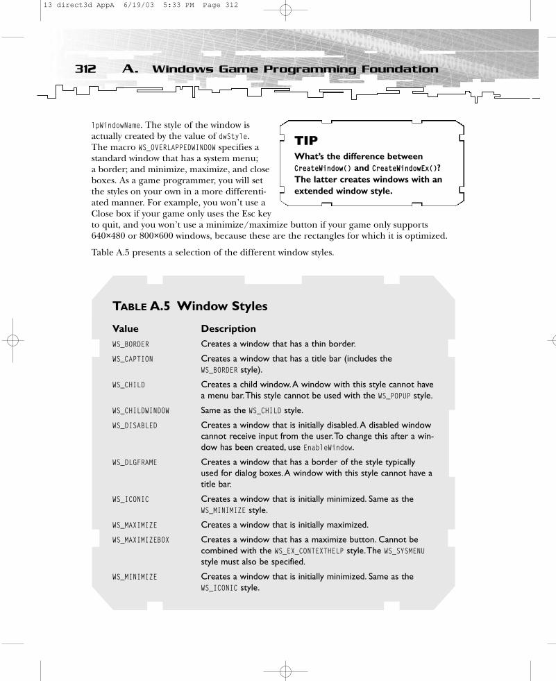
lpWindowName. The style of the window isactually created by the value of dwStyle. The macro WS_OVERLAPPEDWINDOW specifies astandard window that has a system menu; a border; and minimize, maximize, and closeboxes. As a game programmer, you will setthe styles on your own in a more differenti-ated manner. For example, you won’t use aClose box if your game only uses the Esc keyto quit, and you won’t use a minimize/maximize button if your game only supports640×480 or 800×600 windows, because these are the rectangles for which it is optimized.
Table A.5 presents a selection of the different window styles.
312 A. Windows Game Programming Foundation
TABLE A.5 Window Styles
Value DescriptionWS_BORDER Creates a window that has a thin border.
WS_CAPTION Creates a window that has a title bar (includes the WS_BORDER style).
WS_CHILD Creates a child window.A window with this style cannot havea menu bar.This style cannot be used with the WS_POPUP style.
WS_CHILDWINDOW Same as the WS_CHILD style.
WS_DISABLED Creates a window that is initially disabled.A disabled windowcannot receive input from the user.To change this after a win-dow has been created, use EnableWindow.
WS_DLGFRAME Creates a window that has a border of the style typicallyused for dialog boxes.A window with this style cannot have atitle bar.
WS_ICONIC Creates a window that is initially minimized. Same as theWS_MINIMIZE style.
WS_MAXIMIZE Creates a window that is initially maximized.
WS_MAXIMIZEBOX Creates a window that has a maximize button. Cannot becombined with the WS_EX_CONTEXTHELP style.The WS_SYSMENUstyle must also be specified.
WS_MINIMIZE Creates a window that is initially minimized. Same as theWS_ICONIC style.
TIPWhat’s the difference betweenCreateWindow() and CreateWindowEx()?The latter creates windows with anextended window style.
13 direct3d AppA 6/19/03 5:33 PM Page 312
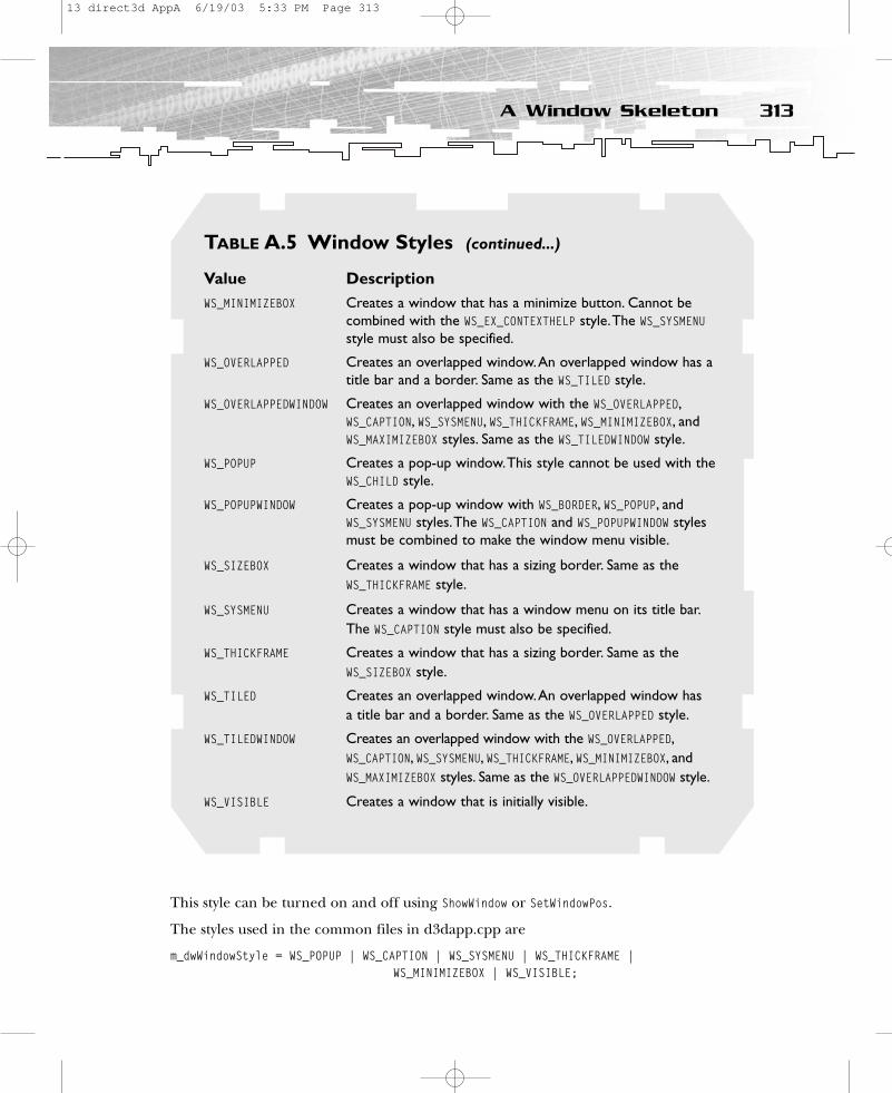
This style can be turned on and off using ShowWindow or SetWindowPos.
The styles used in the common files in d3dapp.cpp are
m_dwWindowStyle = WS_POPUP | WS_CAPTION | WS_SYSMENU | WS_THICKFRAME |WS_MINIMIZEBOX | WS_VISIBLE;
313A Window Skeleton
TABLE A.5 Window Styles (continued...)
Value DescriptionWS_MINIMIZEBOX Creates a window that has a minimize button. Cannot be
combined with the WS_EX_CONTEXTHELP style.The WS_SYSMENUstyle must also be specified.
WS_OVERLAPPED Creates an overlapped window.An overlapped window has atitle bar and a border. Same as the WS_TILED style.
WS_OVERLAPPEDWINDOW Creates an overlapped window with the WS_OVERLAPPED,WS_CAPTION, WS_SYSMENU, WS_THICKFRAME, WS_MINIMIZEBOX, andWS_MAXIMIZEBOX styles. Same as the WS_TILEDWINDOW style.
WS_POPUP Creates a pop-up window.This style cannot be used with theWS_CHILD style.
WS_POPUPWINDOW Creates a pop-up window with WS_BORDER, WS_POPUP, andWS_SYSMENU styles.The WS_CAPTION and WS_POPUPWINDOW stylesmust be combined to make the window menu visible.
WS_SIZEBOX Creates a window that has a sizing border. Same as theWS_THICKFRAME style.
WS_SYSMENU Creates a window that has a window menu on its title bar.The WS_CAPTION style must also be specified.
WS_THICKFRAME Creates a window that has a sizing border. Same as theWS_SIZEBOX style.
WS_TILED Creates an overlapped window.An overlapped window has a title bar and a border. Same as the WS_OVERLAPPED style.
WS_TILEDWINDOW Creates an overlapped window with the WS_OVERLAPPED,WS_CAPTION, WS_SYSMENU, WS_THICKFRAME, WS_MINIMIZEBOX, andWS_MAXIMIZEBOX styles. Same as the WS_OVERLAPPEDWINDOW style.
WS_VISIBLE Creates a window that is initially visible.
13 direct3d AppA 6/19/03 5:33 PM Page 313
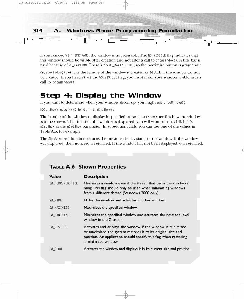
If you remove WS_THICKFRAME, the window is not resizable. The WS_VISIBLE flag indicates thatthis window should be visible after creation and not after a call to ShowWindow(). A title bar isused because of WS_CAPTION. There’s no WS_MAXIMIZEBOX, so the maximize button is grayed out.
CreateWindow() returns the handle of the window it creates, or NULL if the window cannotbe created. If you haven’t set the WS_VISIBLE flag, you must make your window visible with acall to ShowWindow().
Step 4: Display the WindowIf you want to determine when your window shows up, you might use ShowWindow().
BOOL ShowWindow(HWND hWnd, int nCmdShow);
The handle of the window to display is specified in hWnd. nCmdShow specifies how the windowis to be shown. The first time the window is displayed, you will want to pass WinMain()’snCmdShow as the nCmdShow parameter. In subsequent calls, you can use one of the values inTable A.6, for example.
The ShowWindow() function returns the previous display status of the window. If the windowwas displayed, then nonzero is returned. If the window has not been displayed, 0 is returned.
314 A. Windows Game Programming Foundation
TABLE A.6 Shown Properties
Value DescriptionSW_FORCEMINIMIZE Minimizes a window even if the thread that owns the window is
hung.This flag should only be used when minimizing windowsfrom a different thread (Windows 2000 only).
SW_HIDE Hides the window and activates another window.
SW_MAXIMIZE Maximizes the specified window.
SW_MINIMIZE Minimizes the specified window and activates the next top-levelwindow in the Z order.
SW_RESTORE Activates and displays the window. If the window is minimizedor maximized, the system restores it to its original size andposition. An application should specify this flag when restoring a minimized window.
SW_SHOW Activates the window and displays it in its current size and position.
13 direct3d AppA 6/19/03 5:33 PM Page 314

Step 5: Create the Message LoopThe final part of WinMain() is the message loop. It receives and processes messages sent byWindows. When an application is running, it is continually sent messages, which are storedin the application’s message queue until they can be read and processed. Each time yourapplication is ready to read another message, it must call GetMessage().
BOOL GetMessage(LPMSG lpMsg, // message informationHWND hWnd, // handle to windowUINT wMsgFilterMin, // first messageUINT wMsgFilterMax // last message
);
The message is received by lpMsg. All Windows messages are of structure type MSG, shown here:
typedef struct tagMSG {
HWND hwnd; UINT message; WPARAM wParam; LPARAM lParam; DWORD time; POINT pt;
} MSG, *PMSG;
You will find the message data in message with additional information in wParam and lParam. In its hwnd and message fields, a MSG structure identifies the message being referred to by thewindow that the message affects. In its wParam and lParam fields, this structure stores informa-tion about the kind of event the message refers to and the event’s source. For example, if theevent is caused by keyboard input, the wParam and lParam fields identify the key being pressedand also reveal whether a command key was pressed at the same time. There is a time stampin milliseconds in time, and pt holds the coordinates of the mouse in a POINT structure.
typedef struct tagPOINT{
LONG x, y;} POINT;
wMsgFilterMin and wMsgFilterMax specify arange of messages that will be received. Ifyou want your application to receive all ofthe messages, you will specify both min andmax as 0.
GetMessage() returns 0 when the user termi-nates the program, causing the messageloop to terminate; otherwise, it returnsnonzero.
315A Window Skeleton
NOTEJavier F. Otaegui has another inter-esting approach to get rid of thewindow message pump. (See http://www.gamedev.net/reference/articles/article1249.asp.) He uses a secondthread that handles the windowmessage routine.
13 direct3d AppA 6/19/03 5:33 PM Page 315

You won’t use GetMessage() in all situations; there are several situations in which you will usePeekMessage().
BOOL PeekMessage(LPMSG lpMsg, // message informationHWND hWnd, // handle to windowUINT wMsgFilterMin, // first messageUINT wMsgFilterMax, // last messageUINT wRemoveMsg // removal options
);
There’s one additional parameter—wRemoveMsg. It specifies how messages are handled. Table A.7 lists the possible values for this parameter.
You should generally use PM_REMOVE. By default, all message types are processed. One of themore interesting features that came with the advent of Windows 98, Me, and 2000 is theability to specify that only a certain message should be processed. Table A.8 lists some more PeekMessage() flags.
316 A. Windows Game Programming Foundation
TABLE A.7 PeekMessage() Flags
Value DescriptionPM_NOREMOVE Messages are not removed from the queue after processing
by PeekMessage().
PM_REMOVE Messages are removed from the queue after processing byPeekMessage().
TABLE A.8 PeekMessage() II Flags
Value DescriptionPM_QS_INPUT Process mouse and keyboard messages.
PM_QS_PAINT Process paint messages.
PM_QS_POSTMESSAGE Process all posted messages, including timers and hot keys.
PM_QS_SENDMESSAGE Process all sent messages.
13 direct3d AppA 6/19/03 5:33 PM Page 316
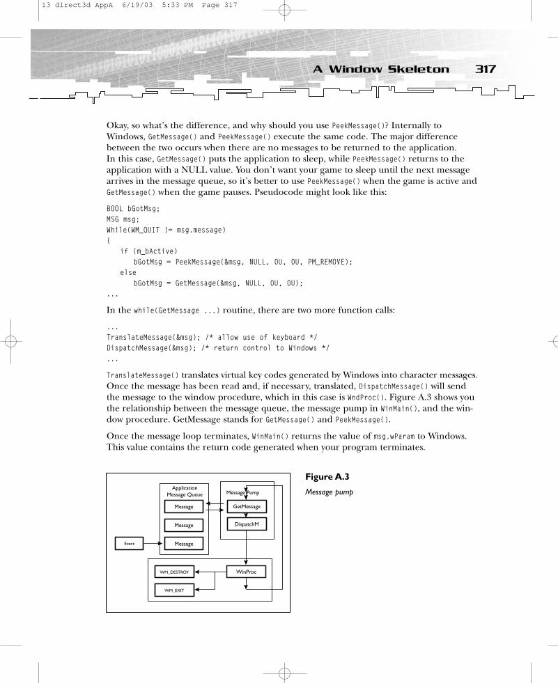
Okay, so what’s the difference, and why should you use PeekMessage()? Internally toWindows, GetMessage() and PeekMessage() execute the same code. The major differencebetween the two occurs when there are no messages to be returned to the application. In this case, GetMessage() puts the application to sleep, while PeekMessage() returns to theapplication with a NULL value. You don’t want your game to sleep until the next messagearrives in the message queue, so it’s better to use PeekMessage() when the game is active andGetMessage() when the game pauses. Pseudocode might look like this:
BOOL bGotMsg;MSG msg;While(WM_QUIT != msg.message){
if (m_bActive)bGotMsg = PeekMessage(&msg, NULL, 0U, 0U, PM_REMOVE);
elsebGotMsg = GetMessage(&msg, NULL, 0U, 0U);
...
In the while(GetMessage ...) routine, there are two more function calls:
...TranslateMessage(&msg); /* allow use of keyboard */ DispatchMessage(&msg); /* return control to Windows */ ...
TranslateMessage() translates virtual key codes generated by Windows into character messages.Once the message has been read and, if necessary, translated, DispatchMessage() will sendthe message to the window procedure, which in this case is WndProc(). Figure A.3 shows youthe relationship between the message queue, the message pump in WinMain(), and the win-dow procedure. GetMessage stands for GetMessage() and PeekMessage().
Once the message loop terminates, WinMain() returns the value of msg.wParam to Windows.This value contains the return code generated when your program terminates.
317A Window Skeleton
ApplicationMessage Queue
Message
Message
Message
WM_DESTROY
WM_EXIT
Event
Message Pump
GetMessage
DispatchM
WinProc
Figure A.3
Message pump
13 direct3d AppA 6/19/03 5:33 PM Page 317
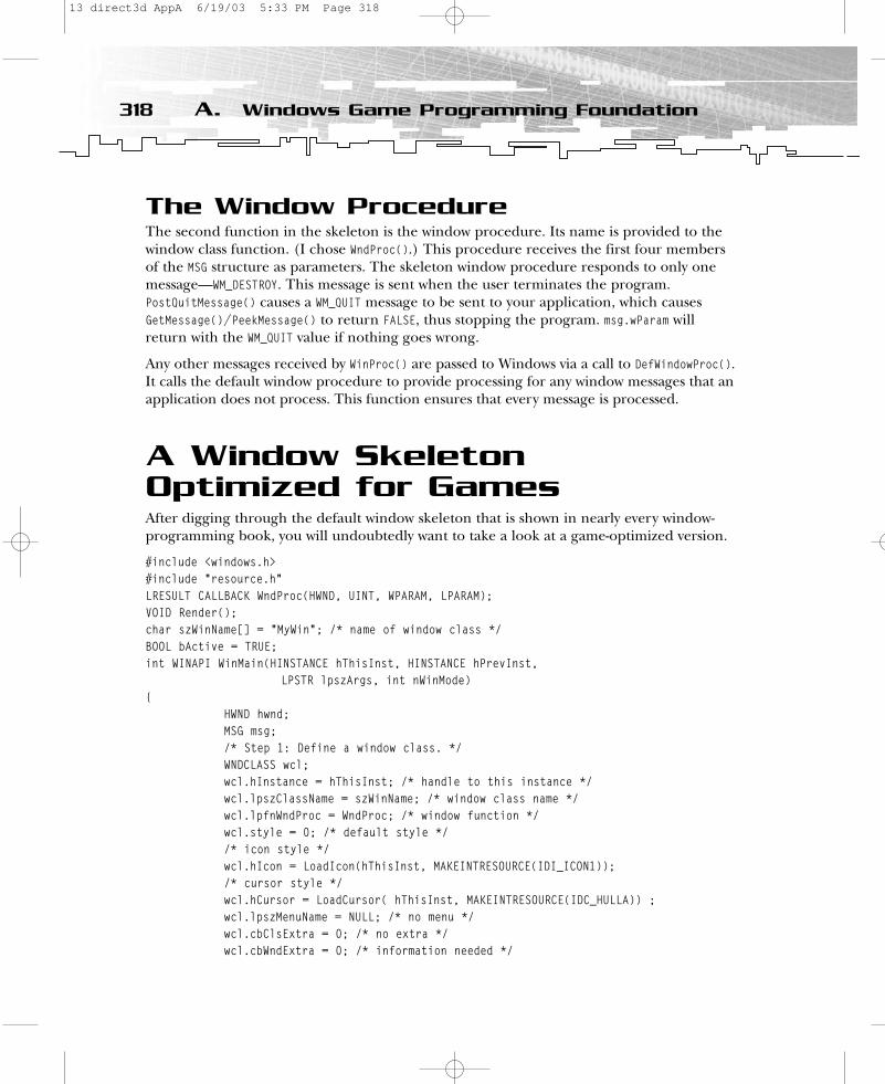
The Window ProcedureThe second function in the skeleton is the window procedure. Its name is provided to thewindow class function. (I chose WndProc().) This procedure receives the first four membersof the MSG structure as parameters. The skeleton window procedure responds to only onemessage—WM_DESTROY. This message is sent when the user terminates the program.PostQuitMessage() causes a WM_QUIT message to be sent to your application, which causesGetMessage()/PeekMessage() to return FALSE, thus stopping the program. msg.wParam willreturn with the WM_QUIT value if nothing goes wrong.
Any other messages received by WinProc() are passed to Windows via a call to DefWindowProc().It calls the default window procedure to provide processing for any window messages that anapplication does not process. This function ensures that every message is processed.
A Window Skeleton Optimized for GamesAfter digging through the default window skeleton that is shown in nearly every window-programming book, you will undoubtedly want to take a look at a game-optimized version.
#include <windows.h> #include “resource.h”LRESULT CALLBACK WndProc(HWND, UINT, WPARAM, LPARAM); VOID Render();char szWinName[] = “MyWin”; /* name of window class */ BOOL bActive = TRUE;int WINAPI WinMain(HINSTANCE hThisInst, HINSTANCE hPrevInst,
LPSTR lpszArgs, int nWinMode) {
HWND hwnd; MSG msg; /* Step 1: Define a window class. */ WNDCLASS wcl; wcl.hInstance = hThisInst; /* handle to this instance */ wcl.lpszClassName = szWinName; /* window class name */ wcl.lpfnWndProc = WndProc; /* window function */ wcl.style = 0; /* default style */ /* icon style */ wcl.hIcon = LoadIcon(hThisInst, MAKEINTRESOURCE(IDI_ICON1));/* cursor style */ wcl.hCursor = LoadCursor( hThisInst, MAKEINTRESOURCE(IDC_HULLA)) ; wcl.lpszMenuName = NULL; /* no menu */ wcl.cbClsExtra = 0; /* no extra */ wcl.cbWndExtra = 0; /* information needed */
318 A. Windows Game Programming Foundation
13 direct3d AppA 6/19/03 5:33 PM Page 318
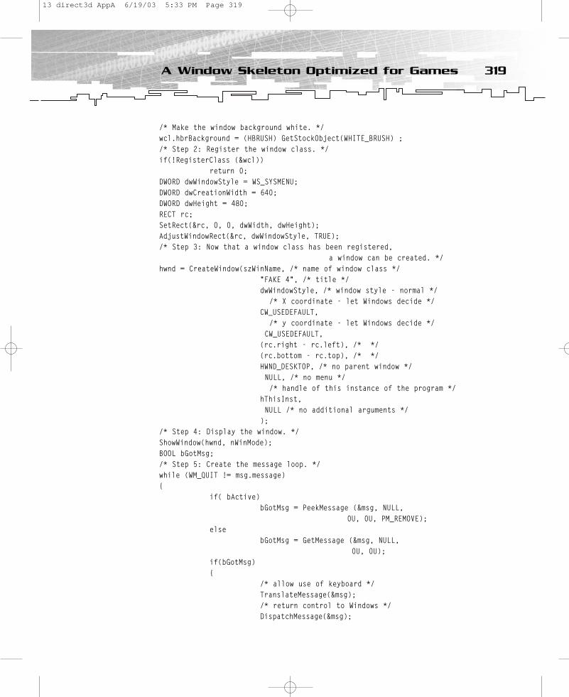
/* Make the window background white. */ wcl.hbrBackground = (HBRUSH) GetStockObject(WHITE_BRUSH) ; /* Step 2: Register the window class. */ if(!RegisterClass (&wcl))
return 0; DWORD dwWindowStyle = WS_SYSMENU;DWORD dwCreationWidth = 640;DWORD dwHeight = 480;RECT rc;SetRect(&rc, 0, 0, dwWidth, dwHeight);AdjustWindowRect(&rc, dwWindowStyle, TRUE);/* Step 3: Now that a window class has been registered,
a window can be created. */ hwnd = CreateWindow(szWinName, /* name of window class */
“FAKE 4”, /* title */ dwWindowStyle, /* window style - normal */
/* X coordinate - let Windows decide */ CW_USEDEFAULT,
/* y coordinate - let Windows decide */ CW_USEDEFAULT,
(rc.right - rc.left), /* */ (rc.bottom - rc.top), /* */ HWND_DESKTOP, /* no parent window */ NULL, /* no menu */ /* handle of this instance of the program */
hThisInst, NULL /* no additional arguments */
);/* Step 4: Display the window. */ ShowWindow(hwnd, nWinMode); BOOL bGotMsg;/* Step 5: Create the message loop. */while (WM_QUIT != msg.message){
if( bActive)bGotMsg = PeekMessage (&msg, NULL,
0U, 0U, PM_REMOVE);else
bGotMsg = GetMessage (&msg, NULL, 0U, 0U);
if(bGotMsg){
/* allow use of keyboard */ TranslateMessage(&msg); /* return control to Windows */ DispatchMessage(&msg);
319A Window Skeleton Optimized for Games
13 direct3d AppA 6/19/03 5:33 PM Page 319
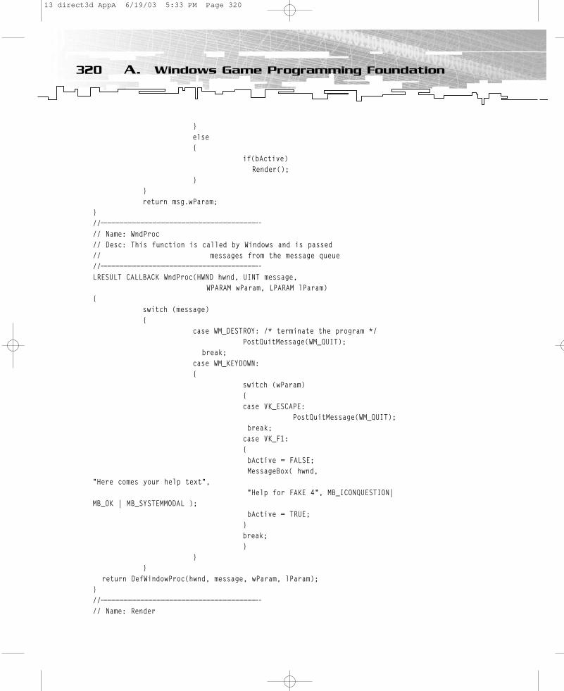
}else{
if(bActive)Render();
}}return msg.wParam;
} //——————————————————————————————————————-// Name: WndProc// Desc: This function is called by Windows and is passed // messages from the message queue//——————————————————————————————————————-LRESULT CALLBACK WndProc(HWND hwnd, UINT message,
WPARAM wParam, LPARAM lParam) {
switch (message) {
case WM_DESTROY: /* terminate the program */ PostQuitMessage(WM_QUIT);
break; case WM_KEYDOWN:{
switch (wParam){case VK_ESCAPE:
PostQuitMessage(WM_QUIT); break;
case VK_F1:{bActive = FALSE;MessageBox( hwnd,
“Here comes your help text”, “Help for FAKE 4”, MB_ICONQUESTION|
MB_OK | MB_SYSTEMMODAL );bActive = TRUE;
}break;}
}}
return DefWindowProc(hwnd, message, wParam, lParam); }//——————————————————————————————————————-// Name: Render
320 A. Windows Game Programming Foundation
13 direct3d AppA 6/19/03 5:33 PM Page 320
// Desc: dummy function to show the use of the enhanced skeleton//——————————————————————————————————————-VOID Render(){};
You will find the first enhancements just before Step 3.
DWORD dwWindowStyle = WS_POPUP | WS_CAPTION;DWORD dwWidth = 640;DWORD dwHeight = 480;RECT rc;SetRect(&rc, 0, 0, dwWidth, dwHeight);AdjustWindowRect(&rc, dwWindowStyle, TRUE);
You define a window style only with a title bar. It should be 640×480 pixels. SetRect() setsthe coordinates of the specified rectangle. AdjustWindowRect() calculates the required size ofthe window rectangle, based on the desired client rectangle size, so you really get a clientwindow size of 640×480. The real stuff is located in the message loop in Step 5.
/* Step 5: Create the message loop. */while (WM_QUIT != msg.message){
if( bActive)bGotMsg = PeekMessage (&msg, NULL, 0U, 0U, PM_REMOVE);
elsebGotMsg = GetMessage (&msg, NULL, 0U, 0U);
if(bGotMsg){
TranslateMessage(&msg); /* allow use of keyboard */ DispatchMessage(&msg); /* return control to Windows */
}else{
if(bActive)Render();
}}
When the application is active, PeekMessage() returns to the application with NULL whenthere is no message in the message queue. When the application is inactive, GetMessage() putsthe application to sleep when there is no message in the message queue. TranslateMessage()and DispatchMessage() are only called when a message has worn out. Render() is only calledwhen the application is active. I made a small example for cases when the application is notactive (see Figure A.4).
case VK_F1:{
bActive = FALSE;
321A Window Skeleton Optimized for Games
13 direct3d AppA 6/19/03 5:33 PM Page 321
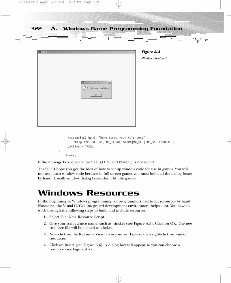
MessageBox( hwnd, “Here comes your help text”, “Help for FAKE 4”, MB_ICONQUESTION|MB_OK | MB_SYSTEMMODAL );
bActive = TRUE;}
break;
If the message box appears, bActive is FALSE and Render() is not called.
That’s it. I hope you got the idea of how to set up window code for use in games. You willnot use much window code because in full-screen games you must build all the dialog boxesby hand. Usually window dialog boxes don’t fit into games.
Windows ResourcesIn the beginning of Windows programming, all programmers had to set resources by hand.Nowadays, the Visual C/C++ integrated development environment helps a lot. You have towork through the following steps to build and include resources:
1. Select File, New, Resource Script.
2. Give your script a nice name, such as winskel (see Figure A.5). Click on OK. The newresource file will be named winskel.rc.
3. Now click on the Resource View tab in your workspace, then right-click on winskelresources.
4. Click on Insert (see Figure A.6). A dialog box will appear so you can choose aresource (see Figure A.7).
322 A. Windows Game Programming Foundation
Figure A.4
Window skeleton 2
13 direct3d AppA 6/19/03 5:33 PM Page 322

323Windows Resources
Figure A.5
Creating a resourcescript
Figure A.6
Insert a resource
Figure A.7
Create an icon
13 direct3d AppA 6/19/03 5:33 PM Page 323
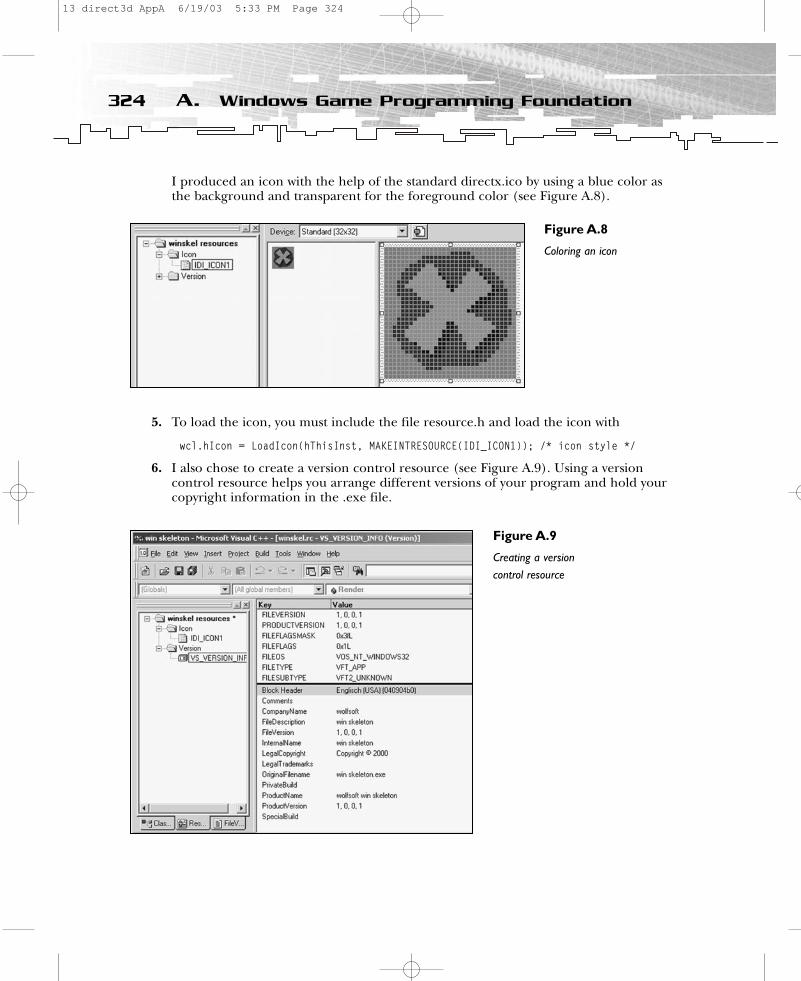
I produced an icon with the help of the standard directx.ico by using a blue color asthe background and transparent for the foreground color (see Figure A.8).
5. To load the icon, you must include the file resource.h and load the icon with
wcl.hIcon = LoadIcon(hThisInst, MAKEINTRESOURCE(IDI_ICON1)); /* icon style */
6. I also chose to create a version control resource (see Figure A.9). Using a versioncontrol resource helps you arrange different versions of your program and hold yourcopyright information in the .exe file.
324 A. Windows Game Programming Foundation
Figure A.8
Coloring an icon
Figure A.9
Creating a versioncontrol resource
13 direct3d AppA 6/19/03 5:33 PM Page 324

7. Oh yes, a special cursor would be nice. Click on the Resource View tab in your work-space, right-click on winskel resources, and then choose Cursor (see Figure A.10).
So you have three resources for your simple skeleton (see Figure A.11).
So now you know how to build your first skeleton with resources. Whereas you have to enterall of the skeleton code by hand in the Visual C/C++ editor, you get a lot of help when youcreate resources from the IDE.
325Windows Resources
Figure A.10
Cursor production
Figure A.11
Three resources
13 direct3d AppA 6/19/03 5:34 PM Page 325
APPENDIX B
C++ Primer
14 direct3d AppB 6/19/03 5:34 PM Page 327
A few years ago, there were a lot of discussions going around in the newsgroups aboutusing C or C++ in games. One faction said that C produces faster code and named
games such as Quake and Unreal as proof. The other faction said that C++ is more elegant,helps structure your game better, and is economically cheaper when used by productionteams.
Practice—as always—leads to the practical solution: Take the speed of C and the ability tostructure game code from C++. I suppose many game programmers don’t use much C++stuff. If you take a look at the examples in the DirectX SDK, you will see a lot of C++ codeand traditional C code.
This appendix covers a host of topics, including:
• A brief explanation of the uses and features of object-oriented programming
• An overview of some C++ keywords and data types that aren’t available in C or thatare used differently in C++ and C
• Creating and using classes, or how the C-language structure has evolved into the C++ class—one of the cornerstones of object-oriented programming in C++
• Other C++ programming techniques such as access specifiers; operators for accessingmember methods and member variables of classes, constructors, and destructors;copy constructors; and the this pointer
What Is Object-OrientedProgramming?In an object-oriented view of programming, a program describes a system of objects inter-acting. This is contrary to a procedure-oriented view of programming, in which a programdescribes a series of steps to be performed.
Object-oriented programming involves a few key concepts. The most basic of these isabstraction, which simplifies writing large programs. Another is encapsulation, which makesit easier to change and maintain a program. The concept of class hierarchies is a powerfulclassification tool that can make a program easily extensible.
To understand C++ as an object-oriented language, you have to understand how C++ takesadvantage of these concepts.
328 B. C++ Primer
14 direct3d AppB 6/19/03 5:34 PM Page 328
AbstractionAbstraction is the process of ignoring details in order to concentrate on essential things. Aso-called high-level programming language supports a high level of abstraction. The usualexample is the comparison of a program written in assembly and one written in C. Theassembly source contains a very detailed description of what the computer does to performthe task, whereas the C source gives a much more abstract description of what the com-puter does; that abstraction makes the program clearer and easier to understand.
All procedural languages support procedural abstraction, in which a piece of source code isput into a function and reused this way. For example, consider matrix multiplication:
FLOAT pM[16];ZeroMemory( pM, sizeof(D3DXMATRIX) );for( WORD i=0; i<4; i++ )
for( WORD j=0; j<4; j++ ) for( WORD k=0; k<4; k++ )
pM[4*i+j] += pM1[4*i+k] * pM2[4*k+j];memcpy( pOut, pM, sizeof(D3DXMATRIX) );
You wouldn’t want to write this piece of code every time two 4×4 matrices have to be multi-plied. Instead, you abstract it by embedding it in a function call like this:
D3DXMATRIX* D3DXMatrixMultiply (D3DXMATRIX* pOut, CONST D3DXMATRIX* pM1, CONST D3DMATRIX* pM2)
{FLOAT pM[16];ZeroMemory( pM, sizeof(D3DXMATRIX) );for( WORD i=0; i<4; i++ )
for( WORD j=0; j<4; j++ ) for( WORD k=0; k<4; k++ )
pM[4*i+j] += pM1[4*i+k] * pM2[4*k+j];memcpy( pOut, pM, sizeof(D3DXMATRIX) );
return (pOut);}
Using D3DXMatrixMultiply() will lead to more readable and understandable source code andwill save you a lot of typing.
You already know about data abstraction, which lets you ignore details of how a data type is represented. The C language provides data types like int or float, which let you type insomething like 42.5, rather than hexadecimal bytes. Thankfully, floating-point arithmeticperformed in binary is something that C programmers don’t have to worry about. On theother hand, C does not support the abstraction of strings because it requires you to manip-ulate strings as a series of characters.
329What Is Object-Oriented Programming?
14 direct3d AppB 6/19/03 5:34 PM Page 329
But C supports user-defined data abstraction through structures and typedefs. Programmersmight use structures to manipulate several pieces of information as a unit instead of indi-vidually.
Struct Mesh{
char cName[68]; // 65 chars, 32-bit aligned == 68 chars in fileint iNumVertices; // Mesh verticesint iMeshFrameNum; // animation frames in meshVMESHFRAME *vMeshFrames; // stores vertices per animation frame in
// vertices[FrameNum][VertexNum]int iNumTriangles; // Mesh trianglesTRIANGLEVERT *pTriangles; int iNumTextures; // Mesh texturesTEXNAMES *pTexNames;LPDIRECT3DTEXTURE8* pTexturesInterfaces;TEXCOORDS *pfTextureCoords; // Mesh tex coordinatesTEXCOORDS *pfEnvTextureCoords; // not used here
};
This user-defined data type lets you manipulate the variables in a more understandable way.For example:
Mesh.iNumVertices = 5;
But there is no conceptual advantage. You get a better data abstraction by defining datatypes and data structures with typedef.
typedef int TRIANGLEVERT[3];typedef char TEXNAMES[68];typedef D3DXVECTOR3 *VMESHFRAME;typedef struct{
float u;float v;
} TEXCOORDS;typedef struct{char cName[68]; // 65 chars, 32-bit aligned == 68 chars in fileint iNumVertices; // Mesh verticesint iMeshFrameNum; // animation frames in meshVMESHFRAME *vMeshFrames; // stores vertices per animation frame in\
// vertices[FrameNum][VertexNum]int iNumTriangles; // Mesh trianglesTRIANGLEVERT *pTriangles; int iNumTextures; // Mesh texturesTEXNAMES *pTexNames;
330 B. C++ Primer
14 direct3d AppB 6/19/03 5:34 PM Page 330

LPDIRECT3DTEXTURE8* pTexturesInterfaces;TEXCOORDS *pfTextureCoords; // Mesh tex coordinatesTEXCOORDS *pfEnvTextureCoords; // not used here} MD3MESH;
Now MD3MESH is an abstract data type that might be used in combination with functions astheir parameter. These functions handle the details of filling the specific fields.
This traditional procedural approach lets you view data abstraction and procedural abstrac-tion as two distinct techniques. A more elegant way would be to link them. The followingsection describes the object-oriented programming approach, which uses classes.
ClassesA class combines procedural and data abstraction by describing everything about a high-level entity at once. Think of the CMD3 class, for example, which holds all of the geometrydata and texture interface pointers for as many .md3 models as you want.
class CMD3Model{private:
int iNumMeshes;MD3MESH *pMd3Meshes;MD3BONEFRAM *md3BoneFrame;MD3TAG **md3Tags;FILE *LogFile; // the log file for md3 geometry data.txt
// and md3 textures.txtLPDIRECT3DVERTEXBUFFER8 m_pVB; // Buffer to hold verticeslong ReadLong(FILE* File); // file i/o helpershort ReadShort(FILE* File);FLOAT ReadFloat(FILE* File);void CreateVB(LPDIRECT3DDEVICE8 lpD3Ddevice); // vertex buffer systemvoid DeleteVB();void CreateTextures(LPDIRECT3DDEVICE8 lpD3Ddevice); // texture systemvoid DeleteTextures();
public:// class methodsBOOL CreateModel( char *fname, LPDIRECT3DDEVICE8 lpD3Ddevice); void DeleteModel();void InitDeviceObjects(LPDIRECT3DDEVICE8 lpD3Ddevice);void DeleteDeviceObjects();void Render(LPDIRECT3DDEVICE8 lpD3Ddevice);
CMD3Model(); // constructor/destructor~CMD3Model();
};
331What Is Object-Oriented Programming?
14 direct3d AppB 6/19/03 5:34 PM Page 331

Classes make it easy for you to create an additional layer of separation between your programand the computer. The high-level entities you define have the same advantages that floating-point numbers and print statements have when compared to bytes and MOV instructions.
This class is only accessible through fivemethods: CreateModel(), DeleteModel(),InitDeviceObjects(), DeleteDeviceObjects(),and Render(). There is no way to access variables from outside the class. This leadsto another advantage of object-oriented programming—encapsulation.
EncapsulationEncapsulation is the process of hiding theinternal workings of a class to support orenforce abstraction. This requires drawing a sharp distinction between a class’s interface,which has public visibility, and its implementation, which has private visibility. These areexpressed by the private: and public: labels.
A class interface describes what a class cando, while its implementation describes howit does it. A user views an object in terms ofthe operations it can perform, not in termsof its data structure.
A truly encapsulated class surrounds orhides its data with its functions so that youcan access the data only by calling the func-tions. An illustration might look like FigureB.1. On the left are the public data mem-bers, and on the right are the private datamembers.
332 B. C++ Primer
NOTEThe keyword-protected label enablesyou to make members visible toderived classes but not to the user.You can give derived classes moreinformation about your class thanyou give users.
NOTEThe C++ encapsulation does notprovide a guarantee of safety.A pro-grammer who is intent on using aclass’s private data can always usethe & and * operators to gain accessto it.
Data
Function
Function
Function
Function
FunctFunct
Function
Function
Function
Data
Figure B.1
Data encapsulationwith functions (publicvs. private datamembers)
14 direct3d AppB 6/19/03 5:34 PM Page 332
The goal of hiding data is to make each module as independent of another as possible.Ideally, a module has no knowledge of the data structures used by other modules, and itrefers to those modules only through their interfaces.
As you saw earlier, this is the case in the CMD3 class. Even if the class interface changes in the future, it is still a good idea to use an encapsulated class rather than accessible datastructures. You can add the changes to the interface through the existing interface. Forexample, if the older interface is Direct3D7, you might add Direct3D8. Any code that uses the old interface still works correctly.
After all this theory, you probably want a little bit of practice.
Declaring a ClassLet’s start where we left off in Appendix A, by building a C++ version of the window skeletonprogram. As usual, you start with a piece of source:
#ifndef APP_H#define APP_Hclass Capp{protected:
TCHAR* m_strWindowTitle;DWORD m_dwWidth;DWORD m_dwHeight;
private:BOOL m_bActive;HRESULT Render();
public:// used in Fake.cpp to create, run and pause fakevirtual HRESULT Create (HINSTANCE hInstance);virtual LRESULT MsgProc (HWND hWnd, UINT uMsg,
WPARAM wParam, LPARAM lParam);virtual WPARAM Run();virtual VOID Pause(BOOL bPause);// internal constructorCApp();
};#endif
You will find the class declaration in the app.h header file, which you can find in the winskeleton++ directory in the example source code directories.
The
#ifndef APP_H#define APP_H...#endif
333What Is Object-Oriented Programming?
14 direct3d AppB 6/19/03 5:34 PM Page 333
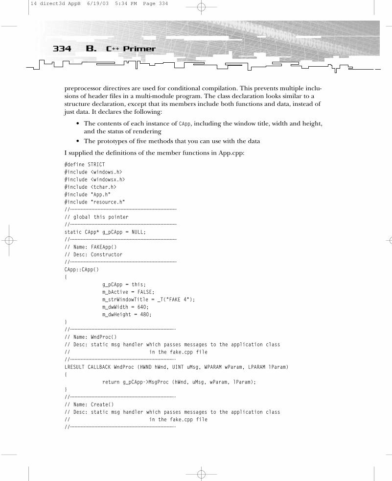
preprocessor directives are used for conditional compilation. This prevents multiple inclu-sions of header files in a multi-module program. The class declaration looks similar to astructure declaration, except that its members include both functions and data, instead ofjust data. It declares the following:
• The contents of each instance of CApp, including the window title, width and height,and the status of rendering
• The prototypes of five methods that you can use with the data
I supplied the definitions of the member functions in App.cpp:
#define STRICT#include <windows.h>#include <windowsx.h>#include <tchar.h>#include “App.h”#include “resource.h”//—————————————————————————————————————// global this pointer//—————————————————————————————————————static CApp* g_pCApp = NULL;//—————————————————————————————————————// Name: FAKEApp()// Desc: Constructor//—————————————————————————————————————CApp::CApp(){
g_pCApp = this;m_bActive = FALSE;m_strWindowTitle = _T(“FAKE 4”);m_dwWidth = 640;m_dwHeight = 480;
}//————————————————————————————————————-// Name: WndProc()// Desc: static msg handler which passes messages to the application class// in the fake.cpp file //————————————————————————————————————-LRESULT CALLBACK WndProc (HWND hWnd, UINT uMsg, WPARAM wParam, LPARAM lParam){
return g_pCApp->MsgProc (hWnd, uMsg, wParam, lParam);}//————————————————————————————————————-// Name: Create()// Desc: static msg handler which passes messages to the application class// in the fake.cpp file //————————————————————————————————————-
334 B. C++ Primer
14 direct3d AppB 6/19/03 5:34 PM Page 334
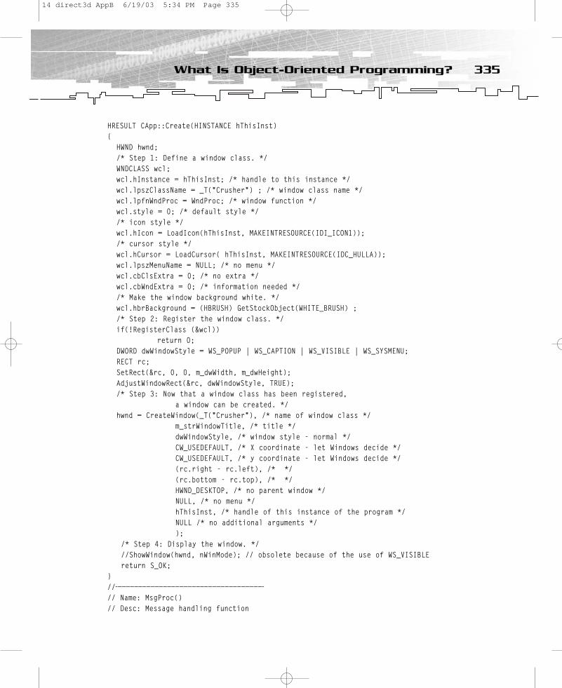
HRESULT CApp::Create(HINSTANCE hThisInst){
HWND hwnd; /* Step 1: Define a window class. */ WNDCLASS wcl; wcl.hInstance = hThisInst; /* handle to this instance */ wcl.lpszClassName = _T(“Crusher”) ; /* window class name */ wcl.lpfnWndProc = WndProc; /* window function */ wcl.style = 0; /* default style */ /* icon style */ wcl.hIcon = LoadIcon(hThisInst, MAKEINTRESOURCE(IDI_ICON1)); /* cursor style */wcl.hCursor = LoadCursor( hThisInst, MAKEINTRESOURCE(IDC_HULLA)); wcl.lpszMenuName = NULL; /* no menu */ wcl.cbClsExtra = 0; /* no extra */ wcl.cbWndExtra = 0; /* information needed */ /* Make the window background white. */ wcl.hbrBackground = (HBRUSH) GetStockObject(WHITE_BRUSH) ; /* Step 2: Register the window class. */ if(!RegisterClass (&wcl))
return 0; DWORD dwWindowStyle = WS_POPUP | WS_CAPTION | WS_VISIBLE | WS_SYSMENU;RECT rc;SetRect(&rc, 0, 0, m_dwWidth, m_dwHeight);AdjustWindowRect(&rc, dwWindowStyle, TRUE);/* Step 3: Now that a window class has been registered,
a window can be created. */ hwnd = CreateWindow(_T(“Crusher”), /* name of window class */
m_strWindowTitle, /* title */ dwWindowStyle, /* window style - normal */ CW_USEDEFAULT, /* X coordinate - let Windows decide */ CW_USEDEFAULT, /* y coordinate - let Windows decide */ (rc.right - rc.left), /* */ (rc.bottom - rc.top), /* */ HWND_DESKTOP, /* no parent window */ NULL, /* no menu */ hThisInst, /* handle of this instance of the program */ NULL /* no additional arguments */ );
/* Step 4: Display the window. */ //ShowWindow(hwnd, nWinMode); // obsolete because of the use of WS_VISIBLEreturn S_OK;
}//————————————————————————————————————// Name: MsgProc()// Desc: Message handling function
335What Is Object-Oriented Programming?
14 direct3d AppB 6/19/03 5:34 PM Page 335
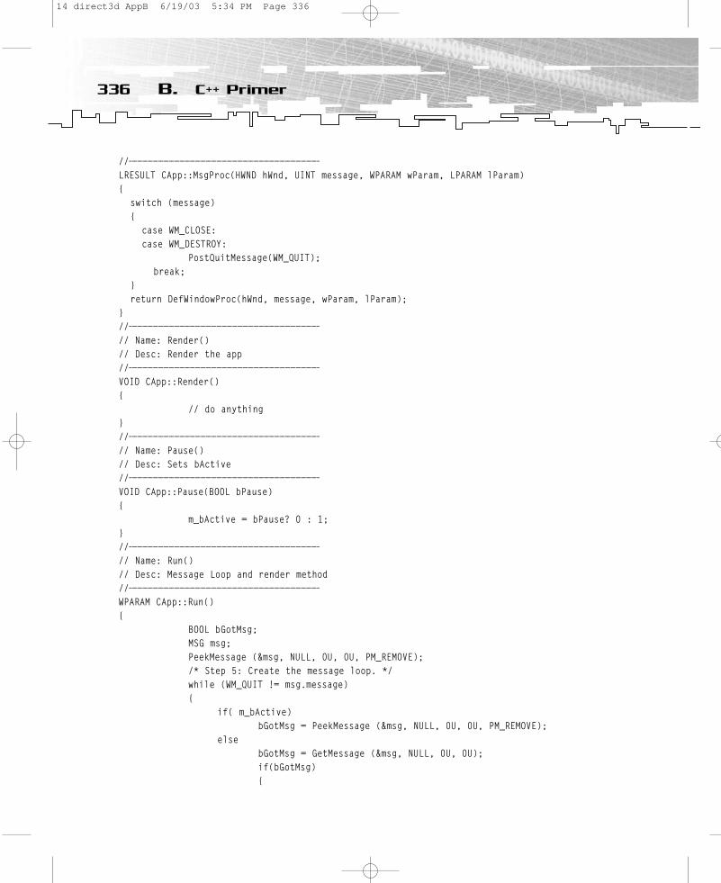
//————————————————————————————————————LRESULT CApp::MsgProc(HWND hWnd, UINT message, WPARAM wParam, LPARAM lParam){
switch (message) {
case WM_CLOSE:case WM_DESTROY:
PostQuitMessage(WM_QUIT); break;
}return DefWindowProc(hWnd, message, wParam, lParam);
}//————————————————————————————————————// Name: Render()// Desc: Render the app//————————————————————————————————————VOID CApp::Render(){
// do anything}//————————————————————————————————————// Name: Pause()// Desc: Sets bActive//————————————————————————————————————VOID CApp::Pause(BOOL bPause){
m_bActive = bPause? 0 : 1;}//————————————————————————————————————// Name: Run()// Desc: Message Loop and render method//————————————————————————————————————WPARAM CApp::Run(){
BOOL bGotMsg;MSG msg;PeekMessage (&msg, NULL, 0U, 0U, PM_REMOVE);/* Step 5: Create the message loop. */while (WM_QUIT != msg.message){
if( m_bActive)bGotMsg = PeekMessage (&msg, NULL, 0U, 0U, PM_REMOVE);
elsebGotMsg = GetMessage (&msg, NULL, 0U, 0U);if(bGotMsg){
336 B. C++ Primer
14 direct3d AppB 6/19/03 5:34 PM Page 336
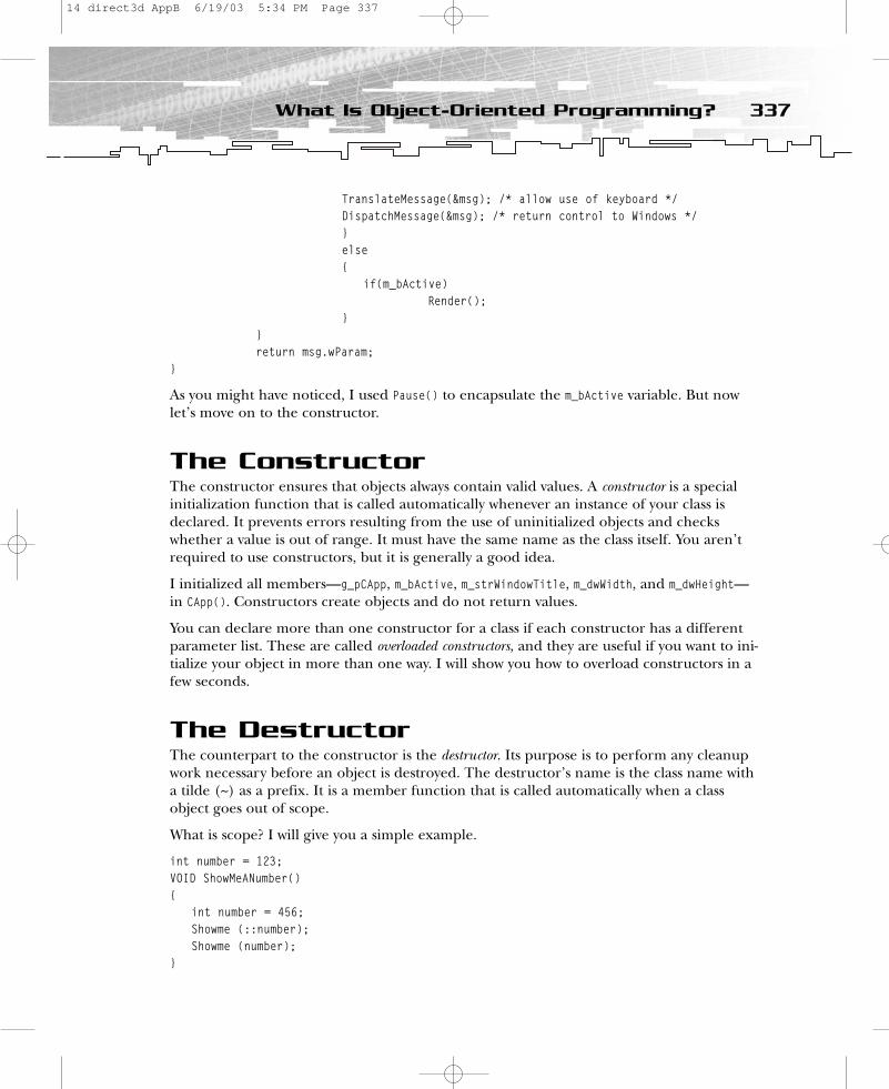
TranslateMessage(&msg); /* allow use of keyboard */ DispatchMessage(&msg); /* return control to Windows */ }else{
if(m_bActive)Render();
}}return msg.wParam;
}
As you might have noticed, I used Pause() to encapsulate the m_bActive variable. But nowlet’s move on to the constructor.
The ConstructorThe constructor ensures that objects always contain valid values. A constructor is a special initialization function that is called automatically whenever an instance of your class isdeclared. It prevents errors resulting from the use of uninitialized objects and checkswhether a value is out of range. It must have the same name as the class itself. You aren’trequired to use constructors, but it is generally a good idea.
I initialized all members—g_pCApp, m_bActive, m_strWindowTitle, m_dwWidth, and m_dwHeight—in CApp(). Constructors create objects and do not return values.
You can declare more than one constructor for a class if each constructor has a differentparameter list. These are called overloaded constructors, and they are useful if you want to ini-tialize your object in more than one way. I will show you how to overload constructors in afew seconds.
The DestructorThe counterpart to the constructor is the destructor. Its purpose is to perform any cleanupwork necessary before an object is destroyed. The destructor’s name is the class name witha tilde (~) as a prefix. It is a member function that is called automatically when a classobject goes out of scope.
What is scope? I will give you a simple example.
int number = 123;VOID ShowMeANumber(){
int number = 456;Showme (::number);Showme (number);
}
337What Is Object-Oriented Programming?
14 direct3d AppB 6/19/03 5:34 PM Page 337

You will see
123456
as an output. There is a global variable called number and a local variable called number. In both cases, C will use the local variable. You might use the scope operator :: to get theglobal variable in C++. So scope is the range of the class.
The scope operator is also used to access member functions, so it appears between thename of the class and the name of a function in a C++ program:
VOID CApp::Render()
This means that the specified function is a member of the specified class.
Now back to destructors. I have not used a destructor here because they are usually requiredfor more complicated classes, where they are used to release dynamically allocated resources.A destructor cannot be overloaded. It takes no parameters and has no return value.
The this PointerThere’s one interesting variable in the constructor of win skeleton++—g_pCApp. It is used as a so-called this pointer. When you call a member function for an object, the compilerassigns the address of the object to the this pointer, and then calls the function. Every timea member function accesses one of the class’s data members, it is implicitly using the thispointer. Type in the following code to build an example:
void CApp::Render (BOOL active){
BOOL bPause;bPause = active;
}myApp.Render(FALSE);
This is equivalent to
void CApp::Render (BOOL active){
BOOL bPause;this->bPause = active;
// or (*this).pause = active}myApp.Render(FALSE);
Both statements in Render() are equivalent. Why do you need a this pointer? The answerlies in WinProc(). You want to call MsgProc() in any derived class. Because you can’t know the name of a class used in the future, you have to use the this pointer. The derived class’MsgProc() will override the MsgProc() in the base class. In this example, MsgProc() is locatedin the MyFrame class, so the calling order would look like Figure B.2.
338 B. C++ Primer
14 direct3d AppB 6/19/03 5:34 PM Page 338
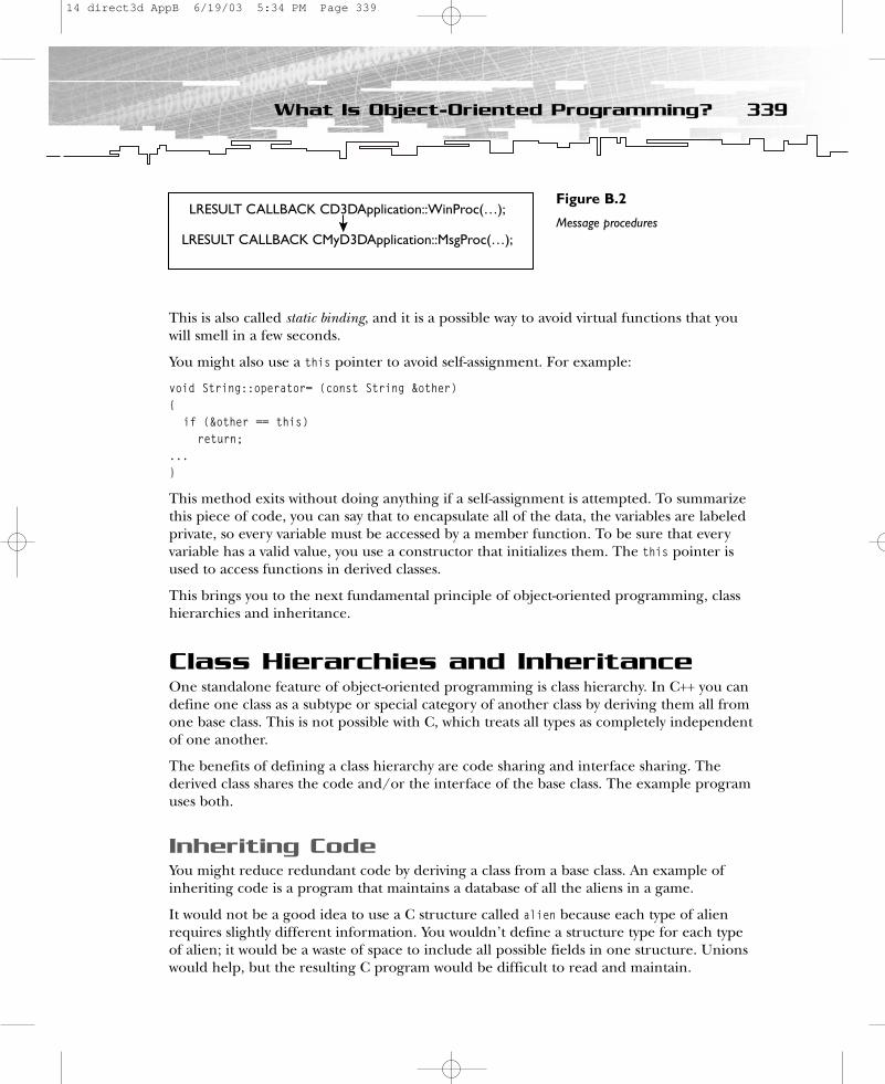
This is also called static binding, and it is a possible way to avoid virtual functions that youwill smell in a few seconds.
You might also use a this pointer to avoid self-assignment. For example:
void String::operator= (const String &other){
if (&other == this)return;
...}
This method exits without doing anything if a self-assignment is attempted. To summarizethis piece of code, you can say that to encapsulate all of the data, the variables are labeledprivate, so every variable must be accessed by a member function. To be sure that everyvariable has a valid value, you use a constructor that initializes them. The this pointer isused to access functions in derived classes.
This brings you to the next fundamental principle of object-oriented programming, classhierarchies and inheritance.
Class Hierarchies and InheritanceOne standalone feature of object-oriented programming is class hierarchy. In C++ you candefine one class as a subtype or special category of another class by deriving them all fromone base class. This is not possible with C, which treats all types as completely independentof one another.
The benefits of defining a class hierarchy are code sharing and interface sharing. Thederived class shares the code and/or the interface of the base class. The example programuses both.
Inheriting CodeYou might reduce redundant code by deriving a class from a base class. An example ofinheriting code is a program that maintains a database of all the aliens in a game.
It would not be a good idea to use a C structure called alien because each type of alienrequires slightly different information. You wouldn’t define a structure type for each type of alien; it would be a waste of space to include all possible fields in one structure. Unionswould help, but the resulting C program would be difficult to read and maintain.
339What Is Object-Oriented Programming?
LRESULT CALLBACK CD3DApplication::WinProc(…);
LRESULT CALLBACK CMyD3DApplication::MsgProc(…);
Figure B.2
Message procedures
14 direct3d AppB 6/19/03 5:34 PM Page 339

It’s easier to do this in C++ with a base class and derived classes. The followingpseudocode provides an example:
class CAlien{public:
CAlien();VOID Attack(HUMAN human);VOID RunTo(WAYPOINT waypoint);VOID SetHealth(DWORD dwHealth);DWORD GetHealth ();
Private:char cName[32];DWORD dwHealth;
}
For simplicity, this CAlien class stores only a few values; in real life, there might be manymore. Assume that there are different aliens that can fly, only crouch, only swim, or tele-port. Some of them bite, fire weapons at humans, or perform magic.
class CMagician : public CAlien{public:
Magician();VOID SetGlow(BOOL bGlow);
private:BOOL bGlow;
}orclass CFrankenstein : class CAlien{public:
Frankenstein();VOID StruckByLightning(BOOL bStruck);
private:BOOL bStruck;
}
CMagician and CFrankenstein are derived classes from the base class CAlien. To declare aderived class, you follow its name with a colon and the keyword public, followed by thename of its base class.
In the declaration of the derived class, you declare the members that are specific to it bydescribing the additional qualities that distinguish it from the base class. Each instance ofCFrankenstein contains all of the CAlien data members in addition to its own (see Figure B.3).
340 B. C++ Primer
NOTEWith the keyword private, the publicand protected members of the baseclass are private members of thederived class, so they are only acces-sible to the derived class.
14 direct3d AppB 6/19/03 5:34 PM Page 340

The member functions of a derived class do not have access to the private members of itsbase class, so the derived class has to use the base class’s public interface to access the privatemembers of its base class.
If you use different magicians with, for example, different levels and kinds of magic, youmight derive special magicians from CMagician.
class CGandalf : CMagician{public:
CGandalf();VOID TellWisdoms(HUMAN bHuman);SetWeakness(WORD wWeakness);
private:char cWisdoms[32][128];WORD wWeakness;
}
This means that CMagician is both a derived and a base class. It derives from the CAlien classand serves as the base for the CGandalf class. You can define as many levels of inheritance asyou want. In the win skeleton++ example, you only derive CMyFrame from CApp in Fake.cpp:
#define STRICT#include <windows.h>#include <tchar.h>#include “App.h”//——————————————————————————————————————-// Name: class App// Desc: Main class to run this application. Most functionality is inherited// from the App base class.//——————————————————————————————————————-class CMyFrame : public CApp{public:
LRESULT MsgProc (HWND hWnd, UINT uMsg, WPARAM wParam, LPARAM lParam);CMyFrame(); // constructor
};
341What Is Object-Oriented Programming?
CAlien
CMagicianadditional members and functions
CFrankensteinadditional members and functions
CGandalfadditional members and functions
Figure B.3
Class hierarchy
14 direct3d AppB 6/19/03 5:34 PM Page 341
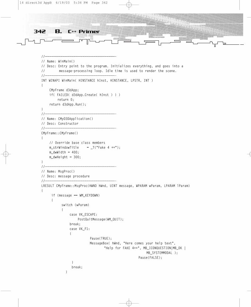
//——————————————————————————————————————-// Name: WinMain()// Desc: Entry point to the program. Initializes everything, and goes into a// message-processing loop. Idle time is used to render the scene.//——————————————————————————————————————-INT WINAPI WinMain( HINSTANCE hInst, HINSTANCE, LPSTR, INT ){
CMyFrame d3dApp;if( FAILED( d3dApp.Create( hInst ) ) )
return 0;return d3dApp.Run();
}//——————————————————————————————————————-// Name: CMyD3DApplication()// Desc: Constructor//——————————————————————————————————————-CMyFrame::CMyFrame(){
// Override base class membersm_strWindowTitle = _T(“Fake 4 ++”);m_dwWidth = 400;m_dwHeight = 300;
}//——————————————————————————————————————-// Name: MsgProc()// Desc: message procedure//——————————————————————————————————————-LRESULT CMyFrame::MsgProc(HWND hWnd, UINT message, WPARAM wParam, LPARAM lParam){
if (message == WM_KEYDOWN){
switch (wParam){
case VK_ESCAPE:PostQuitMessage(WM_QUIT);
break;case VK_F1:{
Pause(TRUE);MessageBox( hWnd, “Here comes your help text”,
“Help for FAKE 4++”, MB_ICONQUESTION|MB_OK | MB_SYSTEMMODAL );
Pause(FALSE);}break;
}
342 B. C++ Primer
14 direct3d AppB 6/19/03 5:34 PM Page 342
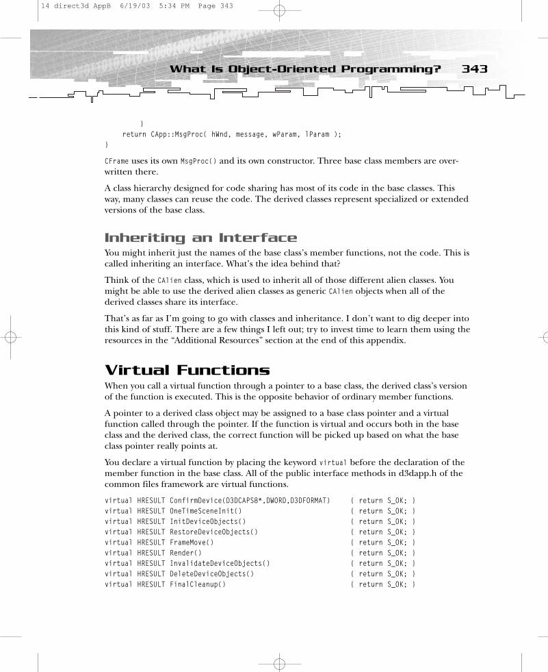
}return CApp::MsgProc( hWnd, message, wParam, lParam );
}
CFrame uses its own MsgProc() and its own constructor. Three base class members are over-written there.
A class hierarchy designed for code sharing has most of its code in the base classes. Thisway, many classes can reuse the code. The derived classes represent specialized or extendedversions of the base class.
Inheriting an InterfaceYou might inherit just the names of the base class’s member functions, not the code. This iscalled inheriting an interface. What’s the idea behind that?
Think of the CAlien class, which is used to inherit all of those different alien classes. Youmight be able to use the derived alien classes as generic CAlien objects when all of thederived classes share its interface.
That’s as far as I’m going to go with classes and inheritance. I don’t want to dig deeper intothis kind of stuff. There are a few things I left out; try to invest time to learn them using theresources in the “Additional Resources” section at the end of this appendix.
Virtual FunctionsWhen you call a virtual function through a pointer to a base class, the derived class’s versionof the function is executed. This is the opposite behavior of ordinary member functions.
A pointer to a derived class object may be assigned to a base class pointer and a virtualfunction called through the pointer. If the function is virtual and occurs both in the baseclass and the derived class, the correct function will be picked up based on what the baseclass pointer really points at.
You declare a virtual function by placing the keyword virtual before the declaration of themember function in the base class. All of the public interface methods in d3dapp.h of thecommon files framework are virtual functions.
virtual HRESULT ConfirmDevice(D3DCAPS8*,DWORD,D3DFORMAT) { return S_OK; }virtual HRESULT OneTimeSceneInit() { return S_OK; }virtual HRESULT InitDeviceObjects() { return S_OK; }virtual HRESULT RestoreDeviceObjects() { return S_OK; }virtual HRESULT FrameMove() { return S_OK; }virtual HRESULT Render() { return S_OK; }virtual HRESULT InvalidateDeviceObjects() { return S_OK; }virtual HRESULT DeleteDeviceObjects() { return S_OK; }virtual HRESULT FinalCleanup() { return S_OK; }
343What Is Object-Oriented Programming?
14 direct3d AppB 6/19/03 5:34 PM Page 343
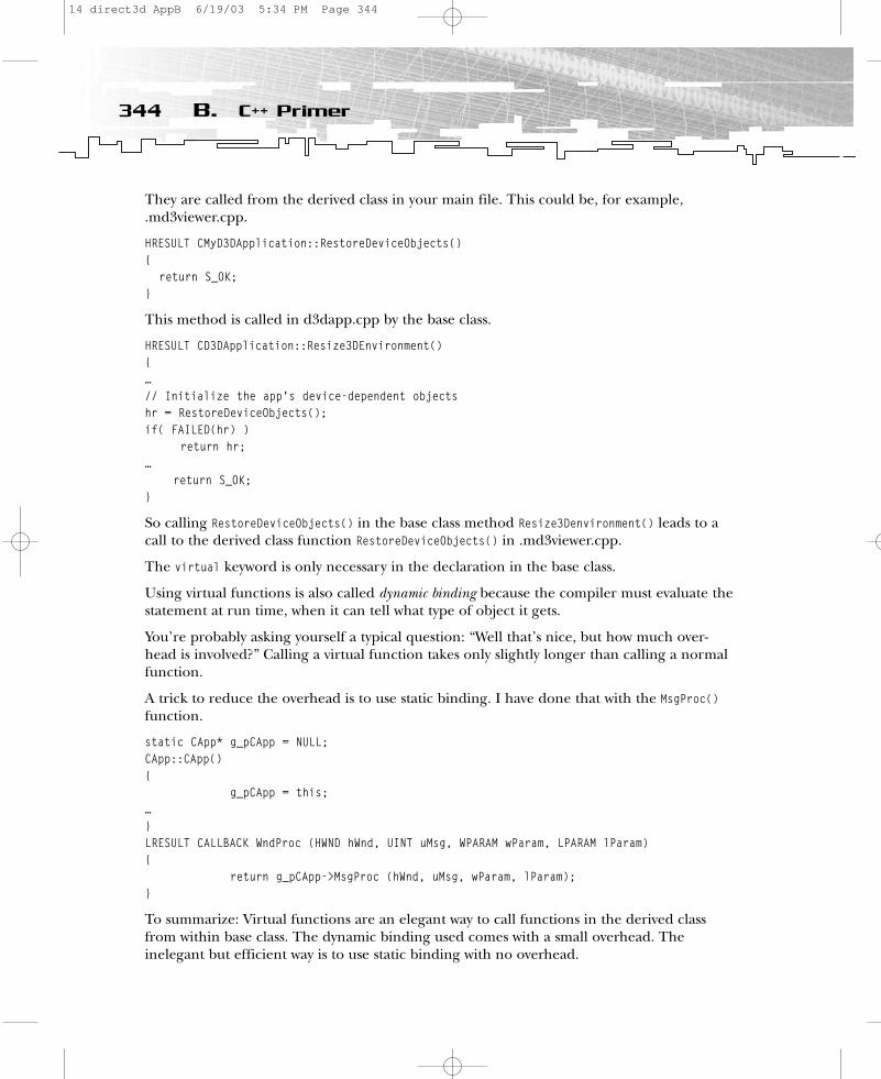
They are called from the derived class in your main file. This could be, for example,.md3viewer.cpp.
HRESULT CMyD3DApplication::RestoreDeviceObjects(){
return S_OK;}
This method is called in d3dapp.cpp by the base class.
HRESULT CD3DApplication::Resize3DEnvironment(){ …// Initialize the app’s device-dependent objectshr = RestoreDeviceObjects();if( FAILED(hr) )
return hr;…
return S_OK;}
So calling RestoreDeviceObjects() in the base class method Resize3Denvironment() leads to acall to the derived class function RestoreDeviceObjects() in .md3viewer.cpp.
The virtual keyword is only necessary in the declaration in the base class.
Using virtual functions is also called dynamic binding because the compiler must evaluate thestatement at run time, when it can tell what type of object it gets.
You’re probably asking yourself a typical question: “Well that’s nice, but how much over-head is involved?” Calling a virtual function takes only slightly longer than calling a normalfunction.
A trick to reduce the overhead is to use static binding. I have done that with the MsgProc()function.
static CApp* g_pCApp = NULL;CApp::CApp(){
g_pCApp = this;…}LRESULT CALLBACK WndProc (HWND hWnd, UINT uMsg, WPARAM wParam, LPARAM lParam){
return g_pCApp->MsgProc (hWnd, uMsg, wParam, lParam);}
To summarize: Virtual functions are an elegant way to call functions in the derived classfrom within base class. The dynamic binding used comes with a small overhead. The inelegant but efficient way is to use static binding with no overhead.
344 B. C++ Primer
14 direct3d AppB 6/19/03 5:34 PM Page 344

PolymorphismThe ability to call member functions for an object without specifying the object’s exact typeis called polymorphism. This means that a single statement can invoke many different func-tions. Let’s build an example. Suppose you are interested in checking the health of allaliens so you can compare their health with the health of all humans.
In C you have to use a switch statement to find the exact type of alien. This might look likethe following code:
DWORD ComputeHealth (struct ALIEN *alien){
switch (alien->type){
case Magician:return alien.dwhealth;
break;
case Frankenstein:return alien.dwhealth;
break;…
};}
In C++ you can call the following function:
DWORD ComputeHealth (CALIEN *alien){
return alien->GetHealth();}
The C++ version of ComputeHealth() calls the appropriate function automatically, withoutrequiring you to examine the type of object that alien points to. There is a tiny amount ofoverhead, as described in the section on virtual functions, but no switch statement is needed.
Inline FunctionsGame programmers can optimize performance by using inline functions. The inline key-word causes a new copy of the function to be inserted in each place it is called. If you callan inline function from 21 places in your program, the compiler will insert 21 copies ofthat function into your .exe file.
Inline eliminates the overhead of calling a function. This makes your program run faster,but having multiple copies of a function can make the program larger. Inline is similar tomacros declared with the #define directive. The difference is that the compiler recognizesinline functions, and macros are implemented by a simple text substitution. But inline
345What Is Object-Oriented Programming?
14 direct3d AppB 6/19/03 5:34 PM Page 345
functions are more powerful. The compiler performs type-checking, and an inline functionbehaves just like an ordinary function, without any side effects that macros might have. Anexample might be:
#define MAX (A, B) ((A) > (B)? (A) : (B))inline int max (int a, int b){if (a > b)
return a;return b;}
This is one of your favorite C++ features, isn’t it? Well, experience has shown that all thethings you like need more work and attention. This is also the case with the inline keyword.
Inlining only occurs if the compiler’s cost/benefit analysis shows it to be profitable. A __forceinline keyword overrides the cost/benefit analysis and relies on the judgment of theprogrammer instead, but this might lead to performance losses if it’s not properly used.
You cannot force the compiler to inline a function with __forceinline when conditionsother than cost/benefit analysis prevent it. You cannot inline a function if:
• The function or its caller is compiled with /Ob0 (the default option for debugbuilds).
• The function and the caller use different types of exception handling (such as C++exception handling in one and structured exception handling in the other).
• The function has a variable argument list.
• The function uses inline assembly and is not compiled with /Og, /Ox, /O1, or /O2.
• The function returns an unwindable object by value and is not compiled with /GX,/EHs, or /EHa.
• The function receives a copy-constructed object passed by the value when compiledwith /GX, /EHs, or /EHa.
• The function is recursive and is not accompanied by #pragma(inline_recursion, on).With the pragma, recursive functions can be inlined to a default depth of eight calls.To change the inlining depth, use #pragma(inline_depth, n).
Check out your Visual C/C++ Compiler Reference for the meaning of the compiler direc-tives. If the compiler cannot inline a function declared __forceinline, it will generate aLevel 1 warning (4714).
You can find a typical example of how inline is used in the file d3dfont.cpp.
inline FONT2DVERTEX InitFont2DVertex( const D3DXVECTOR4& p, D3DCOLOR color,FLOAT tu, FLOAT tv )
{FONT2DVERTEX v; v.p = p; v.color = color; v.tu = tu;
v.tv = tv; return v;}
346 B. C++ Primer
14 direct3d AppB 6/19/03 5:34 PM Page 346

This was the first one of the language enhancements of C++. Read on to take a look at a fewothers.
C++ Enhancements to CC++ introduces some simple enhancements and improvements to C. I will explain the fol-lowing C++ enhancements in this section:
• Default function arguments
• More flexible placement of variable declarations
• The const keyword
• Enumerations
• Function and operator overloading
Default Function ArgumentsA C++ function prototype can list default values for some of the parameters.
VOID Pause(BOOL TRUE);
You might declare this in the header file. If you provide your own arguments, the compilerwill use them instead of the declared defaults.
If you use a more complex example, it might look like this:
VOID DoSomething (DWORD w = 2; FLOAT f = 1.5);
You might call it in the following way:
DoSomething ( , 2.5);
In this example, the first value (w) is 2, and the second value (f) is 2.5. Another way to callit is like this:
DoSomething (3);
The first value (w) is 3, and the second value (f) is 1.5. Be careful: Syntax like this is error-prone and makes reading and writing function calls more difficult.
Placement of Variable DeclarationsThere is a big improvement in C++, about which I suspect you already know. C requires youto declare variables at the beginning of a block. C++ gives you the ability to declare variablesanywhere in the code. A pseudocode function with C would look like this:
VOID Myfunction (){
int z;AnotherFunction (d);
347What Is Object-Oriented Programming?
14 direct3d AppB 6/19/03 5:34 PM Page 347

doSomethingWith(z);}The same function with C++:VOID Myfunction (){
AnotherFunction (d);int z;doSomethingWith(z);
}
That’s a big improvement because it is much easier to read the code when the variable andfunction are near each other. Another nice expression that is often used in C++ is
for (int z = 0; z < 5; z++){// do something}
But it is not possible to use the following statements:
if (int z == 0);while (int j == 0)
Besides, they are meaningless!
Const VariableAs a rule of thumb, you can assume that wherever you can use a constant expression orwould define a #define expression, you can use a const variable.
There is a difference between the const qualifier used by C and the one used in C++. In Cyou can initialize the const qualifier and use it in place of its value in your program. In C++you can use consts in many different ways with pointers, references, and functions.
Most C programs define constant values using the #define preprocessor directive.
#define MAX_HEIGHT 800
The drawback is that the #define directive does not generate type-safe constants because it isjust a preprocessor directive, not a compiler statement. When you generate a constant using#define, your constant has no data type, so your compiler has no way to ensure that opera-tions on the constant are carried out properly—at design time, at run time, or even atdebugging time.
In contrast, when you define a const in a C++ program, you execute a real compiler state-ment, such as this one:
const int MAX_HEIGHT 800
348 B. C++ Primer
14 direct3d AppB 6/19/03 5:34 PM Page 348
You can also use const in pointer declarations:
char *const ptr = cString;
You can change the value to which ptr points:
*ptr = ‘a’;
But you can’t change the const value:
ptr = cString2;
It is another case if the pointer points to a constant:
Const char *ptr = cString;ptr = cString2;*ptr = ‘a’;
It’s okay to change the pointer in the second row, but changing the value will give you an errormessage. You might use the const qualifier to prevent changing a parameter in a function.
int readonly (const struct NODE *nodeptr);
As you have seen, const is a powerful qualifier to make your programs more type-safe, so useit often.
EnumerationAn enumeration is an integral data type that defines a list of named constants. Each elementof an enumeration has an integer value that, by default, is one greater than the value of theprevious element. The first element has the value 0, unless you specify another value. Thefollowing example demonstrates how a C++ program can reference an enumeration:
enum color {yellow, orange, red, green }; // values 0, 1, 2, 4enum day {Monday, Tuesday, Wednesday, Thursday = 8, Friday}; // values 0, 1, 2, 8, 9
You can convert an enumeration into an integer, but you cannot reverse conversion unlessyou use a cast. Casting an integer into an enumeration is not safe. If the integer is outsidethe range of the enumeration, or if the enumeration contains duplicate values, the result of the cast is undefined.
Function and Operator OverloadingC++ uses two kinds of overloading—function overloading and operator overloading. Bothof these are major—and beneficial—features of the C++ language.
Function OverloadingTo implement function overloading, you use two or more functions that share the samename but have different argument lists. The compiler decides which version to call by usingargument matching. It compares the number of arguments and the types of arguments thatare passed to the function.
349What Is Object-Oriented Programming?
14 direct3d AppB 6/19/03 5:34 PM Page 349
Function overloading is often used in C++ because it imposes almost no run-time penaltyand requires practically no overhead.
A special case of function overloading is constructor overloading. You find the followingcode snippet in d3dvec.inl:
inline_D3DVECTOR::_D3DVECTOR(D3DVALUE f){
x = y = z = f;}inline_D3DVECTOR::_D3DVECTOR(D3DVALUE _x, D3DVALUE _y, D3DVALUE _z){
x = _x; y = _y; z = _z;}inline_D3DVECTOR::_D3DVECTOR(const D3DVALUE f[3]){
x = f[0]; y = f[1]; z = f[2];}
Typical function overloading is used in the D3DXVECTOR3 initialization in d3dmath.inl.
D3DXINLINED3DXVECTOR3::D3DXVECTOR3( CONST FLOAT *pf ){#ifdef D3DX_DEBUG
if(!pf)return;
#endifx = pf[0];y = pf[1];z = pf[2];
}D3DXINLINED3DXVECTOR3::D3DXVECTOR3( CONST D3DVECTOR& v ){
x = v.x;y = v.y;z = v.z;
}D3DXINLINED3DXVECTOR3::D3DXVECTOR3( FLOAT fx, FLOAT fy, FLOAT fz ){
x = fx;y = fy;z = fz;
}
350 B. C++ Primer
14 direct3d AppB 6/19/03 5:34 PM Page 350
These overloaded functions pursue the same target by using different parameters. You haveto fill three variables—x, y, and z—with a value.
Complete vector/math libraries are built using function and operator overloading. By usingfunction overloading, you can give the same name to member functions that perform differ-ent, but similar, operations. You can even give the same name to entire groups of functions.
Operator OverloadingWith operator overloading, you can customize operators, such as the addition operator (+),the subtraction operator (–), the assignment operator (=), the increment and decrement oper-ators (++ and – –), and many more to make the operators behave differently when they areused with objects of different classes. Such a self-defined operator is a dressed-up function.
To overload an operator in C++, you must define an operator overloading function (usuallya member function). A function that overloads an operator always contains the keywordoperator.
The syntax for operator overloading is
ReturnType operator @ (arguments) {// code} // global function
ReturnType classname::operator @ (arguments) { // code} // class function
The @ sign is a replacement for the operator. The syntax
z = x @ y
is replaced by
z = operator @ (x, y)
or by
z = x.operator @(y);
A real-world example might look like this:
D3DXINLINE D3DXVECTOR3&D3DXVECTOR3::operator += ( CONST D3DXVECTOR3& v ){
x += v.x;y += v.y;z += v.z;return *this;
}
351What Is Object-Oriented Programming?
14 direct3d AppB 6/19/03 5:35 PM Page 351

This one adds the D3DXVECTOR3 v structure to the D3DVECTOR3 that stands on the left of the +=operator.
z += v;
The operator += produces a new D3DXVECTOR3 structure, which is returned. This temporarystructure is destroyed as soon as it is no longer needed.
Another nice example is
D3DXINLINE D3DXVECTOR3operator * ( FLOAT f, CONST struct D3DXVECTOR3& v ){
return D3DXVECTOR3(f * v.x, f * v.y, f * v.z);}
The syntax prototype of this one looks like this:
z = operator * (f, v)
The return value D3DXVECTOR3(f * v.x, f * v.y, f * v.z) is also a temporary structure.Here you use the so-called returned value optimization. The compiler builds the objectdirectly into the location of the outside return value.
OK…I think you’ve got it. Take a look at the d3dxmath.inl file to play around with manymore examples.
You’ve reached the end of this short C++ primer. I tried to concentrate on the most impor-tant C++ features for game programmers. I left many things unsaid, and you should be sureto look at the use of references and multi-inheritance. So…keep on learning.
Additional ResourcesThere is a free C++ book in HTML/PDF/PalmPilot format at http://www.mindview.net/Books/TICPP/ThinkingInCPP2e.html.
Other C++ tutorials online are at http://www.intap.net/~drw/cpp/index.htm,http://www.cplusplus.com/doc/tutorial, andhttp://devcentral.iftech.com/articles/C++/default.php.
352 B. C++ Primer
14 direct3d AppB 6/19/03 5:35 PM Page 352

APPENDIX C
MathematicsPrimer
15 direct3d AppC 6/19/03 5:35 PM Page 353
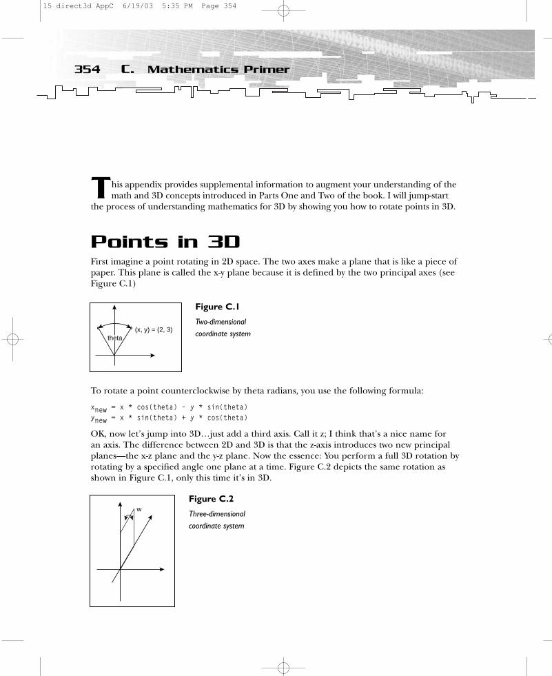
This appendix provides supplemental information to augment your understanding of themath and 3D concepts introduced in Parts One and Two of the book. I will jump-start
the process of understanding mathematics for 3D by showing you how to rotate points in 3D.
Points in 3DFirst imagine a point rotating in 2D space. The two axes make a plane that is like a piece ofpaper. This plane is called the x-y plane because it is defined by the two principal axes (seeFigure C.1)
To rotate a point counterclockwise by theta radians, you use the following formula:
xnew = x * cos(theta) – y * sin(theta)ynew = x * sin(theta) + y * cos(theta)
OK, now let’s jump into 3D…just add a third axis. Call it z; I think that’s a nice name for an axis. The difference between 2D and 3D is that the z-axis introduces two new principalplanes—the x-z plane and the y-z plane. Now the essence: You perform a full 3D rotation byrotating by a specified angle one plane at a time. Figure C.2 depicts the same rotation asshown in Figure C.1, only this time it’s in 3D.
354 C. Mathematics Primer
(x, y) = (2, 3)theta
Figure C.1
Two-dimensionalcoordinate system
w
Figure C.2
Three-dimensionalcoordinate system
15 direct3d AppC 6/19/03 5:35 PM Page 354
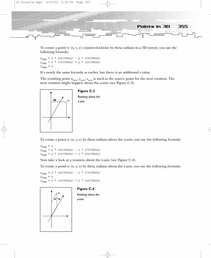
To rotate a point w (x, y, z) counterclockwise by theta radians in a 3D system, you use thefollowing formula:
xnew = x * cos(theta) – y * sin(theta)ynew = x * sin(theta) + y * cos(theta)znew = z
It’s nearly the same formula as earlier, but there is an additional z value.
The resulting point xnew, ynew, znew is used as the source point for the next rotation. Thenext rotation might happen about the x-axis (see Figure C.3).
To rotate a point w (x, y, z) by theta radians about the x-axis, you use the following formula:
xnew = xynew = y * cos(theta) – z * sin(theta)znew = y * sin(theta) + z * cos(theta)
Now take a look at a rotation about the y-axis (see Figure C.4).
To rotate a point w (x, y, z) by theta radians about the y-axis, you use the following formula:
xnew = x * cos(theta) - z * sin(theta)ynew = y znew = x * sin(theta) + z * cos(theta)
355Points in 3D
w
Figure C.3
Rotating about the x-axis
w
Figure C.4
Rotating about they-axis
15 direct3d AppC 6/19/03 5:35 PM Page 355

To rotate a point w (x, y, z) in 3D space, you:
1. Rotate it in the x-y plane and store the results in xnew, ynew, znew.2. Rotate the resulting point around the y-z plane and store the results in x
2, y
2,z
2.3. Rotate the resulting point around the z-x plane and store the results in xnew, ynew,
and znew.
A piece of pseudocode might look like this:
xnew = x * cos(theta) – y * sin(theta)ynew = x * sin(theta) + y * cos(theta)znew = zx2 = xnewy2 = ynew * cos(theta) – znew * sin(theta)z2 = ynew * sin(theta) + znew * cos(theta)xnew = x2 * cos(theta) - z2 * sin(theta)ynew = y2znew = x2 * sin(theta) + z2 * cos(theta)
To summarize 3D point rotation: To rotate a point in 3D, you have to rotate it around thethree axes, one after another.
The translation of a point in 3D is much easier. Moving a point in a direction simplyrequires adding three offsets (representing the direction) to that point—one offset each forx, y, and z. For example, translating the point (2, 3, 0) to (8, 7, 0) requires adding (6, 4, 0)to each component.
VectorsVectors are mathematical entities that describe a direction and a magnitude (which might be speed). This is the difference between vectors and scalars, which describe a magnitudealone. A typical scalar value is, for example, the temperature 32 degrees Celsius. This infor-mation tells you everything about the temperature at that point. It is more difficult todescribe the direction of an airplane and how fast it is going; this would be a job for a vector.
You can differentiate between a general-purpose, or bound, vector and the so-called free vectorused in games.
Bound VectorA bound vector V, as shown in Figure C.5, has the following attributes:
• A starting point• A final point• A direction• A magnitude
356 C. Mathematics Primer
15 direct3d AppC 6/19/03 5:35 PM Page 356

A bound vector might look like Figure C.6 in the coordinate system.
A bound vector consists of two coordinates. You can see the direction of these vectors bydrawing a line between the two coordinates; the distance between the points represents themagnitude. The first coordinate is called the starting point, and the second is the finalpoint.
Free VectorFor game programmers, a vector has no starting point. If all points are moving in the samedirection at the same speed, it would be inefficient to use a vector for each point. It isenough to describe the speed and direction for one vector that is used with all points.Therefore, you don’t have to represent a starting point for a free vector.
By definition, the starting points of all free vectors are in the origin, so only three numbersare required to describe a free vector (see Figure C.7).
Oops…you might say, “That sounds like a point in 3D.” To which I’d say, “That’s an importantremark.” So what’s the difference between a point and a vector in 3D? A free vector, asshown in Figure C.7, is represented additionally by magnitude and direction. The magnitudeof a vector (2, 3, 2) is the distance between the origin (0, 0, 0) and the final point (2, 3, 2).
357Vectors
W
Figure C.5
Bound vector
V
final point
starting point
Figure C.6
A bound vector incoordinate system
15 direct3d AppC 6/19/03 5:35 PM Page 357
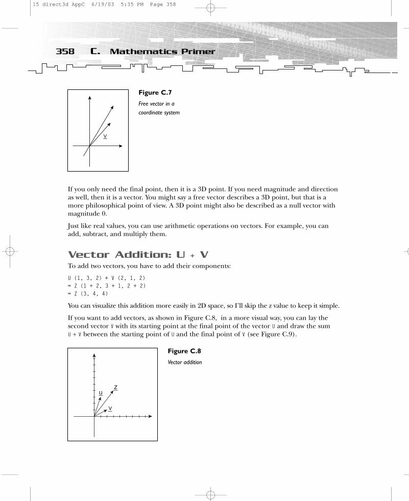
If you only need the final point, then it is a 3D point. If you need magnitude and directionas well, then it is a vector. You might say a free vector describes a 3D point, but that is amore philosophical point of view. A 3D point might also be described as a null vector withmagnitude 0.
Just like real values, you can use arithmetic operations on vectors. For example, you canadd, subtract, and multiply them.
Vector Addition: U + VTo add two vectors, you have to add their components:
U (1, 3, 2) + V (2, 1, 2) = Z (1 + 2, 3 + 1, 2 + 2)= Z (3, 4, 4)
You can visualize this addition more easily in 2D space, so I’ll skip the z value to keep it simple.
If you want to add vectors, as shown in Figure C.8, in a more visual way, you can lay the second vector V with its starting point at the final point of the vector U and draw the sum U + V between the starting point of U and the final point of V (see Figure C.9).
358 C. Mathematics Primer
V
Figure C.7
Free vector in acoordinate system
z
v
u
Figure C.8
Vector addition
15 direct3d AppC 6/19/03 5:35 PM Page 358

Vector additions are useful to show, for example, the drift you get if you are sailing a ship.Adding more vectors works the same way. Yet another important arithmetic function youcan perform is subtraction.
Vector Subtraction: U – VYou subtract vectors by subtracting one vector’s component from the other. Vector subtrac-tion undoes vector addition. For example:
U (1, 3, 2) - V (2, 1, 2)= Z (1 - (-2), 3 - 1, 2 - 2)= Z (-1, 2, 0)
Simplified by using only the x and y values, that equation might look like Figure C.10.
If you want to subtract the two vectors in a visual way, you might multiply the vector V by –1and add that to U (see Figure C.11).
359Vectors
zvu
Figure C.9
Vector additiongraphically
zv
u
Figure C.10
Vector subtraction
15 direct3d AppC 6/19/03 5:35 PM Page 359

You use vector subtraction to remove the effect of vector addition.
Vector MultiplicationThere are three kinds of vector multiplication:
• Scalar-product• Dot-product• Cross-product
Scalar-ProductMultiplication of a vector by a scalar (real number) changes the vector’s magnitude. It changes the distance between its starting and final points.
U (1, 3, 2) * 2 = Z (1 * 1, 3 * 2, 2 * 2)= Z (2, 6, 4)
A simplified picture might look like Figure C.12.
Z has double the magnitude of U, so the scalar-product results in a vector.
360 C. Mathematics Primer
z
–v
u
Figure C.11
Vector subtractiongraphically
z
u
Figure C.12
Scalar-product
15 direct3d AppC 6/19/03 5:35 PM Page 360
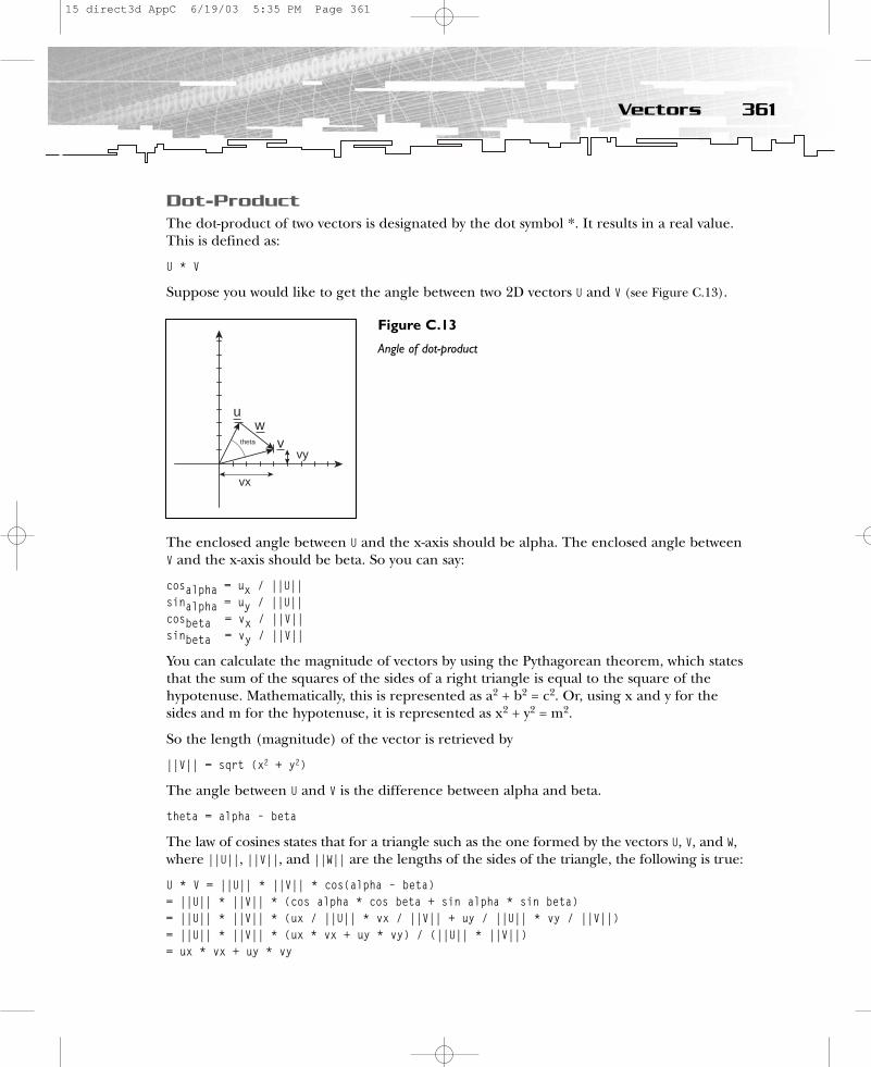
Dot-ProductThe dot-product of two vectors is designated by the dot symbol *. It results in a real value.This is defined as:
U * V
Suppose you would like to get the angle between two 2D vectors U and V (see Figure C.13).
The enclosed angle between U and the x-axis should be alpha. The enclosed angle betweenV and the x-axis should be beta. So you can say:
cosalpha = ux / ||U||sinalpha = uy / ||U||cosbeta = vx / ||V||sinbeta = vy / ||V||
You can calculate the magnitude of vectors by using the Pythagorean theorem, which statesthat the sum of the squares of the sides of a right triangle is equal to the square of thehypotenuse. Mathematically, this is represented as a2 + b2 = c2. Or, using x and y for thesides and m for the hypotenuse, it is represented as x2 + y2 = m2.
So the length (magnitude) of the vector is retrieved by
||V|| = sqrt (x2 + y2)
The angle between U and V is the difference between alpha and beta.
theta = alpha – beta
The law of cosines states that for a triangle such as the one formed by the vectors U, V, and W,where ||U||, ||V||, and ||W|| are the lengths of the sides of the triangle, the following is true:
U * V = ||U|| * ||V|| * cos(alpha – beta) = ||U|| * ||V|| * (cos alpha * cos beta + sin alpha * sin beta)= ||U|| * ||V|| * (ux / ||U|| * vx / ||V|| + uy / ||U|| * vy / ||V||)= ||U|| * ||V|| * (ux * vx + uy * vy) / (||U|| * ||V||)= ux * vx + uy * vy
361Vectors
theta
wv
u
vx
vy
Figure C.13
Angle of dot-product
15 direct3d AppC 6/19/03 5:35 PM Page 361
I would like to solve this equation for the angle between the two vectors.
cos(theta) = U * V / ||U|| * ||V||U (1.5, 3)V (4, 1)||U|| = sqrt(ux2+ uy2)= sqrt (2.25 + 9)= 3.4||V|| = sqrt(vx2 + vy2)= sqrt (16 + 1)= 4.12U * V = ux * vx + uy * vy= 1.5 * 4 + 3 * 1= 9cos (theta) = 9 / 3.4 * 4.12cos (theta) = 0.64theta = 49.99°
Now let’s do that for a 3D vector. For a triangle such as the one formed by the vectors U, V,and W, where ||U||, ||V||, and ||W|| are the lengths of the sides of the triangle, the followingis true:
W = U - VU - V = U2 + V2 - 2* U * V
To solve it after U –V:
2 * U * V = U2 + V2 - (U - V)
To find the magnitude of the vectors, the following is true:
||U||2 = ux2 + uy2 + uz2
||V||2 = vx2 + vy2 + vz2
||U - V||2 = (ux - vx)2 + (uy - vy)2 + (uz - vz)2
Let’s solve the above equation in terms of the dot-product, like this:
2 * U * V = ux + uy2 + uz2 + vx2 + vy2 + vz2 - (ux – vx)2 - (uy – vy)2 - (uz – vz)2
= ux2 + uy2 + uz2 + vx2 + vy2 + vz2 - ux2 - vx2 + 2 * ux * vx – uy2 - vy2 + 2 * ux * vy –uz2 - vz2 + 2 * uz * vz= 2 * ux * vx + 2 * uy * vy + 2 * uz * vz= 2 * (ux * vx + uy * vy + uz * vz)
That leads to:
U * V = ux * vx + uy * vy + uz * vz
To get the angle between those vectors you might use
cos(theta) = U * V / ||U|| * ||V||U (1.5, 3, 4)V (4, 1 ,2)
362 C. Mathematics Primer
15 direct3d AppC 6/19/03 5:35 PM Page 362
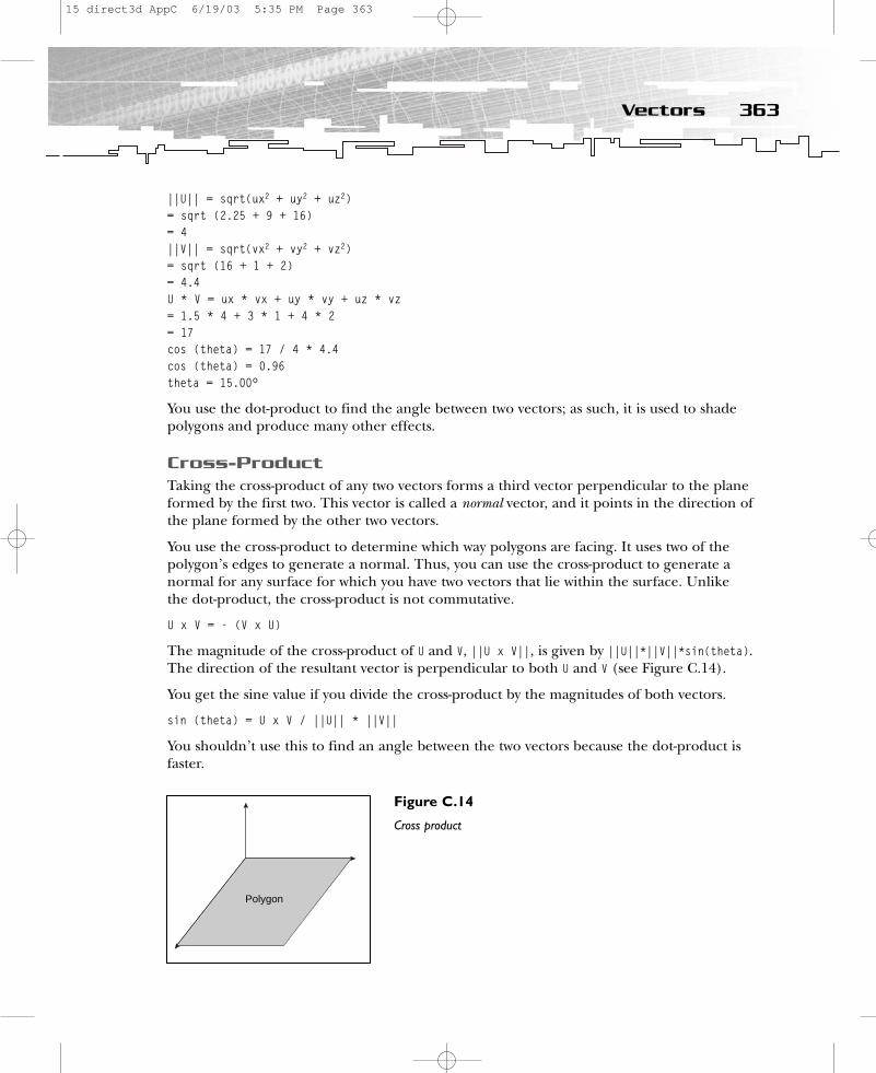
||U|| = sqrt(ux2 + uy2 + uz2)= sqrt (2.25 + 9 + 16)= 4||V|| = sqrt(vx2 + vy2 + vz2)= sqrt (16 + 1 + 2)= 4.4U * V = ux * vx + uy * vy + uz * vz= 1.5 * 4 + 3 * 1 + 4 * 2= 17cos (theta) = 17 / 4 * 4.4cos (theta) = 0.96theta = 15.00°
You use the dot-product to find the angle between two vectors; as such, it is used to shadepolygons and produce many other effects.
Cross-ProductTaking the cross-product of any two vectors forms a third vector perpendicular to the planeformed by the first two. This vector is called a normal vector, and it points in the direction ofthe plane formed by the other two vectors.
You use the cross-product to determine which way polygons are facing. It uses two of thepolygon’s edges to generate a normal. Thus, you can use the cross-product to generate anormal for any surface for which you have two vectors that lie within the surface. Unlikethe dot-product, the cross-product is not commutative.
U x V = - (V x U)
The magnitude of the cross-product of U and V, ||U x V||, is given by ||U||*||V||*sin(theta).The direction of the resultant vector is perpendicular to both U and V (see Figure C.14).
You get the sine value if you divide the cross-product by the magnitudes of both vectors.
sin (theta) = U x V / ||U|| * ||V||
You shouldn’t use this to find an angle between the two vectors because the dot-product isfaster.
363Vectors
Polygon
Figure C.14
Cross product
15 direct3d AppC 6/19/03 5:35 PM Page 363

Unit VectorThere is another class of vectors that is important to know—the unit vector. A unit vectorhas a magnitude of 1. If you combine that with the free vector, you get a vector with all pos-sible directions and a magnitude of 1. All possible free and unit vectors form a sphere withtheir final points. If you define the starting point as the origin of, for example, a camera,you might rotate that camera by altering the vector values.
How do you calculate a unit vector or normalize a vector? To calculate a unit vector, dividethe vector by its magnitude or length.
N = V / ||V||
And you can calculate the magnitude of these vectors by using the 3D version of the dis-tance formula based on the Pythagorean theorem.
x2+y2+z2 = m2
The length of the vector is retrieved by:
||V|| = sqrt (x2 + y2 + z2)
The final length is the square root of the sum of squares (Pythagorean theorem). The mag-nitude of a vector has a special symbol in mathematics, a capital letter designated with twovertical bars: ||V||. A function performing this task might look like this:
D3DXVECTOR3* D3DXVec3Normalize(D3DXVECTOR3* v1, D3DXVECTOR3* v2){
D3DXVECTOR3 tv1 = (D3DXVECTOR3)*v1;D3DXVECTOR3 tv2 = (D3DXVECTOR3)*v2;tv1 = tv2/(float) sqrt(tv2.x * tv2.x + tv2.y * tv2.y + tv2.z * tv2.z);v1 = &tv1;
return (v1);}
It divides the vector by its magnitude, which is retrieved by the square root of thePythagorean theorem.
MatricesMatrices are rectangular arrays of numbers. These numbers can represent anything youwant, such as equations or constants. Additionally, you can think of a matrix as a set of rowvectors or a set of column vectors. For our purposes, we are mostly concerned with usingmatrices as a compact form to write general 3D transformations, so the discussions in thisbook will focus on matrices as representations of transformations such as the world, camera,and projection. For example, a 4×4 world matrix contains four vectors, which represent theworld-space coordinates of the x, y, and z unit axis vectors, and the world-space coordinate,which is the location of these axis vectors.
364 C. Mathematics Primer
15 direct3d AppC 6/19/03 5:35 PM Page 364

ux uy uz 0 vx vy vz 0 wx wy wz 0 tx ty tz 1
The u, v, and w vectors represent the so-called rigid body. This is the matrix that defines themapping from object space to world space. Graphically, it looks like Figure C.15.
To describe the position of this cube, the matrix has to look like:
1, 0, 0, 00, 1, 0, 00, 0, 1, 02, 2, 2, 1
The cube is oriented like the coordinate system. The first row contains the world-spacecoordinates of the local x-axis. The second row contains the local y-axis, and the third rowcontains the world-space coordinates of the local z-axis. The vectors are unit vectors whosemagnitudes are 1. The last row contains the world-space coordinates of the object’s origin.You might translate the cube with these.
A special matrix that has 1s along the main diagonal is the identity matrix:
1 0 0 0 0 1 0 0 0 0 1 0 0 0 0 1
The identity matrix represents a set of object axes that are aligned with the world axes. Theworld x-coordinate of the local x-axis is 1, the world y- and z-coordinates of the local x-axisare 0, and the origin vector is (0, 0, 0). Therefore, the local model x-axis lies directly on theworld x-axis. The same is true for the local y- and z-axes, so it’s a “get back to the roots”matrix. If an object’s position in model space corresponds to its position in world space,simply set the world transformation matrix to the identity matrix. This matrix and all othermatrices in Direct3D can be accessed like this:
365Vectors
+Y
+X
+Z
world coordinates
v
u
w
2, 2
t
Figure C.15
The u, v, and w vectors
15 direct3d AppC 6/19/03 5:35 PM Page 365
D3DMATRIX mat; mat._11 = 1.0f; mat._12 = 0.0f; mat._13 = 0.0f; mat._14 = 0.0f;mat._21 = 0.0f; mat._22 = 1.0f; mat._23 = 0.0f; mat._24 = 0.0f;mat._31 = 0.0f; mat._32 = 0.0f; mat._33 = 1.0f; mat._34 = 0.0f;mat._41 = 0.0f; mat._42 = 0.0f; mat._43 = 0.0f; mat._44 = 1.0f;
Multiplication of a Matrix by a VectorA typical transformation operation is a 4×4 matrix multiplication operation. A transforma-tion engine multiplies a vector representing 3D data, typically a vertex or a normal vector, bya 4×4 matrix. The result is the transformed vector. This is done with standard linear algebra:
Transform Original TransformedMatrix Vector Vector
a b c d x ax + by + cy + dw x’e f g h x y = ex + fy + gz + hw = y’i j k l z ix + jy + kz + lw z’m n o p w mx + ny + oz + pw w’
Before you can transform a vector, you must construct a transform matrix. This matrixholds the data to convert the vector data to the new coordinate system. You must createsuch an interim matrix for each action (scaling, rotation, and transformation) that will beperformed on the vector. Those matrices are multiplied to create a single matrix that repre-sents the combined effects of all of those actions (matrix concatenation). You can use thissingle matrix, called the transform matrix, to transform one vector or a million vectors. Thetime to set it up is made worthwhile by the ability to reuse it.
Matrix Addition and SubtractionIt is simple to add two matrices. You just add the first number in the first column of the firstmatrix to the first number in the first column of the second matrix, and so on. It works thesame with subtraction.
1 2 3 4 17 18 19 20 18 20 22 245 6 7 8 + 21 22 23 24 = 26 28 30 329 10 11 12 25 26 27 28 34 36 38 40
13 14 15 16 29 30 31 32 42 44 46 48
Matrix MultiplicationTo explain matrix multiplication, it’s best to show an example.
1 2 3 4 17 18 19 205 6 7 8 21 22 23 24
366 C. Mathematics Primer
15 direct3d AppC 6/19/03 5:35 PM Page 366
9 10 11 12 * 25 26 27 2813 14 15 16 29 30 31 32
The idea is to multiply the first row of the left matrix by the first column of the second rowand add the result. You do the same with the second column of the second matrix, andthen with the third, and with the fourth.
1 * 17 + 2 * 21 + 3 * 25 + 4 * 29 1 * 18 + 2 * 22 + 3 * 26 + 4 * 30 etc.
Next you start multiplying the second row of the first matrix by the first column of the second matrix, and add the result. You continue by multiplying the second row of the firstmatrix by the second column of the second matrix and so on. In the end, you will get the16 values of the 4×4 matrix.
Translation MatrixTo move an object in 3D space, you normally manipulate the fourth row of the worldmatrix of the object (object matrix) or multiply the world matrix by a translation matrix.
1 0 0 00 1 0 0 0 0 1 0x y z 1
Instead of holding the coordinate, a translation matrix holds how far the object must bemoved. The object matrix is used to store x-, y-, and z-values.
Scaling MatrixThis type of matrix will scale a coordinate, so it’s useful to make an object smaller or bigger.
x 0 0 00 y 0 00 0 z 00 0 0 1
It’s also possible to manipulate the three values directly, without using a matrix, by usingmat._11, mat._22, and mat._33 to access them.
Rotation MatricesThere are three rotation matrices to rotate around the y-, x-, and z-axes.
Rotation around the Y-AxisThe Direct3D function D3DXMatrixRotationY() rotates around the y-axis. I don’t have thesource, but it might look like the following code:
367Vectors
15 direct3d AppC 6/19/03 5:35 PM Page 367
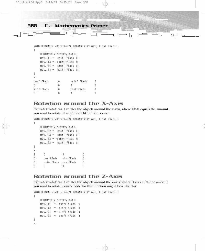
VOID D3DXMatrixRotationY( D3DXMATRIX* mat, FLOAT fRads ){
D3DXMatrixIdentity(mat); mat._11 = cosf( fRads );mat._13 = -sinf( fRads );mat._31 = sinf( fRads );mat._33 = cosf( fRads );
}=cosf fRads 0 -sinf fRads 00 0 0 0sinf fRads 0 cosf fRads 00 0 0 0
Rotation around the X-AxisD3DXMatrixRotationX() rotates the objects around the x-axis, where fRads equals the amountyou want to rotate. It might look like this in source:
VOID D3DXMatrixRotationX( D3DXMATRIX* mat, FLOAT fRads ){
D3DXMatrixIdentity(mat); mat._22 = cosf( fRads );mat._23 = sinf( fRads );mat._32 = -sinf( fRads );mat._33 = cosf( fRads );
}=1 0 0 00 cos fRads sin fRads 00 -sin fRads cos fRads 00 0 0 0
Rotation around the Z-AxisD3DXMatrixRotationZ() rotates the objects around the z-axis, where fRads equals the amountyou want to rotate. Source code for this function might look like this:
VOID D3DXMatrixRotationZ( D3DXMATRIX* mat, FLOAT fRads ){
D3DXMatrixIdentity(mat); mat._11 = cosf( fRads );mat._12 = sinf( fRads );mat._21 = -sinf( fRads );mat._22 = cosf( fRads );
}=
368 C. Mathematics Primer
15 direct3d AppC 6/19/03 5:35 PM Page 368
cosf fRads sinf fRads 0 0-sinf fRads cos fRads 0 00 0 0 00 0 0 0
These matrices are concatenated by Direct3D. It is very important to remember that matrixmultiplication is not commutative. That means ([a] * [b]) is not equal to ([b] * [a]) inmost cases. The formula for transformation is
|W| = |M| * |T| * |X| * |Y| * |Z|
where M is the model’s matrix, T is the translation matrix, and X, Y, and Z are the rotationmatrices. Direct3D uses the resulting matrix W internally.
SummaryThis appendix provided you with the knowledge necessary to understand all of the mathe-matical stuff in this book. Nevertheless, there is much more out there you need to learn to become a more advanced game programmer. Mathematics is the key to most game-programming-related problems. Having a good background in mathematics is a must for a good game programmer.
369Summary
15 direct3d AppC 6/19/03 5:35 PM Page 369
APPENDIX D
Creating aTexture withD3DXCreateTextureFrom
FileEx()
16 direct3d AppD 6/19/03 5:36 PM Page 371
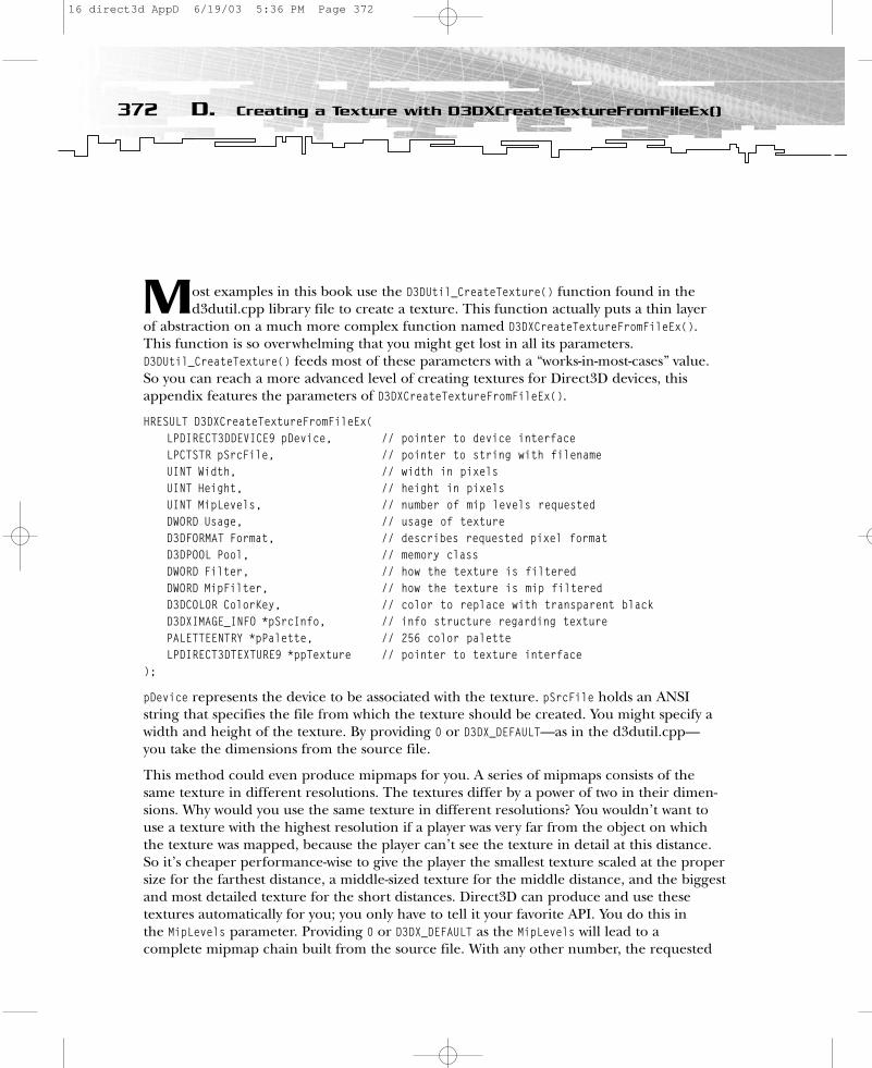
Most examples in this book use the D3DUtil_CreateTexture() function found in thed3dutil.cpp library file to create a texture. This function actually puts a thin layer
of abstraction on a much more complex function named D3DXCreateTextureFromFileEx().This function is so overwhelming that you might get lost in all its parameters.D3DUtil_CreateTexture() feeds most of these parameters with a “works-in-most-cases” value.So you can reach a more advanced level of creating textures for Direct3D devices, thisappendix features the parameters of D3DXCreateTextureFromFileEx().
HRESULT D3DXCreateTextureFromFileEx(LPDIRECT3DDEVICE9 pDevice, // pointer to device interfaceLPCTSTR pSrcFile, // pointer to string with filenameUINT Width, // width in pixelsUINT Height, // height in pixelsUINT MipLevels, // number of mip levels requestedDWORD Usage, // usage of textureD3DFORMAT Format, // describes requested pixel formatD3DPOOL Pool, // memory classDWORD Filter, // how the texture is filteredDWORD MipFilter, // how the texture is mip filteredD3DCOLOR ColorKey, // color to replace with transparent blackD3DXIMAGE_INFO *pSrcInfo, // info structure regarding texturePALETTEENTRY *pPalette, // 256 color paletteLPDIRECT3DTEXTURE9 *ppTexture // pointer to texture interface
);
pDevice represents the device to be associated with the texture. pSrcFile holds an ANSIstring that specifies the file from which the texture should be created. You might specify awidth and height of the texture. By providing 0 or D3DX_DEFAULT—as in the d3dutil.cpp—you take the dimensions from the source file.
This method could even produce mipmaps for you. A series of mipmaps consists of thesame texture in different resolutions. The textures differ by a power of two in their dimen-sions. Why would you use the same texture in different resolutions? You wouldn’t want touse a texture with the highest resolution if a player was very far from the object on whichthe texture was mapped, because the player can’t see the texture in detail at this distance.So it’s cheaper performance-wise to give the player the smallest texture scaled at the propersize for the farthest distance, a middle-sized texture for the middle distance, and the biggestand most detailed texture for the short distances. Direct3D can produce and use these textures automatically for you; you only have to tell it your favorite API. You do this in the MipLevels parameter. Providing 0 or D3DX_DEFAULT as the MipLevels will lead to a complete mipmap chain built from the source file. With any other number, the requested
372 D. Creating a Texture with D3DXCreateTextureFromFileEx()
16 direct3d AppD 6/19/03 5:36 PM Page 372
number of mipmaps will be built. The default value used in d3dutil.cpp is D3DX_DEFAULT,which builds and uses in your engine a complete mipmap chain.
The Usage parameter shows the Direct3D engine whether a texture surface will be used as arender target. There are impressive effects you can accomplish with rendering onto a tex-ture surface. One of the most common examples in the DirectX SDK is rendering a videoon a rotating cube. You might provide 0 or D3DUSAGE_RENDERTARGET as the parameters. If youwant to render on a texture surface, you have to check the capabilities of your graphicshardware with CheckDeviceFormat(), set Pool to default with D3DPOOL_DEFAULT, and later set therender target with SetRenderTarget(). The D3DUtil_CreateTexture() function of d3dutil.cppuses 0 as the default value.
The Format parameter defines the surface format you want to use, so the format of thereturned texture might have a different format than the source file. If the format isunknown, it’s taken from the source file. You can provide the desired format inD3DXCreateTextureFromFileEx(). If you don’t provide a parameter here, the format of the source file is used.
The Pool parameter defines the memory class in which the texture should reside. One ofthe common files, d3dutil.cpp, uses D3DPOOL_MANAGED, the handiest memory class.
With Filter, you can control how the image is filtered (that is, how the pixels are sampledfrom the source image, which affects the picture quality). This is useful when the textureshould have a different size than the source file. If the dimensions of the texture should be half of those in the source file, you might provide D3DX_FILTER_BOX, which computes thepixel in the texture by averaging a 2×2 box from the source image. If the dimensions of the texture should be a quarter of the dimensions of the source file, it would be wise to useD3DX_FILTER_LINEAR, which computes the pixel in the texture by averaging a 4×4 box. This isone of the killer features of this method. The method call of D3DXCreateTextureFromFileEx()in D3DUtil_CreateTexture() uses the same size for the texture as for the source file, so it usesD3DX_FILTER_TRIANGLE|D3DX_FILTER_MIRROR. This tells the Direct3D engine that every pixel inthe source file contributes equally to the texture, and that the mirror filter, which mirrorsthe u, v, and w values, should be used.
The same parameters for Filter work for the MipFilter parameter. Handling visual qualityin different dimensions of textures is even more important when you are using mipmaps.D3DUtil_CreateTexture() uses the same parameters here as Filter.
The ColorKey parameter helps in setting, for example, transparent regions in a texture. It’s aD3DCOLOR value that replaces a provided color with transparent black. I don’t use transparentregions here by default.
pSrcInfo might give you back a pointer with a D3DXIMAGE_INFO structure, which holds thewidth, height, number of mip levels, and the format of the source file. It’s not used in thecall to D3DUtil_CreateTexture().
If you use palettized textures (256 colors), pPalette will give you back the palette entries ina PALETTEENTRY structure. Using 32-bit textures gives you a higher visual quality. You might
373Creating a Texture with D3DXCreateTextureFromFileEx()
16 direct3d AppD 6/19/03 5:36 PM Page 373
see the difference between Quake 2 and Quake 3 models: Whereas the first one could onlyuse 8-bit textures, the latter has the ability to handle the smoother-looking 32-bit textures. I aim for 32-bit quality, so the D3DXCreateTextureFromFileEx() in D3DUtil_CreateTexture() calldoesn’t need to give back a palette structure.
The ppTexture pointer will give you the pointer to the texture interface IDirect3Dtexture9,representing the created texture.
If D3DXCreateTextureFromFileEx() succeeds, it will return D3D_OK.
SummaryIt is worth taking a closer look at the D3DXCreateTextureFromFileEx() function and playingaround with it. It offers a tremendous amount of possibilities for altering textures. You willbe surprised how much source you would have to write to replace this function with yourown code.
374 D. Creating a Texture with D3DXCreateTextureFromFileEx()
16 direct3d AppD 6/19/03 5:36 PM Page 374

APPENDIX E
GameProgramming
Resources
17 direct3d AppE 6/19/03 5:36 PM Page 375
I would like to recommend a few Internet resources, which you might want to check outon a regular basis to be in sync with the fast development of game programming.
Generalhttp://www.voodooextreme.com. Gives you a lot of info and screen shots of the newestgames. This might help you keep an eye on what is possible in game programming.Sometimes it provides you with leaked drivers and information on game development, but it’s not for developers only.
http://www.bluesnews.com. Follows the same rules as Voodoo Extreme. Both are nice sites;they are like your daily newsletter, entertaining and informative.
http://www.realtimerendering.com. A list of interesting links for graphics programming.
DirectX Graphicshttp://msdn.microsoft.com/directx. This is the source. Read the articles of Philip Taylor.
http://www.direct3D.info. This is the accompanying Web site for this book. You will findupdates and corrections here. Besides, there are always a few interesting tutorials onDirect3D.
http://www.gamedev.net. You will find a lot of DirectX Graphics tutorials here. A few ofthem were written by me.
http://www.flipcode.com. A Web site for game programmers. Every day I look at the image,code, and tip of the day.
http://hometown.aol.com/billybop7/index.htm. The Web site of William Chin, alias billybop, who, together with Peter Kovach, has written the road-rage engines used in Inside Direct3D (Microsoft Press, 2000).
http://www.zen-x.net. ZEN-X is a DirectX Graphics engine with source. You can learn a lotby checking the provided source.
http://www.cbloom.com. The Web site of Charles Bloom, who provides a few very interestingpapers and demos to download.
http://www.mrgamemaker.com. Great Direct3D tutorials.
http://www.swissquake.ch/chumbalum-soft. The home of MilkShape 3D, the best modelingtool you can get.
http://discuss.microsoft.com/archives/directxdev.html. The most important know-howdatabase you can use.
376 E. Game Programming Resources
17 direct3d AppE 6/19/03 5:36 PM Page 376
APPENDIX F
What’s onthe CD
18 direct3d AppF 6/19/03 5:37 PM Page 377

You’ve read the book; now it’s time to check out the software! This book’s CD-ROMcontains the source code to every one of the sample programs in the book, as well as
a handful of useful utilities and applications that I used to create the effects mentioned inthis book.
If you haven’t already done so, tear open that CD-ROM sleeve and plop the disc in yourcomputer’s CD drive. If Autorun is enabled, you should be greeted with an interface thatwill guide you through the CD-ROM’s contents. If Autorun is disabled, you can still run theinterface by following these steps:
1. Insert the CD-ROM into your computer’s CD drive.
2. Right-click on My Computer and select Open from the menu.
3. Click on your CD drive in the list of drives.
4. In the list of the CD’s contents, double-click on the Start_Here.html file. After read-ing the licensing agreement, click I Agree if you accept the terms (or click I Disagreeto quit the interface).
If you accepted the licensing terms and clicked on the I Agree button, you’ll be presentedwith the Premier Press user interface. From there you can browse the contents of the CD-ROM or select from a number of applications to install. Following is a list of the applications you will find on the CD-ROM.
DirectX 9.0 SDKThe main application is Microsoft’s DirectX 9 SDK. Used in all the projects in this book,the SDK is the first thing you should install. For help installing the DirectX 9.0 SDK, consultthe Introduction.
ATI RenderMonkeyThe CD includes a beta version of ATI’s fantastic RenderMonkey software, which you canuse to create awesome real-time shader effects.
378 F. What’s on the CD
18 direct3d AppF 6/19/03 5:37 PM Page 378
NVIDIA Cg ToolkitCg is NVIDIA’s new high-level language for graphics programming. The Cg Toolkit is basedon the Cg language, and it allows programmers to create amazing visual effects using real-time pixel and vertex shaders.
Flash MoviesThe CD also includes some Flash movies I created to help you set up Visual C/C++ 6 andVisual C++ .NET so you can start programming your Direct3D applications.
379Flash Movies
18 direct3d AppF 6/19/03 5:37 PM Page 379
Index
AAbrash, Michael, 5abstraction process, 329–331addition
of matrices, 366of vectors, 358–359
Adobe Photoshop, 35, 268color selection dialog, 47
“Advanced Real-Time Per-Pixel Lighting inOpenGL” (Frazier), 191
AGP (Accelerated Graphics Port), 51alpha blending, 145–147
for detail mapping, 164for glow mapping, 162for .md3 files, 264–266SetTextureStateState() function and, 66
alpha modulation, 167–168alpha operations, 166–168alpha resulting from previous stage, 164ambient lighting, 181–183Anderson, Eike F., 252animation. See also CharacterEngine
example program; .md3 files; worldtransformations
key-frame animation, 254–255looping animations, 260of X files, 246–249
animation.cfg, 258–260anisotrophy, 142anisotropic filtering, 142–143
resources on, 169anti-aliasing, 7, 138–139, 143–144APIs (Application Programming
Interfaces), 5
application class constructor, 61area lighting, 181Argonaut, 4arithmetic appendix, 353–369ASCII files
HLSL shaders, 297parsing, 291
Ash, Lee David, 272ATI RADEON
anisotropy levels, 142color operations with, 153–154ShadowShader example, 213
ATI RADEON 8500-9200 cards, 6ATI RADEON 9500, 178ATI RADEON 9700 PRO, 7
texture-blend states in, 128ATI RenderMonkey, 178
on CD, 378tutorial, 196
Bback face culling, 32, 87basic directory, files in, 38–40Basic example, 41–58
functional pairs in, 43–44Basic2 example, 57–67Basic3 example, 67–69Basic4 example, 69–75Basic5 example, 75Beaudoin, Philippe, 190Bezier patches, 128Biker model, 257
animation.cfg file of, 258–259.skin files of, 260–261
bilinear texture filtering, 141–143
19 direct3d Index 6/19/03 5:37 PM Page 381
blending. See also alpha blending; textureblending
with Frame Buffer option, 126, 127in .md3 files, 264–267
BMP files, 6boneframe structures, 269–270border color texture-addressing mode,
126, 127, 135bound vectors, 356–357BoundsChecker, 24BRender, 4Brennan, Chris, 226brushes in windows applications, 309–310bump mapping, 192–194
bumped dynamic refractive/reflectiveenvironment mapping, 208–211
bumped dynamic refractive/reflectiveenvironment mapping, 208–211
bzip files, 230
CC, 39C++, 15, 39. See also classes; object-oriented
programmingappendix information, 327–352class hierarchies, 339–343for COM objects, 20–21const variable, 348–349default function arguments, 347enhancements to C, 347–352enumeration in, 349function overloading in, 349–351GUI debugger, 25inline functions, 345–347operator overloading, 351–352polymorphism, 345variable declarations, placement of,
347–348CalculateNormals2() function, 285Caligari trueSpace, 69camera models. See view transformationsCD-ROM, resources on, 377–379Cg, NVIDIA, 178, 379
382 Index
Change Device dialog box, 144character engines, 178CharacterEngine example program
CMD3Model class, 275DrawSkeleton() function, 292–297geometry, loading, 277HLSL shaders, 297LoadModelGeometry() function,
277–285LoadShaders() function, 285–292Q3Player class
low-level functions called by, 275–277methods, 274–275
choosing a pool, 51clamp texture-addressing mode, 134–135clamping, SetSampleState() function
specifying, 128class hierarchies, 339–343
derived classes, 340–341inheriting an interface, 343inheriting code, 339–343virtual functions, 343–344
class pointers, 24classes. See also class hierarchies
constructors for, 337declaring a class, 333–337derived classes, 340–341destructors, 337–339encapsulation, 332–333naming conventions for, 22–24in object-oriented programming,
331–332this pointer, 338–339virtual functions, 343–344
Clear() method for viewport, 117CloneMesh() functions for X files, 251closed meshes for shadow volumes, 214,
226color buffer, 117color operations, 153–166
constants for additional operations, 165colors
alpha blending, 145–147in Basic example, 47
19 direct3d Index 6/19/03 5:37 PM Page 382
383Index
SetTextureStateState() function and,66
vertices with, 30COM interface, 15–17
accessing COM objects, 20–22C++ and, 20–21as language-independent, 16–17methods, access via, 17tutorial, 119
combining images with alpha blending, 145common files, 7–8
framework for, 40–41public interface of, 41
compilers, inline functions and, 346ConfirmDevice() function, 42, 44–45const variable, 348–349constants
color operations, additional, 165naming conventions for, 22
constructor overloading, 350–351constructors, 338
font class constructor, calling, 61content attribute, 262controlling devices, 14–15CPU-limited performance, 73Create() function for shadow volumes, 214CreateIndexBuffer() function, 70–71,
73–74CreateModel() function, 332CreateVertexBuffer() function, 48CreateVertexNIndexBuffer() function, 275CreateWindow() function, 311–312CreateWindowEx() function, 312cross-product
back face culling and, 32for perpendicular vectors, 95–96of vectors, 363
CRT memory manager, 24cube maps, 178, 198–202
accessing, 199–200dynamic reflective/refractive
environment mapping, 204–208generating, 198–199implementation of, 200–202
reflective environment mapping,202–211
refractive environment mapping,202–211
resource manager for, 50cubes. See cube maps; world
transformationscurrent iterated texture alpha, 164cursor. See mouse cursor
Ddamping effects, 103dark mapping, 154–157, 265–267
animating dark map, 157blended with material diffuse color,
160–161modulation operations, 156
data abstraction, 329–331data types in Windows, 310DDI (Device Driver Interface), 12DDS files, 6death animation, 260debug texture, 25debugging
DirectX, 24–25shader debugger, installing, 179
deformation attributes, 262DeleteDeviceObjects() function, 332
in Basic example, 58for font class, 61, 67for 2D texture maps, 60
DeleteModel() function, 332DeletePlayerGeometry() function, 275DeleteVertexNIndexBuffer() function, 275Dempski, Kelly, 87, 119, 195, 202depth buffer, 116–119
color buffer and, 117rendering errors and, 117viewport values, 116
depth complexity, 116derived classes, 340–341destructors, 337–339detail mapping, 163–166
19 direct3d Index 6/19/03 5:37 PM Page 383

DIB files, 6diffuse color
alpha operations, 166blending texture with, 158–159color operations and, 153dark mapping blended with, 160–161
diffuse lighting, 183–186for DOOM model, 264in X files, 242
Direct3DCreate9() method, 21–22Direct3D
history of, 4–5pipeline, 180
Direct3D 7.0, 5Direct3D Settings dialog box, 11Direct3D ShaderX: Vertex and Pixel Shader Tips
and Tricks (Brennan), 226Direct3DX library, 6
debugging and, 24X files, loading, 250–251
direction, vectors defining, 29–30DirectDraw, 5DirectX 2.0, 4–5DirectX 6.0, 5DirectX 8.0, 5
new features of, 5–6DirectX 9.0, 7–8
SDK, 378DirectX Caps viewer, 142DirectX Control Panel, 24DirectX Graphics, 5
resources, 376DirectX Properties dialog box
controlling devices, configuring, 14DxDiag button, 12Enable Shader Debugging check box,
14DispatchMessage() function, 317displacement maps, 7display buffer, DrawSkeleton() function
and, 292–297DLL (Dynamic Link Library), 15Doom III, 258
384 Index
DOOM model, 254–256geometry of, 264shader scripts for, 262–264
DOS games, 302DirectX 2.0, 4–5
dot-product of vectors, 361–363Downs, Laura, 119Draw() function for CharacterEngine
example program, 275DrawPrimitive() function, 55–56
for textures, 65triangle strip with, 67–69
DrawPrimitiveIndex() function, viewportsand, 115
DrawSkeleton() function, 292–297DrawText() function, 61, 66D3DUtil_CreateTexture() function, 371D3DX image file loader, 6D3DXComputeNormal() function,
192–193for X files, 241
D3DXComputeTangent() function,192–193
D3DXCreateTextureFromFileEx()function, 371–374
DumpAnimInfo() function, 275DxDiag utility for debugging, 24dynamic binding, 344dynamic reflective environment mapping,
204–208for bumped dynamic
refractive/reflective environmentmapping, 208–211
dynamic refractive environment mapping,204–208
for bumped dynamicrefractive/reflective environmentmapping, 208–211
Eelongation, 142encapsulation, 332–333enumeration in C++, 349
19 direct3d Index 6/19/03 5:37 PM Page 384
385Index
environment mapping. See also cube mapsbumped dynamic refractive/reflective
environment mapping, 208–211for DOOM model, 264reflective environment mapping,
202–211refractive environment mapping,
202–211“Euler Angle Conversion” (Shoemake),
102, 119Euler angles, 101–102extending X files, 251
Fface normals, 33faces, 31–32
back face culling, 32F.A.K.K.2, 258field-of-view (FOV) angle, 111–112fill rate limited performance, 73filters for nearest-point sampling, 140FinalCleanup() function
in Basic example, 58for font class, 67
fixed-function pipeline, 48diffuse color in, 159for dynamic reflective/refractive
environment mapping, 208SetFVF() function, 55vertex input registers, mapping of, 49vertex stream in, 54–55
flags. See also vertex flagsin Basic example, 48–50PeekMessage() function flags, 316in Windows applications, 307
Flash movies on CD, 379flat shading, 33–34float4 values, 181floating-point arithmetic, 329floating-point texture, 140font class, 24
Basic2 example, 58–67DrawText() function for, 66
frame buffersblending with, 145for .md3 files, 265
FrameMove() function, 53frames
in Basic2 example, 58–59in .md3 files, 270with X files, 242–243
frames per second with font class, 66framework codes, 7–8Frazier, Ronald, 191free vectors, 29, 357–363FreePlayerShaders() function, 275FreeSkins() function, 275front capping shadow volumes, 226frosted glass effect, 164frustrum, 110FSAA (full screen anti-aliasing), 143function overloading in C++, 349–351functional pairs in Basic example, 43–44functions
inline functions, 345–347naming conventions for, 22
GGamasutra, 169gamma controls, 7G-buffer, 7GDI (Graphics Device Interface) API,
11–12GeForce3, 7, 128GeForce DDR cards, 142GeForce FX, 178general game programing resources, 376GenerateTangent() function, 285GetMessage() function, 315–317GetViewport() function, 116gimbal lock, 90global lighting model, 181glow mapping, 161–162glslang, 178
19 direct3d Index 6/19/03 5:37 PM Page 385
Gouraud shadingalpha operations, 166color operations and, 153vertex normals for, 33–34
graphics cards, pools and, 51–52green ambient light, 167–168Guardado, Juan, 190GUI debugger, 25
HHAL (Hardware Abstraction Layer), 10–13
in Basic2 example, 59changing device, 43
Half-Life, 258Hamilton, Sir William Rowan, 100handles, use of, 306hard shadows, 212HCLIP space, 49headers
.md3 files header, 269–271X file Header template, 230
HEL (Hardware Emulation Layer), 11, 13HLSL (High-Level Shader Language), 7,
178ambient lighting, 181–183bump mapping, 192–194for cube maps, 202diffuse lighting, 183–186lighting formulas with, 181–196requirements for, 179self-shadowing term, 191semantics, use of, 182specular lighting, 186–190
Hook, Brian, 150, 169HLSL shaders, 297Hungarian notation, 22HW VP (Hardware Vertex Processing), 13
Iicons, 308
creating icons, 323–324ID number of icon resource, 308predefined icons, using, 308
386 Index
id Software, 5. See also .md3 filesidentity matrix, 365Immediate Mode API, 5index buffers
in Basic4 example, 69–71with non-indexed triangle strips, 71–75performance and, 73Render() function, setting in, 74–75resource manager for, 50
indexed triangle strips, 75inheriting an interface, 343inheriting code, 339–343InitDeviceObjects() function, 44–45, 332
for font class function, 62for 2D texture maps, 60
inline functions, 345–347installing shader debuggers, 179instruction slots for specular lighting, 189Intel VTune, 25interface pointers, 21–22interfaces of DirectX, 16interpolation of models, 297InvalidateDeviceObjects() function
in Basic example, 57–58for font class, 66–67font class function, calling, 61
inverse cinematics, quaternions in, 100iterated diffuse alpha, 164
JJasc Paint Shop Pro, 268
color selection dialog, 47Java MD3 Model Viewer, 268JPG files, 6
KKeondjian, Servan, 4–5key-frame animation, 254–255
and .md3 files, 258–260keyType, 249
19 direct3d Index 6/19/03 5:37 PM Page 386

387Index
Llabels, key-word protected, 332Lambert’s law, 184Lander, Jeff, 252law of cosines, 361–362Leadtek, 59left-handed coordinate system, 28–30legacy Direct3D, 229, 230legs animation, 260Lengyel, Eric, 225libraries. See also Direct3DX library
COM interface and, 16, 21for example program, 39–40NVMeshMender library, 192–193
light mapping. See dark mappinglighting. See also vertex normals; specific
typesshading modes, 33–34
linear texture filtering, 141–142lines, 32LoadAnim() function, 275LoadIcon() function, 308–309loading X files, 249–251LoadModelGeometry() function, 277–285LoadPlayerGeometry() function, 275LoadPlayerShaderProfile() function, 275LoadPlayerShaders() function, 275LoadShaders() function, 285–292LoadSkins() function, 275Lock() function, 42
for index buffers, 74for vertex buffers, 52–53
locking resources, 524log file class for debugging, 25LOG() function for CharacterEngine
example program, 292Look vector, 92–93
for camera model, 104–106perpendicular vectors and, 96
looping animations, 260
Mmagnification, 139
mipmaps and, 140managed pools, 51
for index buffers, 74tasks of, 52
maskable multisampling, 144matrices, 364–369. See also world
transformationsidentity matrix, 365multiplication
two matrices, multiplication of,366–367vector, multiplication of matrix by,366
quaternions, conversion of, 102rigid body, 365rotation matrices, 367–369scaling matrix, 367subtraction of, 359–360translation matrix, 367x-axis, rotation around, 368y-axis, rotation around, 367–368z-axis, rotation around, 368–369
matrix multiplication, 83–84Matrox Parhelia displacement map
support, 7matte surfaces, diffuse lighting for, 183MaxSimultaneousTextures, 128MaxTextureBlendStages, 128.md3 files, 28, 253–298. See also Biker
model; CharacterEngine exampleprogram; DOOM model
animation.cfg, 258–260blend functions, 264–267boneframe structures, 269–270Capture the Flag mode, 258content attribute, 262deformation attributes, 262downloads of, 267–268DrawSkeleton() function, 292–297file formats used by, 257frames in, 270headers, 269–271
19 direct3d Index 6/19/03 5:37 PM Page 387
HLSL shaders, 297key frames, 254–255links, memory for, 284LoadModelGeometry() function,
277–285LoadShaders() function, 285–292models directory, 257naming convention of files, 255ParseTextLine() function, 291parts of, 254–258phobos model, 266–267shader files for, 261–267skins, attaching, 256, 260–261sounds in, 267, 268stage attribute, 262surface attribute, 262tags, 255–256textures for, 261–267
MDI (Multiple Document Interface) clientwindows, 311
“The Mechanics of Robust Stencil Shadows”(Lengyel), 225
Mellor, Michael “Magarnigal,” 272member class pointers, 24memory managers, 24memory pools, 51Mesh template, X files, 231–232meshes, 32
clamp texture-addressing mode for, 135and LoadShaders() function, 286for shadows, 214skinned meshes, information on, 252
MeshFace template, X files, 231–232MeshMaterialList template, X files,
232–235MeshViewer, 229message loop, creating, 315–318methods
COM interface, accessing, 17naming conventions for, 22return codes, 25–26
Microsoft. See also Windows applicationsReality Lab and, 5
388 Index
MilkShape 3D, 36, 268minification, 139
mipmaps and, 140MIPLOD, SetSampleState() function
specifying, 128mipmaps, 139–140
with D3DXCreateTextureFromFileEx()function, 371
resource manager for, 50mirror texture-addressing mode, 133–134mirroronce texture-addressing mode, 136Mixed VP (Mixed Vertex Processing), 13model transformation, 79mouse cursor
creating cursors, 324–325default shape for, 308loading, 309predefined cursors, 309
MoveX animation set, 249MoveY animation set, 249MRT (Multiple Render Targets), 181MSZip files, 230multi-element texture, 7multipass rendering, 150–151“Multipass Rendering and the Magic of
Alpha Rendering” (Hook), 169multiple render targets, 7multiple textures, 150–152multiplication. See also matrices
of vectors, 360–363multisampling, 143–144multitexturing, 150
resources, 169support, 168–169
Nnaming conventions, 22–24
for .md3 files, 255prefixes and types in, 23
nearest-point sampling, 140Nettle, Paul, 292non-indexed triangle strips, 71–75
19 direct3d Index 6/19/03 5:37 PM Page 388
389Index
“A Non-Integer Power Function on thePixel Shader” (Beaudoin &Guardado), 190
normalizing vectors, 94–95for specular lighting, 189
normals, 33–34bump mapping and, 192for .md3 files, 285for shadows, 214with X files, 235–236
N-patches, 6, 128with X files, 242
NULL reference device, 14number variables, 338NVIDIA
in Basic2 example, 59Cg, 178, 379GeForce3, 7, 128GeForce DDR cards, 142GeForce FX, 178
NVMeshMender library, 192–193
Oobject-oriented programming, 328–352
See also classesabstraction process, 329–331class hierarchies, 339–343constructors, 337destructors, 337–339encapsulation, 332–333inline functions, 345–347polymorphism, 345virtual functions, 343–344
occluder, 2111steps.exe example program, 85–871steps2.exe example program, 87–891steps3.exe example program, 90–981steps4.exe example, 99–1031steps5.exe example, 106–108OneTimeSceneInit() function, 44–45
space flight simulator exampleprogram, 90–98
OpenGL, 5ARB, 178blending parameters for texture
mapping, 265coordinate system, 28–30porting applications from, 6
operator overloading, 351–352optional members, 229order of transformations. See world
transformationsorientation, working with, 31orientation vectors, 92–93. See also Look
vector; Right vector; Up vectorOtaegui, Javier F., 315OutputDebugString() function, 25overdrawing, 116overloaded constructors, 337
PParseTextLine() function, 291parsing ASCII text files, 291Pascal, 16PeekMessage() function, 315–317penumbra, 211–212performance, index buffers and, 73perpendicular vectors, 95–96per-vertex basis calculations, 154phobos model, 266–267Phong, Bui Tong, 186Phong specular lighting formula, 188–190physics
3D physics, quaternions in, 100time-based physics, 103
pitch. See also quaternionsof object, 93
pixel shaders. See also texturesin alpha blending, 145–146for ambient lighting, 182in bump maps, 194for cube maps, 200–202debugging, 25for diffuse lighting, 184–185in DirectX 8.0, 6
19 direct3d Index 6/19/03 5:37 PM Page 389
pixel shaders (continued)in DirectX 9.0, 7–8, 190estimating capabilities of, 180–181G-buffers, 7and LoadShaders() function, 287–291for specular lighting, 189
pluggable software devices, 11, 13PNG files, 6point lights, 194–196point sampling, 143point sprites, 6pointers and virtual functions, 343–344points, 32
in 3D, 354–356polygons, 33polymorphism, 345pools
choosing a pool, 51–52for index buffers, 74tasks of, 52
PowerVR cards, 142PPM files, 6pre-multiplied texture alpha, 164preprocessing algorithm, 213–214preprocessor directives, 334primitives. See also DrawPrimitive()
functionwith non-indexed triangle strips, 72–73number of, 57
projection transformation, 110–112Pure VP (Pure Vertex Processing), 13Pythagorean theorem, 95
unit vectors, calculating magnitude of,364
vectors, magnitude of, 361
QQ3Player class. See CharacterEngine
example programQuake 3. See also .md3 files
.md3 file format, 28rendering passes in, 150–151
390 Index
Quake seriesdark mapping in, 155engine, 5game engine formats for, 228
QuantiseVector() function, 285“Quaternion Powers” (Sobeit), 119quaternions, 100–103
camera rotation with, 109–110multiplication of, 102resources on, 119SLERP-interpolated models, 297
RRabson, Doug, 4–5read/write
alpha operations, temporary registercolor for, 167
color operations and, 154Reality Lab, 4–5Real-Time Rendering Tricks and Techniques in
DirectX (Dempski), 87, 119, 195, 202receiver, 211REF
in Basic2 example, 59changing device, 43
reference rasterizer, 13, 14in Basic2 example, 59
reflection mapping. See environmentmapping
reflective environment mapping, 202–211bumped dynamic refractive/reflective
environment mapping, 208–211dynamic reflective environment
mapping, 204–208refraction, 202refractive environment mapping, 202–211
bumped dynamic refractive/reflectiveenvironment mapping, 208–211
dynamic reflective environmentmapping, 204–208
registering window class, 307–310
19 direct3d Index 6/19/03 5:37 PM Page 390
391Index
Render() function, 44, 332in Basic example, 53–57for dynamic reflective/refractive
environment mapping, 208for font class drawing code, 64–66index buffer set in, 74–75for texture mapping, 64–66for 2D texture maps, 60
rendering passes, 150–152rendering to the render target, 181RenderMonkey. See ATI RenderMonkeyRenderMorphics, 4–5RenderScene() function
for dynamic reflective/refractiveenvironment mapping, 206
RenderSceneIntoEnvMap() function, 208Renderware, 4re-normalizing vectors, 94–95resizing windows, 43, 314resource manager, 50RestoreDeviceObjects() function, 45–53
in Basic example, 57–58for font class function, 62–64viewports, size of, 114–115
Retained Mode API, 5return codes, 25–26RGB color, 10, 13
dark mapping, 155–156RHW (Reciprocal of Homogenous W)
value, 35, 46, 47Right vector, 92, 93
for camera model, 105–106perpendicular vectors and, 96
right-handed coordinate system, 28rigid body, 365roll. See quaternionsrotation. See also quaternions; view
transformations; worldtransformations
1steps4.exe example, 99–103in phobos model, 266–267points in 3D, 354–356quaternions, 100–103vectors and, 30
rotation matrices, 82, 367–369
SSAFE_RELEASE macro
in Basic example, 58for 2D texture maps, 60
saturate() function, 190scalar alpha, 164scalar product of vectors, 360scaling
matrix, 367in phobos model, 266–267
scissor test, 7scratch pools, 51screen space, 47scrolling in phobos model, 266–267Seekings, Kate, 4–5self-assignment, 339self-shadowing term, 191semantics, 182semitransparent objects, simulating, 145SetFVF() function, 55SetIndices() function, 75SetRenderState() function, 118–119SetSamplerState() function, 126, 128
syntax, 128–129SetStreamSource() function, 55SetTexture() function, 60SetTextureStageState() function, 65–66,
129anisotropic filtering and, 142color operations, 153–166
SetViewport() function, 113–114SetViewProjMatrix() function, 275SetWorldMatrix() function, 275sex in animation.cfg file, 259shader debugger, 179shader files
HLSL shaders, 297LoadShaders() function, 285–292for .md3 files, 261–267
shader programming, 177–196. See alsopixel shaders; vertex shaders
instruction slots, availability of, 189for .md3 files, 261–267
19 direct3d Index 6/19/03 5:37 PM Page 391

shading modes, 33–34shadow volumes, 7, 178, 212–225
closed meshes for, 214, 226front capping of, 226improving on, 226rendering, steps for, 225stencil buffer for rendering, 217–225two-sided stencil buffers, 219–224
shadows, 211–226Shoemake, Ken, 100, 102, 119short world matrix, 80shown properties, 314ShowWindow() function, 314Sietrich, Sim, 195SIGGRAPH, 100silhouette edges, 213–214Simonyi, Charles, 22skeleton-based animation system, 258
quaternions in, 100.skin files, 256, 260–261skinned meshes, information on, 252skins to .md3 files, attaching, 256SLERP-interpolated (Spherical Linear
Interpolation) position, 297soft shadows, 212sounds
in .md3 files, 267, 268.wav files for, 256
space flight simulator example program,90–98
special effects, 145multisampling for, 144
specular coloralpha operations, 167color operations and, 153
specular lighting, 186–190self-shadowing term with, 191
sphere map texgen, 7stage attribute, 262staircase effect, 139static binding, 339
with virtual functions, 344
392 Index
stencil buffersclearing, 117shadow volumes with, 217–225
stream datadefining, 54with vertex shaders, 55
STRICT, defining, 24subtraction
of matrices, 366of vectors, 359–360
surface attribute, 262SW VP (Software Vertex Processing), 13system pools, 51
Ttags
in .md3 files, 255–256in .skin file, 260–261
Takashi, Imagire, 213–225tangents
for .md3 files, 285space, 192
taps, 142tcMod commands, 266templates. See also X files
parts of, 231tessellation
with DirectX 8.0, 6with X files, 242
tessellator, 128texels, 129
bilinear texture filtering, 141–142in dark mapping, 155with detail mapping, 163for font class, 62–63mapping, 35texture wrapping, 136–138
texgen (automatic texture-coordinategeneration), 7
text messages, 59. See also font class
19 direct3d Index 6/19/03 5:37 PM Page 392
393Index
texture blending, 152cascade, 152with material diffuse color, 158–159triadic texture-blending members,
165–166texture coordinates, 30–31, 35
border color texture-addressing mode,135
clamp texture-addressing mode,134–135
for cube maps, 199for font class, 62–63mirror texture-addressing mode,
133–134mirroronce texture-addressing mode,
136parts of texture, assigning, 36for 2D texture maps, 60values, providing, 130–131working with, 129–131wrap texture-addressing mode, 132–133for X files, 236–237
texture filtering, 138–139anisotropic filtering, 142–143linear texture filtering, 141–142SetSampleState() function specifying,
128texture management system, 169texture mapping, 34–36
blending parameters for, 265border color texture-addressing mode,
135clamp texture-addressing mode, 134–135for font class, 63mirror texture-addressing mode,
133–134mirroronce texture-addressing mode,
136options for, 127reasons for, 126–129Render() function for, 64–66storage in texture maps, 180–1812D texture maps, 60wrap texture-addressing mode, 132–133
texture space, 192for bumped dynamic
refractive/reflective environmentmapping, 210
coordinate system, calculating, 193–194texture stages, setting, 65–66texture wrapping, 136–138
for X files, 237–239textures
Basic2 example, 58–63color operations and, 153with D3DUtil_CreateTexture()
function, 371with D3DXCreateTextureFromFileEx()
function, 371–374debug texture, 25detail mapping, 163–166glow mapping, 161–162lifecycle of, 60for .md3 files, 261–267mipmaps, 139–140multi-element texture, 7nearest-point sampling, 140in phobos model, 266–267reasons for, 126–129SetTextureStateState() function and, 66with X files, 236–242
TGA files, 6theta radians, 35532-bit textures, 256this pointer, 338–339Thompson, Rich, 2523D file formats, 2283D physics, quaternions in, 1003D Studio Max, 2683D textures, 63-D-DDI, 53dfx, 143tile-based rendering, 142tiling, SetSampleState() function
specifying, 128time-based physics, 103title bar for windows, 321
19 direct3d Index 6/19/03 5:37 PM Page 393

TnLHAL (Transformation and LightingHAL), 10
torso object, 260Transform and Lighting stage (T&L), 180transformation matrix, 80
with X files, 242–245transformations, 78–88. See also world
transformationstranslations
defined, 82matrix, 367of points in 3D, 356
triadic texture-blending members, 165–166triangle fans, 72–73
in Basic2 example, 67, 68triangle strips, 72–73
in Basic3 example, 67–69indexed triangle strips, 75
triangles, 32back face culling feature, 32DrawPrimitive() function, 55–57polygons and, 33
trilinear filtering, 141–142, 143trueSpace, Caligari, 6924-bit color precision, 724-bit depth buffer, 117–1182D coordinate system, 3542D texture maps, 60two-sided stencil buffers, 7, 219–224types, naming conventions for, 22tzip files, 230
Uumbra, 211Unified Memory Architecture mainboards,
52unit vector, 364Unlock() function, 42
for index buffers, 74Unreal 2, 258Up vector, 92, 93
for camera model, 104–106perpendicular vectors and, 96
394 Index
Update() function for CharacterEngineexample program, 275
“Using Quaternions to RepresentRotation” (Downs), 119
UUID (Universally Unique Identifier), 231
Vvariable-naming convention, 22Vector template, X files, 231–232vectors, 29–30, 356–364. See also matrices
addition of, 358–359bound vectors, 356–357cross-product of, 363dot-product of, 361–363free vectors, 29, 357–363multiplication of, 360–363orientation, describing, 31re-normalizing vectors, 94–95scalar-product of, 360for specular lighting, 186–188subtraction of, 359–360unit vector, 364
vertex buffersin Basic example, 41–44resource manager for, 50for world transformations, 80
vertex flagsdefining, 48for font class, 64
vertex normals, 30–31, 33for Gouraud shading, 33–34
vertex shadersfor ambient lighting, 182for bumped dynamic
refractive/reflective environmentmapping, 210
debugging, 25for diffuse lighting, 184–185in DirectX 8.0, 6in DirectX 9.0, 7–8, 190DrawSkeleton() function and, 292estimating capabilities of, 180–181graphics hardware support, checking
for, 42
19 direct3d Index 6/19/03 5:37 PM Page 394
395Index
and LoadShaders() function, 287–291for specular lighting, 189streams with, 55vertex flags and, 48
VertexDuplicationIndices template, 235vertices, 47. See also world transformations
in Basic example, 41–44for cube maps, 200–202defining, 29in fixed-function pipeline, 54–55HAL (Hardware Abstraction Layer)
and, 12–13with non-indexed triangle strips, 71–72performance limitations and, 73per-vertex basis calculations, 154in screen space, 47throughput limitation, 73triangle fan, order for, 68triangle strip, order for, 67–69understanding variables, 30–31vectors defining, 29–30z-values for, 47
view transformations, 103–1101steps5.exe example, 106–108with quaternions, 109–110
viewports, 112–116clearing the, 117defining, 112–113four viewports, 114rotation matrix in, 89
virtual functions, 343–344Visual Basic, 16Visual C++. See C++Visual .NET, 39
debugging with, 25, 179Void, Sobeit, 119volume maps
resource manager for, 50v-tables (VTBLs), 17, 20
W.wav files for sound, 256WBeginScene()/EndScene() pair, 54w-buffers, 118–119
window classcreating window of, 311–314defining, 307–310registering, 311styles of windows, 312–313
window message pump, 315windows
components of, 303displaying windows, 314resizable windows, 43, 314shown properties, 314styles of, 312–313title bar for, 321
Windows applications. See also icons;window class
brushes, 309–310data types, 310default window skeleton for games,
318–322DirectX for, 4–5displaying windows, 314flags in, 307handles, use of, 306interaction with game, 302–303message loop, creating, 315–318resources for, 322–325shown properties, 314styles of windows, 312–313WinMain() function, 303–306WinProc() function, 306–307, 318
WinMain() function, 303–306WinProc() function, 306–307, 318
this pointer, 338–339Witchlord Web site, 119WNDCLASS structure, 307–310world transformations, 79–103. See also
viewportsDrawSkeleton() function and, 2924x4 matrix, 81–82multiplication matrix, 83–841steps.exe example program, 85–871steps2.exe example program, 87–891steps3.exe example program, 90–981steps4.exe example, 99–103
19 direct3d Index 6/19/03 5:37 PM Page 395

world transformations (continued)order of transformations, 81
1steps2.exe example program,87–89
rotation matrix, 82–831steps.exe example program, 85–871steps4.exe example, 99–1031steps3.exe example program,90–98re-normalizing vectors and, 95in viewports, 89
scaling matrix, 84translation, 82
wrap texture-addressing mode, 132–133
XX files, 178, 229–249
animation of, 246–249extending, 251Header template, 230loading, 249–251Mesh template, 231–232MeshMaterialList template, 232–235normals with, 235–236optional members, 229square sample, 229–230textures with, 236–242transformation matrices, 242–245using X files, 249–251VertexDuplicationIndices template, 235
x-y plane, 354
Yyaw. See also quaternions
of object, 93quaternions, conversion to, 101
Zz-buffers, 119
clearing, 117shadow volumes and, 217–225w-buffer and, 118
zero vectors, 29, 357–363
396 Index
Zip utility, 257z-values
for projection transformations, 112for vertices, 47
19 direct3d Index 6/19/03 5:37 PM Page 396
License Agreement/Notice of Limited Warranty
By opening the sealed disc container in this book, you agree to the following terms andconditions. If, upon reading the following license agreement and notice of limited warran-ty, you cannot agree to the terms and conditions set forth, return the unused book withunopened disc to the place where you purchased it for a refund.
License:The enclosed software is copyrighted by the copyright holder(s) indicated on the softwaredisc. You are licensed to copy the software onto a single computer for use by a single userand to a backup disc. You may not reproduce, make copies, or distribute copies or rent orlease the software in whole or in part, except with written permission of the copyright holder(s). You may transfer the enclosed disc only together with this license, and only ifyou destroy all other copies of the software and the transferee agrees to the terms of thelicense. You may not decompile, reverse assemble, or reverse engineer the software.
Notice of Limited Warranty:The enclosed disc is warranted by Premier Press to be free of physical defects in materialsand workmanship for a period of sixty (60) days from end user’s purchase of the book/disccombination. During the sixty-day term of the limited warranty, Premier Press will provide areplacement disc upon the return of a defective disc.
Limited Liability:THE SOLE REMEDY FOR BREACH OF THIS LIMITED WARRANTY SHALL CONSISTENTIRELY OF REPLACEMENT OF THE DEFECTIVE DISC. IN NO EVENT SHALL PRE-MIER PRESS OR THE AUTHORS BE LIABLE FOR ANY OTHER DAMAGES, INCLUDINGLOSS OR CORRUPTION OF DATA, CHANGES IN THE FUNCTIONAL CHARACTERIS-TICS OF THE HARDWARE OR OPERATING SYSTEM, DELETERIOUS INTERACTIONWITH OTHER SOFTWARE, OR ANY OTHER SPECIAL, INCIDENTAL, OR CONSEQUEN-TIAL DAMAGES THAT MAY ARISE, EVEN IF PREMIER AND/OR THE AUTHORS HAVEPREVIOUSLY BEEN NOTIFIED THAT THE POSSIBILITY OF SUCH DAMAGES EXISTS.
Disclaimer of Warranties:PREMIER AND THE AUTHORS SPECIFICALLY DISCLAIM ANY AND ALL OTHER WARRANTIES, EITHER EXPRESS OR IMPLIED, INCLUDING WARRANTIES OF MERCHANTABILITY, SUITABILITY TO A PARTICULAR TASK OR PURPOSE, OR FREEDOM FROM ERRORS. SOME STATES DO NOT ALLOW FOR EXCLUSION OFIMPLIED WARRANTIES OR LIMITATION OF INCIDENTAL OR CONSEQUENTIALDAMAGES, SO THESE LIMITATIONS MIGHT NOT APPLY TO YOU.
Other:This Agreement is governed by the laws of the State of Indiana without regard to choice oflaw principles. The United Convention of Contracts for the International Sale of Goods isspecifically disclaimed. This Agreement constitutes the entire agreement between you andPremier Press regarding use of the software.
19 direct3d Index 6/19/03 5:37 PM Page 402


