Embed Size (px)
Citation preview
http://ijr.sagepub.com
The International Journal of Robotics Research
DOI: 10.1177/0278364902021010841 2002; 21; 917 The International Journal of Robotics Research
Simon Lacroix, Anthony Mallet, David Bonnafous, Gerard Bauzil, Sara Fleury, Matthieu Herrb and Raja Chatila Autonomous Rover Navigation on Unknown Terrains: Functions and Integration
http://ijr.sagepub.com/cgi/content/abstract/21/10-11/917 The online version of this article can be found at:
Published by:
http://www.sagepublications.com
On behalf of:
Multimedia Archives
can be found at:The International Journal of Robotics Research Additional services and information for
http://ijr.sagepub.com/cgi/alerts Email Alerts:
http://ijr.sagepub.com/subscriptions Subscriptions:
http://www.sagepub.com/journalsReprints.navReprints:
http://www.sagepub.com/journalsPermissions.navPermissions:
© 2002 SAGE Publications. All rights reserved. Not for commercial use or unauthorized distribution. at PENNSYLVANIA STATE UNIV on February 5, 2008 http://ijr.sagepub.comDownloaded from

Simon LacroixAnthony MalletDavid BonnafousGérard BauzilSara FleuryMatthieu HerrbRaja ChatilaLAAS/CNRS7, av. du Colonel RocheF-31077 Toulouse Cedex 4, [email protected]@[email protected]é[email protected]@[email protected]@laas.fr
Autonomous RoverNavigation onUnknown Terrains:Functions andIntegration
Abstract
Autonomous long-range navigation in partially known planetary-like terrains is still an open challenge for robotics. Navigating hun-dreds of meters without any human intervention requires the robotto be able to build various representations of its environment, toplan and execute trajectories according to the kind of terrain tra-versed, to control its motions and to localize itself as it moves. Allthese activities have to be scheduled, triggered, controlled and in-terrupted according to the rover context. In this paper, we brieflyreview some functionalities that have been developed in our labora-tory, and implemented on board the Marsokhod model robot, Lama.We then present how the various concurrent instances of the per-ception, localization and motion generation functionalities are inte-grated. Experimental results illustrate the functionalities throughoutthe paper.
KEY WORDS—rover navigation, environment modeling, roverlocalization, trajectory generation, integration architecture
1. Introduction
Autonomous rovers are definitely involved in the various plan-etary exploration programs supported by the agencies. See,for example, various contributions in the following confer-ences: 6th International Symposium on Artificial Intelligence,
The International Journal of Robotics ResearchVol. 21, No. 10–11, October-November 2002, pp. 917-942,©2002 Sage Publications
Robotics and Automation in Space (i-SAIRAS), June 2001;and 6th ESA Workshop on Advanced Space Technologies forRobotics and Automation (ASTRA), Noordwijk, The Nether-lands, December 2000. Indeed, the constraints on the commu-nications with Earth call for vehicles able to autonomouslyperform experiments and data collection tasks. Such a chal-lenge has motivated roboticists for over 15 years, from pioneerwork in the US in the 1980s—e.g., the robots Robby (Milleret al. 1989) and Ambler (Bares et al. 1989)—to most recentdevelopments throughout the world (Boissier and Marechal1995; Maurette 1998; Putz 2000; Kubota et al. 2001; Schenkeret al. 2001). Moreover, the study of autonomous rovers in aplanetary exploration context is also relevant for several appli-cations on Earth: scientific exploration in Antarctica (Moore-head et al. 1999), demining (DeBolt et al. 1997), militaryapplications (Krotkov and Bitch 1999), surveillance, etc.
But to foster ambitious exploration missions, future plane-tary rovers will have to fulfill tasks described at a high abstrac-tion level, such as “reach the top of that hill”or “explore this area.” This calls for the ability tonavigate for several hundreds of meters, dealing with variousand complex situations, without any operator intervention.Such an ability is still quite an open challenge; it requires theintegration and control of a wide variety of autonomous pro-cesses, ranging from the lowest level servoings to the highestlevel decisions, considering time and resource constraints.
We are convinced that no simple autonomy concept canlead to the development of robots able to tackle such complex
917
© 2002 SAGE Publications. All rights reserved. Not for commercial use or unauthorized distribution. at PENNSYLVANIA STATE UNIV on February 5, 2008 http://ijr.sagepub.comDownloaded from
918 THE INTERNATIONAL JOURNAL OF ROBOTICS RESEARCH / October-November 2002
tasks. We believe in the efficiency of deliberative approaches(Chatila 1995), that are able to plan and control a varietyof processes. Following such a paradigm and according to ageneral economy of means principle, we want the robot toautonomously adapt its decisions and behavior to the envi-ronment and to the task it has to achieve (Chatila and Lacroix1997). This requires the development of:
• Various methods to implement each of the perception,decision and action functionalities, adapted to givencontexts;
• An architecture that allows for the integration of thesemethods, in which deliberative and reactive processescan coexist;
• Specific decision-making processes, that dynamicallyselect the appropriate decision, perception and actionprocesses among those the robot is endowed with.
In this paper, we present the current state of developmentof the robot Lama, an experimental platform within whichour developments related to autonomous long-range naviga-tion are integrated and tested. We especially focus on the ne-cessity to integrate various implementations of each of themain functionalities required by autonomous navigation. Af-ter a brief description of Lama and its equipment, the rest ofthe paper is split into two parts: the first part briefly presentsthe main functionalities required by long-range navigation wecurrently consider (environment modeling, rover localization,path and trajectory planning), while the second part insists onthe problems raised by the integration of these functionalities.The paper is intended to be an overview of our work but, still,various mentions of open problems are discussed throughout.
2. The Robot Lama
Lama is a six-wheel Marsokhod model chassis (Kemurdjianet al. 1992) that has been totally equipped at LAAS.1 The chas-sis is composed of three pairs of independently driven wheels,mounted on axles that can roll relatively to one another, thusgiving the robot high obstacle traversability capacities (Fig-ure 2). The length of the chassis can be actively controlled;each of its axles can move one by one, independently fromthe others. This “crawling,” or peristaltic locomotion modeis especially suited to climb over steep sandy slopes for in-stance (Andrade-Barosso et al. 1998), but has actually not yetbeen not used in our integrated experiments. Each motor isdriven by a servo-control board, and the rover maximal speedis 0.17 m s−1.
Lama is equipped with the following sensors:
• Each wheel is equipped with a high-resolution opticalencoder, allowing fine speed control and odometry;
1. Lama is currently lent to LAAS by Alcatel Space Industries.
Fig. 1. The robot Lama on its experimentation site.
• Five potentiometers provide the chassis configuration;
• A two-axis inclinometer provides robot attitude, and amagnetic fluxgate compass and an optical fiber gyrom-eter provide robot orientation and rotational speed;
• A first stereo bench on top of a pan and tilt unit (PTU)is mounted on a 1.80 m mast rigidly tied to the middleaxle. This bench has an azimuthal field of view of ap-proximately 60◦, and is mainly dedicated to goal andlandmarks tracking;
• A second stereo bench, also supported by a PTU, ismounted upon the front axle, at an elevation of 0.80 m.It has a azimuthal field of view of approximately 90◦,and is mainly dedicated to terrain modeling in front ofthe robot;
• A differential carrier-phase GPS receiver2 is used as areference to evaluate the localization algorithms.
All the computing equipment is in a VME rack mountedon the rear axle of the robot. The rack contains four CPUs,operated by the real-time OS VxWorks. Two 68040 are incharge of the data acquisitions (except the camera images)and of the locomotion and PTU control, whereas all the en-vironment modeling and planning functionalities are run ontwo PowerPcs.
The terrain on which we test the navigation algorithms isapproximately 100 × 50 m2. It contains a variety of terraintypes, ranging from flat obstacle-free areas to rough areas, in-cluding gentle and steep slopes, rocks, gravel, trees and bushes
2. Currently lent to LAAS by CNES.
© 2002 SAGE Publications. All rights reserved. Not for commercial use or unauthorized distribution. at PENNSYLVANIA STATE UNIV on February 5, 2008 http://ijr.sagepub.comDownloaded from

Lacroix et al. / Autonomous Rover Navigation 919
¦ ¦
¦ ¦
¦ ¦
¦ ¦
l
(β2)l
(β1)
β2
1.20m
0.45m
1.10m to 1.70m
β1
α1
α2
β3
Fig. 2. Dimensions of the chassis of Lama and passive articulations of the axles.
(some pictures of this terrain can be seen in various placesthroughout the paper).
Part A: Navigation Functionalities
3. Environment Modeling
Perceiving and modeling the environment is of course a keycapacity for the development of autonomous navigation. En-vironment models are actually required for several differentfunctionalities: to plan trajectories (Section 5), paths and per-ception tasks (Section 8), to localize the robot (Section 4),and also to control the execution of trajectories. We are con-vinced that there is no “universal” terrain modeling algorithm,i.e., that can extract all the information required by navigationfrom the various data. The rover must, therefore, be able tomanage various heterogeneous environment representations,adapted to specific functionalities and produced by dedicatedalgorithms. In this section we present two environment map-ping functions that use stereovision data as input, and the wayto manage them during long missions. Pixel-based stereovi-sion is indeed very efficient in natural terrains, as they arealmost always textured (besides some very particular cases,such as on the Earth’s poles or in a salt lake). Moreover,progresses in the stereovision algorithms and in processortechnologies nowadays allow the production of dense three-dimensional (3D) frames at several Hertz (Faugeras et al.1993; Murray and Little 1998).
3.1. Qualitative Model
To give the rover qualitative information on the traversabil-ity of the perceived terrain, we have developed a method thatproduces a description of the terrain in terms of navigabilityclasses, on the basis of stereovision data (Lacroix and Chatila1995). The method is a classification procedure that producesa probabilistically labeled polygonal map, close to an occu-pancy grid representation. Most of the existing contributionsto produce similar terrain models come to a data segmentationprocedure (e.g., Matthies, Kelly, and Litwin 1995; Henriksen
and Krotkov 1997), which produces a binary description ofthe environment, in terms of traversable and non-traversableareas. But approaches that describe the terrain traversabilityin a continuous way, be it with probabilities, fuzzy numbers(Howard and Seraji 2000) or roughness estimate (Singh et al.2000), are more robust, as they do not require any thresh-old determination—a tedious problem with segmentationalgorithms.
The method relies on a specific discretization of the per-ceived area, that defines a cell image. This discretization “re-spects” the sensor characteristics, as the cell resolution de-creases with the distance according to the decrease of the dataresolution (Figure 3).
Every cell is labeled with a non-parametric Bayesian clas-sifier, using a learning base built off-line by an operator fromsample images. On-line, a ten-dimensional attribute vector iscomputed for each cell (cell density is the number of pointscontained in a cell compared with a nominal density definedby the discretization rates, variance on the altitude, mean nor-mal vector and corresponding variances). The usual Bayesformula then yields the determination of the partial probabil-ities for each cell to correspond to a pre-defined traversabilityclass. Figure 4 shows a classification result, with two terrainclasses considered (flat and obstacle). The discretization is dy-namically controlled to allow a finer description: cells whoseprobability distributions yield to a high statistical entropy aresplit, and the sub-cells are then classified. The classificationresults can also be combined with a terrain physical natureBayesian classifier, on the basis of texture or color attributes.This latter classifier is, however, more complex (and not yetintegrated in our experiments), and requires the knowledgeof the types of terrain the robot is likely to encounter. In-deed, there are hundreds of “physical terrain nature” classes,and their definition is objective, whereas the definition oftraversability classes is subjective, and fully defined by theconsidered rover characteristics.
One of the main advantages of this method is that thanks tothe probabilistic description, local maps perceived from dif-ferent points of view can be very easily merged into a globaldescription, using the Bayes formula. The fusion procedure is
© 2002 SAGE Publications. All rights reserved. Not for commercial use or unauthorized distribution. at PENNSYLVANIA STATE UNIV on February 5, 2008 http://ijr.sagepub.comDownloaded from

920 THE INTERNATIONAL JOURNAL OF ROBOTICS RESEARCH / October-November 2002
Fig. 3. Discretization of a 3D stereo image. Left: Regular Cartesian discretization in the sensor frame. Right: Its projectionon the ground (the actual discretization is much finer).
Fig. 4. An example of classification result. From left to right: image showing the pixels to which the stereovision algorithmcould associate a depth (note that no depth is associated to the rover front stereo bench, visible in Figure 3); description of theperceived area with the cell’s partial probabilities to be an obstacle (the clearer it is, the more traversable); and re-projectionof these probabilities in the sensor frame.
performed on a Cartesian grid (a bitmap, Figure 5), in the pix-els of which are encoded cell partial probabilities and someadditional information (namely elevation and variance on theelevation). This terrain model can be either used to gener-ate elementary motions on rather obstacle-clear terrains (Sec-tion 5.1), or to reason at the path level (Section 8).
3.2. Digital Elevation Map
The qualitative model is not suited to represent the terrainfine geometric features, required to navigate in rough terrainsor to model landmarks. For that purpose, a digital elevationmap (DEM), which represents the terrain as a set of elevationscomputed on a regular horizontal Cartesian grid, is computedas the rover navigates.
Although there have been several contributions to DEMbuilding with rovers—see, for example, Kweon and Kanade(1992) and Hoffman and Krotkov (1991)—we think that ithas still not been addressed in a sufficiently satisfactory way.The main difficulty comes from the uncertainties on the 3Dinput data, that can hardly be propagated throughout the com-
putations and represented in the grid structure. Figure 6 illus-trates this difficulty for various sensor/terrain configurations.Ideally, a good way to rigorously manage the uncertaintieswould be to fill a 3D occupancy grid (Tirumalai, Schunck,and Jain 1995), from which a DEM would be extracted.
A 3D occupancy grid would, however, occupy a huge mem-ory for large terrain models. But to gain insight into the wayto manage the uncertainties in a DEM, we have studied oc-cupancy grid building methods in the two-dimensional (2D)case. It turned out that the best results were produced withthe Dempster–Shafer probabilistic fusion framework (Mur-phy 2000), using a sensor model that decouples the impreci-sions on the point coordinates and the confidence on the factthat there is really a point in a particular place (Figure 7).
On the basis of these results, we have developed a heuristicfusion algorithm for the real 3D case. For each cell of theDEM, three values are computed: an elevation z, a precisionσ on the elevation, and a confidence C on the elevation andprecision. An interpolation is performed when integrating the3D points, represented as 2D planar patches.
© 2002 SAGE Publications. All rights reserved. Not for commercial use or unauthorized distribution. at PENNSYLVANIA STATE UNIV on February 5, 2008 http://ijr.sagepub.comDownloaded from

Lacroix et al. / Autonomous Rover Navigation 921
3
4
1
42
1
3
2
Fig. 5. A qualitative terrain model integrating 50 stereo pairs, acquired along a 20 m trajectory.
Fig. 6. 2D illustration of the sensor errors with respect to a horizontal grid. In the leftmost case, the one encountered withrange images acquired from a rover, the precision of the data, which is essentially in the range estimate, should be encodedas occupancy probabilities in a grid’s cells—voxels in the 3D case. In the rightmost case, which correspond to data acquiredfrom a high altitude device (traditional photogrammetry case), the problem is much better conditioned; the precision on thedata can be directly represented by a precision on the elevation computed for the cells. We can also guess from these figuresthat the variable resolution of the data plays an important role.
© 2002 SAGE Publications. All rights reserved. Not for commercial use or unauthorized distribution. at PENNSYLVANIA STATE UNIV on February 5, 2008 http://ijr.sagepub.comDownloaded from

922 THE INTERNATIONAL JOURNAL OF ROBOTICS RESEARCH / October-November 2002
0
0.2
0.4
0.6
0.8
1
1.2
1.4
0 5 10 15 20 25
x (m)
z(m
)
-1
-0.8
-0.6
-0.4
-0.2
0
0.2
0.4
0.6
0.8
1
-4 -3 -2 -1 0 1 2 3 4
distance (in multiples of std. dev.)
cond
ence
III III
0 5 10 15 20 250
5
0
5
0
0.02
0.04
0.06
0.08
0.1
6 8 10 12 14 16 18 20
erro
r(m
)
x (m)
Fig. 7. Illustration of a 2D occupancy grid method using a Dempster–Shafer formalism. A simulated terrain profile (top left)is perceived by a range sensor, modeled as shown in the top left. Basically, this model is a Gaussian centered around thedepth measurement (zero here), whose standard deviation is proportional to the square of the depth to take into account thebehavior of stereovision (Matthies 1992). The confidence ranges from −1 (empty, 100% probable) to +1 (occupied, 100%probable), and the area numbered III represents the occlusion due to the presence of the measured point (confidence ofzero, maximum uncertainty). The bottom left figure represents the 2D occupancy grid built with this model. The differencesbetween the real profile and that extracted from this grid (by taking the most probable elevation in each column) is shownon the bottom right. Note that thanks to the fusion of numerous data points, the remaining errors (less than 2 cm) are muchsmaller than the standard deviation on the coordinates of the points acquired by the camera (10 cm times the square of thedistance in this simulated case).
The fusion of a 3D point in the DEM is performed as fol-lows. First, the surfaceS of the projection of the correspondingplanar patch is computed. Then, a bitmap painting algorithmcomputes the set of n cells � that intersect S, and a confidenceC is computed as 1/n. (This confidence value is thereforeroughly inversely proportional to the square of the measureddepth, thus conforming to the error behavior of stereovision.)Finally, each cell of � is updated using the following rules:
zk+1 = Ck.zk + Cc.zc
Ck + Cc
; σk+1 = Ck.σk + Cc.σc
Ck + Cc
;
Ck+1 = Ck + Cc.
The subscripts k, k + 1 and c denote the values encoded in
the DEM before fusion, after fusion, and the current pointmeasure, respectively.
This technique gives results comparable to the rigorousDempster–Shafer fusion (Figure 8). The produced map can beused either to detect landmarks (Section 4.3), or to generateelementary trajectories on rough terrains (Section 5.2).
3.3. Maps Structure
To fuse several perceptions into a global map, be it the qual-itative model or the DEM, the robot must be localized witha precision of the order of a cell size. This constraint is, ofcourse, not always satisfied. We propose here a map struc-ture that can tolerate localization errors, while preserving thepossibility of building a consistent map.
© 2002 SAGE Publications. All rights reserved. Not for commercial use or unauthorized distribution. at PENNSYLVANIA STATE UNIV on February 5, 2008 http://ijr.sagepub.comDownloaded from

Lacroix et al. / Autonomous Rover Navigation 923
0
0.02
0.04
0.06
0.08
0.1
6 8 10 12 14 16 18 20
erro
r(m
)
x (m)0
0.02
0.04
0.06
0.08
0.1
6 8 10 12 14 16 18 20
erro
r(m
)
x (m)Fig. 8. Analysis of our DEM building method in the simulated 2D case of Figure 7. The left plot shows the error using asimple averaging of the raw 3D points in the cells. On the right, our method yields reconstruction errors almost as good aswith the rigorous Dempster–Shafer approach of Figure 7.
Fig. 9. A digital elevation map built from the same imagesthat produced the qualitative model of Figure 5. The grid sizeis 1 × 1 m2, and the map resolution is here 0.1 × 0.1 m2.
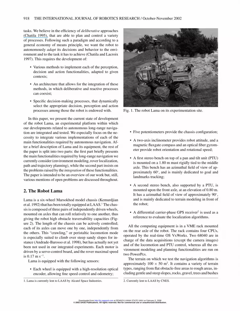
Provided that the localization is precise enough betweensuccessive data acquisitions (i.e., perceptions that are closeto each other), consistent local maps can be built with sizesof about the surface perceived by a 3D image. A rigid localmap is therefore initiated as the rovers starts. During naviga-tion, the perception of some areas beyond the limits of thismap triggers the creation of a new local map, the old onebeing memorized and no longer updated. The process thencontinues, as illustrated in Figure 10; the resulting model is achained list of small local maps, positioned with respect to aglobal frame.
The main advantage of this structure appears when therover crosses a previously modeled area. In such cases, theglobal position is very likely to have drifted so much that thedirect fusion of the overlapping maps would yield an incon-sistent model. If a localization algorithm is able to provide acorrection on the current position, as well as on previous posi-
tions (typically using a SLAM-based localization algorithm,Section 4.3), it is then easy to correct the position of eachlocal map and to generate a globally consistent model, withvery little loss of information. This map structure is thereforeable to bear large localization corrections, and uses much lessmemory space than an approach in which all the acquired datawould be memorized.
4. Localization
For long-range autonomous navigation in planetary environ-ments (and more generally for any mobile robot), the abilityfor the rover to localize itself, i.e., to estimate its position andthe precision on this position, is essential for various reasons:
• The missions to be achieved by the rover are often ex-pressed in localization terms, explicitly (e.g., “reachthat position,” “explore this area,” etc.) or more implic-itly (such as “return near the lander” when it is out ofsight).
• Long-range navigation calls for the building of globalmaps of the environment, to find trajectories or pathsand to enable mission supervision. The spatial consis-tency of such maps is required to allow an efficient androbust behavior of the rover; it is the knowledge of therover position that guarantees this consistency.
• Finally, the proper execution of the geometric trajecto-ries provided by the path planners calls for the preciseknowledge of the rover motions.
Robot self-localization is actually one of the most im-portant issues to tackle in autonomous navigation; this isconfirmed by the vast amount of contributions to this prob-lem in the literature, and the variety of approaches. In theabsence of any external structure (e.g., radioed bearings),we are convinced that no single localization algorithm thatuses on-board data can be robust enough to fulfill the vari-ous localization needs during long-range navigation. A set of
© 2002 SAGE Publications. All rights reserved. Not for commercial use or unauthorized distribution. at PENNSYLVANIA STATE UNIV on February 5, 2008 http://ijr.sagepub.comDownloaded from
924 THE INTERNATIONAL JOURNAL OF ROBOTICS RESEARCH / October-November 2002
R �
R �
A
B
R �
R �
A
Fig. 10. Schematic representation of the map structure. The long arrow represents a fictitious trajectory, the small squaresrepresent local maps that do not overlap, that produced by the fusion of only a few local perceptions. When the trajectorycrosses itself, it is possible to apply a deformation algorithm to the local map frames (right), which back-propagates theposition correction estimated by a localization algorithm (which matched the A and B landmarks in this case).
concurrent and complementary algorithms have to be devel-oped and integrated for that purpose, which raises specificintegration problems (Section 7). We summarize here threelocalization methods, and conclude the section with a synthe-sis on the localization problem.
4.1. Odometry on Natural Terrain
Odometry is one of the most straightforward and “cheap”ways to localize a robot. However, if it is quite a reliable wayto localize a robot evolving indoors, it is much less preciseon natural terrains. Not only the trajectories are 3D (whichcalls for at least inclinometers—or gyros if the rover dynamicsvoids their use), but also the slippages that often occur quicklylead to very erroneous position estimates; they especially af-fect the rotation estimates, which is all the more true whenskid-steering is used to turn the rover. This is why in mostof the contributions related to odometry in natural terrains, arotation or orientation sensor is added (e.g., a gyrometer inGreen, Sasiadek, and Vukovich (1994) and Roumeliotis andBekey (1999), or a sun tracker in Volpe (1999).
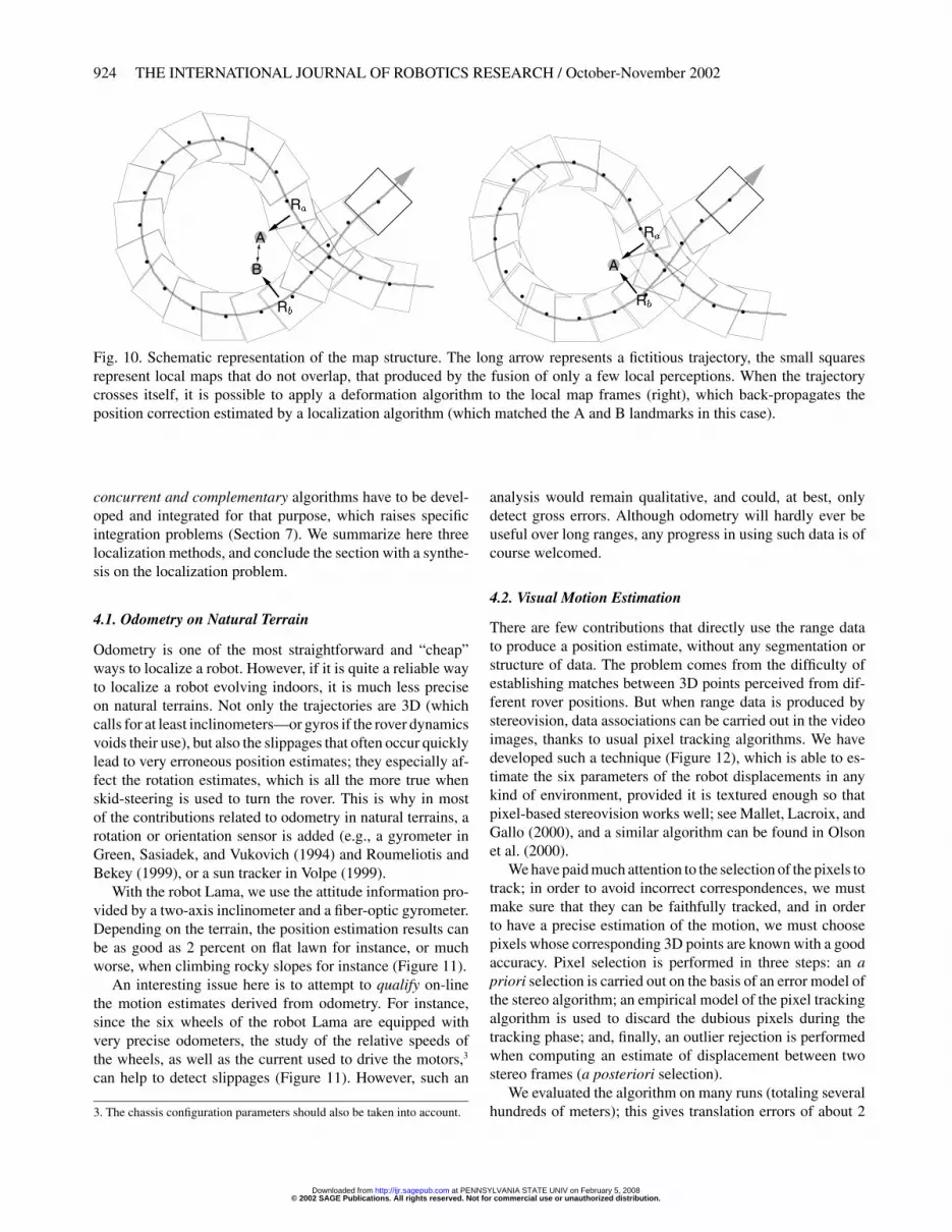
With the robot Lama, we use the attitude information pro-vided by a two-axis inclinometer and a fiber-optic gyrometer.Depending on the terrain, the position estimation results canbe as good as 2 percent on flat lawn for instance, or muchworse, when climbing rocky slopes for instance (Figure 11).
An interesting issue here is to attempt to qualify on-linethe motion estimates derived from odometry. For instance,since the six wheels of the robot Lama are equipped withvery precise odometers, the study of the relative speeds ofthe wheels, as well as the current used to drive the motors,3
can help to detect slippages (Figure 11). However, such an
3. The chassis configuration parameters should also be taken into account.
analysis would remain qualitative, and could, at best, onlydetect gross errors. Although odometry will hardly ever beuseful over long ranges, any progress in using such data is ofcourse welcomed.
4.2. Visual Motion Estimation
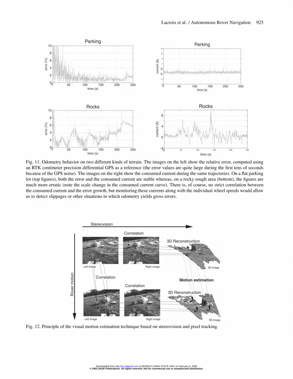
There are few contributions that directly use the range datato produce a position estimate, without any segmentation orstructure of data. The problem comes from the difficulty ofestablishing matches between 3D points perceived from dif-ferent rover positions. But when range data is produced bystereovision, data associations can be carried out in the videoimages, thanks to usual pixel tracking algorithms. We havedeveloped such a technique (Figure 12), which is able to es-timate the six parameters of the robot displacements in anykind of environment, provided it is textured enough so thatpixel-based stereovision works well; see Mallet, Lacroix, andGallo (2000), and a similar algorithm can be found in Olsonet al. (2000).
We have paid much attention to the selection of the pixels totrack; in order to avoid incorrect correspondences, we mustmake sure that they can be faithfully tracked, and in orderto have a precise estimation of the motion, we must choosepixels whose corresponding 3D points are known with a goodaccuracy. Pixel selection is performed in three steps: an apriori selection is carried out on the basis of an error model ofthe stereo algorithm; an empirical model of the pixel trackingalgorithm is used to discard the dubious pixels during thetracking phase; and, finally, an outlier rejection is performedwhen computing an estimate of displacement between twostereo frames (a posteriori selection).
We evaluated the algorithm on many runs (totaling severalhundreds of meters); this gives translation errors of about 2
© 2002 SAGE Publications. All rights reserved. Not for commercial use or unauthorized distribution. at PENNSYLVANIA STATE UNIV on February 5, 2008 http://ijr.sagepub.comDownloaded from
Lacroix et al. / Autonomous Rover Navigation 925
Parking
time (s)
erro
r(%
)10
8
6
4
2
0050 100 150 200 250 -4
-2
4
6
8
10
0
0
2
50 100 150 200 250
Parking
time (s)
curr
ent(
A)
Rocks
time (s)
erro
r(%
)
10
8
6
4
2
0050 100 150 200 250 50 100 150 200 250
-40
0
4
8
Rocks
time (s)cu
rren
t(A
)
Fig. 11. Odometry behavior on two different kinds of terrain. The images on the left show the relative error, computed usingan RTK centimeter precision differential GPS as a reference (the error values are quite large during the first tens of secondsbecause of the GPS noise). The images on the right show the consumed current during the same trajectories. On a flat parkinglot (top figures), both the error and the consumed current are stable whereas, on a rocky rough area (bottom), the figures aremuch more erratic (note the scale change in the consumed current curve). There is, of course, no strict correlation betweenthe consumed current and the error growth, but monitoring these currents along with the individual wheel speeds would allowus to detect slippages or other situations in which odometry yields gross errors.
Left image
Left image
Right image
Right image
3D image
3D image
Correlation
Correlation
Correlation
3D Reconstruction
3D Reconstruction
Motion estimation
Rov
erm
otio
n
Stereovision
Fig. 12. Principle of the visual motion estimation technique based on stereovision and pixel tracking.
© 2002 SAGE Publications. All rights reserved. Not for commercial use or unauthorized distribution. at PENNSYLVANIA STATE UNIV on February 5, 2008 http://ijr.sagepub.comDownloaded from
926 THE INTERNATIONAL JOURNAL OF ROBOTICS RESEARCH / October-November 2002
percent of the distance (Figure 13). Work related to this al-gorithm is still under way, to attempt to minimize the errorgrowth by combining various elementary motion estimatescomputed over several frames. Also, a realistic error modelis required to fuse the estimates with other localization pro-cesses; we are investigating a way to produce a covarianceerror matrix along with each elementary estimate, exploitingthe error model of stereovision (Mallet, Lacroix, and Gallo(2000).
4.3. Long-term Localization
Odometry (or inertial navigation) and visual motion estima-tion cumulates errors over time or distance, and thus leadsto an unbounded error growth as the rover navigates; local-ization methods that memorize, match and exploit environ-mental features are, of course, required to tackle long-rangenavigation.
4.3.1. Landmark-based Localization
One of the most widespread ways to localize a robot is to detectand model landmarks in the environment, and to refine boththeir position and the robot position during navigation usingan extended Kalman filter; techniques often referred to as si-multaneous localization and mapping (SLAM), or concurrentmapping and localization (CML). These techniques have nowreached a mature level of achievement, and help to localizemany robots in indoor- or outdoor-structured environments.However, their application in natural unstructured environ-ments is not straightforward. Indeed, if the consideration of3D rover motions (i.e., six state parameters) is not a problem,the landmark extraction and modeling from the acquired datais much more challenging; unstructured environments do notcontain features that can easily be represented by geomet-ric equations (e.g., lines or planes), with a covariance matrixassociated to their parameters.
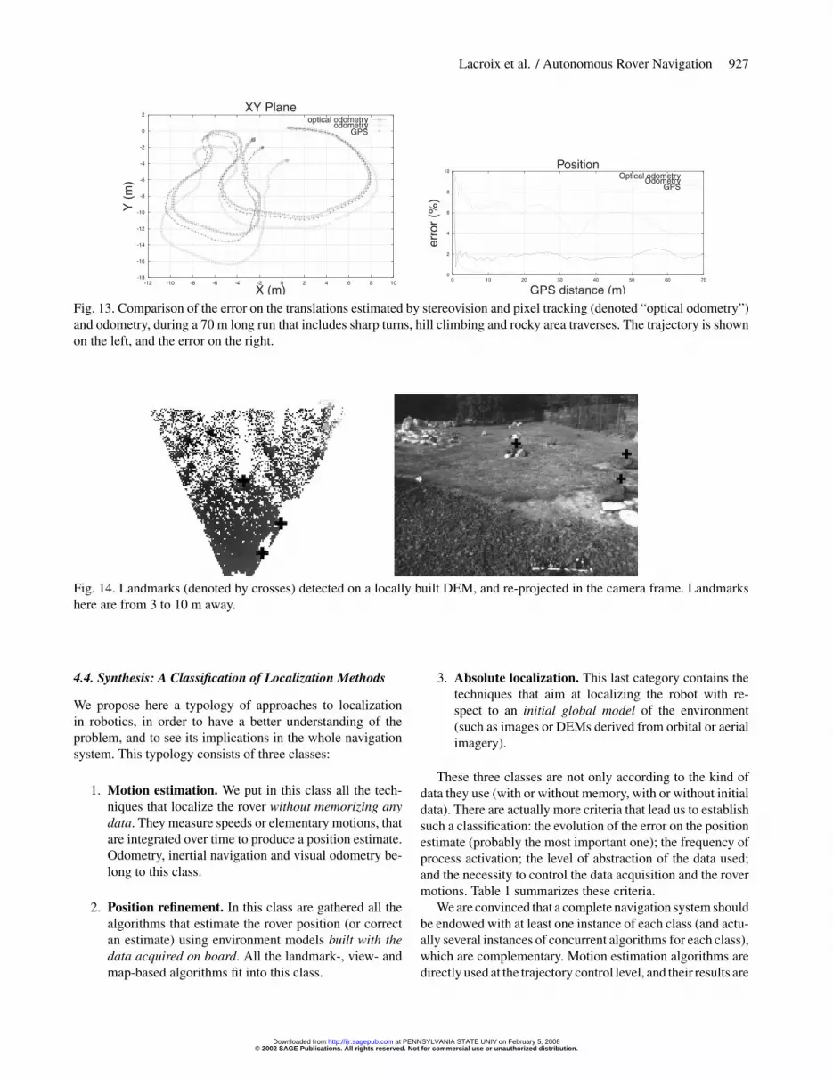
One of our first works in rover navigation has been de-voted to this problem, using obstacle peaks as landmarks (alandmark is here a single 3D point), detected thanks to theapplication of gradient operators in depth images, and an ex-tended Kalman filter to refine the state vector (Betge-Brezetz,Chatila, and Devy 1995; Betge-Brezetz et al. 1996). The re-sults were satisfactory, but not applicable in every kind ofterrain, as the peaks had to be clearly separated from theground to be faithfully detected. More recently, we devel-oped an algorithm to extract local peaks, which relies on thecomputation of similarity scores between a local DEM areaand a pre-defined 3D peak-like pattern (a paraboloid for in-stance), at various scales (Figure 14). Also, we investigatedset theoretic approaches to tackle the state estimation problem(Di Marco et al. 2000). Within such an approach, the only as-sumption made on the landmark positioning errors is that theyare bounded; an assumption much easier to satisfy than in a
Kalman filtering approach, where the error distribution mustbe Gaussian. Estimates of the robot and landmark positionsare derived in terms of feasible uncertainty sets, defined asregions in which the robot and the landmarks are guaranteedto lie. These algorithms have however not been integrated onboard Lama.
4.3.2. Using DEMs
Most of the attempts to localize a rover in unstructured envi-ronments rely on the use of a DEM. Two approaches can bedistinguished here: the DEM is either used to extract particulargeometric features, as in Figure 14 or in Kweon and Kanade(1991), Olson (2000) and Huber, Carmichael, and Hebert(2000), or directly matched with the current perception—iconic approaches (Olson and Matthies 1998). With our DEMbuilding algorithm presented in Section 3.2, we have tried tolocalize the rover on the basis of a local/global DEM correla-tion, using a simplex algorithm to drive the search within thesix-dimensional state space. In terms of precision, the resultsare however less precise than with the visual estimation tech-nique in the case of successive perceptions, and when crossinga previously modeled area after a large loop, the method oftenfalls in local minima, giving erroneous results. We think thatmore work has to be performed in this area, and that it certainlyrequires a more rigorous management of the uncertainties inthe DEMs.
4.3.3. Using Panoramic Images
More and more contributions related to robot localization us-ing panoramic images are being published in various roboticsconferences; see, for example, Ishiguro and Tsuji (1996), Mat-sumoto, Inaba, and Inoue (1997) and Matsumoto et al. (2000).Panoramic sensors are actually making a real breakthroughin robotics. Their geometric properties are well understood(Baker, Nayar, and Murase 1998), and many catadioptric de-vices are now available on the market. Their main attraction isthat they can be used to tackle the place recognition problemusing image indexing techniques, thus bypassing the difficultlandmark extraction step for that purpose. We recently de-veloped such a method (Gonzalez and Lacroix 2002), usingimage histograms computed on local image characteristicsto compute a distance between images acquired as the robotmoves. It turns out that there is a relation between this distanceand the Euclidean distance that separates the image acquisi-tions, and the first results to match panoramic images are verypromising. We must, however, keep in mind that such an ap-proach is limited to a qualitative position estimate, that cantherefore hardly be fused with other estimates. The identifi-cation of features in the environment is still required to refinethis first estimate; points of interest detected in the panoramicimages are worth looking at, as they can feed localizationalgorithms based on bearing angles (Lee and Chung 2001).
© 2002 SAGE Publications. All rights reserved. Not for commercial use or unauthorized distribution. at PENNSYLVANIA STATE UNIV on February 5, 2008 http://ijr.sagepub.comDownloaded from
Lacroix et al. / Autonomous Rover Navigation 927
-18
-16
-14
-12
-10
-8
-6
-4
-2
0
2
-12 -10 -8 -6 -4 -2 0 2 4 6 8 10
XY Plane
Y(m
)
X (m)
optical odometryodometry
GPS
0
2
4
6
8
10
0 10 20 30 40 50 60 70
Position
GPS distance (m)
erro
r(%
)
Optical odometryOdometry
GPS
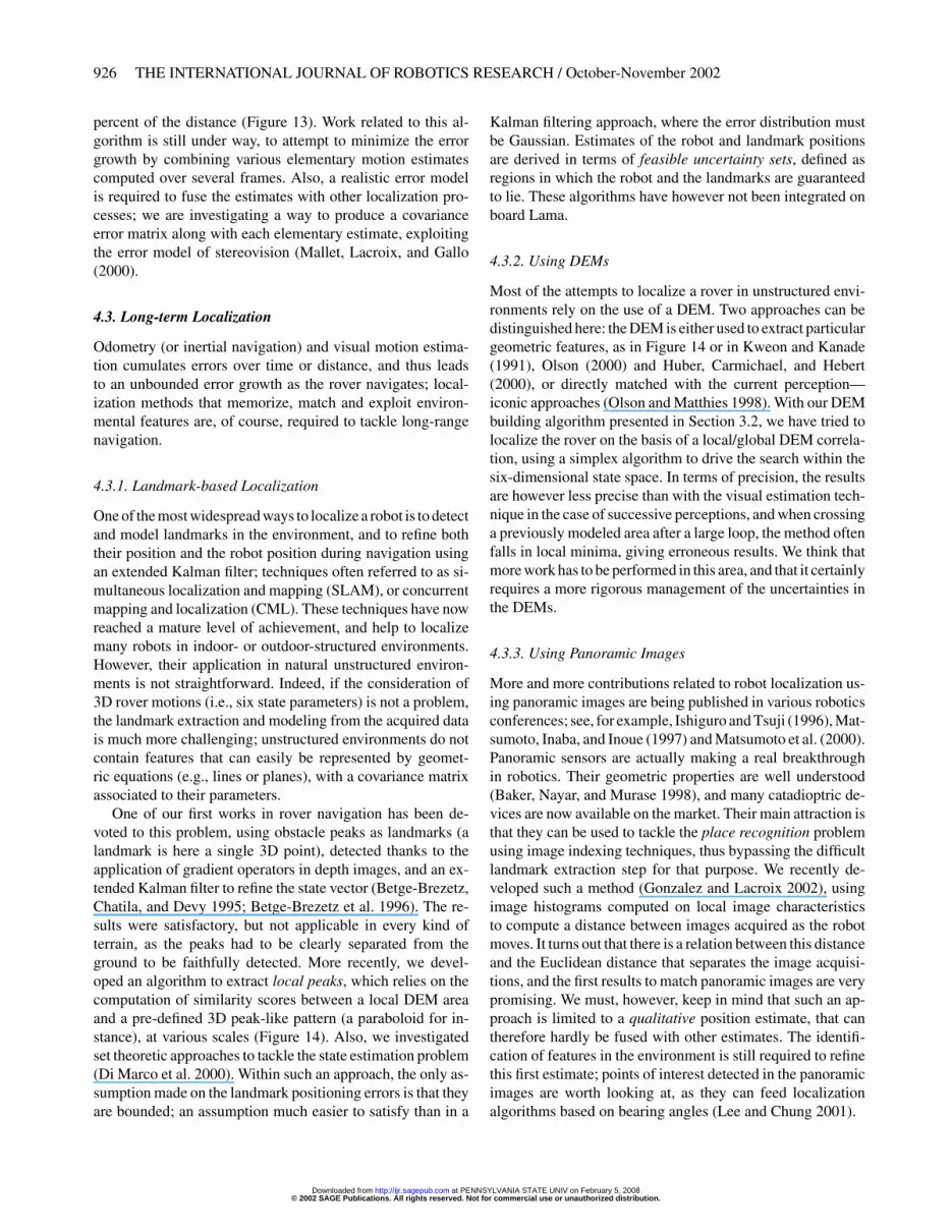
Fig. 13. Comparison of the error on the translations estimated by stereovision and pixel tracking (denoted “optical odometry”)and odometry, during a 70 m long run that includes sharp turns, hill climbing and rocky area traverses. The trajectory is shownon the left, and the error on the right.
Fig. 14. Landmarks (denoted by crosses) detected on a locally built DEM, and re-projected in the camera frame. Landmarkshere are from 3 to 10 m away.
4.4. Synthesis: A Classification of Localization Methods
We propose here a typology of approaches to localizationin robotics, in order to have a better understanding of theproblem, and to see its implications in the whole navigationsystem. This typology consists of three classes:
1. Motion estimation. We put in this class all the tech-niques that localize the rover without memorizing anydata. They measure speeds or elementary motions, thatare integrated over time to produce a position estimate.Odometry, inertial navigation and visual odometry be-long to this class.
2. Position refinement. In this class are gathered all thealgorithms that estimate the rover position (or correctan estimate) using environment models built with thedata acquired on board. All the landmark-, view- andmap-based algorithms fit into this class.
3. Absolute localization. This last category contains thetechniques that aim at localizing the robot with re-spect to an initial global model of the environment(such as images or DEMs derived from orbital or aerialimagery).
These three classes are not only according to the kind ofdata they use (with or without memory, with or without initialdata). There are actually more criteria that lead us to establishsuch a classification: the evolution of the error on the positionestimate (probably the most important one); the frequency ofprocess activation; the level of abstraction of the data used;and the necessity to control the data acquisition and the rovermotions. Table 1 summarizes these criteria.
We are convinced that a complete navigation system shouldbe endowed with at least one instance of each class (and actu-ally several instances of concurrent algorithms for each class),which are complementary. Motion estimation algorithms aredirectly used at the trajectory control level, and their results are
© 2002 SAGE Publications. All rights reserved. Not for commercial use or unauthorized distribution. at PENNSYLVANIA STATE UNIV on February 5, 2008 http://ijr.sagepub.comDownloaded from

928 THE INTERNATIONAL JOURNAL OF ROBOTICS RESEARCH / October-November 2002
Table 1. Behavior of the Four Criteria In Our Typology of Localization Algorithms
Motion Position AbsoluteEstimation Refinement Localization
Error evolution Unbounded growth Unbounded growth Boundedbut can decrease
Process frequency Very fast Slow Very slow
Data abstraction level Raw data Landmarks, environmentalmodels or indexed images
Landmark or environmentmodels
Control No Data acquisition control,influences motion
generation
Drives the motiongeneration
used as initial estimates for position refinement algorithms.Position refinement algorithms are required to build consis-tent global terrain maps, which are the essential representationon which localization with respect to an initial terrain modelcan be performed.
5. Trajectory Generation
A generic trajectory planner able to deal with any situationshould take into account all the constraints, such as roverstability, rover body collisions with the ground, kinematic andeven dynamic constraints. The difficulty of the problem callsfor very time-consuming algorithms, which would actually bequite inefficient in situations where much simpler techniquesare applicable. We therefore think it is worth endowing therover with various trajectory generation algorithms, dedicatedto the kind of terrain to traverse. We briefly describe here threemotion algorithms that have been integrated on board Lama.In Section 8, we describe how they are actively triggered andcontrolled.
5.1. On Easy Terrains
On easy terrains, i.e., rather flat and lightly cluttered, dead-ends are very unlikely to occur. Therefore, the robot can ef-ficiently navigate and avoid the obstacles just on a basis ofa goal to reach4 and a terrain model that only exhibits non-traversable areas (the probabilistic qualitative model in ourcase).
5.1.1. Potential Field Approach
When the environment only contains a few obstacles, reac-tively generating motion commands on the sole basis of alocal obstacle detector can be an efficient enough way to nav-igate. Our first experiments with Lama, back in 1997 (Haddad
4. Not necessarily the distant global goal, it can be a formerly selected sub-goal; see Section 8.
et al. 1998), have been achieved with such a method. Elemen-tary motion commands are generated thanks to potential fieldsdefined on (i) a local qualitative map and (ii) on the result ofa visual goal tracker. No global localization is required, andno global environment model is updated.
Artificial potential field approaches are well known in therobotics community, but only a few attempts in the contextof natural environment have reached effective achievements(Green, Sasiadek, and Vukovich 1994). We have adapted amethod formerly developed in the context of indoor robots(Khatib and Chatila 1995) to the probabilistic polygonal rep-resentation produced by the terrain classification algorithm.The method relies on repulsive rotational potential functions,which depends not only on the distance of the obstacles (themap cells), but also on the relative robot/obstacle cell config-uration. In particular, the robot is not influenced by the pres-ence of obstacle segments parallel to its moving direction.This leads to the generation of motions much smoother thanwith a classical “mass attraction” potential fully determinedby the distances to the obstacles (Figure 15). Also, the partialprobabilities of each cell to contain an obstacle are taken intoaccount in the definition of the potential field (Haddad et al.1998).
This approach gives satisfactory results in very clear ter-rains (Figure 16), but the various parameter tunings areslightly tedious if we want to cross more cluttered areas—theusual difficulties with potential field approaches. In particu-lar, the method is very sensitive to a threshold that specifiesthe maximal influence distance of obstacles (i.e., the distanceover which their potential is null), which is required to avoidpotential wells.
5.1.2. Arcs Approach
We have also developed an algorithm that evaluates circlearcs on the basis of the global qualitative probabilistic model,similarly to Langer, Rosenblatt, and Hebert (1994). Everycycle, the algorithm is run on the updated terrain model. It
© 2002 SAGE Publications. All rights reserved. Not for commercial use or unauthorized distribution. at PENNSYLVANIA STATE UNIV on February 5, 2008 http://ijr.sagepub.comDownloaded from
Lacroix et al. / Autonomous Rover Navigation 929
© Lama Pilot Classical Potential
Start
Goal
© Lama Pilot
Rotational Potential
Start
Goal
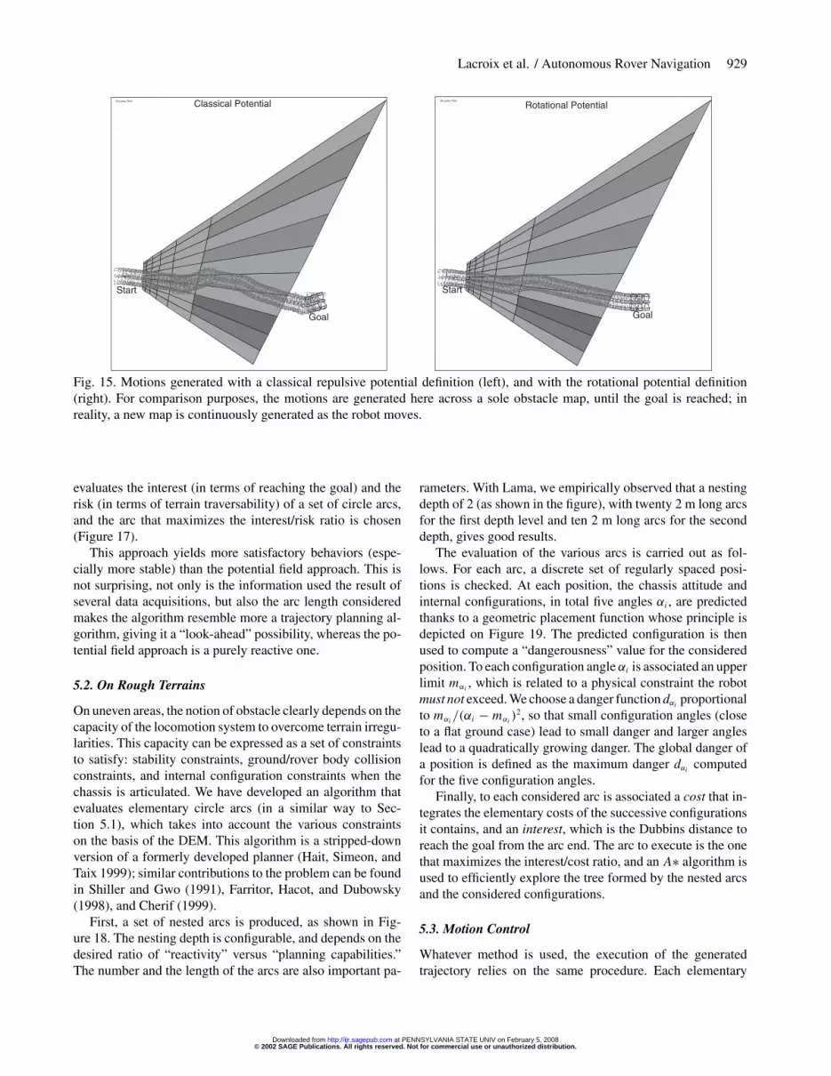
Fig. 15. Motions generated with a classical repulsive potential definition (left), and with the rotational potential definition(right). For comparison purposes, the motions are generated here across a sole obstacle map, until the goal is reached; inreality, a new map is continuously generated as the robot moves.
evaluates the interest (in terms of reaching the goal) and therisk (in terms of terrain traversability) of a set of circle arcs,and the arc that maximizes the interest/risk ratio is chosen(Figure 17).
This approach yields more satisfactory behaviors (espe-cially more stable) than the potential field approach. This isnot surprising, not only is the information used the result ofseveral data acquisitions, but also the arc length consideredmakes the algorithm resemble more a trajectory planning al-gorithm, giving it a “look-ahead” possibility, whereas the po-tential field approach is a purely reactive one.
5.2. On Rough Terrains
On uneven areas, the notion of obstacle clearly depends on thecapacity of the locomotion system to overcome terrain irregu-larities. This capacity can be expressed as a set of constraintsto satisfy: stability constraints, ground/rover body collisionconstraints, and internal configuration constraints when thechassis is articulated. We have developed an algorithm thatevaluates elementary circle arcs (in a similar way to Sec-tion 5.1), which takes into account the various constraintson the basis of the DEM. This algorithm is a stripped-downversion of a formerly developed planner (Hait, Simeon, andTaix 1999); similar contributions to the problem can be foundin Shiller and Gwo (1991), Farritor, Hacot, and Dubowsky(1998), and Cherif (1999).
First, a set of nested arcs is produced, as shown in Fig-ure 18. The nesting depth is configurable, and depends on thedesired ratio of “reactivity” versus “planning capabilities.”The number and the length of the arcs are also important pa-
rameters. With Lama, we empirically observed that a nestingdepth of 2 (as shown in the figure), with twenty 2 m long arcsfor the first depth level and ten 2 m long arcs for the seconddepth, gives good results.
The evaluation of the various arcs is carried out as fol-lows. For each arc, a discrete set of regularly spaced posi-tions is checked. At each position, the chassis attitude andinternal configurations, in total five angles αi , are predictedthanks to a geometric placement function whose principle isdepicted on Figure 19. The predicted configuration is thenused to compute a “dangerousness” value for the consideredposition. To each configuration angle αi is associated an upperlimit mαi
, which is related to a physical constraint the robotmust not exceed. We choose a danger function dαi
proportionalto mαi
/(αi − mαi)2, so that small configuration angles (close
to a flat ground case) lead to small danger and larger angleslead to a quadratically growing danger. The global danger ofa position is defined as the maximum danger dαi
computedfor the five configuration angles.
Finally, to each considered arc is associated a cost that in-tegrates the elementary costs of the successive configurationsit contains, and an interest, which is the Dubbins distance toreach the goal from the arc end. The arc to execute is the onethat maximizes the interest/cost ratio, and an A∗ algorithm isused to efficiently explore the tree formed by the nested arcsand the considered configurations.
5.3. Motion Control
Whatever method is used, the execution of the generatedtrajectory relies on the same procedure. Each elementary
© 2002 SAGE Publications. All rights reserved. Not for commercial use or unauthorized distribution. at PENNSYLVANIA STATE UNIV on February 5, 2008 http://ijr.sagepub.comDownloaded from

930 THE INTERNATIONAL JOURNAL OF ROBOTICS RESEARCH / October-November 2002
© L
am
a P
ilo
t
Fig. 16. A typical run in a lightly cluttered terrain with the potential field approach. The local qualitative maps are heresurimposed, but only one map is known at a time by the rover.
geometric movement is translated into a linear and angularspeed couple, according to a specified speed. This referenceis periodically updated and transmitted to a PID-based servo-controller, which determines a reference rotation speed foreach of the six wheels (the wheels being themselves servoedon the optical encoders by a PID). This simple motion controlalgorithm is satisfactory in most of the cases, when the roveris not evolving in rough terrains. But, in the latter case, moresophisticated motion control algorithms should be used, to
avoid side-slippings, skids, grip loss, etc. Detecting faulty lo-comotion behaviors is, of course, a very important problem totackle to traverse rough terrains. This is actually related to themonitoring of odometry mentioned in Section 4.1, and alsorequires the estimation of motions with exteroceptive means,as in Section 4.2. Several innovative locomotion concepts areregularly proposed in the literature (e.g., Siegwart et al. 2000;Kubota et al. 2001); most of the time, they raise very chal-lenging control issues.
© 2002 SAGE Publications. All rights reserved. Not for commercial use or unauthorized distribution. at PENNSYLVANIA STATE UNIV on February 5, 2008 http://ijr.sagepub.comDownloaded from

Lacroix et al. / Autonomous Rover Navigation 931
Fig. 17. A set of circle arcs evaluated on the global probabilistic model (left), and re-projected in the current camera view,with the chosen arc shown in white (right).
Fig. 18. A sample set of arcs used by the rough terrain motiongeneration method (twenty first depth arcs with ten seconddepth arcs are shown here).
Part B: Integration
6. Integration and Software Architecture
As emphasized in the first part of the paper, endowing a robotwith autonomy requires the integration of a large variety ofheterogeneous and sometimes concurrent functionalities: sen-sor and actuator controls, servo-controls, monitoring, imageprocessing, terrain modeling and localization algorithms, tra-jectory generation algorithms, etc. In this section, we brieflypresent how we tackle this functional integration in our lab,and in particular with Lama.5
5. The system presented here is part of the definition of a generic software anddecisional architecture for autonomous machines (Alami et al. 1998a), whichhas been successfully instantiated with indoor mobile robotics experiments,autonomous satellite simulations and multi-robot cooperation experiments.
φ φ
Fig. 19. Illustration of the geometric placement procedure.First, given an horizontal position x, y, θ on the DEM, theroll and height of each axle is iteratively computed (top). Theconstraints between the three axles of Lama are then takeninto account and used to compute the global placement ofthe rover (bottom).
6.1. Problem Specifications
6.1.1. Co-integration
One of the main problems raised by the integration of thesevarious functionalities comes from their variety. They havebeen developed by experts from various domains (control the-ory, vision, motion planning, etc.), not necessarily aware ofthe robot software architecture, or even of its operating sys-tem. Moreover, these functionalities have various temporaland logical characteristics, and must share common CPU re-sources. Some of them have strong real-time constraints andrequire secure execution contexts (e.g., servo-controllers ormonitoring processes), whereas others can require an unpre-dictable amount of CPU time and/or memory. Finally, the
© 2002 SAGE Publications. All rights reserved. Not for commercial use or unauthorized distribution. at PENNSYLVANIA STATE UNIV on February 5, 2008 http://ijr.sagepub.comDownloaded from
932 THE INTERNATIONAL JOURNAL OF ROBOTICS RESEARCH / October-November 2002
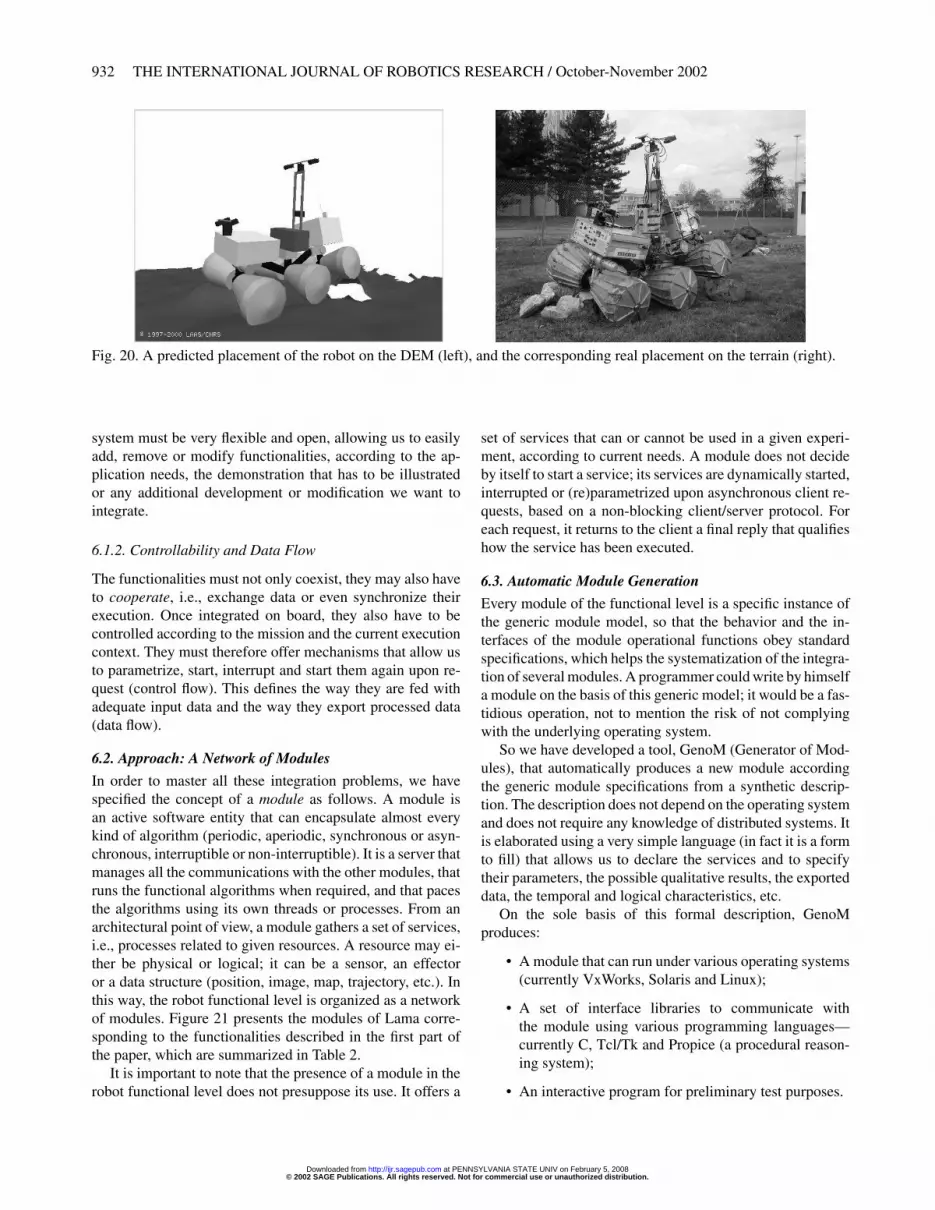
Fig. 20. A predicted placement of the robot on the DEM (left), and the corresponding real placement on the terrain (right).
system must be very flexible and open, allowing us to easilyadd, remove or modify functionalities, according to the ap-plication needs, the demonstration that has to be illustratedor any additional development or modification we want tointegrate.
6.1.2. Controllability and Data Flow
The functionalities must not only coexist, they may also haveto cooperate, i.e., exchange data or even synchronize theirexecution. Once integrated on board, they also have to becontrolled according to the mission and the current executioncontext. They must therefore offer mechanisms that allow usto parametrize, start, interrupt and start them again upon re-quest (control flow). This defines the way they are fed withadequate input data and the way they export processed data(data flow).
6.2. Approach: A Network of Modules
In order to master all these integration problems, we havespecified the concept of a module as follows. A module isan active software entity that can encapsulate almost everykind of algorithm (periodic, aperiodic, synchronous or asyn-chronous, interruptible or non-interruptible). It is a server thatmanages all the communications with the other modules, thatruns the functional algorithms when required, and that pacesthe algorithms using its own threads or processes. From anarchitectural point of view, a module gathers a set of services,i.e., processes related to given resources. A resource may ei-ther be physical or logical; it can be a sensor, an effectoror a data structure (position, image, map, trajectory, etc.). Inthis way, the robot functional level is organized as a networkof modules. Figure 21 presents the modules of Lama corre-sponding to the functionalities described in the first part ofthe paper, which are summarized in Table 2.
It is important to note that the presence of a module in therobot functional level does not presuppose its use. It offers a
set of services that can or cannot be used in a given experi-ment, according to current needs. A module does not decideby itself to start a service; its services are dynamically started,interrupted or (re)parametrized upon asynchronous client re-quests, based on a non-blocking client/server protocol. Foreach request, it returns to the client a final reply that qualifieshow the service has been executed.
6.3. Automatic Module Generation
Every module of the functional level is a specific instance ofthe generic module model, so that the behavior and the in-terfaces of the module operational functions obey standardspecifications, which helps the systematization of the integra-tion of several modules. A programmer could write by himselfa module on the basis of this generic model; it would be a fas-tidious operation, not to mention the risk of not complyingwith the underlying operating system.
So we have developed a tool, GenoM (Generator of Mod-ules), that automatically produces a new module accordingthe generic module specifications from a synthetic descrip-tion. The description does not depend on the operating systemand does not require any knowledge of distributed systems. Itis elaborated using a very simple language (in fact it is a formto fill) that allows us to declare the services and to specifytheir parameters, the possible qualitative results, the exporteddata, the temporal and logical characteristics, etc.
On the sole basis of this formal description, GenoMproduces:
• A module that can run under various operating systems(currently VxWorks, Solaris and Linux);
• A set of interface libraries to communicate withthe module using various programming languages—currently C, Tcl/Tk and Propice (a procedural reason-ing system);
• An interactive program for preliminary test purposes.
© 2002 SAGE Publications. All rights reserved. Not for commercial use or unauthorized distribution. at PENNSYLVANIA STATE UNIV on February 5, 2008 http://ijr.sagepub.comDownloaded from

Lacroix et al. / Autonomous Rover Navigation 933
Table 2. The Main Modules On-board LamaModule Description Section
Hardware PTU Pan-tilt unit controller Section 2controllers CAMERA Cameras controller (settings + acquisition) Section 2
GPS Global Position System (for validation) Section 2LOCO Odometry and servo-control (speed or position) Section 4.1 and 5.3
Localization Steo Stereo-based “odometry” Section 4.2PoM Position manager Section 7
Stereo Stereo vision (correlation procedures) Section 3
Mapping DEM Digital Elevation Map Section 3.2Classif Terrain classification Section 3.1
Motion generation Potential fields Potential fields’ based motion Section 5.1Arc Arcs’ based motion Section 5.1P3D 3D local planner Section 5.2
Goal tracker Camera tracking on visual target Not presented
Sensing
Localisation
Motion generation
Environment maps
Loco
W E
S
N
(odometry +servocontrol )
"can read data from"
PanTiltUnit 2
odometry)(Stereobased
SteoArc
Goal Classif
P3D
Stereo
DEM
hardware level
tracker
CameraPanTiltUnit 1
GPS
Potentialfields
functional level
(Positionmanager)
PoM
Fig. 21. The network of modules on board Lama. Near to the hardware devices, at the bottom, are the modules that managethe sensors and the actuators such as the cameras (CAMERA) or the pan-tilt unit (PTU) or servo-control of the motor-wheels(LLOCO), etc. On the basis of data or services offered by these basic modules, other modules can estimate the robot position(STEO), compute maps (DEM), or produce references for collision-free motions (ARC, P3D). The arrows represent all thepossible data flow that can be set up from one module to another.
© 2002 SAGE Publications. All rights reserved. Not for commercial use or unauthorized distribution. at PENNSYLVANIA STATE UNIV on February 5, 2008 http://ijr.sagepub.comDownloaded from

934 THE INTERNATIONAL JOURNAL OF ROBOTICS RESEARCH / October-November 2002
This approach allows the programmer to focus on the de-velopments of the algorithms, without caring about the robotoperational system and architecture design. The automaticproduction of the modules guarantees a standard behavior andavoids the execution of tedious logical tests. The standardiza-tion associated with the formal description allows us to easilydevelop a complex functional level, in which several tens ofmodules can be integrated. This system has been systemati-cally used for all our indoor and outdoor robots for over fiveyears, and has been validated in large-scale projects.
6.4. Module Control and Interface
All the modules integrated on the robot form the functionallevel; they offer a set of services that can be activated uponrequests sent either by an operator or by a software supervisor.This is enabled by the interface libraries automatically gen-erated by GenoM, which include all the functions required tosend a request, receive a reply or read data produced by themodule.
6.4.1. Using Tcl Scripts
A very simple and straightforward way to control the robotconsists of loading the Tcl library produced by GenoM in a Tclshell interpretor, allowing the operator to interactively activatethe services. Of course, more or less elaborate functions ormacros can be written to sequence the various services. Forinstance, the three following Tcl procedures allow us to reacha goal using the arc-based approach on the qualitative model:
1. Qualitative model updating with updateClassifMap. This procedure consists of sequentially acquir-ing a stereo image pair, running the stereovision algo-rithm, classifying the produced 3D image and fusing itin the global model.
# procedure to update the classification mapproc updateClassifMap { } {
# get a stereo image from bank A: request‘‘OneShot" to module CAMERAcamera::OneShot CAMERA_BANK_A CAMERA_STEREO
# stereo correlation : request ‘‘SCorrel"to module STEREOstereo::SCorrel
# classification and fusion : requestsClassif and FuseLCLMap to module CLASSIFclassif::Classifclassif::FuseMap
}
2. Generate motions with arcStep. This second proce-dure computes speed reference for the robot using theARC module. The result of thearc::GetArc requestis evaluated in order to know whether the goal has been
reached or an error has occurred. If not, the speed ref-erences chosen are sent to the LOCO servo-controllermodule (loco::GotoSpeed request).
# procedure to compute one reference usingARC moduleproc arcStep { } {
# Choose best arcset retCode [catch {
set arc [arc::GetArc -raw $::lamaSpeed]set v [lindex $arc 2]set w [lindex $arc 3]
} message]
# test endif { $retCode } {
switch -regexp $message {‘‘GOAL_REACHED" {
set ::goalReached 1}default {
set ::arcFailed 1}
}# servo the robot} else {
loco::GotoSpeed $v $w}
}
3. Main procedure arcRun. Finally, the main procedureloops over the previous updateClassifMap andarcStep procedures.
# Main function to runproc arcRun {xGoal yGoal} {
# Some initializationsset ::goalReached 0set ::arcFailed 0set ::lamaSpeed 0.08arc::SetGoal $xGoal $yGoal
# Main loopwhile {$::goalReached == 0 && $::arcFailed== 0} {
updateClassifMaparcStep
}
# goal reached ?if {$::goalReached} {
loco::Stopputs "Goal reached. Alleluyah !"
}
# motion mode not adapted ?if {$::arcFailed} {
loco::Stopputs "Arc failed. Call P3D ! !"
}}
The data produced by the modules (images, robot posi-tions, maps, trajectories, etc.) can also be directly read via
© 2002 SAGE Publications. All rights reserved. Not for commercial use or unauthorized distribution. at PENNSYLVANIA STATE UNIV on February 5, 2008 http://ijr.sagepub.comDownloaded from

Lacroix et al. / Autonomous Rover Navigation 935
Tcl using GenoM functions and displayed in the Tk graphi-cal environment. This allows us to conceive relatively easilygraphical control interface (see, for example, Figure 25).
6.4.2. Control using Propice
The development of complex integrated experiments may re-quire an elaborated on-board software supervisor (possiblycoupled with a task planner). For instance, our service robotexperiments are scheduled and supervised by Propice, a pro-cedural reasoning system (Alami et al. 1998b, 2000). Somedemonstrations with Lama have been integrated with this tool;Figure 22 presents a graphical Propice procedure that imple-ments a function similar to the Tcl one presented just above.The graphical representation allows us to easily express par-allelism and synchronization.
More generally, Propice is composed of a set of tools andmethods to represent and execute plans and procedures. Eachplan/procedure is self-contained; it describes in which condi-tion it is applicable and the goals it achieves. This is particu-larly well adapted to context-based task refinement and to alarge class of incremental robot tasks, such as adaptive rovernavigation in a partially known environment.
7. Integration of Localization Algorithms
Some particular problems are raised by the integration of sev-eral concurrent localization algorithms on board the robot.To tackle this in a generic and reconfigurable way, we havedeveloped a particular module named PoM (POsition Man-ager). This module receives as inputs all the position estimatesproduced by the localization algorithms (each being itselfintegrated within a specific module), and produces a singleconsistent position estimate as an output. PoM addresses thefollowing three issues: the sensor geometrical distribution,the localization module asynchronism and the fusion of thevarious position estimates.
7.1. Sensor Geometrical Distribution
Sensors are usually physically distributed over the robot, andtheir relative positions can dynamically change if they aremounted on orientable devices, or if the chassis is articu-lated. This position information is of prime importance for thealgorithms that process the data relative to the environment(raw sensor data as well as processed data). For instance, thevision-based localization module must know the orientationof the cameras for each image it processes, whereas the DEMmodule needs the relative and/or absolute position of the 3Dimages it fuses.
Distributing the geometrical information within the mod-ules is not satisfying, as it can lead to consistency problems(synchronism), not to mention the portability issues whenlinking the module to another sensor or another robot. It is
indeed much more preferable to keep the modules as genericas possible. For that purpose, we use a centralized geometri-cal description of a robot, which provides the necessary framecoordinates to any module when the robot navigates. All thedata acquisition modules use this information to “tag” the datathey produce.
7.1.1. Geometric Relations among Sensors
Upon startup, PoM reads a configuration file which is the tex-tual description of a geometrical graph (Figure 23). The nodesof the graph are frame coordinates that need to be exported;they usually correspond to sensor locations but can also be aconvenient way to split otherwise complex links. Frames areconnected one to another with either static (rigid) or dynamic(mobile) links. A static link cannot change during executionand is usually related to some mechanical part of the robot. Onthe other hand, dynamic links depend on the chassis config-uration or on a particular actuator configuration (for instancea PTU), and are updated continuously at a predefined fre-quency. Finally, the configuration file defines a main frame,in which the data acquired by modules are always expressed,which facilitate and homogenize inter-module data transfers.
7.1.2. Dispatching the Geometric Relations
Every data acquisition component can then read the framewhich it relates to, and associate to its data a “tag” structurewhich contains at least the time of acquisition, the configura-tion of the sensor relative to the “main” frame and the currentglobal robot position estimate. Thanks to this tagging, dataacquisition modules only have to know the name of the framethey are connected to, which can be dynamically specified.Once tagging is done, clients using data do not have to carewhere it comes from, since all the necessary geometrical andtime information is associated with the data itself. The tag ispropagated along with the data between modules, thus makinginter-module data communication very flexible.
7.2. Localization Module Asynchronism
In addition to internal frame configurations, PoM collects theposition produced by the various position estimators present inthe system (see Figure 21). This is the place where positionalinformation is centralized and made available for any modulethat requires it.
The localization algorithms have individual time proper-ties; some produce a position estimate at a regular high fre-quency, while others require some non-constant (and possiblylong) computation time. Thus the robot often has to deal withoutdated positions. To maintain the time consistency betweenthe various position estimates, PoM internally maintains atime chart for each position estimator, plus one particular chartfor the fused position, which is the result of the fusion of every
© 2002 SAGE Publications. All rights reserved. Not for commercial use or unauthorized distribution. at PENNSYLVANIA STATE UNIV on February 5, 2008 http://ijr.sagepub.comDownloaded from

936 THE INTERNATIONAL JOURNAL OF ROBOTICS RESEARCH / October-November 2002
Fig. 22. The Propice procedure to reach a goal using the arc-based approach on the qualitative model.
GPS
Camera(top, left)
PTU(top)
Camera(top, right)
Robot
Robot(vertical)
Front
PTU(bottom)
Camera(bottom, left)
Camera(bottom, right)
Mast
Mobile
Rigid
Fig. 23. The graph representing the geometry of Lama. Rectangular boxes are frames configurations that are exported in thesystem. The thick box (Robot in the figure) is the main frame. Solid lines are links (either rigid or mobile) that are declared inthe configuration file.
© 2002 SAGE Publications. All rights reserved. Not for commercial use or unauthorized distribution. at PENNSYLVANIA STATE UNIV on February 5, 2008 http://ijr.sagepub.comDownloaded from
Lacroix et al. / Autonomous Rover Navigation 937
position estimator (see the following section). PoM periodi-cally polls every position estimator and looks if a positionestimate has been updated. When a new position is produced,it is inserted in the chart at the corresponding date (found inthe position “tag”), and the fused position is then updated.
One important thing to note is that we cannot simply up-date the current fused position “as is” because it might be verydifferent from the previous position. Since some module mayuse the robot position continuously (such as the locomotionmodule that servos the motions along a given trajectory forinstance), such virtual jumps are not permitted. To handle this,we define a reference position estimator (usually, odometryis a good choice). The fused position computed by PoM con-tains two parts: the current position of the reference estimator,plus a correction of this reference. We can then use the refer-ence position locally, and include the correction if an absoluteposition is needed.
7.3. Fusion of the Position Estimates
The two sections above describe a structural scheme to inte-grate various localization algorithms. But the most importantthing related to this integration is the ability to fuse the var-ious estimates, thus leading to a more precise position esti-mate. Among the various formalisms that can be applied tothis problem, Kalman filtering is the most popular. This re-quires the knowledge of an error model for each localizationalgorithm, but also the ability to discard erroneous estimates(fault detection).
Up to now, our various algorithms are not “qualified,” inthe sense that their error model is not precisely known; theestimates are selected on the basis of a confidence (real valuebetween 0.0 and 1.0). These confidence values are currentlyhard-coded, and computed from our experience of the esti-mators, but will eventually be dynamically set by each po-sition estimator, on the basis of the qualification of the al-gorithms (e.g., behavior of the currents consumed and thechassis configuration for odometry, or number of pixels ef-fectively tracked and residual of the mean square estimatorfor the visual motion estimation technique).
8. Integration of Several Motion Modes
The methods to generate motions presented in Section 5 areall local; they evaluate elementary motions, and are thereforenot efficient for dealing with long-range navigation, avoid-ing dead-ends and optimizing the whole trajectory length. Inother words, they can successfully achieve way-point navi-gation, provided the way-points are given by an entity thatis aware of the whole mission context (global environmentmodels, possible a priori knowledge, mission definition withthe associated constraints, etc.). Also, each motion generatoris suited for a given type of terrain; according to a general“economy of means” principle and for efficiency purpose, the
right mode has to be triggered at the right time. The integra-tion of these methods therefore calls for a specific decisionalability, which we refer to as the “navigation planner,” whichchooses, triggers and controls them by providing the appropri-ate way-points (or sub-goals). Several contributions to rovernavigation also tackle the navigation problem with a two-levelhierarchy, a global planner being in charge of generating way-points for a local trajectory finder (Stentz and Hebert 1995;Singh et al. 2000; Delpech, Rastel, and Lamboley 1998).
8.1. A First Solution
Given the robot current position, the goal to reach and theglobal qualitative model that describes the terrain in terms ofnavigability areas, the navigation planner must find a sub-goalto reach, the motion mode to apply, and the perception tasks toexecute. Indeed, the decisions related to motion and percep-tion must be taken jointly, as they are strongly interdependent.Executing a motion requires us to have formerly modeled theenvironment, and to acquire some specific data, a motion isoften necessary to reach the adequate observation position.
We proposed a first approach to this problem, using an op-timal path search algorithm (A�) in the graph defined by thetraversability regions of the global qualitative model (Lacroixand Chatila 1995). Each region of the terrain model has beenprocessed beforehand; a terrain class label has been decided,on the basis of the partial probabilities. The “optimality” crite-rion takes here a crucial importance; it is a linear combinationof time and consumed energy, weighted by the class of theregions to cross and the confidence of the terrain labeling(Figure 24). Introducing the labeling confidence in the cross-ing cost of an arc comes to consider implicitly the modelingcapabilities of the robot; tolerating to cross obstacle areas la-beled with a low confidence means that the robot is easilyable to acquire information on this area. The returned path isnot executed directly. It is analyzed to define the sub-goal toreach, which is the last node of the path that lies in a surelylabeled traversable area, and the area to perceive is the onethat maximizes the coverage of the remaining path.
8.2. Current Work
The work briefly summarized above dates back to the middleof the 1990s, and actually needs to be revisited. In particu-lar, the D� would be more performant in terms of optimalpath computations (Stentz and Hebert 1995). But more fun-damentally, we are currently investigating an approach withina decision theoretic framework, that would integrate the var-ious information in a more rigorous way. The integration onthe detected landmarks should also be taken into account,to generate a path along which a good localization can beguaranteed.
© 2002 SAGE Publications. All rights reserved. Not for commercial use or unauthorized distribution. at PENNSYLVANIA STATE UNIV on February 5, 2008 http://ijr.sagepub.comDownloaded from

938 THE INTERNATIONAL JOURNAL OF ROBOTICS RESEARCH / October-November 2002
Fig. 24. Two results of the navigation planner on the qualitative model. The result of the analysis of the shortest path foundcan be interpreted as the answer to the question: “what area should be perceived to reach the goal?”
9. Experiments
The experimental evaluation of the developments is a keypoint in robotics, to which we devote much energy. The var-ious functionalities described throughout the first part of thispaper have all been tested on board Lama, in various scenarios.Most of experiments have been conducted in our experimen-tation site, and live public demonstrations were presented inSeptember 2000 at the “Cité de l’Espace,” a museum dedi-cated to space technologies in Toulouse (Figure 25).
Up to now, no experiments integrating all the presentedfunctionalities have been successfully performed (this re-quires in particular the mentioned developments at the navi-gation planner level). Each motion generation algorithm hasbeen individually tested:6 they are all able to reach sub-goalsat a distance from ten to several tens of meters, when theterrains do not exhibits any dead-end. The most complex in-tegrated experiment we have performed is the following. Thetwo environment models (qualitative map and digital eleva-tion map) are continuously updated every time new data aregathered, and two integrated localization algorithms (odome-try and visual motion estimate) are also continuously running.The selection of the trajectory generation algorithm is as fol-lows: given a global goal to reach, the easy terrain algorithmis applied until no feasible arcs can be found. In such cases,the rough terrain algorithm is applied. It is run until either theeasy terrain algorithm succeeds again, or until no feasible arcsare found in the elevation map. In the latter case (which canbe assimilated to a dead end), the navigation planner is acti-vated, to select a sub-goal to reach. The whole strategy is then
6. The potential field approach is no longer used, as it gives trajectories lesssatisfying than the arc method.
applied to reach the sub-goal, and so on. Figure 26 presentstwo autonomous runs of a few tens of meters, in which therover successfully found its way through various situations.
9.1. Performances
The experiments are run in a continuous mode, all the algo-rithms being integrated on board the rover. The implementa-tion of the algorithms is not optimized,7 and vision algorithmslimit the rover speed to only 0.05 m s−1, as each loop takesabout 10 s. During these 10 s, the following algorithms arerun: stereovision, qualitative and digital maps building, mo-tion generation and visual position estimation. Among thesefunctions, the visual position estimation takes about 6 s, about500 pixels being tracked. Current work on this algorithm willallow us to reduce by around one order of magnitude thenumber of pixels to track, thus allowing the robot to run at0.10 m s−1. (See Extension 1.)
10. Discussion
We have insisted on the fact that, to efficiently achieve au-tonomous long-range navigation, various algorithms have tobe developed for each of the basic navigation functions (envi-ronment modeling, localization and motion generation). Sucha paradigm eventually leads to the development of a complexintegrated system, thus requiring the development of integra-tion tools, at both the functional and decisional levels. We areconvinced that such tools are the key to implementing efficientautonomy on large time and space ranges.
There are, however, several open issues:
7. In particular, the AltiVec high-performance SIMD instructions of the Pow-erPC processors are not used.
© 2002 SAGE Publications. All rights reserved. Not for commercial use or unauthorized distribution. at PENNSYLVANIA STATE UNIV on February 5, 2008 http://ijr.sagepub.comDownloaded from

Lacroix et al. / Autonomous Rover Navigation 939
Fig. 25. Lama during a live demonstration at the “Cité de l’Espace” in Toulouse, September 2000, and the graphical userinterface used.
Fig. 26. Two autonomous runs of Lama. Left: Live demonstration in the “Cité de l’espace” museum in Toulouse, September2000. Lama found its way trough a narrow corridor, 85 iterations of the navigation loop have been executed, and the trajectoryis about 40 m long. Right: In our experiment site, Lama found a pass to climb a 2 m high hill.
• The whole navigation problem should benefit from theavailability of an initial terrain map, such as providedby an orbiter, whose spatial consistency is guaranteed.For that purpose, it is necessary to develop algorithmsthat match locally built terrain models with such an ini-tial map. These algorithms should allow us to guaranteea bound on the rover position estimate, and should alsoyield the merging of the initial map and the gathereddata into a common map structure, on which the navi-gation planner should reason (Lacroix et al. 2001).
• Even with an initial coarse map, the development ofrobust long-range localization algorithms is really nec-
essary. More generally, the qualification of each indi-vidual localization algorithm is a prerequisite to fusetheir estimates. This is a difficult issue, as there is lit-tle hope that such models can be derived analytically,i.e., by explicitly propagating errors through the dataprocessing. Intensive experiments are necessary hereto derive statistical error models.
• Rough terrain mobility raises very difficult problemsfrom the locomotion control point of view. For thatpurpose, the underlying physics (ground wheel frictionforces, robot dynamics) has to be considered at both thetrajectory planning and execution levels.
© 2002 SAGE Publications. All rights reserved. Not for commercial use or unauthorized distribution. at PENNSYLVANIA STATE UNIV on February 5, 2008 http://ijr.sagepub.comDownloaded from

940 THE INTERNATIONAL JOURNAL OF ROBOTICS RESEARCH / October-November 2002
• The navigation strategy level plays a crucial role, as it isin charge of most of the important decisions. As men-tioned in Section 8, the determination of the sub-goalsto reach, the motion mode to apply, the area to modeland the localization tasks to perform should be consid-ered as a whole, within an unified decision theoreticframework.
Finally, we must always keep in mind that any function-ality will eventually fail in some cases. We think that ourarchitecture can bear with such behaviors, thus enabling thedevelopment of dependable long-range navigation.
Appendix: Index to Multimedia Extensions
The multimedia extension page is found at http://www.ijrr.org.
Table of Multimedia ExtensionsExtension Type Description
1 Video Autonomous navigationin natural environments
References
Alami, R., Chatila, R., Fleury, S., Ghallab, M., and Ingrand, F.1998. An architecture for autonomy. International Journalof Robotics Research, 17(4):315–337.
Alami, R., Chatila, R., Fleury, S., Herrb, M., Ingrand, F., Khatib,M., Morisset, B., Moutarlier, P., and Simeon, T. April 2000.Around the lab in 40 days. In Int. Conf. on Robotics andAutomation, pp. 88–94, San Francisco, CA, IEEE.
Alami, R., Fleury, S., Herrb, M., Ingrand, F., and Robert, F.March 1998. Multi robot cooperation in the Martha project.IEEE Robotics and Automation Magazine 5(1).
Andrade-Barosso, G., Ben-Amar, F., Bidaud, P., and Chatila,R. October 1998. Modeling robot-soil interaction for plan-etary rover motion control. In Int. Conf. on IntelligentRobots and Systems, pp. 576–581, Victoria, Canada, IEEE.
Baker, S., Nayar, S. K., and Murase, H. 1998. Paramatric fea-ture detection. International Journal on Computer Vision27(1):27–50.
Bares, J., Hebert, M., Kanade, T., Krotkov, E., Mitchell, T.,Simmons, R., and Witthacker, W. June 1989. Ambler: Anautonomous rover for planetary exploration. IEEE Com-puter 18–26.
Betge-Brezetz, S., Chatila, R., and Devy, M. May 1995.Object-based modelling and localization in natural en-vironments. In Int. Conf. on Robotics and Automation,pp. 2920–2927, Nagoya, Japan, IEEE.
Betge-Brezetz, S., Hebert, P., Chatila, R., and Devy, M. April1996. Uncertain map making in natural environments. In
Int. Conf. on Robotics and Automation, pp. 1048–1053,Minneapolis, MN, IEEE.
Boissier, L., and Marechal, L. 1995. Rover demonstrator formoon exploration. Autonomous Robots Journal 2(4):353–362.
Chatila, R. 1995. Deliberation and reactivity in autonomousmobile robots. Robotics and Autonomous Systems 16(2-4):197–211.
Chatila, R., and Lacroix, S. August 1997. A case study inmachine intelligence: Adaptive autonomous space rovers.In 1st Int. Conf. on Field and Service Robotics, Canberra,Australia.
Cherif, M. 1999. Motion planning for all-terrain vehicles: aphysical modeling approach for coping with dynamic andcontact interaction constraints. IEEE Trans. Robotics Au-tomation 15(2):202–218.
DeBolt, C., O’Donnell, C., Freed, C., and Nguyen, T. April1997. The bugs ‘basic uxo gathering system’ project foruxo clearance and mine countermeasures. In Int. Conf.on Robotics and Automation, pp. 329–334, Albuquerque,NM, IEEE.
Delpech, M., Rastel, L., and Lamboley, M. December 1998.Enhanced path planning and localization techniques forautonomous planetary rovers. In 5th ESA Workshop on Ad-vanced Space Technologies for Robotics and Automation,Noordwijk, The Netherlands, CNES.
Farritor, S., Hacot, H., and Dubowsky, S. May 1998. Physics-based planning for planetary exploration. In Int. Conf. onRobotics and Automation, pp. 278–283, Leuven, Belgium,IEEE.
Faugeras, O, Vieville, T., Theron, E., Vuillemin, J., Hotz, B.,Zhang, Z., Moll, L., Bertin, P., Mathieu, H., Fua, P., Berry,G., and Proy, C. August 1993. Real-time correlation-basedstereo: Algorithm, implementations and application. Rap-port de recherche 2013, INRIA.
Gonzalez, J., and Lacroix, S. May 2002. Rover localizationin natural environments by indexing panoramic images. InIEEE Int. Conf. on Robotics and Automation, Washington,DC.
Green, D. N., Sasiadek, J. Z., and Vukovich, G. S. May 1994.Path tracking, obstacle avoidance and position estimationby an autonomous, wheeled planetary rover. In Int. Conf.on Robotics and Automation, pp. 1300–1305, San Diego,CA, IEEE.
Haddad, H., Khatib, M., Lacroix, S., and Chatila, R. May1998. Reactive navigation in outdoor environments usingpotential fields. In Int. Conf. on Robotics and Automation,pp. 1232–1237, Leuven, Belgium, IEEE.
Hait, A., Simeon, T., and Taix, M. October 1999. Robust mo-tion planning for rough terrain navigation. In Int. Conf.on Intelligent Robotics and Systems, pp. 11–16, Kyongju,Korea, IEEE.
Henriksen, L., and Krotkov, E. April 1997. Natural terrainhazard detection with a laser rangefinder. In Int. Conf.
© 2002 SAGE Publications. All rights reserved. Not for commercial use or unauthorized distribution. at PENNSYLVANIA STATE UNIV on February 5, 2008 http://ijr.sagepub.comDownloaded from

Lacroix et al. / Autonomous Rover Navigation 941
on Robotics and Automation, pp. 968–973, Albuquerque,NM, IEEE.
Hoffman, R., and Krotkov, E. November 1991. Perception ofrugged terrain for a walking robot: True confessions andnew directions. In Int. Workshop on Intelligent Robots andSystems, pp. 505–510, Osaka, Japan, IEEE.
Howard, A., and Seraji, H. November 2000. Real-time assess-ment of terrain traversability for autonomous rover navi-gation. In Int. Conf. on Intelligent Robotics and Systems,pp. 58–63, Takamatsu, Japan, JPL, IEEE.
Huber, D., Carmichael, O., and Hebert, M. April 2000. Three-dimensional map reconstruction from range data. In Int.Conf. on Robotics and Automation, pp. 891–897, San Fran-cisco, CA, CMU, IEEE.
Ishiguro, H., and Tsuji, S. November 1996. Image based mem-ory of environment. In Int. Conf. on Intelligent Robots andSystems, pp. 634–639, Osaka, Japan, IEEE.
Kemurdjian, A., Gromov, V., Mishkinyuk, V., Kucherenko,V., and Sologub, P. May 1992. Small marsokhod configu-ration. In Int. Conf. on Robotics and Automation, pp. 165–168, Nice, France, IEEE.
Khatib, M., and Chatila, R. March 1995. An extended po-tential field approach for mobile robot sensor-based mo-tions. In 4th Int. Conf. on Intelligent Autonomous Systems,pp. 490–496, Karlsruhe, Germany.
Krotkov, E., and Bitch, J. 1999. The defense advanced re-search projects agency (DARPA) tactical mobile robotprogram. International Journal of Robotics Research18(7):769–776.
Kubota, T., Sawai, S., Hashimoto, T., Kawaguchi, J., and Fuji-wara, A. June 2001. Robotics technology for asteroid sam-ple return mission MUSES-C. In 6th Int. Symposium onArtificial Intelligence, Robotics and Automation in Space(i-SAIRAS).
Kweon, I. S., and Kanade, T. 1992. High-resolution terrainmap from multiple sensor data. IEEE Trans. Pattern Anal.Mach. Intell. 14(2):278–292.
Kweon, I. S., and Kanade, T. April 1991. Extracting topo-graphic features for outdoor mobile robots. In Int. Conf.on Robotics and Automation, pp. 1992–1997, Sacramento,CA, IEEE.
Lacroix, S., and Chatila, R. July 1995. Motion and percep-tion strategies for outdoor mobile robot navigation in un-known environments. In 4th Int. Symposium on Experi-mental Robotics, Stanford, CA.
Lacroix, S., Jung, I.-K., Mallet, A., and Chatila, R. August2001. Towards cooperative air/ground robotics: issues re-lated to environment modeling. In 10th Int. Conf. on Ad-vanced Robotics, Budapest, Hungary.
Langer, D., Rosenblatt, J., and Hebert, M. 1994. A behavior-based system for off-road navigation. IEEE Trans.Robotics Automation 10(6):776–782.
Lee, Y.-J., and Chung, M.-J. August 2001. Absolute local-ization of a mobile robot with an omnidirectional vision
sensor. In 10th Int. Conf. on Advanced Robotics, pp. 529–534, Budapest, Hungary.
Mallet, A., Lacroix, S., and Gallo, L. April 2000. Position es-timation in outdoor environments using pixel tracking andstereovision. In Int. Conf. on Robotics and Automation,pp. 3519–3524, San Francisco, CA, IEEE.
Di Marco, M., Garulli, A., Lacroix, S., and Vicino, A. De-cember 2000. A set theoretic approach to the simultaneouslocalization and map building problem. In 39th Conf. onDecision and Control, Sydney, Australia, IEEE.
Matsumoto, Y., Inaba, M., and Inoue, H. August 1997.Memory-based navigation using omni-view sequence. In1st Int. Conf. on Field and Service Robotics, Canberra,Australia.
Matsumoto, Y., Sakai, K., Inaba, M., and Inoue, H. Novem-ber 2000. View-based approach to robot navigation. InInt. Conf. on Intelligent Robotics and Systems, Takamatsu,Japan, Nara Institute of Science and Technology, IEEE.
Matthies, L. 1992. Toward stochastic modeling of obstacledetectability in passive stereo range imagery. In Conf. onComputer Vision and Pattern Recognition, pp. 765–768,Champaign, IL, IEEE.
Matthies, L., Kelly, A., and Litwin, T. October 1995. Obsta-cle detection for unmanned ground vehicles: A progressreport. In International Symposium of Robotics Research,Munich, Germany.
Maurette, M. December 1998. CNES robotics program. In5th ESA Workshop on Advanced Space Technologies forRobotics and Automation, Noordwijk, The Netherlands,CNES.
Miller, D. P., Atkinson, F. J., Wilcox, B., and Mishkin, A. H.July 1989. Autonomous navigation and control of a marsrover. In 11th IFAC Symposium on Automatic Control inAerospace, pp. 127–130, Tsukuba, Japan, JPL.
Moorehead, S., Simmons, R., Apostolopoulos, D., and Whit-taker, W. L. June 1999. Autonomous navigation field re-sults of a planetary analog robot in Antarctica. In 5th Int.Symposium on Artificial Intelligence, Robotics and Au-tomation in Space, Noordwijk, The Netherlands.
Murphy, R. R. 2000. Introduction to AI Robotics, chapter Lo-calization and Map Making, pp. 375–434, MIT Press.
Murray, D., and Little, J. 1998. Using real-time stereo visionfor mobile robot navigation. In Workshop on Perceptionfor Mobile Agents, Santa Barbara, CA.
Olson, C., Matthies, L., Schoppers, M., and Maimone, M.June 2000. Robust stereo ego-motion for long distance nav-igation. In Conf. on Computer Vision and Pattern Recog-nition, Hilton Head Island, SC, IEEE.
Olson, C. F. April 2000. Landmark selection for terrain match-ing. In Int. Conf. on Robotics and Automation, pp. 1447–1452, San Francisco, CA, IEEE.
Olson, C. F. and Matthies, L. H. May 1998. Maximum like-lihood rover localization by matching range maps. In Int.Conf. on Robotics and Automation, pp. 272–277, Leuven,
© 2002 SAGE Publications. All rights reserved. Not for commercial use or unauthorized distribution. at PENNSYLVANIA STATE UNIV on February 5, 2008 http://ijr.sagepub.comDownloaded from

942 THE INTERNATIONAL JOURNAL OF ROBOTICS RESEARCH / October-November 2002
Belgium, IEEE.Putz, P. December 2000. The esa research and development
programme in space automation and robotics. In 6th ESAWorkshop on Advanced Space Technologies for Roboticsand Automation (ASTRA), Noordwijk, The Netherlands.
Roumeliotis, S. I., and Bekey, G. A. June 1999. Third localiza-tion for a mars rover prototype. In 5th Int. Symposium onArtificial Intelligence, Robotics and Automation in Space,pp. 441–448, Noordwijk, The Netherlands.
Schenker, P., Huntsberger, T., Pirjanian, P., and Baumgartner,T. August 2001. Planetary rover developments supportingmars exploration, sample return and future human-roboticscolonization. In 10th Int. Conf. on Advanced Robotics,pp. 31–47, Budapest, Hungary.
Shiller, Z., and Gwo, Y.-R. 1991. Dynamic motion planningof autonomous vehicles. IEEE Trans. Robotics Automation7(2):241–249.
Siegwart, R., Estier, T., Crausaz, Y., Merminod, B., Lau-
ria, M., and Piguet, R. July 2000. Innovative concept forwheeled locomotion in rough terrain. In 6th Int. Conf. onIntelligent Autonomous Systems, Venice, Italy.
Singh, S., Simmons, R., Smith, M. F., Stentz, A., Verma, V.,Yahja, A., and Schwehr, K. April 2000. Recent progress inlocal and global traversability for planetary rovers. In Int.Conf. on Robotics and Automation, pp. 1194–1200, SanFrancisco, CA, IEEE.
Stentz, A., and Hebert, M. August 1995. A complete naviga-tion system for goal acquisition in unknown environments.Autonomous Robots 2(2).
Tirumalai, A. P., Schunck, B., and Jain, R. C. 1995. Eviden-tial reasoning for building environment maps. IEEE Trans.Syst. Man Cybern. 25(1):10–20.
Volpe, R. 1999. Navigation results from desert field tests ofthe rocky 7 Mars rover prototype. International Journal ofRobotics Research 18(7):669–683.
© 2002 SAGE Publications. All rights reserved. Not for commercial use or unauthorized distribution. at PENNSYLVANIA STATE UNIV on February 5, 2008 http://ijr.sagepub.comDownloaded from


