Embed Size (px)
Citation preview

Automatic Design of Optimal Logic Circuits Based on Ternary
Quantum-dot Cellular Automata
MIHA JANEZ, IZTOK LEBAR BAJEC, PRIMOZ PECAR, ANDREJ JAZBEC, NIKOLAJ ZIMIC
and MIHA MRAZ
Faculty of Computer and Information Science, Computer Structures and Systems Laboratory
University of Ljubljana
Trzaska cesta 25, 1000 Ljubljana
SLOVENIA
[email protected] http://lrss.fri.uni-lj.si/en/default.asp?lc=en
Abstract: - This paper treats the problems involved in the design of logic circuits based on novel processing
platform. It begins with description of the ternary quantum-dot cell, an extended classic binary cell. These cells
are basic building blocks of quantum-dot cellular automata. They are used to construct simple structures with
inputs and output which implement some ternary logic function. These structures are employed as building
blocks of larger and more complex circuits. The computer-aided design tool that finds an optimal
implementation of a circuit by bottom-up approach is described. The search of a solution is based on iterative
deepening. Since searching over all possible solutions is too computationally complex, heuristics are used to
reduce the computation time.
Key-Words: - Quantum-dot cellular automata, Ternary quantum-dot cell, Computer-aided design, Ternary
logic, Logic circuits, Iterative deepening, Heuristics
1 Introduction The well-known Moore’s law implies the
exponential miniaturization of integrated circuits.
With the integration approaching the nanometer
scale and thus the limits of current manufacturing
methods, alternative processing platforms have
received substantial research. One of the possible
future nano-scale platforms is the quantum-dot
cellular automaton (QCA) [1]. Based on a new
computing paradigm, QCA devices are smaller,
faster and are saving more energy than present
computers. Furthermore quantum mechanical
effects present an obstacle at operating of current
miniaturized complementary metal-oxide
semiconductor (CMOS) devices, whereas
functioning of QCA takes advantage of the same
effects.
The basic building block of a QCA is a quantum-
dot cell. Positioned on the plane they constitute
cellular automata, each one characterized by the
setting of cells. A QCA is a structure with
predefined input, internal and output cells, capable
of computing some logical function. A binary QCA
is composed of binary quantum-dot (bQCA) cells,
each of them containing four quantum dots and two
electrons. Quantum dots with assigned positive
charge are distributed over cell’s surface in a square
like pattern. An individual negatively charged
electron occupies one of the quantum dots and has
the capability of tunneling between adjacent dots.
The electrons are positioned in quantum dots within
the cell due to Coulombic interactions among them.
Their possible arrangements have minimal total
electrostatic energy in a cell and they determine
different logic states of a cell. As binary QCA cell’s
name implies, the electrons can constitute two
possible arrangements, thus producing two logic
states. The setting of the selected logic states to
input cells by determining the corresponding
electron arrangements influences the states of
neighboring internal and output cells. By
electrostatic interactions all cells’ states are set in a
way that total electrostatic energy of the electron
arrangements is minimal. At that time the QCA is in
the ground state and the results are obtained by
reading the states of the output cells. By cleverly
placing the cells on the plane various binary
automata are constructed, capable to compute
different binary logic functions.
The use of binary logic in computers was
historically necessary only due to the limited
technology available at the time. This, however,
does not apply to QCA. Lebar Bajec et al. extended
the bQCA cell and introduced the ternary quantum-
dot (tQCA) cell capable of multi-valued logic
processing [2], [3]. As the bQCA cell, the ternary
QCA cell also contains two electrons, however it
has eight quantum dots distributed on its surface in a
WSEAS TRANSACTIONS on CIRCUITS and SYSTEMSManuscript received Mar. 20, 2008; revised Jul. 29, 2008
Miha Janez, Iztok Lebar Bajec, Primoz Pecar, Andrej Jazbec, Nikolaj Zimic and Miha Mraz
ISSN: 1109-2734 919 Issue 9, Volume 7, September 2008

circular pattern. In this case the arrangements of
electrons determine four possible configurations,
thus enabling four different logic states of a cell.
The tQCA cell is shown on figure 1(a) and figure
1(b) presents its four logic states denoted A, B, C
and D respectively. The ternary number system has
been proposed as the most efficient, with such
advantages over binary as more compact coding of
numbers, implicit sign included in the
representation, simple comparison of numbers,
rounding of a fraction coinciding with truncation
and others [4], [5]. Due to these facts we based our
logic analysis on Lukasiewicz's ternary logic [6] and
assigned the logic values to the cell’s states as {A,
B, C, D} = {0, 1, ½, ½}. The analysis is
considerably simplified by treating state D as only
an internal state, i.e. this state only appears in
internal cells of the tQCA and never in input cells,
since it is logically equivalent to state C.
Fig. 1. (a) The tQCA cell. Quantum dots are
depicted as circles and numbered from 1 to 8. Two
electrons are presented as smaller black circles and
are occupying the dots labeled 2 and 4. (b) The four
possible electron arrangements in the tQCA cell,
determining four distinct logic states.
Ternary QCA are similar to binary automata,
except they are composed of tQCA cells, thus being
able of computing ternary logic functions that are
more general than binary. Simple tQCA with few
cells are connected into more complex tQCA
circuits that enable extensive computations. The
algorithms for an exact simulation of the behavior of
large tQCA circuits are inefficient [7], therefore we
propose a novel methodology for the design of
complex tQCA circuits, based on building blocks
with designated inputs and outputs. These are
simple tQCA structures constructed of a small
number of cells. We developed a computer-aided
design (CAD) tool that constructs a desired tQCA
circuit with available predefined blocks. They are
composed of only a few cells so their behavior can
be accurately simulated fast. The implemented tool
finds an optimal solution in terms of spatial
redundancy (the minimal number of tQCA cells
used) and maximal speed of processing (the
minimal number of clocking zones in a circuit).
2 The tQCA structures By placing tQCA cells adjacent to each other
various cellular automata with defined input and
output cells are constructed. After establishing logic
states of the input cells, the processing occurs in the
internal states and finally results are available as
states of the output cells. The positions of cells in
the plane characterize particular ternary QCA
capable of computing a ternary logic function.
Fig. 2. Graph shows the normalized values of the
inter dot barrier height in particular phase of the
cyclic clock signal. The value 1 corresponds to the
highest barrier. The background shade of the tQCA
cell denotes corresponding clock phase assigned to
this cell at the beginning of circuit operation.
Afterwards the phase shifts through complete cycle.
If the inputs are switched suddenly, tQCA can
relax to the undesirable metastable state instead of
the ground state that ensures correct processing [8].
Additional problems are the desired behavior of the
simple tQCA structures such as line and inverter, as
the problem of determining the direction of data
flow from input to output cells. Solution to these
impediments is the introduction of adiabatic
switching [8], [9] to tQCA processing. By
controlling the inter dot barriers with a cyclic signal,
the tQCA structure is in its ground state throughout
the whole switch. The clock signal cycles through
four distinctive phases, denoted Switch, Hold,
Release and Relax, each lasting one fourth of a
clock period. Each cell is assigned a particular
initial phase, so that entire structure is partitioned
into clocking zones. Each zone then cycles through
all four clock phases during computation. The tQCA
processing performed by the tunneling of electrons
WSEAS TRANSACTIONS on CIRCUITS and SYSTEMSMiha Janez, Iztok Lebar Bajec, Primoz Pecar, Andrej Jazbec, Nikolaj Zimic and Miha Mraz
ISSN: 1109-2734 920 Issue 9, Volume 7, September 2008

takes place in the Switch phase, therefore the result
may be available before the clock cycles through all
phases. As presented on figure 2, the inter dot
barrier rises in the Switch phase and is highest in the
Hold phase, thus preventing electrons from
tunneling between quantum dots. In subsequent
Release phase the barrier lowers and is least in the
Relax phase, the final phase of a clock cycle.
Fig. 3. (a) The tQCA ternary logic inverter. The
input cell is labeled In and the output cell is labeled
In . (b) Behavior of the tQCA wire at different
inputs. In each case the input cell is on the left side
of a wire and it is outlined with thick lines. The
internal cells are to the right of the input cell and
outlined with thin lines. The output cell is on the
right end of a wire. Cells with same background
shade belong to the same clocking zone.
The number of clock cycles needed for
computation is determined by the number of
clocking zones used in the tQCA circuit. After the
setting up of the input cells' states and the relaxation
of the tQCA to its ground state in the final clock
phase, the result of the computation is obtained by
reading the states of the output cells. We
constructed various simple tQCA structures used as
building blocks of large and complex circuits. The
blocks are composed of a small number of tQCA
cells grouped in few clocking zones. Every structure
can be used to compute a particular simple ternary
logic function depending on the chosen inputs. For
each of the constructed building blocks we
computed its truth table, i.e. for every input
configuration the corresponding output state was
found. Calculations were made using the quantum-
mechanical simulation model based on the Hubbard
type Hamiltonian equation [9].
Fig. 4. The original tQCA majority gate M and its
truth table. Input cells are labeled In1, In2, In3 and
the output cell is labeled Out.
Figure 3 presents the simplest tQCA structures.
On figure 3(a) are the tQCA ternary logic inverter
and its truth table. The cells of the tQCA inverter
have to be divided into two clocking zones for
correct operation, thus the result of the computation
is available after the second clock phase, i.e. after
half of the full clock cycle. The truth table of the
tQCA inverter corresponds to the truth table of
negation in ternary logic. Figure 3(b) shows the
behavior of the tQCA wire at every possible input.
WSEAS TRANSACTIONS on CIRCUITS and SYSTEMSMiha Janez, Iztok Lebar Bajec, Primoz Pecar, Andrej Jazbec, Nikolaj Zimic and Miha Mraz
ISSN: 1109-2734 921 Issue 9, Volume 7, September 2008

The input cell, internal cells and the output cell are
assigned to three different clocking zones, which
determine the direction of data flow. Upon closer
inspection it is evident that the wire must have an
odd total number of cells to perform correctly.
However the wire of even length can be used to
transform state D to logically equivalent state C.
Fig. 5. The tQCA structure M2 capable of
computing the majority function after only two
clock phases.
A useful structure is the tQCA majority gate that
can be used to implement ternary logic disjunction
and conjunction, similar to the binary QCA majority
gate [10], [11]. The tQCA majority gate with same
form as its binary counterpart is presented on figure
4 together with corresponding truth table. It must be
divided in three clocking zones by use of adiabatic
switching to perform as desired [9]. The tQCA
majority gate can be used to compute ternary logic
conjunction by fixing one of the input states to A,
analogous ternary disjunction is computed by fixing
one of the inputs to state B [2], [3], [10], [11]. Two
input logic values are brought to remaining two
input cells of the gate. In this way the tQCA
majority gate acts as binary QCA majority gate
generalized to ternary logic.
However, another tQCA structure, presented on
figure 5, is capable of implementing the majority
function. Structure denoted M2 uses only two
clocking zones so the result of computation is
available sooner as the result obtained by using
original tQCA majority gate labeled M. The truth
table of M2 on figure 5 is remarkably similar to the
truth table on figure 4 differing by only three
configurations. First two columns in both tables are
identical so ternary conjunction and disjunction can
be implemented with M2 by fixing the first input
cell’s state to A and B respectively. Another useful
building block is the structure denoted Cf shown on
figure 6. It enables simple implementations of tQCA
circuits which compute characteristic functions,
described later in this article. It should be noted that
two structures with same number and positions of
cells but different partition of clocking zones can
have different corresponding truth tables.
Fig. 6. The tQCA structure Cf and its truth table. All
cells belong to the same clocking zone.
WSEAS TRANSACTIONS on CIRCUITS and SYSTEMSMiha Janez, Iztok Lebar Bajec, Primoz Pecar, Andrej Jazbec, Nikolaj Zimic and Miha Mraz
ISSN: 1109-2734 922 Issue 9, Volume 7, September 2008

Each tQCA structure implements some ternary
logic function. The equations of these functions are
written in the form
Output = Si(Input1, Input2, ..., Inputm)
i = 1, 2, ..., n (1)
Si denotes the function that is computed by i-th out
of the n constructed tQCA structures which has m
input cells. The number of input cells m varies
between structures, e.g. the tQCA inverter has one
and the tQCA majority gate has three input cells.
Output is a vector of outputs of the logic function
with k input variables Variablei, Variable2, ...,
Variablek and contains 4k values. Since states C and
D are logically equivalent, i.e. they are both treated
as logic value ½, only 3k values of vector Output are
representative. These are the tQCA cell states in the
output column at each particular input configuration
of values of k variables in the truth table of the
function. Inputj, j=1,2,...,m, can be either a constant
state, a vector of Variable or a vector of function
outputs computed by some tQCA structure. In case
of the tQCA logic inverter with one input variable,
vectors are described by the relations (2), (3) and
(4):
Variable = [A, B, C, D] (2)
Output = [B, A, C, D] (3)
and
Output = Inverter(Variable) (4)
One of many possible equations of ternary logic
conjunction is written as
Output = M(V1, V2, A) (5)
In equation (5) input variables are labeled V1 and V2,
whereas M denotes the tQCA majority gate. The
third input cell is set to constant state A.
Each input can be an output of another tQCA
structure. The tQCA logic circuits are constructed
by connecting the output cell of the tQCA structure
to the input cell of another structure with the tQCA
wire. Thus the state of the output cell is transferred
to the input of the next tQCA structure. Structures in
the circuit must be placed sufficiently apart from
each other or suitably partitioned in clocking zones
so that the operation of one structure does not
interfere with others. In case of interference, output
of a structure can differ from the one calculated by
the simulation of standalone structure. By placing
structures sufficiently apart electrostatic forces
acting between electrons in separate structures are
negligible since they are inversely proportional to
the square of the distance between electrons.
3 Design of optimal tQCA logic
circuits
Although any ternary function can be written in the
normal form as the composition of functions in a
functionally complete set, the realization of this
form may be constituted of many tQCA structures.
Instead of designing circuits by top-down approach
based on normal form, we propose the novel
bottom-up concept. By this method combining
simple tQCA structures leads to development of
large circuits capable of computing complex
functions. Our goal was to find the smallest and the
fastest tQCA circuit that implements the desired
ternary logic function. The optimal logic circuit
consists of the minimal number of tQCA structures
and has the minimal total number of clocking zones.
Fig. 7. The procedure of searching the space of
solutions by iterative deepening strategy. The tQCA
structures are denoted Si. Connection between
structures indicates that the outputs of structures on
lower level of the search tree are driven to the inputs
of the structure on one level above them.
We designed the CAD tool that finds the tQCA
logic circuit composed of predefined tQCA
structures for an arbitrary ternary logic function
with an arbitrary number of variables. The input
data are vector Output and the truth tables of tQCA
structures that will be used to construct the circuit.
The number of variables is computed from the
length of vector Output. Result is the constructed
tQCA logic circuit, written in the form of the
relation (1).
The basic idea of the developed tool is searching
the space of solutions. Among various search
algorithms [12] we implemented the method based
on the iterative deepening [13]. This search strategy
repeatedly checks the nodes in the search tree,
increasing the depth limit on each iteration. It
WSEAS TRANSACTIONS on CIRCUITS and SYSTEMSMiha Janez, Iztok Lebar Bajec, Primoz Pecar, Andrej Jazbec, Nikolaj Zimic and Miha Mraz
ISSN: 1109-2734 923 Issue 9, Volume 7, September 2008
combines space efficiency of the depth-first search
and the promise of obtaining a valid solution like in
the case of breadth-first search. The procedure of
iterative deepening search of tQCA circuits is
demonstrated on figure 7. On first iteration it checks
every predefined single tQCA structure if it is able
to compute the desired function by selecting
appropriate inputs. These can only be constant states
or variables and not another tQCA structures. If the
solution is not found, the procedure repeats the
previous search on each next iteration, since the
results are not saved. Additionally the depth limit
increases by one. This means that now the inputs on
last level of the search tree can also be single
structures instead of just constants or variables. If
available building blocks constitute the functionally
complete set, the procedure is guaranteed to find
any solution.
For the implementation of the CAD tool we
chose the Prolog programming language. In the first
place it is well suited for problems involving
structured objects and relations between them [14].
That is in accordance with our problem of
constructing circuits composed of building blocks.
Secondly, Prolog is designed for artificial
intelligence programming, which among others
includes the intelligent search algorithms. This is
enabled by features like pattern matching, tree-
based data structuring and automatic backtracking
[14], all of them appropriate for the problem of
tQCA circuits construction. Furthermore, Prolog
language has already been used in CAD applications
[15], [16].
X A A A B B B C C C
Y A B C A B C A B C
X→Y B B B A B C C B B
Table 1. The truth table of Lukasiewicz’s
implication.
The truth tables of the basic structures are given
to Prolog as facts. This is very useful as additional
structures can be added by simply designing a new
structure, computing its truth table by simulation
and adding it to the existing facts. The input data is
the truth table of the logic function to be realized.
Furthermore the input can be incompletely
specified. Using the tool it is easy to handle the
don’t cares, as these are represented as anonymous
variables in Prolog. For example, to construct the
tQCA circuit that computes Lukasiewicz’s
implication, the input data is vector
[B, B, B, A, B, C, C, B, B] (6)
The truth table of Lukasiewicz’s implication is
presented in table 1. However, if for example the
output of input configuration X = C and Y = C is not
needed, the input data is described by relation (7).
[B, B, B, A, B, C, C, B, _] (7)
Anonymous variable in Prolog is denoted by sign
‘_’. It can take any value, in this case it can be any
tQCA cell’s logic state. By using anonymous
variables the search of the desired tQCA circuit can
be quickened, since more circuits can satisfy the
input conditions and the solution can be found early.
By taking advantage of the cellular automata’s
intrinsic parallel operation [17] it is possible to
construct tQCA circuit with some of its building
blocks processing in parallel. Concurrent operation
significantly reduces the total time of computation.
The synchronization of building blocks running in
parallel is assured by appropriate placement of their
cells in clocking zones. Figure 8 shows two tQCA
circuits both composed of three building blocks. The
circuit on figure 8(a) operates in strictly sequential
way, while the other circuit on figure 8(b) takes
advantage of parallel processing.
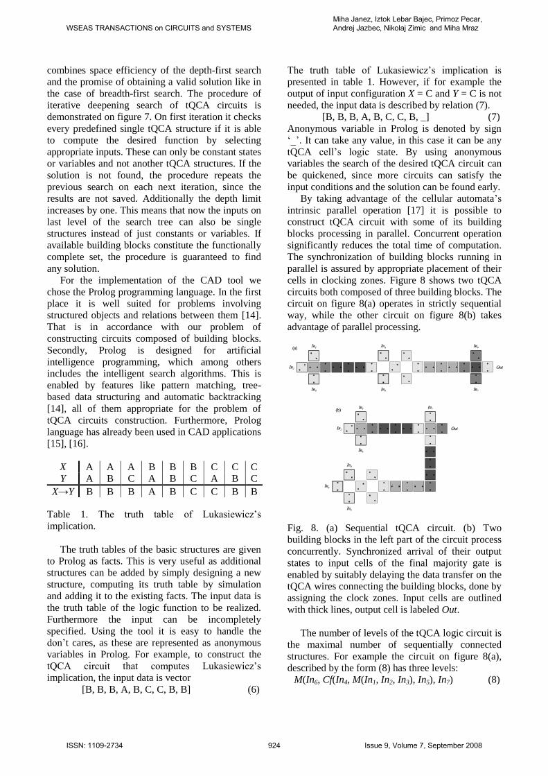
Fig. 8. (a) Sequential tQCA circuit. (b) Two
building blocks in the left part of the circuit process
concurrently. Synchronized arrival of their output
states to input cells of the final majority gate is
enabled by suitably delaying the data transfer on the
tQCA wires connecting the building blocks, done by
assigning the clock zones. Input cells are outlined
with thick lines, output cell is labeled Out.
The number of levels of the tQCA logic circuit is
the maximal number of sequentially connected
structures. For example the circuit on figure 8(a),
described by the form (8) has three levels:
M(In6, Cf(In4, M(In1, In2, In3), In5), In7) (8)
WSEAS TRANSACTIONS on CIRCUITS and SYSTEMSMiha Janez, Iztok Lebar Bajec, Primoz Pecar, Andrej Jazbec, Nikolaj Zimic and Miha Mraz
ISSN: 1109-2734 924 Issue 9, Volume 7, September 2008

On the other hand parallel circuit on figure 8(b) also
contains three building blocks, but they constitute
only two levels:
M(In7, M(In1, In2, In3), Cf(In4, In5, In6)) (9)
In above forms In1 to In7 indicate inputs, whereas M
and Cf are tQCA structures. By iterative deepening
the tool first finds circuits with the minimal number
of levels. From obtained solutions only the circuits
with minimal number of used structures and
clocking zones are chosen. More than one different
optimal circuit that computes the desired ternary
function can be found, depending on the selection of
building blocks.
The search algorithm is initiated by calling
method construct_tQCA_circuit(Function, Circuit,
Building_blocks). Variable names in Prolog start
with capital letter. Function is the truth table of
ternary logic function in vector form, Circuit is the
solution in form of the relation (1) and
Building_blocks is the list of building blocks that
will be used to construct the solution. By taking
advantage of Prolog’s features the method call
works in many ways. For example, the tQCA circuit
for computing ternary conjunction is found by
calling construct_tQCA_circuit([a, a, a, a, b, c, a, c,
c], Circuit, [m]). On the other way, the output
function of the circuit is found by instantiating the
Circuit variable, e.g. by calling the method
construct_tQCA_circuit([Function, m(a, x, y), [m]).
The circuit is checked against the function vector by
instantiating both Circuit and Function variables.
3.1 Reduction of the search space The search space is reduced by not considering
configurations that always output a constant, e.g.
M(A, A, Variable) that always outputs the vector
consisting of states A, independent of the value of
vector Variable. It is evidently more efficient to
assign the constant state to the input cell instead of
computing it by such function. Furthermore only
one of the configurations that have identical truth
tables is used, e.g. M(A, Variable1, Variable2) and
M(Variable1, Variable2, A) both compute the same
output, the ternary conjunction of variables
Variable1 and Variable2. The elimination of such
duplicated configurations is performed before the
search of solution space and it depends on the
selection of building blocks. The remaining
configurations constitute the base of search
algorithm. Computed base can be saved for further
calculation if it is often used.
The number of all possible configurations of the
tQCA majority gate with three inputs, considering
four constant states and three different variable
vectors, is 73=343. Using the described technique,
the number of appropriate configurations is reduced
to merely 25. Since the space of solutions is
expanding by multiplication of possible
configurations for every input of the structure on
higher level of the search tree, the reduction
technique considerably reduces the required search
time.
3.2 Interpretation of the tQCA cell’s states As mentioned before, we assigned the logic values
to the cell’s states as {A, B, C, D} = {0, 1, ½, ½}.
However, different interpretation could produce
faster and smaller tQCA circuits. Although the
interpretation cannot be changed from case to case,
it can be applied to the heuristic method for further
improvement of the search algorithm. The CAD tool
employs heuristics to speed up the calculations,
since it can be hard to find a complex circuit. To
enable different interpretation of the cells, the tool
defines as many variables as there are different
output states and represents the truth table using
them. In other words all of the input combinations
that result in the same output state use the same
variable. Figure 9 shows the procedure in case of
Lukasiewicz's equivalence function. State A is
mapped to variable XA, state B to XB and state C to
variable XC. Through backtracking Prolog
determines the values of variables that are mutually
exclusive. The states may be temporarily mapped to
different ternary logic values as initially, thus the
obtained solution is not the desired function. In this
case the tool maps the output states into the desired
states with the fast method that finds a function of
one variable, which correctly maps the intermediate
output states to the final and correct output states.
With this procedure the tool may not find an optimal
solution, but it finds a good solution fast.
Fig. 9. Mapping the constant output states into
corresponding states, represented as variables in
Prolog. Figure shows the mapping in case of
Lukasiewicz's equivalence function.
WSEAS TRANSACTIONS on CIRCUITS and SYSTEMSMiha Janez, Iztok Lebar Bajec, Primoz Pecar, Andrej Jazbec, Nikolaj Zimic and Miha Mraz
ISSN: 1109-2734 925 Issue 9, Volume 7, September 2008

3.3 Using previously obtained tQCA circuits Every constructed tQCA circuit can be used as the
building block of even more complex circuit. This is
done by computing its truth table and add it to
Prolog facts. In another way it can be inserted as
selected part of the desired solution. For example,
the search can be initiated by calling method
construct_tQCA_circuit([b, b, b, a, b, c, c, b, b],
m(cf(x, y, a), Input1, Input2), [m, cf]). The tool will
search for a circuit that computes Lukasiewicz’s
implication, with tQCA majority gate on the first
level and function Cf(X, Y, A) as its first input. The
other two inputs will be found to satisfy the
appointed conditions. By choosing convenient
predefined parts the solution is found faster.
In abovementioned example the search will
automatically start at second level, since the resulted
tQCA circuit must consist of at least two levels. The
search can begin at higher depth limit even without
predefining parts of a solution. This is useful when
searching for complex circuit which consists of
numerous levels. By this technique the algorithm
omits searching on lower levels thus reducing the
required time for obtaining the solution.
The scheme of the algorithm, omitting the
implementation details, is given below:
construct_tQCA_circuit(Function, Circuit,
Building_blocks):-
construct_base(Base, Building_blocks),
map_states(Function, Mapped_function,
Inverse_mapping),
Depth_limit=1, increase(Depth_limit),
iterate(Mapped_function, Intermediate_circuit,
Depth_limit),
Depth_limit=1, increase(Depth_limit),
iterate(Inverse_mapping, Mapping_circuit,
Depth_limit),
combine(Mapping_circuit, Intermediate_circuit,
Circuit).
First the base is constructed as described in section
3.1, afterwards the states are mapped as in section
3.2. Variable Depth_limit is the depth limit of
iterative deepening search algorithm illustrated on
figure 7. It increases on each iteration by Prolog’s
automatic backtracking. In the first place the
intermediate tQCA circuit is found, then the circuit
that correctly maps the states and finally they are
combined into solution. The search is performed by
the recursive method iterate, outlined below:
iterate(Function, Circuit, 1):-
member(Circuit, Base),
circuit_function(Function, Circuit).
iterate(Function, Circuit, Depth_limit):-
member(Circuit, Base),
iterate(Function1, Input1, Depth_limit-1 ),
iterate(Function2, Input2, Depth_limit-1 ), …,
combine(Function1, Function2, …, Function),
combine(Input1, Input1, …, Circuit).
The boundary condition is Depth_limit = 1, at that
time a structure with determined inputs is selected
from the Base and its output function is returned as
result. Otherwise the procedure is recursively
applied to every uninstantiated input. After the
inputs are instantiated, the procedure checks if the
combination of their functions agrees with the
original input function. If this is the case, the
constructed circuit is returned as valid result.
4 Results The disjunctive normal form of the ternary cyclic
negation, defined in the table 2, is quite lengthy:
X = (fA(X) ˅ C) ˄
(fB(X) ˅ A) ˄ (10)
(fC(X) ˅ B)
In equation (10) the symbol ˄ denotes ternary logic
conjunction, defined as the minimum of the input
logic values. The symbol ˅ denotes ternary
disjunction, defined as the maximum of the input
logic values. Input variable is labeled X and X is the
notation of the cyclic negation. The functions fA(X),
fB(X) and f
C(X) denote the characteristic functions
for states A (logic value 0), B (logic value 1) and C
(logic value ½) respectively. They are defined by
the relation
CB,A,
otherwise A;
if B;=)(f
Y
YXXY
(11)
Circuits for fA(X) and f
B(X) are given by equations
(12) and (13) respectively.
fA(X) = Cf(B, B, X) (12)
fB(X) = Cf(B, B, Inverter(X)) (13)
The tQCA circuit implementing function fC(X) is
slightly more complex:
fC(X) = Cf(Cf(A, X, B), A, Inverter(X)) (14)
X 0 ½ 1
Logic values of X ½ 1 0
Output cell states of X C B A
Table 2. Truth table of the ternary cyclic negation
function.
The straightforward realization of the ternary
cyclic negation by equation (10) is composed of
many structures sequentially connected in numerous
levels. However our tool finds an optimal solution
WSEAS TRANSACTIONS on CIRCUITS and SYSTEMSMiha Janez, Iztok Lebar Bajec, Primoz Pecar, Andrej Jazbec, Nikolaj Zimic and Miha Mraz
ISSN: 1109-2734 926 Issue 9, Volume 7, September 2008

composed of only three structures connected in two
levels as presented in figure 10. It can be written in
equation form as
fC(X) = Cf(X, Cf(B, C, X), Cf(B, B, X)) (15)
With implemented heuristic methods the CAD
tool is able to find even complex tQCA circuits for
implementation of ternary logic functions that do
not have a simple solution. One of these is
Lukasiewicz's equivalence, implemented by the
tQCA circuit described by complex form:
M2(B, M2(B, M2(A, X, Y), M2(A, Inverter(X),
Inverter(Y))), Cf(A, A, M2(B, M2(B, X, Y), Cf(X, A,
Y)))).
Fig. 10. The optimal implementation of the ternary
cyclic negation with tQCA structures. The output X
is computed after 5 clock phases.
5 Conclusion This article describes the methodology used to
design (sub)optimal tQCA logic circuit that
computes an arbitrary ternary logic function. The
solution is composed of predefined tQCA structures.
One criterion for optimality is the number of
interconnected structures, so that an optimal
realization of a function occupies the smallest
possible area. The second criterion is the number of
levels in which the structures are connected. Indeed
every level in the implementation increases the time
needed to compute an output of a function. The third
criterion, connected to the previous two, is the
number of clocking zones in the tQCA circuit.
Obviously the fastest and therefore optimal circuit
computes the result after the minimal number of
clock cycles.
We present the CAD tool that is designed to find
the implementation of the ternary logic function
given as its input. The application, developed in
programming language Prolog, searches for a
solution based on the concept of iterative deepening.
Since the circuit design is computationally complex,
heuristic methods are used to expedite calculations
[18]. In this way the tool may find a suboptimal
solution but the computation time is greatly reduced.
With the developed tool we designed complex
tQCA circuits that were validated by quantum-
mechanical simulation. The benchmarking is not
simple since the design of tQCA circuit is a novel
domain and comparable models do not exist. The
circuits obtained by using the CAD tool are much
smaller and faster than those developed analytically
based on the normal form. Most resembling domain
is construction of binary QCA circuits.
One of the applications of tQCA circuits is
development of fuzzy controller [19] using multi-
valued logic [20]. If the tQCA cell can be further
extended to represent more logic states, render it
useful for fuzzy logic operations, the tool can be
easily modified to design circuits using the
improved QCA cell.
The work presented in this paper was performed at
the Computer Structures and Systems Laboratory,
Faculty of Computer and Information Science,
University of Ljubljana, Slovenia and is part of a
PhD thesis being prepared by Miha Janez.
References:
[1] C. S. Lent, P. D. Tougaw, W. Porod and G. H.
Bernstein, Quantum cellular automata,
Nanotechnology, Vol. 4, No. 1, 1993, pp. 49-
57.
[2] I. Lebar Bajec, N. Zimic and M. Mraz, The
ternary quantum-dot cell and ternary logic,
Nanotechnology, Vol. 17, No. 8, 2006, pp.
1937-1942.
[3] I. Lebar Bajec, N. Zimic and M. Mraz,
Towards the bottom-up concept: Extended
quantum-dot cellular automata,
Microelectronic Engineering, Vol. 83, No. 4-9,
2006, pp. 1826-1829.
[4] B. Hayes, Third Base, American Scientist, Vol.
89, No. 6, 2001, pp. 490-494.
[5] D. E. Knuth, The Art of Computer
Programming, Volume 2: Seminumerical
Algorithms (2nd edition), Addison-Wesley Pub,
1981.
[6] J. Lukasiewicz and L. Borkowski, Selected
Works, North-Holland Publishing Company,
1970.
[7] J. C. Lusth and B. Dixon, A characterization of
important algorithms for quantum-dot cellular
automata, Information Sciences, Vol. 113, No.
3, 1999, pp. 193-204.
WSEAS TRANSACTIONS on CIRCUITS and SYSTEMSMiha Janez, Iztok Lebar Bajec, Primoz Pecar, Andrej Jazbec, Nikolaj Zimic and Miha Mraz
ISSN: 1109-2734 927 Issue 9, Volume 7, September 2008

[8] C. S. Lent and P. D. Tougaw, A device
architecture for computing with quantum dots,
Proceedings of the IEEE, Vol. 85, No. 4, 1997,
pp. 541-557.
[9] P. Pecar, M. Mraz, N. Zimic, M. Janez and I.
Lebar Bajec, Solving the Ternary Quantum-dot
Cellular Automata Logic Gate Problem by
Means of Adiabatic Switching, Japanese
Journal of Applied Physics, Vol. 47, No. 6B,
2008, pp. 5000-5006.
[10] I. Amlani, A. O. Orlov, G. Toth, G. H.
Bernstein, C. S. Lent and G. L. Snider, Digital
Logic Gate Using Quantum-Dot Cellular
Automata, Science, Vol. 284, No. 5412, 1999,
pp. 289-291.
[11] P. D. Tougaw and C. S. Lent, Logical devices
implemented using quantum cellular automata,
Journal of Applied Physics, Vol. 75, No. 3,
1994, pp. 1818-1825.
[12] J. Kluabwang, D. Puangdownreong and S.
Sujitjorn, Management Agent for Search
Algorithms with Surface Optimization
Applications, WSEAS Transactions on
Computers, Vol. 7, No. 6, 2008, pp. 791-803.
[13] R. E. Korf, Depth-first iterative-deepening: an
optimal admissible tree search, Artificial
Intelligence, Vol. 27, No. 1, pp. 97-109.
[14] I. Bratko, Prolog programming for artificial
intelligence (Third edition), Addison-Wesley
Longman Publishing Company, 2001.
[15] P. W. Horstmann and E. P. Stabler, Computer
aided design (CAD) using logic programming,
Proceedings of the 21st conference on Design
automation, 1984, pp. 144-151.
[16] J. C. Gonzalez, M. H. Williams and I. E.
Aitchison, Evaluation of the Effectiveness of
Prolog for a CAD Application, IEEE Computer
Graphics and Applications, Vol. 4, No. 3,
1984, pp. 67-75.
[17] S. Wolfram, Cellular automata, Los Alamos
Science, No.9, 1983, pp. 2-21.
[18] L. Jozwiak, D. Gawlowski and A. Slusarczyk,
Benchmarking in Digital Circuit Design
Automation, WSEAS Transactions on Circuits
and Systems, Vol. 7, No. 4, 2008, pp. 287-310.
[19] M. Mraz, Z. Magdevski, J. Ficzko, N. Zimic,
M. Moskon, M, Janez and I. Lebar Bajec,
Towards multistate nanocomputing: The
implementation of a primitive fuzzy controller,
Proceedings of the Second International
Conference on Quantum, Nano and Micro
Technologies (ICQNM 2008), Vol. 00, 2008,
pp. 45-49.
[20] V. Varshavsky, V. Marakhovsky, I. Levin and
N. Kravchenko, Summing Amplifier as a
Multi-Valued Logical Element For Fuzzy
Control, WSEAS Transactions on Circuits and
Systems, Vol. 2, No. 3, 2003, pp. 625-631.
WSEAS TRANSACTIONS on CIRCUITS and SYSTEMSMiha Janez, Iztok Lebar Bajec, Primoz Pecar, Andrej Jazbec, Nikolaj Zimic and Miha Mraz
ISSN: 1109-2734 928 Issue 9, Volume 7, September 2008