Embed Size (px)
Citation preview
Architecting Microsoft® .NET Solutions for the Enterprise
1
Content
1. Cover ........................................................................................................................ 3 2. Copyright ................................................................................................................. 3
3. Acknowledgments ................................................................................................... 5 4. Introduction ............................................................................................................. 8 5. Part I: Principles ..................................................................................................... 12
5.1 Chapter 1. Architects and Architecture Today .............................................. 12 5.1.1 What's a Software Architecture, Anyway? ......................................... 14
5.1.2 Who's the Architect, Anyway? ............................................................ 27 5.1.3 Overview of the Software Development Process ............................... 33 5.1.4 Summary ............................................................................................. 40
5.1.5 Murphy's Laws of the Chapter ............................................................ 40
5.2 Chapter 2. UML Essentials ............................................................................ 41 5.2.1 UML at a Glance .................................................................................. 42
5.2.2 UML Diagrams ..................................................................................... 52 5.2.3 Summary ............................................................................................. 74
5.2.4 Murphy's Laws of the Chapter ............................................................ 74
5.3 Chapter 3. Design Principles and Patterns ................................................... 75 5.3.1 Basic Design Principles ........................................................................ 76
5.3.2 Object-Oriented Design ...................................................................... 86
5.3.3 From Principles to Patterns ............................................................... 100
5.3.4 Applying Requirements by Design .................................................... 114
5.3.5 From Objects to Aspects ................................................................... 134 5.3.6 Summary ........................................................................................... 144
5.3.7 Murphy's Laws of the Chapter .......................................................... 145
6. Part II: Design of the System ............................................................................... 145
6.1 Chapter 4. The Business Layer .................................................................... 145 6.1.1 What's the Business Logic Layer, Anyway? ....................................... 146
6.1.2 The Transaction Script Pattern .......................................................... 162 6.1.3 The Table Module Pattern ................................................................ 172
6.1.4 The Active Record Pattern ................................................................ 185 6.1.5 The Domain Model Pattern .............................................................. 198 6.1.6 Summary ........................................................................................... 215
6.1.7 Murphy's Laws of the Chapter .......................................................... 216 6.2 Chapter 5. The Service Layer ...................................................................... 216
6.2.1 What's the Service Layer, Anyway?................................................... 218
6.2.2 The Service Layer Pattern in Action .................................................. 231 6.2.3 Related Patterns ................................................................................ 240 6.2.4 Service-Oriented Architecture .......................................................... 259
6.2.5 The Very Special Case of Rich Web Front Ends ................................. 267 6.2.6 Summary ........................................................................................... 281 6.2.7 Murphy's Laws of the Chapter .......................................................... 282
6.3 Chapter 6. The Data Access Layer ............................................................... 282
Architecting Microsoft® .NET Solutions for the Enterprise
2
6.3.1 What's the Data Access Layer, Anyway? ........................................... 283
6.3.2 Designing Your Own Data Access Layer ............................................ 295
6.3.3 Crafting Your Own Data Access Layer ............................................... 318 6.3.4 Power to the DAL with an O/RM Tool ............................................... 371 6.3.5 To SP or Not to SP ............................................................................. 385
6.3.6 Summary ........................................................................................... 392 6.3.7 Murphy's Laws of the Chapter .......................................................... 393
6.4 Chapter 7. The Presentation Layer ............................................................. 394 6.4.1 User Interface and Presentation Logic .............................................. 395 6.4.2 Evolution of the Presentation Patterns ............................................. 404
6.4.3 Design of the Presentation ............................................................... 430 6.4.4 Idiomatic Presentation Design .......................................................... 450
6.4.5 Summary ........................................................................................... 460
6.4.6 Murphy's Laws of the Chapter .......................................................... 461
7. Final Thoughts ..................................................................................................... 462 7.1 Mantra #1-It Depends................................................................................. 462
7.2 Mantra #2-Requirements Are Lord Over All ............................................... 463
7.3 Mantra #3-Program to an Interface ............................................................ 463
7.4 Mantra #4-Keep It Simple but Not Simplistic ............................................. 463
7.5 Mantra #5-Inheritance Is About Polymorphism, Not Reuse ...................... 463
7.6 Mantra #6-Not the DAL? Don't Touch SQL Then ........................................ 463 7.7 Mantra #7-Maintainability First .................................................................. 464
7.8 Mantra #8-All User Input Is Evil .................................................................. 464
7.9 Mantra #9-Post-Mortem Optimization ....................................................... 464
7.10 Mantra #10-Security and Testability Are by Design ................................. 464
8. The Northwind Starter Kit ................................................................................... 464
8.1 Motivation for Creating NSK ....................................................................... 465
8.2 What's in NSK? ............................................................................................ 466 8.3 Future Evolution of NSK .............................................................................. 471
9. About the Authors ............................................................................................... 472 9.1 Dino Esposito .............................................................................................. 472 9.2 Andrea Saltarello ........................................................................................ 473
10. Additional Resources for Developers from Microsoft Press ............................. 473 10.1 Visual Basic ............................................................................................... 474
10.2 Visual C# ................................................................................................... 474 10.3 Web Development .................................................................................... 475 10.4 Data Access ............................................................................................... 475
10.5 .NET Framework ....................................................................................... 476
10.6 Other Developer Topics ............................................................................ 476 11. More Great Developer Resources ..................................................................... 477
11.1 Developer Step by Step ............................................................................ 477 11.2 Developer Reference ................................................................................ 479 11.3 Focused Topics .......................................................................................... 481
12. Index ....................................................................... Error! Bookmark not defined.
Architecting Microsoft® .NET Solutions for the Enterprise
3
1. Cover
Architecting Microsoft .NET Solutions for the Enterprise
by Dino Esposito; Andrea Saltarello
Publisher: Microsoft Press
Pub Date: October 15, 2008
Print ISBN-10: 0-7356-2609-X
Print ISBN-13: 978-0-7356-2609-6
Pages: 304
Overview
To deliver the right solutions for increasingly complex enterprise and user requirements, you need
vision. You need guidance. You need to apply the patterns and practices that by design create
explicit outcomes for often-implicit challenges. In this book, you ll take a structured, realistic
approach to resolving software complexity that places architectural integrity at its core. The authors
share their extensive, real-world experience with enterprise and service-oriented development to
illuminate the patterns, principles, and techniques for producing more-effective solutions, including
the modeling techniques that ensure your architecture fully and explicitly addresses user
requirements. They deftly cover essential concepts (UML, design patterns), the core system
(business, services, data access, and presentation layers), and specific tools, including
Microsoft .NET Framework and Microsoft Visual Studio(r) and they provide code samples and
expert insights you can apply right away to your own .NET-based enterprise solutions.
2. Copyright
PUBLISHED BY
Microsoft Press
A Division of Microsoft Corporation
One Microsoft Way
Redmond, Washington 98052-6399
Copyright ? 2009 by Andrea Saltarello and Dino Esposito
All rights reserved. No part of the contents of this book may be reproduced or transmitted in any
form or by any means without the written permission of the publisher.
Library of Congress Control Number: 2008935425
Printed and bound in the United States of America.
Architecting Microsoft® .NET Solutions for the Enterprise
4
1 2 3 4 5 6 7 8 9 QWT 3 2 1 0 9 8
Distributed in Canada by H.B. Fenn and Company Ltd.
A CIP catalogue record for this book is available from the British Library.
Microsoft Press books are available through booksellers and distributors worldwide. For further
information about international editions, contact your local Microsoft Corporation office or contact
Microsoft Press International directly at fax (425) 936-7329. Visit our Web site at
www.microsoft.com/mspress. Send comments to [email protected].
Microsoft, Microsoft Press, Access, ActiveX, IntelliSense, MS, MSDN, MS-DOS, PowerPoint,
Silverlight, SQL Server, Visio, Visual Basic, Visual C#, Visual Studio, Windows, and Windows
Vista are either registered trademarks or trademarks of the Microsoft group of companies. Other
product and company names mentioned herein may be the trademarks of their respective owners.
The example companies, organizations, products, domain names, e-mail addresses, logos, people,
places, and events depicted herein are fictitious. No association with any real company, organization,
product, domain name, e-mail address, logo, person, place, or event is intended or should be
inferred.
This book expresses the author's views and opinions. The information contained in this book is
provided without any express, statutory, or implied warranties. Neither the authors, Microsoft
Corporation, nor its resellers, or distributors will be held liable for any damages caused or alleged to
be caused either directly or indirectly by this book.
Acquisitions Editor: Ben Ryan
Project Editor: Lynn Finnel
Editorial Production: S4Carlisle Publishing Services
Technical Reviewer: Kenn Scribner; Technical Review services provided by Content Master, a me
mber of CM Group, Ltd.
Cover: Tom Draper Design
Body Part No. X15-12272
Dedication
To Silvia, Francesco, and Michela who wait for me and keep me busy. But I'm happy only when I'm
busy.
¡ªDino
To Mum and Depeche Mode.
¡ªAndrea
Architecting Microsoft® .NET Solutions for the Enterprise
5
"Any sufficiently advanced technology is indistinguishable from magic."
¡ªArthur C. Clarke
3. Acknowledgments
For at least two years, Andrea didn't miss any opportunity to remind Dino about the importance of
a .NET-focused architecture book covering the horizontal slice of a multitier enterprise system. And
for two years Dino strung Andrea along with generic promises, but absolutely no commitment. Then,
suddenly, he saw the light. During a routine chat over Messenger, we found out that we repeatedly
made similar statements about architecture¡ªtoo many to mark it down as a simple coincidence. So
we started thinking, and this time seriously, about this book project. But we needed a team of people
to do it right, and they were very good people, indeed.
Ben Ryan was sneakily convinced to support the project on a colorful Las Vegas night, during an
ethnic dinner at which we watched waiters coming up from and going down to the wine-cellar in
transparent elevators.
Lynn Finnel just didn't want to let Dino walk alone in this key project after brilliantly coordinating
at least five book projects in the past.
Kenn Scribner is now Dino's official book alter ego. Kenn started working with Dino on books back
in 1998 in the age of COM and the Active Template Library. How is it possible that a book with
Dino's name on the cover isn't reviewed and inspired (and fixed) by Kenn's unique and broad
perspective on the world of software? The extent to which Kenn can be helpful is just beyond
human imagination.
Roger LeBlanc joined the team to make sure that all these geeks sitting together at the same virtual
desktop could still communicate using true English syntax and semantics.
We owe you all the (non-rhetorically) monumental "Thank you" for being so kind, patient, and
accurate.
Only two authors and a small team for such a great book? Well, not exactly. Along the project
lifetime, we had the pleasure to welcome aboard a good ensemble of people who helped out in some
way. And we want to spend a word or two about each of them here.
Raffaele Rialdi suggested and reviewed our section in Chapter 3 about design for security. Roy
Osherove was nice enough to share his enormous experience with testing and testing tools. Marco
Abis of ThoughtWorks had only nice words for the project and encouraged us to make it happen.
Alex Homer of Microsoft helped with Unity and Enterprise Library. And the whole team at
Managed Design (our Italian company) contributed tips and ideas¡ªspecial thanks go to Roberto
Messora.
Architecting Microsoft® .NET Solutions for the Enterprise
6
It's really been a pleasure!
¡ªAndrea and Dino
Dino's Credits
This is the first book I have co-authored in 8 or 9 years. I think the last was a multi-author book on
data access involving COM and OLE DB. In the past, co-authoring a book for me meant accepting
to write a few chapters on specific topics, while having only a faint idea of what was coming before
and after my chapters.
This book is different.
This book has really been written by a virtual author: a human with the hands of Dino and the
experience of Andrea. I actually did most of the writing, but Andrea literally put concepts and ideas
into my keyboard. If it were a song, it would be described as lyrics by Dino and music by Andrea.
This book wouldn't exist, or it wouldn't be nearly as valuable, without Andrea. Andrea has been my
personal Google for a few months¡ªthe engine to search when I need to understand certain principles
and design issues. The nicest part of the story is that I almost always asked about things I (thought I)
knew enough about. My "enough" was probably really enough to be a very good architect in real life.
But Andrea gave me a new and broader perspective on virtually everything we covered in the
book¡ªISO standards, UML, design principles, patterns, the user interface, business logic, services,
and persistence. I've been the first hungry reader of this book. And I've been the first to learn a lot.
It was so fun that I spent the whole summer on it. And in Italy, the summer is a serious matter. I
smile when I get some proposals for consulting or training in mid-August. There's no way I can
even vaguely hint to my wife about accepting them.
So, on many days, I reached 7 p.m. so cloudy minded that running, running, and running¡ªwhich
was more soothing than my favorite pastime of trying to catch up to and hit a bouncing tennis
ball¡ªwas the only way to recover a decent state of mind. On other days, my friends at Tennis Club
Monterotondo helped a lot by just throwing at me tons of forehands and passing shots. One of them,
Fabrizio¡ªa guy who played Boris Becker and Stefan Edberg and who now wastes his time with my
hopeless backhand slice¡ªhas been my instructor for a while. He also tried to learn some basic
Architecting Microsoft® .NET Solutions for the Enterprise
7
concepts of Web programming during what often became long conversations while changing ends
of the court. But just as I keep on twirling the wrist during the execution of a backhand slice, he still
keeps on missing the whole point of HTTP cookies.
My friend Antonio deserves a very special mention for organizing a wonderful and regenerative
vacation in the deep blue sea of Sardinia, and for being kind enough to lose all the matches we
played. It was just the right medicine to rejuvenate a fatigued spirit after a tough book project. He
tried to initiate me into the sport of diving, too, but all I could do was snorkel while the kids got
their Scuba Diver certification.
My kids, Francesco and Michela, grow taller with every book I write, and not because they just hop
on the entire pile of dad's books. They're now 10 and 7, and Michela was just a newborn baby when
I started working on my first .NET book for Microsoft Press. I really feel a strong emotion when
attendees of conferences worldwide come by and ask about my kids¡ªloyal readers of my books
have been seeing their pictures for years now.
For me, this book is not like most of the others that I have written¡ªand I do write about one book
per year. This book marks a watershed, both personal and professional. I never expressed its
importance in this way with Silvia, but she understood it anyway and supported me silently and
effectively. And lovingly. And with great food, indeed!
Life is good.
¡ªDino
Andrea's Credits
This is my first book. More precisely, this is my first serious publication. The seeds for this book
were sowed in November 2004 when a rockstar like Dino approached me and proposed that we
work together.
We started a successful business partnership, and we delivered a number of classes and some
articles¡ªincluding one for MSDN Magazine¡ªand took a number of industry projects home to ensure
our customers were happy.
In all these years, Dino impressed me especially with his unique ability of going straight to the point,
and being a terrifically quick learner of the fundamentals of any topics we touched on. More, he also
showed an unparalleled ability to express any concept precisely and concisely. Countless times
during this book project, I found my own wording hard to read, nebulous, and even cryptic. A few
days later, instead, massaged by Dino, the same text looked to me magically fluent and perfectly
understandable¡ªjust like any technical text should always be.
(OK, I admit. Sometimes I thought "I hate this man," but it was an unusual and unconfessed way to
look up to Dino with admiration.)
Architecting Microsoft® .NET Solutions for the Enterprise
8
More than everything else, what initially was a simple although successful professional
collaboration turned into friendship. This book, therefore, is not a finish line. It is, instead, the
starting point of a common path. I really don't know either where we're going or how long it will
take, but I'm going to be happy to take the walk.
Being a full-time consultant, it was very hard for me to set aside the time needed for writing this
book. So I had to start living a double life, resorting to writing in what you would define as "spare
time": evenings and weekends, and suddenly the summer also became standard working time. Every
now and then, it has been a little frustrating, but I found new strength and inspiration due to the love
and support I was blessed with by my guardian angels: my mom and Laura. I'd like to say to them
that words cannot express how precious your caring is. I love you.
Now, this is fun.
¡ªAndrea
4. Introduction
Good judgment comes from experience, and experience comes from bad judgment.
¡ªFred Brooks
Every time we are engaged on a software project, we create a solution. We call the process
architecting, and the resulting concrete artifact is the architecture. Architecture can be implicit or
explicit.
An implicit architecture is the design of the solution we create mentally and persist on a bunch of
Microsoft Office Word documents, when not on handwritten notes. An implicit architecture is the
fruit of hands-on experience, the reuse of tricks learned while working on similar projects, and an
inherent ability to form abstract concepts and factor them into the project at hand. If you're an expert
artisan, you don't need complex drawings and measurements to build a fence or a bed for your dog;
you can implicitly architect it in a few moments. You just proceed and easily make the correct
decision at each crossroad. When you come to an end, it's fine. All's well that ends well.
An explicit architecture is necessary when the stakeholder concerns are too complex and
sophisticated to be handled based only on experience and mental processes. In this case, you need
vision, you need guidance, and you need to apply patterns and practices that, by design, take you
where you need to be.
What Is Architecture?
The word architecture has widespread use in a variety of contexts. You can get a definition for it
from the Oxford English Dictionary or, as far as software is concerned, from the American National
Standards Institute/Institute of Electrical and Electronics Engineers (ANSI/IEEE) library of
Architecting Microsoft® .NET Solutions for the Enterprise
9
standards. In both cases, the definition of architecture revolves around planning, designing, and
constructing something¡ªbe it a building or a software program. Software architecture is the concrete
artifact that solves specific stakeholder concerns¡ªread, specific user requirements.
An architecture doesn't exist outside of a context. To design a software system, you need to
understand how the final system relates to, and is embedded into, the hosting environment. As a
software architect, you can't ignore technologies and development techniques for the environment of
choice¡ªfor this book, the .NET platform.
Again, what is architecture?
We like to summarize it as the art of making hard-to-change decisions correctly. The architecture is
the skeleton of a system, the set of pillars that sustain the whole construction. The architect is
responsible for the architecture. The architect's job is multifaceted. She has to acknowledge
requirements, design the system, ensure the implementation matches the expectation, and overall
ensure that users get what they really need¡ªwhich is not necessarily what they initially accept and
pay for.
Software architecture has some preconditions¡ªthat is, design principles¡ªand one post condition¡ªan
implemented system that produces expected results. Subsequently, this book is divided into two
parts: principles and the design of the system.
The first part focuses on the role of the architect: what he does, who he interacts with and who he
reports to. The architect is primarily responsible for acknowledging the requirements, designing the
system, and communicating that design to the development team. The communication often is based
on Unified Modeling Language (UML) sketches; less often, it's based on UML blueprints. The
architect applies general software engineering principles first, and object-oriented design principles
later, to break down the system into smaller and smaller pieces in an attempt to separate what is
architecture (points that are hard to change) and what is not. One of the purposes of object-oriented
design is to make your code easy to maintain and evolve¡ªand easy to read and understand. The
architect knows that maintainability, security, and testability need to be built into the system right
from the beginning, and so he does that.
The second part of the book focuses on the layers that form a typical enterprise system¡ªthe
presentation layer, business layer, and data access layer. The book discusses design patterns for the
various layers¡ªincluding Domain Model, Model-View-Presenter, and Service Layer¡ªand arguments
about the evolution of technologies and summaries of the new wave of tools that have become a
common presence in software projects¡ªO/R mappers and dependency injection containers.
So, in the end, what's this book about?
It's about the things you need to do and know to serve your customers in the best possible way as far
as the .NET platform is concerned. Patterns, principles, and techniques described in the book are
valid in general and are not specific to particularly complex line-of-business applications. A good
software architecture helps in controlling the complexity of the project. And controlling the
Architecting Microsoft® .NET Solutions for the Enterprise
10
complexity and favoring maintainability are the sharpest tools we have to fight the canonical
Murphy's Law of technology: "Nothing ever gets built on schedule or within budget."
The expert is the one who knows how to handle complexity, not the one who simply predicts the job
will take the longest and cost the most¡ªjust to paraphrase yet another popular Murphy's Law.
Who This Book Is For
In the previous section, we repeatedly mentioned architects. So are software architects the ideal
target audience for this book? Architects and lead developers in particular are the target audience,
but any developers of any type of .NET applications likely will find this book beneficial. Everyone
who wants to be an architect may find this book helpful and worth the cost.
What about prerequisites?
Strong object-oriented programming skills are a requirement, as well as having a good foundation of
knowledge of the .NET platform and data access techniques. We point out a lot of design patterns,
but we explain all of them in detail in nonacademic language with no weird formalisms. Finally, we
put in a lot of effort into making this book read well. It's not a book about abstract design concepts;
it is not a classic architecture book either, full of cross-references and fancy strings in square
brackets that hyperlink to some old paper listed in the bibliography available at the end of the book.
This is (hopefully) a book you'll want to read from cover to cover, and maybe more than once¡ªnot a
book to keep stored on a shelf for future reference. We don't expect readers to pick up this book at
crunch time to find out how to use a given pattern. Instead, our ultimate goal is transferring some
valuable knowledge that enables you to know what to do at any point. In a certain way, we would
happy if, thanks to this book, you could do more implicit architecture design on your own.
Companion Content
In the book, we present several code snippets and discuss sample applications, but with the primary
purpose of illustrating principles and techniques for readers to apply in their own projects. In a
certain way, we tried to teach fishing, but we don't provide some sample fish to take home. However,
there's a CodePlex project that we want to point out to you. You find it at
http://www.codeplex.com/nsk.
This book also features a companion Web site where you can also find the CodePlex project. You
can download it from the companion site at this address:
http://www.microsoft.com/mspress/companion/9780735626096.
The Northwind Starter Kit (NSK) is a set of Microsoft Visual Studio 2008 projects that form a
multitier .NET-based system. Produced by Managed Design (http://www.manageddesign.it), NSK is
a reference application that illustrates most of the principles and patterns we discuss in the book.
Many of the code snippets in the book come directly from some of the projects in the NSK solution.
If you're engaged in the design and implementation of a .NET layered application, NSK can serve as
a sort of blueprint for the architecture.
Architecting Microsoft® .NET Solutions for the Enterprise
11
Refer to the Managed Design Web site for the latest builds and full source code. For an overview of
the reference application, have a look at the Appendix, "The Northwind Starter Kit," in this book.
Hardware and Software Requirements
You'll need the following hardware and software to work with the companion content included with
this book:
Microsoft Windows Vista Home Premium Edition, Windows Vista Business Edition, or
Windows Vista Ultimate Edition
Microsoft Visual Studio 2008 Standard Edition, Visual Studio 2008 Enterprise Edition, or
Microsoft Visual C# 2008 Express Edition and Microsoft Visual Web Developer 2008
Express Edition
Microsoft SQL Server 2005 Express Edition, Service Pack 2
The Northwind database of Microsoft SQL Server 2000 is used by the Northwind Starter
Kit to demonstrate data-access techniques. You can obtain the Northwind database from the
Microsoft Download Center
(http://www.microsoft.com/downloads/details.aspx?FamilyID=).
1.6 GHz Pentium III+ processor, or faster
1 GB of available, physical RAM.
Video (800 by 600 or higher resolution) monitor with at least 256 colors.
CD-ROM or DVD-ROM drive.
Microsoft mouse or compatible pointing device
Find Additional Content Online
As new or updated material becomes available that complements this book, it will be posted online
on the Microsoft Press Online Developer Tools Web site. The type of material you might find
includes updates to book content, articles, links to companion content, errata, sample chapters, and
more. This Web site is available at www.microsoft.com/learning/books/online/developer and is
updated periodically.
Support for This Book
Every effort has been made to ensure the accuracy of this book and the contents of the companion
CD. As corrections or changes are collected, they will be added to a Microsoft Knowledge Base
article.
Microsoft Press provides support for books and companion CDs at the following Web site:
http://www.microsoft.com/learning/support/books
Questions and Comments
Architecting Microsoft® .NET Solutions for the Enterprise
12
If you have comments, questions, or ideas regarding the book or the companion content, or
questions that are not answered by visiting the sites above, please send them to Microsoft Press via
e-mail to
Or via postal mail to
Microsoft Press
Attn: Microsoft .NET: Architecting Applications for the Enterprise Editor
One Microsoft Way
Redmond, WA 98052-6399
Please note that Microsoft software product support is not offered through the above addresses.
5. Part I: Principles
You know you've achieved perfection in design, not when you have nothing more to add, but when
you have nothing more to take away.
¡ªAntoine de Saint-Exupery, "Wind, Sand and Stars"
In this part:
Chapter 1: Architects and Architecture Today
Chapter 2: UML Essentials
Chapter 3: Design Principles and Patterns
5.1 Chapter 1. Architects and Architecture Today
The purpose of software engineering is to control complexity, not to create it.
¡ªDr. Pamela Zave
At the beginning of the computing age, in the early 1960s, the costs of hardware were largely
predominant over the costs of software. Some 40 years later, we find the situation to be radically
different.
Hardware costs have fallen dramatically because of the progress made by the industry. Software
development costs, on the other hand, have risen considerably, mostly because of the increasing
Architecting Microsoft® .NET Solutions for the Enterprise
13
complexity of custom enterprise software development. Cheaper computers made it worthwhile for
companies to add more and more features to their information systems. What in the beginning was a
collection of standalone applications with no connection to one another that barely shared a database
has grown over years into a complex system made of interconnected functions and modules, each
with a particular set of responsibilities.
This situation has created the need for a set of precepts to guide engineers in the design of such
systems. The modern software system¡ªor the software-intensive system, as it is referred to in
international standards papers¡ªcan be compared quite naturally to any construction resulting from a
set of detailed blueprints.
Appropriated from the construction industry, the term architecture has become the appropriate way
to describe the art of planning, designing, and implementing software-intensive systems. In software,
though, architecture needs less artistry than in building. Well-designed buildings are pleasing to the
eye and functional. Software architecture is less subjective. It either functions as required or it does
not. There is less room for artistry and interpretation, unless you want to consider the artistry of a
well-crafted algorithm or a piece of user interface.
One of this book's authors had, in the past, frequent interaction with an architecture studio. One day,
a question popped up for discussion: What's architecture? Is it an art? Or is it just building for a
client?
In software, the term architecture precisely refers to building a system for a client.
In this first chapter, we'll look at some papers from the International Organization for
Standardization (ISO), the International Electrotechnical Commission (IEC), and the Institute of
Electrical and Electronics Engineers (IEEE) that provide an architectural description of
software-intensive systems. From there, we'll give our own interpretation of software architecture
and voice our opinions about the role and responsibilities of software architects.
Note
While some definitions you find in this book come from ISO standards, others
reflect our personal opinions, experiences, and feelings. Although the reader
might not agree with all of our personal reflections, we all should agree that
software systems that lack strong architectural design and support are nearly
guaranteed to fail. So having good architects on the team is a necessity. What's
a "good" architect? It is one who is experienced, educated, and qualified.
Modern systems need more engineering and understanding, and less artistry
and subjective guesswork. This is the direction we need to move toward as
good software architects.
Architecting Microsoft® .NET Solutions for the Enterprise
14
5.1.1 What's a Software Architecture, Anyway?
Herman Melville, the unforgettable author of Moby Dick, once said that men think that by mouthing
hard words they can understand hard things. In software, the "hard" word architecture was
originally introduced into the field to simplify the transmission and understanding of a key and
"hard" guideline. The guideline was this: Care (much) more about the design of software systems
than you have in the past; care about it to the point of guiding the development of a software system
similar to guiding the development of a building.
It's a hard thing to do and probably beyond many developers' capabilities. But let's give it a try. Let's
try to clarify what a "software architecture" is or, at least, what we intend it to be.
Applying Architectural Principles to Software
The word "architecture" is indissolubly bound to the world of construction. It was first used in the
software industry to express the need to plan and design before building computer programs.
However, a fundamental difference exists between designing and building habitable structures and
designing and building usable software systems.
Intuitively, we care if the building falls on people. But software? There is always plenty of money to
rewrite things, right? In construction, the design must be completed entirely up front and based on
extremely detailed calculations and blueprints. In software, you tend to be more agile. A few
decades ago, the up-front design methodology was common and popular in software, too. But, over
the years, that approach increased development costs. And because software can be efficiently (and
safely) tested before deployment, agility got the upper hand over up-front design.
Today the architectural parallelism between construction and software is not as close as it was a few
years ago. However, many dictionaries currently list a software-related definition of the term
"architecture." And a software architecture is described as "the composition, integration, and
interaction of components within a computer system." It is certainly a definition that everybody
would agree on. But, in our opinion, it is rather abstract.
We think that software professionals should agree on a more detailed explanation that breaks down
that definition into smaller pieces and puts them into context.
Defining the Architecture from a Standard Viewpoint
Many seem to forget that a standard definition for software architecture exists. More precisely, it is
in ANSI/IEEE standard 1471, "Recommended Practice for Architectural Description of
Software-intensive Systems." The document was originally developed by IEEE and approved as a
recommended practice in September 2000.
The document focuses on practices to describe the architecture of software-intensive systems. Using
the definition in the standard, a software-intensive system is any system in which software is
essential to implementation and deployment.
Architecting Microsoft® .NET Solutions for the Enterprise
15
Stakeholders are defined as all parties interested or concerned about the building of the system. The
list includes the builders of the system (architects, developers, testers) as well as the acquirer, end
users, analysts, auditors, and chief information officers (CIOs).
In 2007, the ANSI/IEEE document was also recognized as a standard through ISO/IEC document
42010. Those interested in reading the full standard can navigate their browser to the following
URL: http://www.iso.org/iso/iso_catalogue/catalogue_tc/catalogue_detail.htm?csnumber=.
Examining Key Architecture-Related Points in ANSI/IEEE 1471
The key takeaway from the ANSI/IEEE standard for software architecture is that a software system
exists to meet the expectations of its stakeholders. Expectations are expressed as functional and
nonfunctional requirements. Processed by the architect, requirements are then communicated to the
development team and finally implemented. All the steps occur and exist to ensure the quality of the
software. Skipping any step introduces the possibility for less software quality and the potential to
not meet the stakeholders' expectations.
To design a software system that achieves its goals, you need to devise it using an architectural
metaphor. Accepting an architectural metaphor means that you recognize the principle that some
important decisions regarding the system might be made quite early in the development process; just
like key decisions are made very early in the development of civil architecture projects. For example,
you wouldn't build a skyscraper when a bridge was required. Similarly, requirements might steer
you to a Web-oriented architecture rather than a desktop application. Decisions this major must be
made very early.
A software architecture, therefore, is concerned with the organization of a system and lays out the
foundations of the system. The system, then, has to be designed¡ªwhich entails making some hard
decisions up front¡ªand described¡ªwhich entails providing multiple views of the system, with each
view covering a given set of system responsibilities.
Defining the System from a Standard Viewpoint
As mentioned, a software system is universally understood to be a collection of components
composed and integrated to accomplish a specific set of functions.
A system lives in a context; and this context influences the design of the system by driving some
developmental and operational decisions. A system exists to solve a problem and achieve its mission
in full respect of the stakeholders' concerns. Stakeholders' concerns include functional and
nonfunctional requisites as well as system aspects such as security, testability, performance,
reliability, and extensibility.
Although it envisions the system as a composition of interconnected components, an architecture
also establishes some firm points that are hard to modify later. In a way, expressing software
development in terms of an architecture boils down to making some key decisions that affect the
development life cycle and, ultimately, the quality of the resulting system.
Architecting Microsoft® .NET Solutions for the Enterprise
16
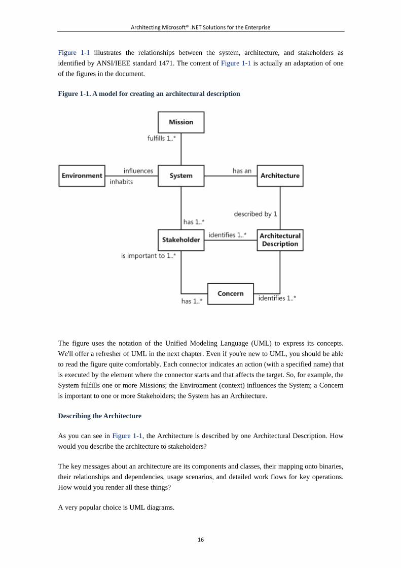
Figure 1-1 illustrates the relationships between the system, architecture, and stakeholders as
identified by ANSI/IEEE standard 1471. The content of Figure 1-1 is actually an adaptation of one
of the figures in the document.
Figure 1-1. A model for creating an architectural description
The figure uses the notation of the Unified Modeling Language (UML) to express its concepts.
We'll offer a refresher of UML in the next chapter. Even if you're new to UML, you should be able
to read the figure quite comfortably. Each connector indicates an action (with a specified name) that
is executed by the element where the connector starts and that affects the target. So, for example, the
System fulfills one or more Missions; the Environment (context) influences the System; a Concern
is important to one or more Stakeholders; the System has an Architecture.
Describing the Architecture
As you can see in Figure 1-1, the Architecture is described by one Architectural Description. How
would you describe the architecture to stakeholders?
The key messages about an architecture are its components and classes, their mapping onto binaries,
their relationships and dependencies, usage scenarios, and detailed work flows for key operations.
How would you render all these things?
A very popular choice is UML diagrams.
Architecting Microsoft® .NET Solutions for the Enterprise
17
UML is also a recognized international standard¡ªprecisely, ISO/IEC 19501 released in 2005. You
create UML class diagrams to show relationships between classes; you employ use-case diagrams
to present usage scenarios; you create component diagrams to capture the relationships between
reusable parts of a system (components) and see more easily how to map them onto binaries. In
some cases, you can also add some sequence diagrams to illustrate in more detail the workflow for
some key scenarios. These terms are defined and discussed in more detail in Chapter 2, "UML
Essentials."
At the end of the day, you serve different and concurrent views of the same architecture and capture
its key facts.
Note
The same principle of offering multiple views from distinct viewpoints lies
behind another vendor-specific model for architectural
description¡ªIBM/Rational's 4+1 views model. The model defines four main
views¡ªnearly equivalent to UML diagrams. These views are as follows:
The logical view, which describe components
The process view, which describes mapping and dependencies
The development view, which describes classes
The physical view, which (if necessary) describes mapping onto hardware
The fifth, partially redundant, view is the scenario view, which is specific to use
cases.
Validating the Architecture
How would you validate the design to ensure that stakeholders' concerns are properly addressed?
There's no magic wand and no magic formulas that take a more or less formal definition of an
architecture as input and tells you whether it is appropriate for the expressed requirements. To
validate the design of a system, you can only test it¡ªin various ways and at various levels.
So you will perform unit tests to validate single functionalities, and you will perform integration
tests to see how the system coexists with other systems and applications. Finally, you'll run
acceptance tests to verify how users actually feel about the application and whether the application
provides the services it was created for. (Testing is one of the key topics of Chapter 3, "Design
Principles and Patterns.")
What's Architecture and What's Not
Architecting Microsoft® .NET Solutions for the Enterprise
18
When you think about creating or defining the architecture of a software system, you first try to
identify a possible collection of interacting components that, all together, accomplish the requested
mission. In international standards, there's no mention for any methodology you should use to
decompose the system into more detailed pieces. Let's say that in the first step you a get a
conceptual architecture and some different views of it. In a second step, you need to get closer to a
functional and physical architecture. How you get there is a subjective choice, although a top-down
approach seems to be a very reasonable strategy. You decompose components into smaller and
smaller pieces, and from there you start building.
No System Is a Monolith
We've been told that, once upon a time, any piece of software was a monolith with an entry point
and finish point. The introduction of structured programming, and the concept of a subroutine, in
the early 1970s started shouldering such monoliths out of the way.
Since then, many software systems have been designed as a graph of components communicating in
various ways and having various levels of dependency. In practical terms, designing a system
consists of expanding the System element that was shown in Figure 1-1 into a graph of subsystems
and defining communication policies and rules for each of them.
The process of breaking down these details should ideally continue until you have described in
detail the structure and relationships for the smallest part of the system. Although fully completing
the breakdown process up front is key for constructing habitable buildings, it is not that necessary
for building software.
The actual implementation of the breakdown process depends on the methodology selected for the
project¡ªthe more you are agile, the more the breakdown process is iterative and articulated in
smaller and more frequent steps. (We'll return to the topic of methodologies later in the chapter.)
The output of the breakdown process is a set of specifications for the development team. Also, the
content and format of the specifications depend on the methodology. The more you are agile, the
more freedom and independence you leave to developers when implementing the architecture.
Defining the Borderline Between Architecture and Implementation
The constituent components you identified while breaking down the system represent logical
functions to be implemented in some way. The design of components, their interface, their
responsibilities, and their behavior are definitely part of the architecture. There's a border, though,
that physically separates architecture from implementation.
This border is important to identify because, to a large extent, it helps to define roles on a
development team. In particular, it marks the boundary between architects and developers. Over the
years, we learned that architects and developers are not different types of fruit, like apples and
oranges. They are the same type of fruit. However, if they are apples, they are like red apples and
Architecting Microsoft® .NET Solutions for the Enterprise
19
green apples. Distinct flavors, but not a different type of fruit. And neither flavor is necessarily
tastier.
You have arrived at the border between architecture and implementation when you reach a black
box of behavior. A black box of behavior is just a piece of functionality that can be easily replaced
or refactored without significant regression and with zero or low impact on the rest of the
architecture. What's above a black box of behavior is likely to have architectural relevance and
might require making a hard-to-change decision.
What's our definition of a good architecture? It is an architecture in which all hard-to-change
decisions turn out to be right.
Dealing with Hard-to-Change Decisions
There are aspects and features of a software system that are hard (just hard, not impossible) to
change once you have entered the course of development. And there are aspects and features that
can be changed at any time without a huge effort and without having a wide impact on the system.
In his book Patterns of Enterprise Application Architecture (Addison-Wesley, 2002), Martin Fowler
puts it quite simply:
If you find that something is easier to change than you once thought, then it's no longer
architectural. In the end architecture boils down to the important stuff¡ªwhatever that is.
To sum it up, we think that under the umbrella of the term architecture falls everything you must
take seriously at quite an early stage of the project. Architecture is ultimately about determining the
key decisions to make and then making them correctly.
Architecture Is About Decisions
When we talk about hard architectural decisions, we are not necessarily referring to irreversible
decisions about design points that can be difficult and expensive to change later. Hard-to-change
decisions are everywhere and range from the definition of a conceptual layers to the attributes of a
class.
To illustrate our point, let's go through a few different examples of architectural points that can run
into budget limits and deadlines if you have to touch them in the course of the project.
Changing the Organization of the Business Logic
In Chapter 4, "The Business Layer," we'll examine various approaches to organizing the business
logic in the context of a layered system. Possible approaches for the design of the business logic
include transaction script, table module, active record, and domain model. The selection of a pattern
for the business logic is an excellent example of a design choice to be made very, very carefully.
Once you have opted for, say, table module (which means, essentially, that you'll be using typed
DataSets to store an application's data in the business logic layer), moving to an object model (for
Architecting Microsoft® .NET Solutions for the Enterprise
20
example, using the LINQ-to-SQL or Entity Framework object model) is definitely hard and requires
nontrivial changes in the data access layer and in the application (service) layer, and probably also
in the presentation layer. If you need to change this decision later in the project, you enter into a
significant refactoring of the whole system.
Switching to a Different Library
Suppose you developed some functionality around a given library. One day, the client pops up and
lets you know that a new company policy prevents the IT department from buying products from a
given vendor. Now you have a new, unexpected nonfunctional requirement to deal with.
A change in the specifications might require a change in the architecture, but at what cost? In such a
case, you have to comply with the new list of requirements, so there's not much you can do.
In the best case, you can get a similar tool from an authorized vendor or, perhaps, you can build a
similar tool yourself. Alternatively, you can consider introducing a radical change into the
architecture that makes that library unnecessary.
We faced an analogous situation recently, and the type of library was an Object/Relational mapping
tool. With, say, a UI control library, it would have been much simpler to deal with. Replacing an
Object/Relational mapping tool is not easy; it is a task that can be accomplished only by getting
another tool from another vendor. Unfortunately, this wasn't possible. In other words, we were left
to choose between either of two unpleasant and painful options: writing our own Object/Relational
mapping tool, or rearchitecting the middle tier to use a different (and much simpler) object model.
With over 500 presenters in the Model View Presenter C̈based user interface directly consuming the
object model, having to make this decision was our worst nightmare. We knew it would require a
huge amount of work on the middle tier, consuming both financial resources and time. We lobbied
for more time and successfully stretched the deadline. Then we built our own tailor-made data
access layer for a domain model. (After you've read Chapter 6, "The Data Access Layer," you'll
have a clear picture of what this all means.)
Changing the Constructor's Signature
Don't think that architecture is only about high-level decisions like those involving the design and
implementation of parts of the middle tier. A requested change in the signature of a class constructor
might get you in a fine mess, too.
Imagine a scenario where you handle an Order class in your application's object model. You don't
see any reason to justify the introduction of a factory for the Order class. It is a plain class and
should be instantiated freely. So you scatter tons of new Order() instructions throughout your code.
You don't see, though, that Order has some logical dependency on, say, Customer.
At some point, a request for change hits you¡ªin the next release, an order will be created only in
association with a customer. What can you do?
Architecting Microsoft® .NET Solutions for the Enterprise
21
If you only add a new constructor to the Order class that accepts a Customer object, you simply
don't meet the requirement, because the old constructor is still there and only new code will follow
the new pattern. If you drop or replace the old constructor, you have tons of new statements to fix
that are scattered throughout the entire code base.
If only you had defined a factory for the Order class, you would have met the new requirement
without the same pain. (By the way, domain-driven design methodology in fact suggests that you
always use a factory for complex objects, such as aggregates.)
Changing a Member's Modifiers
When you design a class, you have to decide whether the class is public or internal and whether it is
sealed or further inheritable. And then you decide whether methods are virtual or nonvirtual.
Misusing the virtual and sealed modifiers might take you along an ugly route.
In general, when you use the sealed and virtual modifiers you take on a not-so-small responsibility.
In C#, by default each class is unsealed and each method on a class is nonvirtual. In Java, for
example, things go differently for methods, which are all virtual by default. Now what should you
do with your .NET classes? Make them sealed, or go with the default option?
The answer is multifaceted¡ªmaintenance, extensibility, performance, and testability all might factor
into your decision. We're mostly interested in maintenance and extensibility here, but we'll return to
this point in Chapter 3 when we touch on design for testability and make some performance
considerations.
From a design perspective, sealed classes are preferable. In fact, when a class is sealed from the
beginning you know it¡ªand you create your code accordingly. If something happens later to justify
inheritance of that class, you can change it to unsealed without breaking changes and without
compromising compatibility. Nearly the same can be said for virtual methods, and the visibility of
classes and class members, which are always private by default.
The opposite doesn't work as smoothly. You often can't seal a class or mark a virtual method as
nonvirtual without potentially breaking some existing code. If you start with most-restrictive
modifiers, you can always increase the visibility and other attributes later. But you can never tighten
restrictions without facing the possibility of breaking existing dependencies. And these broken
dependencies might be scattered everywhere in your code.
To contrast these statements, some considerations arise on the theme of testability. A nonsealed
class and virtual methods make testing much easier. But the degree of ease mostly depends on the
tool you use for testing. For example, TypeMock is a tool that doesn't suffer from these particular
limitations.
It's hard to make a choice as far as the sealed and virtual keywords are concerned. And whatever
choice you make in your context, it doesn't have to be a definitive choice that you blindly repeat
throughout your code for each class and member. Make sure you know the testability and
Architecting Microsoft® .NET Solutions for the Enterprise
22
performance implications, make sure you know the goals and scope of your class, and then make a
decision. And, to the extent that it's possible, make the right decision!
Requirements and Quality of Software
The mission of the system is expressed through a set of requirements. These requirements ultimately
drive the system's architecture.
In rather abstract terms, a requirement is a characteristic of the system that can either be functional
or nonfunctional. A functional requirement refers to a behavior that the system must supply to fulfill
a given scenario. A nonfunctional requirement refers to an attribute of the system explicitly
requested by stakeholders.
Are the definitions of functional and nonfunctional requirements something standard and broadly
accepted? Actually, an international standard to formalize quality characteristics of software systems
has existed since 1991.
Examining the ISO/IEC 9126 Standard
As a matter of fact, failure to acknowledge and adopt quality requirements is one of the most
common causes that lead straight to the failure of software projects. ISO/IEC 9126 defines a general
set of quality characteristics required in software products.
The standard identifies six different families of quality characteristics articulated in 21
subcharacteristics. The main families are functionality, reliability, usability, efficiency,
maintainability, and portability. Table 1-1 explains them in more detail and lists the main
subcharacteristics associated with each.
Table 1-1. Families of Quality Characteristics According to ISO/IEC 9126
Family Description
Functionality Indicates what the software does to meet expectations. It is based on
requirements such as suitability, accuracy, security, interoperability, and
compliance with standards and regulations.
Reliability Indicates the capability of the software to maintain a given level of performance
when used under special conditions. It is based on requirements such as maturity,
fault tolerance, and recoverability. Maturity is when the software doesn't
experience interruptions in the case of internal software failures. Fault tolerance
indicates the ability to control the failure and maintain a given level of behavior.
Recoverability indicates the ability to recover after a failure.
Usability Indicates the software's ability to be understood by, used by, and attractive to
users. It dictates that the software be compliant with standards and regulations
for usability.
Architecting Microsoft® .NET Solutions for the Enterprise
23
Table 1-1. Families of Quality Characteristics According to ISO/IEC 9126
Family Description
Efficiency Indicates the ability to provide a given level of performance both in terms of
appropriate and timely response and resource utilization.
Maintainability Indicates the software's ability to support modifications such as corrections,
improvements, or adaptations. It is based on requirements such as testability,
stability, ability to be analyzed, and ability to be changed.
Portability Indicates the software's ability to be ported from one platform to another and its
capability to coexist with other software in a common environment and sharing
common resources.
Subcharacteristics are of two types: external and internal. An external characteristic is user oriented
and refers to an external view of the system. An internal characteristic is system oriented and refers
to an internal view of the system. External characteristics identify functional requirements; internal
characteristics identify nonfunctional requirements.
As you can see, features such as security and testability are listed as requirements in the ISO
standard. This means that an official paper states that testability and security are an inherent part of
the system and a measure of its quality. More importantly, testability and security should be planned
for up front and appropriate supporting functions developed.
Important
If you look at the ISO/IEC 9126 standard, you should definitely bury the
practice of first building the system and then handing it to a team of network
and security experts to make it run faster and more securely. You can't test
quality in either. Like security, quality has to be designed in. You can't hope to
test for and find all bugs, but you can plan for known failure conditions and
use clean coding practices to prevent (or at least minimize) bugs in the field.
It's surprising that such a practice has been recommended, well, since 1991. To
give you an idea of how old this standard is, consider that at the time it was
written both Windows 3.0 and Linux had just been introduced, and MS-DOS
5.0 was the rage, running on blisteringly fast Intel i486 processors. It was
another age.
In the context of a particular system, the whole set of general quality requirements set by the
ISO/IEC 9126 standard can be pragmatically split into two types of requirements: functional and
nonfunctional.
Functional Requirements
Architecting Microsoft® .NET Solutions for the Enterprise
24
Functional requirements indicate what the system is expected to do and provide an appropriate set of
functions for such specified tasks and user objectives. Generally, a function consists of input,
behavior, and output. A team of analysts is responsible for collecting functional requirements and
communicating them to the architect. Another common source of functional requirements are
meetings organized with users, domain experts, and other relevant stakeholders. This process is
referred to as elicitation.
Requirements play a key role in the generation of the architecture because they are the raw input for
architects to produce specifications for the development team. Needless to say, it is recommended
by ISO/IEC that software requirements be "clear, correct, unambiguous, specific, and verifiable."
However, this is only how things go in a perfect world.
Nonfunctional Requirements
Nonfunctional requirements specify overall requirements of the final system that do not pertain
specifically to functions. Canonical examples of nonfunctional requirements are using (or not using)
a particular version of a framework and having the final product be interoperable with a given
legacy system.
Other common nonfunctional requirements regard support for accessibility (especially in Web
applications developed for the public sector) or perhaps the provision of a given level of security,
extensibility, or reliability.
In general, a nonfunctional requirement indicates a constraint on the system and affects the quality
of the system. Nonfunctional requirements are set by some of the system stakeholders and represent
a part of the contract.
Gathering Requirements
The analyst is usually a person who is very familiar with the problem's domain. He gathers
requirements and writes them down to guarantee the quality and suitability of the system. The
analyst usually composes requirements in a document¡ªeven a Microsoft Office Word document¡ªin
a format that varies with the environment, project, and people involved.
Typically, the analyst writes requirements using casual language and adds any wording that is
specific to the domain. For example, it is acceptable to have in a requirement words such as Fund,
Stock, Bond, and Insurance Policy because they are technical terms. It is less acceptable for a
requirement to use terms such as table or column because these technical terms are likely to be
foreign terms in the problem's domain.
Again, requirements need to be clear and verifiable. Most importantly, they must be understandable,
without ambiguity, to all stakeholders¡ªusers, buyers, analysts, architects, testers, documentation
developers, and the like.
Note
Architecting Microsoft® .NET Solutions for the Enterprise
25
It is not uncommon that analysts write functional requirements using
relatively abstract use cases. As we'll see in a moment, a use case is a
document that describes a form of interaction between the system and its
clients. Use cases created by the analysis team are not usually really detailed
and focus on what the system does rather than how the system does it. In any
case, it must come out in a form that stakeholders can understand. In this
regard, a use case describes all the possible ways for an actor to obtain a
value, or achieve a goal, and all possible exceptions that might result from
that.
Specifications
Based on functional and nonfunctional requirements, specifications offer a development view of the
architecture and are essentially any documentation the architect uses to communicate details about
the architecture to the development team. The main purpose of specifications is to reach an
understanding within the development team as to how the program is going to perform its tasks.
Note
Typically, an architect won't start working on specifications until some
requirements are known. In the real world, it is unlikely that requirements will
be entirely known before specifications are made. The actual mass of
requirements that triggers the generation of specifications depends mostly on
the methodology selected for the process. In an agile context, you start
working on specifications quite soon, even with a largely incomplete set of
requirements.
Specifications for functional requirements are commonly expressed through user stories or use
cases.
A user story is an informal and very short document that describes, in a few sentences, what should
be done. Each story represents a single feature and ideally describes a feature that stands on its own.
User stories work especially well in the context of an agile methodology, such as Extreme
Programming (XP), and are not designed to be exhaustive. A typical user story might be as simple
as, "The user places an order; the system verifies the order and accepts it if all is fine." When, and if,
that user story gets implemented, developers translate it into tasks. Next, through teamwork, they
clarify obscure points and figure out missing details.
A use case is a document that describes a possible scenario in which the system is being used by a
user. Instead of user, here, we should say actor, actually. An actor is a system's user and interacts
with the system. An actor can be a human as well as a computer or another piece of software. When
not human, an actor is not a component of the system; it is an external component. When human,
actors are a subset of the stakeholders.
Architecting Microsoft® .NET Solutions for the Enterprise
26
When used to express a functional requirement, a use case fully describes the interaction between
actors and the system. It shows an actor that calls a system function and then illustrates the system's
reaction. The collection of all use cases defines all possible ways of using the system. In this context,
a use case is often saved as a UML diagram. (See Chapter 2 for detailed UML coverage.) The
scenario mentioned a bit earlier in this section, described through a use case, might sound like this:
"The user creates an order and specifies a date, a shipment date, customer information, and order
items. The system validates the information, generates the order ID, and saves the order to the
database." As you can see, it is a much more detailed description.
The level of detail of a specification depends on a number of factors, including company standards
currently in use and, particularly, the methodology selected to manage the project. Simplifying, we
can say that you typically use user stories within the context of an agile methodology; you use the
use cases otherwise.
Note
Note that use cases you might optionally receive from analysts are not the
same as use cases that you, as an architect, create to communicate with the
development team. More often than not, use cases received by analysts are
plain Microsoft Office Word documents. Those that get handed on to the
development team are typically (but not necessarily) UML diagrams. And,
more importantly, they are much more detailed and oriented to
implementation.
Methodology and the Use of Requirements
Collected and communicated by analysts, requirements are then passed down the chain to the design
team to be transformed into something that could lead to working code. The architect is the member
on the design team who typically receives requirements and massages them into a form that
developers find easy to manage.
The architect is the point of contact between developers and stakeholders, and she works side by
side with the project manager. It is not unusual that the two roles coincide and the same person
serves simultaneously as an architect and a project manager.
The project manager is responsible for choosing a methodology for developing the project. To
simplify, we could say that the project manager decides whether or not an agile methodology is
appropriate for the project.
The choice of methodology has a deep impact on how requirements are used in defining the
architecture.
In the case of using an agile methodology, user stories are the typical output generated from
requirements. For example, consider that a typical XP iteration lasts about two weeks. (An XP
Architecting Microsoft® .NET Solutions for the Enterprise
27
iteration is a smaller and faster version of a classic software development cycle.) In two weeks, you
can hardly manage complex specifications; you would spend all the time on the specifications, thus
making no progress toward the implementation of those specifications. In this context, user stories
are just fine.
In the case of using a traditional, non-agile methodology with much longer iterations, the architect
usually processes a large share of the requirements (if not all of them) and produces exhaustive
specifications, including classes, sequences, and work flows.
5.1.2 Who's the Architect, Anyway?
As we've seen, architecture is mostly about expensive and hard-to-change decisions. And someone
has to make these decisions.
The design of the architecture is based on an analysis of the requirements. Analysis determines what
the system is expected to do; architecture determines how to do that. And someone has to examine
the whats to determine the hows.
The architect is the professional tying together requirements and specifications. But what are the
responsibilities of an architect? And skills?
An Architect's Responsibilities
According to the ISO/IEC 42010 standard, an architect is the person, team, or organization
responsible for the system's architecture. The architect interacts with analysts and the project
manager, evaluates and suggests options for the system, and coordinates a team of developers.
The architect participates in all phases of the development process, including the analysis of
requirements and the architecture's design, implementation, testing, integration, and deployment.
Let's expand on the primary responsibilities of an architect: acknowledging the requirements,
breaking the system down into smaller subsystems, identifying and evaluating technologies, and
formulating specifications.
Acknowledging the Requirements
In a software project, a few things happen before the architect gets involved. Swarms of analysts, IT
managers, and executives meet, discuss, evaluate, and negotiate. Once the need for a new or updated
system is assessed and the budget is found, analysts start eliciting requirements typically based on
their own knowledge of the business, company processes, context, and feedback from end users.
When the list of requirements is ready, the project manager meets with the architect and delivers the
bundle, saying more or less, "This is what we (think we) want; now you build it."
The architect acknowledges the requirements and makes an effort to have them adopted and fulfilled
in the design.
Architecting Microsoft® .NET Solutions for the Enterprise
28
Breaking Down the System
Based on the requirements, the architect expresses the overall system as a composition of smaller
subsystems and components operating within processes. In doing so, the architect envisions logical
layers and/or services. Then, based on the context, the architect decides about the interface of layers,
their relationships to other layers, and the level of service orientation the system requires.
Note
At this stage, the architect evaluates various architectural patterns. Layering is
a common choice and the one we are mostly pursuing in this book. Layering
entails a vertical distribution of functionality. Partitioning is another approach,
where all parts are at the same logical level and scattered around some shared
entities¡ªsuch as an object model or a database. Service-oriented architecture
(SOA) and hexagonal architecture (HA) are patterns that tend to have
components (services in SOA, adapters in HA) operating and interacting at the
same logical level.
The overall design will be consistent with the enterprise goals and requirements. In particular, the
overall design will be driven by requirements; it will not lead requirements.
The resulting architecture is ideally inspired by general guidelines, such as minimizing the coupling
between modules, providing the highest possible level of cohesion within modules, and giving each
module a clear set of responsibilities.
The resulting architecture is also driven by nonfunctional requirements, such as security, scalability,
and technologies allowed or denied. All these aspects pose further constraints and, to some extent,
delimit the space where the architect can look for solutions.
Finally, the architect also strategizes about tasking individual developers, or teams of developers,
with each of the components resulting from the breakdown of the system.
Note
There are no absolute truths in software architecture. And no mathematical
rules (or building codes like in structural engineering) to help in making
choices. Company X might find architecture A successful at the same time
company Y is moving away from it to embrace architecture B. The nice fact is
that both might be totally right. The context is king, and so is gut feeling.
Identifying and Evaluating Technologies
Architecting Microsoft® .NET Solutions for the Enterprise
29
After acknowledging requirements and designing the layers of the system, the next step for the
architect entails mapping logical components onto concrete technologies and products.
The architect typically knows the costs and benefits of products and technologies that might be
related to the content of the project. The architect proposes the use of any technologies and products
that he regards as beneficial and cost-effective for the project.
The architect doesn't choose the technology; based on his skills, the architect just makes proposals.
The architect might suggest using, say, Microsoft Windows 2008 Server for the Web server and a
service-oriented architecture with services implemented through Windows Communication
Foundation (WCF). The architect might suggest NHibernate over Entity Framework and Microsoft
SQL Server 2008 over Oracle. And he might suggest a particular rich control suite for the Web
presentation layer instead of, perhaps, an entirely in-house developed Silverlight client.
Who does make the final decision about which technologies and products are to be used?
Typically, it is the project manager or whoever manages the budget. The architect's suggestions
might be accepted or rejected. If a suggestion is rejected, using or not using a given product or
technology just becomes a new nonfunctional requirement to fulfill, and that might influence, even
significantly, the architecture.
Formulating Specifications
The architect is ultimately responsible for the development of the system and coordinates the work
of a team of developers. Technical specifications are the means by which the architect
communicates architectural decisions to the developers.
Specifications can be rendered in various forms: UML sketches, Word documents, Microsoft Visio
diagrams or, even, working prototypes.
Communication is key for an architect. Communication happens between the architect and
developers, and it also happens between architects and project managers and analysts, if not users. A
great skill for an architect is the clarity of language.
The interaction between architects and developers will vary depending on the methodology chosen.
And also the involvement of project managers, analysts, and users varies based, essentially, on the
level of agility you accept.
We'll return to the topic of methodologies in a moment.
How Many Types of Architects Do You Know?
There are many possible definitions of "architect." Definitions vary depending on how they factor in
different roles and different responsibilities. In this book, we work with the ISO/IEC definition of an
architect, which is the "person, team, or organization responsible for the system's architecture."
Architecting Microsoft® .NET Solutions for the Enterprise
30
According to ISO/IEC, there are not various types of architects. An architect is an architect. Period.
Microsoft, however, recognizes four types of architects: enterprise architect (EA), infrastructure
architect (IA), technology-specific architect (TSA), and solution architect (SA). The list is taken
from the job roles recognized by the Microsoft Certified Architect Program. You can read more
about the program and job roles at
http://www.microsoft.com/learning/mcp/architect/specialties/default.mspx.
In our opinion, the distinctions offered by Microsoft are misleading because they attempt to break
into parts what is ultimately an atomic, yet complex, role. It creates unnecessary categorization and
lays the groundwork for confusing, who-does-what scenarios.
For example, who's responsible for security? Is it the SA or the IA? Ultimately, security is an
ISO-recognized quality attribute of a software architecture and, as such, it should be planned from
the beginning. Security should grow with the system's design and implementation. It cannot be
added at a later time, by a separate team. Not if you really want security in the system.
Who's ultimately responsible for picking out a technology? Is it the SA? Is it the EA? Do both
accept suggestions from a swarm of different TSAs? At the end of the day, it's not the architect who
makes this decision. Instead, it's the customer, who holds the purse strings, that decides.
It is fine to have multiple architects on the same project team. Likewise, it is fine, if not desirable,
that different architects have slightly different skills. But they remain just architects, working on the
same team on the design of the same system. And architects also have a significant exposure to code.
They work out the design of the system but then work closely with developers to ensure proper
implementation.
As we see things, an architect is, among other things, a better and more experienced developer. We
don't believe there's value in having architects who just speak in UML and Visio and leave any
implementation details to developers. At least, we've never found it easy to work with these people
when we've crossed paths with them.
Note
This said, we recognize that titles like enterprise architect, solution architect,
and perhaps security architect look much better than a plain software
architect when printed out on a business card. But the terms are only a way to
more quickly communicate your skills and expertise. When it comes to the
actual role, either you're an architect or you're not.
Common Misconceptions About Architects
Although international ISO standards exist to define requirements, architecture, and architects, they
seem not to be taken into great account by most people. Everybody seems to prefer crafting her own
Architecting Microsoft® .NET Solutions for the Enterprise
31
(subtly similar) definition for something, rather than sticking to (or reading) the ISO definition for
the same something.
Try asking around for the definition of terms such as architect, architecture, or project manager.
You can likely get distinct, and also unrelated and contrasting, answers.
Quite obviously, a set of misconceptions have grown out of the mass of personalized definitions and
interpretations. Let's go through a few of them and, we hope, clear up a few of them.
The Architect Is an Analyst
This is a false statement. An architect is simply not an analyst.
At times, an architect might assist analysts during elicitations to help clarify obscure requirements or
smooth improbable requirements. At times, an architect might participate in meetings with
stakeholders. But that's it.
In general, an analyst is a person who is an expert on the domain. An architect is not (necessarily)
such an expert. An analyst shares with an architect his own findings about how the system should
work and what the system should do.
This common misconception probably originates from the incorrect meaning attributed to the word
analyst. If the word simply indicates someone who does some analysis on a system, it is quite hard
to deny the similarities between architects and analysts. Some 30 years ago, the term system analyst
was used to indicate a professional capable of making design considerations about a system. But, at
the time, the software wasn't as relevant as it is today, and it was merely a (small) part of an
essentially hardware-based system.
Today, the roles of an analyst and an architect are commonly recognized as being different. And
hardly ever does an architect play the role of an analyst.
Note
Given that roles are neatly separated, anyway, in small companies, it can
happen that the same person serves as an analyst and architect. It simply
means that there's a person in the company who knows the business and
processes well enough to come up with functional requirements and translate
them into specifications for developers. The roles and responsibilities are still
distinct, but the distinct skills for each can be found in the same individual.
The Architect Is a Project Manager
Is this another false statement? It depends.
Architecting Microsoft® .NET Solutions for the Enterprise
32
The architect is responsible for the system's architecture and coordinates and guides the
development of the system. The project manager represents stakeholders and manages the project by
choosing, in the first place, a methodology. The project manager is then responsible for ensuring
that the project adheres to the architecture while proceeding within the limits of the timeline and
budget.
If we look at the role of the architect and the role of the project manager, we find out that they are
distinct. Period.
However, it is not unusual that one actor ends up playing two roles. Like in the theater, this hardly
happens in large companies, but it happens quite frequently in small companies.
In summary, if you want to be a software architect when you grow up, you don't necessarily have to
develop project management skills. If you have skills for both roles, though, you can try to get
double pay.
The Architect Never Writes Any Code
This is definitely an ongoing debate: Should architects write code? There are essentially two schools
of thought.
One school thinks that architects live on the upper floor, maybe in an attic. Architects then step
down to the developers' floor just for the time it takes them to illustrate, using UML diagrams, what
they have thought about the system. After this, they take the elevator up, collect their things, and go
out to play golf. When on the course, they switch off their cell phones and focus on the game. When
done, if they missed a call or two, they call back and explain to dummy developers what was so
clear in the diagram that nobody on the developers' floor could understand. According to this school
of thought, architects never, ever dirty their hands with even the simplest C# statement. C#? Oh no,
the latest language they've been exposed to is probably Pascal while in college and Borland Turbo
Pascal at home.
Another school of thought thinks, instead, that every architect is a born developer. To take the
metaphor one step further, we could say that the class Architect inherits from the class Developer
and adds some new methods (skills) while overriding (specializing) a few others. Becoming an
architect is the natural evolution in the career of some developers. The basic differences between an
architect and a developer are experience and education. You gain experience by spending time on
the job; you earn your education from studying good books and taking the right classes. In addition,
an architect has the ability to focus her vision of the system from a higher level than an average
developer. Furthermore, an architect has good customer-handling skills.
An architect might not write much production code. But she writes a lot of code; she practices with
code every day; she knows about programming languages, coding techniques, libraries, products,
tools, Community Technology Previews (CTPs); and she uses the latest version of Visual Studio or
Team Foundation Server. In certain areas of programming, an architect knows even more than many
developers. An architect might be able to write tools and utilities to help developers be more
Architecting Microsoft® .NET Solutions for the Enterprise
33
productive. And, more often than you might think at first, the architect is just a member of the
development team. For example, an architect writing production code is an absolutely normal
occurrence in an agile context. It is also a normal occurrence in small companies regardless of the
methodology. At the same time, an architect who writes production code might be an absolutely
weird occurrence in some large-company scenarios, especially if a traditional and non-agile
methodology is used.
What about the two of us? To which school do we belong?
Well, Andrea is more of an architect than Dino because he lives on the fifth floor. Dino, on the other
hand, is closer to development because he has quite a few highly technical ASP .NET books on his
record and, more importantly, lives on the second floor. We don't play golf, though. Dino plays
tennis regularly, whereas Andrea likes squash better. We just have been denied access to the first
school of thought.
Note
In no other area of engineering is the distinction between those-who-design
and those-who-build as poorly accepted as it is in software. The distinction
exists mostly through postulation rather than flowing from a public recognition
of skills.
The canonical comparison is with civil architecture. Bricklayers have their own
unique skills that engineers lack. No bricklayer, though, will ever dream of
questioning designs or calculations, simply because the bricklayer lacks the
skill to make the decisions himself. Bricklayers do their own work the best they
can, taking full advantage of having the building work delegated to them.
In software, the situation is different because architects and developers have
common roots. The more skilled a developer is, the more he feels encouraged
to discuss design choices¡ªand often with reason. The more the architect loses
contact with everyday programming, the more he loses the respect of other
developers. This generates a sort of vicious circle, which magically becomes
better as you switch to an agile methodology.
5.1.3 Overview of the Software Development Process
For quite a few years, we've been highly exposed to the idea that writing software is easy, pleasant,
and fun. You click this, you drag that, and the tool will write the code for you. You "declare" what
you want, and the award-winning tool will do it for you. Admittedly, in this scenario everybody
could gain the rank of architect, and the burden of writing code can be entirely delegated to the
tool¡ªaptly named the wizard.
Architecting Microsoft® .NET Solutions for the Enterprise
34
Not all software is the same.
Writing a filing system to track the movies you've rented from Blockbuster is different from writing
a line-of-business application to run a company. You probably don't need to work on an architecture
to build a syndication reader; you probably need more than just architecture if you're working on the
control system for, say, a chemical plant.
In some sectors of the industry (for example, in the defense sector), the need for a systematic
approach to the various aspects of software¡ªdevelopment, testing, operation, maintenance¡ªwas
recognized long ago, as early as the 1960s. In fact, the term software engineering was first coined
by Professor Friedrich L. Bauer during the NATO Software Engineering Conference in 1968.
Today, software engineering is a broad term that encompasses numerous aspects of software
development and organizes them into a structured process ruled by a methodology.
The Software Life Cycle
Software development is a process created and formalized to handle complexity and with the
primary goal of ensuring (expected) results. As in the quote at the top of the chapter, the ultimate
goal is controlling complexity, not creating it.
To achieve this goal, a methodology is required that spans the various phases of a software project.
Over the years, an international standard has been developed to formalize the software life cycle in
terms of processes, activities, and tasks that go from initial planning up to the retirement of the
product.
This standard is ISO/IEC 12207, and it was originally released in 1995. The most recent revision,
however, was in March 2008.
Processes
According to the ISO/IEC 12207 standard, the software life cycle is articulated in 23 processes.
Each process has a set of activities and outcomes associated with it. Finally, each activity has a
number of tasks to complete.
Processes are classified in three types: primary, supporting, and organizational. The production of
the code pertains to the primary process. Supporting processes and organizational processes refer to
auxiliary processes, such as configuration, auditing, quality assurance, verification, documentation,
management, and setup and maintenance of the infrastructure (hardware, software, tools). Figure 1-2
offers a graphical view of the software life cycle, showing specific processes.
Figure 1-2. The overall software life cycle according to ISO/IEC 12207
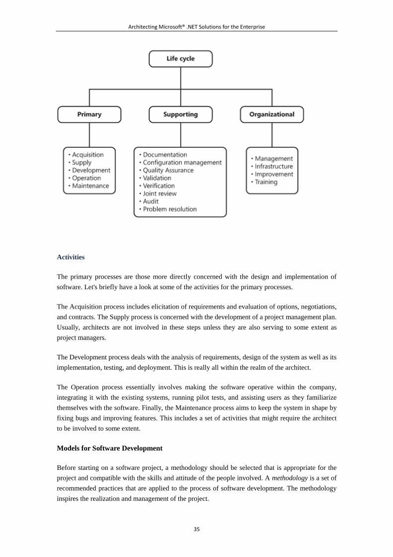
Architecting Microsoft® .NET Solutions for the Enterprise
35
Activities
The primary processes are those more directly concerned with the design and implementation of
software. Let's briefly have a look at some of the activities for the primary processes.
The Acquisition process includes elicitation of requirements and evaluation of options, negotiations,
and contracts. The Supply process is concerned with the development of a project management plan.
Usually, architects are not involved in these steps unless they are also serving to some extent as
project managers.
The Development process deals with the analysis of requirements, design of the system as well as its
implementation, testing, and deployment. This is really all within the realm of the architect.
The Operation process essentially involves making the software operative within the company,
integrating it with the existing systems, running pilot tests, and assisting users as they familiarize
themselves with the software. Finally, the Maintenance process aims to keep the system in shape by
fixing bugs and improving features. This includes a set of activities that might require the architect
to be involved to some extent.
Models for Software Development
Before starting on a software project, a methodology should be selected that is appropriate for the
project and compatible with the skills and attitude of the people involved. A methodology is a set of
recommended practices that are applied to the process of software development. The methodology
inspires the realization and management of the project.
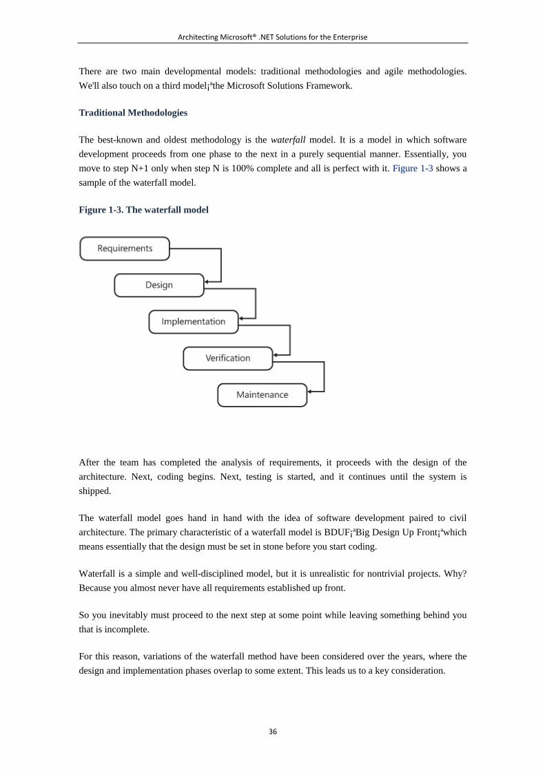
Architecting Microsoft® .NET Solutions for the Enterprise
36
There are two main developmental models: traditional methodologies and agile methodologies.
We'll also touch on a third model¡ªthe Microsoft Solutions Framework.
Traditional Methodologies
The best-known and oldest methodology is the waterfall model. It is a model in which software
development proceeds from one phase to the next in a purely sequential manner. Essentially, you
move to step N+1 only when step N is 100% complete and all is perfect with it. Figure 1-3 shows a
sample of the waterfall model.
Figure 1-3. The waterfall model
After the team has completed the analysis of requirements, it proceeds with the design of the
architecture. Next, coding begins. Next, testing is started, and it continues until the system is
shipped.
The waterfall model goes hand in hand with the idea of software development paired to civil
architecture. The primary characteristic of a waterfall model is BDUF¡ªBig Design Up Front¡ªwhich
means essentially that the design must be set in stone before you start coding.
Waterfall is a simple and well-disciplined model, but it is unrealistic for nontrivial projects. Why?
Because you almost never have all requirements established up front.
So you inevitably must proceed to the next step at some point while leaving something behind you
that is incomplete.
For this reason, variations of the waterfall method have been considered over the years, where the
design and implementation phases overlap to some extent. This leads us to a key consideration.
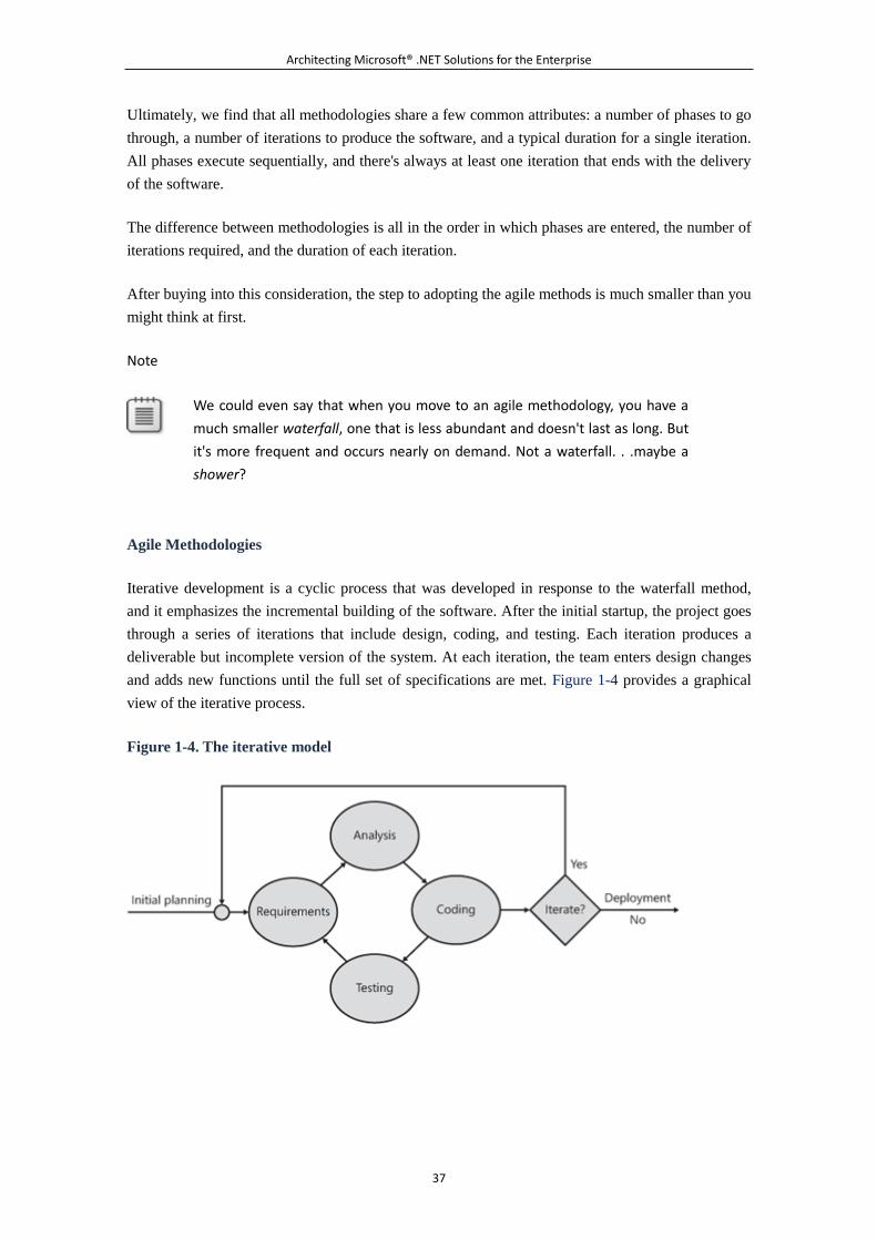
Architecting Microsoft® .NET Solutions for the Enterprise
37
Ultimately, we find that all methodologies share a few common attributes: a number of phases to go
through, a number of iterations to produce the software, and a typical duration for a single iteration.
All phases execute sequentially, and there's always at least one iteration that ends with the delivery
of the software.
The difference between methodologies is all in the order in which phases are entered, the number of
iterations required, and the duration of each iteration.
After buying into this consideration, the step to adopting the agile methods is much smaller than you
might think at first.
Note
We could even say that when you move to an agile methodology, you have a
much smaller waterfall, one that is less abundant and doesn't last as long. But
it's more frequent and occurs nearly on demand. Not a waterfall. . .maybe a
shower?
Agile Methodologies
Iterative development is a cyclic process that was developed in response to the waterfall method,
and it emphasizes the incremental building of the software. After the initial startup, the project goes
through a series of iterations that include design, coding, and testing. Each iteration produces a
deliverable but incomplete version of the system. At each iteration, the team enters design changes
and adds new functions until the full set of specifications are met. Figure 1-4 provides a graphical
view of the iterative process.
Figure 1-4. The iterative model
Architecting Microsoft® .NET Solutions for the Enterprise
38
Iterative development forms the foundation of agile methodologies. The term agile was deliberately
selected to symbolize a clear opposition to heavyweight methods such as the waterfall model. The
principles behind agile methods are listed in the "Agile Manifesto," which you can find at
http://agilemanifesto.org. The agile manifesto was first published in 2001.
Agile methodologies put individuals at the center of the universe. As stated on the home page of the
manifesto, agile methods focus on people working together and communicating rather than on
software building and processes. Change and refactoring are key in an agile methodology. User
feedback is valued over planning, and feedback is driven by regular tests and frequent releases of
the software. In fact, one of the agile principles states, "Working software is the primary measure of
progress."
So in the end, how is an agile methodology different? And how does it work? Let's look at an
example.
The project starts and only a few requirements are known. You know for a fact that many more will
show up between now and the end. With an agile mindset, this is not an issue. You take a subset of
the existing requirements that you can implement in a single iteration. And you go with the first
iteration. During the iteration, you focus on a single requirement at a time and implement it. At the
end of the iteration, you deliver a working piece of software. It might be incomplete, but it works.
Next, you go with another iteration that focuses on another set of requirements. If something
changed in the meantime or proved to be wrong, refactoring is in order. And the process continues
until there's nothing more to add.
Customers and developers work together daily; feedback is solicited and delivered on a timely basis;
results are immediately visible; the architect is just one of the developers; and the team is highly
skilled and motivated. The length of an iteration is measured in weeks¡ªoften, two weeks. In a word,
an agile process is agile to react to changes. And changes in the business are the rule, not the
exception.
Agile methodologies is a blanket term. When you refer to an agile methodology, you aren't talking
very precisely. Which methodology do you mean, actually?
The most popular agile methodology for software development is Extreme Programming (XP). In
XP, phases are carried out in extremely short iterations that take two weeks to terminate. Coding
and design proceed side by side. For more information on XP, visit the site
http://www.extremeprogramming.org.
Scrum is another popular agile methodology, but it is aimed at managing projects rather than
developing code. Scrum is not prescriptive for any software development model, but it works very
well with XP as the method to develop code. For more information on Scrum, have a look at Agile
Project Management with Scrum by Ken Schwaber (Microsoft Press, 2004).
Microsoft Solutions Framework
Architecting Microsoft® .NET Solutions for the Enterprise
39
Microsoft Solutions Framework (MSF) is another methodology for software development, like XP
or waterfall. Like XP, MSF has its own principles, roles, and vocabulary. In particular, the roles in
MSF are Program Manager, Architect, Developer, Tester, Release Manager, DBA, and Business
Analyst. Typical terms are iteration, release, phase, and work item (to indicate an activity within the
project).
MSF is a methodology that Microsoft developed and has used internally for the past ten years. Since
2006, it has also been supported by Team Foundation Server (TFS).
TFS is essentially a collection of Web services within an Internet Information Server (IIS) Web
server that provide business logic specific to project management. Either through the TFS console
(if you have proper administrative rights) or through a Visual Studio plug-in, you can create a TFS
project and use TFS services to manage your project. Great, but what is the methodology being
used?
TFS provides only one methodology out of the box: MSF. However TFS plug-ins exist to add other
methodologies to TFS. In particular, plug-ins exist for the Rational Unified Process (RUP), Feature
Driven Development (FDD), and Scrum.
When the project manager creates a TFS project, he is first asked to pick up an available
methodology (say, MSF). When MSF is picked up, the project manager is also asked to choose
which flavor of MSF he likes. There are two flavors: MSF for Agile, and MSF for CMMI.
Note
CMMI is an acronym for Capability Maturity Model Integration. CMMI is a
general methodology for improving processes within a company. CMMI
focuses on processes and fights common misconceptions such as "good
people are enough" and "processes hinder agility." CMMI proposes a set of
best practices and a framework for organizing and prioritizing activities, with
the purpose of improving processes related to the building of a product.
In essence, you opt for a model that is more agile or more rigorous. In the context of MSF, the word
agile has exactly the meaning it has in an English dictionary. It is not necessarily related to agile
methodologies.
For example, in MSF for Agile you don't give work items an explicit duration in terms of hours;
instead, you use an integer to indicate the level of effort (order of magnitude) required. You have to
use hours in MSF for CMMI, instead. In MSF for Agile, a Developer can assign a task to another
Developer; in MSF for CMMI, only the project manager has a similar right. In an agile process,
therefore, it is assumed that such an action is accomplished with due forethought. In MSF for Agile,
a work item can be moved from one project area to another without problems. This might not be
true for another methodology.
Architecting Microsoft® .NET Solutions for the Enterprise
40
In general, MSF for Agile is designed for small teams working iteratively on a project. MSF for
CMMI is more appropriate for large and heterogeneous teams, working on long iterations and
particularly concerned with control of quality.
5.1.4 Summary
Architecture is a widely used term that has quite a few definitions. If you read between the lines,
though, you mostly find variations of the same concept: architecture refers to identifying the
software components that, when interacting, make the program work.
In the process of identifying these components, you encounter points of decision making. When you
design an architecture, not all decisions you make have the same impact. The approach to the design
of the business logic, for example, is something you can hardly change at a later time in an
inexpensive way. So architecture is about components and hard-to-change decisions.
The design of an architecture is qualified by a number of quality parameters that are part of an
international standard. The design of the architecture comes out of functional and nonfunctional
requirements, gathered by business analysts and acknowledged by architects.
Who's the architect and what are his responsibilities? The role of the architect is different from that
of an analyst or a project manager, but sometimes the same individual can play both roles in the
context of a specific project. Does an architect write code? Oh, yes. In our vision, an architect is a
born developer, and even if the architect doesn't write much, or any, production code, he definitely
practices with deep code.
The role of the architect, and the way in which the architect and the development team work with
requirements, largely depends on the methodology in use¡ªwhether it is agile or traditional.
In this chapter, we mentioned in some places the Unified Modeling Language (UML) as the primary
notation to describe architectural aspects of a system. In the next chapter, we'll take a closer look at
the UML language.
5.1.5 Murphy's Laws of the Chapter
Murphy's laws are the portrait of the real world. If anything happens repeatedly in the real world, it
is then captured in a law. Software projects are a part of the real world and it is not surprising that
laws exist to describe software-related phenomena. In all chapters, therefore, we'll be listing a few
Murphy's laws.
Adding manpower to a late software project makes it later.
Program complexity grows until it exceeds the capability of the programmers who must
maintain it.
If builders built buildings the way programmers wrote programs, the first woodpecker that
came along would destroy civilization.
Architecting Microsoft® .NET Solutions for the Enterprise
41
See http://www.murphys-laws.com for an extensive listing of other computer-related (and
non-computer-related) laws and corollaries.
5.2 Chapter 2. UML Essentials
All models are wrong, but some models are useful.
¡ªGeorge E. P. Box
To design a system¡ªany system in any scientific field¡ªyou first need to create an abstraction of it.
An abstraction is essentially a model that provides a conceptual representation of the system in
terms of views, structure, behavior, participating entities, and processes.
A model exists to be shared among the stakeholders of the system, including developers, architects,
owners, and customers. Stakeholders should be able to understand the model in order to provide
feedback, spot wrong assumptions, and suggest improvements. To share a model, though, you need
to express it in a formal way using a common, and possibly broadly accepted, notation. For this, you
need a modeling language.
Typically, a modeling language is a graphical or textual language based on a set of rules, symbols,
diagrams, and keywords. All together, the language elements are used to express the structure and
behavior of the model in a way that transmits clear knowledge and information to anybody familiar
with the language.
There are several well-known examples of modeling languages¡ªfor example the Integrated
DEFinition (IDEF) family of modeling languages used for functional modeling, information
modeling, simulation, and more. There's also the Virtual Reality Modeling Language (VRML),
which is used to represent 3D graphics, and EXPRESS (textual) and EXPRESS-G (graphical) for
data modeling.
However, when it comes to modeling languages, the most popular one is Unified Modeling
Language (UML). UML is a general-purpose graphical modeling language that, over the years, has
become the industry standard for modeling software systems. Based on a family of graphical
notations, UML is particularly suited to creating models in object-oriented scenarios. It might not
be as effective when another paradigm is used, such as a functional or perhaps a relational paradigm,
but it's a good fit for object-oriented systems.
Although UML is a general-purpose modeling language for software-centric systems, it also
provides tools to customize the language to a specific domain. This is accomplished through UML
profiles, which we'll discuss later in the chapter.
In this book and its companion source code, we'll use some UML here and there to describe
scenarios and design solutions. For this reason, we decided to include this brief chapter that
summarizes the essential facts you have to know about UML. The chapter serves as a primer for
Architecting Microsoft® .NET Solutions for the Enterprise
42
readers with limited exposure to UML, or no exposure at all, and as a quick refresher for more
experienced readers.
We should add the following disclaimer: This chapter doesn't claim to be an exhaustive and in-depth
guide to UML. Instead, it is merely intended to provide a foundation for understanding diagrams
that might appear later in the book. At the same time, it should also communicate to you the gist of
UML and allow you to form an idea about the capabilities of UML to serve as a language for
modeling object-oriented systems¡ªa key preliminary step toward the design of the system layers
that we cover in chapters 4 through 7.
Note
If you're serious about learning UML, we recommend two main routes to
gaining that knowledge. The first route entails downloading the UML
specifications from the Object Modeling Group Web site. You can get any
papers from http://www.uml.org. However, we anticipate that running
through the official UML papers might take you quite a bit of time. One of the
sharpest criticisms of UML is its inherent tendency to be unnecessarily large
and complex. As we'll see later, UML (especially in the latest version) contains
many diagrams that are infrequently used and often redundant. Clearly, this
issue creates problems in both learning and adopting the language. The
problem gets even more acute if you're relatively new to UML.
This leads us to the second suggested route. If you would really like to put a
"UML-Expert" pin on your shirt before you retire¡ªand, more importantly, if
your goal is to use UML skills in real projects as soon as possible¡ªwe
recommend that you get a copy of some digestible books that focus on the
topic. An excellent resource is UML Distilled: A Brief Guide to the Standard
Object Modeling Language (Third Edition) by Martin Fowler (Addison-Wesley,
2003). Also, tutorials and other resources are available online¡ªfor example, at
http://www.uml.org.
If you are an experienced UML designer, you might consider skipping this chapter and moving
directly to the next one. Before you do, however, consider the following anecdote from Dino's early
public-speaking days: Ten years ago, when he was about to deliver one of his first speeches in
English, Dino was shocked to find out that Don Box was peacefully sitting in the audience. Dino
approached Don to ask what he was expecting to learn from a talk covering COM and OLE DB
stuff¡ªexactly the areas in which Don was the recognized expert at the time. Don smiled and said,
"Hey Dino, it's all about perspective."
So, again, it's all about perspective. Even if you know UML very well, you might still find this
chapter to be an interesting read.
5.2.1 UML at a Glance
Architecting Microsoft® .NET Solutions for the Enterprise
43
Modeling is a key stage in any software project, but it is crucial for large, enterprise-class
applications¡ªexactly the class of applications that keep companies up and running. A model is
essential where complexity is high. It helps to check correctness and adherence to specifications,
and it helps to build and maintain the software more easily. A clear and well-designed model also
helps developers¡ªat any time¡ªfind the right place to intervene to fix a bug. In software, a model
should be viewed the same as site maps, blueprints, and physical models in the construction of
houses: a definite need more than an optional tool.
Like it or not, years of real-world experience demonstrate that large projects normally exceed their
budgets, their deadlines, or both. This is just the real world, baby. Proper modeling is not a
guarantee of success for the project. However, it can be seen as your insurance against a dramatic
failure.
UML addresses this need for an effective modeling language¡ªa need that arose back in the early
days of object-orientated development.
Motivation for and History of Modeling Languages
The need for modeling languages is tightly related to the broad adoption of the object-oriented
paradigm, which started in the early 1990s. Object-orientation led developers to abandon
subroutines and structured programming and, instead, embrace a vision in which an application is
seen as a collection of interacting objects. Each object can receive and send messages, process data,
and invoke and control the behavior of other objects.
Quite naturally, the object-oriented paradigm led to devising systems as a web of related
components rather than as something that could be represented with start-to-finish flowcharts.
Describing and documenting the behavior of such systems became harder and required appropriate
tools and methodologies for modeling.
UML Predecessors
In 1991, the need for a modeling language produced Object Modeling Technique (OMT).
Developed by James Rumbaugh, OMT was a language for software modeling and analysis. More or
less at the same time, Grady Booch of Rational Software (now part of IBM) created the so-called
"Booch method," which was an object modeling language and methodology tailor-made for
object-oriented design.
Around 1994, Booch, Rumbaugh, and Ivar Jacobson (the Three Amigos) set up the group that
unified different but related modeling languages and methodologies into a single language. After
that, an international consortium¡ªthe Object Modeling Group (OMG)¡ªwas created under the
technical leadership of the amigos to formalize the Unified Modeling Language specification. This
eventually happened in 1997.
Today, OMG governs the development of UML and has more than 800 organizations associated as
members. You can learn more about OMG roles and initiatives at http://www.omg.org.
Architecting Microsoft® .NET Solutions for the Enterprise
44
Versions and Standards of UML
Currently, there are two main versions of UML, only one of which is officially ratified as an
international standard. Back in 2005, the International Organization for Standardization (ISO)
appointed version 1.4.2 of UML with the rank of a recognized ISO standard with ISO/IEC
19501:2005. You can find out more about the UML ISO standard at
http://www.iso.org/iso/iso_catalogue/catalogue_tc/catalogue_detail.htm?csnumber=.
Note
ISO is an international organization whose primary goal is reaching a general
consensus on solutions that span an entire industry including, but not limited
to, the software industry. Usually, ISO doesn't actually define its own standards
from scratch; rather, it draws on specifications from other organizations.
However, once ratified as an ISO standard, a given specification is an effective
standard worldwide. This has been the case for UML (as of version 1.4.2) since
2005.
ISO/IEC 19501:2005 officially presents UML to the world as a graphical language for visualizing,
specifying, constructing, and documenting the artifacts of a software-intensive system. As a result,
today UML is the standard way to write the blueprints for software systems.
Currently, the progress of UML within OMG has reached version 2.1.2. You can download the full
paper at http://www.omg.org/technology/documents/modeling_spec_catalog.htm#UML. You should
note, though, that this version has not been ratified as an ISO standard just yet.
So how does UML 2.x improve upon the previous, and standard, version?
In a nutshell, UML 1.x is a simpler language centered around the idea of modeling classes and
objects. UML 2.x goes beyond this threshold and adds the capability to present not only behavioral
models but also architectural models, as well as business process and rules. With version 2.x, UML
ceases to be an object-oriented modeling language and begins to target models used in other areas of
the computing world and even in noncomputing disciplines. UML 2.x reorganizes the contents of
version 1.x in a broader perspective and introduces many new tools, including new types of
diagrams. (We'll say more about this in a moment.)
The Strengths and Weaknesses of UML
In the real world, nothing draws criticism like recognized standards built from a generalized
consensus. It's really hard to keep everybody happy. UML is no exception. Although it is by far the
most widely used modeling language, UML lays itself open to criticism for being essentially a
bloated language. Not surprisingly, the ISO standard version 1.x was seen as needing improvement,
and improvement came in version 2.x. Some people, though, now consider UML 2.x as being too
bloated and complex as well as significantly harder to learn.
Architecting Microsoft® .NET Solutions for the Enterprise
45
We feel that the strengths and weaknesses of UML descend from the U in the name, which stands
for Unified. In other words, UML attempts to be too many things to too many people. Because of its
declared generality, UML can be used in nearly all areas of computing, but not always with the
same effectiveness. The bottom line is that UML generates a model, whereas working and
functional code is all that customers want¡ªto start off, at least. Managing the gap between the model
and the code is up to the team, and that is the natural habitat in which general criticism toward the
language as a whole springs up.
Initially, the U in UML had a positive overtone¡ªunifying different, but similar, approaches to
object-oriented modeling. Now, the U in UML is more the crux of the problem. To turn the general
feeling about the U back to positive, we should be able to easily and effectively restrict UML to a
particular domain. How can we easily transform a model into another model without loss of
information? How can we automa(g)ically start working with UML and end up with code? If you
look around, you'll see a number of ideas and some implementations, but no widely accepted and
adopted solutions.
Today, profiles in UML 2.x offer a first formulation to adapt UML to a specific domain. Likewise,
the idea of programming on the UML diagram is precisely the vision behind the model-driven
architecture (MDA)¡ªa design methodology launched by OMG a few years ago. MDA is being
talked about a lot, but it is not yet in widespread use. A domain-specific language (DSL) is a
possible alternative to UML and MDA, as far as generating code out of a model is concerned. (For
more information, see the "Domain-Specific Languages and UML" sidebar later in this chapter.)
In summary, there are a lot of good things in UML. In particular, UML is primarily a standard
language for modeling object-oriented systems through a graphical notation. Based on this key
milestone (essentially achieved with version 1.x), other features have been added to build a richer
modeling platform. And here's where most of the shades begin to appear.
UML should be conceptually split in two parts: U and ML. A unified approach to modeling is
welcome, but context-specific modeling languages that are really close to implementation languages
and that have domain-specific expressivity are an unavoidable requirement.
Note
UML is merely a modeling language; it is not a software development process.
However, a few software development processes exist that fully and rigorously
integrate UML modeling techniques. Examples are Agile Modeling and Unified
Process.
UML in Practice
As mentioned, in this chapter we are basically providing the tools to read any UML you find in the
remaining chapters and any diagrams scattered throughout the source code. That's great, but how
would you use UML in practice? And how do we use UML ourselves?
Architecting Microsoft® .NET Solutions for the Enterprise
46
Abstractly speaking, to use UML you need a methodology to gather and analyze requirements and
then a modeling tool to turn them into a designed model. Usually, UML modeling tools incorporate
their own methodology so that, in the end, you just pick up the best tool for you. So, which tool?
You basically have two options¡ªpick up a plain drawing tool that "does" UML, or pick up a
comprehensive tool that offers a team-based modeling environment and embraces the full software
development life cycle.
Microsoft Visio Professional is certainly a tool that belongs in the first category. There are several
free, shareware tools and commercial tools that just draw UML diagrams. A nonexhaustive list can
be found at http://en.wikipedia.org/wiki/List_of_UML_tools.
In the second category, we find tools such as Rational Rose XDE from IBM, Enterprise Architect
from Sparx Systems and, last but not least, Microsoft Visio for Enterprise Architects. Microsoft
Visio for Enterprise Architects is included in MSDN Premium Subscription. It extends Microsoft
Visio Professional to perform round-trip engineering on software and databases, thus enabling you
to generate code from your UML diagrams and generate databases from your database model
diagrams. You can get the same capabilities, and even more, from the other products mentioned,
which have different pricing models and scopes.
Note, though, that the round-trip engineering description here is a bit emphatic and might look like
an excerpt from some commercial pamphlet. An effective implementation of round-trip engineering
is the key to effective use of UML in the real world. The description here is definitely alluring;
however, we admit the reality might be a bit different. To understand why, we need to introduce
typical UML working modes first.
Note
Even though UML 2.x is the current version of the language, not all modeling
tools fully support it. In particular, if you use Microsoft Visio Professional, you
might want to add some external stencils such as those from Pavel Hruby,
which are available through the Web site http://www.softwarestencils.com.
Note that these stencils and Visio vanilla stencils are mutually exclusive. In
addition, the Pavel Hruby stencils are purely graphics tools and, unlike Visio
standard stencils, do not perform any validation of the model being created.
UML Modes and Usage
Over time, three modes of using UML have emerged and gained more or less wide adoption. They
are referred to as sketch mode, blueprint mode, and programming language mode. Let's dig out
more details about each.
UML as a Sketch
Architecting Microsoft® .NET Solutions for the Enterprise
47
We're pretty sure that every reader of this book, at least once in his or her life, has drawn something
on a paper napkin to record the basics of an idea. This is pretty common among geeks, isn't it?
When drawing or writing on a sticky note, a napkin, a whiteboard, or the back of a paid bill, you are
sketching an idea.
Note
Did you know the venerable B-52 was in fact designed the evening before
Boeing presented it to the US Air Force, and it was designed on a napkin? This
is a true story. It still flies today, 50 years after its design. Now this is exactly
the difference between recording the basics of an idea on a napkin and saving
a napkin design!
"UML as a sketch" works in the same way, except that you sketch out a preliminary model for a
software system and commonly use a file rather than a piece of paper. Used in this way, UML is
merely a formal and visual language to express and communicate an early and incomplete vision of
the system. Tools such as Microsoft Visio Professional and Microsoft Office PowerPoint are
commonly used to sketch out UML diagrams. (We have also seen handmade UML-like paper
drawings scanned to files and incorporated in the project documentation as Microsoft Office Word
files.)
"UML as a sketch" allows you to render incomplete diagrams with the simplest form¡ªfor example,
diagrams with limited details and covering only the principal aspects of a system. More often than
not, UML sketches are collaboratively created by architects and developers during both
forward-engineering and reverse-engineering phases.
In general, forward engineering is classic engineering¡ªthat is, an engineering approach wherein, to
build a system, you start by formally defining how it should be done and how it should work. In
forward engineering, you employ UML as the language to express ideas to be shared and discussed.
Through UML high-level diagrams, you typically weigh alternatives, plan activities, and assign
tasks.
In general, reverse engineering is when you take an existing system and figure out how it works. In
reverse engineering, you get a UML model out of the actual source code of the system. The
optimum situation is when the diagram you get from reverse engineering matches the diagram you
created with forward engineering. Hitting this goal is the essence of round-trip engineering.
Do not be too surprised to see UML in action looking like the diagram shown in Figure 2-1.
Figure 2-1. A sketch representing a use case
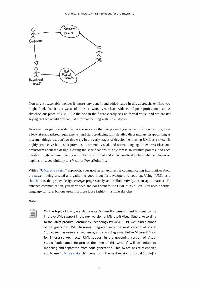
Architecting Microsoft® .NET Solutions for the Enterprise
48
You might reasonably wonder if there's any benefit and added value in this approach. At first, you
might think that it is a waste of time or, worse yet, clear evidence of poor professionalism. A
sketched-out piece of UML like the one in the figure clearly has no formal value, and we are not
saying that we would present it at a formal meeting with the customer.
However, designing a system is far too serious a thing to pretend you can sit down on day one, have
a look at standardized requirements, and start producing fully detailed diagrams. As disappointing as
it seems, things just don't go this way. In the early stages of development, using UML as a sketch is
highly productive because it provides a common, visual, and formal language to express ideas and
brainstorm about the design. Getting the specifications of a system is an iterative process, and each
iteration might require creating a number of informal and approximate sketches, whether drawn on
napkins or saved digitally to a Visio or PowerPoint file.
With a "UML as a sketch" approach, your goal as an architect is communicating information about
the system being created and gathering good input for developers to code up. Using "UML as a
sketch" lets the proper design emerge progressively and collaboratively, in an agile manner. To
enhance communication, you don't need and don't want to use UML at its fullest. You need a formal
language for sure, but one used in a more loose fashion¡ªjust like sketches.
Note
On the topic of UML, we gladly note Microsoft's commitment to significantly
improve UML support in the next version of Microsoft Visual Studio. According
to the latest product Community Technology Preview (CTP), we'll find a bunch
of designers for UML diagrams integrated into the next version of Visual
Studio, such as use-case, sequence, and class diagrams. Unlike Microsoft Visio
for Enterprise Architects, UML support in the upcoming version of Visual
Studio (codenamed Rosario at the time of this writing) will be limited to
modeling and separated from code generation. This switch basically enables
you to use "UML as a sketch" scenarios in the next version of Visual Studio¡ªa
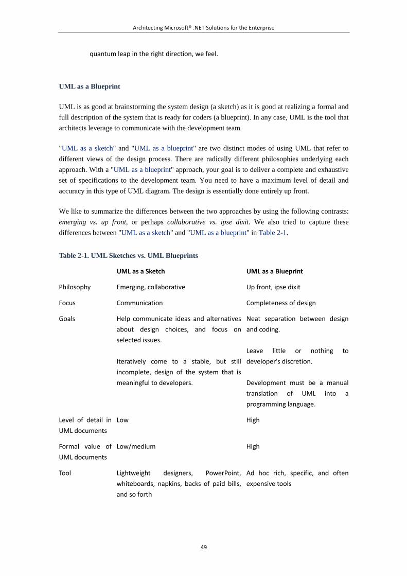
Architecting Microsoft® .NET Solutions for the Enterprise
49
quantum leap in the right direction, we feel.
UML as a Blueprint
UML is as good at brainstorming the system design (a sketch) as it is good at realizing a formal and
full description of the system that is ready for coders (a blueprint). In any case, UML is the tool that
architects leverage to communicate with the development team.
"UML as a sketch" and "UML as a blueprint" are two distinct modes of using UML that refer to
different views of the design process. There are radically different philosophies underlying each
approach. With a "UML as a blueprint" approach, your goal is to deliver a complete and exhaustive
set of specifications to the development team. You need to have a maximum level of detail and
accuracy in this type of UML diagram. The design is essentially done entirely up front.
We like to summarize the differences between the two approaches by using the following contrasts:
emerging vs. up front, or perhaps collaborative vs. ipse dixit. We also tried to capture these
differences between "UML as a sketch" and "UML as a blueprint" in Table 2-1.
Table 2-1. UML Sketches vs. UML Blueprints
UML as a Sketch UML as a Blueprint
Philosophy Emerging, collaborative Up front, ipse dixit
Focus Communication Completeness of design
Goals Help communicate ideas and alternatives
about design choices, and focus on
selected issues.
Iteratively come to a stable, but still
incomplete, design of the system that is
meaningful to developers.
Neat separation between design
and coding.
Leave little or nothing to
developer's discretion.
Development must be a manual
translation of UML into a
programming language.
Level of detail in
UML documents
Low High
Formal value of
UML documents
Low/medium High
Tool Lightweight designers, PowerPoint,
whiteboards, napkins, backs of paid bills,
and so forth
Ad hoc rich, specific, and often
expensive tools
Architecting Microsoft® .NET Solutions for the Enterprise
50
In forward engineering, the team first writes the UML blueprints and then produces the related
implementation code in the language of choice. Blueprints should be detailed enough to leave as
little as possible to the developer's discretion.
In reverse engineering, a blueprint is generated from the source code to describe the effective
behavior of the system, typically in a graphical fashion.
With a "UML as a blueprint" approach, you need a specialized modeling tool. Ideally, the tool
should assist the architect during the forward-engineering stage to generate a set of detailed and
unambiguous diagrams that are easy to turn into code without open points and gaps for developers
to fill. Likewise, the tool should also be able to minimize over time the costs of synchronization
between the UML model and the software artifact. Tools that support both forward engineering and
reverse engineering are said to be round-trip tools.
As you proceed with coding and refactoring, it is crucial that you keep the UML model in sync with
the evolution of the code. As you refactor the code, you want an updated UML returned that reflects
your changes (reverse engineering). The tool should provide this ability, and this is mostly what
makes "UML as a blueprint" tools extremely sophisticated and also expensive.
Does the "perfect" tool exist? This is hard to say.
For sure, tools such as Rational Rose and Enterprise Architect give it a try and do roundtrips. The
tools vary in the way in which they store internal information to sync up the model and the code. It
is not unusual, though, that after a certain number of roundtrips the chain breaks up and you are left
with the model and code out of sync. Manual intervention to restore synchronization is then
required.
For sure, Microsoft Visio for Enterprise Architect does not provide much help in this regard. For
sure, the upcoming Visual Studio version will not be of much help either, but probably for a
different reason. In the upcoming version of Visual Studio, the focus is on the "UML as a sketch"
approach.
Note
"UML as a sketch" and "UML as a blueprint" are based on different
philosophies and have different goals. We summarized this using the contrast
of emerging vs. up front. This might lead you to believe that the "UML as a
sketch" approach is agile and "UML as a blueprint" is not. Agile is a
methodology, and the project manager is responsible for the methodology. A
project manager can certainly require detailed UML blueprints in the context
of an agile methodology¡ªand vice versa. You can pick up a waterfall-like
methodology and still communicate sketched specifications to the
development team.
Architecting Microsoft® .NET Solutions for the Enterprise
51
UML as a Programming Language
The more you can come up with a detailed model, the closer you get to a new programming
language. You have a formal, yet graphical, language and fully detailed behavior. What really keeps
you from compiling that source into executable code? Nothing in theory. But, in practice, graphical
programming is not manna from heaven.
Can UML ever replace C#? Or, better, will there ever come a day when you model your application
using UML and then just pass it on to a tool to generate code? Does this really mean that all
applications will be written in a fraction of the time they take today?
Honestly, we currently don't think so. But we like the idea that this might be (effectively) possible
one day. Everybody has a secret dream, don't they?
In a certain way, "UML as a programming language" is just the next step past "UML as a blueprint."
The highest hurdle on the way to "UML as a blueprint" is the availability of tools that can perform
loss-less roundtrips. A second, and nearly as high, hurdle exists on the way to "UML as a
programming language": the absence of a UML graphical language with a pseudocode syntax.
We don't know what the future has in store, but in our humble opinion the general technology
outlook is not favorable for the success of a pure model-driven architecture¡ªthe methodology that
pushes the idea of using just UML as your programming language. But we probably will get to use
UML in a much more powerful way than it's used today and significantly reduce the impedance
between the model and the code artifact.
Note
OK, we just made a bold statement about MDA here and took a clear and
reasoned stand. Only those who make predictions can make wrong ones. As
the ancient Romans used to say, "The future is held on Jupiter's knees." So
only time will tell. However, if we're wrong about MDA's poor prospects for
success, it will likely be because of significant technical innovations. If MDA
fulfills its promise within a few years, we'll be among the first to adopt it.
How We Use UML in Our Own Real World
So we got to know the three main modes of using UML exist in the industry. But what mode is the
best? This is so hard to measure that we prefer to rephrase the question for clarity and to avoid
misunderstandings. So what, in our humble opinion, is the best way to use UML? And how are we
using it in our real-world projects?
We essentially iterate through cycles of UML sketches up to the point of reaching a sort of blueprint.
More often than not, though, the blueprint is not as perfect and detailed as it should ideally be. What
we deliver as architects is normally a model that is clear enough to communicate some key
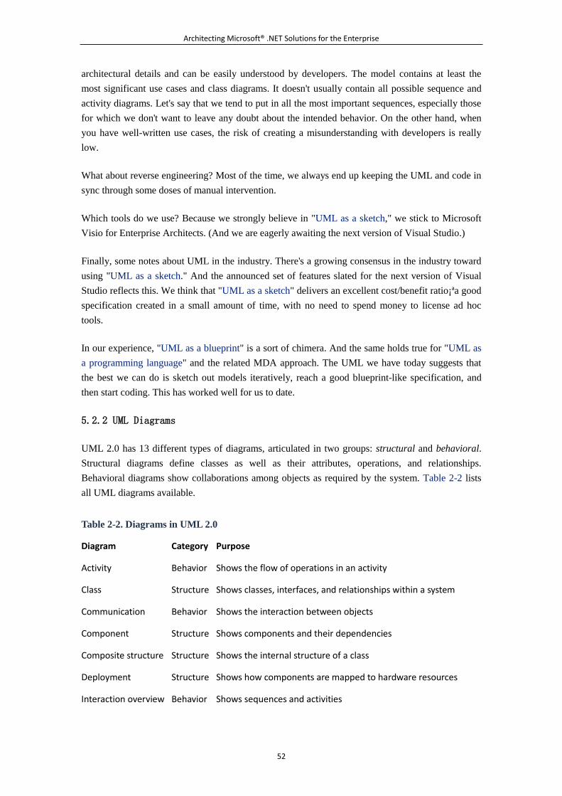
Architecting Microsoft® .NET Solutions for the Enterprise
52
architectural details and can be easily understood by developers. The model contains at least the
most significant use cases and class diagrams. It doesn't usually contain all possible sequence and
activity diagrams. Let's say that we tend to put in all the most important sequences, especially those
for which we don't want to leave any doubt about the intended behavior. On the other hand, when
you have well-written use cases, the risk of creating a misunderstanding with developers is really
low.
What about reverse engineering? Most of the time, we always end up keeping the UML and code in
sync through some doses of manual intervention.
Which tools do we use? Because we strongly believe in "UML as a sketch," we stick to Microsoft
Visio for Enterprise Architects. (And we are eagerly awaiting the next version of Visual Studio.)
Finally, some notes about UML in the industry. There's a growing consensus in the industry toward
using "UML as a sketch." And the announced set of features slated for the next version of Visual
Studio reflects this. We think that "UML as a sketch" delivers an excellent cost/benefit ratio¡ªa good
specification created in a small amount of time, with no need to spend money to license ad hoc
tools.
In our experience, "UML as a blueprint" is a sort of chimera. And the same holds true for "UML as
a programming language" and the related MDA approach. The UML we have today suggests that
the best we can do is sketch out models iteratively, reach a good blueprint-like specification, and
then start coding. This has worked well for us to date.
5.2.2 UML Diagrams
UML 2.0 has 13 different types of diagrams, articulated in two groups: structural and behavioral.
Structural diagrams define classes as well as their attributes, operations, and relationships.
Behavioral diagrams show collaborations among objects as required by the system. Table 2-2 lists
all UML diagrams available.
Table 2-2. Diagrams in UML 2.0
Diagram Category Purpose
Activity Behavior Shows the flow of operations in an activity
Class Structure Shows classes, interfaces, and relationships within a system
Communication Behavior Shows the interaction between objects
Component Structure Shows components and their dependencies
Composite structure Structure Shows the internal structure of a class
Deployment Structure Shows how components are mapped to hardware resources
Interaction overview Behavior Shows sequences and activities
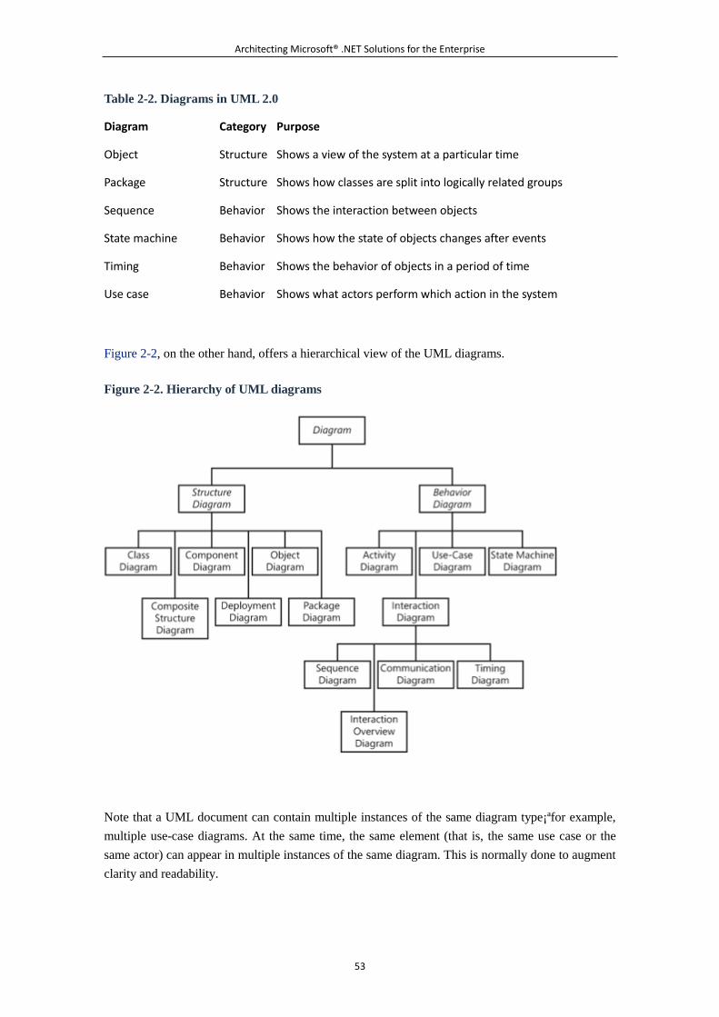
Architecting Microsoft® .NET Solutions for the Enterprise
53
Table 2-2. Diagrams in UML 2.0
Diagram Category Purpose
Object Structure Shows a view of the system at a particular time
Package Structure Shows how classes are split into logically related groups
Sequence Behavior Shows the interaction between objects
State machine Behavior Shows how the state of objects changes after events
Timing Behavior Shows the behavior of objects in a period of time
Use case Behavior Shows what actors perform which action in the system
Figure 2-2, on the other hand, offers a hierarchical view of the UML diagrams.
Figure 2-2. Hierarchy of UML diagrams
Note that a UML document can contain multiple instances of the same diagram type¡ªfor example,
multiple use-case diagrams. At the same time, the same element (that is, the same use case or the
same actor) can appear in multiple instances of the same diagram. This is normally done to augment
clarity and readability.
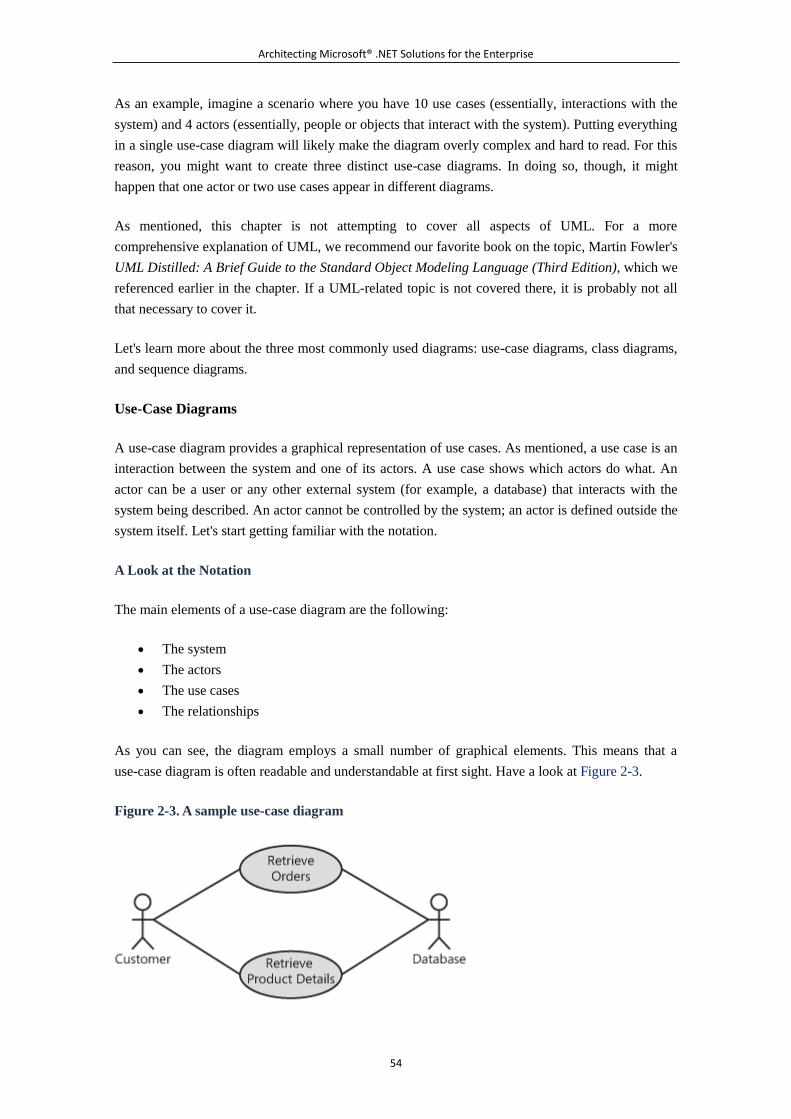
Architecting Microsoft® .NET Solutions for the Enterprise
54
As an example, imagine a scenario where you have 10 use cases (essentially, interactions with the
system) and 4 actors (essentially, people or objects that interact with the system). Putting everything
in a single use-case diagram will likely make the diagram overly complex and hard to read. For this
reason, you might want to create three distinct use-case diagrams. In doing so, though, it might
happen that one actor or two use cases appear in different diagrams.
As mentioned, this chapter is not attempting to cover all aspects of UML. For a more
comprehensive explanation of UML, we recommend our favorite book on the topic, Martin Fowler's
UML Distilled: A Brief Guide to the Standard Object Modeling Language (Third Edition), which we
referenced earlier in the chapter. If a UML-related topic is not covered there, it is probably not all
that necessary to cover it.
Let's learn more about the three most commonly used diagrams: use-case diagrams, class diagrams,
and sequence diagrams.
Use-Case Diagrams
A use-case diagram provides a graphical representation of use cases. As mentioned, a use case is an
interaction between the system and one of its actors. A use case shows which actors do what. An
actor can be a user or any other external system (for example, a database) that interacts with the
system being described. An actor cannot be controlled by the system; an actor is defined outside the
system itself. Let's start getting familiar with the notation.
A Look at the Notation
The main elements of a use-case diagram are the following:
The system
The actors
The use cases
The relationships
As you can see, the diagram employs a small number of graphical elements. This means that a
use-case diagram is often readable and understandable at first sight. Have a look at Figure 2-3.
Figure 2-3. A sample use-case diagram
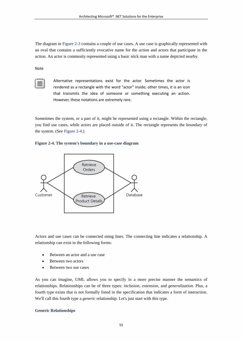
Architecting Microsoft® .NET Solutions for the Enterprise
55
The diagram in Figure 2-3 contains a couple of use cases. A use case is graphically represented with
an oval that contains a sufficiently evocative name for the action and actors that participate in the
action. An actor is commonly represented using a basic stick man with a name depicted nearby.
Note
Alternative representations exist for the actor. Sometimes the actor is
rendered as a rectangle with the word "actor" inside; other times, it is an icon
that transmits the idea of someone or something executing an action.
However, these notations are extremely rare.
Sometimes the system, or a part of it, might be represented using a rectangle. Within the rectangle,
you find use cases, while actors are placed outside of it. The rectangle represents the boundary of
the system. (See Figure 2-4.)
Figure 2-4. The system's boundary in a use-case diagram
Actors and use cases can be connected using lines. The connecting line indicates a relationship. A
relationship can exist in the following forms:
Between an actor and a use case
Between two actors
Between two use cases
As you can imagine, UML allows you to specify in a more precise manner the semantics of
relationships. Relationships can be of three types: inclusion, extension, and generalization. Plus, a
fourth type exists that is not formally listed in the specification that indicates a form of interaction.
We'll call this fourth type a generic relationship. Let's just start with this type.
Generic Relationships
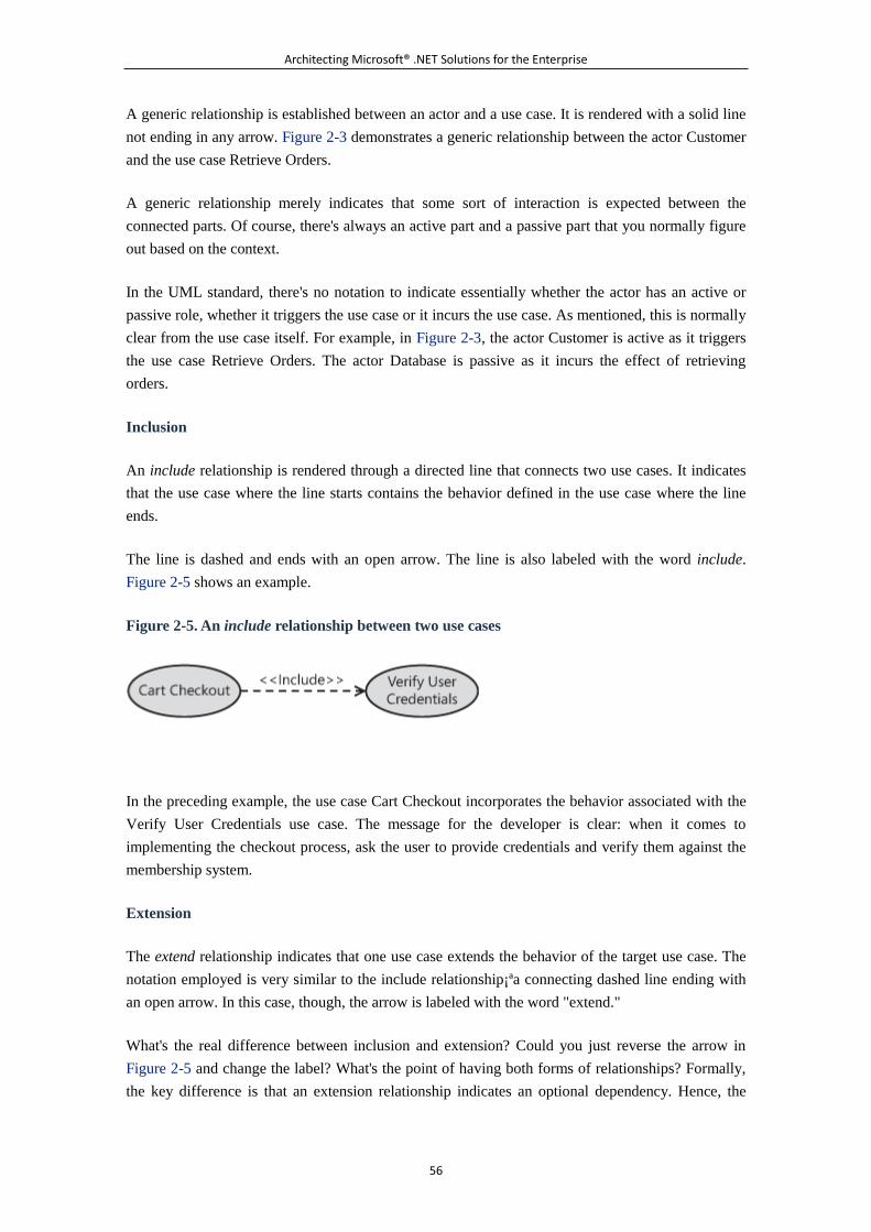
Architecting Microsoft® .NET Solutions for the Enterprise
56
A generic relationship is established between an actor and a use case. It is rendered with a solid line
not ending in any arrow. Figure 2-3 demonstrates a generic relationship between the actor Customer
and the use case Retrieve Orders.
A generic relationship merely indicates that some sort of interaction is expected between the
connected parts. Of course, there's always an active part and a passive part that you normally figure
out based on the context.
In the UML standard, there's no notation to indicate essentially whether the actor has an active or
passive role, whether it triggers the use case or it incurs the use case. As mentioned, this is normally
clear from the use case itself. For example, in Figure 2-3, the actor Customer is active as it triggers
the use case Retrieve Orders. The actor Database is passive as it incurs the effect of retrieving
orders.
Inclusion
An include relationship is rendered through a directed line that connects two use cases. It indicates
that the use case where the line starts contains the behavior defined in the use case where the line
ends.
The line is dashed and ends with an open arrow. The line is also labeled with the word include.
Figure 2-5 shows an example.
Figure 2-5. An include relationship between two use cases
In the preceding example, the use case Cart Checkout incorporates the behavior associated with the
Verify User Credentials use case. The message for the developer is clear: when it comes to
implementing the checkout process, ask the user to provide credentials and verify them against the
membership system.
Extension
The extend relationship indicates that one use case extends the behavior of the target use case. The
notation employed is very similar to the include relationship¡ªa connecting dashed line ending with
an open arrow. In this case, though, the arrow is labeled with the word "extend."
What's the real difference between inclusion and extension? Could you just reverse the arrow in
Figure 2-5 and change the label? What's the point of having both forms of relationships? Formally,
the key difference is that an extension relationship indicates an optional dependency. Hence, the
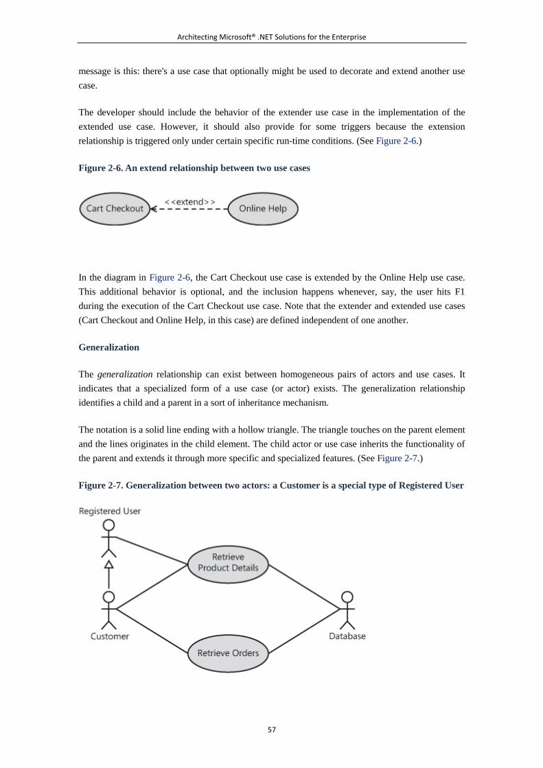
Architecting Microsoft® .NET Solutions for the Enterprise
57
message is this: there's a use case that optionally might be used to decorate and extend another use
case.
The developer should include the behavior of the extender use case in the implementation of the
extended use case. However, it should also provide for some triggers because the extension
relationship is triggered only under certain specific run-time conditions. (See Figure 2-6.)
Figure 2-6. An extend relationship between two use cases
In the diagram in Figure 2-6, the Cart Checkout use case is extended by the Online Help use case.
This additional behavior is optional, and the inclusion happens whenever, say, the user hits F1
during the execution of the Cart Checkout use case. Note that the extender and extended use cases
(Cart Checkout and Online Help, in this case) are defined independent of one another.
Generalization
The generalization relationship can exist between homogeneous pairs of actors and use cases. It
indicates that a specialized form of a use case (or actor) exists. The generalization relationship
identifies a child and a parent in a sort of inheritance mechanism.
The notation is a solid line ending with a hollow triangle. The triangle touches on the parent element
and the lines originates in the child element. The child actor or use case inherits the functionality of
the parent and extends it through more specific and specialized features. (See Figure 2-7.)
Figure 2-7. Generalization between two actors: a Customer is a special type of Registered User
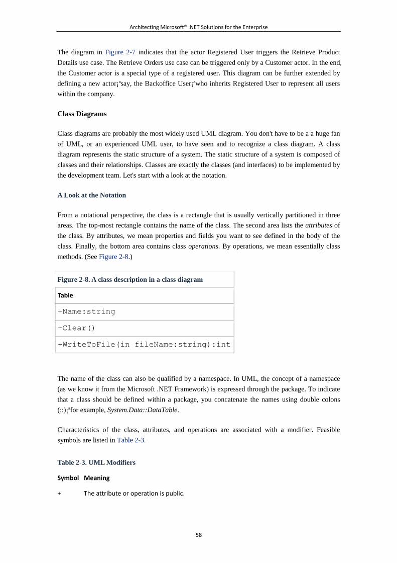
Architecting Microsoft® .NET Solutions for the Enterprise
58
The diagram in Figure 2-7 indicates that the actor Registered User triggers the Retrieve Product
Details use case. The Retrieve Orders use case can be triggered only by a Customer actor. In the end,
the Customer actor is a special type of a registered user. This diagram can be further extended by
defining a new actor¡ªsay, the Backoffice User¡ªwho inherits Registered User to represent all users
within the company.
Class Diagrams
Class diagrams are probably the most widely used UML diagram. You don't have to be a a huge fan
of UML, or an experienced UML user, to have seen and to recognize a class diagram. A class
diagram represents the static structure of a system. The static structure of a system is composed of
classes and their relationships. Classes are exactly the classes (and interfaces) to be implemented by
the development team. Let's start with a look at the notation.
A Look at the Notation
From a notational perspective, the class is a rectangle that is usually vertically partitioned in three
areas. The top-most rectangle contains the name of the class. The second area lists the attributes of
the class. By attributes, we mean properties and fields you want to see defined in the body of the
class. Finally, the bottom area contains class operations. By operations, we mean essentially class
methods. (See Figure 2-8.)
Figure 2-8. A class description in a class diagram
Table
+Name:string
+Clear()
+WriteToFile(in fileName:string):int
The name of the class can also be qualified by a namespace. In UML, the concept of a namespace
(as we know it from the Microsoft .NET Framework) is expressed through the package. To indicate
that a class should be defined within a package, you concatenate the names using double colons
(::)¡ªfor example, System.Data::DataTable.
Characteristics of the class, attributes, and operations are associated with a modifier. Feasible
symbols are listed in Table 2-3.
Table 2-3. UML Modifiers
Symbol Meaning
+ The attribute or operation is public.
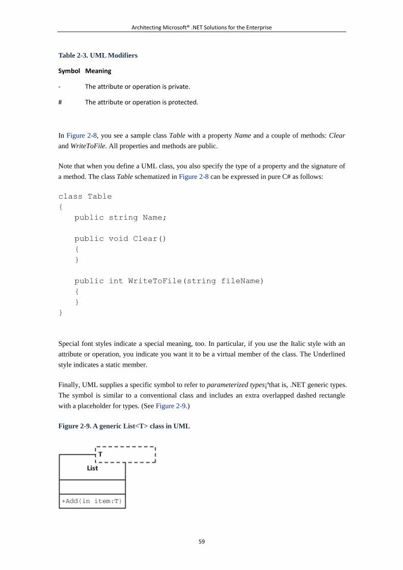
Architecting Microsoft® .NET Solutions for the Enterprise
59
Table 2-3. UML Modifiers
Symbol Meaning
- The attribute or operation is private.
# The attribute or operation is protected.
In Figure 2-8, you see a sample class Table with a property Name and a couple of methods: Clear
and WriteToFile. All properties and methods are public.
Note that when you define a UML class, you also specify the type of a property and the signature of
a method. The class Table schematized in Figure 2-8 can be expressed in pure C# as follows:
class Table
{
public string Name;
public void Clear()
{
}
public int WriteToFile(string fileName)
{
}
}
Special font styles indicate a special meaning, too. In particular, if you use the Italic style with an
attribute or operation, you indicate you want it to be a virtual member of the class. The Underlined
style indicates a static member.
Finally, UML supplies a specific symbol to refer to parameterized types¡ªthat is, .NET generic types.
The symbol is similar to a conventional class and includes an extra overlapped dashed rectangle
with a placeholder for types. (See Figure 2-9.)
Figure 2-9. A generic List<T> class in UML
Architecting Microsoft® .NET Solutions for the Enterprise
60
Let's delve a bit deeper into the syntax and sematics of attributes and relationships.
UML, Java, and the Two of Us
Like it or not, UML is a bit biased by the Java language. You might have suspected this
already from the aforementioned use of the term package instead of namespace. But
there's more to the story.
According to UML and the Java language, class attributes should be limited to defining
fields. So what about properties? In Java, you don't even have properties; in the .NET
Framework, properties are a pinch of syntactic sugar. As you might know, in the .NET
Framework properties are implemented through a pair of getter and setter methods. So
UML suggests that you use the same approach for properties.
This is the theory; but what about the practice? In our projects, we use attributes for both
properties and fields. We employ a sort of de facto standard notation to distinguish fields
from properties. Property names are PascalCase, whereas field names are camelCase.
And in general, everything we mark as public is a property.
Likewise, in both UML and the Java language you don't have events. In Java, a different
eventing model is used based on your own implementation of the publish/subscribe
pattern. In the .NET Framework, events are merely a system-provided implementation of
the same pattern, made even simpler by idiomatic language features such as the event
keyword in C#.
So in UML, you have no syntax element to define an event as a class attribute. Yet,
our .NET classes might require events. What do we do? We simply use attributes of type
EventHandler or any other more specific event delegate type. Developers will understand.
Attributes
As mentioned, attributes indicate fields of a class, but in a pure .NET context we loosely use them to
define properties and events, too. Attributes are made of a line of text. The full notation includes the
following:
Access modifier.
Name of the attribute.
Type of the attribute. The type can be either a primitive type or a custom type.
Multiplicity of the attribute¡ªthat is, the number of objects used to define a value for the
attribute.
Default value (if any) for the attribute.
Architecting Microsoft® .NET Solutions for the Enterprise
61
Here's a more complete definition for the Name attribute in a Table class:
+ Name: String = String.Empty
This UML definition might become the following C# code:
public string Name = String. Empty;
The multiplicity is a single number, or an interval, that indicates how many values are required to
set the attribute. Numbers appear in square brackets. A single number indicates that a single value or
instance is required. The previous example can be rewritten as shown here:
+ Name: String [1] = string.Empty
A collection of values is represented with the following notation:
+ Rows: Row [0..5]
In this case, to initialize the Rows attribute, up to six instances of the Row object are required. In C#,
you might have the following:
public Row[6] Rows;
You use the asterisk (*) symbol to indicate an unlimited number, as shown here:
+ Rows: Row[0..*] = List<Row>
This corresponds to the following C# code:
public IList<Row> Rows = new List<Row>();
Operations
In general, operations in a UML class diagram indicate the actions that instances of a class can take.
Operations are essentially methods. Here's the full notation:
Access modifier
Name of the operation
Parameter list (using the comma as the separator)
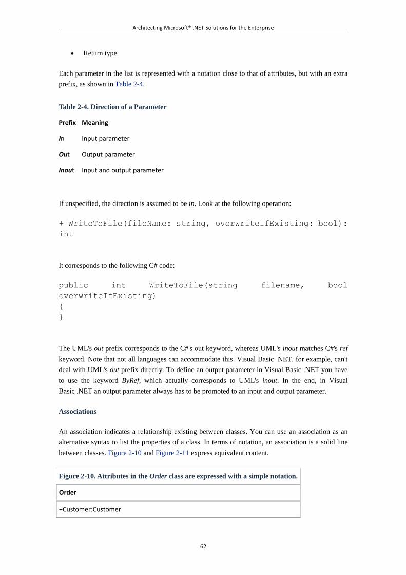
Architecting Microsoft® .NET Solutions for the Enterprise
62
Return type
Each parameter in the list is represented with a notation close to that of attributes, but with an extra
prefix, as shown in Table 2-4.
Table 2-4. Direction of a Parameter
Prefix Meaning
In Input parameter
Out Output parameter
Inout Input and output parameter
If unspecified, the direction is assumed to be in. Look at the following operation:
+ WriteToFile(fileName: string, overwriteIfExisting: bool):
int
It corresponds to the following C# code:
public int WriteToFile(string filename, bool
overwriteIfExisting)
{
}
The UML's out prefix corresponds to the C#'s out keyword, whereas UML's inout matches C#'s ref
keyword. Note that not all languages can accommodate this. Visual Basic .NET. for example, can't
deal with UML's out prefix directly. To define an output parameter in Visual Basic .NET you have
to use the keyword ByRef, which actually corresponds to UML's inout. In the end, in Visual
Basic .NET an output parameter always has to be promoted to an input and output parameter.
Associations
An association indicates a relationship existing between classes. You can use an association as an
alternative syntax to list the properties of a class. In terms of notation, an association is a solid line
between classes. Figure 2-10 and Figure 2-11 express equivalent content.
Figure 2-10. Attributes in the Order class are expressed with a simple notation.
Order
+Customer:Customer
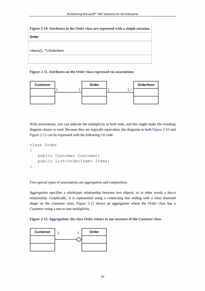
Architecting Microsoft® .NET Solutions for the Enterprise
63
Figure 2-10. Attributes in the Order class are expressed with a simple notation.
Order
+Items[1..*]:OrderItem
Figure 2-11. Attributes on the Order class expressed via associations
With associations, you can indicate the multiplicity at both ends, and this might make the resulting
diagram clearer to read. Because they are logically equivalent, the diagrams in both Figure 2-10 and
Figure 2-11 can be expressed with the following C# code:
class Order
{
public Customer Customer;
public List<OrderItem> Items;
}
Two special types of associations are aggregation and composition.
Aggregation specifies a whole/part relationship between two objects, or in other words a has-a
relationship. Graphically, it is represented using a connecting line ending with a clear diamond
shape on the container class. Figure 2-12 shows an aggregation where the Order class has a
Customer using a one-to-one multiplicity.
Figure 2-12. Aggregation: the class Order relates to one instance of the Customer class.
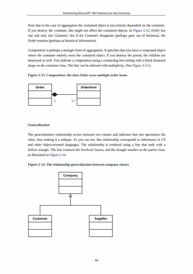
Architecting Microsoft® .NET Solutions for the Enterprise
64
Note that in the case of aggregation the contained object is not entirely dependent on the container.
If you destroy the container, this might not affect the contained objects. In Figure 2-12, Order has
one and only one Customer, but if the Customer disappears (perhaps goes out of business), the
Order remains (perhaps as historical information).
Composition is perhaps a stronger form of aggregation. It specifies that you have a compound object
where the container entirely owns the contained object. If you destroy the parent, the children are
destroyed as well. You indicate a composition using a connecting line ending with a black diamond
shape on the container class. The line can be adorned with multiplicity. (See Figure 2-13.)
Figure 2-13. Composition: the class Order owns multiple order items.
Generalization
The generalization relationship occurs between two classes and indicates that one specializes the
other, thus making it a subtype. As you can see, this relationship corresponds to inheritance in C#
and other object-oriented languages. The relationship is rendered using a line that ends with a
hollow triangle. The line connects the involved classes, and the triangle touches on the parent class,
as illustrated in Figure 2-14.
Figure 2-14. The relationship generalization between company classes
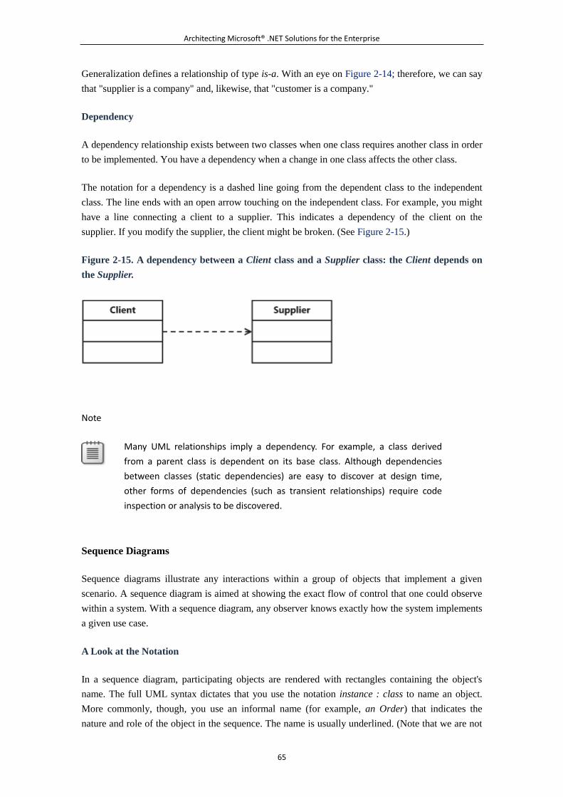
Architecting Microsoft® .NET Solutions for the Enterprise
65
Generalization defines a relationship of type is-a. With an eye on Figure 2-14; therefore, we can say
that "supplier is a company" and, likewise, that "customer is a company."
Dependency
A dependency relationship exists between two classes when one class requires another class in order
to be implemented. You have a dependency when a change in one class affects the other class.
The notation for a dependency is a dashed line going from the dependent class to the independent
class. The line ends with an open arrow touching on the independent class. For example, you might
have a line connecting a client to a supplier. This indicates a dependency of the client on the
supplier. If you modify the supplier, the client might be broken. (See Figure 2-15.)
Figure 2-15. A dependency between a Client class and a Supplier class: the Client depends on
the Supplier.
Note
Many UML relationships imply a dependency. For example, a class derived
from a parent class is dependent on its base class. Although dependencies
between classes (static dependencies) are easy to discover at design time,
other forms of dependencies (such as transient relationships) require code
inspection or analysis to be discovered.
Sequence Diagrams
Sequence diagrams illustrate any interactions within a group of objects that implement a given
scenario. A sequence diagram is aimed at showing the exact flow of control that one could observe
within a system. With a sequence diagram, any observer knows exactly how the system implements
a given use case.
A Look at the Notation
In a sequence diagram, participating objects are rendered with rectangles containing the object's
name. The full UML syntax dictates that you use the notation instance : class to name an object.
More commonly, though, you use an informal name (for example, an Order) that indicates the
nature and role of the object in the sequence. The name is usually underlined. (Note that we are not
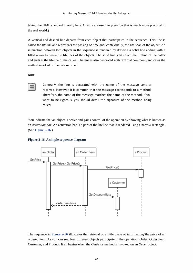
Architecting Microsoft® .NET Solutions for the Enterprise
66
taking the UML standard literally here. Ours is a loose interpretation that is much more practical in
the real world.)
A vertical and dashed line departs from each object that participates in the sequence. This line is
called the lifeline and represents the passing of time and, contextually, the life span of the object. An
interaction between two objects in the sequence is rendered by drawing a solid line ending with a
filled arrow between the lifelines of the objects. The solid line starts from the lifeline of the caller
and ends at the lifeline of the callee. The line is also decorated with text that commonly indicates the
method invoked or the data returned.
Note
Generally, the line is decorated with the name of the message sent or
received. However, it is common that the message corresponds to a method.
Therefore, the name of the message matches the name of the method. If you
want to be rigorous, you should detail the signature of the method being
called.
You indicate that an object is active and gains control of the operation by showing what is known as
an activation bar. An activation bar is a part of the lifeline that is rendered using a narrow rectangle.
(See Figure 2-16.)
Figure 2-16. A simple sequence diagram
The sequence in Figure 2-16 illustrates the retrieval of a little piece of information¡ªthe price of an
ordered item. As you can see, four different objects participate in the operation¡ªOrder, Order Item,
Customer, and Product. It all begins when the GetPrice method is invoked on an Order object.
Architecting Microsoft® .NET Solutions for the Enterprise
67
Internally, the Order object figures out the ordered item and attempts to retrieve the price. In turn,
the Order Item finds a reference to the ordered product and gets the related price. At some point,
when the activation bar of the Product object terminates, the Order Item knows about the standard
price of the product. However, it also needs to check any applicable discount for the customer who
actually ordered it. So the GetDiscountRate method is invoked on a Customer object. At the end, the
price of the ordered item is carried back to the original caller.
When the invoked method returns a value, you typically draw a return line (dashed this time) that
connects callee and caller. This line is decorated with the logical name assigned to the returned
value. This optional item increases the readability of the diagram and also gives you a chance to
express conditions by using interaction frames. (We'll say more about this in a moment.) Return
values are optional, however.
Note
An object can invoke a method on the same instance¡ªfor example, an Order
object invokes a method on itself. This situation is represented by drawing an
arrow (in a semicircular shape) that starts and ends on the same activation bar.
Life and Death of an Object
The lifeline notation in a UML sequence diagram merely shows the passing of time, but it says
nothing about the creation and destruction of objects. A special notation exists to indicate explicitly
the lifetime of an object. (See Figure 2-17.)
Figure 2-17. The UML notation for creating and destroying objects
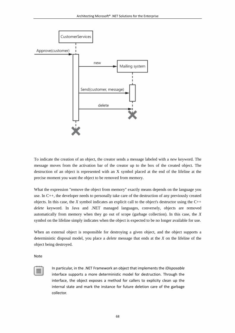
Architecting Microsoft® .NET Solutions for the Enterprise
68
To indicate the creation of an object, the creator sends a message labeled with a new keyword. The
message moves from the activation bar of the creator up to the box of the created object. The
destruction of an object is represented with an X symbol placed at the end of the lifeline at the
precise moment you want the object to be removed from memory.
What the expression "remove the object from memory" exactly means depends on the language you
use. In C++, the developer needs to personally take care of the destruction of any previously created
objects. In this case, the X symbol indicates an explicit call to the object's destructor using the C++
delete keyword. In Java and .NET managed languages, conversely, objects are removed
automatically from memory when they go out of scope (garbage collection). In this case, the X
symbol on the lifeline simply indicates when the object is expected to be no longer available for use.
When an external object is responsible for destroying a given object, and the object supports a
deterministic disposal model, you place a delete message that ends at the X on the lifeline of the
object being destroyed.
Note
In particular, in the .NET Framework an object that implements the IDisposable
interface supports a more deterministic model for destruction. Through the
interface, the object exposes a method for callers to explicity clean up the
internal state and mark the instance for future deletion care of the garbage
collector.
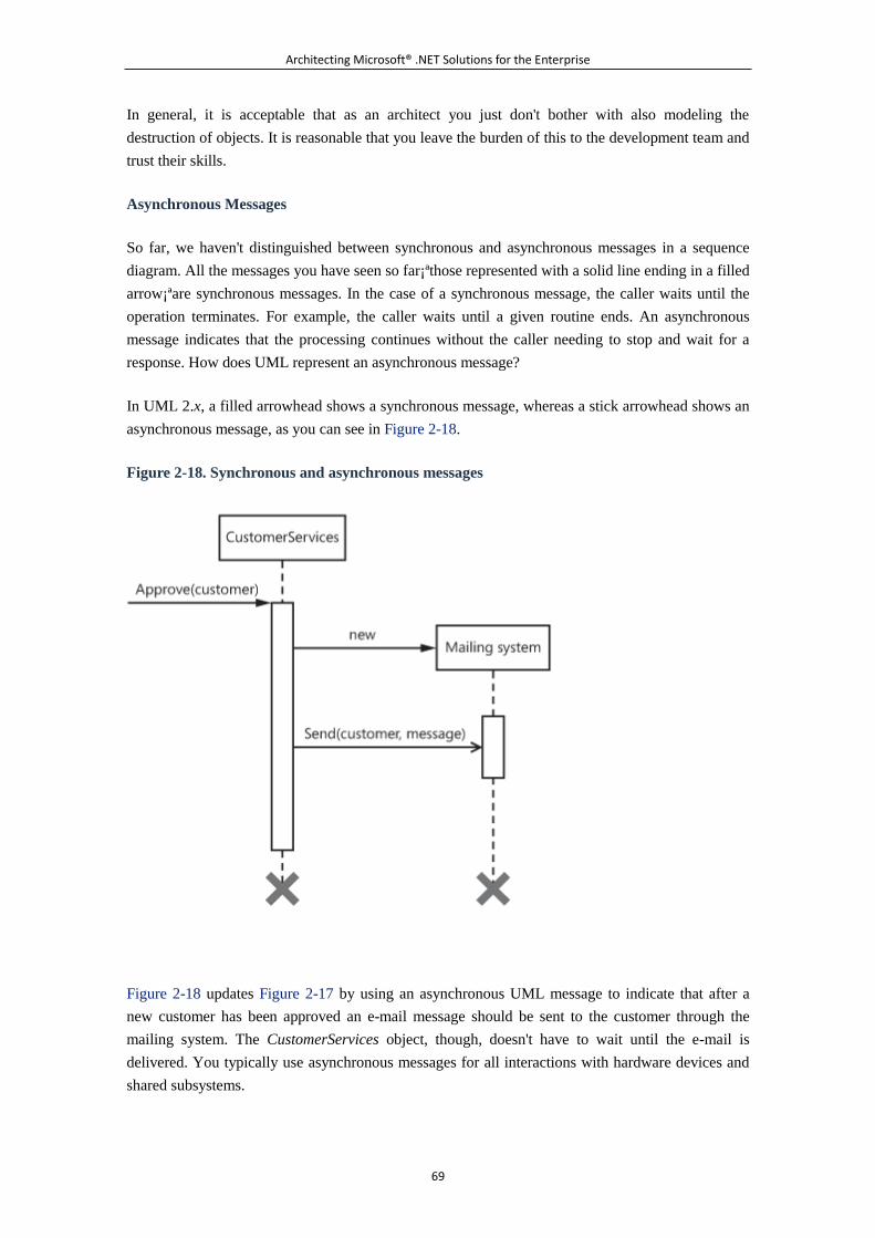
Architecting Microsoft® .NET Solutions for the Enterprise
69
In general, it is acceptable that as an architect you just don't bother with also modeling the
destruction of objects. It is reasonable that you leave the burden of this to the development team and
trust their skills.
Asynchronous Messages
So far, we haven't distinguished between synchronous and asynchronous messages in a sequence
diagram. All the messages you have seen so far¡ªthose represented with a solid line ending in a filled
arrow¡ªare synchronous messages. In the case of a synchronous message, the caller waits until the
operation terminates. For example, the caller waits until a given routine ends. An asynchronous
message indicates that the processing continues without the caller needing to stop and wait for a
response. How does UML represent an asynchronous message?
In UML 2.x, a filled arrowhead shows a synchronous message, whereas a stick arrowhead shows an
asynchronous message, as you can see in Figure 2-18.
Figure 2-18. Synchronous and asynchronous messages
Figure 2-18 updates Figure 2-17 by using an asynchronous UML message to indicate that after a
new customer has been approved an e-mail message should be sent to the customer through the
mailing system. The CustomerServices object, though, doesn't have to wait until the e-mail is
delivered. You typically use asynchronous messages for all interactions with hardware devices and
shared subsystems.
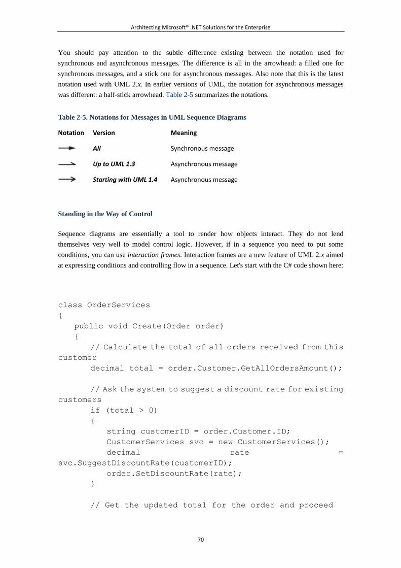
Architecting Microsoft® .NET Solutions for the Enterprise
70
You should pay attention to the subtle difference existing between the notation used for
synchronous and asynchronous messages. The difference is all in the arrowhead: a filled one for
synchronous messages, and a stick one for asynchronous messages. Also note that this is the latest
notation used with UML 2.x. In earlier versions of UML, the notation for asynchronous messages
was different: a half-stick arrowhead. Table 2-5 summarizes the notations.
Table 2-5. Notations for Messages in UML Sequence Diagrams
Notation Version Meaning
All Synchronous message
Up to UML 1.3 Asynchronous message
Starting with UML 1.4 Asynchronous message
Standing in the Way of Control
Sequence diagrams are essentially a tool to render how objects interact. They do not lend
themselves very well to model control logic. However, if in a sequence you need to put some
conditions, you can use interaction frames. Interaction frames are a new feature of UML 2.x aimed
at expressing conditions and controlling flow in a sequence. Let's start with the C# code shown here:
class OrderServices
{
public void Create(Order order)
{
// Calculate the total of all orders received from this
customer
decimal total = order.Customer.GetAllOrdersAmount();
// Ask the system to suggest a discount rate for existing
customers
if (total > 0)
{
string customerID = order.Customer.ID;
CustomerServices svc = new CustomerServices();
decimal rate =
svc.SuggestDiscountRate(customerID);
order.SetDiscountRate(rate);
}
// Get the updated total for the order and proceed
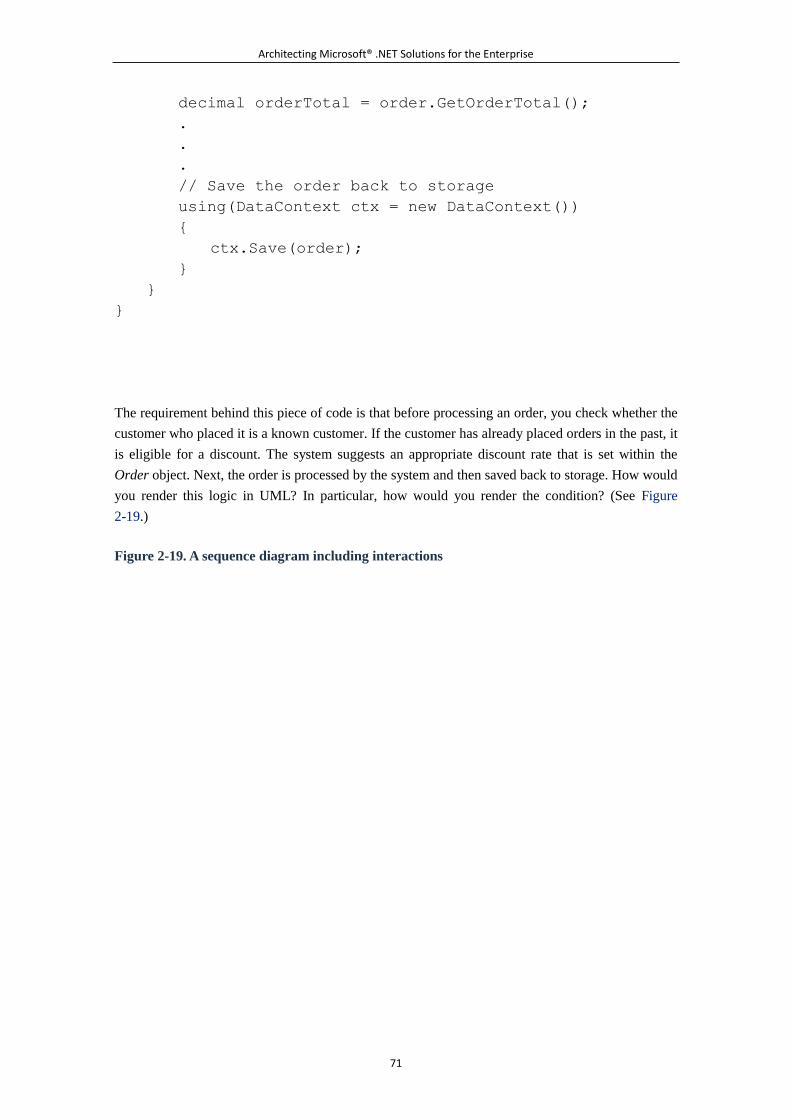
Architecting Microsoft® .NET Solutions for the Enterprise
71
decimal orderTotal = order.GetOrderTotal();
.
.
.
// Save the order back to storage
using(DataContext ctx = new DataContext())
{
ctx.Save(order);
}
}
}
The requirement behind this piece of code is that before processing an order, you check whether the
customer who placed it is a known customer. If the customer has already placed orders in the past, it
is eligible for a discount. The system suggests an appropriate discount rate that is set within the
Order object. Next, the order is processed by the system and then saved back to storage. How would
you render this logic in UML? In particular, how would you render the condition? (See Figure
2-19.)
Figure 2-19. A sequence diagram including interactions
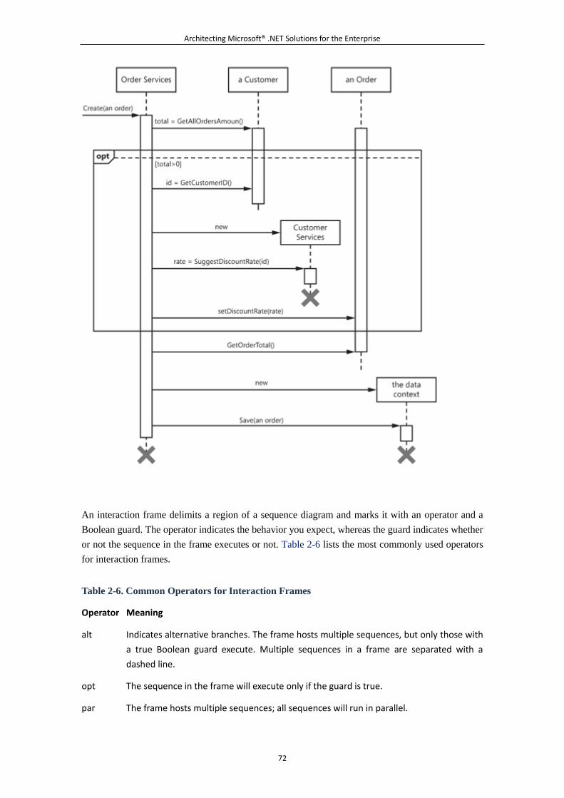
Architecting Microsoft® .NET Solutions for the Enterprise
72
An interaction frame delimits a region of a sequence diagram and marks it with an operator and a
Boolean guard. The operator indicates the behavior you expect, whereas the guard indicates whether
or not the sequence in the frame executes or not. Table 2-6 lists the most commonly used operators
for interaction frames.
Table 2-6. Common Operators for Interaction Frames
Operator Meaning
alt Indicates alternative branches. The frame hosts multiple sequences, but only those with
a true Boolean guard execute. Multiple sequences in a frame are separated with a
dashed line.
opt The sequence in the frame will execute only if the guard is true.
par The frame hosts multiple sequences; all sequences will run in parallel.
Architecting Microsoft® .NET Solutions for the Enterprise
73
Table 2-6. Common Operators for Interaction Frames
Operator Meaning
loop The sequence in the frame will be executed multiple times, based on the guard
expression.
region Indicates a critical section, and requires that only one thread executes it at a time.
Finally, note that interaction frames can be nested if this is really necessary. The point here is that
nested frames augment the complexity, and decrease the readability, of the resulting diagram. If you
have really complex control logic to express, we suggest that you opt for an activity
diagram¡ªessentially, an object-oriented version of flowcharts¡ªor even code snippets. The best you
can do, though, is break the sequence down into smaller pieces so that a standard sequence diagram
with simple interaction frames is readable enough.
Domain-Specific Languages and UML
UML is a general-purpose modeling language with incorporated concepts and tools that
can be easily applied to a variety of contexts. Adapting the model to a particular domain
might require additional and more specific tools and elements. For this reason, UML 2.x
defines a standard mechanism, known as profiles, to extend the language. When you
create a custom UML profile, you essentially extend the base metamodel by adding new
elements with specific properties suitable to a given domain.
However, a UML profile is still a piece of a fixed model. A domain-specific language
(DSL) is something different. A DSL is a domain-specific programming language created
to solve problems in a particular domain. A DSL can be a visual language or a textual
language. In general, it falls somewhere in between a small programming language and a
scripting language. A DSL doesn't usually compile to binary code; rather, it is rendered to
some intermediate language. Although it was not created to be a DSL, all in all SQL can
be considered a realistic example of a DSL¡ªit is a language specific to a domain (database
access), and it is invoked by other applications.
To model your domain effectively, should you use UML extensions or switch to a DSL?
In our way of looking at things, UML is a general-purpose language, meaning that it is
good at describing any sort of domain, but only approximately. Or, put another way, it
can't be used to describe any domain precisely. In the imperfect world where we live, no
universal language can be used to solve all sorts of problems with the same level of
effectiveness. Enter DSLs. A DSL is a language for just one domain and scenario: it's a
made-to-measure, straight-to-the-point, and ad hoc language. Its elements come from the
domain, not from a fixed metamodel.
By extending UML with a profile, you transform a general language into something
Architecting Microsoft® .NET Solutions for the Enterprise
74
specific and, in doing so, you use the set of tools the general language makes available.
Sure, it works. But is it effective? By using DSLs, you create your own language using ad
hoc DSL tools, such as those integrated in Visual Studio. (See
http://msdn.microsoft.com/en-us/library/bb126235.aspx.) This language might not be
reusable outside the domain, but it is direct. And, by the way, are you sure that your
profile is reusable as well?
Because a DSL language is tailor-made for a domain, generating compile code out of it is
easier. And the DSL tool does it for you. We see the future of model-driven development
passing through DSL rather than using UML as the modeling tool.
5.2.3 Summary
UML is a standard language for object modeling. It is independent from any programming language.
This is a key attribute, in both a good way and a bad way. It is a good attribute because it makes
UML an extremely versatile tool for modeling and communicating any business process. At the
same time, all that it can produce is a generic model using a fixed metamodel. This is far from the
compiled code that forms a system.
Based on a metamodel, UML can be extended using profiles and a set of custom tools and elements.
But still, you need to write code based upon your UML model. It is debatable whether extensions to
UML or domain-specific languages are the optimal solution to model applications at the highest
possible level. All in all, we reckon that DSLs are a more direct approach, but we still like UML
when a modeling tool is required. And it is required in most real projects. We feel that UML and
DSL are complementary and one doesn't exclude the other. But they are different things, with each
one being good at different things.
In this chapter, we mostly presented UML as a modeling language. We discussed the three main
modes of using UML, including the emerging "UML as a sketch" mode. In our vision, this
sketching model is ideal to communicate ideas within and around the team; then manual coding, or
DSLs integrated into the development environment, will be responsible for the actual production of
compiled code.
UML is all about diagrams. The latest version of UML supports up to 13 types of diagrams. In this
overview chapter, we covered only the most important of these diagram types¡ªuse-case, class, and
sequence diagrams. For a complete reference for UML, you should look elsewhere. And we
recommend Martin Fowler's excellent book UML Distilled: A Brief Guide to the Standard Object
Modeling Language (Third Edition).
5.2.4 Murphy's Laws of the Chapter
Communication is important in a software project, like in any other aspect of life. Communication,
though, requires notation and models, if not formal specifications. The UML we presented in this
Architecting Microsoft® .NET Solutions for the Enterprise
75
chapter is all about supplying a model for communicating key ideas about design. Communication
and modeling are the subject of the following Murphy's laws:
Real programmers don't comment their code. If it was hard to write, it should be hard to
understand.
Ninety percent of a programmer's errors come from data from other programmers.
Walking on water and developing software to specification are easy as long as both are
frozen.
See http://www.murphys-laws.com for an extensive listing of other computer-related (and
non-computer-related) laws and corollaries.
5.3 Chapter 3. Design Principles and Patterns
Experienced designers evidently know something inexperienced others don't. What is it?
¡ªErich Gamma
In Chapter 1, "Architects and Architecture Today," we focused on the true meaning of architecture
and the steps through which architects get a set of specifications for the development team. We
focused more on the process than the principles and patterns of actual design. In Chapter 2, "UML
Essentials," we filled a gap by serving up a refresher (or a primer, depending on the reader's skills)
of Unified Modeling Language (UML). UML is the most popular modeling language through which
design is expressed and communicated within development teams.
When examining the bundle of requirements, the architect at first gets a relatively blurred picture of
the system. As the team progresses through iterations, the contours of the picture sharpen. In the end,
the interior of the system unveils a web of interrelated classes applying design patterns and fulfilling
design principles.
Designing a software system is challenging because it requires you to focus on today's requested
features while ensuring that the resulting system be flexible enough to support changes and addition
of new features in the future.
Especially in the past two decades, a lot has been done in the Information Technology (IT) industry
to make a systematic approach to software development possible. Methodologies, design principles,
and finally patterns have been developed to help guide architects to envision and build systems of
any complexity in a disciplined way.
This chapter aims to provide you with a quick tutorial about software engineering. It first outlines
some basic principles that should always inspire the design of a modern software system. The
chapter then moves on to discuss principles of object-oriented design. Along the way, we introduce
patterns, idioms, and aspect-orientation, as well as pearls of wisdom regarding requirement-driven
design that affect key areas such as testability, security, and performance.
Architecting Microsoft® .NET Solutions for the Enterprise
76
5.3.1 Basic Design Principles
It is one thing to write code that just works. It is quite another to write good code that works.
Adopting the attitude of "writing good code that works" springs from the ability to view the system
from a broad perspective. In the end, a top-notch system is not just a product of writing instructions
and hacks that make it all work. There's much more, actually. And it relates, directly or indirectly, to
design.
The attitude of "writing good code that works" leads you, for example, to value the maintainability
of the code base over any other quality characteristics, such as those defined by International
Organization for Standardization (ISO) and International Electrotechnical Commission (IEC)
standard 9126. (See Chapter 1.) You adopt this preference not so much because other aspects (such
as extensibility or perhaps scalability) are less important than maintainability¡ªit's just that
maintenance is expensive and can be highly frustrating for the developers involved.
A code base that can be easily searched for bugs, and in which fixing bugs is not problematic for
anyone, is open to any sort of improvements at any time, including extensibility and scalability.
Thus, maintainability is the quality characteristic you should give the highest priority when you
design a system.
Why is software maintenance so expensive?
Maintenance becomes expensive if essentially you have produced unsatisfactory (should we say,
sloppy?) software, you haven't tested the software enough, or both. Which attributes make software
easier to maintain and evolve? Structured design in the first place, which is best applied through
proper coding techniques. Code readability is another fundamental asset, which is best achieved if
the code is combined with a bunch of internal documentation and a change-tracking system¡ªbut this
might occur only in a perfect world.
Before we proceed any further with the basic principles of structured design, let's arrange a brief
cheat-sheet to help us catch clear and unambiguous symptoms of bad code design.
Note
Unsatisfactory software mostly springs from a poor design. But what causes a
poor design? A poor design typically has two causes that are not mutually
exclusive: the architect's insufficient skills, and imprecise or contradictory
requirements. So what about the requirements problem, then? Contradictory
requirements usually result from bad communication. Communication is king,
and it is one of the most important skills for an architect to cultivate and
improve.
Not surprisingly, fixing this communication problem drives us again straight to
agile methodologies. What many people still miss about the agile movement is
that the primary benefit you get is not so much the iterative method itself.
Architecting Microsoft® .NET Solutions for the Enterprise
77
Instead, the major benefit comes from the continuous communication that the
methodology promotes within the team and between the team and the
customers. Whatever you get wrong in the first iteration will be fixed quite
soon in the next (or close to the next) iteration because the communication
that is necessary to move forward will clarify misunderstood requirements and
fix bad ones. And it will do so quite early in the process and on a timely basis.
This iterative approach simply reduces the entry point for the major cause of
costly software maintenance: poor communication. And this is the primary
reason why, one day, a group of (perfectly sane) developers and architects
decided to found the agile movement. It was pragmatism that motivated
them, not caprice.
This said, you should also keep in mind that that agile methodologies also tend
to increase development costs and run the risk of scope/requirements creep.
You also must make sure everyone in the process is on board with it. If the
stakeholders don't understand their role or are not responsive, or can't review
the work between iterations, the agile approach fails. So the bottom line is
that the agile approach isn't a magic wand that works for everyone. But when
it works, it usually works well.
For What the Alarm Bell Should Ring
Even with the best intentions of everyone involved and regardless of their efforts, the design of a
system at some point can head down a slippery slope. The deterioration of a good design is
generally a slow process that occurs over a relatively long period of time. It happens by continually
studding your classes with hacks and workarounds, making a large share of the code harder and
harder to maintain and evolve. At a certain point, you find yourself in serious trouble.
Managers might be tempted to call for a complete redesign, but redesigning an evolving system is
like trying to catch a runaway chicken. You need to be in a very good shape to do it. But is the team
really in shape at that point?
Note
Have you ever seen the movie Rocky? Do you remember the scene where
Rocky, the boxer, finally catches the chicken, thus providing evidence that he's
ready for the match? By the way, the scene is on
http://www.youtube.com/watch?v=. During the movie, Rocky attempts several
times to get the chicken, but he gets the chicken only when he has trained well
enough.
Let's identify a few general signs that would make the alarm bell ring to warn of a problematic
design.
Architecting Microsoft® .NET Solutions for the Enterprise
78
Rigid, Therefore Fragile
Can you bend a piece of wood? What do you risk if you insist on doing it? A piece of wood is
typically a stiff and rigid object characterized by some resistance to deformation. When enough
force is applied, the deformation becomes permanent and the wood breaks.
What about rigid software?
Rigid software is characterized by some resistance to changes. Resistance is measured in terms of
regression. You make a change in one module, but the effects of your change cascade down the list
of dependent modules. As a result, it's really hard to predict how long making a change¡ªany change,
even the simplest¡ªwill actually take.
If you pummel glass or any other fragile material, you manage only to break it into several pieces.
Likewise, when you enter a change in software and break it in various places, it becomes quite
apparent that software is definitely fragile.
As in other areas of life, in the software world fragility and rigidity go hand in hand. When a change
in a software module breaks (many) other modules because of (hidden) dependencies, you have a
clear symptom of a bad design that needs to be remedied as soon as possible.
Easier to Use Than to Reuse
Imagine you have a piece of software that works in one project; you would like to reuse it in another
project. However, copying the class or linking the assembly in the new project just doesn't work.
Why is it so?
If the same code doesn't work when moved to another project, it's because of dependencies. The real
problem isn't just dependencies, but the number and depth of dependencies. The risk is that to reuse
a piece of functionality in another project, you have to import a much larger set of functions.
Ultimately, no reuse is ever attempted and code is rewritten from scratch.
This is not a good sign for your design. This negative aspect of a design is often referred to as
immobility.
Easier to Work Around Than to Fix
When applying a change to a software module, it is not unusual that you figure out two or more
ways to do it. Most of the time, one way of doing things is nifty, elegant, coherent with the design,
but terribly laborious to implement. The other way is, conversely, much smoother, quick to code,
but sort of a hack.
What should you do?
Architecting Microsoft® .NET Solutions for the Enterprise
79
Actually, you can solve it either way, depending on the given deadlines and your manager's
direction about it.
In summary, it is not an ideal situation when a workaround is much easier and faster to apply than
the right solution. And it doesn't make a great statement about your overall design, either. It is a sign
that too many unnecessary dependencies exist between classes and that your classes do not form a
particularly cohesive mass of code.
This aspect of a design¡ªthat it invites or accommodates workarounds more or less than fixes¡ªis
often referred to as viscosity. High viscosity is bad, meaning that the software resists modification
just as highly viscous fluids resist flow.
Structured Design
When the two of us started programming, which was far before we started making a living from it,
the old BASIC language was still around with its set of GOTO statements. Like many others, we
wrote toy programs jumping from one instruction to the next within the same monolithic block of
code. They worked just fine, but they were only toy programs in the end.
Note
Every time we looked at the resulting messy BASIC code we wrote, continually
referring to other instructions that appeared a bunch of lines up or down in
the code, we didn't really like it and we weren't really proud of it. But, at the
time, we just thought we were picking up a cool challenge that only a few
preordained souls could take on. Programming is a darned hard thing¡ªwe
thought¡ªbut we are going to like it.
It was about the late 1960s when the complexity of the average program crossed the significant
threshold that marked the need for a more systematic approach to software development. That
signaled the official beginning of software engineering.
From Spaghetti Code to Lasagna Code
Made of a messy tangle of jumps and returns, GOTO-based code was soon belittled and infamously
labeled as spaghetti code. And we all learned the first of a long list of revolutionary concepts:
structured programming. In particular, we learned to use subroutines to break our code into cohesive
and more reusable pieces. In food terms, we evolved from spaghetti to lasagna. If you look at
Figure 3-1, you will spot the difference quite soon. Lasagna forms a layered block of noodles and
toppings that can be easily cut into pieces and just exudes the concept of structure. Lasagna is also
easier to serve, which is the food analogy for reusability.
Figure 3-1. From a messy tangle to a layered and ordered block
Architecting Microsoft® .NET Solutions for the Enterprise
80
Note
A small note (and some credits) about the figure is in order. First, as Italians we
would have used the term lasagne, which is how we spell it, but we went for
the international spelling of lasagna. However, we eat it regardless of the
spelling. Second, Dino personally ate all the food in the figure in a sort of
manual testing procedure for the book's graphics. Dino, however, didn't cook
anything. Dino's mother-in-law cooked the spaghetti; Dino's mom cooked the
lasagna. Great stuff¡ªif you're in Italy, and want to give it a try, send Dino an
e-mail.
What software engineering really has been trying to convey since its inception is the need for some
design to take place before coding begins and, subsequently, the need for some basic design
principles. Still, today, when someone says "structured programming," immediately many people
think of subroutines. This assumption is correct, but it's oversimplifying the point and missing the
principal point of the structured approach.
Behind structured programming, there is structured design with two core principles. And these
principles are as valid today as they were 30 and more years ago. Subroutines and Pascal-like
programming are gone; the principles of cohesion and coupling, instead, still maintain their
effectiveness in an object-oriented world.
These principles of structured programming, coupling and cohesion, were first introduced by Larry
Constantine and Edward Yourdon in their book Structured Design: Fundamentals of a Discipline of
Computer Program and Systems Design (Yourdon Press, 1976).
Cohesion
Cohesion indicates that a given software module¡ªbe it a subroutine, class, or library¡ªfeatures a set
of responsibilities that are strongly related. Put another way, cohesion measures the distance
between the logic expressed by the various methods on a class, the various functions in a library,
and the various actions accomplished by a method.
Architecting Microsoft® .NET Solutions for the Enterprise
81
If you look for a moment at the definition of cohesion in another field¡ªchemistry¡ªyou should be
able to see a clearer picture of software cohesion. In chemistry, cohesion is a physical property of a
substance that indicates the attraction existing between like molecules within a body.
Cohesion measurement ranges from low to high and is preferably in the highest range possible.
Highly cohesive modules favor maintenance and reusability because they tend to have no
dependencies. Low cohesion, on the other hand, makes it much harder to understand the purpose of
a class and creates a natural habitat for rigidity and fragility in the software. Low cohesive modules
also propagate dependencies through modules, thus contributing to the immobility and high
viscosity of the design.
Decreasing cohesion leads to creating modules (for example, classes) where responsibilities (for
example, methods) have very little in common and refer to distinct and unrelated activities.
Translated in a practical guideline, the principle of cohesion recommends creating extremely
specialized classes with few methods, which refer to logically related operations. If the logical
distance between methods grows, you just create a new class.
Ward Cunningham¡ªa pioneer of Extreme Programming¡ªoffers a concise and pragmatic definition
of cohesion in his wiki at http://c2.com/cgi/wiki?CouplingAndCohesion. He basically says that two
modules, A and B, are cohesive when a change to A has no repercussion for B so that both modules
can add new value to the system.
There's another quote we'd like to use from Ward Cunningham's wiki to reinforce a concept we
expressed a moment ago about cohesion. Cunningham suggests that we define cohesion as inversely
proportional to the number of responsibilities a module (for example, a class) has. We definitely like
this definition.
Important
Strongly related to cohesion is the Single Responsibility Principle (SRP). In the
formulation provided by Robert Martin (which you can see at
http://www.objectmentor.com/resources/articles/srp.pdf), SRP indicates that
each class should always have just one reason to change. In other words, each
class should be given a single responsibility, where a responsibility is defined
as "a reason to change." A class with multiple responsibilities has more
reasons to change and, subsequently, a less cohesive interface. A correct
application of SRP entails breaking the methods of a class into logical subsets
that configure distinct responsibilities. In the real world, however, this is much
harder to do than the opposite¡ªthat is, aggregating distinct responsibilities in
the same class.
Coupling
Architecting Microsoft® .NET Solutions for the Enterprise
82
Coupling measures the level of dependency existing between two software modules, such as classes,
functions, or libraries. An excellent description of coupling comes, again, from Cunningham's wiki
at http://c2.com/cgi/wiki?CouplingAndCohesion. Two modules, A and B, are said to be coupled
when it turns out that you have to make changes to B every time you make any change to A.
In other words, B is not directly and logically involved in the change being made to module A.
However, because of the underlying dependency, B is forced to change; otherwise, the code won't
compile any longer.
Coupling measurement ranges from low to high and the lowest possible range is preferable.
Low coupling doesn't mean that your modules are to be completely isolated from one another. They
are definitely allowed to communicate, but they should do that through a set of well-defined and
stable interfaces. Each module should be able to work without intimate knowledge of another
module's internal implementation.
Conversely, high coupling hinders testing and reusing code and makes understanding it nontrivial. It
is also one of the primary causes of a rigid and fragile design.
Low coupling and high cohesion are strongly correlated. A system designed to achieve low coupling
and high cohesion generally meets the requirements of high readability, maintainability, easy testing,
and good reuse.
Note
Introduced to support a structured design, cohesion and coupling are basic
design principles not specifically related to object orientation. However, it's
the general scope that also makes them valid and effective in an
object-oriented scenario. A good object-oriented design, in fact, is
characterized by low coupling and high cohesion, which means that
self-contained objects (high cohesion) are interacting with other objects
through a stable interface (low coupling).
Separation of Concerns
So you know you need to cook up two key ingredients in your system's recipe. But is there a
supermarket where you can get both? How do you achieve high cohesion and low coupling in the
design of a software system?
A principle that is helpful to achieving high cohesion and low coupling is separation of concerns
(SoC), introduced in 1974 by Edsger W. Dijkstra in his paper "On the Role of Scientific Thought."
If you're interested, you can download the full paper from
http://www.cs.utexas.edu/users/EWD/ewd04xx/EWD447.PDF.
Architecting Microsoft® .NET Solutions for the Enterprise
83
Identifying the Concerns
SoC is all about breaking the system into distinct and possibly nonoverlapping features. Each
feature you want in the system represents a concern and an aspect of the system. Terms such as
feature, concern, and aspect are generally considered synonyms. Concerns are mapped to software
modules and, to the extent that it is possible, there's no duplication of functionalities.
SoC suggests that you focus on one particular concern at a time. It doesn't mean, of course, that you
ignore all other concerns of the system. More simply, after you've assigned a concern to a software
module, you focus on building that module. From the perspective of that module, any other
concerns are irrelevant.
Note
If you read Dijkstra's original text, you'll see that he uses the expression
"separation of concerns" to indicate the general principle, but switches to the
word "aspect" to indicate individual concerns that relate to a software system.
For quite a few years, the word "aspect" didn't mean anything special to
software engineers. Things changed in the late 1990s when aspect-oriented
programming (AOP) entered the industry. We'll return to AOP later in this
chapter, but we make the forward reference here to show Dijkstra's great
farsightedness.
Modularity
SoC is concretely achieved through using modular code and making heavy use of information
hiding.
Modular programming encourages the use of separate modules for each significant feature. Modules
are given their own public interface to communicate with other modules and can contain internal
chunks of information for private use.
Only members in the public interface are visible to other modules. Internal data is either not exposed
or it is encapsulated and exposed in a filtered manner. The implementation of the interface contains
the behavior of the module, whose details are not known or accessible to other modules.
Information Hiding
Information hiding (IH) is a general design principle that refers to hiding behind a stable interface
some implementation details of a software module that are subject to change. In this way, connected
modules continue to see the same fixed interface and are unaffected by changes.
A typical application of the information-hiding principle is the implementation of properties in C#
or Microsoft Visual Basic .NET classes. (See the following code sample.) The property name
Architecting Microsoft® .NET Solutions for the Enterprise
84
represents the stable interface through which callers refer to an internal value. The class can obtain
the value in various ways (for example, from a private field, a control property, a cache, the view
state in ASP.NET) and can even change this implementation detail without breaking external code.
// Software module where information hiding is applied
public class Customer
{
// Implementation detail being hidden
private string _name;
// Public and stable interface
public string CustomerName
{
// Implementation detail being hidden
get {return _name;}
}
}
Information hiding is often referred to as encapsulation. We like to distinguish between the
principle and its practical applications. In the realm of object-oriented programming, encapsulation
is definitely an application of IH.
Generally, though, the principle of SoC manifests itself in different ways in different programming
paradigms, and so it is for modularity and information hiding.
SoC and Programming Paradigms
The first programming paradigm that historically supported SoC was Procedural Programming (PP),
which we find expressed in languages such as Pascal and C. In PP, you separate concerns using
functions and procedures.
Next¡ªwith the advent of object-oriented programming (OOP) in languages such as Java, C++, and
more recently C# and Visual Basic .NET¡ªyou separate concerns using classes.
However, the concept isn't limited to programming languages. It also transcends the realm of pure
programming and is central in many approaches to software architecture. In a service-oriented
architecture (SOA), for example, you use services to represent concerns. Layered architectures are
based on SoC, and within a middle tier you can use an Object/ Relational Mapping tool (O/RM) to
separate persistence from the domain model.
Note
In the preceding section, we basically went back over 40 years of computer
science, and the entire sector of software engineering. We've seen how PP,
Architecting Microsoft® .NET Solutions for the Enterprise
85
OOP, and SOA are all direct or indirect emanations of the SoC principle. (Later
in this chapter, we'll see how AOP also fits this principle. In Chapter 7, "The
Presentation Layer," we'll see how fundamental design patterns for the
presentation layer, such as Model-View-Controller and Model-View-Presenter,
also adhere to the SoC principle.)
You really understand the meaning of the word principle if you look at how SoC
influenced, and still influences, the development of software. And we owe this
principle to a great man who passed away in 2002: Edsger W. Dijkstra. We
mention this out of respect for this man.
For more information about Dijkstra's contributions to the field, pay a visit to
http://www.cs.utexas.edu/users/ewd.
Naming Conventions and Code Readability
When the implementation of a line-of-business application is expected to take several
months to complete and the final application is expected to remain up and running for a
few years, it is quite reasonable to expect that many different people will work on the
project over time.
With such significant personnel turnover in sight, you must pay a lot of attention to
system characteristics such as readability and maintainability. To ensure that the code
base is manageable as well as easily shared and understood, a set of common
programming rules and conventions should be used. Applied all the way through,
common naming conventions, for example, make the whole code base look like it has
been written by a single programmer rather than a very large group of people.
The most popular naming convention is Hungarian Notation (HN). You can read more
about it at http://en.wikipedia.org/wiki/Hungarian_Notation. Not specifically bound to a
programming language, HN became quite popular in the mid-1990s, as it was largely used
in many Microsoft Windows applications, especially those written directly against the
Windows Software Development Kit (SDK).
HN puts the accent on the type of the variable, and it prefixes the variable name with a
mnemonic of the type. For example, szUserName would be used for a zero-terminated
string that contains a user name, and iPageCount would be used for an integer that
indicates the number of pages. Created to make each variable self-explanatory, HN lost
most of its appeal with the advent of object-oriented languages.
In object-oriented languages, everything is an object, and putting the accent on the value,
rather than the type, makes much more sense. So you choose variable names regardless of
the type and look only at the value they are expected to contain. The choice of the
variable name happens in a purely evocative way. Therefore, valid names are, for
Architecting Microsoft® .NET Solutions for the Enterprise
86
example, customer, customerID, and lowestPrice.
Finally, an argument against using HN is that a variable name should be changed every
time the type of the variable changes during development. In practice, this is often
difficult or overlooked, leading developers to make incorrect assumptions about the
values contained within the variables. This often leads directly to bugs.
You can find detailed design guidelines for the .NET Framework classes and applications
at http://msdn.microsoft.com/en-us/library/ms229042.aspx.
5.3.2 Object-Oriented Design
Before object orientation (OO), any program resulted from the interaction of modules and routines.
Programming was procedural, meaning that there was a main stream of code determining the
various steps to be accomplished.
OO is a milestone in software design.
OO lets you envision a program as the result of interacting objects, each of which holds its own data
and behavior. How would you design a graph of objects to represent your system? Which principles
should inspire this design?
We can recognize a set of core principles for object-oriented design (OOD) and a set of more
advanced and specific principles that descend from, and further specialize, the core principles.
Basic OOD Principles
To find a broadly accepted definition of OOD, we need to look at the Gang of Four (Erich Gamma,
Richard Helm, Ralph Johnson, and John Vlissides) and their landmark book Design Patterns:
Elements of Reusable Object-Oriented Software, (Addison-Wesley, 1994). (We'll make further
references to this book as GoF, which is the universal acronym for "Gang of Four.")
The entire gist of OOD is contained in this sentence:
You must find pertinent objects, factor them into classes at the right granularity, define class
interfaces and inheritance hierarchies, and establish key relationships among them.
In GoF, we also find another excerpt that is particularly significant:
Your design should be specific to the problem at hand but also general enough to address future
problems and requirements.
Architecting Microsoft® .NET Solutions for the Enterprise
87
Wouldn't you agree that this last sentence is similar to some of the guidelines resulting from the
ISO/IEC 9126 standard that we covered in Chapter 1? Its obvious similarity to that standard cannot
be denied, and it is not surprising at all.
The basics of OOD can be summarized in three points: find pertinent objects, favor low coupling,
and favor code reuse.
Find Pertinent Objects First
The first key step in OOD is creating a crisp and flexible abstraction of the problem's domain. To
successfully do so, you should think about things instead of processes. You should focus on the
whats instead of the hows. You should stop thinking about algorithms to focus mostly on interacting
entities. Interacting entities are your pertinent objects.
Where do you find them?
Requirements offer the raw material that must be worked out and shaped into a hierarchy of
pertinent objects. The descriptions of the use cases you receive from the team of analysts provide
the foundation for the design of classes. Here's a sample use case you might get from an analyst:
To view all orders placed by a customer, the user indicates the customer ID. The program displays
an error message if the customer does not exist. If the customer exists, the program displays name,
address, date of birth, and all outstanding orders. For each order, the program gets ID, date, and
all order items.
A common practice for finding pertinent objects is tagging all nouns and verbs in the various use
cases. Nouns originate classes or properties, whereas verbs indicate methods on classes. Our sample
use case suggests the definition of classes such as User, Customer, Order, and OrderItem. The class
Customer will have properties such as Name, Address, and DateOfBirth. Methods on the class
Customer might be LoadOrderItems, GetCustomerByID, and LoadOrders.
Note that finding pertinent objects is only the first step. As recommended in the statement that many
consider to be the emblem of OOD, you then have to factor pertinent objects into classes and
determine the right level of granularity and assign responsibilities.
In doing so, two principles of OOD apply, and they are listed in the introduction of GoF.
Favor Low Coupling
In an OO design, objects need to interact and communicate. For this reason, each object exposes its
own public interface for others to call. So suppose you have a logger object with a method Log that
tracks any code activity to, say, a database. And suppose also that another object at some point
needs to log something. Simply enough, the caller creates an instance of the logger and proceeds.
Overall, it's easy and effective. Here's some code to illustrate the point:
class MyComponent
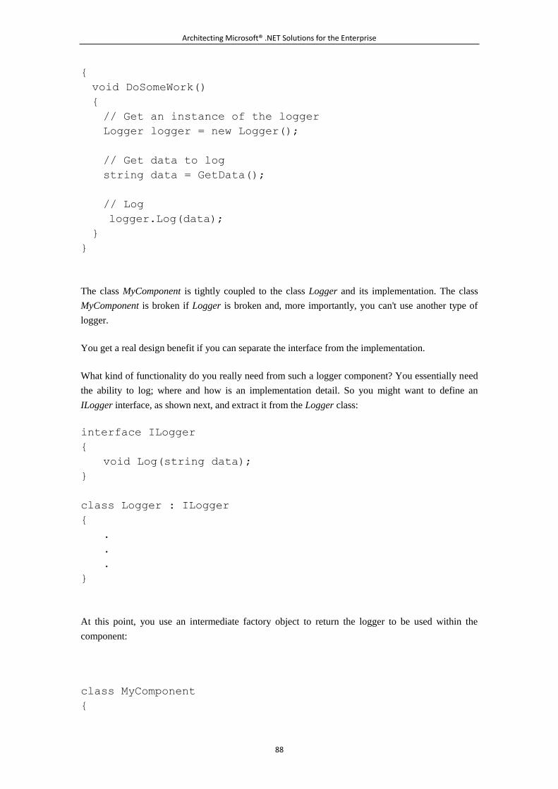
Architecting Microsoft® .NET Solutions for the Enterprise
88
{
void DoSomeWork()
{
// Get an instance of the logger
Logger logger = new Logger();
// Get data to log
string data = GetData();
// Log
logger.Log(data);
}
}
The class MyComponent is tightly coupled to the class Logger and its implementation. The class
MyComponent is broken if Logger is broken and, more importantly, you can't use another type of
logger.
You get a real design benefit if you can separate the interface from the implementation.
What kind of functionality do you really need from such a logger component? You essentially need
the ability to log; where and how is an implementation detail. So you might want to define an
ILogger interface, as shown next, and extract it from the Logger class:
interface ILogger
{
void Log(string data);
}
class Logger : ILogger
{
.
.
.
}
At this point, you use an intermediate factory object to return the logger to be used within the
component:
class MyComponent
{
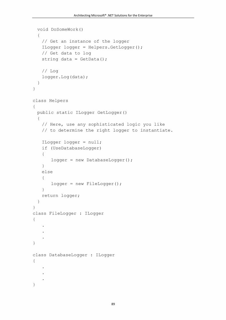
Architecting Microsoft® .NET Solutions for the Enterprise
89
void DoSomeWork()
{
// Get an instance of the logger
ILogger logger = Helpers.GetLogger();
// Get data to log
string data = GetData();
// Log
logger.Log(data);
}
}
class Helpers
{
public static ILogger GetLogger()
{
// Here, use any sophisticated logic you like
// to determine the right logger to instantiate.
ILogger logger = null;
if (UseDatabaseLogger)
{
logger = new DatabaseLogger();
}
else
{
logger = new FileLogger();
}
return logger;
}
}
class FileLogger : ILogger
{
.
.
.
}
class DatabaseLogger : ILogger
{
.
.
.
}
Architecting Microsoft® .NET Solutions for the Enterprise
90
The factory code gets you an instance of the logger for the component to use. The factory returns an
object that implements the ILogger interface, and the component consumes any object that
implements the contracted interface.
The dependency between the component and the logger is now based on an interface rather than an
implementation.
If you base class dependencies on interfaces, you minimize coupling between classes to the smallest
possible set of functions¡ªthose defined in the interface. In doing so, you just applied the first
principle of OOD as outlined in GoF:
Program to an interface, not an implementation.
This approach to design is highly recommended for using with the parts of your code that are most
likely to undergo changes in their implementation.
Note
Should you use an interface? Or should you perhaps opt for an abstract base
class? In object-oriented languages that do not support multiple
inheritance¡ªsuch as Java, C#, and Visual Basic .NET¡ªan interface is always
preferable because it leaves room for another base class of your choice. When
you have multiple inheritance, it is mostly a matter of preference. You should
consider using a base class in .NET languages in all cases where you need more
than just an interface. If you need some hard-coded behavior along with an
interface, a base class is the only option you have. ASP.NET providers, for
example, are based on base classes and not on interfaces.
An interesting possibility beyond base classes and interfaces are mixins, but
they are an OOP feature not supported by .NET languages. A mixin is a class
that provides a certain functionality that other classes can inherit, but it is not
meant to be a standalone class. Put another way, a mixin is like an interface
where some of the members might contain a predefined implementation.
Mixins are supported in some dynamic languages, including Python and Ruby.
No .NET languages currently support mixins, but mixins can be simulated using
ad hoc frameworks such as Castle. DynamicProxy. With this framework, you
first define a class that contains all the methods you want to inject in an
existing class¡ªthe mixin. Next, you use the framework to create a proxy for a
given class that contains the injected methods. Castle.DynamicProxy uses
Reflection.Emit internally to do the trick.
Architecting Microsoft® .NET Solutions for the Enterprise
91
Real-World Example: IButtonControl in ASP.NET
In ASP.NET 1.x, there was no support for cross-page postbacks. Every time the user
clicked a button, he could only post to the same page. Starting with ASP.NET 2.0, buttons
(and only buttons) were given the ability to trigger the post of the current form to an
external page.
To support this feature, the Page class needs to know whether the control that caused the
postback is a button or not. How many types of buttons do you know? There's the Button
class, but also LinkButton and finally ImageButton. Up until ASP.NET 2.0, these classes
had very little in common¡ªjust a few properties, but nothing that could be officially
perceived as a contract or a formal link.
Having the Page class check against the three types before posting would have limited the
extensibility of the framework: only those three types of control would have ever been
able to make a cross-page post.
The ASP.NET team extracted the core behavior of a button to the IButtonControl
interface and implemented that interface in all button classes. Next, they instructed the
Page class to check the interface to verify the suitability of a posting control to make a
cross-page post.
In this way, you can write custom controls that implement the interface and still add the
ability to make your own cross-page posts.
Favor Code Reuse
Reusability is a fundamental aspect of the object-oriented paradigm and one of the keys to its
success and wide adoption. You create a class one day, and you're happy with that. Next, on another
day, you inherit a new class, make some changes here and there, and come up with a slightly
different version of the original class.
Is this what code reuse is all about? Well, there's more to consider.
With class inheritance, the derived class doesn't simply inherit the code of the parent class. It really
inherits the context and, subsequently, it gains some visibility of the parent's state. Is this a problem?
For one thing, a derived class that uses the context it inherits from the parent can be broken by
future changes to the parent class.
In addition, when you inherit from a class, you enter into a polymorphic context, meaning that your
derived class can be used in any scenarios where the parent is accepted. It's not guaranteed, however,
that the two classes can really be used interchangeably. What if the derived class includes changes
that alter the parent's context to the point of breaking the contract between the caller and its expected
Architecting Microsoft® .NET Solutions for the Enterprise
92
(base) class? (Providing the guarantee that parent and derived classes can be used interchangeably is
the goal of Liskov's principle, which we'll discuss later.)
In GoF, the authors recognize two routes to reusability¡ªwhite-box and black-box reusability. The
former is based on class inheritance and lends itself to the objections we just mentioned. The latter
is based on object composition.
Object composition entails creating a new type that holds an instance of the base type and typically
references it through a private member:
public CompositeClass
{
private MyClass theObject;
public CompositeClass()
{
// You can use any lazy-loading policy you want for
instantiation.
// No lazy loading is being used here ...
theObject = new MyClass();
}
public object DoWork()
{
object data = theObject.DoSomeWork();
// Do some other work
return Process(data);
}
private object Process(object data)
{
.
.
.
}
}
In this case, you have a wrapper class that uses a type as a black box and does so through a
well-defined contract. The wrapper class has no access to internal members and cannot change the
behavior in any way¡ªit uses the object as it is rather than changing it to do its will. External calls
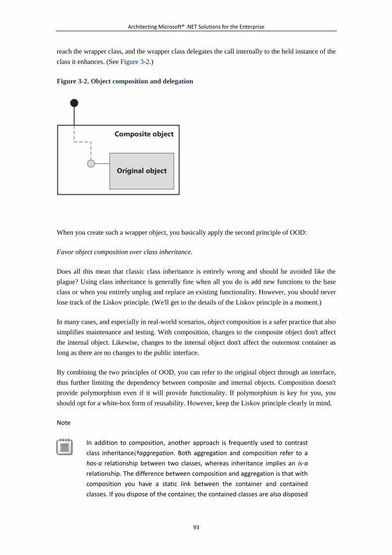
Architecting Microsoft® .NET Solutions for the Enterprise
93
reach the wrapper class, and the wrapper class delegates the call internally to the held instance of the
class it enhances. (See Figure 3-2.)
Figure 3-2. Object composition and delegation
When you create such a wrapper object, you basically apply the second principle of OOD:
Favor object composition over class inheritance.
Does all this mean that classic class inheritance is entirely wrong and should be avoided like the
plague? Using class inheritance is generally fine when all you do is add new functions to the base
class or when you entirely unplug and replace an existing functionality. However, you should never
lose track of the Liskov principle. (We'll get to the details of the Liskov principle in a moment.)
In many cases, and especially in real-world scenarios, object composition is a safer practice that also
simplifies maintenance and testing. With composition, changes to the composite object don't affect
the internal object. Likewise, changes to the internal object don't affect the outermost container as
long as there are no changes to the public interface.
By combining the two principles of OOD, you can refer to the original object through an interface,
thus further limiting the dependency between composite and internal objects. Composition doesn't
provide polymorphism even if it will provide functionality. If polymorphism is key for you, you
should opt for a white-box form of reusability. However, keep the Liskov principle clearly in mind.
Note
In addition to composition, another approach is frequently used to contrast
class inheritance¡ªaggregation. Both aggregation and composition refer to a
has-a relationship between two classes, whereas inheritance implies an is-a
relationship. The difference between composition and aggregation is that with
composition you have a static link between the container and contained
classes. If you dispose of the container, the contained classes are also disposed
Architecting Microsoft® .NET Solutions for the Enterprise
94
of. With aggregation, the link is weaker and the container is simply associated
with an external class. As a result, when the container is disposed of, the child
class blissfully survives.
Advanced Principles
You cannot go to a potential customer and sing the praises of your software by mentioning that it is
modular, well designed, and easy to read and maintain. These are internal characteristics of the
software that do not affect the user in any way. More likely, you'll say that your software is correct,
bug free, fast, easy to use, and perhaps extensible. However, you can hardly write correct, bug-free,
easy-to-use, and extensible software without paying a lot of attention to the internal design.
Basic principles such as low coupling, high cohesion (along with the single responsibility principle),
separation of concerns, plus the first two principles of OOD give us enough guidance about how to
design a software application. As you might have noticed, all these principles are rather old (but
certainly not outdated), as they were devised and formulated at least 15 years ago.
In more recent years, some of these principles have been further refined and enhanced to address
more specific aspects of the design. We like to list three more advanced design principles that, if
properly applied, will certainly make your code easier to read, test, extend, and maintain.
The Open/Closed Principle
We owe the Open/Closed Principle (OCP) to Bertrand Meyer. The principle addresses the need of
creating software entities (whether classes, modules, or functions) that can happily survive changes.
In the current version of the fictional product "This World," the continuous changes to software
requirements are a well-known bug. Unfortunately, although the team is working to eliminate the
bug in the next release, we still have to face reality and deal with frequent changes of requirements
the best we can.
Essentially, we need to have a mechanism that allows us to enter changes where required without
breaking existing code that works. The OCP addresses exactly this issue by saying the following:
A module should be open for extension but closed for modification.
Applied to OOD, the principle recommends that we never edit the source code of a class that works
in order to implement a change. In other words, each class should be conceived to be stable and
immutable and never face change¡ªthe class is closed for modification.
How can we enter changes, then?
Every time a change is required, you enhance the behavior of the class by adding new code and
never touching the old code that works. In practical terms, this means either using composition or
perhaps safe-and-clean class inheritance. Note that OCP just reinforces the point that we made
Architecting Microsoft® .NET Solutions for the Enterprise
95
earlier about the second principle of OOD: if you use class inheritance, you add only new code and
do not modify any part of the inherited context.
Today, the most common way to comply with the OCP is by implementing a fixed interface in any
classes that we figure are subject to changes. Callers will then work against the interface as in the
first principle of OOD. The interface is then closed for modification. But you can make callers
interact with any class that, at a minimum, implements that interface. So the overall model is open
for extension, but it still provides a fixed interface to dependent objects.
Liskov's Substitution Principle
When a new class is derived from an existing one, the derived class can be used in any place where
the parent class is accepted. This is polymorphism, isn't it? Well, the Liskov Substitution Principle
(LSP) restates that this is the way you should design your code. The principle says the following:
Subclasses should be substitutable for their base classes.
Apparently, you get this free of charge from just using an object-oriented language. If you think so,
have a look at the next example:
public class ProgrammerToy
{
private int _state = 0;
public virtual void SetState(int state)
{
_state = state;
}
public int GetState()
{
return _state;
}
}
The class ProgrammerToy just acts as a wrapper for an integer value that callers can read and write
through a pair of public methods. Here's a typical code snippet that shows how to use it:
static void DoSomeWork(ProgrammerToy toy)
{
int magicNumber = 5;
toy.SetState(magicNumber);
Console.WriteLine(toy.GetState());
Console.ReadLine();
Architecting Microsoft® .NET Solutions for the Enterprise
96
}
The caller receives an instance of the ProgrammerToy class, does some work with it, and then
displays any results. So far, so good. Let's now consider a derived class:
public class CustomProgrammerToy : ProgrammerToy
{
public override void SetState(int state)
{
// It inherits the context of the parent but lacks the
tools
// to fully access it. In particular, it has no way to
access
// the private member _state.
// As a result, this class MAY NOT be able to
// honor the contract of its parent class. Whether or
not, mostly
// depends on your intentions and expected goals for the
overridden
// SetState method. In any case, you CAN'T access
directly the private member
// _state from within this override of SetState.
// (In .NET, you can use reflection to access a private
member,
// but that's a sort of a trick.)
.
.
.
}
}
From a syntax point of view, ProgrammerToy and CustomProgrammerToy are just the same and
method DoSomeWork will accept both and successfully compile.
From a behavior point of view, though, they are quite different. In fact, when
CustomProgrammerToy is used, the output is 0 instead of 5. This is because of the override made on
the SetState method.
Architecting Microsoft® .NET Solutions for the Enterprise
97
This is purely an example, but it calls your attention to Liskov's Principle. It doesn't go without
saying that derived classes (subclasses) can safely replace their base classes. You have to ensure that.
How?
You should handle keywords such as sealed and virtual with extreme care. Virtual (overridable)
methods, for example, should never gain access to private members. Access to private members
can't be replicated by overrides, which makes base and derived classes not semantically equivalent
from the perspective of a caller. You should plan ahead of time which members are private and
which are protected. Members consumed by virtual methods must be protected, not private.
Generally, virtual methods of a derived class should work out of the same preconditions of
corresponding parent methods. They also must guarantee at least the same postconditions.
Classes that fail to comply with LSP don't just break polymorphism but also induce violations of
OCP on callers.
Note
OCP and LSP are closely related. Any function using a class that violates
Liskov's Principle violates the Open/Close Principle. Let's reference the
preceding example again. The method DoSomeWork uses a hierarchy of
classes (ProgrammerToy and CustomProgrammerToy) that violate LSP. This
means that to work properly DoSomeWork must be aware of which type it
really receives. Subsequently, it has to be modified each time a new class is
derived from ProgrammerToy. In other words, the method DoSomeWork is not
closed for modification.
The Dependency Inversion Principle
When you create the code for a class, you represent a behavior through a set of methods. Each
method is expected to perform a number of actions. As you specify these actions, you proceed in a
top-down way, going from high-level abstractions down the stack to more and more precise and
specific functions.
As an illustration, imagine a class, perhaps encapsulated in a service, that is expected to return stock
quotes as a chunk of HTML markup:
public class FinanceInfoService
{
public string GetQuotesAsHtml(string symbols)
{
// Get the Finder component
IFinder finder = ResolveFinder();
if (finder == null)
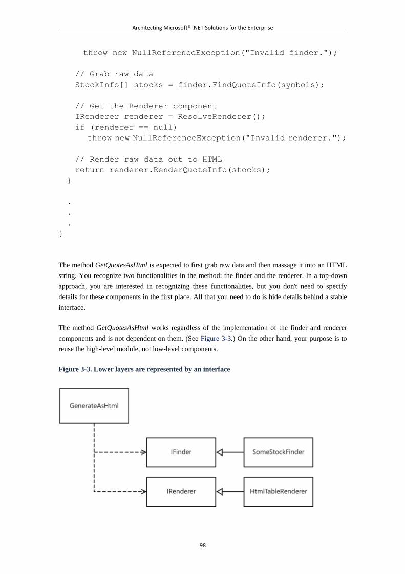
Architecting Microsoft® .NET Solutions for the Enterprise
98
throw new NullReferenceException("Invalid finder.");
// Grab raw data
StockInfo[] stocks = finder.FindQuoteInfo(symbols);
// Get the Renderer component
IRenderer renderer = ResolveRenderer();
if (renderer == null)
throw new NullReferenceException("Invalid renderer.");
// Render raw data out to HTML
return renderer.RenderQuoteInfo(stocks);
}
.
.
.
}
The method GetQuotesAsHtml is expected to first grab raw data and then massage it into an HTML
string. You recognize two functionalities in the method: the finder and the renderer. In a top-down
approach, you are interested in recognizing these functionalities, but you don't need to specify
details for these components in the first place. All that you need to do is hide details behind a stable
interface.
The method GetQuotesAsHtml works regardless of the implementation of the finder and renderer
components and is not dependent on them. (See Figure 3-3.) On the other hand, your purpose is to
reuse the high-level module, not low-level components.
Figure 3-3. Lower layers are represented by an interface
Architecting Microsoft® .NET Solutions for the Enterprise
99
When you get to this, you're in full compliance with the Dependency Inversion Principle (DIP),
which states the following:
High-level modules should not depend upon low-level modules. Both should depend upon
abstractions. Abstractions should not depend upon details. Details should depend upon
abstractions.
The inversion in the name of the principle refers to the fact that you proceed in a top-down manner
during the implementation and focus on the work flow in high-level modules rather than focusing on
the implementation of lower level modules. At this point, lower level modules can be injected
directly into the high-level module. Here's an alternative implementation for a DIP-based module:
public class FinanceInfoService
{
// Inject dependencies through the constructor. References
to such external components
// are resolved outside this module, for example by using an
inversion-of-control
// framework (more later).
IFinder _finder = null;
IRenderer _renderer = null;
public FinanceInfoService(IFinder finder, IRenderer
renderer)
{
_finder = finder;
_renderer = renderer;
}
public string GetQuotesAsHtml(string symbols)
{
// Get the Finder component
if (_finder == null)
throw new NullReferenceException("Invalid finder.");
// Grab raw data
StockInfo[] stocks = _finder.FindQuoteInfo(symbols);
// Get the Renderer component
if (_renderer == null)
throw new NullReferenceException("Invalid renderer.");
Architecting Microsoft® .NET Solutions for the Enterprise
100
// Render raw data out to HTML
return _renderer.RenderQuoteInfo(stocks);
}
.
.
.
}
In this case, the lower level modules are injected through the constructor of the DIP-based class.
The DIP has been formalized by Robert Martin. You can read more about it at
http://www.objectmentor.com/resources/articles/dip.pdf.
Important
In literature, the DIP is often referred to as inversion of control (IoC). In this
book, we use the DIP formulation by Robert Martin to indicate the principle of
dependency inversion and consider IoC as a pattern. In this regard, IoC and
dependency injection are, for us, synonyms. The terminology, however, is
much less important than the recognition that there's a principle about
inversion of control and a practical pattern. We'll return on this in a moment
with a more detailed explanation of our perspective.
5.3.3 From Principles to Patterns
It is guaranteed that by fulfilling all the OOD principles just discussed, you can craft a good design
that matches requirements and is maintainable and extensible. A seasoned development team,
though, will not be limited to applying effective design principles over and over again; members of
the team, in fact, will certainly draw from the well of their experience any solutions for similar
problems that worked in the past.
Such building blocks are nothing more than hints and the skeleton of a solution. However, these
very same building blocks can become more refined day after day and are generalized after each
usage to become applicable to a wider range of problems and scenarios. Such building blocks might
not provide a direct solution, but they usually help you to find your (right) way. And using them is
usually more effective and faster than starting from scratch.
By the way, these building blocks are known as patterns.
Architecting Microsoft® .NET Solutions for the Enterprise
101
What's a Pattern, Anyway?
The word pattern is one of those overloaded terms that morphed from its common usage to assume
a very specific meaning in computer science. According to the dictionary, a pattern is a template or
model that can be used to generate things¡ªany things. In computer science, we use patterns in
design solutions at two levels: implementation and architecture.
At the highest level, two main families of software patterns are recognized: design patterns and
architectural patterns. You look at design patterns when you dive into the implementation and
design of the code. You look at architectural patterns when you fly high looking for the overall
design of the system.
Let's start with design patterns.
Note
A third family of software patterns is also worth a mention¡ªrefactoring
patterns. You look at these patterns only when you're engaged in a refactoring
process. Refactoring is the process of changing your source code to make it
simpler, more efficient, and more readable while preserving the original
functionality. Examples of refactoring patterns are "Extract Interface" and
"Encapsulate Field." Some of these refactoring patterns have been integrated
into Visual Studio 2008 on the Refactor menu. You find even more patterns in
ad hoc tools such as Resharper. (For more information, see
http://www.jetbrains.com/resharper.)
A good book to read to learn about refactoring patterns is Refactoring to
Patterns by Joshua Kerievsky (Addison-Wesley, 2004).
Design Patterns
We software professionals owe design patterns to an architect¡ªa real architect, not a software
architect. In the late 1970s, Christopher Alexander developed a pattern language with the purpose of
letting individuals express their innate sense of design through a sort of informal grammar. From his
work, here's the definition of a pattern:
Each pattern describes a problem which occurs over and over again in our environment, and then
describes the core solution to that problem, in such a way that you can use the solution a million
times over, without ever doing it the same way twice.
Nicely enough, although the definition was not written with software development in mind, it
applies perfectly to that. So what's a design pattern?
Architecting Microsoft® .NET Solutions for the Enterprise
102
A design pattern is a known and well-established core solution applicable to a family of concrete
problems that might show up during implementation. A design pattern is a core solution and, as
such, it might need adaptation to a specific context. This feature becomes a major strength when you
consider that, in this way, the same pattern can be applied many times in many slightly different
scenarios.
Design patterns are not created in a lab; quite the reverse. They originate from the real world and
from the direct experience of developers and architects. You can think of a design pattern as a
package that includes the description of a problem, a list of actors participating in the problem, and a
practical solution.
The primary reference for design patterns is GoF. Another excellent reference we want to
recommend is Pattern-Oriented Software Architecture by Frank Buschmann, et al. (Wiley, 1996).
How to Work with Design Patterns
Here is a list of what design patterns are not:
Design patterns are not the verb and should never be interpreted dogmatically.
Design patterns are not Superman and will never magically pop up to save a project in
trouble.
Design patterns are neither the dark nor the light side of the Force. They might be with you,
but they won't provide you with any special extra power.
Design patterns are just helpful, and that should be enough.
You don't choose a design pattern; the most appropriate design pattern normally emerges out of your
refactoring steps. We could say that the pattern is buried under your classes, but digging it out is
entirely up to you.
The wrong way to deal with design patterns is by going through a list of patterns and matching them
to the problem. Instead, it works the other way around. You have a problem and you have to match
the problem to the pattern. How can you do that? It's quite simple to explain, but it's not so easy to
apply.
You have to understand the problem and generalize it.
If you can take the problem back to its roots, and get the gist of it, you'll probably find a tailor-made
pattern just waiting for you. Why is this so? Well, if you really reached the root of the problem,
chances are that someone else did the same in the past 15 years (the period during which design
patterns became more widely used). So the solution is probably just there for you to read and apply.
This observation prompts us to mention the way in which all members of our teams use books on
design patterns. (By the way, there are always plenty of such books scattered throughout the office.)
Design patterns books are an essential tool. But we never read such books. We use them, instead,
like cookbooks.
Architecting Microsoft® .NET Solutions for the Enterprise
103
What we normally do is stop reading after the first few pages precisely where most books list the
patterns they cover in detail inside. Next, we put the book aside and possibly within reach.
Whenever we encounter a problem, we try to generalize it, and then we flip through the pages of the
book to find a pattern that possibly matches it. We find one much more often than not. And if we
don't, we repeat the process in an attempt to come to a better generalization of the problem.
When we've found the pattern, we start working on its adaptation to our context. This often requires
refactoring of the code which, in turn, might lead to a more appropriate pattern. And the loop goes
on.
Note
If you're looking for an online quick reference about design patterns, you
should look at http://www.dofactory.com. Among other things, the site
offers .NET-specific views of most popular design patterns.
Where's the Value in Patterns, Exactly?
Many people would agree in principle that there's plenty of value in design patterns. Fewer people,
though, would be able to indicate what the value is and where it can be found.
Using design patterns, per se, doesn't make your solution more valuable. What really matters, at the
end of the day, is whether or not your solution works and meets requirements.
Armed with requirements and design principles, you are up to the task of solving a problem. On
your way to the solution, though, a systematic application of design principles to the problem sooner
or later takes you into the immediate neighborhood of a known design pattern. That's a certainty
because, ultimately, patterns are solutions that others have already found and catalogued.
At that point, you have a solution with some structural likeness to a known design pattern. It is up to
you, then, to determine whether an explicit refactoring to that pattern will bring some added value to
the solution. Basically, you have to decide whether or not the known pattern you've found represents
a further, and desirable, refinement of your current solution. Don't worry if your solution doesn't
match a pattern. It means that you have a solution that works and you're happy with that. You're just
fine. You never want to change a winning solution!
In summary, patterns might be an end when you refactor according to them, and they might be a
means when you face a problem that is clearly resolved by a particular pattern. Patterns are not an
added value for your solution, but they are valuable for you as an architect or a developer looking
for a solution.
Applied Design Patterns
Architecting Microsoft® .NET Solutions for the Enterprise
104
We said a lot about design patterns, but we haven't shown a single line of code or a concrete
example. Patterns are everywhere, even if you don't realize it. As we'll see in a moment, sometimes
patterns are buried in the language syntax¡ªin which case, we'll call them idioms.
Have you ever needed to use a global object (or a few global objects) to serve all requests to a given
class? If you have, you used the Singleton pattern. The Singleton pattern is described as a way to
ensure that a class has only one instance for which a global point of access is required. Here's an
example:
public class Helpers
{
public static Helpers DefaultInstance = new Helpers();
protected Helpers() {}
public void DoWork()
{
.
.
.
}
public void DoMoreWork()
{
.
.
.
}
}
In a consumer class, you take advantage of Helpers through the following syntax:
Helpers.DefaultInstance.DoWork();
Swarms of Visual Basic 6 developers have used the Singleton pattern for years probably without
ever realizing it. The Singleton pattern is behind the default instance of Visual Basic 6 forms, as
shown here:
Form1.Show()
Architecting Microsoft® .NET Solutions for the Enterprise
105
The preceding code in Visual Basic 6 invokes the Show method on the default instance of the type
Form1. In the source, there's no explicit mention of the default instance only because of the tricks
played by the Visual Basic runtime.
Tip
Admittedly, the Singleton pattern on a class is similar to defining the same
class with only static methods. Is there any difference?
With a Singleton pattern, you can actually control the number of instances
because you're not actually limited to just one instance. In addition, you can
derive a new (meaningful) class because the Singleton pattern has some
instance-level behavior and is not a mere collection of static functions. Finally,
you have more freedom to control the creation of the actual instance. For
example, you can add a static method, say, GetInstance, instead of the static
field and add there any logic for the factory.
Another interesting pattern to briefly mention is the Strategy pattern. The pattern identifies a
particular functionality that a class needs and can be hot-plugged into the class. The functionality is
abstracted to an interface or a base class, and the Strategy-enabled class uses it through the
abstraction, as shown here:
public class MyService
{
// This is the replaceable strategy
ILogger _logger;
public MyService(ILogger logger)
{
this._logger = logger;
}
public void DoWork()
{
this._logger.Log("Begin method ...");
.
.
.
this._logger.Log("End method ...");
}
}
Architecting Microsoft® .NET Solutions for the Enterprise
106
The Strategy pattern is the canonical example used to illustrate the power of composition. The class
MyService in the example benefits from the services of a logger component, but it depends only on
an abstraction of it. The external logger component can be changed with ease and without risking
breaking changes. Moreover, you can even change the component (for example, the strategy) on the
fly. Try getting the same flexibility in a scenario where the implementation of the strategy object is
hard-coded in the MyService class and you have to inherit a new class to change strategy. It's just
impossible to change strategy in that case without recompilation and redeployment.
Architectural Patterns
Architectural patterns capture key elements of software architecture and offer support for making
hard-to-change decisions about the structure of the system. As we saw in Chapter 1, software
architecture is mostly about decisions regarding design points that, unlike code design, are not
subject to refactoring.
Architectural patterns are selected and applied very early in the course of design, and they influence
various quality characteristics of the system, such as performance, security, maintenance, and
extensibility.
Examples of architectural patterns are Layers and SOA for modeling the application structure,
Model-View-Controller for the presentation, Domain Model and Service Layer for the business
logic, and Peer-to-Peer for the network topology.
Antipatterns
In physics, we have matter and antimatter. Just as matter is made of particles, antimatter is
made of antiparticles. An antiparticle is identical to a particle except for the
charge¡ªpositive in the particles of normal matter, and negative in an element of
antimatter.
Likewise, in software we have patterns made of solutions, and antipatterns made of
antisolutions. What's the difference? It is all in the "charge" of the solution. Patterns drive
us to good solutions, whereas antipatterns drive us to bad solutions. The clearest
definition for antipatterns we could find comes (again) from Ward Cunningham's wiki, at
http://c2.com/cgi/wiki?AntiPattern:
An anti-pattern is a pattern that tells how to go from a problem to a bad solution.
Put this way, one could reasonably wonder why antipatterns are worth the effort of
defining them. For matter and antimatter, it's all about the thirst for knowledge. But
developers and architects are usually more pragmatic and they tend to prefer knowledge
with a practical application to their everyday work. What's the link that relates
antipatterns to the real-world of software development?
The keystone of antipatterns is that they might, at first, look like good ideas that can add
Architecting Microsoft® .NET Solutions for the Enterprise
107
new power and effectiveness to your classes. An antipattern, though, is devious and
insidious and adds more trouble than it removes. From Cunningham's wiki again:
In the old days, we used to just call these bad ideas. The new name is much more
diplomatic.
Designers and antipatterns, in some way, attract each other, but the experienced designer
recognizes and avoids antipatterns. (This is definitely a characteristic that marks the
difference between expert and nonexpert designers.) Because of the fatal attraction
designers generally have toward antipatterns, a catalog of antipatterns is as valuable as a
catalog of good design patterns.
A long list of antipatterns can be found at http://c2.com/cgi/wiki?AntiPatternsCatalog and
also at http://en.wikipedia.org/wiki/anti-pattern. We like to briefly address a couple of
them¡ªone relates to architecture and the other relates to development.
The Architecture-As-Requirements antipattern refers to situations where a prominent and
influential member of the design team has a pet technology or product and absolutely
wants to use it in the project¡ªeven when there is no clear evidence of its usefulness and
applicability in the customer's context.
The Test-By-Release antipattern refers to releasing a software product without paying
much attention to all those boring and time-consuming chores related to unit and
integration testing. Are users the final recipients of the product? Great, let's give them the
last word on whether the software works or not.
Patterns vs. Idioms
Software patterns indicate well-established solutions to recurring design problems. This means that
developers end up coding their way to a given solution over and over again. And they might be
repeatedly writing the same boilerplate code in a given programming language.
Sometimes specific features of a given programming language can help significantly in quickly and
elegantly solving a recurring problem. That specific set of features is referred to as an idiom.
What's an Idiom, Anyway?
An idiom is a pattern hard-coded in a programming language or implemented out of the box in a
framework or technology.
Like a design pattern, an idiom represents a solution to a recurring problem. However, in the case of
idioms, the solution to the problem doesn't come through design techniques but merely by using the
features of the programming language. Whereas a design pattern focuses on the object-oriented
paradigm, an idiom focuses on the technology of the programming language.
Architecting Microsoft® .NET Solutions for the Enterprise
108
An idiom is a way to take advantage of the language capabilities and obtain a desired behavior from
the code. In general, an idiom refers to a very specific, common, and eye-catching piece of code that
accomplishes a given operation¡ªas simple as adding to a counter or as complex as the
implementation of a design pattern.
In C#, for example, the ++ operator can be considered a programming idiom for the recurring task
of adding to a counter variable. The same can be said for the as keyword when it comes to casting
to a type and defaulting to null in case of failure.
Let's see some more examples of programming idioms in C#.
Sample Idioms
Events are the canonical example of a programming idiom. Behind events, you find the Observer
pattern. The pattern refers to a class that has the ability to notify registered observers of some
internal states. Whenever a particular state is reached, the class loops through the list of registered
observers and notifies each observer of the event. It does that using a contracted observer interface.
In languages such as C# or Visual Basic .NET that support event-driven programming, you find this
pattern natively implemented and exposed through keywords. Consider the following code:
Button1.Click += new EventHandler(Button1_Click);
When it runs, a new "observer for the Click event" is added to the list maintained by object Button1.
The observer in this case is a delegate¡ªa special class wrapping a class method.
The interface through which observer and object communicate is the signature of the method
wrapped by the delegate.
Similarly, the foreach keyword in C# (and For . . . Each in Visual Basic .NET) is a hard-coded
version of the Iterator pattern. An iterator object accomplishes two main tasks: it retrieves a
particular element within a collection and jumps to the next element. This is exactly what happens
under the hood of the following code:
foreach(Customer customer in dataContext.Customers)
{
// The variable customer references the current element in
the collection.
// Moving to the next element is implicit.
}
Architecting Microsoft® .NET Solutions for the Enterprise
109
Finally, the most recent versions of C# and Visual Basic .NET¡ªthose shipping with the .NET
Framework 3.5¡ªalso support a set of contextual keywords for Language Integrated Query (LINQ):
from, select, in, orderby. When you apply the set of LINQ keywords to a database-oriented object
model, you have LINQ-to-SQL. With LINQ-to-SQL, you ultimately use language keywords to
query the content of a database. In other words, you programmatically define an object that
represents a query and run it. This behavior is described by the Query Object pattern. And
LINQ-to-SQL is a programming idiom for the pattern.
Idiomatic Design
We spent a lot of time pondering OOD principles and showing their benefits and applicability. We
did it by reasoning in a general context and looking at the OO paradigm rather than by examining
the concrete technology and platform. General principles are always valid and should always be
given due consideration.
However, when you step inside the design, at some point you meet the technology. When this
happens, you might need to review the way you apply principles in the context of the specific
technology or platform you're using. This is called idiomatic design.
As far as the .NET Framework is concerned, a set of idiomatic design rules exists under the name of
Framework Design Guidelines. You can access them online from the following URL:
http://msdn.microsoft.com/en-us/library/ms229042.aspx.
Note
Framework Design Guidelines is also the title of a book written by Krzysztof
Cwalina and Brad Abrams from Microsoft (Addison-Wesley, 2008). Cwalina's
blog is also an excellent source for tidbits and more details on guidelines. We
definitely recommend it. The blog is http://blogs.msdn.com/kcwalina.
As an example, let's go through a couple of these guidelines.
Idiomatic Design: Structures or Classes?
When defining a type in a C# .NET application, should you use struct or class? To start out, a struct
is not inheritable. So if you need to derive new classes from the type, you must opt for a class rather
than a structure. This said, a class is a reference type and is allocated on the heap. Memorywise, a
reference type is managed by the garbage collector. Conversely, a struct is a value type; it is
allocated on the stack and deallocated when it goes out of scope. Value types are generally less
expensive than reference types to work with, but not when boxing is required. In the .NET
Framework, boxing is the task of storing a value type in an object reference so that it can be used
wherever an object is accepted. As an example, consider the ArrayList class. When you add, say, an
Int32 (or a struct) to an ArrayList, the value is automatically boxed to an object. Done all the time,
Architecting Microsoft® .NET Solutions for the Enterprise
110
this extra work might change the balance between class and struct. Hence, the need of an official
guideline on the theme shows up.
The guideline suggests that you always use a class unless the footprint of the type is below 16 bytes
and the type is immutable. A type is immutable if the state of its instances never changes after
they've been created. (The System.String type in the .NET Framework is immutable because a new
string is created after each modification.) However, if the struct is going to be boxed frequently you
might want to consider using a class anyway. (If you're looking for the list of differences between
structs and classes go here: http://msdn.microsoft.com/en-us/library/saxz13w4.aspx.)
Idiomatic Design: Do Not Use List<T> in Public Signatures
Another guideline we want to point out has to do with the List<T> type. Their use in the signature
of public members is not recommended, as you can see in this blog post:
http://blogs.gotdotnet.com/kcwalina/archive/2005/09/26/474010.aspx.
Why is this so?
One of the reasons behind the guideline is that List<T> is a rather bloated type with many members
that are not relevant in many scenarios. This means that List<T> has low cohesion and to some
extent violates the Single Responsibility Principle.
Another reason for not using List<T> in public signatures is that the class is unsealed, yes, but not
specifically designed to be extended. This doesn't mean, though, that the class is not LSP-safe. If
you look at the source of the class, you can see that using List<T> is absolutely safe in any
polymorphic context. The issue is that the class has no protected and virtual methods for inheritors
to do something significant that alters the behavior of the class while preserving the core interface.
The class is just not designed to be extended.
It is therefore recommended that you use IList<T>, or derived interfaces, in public signatures.
Alternatively, use custom classes that directly implement IList<T>.
Dependency Injection
As a design principle, DIP states that higher level modules should depend on abstractions rather
than on the concrete implementation of functionalities. Inversion of control (IoC) is an application
of DIP that refers to situations where generic code controls the execution of more specific and
external components.
In an IoC solution, you typically have a method whose code is filled with one or more stubs. The
functionality of each stub is provided (statically or dynamically) by external components invoked
through an abstract interface. Replacing any external components doesn't affect the high-level
method, as long as LSP and OCP are fulfilled. External components and the high-level method can
be developed independently.
Architecting Microsoft® .NET Solutions for the Enterprise
111
A real-world example of IoC is Windows shell extensions. Whenever the user right-clicks and
selects Properties, Windows Explorer prepares a standard dialog box and then does a bit of IoC. It
looks up the registry and finds out whether custom property page extensions have been registered. If
any are registered, it talks to these extensions through a contracted interface and adds pages to the
user dialog box.
Another real-world example of IoC is event-driven programming as originally offered by Visual
Basic and now supported by Windows Forms and Web Forms. By writing a Button1_Click method
and attaching it to the Click event of, say, the Button1 control, you essentially instruct the (reusable
and generic) code of the Button class to call back your Button1_Click method any time the user
clicks.
What is dependency injection (DI), then?
From DIP to Inversion of Control
For the purpose of this discussion, IoC and DI are synonyms. They are not always considered
synonyms in literature, as sometimes you find IoC to be the principle and DI the application of the
principle¡ªnamely, the pattern. In reality, IoC is historically a pattern based on DIP. The term
dependency injection was coined by Martin Fowler later, as a way to further specialize the concept
of inversion of control.
IoC/DI remains essentially a pattern that works by letting you pass high-level method references to
helper components. This injection can happen in three ways. One way is via the constructor of the
class to which the method belongs. We did just this in the implementation of the FinanceInfoService
class. Another way consists of defining a method or a setter property on the class to which the
method belongs. Finally, the class can implement an interface whose methods offer concrete
implementations of the helper components to use.
Today, IoC/DI is often associated with special frameworks that offer a number of rather advanced
features.
IoC Frameworks
Table 3-1 lists some of the most popular IoC frameworks available.
Table 3-1. Main IoC Frameworks
Framework More Information
Castle Windsor http://www.castleproject.org/container/index.html
Ninject http://www.ninject.org
Spring.NET http://www.springframework.net
StructureMap http://structuremap.sourceforge.net/Default.htm
Architecting Microsoft® .NET Solutions for the Enterprise
112
Table 3-1. Main IoC Frameworks
Framework More Information
Unity http://codeplex.com/unity
Note that Ninject is also available for Silverlight and the Compact Framework. In particular,
Microsoft's Unity Application Block (Unity for short) is a lightweight IoC container with support for
constructor, property, and method call injection. It comes as part of the Enterprise Library 4.0. Let's
use that for our demos.
All IoC frameworks are built around a container object that, bound to some configuration
information, resolves dependencies. The caller code instantiates the container and passes the desired
interface as an argument. In response, the IoC/DI framework returns a concrete object that
implements that interface.
IoC Containers in Action
Suppose you have a class that depends on a logger service, such as the class shown here:
public class Task
{
ILogger _logger;
public Task(ILogger logger)
{
this._logger = logger;
}
public void Execute()
{
this._logger.Log("Begin method ...");
.
.
.
this._logger.Log("End method ...");
}
}
The Task class receives the logger component via the constructor, but how does it locate and
instantiate the logger service? A simple and static new statement certainly works, and so does a
factory. An IoC container is a much richer framework that supports a configuration section:
<configuration>
Architecting Microsoft® .NET Solutions for the Enterprise
113
<configSections>
<section name="unity"
type="Microsoft.Practices.Unity.Configuration.UnityConfigu
rationSection,
Microsoft.Practices.Unity.Configuration" />
</configSections>
.
.
.
<unity>
<containers>
<container>
<types>
<type type="ILogger, mdUtils"
mapTo="ManagedDesign.Tools.DbLogger,
mdTools" />
</types>
</container>
</containers>
</unity>
</configuration>
The configuration file (app.config or web.config) contains mapping between interfaces and concrete
types to be injected. Whenever the container gets a call for ILogger, it'll return an instance of
DbLogger:
IUnityContainer container = new UnityContainer();
UnityConfigurationSection section =
(UnityConfigurationSection)
ConfigurationManager.GetSection("unity");
section.Containers.Default.Configure(container);
ILogger logger = container.Resolve<ILogger>();
Task t = new Task(logger);
.
.
.
Architecting Microsoft® .NET Solutions for the Enterprise
114
IoC/DI is extremely useful for testing purposes and for switching between implementations of
internal components. Frameworks just make it simple and terrific. In Chapter 6, "The Data Access
Layer," we'll return to IoC/DI to show how to inject a data access layer (DAL) in the middle tier of a
layered system.
To finish, here are a couple of brief remarks about IoC/DI containers. Through the configuration
script, you can instruct the container to treat injected objects as singletons. This means, for example,
that the container won't create a new instance of DbLogger every time, but will reuse the same one.
If the DbLogger class is thread safe, this is really a performance boost.
In addition, imagine that the constructor of DbLogger needs a reference to another type registered
with the IoC/DI framework. The container will be able to resolve that dependency, too.
5.3.4 Applying Requirements by Design
In Chapter 1, we saw that international standard ISO/IEC 9126 lists testability and security as key
quality characteristics for any software architecture. This means that we should consider testability
and security as nonfunctional requirements in any software architecture and start planning for them
very early in the design phase.
Testability
A broadly accepted definition for testability in the context of software architecture describes it as the
ease of performing testing. And testing is the process of checking software to ensure that it behaves
as expected, contains no errors, and satisfies its requirements.
A popular slogan to address the importance of software testing comes from Bruce Eckel and reads
like this:
If it ain't tested, it's broken.
The key thing to keep in mind is that you can state that your code works only if you can provide
evidence for that it does. A piece of software can switch to the status of working not when someone
states it works (whether stated by end users, the project manager, the customer, or the chief
architect), but only when its correctness is proven beyond any reasonable doubt.
Software Testing
Testing happens at various levels. You have unit tests to determine whether individual components
of the software meet functional requirements. You have integration tests to determine whether the
software fits in the environment and infrastructure and whether two or more components work well
together. Finally, you have acceptance tests to determine whether the completed system meets
customer requirements.
Architecting Microsoft® .NET Solutions for the Enterprise
115
Unit tests and integration tests pertain to the development team and serve the purpose of making the
team confident about the quality of the software. Test results tell the team if the team is doing well
and is on the right track. Typically, these tests don't cover the entire code base. In general, there's no
clear correlation between the percentage of code coverage and quality of code. Likewise, there's also
no agreement on what would be a valid percentage of code coverage to address. Some figure that 80
percent is a good number. Some do not even instruct the testing tool to calculate it.
The customer is typically not interested in the results of unit and integration tests. Acceptance tests,
on the other hand, are all the customer cares about. Acceptance tests address the completed system
and are part of the contract between the customer and the development team. Acceptance tests can
be written by the customer itself or by the team in strict collaboration with the customer. In an
acceptance test, you can find a checklist such as the following one:
1) Insert a customer with the following data ...;
2) Modify the customer using an existing ID;
3) Observe the reaction of the system and verify specific
expected results;
Another example is the following:
1) During a batch, shut down one nodes on the application server;
2) Observe the reaction of the system and the results of the
transaction;
Run prior to delivery, acceptance tests, if successful, signal the termination of the project and the
approval of the product. (As a consultant, you can issue your final invoice at this point.)
Tests are a serious matter.
Testing the system by having end users poke around the software for a few days is not a reliable
(and exhaustive) test practice. As we saw earlier in the chapter, it is even considered to be an
antipattern.
Note
Admittedly, in the early 1990s Dino delivered a photographic Windows
application using the test-by-poking-around approach. We were a very small
company with five developers, plus the boss. Our (patented?) approach to
testing is described in the following paragraph.
Architecting Microsoft® .NET Solutions for the Enterprise
116
The boss brings a copy of the program home. The boss spends the night
playing with the program. Around 8 a.m. the next day, the team gets a call
from the boss, who is going to get a few hours of very well-deserved sleep.
The boss recites a long list of serious bugs to be fixed instantly and makes
obscure references to alleged features of the program, which are unknown to
the entire team. Early in the afternoon, the boss shows up at work and
discusses improvements in a much more relaxed state of mind. The list of
serious bugs to be fixed instantly morphs into a short list of new features to
add.
In this way, however, we delivered the application and we could say we
delivered a reliable and fully functioning piece of software. It was the 1994,
though. The old days.
Software Contracts
A software test verifies that a component returns the correct output in response to given input and a
given internal state. Having control over the input and the state and being able to observe the output
is therefore essential.
Your testing efforts greatly benefit from detailed knowledge of the software contract supported by a
method. When you design a class, you should always be sure you can answer the following three
questions about the class and its methods in particular:
Under which conditions can the method be invoked?
Which conditions are verified after the method terminates?
Which conditions do not change before and after the method execution?
These three questions are also known, respectively, as preconditions, postconditions, and invariants.
Preconditions mainly refer to the input data you pass; specifically, data that is of given types and
values falling within a given range. Preconditions also refer to the state of the object required for
execution¡ªfor example, the method that might need to throw an exception if an internal member is
null or if certain conditions are not met.
When you design a method with testability in mind, you pay attention to and validate input carefully
and throw exceptions if any preconditions are not met. This gets you clean code, and more
importantly, code that is easier to test.
Postconditions refer to the output generated by the method and the changes produced to the state of
the object. Postconditions are not directly related to the exceptions that might be thrown along the
way. This is not relevant from a testing perspective. When you do testing, in fact, you execute the
method if preconditions are met (and if no exceptions are raised because of failed preconditions).
The method might produce the wrong results, but it should not fail unless really exceptional
Architecting Microsoft® .NET Solutions for the Enterprise
117
situations are encountered. If your code needs to read a file, that the file exists is a precondition and
you should throw a FileNotFoundException before attempting to read. A FileIOException, say, is
acceptable only if during the test you lose connection to the file.
There might be a case where the method delegates some work to an internal component, which
might also throw exceptions. However, for the purpose of testing, that component will be replaced
with a fake one that is guaranteed to return valid data by contract. (You are testing the outermost
method now; you have tested the internal component already or you'll test it later.) So, in the end,
when you design for testability the exceptions you should care about most are those in the
preconditions.
Invariants refer to property values, or expressions involving members of the object's state, that do
not change during the method execution. In a design for testability scenario, you know these
invariants clearly and you assert them in tests. As an example of an invariant, consider the property
Status of DbConnection: it has to be Open before you invoke BeginTransaction, and it must remain
Open afterward.
Software contracts play a key role in the design of classes for testability. Having a contract clearly
defined for each class you write makes your code inherently more testable.
Unit Testing
Unit testing verifies that individual units of code are working properly according to their software
contract. A unit is the smallest part of an application that is testable¡ªtypically, a method.
Unit testing consists of writing and running a small program (referred to as a test harness) that
instantiates classes and invokes methods in an automatic way. In the end, running a battery of tests
is much like compiling. You click a button, you run the test harness and, at the end of it, you know
what went wrong, if anything.
In its simplest form, a test harness is a manually written program that reads test-case input values
and the corresponding expected results from some external files. Then the test harness calls methods
using input values and compares results with expected values. Needless to say, writing such a test
harness entirely from scratch is, at the very minimum, time consuming and error prone. But, more
importantly, it is restrictive in terms of the testing capabilities you can take advantage of.
At the end of the day, the most effective way to conduct unit testing passes through the use of an
automated test framework. An automated test framework is a developer tool that normally includes
a runtime engine and a framework of classes for simplifying the creation of test programs. Table 3-2
lists some of the most popular ones.
Table 3-2. Popular Testing Tools
Product Description
MSTest The testing tool incorporated into Visual Studio 2008 Professional, Team Tester, and
Architecting Microsoft® .NET Solutions for the Enterprise
118
Table 3-2. Popular Testing Tools
Product Description
Team Developer. It is also included in Visual Studio 2005 Team Tester and Team
Developer.
MBUnit An open-source product with a fuller bag of features than MSTest. However, the tight
integration that MSTest has with Visual Studio and Team Foundation Server largely
makes up for the smaller feature set. For more information on MBUnit, pay a visit to
http://www.mbunit.com.
NUnit One of the most widely used testing tools for the .NET Framework. It is an open-source
product. Read more at http://www.nunit.org.
xUnit.NET Currently under development as a CodePlex project, this tool builds on the experience
of James Newkirk¡ªthe original author of NUnit. It is definitely an interesting tool to
look at, with some interesting and innovative features. For more information, pay a visit
to http://www.codeplex.com/xunit.
A nice comparison of testing tools, in terms of their respective feature matrix, is available at
http://www.codeplex.com/xunit/Wiki/View.aspx?title=.
Unit Testing in Action
Let's have a look at some tests written using the MSTest tool that comes with Visual Studio 2008.
You start by grouping related tests in a text fixture. Text fixtures are just test-specific classes where
methods typically represent tests to run. In a text fixture, you might also have code that executes at
the start and end of the test run. Here's the skeleton of a text fixture with MSTest:
using Microsoft.VisualStudio.TestTools.UnitTesting;
.
.
.
[TestClass]
public class CustomerTestCase
{
private Customer customer;
[TestInitialize]
public void SetUp()
{
customer = new Customer();
}
Architecting Microsoft® .NET Solutions for the Enterprise
119
[TestCleanup]
public void TearDown()
{
customer = null;
}
// Your tests go here
[TestMethod]
public void Assign_ID()
{
.
.
.
}
.
.
.
}
It is recommended that you create a separate assembly for your tests and, more importantly, that you
have tests for each class library. A good practice is to have an XxxTestCase class for each Xxx class
in a given assembly.
As you can see, you transform a plain .NET class into a test fixture by simply adding the TestClass
attribute. You turn a method of this class into a test method by using the TestMethod attribute
instead. Attributes such as TestInitialize and TestCleanup have a special meaning and indicate code
to execute at the start and end of the test run. Let's examine an initial test:
[TestMethod]
public void Assign_ID()
{
// Define the input data for the test
string id = "MANDS";
// Execute the action to test (assign a given value)
customer.ID = id;
// Test the postconditions:
// Ensure that the new value of property ID matches the
assigned value.
Assert.AreEqual(id, customer.ID);
Architecting Microsoft® .NET Solutions for the Enterprise
120
}
The test simply verifies that a value is correctly assigned to the ID property of the Customer class.
You use methods of the Assert object to assert conditions that must be true when checked.
The body of a test method contains plain code that works on properties and methods of a class.
Here's another example that invokes a method on the Customer class:
[TestMethod]
public void TestEmptyCustomersHaveNoOrders()
{
Customer c = new Customer();
Assert.AreEqual<decimal>(0, c.GetTotalAmountOfOrders());
}
In this case, the purpose of the test is to ensure that a newly created Customer instance has no
associated orders and the total amount of orders add up to zero.
Dealing with Dependencies
When you test a method, you want to focus only on the code within that method. All that you want
to know is whether that code provides the expected results in the tested scenarios. To get this, you
need to get rid of all dependencies the method might have. If the method, say, invokes another class,
you assume that the invoked class will always return correct results. In this way, you eliminate at the
root the risk that the method fails under test because a failure occurred down the call stack. If you
test method A and it fails, the reason has to be found exclusively in the source code of method
A¡ªgiven preconditions, invariants, and behavior¡ªand not in any of its dependencies.
Generally, the class being tested must be isolated from its dependencies.
In an object-oriented scenario, class A depends on class B when any of the following conditions are
verified:
Class A derives from class B.
Class A includes a member of class B.
One of the methods of class A invokes a method of class B.
One of the methods of class A receives or returns a parameter of class B.
Class A depends on a class that, in turn, depends on class B.
How can you neutralize dependencies when testing a method? This is exactly where manually
written test harnesses no longer live up to your expectations, and you see the full power of
automated testing frameworks.
Architecting Microsoft® .NET Solutions for the Enterprise
121
Dependency injection really comes in handy here and is a pattern that has a huge impact on
testability. A class that depends on interfaces (the first principle of OOD), and uses dependency
injection to receive from the outside world any objects it needs to do its own work, is inherently
more testable. Let's consider the following code snippet:
public class Task
{
// Class Task depends upon type ILogger
ILogger _logger;
public Task(ILogger logger)
{
this._logger = logger;
}
public int Sum(int x, int y)
{
return x+y;
}
public void Execute()
{
// Invoke an external "service"; not relevant when
unit-testing this method
this._logger.Log("Begin method ...");
// Method specific code; RELEVANT when unit-testing this
method
.
.
.
// Invoke an external "service"; not relevant when
unit-testing this method
this._logger.Log("End method ...");
}
}
We want to test the code in method Execute, but we don't care about the logger. Because the class
Task is designed with DI in mind, testing the method Execute in total isolation is much easier.
Architecting Microsoft® .NET Solutions for the Enterprise
122
Again, how can you neutralize dependencies when testing a method?
The simplest option is using fake objects. A fake object is a relatively simple clone of an object that
offers the same interface as the original object but returns hard-coded or programmatically
determined values. Here's a sample fake object for the ILogger type:
public class FakeLogger : ILogger
{
public void Log(string message)
{
return;
}
}
As you can see, the behavior of a fake object is hard-coded; the fake object has no state and no
significant behavior. From the fake object's perspective, it makes no difference how many times you
invoke a fake method and when in the flow the call occurs. Let's see how to inject a fake logger in
the Task class:
[TestMethod]
public void TestIfExecuteWorks()
{
// Inject a fake logger to isolate the method from
dependencies
FakeLogger fake = new FakeLogger();
Task task = new Task(fake);
// Set preconditions
int x = 3;
int y = 4;
int expected = 7;
// Run the method
int actual = task.Sum(x, y);
// Report about the code's behavior using Assert statements
Assert.AreEqual<int>(expected, actual);
.
.
.
}
Architecting Microsoft® .NET Solutions for the Enterprise
123
In a test, you set the preconditions for the method, run the method, and then observe the resulting
postconditions. The concept of assertion is central to the unit test. An assertion is a condition that
might or might not be verified. If verified, the assertion passes. In MSTest, the Assert class provides
many static methods for making assertions, such as AreEqual, IsInstanceOfType, and IsNull.
In the preceding example, after executing the method Sum you are expected to place one or more
assertions aimed at verifying the changes made to the state of the object or comparing the results
produced against expected values.
Note
In some papers, terms such as stub and shunt are used to indicate slight
variations of what we reference here as a fake. A broadly accepted
differentiation is based on the fact that a stub (or a shunt) merely provides the
implementation of an interface. Methods can just throw or, at most, return
canned values.
A fake, on the other hand, is a slightly more sophisticated object that, in
addition to implementing an interface, also usually contains more logic in the
methods. Methods on a fake object can return canned values but also
programmatically set values. Both fakes and stubs can provide a meaningful
implementation for some methods and just throw exceptions for other
methods that are not considered relevant for the purpose of the test.
A bigger and juicier differentiation, however, is the one that exists between
fakes (or stubs) and mock objects, which is discussed next.
From Fakes to Mocks
A mock object is a more evolved and recent version of a fake. A mock does all that a fake or a stub
does, plus something more. In a way, a mock is an object with its own personality that mimics the
behavior and interface of another object. What more does a mock provide to testers?
Essentially, a mock allows for verification of the context of the method call. With a mock, you can
verify that a method call happens with the right preconditions and in the correct order with respect
to other methods in the class.
Writing a fake manually is not usually a big issue¡ªall the logic you need is for the most part simple
and doesn't need to change frequently. When you use fakes, you're mostly interested in verifying
that some expected output derives from a given input. You are interested in the state that a fake
object might represent; you are not interested in interacting with it.
Architecting Microsoft® .NET Solutions for the Enterprise
124
You use a mock instead of a fake only when you need to interact with dependent objects during tests.
For example, you might want to know whether the mock has been invoked or not, and you might
decide within the text what the mock object has to return for a given method.
Writing mocks manually is certainly a possibility, but is rarely an option you really want to consider.
For the level of flexibility you expect from a mock, you should be updating its source code every
now and then or you should have (and maintain) a different mock for each test case in which the
object is being involved. Alternatively, you might come up with a very generic mock class that
works in the guise of any object you specify. This very generic mock class also exposes a
general-purpose interface through which you set your expectations for the mocked object. This is
exactly what mocking frameworks do for you. In the end, you never write mock objects manually;
you generate them on the fly using some mocking framework.
Table 3-3 lists and briefly describes the commonly used mocking frameworks.
Table 3-3. Some Popular Mocking Frameworks
Product Description
NMock2 An open-source library providing a dynamic mocking framework for .NET interfaces.
The mock object uses strings to get input and reflection to set expectations. Read
more at http://sourceforge.net/projects/nmock2.
TypeMock A commercial product with unique capabilities that basically don't require you to
(re)design your code for testability. TypeMock enables testing code that was previously
considered untestable, such as static methods, nonvirtual methods, and sealed classes.
Read more at http://www.typemock.com.
Rhino
Mocks
An open-source product. Through a wizard, it generates a static mock class for
type-safe testing. You set mock expectations by accessing directly the mocked object,
rather than going through one more level of indirection.
Read more at http://www.ayende.com/projects/rhino-mocks.aspx.
Let's go through a mocking example that uses NMock2 in MSTest.
Imagine you have an AccountService class that depends on the ICurrencyService type. The
AccountService class represents a bank account with its own currency. When you transfer funds
between accounts, you might need to deal with conversion rates, and you use the ICurrencyService
type for that:
public interface ICurrencyService
{
// Returns the current conversion rate: how many
"fromCurrency" to
Architecting Microsoft® .NET Solutions for the Enterprise
125
// be changed into toCurrency
decimal GetConversionRate(string fromCurrency, string
toCurrency);
}
Let's see what testing the TransferFunds method looks like:
[TestClass]
public class CurrencyServiceTestCase
{
private Mockery mocks;
private ICurrencyService mockCurrencyService;
private IAccountService accountService;
[TestInitialize]
public void SetUp()
{
// Initialize the mocking framework
mocks = new Mockery();
// Generate a mock for the ICurrencyService type
mockCurrencyService = mocks.NewMock<ICurrencyService>();
// Create the object to test and inject the mocked service
accountService = new AccountService(mockCurrencyService);
}
[TestMethod]
public void TestCrossCurrencyFundsTransfer()
{
// Create two test accounts
Account eurAccount = new Account("12345", "EUR");
Account usdAccount = new Account("54321", "USD");
usdAccount.Deposit(1000);
// Set expectations for the mocked object:
// When method GetConversionRate is invoked with (USD,EUR)
input
// the mock returns 0.64
Expect.Once.On(mockCurrencyService)
.Method("GetConversionRate")
.With("USD", "EUR")
.Will(Return.Value(0.64));
Architecting Microsoft® .NET Solutions for the Enterprise
126
// Invoke the method to test (and transfer $500 to an EUR
account)
accountService.TransferFunds(usdAccount, eurAccount,
500);
// Verify postconditions through assertions
Assert.AreEqual<int>(500, usdAccount.Balance);
Assert.AreEqual<int>(320, eurAccount.Balance);
mocks.VerifyAllExpectationsHaveBeenMet();
}
}
You first create a mock object for each dependent type. Next, you programmatically set expectations
on the mock using the static class Expect from the NMock2 framework. In particular, in this case
you establish that when the method GetConversionRate on the mocked type is invoked with a pair
of arguments such as "USD" and "EUR", it has to return 0.64. This is just the value that the method
TransferFunds receives when it attempts to invoke the currency services internally.
There's no code around that belongs to a mock object, and there's no need for developers to look
into the implementation of mocks. Reading a test, therefore, couldn't be easier. The expectations are
clearly declared and correctly passed on the methods under test.
Note
A mock is generated on the fly using .NET reflection to inspect the type to
mimic and the CodeDOM API to generate and compile code dynamically.
Security
Located at Carnegie Mellon University in Pittsburgh, Pennsylvania, the CERT Coordination Center
(CERT/CC) analyzes the current state of Internet security. It regularly receives reports of
vulnerabilities and researches the inner causes of security vulnerabilities. The center's purpose is to
help with the development of secure coding practices.
Figure 3-4 shows a statistic about the number of identified vulnerabilities in the past ten years. As
you can see, the trend is impressive. Also, you should consider that the data includes only the first
two quarters of 2008. (See http://www.cert.org/stats/vulnerability_remediation.html.)
Figure 3-4. Identified security vulnerabilities in past ten years
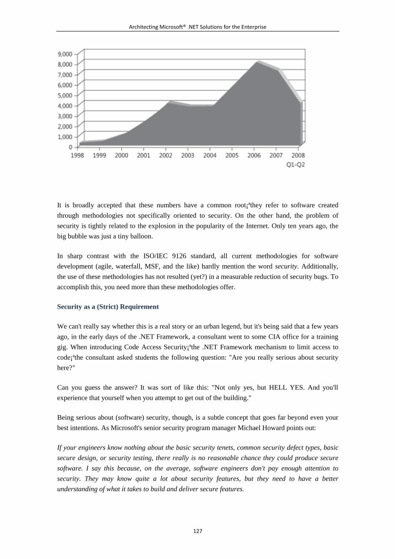
Architecting Microsoft® .NET Solutions for the Enterprise
127
It is broadly accepted that these numbers have a common root¡ªthey refer to software created
through methodologies not specifically oriented to security. On the other hand, the problem of
security is tightly related to the explosion in the popularity of the Internet. Only ten years ago, the
big bubble was just a tiny balloon.
In sharp contrast with the ISO/IEC 9126 standard, all current methodologies for software
development (agile, waterfall, MSF, and the like) hardly mention the word security. Additionally,
the use of these methodologies has not resulted (yet?) in a measurable reduction of security bugs. To
accomplish this, you need more than these methodologies offer.
Security as a (Strict) Requirement
We can't really say whether this is a real story or an urban legend, but it's being said that a few years
ago, in the early days of the .NET Framework, a consultant went to some CIA office for a training
gig. When introducing Code Access Security¡ªthe .NET Framework mechanism to limit access to
code¡ªthe consultant asked students the following question: "Are you really serious about security
here?"
Can you guess the answer? It was sort of like this: "Not only yes, but HELL YES. And you'll
experience that yourself when you attempt to get out of the building."
Being serious about (software) security, though, is a subtle concept that goes far beyond even your
best intentions. As Microsoft's senior security program manager Michael Howard points out:
If your engineers know nothing about the basic security tenets, common security defect types, basic
secure design, or security testing, there really is no reasonable chance they could produce secure
software. I say this because, on the average, software engineers don't pay enough attention to
security. They may know quite a lot about security features, but they need to have a better
understanding of what it takes to build and deliver secure features.
Architecting Microsoft® .NET Solutions for the Enterprise
128
Security must be taken care of from the beginning. A secure design starts with the architecture; it
can't be something you bolt on at a later time. Security is by design. To address security properly,
you need a methodology developed with security in mind that leads you to design your system with
security in mind. This is just what the Security Development Lifecycle (SDL) is all about.
Security Development Lifecycle
SDL is a software development process that Microsoft uses internally to improve software security
by reducing security bugs. SDL is not just an internal methodology. Based on the impressive results
obtained internally, Microsoft is now pushing SDL out to any development team that wants to be
really serious about security.
SDL is essentially an iterative process that focuses on security aspects of developing software. SDL
doesn't mandate a particular software development process and doesn't preclude any. It is agnostic
to the methodology in use in the project¡ªbe it waterfall, agile, spiral, or whatever else.
SDL is the incarnation of the SD3+C principle, which is a shortcut for "Secure by Design, Secure by
Default, Secure in Deployment, plus Communication." Secure by Design refers to identifying
potential security risks starting with the design phase. Secure by Default refers to reducing the attack
surface of each component and making it run with the least possible number of privileges. Secure in
Deployment refers to making security requirements clear during deployment. Communication refers
to sharing information about findings to apply a fix in a timely manner.
Foundations of SDL: Layering
The foundations of SDL are essentially three: layering, componentization, and roles.
Decomposing the architecture to layers is important because of the resulting separation of concerns.
Having functionality organized in distinct layers makes it easier to map functions to physical tiers as
appropriate. This is beneficial at various levels.
For example, it is beneficial for the data server.
You can isolate the data server at will, and even access it through a separate network. In this case,
the data server is much less sensitive to denial of service (DoS) attacks because of the firewalls
scattered along the way that can recognize and neutralize DoS packets.
You move all security checks to the business layer running on the application server and end up
with a single user for the database¡ªthe data layer. Among other things, this results in a bit less work
for the database and a pinch of additional scalability for the system.
Layers are beneficial for the application server, too.
You use Code Access Security (CAS) on the business components to stop untrusted code from
executing privileged actions. You use CAS imperatively through xxxPermission classes to decide
what to do based on actual permissions. You use CAS declaratively on classes or assemblies
Architecting Microsoft® .NET Solutions for the Enterprise
129
through xxxPermission attributes to prevent unauthorized use of sensitive components. If you have
services, the contract helps to delimit what gets in and what gets out of the service.
Finally, if layering is coupled with thin clients, you have fewer upgrades (which are always a risk
for the stability of the application) and less logic running on the client. Securitywise, this means that
a possible dump of the client process would reveal much less information, so being able to use the
client application in partial trust mode is more likely.
Foundations of SDL: Componentization
Each layer is decomposed to components. Components are organized by functions and required
security privileges. It should be noted that performance considerations might lead you to grouping
or further factorizing components in successive iterations.
Componentization here means identifying the components to secure and not merely breaking down
the logical architecture into a group of assemblies.
For each component, you define the public contract and get to know exactly what data is expected to
come in and out of the component. The decomposition can be hierarchical. From a security point of
view, at this stage you are interested only in components within a layer that provide a service. You
are not interested, for example, in the object model (that is, the domain model, typed DataSets,
custom DTOs) because it is shared by multiple layers and represents only data and behavior on the
data.
For each component, you identify the least possible set of privileges that make it run. From a
security perspective, this means that in case of a successful attack, attackers gain the minimum
possible set of privileges.
Components going to different processes run in total isolation and each has its own access control
list (ACL) and Windows privileges set. Other components, conversely, might require their own
AppDomain within the same .NET process. An AppDomain is like a virtual process within a .NET
application that the Common Language Runtime (CLR) uses to isolate code within a secure
boundary. (Note, however, that an AppDomain doesn't represent a security barrier for applications
running in full-trust mode.) An AppDomain can be sandboxed to have a limited set of permissions
that, for example, limit disk access, socket access, and the like.
Foundation of SDL: Roles
Every application has its own assets. In general, an asset is any data that attackers might aim at,
including a component with high privileges. Users access assets through the routes specified by use
cases. From a security perspective, you should associate use cases with categories of users
authorized to manage related assets.
A role is just a logical attribute assigned to a user. A role refers to the logical role the user plays in
the context of the application. In terms of configuration, each user can be assigned one or more roles.
This information is attached to the .NET identity object, and the application code can check it before
Architecting Microsoft® .NET Solutions for the Enterprise
130
the execution of critical operations. For example, an application might define two roles¡ªAdmin and
Guest, each representative of a set of application-specific permissions. Users belonging to the
Admin role can perform tasks that other users are prohibited from performing.
Assigning roles to a user account doesn't add any security restrictions by itself. It is the
responsibility of the application¡ªtypically, the business layer¡ªto ensure that users perform only
operations compatible with their role.
With roles, you employ a unique model for authorization, thus unifying heterogeneous security
models such as LDAP, NTFS, database, and file system. Also, testing is easier. By impersonating a
role, you can test access on any layer.
In a role-based security model, total risks related to the use of impersonation and delegation are
mitigated. Impersonation allows a process to run using the security credentials of the impersonated
user but, unlike delegation, it doesn't allow access to remote resources on behalf of the impersonated
user. In both cases, the original caller's security context can be used to go through computer
boundaries from the user interface to the middle tier and then all the way down to the database. This
is a risk in a security model in which permissions are restricted by object. However, in a role-based
security model, the ability to execute a method that accesses specific resources is determined by role
membership, not credentials. User's credentials might not be sufficient to operate on the application
and data server.
Authorization Manager (AzMan) is a separate Windows download that enables you to group
individual operations together to form tasks. You can then authorize roles to perform specific tasks,
individual operations, or both. AzMan offers a centralized console (an MMC snap-in) to define
manager roles, operations, and users.
Note
AzMan is a COM-based component that has very little to share with the .NET
Framework. The .NET-based successor to AzMan is still in the works
somewhere in Redmond. The community of developers expects something
especially now that Microsoft has unveiled a new claims-based identity model
that essentially factors authentication out of applications so that each request
brings its own set of claims, including user name, e-mail address, user role,
and even more specific information.
Threat Model
Layering, componentization, and roles presuppose that, as an architect, you know the assets (such as
sensitive data, highly privileged components) you want to protect from attackers. It also presupposes
that you understand the threats related to the system you're building and which vulnerabilities it
might be exposed to after it is implemented. Design for security means that you develop a threat
model, understand vulnerabilities, and do something to mitigate risks.
Architecting Microsoft® .NET Solutions for the Enterprise
131
Ideally, you should not stop at designing this into your software, but look ahead to threats and
vulnerabilities in the deployment environment and to those resulting from interaction with other
products or systems. To this end, understanding the threats and developing a threat model is a must.
For threats found at the design level, applying countermeasures is easy. Once the application has
been developed, applying countermeasures is much harder. If an application is deployed, it's nearly
impossible to apply internal countermeasures¡ªyou have to rely on external security practices and
devices. Therefore, it's better to architect systems with built-in security features.
You can find an interesting primer on threat models at the following URL:
http://blogs.msdn.com/ptorr/archive/2005/02/22/GuerillaThreatModelling.aspx.
Threat modeling essentially consists of examining components for different types of threats.
STRIDE is a threat modeling practice that lists the following six types of threats:
Spoofing of user identity Refers to using false identities to get into the system. This threat
is mitigated by filtering out invalid IP addresses.
Tampering Refers to intercepting/modifying data during a module's conversation. This
threat is mitigated by protecting the communication channel (for example, SSL or IPSec).
Repudiation Refers to the execution of operations that can't be traced back to the author.
This threat is mitigated by strong auditing policies.
Information disclosure Refers to unveiling private and sensitive information to
unauthorized users. This threat is mitigated by enhanced authorization rules.
Denial of service Refers to overloading a system up to the point of blocking it. This threat
is mitigated by filtering out requests and frequently and carefully checking the use of the
bandwidth.
Elevation of privilege Refers to executing operations that require a higher privilege than the
privilege currently assigned. This threat is mitigated by assigning the least possible
privilege to any components.
If you're looking for more information on STRIDE, you can check out the following URL:
http://msdn.microsoft.com/en-us/magazine/cc163519.aspx.
After you have the complete list of threats that might apply to your application, you prioritize them
based on the risks you see associated with each threat. It is not realistic, in fact, that you address all
threats you find. Security doesn't come for free, and you should balance costs with effectiveness. As
a result, threats that you regard as unlikely or not particularly harmful can be given a lower priority
or not covered at all.
How do you associate a risk with a threat? You use the DREAD model. It rates the risk as the
probability of the attack multiplied by the impact it might have on the system. You should focus on
the following aspects:
Discoverability Refers to how high the likelihood is that an attacker discovers the
vulnerability. It is a probability attribute.
Architecting Microsoft® .NET Solutions for the Enterprise
132
Reproducibility Refers to how easy it could be to replicate the attack. It is a probability
attribute.
Exploitability Refers to how easy it could be to perpetrate the attack. It is a probability
attribute.
Affected users Refers to the number of users affected by the attack. It is an impact attribute.
Damage potential Refers to the quantity of damage the attack might produce. It is an
impact attribute.
You typically use a simple High, Medium, or Low scale to determine the priority of the threats and
decide which to address and when. If you're looking for more information on DREAD, you can
check out the following URL: http://msdn.microsoft.com/en-us/library/aa302419.aspx.
Note
STRIDE and DREAD is the classic analysis model pushed by the Security Development
Lifecycle (SDL) team and is based on the attacker's viewpoint. It works great in an enterprise
scenario, but it requires a security specialist because the resulting threat model is large and
complex. Another, simplified, model is emerging¡ªthe CIA/PI model, which stands for
Confidentiality Integrity Availability/Probability Impact. This model is simplified and focuses
on the defender's point of view. An interesting post is this one:
http://blogs.msdn.com/threatmodeling/archive/2007/10/30/a-discussion-on-threat-modelin
g.aspx.
Security and the Architect
An inherently secure design, a good threat model, and a precise analysis of the risk might mean very
little if you then pair them with a weak and insecure implementation. As an architect, you should
intervene at three levels: development, code review, and testing.
As far as development is concerned, the use of strong typing should be enforced because, by itself, it
cuts off a good share of possible bugs. Likewise, knowledge of common security patterns (for
example, the "all input is evil" pattern), application of a good idiomatic design, and static code
analysis (for example, using FxCop) are all practices to apply regularly and rigorously.
Sessions of code review should be dedicated to a careful examination of the actual configuration and
implementation of security through CAS, and to spot the portions of code prone to amplified attacks,
such as cross-site scripting, SQL injection, overflows, and similar attack mechanisms.
Unit testing for security is also important if your system receives files and sequences of bytes. You
might want to consider a technique known as fuzzing. Fuzzing is a software testing technique
through which you pass random data to a component as input. The code might throw an appropriate
exception or degrade gracefully. However, it might also crash or fail some expected assertions. This
technique can reveal some otherwise hidden bugs.
Architecting Microsoft® .NET Solutions for the Enterprise
133
Final Security Push
Although security should be planned for from the outset, you can hardly make some serious security
tests until the feature set is complete and the product is close to its beta stage. It goes without saying
that any anomalies found during security tests lead the team to reconsidering the design and
implementation of the application, and even the threat model.
The final security push before shipping to the customer is a delicate examination and should
preferably be delegated to someone outside the team, preferably some other independent figure.
Releasing to production doesn't mean the end of the security life cycle. As long as a system is up
and running, it is exposed to possible attacks. You should always find time for penetration testing,
which might lead to finding new vulnerabilities. So the team then starts the cycle again with the
analysis of the design, implementation, and threat model. Over and over again, in an endless loop.
Performance Considerations
You might wonder why we're including a sidebar on performance rather than a full
"Design for Performance" section. Performance is something that results from the actual
behavior of the system, not something you can put in. If you're creating a standalone,
small disconnected program, you can optimize it almost at will. It is radically different
when we move up in scope to consider an enterprise-class system.
Performance is not something absolute.
What is performance? Is it the response time the end user perceives? Is it resource
utilization that might or might not penalize the middle tier? Is it network latency or
database I/O latency? Is it related to caching or smarter algorithms? Is it a matter of bad
design? Is it merely horsepower?
Too often, a design decision involves a tradeoff between performance and scalability.
You release some performance-oriented improvement to achieve better scalability¡ªthat is,
a better (read, faster) response when the workload grows. Performance is never something
absolute.
In an enterprise-class system, efficiency and performance are certainly requirements to
take into account, but they are not fundamental requirements.
In our opinion, a bad design influences performance, but there's no special suggestion we
can share to help you to come up with a high-performance design. The design is either
good or bad; if it's good, it sets the groundwork for good performance.
As we've seen in this chapter, a good design is based on interfaces, has low coupling, and
allows for injection of external functionalities. Done in this way, the design leaves a lot of
Architecting Microsoft® .NET Solutions for the Enterprise
134
room for replacing components with others that might provide a better performance.
As Donald Knuth used to say, "Premature optimization is the root of all evil." So
optimizing is fine and necessary, but you should care about it only when you have
evidence of poor performance. And only when you know what is doing poorly and that it
can be improved. Optimization is timely¡ªit is never premature, never late.
Performance is hardly something that works (or doesn't work) in theory. You can hardly
say from a design or, worse yet, from a specification whether the resulting system will
perform poorly or not. You build the system in the best and simplest way you can. You
adhere to OOD principles and code your way to the fullest. Then you test the system.
If it works, but it doesn't work as fast as it should, you profile the system and figure out
what can be improved¡ªbe it a stored procedure, an intermediate cache, or a dynamic
proxy injection. If the design is flexible enough and leaves room for changes, you
shouldn't have a hard time applying the necessary optimization.
5.3.5 From Objects to Aspects
No doubt that OOP is currently a mainstream programming paradigm. When you design a system,
you decompose it into components and map the components to classes. Classes hold data and
deliver a behavior. Classes can be reused and used in a polymorphic manner, although you must do
so with the care we discussed earlier in the chapter.
Even with all of its undisputed positive qualities, though, OOP is not the perfect programming
paradigm.
The OO paradigm excels when it comes to breaking a system down into components and describing
processes through components. The OO paradigm also excels when you deal with the concerns of a
component. However, the OO paradigm is not as effective when it comes to dealing with
cross-cutting concerns.
A cross-cutting concern is a concern that affects multiple components in a system, such as logging,
security, and exception handling. Not being a specific responsibility of a given component or family
of components, a cross-cutting concern looks like an aspect of the system that must be dealt with at
a different logical level, a level beyond application classes. Enter a new programming paradigm:
aspect-oriented programming (AOP).
Aspect-Oriented Programming
The inherent limitations of the OO paradigm were identified quite a few years ago, not many years
after the introduction of OOP. However, today AOP still is not widely implemented even though
everybody agrees on the benefits it produces. The main reason for such a limited adoption is
Architecting Microsoft® .NET Solutions for the Enterprise
135
essentially the lack of proper tools. We are pretty sure the day that AOP is (even only partially)
supported by the .NET platform will represent a watershed in the history of AOP.
The concept of AOP was developed at Xerox PARC laboratories in the 1990s. The team also
developed the first (and still most popular) AOP language: AspectJ. Let's discover more about AOP
by exploring its key concepts.
Note
We owe to the Xerox PARC laboratories many software-related facilities we use
every day. In addition to AOP (which we don't exactly use every day), Xerox
PARC is "responsible" for laser printers, Ethernet, and mouse-driven graphical
user interfaces. They always churned out great ideas, but failed sometimes to
push their widespread adoption¡ªlook at AOP. The lesson that everybody
should learn from this is that technical excellence is not necessarily the key to
success, not even in software. Some good commercial and marketing skills are
always (strictly) required.
Cross-Cutting Concerns
AOP is about separating the implementation of cross-cutting concerns from the implementation of
core concerns. For example, AOP is about separating a logger class from a task class so that
multiple task classes can use the same logger and in different ways.
We have seen that dependency injection techniques allow you to inject¡ªand quite easily,
indeed¡ªexternal dependencies in a class. A cross-cutting concern (for example, logging) can
certainly be seen as an external dependency. So where's the problem?
Dependency injection requires up-front design or refactoring, which is not always entirely possible
in a large project or during the update of a legacy system.
In AOP, you wrap up a cross-cutting concern in a new component called an aspect. An aspect is a
reusable component that encapsulates the behavior that multiple classes in your project require.
Processing Aspects
In a classic OOP scenario, your project is made of a number of source files, each implementing one
or more classes, including those representing a cross-cutting concern such as logging. As shown in
Figure 3-5, these classes are then processed by a compiler to produce executable code.
Figure 3-5. The classic OOP model of processing source code
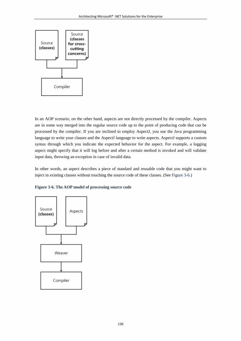
Architecting Microsoft® .NET Solutions for the Enterprise
136
In an AOP scenario, on the other hand, aspects are not directly processed by the compiler. Aspects
are in some way merged into the regular source code up to the point of producing code that can be
processed by the compiler. If you are inclined to employ AspectJ, you use the Java programming
language to write your classes and the AspectJ language to write aspects. AspectJ supports a custom
syntax through which you indicate the expected behavior for the aspect. For example, a logging
aspect might specify that it will log before and after a certain method is invoked and will validate
input data, throwing an exception in case of invalid data.
In other words, an aspect describes a piece of standard and reusable code that you might want to
inject in existing classes without touching the source code of these classes. (See Figure 3-6.)
Figure 3-6. The AOP model of processing source code
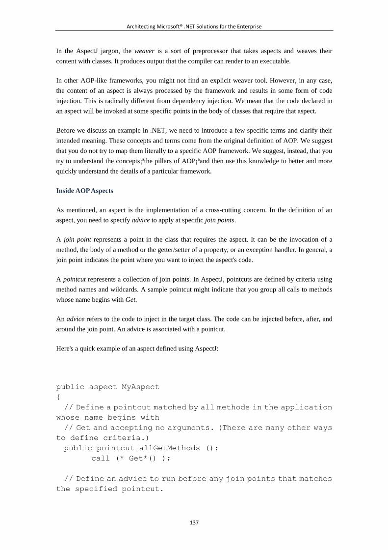
Architecting Microsoft® .NET Solutions for the Enterprise
137
In the AspectJ jargon, the weaver is a sort of preprocessor that takes aspects and weaves their
content with classes. It produces output that the compiler can render to an executable.
In other AOP-like frameworks, you might not find an explicit weaver tool. However, in any case,
the content of an aspect is always processed by the framework and results in some form of code
injection. This is radically different from dependency injection. We mean that the code declared in
an aspect will be invoked at some specific points in the body of classes that require that aspect.
Before we discuss an example in .NET, we need to introduce a few specific terms and clarify their
intended meaning. These concepts and terms come from the original definition of AOP. We suggest
that you do not try to map them literally to a specific AOP framework. We suggest, instead, that you
try to understand the concepts¡ªthe pillars of AOP¡ªand then use this knowledge to better and more
quickly understand the details of a particular framework.
Inside AOP Aspects
As mentioned, an aspect is the implementation of a cross-cutting concern. In the definition of an
aspect, you need to specify advice to apply at specific join points.
A join point represents a point in the class that requires the aspect. It can be the invocation of a
method, the body of a method or the getter/setter of a property, or an exception handler. In general, a
join point indicates the point where you want to inject the aspect's code.
A pointcut represents a collection of join points. In AspectJ, pointcuts are defined by criteria using
method names and wildcards. A sample pointcut might indicate that you group all calls to methods
whose name begins with Get.
An advice refers to the code to inject in the target class. The code can be injected before, after, and
around the join point. An advice is associated with a pointcut.
Here's a quick example of an aspect defined using AspectJ:
public aspect MyAspect
{
// Define a pointcut matched by all methods in the application
whose name begins with
// Get and accepting no arguments. (There are many other ways
to define criteria.)
public pointcut allGetMethods ():
call (* Get*() );
// Define an advice to run before any join points that matches
the specified pointcut.
Architecting Microsoft® .NET Solutions for the Enterprise
138
before(): allGetMethods()
{
// Do your cross-cutting concern stuff here
// for example, log about the method being executed
.
.
.
}
}
The weaver processes the aspect along with the source code (regular class-based source code) and
generates raw material for the compiler. The code actually compiled ensures that an advice is
invoked automatically by the AOP runtime whenever the execution flow reaches a join point in the
matching pointcut.
AOP in .NET
When we turn to AOP, we essentially want our existing code to do extra things. And we want to
achieve that without modifying the source code. We need to specify such extra things (advice) and
where we want to execute them (join points). Let's briefly go through these points from the
perspective of the .NET Framework.
How can you express the semantic of aspects?
The ideal option is to create a custom language a l ¤̈ AspectJ. In this way, you can create an ad hoc
aspect tailor-made to express advice at its configured pointcuts. If you have a custom language,
though, you also need a tool to parse it¡ªlike a weaver.
A very cost-effective alternative is using an external file (for example, an XML file) where you
write all the things you want to do and how to do it. An XML file is not ideal for defining source
code; in such a file, you likely store mapping between types so that when a given type is assigned an
aspect, another type is loaded that contains advice and instructions about how to join it to the
execution flow. This is the approach taken by Microsoft's Policy Injection Application Block (PIAB)
that we'll look at in a moment.
How can you inject an aspect's advice into executable code?
There are two ways to weave a .NET executable. You can do that at compile time or at run time.
Compile-time weaving is preferable, but in our opinion, it requires a strong commitment from a
vendor. It can be accomplished by writing a weaver tool that reads the content of the aspect, parses
the source code of the language (C#, Visual Basic .NET, and all of the other languages based on
the .NET common type system), and produces modified source code, but source code that can still
Architecting Microsoft® .NET Solutions for the Enterprise
139
be compiled. If you want to be language independent, write a weaver tool that works on MSIL and
apply that past the compilation step. Alternatively, you can write a brand new compiler that
understands an extended syntax with ad hoc AOP keywords.
If you want to weave a .NET executable at run time, you have to review all known techniques to
inject code dynamically. One is emitting JIT classes through Reflection.Emit; another one is based
on the CLR's Profiling API. The simplest of all is perhaps managing to have a proxy sitting in
between the class's aspects and its caller. In this case, the caller transparently invokes a proxy for the
class's aspects. The proxy, in turn, interweaves advice with regular code. This is the same
mechanism used in .NET Remoting and Windows Communication Foundation (WCF) services.
Using a transparent proxy has the drawback of requiring that to apply AOP to the class, the class
must derive from ContextBoundObject or MarshalByRefObject. This solution is employed by PIAB.
AOP in Action
To finish off our AOP overview, let's proceed with a full example that demonstrates how to achieve
AOP benefits in .NET applications. We'll use Microsoft's Policy Injection Application Block in
Enterprise Library 3.0 and higher to add aspects to our demo. For more information on PIAB, see
http://msdn.microsoft.com/en-us/library/cc511729.aspx.
Enabling Policies
The following code demonstrates a simple console application that uses the Unity IoC container to
obtain a reference to a class that exposes a given interface¡ªICustomerServices:
public interface ICustomerServices
{
void Delete(string customerID);
}
static void Main(string[] args)
{
// Set up the IoC container
UnityConfigurationSection section;
section = ConfigurationManager.GetSection("unity") as
UnityConfigurationSection;
IUnityContainer container = new UnityContainer();
section.Containers.Default.Configure(container);
// Resolve a reference to ICustomerServices. The actual
class returned depends
// on the content of the configuration section.
Architecting Microsoft® .NET Solutions for the Enterprise
140
ICustomerServices obj =
container.Resolve<ICustomerServices>();
// Enable policies on the object (for example, enable
aspects)
ICustomerServices svc =
PolicyInjection.Wrap<ICustomerServices>(obj);
// Invoke the object
svc.Delete("ALFKI");
// Wait until the user presses any key
Console.ReadLine();
}
After you have resolved the dependency on the ICustomerServices interface, you pass the object to
the PIAB layer so that it can wrap the object in a policy-enabled proxy. What PIAB refers to here as
a policy is really like what many others call, instead, an aspect.
In the end, the Wrap static method wraps a given object in a proxy that is driven by the content of a
new section in the configuration file. The section policyInjection defines the semantics of the aspect.
Let's have a look at the configuration file.
Defining Policies
PIAB is driven by the content of an ad hoc configuration section. There you find listed the policies
that drive the behavior of generated proxies and that ultimately define aspects to be applied to the
object within the proxy.
<policyInjection>
<policies>
<add name="Policy">
<matchingRules>
<add
type="EnterpriseLibrary.PolicyInjection.MatchingRules.Type
MatchingRule ..."
name="Type Matching Rule">
<matches>
<add match="ArchNet.Services.ICustomerServices"
ignoreCase="false" />
Architecting Microsoft® .NET Solutions for the Enterprise
141
</matches>
</add>
</matchingRules>
<handlers>
<add order="0"
type="ManagedDesign.Tools.DbLogger, mdTools"
name="Logging Aspect" />
</handlers>
</add>
</policies>
</policyInjection>
The matchingRules section expresses type-based criteria for a pointcut. It states that whenever the
proxy wraps an object of type ICustomerServices it has to load and execute all listed handlers. The
attribute order indicates the order in which the particular handler has to be invoked.
From this XML snippet, the result of this is that ICustomerServices is now a log-enabled type.
Defining Handlers
All that remains to be done¡ªand it is the key step, indeed¡ªis to take a look at the code for a sample
handler. In this case, it is the DbLogger class:
public interface ILogger
{
void LogMessage(string message);
void LogMessage(string category, string message);
}
public class DbLogger : ILogger, ICallHandler
{
// ILogger implementation
public void LogMessage(string message)
{
Console.WriteLine(message);
}
public void LogMessage(string category, string message)
{
Console.WriteLine(string.Format("{0} - {1}", category,
message));
Architecting Microsoft® .NET Solutions for the Enterprise
142
}
// ICallHandler implementation
public IMethodReturn Invoke(IMethodInvocation input,
GetNextHandlerDelegate getNext)
{
// Advice that runs BEFORE
this.LogMessage("Begin ...");
// Original method invoked on ICustomerServices
IMethodReturn msg = getNext()(input, getNext);
// Advice that runs AFTER
this.LogMessage("End ...");
return msg;
}
public int Order{ get; set; }
}
The class DbLogger implements two interfaces. One is its business-specific interface ILogger; the
other (ICallHandler) is a PIAB-specific interface through which advice code is injected into the
class's aspect list. The implementation of ICallHandler is fairly standard. In the Invoke method, you
basically redefine the flow you want for any aspect-ed methods.
In summary, whenever a method is invoked on a type that implements ICustomerServices, the
execution is delegated to a PIAB proxy. The PIAB proxy recognizes a few handlers and invokes
them in a pipeline. Each handler does the things it needs to do before the method executes. When
done, it yields to the next handler delegate in the pipeline. The last handler in the chain yields to the
object that executes its method. After that, the pipeline is retraced and each registered handler has its
own chance to execute its postexecution code. Figure 3-7 shows the overall pipeline supported by
PIAB.
Figure 3-7. The PIAB handler pipeline
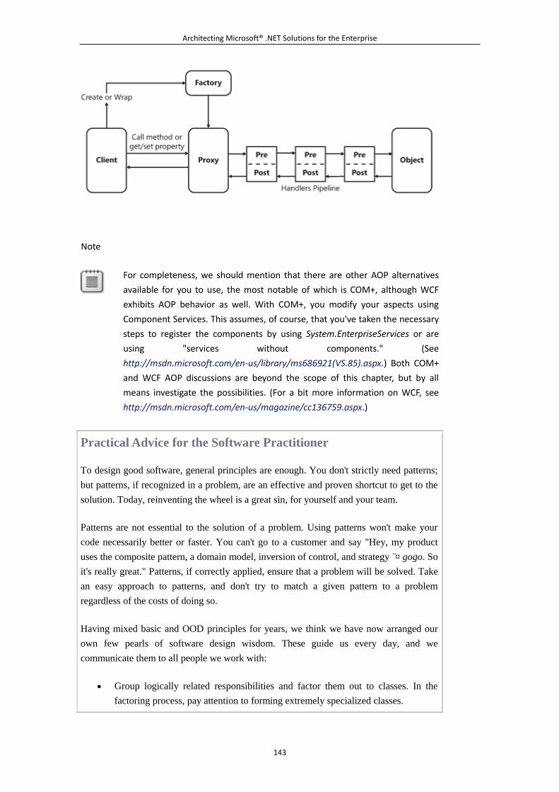
Architecting Microsoft® .NET Solutions for the Enterprise
143
Note
For completeness, we should mention that there are other AOP alternatives
available for you to use, the most notable of which is COM+, although WCF
exhibits AOP behavior as well. With COM+, you modify your aspects using
Component Services. This assumes, of course, that you've taken the necessary
steps to register the components by using System.EnterpriseServices or are
using "services without components." (See
http://msdn.microsoft.com/en-us/library/ms686921(VS.85).aspx.) Both COM+
and WCF AOP discussions are beyond the scope of this chapter, but by all
means investigate the possibilities. (For a bit more information on WCF, see
http://msdn.microsoft.com/en-us/magazine/cc136759.aspx.)
Practical Advice for the Software Practitioner
To design good software, general principles are enough. You don't strictly need patterns;
but patterns, if recognized in a problem, are an effective and proven shortcut to get to the
solution. Today, reinventing the wheel is a great sin, for yourself and your team.
Patterns are not essential to the solution of a problem. Using patterns won't make your
code necessarily better or faster. You can't go to a customer and say "Hey, my product
uses the composite pattern, a domain model, inversion of control, and strategy ¤̈ gogo. So
it's really great." Patterns, if correctly applied, ensure that a problem will be solved. Take
an easy approach to patterns, and don't try to match a given pattern to a problem
regardless of the costs of doing so.
Having mixed basic and OOD principles for years, we think we have now arranged our
own few pearls of software design wisdom. These guide us every day, and we
communicate them to all people we work with:
Group logically related responsibilities and factor them out to classes. In the
factoring process, pay attention to forming extremely specialized classes.
Architecting Microsoft® .NET Solutions for the Enterprise
144
Create concise and flexible abstractions of functionalities in classes. In this
context, two other adjectives are commonly used in literature to describe
abstractions: crisp and resilient.
When it comes to implementing classes, keep in mind separation of
concerns¡ªessentially, who does what¡ªand make sure that each role is played by
just one actor and each actor does the minimum possible; this is not done out of
laziness, but just for simplicity and effectiveness.
The emphasis on simplicity is never enough. Andrea has the following motto on a poster
in the office, and Dino writes it as a dedication in each book he signs: Keep it as simple as
possible, but no simpler. It's a popular quotation from Albert Einstein that every software
professional should always keep in mind.
Often referred to as KISS (short for Keep It Simple, Stupid), the idea of "simplicity above
all" emerges in various forms from a number of heuristic principles that populate software
design articles and conversations. The most popular principles are these:
Don't Repeat Yourself (DRY) Refers to reducing duplication of any information
needed by the application, and suggests you store the same information only in
one place.
Once and Only Once (OAOO) Refers to reducing the number of times you write
the code that accomplishes a given operation within an application.
You Aren't Gonna Need It (YAGNI) Refers to adding any functionality to an
application only when it proves absolutely necessary and unavoidable.
We often like to summarize the "simplicity above all" concept by paraphrasing people's
rights in court: everything you write can and will be used against you in a debugging
session. And, worse yet, it will be used in every meeting with the customer.
5.3.6 Summary
Just as an architect wouldn't design a house while ignoring the law of gravity, a software architect
shouldn't design a piece of software ignoring basic principles such as low coupling and high
cohesion. Just as an architect wouldn't design a house ignoring building codes that apply to the
context, a software architect working in an object-oriented context shouldn't design a piece of
software ignoring OOD principles such as the Open/Closed Principle (OCP), the Liskov
Substitution Principle (LSP), and the Dependency Inversion Principle (DIP).
But other quality characteristics (defined in an ISO/IEC standard) exist¡ªin particular, testability and
security. These aspects must be taken care of at the beginning of the design process¡ªeven though
magical testing tools and aspect orientation might partially alleviate the pain that comes from not
introducing testability and security from the very beginning. The fundamentals never go out of style,
we can safely say, and they are always useful and essential at whatever level of detail.
Architecting Microsoft® .NET Solutions for the Enterprise
145
5.3.7 Murphy's Laws of the Chapter
This chapter is about design and proving that your design is effective and meets requirements. If you
think of acceptance tests, in fact, how can you help but recall the original Murphy's Law: "If
anything can go wrong, it will." We selected a few related laws for the chapter.
The chances of a program doing what it's supposed to do are inversely proportional to the
number of lines of code used to write it.
The probability of bugs appearing is directly proportional to the number and importance of
people watching.
An expert is someone brought in at the last minute to share the blame.
See http://www.murphys-laws.com for an extensive listing of other computer-related (and
non-computer-related) laws and corollaries.
6. Part II: Design of the System
First, solve the problem. Then, write the code.
¡ªJohn B. Johnson
In this part:
Chapter 4: The Business Layer
Chapter 5: The Service Layer
Chapter 6: The Data Access Layer
Chapter 7: The Presentation Layer
6.1 Chapter 4. The Business Layer
Any fool can write code that a computer can understand. Good programmers write code that
humans can understand.
¡ªMartin Fowler
Any software of any reasonable level of complexity is organized in layers. Each layer represents a
logical section of the system. In particular, the modules in the business layer include all the
functional algorithms and calculations that make the system work and interact with other layers,
including the data access layer (DAL) and presentation layer.
Architecting Microsoft® .NET Solutions for the Enterprise
146
The business layer is the nerve center of any layered system and contains most of its core logic. For
this reason, it is often referred to as the business logic layer (BLL). In the rest of this chapter, we'll
primarily use the BLL acronym to indicate the business layer and all of its logic.
How complex and sophisticated can the BLL be?
This is a very hard question to answer in general. It becomes a much easier question to answer once
you know and study the user requirements, rules, and constraints that apply to the specific context.
There's virtually no logic to implement in a simple archiving system that barely has some
user-interface (UI) forms on top of a database. Conversely, there's quite complex logic to deal with
in a financial application or, more generally, in any application that is modeled after some
real-world business process.
Where do you start designing the BLL of a real-world system?
When the problem's domain features a few hundred entities to work with, and thousands of business
rules to fulfill, you need some structured guidance on how to create components. This guidance
comes from two main families of patterns: design and architectural patterns. As we saw in Chapter 3,
a design pattern is a general solution to a recurring software design problem. An architectural
pattern is a larger scale pattern that describes the organizational schema of the system and specifies
the responsibilities of each constituent subsystem.
In this book, we essentially assume a three-tier architecture with some flavors of service orientation.
This chapter, in particular, is dedicated to a set of design patterns that are commonly used to design
the business logic of a layered system.
6.1.1 What's the Business Logic Layer, Anyway?
Abstractly speaking, the BLL is the part of the software system that deals with the performance of
business-related tasks. Essentially, the BLL consists of an array of operations to execute on some
data. Data is modeled after the real entities in the problem's domain¡ªsomething like invoices,
customers, orders, and inventories. Operations, on the other hand, try to model business processes or,
more likely, individual steps of a single process¡ªfor instance, creating an invoice, adding a customer,
or posting an order.
Let's see what the BLL is really made of, where you typically deploy it, and which conceptual
models exist to devise the business layer of a multitier system.
Dissecting the Business Layer
If you could take a look at a vertical section of the BLL, what would you see? In the BLL, you find
an object model that models business entities, business rules that express all the customer's policies
and requirements, services to implement autonomous functionalities, and workflows that define how
documents and data are passed around from one constituent module to another and to and from
other layers.
Architecting Microsoft® .NET Solutions for the Enterprise
147
Security is also a serious matter and must be addressed in all layers, but especially here in the BLL
where the code acts as a gatekeeper for the persistence layer. Security in the BLL means essentially
role-based security to restrict access to business objects only to authorized users.
The Domain's Object Model
The domain's object model is intended to provide a structural view of the whole system, including a
functional description of the entities, their relationships, and their responsibilities. The model is
inspired by user requirements and is documented through the Unified Modeling Language (UML)
use cases and class diagrams. (See Chapter 2, "UML Essentials," and Chapter 3, "Design Principles
and Patterns" for more information about use cases and class diagrams.) With domain entities, you
indicate real-world elements that store some data and expose some operations. Each entity plays a
role in the model and provides an overall behavior. Each entity has responsibilities and interacts
with other entities according to a domain-specific set of relationships.
Many applications that are commonly labeled as complex are, in reality, relatively simple if you
look at the technical challenges they ultimately pose. However, the overall perception that these
applications are complex is often because of the inherent complexity of the domain in which they
originate. Often, the difficulty is all related to the building of an appropriate software model for the
business rather than with its implementation. With a well-designed model, you can possibly go
everywhere and possibly handle any level of complexity with a reasonable effort.
Object Model and Domain Model
For the sake of clarity, let us formalize what we mean by the terms object model and
domain model. Although the terms are often used interchangeably, they actually address
different things¡ªor, at least, the same thing but at different levels of abstraction. What we
call an object model is simply a graph of objects. There are no constraints on how the
model is designed and implemented. Wherever you have a bunch of interrelated classes,
you have an object model. As you can see, the description is quite general and applies to a
large number of scenarios.
What we mean by domain model is kind of different. We haven't used this term yet, but
we'll be using it plenty of times in this chapter and in the rest of the book. A domain
model is an object model designed to meet a given set of requirements. Typically, classes
in a domain model have no knowledge of the persistence layer and ideally have no
dependencies on other classes in some helper framework you might use to create the
graph. In addition, the domain model is designed looking at a particular problem's domain
and trying to abstract processes and data flows in terms of those entities and relationships.
Note that Domain Model is also the name of a specific design pattern that we'll discuss
later in this chapter and in the rest of the book. When referring to the pattern, though,
we'll use either the term pattern, initial caps (as in Domain Model), or the acronym DM.
Architecting Microsoft® .NET Solutions for the Enterprise
148
The Domain Entities
From the outside, the BLL can be seen as a sort of machinery that operates on business objects.
Most of the time, a business object (BO) is just the implementation of a domain entity¡ªnamely, a
class that encapsulates both data and behavior. When it is not, it will be a helper class performing
some special calculations. The BLL determines how business objects interact with one another. It
also enforces rules and workflows for participating modules to interact with, and update, business
objects.
BLL occupies the middle segment of a layered system and exchanges information with both the
presentation layer and DAL. The input and output of the BLL are not necessarily business objects.
In many cases, architects prefer to resort to data-transfer objects (DTOs) to move data across the
layers.
What's the difference between a BO and a DTO?
A business object contains both data and behavior, and it can be considered a full-fledged active
object participating in the domain logic. A data-transfer object is a sort of value object¡ªnamely, a
mere container of data with no attached behavior. The data stored in an instance of a BO is typically
copied into a DTO for serialization purposes. The DTO has no logical behavior except for get
accessors and set mutators. There might be multiple DTOs for each domain entity class in the model.
Why multiple DTOs?
A DTO is not simply a behaviorless copy of a domain object. It is, instead, an object that represents
a subset of a particular domain object as you would use it in a particular context. For example, in
one method you might need a Customer DTO with only the company name and ID; elsewhere, you
might need another one with the ID, company name, country, and contact information. Generally,
however, a domain object is a graph of objects¡ªfor example, the Customer includes orders, which
include order details, and so forth. A DTO indicates any needed projection of this aggregate.
Important
The use of DTOs in conjunction with BOs is one of those topics that can trigger
an endless, and sort of pointless, discussion within a team. The theory
suggests that DTOs are used in all cases to reduce coupling between layers and
to lend the system greater formal neatness. The practice, though, often
reminds us that complexity is generally high enough that we should avoid any
unnecessary additions. As a practical rule, we suggest that when you deal with
a model of a few hundred business objects, you probably don't want to double
the number of classes just to be neater in your implementation. In this case, a
DTO might likely be the same as a BO.
Business Rules
Architecting Microsoft® .NET Solutions for the Enterprise
149
Any real-world organization is based on a set of business rules. We can probably argue about the
level of awareness of these rules within the organization, but you can't just deny that such rules exist.
Each organization has strategies to pursue, and business rules are the primary instrument used to
codify and implement these strategies. The strategy dictates where you want to go; business rules
detail how to get there.
There are various ways to formalize business rules. If we were living and working in a perfect world,
we would find out that each organization maintains its own database of rules that is easy to share
with any teams active on a project. More often than not, though, the process of collecting business
rules starts along with the development project. As a result, rules are shared with architects at quite a
late stage of the project.
Depending on the context in which you operate, business rules can be quite fluid and variable. This
means that in the BLL, rules should be implemented in a very flexible way, preferably through a
rules engine. At the highest level of abstraction, a rules engine is a piece of software that accepts
rules in some formal format and applies them to business objects.
In more practical terms, business rules are often just a set of IF-THEN-ELSE pseudo-statements that
are manually mapped into the methods of business objects, producing what is commonly referred to
as the domain logic or business logic.
In a realistic system, you can easily have thousands of business rules to map over a few hundred
business objects. Quite often, as an architect, you are left alone to figure out which business rules
were meant in the user requirements, while awaiting for the official papers to shed light and clarify.
When the official papers with specifications eventually come in, your rules engine should be
flexible enough to accommodate changes and fix misunderstandings.
Validation
The properties of a business object come from the attributes of the mapped entity. The methods of a
business object come from its own set of responsibilities and any subset of business rules that apply
to the entity.
A significant share of business rules go arm in arm with data validation. Put another way, many of
the business rules are ultimately rules for validating the current content of a given business object.
In light of this, it would be desirable if you could come up with your own validation layer that
business objects might optionally support¡ªfor example, through an interface. Each business object
will then expose an interface for other objects to check their current state against the known set of
applicable rules. With this model in mind, it shouldn't be hard to devise a system that can be fed
externally with rules as they become available.
State validation for business objects is just one aspect of a broader area of BLL that touches on the
relationships between objects and the internal flow of information. In addition to business objects,
other software components contribute to the BLL.
Architecting Microsoft® .NET Solutions for the Enterprise
150
Business Processes and Workflows
In BLL, you might also find cross-cutting components that perform ad hoc calculations, enforce
mandatory flows of data within the system, orchestrate domain-specific processes to manipulate
business objects, or do all of these things.
These components manage specific tasks¡ªsuch as automatic routing of some sort of messages,
automated processing of specific pieces of information, and any required integration between the
core system and some existing subsystems, perhaps running on a different platform.
For example, suppose you have entities such as the order and the invoice. Does it mean that you
have all the pieces you need to manage the full life cycle of an order? You can design the Order
class with methods such as Create, Post, and GetStatus. But which module will actually call into
these methods? The progress in the status of an order depends on a number of factors and triggers. A
cross-cutting component that faithfully represents the effective business process, and that internally
manages instances of business objects, offers a more manageable solution.
Better yet, this cross-cutting component can be created as a workflow. A workflow differs from a
plain class because it allows you to express any required logic through a logical diagram. In addition,
many commercial products (including Visual Studio 2008) supply a nice designer to visually create
the diagram and a built-in toolbox of activities.
Figure 4-1 provides a high-level view of the software pieces a BLL is made of. The main point of
contact with the outside world is represented by a repository of global functions that internally
connect to modules doing calculations or running workflows. If you don't use data-transfer objects,
your business objects should also be publicly available so that the presentation layer can directly
instantiate them.
Figure 4-1. An interior view of a business layer
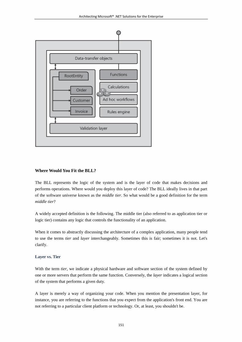
Architecting Microsoft® .NET Solutions for the Enterprise
151
Where Would You Fit the BLL?
The BLL represents the logic of the system and is the layer of code that makes decisions and
performs operations. Where would you deploy this layer of code? The BLL ideally lives in that part
of the software universe known as the middle tier. So what would be a good definition for the term
middle tier?
A widely accepted definition is the following. The middle tier (also referred to as application tier or
logic tier) contains any logic that controls the functionality of an application.
When it comes to abstractly discussing the architecture of a complex application, many people tend
to use the terms tier and layer interchangeably. Sometimes this is fair; sometimes it is not. Let's
clarify.
Layer vs. Tier
With the term tier, we indicate a physical hardware and software section of the system defined by
one or more servers that perform the same function. Conversely, the layer indicates a logical section
of the system that performs a given duty.
A layer is merely a way of organizing your code. When you mention the presentation layer, for
instance, you are referring to the functions that you expect from the application's front end. You are
not referring to a particular client platform or technology. Or, at least, you shouldn't be.
Architecting Microsoft® .NET Solutions for the Enterprise
152
Likewise, when you talk about layers you make no statements¡ªneither implicitly nor
explicitly¡ªabout where these layers might run, such as on different computers or in different
processes. Equally valid terms that are often used to indicate a layer are logical tier and logical
layer.
A tier, on the other hand, refers to where the code runs. For this reason, a tier is often referred to as a
physical tier, or perhaps a physical layer. More specifically, a tier is the place where architects make
logical layers run.
As a result, multiple layers can coexist on the same physical tier. At the same time, a layer should be
easily moveable to another tier.
Why Should You Care About Layers?
A layer is normally conceived as a sort of black box with a clear contract (interface) that defines
input and output and little, or no, dependency on other layers or physical servers. The main benefits
that you get from layering are organizational and revolve around reuse and separation of concerns.
Layer reuse allows you to write your layer once but use it within multiple business applications. A
data access layer is a good candidate for that. Separation of concerns embodies the notion that layers
should be encapsulated, or perhaps better stated, as highly cohesive but loosely coupled. Your
business logic layer should not pull information directly from the database any more than your data
access layer should present information directly to the user. By properly encapsulating your layers,
you gain access to tools such as test-driven design and the use of "mock" layers that serve as
temporary substitutes while the actual layer they represent is created. This allows development of
dependent layers to continue rather than forcing layers to be created sequentially.
A high degree of reusability, coupled with the proper isolation of functions, makes for better and
easier maintenance of the system. In the end, logical layers can significantly shorten the
development cycle, allowing different teams to work in parallel.
Logical layering is often a very desirable feature to have in an application, or a system, regardless of
real complexity. Mapping logical layers onto physical tiers is a different story, though, and it has
different rules and perspectives.
Why Should You Care About Tiers?
Multiple tiers indicate that different physical entities are involved in running the application. A
physical entity can be a computer or a process within a computer. In an enterprise scenario, nearly
all applications these days have at least two tiers¡ªand one of these tiers is a separate computer
hosting the database server. Are multiple physical tiers a desirable feature?
The key point to note about physical tiers is that a tier represents a boundary to cross, whether it is a
process boundary or machine boundary. Crossing a boundary is an expensive operation. The cost is
higher if you have to reach a physically distant computer rather than just another process within the
same machine. One rule of thumb to consider is that a call that crosses the boundaries of a process is
Architecting Microsoft® .NET Solutions for the Enterprise
153
about 100 times slower than an equivalent in-process call. And it is even slower if it has to travel
over the network to reach the endpoint.
Multiple tiers are not generally a good feature to have in a system. Tiers slow down the overall
performance and increase the overall complexity. Both aspects, then, affect the overall cost to build
and maintain the application. This said, tiers¡ªsome tiers¡ªjust can't be avoided. So they're sort of evil,
but a necessary evil.
In any system, there might be some physical boundaries that can't just be ignored and must be dealt
with. For example, an unavoidable barrier exists between the code that runs on the user's machine
and the server-side code. Another typical divide exists between the server-side code (also referred to
as the application server) and the database server. Web applications mostly fall into this category.
In addition, each application might have its own good reasons to introduce multiple tiers. One
reason could be the need to support an external product that requires its own process. Another good
reason for multiple tiers is the quest for security. A module that runs in isolation in a process can be
more easily protected and accessed if it's used only by authorized callers.
Much less often than commonly reckoned, multiple tiers serve as a trick to increase the scalability of
a system. More precisely, a system where certain components can be remoted and duplicated on
additional tiers is inherently more scalable than systems that do not have this capability. But
scalability is just one aspect of a system. And often the quest for scalability¡ªthat is, the need for
stabilized performance under pressure¡ªhurts everyday performance.
In summary, the number of physical tiers should be kept as low as possible. And the addition of a
new tier should happen only after a careful cost-benefit analysis, where costs are mostly in the area
of increased complexity and benefits lie in the area of security, scalability and, perhaps, fault
tolerance.
Exposing BLL to the World
So where should you deploy the BLL? Should it go in the same process as its callers? And how
should you deal with inherent architectural divides such as client machines and application servers?
Back in 2003, Martin Fowler published a popular article in Dr. Dobb's Journal that is still a
milestone for architects, regardless of which specialization and reference platform they use. The
article, "Errant Architectures," is available at http://www.ddj.com/184414966. Why is it such an
interesting read?
In the article, Fowler formalizes his first law of distributed object design. And it couldn't be clearer:
Don't distribute your objects.
In more recent years, distributed objects have become services, which makes them significantly
simpler, more effective, and more affordable. However, it didn't change a basic fact: whether it is a
distributed object or a service, you're placing a call over the wire to a remote piece of software. A
software layer that runs remotely is different from a layer that runs in a local process. Remote
Architecting Microsoft® .NET Solutions for the Enterprise
154
software is better designed with a coarse-grained interface, whereas in-process software is ideally
architected with a fine-grained interface.
Hence, location transparency is a concept that works better in demos and presentations than in the
real world. We're not saying that you have to change the internal architecture of the BLL if it has to
run remotely. However, a remote BLL should always be wrapped by a component with a
coarse-grained interface¡ªtypically, an implementation of the Fa?ade pattern. (We'll return to this
point in the next chapter while discussing the service layer of a system.)
Hosting BLL
At least when using the .NET Framework, the BLL is generally a collection of assemblies waiting
for a host process. The shape and color of the host process are determined based on the application's
context.
In a Web scenario, you typically host the BLL in the same process as ASP.NET. Nothing, if not the
concerns expressed earlier in the chapter, prevents you from using separate processes and thus
running the BLL in its own application server. Having the BLL on the server side greatly simplifies
maintenance.
In a smart-client scenario, the BLL can be bundled with the presentation layer and run entirely on
the user's machine within the application process. You still have separation between the presentation
and business layers, and gain as much as possible in terms of interactivity and responsiveness. On
the down side, maintenance can be problematic, unless you resort to ad hoc deployment
technologies such as ClickOnce.
The BLL on the client is a must in the case of occasionally connected applications. With the BLL in
place, the user of the application can work at will and save changes for later, when the connection is
re-established. In this case, though, it might be sufficient to install only a portion of the BLL on the
client. As a result, the BLL is split across the client and server.
Note
The BLL, though, should not be considered as a monolithic component or as
the composition of disjoint modules. Years of real-world experience taught us
that some duplication of the BLL across layers¡ªthe classic three layers¡ªis
acceptable and realistic. But to the extent that it is possible, it shouldn't be
encouraged.
Business and Other Layers
Everybody would agree that the BLL deserves its own module. However, this is not always what
happens in reality. More often than not, logic that objectively belongs to the BLL is interwoven with
Architecting Microsoft® .NET Solutions for the Enterprise
155
other layers (when not tiers), such as the presentation layer and DAL. Nearly all developers would
agree that this is not the right approach to take; yet, it happens more often than you might think.
With this in mind, let's take a look at some numbers that help us to figure out where we are and what
we should target.
BLL Distribution and Measurements
Let's assume we have a classic layered system articulated in presentation, business, and data access
layers. What percentage of business logic should go in each layer? The canonical answer is 0-100-0.
These numbers, though, are a lot like the ideal gas mileage numbers automobile manufacturers
present when you're looking for a new car. How many vehicles ever attain the reported ideal
mileage? And how realistic are the mileage figures? What really matters is the car is reliable,
relatively fuel efficient, and fun to drive. The same generally holds true for layered architectures too.
When it comes to applications, what really matters is that a system is healthy, easy to maintain, and
makes users happy. As an architect, you might find that the only way to get this is to make
compromises such as duplicating some logic or moving it around. Honestly, the truth of the matter
is often there is no problem with this.
In general, you should try to put everything in the BLL, except create, read, update, and delete
(CRUD) operations and user-interface adjustments such as sizing, moving, and binding. Any
amount of logic you might find in the presentation and data access layers might be because of some
deliberate duplication introduced to capture some bit of extra performance.
Sometimes, though, it is there because of a sort of laziness or because of compromises with other
figures. Have you ever heard or said something like, "It's easier this way; we'll rearchitect it later"?
The duplication might also be because of some gray areas in the overall functionality of the
system¡ªwhen, quite simply, it's not clear enough where some function has to go. The following
sections describe a few common gray areas, with our thoughts about each.
Gray Area #1: Data Formatting
One of the most common reasons why the amount of logic in the presentation layer is not null is that
you end up applying business logic in decisions about input validation and display formatting. Let's
look at a concrete example. How would you store and handle some very specific data, such as a
phone number or a value that represents money?
Users reasonably demand to see phone numbers or money displayed in a human-readable way¡ªthat
is, properly formatted. OK, is this business logic or UI? We would tend to choose the first option,
but we definitely recognize this as a gray area.
Architecting Microsoft® .NET Solutions for the Enterprise
156
If you format data on the client, the presentation layer might need to know a lot about the context
and the logic of the system. If you recognize formatting as part of the business logic, you should
equip the BLL with proper methods for the client to retrieve ready-to-display strings.
And how would you store the raw information¡ªin these examples, just numbers? All in all, you
have three options:
Store data twice, in both raw and easy-display format.
Store data in its raw format, and apply formatting on the fly.
Store data in the same input format as you receive it.
We would clearly go for option #2, but what if, because of other constraints, that meant adding logic
to a stored procedure? This type of decision is where architects consider and work with tradeoffs.
Storing data twice is not an attractive solution because it leads to duplicated data (which might be
the least attractive solution) and, more importantly, because it leads to additional update work and
increased complexity of the code. Put another way, duplicate data results in more tests, risks of
introducing errors, and so forth.
Not using data in its raw format is also problematic because it might hinder you when it comes to
sorting, finding, and indexing that data.
Gray Area #2: CRUD Operations
When the logic in the DAL is not empty, it means that you've probably been forced to encode some
logic in stored procedures. But this can lead to some interesting behavior. Consider this example:
how would you delete a customer record?
You probably agree that in the BLL the customer is a business object whose data is mapped to some
record in some database table. Some business logic decisions need to be made to "delete a
customer." In particular, you must make a decision about the following issues: Can the customer
even be deleted? Historical records such as customer-specific orders might preclude customer
deletion. What other dependent records are to be deleted? Do you delete all orders placed by the
customer, or contacts where the deleted customer is referenced? What else should be done before
and after the deletion? Do you need to notify other processes (say, accounting or customer relations),
close accounts, or send notifications to suppliers?
Such complex logic ideally belongs to the behavior of the business object. The code that implements
the behavior of the business object knows when and if the object can be deleted and what this means
to the rest of the system.
The DAL should only be commanded to proceed with database operations and should not even be
aware of an entity named "the customer." All that it needs to know is how to get to the record, that it
has to check are data types and nullability, and that it needs to ensure data integrity and indexing.
Architecting Microsoft® .NET Solutions for the Enterprise
157
Other types of records that are different from the customer record, however, might not be so
difficult to deal with in a stored procedure. All in all, it is essentially a matter of intelligent
application of design principles and an understanding of the domain and context.
Gray Area #3: Stored Procedures
As mentioned, you often deal with stored procedures (SP). This might happen because you're
fanatical about stored procedures or because the DBA forced you to use SPs. As a result, sometimes
the deletion of data associated with a business object is handled exclusively by a stored procedure.
In this case, inevitably, the SP contains logic.
In a nutshell, you should consider SPs to be only a database tool and not the repository for a single
ounce of business logic. You should use SPs to return and update data, not to interpret data in any
way. Furthermore, SPs should operate only on one table, except when they join tables for the
purpose of returning data or when they implement batch updates that loop over data in a way that
would generate hundreds of statements if executed from the business logic layer.
Let's be honest: often business logic slips into SPs because it's so quick and easy to do it that way. In
a rush, you might decide that it's (temporarily) better to just put a given feature in an SP. But, of
course, you promise yourself that you'll fix it later, as soon as you can catch your breath. Often, this
moment of pause never happens and the code remains there in the SP forever or until the application
is retired or replaced entirely.
Moreover, by moving any business logic out of SPs, you make your logic a lot easier to update, test,
and debug. In addition, you increase the database portability of the solution because SPs designed
for portability need to be extremely simple. In addition, online transaction processing (OLTP) would
also force simple SPs. The more you put in there, the longer the transaction might take, killing
OLTP functionality.
A common objection you have to face with regard to this point frequently comes from DBAs:
moving logic out of SPs increases the traffic to and from the database.
The validity of this objection is debatable. The concerns of the DBA are not always justified.
Databases are often connected over a very high-speed connection, so they can often happily handle
any increased traffic. If this issue comes up, whatever decision you make, just be sure it is backed
up by numbers. And if you have to resort to SPs, pay close attention so that no logic eventually slips
into them.
Note
When it comes to database traffic, it's often possible to add more or better
hardware to ease the bottlenecks. Furthermore, where possible you'd
probably also cache information in the BLL. Sometimes you can't, but other
times you can, especially for simple table lookups, which are just the sort of
thing you'd be hitting the database for on a frequent basis.
Architecting Microsoft® .NET Solutions for the Enterprise
158
Patterns for Creating the Business Layer
As shown in Figure 4-1, the BLL is centered on the domain's object model¡ªthat is, a graph of
objects that model the entities in the domain. Each business object has its own data and behavior.
After you have a class diagram and know the model, how do you approach the task of actually
building this business layer?
There are a few design patterns for organizing the domain logic, each with a different level of
complexity and different objectives. We'll go into the details of these patterns in the remainder of
the chapter. For now, we'd like to briefly describe them by category.
Why Patterns for the BLL?
In the design of the BLL, we could go ad hoc, but the success rate in doing so isn't all that good,
historically speaking. So we leverage patterns because patterns help us understand and deal with
complexity. Each pattern has strengths and weaknesses, or probably more precisely, patterns have
architectural strengths versus cost.
Which path we choose isn't always based on cost; rather, it's often based on an intimate knowledge
of the business domain. The more complex the BLL needs to be to support stakeholders'
requirements, the less likely we are to choose a pattern that doesn't handle domain-specific
complexity well. Some BLL patterns are great for relatively simple applications, but you wouldn't
run large applications on them.
So the focus is on understanding the application's intended domain, understanding the palette of
available and known patterns, and selecting the pattern that we believe gives us the best hope of
dealing with the complexity of the BLL we anticipate.
Procedural Patterns
Before the long wave of object-oriented development, quite a few years ago, the BLL was simply
perceived as a collection of procedures, each handling a single request from the presentation layer.
Therefore, a good design was mostly a matter of organizing procedures in a way that minimized
code redundancy while fully matching the requirements.
The BLL was seen collectively, as a series of related transactions. Starting from the use cases, each
step the system had to carry out was broken down into smaller steps. And each step was then
rendered through an operation, generally referred to as a transaction.
In this context, however, a transaction indicates a monolithic logical operation and has no
relationship to a database management system (DBMS) transaction. This pattern is known as a
Transaction Script.
Architecting Microsoft® .NET Solutions for the Enterprise
159
If you need to submit an order for some goods, your logical transaction is made of steps such as
checking for the availability of goods, calculating totals, verifying funds on the user account,
updating databases, and perhaps interacting with the shipping service.
Historically, a Transaction Script was the first pattern to appear and gain popularity. Over the years,
another approach emerged, built around the notion of a table of data. It goes by the name of Table
Module. The perspective is similar to a series of transactions, but this time operations are grouped
by data. Operations are defined as methods on an object that represents a table of records. From our
standpoint, this remains a mostly procedural approach, but one with a more strongly object-oriented
vision. In the end, you use the table of data (often a real database table or view) as a factor that helps
to organize methods. For example, you might want to set up the BLL as a collection of methods on a
table object that contains all orders or customers.
Object-Based Patterns
A fully object-based pattern takes you to organizing the domain logic as a graph of interrelated and
interconnected objects each representing an entity or a concern in the business and each object
equipped with data and behavior. How close is this object model to the data model represented in
the database? It depends on the complexity and, subsequently, on the level of abstraction you need.
A very simple object model looks a lot like the data model expressed by database tables. In this case,
the objects that form the model are essentially records with some extra methods. This pattern is
generally referred to as the Active Record pattern.
The more you add abstraction, the more you move away from the data model. So to create a
domain-driven object model, most likely, you start from the vision of the domain you have rather
than from the structure of the database. A domain-driven design invariably leads you to having a
significant gap between the data model and the resulting domain model. This pattern is generally
referred to as the Domain Model pattern.
In summary, if you feel the focus should be put on operations, you opt for a Transaction Script. If
you find it easier to reason in terms of tables of data, go for a Table Module. If your domain model
mimics your data model fairly faithfully, the Active Record pattern might best suit your needs.
Finally, if the process you're modeling causes you to start with an abstract schema of interconnected
entities and break it down into compositional subsystems, the Domain Model pattern is probably for
you.
Is this synopsis correct? Are things really as easy and smooth as schematized here? Well, not really.
This wouldn't be the notorious real world then. As you might have guessed, each approach has pros,
cons, and preferred fields of application. Before we delve deeper into each of the primary patterns
for modeling domain logic, an overall look at all of them together is needed to enable you to make
an informed choice.
Differences at a Glance
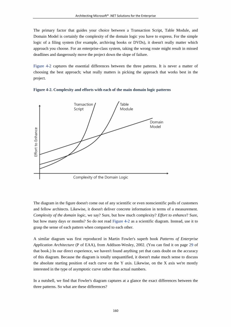
Architecting Microsoft® .NET Solutions for the Enterprise
160
The primary factor that guides your choice between a Transaction Script, Table Module, and
Domain Model is certainly the complexity of the domain logic you have to express. For the simple
logic of a filing system (for example, archiving books or DVDs), it doesn't really matter which
approach you choose. For an enterprise-class system, taking the wrong route might result in missed
deadlines and dangerously move the project down the slope of failure.
Figure 4-2 captures the essential differences between the three patterns. It is never a matter of
choosing the best approach; what really matters is picking the approach that works best in the
project.
Figure 4-2. Complexity and efforts with each of the main domain logic patterns
The diagram in the figure doesn't come out of any scientific or even nonscientific polls of customers
and fellow architects. Likewise, it doesn't deliver concrete information in terms of a measurement.
Complexity of the domain logic, we say? Sure, but how much complexity? Effort to enhance? Sure,
but how many days or months? So do not read Figure 4-2 as a scientific diagram. Instead, use it to
grasp the sense of each pattern when compared to each other.
A similar diagram was first reproduced in Martin Fowler's superb book Patterns of Enterprise
Application Architecture (P of EAA), from Addison-Wesley, 2002. (You can find it on page 29 of
that book.) In our direct experience, we haven't found anything yet that casts doubt on the accuracy
of this diagram. Because the diagram is totally unquantified, it doesn't make much sense to discuss
the absolute starting position of each curve on the Y axis. Likewise, on the X axis we're mostly
interested in the type of asymptotic curve rather than actual numbers.
In a nutshell, we find that Fowler's diagram captures at a glance the exact differences between the
three patterns. So what are these differences?
Architecting Microsoft® .NET Solutions for the Enterprise
161
Object-Based vs. Procedural Patterns
Object-based patterns have higher startup costs and a kind of linear growth with complexity. In
other words, once you have grasped a good understanding of the Domain Model pattern, you are
well positioned to design your system using that pattern whatever the complexity of the system is.
Designing the model to act as the foundation for a piece of software that faithfully represents the
user requirements is a delicate art. Although metrics and practices exist, we found out that getting
the model right is mostly a matter of experience. Experience sharpens your sight and mind and
makes you think in a way that is not too little and not too big, but just right.
Objects provide abstraction, and abstraction inherently introduces a gap between requirements and
the final software product. Your efforts include preventing mismatches and misinterpretation from
sneaking in. A more complex system certainly takes more time and requires more work and
attention, but it's manageable.
On the other hand, procedural patterns tend to reach a point of complexity beyond which adding
new features has exponentially growing costs.
We used the word "complexity" quite a few times already. But how do you measure such a thing?
When can you really call a domain's logic "complex," and when is it, instead, simple enough? How
do you recognize complexity and simplicity in a domain's object model?
A Quick Measure of Complexity
Complexity is essentially a two-fold factor. In all cases, you have some amount of inherent
complexity. This is the complexity deriving from an unavoidable amount of crisp and not
contradictory requirements. This complexity can be managed more or less effectively, but you can't
just make it go away. You have to work with it.
In addition, there's the whole challenge of induced complexity. This is the complexity triggered by
any impedance mismatch that comes into existence among the various stakeholders of the system. A
nasty effect of this mismatch is the misdirection it presents to the team. Misdirection typically leads
to an abstract design that contains unnecessary or nonfunctional features, with the result of pushing
the software to the limit. A common metric with which to measure the stakeholders' mismatch is
requirements churn, which indicates the number of new or changed requirements the team gets per
month.
You want some numbers to try to mark the boundary between object-based and procedural patterns,
right? Complexity can't be quantified up front by counting classes in the object model or lines of
code¡ªyou don't have code or design made yet. Requirements are therefore the only measurable
information you can rely on up front.
The number of requirements can be used to form an idea about the class of complexity of the system.
The order of magnitude for a moderately complex business application is certainly numbered in the
thousands. It's unreasonable to expect to find less than a few thousand business rules in a real-world
Architecting Microsoft® .NET Solutions for the Enterprise
162
application. However, not all requirements have the same effect on the system or add significant
complexity to the development or the final product. For example, in a Web portal where you just
reuse the existing back office, requirements are mostly in the area of the graphical user interface.
This system is inherently much simpler than a system (for example, a banking system) that involves
building a back office to be shared by different applications (for example, online banking, trading,
or customer care).
When you measure the complexity of a system, you expect to get numbers and quantities. However,
in software systems it's easier to recognize complexity than it is to explain how to spot it.
Note
We expect some readers at this point to exclaim, "Hey, I'm new and you can't
explain how to spot complexity in a software system. How would I ever know it
when I saw it?" Seriously, recognizing complexity in a software system is not
like conducting a litmus test to determine the acidity of a material. There's no
paper that turns red or blue to give you a clear and observable response. It's a
matter of experience, education and, yes, gut feeling.
Let's move on and get up close and personal with the four main patterns for modeling the domain
logic. We start from the simplest of all¡ªthe Transaction Script pattern.
6.1.2 The Transaction Script Pattern
When it comes to organizing your business logic, there's just one key decision you have to make. Do
you go with an object-oriented design or with a procedural approach? You are choosing a paradigm
to design the business logic; it's about architecture, not about technology. However, the hardware
and software platform of choice¡ªthe overall technology¡ªcan drive you toward a particular model of
business logic.
The Transaction Script (TS) pattern is probably the simplest possible pattern for business logic; it is
entirely procedural. Like all the other patterns we cover in this and the following chapters, TS owes
its name and classification to Martin Fowler. For further reference, have a look at page 110 of his
book [P of EAA], which we mentioned earlier in the chapter.
Generalities of the TS Pattern
TS encourages you to skip any object-oriented design and map your business components directly
onto required user actions. You focus on the operations the user can accomplish through the
presentation layer and write a method for each request. The method is referred to as a transaction
script.
Architecting Microsoft® .NET Solutions for the Enterprise
163
The word transaction here generically indicates a business transaction you want to carry out. The
word script indicates that you logically associate a sequence of system-carried actions (namely, a
script) with each user action.
When to Use TS
TS is extremely easy to understand and explain. Each required user action proceeds from start to
finish within the boundaries of a physical transaction. Data access is usually encapsulated in a set of
components distinct from those implementing the actual script.
TS doesn't have any flavors of object-oriented design. Any logic you model through a TS is
expressed using language syntax elements such as IF, WHILE, and FOR. Adding a new feature to
an existing user action mostly means adding a new branch or subroutine somewhere in the existing
code.
TS is suited for simple scenarios where the business logic is straightforward and, better yet, not
likely to change and evolve.
TS seems to be the perfect choice for a Web portal that relies on an existing back office. In this case,
you end up with some pages with interactive elements that trigger a server action. Each server action
is resolved by making some data validation, perhaps making some trivial calculations, and then
forwarding data to the back-office system.
Honestly, with such simple requirements there's no need to spend much time planning a domain
model.
Note
Simplicity and complexity are concepts that are not easy to measure. More
importantly, the perception of what's simple and what's complex depends on a
person's attitude and skills. If you've been doing object-oriented design for
years and know your stuff well, it might be easier and faster for you to arrange
a simple domain model than to switch back to procedural coding. So TS
doesn't have to be the choice every time you feel the complexity is below a
given universally recognized threshold. More simply, TS is an option that you
should seriously consider once you feel you know all about the system, and
when it doesn't look overly complex in terms of requirements and business
rules. Objects make code elegant, but elegance is a positive attribute only if
code works and is done right. There's nothing to be ashamed of in using
TS¡ªand especially in using TS when it is appropriate.
What's Good About TS
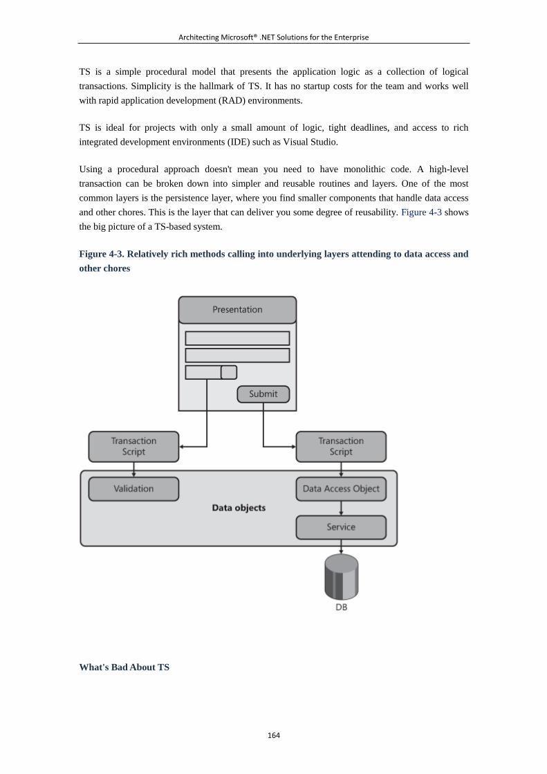
Architecting Microsoft® .NET Solutions for the Enterprise
164
TS is a simple procedural model that presents the application logic as a collection of logical
transactions. Simplicity is the hallmark of TS. It has no startup costs for the team and works well
with rapid application development (RAD) environments.
TS is ideal for projects with only a small amount of logic, tight deadlines, and access to rich
integrated development environments (IDE) such as Visual Studio.
Using a procedural approach doesn't mean you need to have monolithic code. A high-level
transaction can be broken down into simpler and reusable routines and layers. One of the most
common layers is the persistence layer, where you find smaller components that handle data access
and other chores. This is the layer that can deliver you some degree of reusability. Figure 4-3 shows
the big picture of a TS-based system.
Figure 4-3. Relatively rich methods calling into underlying layers attending to data access and
other chores
What's Bad About TS
Architecting Microsoft® .NET Solutions for the Enterprise
165
Simplicity is the major strength and most critical weakness of TS. Setting up a TS is as easy as
creating one or a few container classes that expose logically related methods. As shown in Figure
4-3, each method implements a particular transaction script and, optionally, interacts with helper
data objects that perform a variety of tasks¡ªfrom validation to data massaging, from calculation to
physical data access.
Note that there's nothing but common sense to prevent you from placing all the code, including data
access code, in a transaction script. Likewise, it's mostly common sense to suggest to you how to
group scripts.
In general, TS has remarkable potential for code duplication. It is not unlikely that you'll end up
with a number of transactions accomplishing very similar tasks. The resulting application might not
look really different from a tangle of routines. If it's not spaghetti code, it might perhaps be some
bucatini code. Your code will still look tangled, but at least it will be a more coarse-grained tangle.
Note
Bucatini code is not an officially registered term in software development.
However, it has the same meaning as spaghetti code, except that it refers to
richer building blocks of code¡ªexactly the difference between spaghetti and
bucatini. (Bucatini is a variation of spaghetti; it's just thicker and has a hole
running through the center.)
Code duplication and spaghetti code can be avoided by extracting chunks of code and promoting
them to the rank of a method. This is usually what the process of refactoring does. Refactoring
certainly helps mitigate some issues inherent with TS. However, refactoring has a limited range.
As the volume and content of requirements grow, it usually gets harder to refactor, for at least two
reasons. First, you run behind schedule and don't feel like spending more time to redo what you
already did, even if it means better code. Second, even when you make a point of refactoring your
code regularly, it will take longer and longer to adjust as the complexity of the domain logic grows.
This concept is well captured by the curve that represents TS in Figure 4-2.
To add insult to injury, touching a tangle of routines can be risky from a testing perspective too.
Don't forget software regression testing. You might find out that a newly added feature causes the
software to stop working or perform poorly compared to previous versions. You have one more
thing to fix and, more generally, you just can't make it work without a good battery of regression
tests.
Fight Duplication: One Is Enough
More generally and beyond the context of TS, code duplication is a nasty beast to fight. In
the case of changes to the code, it will cause you headaches because you have to find all
the places where you have similar code. It also is confusing and unfriendly to new
Architecting Microsoft® .NET Solutions for the Enterprise
166
developers on the team and makes testing (regression tests, in particular) much harder to
do.
However, your real enemy is duplication, not just code duplication. A well-designed
system doesn't repeat the same feature in multiple places¡ªbe it code, documentation, unit
tests, or perhaps use cases. What are your weapons to fight off duplication? One is the
broad application of object-oriented principles such as encapsulation and inheritance.
Another one is cohesion¡ªthat is, when classes carry out tightly related activities and have
a small number of responsibilities.
The Pattern in Action
Overall, designing domain logic according to TS is not a hard task. You get the list of required
transactions by looking at the actions available in the presentation layer or, more generally, you look
at the use cases defined for the system.
After you have the list of transactions, you implement each transaction in a method housed in a
component. In the Microsoft .NET Framework, a component is essentially a class compiled to an
assembly.
Designing Business Components
The basic point is that each transaction has its own method in some component. What happens
within the body of the method is entirely up to you. You can have all the code in one place; or you
can delegate the execution of child steps to some shared helper objects. These helper objects
collectively form specific layers, such as validation, formatting, and persistence. (See Figure 4-3.)
All classes that implement transaction scripts can be referred to as business components. You can
derive all business components from a unique parent. In this way, you ensure that all classes have a
common base behavior. What would be a typical behavior you might want to share among all
business components? You might want to share the constructor to make sure that all business
components receive the same information upon initialization. Another example is common error
handling. Handling exceptions pretty much breaks nearly any nicely designed model and should be
considered up front. Security is another example. A base class can offer a one-stop method to check
for authorization.
In addition, you might want to use the base class to define members that import external objects
within the boundaries of the business layer to address cross-cutting concerns such as logging.
Generally, you can build the base class to support dependency injection (which is defined in Chapter
3) and thus receive and consume external objects that supply a service to the script.
Implementing Business Components
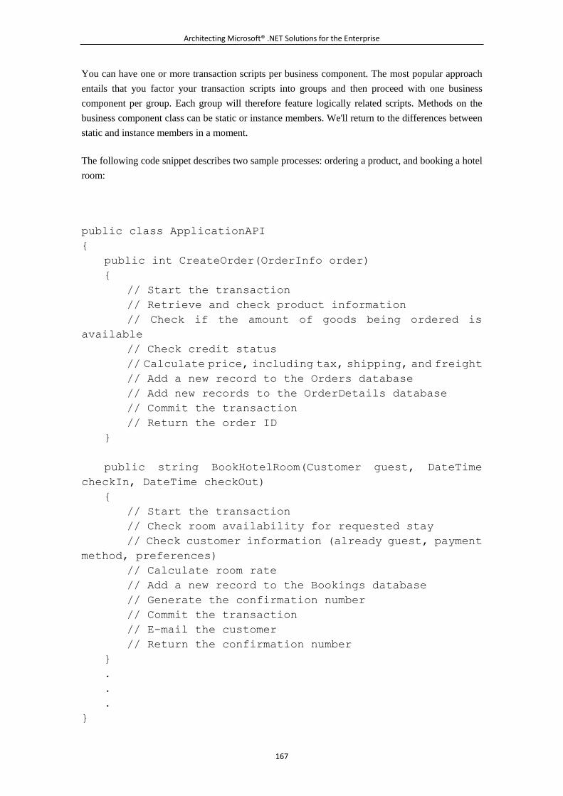
Architecting Microsoft® .NET Solutions for the Enterprise
167
You can have one or more transaction scripts per business component. The most popular approach
entails that you factor your transaction scripts into groups and then proceed with one business
component per group. Each group will therefore feature logically related scripts. Methods on the
business component class can be static or instance members. We'll return to the differences between
static and instance members in a moment.
The following code snippet describes two sample processes: ordering a product, and booking a hotel
room:
public class ApplicationAPI
{
public int CreateOrder(OrderInfo order)
{
// Start the transaction
// Retrieve and check product information
// Check if the amount of goods being ordered is
available
// Check credit status
// Calculate price, including tax, shipping, and freight
// Add a new record to the Orders database
// Add new records to the OrderDetails database
// Commit the transaction
// Return the order ID
}
public string BookHotelRoom(Customer guest, DateTime
checkIn, DateTime checkOut)
{
// Start the transaction
// Check room availability for requested stay
// Check customer information (already guest, payment
method, preferences)
// Calculate room rate
// Add a new record to the Bookings database
// Generate the confirmation number
// Commit the transaction
// E-mail the customer
// Return the confirmation number
}
.
.
.
}
Architecting Microsoft® .NET Solutions for the Enterprise
168
As you can see, both methods are grouped into a single business component and both methods
involve several steps. Each step can be implemented through direct database calls (SQL commands,
stored procedures, or perhaps ADO.NET code) or by placing calls to a specialized component or
service.
The implementation of both methods is not particularly cohesive, which means that there's a lot of
room for refactoring¡ªand a significant exposure to problems if you don't refactor it properly.
Business Components as Command Objects
Alternatively, you can implement each transaction script in its own class. Each business component,
therefore, features just one method. Put another way, in this case the business object is a sort of
command object used to represent an action. This is exactly the definition of the Command pattern.
Note
One of the most popular behavioral design patterns, the Command pattern
uses objects to represent actions. The command object encapsulates an action
and all of its parameters. Typically, the command object exposes a standard
interface so that the caller can invoke any command, without getting the
intimate knowledge of the command class that will actually do the job. Like
many other design patterns, the Command pattern was originally defined in
the book Design Patterns: Elements of Reusable Object-Oriented Software
(Addison-Wesley, 1994). Authored by Erich Gamma, Richard Helm, Ralph
Johnson, and John Vlissides¡ªthe Gang of Four (GoF)¡ªthe book is a landmark
in software engineering.
When the TS business component is a command object, you extract an interface and encapsulate all
required parameters as public properties of the class. Here's how to rewrite the preceding code to use
the Command pattern:
public interface IApplicationCommand
{
int Run();
}
public class CreateOrderCommand : IApplicationCommand
{
OrderInfo _orderinfo;
Architecting Microsoft® .NET Solutions for the Enterprise
169
int _orderID;
// other internal members
public CreateOrderCommand(OrderInfo order)
{
_orderInfo = order;
}
public int OrderID
{
get { return _orderID; }
}
public int Run()
{
// Start the transaction
// Retrieve and check product information
// Check if the amount of goods being ordered is
available
// Check credit status
// Calculate price, including tax, shipping, and freight
// Add a new record to the Orders database
// Add new records to the OrderDetails database
// Commit the transaction
// Get the order ID, and store it in the local member
_orderID
}
}
public class BookHotelRoom : IApplicationCommand
{
Customer _guest;
DateTime _checkIn, _checkOut;
String _confirmationNumber;
// other internal members
public BookHotelRoom(Customer guest, DateTime checkIn,
DateTime checkOut)
{
_guest = guest;
_checkIn = checkIn;
_checkOut = checkOut;
}
Architecting Microsoft® .NET Solutions for the Enterprise
170
public String ConfirmationNumber
{
get { return _confirmationNumber; }
}
public int Run()
{
// Start the transaction
// Check room availability for requested stay
// Check customer information (already guest, payment
method, preferences)
// Calculate room rate
// Add a new record to the Bookings database
// Generate the confirmation number
// Commit the transaction
// E-mail the customer
// Store the confirmation number to the local member
_confirmationNumber
}
.
.
.
}
The Command pattern allows the presentation layer to instantiate command objects indirectly
through a factory, which makes the overall design inherently more extensible. When you opt for a
common interface, though, you need to find out how to return values. A widely accepted solution is
defining public read-only members where the Run method returns any values it wants to make
publicly available through those fields or properties.
Considerations About the Command Pattern
Implementing the Command pattern in TS leads to a proliferation of little classes that can clutter up
the application's namespace. However, the Command pattern has great potential, too. The ability to
represent an action with an object also allows you to combine a series of activities into a larger
transaction. Do you see the point?
Not only can you use the Command pattern to expose a transaction script to the presentation layer,
you can also use it to bundle up smaller activities into the transaction script itself. In other words, all
the steps outlined earlier for, say, CreateOrderCommand can be command objects as well. This
means that you can, for example, also serialize commands to some medium and transfer them to a
different process for handling. In addition, the list of commands in each transaction script can be
Architecting Microsoft® .NET Solutions for the Enterprise
171
read out of the configuration or modified dynamically. In the end, a command is just a class name,
an assembly, and a bunch of parameters. And, of course, a common interface to make it run.
Static and Instance Methods
If you opt for multiple scripts in a single business object, a question arises with regard to the status
of the methods. Should you use static methods or instance methods? Needless to say, if you opt for
the Command pattern there's no option: methods are to be instance based.
In the .NET Framework, static and instance methods are nearly identical performance-wise. A static
method is invoked without an instance of the host class being created. This means that static
methods can directly use static variables and other static methods. Static methods can't talk to
instance member variables unless they manage to get a reference to a particular instance.
For properties, the attribute static might, in some cases, bring benefits in terms of memory because
only one copy of the property exists and it is shared by all instances of the type. For methods,
though, the difference is very minor and limited to the need of creating or getting a fresh instance of
the class every time you make a call to the method.
The bottom line is that any choice between static and instance methods is essentially a design choice.
You can make this choice by applying a simple rule: any method that doesn't have contact with
other members in the class should be implemented as a static method. This rule can be enforced by
FxCop. Note, though, that this is a quick rule that applies to methods in the context of a TS.
Generally, if a method or property is and should be tied to the class as a whole, it should be static. If
the method or property is tied to a specific instance of the class, it's not static.
Note
FxCop is a free, static code-analysis tool from Microsoft. It analyzes managed
assemblies and suggests possible design, performance, and security
improvements. FxCop checks the compiled code for conformance to the
Microsoft .NET Framework Design Guidelines. For more information, visit
http://msdn.microsoft.com/en-us/library/bb429476(VS.80).aspx.
Passing Data to Transaction Scripts
How would you pass operational data to a transaction script? You generally use method parameters
when scripts are exposed as public methods of a business component. You provide data through the
constructor or public properties if you have a single class per transaction script.
Because you likely need to pass multiple values for each call, using lots of parameters on a method
often turns out to be awkward. In this case, you store multiple scalar values in a new class. Such a
class would clearly be a DTO. In the preceding code, both Customer and OrderInfo are DTOs.
Here's another example:
Architecting Microsoft® .NET Solutions for the Enterprise
172
public class Customer
{
public string FirstName {get; set;}
public string LastName {get; set;}
public DateTime DateOfBirth {get; set;}
public string PhotoID {get; set;}
public Address Home {get; set;}
public PaymentDetails MethodOfPayment {get; set;}
.
.
.
}
Obviously, DTOs can be nested and are plain containers of data with no behavior. If you're using
DTOs to pass data among processes, the DTO class must be made serializable.
Note
The main point we want to make here about ways to provide data to
transaction scripts clearly relates to DTOs, but it goes even beyond that. The TS
pattern doesn't mandate any data types or formats. Providing data to scripts
and retrieving data from scripts is up to you. So feel free to opt for the
approach that best suits your preferences and design needs. We just listed the
most common options that we have successfully employed in real projects.
Don't feel limited to using only these.
6.1.3 The Table Module Pattern
The TS pattern envisions the domain logic as a series of transactions triggered by the presentation.
Subsequently, modeling the domain logic means mapping transactions onto methods of one or more
business components. Each business component then talks to the DAL either directly or through
relatively dumb data objects. The logic is implemented in large chunks of code that can be difficult
to understand, maintain, and reuse.
When you partition transaction scripts into business components, you often group methods by entity.
For example, you create an OrderAPI business component to house all transaction scripts related to
the "order" entity. Likewise, you create a CustomerAPI component to expose all methods related to
action the system needs to perform on customers. And so forth.
Furthermore, in relatively simple scenarios the entity can also be mapped directly to a database table.
In the end, you come up with one business component per significant database table.
Architecting Microsoft® .NET Solutions for the Enterprise
173
In TS, you then create DTOs to provide and retrieve data. DTOs are custom data types, whose
property set closely matches the columns in the underlying table.
The Table Module (TM) pattern simply formalizes this common practice in a new procedural
approach.
Generalities of the TM Pattern
Compared to TS, TM is a more structured pattern because it provides more guidance on how to do
things. The simple rule for this pattern can be summarized as follows: define a business component
for each database table. The business component is known as the table module class and contains all
the code that operates on the given table.
The table module class serves as a container and packages data and behavior together. The domain
logic is broken into coarse-grained components that represent the entire table. The granularity of the
table module class never reaches the level of a table row. Subsequently, the table module class can't
get the identity of any individual rows it deals with. You always think in terms of a collection of
table rows and need to specify a key or an index to reference a particular row.
How does the presentation layer exchange data with a TM business layer? Being strictly
table-oriented, TM drives you toward record set C̈like data structures for passing data around.
According to page 508 of [P of EAA], a record set (RS) is an in-memory representation of tabular
data. An RS looks like the result set produced by some SQL query. However, you can make your
implementation of an RS more valuable by providing a layer that disconnects it from the data source.
In doing so, you make the RS behave like a DTO.
Note
Using RS-based data structures when you're modeling through TM is the most
common and natural option. All that TM cares about is the subdivision of
business methods by logical tables. With this done, you can happily use
custom classes to carry data into and out of a table module class. The reason
why you, in your own code, often end up using RS-based data structure is
different. You often find record set data types packed in the software platform
of your choice. In the .NET Framework, you have quite a few such helpful and
ready-made classes, such as DataSet and DataTable.
When to Use TM
In general, an object-based pattern is the most versatile and powerful way of modeling the domain
logic. An object model is a graph of objects that, in reality, you have to interface with a relational
database. Filling the conceptual gap existing between the object-oriented and relational model might
be a nightmare. Known as the object-relational impedance mismatch, this issue is addressed by ad
hoc tools such as O/RMs.
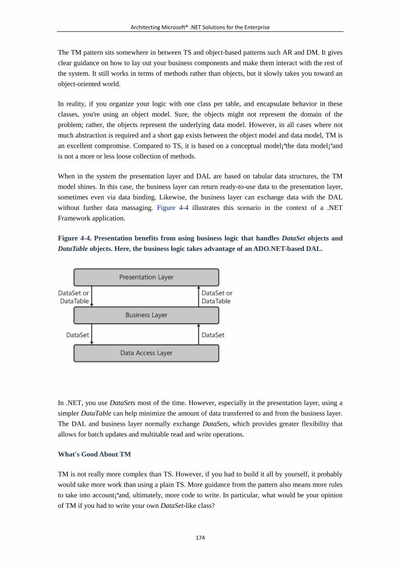
Architecting Microsoft® .NET Solutions for the Enterprise
174
The TM pattern sits somewhere in between TS and object-based patterns such AR and DM. It gives
clear guidance on how to lay out your business components and make them interact with the rest of
the system. It still works in terms of methods rather than objects, but it slowly takes you toward an
object-oriented world.
In reality, if you organize your logic with one class per table, and encapsulate behavior in these
classes, you're using an object model. Sure, the objects might not represent the domain of the
problem; rather, the objects represent the underlying data model. However, in all cases where not
much abstraction is required and a short gap exists between the object model and data model, TM is
an excellent compromise. Compared to TS, it is based on a conceptual model¡ªthe data model¡ªand
is not a more or less loose collection of methods.
When in the system the presentation layer and DAL are based on tabular data structures, the TM
model shines. In this case, the business layer can return ready-to-use data to the presentation layer,
sometimes even via data binding. Likewise, the business layer can exchange data with the DAL
without further data massaging. Figure 4-4 illustrates this scenario in the context of a .NET
Framework application.
Figure 4-4. Presentation benefits from using business logic that handles DataSet objects and
DataTable objects. Here, the business logic takes advantage of an ADO.NET-based DAL.
In .NET, you use DataSets most of the time. However, especially in the presentation layer, using a
simpler DataTable can help minimize the amount of data transferred to and from the business layer.
The DAL and business layer normally exchange DataSets, which provides greater flexibility that
allows for batch updates and multitable read and write operations.
What's Good About TM
TM is not really more complex than TS. However, if you had to build it all by yourself, it probably
would take more work than using a plain TS. More guidance from the pattern also means more rules
to take into account¡ªand, ultimately, more code to write. In particular, what would be your opinion
of TM if you had to write your own DataSet-like class?
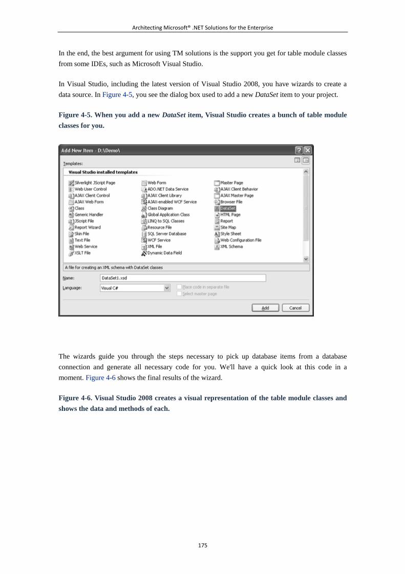
Architecting Microsoft® .NET Solutions for the Enterprise
175
In the end, the best argument for using TM solutions is the support you get for table module classes
from some IDEs, such as Microsoft Visual Studio.
In Visual Studio, including the latest version of Visual Studio 2008, you have wizards to create a
data source. In Figure 4-5, you see the dialog box used to add a new DataSet item to your project.
Figure 4-5. When you add a new DataSet item, Visual Studio creates a bunch of table module
classes for you.
The wizards guide you through the steps necessary to pick up database items from a database
connection and generate all necessary code for you. We'll have a quick look at this code in a
moment. Figure 4-6 shows the final results of the wizard.
Figure 4-6. Visual Studio 2008 creates a visual representation of the table module classes and
shows the data and methods of each.
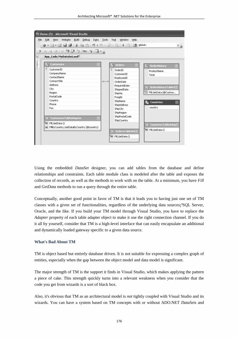
Architecting Microsoft® .NET Solutions for the Enterprise
176
Using the embedded DataSet designer, you can add tables from the database and define
relationships and constraints. Each table module class is modeled after the table and exposes the
collection of records, as well as the methods to work with on the table. At a minimum, you have Fill
and GetData methods to run a query through the entire table.
Conceptually, another good point in favor of TM is that it leads you to having just one set of TM
classes with a given set of functionalities, regardless of the underlying data sources¡ªSQL Server,
Oracle, and the like. If you build your TM model through Visual Studio, you have to replace the
Adapter property of each table adapter object to make it use the right connection channel. If you do
it all by yourself, consider that TM is a high-level interface that can easily encapsulate an additional
and dynamically loaded gateway specific to a given data source.
What's Bad About TM
TM is object based but entirely database driven. It is not suitable for expressing a complex graph of
entities, especially when the gap between the object model and data model is significant.
The major strength of TM is the support it finds in Visual Studio, which makes applying the pattern
a piece of cake. This strength quickly turns into a relevant weakness when you consider that the
code you get from wizards is a sort of black box.
Also, it's obvious that TM as an architectural model is not tightly coupled with Visual Studio and its
wizards. You can have a system based on TM concepts with or without ADO.NET DataSets and
Architecting Microsoft® .NET Solutions for the Enterprise
177
with or without wizards. In summary, what's good and bad with TM is its integration with Visual
Studio. The more you move away from the autogenerated TM-style code, the more you feel
uncomfortable and tempted to either upgrade to an object-based pattern or downgrade to TS.
For this reason, TM is not all that popular for developers using the Java platform, even though some
built-in RS-like data structure exists in JDBC. The Rowset object, in particular, is the counterpart of
the ActiveX Data Objects (ADO) RecordSet¡ªa component that can operate as a smart cursor and
scroll through a result set connected in read and update mode, or just work disconnected on a cached
set of rows.
Gimme a Quick Answer: TS or TM?
The answer here is limited to any scenarios where you just don't want or can't afford to use an
object-based pattern. If you have to use a procedural approach, the quick-and-dirty answer would be
the following.
On the .NET Framework, TM is mostly preferable because of the Visual Studio designers and code
generators. Although they're not designed to be perfect (smile), code generators do a good job of
getting you started in a matter of seconds. The code generated for a DataSet item is hidden from
view, but it can be accessed, duplicated, edited, and reloaded into the project as a code file. In the
worst case, you can just use the services of Visual Studio to grab some code and proceed from there
with your own implementation.
Because of the Visual Studio facilities, in the .NET Framework it's often more convenient to stop
there and avoid TS. It is different, of course, on another development platform. But, again, this is
just the quick answer given to an architect who wants to take the procedural route.
The TM Pattern in Action
A TM business component is a class that represents the content of a table. However, in the real
world you hardly ever need just that. In addition, you likely need to find represented in the
component some of the relationships that exist between tables.
Internals of a Business Component
The table module class can have instance or static methods. With static methods, you tend to lose
some of the benefits derived from encapsulation of data. A static method is simply the trigger of a
query or a mapped stored procedure. Creating the business component as a collection of static
methods makes it hard for you to implement more advanced capabilities, such as caching or lazy
loading. With static methods, in fact, any buffer you define is globally shared. That's not too bad if
you only read data; it's quite an issue if you intend to support in-memory updates, too.
In summary, members of a TM business component are essentially instance members. Let's delve
deeper into the benefits of this approach.
Architecting Microsoft® .NET Solutions for the Enterprise
178
First, you can initialize the class with the results of a query. Second, you can implement the Query
Object pattern (see page 316 of [P of EAA]) and hold the results within the instance. With a static
method, though, you are forced to use the query factory only as a way to get data to be processed
elsewhere¡ªfor example, in the service or the presentation layer.
Note
The Query Object pattern refers to an object that represents the public
interface to a database query. The Query object serves as an interpreter and
accepts any information useful in preparing the SQL query through properties
and methods. The Query Object pattern shields you from the details of the
database and delivers a replaceable object, but it forces you to work with a
relatively static schema for the query. In other words, you can't just run every
query you like, only those whose syntax fits in the schema recognized by the
interpreter.
Finally, if you opt for instance members, you can build your own hierarchy of objects, thus layering
required functionalities. With static members, on the other hand, you have a flat collection of
methods with only a global state.
Because the TM business component probably maintains relationships to data in other business
components, do not expect in general to find a TM business component that merely lists methods to
query and update a single table.
Typical Structure of a Business Component
In TM, a table module class has an internal data container that is initialized with the data to work
with. The cached content is then filtered and manipulated by the various methods you define.
Methods take as parameters any additional information they need.
Note that TM doesn't have the notion of an identity for child objects. This means that you'll have a
table module class Orders representing a table or a view of orders, but not a class Order
representing a row in the table or view. Put another way, the table module class refers internally to a
collection of weakly typed data rows rather than to a collection of strongly typed Order objects.
As an example, let's have a look at a TM business component for managing orders:
public class OrdersManager
{
private DataSet _data;
public OrdersManager(DataSet data)
{
Architecting Microsoft® .NET Solutions for the Enterprise
179
_data = data;
}
public DataTable Orders
{
return _ds;
}
public DataRow GetRow(int index)
{
return _ds.Tables[0].Rows[index];
}
public DataRow GetRowByID(int orderID)
{
return _ds.Tables[0].Select(...);
}
public int Update(DataRow row)
{
.
.
.
}
public int Insert(int orderID, DateTime orderDate, ...)
{
.
.
.
}
public int Delete(int orderID)
{
.
.
.
}
.
.
.
}
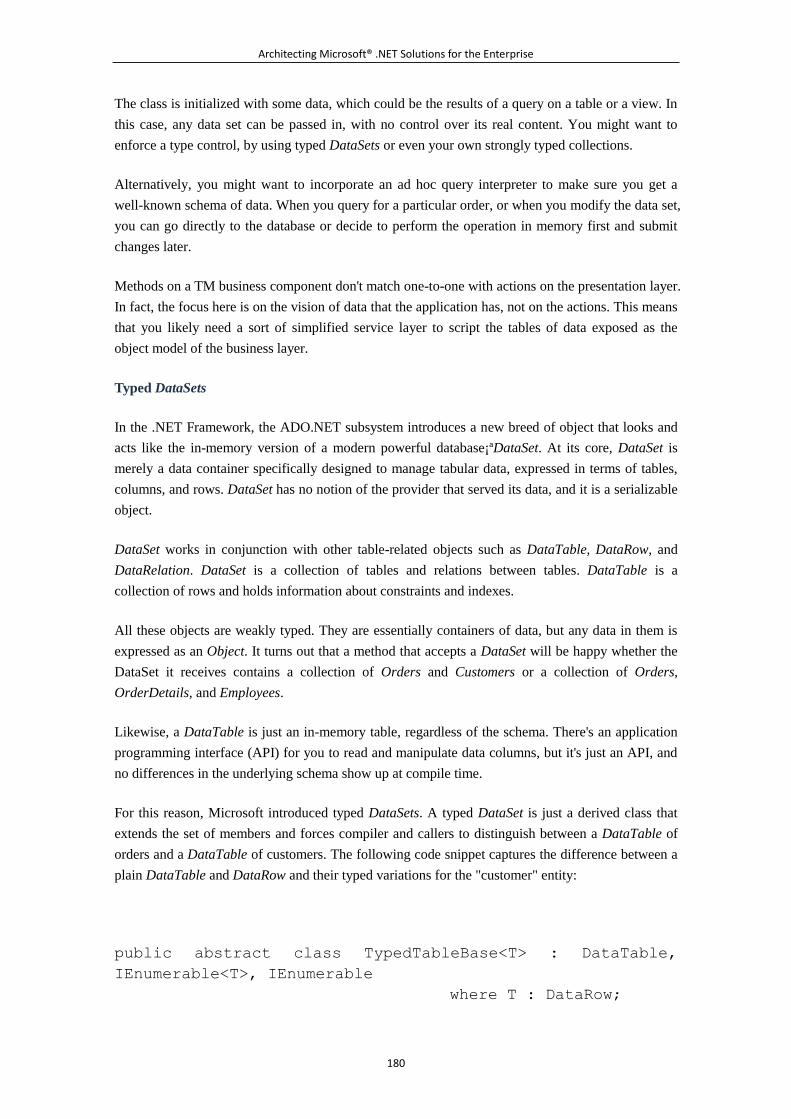
Architecting Microsoft® .NET Solutions for the Enterprise
180
The class is initialized with some data, which could be the results of a query on a table or a view. In
this case, any data set can be passed in, with no control over its real content. You might want to
enforce a type control, by using typed DataSets or even your own strongly typed collections.
Alternatively, you might want to incorporate an ad hoc query interpreter to make sure you get a
well-known schema of data. When you query for a particular order, or when you modify the data set,
you can go directly to the database or decide to perform the operation in memory first and submit
changes later.
Methods on a TM business component don't match one-to-one with actions on the presentation layer.
In fact, the focus here is on the vision of data that the application has, not on the actions. This means
that you likely need a sort of simplified service layer to script the tables of data exposed as the
object model of the business layer.
Typed DataSets
In the .NET Framework, the ADO.NET subsystem introduces a new breed of object that looks and
acts like the in-memory version of a modern powerful database¡ªDataSet. At its core, DataSet is
merely a data container specifically designed to manage tabular data, expressed in terms of tables,
columns, and rows. DataSet has no notion of the provider that served its data, and it is a serializable
object.
DataSet works in conjunction with other table-related objects such as DataTable, DataRow, and
DataRelation. DataSet is a collection of tables and relations between tables. DataTable is a
collection of rows and holds information about constraints and indexes.
All these objects are weakly typed. They are essentially containers of data, but any data in them is
expressed as an Object. It turns out that a method that accepts a DataSet will be happy whether the
DataSet it receives contains a collection of Orders and Customers or a collection of Orders,
OrderDetails, and Employees.
Likewise, a DataTable is just an in-memory table, regardless of the schema. There's an application
programming interface (API) for you to read and manipulate data columns, but it's just an API, and
no differences in the underlying schema show up at compile time.
For this reason, Microsoft introduced typed DataSets. A typed DataSet is just a derived class that
extends the set of members and forces compiler and callers to distinguish between a DataTable of
orders and a DataTable of customers. The following code snippet captures the difference between a
plain DataTable and DataRow and their typed variations for the "customer" entity:
public abstract class TypedTableBase<T> : DataTable,
IEnumerable<T>, IEnumerable
where T : DataRow;
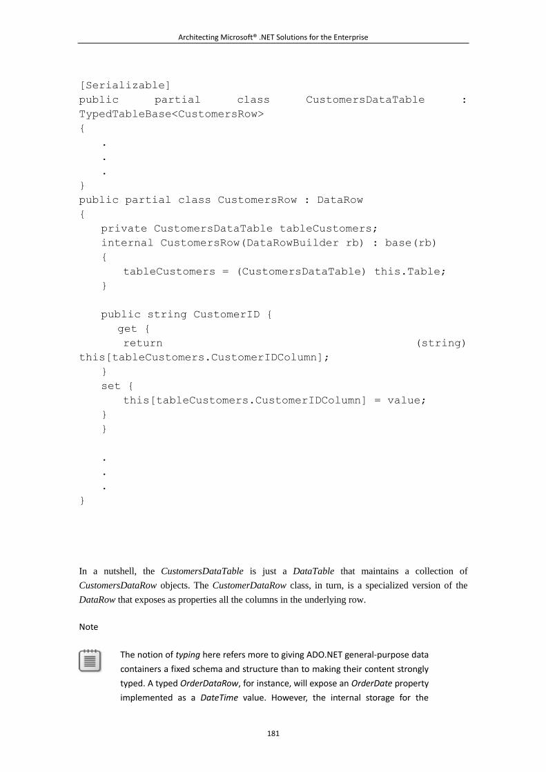
Architecting Microsoft® .NET Solutions for the Enterprise
181
[Serializable]
public partial class CustomersDataTable :
TypedTableBase<CustomersRow>
{
.
.
.
}
public partial class CustomersRow : DataRow
{
private CustomersDataTable tableCustomers;
internal CustomersRow(DataRowBuilder rb) : base(rb)
{
tableCustomers = (CustomersDataTable) this.Table;
}
public string CustomerID {
get {
return (string)
this[tableCustomers.CustomerIDColumn];
}
set {
this[tableCustomers.CustomerIDColumn] = value;
}
}
.
.
.
}
In a nutshell, the CustomersDataTable is just a DataTable that maintains a collection of
CustomersDataRow objects. The CustomerDataRow class, in turn, is a specialized version of the
DataRow that exposes as properties all the columns in the underlying row.
Note
The notion of typing here refers more to giving ADO.NET general-purpose data
containers a fixed schema and structure than to making their content strongly
typed. A typed OrderDataRow, for instance, will expose an OrderDate property
implemented as a DateTime value. However, the internal storage for the
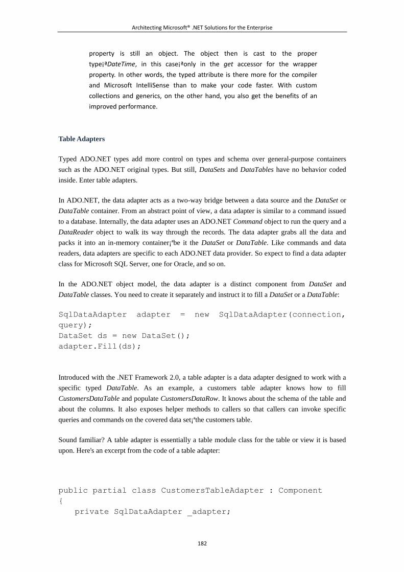
Architecting Microsoft® .NET Solutions for the Enterprise
182
property is still an object. The object then is cast to the proper
type¡ªDateTime, in this case¡ªonly in the get accessor for the wrapper
property. In other words, the typed attribute is there more for the compiler
and Microsoft IntelliSense than to make your code faster. With custom
collections and generics, on the other hand, you also get the benefits of an
improved performance.
Table Adapters
Typed ADO.NET types add more control on types and schema over general-purpose containers
such as the ADO.NET original types. But still, DataSets and DataTables have no behavior coded
inside. Enter table adapters.
In ADO.NET, the data adapter acts as a two-way bridge between a data source and the DataSet or
DataTable container. From an abstract point of view, a data adapter is similar to a command issued
to a database. Internally, the data adapter uses an ADO.NET Command object to run the query and a
DataReader object to walk its way through the records. The data adapter grabs all the data and
packs it into an in-memory container¡ªbe it the DataSet or DataTable. Like commands and data
readers, data adapters are specific to each ADO.NET data provider. So expect to find a data adapter
class for Microsoft SQL Server, one for Oracle, and so on.
In the ADO.NET object model, the data adapter is a distinct component from DataSet and
DataTable classes. You need to create it separately and instruct it to fill a DataSet or a DataTable:
SqlDataAdapter adapter = new SqlDataAdapter(connection,
query);
DataSet ds = new DataSet();
adapter.Fill(ds);
Introduced with the .NET Framework 2.0, a table adapter is a data adapter designed to work with a
specific typed DataTable. As an example, a customers table adapter knows how to fill
CustomersDataTable and populate CustomersDataRow. It knows about the schema of the table and
about the columns. It also exposes helper methods to callers so that callers can invoke specific
queries and commands on the covered data set¡ªthe customers table.
Sound familiar? A table adapter is essentially a table module class for the table or view it is based
upon. Here's an excerpt from the code of a table adapter:
public partial class CustomersTableAdapter : Component
{
private SqlDataAdapter _adapter;
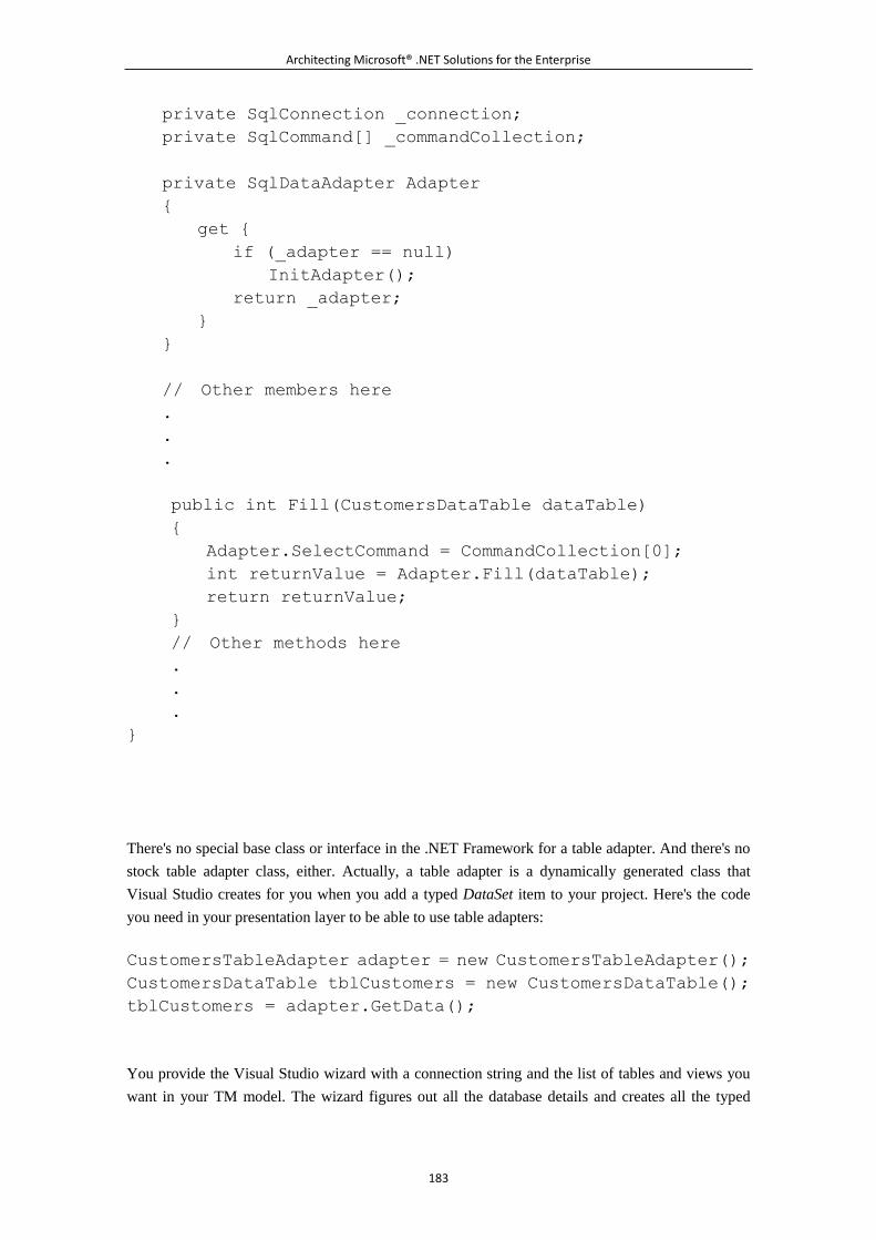
Architecting Microsoft® .NET Solutions for the Enterprise
183
private SqlConnection _connection;
private SqlCommand[] _commandCollection;
private SqlDataAdapter Adapter
{
get {
if (_adapter == null)
InitAdapter();
return _adapter;
}
}
// Other members here
.
.
.
public int Fill(CustomersDataTable dataTable)
{
Adapter.SelectCommand = CommandCollection[0];
int returnValue = Adapter.Fill(dataTable);
return returnValue;
}
// Other methods here
.
.
.
}
There's no special base class or interface in the .NET Framework for a table adapter. And there's no
stock table adapter class, either. Actually, a table adapter is a dynamically generated class that
Visual Studio creates for you when you add a typed DataSet item to your project. Here's the code
you need in your presentation layer to be able to use table adapters:
CustomersTableAdapter adapter = new CustomersTableAdapter();
CustomersDataTable tblCustomers = new CustomersDataTable();
tblCustomers = adapter.GetData();
You provide the Visual Studio wizard with a connection string and the list of tables and views you
want in your TM model. The wizard figures out all the database details and creates all the typed
Architecting Microsoft® .NET Solutions for the Enterprise
184
containers and table-specific adapters for you. A TM model is thereby created for you in an assisted
manner and, more importantly, in a fraction of the time it would take you to create it yourself.
The Table Data Gateway Pattern
The TM pattern for modeling the domain logic requires some helper classes to physically access the
database. From a design perspective, these classes belong to the DAL, but they are obviously
consumed by the table module classes.
In the .NET Framework, if you opt for table adapters and the power of the ADO.NET subsystem,
everything you need for data access is there. You have typed DataSets and typed DataTables to act
as your RecordSet type and table adapters to act as your table module classes. Which modules really
care about physical data access? As mentioned, these modules are hidden in the table adapter
implementation. They are based on a combination of ADO.NET objects, such as data adapters,
commands, data readers, and connections. They work on a particular data store, either SQL Server,
Oracle, or perhaps any store reachable through OLE DB and ODBC.
What if you use your own RS data structures? You need to fill these data structures with the results
of one or more queries. You will probably create a relatively thin layer of code to take care of these
chores. Essentially, you need a few methods out of a class to get a result set and assemble it into an
RS data structure. This layer of code is referred to as the Table Data Gateway (TDG) pattern.
Consider the following table module class:
public class OrdersManager
{
private MyRecordSet _data;
public OrdersManager(MyRecordSet data)
{
_data = data;
}
.
.
.
}
You call this code from the presentation as shown here:
MyRecordSet rs = OrdersGateway.LoadByCustomer(id, from, to);
OrdersManager tmc = new OrdersManager(rs);
Any update method you have in the table module class will fall into the TDG for physical data
access. Figure 4-7 shows a possible interaction between the actors of a TM model when reading
some data.
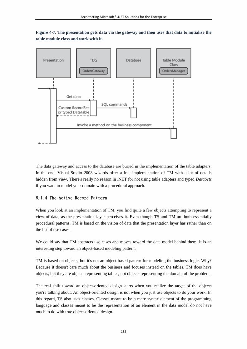
Architecting Microsoft® .NET Solutions for the Enterprise
185
Figure 4-7. The presentation gets data via the gateway and then uses that data to initialize the
table module class and work with it.
The data gateway and access to the database are buried in the implementation of the table adapters.
In the end, Visual Studio 2008 wizards offer a free implementation of TM with a lot of details
hidden from view. There's really no reason in .NET for not using table adapters and typed DataSets
if you want to model your domain with a procedural approach.
6.1.4 The Active Record Pattern
When you look at an implementation of TM, you find quite a few objects attempting to represent a
view of data, as the presentation layer perceives it. Even though TS and TM are both essentially
procedural patterns, TM is based on the vision of data that the presentation layer has rather than on
the list of use cases.
We could say that TM abstracts use cases and moves toward the data model behind them. It is an
interesting step toward an object-based modeling pattern.
TM is based on objects, but it's not an object-based pattern for modeling the business logic. Why?
Because it doesn't care much about the business and focuses instead on the tables. TM does have
objects, but they are objects representing tables, not objects representing the domain of the problem.
The real shift toward an object-oriented design starts when you realize the target of the objects
you're talking about. An object-oriented design is not when you just use objects to do your work. In
this regard, TS also uses classes. Classes meant to be a mere syntax element of the programming
language and classes meant to be the representation of an element in the data model do not have
much to do with true object-oriented design.
Architecting Microsoft® .NET Solutions for the Enterprise
186
The business or domain logic is the real point of a system. It is made of the allowed and required
interactions between entities. Modeling the domain logic in terms of these recognized entities
requires an object-oriented vision of the world rather than a procedural one. Your application is
viewed as a set of interrelated objects¡ªwhich is a different thing than using objects to perform data
access and calculations.
The set of objects mapping to entities, plus special objects doing ad hoc calculations, form what is
known as the domain's object model. This model has two main levels of complexity¡ªsimple and
not-so-simple. A good measure of this complexity is the gap between the domain's object model and
the relational data model you intend to create to store your data. A simple model is when your
entities map closely to tables in the data model. A not-so-simple model is when some mapping is
required to load and save domain objects to a relational database.
The Active Record (AR) pattern is your choice when you want an object-oriented design and have
overall simple domain logic.
Note
In more practical terms, AR differs from TM because AR focuses on classes
representing records in a table. That is, AR has a row-based view of the data,
whereas TM focuses on entire tables.
Generalities of the AR Pattern
The AR pattern is described on page 160 of [P of EAA] as a data source design pattern rather than a
domain logic pattern.
AR is any object that wraps a record in a database table or view. The object is expected to
incorporate both data (column values) and behavior (methods for logic). The structure of an AR
object should be as close as possible to the records of the associated table. For example, if you're
building an AR object for the table Orders, you'll have a class Order with a set of properties that
match the columns in the Orders table.
An AR object represents a row of data and typically embeds data access logic. Therefore, it requires
some gateway to the matching record in the underlying table.
Typical methods on an AR object include find methods to grab results of common queries, CRUD
operations, validation, and domain-specific calculations and cross-checks. For example, an Invoice
object might need to validate individual scalar values (for example, number of items, date,
progressive number, and customer ID), but it might also need to perform a more context-specific
check with regard to the existence and validity of the PO number, check the payment terms, and
calculate taxes.
Architecting Microsoft® .NET Solutions for the Enterprise
187
Specifically, a typical AR class consists of instance properties representing the columns of the
record in the database, instance methods acting on that specific record, plus optionally, a bunch of
static methods working on all records in the table.
When to Use AR
Usually, AR does a good job in all scenarios where the domain logic isn't overly complex and, more
importantly, doesn't require a thick layer of abstraction over the relational data model.
AR is an excellent choice for a large share of Web sites where, regardless of the number of tables
involved, you often have an isomorphic correspondence between domain entities and relational
tables.
In applications where you do not have a service layer (which is discussed in the next chapter), AR
can be combined with TS. In this case, TS defines the code to respond to the user's actions and then
uses AR to work on the data through an object-oriented interface. As you can see, TS replaces the
service layer and script directly in the AR object model.
What's Good About AR
The success of AR depends on two factors: simplicity and frameworks. The two factors are closely
related. AR is a conceptually simple model that is easy to grasp, but it still requires a good deal of
work if you want to code your way through it.
Writing and maintaining one class for each table might be awkward, and this would be the least of
your difficulties because you might have to consider using one or more DTOs per class or table. A
friend of ours likes to reply to such statements with this observation: "Yes, it's boring, but we're
developers at the end of the month, when we get our pay. So writing code is just our job."
We usually object to his statement with the fact that being productive is a must for everybody,
including developers. And we're probably not alone in taking this position if a few companies out
there have developed ad hoc frameworks for AR. This makes us think that a lot of developers find
AR attractive in theory but boring in practice.
It is hard to deny that AR has a very good ratio between simplicity and the effectiveness of the
resulting design. And it gets great support from vendors. Want a couple of illustrious examples? Try
LINQ-to-SQL and Castle ActiveRecord.
What's Bad About AR
AR is good for relatively simple logic. This is good and bad news at the same time. If the
application views data through a different perspective than the relational data model, it is up to you
to organize data properly and fill in the gaps. Ideally, this extra abstraction layer lives between the
object model and data model and is often referred to as the Data Mapper layer. With AR, you can
incorporate this layer directly into the objects; but it gets harder and harder as the thickness grows.
Architecting Microsoft® .NET Solutions for the Enterprise
188
Another issue with AR is the binding that exists between objects and the design of the database
tables. If you happen to change the database, you have to update the AR object model and all of its
related code. And, again, if you need to abstract from the database structure, all the mapping work is
up to you.
In summary, with AR, as you move away from an isomorphic schema between the object model and
data model, you get into trouble quickly. From this perspective, AR is the opposite of
domain-driven design.
Finally, consider that long operations that involve loading or saving thousands of records might not
find AR (or, in general, any object model) to be the ideal environment because of the additional
workload involved with loading raw data into objects. With thousands of records, this can be a
significant issue. In such cases, consider using ADO.NET directly, dressing it as a TS class.
The AR Pattern in Action
In an AR model, you have one class per database table. At first glance, this is not really different
from the Table Module pattern. The devil is in the details, though. An AR class is a plain old .NET
class whose properties match in name and type the corresponding table columns. To group multiple
objects, you use arrays or collections. In other words, an Order class for an Orders table has an
integer property for OrderID and a DateTime property for OrderDate, and so forth. A table of Order
objects is represented by a collection of Order objects. How is this different from a table module
class?
If you create TM entirely from scratch, there might be no significant difference. However, if you use
ADO.NET types, the difference can be relevant. You use DataRow to represent an order record and
DataTable to reference a collection of orders. The typed DataTable and DataRow are both generic
containers of data. Data is stored as instances of the System.Object class and returned via a proper
cast in a strongly typed manner. In TM, you don't have plain old .NET objects; this is just a key
attribute of AR.
A Typical Active Record Class
Suppose you want to use the Active Record pattern to model the Orders table of a database. You
create an Order class in the likeness of the columns in the table. Here's an example:
public class Order
{
public Order()
{
}
public Order(int orderID)
{
Architecting Microsoft® .NET Solutions for the Enterprise
189
.
.
.
}
public int OrderID {get; set;}
public DateTime OrderDate {get; set;}
public DateTime ShipDate {get; set;}
public string ShipName {get; set;}
public string ShipAddress {get; set;}
public string ShipCity {get; set;}
public string ShipCountry {get; set;}
public string CustomerID {get; set;}
public int EmployeeID {get; set;}
.
.
.
public void Insert()
{
// Insert the record in the table
}
public void Delete()
{
// Delete the record from the table
}
public void Update()
{
// Update this record in the table
}
.
.
.
public static int GetOrdersCount()
{
// Return the number of orders in the table
}
public static List<Order> LoadAll()
{
// Load all orders in the table. If too
Architecting Microsoft® .NET Solutions for the Enterprise
190
// many records, consider exposing this
// operation as a plain ADO.NET function.
}
.
.
.
}
In addition, you find at least one method to load an order from the database and a constructor to
build in memory an Order object to be inserted in the storage medium at a later time. Typically, the
Order class has Update, Insert, and Delete methods to respectively update, add, and delete orders.
Finally, a bunch of static methods might exist to implement common operations on orders¡ªfor
example, a method to retrieve detailed information about the customer who placed the order or the
employee who managed it.
Collections of Order types are plain arrays or a generic collection. You might or might not use a
custom collection type to represent a set of Order objects. You create a custom collection type as
shown here:
public class OrdersCollection : List<Order>
{
.
.
.
}
Alternatively, you can directly use the type List<T> to manage the collection of objects.
The Foreign-Key Mapping Pattern
Nearly all databases contain a bunch of tables that reference each other through foreign keys. When
you track an order, you probably need to track the customer who placed it as well as the employee
who managed it. When you track a book, you also need to relate the book to be tracked to its author
and publisher.
A fundamental rule in the design of relational databases instructs you to keep this information in
distinct tables and use foreign keys to build a logical relationship between tables. Specifically, a
foreign key identifies a column in the referencing table that refers to a column in the referenced
table. The column in the referencing table is normally the primary key in the referenced table.
Architecting Microsoft® .NET Solutions for the Enterprise
191
As an example, consider tables named Orders and Customers. Among other columns, in the Orders
table you would have the following:
CREATE TABLE Orders(
OrderID int IDENTITY(1,1) NOT NULL,
CustomerID nchar(5) NULL,
EmployeeID int NULL,
OrderDate datetime NULL,
.
.
.
CONSTRAINT PK_Orders PRIMARY KEY(OrderID),
CONSTRAINT FK_Orders_Customers FOREIGN KEY(CustomerID)
REFERENCES Customers(CustomerID),
CONSTRAINT FK_Orders_Employees FOREIGN KEY(EmployeeID)
REFERENCES Employees(EmployeeID),
.
.
.
CHECK CONSTRAINT FK_Orders_Customers,
CHECK CONSTRAINT FK_Orders_Employees,
.
.
.
)
In the snippet, you recognize two foreign-key relationships: the relationship between Orders and
Customers, and the one between Orders and Employees. Orders is clearly the referencing table. The
Orders-to-Customers relation is based on the CustomerID column that exists on both tables. In this
case, both tables have a column with the same name, but this is just arbitrary. What matters most is
that both tables share the same value in some column. For example, the CustomerID column on
Orders contains a value that is constrained to match the value on the referenced column CustomerID
on Customers. How would you map this relationship in an AR model?
As you can imagine, there are essentially two ways: you map the raw value, or you expand the
mapping to make the Order class point to a Customer object. On page 160 of [P of EAA], Fowler
suggests you keep the AR model as simple as possible, where this mostly means as close as possible
to the database structure. Put this way, it means you end up with the following:
public class Order
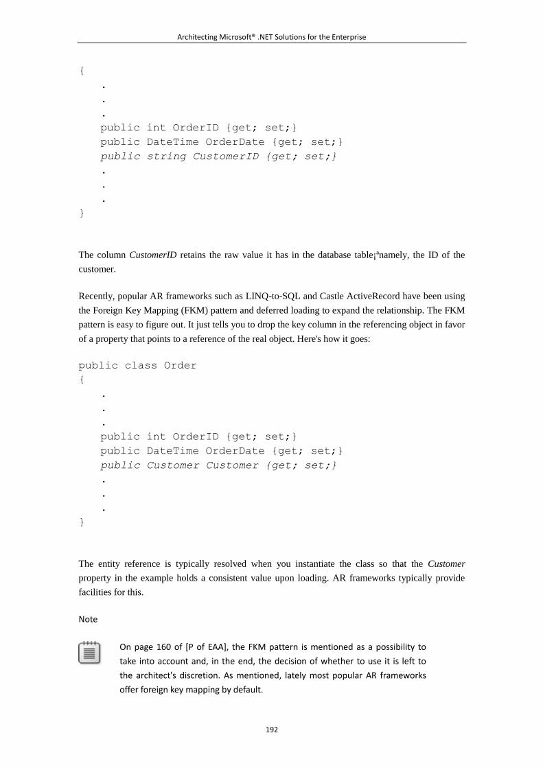
Architecting Microsoft® .NET Solutions for the Enterprise
192
{
.
.
.
public int OrderID {get; set;}
public DateTime OrderDate {get; set;}
public string CustomerID {get; set;}
.
.
.
}
The column CustomerID retains the raw value it has in the database table¡ªnamely, the ID of the
customer.
Recently, popular AR frameworks such as LINQ-to-SQL and Castle ActiveRecord have been using
the Foreign Key Mapping (FKM) pattern and deferred loading to expand the relationship. The FKM
pattern is easy to figure out. It just tells you to drop the key column in the referencing object in favor
of a property that points to a reference of the real object. Here's how it goes:
public class Order
{
.
.
.
public int OrderID {get; set;}
public DateTime OrderDate {get; set;}
public Customer Customer {get; set;}
.
.
.
}
The entity reference is typically resolved when you instantiate the class so that the Customer
property in the example holds a consistent value upon loading. AR frameworks typically provide
facilities for this.
Note
On page 160 of [P of EAA], the FKM pattern is mentioned as a possibility to
take into account and, in the end, the decision of whether to use it is left to
the architect's discretion. As mentioned, lately most popular AR frameworks
offer foreign key mapping by default.
Architecting Microsoft® .NET Solutions for the Enterprise
193
Data Conversion
Another problem you should face when designing an AR model is data conversion. Should you
bring into the class raw data as it appears in the database table? Or should you instead apply any
type conversion that makes sense in the particular case?
As with foreign key mapping, this is mostly up to you. In general, type adaptation is fine, such as
using Nullable<int> instead of int for nullable columns. Another possible adaptation regards
transforming ticks into a DateTime object or perhaps XML strings to document object model.
What about, instead, grouping related properties into a new object? Is it recommended, for example,
to use a custom Address type to package information such as address, city, region, postal code, and
country?
You certainly don't commit a deadly sin if you use an Address type to group multiple properties.
However, this would break the extreme simplicity of the model and start adding abstraction. If you
are writing the AR model yourself, with no classes generated by frameworks, using abstracted types
is doable at the price of writing more, and more complex, code. If you go with frameworks, you
should check the availability of this feature before designing your object model.
Note
Adding abstraction over an AR model is not a bad thing per se. However, the
more you abstract, the more you move toward a Domain Model approach.
(We'll discuss this in more detail in the next section.) If you choose to rely on
frameworks, their built-in reverse-engineering features could be relatively rigid
and stick to the structure of the database tables; if you need more flexibility,
you should upgrade to richer modeling tools that push a domain-driven
approach.
The Row Data Gateway Pattern
In TM, you group methods by tables and need a table gateway to implement physical data access. In
AR, you end up having one class per table, but the class represents a single record in the table. The
granularity is different¡ªthe record versus the table. To represent the whole table, you then use .NET
generic collection objects closed on the type that represents the record in the table¡ªfor example,
List<Customer>.
Subsequently, in AR you need a gateway to the record to grab all the stored data. Having a gateway
adds yet another layer, which makes for more testable and simpler code. The Row Data Gateway
(RDG) pattern delivers an object that acts as the direct interface between the wrapper AR class and
Architecting Microsoft® .NET Solutions for the Enterprise
194
the physical database. In other words, RDG will simply encapsulate all data access code for an
Active Record, thus saving the Active Record class from knowing about database details.
If you use AR frameworks, the RDG implementation is buried in the folds of the provided
infrastructure so that you don't have to worry about it. But an RDG is still there, and you should
consider it if you happen to write an AR model yourself from scratch.
Note
Admittedly, RDG and Active Record have a lot in common and some people
often have trouble seeing any key difference between the two. Our best
answer is that they essentially do the same job, but an RDG class is expected
to contain only database access logic, and no domain logic at all. This means
that Active Record can embed an RDG class, but if an RDG class is extended
with some domain logic methods, it should be automatically considered
upgraded to the rank of an Active Record.
LINQ-to-SQL
The .NET Framework 3.5 comes with a new framework for mapping a SQL Server table to an
object model. The resulting model can then be queried and updated programmatically in a way that
doesn't require developers to deal with T-SQL commands and stored procedures.
Where does the LINQ-to-SQL name come from? The .NET Framework 3.5 supports the LINQ
library, which is a unified query model and syntax that can address any class with a particular
interface¡ªeither IEnumerable or IQueryable. By using LINQ, you can write SQL-like expressions
(join, merge, group by, select) to operate on the properties of objects that are enumerable or
queryable.
LINQ works natively on collections of in-memory data and is adapted to work on ad hoc object
models through a queryable layer. This layer just takes care of mapping the syntax of the LINQ
query expression to the underlying data structure and query engine.
LINQ-to-SQL maps the common LINQ query syntax over the SQL Server query engine. In addition,
LINQ-to-SQL provides an object model that represents a selected group of tables and views. In the
end, this object model is an implementation of the Active Record pattern.
Visual Studio 2008 comes with a designer through which you pick up a bunch of tables from a SQL
Server connection. The tool then generates a C# or Visual Basic .NET class with all definitions. In
Figure 4-8, you see the designer in action.
Figure 4-8. The Visual Studio 2008 designer for LINQ-to-SQL in action
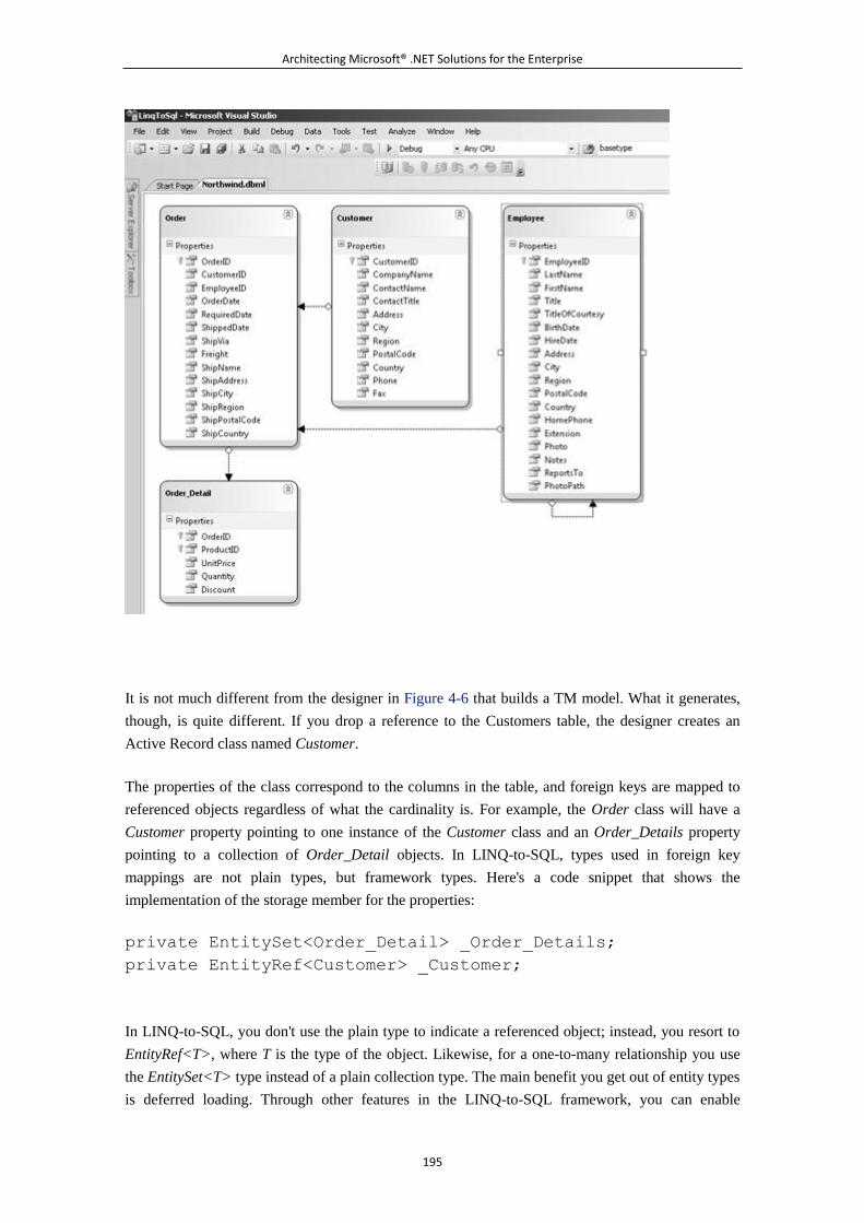
Architecting Microsoft® .NET Solutions for the Enterprise
195
It is not much different from the designer in Figure 4-6 that builds a TM model. What it generates,
though, is quite different. If you drop a reference to the Customers table, the designer creates an
Active Record class named Customer.
The properties of the class correspond to the columns in the table, and foreign keys are mapped to
referenced objects regardless of what the cardinality is. For example, the Order class will have a
Customer property pointing to one instance of the Customer class and an Order_Details property
pointing to a collection of Order_Detail objects. In LINQ-to-SQL, types used in foreign key
mappings are not plain types, but framework types. Here's a code snippet that shows the
implementation of the storage member for the properties:
private EntitySet<Order_Detail> _Order_Details;
private EntityRef<Customer> _Customer;
In LINQ-to-SQL, you don't use the plain type to indicate a referenced object; instead, you resort to
EntityRef<T>, where T is the type of the object. Likewise, for a one-to-many relationship you use
the EntitySet<T> type instead of a plain collection type. The main benefit you get out of entity types
is deferred loading. Through other features in the LINQ-to-SQL framework, you can enable
Architecting Microsoft® .NET Solutions for the Enterprise
196
deferred loading, meaning that values for referenced objects are loaded on demand. This service is
free if you use entity types, but it has to be coded explicitly if you replace entity types with plain
types.
Is LINQ-to-SQL an Active Record?
Some argue that LINQ-to-SQL is really an implementation of Active Record. The point is not far
fetched, if you want to take the definition on page 160 of [P of EAA] literally.
In LINQ-to-SQL, classes primarily contain data; optionally, they can contain behavior. Behavior
can be added through the mechanism of partial classes. More importantly, LINQ-to-SQL classes do
not incorporate a row data gateway and are completely agnostic as far as data access is concerned.
How is a LINQ-to-SQL class loaded or updated? Data persistence is operated through the services
of the DataContext class. This class represents the true gateway to data. Basically, it tracks all the
changes to the object model and submits changes to the data layer. So is the LINQ-to-SQL object
model an Active Record? All in all, we feel that it's kind of pointless to debate that.
In the end, LINQ-to-SQL can be viewed in two ways. It can be a mere tool for a data access layer¡ªa
sort of object-oriented ADO.NET engine¡ªor it can be viewed as a simple O/RM tool that is limited
to SQL Server, offers an Active Record-like object model, offers a smart query language,
incorporates an RDG, and takes care of moving data between classes and tables. By default, the
mapping in LINQ-to-SQL is defined through the designer and persisted via attributes. However, you
can change the setting to use an XML file.
Note
All access to the LINQ-to-SQL object model occurs in the DataContext class.
What kind of class is this? The data context is a container for all collections of
records you put in the model¡ªorders, customers, and the like. It tracks
operations you do on objects and can expose mapped functions and stored
procedures.
Castle ActiveRecord
As part of the Castle Project (http://www.castleproject.org), ActiveRecord (CAR) is a free and
open-source implementation of the Active Record pattern available for the .NET platform. A typical
class in a CAR solution is shown in the following code snippet:
[ActiveRecord]
public class Order : ActiveRecordBase<Order>
{
[PrimaryKey]
public int OrderID { get; set; }
Architecting Microsoft® .NET Solutions for the Enterprise
197
[Property]
public DateTime OrderDate { get; set; }
[HasMany]
public IList<Order_Detail> OrderDetails
{
.
.
.
}
.
.
.
}
In the definition of the object model, you use attributes to inform the framework about the role of
the properties and indicate whether they are mapped to columns, primary keys, or foreign keys.
CAR must be initialized before you use any class. You typically do this when the application starts
up. Mapping with the physical database occurs through an XML configuration file:
XmlConfigurationSource source = new
XmlConfigurationSource("schema.xml");
ActiveRecordStarter.Initialize(source,
typeof(Order), typeof(Customer), typeof(Order_Details));
CAR is built on top of NHibernate and the configuration file mostly serves the purpose of
initializing the underlying NHibernate engine.
NHibernate is a rich O/RM framework that handles persisting plain .NET objects to and from an
underlying relational database and not just to and from SQL Server. You provide an XML
configuration file in which you essentially describe entities and relationships; based on that,
NHibernate automatically generates ad hoc SQL code. (See http://www.nhibernate.org for more
information.)
Note
A good question is whether you should use Castle ActiveRecord, LINQ-to-SQL,
or perhaps NHibernate. LINQ-to-SQL is a Microsoft technology¡ªwhich makes a
big difference in some cases and with some customers. The other options are
open-source, albeit extremely popular, products.
NHibernate is a full-fledged O/RM that allows you to create a plain-old CLR
Architecting Microsoft® .NET Solutions for the Enterprise
198
object (POCO) domain model, where classes are not forced to implement any
interface or inherit from a special base class. Castle ActiveRecord is a wrapper
around NHibernate that infers a lot of things for you, thus reducing the
learning curve. Castle ActiveRecord is preferable over NHibernate when you
have simple domain logic and no legacy database around.
6.1.5 The Domain Model Pattern
In the design of the domain logic, when you opt for a procedural method or for an Active Record,
you are essentially taking a data-centric approach. In this context, data centric means that you create
the foundation of your system around your vision of the data model. The driving force of the
business model design is not the business itself, but rather the data you use to make it happen.
In a data-centric approach, you typically start from the database and then model your business
components around the required actions (that ultimately access the database) or codified tables.
In .NET, the data-centric approach has met with a great deal of success because of the facilities built
into Visual Studio and an array of made-to-measure classes that implement, free of charge, the TDG
and RDG patterns.
As a matter of fact, Visual Studio allows you to build an average simple application, be it a Web site
or a desktop application, in just a few hours without really requiring a lot of thinking up front. You
work with the embedded designer, run through the wizard, maybe edit a bit of code, and here it
is¡ªthe scaffolding of your application is ready to go. Everything is driven by data and happens to
work just fine. Could you ask for anything more?
Note
We're still young boys, but we've been working with Microsoft products and
technologies for 15 years now. And we think we've learned one lesson in
particular. Microsoft tends to supply a low-level framework and some
higher-level tools such as controls, components, and designers. These tools are
never designed to compete with analogous tools from third-party vendors. In
addition, these tools target the average scenario and have the precise goal of
doing a great job in most common situations.
We've experimented with the "First Law of Microsoft Technologies" several
times and in a variety of contexts¡ªfrom ASP.NET controls and components to
business logic models, from workflows to AJAX libraries, and including unit
testing, code editing, code refactoring and, of course, Windows-based user
interfaces. Keep this consideration in mind when you evaluate higher-level
Microsoft tools and facilities. They're excellent most of the time; they're likely
unfit for some situations. But you have to be a good judge of your needs to
decide which option is exactly right for you!
Architecting Microsoft® .NET Solutions for the Enterprise
199
There might be situations in which a data-centric approach just doesn't work. Does it work at all, or
does it just not work well enough? Most of the time, the second option is the accurate assessment.
As the complexity of a system grows, focusing on data only is reductive; therefore, you need to
focus on both data and behavior. Really, nothing prevents you from starting with a data-centric
approach and then extending and enhancing components with methods to express any logic you
need. However, in the long run, a data-centric approach doesn't scale well because the complexity of
the system grows and, beyond a given point, adding new requirements might also be an issue.
The Domain Model (DM) pattern addresses these scenarios. DM focuses on the expected behavior
of system and the data flows that makes it work. You focus on the real system, ideally with some
good help from domain experts (mostly, the client), and try to render it in terms of classes. With DM,
you consider the domain of the problem first and essentially fall into something called
domain-driven design (DDD).
Note
When you opt for DDD, you are neither picking up a technology (something
you can install and code), nor are you adopting a particular set of procedures
to go through a problem. DDD is essentially a state of mind¡ªa way of thinking
that naturally puts the domain of the problem on top of everything else. You
represent the system in terms of software entities, and you do so based on the
behavior of real entities and the data they hold and manage.
DDD is an approach to software design that attempts to deal with complexity
in a manageable, if not comfortable, way. When you opt for DDD, you are not
necessarily choosing a DM pattern. But DM is the most natural choice. DDD is
a discipline for software design introduced by Eric Evans in his book
Domain-Driven Design: Tackling Complexity in the Heart of Software
( Addison-Wesley, 2003). There's also a Web site you can check for information
and discussions: http://www.domaindrivendesign.org.
Generalities of the DM Pattern
The DM pattern aims to get you an object model that is a conceptual model of the system. This
object model is referred to as the domain model. The domain model describes the entities that
participate in the system and captures any relationships and flow of data between them.
The domain model is a key deliverable in the project. By creating it and sharing it, the technical and
business teams agree with one another's understanding of the problem. The domain model is not yet
a piece of software and doesn't incorporate any concept or principle that is software or
implementation specific. It has to be a formal model that bears witness that the technical and
business teams understand each other and can fruitfully communicate.
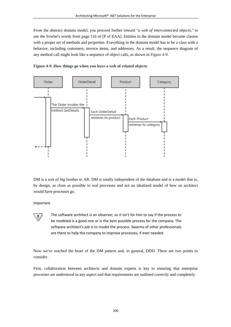
Architecting Microsoft® .NET Solutions for the Enterprise
200
From the abstract domain model, you proceed further toward "a web of interconnected objects," to
use the Fowler's words from page 116 of [P of EAA]. Entities in the domain model become classes
with a proper set of methods and properties. Everything in the domain model has to be a class with a
behavior, including customers, invoice items, and addresses. As a result, the sequence diagram of
any method call might look like a sequence of object calls, as shown in Figure 4-9.
Figure 4-9. How things go when you have a web of related objects
DM is a sort of big brother to AR. DM is totally independent of the database and is a model that is,
by design, as close as possible to real processes and not an idealized model of how an architect
would have processes go.
Important
The software architect is an observer, so it isn't for him to say if the process to
be modeled is a good one or is the best possible process for the company. The
software architect's job is to model the process. Swarms of other professionals
are there to help the company to improve processes, if ever needed.
Now we've reached the heart of the DM pattern and, in general, DDD. There are two points to
consider.
First, collaboration between architects and domain experts is key to ensuring that enterprise
processes are understood in any aspect and that requirements are outlined correctly and completely.
Architecting Microsoft® .NET Solutions for the Enterprise
201
Second, because systems ultimately are based on software and databases, at some point someone
has to take care of mapping the abstract model to an object model and a data model. This is
precisely what makes DM expensive to adopt but also more powerful than other approaches.
Note
What's the (expected) role of the database administrator (DBA) in the design
of the domain model? The DBA has to live within the business process as
modeled and must create a database that supports the domain model. It isn't
for the DBA to say if the domain model is a good one, in the same guise that it
isn't for the architect to say if the business process is a good one. The entire
differentiator is that the DM may or may not, and probably doesn't, make for a
nice and pretty storage layer. In the end, we've found that modeling the
process faithfully and living with a little database complexity is more successful
than forcing a pretty database design only to build a slipshod middle tier over
it.
When to Use DM
DM allows you to design a domain model for the system in total freedom, without feeling bound by
platform and database constraints. The abstract domain model expresses some logic and describes a
number of processes. This means that the domain model for an application should be the same for
another application doing business in the same manner. Reusability of the business logic is a
fundamental parameter to use in determining whether DM is a valuable investment.
If the customer needs to go right away with, say, online banking but also has concrete plans for
other applications¡ªsuch as back office, teller support, or perhaps trading applications¡ªthere's a clear
advantage in reusing the same technological platform. The elements of the domain model are
shared¡ªaccount, customer, check, cash, withdrawal, deposit, loan, stock, and so forth.
The time it takes to design a domain model soon pays off. Costs can be amortized better in a
long-term project, where reusing the business logic is essential.
If all that the customer needs is online banking functionality that requires you to use the existing
back office, it doesn't make much sense to invest time and effort in a DM. In this case, you just
architect a bit of the presentation layer (as discussed in Chapter 7, "The Presentation Layer"), create
a small and local object model to carry out requests from the presentation, and go. What about
future changes? Well, think it over. You're creating a Web site over an existing back office. Often
the most complex feature the customer will ask you for is changes to the layout. If this is the case,
there's nothing to be worried about and nothing that will make your design crumble.
Complexity is the driving force for the adoption of DM. Complexity should be measured in terms of
the current requirements, but you should also look at possible enhancements or changes. As shown
in Figure 4-2, DM has higher initialization costs than other approaches, but it goes linearly as the
Architecting Microsoft® .NET Solutions for the Enterprise
202
complexity grows. (See Figure 4-2.) Working with DM is more complex in simple scenarios, but it
minimizes risks and the costs related to additional requirements and changes.
Note
Among other things, DDD is a state of mind. So skills and attitude also play key
roles. A skilled team with significant experience with object-oriented design
will probably find it easier to use DM also in relatively simple cases. The
reverse is also true. The proper use of typed DataSets and a desire to work
with a data-centric approach can still lead to creating a successful model. Even
so, DM and DDD have greater potential than any other approach. But potential
benefit doesn't necessarily mean actual benefit.
What's Good About DM
With DM, concepts are modeled as classes, and this approach harnesses the full power of
object-oriented design. You can take advantage of all the features of object orientation, including
encapsulation and inheritance, without being constrained by the database structure. This means that
entities are in no way aware of the persistence mechanism used under the covers. Subsequently, at
some point you can replace the data access layer without worrying about how this might affect the
business layer.
The paradigm shift that objects created in the software industry 20 years ago was largely because of
the need to work with complex business logic resulting from thousands of rules and sophisticated, or
just tangled, processes. In this context, objects are in their natural environment and architects can
use them to handle virtually any level of complexity.
DM is essentially driven by requirements, and it requires you to understand only the domain of the
problem and to model it and its logic using classes. Pure design and few if any constraints. Hasn't
this always been the life-long dream of architects and software designers?
What's Bad About DM
As you might have noticed already in this chapter, quite often the major strength of an approach,
taken to the limit, becomes its most significant weakness. This fact also holds true for DM. First, it's
not easy to envision a full system in terms of an abstract model where entities and relationships
describe the processes and their mechanics. On the other hand, you need complexity to handle
complexity. (See Figure 4-10.)
Figure 4-10. A sketch for a domain model. Can you believe you really often start from
something similar?
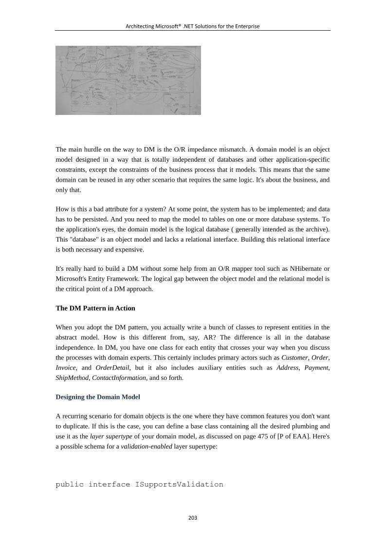
Architecting Microsoft® .NET Solutions for the Enterprise
203
The main hurdle on the way to DM is the O/R impedance mismatch. A domain model is an object
model designed in a way that is totally independent of databases and other application-specific
constraints, except the constraints of the business process that it models. This means that the same
domain can be reused in any other scenario that requires the same logic. It's about the business, and
only that.
How is this a bad attribute for a system? At some point, the system has to be implemented; and data
has to be persisted. And you need to map the model to tables on one or more database systems. To
the application's eyes, the domain model is the logical database ( generally intended as the archive).
This "database" is an object model and lacks a relational interface. Building this relational interface
is both necessary and expensive.
It's really hard to build a DM without some help from an O/R mapper tool such as NHibernate or
Microsoft's Entity Framework. The logical gap between the object model and the relational model is
the critical point of a DM approach.
The DM Pattern in Action
When you adopt the DM pattern, you actually write a bunch of classes to represent entities in the
abstract model. How is this different from, say, AR? The difference is all in the database
independence. In DM, you have one class for each entity that crosses your way when you discuss
the processes with domain experts. This certainly includes primary actors such as Customer, Order,
Invoice, and OrderDetail, but it also includes auxiliary entities such as Address, Payment,
ShipMethod, ContactInformation, and so forth.
Designing the Domain Model
A recurring scenario for domain objects is the one where they have common features you don't want
to duplicate. If this is the case, you can define a base class containing all the desired plumbing and
use it as the layer supertype of your domain model, as discussed on page 475 of [P of EAA]. Here's
a possible schema for a validation-enabled layer supertype:
public interface ISupportsValidation
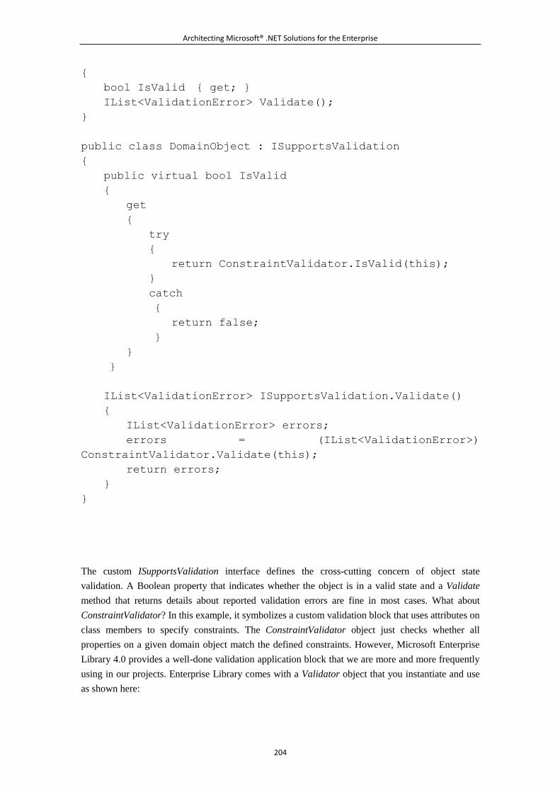
Architecting Microsoft® .NET Solutions for the Enterprise
204
{
bool IsValid { get; }
IList<ValidationError> Validate();
}
public class DomainObject : ISupportsValidation
{
public virtual bool IsValid
{
get
{
try
{
return ConstraintValidator.IsValid(this);
}
catch
{
return false;
}
}
}
IList<ValidationError> ISupportsValidation.Validate()
{
IList<ValidationError> errors;
errors = (IList<ValidationError>)
ConstraintValidator.Validate(this);
return errors;
}
}
The custom ISupportsValidation interface defines the cross-cutting concern of object state
validation. A Boolean property that indicates whether the object is in a valid state and a Validate
method that returns details about reported validation errors are fine in most cases. What about
ConstraintValidator? In this example, it symbolizes a custom validation block that uses attributes on
class members to specify constraints. The ConstraintValidator object just checks whether all
properties on a given domain object match the defined constraints. However, Microsoft Enterprise
Library 4.0 provides a well-done validation application block that we are more and more frequently
using in our projects. Enterprise Library comes with a Validator object that you instantiate and use
as shown here:

Architecting Microsoft® .NET Solutions for the Enterprise
205
Validator validator =
ValidationFactory.CreateValidator(this.GetType());
ValidationResults results = new ValidationResults();
validator.Validate(this, results);
The Validator object checks all properties in a type being validated according to the validation
attributes defined. Here are a couple of domain objects:
public class AddressInfo : DomainObject
{
[StringLengthValidator (60)]
public string Address { get; set; }
[StringLengthValidator (15)]
public string City { get; set; }
[StringLengthValidator (15)]
public string Region { get; set; }
[StringLengthValidator (10)]
public string PostalCode { get; set; }
[StringLengthValidator (15)]
public string Country { get; set; }
public override string ToString()
{
string region = String.IsNullOrEmpty(Region) ? " " : "
(" + Region + ") " ;
return String.Format("{0}, {1}{2}{3}", Address, City,
region, Country.ToUpper());
}
}
public class Customer : DomainObject
{
private AddressInfo _addressInfo = new AddressInfo();
private ContactInfo _contactInfo = new ContactInfo();
[NotNullValidator()]
[StringLengthValidator (5, 5)]
public virtual string ID { get; set; }
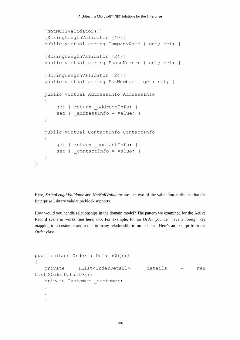
Architecting Microsoft® .NET Solutions for the Enterprise
206
[NotNullValidator()]
[StringLengthValidator (40)]
public virtual string CompanyName { get; set; }
[StringLengthValidator (24)]
public virtual string PhoneNumber { get; set; }
[StringLengthValidator (24)]
public virtual string FaxNumber { get; set; }
public virtual AddressInfo AddressInfo
{
get { return _addressInfo; }
set { _addressInfo = value; }
}
public virtual ContactInfo ContactInfo
{
get { return _contactInfo; }
set { _contactInfo = value; }
}
}
Here, StringLengthValidator and NotNullValidator are just two of the validation attributes that the
Enterprise Library validation block supports.
How would you handle relationships in the domain model? The pattern we examined for the Active
Record scenario works fine here, too. For example, for an Order you can have a foreign key
mapping to a customer and a one-to-many relationship to order items. Here's an excerpt from the
Order class:
public class Order : DomainObject
{
private IList<OrderDetail> _details = new
List<OrderDetail>();
private Customer _customer;
.
.
.
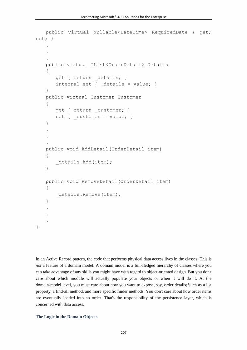
Architecting Microsoft® .NET Solutions for the Enterprise
207
public virtual Nullable<DateTime> RequiredDate { get;
set; }
.
.
.
public virtual IList<OrderDetail> Details
{
get { return _details; }
internal set { _details = value; }
}
public virtual Customer Customer
{
get { return _customer; }
set { _customer = value; }
}
.
.
.
public void AddDetail(OrderDetail item)
{
_details.Add(item);
}
public void RemoveDetail(OrderDetail item)
{
_details.Remove(item);
}
.
.
.
}
In an Active Record pattern, the code that performs physical data access lives in the classes. This is
not a feature of a domain model. A domain model is a full-fledged hierarchy of classes where you
can take advantage of any skills you might have with regard to object-oriented design. But you don't
care about which module will actually populate your objects or when it will do it. At the
domain-model level, you must care about how you want to expose, say, order details¡ªsuch as a list
property, a find-all method, and more specific finder methods. You don't care about how order items
are eventually loaded into an order. That's the responsibility of the persistence layer, which is
concerned with data access.
The Logic in the Domain Objects
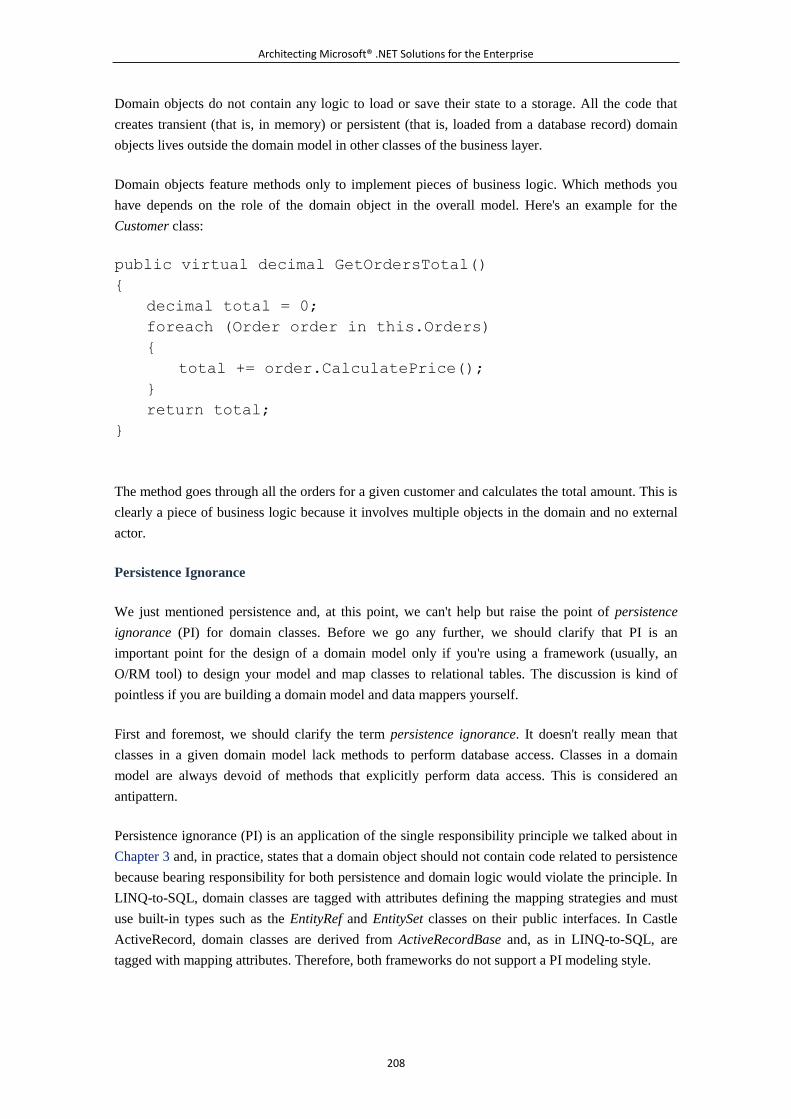
Architecting Microsoft® .NET Solutions for the Enterprise
208
Domain objects do not contain any logic to load or save their state to a storage. All the code that
creates transient (that is, in memory) or persistent (that is, loaded from a database record) domain
objects lives outside the domain model in other classes of the business layer.
Domain objects feature methods only to implement pieces of business logic. Which methods you
have depends on the role of the domain object in the overall model. Here's an example for the
Customer class:
public virtual decimal GetOrdersTotal()
{
decimal total = 0;
foreach (Order order in this.Orders)
{
total += order.CalculatePrice();
}
return total;
}
The method goes through all the orders for a given customer and calculates the total amount. This is
clearly a piece of business logic because it involves multiple objects in the domain and no external
actor.
Persistence Ignorance
We just mentioned persistence and, at this point, we can't help but raise the point of persistence
ignorance (PI) for domain classes. Before we go any further, we should clarify that PI is an
important point for the design of a domain model only if you're using a framework (usually, an
O/RM tool) to design your model and map classes to relational tables. The discussion is kind of
pointless if you are building a domain model and data mappers yourself.
First and foremost, we should clarify the term persistence ignorance. It doesn't really mean that
classes in a given domain model lack methods to perform database access. Classes in a domain
model are always devoid of methods that explicitly perform data access. This is considered an
antipattern.
Persistence ignorance (PI) is an application of the single responsibility principle we talked about in
Chapter 3 and, in practice, states that a domain object should not contain code related to persistence
because bearing responsibility for both persistence and domain logic would violate the principle. In
LINQ-to-SQL, domain classes are tagged with attributes defining the mapping strategies and must
use built-in types such as the EntityRef and EntitySet classes on their public interfaces. In Castle
ActiveRecord, domain classes are derived from ActiveRecordBase and, as in LINQ-to-SQL, are
tagged with mapping attributes. Therefore, both frameworks do not support a PI modeling style.
Architecting Microsoft® .NET Solutions for the Enterprise
209
Finally, a highly debated point in Entity Framework (EF) v1.0 is persistence ignorance of the classes
in the domain. In EF, classes are not persistent ignorant because you are forced to derive your
classes from a framework-provided root class (or implement a bunch of interfaces).
Persistence-ignorant classes are also referred to as plain-old CLR objects (POCO).
Note
Entity Framework is a Microsoft framework for providing data services. EF
includes an O/R mapping tool but is not limited to that. EF, in fact, provides
more services, such as query, view, and reporting services. Generally, EF is a
platform aimed at solving the mismatch between object and relational
models. Entity Framework is included in the .NET Framework 3.5 Service Pack
1, and designers come with Visual Studio 2008 Service Pack 1. From a
persistence-ignorance perspective, EF domain classes are not entirely POCO in
v1.0, but plans exist to make it pure POCO in v2.
What does it mean to a class to be (or not be) persistence ignorant? What are the benefits or
drawbacks?
When you design a domain model using a framework, you might or might not be required to derive
your classes from a given root class or to give each class a constructor of a given shape. The base
class usually brings in some added value¡ªtypically, it brings in some scaffolding that helps map the
content of the class to a physical table. Is this a bad thing? It depends. For sure, there are some
circumstances under which this turns out to be a problem, such as the following ones:
If a third-party library forces you to inherit from a given class, you can't derive your classes
from any other class. (This is because multiple inheritance and mix-ins are not supported in
the .NET Framework.)
From a pure design perspective, deriving from a persistence-aware class adds new (and
unnecessary) responsibilities to your domain classes.
If you have to build the domain on top of other types defined in other, third-party
assemblies, how do you persist any types created from a different root? If you can't release
the constraint, you probably have to consider a different framework or do it all by yourself.
So let's assume that being persistence ignorant is a really good thing and being bound to the
persistence engine of some framework limits your programming power. How can a general-purpose
tool like an O/RM know how to persist a plain .NET class? Where should it look for direction about
mapping? And, more importantly, how does it do it in a way that doesn't hurt performance?
A plain .NET class can't be persisted if some ad hoc code isn't dynamically emitted into the class.
This is what O/RM tools that support POCO models actually do. So the whole point is not whether
or not you need support for persistence¡ªdomain classes always need it. The real point is where you
want this support to live: within the domain classes ( persistence awareness like in EF and Castle
ActiveRecord), or outside of the domain (persistence ignorance like in NHibernate).
Architecting Microsoft® .NET Solutions for the Enterprise
210
Note
Having persistence-related code living outside the domain requires some form
of dynamic code injection. In other words, you avoid spoiling your domain
objects with non-strictly business-related attributes and properties but, at the
same time, those features are to be added to the objects when processed. A
commonly used approach entails the creation of dynamic proxies. A dynamic
proxy is a proxy class for a given type that adds missing capabilities on the fly.
The CLR supports the dynamic creation of proxies for a given type only if the
type inherits from MarshalByRefObject or ContextBoundObject. Castle
DynamicProxy is a nice framework to try for this purpose. Find more
information at http://www.castleproject.org/dynamicproxy/index.html.
Entities and Value Objects
When it comes to implementation, not all the classes in the Domain Model have the same attributes.
Typically, you distinguish between entities and value objects. For both, you use classes, but with
some slight differences.
The biggest difference is that classes for entities support the notion of an identity. Each instance of
the class is unique and can be compared to others using just the object identity as the discriminating
factor. For example, the entities in following code snippets are distinct:
Order o1 = new Order();
o1.OrderDate = 123;
Order o2 = new Order();
o2.ID = 123;
return o1 == o2; // returns false
In the .NET Framework, a plain class supports identity so that you don't have to take special care
when building a class for an entity. You have to do something unusual only when you deal with
value objects. What's a value object, and how does it differ from an entity class?
A value object class represents an entity in the domain that mostly contains data and lives for the
data it contains. A value object is fully identified by a combination of values it contains. An entity
object, on the other hand, has its own life and rich behavior regardless of the data it contains. Entity
objects are usually objects with a longer lifetime. A value object represents an aspect of an entity
and can live only in relation to an entity.
The OrderDetail class is the canonical example of value objects. The same order detail can be used
with different orders because it is fully represented by the data it contains. What's different in the
implementation of a value object? Two objects are equal if they have the same values in a given set
of properties:
Architecting Microsoft® .NET Solutions for the Enterprise
211
public class OrderDetail : DomainObject
{
.
.
.
public override bool Equals(object other)
{
if (this == other)
return true;
OrderDetail obj = other as OrderDetail;
if (obj == null)
return false;
return Order.ID == obj.order.ID &&
Product.ID == obj.Product.ID;
}
public override int GetHashCode()
{
// If you override Equals, you must override GetHashCode
too
// so that two equal objects return the same hash code.
// This is particularly important in domain models (see
NHibernate)
// to avoid duplicate objects in internal collections.
// Get a unique, object-specific value or string and
// return the hash code of that. Default implementation
of the method
// returns a unique but system-generated value that's
not object-specific.
// Get a number that combines order's ID and product's
ID,
// and get the hash code of that
int hash = ID * 10000 + Product.ID;
return hash.GetHashCode();
}
}
Architecting Microsoft® .NET Solutions for the Enterprise
212
Note
In this context, value objects have nothing to share with value types as you
might know them from the .NET Framework. Both entities and value objects
are actually implemented through .NET classes, but the level of abstraction is
totally different.
The Repository Pattern
As mentioned, generically speaking, the domain model contains classes with data and behavior, but
the behavior refers only to the logic of the represented entity. It has nothing to do with how you load
data into, say, an Order class or how you grab all orders issued in a given month. This code is
generically said to belong to the data access layer. But how exactly do you arrive at this?
A good approach is to use the Repository pattern, which is described on page 322 of [P of EAA], to
create a gateway through which code in the presentation or service layer can script the domain
model and update the underlying data store or load from there data that is represented through the
objects in the model.
Put another way, the Repository pattern adds yet another abstraction layer between the domain
model and the data access code. The data access code is where you physically perform queries, run
stored procedures, and deal with T-SQL and ADO.NET.
You typically have a repository object for each entity, such as customer, order, and product. The
interface of the repository is up to you; but it will likely contain finder and update methods that
work both on the single entity and on a collection of entities. Looking back at the Active Record
pattern, we can say that the Repository pattern offers a way to group all the CRUD methods that in
Active Record belong to the entity class.
By separating domain entities and persistence, you also gain another benefit. It won't take much
effort to extract an interface for the repository and then use a factory pattern to encapsulate all
database code in an object that implements the contracted interface. In this way, your domain can
work with whatever data access layer and data provider you use. Here's a sample of the code you
end up with:
// Ask the factory object to retrieve an instance of the
// repository for the Customer entity
CustomerRepository rep =
Repository.GetFactoryFor<Customer>();
// Work with the repository
List<Customer> coll = rep.FindCustomersByCountry(country);
Architecting Microsoft® .NET Solutions for the Enterprise
213
Internally, the repository factory can read the actual class to instantiate from a configuration file,
thus making the overall solution completely extensible, database independent, and customizable.
Mapping Objects to Tables
What's inside the repository? You should think of the repository as a library of I/O functions
available on a given entity. These functions work on the persistence layer, and possibly in an
interface-based way that keeps them independent of details as much as possible. However, no matter
how many layers of code you use, at some point you need to execute T-SQL commands via
ADO.NET or similar frameworks.
When you use a DM pattern, the layer of code that does database stuff is the Data Mapper. The Data
Mapper pattern, discussed on page 165 of [P of EAA], refers to a set of classes that map the logical
entity (and all of its relationships) to a physical collection of tables and records, usually on a
relational database.
For example, the Data Mapper does the dirty job of deleting an order. And it knows which records
on which tables it has to touch to execute your command, preserve data integrity, and maintain a
consistent state for the application.
In the worst case, the implementation of a Data Mapper for each entity is up to you. This is the
major difficulty of a DM approach. Mapping domain objects to a database is hard and, obviously,
time consuming. Using a tool for the job is often the only way out. O/RM tools exist specifically to
assist you in this kind of job.
In summary, what's inside a repository for a given entity? Either you have a Data Mapper class or
some corresponding code generated using the syntax of an O/RM tool such as NHibernate, Genome,
and (why not?) Entity Framework. In Chapter 6, we'll say more about repositories, data mappers,
and O/RM tools.
Note
One further comment is needed to explain the difference between entities
and value objects. You don't need a repository or a data mapper for a value
object. You need a repository only for an entity. The repository (or the
mapper) for a given entity will certainly take care of all value objects that
depend on a given entity.
The Special Case Pattern
When you design an object model (including a very special object model such as a domain model),
you face the problem of handling failures in finder methods. For example, suppose that in the
repository you have a method named FindCustomerByID that just returns a Customer object for the
record in the database that matches the specified ID:
Architecting Microsoft® .NET Solutions for the Enterprise
214
Customer FindCustomerByID(string id)
What if no such customer record is found? What should you return to the caller?
The Data Mapper will probably return an empty data reader or throw an ADO.NET exception. How
would you bubble this up to the service layer or presentation layer? The first answer that springs to
mind probably is to suggest returning NULL.
Ultimately, NULL is a valid answer where an object (of type Customer) is expected. But it is not a
precise answer. For sure, NULL indicates that something went wrong. But what, exactly? The
Special Case pattern can help. (See page 496 of [P of EAA].)
The pattern recommends that you create ad hoc types for each entity so that you return a valid object
that contains implicitly more information about what happened. Here's an example:
public sealed class MissingCustomer : Customer
{
}
The MissingCustomer class can be employed wherever a Customer is accepted, signals a failure in
the underlying code, and doesn't break polymorphism:
public Customer FindCustomerByID(string id)
{
Customer c;
.
.
.
if (failed)
return new MissingCustomer();
return c;
}
If you designed the domain model to support validation, the caller only needs to invoke the IsValid
property on the received object to see if something went wrong. If the caller needs more details, it
calls other methods on the sample ISupportsValidation interface. If no validation is built into the
model from the ground up, the caller has to implement a list of static checks against possible types.
If this is what happens, though, we recommend that you stop for awhile and refactor the domain
model to bring in validation support.
Workflows
Architecting Microsoft® .NET Solutions for the Enterprise
215
Workflows and services are a fundamental part of a real-world business layer. Both are
large topics that deserve a book of their own. We'll cover services in the next chapter, but
we'd like to say a bit more on workflows and their connection to BLL design patterns.
For example, where would you stick workflows if you decide to use TS? Or TM? Frankly,
both TS and TM are patterns that, when speaking in terms of complexity, are truly
designed for low-workflow, high-data-retrieval systems. In TS, you could consider using
a workflow to implement a transaction script and rely on designers to modify and code
activities to improve reusability. However, to us, from a workflow standpoint, TS and TM
look like somewhat special cases.
Instead, object-based BLL patterns such as Active Record and, especially, Domain Model
allow for true workflow. You have workflow at different levels. The workflow in the BLL
might occur between domain objects to implement a required behavior or in the service
layer to orchestrate services, the persistence layer, and domain objects. If you stick the
workflow in the objects, you accept the risk of reducing the likelihood of reusing domain
objects for other applications and purposes. For this reason, workflow in the domain
model is acceptable only if it is business workflow, innate in the domain, and not
dependent on application logic.
For example, the service layer for ordering something would perhaps develop a
coarse-grained workflow to check inventory, remove the item from inventory, issue the
item to shipping, and place the call to bill the customer. The domain model would have a
much finer-grained workflow. Looking just at shipping, domain objects would calculate a
shipping cost based on the desired shipping option and product weight/destination,
register the package with the shipper for pickup, record tracking information for later
recall, print packing labels for the shipping department, and so forth.
Workflows are required, but how you develop them in the BLL relates to the level of
complexity of the workflow and the problem's domain. In the end, it's a judgment call,
and one that's often hard to make. The experience and knowledge of the architect are key.
Again. And over and over again.
6.1.6 Summary
The design of an application is successful when it reproduces the customer's business structure and
processes as faithfully as possible. It requires that architects grab a full understanding of the
problem's domain, the processes, and data flows. This intimate knowledge of the business can
hardly be gained only by interviewing customers and users or even by reading informally written
requirements. Gaining this level of knowledge requires extensive collaboration between the
stakeholders. The role of the architect is not that of forcing analysts and users to learn programming,
but designing a programmable model out of the descriptions and jargon of domain experts.
Architecting Microsoft® .NET Solutions for the Enterprise
216
From the requirements, you can proceed in essentially two ways: you can base your model on user
actions or on the domain. If you opt for a procedural approach, you make your life easier, you
proceed with a good pace, and you have limited overhead in whatever you do. To put it down in
terms of patterns, you opt for either the Transaction Script or Table Module pattern.
Transaction Script is easy to understand and quick to develop. It doesn't scale well because the
complexity of the domain tends to grow. This happens because code accumulates that has a variable
level of cohesion and generally is difficult to refactor and rework as requirements change. Table
Module has excellent support from Visual Studio and the .NET Framework, but it remains
essentially a data-centric, table-oriented procedural model.
The shift toward a full object-oriented design leads you to consider an Active Record pattern or,
better yet, a Domain Model pattern. The Domain Model pattern has the potential and flexibility
necessary to let you deal with any sort of complexity in the domain. Because the Domain Model
adds abstraction that separates you from the details of the underlying databases, you have to fill the
gap in some way and map an otherwise abstract domain model onto tables and columns. This is
challenging, as well as difficult and time consuming. And it requires a higher level of skill and the
right attitude.
The business logic is the heart of the system, but it's not the whole system. However, the choice you
make for the design of the business logic has an impact on other layers¡ªin particular, the persistence
layer or data access layer. These two layers together largely determine the success of your project.
Every approach has pros and cons. The right mix of patterns for the domain is not something that
everybody can calculate out of a recipe or an algorithm. That's why you, the architect, get into the
business.
6.1.7 Murphy's Laws of the Chapter
A successful business layer requires observation and modeling. It also requires an innate ability to
do things in the simplest possible manner. "Do it simply but not simplistically," is one of our
favorite mantras. And it gives a nod to the first Murphy's Law for this chapter:
A complex system that works is invariably found to have evolved from a simple system that
works.
Investment in software reliability will increase until it exceeds the probable cost of errors.
In theory, there is no difference between theory and practice, but in practice there is.
See http://www.murphys-laws.com for an extensive listing of other computer-related (and
non-computer) laws and corollaries.
6.2 Chapter 5. The Service Layer
If you want service(s), serve yourself.
Architecting Microsoft® .NET Solutions for the Enterprise
217
¡ªSpanish proverb
In the previous chapter, we examined various approaches to the design and implementation of the
business logic: Transaction Script (TS), Table Module (TM), and a couple of object-based
approaches such as Active Record (AR) and Domain Model (DM). Of the four approaches, only
TS¡ªunquestionably the simplest¡ªhas a clear dependency on use cases that need to be supported by
the presentation layer.
When you choose a TS procedural approach for the business logic, you define a list of methods
starting from actions the user can trigger from the user interface. Each click or selection triggers a
method on one of the TS objects. Although we could debate whether TS is an effective way of
designing the business layer, we can't deny that TS makes the design of the system exceptionally
simple.
What about all the other approaches? With all the other approaches, you have objects all the way
around. You have table adapters in TM, objects representing a record in a table in AR, and an
abstract object model in DM. The mere fact you have objects in your middle layers is not enough to
make it all work from the UI perspective.
Think of a plain Button1_Click event handler in the world's simplest ASP.NET page. The handler is
part of the presentation layer and represents the expected behavior of the system when the user
clicks a given button. If you work with objects here, you end up implementing some logic in the
presentation layer. On the other hand, a business component has to be instantiated and scripted to
work, and some code is required for this. The code necessary to script the component might be as
simple as calling the constructor and perhaps one method. More often, however, this code is fairly
rich with if-then-else statements, needs to call into multiple objects, and waits for a service to return
a response. This is definitely application logic folded into the presentation layer.
As we saw in Chapter 4, "The Business Layer," having some form and quantity of logic in the
presentation layer might be acceptable sometimes. If you consciously decide to put some logic in
the presentation layer and you're happy with that, it's fine. Otherwise, consider that with a different
system design you can keep logic out of the presentation layer and keep the presentation layer free
of business components.
How would you trigger system behavior from the presentation layer, then? You define an extra layer
of code and place it in between the presentation layer and business layer. This extra layer is known
as the service layer.
Note
Most of the time, the service layer is seen as part of the business layer in a
Domain Model approach. Although this is probably a very common scenario, it
is definitely not the only possible one. In general, a service layer defines an
interface for the presentation layer to trigger predefined system actions. As
the name itself suggests, the service layer is a sort of boundary that marks
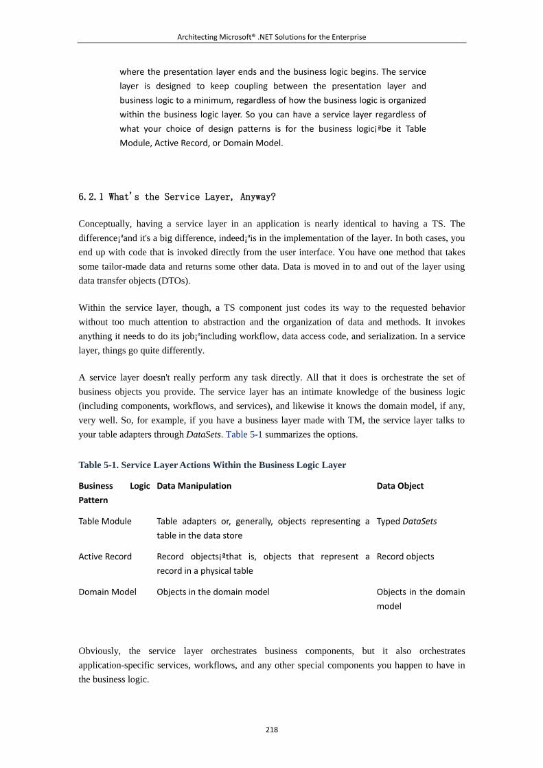
Architecting Microsoft® .NET Solutions for the Enterprise
218
where the presentation layer ends and the business logic begins. The service
layer is designed to keep coupling between the presentation layer and
business logic to a minimum, regardless of how the business logic is organized
within the business logic layer. So you can have a service layer regardless of
what your choice of design patterns is for the business logic¡ªbe it Table
Module, Active Record, or Domain Model.
6.2.1 What's the Service Layer, Anyway?
Conceptually, having a service layer in an application is nearly identical to having a TS. The
difference¡ªand it's a big difference, indeed¡ªis in the implementation of the layer. In both cases, you
end up with code that is invoked directly from the user interface. You have one method that takes
some tailor-made data and returns some other data. Data is moved in to and out of the layer using
data transfer objects (DTOs).
Within the service layer, though, a TS component just codes its way to the requested behavior
without too much attention to abstraction and the organization of data and methods. It invokes
anything it needs to do its job¡ªincluding workflow, data access code, and serialization. In a service
layer, things go quite differently.
A service layer doesn't really perform any task directly. All that it does is orchestrate the set of
business objects you provide. The service layer has an intimate knowledge of the business logic
(including components, workflows, and services), and likewise it knows the domain model, if any,
very well. So, for example, if you have a business layer made with TM, the service layer talks to
your table adapters through DataSets. Table 5-1 summarizes the options.
Table 5-1. Service Layer Actions Within the Business Logic Layer
Business Logic
Pattern
Data Manipulation Data Object
Table Module Table adapters or, generally, objects representing a
table in the data store
Typed DataSets
Active Record Record objects¡ªthat is, objects that represent a
record in a physical table
Record objects
Domain Model Objects in the domain model Objects in the domain
model
Obviously, the service layer orchestrates business components, but it also orchestrates
application-specific services, workflows, and any other special components you happen to have in
the business logic.
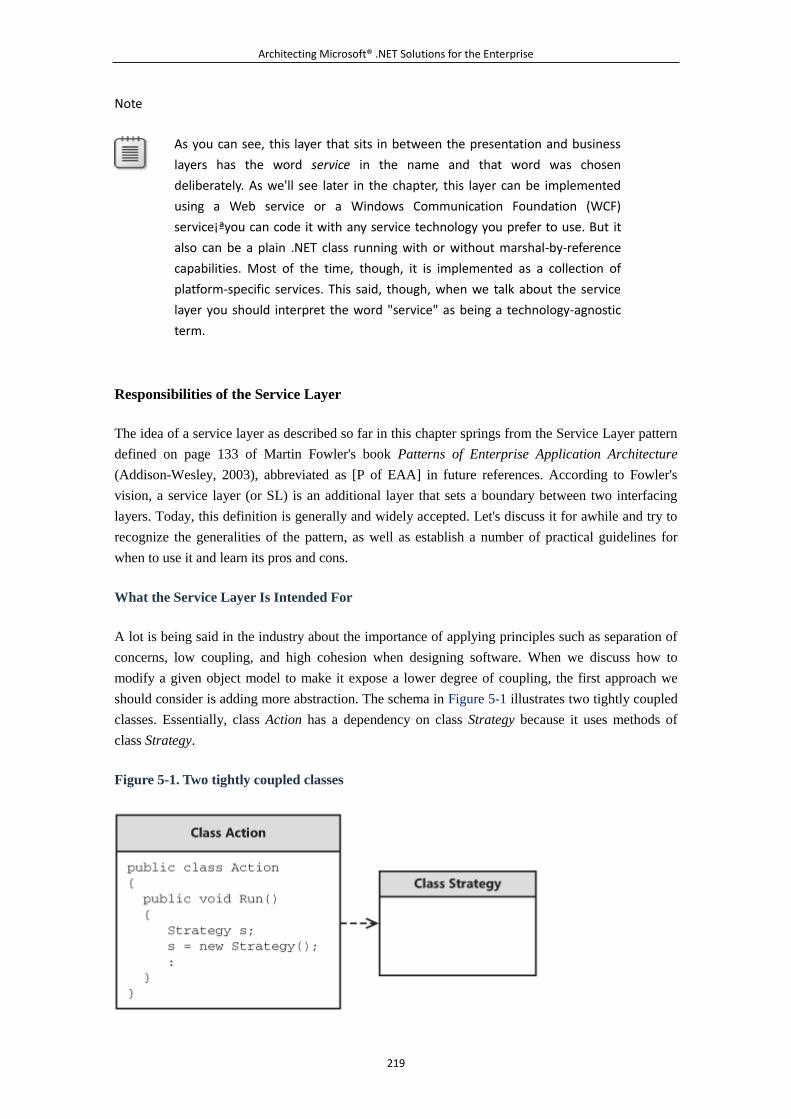
Architecting Microsoft® .NET Solutions for the Enterprise
219
Note
As you can see, this layer that sits in between the presentation and business
layers has the word service in the name and that word was chosen
deliberately. As we'll see later in the chapter, this layer can be implemented
using a Web service or a Windows Communication Foundation (WCF)
service¡ªyou can code it with any service technology you prefer to use. But it
also can be a plain .NET class running with or without marshal-by-reference
capabilities. Most of the time, though, it is implemented as a collection of
platform-specific services. This said, though, when we talk about the service
layer you should interpret the word "service" as being a technology-agnostic
term.
Responsibilities of the Service Layer
The idea of a service layer as described so far in this chapter springs from the Service Layer pattern
defined on page 133 of Martin Fowler's book Patterns of Enterprise Application Architecture
(Addison-Wesley, 2003), abbreviated as [P of EAA] in future references. According to Fowler's
vision, a service layer (or SL) is an additional layer that sets a boundary between two interfacing
layers. Today, this definition is generally and widely accepted. Let's discuss it for awhile and try to
recognize the generalities of the pattern, as well as establish a number of practical guidelines for
when to use it and learn its pros and cons.
What the Service Layer Is Intended For
A lot is being said in the industry about the importance of applying principles such as separation of
concerns, low coupling, and high cohesion when designing software. When we discuss how to
modify a given object model to make it expose a lower degree of coupling, the first approach we
should consider is adding more abstraction. The schema in Figure 5-1 illustrates two tightly coupled
classes. Essentially, class Action has a dependency on class Strategy because it uses methods of
class Strategy.
Figure 5-1. Two tightly coupled classes
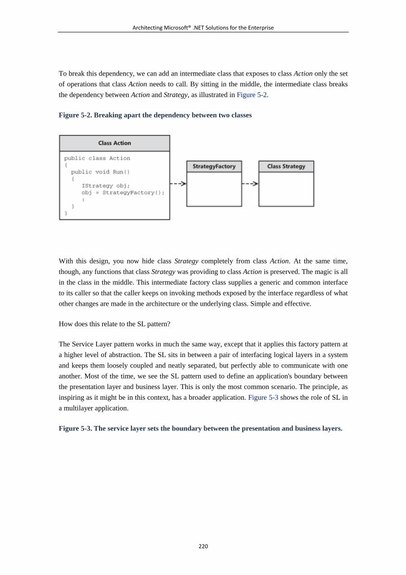
Architecting Microsoft® .NET Solutions for the Enterprise
220
To break this dependency, we can add an intermediate class that exposes to class Action only the set
of operations that class Action needs to call. By sitting in the middle, the intermediate class breaks
the dependency between Action and Strategy, as illustrated in Figure 5-2.
Figure 5-2. Breaking apart the dependency between two classes
With this design, you now hide class Strategy completely from class Action. At the same time,
though, any functions that class Strategy was providing to class Action is preserved. The magic is all
in the class in the middle. This intermediate factory class supplies a generic and common interface
to its caller so that the caller keeps on invoking methods exposed by the interface regardless of what
other changes are made in the architecture or the underlying class. Simple and effective.
How does this relate to the SL pattern?
The Service Layer pattern works in much the same way, except that it applies this factory pattern at
a higher level of abstraction. The SL sits in between a pair of interfacing logical layers in a system
and keeps them loosely coupled and neatly separated, but perfectly able to communicate with one
another. Most of the time, we see the SL pattern used to define an application's boundary between
the presentation layer and business layer. This is only the most common scenario. The principle, as
inspiring as it might be in this context, has a broader application. Figure 5-3 shows the role of SL in
a multilayer application.
Figure 5-3. The service layer sets the boundary between the presentation and business layers.
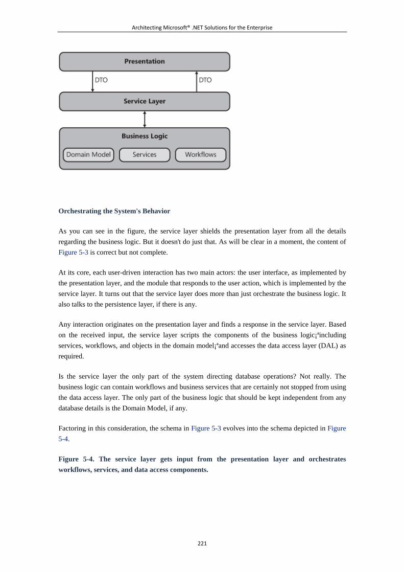
Architecting Microsoft® .NET Solutions for the Enterprise
221
Orchestrating the System's Behavior
As you can see in the figure, the service layer shields the presentation layer from all the details
regarding the business logic. But it doesn't do just that. As will be clear in a moment, the content of
Figure 5-3 is correct but not complete.
At its core, each user-driven interaction has two main actors: the user interface, as implemented by
the presentation layer, and the module that responds to the user action, which is implemented by the
service layer. It turns out that the service layer does more than just orchestrate the business logic. It
also talks to the persistence layer, if there is any.
Any interaction originates on the presentation layer and finds a response in the service layer. Based
on the received input, the service layer scripts the components of the business logic¡ªincluding
services, workflows, and objects in the domain model¡ªand accesses the data access layer (DAL) as
required.
Is the service layer the only part of the system directing database operations? Not really. The
business logic can contain workflows and business services that are certainly not stopped from using
the data access layer. The only part of the business logic that should be kept independent from any
database details is the Domain Model, if any.
Factoring in this consideration, the schema in Figure 5-3 evolves into the schema depicted in Figure
5-4.
Figure 5-4. The service layer gets input from the presentation layer and orchestrates
workflows, services, and data access components.
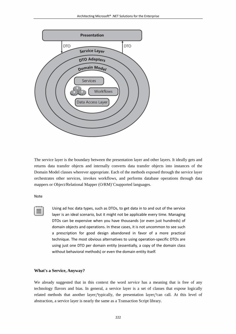
Architecting Microsoft® .NET Solutions for the Enterprise
222
The service layer is the boundary between the presentation layer and other layers. It ideally gets and
returns data transfer objects and internally converts data transfer objects into instances of the
Domain Model classes wherever appropriate. Each of the methods exposed through the service layer
orchestrates other services, invokes workflows, and performs database operations through data
mappers or Object/Relational Mapper (O/RM) C̈supported languages.
Note
Using ad hoc data types, such as DTOs, to get data in to and out of the service
layer is an ideal scenario, but it might not be applicable every time. Managing
DTOs can be expensive when you have thousands (or even just hundreds) of
domain objects and operations. In these cases, it is not uncommon to see such
a prescription for good design abandoned in favor of a more practical
technique. The most obvious alternatives to using operation-specific DTOs are
using just one DTO per domain entity (essentially, a copy of the domain class
without behavioral methods) or even the domain entity itself.
What's a Service, Anyway?
We already suggested that in this context the word service has a meaning that is free of any
technology flavors and bias. In general, a service layer is a set of classes that expose logically
related methods that another layer¡ªtypically, the presentation layer¡ªcan call. At this level of
abstraction, a service layer is nearly the same as a Transaction Script library.
Architecting Microsoft® .NET Solutions for the Enterprise
223
Devoid of any technology reference, the word service simply indicates a piece of software that
services the requests that one layer sends to another. The expression service layer, instead, refers to
a collection of services that collectively form an intermediate layer between two communicating
layers.
What's Service Orientation?
Without beating around the bush, to many people today the word service means something more
specific than just a piece of code that services incoming requests. This change of perspective has
largely come about because of the advent of service orientation (SO) and service-oriented
architectures (SOA).
Service orientation is a way of designing business processes as a set of interconnected services.
Service orientation is not about technology itself, it is merely a different way of approaching the
task of describing how a given business operates.
SOA, in turn, refers to IT architectures that view their resources as services and link and connect
them both statically and on demand. In an SOA world, applications result from the composition and
integration of independent services in a way that might be reminiscent of the design of forms in
early rapid application development (RAD) systems. In an SOA application, the building block is
the service rather than the components.
Our Definition of a Service
In a technology-agnostic scenario, we like to define a service as a business-related operation that all
clients of the application can repeatedly execute. The list of clients includes users, other services in
the application, and other parts of the business logic such as workflows.
For example, let's focus on a banking application and, in particular, on the task of converting
amounts of money between foreign currencies. This operation is a good fit for a service. After you
have defined the input and output data for the service, other parts of the application can repeatedly
take advantage of the service. In addition, the code in the service is reused over and over again.
Here's a possible objection: if all the burden is with reusability, why not just use a plain class?
Ultimately, when you implement the service, you actually use a class. So services and classes share
a common substrate, but a service is something more specialized than a class that takes advantage of
the surrounding environment and, thanks to that, gets its own autonomous life.
A service is a much better fit than a plain class in a service layer. We will even go further and say
that there would probably be no emphasis at all on yet another layer if it weren't for services.
To see the bigger picture, let's have a quick look at the definition of service offered by the
Organization for the Advancement of Structured Information Standards (OASIS):
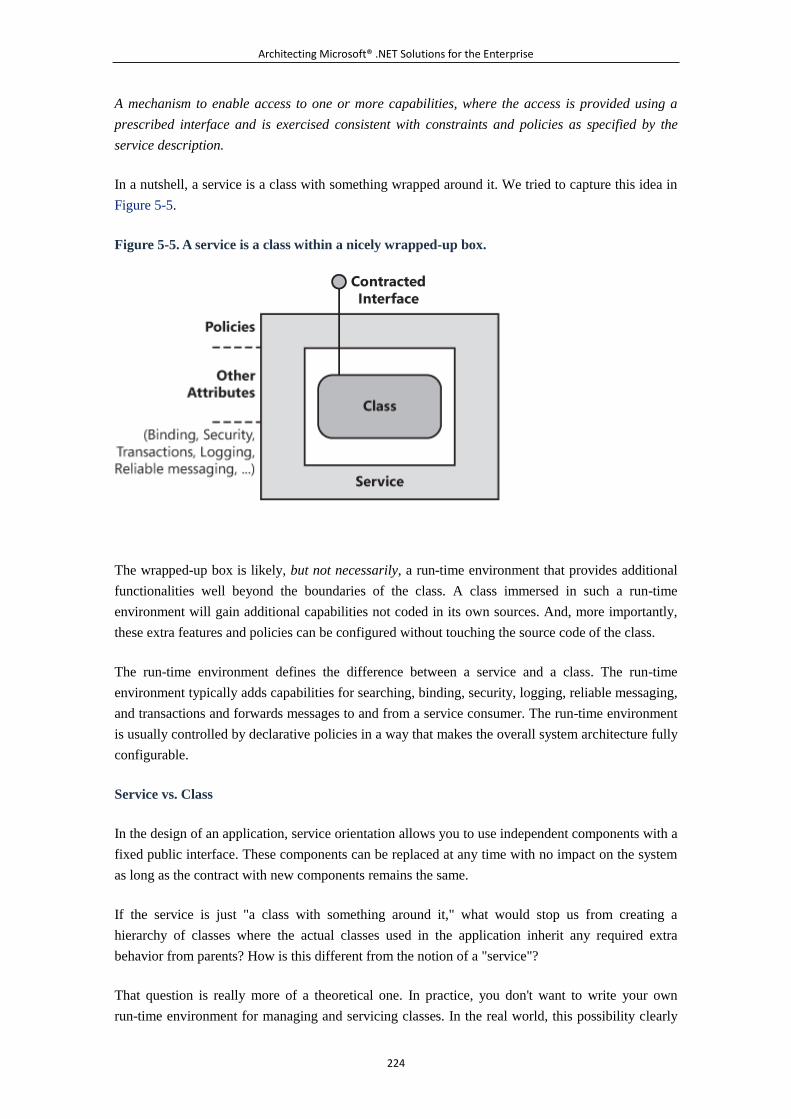
Architecting Microsoft® .NET Solutions for the Enterprise
224
A mechanism to enable access to one or more capabilities, where the access is provided using a
prescribed interface and is exercised consistent with constraints and policies as specified by the
service description.
In a nutshell, a service is a class with something wrapped around it. We tried to capture this idea in
Figure 5-5.
Figure 5-5. A service is a class within a nicely wrapped-up box.
The wrapped-up box is likely, but not necessarily, a run-time environment that provides additional
functionalities well beyond the boundaries of the class. A class immersed in such a run-time
environment will gain additional capabilities not coded in its own sources. And, more importantly,
these extra features and policies can be configured without touching the source code of the class.
The run-time environment defines the difference between a service and a class. The run-time
environment typically adds capabilities for searching, binding, security, logging, reliable messaging,
and transactions and forwards messages to and from a service consumer. The run-time environment
is usually controlled by declarative policies in a way that makes the overall system architecture fully
configurable.
Service vs. Class
In the design of an application, service orientation allows you to use independent components with a
fixed public interface. These components can be replaced at any time with no impact on the system
as long as the contract with new components remains the same.
If the service is just "a class with something around it," what would stop us from creating a
hierarchy of classes where the actual classes used in the application inherit any required extra
behavior from parents? How is this different from the notion of a "service"?
That question is really more of a theoretical one. In practice, you don't want to write your own
run-time environment for managing and servicing classes. In the real world, this possibility clearly
Architecting Microsoft® .NET Solutions for the Enterprise
225
stopped being worth the effort as much as 10 years ago, when Microsoft introduced Microsoft
Transaction Server (MTS).
Note
From its inception, MTS was not dealing with services, public interfaces, and
discoverability like SOA does today. But MTS was certainly promoting the idea
that architects should focus only on the logic of business components¡ªand
their interaction and synchronization¡ªleaving the burden of additional
run-time features to a surrounding environment. A lot has happened since the
MTS days, but in summary a class is still a plain piece of code, whereas a
service is a class wrapped up in a nice and configurable box.
When it comes to implementing a system with services, you end up using some technology with a
run-time environment that takes care of your classes. The run-time environment also publishes your
classes as discoverable resources over some network.
In addition to being an autonomous, discoverable resource with a fixed interface, a service is also
often a stateless component. In general, a stateless component scales better, has an overall simpler
implementation, and can be employed in a larger number of scenarios.
Is Every Class a Service?
Admittedly, this is a question that expresses the difference between what you have and what you
dream of having. Although the possibility of making every class a service sounds like a radical idea,
it is probably less farfetched than one might think at first. So should every single class of an
application be a service? Juval Lowy of IDesign has a nice chat on this topic on MSDN's Channel 9.
If you are interested and want to hear more, here's the link:
http://channel9.msdn.com/ShowPost.aspx?PostID=.
The key point is that after you have made your choice of a technology for the surrounding run-time
environment, if this runtime is powerful enough, every class might get some benefit. Every class
hosted as a service automatically benefits from provided system features, including security,
transactions, tracing, logging, and so forth. (See Figure 5-5 earlier in the chapter.) And what about
performance?
It's a debatable and also relative point. If the performance you can get is good enough, why should
you care about the (obvious) overhead? Anyway, the concept of "every class as a service" is kind of
a provocative and radical idea that we are likely to be faced with more often in the near future.
Services in the Service Layer
Architecting Microsoft® .NET Solutions for the Enterprise
226
Architecturally speaking, the service layer applies a general and well-known principle of software
design¡ªlow coupling¡ªand possibly another principle, high cohesion, as well. It does that by
defining an intermediate layer of code aimed at decoupling the user interface and the middle tier.
The advent of service orientation just made it more intriguing for architects to apply some of the
tenets of service orientation to classes in the service layer. The result of this is that any service layer
is made of services and only services. The fact that the service layer exists as a pattern at all is
directly due to the concepts of services and service-orientation being applied to internal application
logic versus external client operations. Let's take a brief look at the evolution of the service layer
and how it has been applied within single- application architectures.
From Code-Behind to Services
Services in the service layer are invoked directly from the presentation layer. In a Web front end,
this means the code-behind class of each page invokes the service layer. Similarly, in a Windows
Presentation Foundation (WPF) or Windows Forms client, the code-behind class of the window or
form hosts the logic for the invocation.
If you're using a Graphical User Interface (GUI) design pattern, such as the Model-View-Presenter
(MVP) pattern, the service layer is invoked from the methods of the MVP presenter. (We'll cover
GUI patterns in Chapter 7, "The Presentation Layer.")
It is common to see a canonical Button1_Click event handler in an ASP.NET code-behind class
written as shown in the next code snippet. Needless to say, method names are totally arbitrary and
only point to some action you might want to execute as the effect of the user action.
public void Button1_Click(object sender, EventArgs e)
{
if ( ... )
{
// Primary route
AccomplishFirstStep();
if ( ... )
TakeOneMoreStep();
}
else
{
// Secondary route
PerformAnAction();
IfHereTakeThisStep();
}
// Finalize the procedure
CompleteAction();
}
Architecting Microsoft® .NET Solutions for the Enterprise
227
The first level of abstraction you can build is a presenter. (See the discussions about MVP in
Chapter 7.) A presenter simply offers a method in a separate class you call from within the
code-behind class. The benefit of this is you encapsulate logic within the separate presenter class
rather than sprinkle it throughout your ASP.NET code-behind classes. Maintenance is by far easier
and the design is much less tightly-coupled. With a presenter class, the preceding code becomes
code that looks like the following:
public void Button1_Click(object sender, EventArgs e)
{
// The implementation of the MVP pattern ensures that the
// window/form/Web page has a presenter object available
// immediately after loading, typically using dependency
// injection.
this.presenter.PerformSomeAction();
}
The presenter's method then incorporates any logic you need to implement in the UI event handler.
The service layer is even one step ahead of that, within the presenter class.
// From either the presenter, or directly in the code-behind
class,
// you call a service method that orchestrates any required
behavior.
public void PerformSomeAction()
{
// This method belongs to the presenter class. It
instantiates
// the proxy of the "service" and places the call either
synchronously
// or asynchronously.
// Prepares the DTO to pass data to the service
PerformSomeActionRequest dto = new
PerformSomeActionRequest();
.
.
.
// Place the call.
Architecting Microsoft® .NET Solutions for the Enterprise
228
// NB: We're taking services literally as Web/WCF services
here, but
// performance reasons may suggest you opt for a serviced
component if not
// a plain class (especially in ASP.NET where service and
code-behind
// likely run on the same tier).
SampleServiceClient proxy = new SampleServiceClient();
PerformSomeActionResponse response =
proxy.PerformSomeAction(dto);
// Process results
.
.
.
}
[WebMethod]
public PerformSomeActionResponse
PerformSomeAction(PerformSomeActionRequest dto)
{
// The code you would otherwise run directly from the
code-behind class
.
.
.
}
If it sounds like it's just overhead added to the system, have a look at Figure 5-6, which offers a
graphical view of the resulting model and its benefits.
Figure 5-6. The benefit of a service layer: a unique and remotable point of contact between the
UI and middle tier
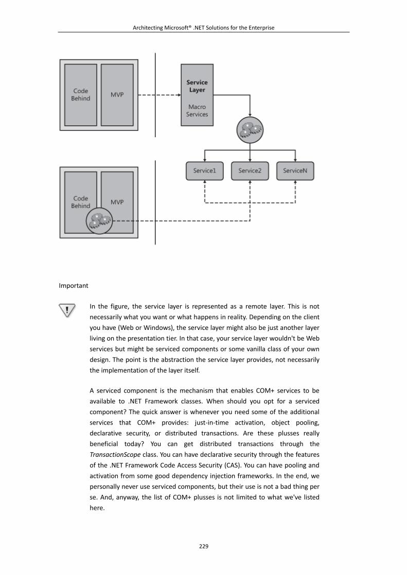
Architecting Microsoft® .NET Solutions for the Enterprise
229
Important
In the figure, the service layer is represented as a remote layer. This is not
necessarily what you want or what happens in reality. Depending on the client
you have (Web or Windows), the service layer might also be just another layer
living on the presentation tier. In that case, your service layer wouldn't be Web
services but might be serviced components or some vanilla class of your own
design. The point is the abstraction the service layer provides, not necessarily
the implementation of the layer itself.
A serviced component is the mechanism that enables COM+ services to be
available to .NET Framework classes. When should you opt for a serviced
component? The quick answer is whenever you need some of the additional
services that COM+ provides: just-in-time activation, object pooling,
declarative security, or distributed transactions. Are these plusses really
beneficial today? You can get distributed transactions through the
TransactionScope class. You can have declarative security through the features
of the .NET Framework Code Access Security (CAS). You can have pooling and
activation from some good dependency injection frameworks. In the end, we
personally never use serviced components, but their use is not a bad thing per
se. And, anyway, the list of COM+ plusses is not limited to what we've listed
here.
Architecting Microsoft® .NET Solutions for the Enterprise
230
When should you opt for a WCF service? Mostly when you need remotability.
In other words, a WCF service is the recommended technology for a service
layer when you need the ability of deploying the service layer on a dedicated
application server. Likewise, it is an excellent choice when you need to make
the service layer externally available in a service-oriented scenario. In this
regard, the biggest benefit of WCF as a service technology is the configuration
capabilities which, among other things, means a delicious pinch of
aspect-orientation added to your solution.
Do we have any words of advice on Web services? WCF incorporates
SOAP-based communication. With WCF you can easily switch to a different
communication API of choice (sockets, remoting, or SOAP). Our advice is to
use SOAP over HTTP¡ªwhat Web services are all about¡ªonly if it is the only (or
the best) option you have.
Benefits of a Service Layer
The service layer offers a unique point of contact between the user interface and the middle tier,
where you concentrate the application logic. The application logic is that part of the business logic
that springs directly from use cases. We'll return to the topics of application and business logic later
in the chapter.
Services with their own surrounding run-time environment make it incredibly easier and more
effective to remote pieces of the application logic. In Figure 5-6, the topmost schema shows a
typical architecture that includes a service layer. You cross the boundary of the application UI with
a single call toward a common programming interface¡ªthe service layer.
On the server side, the invoked method on the service layer orchestrates the required logic by
making and coordinating calls to the Domain Model, specific application services, workflows, and
whatever else your business layer is made of.
Without a service layer, you have direct calls to the application services issued from the presentation
layer. The result is a fine-grained remote interface and a potentially chatty communication model.
You take the risk of having to place multiple remote calls to accomplish the requested task. And this
is not a good thing for performance.
Macro and Micro Services
The service layer is made of coarse-grained services, also referred to as macro services. Macro
services just orchestrate operations that map to directly to use cases. Macro services do not contain
any domain logic that relates to the core business. In other words, macro services don't know about
invoices, products, or mortgages; instead, they know that to place an order they have to go through a
well-known sequence of steps, such as checking the availability of the product and the amount of
credit on the user account.
Architecting Microsoft® .NET Solutions for the Enterprise
231
On the other hand, application services (also referred to as micro services) live on the server side
and represent services specific to the application and functional to the domain logic. Examples of
micro services are a service that performs currency conversions and a workflow-based service to
calculate the quantity of goods that needs to be ordered to maintain appropriate inventory levels.
It is always preferable to have a service layer, as Figure 5-6 clearly shows. However, it is sometimes
acceptable for the presentation layer to invoke an application service directly. This might be the case
when the service method implements a simple, one-shot operation. In essence, the presentation layer
should target an application service (thus bypassing the service layer) when it makes a direct call
and there's no need to orchestrate multiple results and steps on the client.
6.2.2 The Service Layer Pattern in Action
As mentioned on page 133 of [P of EAA], the Service Layer pattern defines an additional layer that
lives between two interfacing layers¡ªtypically, the presentation and business layers. In principle,
this intermediate layer is just a collection of classes that implement the use cases of the application.
The advent of services and service orientation, though, made the whole solution even worthier and
more successful. Services represent a loosely coupled counterpart to the presentation layer, and they
offer an agreed-upon contract, reusability, and cross-platform deployment. And services, like plain
classes, let you fine-tune the amount of abstraction you need.
Generalities of the Service Layer Pattern
The presentation layer of a real-world application is the primary user front end. Everything the user
can do with an application passes through the presentation layer and the user interface.
Enterprise-class applications in particular, though, can have multiple application data presentation
interfaces. One interface will certainly be a user interface¡ªand perhaps there will be one for each
supported platform, such as mobile, Web, WPF, Windows, Silverlight, and other software platforms.
Another interface can be a back-office application that loads data into the system or extracts data
and transforms it. Yet another interface is represented by a connector that attempts to use the
application's C̈internal processing logic in a system-integration scenario.
In all these cases, a common application programming interface (API) is desirable. And it is even
more desirable if it can be available through a number of transportation protocols and communicate
via messages. (See Figure 5-7.)
Figure 5-7. Multiple front ends for a common application's service-based back end
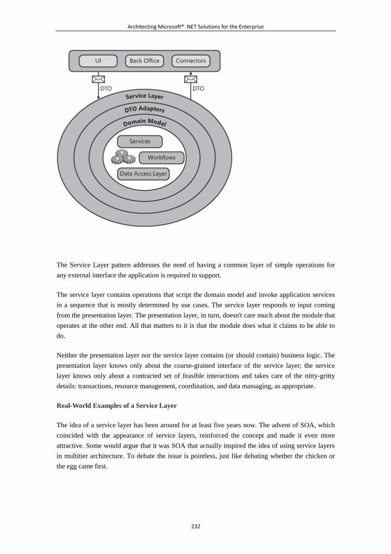
Architecting Microsoft® .NET Solutions for the Enterprise
232
The Service Layer pattern addresses the need of having a common layer of simple operations for
any external interface the application is required to support.
The service layer contains operations that script the domain model and invoke application services
in a sequence that is mostly determined by use cases. The service layer responds to input coming
from the presentation layer. The presentation layer, in turn, doesn't care much about the module that
operates at the other end. All that matters to it is that the module does what it claims to be able to
do.
Neither the presentation layer nor the service layer contains (or should contain) business logic. The
presentation layer knows only about the coarse-grained interface of the service layer; the service
layer knows only about a contracted set of feasible interactions and takes care of the nitty-gritty
details: transactions, resource management, coordination, and data massaging, as appropriate.
Real-World Examples of a Service Layer
The idea of a service layer has been around for at least five years now. The advent of SOA, which
coincided with the appearance of service layers, reinforced the concept and made it even more
attractive. Some would argue that it was SOA that actually inspired the idea of using service layers
in multitier architecture. To debate the issue is pointless, just like debating whether the chicken or
the egg came first.
Architecting Microsoft® .NET Solutions for the Enterprise
233
Based on our experiences in the field, we would say that the purpose of the service layer, and the
rationale behind it, is still something that some developers and architects fail to understand. So let us
offer a real-world example.
Many of us have had the experience of being junior developers. And we all have had a dull and
haughty boss at some time. It was not unusual in the early 1990s in a certain office in Rome, not too
far from the Coliseum, to hear, "Dino, we need to ship a customized version of product X to
customer Y right now."
Do you get the point? The boss is the presentation layer. All that he cares about is sending a simple
command to his counterpart¡ªsay, a manager. To his eyes, the manager exposes a mere list of tasks
and responsibilities. The boss doesn't care how the manager will actually accomplish the task, but he
knows that the contract between the company and the manager says that he will do that. (The
contract also implicitly says that if that manager doesn't fulfill tasks, he can be replaced.) The
manager is the service layer. Finally, the manager coordinates other resources to get the job done.
If you look around, you find zillions of real-life scenarios where you can recognize an instance of
the Service Layer pattern. Want some quick examples? Kids asking for money, editors demanding
changes, you getting some cash at an ATM, and so on.
When to Use a Service Layer
The service layer should be used in nearly all applications of some complexity. There's probably no
cost/benefit gain if a service layer is built into a simple filing system or used in a quick-and-dirty
Web site such as temporary sites that stay posted for just a few weeks.
In multitier systems, there's almost no good reason for not having a service layer. One possible
exception we can think of is when you end up with a single front end (for example, just the regular
user interface) and a set of application services whose methods closely match the use cases of the
system. In this case, the service layer will likely be just a dispatcher and no orchestration work will
be required of it. Even a simple-minded service layer that merely forwards calls to a business layer
is probably more than is needed.
Conversely, when you have multiple front ends with a significant amount of application logic, it is
preferable to store the entire application logic in a single place rather than having it duplicated for
each application interface.
Note
As we saw in the "Macro and Micro Services" section, you should include a
service layer in an application if it makes sense for you to organize your
services into macro and micro categories. Services in the macro category form
the service layer.
Architecting Microsoft® .NET Solutions for the Enterprise
234
What's Good About a Service Layer
The service layer adds abstraction and decouples two interfacing layers. Whenever this solution gets
you a better system, you should build a service layer. A service layer favors the use of
coarse-grained, remote interfaces that minimize traffic between the presentation and business layers.
When the service layer is implemented through services (for example, WCF services), you can
realize additional benefits, such as the possibility of remoting the layer with extreme ease and
changing binding settings through configuration.
What's Bad About a Service Layer
Because abstraction is the major strength of a service layer, for simple systems the service layer
mostly represents overhead.
As we've mentioned a few times already, a service layer doesn't necessarily require a service
technology such as WCF. In ASP.NET presentation layers, for example, you typically call the
"service layer" from within the code-behind class¡ªthat is, in a local scenario. Having a WCF service
here instead of a plain class would probably add overhead and likely degrade performance. Consider
using WCF services in your service layer with a grain of salt and measure your performance
numbers early and often. If performance suffers too greatly, choose another service layer
technology.
Note
All in all, we think you need strong reasons to even consider Web or WCF
services in the first place. For some ASP.NET pages, requiring cross-domain
data, this is acceptable for sure. But most pages shouldn't be made to make
several XML/HTTP network calls like that.
Where Does a Service Layer Fit?
The service layer is invoked from the presentation layer. But is it a local or remote call? As usual
with architecture-related questions, the correct answer is, "It depends."
Fowler's first law of distributed object design recommends that you just don't distribute your objects.
Our corollary to this law is, "unless it's necessary or beneficial." As you might know, necessity and
benefits are extremely volatile concepts that are hard to measure, but they're easy to recognize in
particular scenarios.
So where should you fit the service layer? In general, it is a good thing if you can have a service
layer that can be moved across tiers quite easily. In this regard, a service technology such as WCF is
just the right tool to use.
Architecting Microsoft® .NET Solutions for the Enterprise
235
If the client is a Web page, the service layer is preferably local to the Web server that hosts the page.
If the site is successful, you can relocate the service layer to a separate application server, thus
increasing scalability.
If the client is a desktop application, the service layer is typically deployed to a different tier and
then accessed remotely. The approach is the same in a Software+Services architecture, where the
client contains little more than the GUI¡ªthat is, the entire application logic is remote. If the client is
using Silverlight 2 and the service layer is published to the Internet, you have a perfect example of a
Rich Internet Application (RIA).
The Service Layer Pattern in Action
The actual implementation of a service layer depends on two main technology-oriented choices. The
first choice you have to make is what methods and calls to use as the basis for your service layer.
Are they going to be plain classes or services? And if you opt for services, which service technology
should you use? On the Windows and .NET platforms, you have quite a few options. You can opt
for traditional WCF services, ASP.NET XML Web services, or perhaps REST-like services. (To
learn more about REST services, see http://en.wikipedia.org/wiki/Representational_State_Transfer.)
If you're only a little bit familiar with the .NET Framework, you should know that creating a
service¡ªbe it a WCF service or a Web service¡ªis nearly as easy as creating a plain class decorated
with a few attributes. Sure, there are a lot more details to take into account¡ªsuch as the Web
Services Description Language (WSDL) interface for Web services and configuration and data
contracts for WCF services¡ªbut a service is ultimately a class with something around it.
Where does this take us? Well, upgrading a class in the service layer to the rank of a service is
hardly a big deal. The level of complexity of the operation fits naturally into a standard refactoring
process. It doesn't come for free, but it isn't a huge task either. Let's see how to design a class for the
service layer.
Designing a Service Layer Class
Classes used in a service layer should expose a contract¡ªeither explicitly through a WCF service
contract or implicitly by simply implementing an interface. Implementing an interface is always a
good thing to do because it formalizes and clarifies what the class can and will do. The interface will
probably use data transfer objects to accept and return data, and it will prefer chunky methods over
chatty methods so that it can minimize roundtrips and maximize throughput.
How would you map required methods to interfaces and classes? Overall, you use the same
principles that in Chapter 4 we applied to the Transaction Script pattern for the domain logic. Based
on use cases, you prepare a list of required methods and then factor them into logical groups. Each
group gets its own service or class. Where does this approach take you?
Most of the time, you probably end up having one service class per entity in the problem's
domain¡ªCustomerService, OrderService, and the like. It's all about the application requirements,
Architecting Microsoft® .NET Solutions for the Enterprise
236
however. If the number of required user actions is relatively small and the actions are somewhat
closely related, a single service class is probably appropriate. Otherwise, a single service class can
quickly become too large, as well as too difficult to maintain and change.
Generally, we don't think you should follow a strict rule stating that each entity gets its own service
or that one service fits all user actions on entities. The service layer mediates between the
presentation layer and the rest of the system. The service layer contains macro services (sometimes
referred to as use-case drivers) that, in their programming interface, implement the real use cases.
The service layer typically evolves independently from the rest of the system and is the only
interface for the presentation layer to call into internal application processes. If a use case changes,
you modify the service layer but likely leave the business logic intact. In a relatively large
application, the distinction between macro and micro services works quite nicely. For the
programming interface of the service layer, you should look at your use cases first and then use
common sense when it comes to organizing methods in classes. There's no general guideline that we
can recommend as valid in all cases. The only guideline we will mention is this: "Look at your use
cases and use common sense."
Implementing a Service Layer Class
A second and more practical rule is related to the implementation of a service layer class. We do
recommend that each such class should expose an interface. This is a strict requirement if you opt
for a collection of WCF services, but it is a good technique overall, regardless of the concrete
technology you use for services. Here's a quick example:
public interface IOrderService
{
void Create(Order o);
List<Order> FindAll();
Order FindByID(int orderID);
.
.
.
}
public class OrderService : IOrderService
{
.
.
.
}
There are a few things to point out in the code snippet. First, imagine the interface uses domain
model objects directly. In this case, the Order class is exactly a representation of the Order entity we
created in the domain model. If we're using an actual domain object, we are assuming a Domain
Architecting Microsoft® .NET Solutions for the Enterprise
237
Model pattern (which is described in Chapter 4) in the business logic. If you instead opted for a
Table Module pattern, the Order class in the code snippet should be replaced with a typed
DataTable or perhaps with a made-to-measure data container. We return to the topic of data transfer
objects in a moment.
The Create method typically needs to orchestrate internal application services to check the credit
status of the customer, check the availability of the ordered goods, and synchronize with the
shipment company. The Create method is the perfect example of a service layer method¡ªit offers a
single point of contact to the presentation layer and is a multistep operation that interacts with
various pieces of the domain model and business logic. The canonical implementation of a Create
method will definitely script the domain model and business logic.
The FindAll method returns a list of orders, whereas FindByID returns a particular order. Again,
assume we are using a Domain Model pattern (or an Active Record pattern) in the business layer
and no ad hoc data transfer objects. As we'll see later, many architects recommend that Create, Read,
Update, Delete (CRUD) methods should not appear in services. Finder methods such as FindAll and
FindByID are essentially the R (read) in the CRUD acronym. Are these methods welcome?
Again, it depends on the use cases you have. You must have these finder methods if there's a use
case that entails the user clicking somewhere to display a list of orders or the details of a single
order. You should not have these methods in the service interface if you only have a use case that
enables the user to escalate unprocessed orders to another department in the organization. In this
case, you might still need to get a list of orders, or details of a single order, but this is an internal
detail of the operation and shouldn't be visible at the presentation level.
Dealing with Roles and Security
Where would you handle roles and security? What if, say, a FindAll method must return only the
orders that the current user can see?
If you take security seriously (and if you're even a bit paranoid about it), consider having each
method in the service layer check the identity of the caller and refuse the call in the case of
unauthorized users. Otherwise, the service layer can be designed to assume that the presentation
layer has granted access to the sensitive portion of the user interface only to authorized users.
If you don't want to repeat authorization in each service method call, you might opt for declarative
security and tag service methods with security attributes.
Note
Declarative security uses attributes to place security information into the
metadata of assemblies, classes, and individual methods. The attribute
indicates the type of demand you intend to use. Demands are typically used in
libraries to protect resources from unauthorized callers.
Architecting Microsoft® .NET Solutions for the Enterprise
238
What about roles? Checking roles and adjusting the response based on role inclusion is definitely a
responsibility we assign to the application logic and, subsequently, to methods in the service layer.
If roles are used, the service gets the identity of the call, figures out the role, and decides what to do.
How you handle roles and user authorization is an implementation detail. For example, in a WCF
service you can leverage the OperationContext object. From the static Current property of the
OperationContext class, you retrieve an instance of the ServiceSecurityContext and find out the
identity of the caller.
Note
The service layer acts as the gatekeeper, and usually there's no need to push
role checking into the BLL unless there is a good reason. However, if such a
good reason exists and you have to send role information down to the BLL,
that's fine. But a better design is to factor things such that the different roles
the BLL methods would invoke are available at the service layer.
Service Layer and Transaction Script
Comparing the Service Layer (SL) pattern to the Transaction Script (TS) pattern is only natural at
this point. In Chapter 4, we defined the Transaction Script pattern as a shell where you map each
required user action to a method. The method proceeds from start to finish within the boundaries of
a physical transaction. Data access is usually encapsulated and transferred using ad hoc containers.
What's the difference between the TS pattern and the Service Layer? Functionally speaking, they're
nearly the same. However, if you look at the classification of patterns, you see some differences.
TS is a pattern for organizing the business logic; in this regard, TS is your business logic. SL, on the
other hand, is a pattern to decouple two interfacing layers using services. SL works on top of an
existing business logic layer. It scripts business components and accesses data components in order
to implement a user action. SL is clearly for complex scenarios where you need to keep domain
logic and application logic neatly separated.
Domain Logic and Application Logic
We already hinted at the two types of logic you have in most systems¡ªdomain logic and application
logic. A generally agreed-upon definition exists for each. Let's explore.
Domain logic expresses business concepts, enforces business rules, and stores business information
and the business state. Domain logic is commonly implemented in a domain model with objects that
are ignorant about persistence, but data is stored and behavior is consistent with relevant business
concepts and rules. Domain logic as a concept, though, also makes sense if you use typed DataSets
for modeling the domain.
Architecting Microsoft® .NET Solutions for the Enterprise
239
The domain logic is a sort of library that can be used by various applications interested in that
functionality. In his book Domain-Driven Design: Tackling Complexity in the Heart of Software
(Addison-Wesley, 2003), Eric Evans says the following:
State that reflects the business situation is controlled and used here, even though the technical
details of storing it are delegated to the infrastructure. This layer is the heart of business software.
Application logic is modeled after the various actions the software is designed to take. The
application logic orchestrates domain objects and application services to serve presentation needs.
Application logic is also referred to as the application layer Evans describes it as follows:
The tasks this layer is responsible for are meaningful to the business or necessary for interaction
with the application layers of other systems. This layer is kept thin. It does not contain business
rules or knowledge, but only coordinates tasks and delegates work to collaborations of domain
objects in the next layer down.
The application logic is about workflows that work out problems and is implemented in the service
layer and kept separate from the business layer. The application logic implements use cases and, in
doing so, it consumes the library represented by the domain logic. A good service layer is an
extremely thin layer.
Note
In this context, the term workflow just means a flow diagram that represents a
required piece of work. It has nothing to do with technologies to code
workflows, such as Windows Workflow Foundation.
Why have two types of logic in an application? Because the application logic has clear dependencies
on application use cases and the user interface. Incorporating this logic in the domain model would
make the classes in the domain inherently less reusable. This said, the separation between
application and domain logic comes at a cost and mainly serves to deal with complexity. Including
two types of logic in an application is not a prescription that is sane in all cases.
Note
Entities in the domain logic are mostly standalone objects and have limited
knowledge of other entities. Any interaction between entities (such as
creating, deleting, or commanding entities to do something) is orchestrated by
the service layer but is managed by domain logic. The only interaction
between entities that is acceptable in the domain logic relates to logical
dependencies between entities, such as Orders and Order Details.
Architecting Microsoft® .NET Solutions for the Enterprise
240
6.2.3 Related Patterns
We presented the service layer as a collection of (service) classes that expose methods to the user
interface. Most of the time, you will find it easy to match user actions to service layer methods. Like
it or not, CRUD operations are common in the use cases of many enterprise applications. What the
user really does is not much different than creating, reading, updating, and deleting some domain
entities¡ªsometimes multiple entities in a single operation.
The application logic that one expects from the service layer is essentially role management, data
validation, notification, and adaptation of the data to the user interface or to the format that
integrated systems might require.
When it comes to this, a few additional design patterns might help. Let's have a look at a few related
patterns that help in the implementation of the service layer.
The Remote Fa?ade Pattern
The Remote Fa?ade (RF) pattern is formalized on page 388 of [P of EAA] as a set of methods that
modify the granularity of existing operations already implemented elsewhere. An RF doesn't
implement any new functionality. Rather, it places a different fa?ade over an existing API. But why
is an RF needed?
Motivation for Using the Remote Fa?ade Pattern
RF exists to change the way in which an existing set of objects is accessed. It fits well in all
scenarios where you like to call an existing API but don't like the API itself. An example might be
when accessing a shipper's online services. Each shipper has a different API for registering packages
for shipment, tracking packages, and other services, and all of them involve details your primary
application logic can probably do without. By building a consistent API for your application, you
can hide the details the shipper's API exhibits and allow your application to work with a cleaner
interface.
In other words, if you want your code to deal with a simplified (or just different) interface, this
necessity compels you to create an additional fa?ade. In fact, this is precisely the definition of the
classic Remote Fa?ade pattern.
In particular, RF refers to a particular flavor of fa?ade¡ªa fa?ade for remote objects. The benefit of
this fa?ade is that it allows you to create a coarse-grained interface over a set of fine-grained objects.
Object-orientation leads you toward the creation of small objects with neat and distinct
responsibilities¡ªfine-grained objects. These objects, though, are not suited for distribution. To
effectively remote these objects, you need some adaptation. You don't want to change anything in
the implementation of the fine-grained objects, but you want to be able to execute a batch of
operations over a graph of these objects. In doing so, you need to create new methods that move
around larger chunks of data. When you do so, you actually alter the granularity of the existing
interface and create a remote fa?ade. Turning again to shipping orders, you can ship multiple orders
Architecting Microsoft® .NET Solutions for the Enterprise
241
at once using your API, while mating the actual shipping requests to single packages using the
shipper's API, assuming they don't support multiple shipments.
The Remote Fa?ade Pattern and the Service Layer
By design, the service layer essentially has a coarse-grained interface because it tends to abstract a
number of micro operations into a single endpoint that the application client will call. In this regard,
the service layer is already a remote fa?ade over the business layer and the objects in the domain
layer¡ªbe it classes in the domain model or typed DataSets.
Where would you fit the service layer in a multitier application? We already raised this point earlier
in the chapter. RF relates to the remotability of the service layer and how you move data to and from
the application interface.
There's no need to run the service layer out of process when you have a Web presentation layer. And,
in general, it is advisable that you always opt for a local approach unless something else is required.
In doing so, you likely use plain domain model objects in the signature of service methods, as
shown here:
public interface IOrderService
{
void Create(Order o);
List<Order> FindAll();
Order FindByID(int orderID);
.
.
.
}
Later, if the need for a remote layer ever shows up, you might need to turn your service layer into a
remote layer. If you use WCF, this can be as easy as adding a service contract attribute to the
interface, as shown here:
[ServiceContract]
public interface IOrderService
{
[OperationContract] void Create(Order o);
[OperationContract] List<Order> FindAll();
[OperationContract] Order FindByID(int orderID);
.
.
.
}
Architecting Microsoft® .NET Solutions for the Enterprise
242
But what about data types? All nonprimitive types used in the signatures of WCF service methods
require a DataContract attribute. Essentially, the attribute instructs the WCF runtime to
automatically create data transfer objects for the specified types. Here's an example of the
DataContract attribute:
[DataContract]
public class Order
{
[DataMember] int OrderID {get; set;};
[DataMember] DateTime OrderDate {get; set;};
.
.
.
}
An even less intrusive approach is possible if you use ASP.NET XML Web services. In this case,
you don't even need to touch anything on the signature of the domain classes. You simply add a
WebMethod attribute on remote methods in the service layer classes.
You need an RF when, at some point, you have to refactor the service layer to a more coarse-grained
interface, when you need to use explicit DTOs in the signature, or both. The following interface is
decoupled from domain objects and focuses more on the interactions taking place in the presentation
layer:
public interface IOrderService
{
void Create(OrderDto o);
List<OrderDto> FindAll();
OrderDto FindByID(int orderID);
List<OrderDto> SearchOrder(QueryByExample query);
.
.
.
}
The OrderDto class can be a superset or a subset of the domain's Order class (and its aggregate of
dependent objects such as OrderDetail), and QueryByExample can be an ad hoc class carrying all
the information the user interface requires and transmits into and out of a given form.
As a matter of fact, deep changes in the user interface might sometimes lead to changes in the
service layer. It can even cause you to consider significantly refactoring the service layer or
implementing an outermost wrapper, such as an RF.
Architecting Microsoft® .NET Solutions for the Enterprise
243
The Data Transfer Object Pattern
The definition of the Data Transfer Object (DTO) pattern isn't that scary, is it? Based on page 401 of
[P of EAA], a DTO is merely an object that carries data across an application's boundaries with the
primary goal of minimizing roundtrips. Put this way, it seems to be a helpful pattern. The devil,
though, is in the details.
Note
The DTO pattern described here is sometimes referred to as the Transfer
Object pattern or the Value Object pattern. This is a little confusing because
many who say "DTO" also use the expression "value object" to mean
something different.
In particular, in .NET, a value object (as opposed to a reference object) indicates
a small object that uses its internal state instead of some unique identity value
to compare itself to other value objects. Furthermore, in .NET, a value object is
allocated on the stack and any reference to it points directly to its data. A
reference object, conversely, is allocated on the heap and managed via a
separate reference (yes, a sort of pointer). So be sure about the context when
you use the term, or read about, value objects.
Motivation for Using the Pattern
There are two main scenarios for the DTO pattern. One is minimizing roundtrips when you call
remote objects; another is maintaining a loose coupling between the front end and the classes of
your domain model, if you have one.
In both cases, a DTO is nothing more than a container class that exposes properties but no methods.
A DTO is helpful whenever you need to group data in ad hoc structures for passing data around.
DTOs make clear sense when they are used in the context of a remote fa?ade to send and receive
data to accommodate multiple calls.
DTOs, though, also play a key role in a domain model scenario. You can't reasonably use native
domain objects in the presentation layer in all situations. This is only possible if the presentation and
service layers are both located in the same place, such as in a Web presentation layer. When the
service layer lives on a different tier, you might not always use domain objects to exchange data.
The primary practical reason that hinders this approach is that your domain objects might have
dependencies on each other, even circular references, and this seriously affects their serialization
capabilities.
As an example, consider that WCF doesn't handle circular references and neither does the XML
serializer layer for ASP.NET XML Web services. At the same time, if you consider a domain model
based on the content of the sample Northwind SQL Server database, you find out that each
Architecting Microsoft® .NET Solutions for the Enterprise
244
Customer object holds a reference to a list of Order objects; and each Order object refers to a
Customer object. In complex domain models, circular references are a common thing.
Even when the web of domain objects can be serialized, you seriously risk having to move a lot of
data around¡ªperhaps as much as a significant share of the whole model. A collection of DTOs helps
you avoid this risk and gets you a neater and niftier system. However, it introduces a new level of
complexity. In Figure 5-7, we refer to this extra layer as the DTO adapters layer.
Note
If you're familiar with LINQ-to-SQL, you might know that the Microsoft Visual
Studio 2008 designer allows you to automatically add a DataContract attribute
to each class in the object model it creates. It doesn't even complain when you
have a customer pointing to a list of orders and an order pointing back to a
customer. How is that possible? Quite simply, the wizard ignores the
DataMember attribute on EntityRef<T> types. As a result, during the
serialization of an order, the reference to the customer is ignored.
Data Transfer Object and Service Layer
When we discuss DTOs in preliminary architecture meetings, we often hear objections raised
regarding the use of DTOs. Data transfer objects can appear to be a waste of development time and
resources. You know what? This makes perfect sense. The problem is that DTOs exist because
they're necessary. They can be avoided at times, but they still play a key role in enterprise
architectures.
In theory, we should advocate for the use of DTOs for whatever communication takes place between
interfacing layers, including communications between the presentation layer and service layer.
Additionally, we should advocate for the use of different DTOs for each distinct user-interface
screen and even different DTOs for requests and responses.
In practice, things go differently. Having DTOs in the signature of service layer methods adds a
whole new layer of code and, subsequently, complexity. This is acceptable as long as there's no
better alternative. We like to emphasize that the costs of extensively using DTOs can be easily
underestimated. When you end up having hundreds of domain objects, multiplying the number of
classes by two or three can be a nightmare.
Our pearl of wisdom can be summarized in two points. Follow the DTO-only philosophy, but be
pragmatic in your design. Stated another way, use DTOs only when there's a clear benefit, or a clear
necessity, and use direct domain objects whenever you can. A task that possibly benefits from the
use of DTOs is sending out only data that is strictly necessary or data in a format that better suits the
user interface.
Architecting Microsoft® .NET Solutions for the Enterprise
245
This point of limiting the use of DTOs is sometimes perceived as a typical complaint of lazy
developers. There's much more behind this approach than just laziness. We estimate that the
development cost of a full DTO implementation is comparable to the development cost of building
an in-house, project-specific O/RM layer.
For O/RM layers, you have a number of helper tools¡ªboth commercial and open-source. For DTOs,
on the other hand, you are left to your own devices and must build and manage them yourself. WCF
and ASP.NET XML Web services generate implicit DTOs when they serialize data, but they offer
limited control over the format of the data. By using attributes such as DataMember (in WCF) and
XmlIgnore (in ASP.NET XML Web services), you can keep some properties out of the data transfer
object. However, you have no automatic way to generate ad hoc DTOs for more advanced scenarios,
such as when you need different classes for requests and responses or different DTOs for different
UI screens. As far as we know, no wizards exist for this; all we need is a class designer with some
awareness of the domain model. But there are none because the domain models between
applications differ greatly. Our hope is that with the advent of Entity Framework, at least for its
generated domain model, there will be soon a tool to create DTOs quickly.
The Adapter Pattern
When you use DTOs in multitier systems, you are likely adapting a domain object to a different
interface. You are therefore implementing the Adapter pattern. One of the classic and most popular
design patterns, Adapter essentially converts the interface of one class into another interface that a
client expects.
As you can see, the usefulness of the Adapter pattern goes beyond the DTO scenario we're
discussing here.
Motivation for Using the Adapter Pattern
The adapter is a class responsible for the logic necessary to lay out some data in a different format.
For example, an adapter would extract bits from an integer read out of database table column and
transform them into a sequence of Boolean values to suit the user interface.
In a multitier scenario, as you saw in Figure 5-7, the Adapter pattern is widely applied to render a
domain object into a DTO and vice versa. You should not expect to find particularly complex logic
in an adapter class, but you might need an explicit adapter class for some DTOs you have to
produce.
The Adapter Pattern and the Service Layer
The need for an adapter class for each required DTO inevitably raises development costs. It also
thickens the layer of code to traverse before a consumer can get data from the persistence tier.
When evaluating DTOs, you should continue to consider maintenance issues that would result from
having a bunch of new classes. Keep in mind that for each of those classes, you likely need to have
a duplex adapter¡ªto adapt from a domain object to a DTO and to adapt from a DTO to a domain
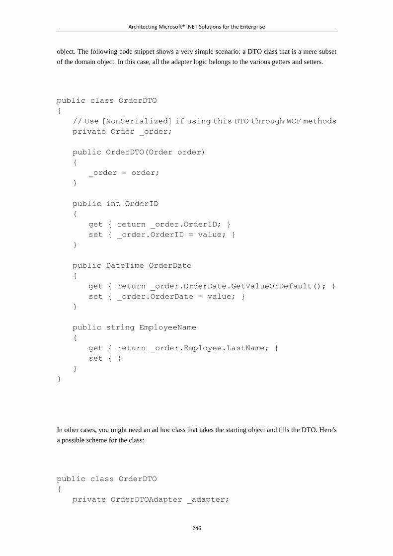
Architecting Microsoft® .NET Solutions for the Enterprise
246
object. The following code snippet shows a very simple scenario: a DTO class that is a mere subset
of the domain object. In this case, all the adapter logic belongs to the various getters and setters.
public class OrderDTO
{
// Use [NonSerialized] if using this DTO through WCF methods
private Order _order;
public OrderDTO(Order order)
{
_order = order;
}
public int OrderID
{
get { return _order.OrderID; }
set { _order.OrderID = value; }
}
public DateTime OrderDate
{
get { return _order.OrderDate.GetValueOrDefault(); }
set { _order.OrderDate = value; }
}
public string EmployeeName
{
get { return _order.Employee.LastName; }
set { }
}
}
In other cases, you might need an ad hoc class that takes the starting object and fills the DTO. Here's
a possible scheme for the class:
public class OrderDTO
{
private OrderDTOAdapter _adapter;
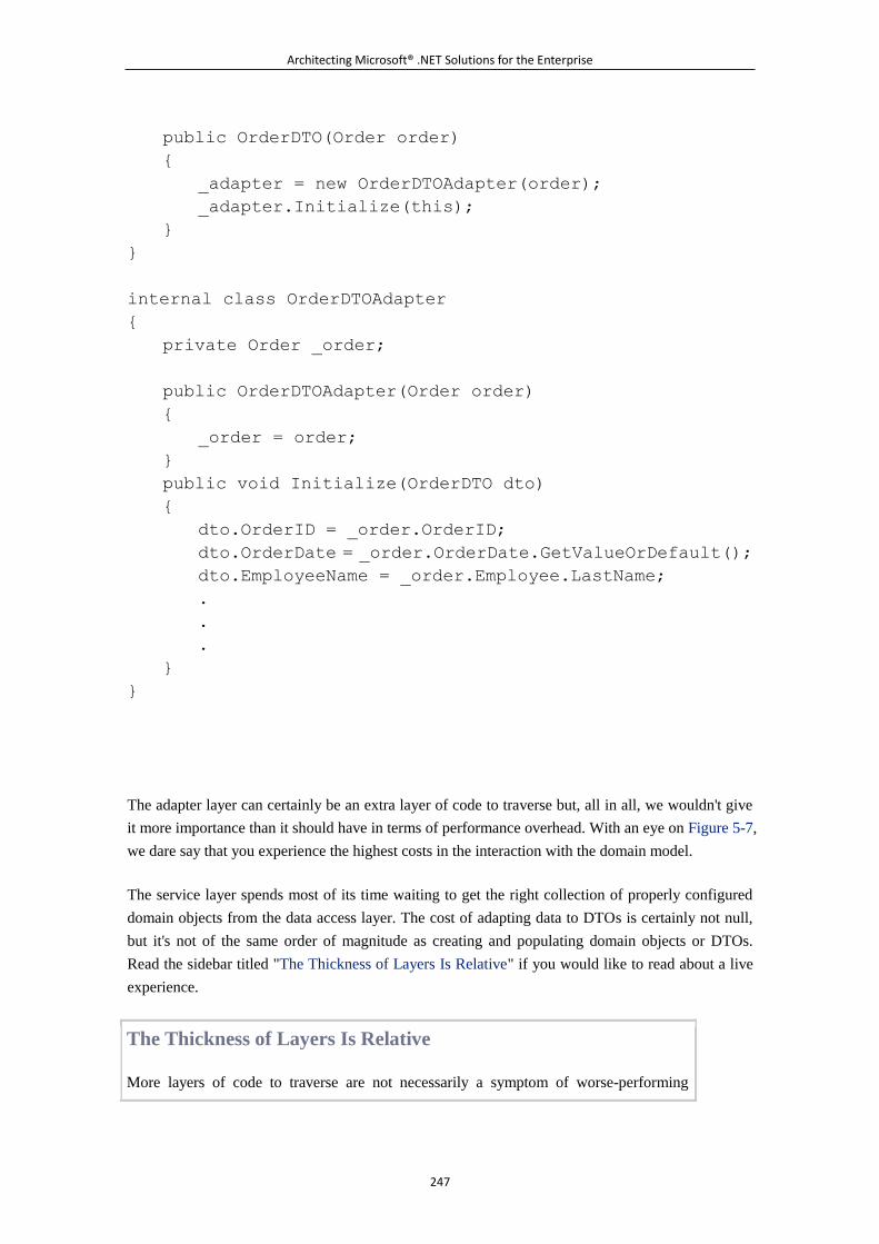
Architecting Microsoft® .NET Solutions for the Enterprise
247
public OrderDTO(Order order)
{
_adapter = new OrderDTOAdapter(order);
_adapter.Initialize(this);
}
}
internal class OrderDTOAdapter
{
private Order _order;
public OrderDTOAdapter(Order order)
{
_order = order;
}
public void Initialize(OrderDTO dto)
{
dto.OrderID = _order.OrderID;
dto.OrderDate = _order.OrderDate.GetValueOrDefault();
dto.EmployeeName = _order.Employee.LastName;
.
.
.
}
}
The adapter layer can certainly be an extra layer of code to traverse but, all in all, we wouldn't give
it more importance than it should have in terms of performance overhead. With an eye on Figure 5-7,
we dare say that you experience the highest costs in the interaction with the domain model.
The service layer spends most of its time waiting to get the right collection of properly configured
domain objects from the data access layer. The cost of adapting data to DTOs is certainly not null,
but it's not of the same order of magnitude as creating and populating domain objects or DTOs.
Read the sidebar titled "The Thickness of Layers Is Relative" if you would like to read about a live
experience.
The Thickness of Layers Is Relative
More layers of code to traverse are not necessarily a symptom of worse-performing
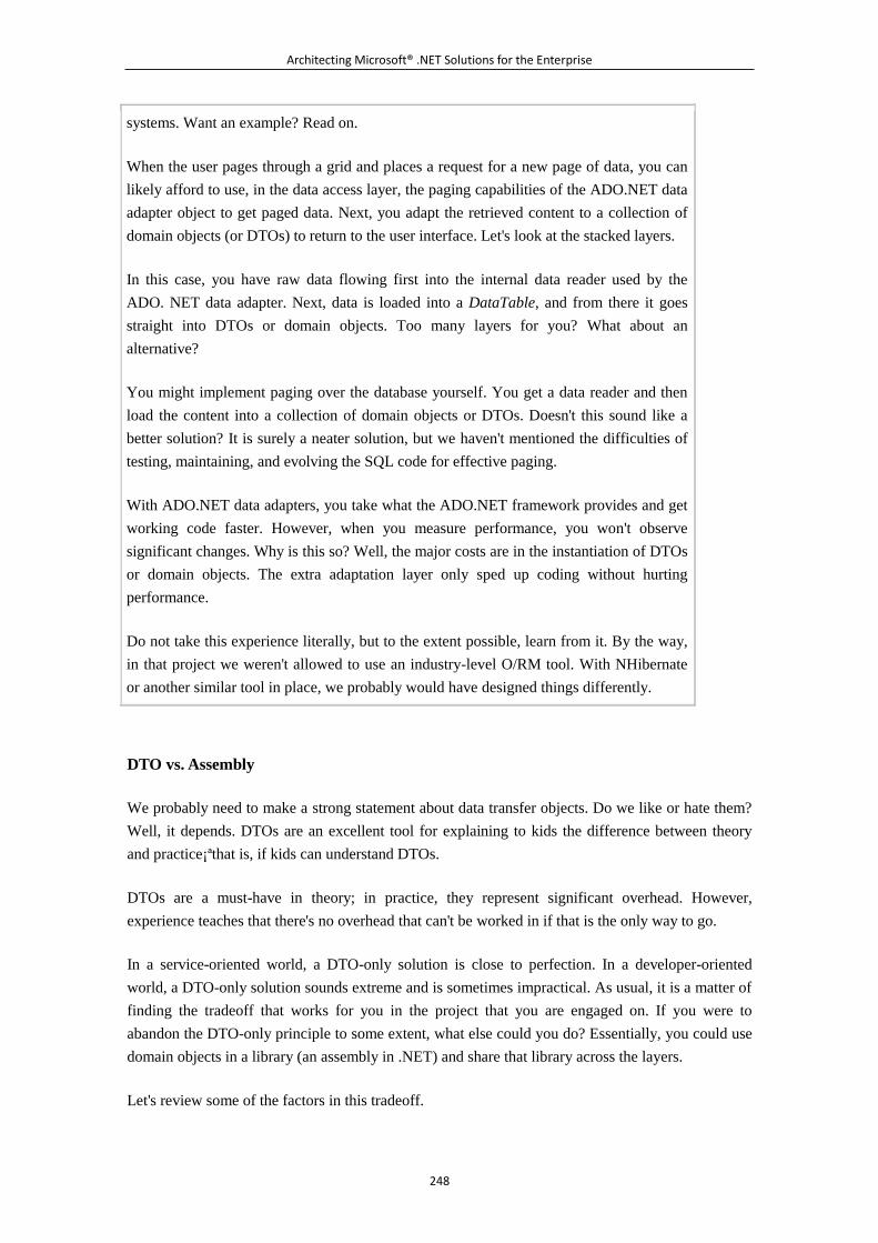
Architecting Microsoft® .NET Solutions for the Enterprise
248
systems. Want an example? Read on.
When the user pages through a grid and places a request for a new page of data, you can
likely afford to use, in the data access layer, the paging capabilities of the ADO.NET data
adapter object to get paged data. Next, you adapt the retrieved content to a collection of
domain objects (or DTOs) to return to the user interface. Let's look at the stacked layers.
In this case, you have raw data flowing first into the internal data reader used by the
ADO. NET data adapter. Next, data is loaded into a DataTable, and from there it goes
straight into DTOs or domain objects. Too many layers for you? What about an
alternative?
You might implement paging over the database yourself. You get a data reader and then
load the content into a collection of domain objects or DTOs. Doesn't this sound like a
better solution? It is surely a neater solution, but we haven't mentioned the difficulties of
testing, maintaining, and evolving the SQL code for effective paging.
With ADO.NET data adapters, you take what the ADO.NET framework provides and get
working code faster. However, when you measure performance, you won't observe
significant changes. Why is this so? Well, the major costs are in the instantiation of DTOs
or domain objects. The extra adaptation layer only sped up coding without hurting
performance.
Do not take this experience literally, but to the extent possible, learn from it. By the way,
in that project we weren't allowed to use an industry-level O/RM tool. With NHibernate
or another similar tool in place, we probably would have designed things differently.
DTO vs. Assembly
We probably need to make a strong statement about data transfer objects. Do we like or hate them?
Well, it depends. DTOs are an excellent tool for explaining to kids the difference between theory
and practice¡ªthat is, if kids can understand DTOs.
DTOs are a must-have in theory; in practice, they represent significant overhead. However,
experience teaches that there's no overhead that can't be worked in if that is the only way to go.
In a service-oriented world, a DTO-only solution is close to perfection. In a developer-oriented
world, a DTO-only solution sounds extreme and is sometimes impractical. As usual, it is a matter of
finding the tradeoff that works for you in the project that you are engaged on. If you were to
abandon the DTO-only principle to some extent, what else could you do? Essentially, you could use
domain objects in a library (an assembly in .NET) and share that library across the layers.
Let's review some of the factors in this tradeoff.
Architecting Microsoft® .NET Solutions for the Enterprise
249
Examining Some DTO Facts
In a multitier system, the service layer is responsible for decoupling the presentation layer from the
rest of the system. To get this behavior, you need to keep in mind that the key guideline is to share
data contracts rather than classes. A data contract is essentially a neutral representation of the data
that interacting components exchange. The data contract describes the data a component receives,
but it is not a system-specific class, such as a domain object. Ultimately, a data contract is a class,
but it is an extra class specifically created for a particular service method.
This extra class is referred to as a data transfer object. Having a layer of DTOs isolates the domain
model from the presentation layer, resulting in both loose coupling and optimized data transfer.
The adoption of data contracts adds flexibility to the schema of data. For example, with DTOs in
place, a change in the user interface that forces you to move a different amount of data doesn't have
any impact on the domain. Instead, the impact is limited to the DTO adapter layer. Likewise, you
can enter changes to the domain without affecting the client.
With DTOs, you also work around the problem of circular references. When you create the domain
model, you find it extremely useful to double-link entities, such as Customer-to-Orders and
Order-to-Customer. As we've mentioned, classes with circular references aren't serializable. With
method-specific DTOs, you brilliantly solve this issue also.
Note
The real problem with circular references is not the lack of support from
serializers. This is a false problem. On one hand, we welcome and love circular
references between parents and children because this gives us unmatched
power when it comes to querying and modeling real problem domains. On the
other hand, a complex web of domain objects can't just be handed to an
automatic tool for serialization. Even if you could rely on serializers that handle
circular references, would you really use them? Would you really serialize a
large share of a domain model? With doubly-linked parent and children, when
you load an order, you likely also load all details of the order and product,
category, customer, and employee information. In this regard, a DTO is a much
safer and smarter approach. In a WCF world, the NonSerializedAttribute is your
best friend because it lets you break the cycle of references at some precise
point.
DTO in Action: Load an Order
Let's see how to address a couple of typical scenarios that involve actions on the service layer. Let's
first consider a form where the user can pick up an ID to see the details of an order. As a result, the
presentation layer invokes a method on the service layer with a similar prototype:
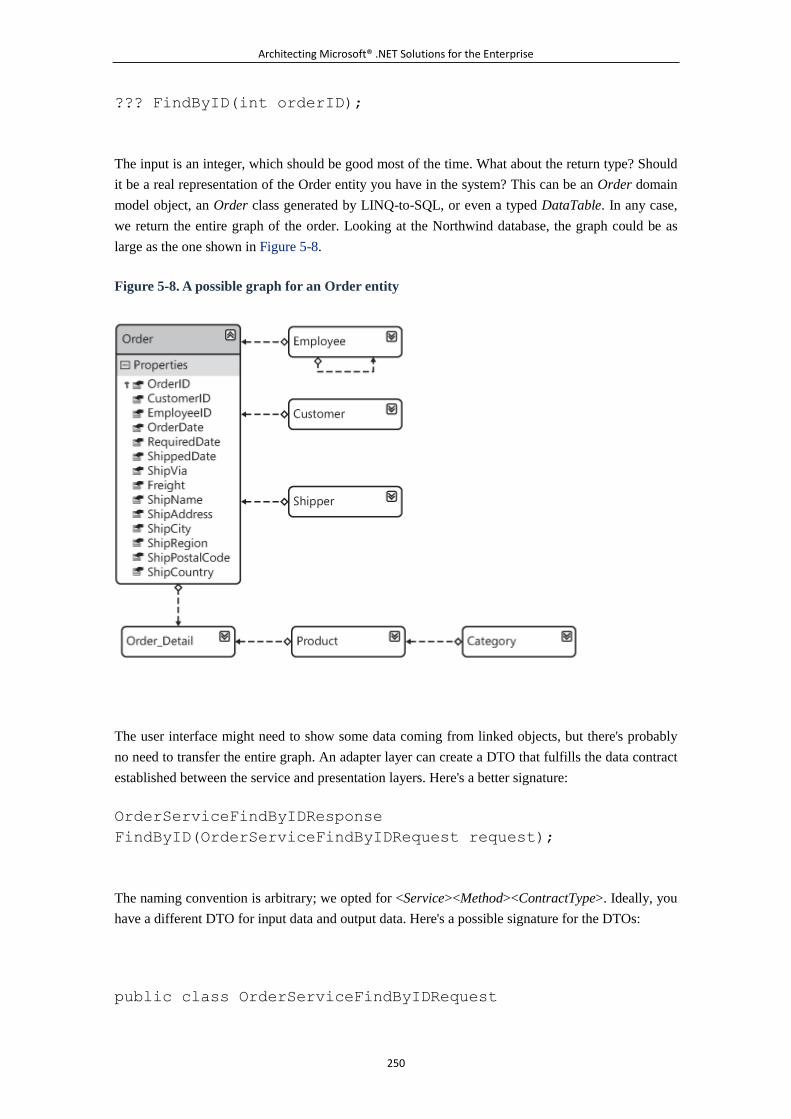
Architecting Microsoft® .NET Solutions for the Enterprise
250
??? FindByID(int orderID);
The input is an integer, which should be good most of the time. What about the return type? Should
it be a real representation of the Order entity you have in the system? This can be an Order domain
model object, an Order class generated by LINQ-to-SQL, or even a typed DataTable. In any case,
we return the entire graph of the order. Looking at the Northwind database, the graph could be as
large as the one shown in Figure 5-8.
Figure 5-8. A possible graph for an Order entity
The user interface might need to show some data coming from linked objects, but there's probably
no need to transfer the entire graph. An adapter layer can create a DTO that fulfills the data contract
established between the service and presentation layers. Here's a better signature:
OrderServiceFindByIDResponse
FindByID(OrderServiceFindByIDRequest request);
The naming convention is arbitrary; we opted for <Service><Method><ContractType>. Ideally, you
have a different DTO for input data and output data. Here's a possible signature for the DTOs:
public class OrderServiceFindByIDRequest
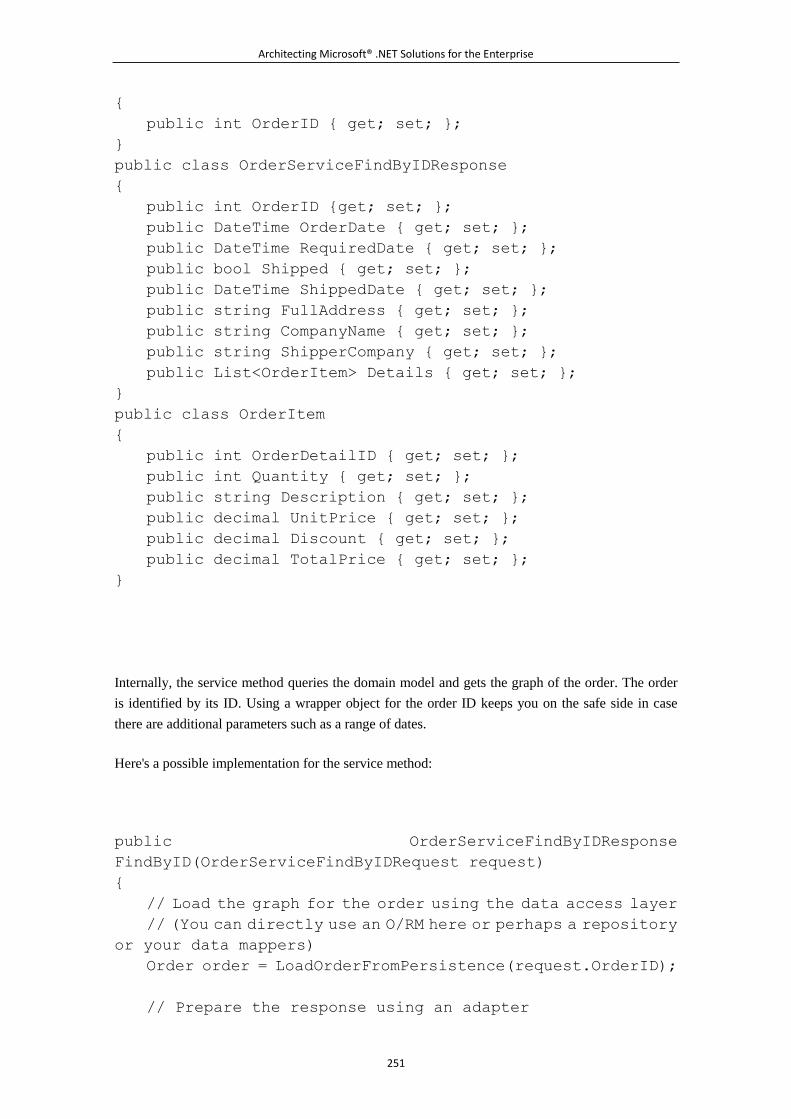
Architecting Microsoft® .NET Solutions for the Enterprise
251
{
public int OrderID { get; set; };
}
public class OrderServiceFindByIDResponse
{
public int OrderID {get; set; };
public DateTime OrderDate { get; set; };
public DateTime RequiredDate { get; set; };
public bool Shipped { get; set; };
public DateTime ShippedDate { get; set; };
public string FullAddress { get; set; };
public string CompanyName { get; set; };
public string ShipperCompany { get; set; };
public List<OrderItem> Details { get; set; };
}
public class OrderItem
{
public int OrderDetailID { get; set; };
public int Quantity { get; set; };
public string Description { get; set; };
public decimal UnitPrice { get; set; };
public decimal Discount { get; set; };
public decimal TotalPrice { get; set; };
}
Internally, the service method queries the domain model and gets the graph of the order. The order
is identified by its ID. Using a wrapper object for the order ID keeps you on the safe side in case
there are additional parameters such as a range of dates.
Here's a possible implementation for the service method:
public OrderServiceFindByIDResponse
FindByID(OrderServiceFindByIDRequest request)
{
// Load the graph for the order using the data access layer
// (You can directly use an O/RM here or perhaps a repository
or your data mappers)
Order order = LoadOrderFromPersistence(request.OrderID);
// Prepare the response using an adapter
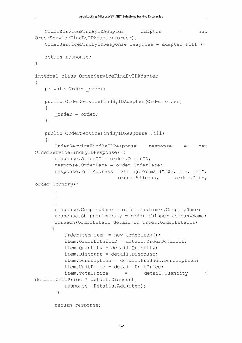
Architecting Microsoft® .NET Solutions for the Enterprise
252
OrderServiceFindByIDAdapter adapter = new
OrderServiceFindByIDAdapter(order);
OrderServiceFindByIDResponse response = adapter.Fill();
return response;
}
internal class OrderServiceFindByIDAdapter
{
private Order _order;
public OrderServiceFindByIDAdapter(Order order)
{
_order = order;
}
public OrderServiceFindByIDResponse Fill()
{
OrderServiceFindByIDResponse response = new
OrderServiceFindByIDResponse();
response.OrderID = order.OrderID;
response.OrderDate = order.OrderDate;
response.FullAddress = String.Format("{0}, {1}, {2}",
order.Address, order.City,
order.Country);
.
.
.
response.CompanyName = order.Customer.CompanyName;
response.ShipperCompany = order.Shipper.CompanyName;
foreach(OrderDetail detail in order.OrderDetails)
{
OrderItem item = new OrderItem();
item.OrderDetailID = detail.OrderDetailID;
item.Quantity = detail.Quantity;
item.Discount = detail.Discount;
item.Description = detail.Product.Description;
item.UnitPrice = detail.UnitPrice;
item.TotalPrice = detail.Quantity *
detail.UnitPrice * detail.Discount;
response .Details.Add(item);
}
return response;
Architecting Microsoft® .NET Solutions for the Enterprise
253
}
}
As you can see, the adapter flattens the Order's graph as appropriate to suit the presentation layer.
The presentation layer, in turn, receives only the data it needs and in the format that it prefers. The
presentation layer doesn't know anything about the Order object in the underlying domain model.
DTO in Action: Update an Order
Let's consider another example: the user navigates to a screen where she is allowed to enter changes
to an existing order. How would you handle this in terms of data transfer between the presentation
and service layers?
The response we get from the service method should contain a failure/success flag and additional
information in case of errors. We clearly need an ad hoc class here. What about the input data for
the service method? Ideally, we pass only the list of changes. Here's a possible signature for the
method:
OrderServiceUpdateOrderResponse
Update(OrderServiceUpdateOrderRequest request);
The response is simple. Possible errors reported to the user interface are caused by failures in the
execution of the request.
public class OrderServiceUpdateOrderResponse
{
public bool Success;
public string[] Errors;
}
You can use a flag or perhaps an error code to indicate the success of the operation. You can also
use another member to communicate additional information, such as a list of errors or suggestions
for retrying.
Note
Architecting Microsoft® .NET Solutions for the Enterprise
254
If the service is for internal use only and is not publicly exposed in an SOA
manner (that is, it is a vanilla class), it might be acceptable for you to make it
throw any exceptions directly to the caller¡ªthe presentation layer. If the
service layer might not be local, and you want to reserve the possibility to
move it to a different machine, you have to code the service to swallow
exceptions and return ad hoc data structures. If you want an approach that
works regardless of the service layer implementation, the only option is
creating ad hoc structures.
We want to let the service know about what has changed in the order. How can we formalize this
information? An order update is essentially a list of changes. Each change is characterized by a type
(update, insertion, or deletion) and a list of values. To specify new order values, we can reuse the
same OrderItem DTO we introduced for the previous load scenario:
public class OrderServiceUpdateOrderRequest
{
public int OrderID;
public List<OrderChange> Changes;
}
public class OrderChange
{
public OrderChangeTypes TypeofChange;
public OrderItem NewItem;
}
Internally, the service method loops through the requested changes, validates values, attempts
updates, and tracks notifications and errors. Here's a general skeleton for the method:
public OrderServiceUpdateOrderResponse
Update(OrderServiceUpdateOrderRequest request)
{
// Count insertions (if only insertions are requested, avoid
loading the graph)
int insertCount = (from op in request.Changes
where op.TypeOfChange ==
OrderChangeTypes.Insert).Count();
if (insertCount == request.Changes.Count)
{
foreach(OrderChange change in request.Changes)
{
Order newOrder = new Order();
Architecting Microsoft® .NET Solutions for the Enterprise
255
.
.
.
InsertOrderIntoPersistence(newOrder);
}
}
// Load the graph for the order using the data access layer
// (You can directly use an O/RM here or perhaps a repository
or your data mappers)
Order order = LoadOrderFromPersistence(request.OrderID);
foreach(OrderChange change in request.Changes)
{
switch(change.TypeOfChange)
{
.
.
.
}
}
// Prepare the response OrderServiceFindByIDAdapter
adapter = new OrderServiceFindByI
DAdapter(order);
OrderServiceUpdateOrderResponse response = new
OrderServiceUpdateOrderResponse();
.
.
.
return response;
}
There are some aspects of the method you can optimize. For example, you can avoid loading the
order's graph from the data access layer if only insertions are requested. For deletions and updates,
you likely need to have the graph available to check conditions and detect possible conflicts.
However, you do not necessarily have to load the entire graph. Lazy loading could be used to
minimize the quantity of data loaded.
Note
It is not unusual that you have to dynamically adjust your fetch plan to be as
lazy as possible. Most tools you might want to use in this context¡ªfrom
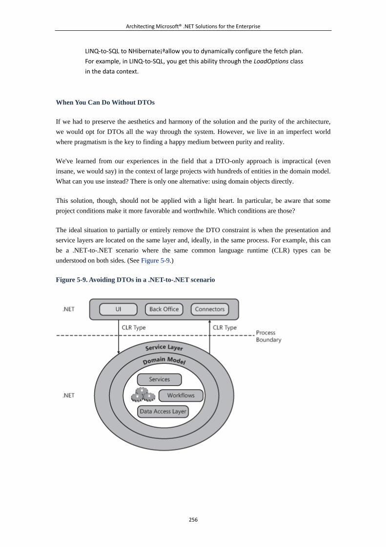
Architecting Microsoft® .NET Solutions for the Enterprise
256
LINQ-to-SQL to NHibernate¡ªallow you to dynamically configure the fetch plan.
For example, in LINQ-to-SQL, you get this ability through the LoadOptions class
in the data context.
When You Can Do Without DTOs
If we had to preserve the aesthetics and harmony of the solution and the purity of the architecture,
we would opt for DTOs all the way through the system. However, we live in an imperfect world
where pragmatism is the key to finding a happy medium between purity and reality.
We've learned from our experiences in the field that a DTO-only approach is impractical (even
insane, we would say) in the context of large projects with hundreds of entities in the domain model.
What can you use instead? There is only one alternative: using domain objects directly.
This solution, though, should not be applied with a light heart. In particular, be aware that some
project conditions make it more favorable and worthwhile. Which conditions are those?
The ideal situation to partially or entirely remove the DTO constraint is when the presentation and
service layers are located on the same layer and, ideally, in the same process. For example, this can
be a .NET-to-.NET scenario where the same common language runtime (CLR) types can be
understood on both sides. (See Figure 5-9.)
Figure 5-9. Avoiding DTOs in a .NET-to-.NET scenario
Architecting Microsoft® .NET Solutions for the Enterprise
257
When the presentation layer is ASP.NET, services implemented as ASMX Web services or WCF
services can live side by side in the same Internet Information Services (IIS) worker process. If the
presentation and service layers are not hosted in the same process, you have an additional nontrivial
problem to deal with: serializing CLR types over the process boundary.
As we've seen, in a domain model it's common and desirable to have circular references between
objects. This is not an issue if objects are referenced in-process, but out-of-process references (and it
doesn't matter whether it is the same layer or different tiers) are another story.
In a .NET-to-.NET scenario, you can opt for a .NET remoting bridge for the cross-process
serialization. Unlike the XML serialization used for Web and WCF services, the binary formatter
used by .NET remoting supports circular references. This is not the main point, though. Would you
really want the entire graph to be serialized? If you did that, you would be back to square one. If
DTOs are not a practical option, you can still use domain objects in the signature of service methods,
but use smart and lazy strategies to pull data into these objects.
The presentation layer still expects to receive, say, an Order; however, the Order object it actually
gets doesn't necessarily have all of its members set to a non-null value. To make it easier for the
presentation layer to figure out which combination of data the domain object provides, you can
implement in the domain object a number of alias interfaces. In this way, the presentation layer
knows that if, say, interface ILoadOrder is found, only a contracted subset of properties is available.
Note that when it comes to moving domain objects between tiers, there's no generally agreed-upon
solution that works in all cases. Mostly, the solution is left to your creativity and to your specific
knowledge of the project.
All in all, valid reasons for not using DTOs can be summarized as follows:
There are hundreds of entities in the domain model.
It is OK for the presentation layer to receive data in the format of domain objects (or, at
least, an adapter layer on the presentation layer is not an issue).
Presentation and service layers are co-located in the same process.
In many of our largest projects, we opt for a mixed approach. We tend to use mostly domain objects,
thus saving our teams the burden of dealing with a lot of extra classes¡ªwhich are a nightmare for
maintenance. At the same time, when the distance between domain model and presentation layer is
significant, we resort to made-to-measure and handwritten, DTOs.
Note
The emphasis on the adjective handwritten is not accidental. The issue with
DTOs is not the extra layer of code (whose benefits we largely recognize) that
is needed, but with the need to write and maintain many more classes. With
400 classes in a domain model, this likely means managing more than 1000
classes. Avoid that situation if you can.
Architecting Microsoft® .NET Solutions for the Enterprise
258
What we would really like to have is a tool that weds awareness of a domain
model with the ability to generate the code for graphically designed DTO
classes. We would gladly welcome a tool that was based on the Visual Studio
2008 class designer and that, for Entity Framework and LINQ-to-SQL, would
provide the ability to add a DTO. Ideally, the wizard for doing this would let you
select properties to import from an existing graph and add an autogenerated
C# class to the project that you could further extend with custom properties.
A DTO, in fact, is not necessarily a mere a subset of a particular domain object,
with some of its properties and none of its methods. A DTO can be significantly
different from any domain objects. You don't need to have a one-to-one or
one-to-n correlation between domain objects and DTOs. You can also have
DTOs that are projections of a portion of the domain model. For this reason,
we would welcome a designer tool for autogenerating code for DTOs.
What You Gain and What You Lose
If you have DTOs, your design of the system is loosely coupled and open to a variety of
consumers¡ªalthough they are not necessarily known at the time the system is architected. If you are
at the same time the provider and consumer of the service layer and have control over the
presentation, there are clear benefits in sharing the domain model via an assembly.
As usual, this is not a point that can be grossly generalized. You should realize that whatever
options we propose here come with a "Well, it depends" clause.
A 100 percent DTO approach has its origins in SOA, which we'll say more about in just a few
moments. The benefits of SOA go beyond the contract with and implementation of a service layer.
SOA in a distributed application is all about ensuring a loose coupling between layers so that
versioning, maintenance, and even evaluation of the threat model are simplified and made more
effective.
As part of an SOA, an adapter layer placed in between the domain model and public data contracts
isolates the domain model from the rest of the system. This arrangement costs you something, but it
is an effort that pays off by allowing changes to be made without affecting consumers.
The problem is, will the payoff be enough for you? Will the subsequent cost/benefit ratio be positive?
We all agree on the added value that an SOA brings to a distributed application. Can we afford it?
In large projects with hundreds of entities, DTOs add a remarkable level of (extra) complexity and
work. Tightly coupled layers, though, might be a remedy that's worse than the disease.
An SOA is a great thing, but its benefits might not be evident when used with a single application. A
strict adherence to SOA principles is especially beneficial for the information system as a whole, but
that's not always so for a single application.
Architecting Microsoft® .NET Solutions for the Enterprise
259
6.2.4 Service-Oriented Architecture
The interest in and need for a service layer in distributed systems has to do with service orientation.
Service orientation is the paradigm according to which you envision the functionality of a software
architecture as a collection of business processes that are, in turn, packaged and exposed as
interoperable services. An architecture designed according to this service-oriented paradigm is said
to be a service-oriented architecture (SOA).
This said, defining SOA is very difficult to do.
The principles associated with an SOA are nothing really new. Other computing paradigms (such as
object orientation and CORBA) share some of the principles of SOA and actually inspired the
definition of SOA. So what is really unique and valuable in an SOA?
The particularly valuable aspect of SOA is that it pushes a loosely coupled, service-based
architecture to model business processes. SOA is also about interoperability and integration via
open standards. With SOA, the solution is composed of services written using different
programming languages, perhaps hosted on a variety of platforms, and likely supporting different
binding models.
SOA is not a service; if you ask for a definition of an SOA service, you're off track. SOA is about
principles for designing services¡ªany flavor of services, including services in the service layer.
Note
Many people talk about the benefits derived from the adoption of SOA
principles. This book is no exception. However, we want to point out there's
never been an ounce of measurable benefit for customers from architectural
blueprints alone. It's always the successful implementation of a well-designed
architecture, not the architecture itself, that generates benefits and added
value for the customer.
Tenets of SOA
Once again, we're talking about services and faced with the same question: what's a service? In
Figure 5-5, we essentially defined a service as a class with something around it. And earlier in this
chapter, we said that in an SOA application, the building block is the service rather than the
components. We can now expand on those basics and say that a service adheres to the common
principles of object-oriented design, such as encapsulation and polymorphism, plus four more
tenets:
Boundaries are explicit.
Services are autonomous.
Use contracts, not classes.
Architecting Microsoft® .NET Solutions for the Enterprise
260
Compatibility is based on policy.
These tenets should inspire your design of services. But keep in mind that organizations might have
different requirements and expectations. For companies, SOAs are like snowflakes or grains of sand:
it's hard to find two alike.
Boundaries Are Explicit
An SOA service exposes a clear and explicit contract. Any interaction with the service takes place
through this public interface. Methods on the interface represent entry points into the service
machinery. Data in the methods' signatures represents the messages used and understood by the
service.
When designing a service, as a developer you should manage to keep its interface (contract) as
simple as possible, without hindering future enhancements. This means that service operations
should accept a well-defined input message and respond with an equally well-defined output
message. Input and output messages take the form of easy-to-serialize classes with no circular
references and dependencies¡ªjust plain data containers.
Opting for message-based semantics also helps you avoid a remote procedure call (RPC) type of
model of interaction. In an RPC-like model, consumers know something about the internal behavior
of the service because this inevitably shines through the interface methods. It is desirable that
consumers send a message and get a response¡ªall in a single operation, with extreme simplicity and
clear responsibilities.
Services Are Autonomous
For a service, autonomy means that each service is being deployed, managed, and versioned
independent of the system in which it is deployed and consumed. This doesn't mean, though, that
each service is an island and is totally isolated from the rest of the system.
An autonomous service is essentially a loosely-coupled service. It is designed and deployed
independently from other services, but it is able to communicate with other services using
contract-based messages and policies.
Service contracts are designed to be static and shouldn't be modified after the service is published.
To fulfill this requirement, message-based semantics is the only way to go because of the flexibility
it allows you to build into the contract.
Use Contracts, Not Classes
In Chapter 4, we suggested that developers define an object model to represent the various entities
that populate a given problem domain. This means having classes such as Customer, Order, Product,
or typed DataTables for analogous database tables.
Architecting Microsoft® .NET Solutions for the Enterprise
261
The object model that represents the data within the system is made of classes that combine
behavior and data into a single platform-specific and language-specific construct.
In SOA, one of the goals is interoperability; in light of this, no platform-specific detail can ever
cross the service boundary. Subsequently, classes are not among a service's best friends. This is yet
another reason for pushing message-based semantics in the definition of a service.
When we say message-based semantics, we essentially mean that at the SOA level, services
communicate by exchanging XML strings (messages). As a developer, you embrace the idea of
services exchanging data messages with a fixed schema, but you actually code services using ad hoc
classes. The service technology you use (for example, WCF) recognizes your classes as
platform-specific types (for example, CLR types) and converts them into XML messages. The XML
serialization and deserialization is entirely transparent to you. So does it ultimately mean that
developers should actually care about classes, not contracts? No, quite the reverse.
For a developer, a service contract is a collection of methods exposed by a service. A data contract,
on the other hand, is a collection of typed values that the developer expresses through a data transfer
object. A data transfer object is still a class, but it's a completely different object than a domain
model class.
Regardless of the technology view, at a lower level services communicate using XML
schema-based messages in a way that is agnostic to both programming languages and platforms.
This ensures broad interoperability and flexibility. Abstractly speaking, defining a service entails
defining for it a service contract and a bunch of data contracts.
Implementation is the next step.
Compatibility Is Based on Policy
The fact that a service is reachable and callable is not necessarily a good reason for a consumer to
place a call. The key point about this tenet is that a service consumer must be able to determine
whether a given service has the capabilities it expects.
Service and data contracts are important, but not enough. Service and data contracts refer to
structural compatibility and merely describe what is communicated¡ªwhat you can call and what you
will get back.
This tenet is about the semantic compatibility between services¡ªwhether a given service does
exactly what the consumer expects. The semantic compatibility should be exposed and discovered
via a publicly accessible and standard policy.
To express service-level policies, and enable them to be discovered or enforced at runtime, you can
use the WS-Policy specification.
A Summary of the Tenets
Architecting Microsoft® .NET Solutions for the Enterprise
262
SOA is a design discipline aimed at achieving interoperability and composability in the building of
complex information systems for organizations. The essence of an SOA is the service.
A service can be used to expose business processes in the form of an application. Services can be
composed into workflows. Services can be consumed by end-users, systems, or other services. The
overall SOA model is not layered; it looks more like a fractal.
The four main tenets we just described in this section apply to the design of services in the context
of an SOA. These tenets are high-level concepts and express the philosophy behind SOA. When it
comes to actually building services, you might want to look at some of the derived principles that
we mentioned earlier in the chapter and that we'll be summarizing in a moment.
Building an SOA is an incremental process and doesn't require a full overhaul of the existing
business processes. You don't need to build an SOA in an organization to add value. Keep in mind
that an SOA is a means, not an end. You need to build applications that model existing business
processes in a faithful and effective manner. SOA principles¡ªbut not necessarily all of them¡ªdo
help in this task.
What SOA Is Not
As it should be clear by now, SOA is about services, but it is not a service technology. Using
services in an application doesn't make the application an SOA. SOA is about principles that inspire
good service-modeling techniques.
As disappointing as it might sound, SOA is a gray area. To many people in the IT industry, SOA is
just a more generic name for a Web service. SOA and Web services are not unrelated. SOA is not a
Web service, but a Web service might be the result of an SOA.
In some cases, the SOA philosophy is too extreme for an organization and requires an incremental
approach. As a result, it is not uncommon in a system to find that some features are SOA and some
not. As a matter of fact, a large share of today's production Web services systems are not SOAs. As
a matter of fact, there's a bit of confusion about SOA and a number of false myths surrounding it.
SOA Is Not a Revolution
Companies need an IT infrastructure that covers all present and future system requirements and runs
and supports the business. Subsequently, the need for SOA is the need to integrate existing systems
in order to implement business processes in software.
This problem is nothing new. Electronic Data Interchange (EDI) defines a set of standards that
organizations use to exchange documents and arrange business transactions electronically, in an
application-to-application scenario. EDI was not defined yesterday; it dates back to at least 15 years
ago. For years, companies have been able to make their IT systems talk to internal and external
customers. And years of experience with older technologies taught that resulting systems and, more
importantly, underlying models were not flexible enough to meet business demands.
Architecting Microsoft® .NET Solutions for the Enterprise
263
As a result, EDI, CORBA, COM, and Distributed COM (DCOM) followed one another in the vain
attempt to define a model for distributed systems that was effective, affordable, and in line with
modern business necessities. SOA is just the latest step in the direction of enabling a company to
run its business and publish its services for other companies to interact with and integrate with their
own business processes.
SOA builds on past technologies and improves them by introducing a paradigm shift. Instead of
remotely invoking methods on objects, you pass messages between services designed to fulfill a few
key tenets. SOA is not a revolution; it is an evolutionary paradigm.
SOA Is Not a Technology
You should see SOA as a general design philosophy rather than a technology for writing concrete
services. In this regard, SOA is entirely independent of any vendors and products.
The major benefits of SOA come from applying SOA design principles to a particular organization.
SOA needs are never the same and vary from one company to another. You won't get SOA by
choosing a product or a vendor; you get SOA by investing your time in understanding the principles
and learning how to apply them to the whole IT infrastructure.
SOA Is Not a Web Service
Because SOA is a design philosophy and not a technology, it can't just be yet another fancy name
for Web services. Having (Web) services in an application is far from being a clear and unequivocal
symptom of an SOA.
In an SOA solution, you might likely find Web services. But not all Web services are SOA services.
And not all SOA solutions have Web services. Equating Web services with SOA is a common
mistake. Organizations that boast of moving to SOA but implement only a few Web services, betray
a clear lack of understanding (or a misunderstanding) of the SOA world.
SOA Is Not a Goal
You should aim at building an SOA for your customers. And, ideally, customers should not ask you
to build an SOA. SOA, in fact, is not a fashion trend.
You might remember, in the early 1990s, all the hype about object-oriented programming. And just
OOP¡ªa mere implementation detail¡ªwas often presented as a plus of a given product. The message
was something like, "Buy product X, it will solve problem Y, and it is object oriented."
How can we forget that time when a customer approached us declaring his absolute need for an
object-oriented new version of a certain application. "What's your problem?" was the question we
asked. "We have a lot of problems, and we know we need an object-oriented application" was the
amazing answer.
With SOA, perceptions are not very different.
Architecting Microsoft® .NET Solutions for the Enterprise
264
As an architect, you should first focus on the problem and then fight to find and deliver an effective
solution. For distributed systems, this might mean identifying coarse-grained services that model the
business processes. Then you might leverage Web services as the implementation technology for an
SOA solution. SOA, like OOP 20 years ago, should never be your goal. It is, instead, a means to
build an effective solution.
SOA and the Service Layer
When it comes to building the service layer of a distributed system, you need to arrange a few
services and make them interact with the presentation layer and the rest of the system. Is there any
value in using SOA principles here?
SOA in Practice
Applying SOA means extracting some practical design rules from the SOA tenets and measuring
them in the context of a real system. Applying SOA principles to a service layer means having
coarse-grained services that act as a remote fa?ade facing the business logic.
As a result, you have the following practical rules:
Services in the service layer do not implement any business logic.
Services in the service layer script and consume the business logic whatever that logic
might entail, including workflows, domain objects, and application services.
Application services¡ªthat is, services that implement pieces of the business¡ªmight or might
not be SOAs themselves.
Data exchange happens through DTOs (via data contracts) and not by using classes in the
domain model.
Services do not distribute and share objects, and service methods do not work on objects.
Services are limited to getting and returning a collection of values formalized in a schema.
Services in the service layer should aim at a UI-oriented interface.
Application services should aim at a business-oriented interface.
Any services with an entity-based interface tend to expose plain CRUD operations. These
services are referred to as CRUDy and, for what it matters, are not SOAs.
Services should be deployed and versioned independently of the system in which they are
deployed and consumed.
To the extent that it is possible, do not modify service and data contracts. When you
absolutely need to do that, apply versioning.
What practical benefits does an application derive from following these rules?
What's Good About Using SOA in the Service Layer
The adoption of SOA principles in the design of services brings quite a few benefits. In addition to
gaining reusability, you have simplified versioning and an analysis of the threat model.
Architecting Microsoft® .NET Solutions for the Enterprise
265
However, if we confine ourselves to considering the benefits of SOA in the service layer of a
distributed system, the key benefit is that you have loosely coupled services where the operations
and data to be exchanged are contracted and well defined. This approach allows you to change the
internal implementation of the service, and even replace or relocate the service, without affecting the
clients.
In general, the service layer is a very special layer of services. We would even say that the service
layer contains the most coupled grouping of services you can think of. In this regard, SOA is often
overkill, and some of its practical rules can often be ignored without many worries.
SOA Antipatterns
This chapter is about the service layer; it is not about principles of service orientation, nor is it about
a specific service technology such as WCF. We briefly covered the essence of SOA, ran through its
tenets, and listed some practical rules for architecting better services.
Strict observance of SOA principles might not be necessary in a service layer because, most of the
time, the same organization controls both the services and consumers. Services in the service layer
are not as autonomous as they are in a pure SOA context because they exist just to sit in between
and accommodate the presentation and business layers. The worst thing imaginable in SOA¡ªthe
breakage of a contract¡ªis not a tragedy in the realm of a service layer when you control both
consumer and producer.
This said, we should note that some principles of SOA are still well received in a service layer, and
some of the most classic antipatterns of SOA are still worth a look for future reference.
Two extremely popular antipatterns of SOA are CRUDy and Chatty. Both patterns refer to attributes
of service contracts. Let's tackle CRUDy first.
CRUDy Interfaces
Guess what? Most of the typical operations requested of a service layer have to do with the creation,
deletion, update, or query of domain objects¡ªpurely CRUD. What should we do? Should we quit
the project because someone said that CRUD methods in a service contract are bad? It depends on
what you mean exactly by the phrase "a CRUDy interface."
In our opinion, a service contract like the following one makes total sense, even though it implies
CRUD operations:
FindOrderByIDResponse FindOrderByID(FindOrderByIdRequest
request);
CreateOrderResponse CreateOrder(CreateOrderRequest
request);
UpdateOrderResponse UpdateOrder(UpdateOrderRequest
request);
Architecting Microsoft® .NET Solutions for the Enterprise
266
DeleteOrderResponse DeleteOrder(DeleteOrderRequest
request);
There are two aspects to consider. First, is there a use case that requires you to create, update, delete,
or look up an order? If so, you need such methods no matter what. From a design perspective, you're
OK as long as you publish service methods that map to business operations triggered by real-life
business events. For example, if the shipper didn't find the consignee, he needs to update the state of
the order. This triggers a business event such as "ConsigneeNotFound," and you must have an
Update service method to modify the data store¡ªeven if it does look CRUDy.
Second, what happens within such a CRUDy service method? Creating or updating an order (or any
other entity in a domain model) is hardly a one-shot database operation. It involves, instead, a unit
of work. The whole unit is accomplished with a single call, ideally following a particular use case.
This is just fine and entirely acceptable. Even one-shot database operations are acceptable from
within a service layer if they match a use case.
What should be avoided then?
In a service, you should avoid having methods with a finer granularity than the business event that
triggers them. Suppose that the processing of a new order requires three steps: checking the
availability of the product, checking the credit status of the customer, and creating the order. You're
fine if you expose one overall CreateOrder method that internally dictates the actions to be taken.
Otherwise, you fall into the CRUDy antipattern if you expose the three internal actions as contracted
methods.
By letting implementation details leak out of the service layer, you at least violate the third tenet of
SOA¡ªshare only contracts¡ªbut more importantly, you encourage a stateful (and coupled)
conversation between the presentation and service layers.
CRUDy interfaces are a fancy name; the real enemy is bad design.
Note
Designing services is different from designing components for, say, Microsoft
Visual Basic 6.0 applications. In a non-service world, it might make sense to
design stateful components that represent objects that the user interface
interacts with. This is no longer the case with services.
Chatty Interfaces
Related to the real sense of CRUDy is the chatty interfaces antipattern. This antipattern is
characterized by a service contract that encourages an RPC-like behavior. In other words, the
Architecting Microsoft® .NET Solutions for the Enterprise
267
service exposes to the presentation layer a set of fine-grained methods that the presentation layer
calls in a workflow to accomplish the desired action.
Let's recall the previous example of the creation of an order. A chatty interface is when the service
exposes a similar contract:
bool CheckGoodAvailability(Order order);
bool CheckCreditStatus(Order order);
bool PlaceOrder(Order order);
The presentation layer then likely consumes the service through the following code:
Order o = new Order( ... );
if (service.CheckGoodAvailability(o) &&
service.CheckCreditStatus(o))
{
service.PlaceOrder(o);
.
.
.
}
The opposite of a chatty interface is a chunky interface. A chunky interface is fully represented by
the following code:
CreateOrderResponse CreateOrder(CreateOrderRequest
request);
In a chunky interface, information for the service (as well as return values) is composed in a
comprehensive document-like package. A badly designed CRUDy interface is also a chatty
interface.
6.2.5 The Very Special Case of Rich Web Front Ends
The service layer is the topmost layer on the business layer. Depending on your system topology
and deployment options, the service layer might live side by side with the presentation or be hosted
remotely on a different tier. A special case occurs when the front end is a Web application.
In an ASP.NET Web application, the presentation is split into two tiers¡ªthe Web browser running
some JavaScript code, and the Web server hosting code-behind files and presentation logic written
in a managed language. Most of the time, the service layer is co-located in the same IIS worker
process as the presentation logic. So far, so good.
Architecting Microsoft® .NET Solutions for the Enterprise
268
The scenario significantly changes with the advent of AJAX, Silverlight and, in general, rich Web
front ends. Why is this so?
In a rich Web scenario, the Web browser code is richer than ever and begins to contain much more
than just user interface tricks, such as roll-over effects and a bit of drag-and-drop functionality.
The richer the Web browser, the more layered the presentation layer becomes. And the service layer
faces the need to be redesigned to better address new challenges, especially in the area of security.
Refactoring the Service Layer
With the progressive consolidation of AJAX and the advent of Rich Internet Applications (RIA), we
entered an age of client applications greedy for communication capabilities and rich with
connectivity options. For example, a key feature of both ASP.NET AJAX and Silverlight 2 is the
ability to connect to a given service and command operations.
The Web browser sends requests over HTTP and receives data back. The client logic then processes
results and updates the user interface. The JavaScript Object Notation (JSON) is the preferred
data-interchange format when a browser-based, JavaScript-powered user interface is used. XML and
SOAP, on the other hand, are still the most favored option in Silverlight 2.
So with a rich Web front end, the presentation logic can be split between the browser and the
code-behind class on the Web server. Any communication between clients and the Web server
happens through public endpoints exposed by the Web server and called back from ASP.NET
AJAX or Silverlight 2. Which endpoints should you expose out of the Web server for Web browsers
to call? The real service layer? Or something running on top of it? The answer springs naturally
from the diagram displayed in Figure 5-10.
Figure 5-10. An extra layer is required to protect the application's service layer.
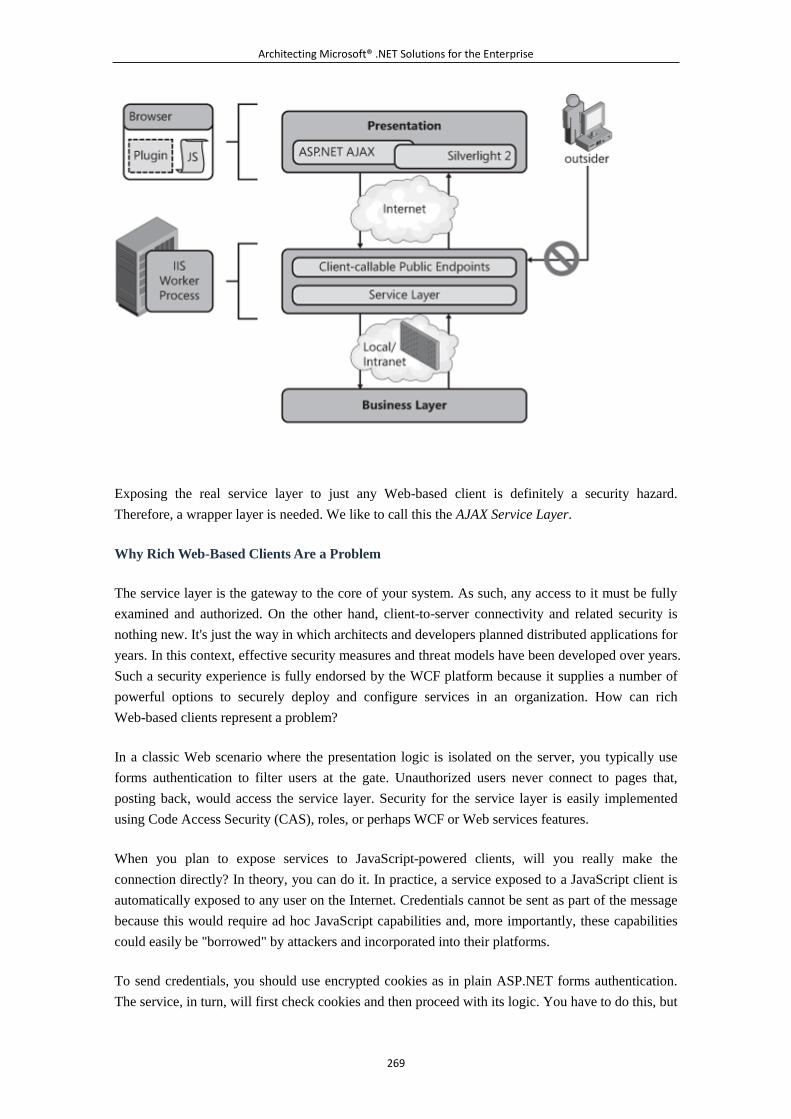
Architecting Microsoft® .NET Solutions for the Enterprise
269
Exposing the real service layer to just any Web-based client is definitely a security hazard.
Therefore, a wrapper layer is needed. We like to call this the AJAX Service Layer.
Why Rich Web-Based Clients Are a Problem
The service layer is the gateway to the core of your system. As such, any access to it must be fully
examined and authorized. On the other hand, client-to-server connectivity and related security is
nothing new. It's just the way in which architects and developers planned distributed applications for
years. In this context, effective security measures and threat models have been developed over years.
Such a security experience is fully endorsed by the WCF platform because it supplies a number of
powerful options to securely deploy and configure services in an organization. How can rich
Web-based clients represent a problem?
In a classic Web scenario where the presentation logic is isolated on the server, you typically use
forms authentication to filter users at the gate. Unauthorized users never connect to pages that,
posting back, would access the service layer. Security for the service layer is easily implemented
using Code Access Security (CAS), roles, or perhaps WCF or Web services features.
When you plan to expose services to JavaScript-powered clients, will you really make the
connection directly? In theory, you can do it. In practice, a service exposed to a JavaScript client is
automatically exposed to any user on the Internet. Credentials cannot be sent as part of the message
because this would require ad hoc JavaScript capabilities and, more importantly, these capabilities
could easily be "borrowed" by attackers and incorporated into their platforms.
To send credentials, you should use encrypted cookies as in plain ASP.NET forms authentication.
The service, in turn, will first check cookies and then proceed with its logic. You have to do this, but
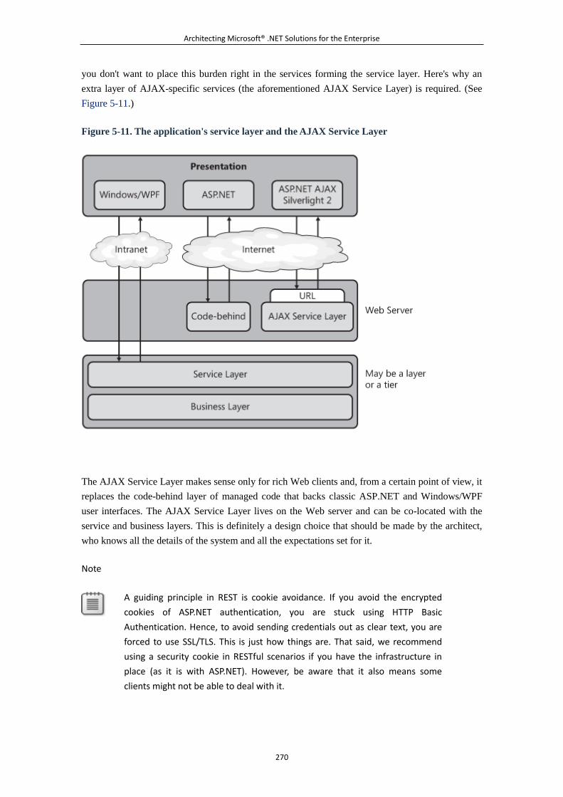
Architecting Microsoft® .NET Solutions for the Enterprise
270
you don't want to place this burden right in the services forming the service layer. Here's why an
extra layer of AJAX-specific services (the aforementioned AJAX Service Layer) is required. (See
Figure 5-11.)
Figure 5-11. The application's service layer and the AJAX Service Layer
The AJAX Service Layer makes sense only for rich Web clients and, from a certain point of view, it
replaces the code-behind layer of managed code that backs classic ASP.NET and Windows/WPF
user interfaces. The AJAX Service Layer lives on the Web server and can be co-located with the
service and business layers. This is definitely a design choice that should be made by the architect,
who knows all the details of the system and all the expectations set for it.
Note
A guiding principle in REST is cookie avoidance. If you avoid the encrypted
cookies of ASP.NET authentication, you are stuck using HTTP Basic
Authentication. Hence, to avoid sending credentials out as clear text, you are
forced to use SSL/TLS. This is just how things are. That said, we recommend
using a security cookie in RESTful scenarios if you have the infrastructure in
place (as it is with ASP.NET). However, be aware that it also means some
clients might not be able to deal with it.
Architecting Microsoft® .NET Solutions for the Enterprise
271
Refactoring for Functionality
One of the most compelling features of presentation layers based on ASP.NET AJAX and
Silverlight 2 is the ability to invoke services directly from the client¡ªa Web-based client. This
possibility introduces a new scenario and offers plenty of new development opportunities. At the
same time, though, it also raises some new concerns.
A first factor to tackle is the identification of service endpoints and data exchange policies. A
second factor to carefully review is, of course, security. Services are essentially a collection of
HTTP endpoints that preferably receive and return HTTP packets with JSON content. The main
reason for dropping XML and SOAP in favor of JSON is that JSON is much easier to handle from
within a JavaScript-powered client than any XML-based format.
Commonly used technologies for implementing services didn't support JSON until a few months
prior to the writing of this book. In the .NET platform, both the ASP.NET XML Web service and
WCF platforms underwent some rework to enable JavaScript clients. The WCF platform, in
particular, introduced in .NET 3.5 a new type of binding specifically aimed at JavaScript clients. In
this way, the core service remains isolated from the binding details. Does this mean that you can call
one of your application's core WCF services from JavaScript? You definitely can. And you
definitely should if you don't have security concerns. Otherwise, you definitely should consider
adding an intermediate layer of services.
Refactoring for Security
Rich Web-based clients are essentially simple connection tools that take advantage of the HTTP
network protocol and its connectivity model. As disappointing as it might sound, HTTP wasn't
designed with security in mind.
Note
If this last sentence leaves you a bit baffled and confused, consider the
following. HTTP has no native security features in it. What about HTTPS, then?
As commonly defined, HTTPS is a uniform resource identifier that combines
HTTP with a cryptography engine, such as Secure Sockets Layer (SSL) or
Transport Layer Security (TLS). HTTPS is like HTTP except that it uses a different
port (port 443 instead of port 80) and adds a cryptography mechanism down
the stack between TCP and HTTP. In this regard, HTTP even with the final S is
not a technologically secure protocol if you're looking for authentication and
authorization. You need HTTP authentication on top of it or something like
ASP.NET support (cookies and such). Authorization is, of course, up to the
individual application. If you still find this statement hard to buy, consider that
when HTTP is used, WCF leverages its own infrastructure and bindings to
ensure security and authentication.
Architecting Microsoft® .NET Solutions for the Enterprise
272
Interaction with simple Web-based clients requires simplicity and necessarily forces you to take
some protocol-level security measures. In other words, ASP.NET AJAX clients can talk to services
but only over simplified security channels that do not account for credentials. (The underlying
reason is that any work to insert credentials in the packet should be done in JavaScript, and then
they can be easily copied, understood, and replayed.)
How can you then secure your services and ensure that only authorized users can gain access? You
need to refactor your client pages and your service layer to enable services to grab credentials from
authentication cookies. The services then will refuse the call if unauthorized access is attempted.
Would you really refactor your service layer for security reasons, especially considering that other
presentation implementations might not have the same security needs? No, it makes more sense to
add an extra layer of services for rich Web-based clients to use. That handles the special security
issues for you.
Note
We like to recall that in a pure REST approach, you should not rely on
authentication cookies. A pure REST approach would recommend using HTTP
Basic Authentication coupled with SSL/TLS, and that's for each call.
Designing an AJAX Service Layer
An AJAX Service Layer essentially exists to decouple rich Web presentation layers from the heart
of the system and to suit the browser-based user interface. An AJAX Service Layer is extremely thin,
and all that it does is secure the calls checking credentials and forwards the call into the service
layer.
How would you write services for an AJAX Service Layer? In .NET, you typically write services
either as ASP.NET XML Web services or WCF services. In both cases, services are to be
script-enabled, meaning that you have to tweak their runtime so that they can accept calls coming
from a JavaScript-powered client.
Note
Although the Silverlight 2 platform is often mixed with the ASP.NET AJAX
platform, some clear differences exist. In particular, Silverlight 2 runs managed
code within the browser and thus it can support most of the features that
simplify the service model for AJAX callers. As an example, Silverlight 2 clients
can happily manage SOAP calls that AJAX clients do not recognize.
Script-Enabling ASP.NET XML Web Services
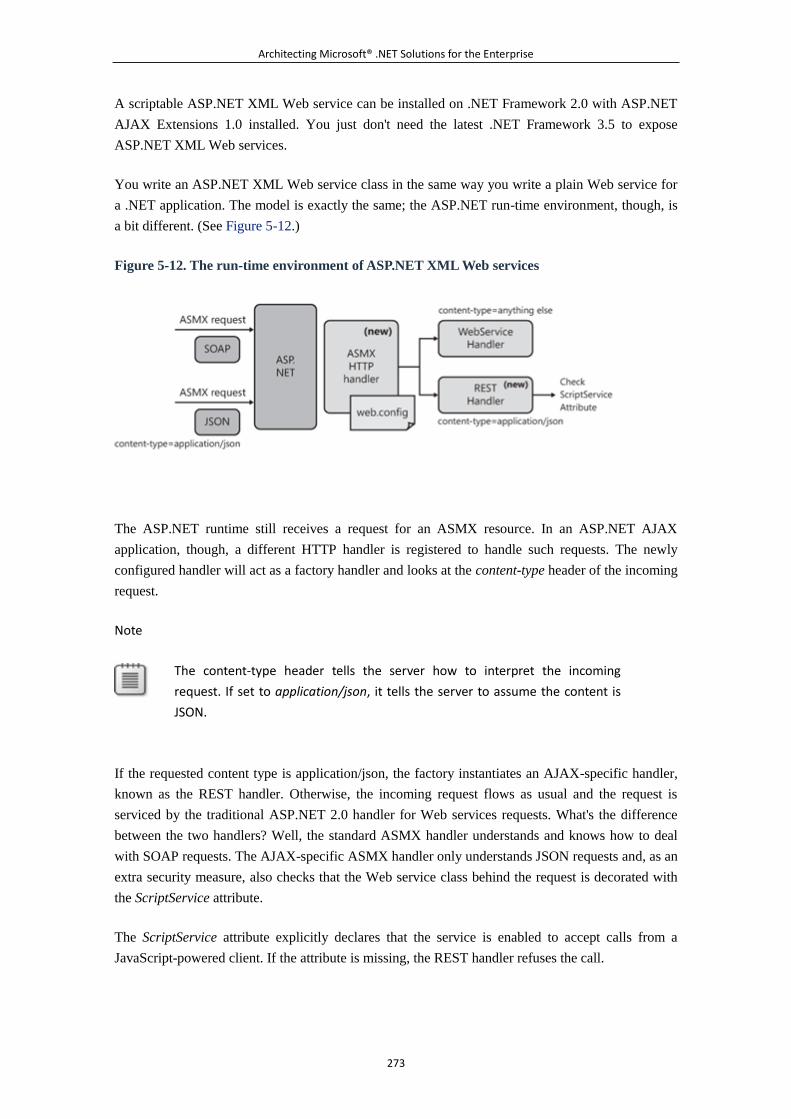
Architecting Microsoft® .NET Solutions for the Enterprise
273
A scriptable ASP.NET XML Web service can be installed on .NET Framework 2.0 with ASP.NET
AJAX Extensions 1.0 installed. You just don't need the latest .NET Framework 3.5 to expose
ASP.NET XML Web services.
You write an ASP.NET XML Web service class in the same way you write a plain Web service for
a .NET application. The model is exactly the same; the ASP.NET run-time environment, though, is
a bit different. (See Figure 5-12.)
Figure 5-12. The run-time environment of ASP.NET XML Web services
The ASP.NET runtime still receives a request for an ASMX resource. In an ASP.NET AJAX
application, though, a different HTTP handler is registered to handle such requests. The newly
configured handler will act as a factory handler and looks at the content-type header of the incoming
request.
Note
The content-type header tells the server how to interpret the incoming
request. If set to application/json, it tells the server to assume the content is
JSON.
If the requested content type is application/json, the factory instantiates an AJAX-specific handler,
known as the REST handler. Otherwise, the incoming request flows as usual and the request is
serviced by the traditional ASP.NET 2.0 handler for Web services requests. What's the difference
between the two handlers? Well, the standard ASMX handler understands and knows how to deal
with SOAP requests. The AJAX-specific ASMX handler only understands JSON requests and, as an
extra security measure, also checks that the Web service class behind the request is decorated with
the ScriptService attribute.
The ScriptService attribute explicitly declares that the service is enabled to accept calls from a
JavaScript-powered client. If the attribute is missing, the REST handler refuses the call.
Architecting Microsoft® .NET Solutions for the Enterprise
274
In summary, a service implemented as an ASP.NET XML Web service is a class decorated with the
ScriptService attribute and that exposes a few Web methods. The run-time system is also enabled to
generate a JavaScript proxy for the service that packs input data for the call as a JSON string.
Likewise, the REST handler also serializes to JSON any return value for the caller. No SOAP at all
is involved in an ASMX Web service call in ASP.NET AJAX applications. The following code
shows a simple service just to help you form an idea about what it looks like:
[ScriptService]
public class TimeService : ITimeService
{
[WebMethod]
public string GetTimeFormat(string format)
{
// Check credentials (see later)
.
.
.
// Forward to the application's service or business
layer
.
.
.
}
.
.
.
}
The interface is not strictly required, but it is helpful to have. Each method on the service class can
be further specialized using the optional ScriptMethod attribute. The attribute allows you to serialize
data for the method using XML instead of JSON, and it enables the method to be invoked over an
HTTP GET call.
Note, though, that 99 percent of the time, having default settings on the ScriptMethod attribute are
just fine. Disabling the HTTP GET calls, as well as requiring an ad hoc content type, are security
measures aimed at discouraging method calls via script injection. In fact, when a <script> tag is
injected, it can refer only to the specified URL via a GET and cannot set a particular content type.
An AJAX Web service is referenced within the page with an .asmx extension¡ªthe same extension
that is used for classic SOAP-based ASP.NET Web services. As you saw in Figure 5-12, the handler
factory can distinguish between SOAP and non-SOAP calls. However, this just means that the same
service is simultaneously exposed to SOAP and JSON callers. The following configuration script
disables all forms of calls except JSON calls:
Architecting Microsoft® .NET Solutions for the Enterprise
275
<system.web>
<system.webservices>
<protocols>
<clear />
</protocols>
</system.webservices>
</system.web>
You add this script to the web.config file of the application that hosts the ASMX Web service.
Script-Enabling WCF Services
The first release of the ASP.NET AJAX Extensions created to support ASP.NET 2.0 didn't include
any support for WCF services. Only with the .NET Framework 3.5, the WCF environment has been
endowed with proper tools to enable integration with an AJAX presentation layer. This support goes
under the name of the WCF Web programming model.
In a nutshell, the WCF Web programming model permits you to expose service methods through
HTTP GET and POST requests. In this way, WCF is enabled to support plain-old XML (POX) style
messaging instead of SOAP. To invoke a WCF service method from within a JavaScript client, you
need to use a mandatory endpoint binding and a specific behavior.
The tailor-made binding that enables the WCF Web programming model is webHttpbinding¡ªa sort
of basic HTTP binding that precludes the use of SOAP. The ad hoc behavior is webScriptBehavior,
which enables JSON data encoding and enables JavaScript callers.
Because WCF separates binding details from the service code, there's nothing special you have to do
to create an AJAX-enabled WCF service:
[ServiceContract(Namespace="Samples.Services",
Name="WcfTimeService")]
public interface ITimeService
{
[OperationContract]
string GetTime();
}
public class TimeService : ITimeService
{
public DateTime GetTime()
{
return DateTime.Now;
}
}
Architecting Microsoft® .NET Solutions for the Enterprise
276
As in the preceding code snippet, you just create a regular service contract interface and then
implement the interface in a service class. You then publish the service in an IIS host and reference
it through a JavaScript proxy from within an ASP.NET AJAX page.
The generation of the JavaScript proxy happens care of the extended run-time environment for both
ASP.NET XML Web and WCF services. We'll cover this aspect in just a moment.
Note
In Silverlight 2 client applications, you reference services (both ASP.NET XML
Web services and WCF services) through a proxy generated by Visual Studio
2008 as you would do in a regular ASP.NET or Windows Forms application.
Generating JavaScript Proxies
You need a proxy class in order to invoke a Web or WCF service from within a browser-hosted
page. The proxy class is a JavaScript class that is generated by the service runtime when a particular
URL is invoked. For both ASP.NET XML Web services and WCF services, the URL takes the form
of <url>/js.
The proxy class is based on the Microsoft AJAX Client Library and leverages the built-in AJAX
stub for XMLHttpRequest. The call model is that of asynchronous calls. The proxy class saves you
from the burden of knowing about URLs and serialization of parameters. A proxy is employed in
both ASP.NET AJAX and Silverlight 2 clients. In the former case, though, they are JavaScript
classes; in the latter case, they are managed classes.
JSON vs. XML
In a rich Web application, at some point, you need to call some server-based code. In doing so, you
likely need to pass some input data and wait to receive some other data back. Clearly, a serialization
format is required to transform platform-specific data (for example, a .NET object) into an HTTP
network packet. For years, this field has been the reign of XML. To a large extent, this is still the
reign of XML, but not when a Web browser is used as the client.
JSON is the emerging standard format for browsers and Web servers to exchange data over HTTP
when a script-led request is made. The main reasons for preferring JSON over XML can be
summarized by saying that overall JSON is simpler than full-blown XML and gets a free
deserialization engine in virtually any browser that supports JavaScript.
JSON is not designed to reach the heights of complexity and portability of full XML, but it is just as
sophisticated as a simple and lightweight XML limited to nodes and attributes. When used in a
Architecting Microsoft® .NET Solutions for the Enterprise
277
service-based context, JSON requires HTTP endpoints to understand the format and to be able to
serialize to it and deserialize from it.
One of the creators of JSON loves to label his creation as the "X in AJAX," which is overall quite a
correct statement. If you look at the official acronym, the X in AJAX stands for XML. However, this
is not what happens in the real world. Why is that so?
The Web proposes a simplified model of interaction that might not need a rigid schema, validation,
or both. Is a schema and a bit of type information useless or mandatory?
Having schema information available wouldn't be a bad thing per se, but not at the cost of creating
an XML parser written in JavaScript. If we were using XML for browser-to-server AJAX-style
interaction, any browser would receive XML from any invoked endpoint. Subsequently, the browser
ought to be able to process any XML data. Is a JavaScript XML parser affordable?
Writing a full-blown XML parser in JavaScript is perhaps beyond the scope of the language. In any
case, no browsers today provide this feature. At the same time, the success of AJAX is largely
because today's browsers support all required technologies. A well-performing parser for the full
XML syntax is not a trivial piece of code to write in JavaScript. And a simpler parser limited to just
nodes and attributes would actually produce a language really similar to JSON. At that point, the big
difference would be the style of the brackets: angle brackets or curly brackets.
Today's browsers, instead, provide native support for a JSON deserializer. Where is it? It's the plain
old JavaScript eval function. Among other things, the eval function takes a JSON string and returns
a corresponding JavaScript object. This is possible because JSON uses a notation that is nearly the
same as the notation internally used by JavaScript to represent objects.
Put another way, it's not that eval was created to support JSON. It's JSON that has been set up so
that the JavaScript's eval function can read it. Either way, as far as browser-to-server
communication is concerned, JSON is a far better option than XML. That's why JSON is ultimately
the X in AJAX.
Securing the AJAX Service Layer
Services in the AJAX Service Layer are called by two groups of users¡ªlegitimate users and
outsiders. Legitimate users connect through a regular Web front end, be it ASP.NET AJAX or
Silverlight 2. Outsiders reach the URL using any platform they can¡ªusually a custom, full-trust
application.
To welcome the former group of users and reject the latter group, you have to identify a piece of
information that only the former group can easily provide. As Figure 5-13 shows, the key difference
between legitimate users and outsiders is the authentication cookie that authorized users grab
through a login page.
Figure 5-13. Legitimate users and outsiders around a service layer
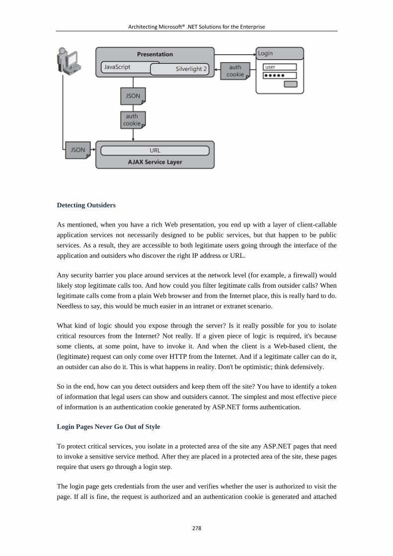
Architecting Microsoft® .NET Solutions for the Enterprise
278
Detecting Outsiders
As mentioned, when you have a rich Web presentation, you end up with a layer of client-callable
application services not necessarily designed to be public services, but that happen to be public
services. As a result, they are accessible to both legitimate users going through the interface of the
application and outsiders who discover the right IP address or URL.
Any security barrier you place around services at the network level (for example, a firewall) would
likely stop legitimate calls too. And how could you filter legitimate calls from outsider calls? When
legitimate calls come from a plain Web browser and from the Internet place, this is really hard to do.
Needless to say, this would be much easier in an intranet or extranet scenario.
What kind of logic should you expose through the server? Is it really possible for you to isolate
critical resources from the Internet? Not really. If a given piece of logic is required, it's because
some clients, at some point, have to invoke it. And when the client is a Web-based client, the
(legitimate) request can only come over HTTP from the Internet. And if a legitimate caller can do it,
an outsider can also do it. This is what happens in reality. Don't be optimistic; think defensively.
So in the end, how can you detect outsiders and keep them off the site? You have to identify a token
of information that legal users can show and outsiders cannot. The simplest and most effective piece
of information is an authentication cookie generated by ASP.NET forms authentication.
Login Pages Never Go Out of Style
To protect critical services, you isolate in a protected area of the site any ASP.NET pages that need
to invoke a sensitive service method. After they are placed in a protected area of the site, these pages
require that users go through a login step.
The login page gets credentials from the user and verifies whether the user is authorized to visit the
page. If all is fine, the request is authorized and an authentication cookie is generated and attached
Architecting Microsoft® .NET Solutions for the Enterprise
279
to the response. From now on, any requests the user makes to the application, including service
requests, will bring the cookie.
Services in the AJAX Service Layer must participate in the game, too. Essentially, a service should
check the authentication cookie to ensure that it is being called by a legitimate user through an
approved workflow and path. Only if the authorization is successful should the service proceed with
the method execution.
Note
It is ultimately up to you to decide whether the sensitive code should be part
of the AJAX Service Layer or be placed elsewhere in the business layer. We
presented the AJAX Service Layer as a layer living on top of the application's
service and business layer. However, it can also be just your service layer. This
makes sense particularly in all those applications where you only have a rich
Web presentation layer.
At the very minimum, a login page contains input controls to collect the user name and password
plus a button to trigger the authentication process. In ASP.NET, login pages require that forms
authentication is turned on. Furthermore, anonymous users should be denied access to any resources
within the protected area. Here's a sample configuration script you can use:
<location path="ProtectedAreaOfTheSite">
<system.web>
<authorization>
<deny users="?" />
</authorization>
</system.web>
</location>
If necessary, login pages can be placed on a different server and work over HTTPS. This solution,
however, has no impact on the security of the AJAX Service Layer.
Checking Identity and Authorization in the Service
Methods in the AJAX Service Layer are extremely thin and limited to checking permissions for the
logged-in user and passing the call down the stack. Here's the typical skeleton of a service method:
public DateTime GetTime()
{
// Get the user name and check permissions.
CheckIdentity();
Architecting Microsoft® .NET Solutions for the Enterprise
280
// Proceed with regular code¡ªtypically call a method
// on the application's service layer
.
.
.
}
In the sample code, CheckIdentity is an internal function that gets the name of the currently
logged-in user and verifies whether the user has been granted enough permissions to call the service
method:
private void CheckIdentity()
{
// Get the user name
string user = HttpContext.Current.User.Identity.Name;
// Check permissions
if (AuthenticationHelper.VerifyUser(user))
return;
// Thrown an exception
throw new InvalidOperationException("Invalid
credentials");
}
How can the service method get to know about the currently logged user? It basically gets this
information from the ASP.NET runtime via the HttpContext.Current object. This approach is
natively supported for ASP.NET XML Web services. However, it requires some extra work if you
employ WCF services.
By default, in ASP.NET AJAX applications WCF services run side by side with the ASP.NET
runtime in the IIS worker process. ASP.NET captures the .svc request and begins processing it. Next,
WCF kicks in and gets hold of the request. After this point, the request is never returned to
ASP.NET. As you can see, there's no interaction between WCF and ASP.NET. The net effect is that
HttpContext.Current is always null when invoked from within a WCF service.
To make WCF and ASP.NET recognize each other, you need to enable the ASP.NET compatibility
mode in WCF. You turn it on in the configuration file, as shown here:
<system.serviceModel>
<serviceHostingEnvironment
aspNetCompatibilityEnabled="true" />
.
Architecting Microsoft® .NET Solutions for the Enterprise
281
.
.
</system.serviceModel>
This setting only enables the compatibility mode for all services hosted by the ASP. NET
application. Each service is required to express its explicit approval of the model. A service does
this by decorating the service class¡ªnot the service contract¡ªwith the
AspNetCompatibilityRequirements attribute, as shown here:
[AspNetCompatibilityRequirements(
RequirementsMode =
AspNetCompatibilityRequirementsMode.Allowed)]
public class TimeService : ITimeService
{
.
.
.
}
Note that, by default, a WCF service has the RequirementsMode property set to NotAllowed. If this
value is not changed to either Allowed or Required, you get a run-time exception as you attempt to
make a call to the service.
6.2.6 Summary
Modern distributed systems have an extra layer of code between the presentation and business
layers. This layer is often referred to as the service layer. Another common name for this type of
code is the application layer.
Essentially, the service layer implements the application logic. The application logic is the list of
actions that, triggered from the user interface, end up scripting the objects and services in the
business logic. In the service layer, you implement the use cases and expose each s equence of steps
through a coarse-grained method for the user interface to call.
A service layer offers through a set of services a programming interface upon which multiple
presentation layers can be built. In this context, presentation layers include the regular user interface
as well as back-office applications and application interfaces for additional supported platforms. A
service layer is almost always useful to have because it decouples the application interfaces from the
middle tier. The only situation where you might want to consider doing without it is when you know
in advance that you'll be having just one, and only one, presentation interface.
In the design of services, you might want to take into account a few principles and practices. In
particular, you might want to embrace service orientation and share data contracts instead of rich
Architecting Microsoft® .NET Solutions for the Enterprise
282
domain classes. This principle is safe and sound, but it often clashes with the real world. In our
experience, a mixed approach that uses data contracts only in a few situations and domain-specific
classes in others is acceptable as long as you have a very large domain model containing large
numbers of objects to justify it and as long as the presentation layer and middle tier share the same
software platform.
6.2.7 Murphy's Laws of the Chapter
The quotation at the top of the chapter says it all. If you want services, serve yourself. And the first
Murphy's Law of this chapter reflects that very well. It says, don't trust even the most documented
interface: there's always an undocumented feature. We know how to work under pressure, and we
often look with some envy at agile methodologies designed to address the development team's
quality of life. We have no personal experiences with agile that demonstrate how "quality of life"
co-exists with software development. In fact, we find it hard to believe things are really as relaxing
and enjoyable as the books about agile claim they are. Perhaps in our case we live by a weird
corollary to some Murphy's Law: "We're never as agile as we would like to be."
The documented interfaces between standard software modules will have undocumented
quirks.
Good enough isn't good enough, unless there is a deadline.
You can never tell which way the train went just by looking at the track.
See http://www.murphys-laws.com for an extensive listing of other computer-related (and
non-computer-related) laws and corollaries.
6.3 Chapter 6. The Data Access Layer
High thoughts must have a high language.
¡ªAristophanes
The data access layer (DAL) is a library of code that provides access to data stored in a persistent
container, such as a database. In a layered system, you delegate to this layer any task that relates to
reading from, and writing to, the persistent storage of choice.
No matter how many abstraction layers you build in your model, at some point you need to open a
connection to some database. That's where and when the DAL fits in. Over the years, a few patterns
have been devised to design a DAL that is efficient and extensible. This chapter covers a number of
these patterns.
It is key to note that the concept of a DAL is a bit nebulous. The idea of a DAL is extremely clear
when you think of a classic layered system from a high level. From this perspective, a system has a
presentation layer where you essentially define the user interface, a business layer where you define
the object model and the behavior of the system, and finally the data access layer where you go
down to the database and run queries and updates. The layers ideally live in clearly delineated
Architecting Microsoft® .NET Solutions for the Enterprise
283
compartments, and each talks only to the layer immediately on top and immediately below. So, for
example, no communication whatsoever should be expected between the presentation and data
access layers.
Put this way, what's really nebulous about the data access layer? If you attempt to detail a DAL a
little bit more (as you should do, at some point, when you build a real system), a number of points
arise. In this chapter, we identify and discuss the goals and responsibilities of a data access layer and
delve deep into patterns and practices to meet expectations and requirements.
6.3.1 What's the Data Access Layer, Anyway?
A DAL has a precise set of responsibilities that are relatively easy to spot. The implementation of
these responsibilities, though, depends on other functional and nonfunctional requirements you get
from stakeholders. To address responsibilities, design patterns exist to guide you through the design
and implementation stages.
Before we proceed any further, though, you should note that the data access layer exists as a
separate software entity only if you have organized your business logic using the Domain Model
pattern. As we saw in Chapter 4, "The Business Layer," using the Domain Model pattern has you
define a particular object model. The object model describes data and behavior of any entities that
participate in the problem's domain. A domain model created using the Domain Model pattern can
be significantly different from any sort of relational data model, and this raises the need for a DAL
to implement persistence. Relational data models, such as those employed within a Transaction
Script or Table Module implementation, simply shuttle data to and from the persistence media.
More complex applications have to deal with the complexity of adapting their in-memory
object-based data model to the relational data model of persistence. The complexity associated with
deciding what data is stored where is handled by the DAL.
Put another way, when you organize the business logic using patterns other than Domain Model,
including even Active Record, persistence is built into the business logic and the DAL is in effect
merged with the business layer. The DAL, in this case, is essentially a collection of stored
procedures and embedded SQL statements.
You need a tailor-made DAL only if you have a full-fledged domain model created using the
Domain Model pattern.
Functional Requirements of the Data Access Layer
The design of a DAL is influenced by a number of requirements that stakeholders can impose.
Should the DAL persist an object model or simple collections ("tuples") of values? Should the DAL
target one particular database or a few databases? Let's review in a more formal way the typical
functional requirements of a DAL.
Database Independence
Architecting Microsoft® .NET Solutions for the Enterprise
284
The DAL is the only place in the system where connection strings and table names are known and
used. Based on this fact, you can conclude only that the DAL must be dependent on the features of a
particular database management system (DBMS). So how can you really achieve database
independence? And why is database independence so important? Let's start with the latter question.
Essentially, database independence means that your DAL is able to offer the same services¡ªsuch as
Create, Read, Update, Delete (CRUD), transactionality, and query¡ªto the rest of the system,
regardless of the capabilities of the final data storage media. After you come up with a model that
includes, say, a Customer object, your DAL is able to work with that object whether it is ultimately
persisted to a Microsoft SQL Server database or an Oracle database, or even to a table named
Customer that maps directly to the Customer object or is less easily mapped. The DAL shields the
business layer from this sort of detail.
To an external observer, the DAL should look like a black box that plugs into the existing system
and encapsulates access for reading and writing to a particular DBMS. Database independence is a
common requirement for a good deal of enterprise applications, especially back-office applications.
How can you achieve that?
Configurable as a Plug-in
There are many possible ways to achieve database independence, and the final choice also depends
on other requirements. In general, database independence requires that you use a common,
cross-database application programming interface (API), such as OLE DB. But OLE DB is too
generic and COM-based to survive in the .NET world.
In the .NET Framework, ADO.NET supplies a database-agnostic API to create connections,
commands, and transactions regardless of the physical database. In this way, you have just one DAL
written using an high-level API. Although this is definitely a possible approach, this is not what we
mean when we refer to database independence.
In our opinion, you reach real database independence only when you devise your DAL as a black
box with a contracted interface and read the details of the current DAL component dynamically
from a configuration file.
For example, once it obtains a reference to the current DAL, the service layer communicates with
the DAL in a polymorphic way using the methods on the public contract. If you store a reference to
the actual component in a configuration file, you can switch from, say, Oracle to SQL Server in two
simple moves: create a DBMS-specific component that implements the required interface, and
adjust a given entry in the configuration file.
Finally, you can make your system independent of the database by using an O/R Mapper (O/ RM)
tool. In this case, the O/RM provides you with a common API and allows you to switch to different
databases by simply changing a configuration parameter. Our experience has been that sometimes
we're allowed to use O/RM tools and sometimes not (a nonfunctional requirement). When we're told
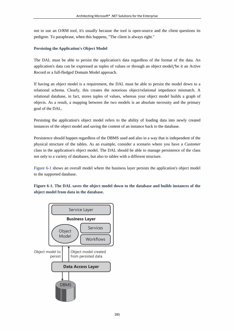
Architecting Microsoft® .NET Solutions for the Enterprise
285
not to use an O/RM tool, it's usually because the tool is open-source and the client questions its
pedigree. To paraphrase, when this happens, "The client is always right."
Persisting the Application's Object Model
The DAL must be able to persist the application's data regardless of the format of the data. An
application's data can be expressed as tuples of values or through an object model¡ªbe it an Active
Record or a full-fledged Domain Model approach.
If having an object model is a requirement, the DAL must be able to persist the model down to a
relational schema. Clearly, this creates the notorious object/relational impedance mismatch. A
relational database, in fact, stores tuples of values, whereas your object model builds a graph of
objects. As a result, a mapping between the two models is an absolute necessity and the primary
goal of the DAL.
Persisting the application's object model refers to the ability of loading data into newly created
instances of the object model and saving the content of an instance back to the database.
Persistence should happen regardless of the DBMS used and also in a way that is independent of the
physical structure of the tables. As an example, consider a scenario where you have a Customer
class in the application's object model. The DAL should be able to manage persistence of the class
not only to a variety of databases, but also to tables with a different structure.
Figure 6-1 shows an overall model where the business layer persists the application's object model
to the supported database.
Figure 6-1. The DAL saves the object model down to the database and builds instances of the
object model from data in the database.
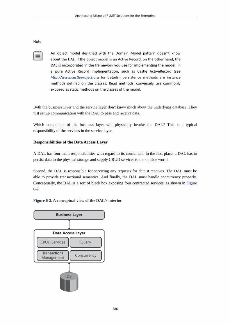
Architecting Microsoft® .NET Solutions for the Enterprise
286
Note
An object model designed with the Domain Model pattern doesn't know
about the DAL. If the object model is an Active Record, on the other hand, the
DAL is incorporated in the framework you use for implementing the model. In
a pure Active Record implementation, such as Castle ActiveRecord (see
http://www.castleproject.org for details), persistence methods are instance
methods defined on the classes. Read methods, conversely, are commonly
exposed as static methods on the classes of the model.
Both the business layer and the service layer don't know much about the underlying database. They
just set up communication with the DAL to pass and receive data.
Which component of the business layer will physically invoke the DAL? This is a typical
responsibility of the services in the service layer.
Responsibilities of the Data Access Layer
A DAL has four main responsibilities with regard to its consumers. In the first place, a DAL has to
persist data to the physical storage and supply CRUD services to the outside world.
Second, the DAL is responsible for servicing any requests for data it receives. The DAL must be
able to provide transactional semantics. And finally, the DAL must handle concurrency properly.
Conceptually, the DAL is a sort of black box exposing four contracted services, as shown in Figure
6-2.
Figure 6-2. A conceptual view of the DAL's interior
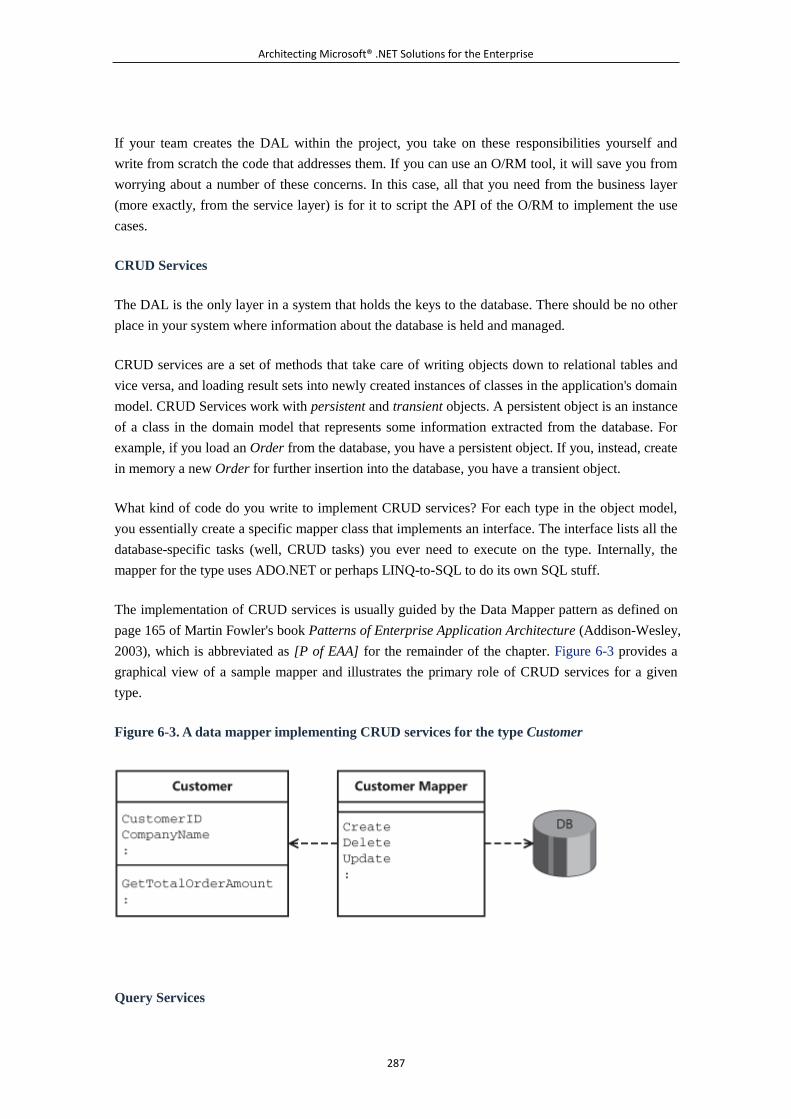
Architecting Microsoft® .NET Solutions for the Enterprise
287
If your team creates the DAL within the project, you take on these responsibilities yourself and
write from scratch the code that addresses them. If you can use an O/RM tool, it will save you from
worrying about a number of these concerns. In this case, all that you need from the business layer
(more exactly, from the service layer) is for it to script the API of the O/RM to implement the use
cases.
CRUD Services
The DAL is the only layer in a system that holds the keys to the database. There should be no other
place in your system where information about the database is held and managed.
CRUD services are a set of methods that take care of writing objects down to relational tables and
vice versa, and loading result sets into newly created instances of classes in the application's domain
model. CRUD Services work with persistent and transient objects. A persistent object is an instance
of a class in the domain model that represents some information extracted from the database. For
example, if you load an Order from the database, you have a persistent object. If you, instead, create
in memory a new Order for further insertion into the database, you have a transient object.
What kind of code do you write to implement CRUD services? For each type in the object model,
you essentially create a specific mapper class that implements an interface. The interface lists all the
database-specific tasks (well, CRUD tasks) you ever need to execute on the type. Internally, the
mapper for the type uses ADO.NET or perhaps LINQ-to-SQL to do its own SQL stuff.
The implementation of CRUD services is usually guided by the Data Mapper pattern as defined on
page 165 of Martin Fowler's book Patterns of Enterprise Application Architecture (Addison-Wesley,
2003), which is abbreviated as [P of EAA] for the remainder of the chapter. Figure 6-3 provides a
graphical view of a sample mapper and illustrates the primary role of CRUD services for a given
type.
Figure 6-3. A data mapper implementing CRUD services for the type Customer
Query Services
Architecting Microsoft® .NET Solutions for the Enterprise
288
The R in CRUD services stands for Read and, in some cases, this task requires quite advanced and
rich capabilities. Most of the time, a DAL consumer needs to query for ad hoc data. But not all the
queries are the same, nor do they require the same treatment.
In some situations, you can identify a few common queries that run from multiple places within the
business and service layers. If the command is the same and the result set is the same, you then
hard-code the query to some method of a repository object and reuse it at will. Let's consider a query
such as GetOrdersByCountry. What do you expect from it exactly? For example, it can be a method
that just runs the following command:
SELECT * FROM orders WHERE countryID=
In this case, you always receive a collection of Order objects with no information whatsoever about
order items and products.
In other situations, the same conceptual Get-Orders-By-Country query might generate different
data¡ªfor example, a collection of Order objects plus order items information. What should you do?
Should you expose two slightly different GetOrdersByCountry methods out of your DAL? And
what if, depending on the user interface, the user might ask the system to return orders, order items,
and products by country? Will you define yet another look-alike method in the DAL?
A better approach consists of defining a repository class where you define all hard-coded queries
you use and reuse throughout the business layer. In addition, you define a general-purpose query
object that is configured programmatically and produces ad hoc SQL code when executed.
The main purpose of such a query object is to collect input data¡ªessentially, criteria¡ªthrough its set
of properties and methods and then generate dynamic SQL for the database. Such a query object is
the ideal tool to compose queries dynamically out of the content of a UI form.
The query object isn't a replacement for SQL; instead, it is a more object-oriented and flexible way
of dynamically generating the SQL code for the database. Put another way, the query object we're
discussing here is a replacement for a SQL-based string-builder object.
The query object is an instance of the Query Object pattern, as defined on page 316 of [P of EAA].
According to the pattern, the resulting query object is built as a class that owns a set of criteria. A
set of criteria is a simple class with a property name, a value, and a logical operator that puts the
property name and value into relation.
Note
Another pattern that is commonly associated with the implementation of
query services in a DAL is the Repository pattern. (See page 322 of [P of EAA].)
A repository is normally a type-specific class that groups common queries for a
given object. So you might have a CustomerRepository and an
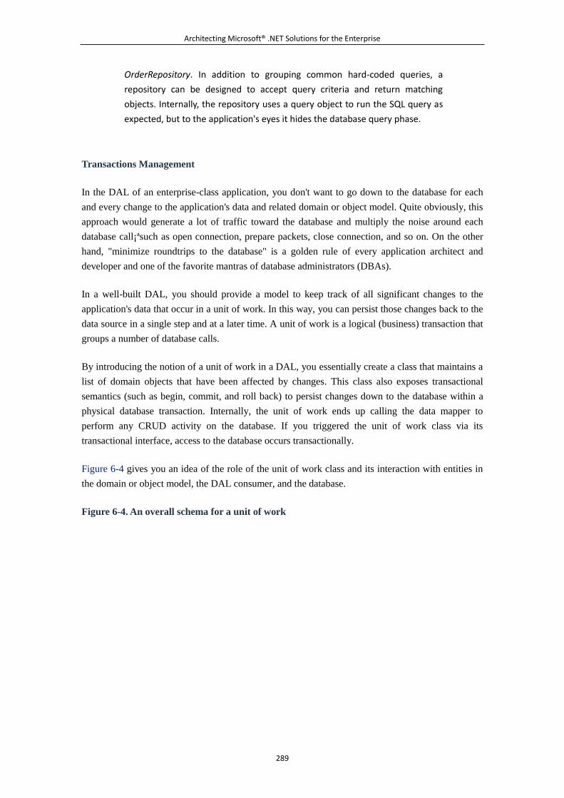
Architecting Microsoft® .NET Solutions for the Enterprise
289
OrderRepository. In addition to grouping common hard-coded queries, a
repository can be designed to accept query criteria and return matching
objects. Internally, the repository uses a query object to run the SQL query as
expected, but to the application's eyes it hides the database query phase.
Transactions Management
In the DAL of an enterprise-class application, you don't want to go down to the database for each
and every change to the application's data and related domain or object model. Quite obviously, this
approach would generate a lot of traffic toward the database and multiply the noise around each
database call¡ªsuch as open connection, prepare packets, close connection, and so on. On the other
hand, "minimize roundtrips to the database" is a golden rule of every application architect and
developer and one of the favorite mantras of database administrators (DBAs).
In a well-built DAL, you should provide a model to keep track of all significant changes to the
application's data that occur in a unit of work. In this way, you can persist those changes back to the
data source in a single step and at a later time. A unit of work is a logical (business) transaction that
groups a number of database calls.
By introducing the notion of a unit of work in a DAL, you essentially create a class that maintains a
list of domain objects that have been affected by changes. This class also exposes transactional
semantics (such as begin, commit, and roll back) to persist changes down to the database within a
physical database transaction. Internally, the unit of work ends up calling the data mapper to
perform any CRUD activity on the database. If you triggered the unit of work class via its
transactional interface, access to the database occurs transactionally.
Figure 6-4 gives you an idea of the role of the unit of work class and its interaction with entities in
the domain or object model, the DAL consumer, and the database.
Figure 6-4. An overall schema for a unit of work
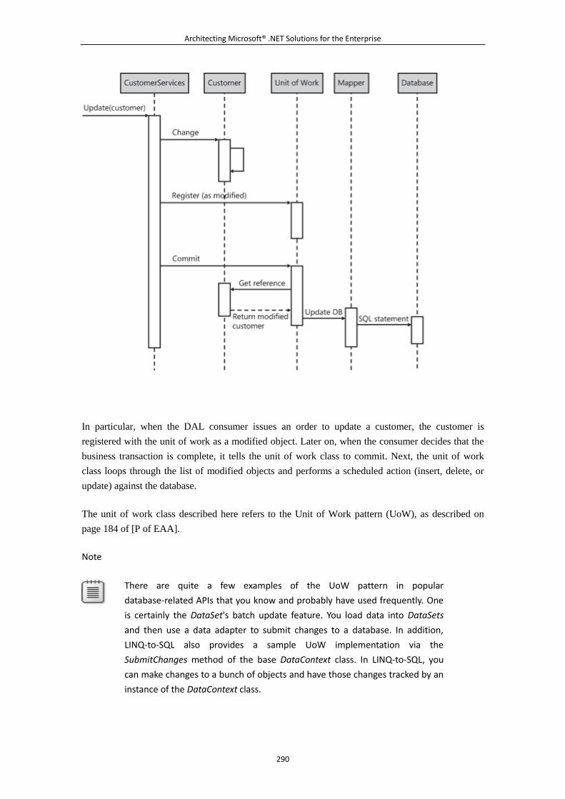
Architecting Microsoft® .NET Solutions for the Enterprise
290
In particular, when the DAL consumer issues an order to update a customer, the customer is
registered with the unit of work as a modified object. Later on, when the consumer decides that the
business transaction is complete, it tells the unit of work class to commit. Next, the unit of work
class loops through the list of modified objects and performs a scheduled action (insert, delete, or
update) against the database.
The unit of work class described here refers to the Unit of Work pattern (UoW), as described on
page 184 of [P of EAA].
Note
There are quite a few examples of the UoW pattern in popular
database-related APIs that you know and probably have used frequently. One
is certainly the DataSet's batch update feature. You load data into DataSets
and then use a data adapter to submit changes to a database. In addition,
LINQ-to-SQL also provides a sample UoW implementation via the
SubmitChanges method of the base DataContext class. In LINQ-to-SQL, you
can make changes to a bunch of objects and have those changes tracked by an
instance of the DataContext class.
Architecting Microsoft® .NET Solutions for the Enterprise
291
Handling Concurrency
As mentioned, going down to the database for each change you enter during a business transaction
is simply impractical. In fact, avoiding this behavior is a no-brainer in any average complex system.
That's why the UoW pattern emerged¡ªit provides a common solution to a recurring problem. When
users work offline from the database, two main issues arise. One is transactionality, which is
properly addressed by UoW. Another one is concurrency.
In a multiuser environment, working offline from the database poses a data-integrity issue. User A
loads its own copy of product 1234 and updates the description. Because the operation is part of a
longer business transaction, let's assume that changes are not committed immediately. At the same
time, user B loads another copy of the same product 1234 and updates the URL that links to the
product's picture. Suppose also that user B commits the changes immediately. What happens when
user A attempts to commit changes to the description?
You might say, "Well, nothing" because the users actually updated distinct fields. OK, so what if
both users entered different descriptions for the product? There's a concrete risk that product
description changes introduced by the first user get lost. This is often called "last writer wins."
A policy is required to handle concurrent user access to the same database records. The chance of
conflicts in data access is not the same in all systems; likewise, the cost of handling a conflict is not
the same in all systems. This said, an optimistic approach to concurrency is recognized as the best
starting point for all systems.
An optimistic approach to concurrency means that your users in their sessions can freely try to
update any records in the database. The result, though, is not guaranteed. In particular, the DAL fails
if it detects that a record being modified has already been updated in the meantime.
Handling concurrency in an optimistic fashion requires an ad hoc data mapper that builds a special
proxy version of a given entity¡ªsuch as CustomerProxy instead of Customer. What's the difference
between CustomerProxy and Customer? The former contains original values from the record read at
creation time, whereas the latter does not. When the data mapper is then about to persist the instance
of the customer, it will add a WHERE clause to the SQL statement to ensure at least that the
columns being modified have not been modified lately.
The idea behind optimistic concurrency is in the Optimistic Offline Lock (OOL) pattern, defined on
page 416 of [P of EAA]. There are various ways of implementing OOL and various policies
regarding the resolution of conflicts. This pattern describes the problem in the most general terms.
Note
Optimistic concurrency is the opposite of pessimistic concurrency. Pessimistic
concurrency, especially when a user is working offline, is a much worse beast.
Personally, we have never seen an implementation of a pessimistic offline lock.
We have serious doubts also about using a pessimistic online lock via the
Architecting Microsoft® .NET Solutions for the Enterprise
292
locking manager built into the DBMS. So when might you want to consider
alternatives to optimistic locking?
You stop thinking optimistically when you realize that the cost of resolving a
conflict is dramatically high, because the conflict itself has a heavy impact on
the system or because, given the characteristics of your system, you will have
too many conflicts within a unit of time. However, pessimistic concurrency
means essentially creating a lock manager¡ªthat is, a component external to
the database that maintains a list of locked records and supports a
compensation mechanism for locks that time out. Even if it works, it would be
a curse for scalability. So what? In the real world, you always use an optimistic
approach to offline concurrency and use policies for handling conflicts to
mitigate unpleasant effects.
Putting It All Together: The Data Context
All the conceptual responsibilities that a DAL should face turn into a relatively standard set of
programming features when you move up to design and implementation. How would you tie all
these features together in an organic set of classes and methods?
In short, you need a sort of super class that represents and conducts a session of work with the
underlying storage. The DAL consumer uses such a super class as its gateway to the storage. O/RM
tools have their own super class; so should your personal DAL.
The super class that provides access to the DAL and its CRUD, transaction, and concurrency
services is often referred to as the data context.
The Data Access Layer and Other Layers
Figure 6-5 shows a bird's-eye view of a layered system, as we presented it in Chapter 4 and Chapter
5, "The Service Layer." As you can see, typically the presentation layer talks to an application layer
mostly made of macro services¡ªin Chapter 5, we called it the service layer. In turn, the service layer
consumes the other components of the business layer, such as the domain model and other micro
services.
Figure 6-5. A high-level view of a layered system
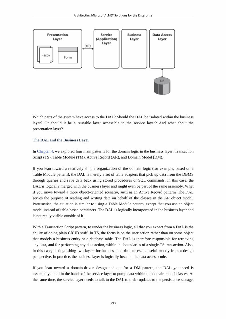
Architecting Microsoft® .NET Solutions for the Enterprise
293
Which parts of the system have access to the DAL? Should the DAL be isolated within the business
layer? Or should it be a reusable layer accessible to the service layer? And what about the
presentation layer?
The DAL and the Business Layer
In Chapter 4, we explored four main patterns for the domain logic in the business layer: Transaction
Script (TS), Table Module (TM), Active Record (AR), and Domain Model (DM).
If you lean toward a relatively simple organization of the domain logic (for example, based on a
Table Module pattern), the DAL is merely a set of table adapters that pick up data from the DBMS
through queries and save data back using stored procedures or SQL commands. In this case, the
DAL is logically merged with the business layer and might even be part of the same assembly. What
if you move toward a more object-oriented scenario, such as an Active Record pattern? The DAL
serves the purpose of reading and writing data on behalf of the classes in the AR object model.
Patternwise, the situation is similar to using a Table Module pattern, except that you use an object
model instead of table-based containers. The DAL is logically incorporated in the business layer and
is not really visible outside of it.
With a Transaction Script pattern, to render the business logic, all that you expect from a DAL is the
ability of doing plain CRUD stuff. In TS, the focus is on the user action rather than on some object
that models a business entity or a database table. The DAL is therefore responsible for retrieving
any data, and for performing any data action, within the boundaries of a single TS transaction. Also,
in this case, distinguishing two layers for business and data access is useful mostly from a design
perspective. In practice, the business layer is logically fused to the data access code.
If you lean toward a domain-driven design and opt for a DM pattern, the DAL you need is
essentially a tool in the hands of the service layer to pump data within the domain model classes. At
the same time, the service layer needs to talk to the DAL to order updates to the persistence storage.
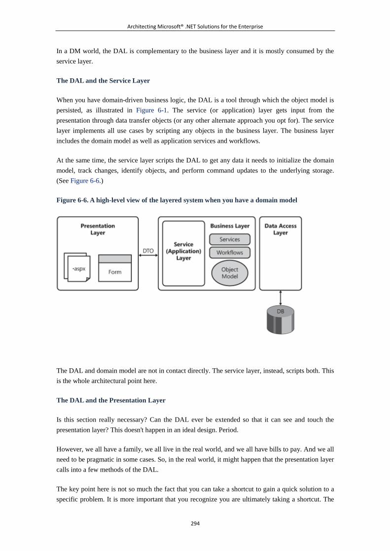
Architecting Microsoft® .NET Solutions for the Enterprise
294
In a DM world, the DAL is complementary to the business layer and it is mostly consumed by the
service layer.
The DAL and the Service Layer
When you have domain-driven business logic, the DAL is a tool through which the object model is
persisted, as illustrated in Figure 6-1. The service (or application) layer gets input from the
presentation through data transfer objects (or any other alternate approach you opt for). The service
layer implements all use cases by scripting any objects in the business layer. The business layer
includes the domain model as well as application services and workflows.
At the same time, the service layer scripts the DAL to get any data it needs to initialize the domain
model, track changes, identify objects, and perform command updates to the underlying storage.
(See Figure 6-6.)
Figure 6-6. A high-level view of the layered system when you have a domain model
The DAL and domain model are not in contact directly. The service layer, instead, scripts both. This
is the whole architectural point here.
The DAL and the Presentation Layer
Is this section really necessary? Can the DAL ever be extended so that it can see and touch the
presentation layer? This doesn't happen in an ideal design. Period.
However, we all have a family, we all live in the real world, and we all have bills to pay. And we all
need to be pragmatic in some cases. So, in the real world, it might happen that the presentation layer
calls into a few methods of the DAL.
The key point here is not so much the fact that you can take a shortcut to gain a quick solution to a
specific problem. It is more important that you recognize you are ultimately taking a shortcut. The
Architecting Microsoft® .NET Solutions for the Enterprise
295
shortcut of invoking a piece of the DAL from the presentation layer is acceptable as long as you are
fully aware of what you are doing. The only reason to ever consider using a presentation-to-DAL
shortcut is to save valuable development time. From a team perspective, it is perhaps just as
important that you pass the message around clearly¡ªyou should try to avoid presentation-to-DAL
shortcuts. We realize that pragmatically those shortcuts, if controlled, are definitely possible and
helpful, but they represent inappropriate tight coupling between disjoint layers¡ªuse the quick
solution when you need it, but definitely refactor things at the earliest possible moment.
For example, you might invoke the DAL directly from the presentation layer to grab a chunk of data
that the presentation layer needs. Consider a simple Get-Order use case. The presentation layer
provides an ID and receives order information for display. In an ideal service-oriented architecture
(SOA) design, you create a service with a GetByID method and use data-transfer objects to move
data. For a single method call, and in a lazier scenario, this is probably too much of an effort. Hence,
you might consider a direct binding between the presentation layer and the DAL.
Note
The shape of the DAL mostly depends on the architect's vision of the business
layer. But, to some extent, things also work the other way around: the DAL
might influence the business layer. It's like the old story of which came first,
the egg or the chicken. Your known constraints and your attitude determine
where you start from and, subsequently, what influences what. As a matter of
fact, there's a limited set of reasonable combinations between the set of
patterns you use to design the business layer and those you consider for
creating a DAL.
6.3.2 Designing Your Own Data Access Layer
We started this chapter by saying that no matter how many abstraction layers you place in your
model of the system, at some point you need to open a connection to some database. The layer
where this happens is referred to as the DAL. After recognizing this core fact, though, we discussed
the overall responsibilities of the DAL. Now it's about time we delve deeper into the topic and say
more about implementing your own DAL.
All in all, we don't expect architects and developers to write a DAL from scratch on a regular basis.
Many applications, even within an enterprise, run happily on typed DataSets and Active Record
object models. As we said earlier, in these cases the DAL is available out of the box. You need a
separate DAL with certain advanced capabilities only if you have a domain model. And also in that
case, choosing a companion O/RM tool will make your life easier and ensure you can take a more
relaxed approach to the project's deadline. If you can employ an O/RM tool, a large share of the
topics we're going to discuss¡ªessentially more detailed implementations of the patterns we listed
earlier¡ªare of limited interest. The O/RM, in fact, provides all of them off the shelf. In the end, the
primary purpose of this section of the book is illustrative.
Architecting Microsoft® .NET Solutions for the Enterprise
296
Note
Thankfully, it doesn't happen every day and on every project, but sometimes it
might happen: imagine your best customer delivering a requirement that
forces you to design a system that runs on two distinct DBMS and doesn't
make use of any O/RM. If you can imagine that happening to you, this chapter
will be helpful.
The Contract of the DAL
We recommend that you design the DAL in a way that separates the interface from the
implementation. After you have abstracted the capabilities of the DAL to a contract, consumers can
get a particular implementation of it and work in peace.
You start by defining the general interface for the DAL¡ªthe data context. Next, you implement this
interface in any modules you need that perform data access tasks against a particular DBMS, or
even a particular O/RM. The layer that consumes the DAL¡ªwhether it's the business, service, or
even presentation layer¡ªreceives a reference to the currently selected DAL. You provide a factory to
build the current DAL. To ensure full independence from the database structure, the DAL and its
consumer will communicate using business entities (domain model objects, objects in an Active
Record model, typed DataSets, or plain data transfer objects).
This approach has a number of benefits.
In particular, the application can easily support a variety of data sources and have a specialized DAL
for each supported DBMS. With this architecture in place, to make your application support, say,
Oracle, all you have to do is create an Oracle-specific DAL and make it visible to the application. In
addition, impersonating the DAL for testing purposes is a piece of cake.
The Separated Interface pattern (which is described on page 476 of [P of EAA]) formalizes the
design rule of keeping the DAL interface neatly separated from the component that actually
implements it.
The Separated Interface Pattern
In general terms, the Separated Interface pattern addresses the problem of separating the interface
that describes a certain functionality from its implementation. The pattern prescribes that you use
different packages (for example, assemblies in the .NET Framework) for the interface and any of its
implementations. Only the definition of the interface is known to any packages that need to
consume the functionality. Let's turn this general pattern to the world of data access.
Applied to the design of a DAL, Separated Interface means that you define a contract for all the
functionality you expose through the DAL. The contract is ultimately an interface compiled to its
own assembly. Which part of the system is going to consume the DAL? As mentioned, it largely
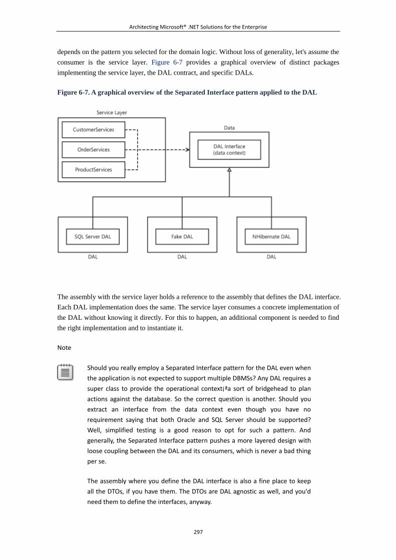
Architecting Microsoft® .NET Solutions for the Enterprise
297
depends on the pattern you selected for the domain logic. Without loss of generality, let's assume the
consumer is the service layer. Figure 6-7 provides a graphical overview of distinct packages
implementing the service layer, the DAL contract, and specific DALs.
Figure 6-7. A graphical overview of the Separated Interface pattern applied to the DAL
The assembly with the service layer holds a reference to the assembly that defines the DAL interface.
Each DAL implementation does the same. The service layer consumes a concrete implementation of
the DAL without knowing it directly. For this to happen, an additional component is needed to find
the right implementation and to instantiate it.
Note
Should you really employ a Separated Interface pattern for the DAL even when
the application is not expected to support multiple DBMSs? Any DAL requires a
super class to provide the operational context¡ªa sort of bridgehead to plan
actions against the database. So the correct question is another. Should you
extract an interface from the data context even though you have no
requirement saying that both Oracle and SQL Server should be supported?
Well, simplified testing is a good reason to opt for such a pattern. And
generally, the Separated Interface pattern pushes a more layered design with
loose coupling between the DAL and its consumers, which is never a bad thing
per se.
The assembly where you define the DAL interface is also a fine place to keep
all the DTOs, if you have them. The DTOs are DAL agnostic as well, and you'd
need them to define the interfaces, anyway.
Architecting Microsoft® .NET Solutions for the Enterprise
298
Program to a (DAL) Interface
The Separated Interface pattern is useful in any scenario where a given functionality of the
application might be implemented through a different behavior based on runtime conditions. The
DAL is just one of these cases.
As you might have noticed yourself, there's a much more general principle of object-oriented design
at work here. It is precisely the principle that the Gang of Four (Erich Gamma, Richard Helm, Ralph
Johnson, and John Vlissides), in their excellent Design Patterns: Elements of Reusable
Object-Oriented Software (Addison-Wesley, 1995), describe as "Program to an interface; not to an
implementation."
When you apply this principle, clients are unaware of the concrete types they end up using. And
clients just don't care about concrete types, as long as the objects they receive expose an
agreed-upon interface. Clients and concrete types are decoupled because clients know only about the
interface.
Based on this principle, you place the interface and implementation of the DAL in separate packages
(for example, assemblies), and you put a factory in the middle so that any clients, such as a class in
the service layer, can get a reference to the current DAL. (See Figure 6-8.)
Figure 6-8. Programming to a DAL interface, not to a DAL implementation
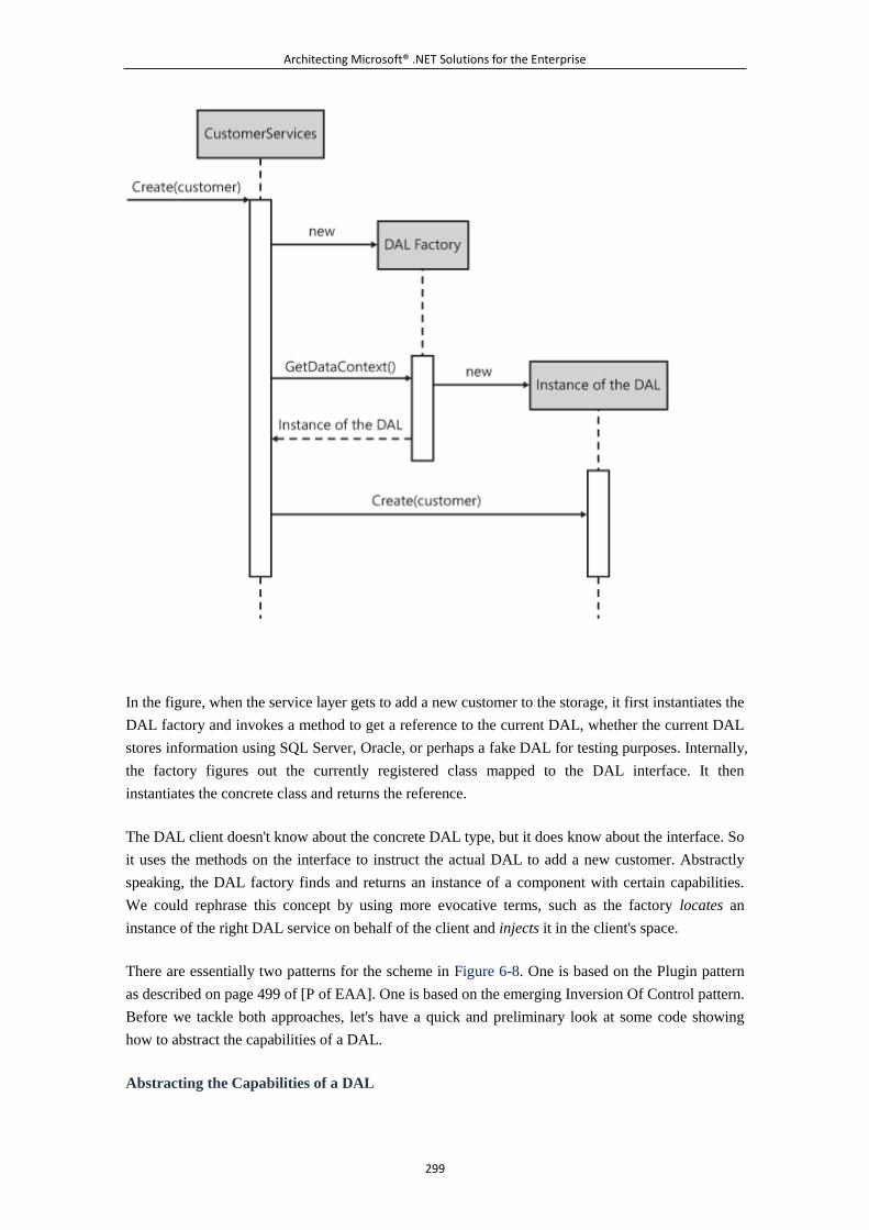
Architecting Microsoft® .NET Solutions for the Enterprise
299
In the figure, when the service layer gets to add a new customer to the storage, it first instantiates the
DAL factory and invokes a method to get a reference to the current DAL, whether the current DAL
stores information using SQL Server, Oracle, or perhaps a fake DAL for testing purposes. Internally,
the factory figures out the currently registered class mapped to the DAL interface. It then
instantiates the concrete class and returns the reference.
The DAL client doesn't know about the concrete DAL type, but it does know about the interface. So
it uses the methods on the interface to instruct the actual DAL to add a new customer. Abstractly
speaking, the DAL factory finds and returns an instance of a component with certain capabilities.
We could rephrase this concept by using more evocative terms, such as the factory locates an
instance of the right DAL service on behalf of the client and injects it in the client's space.
There are essentially two patterns for the scheme in Figure 6-8. One is based on the Plugin pattern
as described on page 499 of [P of EAA]. One is based on the emerging Inversion Of Control pattern.
Before we tackle both approaches, let's have a quick and preliminary look at some code showing
how to abstract the capabilities of a DAL.
Abstracting the Capabilities of a DAL
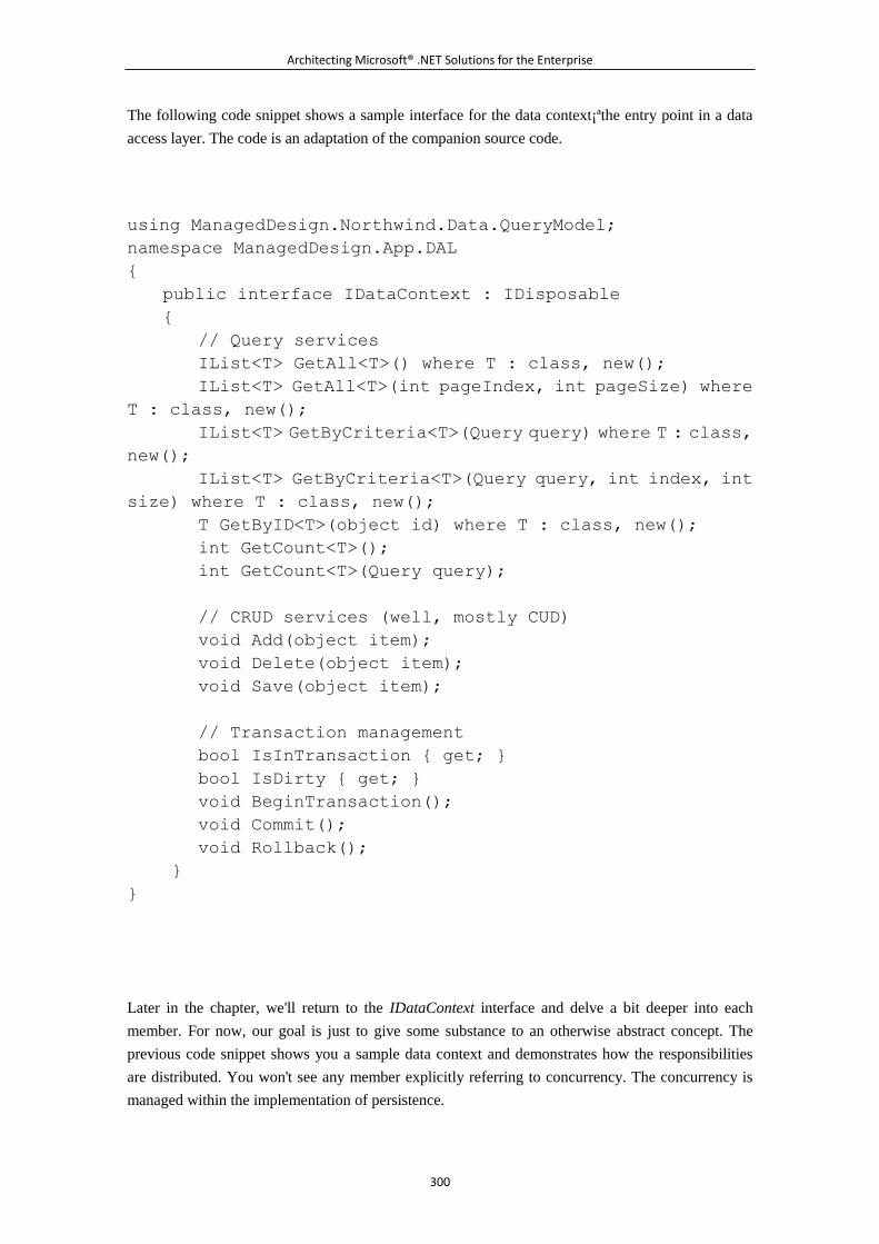
Architecting Microsoft® .NET Solutions for the Enterprise
300
The following code snippet shows a sample interface for the data context¡ªthe entry point in a data
access layer. The code is an adaptation of the companion source code.
using ManagedDesign.Northwind.Data.QueryModel;
namespace ManagedDesign.App.DAL
{
public interface IDataContext : IDisposable
{
// Query services
IList<T> GetAll<T>() where T : class, new();
IList<T> GetAll<T>(int pageIndex, int pageSize) where
T : class, new();
IList<T> GetByCriteria<T>(Query query) where T : class,
new();
IList<T> GetByCriteria<T>(Query query, int index, int
size) where T : class, new();
T GetByID<T>(object id) where T : class, new();
int GetCount<T>();
int GetCount<T>(Query query);
// CRUD services (well, mostly CUD)
void Add(object item);
void Delete(object item);
void Save(object item);
// Transaction management
bool IsInTransaction { get; }
bool IsDirty { get; }
void BeginTransaction();
void Commit();
void Rollback();
}
}
Later in the chapter, we'll return to the IDataContext interface and delve a bit deeper into each
member. For now, our goal is just to give some substance to an otherwise abstract concept. The
previous code snippet shows you a sample data context and demonstrates how the responsibilities
are distributed. You won't see any member explicitly referring to concurrency. The concurrency is
managed within the implementation of persistence.
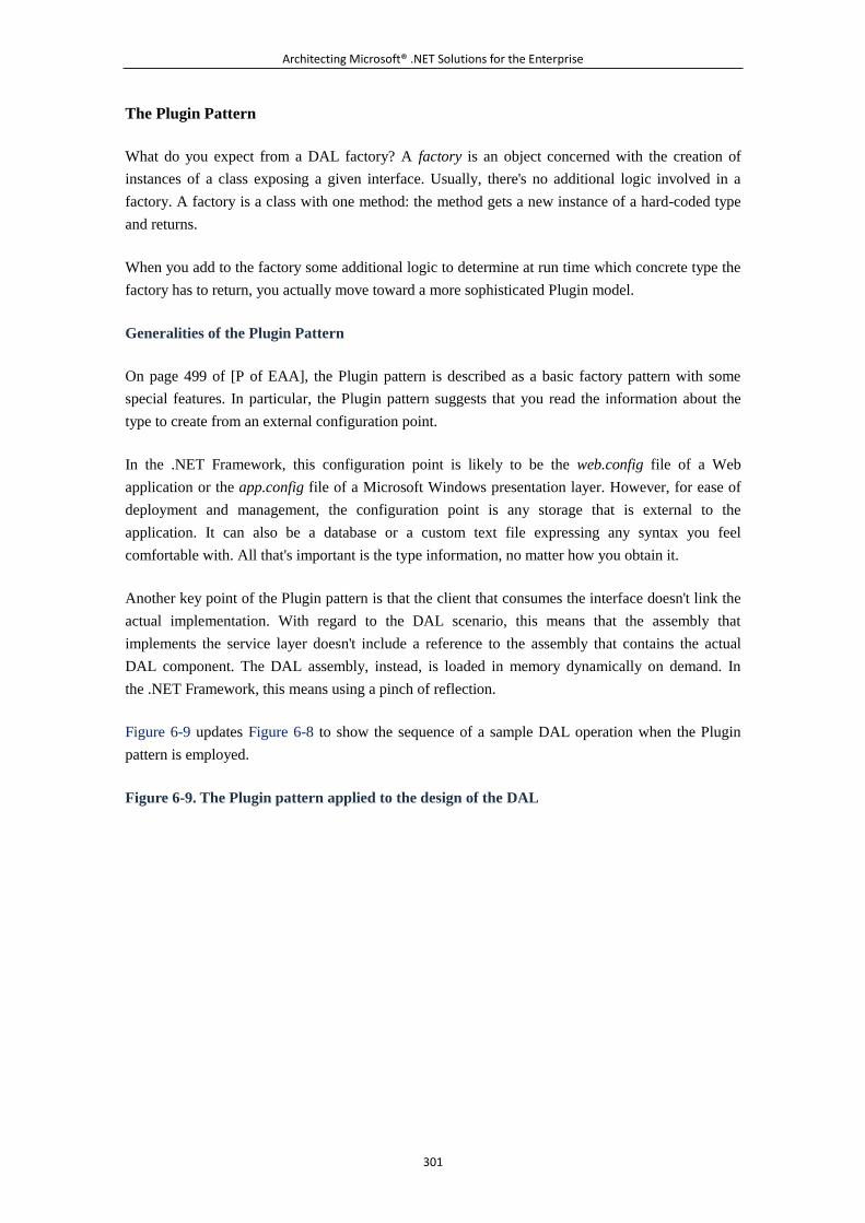
Architecting Microsoft® .NET Solutions for the Enterprise
301
The Plugin Pattern
What do you expect from a DAL factory? A factory is an object concerned with the creation of
instances of a class exposing a given interface. Usually, there's no additional logic involved in a
factory. A factory is a class with one method: the method gets a new instance of a hard-coded type
and returns.
When you add to the factory some additional logic to determine at run time which concrete type the
factory has to return, you actually move toward a more sophisticated Plugin model.
Generalities of the Plugin Pattern
On page 499 of [P of EAA], the Plugin pattern is described as a basic factory pattern with some
special features. In particular, the Plugin pattern suggests that you read the information about the
type to create from an external configuration point.
In the .NET Framework, this configuration point is likely to be the web.config file of a Web
application or the app.config file of a Microsoft Windows presentation layer. However, for ease of
deployment and management, the configuration point is any storage that is external to the
application. It can also be a database or a custom text file expressing any syntax you feel
comfortable with. All that's important is the type information, no matter how you obtain it.
Another key point of the Plugin pattern is that the client that consumes the interface doesn't link the
actual implementation. With regard to the DAL scenario, this means that the assembly that
implements the service layer doesn't include a reference to the assembly that contains the actual
DAL component. The DAL assembly, instead, is loaded in memory dynamically on demand. In
the .NET Framework, this means using a pinch of reflection.
Figure 6-9 updates Figure 6-8 to show the sequence of a sample DAL operation when the Plugin
pattern is employed.
Figure 6-9. The Plugin pattern applied to the design of the DAL
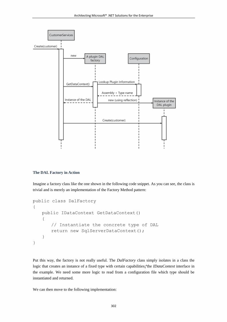
Architecting Microsoft® .NET Solutions for the Enterprise
302
The DAL Factory in Action
Imagine a factory class like the one shown in the following code snippet. As you can see, the class is
trivial and is merely an implementation of the Factory Method pattern:
public class DalFactory
{
public IDataContext GetDataContext()
{
// Instantiate the concrete type of DAL
return new SqlServerDataContext();
}
}
Put this way, the factory is not really useful. The DalFactory class simply isolates in a class the
logic that creates an instance of a fixed type with certain capabilities¡ªthe IDataContext interface in
the example. We need some more logic to read from a configuration file which type should be
instantiated and returned.
We can then move to the following implementation:
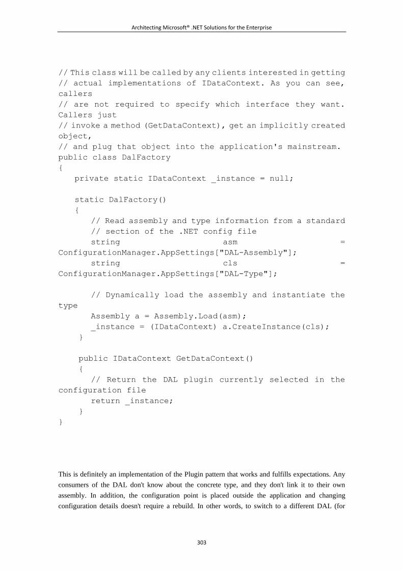
Architecting Microsoft® .NET Solutions for the Enterprise
303
// This class will be called by any clients interested in getting
// actual implementations of IDataContext. As you can see,
callers
// are not required to specify which interface they want.
Callers just
// invoke a method (GetDataContext), get an implicitly created
object,
// and plug that object into the application's mainstream.
public class DalFactory
{
private static IDataContext _instance = null;
static DalFactory()
{
// Read assembly and type information from a standard
// section of the .NET config file
string asm =
ConfigurationManager.AppSettings["DAL-Assembly"];
string cls =
ConfigurationManager.AppSettings["DAL-Type"];
// Dynamically load the assembly and instantiate the
type
Assembly a = Assembly.Load(asm);
_instance = (IDataContext) a.CreateInstance(cls);
}
public IDataContext GetDataContext()
{
// Return the DAL plugin currently selected in the
configuration file
return _instance;
}
}
This is definitely an implementation of the Plugin pattern that works and fulfills expectations. Any
consumers of the DAL don't know about the concrete type, and they don't link it to their own
assembly. In addition, the configuration point is placed outside the application and changing
configuration details doesn't require a rebuild. In other words, to switch to a different DAL (for
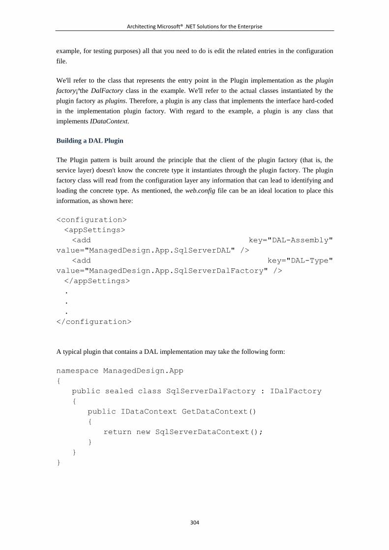
Architecting Microsoft® .NET Solutions for the Enterprise
304
example, for testing purposes) all that you need to do is edit the related entries in the configuration
file.
We'll refer to the class that represents the entry point in the Plugin implementation as the plugin
factory¡ªthe DalFactory class in the example. We'll refer to the actual classes instantiated by the
plugin factory as plugins. Therefore, a plugin is any class that implements the interface hard-coded
in the implementation plugin factory. With regard to the example, a plugin is any class that
implements IDataContext.
Building a DAL Plugin
The Plugin pattern is built around the principle that the client of the plugin factory (that is, the
service layer) doesn't know the concrete type it instantiates through the plugin factory. The plugin
factory class will read from the configuration layer any information that can lead to identifying and
loading the concrete type. As mentioned, the web.config file can be an ideal location to place this
information, as shown here:
<configuration>
<appSettings>
<add key="DAL-Assembly"
value="ManagedDesign.App.SqlServerDAL" />
<add key="DAL-Type"
value="ManagedDesign.App.SqlServerDalFactory" />
</appSettings>
.
.
.
</configuration>
A typical plugin that contains a DAL implementation may take the following form:
namespace ManagedDesign.App
{
public sealed class SqlServerDalFactory : IDalFactory
{
public IDataContext GetDataContext()
{
return new SqlServerDataContext();
}
}
}
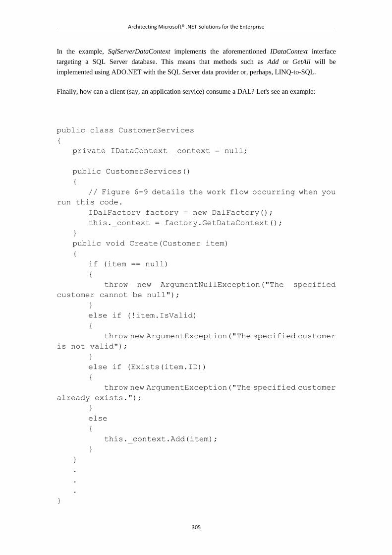
Architecting Microsoft® .NET Solutions for the Enterprise
305
In the example, SqlServerDataContext implements the aforementioned IDataContext interface
targeting a SQL Server database. This means that methods such as Add or GetAll will be
implemented using ADO.NET with the SQL Server data provider or, perhaps, LINQ-to-SQL.
Finally, how can a client (say, an application service) consume a DAL? Let's see an example:
public class CustomerServices
{
private IDataContext _context = null;
public CustomerServices()
{
// Figure 6-9 details the work flow occurring when you
run this code.
IDalFactory factory = new DalFactory();
this._context = factory.GetDataContext();
}
public void Create(Customer item)
{
if (item == null)
{
throw new ArgumentNullException("The specified
customer cannot be null");
}
else if (!item.IsValid)
{
throw new ArgumentException("The specified customer
is not valid");
}
else if (Exists(item.ID))
{
throw new ArgumentException("The specified customer
already exists.");
}
else
{
this._context.Add(item);
}
}
.
.
.
}
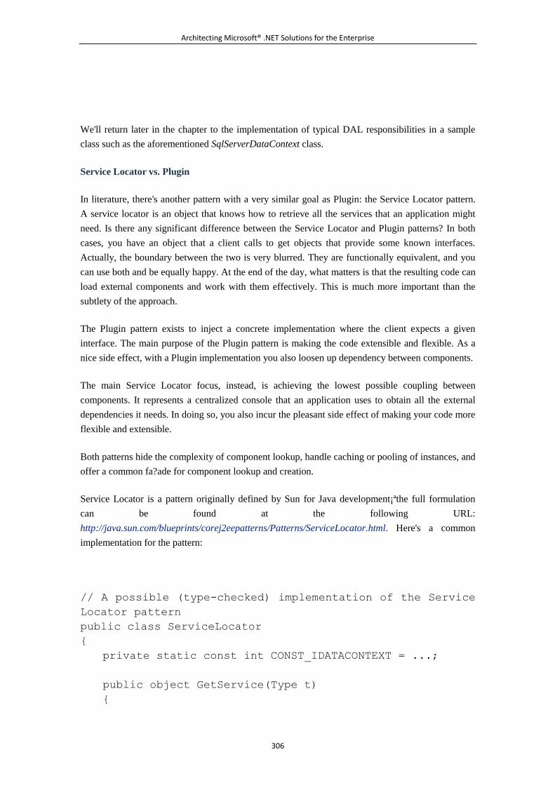
Architecting Microsoft® .NET Solutions for the Enterprise
306
We'll return later in the chapter to the implementation of typical DAL responsibilities in a sample
class such as the aforementioned SqlServerDataContext class.
Service Locator vs. Plugin
In literature, there's another pattern with a very similar goal as Plugin: the Service Locator pattern.
A service locator is an object that knows how to retrieve all the services that an application might
need. Is there any significant difference between the Service Locator and Plugin patterns? In both
cases, you have an object that a client calls to get objects that provide some known interfaces.
Actually, the boundary between the two is very blurred. They are functionally equivalent, and you
can use both and be equally happy. At the end of the day, what matters is that the resulting code can
load external components and work with them effectively. This is much more important than the
subtlety of the approach.
The Plugin pattern exists to inject a concrete implementation where the client expects a given
interface. The main purpose of the Plugin pattern is making the code extensible and flexible. As a
nice side effect, with a Plugin implementation you also loosen up dependency between components.
The main Service Locator focus, instead, is achieving the lowest possible coupling between
components. It represents a centralized console that an application uses to obtain all the external
dependencies it needs. In doing so, you also incur the pleasant side effect of making your code more
flexible and extensible.
Both patterns hide the complexity of component lookup, handle caching or pooling of instances, and
offer a common fa?ade for component lookup and creation.
Service Locator is a pattern originally defined by Sun for Java development¡ªthe full formulation
can be found at the following URL:
http://java.sun.com/blueprints/corej2eepatterns/Patterns/ServiceLocator.html. Here's a common
implementation for the pattern:
// A possible (type-checked) implementation of the Service
Locator pattern
public class ServiceLocator
{
private static const int CONST_IDATACONTEXT = ...;
public object GetService(Type t)
{
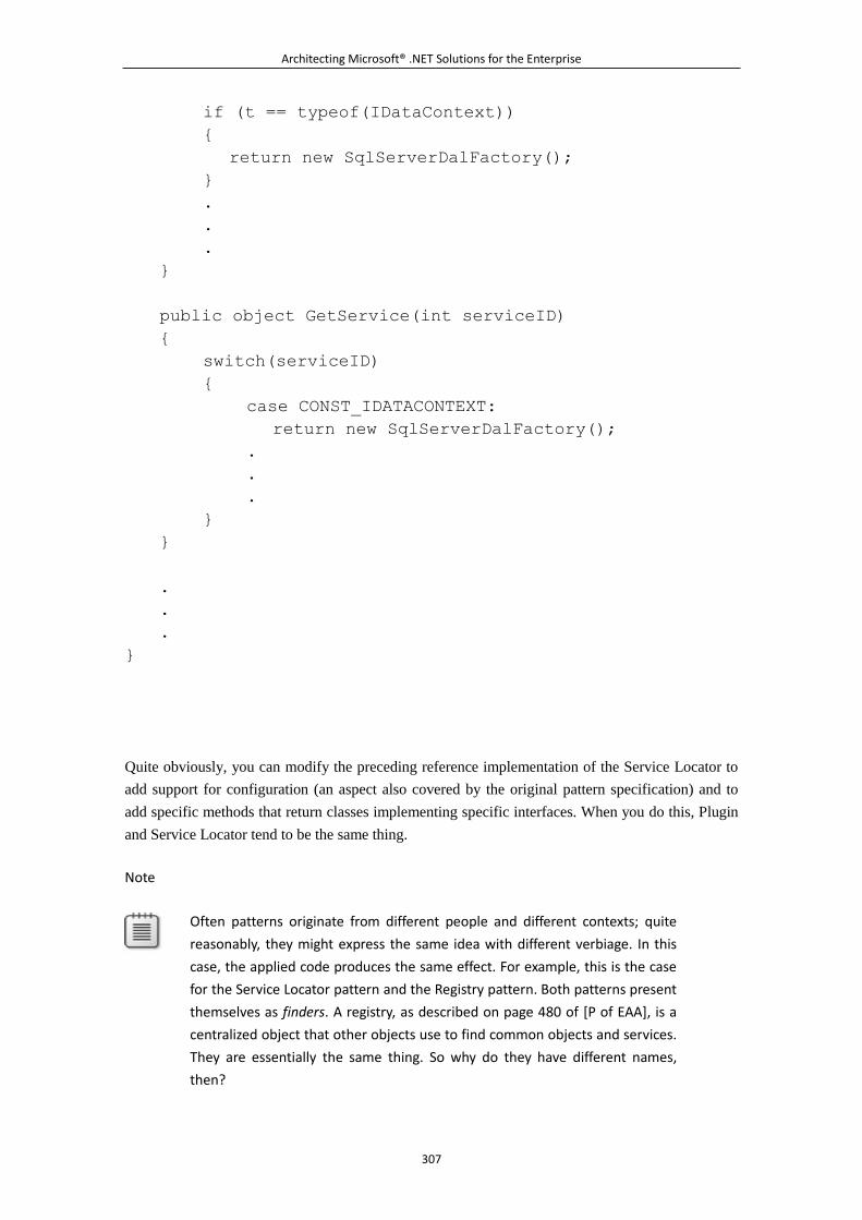
Architecting Microsoft® .NET Solutions for the Enterprise
307
if (t == typeof(IDataContext))
{
return new SqlServerDalFactory();
}
.
.
.
}
public object GetService(int serviceID)
{
switch(serviceID)
{
case CONST_IDATACONTEXT:
return new SqlServerDalFactory();
.
.
.
}
}
.
.
.
}
Quite obviously, you can modify the preceding reference implementation of the Service Locator to
add support for configuration (an aspect also covered by the original pattern specification) and to
add specific methods that return classes implementing specific interfaces. When you do this, Plugin
and Service Locator tend to be the same thing.
Note
Often patterns originate from different people and different contexts; quite
reasonably, they might express the same idea with different verbiage. In this
case, the applied code produces the same effect. For example, this is the case
for the Service Locator pattern and the Registry pattern. Both patterns present
themselves as finders. A registry, as described on page 480 of [P of EAA], is a
centralized object that other objects use to find common objects and services.
They are essentially the same thing. So why do they have different names,
then?
Architecting Microsoft® .NET Solutions for the Enterprise
308
The idea of a "service locator" arose in the context of solutions aimed at
reducing dependency between components. The "registry" originates as a
helper component that objects in an application use to retrieve common
objects and services they need. In other words, in the "registry" there's no
explicit idea of loosening dependency between components. Likewise, in a
"service locator" the focus is on dependencies. But whether you implement a
registry or a service locator, you obtain the same effect. An interesting article
on this subject can be found at
http://martinfowler.com/articles/injection.html.
The Inversion of Control Pattern
Let's briefly recap the design of the DAL we came up with. First, we separated the DAL interface
from its implementation and created distinct assemblies. Next, we set up a Plugin model so that any
DAL consumer calls into a factory and gets an instance of the currently selected DAL. By changing
the configuration, we can switch from one DBMS to another (and even to a fake DBMS for testing
purposes) without rebuilding the application.
The Plugin model works great and is extremely easy to implement for our purpose of handling the
dependencies on any given specific DAL implementation. Generally, using the Plugin pattern
throughout an application as a way to reduce dependencies can be a debatable choice. This is not
because it is an incorrect model per se, but because a possibly better option exists. Enter the
Inversion of Control (IoC) pattern.
Injecting a Reference to the DAL
We already covered IoC in detail Chapter 3, "Design Principles and Patterns," and deeply explored
its goals and the inspiring principle. Here we are basically discussing the applicability of inversion
of control to a DAL scenario, as an alternative to the Plugin model.
Note
For the purpose of this discussion, IoC and Dependency Injection (DI) are
synonyms. They are not always considered synonyms in literature, as
sometimes you find IoC to be the principle and DI the application of the
principle¡ªnamely, the pattern. In reality, IoC is historically a pattern based on
the Dependency Inversion Principle (DIP) by Robert Martin. The term
dependency injection was coined by Martin Fowler later, as a way to further
specialize the concept of inversion of control.
The basic idea behind IoC is that the consumer of some functionality doesn't bother managing
dependencies itself but delegates this burden to a specialized component. Let's apply this principle
to the DAL.
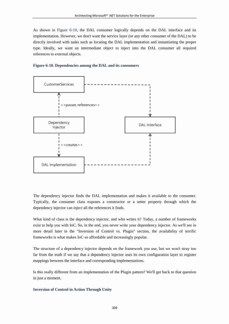
Architecting Microsoft® .NET Solutions for the Enterprise
309
As shown in Figure 6-10, the DAL consumer logically depends on the DAL interface and its
implementation. However, we don't want the service layer (or any other consumer of the DAL) to be
directly involved with tasks such as locating the DAL implementation and instantiating the proper
type. Ideally, we want an intermediate object to inject into the DAL consumer all required
references to external objects.
Figure 6-10. Dependencies among the DAL and its consumers
The dependency injector finds the DAL implementation and makes it available to the consumer.
Typically, the consumer class exposes a constructor or a setter property through which the
dependency injector can inject all the references it finds.
What kind of class is the dependency injector, and who writes it? Today, a number of frameworks
exist to help you with IoC. So, in the end, you never write your dependency injector. As we'll see in
more detail later in the "Inversion of Control vs. Plugin" section, the availability of terrific
frameworks is what makes IoC so affordable and increasingly popular.
The structure of a dependency injector depends on the framework you use, but we won't stray too
far from the truth if we say that a dependency injector uses its own configuration layer to register
mappings between the interface and corresponding implementations.
Is this really different from an implementation of the Plugin pattern? We'll get back to that question
in just a moment.
Inversion of Control in Action Through Unity
Architecting Microsoft® .NET Solutions for the Enterprise
310
To see IoC in action, you need to pick up an IoC framework first. In particular, Microsoft's Unity
Application Block (Unity, for short) is a lightweight IoC container with support for constructor,
property, and method call injection. It comes as part of the Enterprise Library 4.0. Let's use that for
our demonstrations.
Virtually any IoC framework is built around a container class. You bind the container to some
configuration information so that application code can obtain references to instances of specific
concrete objects, based on requests for an interface. Let's see how to proceed with Unity:
// Instantiate the container class
IUnityContainer container;
container = new UnityContainer();
// Bind to working information saved to the <unity> section
of the configuration file
UnityConfigurationSection section;
section = (UnityConfigurationSection)
ConfigurationManager.GetSection("unity");
section.Containers.Default.Configure(container);
// Now you have a fully configured container
.
.
.
The <unity> section in the .NET configuration file looks like the following:
<configuration>
<configSections>
<section name="unity"
type="Microsoft.Practices.Unity.Configuration.UnityConfigu
rationSection,
Microsoft.Practices.Unity.Configuration" />
</configSections>
.
Architecting Microsoft® .NET Solutions for the Enterprise
311
.
.
<unity>
<containers>
<container>
<types>
<type
type="ManagedDesign.App.DAL.IDataContext,
ManagedDesign.App.DALCore"
mapTo="ManagedDesign.App.DAL.SqlServerDataContext,
ManagedDesign.App.SQLServerDAL">
</type>
</types>
</container>
</containers>
</unity>
.
.
.
</configuration>
The <types> section lists mappings between interfaces and corresponding implementations.
Whenever the container is requested to resolve a dependency on a given interface type, it promptly
replies by serving an instance of the corresponding implementation class.
How can you programmatically get the implementation class? You use the Resolve method, as
shown here:
IDataContext impl = container.Resolve<IDataContext>();
Our final step consists of sketching a possible new organization for the code so that classes in the
service layer can be injected with their due dependencies.
Dependency Injection Mechanisms
There are three ways to inject dependencies into a class¡ªusing the constructor, a setter property, or
an interface. In this case, we need to inject the DAL implementation into a service layer class. The
three aforementioned options become the following:
Architecting Microsoft® .NET Solutions for the Enterprise
312
Add a new constructor to each service layer class that consumes the DAL.
Add a new setter property (or method) to each service layer class that consumes the DAL.
Define a new interface, and implement it within each service layer class that consumes the
DAL.
All techniques are valid, and the choice is up to you. We would opt for injecting through the
constructor because this way you make it clear from the beginning what the dependencies of a class
are. The CustomerServices class will look like the following:
public class CustomerServices
{
private IDataContext _context = null;
// Inject the dependency via the ctor
public CustomerServices(IDataContext context)
{
this._context = context;
}
.
.
.
}
The class now features one constructor that receives everything it needs from the outside world.
Note
Where is the Unity container class physically created and managed? The IoC
container is created outside of the CustomerServices class care of any layer of
code that actually consumes an instance of CustomerServices¡ªregardless of
whether it is code in the presentation layer or a WCF custom factory. Before
calling CustomerServices, this layer of code gets hold of the Unity container,
resolves all dependencies, and passes required objects down to the
constructor.
Inversion of Control vs. Plugin
Both the IoC and Plugin patterns provide your application with the fundamental decoupling between
the DAL implementation and DAL consumers. Both are good solutions from a design perspective.
So what's better, IoC or Plugin?
Architecting Microsoft® .NET Solutions for the Enterprise
313
Some people argue that IoC is preferable because you can spot dependencies right from the
constructor (or, in general, from the injection mechanism) of the consumer class. If you use a Plugin,
instead, you need to inspect the source code of the consumer class to spot dependencies. We agree
with this point.
Some people argue that IoC is preferable because it makes for an application that's easier to test.
Honestly, we don't agree with this point. If IoC and Plugin are implemented as discussed here,
testing is not an issue in any case.
Some people argue, in general, that IoC is preferable because it works better in scenarios where
you're writing code that will be incorporated in other applications. It's clear that a CustomerServices
class is inherently more reusable across applications if it is designed to accept the DAL interface
reference via the constructor instances of all the components it uses. If such a CustomerServices
class instantiates any needed components via a factory, it creates a dependency between the host
application and the factory. And this might be a problem.
In general, therefore, the emerging approach is IoC, but using a Plugin is not necessarily a bad idea
and, additionally, it is an approach that works great in a number of situations.
In our opinion, the biggest benefit of using IoC is the support you get from frameworks. IoC
frameworks perform a lot of magic and provide a number of services and facilities (for example,
aspect-oriented capabilities) that you have to code manually in a Plugin scenario. Many of these
features are so sophisticated that to implement them in a Plugin scenario, you have to, well, shape
your own Plugin framework as an IoC framework.
Laying the Groundwork for a Data Context
We recognized the importance of separating the interface of the DAL from its implementation and
agreed that a DAL consumer needs, first of all, to get a reference to the DAL implementation, either
by using a Plugin approach or perhaps through dependency injection.
The consumer doesn't know any details of the actual implementation. In particular, it doesn't know
about the target DBMS and doesn't care about the language being used to run queries and stored
procedures. All that the consumer knows about is an interface that summarizes all the possible
functions that the DAL provides. We refer to such an interface as the data context, and typically
plan to have one distinct data context for testing purposes and one for each low-level data access
API we intend to support.
The IDataContext Interface
For the sake of discussion, let's briefly recall the definition of the IDataContext interface we gave
earlier in the chapter:
public interface IDataContext : IDisposable
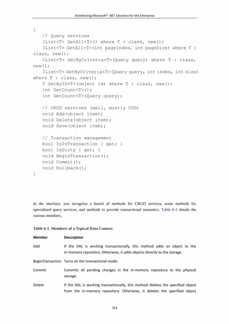
Architecting Microsoft® .NET Solutions for the Enterprise
314
{
// Query services
IList<T> GetAll<T>() where T : class, new();
IList<T> GetAll<T>(int pageIndex, int pageSize) where T :
class, new();
IList<T> GetByCriteria<T>(Query query) where T : class,
new();
IList<T> GetByCriteria<T>(Query query, int index, int size)
where T : class, new();
T GetByID<T>(object id) where T : class, new();
int GetCount<T>();
int GetCount<T>(Query query);
// CRUD services (well, mostly CUD)
void Add(object item);
void Delete(object item);
void Save(object item);
// Transaction management
bool IsInTransaction { get; }
bool IsDirty { get; }
void BeginTransaction();
void Commit();
void Rollback();
}
In the interface, you recognize a bunch of methods for CRUD services, some methods for
specialized query services, and methods to provide transactional semantics. Table 6-1 details the
various members.
Table 6-1. Members of a Typical Data Context
Member Description
Add If the DAL is working transactionally, this method adds an object to the
in-memory repository. Otherwise, it adds objects directly to the storage.
BeginTransaction Turns on the transactional mode.
Commit Commits all pending changes in the in-memory repository to the physical
storage.
Delete If the DAL is working transactionally, this method deletes the specified object
from the in-memory repository. Otherwise, it deletes the specified object
Architecting Microsoft® .NET Solutions for the Enterprise
315
Table 6-1. Members of a Typical Data Context
Member Description
directly from the storage.
GetAll<T> Retrieves all instances of the specified type (Customer, Order) in the underlying
database.
GetByCriteria<T> Executes a query. The query is expressed using a custom type that models a
query through a set of operators and clauses.
GetByID<T> Retrieves the instance of the given type (Customer, Order) whose identifier
matches the passed value.
GetCount<T> Returns the number of objects of the specified type that the given query would
select.
IsDirty Boolean property, indicates whether this instance of the DAL contains any
pending changes not yet saved to the storage.
IsInTransaction Boolean property, indicates whether this instance of the DAL works
transactionally.
Rollback Discards all pending changes, and resets the transactional mode.
Save If the DAL is working transactionally, this method updates the specified object in
the in-memory repository. Otherwise, it directly updates the storage.
The methods in the interface reflect many of the responsibilities of the data context we identified at
the beginning of the chapter. You find methods to add, delete, and update objects to database tables.
You find methods to track changes occurring in a unit of work. You find methods to query for
objects as simple as GetAll and GetByID, plus a more sophisticated GetByCriteria method to
arrange for dynamically built queries.
In our companion source code, we have a hierarchy of classes like those shown in Figure 6-11.
Figure 6-11. Hierarchy of data-context classes
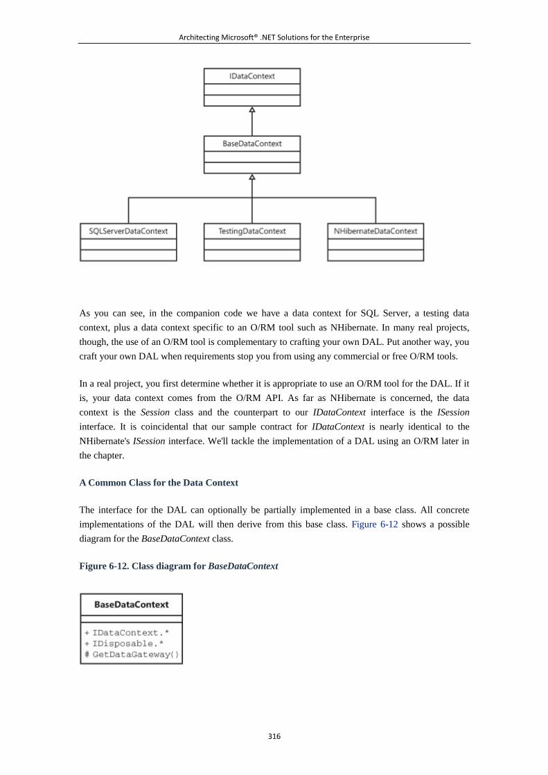
Architecting Microsoft® .NET Solutions for the Enterprise
316
As you can see, in the companion code we have a data context for SQL Server, a testing data
context, plus a data context specific to an O/RM tool such as NHibernate. In many real projects,
though, the use of an O/RM tool is complementary to crafting your own DAL. Put another way, you
craft your own DAL when requirements stop you from using any commercial or free O/RM tools.
In a real project, you first determine whether it is appropriate to use an O/RM tool for the DAL. If it
is, your data context comes from the O/RM API. As far as NHibernate is concerned, the data
context is the Session class and the counterpart to our IDataContext interface is the ISession
interface. It is coincidental that our sample contract for IDataContext is nearly identical to the
NHibernate's ISession interface. We'll tackle the implementation of a DAL using an O/RM later in
the chapter.
A Common Class for the Data Context
The interface for the DAL can optionally be partially implemented in a base class. All concrete
implementations of the DAL will then derive from this base class. Figure 6-12 shows a possible
diagram for the BaseDataContext class.
Figure 6-12. Class diagram for BaseDataContext
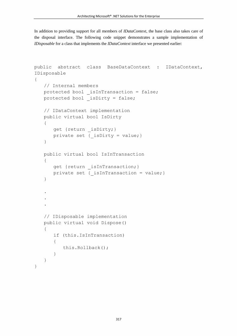
Architecting Microsoft® .NET Solutions for the Enterprise
317
In addition to providing support for all members of IDataContext, the base class also takes care of
the disposal interface. The following code snippet demonstrates a sample implementation of
IDisposable for a class that implements the IDataContext interface we presented earlier:
public abstract class BaseDataContext : IDataContext,
IDisposable
{
// Internal members
protected bool _isInTransaction = false;
protected bool _isDirty = false;
// IDataContext implementation
public virtual bool IsDirty
{
get {return _isDirty;}
private set {_isDirty = value;}
}
public virtual bool IsInTransaction
{
get {return _isInTransaction;}
private set {_isInTransaction = value;}
}
.
.
.
// IDisposable implementation
public virtual void Dispose()
{
if (this.IsInTransaction)
{
this.Rollback();
}
}
}
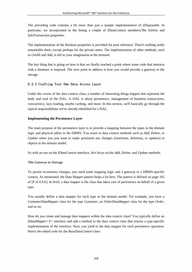
Architecting Microsoft® .NET Solutions for the Enterprise
318
The preceding code contains a bit more than just a sample implementation of IDisposable. In
particular, we incorporated in the listing a couple of IDataContext members¡ªthe IsDirty and
IsInTransaction properties.
The implementation of the Boolean properties is provided for pure reference. There's nothing really
remarkable there, except perhaps for the private setter. The implementation of other methods, such
as GetAll and Add, is left to your imagination at the moment.
The key thing that is going on here is that we finally reached a point where some code that interacts
with a database is required. The next point to address is how you would provide a gateway to the
storage.
6.3.3 Crafting Your Own Data Access Layer
Under the covers of the data context class, a number of interesting things happen that represent the
body and soul of the DAL. A DAL is about persistence, management of business transactions,
concurrency, lazy loading, maybe caching, and more. In this section, we'll basically go through the
typical responsibilities we've already identified for a DAL.
Implementing the Persistence Layer
The main purpose of the persistence layer is to provide a mapping between the types in the domain
logic and physical tables in the DBMS. You resort to data context methods such as Add, Delete, or
Update when you just want to make persistent any changes (insertions, deletions, or updates) to
objects in the domain model.
So with an eye on the IDataContext interface, let's focus on the Add, Delete, and Update methods.
The Gateway to Storage
To persist in-memory changes, you need some mapping logic and a gateway to a DBMS-specific
context. As mentioned, the Data Mapper pattern helps a lot here. The pattern is defined on page 165
of [P of EAA]. In brief, a data mapper is the class that takes care of persistence on behalf of a given
type.
You usually define a data mapper for each type in the domain model. For example, you have a
CustomerDataMapper class for the type Customer, an OrderDataMapper class for the type Order,
and so on.
How do you create and manage data mappers within the data context class? You typically define an
IDataMapper<T> interface and add a method to the data context class that returns a type-specific
implementation of the interface. Next, you yield to the data mapper for each persistence operation.
Here's the edited code for the BaseDataContext class:
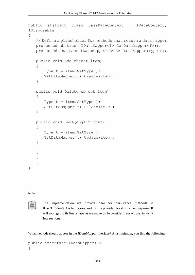
Architecting Microsoft® .NET Solutions for the Enterprise
319
public abstract class BaseDataContext : IDataContext,
IDisposable
{
// Define a placeholder for methods that return a data mapper
protected abstract IDataMapper<T> GetDataMapper<T>();
protected abstract IDataMapper<T> GetDataMapper(Type t);
public void Add(object item)
{
Type t = item.GetType();
GetDataMapper(t).Create(item);
}
public void Delete(object item)
{
Type t = item.GetType();
GetDataMapper(t).Delete(item);
}
public void Save(object item)
{
Type t = item.GetType();
GetDataMapper(t).Update(item);
}
.
.
.
}
Note
The implementation we provide here for persistence methods in
BaseDataContext is temporary and mostly provided for illustrative purposes. It
will soon get to its final shape as we move on to consider transactions, in just a
few sections.
What methods should appear in the IDataMapper interface? At a minimum, you find the following:
public interface IDataMapper<T>
{
Architecting Microsoft® .NET Solutions for the Enterprise
320
void Create(T item);
void Update(T item);
void Delete(T item);
}
The parameter item of type T indicates the object to add, remove, or update in the data storage.
Details of the mapping between the specified object and the tables in the database are known by
each class that implements IDataMapper<T>.
As you might have noticed, the GetDataMapper method is declared protected and abstract in the
base data context class. This means that each derived class¡ªthat is, each concrete and
DBMS-specific implementation of the data context¡ªmust implement GetDataMapper. In this way,
we let subclasses define what a data mapper actually is and how it behaves. This approach is based
on the Template Method pattern, as originally defined by the Gang of Four.
Note
The Template Method pattern is designed to let subclasses redefine given
steps of an algorithm implemented in the parent class. Admittedly, the
Template Method pattern is somewhat similar to the Strategy pattern. Well,
some differences exist if you want to be picky. The Strategy pattern allows
callers to redefine an entire algorithm; the Template Method pattern allows
you to redefine single steps without changing the overall algorithm.
Subsequently, you end up using inheritance with the Template Method
pattern, and delegation with Strategy.
Should we have more methods in the IDataMapper interface? And if so, which methods? When, at
the beginning of the chapter, we presented the typical responsibilities of a DAL, we mentioned
CRUD services. As is widely known, CRUD is an acronym that stands for Create, Read, Update,
Delete. Now that we are discussing the implementation of a DAL, we suddenly switched from
saying "CRUD services" to saying "persistence layer." What's the point with the name change? The
persistence layer is a subset of CRUD services, as it might not include Read services. So the
persistence layer is more CUD services than CRUD services. We'll treat Read features in the next
section when we discuss query services.
A Factory for Data Mappers
The BaseDataContext class features an abstract method named GetDataMapper that is responsible
for providing a type-specific data mapper. The method is abstract and must be defined in any class
derived from BaseDataContext¡ªthat is, in any implementation of the system's DAL. Let's see how it
works for a DAL based on SQL Server:
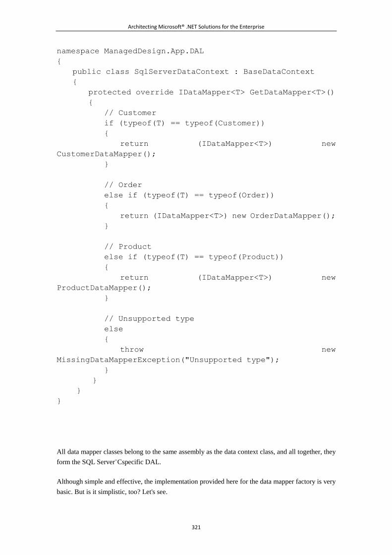
Architecting Microsoft® .NET Solutions for the Enterprise
321
namespace ManagedDesign.App.DAL
{
public class SqlServerDataContext : BaseDataContext
{
protected override IDataMapper<T> GetDataMapper<T>()
{
// Customer
if (typeof(T) == typeof(Customer))
{
return (IDataMapper<T>) new
CustomerDataMapper();
}
// Order
else if (typeof(T) == typeof(Order))
{
return (IDataMapper<T>) new OrderDataMapper();
}
// Product
else if (typeof(T) == typeof(Product))
{
return (IDataMapper<T>) new
ProductDataMapper();
}
// Unsupported type
else
{
throw new
MissingDataMapperException("Unsupported type");
}
}
}
}
All data mapper classes belong to the same assembly as the data context class, and all together, they
form the SQL Server C̈specific DAL.
Although simple and effective, the implementation provided here for the data mapper factory is very
basic. But is it simplistic, too? Let's see.
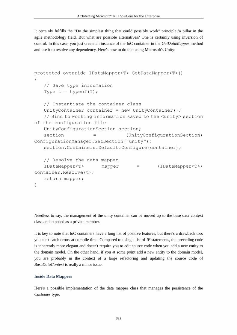
Architecting Microsoft® .NET Solutions for the Enterprise
322
It certainly fulfills the "Do the simplest thing that could possibly work" principle¡ªa pillar in the
agile methodology field. But what are possible alternatives? One is certainly using inversion of
control. In this case, you just create an instance of the IoC container in the GetDataMapper method
and use it to resolve any dependency. Here's how to do that using Microsoft's Unity:
protected override IDataMapper<T> GetDataMapper<T>()
{
// Save type information
Type t = typeof(T);
// Instantiate the container class
UnityContainer container = new UnityContainer();
// Bind to working information saved to the <unity> section
of the configuration file
UnityConfigurationSection section;
section = (UnityConfigurationSection)
ConfigurationManager.GetSection("unity");
section.Containers.Default.Configure(container);
// Resolve the data mapper
IDataMapper<T> mapper = (IDataMapper<T>)
container.Resolve(t);
return mapper;
}
Needless to say, the management of the unity container can be moved up to the base data context
class and exposed as a private member.
It is key to note that IoC containers have a long list of positive features, but there's a drawback too:
you can't catch errors at compile time. Compared to using a list of IF statements, the preceding code
is inherently more elegant and doesn't require you to edit source code when you add a new entity to
the domain model. On the other hand, if you at some point add a new entity to the domain model,
you are probably in the context of a large refactoring and updating the source code of
BaseDataContext is really a minor issue.
Inside Data Mappers
Here's a possible implementation of the data mapper class that manages the persistence of the
Customer type:
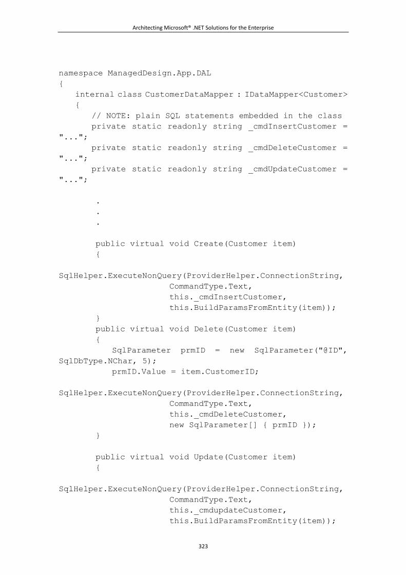
Architecting Microsoft® .NET Solutions for the Enterprise
323
namespace ManagedDesign.App.DAL
{
internal class CustomerDataMapper : IDataMapper<Customer>
{
// NOTE: plain SQL statements embedded in the class
private static readonly string _cmdInsertCustomer =
"...";
private static readonly string _cmdDeleteCustomer =
"...";
private static readonly string _cmdUpdateCustomer =
"...";
.
.
.
public virtual void Create(Customer item)
{
SqlHelper.ExecuteNonQuery(ProviderHelper.ConnectionString,
CommandType.Text,
this._cmdInsertCustomer,
this.BuildParamsFromEntity(item));
}
public virtual void Delete(Customer item)
{
SqlParameter prmID = new SqlParameter("@ID",
SqlDbType.NChar, 5);
prmID.Value = item.CustomerID;
SqlHelper.ExecuteNonQuery(ProviderHelper.ConnectionString,
CommandType.Text,
this._cmdDeleteCustomer,
new SqlParameter[] { prmID });
}
public virtual void Update(Customer item)
{
SqlHelper.ExecuteNonQuery(ProviderHelper.ConnectionString,
CommandType.Text,
this._cmdupdateCustomer,
this.BuildParamsFromEntity(item));
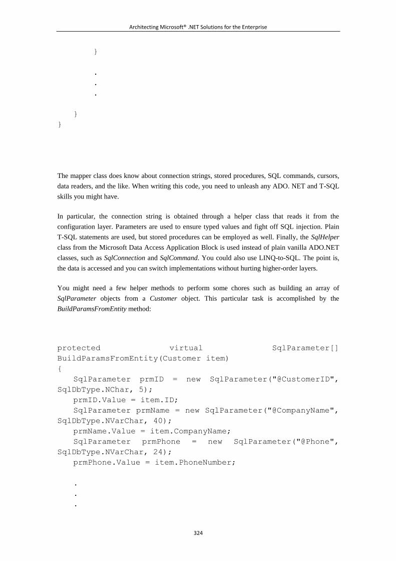
Architecting Microsoft® .NET Solutions for the Enterprise
324
}
.
.
.
}
}
The mapper class does know about connection strings, stored procedures, SQL commands, cursors,
data readers, and the like. When writing this code, you need to unleash any ADO. NET and T-SQL
skills you might have.
In particular, the connection string is obtained through a helper class that reads it from the
configuration layer. Parameters are used to ensure typed values and fight off SQL injection. Plain
T-SQL statements are used, but stored procedures can be employed as well. Finally, the SqlHelper
class from the Microsoft Data Access Application Block is used instead of plain vanilla ADO.NET
classes, such as SqlConnection and SqlCommand. You could also use LINQ-to-SQL. The point is,
the data is accessed and you can switch implementations without hurting higher-order layers.
You might need a few helper methods to perform some chores such as building an array of
SqlParameter objects from a Customer object. This particular task is accomplished by the
BuildParamsFromEntity method:
protected virtual SqlParameter[]
BuildParamsFromEntity(Customer item)
{
SqlParameter prmID = new SqlParameter("@CustomerID",
SqlDbType.NChar, 5);
prmID.Value = item.ID;
SqlParameter prmName = new SqlParameter("@CompanyName",
SqlDbType.NVarChar, 40);
prmName.Value = item.CompanyName;
SqlParameter prmPhone = new SqlParameter("@Phone",
SqlDbType.NVarChar, 24);
prmPhone.Value = item.PhoneNumber;
.
.
.
Architecting Microsoft® .NET Solutions for the Enterprise
325
return new SqlParameter[] { prmID, prmName, prmPhone, ... };
}
As you can see, the SQL code for the various operations is embedded in the class. It can either be
plain T-SQL statements or stored procedures. In any case, what we need here is plain data access
code with nothing more than simple table-oriented statements: no loops, no conditions, no logic.
We'll return later in the chapter to the role that stored procedures ideally have in the design of a
DAL, according to our way of looking at things.
Bridging Types and Tables
Data mappers are essentially developer-created classes that fill the logical gap between the object
model (or domain model) and the physical structure of databases.
The code snippet we just presented assumes a substantial one-to-one correspondence between the
in-memory model and the physical data model. So each method on the data mapper is resolved in a
single call to a single table. Each instance of a class in the object (or domain) model maps to a row
in a table. The more the logical model is distant from the physical organization of tables, the more
sophisticated a data mapper needs to be.
Put another way, the data mapper is a class that takes an entity from the in-memory object (or
domain) model and persists it to the selected storage¡ªwhatever this means in practice. As an
example, consider a Customer class with a property Address of type AddressInfo, as shown here:
public class Customer
{
public Customer()
{
this._addressInfo = new AddressInfo();
.
.
.
}
protected AddressInfo _addressinfo;
public virtual AddressInfo Address
{
get { return this._addressInfo;
}
Architecting Microsoft® .NET Solutions for the Enterprise
326
.
.
.
}
The type AddressInfo groups properties such as Street, City, PostalCode, Region, and Country, as
shown here:
public class AddressInfo
{
public string Street {get; set;}
public string City {get; set;}
public string PostalCode {get; set;}
public string Region {get; set;}
public string Country {get; set;}
}
In this case, there's no direct correspondence between the entity Customer and a table in the
database. It's more likely, in fact, that the table has a distinct column for each of the properties in the
AddressInfo than a single property for the whole address. Properly mapping properties to columns
(and tables) is the primary responsibility of the data mapper. The aforementioned method
BuildParamsFromEntity does just this, as shown here:
protected virtual SqlParameter[]
BuildParamsFromEntity(Customer item)
{
// Create the return array
List<SqlParameter> parms = new List<SqlParameter>();
// @CustomerID from property ID
SqlParameter prmID = new SqlParameter("@CustomerID",
SqlDbType.NChar, 5);
prmID.Value = item.ID;
parms.Add(prmID);
// @CompanyName from property CompanyName
SqlParameter prmName = new SqlParameter("@CompanyName",
SqlDbType.NVarChar, 40);
prmName.Value = item.CompanyName;
parms.Add(prmName);
Architecting Microsoft® .NET Solutions for the Enterprise
327
// @Address from property AddressInfo.Street
SqlParameter prmAddress = new SqlParameter("@Address",
SqlDbType.NVarChar, 60);
prmAddress.Value = item.AddressInfo.Street;
parms.Add(prmAddress);
// @City from property AddressInfo.City
SqlParameter prmCity = new SqlParameter("@City",
SqlDbType.NVarChar, 15);
prmCity.Value = item.AddressInfo.City;
parms.Add(prmCity);
// @Region from property AddressInfo.Region
SqlParameter prmRegion = new SqlParameter("@Region",
SqlDbType.NVarChar, 15);
prmRegion.Value = item.AddressInfo.Region;
parms.Add(prmRegion);
// @PostalCode from property AddressInfo.ZipCode
SqlParameter prmZip = new SqlParameter("@PostalCode",
SqlDbType.NVarChar, 10);
prmZip.Value = item.AddressInfo.ZipCode;
parms.Add(prmZio);
// @Country from property AddressInfo.Country
SqParameter prmCountry = new SqlParameter("@Country",
SqlDbType.NVarChar, 15);
pmCountry.Value = item.AddressInfo.Country;
parms.Add(prmCountry);
.
.
.
return parms.ToArray();
}
Members of the Customer type are mapped to parameters for the SQL statement or stored procedure.
In other words, the state of an object has been serialized to a tuple of values. The same happens the
other way around when you run a query: from a tuple of values the data mapper builds an object.
Want to see a more real-world scenario of type-to-table bridging? Read on.
Architecting Microsoft® .NET Solutions for the Enterprise
328
Note
How well designed is your database? The preceding code assumed we were
using a database like Northwind, which certainly doesn't represent a best
practice for its lack of normalization at various points. In Northwind, address
information is stored in the Customers table. A well-designed database might
present a more normalized form where customer's name information is stored
in one table while the address information is stored in another. The domain
model might feature an AddressInfo structure, regardless of the details of the
physical database tables. If you change the structure of tables, you don't
update the domain model; instead, you focus your changes in the data
mapper. In any other scenario for the BLL, you have to enter changes to the
business components.
Cross-Table Operations
What if the user triggers an action that results in the insertion of an order? An Order class is likely
to contain a bunch of order items, which likely requires you to operate on multiple tables. Another
realistic scenario for operating on multiple tables is when the same entity is fragmented on a variety
of tables¡ªfor example, because the (legacy) database has a limited page size and/or because tables
have grown over the years beyond the page size and you've been forced to add new related tables.
In any case, in a data mapper method you might need to run multiple operations. Here's an example:
public virtual void Create(Order order)
{
// Insert order in the Orders table
SqlHelper.ExecuteNonQuery(ProviderHelper.ConnectionString,
CommandType.Text,
this._cmdinsertOrder,
this.BuildParamsFromEntity(order));
// Insert individual order items in the OrderItems table
foreach(OrderItem item in order.OrderItems)
{
SqlHelper.ExecuteNonQuery(ProviderHelper.ConnectionString,
CommandType.Text,
this._cmdinsertOrderItem,
this.BuildParamsFromEntity(order));
}
}
Architecting Microsoft® .NET Solutions for the Enterprise
329
Note
SQL Server 2008 comes with a nice feature that can help optimize the
preceding code¡ªTable Value Parameters (TVPs). TVPs allow you to pass
user-defined tables of data as an argument to a query or a stored procedure.
Instead of having the query take a long list of parameters, you simply pass just
one parameter C̈a TVP. In a stored procedure, you still query the TVP for data
and then operate as usual with scalar data. So a TVP is not going to transform
SQL Server¡ªneither in an object-oriented DBMS, nor in an O/RM. Using a TVP
is an excellent way to write simpler and more effective ADO.NET code that
targets SQL Server 2008. Note that to use a TVP, you should indicate a special
parameter type¡ªprecisely, SqlDbType.Structured¡ªand have it defined in the
database. A TVP is a temporary table saved to Tempdb.
There a few points to consider here¡ªfirst, roundtrips to the database. For N order items, you get N+1
roundtrips to the database. Can you make it a single batch of SQL statements? That's really hard to
do with a stored procedure or embedded SQL. It's definitely a possibility if you generate the SQL
code dynamically. (By the way, using dynamic SQL is just what O/RM tools do. See later text for
more details.)
Another point relates to the (re)use of connections. If you use SqlHelper, as we did earlier, you pick
up a new connection from the pool (or create a new connection if no pooling is enabled) every time
you run a command. You can optimize this by creating a connection object at the beginning of the
method and using that for all subsequent calls within the method. This is not an option, however, if
your fragmented entity spans different databases. In this case, the best you can do is try to minimize
the number of connections to the extent that it is possible.
Finally, you need the operation to occur within the boundaries of a transaction. In this case, where
should you put the transaction boundaries? Certainly not in the SQL code. A better possibility is
placing the transaction scope in the Create method:
public virtual void Create(Order order)
{
using (TransactionScope tx = new TransactionScope())
{
// Your data access code here
.
.
.
// Commit the transaction
tx.Complete();
}
Architecting Microsoft® .NET Solutions for the Enterprise
330
}
However, the whole topic of transactionality requires a broader approach in the context of a DAL.
We'll get to that in the upcoming "Implementing Transactional Semantics" section.
Implementing Query Services
So far, we focused on going down to the database for writing. Let's see how to read and map result
sets to a graph of objects. In particular, we'll focus on the creation of a query model that abstracts
away SQL and gains you complete independence from a particular relational DBMS. Through the
model, you design your queries as objects and then pass them on to a specific object that translates it
to SQL.
Note
If the expression "query model" sounds a bit too abstract, consider that LINQ
is nothing more than an "idiomatic" query model supplied by the latest C# and
Visual Basic .NET compilers. As we saw in Chapter 3, an idiom is the
technological counterpart of a design pattern. Put another way, an idiom is a
design pattern hard-coded in a language and exposed through ad hoc syntax
elements.
A Repository of Objects
In a world where data is managed via tuples, a query is essentially the act of processing a string of
SQL against a set of database tables. If successful, the query gets you some tabular result sets back.
In a world where data is managed via objects, a query is the act of invoking a method on an object.
The query gets back a collection of other objects. Returned objects can be built directly from a result
set or picked up from some sort of intermediate cache, depending on the internal strategy of the
repository. In an object-oriented world, you query using objects and get objects back. (See Figure
6-13.)
Figure 6-13. The overall idea of a repository for common objects and queries
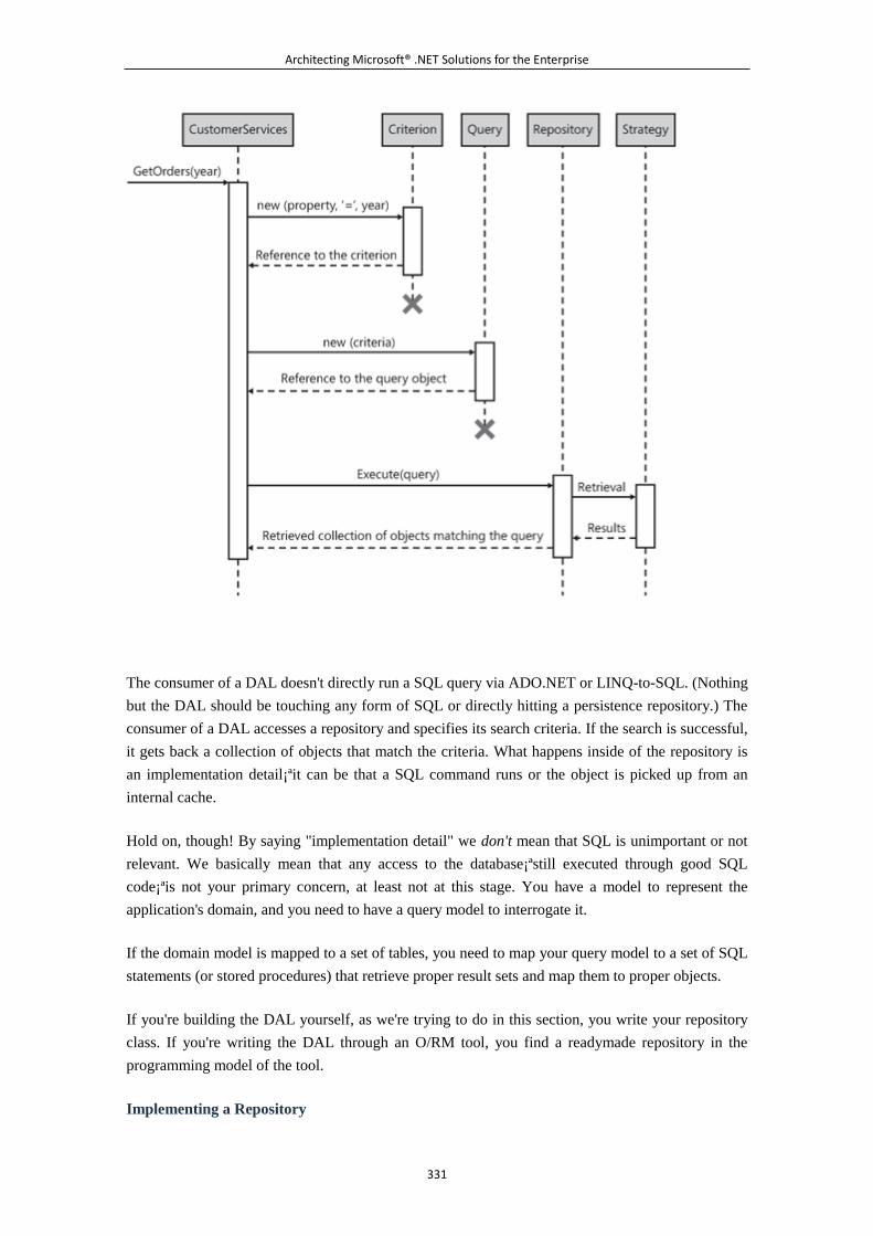
Architecting Microsoft® .NET Solutions for the Enterprise
331
The consumer of a DAL doesn't directly run a SQL query via ADO.NET or LINQ-to-SQL. (Nothing
but the DAL should be touching any form of SQL or directly hitting a persistence repository.) The
consumer of a DAL accesses a repository and specifies its search criteria. If the search is successful,
it gets back a collection of objects that match the criteria. What happens inside of the repository is
an implementation detail¡ªit can be that a SQL command runs or the object is picked up from an
internal cache.
Hold on, though! By saying "implementation detail" we don't mean that SQL is unimportant or not
relevant. We basically mean that any access to the database¡ªstill executed through good SQL
code¡ªis not your primary concern, at least not at this stage. You have a model to represent the
application's domain, and you need to have a query model to interrogate it.
If the domain model is mapped to a set of tables, you need to map your query model to a set of SQL
statements (or stored procedures) that retrieve proper result sets and map them to proper objects.
If you're building the DAL yourself, as we're trying to do in this section, you write your repository
class. If you're writing the DAL through an O/RM tool, you find a readymade repository in the
programming model of the tool.
Implementing a Repository
Architecting Microsoft® .NET Solutions for the Enterprise
332
The idea of a repository in the DAL is formalized in the Repository pattern, as defined on page 322
of [P of EAA]. In a nutshell, a repository is a class that exposes a bunch of query methods. Which
methods? Methods as generic as GetAll, GetByID, and GetCount? Or methods as specific as
GetCustomersByCountry, GetOrdersByYear, and GetDiscontinuedProducts?
Guess what? It depends.
In general, you might want to have general-purpose query methods in the repository, plus any
specific query method that is really reused across the DAL. This is a point that deserves a bit of
attention. Reusing a method is not like reusing a stored procedure. It makes sense to have a stored
procedure like this in the database:
CREATE PROCEDURE [dbo].[getCustomersByCountry]
@CountryID smallint
AS
BEGIN
SET NOCOUNT ON;
-- OK let us use * only for the sake of readability :)
SELECT * FROM customers WHERE countryID=@CountryID
.
.
.
END
GO
It might not make the same sense to have a method in the repository that wraps the stored procedure.
Why? Because of the returned values and, incidentally, because of the different abstraction level
where methods and stored procedures live.
Note
By the way, the different abstraction level where methods and stored
procedures live is, in our humble opinion, one of the reasons that ultimately
arouses the debate around using O/RM tools for building a data access layer.
Database guys seem to be unable to look outside the fence of stored
procedures. Developers, on the other hand, seem to forget that there's still
SQL running at the bottom of it.
Because methods encapsulate calls to SQL, the same stored procedure (or SQL statement) can be
called from within two methods expecting significantly different outcomes. The stored procedure is
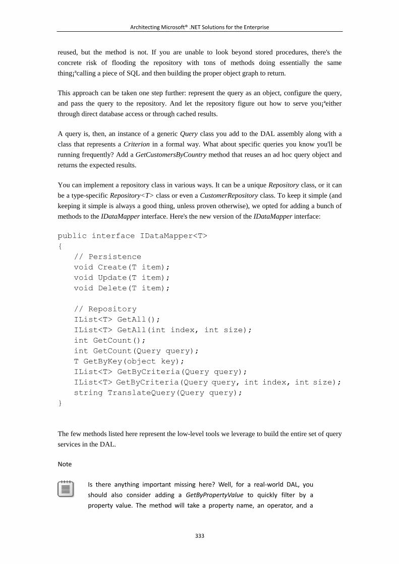
Architecting Microsoft® .NET Solutions for the Enterprise
333
reused, but the method is not. If you are unable to look beyond stored procedures, there's the
concrete risk of flooding the repository with tons of methods doing essentially the same
thing¡ªcalling a piece of SQL and then building the proper object graph to return.
This approach can be taken one step further: represent the query as an object, configure the query,
and pass the query to the repository. And let the repository figure out how to serve you¡ªeither
through direct database access or through cached results.
A query is, then, an instance of a generic Query class you add to the DAL assembly along with a
class that represents a Criterion in a formal way. What about specific queries you know you'll be
running frequently? Add a GetCustomersByCountry method that reuses an ad hoc query object and
returns the expected results.
You can implement a repository class in various ways. It can be a unique Repository class, or it can
be a type-specific Repository<T> class or even a CustomerRepository class. To keep it simple (and
keeping it simple is always a good thing, unless proven otherwise), we opted for adding a bunch of
methods to the IDataMapper interface. Here's the new version of the IDataMapper interface:
public interface IDataMapper<T>
{
// Persistence
void Create(T item);
void Update(T item);
void Delete(T item);
// Repository
IList<T> GetAll();
IList<T> GetAll(int index, int size);
int GetCount();
int GetCount(Query query);
T GetByKey(object key);
IList<T> GetByCriteria(Query query);
IList<T> GetByCriteria(Query query, int index, int size);
string TranslateQuery(Query query);
}
The few methods listed here represent the low-level tools we leverage to build the entire set of query
services in the DAL.
Note
Is there anything important missing here? Well, for a real-world DAL, you
should also consider adding a GetByPropertyValue to quickly filter by a
property value. The method will take a property name, an operator, and a
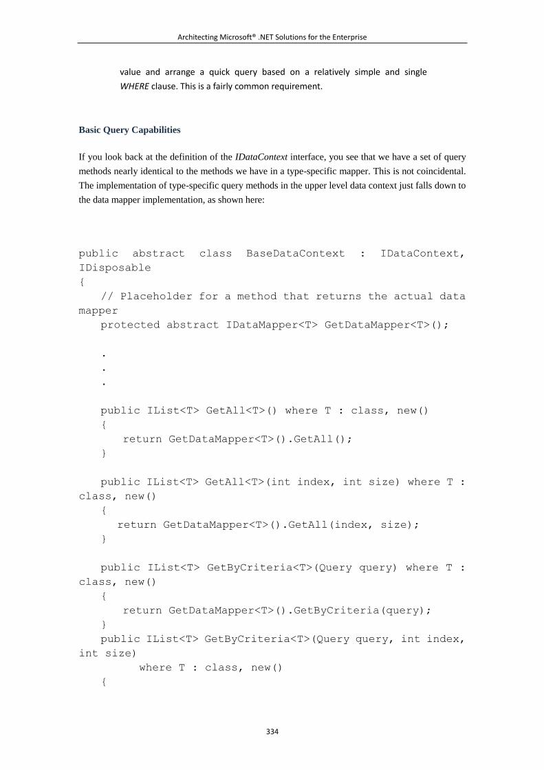
Architecting Microsoft® .NET Solutions for the Enterprise
334
value and arrange a quick query based on a relatively simple and single
WHERE clause. This is a fairly common requirement.
Basic Query Capabilities
If you look back at the definition of the IDataContext interface, you see that we have a set of query
methods nearly identical to the methods we have in a type-specific mapper. This is not coincidental.
The implementation of type-specific query methods in the upper level data context just falls down to
the data mapper implementation, as shown here:
public abstract class BaseDataContext : IDataContext,
IDisposable
{
// Placeholder for a method that returns the actual data
mapper
protected abstract IDataMapper<T> GetDataMapper<T>();
.
.
.
public IList<T> GetAll<T>() where T : class, new()
{
return GetDataMapper<T>().GetAll();
}
public IList<T> GetAll<T>(int index, int size) where T :
class, new()
{
return GetDataMapper<T>().GetAll(index, size);
}
public IList<T> GetByCriteria<T>(Query query) where T :
class, new()
{
return GetDataMapper<T>().GetByCriteria(query);
}
public IList<T> GetByCriteria<T>(Query query, int index,
int size)
where T : class, new()
{
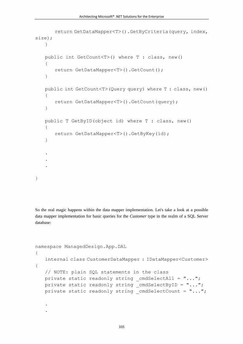
Architecting Microsoft® .NET Solutions for the Enterprise
335
return GetDataMapper<T>().GetByCriteria(query, index,
size);
}
public int GetCount<T>() where T : class, new()
{
return GetDataMapper<T>().GetCount();
}
public int GetCount<T>(Query query) where T : class, new()
{
return GetDataMapper<T>().GetCount(query);
}
public T GetByID(object id) where T : class, new()
{
return GetDataMapper<T>().GetByKey(id);
}
.
.
.
}
So the real magic happens within the data mapper implementation. Let's take a look at a possible
data mapper implementation for basic queries for the Customer type in the realm of a SQL Server
database:
namespace ManagedDesign.App.DAL
{
internal class CustomerDataMapper : IDataMapper<Customer>
{
// NOTE: plain SQL statements in the class
private static readonly string _cmdSelectAll = "...";
private static readonly string _cmdSelectByID = "...";
private static readonly string _cmdSelectCount = "...";
.
.
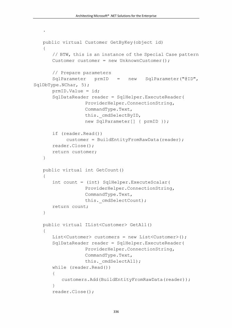
Architecting Microsoft® .NET Solutions for the Enterprise
336
.
public virtual Customer GetByKey(object id)
{
// BTW, this is an instance of the Special Case pattern
Customer customer = new UnknownCustomer();
// Prepare parameters
SqlParameter prmID = new SqlParameter("@ID",
SqlDbType.NChar, 5);
prmID.Value = id;
SqlDataReader reader = SqlHelper.ExecuteReader(
ProviderHelper.ConnectionString,
CommandType.Text,
this._cmdSelectByID,
new SqlParameter[] { prmID });
if (reader.Read())
customer = BuildEntityFromRawData(reader);
reader.Close();
return customer;
}
public virtual int GetCount()
{
int count = (int) SqlHelper.ExecuteScalar(
ProviderHelper.ConnectionString,
CommandType.Text,
this._cmdSelectCount);
return count;
}
public virtual IList<Customer> GetAll()
{
List<Customer> customers = new List<Customer>();
SqlDataReader reader = SqlHelper.ExecuteReader(
ProviderHelper.ConnectionString,
CommandType.Text,
this._cmdSelectAll);
while (reader.Read())
{
customers.Add(BuildEntityFromRawData(reader));
}
reader.Close();
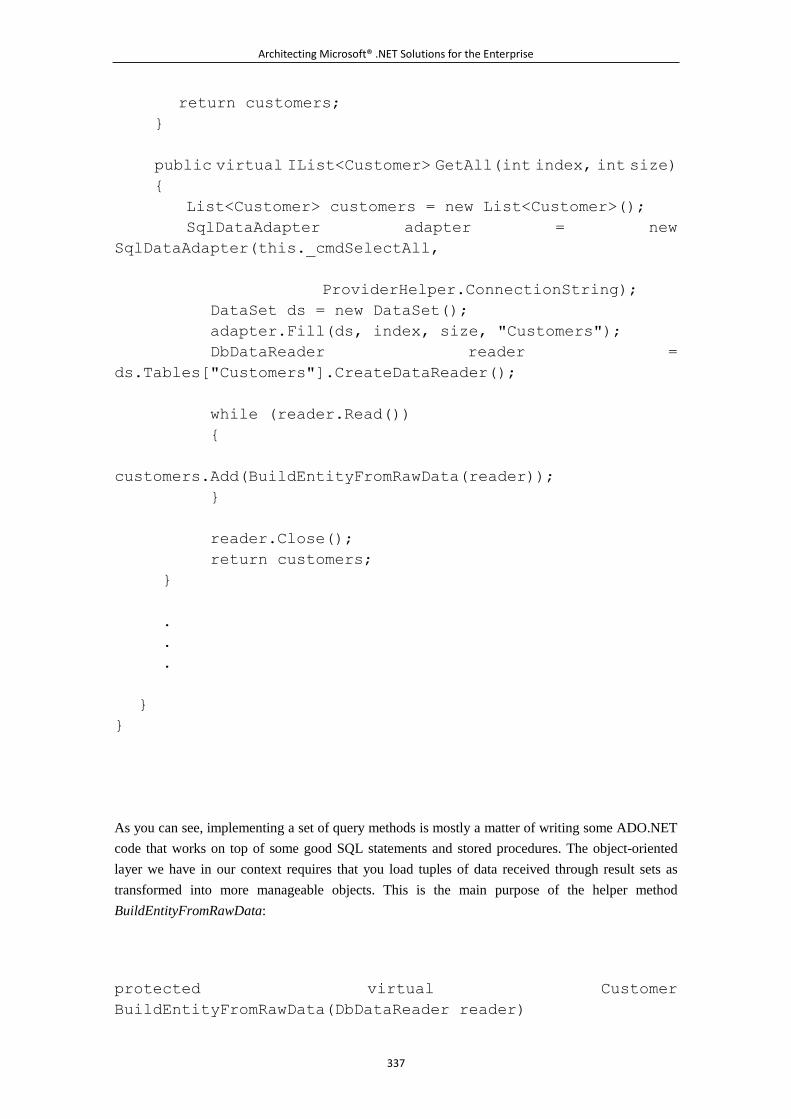
Architecting Microsoft® .NET Solutions for the Enterprise
337
return customers;
}
public virtual IList<Customer> GetAll(int index, int size)
{
List<Customer> customers = new List<Customer>();
SqlDataAdapter adapter = new
SqlDataAdapter(this._cmdSelectAll,
ProviderHelper.ConnectionString);
DataSet ds = new DataSet();
adapter.Fill(ds, index, size, "Customers");
DbDataReader reader =
ds.Tables["Customers"].CreateDataReader();
while (reader.Read())
{
customers.Add(BuildEntityFromRawData(reader));
}
reader.Close();
return customers;
}
.
.
.
}
}
As you can see, implementing a set of query methods is mostly a matter of writing some ADO.NET
code that works on top of some good SQL statements and stored procedures. The object-oriented
layer we have in our context requires that you load tuples of data received through result sets as
transformed into more manageable objects. This is the main purpose of the helper method
BuildEntityFromRawData:
protected virtual Customer
BuildEntityFromRawData(DbDataReader reader)
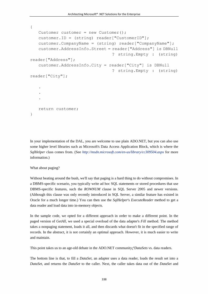
Architecting Microsoft® .NET Solutions for the Enterprise
338
{
Customer customer = new Customer();
customer.ID = (string) reader["CustomerID"];
customer.CompanyName = (string) reader["CompanyName"];
customer.AddressInfo.Street = reader["Address"] is DBNull
? string.Empty : (string)
reader["Address"];
customer.AddressInfo.City = reader["City"] is DBNull
? string.Empty : (string)
reader["City"];
.
.
.
return customer;
}
In your implementation of the DAL, you are welcome to use plain ADO.NET, but you can also use
some higher level libraries such as Microsoft's Data Access Application Block, which is where the
SqlHelper class comes from. (See http://msdn.microsoft.com/en-us/library/cc309504.aspx for more
information.)
What about paging?
Without beating around the bush, we'll say that paging is a hard thing to do without compromises. In
a DBMS-specific scenario, you typically write ad hoc SQL statements or stored procedures that use
DBMS-specific features, such the ROWNUM clause in SQL Server 2005 and newer versions.
(Although this clause was only recently introduced in SQL Server, a similar feature has existed in
Oracle for a much longer time.) You can then use the SqlHelper's ExecuteReader method to get a
data reader and load data into in-memory objects.
In the sample code, we opted for a different approach in order to make a different point. In the
paged version of GetAll, we used a special overload of the data adapter's Fill method. The method
takes a nonpaging statement, loads it all, and then discards what doesn't fit in the specified range of
records. In the abstract, it is not certainly an optimal approach. However, it is much easier to write
and maintain.
This point takes us to an age-old debate in the ADO.NET community¡ªDataSets vs. data readers.
The bottom line is that, to fill a DataSet, an adapter uses a data reader, loads the result set into a
DataSet, and returns the DataSet to the caller. Next, the caller takes data out of the DataSet and
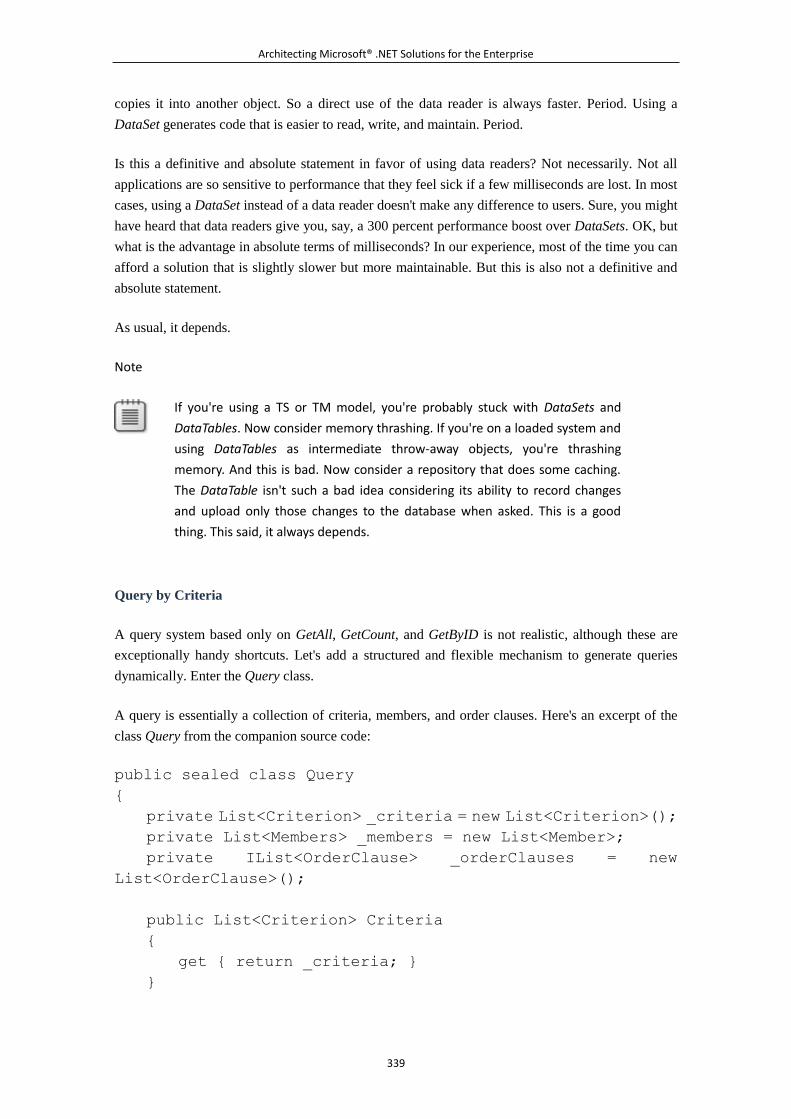
Architecting Microsoft® .NET Solutions for the Enterprise
339
copies it into another object. So a direct use of the data reader is always faster. Period. Using a
DataSet generates code that is easier to read, write, and maintain. Period.
Is this a definitive and absolute statement in favor of using data readers? Not necessarily. Not all
applications are so sensitive to performance that they feel sick if a few milliseconds are lost. In most
cases, using a DataSet instead of a data reader doesn't make any difference to users. Sure, you might
have heard that data readers give you, say, a 300 percent performance boost over DataSets. OK, but
what is the advantage in absolute terms of milliseconds? In our experience, most of the time you can
afford a solution that is slightly slower but more maintainable. But this is also not a definitive and
absolute statement.
As usual, it depends.
Note
If you're using a TS or TM model, you're probably stuck with DataSets and
DataTables. Now consider memory thrashing. If you're on a loaded system and
using DataTables as intermediate throw-away objects, you're thrashing
memory. And this is bad. Now consider a repository that does some caching.
The DataTable isn't such a bad idea considering its ability to record changes
and upload only those changes to the database when asked. This is a good
thing. This said, it always depends.
Query by Criteria
A query system based only on GetAll, GetCount, and GetByID is not realistic, although these are
exceptionally handy shortcuts. Let's add a structured and flexible mechanism to generate queries
dynamically. Enter the Query class.
A query is essentially a collection of criteria, members, and order clauses. Here's an excerpt of the
class Query from the companion source code:
public sealed class Query
{
private List<Criterion> _criteria = new List<Criterion>();
private List<Members> _members = new List<Member>;
private IList<OrderClause> _orderClauses = new
List<OrderClause>();
public List<Criterion> Criteria
{
get { return _criteria; }
}
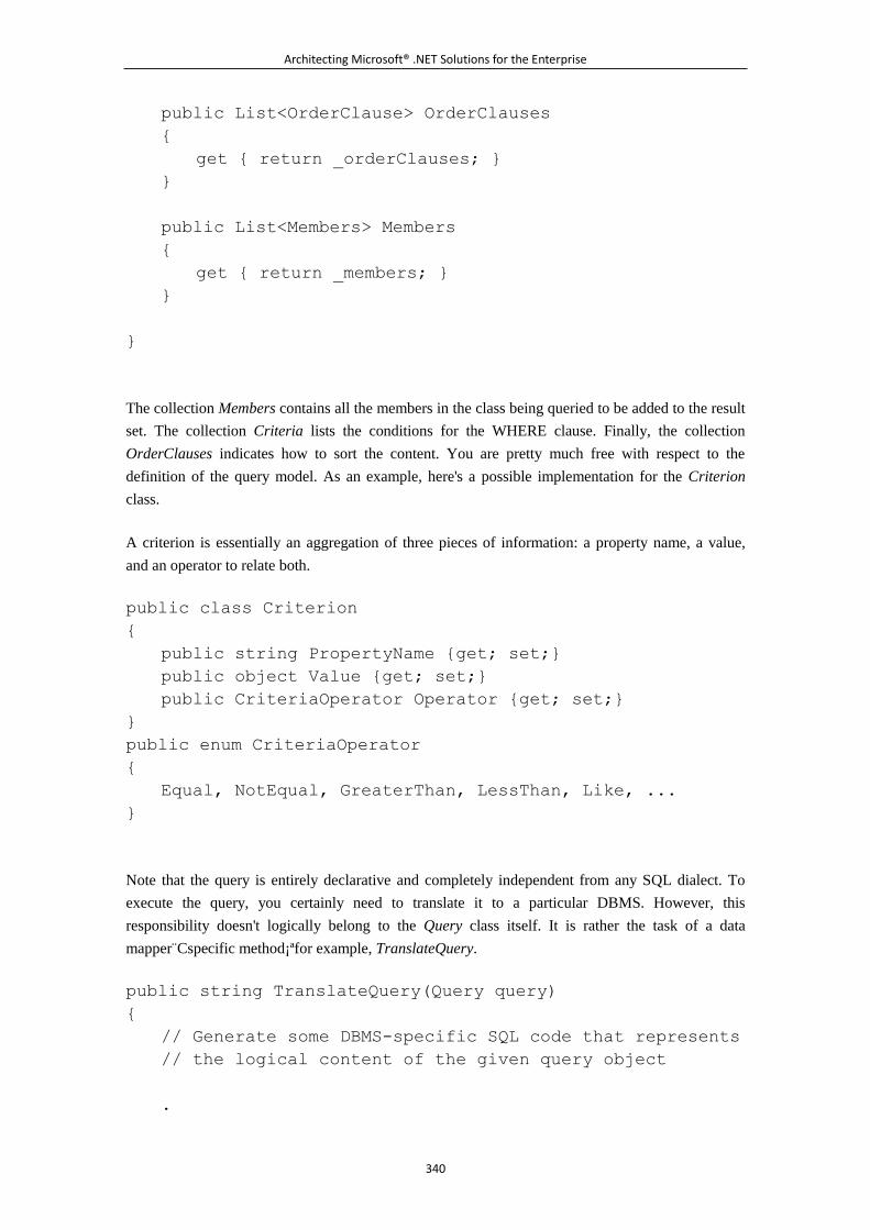
Architecting Microsoft® .NET Solutions for the Enterprise
340
public List<OrderClause> OrderClauses
{
get { return _orderClauses; }
}
public List<Members> Members
{
get { return _members; }
}
}
The collection Members contains all the members in the class being queried to be added to the result
set. The collection Criteria lists the conditions for the WHERE clause. Finally, the collection
OrderClauses indicates how to sort the content. You are pretty much free with respect to the
definition of the query model. As an example, here's a possible implementation for the Criterion
class.
A criterion is essentially an aggregation of three pieces of information: a property name, a value,
and an operator to relate both.
public class Criterion
{
public string PropertyName {get; set;}
public object Value {get; set;}
public CriteriaOperator Operator {get; set;}
}
public enum CriteriaOperator
{
Equal, NotEqual, GreaterThan, LessThan, Like, ...
}
Note that the query is entirely declarative and completely independent from any SQL dialect. To
execute the query, you certainly need to translate it to a particular DBMS. However, this
responsibility doesn't logically belong to the Query class itself. It is rather the task of a data
mapper C̈specific method¡ªfor example, TranslateQuery.
public string TranslateQuery(Query query)
{
// Generate some DBMS-specific SQL code that represents
// the logical content of the given query object
.
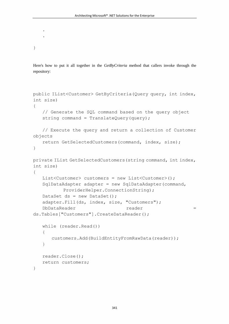
Architecting Microsoft® .NET Solutions for the Enterprise
341
.
.
}
Here's how to put it all together in the GetByCriteria method that callers invoke through the
repository:
public IList<Customer> GetByCriteria(Query query, int index,
int size)
{
// Generate the SQL command based on the query object
string command = TranslateQuery(query);
// Execute the query and return a collection of Customer
objects
return GetSelectedCustomers(command, index, size);
}
private IList GetSelectedCustomers(string command, int index,
int size)
{
List<Customer> customers = new List<Customer>();
SqlDataAdapter adapter = new SqlDataAdapter(command,
ProviderHelper.ConnectionString);
DataSet ds = new DataSet();
adapter.Fill(ds, index, size, "Customers");
DbDataReader reader =
ds.Tables["Customers"].CreateDataReader();
while (reader.Read())
{
customers.Add(BuildEntityFromRawData(reader));
}
reader.Close();
return customers;
}
Architecting Microsoft® .NET Solutions for the Enterprise
342
The beauty of GetByCriteria is that you generate SQL dynamically and in a way that is optimized
for the underlying DBMS. However, the majority of developers don't have to deal with SQL. Only a
small team of SQL gurus can work on it. They receive input coded in the members of a class and
write the best-ever SQL code for the scenario.
Being generated dynamically, the SQL code is something that can be adapted to any run-time
condition and, as such, is on average more effective than any possible hard-coded stored procedure.
(We'll return to this point soon.)
Note
Obviously, the query model can't address all possible query scenarios. Based
on your mapping logic, it can perhaps include JOINs, but not GROUP BY and
other more sophisticated statements. Quite simply, when you have a scenario
that your handmade DAL (or even an O/RM) can't handle properly, you just fall
back to the old-faithful SQL. In this case, you typically write a stored procedure
and create in the repository a wrapper method for the hard-coded SQL.
Nobody will blame you for doing this.
Implementing Transactional Semantics
A business transaction is any sequence of operations that involve the domain model and the business
logic. Most of the time, a business transaction is coordinated by classes in the service layer. If you
have domain logic organized according to the Transaction Script pattern (which is discussed in
Chapter 4), you match a business transaction to a method on some class that provides a physical
transactional boundary, if any is required.
With domain logic organized according to the Table Module or Active Record pattern, you reason
in terms of tables¡ªalthough the data (and therefore the model itself) is represented using different
data containers. A business transaction, therefore, is a sequence of operations on your objects. You
need to track changes to these objects and decide when it is time for those changes to be saved to the
storage. There are a number of reasons for grouping operations together. One is certainly
performance¡ªhandling numerous small changes to the database can be problematic in a production
scenario. Another reason is the functional requirement of having an application that works when
occasionally connected to the rest of the system.
In a DAL based on typed DataSets or an Active Record framework (for example, LINQ-to-SQL),
the framework itself provides you with the ability to make changes in memory and then persist them
back to the storage at a later time. This is the purpose of ADO.NET Batch Update, for example. But
it is also one of the key capabilities of the LINQ-to-SQL's DataContext class.
What if you have a handmade DAL and a completely customized domain model? Unless you use an
O/RM tool, you have to create your own framework for handling business transactions. Another
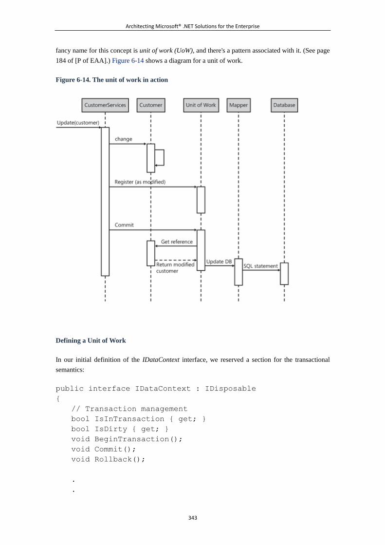
Architecting Microsoft® .NET Solutions for the Enterprise
343
fancy name for this concept is unit of work (UoW), and there's a pattern associated with it. (See page
184 of [P of EAA].) Figure 6-14 shows a diagram for a unit of work.
Figure 6-14. The unit of work in action
Defining a Unit of Work
In our initial definition of the IDataContext interface, we reserved a section for the transactional
semantics:
public interface IDataContext : IDisposable
{
// Transaction management
bool IsInTransaction { get; }
bool IsDirty { get; }
void BeginTransaction();
void Commit();
void Rollback();
.
.
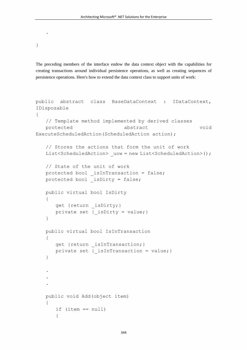
Architecting Microsoft® .NET Solutions for the Enterprise
344
.
}
The preceding members of the interface endow the data context object with the capabilities for
creating transactions around individual persistence operations, as well as creating sequences of
persistence operations. Here's how to extend the data context class to support units of work:
public abstract class BaseDataContext : IDataContext,
IDisposable
{
// Template method implemented by derived classes
protected abstract void
ExecuteScheduledAction(ScheduledAction action);
// Stores the actions that form the unit of work
List<ScheduledAction> _uow = new List<ScheduledAction>();
// State of the unit of work
protected bool _isInTransaction = false;
protected bool _isDirty = false;
public virtual bool IsDirty
{
get {return _isDirty;}
private set {_isDirty = value;}
}
public virtual bool IsInTransaction
{
get {return _isInTransaction;}
private set {_isInTransaction = value;}
}
.
.
.
public void Add(object item)
{
if (item == null)
{
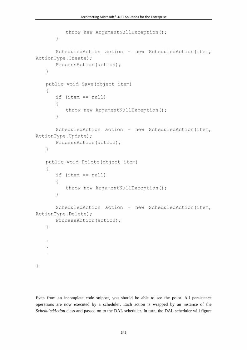
Architecting Microsoft® .NET Solutions for the Enterprise
345
throw new ArgumentNullException();
}
ScheduledAction action = new ScheduledAction(item,
ActionType.Create);
ProcessAction(action);
}
public void Save(object item)
{
if (item == null)
{
throw new ArgumentNullException();
}
ScheduledAction action = new ScheduledAction(item,
ActionType.Update);
ProcessAction(action);
}
public void Delete(object item)
{
if (item == null)
{
throw new ArgumentNullException();
}
ScheduledAction action = new ScheduledAction(item,
ActionType.Delete);
ProcessAction(action);
}
.
.
.
}
Even from an incomplete code snippet, you should be able to see the point. All persistence
operations are now executed by a scheduler. Each action is wrapped by an instance of the
ScheduledAction class and passed on to the DAL scheduler. In turn, the DAL scheduler will figure
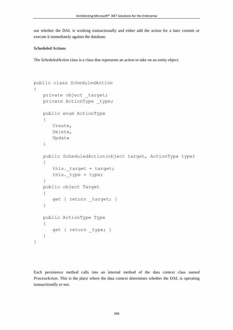
Architecting Microsoft® .NET Solutions for the Enterprise
346
out whether the DAL is working transactionally and either add the action for a later commit or
execute it immediately against the database.
Scheduled Actions
The ScheduledAction class is a class that represents an action to take on an entity object:
public class ScheduledAction
{
private object _target;
private ActionType _type;
public enum ActionType
{
Create,
Delete,
Update
}
public ScheduledAction(object target, ActionType type)
{
this._target = target;
this._type = type;
}
public object Target
{
get { return _target; }
}
public ActionType Type
{
get { return _type; }
}
}
Each persistence method calls into an internal method of the data context class named
ProcessAction. This is the place where the data context determines whether the DAL is operating
transactionally or not.
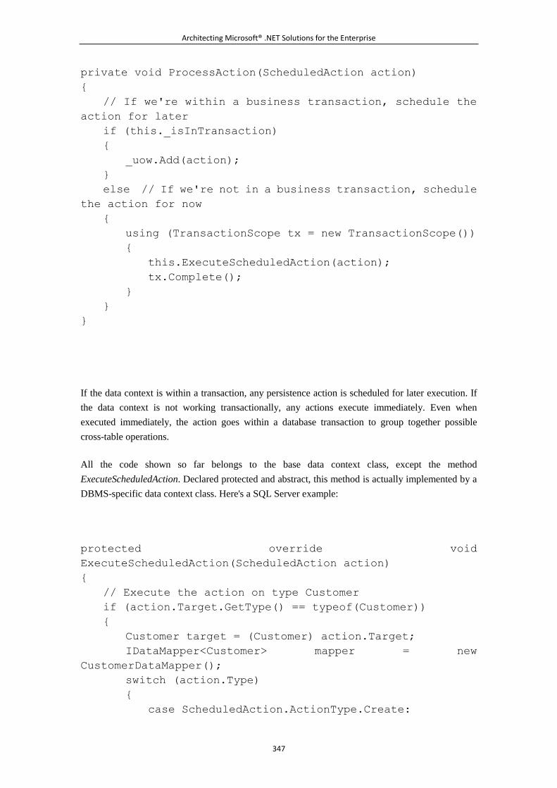
Architecting Microsoft® .NET Solutions for the Enterprise
347
private void ProcessAction(ScheduledAction action)
{
// If we're within a business transaction, schedule the
action for later
if (this._isInTransaction)
{
_uow.Add(action);
}
else // If we're not in a business transaction, schedule
the action for now
{
using (TransactionScope tx = new TransactionScope())
{
this.ExecuteScheduledAction(action);
tx.Complete();
}
}
}
If the data context is within a transaction, any persistence action is scheduled for later execution. If
the data context is not working transactionally, any actions execute immediately. Even when
executed immediately, the action goes within a database transaction to group together possible
cross-table operations.
All the code shown so far belongs to the base data context class, except the method
ExecuteScheduledAction. Declared protected and abstract, this method is actually implemented by a
DBMS-specific data context class. Here's a SQL Server example:
protected override void
ExecuteScheduledAction(ScheduledAction action)
{
// Execute the action on type Customer
if (action.Target.GetType() == typeof(Customer))
{
Customer target = (Customer) action.Target;
IDataMapper<Customer> mapper = new
CustomerDataMapper();
switch (action.Type)
{
case ScheduledAction.ActionType.Create:
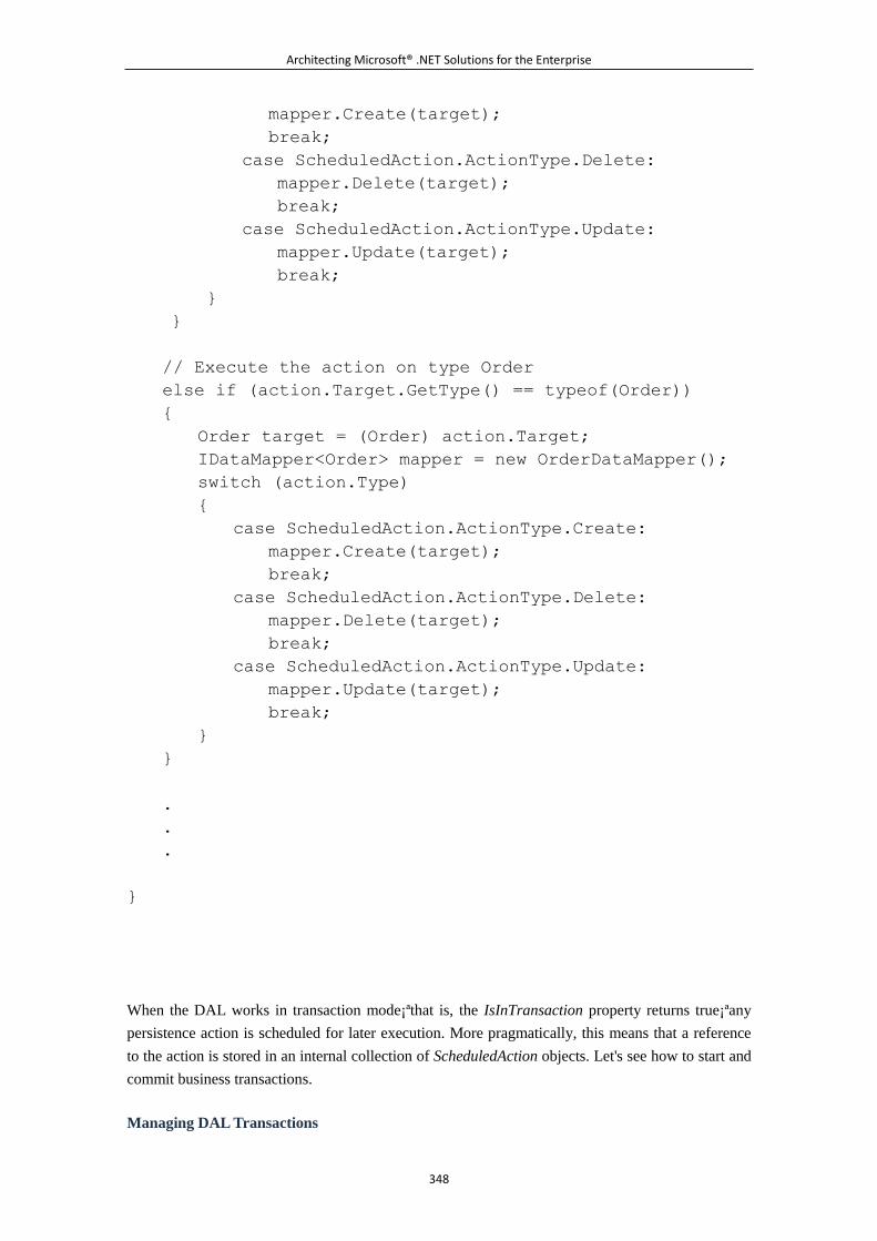
Architecting Microsoft® .NET Solutions for the Enterprise
348
mapper.Create(target);
break;
case ScheduledAction.ActionType.Delete:
mapper.Delete(target);
break;
case ScheduledAction.ActionType.Update:
mapper.Update(target);
break;
}
}
// Execute the action on type Order
else if (action.Target.GetType() == typeof(Order))
{
Order target = (Order) action.Target;
IDataMapper<Order> mapper = new OrderDataMapper();
switch (action.Type)
{
case ScheduledAction.ActionType.Create:
mapper.Create(target);
break;
case ScheduledAction.ActionType.Delete:
mapper.Delete(target);
break;
case ScheduledAction.ActionType.Update:
mapper.Update(target);
break;
}
}
.
.
.
}
When the DAL works in transaction mode¡ªthat is, the IsInTransaction property returns true¡ªany
persistence action is scheduled for later execution. More pragmatically, this means that a reference
to the action is stored in an internal collection of ScheduledAction objects. Let's see how to start and
commit business transactions.
Managing DAL Transactions
Architecting Microsoft® .NET Solutions for the Enterprise
349
The consumer of the DAL decides whether it wants to execute some operations transactionally.
When this is the case, it merely informs the data context of the intention. The method
BeginTransaction exists precisely for this purpose:
// This class is "typically" invoked by the presentation
public class CustomerServices
{
private IDataContext _context = null;
public CustomerServices()
{
IDalFactory factory = new DalFactory();
this._context = factory.GetDataContext();
}
// Execution of this method is typically bound to a UI event
public void AddOrder(Order order)
{
_context.BeginTransaction();
_context.Add(order);
.
.
.
_context.Commit();
}
}
Any call to data context methods¡ªsuch as Add, Delete, and Save¡ªare tracked through the list of
ScheduledAction objects and eventually processed when the consumer invokes Commit:
public void BeginTransaction()
{
if (this._isInTransaction)
throw new InvalidOperationException();
else
{
this._isInTransaction = true;
_uow.Clear();
}
}
Architecting Microsoft® .NET Solutions for the Enterprise
350
public void Commit()
{
if (!this.IsInTransaction)
{
throw new InvalidOperationException();
}
else
{
foreach (ScheduledAction actionw in actions)
{
Object target = action.Target;
if (target == null)
{
throw new InvalidOperationException();
}
}
using (TransactionScope tx = new TransactionScope())
{
_uow.ForEach(
delegate(ScheduledAction action) {
this.ExecuteScheduledAction(action); }
);
tx.Complete();
}
this._isInTransaction = false;
_uow.Clear();
}
}
public void Rollback()
{
if (!this._isInTransaction)
throw new InvalidOperationException();
else
{
this._isInTransaction = false;
_uow.Clear();
}
}

Architecting Microsoft® .NET Solutions for the Enterprise
351
The Unit of Work pattern is hard to avoid in the real world, and the primary reason is simply that
often more than one database action needs to be included in the same transaction. The UoW pattern
makes this necessity easier to code for. After you set up the DAL to support UoW, you have all the
information you need in a single place. In addition, the overall design of your code, far from
becoming too abstract¡ªas the use of such a pattern might suggest at first¡ªgets surprisingly clear and
easy to maintain and evolve.
Implementing Uniquing and Identity Maps
Tightly related to the concept of a unit of work is the idea of uniquing, which is typically obtained
by implementing the Identity Map (IM) pattern as discussed on page 195 of [P of EAA]. During a
unit of work, you typically want to avoid duplicates of the same object¡ªfor example, you don't want
to have two Customer objects referencing the data from the same database record. For this reason,
your DAL maintains a list of objects you have retrieved, and it consults this list whenever a domain
object is requested of it.
Getting Unique Objects
The IM pattern is defined as a map that keeps track of all objects read from the database. The
purpose is to return to callers an existing instance instead of running a new query. The identity map
is hidden in the finder object that exposes query services¡ªa repository, the data context class, or
both. A schema for an identity map is shown in Figure 6-15.
Figure 6-15. An overall schema for an identity map
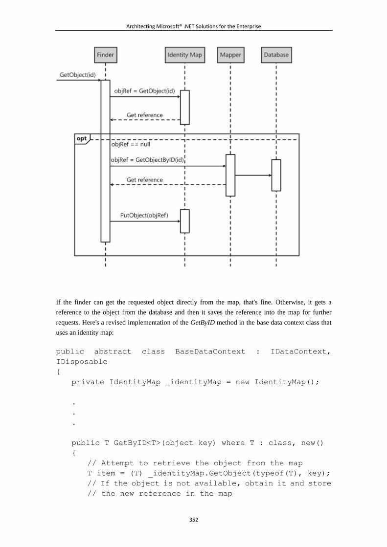
Architecting Microsoft® .NET Solutions for the Enterprise
352
If the finder can get the requested object directly from the map, that's fine. Otherwise, it gets a
reference to the object from the database and then it saves the reference into the map for further
requests. Here's a revised implementation of the GetByID method in the base data context class that
uses an identity map:
public abstract class BaseDataContext : IDataContext,
IDisposable
{
private IdentityMap _identityMap = new IdentityMap();
.
.
.
public T GetByID<T>(object key) where T : class, new()
{
// Attempt to retrieve the object from the map
T item = (T) _identityMap.GetObject(typeof(T), key);
// If the object is not available, obtain it and store
// the new reference in the map
Architecting Microsoft® .NET Solutions for the Enterprise
353
if (item == null)
{
item = GetDataMapper<T>().GetByKey(key);
_identityMap.PutObject(item, key);
}
// Return the object
return item;
}
}
The identity map should be used everywhere in the DAL where you have a piece of code that gains
access to an object. All GetXxx methods should first check the identity map if you have one.
Implementing an Identity Map
In terms of implementation, an identity map is often implemented using a pair of nested dictionaries.
The outermost dictionary uses the type of the object as its key. The value is another (child)
dictionary, which represents the identity map for the given type. The child dictionary uses the
primary key of the object as its key, whereas the value is the actual object reference.
An identity map is often implemented using a hash table. The reason is that a hash table is the data
container with the fastest access time to a contained object. A hash table, in fact, is based on a hash
algorithm according to which, once you know the key of an object, you can access the stored object
in a constant time, O(1)
, regardless of the size of the table. (In this regard, a hash table is a much
better choice than an array or a classic collection.)
The following code snippet shows a sample implementation for an identity map:
public class IdentityMap
{
private Hashtable _mappedTypes = new Hashtable();
public IdentityMap()
{
}
public object GetObject(Type t, object key)
{
// Get the map for the specified type
Hashtable map = GetMapForType(t);
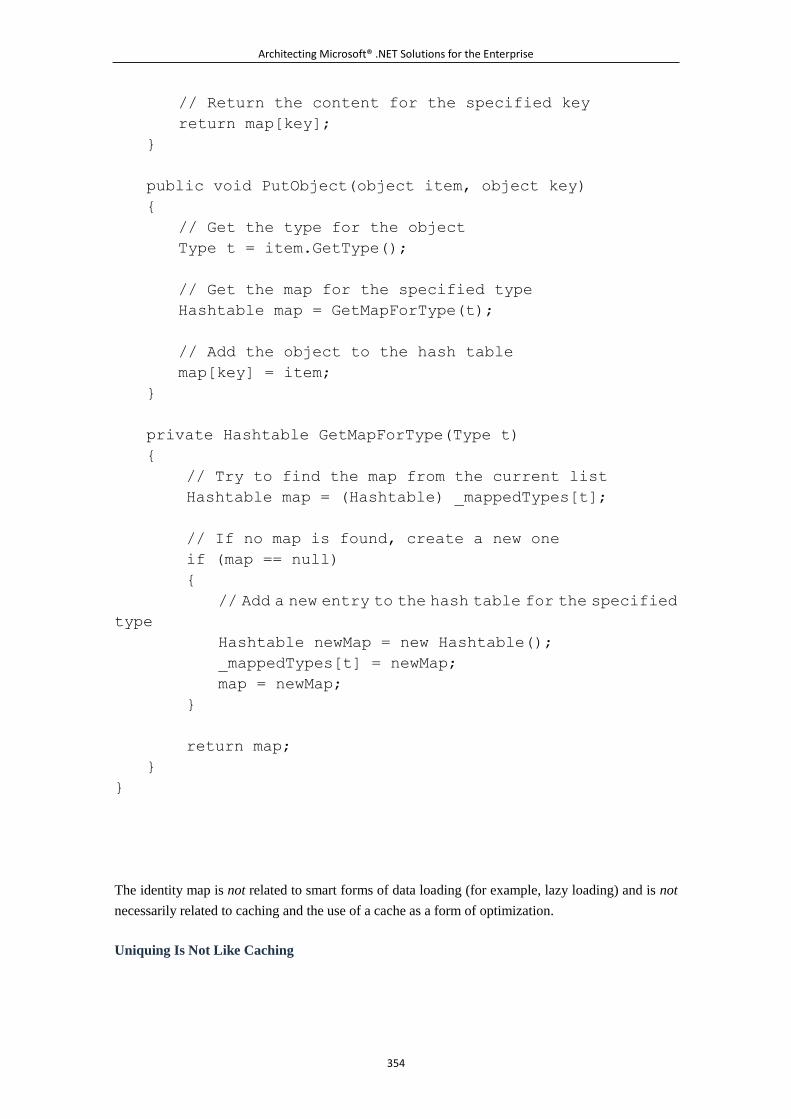
Architecting Microsoft® .NET Solutions for the Enterprise
354
// Return the content for the specified key
return map[key];
}
public void PutObject(object item, object key)
{
// Get the type for the object
Type t = item.GetType();
// Get the map for the specified type
Hashtable map = GetMapForType(t);
// Add the object to the hash table
map[key] = item;
}
private Hashtable GetMapForType(Type t)
{
// Try to find the map from the current list
Hashtable map = (Hashtable) _mappedTypes[t];
// If no map is found, create a new one
if (map == null)
{
// Add a new entry to the hash table for the specified
type
Hashtable newMap = new Hashtable();
_mappedTypes[t] = newMap;
map = newMap;
}
return map;
}
}
The identity map is not related to smart forms of data loading (for example, lazy loading) and is not
necessarily related to caching and the use of a cache as a form of optimization.
Uniquing Is Not Like Caching
Architecting Microsoft® .NET Solutions for the Enterprise
355
To understand the role (and importance) of an identity map, let's set the clock back to ten years ago
and consider how, at that time, a business object (BO) would have implemented a unit of work
against a database. We have the following steps:
1. The BO begins a transaction.
2. The BO gets the record from the Customers table where the ID column matches a value of
1234.
3. The BO proceeds and executes a long list of essential operations.
4. The BO updates the record on the Customers table with an ID of 1234.
5. The BO proceeds and executes another long list of essential operations.
6. The BO commits the transaction.
The following facts come as no surprise:
A second, concurrent unit of work that fetches record 1234 before the first unit of work
reaches step 6 would get the original, unmodified values from the database.
Within the same transaction, if the BO fetches record 1234 beyond step 4, it would get
modified values that have not been committed to the database yet.
Let's see how the unit of work would execute in a Domain Model scenario:
1. The consumer orders the DAL to begin a new transaction.
2. The consumer instructs the DAL to retrieve an instance of the Customer class for an ID of
1234. The DAL looks up the identity map and finds it empty. Next, the DAL queries the
database, builds a Customer object for record 1234, and adds a reference to the object to a
private list known as the identity map.
3. The consumer proceeds and executes a long list of essential operations.
4. The consumer orders the DAL to update the Customer object with an ID of 1234.
5. The consumer proceeds and executes a long list of essential operations.
6. The consumer orders the DAL to commit.
What happens if a concurrent unit of work attempts to read Customer 1234 before the first unit of
work has reached step 6?
This concurrent unit of work would ask its own instance of the DAL to retrieve Customer 1234.
This instance of the DAL has its own (probably empty) identity map, at which time the second DAL
instance will likely go to the database for the query. The consumer would then receive original,
unmodified values from the database.
Architecting Microsoft® .NET Solutions for the Enterprise
356
What if, within the same business transaction, the consumer once again needs to fetch Customer
1234? If an identity map is in place, the existing reference to the Customer object is returned. If the
request comes beyond step 4, the consumer receives the updated Customer object.
As the name suggests, the primary purpose of an identity map is to ensure that unique instances of
domain objects are managed within a single business transaction. And a business transaction is
implemented through the unit of work DAL interface.
If you want, you can still say that IM gives you a sort of cache. But it is a cache with a very short
duration¡ªthe business transaction¡ªand with limited performance benefits. How many times will you
fetch the same Customer in the same business transaction? It is extremely unlikely that you need to
fetch the same object more than once.
Note
The certainty of having just one domain object to reference the same physical
chunk of data in a business transaction makes your DAL neater and inherently
more consistent. It also might add some benefits in terms of performance but,
as mentioned, that is a secondary point.
When using the Identity Map pattern, you should ensure that two objects are
considered to be equal by using an algorithm based on their content. For this
reason, it is recommended that you override in your domain classes the Equals
and GetHashCode methods that all .NET Framework classes expose.
Equals is used for explicit comparisons through the == operator. GetHashCode
is used to ensure that objects with the same logical content are given the
same hash code, which makes them the same when they are added to a hash
table, as they are in the most common implementations of an identity map. To
generate new content-based code, you normally use the primary key of the
record to generate a hash.
An Identity Map Looks, Walks, and Quacks Like a Cache
Ultimately, an identity map is often perceived as a cache. The popular slogan of duck typing can be
applied here, too. An identity map looks like a cache, walks like a cache, and quacks like a cache.
But is it really a cache?
Again, the rigorous answer is no, but let's talk about it.
What is your definition of a cache? We think we could agree on the following definition. A cache is
a collection of objects that have been computed earlier. The cache makes these objects available to
code in a way that is faster than starting a new computation.
Architecting Microsoft® .NET Solutions for the Enterprise
357
Admittedly, this definition applies perfectly to an identity map; so an identity map really looks,
walks, and quacks like a cache.
The point is that the benefits you get in terms of performance from a real cache are significantly
different from the performance benefits you get from an identity map. The main difference between
a real cache (for example, the ASP.NET Cache object or even the ASP.NET page output cache) and
an identity map is the duration.
An identity map should live for the time it takes to complete a business transaction. In many
real-world implementations¡ªsuch as LLBLGen Pro, Entity Framework, NHibernate, and
LINQ-to-SQL¡ªthe identity map is not bound to a single business transaction. Put another way, the
identity map is not released when the consumer commits the unit of work. It is, instead, bound to the
data context and, as such, it lasts a little longer. An identity map is a short-lived object that just
doesn't remove objects from memory like a canonical cache would do.
The data context object has different names in different frameworks, but the purpose is the
same¡ªand so it is with the internal implementation of the identity map. So Context (LLBLGen Pro),
ObjectContext (Entity Framework), Session (NHibernate), and DataContext (LINQ-to-SQL) free the
identity map when their instance is disposed of.
Different instances of the data context have their own identity map for their own uniquing purposes.
If this looks like a cache to you, then OK¡ªan identity map is a cache!
Note
Regarding application-level caches, an interesting platform developed by
Microsoft is Velocity. Velocity is a distributed in-memory application cache
platform for developing high-performance applications. Velocity can be used
to cache any serializable Common Language Runtime (CLR) objects and
provides an ad hoc API for access. Velocity can be configured to run as a
service accessed over the network, or it can be run embedded within the
application. If you think you need a serious platform for object caching within
a DAL, Velocity is more than a custom implementation of an identity map, so it
is perhaps the right way to go. For more information, read
http://msdn.microsoft.com/en-us/data/cc655792.aspx.
Caching and Queries: A Not So Powerful Duo
Let's assume for a moment that you have set up a true and long-lasting cache in your DAL to avoid
going back to the database over and over again. This is not an absolute guarantee of stunning
performance.
With a cache in the middle, you first have to go through the cache to see whether the object, and
often whether all the objects, you need are there. If any object is missing, you arrange a database
Architecting Microsoft® .NET Solutions for the Enterprise
358
query and then sync up the cache. And even when you find objects in the cache, you have to figure
out whether or not they are stale (or assume they are not).
As you can see, there's a lot of extra work to do with a cache. This amount of work grows with the
complexity of objects from a domain model and the ramifications of using them. And we are not
considering here the possibility that the cache is located out of process.
There might be tricks, like versions or timestamps, to speed up the process of determining whether a
given set of objects is already in the cache. In the end, you get real benefits from caching domain
objects only when you cache simple objects (that is, those with no relationships like simple lookups)
and when you can figure out quickly whether they work for you (or when you can safely assume
they do). Using a timed cache, for example, might help because you can assume that if the object is
in the cache, it is not stale.
Implementing Concurrency
When a lot of operations are performed in memory that could possibly end up updating the database,
you have a potential problem¡ªthe consistency of the data for the application is at risk. Imagine that
one user selects a chunk of data and modifies it in memory, but she's following a flow within the UI
that retains changes for a longer time. At the same time, another user selects the same chunk of data
but modifies it instantly. What should happen when the first user attempts to save her own copy of
the same data to the same table?
As usual, the answer is, "It depends." And, in particular, it depends on your implementation of
concurrency. First, it depends on whether or not you have support for concurrency. Moreover, this is
not an unusual scenario, so consider concurrency early in your design.
Don't Worry, Be Optimistic
With the DAL we have outlined so far, no conflict would be raised. Both users will successfully
update the database. However, because both are writing to the same record (or set of records, in
general), the last set of changes overwrites the first set of changes. It is nothing more than the
last-win policy. And it is the approach to concurrency that you get for free in any multiuser system.
If you're OK with this policy, you can jump to the next topic.
Ad hoc policies for concurrency and data conflicts are not a must in any application. Some entities
might need concurrency protection, while others might not. Even within entities, some properties
might need to deal with concurrency while others might not. Simply updating a product date or
description might not affect other properties, such as quantity on hand or stocking location.
What's the solution? Quite simply, instead of just executing the SQL command to persist changes,
you try to execute it under stricter conditions. In other words, you do not use the following code to
update a product description:
UPDATE products SET description=@desc WHERE productID=
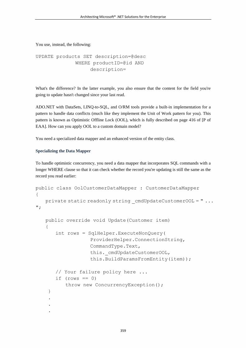
Architecting Microsoft® .NET Solutions for the Enterprise
359
You use, instead, the following:
UPDATE products SET description=@desc
WHERE productID=@id AND
description=
What's the difference? In the latter example, you also ensure that the content for the field you're
going to update hasn't changed since your last read.
ADO.NET with DataSets, LINQ-to-SQL, and O/RM tools provide a built-in implementation for a
pattern to handle data conflicts (much like they implement the Unit of Work pattern for you). This
pattern is known as Optimistic Offline Lock (OOL), which is fully described on page 416 of [P of
EAA]. How can you apply OOL to a custom domain model?
You need a specialized data mapper and an enhanced version of the entity class.
Specializing the Data Mapper
To handle optimistic concurrency, you need a data mapper that incorporates SQL commands with a
longer WHERE clause so that it can check whether the record you're updating is still the same as the
record you read earlier:
public class OolCustomerDataMapper : CustomerDataMapper
{
private static readonly string _cmdUpdateCustomerOOL = " ...
";
public override void Update(Customer item)
{
int rows = SqlHelper.ExecuteNonQuery(
ProviderHelper.ConnectionString,
CommandType.Text,
this._cmdUpdateCustomerOOL,
this.BuildParamsFromEntity(item));
// Your failure policy here ...
if (rows == 0)
throw new ConcurrencyException();
}
.
.
.
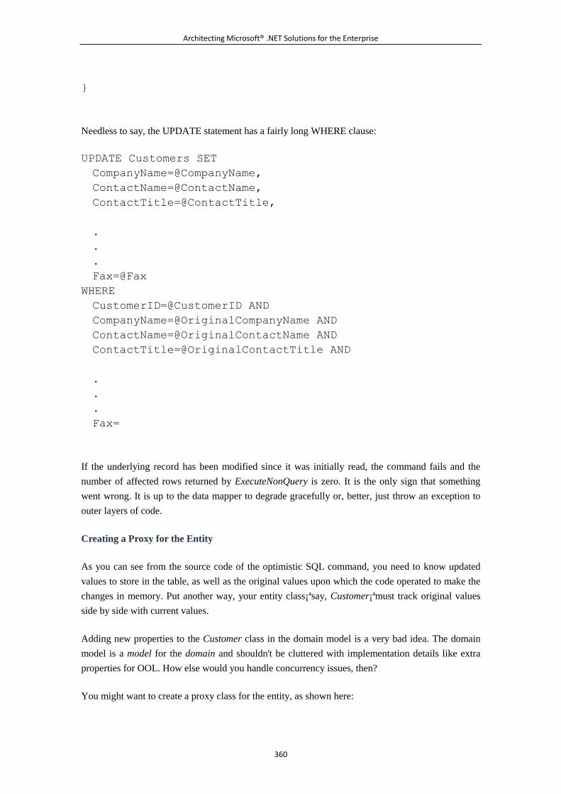
Architecting Microsoft® .NET Solutions for the Enterprise
360
}
Needless to say, the UPDATE statement has a fairly long WHERE clause:
UPDATE Customers SET
CompanyName=@CompanyName,
ContactName=@ContactName,
ContactTitle=@ContactTitle,
.
.
.
Fax=@Fax
WHERE
CustomerID=@CustomerID AND
CompanyName=@OriginalCompanyName AND
ContactName=@OriginalContactName AND
ContactTitle=@OriginalContactTitle AND
.
.
.
Fax=
If the underlying record has been modified since it was initially read, the command fails and the
number of affected rows returned by ExecuteNonQuery is zero. It is the only sign that something
went wrong. It is up to the data mapper to degrade gracefully or, better, just throw an exception to
outer layers of code.
Creating a Proxy for the Entity
As you can see from the source code of the optimistic SQL command, you need to know updated
values to store in the table, as well as the original values upon which the code operated to make the
changes in memory. Put another way, your entity class¡ªsay, Customer¡ªmust track original values
side by side with current values.
Adding new properties to the Customer class in the domain model is a very bad idea. The domain
model is a model for the domain and shouldn't be cluttered with implementation details like extra
properties for OOL. How else would you handle concurrency issues, then?
You might want to create a proxy class for the entity, as shown here:
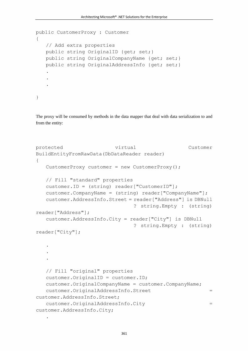
Architecting Microsoft® .NET Solutions for the Enterprise
361
public CustomerProxy : Customer
{
// Add extra properties
public string OriginalID {get; set;}
public string OriginalCompanyName {get; set;}
public string OriginalAddressInfo {get; set;}
.
.
.
}
The proxy will be consumed by methods in the data mapper that deal with data serialization to and
from the entity:
protected virtual Customer
BuildEntityFromRawData(DbDataReader reader)
{
CustomerProxy customer = new CustomerProxy();
// Fill "standard" properties
customer.ID = (string) reader["CustomerID"];
customer.CompanyName = (string) reader["CompanyName"];
customer.AddressInfo.Street = reader["Address"] is DBNull
? string.Empty : (string)
reader["Address"];
customer.AddressInfo.City = reader["City"] is DBNull
? string.Empty : (string)
reader["City"];
.
.
.
// Fill "original" properties
customer.OriginalID = customer.ID;
customer.OriginalCompanyName = customer.CompanyName;
customer.OriginalAddressInfo.Street =
customer.AddressInfo.Street;
customer.OriginalAddressInfo.City =
customer.AddressInfo.City;
.
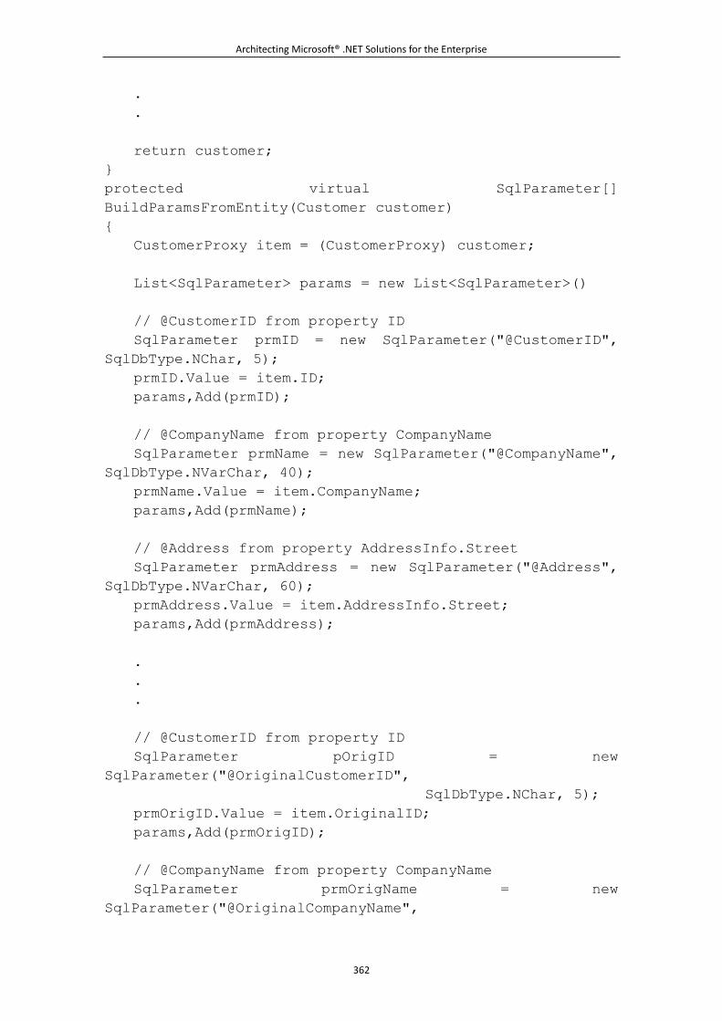
Architecting Microsoft® .NET Solutions for the Enterprise
362
.
.
return customer;
}
protected virtual SqlParameter[]
BuildParamsFromEntity(Customer customer)
{
CustomerProxy item = (CustomerProxy) customer;
List<SqlParameter> params = new List<SqlParameter>()
// @CustomerID from property ID
SqlParameter prmID = new SqlParameter("@CustomerID",
SqlDbType.NChar, 5);
prmID.Value = item.ID;
params,Add(prmID);
// @CompanyName from property CompanyName
SqlParameter prmName = new SqlParameter("@CompanyName",
SqlDbType.NVarChar, 40);
prmName.Value = item.CompanyName;
params,Add(prmName);
// @Address from property AddressInfo.Street
SqlParameter prmAddress = new SqlParameter("@Address",
SqlDbType.NVarChar, 60);
prmAddress.Value = item.AddressInfo.Street;
params,Add(prmAddress);
.
.
.
// @CustomerID from property ID
SqlParameter pOrigID = new
SqlParameter("@OriginalCustomerID",
SqlDbType.NChar, 5);
prmOrigID.Value = item.OriginalID;
params,Add(prmOrigID);
// @CompanyName from property CompanyName
SqlParameter prmOrigName = new
SqlParameter("@OriginalCompanyName",
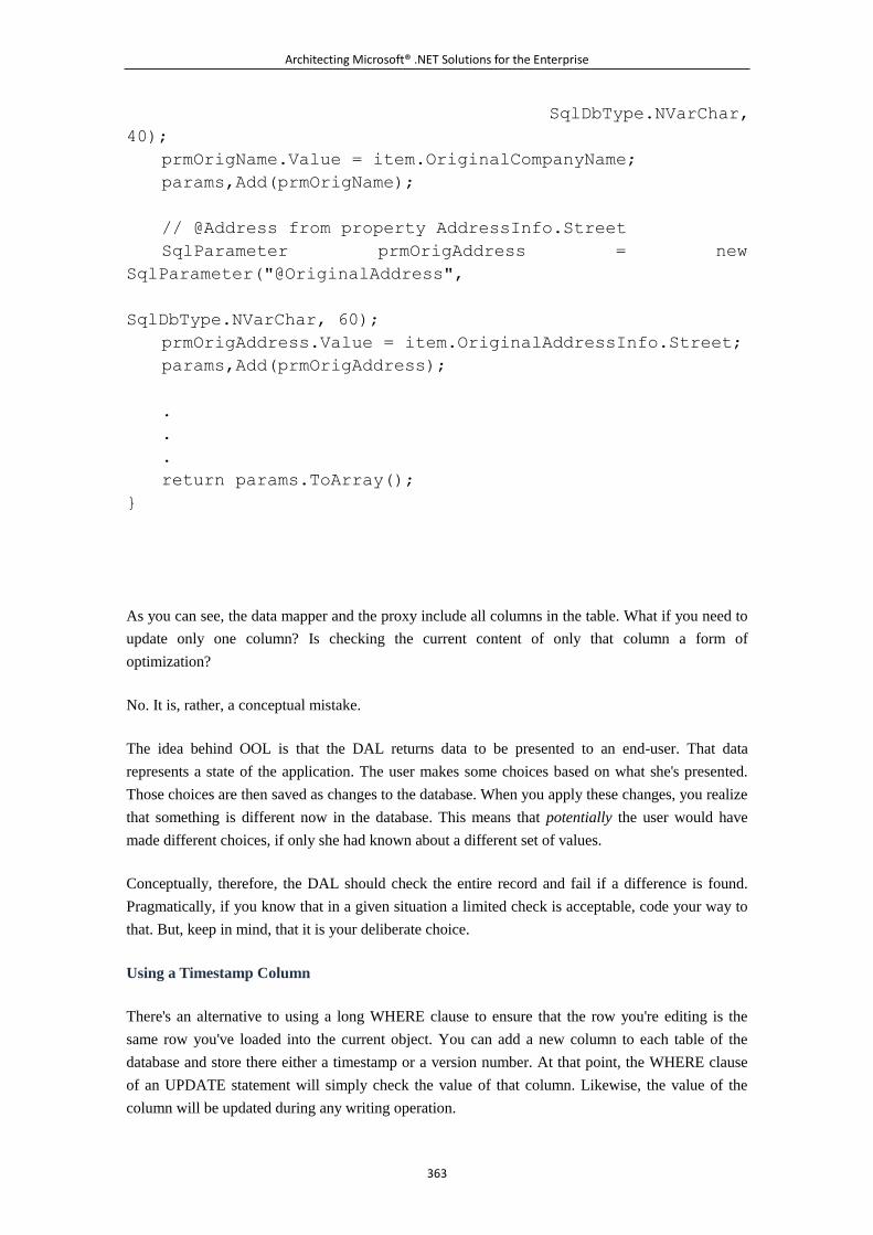
Architecting Microsoft® .NET Solutions for the Enterprise
363
SqlDbType.NVarChar,
40);
prmOrigName.Value = item.OriginalCompanyName;
params,Add(prmOrigName);
// @Address from property AddressInfo.Street
SqlParameter prmOrigAddress = new
SqlParameter("@OriginalAddress",
SqlDbType.NVarChar, 60);
prmOrigAddress.Value = item.OriginalAddressInfo.Street;
params,Add(prmOrigAddress);
.
.
.
return params.ToArray();
}
As you can see, the data mapper and the proxy include all columns in the table. What if you need to
update only one column? Is checking the current content of only that column a form of
optimization?
No. It is, rather, a conceptual mistake.
The idea behind OOL is that the DAL returns data to be presented to an end-user. That data
represents a state of the application. The user makes some choices based on what she's presented.
Those choices are then saved as changes to the database. When you apply these changes, you realize
that something is different now in the database. This means that potentially the user would have
made different choices, if only she had known about a different set of values.
Conceptually, therefore, the DAL should check the entire record and fail if a difference is found.
Pragmatically, if you know that in a given situation a limited check is acceptable, code your way to
that. But, keep in mind, that it is your deliberate choice.
Using a Timestamp Column
There's an alternative to using a long WHERE clause to ensure that the row you're editing is the
same row you've loaded into the current object. You can add a new column to each table of the
database and store there either a timestamp or a version number. At that point, the WHERE clause
of an UPDATE statement will simply check the value of that column. Likewise, the value of the
column will be updated during any writing operation.
Architecting Microsoft® .NET Solutions for the Enterprise
364
Using an additional column for programming purposes requires a certain degree of access and
freedom on the database. And for this reason, it might not be a practical solution every time. It is the
most efficient approach if you can afford it.
Implementing Lazy Loading
When you ask your object model to return a Customer instance with a certain ID, what data would
you expect it to contain?
For sure, the returned object will store personal information about the customer, but what about its
relationships to, say, orders? And what about relationships between orders and order items, and so
on? The more complex the object model, the more you risk pulling up a very large graph of objects.
Lazy loading indicates the DAL's ability to load only a portion of the object graph based on some
rules. When you add this capability to your DAL, you have implemented the Lazy Load pattern
(LL).
On-Demand Data Loading
Defined on page 200 of [P of EAA], the LL pattern refers to an object that doesn't hold all the data it
needs, but knows how to retrieve it on demand. Applied to a domain model object such as Customer,
this pattern enables you to enhance the original class with the ability to prioritize data. When you
load an instance of a Customer, only essential data is loaded¡ªfor example, only personal
information. Later, when some piece of code needs to go through orders associated with the
customer, that information is located and loaded.
Lazy loading, though, expresses an idea that, when applied, provides a form of optimization. It
simply says, "Hey, load the smallest amount of data that you're pretty much sure to use." Who
defines what "smallest amount" means? And, more importantly, are we sure that the meaning of
"smallest amount" is constant over time? The answers to these questions are dictated by the needs of
your application. However, lazy loading as a pattern is a good one. Like all patterns, it should be
tailored to your specific requirements. Figure 6-16 shows the typical behavior of a Customer class
that supports lazy loading.
Figure 6-16. An implementation of lazy loading for the Customer class
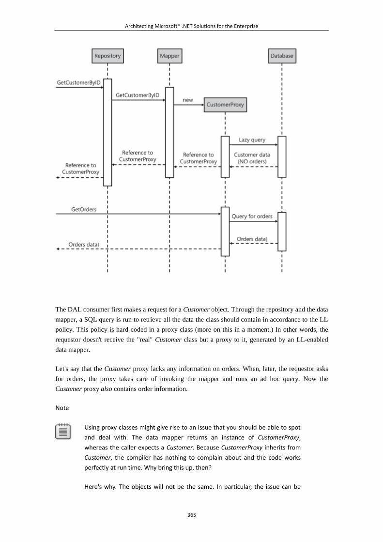
Architecting Microsoft® .NET Solutions for the Enterprise
365
The DAL consumer first makes a request for a Customer object. Through the repository and the data
mapper, a SQL query is run to retrieve all the data the class should contain in accordance to the LL
policy. This policy is hard-coded in a proxy class (more on this in a moment.) In other words, the
requestor doesn't receive the "real" Customer class but a proxy to it, generated by an LL-enabled
data mapper.
Let's say that the Customer proxy lacks any information on orders. When, later, the requestor asks
for orders, the proxy takes care of invoking the mapper and runs an ad hoc query. Now the
Customer proxy also contains order information.
Note
Using proxy classes might give rise to an issue that you should be able to spot
and deal with. The data mapper returns an instance of CustomerProxy,
whereas the caller expects a Customer. Because CustomerProxy inherits from
Customer, the compiler has nothing to complain about and the code works
perfectly at run time. Why bring this up, then?
Here's why. The objects will not be the same. In particular, the issue can be
Architecting Microsoft® .NET Solutions for the Enterprise
366
raised by tests for equality between Customer objects you might have in the
code. Logically, a Customer and a CustomerProxy that contain data from the
same database record are the same. The CLR, though, recognizes two objects
as equal only if they reference the same memory address. However, by
overriding the Equals and GetHashCode methods on Customer, you can
implement a new equality policy that looks at content rather than memory
address. In this way, Customer and CustomerProxy instances will be the same if
they reference the same database record.
Hard-Coded Fetch Plans
Lazy loading is tightly connected with the idea of a fetch plan. A fetch plan indicates your strategy
to retrieve data within a class. If you hard-code the lazy-loading policy within a class, you have a
static fetch plan. This is the most common idea associated with the expressions lazy loading or, in
Microsoft's jargon, deferred loading.
A common way to implement lazy loading with a static fetch plan entails creating a proxy class for
each entity intended to support LL. A static fetch plan indicates that the proxy class implements
some rules to determine what is eagerly loaded and what is loaded in a deferred manner.
The proxy class is DBMS specific and definitely belongs to the DAL. A proxy class extends a
domain model class, but it is not part of the domain model. It lives in the DAL assembly. Here's a
sample proxy class for the Employee entity. The Employee entity includes a couple of properties that
are little used and take up a lot of space¡ªphotos and personal notes. The idea, therefore, is to load
these properties only on demand. Here's a sample proxy class:
internal public sealed class EmployeeProxy : Employee
{
private bool _notesLoaded = false;
private bool _photoLoaded = false;
public override string Notes
{
get
{
string notes;
if (!_notesLoaded)
{
EmployeeDataMapper mapper = new
EmployeeDataMapper();
notes = mapper.GetNotesByID(this.ID);
_notesLoaded = true;
Architecting Microsoft® .NET Solutions for the Enterprise
367
// Caches notes for later use of the instance
base.Notes = notes;
}
else
{
// If cached, just returns
notes = base.Notes;
}
return notes;
}
set
{
base.Notes = value;
_notesLoaded = true;
}
}
public override Bitmap Photo
{
get
{
Bitmap photo;
if (!_photoLoaded)
{
EmployeeDataMapper mapper = new
EmployeeDataMapper();
photo = mapper.GetPhotoByID(this.ID);
_photoLoaded = true;
// Caches photo for later use of the instance
base.Photo = photo;
}
else
{
// If cached, just returns
photo = base.Photo;
}
return photo;
}
Architecting Microsoft® .NET Solutions for the Enterprise
368
set
{
base.Photo = value;
_photoLoaded = true;
}
}
}
The EmployeeProxy class is marked internal because it is essentially an internal class. Shouldn't this
be public instead, as at some point we are probably handing out an instance of it to the BLL? The
EmployeeProxy class is never exposed to the outside world because the data mapper always casts it
to Employee.
The proxy inherits from the domain model class and overrides a few properties to implement lazy
loading. When any of these properties are requested, if data is not in memory, it is loaded through
direct access to the database and cached for later use.
The data mapper has an active role in the implementation of LL, as it is the data mapper that returns
an instance of the proxy instead of the original domain class, as shown here:
protected virtual Employee
BuildEntityFromRawData(DbDataReader reader)
{
// Create an instance of the object to return
Employee employee = new EmployeeProxy();
// Populate the object with eager-loading properties only
employee.ID = (int) reader["EmployeeID"];
employee.FirstName = (string) reader["FirstName"];
employee.LastName = (string) reader["LastName"];
.
.
.
// Lazy-loading properties are skipped
return employee;
}
In general, you have one proxy class for each entity that supports lazy loading. This means that the
proxy class determines in a static and fixed manner what is loaded eagerly and what goes into the
Architecting Microsoft® .NET Solutions for the Enterprise
369
lazy category. In a real-world DAL, this might be a limitation. Lazy loading is an important feature
to have but, at the same time, you also need a mechanism to bypass it. A unique and static proxy
class is not the ideal answer¡ªit does lazy loading always and always on the same properties.
Having multiple proxies is not an attractive option either, as it leads straight to a proliferation of
classes and sets up your worst maintenance nightmare.
In a perfect world, you would be able to specify on a per-query basis which properties you want to
have available right away and which properties should be pulled up on demand. And always in this
perfect world, you would be able to generate ad hoc proxy classes on the fly. This would be the
configuration for a dynamic fetch plan.
Specifying a Dynamic Fetch Plan
We could even say that a serious implementation of lazy loading is not possible without support for
a dynamically configurable fetch plan. So even though static proxies are effective, they probably
address only a small number of scenarios.
The setup of a dynamic fetch plan is not exactly a walk in the park. It assumes a query model where
you dynamically indicate which properties you want to load and under which conditions this should
happen. The query model we presented earlier allows you to shape the query as an object, and it
gives you the required level of flexibility. But this is only the first step.
Once you have successfully translated the query into SQL and run it, you get a data reader or a
DataTable. The next step consists of loading the content of the data reader into a graph of objects. If
you use objects from the domain model, the best you can do is fill only the properties for which the
query can retrieve values. However, any access to empty (lazy) properties is destined to fail. And
this is exactly where proxies fit in.
But how can you write a proxy class if the list of members to lazy-load is known only at runtime?
This is the essence of a dynamic fetch plan.
In the perfect world we mentioned a moment ago, proxies are generated on the fly using
Reflection.Emit to wed great performance and greatest flexibility. But using this rather advanced
form of reflection is not trivial and, honestly, it is beyond the standard skills of the vast majority of
developers.
The bottom line is that implementing by hand serious lazy loading with dynamic fetch plans
requires a significant effort, which leads to a major point we'll develop further in a moment¡ªa
serious and well-built DAL looks and acts very much like an O/RM tool.
Note
Reflection.Emit allows you to dynamically generate new types, methods, and
even code at runtime. It is not a feature you would use every day, but it is a
Architecting Microsoft® .NET Solutions for the Enterprise
370
key ingredient for lazy loading (O/RM tools use it), mocking types, method
interception to produce code metrics, proxying services, and implementing
aspect-oriented programming (AOP) aspects.
In the .NET Framework, Reflection.Emit competes with CodeDOM generation.
With CodeDOM, you have total control over the code and work at a higher
level of abstraction, as you use classes to generate classes and code. However,
you need to explicitly start a compile process either to disk or memory. And,
more importantly, the generated assembly is closed and can't be further
extended. With Emit, instead, you need to know Microsoft intermediate
language (MSIL) because you are required to use it to specify the code. It is
much faster, there's no need to compile, and the assembly you create can be
extended with new types at any time.
Lazy Loading in Data Access APIs
Lazy loading with fetch plans exists in a number of data access APIs, but it comes in quite
different forms. Let's briefly review them.
In ADO.NET, you find a very rudimentary form of lazy loading with no fetch plan
support. The functionality all comes out of the data adapter's ability to sync up a given
DataSet to reflect the current state of the database.
In NHibernate¡ªone of the most popular O/RM tools¡ªthe support for lazy loading and
fetch plans is total and top quality. You can change the fetch plan at runtime and for each
query. For each query, all fields are eagerly loaded unless you mark them as lazy in the
mapping file. Therefore, you can have, say, a Customer object with lazy loading enabled
for its orders. In this case, any access to the Orders collection of the Customer object is
resolved with a dynamic database query on demand.
In LINQ-to-SQL, lazy loading (referred to as deferred loading) can be enabled and
disabled programmatically through a Boolean property¡ªDeferredLoadingEnabled. When
lazy loading is enabled, only the first level of the graph is processed by the query. For
example, only customer information is loaded, not any orders for the customer and not
any details for the orders. However, any subsequent access to orders is resolved correctly
through a new database roundtrip. This happens automatically, and the developer doesn't
even realize it. When you disable lazy loading, though, all the data you can access is data
that has been loaded eagerly. You can control this amount of data using the LoadWith
method on the DataContext class. Note that once you have disabled lazy loading, no
attempt is ever made at a later time to grab any data not currently in memory. In other
words, with DeferredLoadingEnabled set to false, you won't be able to retrieve Orders
from an instance of the Customer class unless you specified a fetch plan through
LoadWith that preloaded orders.
Architecting Microsoft® .NET Solutions for the Enterprise
371
In ADO.NET Entity Framework 1.0 (EF), the situation is slightly different from
LINQ-to-SQL. The main difference is that EF doesn't offer a Boolean
DeferredLoadingEnabled property. Another difference with LINQ-to-SQL is that EF
never loads for you any associated entities (say, orders for a customer) that haven't been
explicitly subjected to eager loading. EF, in fact, offers a query builder that plays a role
analogous to LoadWith in LINQ-to-SQL. EF allows you to load data as you go, but only
through a specific method you have to invoke, say, every time you need to access orders
for a customer. In a certain way, EF defers loading of missing data ad infinitum and never
runs a query implicitly. The development team made this choice in EF version 1.0 in
observance of the "No hidden network roundtrips" principle. EF provides you with a Load
method on entity classes through which you can programmatically load any external data
associated with a domain object. In this way, you can specify a fetch plan dynamically.
6.3.4 Power to the DAL with an O/RM Tool
Why should you write a DAL yourself? Is it because you have a strict nonfunctional requirement
that explicitly prohibits the use of an O/RM? Or is it because you think you would craft your DAL
better than any commercial O/RM tools?
In a domain-based world, a well-built DAL is nearly the same as a well-built O/RM tool. And an
O/RM tool has a team of people (usually, very smart people) entirely devoted to that. They spend
their working hours thinking about new features, experimenting, and receiving and processing
feedback. Very few outside developers can compete with them.
In this book, we went through a handmade DAL for essentially two reasons. One reason was to give
you a concrete idea of how it works and how to design it. As you saw, it's a nontrivial exercise.
Another reason was to make it clear¡ªin practice¡ªthat O/RM tools are an instrument naturally suited
to building layered systems with a domain-driven approach.
Object/Relational Mappers
We identified four main responsibilities for a DAL: persistence, querying, managing transactions,
and maintaining concurrency. At least the latter two responsibilities are general enough to be
delegated to an ad hoc tool that has the appropriate capabilities. In our sample implementation of
query services, we also came up with a rather generic interface¡ªthe Query Object pattern¡ªthe same
pattern that an ad hoc tool can supply out of the box. The only area where handcrafted code might
make some sense is in the area of data persistence. But the inherent power of O/RM tools helps to
generalize persistence, too.
In the end, when opting for an O/RM tool, it is not like you are handing your house keys to a
stranger. You are simply using a more advanced, automated tool.
Do I Really Need an O/RM Tool?

Architecting Microsoft® .NET Solutions for the Enterprise
372
How do you start up your car? You probably turn the key or press a button. And under the hood,
you release some power that activates the engine. Turning the key to release power is definitely a
very simple and easy approach. It delivers you the expected results with minimum effort¡ªyou have,
in the end, a high-level tool to leverage.
To release the power that starts the engine, you can also make some wires contact one another. This
is a low-level approach that requires different skills and is within the reach of fewer drivers of
automobiles. A low-level approach, however, is appropriate in particular scenarios. You play with
wires if you're stealing a car or if, for whatever reason, the higher-level mechanism (key, button) is
not working.
When it comes to building a DAL, the O/RM is your key (or button). It is a high-level tool for
achieving your goal. If, for whatever reason, it doesn't work effectively, you can still look under the
hood and "play with the wires."
So why shouldn't you just turn the key to start up your car? Why should you care about wires? Or,
worse yet, would you really consider designing and crafting your own automobile ignition system?
If Only We Could Have an Object-Oriented DBMS
The primary purpose of an O/RM tool is for fighting off any object-relational impedance mismatch
between your object model and its storage layer. Object-oriented databases (ODBMS) never
captured the heart of the IT community; relational databases (RDBMS) are, therefore, the sole
alternative. But an RDBMS stores its data as tuples of values.
Until a few years ago, layered systems primarily represented their own data using containers
mirrored from RDBMS tables. In the .NET world, this is well described by DataSets and typed
DataSets. From there, the evolution of layered systems quickly brought people¡ªat different speeds
depending on their skills and background¡ªto consider a more conceptual approach to data
representation. And this is where object models such as the Active Record pattern entered the
picture.
From table-based models such as Active Record to domain-driven design (DDD), it was¡ªto
paraphrase Neil Armstrong descending the Apollo 11 lunar lander's platform¡ªonly a small,
conceptual step, but a huge step in the design of a proper architecture. In DDD, you design a model
for the domain first. And you do that in a way that is totally independent from storage and
implementation considerations.
After you have the model, you have to persist it, though. And here's the mismatch between the
object-oriented representation of data and the tuple-based, relational model of most commonly used
DBMSs.
If you could use an ODBMS, things would be much easier. An ODBMS would provide built-in
persistence, rich query services, transactions and concurrency, lazy loading, and identity maps. And
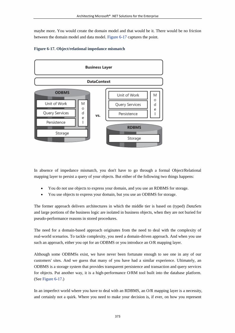
Architecting Microsoft® .NET Solutions for the Enterprise
373
maybe more. You would create the domain model and that would be it. There would be no friction
between the domain model and data model. Figure 6-17 captures the point.
Figure 6-17. Object/relational impedance mismatch
In absence of impedance mismatch, you don't have to go through a formal Object/Relational
mapping layer to persist a query of your objects. But either of the following two things happens:
You do not use objects to express your domain, and you use an RDBMS for storage.
You use objects to express your domain, but you use an ODBMS for storage.
The former approach delivers architectures in which the middle tier is based on (typed) DataSets
and large portions of the business logic are isolated in business objects, when they are not buried for
pseudo-performance reasons in stored procedures.
The need for a domain-based approach originates from the need to deal with the complexity of
real-world scenarios. To tackle complexity, you need a domain-driven approach. And when you use
such an approach, either you opt for an ODBMS or you introduce an O/R mapping layer.
Although some ODBMSs exist, we have never been fortunate enough to see one in any of our
customers' sites. And we guess that many of you have had a similar experience. Ultimately, an
ODBMS is a storage system that provides transparent persistence and transaction and query services
for objects. Put another way, it is a high-performance O/RM tool built into the database platform.
(See Figure 6-17.)
In an imperfect world where you have to deal with an RDBMS, an O/R mapping layer is a necessity,
and certainly not a quirk. Where you need to make your decision is, if ever, on how you represent
Architecting Microsoft® .NET Solutions for the Enterprise
374
the domain logic. Once you have opted for an object-based representation, especially if it's a domain
model, an O/R mapping layer is the natural offspring.
Creating an O/R Mapping Layer
In a scenario where you have to deal with O/R impedance mismatch, you have to create an O/R
mapping layer. But how?
You can craft your own DAL and build into it the ability to persist objects, query objects, and access
objects transactionally. This is doable, but it is definitely a lot of work. And, more importantly, of
that huge amount of work, only a relatively small part of the effort is devoted to core business
functionality. Most of the effort required is for general-purpose stuff such as managing transactions
and writing to storage. You can call it a DAL, but it is in the end a more or less sophisticated O/R
mapping layer.
To speed up development and provide a richer set of features, you can build the O/R mapping layer
using a commercial or open-source O/RM tool.
An O/RM tool translates your object model into a form that can be stored to a relational database. At
the same time, an O/RM tool offers an API to retrieve the same data from the database as a graph of
objects. Relationships between objects and constraints are preserved in memory and in the database.
Sample O/RM Tools
What is the main benefit you get out of an O/RM tool? Essentially, productivity. Quite a few O/RM
tools, both free and commercial, exist in the marketplace. Vendors have been working on such tools
for years, and the level of sophistication of an average O/RM tool is currently far beyond the
capabilities of a single team. (Not to mention that, for the team, persistence normally is more of a
widespread concern than the primary focus.)
Table 6-2 lists a few popular O/RM tools currently available.
Table 6-2. Main O/RM Tools
O/RM More Information
Entity Framework http://msdn.microsoft.com/en-us/library/bb399572.aspx
EntitySpaces http://www.entityspaces.net
Genome http://www.genom-e.com
LINQ-to-SQL http://msdn.microsoft.com/en-us/library/bb386976.aspx
LLBLGen Pro http://www.llblgen.com
NHibernate http://www.nhibernate.org
Architecting Microsoft® .NET Solutions for the Enterprise
375
Using an O/RM tool will not necessarily give you extra days off. And an O/RM tool is not exactly a
wizard or a rapid application development (RAD) instrument. It is still a programming tool,
however, and a sophisticated one too. Using an O/RM tool can enhance your productivity as long as
you know the tool and supply a well-built domain model.
Note
We've been using O/RM tools for years in larger projects. In particular, we
used NHibernate for quite some time. Using an O/RM tool brought us a lot of
benefits. However, we haven't been able to really quantify (and appreciate) it
until, in a recent project, the customer had a requirement that we either use a
Microsoft O/RM or build our own O/RM. At the time, Entity Framework was
still a Beta product, so we had to create a custom O/RM. We shipped the
project more or less on deadline, but it was a nightmare. Long live O/RM tools!
Using an O/RM Tool to Build a DAL
After you bring an O/RM tool into the project, you have a data context object out of the box. So you
typically start using the API of the O/RM directly in the service layer. The O/RM, therefore, is your
DAL. An O/RM tool is made of three main elements:
An API for CRUD operations
A query model plus an ad hoc query language to speed up the definition of most queries
An API for mapping metadata (such as classes to tables or properties to columns)
CRUD operations and the query model are typically exposed out of a root object, which plays the
role of the data context class (such as the SqlServerDataContext class) we created earlier in the
chapter.
Each O/RM product has its own data context object, and each product gives this data context object
a different name and nearly the same capabilities. For example, the data context object is named
Session in NHibernate and ObjectContext in ADO.NET Entity Framework (EF). In the remainder of
the section, we'll go through the main points of using an O/RM to build a DAL, mostly focusing on
NHibernate, but also touching on EF.
Note
NHibernate is an open-source product that can be considered to be the
current de facto standard for O/RM tools. A number of other great commercial
products are available¡ªfor example, LLBLGen Pro¡ªbut NHibernate, maybe
because it is free and because of its overall feature set, has many users and a
lot of credibility in the industry.
What about EF? We bet that EF has a bright future, but it probably does not
Architecting Microsoft® .NET Solutions for the Enterprise
376
rank with the best in its current form (because it is version 1.0). There are
some good things in EF, but currently EF does not cover what developers have
come to expect from other O/RMs. If some features are improved in later
versions, EF (likely EF v2.0 and in the context of the .NET Framework 4.0) will
probably be the only way to go. And it will likely be much more than just an
O/RM tool.
The O/RM Is Your Data Context
As we've seen, you start using the DAL in the service layer. As pointed out in Chapter 5, the service
layer is not necessarily a set of WCF services. Additionally, we tend to use WCF services when we
need to remote services or when we need specific policies such as WS-Security. In general, for our
discussion here a service is a piece of code that services any requests from the presentation layer.
If you choose an O/RM, you leave the O/RM the burden of mapping to a particular database or to a
family of databases (in the case of fragmented entities). In practical terms, this means that you
directly use the data context object provided by the O/RM tool and have no need to employ plugins
or inversion of control. You pick up an O/RM and that's it.
Here's how you typically get hold of a data context in NHibernate. To start out, you typically create
a helper class to act as a factory for the data context:
public class SessionHelper
{
// Configuration and ISessionXxx interfaces are defined in
the NHibernate assembly
private static Configuration _cfg;
private static ISessionFactory _sessionFactory;
static SessionHelper()
{
_cfg = new Configuration();
_cfg.Configure();
_sessionFactory = cfg.BuildSessionFactory();
}
public static ISession GetNewSession()
{
return _sessionFactory.OpenSession();
}
}
Architecting Microsoft® .NET Solutions for the Enterprise
377
The Configure method reads information from the application's configuration file and determines,
among other things, which database driver should be used. In your service layer, you create a new
NHibernate session and start coding your queries and updates:
ISession dal = SessionHelper.GetNewSession();
The ISession interface has a list of members that is nearly identical to our IDataContext interface.
And, by the way, this is not a mere coincidence!
In EF, the data context is the ObjectContext object. However, you don't use this object directly. You
take advantage of a Visual Studio 2008 integrated tool to visually generate a domain model. The
tool also delivers a class derived from ObjectContext where collections of domain objects and ad
hoc CRUD methods are bound together. (If you know LINQ-to-SQL, it is not really a different
model.)
// AdventureWorksEntities is created by the Visual Studio 2008
EF wizard.
// AdventureWorksEntities inherits from ObjectContext and is
your data context object
AdventureWorksEntities context = new
AdventureWorksEntities();
From here onward, in the service layer you start coding against the API of the O/RM of choice.
Object Services with an O/RM
In NHibernate, to add a new object to the underlying storage you first create an instance of the
domain class and get a transient object. Next, you call the method Save on the data context:
// Create a new customer object
Customer customer = new Customer();
customer.ID = "MD";
customer.CompanyName = "Managed Design";
.
.
Architecting Microsoft® .NET Solutions for the Enterprise
378
.
// Add customer to the storage
session.Save(customer);
When you call Save, you are actually instructing the O/RM to provide for persistence. However, in
NHibernate persistence happens asynchronously and leverages an internal layer of caching. So in
the end, when you call Save you have no certainty of when the object will be actually written down
to the database. If you need to, you call Flush to commit the change instantaneously:
// Add a newly created customer to the storage
session.Save(customer);
session.Flush();
Of course, Flush commits the entire set of pending changes in the session.
To delete the records that correspond to a given domain object, you use the method Delete. The
method Update serves the purpose of updating a record in the database. Also in this case, you
should use Flush to commit changes in a synchronous manner.
In EF, you have analogous generic methods named AddObject and DeleteObject to add and delete
database records corresponding to domain objects. You have no explicit method to update. In
addition, you also have in your domain-specific data context class a bunch of domain-specific
CRUD methods, such as AddToCustomer or DeleteCustomer. Here's a code snippet that adds a new
customer:
Customer customer = new Customer();
customer.ID = "MD";
customer.CompanyName = "Managed Design";
.
.
.
// Add customer to the storage
context.AddObject("Customers", customer);
To update a customer object, there are two possible ways to go. If the object is a persistent object
you created through the data context, you simply edit the properties in the object and then call
SaveChanges:
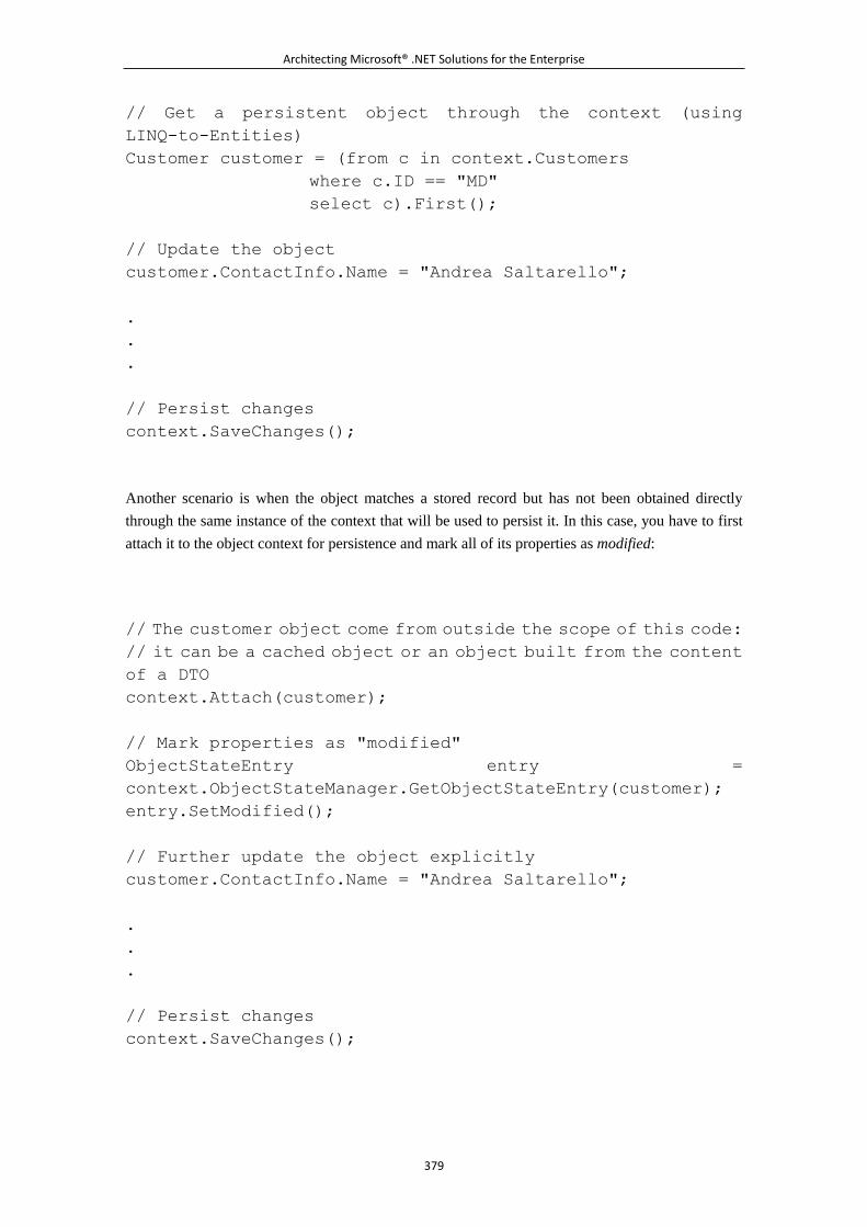
Architecting Microsoft® .NET Solutions for the Enterprise
379
// Get a persistent object through the context (using
LINQ-to-Entities)
Customer customer = (from c in context.Customers
where c.ID == "MD"
select c).First();
// Update the object
customer.ContactInfo.Name = "Andrea Saltarello";
.
.
.
// Persist changes
context.SaveChanges();
Another scenario is when the object matches a stored record but has not been obtained directly
through the same instance of the context that will be used to persist it. In this case, you have to first
attach it to the object context for persistence and mark all of its properties as modified:
// The customer object come from outside the scope of this code:
// it can be a cached object or an object built from the content
of a DTO
context.Attach(customer);
// Mark properties as "modified"
ObjectStateEntry entry =
context.ObjectStateManager.GetObjectStateEntry(customer);
entry.SetModified();
// Further update the object explicitly
customer.ContactInfo.Name = "Andrea Saltarello";
.
.
.
// Persist changes
context.SaveChanges();
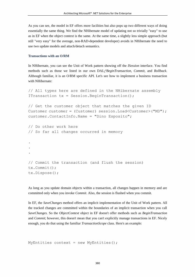
Architecting Microsoft® .NET Solutions for the Enterprise
380
As you can see, the model in EF offers more facilities but also pops up two different ways of doing
essentially the same thing. We find the NHibernate model of updating not so trivially "easy" to use
as in EF when the object context is the same. At the same time, a slightly less simple approach (but
still "very easy" for the average, non-RAD-dependent developer) avoids in NHibernate the need to
use two update models and attach/detach semantics.
Transactions with an O/RM
In NHibernate, you can see the Unit of Work pattern showing off the ISession interface. You find
methods such as those we listed in our own DAL¡ªBeginTransaction, Commit, and Rollback.
Although familiar, it is an O/RM specific API. Let's see how to implement a business transaction
with NHibernate:
// All types here are defined in the NHibernate assembly
ITransaction tx = Session.BeginTransaction();
// Get the customer object that matches the given ID
Customer customer = (Customer) session.Load<Customer>("MD");
customer.ContactInfo.Name = "Dino Esposito";
// Do other work here
// So far all changes occurred in memory
.
.
.
// Commit the transaction (and flush the session)
tx.Commit();
tx.Dispose();
As long as you update domain objects within a transaction, all changes happen in memory and are
committed only when you invoke Commit. Also, the session is flushed when you commit.
In EF, the SaveChanges method offers an implicit implementation of the Unit of Work pattern. All
the tracked changes are committed within the boundaries of an implicit transaction when you call
SaveChanges. So the ObjectContext object in EF doesn't offer methods such as BeginTransaction
and Commit; however, this doesn't mean that you can't explicitly manage transactions in EF. Nicely
enough, you do that using the familiar TransactionScope class. Here's an example:
MyEntities context = new MyEntities();
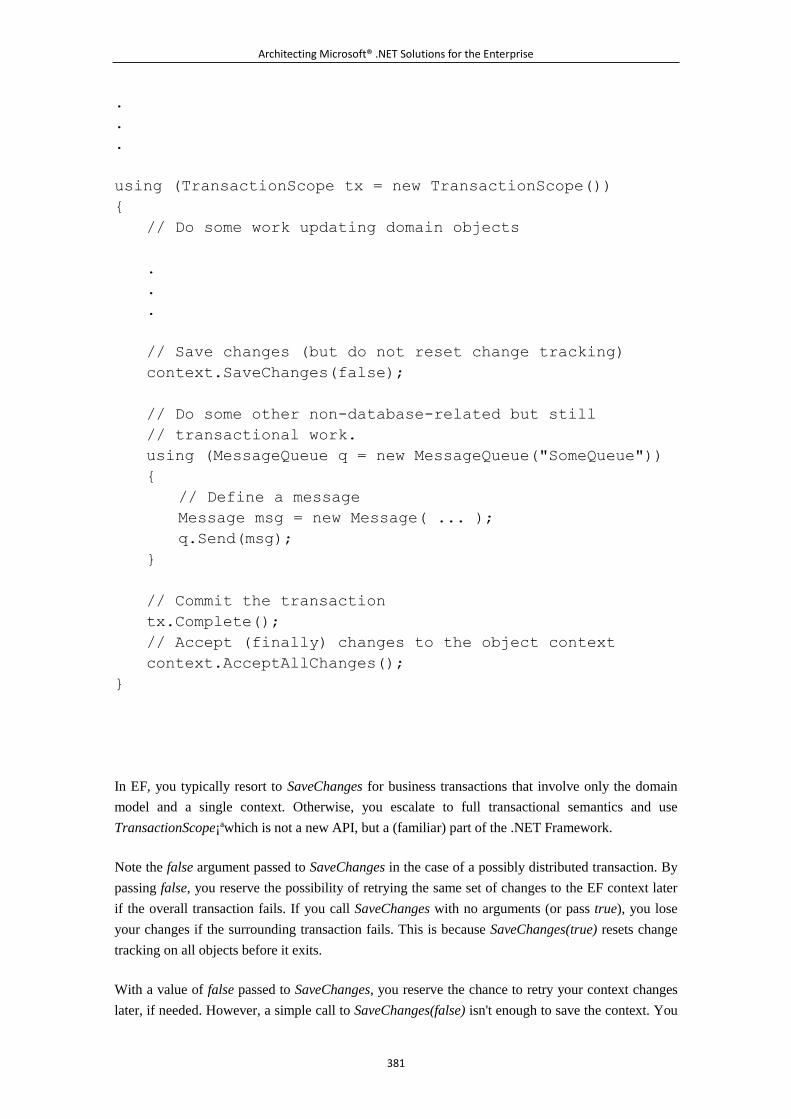
Architecting Microsoft® .NET Solutions for the Enterprise
381
.
.
.
using (TransactionScope tx = new TransactionScope())
{
// Do some work updating domain objects
.
.
.
// Save changes (but do not reset change tracking)
context.SaveChanges(false);
// Do some other non-database-related but still
// transactional work.
using (MessageQueue q = new MessageQueue("SomeQueue"))
{
// Define a message
Message msg = new Message( ... );
q.Send(msg);
}
// Commit the transaction
tx.Complete();
// Accept (finally) changes to the object context
context.AcceptAllChanges();
}
In EF, you typically resort to SaveChanges for business transactions that involve only the domain
model and a single context. Otherwise, you escalate to full transactional semantics and use
TransactionScope¡ªwhich is not a new API, but a (familiar) part of the .NET Framework.
Note the false argument passed to SaveChanges in the case of a possibly distributed transaction. By
passing false, you reserve the possibility of retrying the same set of changes to the EF context later
if the overall transaction fails. If you call SaveChanges with no arguments (or pass true), you lose
your changes if the surrounding transaction fails. This is because SaveChanges(true) resets change
tracking on all objects before it exits.
With a value of false passed to SaveChanges, you reserve the chance to retry your context changes
later, if needed. However, a simple call to SaveChanges(false) isn't enough to save the context. You
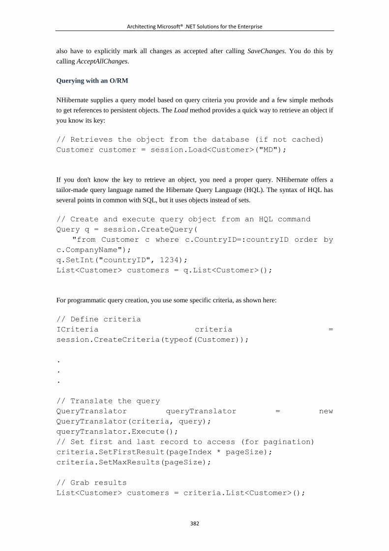
Architecting Microsoft® .NET Solutions for the Enterprise
382
also have to explicitly mark all changes as accepted after calling SaveChanges. You do this by
calling AcceptAllChanges.
Querying with an O/RM
NHibernate supplies a query model based on query criteria you provide and a few simple methods
to get references to persistent objects. The Load method provides a quick way to retrieve an object if
you know its key:
// Retrieves the object from the database (if not cached)
Customer customer = session.Load<Customer>("MD");
If you don't know the key to retrieve an object, you need a proper query. NHibernate offers a
tailor-made query language named the Hibernate Query Language (HQL). The syntax of HQL has
several points in common with SQL, but it uses objects instead of sets.
// Create and execute query object from an HQL command
Query q = session.CreateQuery(
"from Customer c where c.CountryID=:countryID order by
c.CompanyName");
q.SetInt("countryID", 1234);
List<Customer> customers = q.List<Customer>();
For programmatic query creation, you use some specific criteria, as shown here:
// Define criteria
ICriteria criteria =
session.CreateCriteria(typeof(Customer));
.
.
.
// Translate the query
QueryTranslator queryTranslator = new
QueryTranslator(criteria, query);
queryTranslator.Execute();
// Set first and last record to access (for pagination)
criteria.SetFirstResult(pageIndex * pageSize);
criteria.SetMaxResults(pageSize);
// Grab results
List<Customer> customers = criteria.List<Customer>();
Architecting Microsoft® .NET Solutions for the Enterprise
383
Note that the power of the HQL language might not be matched by the Query object. And both HQL
and Query objects might not be able to express the database query you need, especially when
advanced SQL capabilities are required. In this case, you just use the O/RM to run a query in the
native SQL of the underlying DBMS. In NHibernate, the method to use is CreateSqlQuery.
In EF, the set of capabilities is similar. The object-oriented query language is Entity SQL (ESQL),
which is mapped to the LINQ-to-Entities syntax. Here's a sample code snippet:
var q = from c in context.Customers
where c.CompanyName.StartsWith("M")
select c;
List<Customer> customers = q.ToList();
LINQ-to-Entities is an idiomatic query language; you can use the ESQL syntax through a query
builder:
string cmd = @"SELECT VALUE Contact FROM MyEntities.Contact
AS Contact
WHERE Contact.LastName = @ln AND
Contact.FirstName = @fn";
ObjectQuery<Contact> query = new ObjectQuery<Contact>(cmd,
context);
// Add parameters
query.Parameters.Add(new ObjectParameter("ln", "Smith"));
query.Parameters.Add(new ObjectParameter("fn", "John"));
In EF, you can also use ad hoc ADO.NET-like objects to control all aspects of the query. You can
open an EntityConnection to connect to the EF domain model and execute an ESQL query using an
EntityCommand. You access results using a data reader, however. Loading data into objects remains
your responsibility. But because there's no syntax around, this technique is also the fastest. But
performance is not entirely dictated by the architecture.
The Domain Model and Persistence Ignorance
Architecting Microsoft® .NET Solutions for the Enterprise
384
There's an important consideration to be made regarding O/R mapping tools. An O/RM is primarily
an instrument to persist objects to relational tables. Any O/RM, therefore, consumes a domain
model. Should the O/RM impose requirements over the domain model?
In NHibernate, there's no hidden link between the internal workings of the O/RM and the domain
model you use. You write your hierarchy of classes in total freedom, compile them to an assembly,
and then map classes to tables using the XML-based NHibernate mapping files. When an object
model has no dependency on anything outside of it¡ªand especially no dependencies on the layer that
will actually persist it to a database¡ªit is said to be a Persistence Ignorant (PI) model or a Plain Old
CLR Object (POCO) model. As an example, a POCO object is not forced to derive from a base
class, implement a given interface, or provide a specific constructor.
NHibernate fully supports POCO objects. LINQ-to-SQL and EF do not support POCO objects. This
means that when you create a domain model for EF¡ªreferenced as an Entity Data Model
(EDM)¡ªyou end up with a set of classes deriving from a common, and system-provided, parent
class.
It is probably safe to assume that version 2.0 of Entity Framework will have full support for PI. But
why is PI so important?
Why Is Persistence Ignorance So Desirable?
Forcing domain classes to implement an interface, or derive from a given base class (as in EF v1.0),
makes it really hard to integrate external, legacy classes into the domain model. In addition, and
maybe more importantly, not supporting POCO means creating hidden dependencies between the
domain model and the rest of the world. In a domain-driven world, you want no marker interfaces,
no base classes, and no partially implemented classes with some autogenerated code. You want
classes to express a behavior and manage some data. You just want plain .NET classes. With EF
v1.0, this is not the case.
At the same time, Microsoft envisions EF as more than a plain O/R mapping tool. In the near future,
the EDM will become currency for services¡ªany services¡ªto exchange. This idea is brilliant and
envisions a better world for software. But to be able to achieve this goal, the EDM must be totally
free of dependencies on consumers, whether it is the O/R mapper or any other service.
Although PI is definitely the emerging approach, it would be interesting to review the reasons that
led Microsoft to design the Entity Framework's EDM with a non-PI approach. In a nutshell, it was
the need to ensure that each object in the domain model could supply a certain behavior when
persisted or manipulated by the framework.
This need is real.
So how are other O/RM tools addressing it? If the domain model is made of POCO objects, at some
point some code should be added to provide a specific behavior. How do you add extra, dynamic
code to the plain .NET classes you have in the domain model?
Architecting Microsoft® .NET Solutions for the Enterprise
385
We see two main approaches: aspect-oriented programming (AOP) and dynamic proxies.
AOP essentially allows you to add cross-cutting aspects to a class. An aspect is a piece of software
that applies to an object. With AOP, you add behavior on the fly to an object. The problem is that
for performance reasons this should happen at the CLR level. And currently, there's no AOP flavor
in the CLR.
Dynamic proxies are the approach used by NHibernate and most other current O/RM tools. It
consists of using Reflection.Emit to dynamically inject code in the current assembly to decorate an
object with a new behavior, one that is not hard-coded in its sources.
As usual, time will tell. The .NET Framework 4.0, however, is going to be fun to use. This is
exactly what you would call a major release.
6.3.5 To SP or Not to SP
We spent a lot of time discussing how to build a custom DAL, and then we concluded that for a
Domain Model pattern, using a O/R mapping layer is the only way to go. We also concluded that a
well-built DAL is like a simple O/R mapper. Ten years ago, the scenario was radically different.
The best and fastest computers in a company used to be those equipped with a DBMS.
Object-orientation was still in its infancy as far as the Microsoft platform was concerned. (C# was
the first easy-to-use, object-oriented language we had from Microsoft, and it came along in 2002.)
Envisioning a system as "a database with some business code around" was an excellent approach.
And we built quite a few systems that way. Stored procedures were by far the way to go rather than
using plain SQL statements. Storing simple logic in stored procedures seemed safe and sound. And
having aspects such as security moved up to the business layer looked like a misplacement and a
sure loss of performance.
Today, we live in a different IT world.
About Myths and Stored Procedures
It is probably safe enough to assume that everybody who made it this far knows exactly what a
stored procedure (SP) is. An SP is essentially a subroutine defined within a database in a relational
DBMS, such as SQL Server. An SP is then available to any code that connects to the database and
presents proper credentials.
We feel that the word subroutine is key here to understanding the scope and benefits of stored
procedures. And we mean the scope and benefits of stored procedures as perceived today. We
recognize that, for example, ten years ago the general feeling about SPs was different, and overall
more favorable. But ten years in software is like a geological era.
According to Wikipedia, a subroutine is a portion of code within a larger program, which performs a
specific task and can be relatively independent of the remaining code. Applied to database
programming, the notion of a subroutine leads to grouping several SQL statements, forming a single
Architecting Microsoft® .NET Solutions for the Enterprise
386
complex processing statement¡ªin other words, a stored procedure. In this way, the caller code has a
single point of contact with the database that is easier to secure, test, optimize, and maintain¡ªand it
even runs faster.
These statements capture the strength and weakness of stored procedures. Whether each
characteristic mentioned in the previous paragraph is a strength or a weakness depends on the
context. In particular, it depends on the application you are building, the requirements and
constraints you get from the client, and ultimately the complexity of the logic and how you organize
that complexity. Also, the methodology you use might put stored procedures in a bad or good light.
Trying to be as balanced and neutral as possible, we would say that SPs are not an absolute evil. But,
at the same time, for applications of some complexity that are designed and implemented with
today's vision, patterns, tools, and techniques, SPs are probably an obsolete instrument. Our
bottom-line judgment is that the usage of SPs should not be patently avoided, but they should be
avoided until proven necessary or helpful.
Note
In past code snippets, for brevity, we frequently placed SQL strings in classes.
Those strings can be plain SQL statements as well as references to stored
procedures. There's a crucial point here that is easy to overlook: who writes
that code? The assumption we make is that everyone writing SQL knows what
they are doing. C# developers are not necessarily good at set-based
programming and typically do not write optimized SQL. It is more often the
case that hand-written SQL is inelegant and inefficient. Moreover, it's a
maintenance nightmare.
SQL code¡ªwhether it's a hard-coded string or a stored procedure¡ªshould be
written by people who live and breathe SQL, not left to C# middleware
developers. As an architect, you should use your development resources
appropriately. Of course, we're referring to the SQL code you hand-write in the
application. In terms of something LINQ-to-SQL creates, or dynamic queries
NHibernate or EF produce, that's a different story. That SQL code is highly
optimized and the benefits of OR/M tools are significant.
Over the past 10 to 15 years, the tendency has been to build systems according to tried and true
design patterns, but there is one area that for some reason people seem to overlook. People still all
too often mix business logic in stored procedures, which clouds the distinct nature of layers and
their prescribed function. It's very easy to sneak a little business logic into a stored procedure, but is
this the right thing to do? Here are some traditional arguments we hear for building complex stored
procedures, and while some of them might have been more true 10 years ago, today things have
changed significantly. So let's go through some of those stored procedure myths and legends and
take a reasoned look at each, with an eye toward today's technology versus yesterday's.
Architecting Microsoft® .NET Solutions for the Enterprise
387
Myth: Stored Procedures Are Faster Than SQL Code
SQL is a language through which you declare your intentions about the operations (query, update, or
management operations) to execute on the database. All that the database engine gets is text. Much
like a C# source file processed by a compiler, the SQL source code must be compiled in some way
to produce a sequence of lower-level database operations¡ªthis output goes under the name of
execution plan. Conceptually, the generation of the execution plan can be seen as the database
counterpart of compiling a program.
The alleged gain in performance that stored procedures guarantee over plain SQL code lies in the
reuse of the execution plan. In other words, the first time you execute an SP, the DBMS generates
the execution plan and then executes the code. The next time it will just reuse the previously
generated plan, thus executing the command faster. All SQL commands need an execution plan.
The (false) myth is that a DBMS reuses the execution plan only for stored procedures. As far as
SQL Server and Oracle DBMS are concerned (admittedly, we don't know much about other
products), the benefit of reusing execution plans applies to any SQL statements. Quoting from the
SQL Server 2005 online documentation:
When any SQL statement is executed in SQL Server 2005, the relational engine first looks through
the procedure cache to verify that an existing execution plan for the same SQL statement exists. SQL
Server 2005 reuses any existing plan it finds, saving the overhead of recompiling the SQL statement.
If no existing execution plan exists, SQL Server 2005 generates a new execution plan for the query.
The debate around SPs performing better than plain SQL code is pointless. Performancewise, any
SQL code that hits the database is treated the same way. Performance is equivalent once compiled.
Period.
Myth: Stored Procedures Are More Secure Than SQL Code
Before executing any SQL statement, the database engine matches the credentials presented by the
caller to the rights granted to that login for the involved resources. Based on the results, the engine
decides whether or not to execute the statement.
Put this way, stored procedures are obviously a better option than plain SQL code from a security
standpoint. Why is that so? A stored procedure is a recognized entity within the database and can be
secured explicitly and declaratively by the database administrator (DBA). You take advantage of the
DBMS security infrastructure to protect the stored procedure because the stored procedure is a
database resource.
A plain SQL statement is a string that is dynamically sent down for execution; the database engine
doesn't know it as an internal resource and can't associate privileges to it. It can do this only for
tables or views it invokes¡ªwhich is clearly a different level of granularity. As a result, security over
the operation as a whole should be enforced programmatically by the caller layer.
Architecting Microsoft® .NET Solutions for the Enterprise
388
We feel that everybody agrees with this big picture. The point is that two opposite conclusions can
be drawn from this. And they largely depend on people's attitudes, skills, and vision.
If you've grown up with a database mindset, you usually stop here and conclude that stored
procedures are a must-have in the design of the DAL.
But ask yourself these questions: What kind of operations should you perform in a stored procedure,
and what kind of signature can you design for them? And how many stored procedures do you
actually need in a large system?
In our view, if you consider SPs as a must-have item, you dangerously move down the slope of
considering the SP layer the repository of (at least some) business logic. And this is something we
strongly advise you not to do. We'll return to this point in a moment. First let's finish the discussion
on security.
Security is a cross-cutting concern and should be tackled from the presentation layer down to the
database. Role-based security is the most flexible and effective approach today. With role-based
security all the way through, you build a double barrier: a programmatic barrier through middle tier,
role-based security, and a declarative database barrier through the DBMS engine. And this is
unrelated to using dynamic SQL code or stored procedures.
If you focus on stored procedures to implement security in a system, you tend to have database
people and development people working separately. Security, as stated earlier, is rather more a team
sport. So we basically revert to a common point raised by SP advocates who say, "Use SPs if you
want good security." If you want good security, this is precisely why you should stop considering
SPs as a must-have item. We don't say this because there's something bad about SPs; we say it
because having SPs at the center of the universe leads you to making poor design decisions¡ªin
terms of security. You can still have SPs, but do not include them for security reasons. And do not
include them for implementing logic. Why would you have them, then? Mostly for taking care of
table access.
Note
To write good stored procedure and table access code, you must have inner
knowledge of the implementation of the database. This is perhaps something
you might want to leave to LINQ-to-SQL or some O/RM tool. This is not
something you want to leave to C# middleware developers.
Myth: Stored Procedures Can Be Used to Fend Off SQL Injection
This argument is similar to the previous one about performance. It is definitely correct to state that
with stored procedures you reduce the surface for SQL injection attacks. This is because stored
procedures use typed parameters. For attackers, it is then harder to send, say, a string where a
number is expected and vice versa.
Architecting Microsoft® .NET Solutions for the Enterprise
389
However, the same capabilities are offered by parameterized queries. ADO.NET, for example,
provides a great deal of support for building parameterized queries. And ADO.NET is used
everywhere in the .NET platform for data access. ADO.NET is also used by Entity Framework,
NHibernate, and other O/RM tools. A plain SQL statement built using parameters exposes the same
surface-to-SQL injection as do stored procedures.
Myth: Stored Procedures Can Be Used to Reduce Brittleness of SQL Code
There are many versions of the Holy Grail in software. One is the quest for a coding model that
happily survives changes in the database model. What if I change something in one of my tables?
Will this affect my surrounding code? This is a common concern. But the correct answer, again, is
not found in stored procedures.
If you store SQL commands in the data access layer (as we did in the discussion of a handmade
DAL earlier), you create a dependency between your code and the physical data model. If the data
model changes, your code might need updates. We like to argue that, ultimately, such a dependency
is isolated in a standalone data mapper class and that SQL statements are defined as private
members of the class. So a dependency clearly exists, but it has a very limited scope. If any changes
occur to any tables, the data mapper class must be updated. But it is the only class that you need to
update, and attention is limited to the DAL's assembly.
Do you really make your code independent from changes in the data model by using stored
procedures? When the data model changes, you have two types of updates to implement: changes to
the SQL code, and changes to the caller code. Honestly, we don't see the difference between stored
procedures and plain SQL statements isolated in a data mapper class.
That stored procedures reduce the brittleness of data access code is, in our humble opinion, a myth.
And that myth is the child of an old-fashioned way of looking at the design of systems¡ªwhere
essentially database people and the development team have little communication.
If you really want to achieve independence from the physical data model, you should opt for a
domain-driven design of the system and consider the database as a simple persistence layer. The
data access code will be left to the O/R mapping layer, generated dynamically, and made of
parameterized queries (or, why not, even stored procedures).
What Stored Procedures Are For
We tackled this point already in Chapter 4 when we pointed out the gray areas in the design of the
business logic. Let's briefly summarize.
What's a database for your purposes? Is it a plain persistence layer, or is it more? And if it is more,
what exactly is it? In as unbiased a manner as possible, we dare say that a database is the following:
It is the repository of a collection of data.
It enforces data rules.
Architecting Microsoft® .NET Solutions for the Enterprise
390
It ensures data integrity.
It shares data resources with a number of applications.
We obviously agree that a database is a really rich tool with more than tables to hold data. But all
the extra features we might recognize have nothing to do with the design of a software architecture
for applications.
So what's a software application in your own mind? Is it a plain wrapper around a database, or is it
more? And if it is more, what exactly is it? In as unbiased a manner as possible, we dare say that a
software application is the following:
It is made of a presentation layer to talk to end-users.
It is made of a business logic to process user requests.
It is made of a data access layer to manage its data in a persistent manner.
The answer to the question, "What are stored procedures for," is tightly related to your vision of a
software application. If your attitude is, "There's no application without a database," it is essential
for you to live on and thrive on stored procedures. It's an attitude and a lifestyle; but not the only
one.
Our definition of a software application is different.
The business layer lives outside of the database, and the database is a rich tool that provides
persistence under the control of the data access layer. This vision still leads us to using stored
procedures, optimizing indexes, and defining constraints and relationships. But we do this with the
sole purpose of optimizing the performance of the persistence layer.
A stored procedure is like a subroutine in plain SQL code. So using stored procedures is not a bad
thing. It's what is placed in the stored procedure that really matters to us. What do we recommend
that you have in a stored procedure? Just CRUD stuff and possibly CRUD stuff on a per-table basis.
CRUD stuff concerns basic I/O operations plus integrity, nullability, type checking, and indexing.
Conditions and loops might be acceptable as long as they are functional to an optimal execution of
CRUD operations and are not, instead, a sign that the stored procedure has an intimate knowledge of
entities and logical elements. Stored procedures live in the data access layer to return and update
data, not to interpret data in any way.
Note
If you put CRUD stuff in the stored procedures, you actually write code using
the DBMS-specific variation of SQL. And SQL is tailored for the tasks. If you add
more logic, you end up implementing logic using a set-based language, which
is another concept from a classic procedural programming language
perspective. Some programming constructs, such as loops, are exceptionally
poorly performing and difficult to do when implemented using set-based
languages, yet loops are often required in the business logic layer. Why use the
Architecting Microsoft® .NET Solutions for the Enterprise
391
wrong programming idiom for the job?
Should You Use Stored Procedures?
Let's put it this way. Stored procedures are a tool. As such, they might or might not be helpful. The
statement, "Never use stored procedures," is inaccurate and not valid all the time. But the statement,
"Always use stored procedures," is really not the answer either. The truth is somewhere in the
middle¡ªstored procedures have their place, but use them wisely and appropriately.
Consider also that using stored procedures requires the intervention of a DBA. In general, in large
companies, changing SPs is never easy, and during development you might need to do that quite
often.
The idea often associated with stored procedures that we want to fight is that stored procedures
should be used to express, all or in part, the business logic. Never put more than data rules in a
stored procedure, if you ever happen to use them. And consider using stored procedures if there's a
measurable benefit¡ªtypically, in terms of performance or perhaps in the ease of coding a certain
task.
What About Dynamic SQL?
As we've seen, a number of myths have arisen over the years from contrasting SQL code and stored
procedures. In our opinion, the debate over the difference between stored procedures and plain SQL
code is no longer topical. Given the evolution of software design, and in light of current design
principles for layered systems, the real debate is whether to use handcrafted, static SQL or
autogenerated dynamic SQL.
Embedding SQL Statically
By static SQL, we mean SQL code that is statically embedded in the application¡ªeither in the form
of plain SQL statements or stored procedures. These days, we don't see any significant difference
between stored procedures and plain SQL code. In both cases, the DAL knows about the signature
(for example, parameters) of the SQL code that creates a dependency and presents issues in terms of
testing and debugging.
Stored procedures are a possible approach only if you envision the application as a database with
some code around it. This is not our vision, though. In our opinion, it is a very limited and
shortsighted view, indeed.
Statically created SQL has a number of issues¡ªquality of code, maintenance and testing, for
example. If you embed SQL code, you have to write and maintain it. Embedded static SQL is a less
than optimal approach, and it is not mitigated by the use of stored procedures. Furthermore, with
stored procedures you have to involve the DBA.
Architecting Microsoft® .NET Solutions for the Enterprise
392
The Turning Point Created by O/R Mappers
Dynamically generated SQL is a more modern approach that goes hand in hand with the evolution
of software architectures. Dynamic SQL is associated with O/R mapping tools. In an O/RM-based
world, you reason in terms of objects and express your queries and updates using the metalanguage
supported by the tool.
As we've seen, NHibernate features HQL, where you use properties from domain objects instead of
columns from tables. Similarly, in ADO.NET Entity Framework you use LINQ-to-Entities for the
same purposes. In addition, most O/RM tools offer criteria-based queries, where you build the query
using a more object-oriented approach, basically composing the query as an object.
An O/RM tool shields you entirely from the details of the DBMS query language. If you want to
change the target DBMS, you just change some details in the configuration file. If you modify your
data model, you change only the mapping between the domain model and data model.
Note
If at some time you enter changes to the structure of tables in your database,
you have to change something somewhere else. Trusting that there might be
an approach to software that saves you from the burden of at least checking
the DAL for regression is disingenuous, if not silly. Changes to the data model
never go unnoticed, but O/RM tools can only minimize the impact of these
changes, as they represent an intermediate layer between the domain model
and data model.
Do You Still Need a DBA?
Yes, we do in fact need DBAs, but we need them to do the things that are central to managing the
database. That in itself is a huge undertaking. Quite simply, they should do the things they are
trained to do. DBAs aren't trained to be architects any more than any other developer. If a DBA
wants to be an architect, that's fine, but when he's an architect, he's an architect. When (or if) he has
to again be a DBA, at that point he's a DBA. After all, the A in DBA does not stand for architect.
And a good architect knows that mixing layers is a bad thing. Business logic in the database is as
bad, or worse (because it's harder to maintain), than business logic in the presentation layer.
6.3.6 Summary
A strong wind of progress and evolution has been blowing in the IT industry for at least the past ten
years. Recently, this wind freshened, especially with regard to software architectures.
The possibility of pursuing domain-driven design for applications was once only the unconfessed
dreams of the geekiest geeks just a few years ago. Today, in this book (which certainly is not the
first on the subject), we are discussing the importance of a domain model and its repercussion on the
Architecting Microsoft® .NET Solutions for the Enterprise
393
other layers of the architecture. And, amazingly, we find powerful tools to support us in the effort of
building better systems for our clients.
The data access layer is a critical part of each application¡ªjust like the presentation and business
layers.
The data access layer, however, lives on the border of the database and always has been tightly
coupled with the database. Gaining independence from the physical structure of the database is
another, often unconfessed, dream of many IT professionals.
In the end, you currently have two options for the middle tier of a layered system. You can render
your application's data through tabular containers such as typed DataSets, or you can opt for a more
or less abstract object model. In both cases, you end up persisting data down to a relational database,
which creates an impedance mismatch. The former approach worked quite nicely for several
years¡ªthe first years of the .NET revolution.
At some point, many companies along the entire spectrum of the industry realized the benefits of
the .NET platform. And their information systems were old enough to justify a rebuild. Suddenly,
the community of software professionals was expected to deal with an unprecedented level of
complexity.
From here, the need for a domain-driven design arose and, subsequently, the need for working with
data at a more conceptual level. Inevitably, the role of the database has been downgraded to that of a
mere persistence layer. The data access layer that we created for years as a wrapper around stored
procedures is now obsolete and out of place. The data access layer has evolved toward becoming an
O/R mapping layer.
In this chapter, we first identified in an abstract way the responsibilities of a DAL. Next, we
discussed patterns and principles to implement a DAL manually. Finally, we jumped to the
conclusion that an O/R mapper tool is a necessity when you pursue a domain-driven design. As the
final step, we introduced NHibernate and ADO.NET Entity Framework and outlined the future
direction of Entity Framework, which confirms the aforementioned trend.
With the advent of the O/RM, the age of stored procedures as the primary repository of data access
logic is definitely gone.
6.3.7 Murphy's Laws of the Chapter
Something is going on in the data access field¡ªmaybe even a true paradigm shift. We're moving
away from stored procedures and classic SQL programming. We're embracing new tools that
provide (or support) an object model and offer to dynamically generate SQL code for us. This
consideration introduces the Murphy's laws of this chapter. Who knows if embracing O/RM is really
the right thing? Only hindsight can tell us for sure. And just because we're delegating work to tools
and their run-time environment, let's just hope the tools have good memory.
Architecting Microsoft® .NET Solutions for the Enterprise
394
The only perfect science is hindsight.
When putting something into memory, always remember where you put it.
There is never time to do it right, but always time to do it over.
See http://www.murphys-laws.com for an extensive listing of other computer-related (and
non-computer) laws and corollaries.
6.4 Chapter 7. The Presentation Layer
And the users exclaimed with a laugh and a taunt: "Cool! It's just what we asked for, but not what
we want now."
¡ªAnonymous
No applications would be usable without a user interface. No matter what kind of smart code you
lovingly crafted in the middle tier, it couldn't be consumed by any users if it didn't have a way to
present it to the users.
Many architects, however, tend to consider presentation as the less noble part of the system¡ªalmost
a detail to tackle after the business and data access layers have been fully and successfully
completed. The truth is that the user interface (UI), business logic, and data access code are equally
necessary in a system of any complexity. Your attitude, your preferences, and even your skills
determine the "priority" you assign to each layer and, subsequently, the order in which you focus on
the various layers. But the effort you put in, and results, must be the same for each layer¡ªthat is,
they must be great.
As a matter of fact, the presentation layer is often the last part of a system to be developed, and it is
too often highly dependent on the capabilities offered by development tools such as Microsoft
Visual Studio 2008.
The other approach (not treating all these layers equally) is not bad per se and doesn't necessarily
lead you to failure. At the end of the day, the presentation layer is really a layer that can be bolted
onto an existing middle tier. And precisely the ability to unplug an existing UI to replace it with a
different one is a key requirement for a presentation layer, as we'll see later in the chapter. So what's
the reality of the presentation layer? Is it really the simplest part of a system? Well, it depends.
For sure, a significant part of the presentation layer can be created using powerful, high-level tools.
The availability of such smart tools, however, might cause architects and developers to overlook the
importance of using a good design for the presentation layer. The implementation of a presentation
layer can be a really simple matter (as in a data-entry ASP .NET page), but it can also become quite
a complex mess of views, subviews, and navigation flow in enterprise scenarios.
In the end, our point is this: feel free to use rapid application development (RAD) facilities, wizards,
widgets, and direct database data binding as long as you know what you're doing. If the presentation
layer is complex enough¡ªthat is, it is a graphical presentation plus a large dose of application
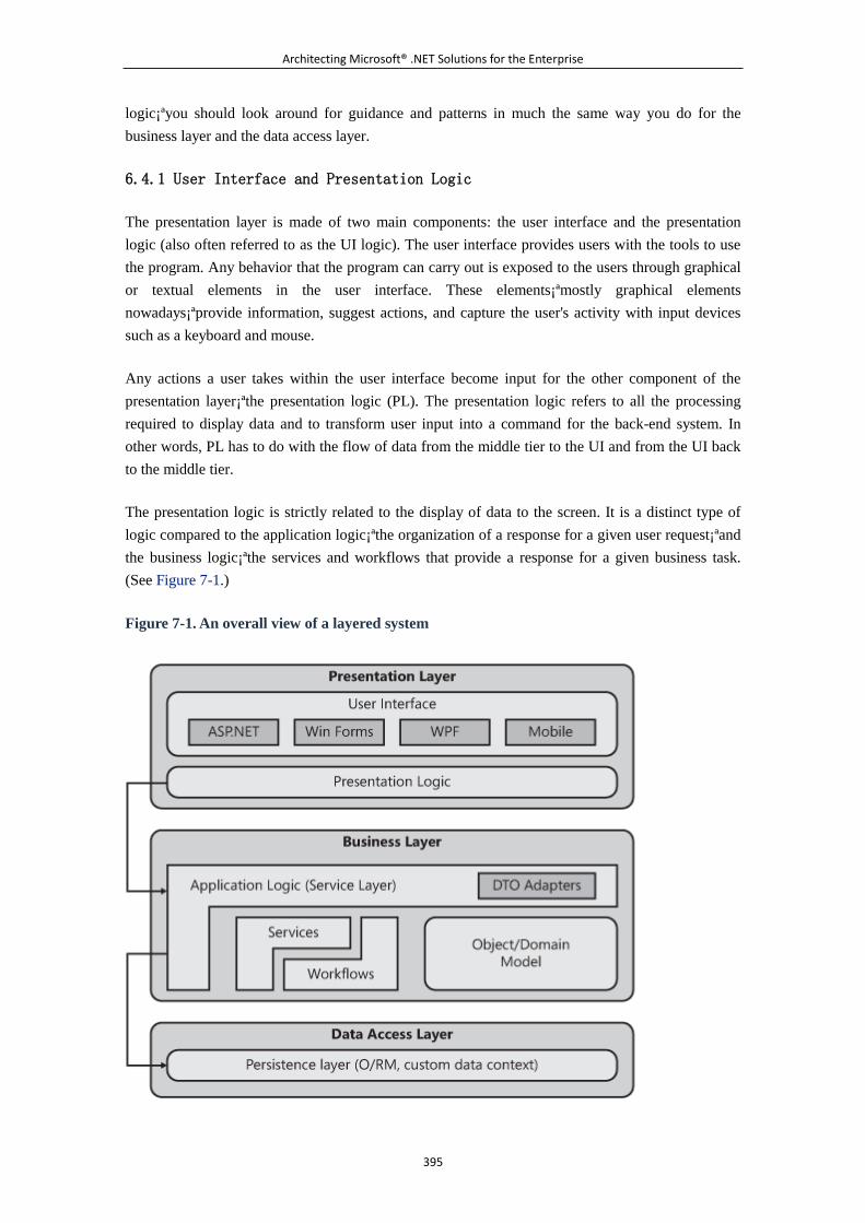
Architecting Microsoft® .NET Solutions for the Enterprise
395
logic¡ªyou should look around for guidance and patterns in much the same way you do for the
business layer and the data access layer.
6.4.1 User Interface and Presentation Logic
The presentation layer is made of two main components: the user interface and the presentation
logic (also often referred to as the UI logic). The user interface provides users with the tools to use
the program. Any behavior that the program can carry out is exposed to the users through graphical
or textual elements in the user interface. These elements¡ªmostly graphical elements
nowadays¡ªprovide information, suggest actions, and capture the user's activity with input devices
such as a keyboard and mouse.
Any actions a user takes within the user interface become input for the other component of the
presentation layer¡ªthe presentation logic (PL). The presentation logic refers to all the processing
required to display data and to transform user input into a command for the back-end system. In
other words, PL has to do with the flow of data from the middle tier to the UI and from the UI back
to the middle tier.
The presentation logic is strictly related to the display of data to the screen. It is a distinct type of
logic compared to the application logic¡ªthe organization of a response for a given user request¡ªand
the business logic¡ªthe services and workflows that provide a response for a given business task.
(See Figure 7-1.)
Figure 7-1. An overall view of a layered system
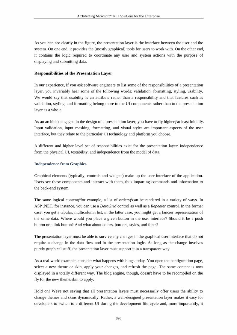
Architecting Microsoft® .NET Solutions for the Enterprise
396
As you can see clearly in the figure, the presentation layer is the interface between the user and the
system. On one end, it provides the (mostly graphical) tools for users to work with. On the other end,
it contains the logic required to coordinate any user and system actions with the purpose of
displaying and submitting data.
Responsibilities of the Presentation Layer
In our experience, if you ask software engineers to list some of the responsibilities of a presentation
layer, you invariably hear some of the following words: validation, formatting, styling, usability.
We would say that usability is an attribute rather than a responsibility and that features such as
validation, styling, and formatting belong more to the UI components rather than to the presentation
layer as a whole.
As an architect engaged in the design of a presentation layer, you have to fly higher¡ªat least initially.
Input validation, input masking, formatting, and visual styles are important aspects of the user
interface, but they relate to the particular UI technology and platform you choose.
A different and higher level set of responsibilities exist for the presentation layer: independence
from the physical UI, testability, and independence from the model of data.
Independence from Graphics
Graphical elements (typically, controls and widgets) make up the user interface of the application.
Users see these components and interact with them, thus imparting commands and information to
the back-end system.
The same logical content¡ªfor example, a list of orders¡ªcan be rendered in a variety of ways. In
ASP .NET, for instance, you can use a DataGrid control as well as a Repeater control. In the former
case, you get a tabular, multicolumn list; in the latter case, you might get a fancier representation of
the same data. Where would you place a given button in the user interface? Should it be a push
button or a link button? And what about colors, borders, styles, and fonts?
The presentation layer must be able to survive any changes in the graphical user interface that do not
require a change in the data flow and in the presentation logic. As long as the change involves
purely graphical stuff, the presentation layer must support it in a transparent way.
As a real-world example, consider what happens with blogs today. You open the configuration page,
select a new theme or skin, apply your changes, and refresh the page. The same content is now
displayed in a totally different way. The blog engine, though, doesn't have to be recompiled on the
fly for the new theme/skin to apply.
Hold on! We're not saying that all presentation layers must necessarily offer users the ability to
change themes and skins dynamically. Rather, a well-designed presentation layer makes it easy for
developers to switch to a different UI during the development life cycle and, more importantly, it
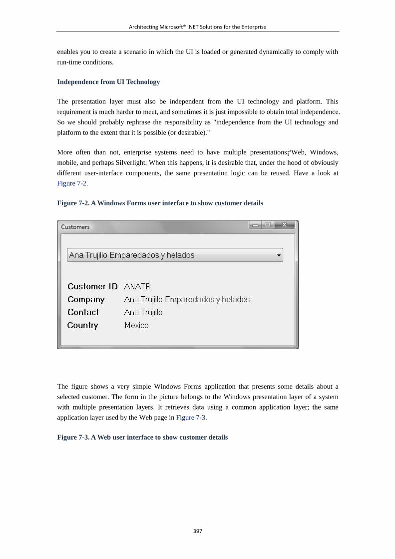
Architecting Microsoft® .NET Solutions for the Enterprise
397
enables you to create a scenario in which the UI is loaded or generated dynamically to comply with
run-time conditions.
Independence from UI Technology
The presentation layer must also be independent from the UI technology and platform. This
requirement is much harder to meet, and sometimes it is just impossible to obtain total independence.
So we should probably rephrase the responsibility as "independence from the UI technology and
platform to the extent that it is possible (or desirable)."
More often than not, enterprise systems need to have multiple presentations¡ªWeb, Windows,
mobile, and perhaps Silverlight. When this happens, it is desirable that, under the hood of obviously
different user-interface components, the same presentation logic can be reused. Have a look at
Figure 7-2.
Figure 7-2. A Windows Forms user interface to show customer details
The figure shows a very simple Windows Forms application that presents some details about a
selected customer. The form in the picture belongs to the Windows presentation layer of a system
with multiple presentation layers. It retrieves data using a common application layer; the same
application layer used by the Web page in Figure 7-3.
Figure 7-3. A Web user interface to show customer details
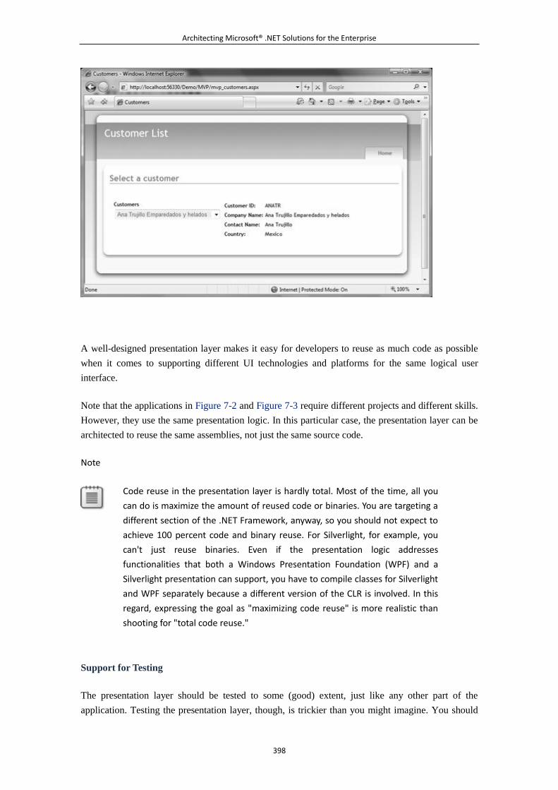
Architecting Microsoft® .NET Solutions for the Enterprise
398
A well-designed presentation layer makes it easy for developers to reuse as much code as possible
when it comes to supporting different UI technologies and platforms for the same logical user
interface.
Note that the applications in Figure 7-2 and Figure 7-3 require different projects and different skills.
However, they use the same presentation logic. In this particular case, the presentation layer can be
architected to reuse the same assemblies, not just the same source code.
Note
Code reuse in the presentation layer is hardly total. Most of the time, all you
can do is maximize the amount of reused code or binaries. You are targeting a
different section of the .NET Framework, anyway, so you should not expect to
achieve 100 percent code and binary reuse. For Silverlight, for example, you
can't just reuse binaries. Even if the presentation logic addresses
functionalities that both a Windows Presentation Foundation (WPF) and a
Silverlight presentation can support, you have to compile classes for Silverlight
and WPF separately because a different version of the CLR is involved. In this
regard, expressing the goal as "maximizing code reuse" is more realistic than
shooting for "total code reuse."
Support for Testing
The presentation layer should be tested to some (good) extent, just like any other part of the
application. Testing the presentation layer, though, is trickier than you might imagine. You should
Architecting Microsoft® .NET Solutions for the Enterprise
399
test that when the user performs a particular action, the user interface is modified accordingly. For
example, data should flow correctly in to and out of the user interface. In addition, the state of the
user interface should be updated¡ªsome buttons might be disabled, some panels might be expanded
or collapsed, and so on.
User-interface components work by triggering events that the run-time environment catches and
maps to your own handlers. It's not easy (to say the least) to simulate a Click action from within a
test environment. So you typically should let things go as usual but move testable code out of your
event handlers. In this way, any event is handled by a method on a distinct and reusable class. This
class is individually testable.
How would you then verify that a given action has generated exactly the expected results? You can't
assert in a unit testing tool whether a given method has produced a certain visual result. However,
you can come to an abstract description of the view (a form, an ASP .NET page, a window, or a
Silverlight user control) and just test that the correct information has been delivered to the object
that represents the view.
Abstraction is the key tool for adding testability to a presentation layer. And abstraction is obtained
by separating concerns¡ªin particular, by separating the view from the presentation logic. (We'll
return to this point in a moment, as it is central to this chapter.)
Note
After you have an abstraction of a given form (for example, an interface that
represents its contract to the outside world), you still have to map the content
in the abstraction to the physical set of UI components. How would you test
this?
In practice, you don't use automated testing here. Automated testing is helpful
for parts of the code that are subject to changes during development.
Mapping data on UI components requires a trivial piece of code. You have to
write it correctly, but after you've done it right nothing in the system can break
it. The real point for which automated testing is important is ensuring that
correct data flows into the view. This is a key point that forms the basis of
passive and humble views; we'll return to this topic later.
Independence from a Model of the Data
An enterprise system has its own representation of data. In Chapter 4, "The Business Layer," we
examined various options to organize the model of the data according to various patterns. Whatever
model you choose for the data in the middle tier, the presentation layer should be unaffected. Or, at
least, the presentation layer should be unaffected to the extent that it is possible.
Architecting Microsoft® .NET Solutions for the Enterprise
400
In Chapter 5, "The Service Layer," we discussed data transfer objects (DTOs) and using them to
carry data in to and out of the presentation layer. Using DTOs keeps the presentation layer
completely independent of whatever model of the data you employ in the lower application layers.
On the other hand, using DTOs everywhere adds significant overhead to the development phase¡ªin
theory, a pair of input and output DTOs is required for each call placed from the presentation layer
down to the application logic. Of course, the expression "each call" means each call from whatever
form or page you have in the presentation layer. It turns out to be, definitely, a large number of
classes to write and maintain.
For this reason, DTOs are often used sparingly and just in the areas of a system where changes are
more likely to occur. Making domain objects flow into the presentation layer creates a dependency.
A dependency is neither a bad thing nor a good thing. It is just a feature of the system. A
dependency added deliberately with due forethought might be a blessing for the system; failing to
spot an implicit dependency between modules in a timely manner, however, is definitely a bad
thing.
As far as the presentation layer is concerned, introducing a dependency on the model of the data
might be acceptable. However, the guideline is to introduce such dependencies only when you have
a clear benefit (or conversely, little or no risk) in terms of performance, maintenance, or both.
Responsibilities of the User Interface
Most of the time, the architect is not directly involved in the definition of graphical details regarding
the user interface. It is a precise responsibility of the architect, instead, to ensure that quality
characteristics (especially, usability and accessibility) are properly addressed.
The toughest part of the presentation logic is designing an abstraction of the view¡ªfor each view in
the presentation layer. The abstraction of the view defines what data is exposed in input to and
output from the view. The goal of the presentation logic is to ensure that the data flows correctly in
to and out of the view.
After all the stakeholders have signed off on the public contract of each view, two distinct teams can
work on the project. The development team can proceed with the implementation and testing of the
presentation logic and the middle tier. The design team can come up with one or more graphical
layouts for any of the supported user-interface designs. The resulting UI and presentation logic can
be tied together at any time with minimal work.
Each view that makes up the user interface has its own set of responsibilities, mostly related to
keeping the overall presentation metaphor as easy to use as possible.
Useful Data Display
Among other things, the user interface is responsible for presenting data to the user. Data includes
general information, hints, and, most importantly, responses obtained from application-specific
operations.
Architecting Microsoft® .NET Solutions for the Enterprise
401
A good user interface always supplies users properly formatted data and displays it in useful visual
styles. The user interface also encapsulates the effect of globalization and localization and uses
proper settings wherever required.
Depending on the actual patterns you employ in the design of the presentation layer, the exact place
where data is adapted for display might change. Most of the time, it happens in the presentation
logic, but it is not unusual that some formatting and display logic is implemented through the
properties of rich controls you have in the user interface. In this case, you also have the benefit that
you can change it in a rather declarative way without writing or editing a single line of C# code.
Comfortable Data Entry
The user interface is the place where users enter data into the system. A usable presentation layer
makes data entry comfortable for users to do by providing input masks and using appropriate
controls for data input.
In this regard, rich controls and drag-and-drop are key features. Tabs also help to partition complex
user interfaces while keeping the various parts at hand.
Whatever the underlying platform (Windows, Web, or mobile) is, data entry is a critical moment for
the application. Of course, it is an especially critical moment for Web applications. Why is that so?
Remember that security mantra? All user input is evil. So providing quick validation is another
fundamental responsibility of the user interface. UI-level validation is not enough, but it is a good
first step.
General Appearance
The look and feel of an application refers to the experience that a user has while using the
application and the main features of its general appearance. Finding the right combination of
controls, visual layouts, and styles is a process that can take time. And it is the aspect of the system
that customers usually have the most questions about.
Typically, applications intended for public use, such as Web portals or productivity suites, have
fancy user interfaces because one of their goals is just to grab the user's attention and leave a
favorable impression. On the other hand, applications intended for internal corporate use lean
toward a user interface that is more functional than visually pleasing.
In the end, it is a matter of following the customer's requirements. The UI architecture should be
chosen according to the actual requirements.
Common Pitfalls of a Presentation Layer
To successfully meet all expectations users have regarding the presentation layer, an architect
should simply treat the presentation layer like any other layer¡ªand apply specific and proven design
patterns. In a moment, we'll be delving deep into the mother of all contemporary UI design
patterns¡ªthe Model-View-Controller (MVC) pattern.
Architecting Microsoft® .NET Solutions for the Enterprise
402
Before we get to that, though, we'd like to make a few observations about the presentation layer with
the purpose of hinting at common pitfalls to avoid.
RADness in the Presentation
Writing the user interface of a Microsoft Windows application is way too easy. Any new version of
Visual Studio comes with a full bag of goodies for developers and seems to tell developers not to
waste any time with design and separation of concerns. This is just the offspring of RAD.
A plain, old T-SQL query correctly attached to the handler of a Click event does the job. And it's
quick and effective¡ªand it just works. That's the beauty and the power of RAD. You point the
mouse, click, select the properties of an element, and double-click and a stub of code is ready for
you to fill. Wizards are also there to help you declare what you want (provided that the wizard
understands you correctly and that you give it the right instructions).
RADness is not the ideal companion for the presentation layer of a large, enterprise-class system.
Visual Studio 2008, of course, is still essential, but the more you care about the aforementioned
responsibilities of a presentation layer, the more you should downgrade Visual Studio to the rank of
a simple UI designer.
We suggest you use Visual Studio 2008 as a rapid UI designer rather than as a rapid application
development tool. Visual Studio 2008 and all of its RAD features are tempting to use in many
situations. But you should resist using it in some cases, abandon the point-and-click metaphor,
and¡ªguess what?¡ªwrite more code on your own. From a mouse-based point-and-click metaphor,
you should move to a keyboard-based tap-and-tab metaphor.
Note
Using RADness a go-go might cause you to build autonomous views. An
autonomous view consists of a class that holds the state of the user interface
and implements any behavior therein. Difficulty of testing is the primary
reason why autonomous views are not so popular these days. An autonomous
view contains in the same class both the presentation logic and user interface,
which makes for difficult, if not impossible, testing. RADness certainly doesn't
prevent proper separation of concerns between the user interface and
presentation logic, but the temptation to put everything in a single place is so
strong that only few can resist it.
Boundaries of the Presentation Layer
As it turns out, in a well-built and effective presentation layer, the UI is a thin layer and the
presentation logic tends to take on all the client-side processing that is required to have data
correctly flow into and out of the presentation layer. How thick should the presentation logic be?
Architecting Microsoft® .NET Solutions for the Enterprise
403
In Chapter 4, we pointed out that it might be acceptable to have some business logic that is run on
the client merged with the presentation layer, if not just duplicated in the presentation logic. As
we've said repeatedly in this book, we live in an imperfect world, meaning that we have to make
compromises more than we ideally would like to. The thickness of the presentation layer is limited
only by scalability and performance requirements, if any. At the same time, though, the presentation
layer should contain only its own presentation logic, plus any extra piece of business you
deliberately, and in full awareness, decide to merge or duplicate.
The real danger is in another area, however.
We're not far from the truth if we say that user-interface facilities encourage developers to put more
stuff and code in the presentation layer than it should reasonably contain. As a result, the
presentation layer operates as a catch-all for the logic of other layers¡ªmostly the middle tier, but
often also the data access layer. Is this really bad? And if so, why is it all that bad?
Again, let's be pragmatic. It isn't all that bad if you're developing a temporary Web site that is
destined to stay up only for a short time¡ªfor example, the three months around a user-group meeting.
In such a case, you probably just shouldn't bother to write complex application layers and instead
simply place an ADO.NET query in the Button1_Click event handler of a code-behind class.
So for Web sites that you use copy-cat designing for¡ªto do the same few and well-known things¡ªan
approach that leverages simplicity and quick time to market isn't a bad thing per se. For these types
of sites, you should feel free to make use of ASP .NET data source controls and all the canned code
that Visual Studio 2008 wizards normally create for you.
Although such an approach is OK for simple applications, for large, durable, enterprise-class
systems it is another story. When it comes to such types of applications, stuffing code in the
presentation layer that logically belongs to other tiers is a tremendous sin. The UI must be isolated
from code, and code must be layered, showing high regard for the separation of concerns (SoC)
principle. Not only do properly factored layers have their concerns separated, but proper layering
also allows for better testing, and therefore higher quality applications, because you can weed out
the early bugs while enjoying a higher percentage of test coverage. That is, your test cases test more
of your code. Moreover, keeping the logic in the appropriate layer also allows for easier presentation
layer refactoring, application layer refactoring, and code re-use, all of which are real-world
requirements.
What Users Get Is What You Want
WYSIWYG is a popular acronym for What-You-See-Is-What-You-Get. When this term is applied to
RAD, it refers to the ability of some development tools to offer a live preview of what you will see
after you have run the application. WYSIWYG in that case is mostly related to the user interface
and declarative programming.
Whenever you take a declarative approach to coding rather than an imperative approach, you are
delegating some responsibilities to some other layer of code¡ªa layer that you don't control entirely.
Architecting Microsoft® .NET Solutions for the Enterprise
404
So you're ultimately hoping that the intermediate tool will understand you correctly and won't
encounter any trouble of its own along the way. In software development, delegating to a third party
makes development faster, but you should guarantee that users get exactly what you want them to.
This doesn't mean that you shouldn't trust Visual Studio 2008 or similar wizard-based products. The
point is something else entirely. In a large system, likely being developed by several teams, classic
declarative programming just doesn't work. You need to have in your presentation a layer of code
that decides what to display, where to read settings, and how to apply them. Declarative
programming is still a great option, but only if you write the engine and the wizards.
For enterprise-class applications, the slogan should rather be
WUGISYW¡ªWhat-Users-Get-Is-What-You-Want.
6.4.2 Evolution of the Presentation Patterns
When it comes to the presentation layer of a system, there is one fundamental principle to adhere
to¡ªkeep the presentation layer separated from anything else, including business and data access
layers. This principle is captured in Martin Fowler's Separated Presentation pattern, whose complete
definition is available at http://www.martinfowler.com/eaaDev/SeparatedPresentation.html. Here is
an excerpt:
Ensure that any code that manipulates presentation only manipulates presentation, pushing all
domain and data source logic into clearly separated areas of the program.
Separating presentation logic from business logic is only the first step toward creating a
well-designed presentation layer. Separating the user interface from the presentation logic is another
important characteristic of a presentation layer designed to meet the requirements mentioned in
Fowler's definition. The internal organization of the presentation logic depends on a variety of UI
patterns.
Ultimately, we recognize three main families of patterns: Model-View-Controller (MVC),
Model-View-Presenter (MVP), and Presentation Model (PM). You should think of these patterns as
base classes that are then specialized by a number of actual patterns, such as Model2 for MVC,
Passive View and Supervising Controller for MVP, Model-View-ViewModel for PM.
Before we describe each pattern, we should note that these patterns span 30 years of computer
design and programming. And many, many things have changed in the past 30 years. So, for
example, the definition of MVC that worked in the 1980s and even the 1990s might not work today.
As a result, probably nobody uses MVC today as its authors originally devised it. At the same time,
a number of variations and refinements have been made to MVC to make it work in disguise. What
we call MVC today doesn't match exactly the definition of MVC you find in the original paper. The
same can be said for MVP. Two flavors of MVP exist and, in many applications, you actually use a
personal mix of both. MVP just doesn't exist anymore¡ªit is either Passive View (PV) or Supervising
Controller (SVC). But in literature and in everyday technical conversation, MVP is still the most
frequently used term.
Architecting Microsoft® .NET Solutions for the Enterprise
405
Another huge point to consider is the impact that UI frameworks might have on the presentation
layer. We're not talking about RAD tools to create forms and Web pages in a snap; we're talking, in
particular, about platform-specific frameworks that offer an MVC idiom, such as Castle MonoRail
(see http://www.castleproject.org/monorail) and ASP .NET MVC Framework (see
http://www.asp.net/mvc). Developers using these frameworks enjoy nifty and highly usable facilities
that cut down development time. And who cares about the purity of the approach compared to the
original paper? If you have a framework that gives you testability and separation of concerns (and
whatever else you ask for), by all means use it and don't get bothered by possible patterns it does or
does not implement.
The purpose of this chapter is to discuss a set of guidelines for an effective design of the
presentation layer, with a particular focus on enterprise-class applications. Let's start from what we
had in the beginning of the software era and examine the requirements that brought us to today's
patterns.
The Model-View-Controller Pattern
In the earliest software, the presentation layer was made of monolithic, autonomous views displayed
to the user. The user interacted with the view and generated some input. The view captured the input,
processed it internally, and updated itself or moved to another view. At a minimum, this model
made it really hard to test the presentation pieces properly. A search for a better model ensued. Enter
the Model-View-Controller pattern.
Moving Away from Autonomous Views
An autonomous view (AV) is similar to a Web or Windows form you obtain by using the RAD
facilities of Visual Studio 2008 to their fullest. If you do so, in fact, you might end up having a form
with a code-behind class that contains almost everything you need¡ªpresentation logic, business
logic, and even data access logic.
Note
Visual Studio 2008 is a stunningly powerful tool with great facilities for
developers. You must be able to master those facilities, though, and use them
properly. However, we certainly don't believe that Visual Studio 2008 is a tool
that promotes autonomous views without exercising a due separation of
concerns. If you use Visual Studio 2008 properly, you can certainly create
well-designed applications and user interfaces. What does properly mean in
this context? You should use Visual Studio 2008 mostly as a plain IDE.
Something still needs to handle the odd button click or list selection, and that
is the code in the code-behind file. Having a wizard generate that isn't
necessarily bad. It's what you do in the method skeleton that's generated that
causes the grief. So is the problem with actually using the wizard, or rather
with using what the wizard produces without thought? The latter.
Architecting Microsoft® .NET Solutions for the Enterprise
406
An AV is a class that contains display and state information for the view, as well as the full logic to
handle any user actions from start to finish. With such monolithic components, you can hardly fulfill
the requirements for the presentation layer outlined earlier in this section. In particular, you have a
presentation layer that is hard (if not impossible) to test and that has no separation of concerns
between the user interface and presentation logic.
Separation of concerns (SoC) is important in the presentation layer for a number of reasons. First, as
we saw in Chapter 3, "Design Principles and Patterns," it is a fundamental design principle that
contributes to creating the right combination of coupling and cohesion for a component. Second,
SoC makes it easier for the presentation layer to implement a navigational workflow to decide
which view comes next.
To achieve testability and separation of concerns in the user interface, the MVC pattern was
introduced back in 1979. The original paper can be found here:
http://st-www.cs.uiuc.edu/users/smarch/st-docs/mvc.html.
MVC: Pattern or Paradigm?
It is not coincidental that the aforementioned paper refers to MVC as a paradigm. Let's look at an
excerpt from the paper:
In the MVC paradigm the user input, the modeling of the external world, and the visual feedback to
the user are explicitly separated and handled by three types of objects, each specialized for its task.
Today, instead, we refer to MVC as a pattern. Pattern or paradigm? Is this question only the
offspring of the attention to subtle differences that is typical of architects? Maybe. The Oxford
English Dictionary indicates three synonyms for paradigm: pattern, model, and exemplar. In
software terms, though, a pattern is a particular concrete and proven solution, whereas a paradigm
indicates a family of similar patterns. Or, put another way, a paradigm indicates the base class from
which a variety of concrete design patterns derive.
In our vision, the original use of the word "paradigm" means that MVC is a (deliberately?) loosely
defined pattern. MVC shows the way to go, but it leaves the architect a lot of freedom when it
comes to implementation details. This is probably the reason why so many variations of MVC exist.
This is probably also the reason why different implementations are all referred to as MVC. Let's go
through the original formulation of MVC and discuss its pros and cons.
Generalities of the MVC Pattern
The primary goal of MVC is to split the application into distinct pieces¡ªthe model, the view, and the
controller. The model refers to state of the application, wraps the application's functionalities, and
notifies the view of state changes. The view refers to the generation of any graphical elements
displayed to the user, and it captures and handles any user gestures. The controller maps user
gestures to actions on the model and selects the next view. These three actors are often referred to as
the MVC triad.
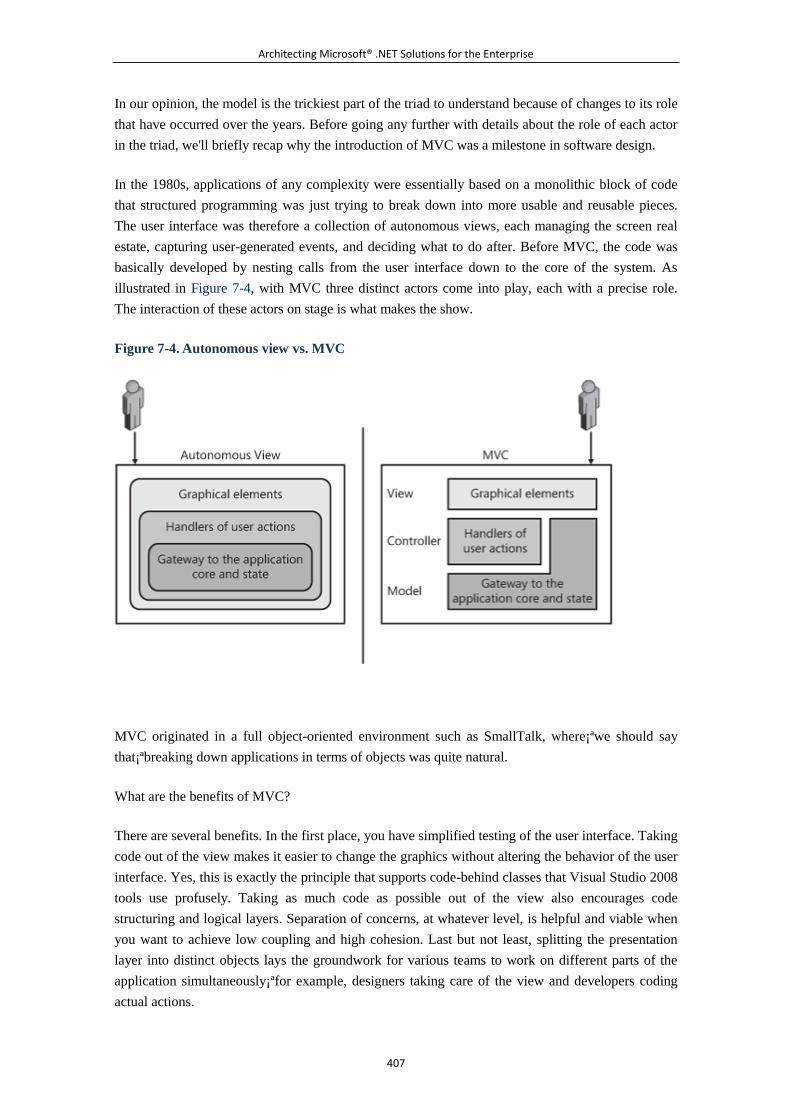
Architecting Microsoft® .NET Solutions for the Enterprise
407
In our opinion, the model is the trickiest part of the triad to understand because of changes to its role
that have occurred over the years. Before going any further with details about the role of each actor
in the triad, we'll briefly recap why the introduction of MVC was a milestone in software design.
In the 1980s, applications of any complexity were essentially based on a monolithic block of code
that structured programming was just trying to break down into more usable and reusable pieces.
The user interface was therefore a collection of autonomous views, each managing the screen real
estate, capturing user-generated events, and deciding what to do after. Before MVC, the code was
basically developed by nesting calls from the user interface down to the core of the system. As
illustrated in Figure 7-4, with MVC three distinct actors come into play, each with a precise role.
The interaction of these actors on stage is what makes the show.
Figure 7-4. Autonomous view vs. MVC
MVC originated in a full object-oriented environment such as SmallTalk, where¡ªwe should say
that¡ªbreaking down applications in terms of objects was quite natural.
What are the benefits of MVC?
There are several benefits. In the first place, you have simplified testing of the user interface. Taking
code out of the view makes it easier to change the graphics without altering the behavior of the user
interface. Yes, this is exactly the principle that supports code-behind classes that Visual Studio 2008
tools use profusely. Taking as much code as possible out of the view also encourages code
structuring and logical layers. Separation of concerns, at whatever level, is helpful and viable when
you want to achieve low coupling and high cohesion. Last but not least, splitting the presentation
layer into distinct objects lays the groundwork for various teams to work on different parts of the
application simultaneously¡ªfor example, designers taking care of the view and developers coding
actual actions.
Architecting Microsoft® .NET Solutions for the Enterprise
408
The Model in MVC
In the original formulation of MVC, the model is the object that represents the application's gateway
to the business logic. In the model, you find the state of the application as well as data to expose
through the view and actions to be invoked in response to user actions. The model is an object
designed to hold state and reply to requests for state changes coming from the view. The model is
also designed to execute actions requested by the controller that typically result in state changes.
This vision of the model made a lot of sense in the 1980s for all applications. Today things are a bit
different.
Originally, MVC was conceived to be a pattern for building the whole application and not just the
presentation layer. If you take a look at the many tutorials about the ASP .NET MVC Framework,
you see that the model is created using the LINQ-to-SQL designer in Visual Studio 2008 in the
context of an MVC application. It might seem, therefore, that you need to use the MVC pattern to
have a distinct business layer. The truth, instead, is that MVC does most of its work with the view
and controller and just requires a model for the data being worked on in the view. The model then
can be your existing business layer (object model and services) or a new set of classes aptly created
for the purpose of applying the pattern.
For simple applications, applying the MVC pattern means creating a view, controller, and business
layer. In enterprise-class applications, you use the MVC pattern for getting separation of concerns
and testability in the presentation layer. Subsequently, MVC is mostly a pattern for the presentation
layer, and all that you focus on is the interaction between the view and the controller.
Figure 7-5 illustrates the interaction in MVC between the various elements of the triad.
Figure 7-5. The MVC triad in action
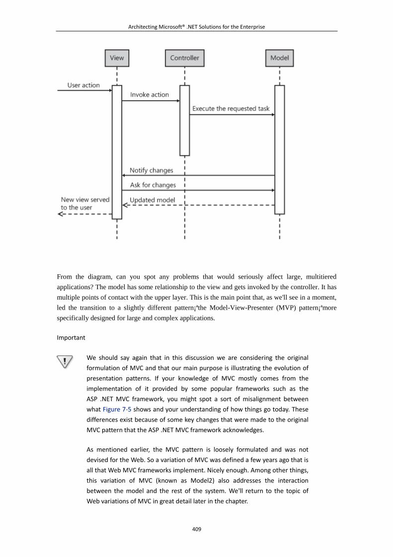
Architecting Microsoft® .NET Solutions for the Enterprise
409
From the diagram, can you spot any problems that would seriously affect large, multitiered
applications? The model has some relationship to the view and gets invoked by the controller. It has
multiple points of contact with the upper layer. This is the main point that, as we'll see in a moment,
led the transition to a slightly different pattern¡ªthe Model-View-Presenter (MVP) pattern¡ªmore
specifically designed for large and complex applications.
Important
We should say again that in this discussion we are considering the original
formulation of MVC and that our main purpose is illustrating the evolution of
presentation patterns. If your knowledge of MVC mostly comes from the
implementation of it provided by some popular frameworks such as the
ASP .NET MVC framework, you might spot a sort of misalignment between
what Figure 7-5 shows and your understanding of how things go today. These
differences exist because of some key changes that were made to the original
MVC pattern that the ASP .NET MVC framework acknowledges.
As mentioned earlier, the MVC pattern is loosely formulated and was not
devised for the Web. So a variation of MVC was defined a few years ago that is
all that Web MVC frameworks implement. Nicely enough. Among other things,
this variation of MVC (known as Model2) also addresses the interaction
between the model and the rest of the system. We'll return to the topic of
Web variations of MVC in great detail later in the chapter.
Architecting Microsoft® .NET Solutions for the Enterprise
410
Let's now delve a bit deeper into the role played by the view and controller actors in an MVC
scenario.
The View in MVC
In MVC, the view is as dumb, humble, and passive as possible. (Dumb, humble, and passive are
terms commonly used to describe the role of the view in an MVC scenario.) Translated as
instructions for developing code, it means that the view should care only about painting the interface
to display to users.
Ideally, the view is so simple and logic-free as to need virtually no testing. Users (and developers
before users) can reasonably test the view by simply looking at the pixels on the screen. Anything
else beyond pure graphical rendering should ideally be taken out of the view and placed in the
controller and model. This includes, for example, the logic that determines whether a certain button
should be enabled or grayed out at some point.
What are the responsibilities of the view in MVC?
A view is made of interactive controls (such as input fields, buttons, and lists), and it waits for any
user actions. When the user, say, clicks a button, the view simply forwards the call to the controller.
How this happens has changed quite a bit over the years and is definitely an aspect that largely
depends on platform, languages, and development tools. In a .NET application, the view handles its
events in the code-behind class and all it does is invoke a particular action method on the controller
class. Here's some sample code:
void Button1_Click(object sender, EventArgs e)
{
ViewController controller = new ViewController();
controller.ActionForButton1Clicked();
}
The ViewController class in the example represents the controller for a particular view¡ªbe it a
Windows form, Web form, or Silverlight user control. The controller features one method for each
possible user action supported by the user interface. Each supported user action corresponds to an
action on the controller.
Another key responsibility of the view is rendering.
In an MVC implementation, the controller updates the model by executing the triggered action. The
model then notifies the view about pending changes on its state that the view might want to reflect
in the user interface. The view reads the model and provides an updated interface.
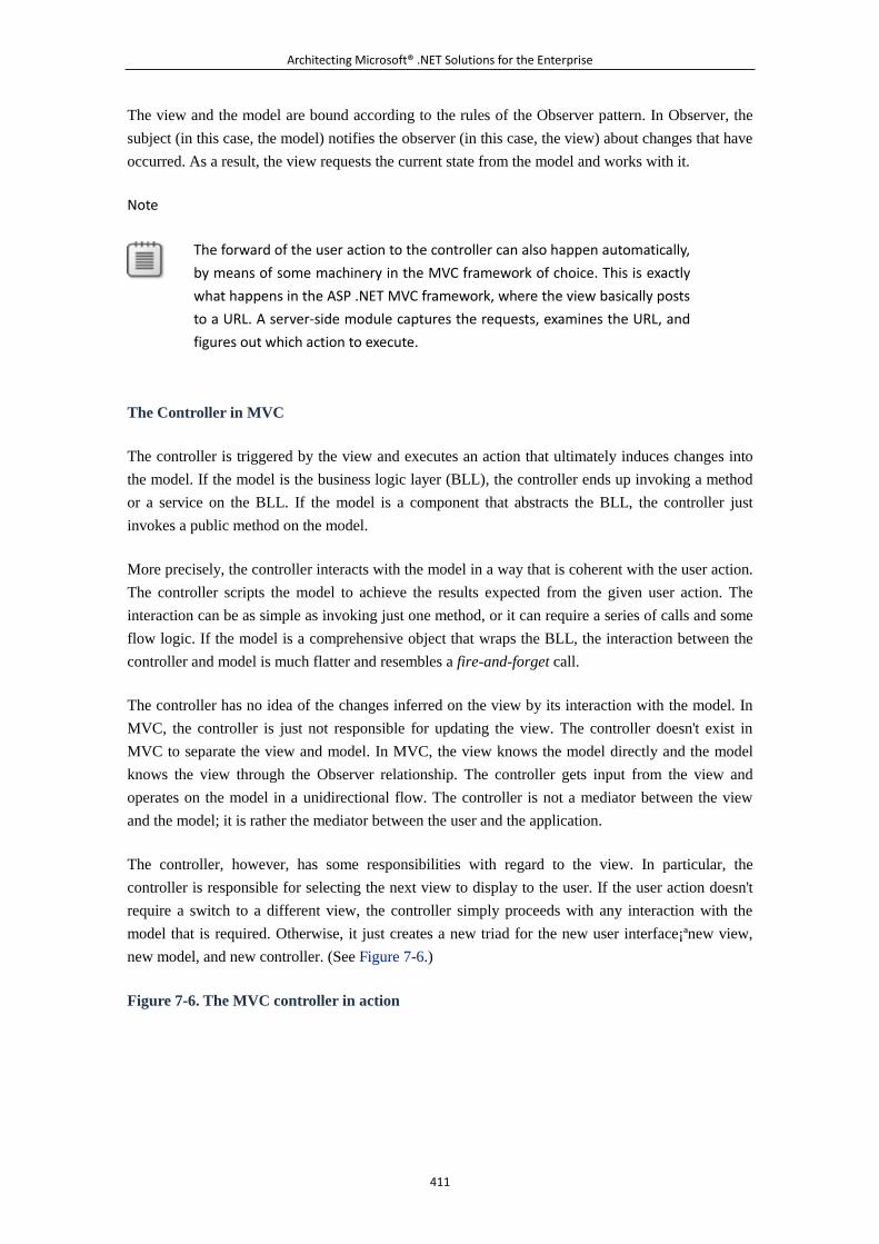
Architecting Microsoft® .NET Solutions for the Enterprise
411
The view and the model are bound according to the rules of the Observer pattern. In Observer, the
subject (in this case, the model) notifies the observer (in this case, the view) about changes that have
occurred. As a result, the view requests the current state from the model and works with it.
Note
The forward of the user action to the controller can also happen automatically,
by means of some machinery in the MVC framework of choice. This is exactly
what happens in the ASP .NET MVC framework, where the view basically posts
to a URL. A server-side module captures the requests, examines the URL, and
figures out which action to execute.
The Controller in MVC
The controller is triggered by the view and executes an action that ultimately induces changes into
the model. If the model is the business logic layer (BLL), the controller ends up invoking a method
or a service on the BLL. If the model is a component that abstracts the BLL, the controller just
invokes a public method on the model.
More precisely, the controller interacts with the model in a way that is coherent with the user action.
The controller scripts the model to achieve the results expected from the given user action. The
interaction can be as simple as invoking just one method, or it can require a series of calls and some
flow logic. If the model is a comprehensive object that wraps the BLL, the interaction between the
controller and model is much flatter and resembles a fire-and-forget call.
The controller has no idea of the changes inferred on the view by its interaction with the model. In
MVC, the controller is just not responsible for updating the view. The controller doesn't exist in
MVC to separate the view and model. In MVC, the view knows the model directly and the model
knows the view through the Observer relationship. The controller gets input from the view and
operates on the model in a unidirectional flow. The controller is not a mediator between the view
and the model; it is rather the mediator between the user and the application.
The controller, however, has some responsibilities with regard to the view. In particular, the
controller is responsible for selecting the next view to display to the user. If the user action doesn't
require a switch to a different view, the controller simply proceeds with any interaction with the
model that is required. Otherwise, it just creates a new triad for the new user interface¡ªnew view,
new model, and new controller. (See Figure 7-6.)
Figure 7-6. The MVC controller in action
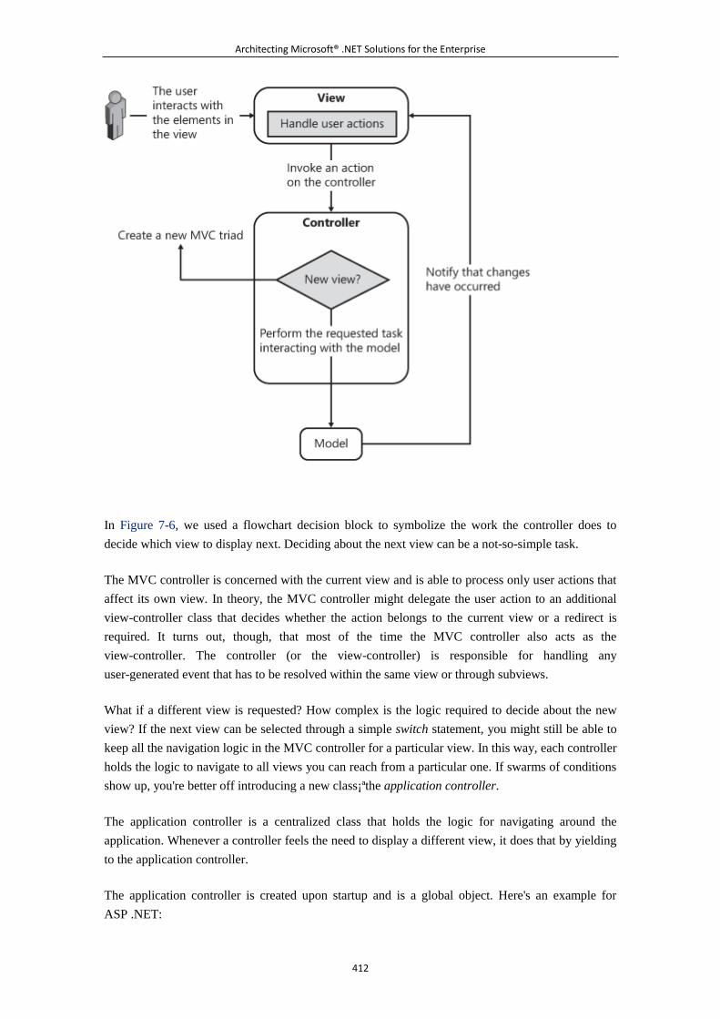
Architecting Microsoft® .NET Solutions for the Enterprise
412
In Figure 7-6, we used a flowchart decision block to symbolize the work the controller does to
decide which view to display next. Deciding about the next view can be a not-so-simple task.
The MVC controller is concerned with the current view and is able to process only user actions that
affect its own view. In theory, the MVC controller might delegate the user action to an additional
view-controller class that decides whether the action belongs to the current view or a redirect is
required. It turns out, though, that most of the time the MVC controller also acts as the
view-controller. The controller (or the view-controller) is responsible for handling any
user-generated event that has to be resolved within the same view or through subviews.
What if a different view is requested? How complex is the logic required to decide about the new
view? If the next view can be selected through a simple switch statement, you might still be able to
keep all the navigation logic in the MVC controller for a particular view. In this way, each controller
holds the logic to navigate to all views you can reach from a particular one. If swarms of conditions
show up, you're better off introducing a new class¡ªthe application controller.
The application controller is a centralized class that holds the logic for navigating around the
application. Whenever a controller feels the need to display a different view, it does that by yielding
to the application controller.
The application controller is created upon startup and is a global object. Here's an example for
ASP .NET:
Architecting Microsoft® .NET Solutions for the Enterprise
413
protected void Application_Start(object sender, EventArgs e)
{
// Create an instance of the specific navigation service
to use
SiteNavigationWorkflow nav = new
SiteNavigationWorkflow();
// Register the navigator with an application-wide service
NavigationController.Register(nav);
}
From within an ASP .NET page, you use code such as in the following snippet to navigate to a
different view:
// Navigate to the view (URL in ASP .NET) referenced by the
"customers" moniker
NavigationController.NavigateTo("customers");
The logic that figures out the new URL (or the new form, if it is a Windows application) is
contained in the SiteNavigationWorkflow class. Here's an excerpt:
class SiteNavigationWorkflow : INavigationWorkflow
{
public void NavigateTo(string url)
{
switch (url)
{
case "main":
HttpContext.Current.Response.Redirect("~/default.aspx");
break;
case "customers":
HttpContext.Current.Response.Redirect("~/CustomersPage.asp
x");
break;
.
.
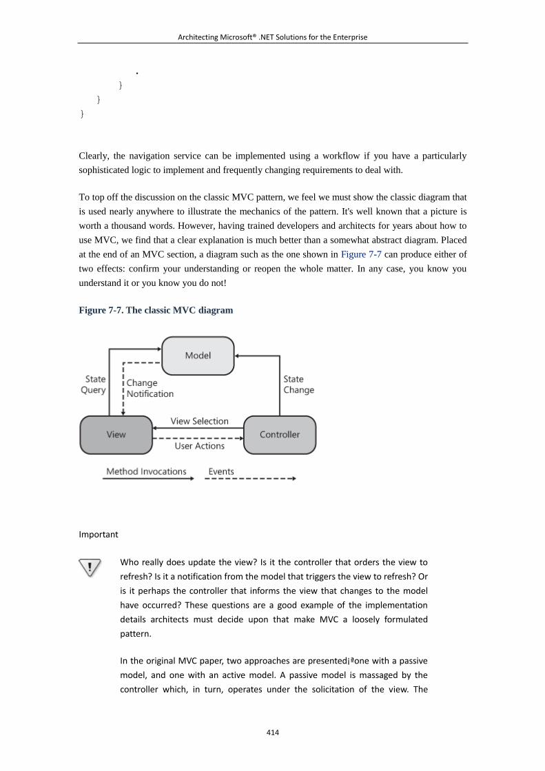
Architecting Microsoft® .NET Solutions for the Enterprise
414
.
}
}
}
Clearly, the navigation service can be implemented using a workflow if you have a particularly
sophisticated logic to implement and frequently changing requirements to deal with.
To top off the discussion on the classic MVC pattern, we feel we must show the classic diagram that
is used nearly anywhere to illustrate the mechanics of the pattern. It's well known that a picture is
worth a thousand words. However, having trained developers and architects for years about how to
use MVC, we find that a clear explanation is much better than a somewhat abstract diagram. Placed
at the end of an MVC section, a diagram such as the one shown in Figure 7-7 can produce either of
two effects: confirm your understanding or reopen the whole matter. In any case, you know you
understand it or you know you do not!
Figure 7-7. The classic MVC diagram
Important
Who really does update the view? Is it the controller that orders the view to
refresh? Is it a notification from the model that triggers the view to refresh? Or
is it perhaps the controller that informs the view that changes to the model
have occurred? These questions are a good example of the implementation
details architects must decide upon that make MVC a loosely formulated
pattern.
In the original MVC paper, two approaches are presented¡ªone with a passive
model, and one with an active model. A passive model is massaged by the
controller which, in turn, operates under the solicitation of the view. The
Architecting Microsoft® .NET Solutions for the Enterprise
415
controller knows, or assumes, that some user actions can update the model;
so it's up to the controller to notify the view about changes. This approach is
too simplistic for the average complexity of today's software. We presented a
more realistic scenario in this chapter, where an active model notifies the view
of its changes and the controller is unaware of the effects that user actions
might produce on the view. Obviously, two different implementations of a
piece of code can both correctly raise the flag of MVC. But there's more.
A popular variation of MVC, the aforementioned Model2, takes yet another
route. In classic MVC with an active model and a passive model, the view
receives notification of the changes and grabs fresh data from the model. With
Model2, on the other hand, the controller orders the view to refresh and
passes all the information the view needs to update the interface. In Model2,
there's no observer-like communication between the view and the model. As
you can see, these are quite significant changes, but they all happen under the
umbrella of MVC.
Model2: A Web Variation of MVC
Until recently with the ASP .NET MVC framework, on the Windows platform the MVC pattern has
never been particularly popular. This reminds us of Microsoft Foundation Classes (MFC), which
offered more than a decade ago an architecture with some points in common with
MVC¡ªparticularly, the Document/View (DV) model. DV can be seen as a version of MVC where
the view and controller are fused together.
We really don't know whether the MFC team intentionally discarded MVC to embrace DV; our
feeling, however, is that DV blossomed autonomously during the design by simply applying
correctly and diffusely the SoC principle. Principles and fundamentals never go out of style! And
patterns are only a shortcut to a solution.
MVC was devised at a time when the Web had not yet come into existence. MVC can certainly be
adapted to Web applications, but its original formulation targets desktop applications. On the other
hand, the loose definition of MVC leaves room for frameworks to customize MVC to particular
areas. This is exactly the case for Model2¡ªan extremely popular Web variation of MVC. (You can
find detailed information on the pattern at
http://java.sun.com/blueprints/guidelines/designing_enterprise_applications_2e/web-tier/web-tier5.
html.)
Model2 is a pattern that was originally created for developing with Java Server Pages (JSP). It owes
a lot of its popularity to the Struts framework. (See http://struts.apache.org.)
In a Model2 application, requests flow from the browser directly to a front controller implemented
as an HTTP interceptor¡ªin ASP .NET jargon, we would call it an HTTP module. In other words, the
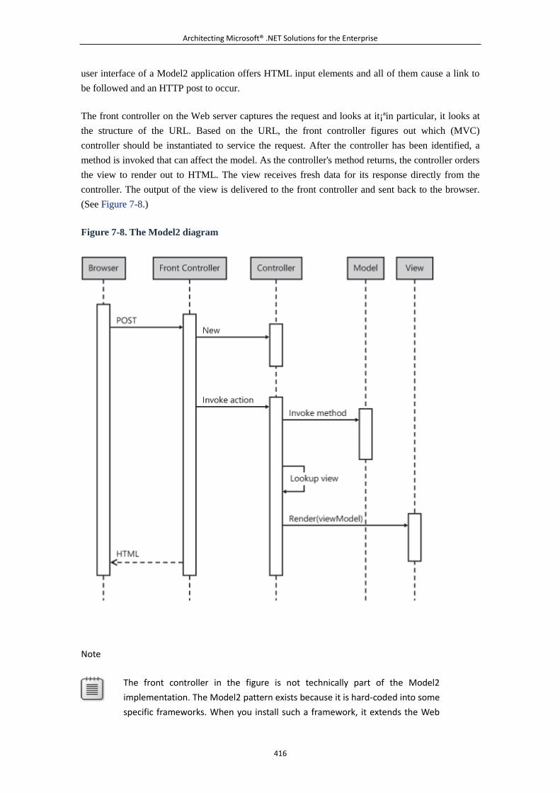
Architecting Microsoft® .NET Solutions for the Enterprise
416
user interface of a Model2 application offers HTML input elements and all of them cause a link to
be followed and an HTTP post to occur.
The front controller on the Web server captures the request and looks at it¡ªin particular, it looks at
the structure of the URL. Based on the URL, the front controller figures out which (MVC)
controller should be instantiated to service the request. After the controller has been identified, a
method is invoked that can affect the model. As the controller's method returns, the controller orders
the view to render out to HTML. The view receives fresh data for its response directly from the
controller. The output of the view is delivered to the front controller and sent back to the browser.
(See Figure 7-8.)
Figure 7-8. The Model2 diagram
Note
The front controller in the figure is not technically part of the Model2
implementation. The Model2 pattern exists because it is hard-coded into some
specific frameworks. When you install such a framework, it extends the Web
Architecting Microsoft® .NET Solutions for the Enterprise
417
server by registering some helper runtime components such as the front
controller.
There are a few differences between classic MVC and Model2. First and foremost, there's no direct
contact, let alone an Observer relationship, between the view and the model. Second, the controller
renders the view and explicitly passes display data to it. The user action is not captured and handled
by the view. A system component in the Web server¡ªthe front controller¡ªintercepts HTTP requests
and figures out from the URL and headers which controller will be in charge of the request.
Model2 is just MVC adapted to a new medium¡ªthe Web¡ªthat just wasn't around at the time MVC
was first devised. Today, people often people speak of MVC with regard to the Web, but what they
actually mean (consciously or unconsciously) is Model2. Model2 is exactly the pattern behind the
Microsoft ASP .NET MVC framework.
Note
We said that classic MVC can be adapted to the Web, but hinted that Model2
is a better option. Why is this so?
Think of how the Web works. Any user action originates an HTTP post. The
Web server captures these requests and maps them to a page class. The page
class goes through its own life cycle, inside of which it figures out which action
the user actually meant to be executed. In a classic MVC scenario, the page
class figures out the right controller and invokes a method. The execution of
the method modifies the model.
What about the refresh of the view? It is left up to you whether to push a
refresh from the controller or use data binding to sync up the view and the
model. As you can see, this route can be shortened quite a bit by using a front
controller. By using properly formatted URLs, the front controller¡ªfor example,
an HTTP module¡ªcan figure out from the URL (in a REST-like manner) the
controller to use and invoke an action on it. You save the page life cycle and
come up with an extremely passive view that needs virtually no testing. You
pour your testing effort into the controller instead. What we have described as
a general approach here applies literally to the ASP .NET MVC framework.
What object really plays the role of the model in a Model2 approach? Is the actor "model" actually
your business layer? This is debatable, and we don't believe there's an answer that serves as an
absolute truth. It is all about perspective. Here is our own.
As you see in Figure 7-8, the model can certainly match the BLL. However, in Model2 the view is
completely detached from the model. At the same time, another, still unnamed, data holder object is
around that the view knows intimately. It is precisely what we called the viewModel entity in Figure
Architecting Microsoft® .NET Solutions for the Enterprise
418
7-8. This element contains all the data the view needs to do its job of creating HTML for the
browser. The view knows the viewModel rather than BLL. The viewModel corresponds to the
ViewData container (and all of its typed variations) in the ASP .NET MVC framework. Similar
containers also exist in MonoRail (another .NET Model2 framework) and Struts. It certainly doesn't
change the way you write your Web applications, but it's an interesting exercise to think about and
is, in our opinion, the real M in the Model2 implementation of the MVC pattern.
Important
It is a sharp and bold statement, but we feel we have to make it: today classic
MVC is gone. However, some of its variations are healthy and thrive. They are
Model2 for the Web and MVP for both the Web and Windows. In turn, and
only more recently, MVP has undergone a facelift. In July 2006, Martin Fowler
proposed to retire MVP entirely and replace it with two variations¡ªPassive
View (PV) and Supervising Controller (SVC). We'll return to this point later in
the chapter.
The Model-View-Presenter Pattern
The advent of MVC is a key milestone because it made it clear that applications should be designed
with separation of concerns in mind. SoC was already a known principle, but MVC put it into
practice. MVC is not perfect, though.
Classic MVC has two big drawbacks. One is that the model needs to communicate to the view
changes of state¡ªtypically through an Observer relationship. The other is that the view has intimate
knowledge of the model. The view is refreshed when it gets a notification of changes in the model.
How does it refresh?
The view basically reads from the model any information it needs and displays it through its UI
elements. There's no explicit contract that states which data the view needs precisely. As a result, the
view needs to have its own logic to select data from the big model and massage it into UI elements.
This code can hardly be taken out of the view¡ªthe view is not as passive as it should be. And also,
the view depends to some extent on the underlying platform or UI toolkit being used.
The controller is merely a mediator between the user and the application. By giving the controller
the power to render the view while interacting with the model, you put it at the center of the
universe. In this way, most of the presentation logic passes through the controller, and the controller
is a plain class with no UI. The controller is an inherently more testable class.
By defining a contract for the view, you automatically make the presentation layer even more
testable, as the view is now mockable. For the same reason, the view can be replaced with another
view class implementing the same contract. This enables at least two interesting scenarios.
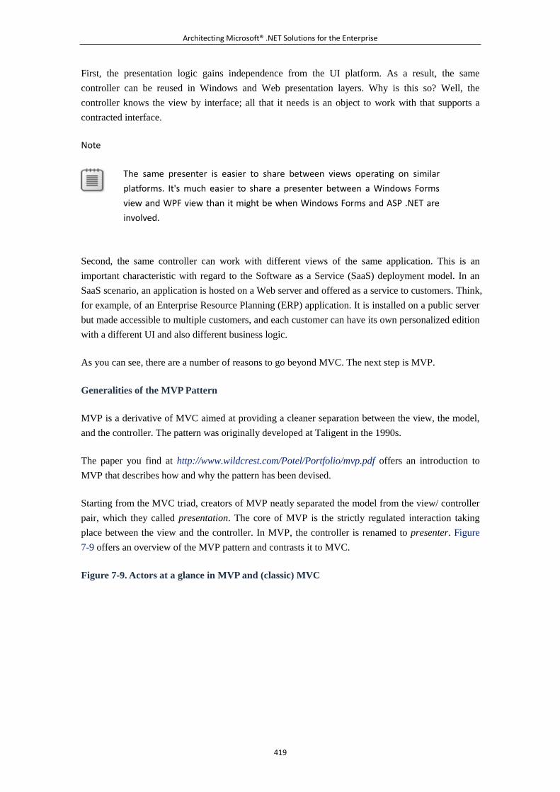
Architecting Microsoft® .NET Solutions for the Enterprise
419
First, the presentation logic gains independence from the UI platform. As a result, the same
controller can be reused in Windows and Web presentation layers. Why is this so? Well, the
controller knows the view by interface; all that it needs is an object to work with that supports a
contracted interface.
Note
The same presenter is easier to share between views operating on similar
platforms. It's much easier to share a presenter between a Windows Forms
view and WPF view than it might be when Windows Forms and ASP .NET are
involved.
Second, the same controller can work with different views of the same application. This is an
important characteristic with regard to the Software as a Service (SaaS) deployment model. In an
SaaS scenario, an application is hosted on a Web server and offered as a service to customers. Think,
for example, of an Enterprise Resource Planning (ERP) application. It is installed on a public server
but made accessible to multiple customers, and each customer can have its own personalized edition
with a different UI and also different business logic.
As you can see, there are a number of reasons to go beyond MVC. The next step is MVP.
Generalities of the MVP Pattern
MVP is a derivative of MVC aimed at providing a cleaner separation between the view, the model,
and the controller. The pattern was originally developed at Taligent in the 1990s.
The paper you find at http://www.wildcrest.com/Potel/Portfolio/mvp.pdf offers an introduction to
MVP that describes how and why the pattern has been devised.
Starting from the MVC triad, creators of MVP neatly separated the model from the view/ controller
pair, which they called presentation. The core of MVP is the strictly regulated interaction taking
place between the view and the controller. In MVP, the controller is renamed to presenter. Figure
7-9 offers an overview of the MVP pattern and contrasts it to MVC.
Figure 7-9. Actors at a glance in MVP and (classic) MVC
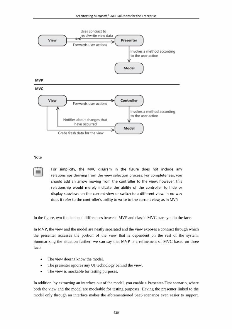
Architecting Microsoft® .NET Solutions for the Enterprise
420
Note
For simplicity, the MVC diagram in the figure does not include any
relationships deriving from the view selection process. For completeness, you
should add an arrow moving from the controller to the view; however, this
relationship would merely indicate the ability of the controller to hide or
display subviews on the current view or switch to a different view. In no way
does it refer to the controller's ability to write to the current view, as in MVP.
In the figure, two fundamental differences between MVP and classic MVC stare you in the face.
In MVP, the view and the model are neatly separated and the view exposes a contract through which
the presenter accesses the portion of the view that is dependent on the rest of the system.
Summarizing the situation further, we can say that MVP is a refinement of MVC based on three
facts:
The view doesn't know the model.
The presenter ignores any UI technology behind the view.
The view is mockable for testing purposes.
In addition, by extracting an interface out of the model, you enable a Presenter-First scenario, where
both the view and the model are mockable for testing purposes. Having the presenter linked to the
model only through an interface makes the aforementioned SaaS scenarios even easier to support.
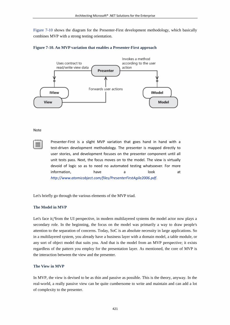
Architecting Microsoft® .NET Solutions for the Enterprise
421
Figure 7-10 shows the diagram for the Presenter-First development methodology, which basically
combines MVP with a strong testing orientation.
Figure 7-10. An MVP variation that enables a Presenter-First approach
Note
Presenter-First is a slight MVP variation that goes hand in hand with a
test-driven development methodology. The presenter is mapped directly to
user stories, and development focuses on the presenter component until all
unit tests pass. Next, the focus moves on to the model. The view is virtually
devoid of logic so as to need no automated testing whatsoever. For more
information, have a look at
http://www.atomicobject.com/files/PresenterFirstAgile2006.pdf.
Let's briefly go through the various elements of the MVP triad.
The Model in MVP
Let's face it¡ªfrom the UI perspective, in modern multilayered systems the model actor now plays a
secondary role. In the beginning, the focus on the model was primarily a way to draw people's
attention to the separation of concerns. Today, SoC is an absolute necessity in large applications. So
in a multilayered system, you already have a business layer with a domain model, a table module, or
any sort of object model that suits you. And that is the model from an MVP perspective; it exists
regardless of the pattern you employ for the presentation layer. As mentioned, the core of MVP is
the interaction between the view and the presenter.
The View in MVP
In MVP, the view is devised to be as thin and passive as possible. This is the theory, anyway. In the
real-world, a really passive view can be quite cumbersome to write and maintain and can add a lot
of complexity to the presenter.
Architecting Microsoft® .NET Solutions for the Enterprise
422
If you are familiar with physics¡ªin particular, the Law of Conservation of Energy (LCE)¡ªyou know
that the total amount of energy in any isolated system remains constant. It can't be re-created,
although it can change forms. By paraphrasing LCE, we came up with a semi-serious Law of
Conservation of Software Complexity (LCSC).
LCSC states that the total amount of complexity in a software system is always constant and can be
moved across layers. This is to say that the amount of presentation logic does not vary. Where you
place it is an architectural choice.
Note
A hilarious (but true) corollary to this law reminds us that complexity is
constant in a production system but variable (mostly growing) during
development. And, anyway, software complexity is never less than the
complexity initially determined by functional requirements. In other words,
unlike energy, software complexity can be created artificially. In our
experience, this usually is done by zealous (and hyperpurist) developers and
architects. Theory is good, but theory inappropriately applied is often a
disaster waiting to happen.
If you opt for a passive view, you have an inherently more testable system because the logic in the
view is reduced to an absolute minimum. Subsequently, you run no serious risk at all by not testing
the view. Any piece of code can contain mistakes, but in the case of a passive view the extreme
simplicity of the code only allows for gross and patently obvious mistakes that can be easily caught
without any automated procedure.
In accordance with LCSC, the complexity taken out of the view moves to another layer¡ªin this case,
the presenter. A passive view is inevitably coupled with a more complex presenter. Opting for a
passive view is a tradeoff between high testability and complexity in the presenter classes. This
approach goes under the name of Passive View. (For more information, see
http://martinfowler.com/eaaDev/PassiveScreen.html.)
Note
Although the driving force for PV remains maximum testability, there's another
benefit in it that you might want to consider. In a Passive View approach, the
view is a raw sequence of UI elements with no additional data binding or
formatting. The presenter acts directly on the UI elements and works simply
by loading data into them. There's nothing that happens in the UI that you
can't spot easily. If there's something wrong in the UI, it's right before your
eyes. Your eyes are your test harness.
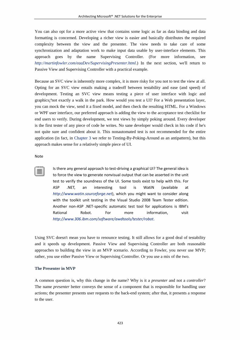
Architecting Microsoft® .NET Solutions for the Enterprise
423
You can also opt for a more active view that contains some logic as far as data binding and data
formatting is concerned. Developing a richer view is easier and basically distributes the required
complexity between the view and the presenter. The view needs to take care of some
synchronization and adaptation work to make input data usable by user-interface elements. This
approach goes by the name Supervising Controller. (For more information, see
http://martinfowler.com/eaaDev/SupervisingPresenter.html.) In the next section, we'll return to
Passive View and Supervising Controller with a practical example.
Because an SVC view is inherently more complex, it is more risky for you not to test the view at all.
Opting for an SVC view entails making a tradeoff between testability and ease (and speed) of
development. Testing an SVC view means testing a piece of user interface with logic and
graphics¡ªnot exactly a walk in the park. How would you test a UI? For a Web presentation layer,
you can mock the view, send it a fixed model, and then check the resulting HTML. For a Windows
or WPF user interface, our preferred approach is adding the view to the acceptance test checklist for
end users to verify. During development, we test views by simply poking around. Every developer
is the first tester of any piece of code he writes. No sane developer would check in his code if he's
not quite sure and confident about it. This nonautomated test is not recommended for the entire
application (in fact, in Chapter 3 we refer to Testing-By-Poking-Around as an antipattern), but this
approach makes sense for a relatively simple piece of UI.
Note
Is there any general approach to test-driving a graphical UI? The general idea is
to force the view to generate nonvisual output that can be asserted in the unit
test to verify the soundness of the UI. Some tools exist to help with this. For
ASP .NET, an interesting tool is WatiN (available at
http://www.watin.sourceforge.net), which you might want to consider along
with the toolkit unit testing in the Visual Studio 2008 Team Tester edition.
Another non-ASP .NET-specific automatic test tool for applications is IBM's
Rational Robot. For more information, visit
http://www.306.ibm.com/software/awdtools/tester/robot.
Using SVC doesn't mean you have to renounce testing. It still allows for a good deal of testability
and it speeds up development. Passive View and Supervising Controller are both reasonable
approaches to building the view in an MVP scenario. According to Fowler, you never use MVP;
rather, you use either Passive View or Supervising Controller. Or you use a mix of the two.
The Presenter in MVP
A common question is, why this change in the name? Why is it a presenter and not a controller?
The name presenter better conveys the sense of a component that is responsible for handling user
actions; the presenter presents user requests to the back-end system; after that, it presents a response
to the user.
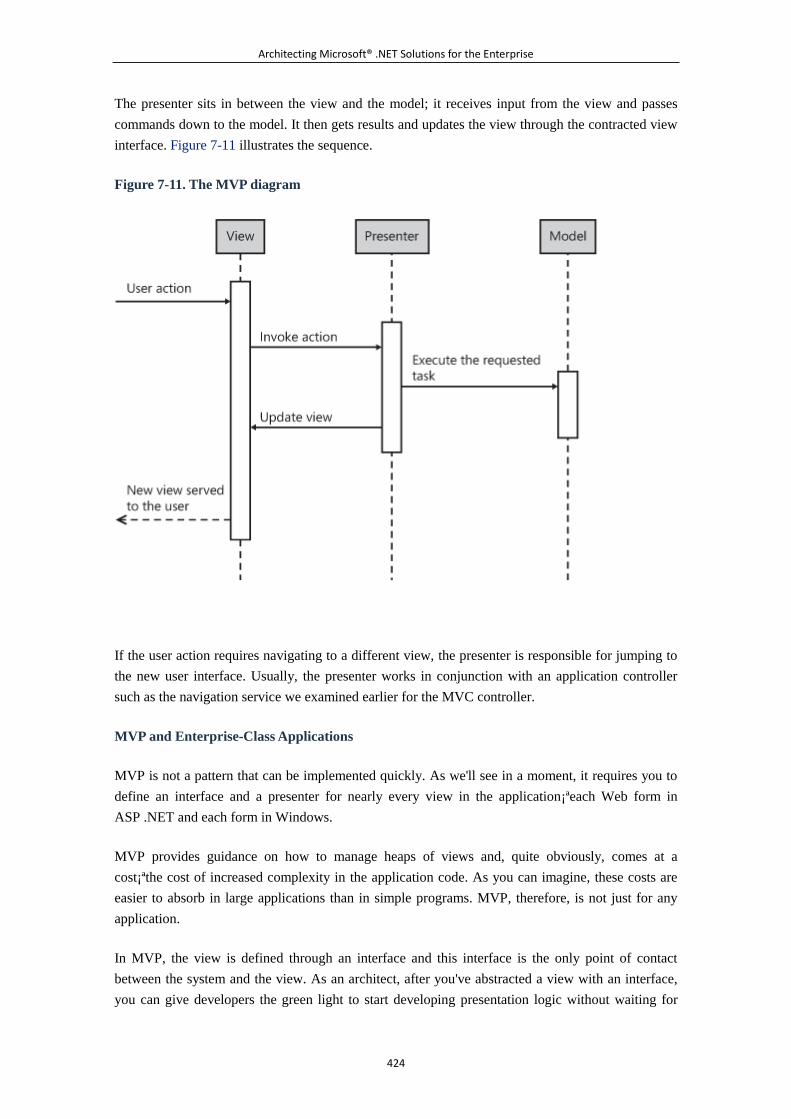
Architecting Microsoft® .NET Solutions for the Enterprise
424
The presenter sits in between the view and the model; it receives input from the view and passes
commands down to the model. It then gets results and updates the view through the contracted view
interface. Figure 7-11 illustrates the sequence.
Figure 7-11. The MVP diagram
If the user action requires navigating to a different view, the presenter is responsible for jumping to
the new user interface. Usually, the presenter works in conjunction with an application controller
such as the navigation service we examined earlier for the MVC controller.
MVP and Enterprise-Class Applications
MVP is not a pattern that can be implemented quickly. As we'll see in a moment, it requires you to
define an interface and a presenter for nearly every view in the application¡ªeach Web form in
ASP .NET and each form in Windows.
MVP provides guidance on how to manage heaps of views and, quite obviously, comes at a
cost¡ªthe cost of increased complexity in the application code. As you can imagine, these costs are
easier to absorb in large applications than in simple programs. MVP, therefore, is not just for any
application.
In MVP, the view is defined through an interface and this interface is the only point of contact
between the system and the view. As an architect, after you've abstracted a view with an interface,
you can give developers the green light to start developing presentation logic without waiting for
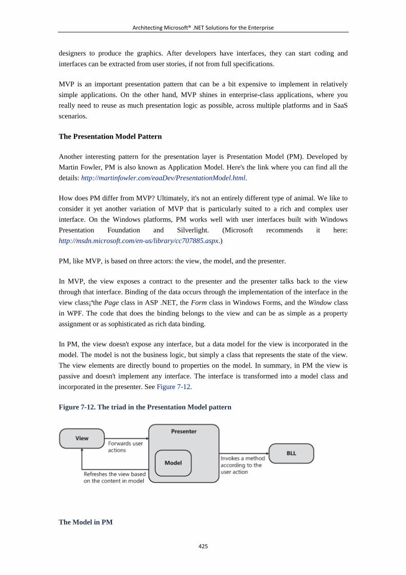
Architecting Microsoft® .NET Solutions for the Enterprise
425
designers to produce the graphics. After developers have interfaces, they can start coding and
interfaces can be extracted from user stories, if not from full specifications.
MVP is an important presentation pattern that can be a bit expensive to implement in relatively
simple applications. On the other hand, MVP shines in enterprise-class applications, where you
really need to reuse as much presentation logic as possible, across multiple platforms and in SaaS
scenarios.
The Presentation Model Pattern
Another interesting pattern for the presentation layer is Presentation Model (PM). Developed by
Martin Fowler, PM is also known as Application Model. Here's the link where you can find all the
details: http://martinfowler.com/eaaDev/PresentationModel.html.
How does PM differ from MVP? Ultimately, it's not an entirely different type of animal. We like to
consider it yet another variation of MVP that is particularly suited to a rich and complex user
interface. On the Windows platforms, PM works well with user interfaces built with Windows
Presentation Foundation and Silverlight. (Microsoft recommends it here:
http://msdn.microsoft.com/en-us/library/cc707885.aspx.)
PM, like MVP, is based on three actors: the view, the model, and the presenter.
In MVP, the view exposes a contract to the presenter and the presenter talks back to the view
through that interface. Binding of the data occurs through the implementation of the interface in the
view class¡ªthe Page class in ASP .NET, the Form class in Windows Forms, and the Window class
in WPF. The code that does the binding belongs to the view and can be as simple as a property
assignment or as sophisticated as rich data binding.
In PM, the view doesn't expose any interface, but a data model for the view is incorporated in the
model. The model is not the business logic, but simply a class that represents the state of the view.
The view elements are directly bound to properties on the model. In summary, in PM the view is
passive and doesn't implement any interface. The interface is transformed into a model class and
incorporated in the presenter. See Figure 7-12.
Figure 7-12. The triad in the Presentation Model pattern
The Model in PM

Architecting Microsoft® .NET Solutions for the Enterprise
426
In PM, the model is no longer the business layer; rather, it is an ad hoc view's model that fully
represents the state of the user interface. The model is a class with properties for each settable UI
element in the view. For example, you have a collection property for the items to show in a grid, a
property for the content of a text box, and even a Boolean property for the state (enabled or disabled)
of a button. After you have fully initialized the model, the view is ready for rendering.
The model is updated by the presenter after an interaction occurs with the system's application logic.
The model is usually encapsulated in the presenter. This class is referred to as the
PresentationModel class.
The View in PM
The view is utterly simple. It is nothing more than a bunch of UI elements bound to properties in the
model. Any events raised by the user are transmitted to the PresentationModel and end up updating
the model. This happens for both selecting a check box and clicking a button.
When the user action requires an interaction with the BLL, the PresentationModel updates the
model with the results it gets. The view is generally owned by the presenter so that the
PresentationModel, after updating the model, just orders the view to render.
No information is passed to the view. The view holds a reference to the PresentationModel, and the
model is exposed out of the PresentationModel class. The most boring part of the PM pattern is
writing the synchronization code that keeps the view and model in sync. Thankfully, in the .NET
Framework data binding helps a lot.
It should be noted, that view/model synchronization is bidirectional. When the user selects an item
in a list, the model should be updated; when an action occurs that modifies the selection, the model
is updated. For this reason, PM is a popular pattern. It is especially popular in combination with
WPF because of the great support the WPF platform offers for two-way data binding.
The Presenter in PM
The presenter in the PM pattern accomplishes nearly the same tasks as in MVP and MVC. It
receives events from the view and processes them against the presentation layer, business logic, or
both. In PM, though, the presenter holds a model object and is responsible for filling it up with any
state changes resulting from back-end operations. Finally, the presenter calls the view to refresh.
Figure 7-13 illustrates the sequence.
Figure 7-13. The Presentation Model diagram
Architecting Microsoft® .NET Solutions for the Enterprise
427
As mentioned, the presenter class goes by the name PresentationModel and exposes public methods
as well as all the public properties that form the data model for the view.
Choosing a Pattern for the User Interface
In this section, we started with autonomous views and went through 30 years of software evolution,
discussing main patterns that emerged for designing applications and the presentation layer of
multitier applications. We saw how MVC was a key step because it introduced the concept of SoC;
then we moved on to consider two further refinements: MVP and PM. But let's briefly look for the
bottom line as far as the presentation layer is concerned.
My Focus Is the Web
For an ASP .NET application, you have two main options in terms of patterns. You can go with the
traditional ASP .NET pattern. (It's ultimately an implementation of the PageController pattern as
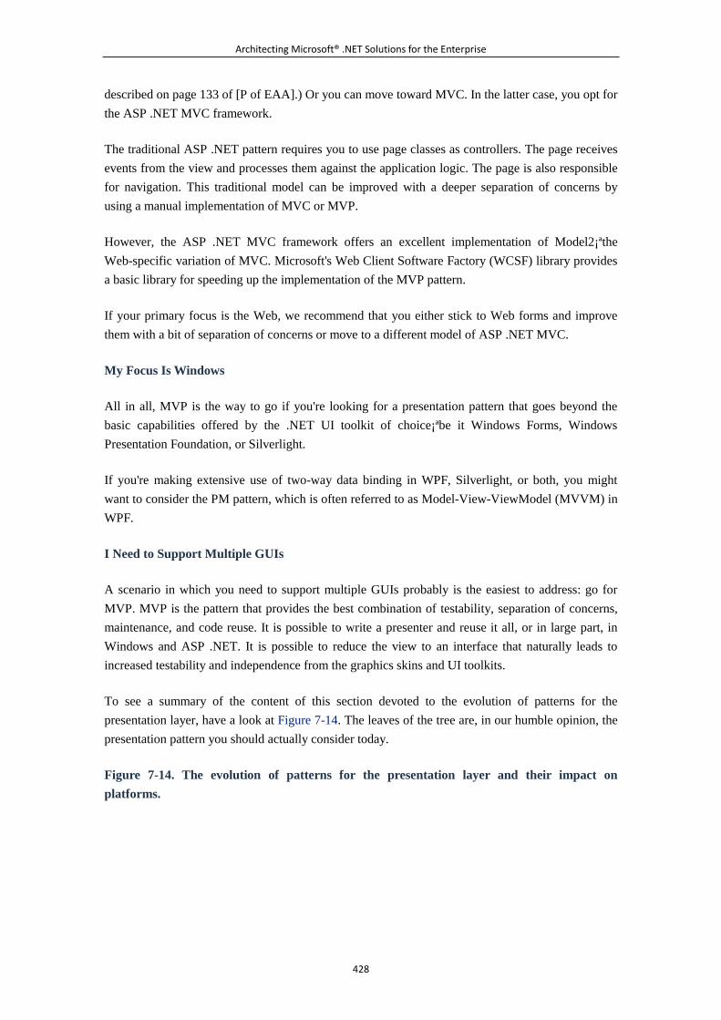
Architecting Microsoft® .NET Solutions for the Enterprise
428
described on page 133 of [P of EAA].) Or you can move toward MVC. In the latter case, you opt for
the ASP .NET MVC framework.
The traditional ASP .NET pattern requires you to use page classes as controllers. The page receives
events from the view and processes them against the application logic. The page is also responsible
for navigation. This traditional model can be improved with a deeper separation of concerns by
using a manual implementation of MVC or MVP.
However, the ASP .NET MVC framework offers an excellent implementation of Model2¡ªthe
Web-specific variation of MVC. Microsoft's Web Client Software Factory (WCSF) library provides
a basic library for speeding up the implementation of the MVP pattern.
If your primary focus is the Web, we recommend that you either stick to Web forms and improve
them with a bit of separation of concerns or move to a different model of ASP .NET MVC.
My Focus Is Windows
All in all, MVP is the way to go if you're looking for a presentation pattern that goes beyond the
basic capabilities offered by the .NET UI toolkit of choice¡ªbe it Windows Forms, Windows
Presentation Foundation, or Silverlight.
If you're making extensive use of two-way data binding in WPF, Silverlight, or both, you might
want to consider the PM pattern, which is often referred to as Model-View-ViewModel (MVVM) in
WPF.
I Need to Support Multiple GUIs
A scenario in which you need to support multiple GUIs probably is the easiest to address: go for
MVP. MVP is the pattern that provides the best combination of testability, separation of concerns,
maintenance, and code reuse. It is possible to write a presenter and reuse it all, or in large part, in
Windows and ASP .NET. It is possible to reduce the view to an interface that naturally leads to
increased testability and independence from the graphics skins and UI toolkits.
To see a summary of the content of this section devoted to the evolution of patterns for the
presentation layer, have a look at Figure 7-14. The leaves of the tree are, in our humble opinion, the
presentation pattern you should actually consider today.
Figure 7-14. The evolution of patterns for the presentation layer and their impact on
platforms.
Architecting Microsoft® .NET Solutions for the Enterprise
429
UI and Behavior-Driven Development
Behavior-driven development (BDD) is a methodology for application development that
was introduced by Ken North in 2003. BDD puts the presentation layer¡ªspecifically, the
UI¡ªat the center of the universe. It is not a pattern for designing software like MVC or
MVP; it is, rather, an approach to developing a system starting from the UI.
The driving force of BDD is delivering high value to customers. This is realized through a
method that has the ultimate goal of preventing scenarios like the one in the satirical
quotation at the beginning of this chapter: users politely smile, congratulate the team for
the effort, agree that the application meets acceptance tests, but. . .it's not what the
company really needs and wants.
The key point of BDD is coming to a full understanding of the system's expected behavior
and, next, to an effective implementation. According to the BDD methodology, the first
piece of code that the team focuses on is the UI. The UI is then shared with stakeholders
quite soon in the project life cycle.
Stakeholders, including end users, can therefore provide early feedback and drive the
team to effectively build a UI that looks and behaves in the most appropriate way. Taken
to the limit, BDD means that any features in the system are there because there's a piece
of user interface that directly or indirectly requires them.
BDD embraces the principle of YAGNI (You Aren't Going to Need It) and is an excellent
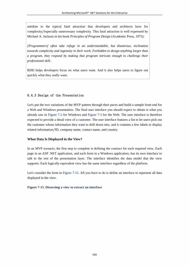
Architecting Microsoft® .NET Solutions for the Enterprise
430
antidote to the typical fatal attraction that developers and architects have for
complexity¡ªespecially unnecessary complexity. This fatal attraction is well expressed by
Michael A. Jackson in his book Principles of Program Design (Academic Press, 1975):
[Programmers] often take refuge in an understandable, but disastrous, inclination
towards complexity and ingenuity in their work. Forbidden to design anything larger than
a program, they respond by making that program intricate enough to challenge their
professional skill.
BDD helps developers focus on what users want. And it also helps users to figure out
quickly what they really want.
6.4.3 Design of the Presentation
Let's put the two variations of the MVP pattern through their paces and build a sample front end for
a Web and Windows presentation. The final user interface you should expect to obtain is what you
already saw in Figure 7-2 for Windows and Figure 7-3 for the Web. The user interface is therefore
expected to provide a detail view of a customer. The user interface features a list to let users pick out
the customer whose information they want to drill down into, and it contains a few labels to display
related information¡ªID, company name, contact name, and country.
What Data Is Displayed in the View?
In an MVP scenario, the first step to complete is defining the contract for each required view. Each
page in an ASP .NET application, and each form in a Windows application, has its own interface to
talk to the rest of the presentation layer. The interface identifies the data model that the view
supports. Each logically equivalent view has the same interface regardless of the platform.
Let's consider the form in Figure 7-15. All you have to do is define an interface to represent all data
displayed in the view.
Figure 7-15. Dissecting a view to extract an interface
Architecting Microsoft® .NET Solutions for the Enterprise
431
Creating a Contract for the View
The view is intended to display a few properties about the currently selected customer. Each of these
properties¡ªmostly scalar values such as strings, dates, and numbers¡ªtake a member in the final
interface, as shown next:
public interface ICustomerDetailsView
{
string CustomerID { set; }
string CompanyName { get; set; }
string ContactName { get; set; }
string Country { get; set; }
IList CustomersList { get; set; }
}
As you can see, the view is expected to also display the list of available customers through a
drop-down list. This poses the first issue that requires an architectural decision to be made.
How Much Logic Do You Want in the View?
The simplest approach entails that you use data binding to populate the drop-down list¡ªbe it a
Windows ComboBox or an ASP .NET DropDownList control. Data binding means that you pump a
collection of Customer objects into the DataSource property of the drop-down control and then
select a couple of properties on the Customer type to decide what text is displayed in the list and the
unique value that is returned when a selection is made.
// collCustomers is assumed to be of type Collection<Customer>.
// lstCustomers is the drop-down list control we have in the
UI.
Architecting Microsoft® .NET Solutions for the Enterprise
432
lstCustomers.DisplayMember = "CompanyName";
lstCustomers.ValueMember = "CustomerID";
lstCustomers.DataSource = collCustomers;
Is there anything wrong, or just debatable, in this solution? Ultimately, there's nothing wrong here. It
is a perfectly functioning solution, and it works well for ASP .NET and Windows. Is it testable?
Sure, it is testable; however, the topic of testability drives us to further considerations. What kind of
view are we designing in this way? Is it a passive and humble view? Or is it a smarter view with a
few ounces of presentation logic in it?
There's quite a bit of logic in the data binding process. Don't be fooled by how simple it is for a
developer to set up a data binding mechanism. Internally, the platform's data binding engine has to
load the data model, cast it to IEnumerable, retrieve every element in the list, and format it to
display. It is a black-boxed piece of code, but it's definitely not a simple value assignment like
setting the Text property on a Label control.
Using data binding makes the view (and the related presenter) much faster and more comfortable to
write, but it also introduces more presentation logic in the view. After you have a portion of the
model in the view (be it a part of the domain's object model or just data transfer objects), you code
your way forward briskly and with ease. In a certain way, you have less bureaucracy and can code
what you need without first ensuring that a particular piece of data is delivered to you through the
interface. Extensions and changes are also easier to accommodate in this way and likely do not
require modifications on the presenter. In a nutshell, you split the logic between the view and the
presenter.
This is neither good nor bad. This is just a reasonable possibility¡ªthe Supervising Controller
variation of the MVP pattern.
The more logic you have in the view, the more you should care about testing. And testing a piece of
UI is a task that can hardly be automated. Going for SVC or opting for a thinner and dumber view is
merely a judgment call.
If you opt for SVC, you might end up using the following (modified) interface:
public interface ICustomerDetailsView
{
// Allows the presenter to update the CustomerID user
interface element
string CustomerID { set; }
// Allows the presenter to update the CompanyName user
interface element
Architecting Microsoft® .NET Solutions for the Enterprise
433
string CompanyName { set; }
// Allows the presenter to update the ContactName user
interface element
string ContactName { set; }
// Allows the presenter to update the Country user interface
element
string Country { set; }
// Allows the presenter to get/set the currently selected
Customer object
Customer SelectedCustomer { get; set; };
// Allows the presenter to populate the drop-down list of
customers
void SetCustomers(Collection<Customer> customers);
}
The combination of get/set modifiers in the interface members is up to you and depends on the real
features you want the view to support. In this example, we assume that the presenter has no need to
read what's currently displayed in the Label for, say, the company name. That's why we used the
sole set modifier for the CompanyName member. Likewise, SelectedCustomer is a property that the
presenter can use to know about the currently selected customer, but also to select a new customer.
Do You Want a Passive View?
If you want the least possible amount of logic in the view because you want the maximum possible
testability¡ªand also if you prefer to stuff all the logic in a single UI-less class¡ªyou take a slightly
different approach.
In a passive view, you should aim to have all the code be of the same conceptual complexity of, say,
a text-box assignment, like this:
TextBox1.Text = someValue;
What if you have a list to fill? In an SVC scenario, you settle on having a smarter and richer view
and go with data binding. In a PV scenario, where you just want to avoid data binding, a collection
is less than ideal. If you expose a collection property and link it to the Items property of a UI list,
you invariably create a strong dependency on the platform. In fact, the Items collection of a
Architecting Microsoft® .NET Solutions for the Enterprise
434
Windows ComboBox is different from the Items collection of an ASP .NET ListControl. This means
that you end up with a similar view interface:
public interface ICustomerDetailsView
{
ListItemCollection CustomersList { get; }
.
.
.
}
The ListItemCollection class wraps the UI element you want to fill and exposes its Items collection
as a custom collection. However, you need to provide a different implementation of this class for
each supported platform¡ªASP .NET, Windows Forms, WPF, and so on. Put another way, the details
of the collection belong to the view. Subsequently, the view is not as skimpy as you might desire.
Here's a better approach:
public interface ICustomerDetailsView
{
void AddCustomer (string companyName, string customerID);
string CustomerID { set; }
string CompanyName { set; }
string ContactName { set; }
string Country { set; }
}
The AddCustomer method takes the smallest possible amount of information you need in the view
for each customer. The implementation of this method is specific to each view. The presenter simply
adds customers to the view by calling the method. The method, internally, adds information to the
UI list.
What if you have more customer information to pass down to a view? What if, for example, you
have grid instead of a list? In this case, you can either add more parameters to the AddCustomer
method or, better yet, use DTO, as shown next:
public interface ICustomerDetailsView
{
void AddCustomer(CustomerDto customer);
}
Architecting Microsoft® .NET Solutions for the Enterprise
435
The CustomerDto class indicates a custom class that groups all the information you need at that
point. It can be as simple as in the following code snippet:
public class CustomerDto
{
public string CustomerID {get; set; };
public string CompanyName {get; set; };
.
.
.
}
Note
The bottom line is that with a Passive View approach, the view is
just. . .passive and is at the total mercy of the presenter. When looking for
data, the view is like a little baby; the presenter plays the role of the attentive
mom who caringly chops the data and spoon-feeds the view.
Implementing the Contract in the View
The interface that represents the view must be implemented by the class that represents the view
itself. As mentioned, the view class is the page in ASP .NET, the form in Windows Forms, the
Window in WPF, and the user control in Silverlight. Here's an example for Windows Forms:
// This code is part of the view: therefore, it must be
platform-specific.
// This is a Windows Forms implementation.
public partial class CustListForm : Form, ICustomerDetailsView
{
public void AddCustomer(CustomerDto customer)
{
this.lstCustomers.Items.Add(customer);
}
public string CustomerID
{
set { this.lblCustomerID.Text = value; }
}
public string CompanyName
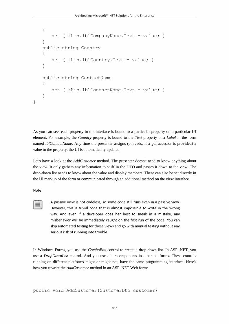
Architecting Microsoft® .NET Solutions for the Enterprise
436
{
set { this.lblCompanyName.Text = value; }
}
public string Country
{
set { this.lblCountry.Text = value; }
}
public string ContactName
{
set { this.lblContactName.Text = value; }
}
}
As you can see, each property in the interface is bound to a particular property on a particular UI
element. For example, the Country property is bound to the Text property of a Label in the form
named lblContactName. Any time the presenter assigns (or reads, if a get accessor is provided) a
value to the property, the UI is automatically updated.
Let's have a look at the AddCustomer method. The presenter doesn't need to know anything about
the view. It only gathers any information to stuff in the DTO and passes it down to the view. The
drop-down list needs to know about the value and display members. These can also be set directly in
the UI markup of the form or communicated through an additional method on the view interface.
Note
A passive view is not codeless, so some code still runs even in a passive view.
However, this is trivial code that is almost impossible to write in the wrong
way. And even if a developer does her best to sneak in a mistake, any
misbehavior will be immediately caught on the first run of the code. You can
skip automated testing for these views and go with manual testing without any
serious risk of running into trouble.
In Windows Forms, you use the ComboBox control to create a drop-down list. In ASP .NET, you
use a DropDownList control. And you use other components in other platforms. These controls
running on different platforms might or might not, have the same programming interface. Here's
how you rewrite the AddCustomer method in an ASP .NET Web form:
public void AddCustomer(CustomerDto customer)
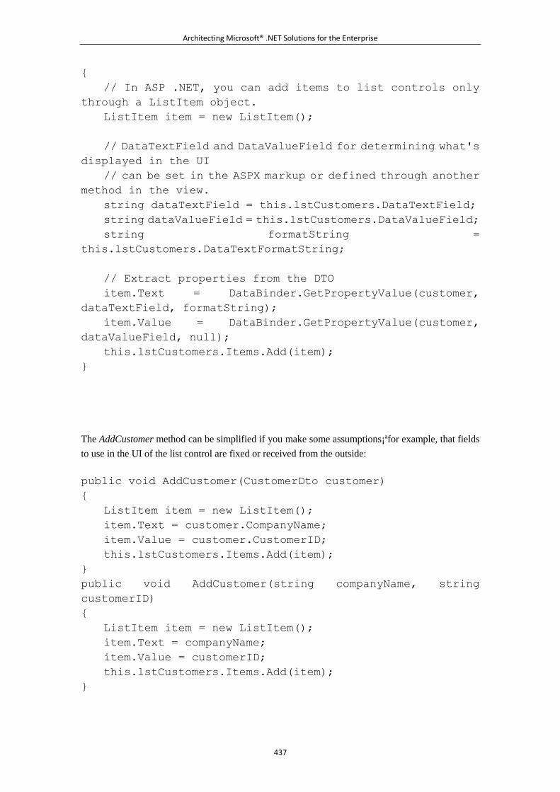
Architecting Microsoft® .NET Solutions for the Enterprise
437
{
// In ASP .NET, you can add items to list controls only
through a ListItem object.
ListItem item = new ListItem();
// DataTextField and DataValueField for determining what's
displayed in the UI
// can be set in the ASPX markup or defined through another
method in the view.
string dataTextField = this.lstCustomers.DataTextField;
string dataValueField = this.lstCustomers.DataValueField;
string formatString =
this.lstCustomers.DataTextFormatString;
// Extract properties from the DTO
item.Text = DataBinder.GetPropertyValue(customer,
dataTextField, formatString);
item.Value = DataBinder.GetPropertyValue(customer,
dataValueField, null);
this.lstCustomers.Items.Add(item);
}
The AddCustomer method can be simplified if you make some assumptions¡ªfor example, that fields
to use in the UI of the list control are fixed or received from the outside:
public void AddCustomer(CustomerDto customer)
{
ListItem item = new ListItem();
item.Text = customer.CompanyName;
item.Value = customer.CustomerID;
this.lstCustomers.Items.Add(item);
}
public void AddCustomer(string companyName, string
customerID)
{
ListItem item = new ListItem();
item.Text = companyName;
item.Value = customerID;
this.lstCustomers.Items.Add(item);
}
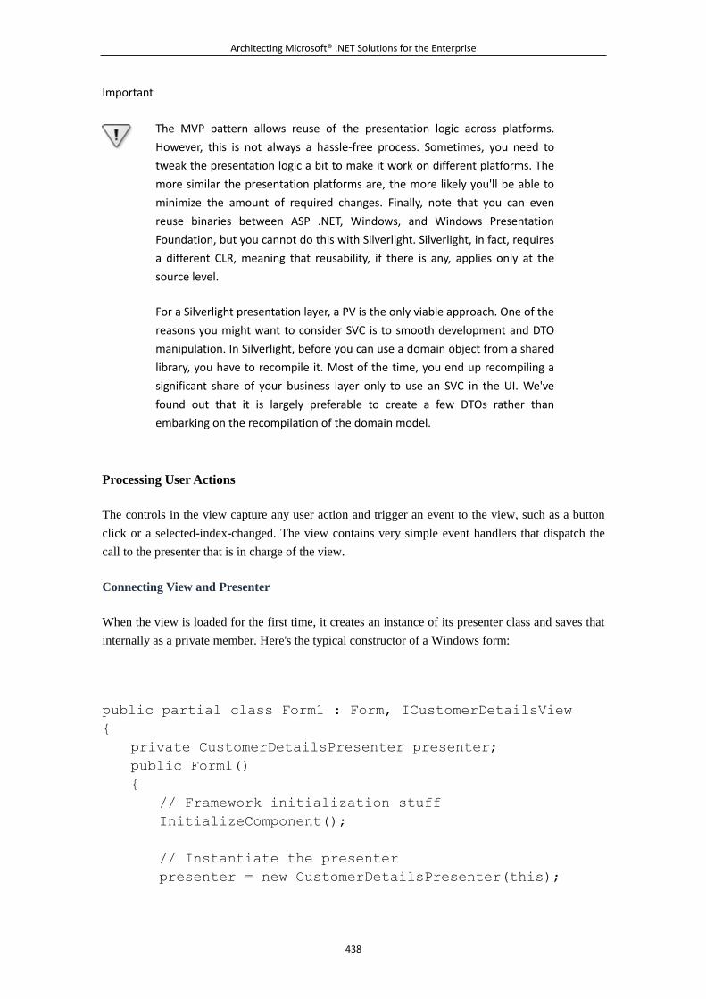
Architecting Microsoft® .NET Solutions for the Enterprise
438
Important
The MVP pattern allows reuse of the presentation logic across platforms.
However, this is not always a hassle-free process. Sometimes, you need to
tweak the presentation logic a bit to make it work on different platforms. The
more similar the presentation platforms are, the more likely you'll be able to
minimize the amount of required changes. Finally, note that you can even
reuse binaries between ASP .NET, Windows, and Windows Presentation
Foundation, but you cannot do this with Silverlight. Silverlight, in fact, requires
a different CLR, meaning that reusability, if there is any, applies only at the
source level.
For a Silverlight presentation layer, a PV is the only viable approach. One of the
reasons you might want to consider SVC is to smooth development and DTO
manipulation. In Silverlight, before you can use a domain object from a shared
library, you have to recompile it. Most of the time, you end up recompiling a
significant share of your business layer only to use an SVC in the UI. We've
found out that it is largely preferable to create a few DTOs rather than
embarking on the recompilation of the domain model.
Processing User Actions
The controls in the view capture any user action and trigger an event to the view, such as a button
click or a selected-index-changed. The view contains very simple event handlers that dispatch the
call to the presenter that is in charge of the view.
Connecting View and Presenter
When the view is loaded for the first time, it creates an instance of its presenter class and saves that
internally as a private member. Here's the typical constructor of a Windows form:
public partial class Form1 : Form, ICustomerDetailsView
{
private CustomerDetailsPresenter presenter;
public Form1()
{
// Framework initialization stuff
InitializeComponent();
// Instantiate the presenter
presenter = new CustomerDetailsPresenter(this);
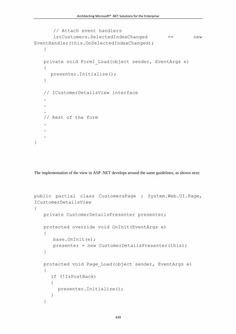
Architecting Microsoft® .NET Solutions for the Enterprise
439
// Attach event handlers
lstCustomers.SelectedIndexChanged += new
EventHandler(this.OnSelectedIndexChanged);
}
private void Form1_Load(object sender, EventArgs e)
{
presenter.Initialize();
}
// ICustomerDetailsView interface
.
.
.
// Rest of the form
.
.
.
}
The implementation of the view in ASP .NET develops around the same guidelines, as shown next:
public partial class CustomersPage : System.Web.UI.Page,
ICustomerDetailsView
{
private CustomerDetailsPresenter presenter;
protected override void OnInit(EventArgs e)
{
base.OnInit(e);
presenter = new CustomerDetailsPresenter(this);
}
protected void Page_Load(object sender, EventArgs e)
{
if (!IsPostBack)
{
presenter.Initialize();
}
}
Architecting Microsoft® .NET Solutions for the Enterprise
440
// ICustomerDetailsView interface
.
.
.
// Rest of the page
.
.
.
}
The view holds a reference to the presenter. And the presenter holds a reference to the view. As you
can see in the preceding code, the presenter's constructor¡ªnote that the presenter class is exactly the
same in ASP .NET and Windows¡ªaccepts a reference to the view. The actual object being passed is
a Form class in Windows and a Page class in ASP .NET. However, the presenter is bound to the
interface of the view, not to an implementation of the view¡ªall that the presenter sees is the
interface.
Building the Presenter
You compile all presenters and view interfaces in the same assembly and then reference the
assembly wherever possible. (See Figure 7-16.)
Figure 7-16. Reusing presentation logic in an MVP-based project
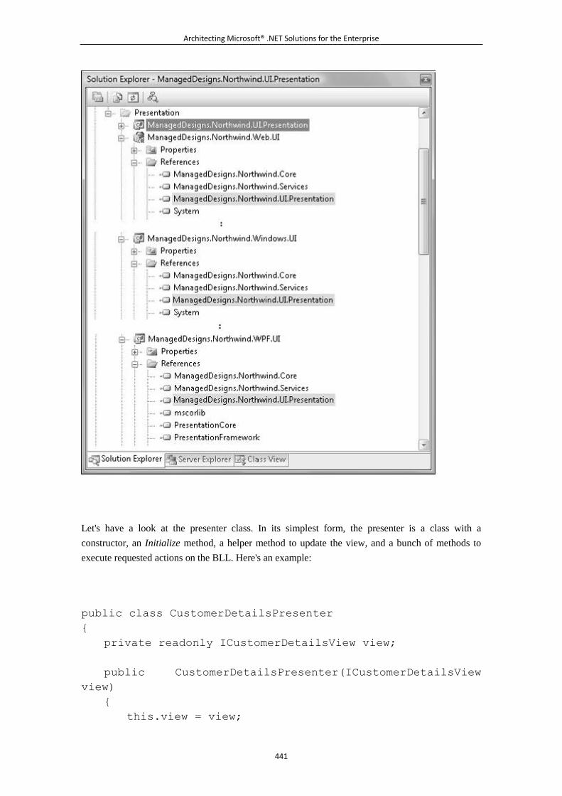
Architecting Microsoft® .NET Solutions for the Enterprise
441
Let's have a look at the presenter class. In its simplest form, the presenter is a class with a
constructor, an Initialize method, a helper method to update the view, and a bunch of methods to
execute requested actions on the BLL. Here's an example:
public class CustomerDetailsPresenter
{
private readonly ICustomerDetailsView view;
public CustomerDetailsPresenter(ICustomerDetailsView
view)
{
this.view = view;
Architecting Microsoft® .NET Solutions for the Enterprise
442
}
public void Initialize()
{
// Initialize the view by filling the list of customers.
// In a realistic implementation, this will probably
refer to
// loading just one page of the data set.
Collection<CustomerDto> customers =
this.LoadAllCustomers();
// Populate the customer list in the view
foreach(Customer c in customers)
{
view.AddCustomer(c);
}
// Clear the view
ClearView();
}
private void ClearView()
{
view.CustomerID = String.Empty;
view.CompanyName = String.Empty;
view.ContactName = String.Empty;
view.Country = String.Empty;
}
private void UpdateView(Customer customer)
{
view.CustomerID = customer.ID;
view.CompanyName = customer.CompanyName;
view.ContactName = customer.ContactName;
view.Country = customer.Country;
}
.
.
.
}
Architecting Microsoft® .NET Solutions for the Enterprise
443
During initialization, the presenter loads customers' data from the BLL, populates the list, and clears
the rest of the view. The method LoadAllCustomers in the snippet is a stub, and we'll return to it in a
moment.
In ASP .NET, you can load items in a list and be sure that this does not affect the user interface until
the page is rendered again. This is different in Windows Forms, for example. Each time you add an
item to a ComboBox, the user interface is refreshed. In the code snippet, we call AddCustomer from
within a loop. This means that each time we add an item to the list we refresh the user interface. As
a form of optimization, you might want to disable rendering of the UI at the beginning of the loop
and restore it at the end of the loop. In this case, you can add a couple of members to the view
interface, such as BeginViewUpdate and EndViewUpdate.
Executing User Actions
When the user selects a customer from the list, the SelectedIndexChanged event is fired in the view.
The view simply forwards the call to the presenter, as shown next. The code is nearly identical in
ASP .NET and Windows implementations.
private void OnSelectedIndexChanged(object sender, EventArgs
e)
{
presenter.ShowCustomerDetails();
}
The presenter holds a reference to the view. The presenter doesn't really know whether the view is a
Windows form or an ASP .NET page. All that it knows is that it holds an object that implements a
contracted view interface. The presenter reads and writes the state of the view only through the
members of the interface. For example, in our sample implementation, the presenter is not allowed
to read the name of the currently displayed customer¡ªthe CompanyName property is write-only.
Through the view interface, the presenter collects all the information it needs to carry on the
requested action. Next, it prepares the call to the BLL or resolves it internally by accessing some
previously cached data. If the user action requires navigating to another view¡ªbe it another
ASP .NET page or another Windows form¡ªthe presenter does anything necessary. The following
fragment shows how the presenter retrieves information about the customer currently selected in the
list:
public void ShowCustomerDetails()
{
string id = this.SelectedCustomerID;
if (!String.IsNullOrEmpty(id))
{
Customer customer = this.LookupCustomer(id);
UpdateView(customer);
Architecting Microsoft® .NET Solutions for the Enterprise
444
}
}
public string SelectedCustomerID
{
get { return view.CustomersList.SelectedItem.Value; }
}
To update the view, the presenter simply assigns new values to the properties exposed by the view
interface. The implementation of the view interface in the actual view class will finally take care of
updating properties on UI widgets.
The Presenter and the Service Layer
To carry on business operations, the presenter needs a reference to the BLL. The shape and color of
the entry point in the business layer of the application depends on how you actually organized that.
(See Chapter 4.)
Most of the time, if you have a service layer, the presenter gains a reference to one of these
macro-services and invoke methods. As we saw in Chapter 5, the service layer is a collection of
classes that implement the application logic and do that by scripting business objects, application
services, and workflows. Stubs, such as LoadAllCustomers and LookupCustomer, just symbolize
calls to the service layer. Here's a more detailed implementation of ShowCustomerDetails:
public void ShowCustomerDetails()
{
string id = this.SelectedCustomerID;
if (!String.IsNullOrEmpty(id))
{
// Grab a reference to one of the services in the service
layer
CustomerServices service = new CustomerServices();
Customer customer = service.LookupCustomer(id);
UpdateView(customer);
}
}
A service layer is simply a way to abstract the business logic for the sake of presentation. If you
don't have a service layer, the presenter deals directly with the BLL and calls services, runs
workflows, or scripts the domain's object model as is most appropriate for you.
Note
Architecting Microsoft® .NET Solutions for the Enterprise
445
Where's the model in this sample implementation of the MVP pattern? We've
seen the view and the presenter, but what about the model? As we said in
"The Model in MVP" section earlier in the chapter, the model is of secondary
importance in an MVP scenario compared to the view and presenter. The
model refers to something¡ªthe BLL¡ªthat is part of the system. The model is
not, therefore, something you add just because you're applying the MVP
pattern. If you want to go with a Presenter-First development methodology,
you need to make the model mockable, which basically means extracting an
interface. However, in a multitier application, the entry point to the model is
represented by the service layer interface or data context interface¡ªeither a
custom one or one provided by the Object/Relational Mapper (O/RM), as we
saw in Chapter 6, "The Data Access Layer."
Selecting the Next View
The presenter is also responsible for navigation within the application. In particular, the presenter is
responsible for enabling (or disabling) subviews in the managed view and for commanding
navigation to the next view.
A subview is essentially a subset of the view. It is typically a panel that can be expanded or
collapsed according to the context or perhaps a child window¡ªeither modal or modeless. The
presenter controls subviews through members (mostly Boolean members) on the view interface.
What about transferring control to another view (and presenter)?
In the "The MVC Controller" section earlier in the chapter, we already examined all the core code
that you need to have. We did it for ASP .NET then; now let's rephrase it for Windows and expand
on it a little bit.
You start with a static class that represents the application controller¡ªthat is, the central console that
holds all the logic to determine the next view. Application Controller is a pattern defined by Fowler
on page 379 of [P of EAA] as a centralized point for handling screen navigation and the flow of an
application, as shown in Figure 7-17.
Figure 7-17. The application controller
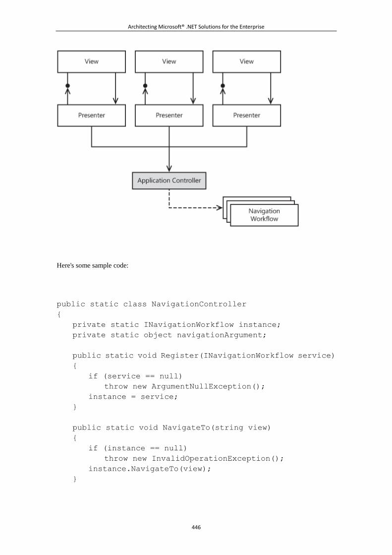
Architecting Microsoft® .NET Solutions for the Enterprise
446
Here's some sample code:
public static class NavigationController
{
private static INavigationWorkflow instance;
private static object navigationArgument;
public static void Register(INavigationWorkflow service)
{
if (service == null)
throw new ArgumentNullException();
instance = service;
}
public static void NavigateTo(string view)
{
if (instance == null)
throw new InvalidOperationException();
instance.NavigateTo(view);
}
Architecting Microsoft® .NET Solutions for the Enterprise
447
public static void NavigateTo(string view, object
argument)
{
if (instance == null)
throw new InvalidOperationException();
navigationArgument = argument;
NavigateTo(view);
}
public static object Argument
{
get { return navigationArgument; }
}
}
The NavigationController class represents the shell that presenters invoke to navigate elsewhere.
The NavigateTo method invokes an internal component that ultimately implements the workflow.
The actual navigation workflow is attached to the class upon loading through the Register method.
The NavigateTo method takes up to two arguments¡ªthe name of the view and, optionally, the
argument for the invoked view to receive. The NavigationController class lives in the same
assembly as presenters and view interfaces and is shared across UI platforms.
In global.asax for ASP .NET applications, and in program.cs for Windows applications, the actual
navigation component is instantiated and registered:
// mainForm is the program's main form
MainForm mainForm = new MainForm();
ApplicationNavigationWorkflow nav = new
ApplicationNavigationWorkflow(mainForm);
NavigationController.Register(nav);
The actual navigation workflow class¡ªthe ApplicationNavigationWorkflow in our example¡ªcontains
the workflow to move to a given view. The class implements the INavigationWorkflow interface:
public interface INavigationWorkflow
{
void NavigateTo(string view);
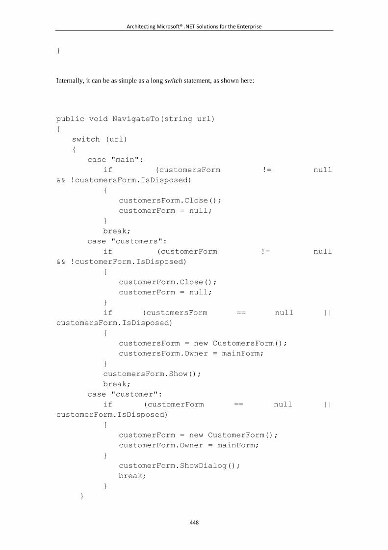
Architecting Microsoft® .NET Solutions for the Enterprise
448
}
Internally, it can be as simple as a long switch statement, as shown here:
public void NavigateTo(string url)
{
switch (url)
{
case "main":
if (customersForm != null
&& !customersForm.IsDisposed)
{
customersForm.Close();
customerForm = null;
}
break;
case "customers":
if (customerForm != null
&& !customerForm.IsDisposed)
{
customerForm.Close();
customerForm = null;
}
if (customersForm == null ||
customersForm.IsDisposed)
{
customersForm = new CustomersForm();
customersForm.Owner = mainForm;
}
customersForm.Show();
break;
case "customer":
if (customerForm == null ||
customerForm.IsDisposed)
{
customerForm = new CustomerForm();
customerForm.Owner = mainForm;
}
customerForm.ShowDialog();
break;
}
}
Architecting Microsoft® .NET Solutions for the Enterprise
449
The ApplicationNavigationWorkflow class holds references to all possible forms in the application
and switches to the right one as appropriate.
Note
This is not the only possible approach to implementing an application
controller. Another possibility entails that you set up a workflow¡ªfor example,
using Windows Workflow Foundation (WF)¡ªand go through the workflow to
determine the next view. In terms of design, an application controller
approach¡ªregardless of the implementation details¡ªis beneficial because it
doesn't create dependencies between views.
Note also that the navigation controller depends on the navigation workflow only through an
interface¡ªwhich makes it possible for you to decide at run time which workflow to load using a
plug-in model or, better yet, dependency injection as we saw in Chapter 3.
Cardinality of Views, Presenters, and Application Controllers
In an MVP implementation, is it OK to have one interface and one presenter for each supported
view? How many application controllers should you have? Just one? Well, it depends.
Logically speaking, each view is represented by an interface and managed by a presenter. Take a
moderately complex application with dozens of views, and you'll start feeling the burden of MVP on
your shoulders quite soon. As we'll see in a moment, Microsoft released an ad hoc application block
(the Web Client Software Factory) to smooth out some of these issues at least in the realm of
ASP .NET implementations. There's no magic though¡ªjust some designer tools to create
ready-made stubs with views and presenters and a workflow to handle the navigation logic. This is
to say that MVP is inherently complex and targeted to enterprise applications and to other scenarios
where complexity is large enough to require precise patterns and policies.
So to get back to the original question about cardinality, most of the time you really have a
one-to-one correspondence between logical views, interfaces, and presenters. A wise use of base
classes and inheritance can certainly lessen the coding burden and save you some code in certain
presenters. On the other hand, a presenter is the presentation logic for a particular view: if you need
two different views, why should you have only one or maybe three presenters?
As far as application controllers are concerned, things can be a little bit different. An application
controller is the machinery that decides about the next view based on some input, such as the view
name (as in our example) or just a collection of values that denote the state of a view. If you have a
large application with hundreds of views, the application controller that takes care of all possible
Architecting Microsoft® .NET Solutions for the Enterprise
450
transitions for all views can become quite a complex one. For this reason, you might want to split
the navigation logic across multiple controllers at the granularity that you feel works best for you.
You might even want to use an application controller for each use case, if use cases involve several
views and complex navigation sequences. Needless to say, in a presentation layer with multiple
navigation controllers, each presenter must receive a reference to its navigation controller upon
instantiation.
6.4.4 Idiomatic Presentation Design
So far, we've presented a few patterns for designing the presentation layer of a software system. We
focused on what patterns consist of and the principles that back them up. The advent of RAD years
ago changed the approach to creating the presentation layer. Today, visual designers are too
powerful and the time savings are too substantial for developers to not use them extensively.
We are not against wizards¡ªquite the opposite. We love wizards and have personally written a few
of them for internal purposes. However, we warn people about blindly using wizards without full
awareness of what they do. In other words, it's okay to use wizards if they simply do the work you
would have done yourself in a fraction of the time. It is not a good thing, conversely, if you use
wizards because they represent the only way you know to accomplish a certain task.
Some of the presentation patterns we discussed in this chapter have been integrated in popular
frameworks. Let's review a few examples.
MVP in Web Presentations
For years, the Web pushed an unnatural programming model and unusual languages¡ªmostly script
languages. ASP .NET changed things significantly because it was the first product (on the Windows
platform) to enable Web programming using a true programming language. In retrospect, you can
see that ASP .NET opened the doors of Web programming to quite a few C++ developers. In the
long run, ASP .NET led (all) Web developers to take design seriously and consider principles such
as SoC.
ASP .NET made the Web really simple but, honestly, it was not designed to let developers apply the
best design patterns and practices without struggling.
ASP .NET Web forms are UI focused, built around the concept of the "page," and have a hidden
page controller. The hidden page controller gets input, operates on it, and determines the output for
the browser. And it shows you its own entry points in terms of postback events. You can customize
the page controller to gain more testability and SoC, but you have to struggle for that.
ASP .NET certainly doesn't prevent SoC, but it makes it seductive to go the other way¡ªto drag
controls onto a form, double-click and enter code in event stubs, and code your application's logic
right in place. MVP is neither prohibited, nor is it a blasphemy; however, it takes sweat and blood to
write it entirely on your own. And that's why very few developers do it.
Enter the Web Client Software Factory (WCSF) and the ASP .NET MVC framework.
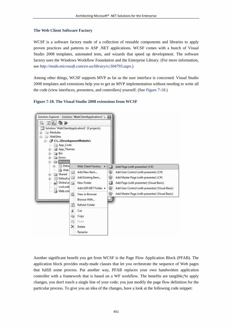
Architecting Microsoft® .NET Solutions for the Enterprise
451
The Web Client Software Factory
WCSF is a software factory made of a collection of reusable components and libraries to apply
proven practices and patterns to ASP .NET applications. WCSF comes with a bunch of Visual
Studio 2008 templates, automated tests, and wizards that speed up development. The software
factory uses the Windows Workflow Foundation and the Enterprise Library. (For more information,
see http://msdn.microsoft.com/en-us/library/cc304793.aspx.)
Among other things, WCSF supports MVP as far as the user interface is concerned. Visual Studio
2008 templates and extensions help you to get an MVP implementation without needing to write all
the code (view interfaces, presenters, and controllers) yourself. (See Figure 7-18.)
Figure 7-18. The Visual Studio 2008 extensions from WCSF
Another significant benefit you get from WCSF is the Page Flow Application Block (PFAB). The
application block provides ready-made classes that let you orchestrate the sequence of Web pages
that fulfill some process. Put another way, PFAB replaces your own handwritten application
controller with a framework that is based on a WF workflow. The benefits are tangible¡ªto apply
changes, you don't touch a single line of your code; you just modify the page flow definition for the
particular process. To give you an idea of the changes, have a look at the following code snippet:
Architecting Microsoft® .NET Solutions for the Enterprise
452
// Method exposed by the presenter class and invoked from the
UI.
// The presenter just navigates away from the current view.
public void RequestLoan(decimal amount)
{
if (amount > MaxAmountWithoutApproval)
{
Response.Redirect("loan.aspx");
}
Response.Redirect("request.aspx");
}
What if at some point you need to modify this code? If you forward the request to an application
controller (as we did earlier), you put yourself on the right track. But still you have to maintain the
code for the application controller. PFAB offers you a workflow-based controller that you only
declaratively configure. In WCSF, the preceding code turns to the following:
// Method exposed by the presenter class and invoked from the
UI.
// The presenter just navigates away from the current view.
public void RequestLoan(decimal amount)
{
// Pump data into the workflow
StorePageFlow.UserData["LoanAmount"] = amount;
// The WCSF specific workflow will redirect to the configured
page
StorePageFlow.Next();
}
PFAB comes with a workflow designer through which configuring the desired flow is as easy as
child's play.
In summary, MVP is mostly for large and durable projects. It helps you deal well with complexity,
but it might be overkill for simple projects. WCSF might help to cut down development time.
The ASP .NET MVC Framework
The ASP .NET MVC Framework is a Model2-based framework for building ASP .NET applications.
It is an alternative to the classic Web forms model. Microsoft likes to illustrate the differences
between the MVC framework and Web forms by calling them cars and motorcycles. We definitely
agree. Both cars and motorcycles can take you somewhere, but with different speeds, levels of
comfort, sense of freedom, and trunk sizes. To us, classic ASP .NET is the more comfortable car
Architecting Microsoft® .NET Solutions for the Enterprise
453
and the MVC framework is the motorcycle, which is more agile, cheaper, and hardly ever gets stuck
in traffic jams.
The MVC Framework doesn't support classic postbacks and view state and doesn't consider any
URLs as the endpoint to a physical server file to parse and compile to a page class. In classic
ASP .NET, you almost always have a one-to-one correspondence between a URL and a server
resource¡ªwhether it's a page, a data file, or an image. The only exception to this rule is when you
use completely custom HTTP handlers bound to a particular path.
In the MVC Framework, well, you just have a custom HTTP handler¡ªthe routing engine¡ªmapped to
handle each and every request. A URL is seen as the means to address an action to be executed in
response to a user action. The URLs employed by the pages of an MVC framework application have
a custom format that the application itself mandates.
In global.asax, you define the URL syntax you want the routing engine to recognize for your
application:
protected void Application_Start()
{
RegisterRoutes(RouteTable.Routes);
}
public static void RegisterRoutes(RouteCollection routes)
{
routes.IgnoreRoute("{resource}.axd/{*pathInfo}");
routes.MapRoute(
"Default", // Route name
"{controller}/{action}/{id}", // URL with
parameters
new { controller = "Home", // Parameter
defaults
action = "Index",
id = "" }
);
}
The MapRoute method defines the route name and the syntax. By default, any URL is assumed to
have passed the server name, the controller name followed by the action required, and optional
parameters. If any parameter is missing, the default controller is assumed to be the class
HomeController and the default action is a method named Index on the class. Needless to say, the
syntax can be customized at will and multiple routes can be defined.
A controller is a class inherited from a framework-provided class with a few public methods. Each
public method is an action that can be invoked via URL from the user interface.
Architecting Microsoft® .NET Solutions for the Enterprise
454
public class HomeController : Controller
{
public ActionResult Index()
{
ViewData["Title"] = "Home Page";
ViewData["Message"] = "Welcome to ASP .NET MVC!";
return View();
}
.
.
.
}
As an example, let's consider the following URL: http://www.contoso.com/home/about. After
parsing the URL, the framework figures out that the request is serviced by invoking the method
About on a controller class named HomeController:
public ActionResult About()
{
ViewData["Title"] = "About Page";
return View("About");
}
Anything in the URL that follows the method token is considered a parameter for the method. If the
method is expected to be passed parameters, you just edit the signature in the controller class. The
method performs its tasks and renders the view.
Fresh data are explicitly passed to the view using the ViewData collection, as in the diagram shown
in Figure 7-8. The View method in the code snippet uses a naming convention to locate the ASPX
file to render out. If no parameter is specified, a file named after the method (About, in this case)
plus the .aspx extension is searched for in the Views subdirectory. (Figure 7-19 provides an overall
view of an ASP .NET MVC project in Visual Studio 2008.)
Figure 7-19. An ASP .NET MVC framework project
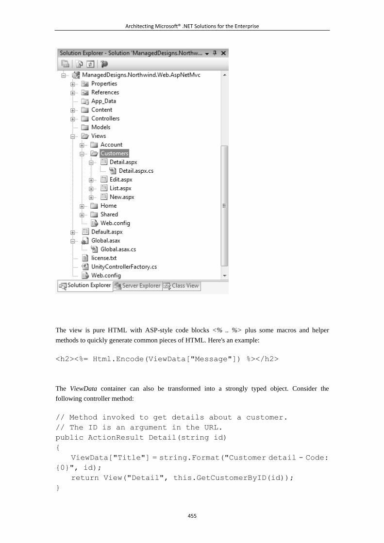
Architecting Microsoft® .NET Solutions for the Enterprise
455
The view is pure HTML with ASP-style code blocks <% .. %> plus some macros and helper
methods to quickly generate common pieces of HTML. Here's an example:
<h2><%= Html.Encode(ViewData["Message"]) %></h2>
The ViewData container can also be transformed into a strongly typed object. Consider the
following controller method:
// Method invoked to get details about a customer.
// The ID is an argument in the URL.
public ActionResult Detail(string id)
{
ViewData["Title"] = string.Format("Customer detail - Code:
{0}", id);
return View("Detail", this.GetCustomerByID(id));
}
Architecting Microsoft® .NET Solutions for the Enterprise
456
The method uses a BLL method to retrieve a Customer object and passes that instance as an
argument to the view. The code-behind class for the page might then look like this:
public partial class Detail : ViewPage<Customer>
{
}
In this case, ViewData stops being a generic data container to expose an instance of the type
Customer. The view is therefore more readable. The inner Customer object is accessed using the
property Model:
<div>
ID: <%=ViewData.Model.Id%><br />
Total income: <% = string.Format("{0:0.00#}",
ViewData.Model.CalculateTotalIncome()) %><br />
Company name: <% = ViewData.Model.CompanyName %><br />
<% =ViewData.Model.ContactInfo %><br />
<% =ViewData.Model.AddressInfo %><br />
<% =ViewData.Model.PhoneNumber %>(fax: <%
=ViewData.Model.FaxNumber %>)<br />
</div>
There's lot more to be discovered about the MVC framework, and the topic probably deserves a
book of its own. Our purpose here is much more limited: the framework allows you to build
MVC-like ASP .NET applications (specifically, Model2 applications) and puts a strong accent on
testability. The run-time environment that supports the framework is entirely based on interfaces
and provides extensibility at all levels. Visual Studio 2008 project templates also push testability,
and a sample test project is also generated and appended to any MVC project you create. For more
information on the ASP .NET MVC framework, have a look at http://www.asp.net/mvc.
MVP in Windows Presentations
As a matter of fact, frameworks for MVC Web development have sprouted copiously in the
development community¡ªbut not specifically for desktop applications. There's probably a reason for
this. A Web-specific variation of MVC¡ªModel2¡ªhas been successfully implemented in a popular
framework, such as Struts on the Java platform and MonoRail on the Windows platform. So, for the
Architecting Microsoft® .NET Solutions for the Enterprise
457
Web, the question of which pattern to choose was closed quite quickly. Whatever you think of
ASP .NET, if you want testability and SoC go for a Model2-based framework. In this context, the
ASP .NET MVC framework is an excellent choice.
For desktop, Silverlight, and mobile applications, there's no specialization of any pattern made
popular by any framework. The original MVP (in both PV and SVC flavors) is still the way to
go¡ªmostly through a handmade implementation. However, a couple of frameworks to look at for
MVP development that is not limited to the Web exist. One is the twin brother of the Web client
software factory we examined earlier; the other is a recently proposed open-source framework for
MVP development.
The Smart Client Software Factory
SCSF is a software factory made of a set of tools that help with the development of composite smart
client applications. For more information on SCSF, have a look at the following URL:
http://msdn.microsoft.com/en-us/library/cc540671.aspx.
As far as MVP is concerned, SCSF provides a set of Visual Studio 2008 extensions to automatically
generate stubs for views and presenters. There's a wizard that guides you through the creation of a
view interface and a class that implements the interface. You then modify this class to call the
presenter for UI actions that affect other views or business logic. The wizard also creates a presenter
class for the view. The class extends the presenter base class in the framework and contains the
business logic for the view. You modify this class to update the view for your business logic.
The MVC# Framework
MVC# is an MVP framework designed for the .NET platform. In spite of the name, which refers to
both the root MVC pattern and the C# language, MVC# is totally devoted to simplifying the
implementation of the MVP pattern in Windows applications of any type¡ªWindows, Web, and
Silverlight. For more information on MVC#, pay a visit to http://www.mvcsharp.org.
The main benefit of MVC# is that, as a framework, it takes on a large share of the work that is
usually concerned with MVP usage and offers developers a simplified application programming
interface (API).
The MVC# API, for example, automatically establishes links between a view and its presenter. It
also supplies a platform-independent navigation between views that is logically equivalent to our
application controller. In other words, you tell the framework the name of the view you want to
reach and the framework takes you there regardless of whether the view is ASP .NET, Windows, or
perhaps Silverlight.
However, the most relevant aspect of MVC# is its native support for tasks. A task is defined as a
collection of related views that, when traversed in a given order, form a business process¡ªsuch as
booking a hotel room or posting an order to some sales system. A task mostly corresponds to the
Architecting Microsoft® .NET Solutions for the Enterprise
458
steps involved in a use case. Here's a sample task that consists of two views¡ªone for listing all
customers and one for viewing details of the selected customer:
public class CustomerDetailsTask : TaskBase
{
string CustomerID;
// This view can be activated by any name (the true value).
// From this view, you can navigate to the view named
"CustomerDetails".
[IPoint(typeof(CustomersPresenter), true,
CustomerDetails)]
public const string ListOfCustomers = "CustomersView";
// This view is activated only programmatically and is the
last of the tasks.
[IPoint(typeof(CustomerDetailPresenter))]
public const string Products = "CustomerDetailsView";
}
The IPoint attribute indicates the presenter for the view. In the presenter of the CustomersView view,
the change of selection executes the following code:
public class CustomersPresenter :
ControllerBase<CustomerDetailsTask, ICustomersView>
{
public void CustomerSelected(string customerID)
{
// Task is a property on the IController interface
// (implemented by ControllerBase). The property is s
used to reference
// the task this presenter is working with.
Task.CustomerID = customerID;
// Navigate to the next view in the task
Task.Navigator.Navigate(CustomerDetailsTask.CustomerDetail
sView);
Architecting Microsoft® .NET Solutions for the Enterprise
459
}
.
.
.
}
MVC# is a recent, and extremely interesting, project that is attempting to slim down the
development of MVP applications.
Note
Don't get confused by the use of the word "Controller" in the MVC# hierarchy
of classes. This is due exclusively to a caprice of the author of the
framework¡ªOleg Zhukov. Regardless of the fact that your classes inherit from
a class named ControllerBase, they ultimately are, and act as, MVP presenters.
Windows Presentation Foundation
Just like ASP .NET and Windows Forms, WPF is also well suited, as a UI platform, to
implementing the MVP pattern. The same holds true for WPF's Web counterpart¡ªSilverlight. In the
end, implementing MVP in WPF and Silverlight is not an issue. Note, though, that in Silverlight you
can't reuse the same assemblies with presenters and view interfaces you created for other platforms.
Silverlight targets a subset of the .NET Framework and, more importantly, a different model of CLR.
This is to say that your code might need further adaptation (and a new compile step, at the very
minimum) to make its way to Silverlight. (An interesting article on techniques you can use to write
code that runs on both WPF and Silverlight appeared in the October 2008 issue of MSDN
Magazine.)
In WPF and Silverlight, however, the most attractive presentation pattern to look at is Presentation
Model. Why is this so? The quick answer is that a WPF infrastructure provides strong support for
two-way data-binding. Let's dig out more details.
As we saw earlier in the chapter, the PM is a variation of MVP that defines a new actor in addition
to the classic view, model (BLL), and presenter. The new actor is essentially a view's model that is
an object that holds all the data the view needs to display, as well as any state information. In our
opinion, one of the primary reasons that prevented PM from reaching widespread use is the inherent
unease of synchronizing the view with its view model. You need to write and maintain a long list of
instructions that copy state from the UI elements of the view (usually, more than just one property
per control) down to the view's model, and vice versa. This is just the kind of code that developers
hate to write¡ªthere's no fame and honor if you write it right (it's a litany of assignments, after all)
and, conversely, there's endless blame if you happen to write it incorrectly.
Architecting Microsoft® .NET Solutions for the Enterprise
460
In Windows Forms, this created the perfect habitat for tools and libraries to thrive and possibly
make some good use out of some smart and bidirectional forms of data binding. In WPF, two-way
data binding comes out of the box, so synchronizing a bunch of UI controls with an existing object
is no longer an issue¡ªbetter yet, it's a declarative matter.
In WPF (including Silverlight), you use the XAML markup language to define the user interface.
And in XAML, you can have the following code:
<TextBox x:Name="txtCompanyName" Text="{Binding CompanyName,
Mode=TwoWay}" />
What this line of code says is the TextBox element named txtCompanyName has the Text property
bound in a bidirectional way to the CompanyName property of some source object. At least in
Silverlight, the source object can only be specified via code through the DataContext property of UI
elements:
// Set the binding context
this.DataContext = viewModelObject;
In WPF and Silverlight, two-way data binding means that any change to the Text property of the UI
element modifies the CompanyName property on the bound object. At the same time, it also means
that the user interface is notified promptly of any changes that occur on the bound object and the
changes are reflected in the view. This form of bidirectional data binding is perfect for successfully
implementing the PM pattern.
The object that actually represents the view's model is preferably a cushion object that sits in
between the view and the business layer. This approach is recommended for two reasons. One has to
do with the implementation of your domain objects. If these objects throw exceptions when passed
inconsistent or invalid data, you have to catch those exceptions in the presentation layer. It's a
doable task, but it is far from being efficient¡ªmost exceptions can be prevented by simply validating
and filtering any input data. The second reason for preferring a cushion object is that, by design, the
view's model is just an object modeled after the view and the state it represents. If you accept this
point, the view's model can only be a made-to-measure object.
As a final note, the PM pattern in WPF goes by a totally different name¡ªthe
Model-View-ViewModel (MVVM) pattern. More significant than the name, though, is the
substance.
6.4.5 Summary
Architecting Microsoft® .NET Solutions for the Enterprise
461
The advent of Visual Basic 3.0 many years ago marked the definitive success of the RAD approach.
This was a watershed for the presentation layer of all applications. Most user interfaces ever since
have tended to be attention-grabbing, and interactivity and responsiveness became critical
requirements.
Among other things, interactivity refers to the presentation's ability to offer a fully synchronized
view of data, with automatic handling of master/detail views. This evolution of the user interface put
the accent on the code required to obtain it¡ªboring code that takes a long time to write. Hence,
developers started looking around for alternate solutions, and they invented data binding. Data
binding and RAD together triggered an unintended consequence¡ªthe development of the user
interface became the last step in a project. Developing the user interface is so simple that we just
don't want to spend any valuable time on it. Creating the presentation layer is a matter of attaching
buttons and grids on a form¡ªit's for newbies and new recruits.
The presentation layer, however, is no less important than the business layer and the data access
layer. A nice presentation layer accounts for nothing without the core behavior of the middle tier; a
powerful middle tier that is not assisted by an equally effective presentation layer will fail to
complete the mission.
In this chapter, we presented the responsibilities of the presentation layer and split it in two
segments¡ªthe user interface and presentation logic. Next, we went through 30 years of software
design and traced the evolution of the presentation layer, from autonomous views to the MVC
pattern to the latest variations of the MVP pattern.
We discussed principles and applied them through concrete code snippets and popular frameworks
for Windows.
Many years ago, after building the back end and the front end of a system, developers were ready to
test or to have their end users poke around the system. Today, things are different. Testability is
probably the driving force behind the evolution of the presentation layer. So you often first write
tests and then start coding; at the least, you use tests as a development tool. What, then, is the final
step of a system? The acceptance test, which is usually run in cooperation with the customer.
Preparing the UI for the final acceptance test requires care¡ªand for this reason, the choice of the
pattern for the presentation layer is critical.
6.4.6 Murphy's Laws of the Chapter
A lot has been said about the usability of programs, and we said a lot about the importance of
delivering a system that works as expected and, more importantly, provides the features that
customers really need. Making jokes about the user interface of computer programs, however, is like
shooting the piano man¡ªit can sometimes be way too easy and way too fun.
The only thing worse than an end user without a clue is an end user who has a clue¡ªusually
the wrong one.
When designing a program to handle all possible dumb errors, nature creates a dumber user.
Architecting Microsoft® .NET Solutions for the Enterprise
462
Build a system that even a fool can use and only a fool will want to use it.
For more tongue-in-cheek laws beyond the ones in this book, have a look at
http://www.murphys-laws.com.
7. Final Thoughts
The pessimist complains about the wind; the optimist expects it to change; the realist adjusts the
sails.
¡ªWilliam Arthur Ward
Now that you made it this far, do you feel like a better informed professional? We definitely hope so,
and we certainly did work hard to put into this book the best content we could. We call ourselves
architects, and we design systems for customers and help customers build and improve their own
systems. Nobody has time to do it right the first time, but there is always time to fix it when it
doesn't work. So we also often fix existing systems.
A number of jokes and urban legends circulate about architects being more concerned with playing
golf, talking in UML, or washing their hands after hitting a curly bracket button on a keyboard. We
would like to point out once again that we are born developers who are just writing software the best
we can. And we wanted to share our experiences, (best) practices, patterns, and vision with you.
Thanks for your trust and attention!
This book is divided into two parts: design principles and using those design principles in
development. The first part on design principles is for everybody with some interest in serious
software development¡ªfrom any perspective, whether it is a developer, architect, tester, project
manager, database expert, analyst, or customer perspective. The second part is for the development
team, including database developers.
Software is one big building with many floors and rooms. Architecture is all around you, regardless
of the reason why you're in the building.
Like posters on the walls of this building, we want to finish the book with some of our favorite
mantras that everybody who happens to work with us knows very well.
7.1 Mantra #1-It Depends
It always depends. As an architect, you are never sure about anything. There's always the possibility
that you're missing something. However, the role requires that decisions be made, so you must be
able to evaluate all options and make an informed decision, and to do this promptly, when a decision
is required. To buy yourself some time and activate your mental processes in the background, first
Architecting Microsoft® .NET Solutions for the Enterprise
463
say, "It depends," and then explain why and what the answer depends on. If you are unsure about
what a point depends on, the default answer is, "It depends on the context."
7.2 Mantra #2-Requirements Are Lord Over All
The architect is just one link in the natural chain of actors in a software project. The customer says
what he wants. If the customer doesn't know what he wants, someone will be there to prompt him
for specifics. The analyst formalizes what the customer wants. The project manager prepares the
groundwork for the formally-defined project. The architect gets the bundle of requirements and sorts
them out. Developers follow the architect. The database administrator does his best to make the
database support the application effectively. Note that the customer leads the chain, and what the
customer wants is the law. What the customer wants goes under the name of requirements. Of
course, only few customers know what it is they want. So requirements change.
7.3 Mantra #3-Program to an Interface
Even if you make a living out of implemented code, you should leverage interfaces wherever
possible. Repeat with us: "No implementation is possible without an interface." Look around, there's
always an interface that can be extracted.
7.4 Mantra #4-Keep It Simple but Not Simplistic
You know KISS (Keep It Simple, Stupid), right? This is just our customized version. Simple and
concise is usually equivalent to great and well done. Aim at simplicity, but give yourself a boundary
for the low end of the range. If you go below that lower boundary, your solution will become
simplistic. And this is not a good thing.
7.5 Mantra #5-Inheritance Is About Polymorphism, Not Reuse
Object-oriented programming (OOP) taught us that we should write a class once and reuse it forever
and extend it at will. And this is possible thanks to inheritance. Does this naturally extend to class
reuse? Reuse is a much subtler concept than you might think at first. Polymorphism is the key
aspect of OOP to leverage. Polymorphism means you can use two inherited classes interchangeably.
As others have said, "Reuse is a nice side effect to have." But reuse shouldn't be your goal, or put
another way, don't reuse a class through inheritance just to reuse the class. It's better to write a new
class that more precisely fits the needs than to try to inherit an existing class that wasn't designed for
the job.
7.6 Mantra #6-Not the DAL? Don't Touch SQL Then
Architecting Microsoft® .NET Solutions for the Enterprise
464
Repeat with us: "Separation of concerns. Separation of concerns." Push data access code and details
(such as connection strings, commands, and table names) to the corner. Sooner or later, you need to
take care of them, but consider business and presentation logic separately from persistence. And if
possible, delegate persistence to ad hoc tools such as Object/ Relational Mapper (O/RM) tools.
7.7 Mantra #7-Maintainability First
If you could pick only one attribute for your software, what would it be? Scalability? Security?
Performance? Testability? Usability? For us, it would be none of the above. For us, what comes first
is maintainability. Through maintainability, you can achieve anything else at any time.
7.8 Mantra #8-All User Input Is Evil
You should have heard this already. If there's a way for users to do something wrong, they'll find it.
Oh, this sounds like Murphy's Law. Yes, you should have heard this one, too, already.
7.9 Mantra #9-Post-Mortem Optimization
Donald Knuth said that premature optimization is the root of all software evil. We go even further.
Do not optimize the system. Instead, design it for being improved and extended at any time. But
focus on pure optimization only when the system is dismissed.
7.10 Mantra #10-Security and Testability Are by Design
If you're serious about a system attribute, design for it right from the beginning. Security and
testability are no exception to this rule, and there's an International Organization for Standardization
(ISO) standard that specifically says so.
8. The Northwind Starter Kit
There are two ways of constructing a software design. One way is to make it so simple that there are
obviously no deficiencies. And the other way is to make it so complicated that there are no obvious
deficiencies.
¡ªC.A.R. Hoare
The Northwind Starter Kit (NSK) is a set of Microsoft Visual Studio 2008 projects that form a
multilayer .NET-based system. Produced by Managed Design (http://www.manageddesign.it), NSK
is a reference application that illustrates most of the principles and patterns we have discussed in
this book.
Architecting Microsoft® .NET Solutions for the Enterprise
465
8.1 Motivation for Creating NSK
Many developers know about patterns and acknowledge that they have some value. Far fewer
developers actually use patterns or use them in the appropriate manner. You shouldn't feel like you
have to catch up with pattern use, though. There's no need for you to find a pattern in everything you
do. However, patterns are there to help. Humbly and obligingly.
When it comes to developing the user interface for an application, to achieve testability and proper
separation of concerns, you look around for guidance. And, upon looking, you find the
Model-View-Presenter (MVP) and Model-View-Controller (MVC) patterns. You sit down and read
the definitions for them: at first sight, the description ranges from obscure to impenetrable. Then
you read them repeatedly and maybe come to a rudimentary understanding. And you're happy. But
then you read about another, similar, pattern to draw a comparison. And you're lost. You might
come to understand the patterns from a different perspective, but the two forms of understandings
might be incompatible.
It took years for us to build the considerable array of skills and knowledge we have today. Andrea
started with object-oriented design back in 1998 when architecture books were a rarity, as were the
opportunities to exchange ideas with fellow architects. It took much less time for Dino to grab the
same knowledge a few years later¡ªpure subliminal absorption obtained from daily chats, meetings,
and interviews with experienced professionals such as Andrea. You buy books, read them, and then
feel lost. You don't understand cross-references, and examples are either too simple or way too
complex. We've had these experiences, so we assume many of you also have had, or still have, such
experiences.
We've found that the language used in many architecture resources (books, Web sites, and so forth)
is a bit too formal and can be difficult for a good share of developers to follow (or at least, this was
often the case for us). Code, and especially well-written code, is what developers understand more
quickly and completely. So we wrote an architecture book that uses a conversational language
throughout and takes a pragmatic approach to explaining concepts.
You find a number of C# code snippets in the 300+ pages of this book. But we might not have done
better in this regard than other analogous books. You might find our code snippets to be too simple
or incomplete if you look at them individually. What would make a big difference is providing a
nontrivial sample application. Enter NSK.
Downloading NSK
NSK is a CodePlex project. You can get the full source code from a link available on the
http://www.codeplex.com/nsk page. Once the download is completed, you get a Visual Studio 2008
solution with more than 20 projects. To compile it, you need the .NET Framework 3.5, plus a
number of other libraries and frameworks¡ªsome mandatory, some optional.
NSK Requirements
Architecting Microsoft® .NET Solutions for the Enterprise
466
The list of requirements for successfully compiling NSK is shown in Table A-1, along with the
URLs where you can get the missing bits.
Table A-1. NSK Dependencies
Library Optional More Information and Download
NHibernate 2.0 yes http://www.nhibernate.org
Enterprise Library 4.0 no http://www.codeplex.com/entlib
NUnit 2.4 yes http://www.nunit.org
NMock2 yes http://sourceforge.net/projects/nmock2
ASP.NET MVC FX yes http://www.codeplex.com/aspnet
CastleProject 1.0 yes http://www.castleproject.org
NUnit is optional in the sense that the Visual Studio 2008 solution also has tests for the native
MSTest environment. So you need this tool if you want to test the code using that framework. Other
testing environments are welcome, provided that you adapt tests yourself.
NHibernate is optional, and to remove it you just drop the NHibernate project from the Data folder.
You need the ASP.NET MVC framework only for the one Web front end; if you remove the project,
you also remove the dependency.
Finally, CastleProject 1.0 is currently required only for the MonoRail Web front end. However, a
planned upgrade deals specifically with the exploitation of aspect-orientation in CastleProject.
When this upgrade is implemented, CastleProject will become a required install.
The Northwind Database
NSK is entirely based on the popular Northwind database. The Northwind database no longer ships
with SQL Server 2005 and newer (any version), so you'll need to download that separately provided
that you don't have it installed yet.
You can download the necessary installation scripts for the Northwind database from
http://www.microsoft.com/downloads/details.aspx?FamilyId=.
Installation instructions are included on the download page.
8.2 What's in NSK?
NSK is a reference implementation of a .NET layered application. Entirely written in C#, NSK can
serve as a sort of blueprint for your architecture. In NSK, you find an MVP presentation layer and a
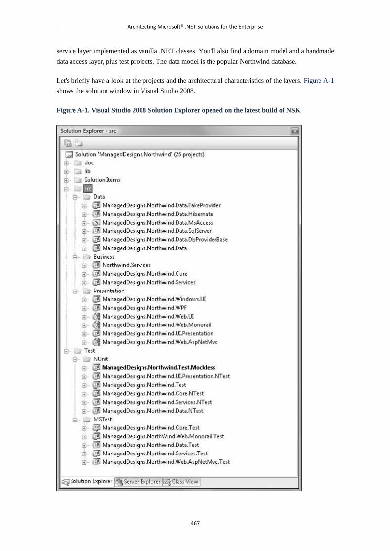
Architecting Microsoft® .NET Solutions for the Enterprise
467
service layer implemented as vanilla .NET classes. You'll also find a domain model and a handmade
data access layer, plus test projects. The data model is the popular Northwind database.
Let's briefly have a look at the projects and the architectural characteristics of the layers. Figure A-1
shows the solution window in Visual Studio 2008.
Figure A-1. Visual Studio 2008 Solution Explorer opened on the latest build of NSK
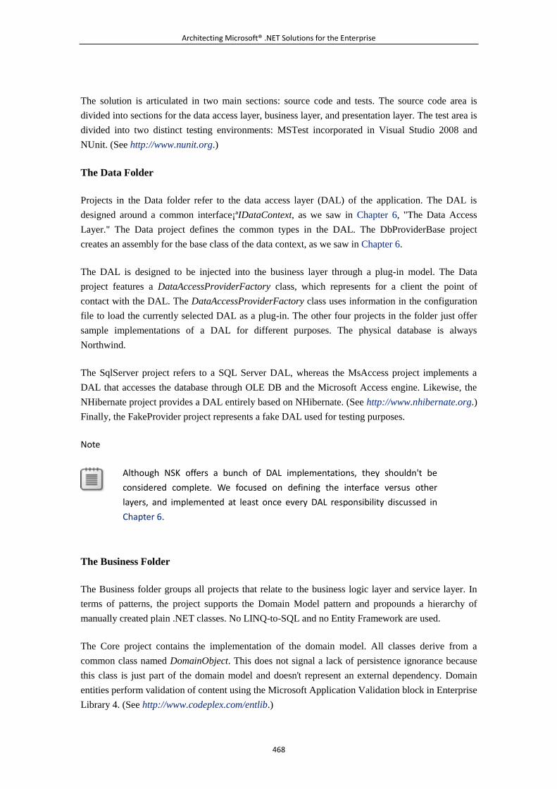
Architecting Microsoft® .NET Solutions for the Enterprise
468
The solution is articulated in two main sections: source code and tests. The source code area is
divided into sections for the data access layer, business layer, and presentation layer. The test area is
divided into two distinct testing environments: MSTest incorporated in Visual Studio 2008 and
NUnit. (See http://www.nunit.org.)
The Data Folder
Projects in the Data folder refer to the data access layer (DAL) of the application. The DAL is
designed around a common interface¡ªIDataContext, as we saw in Chapter 6, "The Data Access
Layer." The Data project defines the common types in the DAL. The DbProviderBase project
creates an assembly for the base class of the data context, as we saw in Chapter 6.
The DAL is designed to be injected into the business layer through a plug-in model. The Data
project features a DataAccessProviderFactory class, which represents for a client the point of
contact with the DAL. The DataAccessProviderFactory class uses information in the configuration
file to load the currently selected DAL as a plug-in. The other four projects in the folder just offer
sample implementations of a DAL for different purposes. The physical database is always
Northwind.
The SqlServer project refers to a SQL Server DAL, whereas the MsAccess project implements a
DAL that accesses the database through OLE DB and the Microsoft Access engine. Likewise, the
NHibernate project provides a DAL entirely based on NHibernate. (See http://www.nhibernate.org.)
Finally, the FakeProvider project represents a fake DAL used for testing purposes.
Note
Although NSK offers a bunch of DAL implementations, they shouldn't be
considered complete. We focused on defining the interface versus other
layers, and implemented at least once every DAL responsibility discussed in
Chapter 6.
The Business Folder
The Business folder groups all projects that relate to the business logic layer and service layer. In
terms of patterns, the project supports the Domain Model pattern and propounds a hierarchy of
manually created plain .NET classes. No LINQ-to-SQL and no Entity Framework are used.
The Core project contains the implementation of the domain model. All classes derive from a
common class named DomainObject. This does not signal a lack of persistence ignorance because
this class is just part of the domain model and doesn't represent an external dependency. Domain
entities perform validation of content using the Microsoft Application Validation block in Enterprise
Library 4. (See http://www.codeplex.com/entlib.)
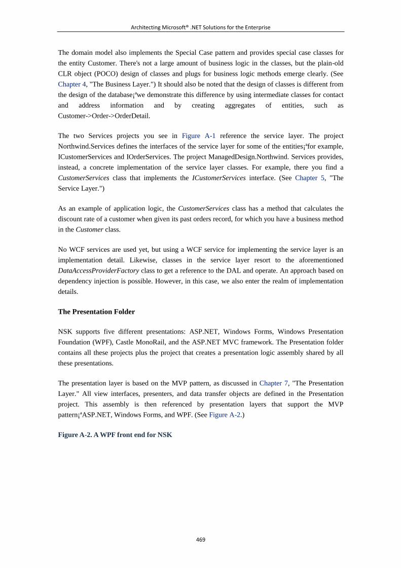
Architecting Microsoft® .NET Solutions for the Enterprise
469
The domain model also implements the Special Case pattern and provides special case classes for
the entity Customer. There's not a large amount of business logic in the classes, but the plain-old
CLR object (POCO) design of classes and plugs for business logic methods emerge clearly. (See
Chapter 4, "The Business Layer.") It should also be noted that the design of classes is different from
the design of the database¡ªwe demonstrate this difference by using intermediate classes for contact
and address information and by creating aggregates of entities, such as
Customer->Order->OrderDetail.
The two Services projects you see in Figure A-1 reference the service layer. The project
Northwind.Services defines the interfaces of the service layer for some of the entities¡ªfor example,
ICustomerServices and IOrderServices. The project ManagedDesign.Northwind. Services provides,
instead, a concrete implementation of the service layer classes. For example, there you find a
CustomerServices class that implements the ICustomerServices interface. (See Chapter 5, "The
Service Layer.")
As an example of application logic, the CustomerServices class has a method that calculates the
discount rate of a customer when given its past orders record, for which you have a business method
in the Customer class.
No WCF services are used yet, but using a WCF service for implementing the service layer is an
implementation detail. Likewise, classes in the service layer resort to the aforementioned
DataAccessProviderFactory class to get a reference to the DAL and operate. An approach based on
dependency injection is possible. However, in this case, we also enter the realm of implementation
details.
The Presentation Folder
NSK supports five different presentations: ASP.NET, Windows Forms, Windows Presentation
Foundation (WPF), Castle MonoRail, and the ASP.NET MVC framework. The Presentation folder
contains all these projects plus the project that creates a presentation logic assembly shared by all
these presentations.
The presentation layer is based on the MVP pattern, as discussed in Chapter 7, "The Presentation
Layer." All view interfaces, presenters, and data transfer objects are defined in the Presentation
project. This assembly is then referenced by presentation layers that support the MVP
pattern¡ªASP.NET, Windows Forms, and WPF. (See Figure A-2.)
Figure A-2. A WPF front end for NSK
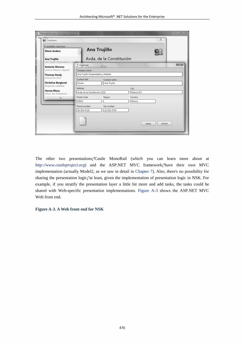
Architecting Microsoft® .NET Solutions for the Enterprise
470
The other two presentations¡ªCastle MonoRail (which you can learn more about at
http://www.castleproject.org) and the ASP.NET MVC framework¡ªhave their own MVC
implementation (actually Model2, as we saw in detail in Chapter 7). Also, there's no possibility for
sharing the presentation logic¡ªat least, given the implementation of presentation logic in NSK. For
example, if you stratify the presentation layer a little bit more and add tasks, the tasks could be
shared with Web-specific presentation implementations. Figure A-3 shows the ASP.NET MVC
Web front end.
Figure A-3. A Web front end for NSK
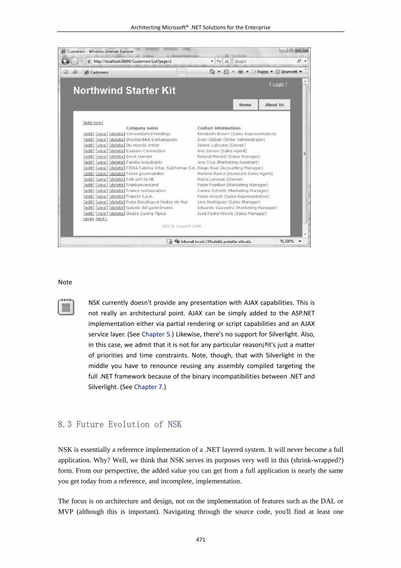
Architecting Microsoft® .NET Solutions for the Enterprise
471
Note
NSK currently doesn't provide any presentation with AJAX capabilities. This is
not really an architectural point. AJAX can be simply added to the ASP.NET
implementation either via partial rendering or script capabilities and an AJAX
service layer. (See Chapter 5.) Likewise, there's no support for Silverlight. Also,
in this case, we admit that it is not for any particular reason¡ªit's just a matter
of priorities and time constraints. Note, though, that with Silverlight in the
middle you have to renounce reusing any assembly compiled targeting the
full .NET framework because of the binary incompatibilities between .NET and
Silverlight. (See Chapter 7.)
8.3 Future Evolution of NSK
NSK is essentially a reference implementation of a .NET layered system. It will never become a full
application. Why? Well, we think that NSK serves its purposes very well in this (shrink-wrapped?)
form. From our perspective, the added value you can get from a full application is nearly the same
you get today from a reference, and incomplete, implementation.
The focus is on architecture and design, not on the implementation of features such as the DAL or
MVP (although this is important). Navigating through the source code, you'll find at least one
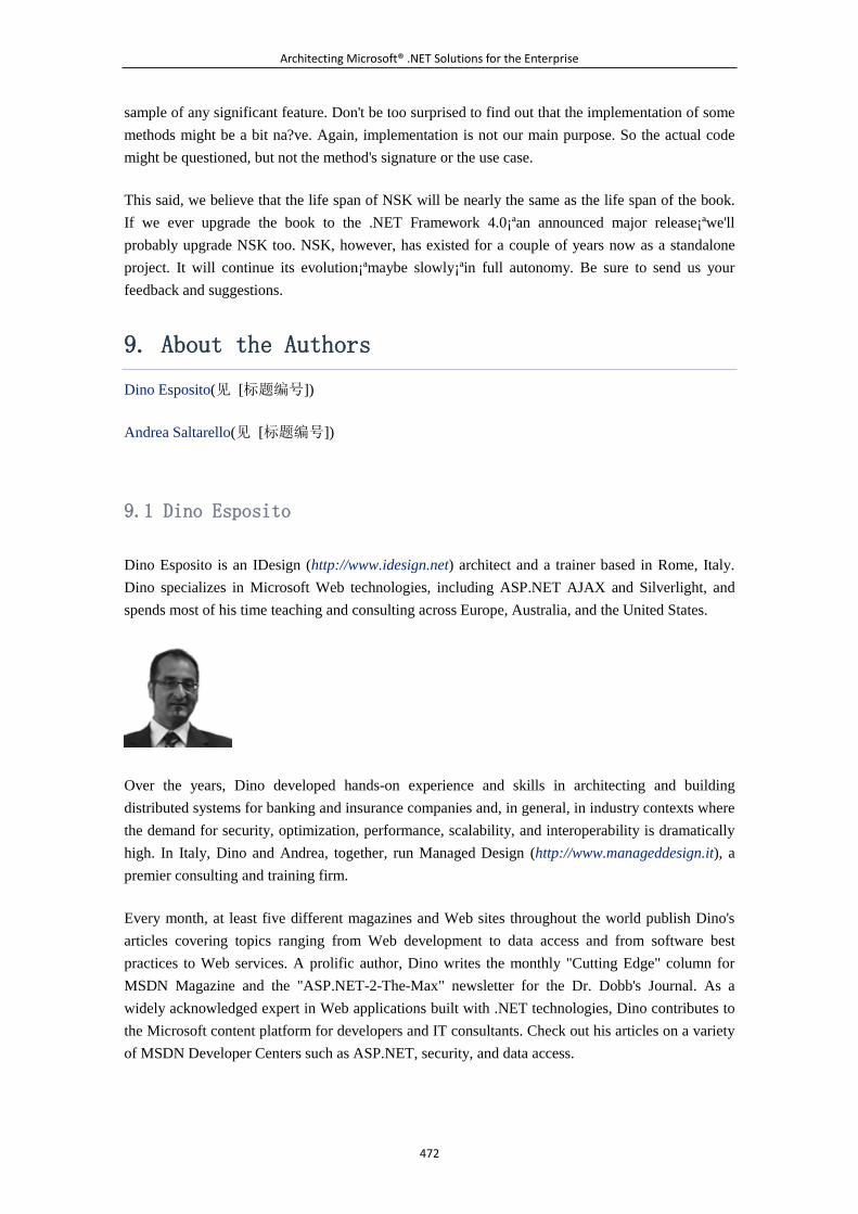
Architecting Microsoft® .NET Solutions for the Enterprise
472
sample of any significant feature. Don't be too surprised to find out that the implementation of some
methods might be a bit na?ve. Again, implementation is not our main purpose. So the actual code
might be questioned, but not the method's signature or the use case.
This said, we believe that the life span of NSK will be nearly the same as the life span of the book.
If we ever upgrade the book to the .NET Framework 4.0¡ªan announced major release¡ªwe'll
probably upgrade NSK too. NSK, however, has existed for a couple of years now as a standalone
project. It will continue its evolution¡ªmaybe slowly¡ªin full autonomy. Be sure to send us your
feedback and suggestions.
9. About the Authors
Dino Esposito(见 [标题编号])
Andrea Saltarello(见 [标题编号])
9.1 Dino Esposito
Dino Esposito is an IDesign (http://www.idesign.net) architect and a trainer based in Rome, Italy.
Dino specializes in Microsoft Web technologies, including ASP.NET AJAX and Silverlight, and
spends most of his time teaching and consulting across Europe, Australia, and the United States.
Over the years, Dino developed hands-on experience and skills in architecting and building
distributed systems for banking and insurance companies and, in general, in industry contexts where
the demand for security, optimization, performance, scalability, and interoperability is dramatically
high. In Italy, Dino and Andrea, together, run Managed Design (http://www.manageddesign.it), a
premier consulting and training firm.
Every month, at least five different magazines and Web sites throughout the world publish Dino's
articles covering topics ranging from Web development to data access and from software best
practices to Web services. A prolific author, Dino writes the monthly "Cutting Edge" column for
MSDN Magazine and the "ASP.NET-2-The-Max" newsletter for the Dr. Dobb's Journal. As a
widely acknowledged expert in Web applications built with .NET technologies, Dino contributes to
the Microsoft content platform for developers and IT consultants. Check out his articles on a variety
of MSDN Developer Centers such as ASP.NET, security, and data access.
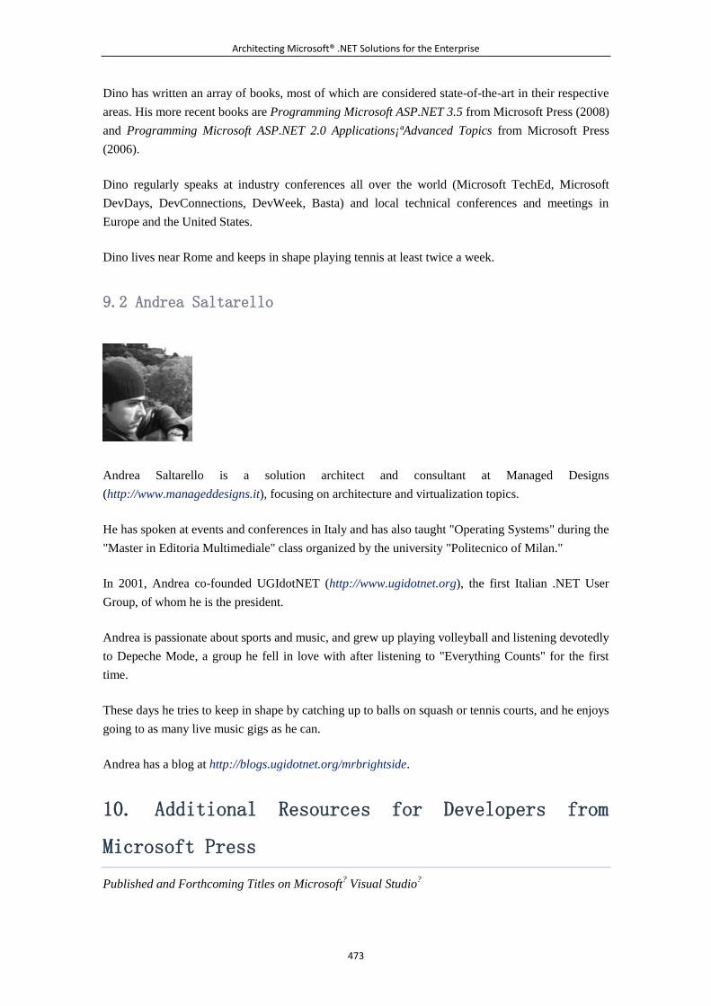
Architecting Microsoft® .NET Solutions for the Enterprise
473
Dino has written an array of books, most of which are considered state-of-the-art in their respective
areas. His more recent books are Programming Microsoft ASP.NET 3.5 from Microsoft Press (2008)
and Programming Microsoft ASP.NET 2.0 Applications¡ªAdvanced Topics from Microsoft Press
(2006).
Dino regularly speaks at industry conferences all over the world (Microsoft TechEd, Microsoft
DevDays, DevConnections, DevWeek, Basta) and local technical conferences and meetings in
Europe and the United States.
Dino lives near Rome and keeps in shape playing tennis at least twice a week.
9.2 Andrea Saltarello
Andrea Saltarello is a solution architect and consultant at Managed Designs
(http://www.manageddesigns.it), focusing on architecture and virtualization topics.
He has spoken at events and conferences in Italy and has also taught "Operating Systems" during the
"Master in Editoria Multimediale" class organized by the university "Politecnico of Milan."
In 2001, Andrea co-founded UGIdotNET (http://www.ugidotnet.org), the first Italian .NET User
Group, of whom he is the president.
Andrea is passionate about sports and music, and grew up playing volleyball and listening devotedly
to Depeche Mode, a group he fell in love with after listening to "Everything Counts" for the first
time.
These days he tries to keep in shape by catching up to balls on squash or tennis courts, and he enjoys
going to as many live music gigs as he can.
Andrea has a blog at http://blogs.ugidotnet.org/mrbrightside.
10. Additional Resources for Developers from
Microsoft Press
Published and Forthcoming Titles on Microsoft? Visual Studio
?
Architecting Microsoft® .NET Solutions for the Enterprise
474
10.1 Visual Basic
Microsoft Visual Basic? 2008 Express Edition: Build a Program Now!
Patrice Pelland
978-0-7356-2541-9
Microsoft Visual Basic 2008 Step by Step
Michael Halvorson
978-0-7356-2537-2
Microsoft Visual Basic 2005 Step by Step
Michael Halvorson
978-0-7356-2131-2
Programming Windows? Services with Microsoft Visual Basic 2008
Michael Gernaey
978-0-7356-2433-7
Programming Microsoft Visual Basic 2005: The Language
Francesco Balena
978-0-7356-2183-1
10.2 Visual C#
Microsoft Visual C#? 2008 Express Edition: Build a Program Now!
Patrice Pelland
978-0-7356-2542-6
Microsoft XNA? Game Studio 2.0 Express: Learn Programming Now!
Rob S. Miles
978-0-7356-2522-8
Microsoft Visual C# 2008 Step by Step
John Sharp
978-0-7356-2430-6
Microsoft Visual C# 2005 Step by Step
John Sharp
978-0-7356-2129-9
Architecting Microsoft® .NET Solutions for the Enterprise
475
Microsoft Visual C# 2005 Step by Step
John Sharp
978-0-7356-2129-9
Programming Microsoft Visual C# 2008: The Language
Donis Marshall
978-0-7356-2540-2
Programming Microsoft Visual C# 2005: The Language
Donis Marshall
978-0-7356-2181-7
Programming Microsoft Visual C# 2005: The Base Class Library
Francesco Balena
978-0-7356-2308-8
CLR via C#, Second Edition
Jeffrey Richter
978-0-7356-2163-3
10.3 Web Development
Microsoft ASP.NET 3.5 Step by Step
George Shepherd
978-0-7356-2426-9
Microsoft ASP.NET 2.0 Step by Step
George Shepherd
978-0-7356-2201-2
Programming Microsoft ASP.NET 3.5
Dino Esposito
978-0-7356-2527-3
Programming Microsoft ASP.NET 2.0 Core Reference
Dino Esposito
978-0-7356-2176-3
Programming Microsoft ASP.NET 2.0 Applications Advanced Topics
Dino Esposito
978-0-7356-2177-0
10.4 Data Access
Architecting Microsoft® .NET Solutions for the Enterprise
476
Microsoft ADO.NET 2.0 Step by Step
Rebecca M. Riordan
978-0-7356-2164-0
Programming Microsoft ADO.NET 2.0 Core Reference
David Sceppa
978-0-7356-2206-7
Programming the Microsoft ADO.NET Entity Framework
David Sceppa
978-0-7356-2529-7
Programming Microsoft ADO.NET 2.0 Applications Advanced Topics
Glenn Johnson
978-0-7356-2141-1
10.5 .NET Framework
Windows Presentation Foundation: A Scenario-Based Approach
Billy Hollis
978-0-7356-2418-4
3D Programming for Windows
Charles Petzold
978-0-7356-2394-1
Microsoft Windows Workflow Foundation Step by Step
Kenn Scribner
978-0-7356-2335-4
Microsoft Windows Communication Foundation Step by Step
John Sharp
978-0-7356-2336-1
Applications =
Charles Petzold
978-0-7356-1957-9
Inside Microsoft Windows Communication Foundation
Justin Smith
978-0-7356-2306-4
10.6 Other Developer Topics
Architecting Microsoft® .NET Solutions for the Enterprise
477
Debugging Microsoft .NET 2.0 Applications
John Robbins
978-0-7356-2202-9
I. M. Wright's "Hard Code"
Eric Brechner
978-0-7356-2435-1
The Practical Guide to Defect Prevention
Marc McDonald, Robert Musson, Ross Smith
978-0-7356-2253-1
Software Estimation: Demystifying the Black Art
Steve McConnell
978-0-7356-0535-0
The Security Development Lifecycle
Michael Howard Steve Lipner
978-0-7356-2214-2
Code Complete, Second Edition
Steve McConnell
978-0-7356-1967-8
Software Requirements, Second Edition
Karl E. Wiegers
978-0-7356-1879-4
More About Software Requirements: Thorny Issues and Practical Advice
Karl E. Wiegers
978-0-7356-2267-8
microsoft.com/mspress
11. More Great Developer Resources
Published and Forthcoming Titles from Microsoft Press
11.1 Developer Step by Step
Hands-on tutorial covering fundamental techniques and features
Practice files on CD

Architecting Microsoft® .NET Solutions for the Enterprise
478
Prepares and informs new-to-topic programmers
Microsoft?
Visual Basic? 2008
Step by Step
Michael
Halvorson
978-0-7356-2537-2
Microsoft
Visual C#? 2008
Step by Step
John Sharp
978-0-7356-2430-6
Microsoft
ASP.NET 3.5
Step by Step
Architecting Microsoft® .NET Solutions for the Enterprise
479
George Shepherd
978-0-7356-2426-9
Microsoft
ADO.NET 2.0
Step by Step
Rebecca M. Riordan
978-0-7356-2164-0
11.2 Developer Reference
Expert coverage of core topics
Extensive, pragmatic coding examples
Builds professional-level proficiency with a Microsoft technology
Programming
Microsoft
Visual C# 2008:
The Language
Donis Marshall
978-0-7356-2540-2

Architecting Microsoft® .NET Solutions for the Enterprise
480
Programming
Microsoft
ADO.NET 2.0
Core Reference
David Sceppa
978-0-7356-2206-7
Programming
Microsoft
ASP.NET 3.5
Dino Esposito
978-0-7356-2527-3
Programming
Microsoft
Visual Basic 2005:
The Language
Francesco Balena
Architecting Microsoft® .NET Solutions for the Enterprise
481
978-0-7356-2183-1
11.3 Focused Topics
Deep
coverage
of
advanced
techniques
and
capabilitie
s
Extensive,
adaptable
coding
examples
Promotes
full
mastery of
a
Microsoft
technology
CLR via C#,
Second Edition
Jeffrey Richter
978-0-7356-2163
-3
Debugging
Microsoft .NET 2.
0
Applications
John Robbins
978-0-7356-2202
-9
Programming
Windows? Servic
es
with Microsoft
Visual Basic 2008
Michael Gernaey
978-0-7356-2433
-7
Programming
Microsoft
ASP.NET 2.0
Applications
Advanced Topics
Dino Esposito
978-0-7356-2177
-0
See even more titles on our Web site!
Explore our full line of learning resources at: microsoft.com/mspress and microsoft.com/learning