Embed Size (px)
Citation preview
Available online at www.sciencedirect.com
www.elsevier.com/locate/commatsci
Computational Materials Science 43 (2008) 374–383
Application of microstructure sensitive design to structuralcomponents produced from hexagonal polycrystalline metals
Tony Fast, Marko Knezevic, Surya R. Kalidindi *
Department of Materials Science and Engineering, Drexel University, Philadelphia, PA 191z04, United States
Received 24 August 2007; received in revised form 28 November 2007; accepted 9 December 2007Available online 28 January 2008
Abstract
In this paper, we present the first successful design case studies in the application of microstructure sensitive design (MSD) method-ology to optimize performance of structural components made from polycrystalline metals with hexagonal close-packed (hcp) crystallattices. It is demonstrated that the underlying spectral framework of the MSD methodology facilitates an efficient consideration ofthe complete set of crystallographic textures in the design optimization. In order to accomplish this task a number of important enhance-ments had to be introduced to the MSD framework. The most significant enhancement is in the mathematical description of the designspace, i.e. the texture hull. The advantages of the new approach described in this paper are illustrated with two specific design case studiesinvolving different assumptions of symmetry at the sample scale. In both case studies presented, it is seen that the overall performance isstrongly influenced by the crystallographic texture in the sample. Furthermore, the relevant property closures and performance mapsaccounting for the complete set of textures are also depicted.Published by Elsevier B.V.
PACS: 62.20.�x; 62.20.Dc; 62.20.Fe; 61.50.Ah
Keywords: Microstructure; Anisotropy; Property closures; Elasticity; Plasticity; Spectral methods
1. Introduction
The current practice in engineering design does not payadequate attention to the internal structure of the materialas a continuous design variable. The design effort is oftenfocused on the optimization of the geometric parametersusing robust numerical simulations tools, while materialselection is typically relegated to a relatively small data-base. Furthermore, material properties are usually assumedto be isotropic, and this significantly reduces the designspace. Since the majority of commercially available metalsused in structural applications are polycrystalline and oftenpossess a non-random distribution of crystal lattice orien-tations (as a consequence of complex thermo-mechanicalloading history experienced in their manufacture), theyshould be expected to exhibit anisotropic properties.
0927-0256/$ - see front matter Published by Elsevier B.V.
doi:10.1016/j.commatsci.2007.12.002
* Corresponding author. Tel.: +1 215 895 1311; fax: +1 215 896 6760.E-mail address: [email protected] (S.R. Kalidindi).
In recent years, a new mathematical framework calledmicrostructure sensitive design (MSD) has been developedto facilitate the rigorous consideration of microstructure asa continuous variable in engineering design and optimiza-tion. At the core of MSD lie rigorous quantitative descrip-tions of the relevant statistics of the local state distributions(at different levels of details classified by n-point statistics[1–5]) in the microstructure. Salient features of MSDinclude: (i) construction of a microstructure hull [6–8] thatrepresents the complete set of theoretically feasible localstate distributions, and (ii) delineation of property closures[9–11] that identify the complete set of theoretically feasiblecombinations of macroscale effective properties of interestin a given application (for a selected homogenization the-ory). The primary advantages of the MSD approach liein its (a) consideration of anisotropy of the properties atthe local length scales, (b) exploration of the complete setof relevant microstructures (due to the use of microstruc-ture hulls and property closures) leading to global optima,
1 The first symmetry in this standard notation used by the texturecommunity refers to symmetry at the crystal level (resulting from theatomic arrangements in the crystal lattice) while the second refers tosymmetry at the sample scale (resulting from processing history).
T. Fast et al. / Computational Materials Science 43 (2008) 374–383 375
and (c) invertibility of the microstructure–propertyrelationships (due to the use of spectral methods in repre-senting these linkages). As a result, MSD facilitates the rig-orous consideration of the microstructure as a continuousdesign variable in optimization of the mechanical perfor-mance of the given structural component.
The main focus of MSD has, thus far, been on the crys-tallographic texture (also called orientation distributionfunction or the ODF) in polycrystalline metals and themacroscale elastic–plastic properties that are strongly influ-enced by this specific microstructural detail. Limited explo-rations have also been conducted into compositionalvariations in microstructures [12] and into fiber reinforcedcomposites [6]. In cubic polycrystalline metals, the MSDframework has been successfully applied to a few designcase studies. These have included maximizing the deflectionin a compliant beam [7], maximizing the in-plane load car-rying capacity of a thin plate with a central circular hole [8],and minimizing the elastic driving force for crack extensionin rotating disks [13] and internally pressurized thin-walledvessels [14]. Property closures were also produced for abroad range of combinations of macroscale effective elasticand plastic properties in cubic metals [9,10,14] and for alimited number of hexagonal metals [11].
In this paper, we present the first successful applicationof the MSD methodology to design case studies involvingpolycrystalline hexagonal close-packed (hcp) metals. Theprimary focus here continues to be on the crystallographictexture in the sample. In order to accomplish this task anumber of important changes had to be introduced tothe MSD framework. The most significant change dealswith the mathematical description of the design space, i.e.the texture hull. The application of the MSD frameworkto hcp polycrystals required the consideration of a signifi-cantly larger number of dimensions of the texture hull,when compared to the previous case studies that involvedcubic polycrystals. The much larger number of dimensions(and the corresponding larger number of design variables)demanded the development of a new approach to the prob-lem. This new approach is described in this paper, and isillustrated with two design case studies involving differentassumptions of symmetry at the sample scale.
2. Microstructure sensitive design framework
MSD [6–8,13,15] starts with a statistical description ofthe relevant details of the microstructure. In this paper,our interest will be limited to 1-point statistics of lattice ori-entation (i.e. ODF) in hcp polycrystals. The ODF, denotedas f(g), reflects the normalized probability density associ-ated with the occurrence of the crystallographic orientationg in the sample [16] as
f gð Þdg ¼ V g
V;
ZFZ
f gð Þdg ¼ 1: ð1Þ
In Eq. (1), V denotes the total sample volume and Vg is thesum of all sub-volume elements in the sample that are asso-
ciated with a lattice orientation that lies within an incre-mental invariant measure, dg, of the orientation ofinterest, g. The lattice orientation, g, is usually defined bya set of three angles called the Bunge–Euler angles [16],i.e. g = (u1,U,u2). The Bunge–Euler angles define a specificsequence of three rotations that would bring the crystal andsample reference frames into coincidence. The local proper-ties depend strongly on the local crystallographic orienta-tion, and therefore, the overall behavior of the material isstrongly influenced by the distribution of the crystallo-graphic orientations inside the polycrystalline material. InEq. (1), FZ denotes the fundamental zone of orientations,and represents the local state space describing the set of dis-tinct orientations relevant to a selected class of textures[16]. As an example, the FZ for hexagonal-orthorhombic1
textures is described by
FZ¼ g ¼ u1;U;u2ð Þ 06 u1 6p2;06 U6
p2;06 u2 6
p3
���n o:
ð2Þ
MSD employs efficient spectral representations of themicrostructure distribution functions. For example, theODF can be expressed in a Fourier series using symme-trized generalized spherical harmonics (GSH), T lm
l ðgÞ, as
f ðgÞ ¼X1l¼0
XM lð Þ
l¼1
XN lð Þ
m¼1
F lml T lm
l ðgÞ: ð3Þ
Eq. (3) facilitates visualization of ODF as a point in Fou-rier space whose coordinates are given by F lm
l . Recognitionof the fact that ODF provides information only about thevolume fraction of the various orientations present in thepolycrystalline sample permits an alternate mathematicaldescription as
f gð Þ ¼X
k
akd g � gk� �
; 0 6 ak 6 1;X
k
ak ¼ 1: ð4Þ
The Dirac-delta function d g � gkð Þ in Eq. (4) represents theODF of a single crystal of orientation gk, and ak denotes itsvolume fraction in the polycrystal. Let kF lm
l define the Fou-rier coefficients of the single crystal ODFs. It is then possi-ble to define a convex and compact texture hull [7], M, as
M ¼ F lml F lm
l ¼X
k
akkF lm
l ;kF lm
l 2Mk; ak P 0;X
k
ak ¼ 1
�����( )
;
ð5Þ
where
Mk ¼ kF lml
kF lml ¼
1
2lþ 1ð Þ Tlml gk� �
; gk 2 FZ
����� �: ð6Þ
The bar on top of the GSH in Eq. (6) denotes the complexconjugate. It should be recognized that M represents the
376 T. Fast et al. / Computational Materials Science 43 (2008) 374–383
complete set of all theoretically feasible ODFs, several ofwhich have not yet been realized in practice or even havebeen targeted for manufacture by materials specialists.
Next, we turn our attention to the homogenization theoryto be adopted to arrive at the macroscale properties of thepolycrystal for a given texture. The ODF described aboveconstitutes a first-order description of the microstructure(also referred as 1-point statistics). Using this microstructuredescription, only the elementary bounds of the macroscaleelastic and plastic properties can be evaluated. In this work,we have decided to employ the upper bound theories for allmacroscale elastic and plastic properties. For example, theupper bounds on the diagonal components of the macroscaleelastic compliance tensor, S*, can be expressed as [10] (nosummation implied on repeated indices)
S�ijij ¼ hSijiji; ð7Þ
where h i denote an ensemble average (also equal to the vol-ume average when the ergodic hypothesis is invoked). S isthe local elastic compliance tensor in the sample referenceframe that is defined using a coordinate transformationlaw for fourth-rank tensors as
Sijkl ¼ gipgjqgkrglsScpqrs; ð8Þ
where Sc is the local elastic compliance tensor in the localcrystal reference frame, and gij are the components of thetransformation matrix defined in terms of the Bunge–Eulerangles [16]. Although, only the first-order description of themicrostructure and elementary bounds are employed in thisstudy, it is emphasized here that the MSD framework hasthe potential for addressing higher-order microstructuredescriptions and advanced homogenization theories [1,3].
The selected homogenization theories are then cast inthe same Fourier space that has been used to representthe microstructure. The Sabcd gð Þ functions can be repre-sented in a Fourier series using GSH functions as
Sabcd gð Þ ¼X4
l¼0
XN lð Þ
l¼1
XM lð Þ
m¼1
abcdSlml T lm
l gð Þ; ð9Þ
where abcdSlml are referred to as the elastic Fourier coeffi-
cients and the details of their computation have been re-ported in an earlier paper [11]. The volume averagedvalue is then computed by exploiting the orthogonality ofthe Fourier basis as
S�abcd ¼ hSabcdi ¼I
Sabcd gð Þf gð Þdg
¼X4
l¼0
XN lð Þ
l¼1
XM lð Þ
m¼1
1
2lþ 1ð Þ abcdSlml F lm
l : ð10Þ
Eqs. (6) and (10) embody one of the central features ofMSD. They provide an efficient linkage between the com-plete set of feasible ODFs and the corresponding feasiblecombinations of macroscale elastic properties. Of particu-lar significance is the fact that unlike the Fourier represen-tation of the ODF, the representation for properties often
extends to only a finite number of terms in the Fourierexpansion. As shown in Eqs. (9) and (10), in considerationof elastic properties, the only relevant Fourier coefficientsare those that correspond to l 6 4. The main advantageof the spectral methods described herein lies in the fact thatthey are able to formulate highly efficient structure–prop-erty relationships.
In many mechanical design problems, avoiding plasticdeformation constitutes an important consideration. Forthis purpose, yield surfaces are often described in the six-dimensional stress space. A common formalism fordescribing anisotropic yield surfaces is the orthorhombicHill’s yield surface description [17]
1
2
1
r2y2
þ 1
r2y3
� 1
r2y1
!r22h i � r33h ið Þ2
þ 1
2
1
r2y3
þ 1
r2y1
� 1
r2y2
!r33h i � r11h ið Þ2
þ 1
2
1
r2y1
þ 1
r2y2
� 1
r2y3
!r11h i � r22h ið Þ2 þ 1
s2y12
s212
� �þ 1
s2y23
s223
� �þ 1
s2y13
s213
� �¼ 1; ð11Þ
where ry1,ry2,ry3 denote the macroscale tensile (or com-pressive) yield strengths and sy12,sy13,sy23 denote the mac-roscale shear yield strengths. In Eq. (11), hriji and hsijidenote the macroscale normal and shear stress componentsexperienced by the material point under consideration. Thesix anisotropic material yield parameters in Eq. (11) can beestimated for a polycrystalline material using an extendedversion of the Taylor model [18], also commonly referredto as the Taylor-type crystal plasticity model. This modelconstitutes an upper bound and has been demonstrated[19] to provide reasonably accurate predictions of the mac-roscopic yield strengths for the polycrystalline a-Ti used inthe case studies presented here. The Taylor-type crystalplasticity model assumes that each constituent single crys-tal experiences the same strain as the imposed strain atthe macroscale, and computes the local stress in the crystalthat allows the accommodation of the imposed plasticstrain through slip on the multiple slip systems in the crys-tal. The volume averaged stress (over the constituent singlecrystals) then provides an estimate of the macroscale yieldstrength for the polycrystal.
As an example, the following macroscopic velocity gra-dient is imposed on the polycrystal in evaluating ry1:
hLi ¼h_ei 0 0
0 �qh_ei 0
0 0 �ð1� qÞh_ei
0B@1CA: ð12Þ
The parameter q is allowed to take any value between 0 and1. Because the deformation imposed by Eq. (12) is iso-choric, the resulting stress field is purely deviatoric. In or-der to calculate the tensile yield strength, the hydrostaticcomponent is computed by establishing the value of q
T. Fast et al. / Computational Materials Science 43 (2008) 374–383 377
(denoted as q*) for which the averaged lateral stresses overthe polycrystal are equal to each other and added to thediagonal elements of the averaged deviatoric stress:
ry1 ¼ hr011 q�ð Þi � hr022 q�ð Þi; ð13Þ
where r0 denotes the volume averaged deviatoric stress ten-sor for the polycrystal.
Fast computation of the yield strengths for polycrystalsin the MSD framework entails the use of Fourier represen-tations to describe the functional dependence of the localstresses in the constituent crystals on their orientations.The Fourier representations needed for evaluating theupper bound for ry1 are expressed as (no summationimplied on repeated index i) [11]
r0ii g; qð Þ ¼Xl�
l¼0
XN lð Þ
l¼1
XM lð Þ
m¼1
iiy1Slm
l qð ÞT lml gð Þ; ð14Þ
r0ii qð Þ� �
¼Xl�
l¼0
XN lð Þ
l¼1
XM lð Þ
m¼1
iiy1Slm
l qð ÞF lml
2lþ 1; ð15Þ
where the procedures for computing y1iiSlm
l qð Þ for hcp crys-tals experiencing slip on prism, basal and pyramidal slipsystems have been already been described in a recent paper[11]. In describing the plastic properties, we have also ob-served that we needed a lot more Fourier coefficients thanthose needed to describe elastic properties. For practicalreasons, we truncated the series after a desirable accuracyhas been attained, and this is reflected in Eqs. (14) and(15) by restricting the series to terms corresponding tol 6 l*. For example, for hexagonal-orthorhombic textures,it was observed that the maximum error in Eq. (15) was lessthan 3% when the series was truncated to 57 terms (corre-sponding to l* = 12) [11]. The desired accuracy in propertypredictions therefore dictates the number of Fourierdimensions that need to be explored by the MSD method-ology for a selected design application.
In previous work, we have demonstrated the power ofspectral microstructure–property linkages described abovein delineation of numerous property closures [9–11]. Prop-erty closures identify the complete set of theoreticallyfeasible effective (homogenized) anisotropic property com-binations in a given material system, and are also of inter-est in this paper. Two different examples of these closurescorresponding to two selected case studies will be delin-eated in 2D and 3D, respectively. In this paper, our pri-mary aim is to extend the MSD framework into designand optimization of structural components made fromhcp polycrystals. This is addressed in the next section.
3. MSD for performance optimization
The main challenge encountered in the application ofthe MSD methodology to mechanical design case studiesis that the microstructure–property linkages need to beexplored in fairly large dimensional Fourier spaces. In thiswork, in dealing with plastic properties of hexagonal poly-
crystals there is a need for consideration of a much higherdimensional Fourier space compared to our earlier workon the more symmetric cubic polycrystals. The increaseddemand in dimensionality is driven by two main reasons:(i) the Fourier representation of the ODF for hcp poylcrys-tals typically needs many more terms compared to the cor-responding representations for cubic polycrystals, and (ii)the yield surfaces in hcp polycrystals are substantially moreanisotropic compared to the yield surfaces for cubic poly-crystals. For example, the design case studies reported byHouskamp et al. [8,14] explored the cubic-orthorhombictexture hull in 12 dimensions, whereas consideration ofsimilar problems here in hexagonal-orthorhombic texturehulls needs exploration of 57 dimensions of the microstruc-ture hull [11].
A number of different approaches have been employedin the past to integrate microstructure sensitive design intothe engineering design framework. The main approaches ofthese prior studies are briefly reviewed below:
1. The initial design case studies discretized the microstruc-ture hull (Eq. (5)) into bins and evaluated the perfor-mance in each bin (e.g. [8,13]). It was assumed that allmicrostructures in one bin could be assumed to exhibitthe same performance for the given design application.In these examples, the Fourier space was restricted toonly the low-order subspaces and consequently, thenumber of bins could be restricted to a reasonably smallnumber. These approximations permitted solutions tosimple case studies. As the dimensionality of the relevantFourier space expands, this approach is bound to becomputationally inefficient, if not completely infeasible.
2. Design case studies were explored using the propertyclosure as the design space [12]. This approach has theinherent advantage of greatly reducing the design spaceby mapping a higher dimensional Fourier space into areduced dimensional property space. This method isparticularly attractive when the property space (alsocalled the property closure) is compact and convex.However, when the property space is not convex, defin-ing the boundary of the property closure becomes extre-mely challenging, especially in design case studies wherethe overall performance is governed by a large numberof macroscale properties. It should be noted that theproperty closures for a vast number of design problemsare likely to be non-convex.
3. In the most recent design case studies [7,14], perfor-mance optimization was explored using a generalizedreduced gradient method while restricting the designspace to the convex microstructure hull. In these exam-ples, the microstructure hull was defined using an algo-rithm based on Gram–Schmidt orthonormalization.This approach also allowed the integration of theMSD methodology with the finite element methods usedtypically by the designers [13,14]. Although this is anextremely efficient algorithm for exploring optimizedsolutions, we found it very difficult to apply this
378 T. Fast et al. / Computational Materials Science 43 (2008) 374–383
algorithm to the case studies described in this paperbecause of the much larger number of Fourier dimen-sions involved.
In the case studies described in this paper, we have takena new approach. Instead of using the Fourier coefficientsF lm
l to define the design space, we found it more convenientto define the design space in terms of the ak (see Eq. (4)).With this choice the design space is simply expressed asX
k
ak ¼ 1; ak P 0: ð16Þ
Note that the constraints described in Eq. (16) can beimplemented much more easily into any optimizationsearch tool, compared to the constraints described inEqs. (5) and (6). The new approach naturally leads to thequestion of how many distinct orientations need to be con-sidered in the FZ (i.e. the range of k in Eq. (16)) for a givendesign problem.
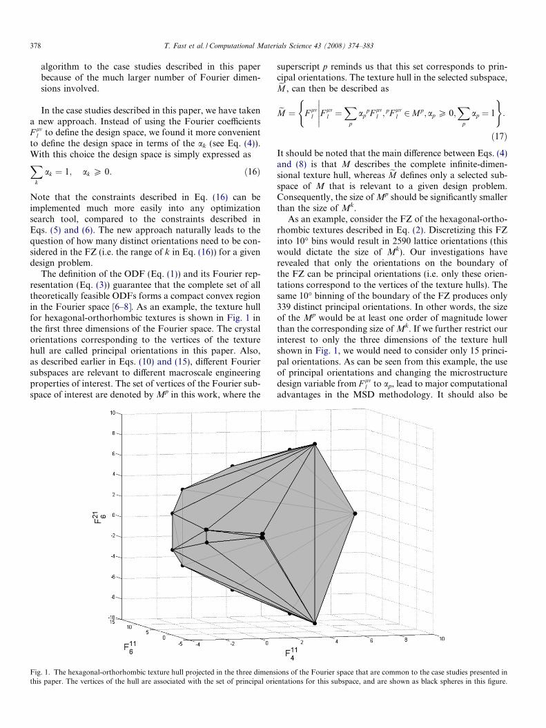
The definition of the ODF (Eq. (1)) and its Fourier rep-resentation (Eq. (3)) guarantee that the complete set of alltheoretically feasible ODFs forms a compact convex regionin the Fourier space [6–8]. As an example, the texture hullfor hexagonal-orthorhombic textures is shown in Fig. 1 inthe first three dimensions of the Fourier space. The crystalorientations corresponding to the vertices of the texturehull are called principal orientations in this paper. Also,as described earlier in Eqs. (10) and (15), different Fouriersubspaces are relevant to different macroscale engineeringproperties of interest. The set of vertices of the Fourier sub-space of interest are denoted by Mp in this work, where the
Fig. 1. The hexagonal-orthorhombic texture hull projected in the three dimensthis paper. The vertices of the hull are associated with the set of principal ori
superscript p reminds us that this set corresponds to prin-cipal orientations. The texture hull in the selected subspace,eM , can then be described as
eM ¼ F lml F lm
l ¼X
p
appF lm
l ;pF lm
l 2Mp;ap P 0;X
p
ap ¼ 1
�����( )
:
ð17Þ
It should be noted that the main difference between Eqs. (4)and (8) is that M describes the complete infinite-dimen-sional texture hull, whereas eM defines only a selected sub-space of M that is relevant to a given design problem.Consequently, the size of Mp should be significantly smallerthan the size of Mk.
As an example, consider the FZ of the hexagonal-ortho-rhombic textures described in Eq. (2). Discretizing this FZinto 10� bins would result in 2590 lattice orientations (thiswould dictate the size of Mk). Our investigations haverevealed that only the orientations on the boundary ofthe FZ can be principal orientations (i.e. only these orien-tations correspond to the vertices of the texture hulls). Thesame 10� binning of the boundary of the FZ produces only339 distinct principal orientations. In other words, the sizeof the Mp would be at least one order of magnitude lowerthan the corresponding size of Mk. If we further restrict ourinterest to only the three dimensions of the texture hullshown in Fig. 1, we would need to consider only 15 princi-pal orientations. As can be seen from this example, the useof principal orientations and changing the microstructuredesign variable from F lm
l to ap, lead to major computationaladvantages in the MSD methodology. It should also be
ions of the Fourier space that are common to the case studies presented inentations for this subspace, and are shown as black spheres in this figure.
T. Fast et al. / Computational Materials Science 43 (2008) 374–383 379
noted that this discovery was instrumental to our success inaddressing the microstructure design case studies presentedin this paper.
It is important, at this stage, to reflect on some of theconsequences of using ap as the microstructure design var-iable. One might be tempted to conclude erroneously that aprescribed set of ap corresponds to a unique ODF. Thereader is cautioned that we are dealing here with truncatedFourier spaces where the mapping between F lm
l and ap isnot one-to-one. Indeed, many different realizations of ap
can correspond to one set of truncated F lml . A prescribed
set of ap, however, corresponds to a single set of truncatedF lm
l coefficients, which in turn corresponds to a very largeset of distinct ODFs. However, all of the distinct ODFscorresponding to the prescribed set of ap are expected toexhibit the same (or approximately similar) values of mac-roscale properties of interest defined by the selected Fouriersubspace [1,10]. Another important consequence of theapproach presented here that it naturally produces non-unique solutions (as expected and desired).
The new approach described here of using ap (hence-forth denoted as a for ease of notation) as the design var-iable can be conveniently applied to mechanical designproblems as well as the delineation of property closures.The optimization problem for mechanical design involvingcomponents with statistically homogeneous microstruc-tures can be formulated as
Maximize O qð Þ; where
q ¼ P 1 að Þ; P 2 að Þ; . . . ; P N að Þð Þ;subject to ap P 0;
Xp
ap ¼ 1; ð18Þ
where O denotes a objective function characterizing theperformance of the mechanical component, and q is a setof relevant macroscale material properties (denoted asP i að Þ) influencing the performance. In particular, it is notedthat the functional dependence in P i að Þ can be highly non-linear (especially with plastic properties; see Eqs. (11)–(15)).
In prior work, the property closures were obtained byformulating optimization problems corresponding to thepoints on the boundary of the closure [10,20]. However,these optimization problems were cast in the F lm
l -space.For the reasons mentioned earlier, the idea of using theap-space instead of the F mn
l -space can prove very beneficialin delineating multi-property closures of interest in micro-structure design problems. Briefly, one starts by identifyingthe potential range, Ri, of values for each property of inter-est, Pi, as
Ri ¼ min P i að Þ ap P 0;Xp¼1
ap ¼ 1
�����( )
;
"
max P i að Þ ap P 0;Xp¼1
ap ¼ 1
�����( )#
: ð19Þ
An N-property closure is then delineated by seeking themaximum and minimum values possible for one of theproperties of interest while constraining all other propertiesto values pre-selected within their respective ranges. As anexample, let P �2; . . . ; P �N
� �represent a selected combination
of values for all properties of interest except P1, where thevalues of each property are constrained to lie within theirrespective potential ranges, i.e. P �i 2 Ri. A restricted feasiblerange for P1 can then be established as
R�1 ¼ P 1 að Þ P i að Þ ¼ P �i 8i 6¼ 1; ap P 0;X
p
ap ¼ 1
�����( )
: ð20Þ
If R�1 is a non-empty set, it leads to the identification ofpoints on the boundary of the property closure. Let P e�
1 de-note the extrema of R�1. Then P e�
1 ; P�2; . . . ; P �N
� �lie on the
boundary of the property closure sought. It should benoted here that for several selections of P �2; . . . ; P �N
� �, the
corresponding R�1 is indeed expected to be a null set.In the present study, all of the optimization problems
formulated in Eqs. (18)–(20) were solved successfully usingthe fmincon function in Matlab’s Optimization Toolbox[21]. The fmincon function uses sequential quadratic pro-gramming, chooses subsequent variables via the line-searchmethod, and implements the Broyden–Fletcher–Goldfarb–Shanno Quasi-Newton formula to define the Hessian [21].Convergence is defined using first-order necessaryconditions.
4. MSD case study: compliant mechanism
Compliant mechanisms are mechanical devices that gainmovement from parts that flex, bend or have ‘‘springiness”
to them [22]. These mechanisms with built-in flexibility arepractical since they are simple. They also eliminate the needfor multiple rigid parts, pin joints and add-on springswhich can reduce design complexity and cost. Compliantmechanisms are found in sensors, gearboxes, valves, bicyclederailleurs, and various other mechanical designs. In thiscase study, we will seek the texture(s) that will maximizethe deflection of the beam without initiating plasticdeformation.
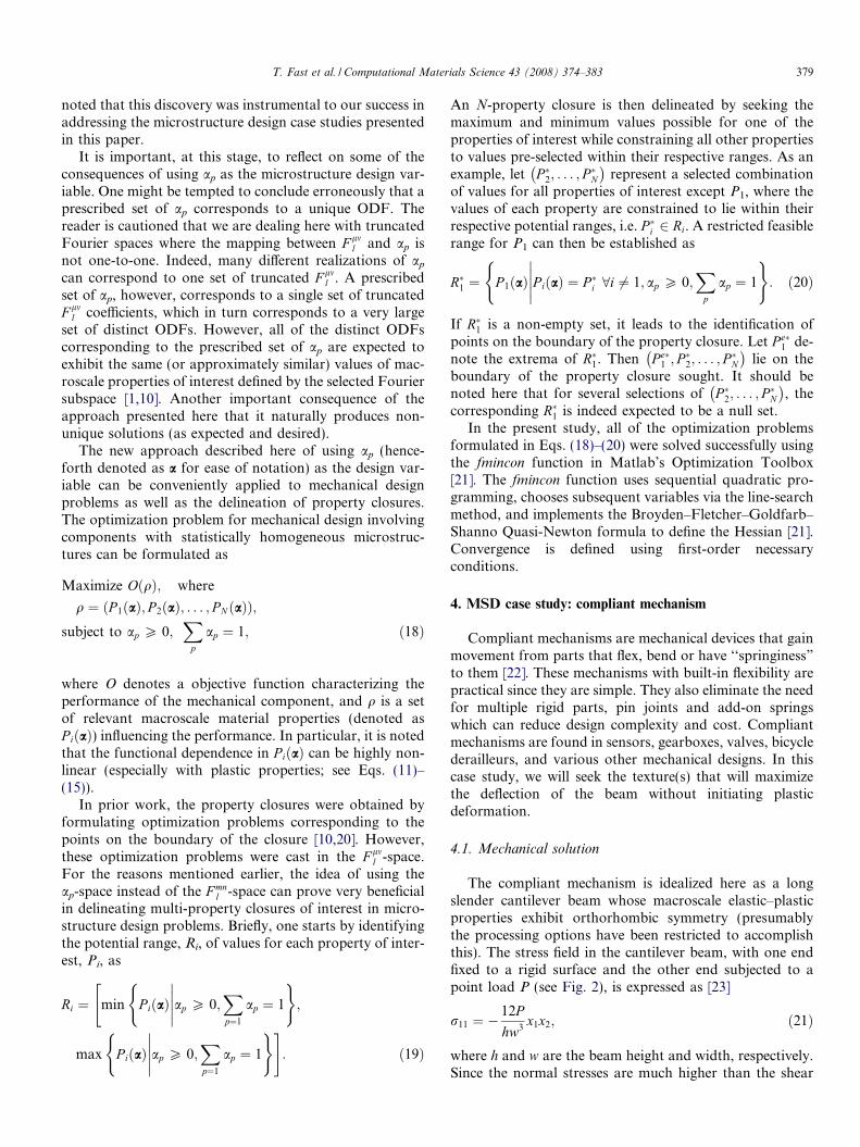
4.1. Mechanical solution
The compliant mechanism is idealized here as a longslender cantilever beam whose macroscale elastic–plasticproperties exhibit orthorhombic symmetry (presumablythe processing options have been restricted to accomplishthis). The stress field in the cantilever beam, with one endfixed to a rigid surface and the other end subjected to apoint load P (see Fig. 2), is expressed as [23]
r11 ¼ �12P
hw3x1x2; ð21Þ
where h and w are the beam height and width, respectively.Since the normal stresses are much higher than the shear
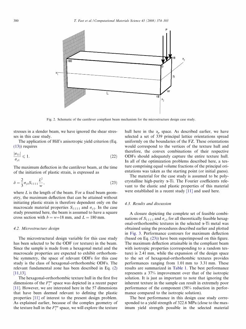
Fig. 2. Schematic of the cantilever compliant beam mechanism for the microstructure design case study.
380 T. Fast et al. / Computational Materials Science 43 (2008) 374–383
stresses in a slender beam, we have ignored the shear stres-ses in this case study.
The application of Hill’s anisotropic yield criterion (Eq.(13)) requires
r11j jry1
6 1: ð22Þ
The maximum deflection in the cantilever beam, at the timeof the initiation of plastic strain, is expressed as
d ¼ 2
3ry1S1 1 1 1
L2
w; ð23Þ
where L is the length of the beam. For a fixed beam geom-etry, the maximum deflection that can be attained withoutinitiating plastic strain is therefore dependent only on themacroscale material properties S1 1 1 1 and ry1. In the casestudy presented here, the beam is assumed to have a squarecross section with b = w=18 mm, and L = 180 mm.
4.2. Microstructure design
The microstructural design variable for this case studyhas been selected to be the ODF (or texture) in the beam.Since the sample is made from a hexagonal metal and themacroscale properties are expected to exhibit orthorhom-bic symmetry, the space of relevant ODFs for this casestudy is the class of hexagonal-orthorhombic ODFs. Therelevant fundamental zone has been described in Eq. (2)[11,13].
The hexagonal-orthorhombic texture hull in the first fivedimensions of the F mn
l space was depicted in a recent paper[11]. However, we are interested here in the 57 dimensionsthat have been deemed relevant to defining the plasticproperties [11] of interest to the present design problem.As explained earlier, because of the complex geometry ofthe texture hull in the F mn
l space, we will explore the texture
hull here in the ap space. As described earlier, we haveselected a set of 339 principal lattice orientations spreaduniformly on the boundaries of the FZ. These orientationswould correspond to the vertices of the texture hull andtherefore, the convex combinations of their respectiveODFs should adequately capture the entire texture hull.In all of the optimization problems described here, a tex-ture comprising equal volume fractions of the principal ori-entations was taken as the starting point (or initial guess).
The material for the case study is assumed to be poly-crystalline high-purity a-Ti. The Fourier coefficients rele-vant to the elastic and plastic properties of this materialwere established in a recent study [11] and used here.
4.3. Results and discussion
A closure depicting the complete set of feasible combi-nations of S1 1 1 1 and ry1 for all theoretically feasible hexag-onal-orthorhombic textures in the selected a-Ti metal wasobtained using the procedures described earlier and plottedin Fig. 3. Performance contours for maximum deflection(based on Eq. (23)) have been superimposed on this figure.The maximum deflection attainable in the compliant beamwith isotropic properties (corresponding to a random tex-ture) is 2.41 mm, while the expansion of the design spaceto the set of hexagonal-orthorhombic textures providesperformances ranging from 1.01 mm to 3.31 mm. Theseresults are summarized in Table 1. The best performancerepresents a 37% improvement over that of the isotropicsolution. It is just as important to note that ignoring theinherent texture in the sample can result in extremely poorperformance of the component (58% reduction in perfor-mance compared to the isotropic solution).
The best performance in this design case study corre-sponded to a yield strength of 322.6 MPa (close to the max-imum yield strength possible in the selected material
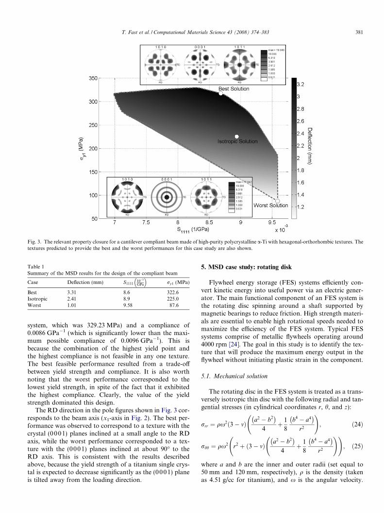
Fig. 3. The relevant property closure for a cantilever compliant beam made of high-purity polycrystalline a-Ti with hexagonal-orthorhombic textures. Thetextures predicted to provide the best and the worst performances for this case study are also shown.
Table 1Summary of the MSD results for the design of the compliant beam
Case Deflection (mm) S111110�3
GPa
ry1 (MPa)
Best 3.31 8.6 322.6Isotropic 2.41 8.9 225.0Worst 1.01 9.58 87.6
T. Fast et al. / Computational Materials Science 43 (2008) 374–383 381
system, which was 329.23 MPa) and a compliance of0.0086 GPa�1 (which is significantly lower than the maxi-mum possible compliance of 0.0096 GPa�1). This isbecause the combination of the highest yield point andthe highest compliance is not feasible in any one texture.The best feasible performance resulted from a trade-offbetween yield strength and compliance. It is also worthnoting that the worst performance corresponded to thelowest yield strength, in spite of the fact that it exhibitedthe highest compliance. Clearly, the value of the yieldstrength dominated this design.
The RD direction in the pole figures shown in Fig. 3 cor-responds to the beam axis (x1-axis in Fig. 2). The best per-formance was observed to correspond to a texture with thecrystal (0001) planes inclined at a small angle to the RDaxis, while the worst performance corresponded to a tex-ture with the (0001) planes inclined at about 90� to theRD axis. This is consistent with the results describedabove, because the yield strength of a titanium single crys-tal is expected to decrease significantly as the (0001) planeis tilted away from the loading direction.
5. MSD case study: rotating disk
Flywheel energy storage (FES) systems efficiently con-vert kinetic energy into useful power via an electric gener-ator. The main functional component of an FES system isthe rotating disc spinning around a shaft supported bymagnetic bearings to reduce friction. High strength materi-als are essential to enable high rotational speeds needed tomaximize the efficiency of the FES system. Typical FESsystems comprise of metallic flywheels operating around4000 rpm [24]. The goal in this study is to identify the tex-ture that will produce the maximum energy output in theflywheel without initiating plastic strain in the component.
5.1. Mechanical solution
The rotating disc in the FES system is treated as a trans-versely isotropic thin disc with the following radial and tan-gential stresses (in cylindrical coordinates r, h, and z):
rrr ¼ qx2 3� mð Þa2 � b2� �
4þ 1
8
b4 � a4� �
r2
!; ð24Þ
rhh ¼ qx2 r2 þ 3� mð Þa2 � b2� �
4þ 1
8
b4 � a4� �
r2
! !; ð25Þ
where a and b are the inner and outer radii (set equal to50 mm and 120 mm, respectively), q is the density (takenas 4.51 g/cc for titanium), and x is the angular velocity.
382 T. Fast et al. / Computational Materials Science 43 (2008) 374–383
The Poisson ratio, m, is defined in the plane of the radialand tangential components as
m ¼ 1� Srrhh
Srrrr: ð26Þ
The cylindrical geometry and the loading conditions de-mand transverse isotropy in macroscale properties. Hill’sanisotropic yield criterion (Eq. (10)) for this symmetryand loading condition can be expressed as
rrr � rhhð Þ2
r2yr
þ rrrrhh
r2yz
¼ 1; ð27Þ
where ryr and ryz denote the yield stresses in the radial andthickness directions, respectively. By substituting the stres-ses in Eqs. (24) and (25) into the yield criterion Eq. (27), theangular velocity (the variable governing kinetic energy) atthe initiation of plastic yield can be solved from
1
qx2¼Max
3þ mð Þ b4 � a4� �
� 4r4r2yr
4r2r2yr
!20@0@
þ 3þ mð Þr2
yz
a2 � b2
4
� �þ
b4 � a4� �
8r2
!
� r2 þ 3þ mð Þr2
yz
a2 � b2
4
� ��
b4 � a4� �
8r2
! !!!12
������r 2 a; b½ �
!: ð28Þ
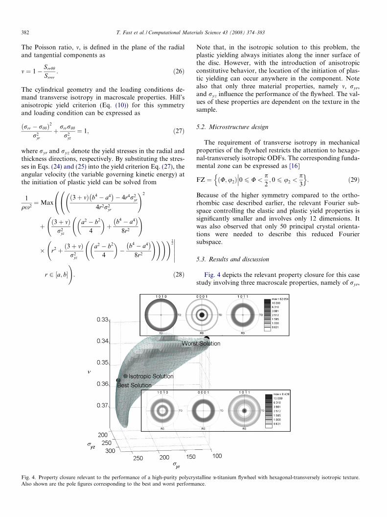
Fig. 4. Property closure relevant to the performance of a high-purity polycryAlso shown are the pole figures corresponding to the best and worst perform
Note that, in the isotropic solution to this problem, theplastic yielding always initiates along the inner surface ofthe disc. However, with the introduction of anisotropicconstitutive behavior, the location of the initiation of plas-tic yielding can occur anywhere in the component. Notealso that only three material properties, namely m, ryr,and ryz influence the performance of the flywheel. The val-ues of these properties are dependent on the texture in thesample.
5.2. Microstructure design
The requirement of transverse isotropy in mechanicalproperties of the flywheel restricts the attention to hexago-nal-transversely isotropic ODFs. The corresponding funda-mental zone can be expressed as [16]
FZ ¼ U;u2ð Þ 0 6 U <p2; 0 6 u2 <
p3
���n o: ð29Þ
Because of the higher symmetry compared to the ortho-rhombic case described earlier, the relevant Fourier sub-space controlling the elastic and plastic yield properties issignificantly smaller and involves only 12 dimensions. Itwas also observed that only 50 principal crystal orienta-tions were needed to describe this reduced Fouriersubspace.
5.3. Results and discussion
Fig. 4 depicts the relevant property closure for this casestudy involving three macroscale properties, namely of ryr,
stalline a-titanium flywheel with hexagonal-transversely isotropic texture.ance.
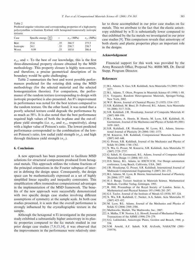
Table 2Predicted angular velocities and corresponding properties of a high-puritypolycrystalline a-titanium flywheel with hexagonal-transversely isotropictextures
Case Specific energy kJkg
m ryr (MPa) ryz (MPa)
Best 25.6 .35 266.5 275.5Isotropic 24.1 .35 250.7 250.7Worst 9.99 .33 105.0 306.4
T. Fast et al. / Computational Materials Science 43 (2008) 374–383 383
ryz, and m. To the best of our knowledge, this is the firstthree-dimensional property closure obtained by the MSDmethodology. This property closure is highly non-convex,and therefore, a precise geometrical description of itsboundary would be quite challenging.
Table 2 summarizes the best and worst possible perfor-mances predicted for the rotating disk using the MSDmethodology (for the selected material and the selectedhomogenization theories). For comparison, the perfor-mance of the random texture (corresponding to design withisotropic properties) is also presented. An 8% improvementin performance was noted for the best texture compared tothe random texture. On the other hand, it was noted that apoorly selected texture could degrade the performance byas much as 58%. It is also noted that the best performancerequired high values of both the in-plane and the out-of-plane yield strengths (i.e. ryr and ryz, respectively), alongwith a higher value of Poisson’s ratio. The lowest predictedperformance corresponded to the combination of the low-est Poisson’s ratio, low radial yield strength (ryr), and highthrough thickness yield strength (ryz).
6. Conclusions
A new approach has been presented to facilitate MSDsolutions for structural components produced from hexag-onal metals. This approach utilizes the volume fractions ofthe principal orientations in the Fourier subspace of inter-est in defining the design space. Consequently, the designspace can be mathematically expressed as a set of highlysimplified linear equality and inequality constraints. Thissimplification offers tremendous computational advantagesin the implementation of the MSD framework. The bene-fits of the new approach were successfully demonstratedwith two specific design case studies involving differentassumptions of symmetry at the sample scale. In both casestudies presented, it is seen that the overall performance isstrongly influenced by the crystallographic texture in thesample.
Although the hexagonal a-Ti investigated in the presentstudy exhibited a substantially higher anisotropy in its plas-tic properties compared to the fcc metals studied in ourprior design case studies [7,9,13,14], it was observed thatthe improvements in the performance were relatively simi-
lar to those accomplished in our prior case studies on fccmetals. This we attribute to the fact that the elastic anisot-ropy exhibited by a-Ti is substantially lower compared tothat exhibited by the fcc metals we investigated in our priorcase studies [9]. This comparison reveals that anisotropy ofboth elastic and plastic properties plays an important rolein the designs.
Acknowledgement
Financial support for this work was provided by theArmy Research Office, Proposal No. 46886 MS, Dr. DavidStepp, Program Director.
References
[1] B.L. Adams, X. Gao, S.R. Kalidindi, Acta Materialia 53 (2005) 3563–3577.
[2] B.L. Adams, T. Olson, Progress in Materials Science 43 (1998) 1–88.[3] S. Torquato, Random Heterogeneous Materials, Springer-Verlag,
New York, 2002.[4] W.F. Brown, Journal of Chemical Physics 23 (1955) 1514–1517.[5] S.R. Kalidindi, M. Binci, D. Fullwood, B.L. Adams, Acta Materialia
54 (2006) 3117–3126.[6] S.R. Kalidindi, J.R. Houskamp, Journal of Composite Materials 41
(2007) 909–930.[7] B.L. Adams, A. Henrie, B. Henrie, M. Lyon, S.R. Kalidindi, H.
Garmestani, Journal of the Mechanics and Physics of Solids 49 (2001)1639–1663.
[8] S.R. Kalidindi, J.R. Houskamp, M. Lyons, B.L. Adams, Interna-tional Journal of Plasticity 20 (2004) 1561–1575.
[9] M. Knezevic, S.R. Kalidindi, Computational Materials Science 39(2007) 643–648.
[10] G. Proust, S.R. Kalidindi, Journal of the Mechanics and Physics ofSolids 54 (2006) 1744–1762.
[11] X. Wu, G. Proust, M. Knezevic, S.R. Kalidindi, Acta Materialia 55(2007) 2729–2737.
[12] G. Saheli, H. Garmestani, B.L. Adams, Journal of Computer-AidedMaterials Design 11 (2004) 103–115.
[13] D.S. Sintay, B.L. Adams, in: IDETC/CIE, 31st Design automationconference, Long Beach, California, USA, 2005.
[14] J.R. Houskamp, G. Proust, S.R. Kalidindi, International Journal ofMultiscale Computational Engineering 5 (2007) 261–272.
[15] B.L. Adams, M. Lyon, B. Henrie, International Journal of Plasticity20 (2004) 1577–1602.
[16] H.-J. Bunge, Texture Analysis in Materials Science, MathematicalMethods, Cuvillier Verlag, Gottingen, 1993.
[17] R. Hill, Proceedings of the Royal Society of London. Series A,Mathematical and Physical Sciences 193 (1948) 281–297.
[18] G.I. Taylor, Journal of the Institute of Metals 62 (1938) 307–324.[19] X. Wu, S.R. Kalidindi, C. Necker, A.A. Salem, Acta Materialia 55
(2007) 423–432.[20] M. Lyon, B.L. Adams, Journal of the Mechanics and Physics of
Solids 52 (2004) 2569–2586.[21] Mathworks, Matlab, The Mathworks, Inc., 2007.[22] A. Midha, T.W. Norton, L.L. Howell, Journal of Mechanical Design –
Transactions of the ASME (1994) 270–279.[23] S.G. Lekhnitskii, Anisotropic Plates, Gordon and Breach, 1968, p.
534.[24] S.M. Arnold, A.F. Saleeb, N.R. Al-Zoubi, NASA/TM (2001-
210578).


