Embed Size (px)
Citation preview

TECHNIQUES by H. Basak, S. Ozkan, and A. Taskesen
APPLICATION OF BURNISHING PROCESS ON FRICTIONSTIR WELDING AND INVESTIGATION OF THE EFFECT OFBURNISHING PROCESS ON THE SURFACE ROUGHNESS,HARDNESS AND STRENGTH
I n this study, Al7075-T6 material has been joined byfriction stir welding (FSW) and then burnishing processhas been applied to the welded region. The effectsof burnishing process parameters such as feed rate,
compression force, revolution, and pass number on surfaceroughness, surface hardness, and weld strength have beenexperimentally investigated. The effects of these parameterson surface roughness and surface hardness of the weldedregion have been determined. Optimum conditions of surfaceroughness and surface hardness values have been obtained.It is observed that higher pass number has a negativeeffect on surface roughness. The results suggest that surfaceroughness of the workpiece improves and surface hardnessincreases provided suitable burnishing conditions are chosen.The mechanical properties were evaluated through uniaxialtensile tests, and tensile strength experiments have beenapplied to the burnished test specimens. Results have shownthat burnishing process negatively affected material strengthalthough it improves surface roughness positively.
Friction Stir WeldingFriction stir welding, a solid-state joining process developedand patented by the Welding Institute (TWI), emerged as awelding technique to be used in high-strength alloys thatwere difficult to join with conventional techniques. Theprocess was developed initially for aluminum alloys, but sincethen FSW was found suitable for joining a large number ofmaterials. Defect-free welds with good mechanical propertieshave been made in a variety of aluminum alloys, even thosepreviously thought to be not weldable. Friction stir weldswill not encounter problems like porosity, alloy segregation,and hot cracking, and welds are produced with good surfacefinish and thus no post-weld cleaning is required.1 Thiswelding process involves the advance of high-speed rotatinghard steel pin extended by a cylindrical shoulder betweentwo contacting metal plates through joint line.2–4 FSWis a new and successful joining method for the flat andlap welding of aluminum alloys.5 There have been a lotof efforts to understand the effect of process parameterson material flow behavior, microstructure formation, andhence mechanical properties of friction-stir welded joints.1In one of the past studies, the influence of two joiningmethods, that is, fusion (TIG) and solid-state (FSW) weldingprocesses, on both microstructure and mechanical propertiesof Al–4.5 Mg–0.26Sc alloy, was investigated. It appearedfrom this study that FSW joints exhibited higher mechanicalproperties than those obtained by A-TIG. Moreover, it was
H. Basak and A. Taskesen ([email protected]) are assistant professors with theDepartment of Mechanical Education, Gazi University, Ankara, Turkey. S. Ozkanis an M.Sc. with the Department of Mechanical Education, Institute of Science andTechnology, Gazi University, Ankara, Turkey
demonstrated there that a post-weld heat treatment on FSWwelds could eventually be avoided which was impossiblewhen a fusion welding process such as A-TIG was used.6However, up until now, there were not many studies reportedin literature about the application of burnishing process onFSW.
The basic principle of FSW is shown in Fig. 1.7,8 Firstly,the metal plates which are to be welded are placed on afixed surface. Application stages of this method could betwo different ways: (1) the metal parts can be movable and(2) the hard steel pin can rotate and move. Frictional heatingis produced from the rubbing of the rotating shoulder with thetwo workpieces, while the rotating pin deforms the heatedmaterial, causing the material to deform plastically. Thisplastic deformation maintains the material flows and thenjoining process occurs.
Burnishing ProcessBurnishing is a chipless and precise post-machining metalfinishing operation where rollers or balls give a smoothsurface, depress the asperities of a machined surface, andat the same time the surface becomes work hardened dueto plastic deformation. During recent years, considerableattentions are being made to the burnishing process thatimprove the surface characteristics by plastic deformationof the surface layers. Besides good surface finish, theburnishing process has advantages over other machiningprocesses such as grinding, in securing increased hardness,corrosion resistance, and fatigue life as a result ofthe produced compressive residual stress.9–11 Therefore,burnishing is a very effective method for the improvementin surface finish and quality of mechanical properties ofthe material.11,12 Moreover, the burnished surface has ahigh wear resistance and better fatigue life.13–17 On accountof its high productivity, it also saves more on productioncosts than other conventional processes such as super-finishing, honing, and grinding.18–20 Residual stresses arethe vital aspect in assessing integrity because of their directinfluence on the performance in service, improvements incomponent performance, and life because they reduce service(working) tensile stresses and inhibits crack nucleation andpropagation.21,22
In this study, burnishing operation has been applied to thewelded region of Al7075-T6 material, which were joinedby FSW, by using different burnishing parameters suchas feed rate, revolution, pass number, and compressionforce. Variations of surface roughness and surface hardnessat the welded region have been investigated. Moreover,in order to establish the effect of burnishing process
doi: 10.1111/j.1747-1567.2009.00555.x8 EXPERIMENTAL TECHNIQUES January/February 2011 © 2009, Society for Experimental Mechanics

PROCESS ON FSW AND EFFECTS OF BURNINGPROCESS PARAMETERS
Fig. 1: Schematic picture of friction-stir welding process and terminology
on material strength, the tensile strength experimentshave been applied to the burnished test specimens.After the burnishing process, strength of the weldedworkpiece was investigated according to tensile strengthtest results.
MATERIALS AND METHODS
Equipment and Measurement DevicesAfter the burnishing process, MAHR-Perthometer M1measuring equipment (Mahr GmbH, Gottingen, Germany)was used to measure surface roughness of the work piecematerial. All of the tests achieved were repeated three timesin order to guarantee its precision. In order to measuresurface roughness, cutoff length and sampling length wereassumed to be 0.8 and 5.6 mm, respectively. Surface hardnessvalues of the specimens were measured using Mitutoyosurface hardness measurement device.
Materials and Process Parameters
Friction Stir WeldingAluminum alloy 7075-T6 with an ultimate strength ofσ ult = 572 MPa and a yield stress of σ y = 503 MPa wasused in this investigation. Because of its low specificweight and high strength to weight ratio and also itshigh electrical and thermal conductance, this alloy iswidely used in industries and in particular in aircraftstructure and pressure vessels. The material’s chemicalcomposition and mechanical properties are given in Tables 1and 2, respectively. Although welding of these materials byconventional fusion welding is difficult, it is known thatjoining capabilities of these alloys by FSW are satisfactorilygood.6
Table 1—Chemical composition of Al7075aluminum alloy %9
Cu Zn Mg Si Mn Fe Cr Ti OTHER Al
1.20 5.10 2.10 0.40 0.30 0.50 0.18 0.200.15 Remaining
2.00 6.10 2.90 Max Max Max 0.28 Max
Table 2—Mechanical composition of Al7075aluminum alloy %9
MATERIAL
ULTIMATESTRENGTH
(MPa)
YIELDSTRENGTH
(MPa)DUCTILITY
(%)
SHEARSTRENGTH
(MPa)
AL 7075 T6 572 503 11 331
Stirrer PinsSelection of stirrer pin, which carry out FSW, was determinedaccording to difficulty level of the weldment process. Hardsteel pins manufactured from X210Cr12 steel were usedfor FSW operations since the hardness and mechanicalproperties of this material were very close to HSS toolsteel. This steel, whose material number is 2080 accordingto DIN 17006, has a very high wear resistance and shearstrength. It was hardened by oil hardening process. The toolused in this study was 10-mm-long cylindrical-shaped pinof 8-mm diameter and with 14-mm-diameter flat shoulder.Diameters of the hardened pins, which were manufacturedfrom X210Cr12 steel, have been designed to be 14.4 mm since+0.4-mm grinding tolerance was left in order to preventthe deflection after heat treatment process. After the heattreatment, tools were ground to 14-mm net diameter. Thehardness value of the tools for FSW could be between 50HRc and 65 HRc.23 If the hardness of X210Cr12 pins is too
January/February 2011 EXPERIMENTAL TECHNIQUES 9
PROCESS ON FSW AND EFFECTS OF BURNINGPROCESS PARAMETERS
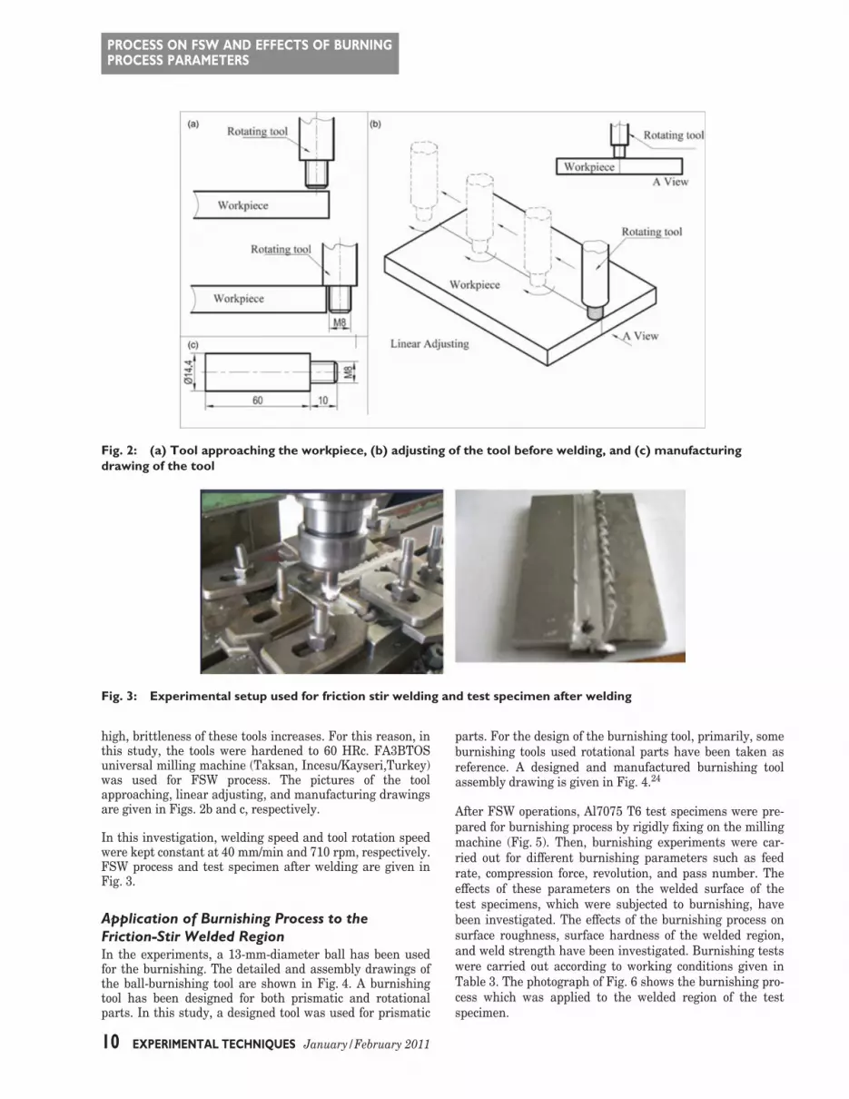
Fig. 2: (a) Tool approaching the workpiece, (b) adjusting of the tool before welding, and (c) manufacturingdrawing of the tool
Fig. 3: Experimental setup used for friction stir welding and test specimen after welding
high, brittleness of these tools increases. For this reason, inthis study, the tools were hardened to 60 HRc. FA3BTOSuniversal milling machine (Taksan, Incesu/Kayseri,Turkey)was used for FSW process. The pictures of the toolapproaching, linear adjusting, and manufacturing drawingsare given in Figs. 2b and c, respectively.
In this investigation, welding speed and tool rotation speedwere kept constant at 40 mm/min and 710 rpm, respectively.FSW process and test specimen after welding are given inFig. 3.
Application of Burnishing Process to theFriction-Stir Welded RegionIn the experiments, a 13-mm-diameter ball has been usedfor the burnishing. The detailed and assembly drawings ofthe ball-burnishing tool are shown in Fig. 4. A burnishingtool has been designed for both prismatic and rotationalparts. In this study, a designed tool was used for prismatic
parts. For the design of the burnishing tool, primarily, someburnishing tools used rotational parts have been taken asreference. A designed and manufactured burnishing toolassembly drawing is given in Fig. 4.24
After FSW operations, Al7075 T6 test specimens were pre-pared for burnishing process by rigidly fixing on the millingmachine (Fig. 5). Then, burnishing experiments were car-ried out for different burnishing parameters such as feedrate, compression force, revolution, and pass number. Theeffects of these parameters on the welded surface of thetest specimens, which were subjected to burnishing, havebeen investigated. The effects of the burnishing process onsurface roughness, surface hardness of the welded region,and weld strength have been investigated. Burnishing testswere carried out according to working conditions given inTable 3. The photograph of Fig. 6 shows the burnishing pro-cess which was applied to the welded region of the testspecimen.
10 EXPERIMENTAL TECHNIQUES January/February 2011
PROCESS ON FSW AND EFFECTS OF BURNINGPROCESS PARAMETERS
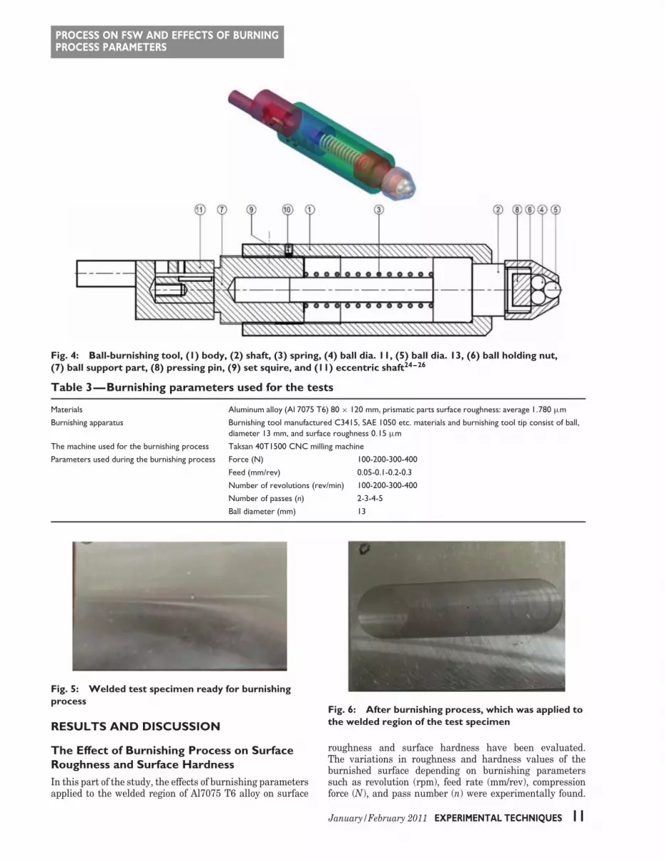
Fig. 4: Ball-burnishing tool, (1) body, (2) shaft, (3) spring, (4) ball dia. 11, (5) ball dia. 13, (6) ball holding nut,(7) ball support part, (8) pressing pin, (9) set squire, and (11) eccentric shaft24–26
Table 3—Burnishing parameters used for the tests
Materials Aluminum alloy (Al 7075 T6) 80 × 120 mm, prismatic parts surface roughness: average 1.780 μm
Burnishing apparatus Burnishing tool manufactured C3415, SAE 1050 etc. materials and burnishing tool tip consist of ball,diameter 13 mm, and surface roughness 0.15 μm
The machine used for the burnishing process Taksan 40T1500 CNC milling machine
Parameters used during the burnishing process Force (N) 100-200-300-400
Feed (mm/rev) 0.05-0.1-0.2-0.3
Number of revolutions (rev/min) 100-200-300-400
Number of passes (n) 2-3-4-5
Ball diameter (mm) 13
Fig. 5: Welded test specimen ready for burnishingprocess
RESULTS AND DISCUSSION
The Effect of Burnishing Process on SurfaceRoughness and Surface HardnessIn this part of the study, the effects of burnishing parametersapplied to the welded region of Al7075 T6 alloy on surface
Fig. 6: After burnishing process, which was applied tothe welded region of the test specimen
roughness and surface hardness have been evaluated.The variations in roughness and hardness values of theburnished surface depending on burnishing parameterssuch as revolution (rpm), feed rate (mm/rev), compressionforce (N), and pass number (n) were experimentally found.
January/February 2011 EXPERIMENTAL TECHNIQUES 11

PROCESS ON FSW AND EFFECTS OF BURNINGPROCESS PARAMETERS
Table 4—Test results of surface roughness (Ra) and surface hardness (Brinell) values ofburnished surface
FACTORS SURFACE ROUGHNESS RESULTS SURFACE HARDNESS RESULTS
PART NO s (dev/dk) f (mm/dev) F (N) n Ra1 (μm) Ra2 (μm) Brinell1 Brinell2
1 100 0.05 100 2 1.78 0.685 66.3 82.3
2 200 0.3 100 4 1.829 0.475 74.5 80.2
3 300 0.1 100 3 1.736 0.579 71.3 81
4 400 0.2 100 4 1.768 0.519 70.5 81
5 100 0.1 200 3 1.51 0.443 76.7 79.4
6 200 0.2 200 3 1.903 0.778 74 74.4
7 300 0.3 200 4 1.735 0.655 75.8 81
8 400 0.05 200 3 1.647 0.706 76.2 81.8
9 100 0.2 300 4 1.418 0.48 74.1 81
10 200 0.1 150 4 1.843 0.465 65.3 74.9
11 100 0.1 150 5 1.843 0.528 65.3 74.3
12 400 0.1 250 4 1.812 0.461 65.2 75.8
13 300 0.1 250 5 1.812 0.444 65.2 77.8
14 250 0.1 350 4 1.722 0.469 74.9 132
15 150 0.1 350 6 1.722 0.47 74.9 128
16 200 0.3 300 3 1.742 0.765 72.7 76.3
17 300 0.2 300 4 1.778 0.596 76.2 82.5
18 400 0.1 300 3 2.45 0.659 77.3 79.6
19 100 0.05 400 4 1.711 0.69 73.8 86
20 200 0.1 400 3 1.735 0.458 73.3 85.3
21 300 0.05 400 2 1.755 0.434 72.2 82.4
22 400 0.1 400 3 1.901 0.466 72.2 85
(a) (b)
Fig. 7: (a) Surface hardness and (b) surface roughness variations for 100-N compression force
The test results of surface roughness (Ra) and surfacehardness (Brinell) values are given in Table 4. These resultsshow that increasing the compression force increases thesurface hardness while surface roughness becomes worseafter a certain force value. Test results suggest thatoptimum compression forces for surface roughness andsurface hardness are 250 and 400 N, respectively.
Where,
Ra1 Surface roughness value of welded regionbefore burnishing process, Ra (μm)
Ra2 Surface roughness value of welded regionafter burnishing process, Ra (μm)
Part number Number of test specimen
12 EXPERIMENTAL TECHNIQUES January/February 2011

PROCESS ON FSW AND EFFECTS OF BURNINGPROCESS PARAMETERS
Brinell1 Surface hardness value of welded regionbefore burnishing process, HB
Brinell2 Surface hardness value of welded regionafter burnishing process, HB
S Revolution number of burnishing process(rpm)
f Feed rate, mm/revF Compression force, Nn Pass number
From the test results, effects of compression force and feedrate on surface roughness and surface hardness can beobserved in Figs. 7–9. Examination of these figures saysthat burnishing process increases the surface hardness andimproves the surface roughness of the welded region. Theresults of Fig. 7a and b indicate that increasing the feed rateimproves the surface roughness and decreases the surface
hardness of the workpiece. Figure 8 also verifies that anincrease in feed rate causes surface hardness to decreaseand surface roughness to improve. Comparison of Fig. 8aand b shows that large revolution numbers have a favorableeffect on surface hardness while surface roughness of theworkpiece deteriorates. In the literature, increasing therevolution number also increases the surface hardness.27
In order to determine the effects of compression force onsurface roughness and surface hardness, comparison ofFigs. 7, 8, and 9 and Table 4 together show that increasingvalues of compression forces increase surface hardness.Surface roughness improves until a certain compressionforce between 200 and 300 N. The surface becomes worseafter critical compression force value.
Deterioration in surface roughness occurs when pass numberexceeds a certain value as seen in Table 4. However, high
(a) (b)
Fig. 8: (a) Surface hardness and (b) surface roughness variations for 300-N compression force
(a) (b)
Fig. 9: (a) Surface hardness and (b) surface roughness variations for 400-N compression force
January/February 2011 EXPERIMENTAL TECHNIQUES 13

PROCESS ON FSW AND EFFECTS OF BURNINGPROCESS PARAMETERS
Table 5—Variation of the strength (MPa) for different burnishing parameters
VARIATION OF THE STRENGTH FORDIFFERENT APPLIED FORCES AND
NUMBER OF REVOLUTION
VARIATION OF THE STRENGTH FORDIFFERENT FEED AND NUMBER OF
REVOLUTION
VARIATION OF THE STRENGTH FORDIFFERENT NUMBER OF REVOLUTION
AND NUMBER OF PASSES
NUMBEROF REVO-LUTION(rev/min) APPLIED FORCE (N) FEED (mm/rev) NUMBER OF PASSES (n)
100 200 300 400 0.05 0.1 0.2 0.3 2 3 4 5
100 377 372 292 280 320 372 392 395 377 372 292 218
200 374 375 361 340 265 300 340 361 366 361 230 203
300 352 395 270 250 240 280 330 342 358 352 270 262
400 363 305 286 284 289 265 320 345 363 305 260 242
Fig. 10: Tensile test specimen prepared from frictionwelded joint (Dimensions mm)
pass number causes an increase in surface hardness of thewelded region. Therefore, pass number can be used as areference when choosing a good surface roughness or a highsurface hardness.
Effect of Burnishing Process on Weld StrengthThe mechanical properties were investigated throughuniaxial tensile tests, and tensile strength experiments havebeen applied to the burnished test specimens in order todetermine the effects of burnishing parameters. Tensile testswere carried out by using standard test specimens given inFig. 10. Minimum three test specimens were used for eachparameter in the experiments and the average of them was
taken. Broken test specimens, after tensile experiments, aredepicted in Fig. 11.
Ultimate strength results according to burnishing param-eters such as revolution number, compression force, andpass number are given in Table 5. Ultimate strengths of testspecimens decreases as the burnishing force increases asseen in Fig. 12b. Formations of micro cracks at the weldedregion, which was subjected to cold burnishing resulting fromcompression forces, can be considered the cause of this decre-ment. Variations of the strengths depending on revolutionnumber are depicted in Fig. 12a. Optimum ultimate strengthis determined at 200 rev/min as seen in this figure.
Figure 13 shows the strength results according to therevolution number and feed rate. The results of this figureindicate that increasing the feed rate also increases theultimate stress. The workpiece was subjected to morecrushing at low feed rates. Therefore, one may considerthat this case results in a more micro crack formation.
Increasing the pass number causes to increase the crushingrate of the material and results in a micro crack formationat the welded region. Therefore, pass number increment inburnishing process has an adverse effect on ultimate strengthof the welded region as seen in Fig. 14a and b.
CONCLUSIONThe effects of burnishing parameters, such as feed rate,compression force, revolution, and pass number, on surface
Fig. 11: (a–d) Samples of broken test specimens after tensile experiments
14 EXPERIMENTAL TECHNIQUES January/February 2011

PROCESS ON FSW AND EFFECTS OF BURNINGPROCESS PARAMETERS
(a) (b)
Fig. 12: Effect of revolution number and compression force on ultimate stress
(a) (b)
Fig. 13: Effect of feed rate and revolution number on ultimate stress
(a) (b)
Fig. 14: Effect of pass number and revolution number on ultimate stress
roughness and surface hardness of the welded regionhave been experimentally investigated. The results of thisexperimental study have shown that both surface roughnessand surface hardness improve after burnishing process.
The most favorable surface roughness values have beendetermined at the average values of revolution number,feed rate, and pass number which are 200–300 rev/min,0.2 mm/rev, and 3–4 pass, respectively. The results of this
January/February 2011 EXPERIMENTAL TECHNIQUES 15

PROCESS ON FSW AND EFFECTS OF BURNINGPROCESS PARAMETERS
study show that one of the most important parameteraffecting the surface roughness is pass number. Large passnumbers have a negative effect on surface roughness of theburnished surface. Test results also indicate that in order toachieve high-quality surface, the burnishing operation mustbe carried out at high revolution number, feed rate between0.05 mm/rev and 0.3 mm/rev, maximum 3–4 pass, and 250-to 300-N compression force. Minimum revolution numberand feed rate, and maximum pass number and compressionforce cause the surface roughness to be maximum value.
Surface roughness of the workpiece improves and surfacehardness increases provided the above burnishing conditionsare chosen. However, the experiment conducted in the givenconditions shows that strength of the welded region wasnegatively affected by burnishing process. Tensile stress testsindicate that material strength of the friction-stir weldedregion decreased. Therefore, burnishing operation, whichwas applied to the region of friction stir weldment, has afavorable effect on surface roughness and surface hardness,but it worsens the strength of the workpiece.
References
1. Moreira, P.M.G.P., Santos, T., Tavares, S.M.O., Richter-Trummer, V., Vilaca, P., and de Castro, P.M.S.T., ‘‘Mechanicaland Metallurgical Characterization of Friction Stir Welding Jointsof AA6061-T6 with AA6082-T6,’’ Materials & Design 30:180–187(2009).
2. Nagasawa, T., and Otsuka, M., Structure and MechanicalProperties of Friction Stir Weld Joints of Magnesium Alloy AZ31, TheMineral, Metal and Materials Society Annual Meeting, Nashville,TN, pp. 383–387 (2000).
3. Cam, G., ‘‘Al- Alasımları Icin Gelistirilen Yeni KaynakYontemleri,’’ Kaynak Teknolojisi III. Ulusal Kongresi BildirilerKitabı Yıldız Teknik Universitesi Oditoryumu 1:268–277 (2001) (InTurkish).
4. Ozsoy, M., and Kaluc, E., ‘‘Surtunen Eleman ile BirlestirmeKaynadının Esasları,’’ Muhendis ve Makine 513:19–26 (2002) (InTurkish).
5. Johnsen, M.R., ‘‘Friction Stir Welding Takes Off at Boeing,’’Welding Journal Cambridge 78:35–39 (1999).
6. Cabello Munoz, A., Ruckert, G., Huneaua, B., Sauvage, X.,and Marya, S., ‘‘Comparison of TIG Welded and Friction StirWelded Al–4.5 Mg–0.26Sc Alloy,’’ Journal of Materials ProcessingTechnology 197:337–343 (2008).
7. Thomas, WM., ‘‘Friction Stir Butt Welding InternationalPatent Application,’’ No. PCT/GB92, Patent Application No.9125978.8 (1991).
8. Boz, M., and Kurt, A., ‘‘The Influence of Stirrer Geometryon Bonding and Mechanical Properties in Friction Stir WeldingProcess,’’ Materials & Design 25:343–347 (2004).
9. Kaiser Aluminum Co. Material Catalogue, Web site:http://www.kaiseraluminum.com [accessed on 1 July 2009].
10. Axir, M.H., EL-Khabeery, M.M., ‘‘Influence of OrthogonalBurnishing Parameters on Surface Characteristics for Various
Materials,’’ Journal of Materials Processing Technology 132:82–89(2003).
11. Loh, N.H., Tam, S.C., and Miyazawa, S., ‘‘A Study of theEffects of Ball-Burnishing Parameters on Surface Roughness usingFactorial Design,’’ Journal of Mechanical Working Technology18:53–61 (1989).
12. Lee, S.S.G., Tam, S.C., Loh, N.H., and Miyazawa, S., ‘‘AnInvestigation into the Ball Burnishing of an AISI 1045 FreeformSurface,’’ Journal of Materials Processing Technology 29:203(1992).
13. Lee, S.S.G., Tam, S.C., and Loh, N.H., ‘‘Ball Burnishing of316L Stainless Steel,’’ Journal of Materials Processing Technology37:241 (1993).
14. Loh, N.H., Tam, S.C., and Miyazawa, S., ‘‘Statistical Analysesof the Effects of Ball Burnishing Parameters on Surface Hardness,’’Wear 129:235 (1989).
15. Yashcheritsyn, I., Pyatosin, E.I., and Votchuga, V.V., ‘‘Hered-itary Influence of Pre-Treatment on Roller-Burnishing SurfaceWear Resistance,’’ Soviet Journal of Friction and Wear 8(2):87(1987).
16. Fattouh, M., El-Axir, M.H., and Serage, S.M., ‘‘Investigationinto the Burnishing of External Cylindrical Surface of 70/30 Cu-Zn-alloy,’’ Wear 127:123–137 (1988).
17. Niberg, A.N., ‘‘Wear Resistance of Sideways Strengthened byBurnishing,’’ Soviet Engineering Research 7(5):67 (1987).
18. Michael, P.C., Saka, N., and Rabinowicz, E., ‘‘Burnishing andAdhesive Wear of an Electrically Conductive Polyestercarbon Film,’’Wear 132:265 (1989).
19. Fattouh, M., and El-Khabeery, M.M., ‘‘Residual Stress Dis-tribution in Burnishing Solution Treated and Aged 7075 AluminumAlloy,’’ International Journal of Machine Tools and Manufacture29(1):153 (1989).
20. Klocke, F., and Liermann, J., ‘‘Roller Burnishing of HardTurne Surface,’’ International Journal of Machine Tools andManufacture 38(5–6):419 (1998).
21. Mittal, S., and Liu, C.R., ‘‘A Method of Modeling ResidualStresses in Super Finish Hard Turning,’’ Wear 218(1):21–33 (1998).
22. Yeldose, B.C., and Ramamoorthy, B., ‘‘An Investigation intothe High Performance of Tin Coated Rollers in Burnishing Process,’’Journal of Materials Processing Technology 207(1–3):350–355(2008).
23. Prado, R.A., Murr, L.E., Shindo, D.J., and Soto, K.F., ‘‘ToolWear in the Friction-Stir Welding of Aluminum Alloy 6061+20%Al2O3: a Preliminary Study,’’ Scripta Materialia 45(1):75–80 (2001).
24. Basak, H., ‘‘Design and Manufacture of Burnishing Equip-ment and the Burnishing Process with AL 7075 T6 Material,’’Strojniski Vestnik Journal of Mechanical Engineering 5(12):885–897(2007).
25. Basak, H., and Goktas, H., ‘‘Burnishing Process on Al-Alloyand Optimization of Surface Roughness and Surface Hardness byFuzzy Logic,’’ Materials and Design 30(4):1275–1281 (2009).
26. Ozkan, S, ‘‘Surtunme Karıstırma Kaynagı Ile BirlestirilenParcalarda Haddeleme (Burnishing) ile Yuzeylerin Islenmesi,Haddelemenin Yuzey Puruzlulugu Ve Sertlesmeye EtkisininIncelenmesi,’’ Gazi Universitesi F.B.E. Yuksek Lisans Tezi, Temmuz(2006) (In Turkish).
27. El-Axir, M.H., ‘‘An Investigation into Roller Burnish-ing,’’ International Journal of Machine Tools and Manufacture40:1603–1617 (2000).�
16 EXPERIMENTAL TECHNIQUES January/February 2011


