Embed Size (px)
Citation preview

ANSI/NEMA MG 1-2016 (Revised 2018) Section IV Application Considerations Part 30—Page 1
© 2021 National Electrical Manufacturers Association
Section IV Performance Standards Applying to All Machines
Part 30 Application Considerations for Constant Speed Motors Used on a Sinusoidal
Bus with Harmonic Content and General Purpose Motors Used with Adjustable Voltage or Adjustable Frequency Controls or Both
30.0 Scope
The information in this Section applies to 60 Hz NEMA Designs A and B squirrel-cage motors covered by Part 12 and to motors covered by Part 20 rated 5000 horsepower or less at 7200 volts or less, when used on a sinusoidal bus with harmonic content, or when used with adjustable voltage or adjustable frequency controls, or both.
NEMA Designs C and D motors and motors larger than 5000 horsepower and voltages greater than 7200 volts are excluded from this section, and the manufacturer should be consulted regarding their application.
For motors intended for use in hazardous (classified) locations, refer to 30.2.2.10.
30.1 Application Considerations for Constant Speed Motors Used on a Sinusoidal Bus with Harmonic Content
30.1.1 Efficiency
Efficiency will be reduced when a motor is operated on a bus with harmonic content. The harmonics present will increase the electrical losses, which in turn decrease efficiency. This increase in losses will also result in an increase in motor temperature, which further reduces efficiency.
30.1.2 Derating for Harmonic Content
Harmonic currents are introduced when the line voltages applied to a polyphase induction motor include voltage components at frequencies other than nominal (fundamental) frequency of the supply. Consequently, the temperature rise of the motor operating at a particular load and per unit voltage harmonic factor will be greater than that for the motor operating under the same conditions with only voltage at the fundamental frequency applied.
When a motor is operated at its rated conditions and the voltage applied to the motor consists of components at frequencies other than the nominal frequency, the rated horsepower of the motor should be multiplied by the factor shown in Figure 30-1 to reduce the possibility of damage to the motor. This curve is developed under the assumption that only harmonics equal to odd multiples (except those divisible by three) of the fundamental frequency are present. It is assumed that any voltage unbalance or any even harmonics, or both, present in the voltage are negligible. This derating curve is not intended to apply when the motor is operated at other than its rated frequency nor when operated from an adjustable voltage or an adjustable frequency power supply, or both.

Section IV ANSI/NEMA MG 1-2016 (Revised 2018) Part 30—Page 2 Application Considerations
© 2021 National Electrical Manufacturers Association
Figure 30-1 Derating Curve for Harmonic Voltages
30.1.2.1 Harmonic Voltage Factor (HVF) Defined The harmonic voltage factor (HVF) is defined as follows:
Where:
n = order of odd harmonic, not including those divisible by three
Vn = the per unit magnitude of the voltage at the nth harmonic frequency Example: With per unit voltages of 0.10, 0.07, 0.045, and 0.036 occurring at the 5, 7, 11, and 13th harmonics, respectively, the value of the HVF is:
30.1.3 Power Factor Correction The proper application of power capacitors to a bus with harmonic currents requires an analysis of the power system to avoid potential harmonic resonance of the power capacitors in combination with transformer and circuit inductance. For power distribution systems that have several motors connected to a bus, power capacitors connected to the bus rather than switched with individual motors are recommended to minimize potentially resonant combinations of capacitance and inductance, and to simplify the application of any tuning filters that may be required. This requires that such bus-connected capacitor banks be sized so that proper bus voltage limits are maintained. (See 14.44 or 20.34.)
n =5

ANSI/NEMA MG 1-2016 (Revised 2018) Section IV Application Considerations Part 30—Page 3
© 2021 National Electrical Manufacturers Association
30.2 General Purpose Motors Used with Adjustable Voltage or Adjustable Frequency Controls or Both 30.2.1 Definitions 30.2.1.1 Base Rating Point Base rating point for motors defines a reference operating point at a specified speed, fundamental voltage, and torque or horsepower. 30.2.1.2 Breakaway Torque (Motor) The torque that a motor produces at zero speed when operating on a control. 30.2.1.3 Constant Horsepower Speed Range (Drive) The portion of its speed range within which the drive is capable of maintaining essentially constant horsepower. 30.2.1.4 Constant Torque Speed Range (Drive) The portion of its speed range within which the drive is capable of maintaining essentially constant torque. 30.2.1.5 Control The term “control” applies to devices that are also called inverters and converters. They are electronic devices that convert an input AC or DC power into a controlled output AC voltage or current. 30.2.1.6 Drive The equipment used for converting available electrical power into mechanical power suitable for the operation of a machine. A drive is a combination of a power converter (control), motor, and any motor-mounted auxiliary devices. Examples of motor-mounted auxiliary devices are encoders, tachometers, thermal switches and detectors, air blowers, heaters, and vibration sensors. 30.2.1.7 (Drive) Speed Range All the speeds that can be obtained in a stable manner by action of part (or parts) of the control equipment governing the performance of the motor. 30.2.1.8 (Drive) System Response The total (transient plus steady state) time response resulting from a sudden change from one level of control input to another. 30.2.1.9 Magnetizing Current (Motor) The reactive current that flows in a motor operating at no load. 30.2.1.10 Maximum Operating Speed (Motor) Maximum operating speed is the upper limit of the rotational velocity at which a motor may operate based on mechanical considerations.

Section IV ANSI/NEMA MG 1-2016 (Revised 2018) Part 30—Page 4 Application Considerations
© 2021 National Electrical Manufacturers Association
30.2.1.11 Motor Output Capability The motor when operated on a control generally has the mechanical output capability to produce constant torque (horsepower proportional to speed) at and below base rated speed, and constant horsepower (torque inversely proportional to speed) at and above base rated speed, except where limited by the following:
a. Effect of reduced speed on cooling (see 30.2.2.2.2);
b. Additional losses introduced by harmonic content (under consideration);
c. Torque produced when operated within the limitations of the control output power (see 30.2.2.2.3).
30.2.1.12 Overload Capability (Motor) The maximum load a motor can carry for a specified period of time without permanent damage or significant performance deterioration. 30.2.1.13 Pulsating Torque The single amplitude of variation in torque from the average torque. 30.2.1.14 Pulse Frequency Pulse frequency (also called carrier frequency, switching frequency, and chopping frequency) is the frequency of the switching pulses used by a control to generate the output voltage or current wave form. 30.2.1.15 Pulse Width Modulated Control A control where the frequency and magnitude of the output voltage or current are accomplished by pulse modulation in which the duration of the pulses is varied. 30.2.1.16 Rated Temperature The maximum allowable winding temperature of the motor when the drive is delivering rated output at any speed within the rated speed range for a defined and specified period of time. 30.2.1.17 Regeneration The process of returning energy to the power source. 30.2.1.18 Regenerative Braking A form of dynamic braking in which the kinetic energy of the motor and driven machinery is returned to the power supply system. 30.2.1.19 Rise Time (Voltage) The time required for the voltage to make the change from 10% of the steady-state value to 90% of the steady-state value, either before overshoot or in the absence of overshoot. See Figure 30-5. 30.2.1.20 Six Step Control A control where the frequency and magnitude of the output voltage or current are accomplished by creating a wave form made up of 6 discrete steps.

ANSI/NEMA MG 1-2016 (Revised 2018) Section IV Application Considerations Part 30—Page 5
© 2021 National Electrical Manufacturers Association
30.2.1.21 Slip Slip is the quotient of (A) the difference between synchronous speed and the actual speed of the rotor to (B) the synchronous speed, expressed as a ratio or as a percentage. 30.2.1.22 Slip rpm Slip rpm is the difference between the speed of a rotating magnetic field (synchronous speed) and that of a rotor expressed in revolutions per minute. 30.2.1.23 Speed Stability Speed stability is the amplitude of the variation in speed from the average speed, expressed in percent, throughout the entire speed range when the drive is connected to the driven equipment. 30.2.1.24 Variable Torque Speed Range (Drive) The portion of its speed range within which the drive is capable of maintaining a varying level of torque (for the defined time rating), generally increasing with speed. It is common for the term variable torque to be used when referring to a torque that varies as the square of the speed and hence the power output varies as the cube of the speed. 30.2.1.25 Voltage Boost
An additional amount of control output voltage, above the value based on constant volts per hertz, applied at any frequency. It is generally applied at lower frequencies to compensate for the voltage drop in the stator winding. 30.2.1.26 Volts/Hertz Ratio (Base)
The base volts/hertz ratio is the ratio of fundamental voltage to frequency at the base rating point. 30.2.2 Application Considerations
30.2.2.1 Base Rating Point (Motor) When a motor is applied to a control, the nameplate data shall be its base rating point. 30.2.2.2 Torque 30.2.2.2.1 Motor Torque During Operation Below Base Speed To develop constant torque below base speed by maintaining constant air-gap flux, the motor input voltage should be varied to maintain approximately rated volts per hertz. At frequencies below approximately 30 hertz, an increase in the volts per hertz ratio (boost voltage) may be required to maintain constant air-gap flux (i.e., constant torque). For applications that require less than rated torque below base speed, system economics may be improved by operation at a reduced volts per hertz ratio. 30.2.2.2.2 Torque Derating Based on Reduction in Cooling Induction motors to be operated in adjustable speed drive applications should be derated because of the reduction in cooling resulting from any reduction in operating speed. This derating should be in accordance with Figure 30-2. This derating may be accomplished by or inherent in the load speed-torque characteristics or may require selection of an oversized motor. The curves are applicable only to the NEMA frame sizes and design types as indicated, and, as noted, additional derating for harmonics may be required. For larger NEMA frames or other design types, consult the motor manufacturer.

Section IV ANSI/NEMA MG 1-2016 (Revised 2018) Part 30—Page 6 Application Considerations
© 2021 National Electrical Manufacturers Association
The curves in Figure 30-2 represent the thermal capability of Design A and B motors under the conditions noted and are based on non-injurious heating, which may exceed the rated temperature rise for 1.0 service factor motors (see 12.44) for the class of insulation. This is analogous to operation of a 1.15 service factor motor at service factor load (with rated voltage and frequency applied) as evidenced by the 115% point at 60 hertz for a 1.15 service factor motor. 30.2.2.2.3 Torque Derating During Control Operation Induction motors to be operated in adjustable speed drive applications should also be derated as a result of the effect of additional losses introduced by harmonics generated by the control. The torque available from the motor for continuous operation is usually lower than on a sinusoidal voltage source. The reduction results from the additional temperature rise due to harmonic losses, and also from the voltage- frequency characteristics of some controls. The temperature rise at any load-speed point depends on the individual motor design, the type of cooling, the effect of the reduction in speed on the cooling, the voltage applied to the motor, and the characteristics of the control. When determining the derating factor, the thermal reserve of the particular motor is important. Taking these matters into account, the derating factor at rated frequency ranges from 0 to 20%. Figure 30-3 shows examples of a derating curve for a typical motor for which the thermal reserve of the motor at rated frequency is less than the additional temperature rise resulting from operation on a control and one for which the thermal reserve is greater. It is not possible to produce a curve that applies to all cases. Other motors with different thermal reserve, different methods of cooling (self-circulation cooling or independent cooling), and used with other types of controls will have different derating curves. There is no established calculation method for determining the derating curve for a particular motor used with a particular control that can be used by anyone not familiar with all of the details of the motor and control characteristics. The preferred method for determining the derating curve for a class of motors is to test representative samples of the motor design under load while operating from a representative sample of the control design and measure the temperature rise of the winding.

ANSI/NEMA MG 1-2016 (Revised 2018) Section IV Application Considerations Part 30—Page 7
© 2021 National Electrical Manufacturers Association
Figure 30-2 Effect of Reduced Cooling on the Torque Capability at Reduced Speeds of
60 Hz NEMA Design A and B Motors
Notes: 1. Curve identification
a. Limit for Class B 80°C or Class F 105°C rise by resistance, 1.0 service factor. b. Limit for Class B 90°C or Class F 115°C rise by resistance, 1.15 service factor.
2. All curves are based on a sinusoidal wave shape, rated air-gap flux. Additional derating for harmonic voltages should be applied as a multiplier to the above limits.
3. All curves are based on non-injurious heating, which may exceed rated temperature rise. 4. Curves are applicable only to frame sizes and design types indicated. For larger frames or other design types, consult the
motor manufacturer.

Section IV ANSI/NEMA MG 1-2016 (Revised 2018) Part 30—Page 8 Application Considerations
© 2021 National Electrical Manufacturers Association
Figure 30-3 Examples of Torque Derating of NEMA Motors When Used with Adjustable Frequency Controls
Notes: 1. Curve identification
a. Motor #1: motor thermal reserve greater than the additional temperature rise resulting from operation on a control. b. Motor #2: motor thermal reserve less than the additional temperature rise resulting from operation on a control.
30.2.2.2.4 Motor Torque During Operation Above Base Speed Above base speed, a motor input voltage having a fundamental component equal to rated motor voltage (which may be limited by the control and its input power) as frequency increases will result in constant horsepower operation (torque reducing with reduced volts per hertz). The maximum (breakdown) torque capability of the motor within this speed range will limit the maximum frequency (and speed) at which constant horsepower operation is possible. The curves in Figure 30-4 represent the load that the defined motor is capable of carrying above base speed. The curves represent operation at constant horsepower for 1.0 service factor motors and similar performance for 1.15 service factor motors. The maximum frequency of 90 hertz is established based on the approximate peak torque capability of greater than 175% for NEMA Design A and B motors assuming operation at a constant level of voltage equal to rated voltage from 60 to 90 hertz. For the capability of motors for which the minimum breakdown torque specified in 12.39.1 or 12.39.2 is less than 175%, consult the motor manufacturer. For operation above 90 hertz at a required horsepower level, it may be necessary to utilize a motor with a greater horsepower rating at 60 hertz. However, the maximum speed at which a motor can safely operate may be limited to some speed below the maximum speed relative to its load carrying capability because of mechanical considerations (see 30.2.2.3).
Frequency-Hertz

ANSI/NEMA MG 1-2016 (Revised 2018) Section IV Application Considerations Part 30—Page 9
© 2021 National Electrical Manufacturers Association
Figure 30-4 Torque Capability Above Base Speed
Notes: 1. Curve identification
a. Limit for Class B 80°C or Class F 105°C rise by resistance, 1.0 service factor. b. Limit for Class B 90°C or Class F 115°C rise by resistance, 1.15 service factor.
2. All curves are based on a sinusoidal wave shape, constant voltage equal to rated voltage. Additional derating for harmonic voltages should be applied as a multiplier to the above limits.
3. All curves are based on non-injurious heating, which may exceed rated temperature rise. 4. Curves are applicable to NEMA Design A and B motors having breakdown torques of not less than 175% at 60 hertz. 5. See 30.2.2.3 for any additional limitations on the maximum operating speed.
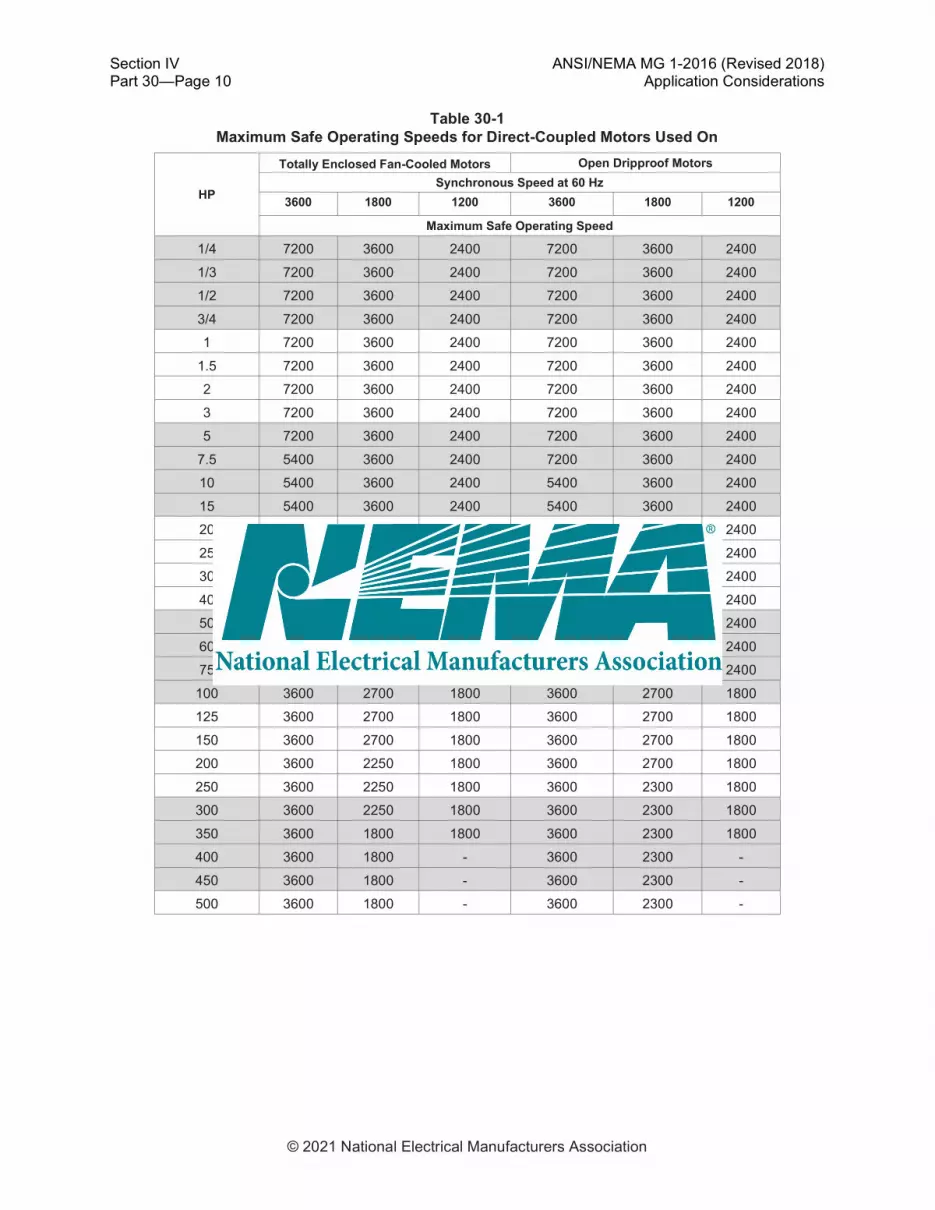
30.2.2.3 Maximum Safe Operating Speeds
The maximum safe operating speed of a direct-coupled motor at 0–40°C ambient temperature should not exceed the values given in Table 30-1. For possible operation at speeds greater than those given in Table 30-1 or conditions other than those stated, consult the motor manufacturer. For motors not covered by Table 30-1, refer to 12.52 or 20.13.
Section IV ANSI/NEMA MG 1-2016 (Revised 2018) Part 30—Page 10 Application Considerations
© 2021 National Electrical Manufacturers Association
Table 30-1 Maximum Safe Operating Speeds for Direct-Coupled Motors Used On
HP
Totally Enclosed Fan-Cooled Motors Open Dripproof Motors
Synchronous Speed at 60 Hz
3600 1800 1200 3600 1800 1200
Maximum Safe Operating Speed
1/4 7200 3600 2400 7200 3600 2400
1/3 7200 3600 2400 7200 3600 2400
1/2 7200 3600 2400 7200 3600 2400
3/4 7200 3600 2400 7200 3600 2400
1 7200 3600 2400 7200 3600 2400
1.5 7200 3600 2400 7200 3600 2400
2 7200 3600 2400 7200 3600 2400
3 7200 3600 2400 7200 3600 2400
5 7200 3600 2400 7200 3600 2400
7.5 5400 3600 2400 7200 3600 2400
10 5400 3600 2400 5400 3600 2400
15 5400 3600 2400 5400 3600 2400
20 5400 3600 2400 5400 3600 2400
25 5400 2700 2400 5400 2700 2400
30 5400 2700 2400 5400 2700 2400
40 4500 2700 2400 5400 2700 2400
50 4500 2700 2400 4500 2700 2400
60 3600 2700 2400 4500 2700 2400
75 3600 2700 2400 3600 2700 2400
100 3600 2700 1800 3600 2700 1800
125 3600 2700 1800 3600 2700 1800
150 3600 2700 1800 3600 2700 1800
200 3600 2250 1800 3600 2700 1800
250 3600 2250 1800 3600 2300 1800
300 3600 2250 1800 3600 2300 1800
350 3600 1800 1800 3600 2300 1800
400 3600 1800 - 3600 2300 -
450 3600 1800 - 3600 2300 -
500 3600 1800 - 3600 2300 -

ANSI/NEMA MG 1-2016 (Revised 2018) Section IV Application Considerations Part 30—Page 11
© 2021 National Electrical Manufacturers Association
Notes: 1. Standard NEMA Design A and B motors in frames per Part 13. 2. The permissible overspeed value is 10% above values in Table 30-1 (not to exceed 2 minutes in duration) except where the
maximum safe operating speed is the same as the synchronous speed at 60 Hz, where the overspeeds referenced in 12.52.3 apply.
3. TS shaft over 250 frame size. 4. The values in the table are based on mechanical limitations. Within the operating limits noted in the table, the motor is capable
of constant horsepower from 60 through 90 hertz. Above approximately 90 hertz, the motor may not provide sufficient torque based on specified voltage to reach stable speeds while under load.
5. Operation above nameplate speed may require refined balance. 6. Contact the manufacturer for speeds and ratings not covered by the table. 7. Considerations:
a. Noise limits per 12.53 and vibration limits per Part 7 are not applicable. b. Bearing life will be affected by the length of time the motor is operated at various speeds.
30.2.2.4 Current 30.2.2.4.1 Running Current Controls are generally rated in terms of a continuous output current capability, a short-term output current, and a peak output current. To properly choose the size of control required in an application, consideration should be given to the peak and transient values in addition to the rms value of motor current, and the manner in which the system is to be operated. Because some level of current will exist at each of the harmonic frequencies characteristic of the particular type of control, the total rms sum of current required by the motor at full load may be from 5% to 10% greater than that level of current corresponding to operation on a sinusoidal power source. The magnitude of the peak values of the current waveform may vary from 1.3 to 2.5 times the rms value of the current, depending on the type of control considered and the motor characteristics. An additional margin from 10% to 50% in the current rating of the control should be considered to allow for possible overload conditions on the motor so as not to trip the control on such short-time overcurrent demand. When the motor and control are used in a system where sudden changes in load torque or frequency might occur, the control should be sized based on the peak value of the transient current that results from the sudden change. Also, when changing from one operating speed to another, if the rate of change in frequency is greater than the possible rate of change in motor speed and if the slip increases beyond the value of slip at rated load, then the amount of rms current or peak current required from the control may exceed that of the steady-state requirements. 30.2.2.4.2 Starting Current In a stall condition, the amount of current drawn by an induction motor is primarily determined by the magnitude and frequency of the applied voltage and the impedance of the motor. Under adjustable frequency control, motors are normally started by applying voltage to the motor at a low frequency (less than 3 hertz). The current drawn by the motor under this condition is mainly a function of the equivalent stator and rotor resistances since the reactive impedance is small because of the low frequency. In order to provide sufficient starting torque, it is necessary to provide an increase in voltage (voltage boost) at low frequencies in order to overcome this resistive drop in the motor. This voltage boost is the product of the required phase current (for the level of breakaway torque needed) and the stator phase resistance and the square root of 3 (to convert phase quantity to line-to-line value). A wye connection is assumed. For rated torque at start it will be necessary to adjust the voltage boost to have at least rated current. Since stator and rotor resistances vary with temperature, the actual starting current will be a function of the machine temperature.

Section IV ANSI/NEMA MG 1-2016 (Revised 2018) Part 30—Page 12 Application Considerations
© 2021 National Electrical Manufacturers Association
CAUTION—Continued application of boosted motor voltage at low frequencies under no-load conditions will increase motor heating. When voltage boost is required to achieve a breakaway torque greater than 140% of rated torque, the motor should not be operated under voltage boost condition at frequencies less than 10 hertz for more than 1 minute without consulting the manufacturer. 30.2.2.5 Efficiency Motor efficiency will be reduced when it is operated on a control. The harmonics present will increase the electrical losses, which decrease efficiency. This increase in losses will also result in an increase in motor temperature, which further reduces efficiency. 30.2.2.6 Sound Sound levels should be considered when using induction motors with an adjustable frequency and voltage power supply. The sound level is dependent upon the construction of the motor, the number of poles, the pulse pattern and pulse frequency, and the fundamental frequency and resulting speed of the motor. The response frequencies of the driven equipment should also be considered. Sound levels produced thus will be higher than published values when operated above rated speed. At certain frequencies, mechanical resonance or magnetic noise may cause a significant increase in sound levels, while a change in frequency and/or voltage may reduce the sound level. Experience has shown that typically an increase in the A-weighted noise level by up to 6 dB can occur at rated frequency when motors are used with non-PWM (pulse width modulated) controls, in comparison with operation on sinusoidal supply voltage and frequency. An increase of up to 5 dB to 15 dB can occur at rated frequency in the case when motors are used with PWM controls. For other frequencies, the noise levels may be higher. 30.2.2.7 Resonances, Sound, Vibration When an induction motor is operated from a control, torque ripple at various frequencies may exist over the operating speed range. Consideration should be given to identifying the frequency and amplitude of these torques and determining the possible effect upon the motor and the driven equipment. It is of particular importance that the equipment not be operated longer than momentarily at a speed where a resonant condition exists between the torsional system and the electrical system (i.e., the motor electrical torque). For example, if the control is of the six step type, then a sixth harmonic torque ripple is created, which would vary from 36 to 360 hertz when the motor is operated over the frequency range of 6 to 60 hertz. At low speeds, such torque ripple may be apparent as observable oscillations of the shaft speed or as torque and speed pulsations (usually termed “cogging”). It is also possible that some speeds within the operating range may correspond to the natural mechanical frequencies of the load or support structure and operation other than momentarily could be damaging to the motor and/or load and should be avoided at those speeds. 30.2.2.8 Voltage Stress The exact quantitative effects of peak voltage and rise time on motor insulation are not fully understood. It can be assumed that when the motor is operated under usual service conditions (14.2 or 20.28.2), there will be no significant reduction in service life due to voltage stress, if the following voltage limit values at the motor terminals are observed.
ANSI/NEMA MG 1-2016 (Revised 2018) Section IV Application Considerations Part 30—Page 13
© 2021 National Electrical Manufacturers Association
Motors with base rating voltage Vrated ≤ 600 volts: Vpeak ≤ 1 kV rise time ≥ 2 μs See Figure 30-5 for a typical voltage response at the motor terminals for an illustration of Vpeak and rise time. Motors with base rating voltage Vrated > 600 volts: Vpeak ≤ 2.04 * Vrated
Rise time ≥ 1 μs
Where: Vpeak is a single amplitude zero-to-peak line-to-line voltage.
CAUTION—When the input voltage to the control exceeds the rated voltage, care must be taken in determining the maximum peak voltage (Vpeak) that will be applied to the motor by the control. For suitability when values are outside these limits, contact the manufacturer for guidance. A definite purpose motor per Part 31 may be required. Filters, chokes, or other voltage conditioning devices applied with guidance from the control manufacturer may also be required. 30.2.2.9 Power and Coupling Capacitors The use of power capacitors for power factor correction or surge suppression on the load side of an electronic control connected to an induction motor is not recommended. The proper application of such capacitors requires an analysis of the motor, electronic control, and load characteristics as a function of speed to avoid potential overexcitation of the motor, harmonic resonance, and capacitor overvoltage. The use of coupling capacitors, typically less than 200 pF, for partial discharge (PD) detection on the load side of an inverter connected to an induction motor is generally acceptable. The proper application of such capacitors requires an analysis of the motor, electronic control, and load characteristics as a function of speed. Additional hardware may be required in the terminal box to take PD measurements. 30.2.2.10 Operation in Hazardous (Classified) Locations WARNING—Motors operated from adjustable frequency or adjustable voltage power supplies or both should not be used in any Division 1 hazardous (classified) locations unless the motor is identified on the nameplate as acceptable for such operation when used in Division 1 hazardous (classified) locations. For motors to be used in any Division 2 hazardous (classified) locations, the motor manufacturer should be consulted. Failure to comply with this warning could result in an unsafe installation that could cause damage to property or serious injury or death to personnel, or both.

Section IV ANSI/NEMA MG 1-2016 (Revised 2018) Part 30—Page 14 Application Considerations
© 2021 National Electrical Manufacturers Association
Figure 30-5 Typical Voltage Response at Motor Terminal


