Embed Size (px)
Citation preview
—
How
to
read
a N
EMA
m
oto
r na
mep
late
—NEMA
How to read a NEMA motor nameplate
2 H OW TO R E A D A N E M A M OTO R N A M E PL ATE
—How to read a NEMA motor nameplate
The motor industry in North America has worked on a standardized basis since the early part of the 20th century. In 1926, the National Electrical Manufacturers Association (NEMA) was established to provide a forum for the standardization of electrical equipment, enabling consumers to select from a range of safe, effective and compatible electrical products. To this day, NEMA updates and publishes standards, application guides and technical papers for electrical products and works in advocacy for the industry.
To help ensure its standards are properly met and communicated, NEMA requires that motors from different manufacturers meet or exceed minimum performance parameters and, for the most part, be about the same size. One way to ensure the identification of interchangeable motors is through the consistency of nameplate information between manufacturers. The common language of the motor nameplate enables installers, operators and maintenance personnel to understand and recognize the type of motor and that motor’s requirements quickly and easily. The nameplate defines a motor’s basic mechanical design, electrical performance and dimensional parameters. NEMA requires specific data to be included on the nameplate, but manufacturers may choose to include other information to assist in the installation, operation and maintenance of custom motors or those manufactured for specific purposes. The style of the nameplate is determined by the manufacturer.
It is important to understand the specifications and other information detailed on the nameplate when purchasing an electric motor. Having the right motor for a specific application helps ensure optimum efficiency, a longer motor life and can mean significant cost savings for your business. But a nameplate remains important even after purchase, and for this reason, most are made of steel or aluminum for longevity, and the information on the plate is engraved for readability throughout the life of the motor. Nameplate information is essential for installation and wiring connection, matching an appropriate variable speed drive, repairing or replacing the motor. Understanding this data will allow you select the right motor for the job, identify performance characteristics and applications of a motor and help solve operational issues.
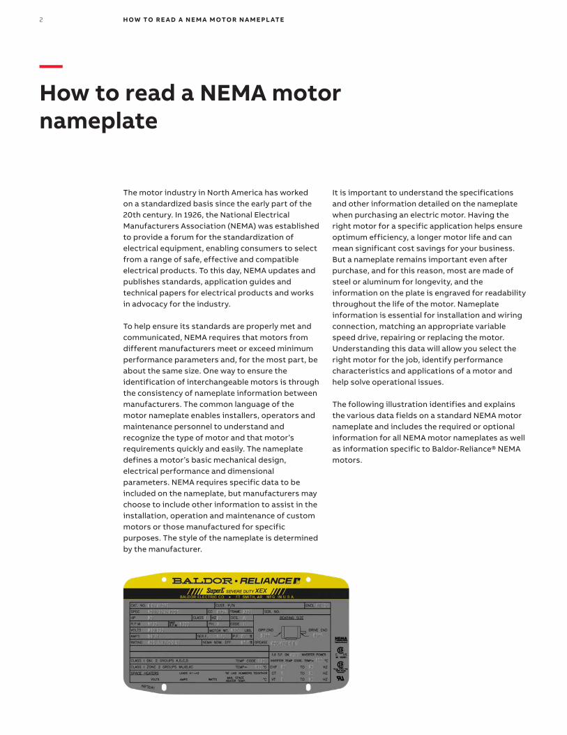
The following illustration identifies and explains the various data fields on a standard NEMA motor nameplate and includes the required or optional information for all NEMA motor nameplates as well as information specific to Baldor-Reliance® NEMA motors.
3
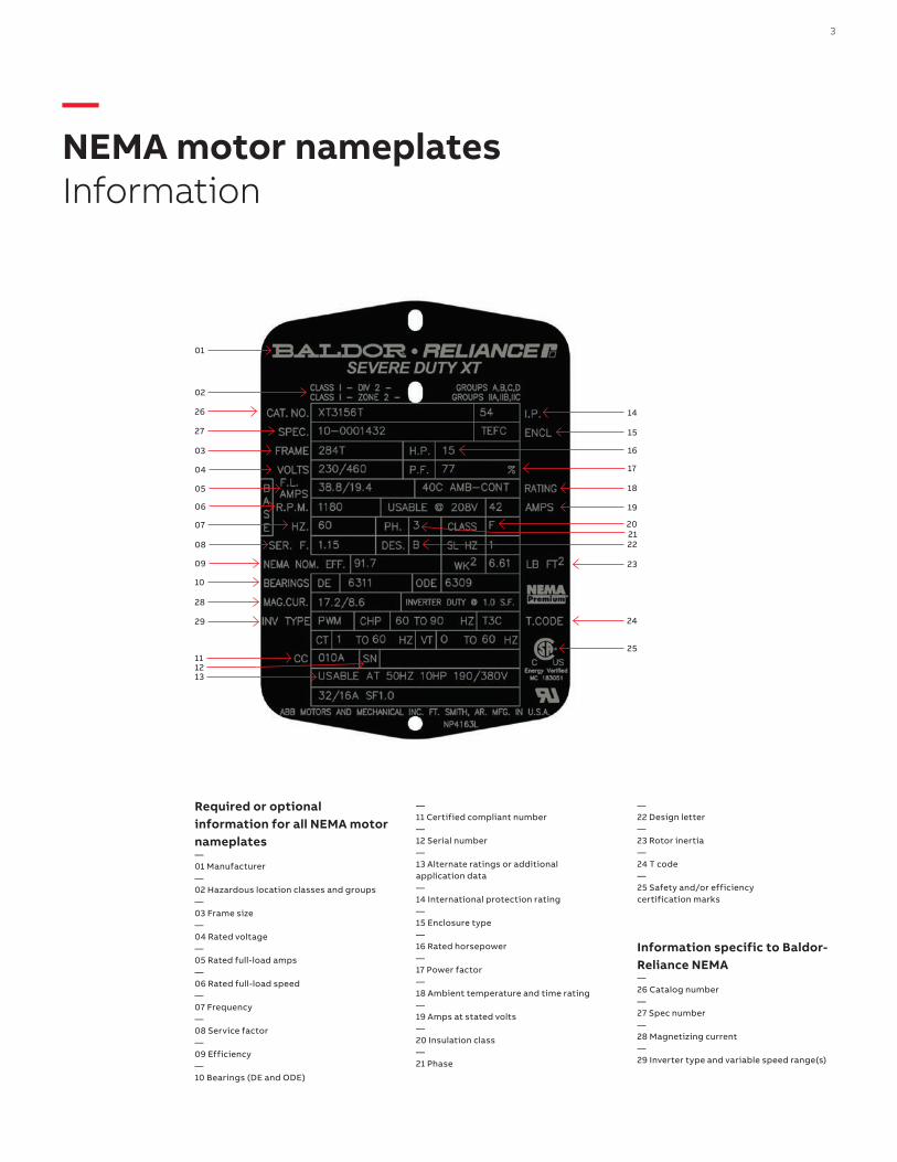
—NEMA motor nameplatesInformation
Required or optional information for all NEMA motor nameplates—01 Manufacturer—02 Hazardous location classes and groups—03 Frame size—04 Rated voltage—05 Rated full-load amps—06 Rated full-load speed—07 Frequency—08 Service factor—09 Efficiency—10 Bearings (DE and ODE)
—11 Certified compliant number—12 Serial number—13 Alternate ratings or additional application data—14 International protection rating—15 Enclosure type—16 Rated horsepower—17 Power factor—18 Ambient temperature and time rating—19 Amps at stated volts—20 Insulation class—21 Phase
—22 Design letter—23 Rotor inertia—24 T code—25 Safety and/or efficiency certification marks
Information specific to Baldor-Reliance NEMA—26 Catalog number—27 Spec number—28 Magnetizing current—29 Inverter type and variable speed range(s)
01
14
15
16
17
18
19
23
24
25
202122
02
26
27
03
04
05
06
07
08
09
10
28
29
111213
4 H OW TO R E A D A N E M A M OTO R N A M E PL ATE
—Nameplate information required or optional for all NEMA motors
01 Manufacturer There is no defined design for this field, and it may differ from one manufacturer to the next. In addition to the name of the manufacturer, it can include the motor model, electrical style or the purpose. Here we have a Baldor-Reliance Severe Duty XT motor.
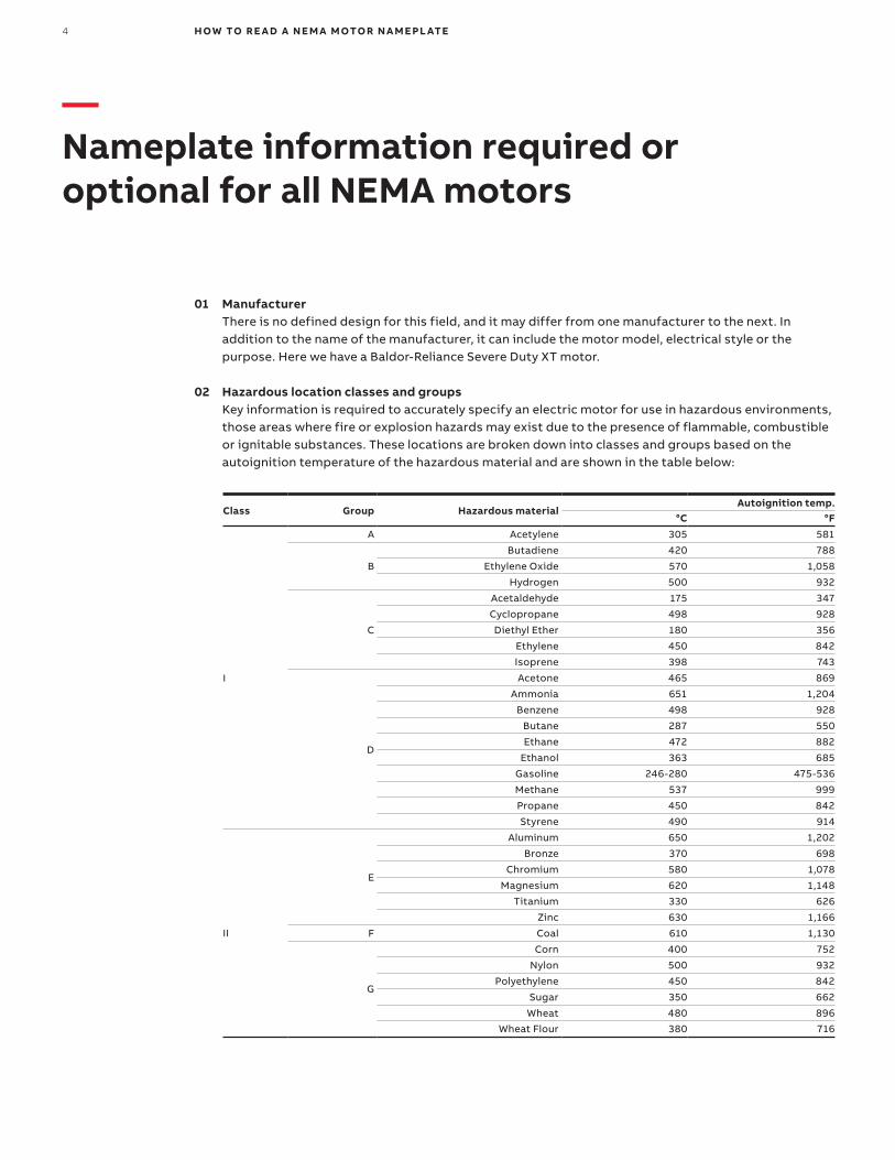
02 Hazardous location classes and groups Key information is required to accurately specify an electric motor for use in hazardous environments, those areas where fire or explosion hazards may exist due to the presence of flammable, combustible or ignitable substances. These locations are broken down into classes and groups based on the autoignition temperature of the hazardous material and are shown in the table below:
Class Group Hazardous materialAutoignition temp.
°C °F
I
A Acetylene 305 581
B
Butadiene 420 788
Ethylene Oxide 570 1,058
Hydrogen 500 932
C
Acetaldehyde 175 347
Cyclopropane 498 928
Diethyl Ether 180 356
Ethylene 450 842
Isoprene 398 743
D
Acetone 465 869
Ammonia 651 1,204
Benzene 498 928
Butane 287 550
Ethane 472 882
Ethanol 363 685
Gasoline 246-280 475-536
Methane 537 999
Propane 450 842
Styrene 490 914
II
E
Aluminum 650 1,202
Bronze 370 698
Chromium 580 1,078
Magnesium 620 1,148
Titanium 330 626
Zinc 630 1,166
F Coal 610 1,130
G
Corn 400 752
Nylon 500 932
Polyethylene 450 842
Sugar 350 662
Wheat 480 896
Wheat Flour 380 716
5
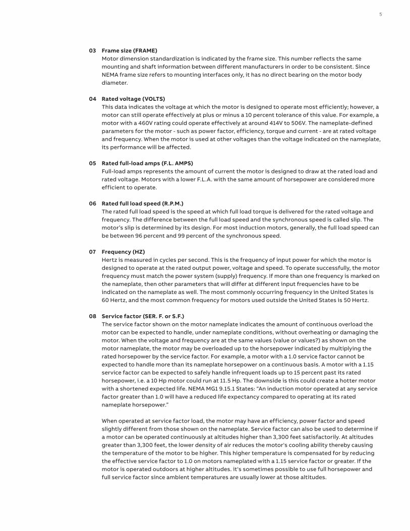
03 Frame size (FRAME) Motor dimension standardization is indicated by the frame size. This number reflects the same mounting and shaft information between different manufacturers in order to be consistent. Since NEMA frame size refers to mounting interfaces only, it has no direct bearing on the motor body diameter.
04 Rated voltage (VOLTS) This data indicates the voltage at which the motor is designed to operate most efficiently; however, a motor can still operate effectively at plus or minus a 10 percent tolerance of this value. For example, a motor with a 460V rating could operate effectively at around 414V to 506V. The nameplate-defined parameters for the motor - such as power factor, efficiency, torque and current - are at rated voltage and frequency. When the motor is used at other voltages than the voltage indicated on the nameplate, its performance will be affected.
05 Rated full-load amps (F.L. AMPS) Full-load amps represents the amount of current the motor is designed to draw at the rated load and rated voltage. Motors with a lower F.L.A. with the same amount of horsepower are considered more efficient to operate.
06 Rated full load speed (R.P.M.) The rated full load speed is the speed at which full load torque is delivered for the rated voltage and frequency. The difference between the full load speed and the synchronous speed is called slip. The motor’s slip is determined by its design. For most induction motors, generally, the full load speed can be between 96 percent and 99 percent of the synchronous speed.
07 Frequency (HZ) Hertz is measured in cycles per second. This is the frequency of input power for which the motor is designed to operate at the rated output power, voltage and speed. To operate successfully, the motor frequency must match the power system (supply) frequency. If more than one frequency is marked on the nameplate, then other parameters that will differ at different input frequencies have to be indicated on the nameplate as well. The most commonly occurring frequency in the United States is 60 Hertz, and the most common frequency for motors used outside the United States is 50 Hertz.
08 Service factor (SER. F. or S.F.) The service factor shown on the motor nameplate indicates the amount of continuous overload the motor can be expected to handle, under nameplate conditions, without overheating or damaging the motor. When the voltage and frequency are at the same values (value or values?) as shown on the motor nameplate, the motor may be overloaded up to the horsepower indicated by multiplying the rated horsepower by the service factor. For example, a motor with a 1.0 service factor cannot be expected to handle more than its nameplate horsepower on a continuous basis. A motor with a 1.15 service factor can be expected to safely handle infrequent loads up to 15 percent past its rated horsepower, i.e. a 10 Hp motor could run at 11.5 Hp. The downside is this could create a hotter motor with a shortened expected life. NEMA MG1 9.15.1 States: “An induction motor operated at any service factor greater than 1.0 will have a reduced life expectancy compared to operating at its rated nameplate horsepower.” When operated at service factor load, the motor may have an efficiency, power factor and speed slightly different from those shown on the nameplate. Service factor can also be used to determine if a motor can be operated continuously at altitudes higher than 3,300 feet satisfactorily. At altitudes greater than 3,300 feet, the lower density of air reduces the motor's cooling ability thereby causing the temperature of the motor to be higher. This higher temperature is compensated for by reducing the effective service factor to 1.0 on motors nameplated with a 1.15 service factor or greater. If the motor is operated outdoors at higher altitudes. it's sometimes possible to use full horsepower and full service factor since ambient temperatures are usually lower at those altitudes.
6 H OW TO R E A D A N E M A M OTO R N A M E PL ATE
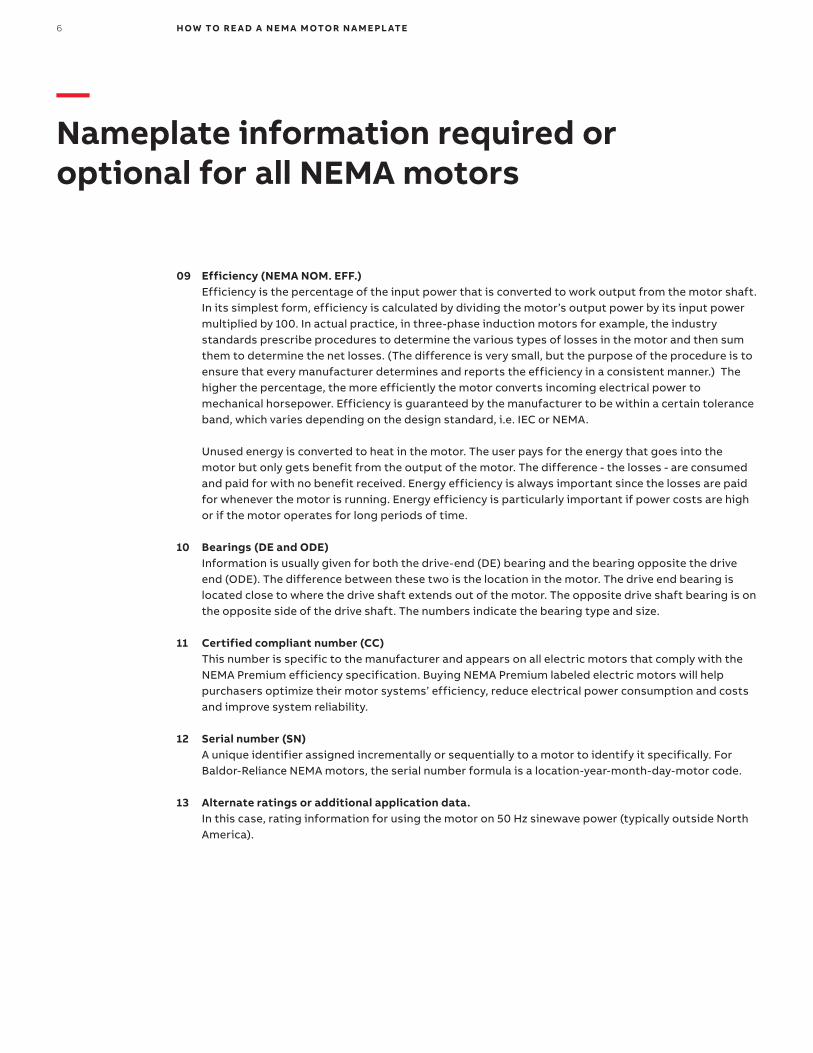
09 Efficiency (NEMA NOM. EFF.) Efficiency is the percentage of the input power that is converted to work output from the motor shaft. In its simplest form, efficiency is calculated by dividing the motor’s output power by its input power multiplied by 100. In actual practice, in three-phase induction motors for example, the industry standards prescribe procedures to determine the various types of losses in the motor and then sum them to determine the net losses. (The difference is very small, but the purpose of the procedure is to ensure that every manufacturer determines and reports the efficiency in a consistent manner.) The higher the percentage, the more efficiently the motor converts incoming electrical power to mechanical horsepower. Efficiency is guaranteed by the manufacturer to be within a certain tolerance band, which varies depending on the design standard, i.e. IEC or NEMA. Unused energy is converted to heat in the motor. The user pays for the energy that goes into the motor but only gets benefit from the output of the motor. The difference - the losses - are consumed and paid for with no benefit received. Energy efficiency is always important since the losses are paid for whenever the motor is running. Energy efficiency is particularly important if power costs are high or if the motor operates for long periods of time.
10 Bearings (DE and ODE) Information is usually given for both the drive-end (DE) bearing and the bearing opposite the drive end (ODE). The difference between these two is the location in the motor. The drive end bearing is located close to where the drive shaft extends out of the motor. The opposite drive shaft bearing is on the opposite side of the drive shaft. The numbers indicate the bearing type and size.
11 Certified compliant number (CC) This number is specific to the manufacturer and appears on all electric motors that comply with the NEMA Premium efficiency specification. Buying NEMA Premium labeled electric motors will help purchasers optimize their motor systems’ efficiency, reduce electrical power consumption and costs and improve system reliability.
12 Serial number (SN) A unique identifier assigned incrementally or sequentially to a motor to identify it specifically. For Baldor-Reliance NEMA motors, the serial number formula is a location-year-month-day-motor code.
13 Alternate ratings or additional application data. In this case, rating information for using the motor on 50 Hz sinewave power (typically outside North America).
—Nameplate information required or optional for all NEMA motors
7
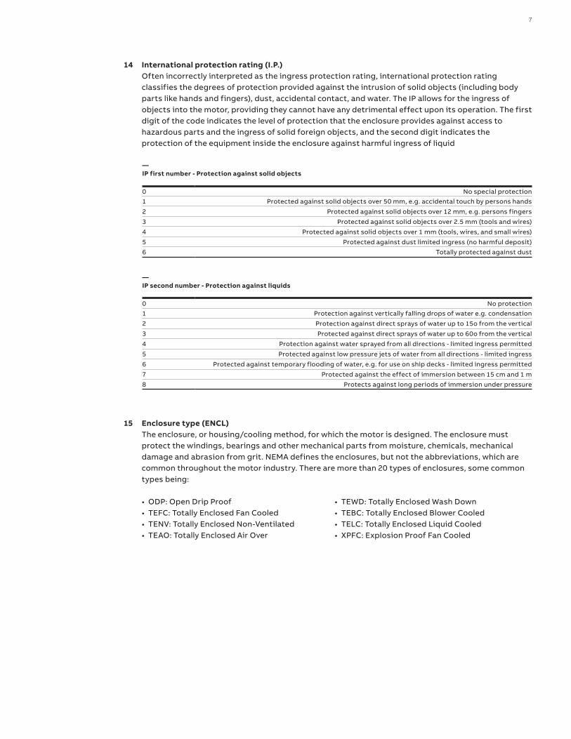
—IP first number - Protection against solid objects
0 No special protection1 Protected against solid objects over 50 mm, e.g. accidental touch by persons hands
2 Protected against solid objects over 12 mm, e.g. persons fingers
3 Protected against solid objects over 2.5 mm (tools and wires)
4 Protected against solid objects over 1 mm (tools, wires, and small wires)
5 Protected against dust limited ingress (no harmful deposit)
6 Totally protected against dust
—IP second number - Protection against liquids
0 No protection1 Protection against vertically falling drops of water e.g. condensation
2 Protection against direct sprays of water up to 15o from the vertical
3 Protected against direct sprays of water up to 60o from the vertical
4 Protection against water sprayed from all directions - limited ingress permitted
5 Protected against low pressure jets of water from all directions - limited ingress
6 Protected against temporary flooding of water, e.g. for use on ship decks - limited ingress permitted
7 Protected against the effect of immersion between 15 cm and 1 m
8 Protects against long periods of immersion under pressure
15 Enclosure type (ENCL) The enclosure, or housing/cooling method, for which the motor is designed. The enclosure must protect the windings, bearings and other mechanical parts from moisture, chemicals, mechanical damage and abrasion from grit. NEMA defines the enclosures, but not the abbreviations, which are common throughout the motor industry. There are more than 20 types of enclosures, some common types being:
• ODP: Open Drip Proof• TEFC: Totally Enclosed Fan Cooled• TENV: Totally Enclosed Non-Ventilated• TEAO: Totally Enclosed Air Over
• TEWD: Totally Enclosed Wash Down• TEBC: Totally Enclosed Blower Cooled• TELC: Totally Enclosed Liquid Cooled• XPFC: Explosion Proof Fan Cooled
14 International protection rating (I.P.) Often incorrectly interpreted as the ingress protection rating, international protection rating classifies the degrees of protection provided against the intrusion of solid objects (including body parts like hands and fingers), dust, accidental contact, and water. The IP allows for the ingress of objects into the motor, providing they cannot have any detrimental effect upon its operation. The first digit of the code indicates the level of protection that the enclosure provides against access to hazardous parts and the ingress of solid foreign objects, and the second digit indicates the protection of the equipment inside the enclosure against harmful ingress of liquid
8 H OW TO R E A D A N E M A M OTO R N A M E PL ATE
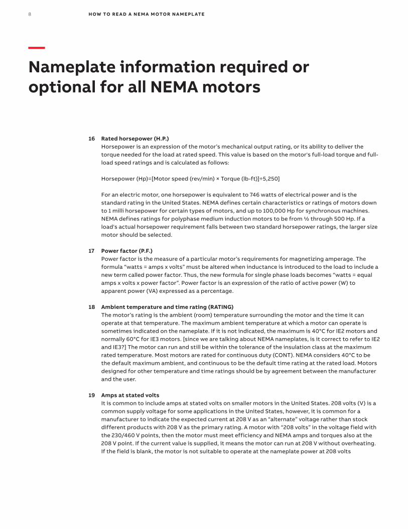
16 Rated horsepower (H.P.) Horsepower is an expression of the motor’s mechanical output rating, or its ability to deliver the torque needed for the load at rated speed. This value is based on the motor's full-load torque and full-load speed ratings and is calculated as follows: Horsepower (Hp)=[Motor speed (rev/min) × Torque (lb-ft)]÷5,250] For an electric motor, one horsepower is equivalent to 746 watts of electrical power and is the standard rating in the United States. NEMA defines certain characteristics or ratings of motors down to 1 milli horsepower for certain types of motors, and up to 100,000 Hp for synchronous machines. NEMA defines ratings for polyphase medium induction motors to be from ½ through 500 Hp. If a load's actual horsepower requirement falls between two standard horsepower ratings, the larger size motor should be selected.
17 Power factor (P.F.) Power factor is the measure of a particular motor’s requirements for magnetizing amperage. The formula “watts = amps x volts” must be altered when inductance is introduced to the load to include a new term called power factor. Thus, the new formula for single phase loads becomes “watts = equal amps x volts x power factor”. Power factor is an expression of the ratio of active power (W) to apparent power (VA) expressed as a percentage.
18 Ambient temperature and time rating (RATING) The motor’s rating is the ambient (room) temperature surrounding the motor and the time it can operate at that temperature. The maximum ambient temperature at which a motor can operate is sometimes indicated on the nameplate. If it is not indicated, the maximum is 40°C for IE2 motors and normally 60°C for IE3 motors. [since we are talking about NEMA nameplates, is it correct to refer to IE2 and IE3?] The motor can run and still be within the tolerance of the insulation class at the maximum rated temperature. Most motors are rated for continuous duty (CONT). NEMA considers 40°C to be the default maximum ambient, and continuous to be the default time rating at the rated load. Motors designed for other temperature and time ratings should be by agreement between the manufacturer and the user.
19 Amps at stated volts It is common to include amps at stated volts on smaller motors in the United States. 208 volts (V) is a common supply voltage for some applications in the United States, however, it is common for a manufacturer to indicate the expected current at 208 V as an “alternate” voltage rather than stock different products with 208 V as the primary rating. A motor with “208 volts” in the voltage field with the 230/460 V points, then the motor must meet efficiency and NEMA amps and torques also at the 208 V point. If the current value is supplied, it means the motor can run at 208 V without overheating. If the field is blank, the motor is not suitable to operate at the nameplate power at 208 volts
—Nameplate information required or optional for all NEMA motors
9
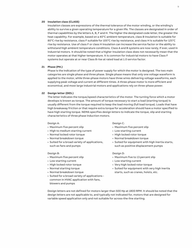
20 Insulation class (CLASS) Insulation classes are expressions of the thermal tolerance of the motor winding, or the winding’s ability to survive a given operating temperature for a given life. The classes are designated in order of thermal capabilities by the letters A, B, F and H. The higher the designated code letter, the greater the heat capability. For example, based on a 40°C ambient temperature, class B insulation is suitable for 80°C rise by resistance, class F suitable for 105°C rise by resistance, and class H is suitable for 125°C rise by resistance. Use of class F or class H insulation can increase the service factor or the ability to withstand high ambient temperature conditions. Class A and B systems are now rarely, if ever, used in industrial motors. It should be noted that a higher insulation class does not necessarily mean that the motor operates at that higher temperature. It is common for industrial motors to have Class F systems but operate at or near Class B rise at rated load at 1.0 service factor.
21 Phase (PH.) Phase is the indication of the type of power supply for which the motor is designed. The two main categories are single phase and three phase. Single phase means that only one voltage waveform is applied to the motor, while three-phase motors have three wires delivering voltage waveforms, each supplying peak voltage and current at different times. A three-phase motor is more efficient and economical, and most large industrial motors and applications rely on three-phase power.
22 Design letter (DES.) The letter indicates the torque/speed characteristics of the motor. The turning force which a motor develops is known as torque. The amount of torque necessary to start a load (starting torque) is usually different from the torque required to keep the load moving (full load torque). Loads that have high breakaway friction or that require extra torque for acceleration should have a motor specified to have high starting torque. NEMA specifies design letters to indicate the torque, slip and starting characteristics of three phase induction motors.
Design A:• Maximum five percent slip• High to medium starting current• Normal locked rotor torque• Normal breakdown torque• Suited for a broad variety of applications,
such as fans and pumps
Design B:• Maximum five percent slip• Low starting current• High locked rotor torque• Normal starting torque• Normal breakdown torque• Suited for a broad variety of applications -
common in HVAC application with fans, blowers and pumps
Design C:• Maximum five percent slip• Low starting current• High locked rotor torque• Normal breakdown torque• Suited for equipment with high inertia starts,
such as positive displacement pumps
Design D:• Maximum five to 13 percent slip• Low starting current• Very high locked rotor torque• Suited for equipment with very high inertia
starts, such as cranes, hoists, etc.
Design letters are not defined for motors larger than 500 Hp at 1800 RPM. It should be noted that the design letters are not applicable to, and typically not indicated for, motors that are designed for variable speed application only and not suitable for across-the-line starting.
10 H OW TO R E A D A N E M A M OTO R N A M E PL ATE
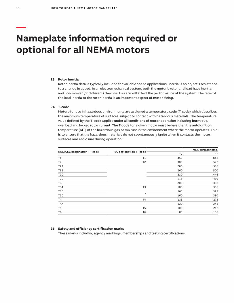
25 Safety and efficiency certification marks These marks including agency markings, memberships and testing certifications
23 Rotor inertia Rotor inertia data is typically included for variable speed applications. Inertia is an object’s resistance to a change in speed. In an electromechanical system, both the motor’s rotor and load have inertia, and how similar (or different) their inertias are will affect the performance of the system. The ratio of the load inertia to the rotor inertia is an important aspect of motor sizing.
24 T-code Motors for use in hazardous environments are assigned a temperature code (T-code) which describes the maximum temperature of surfaces subject to contact with hazardous materials. The temperature value defined by the T-code applies under all conditions of motor operation including burnt out, overload and locked rotor current. The T-code for a given motor must be less than the autoignition temperature (AIT) of the hazardous gas or mixture in the environment where the motor operates. This is to ensure that the hazardous materials do not spontaneously ignite when it contacts the motor surfaces and enclosure during operation.
NEC/CEC designation T – code IEC designation T - codeMax. surface temp.
°C °F
T1 T1 450 842
T2 T2 300 572
T2A
-
280 536
T2B 260 500
T2C 230 446
T2D 215 419
T3 200 392
T3A T3 180 356
T3B-
165 329
T3C 160 320
T4 T4 135 275
T4A - 120 248
T5 T5 100 212
T6 T6 85 185
—Nameplate information required or optional for all NEMA motors
11
—Additional nameplate information that may be found on Baldor-Reliance NEMA motors
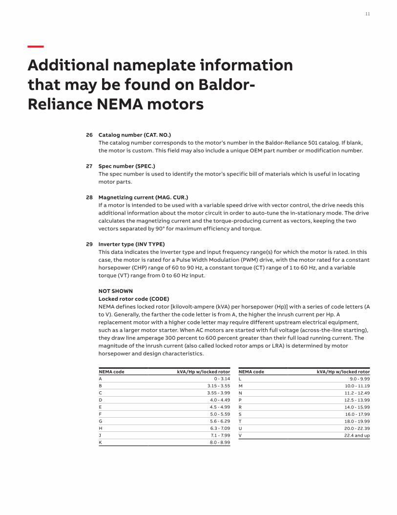
26 Catalog number (CAT. NO.) The catalog number corresponds to the motor’s number in the Baldor-Reliance 501 catalog. If blank, the motor is custom. This field may also include a unique OEM part number or modification number.
27 Spec number (SPEC.) The spec number is used to identify the motor’s specific bill of materials which is useful in locating motor parts.
28 Magnetizing current (MAG. CUR.) If a motor is intended to be used with a variable speed drive with vector control, the drive needs this additional information about the motor circuit in order to auto-tune the in-stationary mode. The drive calculates the magnetizing current and the torque-producing current as vectors, keeping the two vectors separated by 90° for maximum efficiency and torque.
29 Inverter type (INV TYPE) This data indicates the inverter type and input frequency range(s) for which the motor is rated. In this case, the motor is rated for a Pulse Width Modulation (PWM) drive, with the motor rated for a constant horsepower (CHP) range of 60 to 90 Hz, a constant torque (CT) range of 1 to 60 Hz, and a variable torque (VT) range from 0 to 60 Hz input.
NOT SHOWN Locked rotor code (CODE) NEMA defines locked rotor [kilovolt-ampere (kVA) per horsepower (Hp)] with a series of code letters (A to V). Generally, the farther the code letter is from A, the higher the inrush current per Hp. A replacement motor with a higher code letter may require different upstream electrical equipment, such as a larger motor starter. When AC motors are started with full voltage (across-the-line starting), they draw line amperage 300 percent to 600 percent greater than their full load running current. The magnitude of the inrush current (also called locked rotor amps or LRA) is determined by motor horsepower and design characteristics.
NEMA code kVA/Hp w/locked rotorA 0 - 3.14
B 3.15 - 3.55
C 3.55 - 3.99
D 4.0 - 4.49
E 4.5 - 4.99
F 5.0 - 5.59
G 5.6 - 6.29
H 6.3 - 7.09
J 7.1 - 7.99
K 8.0 - 8.99
NEMA code kVA/Hp w/locked rotorL 9.0 - 9.99
M 10.0 - 11.19
N 11.2 - 12.49
P 12.5 - 13.99
R 14.0 - 15.99
S 16.0 - 17.99
T 18.0 - 19.99
U 20.0 - 22.39
V 22.4 and up
—ABB Motors and Mechanical Inc.5711 R.S. Boreham, Jr. StreetFort Smith, AR 72901Ph: 1.479.646.4711
new.abb.com/motors-generators
9A
KK
108
388
07.
2021