Embed Size (px)
Citation preview

m]pmer
Animating soft objects
Brian Wyvill 1, Craig McPheeters 1 and Geoff Wyvill 2
x Department of Computer Science, University of Calgary, 2500 University Drive N.W. Calgary, Alberta, Canada, T2N 1N4
2 Department of Computer Science, University of Otago, Box 56, Dunedin, New Zealand
Soft objects change shape as they move. Specifying such changes is a complicated task which has received little attention in the literature largely because, until re- cently, we had no adequate way to repre- sent such objects. In order to look natural, any animation has to represent possible motion in the physical world. In this sense, the best ani- mation is based on detailed simulation. Fairing in hand animation can be re- garded as a crude attempt to use a few simple rules to do this. Our soft objects are represented by a sur- face constructed around a set of key points. We use both mathematical descrip- tions and physical simulation to determine the motion of the key points and thus achieve convincing animation effects.
Key words: Soft objects - Geometric mo- delli.ng - Computer animation
distinguishing feature of a soft object that its shape changes constantly because Fthe forces imposed on it by its surround- Lgs. There are many examples: a liquid
flows, moulding itself to the surroundings; a boil- ing liquid bubbles; a face changes its expression and a bouncing ball flattens as it strikes the ground. Our research focuses on the problem of describing the animation of soft objects. The motion of a rigid object can be described as a sequence of geometric transformations which are applied uniformly to all the components of the ob- ject. This kind of description has proved very use- ful in engineering and it has been inherited by the discipline of computer animation, but it utterly fails with soft objects. We cannot conveniently sep- arate the gross motion of an object from its chan- ges of shape because some soft objects, liquids for example, actually break into separate parts during their motion. The separate parts can then move independently. The problem centres on the unsui- tability of traditional modelling techniques to de- scribe these objects. We are using a modelling technique introduced in- dependently by Jim Blinn (1982) and Oishi Omura (Nishimura 1985). We represent our soft objects as a surface of constant value in a scalar field. The field value at any point is a function of the distances from the point to members of a set of control points. Each control point has a position, radius, colour and other properties described by the user, and the surface is a smoothly curved enve- lope wrapped around the skeleton described by the control points. Details of our modelling and ren- dering techniques have already been described (Wyvill 1986a) and a revised version of that paper appears as a companion article in this issue of the Visual Computer (Wyvill 1986b). In this paper we discuss the use of this technique for the representation of soft objects in motion, and compare it with traditional modelling meth- ods. We illustrate the discussion with some practi- cal examples and show how some complex motion may be specified. Bill Reeves has used particle systems for modelling explosions and fire (Reeves 1983). Such objects do change shape over time and could be described as " fuzzy" soft objects. However this technique does not lend itself to the decription of non-fuzzy soft objects and we have not pursued it further. The animation described in this paper has all been done using the Graphicsland system at the Univer- sity of Calgary (Wyvill 1985 a). Graphicsland con- sists of a collection of programs for describing ani- mation which pass their output to a common mod-
Computer (1986) 2:235 242 235 The Visual �9 Springer-Verlag 1986
elling program, and a number of rendering pro- grams which may be driven by the modeller.
Building models for animation
It has been pointed out (Thalman 1985) that in the last ten years much research has been devoted to the development of rendering algorithms, but little to the equally difficult task of defining com- plex motion. One of the reasons is the lack of suit- able modelling primitives. In modern animation systems the three most commonly used modelling primitives are: polygon mesh, spline surface patches and quadric surfaces. These techniques are not well suited to represent motion of objects which change shape over time. Polygon meshes are a poor choice for representing curved surfaces anyway. Spline patches, in particu- lar beta splines (Barsky 1982), provide an excellent method for defining curved surfaces. 3D objects consisting of a closed surface may be formed by joining such patches. But moving the object so that it changes shape requires careful management of a large number of control points to ensure that the patches remain as a closed surface and do not penetrate one another. So soft objects may be represented by spline patches as still frames but often lose credibility when motion is attempted (Huitric 1985). Spline surfaces also require the animator to enter a large number of carefully chosen control points to model an object. This can become an immense task for large and complex closed surfaces. Bending could be achieved by moving the spline control points at different velocities and recalculating the spline surface at every frame. Like a spline surface a soft object is also defined by a set of key points. However, unlike a spline surface, the soft object key points from a skeleton of the model which gives a better intuitive idea of the form of the object than can be given by the control points of many spline patches. Our ini- tial experiments indicate that an equivalent model built using the iso-surface technique uses consider- ably fewer control points than are required to de- scribe the same models by patches. This will, how- ever, not be true in all cases. Shape change can be achieved by moving the con- trol points and adjusting the spatial relationship between the points in a controlled manner. Since
soft objects can also change shape, motion specifi- cation for these models becomes more difficult to express than for rigid objects. To some extent this problem is offset, since our representation of these objects guarantees the formation of one or more closed surfaces, no matter how the control points are moved.
The soft object model
A detailed description of our modelling and ren- dering technique is given in the accompanying paper (Wyvill 1986b). Here, we give just enough explanation to allow this paper to be read indepen- dently. A soft object, or collection of objects, is repre- sented by a set of key points specified by the user. Each point has associated with it, a radius R, a colour, a force and possibly other information con- cerning textures. Each key point is considered to be the source of a potential or field value. The value of this field is proportional to the force and decreases as we move away from the key point. The field due to several key points is the sum of the field due to the individual key points. The radi- us R determines the rate at which the field due to the key point decays with distance. R is actually the distance at which the influence of the key point falls to zero. The surface of our objects is defined by the infinite set of points in space for which the field value has some constant value, magic. This surface is guaranteed to be closed because the field is contin- uous. If we move from any point where the field value is greater than magic to a point where it is less, we must pass through a point where the field value is exactly magic. That is to say, we must cross the surface. This property, that the surface is always closed, is very important. The colour at any point on the surface is defined as a weighted sum of the colours of those key points which influence the field at that point. This means that soft objects can exhibit smooth colour changes across their surface. Figures 5a-d show Such a change as objects of different colours merge. We can alter the colour of key points as a function of time to produce special effects. For example, we can make a face blush.
236
omp ter The illusion of animation
In animation we wish to simulate the motion of real objects. This motion control falls roughly into two classes: simulation and illusion. In order to look natural, any animation has to represent possi- ble motion in the physical world. In this sense, the best animation is based on detailed simulation which takes into account the physical laws which govern motion. In such a simulation, a mathemati- cal model representing these laws, produces the desired effect automatically. In many applications, it is not necessary for an animation sequence to follow such a physical model. All that is required is to convince the human eye that the motion is one that would be seen in the real world. Fairing in hand animation can be regarded as a crude at- tempt to use a few simple rules to do this. Such techniques attempt to model the visual effect we refer to in this paper as illusion. In a sense, any approximation, however crude, can be thought of as simulation. Rather than invent new jargon, we use the term simulation in this paper to refer to an accurate physical model as opposed to illusion, where no attempt is made to understand the rele- vant physical laws, merely to produce a recogn- isable visual effect. So far, our experiments indicate that soft objects provide a very powerful way to represent both of these classes of animation.
Keyframe interpolation
In hand animation an animator draws a character in some position, makes a second drawing of the character in a new position and then fills in the inbetween frames. The digital version of this tech- nique that has been used extensively to represent complex motion in 2D animation is generally known as "inbetweening". Technical difficulties, such as shape distortion and even loss of surface continuity, not to mention the expense of computa- tion, encountered in this process are due primarily to the way in which the animated objects have been modelled. Soft objects remove, or at least mit- igate, these problems. Moreover, soft objects are amenable to various techniques of inbetweening (see the discussion of parametric and key point interpolatJLon, below). Best of all, they present a simpler model for the animator to work with. A simple form of inbetweening, suitable for two- dimensional (cartoon) models, would have the
character drawn on a vector oriented display in two positions, and the inbetween frames interpo- lated by the system. The simplest way to do this is to interpolate each point of the first (source) object to a corresponding point on the second (des- tination) object. Difficulties arise if the number of points is different on source and destination ob- jects. New points have to be created or several points have to collapse onto a single point. Even if the number of points is the same on the two objects, if they are distributed in a different way the image will be scrambled as each point is inter- polated. Inbetweening is not only used to show motion of a character from one position to another, it can also be used to show metamorphosis from one character to another. If the characters are very dif- ferent in shape and number of key points, then the scrambling problem is difficult to avoid. Peter Foldes uses software by Burtnyk and Wein (Burt- nyk and Wein 1976) in the film, "La Fa im" and exploits this technique to advantage. However to avoid scrambling is a difficult and tedious task which requires very careful design of the key points for inbetweening. For inbetweening in 3D, two methods of solving these problems have been tried. Both solutions re- quire the definition of a set of keyframes, with the objects in their correct orientations. The first method uses interpolation of a set of keys which are defined for each object. The interpola- tion usually works on the geometric transforma- tions, or the parameters of a parameterized model. Examples of this type of system would be BBOP or EM, both developed at the NYIT Graphics Laboratory (Sturman 84). More elaborate control of the motion is discussed in (Stekette 1985). This system guarantees continuous acceleration while still having local control of key points, and the ability to join motions. Most of the techniques offer the user different methods of interpolation, including linear, cubic, and cosine. The second method uses interpolation of the actual objects. A set of key points are defined either by the artist or by the system, and these key points are interpolated. Theoretically, systems for doing inbetweening of this type in 2D can be extended to 3D, although this may often be impractical. The technique of using moving point constraints (Reeves 1981) may be unsuitable only because of the difficulty of specifying a natural user interface into the system, which would now extend over four
237
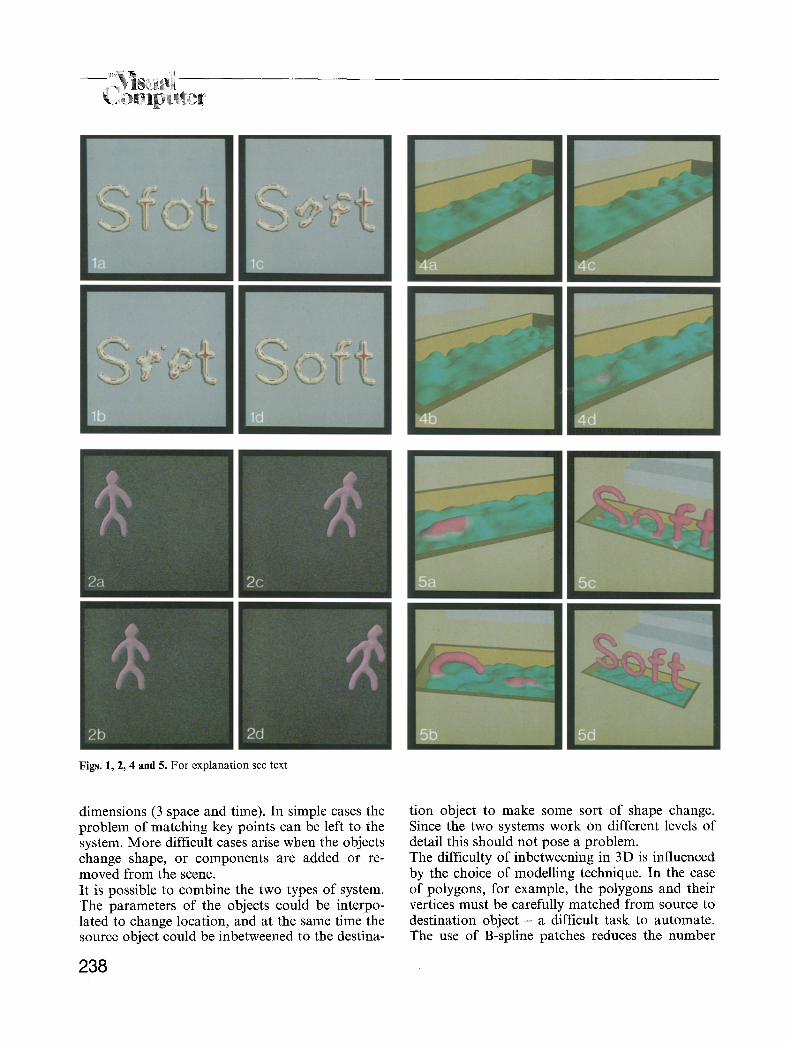
Figs. 1, 2, 4 and 5. For explanation see text
dimensions (3 space and time). In simple cases the problem of matching key points can be left to the system. More difficult cases arise when the objects change shape, or components are added or re- moved from the scene. It is possible to combine the two types of system. The parameters of the objects could be interpo- lated to change location, and at the same time the source object could be inbetweened to the destina-
238
tion object to make some sort of shape change. Since the two systems work on different levels of detail this should not pose a problem. The difficulty of inbetweening in 3D is influenced by the choice of modelling technique. In the case of polygons, for example, the polygons and their vertices must be carefully matched from source to destination object - a difficult task to automate. The use of B-spline patches reduces the number
of points that have to be inbetweened, but to man- ufacture a complex object would require many patches, and maintaining a closed surface demands the management of complicated constraints on the inbetween positions of the patch control points. With the soft object technique, however, a continu- ous closed surface is guaranteed; some kind of closed volume will be produced whatever the shape of the object in the inbetween stage. This will al- ways produce a more desirable result than allowing the obje, cts to collapse incoherently. Soft objects require the user to provide comparati- vely few control points compared with other mod- elling methods. When using keyframe animation the animator has a much better intuitive feel for what is going to happen and how to alter the mo- tion since in a very real sense the key points form a skeleton of the 3D surface. Figures 1 a-d show the letters of the word "Sfot" in various inbetween stages, changing to the word "Soft". The number of key points differs by one between the O and the F, and a sphere representing that key point moves from one letter to the other. The texture is mapped onto the surface using a method dis- cussed in (Wyvill 1986c).
Physical simulation
The example of the bubbling bath (described be- low) and the use of techniques such as inbetween- ing and fairing are very crude methods which create a visual illusion of a desired motion avoiding the calculation necessary for an accurate physical simulation. Soft objects are also useful for model- ling more accurate simulations of processes. Figures 7a-d show the word "Soft" in various stages of a fall. The object reaches the ground, compresses and bounces back up again. In this simulation it is assumed that the object is made from some elastic substance that will deform when a force is applied to it, by an amount specified by some characteristic constant of the material (Young's Modulus). The object gains kinetic ener- gy in the fall under gravity and this is used to deform the object which stores the energy and re- leases it as it bounces back up again. Some of the energy is lost (producing heat) and the second and subsequent bounces gradually damp out the mo- tion. In the example the object is compressed but does not flatten. That is, the local shape of the bottom
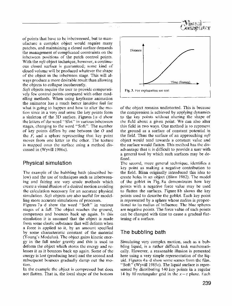
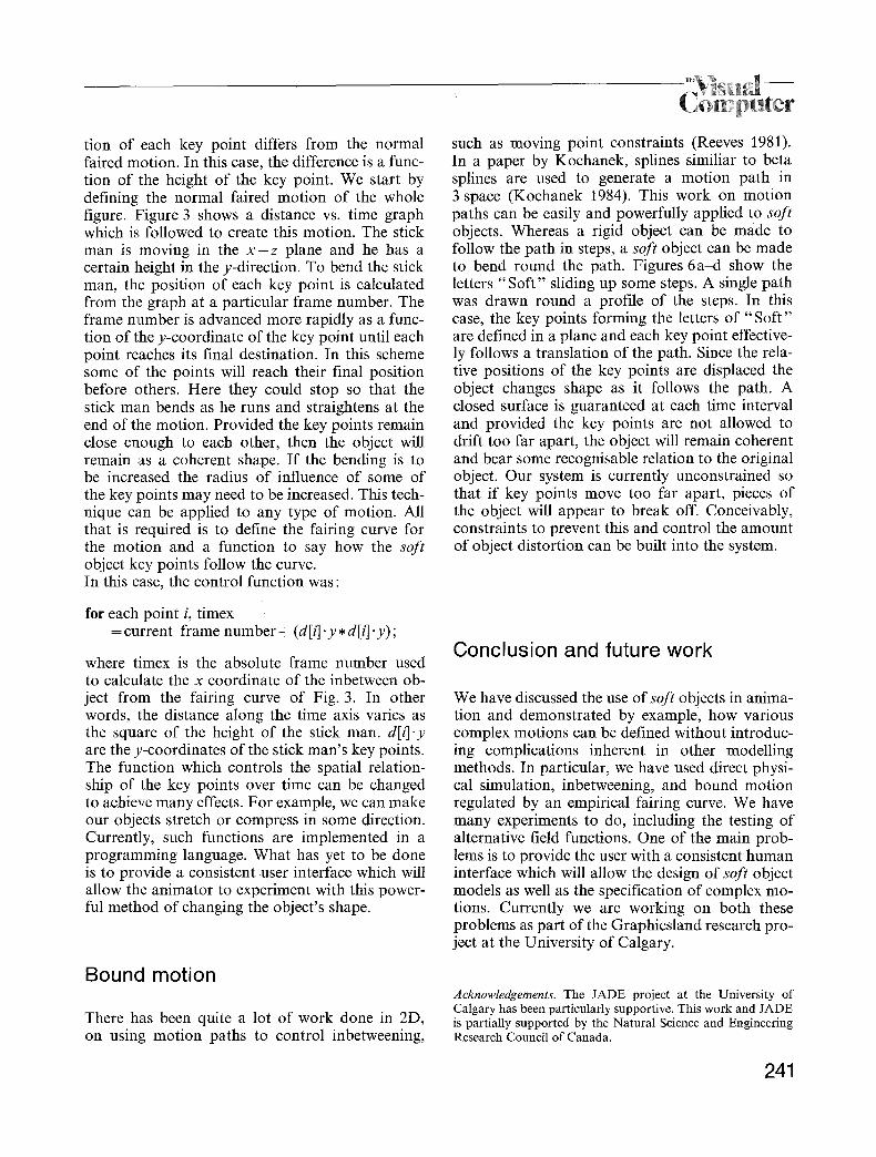
Distance
Fig. 3. For explanation see text
of the object remains undistorted. This is because the compression is achieved by applying dynamics to the key points without altering the shape of the field about a given point. We can also alter this field in two ways. One method is to represent the ground as a surface of constant potential in the field. Thus the surface of an approaching soft object would tend towards a constant value and the surface would flatten. This method has the dis- advantage that it is difficult to provide a user with a general tool by which such surfaces may be de- fined. The second, more general technique, identifies a key point as making a negative contribution to the field. Blinn originally introduced this idea to create holes in an object (Blinn 1982). The model of the goblet in Fig. 8a demonstrates how key points with a negative force value may be used to flatten the surfaces. Figure 8b shows the key points used to describe the goblet. Each key point is represented by a sphere whose radius is propor- tional to its radius of influence. The blue spheres are negative points. The force value of such points can be changed with time to cause a gradual flat- tening of a surface.
The bubbling bath
Simulating very complex motion, such as a bub- bling liquid, is a rather difficult task mathemati- cally. However, a reasonable illusion is presented here using a very simple representation of the liq- uid. Figures 4a-d show some scenes from the film, "Soft" (Wyvill 1985c). The liquid surface is repre- sented by distributing 140 key points in a regular 14 by 10 rectangular grid in the x - z plane. Each
239

mpute
Figs. 6--8. For explanation see text
240
key point is moved in the positive y-direction to some maximum height, H, in F frames. The height increments follow a sine curve and thus the key point returns to its original position. New values of F and H are chosen at random within certain limits and the cycle repeated. To add to the ran- dom nature of the surface each key point was cho- sen with a different radius, again within certain limits. In the film " S o f t " (Wyvill 1985c), the con- straints on H were such that it was a rare event for a key point to rise more than the radius, R, above the surface. The minimum value of R was chosen so that holes did not form in the surface. The net effect was of a very mobile surface which always remained closed. An occasional bubble would break the surface and fall back again. The following information was stored for each key point:
Current Position, xyz Maximum Height for this cycle, H Radius Force Number of frames to reach maximum height, F Current Frame.
The liquid is contained within a box of height BOXY. At the end of each cycle, F and H were recalculated using:
H = meanrand (0.7 �9 BOXY); F = meanrand (TIME);
TIME was set to one second (24 frames). Mean- rand (j) returns a random number from a normal distribution with mean =j/2 standard deviation = mean/2.
Controlling shape change
Soft objects provide a means of exploring com- bined motion and shape change which has not been practical with other modelling techniques. When animating soft objects, a change of shape will occur if the spatial relationship between key points is altered at any frame. To obtain a controlled chan- ge of shape, an object can be moved and the rela- tionship of the key points altered as a function of time. For example, Figs. 2 a-d show a stick man as he moves between two fixed points. To make him appear to bend forward as he moves, the m o -
ompt er
tion of each key point differs from the normal faired motion. In this case, the difference is a func- tion of the height of the k e y point. We start by defining the normal faired motion of the whole figure. ]Figure 3 shows a distance vs. time graph which is; followed to create this motion. The stick man is moving in the x - z plane and he has a certain height in the y-direction. To bend the stick man, the position of each key point is calculated from the graph at a particular frame number. The frame number is advanced more rapidly as a func- tion of the y-coordinate of the key point until each point reaches its final destination. In this scheme some of' the points will reach their final position before others. Here they could stop so that the stick man bends as he runs and straightens at the end of the motion. Provided the key points remain close enough to each other, then the object will remain as a coherent shape. If the bending is to be increased the radius of influence of some of the key points may need to be increased. This tech- nique can be applied to any type of motion. All that is required is to define the fairing curve for the motion and a function to say how the soft object key points follow the curve. In this case, the control function was:
such as moving point constraints (Reeves 1981). In a paper by Kochanek, splines similiar to beta splines are used to generate a motion path in 3 space (Kochanek 1984). This work on motion paths can be easily and powerfully applied to soft objects. Whereas a rigid object can be made to follow the path in steps, a soft object can be made to bend round the path. Figures 6a -d show the letters "Sof t " sliding up some steps. A single path was drawn round a profile of the steps. In this case, the key points forming the letters of "Sof t " are defined in a plane and each key point effective- ly follows a translation of the path. Since the rela- tive positions of the key points are displaced the object changes shape as it follows the path. A closed surface is guaranteed at each time interval and provided the key points are not allowed to drift too far apart, the object will remain coherent and bear some recognisable relation to the original object. Our system is currently unconstrained so that if key points move too far apart, pieces of the object will appear to break off. Conceivably, constraints to prevent this and control the amount of object distortion can be built into the system.
for each point i, timex = current frame number + (d[i] .y �9 d[t] .y);
where timex is the absolute frame number used to calculate the x coordinate of the inbetween ob- ject from the fairing curve of Fig. 3. In other words, the distance along the time axis varies as the square of the height of the stick man. d[i] .y are the y-coordinates of the stick man's key points. The function which controls the spatial relation- ship of the key points over time can be changed to achieve many effects. For example, we can make our objects stretch or compress in some direction. Currently, such functions are implemented in a programming language. What has yet to be done is to provide a consistent user interface which will allow the animator to experiment with this power- ful method of changing the object's shape.
Conclusion and future work
We have discussed the use of soft objects in anima- tion and demonstrated by example, how various complex motions can be defined without introduc- ing complications inherent in other modelling methods. In particular, we have used direct physi- cal simulation, inbetweening, and bound motion regulated by an empirical fairing curve. We have many experiments to do, including the testing of alternative field functions. One of the main prob- lems is to provide the user with a consistent human interface which will allow the design of soft object models as well as the specification of complex mo- tions. Currently we are working on both these problems as part of the Graphicsland research pro- ject at the University of Calgary.
Bound motion
There has been quite a lot of work done in 2D, on using motion paths to control inbetweening,
Acknowledgements. The JADE project at the University of Calgary has been particularly supportive. This work and JADE is partially supported by the Natural Science and Engineering Research Council of Canada.
241
References
Barsky B, Beatty J (1982) Varying the Betas in Beta Splines. TR-82-49. Department of Computer Science, University of Waterloo, Ontario
Blinn J (1982) A Generalization of Algebraic Surface Drawing. ACM Trans Graph 1 : 235-256
Burtnyk N, Wein M (1976) Interactive Skeleton Techniques for Enhancing Motion Dynamics in Key Frame Animation. CACM 19(10):564-569
Fournier A, Fussel D, Carpenter L (1982) Computer Rendering of Stochastic Models. CACM 25 (6): 371-384
Gardner G (1985) Visual Simulation of Clouds. SIGGRAPH 85 Comput Graph 19(32):297-303
Huitric H, Nahas M (1985) B-Spline Surfaces: A Tool for Com- puter Painting. IEEE Comput Graph Appl 5 (3) : 39-47
Kochanek D (1984) Interpolating Splines with Local Tension, Continuity and Bias Control. SIGGRAPH 84 Comput Graph 18:33~41
Mandelbrot B (1983) The Fractal Geometry of Nature W.H. Freeman and Company
Perlin K (1985) An Image Synthesizer. SIGGRAPH 85 Comput Graph 19:287-296
Reeves W (1981) Inbetweening for Computer Animation Utiliz- ing Moving Point Constraints. SIGGRAPH 81 Comput Graph 2 : 263-269
Reeves W (1983) Particle Systems A Technique for Modeling a Class of Fuzzy Objects. ACM Trans Graph 2 : 91-108
Steketee S, Badler N (1985) Parametric Keyframe Interpolation Incorporating Kinetic Adjustment and Phrasing Control. SIGGRAPH 85 Comput Graph 19(3):255-262
Sturman D (1984) Interactive Keyframe Animation of 3-D Ar- ticulated Models. Proc Graph Interface, pp 35-40
Thalman N, Thalman D (1985) Three Dimensional Computer Animation: More an Evolution Than a Motion Problem. IEEE Comput Graph Appl 5 (10) :47-57
Wyvill BLM, McPheeters C, Garbutt R (1985a) A Practical 3D Computer Animation System. The BKSTS Journal (British Kinematograph Sound and Television Society) 67 (6):328-332
Wyvill BLM, McPheeters C, Novacek M (1985b) Specifying Stochastic Objects in a Hierarchical Graphics System. Proc Graph Interface 85, Montreal, pp 17-20
Wyvill BLM, Wyvill G, McPheeters C, Jevans D (1985c) Soft A 90 second animated film. University of Calgary, Depart- ment of Computer Science
Wyvill G, Wyvill B, McPheeters C (1986a) Soft Objects. Ad- vanced Computer Graphics, Proc CG Tokyo 1986, pp 113- 128
Wyvill G, McPheeters C, Wyvill BLM (1986b) Data Structure for Soft Objects. The Visual Computer 2(4):227-234
Wyvill G, Wyvill B, McPheeters C (in preparation) Texturing Soft Objects. University of Otago, Department of Computer Science
242