Embed Size (px)
Citation preview

European Regional Development
Fund
www.italy-croatia.eu/metro
WP 5 / Act. 5.3
ANALYSES OF RO-RO PASSENGER AND CROSS BORDER ROUTES
Prepared by:
Faculty of Maritime Studies, University of Rijeka
Istrian Development Agency – IDA ltd.

1
2021 Contents
1 INTRODUCTION ........................................................................................................................................................ 1
2 NAVIGATION ROUTES AND TYPICAL VESSELS .................................................................................................. 3
2.1 NAVIGATION ROUTES - BRESTOVA-POROZINA AREA ......................................................................................... 3
2.2 NAVIGATION ROUTES - SPLIT-ANCONA AREA ................................................................................................... 7
2.3 TYPICAL VESSELS .......................................................................................................................................... 9
2.3.1 Passenger ships .......................................................................................................................... 9
2.3.2 Container ships ......................................................................................................................... 19
2.3.3 Dry cargo ships ......................................................................................................................... 21
2.3.4 Tankers ..................................................................................................................................... 26
2.3.5 Fishing vessels .......................................................................................................................... 30
3 NAVIGATIONAL RISK ANALYSIS .......................................................................................................................... 32
3.1 VELA VRATA ............................................................................................................................................... 33
3.2 SPLITSKA VRATA ......................................................................................................................................... 42
3.3 DRVENIČKI CHANNEL ................................................................................................................................... 49
4 BWM OPTIONS FOR SHIPS AND PORTS ............................................................................................................. 56
4.1 BWM CONVENTION REQUIREMENTS ............................................................................................................. 57
4.2 BWM TECHNOLOGIES ................................................................................................................................. 58
4.3 THE LEGAL AND ORGANIZATIONAL FRAMEWORK ............................................................................................ 61
4.4 PORT BW COLLECTION AND TREATMENT METHODS ....................................................................................... 64
4.4.1 Land-based reception system ................................................................................................... 65
4.4.2 Barge-based reception system ................................................................................................. 66
4.4.3 Mobile land-based reception system ......................................................................................... 66
4.5 TECHNICAL AND ECONOMIC APPRAISAL OF BW RECEPTION FACILITIES ............................................................ 68
4.6 ROUTES AND SHIPS ..................................................................................................................................... 69
4.6.1 Brestova – Porozina .................................................................................................................. 69
4.6.2 Split – Ancona ........................................................................................................................... 73

2
5 IMPLEMENTATION OF A PILOT STUDY IN THE REGION OF ISTRIA ................................................................ 78
6 CONCLUSIONS ....................................................................................................................................................... 83
7 BIBLIOGRAPHY ...................................................................................................................................................... 86

European Regional Development
Fund
1 www.italy-croatia.eu/acronym
1 INTRODUCTION
This report presents activities carried out as a part of Work Package 5, Activity 5.3.
The main goal of the activities carried out is to provide data needed for the detailed analysis of the respective
ro-pax ships routes, which includes:
− navigational routes (principal, alternative) and traffic patterns of the area under considerations including individual ro-pax routes as well as all other vessels’ routes in the same navigational area;
− ships navigating in the area including their usual features, dimensions, manoeuvring capabilities and destinations;
− risk analysis, i.e. the assessment of collision and grounding risks for restricted waterways including passages Vela Vrata Strait, Splitska Vrata Strait and Drvenički Channel;
− ballast water management options for planned future ro-pax ships in line and ports (Brestova, Porozina, Split and Ancona) to comply with the International Convention for the Control and Management of Ships' Ballast Water and Sediments.
Activities carried out, as well as this Report, are based on the following assumptions:
− a legal framework regulating the safety of navigation and pollution prevention, both national (Croatia and Italy) and international, is assumed as it is at the time of the Report delivery;
− ships considered in this Report comply with the requirements set forth by the provisions of the International Convention for the Safety of Life at Sea, 1974 (SOLAS 74), the International Convention for the Prevention of Pollution from Ships 1973/78 (MARPOL 73/78), the International Convention on Load Lines, 1966 (LOADLINE 1966), the International Convention on Tonnage Measurements of Ships, 1969 (TONNAGE 1969), as amended, or as required by the relevant and applicable technical rules of the recognized organizations;
− characteristics of yachts, boats and ships that are not subject to international conventions comply with requirements prescribed by the maritime administrations of the respective flag states;
− ships' masters and crew meet the standards prescribed by the International Convention on Standards of Training, Certification and Watchkeeping for Seafarers, as amended, as well as provisions of the International Safety Management Code, as defined in Chapter IX of the SOLAS Convention;
− actions of the master and crew of ships, yachts and boats are reasonable and are carried out as a prudent seafarer would act; behaviour that significantly contradicts the rules of the profession or that is aimed at harming people or causing damage to the environment or property is not the subject matter of this Report;
− ships, yachts and boats use the typical traffic routes; the use of other waterways, which ships, yachts and boats, depending on their size or own characteristics, do not use or use only on an exceptional basis, are not considered;
− communication devices used by ships, yachts and boats, and other means of surveillance and data collecting correspond with the nominal effective range and required reliability.

2
Also, one of the activity within work package 5 was the implementation of the pilot study in Region of Istria which
is described in this Report.
The Report assumes working, management and technological presumptions of relevant and valid instruments
and recommendations of the International Maritime Organization and other international bodies regulating
marine safety and environmental protection.
The Report does not consider internal procedures or instructions that maritime companies or other legal subjects
participating in the maritime traffic may prescribe to their employees.
The Report is mainly based on the most recent data available whenever possible or appropriate. Older sources
are used in cases where there is a lack of data. When deciding between more reliable or more current sources,
priority is given to sources of higher reliability.
This Report is written as it is common in the relevant sciences and according to expert knowledge of maritime
traffic technology.
3
2 NAVIGATION ROUTES AND TYPICAL VESSELS
The navigation routes in Brestova-Porozina and approach to the port of Split differ in the type of maritime traffic
and complexity. The types and distribution of the ships in the observed areas vary as well. The ro-ro passenger
ships on the Brestova-Porozina line in Vela Vrata encounter ships sailing almost perpendicularly and within a
relatively small sea area in a somewhat similar manner. On the other hand, ro-ro passenger ships approaching
the port of Split encounter much diverse traffic; however, ships encountered are mostly smaller cargo ships than
those commonly encountered in the Vela Vrata Strait.
2.1 Navigation routes - Brestova-Porozina area
The port of Brestova lies on the eastern coast of Istria, facing the port of Porozina on the opposite north-western
coast of the island of Cres. Both ports are situated in the Vela Vrata Strait, the central part of the waterway
connecting Kvarner Bay and the Bay of Rijeka. Kvarner Bay is an area between Istra and islands Cres and
Lošinj; it extends from Vela Vrata towards the high seas. It is bounded by the coast of Istria and the west coasts
of Cres, Unije, Lošinj and Ilovik islands. The Vela Vrata Strait is 2.3 M to 2.8 M wide and 5.5 M long, with depths
ranging from 55 to 65 meters.
A mandatory Traffic Separation Scheme (TSS) for vessels longer than 20 m has been established in the Vela
Vrata Strait. The inbound traffic to the Bay of Rijeka follows the NE direction, i.e. the traffic lane close to the
island Cres. The outbound traffic from the Bay of Rijeka follows the SW direction and the TSS west lane.
Passage time between the ports is approximately 30 min, with courses almost perpendicular to the main axe of
the TSS.
The main navigation route to and from the Bay of Rijeka is laid through Kvarner Bay. Another route is through
Kvarnerić and the Srednja Vrata Strait, between Krk and Cres. Ships entering the Bay of Rijeka may sail to the
ports of Rijeka and Sušak, the container terminal Brajdica, shipyard "3. Maj", repair shipyard "Viktor Lenac",
Bakar Bay (with INA Urinj terminal, LPG port of Sršćica and bulk cargo terminal Podbok), Omišalj oil and LNG
terminals on the island of Krk and to a lesser extent the passenger port of Opatija.
At the entrance to the Bay of Rijeka, north of the TSS, vessels sailing from the Bay of Rijeka ports cross the
routes of vessels sailing to the Bay of Rijeka ports. The second encountering area is in the central part of the
Bay of Rijeka, where vessels arriving through the Vela Vrata Strait and sailing to the Bay of Bakar or Omišalj
cross with vessels heading through Srednja Vrata and sailing to Rijeka and Opatija.
4
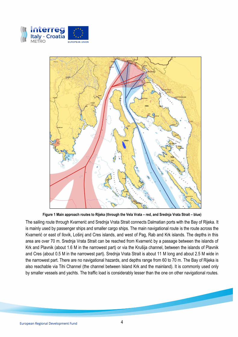
Figure 1 Main approach routes to Rijeka (through the Vela Vrata – red, and Srednja Vrata Strait – blue)
The sailing route through Kvarnerić and Srednja Vrata Strait connects Dalmatian ports with the Bay of Rijeka. It
is mainly used by passenger ships and smaller cargo ships. The main navigational route is the route across the
Kvarnerić or east of Ilovik, Lošinj and Cres islands, and west of Pag, Rab and Krk islands. The depths in this
area are over 70 m. Srednja Vrata Strait can be reached from Kvarnerić by a passage between the islands of
Krk and Plavnik (about 1.6 M in the narrowest part) or via the Krušija channel, between the islands of Plavnik
and Cres (about 0.5 M in the narrowest part). Srednja Vrata Strait is about 11 M long and about 2.5 M wide in
the narrowest part. There are no navigational hazards, and depths range from 60 to 70 m. The Bay of Rijeka is
also reachable via Tihi Channel (the channel between Island Krk and the mainland). It is commonly used only
by smaller vessels and yachts. The traffic load is considerably lesser than the one on other navigational routes.

5
Traffic density based on the AIS equipment is presented in Figure 2. The main traffic routes and highest densities
are clearly in the TSS area. The coastal route for vessels not using the TSS along the north-eastern coast of
Cres is recognizable.
Figure 2 Traffic density in Vela Vrata Strait and approaches
The total traffic density of main routes in Vela Vrata Strait is dominantly concentrated in inbound and outbound
TSS lanes, with somewhat sparser distribution outside the TSS lanes. The traffic between the lanes is mainly
the result of fishing vessels and pleasure crafts sailing in the area. The crossing of the ro-ro passenger ships
line is recognizable in Vela Vrata as well. Furthermore, some traffic is directed to and out of Plomin, located
south of Vela Vrata Strait.

6
Figure 3 Cargo ship (left) and passenger ship (right) yearly traffic densities in Vela Vrata
Regarding traffic categories in Vela Vrata Strait, cargo ships routes are located mainly in the centre of the TSS
lanes with lesser densities towards lane edges. Passenger ships passing the TSS, mostly high-speed passenger
ships, are distributed more sparsely than cargo ships. The passenger ship TSS approach routes are less
compact than cargo ships as well. Furthermore, smaller vessels use mainly a near-coastal area close to the
north-eastern coast of Cres island.
Figure 4 Fishing vessel (left) and pleasure craft (right) yearly traffic densities in Vela Vrata
The highest density of fishing ship positions is on the north-eastern coast, mainly along the island of Cres and
from and to the port of Plomin. In addition, there are some diagonal TSS crossings and uniform traffic in Vela

7
Vrata, indicating fishing activities. Pleasure craft routes are more diverse and non-uniform, with slightly larger
densities approximately in TSS lanes and coastal area of the north-eastern coast of Cres. Generally, the
pleasure craft routes from and to the Vela Vrata Strait are also somewhat comparable to passenger ship routes.
However, routes are more spread out with occasional crossings.
2.2 Navigation routes - Split-Ancona area
The main navigation routes from and to the port of Split connect the port of Split with the main transit route along
the Adriatic Sea, i.e. the route connecting Otranto Strait with northern Adriatic ports. The main transit route
generally passes between two islands, Palagruža and Pianosa, and Cape Gargano. A small part of the
international transit traffic proceeds around the island of Vis.
Besides the main Adriatic transit route, the second principal international route connects the ports of Split and
Ancona. Among other international and national routes, there are also those connecting the port of Split with
other ports of the eastern Adriatic coast.
The most important local routes connect the Split port with nearby islands (Brač, Šolta, Drvenik, Hvar, Vis and
Korčula). The busiest coastal waterways of the Splitsko-dalmatinska County is the access route to the port of
Split.
The port of Split is situated in the Central Adriatic and is the largest port of the Dalmatia region. Due to the deep
indentation into the nearby islands area, passage to the port is provided via coastal waterways through Drvenički,
Šoltanski and Brački channels and Splitska Vrata Strait. The Splitska Vrata Strait is the shortest waterway to the
port of Split from the high sea. The Strait is approximately 2 M long, situated between the islands of Šolta and
Brač. The approach to the port of Split, via the Hvarski and Brački channels (55 M), is the longest waterway from
the open sea and is consequently rarely used.
The Splitska Vrata Strait is the busiest and the narrowest part of the approach waterway to the port of Split. The
available width of the waterway is only 0.3 M in the narrowest part.
Drvenički Channel is about 0.5 M wide in the narrowest part. The most extended segment is from 0.5 to 1 M
wide. Sailing through this channel requires additional attention due to the transverse traffic of ships heading from
Trogir Bay and the city of Trogir to the high seas, that is, other ports of the eastern Adriatic coast, especially
during the tourist season. There is also a local ro-ro passenger line between Trogir and Drvenik Veli and Drvenik
Mali islands.

8
Figure 5 Traffic density with Split-Ancona (red route) and Split-Starigrad-Ancona (blue route) with navigation zones
Drvenički Channel is the main route for ships with dangerous cargo to and from the port of Split. For ships
carrying hazardous liquid chemicals or gases, coastal piloting is mandatory. The channel is well marked with
several lighthouses and coastal lights. However, given the configuration of the coastline and the number of
islands, sailing through the area still requires particular attention.
Figure 6 Cargo (left) and tanker ship (right) traffic from and to the port of Split
Cargo ships may use all approaches from and to the port of Split. The focus area of all these approaches is in
front of the Gradska luka Split. The traffic density is higher in Splitska Vrata Strait compared to Drvenički and
Šoltanski channels. Furthermore, there is some cargo ship traffic between the islands of Brač and Vis. When
considering tankers, the highest traffic density is in the Drvenički Channel. There is also some traffic through

9
Splitska Vrata Strait. At the same time, some tanker traffic is also directed along the southern coasts of Drvenik,
Šolta and Brač.
Figure 7 Passenger ship (left) and yacht traffic (right) from and to the port of Split
The highest density of passenger ships is on routes from and to Drvenik Veli and Drvenik Mali, Šolta, Brač and
through Splitska Vrata Strait towards Hvar and Vis. The passenger liner traffic is highly concentrated on the main
routes. Outside these routes, the traffic is modest or negligible. Farther from the coast, a significant traffic load
may be found south of the Vis island. The higher density of yacht traffic may be found close to the famous
harbours, marinas, and prominent locations on the islands or the coast. Consequently, higher traffic density may
be found close to the Trogir and Hvar and in the Kaštelanski Bay and Splitska Vrata Strait. Similar density may
be recognized in the Drvenik channel, close to the south coast of Čiovo island.
2.3 Typical vessels
The traffic differs in the observed areas by volume and by ship type. Ro-ro passenger ships on the Brestova-
Porozina line encounter mostly cargo vessels of all sizes and some high-speed passenger craft connecting
nearby islands. On the other hand, ro-ro passenger ships from and to the port of Split may encounter other liner
passenger ships as well as large cruise vessels and yachts. The cargo ships sailing in the Split area are mostly
smaller than those using Vela Vrata Strait.
2.3.1 Passenger ships
A passenger ship is defined as a ship carrying more than 12 passengers. In general, seagoing ships for the
transport of passengers can be divided into liner passenger ships, cargo-passenger ships, and cruise ships.
Cruise ships are considered mainly a part of the tourist industry, i.e. the routes and timetable significantly depend
on tourist activities. Based on the hull type, the liner passenger ships can be divided into monohull passenger

10
ships, ships with two or three hulls, ro-ro passenger ships (ro-pax), passenger-cargo ships and high-speed
(HSC) passenger ships. For the presented areas, ro-pax and HCS ships will be considered in more detail.
Ro-ro passenger ships. Generally, ro-ro passenger ships serving Croatian ports may be divided according to
the length of the route (line) serving, i.e. short (up to 6 M), medium (6 to 12 M) and long (12 to 50 M) routes.
Smaller ships employed on short routes can be either conventional (asymmetric) or double-ended (symmetrical).
Most ships on short routes are double-ended, while medium route ships are mainly with conventional hulls.
Depending on the design, ships can have main propulsion situated at the stern and be with or without thruster.
Both short and medium service double-ended ships commonly have an open vehicle deck design. However,
ships on medium routes, as a rule, have a garage for vehicles. Double-ended ships usually have four azimuthal
thrusters, two forward and two aft, to facilitate numerous manoeuvres. Mooring and anchoring equipment is
located at both ends of the ship, thus allowing mooring or anchoring without turning the ship. The superstructure
and navigation bridge of the double-ended ships is located midship, being the surface that is mainly exposed to
the influence of the wind. Some ships have bridges on each end.
Length
[m]
Breadth
[m]
Depth
[m]
Draught
[m]
Gross Tonnage
25 7,5 2,7 2,5 100
35 9,0 3,2 2,6 200
45 10,0 3,5 3,0 300
50 11,5 3,9 3,2 500
65 13,0 4,4 3,4 1.000
80 13,5 4.7 3,8 1.500
90 17,5 3,7 2,4 2.500
100 17,5 3,7 2,4 3.800
105 17,5 5,0 3,2 5.300
125 18,9 7,2 4,8 9.800
Table 1 Typical dimensions of ro-ro passenger ships
Ships with conventional hull forms have the mooring equipment on the bow and stern of the ship while anchoring
equipment is exclusively located on the bow. In general, ro-ro passenger ships have good manoeuvring
capabilities.

11
Figure 8 Ro-ro passenger ship Brestova (left) and Bol (right)
When considering the Brestova-Porozina route, two ro-ro pax ships are presently employed. One is Brestova, a
medium-sized ro-pax ship built in 1985, with a length overall of 58.17 m, breadth of 16.8 m, the draught of 2.7 m
and a gross tonnage of 2315. The main propulsion consists of two four-stroke diesel engines with a total power
output of 2.200 kW, enabling it to speed 12 kt. The two-blade propellers are of fixed type. The ship design allows
conventional drive-through loading using bow and stern ramps and with a total capacity for 70 vehicles and 338
passengers. The ship may be berthed either with a bow or stern, depending on the vehicle's orientation.
Regardless of orientation, before berthing, the ship must turn. The second ship employed on the Brestova-
Porozina service is ro-pax Bol, built in Greece in 2006, with a length of 95,4 m, breadth of 20 m, a draught of 2,3
m, and a gross tonnage of 2.330. The main four-stroke diesel propulsion engines have a total power output of
1.412 kW enabling speeds up to 11,5 kt. There are four fixed azimuthal propellers. The ship is of double-ended
drive-through design and does not have to turn for berthing. It can carry 176 vehicles and 600 passengers.
Figure 9 Conventional (Bartol Kašić) and double-ended (Tin Ujević) ro-ro passenger ships
Port of Split is used by ships employed on lines connecting Split and adjacent Dalmatian islands several times
a day. Ships employed on longer routes connecting Split with Vis, Lastovo, Korčula or Hvar are mainly
characterized by conventional designs. Both double-ended and conventional hull ships are used on the longer
route from Stari Grad (Hvar) to Split. On shorter routes, double-ended ships prevail.
Currently, two ships are connecting Split with Ancona. Jadrolinija's Marko Polo and SNAV's Aurelia. Marko Polo
is in service since 1973. It has a length of 128,7 m, breadth of 19,6 m, depth of 7 m, a draught of 5,8 m and a
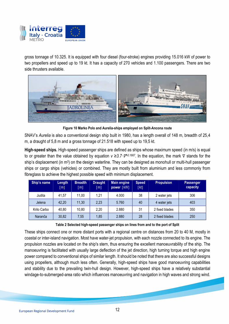
12
gross tonnage of 10.325. It is equipped with four diesel (four-stroke) engines providing 15.016 kW of power to
two propellers and speed up to 19 kt. It has a capacity of 270 vehicles and 1.100 passengers. There are two
side thrusters available.
Figure 10 Marko Polo and Aurelia-ships employed on Split-Ancona route
SNAV’s Aurelia is also a conventional design ship built in 1980, has a length overall of 148 m, breadth of 25,4
m, a draught of 5,8 m and a gross tonnage of 21.518 with speed up to 19,5 kt.
High-speed ships. High-speed passenger ships are defined as ships whose maximum speed (in m/s) is equal
to or greater than the value obtained by equation v ≥3.7∙∇^0.1667. In the equation, the mark ∇ stands for the
ship’s displacement (in m3) on the design waterline. They can be designed as monohull or multi-hull passenger
ships or cargo ships (vehicles) or combined. They are mostly built from aluminium and less commonly from
fibreglass to achieve the highest possible speed with minimum displacement.
Ship’s name Length
m
Breadth
m
Draught
m
Main engine
power kW
Speed
kt
Propulsion Passenger capacity
Judita 41,57 11,00 1,21 4.000 38 2 water jets 306
Jelena 42,20 11,30 2,23 5.760 40 4 water jets 403
Krilo Carbo 40,80 10,80 2,20 2.880 31 2 fixed blades 350
Naranča 30,82 7,55 1,85 2.880 28 2 fixed blades 250
Table 2 Selected high-speed passenger ships on lines from and to the port of Split
These ships connect one or more distant ports with a regional centre on distances from 20 to 40 M, mostly in
coastal or inter-island navigation. Most have water-jet propulsion, with each nozzle connected to its engine. The
propulsion nozzles are located on the ship's stern, thus ensuring the excellent manoeuvrability of the ship. The
manoeuvring is facilitated with usually large deflection of the jet direction, high turning torque and high engine
power compared to conventional ships of similar length. It should be noted that there are also successful designs
using propellers, although much less often. Generally, high-speed ships have good manoeuvring capabilities
and stability due to the prevailing twin-hull design. However, high-speed ships have a relatively substantial
windage-to-submerged-area ratio which influences manoeuvring and navigation in high waves and strong wind.

13
Figure 11 HSC Dubravka and Novalja employed on lines from and to the port of Rijeka
High-speed craft employed on high-speed service from Mali Lošinj, Cres and Rijeka pass twice a day through
Vela Vrata Strait TSS. Depending on the day of the week, there are also calls in-between ports of Ilovik, Susak,
Unije and Martinšćica on the island of Cres. Currently, HSC Dubravka is employed, with HSC Novalja as a
substitute. HSC Dubravka, build in 1990 in Singapore, is a twin-hulled aluminium catamaran. It is 41,57 m long,
has a breadth of 11 m, 1,28 m draft and a gross tonnage of 458. Equipped with two four-stroke 4 kW diesel
engines and two fixed propellers, it can reach speeds up to 38 knots. The available capacity is 324 passengers.
Figure 12 High-speed crafts on Split area lines: Jelena (top-left), Krilo Carbo (top-right), Judita (bottom-right) and Naranča (bottom-left)
HSC Novalja is also delivered in 1991 in Singapore. Similarly, as HSC Dubravka, it has aluminium twin-hull, two
four-stroke diesel engine and can reach up to 32 knots. It has a capacity of 324 passengers.
Several high-speed lines connect Split and adjacent islands, of which Lastovo (60 M) and Korčula (57 M) are
the longest. Besides Jadrolinija, other shipping companies provide liner services as well. There are additional
daily public lines during summer and high tourist season, not bound by the Public Service Obligation.
Cruise ships. The characteristics and design of cruise ships vary significantly depending on their age.
Generally, they can be characterized as either conventional or contemporary (modern) design. Conventional

14
cruise ships usually have a single propulsion unit on the stern and may be designed without bow thrusters. For
such vessels, manoeuvring, berthing and unberthing are demanding, especially in adverse weather, so tugboats
are often used. However, such vessels are not as common as they used to be. Recently built cruise ships usually
have two to three main propulsion units and outstanding manoeuvrability. One or more thrusters are usually
installed on the bow and stern to ensure better manoeuvrability. Nowadays, a diesel-electric powertrain is
commonly installed on these ships, with controllable pitch propellers and azimuth drives, as the main propulsors.
Azimuth propulsors can rotate by 360°, thus enabling the ship to turn in confined areas. Ships with azimuth
propulsors do not have additional stern thrusters and often do not have a classic rudder. Conventional bow and
stern thruster are situated perpendicular to the ship's hull and allow the ship to move when arriving and leaving
the berth laterally.
The superstructure of passenger ships is high. On large ships, it may exceed 60 meters. Therefore the wind
force has a significant influence on the manoeuvring. The shapes of the superstructures may differ significantly.
On ships with so-called balconies, the wind impact may be significant.
Cruise vessels sailing through Vela Vrata are commonly heading to Rijeka or Opatija. One of those ships,
commonly calling Opatija, is the cruise ship Crystal Esprit. It was built in 1991 as a monohull steel ship. The
ship's length is 85,2 m, breadth of 16,5 m and a draught of 3,79 m, with a gross tonnage of 3.370 and capacity
for 62 guests. Equipped with two conventional engines, it has controllable pitch propellers and a bow thruster.
Figure 13 Cruise ships Crystal Espirit and Aidaaura calling ports of Opatija and Rijeka
Larger cruise ships do not call Rijeka frequently. One of such vessels calling at the port of Rijeka is Aidaaura.
The ship was built in 2003, and it has a length of 202,85 m, breadth of 28,1 m, gross tonnage of 42.289 and an
approximate capacity for 1.300 passengers. It has a diesel-electric powertrain with two fixed propellers providing
an approximate speed of 19 knots. It is also equipped with several thrusters.
Figure 14 MSC Sinfonia and Celebrity Constellation cruise ships calling the port of Split

15
Port of Split is visited more frequently by large cruise ships than ports in the Bay of Rijeka area. Beforementioned
ships, Crystal Esprit and Aidaaura, also call the port of Split.
One of the ships relatively frequently calling at the port of Split is MSC Sinfonia. It was built in 2002, has a length
of 274.9 m, breadth of 28,8 m, a gross tonnage of 65.542, and an approximate passenger capacity of 2000. It is
powered by four diesel engines providing 31.680 kW of power and a speed of 20 kt. The second vessel is
Celebrity Constellation. It was built in 2002, has a length of 294 m, breadth of 32,2 m, gross tonnage of 90.940,
and an approximate passenger capacity of 2.100. It is powered by two gas turbines providing 50.000 kW of
power. It has two podded propulsors, 19 MW each.
In addition to previously described large passenger ships, numerous smaller coastal cruisers and excursion
ships are sailing in the area. Coastal cruisers are primarily employed in multiday cruises. In contrast, although
also serving the tourist industry, excursion vessels depart in the morning and return to ports in the evening. The
traffic volume of such ships in Vela Vrata Strait is modest compared to similar ships in Splitska Vrata Strait and
Drvenički Channel.
Figure 15 Small cruise ships of national coastal service category
These ships are commonly displacement type monohull ships powered by a single-engine with a clutch and a
single propeller. However, the two propeller ships with a bow thruster may also be found. The average speeds
of ships are about 10 knots with maximum speeds of approximately 15 knots. The ship's hulls are made of steel
or fibreglass, while older ships are most frequently built of wood.
The engines' power usually ranges from 60 kW to 400 kW, or up to 800 kW in newer ships. The powertrains are
based on either medium-speed (400-500 rpm) or high-speed (approximately 2.000 rpm) diesel engines. The
lengths of excursion ships typically range up to approximately 30 meters. The lengths of recently constructed
multi-day cruise ships are up to 50 meters. In general, excursion ships are smaller compared to cruise ships.
Since these ships are most often designed with a single propeller and a rudder, manoeuvring is demanding,
particularly during inclement weather.
Yachts and boats. Yachts are vessels with a length of more than 15 m. The general division of yachts according
to the length overall is based on three groups:
− yachts from 15 to 25 m,

16
− yachts from 25 to 50 m and
− yachts longer than 50 meters.
Figure 16 Yacht beam vs length overall1
Figure 17 Yacht draft vs length overall
1 PIANC Report 134. Design and Operational Guidelines For Superyacht Facilities. The World Accociation for Waterborne Transport Infrastructure, 2013.

17
Vessels of the second and third groups are commonly known as mega yachts.
Today's motor yachts are most often built of reinforced fibreglass, meaning they are lighter than the wood and
steel vessels of similar sizes. The weight of yachts, built of reinforced fibreglass, for the considered sizes in most
cases ranges between 15 and 1,500 t, depending on the type of vessel.
Dimensions Yacht Mega yacht
Length (m) 18,0 50,0
Breadth (m) 5,1 9,5
Draught (m) 1,8 3,0
Above waterline surface area – Lateral (m2) 65 300
Above waterline surface area – Frontal (m2) 20 90
Below waterline surface area – Lateral (m2) 22 110
Below waterline surface area – Frontal (m2) 10 20
Table 3 Typical yacht dimensions with above and below waterline area
Commonly, yachts have two propellers placed under the hull of the ship on struts. They increase the ship's
draught and are susceptible to damage if contact with the sea bottom occurs. These vessels are commonly
equipped with powerful engines (250 kW to 1.000 kW), maintaining over 6 knots even at a minimum RPM.
Consequently, the master is expected to stop the engines during manoeuvres periodically. Due to the hull’s
shape, small draught and typical Z-drive arrangement, as soon as the propeller stops rotating, steering and
course keeping are reduced. Consequently, the vessel becomes subjected to the significant influence of the
wind.
Figure 18 Motor yachts Varvara (LOA = 33 m) and Follow me V (LOA = 45 m)
Furthermore, this group also includes high-speed yachts (speedboats). The displacement of these vessels is
relatively small concerning their size. Smaller size speedboats and yachts (up to 18 m) are usually equipped
with Z-drive, while larger vessels (approximately 18 m and more) have propellers attached to the struts. The
draught of the vessels is approximately from 0.7 m to 1.2 m, while the displacement is usually between 10 and
50 t.
Yachts from 25 to 50 meters long are commonly considered luxury mega yachts. Usually, the ship's propeller is
a common means of thrust on these vessels. Vessels usually have twin propellers placed under the hull on

18
struts, which further increases stern draught. They are equipped with one or two thrusters perpendicular to the
fore-aft line of the ship on the bow. These vessels are equipped with powerful engines (650 kW to 2.000 kW)
that develop significant speeds even at a minimum RPM. Consequently, it isn't easy to maintain the required
speed during manoeuvring. Vessels have large windage areas and are subject to wind influence.
Yachts over 50 meters in length, given their technical and technological characteristics, can be regarded as
passenger ships with good manoeuvrability. They have a relatively small draught, high power engines and
commonly reach speeds of more than 20 knots.
Another group of crafts to be considered are boats. They are pretty similar to boats owned by the local
population. Based on the length, they may be divided into two main groups: boats up to 8 m long and boats with
a length of 8 to 15 meters. Boats are built chiefly of fibreglass or wood. The number of metal boats (for example,
build of aluminium) is negligible. Boats up to 6 m are commonly powered by outboard engines (from 15 to 40
kW). Structurally, they have an open deck and have good manoeuvrability. Motorboats up to 12 meters long
are mostly made of reinforced fibreglass and a built-in engine for propulsion. These vessels are mostly equipped
with 100 to 250 kW engines, developing considerable speeds at the lowest RPM.
Length
m
Breadth
m
Draught
m
Maximum draught
m
6 - 8 2,80 0,55 0,8
8 – 10 3,25 0,60 1,0
10 – 12 3,6 0,65 1,1
12 – 15 4,2 0,75 1,3
Table 4 Common high-speed boat principal dimensions
Furthermore, fast boats are built most often from reinforced fibreglass and have low weight. Stern draught ranges
approximately up to 0.65 m, while the bow draught gradually decreases. The hull is a so-called "V-shaped" form
without a pronounced keel. Most often, they have a Z-drive (one or two). Infrequently, such boats may be
equipped with a bow thruster for easier manoeuvring. Still, its power is limited and may be ineffective in case of
stronger wind. The ratio between the wind-exposed area and the underwater area is small. Because of this, in
unfavourable weather, manoeuvring is challenging.
Length
m
Breadth
m
Draught
m
8 – 10 2,8 1,5
10 – 12 3,2 1,8
12 – 15 3,6 2,0
Table 5 Common sailboat principal dimensions

19
Crafts used by the tourist also include wind-powered vessels (sailboats). With a length of 6 to 15 m, sailboats
are significantly less susceptible to wind forces during manoeuvring than previously mentioned categories of
vessels. Sailboats are stable, with smooth underwater shapes, large draught, and a smaller above waterline
surface (in case of lowered sails). Sailboats maintain the heading very well thanks to the keel, and large rudder
surface, which allows for a relatively small turning circle respective to length. Sailboats are primarily designed
with a single propeller, making it difficult for manoeuvring due to the limited transverse thrust. Sometimes bow
thrusters are also installed on such boats to facilitate manoeuvring in a confined area.
2.3.2 Container ships
Container ships are designed exclusively to transport containers in designated cargo holds and on the ship's
deck. They have only one deck to make the best use of cargo space and convenient loading and unloading of
containers. Container ships are usually designed without cranes or other deck equipment, so cargo operations
are carried out by shoreside equipment. Container ships can generally be divided into two categories. Smaller,
feeder container ships are used on short-sea services between major ports or hubs and smaller regional ports.
On the other hand, large container ships provide direct services connecting global regions and hub ports.
Depending on the number of containers, feeder ships can be designated as small feeders that can carry up to
1.000 TEUs (Twenty-foot Equivalent Unit), feeders with capacities up to 2.000 TEUs and feedermax ships with
capacities up to 3.000 TEUs. Some ships may be equipped with cargo gear, thus having greater operational
flexibility independent of shore-based cargo equipment. Feeders have a high superstructure situated aft, a single
main engine with a fixed or controllable pitch propeller, and one bow thruster.
Length [m]
Breadth [m]
Main engine power [kW]
Bow thruster power [kW]
Speed [kt]
177,6 32,2 13.440 700 17,5
220,1 30,0 25.000 1.100 24,0
198,6 30,2 28.400 1.100 21,8
244,9 32,2 32.412 1.100 23,5
259,8 32,2 37.050 1.600 24,5
294,0 32,3 41.130 1.800 24,0
299,1 32,2 45.760 2.000 25,0
304,0 42,8 53.800 2.200 25,0
366,0 48 68.640 2 x 1.800 24,0
Table 6 Common containership principal dimensions with main engine and bow thruster powers

20
Larger container ships are usually categorized as Panamax, Post-Panamax, Neo or New-Panamax, Very and Ultra Large Container Ships. Their dimensions are considerable compared to the feeders and are, as a rule, gearless. Commonly they have the main engine with a fixed or controllable pitch propeller and are outfitted with one or more bow thrusters. Hatches extend over 80-90% of the breadth of the ship. The superstructure is relatively narrow and high to achieve the required visibility from the bridge over the containers.
Ship's name Length
[m] Breadth
[m] Draught
[m] Gross
Tonnage Deadweight
[t] TEU
X Press Shannon 134 23,00 7,70 9.981 11.424 868
Contship Joy 140,55 23,08 8,70 10.965 12.611 925
Nordviolet 169,99 28,15 9,05 18.826 23.519 1.700
MSC Tasmania 216,05 32,20 12,05 34.231 45.670 2.680
Stadt Dresden 221,72 29,86 11,40 27.971 37.937 2.700
Cosco Hong Kong 280 39,80 14,08 65.531 69.207 5.618
Maersk Enshi 366 48,27 16,00 142.121 140..973 13.092
Table 7 Typical size of selected feeder and large container ships
Containers are stowed longitudinally, from one side to the other, extending over the available deck surface. In
holds, the number of container rows is limited by the hold size. Modern ships transport up to 50% of containers
on deck. Consequently, most large container ships have a superstructure situated forward. At the same time,
the funnel and engine room are located at approximately 1/5 ship’s length of the ship's stern.
It should be noted that from the superstructure to the stern, containers can be stacked on the deck to the maximum allowed height. In contrast, on the forward part, the stacking height is limited by the required visibility angle. Due to the large windage area, these ships usually list in navigation or manoeuvring. In such cases, the ship list can reach several degrees, with a substantial draught increase.
Figure 19 Feeder container ships Contship Joy (left) and Xpress Shannon (right) calling ports of Rijeka and Split
Container ships call the port of Rijeka, Brajdica terminal. There are more than 300 calls by large container ships
and smaller feeder ships per year.

21
Figure 20 Large containerships Maersk Enshi and Cosco Hong Kong
According to the classification described previously, feeder ships passing Vela Vrata Strait can be categorized
as feeder and feedermax vessels. Besides feeders sailing to and from Rijeka, larger ships call on weekly services
from the Far East. Contrary, in the port of Split, container ship traffic is very modest. Container ships calling the
port of Split are mostly smaller feeder ships such as X Press Shannon and Contship Joy, which also call the port
of Rijeka.
Container ships can be considered as ships with moderately good manoeuvring characteristics. However, it
should be noted that these ships usually have large windage areas due to the many containers on the deck.
2.3.3 Dry cargo ships
When considering dry cargo ships in the observed areas, the most prominent are bulk cargo ships transporting
cargoes such as ore, grain, followed by general cargo ships. Besides conventional bulk carriers and general
cargo ships, there are multi-purpose ships carrying varieties of cargoes. Furthermore, some specialized ships
such as cement carriers can be encountered as well.
Bulk carriers. A bulk carrier is a single or double-hull vessel intended to transport dry cargo in bulk. Such ships
are usually built as single-deck ships, with a double bottom including topside ballast and hopper tanks. Cargoes
transported in bulk carriers vary in density and mass and may be of finer or coarser granulation. Common bulk
cargoes include coal, coke, various ores, cereals, salt, sugar, sand, gravel, stone, etc. Due to the nature of bulk
cargo, loading and unloading are mechanized.
Figure 21 Bulk carriers calling ports of Bakar (Solar Frontier) and Rijeka (Cendana)
Although there are numerous categorizations, generally bulk carriers can be divided into several groups: small
bulk cargo ships or mini-bulk carriers (deadweight up to 10.000t), handysize (deadweight from 10.000 to 35.000
t), handymax (from 35.000 to 50.000 t), supramax (from 50.000 to 60.000 t), Panamax (55.000 to 100.000 t;

22
based on dimensions of Panama canal locks prior expansion), post-Panamax (80.000 to 120.000 t), Capesize
(above 100.000 t) and very large bulk cargo ships (i.e. VLBC - Very Large Bulk Carrier - over 180.000 t). The
draught of small bulk cargo ships, up to 10.000 t, ranges typically between 4,0 and 6,0 m. In contrast, in larger
ships, handysize and handymax ships, it usually ranges between 6,0 and 12,5 m. The breadth usually ranges
between 28 and 32 m.
Smaller bulk cargo ships mostly have two to three holds, while ships from the other two groups mostly have five
holds. In most cases, geared bulk carriers have cranes with Safe Working Load (SWL) up to 25 t. They are
intended for service areas that either doesn’t have or have inadequate shore-based cargo handling equipment.
When considering the general design of bulk carriers, the superstructure and engine room with propulsion are
always situated aft. Due to the size of the ships and speed requirements, ships are generally equipped with a
single medium-speed four-stroke diesel engine. Engine power varies. It usually ranges from 1.000 to 3.000 kW
for small bulk ships. In contrast, for handysize and handymax ships, it usually ranges from 4.500 to 9.500 kW.
The rudders are installed behind the propeller, most often of a semi-balanced or balanced type. The rudders
may be equipped with flaps, which significantly reduces the ship's turning circle. The speed of smaller bulk
carriers usually ranges between 9.0 and 13 knots. In comparison, the speed of handysize and handymax ships
ranges between 13 and 15 knots. Smaller bulk carriers can be equipped with bow thruster, facilitating
manoeuvring. Usually, ships with a more considerable deadweight are not equipped with a bow thruster. They
have more modest manoeuvring capabilities, so in some cases, the anchor is used for when mooring and
unmooring.

23
Length [m] Breadth [m] Draught [m] Deadweight [t] Engine power [kW]
72,0 12,0 4,0 1.600 900
75,1 13,2 5,2 2.700 1.500
80,3 13,8 6,4 3.250 1.100
93,6 13,0 6,0 4.244 1.850
107,0 18,0 6,7 7.580 2.400
135,0 14,0 7,1 11.047 4.000
150,0 23,6 8,6 16.582 6.570
172,00 23,80 10,20 27.000 4.400
180,00 28,80 9,60 35.000 6.848
185,00 30,00 11,22 43.246 8.100
189,90 32,26 11,00 50.286 8.532
189,98 32,26 11,80 55.000 9.400
Table 8 Principal dimensions of common small, handysize and handymax bulk cargo ships
Largest dry cargo ships using Vela Vrata Strait carry iron ore or coal for discharging in terminal Podbok situated
in Bakar, with 10-15 calls a year. They are mostly Panamax, supramax or Capesize ships. Other bulk carrier
ships of various sizes call the port of Rijeka.
Cement carriers. Modern cement carriers are specialized ships that cannot carry other bulk cargo even though
they are classified as bulk carriers. Pneumatic and hydraulic cargo handling systems are used to unload cement
cargo of relatively low granulation and density, while mechanical systems are rarely used.
Figure 22 Selected cement carriers Jadro (left) and Eastcoast (right) calling ports of Bakar and Split
The pneumatic system is equipped with powerful high-capacity compressors to pressurize cargo and transport
it into the storage silos. The advantage of the pneumatic cement transport system is its flexibility, which allows
the ship to unload cargo in ports that do not specialize in cement reception. The common advantage of most
cement ships closed system is that it does not cause environmental problems and dust spreading during cargo
operations.

24
Ship’s name Length m Breadth m Draught m Gross Tonnage Deadweight t
Jadro 66,0 11,72 4,3 1.115 1.418
Eastcoast 67,4 9,50 * 836 1.230
Sirios Cement V 86,0 14,5 * 2.453 3.399
Table 9 Principal dimensions of selected cement carriers
Cement carriers identified in the observed areas are commonly ships with two cargo holds. More recently, the
cargo holds are dived in two separated spaces, with a central tunnel. The superstructure and engine rooms are
situated on the stern. The considered ships are usually equipped with one medium-speed four-stroke diesel
engine with a power of between 600 and 2.000 kW and a single fixed propeller. They have a single rudder,
mostly of semi-balanced or unbalanced type. The manoeuvring capabilities of these ships are moderate since
they are commonly not equipped with a bow thruster, which makes manoeuvring more difficult.
General and multipurpose cargo ships. Conventional general cargo ships are single or double-hull vessels
intended primarily to transport various types of general cargo, which in most cases, unlike bulk cargoes, is
packed. Older general cargo ships had a main deck, one or more tween decks and a double bottom. Modern
general cargo ships are typically built with a single main deck and a double bottom.
Due to the diversity of shapes, dimensions and masses, general cargo handling is not fully mechanized.
However, there is a tendency to adapt cargo handling equipment as much as possible to reduce port stay.
Figure 23 General cargo Puffin S and multipurpose Bremer Johanna ships calling the port of Rijeka
In most cases, conventional general cargo ships do not exceed 60.000 of gross tonnage. The ratio of the total
carrying capacity and displacement of smaller ships in most cases is between 0,50 and 0,70. Modern general
cargo ships have a smaller beam-to-width ratio compared to older single hull ships. For the considered category
of ships, it is on average between 6 and 8. Draught of the considered category of ships ranges between 4.8 and
10 m, making it possible to accept such ships in ports with lower depths.

25
Figure 24 General cargo ship Feyza Genc and multipurpose dry cargo ship UHL Passion calling the port of Split
The freeboard of general cargo ships is commonly slightly higher than freeboard on bulk carriers. In most cases,
general cargo ships are equipped with cargo gear. Some of the older vessels may have derricks with SWL of 10
to 22 t, while modern ships are equipped with cranes with SWL in most cases ranging between 25 and 35 t.
Ship’s name Length m Breadth m Gross
Tonnage Deadweight t
Feyza Genc 87,6 12 1.995 3.490
Puffin S 157,5 23,1 14.118 20.738
Bremer Johanna 89,9 15,4 3.172 4.310
UHL Passion 166,1 23,3 15.549 1.543
Table 10 Principal dimensions of selected general cargo and multipurpose ships
Multipurpose dry cargo ships are different in design from standard general cargo or other dry cargo ships. The
most notable feature is loading and unloading various cargoes, including bulk, break bulk, general,
containerized, heavy, and voluminous cargo. The design features depend on the intended dry cargo category
and trade. Smaller ships, up to several thousand tons of deadweight, are primarily employed in short sea
shipping. The larger ships with deadweight up to 30.000 t operate on the deep-sea services.
General cargo and multipurpose ships using the Vela Vrata Strait are of different sizes and characteristics,
ranging from smaller coastal ships of 70 m up to larger vessels up to 160 m in length overall.
Various ships, either bulk or general dry cargo, are calling the Sjeverna luka and Vranjic-Solin basin. These
ships have mostly lengths ranging from 70 m up to 110 m, with occasional calls of larger vessels up to 160 m.
Manoeuvring capabilities of general cargo and multipurpose ships may vary, depending on the design and age.
Older and smaller ships have modest manoeuvring capabilities, while newer and larger ships have better
capabilities.

26
2.3.4 Tankers
Tankers are ships intended for the transport of liquid cargoes. Tankers are designed with the longitudinal framing
system characterized by strong longitudinal elements, longitudinal stiffening of decks, watertight bulkheads with
longitudinal stiffeners, strong web frames and beams, placed every 4 to 5 m. Longitudinal and transverse
watertight bulkheads divide the liquid cargo sections into several tanks. Smaller tankers have only one
longitudinal bulkhead, while medium and large tankers have two, dividing the hull into central, port, and starboard
side tanks.
Tankers are built as double hull ships, usually with one deck, on which small hatches that serve as the entrance
to tanks are situated. The technical and technological characteristics of tankers are primarily influenced by the
characteristics of the cargo they carry. Therefore, they can be divided into three basic types: the transport of oils
and petroleum products (products), the transport of chemicals, and liquefied gases.
Oil tankers. Crude oil tankers are intended to carry crude oil to refineries and are designed to carry mainly one
or up to three grades of crude oil. The size may vary significantly. Between production and destination regions,
oil is carried by Very Large Crude Carriers (VLCC) of 160-320.000 deadweight and Ultra Large Crude Carriers
(ULCC) with maximum deadweights above 320.000 t.
Product tankers are ships with relatively more minor deadweights (generally up to 70.000 t), with numerous
tanks to transport different types of petroleum products simultaneously. Consequently, they are equipped with a
more complex piping system.
The manoeuvring characteristics of product tankers are usually of similar characteristics as other conventional
cargo ships. These are ships with a single main engine and propulsion situated at the stern and a bow thruster.
The power of bow thruster of ships ranges typically from 800 to 1.000 kW.
Product tankers are usually divided by deadweight into the following categories:
− GP (General Purpose) tankers with a deadweight of 10.000-25.000 t,
− MR (Medium Range) tankers with a deadweight of 25.000-45.000 t,
− LR1 (Long Range 1) tankers with a deadweight of 45.000-80.000 t,
− LR2 (Long Range) tankers with a deadweight of 80,000-160,000 t.
Ships in LR1 and LR2 ranges can be designed to carry crude or product cargoes. General-purpose tankers are
used to deliver oil products on the regional market over relatively short distances.

27
Category Name Type Length
m
Breadth
m
Draught
m
Gross Tonnage
Deadweight
t Propulsion
Coastal tanker
Archangel One
Chemical/Oil products
109,9 17,2 7,1 4.908 7.080 1 CPP
3.500 kW
GP tanker Saracena Chemical/Oil
products 155,2 25,6 8,3 14.701 20.890
2 CPP 6.000 kW
MR tanker Zefirea Chemical/Oil
products 180,0 32,2 9,5 25.923 40.025
1 FPP 9.480 kW
LR 1 tanker Marianna V.V. Crude Oil 239,0 38,0 13,15 50.199 79.999 N/A
LR 2 tanker Aegean Horizon
Crude Oil 274,5 48,0 17,0 81..084 158.738 17.001 kW
Table 11 Principal dimensions of selected tanker ships
In addition, there are smaller tankers for transporting products that are usually classified as tankers intended for
transport in coastal navigation, in protected areas. Such tankers are also used as supply ships. They usually do
not exceed a length of 100 m, and their deadweight is approximately up to 5.000 tons. Usually, these ships do
not use tugs for manoeuvring.
Figure 25 Oil/Chemical tankers Saracena and Zefirea calling ports of Rijeka and Split
Medium range tankers - MR tankers typically connect ports of neighbouring regions. Sometimes they can be
employed on longer voyages. The deadweight of MR tankers is approximately 30.000 t, while the largest tankers
in this group may have a deadweight from 45.000 to 55.000 t.
Figure 26 Oil/chemical tankers Sepen and Kijac
Tankers bound for the Bay of Rijeka and passing Vela Vrata Strait carrying crude oil or oil products to the port of Omišalj are mostly LR2 category. Calls of VLCC ships are rare. Smaller GP and MR tankers are bound for terminals in Bakar Bay. Chemical tankers and LPG tankers call Sršćica terminal.
Besides presented tankers, coastal tankers such as Sepen and Kijac serve to transport petroleum products and
petrochemicals, or to the greatest extent, oil and chemicals. Both ships have very similar features, length overall

28
of 92,86 m, deadweight of 3.500 t and a gross tonnage of 2.700. Their propulsion consists of one propeller
powered by a single-engine of 1.850 kW and 2.040 kW, respectively. These ships count for most calls to the
port of Split of all oil/chemical tankers.
Gas carriers. Liquefied gas carriers are ships on which gas cargo is liquefied by pressurization, refrigeration, or
combination. Generally, liquefied gas ships can be divided into two major categories: Liquefied Petroleum Gas
(LPG) - LPG ships and Liquefied Natural Gas (LNG) ships - LNG ships.
LPG ships carry liquefied petroleum gases, propane, and butane as semi-refrigerated or partially pressurized
cargo up to 5 to 7 bars. These ships are commonly built for the transport of cargo at temperatures cooled
to -48°C. Smaller LPG ships can be designed to transport liquefied gas at pressure up to 18 bars and cargo
capacity up to 8.000 m³.
Length
m
Breadth
m
Draught
m
Deadweight
t
Main engine
power kW
Speed
kt
99 15,5 5,8 5.619 2.400 12,5
110 15,5 7,5 5.985 4.000 14,5
117 18,2 6,8 6.000 3.900 14,8
121 19,4 8,3 6.500 4.100 14,0
125 19,8 8,3 9.000 6.300 16,7
Table 12 Principal dimensions of typical LPG ships
These ships have similar manoeuvring characteristics as other conventional cargo ships of similar sizes. They
usually have one stern propulsor. Modern ships are usually equipped with a bow thruster situated
perpendicularly to the fore-and-aft line. When mooring and unmooring, in most cases, they use tugboats. The
Sršćica terminal has approximately 25 calls of such ships yearly, while LPG ships call Split only a few times a
year.
Figure 27 LPG carriers PG Gas Pioneer and Gas Fidelity
LNG ships. LNG ships are designed to carry liquefied natural gas, which in a liquefied state occupies
approximately 600 times less volume than in a gaseous state at atmospheric pressure. The maximum transport
pressure is about 25 kPa and 250 millibars, respectively, and the temperature is around -160°C. In general,
LNG ships can be divided according to size, a system of built-in tanks, and propulsion. Considering the size and

29
capacity of LNG ships, they can generally be divided into the following groups: small LNG ships, conventional
LNG ships (small and large), Q-Flex ships and Q-Max ships.
LNG ship class Capacity (x 1000 m3) Length [m] Breadth [m] Draught [m]
Small LNG ships < 90 < 250 < 40 < 12,0
Small conventional LNG ships 120 – 150 270 – 298 41 - 49 < 12,0
Large conventional LNG ships 150 - 180 285 – 295 43 - 46 12,0
Q-Flex 200 – 220 315 50 12,0
Q-Max >260 345 53-55 12,0
Table 13 Principal dimensions of common LNG ships groups
Generally, LNG tank containment systems can be divided into membrane systems (commonly GTT or similar)
or self-supporting independent type A, B and C systems. The most common is the spherical Kvaerner Moss
system. There are several propulsion systems installed, ranging from steam turbines, slow-speed diesel (SSD),
dual or triple fuel diesel-electric plants (DFDE and TFDE) and M-type, electronically controlled, gas-injection
(MEGI) engines. Somewhat above 50% of current LNG ships have steam turbines, followed by TFDE and SSD.
Around two-thirds of ordered newbuilding ships will be equipped with TFDE or MEGI engines.
From the viewpoint of maritime characteristics, LNG ships are fundamentally different from all other types of
ships. Given that the propulsion machine of conventional LNG ships is, as a rule, a steam turbine, it is necessary
to consider that while manoeuvring, up to 70% of the power is available when running astern. Starting or stopping
time of the main engine is slightly longer, with the required time to reach emergency shaft power being longer
as well. Furthermore, LNG ships' sizeable lateral surface area may cause unwanted ship movements due to
strong lateral winds.
The relatively small draught creates relatively low resistance to the lateral movement of the ship, thereby further
affecting the ship's manoeuvring characteristics. Due to the high freeboard and cargo spaces, regardless of the
technology used, the visibility may be restricted.

30
LNG ship class Displacement [t] Capacity
[m3] Freeboard
[m]
Engine power [kW]
Bow thruster
[kW]
Approximate lateral surfaces [m2]
Conventional ships
105.000 138.000 –
180.000 14-15 - N/A
6.000-9.000
3.000-4.000
Conventional –
Moss 104.998 147.598 15,0 26.900 N/A 9.000-3.200
Conventional – GTT Mark 3
105.846 145.000 14,0 29.455 2.500 6.100-3.000
Q Flex (SSD) 149.000 217.000 15,0 2 x 18.881 N/A 7.000-3.600
Q Max (SSD) 179.000 265.940 1,.0 2 x 21.770 N/A 7.700-4.000
Table 14 LNG ship characteristics
Dimension to displacement ratio is lower than other similarly sized ships such as oil tankers. Consequently, LNG
ships always require tugs during berthing and unberthing. Nevertheless, LNG ships can be considered as ships
of good manoeuvrability at lower speeds.
Figure 28 Large LNG ship Tristar Ruby and smaller LNG ship Avenir Accolade
The LNG Croatia terminal, located in Omišalj, commenced commercial operation in January 2021. The cargo is
transferred to and from LNG ships via the Floating Storage Regasification Unit (FSRU ship). It may be used
even for transhipment to the nearby terminals. Currently, there is approximately one call per month, with an
expected increase. Additional ships, as well as ships using LNG as fuel, are expected in the future. LNG cargo
ships do not call the port of Split.
2.3.5 Fishing vessels
Fishing vessels in the area are commonly seiners and trawlers. Most of the fishing vessels, given their
characteristics, belong to the group of vessels with limited manoeuvring capabilities. They are commonly built of
wood or fibreglass, while more recently, one can find steel ships.
The dimensions of seiners can vary considerably, but most common is lengths between 14 to 27 m, breadth of
4 to 7 m and drafts from 1,5 to 3,5 m. Recently, vessels with a length of up to 40 m and a breadth of up to 8,65
m can be met. Generally, the speeds of fishing vessels range from 8 to 12 kt. The vertical distance from the
waterline to the top of the bulwark can vary significantly; however, it often ranges from 1 to 2.5 m. Every seiner

31
has one, two or more auxiliary boats equipped with lights. These boats may be used for mooring if the available
mooring area is restricted. The volume of fishing vessel traffic is more significant in the Splitska Vrata and
Drvenički channel than in Vela Vrata Strait.
Figure 29 Common fishing vessels encountered in wider Vela Vrata (Tiha) and Split (Diniva)
The ships are usually powered by medium-speed (400-500 rpm) or high-speed (approximately 2.000 rpm) diesel
engines. The power of the engines ranges from 200 kW to 1,000 kW. The shaft assembly is commonly coupled
with a hydraulic clutch. Seiners usually have a single fixed type right-hand propeller. Most often, they are not
equipped with a bow thruster. The displacements of seiners vary and depend on the material of construction.
The largest seiners displacements on the eastern Adriatic coast are up to 500 t.
Trawlers are intended for fishing with trawls. They are characterized by the high power of the main engine
relative to the size of the vessel. Trawling net may be dispatched at the stern or sideways. Furthermore, the
dimensions can vary considerably. Most often, ships with a 10 to 20 m in length, 3 to 5 m wide, and a draught
from 1,0 to 3,0 m are encountered. The vertical distance from the waterline to the top of the bulwark most often
ranges from 1 to 2,0 m. They are powered by medium-speed (400-500 rpm) or high-speed (approximately 2.000
rpm) diesel engines, ranging from 60 to 500 kW. Trawlers usually have a single fixed type right-hand propeller
and commonly are not equipped with a bow thruster.
Trawlers have similar manoeuvring capabilities to seiners and can be considered vessels with limited
manoeuvrability. The speeds range from 8 to 12 kt. Also, they are usually built of wood or fibreglass, while more
recently, steel ships may be found.
Finally, in all observed areas besides described ship categories, other ship types can be encountered. They can
vary significantly in dimensions and characteristics; however, their traffic may be considered as not significant.

32
3 NAVIGATIONAL RISK ANALYSIS
The assessment of collision and grounding risks for restricted waterway areas is justified in circumstances where
shipping routes show apparent spatial regularity. Consequently, the volume of traffic (number of ships) during
the year-round period (at least) is such that the statistical characteristics of each traffic flow are distinguishable.
The assessment of collision and grounding risks for selected areas may be carried out descriptively, based on
one or more experts (more subjective approach), or using a maritime traffic simulation model (objective
approach). Following the above, a numerical simulation of maritime traffic was performed using the IWRAP2
MK2 program (developed by the International Association of Marine Aids to Navigation and Lighthouse
Authorities - IALA). It considers mostly the navigation areas where the most significant maritime traffic occurs.
The IWRAP model is based on the assumption that the risk of collision or grounding for laterally restricted
waterways is proportional to the traffic volume. In contrast, in unrestricted waterways (open seas), the probability
of a maritime accident is proportional to traffic density. The IWRAP methodology for collision and grounding risk
assessment is justified in cases where:
− the traffic volume is large enough that the obtained results have satisfactory reliability,
− characteristics of traffic and ships are known with sufficient reliability, and
− common shipping routes are distinguishable.
The basic assumptions used in the used numerically model are the following:
− risks are estimated for a period of one year, according to the traffic volume of the most intensive
period of the year (July - August) in both directions; thus, the calculated risks are approximately
twice as high as the actual average risks;
− the volume and characteristics of maritime traffic were estimated according to the data provided
by the Ministry of Sea, Transport and Infrastructure of the Republic of Croatia, statistical reports
of port authorities and data provided by the Croatian Register of Shipping;
− the land area exposed to the grounding includes shores belonging to the respective passage
up to a distance of approximately 1 M from the narrowest part of the passage and the associated
seabed to the depth of 10 m;
− the sea area for ship collision risk assessment includes a waterway divided into three to four
parts: the central part of the passage and the approaches from two sides; traffic is simulated for
each part of the waterway in both directions;
2 IALA Waterway Risk Assessment Program – IWRAP

33
− traffic density or distribution of traffic routes through the navigation area is described by a normal
distribution whose mean value (µ [m]) indicates the average deviation of ships from the
waterway (usually zero because it is shown that most ships navigate in the middle of the
passage), and standard deviation (σ [m]) indicates ship scattering or average deviation from
the mean; thus 99% of the total traffic for each part of the waterway is at a distance of up to 3
standard deviations;
− average values of draft and speed for each ship type, concerning their length, are based on
data available from IALA databases;
− collision and grounding impact coefficients for each ship type are taken according to the
recommendations for similar ship types and sizes proposed by the IALA.
Based on the available data and considered waterways, the risk assessment for collisions and groundings
according to the IWRAP methodology was considered for the following straits:
− Vela Vrata Strait,
− Splitska vrata Strait, and
− Drvenički Channel.
3.1 Vela Vrata
Vela Vrata Strait is the main waterway to and from Rijeka and all associated terminals in the Rijeka Bay area
towards the open sea, i.e. territorial and international waters. The Strait is 2.3 to 2.8 M wide and 5.5 M long, and
a traffic separation system (TSS) has been established in the central part. The entire waterway from Rijeka to
the inland sea border is about 42 M. This route is also the most frequent approach to Rijeka.
This waterway is used by:
− merchant and passenger ships in international navigation (all year round),
− smaller passenger ships for cruises and excursions, especially those coming from the
domestic ports of the northern Adriatic (during the summer period);
− ro-ro passenger liner ships connecting the island of Cres with the mainland (Brestova -
Porozina);
− high-speed passenger ships on line that connects the nearby islands with the mainland (Mali
Lošinj - Ilovik - Susak - Unije - Martinšćica - Cres - Rijeka);
− fishing boats;
− yachts and boats of different sizes (mainly during the summer period).

34
The entire waterway, including Vela Vrata Strait, is well marked with navigational aids. Ships, coming from the
open sea, usually pass between the Istria peninsula and the island of Galijola (width 8 M) with an approaching
course of 013°. Smaller ships coming from the south also pass between the Galijola and the island of Unije
(width 4.5 M) with an approaching course of 004°. Navigation towards the Vela Vrata is not demanding since
there is almost no change of course.
The navigation lane for ships required to use the TSS is 0.7 M wide on both sides, and the separation zone is
0.1 M wide. In the central part of TSS, there is a course alteration to 019°. Ro-ro passenger line between the
island of Cres and the mainland (line Brestova - Porozina) intersect the TSS at almost right angles. Such
maritime navigation situations are not uncommon and are dealt with by respecting the International Regulations
for Preventing Collisions at Sea.
Ship type Number of passes
Average ships’ length Vela Vrata West waterway East waterway
Ro-ro passenger ships in line3 9.490 / / 50 m
High-speed craft passenger ship 730 730 / 40 m
Passenger ships not in line4 264 217 47 20 m
Cruise ships
8 8 / up to 100 m
5 5 / 100-200 m
/ / / 200-300 m
/ / / more than 300 m
Container ships 300 300 / 189 m
Bulk carriers 65 43 22 242 m
Product and chemical tankers 314 6 308 110 m
Oil tankers 48 14 34 226 m
Other cargo ships 676 545 131 145 m
Yachts5 1.095 548 547 40 m
Fishing vessels6 427 348 79 25 m
Table 15 Traffic structure through Vela Vrata and the Bay of Rijeka (annually based on 2019 - the largest volume of traffic)
Approximately 2 M after leaving the TSS, ships have to change the course towards the final destination in the
Bay of Rijeka. The new courses range from 005° for the port of Opatija to 067° for the Omišalj oil terminal and
LNG terminal. In the same area, there is a waterway junction of ships departing from the Bay of Rijeka.
3 Only the Brestova - Porozina line is maintained in the observed area. 4 The number of passes presents 1/3 of passenger ship departures, as an estimated ratio of ships using Vela vrata passage. 5 Yacht traffic includes yachts longer than 30 m. Traffic is estimated to 3 yachts per day or 1095 per year. 6 The number of passes presents 1/3 of fishing vessel departures, as an estimated ratio of ships using Vela vrata passage.

35
Merchant and passenger ships on international voyages generally sail in the exact directions and generally pass
by each other in opposite courses in the area of Kvarner and the Gulf of Rijeka, i.e. before and after the TSS
with minor course alterations. The TSS must be used by all vessels longer than 20 m so that in the Vela Vrata
Strait, there are no head-on situations, but there may be overtaking. Other ships, boats and yachts less than 20
m in length can use the coastal navigation zone. It is not uncommon for inexperienced skippers of boats and
yachts less than 20 m in length to interfere with the navigation of larger ships in TSS.
Due to the above circumstances, a simulation model was developed. The input data for the model are based on
an estimate of annual traffic and average vessel lengths, as shown in Table 15.
In the simulation model, the whole waterway consists of four sections (legs):
− the southern approach,
− Vela Vrata Strait
− the western and eastern approach waterway in the Bay of Rijeka.
Each of these sections has a separate arrival and departure leg, in accordance with the TSS lanes.
Due to the location of terminals, anchorages and pilot stations in the Gulf of Rijeka, the western approach
waterway includes traffic to:
− port of Opatija,
− shipyard “3. Maj”,
− port of Rijeka,
− port of Sušak,
− container terminal Brajdica and
− repair shipyard “Vikor Lenac”.
The eastern approach waterway in the Gulf of Rijeka includes traffic to:
− terminals in the Bay of Bakar,
− LPG terminal Sršćica,
− port of Kraljevica,
− terminal Voz,
− oil terminal Omišalj
− LNG terminal Krk.

36
A normal distribution of ships around the waterway centreline is assumed in all parts, as shown in the adjacent
figure. The following mean deviation (in each direction) per each waterway is assumed:
− Southern approach: σ= 700 m
− Vela Vrata Strait: σ= 150 m
− Western approach: σ= 600 m
− Eastern approach: σ= 600 m

37
Figure 30 Model of traffic distribution in the observed area7
7 For plotted waterways, the IWRAP program allows the entry of traffic statistics in both directions. In the direction for which traffic data is entered, the traffic distribution is graphically displayed, and for the direction for which no data is entered (for example, no traffic), a red arrow is drawn as the initial program setting. The red arrows on the graphic do not indicate the assumed direction of navigation.

38
Figure 31 Graphic results of the simulation model

39
Figure 32 Probability of collisions by crossing (by type of ship)
Figure 33 Probability of collisions by crossing (by waypoint)

40
Figure 34 Probability of collisions by head-on situations (per leg)
Figure 35 Probability of collisions by overtaking (by leg)

41
Figure 36 Probability of collisions between different ship types
The simulation results do not deviate significantly from expectations: passenger ships are exposed to the most
significant threat, followed by other cargo ships. Numerically, the results have the following values:
Type of accident: Annual probability Annual frequency
Grounding - in navigation 0,2047 4,885
Grounding - engine failure 0,3034 3,296
TOTAL Grounding 0,5081 1,968
Collision - overtaking 0,0008047 1,243
Collision - head on 0,0005396 1,853
Collision - crossing 0,001778 562,4
Collision - merging 0,0002218 4,509
TOTAL Collision 0,003344 299
Table 16 Probability of grounding and collision and time interval between events
In the observed area, grounding in navigation should be expected once every 4,9 years. Groundings in case of
engine failure should be expected once every 3,3 years. Viewed together, the probability of grounding,
regardless of nature, is 0,5081, i.e. once every two years. Numerically calculated places of the highest probability
of grounding are the coastal areas of Istria and the island of Cres in the Vela Vrata Strait and the shores of the
basin of the port of Rijeka (coastal edge marked in bright red and purple in the graphic results).
It is important to emphasize that the probability of grounding does not depend on changes in traffic density during
the year. The probability of grounding depends on statistical parameters related to the technological

42
characteristics of the ships and the characteristics of the waterway (proximity to land and shoals). The impact of
surrounding traffic on the probability is negligible.
In contrast, the traffic volume crucially affects the probability of a collision. In this regard, the model has been
adjusted so that the annual number of ships is increased to correspond to the number of ships passing through
the area during the summer period. The annual increase is approximately 50%. Vessels being shorter than 20
m are not included in the estimate of the number of ships because these vessels should not obstruct the passage
of other ships that can safely navigate only within a TSS. In other words, the probability shown here corresponds
to summer traffic intensity extended throughout the year.
According to the estimate, the expected probability of a collision by crossing is 0,001778, i.e. once in 562 years,
while the frequency of collisions of head-on courses, overtaking and merging is even lower. In total, the
probability of all types of collisions is 0,003344, i.e. once in 299 years. It should be borne in mind that vessels
shorter than 20 m are excluded from the assessment.
Given the configuration of the approaching waterways, the highest probability of collision is assigned to ships
from and to the Bay of Rijeka crossing with ro-ro passenger ships on the Brestova-Porozina line in the TSS
(waypoint marked in bright red and purple in the graphic results). The highest probability of collision during
overtaking is in the TSS lanes (almost equal probability for both directions). The highest probability of head-on
collision is in the southern approach waterway (both southern legs marked in orange and bright red in the image
of the graphic results).
3.2 Splitska Vrata
The Splitska Vrata Strait is the shortest route to and from the port of Split. The Strait, 1.5 M long, is located
between the islands of Šolta and Brač. Apart from being the shortest, this waterway is also the most frequent
and the narrowest concerning other waterways approaching the port Split. The minimum distance between Šolta
and Brač is 0,42 M. When the shallow area is not considered, the safe waterway, with depths greater than 20
m, reaches a width of only 0,15 M.
The Strait is well marked with navigational aids. The approach course from south to the Splitska Vrata may vary
but in most cases is approximately 035°. At the very entrance to the Splitska Vrata (after passing the light on
Cape Ražanj), the course is usually changed to the 008°. By doing so, larger ships navigate through the centre
of the Strait.
The Strait is not too demanding for ships coming from the open seas (only one change of course to the port side
is required). The problem is that this change of course usually takes place just before entering the narrowest
part of the Strait. If this is not done on time, there is a significant risk of grounding.

43
Figure 37 Record of ship Alfa Dragon grounding in the Splitska Vrata Strait
Figure 38 Record of ship Malinska (L=55,8 m) passing through Splitska Vrata (after VTS warning calls, she altered course only 150 m from shore)

44
To numerically estimate probabilities of collisions and grounding in given circumstances, a simulation model was
developed. The input data for the model are based on an estimate of annual traffic and average vessel lengths
as follows:
Ship type Number of passes Average ships’ length
Ro-ro passenger liner ships 9.490 70 m
High-speed craft passenger ships 3.650 35 m
Passenger ships8 7.752 25 m
Cruise ships9
22 up to 100 m
136 100-200 m
96 200-300 m
16 more than 300 m
Dry cargo merchant ships10 326 60 m
Oil tankers11 250 90 m
Yachts 5.840 40 m
Fishing vessels 2.190 30 m
Table 17 Structure of the traffic through Splitska Vrata Strait (annually, based on 2019 - the most significant volume of traffic)
The waterway consists of three parts (legs) in the simulation model: southern approach, centre (Strait) and
northern approach. In all three parts, the normal distribution of ships around the centreline of the waterway is
assumed.
The following mean deviation (in each direction) per each leg is assumed:
- southern approach: σ= 200 m
- central (Strait): σ = 70 m
- northern approach: σ = 200 m
8 The number of passes presents 2/5 of passenger ships departures, as an estimated ratio of ships using Splitska vrata passage.
9 The number of passes presents 3/5 of cruise ships departures, as an estimated ratio of ships using Splitska vrata passage.
10 The traffic to the northern cargo port, the City port and Kaštel Sućurac is included. The number of passes presents 2/5 of dry cargo ships departures, as an estimated ratio of ships using Splitska vrata passage.
11 The traffic to the port of Split Petronafta is included. The number of passes presents 2/5 of tanker ships departures, as an estimated ratio of ships using Splitska vrata passage.

45
Figure 39 Model of traffic distribution in Splitska Vrata
Figure 40 Graphic results of the simulation model

46
Figure 41 Probability of grounding (by ship type)
Figure 42 Probability of collisions by head-on situations (per leg)

47
Figure 43 Probability of collisions by overtaking (per leg)
Figure 44 Probabilities of collisions between different types of ships
The simulation results do not deviate significantly from expectations: passenger ships are most at risk, followed
by yachts.

48
Numerically, the results have the following values:
Type of accident: Annual probability Annual frequency
Grounding - in navigation 0,157347 6,3
Grounding - engine failure 0,050475 19,8
TOTAL Grounding 0,207822 4,8
Collision - overtaking 0,00119047 840,0
Collision - head on 0,00569679 175,5
Collision - merging 0,00686683 145,6
TOTAL Collision 0,0137541 72,7
Table 18 Probability of grounding and collision and time interval between events
In the observed area, grounding in navigation should be expected once every 6.3 years. Grounding in the event
of an engine failure should be expected much less frequently, once every 19.8 years. Viewed together,
grounding, regardless of the circumstances, should be expected once every 4.8 years. This value roughly
corresponds to previous experiences in this area. Indeed, four strands have occurred in this area in the last 15
years (ro-ro ship Ivona in 2007, cargo ships Alfa Dragon and Murat Hacibekiroglu III in 2011 and a small
passenger ship Cicero in 2019). However, it should be borne in mind that the observation of such a short period
is not statistically significant.
Figure 45 Ship Alfa Dragon grounded in Splitska Vrata

49
The numerically calculated place of the highest probability of grounding is immediately south of Cape Zaglav
(the part marked in black in the figure of graphical results), where the cargo ship Alfa Dragon stranding took
place.
Regarding the probability of collisions, the model has been adjusted so that the number of ships annually is
increased to correspond to the number of ships passing through the area during the summer period. The annual
increase is approximately 50%. Vessels being shorter than 20 m are not included in the estimate of the number
of ships because these vessels should not obstruct the passage of other ships that can safely navigate only in
the central part of the Strait. In other words, the probability shown here corresponds to the traffic load that would
exist if the summer load is extended to a whole year.
Given the waterway configuration through the Splitska Vrata, the highest probability of collision is merging, i.e.
when entering the waterway from the side, regardless of who should avoid a collision. According to estimates,
the expected frequency of collisions during merging is once in 145 years, while the head-on collisions' frequency
is every 175 years. In total, the probability of all types of collisions is 0,0137541, i.e. the frequency is once in
72,7 years. These values roughly correspond to the actual situation, bearing in mind that vessels shorter than
20 m are excluded from the estimates.
3.3 Drvenički Channel
The Drvenički Channel is located between the mainland and Drvenik Veliki and Drvenik Mali. For the most part,
the Channel is about 0.9 M wide. The narrowest part of the waterway is 0.6 M between the island of Drvenik
Mali and the islet of Murvica on the west side of the Channel. The Channel is about 7 M long. While approaching
the port of Split, after the Drvenički Channel, ships follow the mainland for 12 M. The depths are about 65 to
80 m. In the Channel, two shoals (9 m and 10,4 m, respectively) are identified in the area between the bay of
Vinišće and the islet of Kluda.
At the entrance to the Drvenički Channel (42° 28.2’N, 016° 01.1’E) is a pilot station for mandatory coastal
pilotage for ships transporting chemicals and liquefied gases heading to the port of Split.
This approach waterway is used by:
− ships on international voyages sailing from the ports of the northern Adriatic (all year round),
− cargo ships coming from domestic ports of the northern Adriatic (Rijeka, Pula and Zadar); the most common are small ships with dangerous liquid cargo (all year round),
− ro-pax ships on the international line Split - Ancona (all year round),
− smaller passenger ships for cruises and excursions, especially those coming from the domestic ports of the northern Adriatic (during the summer months);

50
− ro-pax ships in line that connect the islands of Drvenik Veliki and Drvenik Mali with the mainland (Drvenik Veli - Drvenik Mali - Trogir - Split);
− yachts and boats of different sizes (mainly during the summer months).
A ship sailing in the middle of the Channel on the very entrance encounters the narrowest part of the Channel
(0.6 M) between the island of Drvenik Veli and the islet of Murvica. After passing this junction, it continues course
087° for about 4,4 M. After that, it changes course to 101° and thus sails 1.4 M until the Galera cliff (side distance
about 0,54 M). After that, it continues towards the port of Split on course 086° for about 9 M to the Cape Čiovo.
The area is well marked with navigational aids. The prominent point is the islet of Murvica at the entrance to the
Channel (it is marked with navigational light and a sound signal in case of fog). Another point of interest is a
group of islets and cliffs at the eastern exit of the Channel (at the entrance to the Trogir Bay). Between Drvenik
Veliki and Drvenik Mali is the islet of Malta, which is also marked by navigational light. It is shallow and barely
noticeable. The Galera cliff and the islet of Balkun are marked with light.
Ships sailing in the opposite directions pass each other on head-on courses, with minor course alterations (up
to 15°). In such cases, the distances between two ships and the coasts and ships are about 0,3 M. Also,
overtaking takes place in the area.
Three shipowners maintain a ro-pax line Split - Ancona, and departure and arrival times of ships from the port
of Split are similar. One shipowner usually uses the Šoltanski Channel as an exit waterway. The other two use
the Drvenički Channel, so they often overtake each other in the Channel. If another ship appears from the
opposite direction at that moment, complex navigational circumstances may arise. Ro-ro passenger ships on
the line Drvenik Veli - Drvenik Mali - Trogir - Split generally avoid larger ships in the Channel.
Figure 46 Ro-pax ship Marko Polo in the Drvenički Channel

51
The advantage of this waterway is that it is the shortest approach from the north. There are no significant course
changes. It is well marked with navigational aids (unlike the Šoltanski Channel). During winter, when the
southerly winds prevail, ships are more protected. Generally, ships do not reduce their speed during the
passage. However, some ships sail with anchors ready to be used in case of an emergency.
The input data for the model are based on an estimate of annual traffic and average vessel lengths as follows:
Ship type Number of passes Average ships’ length
Ro-ro passenger liner ships 2.555 70 m
Passenger ships 7.752 25 m
Cruise ships
14 up to 100 m
91 100 - 200 m
64 200 - 300 m
10 more than 300 m
Dry cargo ships 326 60 m
Chemical and product tankers 250 90 m
Yachts 3.893 40 m
Fishing vessels 1.460 30 m
Table 19 Traffic structure in the Drvenički Channel (annually, based on 2019 - the largest volume of traffic)
Figure 47 Model of traffic distribution in Drvenički Channel

52
For numerical simulation purposes, the waterway is assumed to consists of four segments (legs): western, central-western, central-eastern and eastern segments. In all segments, a normal distribution of ships around the centreline is assumed. The following mean deviation (in each direction) per each leg is assumed:
− western: σ= 600 m
− central-western: σ= 150 m
− central-eastern: σ= 150 m
− eastern: σ= 250 m
Figure 48 Graphic results of the simulation model

53
Figure 49 Probability of collisions by head-on situations (per leg)
Figure 50 Probability of collisions by overtaking (per leg)

54
Figure 51 Probabilities of collisions between different types of ships
Type of accident: Annual probability Annual frequency
Grounding - in navigation 0,0206807 48,3
Grounding - engine failure 0,178274 5,6
TOTAL Grounding 0,198954 5,0
Collision - overtaking 0,000842649 1.186,7
Collision - head on 0,00529595 188,8
TOTAL Collision 0,0118878 84,1
Table 20 Probability of grounding and collision and time interval between events
In this area, grounding caused by an engine failure should be expected every 5,6 years, and in navigation every
48,3 years. Viewed together, grounding in total should be expected once every five years. Compared to the
Splitska Vrata Strait, although with less heavy traffic, the Drvenički Channel is four times more extended and
has a significantly more significant number of islands, islets, and reefs the risk in the event of an engine failure.
According to estimates, the collisions during overtaking and head-on situations are not significantly probable. In
total, the probability of all types of collisions is 0,0118878, i.e. the frequency is once in 84,1 years.
In this case, too, one should consider that the traffic is simulated for traffic volume during the summer. In other
words, the actual values of the annual probability are somewhere around 50% less than those estimated by
numerical simulation.
As conclusion:
− all assessed areas are well marked with navigational aids,
− course changes on waypoints are relatively small,
− the overall density is acceptable, and

55
− all areas are monitored by the Croatian vessel traffic service (VTS).
Therefore, no additional safety measures are proposed compared to those existing.

56
4 BWM OPTIONS FOR SHIPS AND PORTS
The introduction of non-indigenous species (NIS) into the marine environment is recognized as a potentially
hazardous consequence of technological development relatively early (Boudouresque, 2005, Tsiamis et al.,
2018). According to the available sources (Tsiamis et al., 2018), over 800 non-indigenous species (NIS) have
been identified in the European waters. Considerably dangerous species are species recognised as invasive,
i.e. species that may pose significant risks to the marine ecosystem, functionality, and biodiversity. Furthermore,
these species may cause substantial negative biological, economic and health impacts (Ojaveer et al. l, 2015,
Stæhr et al., 2016). As a result, the EU Biodiversity Strategy considers the introduction of invasive non-
indigenous species as a growing threat to the biological diversity in Europe.
There are several ways of introducing non-indigenous species, among which maritime transport (Ferrario et al.,
2017) maintains a prominent position. With the ever-increasing sizes and numbers of ships serving international
trade routes and different bio-geographical regions, the prevention of invasive species transport is gaining global
importance.
Non-indigenous species may be introduced via ship's ballast water, underwater fouling, and attached to the
anchors (Katsanevakis et al., 2013). Among those, ballast water as a vector seems to be the most important
due to the vast volumes of ballast water transported every day. However, the problem still has not reached its
peak, and invasive non-indigenous species are considered the second most important cause of biodiversity loss.
Several documents deal with the issue at the European Union level, the most important being the EU Biodiversity
Strategy and the Marine Strategy Framework Directive.
The International Conference on Managing the Ship's Ballast Water and Sediments, held in 2004 at the
International Maritime Organization (IMO) headquarters in London, adopted the International Convention for the
Control and Management of Ships' Ballast Water and Sediments (the BWM Convention). The purpose of the
BWM Convention is to prevent the spreading of harmful sea organisms between different regions by establishing
standards and procedures for managing and controlling the ship's ballast water and sediments. In addition to
the Convention, the IMO developed 16 guidelines facilitating different aspects of the BWM Convention, some of
them already being revised.
The Ballast Water Management Convention came into force on 8. September 2017. As of April 2021, the number
of contracting states includes 86 states, with the combined merchant fleets constituting approximately 91.12%
of the gross tonnage of the world's merchant fleet. Among those are some Adriatic states who already ratified
the BWM Convention: Albania in 2008, Croatia in 2010 and Montenegro in 2011. In addition, Montenegro and
Croatia also developed and adopted their national legislations harmonized with the BWM Convention. Although
it has not ratified the BWM Convention, Italy enacted the Minister's Regulation on Establishing Administrative
Procedures Related to Approving the Ballast Water Management System (Rak, 2016).

57
The BWM Convention applies to all vessels (either flying the flag of a Party or operating under the authority of a
Party), other than:
− ships not designed to use ballast water;
− warships or Naval auxiliary vessels;
− vessels only on non-commercial voyages; and
− vessels with permanently sealed ballast
The Adriatic Sea, as a geographic region under consideration, is exposed to the potential introduction of non-
indigenous species by intensive maritime traffic, particularly in its northern part, mainly due to traffic directed
towards the large cargo ports such as Trieste, Venice and Ravenna in Italy, Koper in Slovenia and Rijeka in
Croatia.
In addition to the ports already mentioned, the Adriatic Sea includes numerous ports where ballast water
movement is carried out daily. In that respect, these ports may be divided into the following groups:
− exclusively loading ports,
− exclusively discharging ports,
− ports where most of the with cargo is exported,
− ports mostly accepting imported cargo, and
− ports with relatively equally distributed cargo quantities loaded and discharged.
In the Adriatic region, dominant ports are those where cargo is mainly discharged. Ports, where cargoes are
only loading, are limited to several terminals and specialized ports to export specific commodities (i.e. stone,
cement, oil products, gas, etc.). Presently, almost all ports predominantly carry out unloading operations. Several
ports are exclusively discharging ports, mainly for crude oil or refined oil products.
Consequently, this chapter aims to identify the BWM Convention's requirements regarding the ships and ports
considered under the METRO project. Aspects that may affect efficient operations of these ships in ports and
on routes under consideration will be scrutinized.
Based on the requirements, the possible options for ships under consideration will be analyzed.
4.1 BWM Convention requirements
The BWM Convention sets the global standards on ballast water management (BWM) requirements. At the
same time, it recognizes that regional and local specifics must be considered for its effective implementation.

58
Ships carrying out ballast water management according to the BWM Convention are allowed to discharge less
than ten viable organisms per cubic meter (greater than or equal to 50 micrometres) and less than ten viable
organisms per millilitre (smaller than 50 micrometres and greater than or equal to 10 micrometres). In addition,
discharge of the indicator microbes must not exceed the specified concentrations, including, but not limited to:
1. Toxicogenic Vibrio Cholerae (O1 and O139) with less than one colony-forming unit (cfu) per 100
millilitres or less than one cfu per 1 gram (wet weight) zooplankton samples,
2. Escherichia Coli – less than 250 cfu per 100 millilitres,
3. Intestinal enterococci – less than 100 cfu per 100 millilitres.
Being mandatory for ships in international trades, the Convention presumes that ballast water treatment is
carried out onboard ships by appropriate shipboard equipment. However, any other means that ensure the same
or better quality of ballast water (for example, by loading already pre-treated water) or level of protection from
Harmful Aquatic Organisms and Pathogens (HAOPs) is acceptable.
4.2 BWM technologies
According to the Lloyd's Register (2019),12 there are two generic process technologies used in ballast water
treatment:
− solid-liquid separation, and
− disinfection.
Solid-liquid separation means the separation of suspended solid material, including the suspended
microorganisms, from the ballast water, either by sedimentation (allowing the solids to settle out by their weight)
or by surface filtration (removal by preventing passage through the filtering material with pores being smaller
than the size of the organism). All separation processes produce waste suspended solids. This waste requires
backwash water, including safe discharge at the point where they were taken up. Therefore, on deballasting, the
solid-liquid separation operation is generally not applied.
Disinfection is used to remove or inactivate microorganisms using one or more of the following methods:
− chemical inactivation of the microorganisms through either:
▪ oxidizing biocides – general disinfectants which destroy organic structures, such as cell membranes or nucleic acids; or
12 This sub-chapter is mostly based on the BWM technologies as presented by Lloyd’s Register, with minor adjustments and reductions. For further details readers are advised to consult the cited publication.

59
▪ non-oxidizing biocides – these interfere with reproductive, neural, or metabolic functions of the organisms
− physicochemical inactivation of the microorganisms using UV light, heat or cavitation
− asphyxiation of the microorganisms through deoxygenation.
Most commercial systems include two or more stages of treatment, with a solid-liquid separation stage being
followed by disinfection.
Process Method Benefits Considerations
Filtration Generally using discs or fixed screens with automatic backwashing
Effective for larger particles and organisms
Maintaining flow with minimum pressure drop requires backwashing. Low membrane permeability means surface filtration of smaller microorganisms is not practical
Hydrocyclone High-velocity centrifugal rotation of water to separate particles
Alternative to filtration and can be more effective
Effective only for larger particles
Coagulation Optional pre-treatment before separation to aggregate particles to increase their size
The increasing size of particles increases the efficiency of filtration or hydrocyclone separation
May require additional tank space to store water that has been treated due to prolonged residence time for the process to be effective
Chlorination Classed as an oxidizing biocide that, when diluted in water, destroys cell walls of microorganisms
Well established and used in municipal and industrial water disinfection applications
Virtually ineffective against cysts unless the concentration of at least two mg/l used. May lead to by-products (e.g., chlorinated hydrocarbons/trihalomethanes
Electro-chlorination
Creates oxidizing solution by employing direct current into the water, which creates an electrolytic reaction
As chlorination As chlorination. Brine, needed to produce the chlorine, can be stored onboard the vessel as feedstock for the system
Ozonation Ozone gas (1–2 mg/l) is bubbled into the water, which decomposes and reacts with other chemicals to kill microorganisms
Especially effective at killing microorganisms
Not as effective at killing larger organisms. It produces bromate as a by-product. Ozonate generators are required to treat large volumes of ballast water. These may be expensive and need sufficient installation space

60
Chlorine dioxide
As chlorination Effective on all microorganisms as well as bacteria and other pathogens. It is also effective in high turbidity waters as it does not combine with organics
Reagents used can be chemically hazardous
Peracetic acid and hydrogen peroxide
As chlorination Infinitely soluble in water. Produces few harmful by-products and relatively stable
The reagent is typically dosed at high levels, requires suitable storage facilities and can be relatively expensive
Menadione /Vitamin K
Menadione is toxic to invertebrates
A natural product often used in catfish farming but produced synthetically for commercial use Safe to handle
Treated water will typically require neutralizing before discharge
Ultraviolet (UV) irradiation
Amalgam lamps surrounded by quartz sleeves produce UV light which denatures the microorganism's DNA and prevents it from reproducing
Well established, used extensively in municipal and industrial water treatment applications. Effective against a wide range of microorganisms
The method relies on good UV transmission through the water. Hence, needs clear water and unfouled quartz sleeves to be effective
Deoxygenation Reduces the pressure of oxygen in space above the water with an inert gas injection or by utilizing a vacuum to asphyxiate the microorganisms
Removal of oxygen may result in a decrease in corrosion propensity. If an inert gas generator is already installed on the ship, the deoxygenation plant will take up little additional space
Typically, the time required for organisms to be asphyxiated is between one and four days
Cavitation Induced by ultra-sonic energy or gas injection. Disrupts the cell wall of organisms
Useful as pre-treatment to aid the overall treatment process
Must be used in conjunction with additional treatment processes downstream to kill all microorganisms
Pressure/ vacuum
The majority of organisms are eliminated with a low-temperature boiling condition. However, the process does not eliminate all of the bacteria
Easy installation with a small footprint as the process does not require filters, chemicals and neutralizers
Must be used in conjunction with an additional treatment process to kill bacteria. Sediment build-up must be managed as the process does not use a filter
Each treatment method is characterized by its benefits and considerations. It is particularly the case when the
effectiveness of a treatment system is checked against different microorganisms (or groups of microorganisms)
or different environmental conditions. Nevertheless, most of the methods clearly showed relatively high efficiency
in treating certain types or sizes of organisms while somewhat minor or even complete inefficiency in respect of
others.

61
Consequently, most presently approved solutions are based on a combination of two or three compatible
methods. Filtration is the most commonly used primary method. Other methods may be used in the next stage.
The performance of the ballast water treatment systems may change depending on the quality of the water, flow
rate, quantity of the water to be treated and time available to treat ballast water.
4.3 The legal and organizational framework13 14
According to the BWM Convention, a ship must:
− treat ballast water in the shipboard ballast water treatment unit (satisfying standards described in Regulation D-2) or
− deliver untreated ballast water to the shore reception facility.
Suppose approved shipboard equipment is not functioning correctly. In that case, the Convention assumes two
different lines of action:
− one to be carried out by the Flag State Authorities, and
− the other by the Port State Authorities, i.e. authorities in the port the ship is supposed to load/unload the cargo.
The actions that the Flag State may undertake are, in their essence, legal actions. Therefore, it has to follow its
laws. At the same time, sanctions shall be adequate in severity to discourage violations of this Convention
wherever they occur (BWM Convention Article 8). In addition, it may warn, detain, or exclude the ship.
Regarding actions available to the Port State, it may permit a ship "to leave the port or offshore terminal for the
purpose of discharging ballast water or proceeding to the nearest appropriate repair yard or reception facility
available, provided doing so does not present a threat of harm to the environment, human health, property or
13 This chapter as well as the following one are based on the findings published within the EU supported Ballast water management system for Adriatic Sea protection (BALMAS), 2013 – 2016. BALMAS project integrates all necessary activities to enable a long-term, environmentally efficient, and financially and maritime transport sustainable implementation of BWM (Ballast Water Management) measures in the Adriatic. The general BALMAS objective is to establish a common cross-border system linking all Adriatic research, experts and national responsible authorities to avoid the unwanted risks to the environment and humans from the transfer of HAOP (Harmful Aquatic Organism and Pathogens), through the control and management of ships’ BW and sediments. Further, developments will be encouraged in related knowledge and technology at cross-border level for a long-term effective BWM in the Adriatic according to the BWM Convention, Europe wide developments and local specifics. Short term changes to be achieved by BALMAS include a better protection from unwanted impacts of HAOP. By developing a joint Adriatic BWM DSS, BWM Plan and Strategy, BALMAS aimed to ensure uniform BWM requirements to ease shipping and at the same time to maximise environmental and economic protection of all sea users.
14 In the following considerations the economic viability and validation is not considered.

62
resources." (Article 8). If the sampling of the ballast water indicates that water (if unloaded) may pose a threat
to the environment, human health, property, or resources, the Port State Authorities shall prohibit such
discharging until the threat is removed. Although the reasoning behind such requirement seems understandable
and simple (ship does or does not pose a threat), in reality, it is not the case. In fact, the Port State has to sample
and analyze ballast water, which might be unreliable or may require time, causing undue delays (which is
generally not acceptable).
A ballast water reception facility is any facility capable of receiving ballast water from ships to avoid any risk to
the environment, human health, property, and resources arising from the release of Harmful Aquatic Organisms
and Pathogens (HAOPs). A facility should provide all required technical means, such as pipelines, manifolds,
reducers, equipment, and other resources to enable, as far as practicable, all ships requiring to discharge ballast
water in a port to use the facility efficiently. Detailed requirements for reception facilities are specified in the
Guidelines for ballast water reception facilities (G5).
The Guidelines require reception facilities disposing ballast water into the aquatic environment to meet the
ballast water performance standard specified in Regulation D-2 of the Convention. In respect of other
environmental requirements, ballast water should be treated to a standard acceptable to the Port State. In
addition to the prearrangement of ballast water reception facilities and provisions regulating treatment and
disposal of received ballast, the Guidelines indicate the capabilities of a reception facility and the required
training of the facility personnel. The Guidelines have no requirements specifying capacities or technology to be
used. They are left to the Port States to design and implement.
From an organizational standpoint, the services may be offered by:
− port operator (mainly as a service to their actual or potential clients),
− port authority, or
− independent private companies.
The first case is justified if a particular port operator has exclusive rights, i.e. it is responsible for all port
operations across the entire port area (usually based on concession agreement). In a way, such service is one
of the public services offered to ships using the port. When several operators offer cargo or passenger operations
within the same port area, the port authorities (if appointed) are more appropriate to provide such service (to
ships berthed at berths operated by different port operators). Finally, it might be an independent company, not
related to port activities, trying to profit by offering ballast water reception as a service.
Use of the reception facilities are considered by masters and ship operators mostly in two cases:
1) when shipboard ballast water treatment equipment is not operational (due to malfunction or
other reasons), and
2) when the company deliberately decided not to install the shipboard BW treatment unit and use
shore-based equipment as an economically viable option.

63
When the shipboard BW treatment unit is not operational and ballast water is not compliant, contingency
measures are required. According to the Guidance on contingency measures under the BWM Convention,
options to be considered by the ship and the Port State are:
− actions predetermined in the Ballast Water Management Plan of the vessel,
− discharging ballast water to another vessel or appropriate shipboard or land-based reception facility, if available,
− managing the ballast water or a portion of it following a method acceptable to the port State,
− ballast water exchange carried out to an approved plan in accordance with regulation B-4 to meet the standard in regulation D-1, or
− operational actions, such as modifying sailing or ballast water discharge schedules, internal transfer of ballast water, or ballast water retention on board the ship.
In such circumstances, the Port State has several options to consider, and a shore-based reception facility is
only one of them. Therefore, one can assume the shore-based reception facility as the most attractive option if
available. However, if there are no reception facilities or facilities are not available at the time, the second-best
option will be the one with the least expenses and acceptable by the Port State maritime administration.
Shore-based reception facilities are a viable solution for ships trading in international trade and not being
equipped with the BW treatment unit. It might be the case if:
− installation of the equipment on board existing ships is considered too expensive or technically challenging, or
− the company running the ship decides deliberately not to equip the ship and plan to use shore-based facilities offering lower costs per volume unit of the ballast water loaded/unloaded.
In the first case, the ship needs to trade on the international (regular) route, calling only at ports where reception
facilities are available. The viability of such trading also depends on the suitability of the reception facilities, their
capacities, and BW treatment fees. The main disadvantage of such an approach is the low flexibility of such
trading, particularly in respect of ports the ship can call. Therefore, it has to be emphasized that routes
considered within the project conform to this requirement.
Regarding the second case, it implies that at least several ships are regularly using the same reception facility;
otherwise, the costs of such arrangement are the same or even higher than costs incurred in the case of
shipboard installation of the BW treatment unit.
In both cases, the main disadvantage is the low flexibility of such a trading pattern, particularly in respect of ports
the ship(s) can call.

64
Finally, it needs to be emphasized that installing and maintaining the reception facility depends on the number,
size, and types of ships predominantly using the port and port features. In that respect, installation and
maintenance of the reception facilities are justified in ports:
− serving larger ships,
− loading significant volumes of cargo,
− accommodating a sufficient number of ships at the port regularly.
In ports with different profiles, the economic feasibility of the installation and maintenance of the reception facility
may be marginal or even below the breakeven point.
4.4 Port BW collection and treatment methods
Port-based ballast water treatment systems can receive untreated ballast water from ships, treat it and dispose
of it safely within the port area or make it available to other users (for example, water stored in land-based tanks
may be used as ballast water on another ship).
Port-based systems use the same core methods used for onboard systems but customized to use in ports. The
port-based system may be developed as one of the following (Rata et al., 2018; King and Hagan, 2013; Ballast
water treatment in ports, Feasibility study, 2012):
− land-based systems, having the treatment unit located on the shore; ballast water is transferred from ship to the shore unit using pipeline or a collecting barge;
− barge-based systems, with the treatment unit located on the barge (either a self-propelled or towed barge), with or without storage capacities on the barge,
− truck-based mobile treatment systems, where the treatment plant is mounted on a flatbed trailer with a truck unit.
If a port-based system is used, the shipboard ballast system must pump out ballast water through deck-mounted
piping with adequate couplings. The piping arrangement on board shall provide the discharging manifold near
the ship's side, at least 1m above the quay level when the vessel is fully loaded at low water. The ship's ballast
pumps usually provide working pressure of at least 3.0 bars at sea level. In comparison, pressure at a high-level
discharge outlet shall be at least 1.5 bars to ensure the proper operation of the treatment unit on the quay.
Discharge outlets should be provided on both sides of the ship and located near the stern, thus providing easy
connection in different berth conditions. Also, the lifting devices for handling the hose should be available.

65
4.4.1 Land-based reception system
Land-based reception systems are systems having a treatment system located ashore. It is coupled with one or
more terminals with pipelines, including auxiliary pumps if required. As a rule, land-based systems may use any
treatment methods (or combination) usually used on board. However, treatment facilities should be located as
close as possible to the ship berths to keep the connecting pipelines not too long, thus minimizing the capital
expenses.
Another option is to use a barge instead of the piping. In this case, a large 'collecting barge' is used to transfer
the untreated ballast water to the land-based treatment plant. The capacity of the barge must at least exceed
the largest ballast quantities that may be discharged from the largest ships in a given port.
The land-based system may be designed with or without storage tanks. The system without storage tanks (flow-
through system) implies that the untreated ballast water is collected from the ship, treated at the same rate as
pumped, and discharged in the sea. If storage tanks are used, a much larger land area is required (thus
increasing investment) but offers flexibility and additional services. Firstly, shore-based storage tanks may be
used as buffers, i.e. the ballast may be collected from the ship and stored much faster, independently of the
ballast treatment system rate. Secondly, instead of being discharged, the treated ballast water may be stored
and kept as clean ballast water and loaded on another ship that cannot comply with the BWM Convention
requirements. Such treated ballast water, loaded at the port of departure, would not require further treatment at
the destination port.
The concept of reusing the treated ballast water at the port of departure could be feasible if maritime authorities
of the destination port accept treated ballast water as compliant and allow the ship to discharge such water
(Ballast water treatment in ports. Feasibility study, 2012). However, this concept would require an internationally
accepted procedure or a certificate system.
In general, the advantages of the standard land-based system are:
− greater flexibility in the selection of technology – there are no footprint restrictions;
− higher treatment capacity – land-based systems may be designed for any capacity that may be needed, only being restricted by the selected technology;
− greater operational flexibility – systems are operated by well-trained staff, and there are no restrictions regarding safety systems to be used to control operations;
− greater power flexibilities – main electrical lines may be used as the primary power source as well as independent power generators;
− better maintenance – technically sensitive elements are easier to maintain or to keep them redundant;
− better waste control – treatment process and residuals (or their disposal) are easier to provide and control.

66
The main disadvantages are:
− choosing the location of the treatment plant might be challenging due to limitations of the port areas available for such purpose, particularly ports encircled with urban areas;
− number of berths as well as distances between terminals and the ballast water treatment plant may limit the application;
− even in the case of high ballast dependent vessels, the system could be highly underutilized;
− the facility may be subject to additional requirements (such as environmental impact assessment) to prove that the facility is environmentally sound.
4.4.2 Barge-based reception system
A barge-based reception system consists of a ballast water treatment plant installed on the barge. As an
alternative to the land-based system, the barge-based system can serve ships within a much larger port area,
including anchorages. In addition, the system does not depend on the port infrastructure and minimally
interferences loading/unloading operations since the barge berths alongside the ship being serviced.
A treatment barge is built as a smaller barge with the ballast water treatment unit on board. It can be either self-
propelled or towed. Barge based systems generally might use any of the approved treatment methodologies (or
their combination).
The advantages of using the barge-based systems are:
− use at different locations, including at anchorage (weather permitting);
− effective use of treatment plants that may not be economically viable in case of land-based systems (smaller capacity, independent power supply);
− no need to install a pipeline system;
− effective use due to the qualified staff responsible only for the ballast water treatment system.
The disadvantages of the use of barges are:
− additional costs for barge fuel and maintenance;
− under optimal operations – in case of a low capacity system installed on the barge, delays are highly probable when servicing the high ballast dependent ships; if the high capacity system is installed, it will be underutilized except in case of servicing high ballast dependent ships; the issue may be dealt with in case of modular installations;
− delays are probable in case of concurrent requests or case of barge systems' malfunction.
4.4.3 Mobile land-based reception system
Mobile land-based systems are systems where a ballast water treatment plant is installed on a truck or a similar
vehicle capable of receiving and treating a ship's ballast water.

67
The assumed systems are primarily based on filtration (mechanical cleaning with back-flushing) and UV
irradiation (disinfection) technology, including treatment with self-produced ozone (as a by-product of UV
treatment).
The equipment may be installed in a standard 20'container, mounted on a 40' flatbed trailer, with a tug or truck
unit for hauling in the ports and roads. If there are restrictions on power use in the port, it will require an
independent power source at the quay. The independent power supply may be a generator mounted on the
trailer. The system should be equipped with a tank for back-flushing slurry from the filters, usually via a
hydrocyclone. The quay must be able to support the total weight of the treatment equipment and trailer.
During deballasting ballast water, only a small amount of suspended material and back-flushing material may
be returned to the tanks. If the slurry is retained, it must be adequately stored because it may contain viable
aquatic organisms. Consequently, the system needs approval from the local environmental authorities.
Disinfection of the residue material could be achieved by chlorination in reception tanks. Slurry shall be kept for
at least 24 hours. Afterwards, it could be deposited for settlement in storage tanks. After settlement, the residue
might be delivered to a controlled depot or a land reclamation area.
It should be noted that for the moment, no regulations or guidelines dealing with such generated waste disposal
(slurry, solid residues, or sediments) neither from ballast water treatment plants nor from the process of ballast
water tanks cleaning (the sediment that might be collected onboard or at shipyards) is identified. However, such
regulations should be expected in time. Here, it is assumed that so generated waste should be treated the same
way as sediments unloaded from ships.
The advantages of land-mobile systems are:
− flexibility regarding berths where it can be used, including neighbouring ports;
− high mobility, particularly in respect to barge-based systems;
− independent power supply;
− simple operations and maintenance.
The main disadvantages are:
− limited capacity making the system effective only for low ballast dependent vessels; otherwise, undue delays may be expected;
− limited applicability for ships or at terminals where the area next to the ship is used for cargo manipulation (e.g. container cranes, etc.).

68
4.5 Technical and economic appraisal of BW reception facilities
Implementing a BW reception facility only makes sense if the services offered will provide sound protection of
the environment at reasonable costs. To evaluate different options in given circumstances, one should consider
different aspects of the port reception facility.
Evaluation should start with an evaluation of the technical feasibility. It should consider different design aspects
and, as the outcome, estimate whether the project can be implemented as planned, using designed
technologies, and without unreasonable risks. In that respect, the following predetermining factors need to be
considered:
− the predominant type and size of ships, including the largest ship that may be reasonable expected in the port,
− predominant geographical ballast water sources (bioregions, time onboard, quantities, etc.),
− maximum and average treatment capacities (including the probability of concurrent requests),
− available time to complete treatment (and not causing undue delays to ships),
− modes of connecting ships' ballast systems and reception facility,
− ballast water storage requirements, if any,
− required seaworthiness (for shipboard systems),
− location (lay-up position) and port configuration.
The next step is to consider the treatment methods and associated capacities. Treatment methods should be
selected considering the required footprint, the time required to destroy organisms and safe discharge, the
impacts on other systems or structures (such as corrosion effects), reliability, serviceability, etc.
In general, the BW reception facility capacity should accept ballast water from the largest ship at its maximum
cargo loading rate, thus avoiding unduly delays. However, although considered rare events, concurrent requests
may happen, with higher probability in specific periods of the day, e.g. within two hours after loading commences
and loaded quantities reach the level requiring deballasting. If such probability is not negligible, then total
capacity should be increased.
The quantity of ballast water delivered by the ship strongly relates to the type and size of the ship. In that respect,
ships can be separated into two distinctive groups. The first group consists of ships carrying large quantities of
ballast water on board, such as tankers and bulk carriers. The high-capacity pumps onboard these ships are
designed to unload large quantities of ballast water in a relatively short time. The second group consists mainly
of ships that do not load large quantities of ballast, such as container ships, general cargo, and passenger ships.
These ships usually load or unload only a portion of ballast water carried on board, primarily to trim the ship.
Consequently, the installed capacities of the ballast pumps on these ships are considerably smaller.

69
The next step is a conceptual design of the BW reception facility. The most critical decision in that respect is
whether the facility will be fixed or mobile. If a fixed facility is selected, its location, supply, and footprints are to
be selected. In the case of mobile units, the transport mode needs to be determined. The available solutions
include barge-based or truck-based units. For each one, the laid-up location(s) must be decided.
Based on these data, the required investment, as well as running costs, can be estimated. Together with
expected quantities of treated ballast water per year, these data can be used to estimate the unit costs of the
BW treatment and estimate project cash flow during the reception facility life cycle.
A preliminary hazard analysis may be carried out for selected BW reception facilities. The hazard analysis should
identify potential hazards the port is exposed to if different options are selected. The options under consideration
should include different BW reception facilities' designs and different contingency measures as alternatives to
BW reception facilities.
Finally, the legal feasibility may be undertaken. The goal of the legal feasibility is to estimate the legal implications
of the BW reception facilities operations. It should also examine the target treatment system against national
environmental requirements. Depending on the national requirements and characteristics of the treatment
method, the environmental impact assessment may be needed.
Based on previously collected data and assessments, it is possible to reach an informed decision on the
appropriateness of the considered BW reception facility. Finally, if identified hazards are low and investments
relatively high, a decision not to develop the BW reception facility may be adopted.
4.6 Routes and ships
4.6.1 Brestova – Porozina
Port of Porozina is a port on the northwest side of the island of Cres. The port consists of the pier, a port plateau
and an area for mooring boats. The main pier accommodates ro-ro passenger ships to the port of Brestova. It is
80 meters long, with depths up to four meters alongside. The mooring capacity of the port is sufficient for berthing
up to three ro-ro passenger ships of various lengths (two ships ready for loading or unloading), the largest being
up to 100 m.
The port plateau covers an area of 0.3 ha. The area reserved for boats is in the eastern part of the port, with
berths for 80 boats approximately. The port is equipped with water and electricity. Port equipment also includes
mooring devices, fenders, navigation lights and lighting. The ramp is adjustable (linkspan type), i.e. it can change
the height above sea level.

70
Figure 52 Port of Porozina
Figure 53 Port of Porozina
Port of Brestova is a ro-ro passenger terminal located south of the mountain Učka, on the eastern side of the
Istrian peninsula. The port provides only one berth for ships up to 100 m in length. During inclement weather,
both in case of strong NE or SW winds, ships, particularly those with a length close to 100 m, are not safely
berthed in the port. There are no urban sites in the immediate vicinity (small village Brestova is located uphill).

71
On average, there are up to nine voyages per day between Porozina and Brestova. During the low season, there
are eight voyages per day. Passage time is 20 minutes. Ro-ro passenger lines to and from Brestova are currently
served by Jadrolinija, a Croatian state-owned shipping company, serving predominantly local lines between
islands and the mainland.
Figure 54 Port of Brestova
The distance between the two ports is 2,74 miles. Ro-ro passenger ships connecting these two ports are ships
using ballast water only exceptionally, mainly to adjust the loading/unloading ramp above the sea level and
minimise the slope cars and other vehicles have to overcome. Consequently, the ballast water capacity assumed
is about 70 tons per tank, loaded in forepeak and afterpeak tanks.
Figure 55 Double-ended ro-ro passenger ship designed for Porozina – Brestova line

72
Figure 56 Tank distribution on the double-ended ro-ro passenger ship
Considering the expected vehicle weights and their distribution aboard, ballast water will only occasionally be
loaded or unloaded, mainly to adjust the height of the loading/unloading ramp above the sea level in case of
significantly different loading conditions.
Regarding the onboard equipment for ballast water treatment, the ships under consideration are exempted from
requirements imposed by the BWM Convention. The primary reason is that both ports are located within the
Republic of Croatia's internal waters and are subject only to national requirements. Therefore, at the time this
report is prepared, no national requirements demand a BWT system on board.
In addition, both ports face the same body of water. Therefore, even if national requirements become equivalent
to those prescribed in the BWM Convention, it may be reasonably expected that ships would be exempted from
such requirements due to the Same Risk Area concept. Broadly speaking, the Same Risk Area concept covers
an area within which aquatic invasive species will be (or it is highly probable) dispersed due to natural factors.
Hence, it is a kind of an area-based approach for the risk assessment of aquatic invasive species, and as such,
it is a part of the Guidelines on Risk Assessment (G7) under the BWM Convention.
In other words, the Convention recognizes that ships trading within a geographically limited area or on voyages
between particular ports may present only minimal risk or no risk at all regarding the transport of invasive species
via ballast water. Therefore, the use of BWM treatment systems may not be necessary. Accordingly, Regulation
A-4 of the BWM Convention allows exempting these ships from compliance with the discharge criteria requiring
approved BWM treatment systems. However, to ensure exemptions are granted only to those that do not present
a medium or high risk, the Convention requires that the risk of transfer of invasive species is estimated and
found as acceptable. Therefore, it is reasonable to conclude, mainly due to the small distance and the same
biological features of the area, that ships navigating solely between these two ports will be exempted.

73
4.6.2 Split – Ancona
Split is the second-largest city in Croatia and a significant cultural, tourist, industrial, commercial, the
administrative centre of Dalmatia. Its port is the largest passenger port in Croatia and one of the large passenger
ports in the European Union.
Port of Split is an international port and consists of two main port areas (North port and South port) and several
basins, all of them being relatively well-protected from all winds except the south.
North port includes is located in the Bay of Kaštela area. It includes Sv. Kajo cement factory's quay (220 m), oil
tanker berth "INA-Trgovina" (200 m), Vranjic North (410 m), and Vranjic South (841 m). North port is
predominantly a cargo port. In addition, within the Bay, there are other quays with no significance for the subject
under consideration.
South port comprises Sv. Nikola quay and Obala Lazareta quay (230 m), Sv. Petra (350 m), Sv. Duje quay (465
m), and the breakwater (230 m quay). South port is by large a passenger port.
Figure 57 North port

74
Figure 58 South port
Port of Ancona is a multipurpose port. Main cargoes include dry goods, including bulk, breakbulk and
containers. Liquid cargoes are handled mainly by an oil refinery located at Falconara Marittima, 4.6 M WNW of
Ancona. In addition, the port is a major ferry port for the Adriatic, handling about 1.5 M passengers per year.
Ancona is a city and a seaport in the Marche region in central Italy. It is one of the main ports on the Adriatic
Sea, especially for passenger traffic, and is the region's leading economic and demographic centre.
Consequently, regular ferry lines connect Ancona with Durrës, Split, Zadar, Igoumenitsa, Patras and Cesme.
All-year service is provided by Jadrolinija, a Croatian state-owned shipping company. During the winter season,
the company provides two return voyages per week. Before and immediately after the tourist season, there are
three return voyages per week, and during the high season, there are four return voyages per week. During the
high season, several other companies, mostly Italians, offer the service. Duration and number of return voyages
differ by the company and the year. As a rule, loading is in the evening hours with sailing overnight.

75
Figure 59 Port of Ancona
Figure 60 Port of Ancona - passenger terminal

76
The one-way distance between ports is approximately 131 M. The return voyage is approximately 262 M. Sailing
time depends on the state of the sea and ship characteristics but generally lasts between nine and eleven hours.
Figure 61 Ro-ro passenger ship designed for Split – Ancona line
The designed ro-ro passenger ship has a total capacity of ballast tanks of 511 tons (three ballast tanks and two
anti-heeling tanks).
The ships serving the line Split – Ancona are ships sailing on international routes and thus have to be fully
compliant with the BWM Convention requirements. It can be accomplished by:
− installing approved BWM treatment plant,
− applying for exemption, according to the Rule A-4 of the BWM Convention,
− using port-based BW treatment plants.
Installing an approved BWM treatment plant is the most viable solution. The main benefits are:
− administrative procedure is relatively well-known and straightforward; it involves only two legal entities, i.e. shipping company and recognized organization,
− it provides a wide range of opportunities in terms of lines and services the ship may serve during the ship's lifetime,
− the service is always available.
The main disadvantages are:
− high capital and operational expenses,
− additional maintenance efforts,

77
− added complexity, mainly if the system is interconnected with an anti-heeling system (as is the case on a ship designed as a part of the project activities).
According to the Rule A-4 of the BWM Convention, applying for exemption offers some benefits and
disadvantages. The main benefits are:
− additional capital and operational expenditures are not required,
− operational procedures are the same as they were before the BWM Convention entered into force,
The main disadvantages are:
− a highly complex administrative procedure involving at least two states,
− highly demanding (and costly) procedure to prove the low risk of transfer (according to the G7 Guidelines),
− limited warranted time of validity (new circumstances may result in withdrawal of exemption after it expires).
Using port-based BW treatment plants as an option is, in a significant part, dependable on developments in both
ports, i.e. not under complete control by the shipping company. The main benefits are:
− additional capital expenditures are minimal or, in case of a new ship, not existing,
− operational expenditures are proportionate with quantities delivered; in most cases, these expenditures may be considered insignificant.
The main disadvantages are:
− operations are not under complete control of the shipping company; there may be delays in cases when several ships are trying to use port facilities,
− cost per unit quantity might be higher due to more complicated arrangements of the offered port facilities,
− the service might be terminated if there is no sufficient number of users,
− ship's operations are bound to ports where such services are provided.
Considering all benefits and disadvantages, and particularly the designed cargo capacities of the ship and
required quantities of ballast water to be unloaded, the first option, i.e. installation of the approved BWM
treatment system onboard, is estimated as the most suitable option for ro-ro passenger ships sailing between
Split and Ancona.

78
5 IMPLEMENTATION OF A PILOT STUDY IN THE REGION OF ISTRIA
As METRO project main output was the development of new IT system for monitoring traffic and passenger flow
in regional area of Istria and based on the analyses which was developed within the project and on conclusions
collected from two round tables which was organised through the project implementation, Istrian development
agency has installed new interactive screens in Pula, Rabac and Poreč, which resulted from excellent
cooperation between PENTA d.o.o. and with the cities of Pula, Labin, Poreč, local tourist boards and relevant
port authorities.
Figure 62 Interactive screen in the Port of Pula (crossborder pier)
The main goal of this pilot activity is to raise the level of customer service, informing them about public transport
options in Istria region and the entire tourist offer, depending on the location where the screen is placed.
The most frequent locations were chosen for the places where the interactive screens will be placed, so in Pula,
the screen was set in the area of the Rijeka pier which is crossborder pier for Italy-Croatia passengers, in Poreč

79
in the highly visited (especially in the summer months) Peškera bay, while the third screen was placed in Rabac
on the Rabac waterfront which is also very well visited by tourists and domestic travelers. In Rabac and Poreč
maritime crossborder routes (Rabac – Venice & Poreč - Venice) are available for passengers only in the summer
months. Therefore, cross-border maritime transport needs to be promoted as much as possible in order to make
it more profitable for shipping companies to sail in the off-season months as well. In order to that aim, Istrian
Development Agency within this project sought to bring public transport closer to cross-border passengers, but
also domestic passengers that are coming to the territory of Istria and show them all the possibilities of transport
in that area.
Figure 63 Interactive screen in Rabac

80
The interactive screen provides visitors with crucial and valuable information in one place, in an exciting and
modern way, and makes it easier to navigate the city since a detailed city plan is available on each screen. At
the same time, it enables cities as tourist destinations to keep up with innovations and recognize visitors' needs.
Figure 64 Interactive screen in Poreč
Software and functions
An intuitive CMS system (Content Management System) has been set up to manage and update the screen
layout, add new audio and visual content. All interactive screens also have built-in side shelves for storing mobile
phones with a USB socket for charging mobile phones, while screens set up in Poreč and Rabac also have a
charger for electric vehicles and bicycles, with a built-in LCD screen for monitoring charging status (Figure 64).
Content (Figure 65) for the users is available in 4 languages (English, Italian, Croatian and German).
Passengers can easily check which are the best transport options in the area (maritime routes (domicil & cross
border), train routes, bus routes, e-bike/e-scooter points, and similar...). Except all information about transport,
passengers can also see tourist offer in the area (hotels, restourants, monuments and tourist atractions...), city

81
map and the description of the METRO project. All information on the screens are linked to local tourist board
and transport operators websites so there is no need for updating the information manualy because when they
update their websites, automatically is updated the content on the screens.
Figure 65 Software for users
Improvment of port managment system in Pula

82
Regarding the improvment of port managment systems which is one of the aims of this pilot activity, Istrian
development agency has installed a device to monitor the number of cross-border passengers in the port of Pula
which is connected with port managament system so the porth authorities can easily keep records of the cross
border arrivals and departures.
Installed passager counter includes the following functions:
• recording data on the passage of persons,
• stereo vision analysis,
• deep learning technology for the needs of traffic intelligence,
• counting and tracking the passage of persons,
• visualization of zone or hot-spot occupancy,
• distinguishing passages between adults and children
Figure 66 Passenger counter in the Port of Pula

83
6 CONCLUSIONS
The main conclusions of this report are:
NAVIGATION ROUTES AND TYPICAL VESSELS
1) In Vela Vrata, ships longer than 20 m must use the TSS, directing the inbound traffic in a north-easterly direction and outbound traffic in a south-westerly direction. Smaller vessels use the coastal routes.
2) Besides passenger HSC ships passing Vela Vrata, yachts and passenger ships (not in regular service) are encountered chiefly during summer. Cruise ships are not so common. Cargo ships encountered include container ships, general and multipurpose ships, product and chemical tankers, and bulk carriers and oil tankers.
3) The route through Drvenik Channel is the main route for ships with dangerous cargo from and to the port of Split with liner passenger ship and yacht traffic during the summer season. Splitska Vrata Strait is used mainly by cruisers, ro-pax liners and yachts.
4) Manoeuvring characteristics of liner ro-pax ships, HSC ships, cruisers, and yachts can be considered generally good to very good. However, they can vary considerably due to design, age, and dimensions. Furthermore, a large windage area can lower the manoeuvring capabilities during adverse weather.
5) Typical container ships encountered in Vela Vrata belong to feeder, feedermax and larger Post-Panamax and New-Panamax classes. Container ships in the wider Split area are mostly feeders, making a relatively modest number of port calls. Generally, container ships are of moderately good manoeuvring characteristics; however, they can have low manoeuvring capabilities in adverse weather due to large windage areas.
6) Large Panamax, supramax or Capeszise bulk carriers can be encountered in Vela Vrata only, while other smaller-sized ships, including cement carriers, can be encountered in both areas. Their manoeuvrability can be considered moderate with variations due to age and design.
7) General cargo and multipurpose ships encountered in Vela Vrata and the wider Split area are of diverse dimensions ranging up to approximately 160 m in length overall. They are of various ages and designs, which directly influence the manoeuvring capabilities. Older and smaller ships can have modest manoeuvring capabilities, while newer ships, in general, have better capabilities.
8) Larger tankers are encountered in Vela Vrata, while smaller coastal tankers carrying oil, oil products or chemicals are encountered in both areas. Liquified gas carriers are encountered dominantly in Vela Vrata. Generally, tankers' manoeuvring capabilities can be considered similar to other conventional ships except for LNG ships due to their dimension to displacement ratio, propulsion, and design characteristics.

84
NAVIGATIONAL RISK ANALYSIS
9) The probability of grounding does not depend on changes in traffic density during the year but statistical parameters related to the technological characteristics of the ship and the characteristics of the waterway (proximity to land and shoals).
10) The probability of a collision depends on the traffic volume. In this regard, the model has been adjusted so that the number of ships annually is increased to correspond to the number of ships passing through the areas during the summer period. Thus, the annual increase is approximately 50%.
11) Vessels being shorter than 20 m are not considered in the risk analysis.
12) In the Vela Vrata area, grounding during navigation should be expected once every 4,9 years. Groundings in case of engine failure should be expected once every 3,3 years. Viewed together, the total probability of grounding is 0,5081, i.e. once every two years.
13) In Vela Vrata, the expected probability of a collision by crossing is 0,001778, i.e. once in 562 years, while it is lower for head-on courses, overtaking and merging. The probability of all types of collisions is 0,003344, i.e. once in 299 years.
14) In Splitska Vrata Strait, grounding during navigation should be expected once every 6,3 years. Grounding due to engine failure should be expected once every 19,8 years. In total, grounding should be expected once every 4,8 years. This value roughly corresponds to previous experiences in this area.
15) In Splitska Vrata, the expected frequency of collisions during merging is once in 145 years, while the head-on collisions' frequency is every 175 years. In total, the probability of all types of collisions is 0,0137541, i.e. once in 72,7 years.
16) In Drvenički Channel, grounding in the event of an engine failure should be expected every 5,6 years, and in navigation every 48,3 years. Viewed together, grounding in total should be expected once every five years.
17) In Drvenički Channel, the collisions during overtaking and head-on situations are not significantly probable. In total, the probability of all types of collisions is 0,0118878, i.e. the frequency is once in 84,1 years.
BWM OPTIONS FOR SHIPS AND PORTS
18) For the ship sailing between the port of Brestova and Porozina, the BWT system is not assumed. The line is relatively short and within the same country's internal waters; thus, the Same Risk Area concept is easily applicable. The risk of HAOP transfer may be assumed as Low Risk.
19) Following the same line of reasoning, it is assumed that there will be no port BWM facilities.
20) For the ship sailing between the port of Split and Ancona, it is anticipated that installation of a BW treatment facility onboard the ship is the most viable option, offering numerous advantages over the other two options (use of port facilities for BWM, exemption according to the Rule A-4).

85
21) The use of port BWM facilities is assessed as having an unlikely probability of implementation. The development of such facilities in one or both ports depends on numerous factors whose influence are not easily determined; thus, it is not advisable to count on such development.
22) According to Rule A-4, the exemption is an option with significant downsides. The most important restriction is to service only those two ports and uncertainty regarding future extensions of initially granted exemption. Thus, this option is esteemed as having a negligent probability of successful implementation.
IMPLEMENTATION OF A PILOT STUDY IN THE REGION OF ISTRIA
23) Based on the analyses which was developed within METRO project and based on conclusions collected from two round tables which was organised through the project implementation, Istrian development agency has installed new interactive screens in Pula, Rabac and Poreč.
24) The main goal of this pilot activity is to raise the level of customer service, informing them about public transport options in Istria region and the entire tourist offer, depending on the location where the screen is placed.
25) The interactive screen provides visitors with crucial and valuable information in one place, in an exciting and modern way, and makes it easier to navigate the city since a detailed city plan is available on each screen. At the same time, it enables cities as tourist destinations to keep up with innovations and recognize visitors' needs.
26) All interactive screens also have built-in side shelves for storing mobile phones with a USB socket for charging mobile phones, while screens set up in Poreč and Rabac also have a charger for electric vehicles and bicycles, with a built-in LCD screen for monitoring charging status.
27) Regarding the improvment of port managment systems which is one of the aims of this pilot activity, Istrian development agency has installed a device to monitor the number of cross-border passengers in the port of Pula which is connected with port managament system so the porth authorities can easily keep records of the cross border arrivals and departures.

86
7 BIBLIOGRAPHY
1. Albert, R.J., Lishman, J.M., Saxena, J.R., (2013), Ballast water regulations and the move toward
concentration-based numeric discharge limits. Ecol. Appl. 23 (2), 289–300.
2. Anstey F. (2008) Ballast Water Management: A Time for Action. Proceedings of the International Maritime
Lecturers Association 16th Conference on Met, 14-17 October, Izmir, Turkey.
3. Aravossis K, Pavlopoulou Y. (2013). Creating shared value with eco-efficient and green chemical systems
in ship operations and ballast water management. Fresenius Environmental Bulletin. 22 (12a).
4. Boudouresque CF., Verlaque M., (2005), Nature conservation, Marine Protected Areas, sustainable
development and the flow of invasive species to the Mediterranean Sea, Scientific reports of the Port-
Cros national park, France 21: 29–54.
5. Carpenter A, Macgill S M. (2000). The new EU Directive on port reception facilities for ship-generated
waste and cargo residues: an evaluation. Maritime Engineering and Ports II, C.A. Brebbia & J. Olivella
(ed). 51. Doi: 10.2495/PORTS000151.
6. David M., Gollasch S., Leppakoski E., (2013), Risk assessment for exemptions from ballast water
management – The Baltic Sea case study, Marine Pollution Bulletin 75 (2013) 205–217 All rights reserved.
http://dx.doi.org/10.1016/j.marpolbul.2013.07.031
7. David M., Gollasch S., Leppäkoski E., Hewitt C., (2015), Risk Assessment in Ballast Water Management,
in David M, Gollasch S eds. Global Maritime Transport and Ballast Water Management. Springer,
Netherland. p.133-169; DOI: 10.1007/978-94-017-9367-4_7
8. David M., Magaletti E., Kraus R., Marini M., (2019), Vulnerability to bioinvasions: Current status, risk
assessment and management of ballast water through a regional approach – The Adriatic Sea
https://doi.org/10.1016/j.marpolbul.2019.06.057
9. Donner P. (2010). Ballast water treatment ashore — Better for the environment and seafarers. WMU
Journal of Maritime Affairs. 9(2):191-199. Doi: 10.1007/BF03195174.
10. Faculty of Maritime Studies, University of Rijeka, Maritime study - Liquefied Natural Gas Station in the
Port of Rijeka, Rijeka, 2018
11. Faculty of Maritime Studies, University of Rijeka, Maritime study - LNG FSRU Krk, Rijeka, 2017
12. Faculty of Maritime Studies, University of Rijeka, Maritime study – Maritime Safety Measures and
Preparation of Maritime Conditions for Arrival and Stay of Ships in the Passenger, Fishing and Cargo Port
of Gaženica and Gradska luka Zadar.

87
13. Faculty of Maritime Studies, University of Rijeka, Traffic and navigation study, areas of Primorsko-Goranska, Ličko-Senjska, Zadarska and Šibensko-Kninska, Rijeka, 2015
14. Faculty of Maritime Studies, University of Rijeka, Traffic and navigation study, areas of Split, Ploče and
Dubrovnik, Rijeka, 2014
15. Faculty of Maritime Studies, University of Rijeka, Maritime study – Construction of Part of the Dock Wall
And Primary Breakwater in the Port of Rabac, 2020
16. Ferrario J., Caronni S., Occhipinti-Ambrogi A., Marchini A., (2017), Role of commercial harbours and
recreational marinas in the spread of non-indigenous fouling species. Biofouling 33(8): 651-660.
https://doi.org/10.1080/08927014.2017.1351958Mar. Pollut. Bull. 55, 323–332.
https://doi.org/10.1016/j.marpolbul.2006.11.010
17. Katsanevakis S., Zenetos A., Belchior C., Cardoso AC., (2013), Invading European Seas: assessing
pathways of introduction of marine aliens. Ocean Coastal Manage 64–74.
http://dx.doi.org/10.1016/j.ocecoaman.2013.02.024
18. King D M, Hagan P T. (2013). Economic and Logistical Feasibility of Port-based Ballast Water Treatment:
A Case Study at the Port of Baltimore (USA). MERC Ballast Water Economics Discussion Paper No. 6.
19. Kontovas C.A. (2019) "The market and economics of mobile port-based Ballast Water Treatment
solutions", Proceedings of IAME 2019 Conference, Athens, Greece
20. Maglić L, Frančić V, Zec D, David M. (2019). Ballast water-sediment management in ports. Marine
Pollution Bulletin. doi: 10.1016/j.marpolbul.2017.09.065.
21. Maglić L, Zec D, Frančić V. (2015). Effectiveness of a barge-based ballast water treatment system for
multi-terminal ports. Promet – Traffic & Transportation. 27(5):429-437. Doi: 10.7307/ptt.v27i5.1812.
22. Maglić L, Zec D, Frančić V. (2016). Ballast water-sediment elemental analysis. Mar Pollut Bull. 103(1-
2):93-100. doi: 10.1016/j.marpolbul.2015.12.042.
23. Ninčević Gladan Ž., Magaletti E., Scarpato A., Azzurro E., Bacci T., Berto D., Dulčić J., Gennaro P.,
Marusso V., Penna M., Rampazzo F., Sante Rende F., Romanelli G., Vidjak O., Trabucco B., Žuljević A.,
(2016), Final Report of Port Baseline Survey, BALMAS, IPA Adriatic Cross-border Cooperation
Programme 2007 – 2013
24. Ninčević Gladan, Ž., Vidjak O., Žuljević, A., Šolić, M., Cvitković, I., Matić Skoko S. (2016). Port Baseline
Survey. (Final Report) BALMAS project. WP5. Activity 5.1, 31 pp.
25. Olenin S., Ojaveer H., Minchin D., Boelens R. (2015), Assessing exemptions under the ballast water
management convention: preclude the Trojan horse, Marine Pollution Bulletin, DOI:
https://doi.org/10.1016/j.marpolbul.2015.12.043

88
26. Pereira N.N, Brinati H.L, Antunes R.P. (2017). Onshore Reception Facilities for ballast water. Ship
Science & Technology. 10(20):41-57.
27. PIANC (2013). Report 134. Design and Operational Guidelines For Superyacht Facilities. The World
Association for Waterborne Transport Infrastructure.
28. Rak G., (2016), Legal and Policy Aspects Relevant for the Ships' Ballast Water Management in the
Adriatic Sea Area. BALMAS Project Final Report, Rapporto ISPRA 250/2016, 64 pp.
29. Rak G., Zec D., Markovčić Kostelac M., Joksimović D., Gollasch S., David M. (2018), The implementation
of the ballast water management convention in the Adriatic Sea through States' cooperation: The
contribution of environmental law and institutions; Marine Pollution Bulletin 147; DOI:
10.1016/j.marpolbul.2018.06.012
30. Rata V, Gasparotti C, Rusu L. (2018). Ballast Water Management in the Black Sea's Ports. Journal of
Marine Science and Engineering. 6 (69). Doi:10.3390/jmse6020069.
31. Stehouwer P P, Fuhr F, Veldhuis M. (2010). A Novel Approach to Determine Ballast Water Vitality and
Viability after Treatment. Emerging Ballast Water Management Systems: Proceedings of the IMO-WMU
Research and Development Fo-rum, 26–29 January 2010, Malmö, Sweden.
32. Stuer-Lauridsen F., Drillet G., Thorbjørn Hansenc F., Saunders, (2018), Same Risk Area: An area-based
approach for the management of bio-invasion risks from ships' ballast water Marine Policy Volume 97,
Pages 147-155, https://doi.org/10.1016/j.marpol.2018.05.009
33. Tjahjono A, Handoko W. (2018). The implementation of ballast water management in Port of Tanjung
Emas Semarang: strategy and model. AACL Bioflux. 11(4):1231-1247.
34. Tsiamis, K., Zenetos, A., Deriu, I., Gervasini, E., & Cardoso, A. C. (2018), The native distribution range of
the European marine non-indigenous species. Aquatic Invasions, 13, 187– 198.
https://doi.org/10.3391/ai.2018.13.2.01
35. Wallentinus, I., Nyberg, C.D., (2007), Introduced marine organisms as habitat modifiers, Marine Pollution
Bulletin Volume 55, Issues 7–9, 2007, Pages 323-332, available at
https://doi.org/10.1016/j.marpolbul.2006.11.010
36. Werschkun B, Banerji S, Basurko O.C, David M, Fuhr F, Gollasch S, Grummt T, Haarich M, Jha A.N,
Kacan S, Kehrer A, Linders J, Mesbahi E, Pughiucm D, Richardson S.D, Schwarz-Schulz B, Shah A,
Theobald N, Gunten U, Wieck S, Höfer T. (2014). Emerging risks from ballast water treatment: The run-
up to the International Ballast Water Management Convention. Chemosphere 112:256–266. Doi:
10.1016/j.chemosphere.2014.03.135.
37. Lloyd's Register, Understanding ballast water management, Guidance for shipowners and operators,
2019

89
38. Ballast Water Treatment Advisory ABS, 80 pp., available at http://ww2.eagle.org/
content/dam/eagle/publications/2014/BWTAdvisory14312rev3.pdf, 2014 (accessed 31 May 2020)
39. Maritime and port authority of Singapore, (2017). Update on the implementation of the Ballast water
management Convention (BWMC), 2004. Port Marine No-tice No. 120 of 2017.
40. Danish Shipowners' Association, Maersk, DFDS, Danish Ports (A consortium). Ballast water treatment in
ports. Feasibility study. Cowi. Denmark. 2012.
41. GloBallast Partnerships Programme Coordination Unit, Guidance on Best Management Practices for
Sediment Reception Facilities under the Ballast Water Management Convention. Globallast Monograph
Series No.23. 2017
42. Baltic Marine Environment Protection Commission, HELCOM/OSPAR Guidelines on the granting of
exemptions under the International Convention for the Control and Management of Ships' Ballast Water
and Sediments, Regulation A-4, available at: https://helcom.fi/media/documents/Joint-
HELCOM_OSPAR-Guidelines.pdf, 2013, (accessed 31 May 2020)
43. IMO G5 Guidelines for Ballast Water Reception Facilities, 2006
44. IMO G7 Guidelines for Risk Assessment under Regulation A-4 of the BWM Convention, 2017
45. IMO BWM.2/Circ.17, Guidance document on arrangements for responding to emergency situations
involving ballast water operations, 2008
46. IMO BWM.2/Circ.51. Communication received from the Government of Lithuania, 2014
47. IMO BWM.2/Circ.52/Rev.1, Guidance on entry or re-entry of ships into exclusive operation within waters
under the jurisdiction of a single Party, 2017
48. IMO BWM.2/Circ.62 Guidance on contingency measures under the BWM Convention, 2017
49. Ministarstvo mora prometa i infrastructure, (2012), Pravilnik o upravljanju i nadzoru balastnih voda (2012),
Ministarstvo mora prometa i infrastrukture, NN 128/2012, available at: https://narodne-
novine.nn.hr/clanci/sluzbeni/2012_11_128_2733.html (accessed May 31, 2020.)
50. Montenegro, Law on the prevention of pollution from ships, (2011), available at:
http://extwprlegs1.fao.org/docs/pdf/mne139383.pdf


