Embed Size (px)
Citation preview
AN INTELLIGENT ROBOT CONTROL SYSTEM
FOR PHYSIOTHERAPIC APPLICATIONS
b y
Ju n Y an , B . S c . , M . S c .
T h is t h e s i s i s s u b m i t t e d a s t h e f u l f i l m e n t o f t h e
r e q u ir e m e n t f o r t h e a w ard o f t h e D e g r e e o f D o c t o r o f
P h i l o s o p h y (Ph . D) b y r e s e a r c h t o :
DUBLIN CITY UNIVERSITY
S p o n s o r in g E s t a b l i s h m e n t :
D u b l in C i t y U n i v e r s i t y
S c h o o l o f M e c h a n ic a l & M a n u f a c t u r in g E n g in e e r in g
G l a s n e v i n , D u b l in 9
I r e l a n d
AUGUST 1991

L in L in a n d my f a m i l y
DECLARATION
I hereby declare that all the work reported in this thesis were carried out by me at Dublin City University during the period of February 1989 to August 1991.
To the best of my knowledge, the results presented in this thesis originated from the present study, except where references have been made. No part of this thesis has been submitted for a degree at any other institution.
Signature of Candidate
JUN YAN
i
ACKNOWLEDGMENTS
The author wishes to express his sincere gratitude to Dr. M. A. El Baradie and Professor M. S. J. Hashmi for their supervision and for their kind guidance, helpful comments, valuable assistance and encouragement at all stages of this research.
The author is indebted to EOLAS, the Irish Science and Technology Agency, for their invitation of the author as a visiting researcher in EOLAS and for the provision of the grant.
The author is also indebted to Mr. J. J. Murhpy, head of the Manufacturing Consultancy Services, EOLAS, and Mr. Michael Fitzgibbon, Director of the Science and Technology Evaluation Unit, EOLAS, for their kind help and encouragement.
Thanks are also due to Mr. T. Walsh, Mr. J. Tracey, and Mr. I. Hooper, of the workshop staff at the School of Mechanical & Manufacturing Engineering, for their great work in manufacturing the designed robotic hands. And to G. Anderson for his valuable assistance.
Thanks are also extended to all the technical staff of the School of the Electronic Engineering for providing the necessary equipment during the manufacturing process of the designed PCB.
The author would like to express his sincere gratitute to Ms. L. Lawlor, the secretary of the School of Mechanical and Manufacturing Engineering, for typing all the papers which the author published during this research.
i i
AN INTELLIGENT ROBOT CONTROL SYSTEM FOR PHYSIOTHERAPIC APPLICATIONS
Jun Yan, B.Sc., M.Sc.
ABSTRACT
An intelligent robot control system for physiotherapic applications has been developed. The intelligent robot control system consists of a specially designed robotic hand with built-in sensors, an interfacing module between the robot system and the computer, an intelligent path planning module and a fuzzy logic based intelligent control module.
The robotic hand with the integrated palm and two fingers has been used to perform the padding and kneading opeartions. The sensory information of the robotic hand have been used in the intelligent control process.
The intelligent path planning and control modules have been constructed with the knowledge bases (KBS) and the fuzzy logic based inference mechanism, which are able to deal with uncertainties by manipulating the fuzzy terms.
Thus, with the fuzzy/linguistic input terms, the required parameters can be generated for the path planning module. The massaging path can be planned by using the KBS in the intelligent path planning module.
While the task execution is monitored by the intelligent control module. The intelligent control module allows error-correction strategies to be formulated.The required corrections can be carried out by using the on-line KBS and fuzzy inference mechanism in the intelligent control module.
Experimental results are presented, which show the feasibility and the effectiveness of the designed intelligent control system.
i i i
D e c l a r a t i o n i
A c k n o w le d g e m e n t i i
A b s t r a c t i i i
C o n t e n t s i v
I n d e x t o F i g u r e s x
I n d e x t o T a b le s x i i
I n t r o d u c t i o n x i v
Contents Page
CHAPTER 1 LITERATURE SURVEY
1 -1 I n t r o d u c t i o n 1
1 - 2 R o b o t i c e n d - e f f e c t o r s 2
1-3 Sensing in robotics 8
1-4 Compliance control 13
1-5 AI in robotics 17
CHAPTER 2 ROBOTIC MASSAGING PROCESS
2 -1 I n t r o d u c t i o n 28
2 - 2 R o b o t i c m a s s a g in g p r o c e s s 28
2 - 3 R o b o t i c m a s s a g i n g s y s t e m 3 3
i v
CHAPTER 3 CONFIGURATION OF THE ROBOTIC MASSAGING SYSTEM
3-1 Introduction 37
3-2 System configuration 37
3-2-1 Robot arm and its controller 39
3-2-2 Robotic hand and its controller 41
3-2-3 Interfaces 44
3-2-4 Computer system 51
3-3 Design & development of the robotic hands 52
3-3-1 Design specifications 52
3-3-2 Mechanical design of the robotic hands 53
CHAPTER 4 DEVELOPMENT OF THE END-EFFECTOR'S CONTROLLER— HARDWARE AND SOFTWARE
4-1 Introduction 67
4-2 Configurations of the controllers 67
4-3 Sensors and their amplifiers 70
4-3-1 Potentiometers and calibrations 71
4-3-2 FSR sensor amplifiers and calibrations 72
v
4-3-4 Microswitch and sensing logic 80
4-3-5 Sensor PCB 81
4-4 DC motor drive circuit design 83
4-5 Robotic hand interfacing with the PC 85
4-6 Position servo control of robotic fingers 89
4-6-1 Plant modelling 89
4-6-2 Digital controller design 95
4-7 Force control of the end-effectors 102
4-7-1 Kneading force control 102
4-7-2 Padding force control 107
CHAPTER 5 ROBOTIC KINEMATICS AND PATH DESIGN
5-1 Introduction 109
5-2 Kinematics of the robot arm 110
5-2-1 Direct kinematics 111
5-2-2 Inverse kinematics 118
5-3 Coordinates of the end-effector 124
4 - 3 - 3 L o a d c e l l a m p l i f i e r a n d c a l i b r a t i o n s 7 7
v i
5-5 Motion control
5 - 4 T h e m a s s a g i n g p a t h d e s i g n
136
130
CHAPTER 6 INTELLIGENT CONTROL SYSTEM
6-1 Introduction 139
6-2 AI control system 139
6-3 Parameter oraganizing and path planning 144
6-3-1 Off-line KB 144
6-3-2 Knowledge based parameter organizing 161
6-3-3 Knowledge based path planning 163
6-4 Control organizing module 169
6-5 On-line error-correction 176
6-5-1 Error types and correction equations 178
6-5-2 Fuzzy logic based error-corrections 184
6-5-3 on-line KB 196
6-5-4 Realization of on-line error-corrections 200
6-6 Software development & experimental results 202
v i i
6-6-1 Software development
6-6-2 Experimental results
202
203
CHAPTER 7 CONCLUSIONS AND RECOMMENDATIONS FOR FURTHERWORK
7-1 Conclusions 215
7 -2 Recommendations for further work 218
REFERENCES 220
APPENDICE
APPENDIX A-1
APPENDIX A-2
APPENDIX B-1
APPENDIX B-2
APPENDIX B-3
APPENDIX B-4
APPENDIX B-5
Intelligent commands of robot arm
Robot arm specifications
DC Motor specifications
Potentiometer specifications
FSR sensor characteristics
Load cell specifications
C a l i b r a t i o n e q u a t io n s f o r FSR s e n s o r s
v a n
APPENDIX B -6 C a l i b r a t i o n e q u a t i o n s f o r lo a d c e l l s
APPENDIX C-1
APPENDIX C-2
APPENDIX D-1
APPENDIX D-2
APPENDIX D-3
APPENDIX E-1
APPENDIX E-2
APPENDIX F-1
APPENDIX F-2
APPENDIX F-3
Mechanical drawings for HAND-I
Mechanical drawings for HAND-II
Electronic connections for the PCB of the sensor amplifiers
Electronic connections for the PCB of the motor drive circuit
Electronic connections for the PCB of interfacing
Discretized universes for massaging speed, robot arm speed and the force retention time
Fuzzy relations for Rule base 2, Rule base 3 and Rule base 4
Parameter generating and path planning software -- EXPERTP.BAS
Intelligent control software for robot system using HAND-I -- EXPERTO.BAS
Intelligent control software for robot system using HAND-II — EXPERTN.BAS
APPENDIX G Publications
F i g . No. Page
1.1 Basic configuration of FLC 222.1 Robotic massaging system 343.1 General system configuration 383.2 Robot arm joint space motion 393.3 Robot arm dimensions and mounting surface 403.4 Robotic hand -- HAND-II 423.5 Hardware controller of HAND-II 433.6 Link between C0M1 and RS232C connector 453.7 Switch settings for robot arm controller 483.8 Interfacing between the robot hand and the PC 493.9 Robotic hand design — HAND-I 593.10 Robotic finger design for HAND-I 603.11 Robotic hand body design for HAND-I 613.12 Robotic palm design for HAND-I 623.13 Robotic hand design -- HAND-II 633.14 Robotic finger design for HAND-II 643.15 Robotic hand body design for HAND-II 653.16 Robotic palm design for HAND-II 664.1 General closed-loop controller 684.2 Finger position control architecture 694.3 Finger force control architecture 704.4 Amplifier circuit for FSR 734.5 a) Calibration curve for FSR on finger #1 75
b) Calibration curve for FSR on finger #2 75c) Calibration curve for FSR on palm (HAND-I) 76d) Calibration curve for FSR on palm (HAND-II) 76
4.6 Amplifier circuit for load cell 784.7 a) Calibration for the load cell on finger #1 79
b) Calibration for the load cell on Finger #2 794.8 Microswitch connections 804.9 a) Sensor PCB for HAND-I 81
b) Sensor PCB for HAND-II 824.10 DC motor drive circuit 844.11 a) DC motor PCB for HAND-I 86
b) DC motor PCB for HAND-II 87
x
4.12 Interfacing PCB 884.13 DC motor drive system for robotic fingers 904.14 Position servo loop for fingers 944.15 Digital servo control system 994.16 Position servo control results 1014.17 Flow chart for force control scheme 1054.18 Kneading force control results 1064.19 Padding force control scheme 1084.20 Padding force and compliance motion 1085.1 Robot coordinate frames 1125.2 Robotic hand position and orientation 1145.3 Computation algorithm of inverse kinematics 1235.4 Coordinates of the robotic hand 1265.5 Robotic hand in kneading operations 1275.6 Robot hand follows space curve 1315.7 Massaging path along a straight line 1335.8 Computations in motion control process 1386.1 Schematic representation of the AI system 1426.2 Robotic massaging operation procedure 1436.3 Off-line KB 1456.4 Membership function 1506.5 Knowledge based parameter organizing 1616.6 Discrete path for conical part 1656.7 Discrete path for flat part 1656.8 Functions of the control organizing module 1706.9 Task execution for kneading operations 1736.10 Task execution for padding operations 1746.11 On-line display of the sensory information 1756.12 On-line intelligent control system 1776.13 Path misplanning errors 1796.14 Membership function and universe partition 1866.15 Error-correction module 2016.16 Padding force-time history 2076.17 Kneading force-time history 2116.18 Force-time history in error-correction process 2126.19 Force-time history in error-correction process 214
x i
T a b le No. P a g e
1.1 Robotic hand summary 72.1 Robotic massaging strategies 293.1 Signal function 463.2 Signal connection 503.3 Pulley-timing belt selections 564.1 Calibrations and pin connections 724.2 Resistors selection 744.3 Sensing logic 804.4 Servo loop response 964.5 System transient performance 974.6 Kp and Kd design 984.7 KF and LF 1045.1 Robot arm link coordinate parameters 1155.2 Inverse kinematics solutions 1225.3 Offset distances 1285.4 Special cases 1356.1 Rule base 1 1486.2 Rule base 2 1486.3 Rule base 3 1496.4 Rule base 4 1496.5 Universe of part size 1516.6 Uinverse of massaging force 1516.7 INPUT and OUTPUT terms 1536.8 yRn 1556.9 Membership function for rule base 1 1566.10 Data base of part size 1576.11 Data base of force level 1586.12 Data base of massaging speed 1586.13 Data base of massaging type 1596.14 Robot valid joint space 1606.15 Error and detections 1836.16 Mapping scalers 1866.17 Input variable fuzzifications 187
x i i
6.18 Fuzzy control rules for padding 1886.19 Fuzzy control rules for kneading 1896.20 Fire strength for control rules 1906.21 Coordinating KB 1966.22 Error correction strategy KB 1976.23 Robot adaptive KB 1996.24 Planned positions for padding 2056.25 Planned positions for kneading 2106.26 Fuzzy inference process 2126.27 Fuzzy inference process 213
x i i i
INTRODUCTION
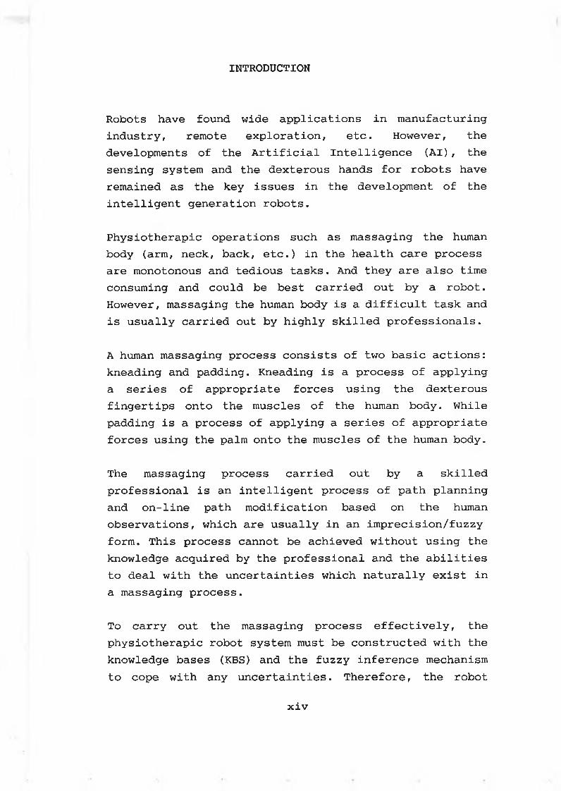
Robots have found wide applications in manufacturing industry, remote exploration, etc. However, the developments of the Artificial Intelligence (AI), the sensing system and the dexterous hands for robots have remained as the key issues in the development of the intelligent generation robots.
Physiothérapie operations such as massaging the human body (arm, neck, back, etc.) in the health care process are monotonous and tedious tasks. And they are also time consuming and could be best carried out by a robot. However, massaging the human body is a difficult task and is usually carried out by highly skilled professionals.
A human massaging process consists of two basic actions: kneading and padding. Kneading is a process of applying a series of appropriate forces using the dexterous fingertips onto the muscles of the human body. While padding is a process of applying a series of appropriate forces using the palm onto the muscles of the human body.
The massaging process carried out by a skilled professional is an intelligent process of path planning and on-line path modification based on the human observations, which are usually in an imprecision/fuzzy form. This process cannot be achieved without using the knowledge acquired by the professional and the abilities to deal with the uncertainties which naturally exist in a massaging process.
To carry out the massaging process effectively, the physiothérapie robot system must be constructed with the knowledge bases (KBS) and the fuzzy inference mechanism to cope with any uncertainties. Therefore, the robot
x i v
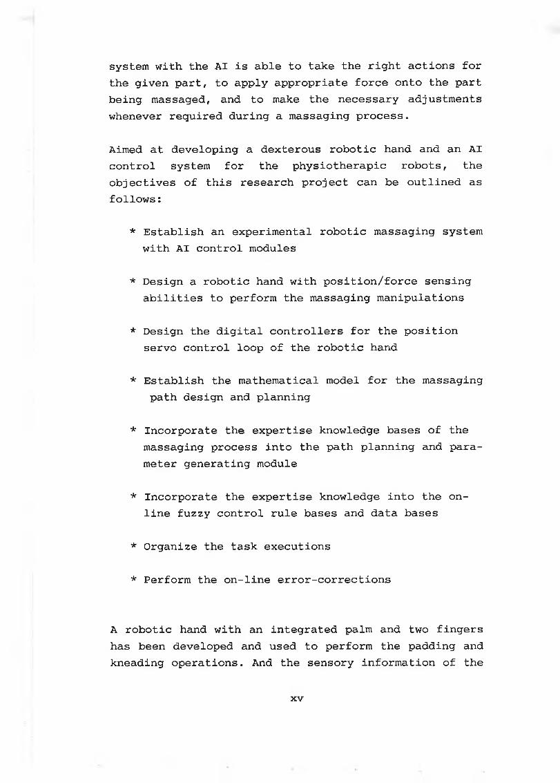
system with the AI is able to take the right actions for the given part, to apply appropriate force onto the part being massaged, and to make the necessary adjustments whenever required during a massaging process.
Aimed at developing a dexterous robotic hand and an AI control system for the physiothérapie robots, the objectives of this research project can be outlined as follows :
* Establish an experimental robotic massaging system with AI control modules
* Design a robotic hand with position/force sensing abilities to perform the massaging manipulations
* Design the digital controllers for the position servo control loop of the robotic hand
* Establish the mathematical model for the massagingpath design and planning
* Incorporate the expertise knowledge bases of the massaging process into the path planning and parameter generating module
* Incorporate the expertise knowledge into the online fuzzy control rule bases and data bases
* Organize the task executions
* Perform the on-line error-corrections
A robotic hand with an integrated palm and two fingers has been developed and used to perform the padding and kneading operations. And the sensory information of the
x v
robotic hand have been used in the intelligent control process.
In a robotic massaging process, uncertainties and errors may occur due to wrongly specified part location, part deviations from its specified position and incorrectly planned path.
The intelligent path planning and control modules have been constructed with the KBS and the fuzzy logic inference mechanism, which are able to deal with uncertainties and errors by manipulating the fuzzy terms.
Thus, with the fuzzy/linguistic input terms, the required parameters can be generated for the path planning module. And the massaging path can be planned by using the KBS in the path planning module.
The task execution is monitored by the intelligent control module. The intelligent control module allows error-correction strategies to be formulated. The required corrections can be carried out by using the online KBS and fuzzy inference mechanism in the intelligent control module.
In this thesis, the literature survey is conducted in chapter 1 , which is mainly concerned with the development of the robotic end-effectors, sensing, compliance control and AI control in robotics.
The robotic massaging process is studied in chapter 2. And a robotic massaging system with AI is also proposed.
The configuration of the robotic massaging system is described in chapter 3, which includes the robot arm and the robotic hand with their controllers, the interfaces
x v i
and the computer. The mechanical design of the robotic hand is also given out.
The development of the end-effector's controller is presented in chapter 4 Where the sensors and amplifier, the DC motor drive circuit design, the position and force servo loop control over the robotic hand have been described.
The direct and inverse kinematics of the robot arm are analysed in chapter 5. And the robotic hand coordinates are presented. Also the massaging path design is described.
The intelligent control system is presented in chapter 6 in which the off-line and on-line KBS are described. The parameter generating and path planning using off-line KBS are established and the task execution module is introduced. The on-line error-corrections based on fuzzy logic are studied. Also the experimental results are presented.
x v i i
C h a p te r One
Literature Survey
1-1 Introduction
A robot is defined as a reprogrammable multifunctional manipulator designed to move materials, parts, tools, or specialized devices, through variable programmed motions for the performance of a variety of tasks.[1]
Robots have found wide applications in industrial flexible manufacturing, remote exploration, and daily life service.
The new generation of robots are characterized by their abilities of:
* intelligent sensing* intelligent decision-making* dealing with uncertainties* intelligent path-planning & error-corrections* performing delicate tasks using dexterous hand
One may always find an application area to verify or to develop the new generation robots. The physiotherapic robot is one of them which requires Artificial Intelligence (AI), sensing, and dexterous robotic hand.
In this chapter, the literature survey on robotic hand design, robotic sensing, compliance control, AI system and fuzzy logic control is carried out.
The development of the robotic hands with multiple fingers is presented in section 1-2. The force/tactile sensing in robotics is reviewed in section 1-3. The compliance control stategies and compliance devices used in robotics are
1
outlined in section 1-4. The literature of the development of AI including fuzzy logic control are surveyed in section 1-5.
1-2 Robotic end-effectors
Robotic end-effectors perform all the tasks instructed by robots. The performance of the end-effectors decides what kind of jobs the robot can do.
Placed at the end of the robot arm and interacting with external objects, end-effectors are often equipped with their own sensors and actuators.
There are two types of end-effectors:* Special-purpose end-effectors which are designed to
adapt to the specific tasks, such as welding, grinding, etc.
* General-purpose end-effectors which are designed with the dexterity and versatility.
The general-purpose end-effectors are featured by the multifingers and the built-in sensors. While the special- purpose end-effectors are characterized with the simple mechanical configurations. The development of the special -purpose end-effectors is at the mature stage except the sensing ability.
The general-purpose end-effectors have long been dreamt of. And in the course of development of robots, many articulated robot hands have been developed to achieve high levels of dexterity and versatility in imitating the human hand with its 32 DOF and thousands of positional, force and temperature sensors. The development of dexterous robot hands with the built-in sensors holds considerable promise for advanced robot capabilities.
2
Depending on the applications, the dexterous robot hand is usually designed with the following functions for the industrial applications:
* The ability to perform advanced manipulation, such as grasping arbitrary objects and tools in the robot workspace.
* The ability to provide the required information to infer the properties of the environment.
Several research projects have been carried out to develop reasonable and practical mechanical design configuration for the robot hands with built-in sensors. The major developments on the multifingered robotic hand are listed as follows.
OKADA HAND (1977)
Research into multifingered robotic hands took its first major step forward with the development of a 3-fingered hand [2] by OKADA in 1977. The hand consists of three fingers: an equivalent thumb with 3 joints, an equivalent index finger with 4 joints and an equivalent middle finger with 4 joints.
Thus, the hand has 11 DOF in total. There are 11 tendons to the fingers, one per joint. The tendons are wires run- ing through a flexible but incompressible sheath off the arm to the DC motors with gearboxes. The joint torque is generated by controlling the DC motors. And the tendon length is measured by using the potentiometers mounted at the motors.
The OKADA hand was designed to handle objects in industrial applications. The problems with the OKADA hand are inadequate sensory feedback [3-4]. There are no force sensors on the tendons to measure real tendon force. The
3
force inferred from the motor torque is grossly in error because of friction in the tendon sheaths. No account was taken of tendon stretch, and the finger positions are not precise.
HANAFUSA HAND (1977)
A three fingered planar gripper was developed for industrial assembly applications by HANAFUSA and ASADA [5-6] in 1977. Each finger is a single DOF level driven by a stepping motor. The frictionless rollers are mounted on the fingertips to prevent any tangential contact force.
The only sensing feedback was the position from the motor. Besides the mechanical design, a gripping theory in the grasping plane was also developed [5] . By defining a potential function arising from the fingertip forces, the stable grasps can be determined by using the knowledge of the object shapes.
Stanford/JPL HAND (1982)
The Stanford/JPL hand was designed for objects handling by SALISBURY [7-10] by following the design philosophy of achieving an arbitrary grasping ability with the fewest fingers, tendons, and sensors.
The hand has three fingers with three joints each, arranged as two fingers and an opposing thumb. There are 4 tendons per finger, following the (n+1) rule that n tendons are needed for n DOF plus extra one since tendons cannot push. The tendons are teflon-coated cables, running over pulleys at the joints, and traveling through flexible but incompressible sheaths.
The position and force sensors have been embedded into the design of the hand. The position sensors at the DC
4
motors are used to measure tendon length. Where the force sensors on the tendon are used to measure the tendon force and to correct the tendon stretch.
Pennsylvania Articulated Mechanical HAND (PAMH) (1983)
Used in industrial assembly operations, PAMH [11] has two forefingers and an opposing thumb. Each finger has two links and two joints with a parallel action. A linear actuator is used to drive the fingers. And the passive springs provide the restoring joint torque. Also optical encoders are used to measure the rotations of the motor shaft.
CAPORALI HAND (1984)
A five fingered hand with four forefingers and a thumb has been designed for industrial applications by Caporali and Shahinpoor [12]. Each finger has three links and 3 DOF. Cables over pulleys are driven by stepping motors. The passive extension of each joint is achieved by using springs. No contact sensing is provided.
Utah/MIT HAND (1985)
The Utah/MIT hand [13-18] consists of four fingers, arranged as a thumb opposing three fingers. Each finger has three links and four joints. Each joint is actuated by 2 antagonistic ploymeric tendon tapes, which run over pulleys to a remote actuator package.
There are 32 tendon tension sensors and 16 joint position encoders. Each joint angle is measured directly by miniature position encoder. Each tendon force is detected at the knuckles by using strain gauges on idler pulleys. Incorporating tactile sensors on the fingertips are being investigated [22].
5
Characterized with large numbers of actuators and sensors, the Utah/MIT dexterous hand requires high servo rates. Thus powerful and flexible computer architectures are needed to carry out the computation and control. Five M68000 microprocessors on a multibus, connected to a VAX 11/750 through a parallel DMA interface, are used to control the Utah/MIT hand [16,18].
The hand control system tends to become more and more complicated and bulky to improve the computation speed [17], Thus it is not easy for the users to incorporate this hand into their robot system.
Hitachi HAND (1985)
A three fingered, tension-driven hand was developed by Hitachi Ltd. [19,20]. A thumb is arranged to oppose two fore fingers. Every finger has three segments and four DOF. Each joint is driven by a novel Shape Memory Alloy (SMA) actuator through tendons. The restoring torque is provided by springs.
The Hitachi hand can lift 2 Kg weight. The maximum joint motion is 90 degree per second. The SMA actuator is compact and light. But the response time due to slow temperature changes does not meet the requirements of most current industrial applications.
YAMAFUJI HAND (1988)
A three fingered hand was developed for objects handling by YAMAFUJI and MAEDA [21]. The hand consists of a palm, a thumb and two fore fingers. The thumb is constructed with 2 joints. While each forefinger has three joints. The bending motion of each finger is realized by using a steel wire driven by a DC motor mounted on the palm. The rotation of the thumb is carried out by using the same
6
driven system. Only one steel wire driven by a DC motor is used to rotate the forefingers.
Eight rotary encoders are mounted on the fingers to detect the motion of the joints, and 22 touch sensors are used to detect the grasped objects. One master microprocessor and three slave microprocessors are used to contruct the hand control system.
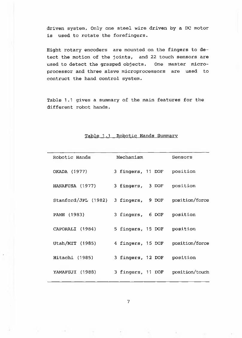
Table 1.1 gives a summary of the main features for the different robot hands.
Table 1.1 Robotic Hands Summary
Robotic Hands Mechanism Sensors
OKADA (1977) 3 fingers, 11 DOF position
HANAFUSA (1977) 3 fingers, 3 DOF position
Stanford/JPL (1982) 3 fingers, 9 DOF position/force
PAMH (1983) 3 fingers, 6 DOF position
CAPORALI (1984) 5 fingers, 15 DOF position
Utah/MIT (1985) 4 fingers, 15 DOF position/force
Hitachi (1985) 3 fingers, 12 DOF position
YAMAFUJI (1988) 3 fingers, 11 DOF position/touch
7
The use of sensors plays an important role in extending the capability of robots to deal with unknown environment and unexpected events. In general, sensors in robotics are mainly used for the following objectives:
* obtaining the on-line information about the workspace and workpieces [23-27]
* detecting the interactions between robots and environment [27-34]
* guiding the motion of the robots based on the sensory information [35-40]
* enhancing the performance of the robots
Sensors used in robotics can be classified into internal sensors and external sensors. The internal sensors, which are usually embedded in the drive systems of the robot to measure position and speed of robot joints and linkages, include encoders, potentiometers, and tachometers. This group of sensors has been well developed and widely used in robotics.
Opposed to the internal position sensors, the external sensors, which are subdivided into contact sensors and non-contact sensors, are under intensive development. Contact sensors detect force/torque and touch/pressure when physically contacting an object. While noncontact sensors sense images, range, and the presence of objects without making any physical contact.
Non-contact sensors are used mainly for:
* identifying and locating objects in an environment [23-25]
* visually inspecting the objects [26]* guiding the manipulation of the robots [36,38,39]
1-3 Sensing in Robotics
8
However, using visual sensing, it is only possible to discover mechanical properties of the objects by deducing them from optical properties. Furthermore, the interaction properties, such as force and torque, between the robot and the environment, can not be detected by using visual sensing. Hence, the contact type sensors such as force and tactile sensors are required to provide the interaction information.
Contact sensors include:* touch sensors* force/torque sensors* tactile/pressure sensors
Tactile sensors, which gives information only about whether or not contact has occurred, are widely used in robotics due to their simple configuration, and low cost. The touch sensors have been used to prevent damaging collisions with obstacles [41-43].
Force/torque sensors are used primarily for measuring the reaction forces developed due to the interactions between the robot and its environment. The measuredforces can be used to guide the motion of the robots.
Different types of sensing materials have been used to construct the force/torque sensing devices, which include: [28,34]
* metal strain gauges* semiconductor strain gauges* conductive elastomers* piezoelectric ceramics, etc.
According to the placement relative to the robotic manipulator, the force/torque sensing devices can be further subdivided into: [32,34]
* force sensing platform
9
* joint torque sensing devices* force sensing wrist and fingers
The force sensing platform has been used by WATSON and DRAKE [33] in 1975 to carry out assembly work. Thehorizontal and vertical forces generated due to the interaction between robot and environment can be measured by using the platform, on which the object being manipulated is placed.
The joint torque sensing devices are usually mounted on the joints of the manipulator. Joint torque sensing has the added advantage of not only detecting forces and torques applied at robotic hand, but also those applied at other points on the manipulator. This is very usefule in providing feedback information if, for instance, some portion of the manipulator were to unexpectedly encounter an obstacle [32,44].
The disadvantages in using the joint torque sensors are:* time consuming to convert joint torques to the
equivalent forces and moment at the robotic hand frame
* uncertainties in measuring and controlling robotic hand forces
One of the solutions to reduce the uncertainties in measuring and controlling hand forces is to mount the force sensing devices either close to the robotic hand or on the robotic fingers, where they are subjected to a minimum of interference from the configuration of the manipulator.
Based on strain gauges and elastically flexing beams, the wrist sensors have been developed by many researchers [45-52] since 1973.
1 0
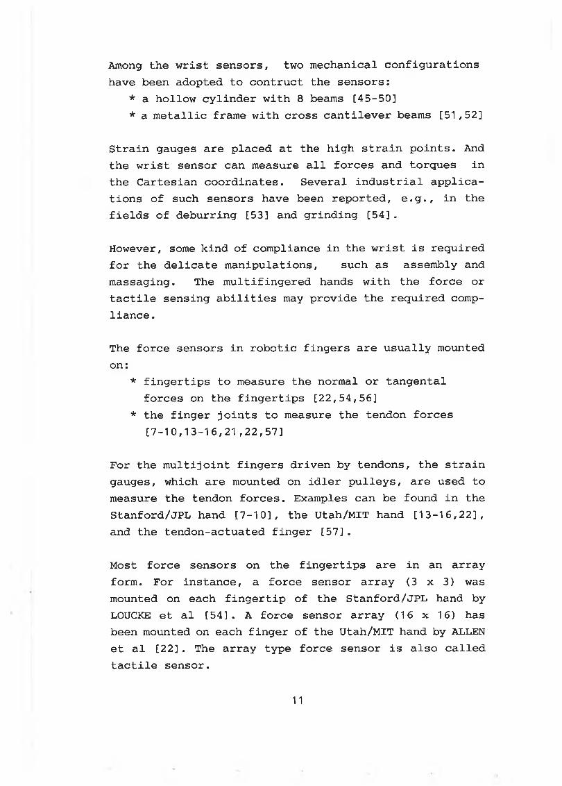
Among the wrist sensors, two mechanical configurations have been adopted to contruct the sensors:
* a hollow cylinder with 8 beams [45-50]* a metallic frame with cross cantilever beams [51,52]
Strain gauges are placed at the high strain points. And the wrist sensor can measure all forces and torques in the Cartesian coordinates. Several industrial applications of such sensors have been reported, e.g., in the fields of deburring [53] and grinding [54].
However, some kind of compliance in the wrist is required for the delicate manipulations, such as assembly and massaging. The multifingered hands with the force or tactile sensing abilities may provide the required compliance.
The force sensors in robotic fingers are usually mounted on:
* fingertips to measure the normal or tangental forces on the fingertips [22,54,56]
* the finger joints to measure the tendon forces [7-10,13-16,21,22,57]
For the multijoint fingers driven by tendons, the strain gauges, which are mounted on idler pulleys, are used to measure the tendon forces. Examples can be found in the Stanford/JPL hand [7-10], the Utah/MIT hand [13-16,22], and the tendon-actuated finger [57].
Most force sensors on the fingertips are in an array form. For instance, a force sensor array (3 x 3) was mounted on each fingertip of the Stanford/JPL hand by LOUCKE et al [54]. A force sensor array (16 x 16) has been mounted on each finger of the Utah/MIT hand by ALLEN et al [22] . The array type force sensor is also called tactile sensor.
11
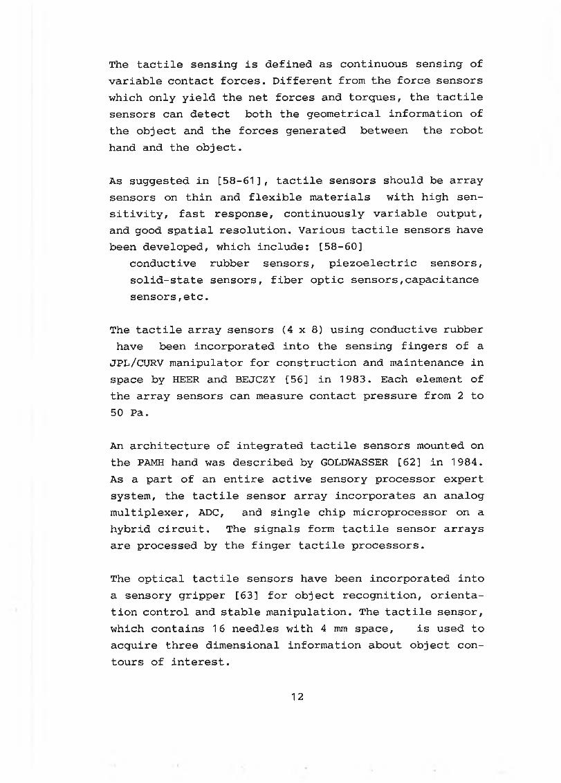
The tactile sensing is defined as continuous sensing of variable contact forces. Different from the force sensors which only yield the net forces and torques, the tactile sensors can detect both the geometrical information of the object and the forces generated between the robot hand and the object.
As suggested in [58-61], tactile sensors should be array sensors on thin and flexible materials with high sensitivity, fast response, continuously variable output, and good spatial resolution. Various tactile sensors have been developed, which include: [58-60]
conductive rubber sensors, piezoelectric sensors, solid-state sensors, fiber optic sensors,capacitance sensors,etc.
The tactile array sensors (4x8) using conductive rubber have been incorporated into the sensing fingers of a
JPL/CURV manipulator for construction and maintenance in space by HEER and BEJCZY [56] in 1983. Each element of the array sensors can measure contact pressure from 2 to 50 Pa.
An architecture of integrated tactile sensors mounted on the PAMH hand was described by GOLDWASSER [62] in 1984. As a part of an entire active sensory processor expert system, the tactile sensor array incorporates an analog multiplexer, ADC, and single chip microprocessor on a hybrid circuit. The signals form tactile sensor arrays are processed by the finger tactile processors.
The optical tactile sensors have been incorporated into a sensory gripper [63] for object recognition, orientation control and stable manipulation. The tactile sensor, which contains 16 needles with 4 mm space, is used to acquire three dimensional information about object contours of interest.
1 2
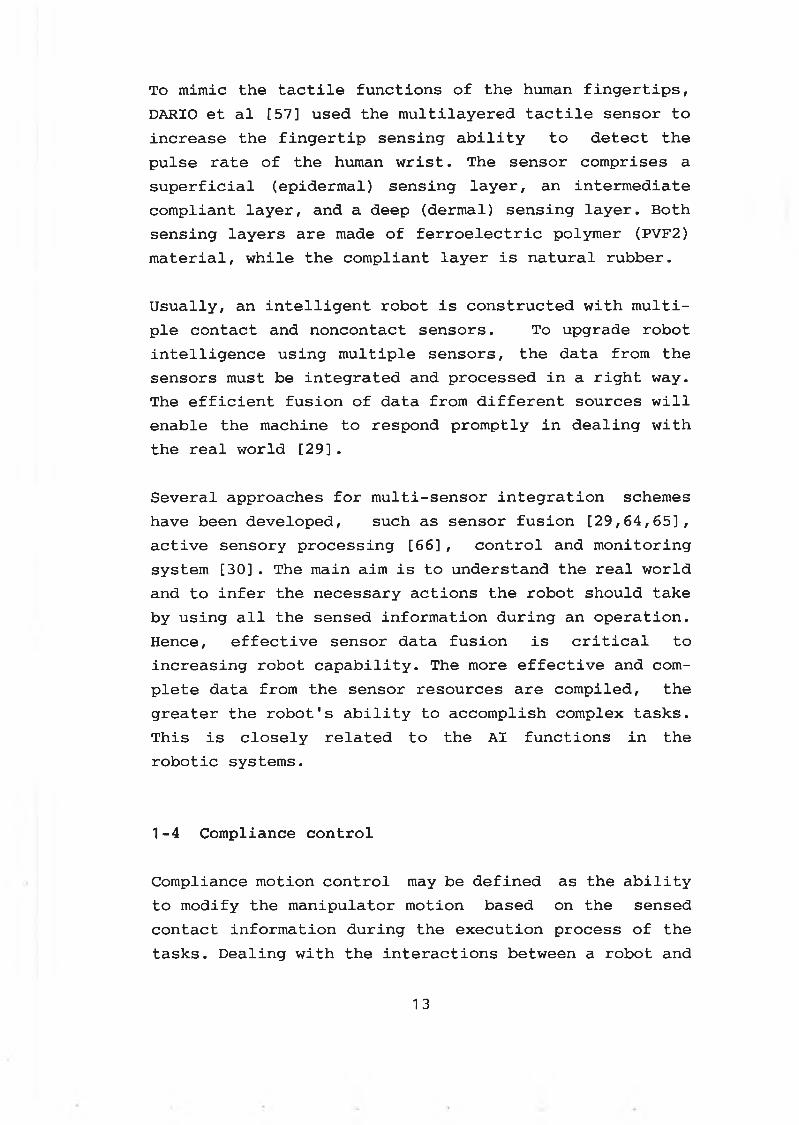
To mimic the tactile functions of the human fingertips, DARIO et al [57] used the multilayered tactile sensor to increase the fingertip sensing ability to detect the pulse rate of the human wrist. The sensor comprises a superficial (epidermal) sensing layer, an intermediate compliant layer, and a deep (dermal) sensing layer. Both sensing layers are made of ferroelectric polymer (PVF2) material, while the compliant layer is natural rubber.
Usually, an intelligent robot is constructed with multiple contact and noncontact sensors. To upgrade robot intelligence using multiple sensors, the data from the sensors must be integrated and processed in a right way. The efficient fusion of data from different sources will enable the machine to respond promptly in dealing with the real world [29].
Several approaches for multi-sensor integration schemes have been developed, such as sensor fusion [29,64,65], active sensory processing [66], control and monitoring system [30]. The main aim is to understand the real world and to infer the necessary actions the robot should take by using all the sensed information during an operation. Hence, effective sensor data fusion is critical to increasing robot capability. The more effective and complete data from the sensor resources are compiled, the greater the robot's ability to accomplish complex tasks. This is closely related to the AI functions in the robotic systems.
1-4 Compliance control
Compliance motion control may be defined as the ability to modify the manipulator motion based on the sensed contact information during the execution process of the tasks. Dealing with the interactions between a robot and
13
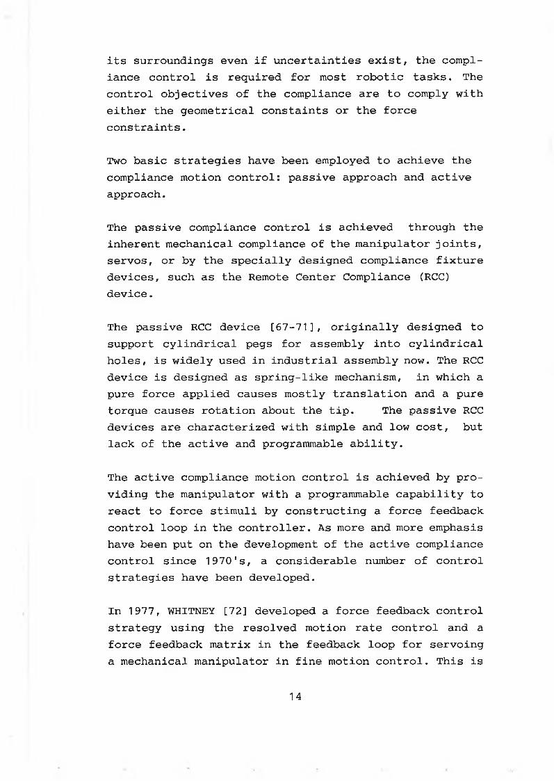
its surroundings even if uncertainties exist, the compliance control is required for most robotic tasks. The control objectives of the compliance are to comply with either the geometrical constaints or the force constraints.
Two basic strategies have been employed to achieve the compliance motion control: passive approach and active approach.
The passive compliance control is achieved through the inherent mechanical compliance of the manipulator joints, servos, or by the specially designed compliance fixture devices, such as the Remote Center Compliance (RCC) device.
The passive RCC device [67-71], originally designed to support cylindrical pegs for assembly into cylindrical holes, is widely used in industrial assembly now. The RCC device is designed as spring-like mechanism, in which a pure force applied causes mostly translation and a pure torque causes rotation about the tip. The passive RCC devices are characterized with simple and low cost, but lack of the active and programmable ability.
The active compliance motion control is achieved by providing the manipulator with a programmable capability to react to force stimuli by constructing a force feedback control loop in the controller. As more and more emphasis have been put on the development of the active compliance control since 1970's, a considerable number of control strategies have been developed.
In 1977, WHITNEY [72] developed a force feedback control strategy using the resolved motion rate control and a force feedback matrix in the feedback loop for servoing a mechanical manipulator in fine motion control. This is
14
the earliest description of the generalized damper approach to compliance control. WHITNEY's work has been classified into velocity based accommodation control in Cartesian space by MAPLES & BECKER [73].
In 1980, SALISBURY [74] described a method for actively controlling the stiffness of an robot arm. Using this method, the three translational and three rotational stiffness of a frame located arbitrarly in the robotic hand coordinates can be programmed.
Using the resolved force vector from the wrist force sensor, PAUL & SHIMANO [75] proposed a simple joint compliance motion control method by selectively servoing several joints to complete the insertion peg tasks. The main idea in [75] is:" control forces applied to the object by selecting a certain joint (or joints) in the manipulator whose action is most closely aligned with the desired direction of force. The selected joints are then force controlled while the remaining joints are left under position control."
In 1981, MASON's theoretical work [76] on compliance control grounded the base for hybrid position/force control architecture proposed by RAIBERT & CRAIG [77] . The kinematics constraints imposed on manipulator motion due to a particular task geometry was discussed in [76]. Hybrid control was proposed to address the issue of control in the presence of natural constraints imposed by task geometry and artificial constraints imposed by the performance of the task itself. The use of artificial constraints orthogonal to the natural constraints was suggested as well. Once the constraint frame is specified, the directions in which position and orientation is constrained by task geometry may be defined with respect to the cartesian space. Therefore,
15
in these directions, constraint forces and torques can be controlled, while in other cartesian space directions, position and orientation is controlled.
Based on the theoretical framework described in [76], RAIBERT & CRAIG [77] proposed a hybrid position/force control architecture to satisfy simultaneous position and force constraints on manipulator motion. This architecture consists of separate position and force control loops. The hybrid controller servos each degree of motion freedom, position or force, at the cartesian space by a closed loop. The joint drive signal is a linear combination of all position/force errors in the cartesian space.
Several arguments have been made for the hybrid control architecture proposed in [77]:
a. high cost computation [78]b. neglecting manipulator dynamics [79,80]c. instability [81]
An improved method was proposed by ZHANG & PAUL [78] to speed up the computation and to simplify the control algorithm by combining the stiffness control [74] with the hybrid control [77]. The dynamic hybrid control of the manipulator was discussed by YOSHIKAWA et al [79,80] and MILLS et al [82] . The stability of the hybrid controller proposed in [77] was found unstable for revolute manipulator [81].
To achieve a robust controller and an effective system, ARONNE & YANG [83] proposed a force control scheme which incorporates both the active compliance control and the passive compliance control. The RCC device was mounted between the wrist sensor and the tool. The hybrid control idea was used to minimize disturbance of the position controller.
16
Several programmable compliance devices have been designed since 1983 for the industrial assembly applications [84,85]
Realizing that both the characteristic of the robot and its environment should be considered, HOGAN [86] proposed an approach which is called impedance control to the control of dynamic interaction between a manipulator and its environment. The impedance control considers the effects of impedance on robot/environment interactions, when performed in task space, a known impedance can be maintained for all configurations. It is considered, however, to be solely a position control scheme, with small adjustments made to react to contact forces. Positions are commanded, and impedance are adjusted to obtain the proper force response.
An unified control approach called hybrid impedance control was proposed by ANDERSON & SPONG [87] by combining the hybrid control [77] with the impedance control [86] . The main feature of the proposed method is its adaptability.[87]
Compliance control, as stated in [88], is one of the key issues of the research in robotics. Research on the compliance control have been focused on the following aspects:
* establishing compliance models* developing control strategies* implementations
1-5 AI in robotics
AI is an embryonic technology dealing with the structure, interpretation, and presentation of knowledge, judge-
17
ments, and inferences. AI involves all elements ofinvestigation that simulate the features, attributes, and behavior of the human brain and related functions. The primary goal of AI is to make machines smarter and more useful. An AI system is usually constructed with: [89]
* knowledge of the domain of interest* methods for operating on the knowledge* control structures for choosing the control actions
and modifying the data base as required
Robotics is generally regarded as a bright area of application of AI. Robots should be intelligent enough to perform the delicate tasks. An intelligent robot is expected to be capable of: [90]
* Receiving high level communications* Understanding its environment* Formulating plans based on reasoning* executing plans and monitoring its operation
Though there is a long way to go for the robots to reach the human' abilities, many efforts have been made to incorporate AI into the robotic systems.
AI Planning in Robotics
Using the hierarchical approach, a robot expert planning system called ABSTRIPS was developed by SACERDOTI [91] in 1974 to devise plans for a robot to move objects between rooms. The knowledge base was constructed with configuration of the rooms, objects properties in the domain, and heuristic search rules, etc.
Unlike ABSTRIPS, which orders the subgoal sequence strictly, some systems do not enforce subgoal sequence until sufficient information exists — a technique known as least commitment. A hierarchy with least commitment
18
technique can be found in the AI planning softwares [92- 93] .
A knowledge based planning system [94] for mechanical assembly using robots was proposed in 1988. The planning efficiency was improved due to two novel features: problem analysis and goal-oriented hierarchical operation representation.
A telerobot interactive planning system (TIPS) [95] was developed in 1980s to perform planning for the space telerobots. An AI planning has also been developed in 1980s for a planetary rover which is used to explore and sample planetary surfaces [96]. With the abilities to recover from planning errors, the AI control module embedded in the planetary rover system can reason about plans, terminate or suspend partions of plans, add patches, and retry plans.
A knowledge based task planning and execution system was developed for an assembly workcell [97] in 1985. The system is constructed with off-line and on-line modules. The off-line module includes various planners based on geometric reasoning in order to structure the workcell space, to synthesize the various actions that can be executed, and to provide rules for action selection and scheduling. The on-line module is a knowledge based system. It maps the task execution parameters into the execution actions and performs the on-line control.
Real-time Knowledge Based System in Robotics
ADAPTIWELD [98] is one of the first arc welding systems to incorporate knowledge of the skilled welders in its information and control base. A three dimensional vision system is used to detect the characteristics of a seam
19
to be welded. These characteristics are stored in the computer memory and are manipulated by the expert system to infer a set of welding actions. The expert system allows the system to perform autonomous welding. Also the expertise knowledge can be added into the welding system1s knowledge base.
A robot system with learning ability and knowledge base has been proposed for the meat cutting applications [99] in 1989. The knowledge base has been constructed with the three dimensional models of typical carcasses, the cutting strategies, etc. Two 2-D cameras have been used to provide the geometric properties of the carcass being cut. The force sensor in the cutting device provides feedback of the cutting force. The sensed information will be processed by the AI controller of the robot. Hence, the on-line error-correction can be realized. The learning unit is used to update the data and knowledge needed in the meat cutting process. Further work of this system is to deal with the uncertainties by using fuzzy logic control method.
The on-line error-correction using the real-time expert system can also be found in the sheep shearing robots [100-102]. A sheep shearing robot needs delicate yet fast tactile action, efficient vision, and a sophisticated control and planning system capable of operating under the pressure of a real-time environment. The surface models of the sheep have been built into the knowledge base of the AI system. The surface model provides advance warnings of changes in surface curvature and serves as a reference for planning robot movements. A machine vision system is used to generate geometric models of the sheep's surface. Based on the surface model, the robot arm trajectory and the cutter attitude are planned. The knowledge of the shearing techniques, combined with force sensing and monitoring of unusual conditions in the
2 0
adaptation mechanism of the robot, provides the inputs to a real-time expert system embedded in the sheep shearing robot system. Incorporated with the on-line recovery strategies, the real-time expert system is able to replan the shear strategy when the lower level path and trajectory adaptation is not sufficient.
The developments of the intelligent control systems for robots have been focused on incorporating on-line expert system into real-time path planning and error-correction. Jet Propulsion Laboratory [103] is developing this kind of AI systems, which consist of a planner expert system, a system diagnostic module, and execution with error recovery module, for the space robot systems.
Fuzzy Logic Based Control in Robotics
To upgrade the level of the intelligence of robotic systems, fuzzy logic based control modules have been incorporated into the AI systems in robotics. Introduced and formulated by ZADEH [104-108] since 1965, fuzzy logic, on which the fuzzy control is based, is an effective means of dealing with uncertainties and linguistic terms. Linguistic terms such as 'small' and 'big' may be defined as fuzzy sets. A fuzzy set is characterized by a membership function that assigns to each element in a given class a grade of membership ranging between zero and one. Therefore, heuristic knowledge may be used as basis for logical inference. Moreover, lingustic rules may be used for specification of control laws in control problems. Fuzzy sets allow for qualitative and imprecise information to be expressed in an exact mathematical way.
Derived from the fuzzy set theory, fuzzy logic deals with relations between fuzzy sets. Fuzzy logic is much closer in spirit to human thinking and reasoning than the
21
traditional logical systems. As an extension of traditional Boolean logic, Fuzzy logic allows partial truth and partial falseness.
Motivated by ZADEH's work, MAMDANI et al [109-115] have pioneered the research on the applications of fuzzy logic controllers to the industrial processes. Recently, fuzzy logic controller is getting intensively studied and applied in Japan and USA due to its ability to: [116]
* incorporate expert knowledge into the control system* make tough problems much simpler to solve* improve system performance radically* make the control system more flexible by carrying
out the inference under uncertainties
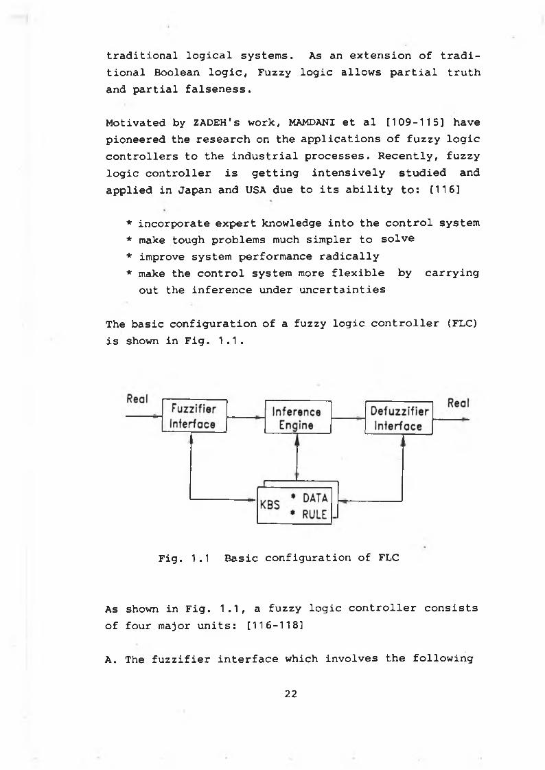
The basic configuration of a fuzzy logic controller (FLC) is shown in Fig. 1.1.
Fig. 1.1 Basic configuration of FLC
As shown in Fig. 1.1, a fuzzy logic controller consists of four major units: [116-118]
A. The fuzzifier interface which involves the following
22
functions:* measure the values of input variables* perform a scale mapping to transfer the range of the
values of input variables into corresponding universes of discourse
* perform fuzzification to convert input data into suitable linguistic values which may be viewed as labels of fuzzy sets
B. The knowledge base which consists of a data base and a lingustic fuzzy control rule base* the data base provides necessary definitions, which
are used to define linguistic control rules and fuzzy data manipulation in a FLC
* the rule base characterizes the control goals and control policy of the domain experts by means of a set of linguistic control rules
C. The inference engine which has the following capabilities :* simulating human decision-making based on fuzzy
concepts* inferring fuzzy control actions employing fuzzy
relations and the rules of inference
D. The defuzzifier interface which performs the following functions:* scale mapping to convert the range of values of out
put variables into the corresponding universes of discourse
* defuzzification to yield a non-fuzzy control action from an inferred fuzzy control action
According to HUANG et al [116], the control rules in aFLC can be derived in several ways:
* based on the expertise experience/knowledge [119]
23
* based on the fuzzy model of the process [120]* based on the operator's control action [121]* based on learning algorithms [122,123]
The application of fuzzy logic to robotics was first conducted by URAGAMI et al [124] in 1976. The robot was able to move through a map space. The robot controls were based on fuzzy programmes. The fuzzy program [124] has been defined as an ordered sequence of fuzzy instructions. In the execution of a fuzzy program, fuzzy instructions are translated into machine instructions by the use of MAX-method and back-tracking.
The MAX-method is referred to the max-selection function used to select the machine instruction with the highest grade. The back-tracking is performed if the result of the interpretation of a fuzzy instruction is impossible to execute. The present state is replaced by the one step before. Then re-intepretation is carried out. Again, the machine instruction, which should be selected in the backtracking process, is the one with the highest grade among those which have never been selected.
A similar work on robots was also reported by GOGUAN [125]. Fuzzy linguistic hints were used to aid a robot running through a maze.
A robot with a knowledge base of movements was studied by HIROTA et al [126] in 1985. The knowledge base is mainly composed of control rules in terms of probabilistic sets in extended fuzzy expressions. The ambiguous instructions in terms of membership and vagueness are given to the robot. The robot is able to recognize these instructions and select an appropriate movement.
In 1985, SCHARF and MANDIC [122] presented a fuzzy Self- Organizing Controller (SOC) for a robot arm. The robot
2 4
controller was contructed with the following features:
* the control rules are formulated through learning* each algorithm needs to act in the direct forward
path of its respective motor control loop* the output of the controller is interpreted directly
as the width of the motor drive pulse.
The SOC consists of the rule base, the performance matrix, the rule reinforcement and the history buffer. The learning function is realized by reference to an incremental performance matrix which has the same size and axes as the rule matrix. The performance matrix is derived from the fuzzy linguistic statements. Experiment shows that the performance of the SOC is superior to a conventional PID controller.
Further work on the SOC based on fuzzy logic was carried out by TANSCHEIT and SCHARF [123]. In the improved SOC, the input signals, which are mapped to one of the 13 discrete levels, are processed by using the rule-based control algorithm. The output signals, in a form of linguistics, will be mapped to a real value.
A fuzzy controller for a robot welding system was developed by KOUATLI et al [127] . The objective is to control the speed of the robot arm to carry out the weld in the same manner as the human welding operators. The fuzzy set shapes have been chosen as 'fuzzimetric arcs'. A scale for partitioning the universe of discourse is determined by using the expertise knowledge. The fuzzy reasoning is based on a compositional rule of inference. The speed of the robot arm controlled by the fuzzy logic controller varies with the cavity size of the workpiece being welded.
25
The fuzzy logic based controller has also been used by SARIDIS [128-130] to construct the linguistic decision modules for the intelligent robots.
Though not specially designed for robotic applications, the intelligent fuzzy logic controller proposed by RAY et al [131] will definitly have potential impact on the future intelligent robots. As suggested in [131], under normal operating conditions the controller will receive information of regular observations of plant data and select a suitable control strategy using compositional rule of inference. While under abnormal conditions,normal control actions are modified using knowledge based decision theoretic scheme.
The global analysis of fuzzy dynamical system was carried out by CHEN et al [132]. Using this method, the approximate prediction of the behavior of a FLC can be achieved.
To speed up the fuzzy inference processing, fuzzy logic chips and computers [133-136] have been developed since 1985.
The first fuzzy logic chip was designed by TOGAI and WATANABE [133] in 1985. The inference mechanism embedded in the VLSI chip is the max-min logic operation. A fuzzy logic accelerator (FLA) and fuzzy processor based on this chip are also available now [116,137].
YAMAKAWA et al [134] realized 9 basic fuzzy logic functions by the standard CMOS process in current-mode circuit systems in 1986.
As mentioned by LIM and TAKEFUJI [136] in 1990, incorporating reasoning system on hardware is significant because expert systems have to make decisions in realtime. Developing reasoning system hardware for an fuzzy
26

processor system consists of two stages: specifying the fuzzy reasoning algorithm and designing special-purpose hardware.
The fuzzy chips and computers, on which the fuzzy inference speed is greatly enhanced, will speed up the applications of fuzzy logic controllers to the intelligent robot systems.
27
Physiotherapic applications such as massaging the human body ( arm,neck,back, etc. ) are monotonous and tedious tasks. They are also time consuming and could be best carried out by a robot.
However, massaging the human body is a difficult task and is usually carried out by highly skilled professionals. The professional can take advantages of the well developed human coordination between the dexterous hands and eyes to locate the part to be massaged and to carry out the massaging manipulations. Also, he/she can utilize the knowledge about the human body and the trained knowledge about the massaging to perform the path planning and the necessary modifications based on his/her rough observations during a massaging process. To carry out the massaging operations, the robot system must be equipped with the necessary intelligence to meet the basic requirements of a massaging process.
In this chapter, the robotic massaging process has been defined in section 2-2. The basic construction of the robotic massaging system has been described in section2-3.
Chapter TwoRobotic Massaging Process
2-1 Introduction
2 - 2 R o b o t i c m a s s a g i n g p r o c e s s
To simulate a massaging process which is carried out by a skilled professional, the robot system should be constructed with the massaging intelligent procedures to
28
handle the complicated and difficult problems associated with part locating , parameter generating, path planning and on-line error corrections.
A robotic massaging process may be defined as a process of applying a series of predefined forces onto the part being massaged along a predefined massaging path, which may be modified by utilizing the sensory information.
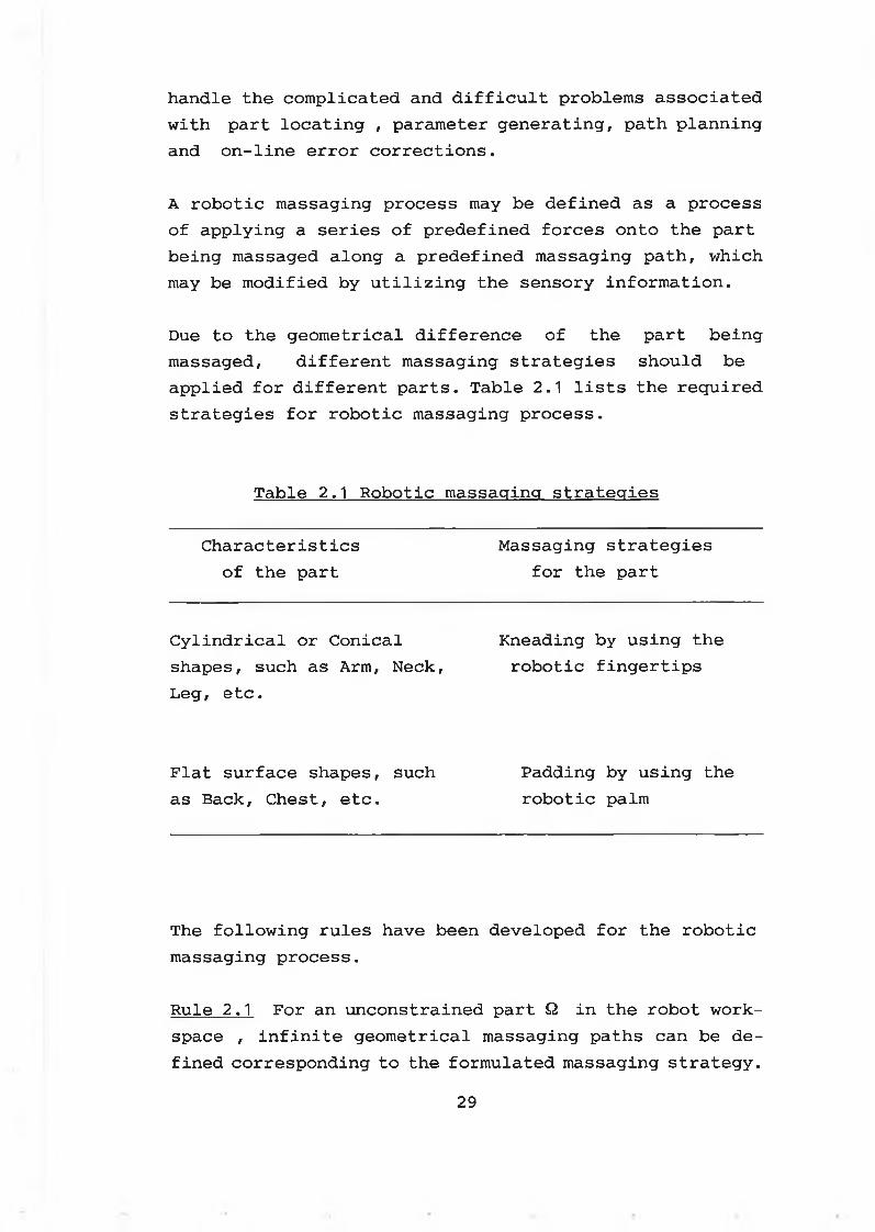
Due to the geometrical difference of the part being massaged, different massaging strategies should be applied for different parts. Table 2.1 lists the required strategies for robotic massaging process.
Table 2.1 Robotic massaging strategies
Characteristics of the part
Massaging strategies for the part
Cylindrical or Conical Kneading by using theshapes, such as Arm, Neck, robotic fingertipsLeg, etc.
Flat surface shapes, such Padding by using theas Back, Chest, etc. robotic palm
The following rules have been developed for the robotic massaging process.
Rule 2.1 For an unconstrained part £2 in the robot workspace , infinite geometrical massaging paths can be defined corresponding to the formulated massaging strategy.
29
Otherwise, finite geometrical massaging paths can be defined for a constrained part Q in the robot workspace.
Rule 2.2 For a given part £2 in the robot workspace, at least one massaging strategy can be formulated.
For example, for a segment of the human arm in the robot workspace, a massaging strategy can be formulated as: "kneading the arm along its axial direction."
Rule 2.3 For any part £2 in the robot workspace, its geometrical properties can be represented by a virtual surface on which the geometrical massaging paths (axial and radial) are planned, the force is applied along the radial path.
Rule 2.4 For a given part, the massaging force is proportional to its size.
The following functions have to be performed to carry out the robotic massaging:
a. Part locating -- Locate the part to be massaged in the robot workspace.
b. Parameter generating -- Generate the required parameters for the path planning.
c. Path planning — Plan the massaging paths
d. Massaging execution — Carry out the massaging
e. On-line error corrections -- Adjust the massaging path and force using the sensed information and the knowledge bases in the AI modules.
According to Rule 2.3, there are two types of massaging
30
paths -- position path and force path, for a given part to be massaged in the robot workspace.
The position path is defined as a geometrical massaging path, which can be denoted by an axial path and a radial path. The force path is defined as a collection of the massaging forces exerted on the part surface along the radial path.
The virtual surface concept has been introduced into the path planning process. In general, a virtual surface may be defined as follows:
Definition 2.1 Regardless of the local properties of the surface of a part being massaged, a virtual path surface can be constructed with the global properties of the surface to encompass the surface of the part being massaged.
Since the local properties of the part surface are not regarded, the part surface can be represented by a simpler form of virtual surface in a global range. For instance, the surface to encompass the fore arm of the human body can be denoted by either a conical or a cylindrical surface, which has been referred to as a virtual surface.
Once the virtual surface is defined for a given part, the position path can be formulated.
Remark 2.1 For a part being massaged using the robotic fingers, an axial center line of the virtual path always exists. The axial center line is always followed by the finger grasp center while the opening of the robotic fingers complies with the radial path.
The massaging process carried out by a skilled professional is a process of intelligent path planning and intelligent on-line error corrections. This process
31
cannot be achieved without using the knowledge acquired by the professional and the inference abilities of the human being.
To carry out the massaging process effectively, the robot system should be constructed with the knowledge base and the intelligent mechanism. Therefore, the robot system may be expected to be able to take the right actions for the given part, to apply appropriate forces onto the part being massaged, and to make the necessary adjustments whenever required during a massaging cycle.
An AI control system, characterized by the abilities to react in an uncertainty environment, generally comprises four components :
a. Man-machine interfaceb. Sensingc. Intelligent decision-makingd. Knowledge bases (KBS)
According to the time requirements of the robotic massaging system, the knowledge bases incorporated into the AI system can be divided into two types:
a. Off-line KBSb. On-line KBS
The off-line KBS are referred to as the knowledge bases which are used to assist the operations without crucial time requirement. While the on-line KBS are referred to as the knowledge bases which are used to assist the operations with crucial time requirement. Hence, the offline KBS are incorporated into the following modules:
a. Man-machine interfaceb. Parameter generating
32
c . Path planningd. Off-line fuzzy inference
And the on-line KBS are incorporated into the following modules :
a. Error correctionb. Path modifyingc. On-line fuzzy inference
2 - 3 R o b o t i c m a s s a g i n g s y s t e m
To develop the associated techniques for the physiothérapie applications, an experimental robotic massaging system has been constructed as shown in Fig. 2 . 1 . The robotic massaging system includes:
A. Hardwarea. Robotic arm & its controllerb. Robotic hand & its controllerc. Position, force and tactile sensing unitsd. Interfacing between the sensing units and the PCe. Interfacing between the controller and the PCf. Personal Computer (IBM-PC/AT)g. A/D , D/A, and I/O boards on the PC
B. Softwarea. Man-machine dialogueb. Off-line KBSc. On-line KBSd. Path planninge. Task executionf. Error correction & path modifyingg. Sensing processing & interfacingh. Servo loop controller
33
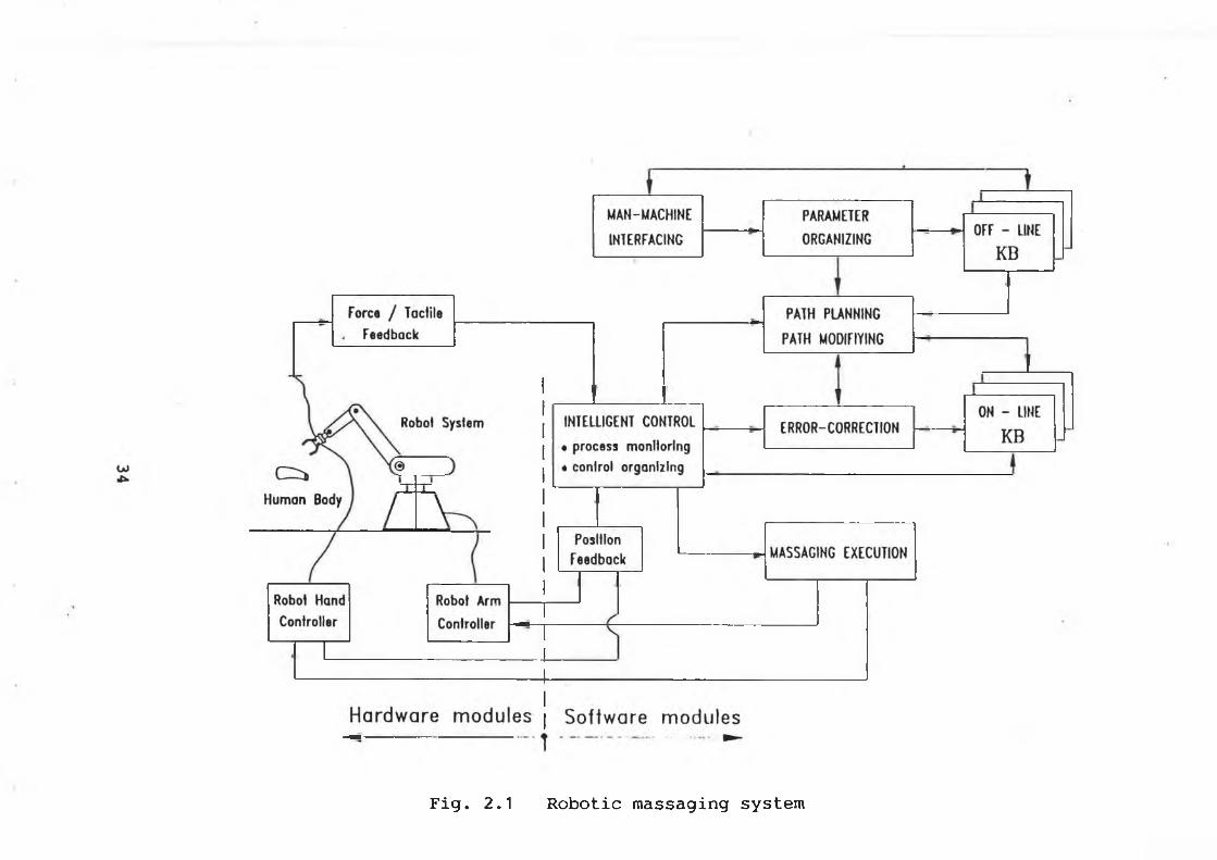
Fig. 2.1 Robotic massaging system
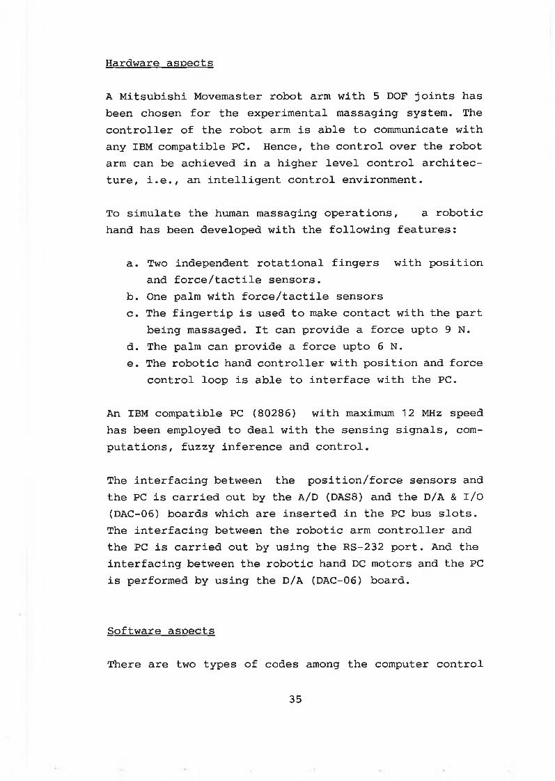
Hardware aspects
A Mitsubishi Movemaster robot arm with 5 DOF joints has been chosen for the experimental massaging system. The controller of the robot arm is able to communicate with any IBM compatible PC. Hence, the control over the robot arm can be achieved in a higher level control architecture, i.e., an intelligent control environment.
To simulate the human massaging operations, a robotic hand has been developed with the following features:
a. Two independent rotational fingers with position and force/tactile sensors.
b. One palm with force/tactile sensorsc. The fingertip is used to make contact with the part
being massaged. It can provide a force upto 9 N.d. The palm can provide a force upto 6 N.e. The robotic hand controller with position and force
control loop is able to interface with the PC.
An IBM compatible PC (80286) with maximum 12 MHz speed has been employed to deal with the sensing signals, computations, fuzzy inference and control.
The interfacing between the position/force sensors and the PC is carried out by the A/D (DAS8) and the D/A & I/O (DAC-06) boards which are inserted in the PC bus slots. The interfacing between the robotic arm controller and the PC is carried out by using the RS-232 port. And the interfacing between the robotic hand DC motors and the PC is performed by using the D/A (DAC-06) board.
Software aspects
There are two types of codes among the computer control
35
and computation software:
a. Compiled BASIC code, which provides the control system with machine instructions.
b. Robot arm control code, which is provided by the manufacturer.
The motion of the robot arm can be realized by sending the robot arm control codes to the robot arm controller. For example, the code "NT" sent out by the PC will cause the robot arm to move back to its defined home position.
The compiled BASIC has been employed to develop and construct the following software:
a . Man-machine dialogueb. KBS for off-line and on-linec. Robotic kinematics computationd. Intelligent path planninge. Sensory information processingf. Interfacing programmingg. Robotic hand digital controllerh. Fuzzy inference and decision-makingi. Intelligent control
When an anolog-to-digital conversion is performed by the A/D board, its driven software, which is written in assemblier language, can be incorporated into the compiled BASIC code by users.
The intelligent control software written in the complied BASIC can also be programmed with other computer languages such as C and LISP, provided that the language used can handle the information flows in the whole system.
36
C h a p t e r T h r e e
C o n f i g u r a t i o n o f t h e r o b o t i c m a s s a g i n g s y s t e m
3 -1 I n t r o d u c t i o n
In this chapter, the robotic massaging system configuration is presented in section 3-2. While the mechanical designs of the robotic hand and its sensing units are described in section 3-3.
3 - 2 S y s t e m c o n f i g u r a t i o n
The main components of the robotic massaging system can be generated as follows:
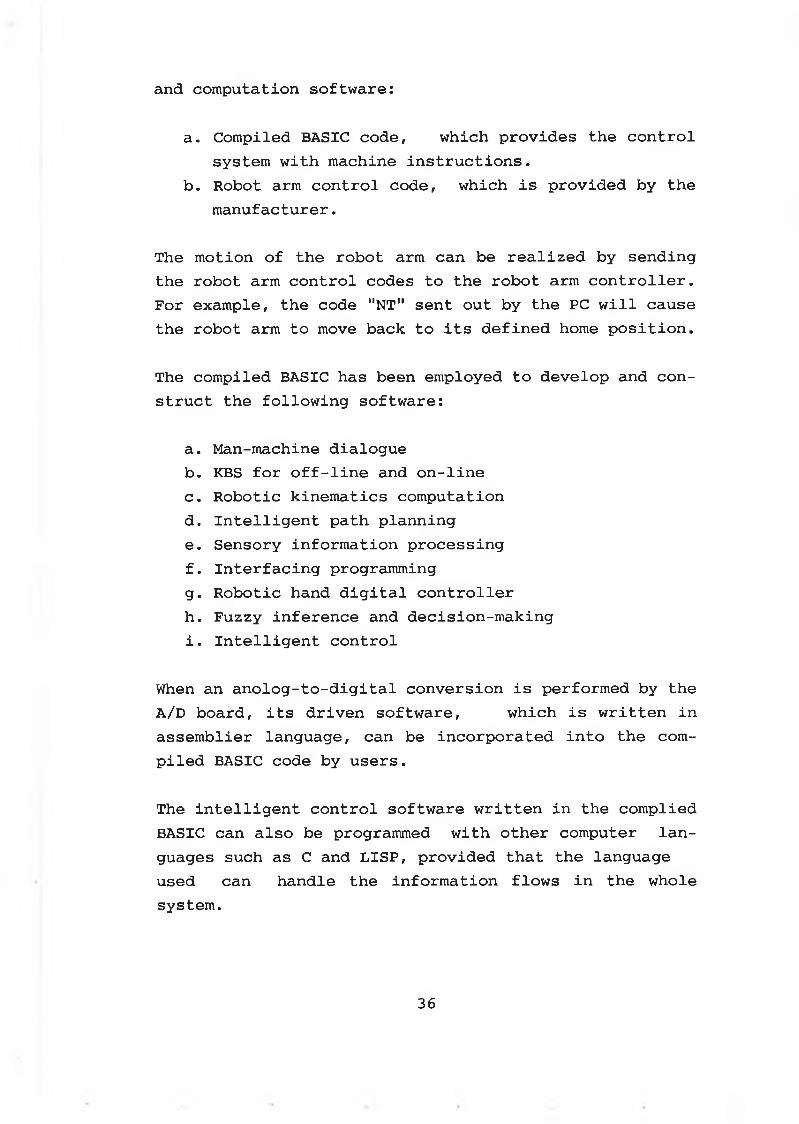
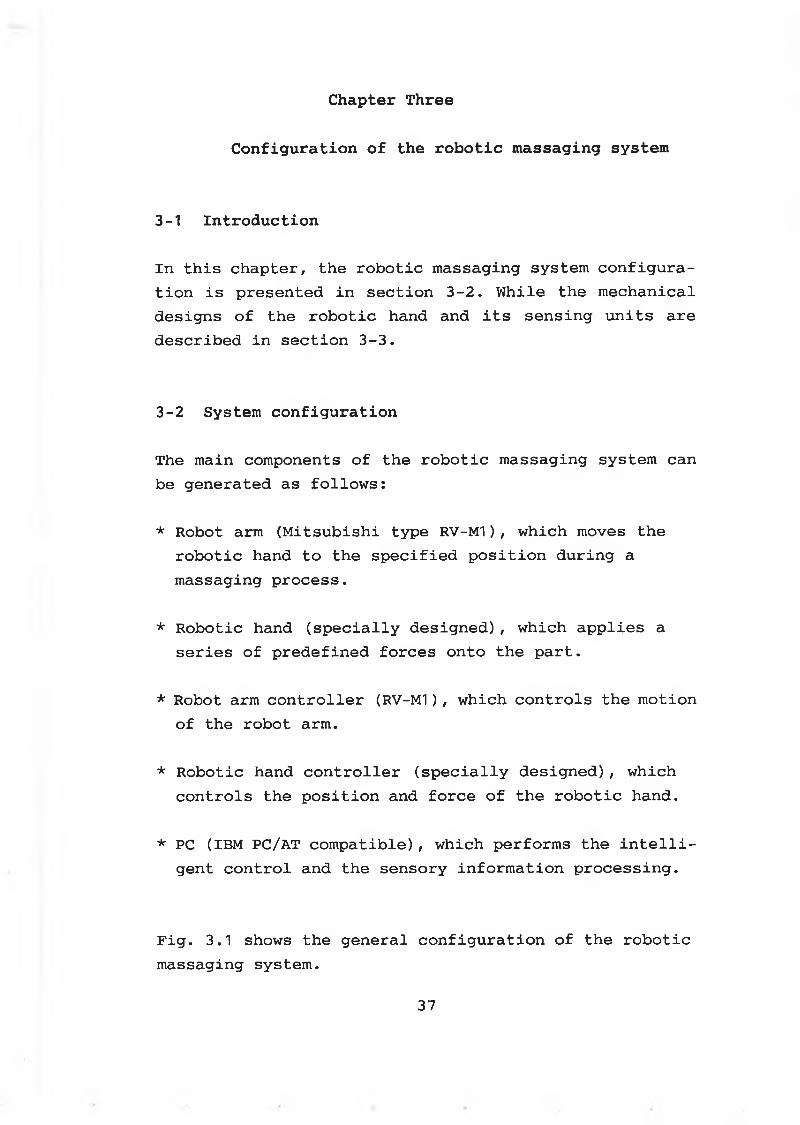
* Robot arm (Mitsubishi type RV-M1), which moves the robotic hand to the specified position during a massaging process.
* Robotic hand (specially designed), which applies a series of predefined forces onto the part.
* Robot arm controller (RV-M1), which controls the motion of the robot arm.
* Robotic hand controller (specially designed), which controls the position and force of the robotic hand.
* PC (IBM PC/AT compatible), which performs the intelligent control and the sensory information processing.
Fig. 3.1 shows the general configuration of the robotic massaging system.
37
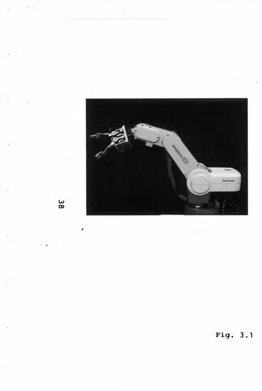
Fig. 3 .1
General system configuration
3-2-1 Robot arm and its controller
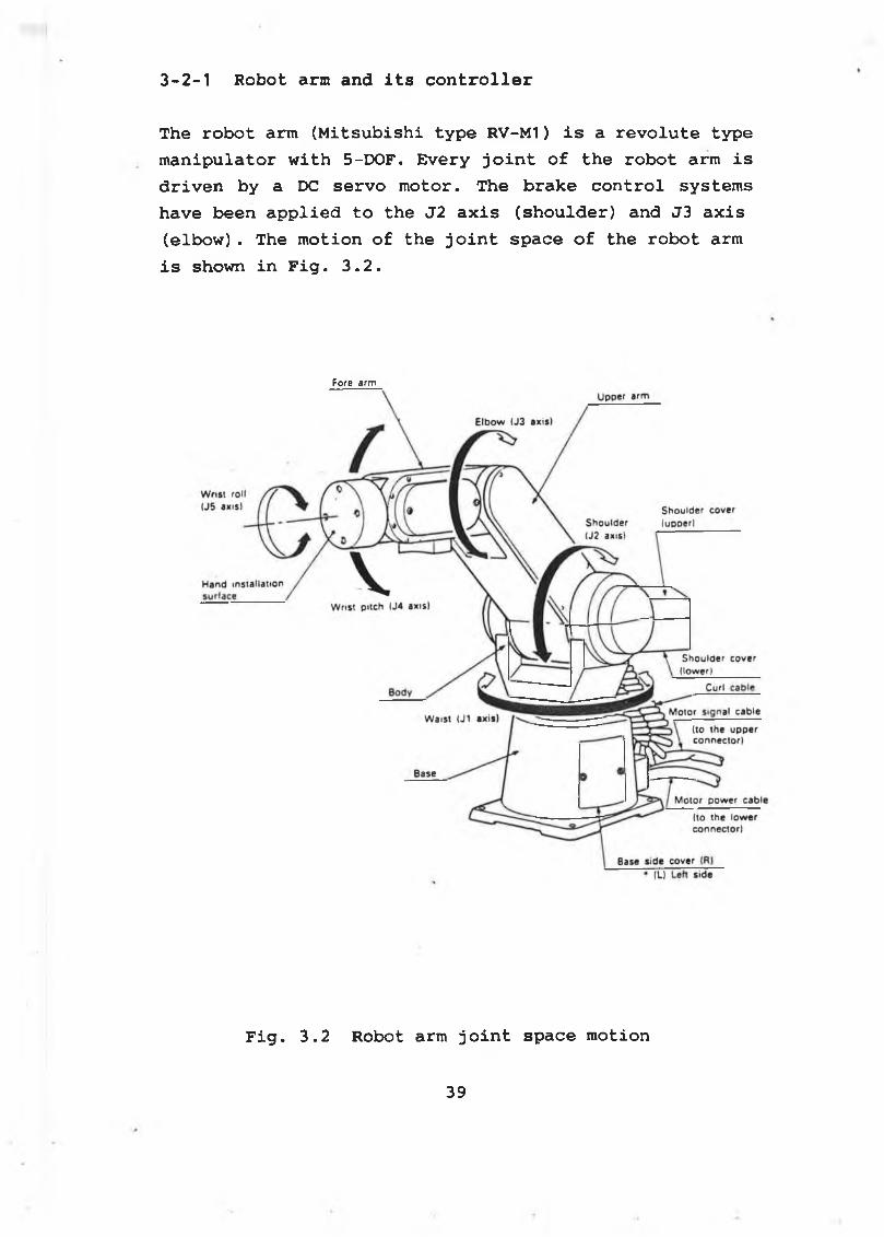
The robot arm (Mitsubishi type RV-M1) is a revolute type manipulator with 5-DOF. Every joint of the robot arm is driven by a DC servo motor. The brake control systems have been applied to the J2 axis (shoulder) and J3 axis (elbow). The motion of the joint space of the robot arm is shown in Fig. 3.2.
Fore a rm
Fig. 3.2 Robot arm joint space motion
39
The robot arm together with its controller have been configured with the PC. The PC invokes the robot's joint motion by the intelligent commands provided in the robot arm controller. The intelligent commands for the robot arm are given in Appendix A-1 . In this configuration, the PC has been used to control the robot to perform a variety of tasks.
The robot arm controller has a built-in arithmetic processing unit and a battery backed static RAM (Random Access Memory). Any commands from the PC will be stored in the RAM and executed under the control of the PC. The interfacing between the PC and the robot arm controller is made through RS232C.
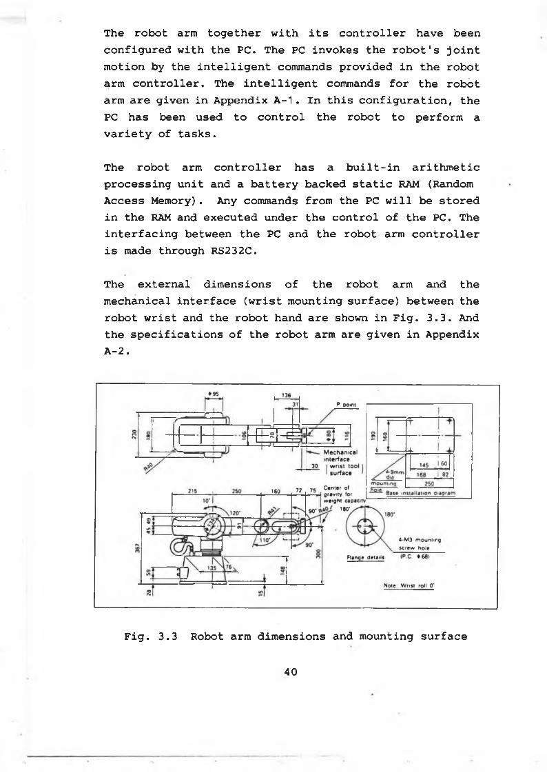
The external dimensions of the robot arm and the mechanical interface (wrist mounting surface) between the robot wrist and the robot hand are shown in Fig. 3.3. And the specifications of the robot arm are given in Appendix A-2.
Fig. 3.3 Robot arm dimensions and mounting surface
40
3-2-2 Robotic hand and its controller
In this research project, two sets of robotic hands have been designed and developed, which are HAND-I and HAND-
The first hand (HAND-I) is an experimental model, where FSR (Force Sensing Resistor) sensors are used to constructed the force sensing fingertips and the palm. And potentiometers are used to construct the position sensing unit for the robotic fingers. Each robotic finger is driven by a DC-motor through a pulley-timing belt system.
The second hand (HAND-II) is a modified version of HAND- I. And HAND-II is intended to be a general purpose hand for different applications such as delicate material handling and massaging.
The drive system for HAND-II is almost the same as that of HAND-I. The differences between HAND-II and HAND-I in massaging applications are as follows:
* A big size palm has been built in HAND-II.
* Load cells are used as force sensing units in the fingertips of HAND-II.
* Microswitches are mounted at the fingertips of HAND-II.
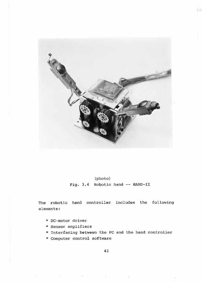
Fig. 3.4 shows the configuration of HAND-II.
The more detailed mechanical design of the robotic hands can be found in section 3-3.
41
*
(photo)Fig. 3.4 Robotic hand -- HAND-II
The robotic hand controller includes the following elements:
* DC-motor driver* Sensor amplifiers* Interfacing between the PC and the hand controller* Computer control software
4 2
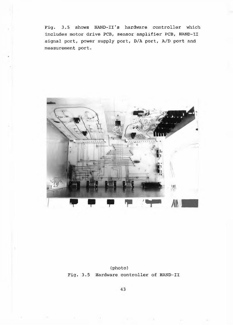
Fig. 3.5 shows HAND-II's hardware controller which includes motor drive PCB, sensor amplifier PCB, HAND-II signal port, power supply port, D/A port, A/D port and measurement port.
(photo)Fig. 3.5 Hardware controller of HAND-II
A. Interfacing between robot arm controller and PC
The robot arm controller allows two types of interfaces for the link between the robot arm controller and the PC: Parallel and serial interfaces.
In the parallel interface mode, the PC sends 8 bits in parallel through the centronics port and the dedicated signal lines control the flow of data. The parallel transmission ensures the faster transmission speed and requires no special settings. But the following problems will discourage the use of the parallel interface:
* The data transmission distance is restricted to 1 to 2 meters.
* The data transfer is only one-way from the PC to the robot arm controller.
* Some intelligent commands such as position feedback of the robot arm cannot be used.
Thus, the parallel interface was not used in this study.
The serial interface, or RS232C interface, was originally the standard for data communication equipment using telephone lines and has evolved into the serial data transmission standard for the computers and their peripheral equipment.
In RS232C interface mode, the data are sent along a single wire (or channel) , one bit at a time. Thus, it takes longer than in the parallel transmission if the baud rate is low. However, the capability of bidirectional data transfer enables the PC to read the robot' s internal data such as position feedback. Also, the serial communication adapter permits a longer transmission
3-2-3 Interfaces
44
distance than parallel communication (as long as 3 to 15 meters) .
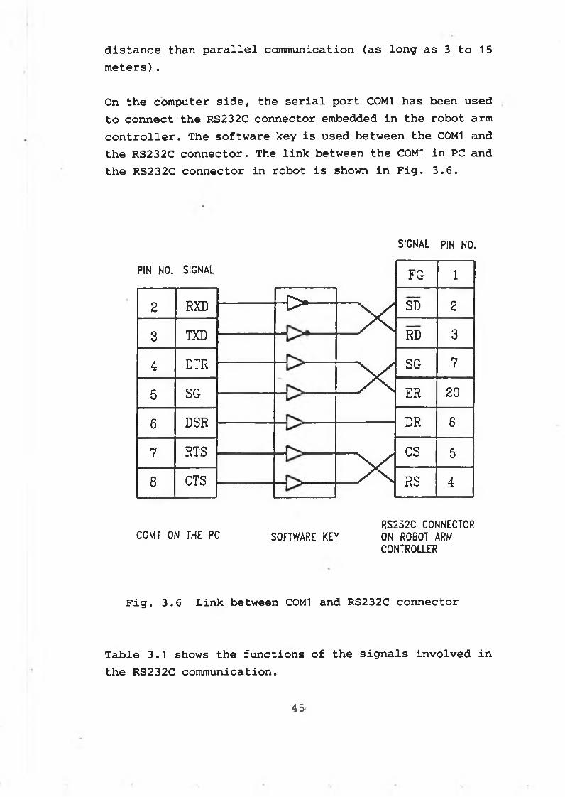
On the computer side, the serial port C0M1 has been used to connect the RS232C connector embedded in the robot arm controller. The software key is used between the C0M1 and the RS232C connector. The link between the C0M1 in PC and the RS232C connector in robot is shown in Fig. 3.6.
SIGNAL PIN NO.
PIN NO. SIGNAL
2 RXD
3 TXD
4 DTR
5 SG
6 DSR
7 RTS
8 CTS
■ O - XX
X
FG 1
SD 2
RD 3
SG 7
ER 20
DR 6
CS 5
RS 4
C0M1 ON THE PC SOFTWARE KEYRS232C CONNECTOR ON ROBOT ARM CONTROLLER
Fig. 3.6 Link between COM1 and RS232C connector
T a b l e 3 . 1 s h o w s t h e f u n c t i o n s o f t h e s i g n a l s i n v o l v e d i n
t h e RS232C c o m m u n i c a t i o n .
45
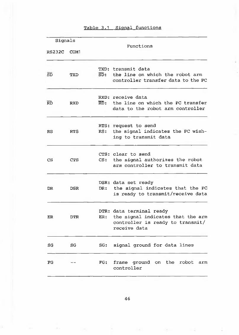
Table 3.1 Signal functions
Signals
RS232C C0M1Functions
SD TXDTXD:SD:
transmit datathe line on which the robot arm controller transfer data to the PC
RD RXDRXD:RD:
receive datathe line on which the PC transfer data to the robot arm controller
RS RTSRTS:RS:
request to sendthe signal indicates the PC wishing to transmit data
CS CTSCTS:CS:
clear to sendthe signal authorizes the robot arm controller to transmit data
DR DSRDSR:DR:
data set readythe signal indicates that the PC is ready to transmit/receive data
ER DTRDTR:ER:
data terminal ready the signal indicates that the arm controller is ready to transmit/ receive data
SG SG SG: signal ground for data lines
FG — FG: frame ground on the robot arm controller
46
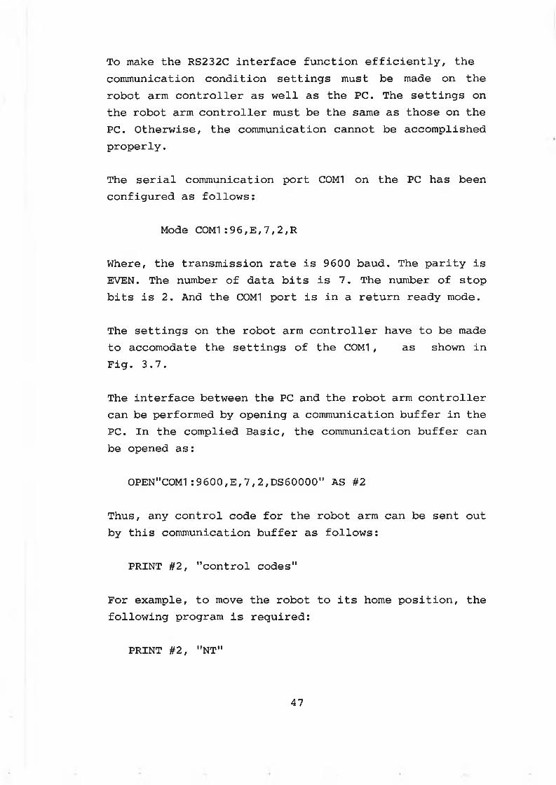
To make the RS232C interface function efficiently, the communication condition settings must be made on the robot arm controller as well as the PC. The settings on the robot arm controller must be the same as those on the PC. Otherwise, the communication cannot be accomplished properly.
The serial communication port C0M1 on the PC has been configured as follows:
Mode COM1:96,E,7,2,R
Where, the transmission rate is 9600 baud. The parity is EVEN. The number of data bits is 7. The number of stop bits is 2. And the COM1 port is in a return ready mode.
The settings on the robot arm controller have to be made to accomodate the settings of the COM1 , as shown in Fig. 3.7.
The interface between the PC and the robot arm controller can be performed by opening a communication buffer in the PC. In the complied Basic, the communication buffer can be opened as:
0PEN"C0M1:9600,E ,7,2,DS60000" AS #2
Thus, any control code for the robot arm can be sent out by this communication buffer as follows:
PRINT #2, "control codes"
For example, to move the robot to its home position, the following program is required:
PRINT #2, "NT"
47
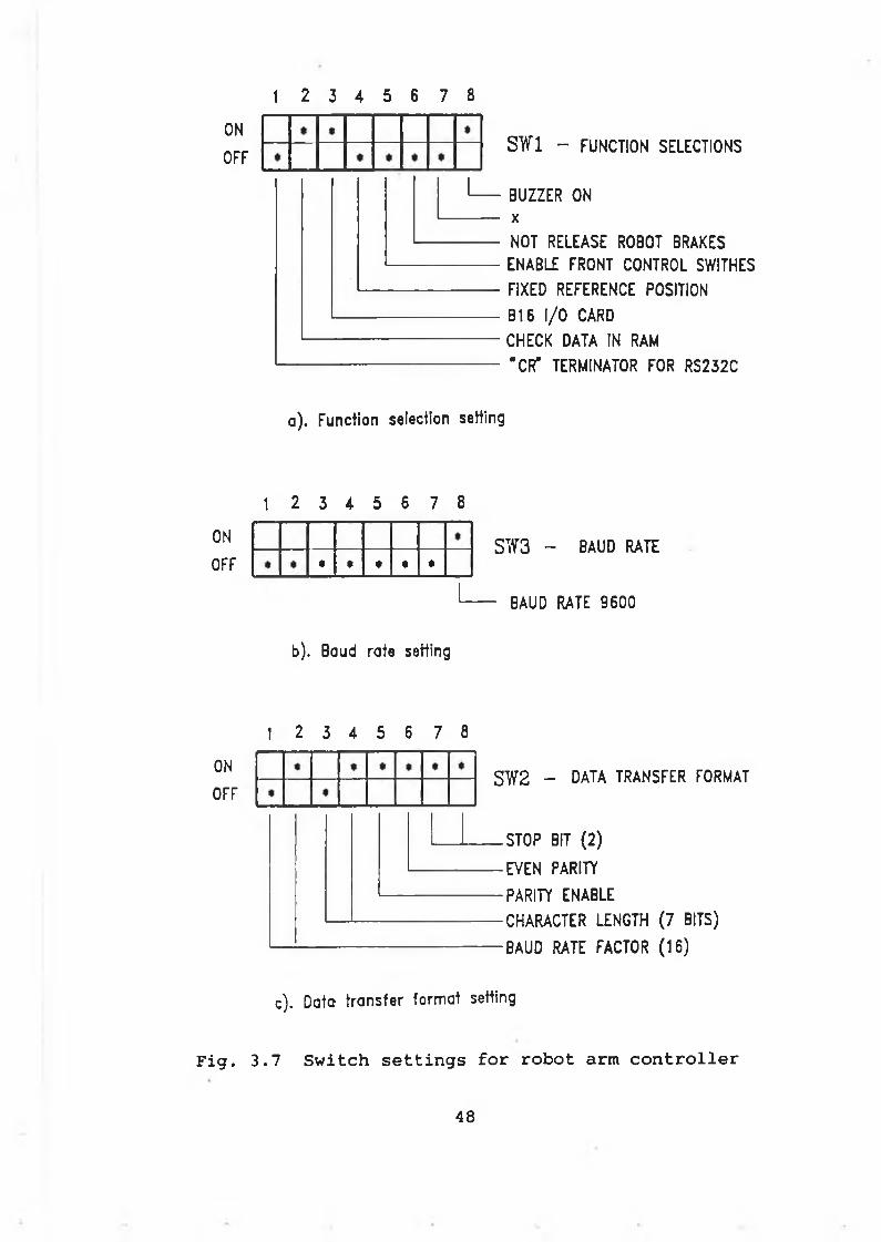
1 2 3 4 5 6 7 8
ON
OFFS W 1 - FUNCTION SELECTIONS
BUZZER ON xNOT RELEASE ROBOT BRAKES
ENABLE FRONT CONTROL SWITHES FIXED REFERENCE POSITION
B16 I /O CARD CHECK DATA IN RAM "CR* TERMINATOR FOR RS232C
a ) . Function selection setting
1 2 3 4 5 6 7 8
ON
OFF
b). Baud rate setting
SW3 - BAUD RATE
- BAUD RATE 9 6 0 0
1 2 3 4 5 6 7 8
ON
OFFSW2 - DATA t r a n s f e r f o r m a t
.STOP BIT (2 )
■EVEN p a r it y
■PARITY ENABLE •CHARACTER LENGTH (7 BITS)
•BAUD RATE FACTOR (1 6 )
c). D ate tra n s fe r fo rm a t setting
Fig. 3.7 Switch settings for robot arm controller
48
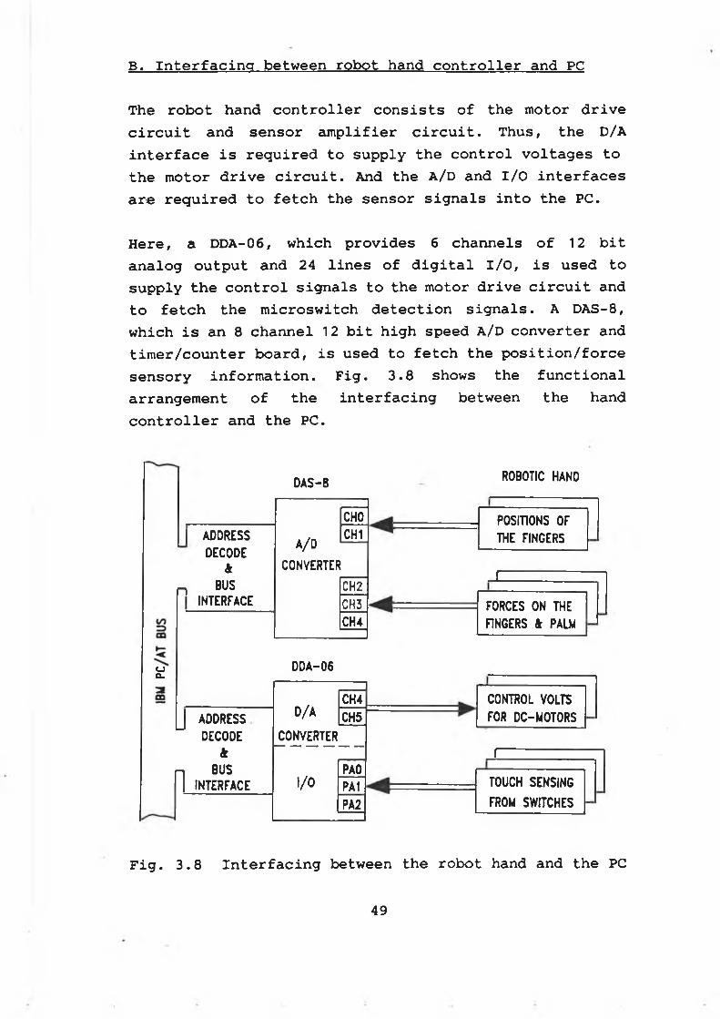
B . I n t e r f a c i n g b e t w e e n r o b o t h a n d c o n t r o l l e r a n d PC
T h e r o b o t h a n d c o n t r o l l e r c o n s i s t s o f t h e m o t o r d r i v e
c i r c u i t a n d s e n s o r a m p l i f i e r c i r c u i t . T h u s , t h e D /A
i n t e r f a c e i s r e q u i r e d t o s u p p l y t h e c o n t r o l v o l t a g e s t o
t h e m o t o r d r i v e c i r c u i t . And t h e A /D a n d I / O i n t e r f a c e s
a r e r e q u i r e d t o f e t c h t h e s e n s o r s i g n a l s i n t o t h e PC.
H e r e , a D D A -0 6 , w h i c h p r o v i d e s 6 c h a n n e l s o f 12 b i t
a n a l o g o u t p u t a n d 2 4 l i n e s o f d i g i t a l I / O , i s u s e d t o
s u p p l y t h e c o n t r o l s i g n a l s t o t h e m o t o r d r i v e c i r c u i t a n d
t o f e t c h t h e m i c r o s w i t c h d e t e c t i o n s i g n a l s . A D A S -8 ,
w h i c h i s a n 8 c h a n n e l 12 b i t h i g h s p e e d A /D c o n v e r t e r a n d
t i m e r / c o u n t e r b o a r d , i s u s e d t o f e t c h t h e p o s i t i o n / f o r c e
s e n s o r y i n f o r m a t i o n . F i g . 3 . 8 s h o w s t h e f u n c t i o n a l
a r r a n g e m e n t o f t h e i n t e r f a c i n g b e t w e e n t h e h a n d
c o n t r o l l e r a n d t h e PC.
oQ-
DAS-8
CHOI ADDRESS CH1
DECODEA /D
k CONVERTERn BUS CH2
INTERFACE CH3CH4
DDA-06
D /ACH4
J ADDRESS CH5DECODE CONVERTER
ftn BUS PAO
I INTERFACE I/O PA1PA2
ROBOTIC HAND
POSITIONS OF THE FINGERS
_c
r
FORCES ON THE FINGERS & PALM
CONTROL VOLTS FOR DC-MOTORS
------------------------- TOUCH SENSING------- ----------- - _FROM SWITCHES
Fig. 3.8 Interfacing between the robot hand and the PC
49
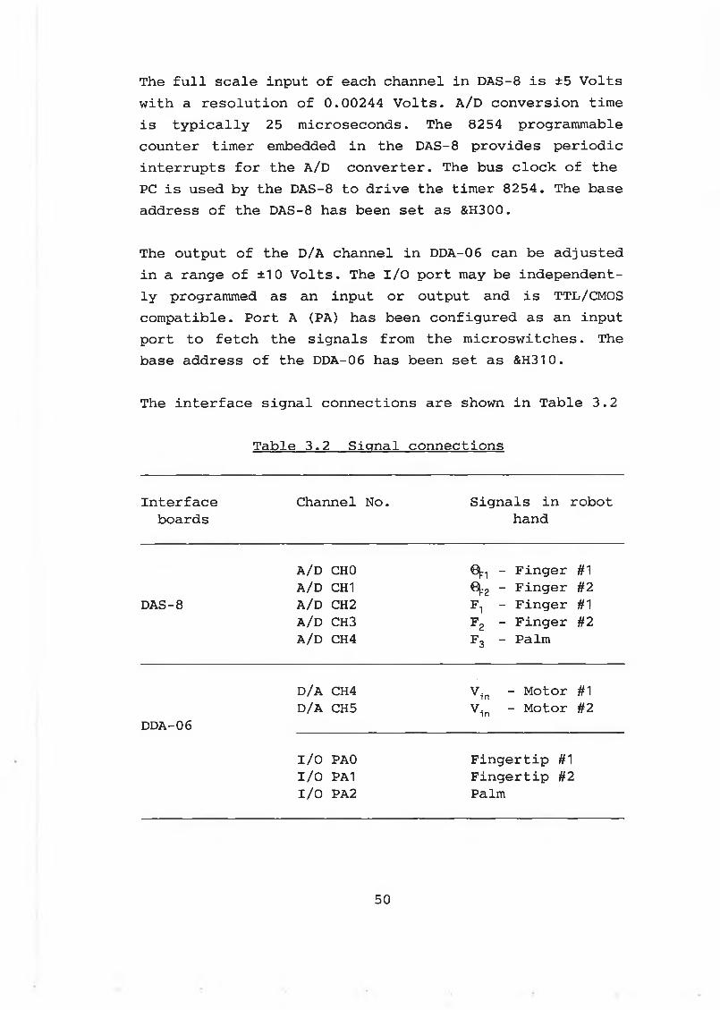
The full scale input of each channel in DAS-8 is ±5 Volts with a resolution of 0.00244 Volts. A/D conversion time is typically 25 microseconds. The 8254 programmable counter timer embedded in the DAS-8 provides periodic interrupts for the A/D converter. The bus clock of the PC is used by the DAS-8 to drive the timer 8254. The base address of the DAS-8 has been set as &H300.
The output of the D/A channel in DDA-06 can be adjusted in a range of ±10 Volts. The I/O port may be independently programmed as an input or output and is TTL/CMOS compatible. Port A (PA) has been configured as an input port to fetch the signals from the microswitches. The base address of the DDA-06 has been set as &H310.
The interface signal connections are shown in Table 3.2
Table 3.2 Signal connections
Interface Channel No. Signals in robotboards hand
DAS-8
A/D CH0 A/D CH1 A/D CH2 A/D CH3 A/D CH4
0^ - Finger #1 0[:2 - Finger #2 F1 - Finger #1 F2 - Finger #2 F3 - Palm
D/A CH4 Vin - Motor #1
DDA-06D/A CH5 Vin - Motor #2
I/O PAO Fingertip #1I/O PA1 Fingertip #2I/O PA2 Palm
50
3-2-4 Computer system
The IBM PC/AT compatible PC (Proturbo 286) used consists of a motherboard, 2 serial ports, 1 parallel port, a 33 MB hard disk, 2 floppy diskette drivers, a keyboard and an EGA monitor.
The motherboard, on which the function jumpers and switches are used to enable the various add-on features, has been constructed with the following components:
* CPU 80286
* Math coprocessor 80287-10
* 32 KB ROM
* 1 MB RAM
* Clock generator chip with speed selection switch on the front pannel ( 8MHz or 12 MHz)
* Bus controller chip
* Peripheral chips
* System unit expansion slots (5)
The speed of the PC is under the control of the speed button on the front panel. Normally, the system is running at 12 MHz, where the bus clock is selected as 12 MHz.
When the DAS-8 is inserted into the bus slot on the motherboard, the bus clock 12 MHz is selected to drive the timer in DAS-8.
51
3-3 Design & development of the robotic hands
3 - 3 - 1 D e s i g n s p e c i f i c a t i o n s
The design objectives of the robot hand are as follows:
* The robotic fingers and robotic palm are integrated into the robotic hand
* The kneading operations can be carried out by using the fingers, while the padding operations can be carried out by the palm.
* The force applied by the hand should be programmable .
* The hand can sense its surroundings by using the touch sensors, position sensors, and force sensors embedded in the robotic hand.
The design specifications can be generalized as:
A. For robotic fingers
* Two rotational fingers driven by two DC-motors can be rotated independently.
* The maximum working torque provided by each finger is 0.9 Nm.
* The fingers can be either position controlled or force controlled
* The position sensor is mounted on the rotational center of each finger
52
* The force sensor is mounted on each fingertip
* The finger rotation range is from -5° to 95°.
* The microswitch is mounted on each fingertip.
B. For robotic palm
* The maximum force provided by the palm is 5 N
* The force sensor is mounted on the top of the palm
* The physical size of the palm should be big enough with less weight
C. For robotic hand body
* The weight of the hand is less than 1.2 Kg
* The hand is easy to be mounted on the robotic wrist mounting surface.
3-3-2 Mechanical design of the robotic hands
As an experimental model for the massaging operations, HAND-I is featured by:
* FSR sensors are mounted on the robotic fingertips and the robotic palm to carry out the force sensing
* Potentiometers are mounted on the finger shafts to carry out the position sensing
* A microswitch is mounted on the palm to detect the
53
touch
* Each finger is driven by a DC-motor through a pulley-timing belt system
* Exchangable fingers
* Single mounting surface
As a modified version of HAND-I, HAND-II is featured by:
* The load cell are mounted on the fingertips to measure the forces
* The big size FSR is mounted on the palm to measure the force
* Potentiometers are mounted on the finger shafts to measure the rotational position of the fingers
* A microswitch is mounted on each fingertip
* Each finger is driven by a DC-motor through a pulley-timing belt system
* Multi mounting surfaces
* exchangable fingers
A. Selection of DC-motors
The DC motor (Maxon F-2140-934) with a gearbox (Maxon 2938.304-0100) has been selected as the drive unit for each robotic finger. The specifications of the DC motor
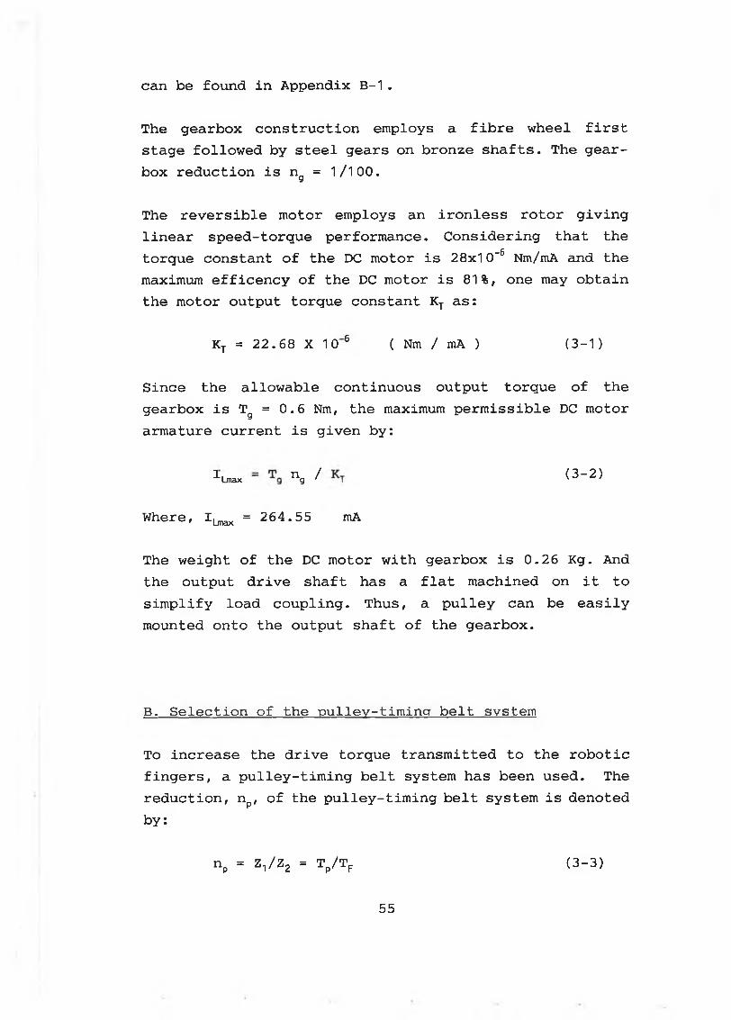
can be found in Appendix B-1.
The gearbox construction employs a fibre wheel first stage followed by steel gears on bronze shafts. The gearbox reduction is ng = 1/100.
The reversible motor employs an ironless rotor giving linear speed-torque performance. Considering that the torque constant of the DC motor is 28x10-6 Nm/mA and the maximum efficency of the DC motor is 81%, one may obtain the motor output torque constant KT as:
Since the allowable continuous output torque of the gearbox is Tg = 0.6 Nm, the maximum permissible DC motor armature current is given by:
Where, 1^^ = 264.55 mA
The weight of the DC motor with gearbox is 0.26 Kg. And the output drive shaft has a flat machined on it to simplify load coupling. Thus, a pulley can be easily mounted onto the output shaft of the gearbox.
B. Selection of the pulley-timing belt system
To increase the drive torque transmitted to the robotic fingers, a pulley-timing belt system has been used. The reduction, np, of the pulley-timing belt system is denoted
KT = 22.68 X 10 6 ( N m / m A ) (3-1)
^"Lmax n g ^ (3-2)
by:
np = Zl/Z2 = Tp/Tp (3-3)
55
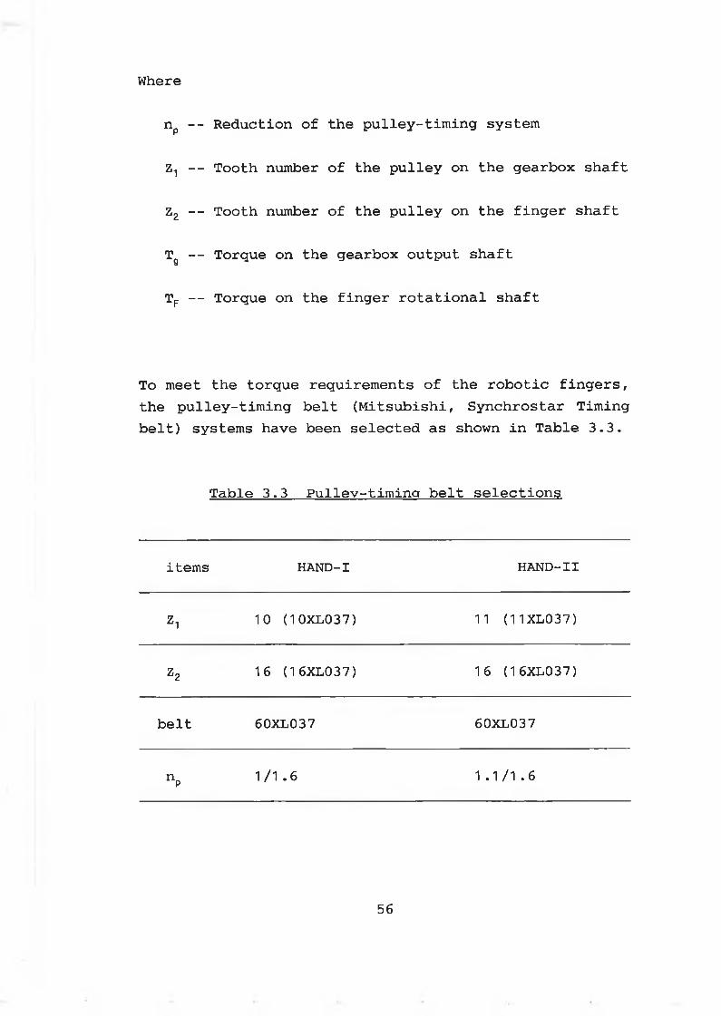
Where
np -- Reduction of the pulley-timing system
Z: — Tooth number of the pulley on the gearbox shaft
Z2 -- Tooth number of the pulley on the finger shaft
Tg — Torque on the gearbox output shaft
TF — Torque on the finger rotational shaft
To meet the torque requirements of the robotic fingers, the pulley-timing belt (Mitsubishi, Synchrostar Timing belt) systems have been selected as shown in Table 3.3.
Table 3.3 Pullev-timing belt selections
items H A N D - I H A N D - I I
Z1 10 (10XL037) 11 (11XL037)
z2 16 (16XL037) 16 (16XL037)
belt 60XL037 60XL037
n P1 / 1 . 6 1 . 1 / 1 . 6
56
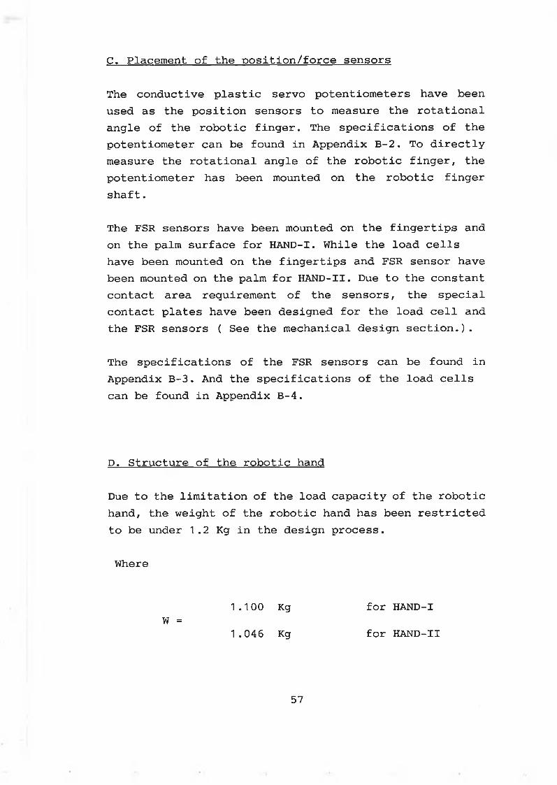
C. Placement of the position/force sensors
The conductive plastic servo potentiometers have been used as the position sensors to measure the rotational angle of the robotic finger. The specifications of the potentiometer can be found in Appendix B-2. To directly measure the rotational angle of the robotic finger, the potentiometer has been mounted on the robotic finger shaft.
The FSR sensors have been mounted on the fingertips and on the palm surface for HAND-I. While the load cells have been mounted on the fingertips and FSR sensor have been mounted on the palm for HAND-II. Due to the constant contact area requirement of the sensors, the special contact plates have been designed for the load cell and the FSR sensors ( See the mechanical design section.).
The specifications of the FSR sensors can be found in Appendix B-3. And the specifications of the load cells can be found in Appendix B-4.
D. Structure of the robotic hand
Due to the limitation of the load capacity of the robotic hand, the weight of the robotic hand has been restricted to be under 1.2 Kg in the design process.
Where
1.100 Kg for HAND-IW =
1.046 Kg for HAND-II
57
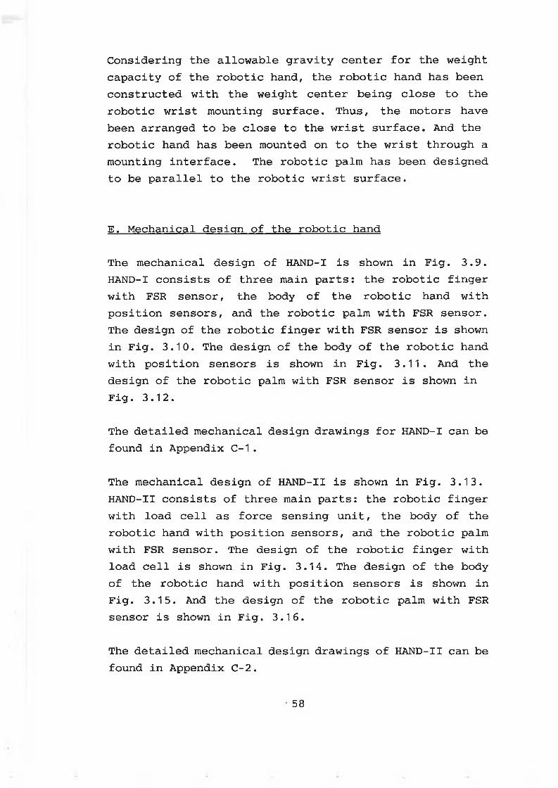
Considering the allowable gravity center for the weight capacity of the robotic hand, the robotic hand has been constructed with the weight center being close to the robotic wrist mounting surface. Thus, the motors have been arranged to be close to the wrist surface. And the robotic hand has been mounted on to the wrist through a mounting interface. The robotic palm has been designed to be parallel to the robotic wrist surface.
E. Mechanical design of the robotic hand
The mechanical design of HAND-1 is shown in Fig. 3.9. HAND-I consists of three main parts: the robotic finger with FSR sensor, the body of the robotic hand with position sensors, and the robotic palm with FSR sensor. The design of the robotic finger with FSR sensor is shown in Fig. 3.10. The design of the body of the robotic hand with position sensors is shown in Fig. 3.11. And the design of the robotic palm with FSR sensor is shown in Fig. 3.12.
The detailed mechanical design drawings for HAND-I can be found in Appendix C-1.
The mechanical design of HAND-II is shown in Fig. 3.13. HAND-II consists of three main parts: the robotic finger with load cell as force sensing unit, the body of the robotic hand with position sensors, and the robotic palm with FSR sensor. The design of the robotic finger with load cell is shown in Fig. 3.14. The design of the body of the robotic hand with position sensors is shown in Fig. 3.15. And the design of the robotic palm with FSR sensor is shown in Fig. 3.16.
The detailed mechanical design drawings of HAND-II can be found in Appendix C-2.
58
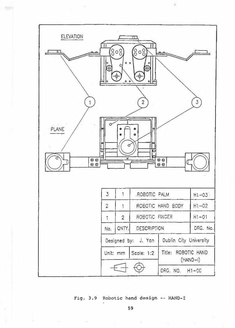
3 1 .ROEOTIC PALM H 1-03
2 1 ROEOTIC HAND EODY H i-0 2
1 2 ROBOTIC FINGER H i-0 1
No. QNTY. DESCRIPTION DRG. Nc.
Designed by: J. Yan Dublin City University
Unit: mm Seale: 1:2 Title: ROBOTIC HAND
(HAND-I)
DRG. NO. H 1 —00
Fig. 3.9 Robotic hand design -- HAND-I59
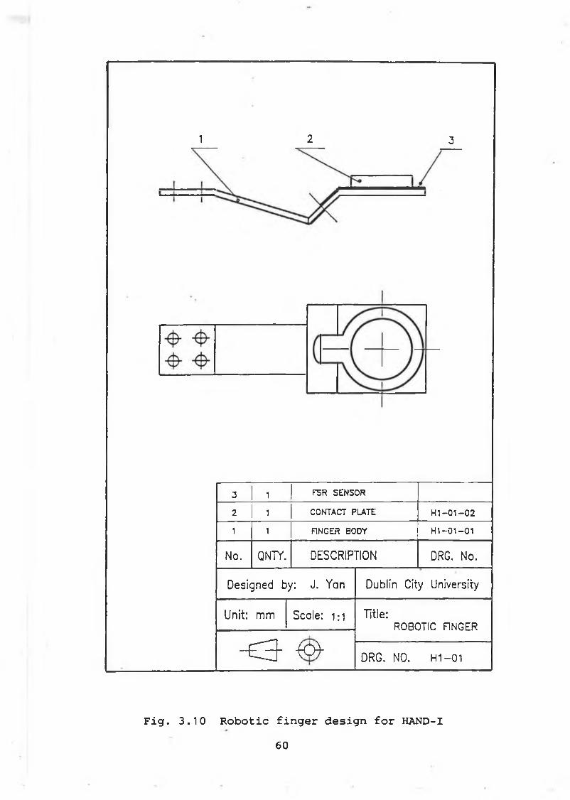
1 2 3
3 1 F5R SENSOR
2 1 CONTACT PLATE HI-01-02
1 i FINGER BODY H1-01—01
No. QN7Y. DESCRIPTION DRG. No.
Designed by: J. Yan Dublin City University
Unit: mm Scale: 1 : 1 Title:ROBOTIC FINGER
~ £ 3 - - (o ) - DRG. NO. H1-01
Fig. 3.10 Robotic finger design for HAND-I60
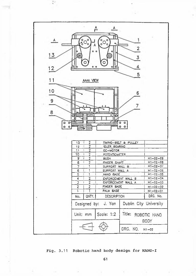
A A
1 1 AAAA VIEW
13 1 2 TIMING—BELT <k PULLEY12 1 2 IDLES BEARING11 i 2 DC-MOTOR10 I 2 POTENTIOMETER9 I 2 BUSH H I - 0 2 - 0 9
CD ro FINGER SHAFT H I- 0 2 - 0 8
7 Ì 1 SUPPORT WALL B H1 - 0 2 - 0 7
6 I 1 SUPPORT WALL A I H 1- 0 2 - 0 65 1 1 HAND BASE I H I- 0 2 - 0 5
4 ! 2 ENFORCEMENT WALL B I H I- 0 2 - 0 43 i 2 ENFORCEMENT WALL A 1 H1 - 0 2 - 0 3
2 2 f ìn g e r b a s e H I - 0 2 - 0 21 1 PALM BASE H I- 0 2 - 0 1
No. QNTY. DESCRIPTION DRG. No.
Designed by: J. Yan Dublin City University
Unit: mm Scale: 1:2 Title: ROBOTIC HAND
BODY
- f DRG. NO. h i -02
Fig. 3.11 Robotic hand body design for HAND-I61
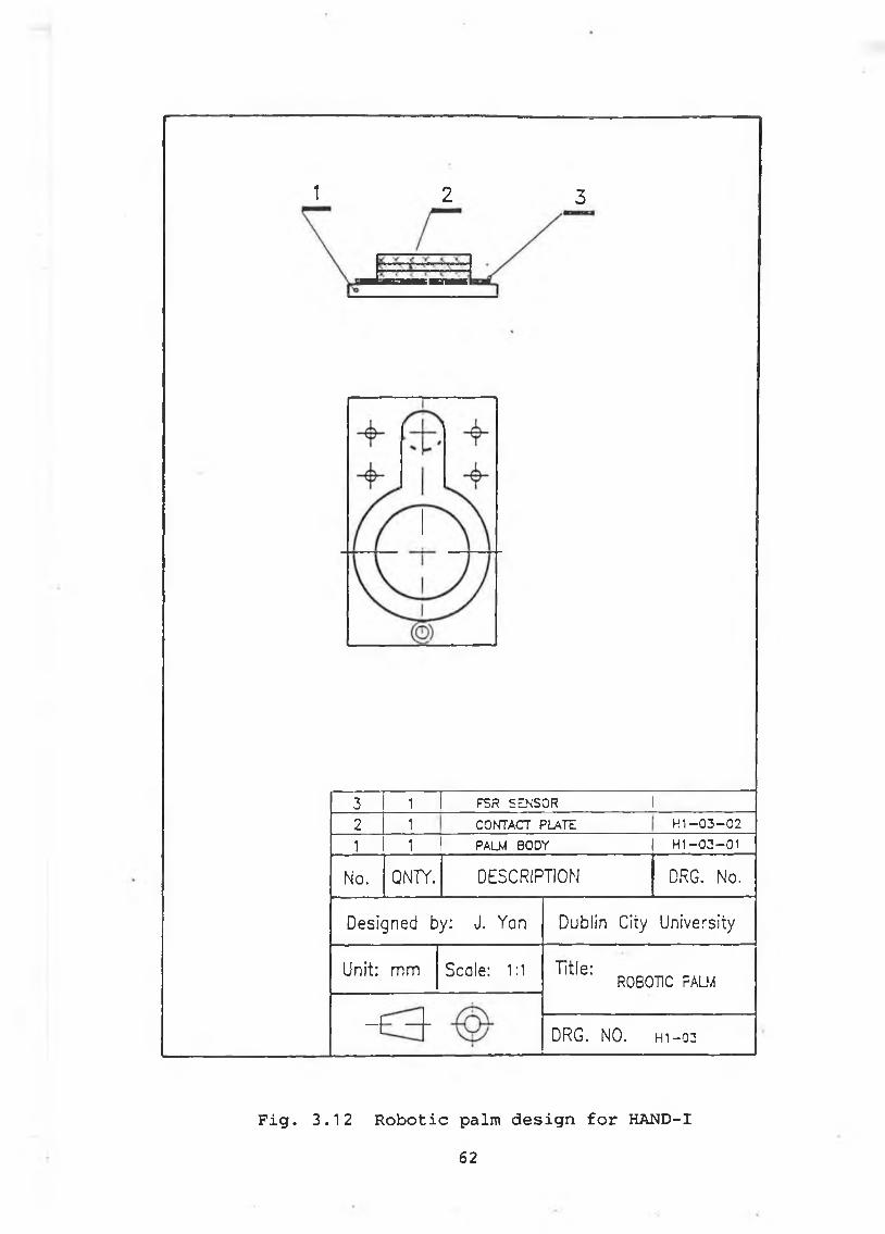
1 2 3
3 1 FSR SENSOR 1
2 1 CONTACT PLATE H I-0 3 -0 2
1 1 PALM BODY H1-03-01
No. QNTY. DESCRIPTION DRG. No.
Designed by: J. Yan Dublin City University
Unit: mm Scale: 1:1 Title:ROBOTIC PALM
“ i DRG. NO. H1-03
Fig. 3.12 Robotic palm design for HAND-I62
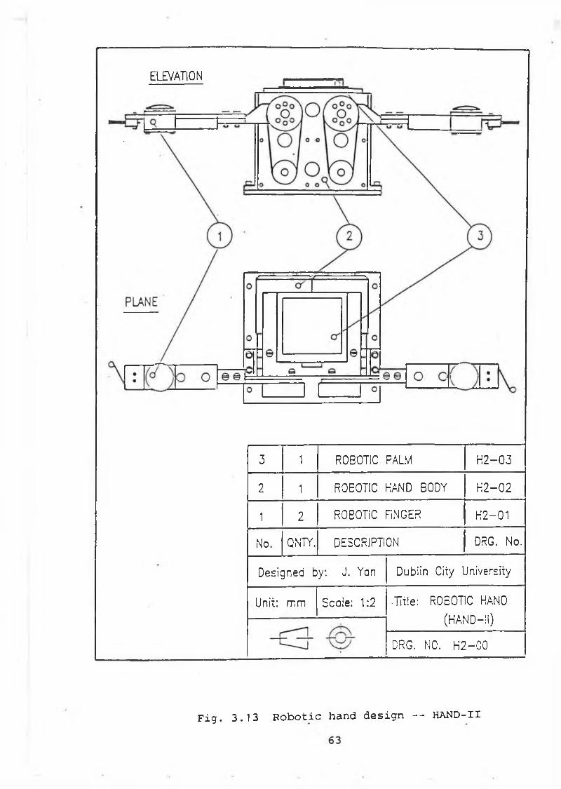
ELEVATION
3 1 ROBOTIC PALM H 2 -03
2 1 ROEOTIC HAND EODY H 2 -02
1n/ r o b o t ic f ìn g e r H2-01
No. QNTY. DESCRIPTION DRG. No.
Designed by: J. Yan Dublin City University
Unit: rr,m Scale: 1:2 •Title: ROEOTIC HAND
(HAND-11)
i■
DRG. NO. H 2-C0
Fig. 3.13 Robotic hand design -- HAND-II
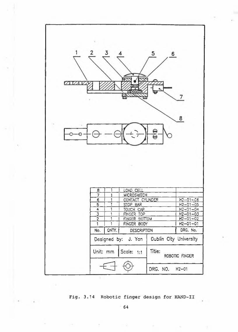
8 1 LOAD CELL7 1 MICROSWiïCH6 1 CONTACT CYUNDER H2-01 —065 1 STOP BAR H2-01-054 1 TOUCH CAP H 2-01-043 1 F1NGER TOP H 2-01-032 1 F1NGER 0OTTOM H 2-01-021 1 FINGER BODY H2-01-01
No. QNTT. DESCRIPTION DRG. No.
Designed by: J. Yan Dublin City University
Unit: mm Scale: 1 : 1 Title:ROBOTIC FINGER
< 3 - ^ 1 DRG. NO. H2-01
Fig. 3.14 Robotic finger design for HAND-II64
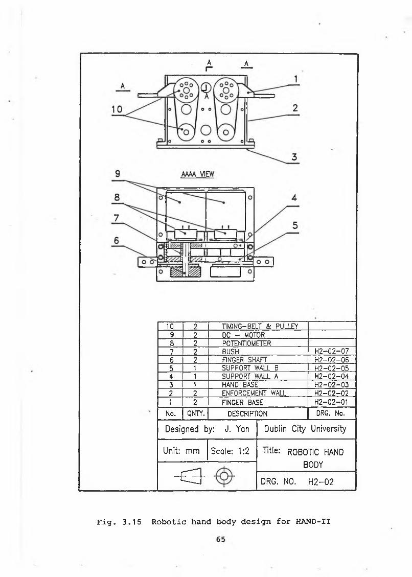
A A
10 2 TIMING-BELT k PULLEY9 2 DC - W0T0R8 2 POTENTIOMETER7 2 BUSH H 2-02-076 2 FINGER SHAFT H 2-02-065 1 SUPPORT WALL B H 2-02-054 1 SUPPORT WALL A H 2-02-043 1 HAND BASE H2-02-032 2 ENFORCEMENT WALL H2-02-021 2 FINGER BASE H2-02-01
No. QNTY. DESCRIPTION DRG. No.
Designed by: J. Yan Dublin City University
Unit: mm Scale: 1:2 Title: ROBOTIC HAND
BODY
o - DRG. NO. H 2 -02
Fig. 3.15 Robotic hand body design for HAND-II
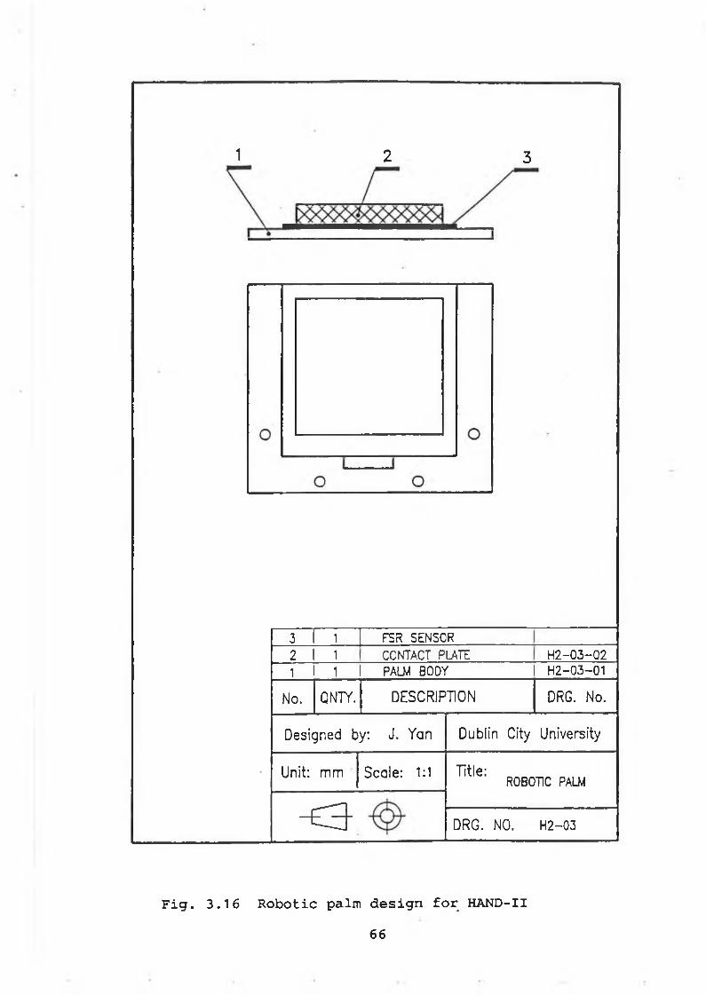
1 2 3
3 1 FSR SENSOR
2 I 1 CONTACT PUTE H2-03-Q21 1 PALM BODY H2-03-01
No. QNTY. DESCRIPTION DRG. No.
Designed by: J. Yan Dublin City University
Unit: mm Scale: 1:1 Title:ROBOTIC PALM
o - DRG. NO. H2-03
Fig. 3.16 Robotic palm design for HAND-II66
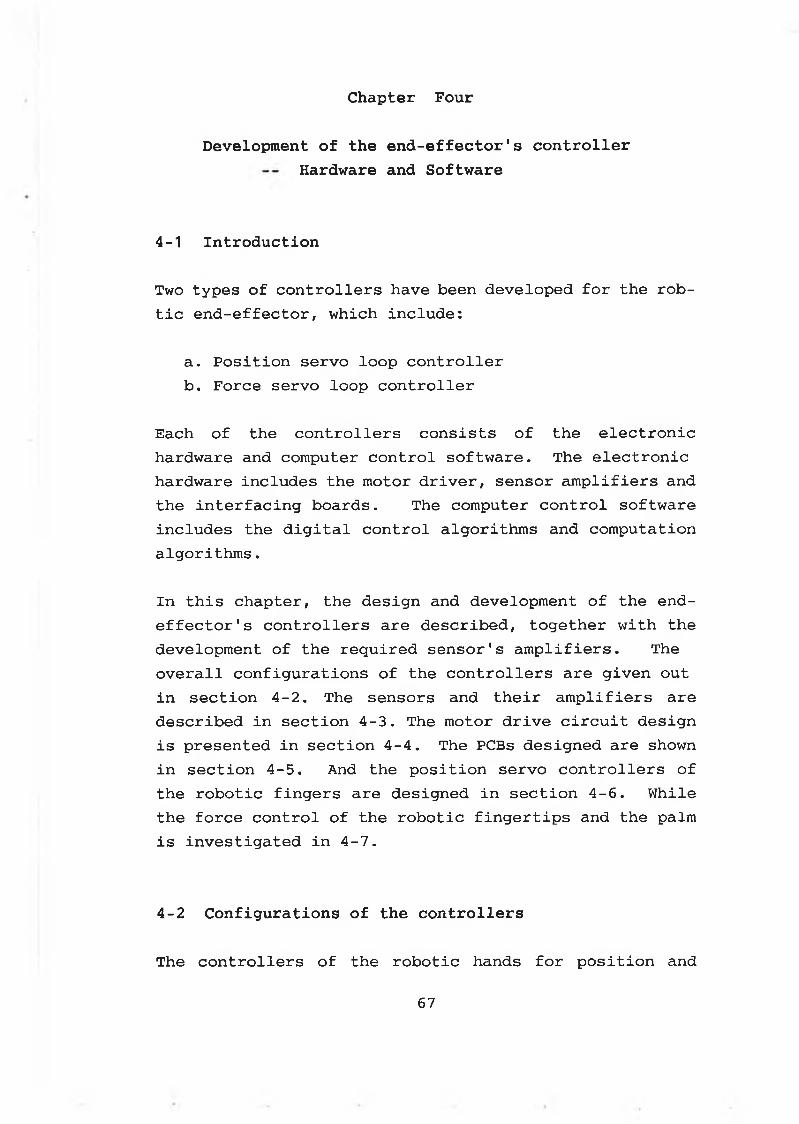
Chapter Four
D evelopm ent o f th e e n d - e f f e c t o r 1s c o n t r o l l e r
H ard w are and S o f tw a re
4-1 I n t r o d u c t i o n
Two t y p e s o f c o n t r o l l e r s have been d e v e lo p e d f o r th e r o b -
t i c e n d - e f f e c t o r , w h ic h i n c l u d e :
a . P o s i t i o n s e r v o lo o p c o n t r o l l e r
b . F o rc e s e r v o lo o p c o n t r o l l e r
E ach o f th e c o n t r o l l e r s c o n s i s t s o f th e e l e c t r o n i c
h a rd w a re and co m p u te r c o n t r o l s o f t w a r e . T h e e l e c t r o n i c
h a rd w a re i n c lu d e s th e m oto r d r i v e r , s e n s o r a m p l i f i e r s and
th e i n t e r f a c i n g b o a r d s . The co m p u te r c o n t r o l s o f t w a r e
i n c lu d e s th e d i g i t a l c o n t r o l a l g o r i t h m s and c o m p u ta t io n
a l g o r i t h m s .
I n t h i s c h a p t e r , th e d e s ig n and d e ve lo p m e n t o f th e e n d -
e f f e c t o r ' s c o n t r o l l e r s a r e d e s c r i b e d , t o g e t h e r w i t h th e
d e ve lo p m e n t o f th e r e q u i r e d s e n s o r 's a m p l i f i e r s . The
o v e r a l l c o n f i g u r a t i o n s o f th e c o n t r o l l e r s a r e g i v e n o u t
i n s e c t i o n 4 - 2 . Th e s e n s o rs and t h e i r a m p l i f i e r s a r e
d e s c r ib e d i n s e c t i o n 4 - 3 . The m o to r d r i v e c i r c u i t d e s ig n
i s p r e s e n te d i n s e c t i o n 4 - 4 . The PCBs d e s ig n e d a re shown
i n s e c t i o n 4 - 5 . And th e p o s i t i o n s e r v o c o n t r o l l e r s o f
th e r o b o t i c f i n g e r s a r e d e s ig n e d i n s e c t i o n 4 - 6 . W h ile
th e f o r c e c o n t r o l o f th e r o b o t i c f i n g e r t i p s and th e palm
i s i n v e s t i g a t e d i n 4 - 7 .
4 - 2 C o n f i g u r a t i o n s o f th e c o n t r o l l e r s
Th e c o n t r o l l e r s o f th e r o b o t i c hands f o r p o s i t i o n and
67
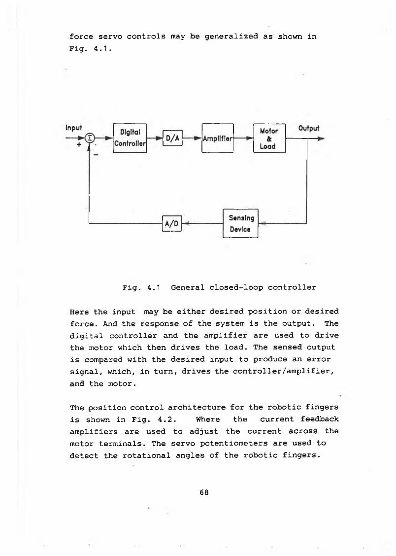
force servo controls may be generalized as shown in Fig. 4.1.
Fig. 4.1 General closed-loop controller
Here the input may be either desired position or desired force. And the response of the system is the output. The digital controller and the amplifier are used to drive the motor which then drives the load. The sensed output is compared with the desired input to produce an error signal, which, in turn, drives the controller/amplifier, and the motor.
The position control architecture for the robotic fingers is shown in Fig. 4.2. Where the current feedback amplifiers are used to adjust the current across the motor terminals. The servo potentiometers are used to detect the rotational angles of the robotic fingers.
68
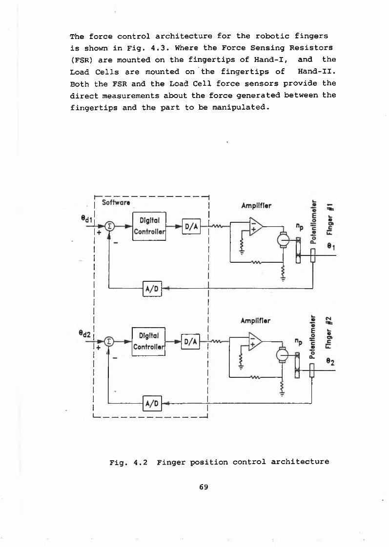
The force control architecture for the robotic fingers is shown in Fig. 4.3. Where the Force Sensing Resistors (FSR) are mounted on the fingertips of Hand-I, and the Load Cells are mounted on the fingertips of Hand-II. Both the FSR and the Load Cell force sensors provide the direct measurements about the force generated between the fingertips and the part to be manipulated.
Fig. 4.2 Finger position control architecture
69
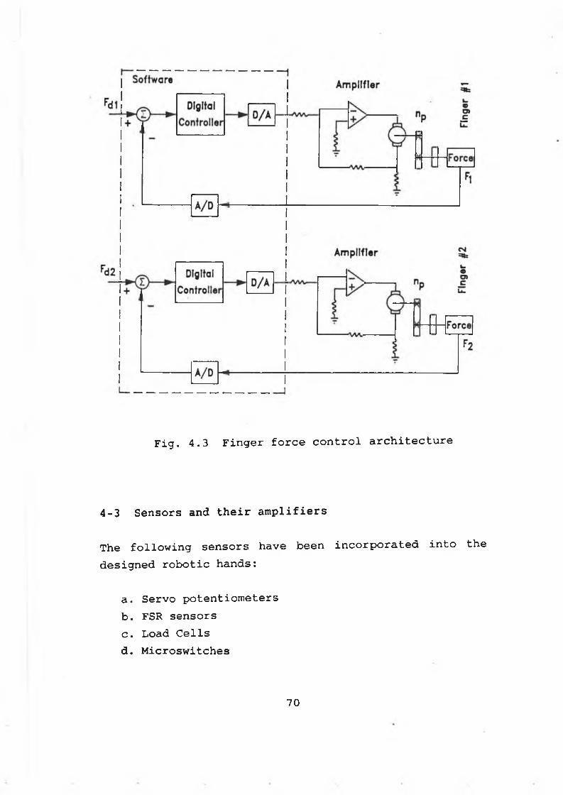
Fig. 4.3 Finger force control architecture
4-3 Sensors and their amplifiers
The following sensors have been incorporated into the designed robotic hands:
a. Servo potentiometersb. FSR sensorsc. Load Cellsd . Microswitches
7 0
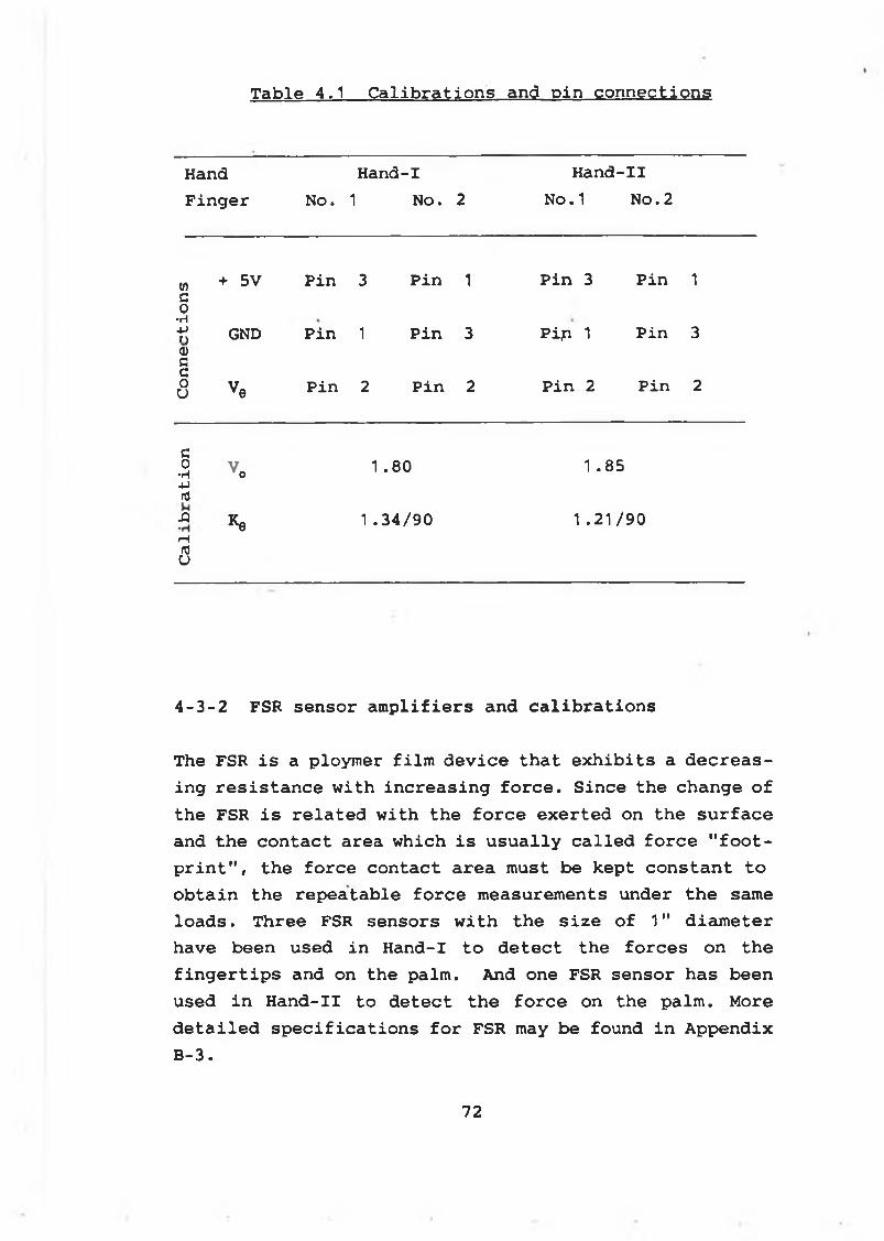
Table 4.1 Calibrations and pin connections
Hand Hand-I Hand-IIFinger No. 1 NO. 2 No.1 No.2
w + 5V Pin 3 Pin 1 Pin 3 Pin 1c0•H-Pf) GND Pin 1 Pin 3 Pi p. 1 Pin 3<DCc0u ve Pin 2 Pin 2 Pin 2 Pin 2
G0•rf Vo 1.80 1 .854JnlXI *e 1 .34/90 1.21/90rH(0u
4-3-2 FSR sensor amplifiers and calibrations
The FSR is a ploymer film device that exhibits a decreasing resistance with increasing force. Since the change of the FSR is related with the force exerted on the surface and the contact area which is usually called force "footprint", the force contact area must be kept constant to obtain the repeatable force measurements under the same loads. Three FSR sensors with the size of 1" diameter have been used in Hand-I to detect the forces on the fingertips and on the palm. And one FSR sensor has been used in Hand-II to detect the force on the palm. More detailed specifications for FSR may be found in Appendix B-3.
72
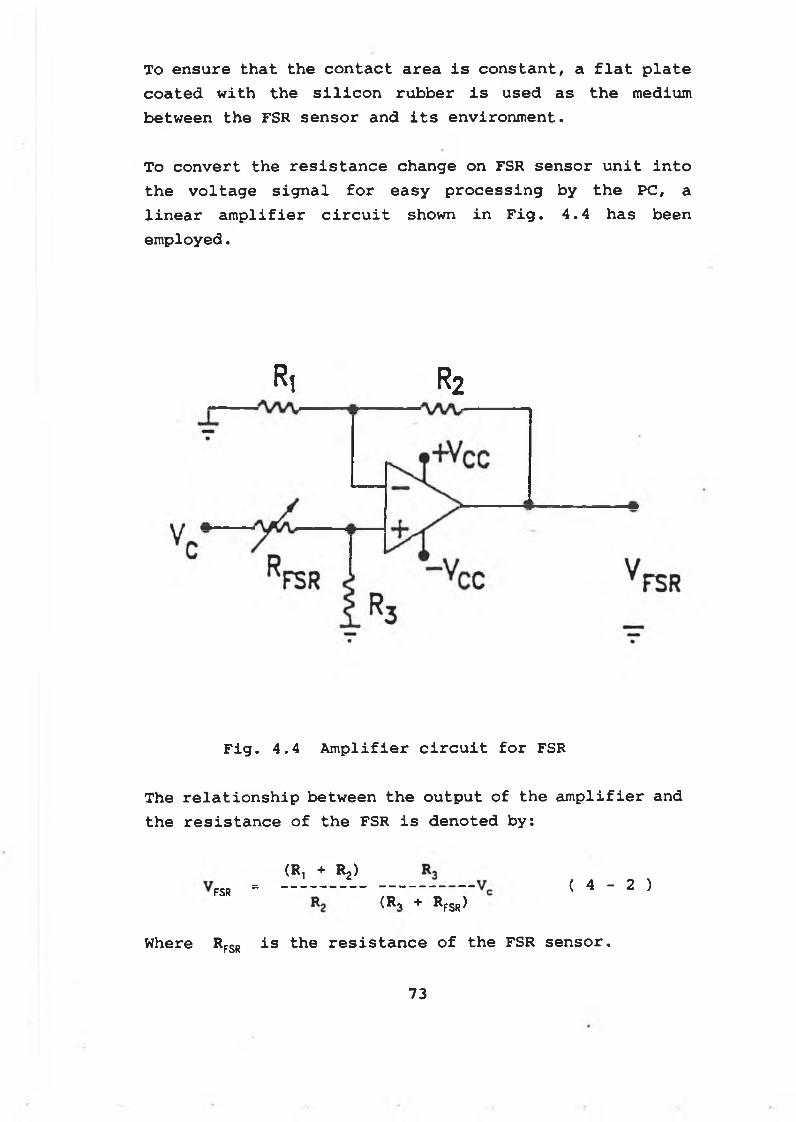
To ensure that the contact area is constant, a flat plate coated with the silicon rubber is used as the medium between the FSR sensor and its environment.
To convert the resistance change on FSR sensor unit into the voltage signal for easy processing by the PC, a linear amplifier circuit shown in Fig. 4.4 has been employed.
Ri r 2
Fig. 4.4 Amplifier circuit for FSR
The relationship between the output of the amplifier and the resistance of the FSR is denoted by:
(R-, + Ra)FSR (R, + Rfsr)
( 4 - 2 )
Where Rfsr is the resistance of the FSR sensor.
73
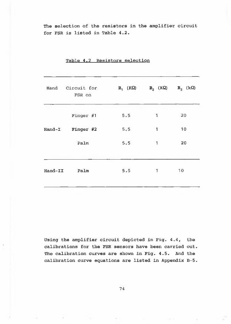
The s e l e c t i o n o f th e r e s i s t o r s i n th e a m p l i f i e r c i r c u i t f o r FSR i s l i s t e d in T a b le 4 . 2 .
T a b le 4 .2 R e s i s t o r s s e l e c t i o n
Hand C ir c u i t f o r FSR on
R1 (KQ) R2 (HQ) R3 (kQ)
F in g e r #1 5 .5 1 20
H and-I F in g e r #2 5 .5 1 10
Palm 5 .5 1 20
H an d -II Palm 5 .5 1 10
U sin g t h e a m p l i f i e r c i r c u i t d e p ic t e d i n F ig . 4 . 4 , th e c a l i b r a t i o n s f o r th e FSR s e n s o r s h a v e b een c a r r ie d o u t . The c a l i b r a t i o n c u r v e s a r e shown i n F i g . 4 . 5 . And th e c a l i b r a t i o n c u r v e e q u a t io n s a r e l i s t e d i n A ppendix B- 5 .
74
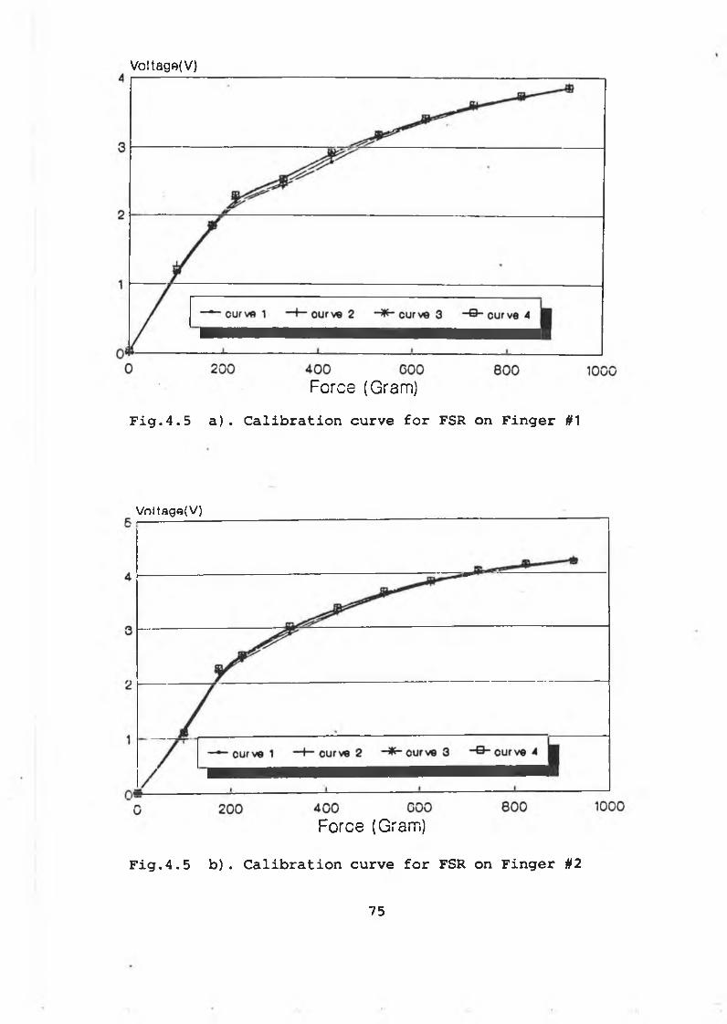
Voltago(V)
Force (Gram)Fig.4.5 a). Calibration curve for FSR on Finger #1
V oltage(V )
Force (Gram)
Fig.4.5 b). Calibration curve for FSR on Finger U2
75
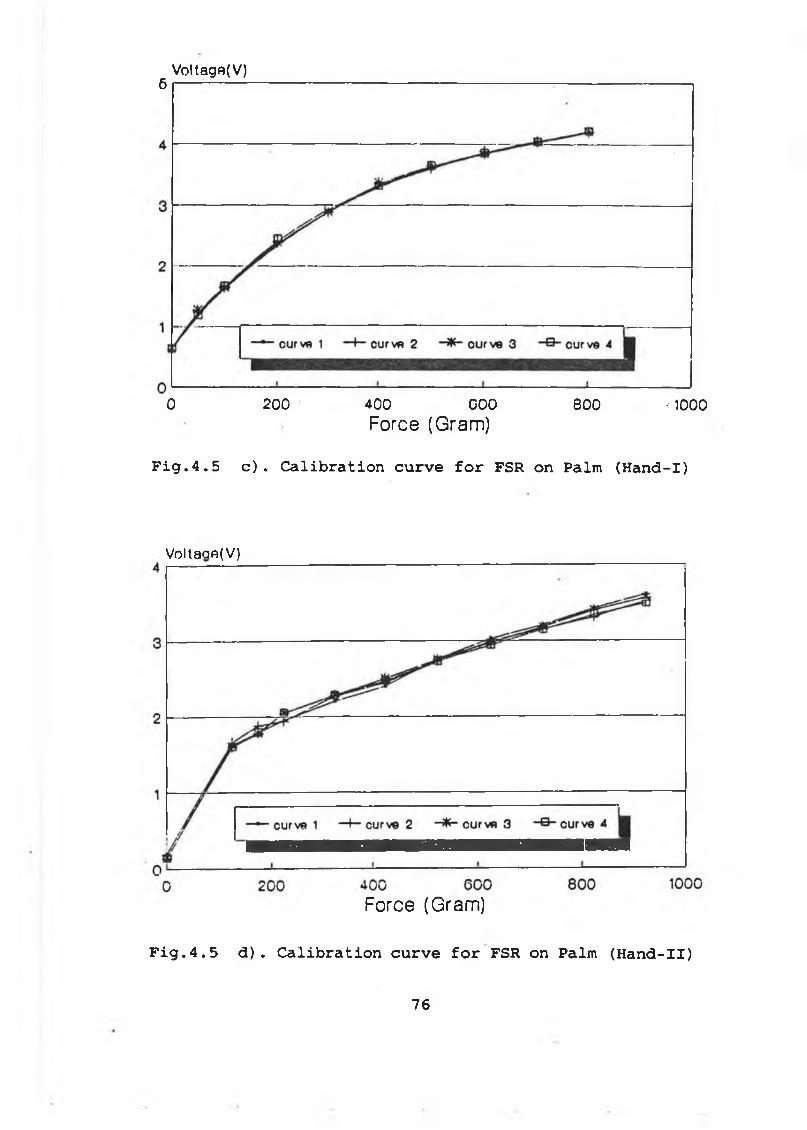
Voltago(V)6 I ----
0 200 400 COO 800 -1000Force (Gram)
Fig.4.5 c) . Calibration curve for FSR on Palm (Hand-I)
Voltaae(V)
Force (Gram)
Fig.4.5 d). Calibration curve for FSR on Palm (Hand-II)
76
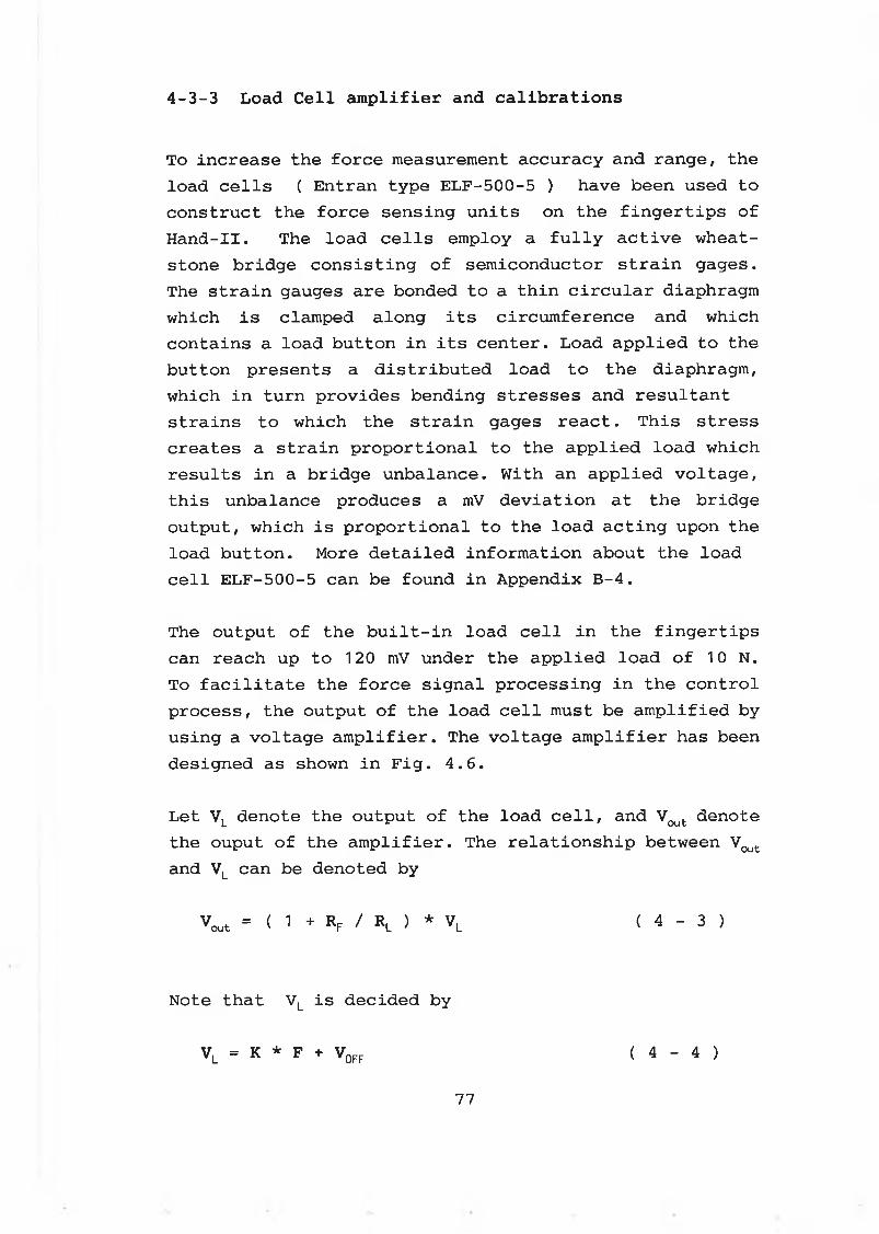
4-3-3 Load Cell amplifier and calibrations
To increase the force measurement accuracy and range, the load cells ( Entran type ELF-500-5 ) have been used to construct the force sensing units on the fingertips of Hand-II. The load cells employ a fully active wheat- stone bridge consisting of semiconductor strain gages. The strain gauges are bonded to a thin circular diaphragm which is clamped along its circumference and which contains a load button in its center. Load applied to the button presents a distributed load to the diaphragm, which in turn provides bending stresses and resultant strains to which the strain gages react. This stress creates a strain proportional to the applied load which results in a bridge unbalance. With an applied voltage, this unbalance produces a mV deviation at the bridge output, which is proportional to the load acting upon the load button. More detailed information about the load cell ELF-500-5 can be found in Appendix B-4.
The output of the built-in load cell in the fingertips can reach up to 120 mV under the applied load of 10 N. To facilitate the force signal processing in the control process, the output of the load cell must be amplified by using a voltage amplifier. The voltage amplifier has been designed as shown in Fig. 4.6.
Let VL denote the output of the load cell, and Vout denote the ouput of the amplifier. The relationship between Vout
and VL can be denoted by
V o u t = ( 1 + r f / r l ) * V L ( 4 - 3 )
Note that VL is decided by
VL = K * F + V0FF ( 4 - 4 )
77
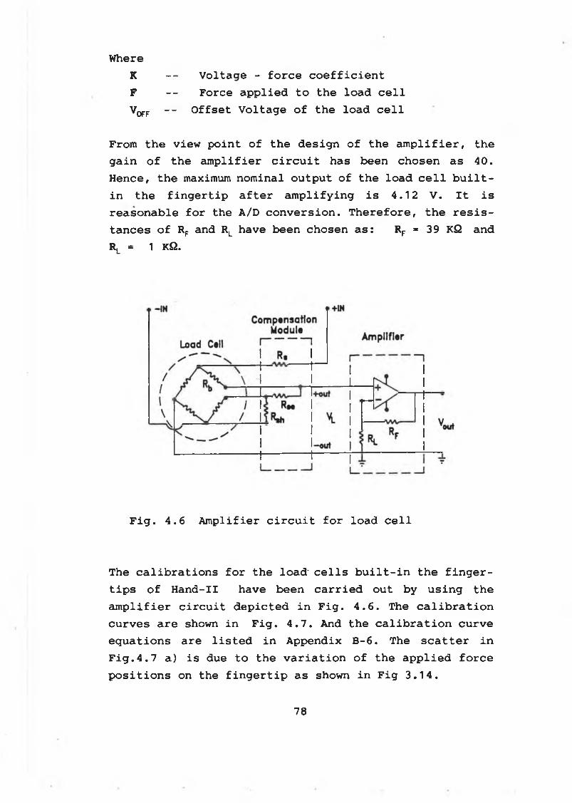
WhereK -- Voltage - force coefficient F -- Force applied to the load cellV OFF ““ Offset Voltage of the load cell
From the view point of the design of the amplifier, the gain of the amplifier circuit has been chosen as 40. Hence, the maximum nominal output of the load cell built-in the fingertip after amplifying is 4.12 V. It isreasonable for the A/D conversion. Therefore, the resistances of RF and RL have been chosen as: RF = 39 KQ andRL * 1 KQ.
Fig. 4.6 Amplifier circuit for load cell
The calibrations for the load- cells built-in the fingertips of Hand-II have been carried out by using the amplifier circuit depicted in Fig. 4.6. The calibration curves are shown in Fig. 4.7. And the calibration curve equations are listed in Appendix B-6. The scatter in Fig.4.7 a) is due to the variation of the applied force positions on the fingertip as shown in Fig 3.14.
78
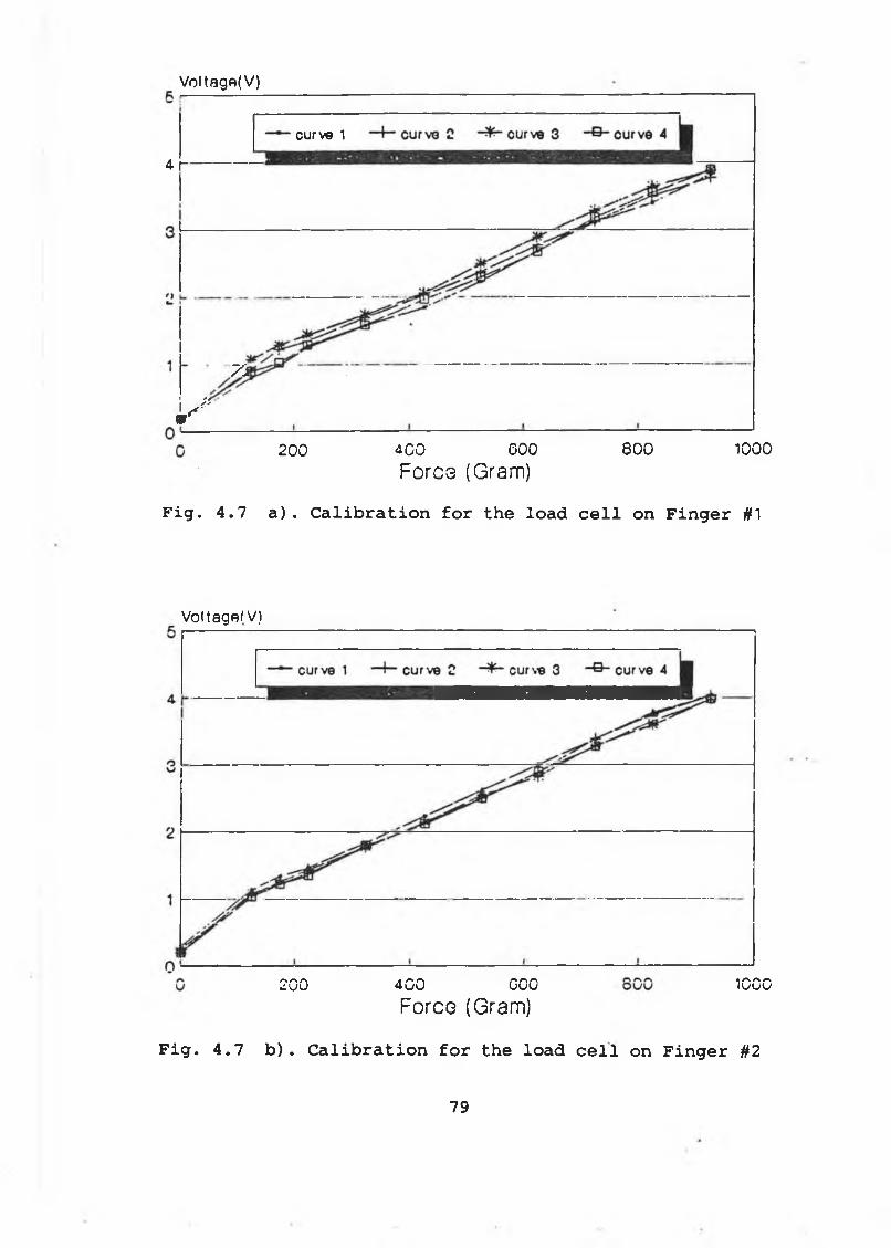
Voitagfi(V)
4- r
curve 1
--------
i ' *
70
200 400 000Fores (Gram)
eoo 1000
Fig. 4.7 a). Calibration for the load cell on Finger #1
Voltage/V)
200 400 000Force (Gram)
4 A A AIv j u u
Fig. 4.7 b). Calibration for the load cell on Finger #2
79
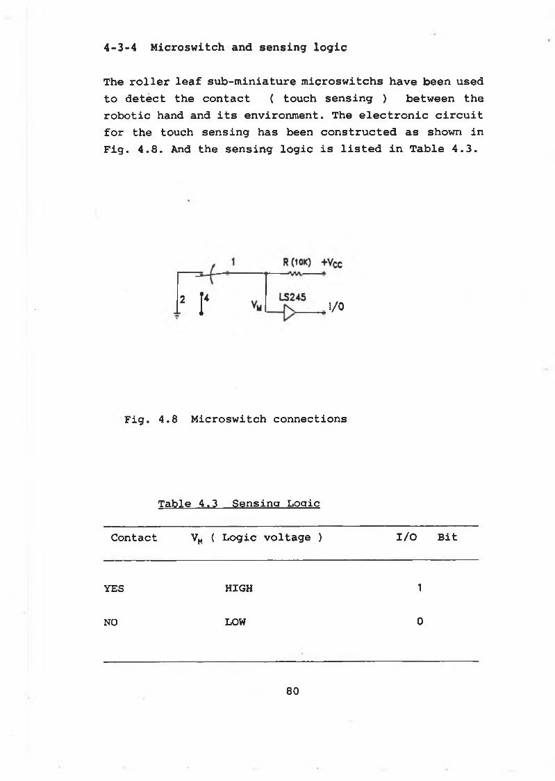
T h e r o l l e r l e a f s u b - m i n i a t u r e m i c r o s w i t c h s h a v e b e e n u s e d
t o d e t e c t t h e c o n t a c t ( t o u c h s e n s i n g ) b e t w e e n t h e
r o b o t i c h a n d a n d i t s e n v i r o n m e n t . T h e e l e c t r o n i c c i r c u i t
f o r t h e t o u c h s e n s i n g h a s b e e n c o n s t r u c t e d a s sh o w n i n
F i g . 4 . 8 . And t h e s e n s i n g l o g i c i s l i s t e d i n T a b l e 4 . 3 .
4-3-4 Microswitch and sensing logic
2r I/O
F i g . 4 . 8 M i c r o s w i t c h c o n n e c t i o n s
T a b l e 4 . 3 S e n s i n g L o g i c
C o n t a c t VM ( L o g i c v o l t a g e ) I / O B i t
YES HIGH 1
NO LOW 0
80
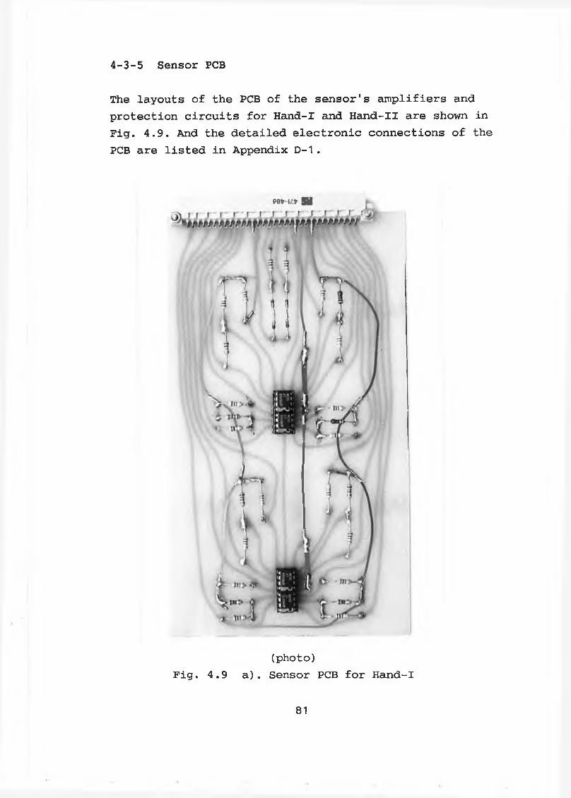
4-3-5 Sensor PCB
The layouts of the PCB of the sensor's amplifiers and protection circuits for Hand-I and Hand-II are shown in Fig. 4.9. And the detailed electronic connections of the PCB are listed in Appendix D-1 .
(photo)Fig. 4.9 a). Sensor PCB for Hand-I
81
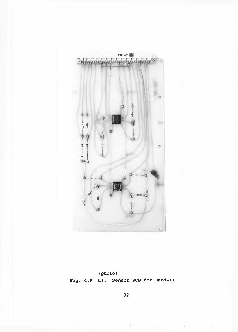
96tr-Ut»
' 1 I
A %Ih
•O)
il3 i o 4
sf A * \ ’
>ir
:nr--3)*
f• i
f
Sii
(p h o to )
F i g . 4 . 9 b ) . S e n s o r PCB f o r H a n d -I I
82
§ 5 - 4 DC m o to r d r i v e c i r c u i t d e s i g n
The current amplifier has been used to drive the DC servo motor. Fig. 4.10 shows the DC motor drive circuit.
This type of amplifier is very popular when it is desired to adjust the current across the DC motors. The position/ force control of the DC motors can be achieved by using this type of amplifier.
One advantage of using such a device with a DC servo motor is the fact that the currect delivered will maintain the same regardless of changes in the motor' s armture resistance which is a function of the armture temperature. In addition, the voltage drops inherent in the wiring from the amplifier to the motor will not affect the power delivered to the motor.
The diodes (PX1N4003) function as flyback protection. The inductance in the servo motor armture can produce an inductive kick when the power amplifier transistors are either suddenly all turned off or when the motor is reversed. Hence, the flyback diodes must be placed across the collect-emitter terminals of the output transistors. Otherwise, a short circuit between the collector and emitter may occur.
The current, IL, across the motor can be directly adjusted by the input control voltage Vin. The relationship between them can be denoted by
r L “ [ Rr / ( Rs * R ) 1 * Vin 1 1 in ( 4 - 5 )
83
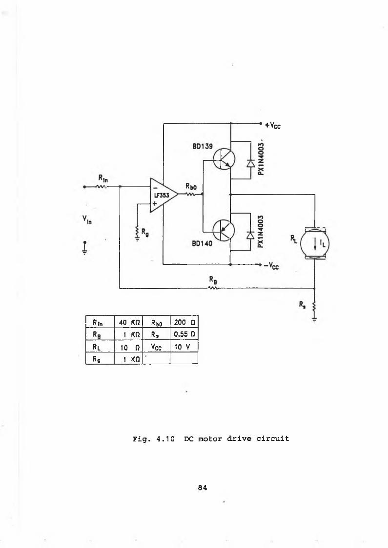
" + V c c
vw
Rln 40 Kil Rbo 200 n
1 Kil R . 0.55 n
Rl 10 0 Vcc 10 V
R9 1 Kfi
F i g . 4 . 1 0 DC m o to r d r i v e c i r c u i t
84
The nominal relationship between IL and Vin can be inferred from Eq. ( 4 - 5 ) as :
IL = (1000/22) * Vin ( 4 - 6 )
However, the experimental measurement is slightly different from the nominal one:
The PCB design for motor drive circuit is shown in Fig. 4.11. And the detailed electronic connections are listed in Appendix D-2.
4-5 Robotic hand interfacing with the PC
To facilitate the signals distribution and interfacing among the motor/PCB, the sensor/PCB, the robotic hand, the A/D cable, the D/A cable, the signal measurement cable and the power supply, a interfacing PCB has been designed for Hand-II to handle the signals distribution and interfacing.
Fig. 4.12 shows the layout of the interfacing PCB. And the detailed electronic connections are listed in Appendix D-3.
I = k * VL in ( 4 - 7 )
Where K: is the current constant. And
Kt = 1000/20.1 ( mA / V )
85
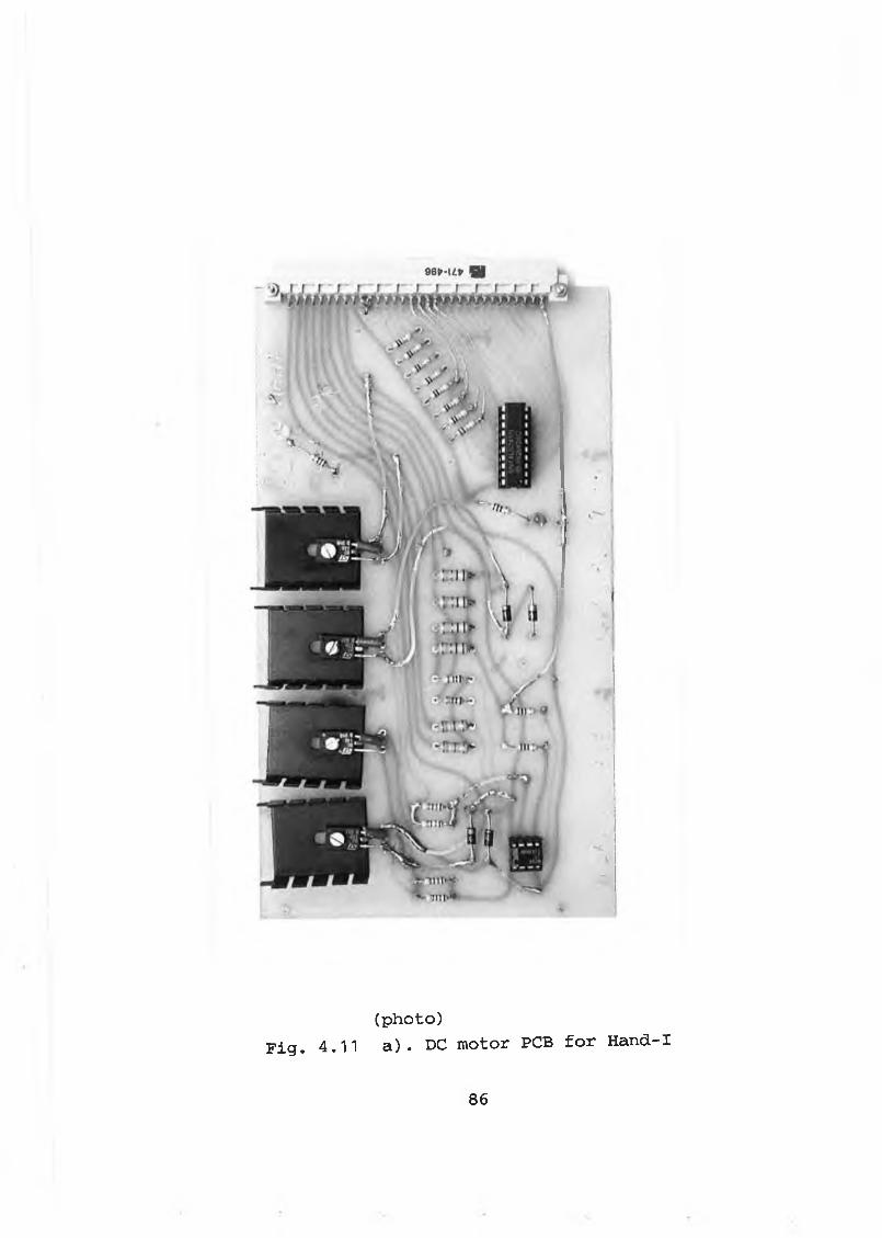
(photo)F i g . 4.11 a). DC motor PCB for Hand-I
8 6
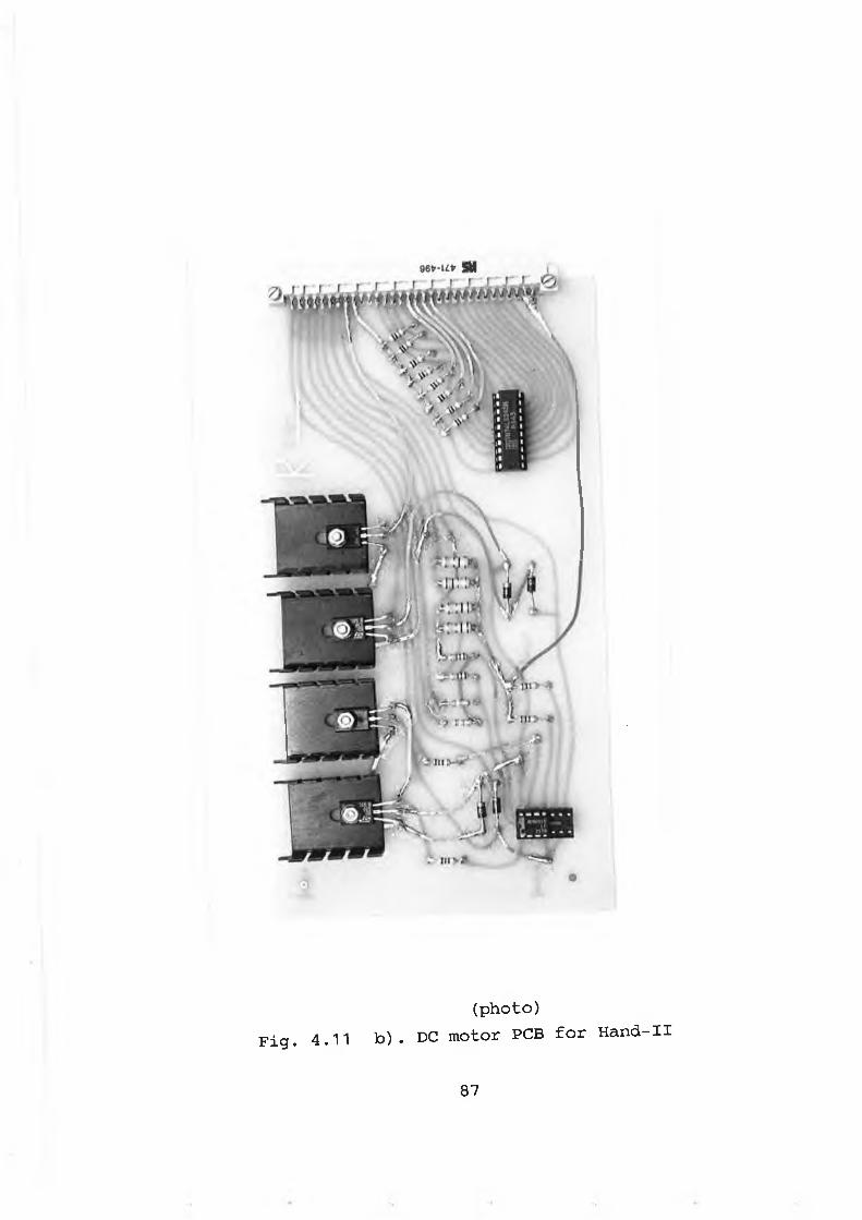
(photo)Fig. 4.11 b ) . DC motor PCB for Hand-II
87
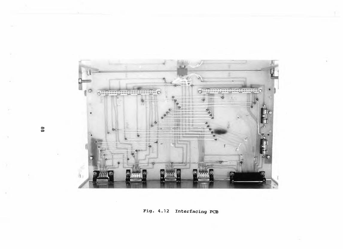
0000
F i g . 4 . 1 2 I n t e r f a c i n g PCB
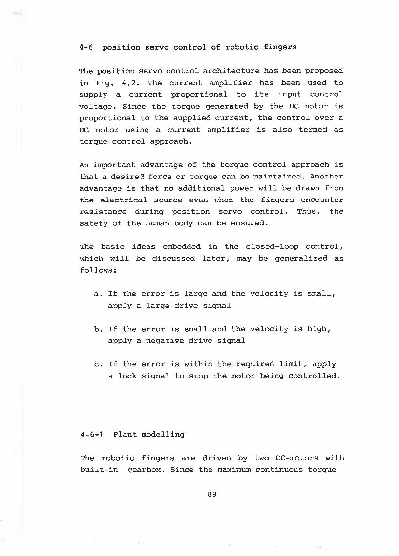
4 - 6 p o s i t i o n s e r v o c o n t r o l o f r o b o t i c f i n g e r s
The position servo control architecture has been proposed in Fig. 4.2. The current amplifier has been used to supply a current proportional to its input control voltage. Since the torque generated by the DC motor is proportional to the supplied current, the control over a DC motor using a current amplifier is also termed as torque control approach.
An important advantage of the torque control approach is that a desired force or torque can be maintained. Another advantage is that no additional power will be drawn from the electrical source even when the fingers encounter resistance during position servo control. Thus, the safety of the human body can be ensured.
The basic ideas embedded in the closed-loop control, which will be discussed later, may be generalized as follows:
a. If the error is large and the velocity is small, apply a large drive signal
b. If the error is small and the velocity is high, apply a negative drive signal
c. If the error is within the required limit, apply a lock signal to stop the motor being controlled.
4 - 6 - 1 P l a n t m o d e l l i n g
The robotic fingers are driven by two DC-motors with built-in gearbox. Since the maximum continuous torque
89
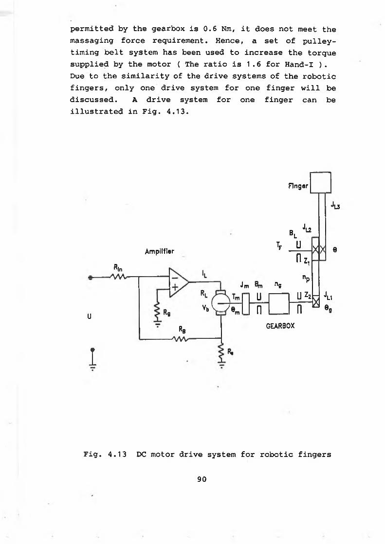
p e r m i t t e d b y t h e g e a r b o x i s 0 . 6 Nm, i t d o e s n o t m e e t t h e
m a s s a g i n g f o r c e r e q u ir e m e n t . H e n c e , a s e t o f p u l l e y -
t i m i n g b e l t s y s t e m h a s b e e n u s e d t o i n c r e a s e t h e t o r q u e
s u p p l i e d b y t h e m o to r ( T he r a t i o i s 1 . 6 f o r H a n d -I ) .
D ue t o t h e s i m i l a r i t y o f t h e d r i v e s y s t e m s o f t h e r o b o t i c
f i n g e r s , o n l y o n e d r i v e s y s t e m f o r o n e f i n g e r w i l l b e
d i s c u s s e d . A d r i v e s y s t e m f o r o n e f i n g e r c a n b e
i l l u s t r a t e d i n F i g . 4 . 1 3 .
Finger
L3
Amplifier
R|n- w v
u
1
Rb■ M V
J,b l
Tp U
L2
n -XX e
vb W e ,m
Jm n 8
Un
z.np
U Z2
n s i
GEARBOX
F i g . 4 . 1 3 DC m o to r d r i v e s y s te m f o r r o b o t i c f i n g e r s
9 0
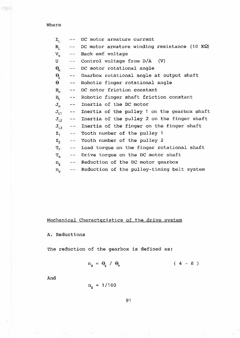
Where
- DC motor armature currentr l
-- DC motor armature winding resistance (10 KQ)vb - Back emf voltageu -- Control voltage from D/A (V)
- DC motor rotational angle0 g - Gearbox rotational angle at output shaft0 -- Robotic finger rotational angle
- DC motor friction constantbl - Robotic finger shaft friction constant
- Inertia of the DC motorJL1 - Inertia of the pulley 1 on the gearbox shaftJL2 -- Inertia of the pulley 2 on the finger shaftJL3 - Inertia of the finger on the finger shaftZT -- Tooth number of the pulley 1z2 _ _ Tooth number of the pulley 2
-- Load torque on the finger rotational shaft- Drive torque on the DC motor shaft
n9 -- Reduction of the DC motor gearboxnp - Reduction of the pulley-timing belt system
Mechanical Characteristics of the drive system
A. Reductions
The reduction of the gearbox is defined as:
n = 0 / 0 ( 4 - 8 )g g ' m '
Andng = 1 / 1 0 0
91
The r e d u c t i o n o f t h e p u l l e y - t i m i n g b e l t s y s te m i s d e f i n e d
as :
And
np = 6 / 0g ( 4 - 9 )
np = 1/1.6 for Hand-Inp = 1.1/1.6 for Hand-II
Thus the relationship between the robotic finger rotational angle and the DC motor rotational angle is denoted by
0 = (nn ) 0 ( 4 - 10 )' p g ' m
B. Equivalent load inertia ( J )
The equivalent load inertia, J, at the DC motor shaft is denoted by:
J = J m + ( n g ) 2 j n + ( n pn g ) 2 ( J L2 + J L3> ( 4 - 1 1 )
AndJ = 2.325 X 1(T6 (Kgm2) for Hand-IJ = 2.332 X 10~6 (Kgm2) for Hand-II
C. Equivalent load friction constant ( B )
The equivalent load friction, B, at the DC motor shaft is denoted by:
B = Bm + (npng>2BL ( 4 - 12 )
92
AndB = 0 f o r H a n d -I and H a n d - I I
D. M o t io n e q u a t i o n f o r t h e d r i v e s y s t e m
T he m o t io n e q u a t i o n f o r t h e d r i v e s y s t e m c a n b e g i v e n b y
From e q . ( 4 - 13 ) , tw o c a s e s c a n b e d e r i v e d :
C a se I - - w hen t h e f i n g e r m o v es i n t h e f r e e s p a c e
In t h i s c a s e , TF = 0 . T h is i s t h e s i t u a t i o n
o f p o s i t i o n c o n t r o l .
C a se I I - - When t h e f i n g e r a p p l i e s a f o r c e o n t o a p a r t
E l e c t r i c a l c h a r a c t e r i s t i c s o f t h e p l a n t
F o r a g i v e n c u r r e n t , t h e o u t p u t t o r q u e o f t h e DC m o to r
may b e d e n o t e d b y :
W here KT i s t h e DC m o to r o u t p u t t o r q u e c o n s t a n t . And
( 4 - 13 )
I n t h i s c a s e , TF > 0 . And t h e a n g l e s p e e d a n d
t h e a n g l e a c c e l e r a t i o n a r e v e r y lo w . T h is i s
t h e s i t u a t i o n o f f o r c e c o n t r o l .
( 4 - 14 )
Kt = 2 2 . 6 8 x 1CT6 ( Nm / mA )
93
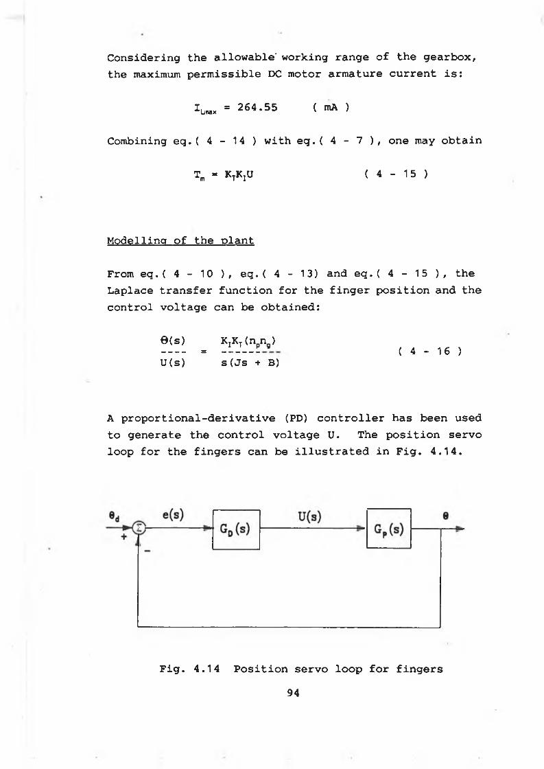
Considering the allowable' working range of the gearbox, the maximum permissible DC motor armature current is:
*l»x = 264.55 ( mA )
Combining eq.( 4 - 14 ) with eg.( 4 - 7 ), one may obtain
Tm = KtKjU ( 4 - 15 )
M o d e l l in g o f t h e p l a n t
From eq.( 4 - 10 ), eq.( 4 - 13) and eq.( 4 - 15 ), the Laplace transfer function for the finger position and the control voltage can be obtained:
6 ( 8 ) KjKt (n n ) = ( 4 - 16 )u ( s ) s ( j s + B)
A proportional-derivative (PD) controller has been used to generate the control voltage U. The position servo loop for the fingers can be illustrated in Fig. 4.14.
F i g . 4 . 1 4 P o s i t i o n s e r v o l o o p f o r f i n g e r s
94
Where
_ jfto_______s(s + a) ( 4 - 17 )
K 0 = K I K Tn pn g / JI T p g( 4 - 18 )
a = B / J ( 4 - 19 )
Furthermore
K0 = 3.048 Kq = 3.343
for Hand-I for Hand-II
a = 0
4-6-2 Digital controller design
The design of the digital controller is carried out by using the well-developed analogue design techniques. The analogue controller designed is transformed into the discrete form to obtain the digital controller.
Referring to Fig. 4.14, the analogue PD controller in the position servo loop can be expressed by :
Hence, the Laplace transfer function of the servo loop may be denoted by
G d ( s ) = Kp + Kds ( 4 - 20 )
0(s)S 2 + K0Kds + K0Kp
( 4 - 21 )0d(s)
95
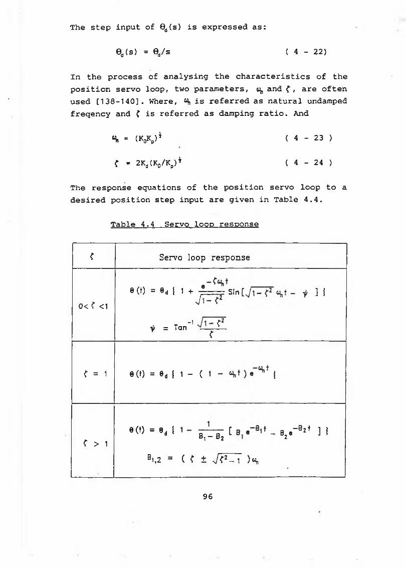
T he s t e p i n p u t o f 9d( s ) i s e x p r e s s e d a s :
0d(s) = 0d/s ( 4 - 2 2 )
In the process of analysing the characteristics of the position servo loop, two parameters, ^ and f , are oftenused [138-140]. Where, Si is referred as natural undamped freqency and f is referred as damping ratio. And
s. = (jyy1 < 4 - 2 3 >
( - 2Ka(K0/K„)i ( 4 - 24 )
The response equations of the position servo loop to adesired position step input are given in Table 4.4.
Table 4.4 Servo loop response
< Servo loop response
0< ( <10 (t) - 0d { 1 + j z ----- Sin ^ ] j
it = Tan"' ~ ^r
<• = 1 0(0 = 0d i 1 - ( 1 - j
< > 19(0 = 9- ! 1 8 ,-B j [ - V " 52' ] !
B1,2 = ( ? + J < * - 1 H
9 6
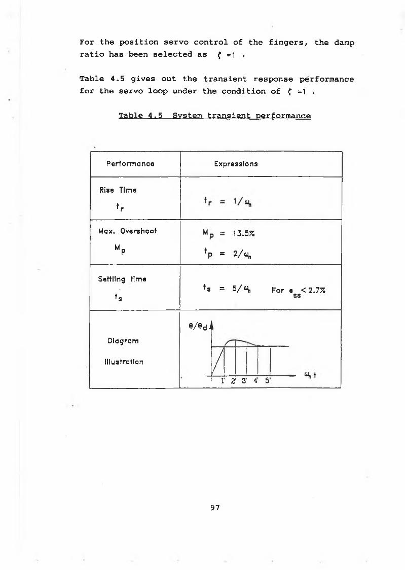
F o r t h e p o s i t i o n s e r v o c o n t r o l o f t h e f i n g e r s , t h e damp
r a t i o h a s b e e n s e l e c t e d a s { =1 .
T a b le 4 . 5 g i v e s o u t t h e t r a n s i e n t r e s p o n s e p e r f o r m a n c e
f o r t h e s e r v o l o o p u n d e r t h e c o n d i t i o n o f f =1 .
T a b le 4 , 5 S y s te m t r a n s i e n t p e r f o r m a n c e
P e r f o r m a n c e E x p r e s s io n s
Rise T im e
* r
IIM a x . O v e r s h o o t = 1 3 .5 %
MpfP = 2/«„
S e tt l in g t im e
t sf s = 5 / S, F o r e < 2 . 7 %
ss
D i a g r a m
I l lu s t r a t io n
e / 0 d J i
/1' Z 3' 4' 5
97
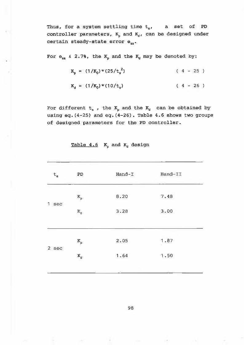
Thus, for a system settling time ts, a set of PD controller parameters, Kp and Kd, can be designed under certain steady-state error esg.
For egs i 2.7%, the Kp and the Kd may be denoted by:
Kp = d/K0)*(25/ts2) { 4 - 25 )
Kd = (l/K0)*(1O/ts) ( 4 - 26 )
For different ts , the Kp and the Kd can be obtained by using eg.(4-25) and eq.(4-26) . Table 4.6 shows two groups of designed parameters for the PD controller.
Table 4.6 Kp and Kd design
ts PD Hand-I Hand-IX
K p8.20 7.48
1 secK d 3.28 3.00
Kp 2.05 1 .872 sec
Kd 1 .64 1 .50
98
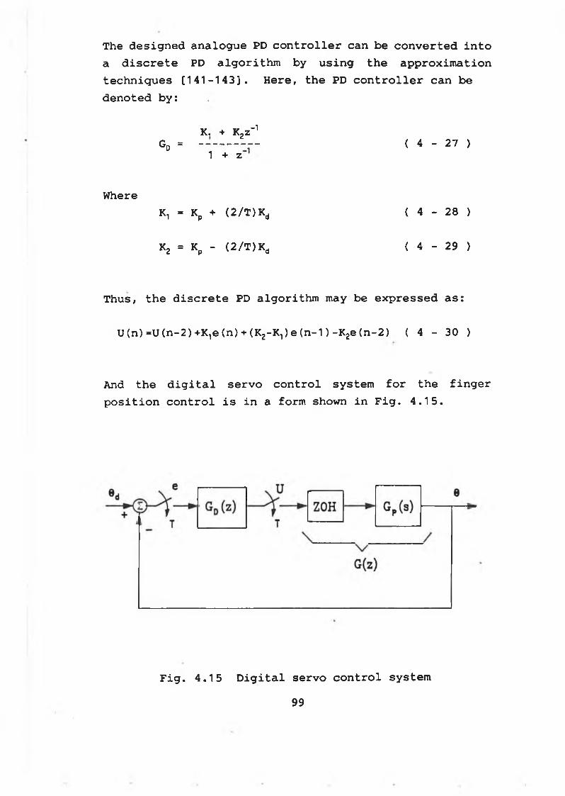
The designed analogue PD controller can be converted into a discrete PD algorithm by using the approximation techniques [141-143]. Here, the PD controller can be denoted by:
K, + K2z_1Gd = ( 4 - 27 )
1 + z
WhereK1 = Kp + (2/T)Kd ( 4 - 28 )
K2 = Kp - (2/T)Kd ( 4 - 29 )
Thus, the discrete PD algorithm may be expressed as:
U(n)=U(n-2)+K1e(n) + (K2-Kl)e(n-1)-K2e(n-2) ( 4 - 30 )
And the digital servo control system for the finger position control is in a form shown in Fig. 4.15.
F i g . 4 . 1 5 D i g i t a l s e r v o c o n t r o l s y s t e m
99
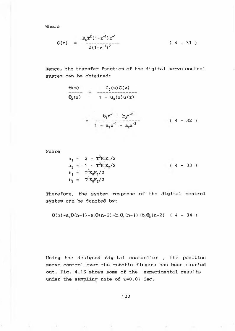
Where
KqT2 (1 + z n) z“1( 4 - 3 1 )G ( z)
2(1- z-1)2
Hence, the transfer function of the digital servo control system can be obtained:
Therefore, the system response of the digital control system can be denoted by:
0(n) =a10(n-1)+a20(n-2)+b10d (n-1)+b20d (n-2) ( 4 - 34 )
Using the designed digital controller , the position servo control over the robotic fingers has been carried out. Fig. 4.16 shows some of the experimental results under the sampling rate of T=0.01 Sec.
0(z) Gd ( z ) G ( z )
1 + Gd ( z ) G ( z )Bd(z)
b.,z 1 + b2z 24 - 32 )
-2
Wherean = 2 - T2K0K1/2a2 = -1 - T2K0K2/2 bn = TzK0K1/2 b2 = T2K0K2/2
4 - 33 )
1 00
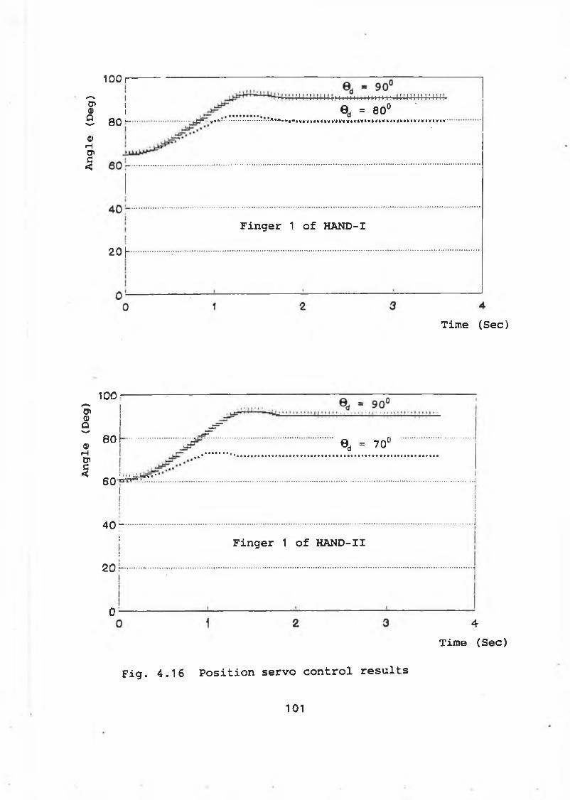
Angle
(Deg)
Angle
(Deg) 1 0 0 1 ---------------------------------------------
I ! I ! i r ! l l ! r H i I M i! HH 111 I !■, U H ^4-1 } ! I \ i ~
i 0 = 80°Q 0 fc— ............ ■ ■ J p - y i * .................................................... A M < * l * I V I ' n ,4 k ,i k ' 4 k ‘ i k ,4 V « V è V è V è ï * V | - < I O i r < H k ' I V I Y t V '
20 |-
Finger 1 of HAND-I
Time (See)
100
80 ........................... 0d = 70C
I
4 0 -
2 O r
o -
Finger 1 of HAND-II
F i g . 4 . 1 6 P o s i t i o n s e r v o c o n t r o l r e s u l t s
- - ' •1 ' -Hr> « ’ '6 0 “ = ^ " 1.............................................................................................................................................................................................................................................................................................................................................
4
Time (See)
101
4 - 7 F o r c e c o n t r o l o f th e e n d - e f f e c t o r s
There are two types of forces applied by the robotic end-effectors: the kneading force applied by the fingertips and the padding force applied by the palm.
The control of the kneading force is realized by regulating the current across the DC motors. While control of the padding force is realized by controlling the motion of the robotic arm.
4 -7 -1 Kneading force control
From eqs.(4-10), (4-13) and (4-14), the torque, TF(s),applied by the DC motor on the finger can be derived as:
TF(s) = (KTKI/npng)U(s)-[s(Js+B)/(npng)2]0(s) ( 4 - 35 )
Since the kneading force can only be produced when the robotic fingers contact the part being massaged, the angular speed and acceleration of the finger are very small at this stage. Hence, the force generated due to angular speed and acceleration can be neglected in this case. Thus, the kneading torque applied by one finger can be controlled by a linear equation:
TF = KFU ( 4 - 36 )
Where
KF = KTKT/npng ( 4 - 37 )
1 0 2
The f o r c e on t h e f i n g e r t i p c a n b e d e n o t e d by
F = TF / LF ( 4 - 38 )
Where, LF is the distance from the force exerting point on the fingertip to the finger rotational center.
Hence, the force control equation can be generalized from eq.(4-36) and eq.(4-38):
Kf U = F Lf ( 4 - 39 )
For a given kneading force, F, on one fingertip, the required input control voltage, U, can be decided by using eq.(4-39), that is:
U = FLf/Kf ( 4 - 40 )
For a given control voltage, U, the sensitivity of the force control equation is denoted by:
dL dF— ( 4 - 41 )
LF F
To ensure the desired force to be applied onto the part being massaged, the contact between the fingertips and the part must be maintained. In most situations, the forces applied by both fingertips are required to be the same. Hence, the part being massaged is required to be centralized in the robotic hand frame, so that the force exerting distance, LF, can be kept the same. The centralizing process of the part can be performed by detecting the forces and the positions of the fingertips. Any decentralization of the part out of the limitations
103
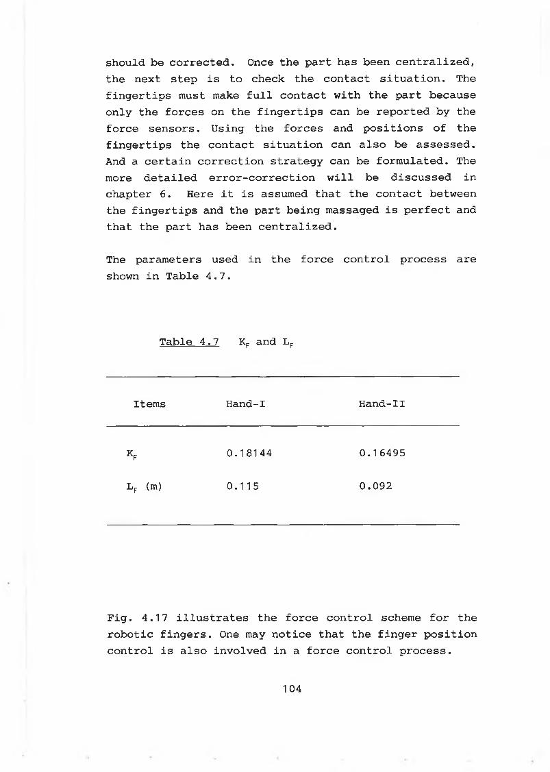
should be corrected. Once the part has been centralized, the next step is to check the contact situation. The fingertips must make full contact with the part because only the forces on the fingertips can be reported by the force sensors. Using the forces and positions of the fingertips the contact situation can also be assessed. And a certain correction strategy can be formulated. The more detailed error-correction will be discussed in chapter 6. Here it is assumed that the contact between the fingertips and the part being massaged is perfect and that the part has been centralized.
The parameters used in the force control process are shown in Table 4.7.
Table 4.7 Kr and Lr
Items Hand-I Hand-II
k f 0.18144 0.16495
Lf (m) 0.115 0.092
Fig. 4.17 illustrates the force control scheme for the robotic fingers. One may notice that the finger position control is also involved in a force control process.
104
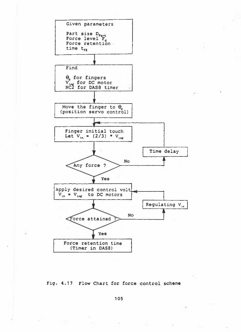
F i g . 4 . 1 7 F lo w C h a r t f o r f o r c e c o n t r o l sch em e
1 0 5
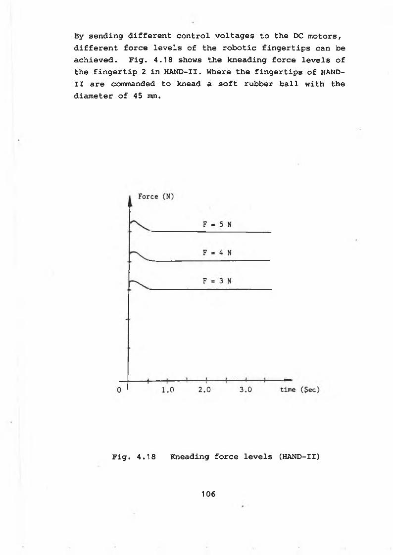
By s e n d i n g d i f f e r e n t c o n t r o l v o l t a g e s t o t h e DC m o t o r s ,
d i f f e r e n t f o r c e l e v e l s o f t h e r o b o t i c f i n g e r t i p s c a n b e
a c h i e v e d . F i g . 4 . 1 8 sh o w s t h e k n e a d in g f o r c e l e v e l s o f
t h e f i n g e r t i p 2 i n H A N D -II. W here t h e f i n g e r t i p s o f HAND-
I I a r e com m anded t o k n e a d a s o f t r u b b e r b a l l w i t h t h e
d i a m e t e r o f 4 5 mm.
F i g . 4 . 1 8 K n e a d in g f o r c e l e v e l s (HAND-II)
1 0 6
4 - 7 - 2 P a d d in g f o r c e c o n t r o l
The padding force control can be achieved by controlling the fine motion of the robotic palm, which moves against the part being massaged.
A general force control equation has been embedded in the palm fine motion control algorithm, which is denoted by
[F] = [K] [5X] ( 4 - 42 )
Where[F] — the padding force vector[K] — the stiffness matrix of the part[5x] — the palm fine motion vector
Since the stiffness of the part being massaged varies from one person to another, the stiffness matrix is not easy to be formulated. Hence, a trial and error method has been implemented to obtain the desired padding force by regulating the fine motion of the palm against the part being massaged. The force feedback of the palm gives the contact situation between the palm and the part. And the position feedback of the palm provides the palm motion status. If the motion covers a long range, a quick approaching distance must be formulated to speed up the force control process ( The fuzzy inference has been usedin Chapter 6 ) . Once the initial contact is detected, afine motion control of the palm must be initiated, while the force should be assessed in every motion cycle. The speed of the palm motion can be adjusted by setting the robot arm speed and the force retention time.
Where Fig. 4 .19 shows the padding force control scheme using the trial and error method. And Fig. 4 .2 0 shows an experimental result.
107
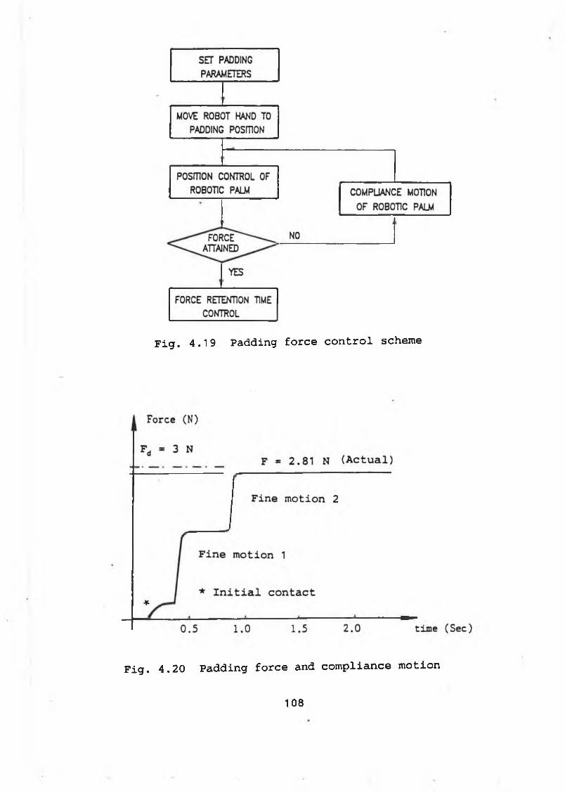
Fig. 4.19 Padding force control scheme
F i g . 4 . 2 0 P a d d in g f o r c e and c o m p l i a n c e m o tio n
108
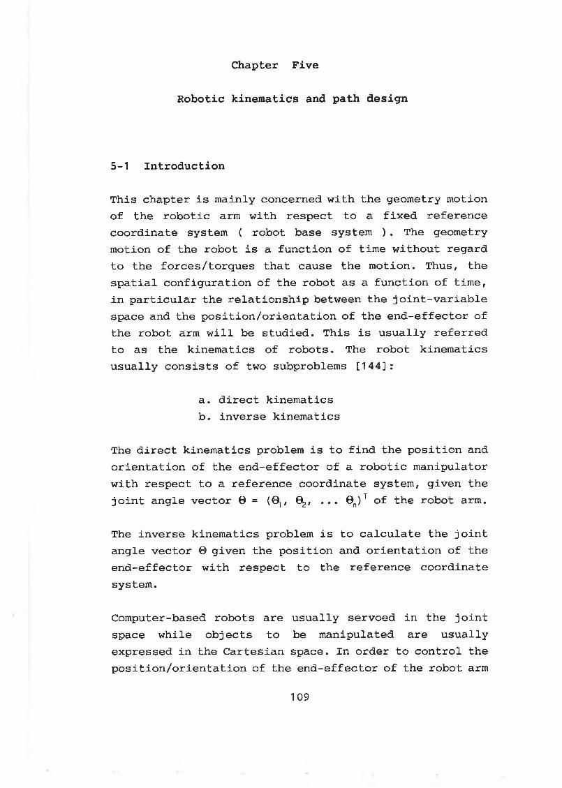
C h a p te r F i v e
R o b o t i c k i n e m a t i c s and p a t h d e s i g n
5-1 Introduction
This chapter is mainly concerned with the geometry motion of the robotic arm with respect to a fixed reference coordinate system ( robot base system ) . The geometry motion of the robot is a function of time without regard to the forces/torques that cause the motion. Thus, the spatial configuration of the robot as a function of time, in particular the relationship between the joint-variable space and the position/orientation of the end-effector of the robot arm will be studied. This is usually referred to as the kinematics of robots. The robot kinematics usually consists of two subproblems [144]:
a. direct kinematicsb. inverse kinematics
The direct kinematics problem is to find the position and orientation of the end-effector of a robotic manipulator with respect to a reference coordinate system, given the joint angle vector 0 = (0,, 0 , ... 0n)T of the robot arm.
The inverse kinematics problem is to calculate the joint angle vector 0 given the position and orientation of the end-effector with respect to the reference coordinate system.
Computer-based robots are usually servoed in the joint space while objects to be manipulated are usually expressed in the Cartesian space. In order to control the position/orientation of the end-effector of the robot arm
109
as it follows a predefined path, the inverse kinematics solutions are required.
Since the link of a robot arm may rotate with respect to a reference coordinate frame, the total spatial displacement of the end-effector is a result of the angular rotations of the links. The Denavit and Hartenberg(D-H) method [145] has been used to describe the spatial relationship between two adjacent rigid mechanical links. And the direct and inverse kinematics of the Mitsubishi robot arm with five DOF are analysed in 5-2.
The coordinate frames attached to the specially designed robotic hand are defined in 5-3. The path design for a given part to be massaged in the Cartesian space is described in 5-4. While the motion control of the robot arm is outlined in 5-5.
5-2 Kinematics of the robot arm
The physical construction of the robot arm has been shown in Fig. 3.2. A reference frame O0X0Y0Z0, which is usually called world frame, has been attached at the robot base as shown in Fig. 3.2. The world frame is the reference frame for position control and feedback of the robot arm. It is also the reference frame in which the position and the orientation of the part to be massaged are defined.
To study the kinematics of the robot arm, it is assumed that an ideal robotic hand with a fixed grasping center has been mounted onto the wrist mounting surface. A hand frame can be attached on the grasping center of the ideal hand. The hand frame is denoted by 05X5Y5Z5. In the hand frame, a set of orientation vectors ( n o a ) can be always defined by using the right-hand rule [144],
110
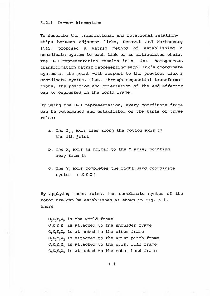
5 - 2 - 1 D i r e c t k i n e m a t i c s
To describe the translational and rotational relationships between adjacent links, Denavit and Hartenberg [145] proposed a matrix method of establishing a coordinate system to each link of an articulated chain. The D-H representation results in a 4x4 homogeneous transformation matrix representing each link's coordinate system at the joint with respect to the previous link's coordinate system. Thus, through sequential transformations, the position and orientation of the end-effector can be expressed in the world frame.
By using the D-H representation, every coordinate frame can be determined and established on the basis of three rules:
a. The Zi_1 axis lies along the motion axis of the ith joint
b. The Xi axis is normal to the Z axis, pointing away from it
c. The Yi axis completes the right hand coordinate system ( X ^ Z ^
By applying these rules, the coordinate system of the robot arm can be established as shown in Fig. 5.1.Where
O0X0Y0Z0 is the world frame0‘|X1 Y-| Z-| is attached to the shoulder frameo2x2y2z2 is attached to the elbow frame®3 3 3Z3 is attached to the wrist pitch frameo4x4y4z4 is attached to the wrist roll frame° 5x 5y 5z 5 is attached to the robot hand frame
111
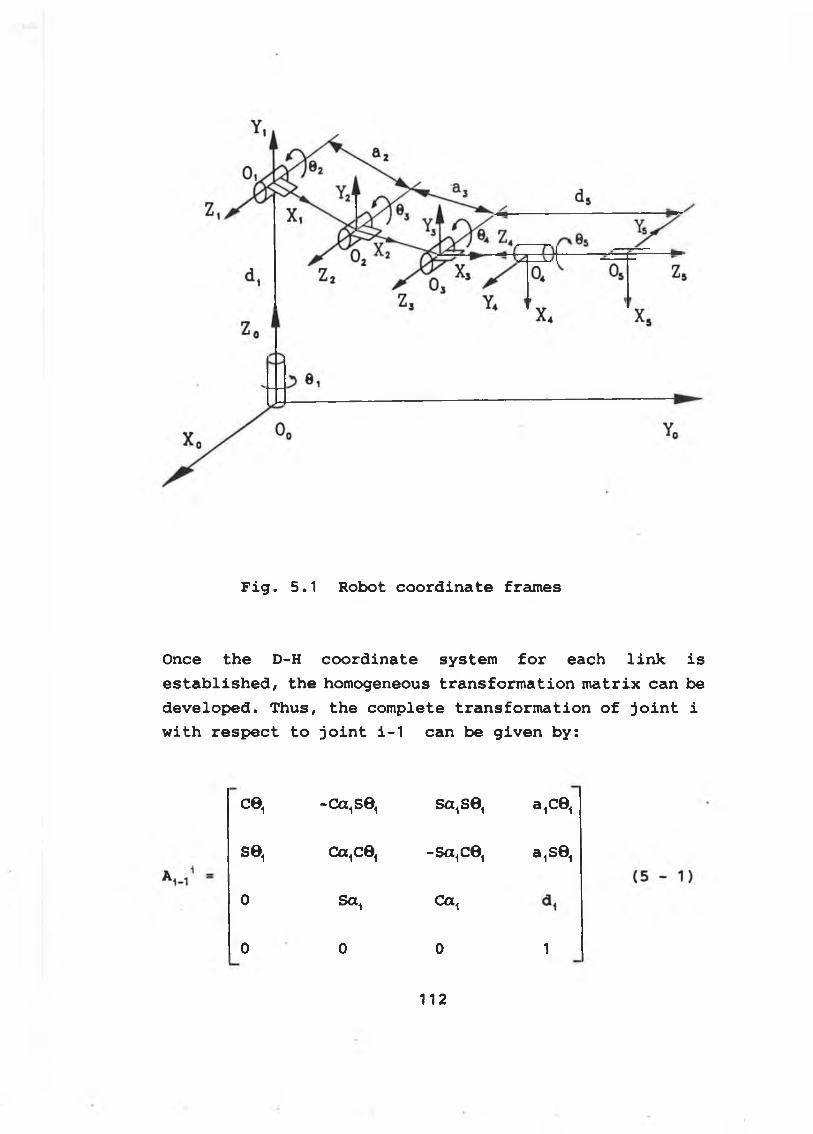
F i g . 5 .1 R o b o t c o o r d i n a t e f reúnes
O n ce t h e D-H c o o r d i n a t e s y s t e m f o r e a c h l i n k i s
e s t a b l i s h e d , t h e h o m o g e n e o u s t r a n s f o r m a t i o n m a t r ix c a n b e
d e v e l o p e d . T h u s , t h e c o m p le t e t r a n s f o r m a t i o n o f j o i n t i
w i t h r e s p e c t t o j o i n t i - 1 c a n b e g i v e n b y :
ce, -ca,se, sa, se, 3 ,0 6 ,
se. ca,ce, - S a 1C 01 a ,S 6 ,
0 S a , Ca,
0 0 0 1
112
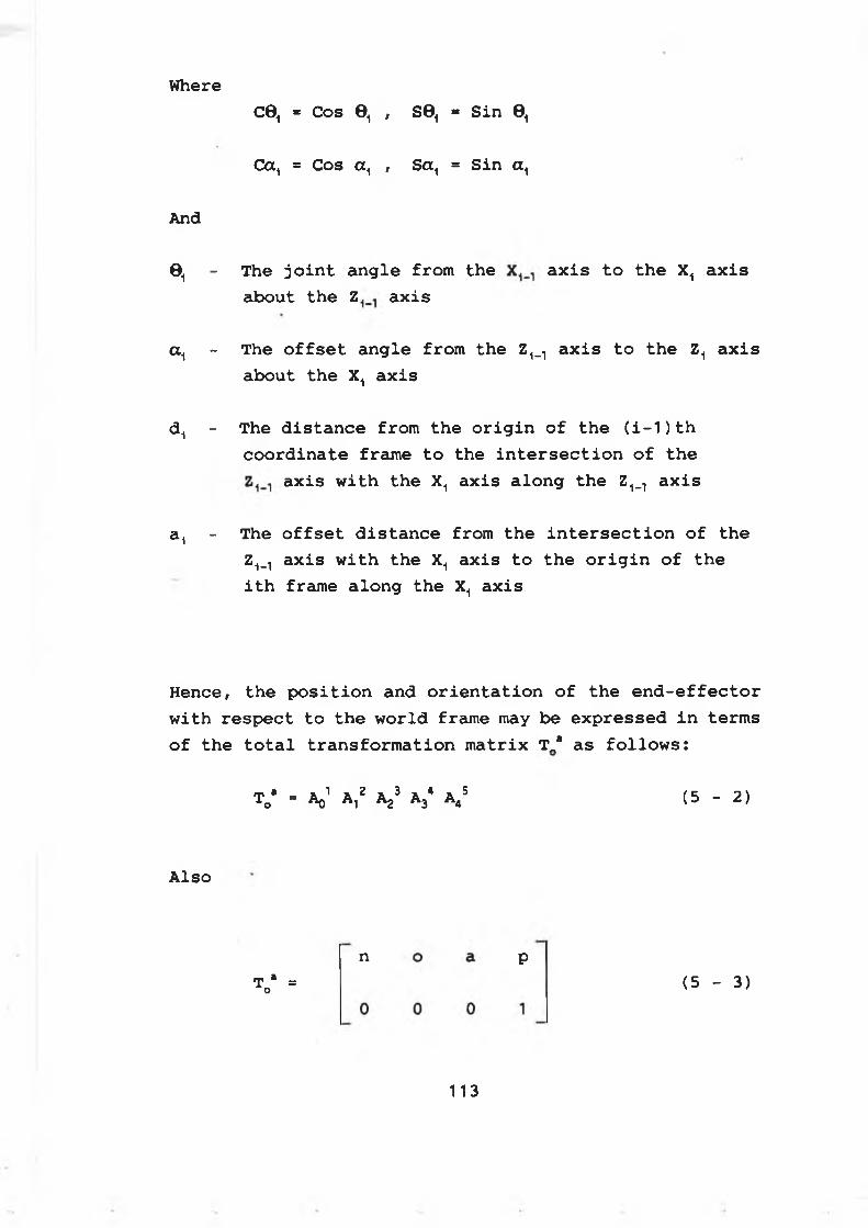
W here
C0, * C os 0 , , S 0 , * Sin 0 ,
C a1 = C os a , , S a 1 = S in a ,
And
0 , - T he j o i n t a n g l e fr o m t h e a x i s t o t h e X, a x i s
a b o u t t h e Z a x i s
a , - T he o f f s e t a n g l e fr o m t h e Z ^ a x i s t o t h e Z, a x i s
a b o u t t h e X, a x i s
d , - T he d i s t a n c e fro m t h e o r i g i n o f t h e ( i - 1 ) t h
c o o r d i n a t e fr a m e t o t h e i n t e r s e c t i o n o f t h e
a x i s w i t h t h e X, a x i s a l o n g t h e Z1s1 a x i s
a , - T he o f f s e t d i s t a n c e fro m t h e i n t e r s e c t i o n o f t h e
Z1_l a x i s w i t h t h e X, a x i s t o t h e o r i g i n o f t h e
i t h fr a m e a l o n g t h e X, a x i s
H e n c e , t h e p o s i t i o n a n d o r i e n t a t i o n o f t h e e n d - e f f e c t o r
w it h r e s p e c t t o t h e w o r ld fr a m e may b e e x p r e s s e d i n t e r m s
o f t h e t o t a l t r a n s f o r m a t i o n m a t r ix T„a a s f o l l o w s :
T0‘ - V A,2 Aj3 A34 A4S (5 - 2)
Also
To“ "
n P(5 - 3)
113
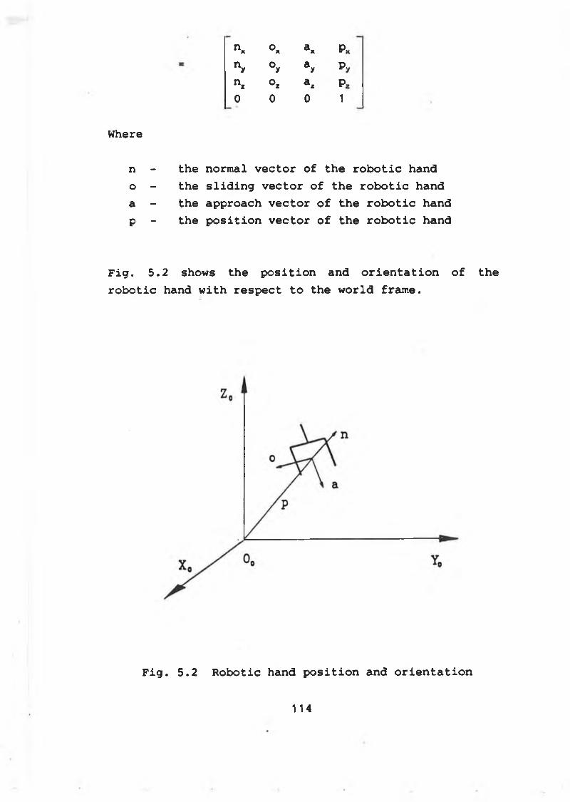
n* Ox a* P.ny °y ay P,nz °z az P;0 0 0 1
Where
n - the normal vector of the robotic hando - the sliding vector of the robotic handa - the approach vector of the robotic handp - the position vector of the robotic hand
Fig. 5.2 shows the position and orientation of robotic hand with respect to the world frame.
F i g . 5 . 2 R o b o t i c hand p o s i t i o n an d o r i e n t a t i o n
the
1 14
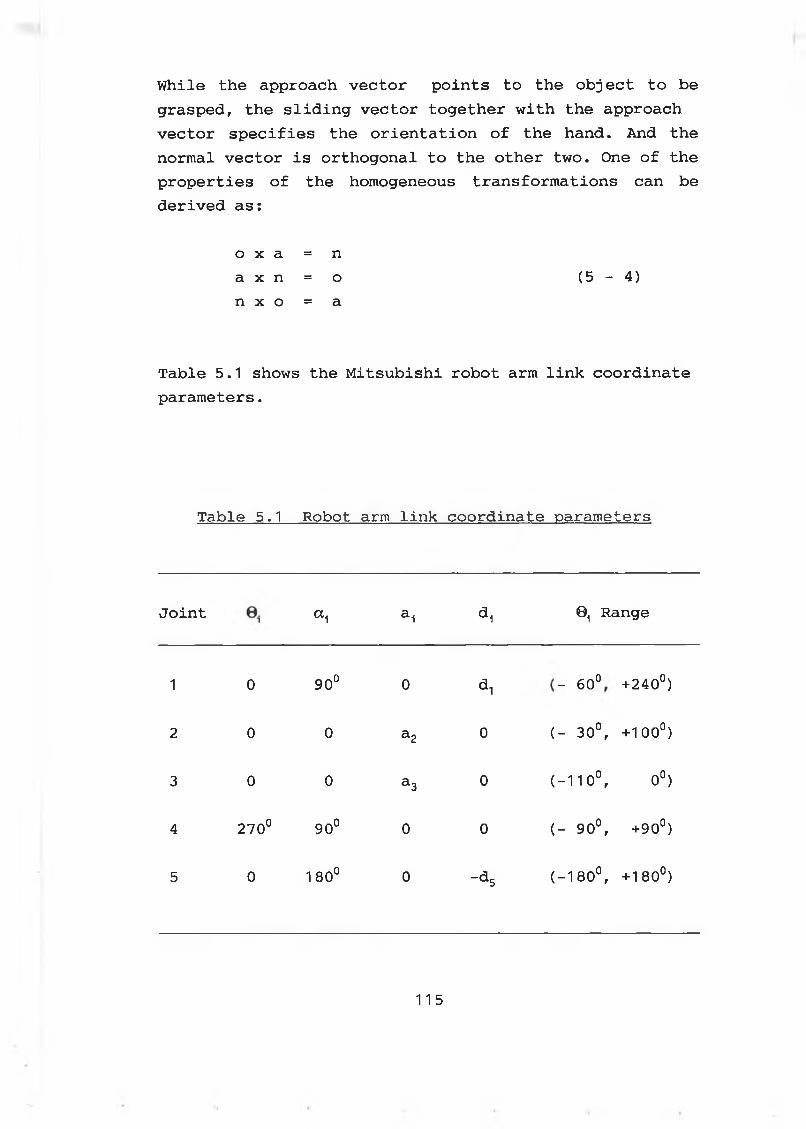
While the approach vector points to the object to be grasped, the sliding vector together with the approach vector specifies the orientation of the hand. And the normal vector is orthogonal to the other two. One of the properties of the homogeneous transformations can be derived as:
o X a = na X n = o (5 - 4)n X o = a
Table 5.1 shows the Mitsubishi robot arm link coordinate parameters.
Table 5.1 Robot arm link coordinate parameters
Joint a i ai a, Oi Range
1 0 900 0 *1 i o\ o o +240°)
2 0 0 a2 0 ( - 30°, + 1 0 0 °)
3 0 0 a3 0 ( - 1 1 0 °, 0 °)
4 270° \D O o 0 0 ( - 90°, +90°)
5 0 180° 0 -*5 ( - 1 8 0 ° , + 180°)
115
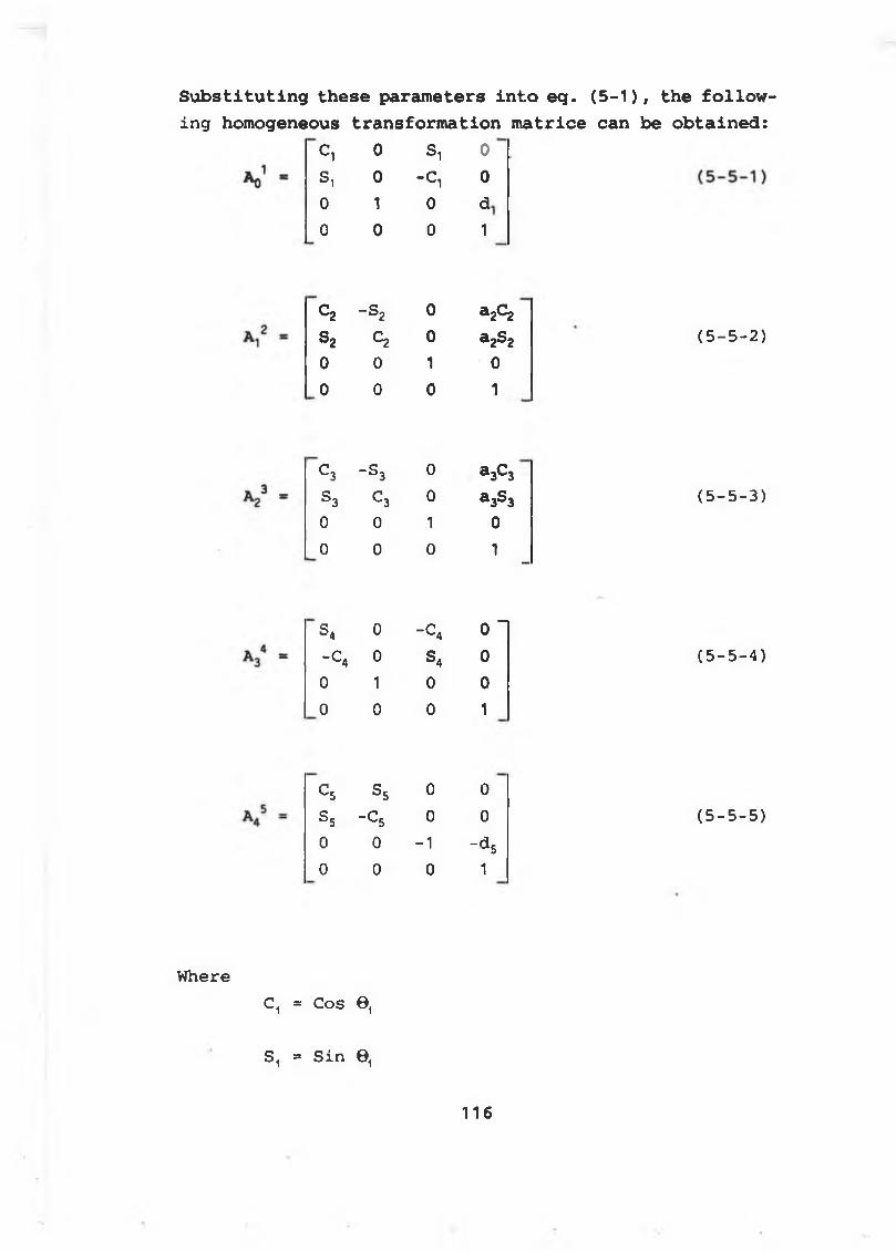
Substituting these parameters into eg. (5-1), the following homogeneous transformation matrice can be obtained:
C , 0 S i 0
S , 0 - C , 0
0 1 0 d
0 0 0 1
C2 - s 2 0 a 2c 2S2 C2 0 a2S20 0 1 00 0 0 1
(5-5-2)
C3 - S 3 0 a3C3S 3 C 3 0 a3S3 (5-5-3)0 0 1 00 0 0 1
-
S* 0 - C 4 0 “- C 4 0 S4 0 (5-5-4)0 1 0 00 0 0 1
C 5 S5 0 0S5 - C 5 0 0 (5-5-5)0 0 -1 -<*50 0 0 1
WhereC, = Cos 0,
S, * Sin 9,
1 1 6
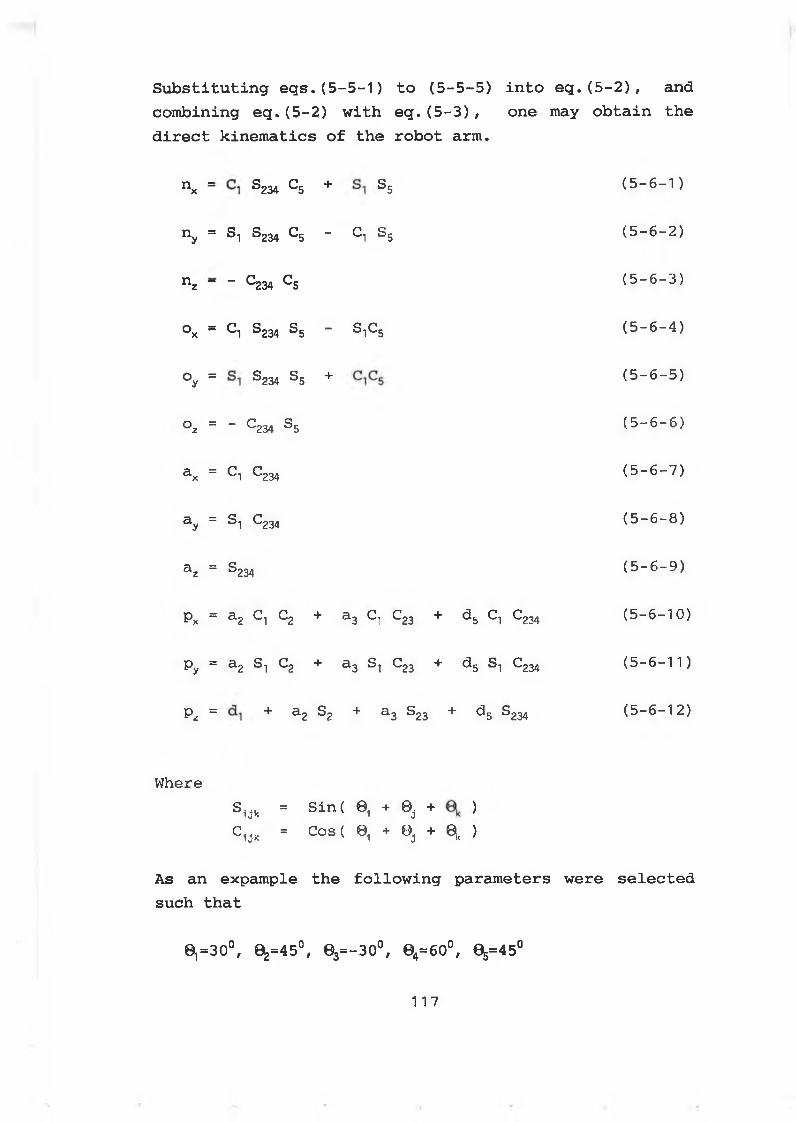
Substituting eqs.(5-5-1) to (5-5-5) into eq.(5-2), and combining eq.(5-2) with eq.(5-3), one may obtain the direct kinematics of the robot arm.
nx = ®234 ^5 + S 5 (5-6-1)
ny = S1 S234 C5 - C, S 5 (5-6-2)
nz - - C234 c5 (5 - 6 - 3)
Ox * q S234 S5 - SiC5 (5-6-4)
°y = ®234 5 + (5-6-5)
oz = - C234 s5 (5-6-6)
a x = C 1 C 234 ( 5 - 6 - 7 )
ay = St C234 (5-6-8)
a z = S 234 (5-6-9)
px = a2 C-, C2 + a3 C} C23 + d5 C-, C234 (5-6-10)
py = a2 S-i C2 + a3 St C23 + d5 S-, C234 (5-6-1 1 )
pz = + a2 S2 + a3 S23 + d5 S234 (5-6-12)
Wheres uk ■ s i n < 0 i + ® j + )c1Jk = cost 0, + 0J + q, )
As an expample the following parameters were selected such that
0,=3O°, 0^=45°, 03=-3O°, 04=6O°, 0^=45°
117
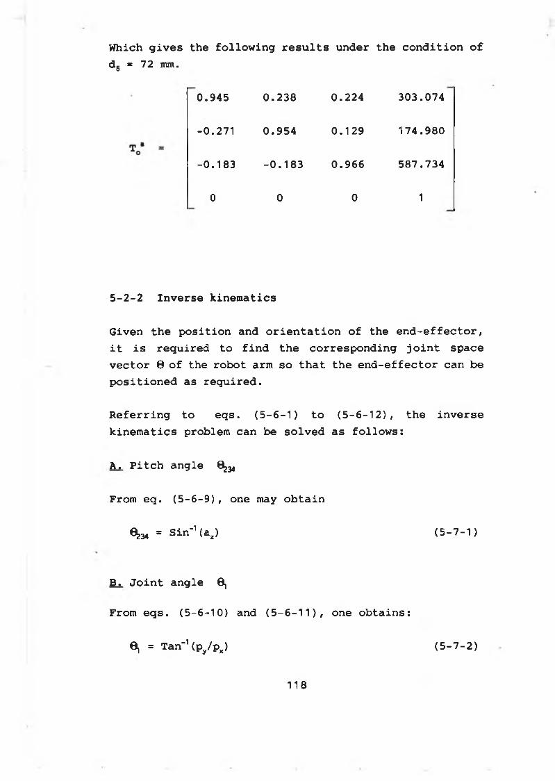
Which gives the following results under the condition of d5 * 72 mm.
0.945 0.238 0.224 303.074
-0.271 0.954 0.129 174.980
-0.183 -0.183 0.966 587.734
0 0 0 1
5-2-2 Inverse kinematics
Given the position and orientation of the end-effector, it is required to find the corresponding joint space vector 8 of the robot arm so that the end-effector can be positioned as required.
Referring to eqs. (5-6-1) to (5-6-12), the inverse kinematics problem can be solved as follows:
A. Pitch angle 6^
From eq. (5-6-9), one may obtain
6^ = Sin-1 (a2) (5-7-1)
B. Joint angle 0,
From eqs. (5-6-10) and (5-6-11), one obtains:
O, = Tan-1 (py/px) (5-7-2)
1 1 8
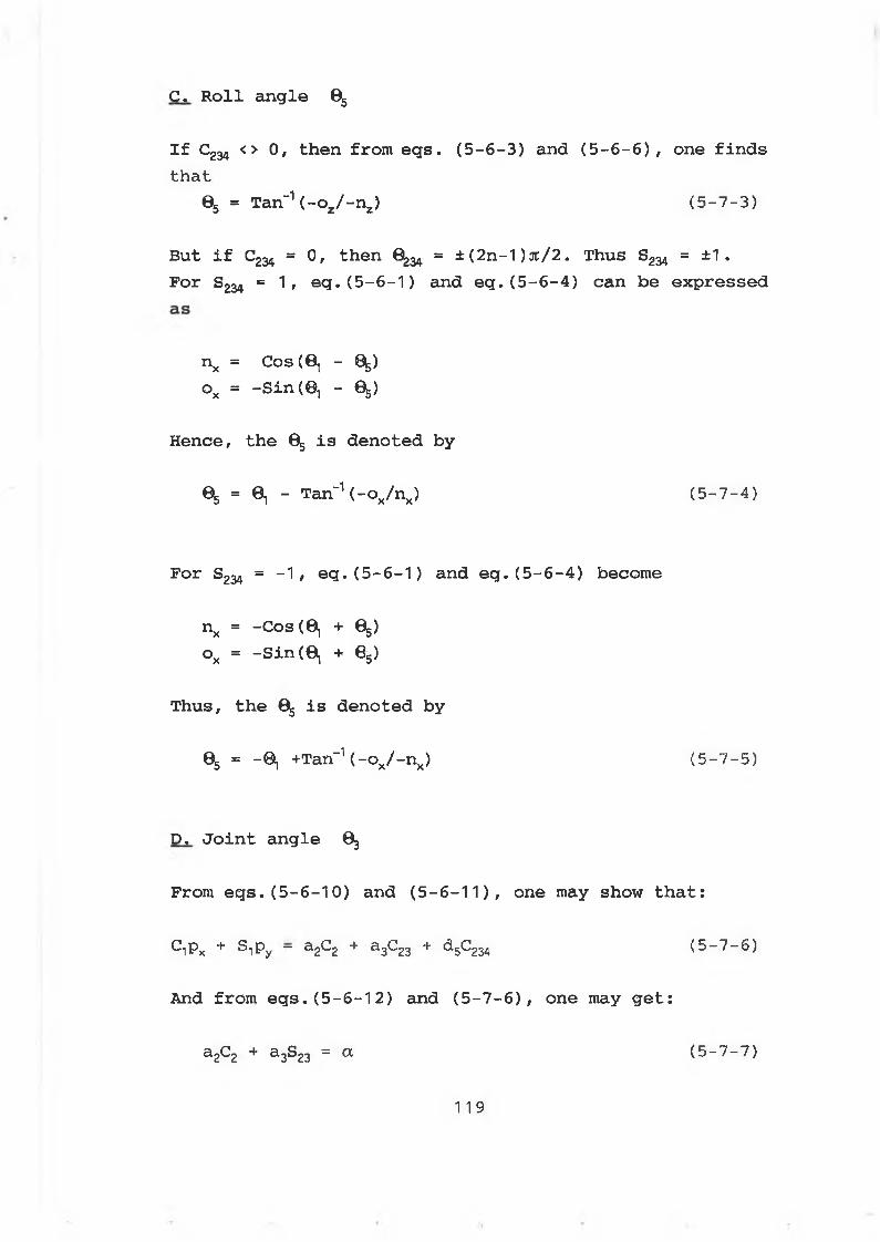
C. Roll angle 6^
If C234 <> 0, then from eqs. (5-6-3) and (5-6-6), one findsthat
e5 = Tan-1 (-o2/-nz) (5-7-3)
But if C234 = 0, then 6^ = ± (2n-1 )jt/2. Thus S234 = ±1 .For S234 = 1, eq. (5-6-1) and eq. (5-6-4) can be expressed
nx = Cos (8, - ^) ox = -Sin (0, - 05)
Hence, the 05 is denoted by
05 = ©1 - Tan-1 (-ox/nx) (5-7-4)
For S234 = -1, eq. (5-6-1) and eq. (5-6-4) become
nx = -Cos (6, + %) ox = -Sin (0, + 8 .)
Thus, the 0 is denoted by
05 = — 0, +Tan_1 (-ox/-nx) (5-7-5)
D. Joint angle ©3
From eqs.(5-6-10) and (5-6-11), one may show that:
C^PX + S Py — a2C2 + a3C23 + 5 23 (5-7-6)
And from eqs.(5-6-12) and (5-7-6), one may get:
a2C2 + a-3S23 = a (5-7-7)
119
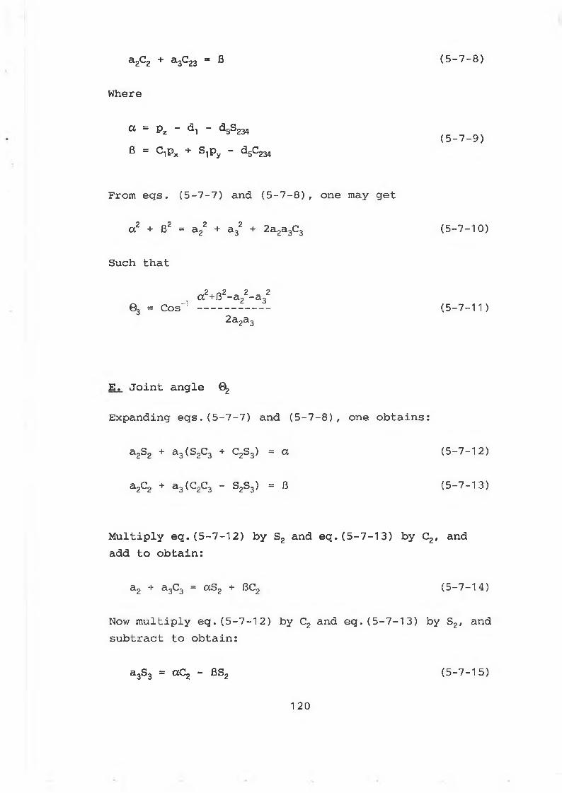
a 2C2 + a 3C23 = ß ( 5 - 7 - 8 )
Where
a = p z - d, - d 5S 234
® = C l P x + S l P y ~ a 5 C 2 3 4
From eqs. (5-7-7) and (5-7-8), one may get
a2 + R2 = a22 + a32 + 2a2a3C3 (5-7-10)
Such that
cc2+ß2-a22-a322a2a3
(5-7-9)
03 = Cos“ ---------- (5-7-11)
E. Joint angle 6
Expanding eqs.(5-7-7) and (5-7-8), one obtains:
a2S2 + a3(S2C3 + C2s3) = a (5-7-12)
a2C2 + a3(C2C3 - S2S3) = 6 (5-7-13)
Multiply eq. (5-7-12) by S2 and eq. (5-7-13) by C2, and add to obtain:
a2 + a3C3 = aS2 + BC2 (5-7-14)
Now multiply eq. (5-7-12) by C2 and eq. (5-7-13) by S2, and subtract to obtain:
a 3S3 = OC2 - fiS2 ( 5 - 7 - 1 5 )
120
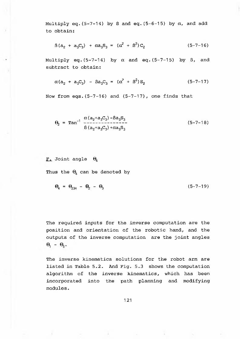
Multiply eg.(5-7-14) by 3 and eq.(5-6-15) by a, and add to obtain:
fi(a2 + a3C3) + aa3S3 = (a2 + 82)C2 (5-7-16)
Multiply eq. (5-7-14) by a and eq. (5-7-15) by 6, and subtract to obtain:
a(a2 + a3C3) - Ba3C3 = (a2 + B2)S2 (5-7-17)
Now from eqs.(5-7-16) and (5-7-17), one finds that
a(a2+a3C3) -Ba3S30 = Tan-1-------------- (5-7-18)
J3 (a2+a3C3) +«a3S3
F. Joint angle 04
Thus the 04 can be denoted by
04 = 0234 - 02 - 03 (5-7-19)
The required inputs for the inverse computation are the position and orientation of the robotic hand, and the outputs of the inverse computation are the joint angles
The inverse kinematics solutions for the robot arm are listed in Table 5.2. And Fig. 5.3 shows the computation algorithm of the inverse kinematics, which has been incorporated into the path planning and modifying modules.
121
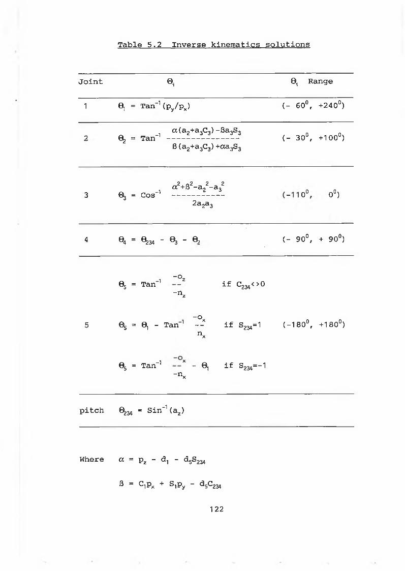
Table 5.2 Inverse kinematics solutions
Joint « I0, Range
1 0, = Tan 1(Py/Px) ( - 60°, +240°)
02 = Tan-1a(a2+a3C3) -fîa3S39 ( - 30°, +100°)6 (a2+a3C3) +aa3S3
3 03 = Cos-1a2+62-a22-a32
i o o
Oo
v_>-
2a2a3
4 i3
csThaf
' 0 3 " ® 2 ( - 90°, + 90°)
05 = Tan 1 “ ° z if C234< > 0- n z
-°x (-180°, +180°)5 % = 0, - Tan -- if S234=1n x
05 = Tan-1 - 0 if S234=-1- n x
pitch 0234 = Sin-1 (a2)
Where a = pz - d., - d5S234
® = c iPx + s iPy “ a 5C234
122
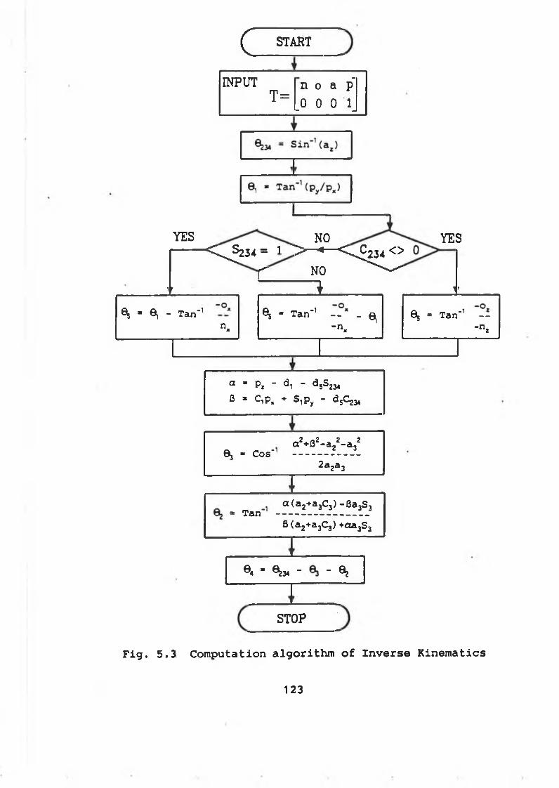
c START
INPUT n o a p"T =
i.
HooQ|
YES NO YES
a * px - d, - d 5S234 0 * C,p, + S ,py - djC ,*
' " ^ < ^ 2 3 4 = r > - • ^>£234 ^
f NO ^
1r * i t
JP H Jt> 1 T a n ' 1
n *
% * T a n ' 1- - a ,- n
X
65 * T a n -1 - -
" n z
0j * Cos'a 2+B2- a 22- a 32
2 a 2a 3
a ( a 2+ a 3C3) - B a 3S 3= Tan ----------------------- -----
f l(a 2+a3C3) +aa3S3
0 4 * ^ 3 4 - " Q j
STOP
F i g . 5 . 3 C o m p u ta t io n a l g o r i t h m o f I n v e r s e K i n e m a t i c s
123
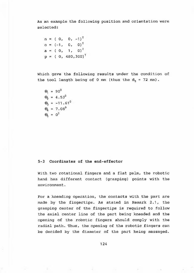
As an example the following position and orientation were selected:
n = ( 0, 0, -1)'o = (■-1, 0, 0)Ta = ( o, 1, 0)TP = ( 0, 480, 300)
Which gave the following results under the condition of the tool length being of 0 mm (thus the d5 = 72 mm) .
0. = 90°
®2 = 4 .53 °
03 = - 1 1 .6 1
© 4 = • o COo
^ = 0°
5 - 3 C o o r d in a t e s o f t h e e n d - e f f e c t o r
With two rotational fingers and a flat palm, the robotic hand has different contact (grasping) points with the environment.
For a kneading operation, the contacts with the part are made by the fingertips. As stated in Remark 2.1, the grasping center of the fingertips is required to follow the axial center line of the part being kneaded and the opening of the robotic fingers should comply with the radial path. Thus, the opening of the robotic fingers can be decided by the diameter of the part being massaged.
1 24
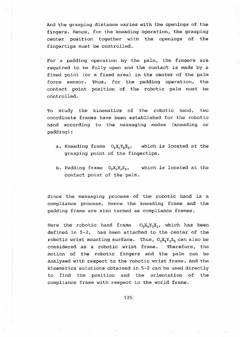
And the grasping distance varies with the openings of the fingers. Hence, for the kneading operation, the grasping center position together with the openings of the fingertips must be controlled.
For a padding operation by the palm, the fingers are required to be fully open and the contact is made by a fixed point (or a fixed area) in the center of the palm force sensor. Thus, for the padding operation, the contact point position of the robotic palm must be controlled.
To study the kinematics of the robotic hand, two coordinate frames have been established for the robotic hand according to the massaging modes (kneading or padding):
a. Kneading frame 0KXKYKZK, which is located at the grasping point of the fingertips.
b. Padding frame OpXpYpZp, which is located at the contact point of the palm.
Since the massaging process of the robotic hand is a compliance process, hence the kneading frame and the padding frame are also termed as compliance frames.
Here the robotic hand frame °5X5YsZ5/ which has been defined in 5-2, has been attached to the center of the robotic wrist mounting surface. Thus, 05X5Y5Z5 can also be considered as a robotic wrist frame. Therefore, the motion of the robotic fingers and the palm can be analysed with respect to the robotic wrist frame. And the kinematics solutions obtained in 5-2 can be used directly to find the position and the orientation of the compliance frame with respect to the world frame.
125
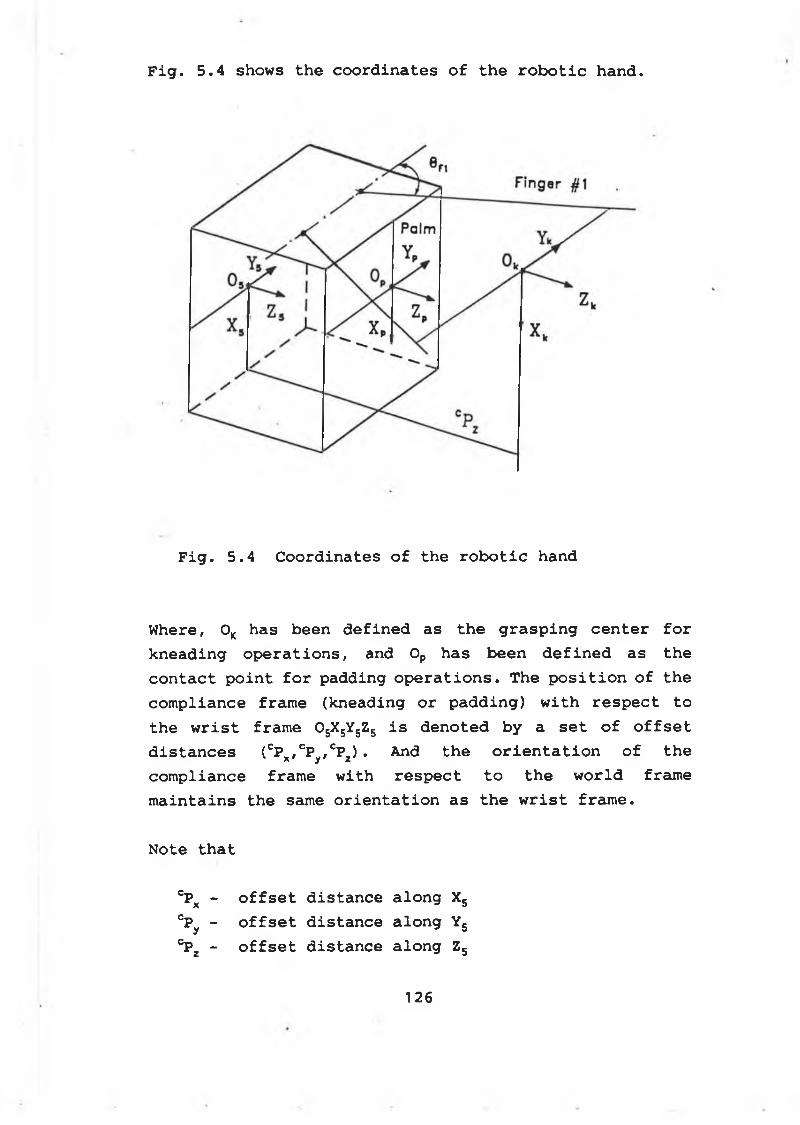
F i g . 5 . 4 shows t h e c o o r d i n a t e s o f t h e r o b o t i c h a n d .
Fig. 5.4 Coordinates of the robotic hand
Where, 0K has been defined as the grasping center for kneading operations, and 0P has been defined as the contact point for padding operations. The position of the compliance frame (kneading or padding) with respect to the wrist frame OsX5Y5Z5 is denoted by a set of offset distances (CP«,CP„,CPJ • And the orientation of thex y zcompliance frame with respect to the world frame maintains the same orientation as the wrist frame.
Note that
°PX - offset distance along X5cPy - offset distance along Y5°P2 - offset distance along Z5
1 2 6
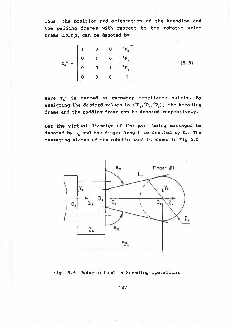
Thus, the position and orientation of the kneading and the padding frames with respect to the robotic wrist frame 05X5Y5Z5 can be denoted by
1 0 0
0 1 0C p :
0 0 1C p ;
0 0 0 1
Here Ttc is termed as geometry compliance matrix. By assigning the desired values to (cPx/CPy»cPx) / the kneading frame and the padding frame can be denoted respectively.
Let the virtual diameter of the part being massaged be denoted by DR and the finger length be denoted by LF. The massaging status of the robotic hand is shown in Fig 5.5.
F i g . 5 . 5 R o b o t i c hand i n k n e a d in g o p e r a t i o n s
1 2 7
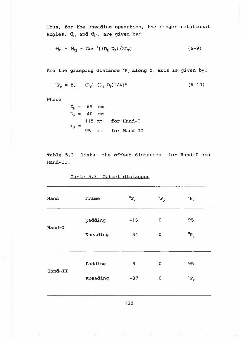
Thus, for the kneading opeartion, the finger rotational angles, 0^ and 0[r2, are given by:
0^ = 0 2 = Cos'1 [ (Dr-Df) /2Lf] (6-9)
And the grasping distance CPZ along Z5 axis is given by:
CPZ = Zh + (LF2-(DR-DF)2/4)i (6-10)
WhereZh = 65 nun DF = 40 mm
115 mm for Hand-Il f = 95 mm for Hand-II
Table 5.3 lists the offset distances for Hand-I and Hand-II.
Table 5.3 Offset distances
Hand Frame CPx % Cpz
padding -15 0 95Hand-I
Kneading -34 0 Cpz
Padding -5 0 95Hand-II
Kneading -37 0 Cpz
1 28
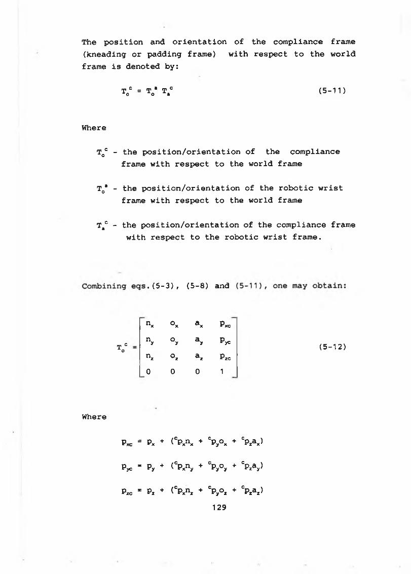
The position and orientation of the compliance frame (kneading or padding frame) with respect to the world frame is denoted by:
T c = T * T co O S (5-11)
Where
T0C - the position/orientation of the compliance frame with respect to the world frame
T0a - the position/orientation of the robotic wrist frame with respect to the world frame
T#c - the position/orientation of the compliance frame with respect to the robotic wrist frame.
ToC
. (5-3), (5-8) and
nx °x ax Pxcny °y ay Pycnz °z az Pzc0 0 0 1
(5-12)
Where
P*c “ Px + <CP*nx + cPy°x + CPzax>
Pyc - Py + (cPxny + cpyoy + cp2ay)x y ry y
Pzc * Pz + (CPxnz + CPy°z + CPzaz>129
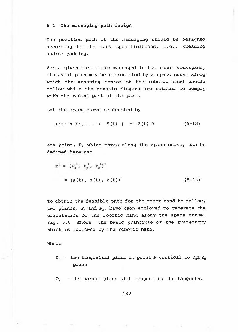
5 - 4 The m a s s a g in g p a t h d e s i g n
The position path of the massaging should be designed according to the task specifications, i.e., kneading and/or padding.
For a given part to be massaged in the robot workspace, its axial path may be represented by a space curve along which the grasping center of the robotic hand should follow while the robotic fingers are rotated to comply with the radial path of the part.
Let the space curve be denoted by
r (t) = X (t) i + Y(t) j + Z(t) k (5-13)
Any point, P, which moves along the space curve, can be defined here as:
= (X(t) , Y (t) , Z(t) )T (5 -1 4 )
To obtain the feasible path for the robot hand to follow, two planes, Pm and Pn, have been employed to generate the orientation of the robotic hand along the space curve. Fig. 5 .6 shows the basic principle of the trajectory which is followed by the robotic hand.
Where
Pm - the tangential plane at point P vertical to O0X0Y0 plane
Pn - the normal plane with respect to the tangental
1 30
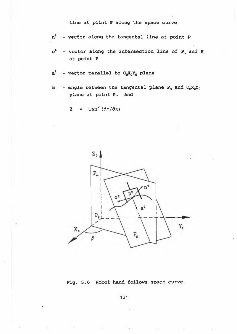
l i n e a t p o i n t P a l o n g t h e s p a c e c u r v e
n* - v e c t o r a l o n g t h e t a n g e n t a l l i n e a t p o i n t P
o 1 - v e c t o r a l o n g t h e i n t e r s e c t i o n l i n e o f Pm a n d Pn
a t p o i n t P
a* - v e c t o r p a r a l l e l t o OqXqYq p l a n e
S - a n g l e b e t w e e n t h e t a n g e n t a l p l a n e Pm a n d OqXqZq
p l a n e a t p o i n t P . And
B = Tan-1 (dY/dX)
F i g . 5 . 6 R ob ot han d f o l l o w s s p a c e c u r v e
131
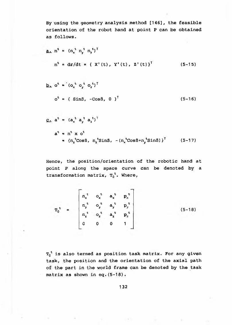
By using the geometry analysis method [146], the feasible orientation of the robot hand at point P can be obtained as follows.
n* * (n^ ny* nz*)T
n1 = dr/dt = { X 1 (t), Y'(t), Z * (t) >T (5-15)
kt o* = ‘ ( o* o * ozV
o* = { SinB, -CosB, 0 }T (5-16)
^ a t _ t _ t * TS_i_ a - (ax ay az )
t t ta * n x o* {n^CosB, n^SinB, - (n^CosB+n^SinB) }T (5-17)
Hence, the position/orientation of the robotic hand at point P along the space curve can be denoted by a transformation matrix, T^. Where,
n x* ° x t a xt P ,
V V a y* P ;
n z* a z* P;
0 0 0 1
Tq1 is also termed as position task matrix. For any given task, the position and the orientation of the axial path of the part in the world frame can be denoted by the task matrix as shown in eq.(5-18).
132
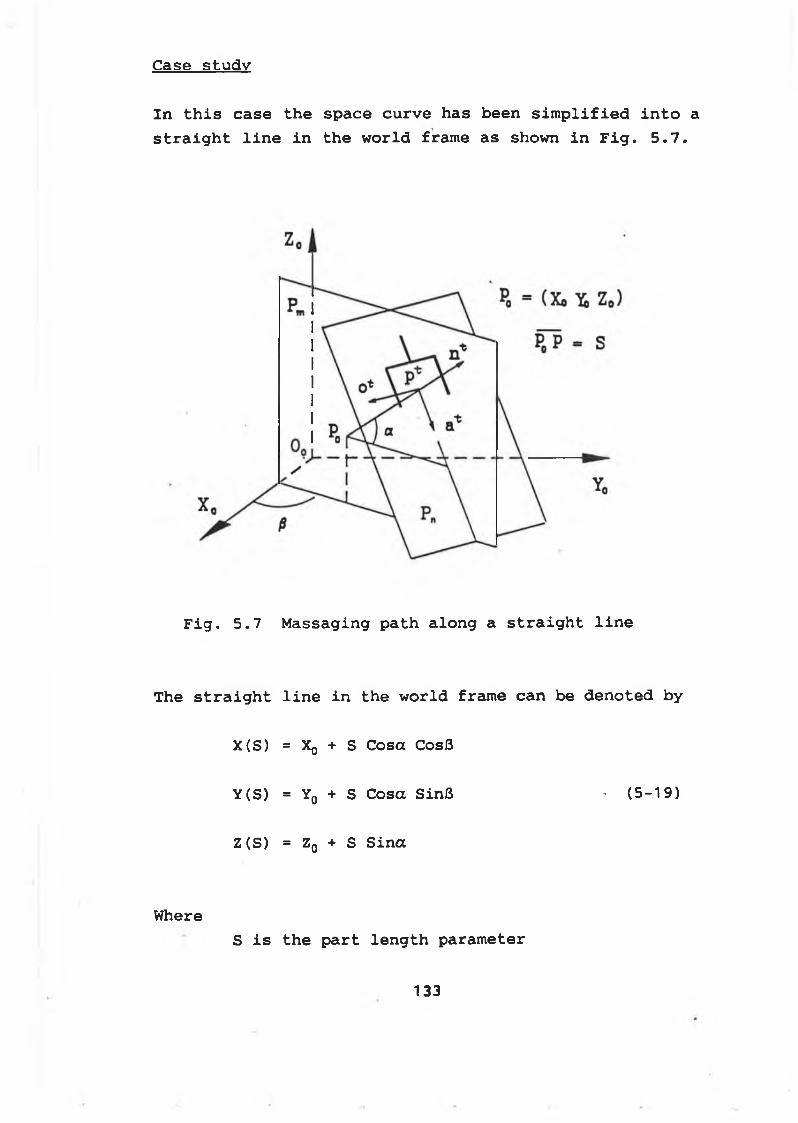
C a s e s t u d y
In this case the space curve has been simplified into a straight line in the world frame as shown in Fig. 5.7.
Fig. 5 . 7 Massaging path along a straight line
The straight line in the world frame can be denoted by
X(S) = Xq + S Cosa CosB
Y(S) = Y0 + S Cosa SinS • (5 - 1 9 )
Z (5) = Z0 + S Sina
WhereS is the part length parameter
133
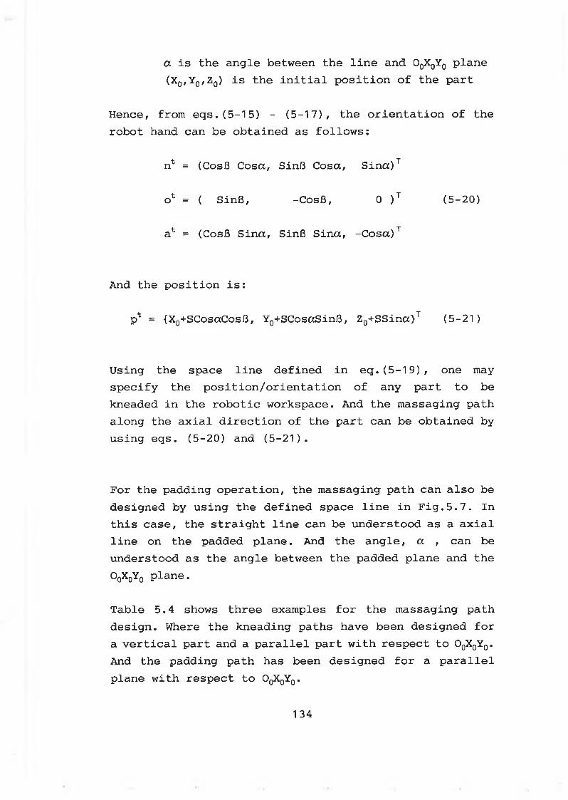
a is the angle between the line and O0X0Y0 plane (X0,Y0,Z0) is the initial position of the part
Hence, from eqs.(5-15) - (5-17), the orientation of the robot hand can be obtained as follows:
nt = (CosB Cosa, SinB Cosa, Sina)T
ot = ( SinB, -CosB, 0 )T (5-20)
at = (CosB Sina, SinB Sina, -Cosa)T
And the position is:
pt = {X0+SCosaCosB, Y0+SCosaSinB, Z0+SSina}T (5-21)
Using the space line defined in eq.(5-19), one may specify the position/orientation of any part to be kneaded in the robotic workspace. And the massaging path along the axial direction of the part can be obtained by using eqs. (5-20) and (5-21).
For the padding operation, the massaging path can also be designed by using the defined space line in Fig.5.7. In this case, the straight line can be understood as a axial line on the padded plane. And the angle, a , can be understood as the angle between the padded plane and the O0X0Y0 plane.
Table 5.4 shows three examples for the massaging path design. Where the kneading paths have been designed for a vertical part and a parallel part with respect to O0X0Y0. And the padding path has been designed for a parallel plane with respect to O0X0Y0.
134
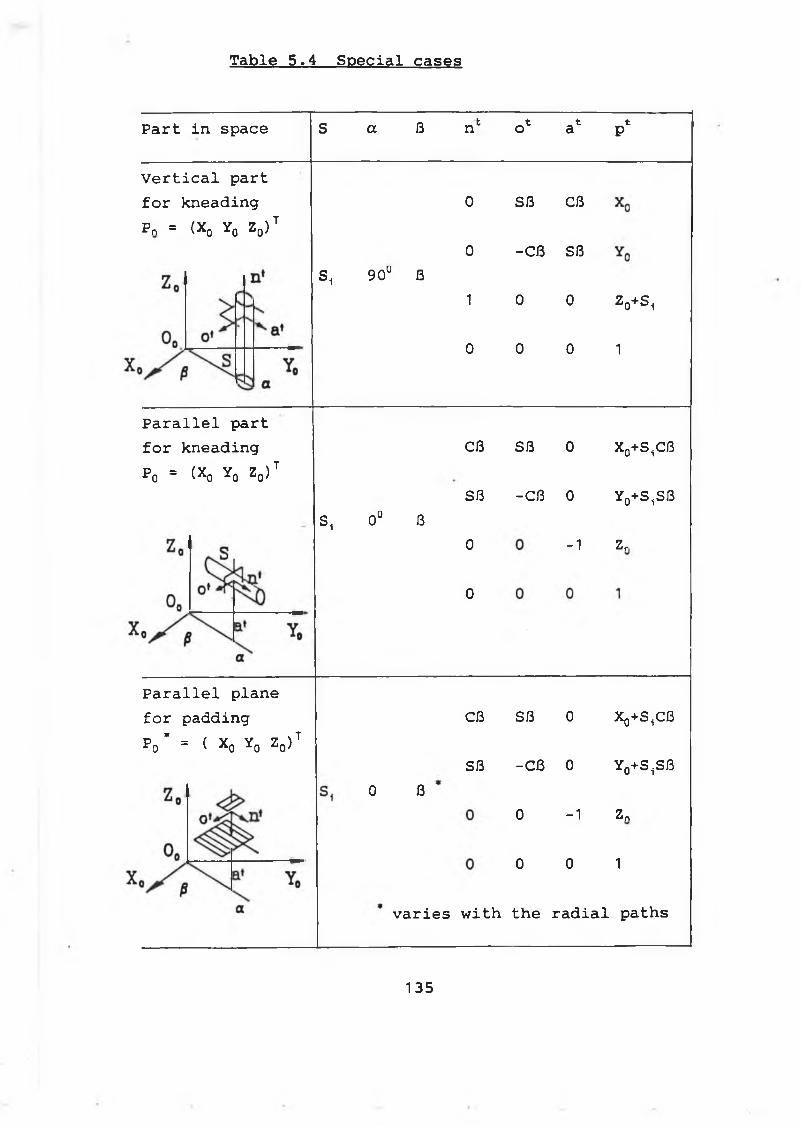
T a b le 5 . 4 S p e c i a l c a s e s
Part in space S a ß nfc _t t to a p
Vertical part for kneading Pn = (X0 Y0 Zq) t
S, 90° ß
0
0
1
0
Sß Cß
-Cß Sß
0 0
0 0
V s i
1
Parallel part for kneading P0 = (X0 Y0 ZQ)T
Cß Sß 0 Xo+S^ß
Sß -Cß 0 Yg+S^SßS, 0° ß
0
0
-1 Zr
Parallel plane for padding P0* = ( X0 Y0 ZQ)T
0 ß
Cß Sß 0 Xq+S^B
Sß -Cß 0 Y0+S.jSß
0 -1 Zn
0 0 1
varies with the radial paths
1 3 5
5 - 5 M o tion c o n t r o l
For a given massaging task (kneading or padding), the massaging path can be designed by using the methods given in 5-4. To follow the designed path, the robot hand must be controlled with the required position and orientation. This can be achieved by controlling the joint space of the robot.
Motion control for kneading operations
For kneading operations using the robotic fingers, both the robotic finger joint space and the robotic arm joint space should be calculated and controlled.
The robotic finger rotational angles, 0., and 0^, can be calculated by using eq.(5-9). The required input for the computation of the rotational angles is the diameter, DR, of the part being massaged.
The kneading geometry compliance matrix, Tac, which is related with the size of the part being massaged, can be obtained as shown in eq.(5-8) by referring to Table 5.3.
To follow the designed path, the motion control equation for the robot hand at any point P along the space curve must be maintained as follows:
T0C = T^ (5-22)
Where
T0C is the compliance matrix as defined in eq.(5-11).
To* is the task matrix as defined in eq.(5-18).
1 3 6
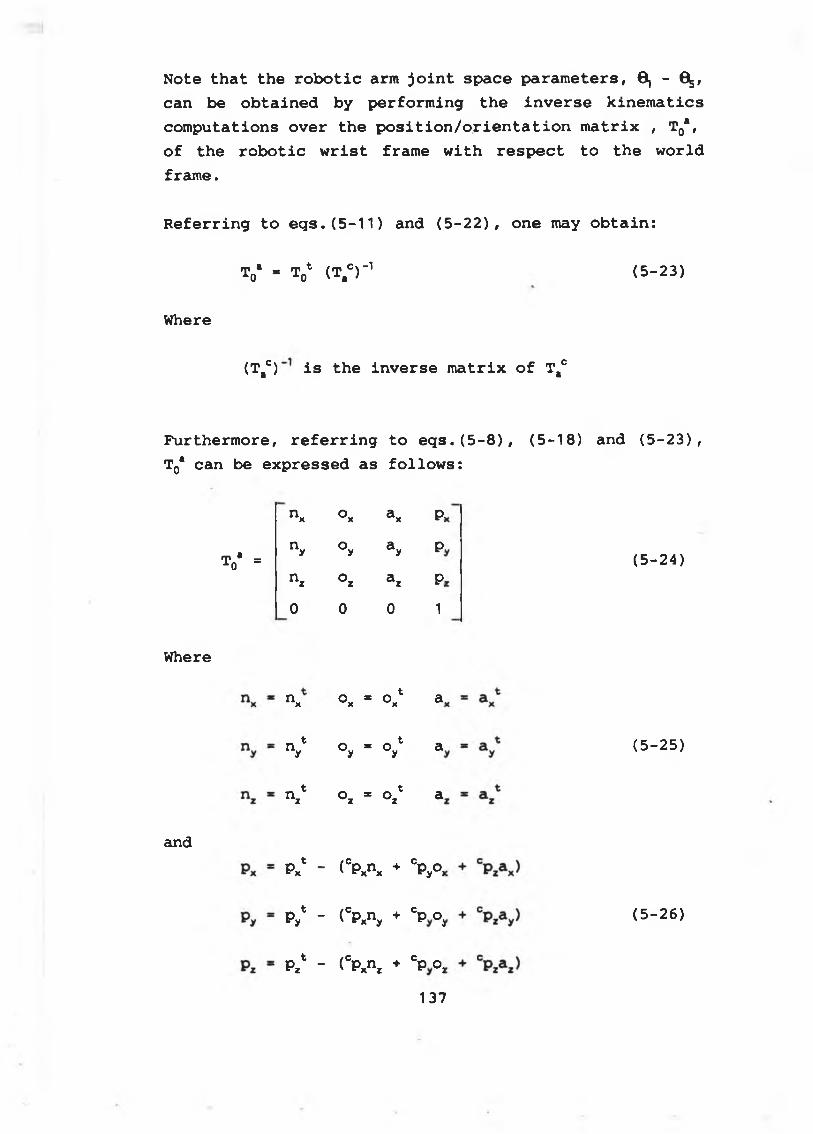
Note that the robotic arm joint space parameters, 6, - 0 , can be obtained by performing the inverse kinematics computations over the position/orientation matrix , T0a, of the robotic wrist frame with respect to the world frame.
Referring to eqs.(5-11) and (5-22), one may obtain:
t0b - V (t,cr 1 (5-23)
Where
(T#c) is the inverse matrix of Tac
Furthermore, referring to eqs.(5-8), (5-18) and (5-23), T0* can be expressed as follows:
T * = i o
Where
and
n x o aX X P:
n y o ay y P,
n z o az z P
0 0 0 1
n x ° x = Oxt a.
V o = o 1 y y a
n z" o * o *z z a
Px1 - ( CPxn x + ° P °e'yw>
Py* - (cpxny + cp oj
P , 1 - ( CP xn z + °P oa
(5-24)
(5-25)
( 5 - 2 6 )
137
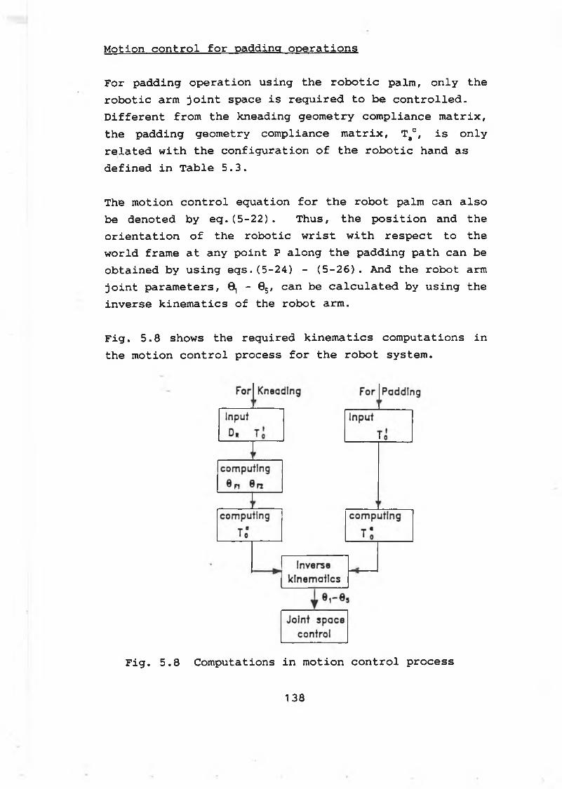
M o tio n c o n t r o l f o r p a d d in g o p e r a t i o n s
For padding operation using the robotic palm, only the robotic arm joint space is required to be controlled. Different from the kneading geometry compliance matrix, the padding geometry compliance matrix, T#c, is only related with the configuration of the robotic hand as defined in Table 5.3.
The motion control equation for the robot palm can also be denoted by eq.(5-22). Thus, the position and the orientation of the robotic wrist with respect to the world frame at any point P along the padding path can be obtained by using eqs.(5-24) - (5-26). And the robot arm joint parameters, 0,-0^, can be calculated by using the inverse kinematics of the robot arm.
Fig. 5.8 shows the required kinematics computations in the motion control process for the robot system.
F i g . 5 . 8 C o m p u ta tio n s i n m o tio n c o n t r o l p r o c e s s
1 3 8
C h a p te r S i x
Intelligent Control System
6-1 Introduction
In this chapter, the intelligent control system for the robotic massaging operations has been developed.
The overall AI system is described in section 6-2. The parameter organizing and path planning using the offline KBS are given out in section 6-3. While the on-line error-corrections using the on-line KBS are constructed in section 6-5. The robot control organizing and task execution are outlined in section 6-4. And the software development of the AI control system together with the experimental results are presented in section 6-6.
6-2 AI Control System
There are many uncertainties or fuzziness in a robotic massaging process due to:
* The characteristics of the part to be massaged varies from one person to another.
* The unpredictable deviations of the part being massaged from its planned path
* The configuration limitations of the robotic sensing system.
To carry out the task execution using the robot, AI is required for the robotic massaging system. The AI
139
embedded in the control system is capable of handling the imprecision (fuzzy) knowledge by using the fuzzy sets theory and fuzzy logic [109-116 & 123-128].
In general, the robotic system with AI is able to perform the following functions:
a. Path planningb. Sensory information interpretationc. Knowledge manipulationd. Uncertainty/fuzzy processinge. Intelligent inferencef. Conditional adaptive controlg. Process monitoringh. Automatic error-correction
The design objectives of the intelligent robot system depend on the application fields. In this investigation, the intelligent robot control system has been developed to achieve the following objectives:
a. friendly man-machine dialogueb. parameter organizing by using the fuzzy setsc. path planning by using the robotic kinematics KBd. automatic motion coordinatinge. process execution and monitoringf. intelligent inference based on the fuzzy logicg. automatic error-correction by using the on-line KB
For a given part in the robot workspace, the man-machine module provides the system with the fuzzy descriptions of the part and its environment.
Two types of knowledge bases, off-line KB and on-line KB, have been established in the AI system according to their applications.
1 40
The off-line KB will be interfaced and used by the following modules:
a. man-machine moduleb. parameter organizing modulec. path planning module
And the on-line KB will be interfaced and used by the following modules:
a. intelligent control moduleb. error-correction modulec. path modifying module
Once the path planning has been completed, a massaging can be carried out by the execution module under the supervision of the intelligent control module.
The massaging operation will be closely watched by the intelligent control module. The error-correction module will be initiated by the intelligent control module once any error is detected from the sensing feedback.
Fig. 6.1 shows the AI control system for the robot system.
A specially designed robotic hand with the position/force sensors has been used to carry out the massaging operations. The force/tactile sensors are mounted on the fingertips and the palm of the robotic hand.
The operation procedure of the robotic massaging system with AI is illustrated in Fig. 6.2.
141
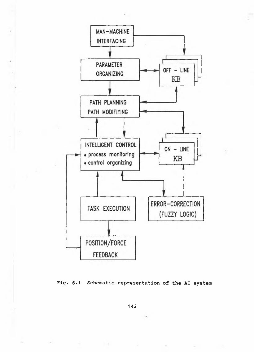
F i g . 6 .1 S c h e m a t i c r e p r e s e n t a t i o n o f t h e AI s y s te m
1 4 2
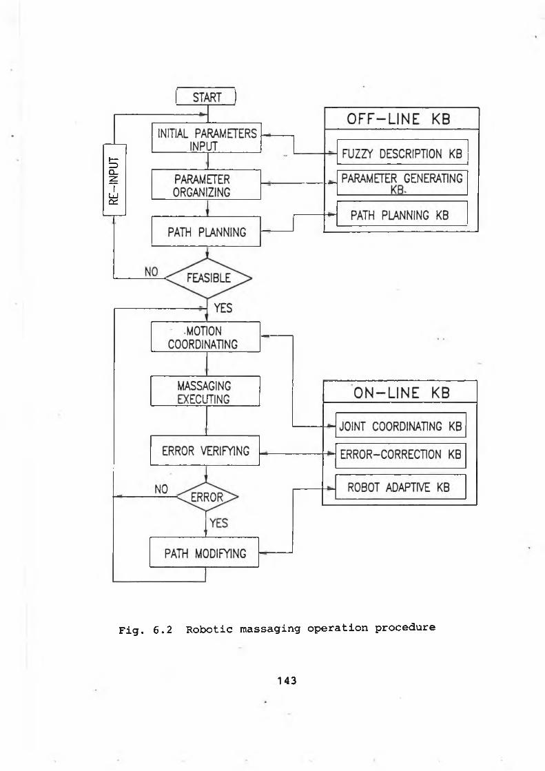
RE-IN
PUT
Fig. 6.2 Robotic massaging operation procedure
143
6-3 Parameter organizing and path planning
In the robot workspace, the human's observations provide the quickest way to describe the parts to be massaged provided that the location constraints have been imposed on the parts. Nevertheless, the human assessments are usually in a term of fuzziness. For example, the geometry size of an arm to be massaged in a predefined location may be described as "large", which is a fuzzy description [110-114 & 124-127].
Furthermore, the massaging force and massaging path have to be decided by using the human's massaging knowledge.
Hence, a off-line knowledge base can be constructed to assist the interpretation of the fuzzy inputs, the parameter generating and the path planning.
6-3-1 Off-line KB
The off-line KB consists of three parts: fuzzy description KB, parameter generating KB and path planning KB, as shown in Fig. 6.3.
A. Fuzzy description KB
The fuzzy/linguistic description of a task include:
a. the part to be massaged (linguistic terms)
arm, neck, back, etc.
144
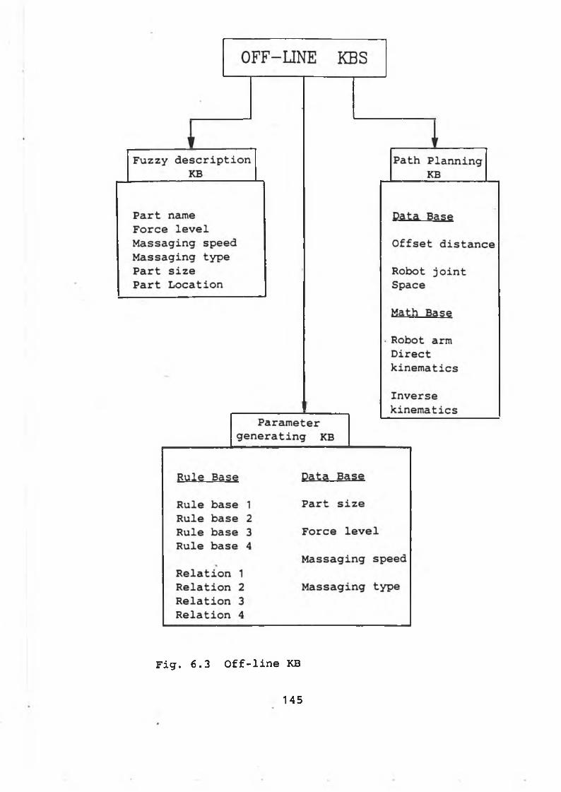
Fig. 6.3 Off-line KB
145
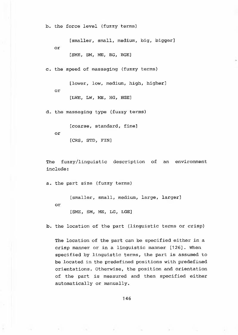
b. the force level (fuzzy terms)
[smaller, small, medium, big, bigger]or
[SME, SM, ME, BG, BGE]
c. the speed of massaging (fuzzy terms)
[lower, low, medium, high, higher]or
[LWE, LW, ME, HG, HGE]
d. the massaging type (fuzzy terms)
[coarse, standard, fine]or
[CRS, STD, FIN]
The fuzzy/linguistic description of an environment include:
a. the part size (fuzzy terms)
[smaller, small, medium, large, larger]or
[SME, SM, ME, LG, LGE]
b. the location of the part (linguistic terms or crisp)
The location of the part can be specified either in a crisp manner or in a linguistic manner [126]. When specified by linguistic terms, the part is assumed to be located in the predefined positions with predefined orientations. Otherwise, the position and orientation of the part is measured and then specified either automatically or manually.
146
B. Parameter generating KB
B.1. Rule base
The rule base can be established by considering the following correlations generalized from the human massaging knowledge:
* the massaging force level related with the part size
* the robot arm speed and the force retention time related with the massaging speed
* the number of the massaging points and the number of the radial path related with the massaging type
* the length and diameter (or the height and width) of the part related with the size of the part.
Based on the above correlations/ the rule base has been constructed in the form of fuzzy conditional statements:
IF ( a set of conditions are satisfied )
THEN ( a set of consequences can be inferred )
Thus, the following fuzzy relations ( Rule base 1 - Rule base 4 ) have been incorporated into the rule base for the parameter generating module.
147
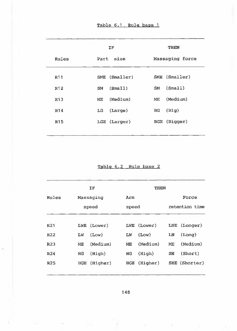
Table 6.1 Rule base 1
Rules
IF
Part size
THEN
Massaging force
R1 1 SME (Smaller) SME (Smaller)
R1 2 SM (Small) SM (Small)
R1 3 ME (Medium) ME (Medium)
R1 4 LG (Large) BG (Big)
R15 LGE (Larger) BGE (Bigger)
Table 6 .2 Rule base 2
RulesIF
Massagingspeed
THENArmspeed
Force retention time
R21 LWE (Lower) LWE (Lower) LNE (Longer)R22 LW (Low) LW (Low) LN (Long)R23 ME (Medium) ME (Medium) ME (Medium)R24 HG (High) HG (High) SH (Short)R25 HGE (Higher) HGE (Higher) SHE (Shorter)
1 48
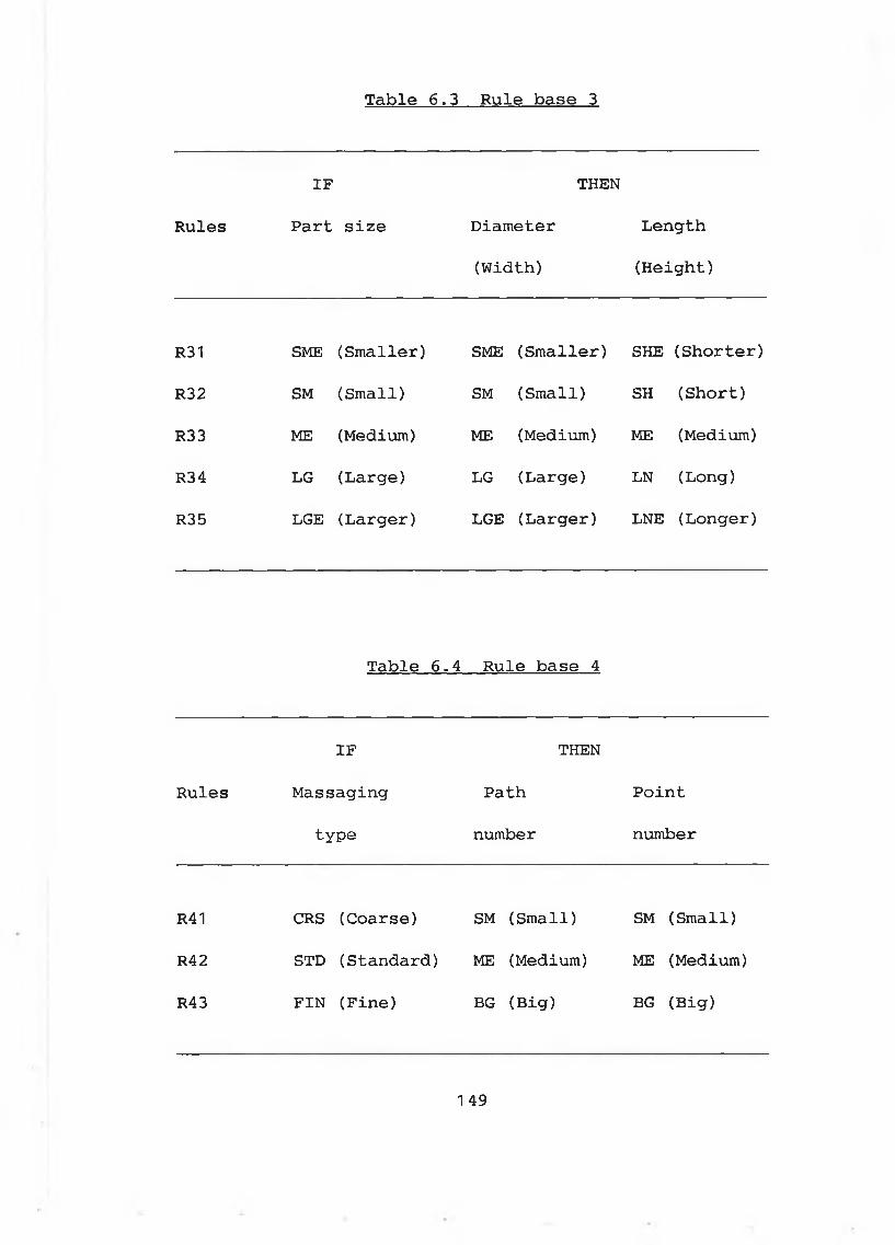
Table 6.3 Rule base 3
Rules
IF
Part size
THEN
Diameter
(Width)
Length
(Height)
R31 SME (Smaller) SME (Smaller) SHE (Shorter)
R32 SM (Small) SM (Small) SH (Short)
R33 ME (Medium) ME (Medium) ME (Medium)
R34 LG (Large) LG (Large) LN (Long)
R35 LGE (Larger) LGE (Larger) LNE (Longer)
Table 6 .4 Rule base 4
IF THEN
Rules Massaging Path Point
type number number
R41 CRS (Coarse) SM (Small) SM (Small)
R42 STD (Standard) ME (Medium) ME (Medium)
R43 FIN (Fine) BG (Big) BG (Big)
1 49
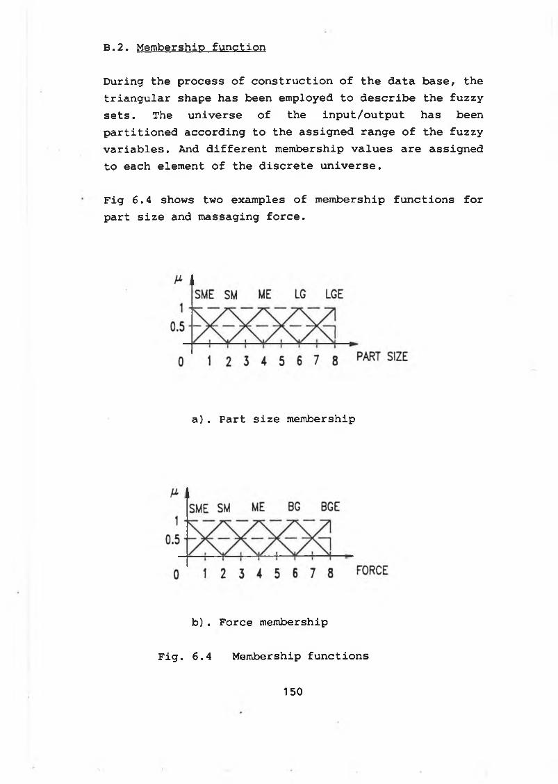
B.2. Membership function
During the process of construction of the data base, the triangular shape has been employed to describe the fuzzy sets. The universe of the input/output has been partitioned according to the assigned range of the fuzzy variables. And different membership values are assigned to each element of the discrete universe.
Fig 6.4 shows two examples of membership functions for part size and massaging force.
a). Part size membership
b). Force membership
Fig. 6.4 Membership functions
150
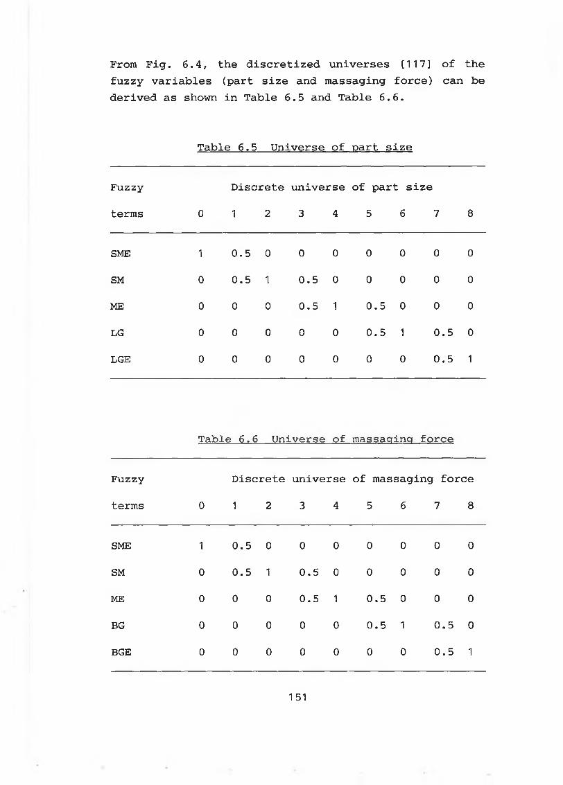
From Fig. 6.4, the discretized universes [117] of the fuzzy variables (part size and massaging force) can be derived as shown in Table 6 .5 and Table 6 .6 .
Table 6.5 Universe of part size
Fuzzy Discrete universe of part size
terms 0 1 2 3 4 5 6 7 8
SME 1 0.5 0 0 0 0 0 0 0
SM 0 0.5 1 0.5 0 0 0 0 0
ME 0 0 0 0.5 1 0.5 0 0 0
LG 0 0 0 0 0 0.5 1 0.5 0
LGE 0 0 0 0 0 0 0 0.5 1
Table! 6 . 6 Universe of massacring force
Fuzzy Discrete universe of massaging force
terms 0 1 2 3 4 5 6 7 8
SME 1 0.5 0 0 0 0 0 0 0
SM 0 0.5 1 0.5 0 0 0 0 0
ME 0 0 0 0.5 1 0.5 0 0 0
BG 0 0 0 0 0 0.5 1 0.5 0
BGE 0 0 0 0 0 0 0 0.5 1
151
The same procedure can be applied to define the fuzzy membership functions and to derive the discretized universes of the fuzzy variables: massaging speed, robot arm speed, force retention time.
The discretized universes for massaging speed, robot arm speed and the force retention time can be found in Appendix E-1.
B. 3. Fuzzy relations
Due to the difficulty of having a control rule for every possible situation, a composition rule of inference may be used to obtain an output subset which belongs to the output fuzzy set from an fuzzy input term using the fuzzy relationship between the object in the condition section (known as "IN_PUT") and the object in the consequence section (Known as "OUT_PUT").
For example, the object in the condition section ( or IN_PUT) in Rule Base 1 (see Table 6.1) is referred to "PART SIZE", while the object in the consequence section (or OUT PUT) in Rule Base 1 is referred to "MASSAGING FORCE".
Let the object in the condition section of the jth rule base be denoted by IN_PUTj, and the object in the consequence section of the jth rule be denoted by OUT_PUTJ.
Thus, from Table 6.1 to Table 6.4, the IN_PUTJ and OUTPUT 1-5 can be outlined as shown in Table 6.7.
1 52
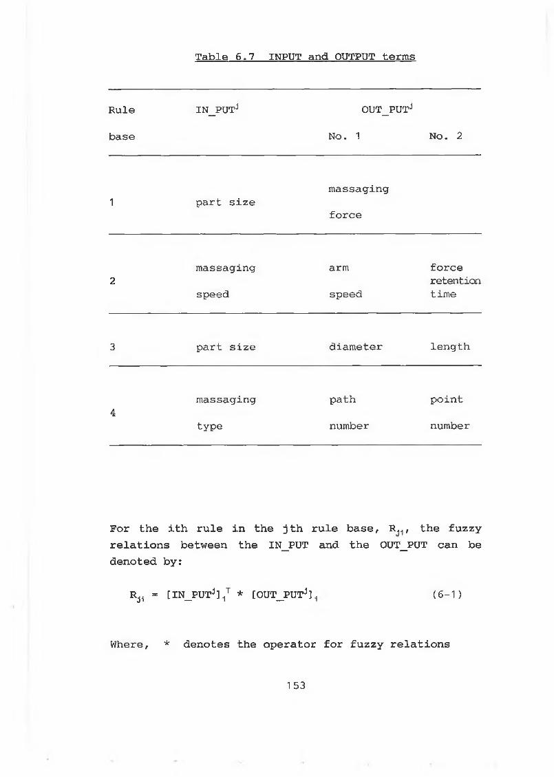
Table 6.7 INPUT and OUTPUT terms
Rule
base
IN_PUTJ OUT_PUTj
No. 1 No. 2
1 part sizemassaging
force
2
massaging arm forceretention
speed speed time
3 part size diameter length
4massaging path point
type number number
For th e i t h r u le i n th e j t h r u le b a s e , R ,,, th e fu z z y r e l a t i o n s b e tw een th e IN_PUT and t h e OUT_PUT ca n b e d e n o te d b y:
Rji = [IN_PUTj ] 1T * [OUT_PUTJ] . ( 6 - 1 )
Where, * d e n o te s th e o p e r a to r f o r f u z z y r e l a t i o n s
153
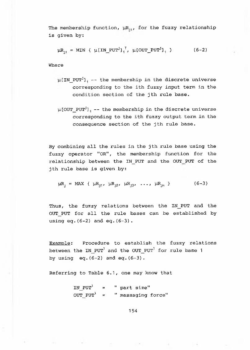
The membership function, for the fuzzy relationshipis given by:
yR^. = MIN { ia[IN_PUTd] .T, vi[OUT_PUTJ] . } (6-2)
Where
[IN_PUTd]. -- the membership in the discrete universe corresponding to the ith fuzzy input term in the condition section of the jth rule base.
y.[OUT_PUT:i] . -- the membership in the discrete universe corresponding to the ith fuzzy output term in the consequence section of the jth rule base.
By combining all the rules in the jth rule base using the fuzzy operator "OR", the membership function for the relationship between the IN_PUT and the OUTPUT of the jth rule base is given by:
)-iRj = MAX { )-iRj-[, yRJ2, l-iRjj, . . . , V ^ jn } ( 6 —3)
Thus, the fuzzy relations between the IN_PUT and the OUT_PUT for all the rule bases can be established byusing eq.(6 -2 ) and eq.(6-3).
Example: Procedure to establish the fuzzy relationsbetween the IN_PUT1 and the OUTPUT 1 for rule base 1 by using eq.(6-2) and eq.(6-3).
Referring to Table 6.1, one may know that
IN_PUT1 = " part size"OUTPUT 1 = " massaging force"
1 5 4
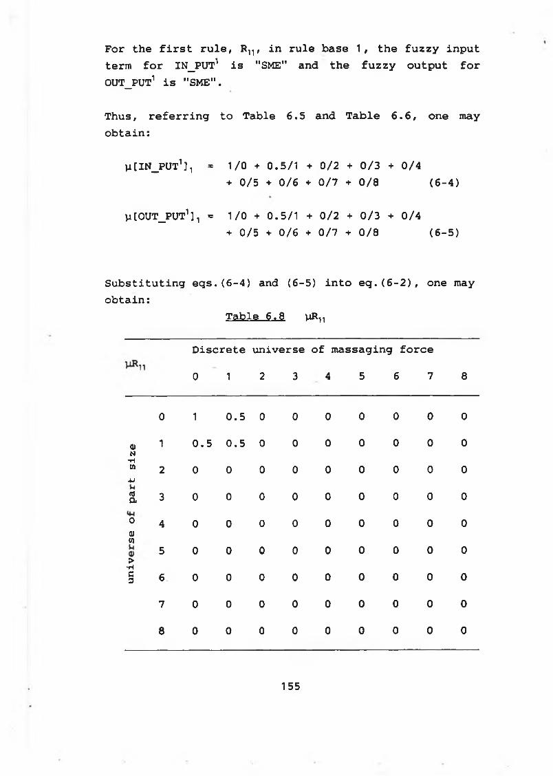
For the first rule, Rn , in rule base 1, the fuzzy input term for IN_PUT1 is "SME" and the fuzzy output for OUT_PUT1 is "SME".
Thus, referring to Table 6.5 and Table 6 .6 , one may obtain:
]i[IN_PUT1 ] 1 * 1/0 + 0.5/1 + 0/2 + 0/3 + 0/4+ 0/5 + 0/6 + 0/7 + 0/8 (6-4)
li[0UT_PUT1] t = 1/0 + 0.5/1 + 0/2 + 0/3 + 0/4+ 0/5 + 0/6 + 0/7 + 0/8 (6-5)
Substituting eqs.(6-4) and (6-5) into eq.(6-2), one may obtain:
Table 6.8 viR
Discrete universe of massaging force
0 1 2 3 4 5 6 7 8
0 1
in•o
0 0 0 0 0 0 0
<b 1 0.5 0.5 0 0 0 0 0 0 0
N•H(0
2 0 0 0 0 0 0 0 0 0■urta 3 0 0 0 0 0 0 0 0 0
0 4 0 0 0 0 0 0 0 0 0
<dw
5 0 0 0 0 0 0 0 0 0
>■Hc3 6 0 0 0 0 0 0 0 0 0
7 0 0 0 0 0 0 0 0 0
8 0 0 0 0 0 0 0 0 0
155
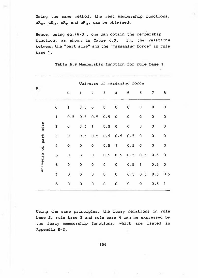
Using the same method, the rest membership functions, ViR-,2 , UR1 3 / UR1 4 and viR15, can be obtained.
Hence, using eq.(6-3), one can obtain the membership function, as shown in Table 6.9, for the relations between the "part size" and the "massaging force" in rule base 1 .
Table 6.9 Membership function for rule base 1
0
U n i v e r s e
1 2
o f m a s s a g i n g f o r c e
3 4 5 6 7 8
0 1 0 . 5 0 0 0 0 0 0 0
1 0 . 5 0 . 5 0 . 5 0 . 5 0 0 0 0 0
©N•H 2 0
in•o
1 0 . 5 0 0 0 0 0(0
4Ju 3 0 0 . 5 0 . 5 0 . 5
in•o
0 . 5 0 0 0nja
>4-1 4 0 0 0 0 . 5 1 0 . 5 0 0 00
Q>CO 5 0 0 0
in•o
0 . 5 0 . 5 0 . 5 0 . 5 0u0)>
•H 6 0 0 0 0 0
m•
o
1
in•o
0cp
7 0 0 0 0 0 0 . 5
in•o
0 . 5 0 .5
8 0 0 0 0 0 0 0 0 . 5 1
Using the same principles, the fuzzy relations in rule base 2, rule base 3 and rule base 4 can be expressed by the fuzzy membership functions, which are listed in Appendix E-2.
156
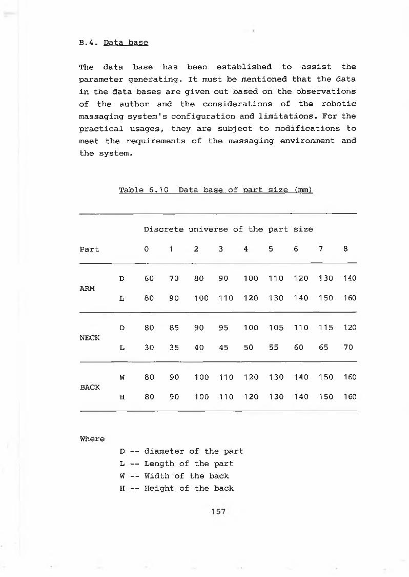
B.4. Data base
The data base has been established to assist the parameter generating. It must be mentioned that the data in the data bases are given out based on the observations of the author and the considerations of the robotic massaging system's configuration and limitations. For the practical usages, they are subject to modifications to meet the requirements of the massaging environment and the system.
Table 6.10 Data base of part size (mm)
Part
Discrete
0 1
universe of
2 3
the
4
part
5
size
6 7 8
D 60 70 80 90 1 0 0 1 1 0 1 2 0 130 140ARM
L 80 90 1 0 0 1 1 0 1 2 0 130 140 1 50 160
D 80 85 90 95 1 0 0 105 1 1 0 115 1 2 0
NECKL 30 35 40 45 50 55 60 65 70
W 80 90 1 0 0 1 1 0 1 2 0 130 140 150 160BACK
H 80 90 1 0 0 1 1 0 1 2 0 130 140 1 50 160
WhereD -- diameter of the part L -- Length of the part W -- Width of the back H -- Height of the back
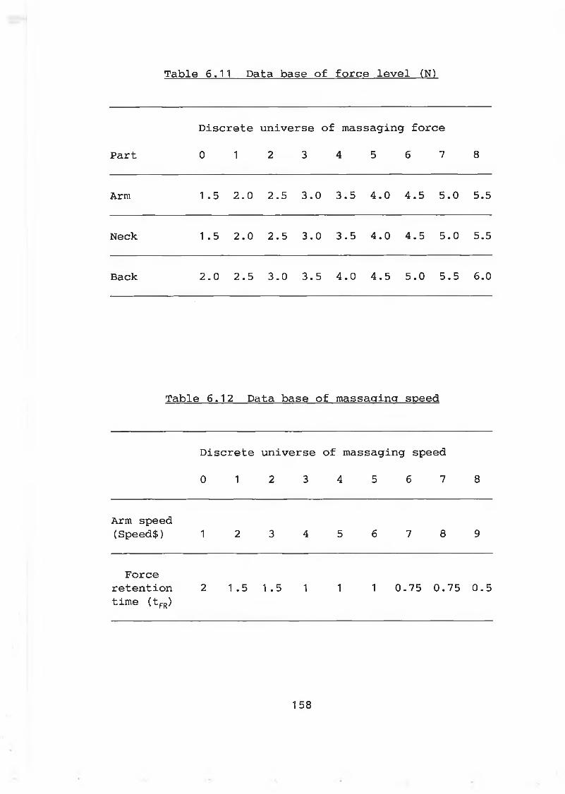
Table 6.11 Data base of force level (N)
Part
Discrete
0 1
universe of
2 3
massaging
4 5
r force
6 7 8
Arm 1 .5 2 . 0 2.5 3.0 3.5 4.0 4.5 5.0 5.5
Neck 1 .5 2 . 0 2.5 3.0 3.5 4.0 4.5 5.0 5.5
Back 2 . 0 2.5 3.0 3.5 4.0 4.5 5.0 5.5 6 . 0
Table 6.12 Data base of massaging speed
Discrete universe of massaging speed
0 1 2 3 4 5 6 7 8
Arm speed (Speed$) 1 2 3 4 5 6 7 8 9
Force retention time (tFR)
2 1.5 1.5 1 1 1 0.75 0.75 0.5
158
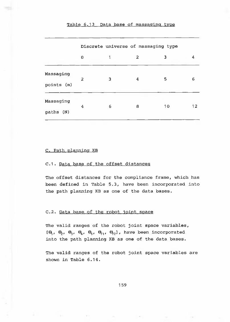
Table 6.13 Data base of massaging type
Discrete universe of massaging type
0 1 2 3 4
Massaging2 3 4 5 6
points (m)
Massaging4 6 8 1 0 1 2
paths (N)
C. Path planning KB
C.1. Data base of the offset distances
The offset distances for the compliance frame, which has been defined in Table 5.3, have been incorporated into the path planning KB as one of the data bases.
C. 2. Data base of the robot joint space
The valid ranges of the robot joint space variables,[0 j, 6 3 , 0 4, 0 5, 0 ^, 0 ^] r have been incorporatedinto the path planning KB as one of the data bases.
The valid ranges of the robot joint space variables are shown in Table 6.14.
159
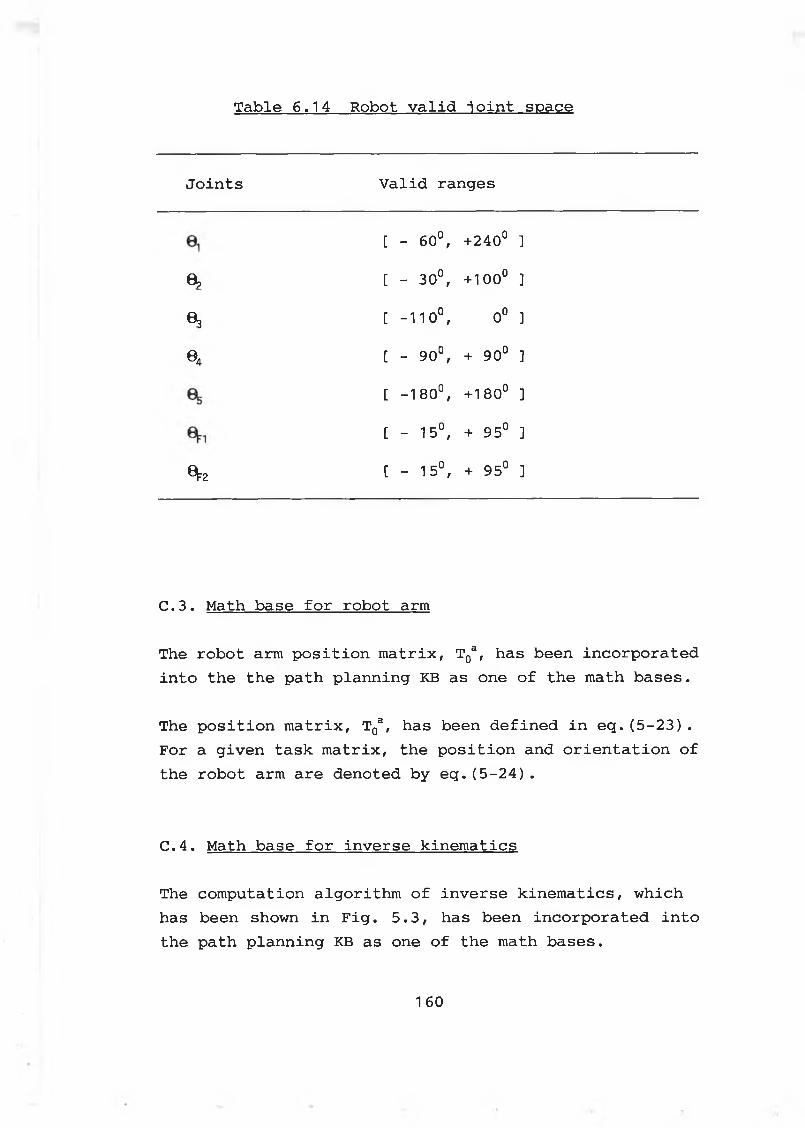
Table 6.14 Robot valid joint space
Joints Valid ranges
[ - 60°, +240° ]
0 ? [ - 30°, + 1 0 0 ° ]
03 t -1 1 0 °, 0 ° ]
04 [ - 90°, + 90° ]
t -180°, + 180° ]
[ - 15°, + 95° ]0 2 [ - 15°, + 95° ]
C.3. Math base for robot arm
The robot arm position matrix, T0a, has been incorporated into the the path planning KB as one of the math bases.
The position matrix, T0a, has been defined in eq. (5-23) . For a given task matrix, the position and orientation of the robot arm are denoted by eq.(5-24).
C.4. Math base for inverse kinematics
The computation algorithm of inverse kinematics, which has been shown in Fig. 5.3, has been incorporated into the path planning KB as one of the math bases.
1 60
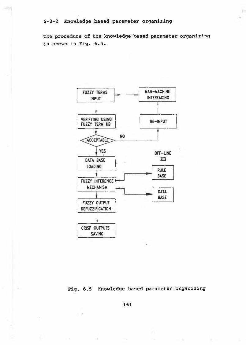
6-3-2 Knowledge based parameter organizing
The procedure of the knowledge based parameter organizing is shown in Fig. 6^5.
Fig. 6.5 Knowledge based parameter organizing
161
The input to the parameter generating module are:
* p a r t t o be m assaged ( l i n g u i s t i c )
* p a r t s i z e ( f u z z y )
* m a ssa g in g speed ( f u z z y )
* massaging type (fuzzy)* p a r t l o c a t io n ( c r i s p / l i n g u i s t i c )
Th e o u tp u t o f th e p a ra m e te r g e n e r a t in g m odule a r e ;
* th e ro b o t arm speed (S pee d$)
* th e m a ssa g in g f o r c e (F F o rc e )
* th e f o r c e r e t e n t io n tim e ( t FR)
* the diameter (width) of the part (Dpart)* the length (height) of the part (Lpart)* th e N o. o f th e r a d i a l m a ssa g in g p a th s (N )
* th e m a ssa g in g p o in t s a lo n g th e r a d i a l p a th (m)
* the initial position of the part (XQ Y0 Z0)* the angle B for the part* th e a n g le a f o r th e p a r t
Th e f u z z y in f e r e n c e i s c a r r i e d o u t b y m a n ip u la t in g
th e r u l e b a s e s . F o r a f u z z y in p u t te rm s , th e o u tp u t can
be i n f e r r e d b y u s in g th e f u z z y r e l a t i o n s w h ic h ha ve been
o b ta in e d i n p a ra m e te r g e n e r a t in g KB. And th e d a ta base
i n th e KB w i l l a ls o be m a n ip u la te d t o o b t a in th e c r i s p
v a lu e s o f th e in f e r r e d f u z z y o u t p u t .
E x a m p le : Assume t h a t th e "a rm " s i z e i s " s m a l l " . What i s
th e m a ssa g in g f o rc e ? (Th e m a ssa g in g f o r c e i s r e l a t e d w it h
th e p a r t i )
S o l u t i o n :
a ) . R e f e r r in g to F i g . 6 . 4 , th e " s m a ll" p a r t s i z e i s
c o rre s p o n d in g to th e u n iv e r s e " 2 " .
1 62
b ) . R e f e r r in g t o T a b le 6 . 9 , th e f u z z y m em bership
f u n c t io n f o r th e r e l a t i o n betw een th e m a ssa g in g
f o r c e and th e p a r t s i z e c o rre s p o n d in g to th e p a r t
s i z e "2 " i s :
[y F o r c e ] = 0/0 + 0. 5/1 + 1/2 + 0 . 5 / 3 + 0/4
+ 0/5 + 0/6 + 0/7 + 0/8
c ) . R e f e r r in g to T a b le 6 . 1 1 , th e m a ssa g in g f o r c e
d i s t r i b u t i o n f o r th e "a rm " a lo n g th e d i s c r e t e
u n iv e r s e o f th e m a ssa g in g f o r c e i s :
[F o r c e ] = 1 . 5 / 0 + 2/1 + 2 . 5 / 2 + 3/3 + 3 . 5 / 4
+ 4/5 + 4 . 5 / 6 + 5/7 + 5 . 5 / 8
d ) . Th e d e f u z z f ie d o u tp u t o f th e m a ssa g in g f o r c e can
be o b ta in e d :
FForce = [jiForce ] * [ Force ] T/2iaFor ce j
0 . 5 * 2 + 1 * 2 . 5 + 0 . 5*3 --------------------------------------------------------= 2 . 5 (N)
0 . 5 + 1 + 0 . 5
6 - 3 - 3 K now ledge based p a th p la n n in g
B e fo re m a ssa g in g i s p e rfo rm e d , th e f o l lo w in g m a ssa g in g
p a th s m ust be p la n n e d b a sed on th e g e n e ra te d p a ra m e te rs
b y th e p la n n in g system w it h th e a id o f th e p a th p la n n in g
KB:
* th e r a d i a l / a x i a l p o s i t i o n p a th
* th e f o r c e p a th
1 63

Once th e p o s i t io n / f o r c e p a th s have been p la n n e d , two
g ro u p s o f th e c o n t r o l d a ta s h o u ld be g e n e ra te d f o r th e
ro b o t syste m a t e v e ry m a ssa g in g p o i n t :
a . th e ro b o t j o i n t space p a ra m e te rs
* ro b o t arm j o i n t space v a r ia b le s 0 , - 6 ^
* r o b o t ic hand j o i n t space p a ra m e te rs : 0 ^ - 0jr2
* f o r c e s u p p lie d b y th e h a n d : F t - F 3
b . th e ro b o t C a r t e s ia n space p a ra m e te rs
* r o b o t hand p o s i t i o n [X Y Z 0p 0r 0 ^ 0[:2]
* ro b o t hand o r i e n t a t i o n [n o a]
Position path planning
The m a th e m a tic a l a n a ly s is o f th e m a ssa g in g p a th d e s ig n
f o r a g iv e n p a r t i n th e ro b o t w o rksp a ce has been g iv e n i n
s e c t io n 5 - 4 . And th e m o tio n c o n t r o l f o r th e r o b o t i c hand
has been s t u d ie d i n s e c t io n 5 - 5 .
A d i s c r e t e m a ssa g in g p a th has been em ployed to p la n th e
p a th . F o r a p a r t w it h c o n ic a l shape (a rm , n e c k , e t c . ) ,
th e d i s c r e t e m a ssa g in g p a th i s shown i n F i g . 6 .6 . F o r a
p a r t w it h f l a t s u r f a c e , th e d i s c r e t e m a ssa g in g p a th i s
shown i n F i g . 6 . 7 .
F o r th e k n e a d in g o p e r a t io n , th e p a r t s i z e i s d e n o te d by
i t s d ia m e te r (D p a r t ) and le n g t h ( L p a r t ) . And th e p a r t i s
r e q u ir e d to be c e n t r a l i z e d i n th e r o b o t ic hand fra m e . F o r
th e p a d d in g o p e r a t io n , th e p a r t s iz e i s d e n o te d b y i t s
w id th (D p a r t ) and h e ig h t ( L p a r t ) . F o r b o th o p e r a t io n s ,
th e num ber o f th e a x i a l p a th s i s d e n o te d b y N and th e
m a ssa g in g p o in t s a lo n g th e r a d i a l p a th i s d e n o te d b y m.
164
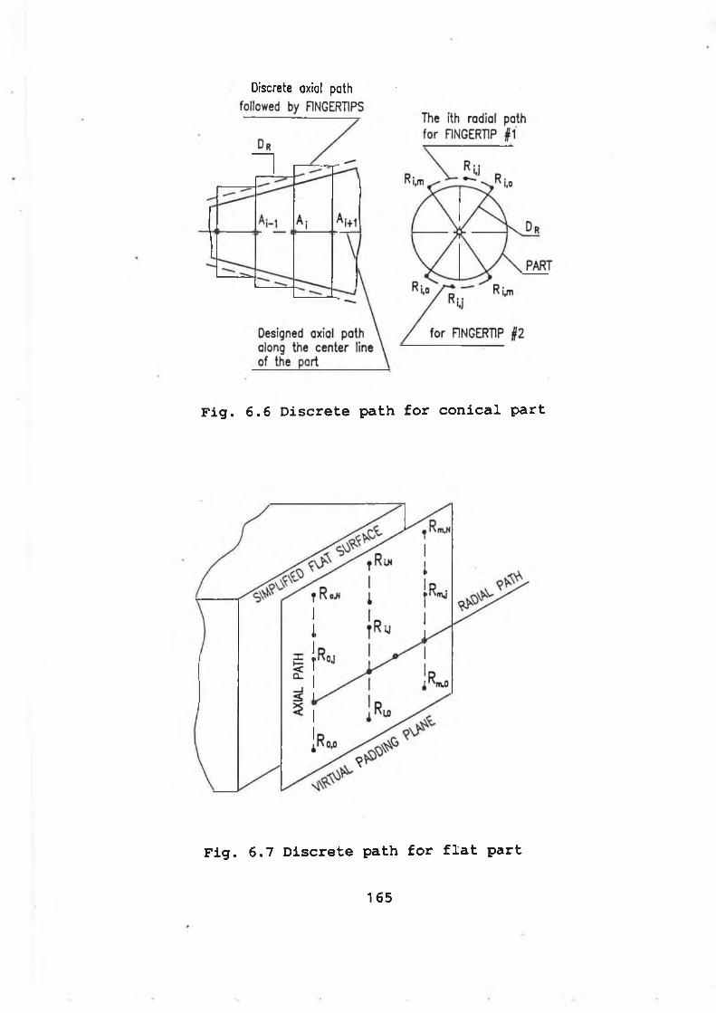
Discrete axial path
Fig. 6.6 Discrete path for conical part
Fig. 6.7 Discrete path for flat part
165
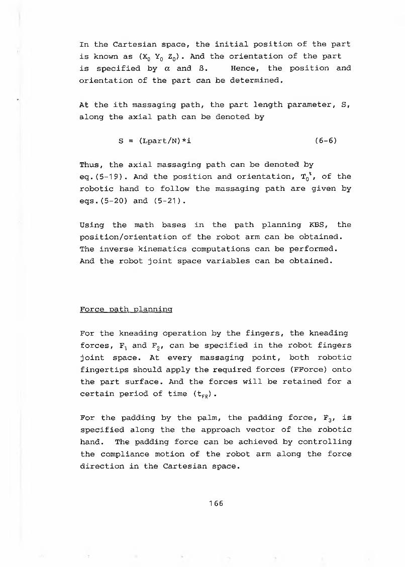
I n th e C a r t e s ia n s p a ce , th e i n i t i a l p o s i t i o n o f th e p a r t
i s known as (X0 Y 0 Z0) . And th e o r i e n t a t i o n o f th e p a r t
i s s p e c i f i e d b y a and B . H ence, th e p o s i t i o n and
o r i e n t a t i o n o f th e p a r t can be d e te rm in e d .
A t th e i t h m assag in g p a th , th e p a r t le n g t h p a ra m e te r , S ,
a lo n g th e a x i a l p a th can be d e n o te d b y
S = (L p a r t / N )* i ( 6 - 6 )
Thus, the axial massaging path can be denoted by eq.(5-19). And the position and orientation, T^, of the robotic hand to follow the massaging path are given by eqs.(5-20) and (5-21).
U s in g th e m ath bases i n th e p a th p la n n in g KBS, th e
p o s i t i o n / o r i e n t a t i o n o f th e ro b o t arm ca n be o b t a in e d .
Th e in v e r s e k in e m a tic s c o m p u ta tio n s ca n be p e rfo rm e d .
And th e ro b o t j o i n t space v a r ia b le s ca n be o b t a in e d .
F o rc e p a th p la n n in g
F o r th e k n e a d in g o p e r a t io n b y th e f i n g e r s , th e k n e a d in g
f o r c e s , F t and F 2, can be s p e c i f ie d i n th e r o b o t f i n g e r s
j o i n t s p a ce . A t e v e ry m a ssa g in g p o i n t , b o th r o b o t ic
f i n g e r t i p s s h o u ld a p p ly th e r e q u ir e d f o r c e s (F F o r c e ) o n to
th e p a r t s u r f a c e . And th e f o rc e s w i l l be r e t a in e d f o r a
c e r t a i n p e r io d o f tim e ( t FR) .
F o r th e p a d d in g b y th e p a lm , th e p a d d in g f o r c e , F 3, i s
s p e c i f i e d a lo n g th e th e a p p ro a c h v e c t o r o f th e r o b o t ic
h a n d . Th e p a d d in g f o r c e ca n be a c h ie v e d b y c o n t r o l l i n g
th e c o m p lia n c e m o tio n o f th e ro b o t arm a lo n g th e f o r c e
d i r e c t i o n i n th e C a r t e s ia n sp a ce .
166
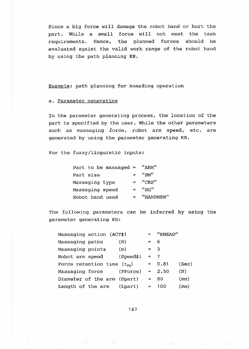
S in c e a b i g f o r c e w i l l damage th e r o b o t hand o r h u r t th e
p a r t . W h ile a s m a ll f o r c e w i l l n o t meet th e ta s k
re q u ire m e n ts . H e n ce , th e p la n n e d f o r c e s s h o u ld be
e v a lu a te d a g a is t th e v a l i d w ork ra n g e o f th e r o b o t hand
b y u s in g th e p a th p la n n in g KB.
E x a m p le : p a th p la n n in g f o r k n e a d in g o p e r a t io n
a . P a ra m e te r g e n e r a t in g
I n th e p a ra m e te r g e n e r a t in g p ro c e s s , th e l o c a t i o n o f th e
p a r t i s s p e c i f ie d b y th e u s e r . W h ile th e o t h e r p a ra m e te rs
such as m a ssa g in g f o r c e , ro b o t arm sp e e d , e t c . a re
g e n e ra te d b y u s in g th e p a ra m e te r g e n e r a t in g KB.
F o r th e f u z z y / l i n g u i s t i c in p u t s :
P a r t to be m assaged = "ARM"
P a r t s i z e = "SM"
M a ssa g in g ty p e = "CRS"
M a ssa g in g speed = "HG"
R obot hand used = "HANDNEW"
Th e f o l lo w in g p a ra m e te rs can be i n f e r r e d b y u s in g th e
p a ra m e te r g e n e r a t in g KB:
M a ssa g in g a c t io n (A C T$ ) = "KNEAD"
M a ssa g in g p a th s (N ) = 6
M a ssa g in g p o in t s (m) = 3
R obot arm speed (Speed$) = 7
F o rc e r e t e n t io n tim e ^ fr) = 0. 81 ( Sec)
M a ssa g in g f o r c e (F F o rc e ) = 2 . 5 0 (N)
D ia m e te r o f th e arm (D p a r t ) = 80 (mm)
L e n g th o f th e arm (L p a r t ) = 100 (mm)
167
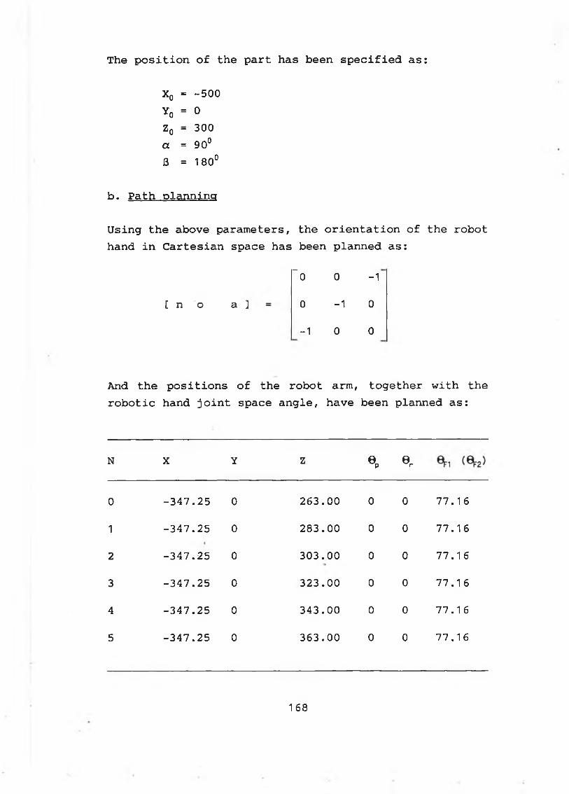
The position of the part has been specified as:
IIoX
-5 0 0
IIo>* 0
zo = 300
a = 90°
6 = 180°
b. Path planning
Using the above parameters, the orientation of the robot hand in Cartesian space has been planned as:
~0 0 -1
[ n o a ] 0 -1 0
-1 0 0
And the positions of the robot arm, together with the robotic hand joint space angle, have been planned as:
N X Y Z6 p « r
0 - 3 4 7 . 2 5 0 2 6 3 . 0 0 0 0 7 7 . 1 6
1 - 3 4 7 . 2 5 0 2 8 3 . 0 0 0 0 7 7 . 1 6
2 - 3 4 7 . 2 5 0 3 0 3 . 0 0 0 0 77. 1 6
3 - 3 4 7 . 2 5 0 3 2 3 . 0 0 0 0 7 7 . 1 6
4 - 3 4 7 . 2 5 0 3 4 3 . 0 0 0 0 7 7 . 1 6
5 - 3 4 7 . 2 5 0 3 6 3 . 0 0 0 0 7 7 . 1 6
168
6-4 Control organizing module
The robot control organizing module includes:
* Identify the task and go to right control module
* map the planned parameters into the robot joint space or Cartesian space according to the task executed.
* execute the task planned
* monitor and display the operation of the system
* continue the task execution if the error occured is within the specified range
* Branch the control into the error-correction module if the error occurred is intolerable.
Fig. 6.8 shows the functions of the control organizing module.
a. identification of the task
The identification of the task is carried out by checking the contents in the planned parameters -- ACT$ and HAND$.
The massaging action is defined in ACT$. For kneading opeartion, ACT$="KNEAD". While for padding operation, ACT$="PAD".
The robotic hand is specified by HAND$. The HAND-I should be used when HAND$="HANDOLD". While the HAND-II should be used when HAND$="HANDNEW".
169
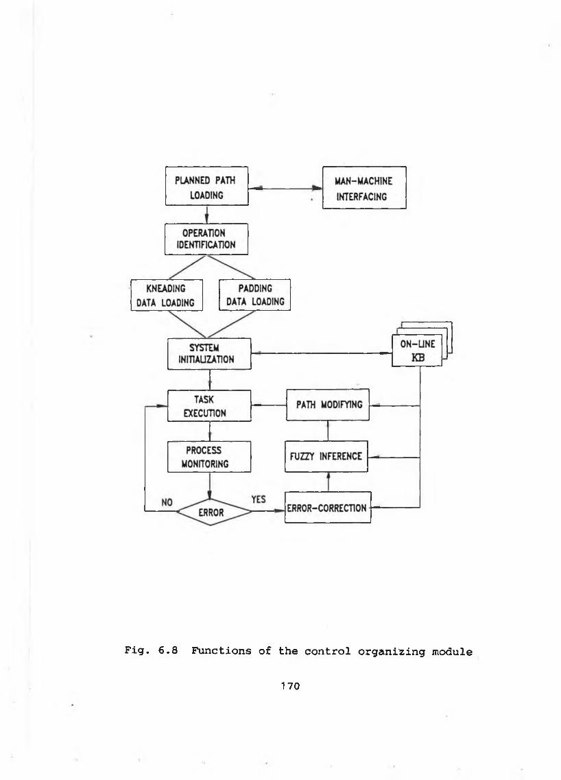
Fig. 6.8 Functions of the control organizing module
170
b. planned parameters mapping
The planned parameters must be mapped into the buffer of the control module. For kneading operation, the position parameters [X Y Z 0p 8r 0 ^ ] at the ith massaging path for the robotic hand are mapped into the control buffers of:
* robotic finger position control space [0^ 0 2]* r o b o t ic arm p o s i t i o n c o n t r o l space [X Y Z 0p 0r ]
The robot arm speed (Speed$) is mapped into the control buffer of the robot arm speed controller.
The massaging force (FForce) is mapped into the control buffer of the robotic finger force control space.
The massaging path number , together with the massaging point number, are loaded into the control loop. And the number of the massaging points along a radial path in a kneading operation means the massaging repeat times of the robotic fingertips at the same massaging position.
The orientation vectors of the robotic hand in the cartesian space are mapped into the buffer of the error- correction module. Once error-correction is required, the orientation vectors of the robotic hand will be used to find the new position of the robotic hand.
For the padding operation, the robotic palm are used to apply the required force onto the part. The position parameters [X Y Z 0p 0r ] are still mapped into the robot arm position control buffer. The massaging force (FForce) is mapped into the compliance motion control buffer as a condition to be evaluated. The fine motion to achieve the massaging force will be commanded by the compliance loop according to the sensed information.
171
c . Task execution
Th e ta s k e x e c u t io n i s c a r r i e d o u t b y u s in g th e d a ta i n
th e c o n t r o l b u f f e r s . By i n t e r f a c i n g w it h th e ro b o t
c o n t r o l l e r and th e r o b o t ic hand c o n t r o l l e r , th e PC
c o n t r o ls and m o n ito rs th e w h o le m a ssa g in g s y s te m .
F o r th e m o tio n c o n t r o l o f th e r o b o t arm , th e b u i l t - i n
c o d e s , such as "M P ", e t c . , a re u se d t o i n i t i a t e and
c o n t r o l th e m o tio n o f th e ro b o t a rm . W h ile th e m o tio n
c o n t r o l o f th e ro b o t f in g e r s i s c a r r i e d o u t b y a c t i v a t i n g
th e ro b o t hand p o s i t i o n s e rv o lo o p .
The f o r c e c o n t r o l o f th e r o b o t ic f i n g e r t i p s i s r e a l i z e d
b y a c t i v a t i n g th e r o b o t ic hand f o r c e s e rv o lo o p .
F i g . 6 .9 shows th e ta s k e x e c u t io n f o r th e k n e a d in g
o p e r a t io n . W h ile th e p a d d in g o p e r a t io n i s shown i n
F i g . 6 . 1 0 .
D u r in g th e ta s k e x e c u t io n , th e o p e r a t io n i s a ls o u n d e r
c lo s e w a tc h b y th e PC. Th e c u r r e n t p o s i t io n / f o r c e o f th e
ro b o t h a n d , to g e th e r w it h th e f u z z y in f e r e n c e p ro c e s s ,
a re d is p la y e d on th e s c re e n .r
F i g . 6. 11 shows th e o n - l i n e d i s p l a y o f th e s e n s o ry
in f o r m a t io n .
Th e ta s k e x e c u t io n w i l l c o n t in u e i f t h e r e i s n o t
in t o l e r a b l e e r r o r s d u r in g th e o p e r a t io n p r o c e s s .
H ow ever, th e o n - l i n e e r r o r - c o r r e c t i o n ba sed on f u z z y
l o g i c w i l l be a c t iv a t e d i f th e e r r o r exceed s th e
t o l e r a b l e l i m i t a t i o n s d u r in g a ta s k e x e c u t io n p r o c e s s .
172
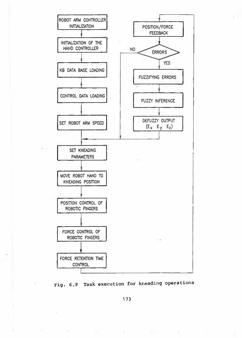
Fig. 6.9 Task execution for kneading operations
173
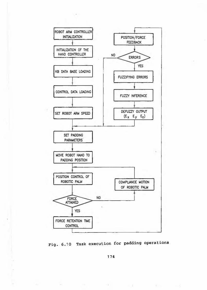
Fig. 6.10 Task execution for padding operations
174
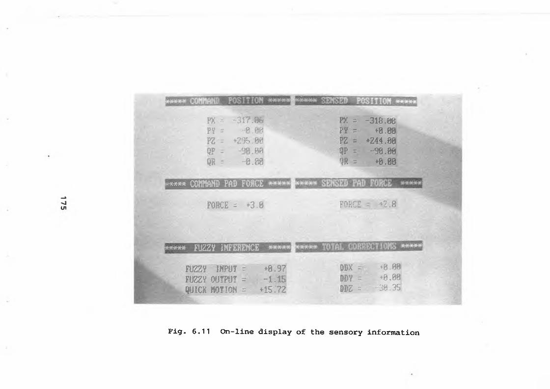
PX =py * ?z =QP rm *
-3 Î? M -8 ,8 9
♦295.00_qa m» UiJ-9.08
PX =py = pz = UP -m =
-318.86+ 8 .00.
+244.00-30.B0♦0.00
* * * * * amm pad fo h c e
FORCE = +3.0 FORCE +2.8
FUZZY IKFESENCE
m m INPUT = +8.97FÜZZV OUTPUT = -1.15QUICK MOTION = +1S.72
m =DDY = DDZ =
>0.08♦8.08
-30 .--35Î
Fig. 6.11 On-line display of the sensory information
6-5 On-line error-correction
The robotic massaging performs well provided that:
a. The location of the part being massaged is accurately specified
b. The massaging path is well plannedc. The part being massaged does not deviate from its
original position during the massaging processd. There is no unpredictable obstacle during the
massaging operations
However, these conditions can not be guaranteed in the practical operations. The robotic massaging system must be endowed with the abilities to carry out on-line error- corrections.
The on-line error-corrections include two tasks:* error-detections* error-corrections
An error-correction process is defined as a process of adjusting the robot hand to the actual massaging position of the part being massaged from its planned position, if there is an intolerable error between the planned position and the actual position of the part.
The feedback of the sensory information of the robot system is used to perform the error-detections, while the error-corrections are carried out by manipulating the on-line KB, the fuzzy inference module, the path modifying module and the intelligent control module.
Incorporated with the error-correction module, the online intelligent control system for the robotic massaging system can be organized as shown in Fig. 6.12.
1 76
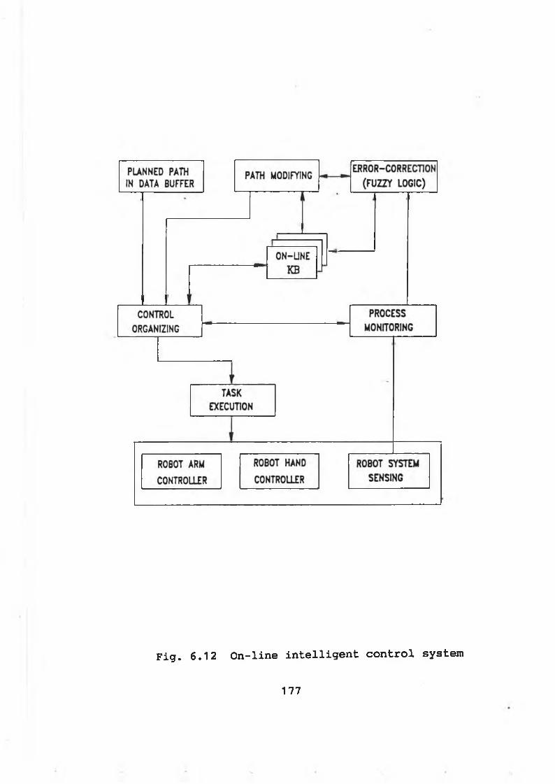
F i g . 6 . 1 2 O n - l i n e i n t e l l i g e n t c o n t r o l s y s t e m
177
6-5-1 Error types and correction equations
The error between the actual massaging position and the planned massaging position can be classified as path misplanning errors.
Depending on its extent, a path misplanning error may cause several problems:
* damaging the robot arm due to collisions* hurting the part being massaged* massaging the part in a wrong position
The path misplanning errors may be caused by any one of the factors, such as:
a. the location of the part is wrong specifiedb. the part deviates from its specified positionc. the path is incorrectly planned
A. Analysis of the errors in Cartesian space
For a massaging operation using the robotic hand, the position and orientation of the robotic hand with respect to the world frame has been specified by a position task matrix Tg*. The motion control for the robotic hand to follow the specified path has been discussed in section 6-5. Where the compliance (kneading or padding) frame is required to maintain the same position and orientation as the task frame.
The robotic massaging will be carried out smoothly if there is no error occured during the massaging process. However, certain errors may exist during a massaging process, such as path misplanning errors.
178
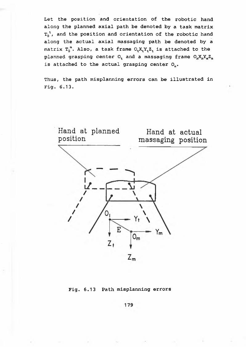
L e t t h e p o s i t i o n a n d o r i e n t a t i o n o f t h e r o b o t i c h a n d
a l o n g t h e p l a n n e d a x i a l p a t h b e d e n o t e d b y a t a s k m a t r i x
Tg1, a n d t h e p o s i t i o n a n d o r i e n t a t i o n o f t h e r o b o t i c h a n d
a l o n g t h e a c t u a l a x i a l m a s s a g i n g p a t h b e d e n o t e d b y a
m a t r i x T0m. A l s o , a t a s k f r a m e OtXtYt Zt i s a t t a c h e d t o t h e
p l a n n e d g r a s p i n g c e n t e r 0 t a n d a m a s s a g i n g f r a m e O ^ Y ^
i s a t t a c h e d t o t h e a c t u a l g r a s p i n g c e n t e r 0 m.
T h u s , t h e p a t h m i s p l a n n i n g e r r o r s c a n b e i l l u s t r a t e d i n
F i g . 6 . 1 3 .
Hand at planned Hand at actualposition massaging position
Fig. 6.13 Path misplanning errors
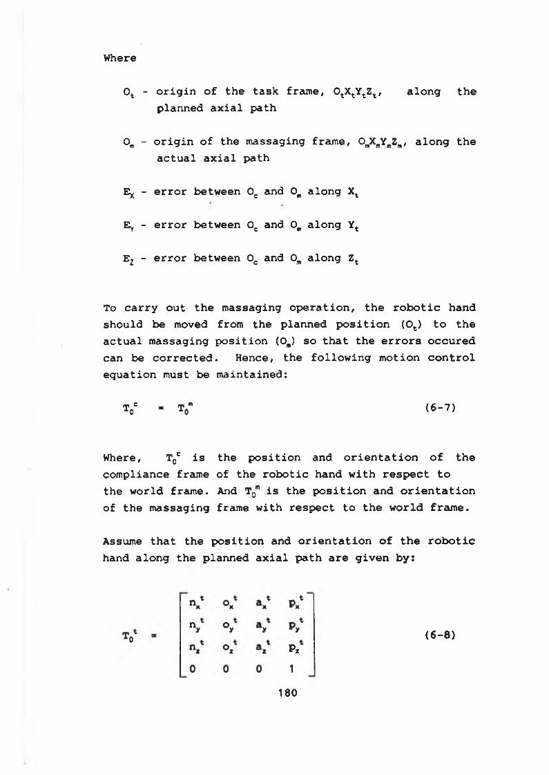
Where
Ot - o r i g i n o f t h e t a s k f r a m e , OtXtYt Zt , a l o n g t h e
p l a n n e d a x i a l p a t h
0 m - o r i g i n o f t h e m a s s a g i n g f r a m e , OmXmYmZm, a l o n g t h e
a c t u a l a x i a l p a t h
E* - e r r o r b e t w e e n 0 C an d 0 m a l o n g Xt
Ey - e r r o r b e t w e e n 0 C an d 0 m a l o n g Yt
Ez - e r r o r b e t w e e n 0 C an d 0 m a l o n g Zt
To c a r r y o u t t h e m a s s a g i n g o p e r a t i o n , t h e r o b o t i c h a n d
s h o u l d b e m oved fro m t h e p l a n n e d p o s i t i o n ( 0 t ) t o t h e
a c t u a l m a s s a g i n g p o s i t i o n (OJ s o t h a t t h e e r r o r s o c c u r e d
c a n b e c o r r e c t e d . H e n c e , t h e f o l l o w i n g m o t i o n c o n t r o l
e q u a t i o n m u st b e m a i n t a i n e d :
T0C « T0m ( 6 - 7 )
W here , T0C i s t h e p o s i t i o n an d o r i e n t a t i o n o f t h e
c o m p l i a n c e f r a m e o f t h e r o b o t i c h a n d w i t h r e s p e c t t o
t h e w o r l d f r a m e . And T0m i s t h e p o s i t i o n a n d o r i e n t a t i o n
o f t h e m a s s a g i n g fr a m e w i t h r e s p e c t t o t h e w o r l d f r a m e .
A ssum e t h a t t h e p o s i t i o n a n d o r i e n t a t i o n o f t h e r o b o t i c
h a n d a l o n g t h e p l a n n e d a x i a l p a t h a r e g i v e n b y :
180
n
P z
1
(6-8)
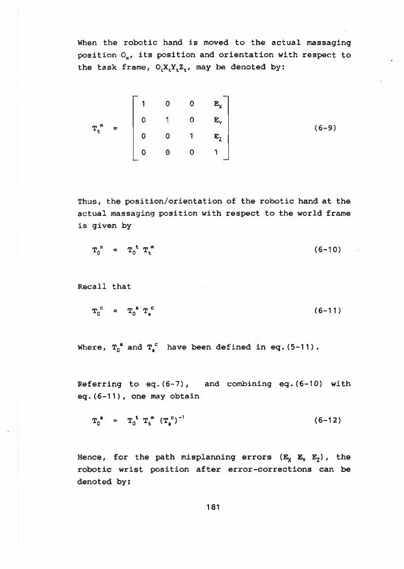
When t h e r o b o t i c h an d i s m oved t o t h e a c t u a l m a s s a g i n g
p o s i t i o n 0 m, i t s p o s i t i o n a n d o r i e n t a t i o n w i t h r e s p e c t t o
t h e t a s k f r a m e , OtXtYt Zt , may b e d e n o t e d b y :
1 0 0 E x
0 1 0 E y
0 0 1 E Z
0 0 0 1
Thus, the position/orientation of the robotic hand at the actual massaging position with respect to the world frame is given by
T0m = T ^ Ttm ( 6 - 1 0 )
R e c a l l t h a t
ToC = To‘ T.C (6 -1 1 )
W h ere , T0* a n d T#° h a v e b e e n d e f i n e d i n e q . ( 5 - 1 1 ) .
R e f e r r i n g t o e q . ( 6 - 7 ) , a n d c o m b i n i n g e q . ( 6 - 1 0 ) w i t h
e q . ( 6 - 1 1 ) , o n e may o b t a i n
T0a * Tq* Ttm (T,0) ' 1 ( 6 - 1 2 )
H e n c e , f o r t h e p a t h m i s p l a n n i n g e r r o r s (Ey Ey Ez) , t h e
r o b o t i c w r i s t p o s i t i o n a f t e r e r r o r - c o r r e c t i o n s c a n b e
d e n o t e d b y :
181
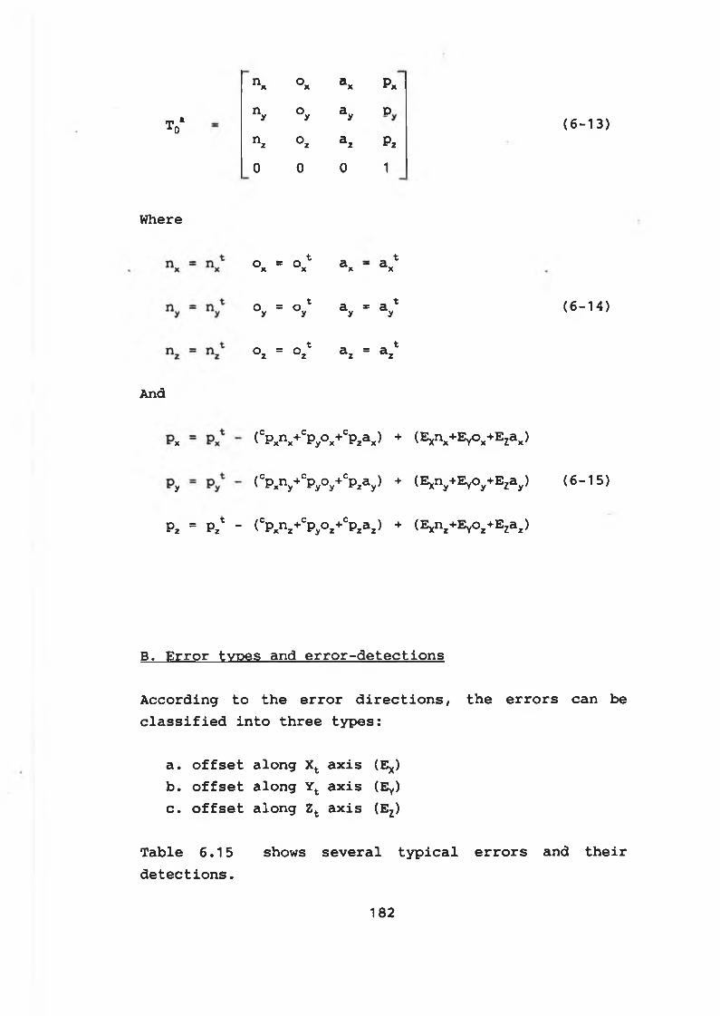
T *A0
Where
And
x
y
n x o a pX X r *
nyn z
o a py yo a pz z ^
(6-13)
0 0 0 1
° x =_ t t ° x a x - a x
°y = °y* ay * V (6-14)
° z = o * a = a *z z z
(cpxn x+CP y ° x +CP za x) + ( E x ^ + E y O x + ^ x )
(cpxn y+CP y0 y+CP Za y) + (Exny+EYoy+Ezay) (6-15)
P 2 = Pzt - ( CP x n z + C P y ° z + C P z a z ) + ( E Xn z + E V ° z + E Za z )
B. Error types and error-detections
According to the error directions, the errors can be classified into three types:
a. offset along Xt axis (E*)b. offset along Yt axis (Ey)c. offset along Zt axis (Ez)
T a b l e 6 . 1 5 s h o w s s e v e r a l t y p i c a l e r r o r s a n d t h e i r
d e t e c t i o n s .
182
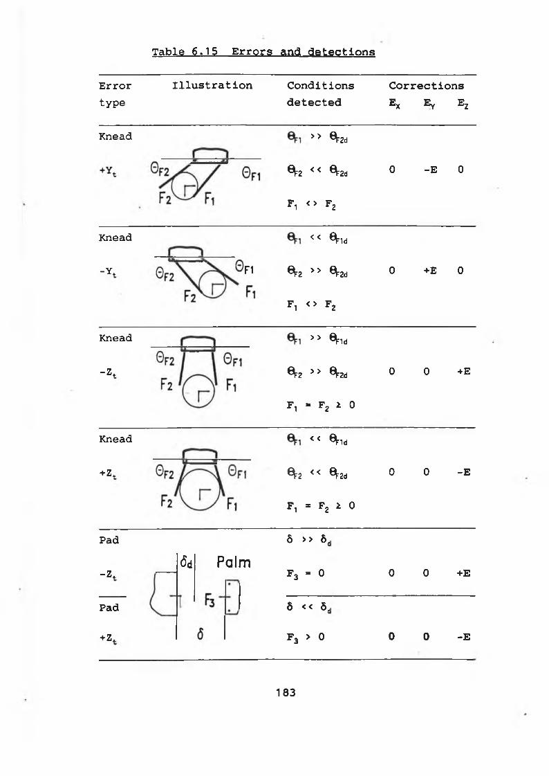
Table 6.15 Errors and detections
Errortype
Illustration C o n d i t i o n s
d e t e c t e d
C o r r e c t i o n s
Ex Ey Ez
Knead >> ^2d
^2 << ^2d
F t < > F2
0 - E 0
Knead
-Y. F1
<< ^ld
*F2 >> ^2d
F, < > F2
0 +E 0
Knead
-Z.
>> ^id
^2 > > ^2d
F , = F2 i 0
0 0 +E
Knead
+Zt
< < ^1d
^2 << ^2d
F, = F2 t 0
0 0 -E
Pad
-Z .
Pad
+Z.
!
(5d Palmô >> ô.
F3 = 0
ô << Ô,
f 3 > 0
0 0 +E
0 0 -E
183
For the kneading operations using the robotic fingers, there exist uncertainties in the error detection process due to:
* The contact points between the robotic fingers and the part being contacted are not exactly known, since the force/tactile sensors are mounted on the fingertips.
* The part size may be different from the specified size.
To deal with the uncertainties, the fuzzy inference and the human massaging knowledge are employed in this case. By manipulating the detected information and the expert knowledge base embedded in the fuzzy inference rule base and data base, the required control strategies and error- correction distances (Ex Ey Ez) can be obtained. And the error-correction can be carried out on-line.
6-5-2 Fuzzy logic based error-corrections
Based on the human massaging knowledge and the human inference process, the fuzzy error-correction strategies may be developed, which include:
Criterion 1.
IF { the offset (Ex Ey Ez) is very small }
THEN { no correction is required }
184
Criterion 2.
IF { the offset (Ex Ey Ez) is [Small, Medium, Big] }
THEN { move the robot hand a [Small, Medium, Big] distance along the opposite direction of the offset (to reduce the offset) }
A. Universes of discourse
Let the angle errors of the robotic fingers be denoted by
E8' ' ^ ^ (6-16)E02 - G 2d £ 2
For kneading operations, the inputs to the fuzzy error- correction inference mechanism are E0T and E02. And the input to the fuzzy inference mechanism is 8 for padding operation.
The outputs of the fuzzy inference mechanism are a set of correction distances, i.e., (E x E y E z ) .
Hence, the universes of discourse can be classified into two types:
* process input variables -- (E0, E02 8)
* control output variables -- ( E x E y E z )
For the universes of discourse (EOt E0t 8 E x E y E z ) , the universe partition and the membership function are defined as shown in Fig. 6.14.
185
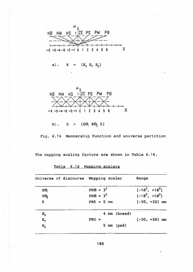
a) . X = [Ex Ey Ez]
b) . X = [EG, E0, 6 ]
Fig. 6.14 Membership function and universe partition
The mapping scaling factors are shown in Table 6.16.
Table 6.16 Mapping scalers
Universe of discourse Mapping scaler Range
E6 j FK0 = 3° [-18°, +18°]E ^ FK0 = 3° [-18°, +18°]6 FK6 = 5 mm [-30, +30] mm
4 mm (knead)Ey FKO = [-30, +30] mmEz 5 mm (pad)
186
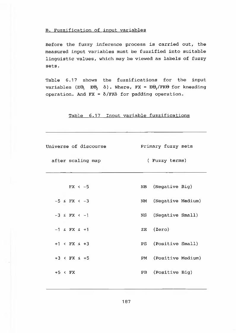
B. Fuzzification of input variables
Before the fuzzy inference process is carried out, the measured input variables must be fuzzified into suitable linguistic values, which may be viewed as labels of fuzzy sets.
Table 6.17 shows the fuzzifications for the input variables (E0| E0^ 5) . Where, FX = EO^FKO for kneadingoperation. And FX = 5/FK5 for padding operation.
Table 6.17 Input variable fuzzifications
Universe of discourse
after scaling map
Primary fuzzy sets
( Fuzzy terms)
FX < -5 NB (Negative Big)
-5 < FX < -3 NM (Negative Medium)
-3 < FX < -1 NS (Negative Small)
-1 i FX £ +1 ZE (Zero)
+1 < FX < +3 PS (Positive Small)
+3 < FX i +5 PM (Positive Medium)
+ 5 < FX PB (Positive Big)
1 87
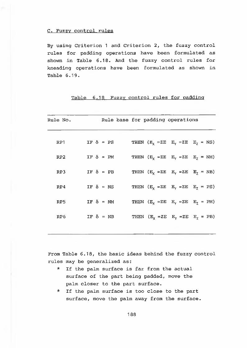
C. Fuzzy control rules
By using Criterion 1 and Criterion 2, the fuzzy control rules for padding operations have been formulated as shown in Table 6.18. And the fuzzy control rules for kneading operations have been formulated as shown in Table 6.19.
Table 6.18 Fuzzy control rules for padding
Rule No. Rule base for padding operations
RP1 IF 8 = PS THEN (Ex =ZE Ey =ZE Ez = NS)
RP2 IF 8 = PM THEN (Ex =ZE Ey =ZE Ez = NM)
RP3 IF 8 = PB THEN (Ex =ZE Ey =ZE Ez = NB)
RP4 IF 8 = NS THEN (Ex =ZE Ey =ZE Ez = PS)
RP5 IF 8 = NM THEN (Ex =ZE Ey =ZE Ez = PM)
RP6 IF 8 = NB THEN (Ex =ZE Ey =ZE Ez = PB)
From Table 6.18, the basic ideas behind the fuzzy control rules may be generalized as:
* If the palm surface is far from the actual surface of the part being padded, move the palm closer to the part surface.
* If the palm surface is too close to the part surface, move the palm away from the surface.
188
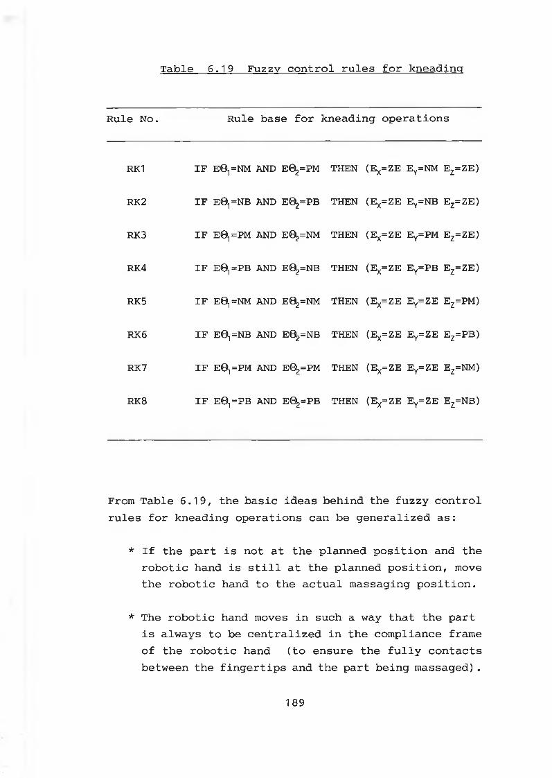
Table 6.19 Fuzzy control rules for kneading
Rule No. Rule base for kneading operations
RK1 IF EO^NM A N D E0^=PM THEN (EX=Z E Ey=NM E z=ZE)
RK2 IF E0,=NB A N D E0^=PB THEN (EX=ZE Ey=NB E z=ZE)
RK3 IF E01 =PM A N D E0^=NM THEN (EX=Z E Ey=PM E z=ZE)
RK4 IF E O ^ P B A N D E02=NB THEN (EX=Z E Ey=PB E z=ZE)
RK5 IF EO^NM A N D E02=NM THEN (EX= Z E E y= Z E EZ=PM)
RK6 IF E0,=NB A N D E02=NB THEN (EX= Z E E y= Z E EZ=PB)
RK7 IF E01=PM A N D E02=PM THEN (EX=ZE E y= Z E EZ=NM)
RK8 IF E©,=PB A N D E0^=PB THEN (EX=ZE E y= Z E EZ=NB)
From Table 6.19, the basic ideas behind the fuzzy control rules for kneading operations can be generalized as:
* If the part is not at the planned position and the robotic hand is still at the planned position, move the robotic hand to the actual massaging position.
* The robotic hand moves in such a way that the part is always to be centralized in the compliance frame of the robotic hand (to ensure the fully contacts between the fingertips and the part being massaged).
189
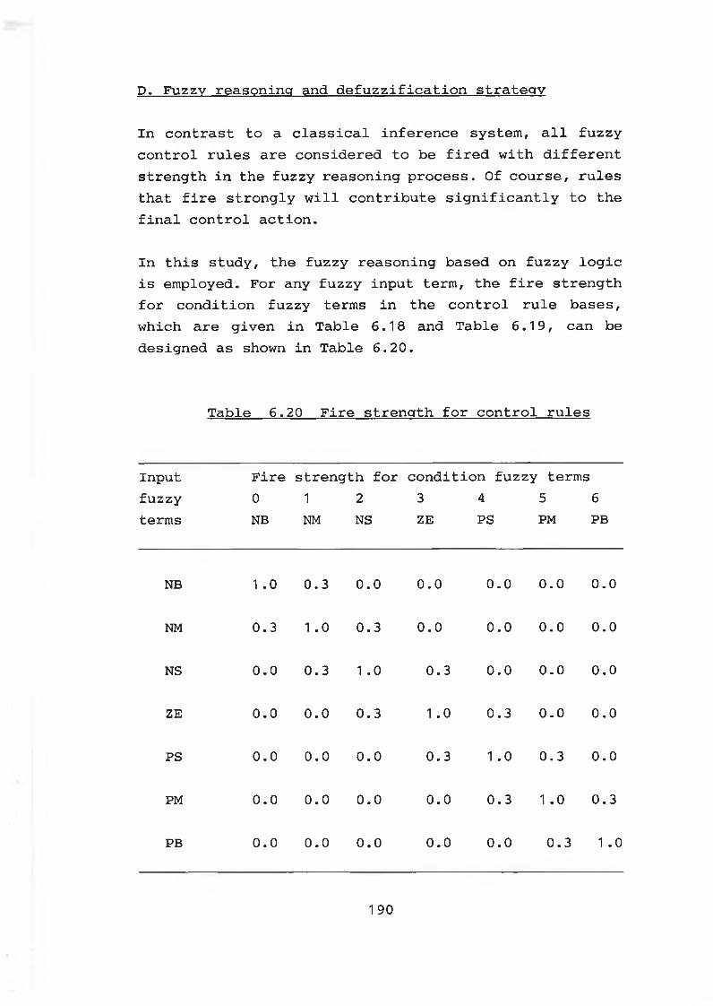
D. Fuzzy reasoning and defuzzification strategy
In contrast to a classical inference system, all fuzzy control rules are considered to be fired with different strength in the fuzzy reasoning process. Of course, rules that fire strongly will contribute significantly to the final control action.
In this study, the fuzzy reasoning based on fuzzy logic is employed. For any fuzzy input term, the fire strength for condition fuzzy terms in the control rule bases, which are given in Table 6.18 and Table 6.19, can be designed as shown in Table 6.20.
Table 6.20 Fire strength for control rules
Input Fire strength for condition fuzzy termsfuzzy 0 1 2 3 4 5 6terms NB NM NS ZE PS PM PB
NB 1 .0 0.3 0.0 0.0 0.0 0.0 0.0
NM 0.3 1 .0 0.3 0.0 0.0 0.0 0.0
NS 0.0 0.3 1 .0 0.3 0.0 0.0 0.0
ZE 0.0 0.0 0.3 1 .0 0.3 0.0 0.0
PS 0.0 0.0 0.0 0.3 1 .0 0.3 0.0
PM 0.0 0.0 0.0 0.0 0.3 1 .0 0.3
PB 0.0 0.0 0.0 0.0 0.0 0.3 1 .0
1 90
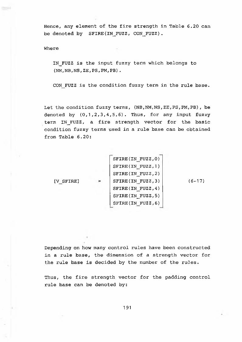
Hence, any element of the fire strength in Table 6.20 can be denoted by SFIRE(IN_FUZZ, C0N_FUZZ).
Where
IN_FUZZ is the input fuzzy term which belongs to (NM, NB, NS , ZE, PS , PM, PB) .
C0N_FUZZ is the condition fuzzy term in the rule base.
Let the condition fuzzy terms, (NB,NM,NS,ZE,PS,PM,PB), be denoted by (0,1,2,3,4,5,6). Thus, for any input fuzzy term IN_FUZZ, a fire strength vector for the basic condition fuzzy terms used in a rule base can be obtained from Table 6.20:
(6-17)
Depending on how many control rules have been constructed in a rule base, the dimension of a strength vector for the rule base is decided by the number of the rules.
Thus, the fire strength vector for the padding control rule base can be denoted by:
[V SFIRE]
SFIRE ( IN_ SFIRE ( IN_ SFIRE ( IN_ SFIRE (IN_ SFIRE ( IN_ SFIRE (IN_ SFIRE(IN
FUZZ,0) FUZZ,1) FUZZ,2) FUZZ,3) FUZZ,4) FUZZ,5) FUZZ,6)
1 91
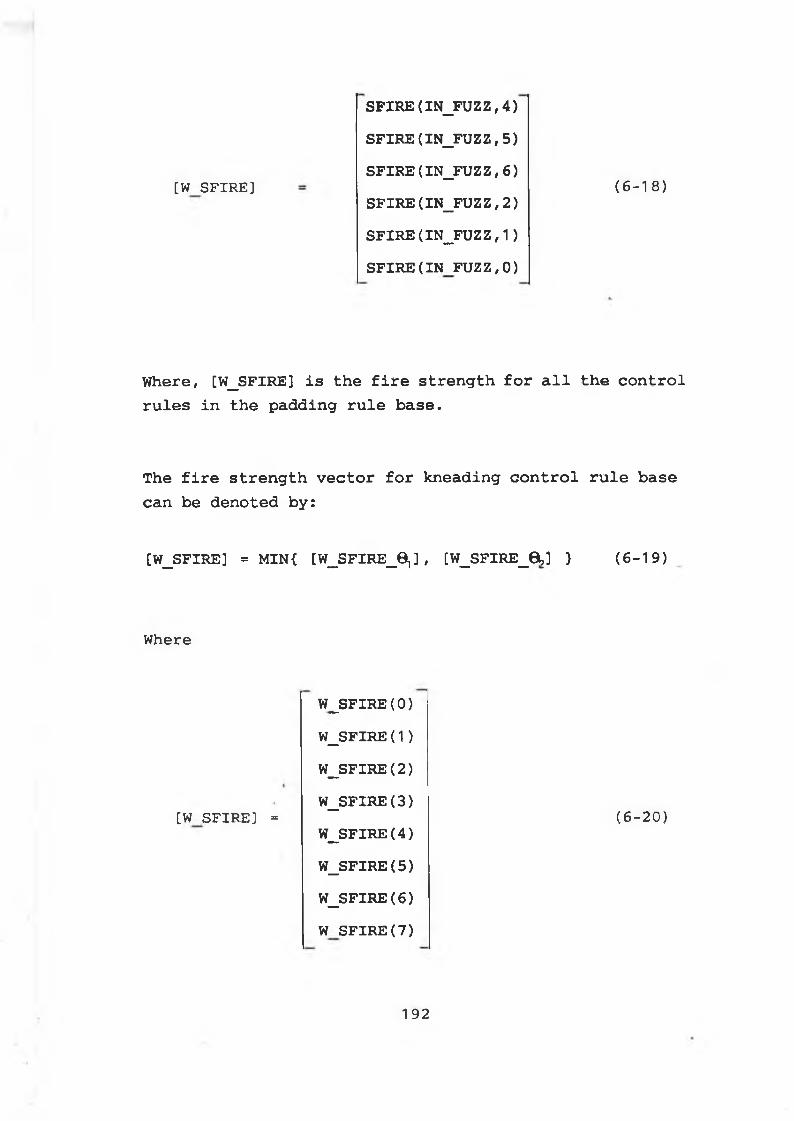
[W SFIRE]
S F I R E ( IN_FUZZ, 4 )
S F I R E ( IN_FUZZ, 5 )
S F IR E (IN _ F U Z Z ,6)
SF IR E (IN _F U Z Z , 2 )
SF IR E (IN _F U Z Z , 1 )
S F IR E (IN FUZZ, 0 )
( 6 - 1 8 )
Where, [W_SFIRE] is the fire strength for all the control rules in the padding rule base.
The fire strength vector for kneading control rule base can be denoted by:
[W_SFIRE] = MIN{ [W_SFIRE_B,] , [W_SFIRE_8 ,] } (6-19)
Where
[W SFIRE] =
W _SFIRE(0 )
W _SFIRE(1 )
W _SFIRE(2 )
W _SFIRE(3 )
W _SFIR E (4)
W _SFIR E (5)
W _SFIR E (6)
W S F I R E (7 )
(6 - 20 )
1 92
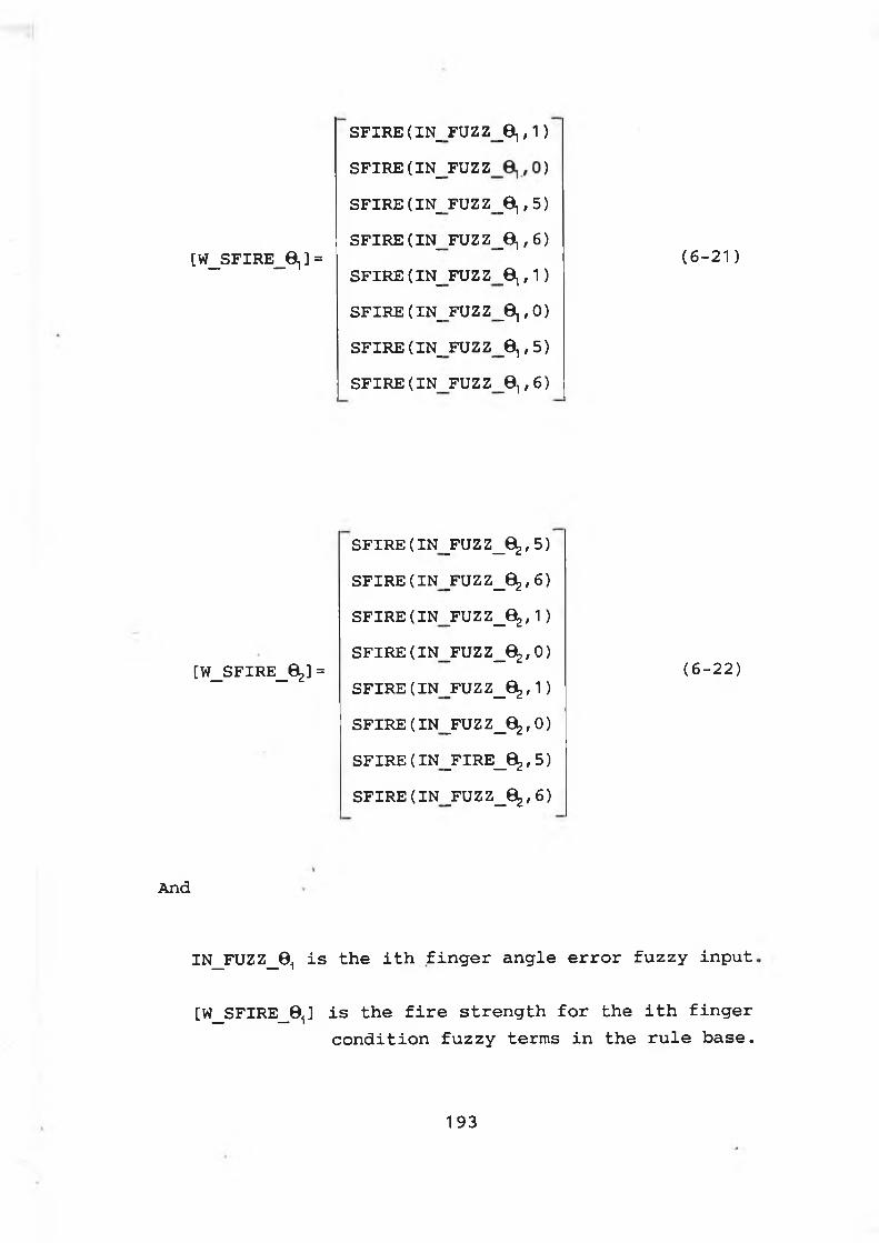
[W_SFIRE_6 1 ] =
SFIRE (IN_ SFIRE (IN_ SFIRE (IN_ SFIRE (IN_ SFIRE (IN_ SFIRE (IN_ SFIRE (IN_ SFIRE(IN
FUZZFUZZFUZZFUZZFUZZFUZZFUZZFUZZ
_ei»1
_e,,5_e,,6
_0,,i_©i,0_e,,5
_®i f 6
(6-2 1)
[W_SFIRE_6 ] =
SFIRE(IN SFIRE(IN SFIRE(IN SFIRE(IN SFIRE(IN SFIRE(IN SFIRE(IN SFIRE(IN
_FUZZ_0^,5 _FUZZ_0^,6 _FUZZ_0^, 1 _FUZZ_0^,O _FU Z Z_6 ^, 1 _FUZZ_0^,O _FIRE_0^; 5 _FUZZ_0^,6
(6-22)
And
IN_FUZZ_0i is the ith finger angle error fuzzy input,
[W_SFIRE_0i] is the fire strength for the ith finger condition fuzzy terms in the rule base.
193
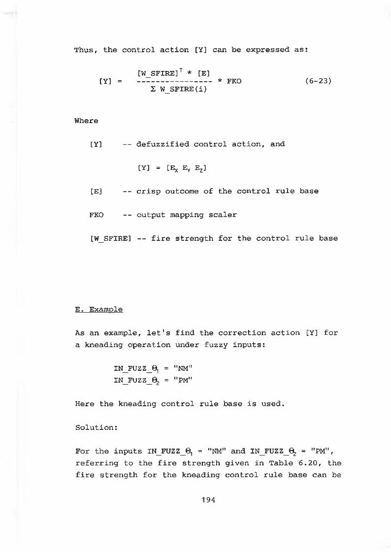
[W_SFIRE]T * [E][Y] = * FKO (6-23)
£ W_SFIRE(i)
Where
[Y] — defuzzified control action, and
[Y] = [Ex Ey Ez]
[E] -- crisp outcome of the control rule base
FKO -- output mapping scaler
[W_SFIRE] — fire strength for the control rule base
E . Example
As an example, let's find the correction action [Y] for a kneading operation under fuzzy inputs:
IN_FUZZ_01 = "NM"IN_FUZZ_02 = "PM"
Here the kneading control rule base is used.
Solution:
For the inputs IN_FUZZ_01 = "NM" and IN_FUZZ_02 = "PM", referring to the fire strength given in Table 6.20, the fire strength for the kneading control rule base can be
Thus, the control action [Y] can be expressed as:
1 94
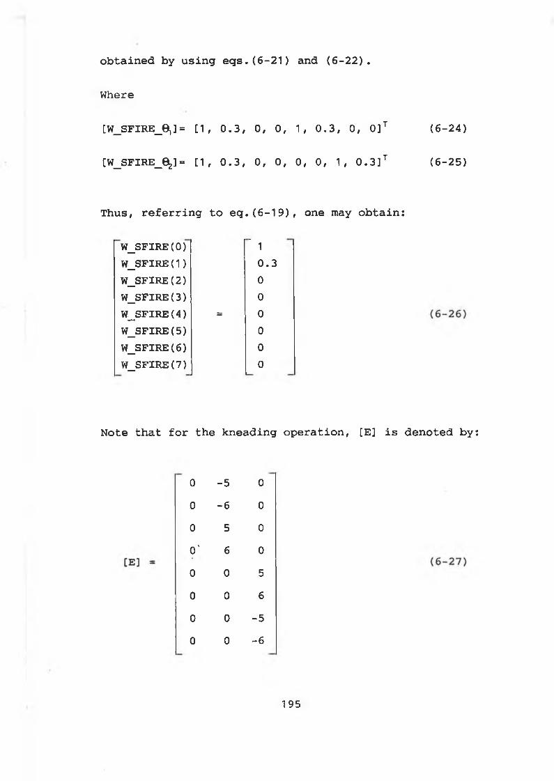
Where
[W_SFIRE_6 ,]= [1, 0.3, 0, 0, 1, 0.3, 0, 0]T (6-24)
[W_SFIRE_6 ] = [1, 0.3, 0, 0, 0, 0, 1, 0.3]T (6-25)
obtained by using eqs.(6-21) and (6-22).
Thus, referring to eq.(6-19), one may obtain:
W_SFIRE(0) " 1W_SFIRE(1 ) 0.3W_SFIRE(2) 0
W_SFIRE(3) 0
W_SFIRE(4) = 0
W_SFIRE(5) 0
W_SFIRE(6 ) 0
W_SFIRE(7) 0
Note that for the kneading operation, [E] is denoted by:
0 -5 0
0 - 6 0
0 5 0
o' 6 0
0 0 50 0 6
0 0 -50 0 - 6
195
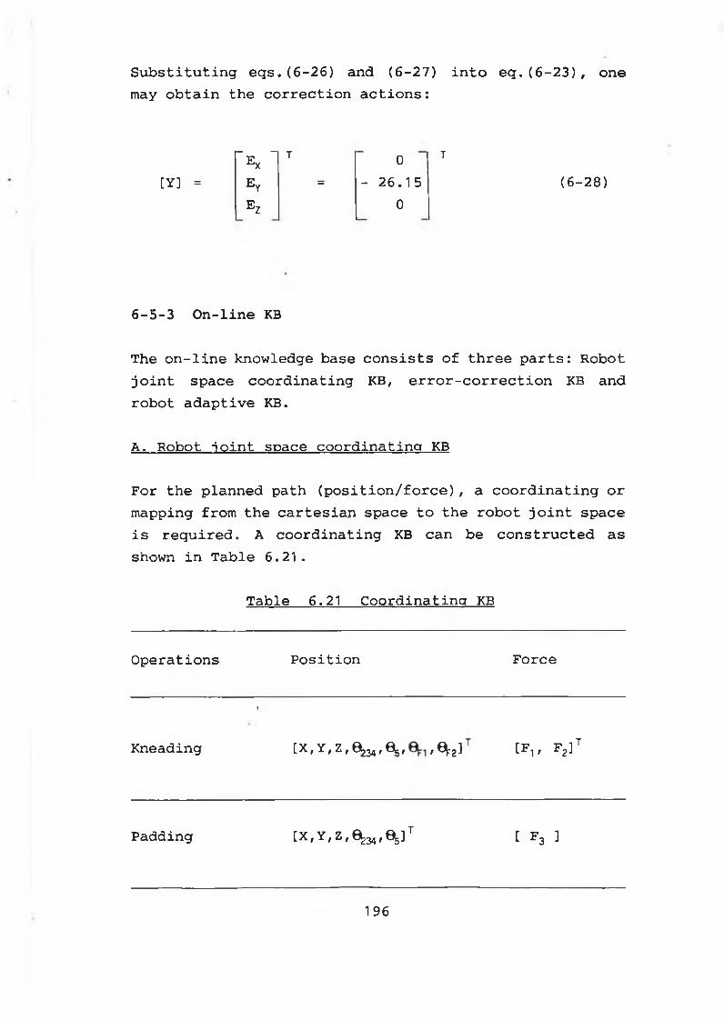
Substituting eqs.(6-26) and (6-27) into eq.(6-23), one may obtain the correction actions:
[Y] =~EX "
T 0 T
ey = - 26.15 (6-28)E Z 0
6-5-3 On-line KB
The on-line knowledge base consists of three parts: Robot joint space coordinating KB, error-correction KB and robot adaptive KB.
A. Robot joint space coordinating KB
For the planned path (position/force), a coordinating or mapping from the cartesian space to the robot joint space is required. A coordinating KB can be constructed as shown in Table 6.21.
Table 6.21 Coordinating KB
Operations Position Force
Kneading
i
[X, Y, Z , 0?34, 0j, , 2^ [F1f F2]t
Padding [ X ^ Z , * ^ , ^ ] 1 [ F3 ]
196
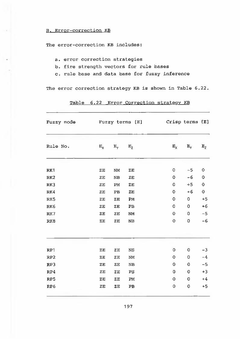
B. Error-correction KB
The error-correction KB includes:
a. error correction strategiesb. fire strength vectors for rule basesc. rule base and data base for fuzzy inference
The error correction strategy KB is shown in Table 6.22.
Table 6.22 Error Correction strategy KB
Fuzzy mode Fuzzy terms [E] Crisp terms [E]
Rule No. E x e y e z E x e y e z
RK1 ZE NM ZE 0 -5 0RK2 ZE NB ZE 0 -6 0RK3 ZE PM ZE 0 +5 0RK4 ZE PB ZE 0 + 6 0RK5 ZE ZE PM 0 0 + 5RK6 ZE ZE PB 0 0 + 6RK7 ZE ZE NM 0 0 -5RK8 ZE ZE NB 0 0 -6
RP1 ZE ZE NS 0 0 -3RP2 ZE ZE NM 0 0 -4RP3 ZE ZE NB 0 0 -5RP4 ZE ZE PS 0 0 +3RP5 ZE ZE PM 0 0 +4RP6 ZE ZE PB 0 0 + 5
197
The fire strength vector KB for padding rule base can be constructed by using eq.(6-18). And the fire stength vector KB for kneading rule base can be formulated by using eq. (6-19) .
The rule bases in Table 6.18 and Table 6.19 can be incorporated into the rule base KB. And the data base KB can be established by using Table 6.16 and Table 6.17.
C. Robot adaptive KB
For any inferred correction (Ex Ey Ez) , there are two ways to carry out the corrections:
a. Direct modifying.Where no verifying is involved. The path is directly modified.
b. Verifying and modifying.Where the feasibility of the inferred new position is verified first by using the kinematics of the robot. If feasible, the path will be modified accordingly. Otherwise, the inferred corrections will be either discarded or modified.
Since the position of the robot hand is modified to adapt the position change of the part being massaged, the path modifying process is also termed as robot adaptive process. And the KB used to assist the path modifying is referred to robot adaptive KB.
For the direct modifying strategy, the correction equation of the robotic hand can be incorporated into the
198
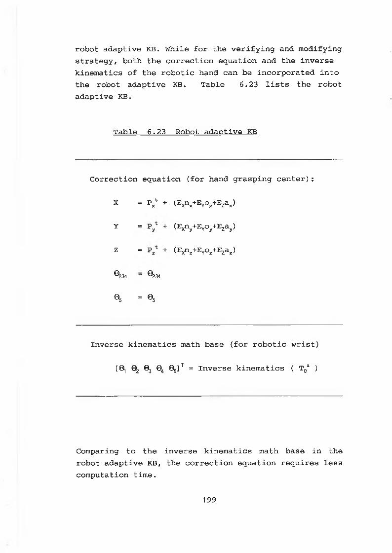
robot adaptive KB. While for the verifying and modifying strategy, both the correction equation and the inverse kinematics of the robotic hand can be incorporated into the robot adaptive KB. Table 6.23 lists the robot adaptive KB.
Table 6.23 Robot adaptive KB
Correction equation (for hand grasping center):
X = Px* + ( E X n x + E Y ° x + E Z a x )
y II +
( E X n y + E Y ° y + E Za y )
z = + (Exnz+EYoz+Ezaz)
® 234 ~ ® 234
©5 = ©5
Inverse kinematics math base (for robotic wrist)
[0, 02 03 04 05]t = Inverse kinematics ( T0a )
Comparing to the inverse kinematics math base in the robot adaptive KB, the correction equation requires less computation time.
199
The procedure of on-line error-corrections during amassaging process can be generalized as follows:
a. move the robotic hand to the massaging position
b. move the robotic fingers into the required positions
c. apply the desired force onto the part being massaged
d. detect the massaging position and force of the robotic hand
e. check the errors. If there is error, go to step ( f ). Otherwise, go back to step ( a ) to carry out next massaging operation.
f. fuzzify the crisp inputs into the fuzzy sets
g. fuzzy inference
h. defuzzy the fuzzy output
i. calculate the new position of the robotic hand at the corrected position
j. control the robot hand to move to the correction position
k. go to step ( a ) to carry out next massaging operation.
6-5-4 Realization of the on-line error-corrections
Fig. 6.15 shows a general error-correction module using the fuzzy inference mechanism.
2 0 0
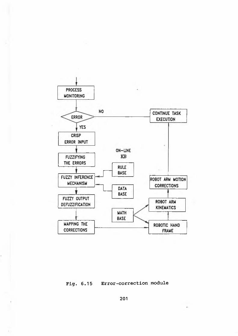
Fig. 6.15 Error-correction module
201
6-6 Software development and experimental results
6-6-1 Software development
The software for the intelligent robot control system have been developed, which include:
* Parameter generating and path planning software for the robot system in which both HAND-I and HAND-II are included. The source codes of the developed software, named as EXPERTP.BAS, can be found in APPENDIX F-1.
* Task execution and intelligent control software for the robot system using HAND-I. The source codes of the developed software, named as EXPERTO.BAS, can be found in APPENDIX F-2.
* Task execution and intelligent control software for the robot system using HAND-II. The source codes of the developed software, named as EXPERTN.BAS, can be found in APPENDIX F-3.
202
6-6-2 Experimental results
A. Padding operation
Both HAND-I and HAND-II can be used to perform the padding operations. Followed is one of the experiments carried out by using HAND-II to pad a flat foam which simulates the human back.
a. Parameter generating
For the fuzzy/liguistic inputs:
Part to be massaged = "BACK"Part size = "SM"Massaging type = "CRS"Massaging speed = "ME"Robot hand used = "HANDNEW
The following parameters can be inferred by using the parameter generating KB:
Massaging action (ACT$) = "PAD"Massaging paths (N) = 6Radial massaging points (m) = 3Robot arm speed = 5Force retention time = 1 .0 (Sec)Massaging force - 3.0 (N)Width of the back = 100 (mm)Length of the back = 100 (mm)
203
The position of the back has been specified as:
-280 0 190 0° 180°
b. Path planning
Using the generated parameters, the orientation of the robotic hand in Cartesian space has been planned as:
1 0 0
[ n o a ] 0 -1 0
0 0 -1
And the positions of the robot arm, together with the control angles, have been planned as shown in Table 6.24. Where N=6 has been changed into N=8.
c. Parameter mapping
Before the task execution, the intelligent control organizing module will map all the planned parameters into the control buffer.
In this experiment, the padding has been performed by the robotic palm along the axial padding path. When the padding along the first axial path is completed, the padding will be continued in the next axial padding path.
204
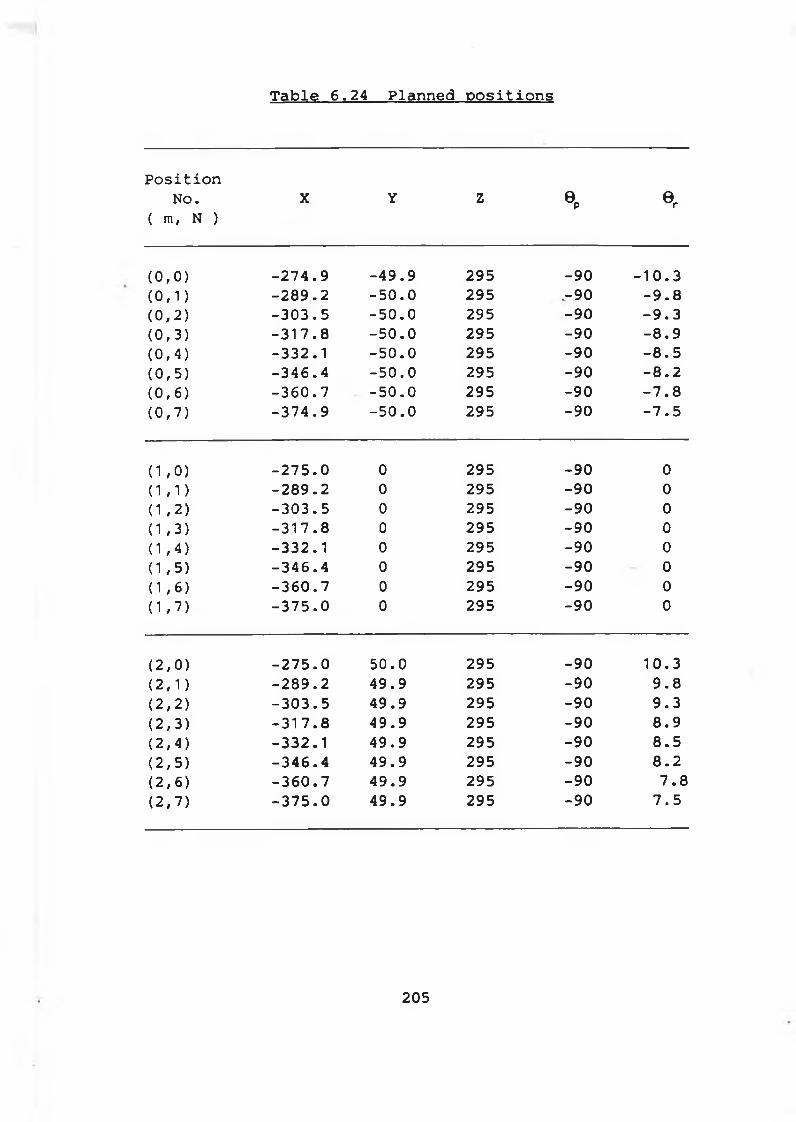
Table 6.24 Planned positions
Positionno. x y z ep er
( m, N )
( 0 , 0 ) - 2 7 4 . 9 - 4 9 . 9 295 - 9 0 - 1 0 . 3( 0 , 1 ) - 2 8 9 . 2 i ui O • O 295 - 9 0 - 9 . 8( 0 , 2 ) - 3 0 3 . 5 - 5 0 . 0 295 - 9 0 - 9 . 3( 0 , 3 ) - 3 1 7 . 8 i U! O • o 295 - 9 0 - 8 . 9( 0 , 4 ) - 3 3 2 . 1 1 en o • o 295 - 9 0 - 8 . 5( 0 , 5 ) - 3 4 6 . 4 1 U1 o • o 295 - 9 0 - 8 . 2( 0 , 6 ) - 3 6 0 . 7 - 5 0 . 0 295 - 9 0 - 7 . 8( 0 , 7 ) - 3 7 4 . 9 i en O ■ o 295 - 9 0 - 7 . 5
( 1 , 0 ) - 2 7 5 . 0 0 295 - 9 0 0( 1 , 1 ) - 2 8 9 . 2 0 295 - 9 0 0( 1 , 2 ) - 3 0 3 . 5 0 295 - 9 0 0( 1 , 3 ) - 3 1 7 . 8 0 295 - 9 0 0( 1 , 4 ) - 3 3 2 . 1 0 295 - 9 0 0( 1 , 5 ) - 3 4 6 . 4 0 295 - 9 0 0( 1 , 6 ) - 3 6 0 . 7 0 295 - 9 0 0( 1 , 7 ) - 3 7 5 . 0 0 295 - 9 0 0
( 2 , 0 ) - 2 7 5 . 0 5 0 . 0 295 - 9 0 1 0 . 3( 2 , 1 ) - 2 8 9 . 2 4 9 . 9 295 - 9 0 9 . 8( 2 , 2 ) - 3 0 3 . 5 4 9 . 9 295 - 9 0 9 . 3( 2 , 3 ) - 3 1 7 . 8 4 9 . 9 295 - 9 0 8 . 9( 2 , 4 ) - 3 3 2 . 1 4 9 . 9 295 - 9 0 8 . 5( 2 , 5 ) - 3 4 6 . 4 4 9 . 9 295 - 9 0 8 . 2( 2 , 6 ) - 3 6 0 . 7 4 9 . 9 295 - 9 0 7 . 8( 2 , 7 ) - 3 7 5 . 0 4 9 . 9 295 - 9 0 7 . 5
205
d. Task execution
Using the control variables in the control buffer, the padding operations can be carried out.
T o e n s u re th e s a fe o p e r a t i o n , a c o n s t a n t a p p r o a c h in g
d i s t a n c e , DABOVE, above th e p a d d in g s u r f a c e has been
in t r o d u c e d i n t o th e p a d d in g p r o c e s s . W here, DABOVE=20 mm.
T o i n c r e a s e th e p a d d in g s p e e d , a q u i c k a p p ro a c h m o t io n
has a l s o been em ployed i n th e p a d d in g c o n t r o l p r o c e s s .
To achieve the desired padding force, the compliance motion control of the palm is required. Experiment shows that two or three times of fine motions are required in every padding cycle to attain the desired force. Where the fine motion distance is 1.0 mm.
F i g . 6 . 1 6 shows th e p a d d in g f o r c e - t i m e h i s t o r y o f th e
r o b o t i c p a lm . W here, th e r o b o t i c pa lm moves fro m th e
p o s i t i o n ( 1 , 0 ) to th e p o s i t i o n ( 1 , 7 ) (See T a b l e 6 . 2 4 ) .
206
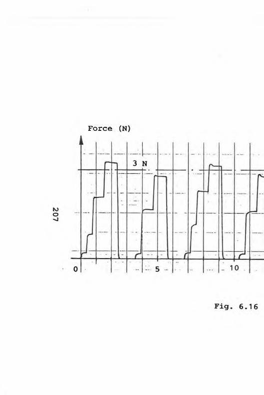
F o r c e
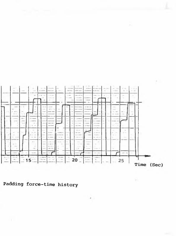
P ad d in g f o r c e - t i m e h i s t o r y
B. Kneading operation with on-line error-correction
B o th HAND-1 and H A N D -I I can be use d t o p e r f o r m th e
k n e a d in g o p e r a t i o n s . F o l lo w e d i s one o f th e e x p e r im e n ts
c a r r i e d o u t b y H A N D - I I . Where H A N D -I I i s commanded to
knead a c y l i n d e r foam w h ic h s im u la t e s t h e human arm .
a . P a ra m e te r g e n e r a t i n g
F o r th e f u z z y / l i n g u i s t i c i n p u t s :
P a r t t o be massaged = "ARM"
P a r t s i z e = "ME"
M a ssa g in g ty p e = "CRS"
M a s s a g in g speed = "ME"
R obot hand used = "HANDNEW"
The f o l l o w i n g p a ra m e te rs can be i n f e r r e d b y u s i n g th e
p a ra m e te r g e n e r a t i n g KB:
M a s s a g in g a c t i o n (A C T$ ) = "KNEAD II
M a s s a g in g p a th s (N) = 6
R a d i a l m a ssa g in g p o i n t s (m) = 3
R obot arm speed = 5
F o r c e r e t e n t i o n t im e = 1 .0 (S e c )
M a ssa g in g f o r c e = 3 .5 (N)
D ia m e te r o f th e arm = 100 (mm)
L e n g th o f th e arm = 120 (mm)
208
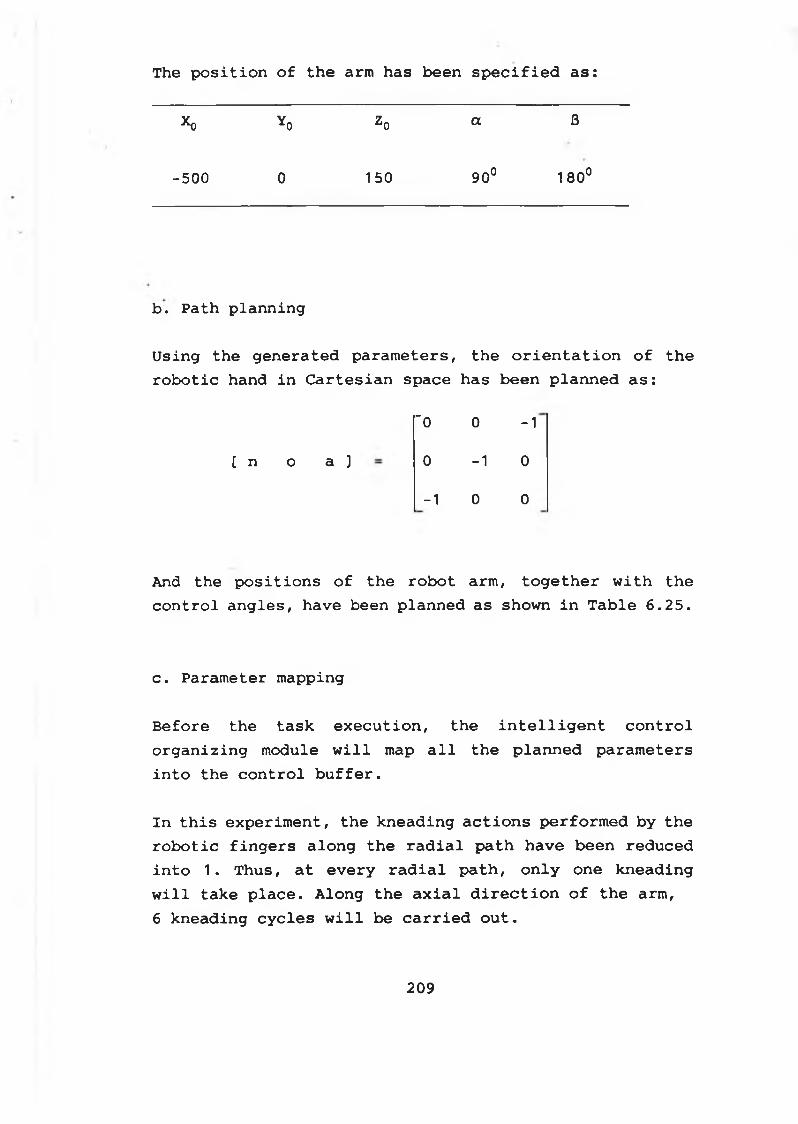
The position of the arm has been specified as:
*0 Yo z o a B
-5 0 0 0 150 90° 180°
b . P ath p la n n in g
U s in g th e g e n e ra te d p a ra m e te rs , th e o r i e n t a t i o n o f th e
r o b o t i c hand i n C a r t e s i a n space has been p la n n e d a s :
"0 0 -1
[ n o a ] 0 -1 0
-1 0 0
And th e p o s i t i o n s o f th e r o b o t arm , t o g e t h e r w i t h th e
c o n t r o l a n g le s , have been p la n n e d as shown i n T a b l e 6 . 2 5 .
c . P a ra m e te r m apping
B e fo re th e t a s k e x e c u t i o n , th e i n t e l l i g e n t c o n t r o l
o r g a n i z i n g module w i l l map a l l th e p la n n e d p a ra m e te rs
i n t o th e c o n t r o l b u f f e r .
I n t h i s e x p e r im e n t , th e k n e a d in g a c t i o n s p e rf o rm e d b y th e
r o b o t i c f i n g e r s a lo n g th e r a d i a l p a t h h ave been re d u ce d
i n t o 1 . T h u s , a t e v e r y r a d i a l p a t h , o n l y one k n e a d in g
w i l l ta k e p l a c e . A lo n g th e a x i a l d i r e c t i o n o f th e arm ,
6 k n e a d in g c y c l e s w i l l be c a r r i e d o u t .
209
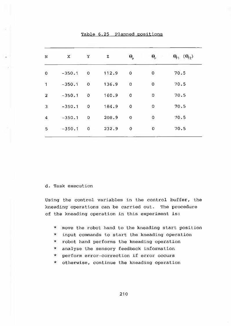
Table 6.25 Planned positions
N X Y Z0 p
/-NCVJÿ
0 - 3 5 0 . 1 0 112. 9 0 0 7 0 . 5
1 - 3 5 0 . 1 0 136. 9 0 0 7 0 . 5
2 - 3 5 0 . 1 0 160. 9 0 0 7 0 . 5
3 - 3 5 0 . 1 0 1 84. 9 0 0 7 0 . 5
4 - 3 5 0 . 1 0 2 0 8 . 9 0 0 7 0 . 5
5 - 3 5 0 . 1 0 2 3 2 . 9 0 0 7 0 . 5
d . T a s k e x e c u t io n
U s in g th e c o n t r o l v a r i a b l e s i n th e c o n t r o l b u f f e r , th e
k n e a d in g o p e r a t i o n s can be c a r r i e d o u t . T h e p r o c e d u r e
o f th e k n e a d in g o p e r a t i o n i n t h i s e x p e r im e n t i s :
* move th e r o b o t hand t o th e k n e a d in g s t a r t p o s i t i o n
* i n p u t commands t o s t a r t th e k n e a d in g o p e r a t i o n
* r o b o t hand p e rf o rm s th e k n e a d in g o p e r a t i o n
* a n a ly s e th e s e n s o ry fe e d b a c k i n f o r m a t i o n
* p e rf o rm e r r o r - c o r r e c t i o n i f e r r o r o c c u r s
* o t h e r w i s e , c o n t in u e th e k n e a d in g o p e r a t i o n
210
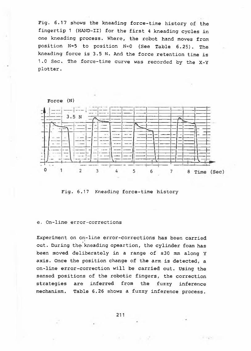
F i g . 6 . 1 7 shows th e k n e a d in g f o r c e - t i m e h i s t o r y o f t h e
f i n g e r t i p 1 ( H A N D - I I ) f o r t h e f i r s t 4 k n e a d in g c y c l e s i n
one k n e a d in g p r o c e s s . W here, th e r o b o t hand moves fro m
p o s i t i o n N=5 t o p o s i t i o n N=0 ( See T a b l e 6 . 2 5 ) . Th e
k n e a d in g f o r c e i s 3 .5 N. And th e f o r c e r e t e n t i o n t im e i s
1 .0 S e c . T h e f o r c e - t i m e c u r v e was r e c o r d e d b y th e X - Y
p l o t t e r .
F o r c e (N)
F i g . 6 . 1 7 K n e a d in g f o r c e - t i m e h i s t o r y
e . O n - l i n e e r r o r - c o r r e c t i o n s
E x p e r im e n t on o n - l i n e e r r o r - c o r r e c t i o n s has been c a r r i e d
o u t . D u r i n g the. k n e a d in g o p e a r t i o n , th e c y l i n d e r foam has
been moved d e l i b e r a t e l y i n a r a n g e o f ±30 mm a lo n g Y
a x i s . Once th e p o s i t i o n change o f t h e arm i s d e t e c t e d , a
o n - l i n e e r r o r - c o r r e c t i o n w i l l be c a r r i e d o u t . U s in g th e
sensed p o s i t i o n s o f th e r o b o t i c f i n g e r s , th e c o r r e c t i o n
s t r a t e g i e s a r e i n f e r r e d fro m th e f u z z y i n f e r e n c e
m echanism . T a b l e 6 . 2 6 shows a f u z z y i n f e r e n c e p r o c e s s .
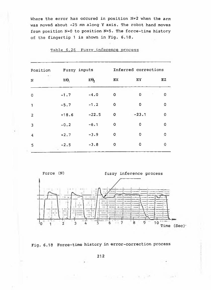
Where t h e e r r o r has o c c u r e d i n p o s i t i o n N=2 when th e arm
was moved a b o u t - 2 5 mm a l o n g Y a x i s . Th e r o b o t hand moves
fro m p o s i t i o n N=0 t o p o s i t i o n N =5. T h e f o r c e - t i m e h i s t o r y
o f th e f i n g e r t i p 1 i s shown i n F i g . 6 . 1 8 .
Table 6.26 Fuzzy inference process
P o s i t i o n F u z z y i n p u t s I n f e r r e d c o r r e c t i o n s
N E6, E8, EX EY EZ
0 -1 .7 - 4 . 0 0 0 0
1 - 5 . 7 -1 . 2 0 0 0
2 + 1 8 . 6 - 2 2 . 5 0 - 2 3 . 1 0
3 - 0 . 2 - 6 . 1 0 0 0
4 + 2 . 7 - 3 . 9 0 0 0
5 - 2 . 5 - 3 . 8 0 0 0
Force (N) fuzzy inference process
Fig. 6.18 Force-time history in error-correction process
212
I
)
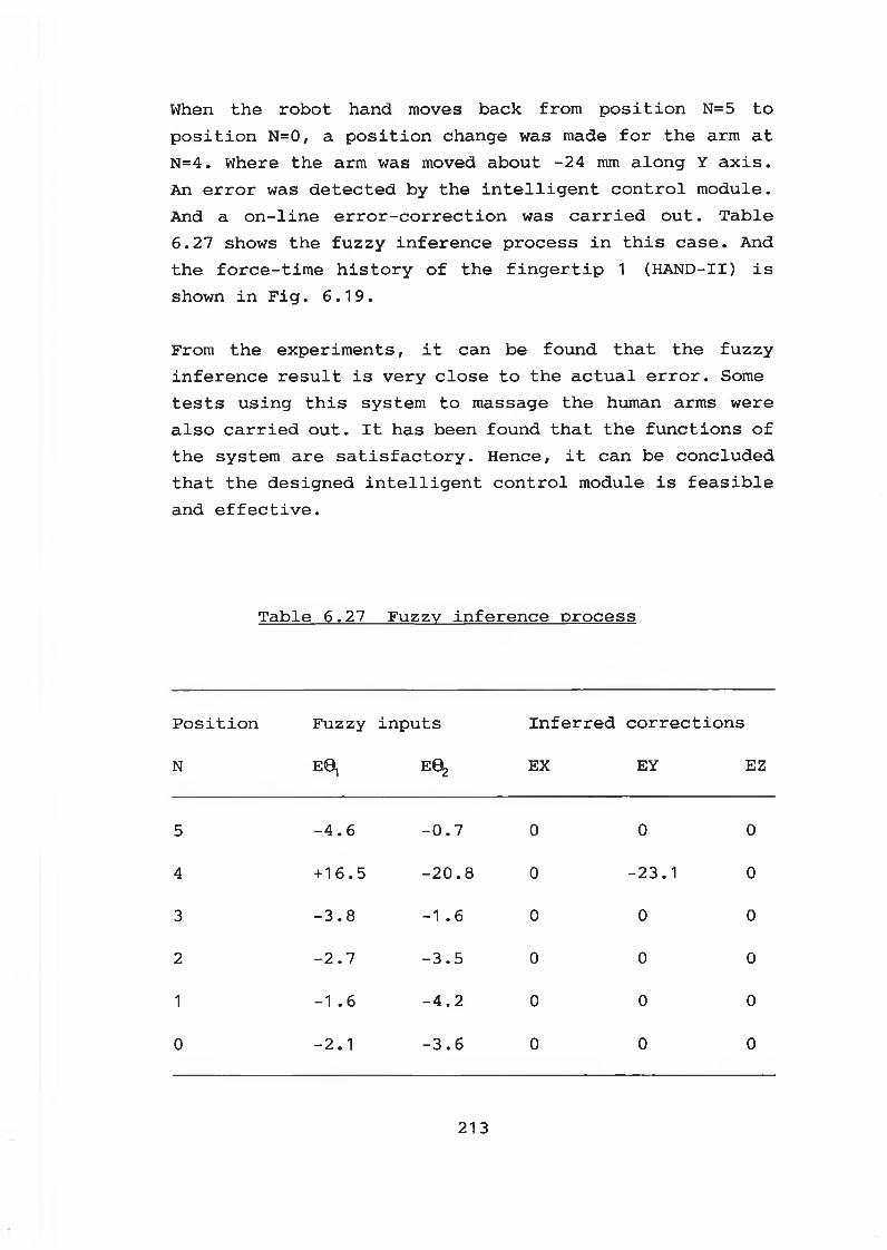
When th e r o b o t hand moves ba ck fro m p o s i t i o n N=5 t o
p o s i t i o n N=0, a p o s i t i o n change was made f o r th e arm a t
N =4. Where th e arm was moved a b o u t -2 4 mm a lo n g Y a x i s .
An e r r o r was d e t e c t e d b y th e i n t e l l i g e n t c o n t r o l m o d u le .
And a o n - l i n e e r r o r - c o r r e c t i o n was c a r r i e d o u t . T a b l e
6 . 2 7 shows th e f u z z y i n f e r e n c e p ro c e s s i n t h i s c a s e . And
th e f o r c e - t i m e h i s t o r y o f th e f i n g e r t i p 1 ( H A N D - I I ) i s
shown i n F i g . 6 . 1 9 .
From th e e x p e r im e n t s , i t can be fo u n d t h a t th e f u z z y
in f e r e n c e r e s u l t i s v e r y c l o s e t o th e a c t u a l e r r o r . Some
t e s t s u s i n g t h i s system to massage th e human arms w ere
a l s o c a r r i e d o u t . I t has been fo u n d t h a t th e f u n c t i o n s o f
th e system a r e s a t i s f a c t o r y . H ence, i t can be c o n c lu d e d
t h a t th e d e s ig n e d i n t e l l i g e n t c o n t r o l m odule i s f e a s i b l e
and e f f e c t i v e .
T a b l e 6 . 2 7 F u z z y i n f e r e n c e p ro c e s s
P o s i t i o n F u z z y in p u t s I n f e r r e d c o r r e c t i o n s
N E 0 1 E0^ EX EY EZ
5 - 4 . 6 - 0 . 7 0 0 0
4 + 1 6 . 5 - 2 0 . 8 0 - 2 3 . 1 0
3 - 3 . 8 -1 .6 0 0 0
2 - 2 . 7 - 3 . 5 0 0 0
1 -1 .6 - 4 . 2 0 0 0
0 - 2 . 1 - 3 . 6 0 0 0
213
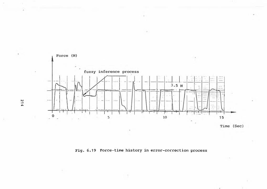
214
F i g . 6 . 1 9 F o r c e - t i m e h i s t o r y i n e r r o r - c o r r e c t i o n p r o c e s s
Chapter Seven
C o n c lu s io n s and R ecom m endations f o r f u r t h e r work
7-1 C o n c lu s io n s
In this research, the physiothérapie robot system has been constructed with the KBS and the fuzzy inference mechanism to cope with any uncertainties and errors in the real-time control process. And a dexterous robotic hand with an integrated palm and two fingers has been employed to perform the padding and kneading opeartions.
To carry out the massaging process effectively, an intelligent robot control system for physiothérapie applications has been developed. The intelligent robot control system consists of a specially designed robotic hand with built-in sensors, an interfacing module between the robot system and the computer, an intelligent path planning module and a fuzzy logic based intelligent control module.
Two hands, HAND-I and HAND-II, have been developed with different types of force sensing units -- FSR and load cell. For the FSR sensor on each fingertip of HAND-I, a constant contact area was maintained by using a layer of silicone rubber between the contact piece and the FSR sensing surface. And a good response of the FSR force sensor has been achieved. While for the load cell on each fingertip of HAND-II, a constant contact area was maintained by using a cylinder bar with a contact cap on top of it. Comparing with FSR sensors, load cell sensing units are more sensitive, robust and compact.
The force level of the robotic fingers can be controlled directly by sending the control voltages to the designed
215
DC m o to r d r i v e c i r c u i t . Th e maximum w o r k in g t o r q u e
p r o v i d e d b y each f i n g e r i s 0 .9 Nm.
Th e f o r c e l e v e l o f th e r o b o t i c palm ca n o n l y be a c h ie v e d
b y c o n t r o l l i n g th e f i n e m o t io n o f th e r o b o t pa lm a f t e r
c o n t a c t i s made. Th e maximum w o r k in g f o r c e p r o v i d e d b y
th e palm i s 5 N.
Th e d e s ig n e d r o b o t hands (HAND-I & HAND-II) w i t h th e
i n t e g r a t e d palm and two f i n g e r s ca n be used t o p e rf o rm
th e p a d d in g and k n e a d in g o p e r a t i o n s .
H ow ever, th e w e ig h t o f th e r o b o t i c hands was l i m i t e d b y
th e lo a d c a r r y i n g c a p a b i l i t y o f th e r o b o t arm . From th e
d e s ig n o f H A N D -I and H A N D - I I , i t has been c o n c lu d e d t h a t
th e w e ig h t o f th e r o b o t i c hands c a n n o t be g r e a t l y re d u c e d
due t o th e n e c e s s i t y o f i n t e g r a t i n g th e two DC m o to rs
i n t o th e body o f th e han d.
Th e m a ssa g in g speed i s p r o p o r t i o n a l t o th e r o b o t arm
speed and th e f o r c e r e t e n t i o n t im e . The h i g h e r th e
m a ssa g in g spe ed, th e h i g h e r th e r o b o t arm s p e e d . W h i le ,
th e h i g h e r th e m assag in g spe ed, th e s h o r t e r th e f o r c e
r e t e n t i o n t im e . F o r th e s a fe o p e r a t i o n , th e r o b o t arm
speed s h o u ld be u n d e r 7 (speed l e v e l ) .
The r e q u i r e d f o r c e r e t e n t i o n t im e can be r e a l i z e d b y
u s i n g th e t im e r i n th e A/D c o n v e r s io n b o a rd ( D A S 8 ) . As
i t has been fo u n d t h a t th e t i m e r i n th e r o b o t arm
c o n t r o l l e r was n o t s u i t a b l e f o r g e n e r a t i n g th e r e q u i r e d
t im e d e l a y .
C o n s t r u c t e d w i t h th e e x p e r t i s e kn o w le d ge bases (KBS) o f
th e m a ssa g in g p ro c e s s and th e f u z z y l o g i c based i n f e r e n c e
m echanism , th e i n t e l l i g e n t p a t h p l a n n i n g m odule can d e a l
w i t h u n c e r t a i n t i e s b y m a n i p u l a t i n g th e f u z z y / l i n g u i s t i c
te rm s . T h u s , W it h th e f u z z y / l i n g u i s t i c i n p u t te r m s , th e
21 6
required parameters can be generated and the massaging path can be planned off-line. From the path planning examples, it can be concluded that the designed intelligent path planning module is effective and feasible. However, due to the limitation of the configuration of the robot arm, not all positions and orientations of the part being massaged can be attained by the robotic hand. To make the robot system more dexterous, a 6 DOF robot arm should be used.
In robotic massaging process, the wrong specified part location, part deviations from its specified position and incorrectly planned path have been identified as the causes of uncertainties and errors.
Hence, it can be concluded that to carry out the massaging process effectively, the intelligent control module has to be constructed with the KBS and the fuzzy logic inference mechanism to cope with any uncertainties or errors. Furthermore, by using the error threshold in the intelligent control software, a more effective massaging operation has been achieved. When the detected errors are within the threshold, the errors will be ignored and no error-correction is taken place. Otherwise, fuzzy logic inference will be initiated and error-correction must be carried out.
Experimental results have shown that the fuzzy inferred correction distances are very close to the actual errors. Thus, it can be concluded that the designed fuzzy inference mechanism is feasible and effective.
Furthermore, using the designed intelligent control module, the complicated methematical model and dynamical analysis of the control system can be avoided. And the expertise knowledge can be incorporated into the control process. Also the AI control can be realized in a real
217
time control process. Thus, the developed fuzzy inference mechanism and the AI control system can be applied to other similar application areas.
7 -2 R ecom m endations f o r f u r t h e r work
-- To speed up the part locating process and to ensure the safe operation of the robotic system, robotic vision sensors should be incorporated into the robotic massaging system. Using robotic visions, the part size and location in the robot workspace can be roughly observed. These observations may be in a form of fuzziness and can be employed by the parameter generating module to organize the parameters for the path planning.
-- To give the host PC more time to handle higher level control organizing, the slave microcomputers should be used to perform the position/force servo loop control of the robotic hand. Speed/acceleration sensors should be mounted onto the DC motor shafts to realize the speed and acceleration control over the robotic fingers.
— To apply the developed robot control system into other applications such as delicate material handling and industrial assembly, a three fingered hand with multi-joints should be developed. Different types of force sensors should be used. A 6 axial robot wrist force sensing unit might be required to carry out the complicated industrial assembley operations.
218

— To sp e e d up t h e f u z z y i n f e r e n c e , f u z z y l o g i c com puter s h o u ld b e u s e d i n t h e n e x t r e s e a r c h s t a g e . F u rth erm o re , U s in g t h e f u z z y l o g i c c o m p u ter , t h e e x p e r t k n o w led g e ca n b e e a s i l y i n c o r p o r a t e d i n t o t h e c o n t r o l s y s t e m and t h e o n - l i n e c o n t r o l s y s t e m w i l l be more r o b u s t .
219
REFERENCES
[1 ] S h a h in p o o r , M . , " A r o b o t e n g i n e e r i n g t e x t b o o k " ,
H a rp e r & Row P u b l i s h e r s , 1987
[ 2] Okada, T . , " On a v e r s a t i l e f i n g e r system " , P r o c .
7 t h I n t . Symp. on I n d u s t r i a l R o b o ts , T o k y o , 1977,
P P345-352
[3 ] Okada, T . , " O b je c t h a n d l i n g sy s te m f o r m anual i n
d u s t r y " , I E E E T r a n s . S y s t . , Man, C y b e r n . , S M C-9,
1979, P P 79-89
[4 ] Okada, T . , " Com puter c o n t r o l o f m u l t i j o i n t e d f i n g e r
system f o r p r e c i s e o b j e c t - h a n d l i n g " , IE E E T r a n s .
S y s t . , Man, C y b e r n . , SM C-12, 1982, PP289-299
[5 ] H a n a fu s a , H. and A sad a, H . , " S t a b l e p r e h e s io n b y a
r o b o t hand w i t h e l a s t i c f i n g e r s " , P r o c . 7 t h I n t .
Symp. on I n d u s t r i a l R o b o ts , T o k y o , 1977, PP361- 368
[ 6] H a n a fu s a , H . and Asada, H . , " A r o b o t hand w i t h e l a
s t i c f i n g e r s and i t s a p p l i c a t i o n t o a ss e m b ly p ro c e s s
" , P r o c . IF A C Symp. on I n f o r m , and C o n t r o l Problem s
i n M a n u fa c t . T e c h . , T o k y o , 1977, PP127- 138
[ 7] S a l i s b u r y , J . K . and C r a i g , J . J . , " A r t i c u l a t e d h a n d s :
f o r c e c o n t r o l and k in e m a t ic is s u e s " , I n t . J . o f
R o b o t ic s R e s e a rc h , V o l . 1 , N o . 1 , 1982
[ 8] S a l i s b u r y , J . K . and R o th , B . , " K in e m a t ic and f o r c e
a n a l y s i s o f a r t i c u l a t e d hands " , J . M echanism s,
T r a n s m i s s i o n s , and A u to m a t io n i n D e s ig n , 1983,
PP35-41
[9 ] S a l i s b u r y , J . K . , " I n t e r p r e t a t i o n o f c o n t a c t g e o
m e t r ie s fro m f o r c e m easurem ents " , R o b o t ic s R e se a rch
220
( e d s . ) b y B r a d y , M. and P a u l , R . , M IT P r e s s , 1984,
P P565-577
[ 10] S a l i s b u r y , J . K . , e t a l , " I n t e g r a t e d lam guage, s e n s
i n g , and c o n t r o l f o r a r o b o t hand " , P r o c . 3 rd I n t .
Symp. o f R o b o t ic s R e s e a rc h , F r a n c e , 1985, PP54-61
[ 11] A b ra m o w itz , J . , e t a l , " P e n n s y lv a n ia a r t i c u l a t e d
m e c h a n ic a l hand " , P r o c . ASME C o n f . on R o b o t i c s ,
C h ic a g o , USA, 1983
[ 12] C a p o r a l i , M. and S h a h in p o o r , M . , " D e s ig n and c o n
s t r u c t i o n o f a f i v e - f i n g e r e d r o b o t i c h a n d " , R o b o t ic s
A g e , V o l . 6, N o . 2, 1984, PP14- 20
[ 13] J a c o b s e n , S . C . , e t a l , " Th e v e r s i o n I U ta h / M IT d e x
t e r o u s hand " , R o b o t ic R e s e a rch ( e d s . ) b y H an afusa
& In o u e , M IT P r e s s , 1985, PP301- 308
[ 14] S i e g e l , D . M . , e t a l , " C o m p u t a t io n a l a r c h i t e c t u r e £r
th e U ta h / M IT hand " , P r o c . IE E E I n t . C o n f . R o b o t ic s
and A u to m a t io n , S t . L o u i s , USA, 1985, PP1016- 1021
[ 15] J a c o b s e n , S . C . , e t a l , " D e s ig n o f th e U t a h / M IT d e x
t e r o u s hand " , P r o c . I E E E I n t . C o n f . R o b o t ic s and
A u to m a t io n , San F r a n c i s c o , USA, 1986, PP1520- 1532
[ 16] N a ra s im h a n , S . , e t a l , " Im p le m e n ta t io n o f c o n t r o l
m e th o d o lo g ie s on th e c o m p u t a t io n a l a r c h i t e c t u r e f o r
th e U ta h / M IT hand " , P r o c . IE E E I n t . C o n f . R o b o t ic s
& A u to m a t io n , San F r a n c i s c o , USA, 1986, PP1884- 188 9
[ 17] N a ra s im h a n , S . , e t a l , " CONDOR: An a r c h i t a c t u r e f o r
c o n t r o l l i n g th e U t a h -M I T d e x t e r o u s h a n d " , IE E E T r a n s
R o b o t ic s and A u to m a t io n , V o l . 5, N o . 5, O c t . 1989,
PP616 -6 2 7
221
[ 18] B i g g e r s , K . B . , e t a l , " L o w - l e v e l c o n t r o l o f th e
U t a h -M I T d e x te r o u s hand " , P r o c . IE E E I n t . C o n f . on
R o b o t ic s and A u to m a t io n , CA, USA, 1986, PP61- 66
[ 19] E d s o n , D . V . , " G i v i n g r o b o t hands a human t o u c h " ,
H ig h T e c h n o lo g y , 1985, PP31- 35
[ 20] H i t a c h i , L t d . , " H i t a c h i ' s SMA r o b o t hand " , 1985
[ 21] Y a m a f u j i , K . and Maeda, T . , "D e v e lo p m e n t o f a m u l t i
p r o c e s s o r c o n t r o l l e d r o b o t hand " , A d v . M anuf. E n g . ,
V o l . 1 , O c t . 1988, PP21- 25
[ 22] A l l e n , P . K . , e t a l , 11 A system f o r p ro g ra m m in g and
c o n t r o l l i n g a m u l t i s e n s o r r o b o t i c hand " , IE E E T r a n s
on S y s t . , Man, C y b e r n . , V o l . 20, N o . 6, 1990,
PP1450- 1456
[ 23] K o iv o , A . J . and H o u s h a n g i ,N . , " R e a l - t i m e v i s i o n
fe e d b a c k f o r s e r v o in g r o b o t i c m a n i p u la t o r w i t h s e l f
t u r n i n g c o n t r o l l e r " , IE E E T r a n s . S y s t . , Man, C y b e r n .
V o l . 21, N o . 1 , 1991, PP13 4 - 1 4 2
[ 24] Dreyfus, M . G . , " Visual Robots ", Industrial Robot, Dec., 1974
[ 25] F a i r h u r s t , M . C . , " Com puter v i s i o n f o r r o b o t i c
system s " , Englew ood C l i f f s , 1988
[ 26] T r i v e d i , M . M . , e t a l , " A v i s i o n system f o r r o b o t i c
i n s p e c t i o n and m a n i p u la t io n " , IE E E C o m p u t., V o l . 22,
1989, PP91- 98
[ 27] B e n i , G. and Hackwood, S . , " R e ce n t ad vances i n
r o b o t i c s " , Jo h n w i l e y & s o n s , I n c . , 1985
222
[ 28] W e b s te r , J . G . , " T a c t i l e s e n s o rs f o r r o b o t i c s and
m e d ic in e " , Jo h n w i l e y & s o n s , I n c . , 1988
[ 29] L u o , R . C . , e t a l , " Dynam ic m u l t i - s e n s o r d a t a f u s i o n
system f o r i n t e l l i g e n t r o b o t s " , IE E E T r a n s . R o b o t ic s
& A u to m a t io n , V o l . 4, N o . 4, 1988, PP386- 396
[ 30] L e e , M . H . , e t a l , " A c o n t r o l and m o n i t o r i n g system
f o r m u l t i p l e - s e n s o r i n d u s t r i a l r o b o t s " , P r o c . 3 rd
I n t . C o n f . on R obot V i s i o n & S e n s o ry C o n t r o l s , USA,
1983
[ 31] H i l l i s , D . , " A h i g h r e s o l u t i o n im a g in g t a c t i l e
s e n s o r " , I n t . J . R o b o t ic s R e s e a rc h , V o l . 1 , N o . 2
1982, PP33-44
[ 32] Shim ano, B . and R o th , B . , " On f o r c e s e n s in g i n f o r
m a t io n and i t s use i n c o n t r o l l i n g m a n i p u la t o r s " ,
P r o c . 8 th I n t . Symp. on I n d u s t r i a l R o b o ts , 1978,
PP119- 126
[ 33] W atson, P . C . and D ra k e , S . H . , " P e d e s t a l and w r i s t
f o r c e s e n s o rs f o r a u to m a t ic a s s e m b ly " , P r o c . 5 th
I n t . Symp. on I n d u s t r i a l R o b o ts , 1975, PP501-511
[ 34] C o i f f e t , P . , " I n t e r a c t i o n w i t h th e e n v iro n m e n t " ,
( Robot T e c h n o lo g y , V o l . 2 ) , Kogan page L t d . , 1983
[ 35] H i l l , J . W . and Sw ord, A . J . " M a n i p u la t i o n based on
s e n s o r d i r e c t e d c o n t r o l : an i n t e g r a t e d e n d - e f f e c t o r
and to u c h s e n s in g system " , P r o c . 1 7t h A n n u a l Human
F a c t o r S o c i e t y C o n v e n t io n , USA, 1973
[ 36] Feddema, J . T . and M i t c h e l l , O . R . , " V i s i o n - g u i d e d
s e r v o i n g w i t h f e a t u r e -b a s e d t r a j e c t o r y g e n e r a t i o n " ,
IE E E T r a n s . R o b o t ic s & A u to m a t io n , V o l . 5, 1989,
PP691- 7 0 0
223
[ 37] Elmaraghy, H.A. and Payandeh, S . , " Contact prediction and reasoning for compliant robot motions ", IEEE Trans. Robotics & Automation, Vol.5, No.4, 1989, PP533-538
[ 38] Kwoh, Y . S . , e t a l , " A r o b o t w i t h im p ro v e d a b s o lu t e
p o s i t i o n i n g a c c u r a c y f o r C T g u id e d s t e r e o t a c t i c
b r a i n s u r g e r y " , IE E E T r a n s . B io m e d ic a l E n g . , V o l . 35
N o . 2, 1988, PP153- 160
[ 39] A n d re , G . , " A m u l t i p r o x i m i t y s e n s o r system f o r th e
g u id a n c e o f r o b o t end e f f e c t o r s " , P r o c . I n t . C o n f .
R obot V i s i o n and S e n s o ry C o n t r o l s , The N e t h e r la n d s ,
1985
[ 40] H i r z i n g e r , G . , e t a l , " M u l t i s e n s o r y r o b o t s and
s e n s o r ba sed p a th g e n e r a t i o n " , P r o c . IE E E I n t .
C o n f . R o b o t ic s and A u to m a t io n , CA, USA, 1986
[ 41] Critchlow, A . J . , " Introduction to Robotics ",New York: Macmillan, 1985
[ 42] R u s s e l , R . A . , " C l o s i n g th e s e n s o r -c o m p u t e r - r o b o t
c o n t r o l lo o p " , R o b o t ic s Age, V o l . 6, N o . 4, 1984,
PP15 - 2 0
[ 43] R a i b e r t , M . H . , " An a l l d i g i t a l V L S I t a c t i l e a r r a y
s e n s o r " , P r o c . IE E E I n t . C o n f . R o b o t ic s , 1984,
PP314 - 3 1 9
[ 44] Nakano, E . , e t a l , " C o o p e r a t i o n a l c o n t r o l o f th e
a n th rop om o rp h o u s m a n i p u l a t o r " , P r o c . 4 t h I n t . Symp.
on I n d u s t r i a l R o b o ts , 1974, PP251- 260
[ 45] B i n f o r d , T . D . , " s e n s o r system f o r m a n i p u l a t io n " ,
P r o c . 1 s t C o n f . On R e m o te ly Manned S yste m s, 1973,
PP283-291
224
[46] Rosen, C.A. and Nitzan, D., " Development in programmable automation ", Manufact. Eng., 1975, PP26-30
[47] Nitzan, D., et al, " The measurement and use of registered reflectance and range data in scene analysis ", Proc. IEEE, Vol.65, 1977, PP206-220
[48] Nevins, J.L. and Whitney, D.E., " Computer controlled assembly ", Science of American, Vol.238, No.2, 1978, PP62-73
[49] Van Brushell, H. and Simons, J., " Automatic assembly by active force feeadback accommodation ", Proc. 8th Int. Symp. Indutrial Robots, 1978, PP181-193
[50] Warnecke, H.J., et al, " Programmable assembly with tactile sensors and visual inspection ", Proc. 1st Int. Conf. Assembly Automation, UK, 1980, PP23-32
[51] Bejczy, A.K., " Smart sensors for smart hands ", AIAA/NASA Conf. on Smart Sensors, USA, 1978, PP17
[52] Bejczy, A.K., " Effect of hand-based sensors on manipulator control performance ", Mechanism & Machine Theory, Vol.12, 1977, PP547-567
[53] Hirzinger, G. and Plank, G., "Controlling a Robot's motion speed by a force-torque-sensor for deburring problems ", Proc. 4th IFAC-IFIP Symp. Infrom. Contr. Problems in Manufact. Tech., 1982
[54] Loucks, C.S., et al, " Modeling and control of the Stanford/JPL hand ", Proc. IEEE Int. Conf. Robotics Automation, 1986, PP1520-1532
225
[55] Whitney, D.E., " Elements of intelligent robotgrinding systems", Proc. 3rd Int. Symp. Robotics Research, France, 1985
[56] Heer, E. and Bejczy, A.K., " Control of robot manipulators for handling and assembling in space ", Mech. Mach. Theory, Vol.18, No.1, 1983, PP23-35
[57] Dario, P., et al, "An advanced robot system for automated diagnostic tasks through palpation", IEEE Trans. Biomedical Eng., Vol.35, No.2, 1988, PP118- 126
[58] Ogorek, M., " Tactile sensors ", Manufact. Eng.,Vol.94, No.2, 1985, PP69-77
[59] Pennywitt, K.E., " Robotic tactile sensing ", BYTE, 1986, PP177-200
[60] Dario, P. and Rossi, D.D., "Tactile sensors and the gripping chanllenge ", IEEE Spectrum, Vol.22, No. 8, PP46-52
[61] Harmon, L.D., " Automated tactile sensing ", Int. J. Robotics Research, Vol.1, No.2, 1982, PP3-32
[62] Goldwasser, S.M., " Computer architecture for grasping ", Proc. IEEE Int. Conf. on Robotics, 1984, PP320-325
[63] Mehdian, M. and Rahnejat, H., " A sensory gripper using tactile sensors for object recognition, orientation control, and stable manipulation ", IEEE Trans syst., Man, Cybern., Vol.19, No.5, 1989, PP1250-1261
2 2 6
[64] Harmon, S.Y., et al, " Sensor data fusion through a distributed blackboard ", Proc. IEEE Int. Conf. on Robotics & Automation, USA, 1986, PP1449-1454
[65] Moravec, H.P. and Elfes, A.E., " High resolutionmaps from wide angle sonar ", Proc. IEEE Int. Conf. on Robotics & Automation, USA, 1985, PP116-121
[66] Lee, I. and Goldwasser, S.M., " A distributed test for active sensory processing", Proc. IEEE Int. Conf on Robotics and Automation, USA, 1985, PP925-930
[67] Watson, P.C., " A multidimensional system analysis of the assembly process as performed by a manipulator ", 1st North American Robot Conf., USA, 1976
[68] Whitney, D.E. and Nevins, J.L., " What is the romote centre complinace and what can it do? ", Proc. 9th Int. Symp. on Industrial Robots, USA, 1979, PP135-152
[69] Nevins, J.L. and Whitney, D.E., "Assembly research", Automatica, Vol. 16, 1980, PP595-613
[70] Whitney, D.E., " Quasi-static assembly of compliantly supported rigid parts ", J. Dyn. Syst., Meas., Contr., Vol.104, 1982, PP65-77
[71] El Baradie, M.A., et al, "The design and development of a romote center compliance, for automatic assembly ", Proc. IMC-6, Ireland, 1989, PP1268-1283
[72] Whitney, D.E., "Force feedback control of manipulator fine motions ", J. Dyn. Syst., Meas., Contr., June 1977, PP91-97
227
[73] Maples, J.A. and Becker, J.H., " Experiments in force control of robotic manipulators ", Proc. IEEE Robotics and Automation, 1986, PP695-702
[74] Salisbury, J . K . , " Active stiffness control of amanipulator in cartesian coordinates ", IEEE Conf. on Decision & Control, USA, 1980
[75] Paul, R.P. and Shimano, B. , "Compliance and control" Proc. Joint Automatic Control Conf., CA, USA, 1976, PP694-699
[76] Mason, M.T., " Compliance and force control for computer controlled manipulators ", IEEE Trans. Syst., Man, and Cybern., Vol SMC-11, No.6, 1981, PP418-432
[77] Raibert, M.H. and Craig, J.J, " Hybrid position/ force control of manipulators ", J. Dyn. Syst., Meas., Contr., Vol 102, 1981, PP126-133
[78] Zhang, H. and Paul, R.P., " Hybrid control of robot manipulators ", Proc. IEEE Robotics and Automation, 1985
[79] Yoshikawa, T., et al, "Dynamic hybrid position/force control of robot manipulators -- controller design and experiment ", IEEE Trans, on Robotics and Automation, Vol.4, No.6, 1988, PP699-705
[80] Yoshikawa, T., et al, "Dynamic hybrid position/force control of robot manipulators -- description of hand constraints and calculation of joint driving force", Proc. IEEE Robotics & Automation, 1986, PP1393-1398
[81] An, C.H. and Hollerbach, J.M., " The role of dynamic models in cartesian force control of manipulators ", Int. J. Robot Research, Vol.8, No.4, 1989, PP51-72
228
[82] Mills, J.K. and Goldenberg, A.A., " Force and position control of manipulators during constrained motion tasks ", IEEE Trans, on Robotics & Automation, Vol.5, No.1, 1989, PP30-46
[83] Aronne, E.J. and Yang, J.C.S., " A force control system for robotic manipulators ", 8th Int. Conf. on Offshore Mechanica and Arctic Eng., 1989, PP143-155
[84] Asakawa, K., et al, " A variable complinace device and its application for automatic assembly ", Proc. 5th Conf. Auto. Fact., USA, 1983, PP10.1-10.17
[85] Kazerooni, H., "Direct-drive active compliant end- effector (active RCC) ", IEEE Trans, on Robotics & Automation, Vol.4, No.3, 1988, PP324-333
[86] Hogan, N., " Impedance control: An approach to manipulation ", J. Dyn. Syst., Meas., Contr., Vol.107, 1985, PP1-24
[87] Anderson, R.J. and Spong, M.W., " Hybrid Impedancecontrol of robotic manipulators ", IEEE Trans. on Robotics & Automation, Vol.4, No.5, 1988, PP549-556
[88] Loozano-Perez, T., " Compliance in robot manipulation", Artificial Intelligence, Vol.25, 1985,PP5-12
[89] Gevarter, W.B., " Intelligent machines: An introductory perspective of artificial intelligence and robotics ", Prentic-Hall, Inc., 1985
[90] Bick, J.R. and Kelley, R.B., " An overview of thebasic research needed to advance the state of knowledge in robotics ", IEEE Trans, on Syst., Man, & Cybern., Vol. SMC-11, No.8, 1981, PP575-579
229
[91] Sacerdoti, E.D., " Planning in a hierarchy of abstraction spaces ", Artificial Intelligence, Vol.5, 1974, PP115-135
[92] Sacertodi, E.D., " The nonlinear nature of plan ", Proc. 4th Int. Joint Conf. AI, USA, 1975, PP206-214
[93] Tate, A., " Generating project networks ", Proc. 5th Int. Joint Conf. AI, USA, 1977, PP888-893
[94] Chang, K.H. and Wee, W.G., " A Knowledge-based planning system for mechanical assembly using robots ", IEEE Expert, Spring, 1988, PP18-30
[95] Rokey, M. and Grenander, S., " Planning for spacetelerobotics: The remote mission specialist ", IEEE Expert, June, 1990, PP8-15
[96] Locke, C., " Pushing the envelope ", IEEE Expert, June, 1990, PP2-7
[97] Chochon, H. and Alami, R., " NNS, A knowledge-based on-line system for an assembly workcell ", IEEE Int. Conf. on Robotics & Automation, USA, 1986
[98] Kerth, Jr. and William, J. , " Knowledge-based expert welding ", Proc. SME 9th Conf. on Robots, USA, 1985, PP5-110
[99] Khogabandehloo, K., "Getting down to the bare bones" The Industrial Robot, Vol.16, No.3, 1989, PP160-165
[100] Trevelyan, J.P., " Skills for a shearing robot: dexterity and sensing ", Proc. 2nd Int. Synp. on Robotics Research, Japan, 1984
230
[101] Trevelyan, J.P., et al, "Adaptive motion sequencing for process robots ", Proc. 4th Int. Symp. on Robotics Research, USA, 1986
[102] Trevelyan, J.P., " Sensing and control for sheep- shearing robots ", IEEE Trans. on Robotics & Automation, Vol.5, No.6, 1989, PP716-727
[103] Walker, T.C. and Miller, B.K., " Expert systems handbook ", The Fairmont Press, Inc., 1990
[104] Zadeh, L.A., "Fuzzy sets ", Information & Control, Vol.8, 1965, PP338-353
[105] ____, "Fuzzy algorithm ", Information & Control,Vol.12, 1968, PP94-102
[106] ____, " A rational for fuzzy control ", J. Dyn.Syst., Meas., Contr., Vol.94, 1072, PP3-4
[107] ____, " Outline of a new approach to the analysiscomplex systems and decision processes ", IEEE
Trans. Syst., Man, & Cybern., Vol. SMC-3, 1973, PP28-44
[108] ____, " The role of fuzzy logic in the managementof uncertainty in expert system ", Fuzzy set and Systems, Vol.11, 1983, PP199-227
[109] Mamdani, E.H., " Applications of fuzzy algorithmfor simple dynamic plant ", Proc. IEEE, Vol.121, No12, 1974, PP1585-1588
[110] Mamdani, E.H. and Assilian, S., " An experiment in linguistic synthesis with a fuzzy logic controller" Int. J. Man & Mach. Studies, Vol.7, No.1, 1975,PP1-13
231
[111] Mandani, E.H., " Advances in linguistic synthesis of fuzzy controllers", Int. J. Man & Mach. Studies, Vol.8, No.6, 1976, PP669-678
[112] ____, " Application of fuzzy logic to approximatereasoning using linguistic synthesis ", IEEE Trans. Computer, Vol. C-26, No.12, 1977, PP1182-2291
[113] King, P.J. and Mamdani, E.H., " The application of fuzzy control systems to industrial processes ", Automatica, Vol.13, No.3, 1977, PP235-242
[114] Mamdani, E.H. and Gaines, B . R . , " Fuzzy reasoningand its applications ", London:Academic, 1981
[115] Kickert, W.J.M. and Mamdani, E.H., " Analysis of fuzzy logic controller ", Fuzzy Sets and Systems, Vol.1, 1978, PP29-44
[116] Williams, T., " Fuzzy logic simplifies complexcontrol problems ", Computer Design, March 1991, PP90-102
[117] Lee, C.C., " Fuzzy logic in control systems: Fuzzy logic controller - Part I ", IEEE Trans. Syst., Man, & Cybern., Vol.20, No.2, 1990, PP404-418
[118] Lee, C.C., " Fuzzy Logic in control Systems: Fuzzy logic controller - part II ", I E E E Trans. Syst., Man, & Cybern., Vol.20, No.2, 1990, PP419-435
[119] Mamdani, E.H., et al, " Use of fuzzy logic for implementation rule-based control of industrial processes ", Fuzzy Sets & Decision Analysis, NY: North Holland, 1984, PP429-445
232
[120] Tokagi, T. and Sugeno, M., " Fuzzy identification of systems and its applications to modelling and control ", IEEE Trans. Syst., Man, & Cybern., Vol. SMC-15, No.1, 1985, PP116-132
[121] ____ , " Derivation of fuzzy control rules fromhuman operator's control actions", Proc. IFAC Symp. Fuzzy Information, Knowledge Representation & Decision Analysis, France, 1983
[123] Tanscheit, R. and Scharf, E.M., " Experiments with the use of a rule-based self-organizing controller for Robotics Application ", Fuzzy Sets and Systems, Vol.26, 1988, PP195-214
[124] Uragami, M., et al, " Fuzzy robot controls ", J. Cybernetics, Vol.6, 1976, PP39-64
[125] Goguen, J., " On fuzzy robot planning ", in Fuzzy Sets & Application to Cognitive Decision Processes, (eds.) by Zadeh, L., et al, 1977, PP429-447
[126] Hirota, K., et al, " Robot Control based on membership and vagueness ", in Approximate Reasoning in Expert Systems, (eds.) by Gupta, M.M., et al, 1985, PP621-635
[127] Kouatli, I. and Jones, B., " A n improved design procedure for fuzzy control systems", Int. J. Mach. Tools & Manufact., Vol.31, No.1, 1991, PP107-122
[128] Saradis, G.N., " Intelligent Robotic Control ",I E E E Trans. on AC, Vol. AC-28, No.5, 1983,PP547-557
[129] ____, " Foundations of the theory of intelligentcontrols ", IEEE Workshop on Intelligent Control,
233
USA, 1986, PP23-28
[130] Saridis, G.N. and Graham, J.H., " Linguistic decision scemata for intelligent robots ", Automatica, Vol.20, NO.1, 1984, PP121-126
[131] Ray, K.S., et al, " Structure of an intelligent fuzzy logic controller and its behaviour ", in Approximate Reasoning in Expert Systems, (eds.) by Gupta, M.M., et al, 1985, PP593-619
[132] Chen, Y.Y. and Tsao, T.C., " A description of thedynamical behavior of fuzzy systems ", IEEE Trans, on Syst., Man, & Cybern., Vol.19, No.4, 1989,PP745-755
[133] Togai, M. and Watanabe, H., " Expert system on achip : An engine for real-time approximatereasoning ", IEEE Expert, Fall 1986, PP55-62
[134] Yamakawa, T. and Miki, K., " The currect mode fuzzy logic integrated circuits fabricated by the standard CMOS process ", IEEE Trans, on Computer, Vol. C-35, No.2, 1986, PP161-167
[135] Eshera, M.A. and Barash, S.C., " Parallel Rule- based fuzzy inference on mesh-connected systolic arrays", IEEE Expert, Winter, 1989, PP27-35.
[136] Lim, M.H. and Takefuji, Y., " Implementing fuzzyrule-based system on silicon chips ", IEEE Expert, Feb. 1990, P31-45
[137] Waller, L., " Fuzzy logic: It's comprehensible, It's practical — and it's commercial ", Electronics, March 1989
234
[138] Kuo, B.C., " Automatic control systems ", Prentice- Hall, Inc., 1977
[139] Koren, Y., " Robotics for engineers ", McGraw-Hill, Inc., 1985
[140] Lee, C.S.G., etc., "Hierarchical control structure using special purpose processors for the control of robot arms ", Proc. IEEE Conf. Pat. Recog. Image Process., USA, 1982
[141] Ogata, K., " Discrete-time control systems ",Prentice-Hall, Inc., 1987
[142] Kaze, P., "Digital control using microprocessors", Prentice-Hall, Inc., 1981
[143] Bibbero, R.J., " Microprocessors in instrumentation and control ", Wiley Ltd., 1977
[144] Lee, C.S.G., " Robot arm kinematics, dynamics, and control", Computer, Vol.15, No.12, 1982, PP62-80
[145] Denavit, J. and Hartenberg, R.S., " A Kinematic notation for lower-pair mechanisms based on matrices", J. Applied Mechanics, June 1955, PP215-221
[146] Lennox, S.C. and Chadwick, M., " Mathematics for engineers and applied scientists", Heinemann, 1979
[147] Self, K., " Designing with fuzzy logic ", IEEE Spectrum, Nov. 1990, PP42-44
235
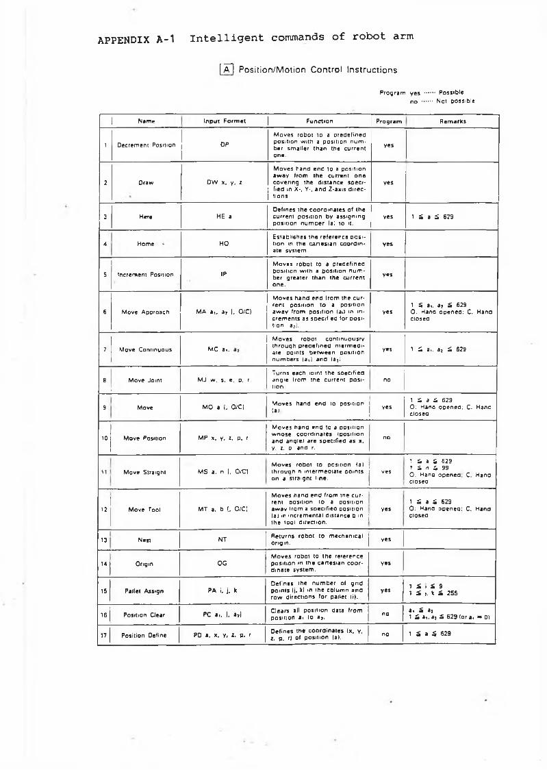
APPENDIX A-1 I n t e l l i g e n t commands o f r o b o t arm
[Â] Position/Motion Control Instructions
Prog ram yes ....... Possib leno ....... Not possible
J Name InpuT F o r m n | Function | Prog ram Rem arks
1 Decrement Position DP
M oves robo t to a prede f ined posit ion with a posit ion n u m ber smalle r th an the curren t one.
yes
2 Draw DW x, y, i
M oves h a n d e n d to a pos i t ion a w ay from th e current o n e cover ing the d is tance soeci- fied in X-, V-, a n d Z-axis d i re c tions.
yes
3 Here HE aDefines th e c o o rd in a te s of the curren t posit ion by ass ign ing posit ion n u m o e r (a) to it.
yes 1 S a £ 629
4HHome HO
Establ ishes th e re fe rence p o s i tion in the c a n e s i a n c o o rd in a te system.
yes
5 Increment Position IP
M oves robo t to a predefined posit ion with a posit ion n u m ber grea te r t h a n the curren t one .
yes
6 Move Approach MA a , , a , 1. 0/C)
M oves h a n d e n d from the c u r rent position to a posit ion aw ay from pos i t ion (a.) in in c rem en ts as specif ied for p o s i t ion ia7).
yes1 S a,, a , £ 6290 : Hand o p e n e d : C. Handclosed
7 Move Continuous MC a,.
M oves robot con t inuous ly th rough p re o e fm ed m ierm eoi- ate points b e tw e e n position n u m o e rs ( a j an d (a2).
yes 1 £ a,, a , S. 629
8 Move JomiL
MJ w. s, e. p. rTurns each |omt the soecif ieo angie from the current p o s i tion
no
9Move MO a 1. O/C!
M oves hand end to posit ion(a) yes
1 S a 5 6290 : Hana o p e n ed : C. Handclosed
10 Move Position MP x. y, I. p. r
M oves h a n d en d to a posit ion w n o s e co o rd in a te s (pos ition and angle) are specif ied a s x. y, i. D and r.
no
11 Move Straight MS a. n [, O/CIM oves robot to position fa) t h ro u a n n in te rm edia te po in ts on a s traight line.
ves
1 £ a Ï 629 1 S n S 990 . Hana o p e n e d C. Hand cioseo
12 Move Tool MT a. b (. O/CI
M oves ha nd e n d from m e c u r rent position to a posit ion aw ay from a soecif ieo posit ion (a) m increm ental d is tance b in j th e tool direction.
yes1 £ a S 6290 : Hand open ed : C. Handclosea
13 Nen NT Returns robot to mechan ica lorigin. yes
14 Origin OGM oves robot to the re ference posit ion m the c a n e s ia n c o o r d ina te sys tem .
yes
15 Pallet Assign PA i, j, kDefines the n u m b e r of grid po in ts (j. k) m the co lum n an d row directions for pallet (i).
yes 1 S i i 9 1 £ 1. k £ 2SS
16 Position Clear PC a.. 1. a,)Clears all posit ion data from posit ion a* to aj. no a , £ a]
1 £ *i. a; £ 629 (or a< » 01
17 Position Deline PD a. x. y, z. p. rDefines the coo rd in a te s (x. y. z. p. rj of posit ion (a). no 1 £ a £ 629
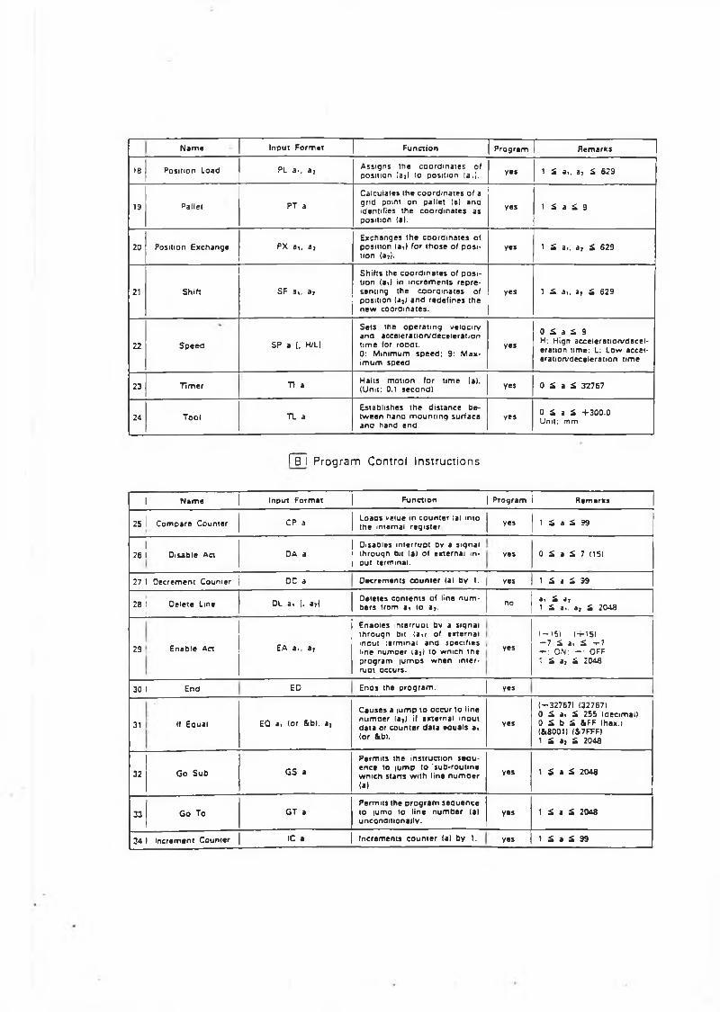
N a m e Inpu t F o rm at Func t ion P rog ram R em arks
18 Posi tion Load PL a*, a j A ssigns the c o o rd in a te s of position (a?) to posit ion la,). yes 1 £ a,. 3, £ 629
13 Pallet PT aCalculates the c o o rd in a te s of a grid point on palle t lal and identifies the c o o rd in a te s as position (al.
yes 1 £ a £ 9
20 Position Exchange PX 3i, 37Exchanges th e coo rd in a te s of posit ion laW for t h o s e of p os i tion (a*|.
yes 1 £ a,. 3, £ 629
21 Shift SF a i , 3j
Shif ts the c o o rd in a te s of p o s i tion It il in in c re m e n ts r e p re sent ing the co o rd in a te s of posit ion |32| 3 n d rede f ines the n e w coordina tes .
yes 1 £ 3,. a , £ 629
22 S p e e d SP a 1. H/L|
Se ts the o p e r s t i n g velocity and acce lera t ion /dece lera t ion t im e for roDot.0: Minimum s p e e d ; 9: M ax im u m speed
yes
0 £ a £ 9H. Hign acce lera t ion /dece leration time; L: Low accelera tion/decele ration time
23 Tim er Tl a Halts m otion for time lal. (Unit: 0.1 s econd) yes 0 £ 3 £ 32767
24 Tool TL aEstablishes th e d is tance b e tw e en nano m o u n t in g surface and hand end.
yes 0 £ a £ + 3 0 0 .0 Unit: mm
[~~B~Ì Program Control Instructions
I N a m e | Input F o r m a t | F unc t ion | P rog ram i R e m a r t s
25 1 C om pare Counte r CP 3Loads veiue in c o u n te r lal into the internal reg is te r yes 1 £ a £ 99
126 1 Disable Act DA 3
Oisabies in te rrup t By a s iqnal th rouqn bit lal of external input terminal.
yes 0 £ a £ 7 (15)
27 1 D ecrem ent Coum er DC a D ecrem ents c o u n te r (al by 1. yes 1 £ 4 £ 99
2B 1 Delete Line DL 3. 1. a,IDeletes c o n ten ts of line n u m bers from a< to a 7. no a, £ a,
1 £ a., a , £ 2043
29 E nable Act EA a, 3;
Enaoies in te rrupt by a siqnal tn rougn bit (aw of exte rnal input :e rminal an d specif ies line num oer ia>) to wnich tne p rog ram lu m p s w nen in te r rupt occurs.
yes
1 -1 5 ) ( - r i 5) - 7 £ a. £ -r-7 + : ON: - • OFF 1 £ a, £ :o 4 a
30 1 End ED Enos the p ro g r a m . | yes
31 If Eaual EQ a, lor &bl. aj
C ause s a iu m p to occur to line n u m o e r lat ) if ex te rnal input da ta or c oun te r da ta equal s a< (or &bl.
yes
( -3 2 7 6 7 I (327671 0 £ 3 i £ 255 Id e a m e l i0 £ b £ &FF (hex.) (&8001I (47FFFI1 £ a, £ 2048
32 Go S ub GS a
Permi ts the ins truction seou- ence to lu m p to 'sub-rou t ine w nich starts with line n u m b e r(al
Y®* 1 £ a £ 2048
33 Go To GT aPermits the p r o g r a m s eq u e n c e to |um o to line n u m b e r (al uncondit ionally .
yes 1 £ a £ 2048
34 1 Increment Counte r 1C a Increments c o u n te r lal by 1. yes 1 £ a £ 99
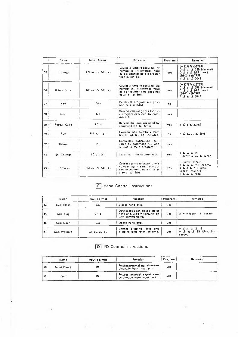
Name Input F o rm at | Function I P ro g ram Rem arks
35 If Larger
f
LG ai (or &bl. a?
Causes a /um p to occur to line num oer (a7) if ex te rnal input data or coun te r da ta is g r e a t e r than (or &b).
yes
(-327671 (32767)0 £ a, £ 255 Idecimal)0 £ b £ &FF (hex.) (&8001) (Î.7FFF)1 £ a, £ 2048
i36 If Noi Ecuai NE a, (or &b), a?
Causes a iump to occur to line num&er (a?) if ex te rnal m o u t data or coun ter da ta d o e s no t equal a, (or &b).
yes
( -3 2 7 6 7 ) 1327671 0 £ a, £ 255 Idecimal)0 S b S 4 F F (hex. 1 I&B001I (&7FFF)1 £ a , £ 2048
37 i New NW Deletes all p ro g ram and p o s i tion data in RAM. no
i38 ' Next NX
Specifies the range of a loop in a program ex ecu ted by c o m mand RC.
yes
39 * Repeat Cvciei
RC a Repeats the loop specif ied by com m and NX (a) times. yes 1 £ a £ 32767
40 , Run RN a* 1. a,i Executes line n u m b e rs f rom ( a J to fa3). (a}) no t included. no 1 £ a,, a , £ 2048
52 ! Return1 Comple tes s u b rou t ine acu-
RT I vaiea bv c o m m a n d GS a n a j re turns to m am p rog ram
yes
42 ; Sei Counter j SC |a?i Loaos (a?) into c oun te r (a,). yes 1 i a, ^ 99 - 3 2 7 6 7 £ a , £ 32767
!43 Î If Smaller
:
SM ai lor &bi. a 7
•Causes a iump to occur to line [ numoer la?) if ex te rnal inout i vesdata or counter oata is s m al le r 1 than i , lor &0)
(-3 2 7 6 7 ) 132767)0 £ a, £ 255 (decimali0 £ 0 £ &Fr |hex ) (&8001I (&7FFFÌ1 £ a, £ 2048
I C ! Hand Control Instructions
1 N am e Input Form at Function P ro g ra m Rem arks
44 1 Gno Close GC Closes hand grip yes
145 Ì Grip Flag
1GF a
Oefmes the o p e n /c lo se s ta t e of hano grio. u seo m c o n iu n a io n witn c o m m an d PD
yes a « 0 looeni. 1 Icloseol
46 i Gno Ooen GO Ooens nand grip ves
I47 I Grip Pressure
iGP a i . aj, a^
Defines gripping force a n d gripping force re tent ion time. yes
0 £ a,. a : £ 150 £ a , £ 99 (Unit: 0.1s e c o n d
I D I I/O Control Instructions
| Nam e Input F o rm at Function P ro g ra m Rem arks
48 | Inout Dire«!
10Fetches external signal u n c o n ditionally from input port. yes
149 | Input IN Fetches external signal s y n
chronously from input port. yes
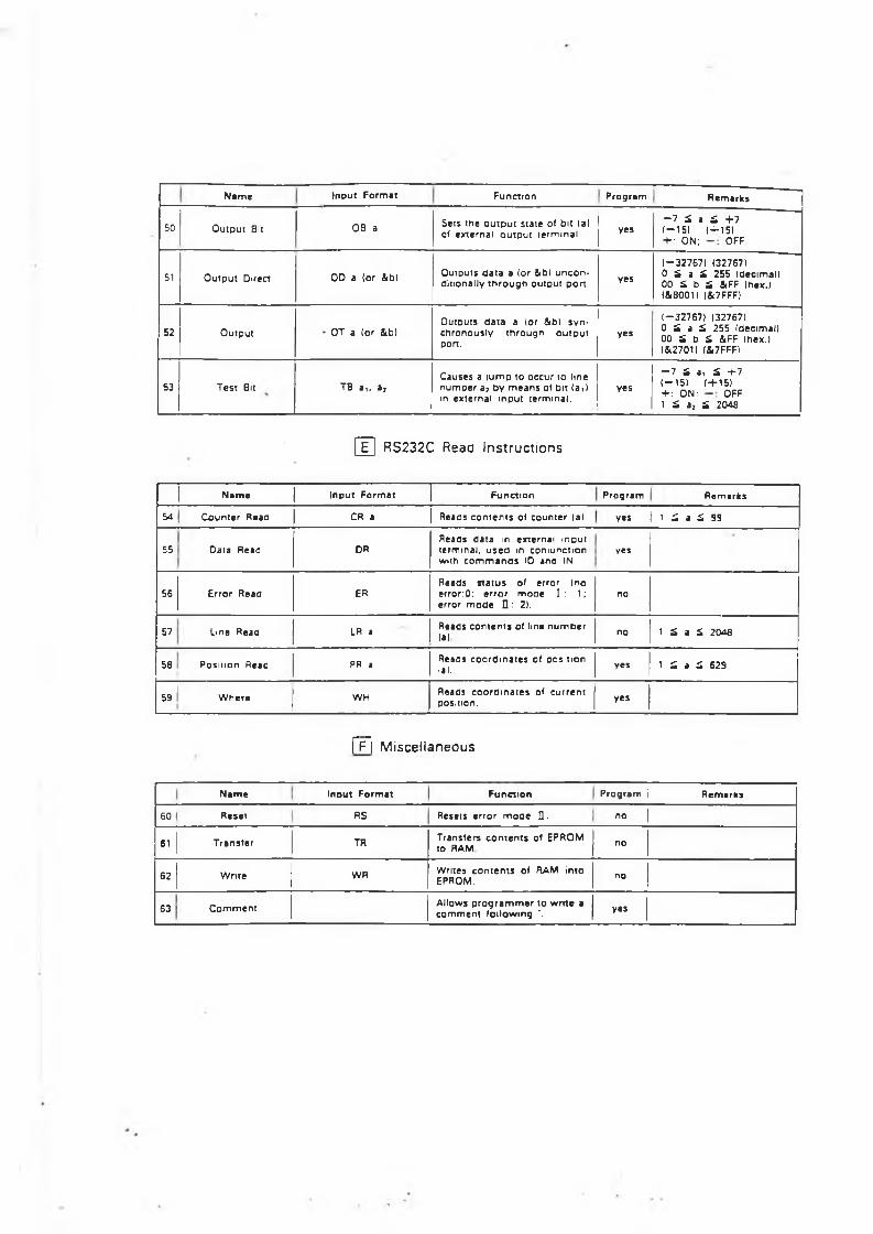
N am e Input Form at Function Program Rem arks
50 O utpu t Bit OB a Sets the o u tp u t s ta te of bit (al of external o u tp u t term inal yes
- 7 £ a £ + 7( - 1 5 1 (+ 1 5 )+ : ON; OFF
51 O utpu t Direct OD a (or &b) Outputs d a ta a (or &b) u n c o n ditionally t h r o u g h ou tpu t port . yes
(“ 32757) (32767)0 £ a £ 255 (decimali 00 £ b £ &FF (hex.) (IBOOK (&7FFF)
52 Output * OT a (or &b)Outputs d a ta a lor ¡ibl s y n chronous ly th rougn o u tp u t pon.
yes
( — 32767) (32767)0 £ a £ 255 Idecimall 00 £ b £ &FF (hex.) (Si2701l (&7FFFI
53 Test Bit TB 3i, 87Causes a | u m o to occur to line n um oer a? by m e a n s of bit (ail in external input te rminal.
y«s
- 7 £ a, £ + 7 (— 151 (+ 1 5 )+ ; ON; OFF 1 £ a, £ 2048
E RS232C Read Instructions
N am e Input Form at Func t ion Program Rem arks
54 C oun te r Read CR a Reads c o n te n t s of c oun te r (a) yes I 1 £ a à 99
55 Data Read DRReads da ta in external m ou t terminal, u s e d m coniunction wuh c o m m a n d s ID and IN
yes
56 Error Read ERReads s ta t u s of error (no e rrorO: e r ro r m o o e 1 : 1; error m o d e □ : 2).
no
57 Line Read LR a Reads c o n te n t s of line n u m o e r(a) no 1 £ a
INVI
58 Posit ion Read PR a Reads co o rd in a te s of oosit ion (al. yes 1 £ a £ 629
59 W here WH Reads co o rd in a te s of c u rren t position. yes
|~F~| Miscellaneous
N am e Inout Format Func t ion Prog ram i Rem arks
60 Reset RS Resets e rror m o d e Q. no 1
61 Transfe r TH Transfers c o n te n t s of EPROM to RAM no
62 Write WR Writes c o n te n t s of RAM into EPROM. no
63 C o m m e n t Allows p r o g r a m m e r to wri te a co m m en t fo llowing '. yes
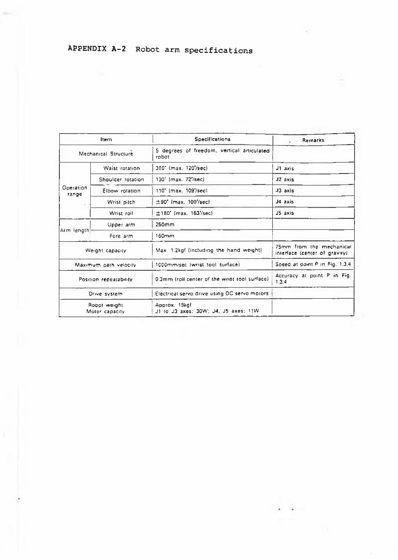
APPENDIX A - 2 Robot arm specifications
Item Sp ec ifica t io n s R em arks
M echanical Structure5 degrees of freedom , ve rtica l articu lated robot
O perationrange
W aist rotation 300" (m ax . 120'/sec) J1 axis
Shou lder rotation 130' (m ax . 727sec) J2 ax is
E lbow rotation 110‘ (m ax . 1097sec) J3 ax is
W rist pitch ± 9 0 ‘ (m ax . lOOVsec) J4 ax is
W rist roll ± 1 8 0 ' (m ax. 1637sec) J5 ax is
A rm lengthUpper arm 250m m
Fore arm 160mm
W eight capacity M ax. l.2 kg f (includ ing the hand w eight)75mm from the m ech an ica l interface Icenter of g rav ity )
M axim um path velocity | 1000m m /sec (w rist tool su rface ! Speed at point P in Fig . 1.3.4
Position repeatab ility 0 .3m m (roll center of the w ris t tool su rface)A ccu racy at point P in Fig1.3.4
Drive system Electrica l servo d rive using DC se rvo m otors
Robot w eight j A p prox. 19kgfMotor capacity 1 J1 to J3 a xe s : 30W ; J4 , J5 a x e s : 11W
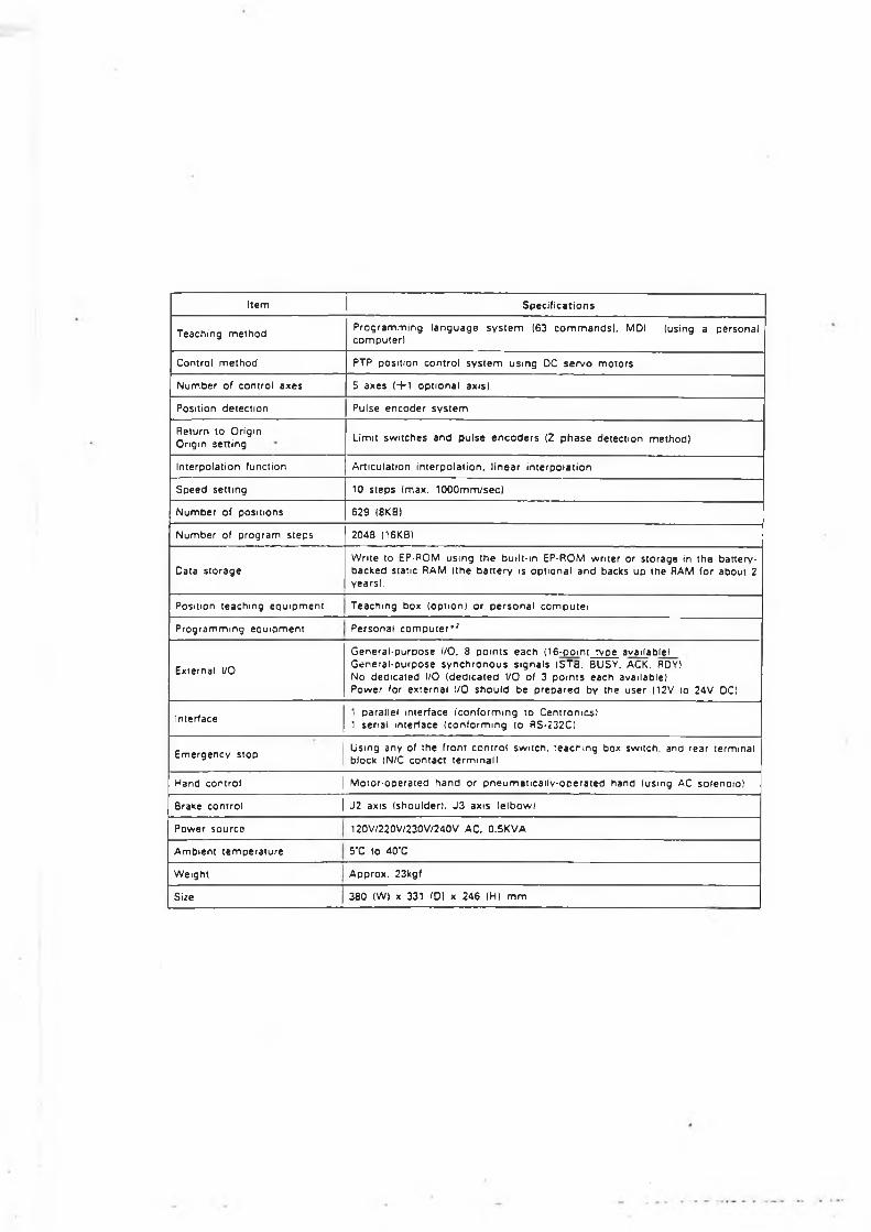
I tem | S p e c i f i c a t io n s
T e ach in g m e th o d P r o g r a m m in g l a n g u a g e s y s t e m (63 c o m m a n d s ) , MDI (using a p e rs o n a l c o m p u te r l
Control m e t h o d PTP pos i t ion c o n t ro l s y s t e m u s in g DC s e r v o m o to r s
N u m b e r of contro l a x es 5 a x e s ( + 1 o p t io n a l axis)
Posit ion d e te c t io n Pulse e n c o d e r s y s t e m
Return to Origin Origin s e t t in g Limit s w i tch e s a n d p u l s e e n c o d e r s (Z p h a s e d e tec t io n m e th o d )
In te rpo la t ion func t ion Art icula t ion in te rp o la t io n , l i n e a r in te rp o la t io n
S p e e d se t t ing 10 s t e p s Imax. lOOOmm/sec)
N u m b e r of pos i t ions 629 (8KB)
N u m b e r of p ro g r a m s te p s 2048 (16KB)
Data s to r a g eW rite to EP-ROM u s in g th e buil t- in EP-ROM w ri te r or s to ra g e in t h e ba tte ry- b a c k e d s ta t ic RAM ( the b a t t e r y is o p t io n a l a n d backs u p th e RAM for ab o u t 2 years) .
Posit ion te a ch in g e q u ip m e n t T e a c h in g box (op t ion ) o r p e r s o n a l c o m p u te i
P r o g r a m m in g e a u i p m e n t P e r s o n a l co m p u te r* ^
External I/O
G e n e r a l - p u r p o s e I/O. 8 p o i n t s e a c h (1 6-po in t rvpe avai lab le l G e n e r a l - p u r p o s e s y n c h r o n o u s s ig n a l s ISTB. BUSY, ACK. RDYI No d e d ic a te d I/O ( d e d ic a t e d I/O of 3 p o i n t s e ac h avai lable )P o w e r for e x te rn a l I/O s h o u l d b e p r e p a r e d by the u s e r (12V to 24V DC!
Interface1 para l le l in te r face ( c o n f o r m in g to C en t ro n ic s ) 1 ser ia l in te r face ( c o n f o r m in g to RS-232C)
E m e r g e n c y s topU sing any of the f ront c o n t ro l sw i tch , t e a c h in g box switch , and rea r te rm ina l block IN/C c o n ta c t te rm ina l )
Hand c on t ro l | M o to r -o p e ra te d h a n d or p n e u m a t i c a i l v - o p e r a t e d h a n d (us ing AC so len o io )
Brake c on tro l | J 2 axis ( shou lde r) , J 3 axis (e lb o w l
P o w e r s o u r c e 120V/220V/230V/240V AC, 0.5KVA
A m b ie n t t e m p e r a tu r e 5'C to 4 0 T
W eigh t A pprox . 23kgf
Size 380 (W) x 331 (D) x 246 (HI m m
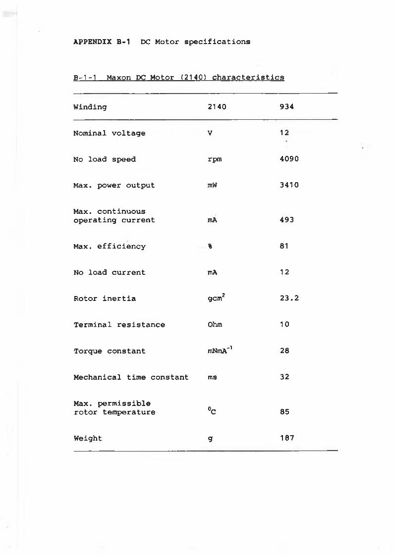
APPENDIX B-1 DC Motor specifications
B - 1-1 Maxon DC M o to r ( 2140) c h a r a c t e r i s t i c s
W in d in g 2140 934
N o m inal v o l t a g e V 12
No lo a d speed rpm 4090
Max. power o u t p u t mW 3410
Max. c o n t in u o u s o p e r a t i n g c u r r e n t mA 493
Max. e f f i c i e n c y % 81
No lo a d c u r r e n t mA 12
R o to r i n e r t i a gem2 2 3 . 2
T e r m in a l r e s i s t a n c e Ohm 10
T o rq u e c o n s t a n t mNmA“1 28
M e c h a n ic a l t im e c o n s t a n t ms 32
Max. p e r m i s s i b l e r o t o r te m p e ra tu re °C 85
W eight g 187
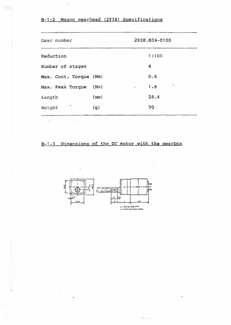
B-1-2 Maxon aearhead (2938) Specifications
Gear number 2 9 3 8 . 8 0 4 - 0 1 0 0
R e d u c t io n 1 :1 00
Number o f s t a g e s 4Max. C o n t . T o r q u e (Nm) 0 .6
M ax. Peak T o r q u e (Nm) 1 .8
Length (mm) 2 8 . 4
Weight (g) 70
B—1—3 D im e n s io n s o f the DC m o to r w i t h th e g e a rb o x
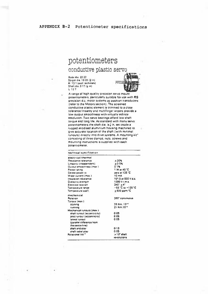
APPENDIX B-2 Potentiometer specifications
p o t e n t i o m e t e r s
conductive plastic servoBody dis 22 22 S p igo t dia 19 05 (1 in)H 13 1 (excl terminals)Shaf t dia 3 17 (J m)L 12 7
A range of high qu a lity precision se rvo m ount potentiom eters, particu larly su itab le for use w ith R S precision d .c . m otor system s as position transducers (re fer to the M otors se c t io n ). Th e screened co n d u ctive p lastic elem ent is trim m ed to a c lose to le rance linearity and m ultifinger w ip e rs provide a lo w output sm oothness w ith v irtu a lly in fin ite reso lu tion . T w o servo bearings afford lo w shaft torque and long life . A s standard w ith m any servo potentiom eters the shaft dia. is J in, se t ins id e a rugged anod ised a lum in ium housing m ach ined to g ive accurate location of the shaft (w ith m inim al runouts) d irectly into drive system s. A m ounting k it ' co nsis ting of three c lam p s, nuts, s c re w s and m ounting in structio ns is supp lied w ith each potentiom eter.
t a c h m c a l s p e c i f i c a t i o n
e le c t r i c a l/ t h e r m a lResistance tolerance ± 2 0 %Linearity (independent) ± 0 5%O utput smoothness (man ) 0 1%Power rating 1 W at 4 0 *CDerate power to zero at 125 ‘CWiper current (max ) 10 m AInsulation resistance 10* f l a t 500 V d .c .Dielectric strength 1000 V r m *.Electrical rotation 3 4 0 ’Temoerature range - 5 5 ‘ C i o *125 ‘ CTemperature coeff. + 600 pp m / 'C
m e c h a n ic a lRotation 360* continuousTo ra ue (max.)
starting 2B N m . 1 0 -running 21 N m . 1 0 -
Mechanical runouts (max.)shall runout (eccentricity) 0 05pilot runout (eccentricity) 0 05lateral runout 0 05(parallel difference fromthe centre line)shalt end play 0 13shall radial play 0 05
Rotational life” > 1 0 ’ shaftrevolutions
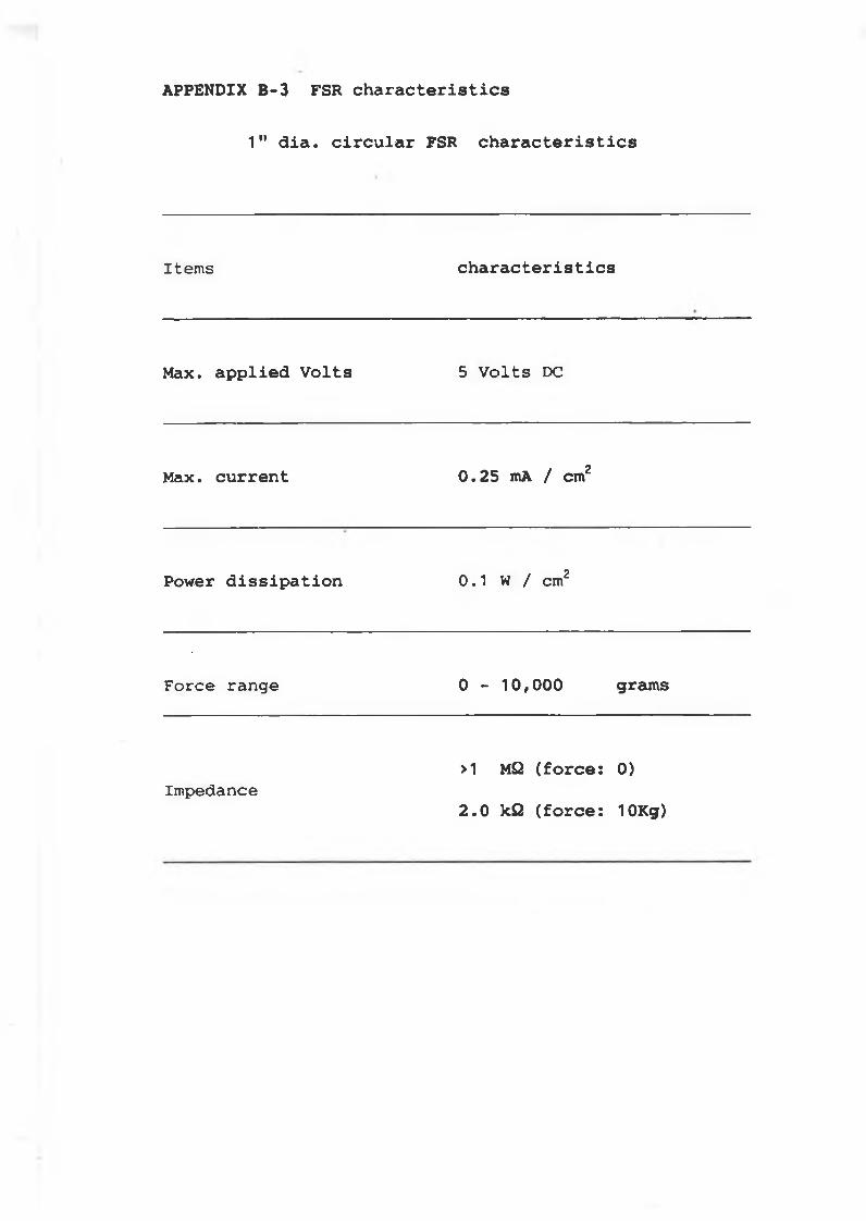
1" d i a . c i r c u l a r FSR c h a r a c t e r i s t i c s
APPENDIX B -3 FSR c h a r a c t e r i s t i c s
Items c h a r a c t e r i s t i c s
Max. a p p l i e d V o l t s 5 Volts DC
Max. c u r r e n t 0 .2 5 mA / cm2
Power d i s s i p a t i o n 0 .1 W / cm2
Force range 0 - 1 0 /0 0 0 grams
Impedance>1 MQ ( f o r c e : 0)
2 . 0 kQ ( f o r c e : 10Kg)
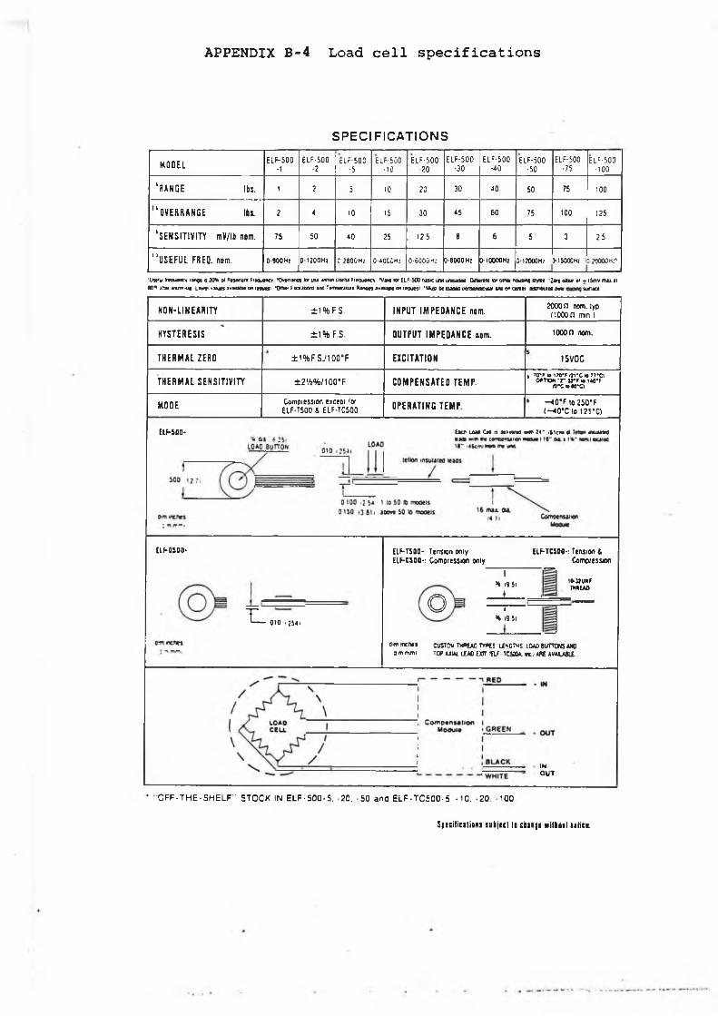
APPENDIX B-4 Load cell specifications
SPECIFICATIONS
M O D E L ELF-500-1
ELF-500-2
cLr-500■5
ELr-500•10
ELF-50020
ELF-500•30
ELF-500•40
ELF-500•50
ELF-500■75
ELF-500-100
' R A N G E lbs. 1 2 5 10 20 30 40 50 75 100
" O V E R R A N G E I h i 2 4 10 15 30 45 60 75 100 125
' S E N S I T I V I T Y mV/lb non. 75 50 40 25 125 8 6 5 3 25
' ’ U S E F U L FREQ. nom. 0-900Hr 0-1200Hz r 2800HÍ OJOCCm; 0-6Û0ÛM: 0-8000 H! CHOOOOHl S 12000H; HSOOOm 3 »000«.-
'UltM taM n cy rang« n 20S ot Rnowm ff*ou*ncy •Ovrrmgt W leu «httm u u u Freoutncv *Vm W ELF 500 ö i « uw m uocd W * * « D* Mn« nousnQ nyttt '2 *0 ortul »i ♦ l5ffiV m u <( K H i n » « v m -u c l d w y i u t i v M M o n r n u a i *0nw tm a n o m a n d Ttfnocniuri R jn o n a v ju M o n r ro u M i 'M usj m kmoco m t m a s c i M t w o on c m n « t n e w t o o w u*i*ce
N O N - L I N E A R I T Y ± 1 % F S. I N P U T I M P E D A N C E nom. 2000 n nom. lyp (1000 n min )
H Y S T E R E S I S ±1% F S- O U T P U T I M P E D A N C E nom. 10000 nom.
T H E R M A L ZERO ± 1 % F S J 1 0 0 ° F E X C I T A T I O N 15VDC
T H E R M A L S E N S I T I V I T Y ± 2 ’A % /1 0 0 “ F C O M P E N S A T E D T E M P .I 70‘ F io 170-f I J I 'C IB TT'Cl
O ^ T IO W T V F « !40‘ F io’cb u*a
MODE Compression eictoi lor ELF-T500 4 ELF-TC500 O P E R A T I N G T E M P . —40"F lo 250*F
(— «0*C lo 121*C)
ElF-500- Eicfl IAM CH n aii'.me w« i r nient ¥ « iu w
ELF-0100-
T L 010 I 2S4i
EIF-T500- Tension only EIF-C500-. Compression only
Ot
H i9 S i
__
ELF-TCS00-: Tension iCompression
lO-JJUM THU E M
I<t 19 il
öim m e n ti
3im mm icusTcw tw »uû r m s lísg tm s load buttons m oTOP U U l LEAD ixn r R f TCMOA. r t ) A « A V A U & i
INO U T
O F F - T H E - S H E L F " STOCK IN E L F-5 0 0 -5 . -20. -5 0 and E L F -T C 500-5 , -10. «20 -100
Specifications sabject to cbaige w i t l n t biHce.
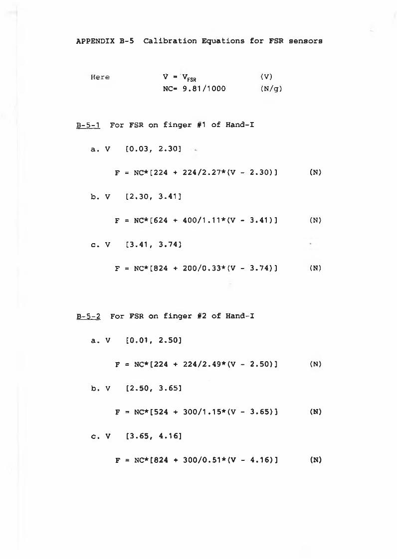
APPENDIX B-5 Calibration Equations for FSR sensors
Here V = VFSR (V)NC= 9 .8 1 /1 0 0 0 (N /g)
B -5-1 For FSR on f i n g e r #1 o f Hand-I
a . V [ 0 .0 3 , 2 .3 0 ]
F = NC* [224 + 2 2 4 / 2 . 27*(V - 2 . 3 0 ) ] (N)
b . V [ 2 . 3 0 , 3 . 4 1 ]
F = NC*[624 + 4 0 0 / 1 . 1 1 * (V - 3 . 4 1 ) ] (N)
c . V [ 3 . 4 1 , 3 . 7 4 ]
F = NC*[824 + 2 0 0 / 0 . 33*(V - 3 . 7 4 ) ] (N)
B - 5 - 2 For FSR on f i n g e r §2 o f Hand-I
a . V [ 0 . 0 1 , 2 . 5 0 ]
F = NC*[224 + 2 2 4 / 2 . 49*(V - 2 . 5 0 ) ] (N)
b . V [ 2 . 5 0 , 3 . 6 5 ]
F = NC*[524 + 3 0 0 / 1 . 15*(V - 3 . 6 5 ) ] (N)
c . V [ 3 . 6 5 , 4 . 1 6 ]
F = NC*[824 ♦ 300/0.51*(V - 4.16)] (N)
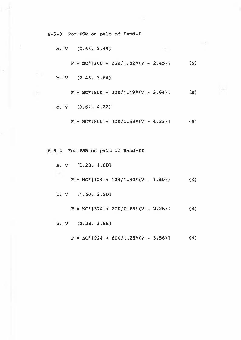
a . V [ 0 . 6 3 , 2 . 4 5 ]
F = NC*[200 + 2 0 0 / 1 . 8 2 * (V - 2 . 4 5 ) ] (N)
b . V [ 2 . 4 5 , 3 . 6 4 ]
F = NC*[500 + 3 0 0 / 1 . 1 9 * (V - 3 . 6 4 ) ] (N)
c . V [ 3 . 6 4 , 4 . 2 2 ]
F = NC*[800 + 3 0 0 / 0 . 58*(V - 4 . 2 2 ) ] (N)
B - 5 - 4 For FSR on palm o f H a n d -II
a . V [ 0 . 2 0 , 1 . 6 0 ]
F = NC* [124 + 1 2 4 / 1 . 40*(V - 1 . 6 0 ) ] (N)
b . V [ 1 . 6 0 , 2 . 2 8 ]
F = NC*[324 + 2 0 0 / 0 . 6 8 * (V - 2 . 2 8 ) ] (N)
c . V [ 2 . 2 8 , 3 . 5 6 ]
F = NC*[924 + 6 0 0 / 1 . 2 8*( V - 3 . 5 6 ) ] (N)
B-5-3 For FSR on palm of Hand-I
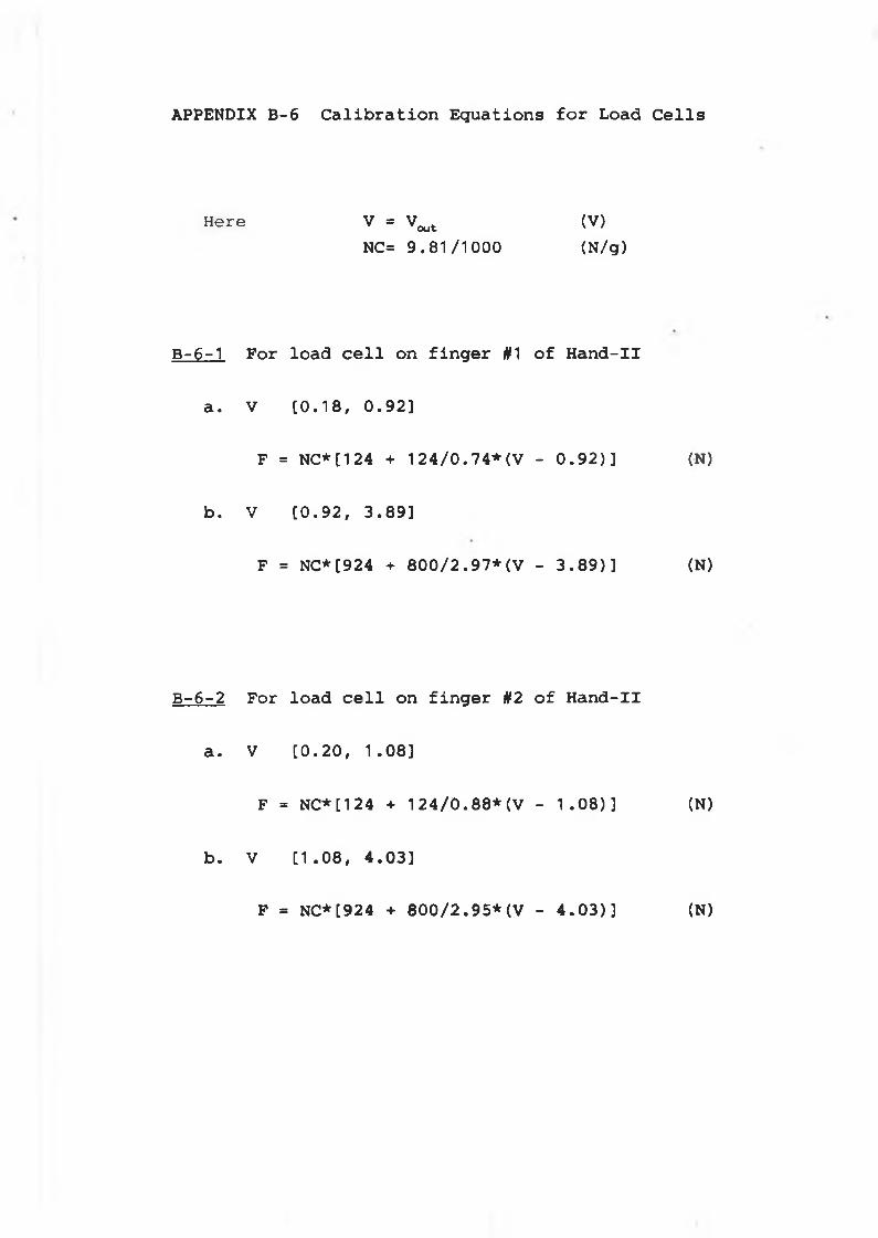
APPENDIX B-6 Calibration Equations for Load Cells
Here V = Vout (V)NC= 9 . 8 1/ 1000 ( N/g)
B - 6 - 1 For lo a d c e l l on f i n g e r #1 o f H a n d - I I
a . V [ 0 . 1 8 , 0 . 9 2 ]
F = N C * [124 + 1 2 4 / 0 . 7 4 * ( V - 0 . 9 2 ) ] (N)
b . V [ 0 . 9 2 , 3 . 8 9 ]
F = N C * [924 + 8 0 0 / 2 . 9 7 * ( V - 3 . 8 9 ) ] (N)
B - 6 - 2 For lo a d c e l l on f i n g e r §2 o f H a n d - I I
a . V [ 0 . 2 0 , 1 . 0 8 ]
F = N C * [124 + 1 2 4 / 0 . 8 8 * ( V - 1 . 0 8 ) ] (N)
b . V [ 1 . 0 8 , 4 . 0 3 ]
F = N C * [924 + 8 0 0 / 2 . 9 5 * ( V - 4 . 0 3 ) ] (N)

APPNEDIX C-1 M e c h a n ic a l d ra w in g s f o r H A N D -I
INDEX TO DESIGN DRAWINGS f o r H A N D -I
D ra w in g No. T i t l e
H1 -0 0 ROBOTIC H A N D -I
H1 -01 ROBOTIC FINGER
H1 - 0 1 - 0 1 FINGER BODY
H1 - 0 1 - 0 2 CONTACT PLATE
H I - 0 2 ROBOTIC HAND BODY
H I - 02 - 01 PALM BASE
H1- 0 2 - 0 2 FINGER BASE
H1- 0 2 - 0 3 ENFORCEMENT WALL A
H1- 0 2 - 0 4 ENFORCEMENT WALL B
H1- 0 2 - 0 5 HAND BASE
H1 - 0 2 - 0 6 SUPPORT WALL A
H1- 0 2 - 0 7 SUPPORT WALL B
H1- 0 2 - 0 8 FINGER SHAFT
H1- 0 2 - 0 9 BUSH
H1- 03 ROBOTIC PALM
H1- 03 - 0 1 PALM BODY
H1- 0 3 - 0 2 CONTACT PLATE
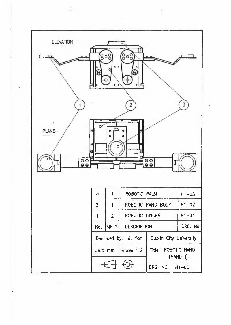
3 1 ROBOTIC PALM H1 —03
2 1 ROBOTIC HAND BODY H 1 -0 2
1 2 ROBOTIC FINGER H I-0 1
No. QNTY. DESCRIPTION DRG. No.
Designed by: J. Yan Dublin City University
Unit: mm Scale: 1:2 Title: ROBOTIC HAND
(HAND-I)
~ £ 3 " ^ DRG. NO. H 1 -0 0
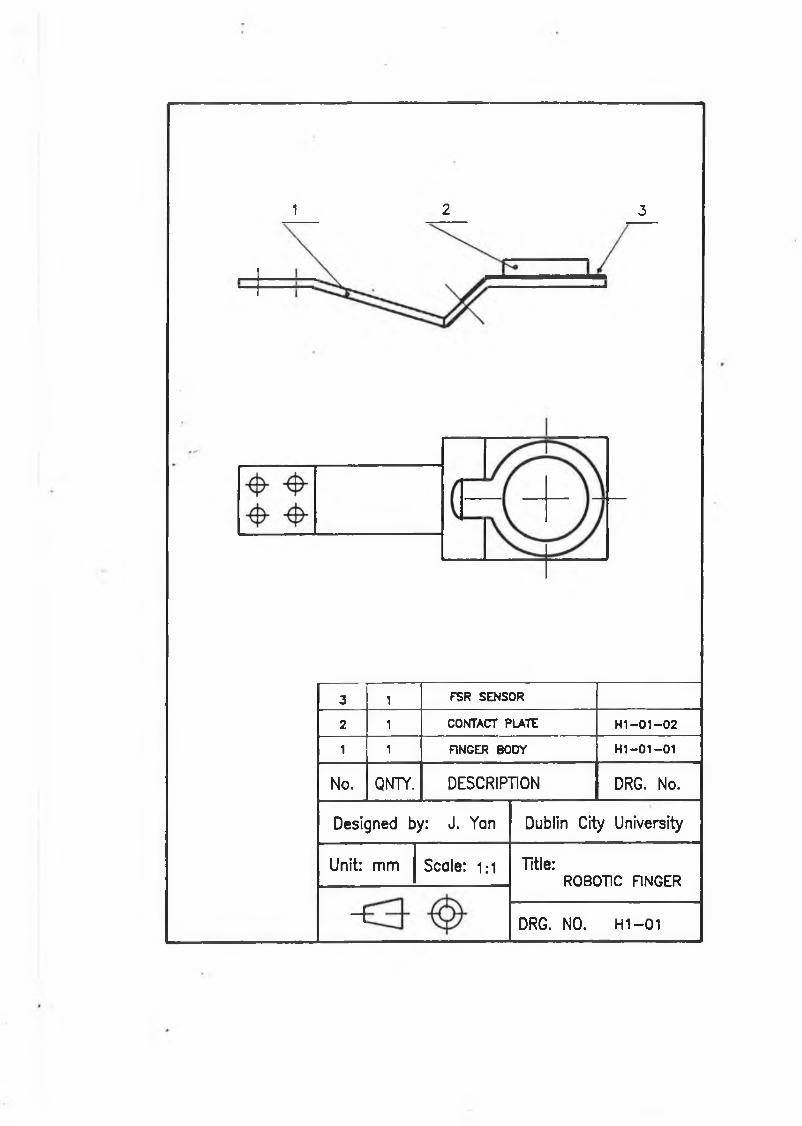
1 2 3
3 1 FSR SENSOR
2 1 CONTACT PLATE HI-01-02
1 1 FINGER BODY H1-01-01
No. QNTY. DESCRIPTION DRG. No.
Designed by: J. Yon Dublin City University
Unit: mm Scale: 1;1 Title:ROBOTIC FINGER
-i DRG. NO. H1 - 0 1
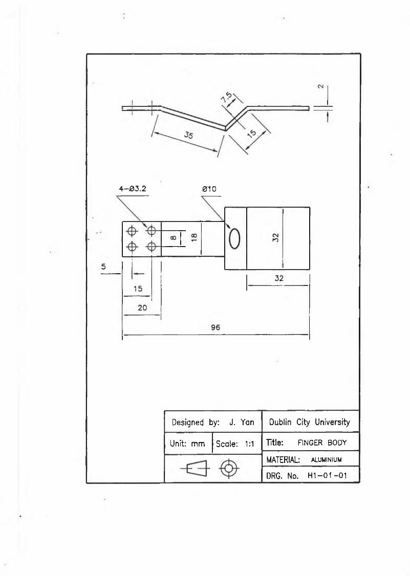
4—03.2 010
Designed by: J. Yan Dublin City University
Unit: mm Scale: 1:1 Title: FINGER BODY
MATERIAL: aluminium
DRG. No. H 1 -0 1 -0 1
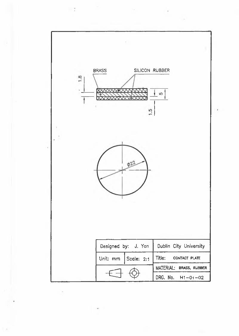
BRASS SILICON RUBBER
Designed by: J. Yan Dublin City University
Unit: mm Scale: 2:1 Title: c o n t a c t p la t e
- £ 3 - <§>■ MATERIAL: b r a s s , r u b b e r
DRG. No. H 1 - 0 1 - 0 2
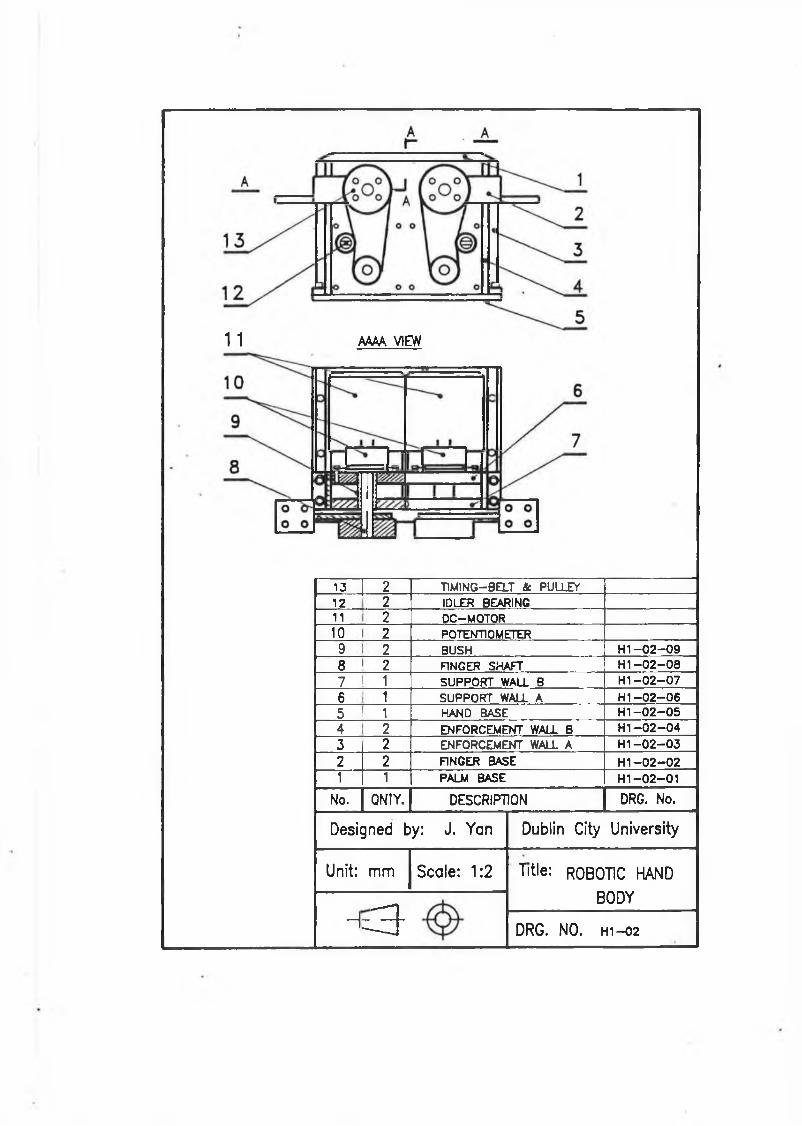
1 1 AAAA VIEW
13 2 T1MING-BELT Sc PULLEY12 2 IDLER BEARING11 2 DC-MOTOR10 2 POTENTIOMETER9 2 BUSH HI-02-098 2 FINGER SHAFT HI-02-087 1 SUPPORT WALL B H1-02-076 1 SUPPORT WALL A H1-02-065 1 HAND BASE HI-02-054 2 ENFORCEMENT WALL B HI-02-043 2 ENFORCEMENT WALL A H1-02-032 2 FINGER BASE H1-02-021 1 PALM BASE H1-02-01
No. QNTY. DESCRIPTION DRG. No.
Designed by: J. Yan Dublin City University
Unit: mm Scale: 1:2 Title: ROBOTIC HAND
BODY
H = 3 DRG. NO. h i—02
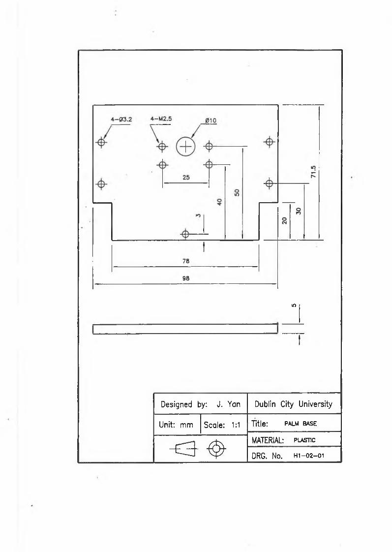
w
Designed by: J. Yan Dublin City University
Unit: mm Scale: 1:1 Title: palm BASE
<3- ^
MATERIAL: plastic
DRG. No. h i - 02-01
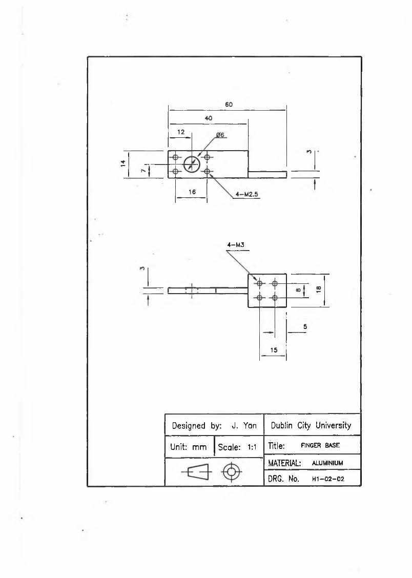
4—M3
Designed by: J. Yan Dublin City University
Unit: mm Scale: 1:1 Title: hnger base
MATERIAL: aluminium
DRG. No. h i- 02-02
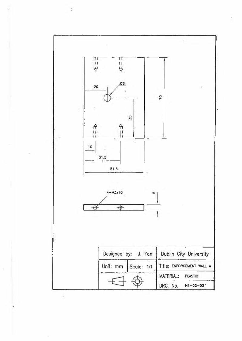
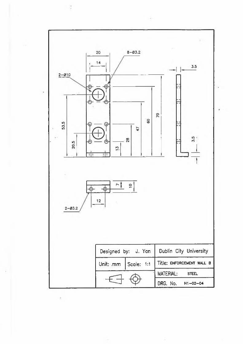
I
Designed by: J. Yan Dublin City University
Unit: .mm Scale: 1:1 t it le : ENFORCEMENT WALL B
< 3
•
MATERIAL: s t e e l
DRG. No. h i -0 2 -0 4
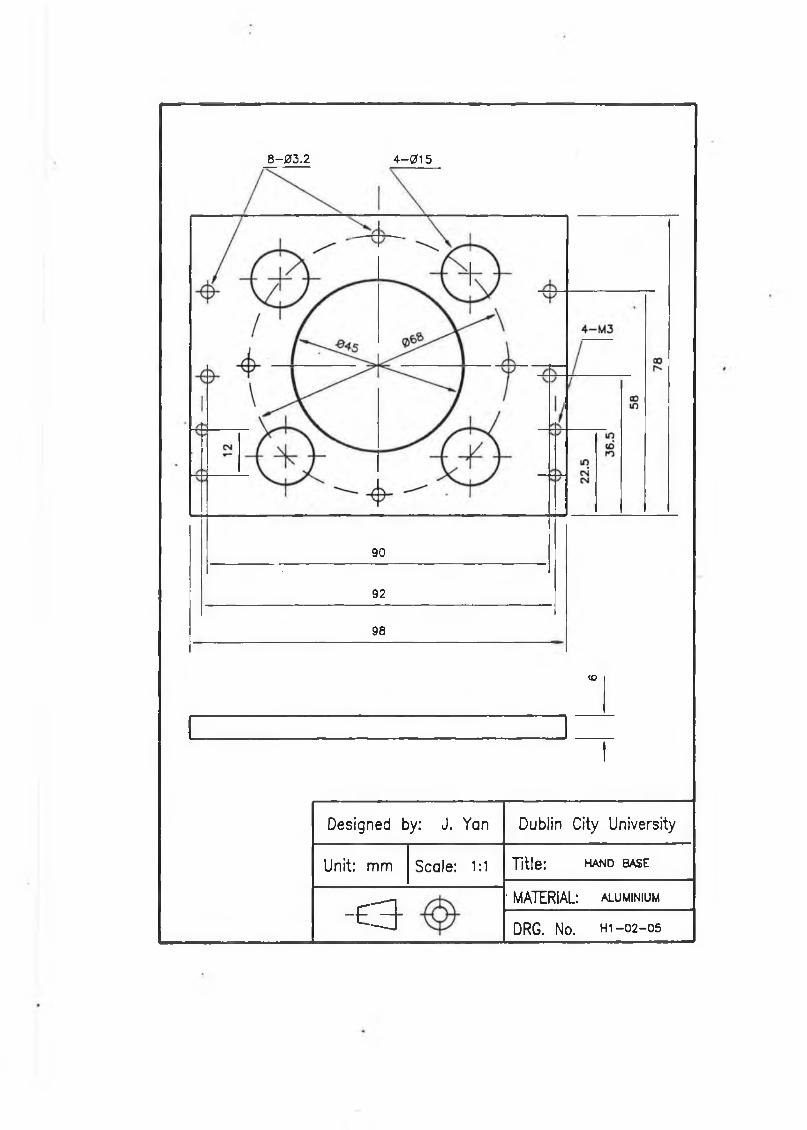
8-03.2 4 -015
90
92
98
<o
I
Designed by: J. Yan Dublin City University
Unit: mm Scale: 1:1 Title: hand base
- 6 3
' MATERIAL: aluminium
DRG. No. h i - 0 2 - 0 5
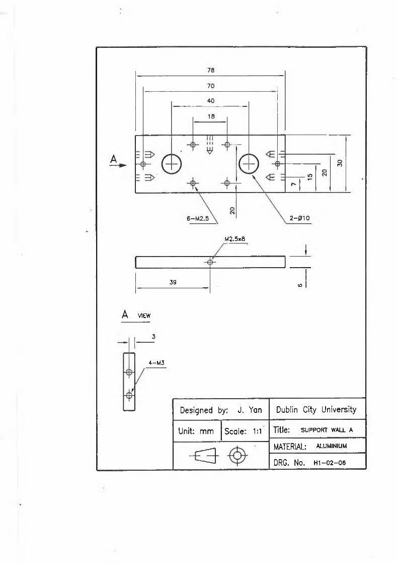
M2.5x8
-i
39 CD
VIEW
'
4—M3
Designed by: J. Yan Dublin City University
Unit: mm Scale: 1:1 Title: s u p p o r t wall a
- S 3 -
MATERIAL: aluminium
DRG. No. h i - 02-06
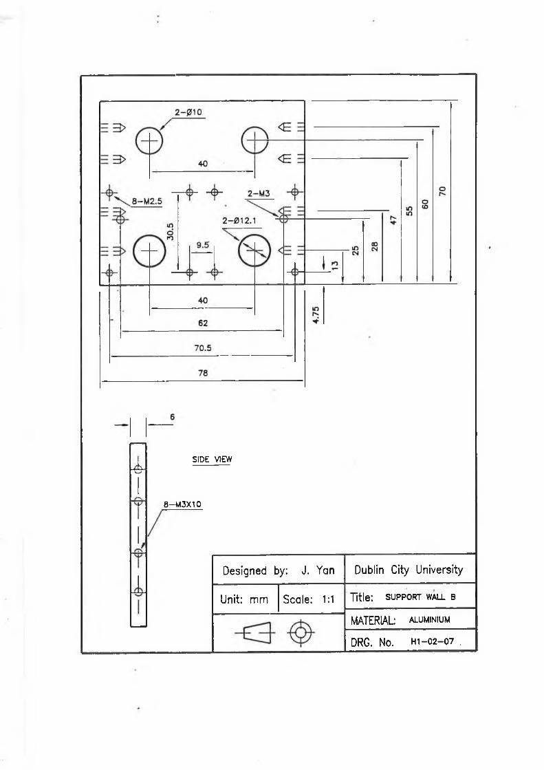
-<d:
:
SIDE VIEW
8-M3X10
Designed by: J. Yan Dublin City University
Unit: mm Scale: 1:1 Title: s u p p o r t wm_l b
MATERIAL: aluminium
DRG. No. h i - 02-07 ,
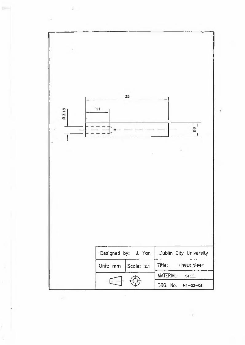
Designed by: J. Yan Dublin City University
Unit: mm Scale: 2:1 Title: FINGER SHAFT
o - ^
MATERIAL: steel
DRG. No. h i - 02-08
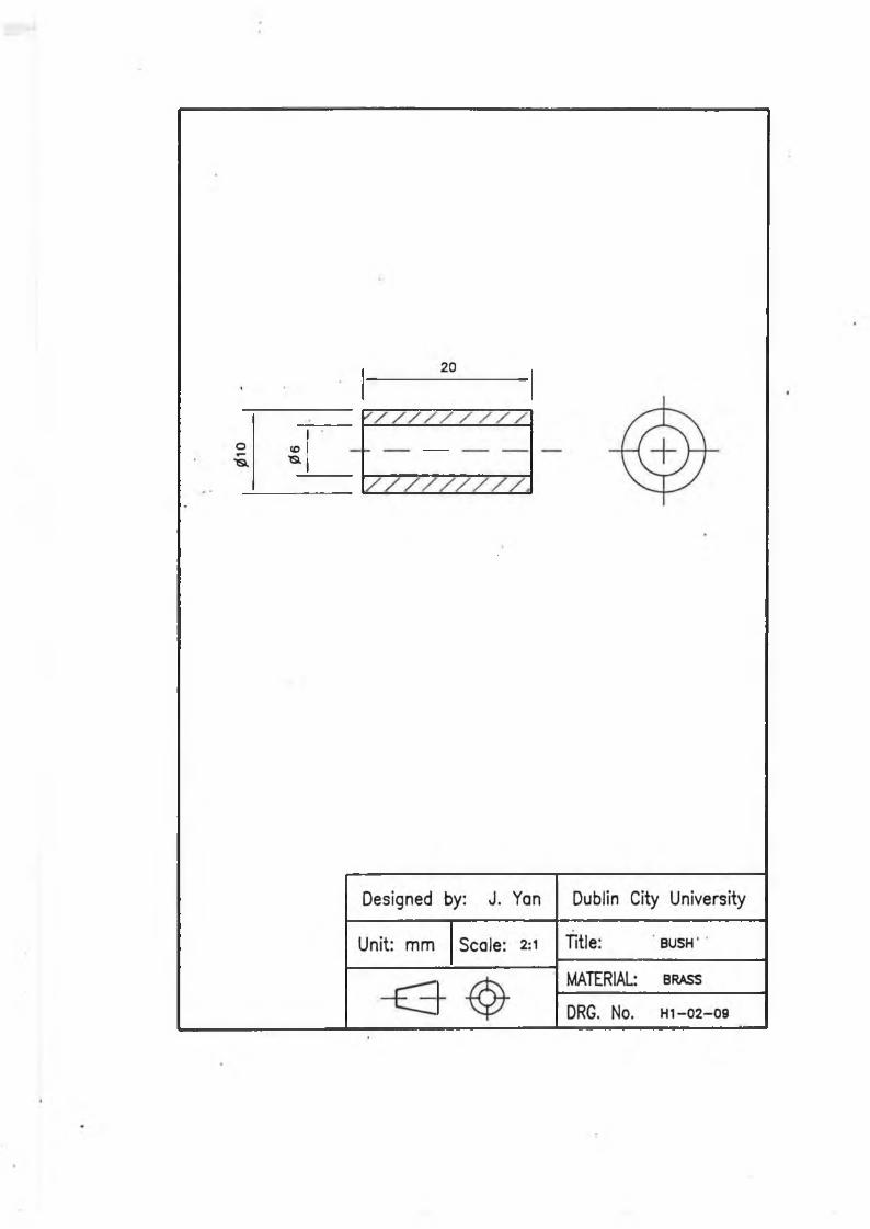
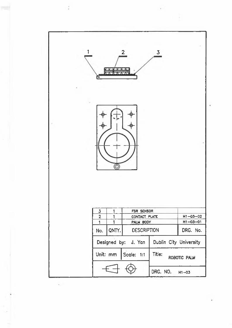
1 2 3
3 1 FSR SENSOR
2 1 CONTACT PLATE H1 -0 3 -0 2
1 1 PALM BODY H I-0 3 -0 1
No. QNTY. DESCRIPTION DRG. No.
Designed by: J. Yan Dublin City University
Unit: mm Scale: 1:1 Title*’ ROBOTIC PALM
o ^ DRG. NO. H 1 -0 3
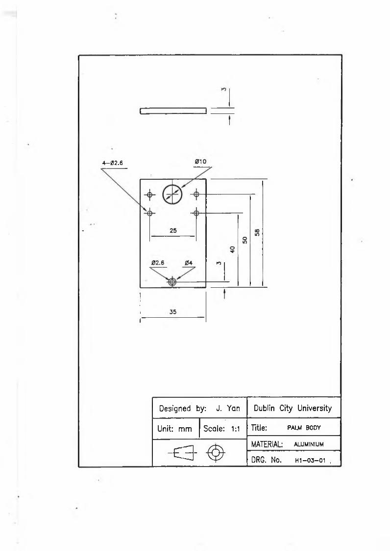
I ---------
t
4-02.6
Designed by: J. Yan Dublin City University
Unit: mm Scale: 1:1 Title: palm BODY
- e a - ^
MATERIAL: aluminium
DRG. No. H i- 0 3 - 0 1 ,
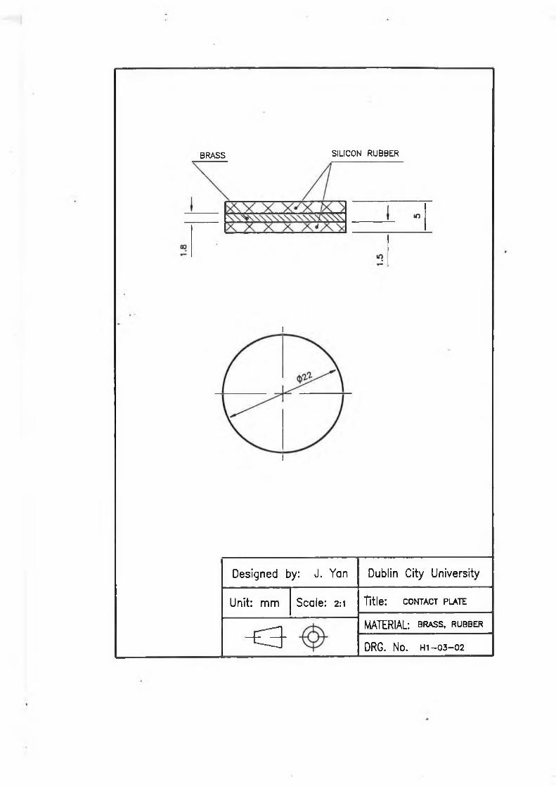
BRASS s il ic o n r u b b e r
I
Designed by: J. Yan Dublin City University
Unit: m m Scale: 2:1 Title: c o n t a c t p l a t e
< 3MATERIAL: b r a s s , r u b b e r
DRG. No. h i - 0 3 - 0 2
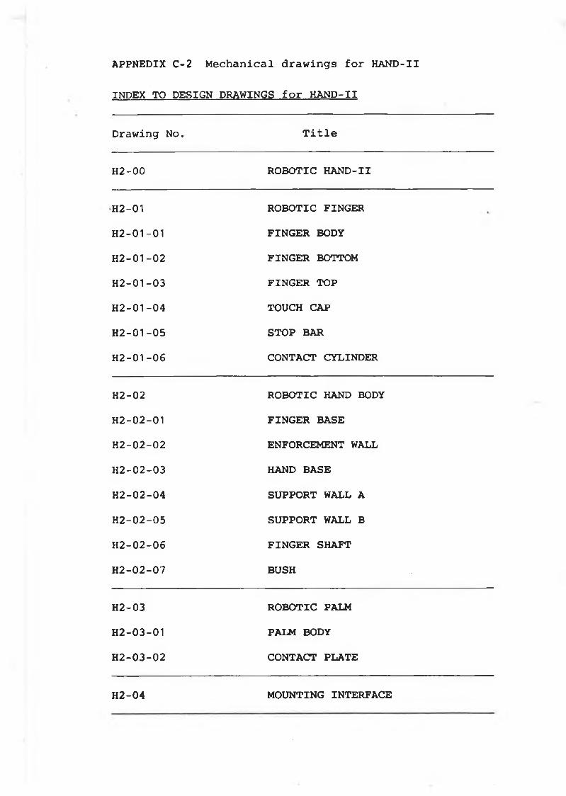
APPNEDIX C-2 Mechanical drawings for HAND-II
INDEX TO DESIGN DRAWINGS for HAND-II
Drawing No. Title
H2-00 ROBOTIC HAND-II
H2-01 ROBOTIC FINGERH2-01-01 FINGER BODYH2-01-02 FINGER BOTTOMH2-01-03 FINGER TOPH2-01-04 TOUCH CAPH2-01-05 STOP BARH2-01-06 CONTACT CYLINDER
H2-02 ROBOTIC HAND BODYH2-02-01 FINGER BASEH2-02-02 ENFORCEMENT WALLH2-02-03 HAND BASEH2-02-04 SUPPORT WALL AH2-02-05 SUPPORT WALL BH2-02-06 FINGER SHAFTH2-02-07 BUSH
H2-03 ROBOTIC PALMH2-03-01 PALM BODYH2-03-02 CONTACT PLATE
H2-04 MOUNTING INTERFACE
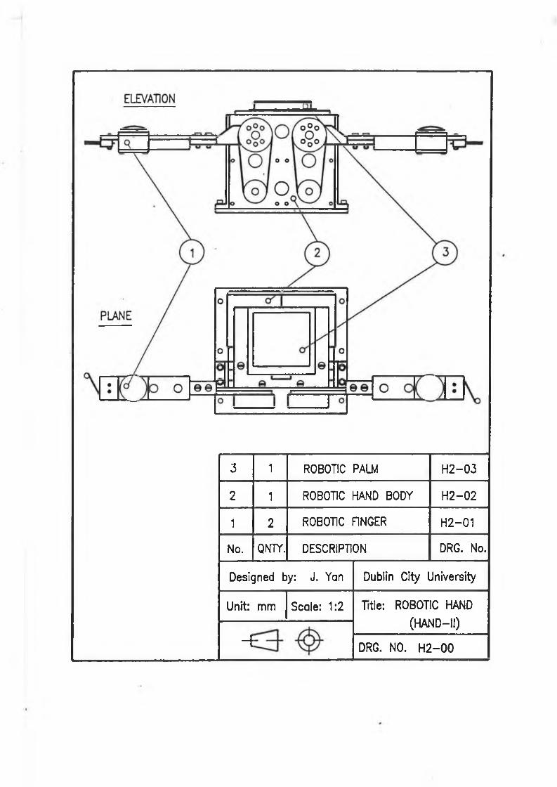
3 1 ROBOTIC PALM H 2 -0 3
2 1 ROBOTIC HAND BODY H 2 -0 2
1 2 ROBOTIC FINGER H 2 -0 1
No. QN7Y. DESCRIPTION DRG. No.
Designed by: J. Yan Dublin City University
Unit: mm Scale: 1:2 Title: ROBOTIC HAND (H A N D -II)
- f DRG. NO. H 2 - 0 0
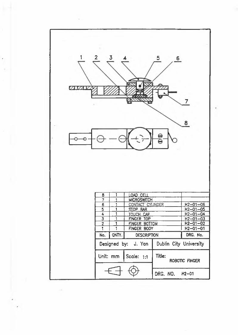
1 2 3 4 5 6
8 1 LOAD CELL7 1 MICROSWiïCH6 1 ........... H2-01—065 1 _ STOP BAR H2-01-0 5A 1 T O U C H C A P H2-01—043 1 F1NGER TOP H 2-01-032 1 FINGER BOTTOM . H 2-01-021 1 FINGER BODY H2-01-01
No. QNTY. DESCRIPTION DRG. No.
Designed by: J. Yan Dublin City University
Unit: mm Scale: 1 : 1 Title:ROBOTIC FINGER
o - & DRG. NO. H2-01
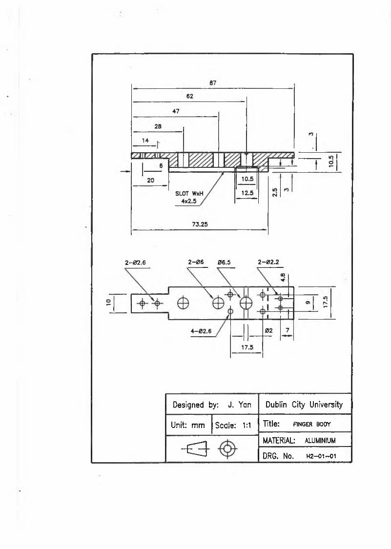
2-02.6 2-06 06.5 2-02.2
Designed by: J. Yan Dublin City University
Unit: m m Scale: 1:1 Title: FINGER BODY
“ E S -
MATERIAL ALUMINIUM
DRG. No. H2—01—01
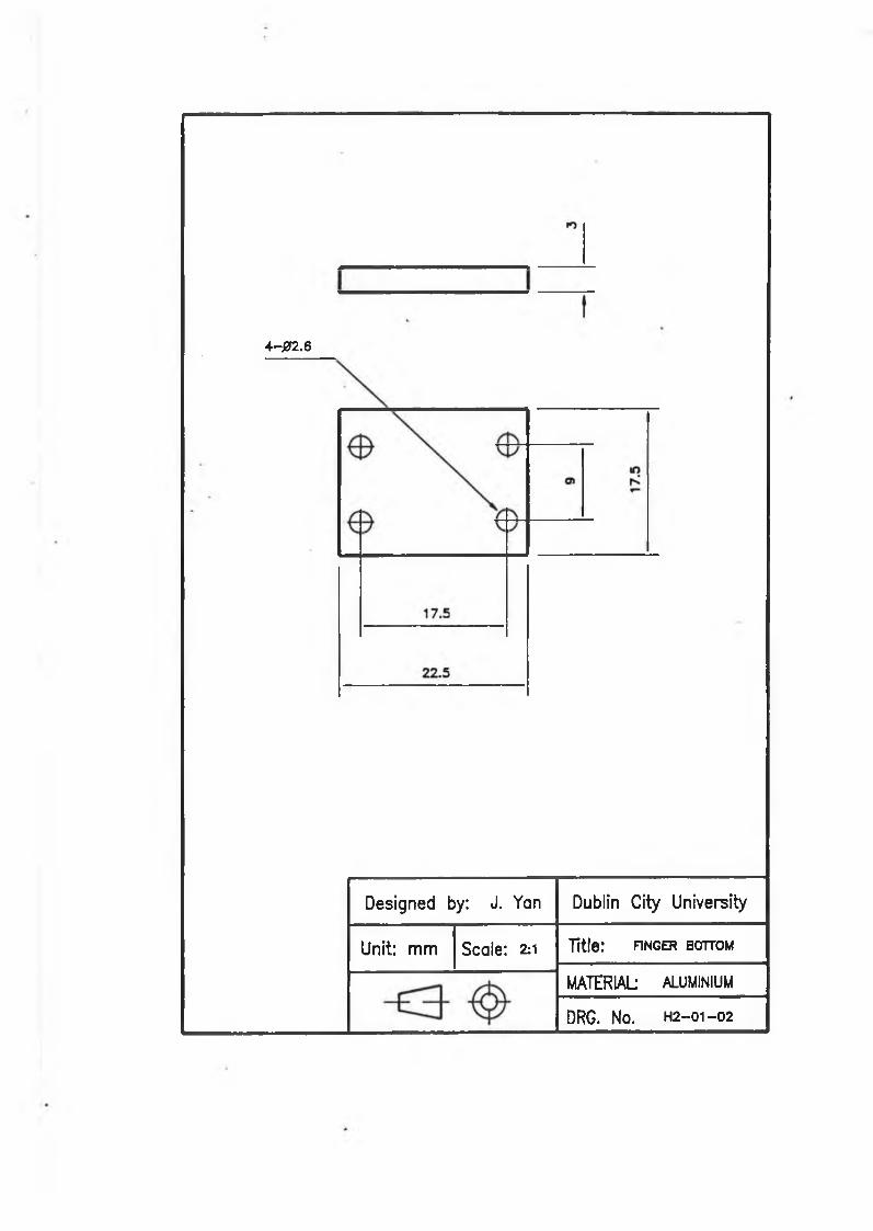
4 - 0 2 . 6
Designed by: J. Yan Dublin City University
Unit: m m Scale: 211 Title: FINGER BOTTOM
MATERIAL ALUMINIUM
DRG. No. H2- 01-02
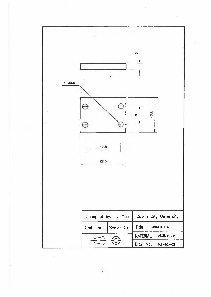
4-M2.5
Designed by: J. Yan Dublin City University
Unit: m m Scale: 2:1 Title: FINGER TOP
o - ^MATERIAL ALUMINIUM
DRG. No. H2-02-03
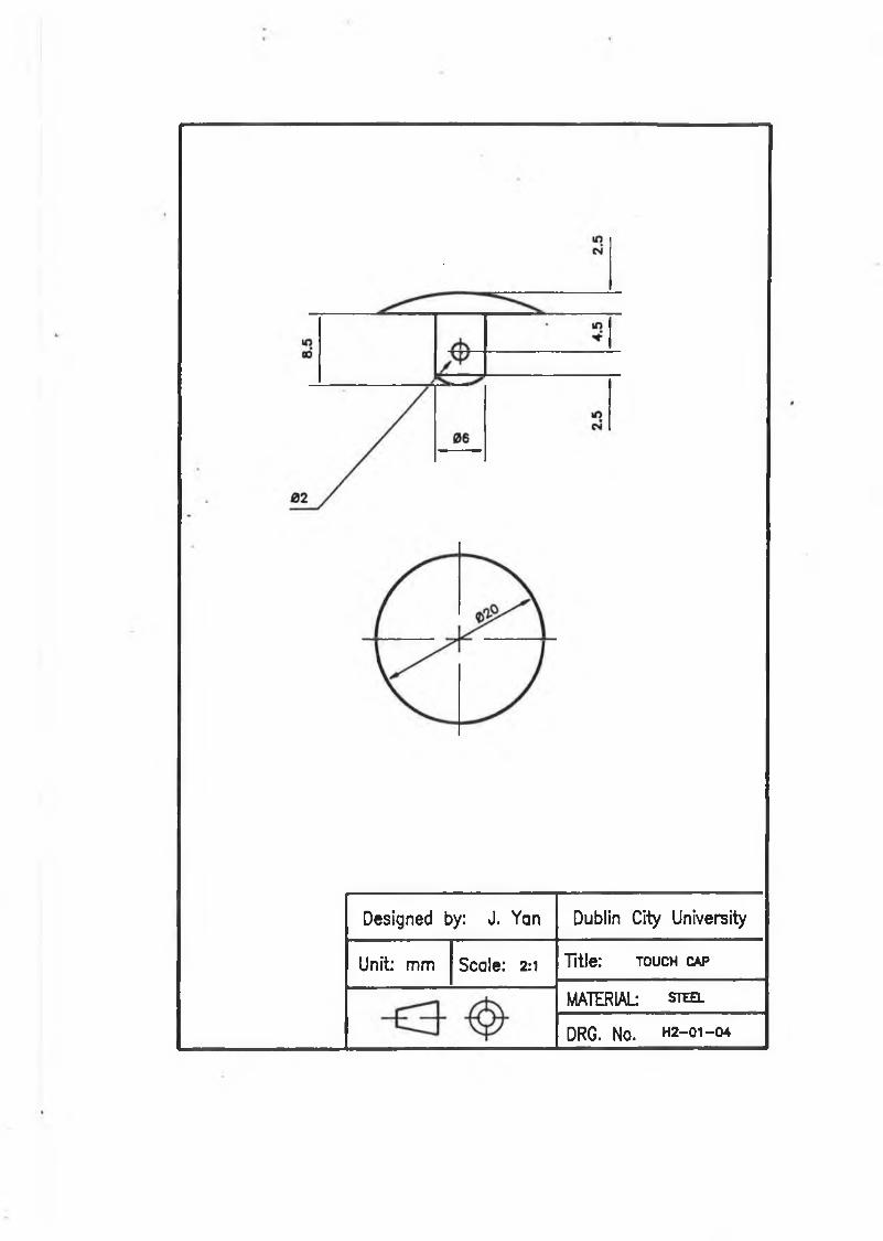
Designed by: J. Yan Dublin City University
Unit: mm Scale: 2:1 Title: t o u c h c a p
MATERIAL s t e e l
DRG. No. H2-01 —04
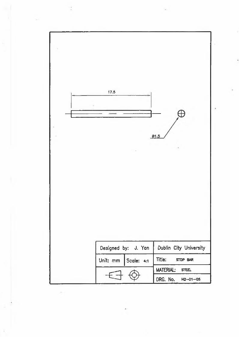
17.5
Designed by: J. Yan Dublin City University
Unit: m m Scale: 4:1 Title: stop bar
- £ 3 ^MATERIAL steel
DRG. No. H2-01-05
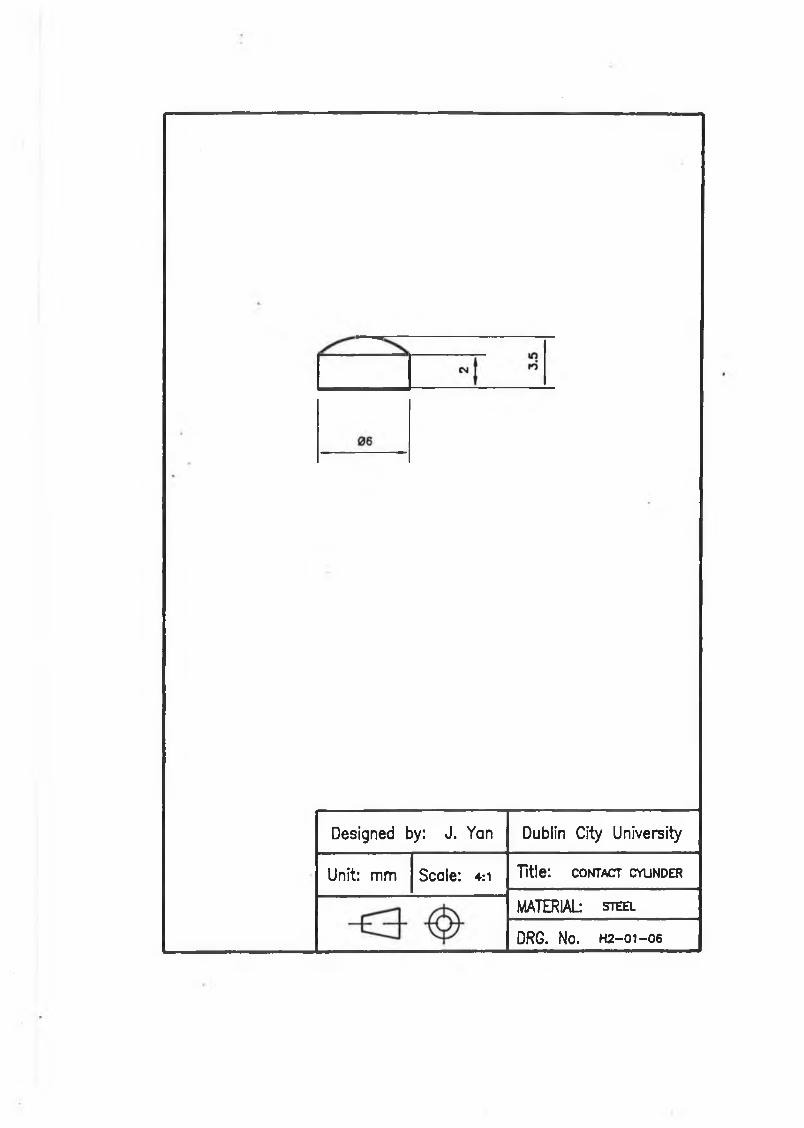
Designed by: J. Yan Dublin City University
Unit: mm Scale: 4:1 Title: c o n t a c t c y l in d e r
MATERIAL- s t e e l
DRG. No. H2-01 —06
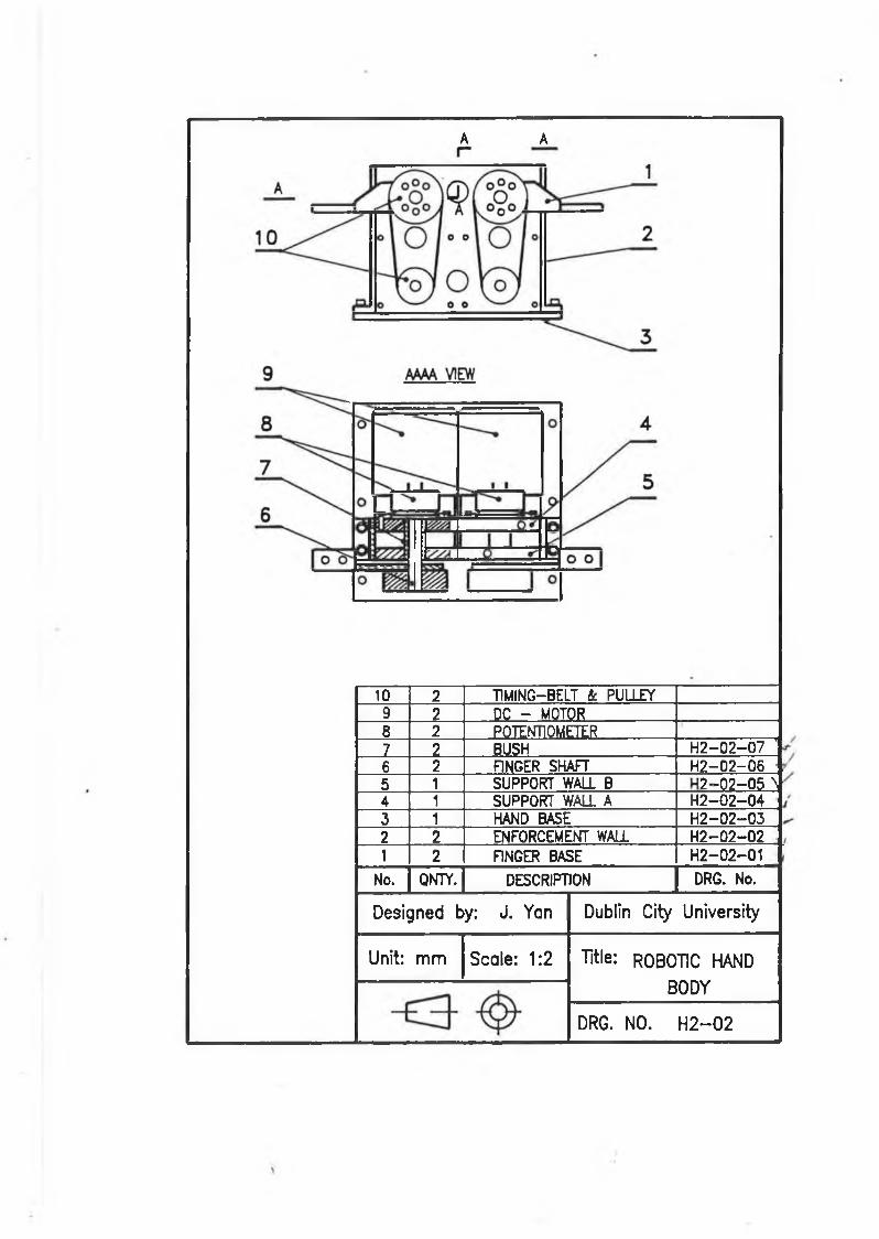
A A
10 2 T1MING-BELT à PULLEY9 2 DC - MOTOR8 2 POTENTIOMETER7 2 BUSH H 2-02-07 '6 2 FINGER SHAFT 4 2 -0 2 -0 65 1 SUPPORT WALL B ■ ? - 0 ? - 0 $ 44 1 SUPPORT WALL A H 2 -0 2 -043 1 HAND BASE H 2-02-032 2 ENFORCEMENT WALL H 2-02-021 2 FINGER BASE H2-02-01
No. QNTY. DESCRIPTION DRG. No.
Designed by: J. Yan Dublin City University
Unit: m m Scale: 1:2 Title: ROBOTIC HAND BODY
DRG. NO. H 2 - 0 2
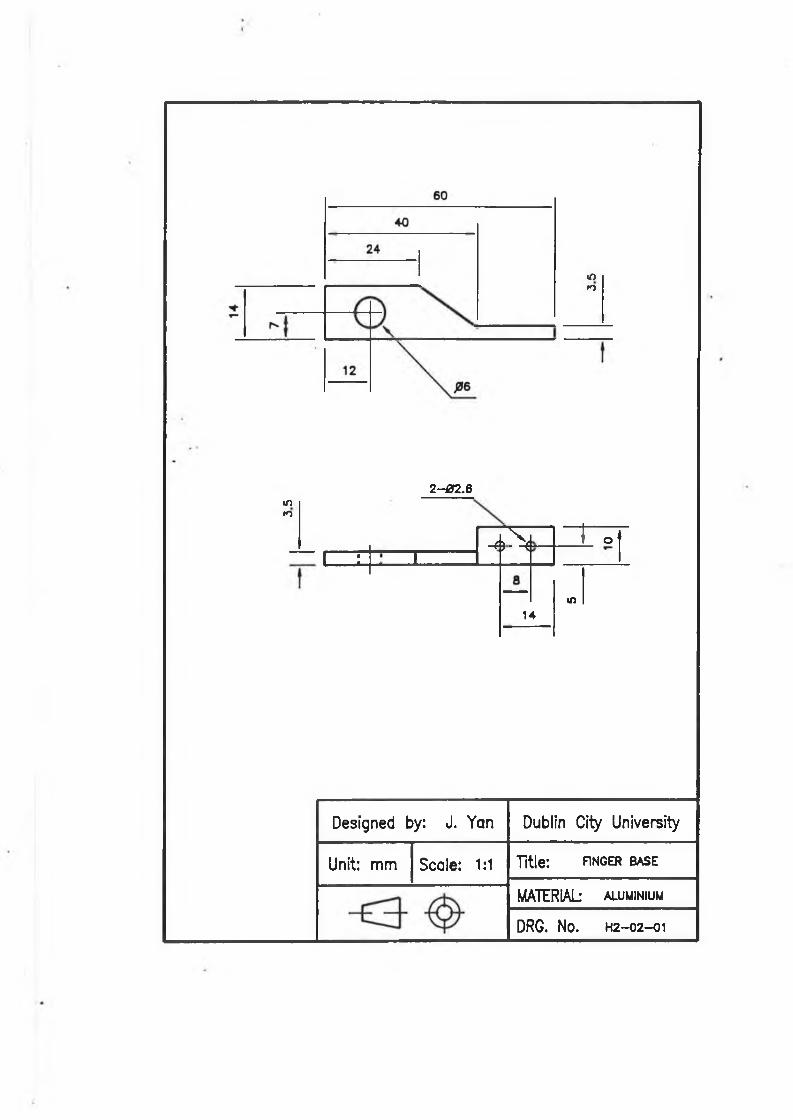
inK>
»nrn
2- 02.6
- 4 i> N- T o t
I : i
14m
Designed by: J. Yan Dublin City University
Unit: mm Scale: 1:1 Title: FINGER BASE
MATERIAL aluminium
DRG. No. H2—02—01
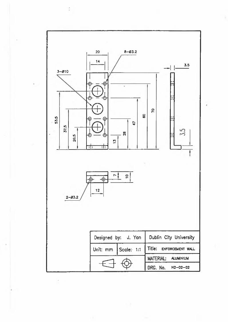
3-010
m10m
mKi
moCM
20
14
8-03.2
3.5
m ©\
i
TTi ITl
soCNro
otoop-
LOr-O
Designed by: J. Yan Dublin City University
Unit: m m Scale: 1:1 Title: ENFORCEMENT WALL
o MATERIAL aluminium
DRG. NO. H2-02—02
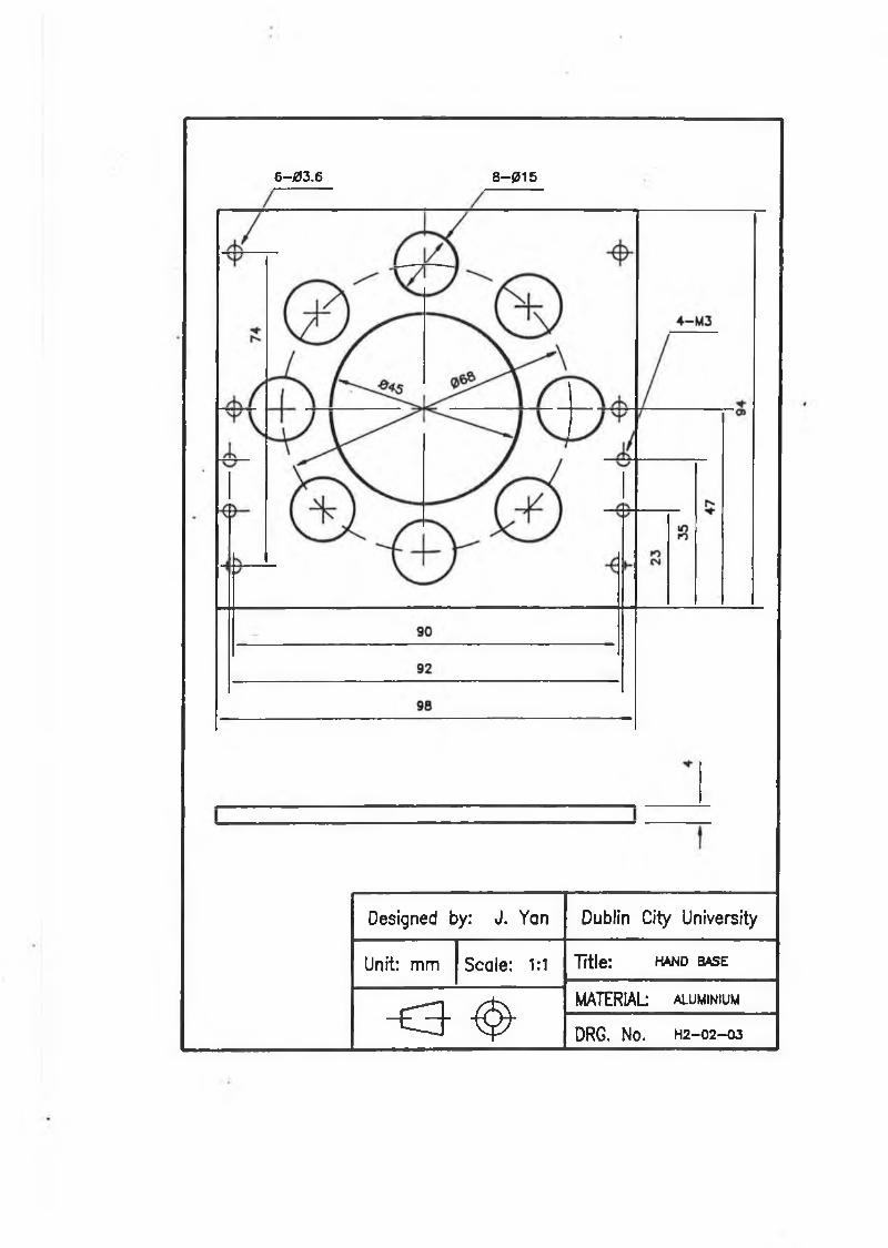
6 -03.6 8 -0 1 5
Designed by: J. Yan Dublin City University
Unit: mm Scale: 1:1 Title: h a n d b a s e
- E 3 ' ^MATERIAL alum inium
DRG. NO. H2—0 2 —03
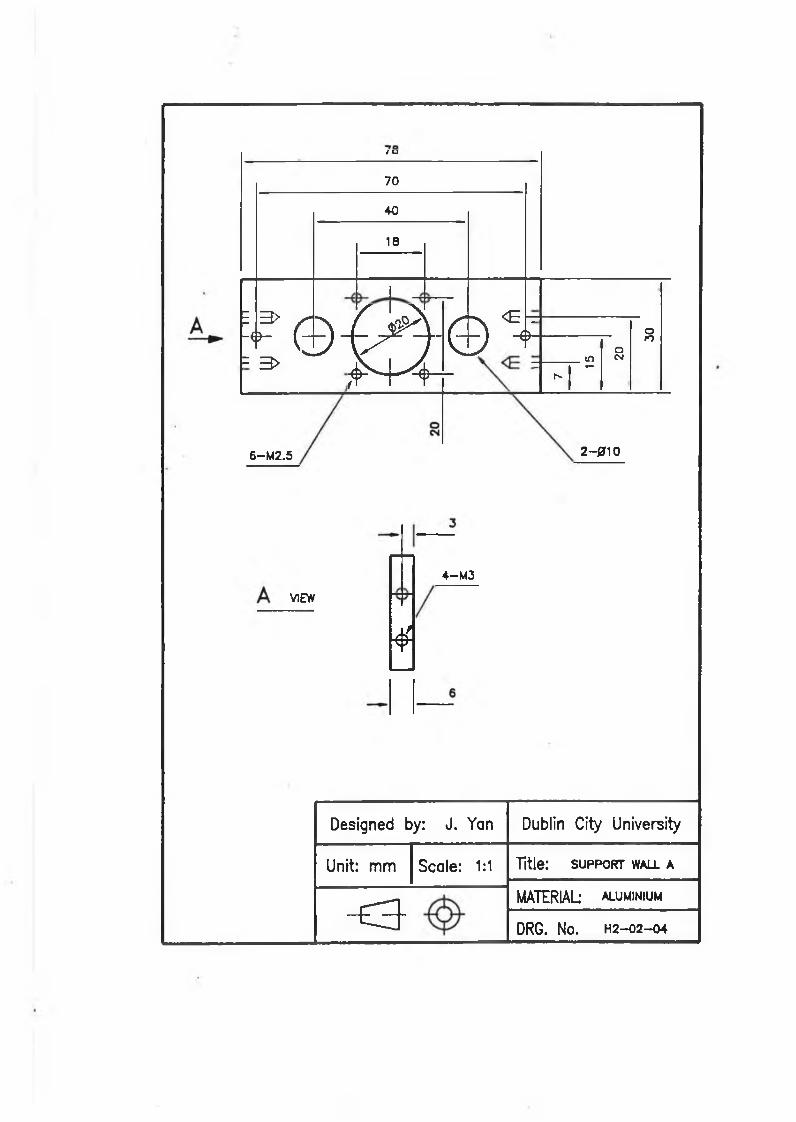
/ o704018
E 3> r ""sC j ^ x
K h (
S' -N € .
i t , <3- 3> Q - - 0 V j 4 OnoIft CM_ t—h**
6-M2.5 2-010
VIEW
¥
4— M3
Designed by: J. Yan Dublin City University
Unit: m m Scale: 1:1 Title: support wall a
~ e 3 -MATERIAL aluminiumDRG. NO. H2-02—04
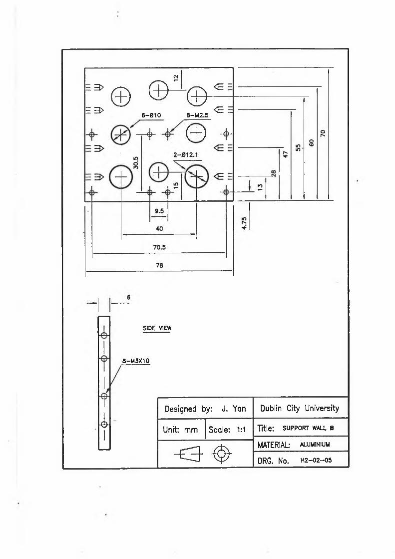
CM
m 3>
E 3 >© © ^ ©
6-010 8-M2.5
< E =
< E E
- f ( + ) - 4 -
i
SIDE VIEW
8-M3X10
Designed by: J. Yan Dublin City University
Unit: m m Scale: 1:1 Title: support wall b
< 3 ^
MATERIAL aluminium
DRG. NO. H2—02—05
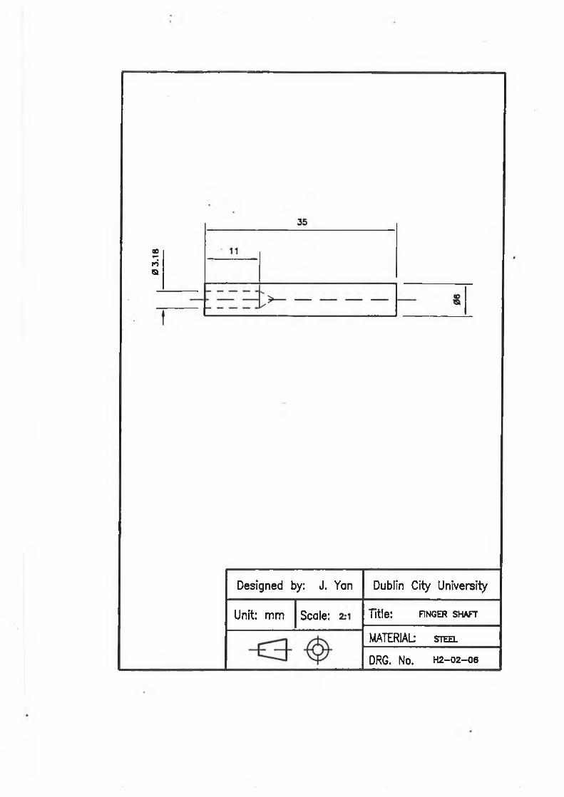
0 3.
18
Designed by: J. Yan Dublin City University
Unit: m m Scale: Title: FINGER SHAFT
MATERIAL steel
DRG. NO. H2-02—06
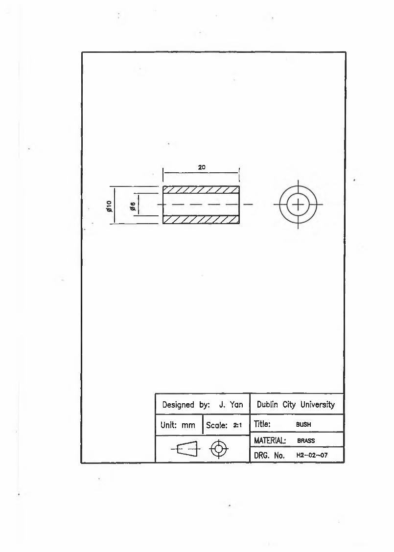
20________
IZZZZZZZZZ
zzzzzzzz z
Designed by: J. Yan Dublin City University
Unit: mm Scale: 2:1 Title: b u s h
< 3 ^
MATERIAL b r a s s
DRG. NO. H 2 -0 2 —0 7
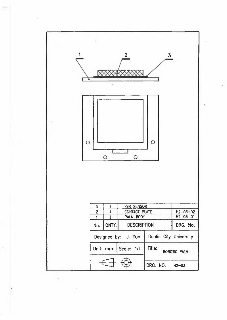
1 2 3
3 1 FSR SENSOR2 1 COMTACT PLATE H 2-03-021 1 PALM BODY H2-03-01
No. QNTY. DESCRIPTION DRG. No.
Designed by: J. Yan Dublin City University
U n it mm Scale: 1:1 Title** ROBOTIC PALM
o - ^ DRG. NO. H2-03
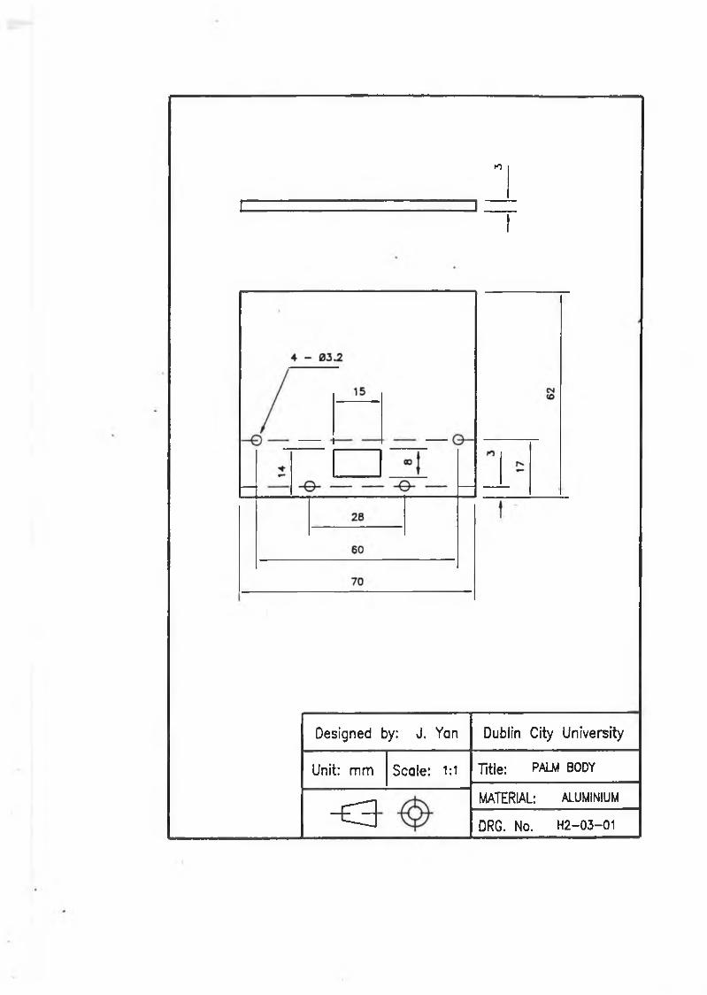
►o
I = 3 1 =I
Designed by: J. Yan Dublin City University
Unit: mm Scale: 1:1 Title: PALM BODY
- £ 3
MATERIAL: ALUMINIUM
DRG. No. H2-03-01
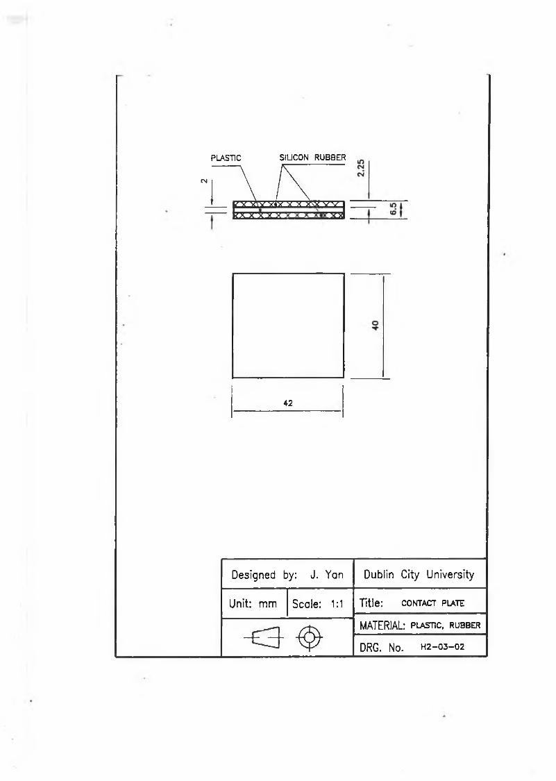
PLASTIC SILICON RUBBER
• r i E zJ v V VW w-7— kx-s-ra x ^
42
Designed by: J. Yan Dublin City University
Unit: mm Scale: 1:1 Title: contact plate
- E 3 - ^MATERIAL: plastic, rubber
DRG. NO. H2—03—02
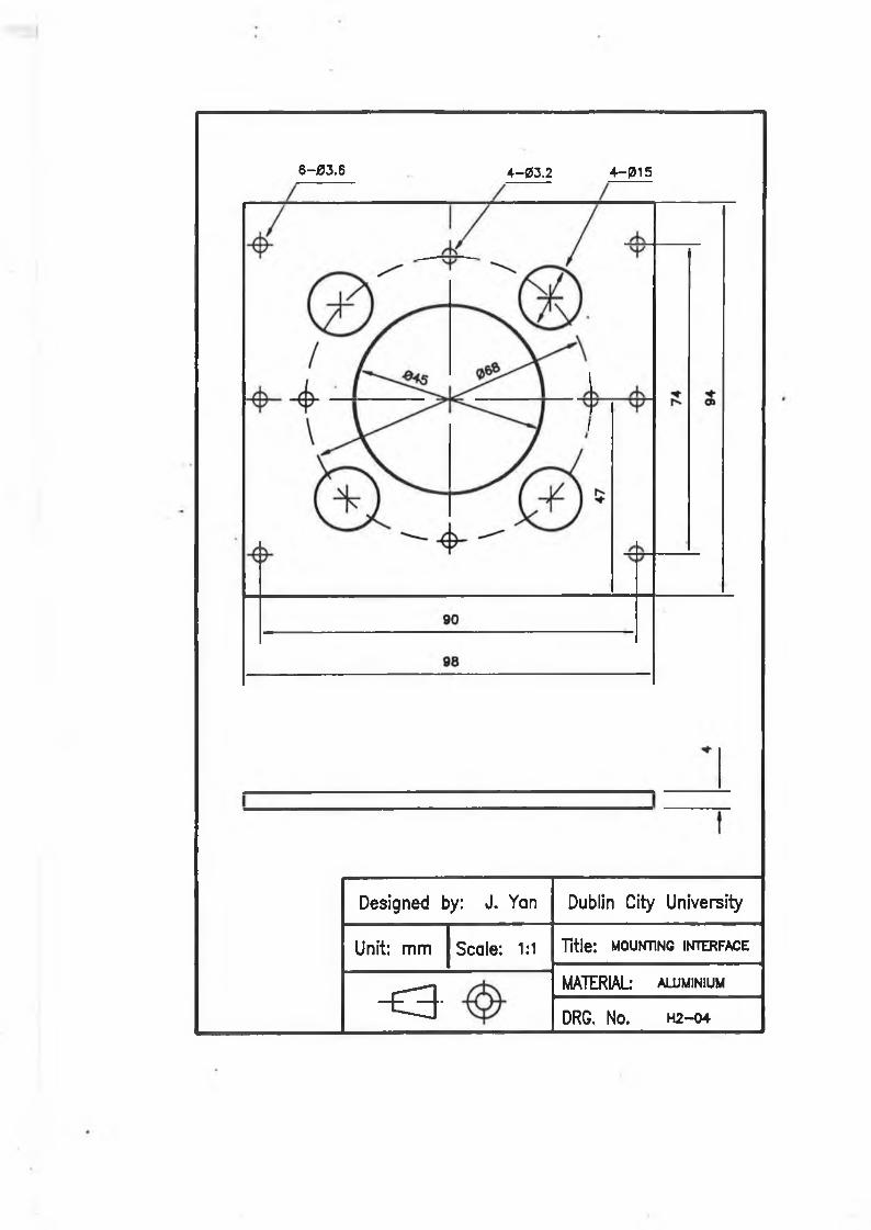
6-03.6 4-03.2 4 -015
Designed by: J. Yan Dublin City University
Unit: m m Scale: 1:1 Title: mounting interface
o -
MATERIAL* aluminium
DRG. No. H2—04
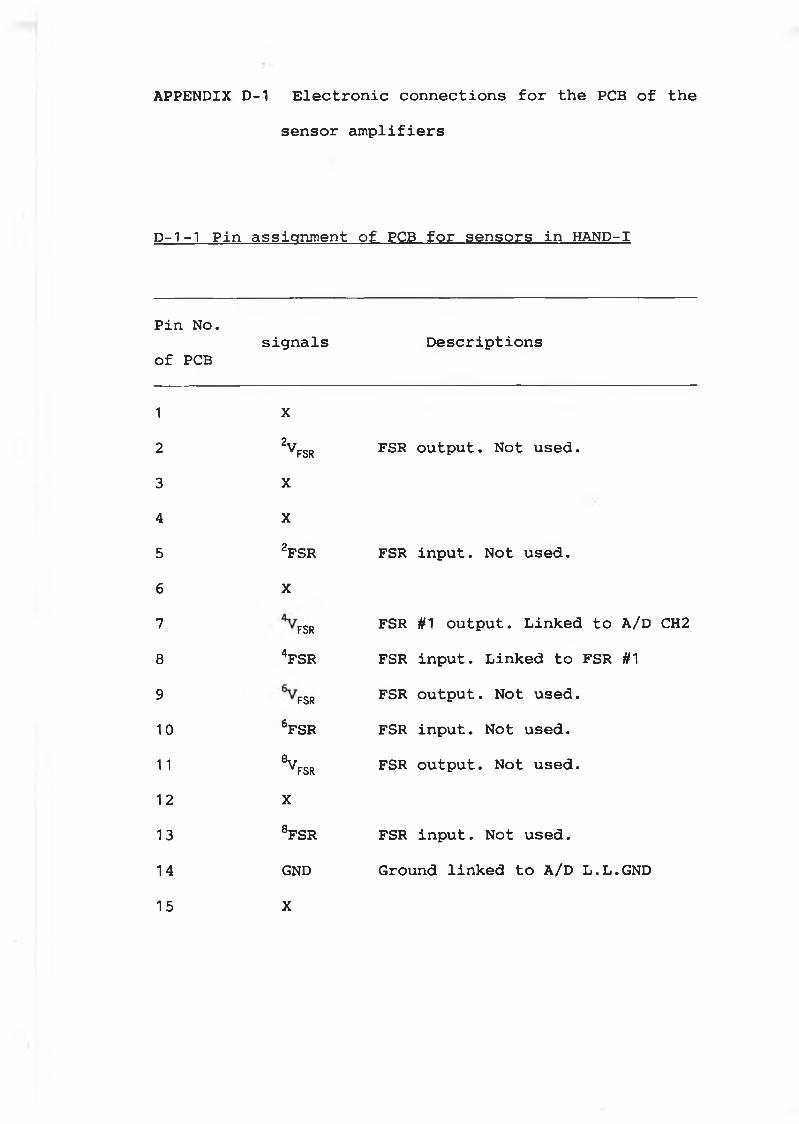
APPENDIX D-1 Electronic connections for the PCB of thesensor amplifiers
D-1-1 Pin assignment of PCB for sensors in HAND-I
Pin No. of PCB
signals Descriptions
1 X2 2V FSR FSR output. Not used.3 X4 X5 2fs r FSR input. Not used.6 X7 FSR FSR #1 output. Linked to A/D CH28 4fsr FSR input. Linked to FSR #19 FSR FSR output. Not used.1 0 6fsr FSR input. Not used.1 1 ®v
FSR FSR output. Not used.1 2 X13 8fsr FSR input. Not used.14 GND Ground linked to A/D L.L.GND15 X
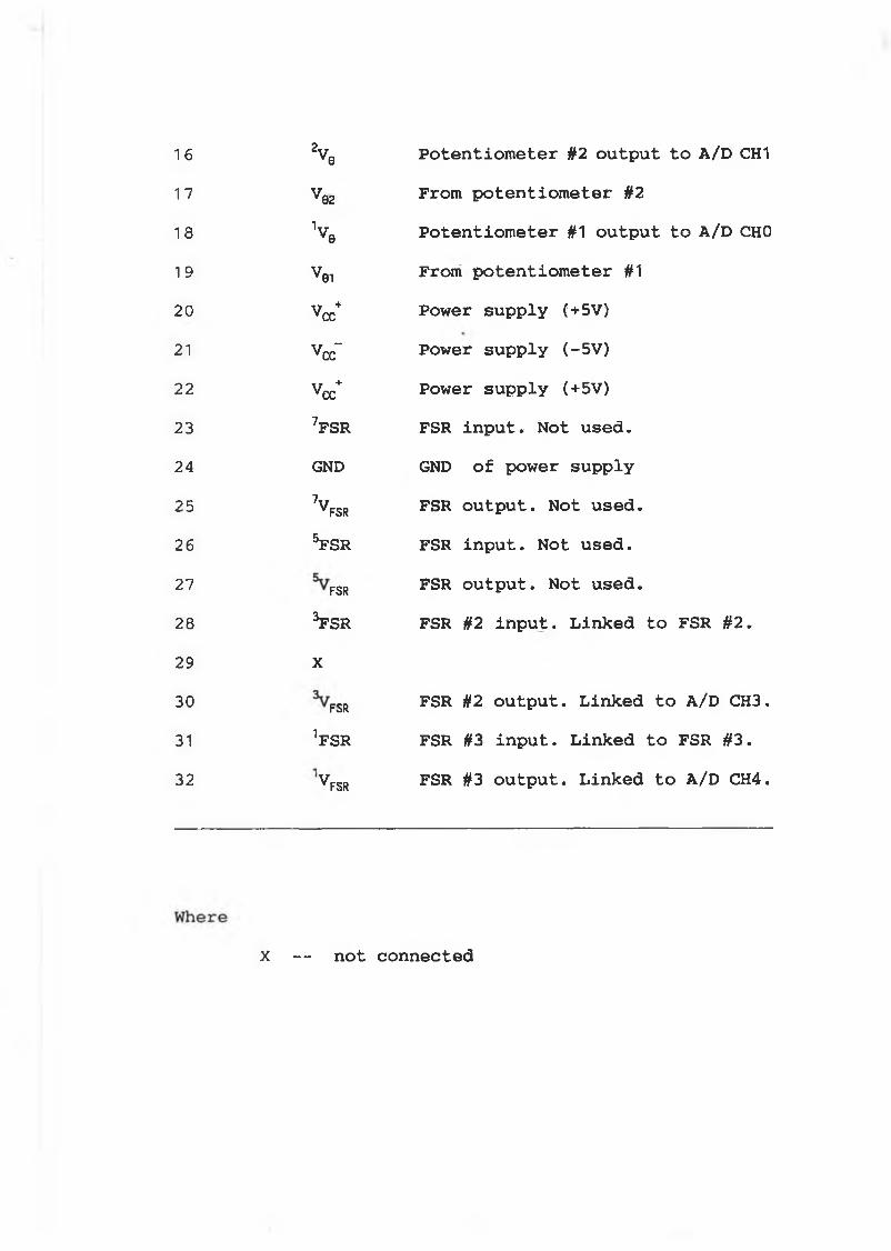
16
17
18
19
20
21
22
23
24
25
26
27
28
29
30
31
32
2V0 Potentiometer §2 output to A/D CH1
Ve2 From potentiometer §2
V e Potentiometer #1 output to A/D CHO
vei From potentiometer #1
V Power supply (+5V)
Vccf Power supply (-5V)
Vcc+ Power supply (+5V)7f s r FSR input. Not used.GND GND of power supply7VFSR FSR output. Not used.5fsr FSR input. Not used.
FSR FSR output. Not used.3FSRY
FSR #2 input. Linked to FSR §2.A
FSR FSR #2 output. Linked to A/D CH3.^FSR FSR #3 input. Linked to FSR #3.
^FSR FSR #3 output. Linked to A/D CH4.
X — not connected
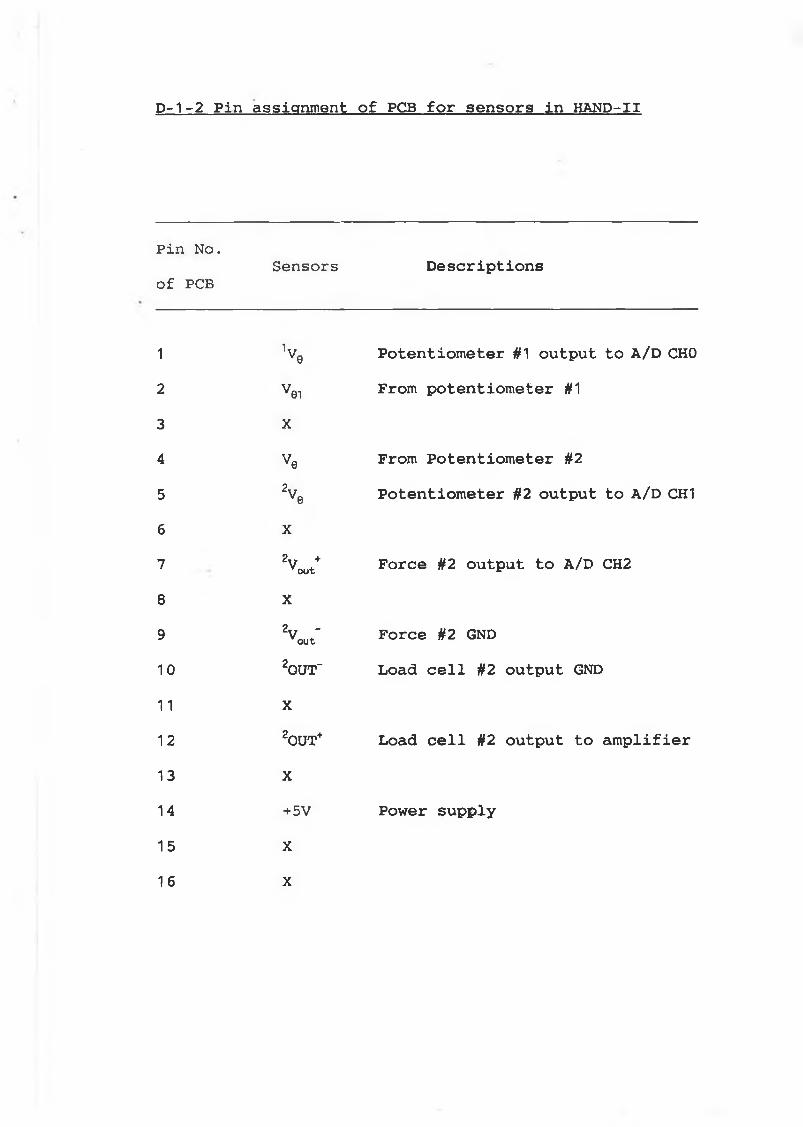
D-1-2 Pin assignment of PCB for sensors in HAND-II
Pin No.Sensors Descriptions
of PCB
1 V q Potentiometer #1 output to A/D CHO2 Vei From potentiometer #13 X4 Ve From Potentiometer #25 2Ve Potentiometer §2 output to A/D CH16 X7 2vout+ Force #2 output to A/D CH28 X
9 2voutf F o r c e # 2 GND
10 2OUT" Load cell #2 output GND11 X12 2OUT+ Load cell #2 output to amplifier13 X14 +5V Power supply15 X16 X
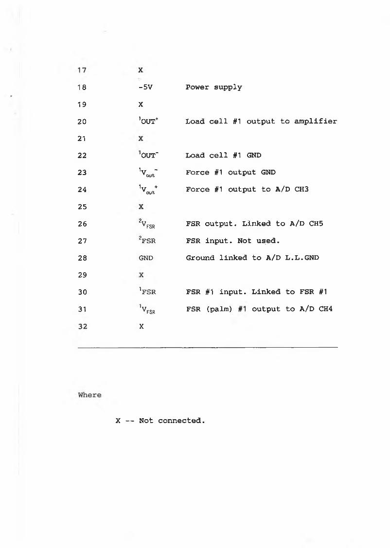
181920
2 1
22
232425262728293031
X1OUT+ Load cell #1 output to amplifier
^UT' Load cell #1 GND1vout~ Force #1 output GND1vout+ Force #1 output to A/D CH3
2v fsr f s r output. Linked to A/D CH52FSR FSR input. Not used.GND Ground linked to A/D L.L.GND
’FSR FSR #1 input. Linked to FSR #1
1v fsr FSR (Palm) output to A/D CH4X
-5V Power supply
X — Not connected.
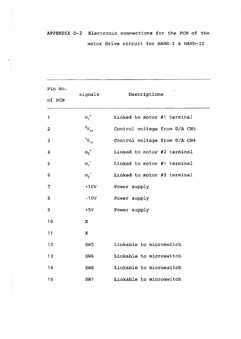
APPENDIX D-2 Electronic connections for the PCB of themotor drive circuit for HAND-I & HAND-II
Pin No.signals Descriptions
of PCB
1 V Linked to motor #1 terminal
2 2v,„ Control voltage from D/A CH5
3 V in Control voltage from D/A CH4
4 Iîl2+ Linked to motor #2 terminal
5 V Linked to motor #1 terminal
6 ITlg Linked to motor §2 terminal
7 + 1 ov Power supply
8 -10V Power supply
9 + 5V Power supply
1 0 X
1 1 X
1 2 SW5 Linkable to microswitch
13 SW6 Linkable to microswitch
14 SW8 Linkable to microswitch
15 SW7 Linkable to microswitch
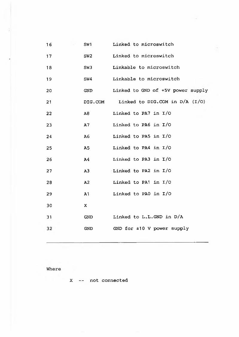
16
17
18
19
20
21
22
23
24
25
26
27
28
29
30
31
SW1 Linked to microswitch
SW2 Linked to microswitch
SW3 Linkable to microswitch
SW4 Linkable to microswitch
GND Linked to GND of +5V power
DIG.COM Linked to DIG.COM in D/A
A 8 Linked to PA7 in I/O
A7 Linked to PA6 in I/O
A6 Linked to PA5 in I/O
A5 Linked to PA4 in I/O
A4 Linked to PA3 in I/O
A3 Linked to PA2 in I/O
A2 Linked to PA1 in I/O
A1 Linked to PAO in I/O
X
GND Linked to L.L.GND in D/A
GND GND for ±10 V power supply
X — not connected
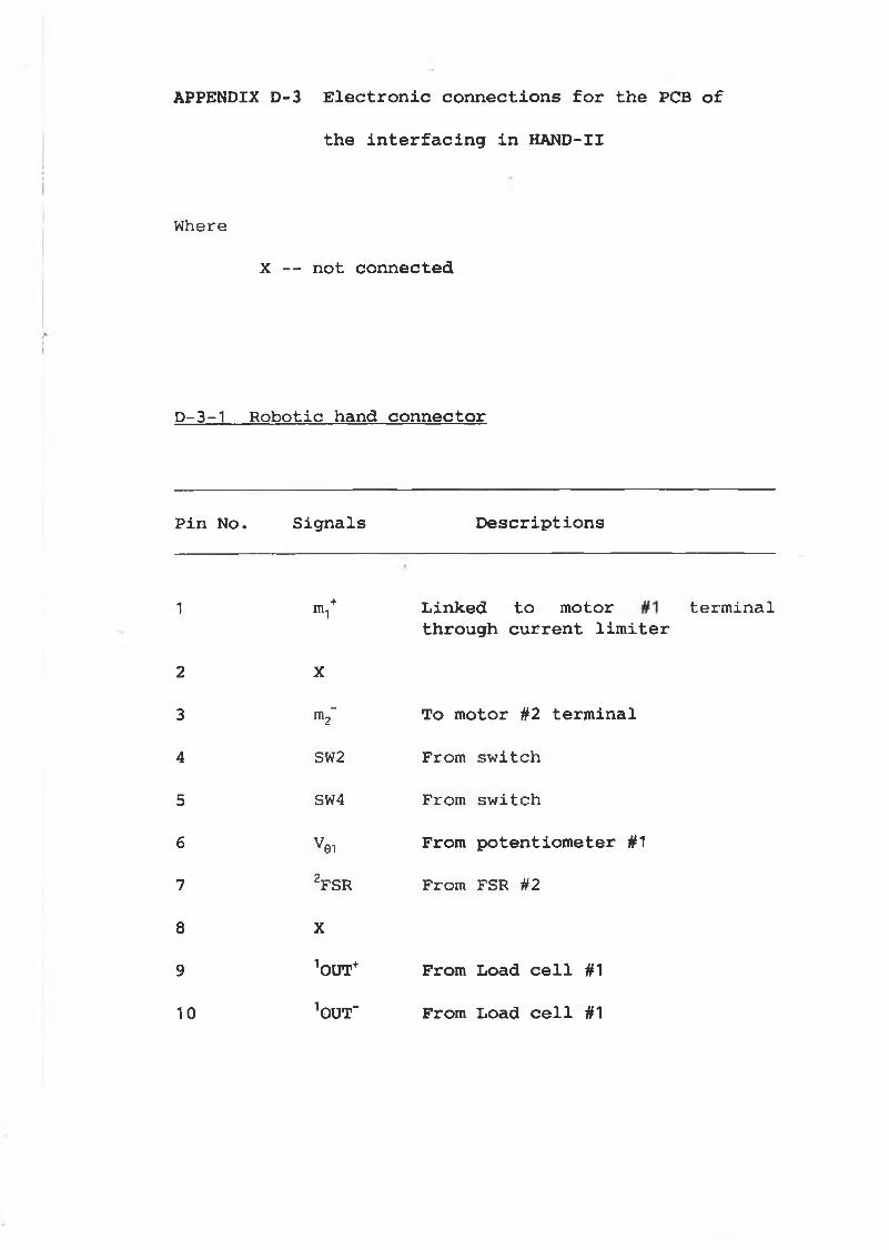
APPENDIX D -3 E l e c t r o n i c c o n n e c t i o n s f o r th e PCB o f
th e i n t e r f a c i n g i n HAND-II
Where
X — not connected
D-3-1 Robotic hand connector
Pin No. Signals Descriptions
1 m.,+ Linked to motor terminalthrough current limiter
2 X
3 m2" To motor #2 terminal
4 SW2 From switch
5 SW4 From switch
6 V0i From potentiometer #1
7 2FSR From FSR #2
8 X
9 1OUT+ From Load cell #1
10 10UTr From Load cell #1
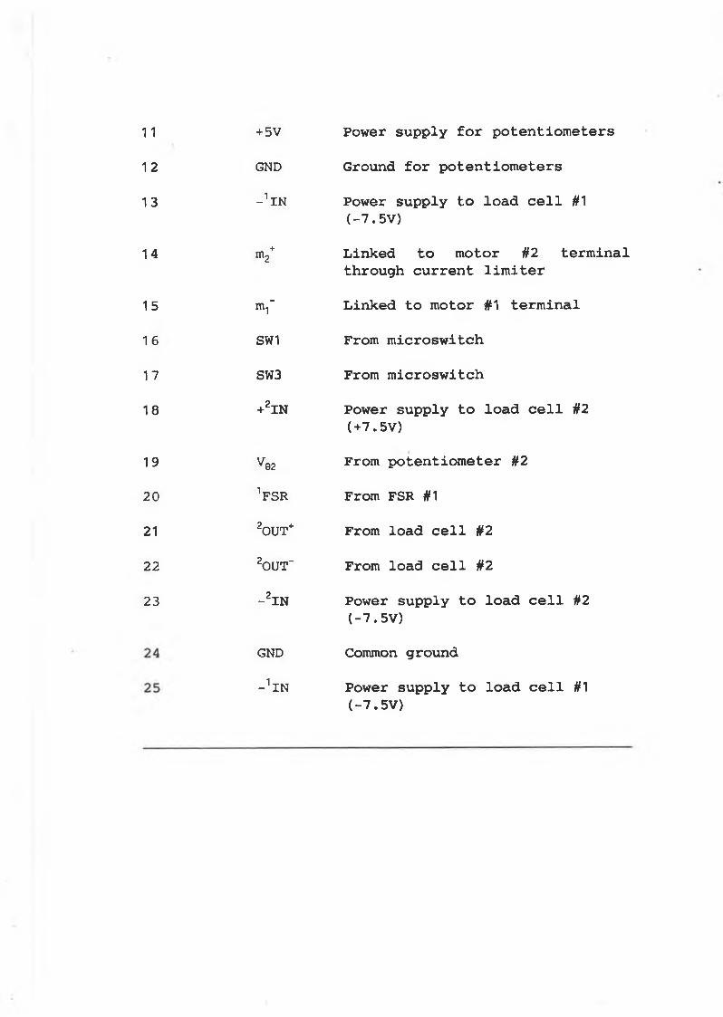
1 1
12
13
14
15
1 6
17
18
19
20
21
22
23
GND Ground for potentiometers
- 1 IN Power supply to load cell #1(-7.5V)
m2+ Linked to motor #2 terminalthrough current limiter
m^ Linked to motor #1 terminal
SW1 From microswitch
SW3 From microswitch
+2IN Power supply to load cell §2(+7.5V)
Ve 2 From potentiometer #2
VSR From FSR #1
20UT+ From load cell §2
20UT" From load cell #2
-2IN Power supply to load cell #2(-7.5V)
GND Common ground
^IN Power supply to load cell #1(-7.5V)
+5V Power supply for potentiometers
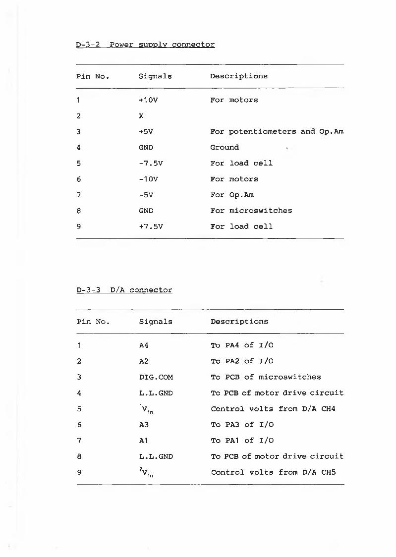
D-3-2 Power supply connector
Pin No. Signals Descriptions
1 + 10V For motors2 X3 +5V For potentiometers and Op.Am4 GND Ground5 -7.5V For load cell6 -1 OV For motors7 -5V For Op.Am8 GND For microswitches9 +7.5V For load cell
D-3-3 D/A connector
Pin No. Signals Descriptions
1 A4 To PA4 of I/O2 A2 To PA2 of I/O3 DIG.COM To PCB of microswitches4 L .L .GND To PCB of motor drive circuit5 V 1n Control volts from D/A CH46 A3 To PA3 Of I/O7 A1 To PA1 Of I/O8 L.L.GND To PCB of motor drive circuit9 2V 1n Control volts from D/A CH5
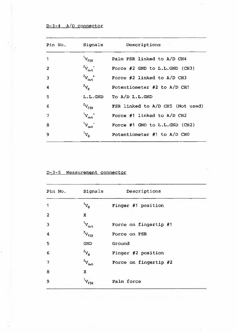
D-3-4 A/D connector
Pin No. Signals Descriptions
1 1yFSR Palm FSR linked to A/D CH42 2V ”
o u tForce U2 GND to L.L.GND (CH3)
3 2 V o u t +Force #2 linked to A/D CH3
4 2Ve Potentiometer #2 to A/D CH.15 L.L.GND To A/D L.L.GND6 2VFSr FSR linked to A/D CH5 (Not used)7 1V +o u t
Force #1 linked to A/D CH28 V -
o u tForce #1 GND to L.L.GND (CH2)
9 1vve Potentiometer #1 to A/D CHO
D-3-5 Measurement connector
Pin No. Signals Descriptions
1 V e Finger position2 X3 1v
o u tForce on fingertip #1
4 2v fsr Force on FSR5 GND Ground6 2 V e Finger #2 position7
2 V o u tForce on fingertip #2
8 X9 1VFSR Palm force
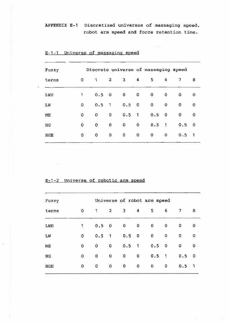
APPENDIX E-1 Discretized universes of massaging speed, robot arm speed and force retention time.
E-1-1 Universe of massaging speed
Fuzzy Discrete universe of massaging speedterms 0 1 2 3 4 5 6 7 8
LWE 1 •o 0 0 0 0 0 0 0
LW 0
in•o 1 0.5 0 0 0 0 0
ME 0 0 0 0.5 1 0.5 0 0 0
HG 0 0 0 0 0
in•o 1 0.5 0
HGE 0 0 0 0 0 0 0
in•o 1
E-1-2 Universe of robotic arm speed
Fuzzy Universe of robot arm speedterms 0 1 2 3 4 5 6 7 8
LWE 1 0.5 0 0 0 0 0 0 0
LW 0 0.5 1 0.5 0 0 0 0 0
ME 0 0 0 0.5 1 0.5 0 0 0
HG 0 0 0 0 0 0.5 1 0.5 0
HGE 0 0 0 0 0 0 0 0.5 1
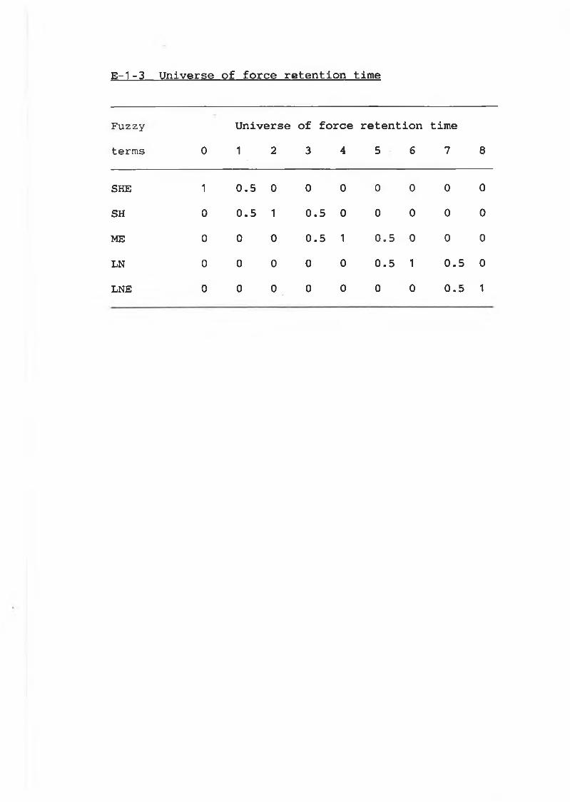
E-1-3 Universe of force retention time
Fuzzy U n i v e r s e o f f o r c e r e t e n t i o n t i m e
terms 0 1 2 3 4 5 6 7 8
SHE 1 0 . 5 0 0 0 0 0 0 0
SH 0 0 . 5 1 0 . 5 0 0 0 0 0
ME 0 0 0 0 . 5 1 0 . 5 0 0 0
LN 0 0 0 0 0 0 . 5 1 0 . 5 0
LNE 0 0 0 0 0 0 0 0 . 5 1
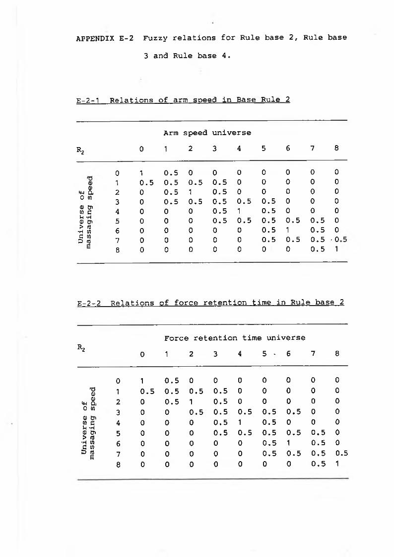
APPENDIX E-2 Fuzzy relations for Rule base 2, Rule base 3 and Rule base 4.
E-2-1 Relations of arm speed in Base Rule 2
Arm speed universe R2 0 1 2 3 4 5 6 7 8
<DQ)<W Û 0 Wa) &> m aM -Hai > <0
•H to G tn D nje
0 1 0 . 5 0 0 0 0 0 0 01 0 . 5 0 . 5 0 . 5 0 . 5 0 0 0 0 02 0 0 . 5 1 0 . 5 0 0 0 0 03 0 0 . 5 0 . 5 0 . 5 0 . 5 0 . 5 0 0 04 0 0 0 0 . 5 1 0 . 5 0 0 05 0 0 0 0 . 5 0 . 5 0 . 5 0 . 5 0 . 5 06 0 0 0 0 0 0 . 5 1 0 . 5 07 0 0 0 0 0 0 . 5 0 . 5 0 . 5 • 08 0 0 0 0 0 0 0 0 . 5 1
E-2-2 Relations of force retention time in Rule base 2
r2
Force retention time universe0 1 2 3 4 5 ' 6 7 8
0 1 0 . 5 0 0 0 0 0 0 01 0 . 5 0 . 5 0 . 5 0 . 5 0 0 0 0 02 0 0 . 5 1 0 . 5 0 0 0 0 03 0 0 0 . 5 0 . 5 0 . 5 0 . 5 0 . 5 0 04 0 0 0 0 . 5 1 0 . 5 0 0 05 0 0 0 0 . 5 0 . 5 0 . 5 o • Ul 0 . 5 06 0 0 0 0 0 0 . 5 1
in•o
07 0 0 0 0 0 0 . 5 0 . 5 0 . 5 0. 58 0 0 0 0 0 0 0 0 . 5 1
T3a)* 8 , o w0)m öVf "Ha) cn > m
■h m C w D m
£
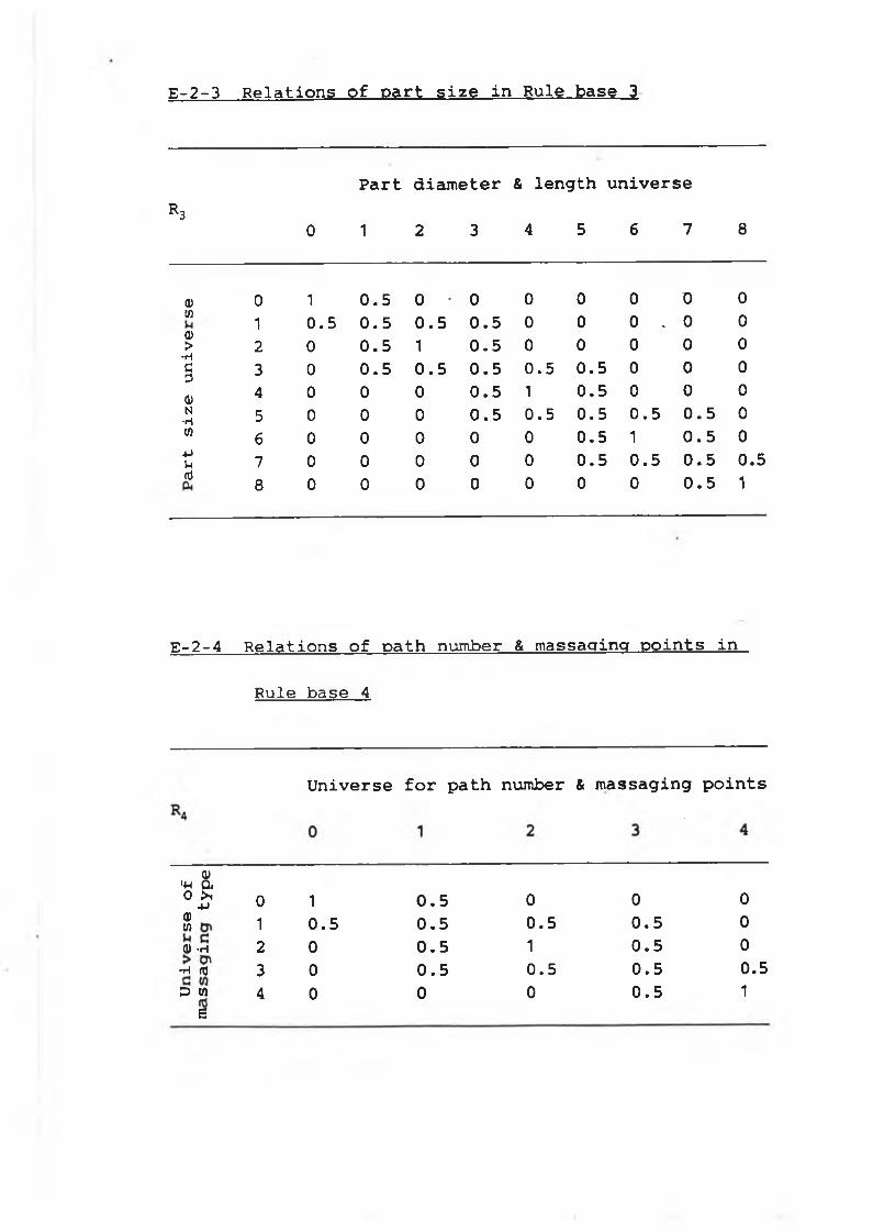
E-2-3 Relations of part size in Rule base 3
Part diameter & length universeR 3
0 1 2 3 4 5 6 7 8
a) 0 1 0.5 0 • 0 0 0 0 0 0w 1 0.5 0.5 0.5 0.5 0 0 0 .. 0 0Q>•H
2 0 0.5 1 0.5 0 0 0 0 0c3 3 0 0.5 0.5 0.5 0.5 0.5 0 0 00) 4 0 0 0 0.5 1 0.5 0 0 0N■H 5 0 0 0 0.5 0.5 0.5 0.5 0.5 0(0
6 0 0 0 0 0 0.5 1 0.5 0-Pl-l 7 0 0 0 0 0 0.5 0.5 in•o 0.5nJ 8 0 0 0 0 0 0 0 0.5 1
E-2-4 Relations of path number & massaging points in
Rule base 4
Universe for path number & massaging points
«M 8 .0 £ 0 1 0.5 0 0 0$ 1 0.5 0.5 0.5 0.5 0q) . h 2 0 0.5 1 0.5 0
•h re 3 0 0.5 0.5 0.5 0.5D M 4 0 0 0 0.5 1
e
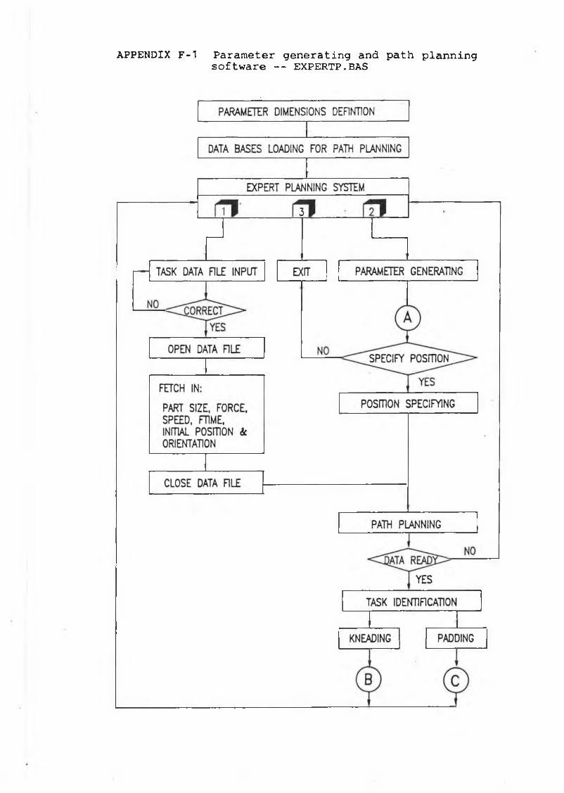
APPENDIX F-l Parameter generating and path planning software — EXPERTP.BAS
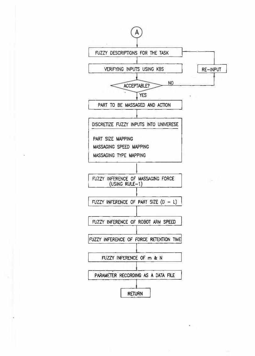
FTJZZY INFERENCE OF MASSAGING FORCE (USING RULE-1)_______________
FUZZY INFERENCE OF PART SIZE (D - L)
FUZZY INFERENCE OF ROBOT ARM SPEED
FUZZY INFERENCE OF FORCE RETENTION TIME
FTJZZY INFERENCE OF m k N
PARAMETER RECORDING AS A DATA RLE
RETURN
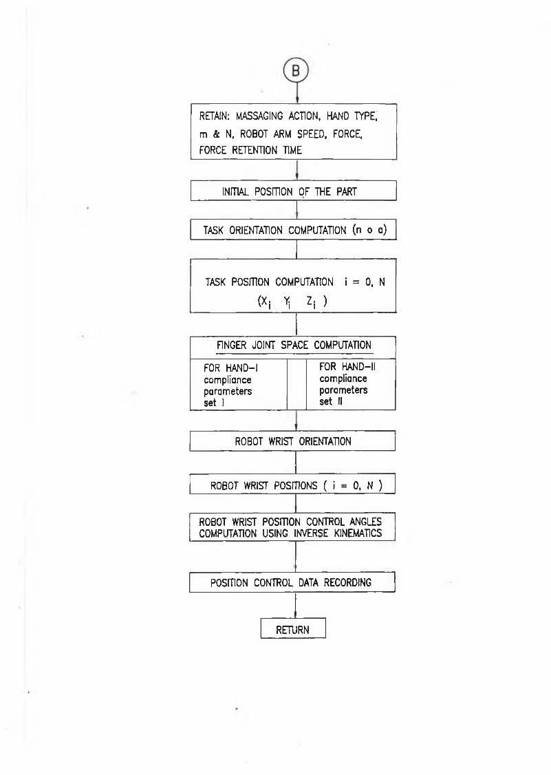
RETAIN: MASSAGING ACTION, HAND TYPE,
m & N, ROBOT ARM SPEED, FORCE,
FORCE RETENTION TIME
INITIAL POSITION OF THE PART
TASK ORIENTATION COMPUTATION (n o a)
TASK POSITION COMPUTATION I = 0, N
(X i Yi Z i )
FINGER JOINT SPACE COMPUTATION
FOR HAND-1 compliance parameters set 1
FOR HAND—II compliance parameters set II
ROBOT WRIST ORIENTATION
ROBOT WRIST POSITIONS ( i = 0, N )
ROBOT WRIST POSITION CONTROL ANGLES COMPUTATION USING INVERSE KINEMATICS
POSITION CONTROL DATA RECORDING
RETURN
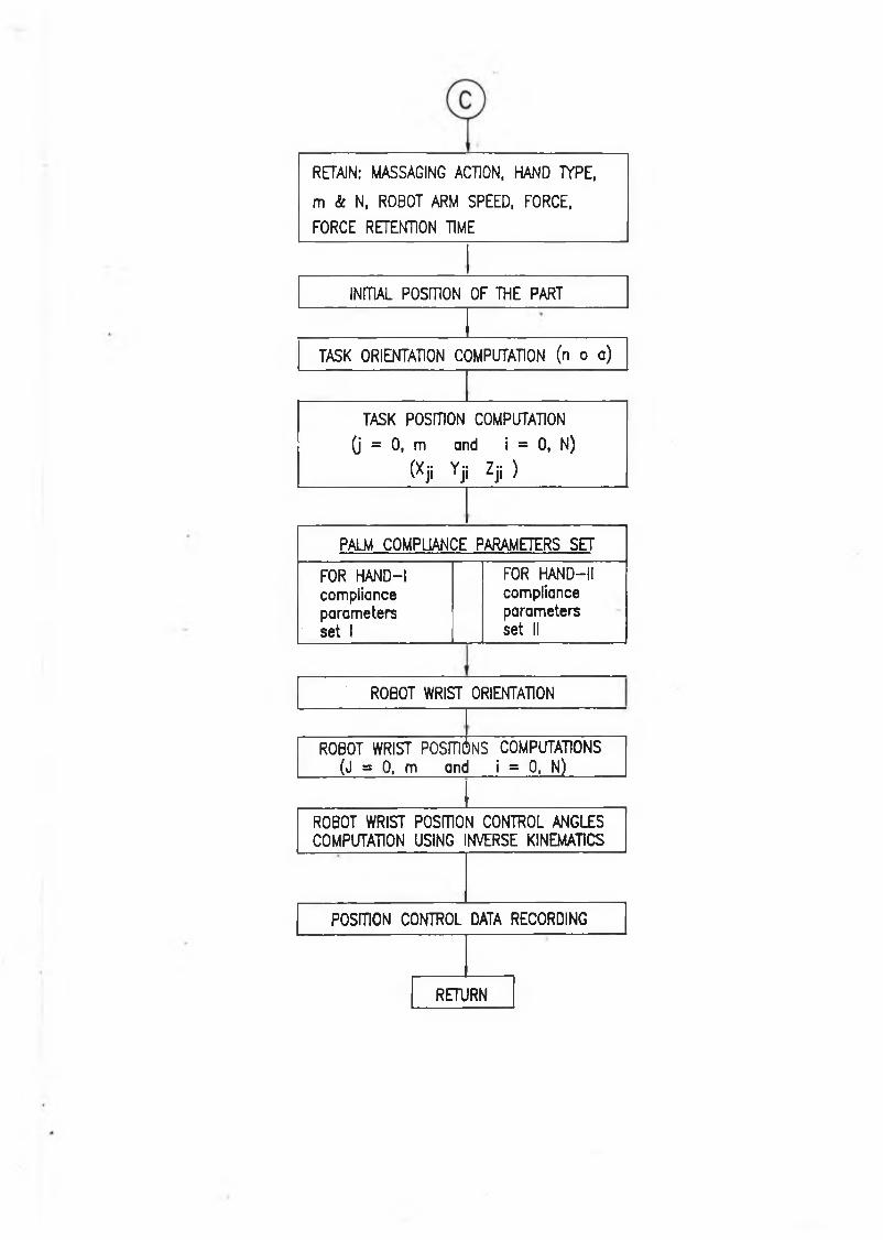
RETAIN: MASSAGING ACTION, HAND TYPE,
m & N, ROBOT ARM SPEED, FORCE,
FORCE RETENTION TIME
INITIAL POSITION OF THE PART
TASK ORIENTATION COMPUTATION (n o a)
TASK POSITION COMPUTATION
(j = 0, m and i = 0, N)
(Xji Yjj Zjj )
PALM COMPLIANCE PARAMETERS SET
FOR HAND-1 compliance parameters set 1
FOR HAND— II compliance parameters set II
ROBOT WRIST ORIENTATION
ROBOT WRIST POSITIONS COMPUTATIONS (J = 0, m and i = 0, N)
IROBOT WRIST POSmON CONTROL ANGLES COMPUTATION USING INVERSE KINEMATICS
POSITION CONTROL DATA RECORDING
RETURN
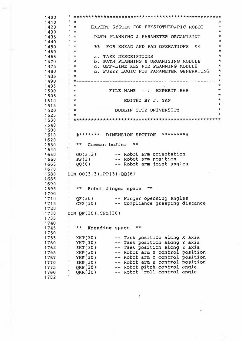
1 400 1410 1 420 1 430 1435 1 440 1 450 1 460 1 465 1 470 1 475 1 480 1 485 1 490 1 495 1 500 1 505 1510 1 51 5 1 520 1 525 1 530 1540 1 600 1 61 0
1620 1 630 1 640 1 650 1 660 1665 1 670 1680 1 685 1690 1695 1 700 1710 1715 1 720 1730 1 735 1 740 1745 1 750 1755 1 760 1762 1 765 1 767 1770 1775 1780 1782
****************************************************
***
*****
**
***★*★★
EXPERT SYSTEM FOR PHYSIOTHERAPIC ROBOT PATH PLANNING & PARAMETER ORGANIZING %% FOR KNEAD AND PAD OPERATIONS %%a. TASK DESCRIPTIONSb. PATH PLANNING & ORGANIZING MODULEc. OFF-LINE KBS FOR PLANNING MODULEd. FUZZY LOGIC FOR PARAMETER GENERATING
FILE NAME — > EXPERTP.BAS EDITED BY J. YAN
DUBLIN CITY UNIVERSITY
* * * * * * * * * * * * . * * * * * * * *
%***★**★ DIMENSION SECTION ********% ** Comman buffer **OO( 3 , 3 ) PP ( 3 )QQ( 6 )
-- Robot arm orientation -- Robot arm position -- Robot arm joint angles
DIM 00(3,3),PP(3),QQ(6 )
** Robot finger space **QF(30) CPZ(30)
-- Finger openning angles -- Compliance grasping distance
DIM QF(30),CPZ(30 )
** Kneading spaceXKT(30) YKT(30) ZKT(30) XKP(30) YKP(30) ZKP(30) QKP(30) QKR(30)
Task position along Task position along Task position along Robot arm X control Robot arm Y control Robot arm Z control Robot pitch control Robot roll control
X axis Y axis Z axis position position position angle angle
1
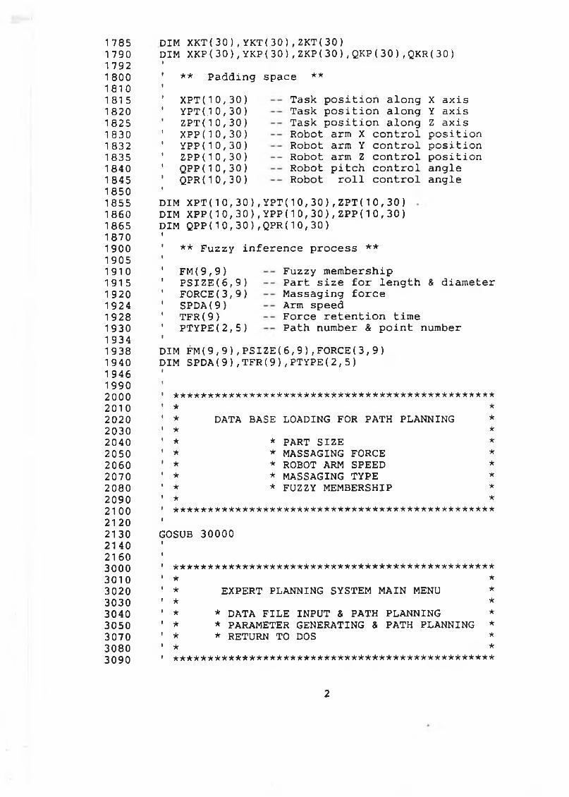
1 7851 7901 7921 800181018151820182518301 8321835184018451850185518601865187019001905191019151 9201924192819301 934193819401946199020002010202020302040205020602070208020902 1 0 021 20213021 402160300030103020303030403050307030803090
DIM XKT(30),YKT(30),ZKT(30)DIM XKP(30),YKP(30),ZKP(30),QKP(30),QKR(30)
** Padding space **
XPT(10,30) YPT(.1 0, 30 ) ZPT(10,30) X P P ( 1 0 , 3 0 ) YPP(10,30 ) Z P P ( 10,30 ) QPP(10,30) QPR(10,3 0 )
Task position along Task position along Task position along Robot arm X control Robot arm Y control Robot arm Z control Robot pitch control Robot roll control
X axis Y axis Z axis position position position angle angle
DIM XPT(10,30),YPT(10,30),ZPT(10,30) DIM XPP(10,30),YPP(10,30),ZPP(10,30) DIM QPP(10,30),QPR(10,30)
** Fuzzy inference process **FM(9,9) PSIZE(6 ,9) FORCE(3,9) SPDA(9) TFR(9) PTYPE(2,5)
Fuzzy membershipPart size for length & diameterMassaging forceArm speedForce retention time Path number & point number
DIM FM(9,9),PSIZE(6,9),FORCE(3,9) DIM SPDA(9),TFR(9),PTYPE(2,5)
★ it*********************************************★ ** DATA BASE LOADING FOR PATH PLANNING ** *
* * PART SIZE ** * MASSAGING FORCE ** * ROBOT ARM SPEED ** * MASSAGING TYPE ** * FUZZY MEMBERSHIP ** *
' * * * * * * * * * * * * * * * * * * * * * * * * * * * * * * * * * * * * * * * * * * * * * * * ■GOSUB 30000
*********************************************** * ** EXPERT PLANNING SYSTEM MAIN MENU ** ** * DATA FILE INPUT & PATH PLANNING ** * PARAMETER GENERATING & PATH PLANNING ** * RETURN TO DOS ** * ***********************************************
2
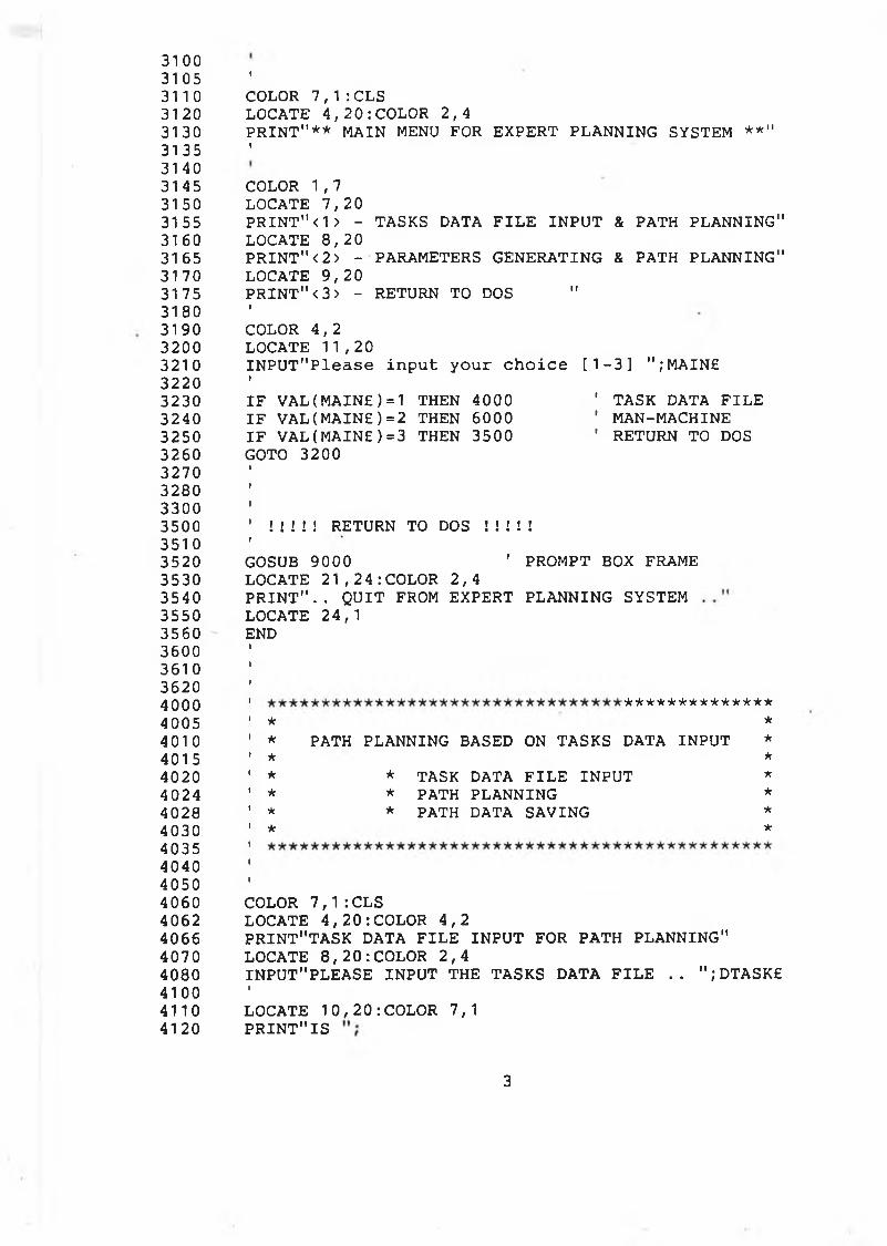
31003105 1
311 0 COLOR 7,1 :CLS31 20 LOCATE 4,20:COLOR 2,43130 PRINT"** MAIN MENU FOR EXPERT PLANNING SYSTEM **"31 35 1
31403145 COLOR 1,73150 LOCATE 7,2031 55 PRINT"<1> - TASKS DATA FILE INPUT & PATH PLANNING"31 60 LOCATE 8,2031 65 PRINT"<2> - PARAMETERS GENERATING & PATH PLANNING"31 70 LOCATE 9,203175 PRINT"< 3 > - RETURN TO DOS "3180 1
3190 COLOR 4,23200 LOCATE 11,203210 INPUT"Please input your choice [1-3] ";MAIN£3220 1
3230 IF VAL(MAINE)=1 THEN 4000 ' TASK DATA FILE3240 IF VAL(MAINE)= 2 THEN 6000 ' MAN-MACHINE3250 IF VAL(MAINE)=3 THEN 3500 ' RETURN TO DOS3260 GOTO 32003270 1
3280 t
33003500 ' ! ! ! ! ! RETURN TO DOS ! ! ! ! !35103520 GOSUB 9000 ' PROMPT BOX FRAME3530 LOCATE 21,24:COLOR 2,43540 PRINT".. QUIT FROM EXPERT PLANNING SYSTEM3550 LOCATE 24,13560 END3600 1
36103620 1
4000 1 **************4005 » * *401 0 ' * PATH PLANNING BASED ON TASKS DATA INPUT *4015 ' * *4020 ' * * TASK DATA FILE INPUT *4024 ' * * PATH PLANNING *4028 ' * * PATH DATA SAVING *4030 ' * *40354040 i
40504060 COLOR 7,1:CLS4062 LOCATE 4,20:COLOR 4,24066 PRINT"TASK DATA FILE INPUT FOR PATH PLANNING"4070 LOCATE 8 ,20:COLOR 2,44080 INPUT"PLEASE INPUT THE TASKS DATA FILE .. ";DTASKE4100 1
4110 LOCATE 10,20:COLOR 7,14120 PRINT"IS
3
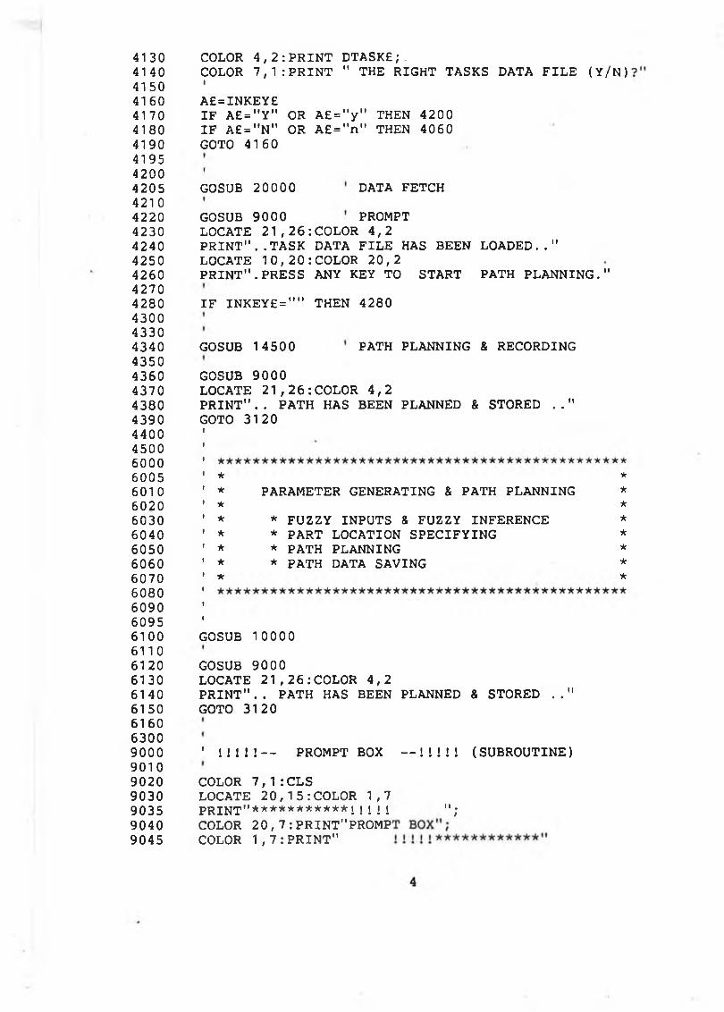
4130414041504160417041804190419542004205421 04220423042404250426042704280430043304340435043604370438043904400450060006005601 0
602060306040605060606070608060906095610061106120613061 406150616063009000901090209030903590409045
COLOR 4,2:PRINT DTASKE; .COLOR 7,1:PRINT " THE RIGHT TASKS DATA FILE (Y/N)IA£=INKEY£IF A£="Y" OR A£="y" THEN 4200 IF A£="N" OR A£="n" THEN 4060 GOTO 4160
GOSUB 20000 DATA FETCHGOSUB 9000 PROMPTLOCATE 21,26:COLOR 4,2PRINT"..TASK DATA FILE HAS BEEN LOADED.."LOCATE 10,20:COLOR 20,2PRINT".PRESS ANY KEY TO START PATH PLANNING."
GOSUB 9000LOCATE 21,26:COLOR 4,2PRINT".. PATH HAS BEEN PLANNED & STORED .."GOTO 3120I!
* * *
' * PARAMETER GENERATING & PATH PLANNING *' * *' * * FUZZY INPUTS & FUZZY INFERENCE *’ * * PART LOCATION SPECIFYING *1 * * PATH PLANNING *1 * * PATH DATA SAVING *' * *
GOSUB 10000GOSUB 9000LOCATE 21,26:COLOR 4,2PRINT".. PATH HAS BEEN PLANNED & STORED .." GOTO 3120
' ! ! ! ! ! — PROMPT BOX — !!!!! (SUBROUTINE)
IF INKEY£="" THEN 4280
GOSUB 14500 PATH PLANNING & RECORDING
COLOR 7,1:CLS LOCATE 20,15:COLOR 1,7 PRINT"***********i! ! ! ! COLOR 20,7: PRINT"PROMP' COLOR 1,7:PRINT"
I« .t
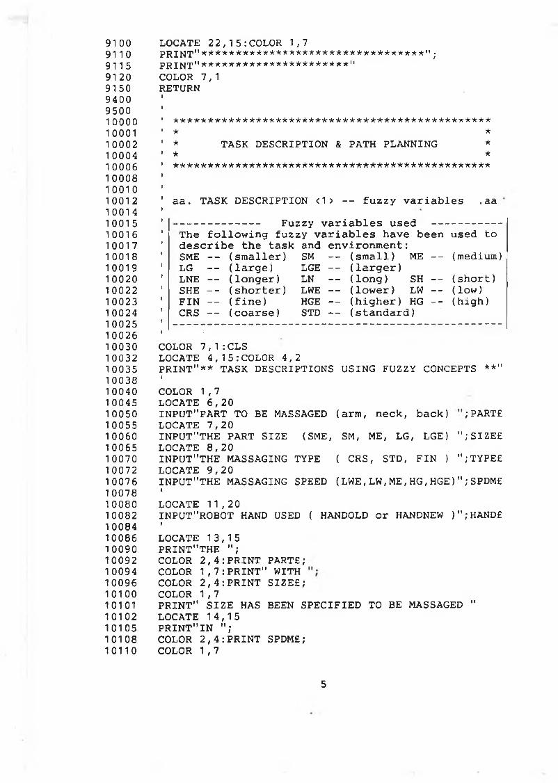
91 009110911591 209150940095001 0 0 0 0100011 0 0 0 21 000410006100081 0 0 1 01 0 0 1 21 001 41001510016100171 0018100191 0 0 2 01 0 0 2 21 0023100241 0025100261003010032100351 00381 0040100451 00501 00551 00601 00651 0070100721 007610078100801008210084100861009010092100941009610100101011010210105101081 0 1 1 0
LOCATE 22,15:COLOR 1,7PRINT" ************************■*********";p r i n t "**********************"COLOR 7,1 RETURN
* * * * * * * * * * * * * * * * * * * * * * * * * * * * * * * * * * * * * * * * * * * * * * * * ** TASK DESCRIPTION & PATH PLANNING ** * ***********************************************
aa. TASK DESCRIPTION <1> -- fuzzy variables .aa------------- Fuzzy variables used ----------The following fuzzy variables have been used to describe the task and environment:SME — (smaller) SM -- (small) ME — (medium)LG — (large) LGE -- (larger)LNE -- (longer) LN — ( long ) SH — (short)SHE -- (shorter) LWE -- (lower) LW -- ( low)FIN -- (fine) HGE -- (higher) HG -- (high)CRS — (coarse) STD -- (standard)
COLOR 7,1:CLS LOCATE 4,15:COLOR 4,2PRINT"** TASK DESCRIPTIONS USING FUZZY CONCEPTS **"ICOLOR 1,7 LOCATE 6,20INPUT"PART TO BE MASSAGED (arm, neck, back) PARTE LOCATE 7,20INPUT"THE PART SIZE (SME, SM, ME, LG, LGE) ";SIZE£ LOCATE 8,20INPUT"THE MASSAGING TYPE ( CRS, STD, FIN ) ";TYPE£ LOCATE 9,20INPUT"THE MASSAGING SPEED (LWE,LW,ME,HG,HGE)";SPDMEILOCATE 11,20INPUT"ROBOT HAND USED ( HANDOLD or HANDNEW )";HANDEILOCATE 13,15 PRINT"THE ";COLOR 2,4:PRINT PARTE;COLOR 1,7:PRINT" WITH COLOR 2,4:PRINT SIZEE;COLOR 1,7PRINT" SIZE HAS BEEN SPECIFIED TO BE MASSAGED " LOCATE 14,15 PRINT"IN ";COLOR 2,4:PRINT SPDME;COLOR 1,7
5
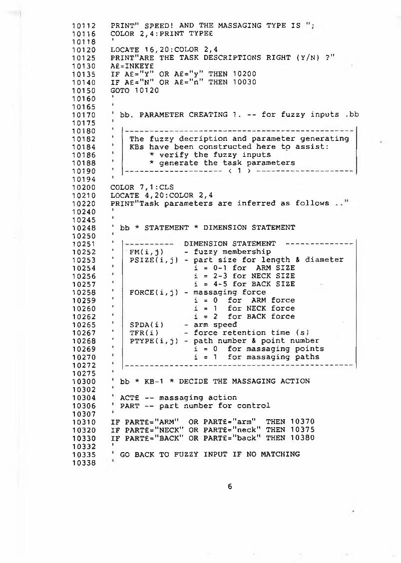
1 0 1 1 21011610118101201 01 251 01 30101351 01 401 01 501 0 1 601016510170101751 01801 0182101841018610188101901 019410200102101 0 2 2 01 02401 02451 024810250102511 02521 02531 02541 02561 0257102581 02591 0260102621 0265102671 0268102691 02701 0272102751 0300103021 03041030610307103101032010330103321033510338
PRINT" SPEED! AND THE MASSAGING TYPE IS COLOR 2,4:PRINT TYPEEILOCATE 16,20:COLOR 2,4PRINT"ARE THE TASK DESCRIPTIONS RIGHT (Y/N) ?" A£=INKEY£IF A£="Y" OR A£="y" THEN 10200 IF A£="N" OR A£="n" THEN 10030 GOTO 10120
bb. PARAMETER CREATING 1. -- for fuzzy inputs .bb
The fuzzy decription and parameter generatingKBs have been constructed here to assist:
1 * verify the fuzzy inputs* generate the task parameters
' < 1 > ---------------------------------------------------ICOLOR 7,1:CLS LOCATE 4,20:COLOR 2,4PRINT"Task parameters are inferred as follows
bb * S T A T E M E N T * D I M E N S I O N S T A T E M E N T
FM( i , j ) PSIZE(i ,j )
DIMENSION STATEMENT -------------- fuzzy membership- part size for length & diameter
i = 0-1 for ARM SIZEi = 2-3 for NECK SIZEi = 4-5 for BACK SIZE
FORCE(i,j) - massaging forcei = 0 for ARM forcei = 1 for NECK forcei = 2 for BACK forcearm speedforce retention time (s) path number & point number i = 0 for massaging pointsi = 1 for massaging paths
SPDA( i )T F R ( i ) P T Y P E ( i , j )
' bb * KB-1 * DECIDE THE MASSAGING ACTIONI' ACTE — massaging action 1 PART -- part number for controlf
IF PART£="ARM" OR PART£="arm" THEN 10370IF PARTE="NECK" OR PART£="neck" THEN 10375IF PARTE="BACK" OR PART£="back" THEN 10380f' GO BACK TO FUZZY INPUT IF NO MATCHING
6
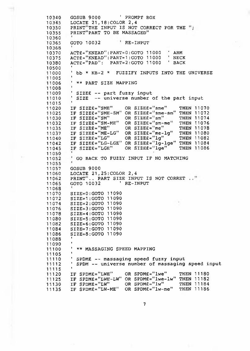
103401 0345103501 03551036010365103681 03701 037510380105001 1 0 0 011 0051 1 00611008110091 1 0 1 011015110201102511 03011032110351103711040110421104511 050110521 10551 10571 1 060110621 10651 1 0681 1 0701 1 0721 1 0741 1076110781 1 0801 1 0821108411086110881 109011100111051 1 1 1 01 1 1 1 21111511120111251113011135
GOSUB 9000 ' PROMPT BOXLOCATE 21,18:COLOR 2,4PRINT"THE INPUT IS NOT CORRECT FOR THE PRINT"PART TO BE MASSAGED"GOTO 10032r RE-INPUTACT£="KNEAD":PART=0:GOTO 11000 ACT£="KNEAD":PART=1:GOTO 11000 ACT£="PAD": PART=2:GOTO 11000
' ARM ' NECK ' BACK
bb * KB-2 * FUZZIFY INPUTS INTO THE UNIVERSE ** PART SIZE MAPPING SIZE£ — part fuzzy inputSIZE — universe number of the part input
IF SIZE£="SME" OR SIZE£= ’sme" THEN 1 1 070IF SIZE£="SME-SM" OR SIZE£= 'sme-sm" THEN 11 072IF SIZE£="SM" OR SIZE£= sm THEN 1 1 074IF SIZE£="SM-ME" OR SIZE£= 'sm-me" THEN 1 1076IF SIZE£="ME" OR SIZE£= 'me" THEN 1 1 078IF SIZE£="ME-LG" OR SIZE£= 'me-lg" THEN 11080IF SIZE£="LG" OR SIZE£= 'lg" THEN 1 1082IF SIZE£="LG-LGE" OR SIZE£= ’lg-lge" THEN 1 1 084IF SIZE£="LGE" OR SIZE£= ’lge" THEN 11086
GO BACK TO FUZZY INPUT IF NO MATCHINGGOSUB 9000LOCATE 21,25:COLOR 2,4PRINT".. PART SIZE INPUT IS NOT CORRET GOTO 10032 ' RE-INPUTSIZE^SIZE:SIZE:SIZE:SIZE:SIZE:SIZE:SIZE:SIZE:
= 0 :GOTO = 1 :GOTO = 2 : GOTO = 3: GOTO »4 : GOTO = 5 : GOTO = 6 : GOTO = 7 : GOTO =8 : GOTO
11090 1 1 090I 1 090II 090I 1 090II 090I 1 090II 090 11 090
' ** MASSAGING SPEED MAPPINGI' SPDM£ -- massaging speed fuzzy input 1 SPDM — universe number of massaging speed inputIIF SPDM£="LWE" OR SPDM£="lwe" THEN 11180IF SPDM£="LWE-LW" OR SPDM£="lwe-lw" THEN 11182IF SPDM£="LW" OR SPDM£="lw" THEN 11184IF SPDM£="LW-ME" OR SPDM£="lw-me" THEN 11186
7
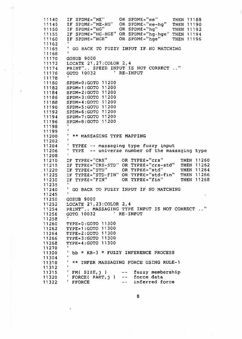
11140 IF SPDM£ = "ME" OR- SPDM£ = "me" THEN 1118811145 IF SPDM£="ME-HG" OR SPDM£="me-hg" THEN 1119011150 IF SPDM£="HG" OR SPDM£="hg" THEN 1119211155 IF SPDM£="HG-HGE" OR SPDM£="hg-hge" THEN 1119411160 IF SPDM£="HGE" OR SPDM£="hge" THEN 111961116211165 'GO BACK TO FUZZY INPUT IF-NO MATCHING 11168 '11170 GOSUB 900011172 LOCATE 21,27:COLOR 2,411174 PRINT".. SPEED INPUT IS NOT CORRECT11176 GOTO 10032 ' RE-INPUT1117811180 SPDM=0:GOTO 1120011182 SPDM=1:GOTO 1120011184 SPDM=2:GOTO 1120011186 SPDM=3:GOTO 1120011188 SPDM=4:GOTO 1120011190 SPDM=5:GOTO 1120011192 SPDM=6 :GOTO 1120011194 SPDM=7:GOTO 1120011196 SPDM=8 :GOTO 1120011198 1
1119911200 ' ** MASSAGING TYPE MAPPING 1120211204 ' TYPE£ -- massaging type fuzzy input11206 ' TYPE -- universe number of the massaging type11208 1
11210 IF TYPE£="CRS" OR TYPE£="crs" THEN 1126011215 IF TYPE£="CRS-STD" OR TYPE£="crs-std" THEN 11262
.11220 IF TYPE£="STD" OR TYPE£="std" THEN 1126411225 IF TYPE£="STD-FIN" OR TYPE£="std-fin" THEN 1126611230 IF TYPE£="FIN" OR TYPE£="fin" THEN 1126811235 '11240 ' GO BACK TO FUZZY INPUT IF NO MATCHING1124511250 GOSUB 900011252 LOCATE 21,23:COLOR 2,411254 PRINT".. MASSAGING TYPE INPUT IS NOT CORRECT .11256 GOTO 10032 ' RE-INPUT1125811260 TYPE=0:GOTO 1130011262 TYPE=1:GOTO 1130011264 TYPE=2:GOTO 1130011266 TYPE=3:GOTO 1130011268 TYPE=4:GOTO 113001127011300 ' bb * KB-3 * FUZZY INFERENCE PROCESS1130411310 ' ** INFER MASSAGING FORCE USING RULE-11131211315 ' FM( SIZE,j ) — fuzzy membership11320 ' FORCE( PART,j ) -- force data11322 ' FFORCE -- inferred force
8
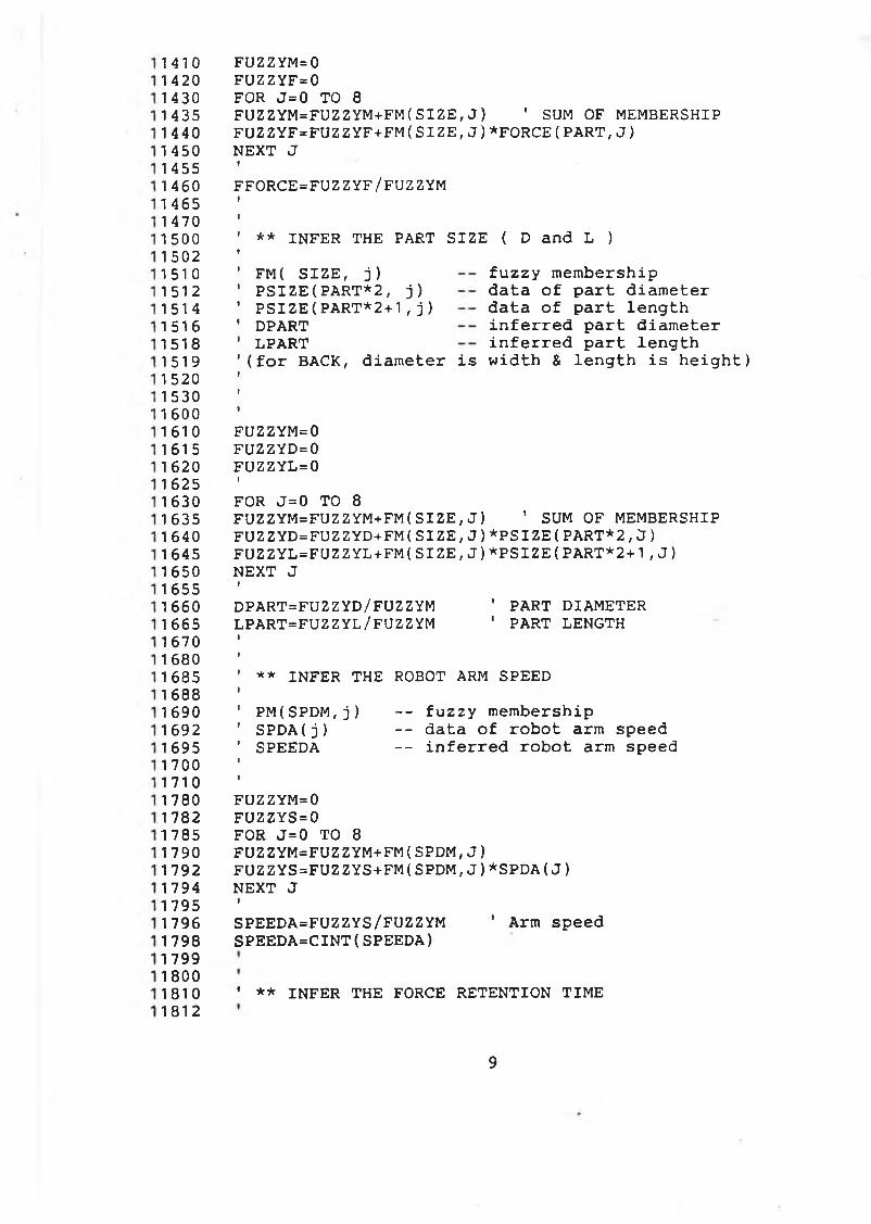
14101420143014351 44014501 4551 4601 4651 4701 5001 50215101512151415161518151915201 5301 6001 61 0
16151 6201625163016351 6401645165016551660166516701 68016851688169016921695170017101780178217851790179217941795179617981799180018101812
FUZZYM=0 FUZZYF=0 FOR J=0 TO 8
F U Z Z Y M = F U Z Z Y M + FM (SIZE,J) ' SUM OF M E M B E R S H I PFUZ Z Y F = F U Z Z Y F + F M (S I Z E ,J )* F O R C E (P A R T ,J )NEXT JIFFORCE=FUZZYF/FUZZYM
** INFER THE PART SIZE { D and L )FM( SIZE, j)PSIZE(PART*2, j) PSIZE(PART*2+1,j) DPART LPART
fuzzy membership data of part diameter data of part length inferred part diameter inferred part length
(for BACK, diameter is width & length is height)
FUZZYM=0FUZZYD=0FUZZYL=0IFOR J=0 TO 8
FUZZYM=FUZZYM+FM(SIZE,J) ' SUM OF MEMBERSHIP FUZZYD=FUZZYD+FM ( SIZE, J ) *PSIZE ( PART*2 , ¿J ) FUZZYL=FUZZYL+FM(SIZE,J)*PSIZE(PART*2+1,J)NEXT JIDPART=FUZZYD/FUZZYM ' PART DIAMETERLPART=FUZZYL/FUZZYM 1 PART LENGTH
** INFER THE ROBOT ARM SPEEDPM(SPDM,j) -- fuzzy membershipSPDA(j) -- data of robot arm speedSPEEDA -- inferred robot arm speed
FUZZYM=0FUZZYS = 0FOR J=0 TO 8
FUZZYM=FUZZYM+FM(SPDM,J)FUZZYS=FUZZYS+FM(SPDM,J)*SPDA(J)NEXT JISPEEDA=FUZZYS/FUZZYM ' Arm speedSPEEDA=CINT(SPEEDA)
• ** INFER THE FORCE RETENTION TIME
9
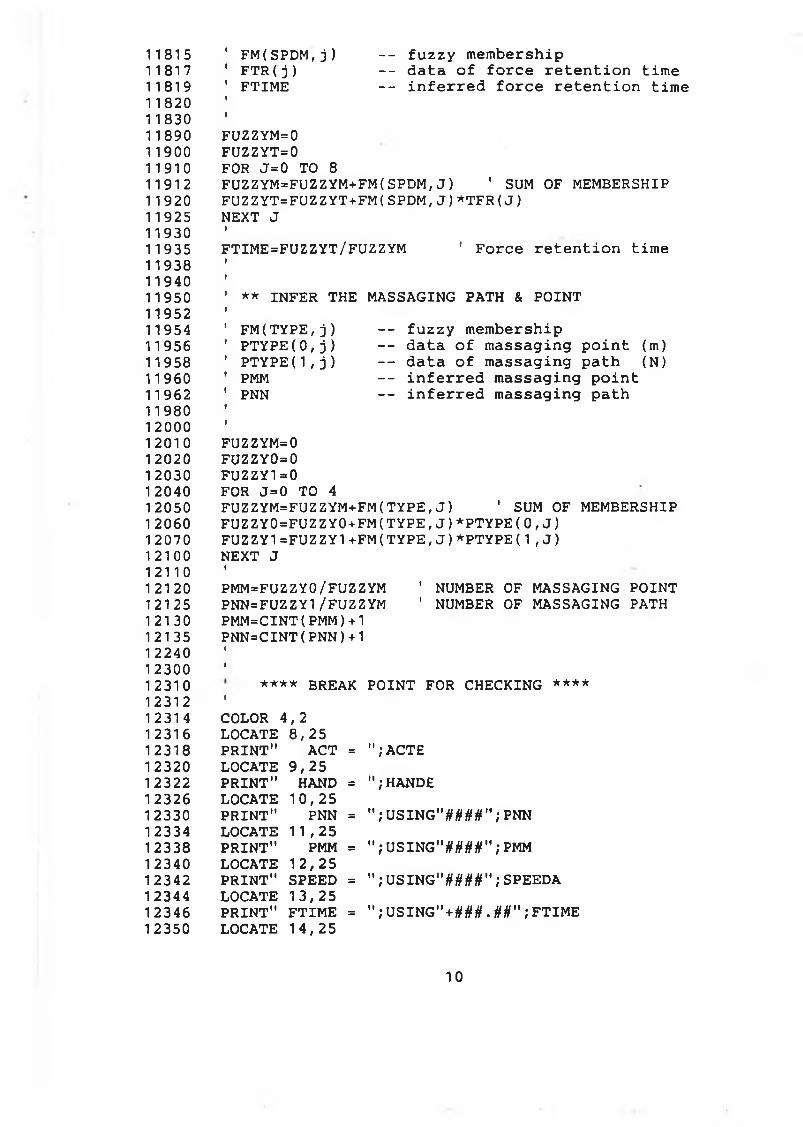
11815 ' FM(SPDM,j) -- fuzzy membership11817 ' FTR(j) -- data of force retention time11819 ' FTIME -- inferred force retention time11820 11 1830 111890 FUZZYM=011900 FUZZYT=011910 FOR J=0 TO 8
11912 FUZZYM=FUZZYM+FM(SPDM,J) ' SUM OF MEMBERSHIP11920 FUZZYT=FUZZYT+FM(SPDM,J)*TFR(J)11925 NEXT J11930 t11935 FTIME=FUZZYT/FUZZYM 1 Force retention time11938 1
11940 1
11950 ' ** INFER THE MASSAGING PATH & POINT11952 111954 ' FM(TYPE,j) — fuzzy membership11956 ' PTYPE(0,j) - - data of massaging point (m)11958 ' PTYPE ( 1 , j) - - data of massaging path (N)11960 ' PMM - - inferred massaging point11962 ' PNN — inferred massaging path11980 t
1 2 0 0 01
1 2 0 1 0 FUZZYM=01 2 0 2 0 FUZZY0=01 2030 FUZZY1=01 2040 FOR J=0 TO 41 2050 FUZZYM=FUZZYM+FM( TYPE,J ) ' SUM OF MEMBERSHIP1 2060 FUZZY0=FUZZY0+FM( TYPE,J ) *PTYPE( 0 , J )
12070 FUZZY1=FUZZY1+FM(TYPE,J )*PTYPE ( 1,J )
1 2 1 0 0 NEXT J1 2 1 1 0
1
1 2 1 2 0 PMM=FUZZY0/FUZZYM ' NUMBER OF MASSAGING POINT12125 PNN=FUZZY1/FUZZYM ' NUMBER OF MASSAGING PATH1 21 30 PMM=CINT(PMM)+112135 PNN=CINT(PNN)+11 2240 »12300 »12310 **** BREAK POINT FOR CHECKING ****12312 1
12314 COLOR 4,212316 LOCATE 8,2512318 PRINT" ACT = "; ACTE12320 LOCATE 9,2512322 PRINT" HAND = ";HANDE12326 LOCATE 10,2512330 PRINT" PNN = "; USING"####";PNN12334 LOCATE 11,2512338 PRINT" PMM = "; USING"####";PMM12340 LOCATE 12,2512342 PRINT" SPEED = "; USING"####";SPEEDA12344 LOCATE 13,2512346 PRINT" FTIME = ";USING"+###.##";FTIME1 2350 LOCATE 14,25
1 0
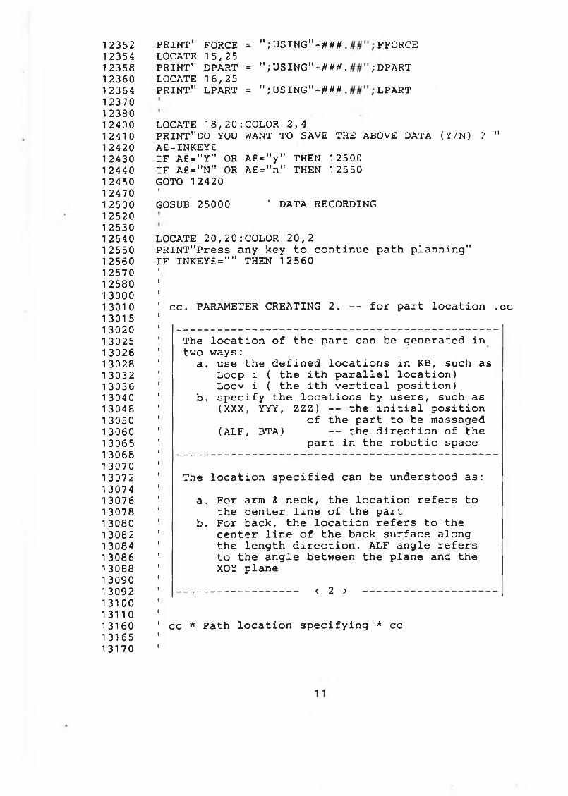
1 23521 23541 23581 23601236412370123801 2400124101 24201 2430124401 2450124701 2500125201 253012540125501 25601257012580130001301 013015130201 30251 30261 30281 30321 30361 3040130481 3050130601 30651 3068130701 3072130741 30761 30781 308013082130841 30861308813090130921310013110131601316513170
PRINT" FORCE = " ; USING"+### FFORCELOCATE 15,25PRINT" DPART = ";USING"+ # # # . ; DPART LOCATE 16,25PRINT" LPART = " ; USING"+ ### LPART
LOCATE 18,20:COLOR 2,4PRINT"DO YOU WANT TO SAVE THE ABOVE DATA (Y/N) ? " A£=INKEY£IF A£="Y" OR A£="y" THEN 12500 IF A£="N" OR A£="n" THEN 12550 GOTO 12420t
GOSUB 25000 ' DATA RECORDING
LOCATE 20,20:COLOR 20,2PRINT"Press any key to continue path planning" IF INKEY£="" THEN 12560
cc. PARAMETER CREATING 2. — for part location .cc
The location of the part can be generated in two ways:
a. use the defined locations in KB, such as Locp i ( the ith parallel location)Locv i ( the ith vertical position)
b. specify the locations by users, such as (XXX, YYY, ZZZ) -- the initial position
of the part to be massaged (ALF, BTA) -- the direction of the
part in the robotic space
The location specified can be understood as:a. For arm & neck, the location refers to
the center line of the partb. For back, the location refers to the
center line of the back surface along the length direction. ALF angle refers to the angle between the plane and the XOY plane
< 2 > --------------------------------
cc * Path location specifying * cc
13190 1 3200 1 3220 1 3222 1 3230 1 3235 1 3240 1 3250 1 3255 1 3262 13265 1 3270 13275 13280 1 3285 1 3290 1 3295 13298 13300 13310 13320 13400 13500 13510 13515 1 3520 1 3525 13530 1 3535 1 3540 13550
.13555 1 3560 1 3565 1 3570 1 3575 1 3580 1 3585 1 3590 1 3592 13595 1 3600 1 3620 1 3625 1 3630 1 3635 1 3640 1 3650 13660 13670 1 3675 1 3680 1 3700 13705 13710
COLOR 7,1:CLS LOCATE 5,15:COLOR 2,4PRINT"*** Part LOCATION specify & input menu ***"ICOLOR 1,7 LOCATE 8,18PRINT"< 1 > - KB assists to generate part location" LOCATE 9,18PRINT" (using the defined positions in KB) "LOCATE 11,18PRINT"< 2 > - User assists to specify part location" LOCATE 12,18PRINT" (specifying the positions directly) "fCOLOR 4,2 LOCATE 14,15INPUT"Which way to specify part position ";WAY£IF VAL(WAYS)=1 THEN 13500 ' KB assistanceIF VAL(WAY£)=2 THEN 14000 ' USER specifyGOTO 13290
' cc * KB HELP * USING KB TO GENERATE PART LOCATIONICOLOR 7,1:CLS LOCATE 2,15:COLOR 4,2PRINT"lnput part LOCATION using the data in KB";ILOCATE 4,18:COLOR 1,7PRINT"Positions for the part parallel to XOY plane" LOCATE 5,23:COLOR 2,4PRINT"( LOCP1,LOCP2,LOCP3,LOCP4,LOCP5 )ILOCATE 7,18:COLOR 1,7PRINT"Positions for the part vertical to XOY plane" LOCATE 8,23:COLOR 2,4PRINT"( LOCV1,LOCV2,LOCV3,LOCV4,LOCV5 )ILOCATE 10,15:COLOR 1,7INPUT"Input your choice (LOCPi or LOCVi) ";LYC£
--------- PARAMETERS DEFINED IN KB -------XXX -- position along X axisYYY -- position along Y axisZZZ — position along Z axisALF -- angle of part with respect of XOYBTA -- angle of part with respect of XOZ
GOSUB 19000II F REINPUT=0 THEN 1 3 8 0 0
12
1 371 51372013725137301 3735137401 37451 37501 37601 3800138101 38201 3830138401 3850138601387013880139001 40001 400514010140151 40201 4025140301 40351 40401 4045140501 40551 40601 40651 40701 40751 40801 4085140901 409514100141051 411 014120141 301414014150141601 41 7014180141901 44001440114402144031 4404
IGOSUB 9000LOCATE 21,23:COLOR 4,2PRINT".. PART LOCATION INPUT IS INCORRECTIGOTO 13200i
xxx=xYYY=Y ZZZ = Z ALF=AF BTA=BAGOTO 14500 ' GO TO PATH PLANNING
CC * USER ASSIST * USER SPECIFY PART LOCATIONCOLOR 7,1: CLS LOCATE 2,20:COLOR 4,2PRINT".. USER SPECIFYING THE PART LOCATION .."ILOCATE 5,15:COLOR 4,2PRINT"PLEASE INPUT THE FOLLOWING PARAMETERS..."ICOLOR 1,7 LOCATE 7,20INPUT"INITIAL POSITION ALONG X AXIS (mm) "; XXX LOCATE 8,20INPUT"INITIAL POSITION ALONG Y AXIS (mm) ";YYY LOCATE 9,20INPUT"INITIAL POSITION ALONG Z AXIS (mm) ";ZZZ LOCATE 10,20INPUT"ANGLE ALF FOR PART WITH XOY (Deg) ";ALF LOCATE 11,20INPUT"ANGLE BTA FOR PART WITH XOZ (Deg) ";BTALOCATE 13,20:COLOR 4,2PRINT"ARE THE INPUTS CORRECT (Y/N) ? " A£=INKEY£IF A£="Y" OR A£="y" THEN 14500 IF A£="N" OR A£="n" THEN 14005 GOTO 14120
*********************************************** * ** PATH PLANNING SECTION ** * TV**********************************************
13
1 4406 1 441 0 1 441 5 1 441 7 14418 1 4420 1 4425 1 4428 1 4430 1 4435 14440 1 4445 1 4448 1 4450 1*4454 14458 1 4460 1 4462 1 4464 14468 1 4470 1 4472 14474 1 4476 1 4480 1 4482 14484 1 4486 1 4490 14500 1 4505 1 4510 14515 1 4520 1 4525 1 4530 1 4535 1 4540 1 4545 1 4560 1 4570 14580 1 4590 1 4600 14610 1 4620 14630 1 4640 15000 15010 15015 1 5020 15022
For arm & neck, the robot hand moves along a line which is defined by initial position & the angles ALF and BTA in Cartesian space:XX0 -- initial position specified along X axis YY0 -- initial position specified along Y axis ZZ0 -- initial position specified along Z axis BTA -- angle between the line and XOZ plane ALF -- angle between the line and XOY planeFor back, the robot hand moves in a flat surface which consists of the points in the back surface coordinates [Xback Yback Zback]:Xback -> [ -DPART/2, +DPART/2 ]Yback -> [0, LPART ]Zback -> [ 0, 0 ]The back surface in Cartesian space is given bya plane attached to a line. The plane is a flatsurface. The line is the center line of the plane along its axial direction.XX0 -- initial position along X axisYY0 -- initial position along Y axisZZ0 -- initial position along Z axisBTA -- angle between the line and XOZ planeALF -- angle between back surface and XOY plane
’ aa. PLANNING STRATEGY & HAND PARAMETERS .aaiCOLOR 7,1:CLSLOCATE 10,20:COLOR 20,2PRINT"PATH PLANNING IS GOING ON, PLEASE WAIT ! "ICC=3.141596/180ALF=ALF*CCBTA=BTA*CC
** Strategies -- Padding or Kneading **
IF ACT£="PAD" THEN 16000 ' Planning for paddingI' OTHERWISE PLANNING FOR KNEADING
bb. PLANNING FOR KNEADING ACTIONS .bb
bb * ARRAY * Array used for keading
14
1 5025 ' XKT(30) -- TASK POSITION ALONG X AXIS1 5027 ' YKT(30) — TASK POSITION ALONG Y AXIS1 5030 ' ZKT(30) -- TASK POSITION ALONG Z AXIS1 5032 ' 00(3,3) -- TASK ORIENTATION15034 ' XKP(30) -- ROBOT ARM X CONTROL POSITION1 5036 ' YKP(30) -- ROBOT ARM Y CONTROL POSITION1 5038 1 ZKP(30) -- ROBOT ARM Z CONTROL POSITION1 5040 ' QKR(30) -- ROBOT ROLL AGNLE1 5044 ' QKP(30) — ROBOT PITCH ANGLE1 5048 1 PP(3) -- ROBOT ARM POSITIONS1 5050 '00(5) -- ROBOT JOINT ANGLE15052 ’ OF(30) -- ROBOT FINGER OPENNING ANGLES15054 ' CPZ(30) — COMPLIANCE GRASPING DISTANCE150601 506215065 ' bb * Parameters Retaining *15068 1
15070 ACTK£=ACT£15075 HANDK£=HAND£15078 PNNK=PNN-11 5080 PMMK=PMM-115082 SPEEDAK=SPEEDA15084 FTIMEK=FTIME1 5086 FFORCEK=FFORCE1 5088 1
1 5090 1
15110 ' bb * Task matrix * Position & orientation15115 t15117 ' ** Initial positions of the part15119 1
15120 XX0=XXX151 25 YY0=YYY15130 ZZ0=ZZZ1 51 40 f15160 1
1 5165 ' ** Task Orientation (Attached to grasp center15168 1
1 51 70 TNX=-COS(BTA)*COS(ALF) nx1 51 72 TNY=-SIN(BTA)*COS(ALF) ny15174 TNZ=-SIN(ALF) ' nz1 5176 f1 51 78 TOX=-SIN(BTA) ox1 5180 TOY=COS(BTA) oy15182 TOZ=0 ' oz1 5184 1
15186 TAX=+COS(BTA)*SIN(ALF) ax15188 TAY=+SIN(BTA)*SIN(ALF) ay15190 TAZ=-COS(ALF) az15192 »15195 1
1 5200 ' ** Task Position (Attached to grasp center)15205 1
15210 DLPART=LPART/PNNK ' part segment15215 1
15
15220 FOR 1=0 TO PNNK1 5225 XKT(I)=XXO+I*DLPART*COS(ALF)*COS(BTA) ’ px15230 YKT(I)= YY0 +1*DLPART*COS(ALF)*SIN(BTA) py15235 ZKT(I)=ZZ0+I*DLPART*SIN(ALF) ' pz1 5240 NEXT I15245 i15248 i15250 1 bb * Finger joint * Finger joint space15252 1
15254 ' ** Initial compliance parameters15256 1
1 5258 IF HANDK£="HANDOLD" OR HANDK£="handold" THEN 1528015260 1
15262 LFING=90 ' HAND -II parameters15264 DFING= 4 015266 ZH=6515270 CPX=-37:CPY=015272 1
15274 GOTO 1530015276 1
15280 LFING=115 ' HAND -I parameters1 5282 DFING= 4015284 ZH=651 5286 CPX=-34:CPY=015288 1
1 5290 1 ** Compliance grasping distance & finger angles15292 1
1 5294 ' DDDN -- the end diameter of the part15296 ' DDD0 -- the initial diameter of the part15298 ' DDDI -- the ith diameter of the part15300 1
1 5302 DDD0=DPART15304 DDDN=DPART1 5308 1
15310 FOR 1=0 TO PNNK15312 DDDI=DDD0+(DDDN-DDD0)*l/PNNK15314 XR=(DDDI-DFING)/215318 XQ=ABS(LFING*LFING-XR*XR)15320 DGRASP=SQR(XQ) ' GRASP DISTANCE1 5321 1
15322 ' ** 1st. compliance distance along Z axis15323 »15325 CPZ(I) = ZH+DGRASP15327 1
15330 1 ** 2 nd. finger joint angle1 5332 I15336 YY=DGRASP:XX=XR15340 GOSUB 17800 ' using KB15345 QF(I)=Q ' FINGER JOINT ANGLE15350 NEXT I15352 f15360 1
15370 ' bb * ARM MATRIX * AFTER COMPLIANCE15374 i
16
1 5376153781538015382153851538815390153921 53951539815399154001 54051541 01 541 515418154201542515430154321543415438154401545015455154601 5465154701 54721 54741 54781548015484154881 54901550015560155651557015575155801560015605156101561 515620156251563015634156381564015642156501565515658
' ** 1st. The wrist orientation is the same' as that of task orientation1
1 ** 2nd. The wrist position after complianceIFOR 1=0 TO PNNKXKP(I)=XKT(I)-(CPX*TNX+CPY*TOX+CPZ(I)*TAX)YKP(I)=YKT(I)-(CPX*TNY+CPY*TOY+CPZ(I)*TAY)Z K P ( I ) = Z K T ( I ) - ( C P X * T N Z + C P Y * T O Z + C P Z ( I ) * T A Z )
NEXT I1
1 bb * Inverse * pitch & roll anglesIFOR 1 = 0 TO -PNNK *00(0,0)=TNX:00(0,1)=TOX:00(0,2)=TAX OO(1,0)=TNY:00(1,1)=TOY:OO(1,2)=TAY 00(2,0)=TNZ:OO(2,1)=T0Z:OO(2,2)=TAZIPP(0)=XKP(I):PP(1)=YKP(I):PP(2)=ZKP(I)BTA=BTAALF=ALFi' ** Inverse solution using KBIGOSUB 17000IIF YERR=1 THEN COLOR 7,1:ENDIQKR(I)=QQ(4):QKP(I)=QQ(6 )INEXT II
' bb * Path data save *
R e c o r d t h e p a t h p l a n n e d f o r K n e a d i n g
' bb * KB -1 * Path planned recordingI' ** 1st. Data file name inputICOLOR 7,1:CLS LOCATE 5,20:COLOR 2,4PRINT"SAVE THE PLANNED PATH AS DATA FILES"ICOLOR 1,7 LOCATE 7,15INPUT"PLEASE INPUT FILE NAME FOR .DOC ";FDOC£ LOCATE 8,15INPUT"PLEASE INPUT FILE NAME FOR .DAT ";FDATE
15660 LOCATE 10, 1 5 : COLOR 2,41 5665 PRINT"ARE THE INPUTS CORRECT (Y/N) ? "1 5668 A£=INKEY£15670 IF A£="Y" OR A£="y" THEN 157001 5675 IF A£="N" OR A£="n' 1 THEN 1562015680 GOTO 1566815685 1
15690 1
15700 ' ** 2 nd. Data processing15705 i15710 CD=180/3.14159615714 FOR 1=0 TO PNNK15716 QKR(I)=QKR(I)*CD:QKP(I)=QKP(I)*CD15718 QF(I)=QF(I)*CD1 5720 NEXT I ■15722 1 *15724 1
15726 ' ** 3rd. data saving section15728 1
15730 ' ** .DOC FILE **1 5731 i15732 OPEN FDOCE FOR OUTPUT AS #115734 PRINT #1 ’ FOR THE PART & PART LOCATION INPUTS1 5736 PRINT #1,' it15738 PRINT #1,' DDD= " USING"*###.###";DPART15740 PRINT #1 , 1 LLL= " USING"+### .###",* LPART15742 PRINT #1 , 1 XX0= " USING"+###.###";XX015744 PRINT #1,' YY0= " USING"*###.###";YY01 5746 PRINT #1,' ZZ0= " USING"*###.###";ZZ01 5748 PRINT #1 ' BTA= " USING"*###.###"}BTA*CD1 5750 PRINT #1,' ALF = " USING"*###.###";ALF*CD1 5752 PRINT #1,' I I
15754 PRINT #1,' AND THE TASK INPUTS"1 5756 PRINT #1 , 1 ACT= " ACTKE15757 PRINT #1,’ HAND= " HANDKE15758 PRINT #1 , ' PNN= " USING"####" ; PNNK1 5760 PRINT #1 , ' PMM= " USING"####" ; PMMK1 5762 PRINT #1 , 'SPEED= " USING"####" ; SPEEDAK15764 PRINT #1,' FTIME= " USING"##.##";FTIMEK1 5766 PRINT #1 , 'FORCE= " USING"##.##"; FFORCEK1 5768 PRINT #1 , ' " : PRINT #1 , " "15770 1
1 5774 print #1 ,' PATH DATA FOR ROBOT MOTION CONTROL"1 5778 PRINT #1,' I I
15780 I15782 PRINT #1,' NX= " USING"*##.##";TNX1 5784 PRINT #1,' NY= " USING"+##.##";TNY15786 PRINT #1,' NZ= " USING" + ##.##";TNZ15790 PRINT #1,’ OX= " USING"+##.##";TOX15792 PRINT #1,' OY= " USING" + ## . ## " ,* TOY15794 PRINT #1,' OZ= " USING" + ##.##";TOZ15798 PRINT #1,' AX= " USING"+ ##.##"; TAX15800 PRINT #1 , ' AY= " USING"+##.##";TAY15804 PRINT #1, ' AZ= " USING1'*##.##"; TAZ1 5806 t
18
15810 15812 1581 4 1 581 6
15818 15820 15822 15824 15828 1 5830 1 5834 15840 1 5842 1 5845 15850 1 5852 15854 15858 15860 15864 1 5868 15870 1 5876 15878 1 5880 15882 1 5885 1 5890 15895 1 5898 15900 15905 1 591 0 15915 1 5920 1 5930 15940 1 5950 1 5970 15990 16000 1 601 5 16020 16025 1 6030 16032 1 6034 16036 16038 1 6040 16042 16044 16046 16048 16050
FOR 1=0 TO PNNK PRINT #1,PRINT #1,PRINT #1,PRINT #1,PRINT #1,PRINT #1,PRINT #1,PRINT #1,NEXT I CLOSE #1
" P O S I T I O N = " ; U S I N G " # # # " ; I" PX= " USING" + jW . W ' ; X K P ( I )» PY= " USING" + W . W ' ; Y K P ( I )" PZ= " USING" + W . W ; ZKP (I )" QP= " USING" + W . # # # " ; QKP ( I )" QR= " US I N G " + W . W ;QKR ( I )" QF= "I f I I
USING" + ¡ W . W ' ; Q F ( I )
** .DAT FILE **
OPEN FDAT£ FOR OUTPUT AS #1IWRITE Jf 1 , ACTK£WRITE # 1,HANDK£WRITE #1,PNNK WRITE § 1,PMMK WRITE § 1,SPEEDAK WRITE #1,FTIMEK WRITE #1,FFORCEKIWRITE § 1,TNX,TNY,TNZ WRITE #1,TOX,TOY,TOZWRITE #1,TAX,TAY,TAZ1
FOR 1=0 TO PNNKWRITE U1,XKP(I),YKP(I),ZKP(I)WRITE #1,QKP(I),QKR(I),QF(I)NEXT ICLOSE #1IRETURN
CC, PLANNING FOR PADDING ACTION .CCCC * ARRAY * Array
XPT(10,30) -- TASKYPT(10,30) -- TASKZPT(10,30) -- TASK00(3,3) -- TASKXPP(10,30) — ROBOTYPP(10,30) — ROBOTZPP(10,30) -- ROBOTQPR(10,30) -- ROBOTQPP(10,30) — ROBOTQQ(5) -- ROBOTPP ( 3 ) — ROBOT
CONTROLCONTROLCONTROL
ROLL ANGLE
X AXIS Y AXIS Z AXISPOSITIONPOSITIONPOSITION
(X Y Z)
19
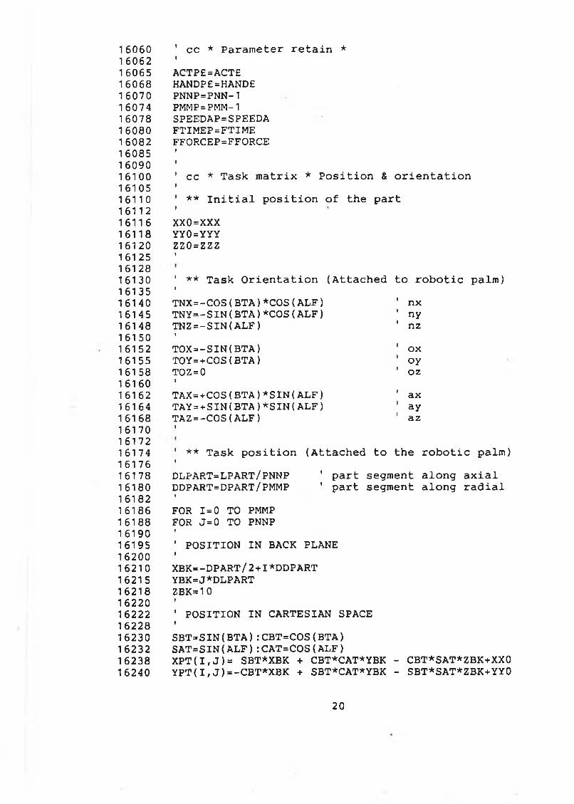
1 60601 60621 6065160681 6070160741 6078160801 6082160851 609016100161051 611 0
1611216116161181 612016125161281613016135161401614516148161501615216155161581616016162161641616816170161721617416176161781618016182161861618816190161951620016210162151 621816220162221622816230162321623816240
' cc * Parameter retain *IACTP£=ACT£HANDP£=HAND£PNNP=PNN-1 PMMP=PMM-1 SPEEDAP=SPEEDA FTIMEP=FTIME FFORCEP=FFORCE
' cc * Task matrix * Position & orientationI1 ** Initial position of the partXX0=XXX YY0=YYYzzo=zzzI
' ** Task Orientation (Attached to robotic palm)<TNX=-COS(BTA)*COS(ALF)TNY=-SIN(BTA)*COS(ALF)TNZ=-SIN(ALF)I:TOX=-SIN(BTA)T0Y=+C0S(BTA)TOZ = 0ITAX=+C0S(BTA)*SIN(ALF)TAY=+SIN(BTA)*SIN(ALF)TAZ=-COS(ALF)I
' ** Task position (Attached to the robotic palm)IDLPART=LPART/PNNP ' part segment along axialDDPART=DPART/PMMP 1 part segment along radialIFOR 1=0 TO PMMP FOR J=0 TO PNNPr' POSITION IN BACK PLANEIXBK=-DPART/2+I*DDPART YBK=J*DLPART ZBK=10I' POSITION IN CARTESIAN SPACE »SBT=SIN(BTA):CBT=COS(BTA)SAT=SIN(ALF):CAT=COS(ALF)XPT(I,J )= SBT*XBK + CBT*CAT*YBK - CBT*SAT*ZBK+XX0 YPT( I, J )=-CBT*XBK + SBT*CAT*YBK - SBT*SAT*ZBK+YY0
nxnynzoxoyozaxayaz
20
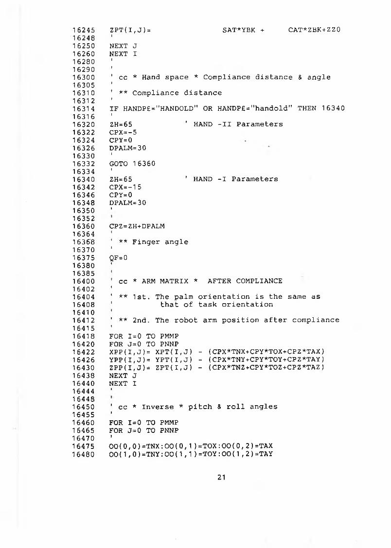
1 6245162481 62501 6260162801 62901 63001 63051 631 01631 21 631 41631616320163221 6324163261633016332163341 63401634216346163481635016352163601 6364163681 637016375163801638516400164021 64041640816410164121641516418164201642216426164301643816440164441644816450164551646016465164701647516480
Z P T (I ,J )=I SAT*YBK + CAT*ZBK+ZZ0NEXT J N EXT I
' cc * Hand space * Compliance distance & angleI1 ** Compliance distanceIIF HANDP£="HANDOLD" OR HANDP£="handold" THEN 16340IZH=65 ' HAND -II ParametersCPX=-5CPY=0DPALM=30IGOTO 16360IZH=65 1 HAND -I ParametersCPX=-15 CPY= 0 DPALM=30I
CPZ=ZH+DPALMI' ** Finger angleIQF=0II' cc * ARM MATRIX * AFTER COMPLIANCEI' ** 1st. The palm orientation is the same as ' that of task orientationI’ ** 2nd. The robot arm position after compliance 1FOR 1=0 TO PMMP FOR J= 0 TO PNNPXPP(I,J)= XPT(I,J ) - (CPX*TNX+CPY*TOX+CPZ*TAX)YPP(I,J )= YPT(I,J ) - (CPX*TNY+CPY*TOY+CPZ*TAY) ZPP(I,J)= ZPT(I, J ) - (CPX*TNZ+CPY*TOZ+CPZ*TAZ)NEXT J NEXT II
' cc * Inverse * pitch & roll anglesIFOR 1=0 TO PMMP FOR J=0 TO PNNPi00(0,0)=TNX:00(0,1)=TOX:00(0,2)=TAX 00(1,0)=TNY:00(1,1)=T0Y:00(1,2)=TAY
21
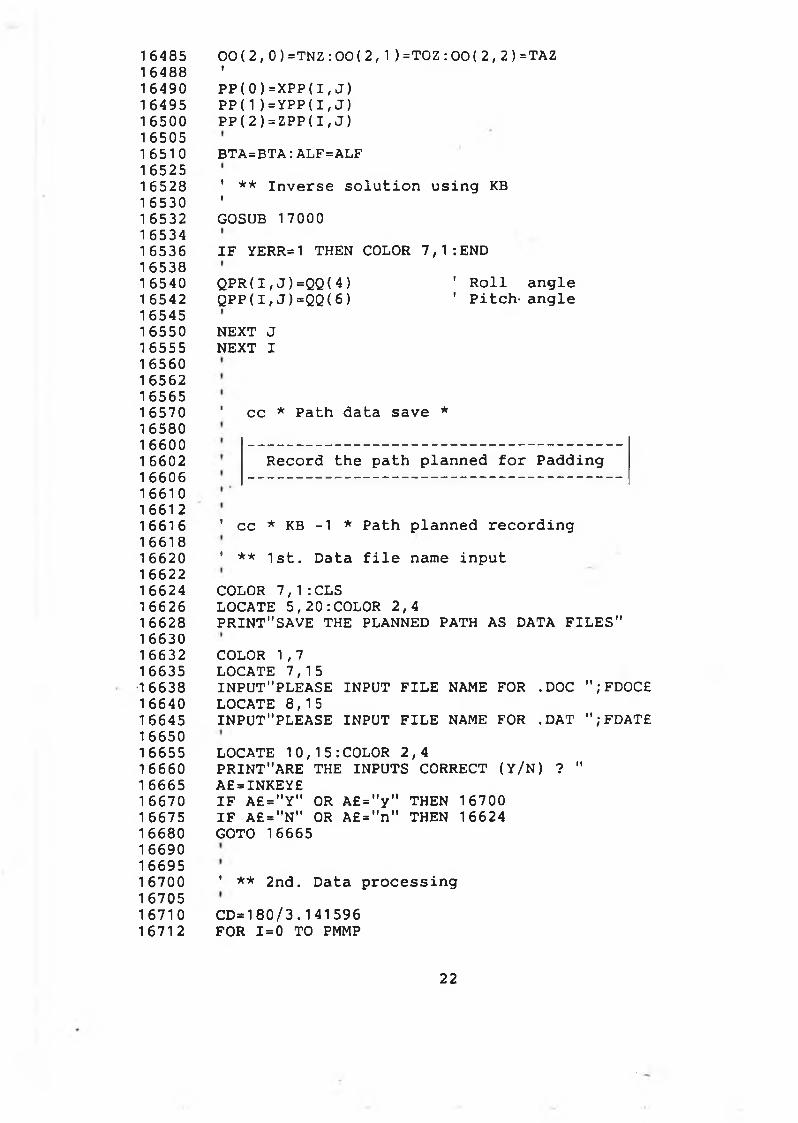
16485 00(2,0)=TNZ:00(2,1)=T0Z:00(2,2)=TAZ16488 ’16490 PP(0)=XPP(I,J)16495 PP(1)=YPP(I,J)16500 PP(2)=ZPP(I,J)1 650516510 BTA=BTA:ALF=ALF1 652516528 ' ** Inverse solution using KB16530 '16532 GOSUB 17000 1 653416536 IF YERR=1 THEN COLOR 7,1:END 1653816540 QPR(I,J )=QQ(4) ' Roll angle1 6542 QPP(I,J )=QQ(6 ) ' Pitch- angle1654516550 NEXT J16555 NEXT I16560 16562 1656516570 1 cc * Path data save *16580 1 6600 1 6602 1 6606 16610 1661216616 ' cc * KB -1 * Path planned recording1661816620 ' ** 1st. Data file name input1 662216624 COLOR 7,1:CLS16626 LOCATE 5,20:COLOR 2,416628 PRINT"SAVE THE PLANNED PATH AS DATA FILES" 1663016632 COLOR 1,7 16635 LOCATE 7,1516638 INPUT"PLEASE INPUT FILE NAME FOR .DOC ";FDOC£1 6640 LOCATE 8,1516645 INPUT"PLEASE INPUT FILE NAME FOR .DAT ";FDATE1665016655 LOCATE 10,15:COLOR 2,416660 PRINT"ARE THE INPUTS CORRECT (Y/N) ? "16665 A£=INKEY£16670 IF A£="Y" OR A£="y" THEN 1670016675 IF A£="N" OR A£="n" THEN 1662416680 GOTO 16665166901669516700 ' ** 2nd. Data processing1670516710 CD=180/3.141596 16712 FOR 1=0 TO PMMP
Record the path planned for Padding
22
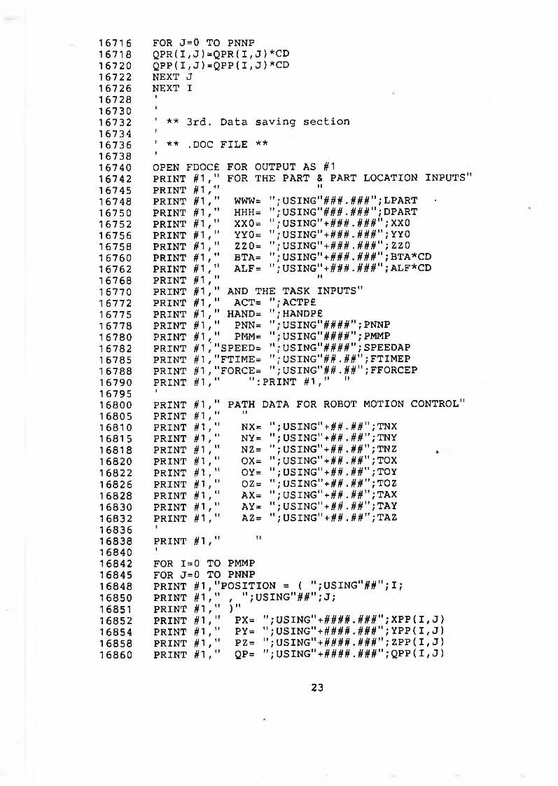
1 671 616718167201 67221 6726167281 67301 67321 67341 67361 67381 6740167421 67451 67481 67501 67521 6756167581 67601 6762167681 67701 6772167751 67781 67801 67821 6785167881 67901 6795168001 68051 681 01 681 5168181 6820168221 682616828168301 683216836168381 68401 68421684516848168501685116852168541685816860
FOR J=0 TO PNNP QPR( I , J ) =QPR( I , J ) *CD QPP( I , J ) = QPP( I , J ) *CD NEXT J NEXT I
1 ** 3 r d . D a t a s a v i n g s e c t i o nI' ** .DOC F I L E **t
OPEN FDOC£ FOR OUTPUT AS #1PRINT #1 , " FOR THE PART & PART LOCATION INPUTSPRINT #1 , ■II II
PRINT #1 , " www= " , U S I N G " # # # . # # # " ; L P A R T •PRINT #1 , " HHH= " , U S I N G " # # # . # # # " ; DPARTPRINT #1 , " XX0= " , U S I N G " + # # # . # # # " ; XX0PRINT #1 , " YY0= " , U S I N G " + # # # • # # # " ; YY0PRINT #1 , " ZZ0= " , U S I N G " + # # # . # # # " ; ZZ0PRINT #1 , " BTA= " , U S I N G " * # # # . # # # " ; BTA*CDPRINT #1 , " ALF= " , U S I N G " + # # # . # # # " ; ALF*CDPRINT #1 ,
II II
PRINT #1 , " AND THE TASK INPUTS"PRINT #1 , " ACT= " , ACTPEPRINT #1 , " HAND= " , HANDPEPRINT #1 , " PNN= " , USI NG"####" ; PNNPPRINT #1 , " PMM= " USING"####";PMMPPRINT #1 ; "SPEED= ", USING" ####" ; SPEEDAPPRINT , " F T I M E = " , U S I N G " # # . # # " ; F T I M E PPRINT #1, "FORCE= " U S I N G " # # . # # " ; FFORCEPPRINT1 #1, " " : PRI NT # 1 , " "
PRINT # i , " PATH DATA FOR ROBOT MOTION CONTROL"PRINT #1,
Il II
PRINT # i , NX= " U S I N G " + # # . # # " ; TNXPRINT #1, NY= " U S I N G " + # # . # # " ; T N YPRINT # i , " NZ= " U S I N G " + # # . # # " ; TNZPRINT #1, ox= " U S I N G " + ## . ##" ," TOXPRINT # 1 , " OY= " USING" + ## . ##" ,’ TOYPRINT #1, " OZ= " U S I N G " + # # . # # " ; TOZPRINT #1, AX= " USING" + # # . # # " ; TAXPRINT #1, AY= " USING" + ## . ##" ,' TAYPRINT1 #1, " AZ= " USING" + ## . ##" ,’ TAZ
PRINT1 #1, Il II
FOR 1 ==0 TO PMMPFOR J==0 TO PNNPPRINT #1, ' ' P O S I T I O N = ( " ; U S I N G " # # " ; I ;PRINT #1, " , " ; U S I N G " # # " ; J ;PRINT #1, " ) "PRINT #1, " PX= " ; U S I N G " + # # # # . # # # " ; X P P ( I , J )PRINT #1, " PY= " ; U S I N G " + # # # # . # # # " ; YPP( I , J )PRINT #1, " PZ= " ; U S I N G " + # # # # . # # # " ; ZPP( I , J )PRINT #1, " QP= " ; U S I N G " + # # # # . # # # " ; QPP( I , J )
23
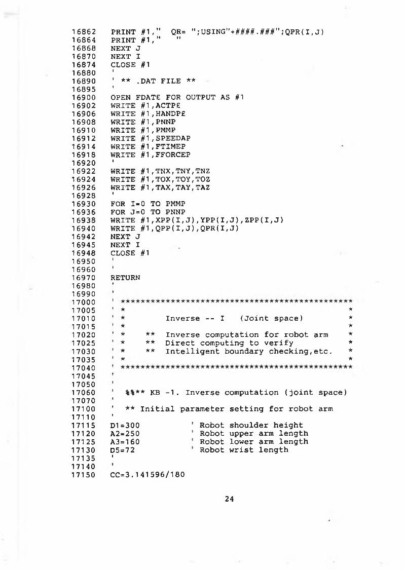
1 6862168641 686816870168741 68801 68901 68951 69001 69021 6906169081 691 01 691 216914169181 69201 69221692416926169281 69301 693616938169401 69421 6945169481 695016960169701698016990170001 70051 7010170151 70201 702517030170351 7040170451 70501 706017070171001711017115171201712517130171351714017150
PRI NT # 1 , " QR= " ; U S I N G " + # W . W ' ; Q P R ( I , J ) P RI NT # 1 , " "NEXT J NEXT I CLOSE #1I' ** . DAT F I L E **IOPEN FDATE FOR OUTPUT AS #1WRITE # 1 , ACTPEWRITE # 1 , HANDPEWRITE # 1 , PNNPWRITE § 1 , PMMPWRITE # 1 , SPEEDAPWRITE § 1 , F T I M E PWRITE #1 , FFORCEPIWRITE § 1 , T N X , T N Y , TNZ WRITE #1 , T O X , T O Y , TOZ WRITE § 1 , T A X , T A Y , TAZIFOR 1=0 TO PMMP FOR J = 0 TO PNNPWRITE # 1 , X PP( I , J ) , Y P P ( I , J ) , ZPP ( I , J )WRITE #1 , QPP( I , J ) , QPR( I , J )NEXT J NEXT I CLOSE #1
R E T U R N
* *
* I n v e r s e - - I ( J o i n t s p a ce ) *★ ** ** I n v e r s e c o m p u t a t i o n f o r r o b o t arm ** ** D i r e c t c o mp u t i ng t o v e r i f y ** ** I n t e l l i g e n t b o u n d a r y c h e c k i n g , e t c . ** *
%%** KB - 1 . I n v e r s e c o m p u t a t i o n ( j o i n t space)
** I n i t i a l p a r a m e t e r s e t t i n g f o r r o b o t arm
D1=300 ' Robot s h o u l d e r h e i g h tA2=250 ' Robot u pp e r arm l e n g t hA3=160 1 Robot l o w e r arm l e n g t hD5=72 ' Robot w r i s t l e n g t hI
CC=3.141596/180
24
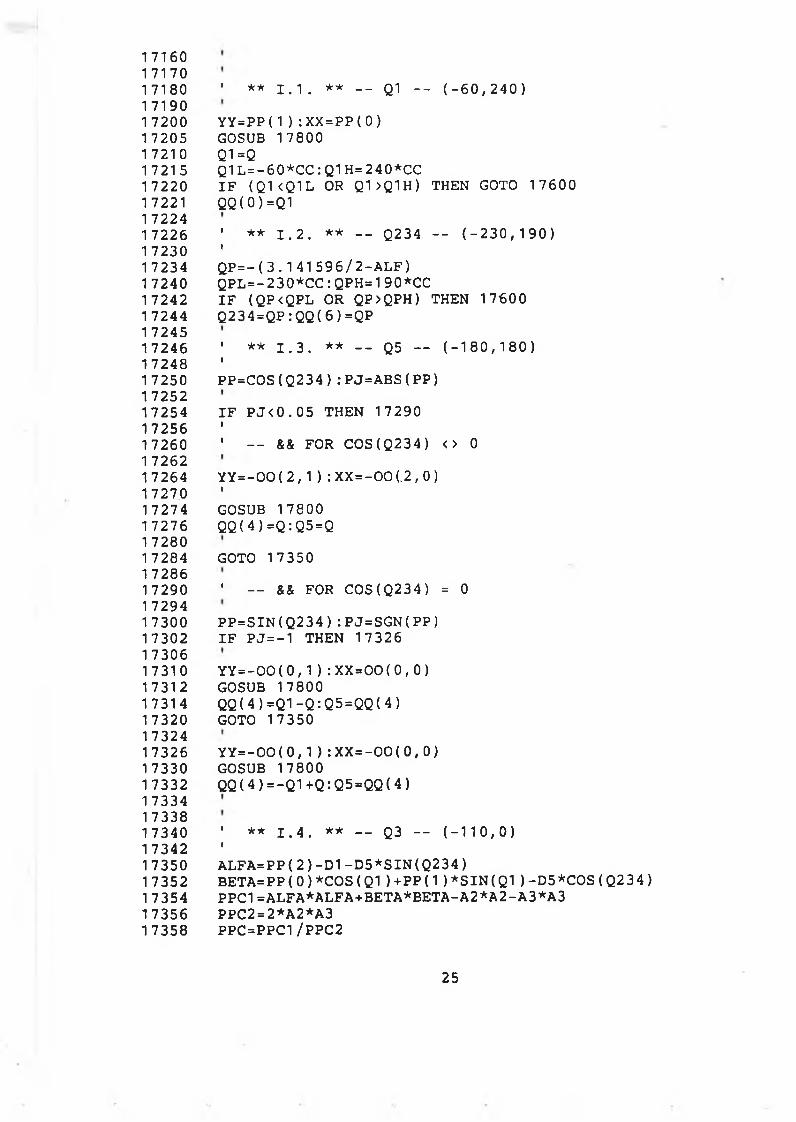
716071707180 1 ** 1 . 1 . ** - - Q1 - - ( - 6 0 , 2 4 0 )71907200 YY=PP( 1 ) : XX=PP( 0 )7205 GOSUB 17800 7210 Q1=Q7215 Q1L=- 60*CC:Q1H=240*CC7220 I F ( Q1<Q1L OR Q1>Q1H) THEN GOTO 176007221 QQ( 0 ) =Q1 72247226 ' ** 1 . 2 . ** - - Q234 - - ( - 2 3 0 , 1 9 0 )7230 '7234 Q P = - ( 3 . 1 4 1 5 9 6 / 2 - A L F )7240 Q P L = - 230*00 : QPH=190*CC7242 I F ( QP<QPL OR QP>QPH) THEN 176007244 Q234=QP: QQ( 6 ) =QP72457246 1 ** 1 . 3 . ** - - Q5 — ( - 1 8 0 , 1 8 0 )7248 '7250 P P = C O S ( Q 2 3 4 ) : P J = A B S ( P P )72527254 I F P J < 0 . 0 5 THEN 1 7290 7256 '7260 ' - - && FOR C OS ( Q 2 3 4 ) <> 072627264 Y Y = - 0 0 ( 2 , 1 ) : X X = - 0 0 ( .2,0)7270 '7274 GOSUB 178007276 QQ( 4 ) = Q : Q5=Q72807284 GOTO 1735072867290 ' — && FOR C OS ( Q2 3 4 ) = 072947300 P P = S I N ( Q 2 3 4 ) : P J = S G N ( P P )7302 I F P J= - 1 THEN 1732673067310 Y Y = - 0 0 ( 0 , 1 ) : XX= 0 0 ( 0 , 0 )7312 GOSUB 178007314 Q Q ( 4 ) = Q 1 - Q : Q5=QQ( 4 )7320 GOTO 1735073247326 Y Y = - 0 0 ( 0 , 1 ) : X X = - 0 0 ( 0 , 0 )7330 GOSUB 178007332 Q Q ( 4 ) = - Q 1 + Q : Q 5 = Q Q ( 4 )733473387340 ' ** 1 . 4 . ** — Q3 — ( - 1 1 0 , 0 )7342 '7350 A L F A = P P ( 2 ) - D 1 - D 5 * S I N ( Q 2 3 4 )7352 B E T A = P P ( 0 ) * C O S ( Q 1 ) + P P ( 1 ) * S I N ( Q 1 ) - D 5 * C O S ( Q 2 3 4 ) 7354 PPC1 =ALFA*ALFA+BETA*BETA-A2*A2-A3*A3 7356 PPC2=2*A2*A37358 PPC=PPC1/PPC2
25
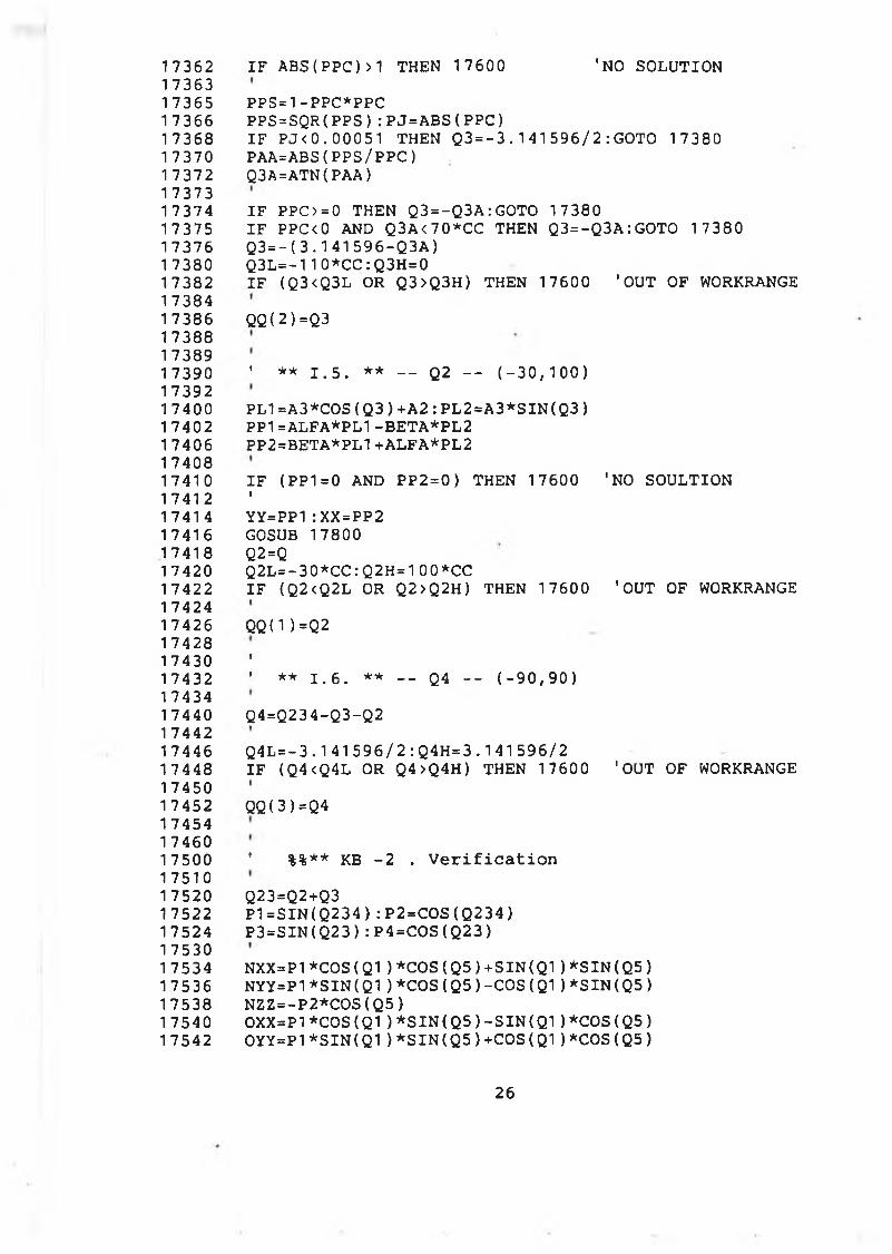
17362 I F A BS ( PPC)>1 THEN 17600 'NO SOLUTION1 736317365 PPS=1-PPC*PPC17366 P PS = S Q R ( PP S ) : PJ = AB S ( PP C )17368 I F P J < 0 . 00051 THEN Q 3 = - 3 . 1 4 1 5 9 6 / 2 : GOTO 17380 17370 PAA=ABS( PPS/ P P C )17 372 Q3A=ATN( PAA)1 737317374 I F PPC>=0 THEN Q3=- Q3A: GOTO 1738017375 I F PPC<0 AND Q3A<70*CC THEN Q3=- Q3A: GOTO 1738017376 Q 3 = - ( 3 . 1 4 1 5 9 6 - Q 3 A )17380 Q 3 L = - 110*CC: Q3H=01 7382 I F (Q3 <Q3L OR Q3>Q3H) THEN 17600 ' OUT OF WORKRANGE 1 738417386 Q Q ( 2 ) =Q3 17388 1 738917390 ' ** 1 . 5 . ** — Q2 - - ( - 3 0 , 1 0 0 )1739217400 P L 1 = A 3 *C 0S ( Q 3 ) + A 2 : P L 2 = A 3* S I N ( Q 3 )1 7402 PP1=ALFA*PL1 - BE T A * P L 2 17406 PP2=BETA*PL1+ALFA*PL2 1740817410 I F (PP1=0 AND PP2=0) THEN 17600 'NO SOULTION 17412 '17414 YY=PP1 :XX=PP217416 GOSUB 1780017418 Q2=Q17420 Q2L=- 30*CC:Q2H=100*CC1 7422 I F ( Q2<Q2L OR Q2>Q2H) THEN 17600 ' OUT OF WORKRANGE1 742417426 Q Q ( 1 ) =Q2 1 7428 17430 '17432 ' ** 1 . 6 . ** - - Q4 - - ( - 9 0 , 9 0 )1743417440 Q4=Q234-Q3-Q21 744217 446 Q4L = - 3 .1 41 5 9 6 / 2 : Q 4 H = 3 .1 41 596/217448 I F (Q4 <Q4L OR Q4>Q4H) THEN 1 7600 'OUT OF WORKRANGE1745017452 QQ( 3 ) =Q41 7454 1 746017500 ' %%** KB - 2 . V e r i f i c a t i o n1751017520 Q23=Q2+Q317522 P 1 = S I N ( Q 2 3 4 ) : P 2 = C O S ( Q2 3 4 )17524 P 3 = S I N ( Q 2 3 ) : P 4 = C O S ( Q 2 3 )1 75301 7534 NXX=P1*COS(Q1 ) * C O S ( Q 5 ) + S I N ( Q 1 ) * S I N ( Q 5 )17536 NYY=P1*SI N( Q 1 ) * C O S ( Q 5 ) - C O S ( Q 1 ) * S I N ( Q 5 )17538 NZZ=- P2*COS( Q5)1 7540 OXX=P1*COS(Q1 ) * S I N ( Q 5 ) - S I N ( Q 1 ) * C O S ( Q 5 )17542 0 Y Y = P 1 * S I N ( Q 1 ) * S I N ( Q 5 ) +COS( Q1) *COS( Q5)
26
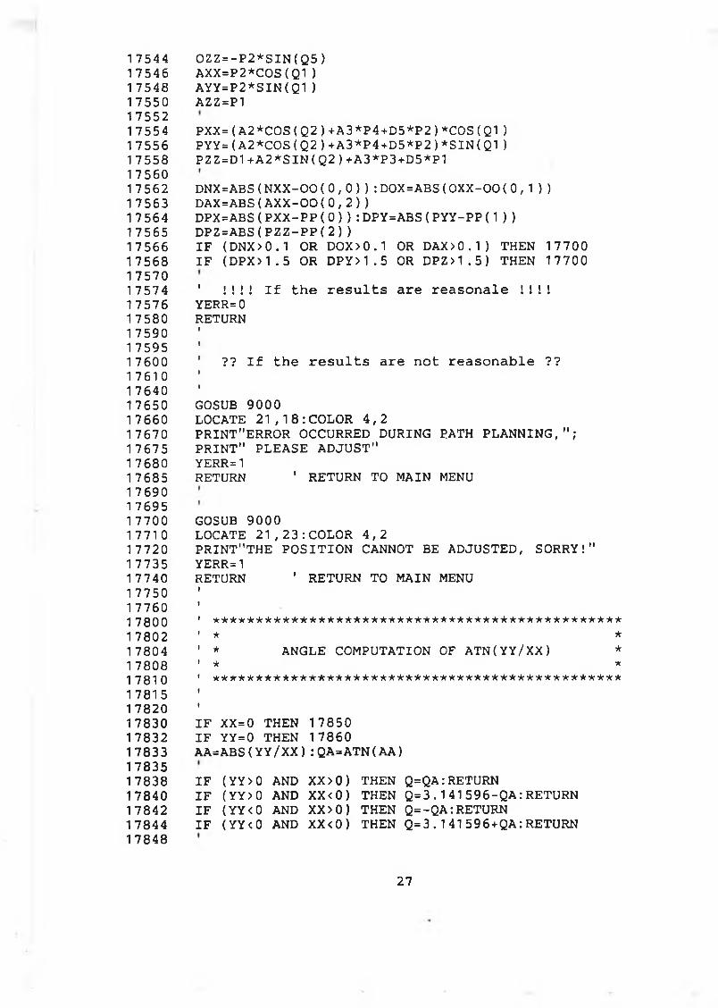
17544 O Z Z = - P 2 * S I N ( Q 5 )17546 A XX =P2* C0 S( Q1)17548 A Y Y = P 2 * S I N ( Q 1 )17550 AZZ=P1 1 75521 7554 PXX=( A2*COS( Q2) +A3*P4+D5*P2) *COS( Q1 )1 7556 P Y Y = ( A 2 * C O S ( Q 2 ) +A3*P4+D5*P2)*SIN(Q1 )17558 P Z Z = D 1 + A 2 * S I N ( Q 2 ) +A3*P3+D5*P1 1 75601 7562 DNX=ABS( N X X - 0 0 ( 0 , 0 ) ) : DOX=ABS( 0 X X - 0 0 ( 0 , 1 ) )17563 D A X = A B S ( A X X - 0 0 ( 0 , 2 ) )1 7564 DPX=ABS( P X X - P P ( 0 ) ) : DPY=ABS( P Y Y - P P (1 ) )1 7565 D P Z = A B S ( P Z Z - P P ( 2 ) )17566 I F ( DNX>0.1 OR DOX>0.1 OR DAX>0. 1) THEN 1 770017568 I F ( DPX>1 . 5 OR D PY>1. 5 OR D P Z>1. 5) THEN 177001757017574 ' ! ! ! ! I f t h e r e s u l t s a r e r e a s o n a l e ! ! ! !1 7576 YERR= 0 17 580 RETURN 1 7590 1 759517600 ' ?? I f t he r e s u l t s a r e n o t r e a s o n a b l e ??17610 '1 764017650 GOSUB 900017660 LOCATE 2 1 , 1 8 : C O L O R 4 , 217670 PRINT"ERROR OCCURRED DURING PATH P L A N N I N G , " ;17675 PRINT" PLEASE AD J U S T "17 680 YERR=117685 RETURN ' RETURN TO MAIN MENU1 7690 1 769517700 GOSUB 900017710 LOCATE 21, 2 3 : COLOR 4 , 217720 PRI N T " T HE P O S I T I O N CANNOT BE ADJUSTED, SORRY!"17735 YERR=117740 RETURN ' RETURN TO MAIN MENU1 7750 17760 '17800 ' ***********************************************17802 ' * *17804 ' * ANGLE COMPUTATION OF A T N ( Y Y / X X ) *17808 ' * *17810 1 ***********************************************17815 1782017830 I F XX=0 THEN 1785017832 I F YY=0 THEN 1786017833 AA=ABS( Y Y /X X ) : QA=AT N( A A )178351 7838 I F ( Y Y >0 AND XX>0) THEN Q=QA:RETURN1 7840 I F ( YY > 0 AND XX<0) THEN Q = 3 . 1 4 1 5 9 6 - Q A : RETURN1 7842 I F ( YY < 0 AND XX>0) THEN Q=-Q A:R ETUR N1 7844 I F ( Y Y <0 AND XX<0) THEN Q = 3 . 1 4 1 596 + QA:RETURN1 7848
27
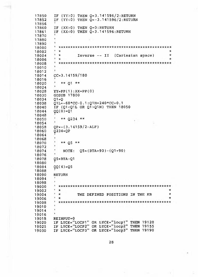
1 78501 78521 78561 7860178611 7870178801 789018000180021800418006180081 801 0180121801418016180201802418028180301803418038180401804418048180501805418058180601806418068180701807218074180761807818080180841808818090180941809819000190021 9004190061900819010190141901619018190201902519030
I F ( YY>0) THEN Q = 3 .1 41 5 9 6 / 2 : RETURNI F ( Y Y < 0) THEN Q=- 3 . 1 4 1 5 9 6 / 2 : RETURNII F ( XX>0) THEN Q=0:RETURNI F ( XX<0) THEN Q = 3 . 1 4 1 5 9 6 : RETURN»I
1 ******************************* ** * * * * * * * * * * * * * * ' ★ *' * I n v e r s e — I I ( C a r t e s i a n s p a ce ) *' * *
I
C C = 3 . 14159/180t1 ** Q1 **iYY=PP(1 ) : XX=PP( 0 )GOSUB 17800 Q1 =QQ 1 L = - 6 0 * C C - 0 . 1 : Q1H=240*CC+0.1 I F ( Q K Q 1 L OR Q1 >Q1 H ) THEN 18050 QQ( 0 ) =Q1
** **Q234
Q P = - ( 3 . 141 5 9 / 2 - A L F ) Q234=QP
** Q5 **
N O TE: Q 5 = ( BTA+ 9 0 ) - ( Q 1 + 9 0 )
Q5=BTA-Q1t
QQ( 4 ) =Q5 ?RETURN
* ** THE D EFIN ED P O S ITIO N S IN THE KB ** *
REINPUT=0I F LYC£="LOCP1" OR L Y C £ = " l o c p 1 " THEN 19120I F LYC£="LOCP2" OR L Y C £ = " l o c p 2 " THEN 19155I F LYC £="LO C P 3" OR L Y C £ = " l o c p 3 " THEN 19190
28
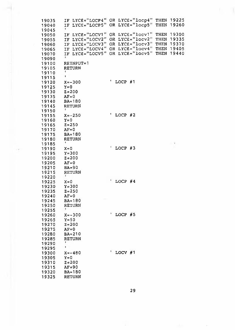
19035 I F LYC£="LOCP4” OR L Y C £ = " l o c p 4 " ‘ THEN 1922519040 I F LYC£="LOCP5" OR L Y C £ = " l o c p 5 " THEN 192601904519050 IF LYC£="L0CV1" OR L Y C £ = " l o c v 1 " T H E N 1930019055 IF LYC£="LOCV2" OR L Y C £ = " l o c v 2 " T H E N 1933519060 IF LYC£="LOCV3" OR L Y C £ = " l o c v 3 " T H E N 1937019065 IF LYC£="LOCV4" OR L Y C £ = " l o c v 4 " T H E N 1940519070 IF LYC£="LOCV5" OR L Y C £ = " l o c v 5 " T H E N 194401909019100 R EIN P U T=119105 RETURN19110 '1911519120 X=- 300 ' LOCP #119125 Y=019130 Z=20019135 AF=019140 BA=18019145 RETURN19150 '19155 X=- 250 ’ LOCP #219160 Y=019165 Z=25019170 AF=019175 BA=18019180 RETURN19185 '19190 X=0 1 LOCP #319195 Y=30019200 Z=20019205 AF = 019210 BA=9019215 RETURN1 922019225 X=0 ’ LOCP #419230 Y= 30019235 Z=25019240 AF=019245 BA=18019250 RETURN1 925519260 X=-300 ' LOCP #519265 Y=5019270 Z=20019275 AF=019280 BA=21019285 RETURN192901929519300 X =-480 ’ LOCV #119305 Y=019310 Z=20019315 AF=9019320 BA=18019325 RETURN
29
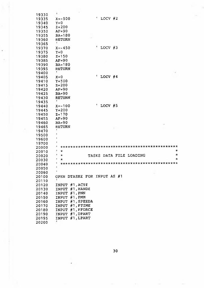
193 3 01 93 3 5 X = - 5 0 0 ' LOCV §21 9 3 4 0 Y=01 9 3 4 5 Z=2001 9 3 5 0 AF=90193 5 5 BA=180193 6 0 RETURN1 93 6 51 9 3 7 0 X = - 450 ’ LOCV #3193 7 5 Y=01 93 8 0 Z = 1 501 93 8 5 AF=901 9 3 9 0 BA=1801 93 9 5 RETURN1 9 4 0 0 '1 9 4 0 5 X=0 ' LOCV #41 9 4 1 0 Y =5001 94 1 5 Z=2001 94 2 0 AF=901 9 4 2 5 BA=901 94 3 0 RETURN1 9 4 3 51 9 4 4 0 X = - 1 0 0 ' LOCV #51 94 4 5 Y =200194 5 0 Z = 1 701 94 5 5 AF=901 94 6 0 BA=901 94 6 5 RETURN194 7 01 9 5 0 01 96 0 0197 0 020000 ' ***********************************************20010 1 * *2 0 0 2 0 ’ * TASKS DATA F IL E LOADING *2 0 0 3 0 ' * *2 0 0 4 0 ' * * * * * * * * * * * * * * * * * * * * * * * * * * * * * * * * * * * * * * * * * * * * * * *2 00 5 0 2 00 6 02 0 1 0 0 OPEN DTASKE FOR IN P U T AS #1 2 0 1 1 02 0 1 2 0 IN P U T # 1 , ACTE2 0 1 3 0 IN P U T # 1 , HANDE2 0 1 4 0 IN P U T # 1 , PNN2 0 1 5 0 IN P U T § 1 , PMM2 0 1 6 0 IN P U T # 1 , SPEEDA2 0 1 7 0 IN P U T § 1 , F T I M E2 0 1 8 0 IN P U T # 1 , FFORCE2 0 1 9 0 IN P U T #1 , DPART2 01 9 5 IN P U T § 1 , LPART20200
30
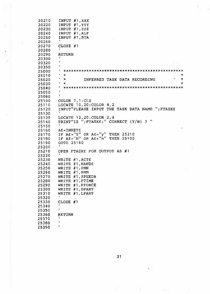
2 0 2 1 0 IN P U T # 1 , XXX2 0 2 2 0 IN P U T # 1 , YYY2 0 2 3 0 IN P U T # 1 , ZZZ2 0 2 4 0 IN P U T # 1 , ALF2 0 2 5 0 IN P U T tf 1 , BTA2 0 2 6 02 0 2 7 0 CLOSE #12 0 2 8 02 0 2 9 0 RETURN2 0 3 0 02 0 3 2 02 0 3 5 02 5 0 0 0 1 * * * * ★ * * * * * * * * * * * * * * * * * * * * * * * * * * * * * * * * * * ' * * ' * * * * * *2 5 0 1 0 ’ * *2 5 0 2 0 ' * INFERRED TASK DATA RECORDING - *2 5 0 3 0 ' * *2 5 0 4 0 ' * * * * * * * * * * * * * * * * * * * * * * * * * * * * * * * * * * * * * * * * * * * * * * *2 5 0 5 0 2 5 0 6 02 5 1 0 0 COLOR 7 , 1 :CLS2 5 1 1 0 LOCATE 1 0 , 2 0 : COLOR 4 , 22 5 1 2 0 IN P U T " PLEASE IN P U T THE TASK DATA NAME " ; FTASKE2 5 1 3 02 5 1 3 5 LOCATE 1 2 , 2 0 : COLOR 2 , 42 5 1 4 0 P R IN T " IS F T A S K E ; " CORRECT ( Y / N ) ? "2 5 1 5 02 5 1 6 0 A £= IN K E Y £2 5 1 7 0 I F a E = " Y " OR A £ = " y " THEN 2 5 2 1 02 5 1 8 0 I F A £ = " N " OR A £ = " n " THEN 2 5 1 0 02 5 1 9 0 GOTO 2 5 1 6 02 5 2 0 02 5 2 1 0 OPEN FTASKE FOR OUTPUT AS #12 5 2 2 02 5 2 3 0 W RITE # 1 , A C T £2 5 2 4 0 W RITE # 1 , HA ND£2 5 2 5 0 W RITE # 1 , PNN2 5 2 6 0 W RITE # 1 , PMM2 5 2 7 0 W RITE # 1 , SPEEDA2 5 2 8 0 W RITE # 1 , F T I ME2 5 2 9 0 W RITE # 1 , FFORCE2 5 3 0 0 W RITE # 1 , DPART2 5 3 1 0 W RITE # 1 , LPART2 5 3 2 02 5 3 3 0 CLOSE #12 5 3 4 02 5 3 5 02 5 3 6 0 RETURN2 5 3 7 02 5 3 8 02 5 3 9 0
31
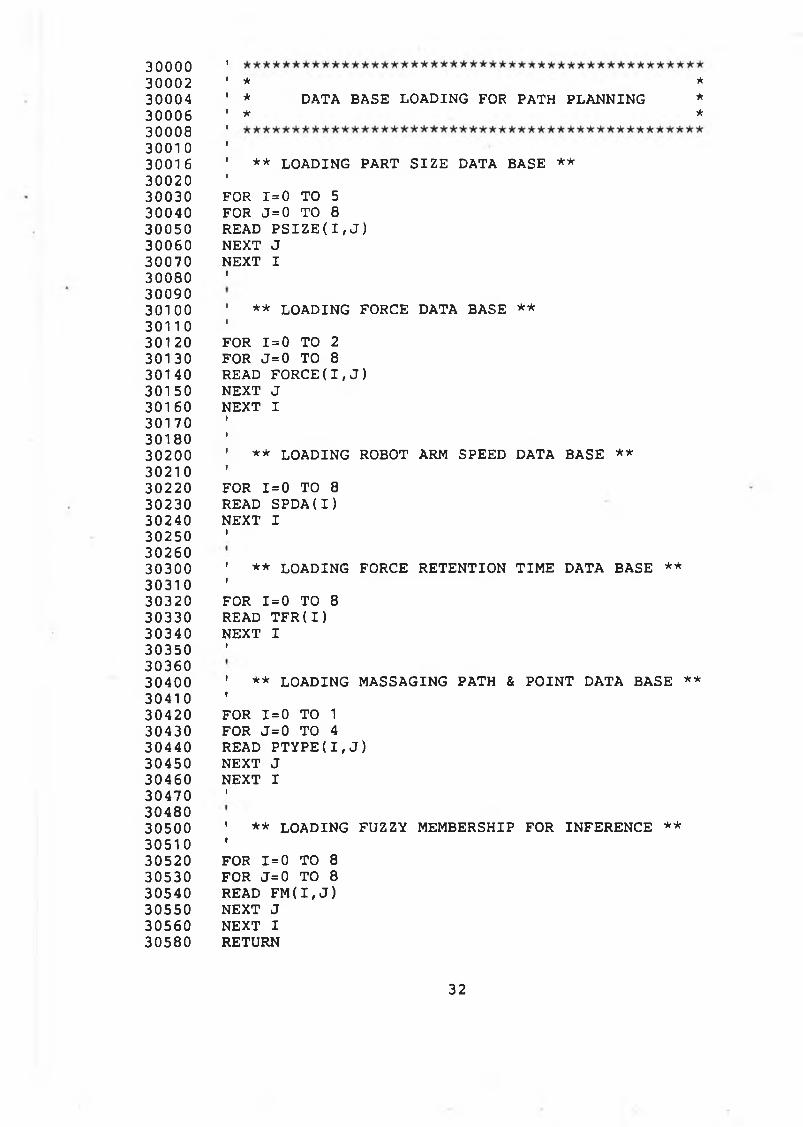
3 0 0 0 0 1
3 0 0 0 2 ' * *3 0 0 0 4 ' * DATA BASE LOADING FOR PATH PLANNING *3 0 0 0 6 ' * *3 0 0 0 83001 0 t
3001 6 ' * * LOADING PART S I Z E DATA BASE * *3 0 0 2 0 1
3 0 0 3 0 FOR 1 = 0 TO 53 0 0 4 0 FOR J = 0 TO 8
3 0 0 5 0 READ P S I Z E ( I , J )3 0 0 6 0 NEXT J3 0 0 7 0 NEXT I3 0 0 8 0 t
3 0 0 9 03 0 1 0 0 ' * * LO ADING FORCE DATA BASE * *3011 0 1
301 20 FOR 1=0 TO 23 0 1 3 0 FOR J = 0 TO 8
3 0 1 4 0 READ FORCE( I , J )3 0 1 5 0 NEXT J3 0 1 6 0 NEXT I3 0 1 7 0 t
3 0 1 8 0 i
3 0 2 0 0 ' * * LOADING ROBOT ARM SPEED DATA BASE * *3 0 2 1 0 •
3 0 2 2 0 FOR 1= 0 TO 8
3 0 2 3 0 READ S P D A ( I )3 0 2 4 0 NEXT I3 0 2 5 0 i
3 0 2 6 03 0 3 0 0 ' * * LOADING FORCE RETENTIO N T IM E DATA BASE * *3031 0 i
3 0 3 2 0 FOR 1=0 TO 8
3 0 3 3 0 READ T F R ( I )3 0 3 4 0 NEXT I3 0 3 5 0 i
3 0 3 6 03 0 4 0 0 ' * * LOADING MASSAGING PATH & P O IN T DATA BASE * *3041 0 i
3 0 4 2 0 FOR 1=0 TO 13 0 4 3 0 FOR J = 0 TO 43 0 4 4 0 READ P T Y P E ( I , J )3 0 4 5 0 NEXT J3 0 4 6 0 NEXT I3 0 4 7 0 i
3 0 4 8 03 0 5 0 0 ' * * LOADING FUZZY MEMBERSHIP FOR INFERENCE * *3 0 5 1 0 «
3 0 5 2 0 FOR 1=0 TO 8
3 0 5 3 0 FOR J= 0 TO 8
3 0 5 4 0 READ F M ( I , J )3 0 5 5 0 NEXT J3 0 5 6 0 NEXT I3 0 5 8 0 RETURN
32
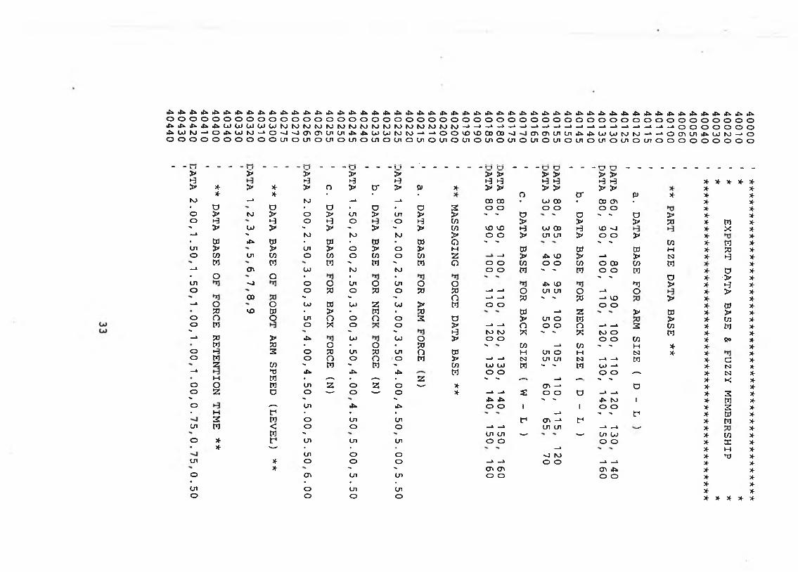
lb •fe•fe.fe ib •fe•o 4* •fe•fe•fe•fe■fe>fe ■fe•fe•fe•fe•fe•fe•fe•fe•fe•fe•fe•fe•fe•fe•fe•fe•fe•fe•fe•fe•fe•fe•fe•feJa. •fe•fe•fe•fe•fe■fe•fe•fe•fe•fe■fe■fe■feo O o o o o o o o o o o o o O O o o o o o o o o o O O O o o o o o o o O o O O o o o O O o o o o o o o o.fe •fe•fe.fe •feOJ OJ u> OJ U) M NJ NJ NJ NJ to M NJ fO M nj NJ NJ NJ NJ NJ —» —t—i —i—1—. —» _k—i —» —1—*—» —•—» —i —í—1—1o o o o o o o.fe OJ nj —1o •feOJ NJ —» o -J -J en (Ti Cn Cn •fe•feu> OJ NJ NJ —» —i O O >x>vo 00 00 -J <n <n cn cn .fe •fe00 0J NJ NJ _i —1o cr>cn •feOJ NJ —i oo o o o o o o O o o en O en O Ul O cn o en o Cn o OI O Ul O Ui o en o cn o cn o en O cn o cn o cn O cn o o o o o o o o o
> > > > > > > > > > >>-3 1-3 >-3 H •-3 *-3 ►-3 >-3 •-3 t-g * X- X- X- X-> X- > * > o > cr > CU * > > > > > > * X-* X- * • ■ o cr cu * >«■ X-NJ —1 N> —i —» 00 00 • OJ 00 . 00 <T> • * *■ o o « o • o ■ a 2 o o o o o o * Xo > NJ > O > cn > cn > > "• - O S. o - - D > X- Xo 1-3 •-3 O *-3 O O •-3 to > > > fO X- M X-- > OJ > ■» > - > " > to <D VD H OJ 00 1-3 VO ~J * X X-—1 - NJ NJ NJ > o o > Ul Ul > o o > * X-■ w •fe W ■ tí) ■ w ■ Cd O ■>» ^ 's -< to * w Xcn > > cn > O > O > M W til W M X- ?0 X-o w cn w o cn O to O w z —» > b VO > —» > N * •-3 X-M m m " M - M o O O to o o to O 00 to M X-—1 cn OJ NJ NJ O O M - ' M o o w * Ö X-• O o • • • - " Ö * > X-cn -j o o Cn O Ul O o •fe vo *1 > 3f t-3 X-o o * O 50 O PO ?0 —* —* O ui cn O —• o X- > X00 " ■» ■» o —i _k ?0 ■» '• ?a _» vo > X- X-—* O o OJ Od 0J Z 0J > M O o o o * ffl X-50 vO w • > • M • 50 W —« Z > W X- > X-o O o cn o o O o 2 a > Ul o w > * to X-o M o « o o > —* —* O o o o —■ _» 2 to * w X-■*» — " »-3 isj N) « >• >» « NJ O M * X-—* PO > •fe OJ 0J o > O O o o to * ßo XW so • o • O • w 's to —• to ■» - M * X- X-o ►-3 2 o P0 Cn SO cn o CO H cn o M N * X- *o W o O o o o w > —* —■ N cn en tsi —1 _» w X- G X-z to " M ' M ' to OJ OJ w - •» W OJ —“ X- N X-—1 ►d .fe 4 •fe w o o o o .--- X- tsi X-M W • •—■ • -—- ■ z - "• ^^ —« ,— - 'S X- k; X-o o W cn z O z o '—■ * cn -* o X- X-o z D o '—• o —' o * —» —» 2 o o c _t _t X- 2 X>» - - •fe tfe ■> - ^ NJ 1 X- m X-o *■—- cn •fe •fe o o i 1 o o X- 2 X-• M f ■ • • —» - - tr< X- m X-2 n o cn cn f (T> -* tr< X- M X-Ul M < o O o —* —* cn cn _i —X — X- X-M ' Ul Ul —- '—- cn 0J X- to Xo X- f cn Cn cn o o o o X- DC X-• * ■—• ■ • ■ —* X- H X-cn O o ■J NJ X- ’’O X-ül X- o o o —» —» O O _V _1 X- X-* - " cn cn cn .fe X- Xo cn Cn Ul o o o o X- X-• • • ■ X- X-cn o Cn Ul X- *o o O o X- X- X- X- X
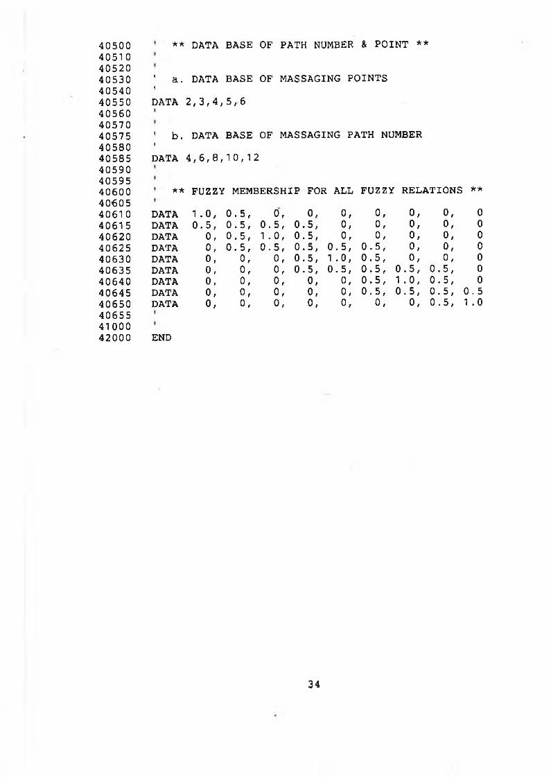
40500 4051 0 40520 40530 40540 40550 40560 40570 40575 40580 40585 40590 40595 40600 40605
406554100042000
** DATA BASE OF PATH NUMBER & P O IN T **
' a. DATA BASE OF MASSAGING PO IN TSIDATA 2 , 3 , 4 , 5 , 6I
' b . DATA BASE OF MASSAGING PATH NUMBERIDATA 4 , 6 , 8 , 1 0 , 1 2
** FUZZY MEMBERSHIP FOR ALL FUZZY R ELATIO N S **
4061 0 DATA 1 . 0 , 0 . 5 , o, 0, o, o, o, o, 040615 DATA 0 . 5 , 0 . 5 , 0 . 5 , 0 . 5 , o, 0, o, o, 040620 DATA o, 0 . 5 , 1 . 0 , 0 . 5 , o, 0, o, 0, 040625 DATA 0, 0 . 5 , 0 . 5 , 0 . 5 , 0 . 5 , 0 . 5 , o, o, 040630 DATA o, 0, o, 0 . 5 , 1 . 0 , 0 . 5 , o, 0, 040635 DATA o, o, o, 0 . 5 , 0 . 5 , 0 . 5 , 0 . 5 , 0 . 5 , 040640 DATA o, o, o, o, o, 0 . 5 , 1 . 0 , 0 . 5 , 040645 DATA o, o, o, o, o, 0 .5 , 0 . 5 , 0 . 5 , 0 . 540650 DATA o, o, 0, 0, o, o , o, 0 . 5 , 1 .0
END
34
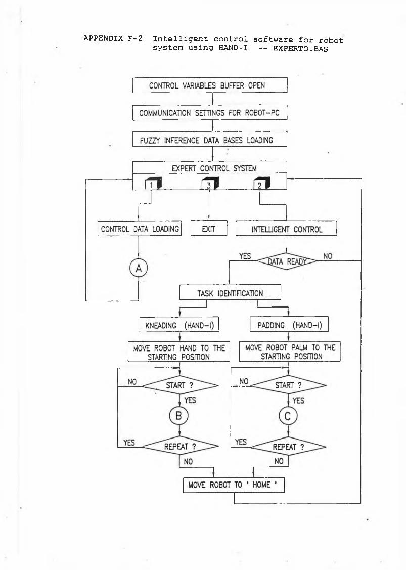
APPENDIX F - 2 I n t e l l i g e n t c o n t r o l s o f t w a r e f o r r o b o t s y s t e m u s i n g H A N D -I - - E X P E R TO .BAS
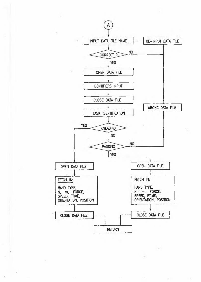
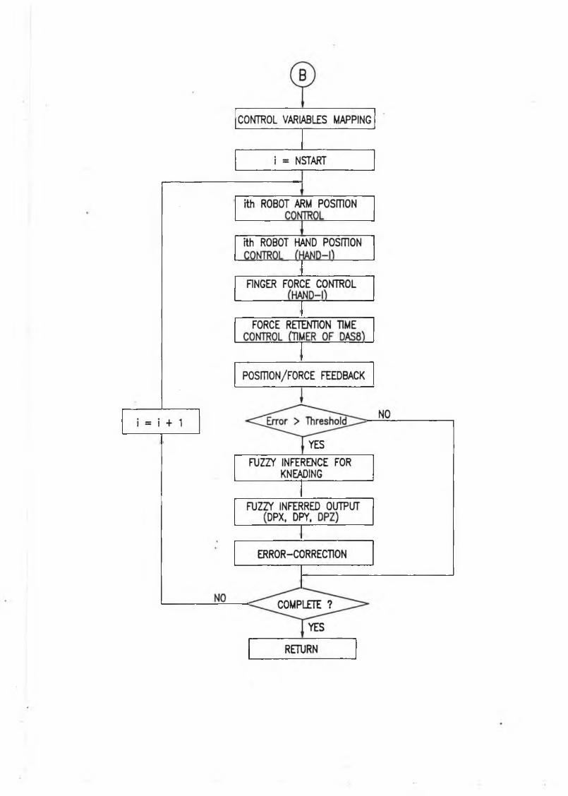
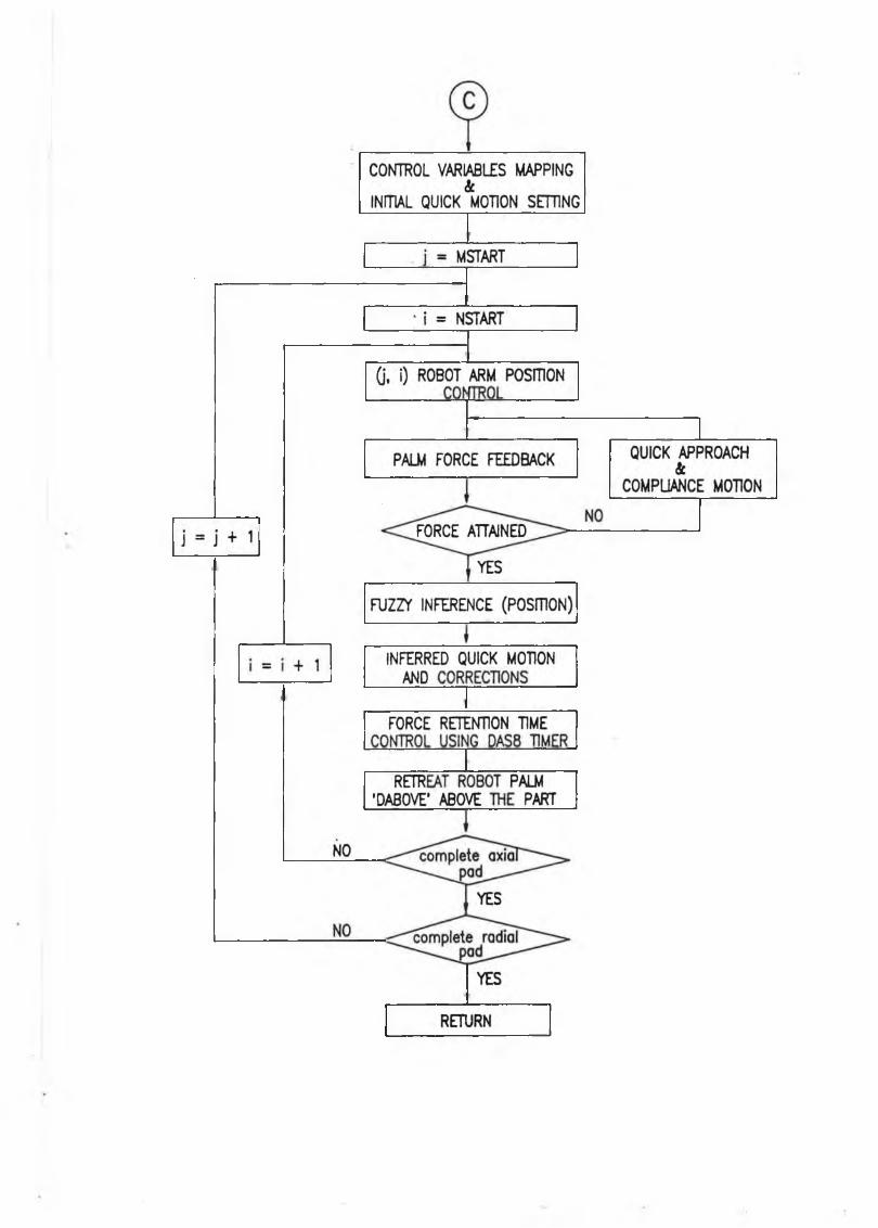
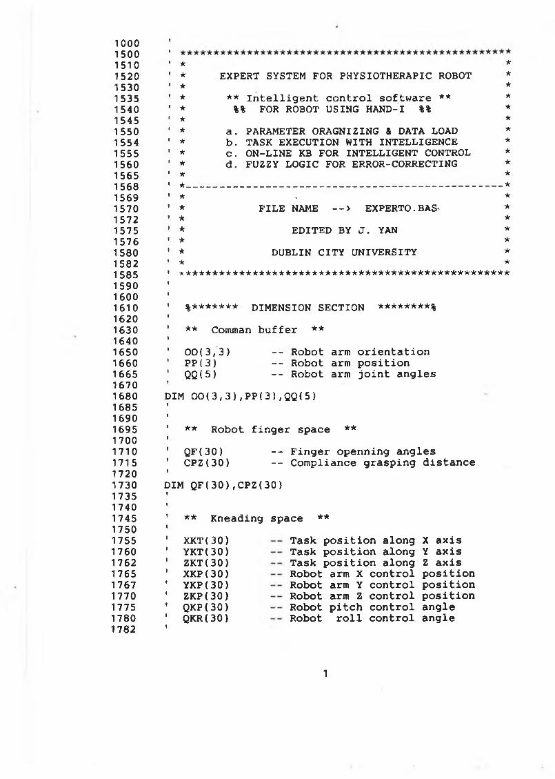
10001 5 0 015101 5 2 01 5 3 01535154015451550155415 5 5 15 6 0 15 6 5156815691 5 7 0 157215751 5 7 6 1580 1582 1585 1590 16 0 0 16 1 0 1620 1630 1640 1 6 5 0 16 6 0 1665 16 7 0 16 8 0 1685 1 6 9 0 1695 1700 1 7 1 0 1715 1720 17 3 0 1735 1740 1745 1750 1755 1 7 6 0 1762 1765 1767 1770 1775 1780 1782
★ ** EXPERT SYSTEM FOR PHYSIOTHERAPIC ROBOT ** *
* ** I n t e l l i g e n t c o n t r o l s o f t w a r e ** ** %% FOR ROBOT USING H A N D -I %% ** ** a . PARAMETER ORAGNIZING & DATA LOAD ** b . TASK EXECUTION WITH IN TE LLIG E N C E ** C . O N -L IN E KB FOR IN TE L L IG E N T CONTROL ** d . FUZZY LO G IC FOR ERROR-CORRECTING ** ** ____________________________________________________________________________________________ ** . ** F IL E NAME — > EXPERTO. BAS- *★ ** E D ITE D BY J . YAN ** ★* DUBLIN C I T Y U N IV ER S ITY ** ** *************************************************
' % ******* DIMENSION SECTION ★******★%i* * * Comman b u f f e r **I' 0 0 ( 3 , 3 ) - - R o b o t arm o r i e n t a t i o n' P P ( 3 ) - - R o b o t arm p o s i t i o n' QQ( 5) - - R o b o t arm j o i n t a n g l e st
DIM 0 0 ( 3 , 3 ) , P P ( 3 ) , Q Q ( 5 )I
' * * R o b o t f i n g e r s p a c e **I' Q F ( 3 0 ) - - F i n g e r o p e n n i n g a n g l e s' CP Z ( 3 0 ) - - C o m p l ia n c e g r a s p i n g d i s t a n c eIDIM QF( 3 0 ) , CPZ( 3 0 )
* * K n e a d in g s p a c e ★ ★
X K T ( 3 0 ) Y K T ( 30) Z K T ( 30) XKP( 3 0 ) Y KP( 3 0 ) ZKP( 3 0 ) QKP( 3 0 ) QKR( 3 0 )
T a s k p o s i t i o n a l o n g X a x i s T a sk p o s i t i o n a l o n g Y a x i s T a s k p o s i t i o n a l o n g Z a x i s R o b o t arm X c o n t r o l p o s i t i o n R o b o t arm Y c o n t r o l p o s i t i o n R o b o t arm Z c o n t r o l p o s i t i o n R o b o t p i t c h c o n t r o l a n g l e R o b o t r o l l c o n t r o l a n g l e
1
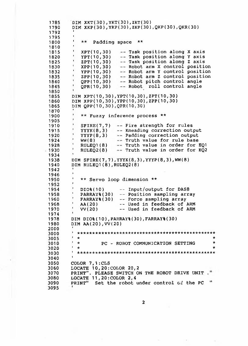
1785179017921795180018101815182018251830183218351840184518501855186018651870190019051910191519201924192819301934193819401942194619501952195419581960196819701974197819802000300030053010302030303040305030603070308030903095
DIM X K T ( 3 0 ) , YKT ( 30 ) , Z K T ( 30)DIM X K P ( 3 0 ) , Y K P ( 3 0 ) , Z K P ( 3 0 ) , Q K P ( 3 0 ) , Q K R ( 30)
** P a d d i n g space **
X P T ( 1 0 , 3 0 ) Y P T ( 1 0 , 3 0 ) Z P T ( 1 0 , 3 0 ) X P P ( 1 0 , 3 0 ) Y P P ( 1 0 , 3 0 ) Z P P ( 1 0 , 3 0 ) Q P P ( 1 0 , 3 0 ) QPR( 1 0 , 3 0 )
Task p o s i t i o n a lo n g Task p o s i t i o n a lo n g Task p o s i t i o n a lo n g Robot arm X c o n t r o l Robot arm Y c o n t r o l Robot arm Z c o n t r o l Robot p i t c h c o n t r o l Robot r o l l c o n t r o l
X a x i s Y a x i s Z a x i s p o s i t i o n p o s i t i o n p o s i t i o n a n g le a n g le
DIM XPT ( 1 0 , 3 0 ) , Y P T ( 1 0 , 3 0 ) , Z P T ( 1 0 , 3 0 ) DIM X PP(1 0 , 3 0 ) , Y P P ( 1 0 , 3 0 ) , ZPP( 1 0 , 3 0 ) DIM QPP( 1 0 , 3 0 ) , QPR( 1 0 , 3 0 )
** F u z z y i n f e r e n c e p r o c e s s **
S F I R E ( 7 , 7 ) Y Y Y K ( 8 , 3 ) Y Y Y P ( 8 , 3 ) WW ( 8 ) RULEQ1( 8 ) RULEQ2( 8 )
F i r e s t r e n g t h f o r r u l e s K neading c o r r e c t i o n o u tp u t Padding c o r r e c t io n o u tp u t T r u t h v a lu e f o r r u l e base T r u t h v a lu e in o r d e r f o r EQ1 T r u t h v a lu e in o r d e r f o r EQ2
DIM S F I R E ( 7 , 7 ) , Y Y Y K( 8 , 3 ) , YY Y P ( 8 , 3 ) , WW( 8 ) DIM RULEQ1( 8 ) , RULEQ2( 8 )
** S e rv o lo o p d im e n sio n **
D I O % ( 1 0 ) - - In p u t/ o u tp u t f o r DAS8PARRAY%( 30 ) - - P o s i t i o n s a m p lin g a r r a yFARRAY%( 3 0 ) — F o rce s a m p lin g a r r a yA A (20 ) - - Used in fe e d b a ck o f ARMW ( 2 0 ) - - Used i n fe e d b a ck o f ARM
DIM DIO% ( 1 0 ) , PARRAY%( 3 0 ) , FARRAY% ( 3 0 ) DIM AA( 20 ) , W ( 2 0 )
*************************** ************ ******** ★ *
* PC - ROBOT COMMUNICATION S E TTIN G ** * A**********************************************
COLOR 7 , 1 : CLSLOCATE 1 0 , 2 0 : COLOR 2 0 , 2P R I N T " . PLEASE SWITCH ON THE ROBOT DRIVE U N IT LOCATE 1 1 , 2 0 : COLOR 2 , 4P R IN T" S e t th e ro b o t u nd er c o n t r o l c i; th e PC "
2
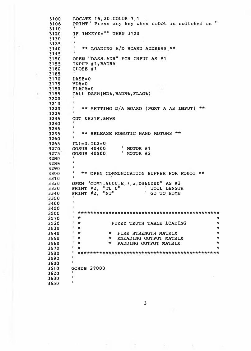
3100 LOCATE 15, 20 .’ COLOR 7,13106 P R IN T" P r e s s any key when ro b o t i s s w i t c h e d on "31103120 I F I N K E Y £ = " " THEN 3120313031353140 ' ** LOADING A/D BOARD ADDRESS **31453150 OPEN " DAS8. ADR" FOR IN P U T AS #13155 IN P U T # 1 , BADR%3160 CLOSE #131653170 DAS8=03175 MD%=03180 FLAG%=03185 CALL D A S 8 ( MD%, BADR%, FLAG%)320032103220 ’ ** S E TTIN G D/A BOARD (PORT A AS IN P U T) **32253235 OUT &H31F,&H9B32403245 '3255 ' ** RELEASE ROBOTIC HAND MOTORS **32603265 I L 1 = 0 : I L 2 = 03270 GOSUB 40400 ' MOTOR #13275' GOSUB 40500 ' MOTOR #23280328532903300 ' ** OPEN COMMUNICATION BUFFER FOR ROBOT **33103320 OPEN " C O M 1 : 9 6 0 0 , E , 7 , 2 , D S 6 0 0 0 0 " AS §2 3330 P R IN T # 2 , " T L 0" ' TOOL LENGTH3340 P R IN T #2 , "N T " ' GO TO HOME3350 '340034503 5 0 0 1 * * * * * * * * * * * * * * * * * * * * * * * * * * * * * * * * * * * * * * * * * * * * * * *
3510 ' * *3520 ' * FUZZY TRUTH TABLE LOADING *3530 ’ * *3540 1 * * F IR E STRENGTH MATRIX *3550 ' * * KNEADING OUTPUT MATRIX *3560 ' * * PADDING OUTPUT MATRIX *3570 * * *3580 ' ***********************************************3590 '36003610 GOSUB 37000362036303650
3
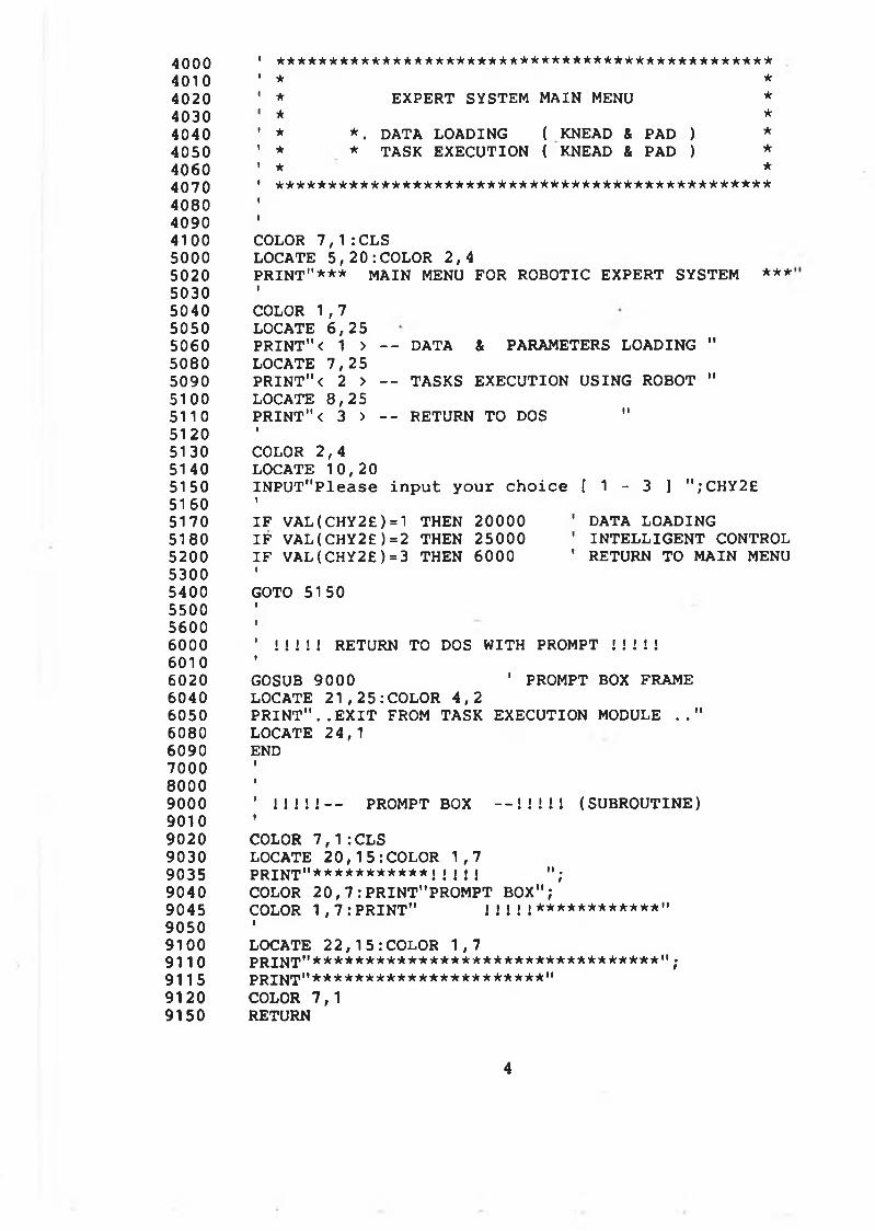
4000 1 ***********************************************4010 1 * *4020 ' * EXPERT SYSTEM MAIN MENU *4030 1 * *4040 ' * *. DATA LOADING ( KNEAD & PAD ) *4050 ' * * TASK EXECUTION ( KNEAD & PAD ) ★4060 1 * *4070 ' ***********************************************4080 i
4090 i
4100 COLOR 7 , 1 : CLS5000 LOCATE 5 , 2 0 : COLOR 2 , 45020 P R IN T"* * * MAIN MENU FOR ROBOTIC EXPERT SYSTEM ***5030 I
5040 COLOR 1 ,75050 LOCATE 6 , 255060 P R IN T "< 1 > — DATA & PARAMETERS LOADING "5080 LOCATE 7 , 2 55090 P R IN T " < 2 > - - TASKS EXECUTION USING ROBOT "5100 LOCATE 8 , 255110 P R IN T "< 3 > — RETURN TO DOS "5120 I
5130 COLOR 2 ,45140 LOCATE 10 , 205150 IN P U T"P le a s e in p u t y o u r c h o ic e [ 1 - 3 ] " ; CHY 2£5160 1
5170 I F V A L ( CHY2E)=1 THEN 20000 ’ DATA LOADING5180 I F V A L ( CHY2E)=2 THEN 25000 ' IN T E L L IG E N T CONTROL5200 I F V A L ( CHY2E)=3 THEN 6000 ' RETURN TO MAIN MENU5300 t
5400 GOTO 51505500 I
5600 f
6000 ' ! ! ! ! ! RETURN TO DOS WITH PROMPT ! ! ! ! !6010 t
6020 GOSUB 9000 ' PROMPT BOX FRAME6040 LOCATE 2 1 , 2 5 : COLOR 4 , 26050 P R I N T " . . E X I T FROM TASK EXECUTION MODULE . . "6080 LOCATE 24,16090 END7000 1
8000 1
9000 ’ ! ! ! ! ! - - PROMPT BOX - - ! ! M l (SU BR O UTIN E)9010 •
9020 COLOR 7 , 1 : CLS9030 LOCATE 2 0 , 1 5 : COLOR 1 , 79035 P R IN T"* * * * * * * * * * * ! Í 1 ! ! " ;9040 COLOR 2 0 , 7 : PRINT"PROMPT BOX";9045 COLOR 1 , 7 : PRI NT " ! ! ! ! ! * * * * * * * * * * * * "9050 1
9100 LOCATE 2 2 , 1 5 : COLOR 1 , 79110 p rin t"* * * * * * * * * * * * * * * * * * * * * * * * * * * * * * * * * " ;9115 PR IN T"**********************"9120 COLOR 7 ,19150 RETURN
4
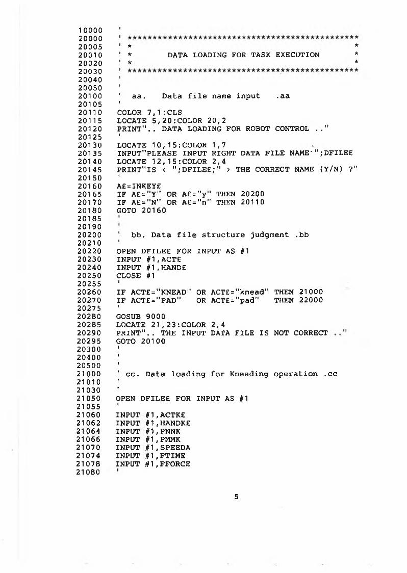
1 0 0 0 020000200052 00102002020030200402005020100201052 0110201152 01202012520130201352014020145201502016020165201702018020185201902 0 2002021 02022020230202402025020255202602027020275202802028520290202952030020400205002 1 000210102103021050210552106021062210642106621070210742107821080
★ ** DATA LOADING FOR TASK EXECUTION ** *
aa. D a t a f i l e name in p u t .a a
COLOR 7 , 1 : CLS LOCATE 5 , 2 0 : COLOR 20,2P R I N T " . . DATA LOADING FOR ROBOT CONTROL . . "ILOCATE 1 0 , 1 5 : COLOR 1,7IN P U T"P LE A S E IN P U T RIGHT DATA F IL E N A M E '" ;D F IL E £ LOCATE 1 2 , 1 5 : COLOR 2,4P R IN T " IS < " ; D F I L E E ; " > THE CORRECT NAME ( Y/ N) ?"1A£=INKEY£I F A £ = " Y " OR A £ = " y " THEN 20200 I F A£ = " N" OR A £= " n" THEN 20110 GOTO 20160
' bb . D a t a f i l e s t r u c t u r e judgm ent .b b 1OPEN D F IL E E FOR INPUT AS #1 IN P U T # 1 , ACTE IN PU T # 1 , HANDECLOSE #1»I F AC T£="K N EA D " OR A CT£="kne ad" THEN 21000 I F ACT£ = "P A D " OR ACT£ = "p a d " THEN 22000IGOSUB 9000LOCATE 2 1 , 2 3 : COLOR 2 , 4P R I N T " . . THE IN P U T DATA F IL E IS NOT CORRECT GOTO 20100
c c . D a t a lo a d in g f o r K nead in g o p e r a t io n .c c
OPEN D F IL E E FOR IN PU T AS #1IIN P U T # 1 , ACTK£IN P U T # 1 , HANDKE IN P U T # 1 , PNNK IN P U T # 1 , PMMK IN P U T # 1 , SPEEDA IN P U T # 1 , F T I M E IN P U T # 1 , FFORCE
5
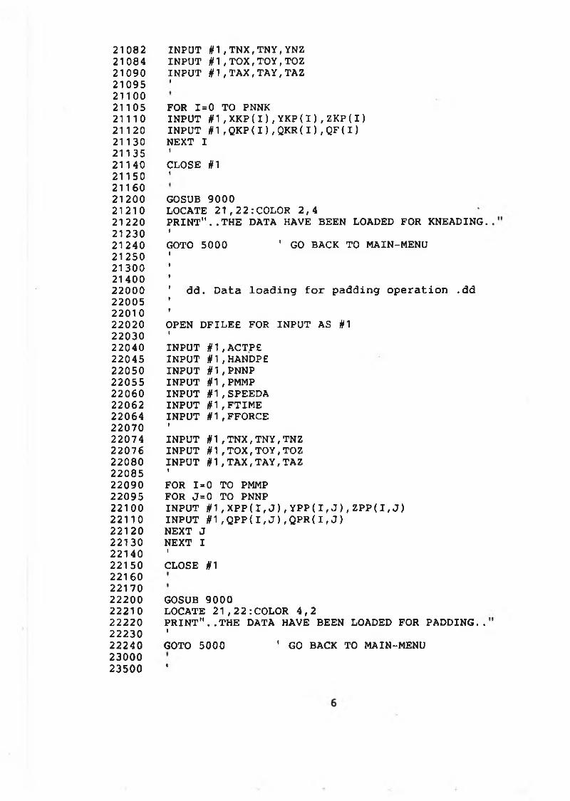
21082210842109021095211002110521110211202113021135211402115021160212002121021220212302124021250213002140022000220052201022020220302204022045220502205522060220622206422070220742207622080220852209022095221002 21102 21 20221302214022150221602217022200222102222022230222402300023500
IN PU T #1 , T N X , T N Y , YNZ IN P U T # 1 , T O X , T O Y , TOZ IN P U T # 1 , T A X , T A Y , TAZI
FOR 1=0 TO PNNKIN P U T § 1 , XKP( I ) , YKP( I ) , ZKP( I )IN P U T # 1 , Q K P ( I ) , Q K R ( I ) , Q F ( I )NEXT IICLOSE #1t
GOSUB 9000LOCATE 2 1 , 2 2 :COLOR 2 , 4P R I N T " . . T H E DATA HAVE BEEN LOADED FOR KNEADING.iGOTO 5000 ' G O BACK TO MAIN-MENU
dd. D a t a lo a d in g f o r p a d d in g o p e ra t io n .d d
OPEN D F IL E E FOR IN P U T AS #1IIN P U T # 1 , ACTPE IN P U T § 1 , HANDPE IN P U T § 1 , PNNP IN P U T if 1 , PMMP IN P U T # 1 , SPEEDA IN P U T if1 , F T I M E IN P U T # 1 , FFORCEIIN P U T if 1 , T N X , T N Y , TNZ IN P U T # 1 , T O X , T O Y , T O Z IN P U T § 1 , T A X , T A Y , TAZIFOR 1=0 TO PMMP FOR J= 0 TO PNNPIN P U T # 1 , X P P ( I , J ) , Y P P ( I , J ) , Z P P ( I , J ) IN P U T H1 , Q P P ( I , J ) , Q P R ( I , J )NEXT J NEXT IICLOSE jf1
GOSUB 9000LOCATE 2 1 , 2 2 : COLOR 4 , 2P R I N T " . . T H E DATA HAVE BEEN LOADED FOR P A D D IN G ..tGOTO 5000 1 GO BACK TO MAIN-MENU
t
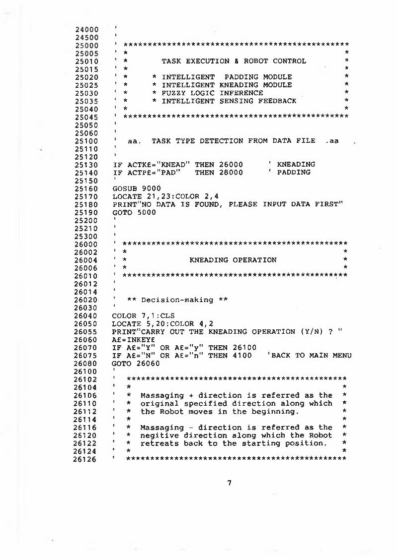
25010250152502025025250302503525040250452505025060251002511025120251302514025150251602517025180251902520025210253002600026002260042600626010260122601 4260202603026040260502605526060260702607526080261002610226104261062611026112261142611626120261222612426126
* * * * * * * * * * * * * * * * * * * * * * * * * * * * * * * * * * * * * * * * * * * * * * *
** TASK EXECUTION & ROBOT CONTROL** * IN T E L L IG E N T PADDING MODULE* * IN T E L L IG E N T KNEADING MODULE* * FUZZY LO G IC INFERENCE* * IN T E L L IG E N T SENSING FEEDBACK************************************************
aa . TASK TYPE D ETEC TIO N FROM DATA F IL E . aa
***★****
I F ACTK£="KNEAD" THEN 26000 ' KNEADINGI F ACTP£="PAD" THEN 28000 ' PADDINGIGOSUB 9000LOCATE 2 1 , 2 3 : COLOR 2 , 4P R IN T"N O DATA IS FOUND, PLEASE IN P U T DATA F IR S T " GOTO 5000
*********************************************** * ** KNEADING OPERATION ** ************************************************
** D e c is io n -m a k in g **
COLOR 7 , 1 : CLS LOCATE 5 , 2 0 : COLOR 4 , 2PRINT"CARRY OUT THE KNEADING OPERATION ( Y/N) ? " A£=INKEY£I F A £ = " Y " OR A £ = " y " THEN 26100I F A£="N" OR A £ = " n " THEN 4100 'BACK TO MAIN MENUGOTO 26060
*********************************************** ** M assagin g + d i r e c t i o n i s r e f e r r e d as th e ** o r i g i n a l s p e c i f i e d d i r e c t i o n a lo n g w hich ** th e R obot moves in th e b e g in n in g . ** ** M a ssa g in g - d i r e c t i o n i s r e f e r r e d as th e ** n e g i t i v e d i r e c t i o n a lo n g w h ich th e Robot ** r e t r e a t s back t o th e s t a r t i n g p o s i t io n . ** *
* * * * * * * * * * * * * * * * * n r * * * * * * * * * * * * * * * * * * * * * * * * * * * *
7
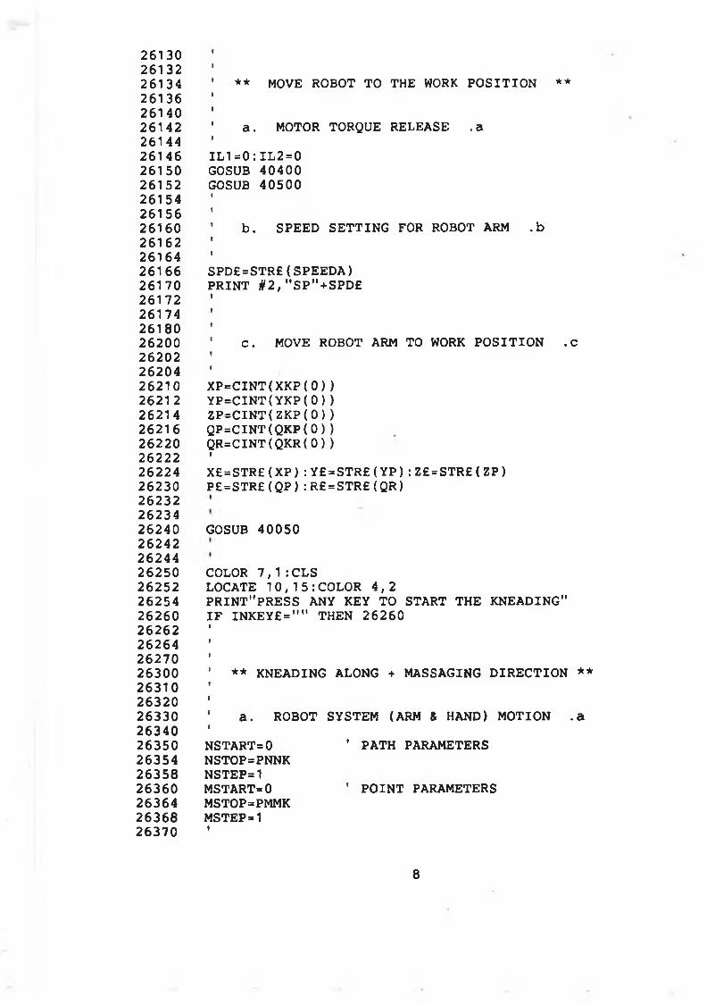
2613026132261342613626140261422614426146261502615226154261562616026162261642616626170261722617426180262002620226204262102621 2262142621626220262222622426230262322623426240262422624426250262522625426260262622626426270263002631026320263302634026350263542635826360263642636826370
** MOVE ROBOT TO THE WORK P O S ITIO N **
' a . MOTOR TORQUEII L I =0 : I L 2 = 0 GOSUB 40400 GOSUB 40500
RELEASE . a
b . SPEED S E TTIN G FOR ROBOT ARM .b
SPD£=STR£( SPEEDA) P R IN T # 2 , "SP"+SPD£
C . MOVE ROBOT ARM TO WORK P O S IT IO N .c
X P = C I N T ( X KP ( 0 ) )Y P = C I N T ( Y K P ( 0 ) )Z P = C I N T ( ZKP( 0 ) )Q P = C I N T ( Q K P ( 0 ) )Q R =C I N T ( Q K R ( 0 ) )IX£=STR£( X P ) : Y £ = S T R £ ( Y P ) : Z £ = S T R£ ( Z P) P£=STR£( Q P ) : R£ = S TR£ ( QR)
GOSUB 40050
COLOR 7 , 1 : CLSLOCATE 1 0 , 1 5 : COLOR 4 , 2PRINT"PRESS ANY KEY TO START TH E KNEADING" I F IN K E Y £ = "" THEN 26260
** KNEADING ALONG + MASSAGING D IR E C TIO N **
' a . ROBOT SYSTEM (ARM & HAND) MOTION .aINSTART=0 ' PATH PARAMETERSNSTOP=PNNKNSTEP=1MSTART=0 ' P O IN T PARAMETERSMSTOP=PMMKMSTEP=1f
8
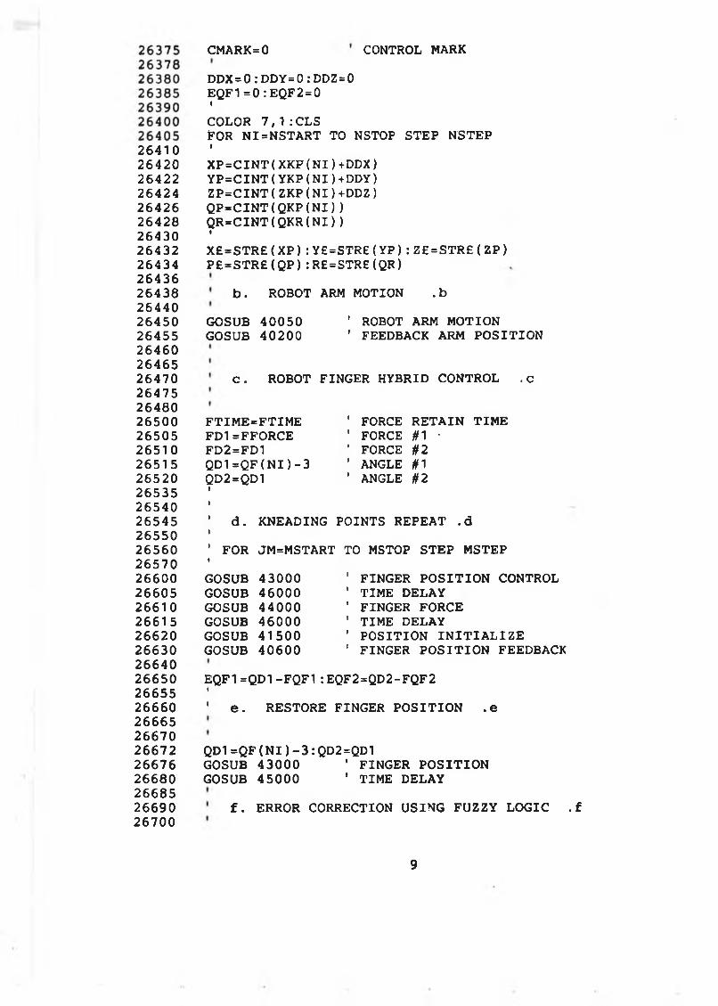
264102642026422264242642626428264302643226434264362643826440264502645526460264652647026475264802650026505265102651526520265352654026545265502656026570266002660526610266152662026630266402665026655266602666526670266722667626680266852669026700
CMARK=0 CONTROL MARK
D DX=0: DDY= 0: DDZ=0 EQF1= 0 :EQF2=0t
COLOR 7 , 1 : CLSFOR N I= N S TA R T TO NSTOP STEP NSTEPIX P = C I N T ( XKP( N I ) +DDX)Y P = C I N T ( YKP( N I ) +DDY)Z P = C I N T ( ZKP( N I ) +DDZ)Q P = C I N T ( Q K P ( N I ) )Q R = C I N T ( QKR( N I ) )IX£ = S T R £ ( X P ) : Y£=STR£( Y P ) : Z£ = S T R £ ( Z P ) P£ = S T R £ ( Q P ) :R£ = STR£(QR)
b . ROBOT ARM MOTION .b
GOSUB 40050 GOSUB 40200
' ROBOT ARM MOTION ' FEEDBACK ARM P O S ITIO N
c . ROBOT FINGER HYBRID CONTROL .c
F T IM E = F TIM E FD1=FFORCE FD2=FD1 QD1=QF( N I ) - 3 QD2=QD1
FORCE R E TA IN TIM E FORCE #1 •FORCE #2 ANGLE #1 ANGLE #2
' d . 1
KNEADING POINTS REPEAT .d
' FORtJM=MSTART TO MSTOP STEP MSTEP
GOSUB 43000 ' FINGER P O S IT IO N CONTROLGOSUB 46000 ' TIM E DELAYGOSUB 44000 ' FINGER FORCEGOSUB 46000 ' TIM E DELAYGOSUB 41500 ' P O S ITIO N I N I T I A L I Z EGOSUB 40600 ' FINGER P O S IT IO N FEEDBACK
EQF1 = Q D 1 - F Q F 1 : EQF2=QD2-FQF2I' e . RESTORE FINGER P O S IT IO N .e
QD1=QF( N I ) - 3 : QD2=QD1GOSUB 43000 ' FINGER P O S IT IO NGOSUB 45000 ' TIM E DELAY
f . ERROR CORRECTION USING FUZZY LO G IC . f
9
26710 GOSUB 30000 ' FUZZY INFERENCE26720 1
26730 DDX=DDX+DPX26735 DDY=DDY+DPY26740 DDZ=DDZ+DPZ26745 •
26750 GOSUB 39000 ' D ISPLAY26755 ' NEXT JM26760 N EXT N I26770 1
26780 1
26790 1
26800 ' **. KNEADING ALONG - MASSAGING D IR EC TIO N .26810 •
26820 1
26830 ' a . D ECIS IO N -M A K IN G FOR REPEAT .a26835 i
26840 •
26845 COLOR 7 , 1 : CLS26850 LOCATE 1 0 , 2 0 : COLOR 4 , 226855 P R IN T"R EP EA T THE KNEADING OPERATION ( Y / N ) ?"26860 1
26865 A£=INKEY£26870 I F A £ = " Y " OR A £ = " y " THEN 2700026875 I F A£="N" OR A£ = " n" THEN 2690026880 GOTO 2686526885 1
26890 1
26900 COLOR 7 , 1 : CLS26905 LOCATE 1 0 , 2 0 : COLOR 2 , 426910 P R IN T "L E T ROBOT GO BACK TO HOME P O S ITIO N ( Y/ N)2691 5 A£=INKEY£26920 I F A £ = " Y " OR A £ = " y " THEN 2694526925 I F A £ = " N" OR A £ = "n " THEN 2696026930 GOTO 2691526935 •
26940 »
26945 P R IN T # 2 , " NT "26950 I
2695526960 GOSUB 900026965 LOCATE 2 1 , 2 4 : COLOR 4 , 226970 P R IN T " . .KNEADING OPERATION HAS BEEN COMPLETED.26975 GOTO 500026980 I
2699027000 ' b . REPEAT KNEADING OPERATION .b27010 1
2701527020 I F CMARK=1 THEN 2710027025 •
27030 NSTART=PNNK27035 NSTOP=027040 N S T E P = -127045 MSTART=0
**
10
27050 27055 27060 27065 27070 27080 27090 271 00 27110 27120 271 30 271 40 27150 27160 271 70 27180 271 90 27200 27210 27215 27220 27230 27240 27250 27260 27270 27280 27290 27300 27310 28000 28002 28004 28006 28010 2801 2 2801 4 2801 6 28020 28022 28024 28026 28030 28032 28034 28036 28040 28042 28044 28046 • 28050 28052 28054 28056 28058
MSTOP=PMMK MSTEP=1ICMARK=1IGOTO 27200II
N START=0 NSTOP=PNNK N S TE P = 1 M START=0 MSTOP=PMMK M STEP=1ICMARK=0
C . I N I T I A T E THE OPERATION . CiCOLOR 7,1 : CLS LOCATE 1 5 , 2 0 : COLOR 4 , 2P R IN T"P R ES S ANY KEY TO REPEAT KNEADING OPERATION"
I F I N K E Y £ = " " THEN 27260IGOTO 26400
*********************************************** * ** PADDING OPERATION *★ *
* * . D EC IS IO N -M A K IN G FOR PADDING .**
COLOR 7 , 1 : CLS LOCATE 5 , 2 0 : COLOR 4 , 2P R IN T"CA R R Y OUT THE PADDING OPERATION ( Y / N ) ? " A £=IN KEY£I F A £ = ” Y " OR A £ = " y " THEN 28050I F A £ = " N " OR A £ = " n " THEN 4100 ' BACK TO MAIN MENUGOTO 28030
** MOVE ROBOT TO THE WORK P O S ITIO N **
a . I N I T I A L I Z E DAS8 FOR PALM FORCE .a
GOSUB 417009
11
2808028082280842808628090280922809428096281002810228104281102811228114281202812228130281 3528140281502815428160281622816428166281 70281722817428178281802818228184281862819028192281942819628200282022820628210282202822528230282352824028242
t
' b . SPEED S E TTIN G FOR ROBOT ARM . bt
SPD£=STR£( SPEEDA)P R IN T # 2 , "SP 7 , H"
C . MOVE ROBOT ARM TO THE WORK P O S ITIO N . C
X P = C I N T ( X PP( 0 , 0 ) )Y P = C I N T ( Y P P ( 0 , 0 ) )Z P = C I N T ( Z P P ( 0 , 0 ) )Q P = C I N T ( QPP( 0 , 0 ) )Q R = C I N T ( QPR( 0 , 0 ) )IX £ = S T R £ (X P ):Y £ = S T R £ (Y P ) :Z£=STR£(ZP) P £ = S T R £ (Q P ) :R £ = S T R £ (Q R )IGOSUB 40050 •COLOR 7 , 1 : CLSLOCATE 1 0 , 1 5 : COLOR 4 , 2PR IN T"PR ESS ANY KEY TO STAR T THE PADDING" I F I N K E Y £ = " " THEN 28130
II
**. PADDING ALONG + MASSAGING D IR E C TIO N
DDX=0: D DY= 0: DDZ=0IDABOVE= 20 ' PALM ABOVE PART SURFACEDGRADE=10 ' PALM I N I T I A L MOTION GRADEDFUZZC=0 1 PALM QUICK MOTION D ISTAN CEI
NSTART=0NSTOP=PNNPN S TE P =1MSTART=0MSTOP=PMMPMSTEP=1iZZC=0: FDZ=0i
COLOR 7 , 1 : CLSFOR JM=MSTART TO MSTOP STEP MSTEP FOR N I= N 3 TA R T TO NSTOP STEP NSTEPiEZC=0X P = C I N T ( X PP ( J M , N I ) +DDX)Y P = C I N T ( Y P P ( J M , N I ) +DDY)Z P = C I N T ( Z P P ( J M , N I ) +DDZ)Q P = C I N T ( QPP( J M , N I ) )Q R = C I N T ( QPR( J M , N I ) )
. **
12
2 82 5 02 8 2 5 2
1
1
2 8 2 5 5 X £ = S T R £ ( X P )2 8 2 6 0 Y £ = S T R £ ( Y P )2 82 6 5 Z £ = S T R £ { Z P )2 82 7 0 P £ = S T R £ ( Q P )2 82 7 5 R £ = S T R £ ( Q R )2 82 8 0 1
2 82 9 0 1
2 83 0 0 GOSUB 4 0 0 5 0 ' ROBOT ARM MOTION EXECUTION2 8 3 1 0 GOSUB 4 0 2 0 0 ' FEEDBACK ARM P O S IT IO N2 8 3 2 0 1
283 2 5 GOSUB 4 0 9 0 0 ' FORCE FEEDBACK283 3 0 GOSUB 4 1 4 0 0 ' FORCE COMPUTING2 83 3 4 GOSUB 3 8 0 0 0 ’ D IS P L A Y SENSED INFORMATION2 8 3 3 6 1
2 8 3 4 0 F L I M I T = 0 . 22 8 3 4 2 JFD D P =A B S ( FDDP-FFORCE)283 4 4 I F F D D P < F L IM IT THEN PZD=DGRADE: GOTO 2 8 3 5 62 8 3 4 6 I F FDDP> =FFORCE THEN P ZD =-D G R A D E/2:G O TO 2 8 4 0 0283 4 8 I F JFDDP < = 0 .3 THEN P Z D = 0 : GOTO 284 0 02 83 5 0 PZD=DG RADE/22 8 3 5 4 i
2 83 5 6 EZC=EZC+PZD ' F IN E MOTION CONTROL2 8 3 6 0 ZZC=EZC+DFUZZC ' Q UICK APPROACH2 8 3 6 4 r
2 83 6 6 DXC= Z ZC*TAX ' MOTION COORDINATING2 83 7 0 DYC= Z ZC*TAY2 83 7 4 DZC= Z ZC*TAZ2 8 3 7 8 i
2 8 3 8 0 X C = C I N T ( XP+DXC)2 83 8 4 Y C = C I N T ( YP+DYC)2 83 8 6 Z C = C I N T ( ZP+DZC)2 8 3 8 8 X £ = S T R £ ( X C )2 83 9 0 Y £ = S T R £ ( Y C )2 83 9 2 Z £ = S T R £ ( Z C )283 9 4 i
2 8 3 9 6 GOTO 2 8 3 0 0 ' F IN E MOTION REPEAT2 83 9 8 i
2 8 4 0 0 DGRADE=32 8 4 1 0 EZC=ZZC2 8 4 1 5 i
2 8 4 2 0 I F A B S ( E Z C )> = 29 THEN 2 8 4 6 02 8 4 2 5 i
2 84 3 0 GOSUB 3 2 0 0 0 ' FUZZY INFERENCE284 3 2 FDZ1=DABOVE*SGN( F D Z )2 8 4 3 5 F D Z =F D Z -F D Z 1 1 FUZZY CORRECTION2 84 4 0 D F U Z Z C = ( E Z C - F D Z ) * 0 . 75 ' Q UICK APPROACH284 4 5 GOTO 2 8 4 8 02 84 5 0 i
2 8 4 5 5 t
2 84 6 0 FDZ=EZC-DABOVE ' N O N -FU ZZY CORRECTION2 84 6 5 DFUZZC=DABOVE*0 . 75 1 Q UICK APPROACH2 84 7 0 i
2 8 4 7 5 t
13
2 8 4 8 0 DDX=DD X+FDZ*TAX ' MOTION CO O RDINATING2 8 4 8 5 DDY=DD Y+FDZ*TAY2 8 4 9 0 DDZ=DDZ+FDZ*TAZ2 8 5 0 0 1
2 8 5 2 0 MBACK=-DABOVE2 8 5 3 0 X C = C I N T ( XC+MBACK*TAX)2 8 5 3 5 Y C = C I N T ( YC+MBACK*TAY)2 8 5 4 0 Z C = C I N T ( Z C + M B A C K * T A Z )2 8 5 4 5 I
2 8 5 5 0 X £ = S T R £ ( X C )2 8 5 5 5 Y £ = S T R £ ( Y C )2 8 5 6 0 Z £ = S T R £ ( Z C )2 8 5 6 5 i
2 8 5 7 0 GOSUB 4 0 0 5 02 8 5 7 5 »2 8 5 8 0 NEXT N I2 8 5 8 5 NEXT JM2 8 5 9 0 i
2 8 5 9 5 i
2 8 6 0 0 * * . PADDING ALONG - MASSAGING D IR E C T IO N . * *2 8 6 0 5 i
2 8 6 1 0 i
2 8 6 1 5 COLOR 7 , 1 : CLS2 8 6 2 0 LOCATE 1 0 , 2 0 : COLOR 4 , 22 8 6 2 5 P R IN T"R E P E A T THE PADDING OPERATION ( Y / N ) ? "2 8 6 3 0 •
2 8 6 3 5 A £= IN K E Y £2 8 6 4 0 I F A £ = " Y " OR A £ = " y " THEN 2 88 0 02 8 6 4 5 I F A £ = " N " OR A £ = " n " THEN 2 86 6 52 86 5 0 GOTO 2 8 6 3 52 8 6 5 5 1
2 8 6 6 02 8 6 6 5 COLOR 7 , 1 : CLS2 8 6 7 0 LOCATE 1 0 , 2 0 : COLOR 4 , 22 8 6 7 5 P R IN T "L E T ROBOT GO BACK TO HOME P O S IT IO N ( Y / N ) ?2 8 6 8 0 1
2 8 6 8 5 A £= IN K E Y £2 8 6 9 0 I F A £ = " Y " OR A £ = " y " THEN 2 87 0 52 8 6 9 4 I F A £ = " N " OR A £ = " n " THEN 2 8 7 1 02 8 6 9 8 GOTO 2 8 6 8 52 8 7 0 0 1
2 8 7 0 5 P R IN T § 2 , "N T "2 8 7 0 8 i
2871 0 GOSUB 9 0 0 02871 5 LOCATE 2 1 , 2 2 : COLOR 4 , 22 8 7 2 0 P R IN T 1' . . PADDING OPERATION HAS BEEN COMPLETED . . 1
2 8 7 2 5 GOTO 5 0 0 02 8 7 3 0 i
2 8 7 4 0 ' * * REPEAT PADDING * *2 8 7 5 0 1
2 8 7 6 02 8 8 0 0 COLOR 7 , 1 : CLS2 8 8 1 0 LOCATE 1 0 , 2 0 : COLOR 4 , 22 8 8 2 0 P R IN T ' PRESS ANY KEY TO REPEAT PADDING O PER A TIO N "2 8 8 3 0 1
14
288402885028860288702890028920289303000030005300103001 13001 23001 4300163001830020300223002630028300303004030050300553006030065300703007530078300803009030095301003020030205302103021 530220302253033030332303343033830340303443034630350303523035530360303653037030375303803038530390
I F IN KEY£='
GOTO 28200
THEN 28840
REPEAT
%%** O n - l i n e e r r o r c o r r e c t i o n f o r k n e a d in g **%%
****************** S t a t e m e n t ******************* ** S u b ro u tin e t o i n f e r t he c o r r e c t io n s ** ** a. F u z z i f i c a t i o n o f t he e r r o r in p u t ** b . F u z z y in f e r e n c e - ** c . D e f u z z i f i c a t i o n o f in f e r r e d o u tp u t ** d . C o m p u ta tio n o f c o r r e c t io n d is ta n c e ** * ***********************************************
a a . Ju d g e i f c o r r e c t i o n i s r e q u ir e d . aa
I F A B S ( E Q F 1 )>9 OR A B S ( E Q F 2 ) > 9 THEN 30200
** NO CORRECTION REQUIRED **
DPX=0: D PY=0: DPZ=0 RETURN
bb . F u z z f i c a t i o n o f e r r o r in p u t .bb
** F u z z y s c a le r **
FKKQ=3 ' D e gre e
** F U Z ZI F Y I N G IN P U TS **
FOR FING ER #1
FXX=EQF1 SCALE=FKKQ GOSUB 36000 QFU1£=FUZ£ N F IR E 1 = F F IR E
' F IR E D TERM ' F IR E STRENGTH TERM
' FOR FIN G ER #2IFXX=EQF2 SCALE=FKKQ GOSUB 36000 QFU2£=FUZ£ N F IR E 2 = F F IR E
' F IR ED TERM ' F IR E STRENGTH TERM
15
3051030520305303053530542305443054630550305543055830564305663056830570305723057630578305803058230584305903060030605306103061 53062030625306303063530640306453065030655306603066530670306753068030685306903070030705307103071230714307183072030722307243072530728
cc. Truth for control rules (Knead) .ccWW(8) - - T r u t h v a lu e f o r k n e a d in g r u l e base
F o r EQ1 i n p u t , t h e f i r e s t r e n g t h v e c t o r S F I R E ( N F I R E 1 , J ) w here J= 0 to 6
i s :
F o r EQ2 i n p u t , t h e f i r e s t r e n g t h v e c t o r i s : S F I R E ( N F I R E 2 , J ) w here J= 0 to 6
The o r d e r o f th e f i r e s t r e n g th in th e c o n t r o l r u le base s h o u ld be o rg a n iz e d as f o l l o w s :
min
S F I R E ( N F I R E 1 , 1 ) S F I R E ( N F I R E 1 , 0 ) S F I R E ( N F I R E 1 , 5 ) S F I R E ( N F I R E 1 , 6 ) S F I R E ( N F I R E 1 , 1 ) S F I R E ( N F I R E 1 , 0 ) S F I R E ( N F I R E 1 , 5 ) S F I R E ( N F I R E 1 , 6 )
S F IR E (N F IR E 2 , 5) S F I R E ( N F I R E 2 , 6) S F I R E ( N F I R E 2 , 1) S F I R E ( N F I R E 2 , 0) S F I R E ( N F I R E 2 , 1 ) S F I R E ( N F I R E 2 , 0) S F I R E ( N F I R E 2 , 5 ) S F I R E ( N F I R E 2 , 6 )
RULEQ1 (0 ) : RULEQ1( 1 ) RULEQ1( 2 ) : RULEQ1( 3 ) : RULEQ1 ( 4 ) = RULEQ1 ( 5 ) = RULEQ1( 6 ) : RULEQ1 (7 ) =
¡SFIRE:SFIR ESFIR ES FIR E
¡SFIRE¡SFIRESFIR ES FIR E
(N FIR E1(N FIR E1(N FIR E1(NFIR E1(N FIR E1(N FIR E1(N FIR E1(N FIR E1
1 ) 0)5 )6 ) 1 ) 0)5 )6 )
: RULEQ2(0)= : RULEQ2( 1 ) : : RULEQ2( 2 ) : RULEQ2( 3 ) ; : RULEQ2( 4 ) ; : RULEQ2( 5 ) : : RULEQ2( 6 ) = : RULEQ2(7)=
= S FIR E ¡SFIR E ¡SFIR E ¡SFIR E ¡SFIR E ¡SFIR E ¡SFIRE S FIR E
( N F I R E 2 , 5) ( N F I R E 2 , 6) ( N F I R E 2 , 1 ) ( N F I R E 2 , 0 ) (N F IR E 2 , 1 ) ( N F I R E 2 , 0 ) ( N F I R E 2 , 5) ( N F I R E 2 , 6)
THEN 30670FOR 1=0 TO 7 I F RULEQ1( I ) < RULEQ2( I ) WW( I ) =RULEQ2( I )GOTO 30675 WW( I ) = R U LE Q 1 ( I )NEXT I
dd . f u z z y in f e r e n c e p ro c e s s .dd
** D e f u z z y s c a le r **
FKK0=4 ' mm
** F u z z y in f e r e n c e based on f u z z y l o g i c **
E P X = 0 : EPY=C: EPZ=0 WWD=0
3077230776307803078230784307863079030792307943080030810308153082030830308353085030900310003150032000320103201 532020320253203032032320343204032044320483205032060321053211032115321203212532130321353214032145321503215532160321653217032175
I
FOR 1=0 TO 7 WWD=WWD+WW( I )EPX=EPX+WW( I ) * Y Y Y K ( 1 , 0 ) EPY=EPY+WW( I ) *YYYK( 1 ,1 ) EPZ=EPZ+WW( I ) *YYYK( 1 , 2 ) NEXT III F WWD=0 THEN 30790 EPX=EPX/WWD*FKKO EPY=EPY/WWD*FKKO EPZ=EPZ/WWD*FKKO GOTO 30820
EPX=0: EPY=0: EPZ=0
ee. Path m o d if y in g .e e
DPX=EPX*TNX+EPY*TOX+EPZ*TAXDPY=EPX*TNY+EPY*TOY+EPZ*TAYDPZ=EPX*TNZ+EPY*TOZ+EPZ*TAZIRETURN
%%** O n - l in e e r r o r c o r r e c t io n f o r p a d d in g **%%
**************** S t a t e m e n t ****************** ** S u b ro u tin e to i n f e r th e c o r r e c t io n s ** ** a. F u z z i f i c a t i o n o f t he e r r o r in p u t ** b. F u z z y in f e r e n c e ** d. D e f u z z i f i c a t i o n o f in f e r r e d o u tp u t ** e . C o m p u ta tio n o f c o r r e c t io n d is ta n c e ** * **********************************************
bb. F u z z i f i c a t i o n o f e r r o r in p u t .bb
** F u z z y s c a le r **
FKKD= 5 ' mm
** FU Z Z IFY IN G IN P U TS **
FXX=EZC SCALE=FKKD GOSUB 36000DFU£=FUZ£ ' F IR ED TERMN F IR E = FF IR E ' F IR E STRENGTH
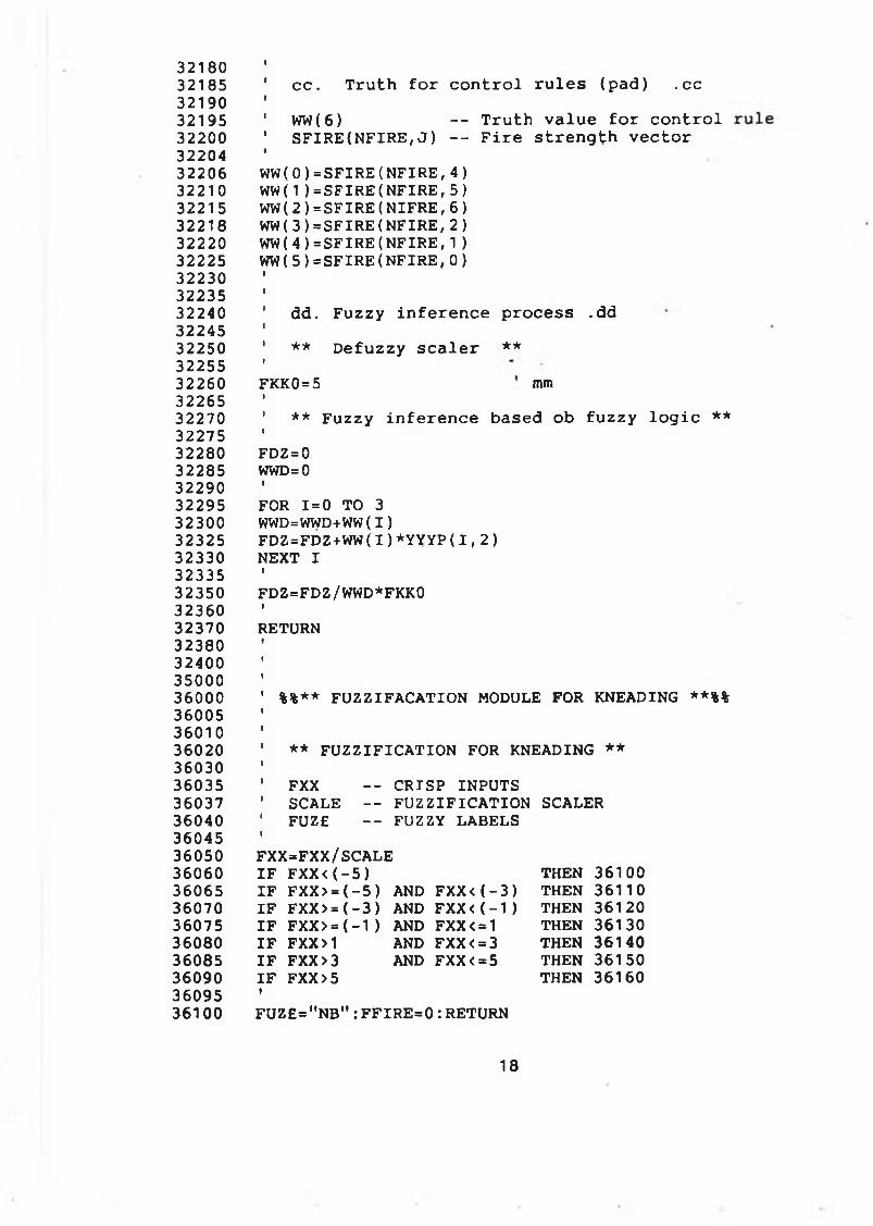
32180 I
32185 ' c c . T r u t h f o r c o n t r o l r u l e s ( p a d ) . c c32190 I
32195 ' WW(6) - - T r u t h v a lu e f o r c o n t r o l32200 ' S F I R E ( N F I R E , J ) - - F i r e s t r e n g t h v e c t o r32204 1
32206 WW( 0 ) = S F I R E ( N F I R E , 4 )32210 WW(1) = S F I R E ( N F I R E , 5 )32215 WW( 2 ) = S F I R E ( N I F R E , 6)32218 WW( 3 ) = S F I R E ( N F I R E , 2 )32220 WW( 4 ) = S F I R E ( N F I R E , 1 )32225 WW(5 ) = S F I R E ( N F I R E , 0)32230 1
32235 1
32240 ' dd. F u z z y in f e r e n c e p ro c e s s .dd32245 1
32250 ' ** D e f u z z y s c a l e r * *32255 I
32260 FKK0=5 mm32265 1
32270 ' * * F u z z y in f e r e n c e based ob f u z z y l o g i c * *32275 1
32280 FDZ = 032285 WWD=032290 1
32295 FOR 1=0 TO 332300 WWD=WWD+WW( I )32325 F D Z = F D Z + W W ( I ) * Y Y Y P ( I , 2)32330 NEXT I32335 t
32350 FDZ=FDZ/WWD*FKK032360 1
32370 RETURN32380 1
32400 1
35000 1
36000 1 %%** FU Z Z IFA C A TIO N MODULE FOR KNEADING **%%36005 I
36010 »
36020 ' ** F U Z Z IF IC A TIO N FOR KNEADING **36030 1
36035 ' FXX - - CRISP INPUTS36037 ' SCALE - - F U Z Z IF IC A TIO N SCALER36040 ' FUZE — FUZZY LABELS36045 1
36050 FXX=FXX/SCALE36060 I F F X X < ( - 5 ) THEN 3610036065 I F F XX>=( - 5 ) AND F X X < ( - 3 ) THEN 3611036070 I F FXX > = ( - 3 ) AND F X X < ( - 1 ) THEN 3612036075 I F F XX > = ( - 1 ) AND FXX<=1 THEN 3613036080 I F FXX>1 AND FXX< = 3 THEN 3614036085 I F F X X >3 AND F X X <=5 THEN 3615036090 I F FX X >5 THEN 3616036095 •
36100 F U Z £ = "N B ":F F IR E = 0 :R E TU R N
18
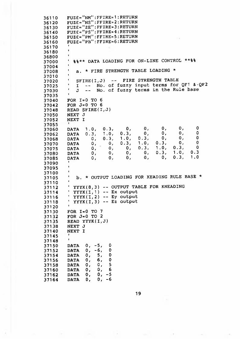
36110361 203613036140361503616036170361803680037000370043700837010370203702537030370353704037042370483705037052370553706037062370683707037075370803708537090370953710037105371103711 2371143711637118371 20371303713237135371383714037145371483715037152371543715637158371603716237164
F U Z £ = " N M " : F F I R E = 1 : RETURN FUZ£ = " N S " : F F I R E = 2 : RETURN FUZ£ = " Z E " : FFIRE= 3 : RETURN FUZ£ = " P S " : FFIRE= 4 : RETURN FUZ£ = " P M " : F F I R E = 5 : RETURN F U Z £ = " P B " : F F I R E = 6 : RETURN
%%** DATA LOADING FOR O N -L IN E CONTROL **%%
a . * F IR E STRENGTH TA B LE LOADING *
S F I R E ( I , J ) - - F IR E STRENGTH TABLEI - - No. o f f u z z y in p u t te rm s f o r QF1 &-QF2 J - - No. o f f u z z y te rm s i n th e R u le base
FOR 1=0 TO 6 FOR J= 0 TO 6 READ S F IR E ( I , J ) NEXT J NEXT I
DATA 1 .0 , 0 . 3 , o, 0, 0, 0, 0DATA 0 . 3 , 1 . 0 , 0 . 3 , 0, 0, o, 0DATA o, 0 . 3 , 1 . 0 , 0 . 3 , 0, 0, 0DATA 0, 0, 0 . 3 , 1 . 0 , 0 . 3 , 0, 0DATA o, 0, 0, 0 . 3 , 1 . 0 , 0 . 3 , 0DATA 0, 0, o, 0, 0 . 3 , 1 . 0 , 0 . 3DATA o, 0, 0, o, o, 0 . 3 , 1 . 0
b . * OUTPUT LOADING FOR READING RULE BASE *
Y Y Y K ( 8 , 3 ) - - OUTPUT TA B LE FOR KNEADING Y Y Y K ( 1 , 1 ) - - E x o u tp u t Y Y Y K ( 1 , 2 ) - - Ey o u tp u t Y Y Y K ( 1 , 3 ) - - Ez o u tp u t
FOR 1=0 TO 7 FOR J= 0 TO 2 READ Y Y Y K ( I , J ) NEXT J NEXT I
DATA o, - 5 , 0DATA o, - 6 , 0DATA o, 5 # 0DATA o, 6/ 0DATA o, o, 5DATA o, 0, 6DATA o, 0, -5DATA o, 0, -6
19
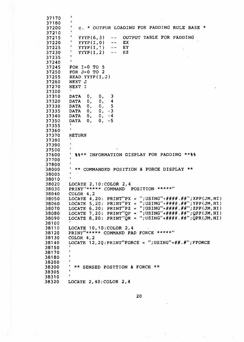
3717037180372003721 0372153722037225372303723537240372453725037255372603727037300373103732037330373353734037350373553736037370373803739037500376003770037800380003800538010380203803038040380503806038070380803809038100381103812038130381403815038170381803820038300383053831038320
C . * OUTPUR LOADING FOR PADDING RULE BASE *
YYY P( 6 , 3 ) - - OUTPUT TABLE FOR PADDINGYYY P( 1 , 0 ) - - EXYY Y P( 1 , 1 ) — EYY Y Y P ( I , 2) - - EZ
FOR 1=0 TO 5 FOR J= 0 TO 2 READ YY Y P( I , J ) NEXT J NEXT IIDATA 0, 0 , 3DATA 0, 0 , 4DATA 0, 0 , 5DATA 0, 0 , -3DATA 0, 0, -4DATA 0, 0 , -5
RETURN
%%** INFORM ATION D ISPLAY FOR PADDING **%%
** COMMANDED P O S IT IO N & FORCE D IS P LA Y **
LOCATE 2 , 1 0 : COLOR 2 , 4P R IN T"* * * * * COMMAND P O S ITIO N ***★*"COLOR 4 ,2LOCATE 4 , 2 0 : P R IN T"P X = " ; USIN G " + # W . ; XPP ( JM , N I )LOCATE 5 , 2 0 : P R IN T"P Y = 11 ; USIN G " + ###JH . ##" ; YPP ( JM, NI )LOCATE 6 , 2 0 : P R IN T"P Z = " ; U SIN G " + # W . ##" ; ZPP( JM, NI )LOCATE 7 , 2 0 : P R IN T"Q P = " ;U S IN G " + W # . ##" ;QPP( JM, NI )LOCATE 8 , 2 0 : P R IN T"Q R = " ; USING " + # M # . ##" ; QPR( JM , N I ) 1LOCATE 1 0 , 1 0 : COLOR 2 , 4P R IN T"***** COMMAND PAD FORCE ***★*"COLOR 4 ,2LOCATE 12, 2 Q :P R IN T"FO R C E = " ; U S I N G " + # 0 . # " ; FFORCE
** SENSED P O S IT IO N & FORCE **
LOCATE 2,40:COLOR 2,4
20
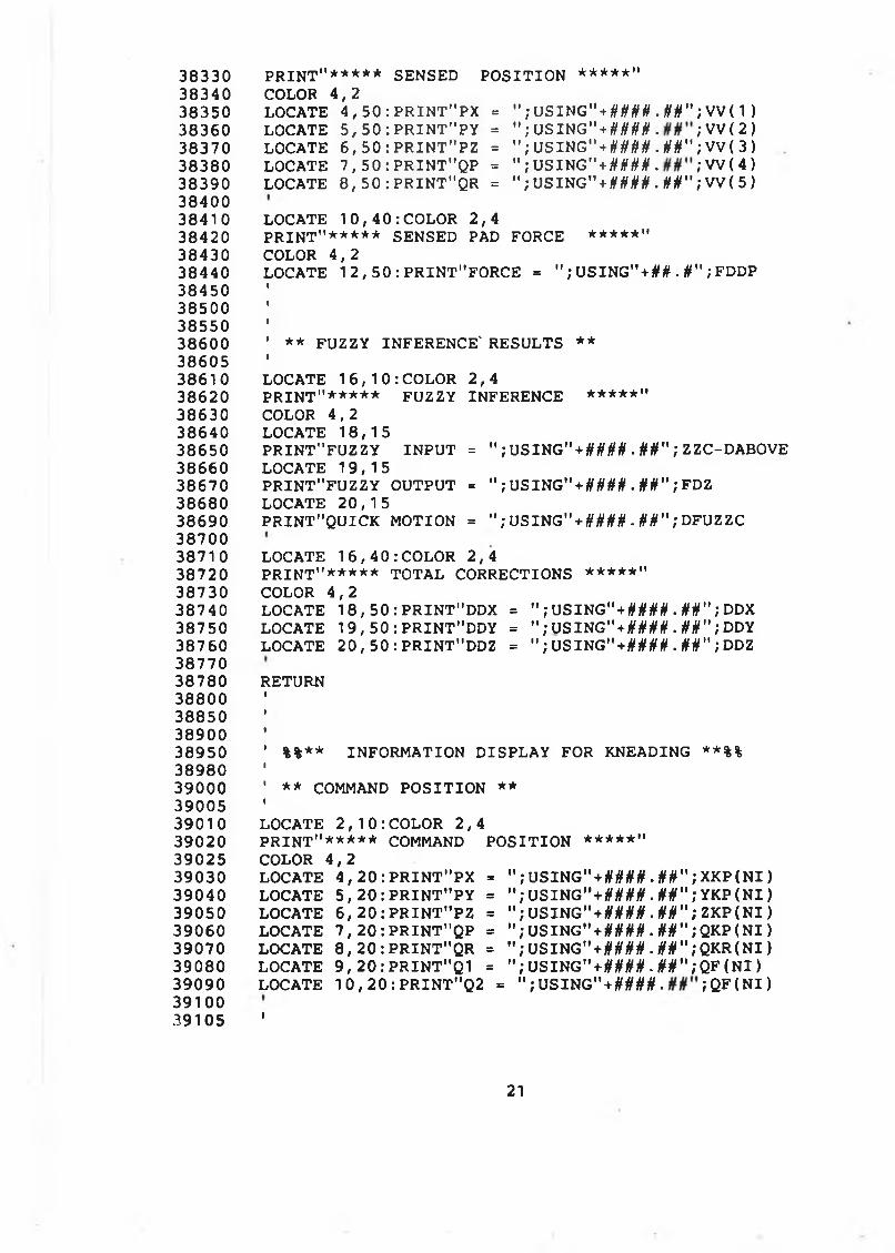
38330 P R IN T"***** SENSED P O S ITIO N *****"38340 COLOR 4 , 238350 LOCATE 4 , 5 0 : P R I N T MPX = " ; U S I N G " + # # # # . ffif"; V V ( 1 ) 38360 LOCATE 5, 50 : P R IN T"P Y = " ; U S I N G" + M M . ; VV ( 2 )38370 LOCATE 6 , 5 0 : PRI NT" PZ = " ; USING" + # W . #§"; V V ( 3)38380 LOCATE 1, 5 0 : PRINT"QP = " ; U S IN G " + W # . ; W ( 4 )38390 LOCATE 8 , 5 0 : PR IN T"Q R - " ; U S IN G " + iW # . ffif" ; VV( 5 )3840038410 LOCATE 1 0 , 4 0 : COLOR 2 , 438420 P R IN T"***** SENSED PAD FORCE ***★*"38430 COLOR 4 , 238440 LOCATE 1 2 , 5 0 : PRINT"FORCE = " ; U S I N G " + # # . # " ; FDDP38450385003855038600 ' ** FUZZY INFERENCE' RESULTS **3860538610 LOCATE 1 6 , 10 : COL OR 2 , 438620 P R IN T"* * * * * FUZZY INFERENCE **★**"38630 COLOR 4 , 2 38640 LOCATE 18 , 1538650 P R IN T"FU Z Z Y IN P U T = " ; U S IN G " + W # . §§”} ZZC-DABOVE 38660 LOCATE 19, 1538670 P R IN T"FU Z Z Y OUTPUT = " ; USING"+#### .§#"} FDZ 38680 LOCATE 2 0 , 1538690 P R IN T"Q U IC K MOTION = " ; U S IN G"+####. ffff") DFUZZC 3870038710 LOCATE 1 6 , 4 0 : COLOR 2 , 438720 p r i n t "***** TO TA L CORRECTIONS *****"38730 COLOR 4 , 238740 LOCATE 1 8 , 50 : PRINT"DDX = " ; USING" + ffif if ff .ffif"; DDX38750 LOCATE 1 9 , 5 0 : PR IN T"DD Y = " ; VSIHG" + ftffffff .ffff"; DDY38760 LOCATE 20, 50 : PRINT"DDZ = " ; U SIN G " + W # . ffif" ; DDZ3877038780 RETURN388003885038900 '38950 ' %%** INFORM ATION DISPLAY FOR KNEADING **%%3898039000 ' ** COMMAND P O S ITIO N **3900539010 LOCATE 2 , 10 : CO L O R 2 , 439020 P R IN T"* * * * * COMMAND P O S ITIO N *****"39025 COLOR 4 , 239030 LOCATE 4, 20 : P R IN T"P X = " ; U S IN G " + # M # . ifff" ; X K P ( N I )39040 LOCATE 5 , 2 0 : P RI NT " PY = " ; U S I N G " + # # # # . # # " ; Y K P ( N I )39050 LOCATE 6, 20 : P R IN T"P Z = " ; USING” + ifi/ifff. § § " ; Z K P ( N I )39060 LOCATE 7, 20 : P R IN T"Q P = " ; U S IN G " + # W . ffif" ; QKP ( N I )39070 LOCATE 8 , 2 0 : P R IN T"Q R = " ; U SIN G " + #### . ffif" ; Q K R ( N I )39080 LOCATE 9, 2 0 :P R IN T"Q 1 = " ; U S I N G " + l W # . # # " ; Q F ( N I )39090 LOCATE 1 0 , 2 0 : PRINT"Q2 = " ; U S I N G " + # # # # . ; Q F ( N I ) 39100 39105 '
21
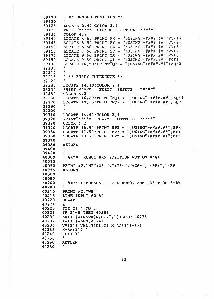
39110 ' ** SENSED P O S ITIO N **3912039125 LOCATE 2 , 4 0 : COLOR 2 , 439130 P R IN T"* * * * * SENSED P O S ITIO N ****★"39135 COLOR 4 , 239140 LOCATE 4 , 50 : P R IN T ” PX = " ; USING"*#### . # # " ; VV ( 1 )39145 LOCATE 5 , 50 : P R IN T"P Y = USING"*#### .##",* VV{ 2 )39150 LOCATE 6 , 5 0 : PRI NT" PZ = " ; U S I N G " * # # # # . # # " ; V V ( 3) 39160 LOCATE 7 , 5 0 : PRI NT "QP = U S I N G " + # # # # . # # " ; V V ( 4 )39170 LOCATE 8 , 5 0 : PRINT"QR = U S IN G "+ # # # # . # # " ; W ( 5 )39180 LOCATE 9 , 5 0 : PRINT"Q1 = U S I N G " * # # # # . # # " ; FQF139190 LOCATE 1 0 , 5 0 : PRINT"Q2 = U S I N G " + # # # # . # # " ; FQF2 39200 3921039215 ’ ** FUZZY INFERENCE **3922039230 LOCATE 1 4 , 10 : COL OR 2 , 439240 p r i n t "***** FUZZY INPUTS ★****"39250 COLOR 4 , 239260 LOCATE 1 6 , 2 0 : PRINT"EQ1 = " ; U S I N G " * # # # # . # # " ; EQF139270 LOCATE 1 8 , 2 0 : PRI NT" EQ2 = " ; U S I N G " * # # # # . # # " ; EQF239280 3930039310 LOCATE 1 4 , 4 0 : COLOR 2 , 439320 P R IN T"* * * * * FUZZY OUTPUTS *****"39330 COLOR 4 , 239340 LOCATE 1 6 , 5 0 : PRI NT" EPX = " ; U S I N G " * # # # # . # # " ; EPX39350 LOCATE 1 7 , 5 0 : PRI NT " EP Y = " ; U S I NG " * # # # # . # # " ; EPY39360 LOCATE 1 8 , 5 0 : PRI NT " EPZ = " ; U S I N G " * # # # # . # # " ; EPZ3937039380 RETURN394003942040000 ' %%** ROBOT ARM P O S ITIO N MOTION **%%4001040050 P R IN T # 2 , " M P " + X £ + " , " + Y £ + " , " + Z E + " , " + P £ + " , " + R £40055 RETURN400604008040200 ' %%** FEEDBACK OF THE ROBOT ARM P O S ITIO N **%%4020840210 P R IN T §2 , "WH"40215 L IN E IN P U T #2 , A£40220 D£=A£40224 K=140226 FOR 11=1 TO 540228 I F 11=5 THEN 4023240230 A A ( I I ) = I N S T R ( K , D £ , " , " ) : GOTO 4023640232 A A ( 1 1 ) = LE N( D £ )+140236 W ( I 1 ) = V A L ( M I D £ ( D £ , K , A A ( 11 ) - 1 ) )40238 K = A A ( 11)+1 40240 NEXT 1140250 '40260 RETURN40280 '
22
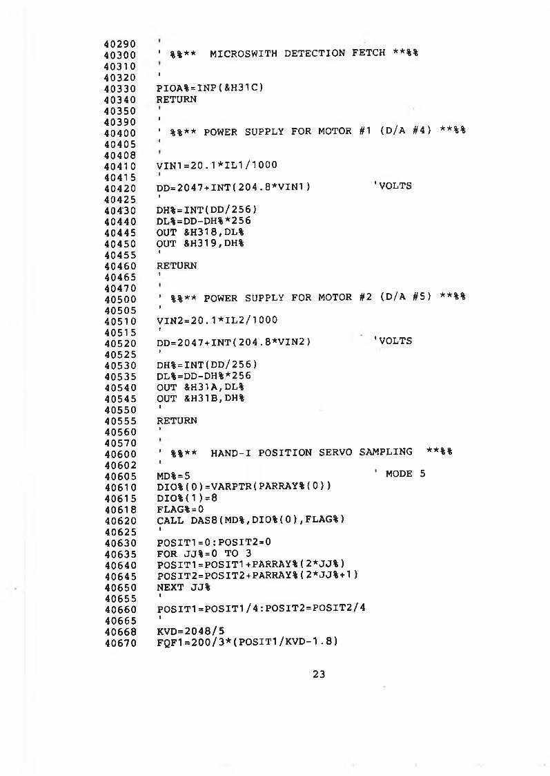
40290 40300 4031 0 40320 40330 40340 40350 40390 40400 40405 40408 4041 0 4041 5 40420 40425 40430 40440 40445 40450 40455 40460 40465 40470 40500 40505 4051 0 4051 5 40520 40525 40530 40535 40540 40545 40550 40555 40560 40570 40600 40602 40605 40610 4061 5 40618 40620 40625 40630 40635 40640 40645 40650 40655 40660 40665 40668 40670
' %%** MICROSWITH D E TE C TIO N FETCH **%%
tP I O A % = I N P ( &H31C)RETURN
I' %%** POWER SUPPLY FOR MOTOR #1 (D/A #4) **%%I
V I N 1 = 2 0 . 1* I L 1 / 1 00 0ID D = 2 0 4 7 + I N T ( 2 0 4 . 8 * V I N 1 ) 'VO LTSID H % = I N T ( D D / 256)DL%=DD-DH%*256 OUT &H318 , DL%OUT &H31 9 , DH%IRETURNI
' %%** POWER SUPPLY FOR MOTOR #2 ( D/A #5) **%%IV I N 2 = 2 0 . 1 * I L 2 / 1 0 0 0 «D D = 2 0 4 7 + I N T ( 2 0 4 . 8 * V I N 2 ) 'VOLTS»D H % = I N T ( D D /256)DL%=DD-DH%*256 OUT &H31 A,DL%OUT &H31B , DH%IRETURN»
' %%** H A N D -I P O S ITIO N SERVO SAMPLING **%%IMD%=5 ' MODE 5D I O % ( 0 ) =VARPTR( PARRAY%( 0 ) )D I O % ( 1 ) = 8 FLAG%=0CALL DAS8( MD%, DI O%( 0 ) , FLAG%)IP O S I T 1 = 0 : POS I T2 = 0FOR JJ% = 0 TO 3P O S I T 1 = P 0 S I T 1 +PARRAY% ( 2 * J J % )POSI T2=POSIT2+PARRAY%( 2 * J J % + 1)NEXT JJ%IP O S I T 1 = P 0 S I T 1 / 4 : P OS I T 2 = P O S I T 2/ 4IKVD=2048/5F Q F 1 = 2 0 0 / 3 * ( P O S I T 1 / K V D - 1 . 8 )
23
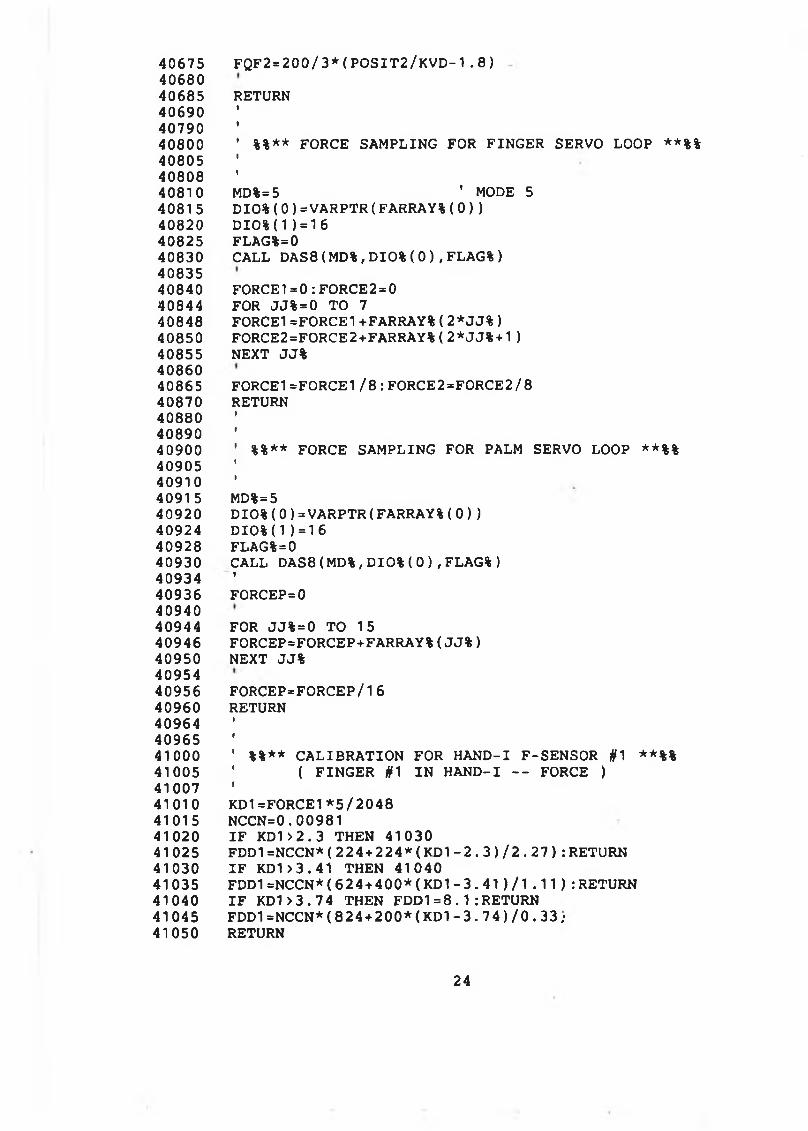
40675 FQF2=200/3 * ( P O S I T 2 / K V D - 1 . 8 )4068040685 RETURN406904079040800 ' %%** FORCE SAMPLING FOR FINGER SERVO LOOP **%%408054080840810 MD% = 5 ' MODE 540815 D IO % ( 0 ) = VARPTR( FARRAY%( 0 ) )40820 D IO % ( 1 ) = 1 6 40825 FLAG%=040830 CALL DAS8( MD%, D I O % ( 0 ) , FLAG%)4083540840 FORCE1=0 : FORCE2 = 040844 FOR JJ% = 0 TO 740848 FORCE 1 =F0RCE1+FARRAY%( 2 * J J % )40850 FORCE2=FORCE2+FARRAY%(2 * J J % + 1)40855 NEXT JJ%4086040865 FORCE1=FORCE1/8: FORCE2=FORCE2/840870 RETURN408804089040900 ' %%** FORCE SAMPLING FOR PALM SERVO LOOP **%%409054091040915 MD%=540920 D I O%( 0 ) = VARPTR( FARRAY%( 0 ) )40924 D I O % ( 1 ) = 1 640928 FLAG%=040930 CALL DAS8( MD%, D I O % ( 0 ) , FLAG%)40934 '40936 FORCEP=04094040944 FOR JJ% = 0 TO 1540946 FORCEP=FORCEP+FARRAY%( J J % )40950 NEXT JJ%4095440956 FORCEP=FORCEP/1640960 RETURN409644096541000 1 %%** C A LIB R A TIO N FOR H A N D -I F-SENSOR #1 **%%41005 ' ( F IN G ER #1 IN H A N D -I - - FORCE )41007 '41010 KD1=FORCE1*5/204841015 NCCN=0. 0098141020 I F KD1>2. 3 THEN 4103041025 FDD1=NCCN*( 224 + 2 2 4 * ( KD1- 2 . 3 ) / 2 . 2 7 ) : RETURN41030 I F KD1>3.41 THEN 4104041035 FDD1=NCCN*(6 2 4 + 4 0 0 * ( KD1- 3 . 4 1 ) / l . 1 1 ) : RETURN 41040 I F KD1> 3 . 7 4 THEN FDD1=8.1 : RETURN41045 FDD1=NCCN*(8 2 4 + 2 0 0 * ( KD 1- 3 . 7 4 ) / 0 . 3 3 ;41050 RETURN
24
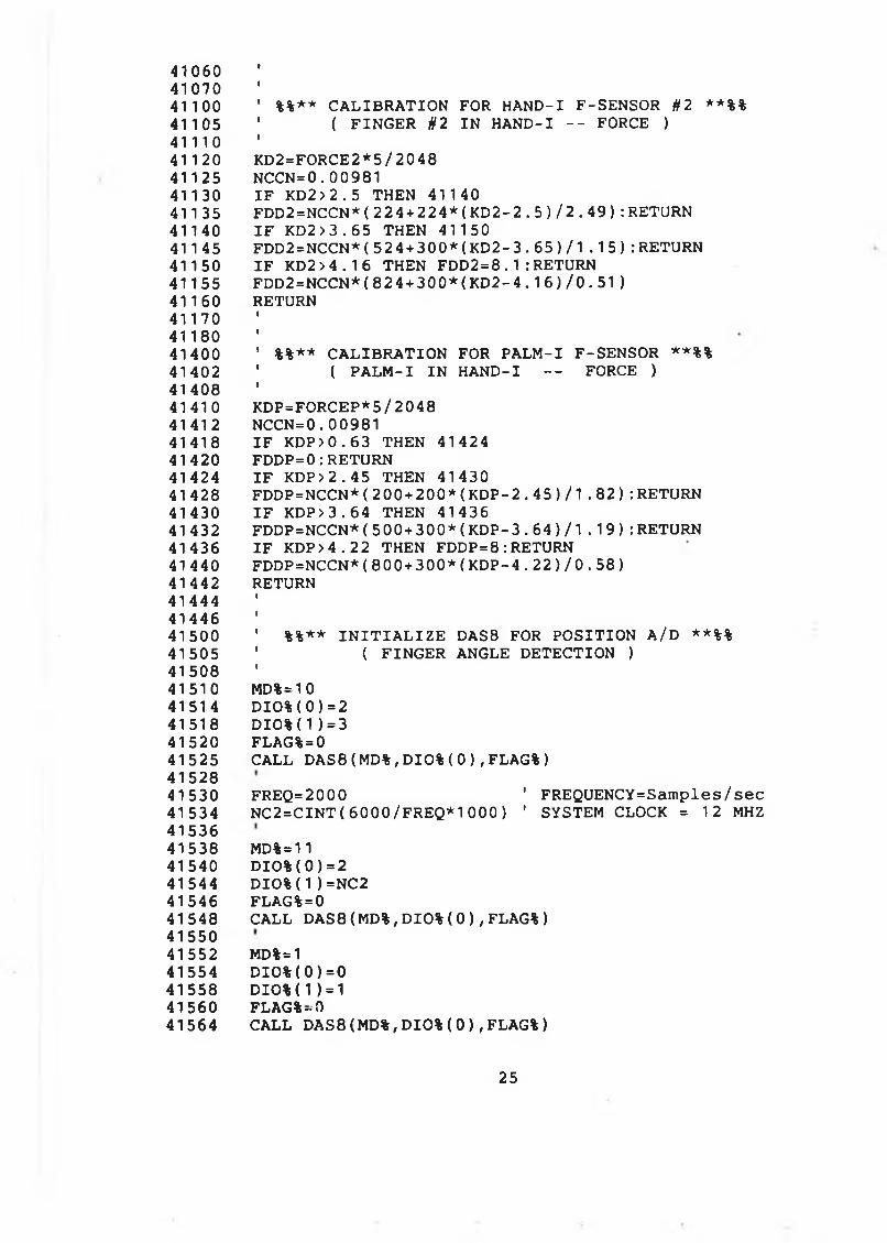
410604107041100 ' %%** C A L IB R A TIO N FOR H A N D -I F-SENSOR #2 **%%41105 ' ( FIN G ER #2 IN H A N D -I - - FORCE )41110 '41120 KD2=FORCE2*5/204841125 N C C N = 0 . 0098141130 I F KD2 >2. 5 THEN 4114041135 FDD2=NCCN*( 2 2 4 + 2 2 4* ( K D 2 - 2 . 5 ) / 2 . 4 9 ) : RETURN 41140 I F KD2 > 3 . 65 THEN 4115041145 FDD2=NCCN*( 5 2 4 + 3 0 0 * ( K D 2 - 3 . 6 5 ) / 1 . 1 5 ) : RETURN 41150 I F KD2 > 4 . 1 6 THEN FDD2 = 8 .1 : RETURN 41155 FDD2=NCCN*( 824 + 3 0 0 * ( K D 2 - 4 . 1 6 ) / 0 .51 )41160 RETURN411704118041400 ' %%** C A L IB R A TIO N FOR P A LM -I F-SENSOR **%%41402 ' ( P A L M - I IN HAND-I - - FORCE )4140841410 KDP=FORCEP*5/204841412 NCCN= 0 . 0098141418 I F KDP>0 . 6 3 THEN 4142441420 FDDP=0:RETURN41424 I F KDP>2 . 4 5 THEN 4143041428 FDDP=NCCN*( 200+200* ( K D P - 2 . 4 5 ) / 1 . 8 2 ) : RETURN 41430 I F KDP> 3 . 6 4 THEN 4143641432 FDDP=NCCN*( 5 0 0 + 3 0 0 * ( K D P - 3 . 6 4 ) / 1 . 1 9 ) : RETURN41436 IF K D P > 4 . 2 2 THEN FDD P = 8 : RETURN414 40 F D D P = N C C N * ( 8 0 0 + 3 0 0 *( K D P -4 .2 2 ) / 0 . 58)41442 RETURN414444144641500 ' %%** I N I T I A L I Z E DAS8 FOR P O S ITIO N A/D **%%41505 ' ( FINGER ANGLE D ETECTIO N )4150841510 MD%=10 41514 D I O % ( 0 ) = 2 41518 D I O % ( 1 ) = 3 41520 FLAG%=041525 CALL D A S 8 ( MD%, D I O % ( 0 ) , FLAG%)4152841530 FREQ=2000 ' FREQUENCY=Sam ples/sec41534 N C 2 = C I N T ( 6 0 0 0 /FREQ*1000) 1 SYSTEM CLOCK = 12 MHZ4153641538 MD%=11 41540 D I O % ( 0 ) = 2 41544 D I O % ( 1 ) =NC2 41546 FLAG%=041548 CALL DAS8(MD%, D I O % ( 0 ) , FLAG%)4155041552 MD%=141554 D I O % ( 0 ) = 0 41558 D I O % ( 1 ) = 1 41560 FLAG % -041564 CALL DAS8(MD%, D I O % ( 0 ) , FLAG%)
25
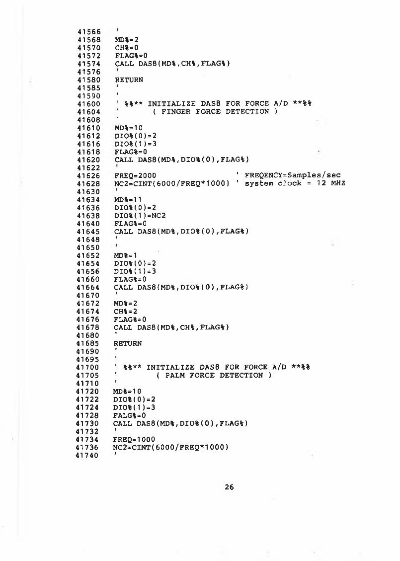
4156641568 MD%=241570 CH%=041572 FLAG%=041574 CALL DAS8( MD%, CH%, F LA G % )4157641580 RETURN 415854159041600 ' %%** I N I T I A L I Z E DAS8 FOR FORCE A/D **%%41604 ' ( FINGER FORCE D ETEC TIO N )4160841610 MD%=1041612 DI O%( 0 ) = 2 41616 D I O%( 1) = 3 41618 FLAG%=041620 CALL DAS8 ( MD% , DIO% ( 0 ) , FLAG% )4162241626 FREQ=2000 ' FREQENCY=Sam ples/sec41628 NC2=CI NT ( 600 0/FREQ*1 000) ' system c lo c k = 12 MHZ4163041634 MD%=1141636 DI O%( 0 ) = 2 41638 D I O%( 1 ) =NC2 41640 FLAG%=041645 CALL DAS8(MD%, D I O % ( 0 ) , FLAG%)416484165041652 MD%=141654 DI O%( 0 ) = 2 41656 DI O%( 1 ) = 3 41660 FLAG%=041664 CALL DAS8 ( MD% , DIO% ( 0 ) , FLAG% )41670 '41672 MD%=241674 CH%=241676 FLAG%=041678 CALL DAS8 ( MD%, CH% , FLAG% )41680 '41685 RETURN416904169541700 ' %%** I N I T I A L I Z E DAS8 FOR FORCE A/D **%%41705 ' ( PALM FORCE D ETEC TIO N )41710 '41720 MD%=1041722 DI O%( 0 ) = 2 41724 D IO % ( 1 ) = 3 41728 FALG%=041730 CALL DAS8(MD%, D I O % ( 0 ) , FLAG%)41732 '41734 FREQ=100041736 N C 2 = C I NT ( 60 0 0 / F RE Q* 1 0 00)41740 '
26
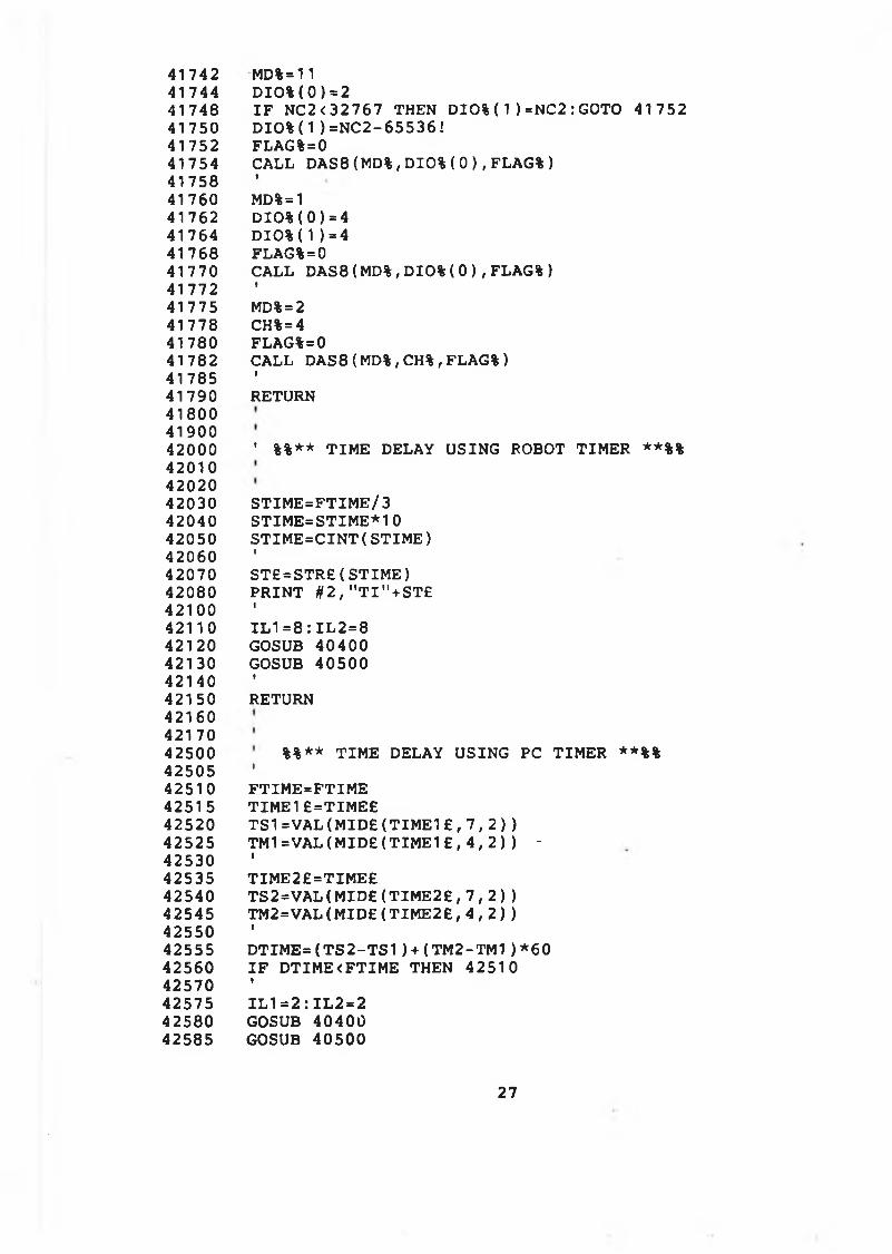
41742417444174841750417524175441758417604176241764417684177041772417754177841780417824178541790418004190042000420104202042030420404205042060420704208042100421104212042130421404215042160421704250042505425104251542520425254253042535425404254542550425554256042570425754258042585
MD%= 11 D I O % ( 0 ) = 2I F NC2 <32767 THEN D I O % ( 1 ) =NC2: GOTO 41752 D I O % ( 1 ) =N C2 - 6 5 53 6 !FLAG%=0CALL OAS 8( MD%, D I O % ( 0 ) , FLAG%)IMD%= 1 D I O % ( 0 ) = 4 D I O % ( 1 ) = 4 FLAG%=0CALL DAS8( MD%, D I O % ( 0 ) , FLAG%)*MD% = 2 CH%=4 FLAG%=0CALL OAS 8( MD%, CH%, FLAG%)i
RETURN
' %%** T IM E DELAY USING ROBOT TIM ER **%%
S TIM E = FTIM E /3 S TIM E = S TIM E * 1 0 S T IM E = C IN T ( S T IM E )IS T £ = S T R £ ( S T I ME ) P R IN T # 2 , " T I " + S T £II L 1 =8 : I L 2 = 8 GOSUB 40400 GOSUB 40500iRETURN
%%** T IM E DELAY USING PC TIM ER **%%IF TIM E = F TIM E TIM E 1 £ = TIM E £T S 1 = V A L ( M I D £ ( T I M E 1 £ , 7 , 2 ) )TM1=VAL( M I D £ ( T I M E 1 £ , 4 , 2 ) ) *iTIM E 2 £ = TIM E £T S 2 = V A L ( M I D £ ( T I M E 2 £ , 7 , 2 ) ) TM 2 = V A L (M ID £ (TIM E 2 £ , 4 , 2 ) )iD T I M E = ( T S 2 - T S 1 ) + ( T M 2 - T M 1 ) * 6 0 I F D TIM E < FTIM E THEN 42510iI L I = 2 : I L 2 = 2 GOSUB 40400 GOSUB 40500
27
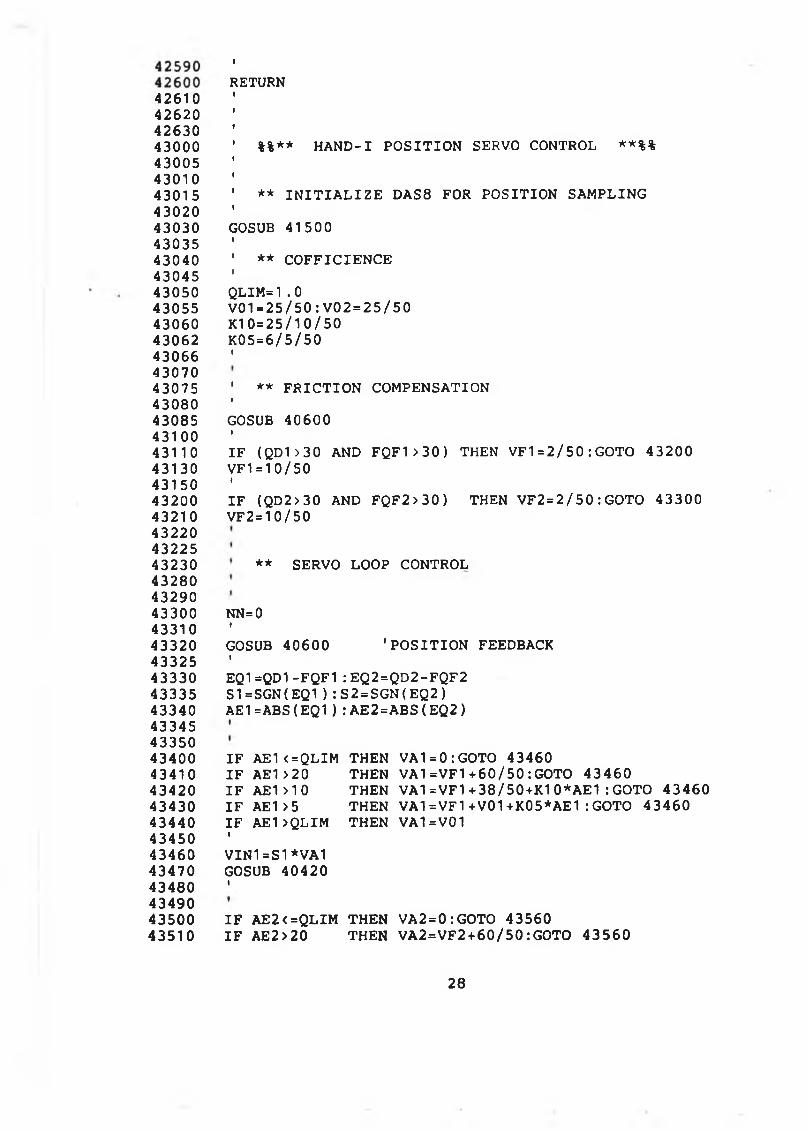
4261042620426304300043005430104301543020430304303543040430454305043055430604306243066430704307543080430854310043110431304315043200432104322043225432304328043290433004331043320433254333043335433404334543350434004341043420434304344043450434604347043480434904350043510
RETURNi
%%** H A N D -I P O S IT IO N SERVO CONTROL **%%
** I N I T I A L I Z E DAS8 FOR P O S ITIO N SAMPLING
GOSUB 41500
** C O F F IC IE N C E
QLIM=1.0V01=25/50: V02=25/50 K1 0=25/10/50 K05=6/5/50I
' ** F R IC T IO N COMPENSATIONIGOSUB 40600II F ( QD1>30 AND FQF1>30) THEN VF1=2/50 : GOTO 43200 VF1=10/50II F (QD2 >30 AND FQF2>30) THEN VF2 = 2 /50 : GOTO 43300 VF 2 = 10/50
** SERVO LOOP CONTROL
NN=0f
GOSUB 40600 'P O S IT IO N FEEDBACKIEQ1 =QD1-FQF1 : EQ 2=QD2-FQF2 S1 =SGN( E Q 1 ) : S2 = SGN( E Q 2 ) AE1 =ABS( EQ1) : A E 2 = A B S ( E Q 2 )
I F AE1<=QLIM THEN V A I = 0 : GOTO 43460I F AE1>20 THEN V A I =VF1+60/50 : GOTO 43460I F AE1>10 THEN VA1=VF1+38/50+K10*AE1 : GOTO 43460I F AE1 > 5 THEN V A I =VF1+V01+K05*AE1 : GOTO 43460I F AE1>QLIM THEN VA1=V01IVIN1=S1*VA1 GOSUB 40420I
I F AE2<=QLIM THEN VA2=0:GOTO 43560I F AE2 >20 THEN VA2=VF2 + 6 0 / 5 0 : GOTO 43560
28
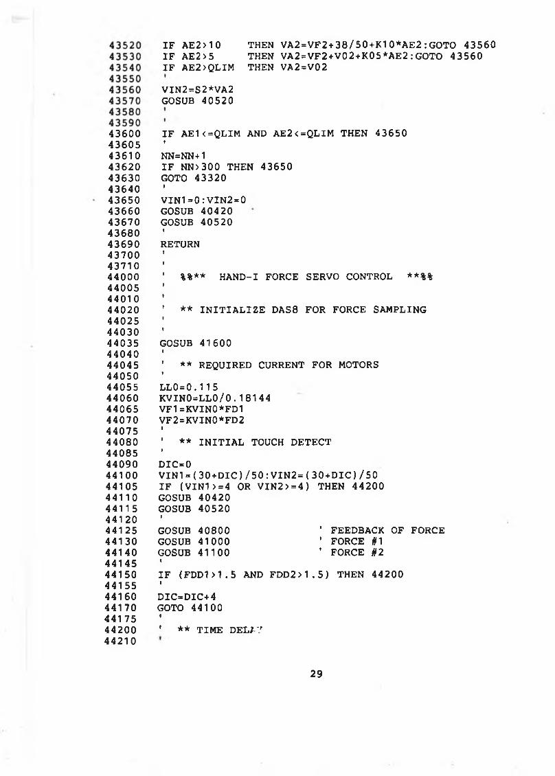
436004360543610436204363043640436504366043670436804369043700437104400044005440104402044025440304403544040440454405044055440604406544070440754408044085440904410044105441104411 5441 204412544130441404414544150441554416044170441 754420044210
I F A E2 >10 THEN VA2 = VF2 + 38/50 + K10*AE2: GOTO 43560 I F AE2 > 5 THEN VA2 = VF2+V02 + K 0 5*AE2: GOTO 43560I F AE2>QLIM THEN VA2=V02
VIN2=S2*VA2 GOSUB 40520
I F A E1 < =QLIM AND AE2 < =QLIM THEN 43650i
NN=NN+1I F NN> 300 THEN 43650 GOTO 43320IV I N 1 = 0 : VIN2=0 GOSUB 40420 GOSUB 40520iRETURN
%%** H A N D -I FORCE SERVO CONTROL **%%
** I N I T I A L I Z E DAS8 FOR FORCE SAMPLING
GOSUB 41600I' ** REQUIRED CURRENT FOR MOTORSIL L 0 = 0 .115 K V I N 0 = L L 0 / 0 . 18144 VF1=KVIN0*FD1 VF2=KVIN0*FD2I' ** I N I T I A L TOUCH D E TE C TID IC=0V I N 1 = ( 3 0 + D I C ) / 5 0 : V I N 2 = ( 3 0 + D I C ) / 5 0 I F ( V I N 1 > = 4 OR V IN 2 > = 4 ) THEN 44200 GOSUB 40420 GOSUB 40520IGOSUB 4 0800 ' FEEDBACK OF FORCEGOSUB 41000 ' FORCE #1GOSUB 41100 ' FORCE #2•I F ( FDD1>1. 5 AND F D D 2 > 1 . 5 ) THEN 44200ID IC =D IC+4GOTO 44100 •* ** TIM E DELIV
29
44220442304423544240442454425044255442604428044290443004431044320450004501045020450304504045050451004520046000460104602046030460354604046050460604607046080461004611050000
GOSUB 45000
' ** FORCE CONTROLIVIN1=VF1 : V IN 2 = V F2 GOSUB 40420 GOSUB 40520IRETURN
%%** T IM E DELAY FOR FORCE CONTROL **%%
FOR KW%=0 TO 100 NEXT KW%RETURN
' %%** T IM E DELAY FOR HYBRID CONTROL **%%IFOR KW%=0 TO 500 NEXT KW%II L 1 =0 : I L 2 = 0 GOSUB 40400 GOSUB 40500IRETURN
1 ************* END OF THE F IL E **************
30
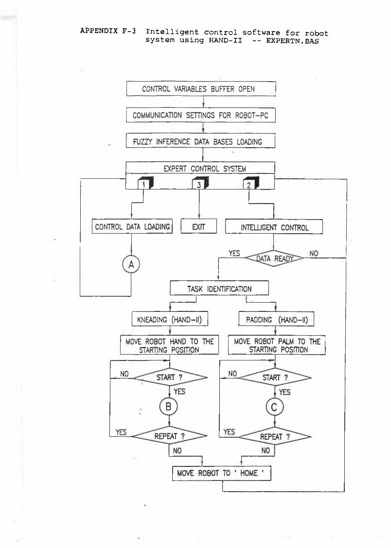
APPENDIX F -3 I n t e l l i g e n t c o n t r o l s o f t w a r e f o r ro b o t s y s t e m u s in g H A N D -I I - - EX P ER TN . BAS
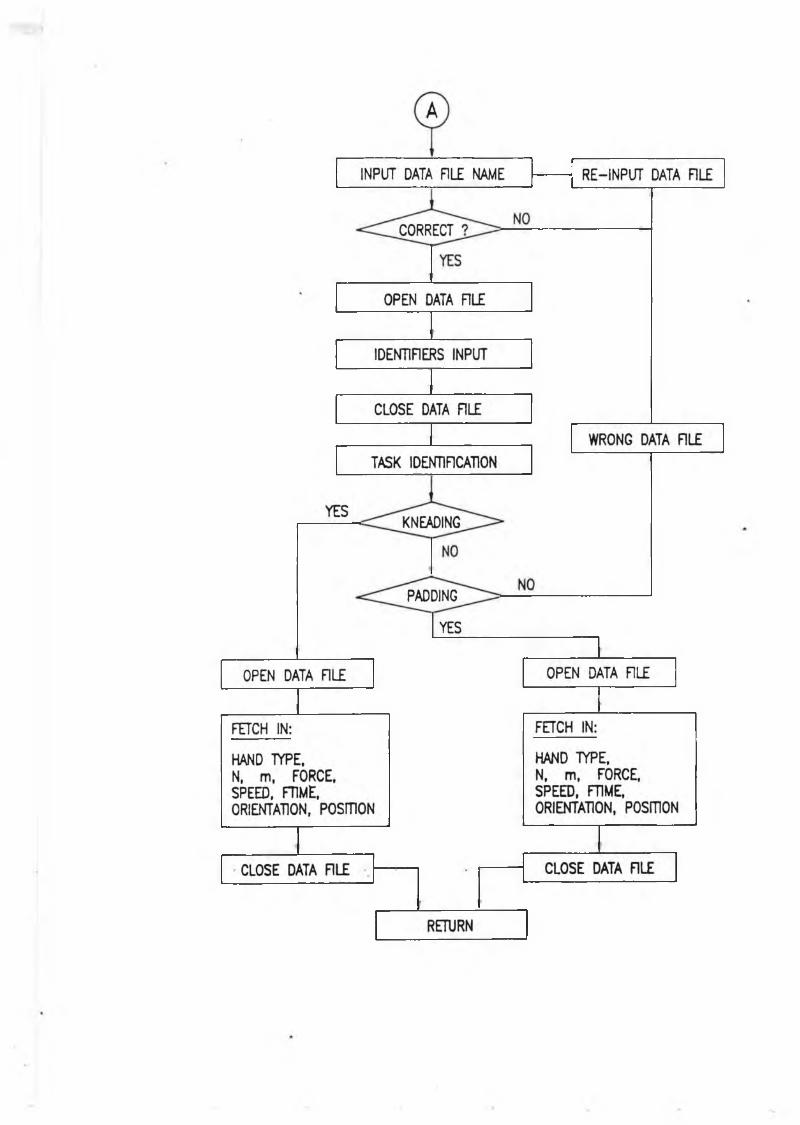
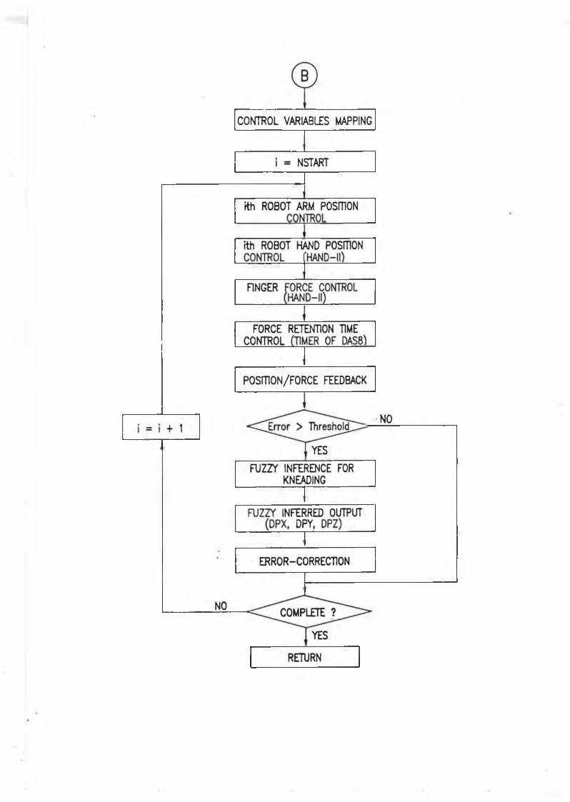
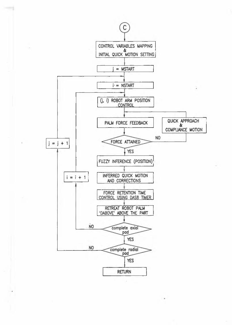
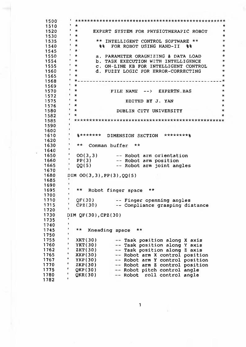
1 5 0 01510152015301535154015451 5501 55415551560156515681569157015721 5751 57615801582158515901600161016201630164016501660166516701680168516901695170017101715172017301735174017451750175517601762176517671770177517801782
* ** E X P E R T S Y S T E M FOR P H Y S I O T H E R A P I C R O B O T ** ** ** I N T E L L I G E N T C O N T R O L S O F T W A R E ** ** %% F O R R O B O T U SING H A N D - I I %% **' ** a. P A R A M E T E R O R A G N I Z I N G & D A T A L O A D ** b. T A S K E X E C U T I O N W I T H I N T E L L I G E N C E ** C. O N - L I N E KB FOR I N T E L L I G E N T C O N T R O L ** d. F U Z Z Y L O G I C FOR E R R O R - C O R R E C T I N G ** **___________________________________________________________ ** ** F I L E N A M E --> E X P E R T N .BAS ** ** E D I T E D BY J. Y A N *★ ** DUB L I N C ITY U N I V E R S I T Y ** *
' %******* DIM ENSION SECTION ********%
' ** Comman b u f f e r **
' 0 0 ( 3 , 3 ) - - R obot arm o r i e n t a t i o n1 P P ( 3 ) - - R obot arm p o s i t io n' QQ(5) - - R obot arm j o i n t a n g le s
DIM 0 0 ( 3 , 3 ) , P P ( 3 ) ,QQ(5)
' ** R obot f i n g e r space **
' Q F ( 3 0 ) - - F in g e r o p e n n in g a n g le s' C P Z ( 3 0 ) - - C o m p lia n ce g r a s p in g d i s t a n c e
DIM Q F ( 3 0 ) , C P Z ( 3 0 )
** K n e a d in g space **
X K T ( 3 0 ) Y K T ( 30) Z K T ( 30) X KP( 3 0 ) Y K P ( 3 0 ) ZKP( 3 0 ) QKP( 3 0 ) Q K R ( 30)
Ta s k p o s i t io n a lo n g X a x i s T a s k p o s i t io n a lo n g Y a x i s T a s k p o s i t io n a lo n g Z a x i s R obot arm X c o n t r o l p o s i t io n R obot arm Y c o n t r o l p o s i t io n Robot arm Z c o n t r o l p o s i t i o n R obot p i t c h c o n t r o l a n g le R obot r o l l c o n t r o l a n g le
1
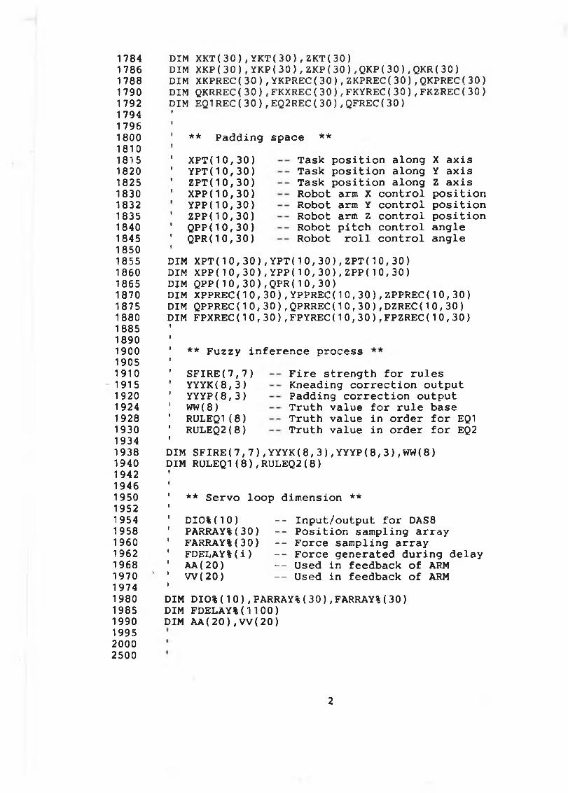
178417861788179017921794179618001810181518201825183018321835184018451850185518601865187018751880188518901900190519101915192019241928193019341938194019421946195019521954195819601962196819701974198019851990199520002500
DIM X K T ( 3 0 ) , Y K T ( 3 0 ) , Z K T ( 30 )DIM XKP( 3 0 ) , Y K P ( 3 0 ) , Z K P ( 3 0 ) , QKP( 3 0 ) , QKR( 3 0 )DIM XKPREC( 3 0 ) , YKPREC( 3 0 ) , ZKPREC( 3 0 ) , QKPREC( 3 0 ) DIM QKRREC( 3 0 ) , FKXREC( 3 0 ) , FKYREC( 3 0 ) , FK Z R E C ( 3 0 ) DIM EQ1REC( 3 0 ) , EQ2REC( 3 0 ) , QFREC( 3 0 )
** P a d d in g space **
X P T ( 1 0 , 3 0 ) Y P T ( 1 0 , 3 0 ) Z P T ( 1 0 , 3 0 ) XPP( 1 0 , 3 0 ) YPP( 1 0 , 3 0 ) ZPP( 1 0 , 3 0 ) QPP( 1 0 , 3 0 ) Q P R ( 1 0 , 3 0 )
T a s k p o s i t i o n a lo n g T a s k p o s i t io n a lo n g T a s k p o s i t i o n a lo n g R obot arm X c o n t r o l R obot arm Y c o n t r o l Robot arm Z c o n t r o l Robot p i t c h c o n t r o l R obot r o l l c o n t r o l
X a x i s Y a x i s Z a x is p o s i t io n p o s i t io n p o s i t io n a n g le a n g le
DIMDIMDIMDIMDIMDIM
X P T ( 1 0 , 3 0 ) , Y P T ( 1 0 , 3 0 ) , Z P T ( 1 0 , 3 0 )X P P ( 1 0 , 3 0 ) , Y P P ( 1 0 , 3 0 ) , ZPP( 1 0 , 3 0 )Q P P ( 1 0 , 3 0 ) , Q P R ( 1 0 , 3 0 )XPPREC( 1 0 , 3 0 ) , YPPREC( 1 0 , 3 0 ) , ZPPREC( 1 0, 30) QPPREC( 1 0 , 3 0 ) , QPRREC( 1 0 , 3 0 ) , DZREC( 1 0 , 3 0 ) FPXREC( 1 0 , 3 0 ) , FPYREC( 1 0 , 3 0 ) , FPZREC( 1 0 , 3 0 )
** F u z z y in f e r e n c e p ro c e s s
S F I R E ( 7 , 7 ) Y Y Y K ( 8 , 3 ) Y YYP( 8 , 3 ) WW(8) RULEQ1( 8 ) RULEQ2( 8 )
F i r e s t r e n g t h f o r r u le s K nead in g c o r r e c t io n o u tp u t P a d d in g c o r r e c t io n o u tp u t T r u t h v a lu e f o r r u l e base T r u t h v a lu e in o rd e r f o r EQ1 T r u t h v a lu e in o rd e r f o r EQ2
DIM S F I R E ( 7 , 7 ) , Y Y Y K ( 8 , 3 ) , YYYP( 8 , 3 ) , WW( 8 ) DIM RULEQ1( 8 ) , RULEQ2( 8 )
** S e rv o lo o p d im e n s io n **
D I 0 % ( 1 0 ) PARRAY%( 3 0 ) FARRAY%( 3 0 ) FDELAY%( i ) AA ( 2 0 )W ( 20 )
- - In p u t/ o u tp u t f o r DAS8 - - P o s i t i o n s a m p lin g a r r a y - - F o rc e s a m p lin g a r r a y - - F o rc e g e n e ra te d d u r in g d e la y - - Used i n feedback o f ARM - - Used i n feedback o f ARM
DIM D I O % ( 1 0 ) , PARRAY%( 3 0 ) , FARRAY%( 3 0 ) DIM F D E L A Y % ( 1 100)DIM A A ( 2 0 ) , V V ( 20)
2
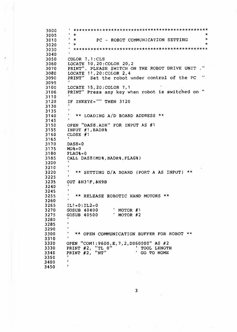
3000 1 ***********************************************3005 ' * *3010 ' * PC - ROBOT COMMUNICATION SETTING *3020 ’ * *3030 1 * * * * * * * * * * * * * * * * * * * * * * * * * * * * * * * * * * * * * * * * * * * * * * *
30403050 COLOR 7 , 1 : CLS3060 LOCATE 1 0 , 2 0 : COLOR 20, 23070 P R IN T " . PLEASE SWITCH ON THE ROBOT DR IVE U N IT 3080 LOCATE 1 1 , 2 0 : COLOR 2 , 43090 P R IN T" Set the robot under control of the PC "30953100 LOCATE 1 5 , 2 0 : COLOR 7,13106 PRINT" Press any key when robot is switched on "31103120 IF INKEY£="" THEN 3120.31303135 '3140 ' ** LOADING A/D BOARD ADDRESS **31453150 OPEN " DAS8. ADR" FOR INPUT AS #13155 INPUT #1,BADR%3160 CLOSE #131653170 -DAS8=03175 MD%=03180 FLAG%=03185 CALL DAS8(MD%,BADR%,FLAG%)320032103220 ' ** S E TTIN G D/A BOARD (PORT A AS IN P U T ) **32253235 OUT &H31F,&H9B324032453255 ' ** RELEASE ROBOTIC HAND MOTORS **32603265 I L 1 = 0 : I L 2 = 03270 GOSUB 40400 ' MOTOR #13275 GOSUB 40500 ' MOTOR #23280328532903300 ' ** OPEN COMMUNICATION BUFFER FOR ROBOT **33103320 OPEN " C O M 1 : 9 6 0 0 , E , 7 , 2 , DS60000" AS #23330 PRINT §2, " T L 0" 1 TOOL LENGTH3340 PRINT §2, "NT" ' GO TO HOME335034003450
3
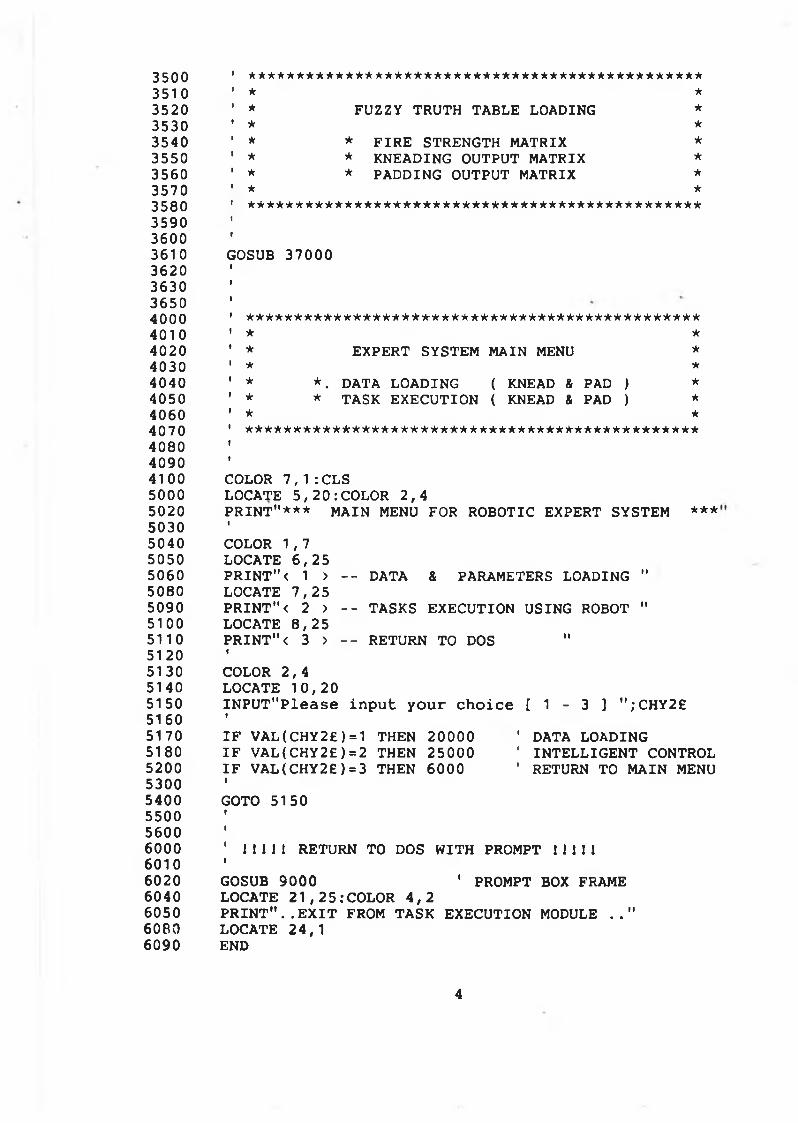
3500 ' ***********************************************3510 ' * *3520 ' * FUZZY TRUTH TABLE LOADING *3530 ' * *3540 ' * * F IR E STRENGTH MATRIX *3550 ’ * * KNEADING OUTPUT MATRIX *3560 ' * * PADDING OUTPUT MATRIX *3570 1 * *3580 ' ***********************************************35903600 ■
3610 GOSUB 370003620 i
3630 i
36504000 ' ***********************************************4010 ' * *4020 ' * EXPERT SYSTEM MAIN MENU *4030 1 * *4040 ' * * . DATA LOADING ( KNEAD & PAD ) *4050 ' * * TASK EX ECU TIO N ( KNEAD & PAD ) *4060 ' * *4070 1 ***********************************************4080 i4090 i4100 COLOR 7 , 1 : CLS5000 LOCATE 5 , 2 0 : COLOR 2 , 45020 P R IN T"* * * MAIN MENU FOR ROBOTIC EXPERT SYSTEM ***5030 1
5040 COLOR 1 ,75050 LOCATE 6 , 2 55060 P R IN T " < 1 > - - DATA & PARAMETERS LOADING "5080 LOCATE 7 , 2 55090 P R IN T " < 2 > - - TASKS EXECUTION USING ROBOT "5100 LOCATE 8 , 2 55110 P R IN T " < 3 > - - RETURN TO DOS "5120 f
5130 COLOR 2 ,45140 LOCATE 1 0 , 205150 IN P U T "P le a s e in p u t y o u r c h o ic e [ 1 - 3 ] " ; C H Y 2 £5160 1
5170 I F VAL ( CHY2£) =1 THEN 20000 ' DATA LOADING5180 I F V A L ( C H Y 2 £ )=2 THEN 25000 ' IN TE L L IG E N T CONTROL5200 I F V A L( C H Y 2 £ ) = 3 THEN 6000 ' RETURN TO MAIN MENU5300 15400 GOTO 51505500 1
5600 1
6000 ' I 1 1 1 I RETURN TO DOS W ITH PROMPT 111116010 t
6020 GOSUB 9000 ' PROMPT BOX FRAME6040 LOCATE 2 1 , 2 5 : COLOR 4 , 26050 P R I N T " . . E X I T FROM TASK EXECUTION MODULE . . "6080 LOCATE 24,16090 END
4
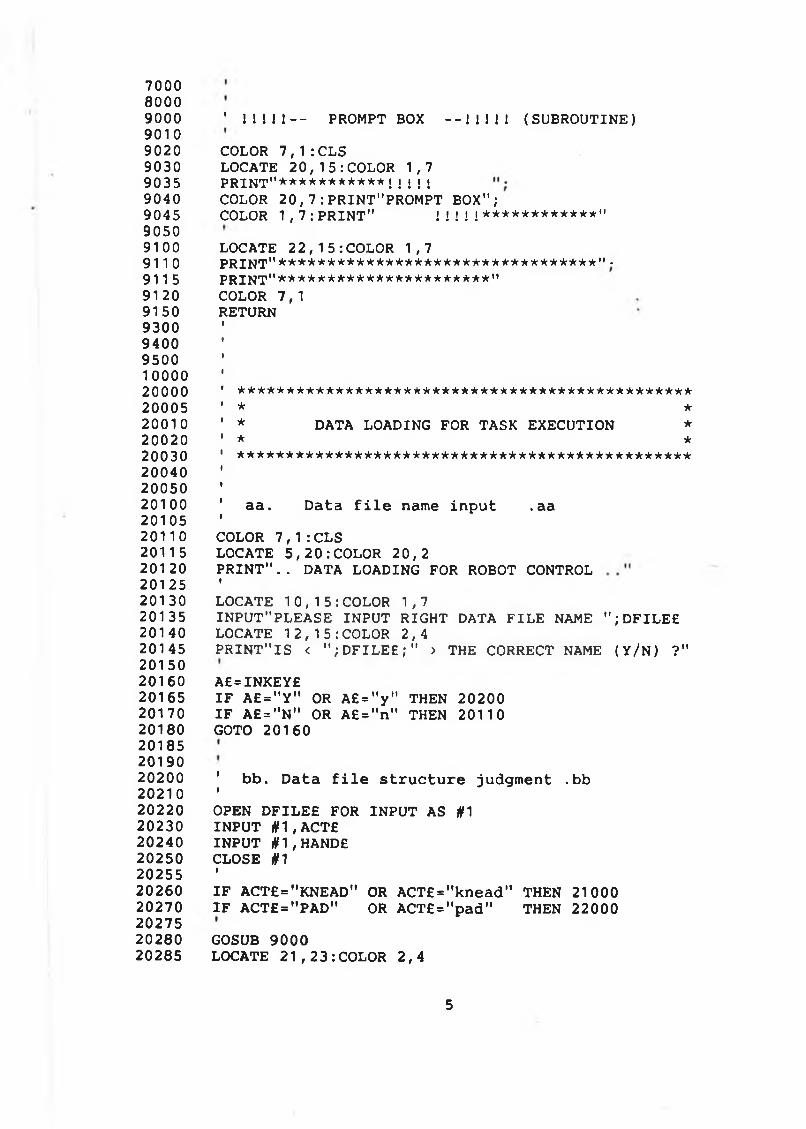
700080009000 ' 11111 — PROMPT BOX - - 1 1 1 1 ! (SU B R O U TIN E)90109020 COLOR 7 , 1 :CLS9030 LOCATE 2 0 , 15 : COL OR 1,79035 p r i n t " * * * * * * * * * * * ! ! ! ! !9040 COLOR 2 0 , 7 :PRINT"PROMPT BOX";9045 COLOR 1 , 7 : P R I N T " ! ! ! ! ! * * * * * * * * * * * * "90509100 LOCATE 22 , 15 : COL OR 1, 79110 P R IN T"*********************************"•9115 p r i n t "**********************"9120 COLOR 7,19150 RETURN9300 94009500 '100002 0 0 0 0 ' * * * * * * * * * * * * * * * * * * * * * * * * * * * * * * * * * * * * * * * * * * * * * * *
20005 ' * *20010 ' * DATA LOADING FOR TASK EXECUTION *2 0 0 2 0 ' * *20030 1 ***********************************************20040 '2005020100 ' aa. Data f i l e name in p u t .aa2010520110 COLOR 7 , 1 : CLS20115 LOCATE 5 , 2 0 : COLOR 2 0, 220120 P R I N T " . . DATA LOADING FOR ROBOT CONTROL20125 '20130 LOCATE 1 0 , 1 5 : COLOR 1, 720135 IN P U T"P LE A S E IN P U T RIG HT DATA F IL E NAME " ; D FI LEE20140 LOCATE 1 2 , 1 5 : COLOR 2 , 420145 P R IN T " IS < " ; D F I L E E ; " > THE CORRECT NAME ( Y / N ) ?"2015020160 A£=INKEY£20165 I F A £ = " Y " OR A £ = " y " THEN 2020020170 I F A £ =" N" OR A £ = " n " THEN 2011020180 GOTO 20160201852019020200 ' bb. D a t a f i l e s t r u c t u r e judgm ent .bb2 0210 '
20220 OPEN D F IL E E FOR IN P U T AS #120230 IN P U T # 1 , A C T £20240 IN P U T § 1 , HANDE20250 CLOSE #120255 '20260 I F A CT£="KN EAD " OR A C T£ = "k n e a d " THEN 2100020270 I F A C T£ = "P A D " OR A C T£ = "p a d " THEN 220002027520280 GOSUB 900020285 LOCATE 2 1 , 2 3 : COLOR 2 , 4
5
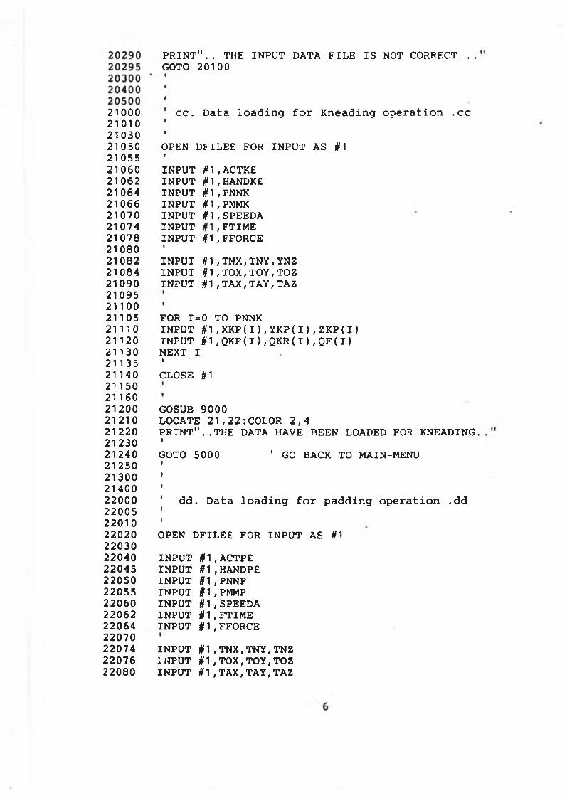
210002 1010210302105021055210602106221064210662107021074210782108021082210842109021095211002110521110211202113021135211402115021160212002121021220212302124021250213002140022000220052201022020220302204022045220502205522060220622206422070220742207622080
P R I N T " . . THE IN P U T DATA F IL E IS NOT CORRECT . , GOTO 20100
c c . Data lo a d in g f o r K n e a d in g o p e ra tio n .c c
OPEN D FILEE FOR IN P U T AS #1tIN P U T # 1 , ACTKEIN P U T # 1 , HANDKEIN P U T # 1 , PNNKIN P U T #1,PMMKIN P U T § 1 , SPEEDAIN P U T , FTIM EIN P U T § 1 , FFORCE 1IN P U T # 1 , T N X , T N Y , Y N Z IN P U T # 1 , T O X , T O Y , TOZ IN P U T # 1 , T A X , T A Y , TAZ
FOR 1=0 TO PNNK INPUT #1,XKP(I),YKP(I),ZKP(I) INPUT #1,QKP( I ) ,QKR(I),QF(I) NEXT IICLOSE #1
GOSUB 9000LOCATE 2 1 , 2 2 : COLOR 2 , 4P R I N T " . . T H E DATA HAVE BEEN LOADED FOR KNEADING.IGOTO 5000 ' G O BACK TO MAIN-MENU
d d . D ata lo a d in g f o r p a d d in g o p e ra t io n .d d
OPEN D FILEE FOR IN P U T AS #1IIN P U T § 1 , ACTPE IN P U T # 1 ,HANDPE IN P U T # 1 , PNNP IN P U T #1 ,PMMP IN P U T # 1 , SPEEDA IN P U T # 1 , FT IME IN P U T if 1 , FFORCE
IN P U T # 1 , T NX , T N Y , TNZ IN P U T # 1 , T O X , T O Y , T O Z IN P U T § 1 , T A X , T A Y , TAZ
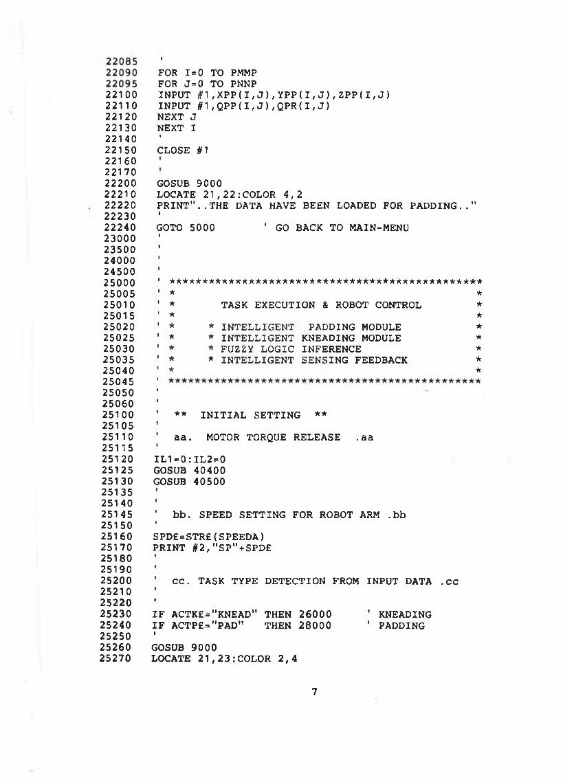
2 2 1 0 02 2 1 1 02 2 1 2 022130221402215022160221702 2 2 0 0222102 22 2 02223022240230002350024000245002500025005250102501525020250252503025035250402504525050250602510025105251102511525120251252513025135251 402514525150251602517025180251902520025210252202523025240252502526025270
»
FOR 1=0 TO PMMP FOR J= 0 TO PNNPIN PU T jjf1 , XPP( I , J ) , Y P P ( I , J ) , ZPP( I , J ) IN PU T # 1 , QPP( I , J ) , QPR( I , J )NEXT J NEXT II
CLOSE H 1
GOSUB 9000LOCATE 2 1 , 2 2 : COLOR 4 , 2P R I N T " . . T H E DATA HAVE BEEN LOADED FOR P A D D I N G . . "IGOTO 5000 ' G O BACK TO MAIN-MENU
***** ******* ********** *************** *********** *
* TASK EXECUTION & ROBOT CONTROL ** ** * INTELLIGENT PADDING MODULE ** * INTELLIGENT KNEADING MODULE ** * FUZZY LOGIC INFERENCE ** * INTELLIGENT SENSING FEEDBACK ** *
• ** I N I T I A L S E TTIN G **I’ aa . MOTOR TORQUE RELEASE . aaII L I =0 : I L 2 = 0 GOSUB 40400 GOSUB 40500II’ bb. SPEED S E TTIN G FOR ROBOT ARM . bbISPD£=STR£( SPEEDA)P R IN T §2,"SP"+SPD£
C C . TASK TYPE D E TE C TIO N FROM IN PU T DATA . c c
I F ACTK£="KNEAD" THEN 26000 ' KNEADINGI F ACTP£="PAD" THEN 28000 ' PADDINGIGOSUB 9000LOCATE 2 1 , 2 3 : COLOR 2 , 4
7
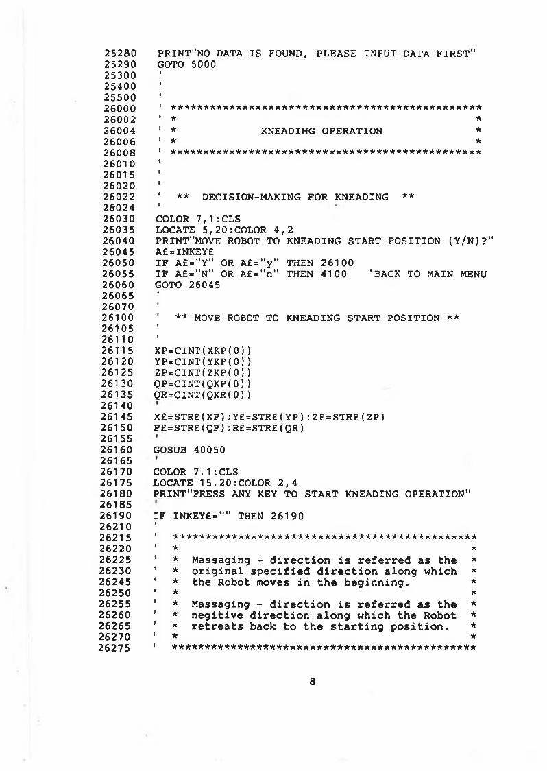
25280 PRINT"NO DATA IS FOUND, PLEASE IN P U T DATA F I R S T "25290 GOTO 5000253002540025500 '26000 1 ***********************************************26002 ' * *26004 ’ * KNEADING OPERATION *26006 ' * *26008 ' ***********************************************26010 26015 2602026022 1 ** D ECISIO N -M AKIN G FOR KNEADING **2602426030 COLOR 7 , 1 :CLS 26035 LOCATE 5 , 2 0 : COLOR 4 , 226040 PRINT"MOVE ROBOT TO KNEADING STAR T P O S ITIO N ( Y / N ) ? " 26045 A£=INKEY£26050 I F A£=" Y" OR A £ = " y " THEN 2610026055 IF A£="N" OR A£="n" THEN 4100 'BACK TO MAIN MENU26060 GOTO 26045260652607026100 1 ** MOVE ROBOT TO KNEADING START P O S ITIO N **261052611026115 X P = C I N T ( XKP( 0 ) )26120 Y P = C I N T ( YKP( 0 ) )26125 Z P = C I N T ( ZKP( 0 ) )26130 Q P = C I N T ( QKP( 0 ) )26135 Q R = C I N T ( QKR( 0 ) )2614026145 X £ = S T R£ ( XP ) : Y £ = S T R £ ( Y P ) : Z £ = S T R£ ( ZP )26150 P£ = S T R £ ( QP ) : R£ = S TR £ ( Q R )2615526160 GOSUB 40050 26165261 70 COLOR 7,1 :CLS26175 LOCATE 1 5 , 2 0 : COLOR 2 , 426180 PRINT"PRESS ANY KEY TO S TA R T KNEADING OPERATION" 2618526190 IF INKEY£=" " THEN 26190 2621026215 1 **********************************************26220 ' * *26225 ' * M assaging + d i r e c t i o n i s r e f e r r e d as th e *26230 ' * o r i g i n a l s p e c i f i e d d i r e c t i o n a lo n g w h ic h *26245 ' * the Robot moves in th e b e g in n in g . *26250 ' * *26255 * * M assaging - d i r e c t i o n i s r e f e r r e d as th e *26260 ' * n e g i t iv e d i r e c t i o n a lo n g w h ic h th e R obot *26265 ' * r e t r e a t s back t o th e s t a r t i n g p o s i t i o n . *26270 1 * *26275 ' **********************************************
8
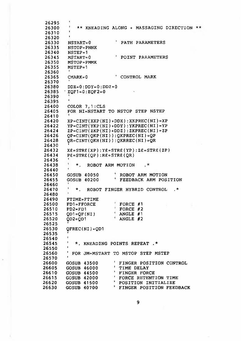
2 6 2 9 5 1
2 6 3 0 0 * * KNEADING ALONG + MASSAGING D IR E C T IO N2 6 3 1 0 1
2 6 3 2 0 1
2 6 3 3 0 NSTART=0 ' PATH PARAMETERS2 6 3 3 5 NSTOP=PNNK2 6 3 4 0 NSTEP=12 6 3 4 5 MSTART=0 1 P O IN T PARAMETERS2 63 5 0 MSTOP=PMMK2 6 3 5 5 MSTEP=12 63 6 0 1
2 6 3 6 5 CMARK=0 ’ CONTROL MARK2 6 3 7 0 1
2 6 3 8 0 D D X =0 : D D Y = 0 : DDZ = 02 6 3 8 5 ‘ EQF1=0 : EQF2 = 0 -2 6 3 9 0 1
2 6 3 9 5 1
2 6 4 0 0 COLOR 7 , 1 : CLS2 6 4 0 5 FOR N I=N S TA R T TO NSTOP STEP NSTEP2 6 4 1 0 1
2 6 4 2 0 X P = C I N T ( X K P ( N I ) +DDX) : XKPREC( N I ) =XP2 6 4 2 2 Y P = C I N T ( Y K P ( N I ) +DDY) : YKPREC( N I ) = YP2 6 4 2 4 Z P = C I N T ( Z K P ( N I ) + D D Z ) : Z K P R E C ( N I ) =ZP2 6 4 2 6 Q P = C I N T ( QKP( N I ) ) : QKPREC( N I ) =QP2 6 4 2 8 Q R = CI NT ( QKR( N I ) ) : QKRREC( N I ) =QR2 6 4 3 0 1
2 6 4 3 2 X £ = S T R £ ( X P ) : Y£= S T R £ ( Y P ) : Z £ = S T R £ ( Z P )2 64 3 4 P £ = S T R £ ( Q P ) : R£= STR£ ( QR)2 6 4 3 6 t
2 6 4 3 8 ' * . ROBOT ARM MOTION . *2 6 4 4 0 1
2 6 4 5 0 GOSUB 4 0 0 5 0 ' ROBOT ARM MOTION2 64 5 5 GOSUB 4 0 2 0 0 ' FEEDBACK ARM P O S IT IO N2 64 6 0 *
2 64 7 0 ' * . ROBOT F IN G E R HYBRID CONTROL . *2 64 8 0 1
2 6 4 9 0 F T IM E = F T IM E2 6 5 0 0 FD1=FFORCE ' FORCE #12 65 1 0 FD2=FD1 ’ FORCE §22 65 1 5 Q D 1 = Q F ( N I ) ' ANGLE #12 6 5 2 0 QD2=QD1 ' ANGLE §22 65 2 5 1
2 6 5 3 0 Q F R E C ( N I ) =QD12 65 3 5 1
2 6 5 4 0 1
2 6 5 4 5 ' * . KNEADING PO IN TS REPEAT . *2 65 5 0 t
2 6 5 6 0 ' FOR JM=MSTART TO MSTOP STEP MSTEP2 6 5 7 0 V
2 6 6 0 0 GOSUB 4 3 5 0 0 ' F IN G E R P O S IT IO N CONTROL2 6 6 0 5 GOSUB 4 6 0 0 0 ' T IM E DELAY2 6 6 1 0 GOSUB 4 4 5 0 0 1 F IN G E R FORCE2 6 6 1 5 GOSUB 4 2 0 0 0 ' FORCE RETENTIO N T IM E2 66 2 0 GOSUB 4 1 5 0 0 1 P O S IT IO N IN IT IA L IZ E2 6 6 3 0 GOSUB 4 0 7 0 0 ' F IN G E R P O S IT IO N FEEDBACK
9
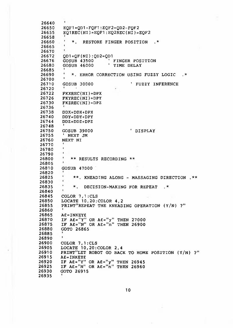
2664026650 EQF1=QD1- FQF1: EQF2=QD2-FQF2 26655 E Q 1 R E C ( N I ) = E Q F 1 : E Q2 R E C ( N I ) =E Q F 2 2665826660 ' *. RESTORE FINGER P O S ITIO N .*26665 '2667026672 QD1=QF(NI ) :QD2=QD126676 GOSUB 43500 ' FINGER P O S ITIO N26680 GOSUB 46000 ' TIME DELAY2668526690 ' *. ERROR CORRECTION USING FUZZY LOG IC . *26700 '26710 GOSUB 30000 1 FUZZY INFERENCE2672026722 FKXREC( N I ) =DPX26726 FKYR EC( N I ) =DPY 26730 FKZREC( N I ) =DPZ 2673626738 DDX=DDX+DPX 26740 DDY=DDY+DPY 26744 DDZ=DDZ+DPZ 2674826750 GOSUB 39000 ' D ISPLAY26755 ' NEXT JM26760 NEXT N I 26770 '26780 '2679026800 ' ** RESULTS RECORDING **2680526810 GOSUB 47000 2682026825 ' **. KNEADING ALONG - MASSAGING D IR E C TIO N .**2683026835 ' *. D ECISIO N -M AKIN G FOR REPEAT . *2684026845 COLOR 7 , 1 : C L S26850 LOCATE 1 0 , 2 0 : COLOR 4 , 226855 P R IN T"R EP EA T THE KNEADING OPERATION ( Y / N ) ?"2686026865 A£=INKEY£26870 I F A £ = "Y " OR A £ = " y " THEN 2700026875 I F A£="N" OR A£="n" THEN 2690026880 GOTO 26865268852689026900 COLOR 7 , 1 : C L S26905 LOCATE 10,20:COLOR 2 , 426910 P R IN T "L E T ROBOT GO BACK TO HOME P O S ITIO N ( Y / N ) ?"26915 A£=INKEY£26920 I F A£=" Y" OR A£="y" THEN 2694526925 I F A£="N" OR A£="n" THEN 2696026930 GOTO 26915 26935
10
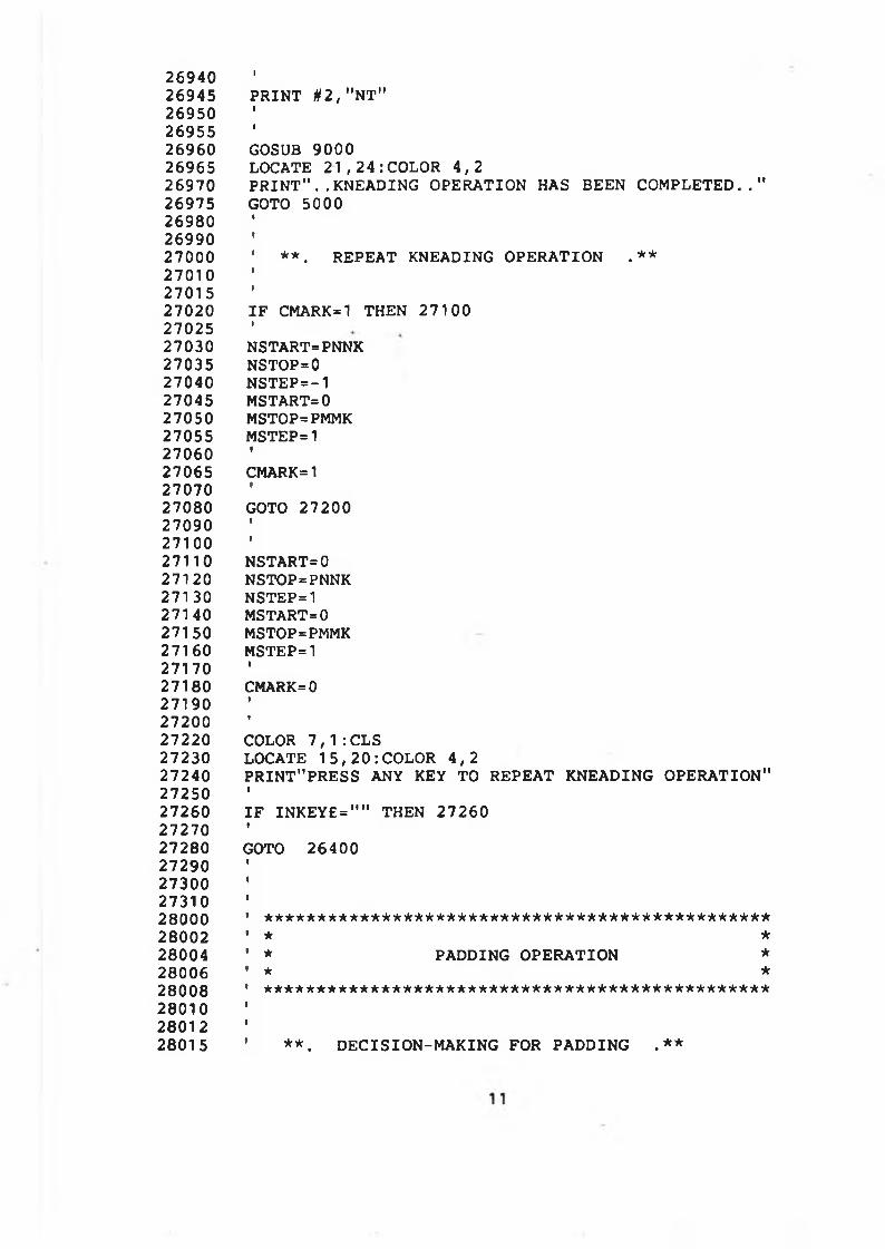
2 69 4 0 t
269 4 5 P R IN T # 2 , "NT"269 5 0 1
2 69 5 5 1
2 69 6 0 GOSUB 9 0 0 026965 LOCATE 2 1 , 2 4 : COLOR 4 , 22 69 7 0 P R I N T " . .KNEADING OPERATION HAS BEEN C O M P L E T E D . . ”2 69 7 5 GOTO 5 0002 69 8 0 I
269 9 0 I
2 70 0 0 ' * * . REPEAT KNEADING OPERATION . * *2 7 0 1 0 i
270 1 5 i
270 2 0 I F CMARK=1 THEN 2 7 1 0 02 70 2 5 i
270 3 0 NSTART=PNNK2 70 3 5 NSTOP=02 70 4 0 N S T E P = -1270 4 5 MSTART=0270 5 0 MSTOP=PMMK270 5 5 MSTEP=12 7 0 6 0 i
270 6 5 CMARK=12 70 7 0 *
2 70 8 0 GOTO 2 7 2 0 0270 9 0 i
271 0 0 i
271 1 0 NSTART=0271 2 0 NSTOP=PNNK271 3 0 NSTEP=1271 4 0 MSTART=0271 5 0 MSTOP=PMMK271 6 0 MSTEP=1271 7 0 ■
2 7 1 8 0 CMARK=02 71 9 0 t
272 0 0 i
272 2 0 COLOR 7 , 1 : CLS272 3 0 LOCATE 1 5 , 2 0 : COLOR 4 , 2272 4 0 PRINT"PRESS ANY KEY TO REPEAT KNEADING OPERATION"2 72 5 0 i
2 72 6 0 I F I N K E Y £ = " " THEN 2 7 2 6 02 7 2 7 0 i
2 7 2 8 0 GOTO 2 6 4 0 02 72 9 0 ■
2 73 0 0 i
2 73 1 0 i
280 0 0 ' * * * * * * * * * * * * * * * * * * * * * * * * * * * * * * * * * * * * * * * * * * * * * * *280 0 2 ' * *2 80 0 4 1 * PADDING OPERATION *2 80 0 6 * * *2 8 0 0 8 * * * * * * * * * * * * * * * * * * * * * * * * * * * * * * * * * * * * * * * * * * * * * * * *2 80 1 0 i
2 8 0 1 2 i
2 8 0 1 5 ' * * . D E C IS IO N -M A K IN G FOR PADDING . * *
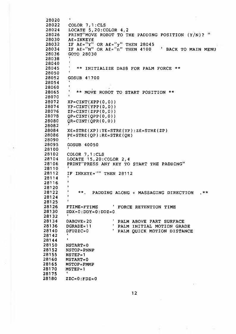
28020 28022 28024 28026 28030 28032 28034 28036 28038 28040 28045 28050 28052 28054 28060 28065 28070 28072 28074 28076 28078 28080 28082 28084 28086 28090 28095 28100 28102 28104 28106 28110 2811 2 28114 28116 28120 28122281242812528126 28130 28132 28134 28136 28140 28142 28144 28150 28152 28155 28160 28165 28170 28175 28180
COLOR 7 , 1 : CLS LOCATE 5 , 2 0 : COLOR 4 , 2PRINT"MOVE ROBOT TO THE PADDING P O S IT IO N ( Y / N ) ? " A£=INKEY£IF A£=" Y" OR A £ = " y " THEN 28045I F A£="N" OR A£ = " n" THEN 4100 ' BACK TO MAIN MENUGOTO 28030
** I N I T I A L I Z E DAS8 FOR PALM FORCE **
GOSUB 41700
** MOVE ROBOT TO START P O S IT IO N **
X P = C I N T ( X P P ( 0 , 0 ) )Y P = C I N T ( Y P P ( 0 , 0 ) )Z P = C I N T ( ZPP( 0 , 0 ) )Q P = C I N T ( QPP( 0 , 0 ) )QR = C I N T ( QPR( 0 , 0 ) )IX£=STR£(XP):Y£=STR£(YP):Z£=STR£(ZP) P£=STR£(QP):R£=STR£(QR)IGOSUB 40050ICOLOR 7 , 1 : CLSLOCATE 1 5 , 2 0 : COLOR 2, 4PRINT"PRESS ANY KEY TO START TH E PADDING"
IF IN K E Y £ = ' THEN 28112
**. PADDING ALONG + MASSAGING D IR E C TIO N . **
F TIM E = F TIM E ' FORCE R ETEN TIO N TIM EDDX=0: DDY=0: DDZ=0
DABOVE = 20 DGRADE=11 DFUZZC=0I!NSTART=0NSTOP=PNNPNSTEP=1MSTART=0MSTOP=PMMPMSTEP=1iZZC=0:FDZ=0
' PALM ABOVE PART SURFACE ’ PALM I N I T I A L MOTION GRADE ’ PALM QUICK MOTION D ISTAN CE
12
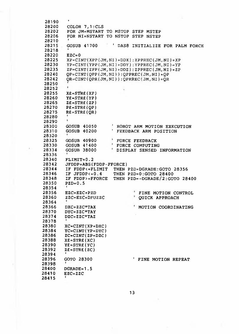
28190282002820228206282102821 528218282202822528230282352824028242282502825228255282602826528270282752828028290283002831028320283252833028334283362834028342283442834628348283502835428356283602836428366283702837428378283802838428386283882839028392283942839628398284002841028415
ICOLOR 7 , 1 :CLSFOR JM=MSTART TO MSTOP STEP MSTEP FOR N I=NSTART TO NSTOP STEP NSTEPIGOSUB 41700 ' DAS8 I N I T I A L I Z E FOR PALM FORCEIEZC=0X P = C I N T { X P P (J M ,N I )+ D D X ):X P P R E C (J M , N I )=XP Y P = C I N T (Y P P (J M ,N I )+ D D Y ):Y P P R E C (J M , N I )=YP Z P = C I N T (Z P P (J M , N I )+ D D Z ):Z P P R E C (J M , N I )=ZP Q P = C I N T (Q P P (J M ,N I )):Q P P R E C (J M ,N I )=QP Q R = C I N T (Q P R (J M ,N I )):Q P R R E C (J M ,N I )=QRI
X£=STR£(XP) Y£=STR£(YP) Z£=STR£(ZP) P£=STR£(QP) R£=STR£(QR)
GOSUB 40050 GOSUB 40200
’ ROBOT ARM MOTION EXECUTION ' FEEDBACK ARM P O S IT IO N
GOSUB 40900 GOSUB 41400 GOSUB 38000
' FORCE FEEDBACK ' FORCE COMPUTING
DISPLAY SENSED INFORMATION
F L I M I T = 0 .2JFDDP=ABS( FDDP-FFORCE)I F FD D P<=FLIM IT THEN PZD=DGRADE: GOTO 28356 I F JFDDP< = 0 . 4 THEN PZD=0:GOTO 28400 I F FDDP> =FFORCE THEN PZD=-DGRADE/2:GOTO 28400 PZD=0.5
EZC=EZC+PZDZZC=EZC+DFUZZC
F I N E MOTION CONTROL QUICK APPROACH
DXC=ZZC*TAXDYC=ZZC*TAYDZC=ZZC*TAZ
MOTION COORDINATING
X C = C I N T ( XP+DXC) Y C = C IN T (Y P + D Y C ) Z C = C IN T (Z P + D Z C ) X£=STR£( X C) Y£=S TR £( Y C ) Z£=STR£( ZC)
GOTO 28300 1 F I N E MOTION REPEAT
DGRADE=1.5 EZC=ZZC
13
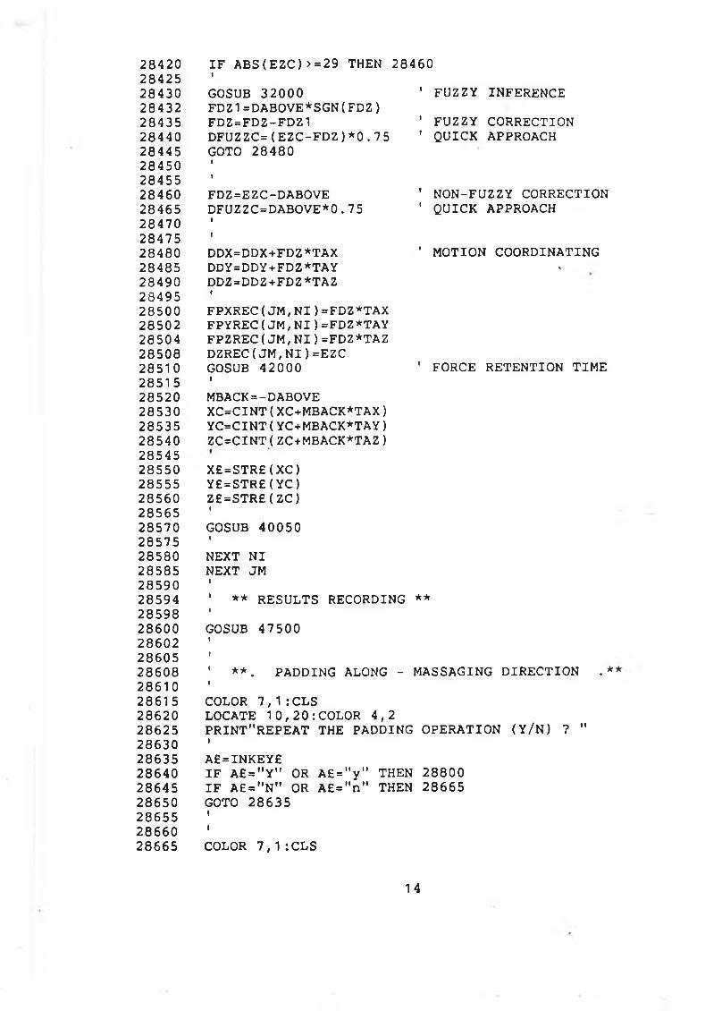
2 8 4 2 0 I F A BS( E Z C )> = 29 THEN 2 8 4 6 02 8 4 2 5 1
2 8 4 3 0 GOSUB 3 2 0 0 0 ' FUZZY INFERENCE2 8 4 3 2 FDZ1=DABOVE*SGN( F D Z )2 8 4 3 5 FD Z=FD Z-FD Z1 1 FUZZY CORRECTION2 8 4 4 0 D F U Z Z C =( E Z C - F D Z ) * 0 . 7 5 ' QUICK APPROACH2 8 4 4 5 GOTO 2 8 4 8 02 8 4 5 0 1
2 8 4 5 5 t
2 8 4 6 0 FDZ=EZC-DABOVE ' NON-FUZZY CORRECTION2 8 4 6 5 DFUZZC=DABOVE*0 .7 5 ' QUICK APPROACH2 8 4 7 0 i
2 8 4 7 5 i
2 8 4 8 0 DDX=DDX+FDZ*TAX ' MOTION COORDINATING2 8 4 8 5 DDY=DDY+FDZ*TAY •
2 8 4 9 0 DDZ=DDZ + F D Z *T A Z2 8 4 9 5 «
2 8 5 0 0 FPXREC( J M , N I ) =FDZ*TAX2 8 5 0 2 FPYREC( J M ; N I ) =FDZ*TAY2 8 5 0 4 FPZREC( J M , N I ) =FDZ*TAZ2 8 5 0 8 DZREC( J M , N I ) =EZC2 8 5 1 0 GOSUB 4 2 0 0 0 ' FORCE RETENTION T IM E2 8 5 1 5 i
2 8 5 2 0 MBACK=-DABOVE2 8 5 3 0 X C = C I N T ( XC+MBACK*TAX)2 8 5 3 5 Y C = C I N T ( YC+MBACK*TAY)2 8 5 4 0 Z C = C IN T {Z C + M B A C K *T A Z )2 8 5 4 52 8 5 5 0 X £ = S T R £ ( X C )2 8 5 5 5 Y £ = S T R £ ( Y C )2 8 5 6 0 Z £ = S T R £ ( Z C )2 8 5 6 5 1
2 8 5 7 0 GOSUB 4 0 0 5 02 8 5 7 5 1
2 8 5 8 0 NEXT N I2 8 5 8 5 NEXT JM2 8 5 9 0 t
2 8 5 9 4 ' * * RESULTS RECORDING * ★
2 8 5 9 8 1
2 8 6 0 0 GOSUB 47 5002 8 6 0 2 1
2 8 6 0 5 1
2 8 6 0 8 ' * * . PADDING ALONG - 1MASSAGING D IR E C T IO N . *2 8 6 1 0 1
2 8 6 1 5 COLOR 7 , 1 : CLS2 8 6 2 0 LOCATE 1 0 , 2 0 : COLOR 4 , 2
OPERATION ( Y / N ) ? "2 8 6 2 5 PR IN T"R EPEA T THE PADDING2 8 6 3 0 t
2 8 6 3 5 A £ = IN K E Y £2 8 6 4 0 I F A £ = " Y " OR A £ = " y " THEN 2 8 8 0 02 8 6 4 5 I F A £ = " N " OR A £ = " n " THEN 2 8 6 6 52 8 6 5 0 GOTO 2 8 6 3 52 8 6 5 5 i
2 8 6 6 0 i
2 8 6 6 5 COLOR 7 , 1 : CLS
14
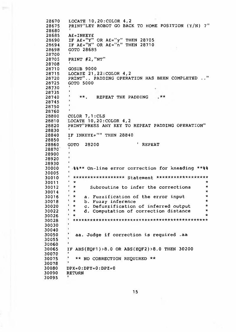
2 8 6 7 02 8 6 7 52 8 6 8 028 6 8 52 8 6 9 02 86 9 42 8 6 9 82 8 7 0 028 7 0 52 8 7 0 82 8 7 1 02 8 7 1 52 8 7 2 02 87 2 52 8 7 3 02 8 7 3 52 8 7 4 02 8 7 4 52 8 7 5 02 8 7 6 02 88 0 02 8 8 1 02 8 8 2 02 8 8 3 02 8 8 4 02 8 8 5 02 8 8 6 02 88 7 02 8 9 0 02 8 9 2 02 8 9 3 03 0 0 0 03 0 0 0 53 0 0 1 03001 13 0 0 1 23001 43 0 0 1 63 0 0 1 83 0 0 2 03 0 0 2 23 0 0 2 63 0 0 2 83 0 0 3 03 0 0 4 03 0 0 5 03 0 0 5 53 0 0 6 03 0 0 6 53 0 0 7 03 0 0 7 53 0 0 7 83 0 0 8 03 0 0 9 03 0 0 9 5
LOCATE 1 0 , 2 0 : COLOR 4 , 2P R IN T " L E T ROBOT GO BACK TO HOME P O S IT IO N ( Y / N ) ?"IA £=IN K EY£I F A £ = " Y " OR A £ = " y " THEN 2 8 7 0 5 I F A £ = " N " OR A £ = " n " THEN 2 8 7 1 0 GOTO 2 8 6 8 5IP R IN T U2, "N T"IGOSUB 9 0 0 0LOCATE 2 1 , 2 2 : COLOR 4 , 2P R I N T " . . PADDING OPERATION HAS BEEN COMPLETED . . " GOTO 5 0 0 0
**. REPEAT THE PADDING
COLOR 7 , 1 :CLS LOCATE 1 0 , 2 0 : COLOR 4 , 2PRINT"PRESS ANY KEY TO REPEAT PADDING OPERATION"IIF INKEY£="" THEN 2 8 8 4 0IGOTO 2 8 2 0 0 ' REPEAT
-%%** On-line error correction for kneading **%%statement ****************** * *
* Subroutine to infer the corrections ** ** a. Fuzzification of the error input ** b. Fuzzy inference ** c. Defuzzification of inferred output ** d. Computation of correction distance ** ******************************* *****************
aa. Judge if correction is required .aa
I F A B S ( E Q F 1 ) > 8 . 0 OR A B S ( E Q F 2 ) > 8 . 0 THEN 30200
** NO CORRECTION REQUIRED **
DPX=0: D PY=0: DPZ=0 RETURN
15
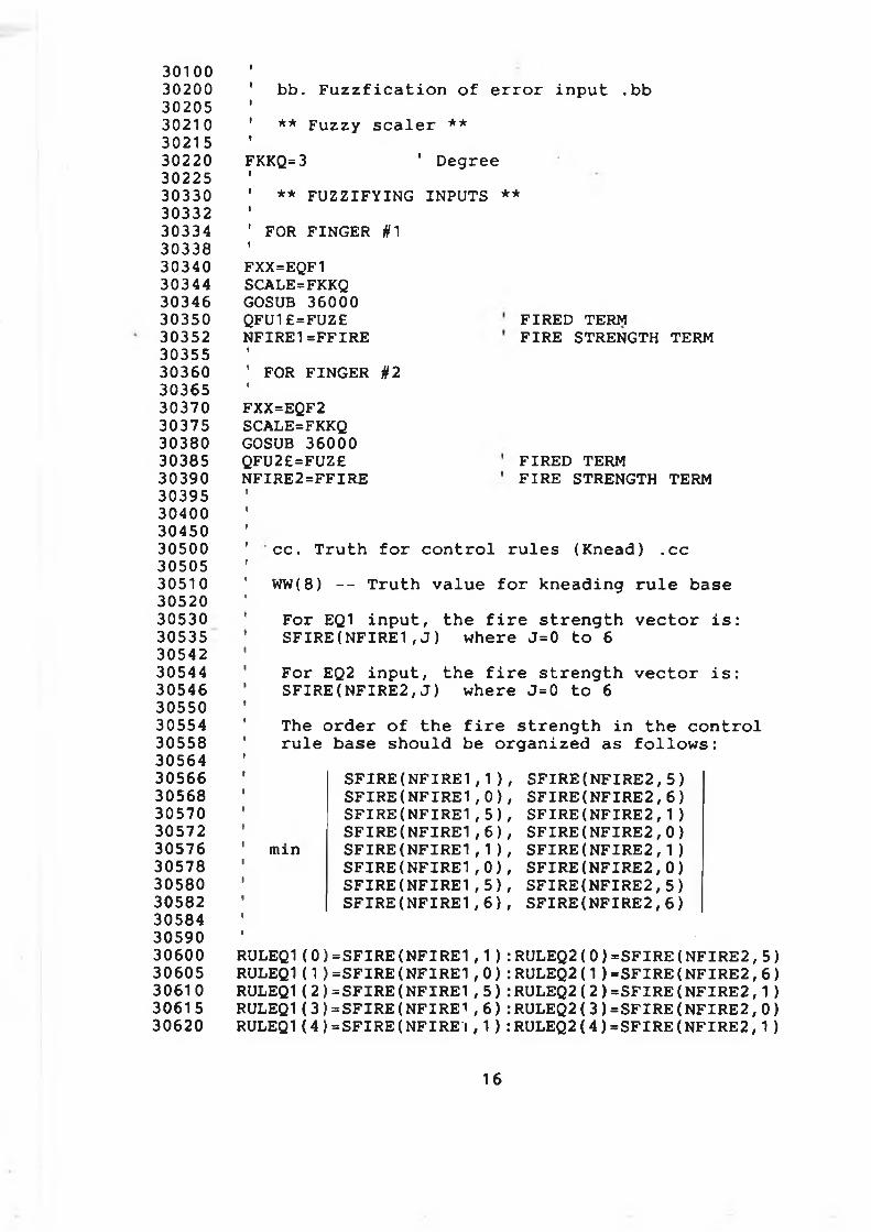
3010030200302053021 03021 53022030225303303033230334303383034030344303463035030352303553036030365303703037530380303853039030395304003045030500305053051030520305303053530542305443054630550305543055830564305663056830570305723057630578305803058230584305903060030605306103061530620
bb. F u z z f i c a t i o n o f e r r o r i n p u t . bb
** F u z z y s c a l e r **
FKKQ=3 ' Degree
** F U Z Z I F Y IN G INPUTS **
FOR FINGER 01
FXX=EQF1 SCALE=FKKQ GOSUB 36000 QFU1£=FUZ£N F IR E1 =FFIR E
♦
1 FOR FINGER §2IFXX=EQF2 SCALE=FKKQ GOSUB 36000 QFU2£=FUZ£ N FIR E2 = FFIR E
FIRED TERMF IR E STRENGTH TERM
FIRED TERMF IR E STRENGTH TERM
c c . T r u t h f o r c o n t r o l r u l e s (Kn ead) . cc
WW(8) - - T r u t h v a l u e f o r k n e a d in g r u l e base
F o r EQ1 i n p u t , th e f i r e s t r e n g t h v e c t o r i s : S F I R E ( N F I R E 1 , J ) where J=0 t o 6
F o r EQ2 i n p u t , t h e f i r e s t r e n g t h v e c t o r i s : S F I R E ( N F I R E 2 , J ) where J=0 to 6
The o r d e r o f t h e f i r e s t r e n g t h i n t h e c o n t r o l r u l e base s h o u l d be o r g a n i z e d as f o l l o w s :
min
S FIR ES FIRES FIR ES F IR ES FIR ES FIR ES FIR ESFIR E
( N F I R E 1 , 1 ) , ( N F I R E 1 , 0 ) , ( N F I R E 1 , 5 ) , ( N F I R E 1 , 6 ) , ( N F I R E 1 , 1 ) , ( N F I R E 1 , 0 ) , ( N F I R E 1 , 5 ) , ( N F I R E 1,6 ) ,
SFIRE(NFIRE2,5) SFIRE(NFIRE2,6) SFIRE(NFIRE2,1) SFIRE(NFIRE2,0) SFIRE(NFIRE2,1) SFIRE(NFIRE2,0) SFIRE(NFIRE2,5) SFIRE(NFIRE2,6)
RULEQ1( 0 ) = S F I R E ( N F I R E 1 , 1 ) : RULEQ2( 0 ) = S F I R E ( N F I R E 2 , 5 ) RULEQ1( 1 ) = S F I R E ( N F I R E 1 , 0 ) :R U L E Q 2 (1 ) = S F I R E ( N F I R E 2 , 6 ) RULEQ1( 2 ) = S F I R E ( N F I R E 1 , 5 ) : RULEQ2( 2 ) = S F I R E ( N F I R E 2 , 1 ) RULEQ1( 3 ) = S F I R E ( N F I R E 1 , 6 ) : RULEQ2( 3 ) = S F I R E ( N F I R E 2 , 0 ) RULEQ1 ( 4 ) =S FIR E ( NFIRE'I , 1 ) : RULEQ2 ( 4 ) = S F IR E ( N F I R E 2 , 1 )
16
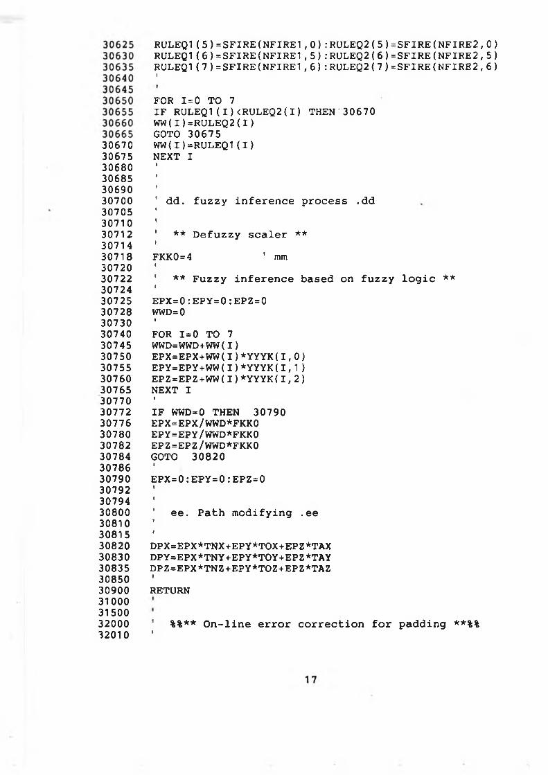
306703067530680306853069030700307053071030712307143071830720307223072430725307283073030740307453075030755307603076530770307723077630780307823078430786307903079230794308003081030815308203083030835308503090031000315003200032010
RULEQ1( 5 ) = S F I R E ( N F I R E 1 , 0 ) : RULEQ2( 5 ) = S F I R E ( N F I R E 2 , 0 ) RULEQ1( 6 ) = S F I R E ( N F I R E 1 , 5 ) : RULEQ2( 6 ) = S F I R E ( N F I R E 2 , 5 ) RULEQ1 ( 7 ) = S F I R E ( N F I R E 1 , 6 ) : RULEQ2( 7 ) = S F I R E ( N F I R E 2 , 6 )I
FOR 1=0 TO 7IF RULEQ1( I ) <RULEQ2( I ) THEN 3 0 6 7 0 WW( I ) =RULEQ2( I )GOTO 3 0 6 7 5 WW( I ) =RULEQ1(I )NEXT I
dd. fuzzy inference process .dd
1 ** Defuzzy scaler **t
FKK0=4 ' mmI' ** Fuzzy inference based on fuzzy logic **IEPX=0:EPY=0:EPZ=0 WWD= 0IFOR 1=0 TO 7 WWD=WWD+WW(I)EPX=EPX+WW(I)*YYYK(1,0)EPY=EPY+WW(I)*YYYK(1,1)EPZ=EPZ+WW(I)*YYYK(1,2)NEXT IIIF WWD=0 THEN 30790 EPX=EPX/WWD*FKK0 EPY=EPY/WWD*FKK0 EPZ=EPZ/WWD*FKK0 GOTO 30820IEPX=0:EPY=0:EPZ=0
ee. Path modifying .ee
DPX=EPX*TNX+EPY*TOX+EPZ*TAXDPY=EPX*TNY+EPY*TOY+EPZ*TAYDPZ=EPX*TNZ+EPY*TOZ+EPZ*TAZtRETURN
1 %%** On-line error correction for padding **%%f
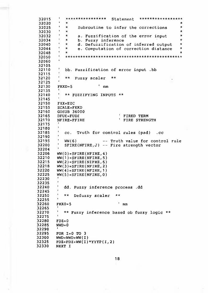
32015320203202532030320323203432040320443204832050320603210532110321153212032125321303213532140321453215032155321603216532170321753218032185321903219532200322043220632210322153221832220322253223032235322403224532250322553226032265322703227532280322853229032295323003232532330
**************** Statement ***************** ★ ** Subroutine to infer the corrections ** ** a. Fuzzification of the error input ** b. Fuzzy inference ** d. Defuzzification of inferred output ** e. Computation of correction distance ** * * * * * * * * * * * * * * * * * * * * * * * * * * * * * * * * * * * * * * * * * * * * * * *
bb. Fuzzification of error input .bb** Fuzzy scaler **
FKKD=5 ' mm** FUZZIFYING INPUTS **
FXX=EZC SCALE=FKKD GOSUB 36000DFU£=FUZ£ ' FIRED TERMNFIRE=FFIRE ' FIRE STRENGTH
cc. Truth for control rules (pad) .ccWW(6) -- Truth value for control ruleSFIRE(NFIRE,J) -- Fire strength vector
WW(0)=SFIRE(NFIRE,4)WW(1)=SFIRE(NFIRE,5)WW( 2 ) = S F I R E ( N I F R E , 6 )WW(3)=SFIRE(NFIRE,2)WW(4)=SFIRE(NFIRE,1)WW(5)=SFIRE(NFIRE,0)
dd. Fuzzy inference process .dd** Defuzzy scaler **
FKK0 = 5 ' mm** Fuzzy inference based ob fuzzy logic **
FDZ=0WWD=0IFOR 1=0 TO 3 WWD=WWD+WW(I)FDZ=FDZ+WW(I)*YYYP(I,2)NEXT I
18
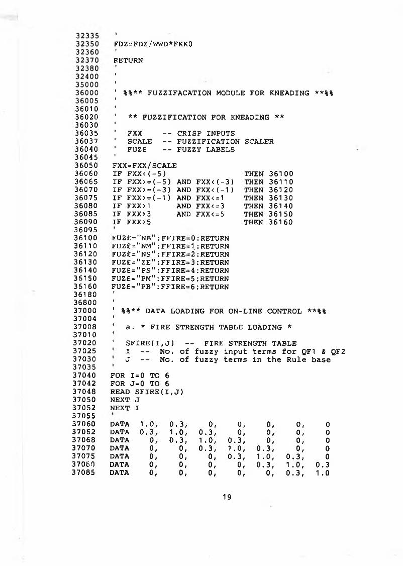
360103602036030360353603736040360453605036060360653607036075360803608536090360953610036110361203613036140361 50361603618036800370003700437008370103702037025370303703537040370423704837050370523705537060370623706837070370753706037085
FDZ=FDZ/WWD*FKKOIRETURN
%%** FUZZIFACATION MODULE FOR KNEADING **%%
** FUZZIFICATION FOR KNEADING **FXX — CRISP INPUTSSCALE — FUZZIFICATION SCALERFUZE — FUZZY LABELS
FXX=FXX/SCALE IF FXX<(-5)IF FXX> = (-5) AND IF FXX> = (-3 ) AND IF FXX> = (-1) AND IF FXX>1 ANDIF FXX> 3 ANDIF FXX>5
FXX <(-3) FXX <(-1) FXX< = 1 FXX<=3 FXX < = 5
THENTHENTHENTHENTHENTHENTHEN
36100 36110 361 20 361 30 361 40 36150 361 60
FUZ£="NB" FUZ£="NM" FUZ£="NS" FUZ£="ZE" FUZ£="PS" FUZ£="PM" FUZ£="PB"
FFIRE:FFIRE’FFIRE:FFIRE:FFIRE:FFIRE:FFIRE:
= 0 : RETURN = 1 : RETURN =2:RETURN = 3 : RETURN = 4 : RETURN = 5 : RETURN = 6: RETURN
%%** DATA LOADING FOR ON-LINE CONTROL **%%a. * FIRE STRENGTH TABLE LOADING *SFIRE(I, J ) -- FIRE STRENGTH TABLE I -- No. of fuzzy input terms for QF1 & QF2 J -- No. of fuzzy terms in the Rule base
FOR 1=0 TO 6 FOR J=0 TO 6 READ SFIRE(I,J) NEXT J NEXT IDATADATADATADATADATADATADATA
1.0, 0.3, 0, 0, 0, 0, 00.3, 1 .0, 0.3, 0, 0, 0, 0o, 0.3, 1 .0, 0.3, o, 0, 0o, o, 0.3, 1.0, 0.3, 0, 0o, o, 0, 0.3, 1 .0, 0.3, 0o, 0, 0, 0, 0.3, 1 .0, 0.30, 0, 0, 0, 0, 0.3, 1 .0
19
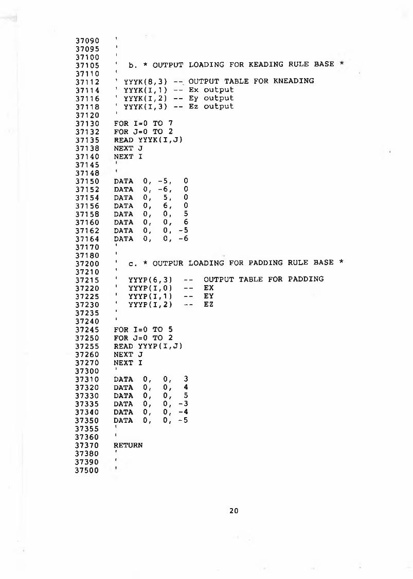
37090 37095 37100 37105 37110 37112 37114 37116 37118 37120 37130 37132 37135 37138 37140 37145 37148 37150 37152 37154 371 56 37158 37160 37162 37164 37170 37180 37200 37210 3721 5 37220 37225 37230 37235 37240 37245 37250 37255 37260 37270 37300 37310 37320 37330 37335 37340 37350 37355 37360 37370 37380 37390 37500
b. * OUTPUT LOADING FOR KEADING RULE BASEYYYK(8,3) - YYYK(1,1) - YYYK(1,2) - YYYK(1 ,3 ) -
- OUTPUT TABLE FOR KNEADING- Ex output- Ey output- Ez output
FOR 1=0 TO 7 FOR J=0 TO 2 READ YYYK(I,J ) NEXT J NEXT I
DATA 0, -5, 0DATA o, -6, 0DATA o, 5, 0DATA o, 6, 0DATA o, o, 5DATA 0, 0, 6DATA o, o, -5DATA 0, 0, -6
C. * OUTPUR LOADING FOR PADDING RULE BASE *YYYP(6,3) -- OUTPUT TABLE FOR PADDINGYYYP(1,0) -- EXYYYP(1,1) -- EYYYYP(I,2) -- EZ
FOR I= 0 TO 5FOR J= 0 TO 2READ YYYP(I,J )NEXT JNEXT1 IDATA 0, 0, 3DATA 0, 0, 4DATA 0, 0, 5DATA 0, 0, -3DATA 0, 0, -4DATA 0, 0, -5IIRETURNtI
20
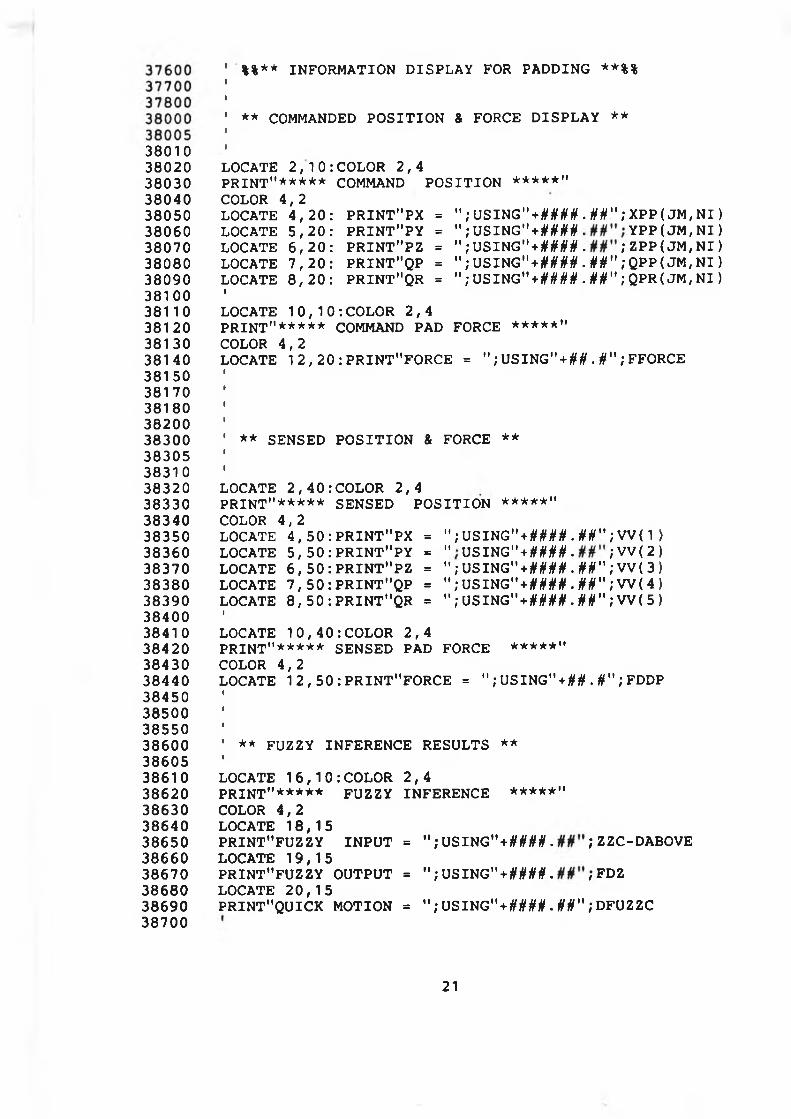
3801038020380303804038050380603807038080380903810038110381203813038140381503817038180382003830038305383103832038330383403835038360383703838038390384003841 0384203843038440384503850038550386003860538610386203863038640386503866038670386803869038700
%%** INFORMATION DISPLAY FOR PADDING **%%
** COMMANDED POSITION & FORCE DISPLAY **
LOCATE 2 , 1 0 : COLOR 2 ,4P R INT"***** COMMAND P O S IT IO N *****"COLOR 4 ,2LOCATE 4 , 2 0 : PR IN T"P X = " ; USING" + # W . §§ " ; XPP ( JM, N I ) LOCATE 5 , 2 0 : P R IN T " P Y = " ; USIHG" + if if if# YPP ( JM, N I )LOCATE 6 , 2 0 : P R IN T "P Z = " ; US I NG" + # # # # . ; ZPP( J M , N I ) LOCATE 7 , 2 0 : PRINT"QP = " ; USING" + W # . §#" ; QPP ( JM, N I ) LOCATE 8 , 2 0 : PRINT"QR = " ; U S I N G " + # W . ifif" ; QPR( JM, NI )ILOCATE 1 0 , 1 0 : COLOR 2 , 4P R INT"***** COMMAND PAD FORCE ***★*"COLOR 4 , 2LOCATE 1 2 , 2 0 : PRIN T"FORCE = " ; U S I N G " + M . if" ; FFORCE
** SENSED P O S IT IO N & FORCE **
LOCATE 2 , 4 0 : COLOR 2 ,4PRINT"***** SENSED P O S IT IO N *****"COLOR 4 , 2LOCATE 4 , 5 0 : P R IN T "P X = " ; USING" + # W . Hit" ; VV( 1 ) LOCATE 5 , 5 0 : P R IN T " P Y = U S I N G " + # W . ; V V ( 2) LOCATE 6 , 5 0 : P R IN T "P Z = " ; USING" + # W . ifif"; V V ( 3) LOCATE 7 , 5 0 : P R IN T " Q P = " ; USING" + W # . §§"; W ( 4) LOCATE 8 , 5 0 :P R IN T "Q R = " ; USING" + # # M . §§"; W ( 5)ILOCATE 1 0 , 4 0 ¡COLOR 2 , 4PRINT"***** SENSED PAD FORCE *★***"COLOR 4 ,2LOCATE 1 2 , 5 0 :P R IN T"FO R C E = " ; USING"+ M . U" ; FDDP
' ** FUZZY INFERENCE RESULTS **ILOCATE 1 6 , 1 0 : COLOR 2 , 4P R INT"***** FUZZY INFERENCE *****"COLOR 4 , 2 LOCATE 18, 15P RINT"FUZZY IN P U T = " ; USING" + M M . ; ZZC-DABOVELOCATE 19, 15PRINT"FUZZY OUTPUT = " ; U S IN G " + #)!(## . ; FDZLOCATE 2 0 , 1 5PR IN T"Q UICK MOTION = " ; USING" + #### . if if" ; DFUZZC
21
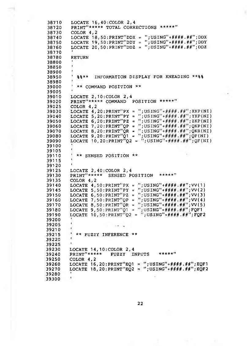
387103872038730387403875038760387 7038780388003885038900389503898039000390053901039020390253903039040390503906039070390803909039100391053911 0391 1539120391 2539130391353914039145391503916039170391803919039200392053921039215392203922539230392403925039260392703928039300
LOCATE 16, 40‘.COLOR 2,4PRINT"***** TOTAL CORRECTIONS *****"COLOR 4,2LOCATE 18,50: PRINT"DDX = " ; USING"+ #### .tttt" ", DDXLOCATE 19,50: PRINT"DDY = 11 ; USING"+#0#0 . tttt" ; DDYLOCATE 20 , 50 : PRINT"DDZ = " ; USING" + tttt tttt .tttt" ', DDZ •RETURN
' %%** INFORMATION DISPLAY FOR KNEADING **%%I' ** COMMAND POSITION **ILOCATE 2 , 1 0 : COLOR 2 , 4PRINT"***** COMMAND POSITION *****"COLOR 4 , 2LOCATE 4, 20 :PRINT"PX = " ; USING" + W # . tttt" ; XKP<NI ) LOCATE 5,20: PRINT"PY = " ; USING" + W # - fttf" ; YKP(NI ) LOCATE 6 , 20 :PRINT"PZ = " ; USING" + #### .fttf"; ZKP(NI ) LOCATE 7,20: PRINT"QP = " ; USING" + # M # . M";QKP(NI ) LOCATE 8,20: PRINT"QR = " ; USING” + ttfffftf .ft ft" ;QKR(NI ) LOCATE 9,20:PRINT"Q1 = U S I N G " Q F ( N I ) LOCATE 10,20:PRINT"Q2 = "; USING"+ # # # # . ; QF(NI)
** SENSED POSITION **
LOCATE 2,40:COLOR 2,4PRINT"***** SENSED POSITION *★***"COLOR 4,2LOCATE 4,50: PRINT"PX = " ;USING"+ tttttftf. tttt" ;VV (“I ) LOCATE 5,50: PRINT"PY = " ; USING" + ##M . tttt" ; W ( 2 )LOCATE 6,50: PRINT"PZ = " ; USING" + W # . fttf" ; W ( 3 )LOCATE 7,50: PRINT"QP = " ; USING" + #### . tttt" ; W ( 4 )LOCATE 8,50: PRINT"QR = " ; USING" + #### . fttf" ; W ( 5 )LOCATE 9,50: PRINT"Q1 = " ; USING"+ #### .tttt" ;FQF1 LOCATE 10,50: PRINT"Q2 = " ; USlKG” + ttt(tttt. fttf" ; FQF2
** FUZZY INFERENCE **
LOCATE 14,10:COLOR 2,4PRINT"***** FUZZY INPUTS *****"COLOR 4,2LOCATE 16,20: PRINT"EQ1 = " ; USING" + ft ft it ft. tttt" EQF1 LOCATE 18,20: PRINT"EQ2 = " ; USING" + tttt tttt. Hft" EQF2
22
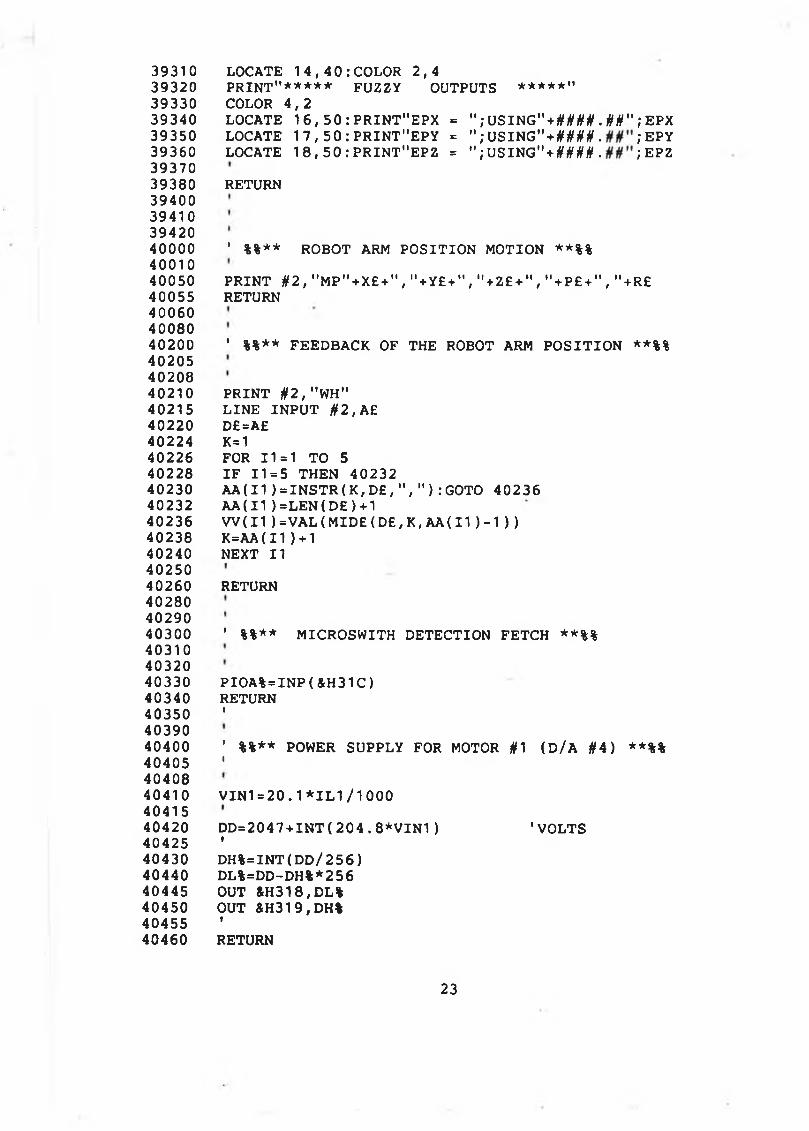
39310 LOCATE 14,40:COLOR 2,439320 PRINT"***** FUZZY OUTPUTS ****★"39330 COLOR 4,239340 LOCATE 1 6, 50 : PRINT"EPX = "; USING" + #/|/M . ## " ; EPX39350 LOCATE 1 7 , 50 : PRINT"EPY = "; USING" + W # . ; EPY39360 LOCATE 1 8,50:PRINT"EPZ = ";USING"+##0#. ; EPZ3937039380 RETURN39400394103942040000 ' %%** ROBOT ARM POSITION MOTION **%%4001040050 PRINT #2,"MP"+X£+","+Y£+","+Z£+","+P£+","+R£40055 RETURN400604008040200 ' %%** FEEDBACK OF THE ROBOT ARM POSITION **%%402054020840210 PRINT #2,"WH"40215 LINE INPUT #2,A£40220 D£=A£40224 K=140226 FOR 11=1 TO 540228 IF 11=5 THEN 4023240230 AA(I1 ) = INSTR(K,D£,","):GOTO 4023640232 AA(11)=LEN(D£)+140236 W(I1 ) =VAL (MID£ (D£, K, AA( 11 )-1 ) )40238 K=AA(11)+1 40240 NEXT II 4025040260 RETURN402804029040300 ' %%** MICROSWITH DETECTION FETCH **%%403104032040330 PIOA%=INP(&H31C)40340 RETURN40350 '4039040400 ' %%** POWER SUPPLY FOR MOTOR #1 (D/A #4) **%%40405 14040840410 VIN1=20.1*IL1/10004041540420 DD=2047+INT(204.8*VIN1) 'VOLTS40425 '40430 DH%=INT(DD/256)40440 DL%=DD-DH%*25640445 OUT &H318,DL%40450 OUT &H319,DH%40455 '40460 RETURN
23
<#>dp-K■X dpdp—- *m *% CO o< Eh zHÛ o■—' > 04- s(N <=fc CO02 oO >E-< 02O ws COo2 —« zo CM oU4 2 MM EH>H > H►J o * COo. o 0 0 oa. o • 043 1— ■*r .—-to o \0 \D ' HÍN CM in indP dP H02 .J —- CM CM.4 SC 1W M E-* \ * Q Û Q2 * Z Q dp ■*. ZO i— M Q S < DQ <04 ■ + — Q T— 1— X
O r - (r> 1 m n* CM Z Q a: X z ** II o M Q «Ò OB DC *<#> <N CM Il II D dP<#> z II <#> dp Eh tr> f-> dP
M Q X i j 3 D w- - > - Q - û Q o o - 02 -
<D<UWO'0)Q
m in00 00
-— ' V . • •T— (N i— i—
-— ‘ ■---- ' + Eh I 1dP dP dP H 00 00O •-> ^ CO ^
— < ^ 3 *T) O O Oo i J * * O 4 CM CM■-- ' [14 fN fsj IIdp -— — ^ ( N i f i i nX — dP dp Eh * **5 O >4 >4 H 1— CMc¿ — < < CO Eh H02 dP 02 02 O h m< o o 02 02 O 4 CO C/504 M H < < • ■ O O— D CM 04 Oi TJ> O4 O 402 Eh rn + + ----- --- -wH dP H «— CM r - * *04 Û CO O Eh Eh Eh »— r -02 S O E h h h H (M CM<C — 04 co co CO • •> 00 00 •• o O O O « - « -II II CO O II 04 04 dp 0 4 ^ ^
— — o < il dp II II 1-3 II O OO i - h O t- >-J CM >7) 1 - a\ on
m '— —■ dp Eh 1 1 Eh Eh Eh II IIII dp dp o *J M M H Eh H t— CM
dp O O < ^ CO OS CO W X CO (14 [14Q H H ,-J < O O O O W O O C »S Q Q h U - 04 Cl4 O4 Oi Z * O4 (14 U4
DEhW02 ■
dPdP-K*04ooo>ocwCO
DC
m o o in 0 ID O in 0 in 0 m 0 i n 0 O 0 in 0 0 m CM ■»r 00 0vo r~ 0 0 1—T— CM fN m co xp m m \o 0 0 j— CM CM COCO m
■*r in tn i n m LO in in in m i n i n i n i/> in p ' r ' r - r~ r - r - r-~O O 0 0 0 0 O 0 0 0 0 0 0 0 0 0 0 0 0 0 0 0 0 O 0 0■«r ■*r *3» TT ^ ^ T T T f t j * ■*r TT
w in COÜz W r— CMM Q -—* + uOi O dP dP dp uX — U *D 0202 -—- < I- ) OO — 0 iJ * * [14u, ■—- O4 CM CM II
dP — — CM0 >H —» <#> i*0 uz < O PH X uM 02 *— < < 02
02 dP « 02 OO4 < O 0 02 02 [14z C14 M II < << '— Q <N C14 U* 00CO DC W r - + + \
Eh dP u i— CM i—w O4 Q 02 O W u wu DC S O Eh u u u02 < VO C14 02 02 02O > f—■ CO • • O O O Ob II II co O II C14 C14 dP &4
■—• *-». 0 < II dp II II II* O r - il 0 1— r> 1— CM 1—* in <—» dP W w u w sdP h dp dp Ü ►J O 0 0 Eh u ndP dP O O < t J 02 02 02 02 X 02 Eh
Q M M iJ < O O O O W O MZ Û Û t«4 u - f*4 U4 U4 O4 Z (X4 02
O in 00 0 in O in 0 m 0 V 0 0 O m o m OO 0 0 j— r—CM CM TP m m vo vo r -0 0 CO 0 0 0 0 0 0 0 0 00 00 00 CO 00 0 0 0 0 00 00 00 coO 0 0 0 O 0 0 O O O 0 O 0 0 0 O 0
•sr rr TT <0 * ■V TT
C\l
4 08 8 0 I
4 08 9 0 1
4 09 0 0 ' %%** FORCE SAMPLING FOR PALM SERVO LOOP **%%40 9 0 5 1
4 09 1 0 1
4091 5 MD% = 540 9 2 0 DIO%( 0 ) =VARPTR( FARRAY%( 0 ) ) *409 24 DIO%( 1 ) = 1 6409 2 8 FLAG%=04 09 3 0 CALL DAS8( MD%, D IO % ( 0 ) , FLAG%)409 34 1
4 09 3 6 FORCEP=0409 4 0 1
409 4 4 FOR JJ%=0 TO 154 09 4 6 .FORCEP=FORCEP+FARRAY%( J J % )4 0 9 5 0 ' NEXT JJ%4 0 9 5 4 1
4 0 9 5 6 F0R C E P =F0R C EP /1640 9 6 0 RETURN40 9 6 4 »
409 65 1
411 8 0 1
4 12 0 0 ' %%** C ALIBR ATIO N FOR H A N D - I I F -SENSOR **%%4 12 0 5 ' ( F INGER #1 I N H A N D - I I — FORCE )412 10 1
4 12 2 0 KD1=FORCE1* 5 / 2 0 4 84 12 2 5 N C C N = 0 .00981412 2 7 I F K D 1 > 0 . 2 3 THEN 4 1 2 3 041 2 2 9 FDD1=0:RETURN4 1 2 3 0 I F KD1> 0 . 9 2 THEN 4 1 2 4 04 1 2 3 5 FDD1=NCCN*( 124 + 1 2 4 * ( K D 1 - 0 . 9 2 ) / 0 . 7 4 ) : RETURN41 2 4 0 I F K D 1 > 3 . 8 9 THEN FDD1 = 9 : RETURN41 2 4 5 FDD1=NCCN*( 9 2 4 + 8 0 0 * ( K D 1 - 3 . 8 9 ) / 2 . 9 7 )4 12 5 0 RETURN412 5 5 1
41 2 6 0 1
412 7 0 1
413 0 0 ' %%** CALIB R A TIO N FOR H A N D - I I F-SENSOR # 2 **%%4130 5 ( F INGER #2 I N HAND #2 - - FORCE )41 3 1 0 1
41 3 2 0 K D 2 = F O R C E 2 * 5 /2 0 4 84 1 3 2 5 N C C N = 0 .009814 13 2 7 I F K D 2> 0 . 6 0 THEN 4 1 3 3 04 1 3 2 9 FDD2=0:RETURN4 13 3 0 I F KD2> 1 . 0 8 THEN 4 1 3 4 0413 3 5 FD D 2 = N C C N *(1 2 4 + 1 2 4 * ( K D 2 - 1 . 0 8 ) / 0 . 8 8 ) : RETURN41 3 4 0 I F KD2 > 4 . 0 3 THEN FDD2 = 9 : RETURN41 3 4 5 F D D 2=N C C N *(9 2 4 + 8 0 0 * ( K D 2 - 4 . 0 3 ) / 2 . 9 5 )4 1 3 5 0 RETURN4 1 3 5 5 •
4 1 3 6 0 1
41 3 8 0 I
4 1 4 0 0 ' %%** CALIB R A TIO N FOR P A L M - I I F-SENSOR **%%4 1 4 1 0 ' ( P A L M - I I I N H A N D - I I - - FORCE )4 1 4 2 0 t
25
41450 KDP=FORCEP*5/204841452 NCCN=0.0098141458 141460 IF KDP>0.20 THEN 4146441462 FDDP= 0:RETURN41464 IF KDP>1.60 THEN 4147241470 FDDP=NCCN*( 1 24 + 124*(KDP-1 .6)/1 .4):RETURN41472 IF KDP> 2.28 THEN 4148041474 FDDP=NCCN*(324+200*(KDP-2.28)/0.68):RETURN41480 IF KDP> 3.56 THEN FDDP=8:RETURN41482 FDDP=NCCN*(924+600*(KDP-3.56)/l.28):RETURN41484 RETURN41490 14149241494 t41 $00 * %%** INITIALIZE DAS8 FOR POSITION A/D **%%41505 ( FINGER ANGLE DETECTION )41508 141510 MD%=1041514 DIO%(0)=241518 DIO%(1)=341520 FLAG%=041525 CALL DAS8(MD%,DIO%(0),FLAG%)41528 141530 FREQ=2000 ' FREQUENCY=Samples/sec41534 NC2=CINT(6000/FREQ*1000) ' SYSTEM CLOCK = 12 MHZ41536 »41538 MD%=1141540 DIO%(0)=241544 DIO%(1)=NC241546 FLAG%=041548 CALL DAS8(MD%,DIO%(0),FLAG%)41550 141552 MD%= 141554 DIO%(0)=041558 DIO%(1)=141560 FLAG%=041564 CALL DAS8(MD%,DIO%(0),FLAG%)41566 t41568 MD%=241570 CH%=041572 FLAG%=041574 CALL DAS8(MD%,CH%,FLAG%)41576 141580 RETURN41585 i4159041600 f %%** INITIALIZE DAS8 FOR FORCE A/D **%%41604 ' ( FINGER FORCE DETECTION )41608 141610 MD%=1041612 DIO%(0)=241616 DIO%(1)=341618 FLAG%=041620 CALL DAS8(MD%,DIO%(0),FLAG%)
26
4162241626416284163041634416364163841640416454164841650416524165441656416604166441670416724167441676416784168041685416904169541 70041 70541710417204172241 7244172841 7304173241 7344173641 7404174241 74441748417504175241754417584176041762417644176841770417724177541778417804178241785
FREQ=2000 ' FREQENCY=Samples/secNC2=CINT(6000/FREQ*1000) ' system clock = 12 MHZ•MD%=11 DIO%(0)=2 DI0%(1)=NC2 FLAG%=0CALL DAS8(MD%,DIO%(0),FLAG%)
MD% = 1 DI0%(0)=2 DI0%(1 ) = 3 FLAG%=0CALL DAS8(MD%,DIO%(0),FLAG%)IMD%=2 CH% = 2 FLAG%=0CALL DAS8(MD%,CH%,FLAG%)IRETURN
' %%** INITIALIZE DAS8 FOR FORCE A/D **%% ' ( PALM FORCE DETECTION )IMD%=10 DIO%(0)=2 DIO%(1)=3 FALG%=0CALL DAS8(MD%,DIO%(0),FLAG%)IFREQ=1000NC2=CINT(6000/FREQ*1000)IMD%=11 DIO%(0)=2IF NC2<32767 THEN DIO%( 1 )=NC2: GOTO 41752DIO%(1)=NC2-655361FLAG%=0CALL DAS8(MD%,DIO%(0),FLAG%)IMD%=1 DIO%(0)=4 DIO%(1)=4 FLAG%=0CALL DAS8(MD%,DIO%(0),FLAG%)•
MD%=2 CH%=4 FLAG%=0CALL DAS8(MD%,CH%,FLAG%)I
27
417904180041900420004201 0420204203042040420504205542060420654207042075420804208542090421004211 0421 204213042140421504216042170421804219042195422004220542210422304224042250422604227042300423104232042330423404235042360423704238043000435004350543510435154352043525435304353543540
RETURNI
' %%** TIME DELAY USING TIMER IN DAS8 **%%IIDSCAN=FTIME ' FORCE RETENTION TIMEIFREQ=200 ' A/D FREQENCYIIMD%=10DIO%(0)=2 :DIO%(1) = 3CALL DAS8(MD%,DIO%(0),FLAG%)»NC2=CINT(6000/FREQ*1000) ' SYSTEM CLOCKIMD%=11 DIO%(0)=2IF NC2<32767 THEN DIO%(1)=NC2: GOTO 42140 DIO%(1)=NC2-65536!CALL DAS8(MD%,DIO%( 0 ) ,FLAG%)INCCD=CINT(DSCAN*FREQ)NCCD1=CINT(NCCD/2)IF (NCCD-2*NCCD1)=0 THEN 42200 NCCD=NCCD-1IMD% = 5DIO%(0)=VARPTR(FDELAY% ( 0) )DIO%(1)=NCCD FLAG%=0CALL DAS8(MD%,DIO%(0),FLAG%)
** RELEASE FORCE HOLDING **
IL1=2 :IL2 = 2 GOSUB 40400 GOSUB 40500IRETURN
%%** HAND-II POSITION SERVO CONTROL **%%
' ** INITIALIZE DAS8 FOR POSITION SAMPLINGGOSUB 41500 1 ** COFFICIENCE
43545 VO1=30/50:VO2=50/5043550 K101=15/10/50:K102=15/10/5043555 KO51=10/10/50:KO52=10/5/5043560 QLIM=1.04356543570 ’ ** FRICTION COMPENSATION **4357543580 VF1=-5/50 43584 VF2=10/504358643590 ' ** FINGER POSITION SERVO CONTROL4359443596 NN=0 4360043610 GOSUB 40700 43620 143625 EQ1=QD1-FQF1:EQ2=QD2-FQF2 43630 S1=SGN(EQ1):S2=SGN(EQ2)43635 AE1=ABS(EQ1):AE2=ABS(EQ2)4364043700 IF AE1< =QLIM THEN VA1=0:GOTO 4372043702 IF AE1>20 THEN VA1=VF1+60/50:GOTO 4372043704 IF AE1>10 THEN VA1=VF1+45/50+K101*AE1:GOTO 4372043706 IF AE1>5 THEN VA1=VF1+V01+K051*AE1:GOTO 4372043710 IF AE1>QLIM THEN VA1=V014371543720 VIN1=S1*VA1 43725 GOSUB 40420 4372843730 IF AE2<QLIM THEN VA2 = 0:GOTO 4374043732 IF AE2>20 THEN VA2=VF2 + 75/50:GOTO 4374043734 IF AE2>10 THEN VA2=VF2 + 60/50+K1 02*AE2:GOTO 4374043736 IF AE2>5 THEN VA2=VF2+V02+K052*AE1:GOTO 4374043738 IF AE2>QLIM THEN VA2=VF2+V0243740 '43742 VIN2=S2*VA2 43744 GOSUB 40520 43746 4374843750 IF AE1< =QLIM AND AE2<=QLIM THEN 43770 4375243754 NN=NN+143756 IF NN>300 THEN 4377043760 GOTO 436104376543770 VIN1=0:VIN2=0 43775 GOSUB 4042043780 GOSUB 4052043785 '43790 RETURN4379543800 '43810 '
29
44500445054451044515445204452544530445354454044545445504455544560445654457044600446054461044615446204462544630446354466544670446804468544690446954470044705447104471544720447304474044750447554476044765447804478544790448954500045010450204503045040450504510045200453004600046010
%%** HAND-II FORCE SERVO CONTROL **%%
** INITIALIZE DAS8 FOR FORCE SAMPLINGiGOSUB 41600t1 ** REQUIRED CURRECT FOR MOTORSiLL0=0.090 KVIN0=LL0/0.16495 VF1=KVIN0*FD1 VF2=KVIN0*FD2I♦* ** INITIAL TOUCH DETECTtFOR KN=0 TO 100VIN1=KVIN0*(1 .5+(FDl*2/3-1 .5)/l00*KN) VIN2=KVIN0*(1.5+(FD2*2/3-1 .5)/l00*KN)IGOSUB 40420 GOSUB 40520 GOSUB 45000 NEXT KNt
' ** TIME DELAYIGOSUB 45000t
* ** FORCE CONTROL1FOR KN=1 TO 100VIN1=VF1*(2/3+1/300*KN)VIN2=VF2*(2/3+1/300*KN)!GOSUB 40420 GOSUB 40520 NEXT KNiRETURN
%%** TIME DELAY FOR FORCE CONTROL **%%
FOR KW%=0 TO 1000 NEXT KW%RETURN
%%** TIME DELAY FOR HYBRID CONTROL **%%
30

46020460304604046050460604607046080460904610046500470004700547010470204703047040470504706047070470804709047100471054711047120471 254713047135471404715047160471704717547180471904719547200472054721047220472254723047240472504726047270472804728547290473004730247305473104731247315
FOR KW%=0 TO 300 NEXT KW%IIL1=0 :IL2 = 0 GOSUB 40400 GOSUB 40500IRETURN
' ** K N E A D I N G E X P E R I M E N T A L R E S U L T S R E C O R D I N G **ICOLOR 7,1:CLS LOCATE 5,20:COLOR 4,2PRINT"RECORD THE KNEADING RESULTS (Y/NX?"A£=INKEY£IF A£="Y"IF A£="N" OR A£="n" GOTO 47050
OR A£="y" T H E N 47100 T H E N R E T U R N
COLOR 7,1:CLS:LOCATE 10,15:COLOR 4,2INPUT"PLEASE INPUT DATA FILE NAME *. DOC ";RDOC£ILOCATE 12,15:COLOR 2,4PRINT"IS THE FILE NAME CORRECT (Y/N)? " A£=INKEY£IF A£="Y" OR A£="y" THEN 47170 IF A£="N" OR A£="N" THEN 47100 GOTO 47130OPEN RDOC£ FOR OUTPUT AS #1P R I N T #1," K N E A D I N G E X P E R I M E N T R E S U L T S " P R I N T # 1 , " "FOR I=NSTART TO NSTOP STEP NSTEP PRINT #1,"POSITION NO. = ";USING"###";I PRINT #1," "PRINT #1,"CONTROL VARIABLES FOR HAND AND ARM"PRINT #1,"PX_CONTROL = PRINT #1,"PY_CONTROL = PRINT #1,"PZ_CONTROL = PRINT #1,"QP_CONTROL = PRINT #1,"QR_CONTROL = PRINT #1,"QF_CONTROL =
";USING"+####";XKPREC(I ";USING"+####";YKPREC(I ";USING"+####";ZKPREC(I "; USING"+ ####";QKPREC(I ";USING"+####";QKRREC(I "; USING"+ # # # . ; QFREC(I
PRINT #1," "PRINT #1,"INPUTS TO FUZZY INFERENCE MECHANISM"IPRINT #1 ,"EQF1_INPUT = ";USING"+ ###.#";EQ1REC(I) PRINT #1,"EQF2 INPUT = ";USING"+###.#";EQ2REC(I)IPRINT #1," "
31
47320 PRINT #1,"INFERRED FUZZY CORRECTIONS (X Y Z)" 4732247325 PRINT #1,"CX_FUZZY = " ; USING"+###.#";FKXREC(I)47330 PRINT #1,"CY_FUZZY = ";USING"+###.#";FKYREC(I)47340 PRINT #1,"CZ_FUZZY = " ; USING"*###.#";FKZREC(I)47345 PRINT #1," "47350 NEXT I 4735547360 CLOSE #1 4737047380 RETURN 47400 '4741 0 47420 47500 - '47510 1 ** PADDING EXPERIMENT RESULTS RECORDING **4751547520 '47525 COLOR 7,1:CLS 47530 LOCATE 5,20:COLOR 2,447540 PRINT"RECORD THE PADDING RESULTS (Y/N)?"4755047560 A£=INKEY£47570 IF A£="Y" OR A£="y" THEN 4761047580 IF A£="N" OR A£="n" THEN RETURN47590 GOTO 475604760047610 COLOR 7,1:CLS:LOCATE 10,15:COLOR 4,247615 INPUT"PLEASE INPUT THE DATA FILE *.DOC ";RDOC£4762047625 LOCATE 12,15:COLOR 2,447630 PRINT"IS THE DATA FILE NAME CORRECT (Y/N)?"4764047650 A£=INKEY£47660 IF A£="Y" OR A£="y" THEN 4770047670 IF A£="N" OR A£="n" THEN 4761047680 GOTO 476504769047700 OPEN RDOC£ FOR OUTPUT AS #14770547710 PRINT #1,"PADDING EXPERIMENT RESULTS"4771 5 PRINT #1 ," "47720 FOR J=MSTART TO MSTOP STEP MSTEP47725 FOR I=NSTART TO NSTOP STEP NSTEP47730 PRINT #1,"POSITION NO. = ( " ; USING"##"; J;47735 PRINT #1," , ";USING"##";I;47738 PRINT #1," )"47740 PRINT #1," "47745 PRINT #1, "CONTROL VARIABLES FOR HAND AND ARM"47750 '47755 PRINT #1,"PX_CONTROL = "; USING"+ ####";XPPREC(J,I)47760 PRINT #1,"PY_CONTROL = ";USING"+####";YPPREC{J,I)47770 PRINT #1,"PZ_CONTROL = ";USING"+####";ZPPREC(J,I)47780 PRINT #1,"QP_CONTROL = "; USING"+####";QPPREC(J,I)47790 PRINT #1,"QR_CONTROL = " ; USING"*####";QPRREC(J,I)
32
47800 ♦47805 PRINT #147810 PRINT #14781 5 147820 PRINT #147830 i47840 PRINT #147850 PRINT #147860 i47870 PRINT #147880 PRINT #147885 PRINT #147890 i47900 PRINT #147910 i47920 NEXT I47930 NEXT J47940 •47950 CLOSE #147960 i47970 RETURN47980 i47990 i47995 i50000 1 ******
INPUTS TO FUZZY INFERENCE MECHANISM" DZ_INPUT = ";USING"*###.#";DZREC(J,I)
IIINFERRED FUZZY CORRECTIONS (X Y Z)"CX_FUZZY = ";USING"*###. #";FPXREC(J,I )CY_FUZZY = ";USING"*###.#";FPYREC(J,I)CZ FUZZY = ";USING"*###.#";FPZREC(J ,I)
1 ************* END OF THE FILE **************
33
APPENDIX G P u b l i c a t i o n s
1 . J. Yan, M.A. El-Baradie and M.S.J. Hashmi "Fuzzy logic based robotic on-line error correction", to be published on the 1st Int. Conf. on Manufact. Tech., Hongkong, Dec. 1991
2. J. Yan, M.A. El-Baradie and M.S.J. Hashmi "The development of a robotic compliance control system", (accepted) Int. J. Machine Tools & Manufact., Jan. 1991
3. J. Yan, M.A. El-Baradie and M.S.J. Hashmi "AI system for the robotic physiothérapie applications", to be published on the Int. Conf. on CIM (ICCIM'91), Singapore, Oct. 1991
4. J. Yan, J.J. Murphy, M.A. El-Baradie and M.S.J. Hashmi "Path planning and compliance control system for physiothérapie applications", Proc. of the 11th Int. Conf. on production research (ICPR'91), Hefei, China, Aug. 1991, PP601-604
5. J. Yan, M.A. El-Baradie and M.S.J. Hashmi " The development of a robotic compliance system", Proc. of Int. Conf. on FAIM191 (Factory Automation & Informat- tion Management), Limerick, Ireland, Mar. 1991, PP729-742
6. J. Yan, M.A. El-Baradie and M.S.J. Hashmi "Modelling and software development of the trajectory control of a robot's hand", Proc. of IMC-7 conf. on Advanced Manufact. Tech. & Systems, Dublin, Aug. 1990, PP249-266


