Embed Size (px)
Citation preview
Ammonia Synthesis Flowsheet
Operator Training
By Gerard B. Hawkins
Managing Director, CEO
Introduction Most modern ammonia processes are
based on steam-reforming of natural gas or naphtha.
The 3 main technology suppliers are Uhde (Uhde/JM Partnership), Topsoe & KBR.
The process steps are very similar in all cases.
Other suppliers are Linde (LAC) & Ammonia Casale.
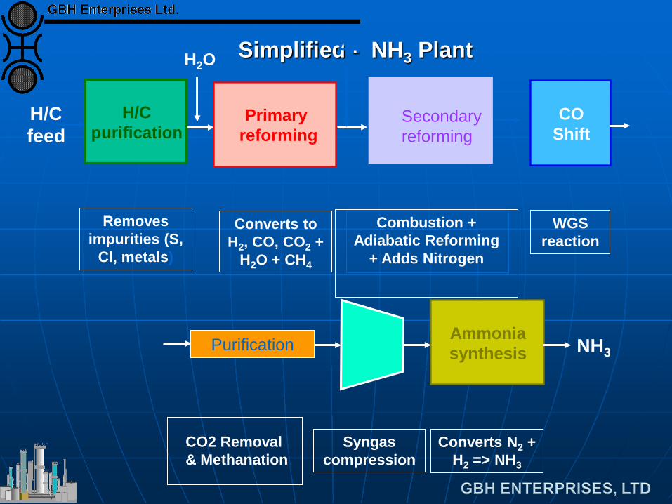
Simplified - NH3 Plant H2O
H/C feed
H/C purification
Removes impurities (S,
Cl, metals)
Primary reforming
Converts to H2, CO, CO2 +
H2O + CH4
CO Shift
WGS reaction
Secondary reforming
Combustion + Adiabatic Reforming
+ Adds Nitrogen
Air
Ammonia synthesis NH3
Converts N2 + H2 => NH3
Syngas compression
Purification
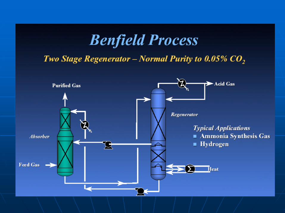
CO2 Removal & Methanation
Ammonia Synthesis Loop
Synthesis reaction is equilibrium limited, typically 15 – 20% NH3 at converter exit.
Therefore recycle in a ‘loop’ is required. Multi-stage complex converters are
required to control bed temperatures. Various designs are used depending on
contractor. Liquid Ammonia is recovered by
refrigeration.
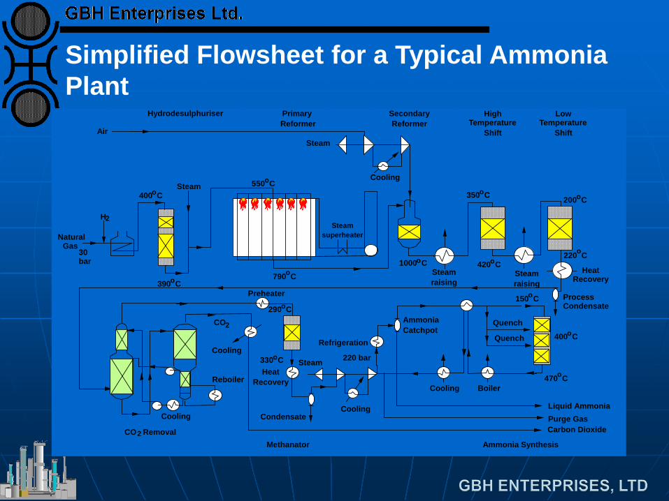
Simplified Flowsheet for a Typical Ammonia Plant
Natural Gas
Steamsuperheater
AirSteam
30 bar
Steam
Steamraising
350 C 200 C
Heat Recovery
Steamraising
Cooling
Cooling
Reboiler
CO
Cooling
Preheater
HeatRecovery
Steam
Boiler
Process Condensate
Quench
Quench
Liquid Ammonia
H
Hydrodesulphuriser Primary Reformer
SecondaryReformer
High Temperature
Shift
Low Temperature
Shift
Ammonia SynthesisMethanator
Carbon DioxidePurge Gas
Cooling
400 Co
390 Co
2
790 Co
550 Co
1000 Co
o
420 Co
150 Co
400 Co
470 Co
o
220 Co
290 Co
330 Co
2
CO Removal2
220 bar
Refrigeration
CondensateCooling
AmmoniaCatchpot
Ammonia Plant Steam & Power System
Waste Heat recovery is used to raise HP steam, 100 – 120 bar
Steam is used to drive the main compressors • Process air • Syn gas compression + circulator • Refrigeration
Pass-out steam is used for process.
Ammonia Flowsheet Variations 1. Uhde
Top fired reformer • Cold outlet manifold design
Secondary reformer with internal riser H P loop (200 bar) with radial flow
converter • 1 or 2 converters
Once-through synthesis section upstream of main synthesis loop for very large capacities (dual pressure Uhde process)
Ammonia Flowsheet Variations 2. KBR
Top-fired reformer • With internal risers
Several synthesis loop options: • Conventional 140 bar loop with 4bed
quench converter • Higher pressure for large-scale plants • Horizontal converter on modern plants. • KAAP design – 100 bar loop with Ru/C
catalyst Braun Purifier flowsheet
• Excess air with cryogenic ‘purifier’ to remove excess N2 and inerts from MUG
Ammonia Flowsheet Variations 3. Topsøe
Side-fired reformer Radial flow converter
• S-100 2 bed quench • S-200 2 bed intercooled • S-250 = S-200 + boiler + 2nd converter
(1 bed) • S-300 3 bed intercooled
Ammonia Flowsheet Variations 4. Linde LAC (Linde Ammonia
Concept)
Hydrogen plant + N2 addition from air separation unit
Ammonia Casale synthesis loop
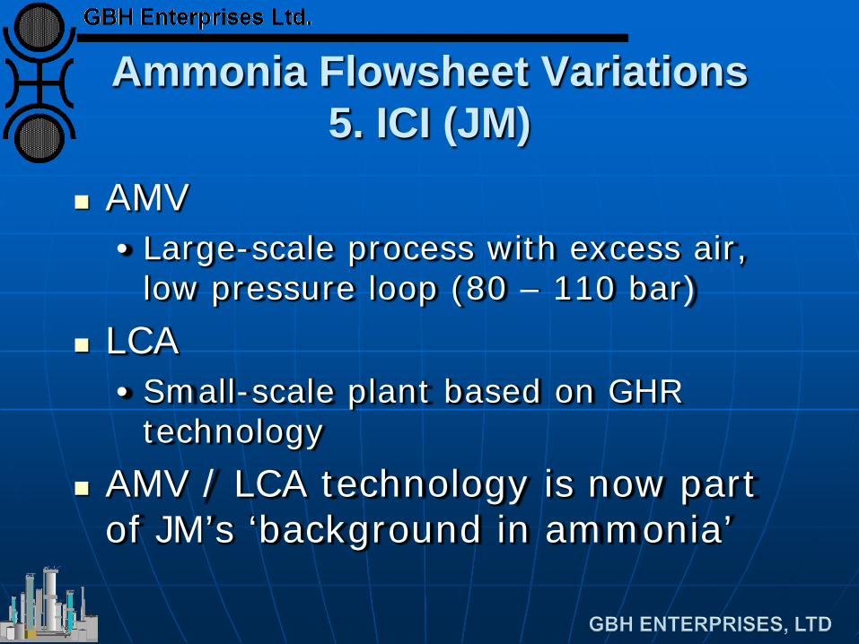
Ammonia Flowsheet Variations 5. ICI (JM)
AMV • Large-scale process with excess air,
low pressure loop (80 – 110 bar) LCA
• Small-scale plant based on GHR technology
AMV / LCA technology is now part of JM’s ‘background in ammonia’
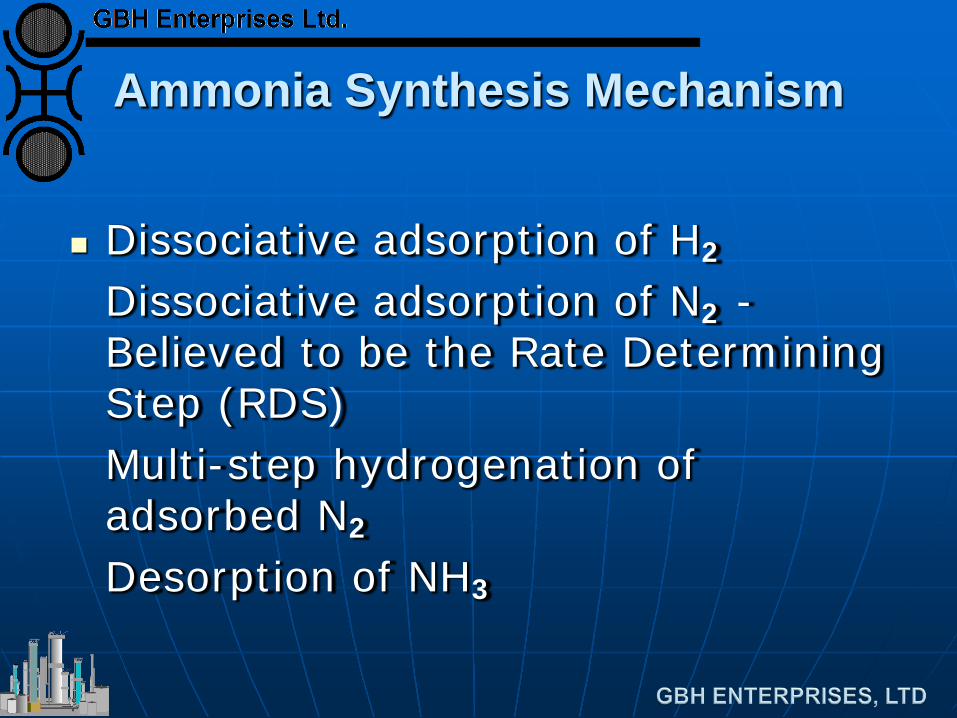
Ammonia Synthesis Mechanism
Dissociative adsorption of H2
Dissociative adsorption of N2 - Believed to be the Rate Determining Step (RDS)
Multi-step hydrogenation of adsorbed N2
Desorption of NH3
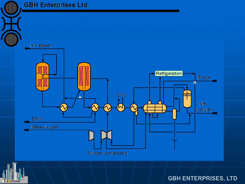
Typical Uhde Synthesis Loop
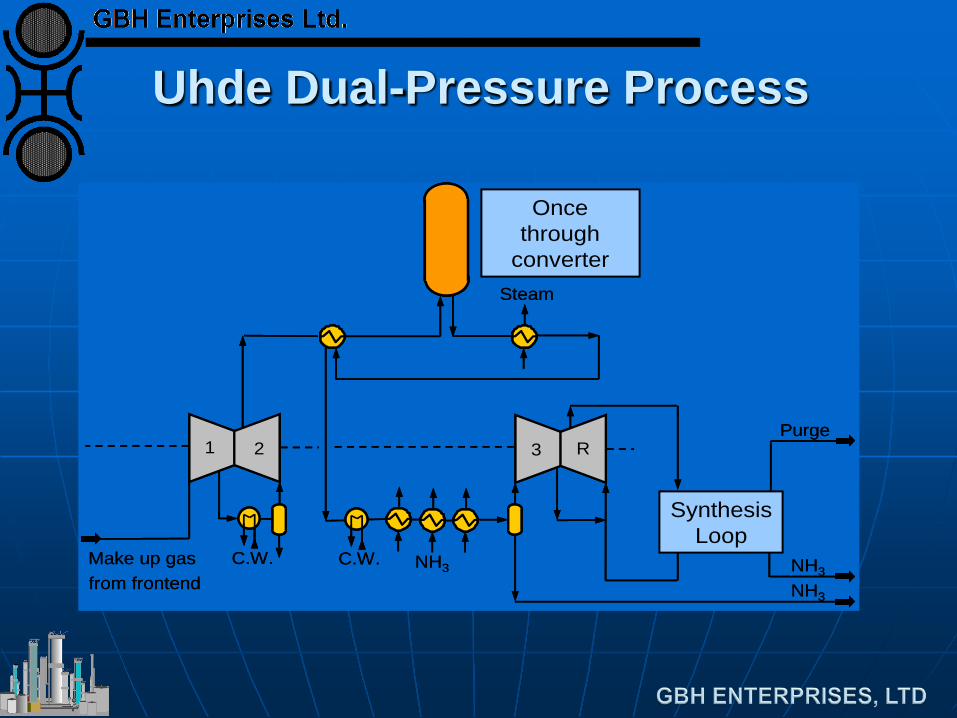
Uhde Dual-Pressure Process
C.W.Make up gas from frontend
C.W.
Steam
Once through
converter
SynthesisLoop
Purge
NH3NH3
NH3
1 2 3 R
C.W.Make up gas from frontend
C.W.
Steam
Once through
converter
SynthesisLoop
Purge
NH3NH3
NH3
1 2 3 R
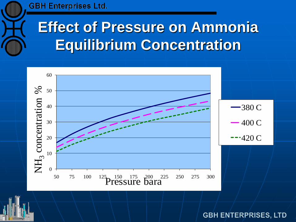
Effect of Pressure on Ammonia Equilibrium Concentration
0
10
20
30
40
50
60
50 75 100 125 150 175 200 225 250 275 300
NH
3co
ncen
tratio
n %
Pressure bara
380 C
400 C
420 C
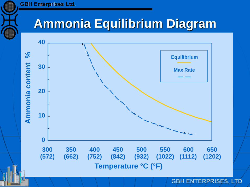
Ammonia Equilibrium Diagram
300 (572)
350 (662)
400 (752)
450 (842)
500 (932)
550 (1022)
600 (1112)
650 (1202)
0
10
20
30
40
Equilibrium
Max Rate
Temperature °C (°F)
Am
mon
ia c
onte
nt %
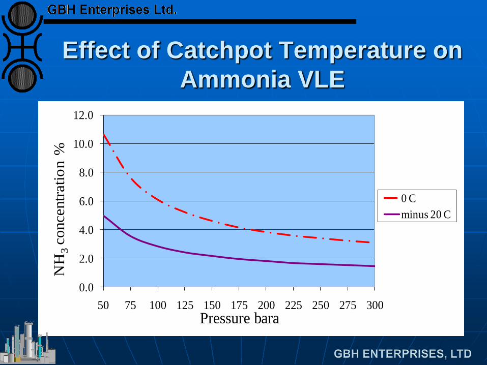
Effect of Catchpot Temperature on Ammonia VLE
0.0
2.0
4.0
6.0
8.0
10.0
12.0
50 75 100 125 150 175 200 225 250 275 300
NH
3co
ncen
tratio
n %
Pressure bara
0 Cminus 20 C
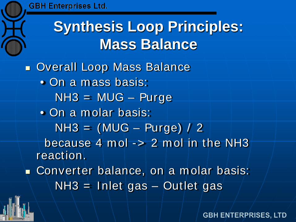
Synthesis Loop Principles: Mass Balance
Overall Loop Mass Balance • On a mass basis:
NH3 = MUG – Purge • On a molar basis:
NH3 = (MUG – Purge) / 2 because 4 mol -> 2 mol in the NH3
reaction. Converter balance, on a molar basis: NH3 = Inlet gas – Outlet gas
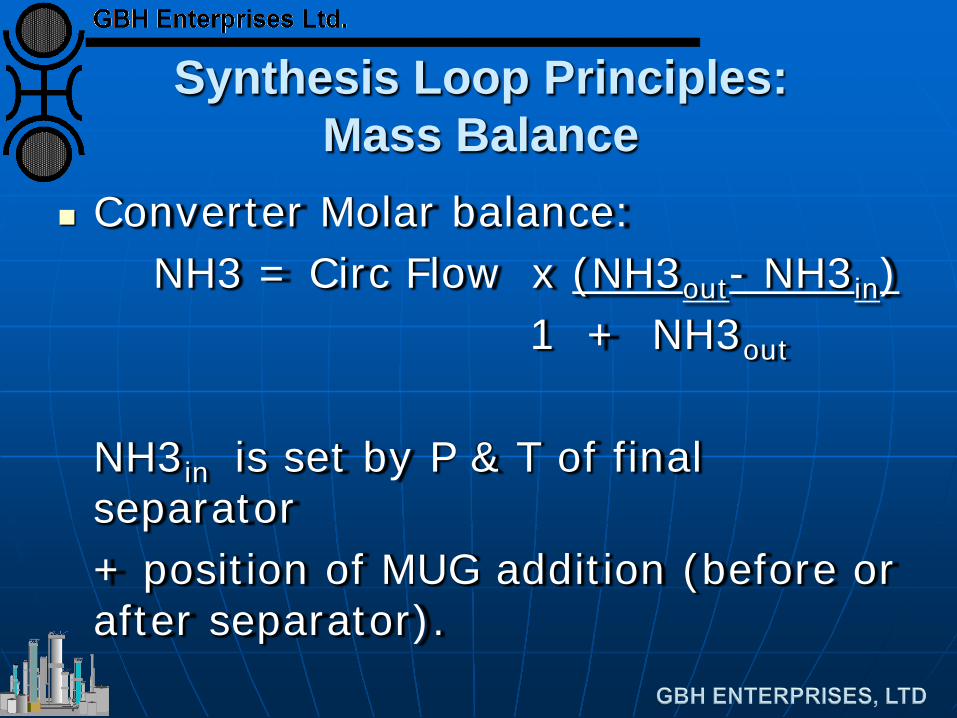
Synthesis Loop Principles: Mass Balance
Converter Molar balance: NH3 = Circ Flow x (NH3out- NH3in) 1 + NH3out NH3in is set by P & T of final
separator + position of MUG addition (before or
after separator).
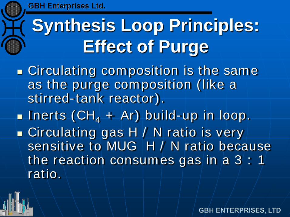
Synthesis Loop Principles: Effect of Purge
Circulating composition is the same as the purge composition (like a stirred-tank reactor).
Inerts (CH4 + Ar) build-up in loop. Circulating gas H / N ratio is very
sensitive to MUG H / N ratio because the reaction consumes gas in a 3 : 1 ratio.
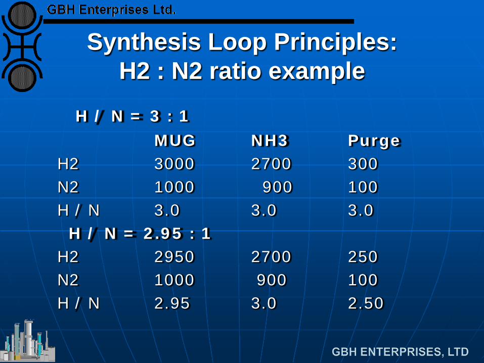
Synthesis Loop Principles: H2 : N2 ratio example
H / N = 3 : 1 MUG NH3 Purge H2 3000 2700 300 N2 1000 900 100 H / N 3.0 3.0 3.0 H / N = 2.95 : 1 H2 2950 2700 250 N2 1000 900 100 H / N 2.95 3.0 2.50
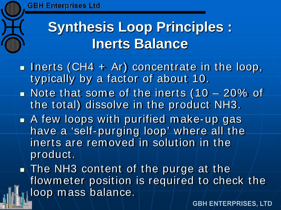
Synthesis Loop Principles :
Inerts Balance
Inerts (CH4 + Ar) concentrate in the loop, typically by a factor of about 10.
Note that some of the inerts (10 – 20% of the total) dissolve in the product NH3.
A few loops with purified make-up gas have a ‘self-purging loop’ where all the inerts are removed in solution in the product.
The NH3 content of the purge at the flowmeter position is required to check the loop mass balance.
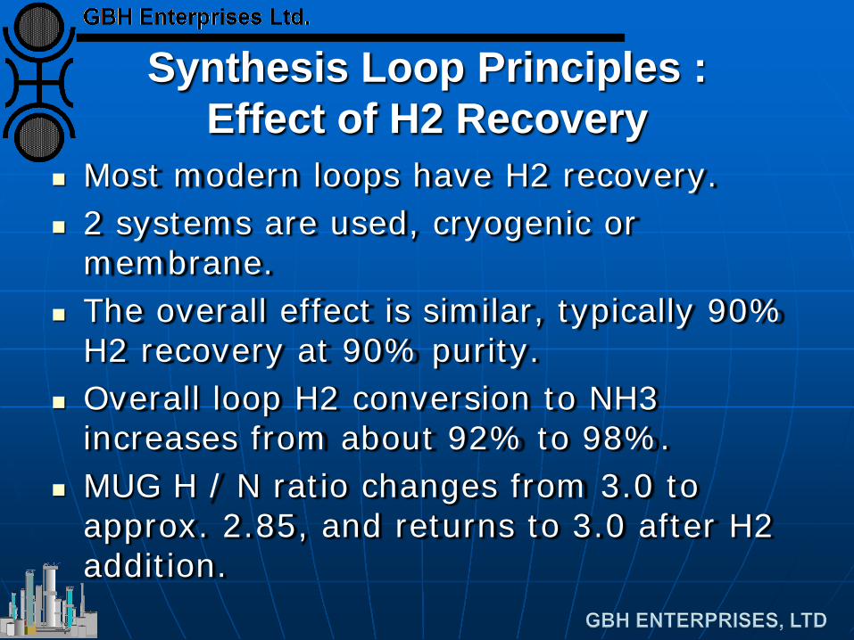
Synthesis Loop Principles : Effect of H2 Recovery
Most modern loops have H2 recovery. 2 systems are used, cryogenic or
membrane. The overall effect is similar, typically 90%
H2 recovery at 90% purity. Overall loop H2 conversion to NH3
increases from about 92% to 98%. MUG H / N ratio changes from 3.0 to
approx. 2.85, and returns to 3.0 after H2 addition.
Synthesis Loop Principles : Control of Catalyst Bed Temperatures
Multi-bed design : 2, 3, or 4 catalyst beds with
intermediate cooling.
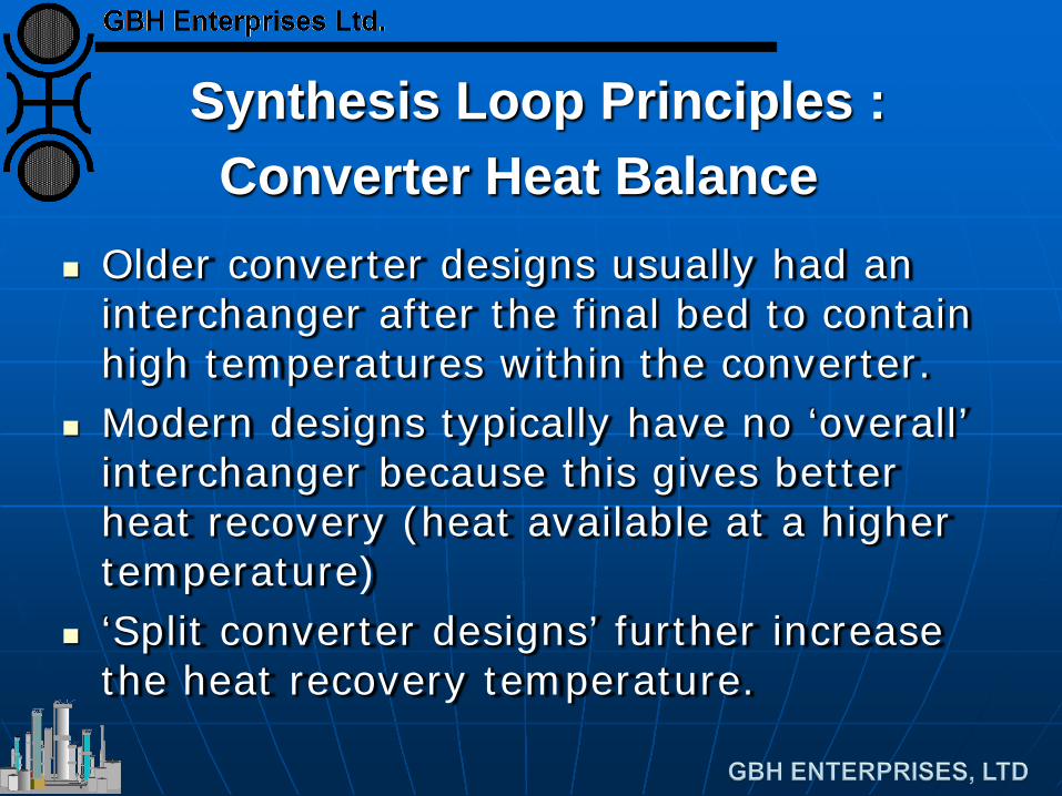
Synthesis Loop Principles : Converter Heat Balance
Older converter designs usually had an interchanger after the final bed to contain high temperatures within the converter.
Modern designs typically have no ‘overall’ interchanger because this gives better heat recovery (heat available at a higher temperature)
‘Split converter designs’ further increase the heat recovery temperature.
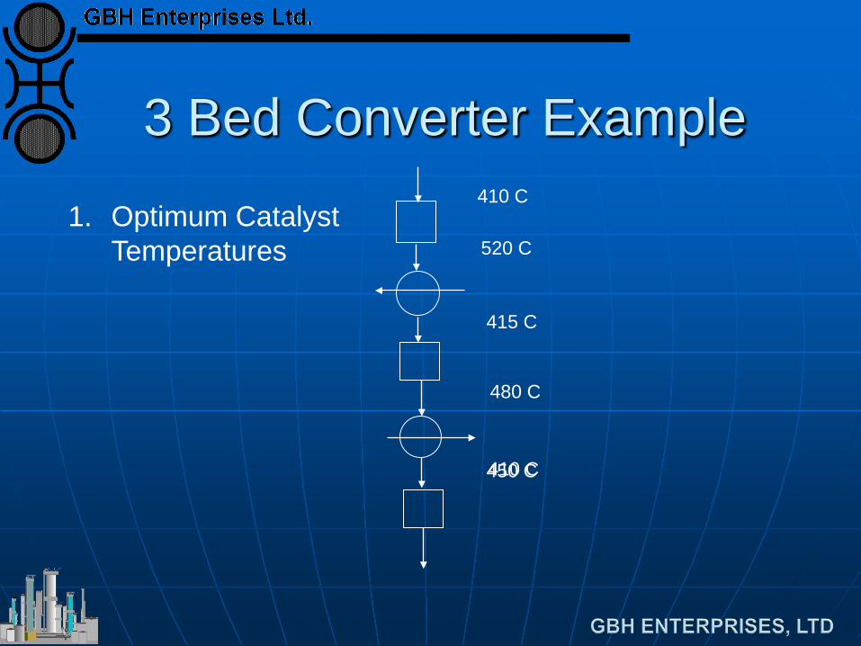
3 Bed Converter Example
450 C
1. Optimum Catalyst Temperatures
410 C
520 C
415 C
480 C
410 C
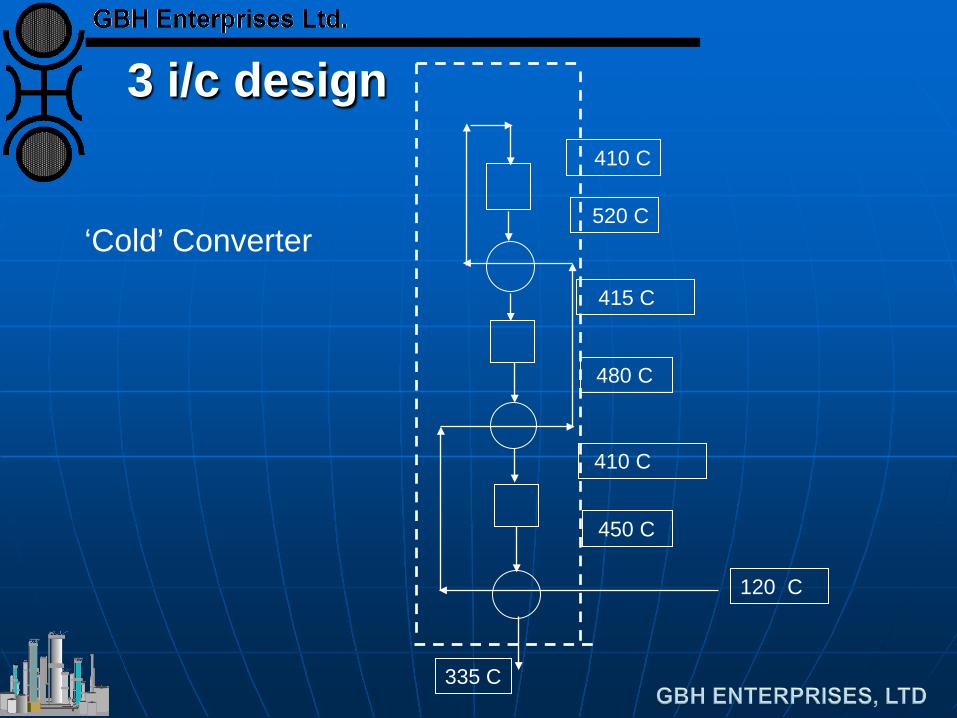
3 i/c design
‘Cold’ Converter
410 C
520 C
415 C
480 C
410 C
450 C
120 C
335 C
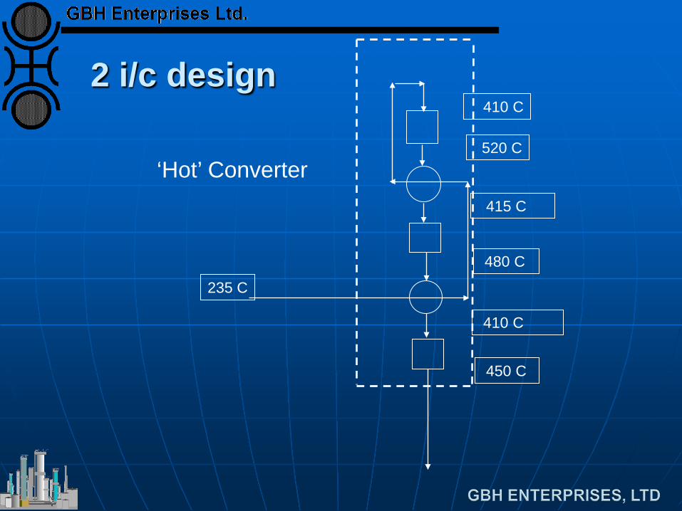
2 i/c design 410 C
520 C
415 C
480 C
410 C
450 C
‘Hot’ Converter
235 C
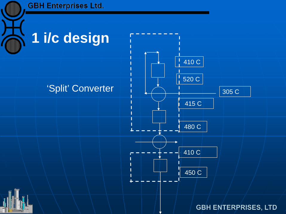
1 i/c design 410 C
520 C
415 C
480 C
410 C
450 C
‘Split’ Converter 305 C
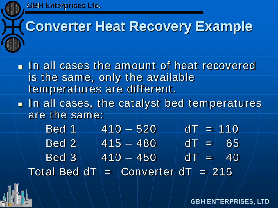
Converter Heat Recovery Example
In all cases the amount of heat recovered is the same, only the available temperatures are different.
In all cases, the catalyst bed temperatures are the same:
Bed 1 410 – 520 dT = 110 Bed 2 415 – 480 dT = 65 Bed 3 410 – 450 dT = 40 Total Bed dT = Converter dT = 215
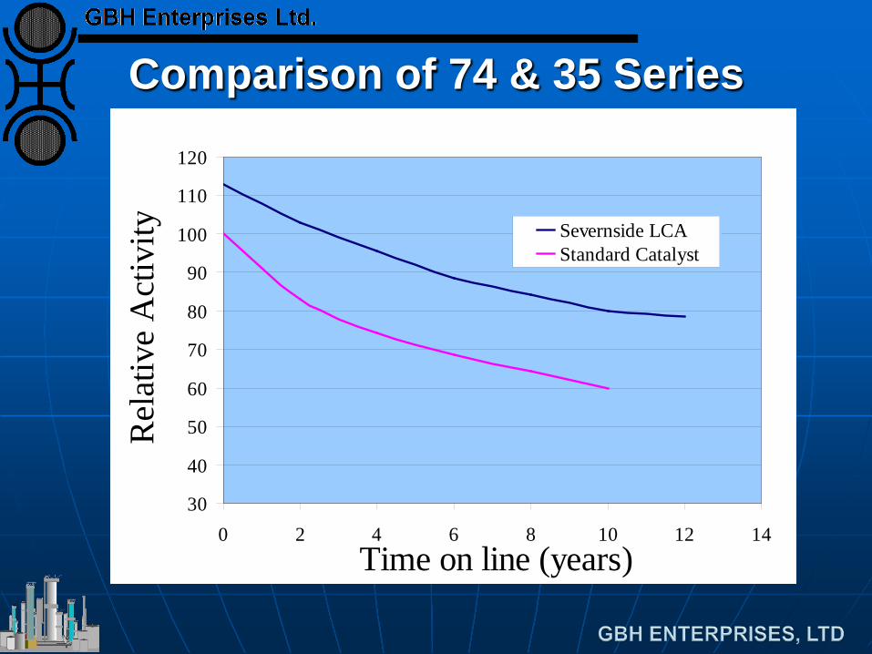
Comparison of 74 & 35 Series
30
40
50
60
70
80
90
100
110
120
0 2 4 6 8 10 12 14Time on line (years)
Rel
ativ
e A
ctiv
ity Severnside LCAStandard Catalyst
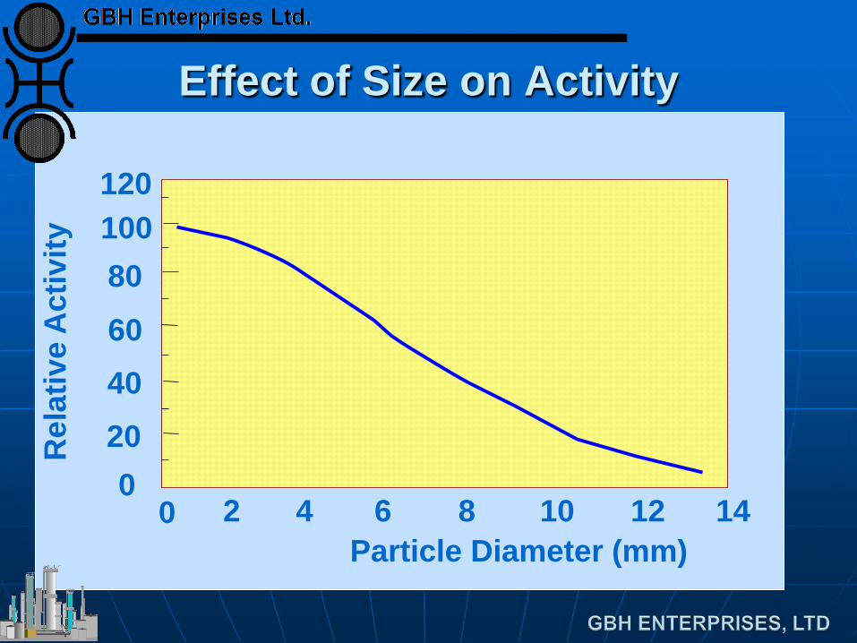
Effect of Size on Activity
Particle Diameter (mm) 14 12 10 8 6 4 2 0
Rel
ativ
e A
ctiv
ity
120 100 80
60
40
0 20
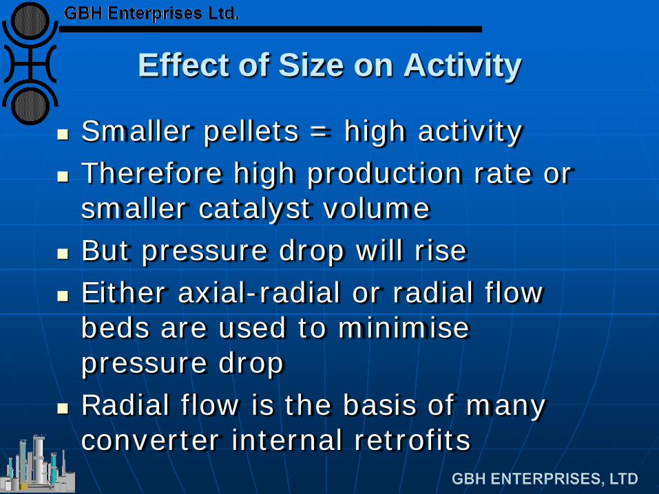
Effect of Size on Activity
Smaller pellets = high activity Therefore high production rate or
smaller catalyst volume But pressure drop will rise Either axial-radial or radial flow
beds are used to minimise pressure drop
Radial flow is the basis of many converter internal retrofits
Deactivation
Clean Gas • Thermal sintering
Contaminated Gas • Both Temporary and Permanent
Poisoning • Oxygen induced sintering • By water, CO and CO2 • Site blocking/Sintering
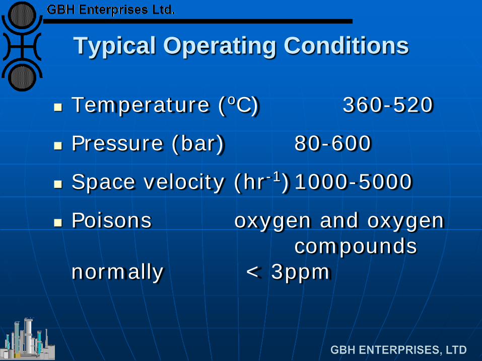
Typical Operating Conditions
Temperature (oC) 360-520
Pressure (bar) 80-600
Space velocity (hr-1) 1000-5000
Poisons oxygen and oxygen compounds normally < 3ppm
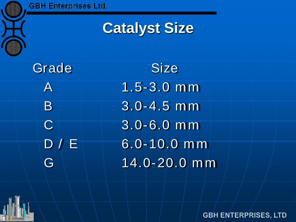
Catalyst Size
Grade Size A 1.5-3.0 mm B 3.0-4.5 mm C 3.0-6.0 mm D / E 6.0-10.0 mm G 14.0-20.0 mm
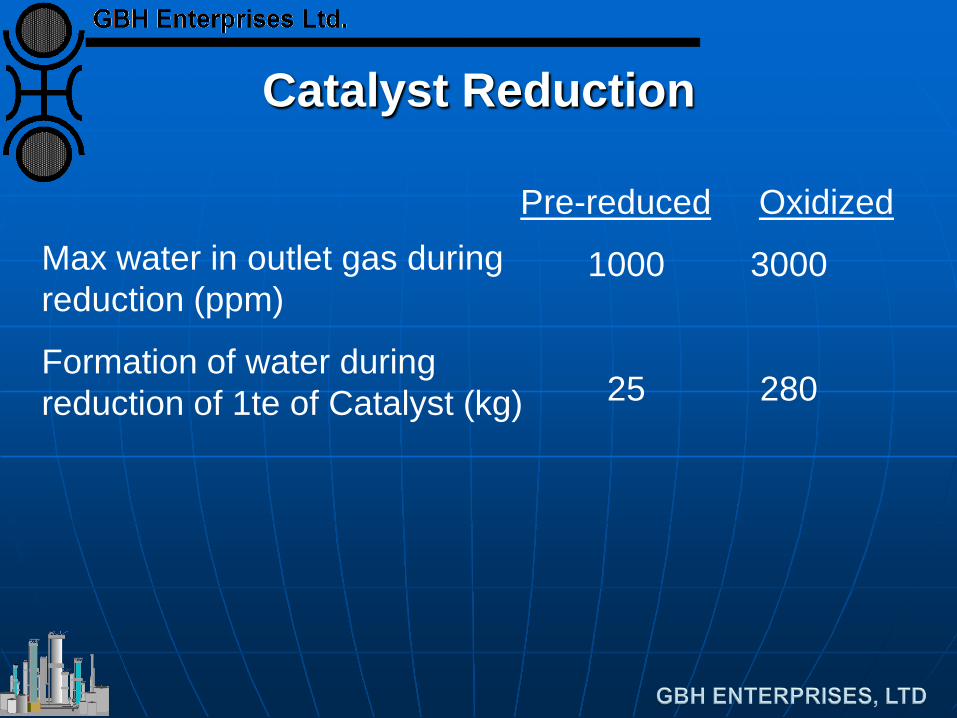
Catalyst Reduction
Max water in outlet gas during reduction (ppm)
Formation of water during reduction of 1te of Catalyst (kg)
Pre-reduced Oxidized
1000 3000
25 280

End
Ammonia Converter Designs
Converter Designs Objectives for modern designs are; - low pressure drop with small catalyst
particles. - high conversion per pass with high grade heat recovery. Principal types are designed by: Uhde Kellogg (KBR) - conventional, Braun,
KAAP Topsoe Ammonia Casale JM (I C I)
Uhde
Uhde design a range of converters: Modern designs use radial flow
with inter-cooling & 'split converters' with heat recovery between,
- Converter 1 : 2-bed, 1 interchanger
- Heat recovery (boiler) - Converter 2 : 3rd bed.
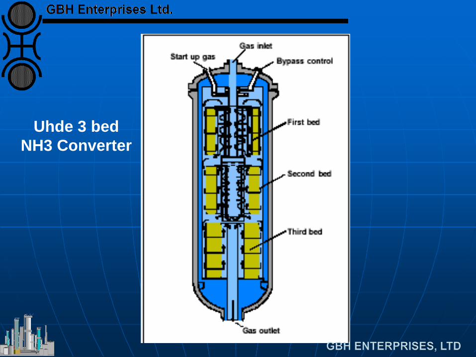
Uhde 3 bed NH3 Converter
M W Kellogg Converter Types
'Conventional' make-up gas and loop layout, refrigeration to low temperature (-25 C),
loop pressure typically 140 - 180 bar. Converters: 4 bed quench ; conventional Kellogg
design. Horizontal converter ;
• lower cost, low pressure drop, easier installation
• 2 bed inter-cooled layout with small catalyst
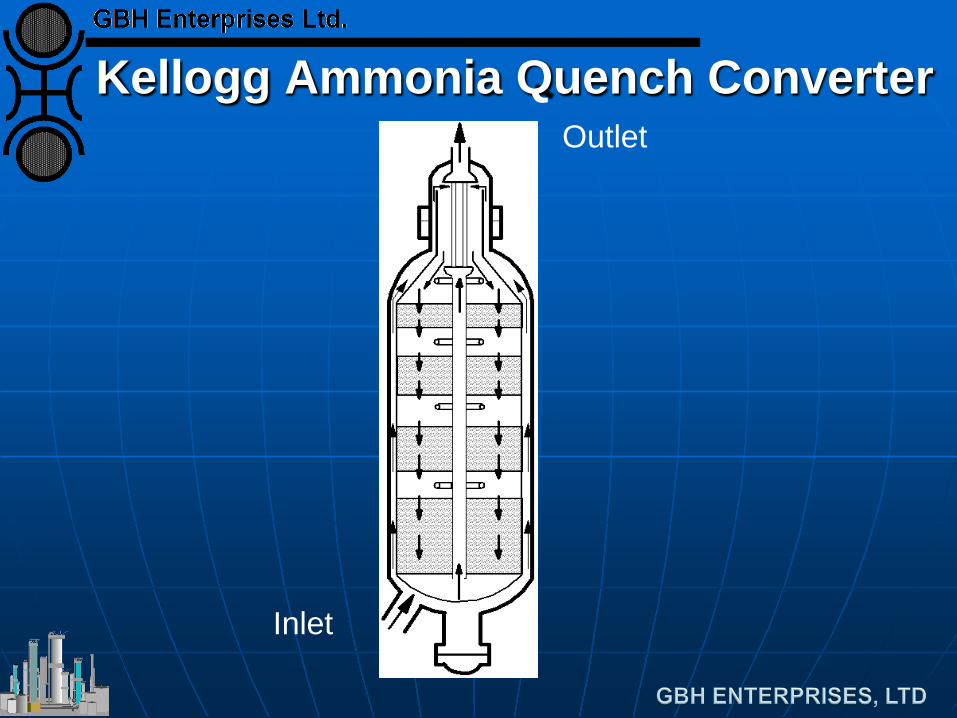
Kellogg Ammonia Quench Converter Outlet
Inlet
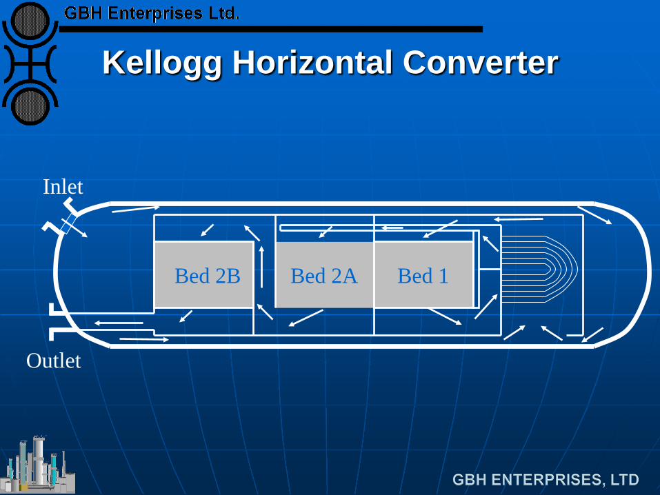
Kellogg Horizontal Converter
Bed 1 Bed 2A Bed 2B
Inlet
Outlet
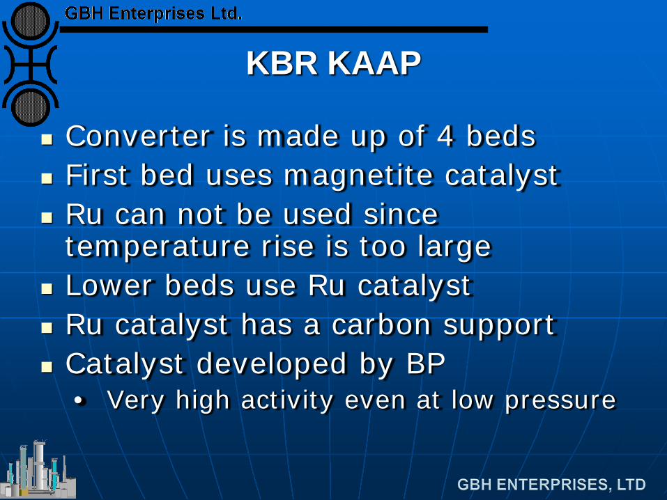
KBR KAAP
Converter is made up of 4 beds First bed uses magnetite catalyst Ru can not be used since
temperature rise is too large Lower beds use Ru catalyst Ru catalyst has a carbon support Catalyst developed by BP
• Very high activity even at low pressure
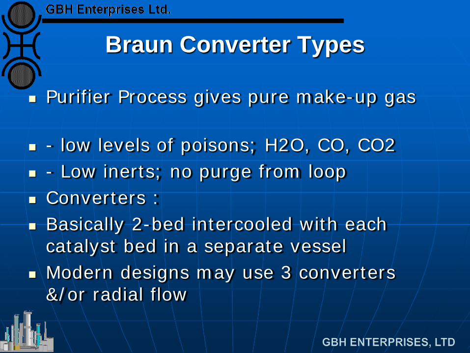
Braun Converter Types
Purifier Process gives pure make-up gas
- low levels of poisons; H2O, CO, CO2 - Low inerts; no purge from loop Converters : Basically 2-bed intercooled with each
catalyst bed in a separate vessel Modern designs may use 3 converters
&/or radial flow
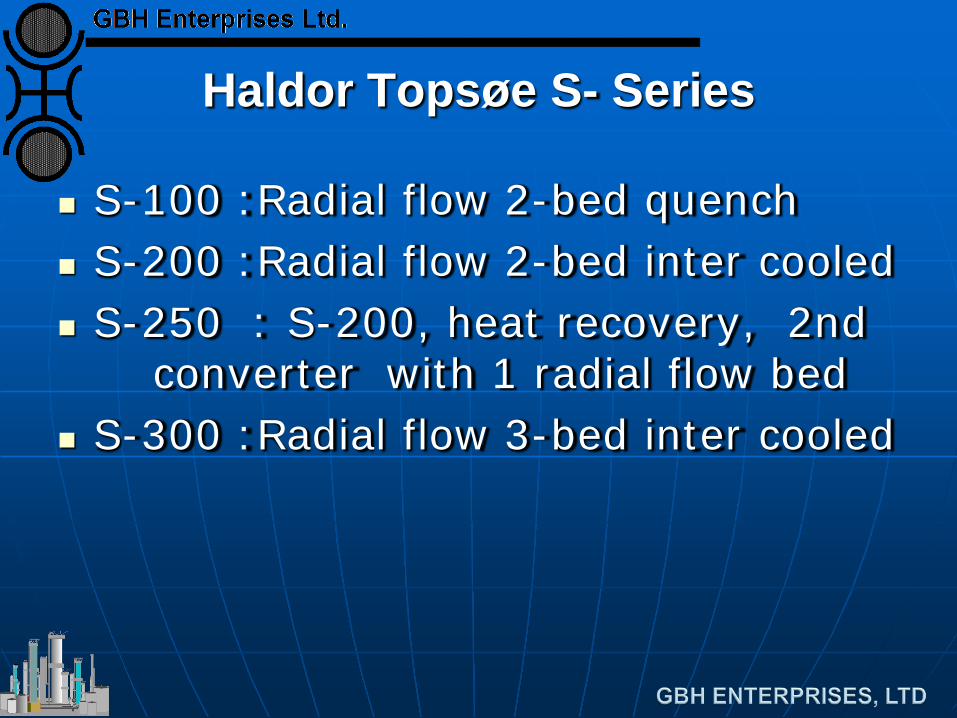
Haldor Topsøe S- Series
S-100 :Radial flow 2-bed quench S-200 :Radial flow 2-bed inter cooled S-250 : S-200, heat recovery, 2nd
converter with 1 radial flow bed S-300 :Radial flow 3-bed inter cooled
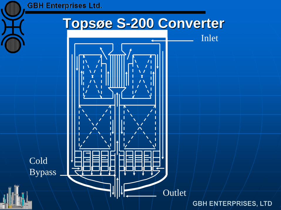
Topsøe S-200 Converter Inlet
Outlet
Cold Bypass
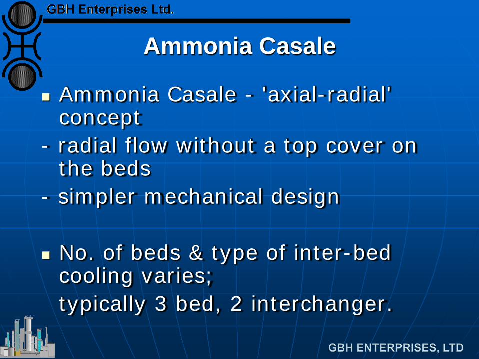
Ammonia Casale
Ammonia Casale - 'axial-radial' concept
- radial flow without a top cover on the beds
- simpler mechanical design
No. of beds & type of inter-bed cooling varies;
typically 3 bed, 2 interchanger.
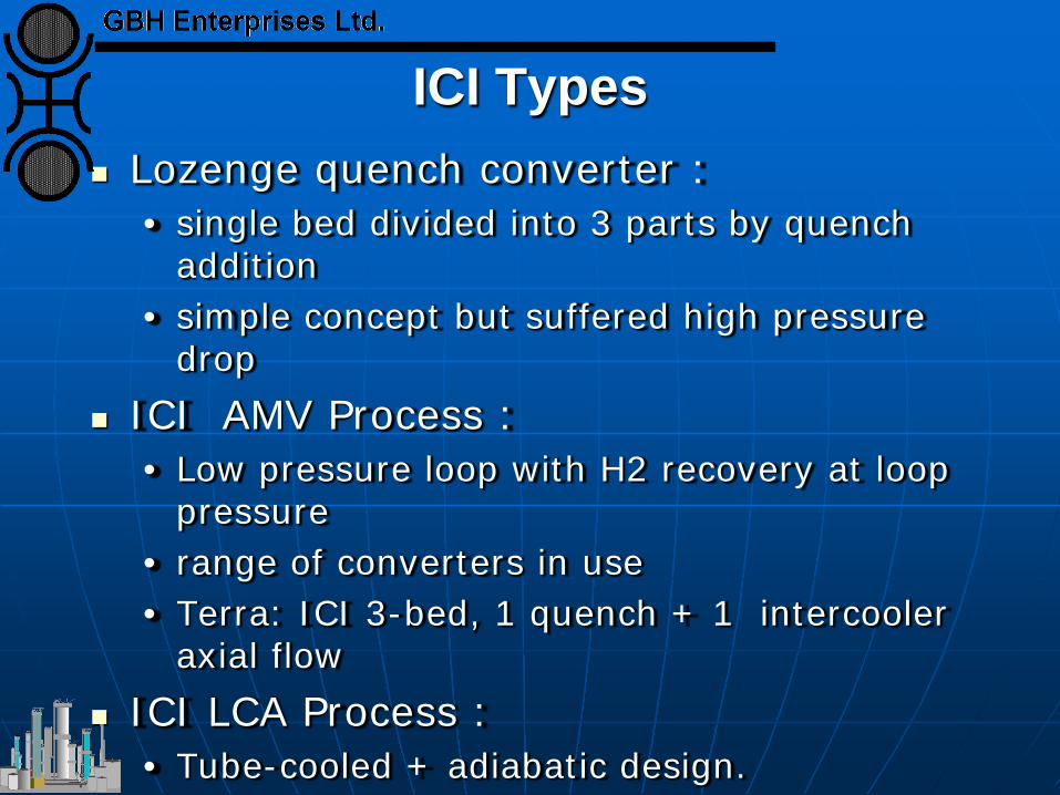
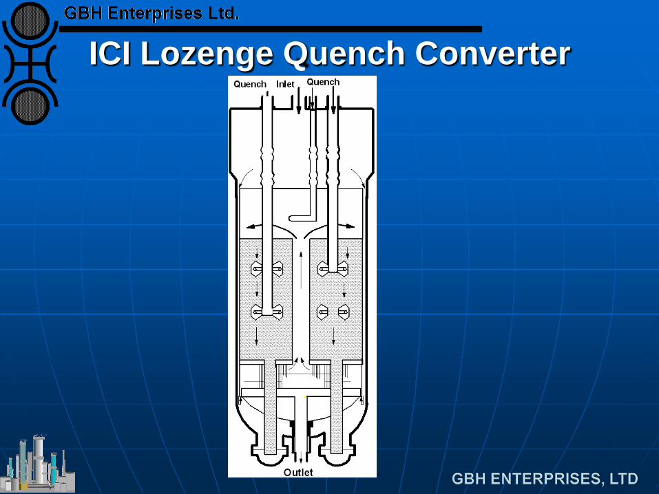
ICI Types Lozenge quench converter :
• single bed divided into 3 parts by quench addition
• simple concept but suffered high pressure drop
ICI AMV Process : • Low pressure loop with H2 recovery at loop
pressure • range of converters in use • Terra: ICI 3-bed, 1 quench + 1 intercooler
axial flow ICI LCA Process :
• Tube-cooled + adiabatic design.
ICI Lozenge Quench Converter
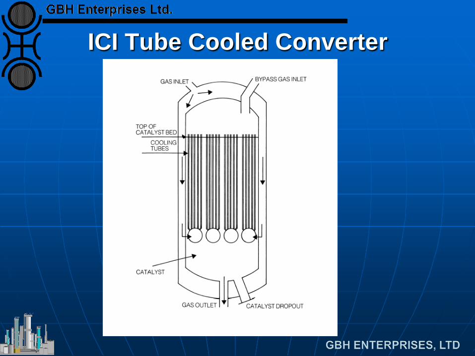
ICI Tube Cooled Converter
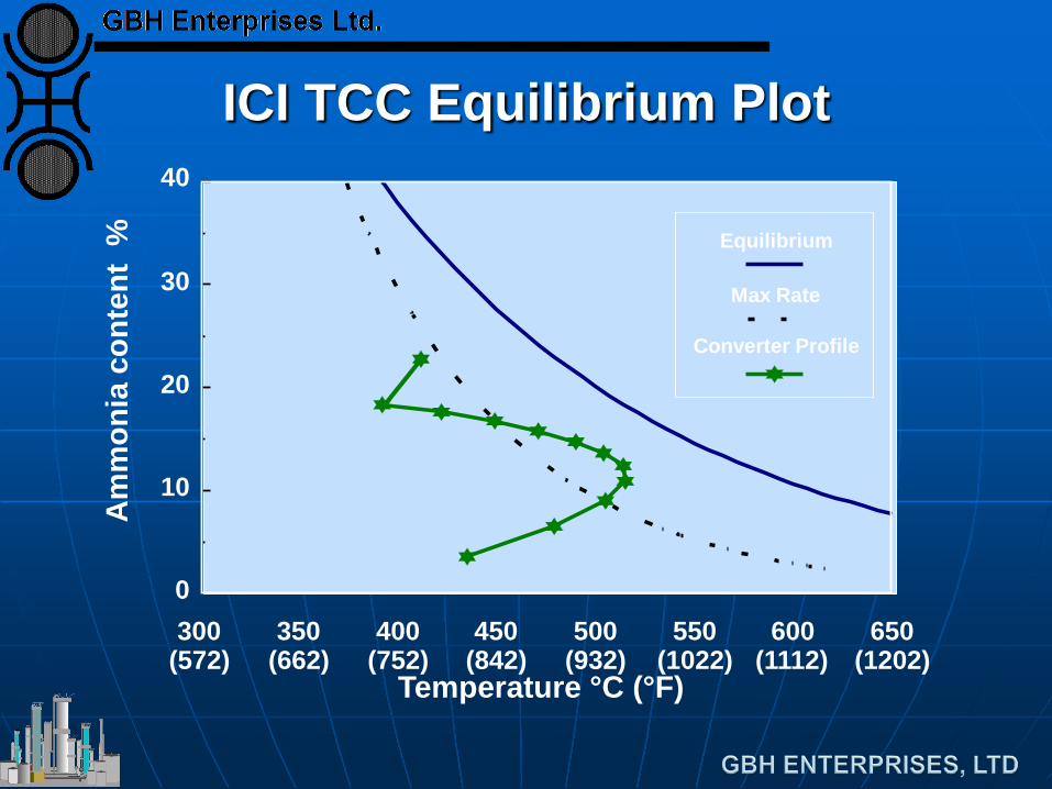
ICI TCC Equilibrium Plot
300 (572)
350 (662)
400 (752)
450 (842)
500 (932)
550 (1022)
600 (1112)
650 (1202)
0
10
20
30
40
Equilibrium
Max Rate
Converter Profile
Temperature °C (°F)
Am
mon
ia c
onte
nt %