Embed Size (px)
Citation preview

ENGLISH
GO7Operator Manual
simrad-yachting.com


Preface
DisclaimerAs Navico is continuously improving this product, we retain theright to make changes to the product at any time which may not bereflected in this version of the manual. Please contact your nearestdistributor if you require any further assistance.
It is the owner’s sole responsibility to install and use the equipmentin a manner that will not cause accidents, personal injury orproperty damage. The user of this product is solely responsible forobserving safe boating practices.
NAVICO HOLDING AS AND ITS SUBSIDIARIES, BRANCHES ANDAFFILIATES DISCLAIM ALL LIABILITY FOR ANY USE OF THIS PRODUCTIN A WAY THAT MAY CAUSE ACCIDENTS, DAMAGE OR THAT MAYVIOLATE THE LAW.
Governing Language: This statement, any instruction manuals, userguides and other information relating to the product(Documentation) may be translated to, or has been translated from,another language (Translation). In the event of any conflict betweenany Translation of the Documentation, the English language versionof the Documentation will be the official version of theDocumentation.
This manual represents the product as at the time of printing.Navico Holding AS and its subsidiaries, branches and affiliatesreserve the right to make changes to specifications without notice.
TrademarksLowrance® and Navico® are registered trademarks of Navico.
Fishing Hot Spots® is a registered trademark of Fishing Hot Spots Inc.Copyright© 2012 Fishing Hot Spots.
Navionics® is a registered trademark of Navionics, Inc.
NMEA 2000® is a registered trademark of the National MarineElectronics Association.
SiriusXM® is a registered trademark of Sirius XM Radio Inc.
FUSION-Link™ Marine Entertainment Standard™ is a registeredtrademark of FUSION Electronics Ltd.
Preface | GO7 Operator Manual 3

The terms HDMI and HDMI High-Definition Multimedia Interface,and the HDMI Logo are trademarks or registered trademarks ofHDMI Licensing LLC in the United States and other countries.
SD™ and microSD™ are trademarks or registered trademarks ofSD-3C, LLC in the United States, other countries or both.
Wi-Fi® is a registered trademark of the Wi-Fi Alliance®.
Additional mapping data: Copyright© 2012 NSI, Inc.: Copyright©2012 by Richardson’s Maptech.
Navico product referencesThis manual can refer to the following Navico products:
• Broadband Sounder™ (Broadband Sounder)• DownScan Imaging™ (DownScan)• DownScan Overlay™ (Overlay)• GoFree™ (GoFree)• SonicHub® (SonicHub)
CopyrightCopyright © 2015 Navico Holding AS.
WarrantyThe warranty card is supplied as a separate document.
In case of any queries, refer to the brand website of your display orsystem: simrad-yachting.com.
Regulatory statementsThis equipment is intended for use in international waters as well ascoastal sea areas administered by countries of the E.U. and E.E.A.
The GO7 complies with:
• CE under R&TTE directive 1999/5/EC• The requirements of level 2 devices of the
Radiocommunications (Electromagnetic Compatibility)standard 2008
The relevant Declaration of conformity is available in the GO7section on the following website: simrad-yachting.com.
4 Preface | GO7 Operator Manual

About this manualThis manual is a reference guide for operating the GO7. It assumesthat all equipment is installed and configured, and that the systemis ready to use.
The manual assumes that the user has basic knowledge ofnavigation, nautical terminology and practices.
Important text that requires special attention from the reader isemphasized as follows:
Ú Note: Used to draw the reader’s attention to a comment orsome important information.
Warning: Used when it is necessary to warnpersonnel that they should proceed carefully toprevent risk of injury and/or damage to equipment/personnel.
Manual versionThis manual is written for the GO7 software version 1.0. The manualis continuously updated to match new software releases. The latestavailable manual version can be downloaded from simrad-yachting.com.
Preface | GO7 Operator Manual 5

Viewing the manual on the screenThe pdf viewer included in the GO7 makes it possible to read themanuals and other pdf files on the screen. Manuals can bedownloaded from simrad-yachting.com.
The manuals can be read from a card inserted in the card reader orcopied to the unit’s internal memory.
Use the menu options and on-screen buttons to maneuver in thepdf file as described below:
• Search, Goto page, Page Up and DownSelect the relevant panel button.
• Scroll pagesDrag finger on the screen in any direction.
• Panning on the pageDrag finger on the screen in any direction.
• Zoom In/OutSelect the relevant panel button.Touch operation: Use pinch or spread gestures.
• Exit the pdf viewerSelect the X in the upper right corner of the panel.
6 Preface | GO7 Operator Manual
The Software versionThe software version currently on this unit can be found in theAbout dialog. The About dialog is available in the System Settings.
For information regarding upgrading your software, refer to "Softwareupgrades" on page 110.
Preface | GO7 Operator Manual 7

8 Preface | GO7 Operator Manual

Contents
13 Introduction13 The Home page14 Application pages16 Integration of 3rd party devices17 GoFree wireless17 Remote controllers
18 Basic operation18 System Controls dialog18 Turning the system on and off19 Display illumination19 Locking the touchscreen20 Using menus and dialogs20 Selecting pages and panels21 Using the cursor on the panel22 Creating a Man Overboard waypoint23 Screen capture
24 Customizing your system24 Customizing the Home page wallpaper24 Adjusting panel size25 Adding new favorite pages26 Edit favorite pages26 Setting the appearance of the Instrument bar
27 Charts27 The Chart panel28 Chart data28 Showing dual chart types29 Vessel symbol29 Chart scale29 Panning the chart29 Positioning the vessel on the chart panel30 Displaying information about chart items30 Using the cursor on the chart panel31 Creating routes31 Find objects on chart panels32 3D charts
Contents | GO7 Operator Manual 9

33 Insight specific chart options33 Insight view options34 Navionics specific chart options35 Navionics chart settings36 Navionics view options39 Jeppesen tides and currents40 Chart settings
42 Waypoints, Routes, and Tracks42 Waypoints44 Routes48 Tracks50 Waypoints, Routes, and Tracks dialogs
51 Navigating51 Navigation panels52 Navigate to cursor position52 Navigate a route54 Navigating with the autopilot54 Navigation settings
57 Autopilot57 Safe operation with the autopilot57 Activating the autopilot57 Switching from automatic mode to manual steering58 Autopilot indication on the pages59 The Autopilot panel60 Mode overview61 Standby mode61 Non-Follow Up (NFU, Power steering)61 Follow-up steering (FU)62 AUTO mode (auto compass)63 NoDrift mode64 NAV mode65 WIND mode67 WIND Nav mode68 Turn pattern steering71 Using the GO7 in an AP24/AP28 system71 Using the autopilot in an EVC system72 Autopilot settings
10 Contents | GO7 Operator Manual

75 Echosounder75 The Echosounder image76 Using the cursor on the Echosounder panel77 Viewing Echosounder history77 Setting up the Echosounder image79 Recording log data81 Echosounder settings
83 DownScan83 The DownScan image84 Zooming the DownScan image84 Using the cursor on the DownScan panel84 Viewing DownScan history85 Setting up the DownScan image
87 AIS87 AIS target symbols88 Viewing information about AIS targets89 Calling an AIS vessel89 AIS SART91 Vessel alarms92 Vessel settings
95 Instrument panels95 Dashboards95 Customizing the Instruments panel
97 Audio97 Enabling audio97 The Audio panel100 Setting up the audio system100 Operating the audio system101 Favorite channels101 Sirius radio (North America only)
102 Time plots102 The Time plot panel102 Selecting data
Contents | GO7 Operator Manual 11

103 Alarms103 Alarm system103 Type of messages103 Single alarms103 Multiple alarms104 Acknowledging a message104 Alarms dialog
106 Tools106 Waypoints/routes/tracks106 Tides106 Alarms106 Settings106 Vessels107 Sun, Moon107 Trip calculator107 Files107 Find
108 Simulator108 Demo mode108 Simulator source files109 Advanced simulator settings
110 Maintenance110 Preventive maintenance110 Cleaning the display unit110 Cleaning the media port door110 Checking the connectors110 Software upgrades111 Backing up your system data
113 Touchscreen operation
12 Contents | GO7 Operator Manual

Introduction
The Home pageThe Home page is accessed from any operation by selecting theHome button in the upper left corner of a panel.
1 ToolsSelect a button to access dialogs used for carrying out a task,or for browsing stored information.
2 ApplicationsSelect a button to display the application as a full pagepanel. Press and hold a button to display pre-configuredsplit page options for the application.
3 Close buttonSelect to exit the Home page and return to the previousactive page.
4 FavoritesSelect a button to display the panel combination.Press and hold a favorite button to enter edit mode for theFavorites panel.
1
Introduction | GO7 Operator Manual 13

5 Man Over Board (MOB) buttonSelect to save a Man Over Board (MOB) waypoint at thecurrent vessel position.
Application pages
Each application connected to the system is presented on panels.The application can be presented as a full page, or in combinationwith other panels in a multiple panel page.
All application pages are accessed from the Home page.
1 Application panel
2 Instrument barNavigation and sensor information. The bar can be turnedoff and it can be configured by the user.
3 System controls dialogQuick access to basic system settings.Display the dialog by a short press on the Power key or byswiping down from top of the screen.
4 Status bar
5 DialogInformation to or input from the user.
6 Alarm messageDisplayed if dangerous situations or system faults occur.
14 Introduction | GO7 Operator Manual

7 MenuPanel specific menu.Display the menu by selecting the MENU panel button.
Split pagesYou can have up to 4 panels on each page.
2 panels page 3 panels page 4 panels page
Panel sizes in a split page can be adjusted from the SystemControls dialog.
Ú Note: Mercury features, if enabled, do not allow split pages.
Pre-configured split pagesEach full screen application has several pre-configured split pages,featuring the selected application combined with each of the otherpanels.
Ú Note: The number of pre-configured split pages cannot bechanged, and the pages cannot be customized or deleted.
Access a pre-configured split page by pressing and holding themain panel button.
Favorite pages All preconfigured favorite pages can be modified and deleted, andyou can create your own. You can have a total of 12 favorite pages.
Introduction | GO7 Operator Manual 15

For more information, refer to "Adding new favorite pages" on page 25.
Integration of 3rd party devicesSeveral 3rd party devices can be connected to the GO7. Theapplications are displayed on separate panels or integrated withother panels.
A device connected to the NMEA 2000 network shouldautomatically be identified by the system. If not, enable the featurefrom the advanced option in the System settings dialog.
The 3rd party device is operated by using menus and dialogs as onother panels.
This manual does not include specific operation instructions for any3rd party device. For features and functionality, refer to thedocumentation included with the 3rd party device.
Mercury VesselView integration
Mercury VesselView SmartCraft data display and interaction areenabled through the GO7 when a VesselView 7 or VesselView 4gateway device is present on the NMEA 2000 network.
A Mercury icon appears on the Home page when the device isavailable.
FUSION-Link integrationFUSION-Link devices connected to the NMEA 2000 network can becontrolled from the GO7 system.
The FUSION-Link devices appear as additional sources when usingthe audio function. No additional icons are available.
Refer to "Audio" on page 97 for more information.
BEP CZone integration
The GO7 integrates with BEP’s CZone system used for controllingand monitoring a distributed power system on your vessel.
The CZone icon is available in the Tools panel on the Home pagewhen a CZone system is available on the network.
16 Introduction | GO7 Operator Manual

A separate manual is provided with your CZone system. Refer to thisdocumentation and to the GO7 Installation manual for how toinstall and configure the CZone system.
CZone dashboardWhen the CZone is installed and configured, an additional CZonedashboard is added to the Instruments panels.
You switch between a panel’s dashboards by selecting the left andright arrow symbols or by selecting the dashboard from the menu.
Editing a CZone dashboardYou can customize a CZone dashboard by changing the data foreach of the gauges. Available editing options depend on the type ofgauge and which data sources that are connected to your system.
For more information, refer to "Instrument panels" on page 95.
GoFree wirelessThe GO7 includes built-in wireless functionality that lets you use awireless device to remotely view (phone and tablet) and control thesystem (tablet only). The system is controlled from the wirelessdevice by Apps downloaded from their relevant Application store.
Configuration and setup are described in the GO7 Installationmanual.
Ú Note: For safety reasons, Autopilot and CZone functionscannot be controlled from a wireless device.
Operating the system with a wireless deviceWhen remote control is accepted, the active page is mirrored to thewireless device.
The image on the wireless device includes softkeys used foroperating the GO7 system.
Remote controllers
You can connect an OP40 to the network and remotely control theGO7.
A separate manual is included with the remote controller.
Introduction | GO7 Operator Manual 17

Basic operation
System Controls dialogThe System Controls dialog provides quick access to basic systemsettings. You display the dialog by making a short press on thePower key. The icons displayed on the dialog can vary. For example,the adjust splits option is only available if you are viewing a splitpage when you open the System Controls dialog.
Activating functionsSelect the icon of the function you want to set or toggle on or off.For those functions that toggle on and off, a highlighted iconindicates the function is activated, as shown in the Instrument baricon above.
Turning the system on and off
You turn the system on and off by pressing and holding the Powerkey. You can also turn the unit off from the System Controlsdialog.
If the Power key is released before the shut-down is completed, thepower off process is cancelled.
2
18 Basic operation | GO7 Operator Manual

First time startupThe first time the unit is started and after a master reset, the systemruns through an automatic start-up sequence, including languagesetup and automatic data source selection.
You can select to interrupt this sequence and later configure thesystem yourself.
Standby mode
In Standby mode, the Sonar and the backlight for screen and keysare turned off to save power. The system continues to run in thebackground.
You select Standby mode from the System Controls dialog.
Switch from Standby mode to normal operation by a short press onthe Power key.
Display illumination
Brightness
The display backlighting can be adjusted at any time from theSystem Controls dialog. You can also cycle the preset backlightlevels by short presses on the Power key.
Night modeThe night mode option optimizes the color palette and backlight forlow light conditions.
Ú Note: Details on the chart may be less visible when theNight mode is selected!
Locking the touchscreen
You can temporarily lock a touchscreen to prevent accidentaloperation of the system. Lock the touchscreen when large amountsof water are on the screen, for example, in heavy seas and weather.This feature is also useful when cleaning the screen while the unit isturned on.
Basic operation | GO7 Operator Manual 19

You lock the touchscreen from the System Controls dialog.
You remove the lock function by a short press on the Power key.
Using menus and dialogs
MenusYou display a page menu by selecting the MENU button in theupper right corner of the page.
• Activate a menu item and toggle on/off an option by selectingit
• Adjust a slide bar value by either:• dragging the slide bar• selecting the + or - icons
Select the Back menu option to return to the previous menu level,and then exit.
You can make the menu slide away by tapping the screen outsidethe menu area, or by pressing the MENU button. When you re-press the MENU button, the menu opens in the same status it hadbefore it closed.
The status of the cursor (active vs. inactive) changes the menuoptions.
Selecting pages and panels
Selecting a page• Select a full page panel by selecting the relevant application
button on the Home page• Select a favorite page by selecting the relevant favorite button• Select a predefined split panel by pressing and holding the
relevant application icon
Select active panelIn a multiple panel page, only one panel can be active at a time. Theactive panel is outlined with a border.
You can only access the page menu of an active panel.
You activate a panel by tapping it.
20 Basic operation | GO7 Operator Manual

Using the cursor on the panelThe cursor can be used to measure a distance, to mark a position,and to select items.
By default, the cursor is not shown on the panel.
Position the cursor by tapping the desired location on the screen.
When the cursor is active, the cursor position window is displayed.
To remove the cursor and cursor elements from the panel, selectthe Clear cursor option.
GoTo cursorYou can navigate to a selected position on the image by positioningthe cursor on the panel, then using the Goto Cursor option in themenu.
The Cursor assist functionThe cursor assist function allows for fine tuning and precisionplacement of the cursor without covering details with your finger.
Press and hold your finger on the screen to switch the cursorsymbol to a selection circle, appearing above your finger.
Without removing your finger from the screen, drag the selectioncircle over the desired item to display item information.
When you remove your finger from the screen the cursor reverts tonormal cursor operation.
Basic operation | GO7 Operator Manual 21

Measuring distance
The cursor can be used to measure the distance between yourvessel and a selected position, or between 2 points on the chartpanel.
1. Position the cursor on the point from where you want tomeasure the distance.
2. Start the measure function from the menu.- The measuring icons appear with a line drawn from the vessel
center to the cursor position, and the distance is listed in thecursor information window.
3. You can reposition the measuring points by dragging eithericon as long as the measuring function is active.
Ú Note: The bearing is always measured from the grey iconto the blue icon.
You can also start the measuring function without an active cursor.Both measuring icons are then initially located at the vessel position.The grey icon follows the vessel as the vessel moves, while the blueicon remains at the position given when you activated the function.
You terminate the measuring function by selecting the Finishmeasuring menu option.
Creating a Man Overboard waypointIf an emergency situation should occur, you can position a ManOverboard (MOB) waypoint at the vessel’s current position byselecting the MOB button on the Home page.
When you activate the MOB function the following actions areautomatically performed:
• a MOB waypoint is positioned at the vessel’s position• the display switches to a zoomed chart panel, centered on the
vessel's position• the system displays navigation information back to the MOB
waypointMultiple MOB waypoints are saved by repeatedly pressing the MOBbuttons. The vessel continues to show navigation information tothe initial MOB waypoint. Navigation to subsequent MOB waypointsneeds to be done manually.
22 Basic operation | GO7 Operator Manual
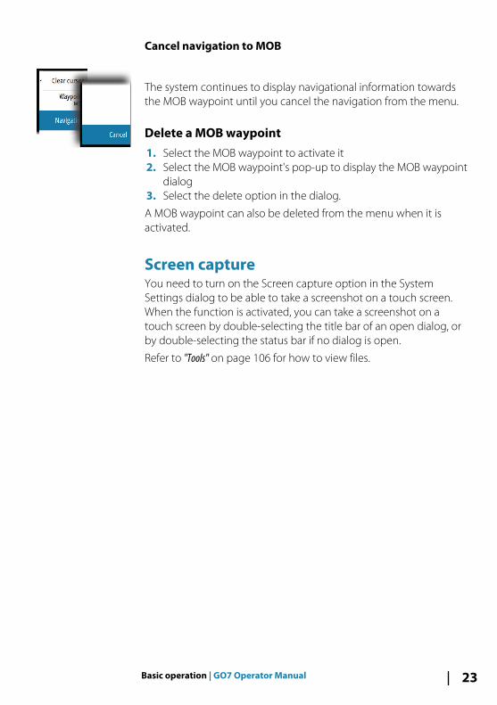
Cancel navigation to MOB
The system continues to display navigational information towardsthe MOB waypoint until you cancel the navigation from the menu.
Delete a MOB waypoint1. Select the MOB waypoint to activate it2. Select the MOB waypoint's pop-up to display the MOB waypoint
dialog3. Select the delete option in the dialog.
A MOB waypoint can also be deleted from the menu when it isactivated.
Screen captureYou need to turn on the Screen capture option in the SystemSettings dialog to be able to take a screenshot on a touch screen.When the function is activated, you can take a screenshot on atouch screen by double-selecting the title bar of an open dialog, orby double-selecting the status bar if no dialog is open.
Refer to "Tools" on page 106 for how to view files.
Basic operation | GO7 Operator Manual 23
Customizing your system
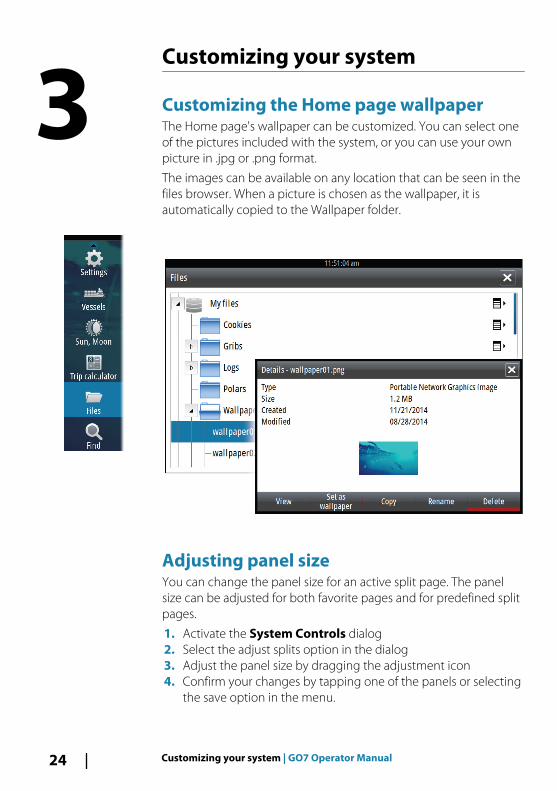
Customizing the Home page wallpaperThe Home page's wallpaper can be customized. You can select oneof the pictures included with the system, or you can use your ownpicture in .jpg or .png format.
The images can be available on any location that can be seen in thefiles browser. When a picture is chosen as the wallpaper, it isautomatically copied to the Wallpaper folder.
Adjusting panel sizeYou can change the panel size for an active split page. The panelsize can be adjusted for both favorite pages and for predefined splitpages.
1. Activate the System Controls dialog2. Select the adjust splits option in the dialog3. Adjust the panel size by dragging the adjustment icon4. Confirm your changes by tapping one of the panels or selecting
the save option in the menu.
3
24 Customizing your system | GO7 Operator Manual
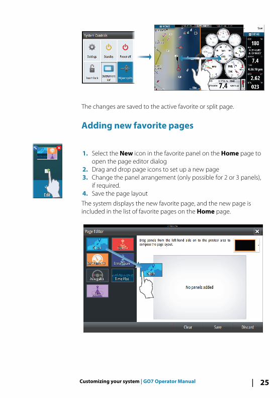
The changes are saved to the active favorite or split page.
Adding new favorite pages
1. Select the New icon in the favorite panel on the Home page toopen the page editor dialog
2. Drag and drop page icons to set up a new page3. Change the panel arrangement (only possible for 2 or 3 panels),
if required.4. Save the page layout
The system displays the new favorite page, and the new page isincluded in the list of favorite pages on the Home page.
Customizing your system | GO7 Operator Manual 25

Edit favorite pages
1. Select the edit icon for a favorite icon to enter edit mode- Select the X icon to remove the page- Select the tool icon to display the page editor dialog
2. Add or remove panels in the page editor dialog.3. Save or discard your changes to leave the favorite edit mode.
Setting the appearance of the InstrumentbarData sources connected to the system can be viewed in theInstrument bar.
You can configure the Instrument bar to display either one or twobars, or set it to alternate the bars automatically.
You can turn the Instrument bar off from the System controlsdialog.
Ú Note: This only turns the Instrument bar off for the currentpage.
Turning the Instrument bar on/off1. Activate the System controls dialog2. Deactivate/activate the instrument bar icon to toggle the bar on
and off.
Edit the content of the Instrument bar1. Select the MENU button to edit the content2. Select the content you want to display
Ú Note: You can configure Bar 1 for active page or for allpages except those that have a local configuration. Bar 2can only be configured for active page.
3. Define the time period if you want the two bars to alternateautomatically
4. Select the edit option to change any of the instrument fields,followed by the field you want to change
5. Save your changes by selecting the finish edit option in themenu.
26 Customizing your system | GO7 Operator Manual

ChartsThe chart function displays your vessel’s position relative to landand other chart objects. On the chart panel you can plan andnavigate routes, place waypoints, and display AIS targets.
The Chart panel
1 Waypoint*
2 Vessel with extension line (extension line is optional)
3 Route*
4 North indicator
5 Grid lines*
6 Range rings*
7 Track*
8 Chart range scale
9 Range rings interval (only displayed when Range rings areturned on)
* Optional chart items. You turn the optional images on/offindividually from the Chart settings dialog.
4
Charts | GO7 Operator Manual 27

Chart dataThe system is delivered with different embedded cartographydepending on region.
All units support Insight charts from Navico including InsightGenesis. The system also supports Navionics Gold, Platinum+ andNavionics+, C-MAP MAX-N/MAX-N+ by Jeppesen as well as contentcreated by variety of third party mapping providers in the AT5format. For a full selection of available charts please visitinsightstore.navico.com, c-map.jeppesen.com or navionics.com.
Ú Note: The system does not automatically switch toembedded cartography if the chart card is removed. A low-resolution chart will be displayed until you re-insert thecard or manually switch back to the embeddedcartography.
Showing dual chart typesIf you have different chart types available - embedded or in the cardslot - you can show two different chart types simultaneously on apage with two chart panels.
You can select a dual chart panel by pressing and holding the Chartapplication button on the Home page, or by creating a favoritepage with two chart panels.
Selecting chart type
You specify the chart type in the Chart panel by selecting one of theavailable chart types in the chart source menu option. If you have amultiple Chart panel, the chart type is set individually for each chartpanel. Activate one of the chart panels, and then select one of theavailable chart types in the chart source menu option. Repeat theprocess for the second chart panel, and select an alternative charttype for this panel.
Ú Note: To show charts other than Navionics, Insight charttype must be selected.
If you have identical charts available - built in or in the card slot - thesystem automatically selects the chart with most chart details foryour displayed region.
28 Charts | GO7 Operator Manual

Vessel symbol
When the GO7 has a valid GPS position lock, the vessel symbolindicates vessel position. If no GPS position is available, the vesselsymbol includes a question mark.
Chart scale
You zoom in and out on the chart by using the zoom panel icons, orby using fingers to pinch (zoom out) or spread (zoom in).
Chart range scale and range rings interval (when turned on) areshown in the lower right corner of the chart panel.
Panning the chartYou can move the chart in any direction by dragging your finger onthe screen.
Select the Clear cursor menu option to remove the cursor andcursor window from the panel. This also centers the chart to thevessel position.
Positioning the vessel on the chart panel
Chart orientationSeveral options are available for how the chart is rotated in thepanel. The chart orientation symbol in the panel’s upper rightcorner indicates the north direction.
North up Heading up Course up
North upDisplays the chart with north upward.
Charts | GO7 Operator Manual 29

Heading upDisplays the chart with the vessel’s heading directed upward.Heading information is received from a compass. If heading is notavailable, then the COG from the GPS is used.
Course upRotates the chart in the direction of the next waypoint whennavigating a route or navigating to a waypoint. If not navigating theheading up orientation is used until navigation is started.
Look aheadMoves the vessel icon closer to the bottom of the screen so thatyou can maximize your view ahead.
Displaying information about chart itemsWhen you select a chart item, a waypoint, a route, or a target, basicinformation for the selected item is displayed. Select the chart item'spop-up to display all available information for that item. You canalso activate the detailed information dialog from the menu.
Ú Note: Pop-up information has to be enabled in chartsettings to see basic item information.
Using the cursor on the chart panelBy default, the cursor is not shown on the chart panel.
When you activate the cursor, the cursor position window isdisplayed. When the cursor is active, the chart does not pan orrotate to follow the vessel.
30 Charts | GO7 Operator Manual

Select the Clear cursor menu option to remove the cursor and thecursor window from the panel. This also centers the chart to thevessel position.
Select the Restore cursor menu option to display the cursor in itsprevious location. The Clear cursor and Restore cursor optionsare useful features for toggling between the vessel's currentlocation and the cursor position.
Creating routesYou can create routes as follows on the chart panel.
1. Position the cursor on the chart panel.2. Select New followed by New route in the menu.3. Tap the chart panel to position the first routepoint.4. Continue positioning the remaining routepoints.5. Save the route by selecting the save option in the menu.
Ú Note: For more information, refer to "Waypoints, Routes, andTracks" on page 50.
Find objects on chart panelsYou can search for other vessels or various chart items from a chartpanel.
Activate the cursor on the panel to search from the cursor position.If the cursor is not active, the system searches for items from thevessel's position.
Ú Note: You must have a SIRIUS data package subscription tosearch for fueling stations and an AIS receiver connected tosearch for vessels.
Charts | GO7 Operator Manual 31

3D chartsThe 3D option provides a three dimensional graphical view of landand sea contours.
Ú Note: All chart types work in 3D mode, but without 3Dcartography for the appropriate area the chart appears flat.
When 3D chart option is selected, the Pan and the Rotate iconsappear on the right side of the chart panel.
Panning the 3D chart
You can move the chart in any direction by selecting the Pan iconand then panning in the desired direction.
Select the Return to vessel menu option to stop panning, and tocenter the chart to vessel position.
Controlling the view angle
You can control the view angle by selecting the Rotate icon andthen panning the chart panel.
• To change the direction you are viewing, pan horizontally• To change the tilt angle of the view, pan vertically
Ú Note: When centered on the vessel position, only the tiltangle can be adjusted. The view direction is controlled bythe chart orientation setting. See "Positioning the vessel on the chartpanel" on page 29.
Zooming a 3D chartYou zoom in and out on a 3D chart by using the zoom (+ or -)buttons, or the touch method of pinching and spreading yourfingers.
32 Charts | GO7 Operator Manual

Insight specific chart options
Orientation, Look ahead, 3D, and change Chart source (previouslydescribed in this section) are common for all chart types.
Chart imagery styleThe charts can be displayed in three imagery styles.
2D mapping style Shaded relief No contours
Insight view options
Chart detail• Full
All available information for the chart in use.• Medium
Minimum information sufficient for navigation.• Low
Basic level of information that cannot be removed, and includesinformation that is required in all geographic areas. It is notintended to be sufficient for safe navigation.
Insight chart categoriesInsight charts include several categories and sub-categories thatyou can turn on/off individually depending on which informationyou want to see.
Charts | GO7 Operator Manual 33

Land Exaggeration and Water ExaggerationGraphical settings available in 3D mode only. Exaggeration is amultiplier applied to the drawn height of hills on land, and troughsin water to make them look taller or deeper.
Navionics specific chart options
Orientation, Look ahead, 3D and change Chart source (previouslydescribed in this section) are common for all chart types.
Community editsToggles on the chart layer including Navionics edits. These are userinformation or edits uploaded to Navionics Community by users,and made available in Navionics charts.
For more information, refer to Navionics information included withyour chart, or to Navionics website: www.navionics.com.
34 Charts | GO7 Operator Manual

Navionics chart settings
Colored seabed areas
Used for displaying different depth areas in different shades of blue.
AnnotationDetermines what area information, such as names of locations andnotes of areas, is available to display.
Presentation typeProvides marine charting information such as symbols, colors of thenavigation chart and wording for either International or U.S.presentation types.
Chart detailsProvides you with different levels of geographical layer information.
Safety depthThe Navionics charts use different shades of blue to distinguishbetween shallow and deep water.
Safety depth, based on a selected limit, is drawn without blueshading.
Ú Note: The built in Navionics database features data downto 20 m, after which it is all white.
Contours depthDetermines which contours you see on the chart down to theselected safety depth value.
Rock filter levelHides rock identification on the chart beneath a given depth.
This helps you to declutter charts in areas where there are manyrocks located at depths well below your vessel's draught.
Charts | GO7 Operator Manual 35
Navionics view options
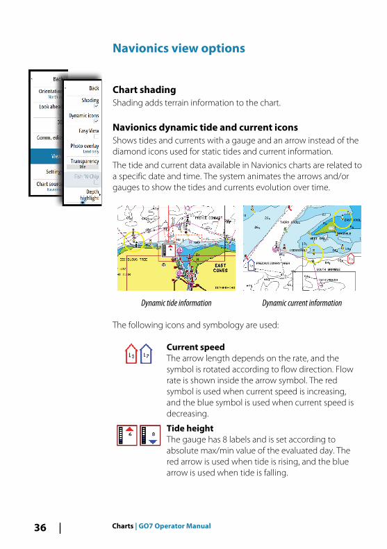
Chart shadingShading adds terrain information to the chart.
Navionics dynamic tide and current iconsShows tides and currents with a gauge and an arrow instead of thediamond icons used for static tides and current information.
The tide and current data available in Navionics charts are related toa specific date and time. The system animates the arrows and/orgauges to show the tides and currents evolution over time.
Dynamic tide information Dynamic current information
The following icons and symbology are used:
Current speedThe arrow length depends on the rate, and thesymbol is rotated according to flow direction. Flowrate is shown inside the arrow symbol. The redsymbol is used when current speed is increasing,and the blue symbol is used when current speed isdecreasing.
Tide heightThe gauge has 8 labels and is set according toabsolute max/min value of the evaluated day. Thered arrow is used when tide is rising, and the bluearrow is used when tide is falling.
36 Charts | GO7 Operator Manual

Ú Note: All numeric values are shown in the relevant systemunits (unit of measurement) set by user.
Easy ViewMagnifying feature that increases the size of chart items and text.
Ú Note: There is no indication on the chart showing that thisfeature is active.
Photo overlayPhoto overlay enables you to view satellite photo images of an areaas an overlay on the chart. The availability of such photos is limitedto certain regions, and cartography versions.
You can view photo overlays in either 2D or 3D modes.
No Photo overlay Photo overlay, land only Full Photo overlay
Photo transparencyThe Photo transparency sets the opaqueness of the photo overlay.With minimum transparency settings the chart details are almosthidden by the photo.
Minimum transparency Maximum transparency
Charts | GO7 Operator Manual 37
Navionics Fish N' ChipThe system supports Navionics Fish N' Chip (U.S. only) chart feature.
For more information, see www.navionics.com.
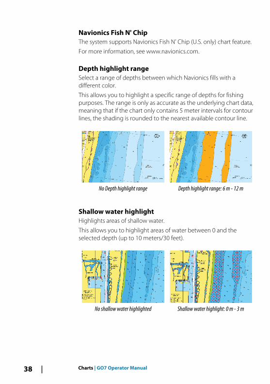
Depth highlight rangeSelect a range of depths between which Navionics fills with adifferent color.
This allows you to highlight a specific range of depths for fishingpurposes. The range is only as accurate as the underlying chart data,meaning that if the chart only contains 5 meter intervals for contourlines, the shading is rounded to the nearest available contour line.
No Depth highlight range Depth highlight range: 6 m - 12 m
Shallow water highlightHighlights areas of shallow water.
This allows you to highlight areas of water between 0 and theselected depth (up to 10 meters/30 feet).
No shallow water highlighted Shallow water highlight: 0 m - 3 m
38 Charts | GO7 Operator Manual

Jeppesen tides and currentsThe system can display Jeppesen tides and currents. With thisinformation it is possible to predict the time, level, direction andstrength of currents and tides. This is an important tool whenconsidering planning and navigation of a trip.
In large zoom ranges the tides and currents are displayed as asquare icon including the letter T (Tides) or C (Current). When youselect one of the icons, tidal or current information for that locationare displayed.
Dynamic current data can be viewed by zooming inside a 1-nauticalmile zoom range. At that range, the Current icon changes to ananimated dynamic icon that shows the speed and direction of thecurrent. Dynamic icons are colored in black (greater than 6 knots),red (greater than 2 knots and less than or equal to 6 knots), yellow(greater than 1 knot and less than or equal to 2 knots) or green(equal to or less than 1 knot), depending on the current in thatlocation.
If there is no current (0 knots) this will be shown as a white, squareicon.
Static Current and Tide icons Dynamic Current icons
Charts | GO7 Operator Manual 39
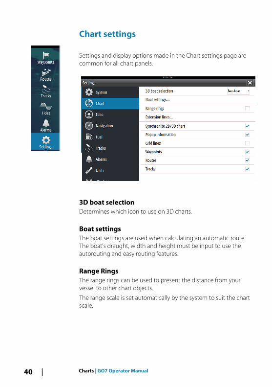
Chart settings
Settings and display options made in the Chart settings page arecommon for all chart panels.
3D boat selectionDetermines which icon to use on 3D charts.
Boat settingsThe boat settings are used when calculating an automatic route.The boat's draught, width and height must be input to use theautorouting and easy routing features.
Range RingsThe range rings can be used to present the distance from yourvessel to other chart objects.
The range scale is set automatically by the system to suit the chartscale.
40 Charts | GO7 Operator Manual
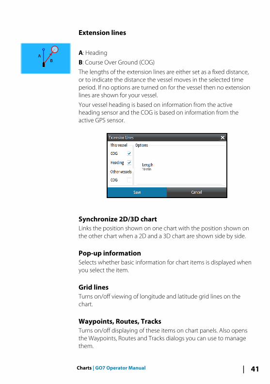
Extension lines
A: Heading
B: Course Over Ground (COG)
The lengths of the extension lines are either set as a fixed distance,or to indicate the distance the vessel moves in the selected timeperiod. If no options are turned on for the vessel then no extensionlines are shown for your vessel.
Your vessel heading is based on information from the activeheading sensor and the COG is based on information from theactive GPS sensor.
Synchronize 2D/3D chartLinks the position shown on one chart with the position shown onthe other chart when a 2D and a 3D chart are shown side by side.
Pop-up informationSelects whether basic information for chart items is displayed whenyou select the item.
Grid linesTurns on/off viewing of longitude and latitude grid lines on thechart.
Waypoints, Routes, TracksTurns on/off displaying of these items on chart panels. Also opensthe Waypoints, Routes and Tracks dialogs you can use to managethem.
Charts | GO7 Operator Manual 41

Waypoints, Routes, and Tracks
WaypointsA waypoint is a user generated mark positioned on a chart, or onthe Echosounder image. Each waypoint has an exact position withlatitude and longitude coordinates. A waypoint positioned on theEchosounder image has a depth value, in addition to positioninformation. A waypoint is used to mark a position you later maywant to return to. Two or more waypoints can also be combined tocreate a route.
Saving waypointsYou can save a waypoint at a selected location by positioning thecursor on the panel, and then selecting the new waypoint option inthe menu.
In the Chart and Nav panels, you can save a waypoint at the vesselposition, when the cursor is not active, by selecting the newwaypoint option in the menu.
Moving a waypoint
1. Select the waypoint you want to move- The waypoint icon expands to indicate that it is active
2. Activate the menu and select the waypoint in the menu3. Select the move option4. Select the new waypoint position5. Select Finish in the menu
The waypoint is now automatically saved at the new position.
5
42 Waypoints | GO7 Operator Manual

Edit a waypointYou can edit all information about a waypoint from the EditWaypoint dialog.
This dialog is activated by selecting the waypoint's pop-up, or fromthe menu when the waypoint is activated.
The dialog can also be accessed from the Waypoints tool on theHome page.
Delete a waypointYou can delete a waypoint from the Edit Waypoint dialog or byselecting the Delete menu option when the waypoint is activated.
You can also delete waypoints from the Waypoints tool on theHome page.
You can delete MOB waypoints the same way.
Waypoint alarm settingsYou can set an alarm radius for each individual waypoint you create.The alarm is set in the Edit Waypoint dialog.
Ú Note: The waypoint radius alarm must be toggled ON inthe alarm dialog to activate an alarm when your vesselcomes within the defined radius. For more information,refer to "Alarms dialog" on page 104.
Waypoints | GO7 Operator Manual 43
Routes
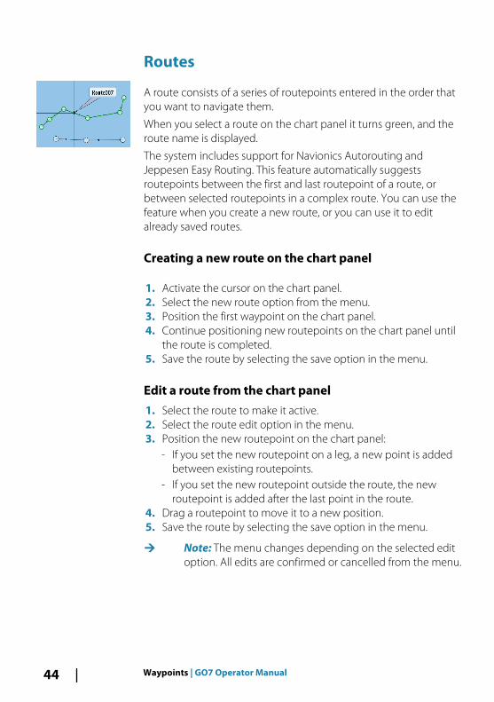
A route consists of a series of routepoints entered in the order thatyou want to navigate them.
When you select a route on the chart panel it turns green, and theroute name is displayed.
The system includes support for Navionics Autorouting andJeppesen Easy Routing. This feature automatically suggestsroutepoints between the first and last routepoint of a route, orbetween selected routepoints in a complex route. You can use thefeature when you create a new route, or you can use it to editalready saved routes.
Creating a new route on the chart panel
1. Activate the cursor on the chart panel.2. Select the new route option from the menu.3. Position the first waypoint on the chart panel.4. Continue positioning new routepoints on the chart panel until
the route is completed.5. Save the route by selecting the save option in the menu.
Edit a route from the chart panel1. Select the route to make it active.2. Select the route edit option in the menu.3. Position the new routepoint on the chart panel:
- If you set the new routepoint on a leg, a new point is addedbetween existing routepoints.
- If you set the new routepoint outside the route, the newroutepoint is added after the last point in the route.
4. Drag a routepoint to move it to a new position.5. Save the route by selecting the save option in the menu.
Ú Note: The menu changes depending on the selected editoption. All edits are confirmed or cancelled from the menu.
44 Waypoints | GO7 Operator Manual
Delete a routeYou can delete a route by selecting the Delete menu option whenthe route is activated. You can also delete routes from the Routestool on the Home page.
Autorouting and Easy RoutingThe Autorouting and Easy Routing suggest new routepointpositions based on information in the map and on your boat's size.Before you can start using this feature the boat draught, width andheight must be entered into the system. The boat settings dialog isautomatically displayed if the information is missing when you startthe feature.
Ú Note: GO7 units designed for sale in the U.S. region do nothave Autorouting or Easy Routing capabilities. Autoroutingor Easy Routing features are disabled on all non-U.S. unitswhen they are used in U.S. territorial waters.
Ú Note: It is not possible to start the Autorouting or EasyRouting if one of the selected routepoints is located in anunsafe area. A warning dialog is displayed, and you have tomove the relevant routepoint(s) to a safe area to proceed.
Ú Note: If no compatible cartography is available, theAutorouting or Easy Routing menu option is not available.Compatible cartography includes Jeppesen CMAP MAX-N+, Navionics+ and Navionics Platinum. For a full selection ofavailable charts please visit insightstore.navico.com, c-map.jeppesen.com or navionics.com.
1. Position at least two routepoints on a new route, or open anexisting route for editing.
2. Select Autorouting, followed by:- Entire Route if you want the system to add new routepoints
between the first and the last routepoint of the open route.- Selection if you want to manually select the routepoints that
define the limits for the autorouting, then select the relevantroutepoints. Selected routepoints are colored red. Only tworoutepoints can be selected, and the system discards anyroutepoints between your selected start and end points.
3. Select Accept to start the automatic routing.
Waypoints | GO7 Operator Manual 45
- When the automatic routing is completed the route appearsin preview mode, and the legs are color coded to indicate safeor unsafe areas. Navionics uses red (unsafe) and green (safe),while C-MAP uses red (unsafe), yellow (dangerous) and green(safe).
4. Move any routepoints if required when the route is in previewmode.
5. Select Keep to accept the routepoints positions.6. Eventually repeat step 2 (Selection) and step 3 if you want the
system to automatically position routepoints for other parts ofthe route.
7. Select Save to complete the automatic routing and save theroute.
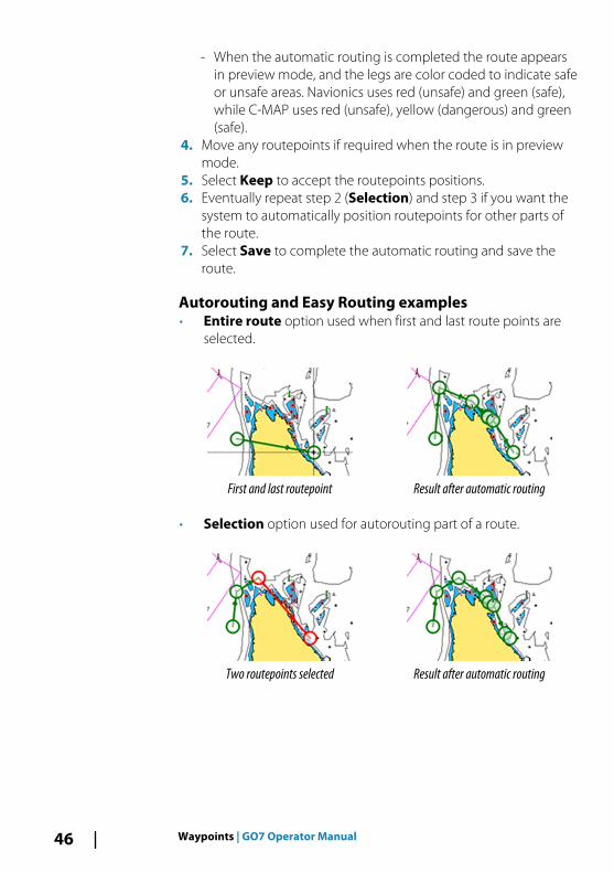
Autorouting and Easy Routing examples• Entire route option used when first and last route points are
selected.
First and last routepoint Result after automatic routing
• Selection option used for autorouting part of a route.
Two routepoints selected Result after automatic routing
46 Waypoints | GO7 Operator Manual
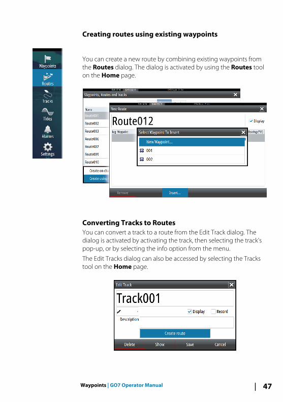
Creating routes using existing waypoints
You can create a new route by combining existing waypoints fromthe Routes dialog. The dialog is activated by using the Routes toolon the Home page.
Converting Tracks to RoutesYou can convert a track to a route from the Edit Track dialog. Thedialog is activated by activating the track, then selecting the track'spop-up, or by selecting the info option from the menu.
The Edit Tracks dialog can also be accessed by selecting the Trackstool on the Home page.
Waypoints | GO7 Operator Manual 47
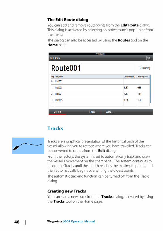
The Edit Route dialogYou can add and remove routepoints from the Edit Route dialog.This dialog is activated by selecting an active route's pop-up or fromthe menu.
The dialog can also be accessed by using the Routes tool on theHome page.
Tracks
Tracks are a graphical presentation of the historical path of thevessel, allowing you to retrace where you have travelled. Tracks canbe converted to routes from the Edit dialog.
From the factory, the system is set to automatically track and drawthe vessel's movement on the chart panel. The system continues torecord the Tracks until the length reaches the maximum points, andthen automatically begins overwriting the oldest points.
The automatic tracking function can be turned off from the Tracksdialog.
Creating new TracksYou can start a new track from the Tracks dialog, activated by usingthe Tracks tool on the Home page.
48 Waypoints | GO7 Operator Manual

Tracks settingsTracks are made up of a series of points connected by line segmentswhose length depends on the frequency of the recording.
You can select to position track points based on time settings,distance, or by letting the system position a waypoint automaticallywhen a course change is registered.
Ú Note: The Tracks option must also be turned ON in thechart settings to be visible.
Waypoints | GO7 Operator Manual 49

Waypoints, Routes, and Tracks dialogsThe Waypoints, Routes, and Tracks dialogs give access to advancededit functions and settings for these items.
The dialogs are accessed from the Tools panel on the Home page.
50 Waypoints | GO7 Operator Manual
NavigatingThe navigation function included in the system allows you tonavigate to the cursor position, to a waypoint, or along a predefinedroute.
If autopilot functionality is included in your system, the autopilotcan be set to automatically navigate the vessel.
For information about positioning waypoints and creating routes,refer to "Waypoints, Routes, and Tracks" on page 42.
Navigation panelsThe Nav panels can be used to display information when you arenavigating.
The Nav panel
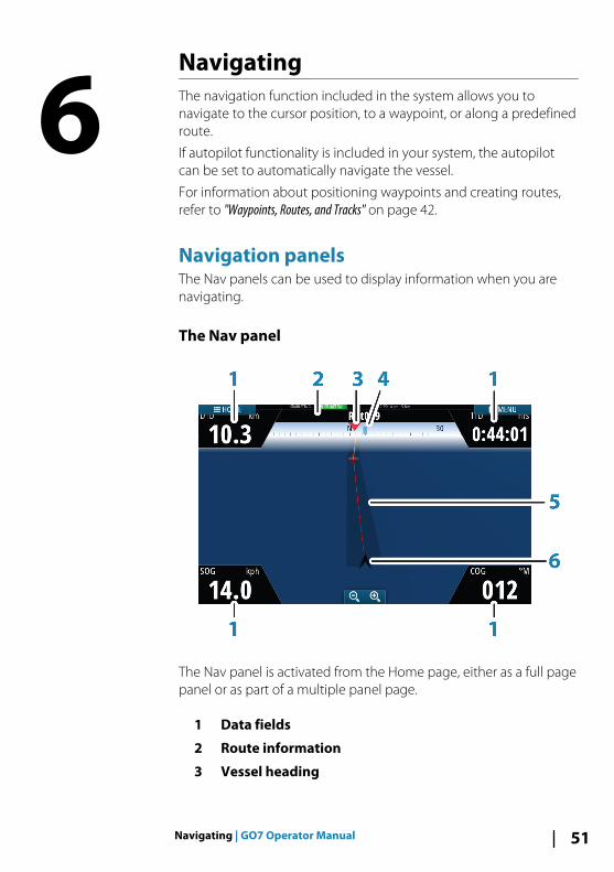
The Nav panel is activated from the Home page, either as a full pagepanel or as part of a multiple panel page.
1 Data fields
2 Route information
3 Vessel heading
6
Navigating | GO7 Operator Manual 51

4 Bearing to next routepoint
5 Bearing line with allowed off course limitWhen travelling on a route the bearing line shows theintended course from one waypoint towards the next.When navigating towards a waypoint (cursor position, MOBor an entered lat/lon position), the bearing line shows theintended course from the point at which navigation wasstarted towards the waypoint.
6 Vessel symbolIndicates distance and bearing relative to the intendedcourse.If the XTE (Cross Track Error) exceeds the defined XTE limit,this is indicated with a red arrow including the distancefrom the track line. Refer to "XTE limit" on page 55.
Data FieldsThe Nav panel offers the following information:
DTD Distance to destination
SOG Speed over ground
COG Course over ground
TTD Time to destination
Navigate to cursor positionYou can start navigating to a cursor position on any chart, orEchosounder panel.
Position the cursor at the selected destination on the panel, andthen select the Goto Cursor option in the menu.
Ú Note: The Goto Cursor menu option is not available if youare already navigating.
Navigate a routeYou can start navigating a route from the chart panel or from theRoute dialog.
52 Navigating | GO7 Operator Manual

When route navigation is started, the menu expands and showsoptions for canceling the navigation, for skipping a waypoint, andfor restarting the route from current vessel position.
Starting a route from the chart panelActivate a route on the panel, and then select the route navigationoption from the menu.
You can select a routepoint to start navigating from a selectedposition.
Start navigating a route from the Route dialog
You can start navigating from the Route dialog, activated by:
• Selecting the Route tool from the Home page• Selecting the route details from the menu
Cancel navigation
When you are navigating, the menu includes an option forcancelling the navigation.
Navigating | GO7 Operator Manual 53

Navigating with the autopilotWhen you start navigation on a system with autopilot functionality,you are prompted to set the autopilot to navigation mode.
If you choose not to engage the autopilot, the autopilot can be setto navigation mode from the Autopilot Controller later on.
For more information about autopilot functionality, refer to "Autopilot"on page 57.
Navigation settings
Navigation methodDifferent methods are available for calculating the distance andbearing between any two points on a chart.
The Great circle route is the shortest path between two points.However, if you are to travel along such a route, it would be difficultto steer manually as the heading would constantly be changing(except in the case of due north, south, or along the equator).
Rhumb lines are tracks of constant bearing. It is possible to travelbetween two locations using Rhumb line computation, but thedistance would usually be greater than if Great circle is used.
54 Navigating | GO7 Operator Manual

Arrival radiusSets an invisible circle around the destination waypoint.
The vessel is considered arrived at the waypoint when it is withinthis radius.
XTE limitThis setting defines how far the vessel can deviate from the selectedroute, if the vessel goes beyond this limit, an alarm is activated.
Arrival alarmWhen the arrival alarm is enabled, an alarm is activated when thevessel reaches the waypoint or when it is within the specified arrivalradius.
Magnetic variationMagnetic variation is the difference between true bearings andmagnetic bearings, caused by different locations of the Geographicand the Magnetic north poles. Any local anomalies such as irondeposits might also affect the magnetic bearings.
When set to Auto, the system automatically converts magneticnorth to true north. Select manual mode if you need to enter yourown local magnetic variation.
DatumMost paper charts are made in the WGS84 format, which also isused by the GO7.
If your paper charts are in a different format, you can change thedatum settings accordingly to match your paper charts.
Coordinate systemSeveral coordinate systems can be used to control the format forlatitude and longitude coordinates displayed on the chart panel.
Phantom LoranEnables use of Phantom Loran positioning system.
Navigating | GO7 Operator Manual 55

Loran settings
Defines Loran chains (GRI) and preferred station for waypoint entry,cursor position and position panel.
The graphic example shows a cursor position window with Loranposition information.
For more information refer to your Loran system documentation.
56 Navigating | GO7 Operator Manual

AutopilotIf an AC12N, AC42N or SG05 autopilot computer is connected to thesystem, autopilot functionality is available in the system.
An Autopilot is designed to maintain an accurate course in varioussea conditions with minimal helm movements.
Safe operation with the autopilot
Warning: An autopilot is a useful navigational aid,but DOES NOT replace a human navigator.
Activating the autopilot
You activate the autopilot from any panel by selecting the autopilottile in the Instrument bar, followed by selecting a mode in theAutopilot Controller.
Switching from automatic mode to manualsteeringYou switch the autopilot to STBY mode from any automaticoperation mode from the autopilot pop-up.
7
Autopilot | GO7 Operator Manual 57

Autopilot indication on the pages
1 Autopilot indication in Status bar
2 Autopilot pop-up
3 Autopilot tile in Instrument bar
Autopilot mode indication in the Status bar
The Status bar shows autopilot information as long as an autopilotcomputer is connected to the network.
Icons are included if the autopilot is passive or locked by anotherautopilot control unit.
Autopilot pop upYou control the autopilot from the autopilot pop-up.
The pop-up has a fixed position on the page, and it is available forall pages except when an Autopilot panel is active.
As long as the autopilot pop-up is active, you cannot operate thebackground panel or its menu.
You remove the pop-up from a page by selecting the X in theupper right corner. You turn it on again by selecting the autopilottile in the instrument bar.
The following pop-ups are available:
58 Autopilot | GO7 Operator Manual

• Autopilot controller, showing active mode, heading, rudderand various steering information depending on active autopilotmode. Manual adjustments to the set heading can only bemade when the port and starboard arrow indicators areilluminated red and green.
• Mode selection, includes access to turn pattern selection.• Turn pattern selection
Autopilot controller Mode selection Turn pattern selection
Autopilot tile in Instrument bar
You can select to show the autopilot tile in the Instrument bar.
If the autopilot pop-up is turned off you can turn it on by selectingthe tile in the Instrument bar.
The Autopilot panelThe autopilot panel is used to display navigation data. It can beshown as a full screen panel, or in a multi-panel page.
The number of data fields included in the autopilot panel isdependent on available panel size.
Autopilot | GO7 Operator Manual 59

Data fieldsThe following abbreviations are used in the autopilot panel:
CTS Course to steer
DTD Distance to destination
DTW Distance to next waypoint
SOG Speed over ground
COG Course over ground
XTE Cross track error (L: left or R: right)
Mode overviewThe autopilot has several steering modes. The number of modesand features within the mode depend on boat type and availableinputs, as shown in the following list:
• StandbyStandby mode used when manually steering at the helm.Compass and rudder angle is shown on the display.
• NFUNon-Follow Up steering where the rudder movement iscontrolled by using the Port and Starboard keys in the Pilotpop-up, or by another NFU unit.
• FUFollow-up steering where the rudder angle is set by another FUunit.
• AUTOAutomatic steering where the set heading is maintained.
• Heading captureAborts the turn and uses the instantaneous compassreading as set heading.
• Turn patternsMoves the vessel automatically in pre-defined turn steeringpatterns.
• TackingOnly available if the boat type is set to Sail in the AutopilotCommissioning dialog. Tacking with a fixed angle.
• NoDrift
60 Autopilot | GO7 Operator Manual

Automatic steering, keeping the vessel on a straight bearingline by compensating for drift.
• DodgingReturns to NoDrift mode after a heading change.
• NAVNavigation steering. Steers the vessel to a specific waypoint orthrough a route.
• WINDOnly available if the boat type is set to Sail in the AutopilotCommissioning dialog. Automatic steering where the vesselheading is changed to maintain a set wind angle.
• Tacking/GybingOnly available if the boat type is set to Sail in the AutopilotCommissioning dialog. Tacking/Gybing with apparent ortrue wing angle as reference.
• WIND NavAutomatic steering, using both wind and GPS data to steer thevessel to a specific waypoint or through a route.
Standby modeStandby (STBY) mode is used when you steer the boat at the helm.
Non-Follow Up (NFU, Power steering)In NFU mode you use the port and starboard arrow buttons in theautopilot pop-up to control the rudder. The rudder will move aslong as the button is pressed.
• Activate NFU mode by selecting the port or starboard arrowbutton in the pop-up when the autopilot is in STBY or FU mode.
You return to STBY mode by selecting the STBY mode button in theautopilot pop-up.
Follow-up steering (FU)Ú Note: FU mode is only available if you have an OP40 or
similar included in the system. The GO7 does not have arotary knob.
In FU mode you use the rotary knob to control the rudder angle.Press the rotary knob, then turn the knob to set the rudder angle.The rudder moves to the commanded angle and then stop.
• You select FU mode from the autopilot pop-up
Autopilot | GO7 Operator Manual 61

Ú Note: If the autopilot pop-up is closed or if an alarm dialogis activated on the unit controlling the autopilot in FUmode, the autopilot automatically changes to STBY mode.
Warning: While in FU mode you cannot take manualcontrol of the wheel.
AUTO mode (auto compass)In AUTO mode the autopilot issues rudder commands required tosteer the vessel automatically on a set heading.
• You select AUTO mode from the autopilot pop-up. When themode is activated, the autopilot selects the current boatheading as the set heading.
Changing set heading in AUTO modeYou adjust the set heading by using the Port and Starboard arrowbuttons in the autopilot pop-up, or by selecting the Heading tile inthe autopilot pop-up and then entering the desired heading value.
An immediate heading change takes place. The new heading ismaintained until a new heading is set.
Heading captureWhen the vessel is turning in AUTO mode, an instant reset of themode activates the heading capture function. This automaticallycancels the turn, and the vessel continues on the heading read fromthe compass the very moment you re-activated the mode.
Tacking in AUTO mode
Ú Note: The tack function is only available when the system isset up for boat type SAIL in the Autopilot Commissioningdialog.
Tacking should only be performed into the wind and must be triedout in calm sea conditions with light wind to find out how it workson your boat. Due to a wide range of boat characteristics (fromcruising to racing boats) the performance of the tack function mayvary from boat to boat.
62 Autopilot | GO7 Operator Manual

Tacking in AUTO mode is different from tacking in WIND mode. InAUTO mode the tack angle is fixed and as defined by the user. Formore details, see "Tacking - WIND mode" on page 66.
You initiate the tack function from AUTO mode.
When tacking direction is selected the autopilot changes thecurrent set course according to the set fixed tacking angle.
You can interrupt the tack operation as long as the tack dialog isopen by selecting the opposite tacking direction. When interruptedthe boat returns to the previous set heading.
NoDrift modeNoDrift mode combines the autopilot and the positioninginformation from the GPS.
In NoDrift mode the vessel is steered along a calculated track line ina direction set by the user. If the vessel's heading is drifting awayfrom the original heading due to current and/or wind, the vesselfollows the line with a crab angle.
1. Turn the vessel to the desired heading2. Activate the NoDrift mode. The autopilot draws an invisible
bearing line based on current heading from the boat’s position
Unlike in AUTO (compass) mode, the autopilot now uses theposition information to calculate the cross track error, andautomatically keeps your track straight.
You use the port/starboard arrow panel buttons in the autopilotpop-up to reset the bearing line while in NoDrift mode.
DodgingIf you need to avoid an obstacle when using NoDrift mode, you canset the autopilot to STBY and power steer or use the helm until theobstacle is passed.
If you return to NoDrift mode within 60 seconds you can select tocontinue on previous set bearing line.
If you do not respond, the dialog disappears and the autopilot goesto NoDrift mode with current heading as set bearing line.
Autopilot | GO7 Operator Manual 63
NAV mode
Warning: NAV mode should only be used in openwaters.
You can use the autopilot to automatically steer the boat to aspecific waypoint location, or along a pre-defined route. Theposition information from the GPS is used to change the course tosteer to keep the boat on the track line and to the destinationwaypoint.
Ú Note: To obtain satisfactory navigation steering, the GO7must have valid position input. Autosteering must betested and determined satisfactory prior to entering theNAV mode.
Start automatic navigatingWhen you start navigating a route or to a waypoint from the chartpanel, you are prompted to set the autopilot to NAV mode. If youreject this request, you can start NAV mode from the autopilotmode menu.
When NAV mode is initiated, the autopilot automatically keeps thevessel on the leg.
When the vessel reaches the arrival circle for a routepoint, theautopilot gives an audible warning and displays a dialog with thenew course information. If the required course change to the nextwaypoint is less than the Navigation change limit, the autopilotautomatically changes the course. If the required course change tonext waypoint in a route is more than the set limit, you areprompted to verify that the upcoming course change is acceptable.
Ú Note: For information about navigation settings, refer to"Navigation settings" on page 54.
Waypoint arrival circleThe Arrival radius defines the point at which a turn is initiated whenyou are navigating a route.
64 Autopilot | GO7 Operator Manual
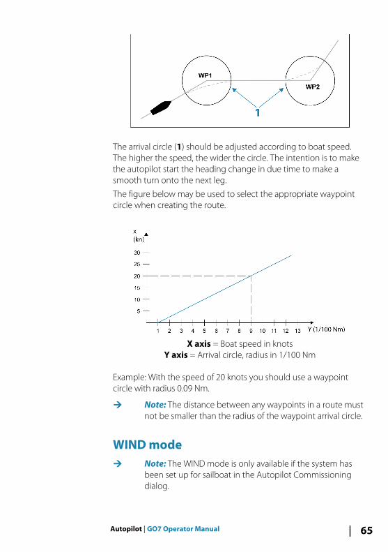
The arrival circle (1) should be adjusted according to boat speed.The higher the speed, the wider the circle. The intention is to makethe autopilot start the heading change in due time to make asmooth turn onto the next leg.
The figure below may be used to select the appropriate waypointcircle when creating the route.
X axis = Boat speed in knotsY axis = Arrival circle, radius in 1/100 Nm
Example: With the speed of 20 knots you should use a waypointcircle with radius 0.09 Nm.
Ú Note: The distance between any waypoints in a route mustnot be smaller than the radius of the waypoint arrival circle.
WIND modeÚ Note: The WIND mode is only available if the system has
been set up for sailboat in the Autopilot Commissioningdialog.
Autopilot | GO7 Operator Manual 65

Before the WIND mode is started it must be verified that valid inputfrom wind transducer is available.
Initiate wind steering as follows;
1. Switch the Autopilot to AUTO mode2. Adjust the boat heading until wind angle is according to the
angle you want to maintain3. Select the mode indication in the autopilot controller to activate
the autopilot menu, and select WIND mode
The set course to steer (CTS) and set wind angle are entered fromthe compass heading and the wind transducer at the moment theWIND mode is selected. From that point the autopilot changes thecourse to maintain the wind angle as the wind direction maychange.
Tacking in WIND mode
Ú Note: The tack function is only available when the system isset up for boat type SAIL in the Autopilot Commissioningdialog.
Tacking should only be performed into the wind and must be triedout in calm sea conditions with light wind to find out how it workson your boat. Due to a wide range of boat characteristics (fromcruising to racing boats) the performance of the tack function mayvary from boat to boat.
Tacking in WIND mode as compared to AUTO mode is performedwhen sailing with apparent or true wind as the reference. The truewind angle should be less than 90 degrees.
The rate of turn during the tack will be given by the Tack timedefined in the sailing parameter setup. The tack time is alsocontrolled by the speed of the boat to prevent loss of speed duringa tack.
You can initiate the tack function from WIND mode.
When you initiate the tacking, the autopilot immediately mirrors theset wind angle to the opposite side of the bow.
You can interrupt the tack operation as long as the tack dialog isopen by selecting the opposite tacking direction. When interrupted,the boat returns to the previous set heading.
66 Autopilot | GO7 Operator Manual

GybingGybing is possible when the true wind angle is larger than 120°.
The time to make a gybe is determined by the speed of the boat tomake it as quick as possible within control.
Tack and gybe preventYou should use the autopilot with care when beating and running.
If the sails are unbalanced when beating, yaw forces from the sailscan drive the boat into the wind. If the boat is driven beyond the setminimum wind angle, the thrust from the sails suddenly disappearsand reduces the boat speed. The boat becomes more difficult tosteer as the rudder becomes less effective.
The tack prevent function in WIND mode has been implemented toavoid such situations. It reacts immediately when the apparent windangle becomes 5° less than the set minimum wind angle, and morerudder is commanded.
When running, it is difficult to steer the boat with waves comingsideways or from behind. The waves can yaw the boat into anunwanted gybe; this can be hazardous for both the crew and themast.
The gybe prevent function is activated when the actual apparentwind angle becomes greater than 175° or gets opposite to the setwind angle. More rudder is commanded to prevent an unwantedgybe.
The tack and gybe prevent functions are not a guarantee againstgetting into a hazardous situation. If the effect of the rudder and/ordrive unit is not adequate, a dangerous situation may occur. Payparticular attention in such situations.
WIND Nav modeIn WIND Nav mode the autopilot steers the boat given both windand position data.
In this mode the autopilot calculates the initial course changeneeded to navigate towards the active waypoint, but the pilot alsoutilizes the current wind direction in the calculation.
Autopilot | GO7 Operator Manual 67

Turn pattern steering
The autopilot includes a number of automatic turn steering featuresfor power boats when the pilot is in AUTO mode.
Ú Note: The turn steering option is not be available if theboat type is set to SAIL in the Autopilot Commissioningdialog, instead the tack/gybe feature is implemented.
Initiating a turnYou start the turn by selecting the relevant turn icon, followed byselecting the port or starboard options in the turn dialog to selectthe turn direction.
Stopping the turnYou can stop the turn from within the turn dialog.
At any time during a turn you can select STBY in the autopilot pop-up to return to STBY mode and manual steering.
Turn variablesThe turn steering options, except the C-turn, have settings that youcan adjust before you start a turn and at any time when the boat isin a turn.
U-turnU-Turn changes the current set heading to be 180° in the oppositedirection.
The turn rate is identical to Rate limit settings. This cannot bechanged during the turn.
Ú Note: Refer to the separate GO7 Installation manual forinformation about Rate limit settings.
C-turnSteers the vessel in a circle.
You can adjust the Rate of turn from the turn dialog before the turnis initiated and during the turn. Increasing the turn rate makes thevessel turn a smaller circle.
68 Autopilot | GO7 Operator Manual

Spiral turnSpiral-turn makes the vessel turn in a spiral with a decreasing orincreasing radius. You set the initial radius before the turn isinitiated, and the change per turn during the turn. If the change perturn is set to zero, the vessel turns in a circle. Negative valuesindicate decreasing radius while positive values indicate increasingradius.
Zigzag turnsSteers the vessel in a zigzag pattern.
For navigating in a zigzag pattern, you set the initial headingchange before the turn is started.
During the turn you can alter the main heading, the headingchange, and the leg distance.
Square turnMakes the vessel automatically turn 90° after having travelled adefined leg distance.
At any time during the turn you can change the main heading andthe distance of the leg until the vessel makes a new 90° turn.
Lazy S-turnMakes the vessel yaw around the main heading.
You set the selected heading change before the turn is started.
During the turn you can alter the main heading, the headingchange and the turn radius from within the turn dialog.
Depth contour tracking, DCTTM
If the system has Echosounder input, the autopilot can be set tofollow a depth contour.
Warning: Do not use this feature unless the seabed issuitable. Do not use it in rocky waters where the depthis varying significantly over a small area.
Autopilot | GO7 Operator Manual 69

Use the following process to initiate DCT steering:
1. Ensure that you have depth reading on the panel or on aseparate depth instrument.
2. Steer the boat to the depth you want to track, and in thedirection of the depth contour.
3. Activate AUTO mode, select depth contour steering andmonitor the depth reading.
4. Select the port or starboard option in the turn dialog to initiatethe depth contour steering to follow the bottom sloping tostarboard or to port:
The following parameters are available for depth contour tracking:
Depth gainThis parameter determines the ratio between commanded rudderand the deviation from the selected depth contour. The higherdepth gain value the more rudder is applied.
If the value is too small, it takes a long time to compensate fordrifting off the set depth contour, and the autopilot fails to keep theboat on the selected depth.
If the value is set too high, the overshoot increases and the steeringis unstable.
Contour Cross Angle (CCA)The CCA is an angle that is added to or subtracted from the setcourse.
With this parameter you can make the boat yaw around thereference depth with lazy-s movements.
The larger the CCA, the bigger yawing is allowed. If you the CCA setto zero there are no lazy-s movements.
70 Autopilot | GO7 Operator Manual

Using the GO7 in an AP24/AP28 system
Command transfer
If your GO7 is connected to an autopilot system including an AP24or AP28 control unit, only one control unit can be active at the sametime. An inactive control unit is indicated with a square with a crosssymbol in autopilot controller pop-up.
You take command from an inactive control unit by selecting themode in the autopilot pop-up, and then confirming active mode.
Locking remote stations
The AP24/AP28 includes a Remote Lock function that disablesautopilot control from other units. A locked control unit is indicatedwith a key symbol in autopilot controller pop-up.
When the remote lock function is enabled on an AP24/AP28 controlunit, only the active control unit stays in command. No transfer ofcommand to GO7 or other autopilot control units on the systemcan take place.
You can only unlock the remote stations from the AP24/AP28 unit incommand.
Using the autopilot in an EVC system
When the GO7 is connected to an EVC system via the SG05, you cantake manual control of the steering regardless of the autopilotmode.
The mode indicator on the pilot pop-up is replaced by a dash toindicate EVC override.
The system returns to GO7 control in standby mode if no ruddercommand is given from the EVC system within a predefined period.
Autopilot | GO7 Operator Manual 71

Autopilot settings
Chart compass
You can select to show a compass symbol around your boat on thechart panel. The compass symbol is off when the cursor is active onthe panel.
Locking autopilot operation from a unitYou can lock a GO7 unit to prevent unauthorized operation of theautopilot. When the unit is locked this is indicated with a locksymbol and with text in the pop-up. No automatic modes can beselected from a locked unit.
Ú Note: The lock function is not available on a unit which hasautopilot control!
If the GO7 is part of an AP24/AP28 system, all other autopilot controlunits can be locked for autopilot control from the AP24/ AP28control unit.
Sea state filterThe Seastate filter is used to reduce rudder activity and autopilotsensitivity in rough weather. Setting options are:
72 Autopilot | GO7 Operator Manual

• OFFSeastate filter is disabled. This is the default setting.
• AUTOReduces rudder activity and autopilot sensitivity in roughweather by an adaptive process. The AUTO setting isrecommended if you want to use the seastate filter.
• MANUALLinked to the steering response control settings describedpreviously. It may be used to manually find the optimumcombination of course keeping and low rudder activity in roughbut steady sea conditions.
Sailing parameters
Ú Note: Sailing parameter settings are only available if theboat type is set to Sail in the Autopilot Commissioningdialog.
Tack timeWhen performing a tack in WIND mode, the rate of turn (tack time)can be adjusted. This gives single-handed sailors time to handle theboat and the sails during a tack.
A turn performed without shifting wind side, is also made at acontrolled turn rate.
Tack angleThis value is used to preset the course change used when tacking inAUTO mode. By pressing the port and starboard indicators in theautopilot pop-up the course changes as much as this value.
Wind functionWith wind function set to AUTO, the autopilot automatically selectsbetween apparent and true wind steering. AUTO is default andrecommended for cruising.
When the boat is running, it is also surfing on the waves. This maylead to significant changes in boat speed, and thereby also changesin apparent wind angle. True wind steering is therefore used whenrunning, while steering to apparent wind is used when beating orreaching.
Apparent wind steering is preferred when you want to achievemaximum boat speed. The autopilot tries to maintain a constantapparent wind angle to get maximum thrust from a given trim ofthe sails.
Autopilot | GO7 Operator Manual 73

When sailing in closed waters, the apparent wind angle may changetemporarily due to wind gusts. It may then be preferred to sail tothe true wind.
VMG optimizingYou can optimize the VMG to wind. When selected, the function isactive for 5–10 minutes after a new wind angle has been set andonly when beating.
Layline steeringLayline steering is useful when navigating. Cross Track Error (XTE)from the navigator keeps the boat on the track line. If the XTE fromthe navigator exceeds 0.15 NM, the autopilot calculates the laylineand track towards the waypoint.
ResponseBy default the system switches between HI/LO parameter set basedon speed (motor boats) or speed and wind (sail boats). You canhowever manually select which parameter set that shall be used.
HI or LO must be selected if no speed input is available.
You can manually fine tune each of the two (HI/LO) parameter sets.Level 4 is default with parameter values as set by the autotunefunction. If no autotune is made (not recommended) the level 4values are the factory default values.
A low response level reduces the rudder activity and provides amore “loose” steering.
A high response level increases the rudder activity and provides amore “tight” steering. A too high response level causes the boat tostart lazy-s movements.
Automatic steeringThis option displays an overview of all autopilot steeringparameters, and you can adjust parameters if required.
For more details, refer to the separate GO7 Installation manual.
InstallationUsed for autopilot installation and commissioning. See the separateGO7 Installation manual.
74 Autopilot | GO7 Operator Manual

EchosounderThe Echosounder function provides a view of the water and bottombeneath your vessel, allowing you to detect fish and examine thestructure of the sea floor.
The Echosounder image
1 Depth
2 Temperature
3 Frequency and Zoom scale
4 Bottom
5 Zoom buttons
6 Depth Range scale
7 Instrument panel
8 Zoom column
9 Fish arches
8
Echosounder | GO7 Operator Manual 75
Using the cursor on the Echosounder panelThe cursor can be used to measure a distance to a target, to mark aposition, and to select targets.
By default, the cursor is not shown on the Echosounder image.
When you position the cursor on the Echosounder image; thescreen pauses, the depth at the cursor position is shown, and theinformation window is activated.
To remove the cursor and cursor elements from the panel, selectthe Clear cursor menu option.
GoTo cursorYou can navigate to a selected position on the image by positioningthe cursor on the panel, then using the Goto Cursor option in themenu.
The Cursor assist functionThe cursor assist function allows for fine tuning and precisionplacement of the cursor without covering details with your finger.
Press and hold your finger on the screen to switch the cursorsymbol to a selection circle, appearing above your finger.
Without removing your finger from the screen, drag the selectioncircle over the desired item to display item information.
When you remove your finger from the screen the cursor reverts tonormal cursor operation.
Measuring distanceThe cursor can be used to measure the distance between theposition of two observations on the image.
It is easier to use the measuring function when the image is paused.
1. Position the cursor on the point from where you want tomeasure the distance
2. Start the measuring function from the menu3. Position the cursor on the second measuring point
- A line is drawn between the measuring points, and thedistance is listed in the Information window
4. Continue selecting new measuring points if required
76 Echosounder | GO7 Operator Manual
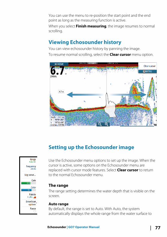
You can use the menu to re-position the start point and the endpoint as long as the measuring function is active.
When you select Finish measuring, the image resumes to normalscrolling.
Viewing Echosounder historyYou can view echosounder history by panning the image.
To resume normal scrolling, select the Clear cursor menu option.
Setting up the Echosounder image
Use the Echosounder menu options to set up the image. When thecursor is active, some options on the Echosounder menu arereplaced with cursor mode features. Select Clear cursor to returnto the normal Echosounder menu.
The rangeThe range setting determines the water depth that is visible on thescreen.
Auto rangeBy default, the range is set to Auto. With Auto, the systemautomatically displays the whole range from the water surface to
Echosounder | GO7 Operator Manual 77

the bottom. Auto is the preferred setting for most fish finding sonaruse.
Preset range levelsAllows for the selection of a specific depth range that is not tied tothe depth of the water.
Custom rangeThis option allows you to manually set both upper and lower rangelimits.
Ú Note: Setting a custom range puts the sonar in manualmode. If the bottom is well beyond the lower range set,you may lose digital depth.
Echosounder frequencyThe GO7 unit supports several transducer frequencies. Availablefrequencies depend on the transducer model that is connected.
You can view two frequencies at the same time by selecting dualEchosounder panels from the Home page.
Log sonarSelect to start and stop recording of Echosounder data. For moreinformation, refer to "Recording log data" on page 79.
GainThe gain controls the sensitivity of the Echosounder. The more youincrease the gain, the more details are shown on the image.However, a higher gain setting may introduce more backgroundclutter on the image. If the gain is set too low, weak echoes mightnot be displayed.
Auto gainThe Auto gain option keeps the sensitivity at a level that works wellunder most conditions. With the gain in auto mode, you can set apositive or negative offset that gets applied to the auto gain.
ColorStrong and weak Echosounder signals have different colors toindicate the different signal strengths. The colors used depend onwhich palette you select. The more you increase the Color setting,
78 Echosounder | GO7 Operator Manual

the more echoes is displayed in the color at the strong return end ofthe scale.
PalettesYou can select between several display palettes optimized for avariety of fishing conditions.
DownScan optionsProvides options for specifying the DownScan image. This menuoption is available when Overlay downscan is selected in Echosettings dialog. For more information see "Echosounder settings" on page81.
Pausing the EchosounderYou can pause the Echosounder, allowing you to examine theEchosounder echoes.
This function is useful when you need to position a waypointexactly on the Echosounder panel, and if you are using the cursor tomeasure a distance between 2 elements on the image.
Recording log data
You can record data and save the file internally in the unit, or save itonto a card inserted into the unit's card reader. Select the Log sonarmenu option, and then Record in the Record Echo dialog.
When the Echosounder data is being recorded, there is a flashingred symbol in the top left corner and a message appearsperiodically at the bottom of the screen.
Echosounder | GO7 Operator Manual 79

FilenameSpecify the name of the recording (log).
File formatSelect a file format from the drop-down, slg (Echosounder only), xtf(DownScan only*), or sl2 (Echosounder and DownScan).
Ú Note: XTF format is for use only with select 3rd partyEchosounder viewing tools.
Save toSelect whether the recording is to be saved internally or to amemory card in the card reader.
Time remainingShows the remaining allocated space available for recordings.
Viewing the recorded sounder dataBoth internally and externally stored sounder records may bereviewed when selected.
The log file is displayed as a paused image, and you control thescrolling and display from the replay menu option.
You can use the cursor on the replay image, and pan the image ason a normal echo image.
If more than one channel was recorded in the selected echo file,you can select which channel to display.
80 Echosounder | GO7 Operator Manual

Stop recording log data
Select the Log sonar menu option, and then Stop in the RecordingEcho dialog to stop the recording of Echosounder data.
Echosounder settings
Overlay downscanWhen a HDI transducer with DownScan is connected to yoursystem, you can overlay DownScan images on the regularEchosounder image.
When activated, the Echosounder menu expands to include basicDownScan options.
Echosounder | GO7 Operator Manual 81

View Echosounder logUsed to view Echosounder recordings. The log file is displayed as apaused image, and you control the scrolling and display from themenu.
You can use the cursor on the image, measure distance, and setview options as on a live Echosounder image. If more than onechannel was recorded in the selected Echosounder file, you canselect which channel to display.
You exit the view function by selecting the X in the upper rightcorner.
InstallationUsed for installation and setup. See the separate GO7 Installationmanual.
82 Echosounder | GO7 Operator Manual

DownScanDownScan provides detailed images of structure directly belowyour boat, down to 92 m (300 ft). The DownScan page is accessedfrom the Home page when the DownScan transducer is connected.
The DownScan image
1 Depth
2 Temperature
3 Frequency
4 Zoom buttons
5 Range scale
9
DownScan | GO7 Operator Manual 83

Zooming the DownScan imageYou can zoom a DownScan image by using the panel zoom icons.
Using the cursor on the DownScan panelBy default, the cursor is not shown on the DownScan image.
When you tap the screen the cursor appears, the informationwindow is activated, the depth is shown at the cursor position, andthe image stops scrolling.
To remove the cursor and cursor elements from the panel, selectthe Clear cursor option.
GoTo cursorYou can navigate to a selected position on the image by positioningthe cursor on the panel, then using the Goto Cursor option in themenu.
Measuring distanceThe cursor can be used to measure the distance between theposition of two observations on the image.
It is easier to use the measuring function when the image is paused.
1. Position the cursor on the point from where you want tomeasure the distance
2. Start the measuring function from the menu3. Position the cursor on the second measuring point
- A line is drawn between the measuring points, and thedistance is listed in the Information window
4. Continue selecting new measuring points if required
You can use the menu to re-position the start point and the endpoint as long as the measuring function is active.
When you select Finish measuring, the image resumes to normalscrolling.
Viewing DownScan historyYou can pan the image history by dragging the image to the leftand right.
To resume normal DownScan scrolling, select the Clear cursoroption.
84 DownScan | GO7 Operator Manual

Setting up the DownScan image
Use the DownScan menu to set up the image. When the cursor isactive, some options in the menu are replaced with cursor modefeatures. Select Clear cursor to return to the normal menu.
RangeThe range setting determines the water depth that is visible on theimage.
Auto rangeBy default, the range is set to Auto. With Auto, the systemautomatically displays the whole range from the water surface tothe bottom.
Preset range levelsAllows for the selection of a specific depth range that is not tied tothe depth of the water.
FrequencyDownScan can be used at 800 kHz or 455 kHz. 800 kHz provides thehighest resolution with less range. 455 kHz has the best range, butwith lower resolution.
ContrastThe contrast determines the brightness ratio between light anddark areas of the screen. This makes it easier to distinguish objectfrom the background.
Drag the bar up or down to get the desired contrast setting orselect Auto contrast.
PalettesYou can select between several display palettes optimized for avariety of fishing conditions.
DownScan | GO7 Operator Manual 85

Record DownScan dataYou can record DownScan data and save the file internally in theunit, or onto a memory card in the card reader slot as described in"Recording log data" on page 79.
Pausing the DownScan imageYou can pause the DownScan image, allowing you to examine thestructures and other images in more detail.
This function is useful when you need to position a waypointprecisely on the DownScan image, and if you are using the cursor tomeasure a distance between 2 elements on the image.
86 DownScan | GO7 Operator Manual

AISIf an NAIS400, an AI50 or an NMEA 2000 VHF that can do AIS(Automatic Identification System) is connected to the network, thenany targets detected by these devices can be displayed and tracked.You can also see messages and position for DSC transmittingdevices within range.
AIS targets can be displayed as overlay on chart images, making thisfeature an important tool for safe travelling and collision avoidance.You can set alarms to notify you if an AIS target gets too close or ifthe target is lost.
AIS target symbolsThe system uses the AIS target symbols shown below:
Symbol Description
Sleeping AIS target (not moving or at anchor).
Moving and safe AIS target with course extensionline.
Dangerous AIS target, illustrated with bold line.A target is defined as dangerous based on theCPA and TCPA settings. Refer to "Defining dangerousvessels" on page 94.
10
AIS | GO7 Operator Manual 87

Symbol Description
Lost AIS target.When no signals have been received within atime limit, a target is defined as lost.The target symbol represents the last validposition of the target before the reception ofdata was lost.
Selected AIS target, activated by selecting atarget symbol.The target returns to the default target symbolwhen the cursor is removed from the symbol.
Viewing information about AIS targets
Searching for AIS itemsYou can search for AIS targets by using the Find option in the Toolspanel.
From a chart panel you can search for AIS targets by using the Findoption in the menu. If the cursor is active, the system searches forvessels around the cursor position. Without an active cursor, thesystem searches for vessels around your vessel's position.
Viewing information about single AIS targets
When you select an AIS icon on the chart panel the symbol changesto Selected target symbol, and the vessel's name is displayed.
You can display detailed information for a target by selecting theAIS pop-up, or from the menu when the target is selected.
88 AIS | GO7 Operator Manual
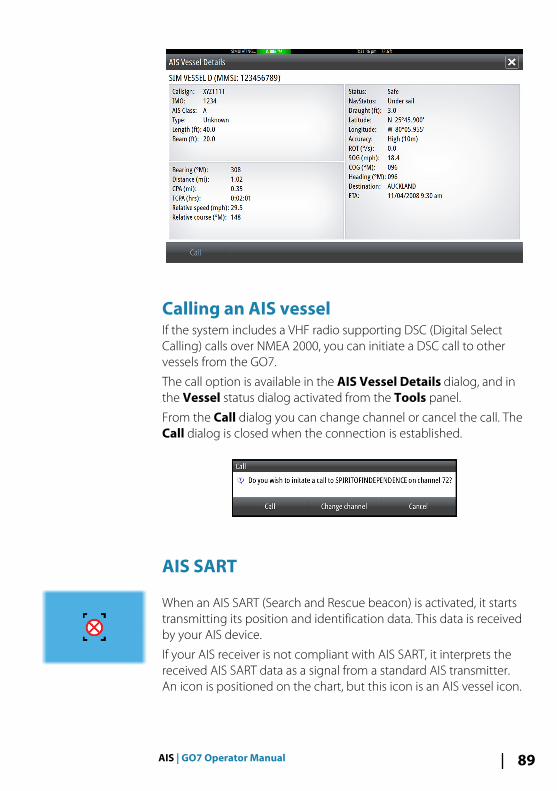
Calling an AIS vessel If the system includes a VHF radio supporting DSC (Digital SelectCalling) calls over NMEA 2000, you can initiate a DSC call to othervessels from the GO7.
The call option is available in the AIS Vessel Details dialog, and inthe Vessel status dialog activated from the Tools panel.
From the Call dialog you can change channel or cancel the call. TheCall dialog is closed when the connection is established.
AIS SART
When an AIS SART (Search and Rescue beacon) is activated, it startstransmitting its position and identification data. This data is receivedby your AIS device.
If your AIS receiver is not compliant with AIS SART, it interprets thereceived AIS SART data as a signal from a standard AIS transmitter.An icon is positioned on the chart, but this icon is an AIS vessel icon.
AIS | GO7 Operator Manual 89
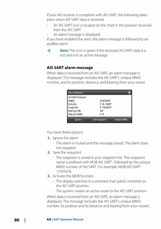
If your AIS receiver is compliant with AIS SART, the following takesplace when AIS SART data is received:
• An AIS SART icon is located on the chart in the position receivedfrom the AIS SART
• An alarm message is displayedIf you have enabled the siren, the alarm message is followed by anaudible alarm.
Ú Note: The icon is green if the received AIS SART data is atest and not an active message.
AIS SART alarm messageWhen data is received from an AIS SART, an alarm message isdisplayed. This message includes the AIS SART’s unique MMSInumber, and its position, distance, and bearing from your vessel.
You have three options:
1. Ignore the alarm- The alarm is muted and the message closed. The alarm does
not reappear2. Save the waypoint
- The waypoint is saved to your waypoint list. This waypointname is prefixed with MOB AIS SART - followed by the uniqueMMSI number of the SART. For example, MOB AIS SART -12345678.
3. Activate the MOB function- The display switches to a zoomed chart panel, centered on
the AIS SART position- The system creates an active route to the AIS SART position
When data is received from an AIS SART, an alarm message isdisplayed. This message includes the AIS SART’s unique MMSInumber, its position and its distance and bearing from your vessels.
90 AIS | GO7 Operator Manual
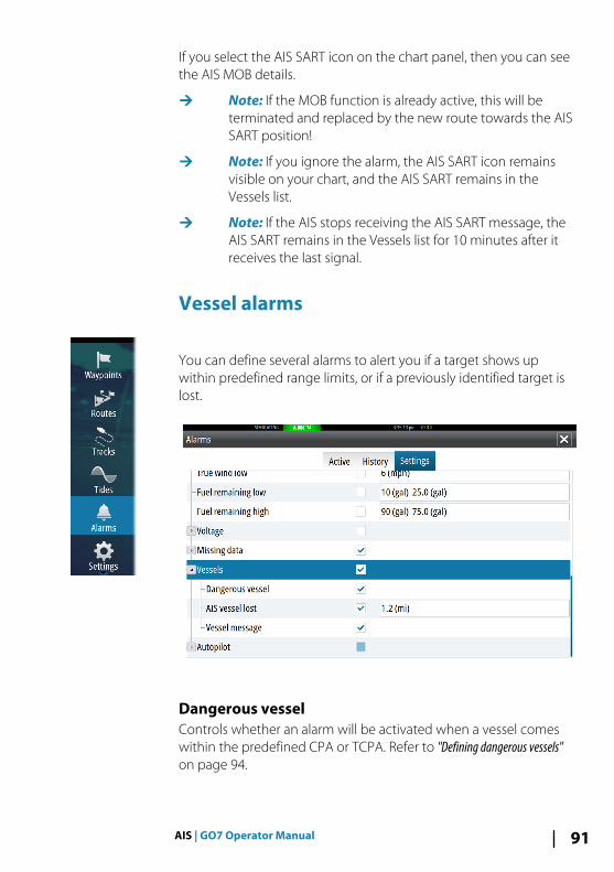
If you select the AIS SART icon on the chart panel, then you can seethe AIS MOB details.
Ú Note: If the MOB function is already active, this will beterminated and replaced by the new route towards the AISSART position!
Ú Note: If you ignore the alarm, the AIS SART icon remainsvisible on your chart, and the AIS SART remains in theVessels list.
Ú Note: If the AIS stops receiving the AIS SART message, theAIS SART remains in the Vessels list for 10 minutes after itreceives the last signal.
Vessel alarms
You can define several alarms to alert you if a target shows upwithin predefined range limits, or if a previously identified target islost.
Dangerous vesselControls whether an alarm will be activated when a vessel comeswithin the predefined CPA or TCPA. Refer to "Defining dangerous vessels"on page 94.
AIS | GO7 Operator Manual 91

AIS vessel lostSets the range for lost vessels. If a vessel is lost within the set range,an alarm occurs.
Ú Note: The check box controls whether the alarm pop-upbox is displayed and if the siren goes on. The CPA and TCPAdefine when a vessel is dangerous regardless of theenabled or disabled state.
Vessel messageControls whether an alarm will be activated when a message isreceived from an AIS target.
Vessel settings
Your vessel’s MMSI numberYou need to have your own MMSI (Maritime Mobile Service Identity)number entered in the system to receive addressed messages fromAIS and DSC vessels.
It is also important to have the MMSI number entered to avoidseeing your own vessel as an AIS target on the chart.
Ú Note: The Vessel message option in the alarm settingsmust be toggled on for any MMSI message to be displayed.
92 AIS | GO7 Operator Manual

Icon filtersBy default, all targets are shown on the panel if an AIS device isconnected to the system.
You can select not to show any targets, or to filter the icons basedon security settings, distance, and vessel speed.
Extension lines
The length of the extension lines for your vessel and for othervessels can be set by the user.
• A: Heading• B: Course Over Ground (COG)The length of the extension lines is either set as a fixed distance, orto indicate the distance the vessel will move in the selected timeperiod. If no options are turned on for This vessel then noextension lines are shown for your vessel.
Your own vessel heading information is read from the activeheading sensor, and COG information is received from the activeGPS.
AIS | GO7 Operator Manual 93

For other vessels COG data is included in the message receivedfrom the AIS system.
Defining dangerous vesselsYou can define an invisible guard zone around your vessel. When atarget comes within this distance, the symbol changes to the“dangerous” target symbol. An alarm is triggered if activated in theAlarm settings panel.
Speed and course indicationThe extension line can be used to indicate speed and course fortargets, either as absolute (true) motion in the chart or relative toyour vessel.
A different line style is used on the extension lines to indicatemotion, as shown below.
AIS vessels shown with Absolute motion AIS vessels shown with Relative motion
AIS icon orientationSets the orientation of the AIS icon, either based on heading or COGinformation.
94 AIS | GO7 Operator Manual

Instrument panelsThe Instruments panels consist of multiple gauges - analog, digitaland bar - that can be customized to display selected data. TheInstruments panel displays data on dashboards, and you can defineup to ten dashboards within the Instruments panel.
Ú Note: To include fuel/engine information, engine and tankinformation has to be configured from the Settings panel.
DashboardsA set of dashboard styles are predefined to display vessel,navigation, and angler information.
You switch between the panel’s dashboards by selecting the leftand right arrow buttons on the panel. You can also select thedashboard from the menu.
Vessel dashboard Navigation dashboard Angler dashboard
Ú Note: Additional dashboards can be activated from themenu if other systems (e.g. CZone) are present on thenetwork.
Customizing the Instruments panelYou can customize the Instruments panel by changing the data foreach of the gauges in the dashboard, by changing the dashboardlayout, and by adding new dashboards. You can also set limits foranalog gauges.
All edit options are available from the Instruments panel menu.
Available editing options depends on which data sources areconnected to your system.
11
Instrument panels | GO7 Operator Manual 95
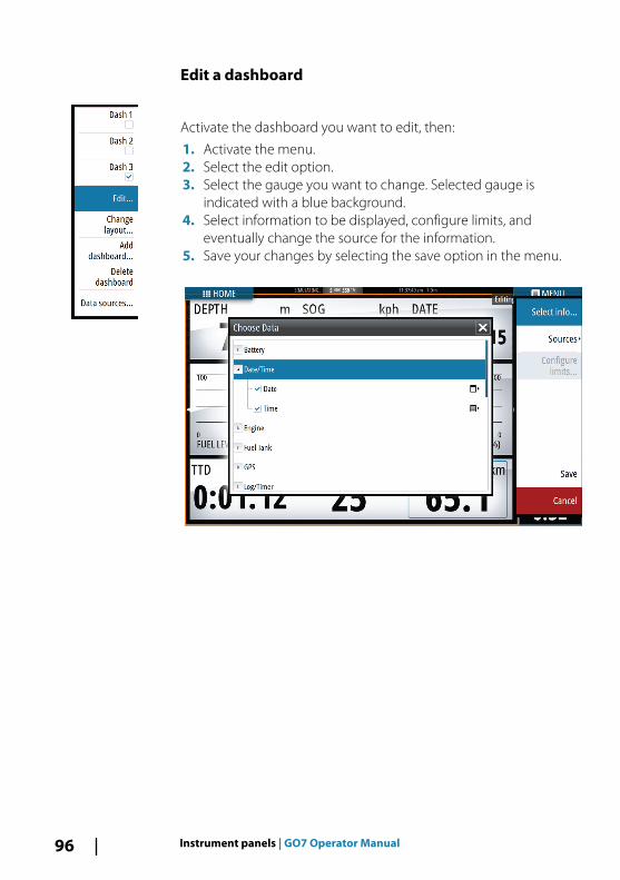
Edit a dashboard
Activate the dashboard you want to edit, then:
1. Activate the menu.2. Select the edit option.3. Select the gauge you want to change. Selected gauge is
indicated with a blue background.4. Select information to be displayed, configure limits, and
eventually change the source for the information.5. Save your changes by selecting the save option in the menu.
96 Instrument panels | GO7 Operator Manual

AudioIf a SonicHub server or a FUSION marine entertainment system isconnected to the NMEA 2000 network, you can use the GO7 tocontrol and customize the audio system on your vessel.
Before you can start using your audio equipment, it must beinstalled according to the GO7 Installation manual and to thedocumentation included with the audio device.
Enabling audioA compatible audio device connected to the NMEA 2000 networkshould automatically be identified by the system. If not, enable thefeature from the Advanced Settings dialog.
The Audio panelYou activate the audio panel by activating the audio tile in theInstrument bar.
The control buttons, tools and options vary from one audio sourceto another as described later in this chapter.
12
Audio | GO7 Operator Manual 97
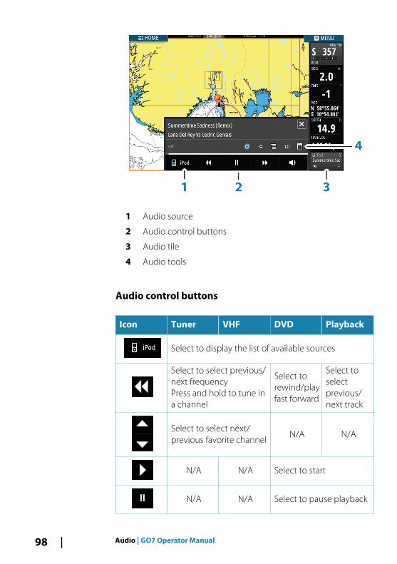
1 Audio source
2 Audio control buttons
3 Audio tile
4 Audio tools
Audio control buttons
Icon Tuner VHF DVD Playback
Select to display the list of available sources
Select to select previous/next frequencyPress and hold to tune ina channel
Select torewind/playfast forward
Select toselectprevious/next track
Select to select next/previous favorite channel
N/A N/A
N/A N/A Select to start
N/A N/A Select to pause playback
98 Audio | GO7 Operator Manual

Icon Tuner VHF DVD Playback
Select to display the volume slider
Audio tools
Icon Tuner VHF Playback
Signal strength N/A N/A
N/A N/A
Select totoggle on/offrepeatfunction. Theicon is coloredwhen thefunction isactive.
N/A N/A
Select totoggle on/offshuffle mode.The icon iscolored whenthe function isactive.
Select to display menus used for setting up zonesand master control
Select todisplay thefavoritestations for thetuner
Select todisplay the
favoritechannels for
the VHF
Select todisplay thenative menufor activesource
Select to display optional settings for activesource
Audio | GO7 Operator Manual 99

Setting up the audio system
The speakers
Speaker zonesThe GO7 can be set up to control different audio zones. The numberof zones depends on the audio server connected to your system.
You can adjust balance, volume and volume limit settingsindividually for each zone. Adjustments to the bass and tremblesettings will alter all zones.
Master volume controlBy default the volume for all speaker zones are adjusted when youadjust the volume. You can define which zones will be altered whenyou increase/decrease the volume.
Selecting tuner regionBefore playing FM or AM radio, and using a VHF radio, you mustselect the appropriate region for your location.
Detaching Sirius from the AUX sourceIf a Sirius radio is connected to the FUSION radio/server, the AUXsource is automatically attached to the Sirius feed. Sirius thenappears in the source list when the FUSION server is active.
To use the AUX source for a different device, the Sirius must bedetached from the AUX source.
Ú Note: To use SiriusXM, an optional SiriusXM tuner must beconnected to the FUSION server.
Operating the audio system1. Select the Audio tile in the Instrument bar to activate the Audio
overlay2. Select the options icon and then select the audio server3. Select the source icon and then select the audio source
- Number of sources depends on the active audio server4. Use the panel buttons to control your audio system
100 Audio | GO7 Operator Manual
For an overview of audio control buttons and tools, refer to "Audiocontrol buttons" on page 98 and "Audio Tools" on page 99.
For available options, refer to the documentation following youraudio equipment.
Favorite channelsWhen a tuner or VHF channel is tuned in, you can add the channelto your favorite list. The favorite channels can be viewed, selectedand deleted from within the Favorite list.
You page through favorite channels by using the up/down audiopanel buttons.
Sirius radio (North America only)
Channels listThe channels list displays all available Sirius channels, whether ornot you have a subscription for the channel.
Favorites listYou can create a list of your favorite Sirius channels from within thechannels list. You cannot add unsubscribed channels.
Locking channelsYou can lock selected Sirius channels from being broadcasted. A 4-digit-code must be entered to lock channels and the same codeentered to unlock the channels.
Audio | GO7 Operator Manual 101
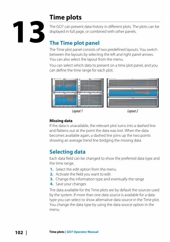
Time plotsThe GO7 can present data history in different plots. The plots can bedisplayed in full page, or combined with other panels.
The Time plot panelThe Time plot panel consists of two predefined layouts. You switchbetween the layouts by selecting the left and right panel arrows.You can also select the layout from the menu.
You can select which data to present on a time plot panel, and youcan define the time range for each plot.
Layout 1 Layout 2
Missing dataIf the data is unavailable, the relevant plot turns into a dashed lineand flattens out at the point the data was lost. When the databecomes available again, a dashed line joins up the two pointsshowing an average trend line bridging the missing data.
Selecting dataEach data field can be changed to show the preferred data type andthe time range.
1. Select the edit option from the menu2. Activate the field you want to edit3. Change the information type and eventually the range4. Save your changes
The data available for the Time plots are by default the sources usedby the system. If more than one data source is available for a datatype you can select to show alternative data source in the Time plot.You change the data type by using the data source option in themenu.
13
102 Time plots | GO7 Operator Manual

Alarms
Alarm systemThe system continuously checks for dangerous situations andsystem faults while the system is running. When an alarm situationoccurs, an alarm message pops up on the screen.
If you have enabled the siren, the alarm message is followed by anaudible alarm, and the switch for external alarm becomes active.
The alarm is recorded in the alarm listing so that you can see thedetails and take the appropriate corrective action.
Type of messagesThe messages are classified according to how the reported situationaffects your vessel. The following color codes are used:
Color Importance
Red Critical
Orange Important
Yellow Standard
Blue Warning
Green Light warning
Single alarms
A single alarm is displayed with the name of the alarm as the title,and with details for the alarm.
Multiple alarms
If more than one alarm is activated simultaneously, then the alarmmessage displays a list of up to 3 alarms. The alarms are listed in theorder they occur with the alarm activated first at the top. Theremaining alarms are available in the Alarms dialog.
14
Alarms | GO7 Operator Manual 103

Acknowledging a messageThe following options are available in the alarm dialog foracknowledging a message:
• CloseSets the alarm state to acknowledged, meaning that you areaware of the alarm condition. The siren / buzzer stops and thealarm dialog is removed.However, the alarm remains active in the alarm listing until thereason for the alarm has been removed.
• DisableDisables the current alarm setting. The alarm does not showagain unless you turn it back on in the Alarms dialog.
There is no time-out on the alarm message or siren. They remainuntil you acknowledge the alarm or until the reason for the alarm isremoved.
Alarms dialog
All alarms are setup in the Alarms Settings dialog.
The alarm dialogs can also be activated from the Tools panel. Thealarm dialogs include information about active alarms and alarmhistory.
104 Alarms | GO7 Operator Manual

Alarms | GO7 Operator Manual 105

ToolsBy default, the Tools panel includes icons used for accessing optionsand tools that are not specific to any panel.
When external equipment is integrated to the GO7, new iconsmight be added to the Tools panel. These icons are used foraccessing the external equipment's features.
Waypoints/routes/tracks
List of waypoints, routes, and tracks with details.
Select the waypoint, route, or track you wish to edit or delete.
TidesDisplays tide information for the tide station nearest to your vessel.
Select the arrow panel buttons to change the date, or select thedate field to access the calendar function.
Available tide stations can be selected from the menu.
Alarms
Active alarmsList of active alarms.
Alarm historyList of all alarms with time stamp.
Alarm settingsList of all available alarm options in the system, with currentsettings.
SettingsProvides access to application and system settings.
Vessels
Status listingList of all AIS and DSC vessels with available information.
15
106 Tools | GO7 Operator Manual

Message listingList of all messages received from other AIS vessels with time stamp.
Sun, MoonDisplays sunrise, sunset, moonrise and moonset for a position basedon entered date and the position’s latitude/longitude.
Trip calculator
Trip 1 / Trip 2Displays voyage and engine information, with reset option for alldata fields.
TodayDisplays voyage and engine information for current date. All datafields are automatically reset when the date changes.
FilesFile management system for Files, Waypoints, Routes, Tracks, andSettings.
Copying files to a card in the card readerYou can copy screen captures and logs to a card in the card reader.You can also export System Settings, Waypoints, Routes, and Tracksto a card. Exporting files is covered in the section "Maintenance" onpage 110.
FindSearch function for chart items (waypoints, routes, tracks, etc.).
Tools | GO7 Operator Manual 107

SimulatorThe simulation feature lets you see how the unit works in astationary position and without being connected to theEchosounder, GPS, etc.
Use the simulator to become familiar with your unit before using iton the water.
The status bar indicates if the simulator is toggled on.
Demo modeIn this mode the unit automatically runs through the main featuresof the product; it changes pages automatically, adjusts settings,opens menus, and so on.
If you tap on the touchscreen when demo mode is running, thedemonstration pauses. After a time-out period, demo moderesumes and any changed settings are restored to default.
Ú Note: Demo mode is designed for retail/showroomdemonstrations.
Simulator source filesYou can select which data files are used by the simulator. A set ofsource files is included in your system, and you can import files by
16
108 Simulator | GO7 Operator Manual
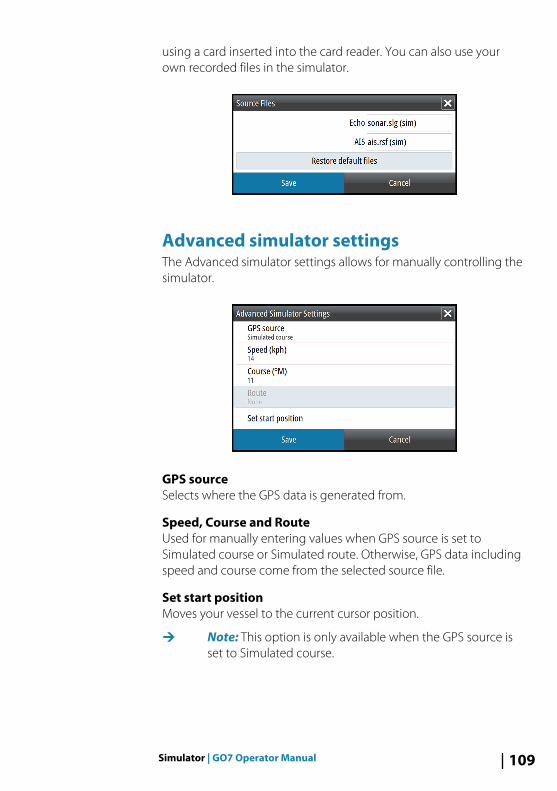
using a card inserted into the card reader. You can also use yourown recorded files in the simulator.
Advanced simulator settingsThe Advanced simulator settings allows for manually controlling thesimulator.
GPS sourceSelects where the GPS data is generated from.
Speed, Course and RouteUsed for manually entering values when GPS source is set toSimulated course or Simulated route. Otherwise, GPS data includingspeed and course come from the selected source file.
Set start positionMoves your vessel to the current cursor position.
Ú Note: This option is only available when the GPS source isset to Simulated course.
Simulator | GO7 Operator Manual 109

Maintenance
Preventive maintenanceThe GO7 does not contain any field serviceable components,therefore the operator is required to perform only a very limitedamount of preventative maintenance.
Cleaning the display unitA proper cleaning cloth should be used to clean the screen, wherepossible. Use plenty of water to dissolve and take away salt remains.Crystalized salt may scratch the coating if using a damp cloth. Applyminimal pressure to the screen.
Where marks on the screen cannot be removed by the cloth alone,use a 50/50 mixture of warm water and isopropyl alcohol to cleanthe screen. Avoid any contact with solvents (acetone, mineralturpentine, etc.), or ammonia based cleaning products, as they maydamage the anti-glare layer or plastic bezel.
To prevent UV damage to the plastic bezel, it is recommended thatthe sun cover be fitted when the unit is not in use for an extendedperiod.
Cleaning the media port doorClean the media port door regularly to avoid salt crystallization onthe surface, causing water to leak into the card slot.
Checking the connectorsThe connectors should be checked by visual inspection only.
Push the connector plugs into the connector. If the connector plugsare equipped with a lock, ensure that it is in the correct position.
Software upgradesThe latest software for the GO7 is available for download from ourwebsite, simrad-yachting.com.
Detailed instructions for how to install the software are included inthe upgrade files.
17
110 Maintenance | GO7 Operator Manual

Backing up your system dataWaypoints, Routes, and Tracks that you create are filed in yoursystem. It is recommended to regularly copy these files and yoursystem settings files as part of your back-up routine. The files can becopied to a card inserted in the card reader.
There are no export file format options for the system settings file.The following output formats are available for exporting Waypoints,Routes, and Tracks files:
• User Data File version 5This is used to import and export waypoints and routes with astandardized universally unique identifier (UUID), which is veryreliable and easy to use. The data includes such information asthe time and date when a route was created, and so on.
• User Data File version 4This is best used when transferring data from one system toanother, since it contains all the extra bits of information thesesystems store about items.
• User Data file version 3 (w/depth)Should be used when transferring user data from one system toa legacy product (Lowrance LMS, LCX, and so on.)
• User data file version 2 (no depth)Can be used when transferring user data from one system to alegacy product (Lowrance LMS, LCX, and so on.)
• GPX (GPS Exchange, no depth)This is the format most used on the web that shares amongmost GPS systems in the world. Use this format if you are takingdata to a competitors unit.
• Northstar.dat (no Tracks)Used to transfer data to a legacy Northstar device.
Maintenance | GO7 Operator Manual 111

Export all Waypoints, Routes and Tracks
Use the export option if you want to backup all Waypoints, Routes,and Tracks on your system.
Export regionThe export region option allows you to select the area from whereyou want to export data.
1. Drag the boundary box to define the desired region2. Select the export option from the menu3. Select the appropriate file format4. Select Export to start the export
Purging Waypoints, Routes and TracksDeleted Waypoints, Routes and Tracks are stored in the GO7memory until the data is purged. If you have numerous deleted,unpurged Waypoints, purging may improve the performance ofyour system.
Ú Note: When user data is purged from the memory, itcannot be recovered.
112 Maintenance | GO7 Operator Manual

Touchscreen operationBasic touchscreen operation on the different panels is shown in thetable below.
The panel sections in this manual have more information aboutpanel specific touchscreen operation.
Icon Description
Tap to:• Activate a panel on a multi-panel page• Position the cursor on a panel• Select a menu and a dialog item• Toggle a checkbox option on or off• Show basic information for a selected item
Press and hold:• On any panel with a cursor to activate the
cursor assist feature• On a panel button to see available split screen
options• On a favorite button to enter edit mode
Scroll through a list of available options withoutactivating any option.
Flick to quickly scroll through e.g. the waypoint list.Tap the screen to stop the scrolling.
Pan to position a chart or Echosounder image onthe panel.
18
T | GO7 Operator Manual 113

Icon Description
Pinch to zoom out on the chart or on an image.
Spread to zoom in on the chart or on an image.
114 T | GO7 Operator Manual

IndexA
Active panel 20Adjusting panel size 24AIS 87
Calling a vessel 89DSC 89Icon filters 93Icon orientation 94Searching for AIS items 88Target symbols 87Viewing information abouttargets 88
AIS SART 89Alarm message 90
AlarmsAcknowledging 104Alarm settings dialog 104Multiple alarms 103Single alarm 103Type of messages 103
Application pages 14Arrival alarm 55Arrival radius 55Audio 97
Control buttons 98Detaching Sirius 100Enable 97Favorite channels 101Master volume control 100Operating 100Selecting tuner region 100Setting up the system 100Sirius radio 101Speaker zones 100Speakers 100
AudioPanel 97
Audio tools 99Autopilot 57
Activating 57AP24/28 systems 71AUTO mode 62Autopilot pop-up 58Autopilot tile in Instrumentbar 59Chart compass 72Depth contour tracking 69Dodging 63EVC system 71Follow-up steering 61Gybing 67HI/LO parameters 74Indication in Status bar 58Indication on pages 58Locking remote stations 71Mode overview 60Non-Follow up mode 61Panel 59Panel data fields 60Response 74Sailing parameters 73Sea state filter 72Settings 72Standby (STBY) mode 61Switching to manualsteering 57Tacking in AUTO mode 62Tacking in WIND mode 66Turn pattern steering 68Waypoint arrival circle 64WIND mode 65WIND Nav mode 67
Autorouting 45Entire route 45, 46Example 46Selection 45, 46
Index | GO7 Operator Manual 115
B
Backing up your systemdata 111
C
CardCopying files to 107
Charts 273D charts 32Chart compass 72Chart data 28Chart detail 33Chart panel 27Chart scale 29Course up 30Creating routes 31Embedded cartography 28Find chart objects 31Insight 33
Chart categories 33Exaggeration 34Imagery style 33
JeppesenTides and currents 39
Look ahead 30Measuring distance 22Navionics 34, 35, 36
Annotation 35Chart details 35Chart shading 36Colored seabedareas 35Community edits 34Contours depth 35Depth highlightrange 38Dynamic tides andcurrents 36Easy view 37
Fish N' Chip 38Presentation type 35Rock filter 35Safety depth 35Shallow waterhighlight 38
Orientation 29Panning 29Photo overlay,Navionics 37Photo transparency,Navionics 37Positioning the vessel on thechart panel 29Selecting chart type 28Settings 40Symbol 29Using the cursor 30Vessel symbol 29Zooming 29
ChartHeading up 30North up 29
Color 78Contrast, SpotlightScan 85Converting tracks toroutes 47Coordinate system 55Copying files to a card 107Cursor 21Cursor assist 21, 76Customizing your system 24CZone 16
D
Dangerous vessels 94Dashboards 95Datum 55DCT 69Demo mode 108
116 Index | GO7 Operator Manual

Display illumination 19DownScan image 83DownScan
Pausing the image 86Range 85Record 86Using the cursor 84View history 84
E
Easy Routing 45Example 46
Echosounder 75Image 75Pausing 79Recording log data 79Using the cursor 76View history 77
Export region 112Extension lines 93
F
Favorite pages 15Adding new 25Edit 26
Files to a card, copying 107Files, management 107Find items tool 107First time startup 19Frequency 78FUSION-Link 16, 97
G
Gain 78Go to cursor 21, 76, 84GoFree wireless 17Great circle 54
H
Home page 13Home page background 24
I
Illumination 19Improving systemperformance 112Instrument bar 26
Edit the content 26Setting the appearance 26Turning on/off 26
Instrument panelsCustomizing 95Edit the dashboard 96
Integration of 3rd partydevices 16
L
Locking the touchscreen 19Log data
Recording 79Stop recording 81
Log sonar 78
M
Magnetic variation 55Man Overboard
Cancel navigation toMOB 23Creating a MOB 22Delete a MOB waypoint 23
ManualAbout 5Version 5
Manuals, viewing 6Measuring distance 22, 76,84Menus 20
Index | GO7 Operator Manual 117
Mercury VesselView 16MMSI number 92
N
Navigate 51Arrival alarm 55Arrival radius 55Cancel navigating aroute 53Datum 55Methods 54
Great circle 54Rhumb lines 54
Nav panel data fields 52Panels 51Routes 52To cursor position 52With autopilot 54
Navigation settings 54
O
OP40 17Operation
Touch 113Overlay downscan 81
P
PagesSelecting a page 20Selecting active panel 20
Palettes 79, 85Panels
Adjusting panel size 24PDF, viewing files 6Phantom Loran 55
Settings 56Preventive maintenance 110Purging 112
R
Range 77Record
DownScan data 86Recording
Log data 79Rhumb lines 54Routes 44
Autorouting 45Converting tracks toroutes 47Creating a new route on thechart panel 44Creating a route fromexisting waypoints 47Delete 45Edit in chart panel 44Edit Route dialog 48Navigate 52
RoutesDialog 50
S
Saving waypoints 42Screen capture 23Settings
Autopilot 72Tools 106
Simulator 108Demo mode 108Source files 108
Sirius radio 101Channels list 101Favorite list 101Locking channels 101
SL2 format 80SLG format 80Software upgrade 110Software version 7
118 Index | GO7 Operator Manual
SonicHub 97Speaker zones 100Speakers 100Speed and courseindication 94Split pages 15
Pre-configured 15SpotlightScan
Contrast 85Standby mode 19Stop recording log data 81System Controls dialog 18System Settings
Coordinate system 55Datum 55Magnetic variation 55
T
Time plot panel 102Missing data 102
Time plots 102Selecting data 102
Tools 106Tools
Files 107Find items 107Settings 106
TouchOperation 113
TouchscreenLocking 19
TracksCreating new 48Settings 49
Turn pattern steeringAutopilot 68
Turning the unit on andoff 18
V
Vessel alarms 91Vessel settings 92View Echosounder log 82
W
Wallpaper, customizing 24Warranty 4Waypoints 42
Alarm settings 43Delete 43Dialog 50Edit 43Moving 42Saving 42
Waypoints, routes and tracksExport 112
Wireless 17
X
XTE limit 55xtf format 80
Index | GO7 Operator Manual 119

120 Index | GO7 Operator Manual


*988
-108
53-0
01*
0980

simrad-yachting.com
ENGLISH
RS35 VHFHS35 HandsetUser Guide

Copyright © 2013 Navico
All rights reserved.
Simrad® is a registered trademark of Navico
No part of this manual may be copied, reproduced, republished, transmitted or distributed for any purpose, without prior written consent of Simrad Electronics.
Any unauthorized commercial distribution of this manual is strictly prohibited.
Simrad Electronics may find it necessary to change or end our policies, regulations, and special offers at any time. We reserve the right to do so without notice. All
features and specifications subject to change without notice. All screens in this manual are simulated.
For free owner’s manuals and the most current information on this product, its operation and accessories, visit our website: www.simrad-yachting.com
Important safety information Please read carefully before installation and use.
DANGERThis is the safety alert symbol. It is used to alert you to potential personal injury hazards, Obey all safety messages that follow this symbol to avoid possible injury or death.
WARNING WARNING indicates a potentially hazardous situation which, if not avoided, could result in death or serious injury
CAUTION CAUTION indicates a potentially hazardous situation which, if not avoided, could result in minor or moderate injury.
CAUTIONCAUTION used without the safety alert symbol indicates a potentially hazardous situation which, if not avoided, may result in property damage.

Simrad - RS35 & HS35 Operation Instructions 3
Section 1 - General information .......................................................................71-1 Features ................................................................................................................................................71-2 Customizing your Simrad VHF radio ...........................................................................................81-3 How to display and navigate menus .........................................................................................81-4 How to enter alphanumeric data .................................................................................................81-5 LCD symbols and meanings ..........................................................................................................81-6 Beep tones & call alerts ................................................................................................................. 10
Section 2 - Basic operation and key functions ...............................................11
Section 3 - Radio MENU SELECT options .........................................................173-1 Manage your waypoints list (WAYPOINT) .............................................................................. 18
3-1-1 Add a new waypoint ...................................................................................................................................183-1-2 Edit or delete a waypoint .........................................................................................................................183-1-3 Go to a new waypoint ...............................................................................................................................193-1-4 Go to nearest waypoint (NEAREST WP) ...........................................................................................193-1-5 Go to temporary waypoint .....................................................................................................................203-1-6 Edit or delete a temporary waypoint ................................................................................................203-1-7 Send waypoint data to a chartplotter ..............................................................................................21
3-2 Set the backlighting level (BACKLIGHT) ............................................................................... 213-3 Maintain your buddy list (BUDDY LIST) .................................................................................. 22
3-3-1 Add an entry ...................................................................................................................................................223-3-2 Edit or delete an entry ..............................................................................................................................23
3-4 Local or distance sensitivity (LOCAL/DIST) ........................................................................... 233-4-1 Set distance sensitivity ...............................................................................................................................233-4-2 Set local sensitivity .......................................................................................................................................24
3-5 Set the contrast level (CONTRAST) .......................................................................................... 243-6 GPS data and time (GPS/DATA) ................................................................................................. 24
3-6-1 Manually enter position and UTC time (MANUAL) ................................................................253-6-2 Local time (TIME OFFSET) ........................................................................................................................253-6-3 Time format options (TIME FORMAT) ..............................................................................................263-6-4 Time display options (TIME DISPLY) .................................................................................................263-6-5 Position display options (LL DISPLY) ................................................................................................273-6-6 Course & speed display options (COG/SOG) ..............................................................................273-6-7 GPS alert (GPS ALERT) ...............................................................................................................................28
3-7 GPS simulator (GPS SIM) .............................................................................................................. 283-8 Reset to factory defaults (RESET) ............................................................................................. 28
Section 4 - Radio setup menu (RADIO SETUP) ................................................294-1 Channel (UIC) ................................................................................................................................... 294-2 Channel names (CH NAME) ........................................................................................................ 29

Simrad - RS35 & HS35 Operation Instructions4
4-3 Ring volume (RING VOLUME) ..................................................................................................... 304-4 Key beep volume (KEY BEEP) ..................................................................................................... 304-5 Select units (UNITS) ........................................................................................................................ 314-6 Internal speaker connections (INT SPEAKER) ........................................................................ 314-7 Set the priority channel (WATCH MODE) ................................................................................ 314-8 Weather alerts (WX ALERT).......................................................................................................... 32
4-8-1 TONE ALERT ......................................................................................................................................................324-8-2 SAME ALERT......................................................................................................................................................324-8-3 Receiving a SAME ALERT ..........................................................................................................................334-8-4 Receiving SAME TEST messages ..........................................................................................................334-8-5 Enter a SAME CODE (County ID) ..........................................................................................................334-8-6 Select a working SAME code .................................................................................................................34
4-9 NMEA protocol (COM PORT) ..................................................................................................... 354-10 Select the GPS source (GPS SOURCE) .................................................................................... 354-11 Favorite channel setup - Wx key (FAV CH SETU) ................................................................ 35
Section 5 - DSC setup menu (DSC SETUP) ........................................................365-1 Enter or view your USER MMSI (USER MMSI) ........................................................................ 365-2 Maintain your groups ................................................................................................................... 37
5-2-1 Create a group (GROUP SETUP) ...........................................................................................................375-2-2 Edit or delete a group name or group MMSI (GROUP SETUP) ..........................................38
5-3 Enter or check your ATIS MMSI (ATIS MMSI) .......................................................................... 385-4 Enable ATIS functionality (ATIS SELECT) ................................................................................. 395-5 Response to individual calls (INDIV REPLY) ........................................................................... 405-6 Enable DSC functionality (DSC FUNC) ..................................................................................... 405-7 Response type to LL polling calls (LL REPLY) ........................................................................ 415-8 Automatic channel switching (AUTO SWITCH) .................................................................... 415-9 DSC Test Reply (TEST REPLY) ....................................................................................................... 425-10 Set the inactivity timer (TIMEOUT) ........................................................................................ 42
Section 6 - AIS setup menu (AIS SETUP) ...........................................................436-1 Enable AIS functionality (AIS FUNC) ......................................................................................... 436-2 AIS data display format (AIS DISPLAY) ..................................................................................... 436-3 AIS baud rate (BAUD RATE) .......................................................................................................... 436-4 GPS redirection (GPS REDIR) ....................................................................................................... 446-5 Closest point of approach alarm (CPA ALARM) .................................................................... 446-6 Closest point of approach settings (CPA) ............................................................................... 446-7 Time to closest point of approach (TCPA) .............................................................................. 44

Simrad - RS35 & HS35 Operation Instructions 5
Section 7 - Wireless handset setup menu (HS SETTING) .................................457-1 Register a wireless handset (SUBSCRIBE) ............................................................................... 457-2 Delete a registered wireless handset (REGISTERED HS) .................................................... 45
Section 8 - Sending and receiving DSC calls ...................................................468-1 What is DSC? .................................................................................................................................... 468-2 Sending DSC Calls ........................................................................................................................... 468-3 Send an individual call (INDIVIDUAL) ...................................................................................... 47
8-3-1 Call to a Buddy ................................................................................................................................................478-3-2 Call to others ....................................................................................................................................................47
8-4 Acknowledgement of an individual incoming call (INDIV) ............................................. 488-5 Reply to the Last Call (LAST CALL) ............................................................................................ 488-6 Send a group call (GROUP) ......................................................................................................... 498-7 Send an all ships call (ALL SHIPS) .............................................................................................. 498-8 Send using the call log (CALL LOG) .......................................................................................... 508-9 Send using the distress log (DIST LOG) ................................................................................... 518-10 View sent call log (SENT CALL) ................................................................................................. 528-11 Request the LL position of a Buddy (LL REQUEST) ........................................................... 528-12 Track your Buddy (TRACK BUDDY) ......................................................................................... 53
8-12-1 Start or stop tracking a Buddy (START TRACK) .........................................................................538-12-2 Select a Buddy to Track (SET BUDDY) ............................................................................................538-12-3 Add or delete a Buddy on your track list (TRACKLIST) ........................................................548-12-4 Set the track your Buddy update interval (INTERVAL) ........................................................54
8-13 Make a DSC test call (DSC TEST) .............................................................................................. 548-13-1 Send a DSC TEST call ................................................................................................................................548-13-2 Receiving an incoming DSC TEST call reply (DSC TEST ACK) ..........................................558-13-3 Acknowledging an incoming DSC TEST call .............................................................................55
8-14 View user MMSI and GPS information ................................................................................... 568-15 Receiving DSC calls ...................................................................................................................... 568-16 Receiving an all ships call (ALL SHIPS) .................................................................................. 568-17 Receiving an individual call (INDIV) ....................................................................................... 578-18 Receiving a group call (GROUP) .............................................................................................. 578-19 Receiving a geographic area call (GEOGRAPH) ................................................................. 588-20 Receiving a polled position call (POSITION) ....................................................................... 58
Section 9 - DISTRESS calls ................................................................................599-1 Sending a Distress Call ................................................................................................................. 599-2 Receiving a distress call (DISTRESS!) ......................................................................................... 60
Simrad - RS35 & HS35 Operation Instructions6
9-3 Distress acknowledgement (DISTRESS ACK) or distress relay all ships (DISTRESS REL) .............................................................................................................................................................. 619-4 Distress relay individual (INDIV DISTR RELAY) ...................................................................... 61
Section 10 - AIS functionality...........................................................................6210-1 About AIS ......................................................................................................................................... 6210-2 AIS - Static and dynamic information .................................................................................... 6210-3 Using the AIS receiver ................................................................................................................. 6310-4 AIS Information and display ..................................................................................................... 64
10-4-1 T/CPA approach screen...........................................................................................................................6510-4-2 Plotter symbols and meanings ..........................................................................................................65
Section 11 - General functionality ...................................................................6611-1 Using the Fog Horn ...................................................................................................................... 6611-2 Using the PA (Public Address) Hailer ..................................................................................... 67
Section 12 - Wireless handset functionality ...................................................6812-1 Using the wireless handset ....................................................................................................... 6812-2 Using the intercom / Conference facility ............................................................................. 6812-3 Wireless handset key functions ............................................................................................... 69
Appendix A - Technical specifications ............................................................70Simrad RS35 ...................................................................................................................................................................70RS35 NMEA 2000 PGNS .........................................................................................................................................73
Appendix B - Troubleshooting ........................................................................74
Appendix C - US & ROW VHF marine channel charts ......................................75C-1 International channel chart ........................................................................................................ 75C-2 USA channel chart .......................................................................................................................... 77C-3 CANADA channel chart ................................................................................................................ 79C-4 US & Canada WEATHER channels .............................................................................................. 81C-5 EAS (Emergency Alert Systems) alerts .................................................................................... 82
Appendix D - EU VHF marine channel charts .................................................84D-1 EU international channel chart ................................................................................................. 84D-2 Inland waterways country specific table - ATIS ON ........................................................... 86D-3 Special channels ............................................................................................................................. 89
Appendix E - MMSI and license information ...................................................90Countries of intended use in the EU: .................................................................. 90

Section 1 - General information 1-1 Features
Congratulations on your purchase of this Simrad RS35 marine band VHF radio. Your RS35 provides you with the following useful features: • Access to all currently available Marine VHF Channel Banks (USA, Canada, International)
including weather channels where available (model dependant)• DSC (Digital Select Calling) capability that meets Class D standards
• Separate CH70 DSC receiver built in• ATIS facility for inland waterways (EU models)• 10 weather channels (where available)• NOAA and SAME weather alert capability (US models)
• Dual channel AIS receiver built in - receive AIS transmissions (receive only)• Choice of High or Low (25 W or 1 W) transmission power • Special CH16 or CH16/9 key for quick access to the priority (International Distress)
channel• DISTRESS call button to automatically transmit the MMSI and position until an
acknowledgement is received• Special 3CH key for quick selection of your three favorite channels• Memory channel scan and All channel priority scan• Dual/Tri Watch capability • Call log for the 20 most recent incoming DSC calls
• Distress call log for the 20 most recent distress calls• Easy access to a buddy list of up to 20 favorite people• MMSI storage for 20 favorite groups• GROUP CALL and ALL SHIPS CALL facility
• LL position polling and Track Your Buddy feature• Automatic position and time update when connected to a GPS receiver• Adjustable keypad backlighting for easy night-time use
• Adjustable contrast settings for the LCD• Waterproof and submersible to comply with JIS-7• Rotary channel selector knob with Push To Select function • Speaker microphone with large PTT key and 6 keys for easy channel and mode selection• 30 W Hailer with listen back capability• Foghorn (manual and automatic)• Great Circle GPS navigation calculations to a waypoint (stores up to 200 waypoints)• NMEA 2000 & NMEA 0183 connectivity
• Local/Distance sensitivity to eliminate noise in high traffic urban areas
• Ability to communicate with up to two optional wireless handsets (HS35).
Simrad - RS35 & HS35 Operation Instructions 7

1-2 Customizing your Simrad VHF radio
You can customize the radio to suit your individual preferences. Some preferences can be set directly through the keys as explained in this section.
Other preferences are set up through the built-in menus and these are explained in the other sections.
1-3 How to display and navigate menus 1. Press MENU (or CALL) key.
2. Some line items may show an ▲ or ▼ indicator. This means there is more information available to show. Scroll (rotate the Rotary knob, or use + / - keys on the handset mic) to scroll up and down the menu until the cursor is positioned at the desired option. Press ENT (press the Push To Select) to display that option.
3. Make any entries or changes as explained in the following section.
4. Press ENT to confirm changes. Otherwise, press EXIT to keep the original entry.
5. Press EXIT to backup one screen (this key is equivalent to an ESC function on a PC).
1-4 How to enter alphanumeric data
If your radio does not have the optional alphanumeric microphone, you can rotate the rotary knob, or use +/- keys on the handset mic to enter alphanumeric data.
• Press - to count through numbers, or hold down to scroll rapidly to the desired number
• Press + to step through the alphabet, or hold down to scroll rapidly to the desired character
• If you make an error, press - until < is displayed, then press ENT to backup and correct the entry.
1-5 LCD symbols and meanings
A typical operational display is shown here:
The bottom line is blank when a waypoint is not selected. This operational display shows:• the channel that you are receiving (16) and Tx power is set to high (Hi)• the International channel bank selected (INT) and DSC is enabled (DSC)• the channel name tag (DISTRESS)
Simrad - RS35 & HS35 Operation Instructions8

• your current course (128°) and speed (5.0Kt)• your latitude (55°33.122N) and longitude (012°42.408E) and UTC time displayed in 24
hour format (14:43 - 2:43pm)• the name of the destination waypoint (FISH), its bearing (275°), your distance in nautical
miles, mile, or kilometres (depending on your choice of units) - in this case, 800nm, and the cross track error (XTE - 0.00) are shown.
All the symbols that may appear on the LCD are explained here:
Symbol Meaning TX Transmitting.
Receiver busy with an incoming signal.
SCAN Scanning for the broadcasting channel. Press PTT to stop scanning. When the broadcasting channel is found, scanning stops at that channel.
DW Dual watch mode.
TRI Tri watch mode.
DSC DSC function is enabled.
ATIS ATIS is enabled for use in European inland waterways. Otherwise, blank.
AIS AIS function is enabled.
Incoming DSC call, or blinks to notify you of any unread call log messages.
DISTRESS Channel name tag.
55 33.122N Your latitude.
012 42.408E Your longitude.
14:43 UTC Time (UTC). Local time has suffix LOC (for example; 12:30pm LOC).
16 Channel selected.
LOCAL Local calling is selected. Otherwise, blank for distance calling.
SKIP Channel is temporarily deleted ‘skipped’ from the SCAN operation.
A Channel suffix, if applicable - A or B - otherwise blank.
CH1 Shows which of the 3 favorite channels, if any, are selected. CH1, CH2, CH3 - otherwise blank.
Hi Transmission power. High (Hi) 25 W or Low (Lo) 1 W.
INT Selected channel bank for VHF radio operations and regulations. INT=International; USA=USA; CAN=CANADA.
Wx Weather channel.
Weather alert. US only.
SAME Specific Area Message Encoding. US only.
BUSY
Simrad - RS35 & HS35 Operation Instructions 9

D Duplex operation. Otherwise, blank for Simplex operation.
PRI Priority channel is selected.
ACK Your DSC call has been received.
Low Battery warning (activates at 10.5 V).
FISH 275 Waypoint name and bearing.
800nm Distance to waypoint.
0.00 XTE (Cross track error).
NO GPS GPS data is not available.X AUTO SWITCH is disabled.
1-6 Beep tones & call alerts• Error 2 short beeps
• Acknowledge 1 long beep
• Alarm Two-tone ring (repeated for 2 minutes or until any key is pressed)
• LL position call alert Friendly 5-tone ring sequence (press any key to cancel)
• WX alert/SAME alert Ear-catching multi-tone sequence
• ROUTINE call alert Friendly 5-tone ring sequence (press any key to cancel)
• URGENCY call alert Two-tone ring (repeated for 2 minutes or until any key is pressed)
• SAFETY call alert Two-tone ring (repeated for 2 minutes or until any key is pressed)
• DISTRESS call alert Two-tone ring (repeated for 2 minutes or until any key is pressed)
Simrad - RS35 & HS35 Operation Instructions10

Section 2 - Basic operation and key functions All possible keys and their functions are listed here. Note that some of the keys may not be available, depending on your Simrad VHF radio model.
Key: Function:
VOL / Volume and Power Turn clockwise to power on. Continue to turn until a comfortable volume is reached. VOL / will also adjust the settings of an external speaker, if connected.
SQL Squelch or Threshold Level Sets the threshold level for the minimum receiver signal. Turn fully counterclockwise until random noise is heard, then turn slowly clockwise until the random noise disappears. Make another 1/4 turn clockwise for best reception in open sea conditions. In areas of high noise (eg. close to large cities) reception may improve if sensitivity is reduced. Either turn SQL slowly clockwise or use the LOCAL setting. See section 3-4.
16 / 9 Priority channel Also on the handset mic. Press to cancel all other modes and to tune into the priority channel. Press again to return to your original channel. The default Priority Channel is CH16.
For US models: To make Channel 09 the priority channel, hold down 16/9 until a beep sounds and 09 is displayed.
DISTRESS Send a DSC Distress Call DSC must be active and an MMSI must be programmed. See Section 8. Lift the red cover door then press and release DISTRESS to show the DISTRESS menu. Select the category you want to transmit. Hold down DISTRESS for about 3 seconds to transmit. The DISTRESS key can also be held down continuously to transmit an “undefined” category Distress call.
See Section 9 for more information about distress calls.
6 key handset mic RS35 base station radio
Simrad - RS35 & HS35 Operation Instructions 11

PTT Press To Talk (Located on the handset mic). Press PTT to transmit at any time on an allowable channel. This automatically exits you from menu mode and stops scanning. You must release PTT to receive a signal.
If PTT sticks, a built-in timer will automatically shut down a transmission after five minutes and sound a short error beep.
PUSH TO SELECT Enter (ENT) When you are in MENU mode, push the center of the Channel Select knob to enter your choice or setting. This is referred to throughout the manual as “press ENT”.
Rotary knob Channel select Turn to select a channel. The current channel is shown on the LCD in BIG digits and an A or B designator suffix (if applicable) in small letters below the channel number. See Appendix C for a complete listing of channel charts.
Push to activate the ENT function.
Alphanumeric entry You can also use the rotary knob for alphanumeric entry. Turn to step through alphanumeric characters one at a time, then push to confirm each selection. If you make an error, select the < character then push to backup.
+ / - Channel select (Located on the handset mic). The current channel is shown on the screen in BIG digits with an appropriate designator suffix A or B in small letters below the channel number.
Press + or - to step through the available channels one at a time, or hold down to scroll rapidly through all the available channels. See Appendix C for a complete listing of channel charts.
Alphanumeric entry This key can be used for both menu selection and for alphanumeric entry. Press + or - to scroll the cursor up or down to menu options when navigating menus. When editing an item containing only numbers, press - to count through the numbers or hold down to scroll rapidly. To enter a character, press + to step through the alphabet or hold down to scroll rapidly.
X Exit Use EXIT (X) key when navigating menus, to clear incorrect entries, to exit from a menu without saving changes, and to back up to the previous screen.
CALL/MENU DSC CALL menu Quick press to enter the DSC CALL menu and make DSC calls. See Section 5.
Simrad - RS35 & HS35 Operation Instructions12

Radio and DSC setup MENU mode Hold down for about 1 second to show the radio MENU so that you can customize your radio. See section 4.
WX/NAV Weather channel For US models: In USA and Canadian waters, press to hear the most recently selected weather station. The WX symbol Wx is displayed on the LCD. Rotate the dial or + / - on the handset mic to change to a different weather channel. Press WX again to return to the most recent channel. If the weather alert mode (ALT) is ON and an alert tone of 1050 Hz is broadcast from the weather station, it is picked up automatically and the alarm sounds. Press any key to hear the weather alert voice message. Note: If SAME is activated and the 6 digit County IDs you want to monitor are entered, the radio will sound the weather alarm when it detects a weather alert or weather hazard alert on the selected weather channel.
For all other models: The Wx key can be programmed to a weather channel of your choice. See section 4-11 to program your favourite channel.
NAV (Show waypoint) Hold down for about 1 second to enter the Navigation mode. If a waypoint is already selected, the bearing and distance to the waypoint and the cross track error are shown on the bottom line of the LCD.
If you are in Navigation mode and want to scan all the VHF channels while staying in Navigation mode, just hold down SCAN. Press SCAN to quit scanning.
3CH Three favourite channels Also on the handset mic. Press to toggle between your favourite channels. The CH1, CH2, or CH3 symbol appears on the LCD to show which favourite channel is selected.
To scan only one of your favourite channels, press 3CH then immediately press and release SCAN. If you want to scan all three favourite channels, press 3CH then immediately press and hold SCAN.
To add a favourite channel for the first time, select that channel then hold 3CH to store it in the CH1 location. Repeat the procedure to store two more favourite channels in the CH2 and CH3 locations respectively.
If you try and add another favourite channel it will overwrite the existing CH3. CH1 and CH2 remain unless you delete them.
To delete a favourite channel, select that channel then hold down 3CH until the CH1, CH2 or CH3 symbol disappears off the LCD.
Simrad - RS35 & HS35 Operation Instructions 13

SCAN Scan (ALL SCAN & 3CH SCAN) There are two SCAN modes you can use to find the broadcast channel: • ALLSCANmodescansALLchannelsinsequence,andcheckstheprioritychannel every 2 seconds. • 3CHSCANmodescansthefavoritechannelsandCH16.
When a signal is received, scanning stops at that channel and BUSY appears on the LCD. If the signal ceases for more than 5 seconds, the scan restarts. Press SCAN or PTT to stop at the current channel. If you are in NAVIGATION mode and want to scan the DSC channels while staying in that mode, just hold down SCAN.
Note: SCAN functionality is limited in some European countries and, if ATIS mode is enabled, the 3CH SCAN mode will be disabled and an error beep will sound.
Note: The weather channel is also scanned if TONE ALERT or SAME is ON (US only).
ALL SCAN mode: Hold down SCAN for about 3 seconds to start an ALL SCAN. ALL SCAN appears on the LCD. Press ENT to temporarily skip over (lock out) an “always busy” channel when in ALL SCAN mode. SKIP is shown on the top line of the LCD to designate a skipped channel. SKIP will disappear when the radio is powered OFF/ON. With scanning OFF and the SKIP channel selected, press ENT to cancel the skipped channel.
Note: It is not possible to skip over the priority channel.
Press SCAN to stop at the current channel. Press EXIT to cancel scan mode and return to normal operation.
3CH SCAN mode With any of your three favorite channels selected (by pressing the 3CH key) hold down SCAN to start all 3CH scanning. Press SCAN again to stop at the broadcast channel, or press EXIT to quit 3CH SCAN and return automatically to the previous broadcast channel.
AIS / IC AIS (Automatic Identification System) Quick press to enter the AIS menu. See section 6 for AIS setup or Section 9 for AIS functionality.
Simrad - RS35 & HS35 Operation Instructions14

IC (FOG HORN mode) Hold down for about 1 second to enter HAILER mode. Select FOG HORN. The FOG HORN will sound certain international standard fog horn tones through the hailer speaker depending on the mode selected. See section 11 for HAILER functionality.
IC (PA HAILER mode) Hold down for about 1 second to enter HAILER mode. Select PA (Public Address). The PA allows you to make an announcement at high volume to people or vessels using the RS35 hand mic. See section 11 for HAILER functionality.
GO / MOB GO (Reset the Cross Track Error) Note: A valid GPS signal must be received to see this selection. Press GO if you are navigating to a waypoint and want to reset the cross track error. This is a very useful single keystroke feature to use if you wander a little off-course but want to continue to your active waypoint.
The bearing and distance to the waypoint and any cross track error are shown on the bottom line of the LCD.
MOB (Man Over Board) Hold down MOB until the radio automatically enters Navigation mode, saves your cur-rent latitude and longitude as the MOB waypoint and immediately sets this position as the destination waypoint.
You will see the following sequence of LCDs:
HOLD 3 SECFOR MOBRELEASE TOSAVE
HOLD 2 SECFOR MOBRELEASE TOSAVE
HOLD 1 SECFOR MOBRELEASE TOSAVE
MOB
B 010D 0.01X 0.00
The bearing and distance to the Man Overboard position, and any cross track error (XTE), are shown on the bottom line of the LCD.
To cancel MOB, select another waypoint.
Simrad - RS35 & HS35 Operation Instructions 15
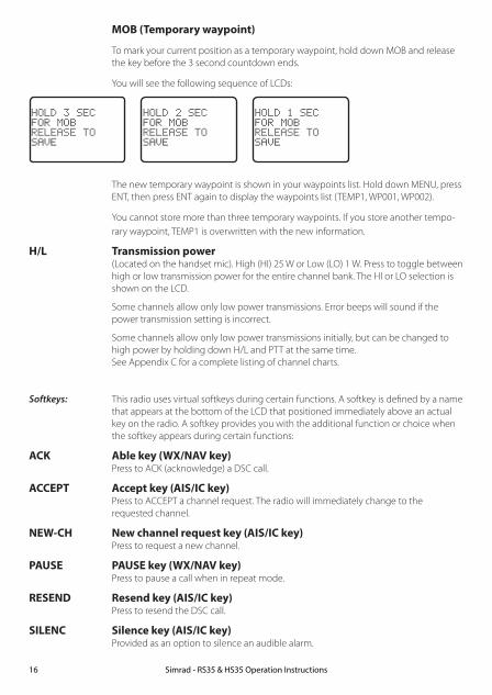
MOB (Temporary waypoint)
To mark your current position as a temporary waypoint, hold down MOB and release the key before the 3 second countdown ends.
You will see the following sequence of LCDs:
HOLD 3 SECFOR MOBRELEASE TOSAVE
HOLD 2 SECFOR MOBRELEASE TOSAVE
HOLD 1 SECFOR MOBRELEASE TOSAVE
The new temporary waypoint is shown in your waypoints list. Hold down MENU, press ENT, then press ENT again to display the waypoints list (TEMP1, WP001, WP002).
You cannot store more than three temporary waypoints. If you store another tempo-rary waypoint, TEMP1 is overwritten with the new information.
H/L Transmission power (Located on the handset mic). High (HI) 25 W or Low (LO) 1 W. Press to toggle between high or low transmission power for the entire channel bank. The HI or LO selection is shown on the LCD.
Some channels allow only low power transmissions. Error beeps will sound if the power transmission setting is incorrect.
Some channels allow only low power transmissions initially, but can be changed to high power by holding down H/L and PTT at the same time. See Appendix C for a complete listing of channel charts.
Softkeys: This radio uses virtual softkeys during certain functions. A softkey is defined by a name that appears at the bottom of the LCD that positioned immediately above an actual key on the radio. A softkey provides you with the additional function or choice when the softkey appears during certain functions:
ACK Able key (WX/NAV key) Press to ACK (acknowledge) a DSC call.
ACCEPT Accept key (AIS/IC key) Press to ACCEPT a channel request. The radio will immediately change to the requested channel.
NEW-CH New channel request key (AIS/IC key) Press to request a new channel.
PAUSE PAUSE key (WX/NAV key) Press to pause a call when in repeat mode.
RESEND Resend key (AIS/IC key) Press to resend the DSC call.
SILENC Silence key (AIS/IC key) Provided as an option to silence an audible alarm.
Simrad - RS35 & HS35 Operation Instructions16

Section 3 - Radio MENU SELECT optionsHold down CALL MENU for about 1 second to access any of the following radio MENU SELECT options.
Menu options shown inside the gray boxes are explained in this section.
Simrad - RS35 & HS35 Operation Instructions 17
WAYPOINT Section 3-1BACKLIGHT Section 3-2BUDDY LIST Section 3-3LOCAL/DIST Section 3-4CONTRAST Section 3-5GPS/DATA MANUAL Section 3-6-1
SETTING TIME OFFSET Section 3-6-2TIME FORMAT Section 3-6-3TIME DISPLY Section 3-6-4LL DISPLY Section 3-6-5COG/SOG Section 3-6-6GPS ALERT Section 3-6-7
RADIO SETUP UIC (US and AUS only) Section 4-1CH NAME Section 4-2RING VOLUME Section 4-3KEY BEEP Section 4-4UNITS Section 4-5INT SPEAKER Section 4-6WATCH MODE (US only) Section 4-7WX ALERT (US only) TONE ALERT Section 4-8-1
SAME ALERT Section 4-8-2SAME CODE Section 4-8-5
COM PORT Section 4-9GPS SOURCE Section 4-10FAV CH SETU (EU and AUS only) Section 4-11
DSC SETUP USER MMSI Section 5-1GROUP SETUP Section 5-2ATIS MMSI (EU only) Section 5-3ATIS SELECT (EU only) Section 5-4INDIV REPLY Section 5-5DSC FUNC Section 5-6LL REPLY Section 5-7AUTO SWITC Section 5-8TEST REPLY Section 5-9TIMEOUT Section 5-10
AIS SETUP AIS FUNC Section 6-1AIS DISPLAY Section 6-2BAUD RATE Section 6-3GPS REDIR Section 6-4CPA ALARM Section 6-5CPA Section 6-6TCPA Section 6-7
GPS SIM Section 3-7HS SETTING SUBSCRIBE Section 7-1
REGISTERED HS Section 7-2RESET Section 3-8
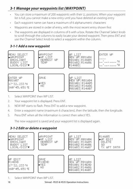
3-1 Manage your waypoints list (WAYPOINT)• You can store a maximum of 200 waypoints with their LL positions. When your waypoint
list is full, you cannot make a new entry until you have deleted an existing entry
• Each waypoint name can have a maximum of 6 alphanumeric characters
• Waypoints are stored in order of entry, with the most recent entry shown first
• The waypoints are displayed in columns of 6 with a box. Rotate the Channel Select knob to scroll through the columns to easily locate your desired waypoint. Then press ENT and use the Channel Select knob to select a waypoint within the column.
3-1-1 Add a new waypoint
MENU SELECT►WAYPOINT BACKLIGHT BUDDY LIST LOCAL/DIST▼
WAYPOINT►WP LIST NEAREST WP TEMP
WP LISTNEW WP R01W04R01W01 R14W05R01W02 R14W06R14W03
ENTER WP
. N
. W
ENTER WPR01W07
17 32.233 N
160 45.651 E
SAVE
►YES NO
WP LISTNEW WP R01W04R01W01 R14W05R01W02 R14W06R01W03 R14W07
1. Select WAYPOINT then WP LIST.
2. Your waypoint list is displayed. Press ENT.
3. NEW WP starts to flash. Press ENT to add a new waypoint.
4. Enter a waypoint name (maximum 6 characters), then the latitude, then the longitude.
5. Press ENT when all the information is correct then select YES.
The new waypoint is saved and your waypoint list is displayed again.
3-1-2 Edit or delete a waypoint
MENU SELECT►WAYPOINT BACKLIGHT BUDDY LIST LOCAL/DIST▼
WAYPOINT►WP LIST NEAREST WP TEMP
WP LISTNEW WP R01W04R01W01 R14W05R01W02 R14W06R01W03 R14W07
R14W05►WP EDIT DELETE GO TX WPT DATA
WP EDITR14END
17 32.233 N
160 45.651 E
SAVER14END►YES NO
WP LISTNEW WP R01W04R01W01 R14ENDR01W02 R14W06R01W03 R14W07
1. Select WAYPOINT then WP LIST. Simrad - RS35 & HS35 Operation Instructions18

Note: A valid GPS signal must be received to see parts of this selection.
2. Your waypoint list is displayed. Press ENT.
3. NEW WP starts to flash. Scroll down to the incorrect entry. The selected waypoint flashes. Press ENT again.
4. To delete the waypoint, select DELETE then YES. The waypoint is deleted immediately and the waypoint list is refreshed and displayed again.
5. To edit the waypoint, select WP EDIT. The cursor is at the first character of the name. Edit the waypoint name or to edit only the latitude or longitude, press ENT repeatedly until the cursor moves to the required line.
6. When you are finished, press ENT (repeatedly if necessary) until an updated page appears.
7. Press ENT to store the changes. The waypoint list is displayed again. If more changes are required, repeat steps 2 through 6. Otherwise, press EXIT to cancel any edits.
3-1-3 Go to a new waypoint
MENU SELECT►WAYPOINT BACKLIGHT BUDDY LIST LOCAL/DIST▼
WAYPOINT►WP LIST NEAREST WP TEMP
WP LISTNEW WP R01W04R01W01 R14ENDR01W02 R14W06R01W03 R14W07
R01W01 WP EDIT DELETE►GO TX WPT DATA
1. Select WAYPOINT then WP LIST.
2. Your waypoint list is displayed. Press ENT.
3. NEW WP starts to flash. Scroll down to the waypoint you want to go to. The selected waypoint flashes. Press ENT again.
4. Select GO.
5. Select Yes. The waypoint is set immediately as the destination waypoint.
Tip: If you are in the NAV big number screen, just turn the Channel Select knob to immediately access the Waypoint List. Select the new waypoint and press ENT.
3-1-4 Go to nearest waypoint (NEAREST WP)
Note: A valid GPS signal must be received to see this selection.
MENU SELECT►WAYPOINT BACKLIGHT BUDDY LIST LOCAL/DIST▼
WAYPOINT WP LIST►NEAREST WP TEMP
NEAREST WP►R01W04 001 98 R01W01 003 136
1. Select WAYPOINT then NEAREST WP.
2. Press ENT to display the nearest waypoint with distance and bearing from your current position.
Other waypoints are listed in increasing distance from your current position.
Simrad - RS35 & HS35 Operation Instructions 19

3. Press ENT to set the nearest waypoint as the active waypoint OR move the cursor to another waypoint and then press ENT.
The chosen waypoint is shown on the bottom line of the LCD.
3-1-5 Go to temporary waypoint
MENU SELECT►WAYPOINT BACKLIGHT BUDDY LIST LOCAL/DIST▼
WAYPOINT WP LIST NEAREST WP►TEMP
TEMP►TEMP1 TEMP2
TEMP1►GO TEMP EDIT DELETE
1. Select WAYPOINT then TEMP.
2. Your temporary waypoint list is displayed. There are 3 choices for quick access.
3. Select the temporary waypoint to go to. Press ENT.
4. Press ENT to set the temporary waypoint as the destination waypoint. It is immediately shown on the bottom line of the LCD.
Tip: Hold down MOB and release before the 3 second countdown completes. Your current LL position is stored in TEMP1 to TEMP3 in the waypoint list.
If the list is full, a message appears. See following section to delete a TEMP WP.
TEMP IS FULL
3-1-6 Edit or delete a temporary waypoint
MENU SELECT►WAYPOINT BACKLIGHT BUDDY LIST LOCAL/DIST▼
WAYPOINT WP LIST NEAREST WP►TEMP
TEMP2 GO TEMP EDIT►DELETE
DELETE►YES NO
WAYPOINT WP LIST NEAREST WP►TEMP
TEMP TEMP1►TEMP2
1. Select WAYPOINT then TEMP. Your temporary waypoint list is displayed.
2. Select the temporary waypoint to edit then select TEMP EDIT.
Note: To delete the temporary waypoint, select DELETE then YES. The temporary waypoint is deleted immediately and the temporary waypoint list is displayed again.
Simrad - RS35 & HS35 Operation Instructions20
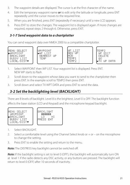
3. The waypoint details are displayed. The cursor is at the first character of the name.
4. Edit the temporary waypoint name or to edit only the latitude or longitude, press ENT repeatedly until the cursor moves to the required line.
5. When you are finished, press ENT (repeatedly if necessary) until a new LCD appears.
6. Press ENT to store the changes. The waypoint list is displayed again. If more changes are required, repeat steps 2 through 6. Otherwise, press EXIT.
3-1-7 Send waypoint data to a chartplotter
You can send waypoint data over NMEA 2000 to a compatible chartplotter.
MENU SELECT►WAYPOINT BACKLIGHT BUDDY LIST LOCAL/DIST▼
WAYPOINT►WP LIST NEAREST WP TEMP
TEMP2 WP EDIT DELETE GO►TX WP DATA
WP LISTNEW WPMOB TEMP1 TEMP2
1. Select WAYPOINT then WP LIST. Your waypoint list is displayed. Press ENT. NEW WP starts to flash.
2. Scroll down to the waypoint whose data you want to send to the chartplotter then press ENT. In the example scroll to TEMP2 then press ENT.
3. Scroll down and select TX WPT DATA and press ENT to send the data.
3-2 Set the backlighting level (BACKLIGHT)
There are 8 levels of backlight. Level 8 is the brightest, Level 0 is OFF. The backlight function
affects the base station (LCD and Keypad) and the microphone keypad backlight.
MENU SELECT WAYPOINT►BACKLIGHT BUDDY LIST LOCAL/DIST▼
BACKLIGHT LO HIPRESS ENT
1. Select BACKLIGHT.
2. Select a comfortable level using the Channel Select knob or + or – on the microphone to change the setting.
3. Press ENT to enable the setting and return to the menu.
Note: The DISTRESS key backlight cannot be switched off.
Note: If the backlight setting is set to level 0 (OFF), the backlight will automatically turn ON at level 1 if the radio detects any DSC activity, or any buttons are pressed. The backlight will return to level 0 (OFF) after 10 seconds of inactivity.
Simrad - RS35 & HS35 Operation Instructions 21
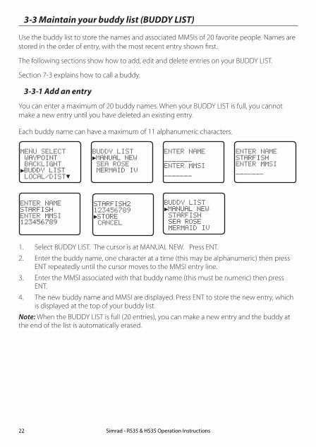
3-3 Maintain your buddy list (BUDDY LIST)
Use the buddy list to store the names and associated MMSIs of 20 favorite people. Names are stored in the order of entry, with the most recent entry shown first.
The following sections show how to add, edit and delete entries on your BUDDY LIST.
Section 7-3 explains how to call a buddy.
3-3-1 Add an entry
You can enter a maximum of 20 buddy names. When your BUDDY LIST is full, you cannot make a new entry until you have deleted an existing entry.
Each buddy name can have a maximum of 11 alphanumeric characters.
MENU SELECT WAYPOINT BACKLIGHT►BUDDY LIST LOCAL/DIST▼
BUDDY LIST►MANUAL NEW SEA ROSE MERMAID IV
ENTER NAME
ENTER MMSI
ENTER NAMESTARFISHENTER MMSI
ENTER NAMESTARFISHENTER MMSI123456789
STARFISH2123456789►STORE CANCEL
BUDDY LIST►MANUAL NEW STARFISH SEA ROSE MERMAID IV
1. Select BUDDY LIST. The cursor is at MANUAL NEW. Press ENT.
2. Enter the buddy name, one character at a time (this may be alphanumeric) then press ENT repeatedly until the cursor moves to the MMSI entry line.
3. Enter the MMSI associated with that buddy name (this must be numeric) then press ENT.
4. The new buddy name and MMSI are displayed. Press ENT to store the new entry, which is displayed at the top of your buddy list.
Note: When the BUDDY LIST is full (20 entries), you can make a new entry and the buddy at the end of the list is automatically erased.
Simrad - RS35 & HS35 Operation Instructions22
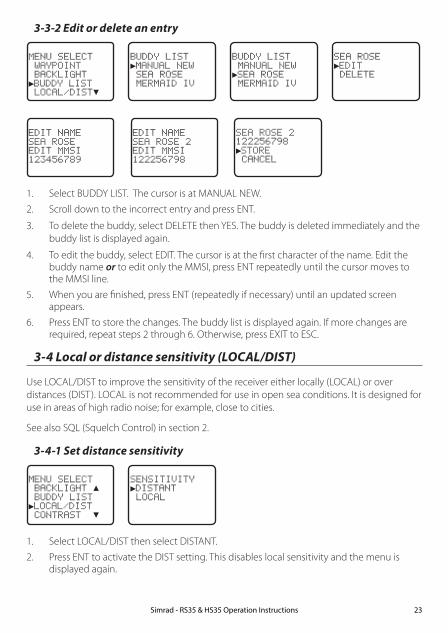
3-3-2 Edit or delete an entry
MENU SELECT WAYPOINT BACKLIGHT►BUDDY LIST LOCAL/DIST▼
BUDDY LIST►MANUAL NEW SEA ROSE MERMAID IV
BUDDY LIST MANUAL NEW►SEA ROSE MERMAID IV
SEA ROSE►EDIT DELETE
EDIT NAMESEA ROSEEDIT MMSI123456789
EDIT NAMESEA ROSE 2EDIT MMSI122256798
SEA ROSE 2122256798►STORE CANCEL
1. Select BUDDY LIST. The cursor is at MANUAL NEW.
2. Scroll down to the incorrect entry and press ENT.
3. To delete the buddy, select DELETE then YES. The buddy is deleted immediately and the buddy list is displayed again.
4. To edit the buddy, select EDIT. The cursor is at the first character of the name. Edit the buddy name or to edit only the MMSI, press ENT repeatedly until the cursor moves to the MMSI line.
5. When you are finished, press ENT (repeatedly if necessary) until an updated screen appears.
6. Press ENT to store the changes. The buddy list is displayed again. If more changes are required, repeat steps 2 through 6. Otherwise, press EXIT to ESC.
3-4 Local or distance sensitivity (LOCAL/DIST)
Use LOCAL/DIST to improve the sensitivity of the receiver either locally (LOCAL) or over distances (DIST). LOCAL is not recommended for use in open sea conditions. It is designed for use in areas of high radio noise; for example, close to cities.
See also SQL (Squelch Control) in section 2.
3-4-1 Set distance sensitivity
MENU SELECT BACKLIGHT ▲ BUDDY LIST►LOCAL/DIST CONTRAST ▼
SENSITIVITY►DISTANT LOCAL
1. Select LOCAL/DIST then select DISTANT.
2. Press ENT to activate the DIST setting. This disables local sensitivity and the menu is displayed again.
Simrad - RS35 & HS35 Operation Instructions 23
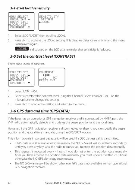
3-4-2 Set local sensitivity
MENU SELECT BACKLIGHT ▲ BUDDY LIST►LOCAL/DIST CONTRAST ▼
SENSITIVITY DISTANT►LOCAL
1. Select LOCAL/DIST then scroll to LOCAL.
2. Press ENT to activate the LOCAL setting. This disables distance sensitivity and the menu is displayed again.
LOCAL is displayed on the LCD as a reminder that sensitivity is reduced.
3-5 Set the contrast level (CONTRAST)
There are 8 levels of contrast.
MENU SELECT BUDDY LIST▲ LOCAL/DIST►CONTRAST GPS/DATA ▼
CONTRAST LO HIPRESS ENT
1. Select CONTRAST.
2. Select a comfortable contrast level using the Channel Select knob or + or – on the microphone to change the setting.
3. Press ENT to enable the setting and return to the menu.
3-6 GPS data and time (GPS/DATA)
If the boat has an operational GPS navigation receiver and is connected by NMEA port, the VHF radio automatically detects and updates the vessel position and the local time.
However, if the GPS navigation receiver is disconnected or absent, you can specify the vessel position and the local time manually, using the GPS/DATA option.
This information is important because it will be used if a DSC distress call is transmitted.
• If GPS data is NOT available for some reason, the NO GPS alert will sound for 5 seconds (or until you press any key) and the radio requests you to enter the position data manually
• This request is repeated every 4 hours if you do not enter the position data manually. After you have entered the position data manually, you must update it within 23.5 hours otherwise the NO GPS alert sequence repeats
• The NO GPS warning will be shown whenever GPS data is not available from an operational GPS navigation receiver.
Simrad - RS35 & HS35 Operation Instructions24

3-6-1 Manually enter position and UTC time (MANUAL)
Note: this function is available only if an operational GPS receiver is not connected.
MENU SELECT LOCAL/DIST CONTRAST►GPS/DATA RADIO SETU
GPS/DATA►MANUAL SETTING
MANUAL LL
. N
. WMAN --:--UTC
14:38 UTC
M17 32.233 S
160 45.651 E
1. Select GPS/DATA then MANUAL.
2. Enter the latitude, then the longitude, then the UTC.
3. Press ENT when all the information is correct.
The vessel’s latitude and longitude are shown on the screen, with the UTC time. The prefix M indicates a manual entry. The manual entries are cancelled if a real GPS position is received.
Note: a warning will be displayed after 4 hours to remind you that the current position information is manually entered.
3-6-2 Local time (TIME OFFSET)
If your position and time data are being updated through a GPS navigation receiver, you can enter the time difference between UTC and local time and display your local time on the LCD.
MENU SELECT LOCAL/DIST▲ CONTRAST►GPS/DATA RADIO SETU▼
GPS/DATA MANUAL►SETTING
SETTING►TIME OFFSET TIME FORMAT TIME DISPLY LL DISPLY ▼
TIME OFFSET +00.00
04:43 UTC
TIME OFFSET +03.00
07:43 LOC
07:50AM LOC
17 36.233 N
161 05.651 E
1. Work out the time difference between UTC and your local time (from the following graphic).
2. Select GPS/DATA then SETTING.
3. Select TIME OFFSET to enter the difference between UTC and local time. Use the Channel Select knob or + or – to change the time. Half hour increments can be used with a maximum offset of ±13 hours.
4. Press ENT when the local time is correct.
LOC is displayed after the time on the LCD as a reminder that local time is selected.
Simrad - RS35 & HS35 Operation Instructions 25

Z A B C D F G H INOPQRSTUW E
STANDARD TIME ZONESCorrected to January 2011
Zone boundaries are approximate
Daylight Saving Time (Summer Time),usually one hour in advance of Standard
Time, is kept in some places
Map outline © Mountain High MapsCompiled by HM Nautical Almanac Office
VX K L
PQ
Q
R
V
U T
S
RQ
P*
T
S
A
AZ
B
C
Z
A B
B
B
C
S
S
S
R
H I*K
K
M
M
H
H
H
I K
FG
ED*
*E*
*C
CD
GH
EF
H
IG
CE
K L
Z
ZP
N
0° 30°E 60°E 90°E 120°E 150°E30°W60°W90°W120°W150°W180° 180°
L
Z
N
O
O
Z
Z
Z
C
D
D
E
F
E*
F*
KL*
*
L
L MM
Q
O
Q
A
SU
W
V*
A
YML M Y
P
K
H
M
X X
W
W
X
M*
WM* M*
M M
L
M
M†
K
ID
F
G I
I
I
KL
L
Z
International Date L
ine
International Date L
ine
WO
RL
D M
AP O
F TIM
E Z
ON
ES
R
C
B
B
A
P
R
I
C
R
Q*
TU
Q
§
§
W
M
E†
M
K
C
G
GHII*KK*
– 7– 8– 9– 9 30–10–10 30
LL*MMM*M†
–11–11 30–12–12 45–13–14
VV*WXY
+ 9+ 9 30+10+11+12
h h h mmmmZABCC*D
0– 1– 2– 3– 3 30– 4
h m
EE*E†FF*
– 5 30– 5 45– 6 – 6 30
D* – 4 30– 5
NOPP*Q
+ 1+ 2+ 3+ 3 30+ 4
Q*RSTU
+ 4 30+ 5+ 6+ 7+ 8
Standard Time = Universal Time – value from table
h
No Standard Time legally adopted
Universal Time = Standard Time + value from table
h hm m
§
3-6-3 Time format options (TIME FORMAT)
Time can be shown in 12 or 24 hour format.
MENU SELECT LOCAL/DIST▲ CONTRAST►GPS/DATA RADIO SETU▼
GPS/DATA MANUAL►SETTING
SETTING TIME OFFSET►TIME FORMAT TIME DISPLY LL DISPLY ▼
TIME FORMAT►12 Hr 24 Hr 06:56PM LOC
1. Select GPS/DATA then SETTING.
2. Select TIME FORMAT.
3. Select 12 or 24 hr as desired. In this example, 12 hour format has been selected and so the LCD shows the AM or PM suffix.
3-6-4 Time display options (TIME DISPLY)
If your vessel position and time data are being updated through a GPS navigation receiver,
you can show or hide the time on the LCD.
Simrad - RS35 & HS35 Operation Instructions26

MENU SELECT LOCAL/DIST▲ CONTRAST►GPS/DATA RADIO SETU▼
GPS/DATA MANUAL►SETTING
SETTING TIME OFFSET TIME FORMAT►TIME DISPLY LL DISPLY ▼
TIME DISPLY►ON OFF
1. Select GPS/DATA then SETTING.
2. Select TIME DISPLY.
3. Select ON (on) or OFF (off ) as desired. In this example, OFF has been selected and the LCD no longer shows the time.
3-6-5 Position display options (LL DISPLY)
If your vessel position and time data are being updated through a GPS navigation receiver, you can show or hide your vessel position on the LCD.
MENU SELECT LOCAL/DIST▲ CONTRAST►GPS/DATA RADIO SETU▼
GPS/DATA MANUAL►SETTING
SETTING TIME FORMAT TIME DISPLY►LL DISPLY COG/SOG
LL DISPLY►ON OFF
1. Select GPS/DATA then SETTING.
2. Select LL DISPLY.
3. Select ON (on) or OFF (off ) as desired. In this example, OFF has been selected and the LCD no longer shows the vessel position.
3-6-6 Course & speed display options (COG/SOG)
If your vessel position and time data are being updated through a GPS navigation receiver, you can show or hide your course over ground (COG) and speed over ground (SOG) data on
the LCD.
MENU SELECT LOCAL/DIST▲ CONTRAST►GPS/DATA RADIO SETU▼
GPS/DATA MANUAL►SETTING
SETTING TIME DISPL▲ LL DISPLY►COG/SOG GPS ALERT
COG/SOG ON►OFF
1. Select GPS/DATA then SETTING.
2. Select COG/SOG.
3. Select ON (on) or OFF (off ) as desired. In this example, ON has been selected and so the LCD shows the bearing and speed.
Simrad - RS35 & HS35 Operation Instructions 27
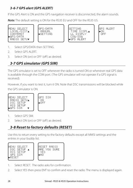
3-6-7 GPS alert (GPS ALERT)
If the GPS Alert is ON and the GPS navigation receiver is disconnected, the alarm sounds.
Note: The default setting is ON for the RS35 EU and OFF for the RS35 US.
MENU SELECT LOCAL/DIST▲ CONTRAST►GPS/DATA RADIO SETU▼
GPS/DATA MANUAL►SETTING
SETTING TIME DISPL▲ LL DISPLY COG/SOG►GPS ALERT
GPS ALERT►ON OFF
1. Select GPS/DATA then SETTING.
2. Select GPS ALERT.
3. Select ON (on) or OFF (off ) as desired.
3-7 GPS simulator (GPS SIM)
The GPS simulator is set to OFF whenever the radio is turned ON or whenever real GPS data is available through the COM port. (The GPS simulator will not operate if a GPS signal is received).
However, if you want to test it, turn it ON. Note that DSC transmissions will be blocked while
the GPS simulator is ON.
MENU SELECT RADIO SETU▲ DSC SETUP AIS SETUP►GPS SIM ▼
GPS SIM ON►OFF
1. Select GPS SIM.
2. Select ON (on) or OFF (off ) as desired.
3-8 Reset to factory defaults (RESET)
Use this to return every setting to the factory defaults except all MMSI settings and the entries in your buddy list.
MENU SELECT DSC SETUP ▲ AIS SETUP GPS SIM►RESET
RESET RADIOARE YOU SURE YES►NO
1. Select RESET. The radio asks for confirmation.
2. Select YES then press ENT to confirm and reset the radio. The menu is displayed again.
Simrad - RS35 & HS35 Operation Instructions28
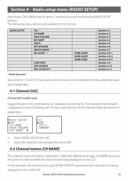
Section 4 - Radio setup menu (RADIO SETUP)Hold down CALL/MENU key for about 1 second to access the following RADIO SETUP options. The following menu options are explained in this section.
RADIO SETUP UIC * Section 4-1CH NAME Section 4-2RING VOLUME Section 4-3KEY BEEP Section 4-4UNITS Section 4-5INT SPEAKER Section 4-6WATCH MODE * Section 4-7WX ALERT * TONE ALERT Section 4-8-1
SAME ALERT Section 4-8-2SAME CODE Section 4-8-5
COM PORT Section 4-9GPS SOURCE Section 4-10FAV CH SETUP * Section 4-11
* Model dependant
See sections 1-3 and 1-4 if you want to know how to move around the menu and enter, save
and change data.
4-1 Channel (UIC)
US and AUS models only.
Toggle between USA, International, or Canadian channel banks. The selected channel bank is displayed on the LCD along with the last used channel. All the channel charts are shown in
Appendix C.
RADIO SETUP►UIC CH NAME RING VOLUME KEY BEEP ▼
UIC►USA INT L CANADA
1. Select RADIO SETUP then UIC.
2. Select the desired channel bank then press ENT.
4-2 Channel names (CH NAME)
The channel charts are listed in Appendix C with their default name tags. CH NAME gives you the option to edit or delete the channel name tags displayed on the LCD.
In this example, the channel name tag PHONE-PORTOP associated with channel 87 is being
changed to CALL PORT OP.Simrad - RS35 & HS35 Operation Instructions 29

RADIO SETUP UIC►CH NAME RING VOLUME KEY BEEP ▼
CH NAMEPHONE-PORTOP
PHONE-PORTOP►EDIT DELETE
EDIT CH NAMEPHONE-PORTOP
SAVE CH NAMECALL PORTOP►YES NO
63
1. Select RADIO SETUP then CH NAME. Use the Channel Select knob or + or - to step through the channel name tags until you see the one you want to change then press ENT.
2. To delete the channel name, select DELETE and press ENT.
3. To edit the channel name, select EDIT to edit the existing name tag.
4. Input the new name over the existing name. It can be a maximum of 12 characters.
5. Press ENT (repeatedly is necessary) to display the YES/NO confirmation.
6. Press ENT to confirm the new channel name tag (or the deletion).
7. Press EXIT to return to the CH NAME screen.
4-3 Ring volume (RING VOLUME)
The radio sounds the friendly two-tone alert when it detects an incoming DSC call. You can
change the volume level.
RADIO SETUP UIC CH NAME►RING VOLUME KEY BEEP ▼
RING VOLUME►HIGH LOW
1. Select RADIO SETUP then RING VOLUME.
2. Select HIGH (loud) or LOW (soft) then press ENT.
4-4 Key beep volume (KEY BEEP)
You can change the key beep volume or turn the key beeps off completely.
RADIO SETUP CH NAME ▲ RING VOLUME►KEY BEEP UNITS ▼
KEY BEEP HIGH►LOW OFF
Simrad - RS35 & HS35 Operation Instructions30

Simrad - RS35 & HS35 Operation Instructions 31
1. Select RADIO SETUP then KEY BEEP.
2. Select the desired setting then press ENT.
4-5 Select units (UNITS)
You can select your preferred measurement units for distance and cross track error (for
waypoint navigation).
RADIO SETUP RING VOLUM▲ KEY BEEP►UNITS INT SPEAKE▼
UNITS►METRIC NAUTICAL STATUTE
1. Select RADIO SETUP then UNITS.
2. Select your preferred measurement units then press ENT.
Note: Nautical Miles is the only unit used in AIS mode.
4-6 Internal speaker connections (INT SPEAKER)
You can switch the radio’s internal speaker ON or OFF. The external speaker is always ON if a speaker is plugged into the external speaker jack.
RADIO SETUP KEY BEEP ▲ UNITS►INT SPEAKER WATCH MODE▼
INT SPEAKER►ON OFF
1. Select RADIO SETUP then INT SPEAKER.
2. Select ON (on) or OFF (off ) then press ENT to enable the setting and return to the menu.
4-7 Set the priority channel (WATCH MODE)
US model only.
If you are operating on the USA or Canadian channel banks, you can set the priority channel
to cover both CH16 and CH09 as well as the working channel, similar to a TRI WATCH.
RADIO SETUP UNITS ▲ INT SPEAKER►WATCH MODE WX ALERT ▼
WATCH MODE►ONLY 16 16CH + 9CH
1. Select RADIO SETUP then WATCH MODE.
2. Select the desired setting then press ENT.

Simrad - RS35 & HS35 Operation Instructions32
4-8 Weather alerts (WX ALERT)
US model only.
Use WX ALERT to set your preferences for weather alert information.
The NOAA provides several weather forecast channels on USA and Canadian channel banks. If severe weather such as storms or hurricanes are forecast, the NOAA broadcasts a weather alert on 1050 Hz.
The NOAA All Hazards Weather Radio Service (NWR) works in conjunction with the Emergency Alert System (EAS) to issue weather alerts for specific geographic areas or specific weather conditions. It uses a digital encoding system known as SAME (Specific Area Message Encoding) to broadcast these alerts.
Each transmitter in the NOAA All Hazards Weather Radio Service (NWR) network is identified with a unique 6-digit SAME code. Each transmitter operates on one of 7 frequencies.
Note: To activate a SAME alert, a SAME CODE (county ID) must be selected and turned ON (see section 4-8-2).
4-8-1 TONE ALERT
If TONE ALERT is ON and an alert tone of 1050 Hz is broadcast from the NOAA weather station, the weather alert is picked up automatically and the alarm sounds. Press any key to
cancel the alarm and to hear the weather alert message.
RADIO SETUP INT SPEAKE▲ WATCH MODE►WX ALERT COM PORT ▼
►TONE ALERT SAME ALERT SAME CODE
TONE ALERT►ON OFF
1. Select RADIO SETUP then WX ALERT.
2. Select TONE ALERT.
3. Select ON to hear any weather alerts on 1050 Hz - the TONE ALERT symbol will be displayed on the LCD or, to ignore these weather alerts, select OFF.
4-8-2 SAME ALERT
Note: SAME ALERT works only after you have entered and selected a SAME code for your geographic area (see Section 4-8-5 and 4-8-6).
Note: SCAN mode will operate up to 50% more slowly when SAME ALERT is ON to allow time to decode the special warning code transmissions.

Simrad - RS35 & HS35 Operation Instructions 33
RADIO SETUP INT SPEAKE▲ WATCH MODE►WX ALERT COM PORT ▼
TONE ALERT►SAME ALERT SAME CODE
SAME ALERT ON►OFF
1. Select RADIO SETUP then WX ALERT.
2. Select SAME ALERT.
3. Select ON to receive any local NWR or EAS alerts - the SAME ALERT symbol SAME will be displayed on the LCD or, to ignore these weather alerts, select OFF.
4-8-3 Receiving a SAME ALERT
If SAME ALERT alert is ON and an NWR or EAS alert for your geographic area is broadcast by the NOAA NWR transmitters, the alert is picked up automatically and the alarm sounds. Press any key to cancel the alarm.
If the alert is being sent by NOAA NWR, the radio automatically tunes to the designated frequency so that you can listen to the alert.
If the alert is being sent by the EAS, the nature of the alert is shown on the LCD as WARNING, WATCH, ADVISORY, or TEST. Press any key to show the nature of the alert. (The list of alerts is shown in Appendix C.)
4-8-4 Receiving SAME TEST messages
In addition to the WARNING, WATCH and ADVISORY alerts, the EAS also send out TEST mes-sages so that you can check your WX ALERT setup is working correctly. The TEST message is usually transmitted between 1000 and 1200 (10.00AM and noon) every Wednesday.
Note: If there is a threat of severe weather, the test is postponed until the next good weather day.
If your WX ALERT setup is working correctly, the alert sounds and TEST is displayed on the LCD, followed by a broadcast message from the National Weather Service.
4-8-5 Enter a SAME CODE (County ID)
If you want to receive SAME weather alerts, you must enter and then Select a SAME code for your geographic area into your radio. You can enter a maximum of 4 SAME codes (4 counties) in your geographic area.
Telephone 1-888-NWR-SAME (1-888-697-7263) or visit www.nws.noaa.gov/nwr/indexnw.htm to find the SAME codes for your geographic area (you must be within the United States of America, Puerto Rico, the U.S. Virgin Islands and U.S. Pacific Territories).

Simrad - RS35 & HS35 Operation Instructions34
RADIO SETUP INT SPEAKE▲ WATCH MODE►WX ALERT COM PORT ▼
WX ALERT TONE ALERT SAME ALERT►SAME CODE
SAME CODE►NEW CODE
INPUT SAMECODE
SAME CODE012011►STORE CANCEL
SAME CODE►NEW CODE 0122003
1. Select RADIO SETUP then WX ALERT.
2. Select SAME CODE. If you have already entered any SAME codes, they are listed on the LCD.
3. Select NEW CODE. Enter the new SAME code along the dashed line, one number at a time. Press ENT to confirm each correct entry and to move to the next digit.
If you make an error, press – until < appears, then press ENT to backup and correct the entry.
4. Press ENT to store the SAME code.
5. Repeat if necessary to enter a maximum of 10 SAME codes.
4-8-6 Select a working SAME code
You must select a SAME code for your geographic working area that you have previously entered into the radio in order to receive SAME weather alerts:
RADIO SETUP INT SPEAKE▲ WATCH MODE►WX ALERT COM PORT ▼
WX ALERT TONE ALERT SAME ALERT►SAME CODE
SAME CODE NEW CODE►012203 017093
012203 EDIT DELETE CODE►SELECT CODE
SELECT CODE012203►YES NO
1. Select RADIO SETUP then WX ALERT. 2. Select SAME CODE. If you have already entered any SAME codes, they are listed on the
LCD.3. Select the SAME# for your geographic area (0122003 in the above example) and press ENT.
4. Choose SELECT CODE. Then select YES.

Simrad - RS35 & HS35 Operation Instructions 35
4-9 NMEA protocol (COM PORT)
The COM PORT must be configured correctly before use. The radio can be added to a group
of instruments using NMEA protocol.
RADIO SETUP WATCH MODE▲ WX ALERT►COM PORT GPS SOURCE▼
NMEACHECK SUM►ON OFF
1. Select RADIO SETUP then COM PORT.
2. Select the desired setting then press ENT.
CHECK SUM ON (on) is the usual setting.
The COM PORT uses 4800 baud rate and can receive the following GPS data sentences: RMC, GGA, GLL, GNS. Additionally, the radio will output the following NMEA DSC data: DSC (for DSC call), DSE (for enhanced position).
4-10 Select the GPS source (GPS SOURCE)
This radio can use either NMEA 0183 or NMEA 2000 protocol to receive GPS data from a compatible GPS unit.
Note: NMEA 2000 SOURCE options will appear (up to 4 sources showing the actual source name) only if an NMEA 2000 network is connected to the radio and is operational.
RADIO SETUP WX ALERT ▲ COM PORT►GPS SOURCE FAV CH SETU
GPS SOURCE►NMEA0183 LGC3000 LCX113CHD
1. Select RADIO SETUP then GPS SOURCE. (If there is only one NMEA protocol available on your vessel, only that will be shown).
2. Select the desired NMEA source then press ENT.
4-11 Favorite channel setup - Wx key (FAV CH SETU)
EU and AUS models only.
The Wx key can be programmed to a weather channel of your choice so that you have quick access to that channel.
1. Select RADIO SETUP then FAV CH SETU.
2. Rotate the CH knob or press UP/DOWN key to select a channel that you want to save as your WX favorite channel. Press ENT to save the selection. The WX icon Wx will indicate each time your favorite channel is selected.

Section 5 - DSC setup menu (DSC SETUP)
WARNING
A valid USER MMSI must be entered into the radio before these DSC functions can be used. See Section 5-1 for instructions on entering your USER MMSI.
Hold down CALL/MENU key for about 1 second to access the following DSC SETUP options. The following menu options are explained in this section.
DSC SETUP USER MMSI Section 5-1GROUP SETUP Section 5-2ATIS MMSI (EU only) Section 5-3ATIS SELECT (EU only) Section 5-4INDIV REPLY Section 5-5DSC FUNC Section 5-6LL REPLY Section 5-7AUTO SWITC Section 5-8TEST REPLY Section 5-9TIMEOUT Section 5-10
See sections 1-3 and 1-4 if you want to know how to move around the menu and enter, save and change data.
5-1 Enter or view your USER MMSI (USER MMSI)
This is a once-only operation. You must enter your user MMSI before you can access the DSC functions.
You can display and read your user MMSI at any time, but you get only one opportunity to enter your user MMSI.
The user MMSI (Marine Mobile Service Identity) is a unique 9 digit number, similar to a personal telephone number. It is used on marine transceivers that are capable of using DSC (Digital Select Calling).
Contact the appropriate authorities in your country to obtain your user MMSI. If you are unsure who to contact, consult your Simrad dealer.
DSC SETUP►USER MMSI GROUP SETUP ATIS MMSI ATIS SELEC▼
INPUT USERMMSI
USER MMSI876543210►STORE CANCEL
USER MMSIINPUT AGAIN
Simrad - RS35 & HS35 Operation Instructions36
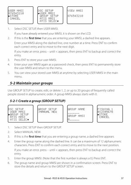
USER MMSI876543210►STORE CANCEL
DSC SETUP►USER MMSI GROUP SETUP ATIS MMSI ATIS SELEC▼
VIEW MMSI
876543210
1. Select DSC SETUP, then USER MMSI.
If you have already entered your MMSI, it is shown on the LCD.
2. If this is the first time that you are entering your MMSI, a dashed line appears.
Enter your MMSI along the dashed line, one number at a time. Press ENT to confirm each correct entry and to move to the next digit.
If you make an error, press – until < appears, then press ENT to backup and correct the entry.
3. Press ENT to store your user MMSI.
4. Enter your user MMSI again as a password check, then press ENT to permanently store the user MMSI and return to the menu.
5. You can view your stored user MMSI at anytime by selecting USER MMSI in the main menu.
5-2 Maintain your groups
Use GROUP SETUP to create, edit, or delete 1, 2, or up to 20 groups of frequently called people stored in alphanumeric order. A group MMSI always starts with 0.
5-2-1 Create a group (GROUP SETUP)
DSC SETUP USER MMSI►GROUP SETUP ATIS MMSI ATIS SELEC▼
GROUP SETUPMANUAL NEW
GROUP NAME
GROUP MMSI
0
FISHING 1012345678►STORE CANCEL
1. Select DSC SETUP then GROUP SETUP.
2. Select MANUAL NEW.
3. If this is the first time that you are entering a group name, a dashed line appears
4. Enter the group name along the dashed line. It can be a maximum of 12 alphanumeric characters. Press ENT to confirm each correct entry and to move to the next position.
If you make an error, press – until < appears, then press ENT to backup and correct the entry.
5. Enter the group MMSI. (Note that the first number is always a 0.) Press ENT.
6. The group name and group MMSI are shown in a confirmation screen. Press ENT to store the details and return to the GROUP SETUP screen.
Simrad - RS35 & HS35 Operation Instructions 37

5-2-2 Edit or delete a group name or group MMSI (GROUP SETUP)
You can edit a group name or group MMSI at any time.
DSC SETUP USER MMSI►GROUP SETUP ATIS MMSI ATIS SELEC▼
GROUP SETUP MANUAL NEW►FISHING 1 SAILING
FISHING 1012345678►EDIT DELETE
EDIT NAMEFISHING 1ENTER MMSI012345678
FISHING 1012345678►STORE CANCEL
1. Select DSC SETUP then GROUP SETUP. The existing group names are displayed.
2. Select the group you want to edit. Press ENT.
3. To delete the group, select DELETE then YES. The group is deleted immediately and the group list is displayed again.
4. To edit the group, select EDIT.
5. Edit the group name OR to edit only the MMSI, press ENT repeatedly until the cursor moves to the MMSI line.
6. When you are finished, press ENT (repeatedly if necessary) until a new LCD appears.
7. Press ENT to store the changes and return to the GROUP SETUP screen.
5-3 Enter or check your ATIS MMSI (ATIS MMSI)
EU models only.
You must enter your ATIS MMSI to access ATIS functionality if you are navigating inland waterways within Europe.
• ATIS sends a digital message any time that you release the PTT key. Inland waterways rules require 1 W Tx power on Channels 06, 08, 10, 11, 12, 13, 14, 15, 17, 71, 72, 74, and 77.
• An ATIS MMSI always starts with the number 9
• This is a once-only operation. You must enter your ATIS MMSI before you can access the ATIS functions
• You can display and read your ATIS MMSI at any time, but you get only one opportunity to enter your ATIS MMSI.
1. Select DSC SETUP then ATIS MMSI.
If you have already entered your ATIS MMSI, it is shown on the LCD.
Simrad - RS35 & HS35 Operation Instructions38

DSC SETUP USER MMSI GROUP SETUP►ATIS MMSI ATIS SELEC▼
INPUT ATISMMSI
9
ATIS MMSI9987654321►STORE CANCEL
ATIS MMSIINPUT AGAIN
9
ATIS MMSI9987654321►STORE CANCEL
2. If this is the first time that you are entering your ATIS MMSI, a dashed line appears. Enter your ATIS MMSI along the dashed line. The first number is always 9. Press ENT to confirm each correct entry and to move to the next digit.
If you make an error, press – until < appears then press ENT to backup and correct the entry.
3. Press ENT to store the ATIS MMS.
4. Enter your ATIS MMSI again as a password check, then press ENT to permanently store the ATIS MMSI and return to the menu.
5. You can view your stored ATIS MMSI at any time by selecting ATIS MMSI in the main
menu.
5-4 Enable ATIS functionality (ATIS SELECT)
EU models only.
ATIS functionality will operate only after the ATIS MMSI has been entered (see previous section).
When ATIS functionality is enabled, the ATIS symbol ATIS is shown on the LCD.
DSC SETUP GROUP SETUP ATIS MMSI►ATIS SELECT INDIV REPL▼
ATIS SELECT►ON OFF
1. Select DSC SETUP then ATIS SELECT.
2. Select OFF to disable ATIS functionality or select ON to enable the ATIS functionality - DSC must be turned off first.
3. Press ENT to confirm.
Note: It is not possible to have both ATIS ON (on) and DSC ON (on) simultaneously. If you want to activate ATIS, you must first switch DSC off. A warning will remind you if DSC is already ON.
Simrad - RS35 & HS35 Operation Instructions 39

5-5 Response to individual calls (INDIV REPLY)
You can respond to incoming individual calls with an automatic response or with a manual response.
An automatic response sends an acknowledgement and then sets the request link channel, ready for a conversation.
A manual response asks if you want to acknowledge the call, and then asks if you want to converse with the caller.
1. Select DSC SETUP, then INDIV REPLY.
2. Select AUTO for an automatic response, or MANUAL for a manual response.
3. Press ENT to confirm your choice and return to the menu.
DSC SETUP GROUP SETU▲ ATIS MMSI ATIS SELECT►INDIV REPL▼
INDIV REPLY MANUAL►AUTO
5-6 Enable DSC functionality (DSC FUNC)
DSC functionality will operate only after a valid USER MMSI has been entered - see 5-1.
When DSC functionality is selected, the DSC symbol DSC is shown on the LCD.
DSC SETUP ATIS MMSI ▲ ATIS SELECT INDIV REPLY►DSC FUNC ▼
DSC FUNC►ON OFF
1. Select DSC SETUP then DSC FUNC.
2. Select OFF to disable DSC functionality or select ON to enable the DSC functionality - ATIS (if applicable) must be turned off first.
Note: Disabling DSC functionality is not recommended.
3. Press ENT to confirm.
Note: It is not possible to have both ATIS ON (on) and DSC ON (on) simultaneously. If you want to activate DSC, you must first switch ATIS off. A warning will remind you if ATIS is already ON.
Simrad - RS35 & HS35 Operation Instructions40

5-7 Response type to LL polling calls (LL REPLY)
You can set up the radio to respond to an LL polling request in one of three ways:
• MANUAL reply manually to any incoming LL polling requests from your buddies.
• AUTO automatically replies to any incoming LL polling requests from any of your buddies.
• OFF ignores all incoming buddy LL polling requests.
DSC SETUP INDIV REPL▲ DSC FUNC►LL REPLY AUTO SWITC▼
LL REPLY►MANUAL AUTO OFF
1. Select DSC SETUP then LL REPLY.
2. Select your response and press ENT to confirm and return to the menu.
5-8 Automatic channel switching (AUTO SWITCH)
When a DSC call is received, it may include a request to change to a specific channel for subsequent communications. If a channel switch request is included, your options are:
• allow the radio to switch to the requested channel immediately by pressing the ENT button, or
• do nothing to allow the radio to automatically switch to the requested channel after a delay of 10 seconds, or
• cancel the automatic switch and remain on the current channel by pressing the EXIT button.
However, automatic switching to a subsequent communications channel on receipt of a DSC call might in some cases disrupt important ongoing communications if the working channel changes without the operator knowing. You can prevent the radio from automatically switching from the current working channel by setting the AUTO SWITCH feature to OFF.
If the AUTO SWITCH feature is set to OFF, an X will be displayed on the LCD to remind you that this feature is set to off. Additionally, the text “AUTO SW OFF” will be included in an All Ships or Group call replacing the text “AUTO CHxx”
DSC SETUP DSC FUNC ▲ LL REPLY►AUTO SWITC TEST REPLY▼
AUTO SWITCH►ON OFF
1. Select DSC SETUP, then AUTO SWITCH.
2. Select ON (on) to enable automatic channel switching.
3. Select OFF (off) to disable automatic channel switching.
Simrad - RS35 & HS35 Operation Instructions 41

5-9 DSC Test Reply (TEST REPLY)
You can respond to incoming DSC TEST calls with an automatic response or with a manual response.
• MANUAL manual response is required, press ENT to confirm or press EXIT to cancel.
• AUTO automatically replies after a 10 second delay with an ACK to any incoming DSC TEST call.
DSC SETUP LL REPLY ▲ AUTO SWITC►TEST REPLY TIMEOUT
TEST REPLY►AUTO MANUAL
5-10 Set the inactivity timer (TIMEOUT)
You can set the inactivity timer with the following options:
• AUTOMATED you can set the inactivity timer to automatically timeout after a period of inactivity for the following two categories: NON-DISTRESS or DISTRESS. Timeout options are: DISTRESS: NO TIMEOUT; 5 MINS; 10 MINS (default is NO TIMEOUT) NON-DISTR: NO TIMEOUT; 10 MINS; 15 MINS (default is 15 MINS)
• NON AUTO you can set the inactivity timer to exit any non-automated procedure activity. Timeout options are: NO TIMEOUT; 10 MINS; 15 MINS (default is 10 MINS)
Note: If NO TIMEOUT is selected, then you must press the EXIT key to exit the procedure.
Example: to set a 10 minute TIMEOUT for non-automated functions:
1. Select TIMEOUT, then select NON AUTO
2. Select desired timeout period: NO TIMEOUT, 10 MINS or 15 MINS
NON AUTO NO TIMEOUT►10 MINS 15 MINS
TIMEOUT►AUTOMATED NON AUTO
DSC SETUP LL REPLY ▲ AUTO SWITC TEST REPLY►TIMEOUT
In this example, 10 MINS has been selected, meaning the radio will exit any non-automated procedure after a period of 10 minutes of non-activity.
Simrad - RS35 & HS35 Operation Instructions42

Section 6 - AIS setup menu (AIS SETUP)Hold down CALL/MENU key for about 1 second to access the following AIS SETUP options. The following menu options are explained in this section.
AIS SETUP AIS FUNC Section 6-1AIS DISPLAY Section 6-2BAUD RATE Section 6-3GPS REDIR Section 6-4CPA ALARM Section 6-5CPA Section 6-6TCPA Section 6-7
Simrad - RS35 & HS35 Operation Instructions 43
See sections 1-3 and 1-4 if you want to know how to move around the menu and enter, save and change data.
6-1 Enable AIS functionality (AIS FUNC)
The AIS function can be turned ON or OFF. When AIS functionality is selected, the AIS symbol AIS is shown on the LCD.
AIS SETUP►AIS FUNC AIS DISPLAY BAUD RATE GPS REDIR
AIS FUNC►ON OFF
6-2 AIS data display format (AIS DISPLAY)
When viewing the AIS plotter screen, AIS targets can be displayed with the vessels name or the vessels MMSI.
AIS SETUP►AIS DISPLAY BAUD RATE GPS REDIR CPA ALARM
AIS DISPLAY►SHIP MMSI SHIP NAME
6-3 AIS baud rate (BAUD RATE)
AIS data can be output to a compatible chart-plotter / MFD or PC via the NMEA port. The NMEA port baud rate can be set to 4800 or 38400. The default setting is 38400. If 4800 is selected, a warning that data may be lost is displayed.
AIS SETUP►BAUD RATE GPS REDIR CPA ALARM CPA
AIS SETUP 38400►4800
AIS INFOMAY BE LOST!►NO YES
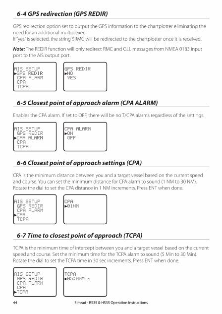
6-4 GPS redirection (GPS REDIR)
GPS redirection option set to output the GPS information to the chartplotter eliminating the need for an additional multiplexer. If “yes” is selected, the string $RMC will be redirected to the chartplotter once it is received.
Note: The REDIR function will only redirect RMC and GLL messages from NMEA 0183 input port to the AIS output port.
AIS SETUP►GPS REDIR CPA ALARM CPA TCPA
GPS REDIR►NO YES
6-5 Closest point of approach alarm (CPA ALARM)
Enables the CPA alarm. If set to OFF, there will be no T/CPA alarms regardless of the settings.
AIS SETUP GPS REDIR►CPA ALARM CPA TCPA
CPA ALARM►ON OFF
6-6 Closest point of approach settings (CPA)
CPA is the minimum distance between you and a target vessel based on the current speed and course. You can set the minimum distance for CPA alarm to sound (1 NM to 30 NM). Rotate the dial to set the CPA distance in 1 NM increments. Press ENT when done.
AIS SETUP GPS REDIR CPA ALARM►CPA TCPA
CPA►01NM
6-7 Time to closest point of approach (TCPA)
TCPA is the minimum time of intercept between you and a target vessel based on the current speed and course. Set the minimum time for the TCPA alarm to sound (5 Min to 30 Min). Rotate the dial to set the TCPA time in 30 sec increments. Press ENT when done.
AIS SETUP GPS REDIR CPA ALARM CPA►TCPA
TCPA►05:00Min
Simrad - RS35 & HS35 Operation Instructions44

Section 7 - Wireless handset setup menu (HS SETTING)Hold down CALL/MENU key for about 1 second to access the following HS SETTING options. The following menu options are explained in this section.
HS SETTING SUBSCRIBE Section 7-1REGISTERED HS Section 7-2
See sections 1-3 and 1-4 if you want to know how to move around the menu and enter, save and change data.
7-1 Register a wireless handset (SUBSCRIBE)
Before a HS35 wireless handset can be used with the RS35 radio, it must be registered (paired)with the radio through the subscription process.
HS SETTING►SUBSCRIBE REGISTERD HS
SUBSCRIBE►YES NO
SUBSCRIBE WAITINGEXIT->ESC
SUBSCRIBE HS SUBSCRIBESUCCESSFUL!EXIT->ESC
1. Ensure the HS35, that you want to subscribe, is charged and turned OFF.
Note: If you have another HS35 that is already subscribed to the RS35, ensure it remains off during this proceedure.
On the RS35 base station radio:
2. Select HS SETTING, then SUBSCRIBE.
3. Select YES. The radio will display WAITING.
On the HS35 wireless handset:
4. Turn ON the HS35 that you want to subscribe to the RS35, the display will show SEARCHING.
5. Press SCAN key until the display shows REGISTER.
6. The display will soon show CONNECTING, and then the HS35 will be paired to the RS35.
7-2 Delete a registered wireless handset (REGISTERED HS)1. To delete an already registered handset, select REGISTERED HS.
2. Select the handset you wish to remove, press ENT and then YES.
HS SETTING SUBSCRIBE►REGISTERD HS
REGISTERED HS►CLEAR HS1 CLEAR HS2
CLEAR HS1►YES NO
Simrad - RS35 & HS35 Operation Instructions 45

Section 8 - Sending and receiving DSC calls
WARNING
A valid USER MMSI must be entered into this radio before these DSC functions can be used. See section 5-1.
8-1 What is DSC?
DSC (Digital Selective Calling) is a semi-automated method of establishing VHF, MF, and HF radio calls. It has been designated as an international standard by the IMO (International Maritime Organization) and is part of the GMDSS (Global Maritime Distress and Safety System).
Currently, you are required to monitor Distress Channel 16, but DSC will eventually replace listening watches on distress frequencies and will be used to broadcast routine and urgent maritime safety information.
DSC enables you to send and receive calls from any vessel or coast station that is equipped with DSC functionality and within geographic range. Calls can be categorized as distress, urgency, safety, or routine, and DSC selects a working channel automatically.
8-2 Sending DSC Calls
You can call any other person that has another DSC equipped radio.
• Quick press the CALL / MENU key to access the following DSC CALL menu options – select LAST CALL to quickly call back the person who called you.
• Note that only four DSC CALL menu options can be shown on the LCD at any one time.
• Press + or – on the microphone or turn the Channel Select knob on the base station to scroll up or down through the menu until the cursor is positioned at the desired option. Press ENT (the center of the Channel Select knob) to display that option.
The following options are available:
DSC CALL INDIVIDUAL Make a DSC Call Section 8-3LAST CALL Repeat the last DSC Call Section 8-5GROUP Make a Group DSC Call Section 8-6ALL SHIPS Make an All Ships DSC Call Section 8-7CALL LOG View DSC Call Log Section 8-8DISTR LOG View DSC Distress Log Section 8-9SENT CALL View DSC Sent Call Log Section 8-10LL REQUEST Request a position report Section 8-11TRACK BUDDY Automatically track Buddy’s Section 8-12DSC TEST Make a DSC Test Call Section 8-13MMSI/GPS View MMSI and GPS information Section 8-14
Simrad - RS35 & HS35 Operation Instructions46
8-3 Send an individual call (INDIVIDUAL)
8-3-1 Call to a Buddy
DSC CALL►INDIVIDUAL LAST CALL GROUP ALL SHIPS ▼
INDIVIDUAL►ROUTINE SAFETY URGENCY
INDIVIDUAL MANUAL NEW►MERMAID IV SEAROSE
CHOOSE CH
►INTER-SHIP MANUAL
MERMAID IV INDIVIDUAL ROUTINE►SET INTER
MERMAID IV INDIVIDUAL ROUTINE►SEND?
MERMAID IV INDIVIDUALROUTINEWAIT.. 00:00
INDIVIDUALROUTINEACK FROMMERMAID IV ▼ 00:00
8-3-2 Call to others
DSC CALL►INDIVIDUAL LAST CALL GROUP ALL SHIPS ▼
INDIVIDUALROUTINE SAFETY URGENCY
INDIVIDUALMANUAL NEW MERMAID IV SEAROSE
MANUAL MMSI
0
CHOOSE CH
►INTER-SHIP MANUAL
678912345 INDIVIDUAL ROUTINESEND?
678912345INDIVIDUAL ROUTINECALLING...
678912345INDIVIDUALROUTINEWAIT.. 00:00
1. Select DSC CALL then INDIVIDUAL.
2. Select the priority level: ROUTINE, SAFETY, URGENCY.
3. Select the buddy you want to call from your buddy list - or Select MANUAL NEW then enter the MMSI of the individual you want to call and press ENT.
4. Choose a working channel to talk on. Select the INTER-SHIP and press ENT. The radio automatically lists all Inter-ship (Simplex) channels that can be used. Duplex channels cannot usually be called, however, If you wish to use a Duplex channel, select MANUAL instead, then select your channel of choice. If the call is to a Coast Station (MMSI begins with 00) the radio will recognize this and specify the correct channel to talk on.
5. Press ENT to SEND the call. Channel 70 is selected automatically and the Tx symbol is shown on the LCD while the call is being sent.
6. The radio waits for an acknowledgement (WAIT). If the call is acknowledged (INDIV ACK) press PTT to talk. Rotate the Channel Select knob to view additional options.
7. If there is no reply (UNABLE TO ACKNOWLEDGE) a message asks if you want to retry (SEND AGAIN?). Press ENT to retry the call.
Simrad - RS35 & HS35 Operation Instructions 47

8-4 Acknowledgement of an individual incoming call (INDIV)
When an incoming call is received, the alarm sounds for 2 minutes and INDIVIDUAL is displayed.
123456789NO AUTO SWCH12 REQUEST12:45 UTC ▲ 00:03
ROUTINE FROM123456789NO AUTO SWCH12 REQUEST ▲▼ 00:02
INDIVIDUALROUTINE FROM123456789NO AUTO SW ▼ 00:01
1. Press SILENC softkey (AIS/IC key) to silence the alert.
2. Press +/- button or rotate the CH knob to scroll any further information about the call.
3. Press NEW-CH softkey (AIS/IC key) to request a different working channel, or press ABLE softkey (WX/NAV key) to acknowledge the call.
4. Or press EXIT to return to standby.
8-5 Reply to the Last Call (LAST CALL)
This facility is useful and used frequently.
DSC CALL INDIVIDUAL►LAST CALL GROUP ALL SHIPS ▼
SEAROSEINDIVIDUALROUTINE10:22AM LOC
CHOOSE CH
►INTER-SHIP MANUAL
SEAROSEINDIVIDUALROUTINE►SEND?
1. Select DSC CALL then LAST CALL.
2. The contact details of the most recent incoming call are displayed. Press ENT.
3. Choose a working channel to talk on. Select the INTER-SHIP and press ENT. The radio automatically lists all Inter-ship (Simplex) channels that can be used. Duplex channels cannot usually be called, however, If you wish to use a Duplex channel, select MANUAL instead, then select your channel of choice. If the call is to a Coast Station (MMSI begins with 00) the radio will recognize this and specify the correct channel to talk on.
4. The call details are shown. Press ENT to send the call. The Tx symbol is displayed on the LCD while the call is being sent.
5. If the call is acknowledged (INDIV ACK) press PTT to talk. If there is no reply a message asks if you want to retry (SEND AGAIN?). Press ENT to retry the call.
Simrad - RS35 & HS35 Operation Instructions48

8-6 Send a group call (GROUP) You must already have stored a GROUP MMSI before making the call - see Section 5-2. Group
calls are always sent with ROUTINE priority.
DSC CALL INDIVIDUAL►LAST CALL GROUP ALL SHIPS ▼
GROUP►DIVE 1 DIVE 2
CHOOSE CH
►INTER-SHIP MANUAL
DIVE 1GROUP CALL
►SEND?
1. Select DSC CALL then GROUP.
The radio displays the names of your pre-programed groups.
2. Select the group that you want to call (the GROUP MMSI must be set before making the call).
3. Choose a working channel to talk on. Select the INTER-SHIP and press ENT. The radio automatically lists all Inter-ship (Simplex) channels that can be used. Duplex channels cannot usually be called, however, If you wish to use a Duplex channel, select MANUAL instead, then select your channel of choice.
4. The call details are shown. Press ENT to send the call. The Tx symbol is displayed on the LCD while the call is being sent.
8-7 Send an all ships call (ALL SHIPS)
DSC CALL LAST CALL ▲ GROUP►ALL SHIPS CALL LOG ▼
ALL SHIPS►SAFETY URGENCY
CHOOSE CH
►INTER-SHIP MANUAL
ALL SHIPSSAFETY►SEND?
1. Select DSC CALL then ALL SHIPS.
2. Select one of the following call priorities:
• SAFETY To send safety information to all other vessels in range.
• URGENCY For use when a serious situation or problem arises that could lead to a distress situation.
3. Choose a working channel to talk on. Select the INTER-SHIP and press ENT. The radio automatically lists all Inter-ship (Simplex) channels that can be used. Duplex channels cannot usually be called, however, If you wish to use a Duplex channel, select MANUAL instead, then select your channel of choice.
4. The call details are shown. Press ENT to send the call. The Tx symbol is displayed on the LCD while the call is being sent.
Simrad - RS35 & HS35 Operation Instructions 49

When the call log is full, the oldest entry is overwritten.
8-8 Send using the call log (CALL LOG)
The Call Log contains the contact details for the 20 most recent incoming calls, so that you can call any of them again quickly.
DSC CALL GROUP ▲ ALL SHIPS►CALL LOG DISTR LOG ▼
11 12345678INDIVIDUALROUTINE09:45 UTC
11 12345678►CALL BACK DELETE SAVE MMSI
CHOOSE CH
►INTER-SHIP MANUAL
12345678INDIVIDUALROUTINE►SEND?
1. Select DSC CALL then CALL LOG.
2. The radio displays the contact details for the most recent incoming call as the first entry (01) in the call log. In the example, the contact details for the 11th most recent call are displayed. Press ENT to move to the next screen.
3. Press ENT again to confirm the call back.
4. Choose a working channel to talk on. Select the INTER-SHIP and press ENT. The radio automatically lists all Inter-ship (Simplex) channels that can be used. Duplex channels cannot usually be called, however, If you wish to use a Duplex channel, select MANUAL instead, then select your channel of choice. If the call is to a Coast Station (MMSI begins with 00) the radio will recognize this and specify the correct channel to talk on.
5. The call details are shown. Press ENT to send the call. The Tx symbol is displayed on the LCD while the call is being sent.
Simrad - RS35 & HS35 Operation Instructions50

8-9 Send using the distress log (DIST LOG)
DSC CALL ALL SHIPS ▲ CALL LOG►DISTR LOG SENT CALL ▼
02 SEASPRAYDISTRESSFLOODING
ENT-- OPTION
CHOOSE CH
►INTER-SHIP MANUAL
02 SEASPRAY►CALL BACK DELETE INFO
02 SEASPRAY INDIVIDUAL ROUTINE►SEND?
The Distress Log contains the Distress Log data for the 20 most recent received Distress Calls, so that you can call any of them quickly. Always try to make voice contact on CH16 first, as follows:
1. Select DSC CALL then DIST LOG.
2. The most recently received Distress Call is the first entry (01) in the Distress Log. Select the entry that you want to call and press ENT.
3. Select one of the following options:
• CALL BACK To CALL the station.
• DELETE To delete the details from the distress log.
• INFO To view additional information about the station.
4. Select CALL BACK and press ENT.
5. Choose a working channel to talk on. Select the INTER-SHIP and press ENT. The radio automatically lists all Inter-ship (Simplex) channels that can be used. Duplex channels cannot usually be called, however, If you wish to use a Duplex channel, select MANUAL instead, then select your channel of choice. If the call is to a Coast Station (MMSI begins with 00) the radio will recognize this and specify the correct channel to talk on.
6. The call details are shown. Press ENT to send the call. The Tx symbol is displayed on the LCD while the call is being sent.
Simrad - RS35 & HS35 Operation Instructions 51
8-10 View sent call log (SENT CALL)
The Sent Call log contains the contact details for the 20 most recent sent calls, so that you review details of the call.
BOBBY D►DELETE
01 BOBBY DINDIVIDUALROUTINE10:45 UTC
DSC CALL CALL LOG ▲ DISTR LOG►SENT CALL LL REQUEST ▼
1. Select DSC CALL then SENT CALL. Scroll down to the desired sent call details.
2. The radio displays the details for the most recent sent call as the first entry (01) in the call log. In the example, the contact details for the most recent call are displayed.
3. Press ENT to advance to next screen. You now have the following options:
• DELETE To delete the entry from the sent call log.
8-11 Request the LL position of a Buddy (LL REQUEST)
DSC CALL DIST LOG ▲ SENT CALL►LL REQUEST TRACK BUDD▼
LL REQUEST►STARFISH SEAROSE MERMAID IV
STARFISHLL REQUEST
►SEND?
STARFISH LL REQUEST
CALLING...
STARFISHLL REQUEST
WAIT.. 00:00
1. Press CALL to enter DSC mode, then select LL REQUEST.
2. Select the buddy whose LL position you want to request then press ENT to send the request.
3. The radio waits for an acknowledgement from your buddy. If there is no reply after 30 seconds the radio asks if you want to retry. Press ENT to retry the call.
4. If the call is acknowledged, press SILENC softkey (AIS/IC key) to silence the alert, press +/- button or rotate the CH knob to scroll any further information about the call.
POSITIONREPLY FROMSTARFISH 99°99.999'X ▼ 00:00
Simrad - RS35 & HS35 Operation Instructions52

8-12 Track your Buddy (TRACK BUDDY)
You can select a buddy or buddy’s to automatically track their positions. You must setup a tracklist first and set their track status to ON before buddy track can begin. You can also start and stop tracking your buddy and add or remove buddies from your buddy tracklist.
8-12-1 Start or stop tracking a Buddy (START TRACK)
Use START TRACK to track the position of a buddy(s) on your TRACKLIST whose status is ON (see the following section). The buddy’s position is updated at the interval you select in INTERVAL (15, 30, or 60 minutes). Note: START TRACK will only track buddy(s) on your TRACKLIST whose status is ON.
DSC CALL SENT CALL ▲ LL REQUEST►TRACK BUDD DSC TEST ▼
TRACK BUDDY►START TRACK SET BUDDY TRACKLIST INTERVAL
START TRACK SEAROSE OFF MERMAID ON SEASPRA ON
START TRACKYES NO
MERMAID IVLL REQUEST
CALLING...
SEASPRAYLL REQUEST
CALLING...
1. Select DSC CALL then TRACK BUDDY.
2. Select START TRACK. The status of each buddy on your tracklist (ON or OFF) is displayed.
3. Check that the status of the buddy (or buddies) that you want to track is ON, then press ENT.
4. Select YES then press ENT to start tracking (in this example, MERMAID IV and SEASPRAY.)
An LL Request is sent to each buddy on CH70 and your radio waits for your buddy’s LL position to be displayed on the LCD. See Section 8-20 for more information.
(Select NO in the START TRACK page to STOP tracking your buddies.)
8-12-2 Select a Buddy to Track (SET BUDDY)
DSC CALL SENT CALL ▲ LL REQUEST►TRACK BUDD DSC TEST ▼
TRACK BUDDY START TRACK►SET BUDDY TRACKLIST INTERVAL
SET BUDDY SEAROSE OFF►MERMAID OFF
SET BUDDYMERMAID IV►ON OFF
1. Select DSC CALL then TRACK BUDDY.
2. Select SET BUDDY to show the status of each buddy on your tracklist (ON or OFF).
3. Select the buddy whose status you want to change, then select the new status and press ENT to confirm.
Simrad - RS35 & HS35 Operation Instructions 53
8-12-3 Add or delete a Buddy on your track list (TRACKLIST)
DSC CALL SENT CALL ▲ LL REQUEST►TRACK BUDD DSC TEST ▼
TRACK BUDDY START TRACK SET BUDDY ►TRACKLIST INTERVAL
TRACKLIST►ADD NEW SEAROSE
ADD NEW►MERMAID IV SEASPRAY
1. Select DSC CALL then TRACK BUDDY.
2. Select TRACKLIST. Any buddies already on the tracklist will be listed. Note: To delete a buddy from the tracklist, select that buddy then press ENT. Select YES then press ENT again to delete.
3. Select ADD NEW to show your buddy list. Buddy’s must be already setup in your Buddy list - see section 3-3.
4. Select a buddy then press ENT to add that buddy to the tracklist.
8-12-4 Set the track your Buddy update interval (INTERVAL)
Set the interval rate at which the position of your buddy is updated - options are 15, 30 or 60 minutes.
DSC CALL SENT CALL ▲ LL REQUEST►TRACK BUDD DSC TEST ▼
TRACK BUDDY START TRACK SET BUDDY TRACKLIST►INTERVAL
TRACKLIST►15 MINUTES 30 MINUTES 1 HOUR
8-13 Make a DSC test call (DSC TEST)
You can test your radio’s DSC operation by sending a DSC TEST CALL to a Buddy or other station equipped with a DSC radio.
Note: You should not use a routine DSC call to test your radio and you should minimize the use of the safety channel for test purposes.
8-13-1 Send a DSC TEST call
1. Select DSC CALL then DSC TEST.
2. Select the buddy you want to call from your buddy list, or Select MANUAL NEW then enter the MMSI of the individual you want to call.
3. Press ENT to accept the selection.
4. Press ENT again to SEND the call. Channel 70 is selected automatically and the TX symbol is shown on the LCD while the call is being sent.
5. The radio waits for an acknowledgement (WAIT). If the call is acknowledged a notification is displayed.
Simrad - RS35 & HS35 Operation Instructions54
TOMDSC TEST
►SEND?
DSC TEST MANUAL NEW SAM►TOM
DSC CALL LL REQUEST▲ TRACK BUDDY►DSC TEST MMSI/GPS
TOMDSC TEST
WAIT.. 00:17
6. If there is no reply after 30 seconds, the radio asks you if you want to retry.
8-13-2 Receiving an incoming DSC TEST call reply (DSC TEST ACK)1. When you receive notification of a DSC TEST reply, press SILENC softkey (AIS/IC key) to
silence the alert.
2. If the radio recognizes the user MMSI as one of your buddies, the buddy’s name is displayed in place of the user MMSI.
8-13-3 Acknowledging an incoming DSC TEST call
The radio sounds a friendly two-tone alert when it detects an incoming DSC TEST call.
Note: If TEST REPLY is set to AUTO, no sound will be emitted.
1. If the radio recognizes the MMSI as one of your buddies, your buddy’s name is displayed in place of the MMSI.
2. Press SILENC softkey (AIS/IC key) to silence the alert.
3. The radio will automatically acknowledge the call if TEST REPLY is set to AUTO (See sec-tion 5-9) and after a TIMEOUT period set for AUTO REPLY (See section 5-10).
CALL FROMTOMAUTO ACKIN 10S ▲▼ 00:02
TESTCALL FROMTOMAUTO ACK ▼ 00:01
4. Alternatively, if TEST REPLY is set to MANUAL, a manual response is required, press ACK (AIS/IC key) to acknowledge the DSC Test Call.
CALL FROMTOMAUTO ACKIS OFF ▲▼ 00:02
TESTCALL FROMTOMAUTO ACK ▼ 00:01
5. Press +/- button or rotate the CH knob to scroll any further information (if available), or press EXIT to cancel.
Simrad - RS35 & HS35 Operation Instructions 55

8-14 View user MMSI and GPS information
The radio’s MMSI can be viewed as well as the current position.
ID:123456789 99°99.999’X999°99.000’Y
DSC CALL LL REQUEST▲ TRACK BUDDY DSC TEST►MMSI/GPS
8-15 Receiving DSC calls
Several types of DSC calls can be received from vessels within range at various priority levels:
• DISTRESS See Section 9.
• ALL SHIPS Urgency or Safety priority (see Section 8-16)
• INDIVIDUAL Urgency, Safety, or Routine priority (see Section 8-17)
• GROUP Routine priority only (see Section 8-18)
• GEOGRAPHIC Routine priority only see Section 8-19)
• POLLED POSITION Routine or Safety priority (see Section 8-20)
In addition to the audible alert, the telephone icon will flash on the screen.
This is to remind you that a call is stored in the CALL LOG. Polled position call data is NOT stored.
8-16 Receiving an all ships call (ALL SHIPS)
ALL SHIPSSAFETY FROM123456789AUTO SWITCH ▼ 00:01
ALL SHIPSSAFETY FROM123456789AUTO SW OFF ▼ 00:01
ALL SHIPSSAFETY FROM123456789CHANGE TO ▼ 00:11
1. When you receive notification of an ALL SHIPS call, press SILENC softkey (AIS/IC key) to silence the alert. The priority level and the user MMSI are displayed on the screen. If the radio recognises the user MMSI as one of your buddies, the buddy name is shown in place of the user MMSI.
2. Press ACCEPT softkey (AIS/IC key) to switch to the designated channel immediately, Press +/- button or rotate the CH knob to scroll any further information about the call, or press EXIT to return the current DSC receive process.
3. If the display shows "AUTO SWITCH", the radio will automatically switch to the designated channel after 10s if no user intervention. For "AUTO SW OFF", a manual change is required - for "AUTO SWITCH" options, see section 5-8.
Simrad - RS35 & HS35 Operation Instructions56

4. Press PTT to initiate voice contact on current display channel.
The call data is stored in your Call Log (see Section 8-8).
8-17 Receiving an individual call (INDIV)
INDIVIDUALROUTINE FROM123456789AUTO SWITCH ▼ 00:01
INDIVIDUALROUTINE FROM123456789AUTO SW OFF ▼ 00:01
1. When you receive notification of an INDIV call, press SILENC softkey (AIS/IC key) to silence the alert. INDIV calls are almost always routine priority. If the radio recognises the user MMSI as one of your buddies, the buddy’s name is displayed in place of the user MMSI.
2. Press +/- button or rotate the CH knob to scroll any further information about the call, or press EXIT to return the current DSC receive process.
3. You have the following options to respond the call:
• ABLE softkey (WX/NAV key) respond to the call with requested channel
• NEW-CH softkey (AIS/IC key) respond to the call with but request a different channel
• UNABLE softkey (GO/MOB key) respond to the call with unable to use the requested channel ( Note: this option is not available with ROUTINE calls)
4. If the display shows "AUTO SWITCH", the radio will automatically respond to the call after 10s if no user intervention. For "AUTO SW OFF", a manual responce is required - for "INDIV REPLY" options, see section 5-5.
5. The caller should respond to your acknowledgement by making voice contact designated channel. If this does not happen, you can press PTT to initiate voice contact instead.
The call data is stored in your Call Log (see Section 8-8).
8-18 Receiving a group call (GROUP)
GP: SAMCALL FROM123456789AUTO SWITCH ▼ 00:01
GP: SAMCALL FROM123456789AUTO SW OFF ▼ 00:01
GP: SAMCALL FROM012345678CHANGE TO ▼ 00:11
1. When you receive notification of a GROUP call, press SILENC softkey (AIS/IC key) to silence the alert. Press +/- button or rotate the CH knob to scroll any further information about the call.
The priority level is always routine, and the group is identified on the screen. The group will be one of the 20 groups of frequently called people that you set up earlier (see Section 5-2).
2. Press ACCEPT softkey (AIS/IC key) to switch to the designated channel immediately, or
Simrad - RS35 & HS35 Operation Instructions 57

press EXIT to return the current DSC receive process.
3. If the display shows "AUTO SWITCH", the radio will automatically switch to the designated channel after 10s if no user intervention. For "AUTO SW OFF", a manual change is required - for "AUTO SWITCH" options , see section 5-8.
4. You do not need to send an acknowledgement. If desired, press PTT to initiate voice contact on the designated channel.
The call data is stored in your Call Log (see Section 8-8).
8-19 Receiving a geographic area call (GEOGRAPH)
GEOGRAPHICALCALL FROM254622211CH12 REQUEST ▼ 00:01
GEOGRAPHICALCALL FROM254622211CHANGE TO ▼ 00:08
A geographic call is received by vessels within a specific geographic boundary area.
1. When you receive notification of a GEOGRAPHICAL call, press SILENC softkey (AIS/IC key) to silence the alert. Then press ACCEPT softkey (AIS/IC key) to manually select the channel designated in the incoming call.
The user MMSI or name is displayed on the screen. If the radio recognises the user MMSI as one of your buddies, the buddy’s name is displayed in place of the user MMSI.
2. Press +/- button or rotate the CH knob to scroll any further information about the call, or press EXIT to return the current DSC receive process.
3. Monitor the working channel for an announcement from the calling vessel.
8-20 Receiving a polled position call (POSITION)
POSITIONREPLY FROM12345678982°50.1234 N ▼ 00:01
When you receive GPS position data from a buddy in response to your LL request you are recommended to make a written note of the position, especially is it is a good fishing position.
If enhanced LL position information is available from your buddy, press SILENC softkey (AIS/IC key) to silence the alert. Press +/- button or rotate the CH knob to scroll any further information about the call, or press EXIT to return the current DSC receive process.
Note: DSC & DSE sentence will be output on the NMEA 0183 port for indication on a connected chartplotter / MFD.
Simrad - RS35 & HS35 Operation Instructions58

Section 9 - DISTRESS calls
WARNING
A valid USER MMSI must be entered into this radio before these DSC functions can be used. See section 5-1.
9-1 Sending a Distress Call
DISTRES CALL►UNDEFINED FIRE FLOODING COLLISION
DISTRES CALL ►UNDEFINED HOLD DISTRES 3 SECONDS..
DISTRES CALLUNDEFINED11:23 UTC 22°12.023’N ▼TX IN 00:01
1. Open the red cover labelled DISTRESS.
If time is available to specify the nature of the distress, go to step 2. Otherwise, go directly to step 3.
2. Press and release the DISTRESS key to display the following categories. Press +/- button or rotate the CH knob to select the category that describes your situation then press ENT.
• UNDEFINED (Undefined)
• FIRE (Fire)
• FLOODING (Flooding)
• COLLISION (Collision)
• GROUNDING (Grounding)
• LISTING (Listing)
• SINKING (Sinking)
• ADRIFT (Adrift)
• ABANDONING (Abandoning)
• PIRACY (Piracy)
• OVER BOARD (Overboard)
3. Press and hold down the DISTRESS key for about 3 seconds, until you see the distress call sending message (DISTRESS CALL SENDING) on the screen. The whole display starts to flash and beep loudly.
4. After the Distress Call is sent, the radio waits for an acknowledgment.
•The Distress call is automatically transmitted every 3.5 to 4.5 minutes, until an acknowledgement is received ("Call repeat" mode).
•Press ▼ / ▲ to display the transmitted Distress call information.
Simrad - RS35 & HS35 Operation Instructions 59
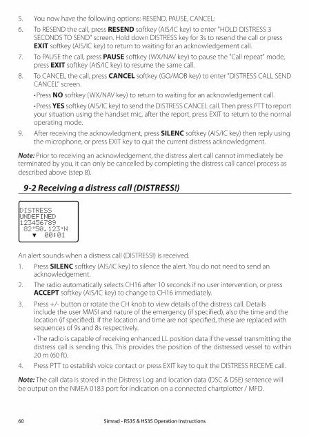
5. You now have the following options: RESEND, PAUSE, CANCEL:
6. To RESEND the call, press RESEND softkey (AIS/IC key) to enter "HOLD DISTRESS 3 SECONDS TO SEND" screen. Hold down DISTRESS key for 3s to resend the call or press EXIT softkey (AIS/IC key) to return to waiting for an acknowledgement call.
7. To PAUSE the call, press PAUSE softkey (WX/NAV key) to pause the "Call repeat" mode, press EXIT softkey (AIS/IC key) to resume the same call.
8. To CANCEL the call, press CANCEL softkey (GO/MOB key) to enter "DISTRESS CALL SEND CANCEL" screen.
•Press NO softkey (WX/NAV key) to return to waiting for an acknowledgement call.
•Press YES softkey (AIS/IC key) to send the DISTRESS CANCEL call. Then press PTT to report your situation using the handset mic, after the report, press EXIT to return to the normal operating mode.
9. After receiving the acknowledgment, press SILENC softkey (AIS/IC key) then reply using the microphone, or press EXIT key to quit the current distress acknowledgment.
Note: Prior to receiving an acknowledgement, the distress alert call cannot immediately be terminated by you, it can only be cancelled by completing the distress call cancel process as described above (step 8).
9-2 Receiving a distress call (DISTRESS!)
DISTRESSUNDEFINED123456789 82°50.123'N ▼ 00:01
An alert sounds when a distress call (DISTRESS!) is received.
1. Press SILENC softkey (AIS/IC key) to silence the alert. You do not need to send an acknowledgement.
2. The radio automatically selects CH16 after 10 seconds if no user intervention, or press ACCEPT softkey (AIS/IC key) to change to CH16 immediately.
3. Press +/- button or rotate the CH knob to view details of the distress call. Details include the user MMSI and nature of the emergency (if specified), also the time and the location (if specified). If the location and time are not specified, these are replaced with sequences of 9s and 8s respectively.
•The radio is capable of receiving enhanced LL position data if the vessel transmitting the distress call is sending this. This provides the position of the distressed vessel to within 20 m (60 ft).
4. Press PTT to establish voice contact or press EXIT key to quit the DISTRESS RECEIVE call.
Note: The call data is stored in the Distress Log and location data (DSC & DSE) sentence will be output on the NMEA 0183 port for indication on a connected chartplotter / MFD.
Simrad - RS35 & HS35 Operation Instructions60
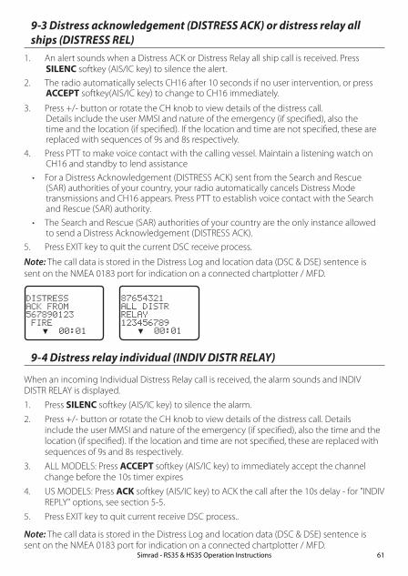
9-3 Distress acknowledgement (DISTRESS ACK) or distress relay all ships (DISTRESS REL)
1. An alert sounds when a Distress ACK or Distress Relay all ship call is received. Press SILENC softkey (AIS/IC key) to silence the alert.
2. The radio automatically selects CH16 after 10 seconds if no user intervention, or press ACCEPT softkey(AIS/IC key) to change to CH16 immediately.
3. Press +/- button or rotate the CH knob to view details of the distress call. Details include the user MMSI and nature of the emergency (if specified), also the time and the location (if specified). If the location and time are not specified, these are replaced with sequences of 9s and 8s respectively.
4. Press PTT to make voice contact with the calling vessel. Maintain a listening watch on CH16 and standby to lend assistance
• For a Distress Acknowledgement (DISTRESS ACK) sent from the Search and Rescue (SAR) authorities of your country, your radio automatically cancels Distress Mode transmissions and CH16 appears. Press PTT to establish voice contact with the Search and Rescue (SAR) authority.
• The Search and Rescue (SAR) authorities of your country are the only instance allowed to send a Distress Acknowledgement (DISTRESS ACK).
5. Press EXIT key to quit the current DSC receive process.
Note: The call data is stored in the Distress Log and location data (DSC & DSE) sentence is sent on the NMEA 0183 port for indication on a connected chartplotter / MFD.
DISTRESSACK FROM567890123 FIRE ▼ 00:01
9-4 Distress relay individual (INDIV DISTR RELAY)
When an incoming Individual Distress Relay call is received, the alarm sounds and INDIV DISTR RELAY is displayed.
1. Press SILENC softkey (AIS/IC key) to silence the alarm.
2. Press +/- button or rotate the CH knob to view details of the distress call. Details include the user MMSI and nature of the emergency (if specified), also the time and the location (if specified). If the location and time are not specified, these are replaced with sequences of 9s and 8s respectively.
3. ALL MODELS: Press ACCEPT softkey (AIS/IC key) to immediately accept the channel change before the 10s timer expires
4. US MODELS: Press ACK softkey (AIS/IC key) to ACK the call after the 10s delay - for "INDIV REPLY" options, see section 5-5.
5. Press EXIT key to quit current receive DSC process..
Note: The call data is stored in the Distress Log and location data (DSC & DSE) sentence is sent on the NMEA 0183 port for indication on a connected chartplotter / MFD.
87654321ALL DISTRRELAY123456789 ▼ 00:01
Simrad - RS35 & HS35 Operation Instructions 61

Section 10 - AIS functionality
CAUTION
Valid GPS data must be entered into this radio before the AIS functions can be used. The plotter PPI function will not display targets accurately with incorrect GPS data.
10-1 About AIS
The marine Automatic Identification System (AIS) is a location and vessel information reporting system. It allows vessels equipped with AIS to automatically and dynamically share and regularly update their position, speed, course and other information such as vessel identity with similarly equipped vessels. Position is derived from the Global Positioning System (GPS) and communication between vessels is by Very High Frequency (VHF) digital transmissions.
There are a number of types of AIS device as follows:
• Class A transceivers. These are similar to class B transceivers, but they are designed to be fitted on large vessels such as cargo ships and large passenger vessels. Class A transceivers transmit at a higher VHF signal power than class B transceivers and therefore can be received by more distant vessels, and also transmit more frequently. Class A transceivers are mandatory on all vessels over 300 gross tonnes on international voyages and certain types of passenger vessels under the SOLAS regulations.
• Class B transceivers. Similar to class A transceivers in many ways, but are normally lower cost due to the less stringent performance requirements. Class B transceivers transmit at a lower power and at a lower reporting rate than class A transceivers.
• AIS base stations. AIS base stations are used by Vessel Traffic Systems to monitor and control the transmissions of AIS transceivers.
• Aids to Navigation (AtoN) transceivers. AtoNs are transceivers mounted on buoys or other hazards to shipping which transmit details of their location to the surrounding vessels.
• AIS receivers. AIS receivers will generally receive transmissions from class A transceivers, class B transceivers, AtoNs and AIS base stations but do not transmit any information about the vessel on which they are installed.
This radio contains an AIS receiver only function.
10-2 AIS - Static and dynamic information
Defined transmit rates for Class A vessels shown below are provided for reference purposes only. The frequency of messages received will vary due to a number of factors including but not limited to such factors as antenna height, gain and signal interference.
• Static information is either broadcast every 6 minutes, when data has been amended, or upon request.
Simrad - RS35 & HS35 Operation Instructions62

• Dynamic information is broadcast depending on speed and course alteration based on the following tables:
Ship's dynamic conditions Normal reporting interval
At anchor or moored 3 Minutes
0-14 knots 10 Seconds
0-14 knots and changing course 3 1/3 Seconds
14-23 knots 6 Seconds
14-23 knots and changing course 2 Seconds
Ship faster than 23 knots 2 Seconds
Ship faster than 23 knots and changing course 2 Seconds
Platform's condition Normal reporting interval
Class B Shipborne mobile equipment not moving faster than 2 Knots
3 Minutes
Class B Shipbome mobile equipment moving 2-14 Knots
30 Seconds
Class B Shipbome mobile equipment moving 14-23 Knots
15 Seconds
Class B Shipbome mobile equipment moving faster than 23 Knots
5 Seconds
Search and Rescue aircraft (airborne mobile equipment)
10 Seconds
Aids to Navigation 3 Minutes
AIS base station 10 Seconds
Source of information for above tables 1-1, 1-2: (ITU recommendations technical document: ITU-R M.1371-1)
10-3 Using the AIS receiver
Providing that other vessels with AIS transceivers installed are within radio range of your vessel, you should see their details appear on the AIS plotter screen. These details are also repeated on the NMEA ports for display on a compatible chartplotter / MFD.
Specific details of how to configure your chartplotter to make use of the AIS receiver features will be given in your chartplotter manual. If you are using charting software running on a PC, please refer to the instructions provided with your chartplotting software for details of how to configure it to display AIS information.
Simrad - RS35 & HS35 Operation Instructions 63
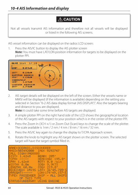
10-4 AIS Information and display
CAUTION
Not all vessels transmit AIS information and therefore not all vessels will be displayed or listed in the following AIS screens.
AIS vessel information can be displayed on the radios LCD screen:
1. Press the AIS/IC button to display the AIS plotter screen Note: You must have LAT/LON position information for targets to be displayed on the plotter PPI.
2. AIS target details will be displayed on the left of the screen. Either the vessels name or MMSI will be displayed (if the information is available) depending on the setting you selected in Section "6-2 AIS data display format (AIS DISPLAY)". Also the targets bearing and distance to you are displayed. Note: it could take some time before AIS targets are displayed.
3. A simple plotter PPI on the right hand side of the LCD shows the geographical location of the AIS targets with respect to your position which is in the center of the plotter PPI.
4. Press the Zoom In (3CH +/-) or Zoom Out (Scan) keys to change the scale of the plotter. The scale available is 1nm / 2 nm / 4 nm / 8 nm / 16 nm / 32 nm.
5. Press the AIS/IC key again to change the display to T/CPA Approach screen.
6. Rotate the knob to highlight any AIS target shown on the plotter screen. The selected target will have the target symbol filled in.
NAME:OCEANIC.DISCOVERERMMSI:503492000 IMO: 9292747CALL SIGN:VMQ8808DIST: 1.62nM BEAR: 285°TCPA: ----- HEADING: 195.0°CPA: 1.62nM ROT: 0.0 /minWIDTH: 0.0m SOG: 9.9KTSLENGTH: 60.0m COG: 219.0°RECEIVED: 1M19S LAT: 36°45.785’SDRAUGHT:----- LON:174°49.157’ETYPE: PASSENGER SHIP - ALL SHIPS OF THIS TYPE STATUS:UNDERWAY USING ENGINE
Simrad - RS35 & HS35 Operation Instructions64

7. Press ENT to view full details of the highlighted target such as MMSI, Vessel name, distance, bearing, heading, ROT, COG, SOG, status and other vessel information.
10-4-1 T/CPA approach screen1. When in AIS mode, press the AIS/IC key again to toggle between the standard AIS
screen and the T/CPA Approach screen.
2. In TCPA Approach mode, the approaching AIS target's details are listed on the left side along with it's geographical position on the plotter PPI.
3. The zoom range is automatically selected to the best range according to the selected target on the left. You can’t change the zoom range in this mode.
4. Press +/- button or rotate the CH knob to select the target, press ENT key to display target information, or press EXIT key to return to the previous display.
Note: If the radio detects a TCPA or CPA breach, the T/CPA Approach screen will automatically popup with an alert tone. Press EXIT to stop the alert. The alert will sound again after 1 minute if the AIS alarm has not been released.
T/CPA APPROACH
228278700 0.59Min 1.0nM
10-4-2 Plotter symbols and meanings
Your vessel is always in the center of the plotter screen. You are represented by a solid circle, along with a small line that indicates your bearing with respect to North.
All other vessels or targets displayed on the plotter screen are represented by a diamond shape. These are targets around your vessel that are within the current zoom distance setting. The small line indicates the targets bearing.
When a target is selected, it is represented by a solid diamond.
Examples:
You and the target vessel are heading away from each other.
You and the target vessel are heading towards each other.
Note: Nautical Miles is the only unit used in AIS mode.
Simrad - RS35 & HS35 Operation Instructions 65
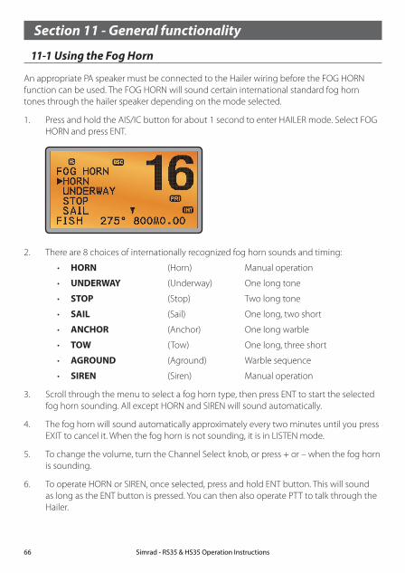
Section 11 - General functionality
11-1 Using the Fog Horn
An appropriate PA speaker must be connected to the Hailer wiring before the FOG HORN function can be used. The FOG HORN will sound certain international standard fog horn tones through the hailer speaker depending on the mode selected.
1. Press and hold the AIS/IC button for about 1 second to enter HAILER mode. Select FOG HORN and press ENT.
2. There are 8 choices of internationally recognized fog horn sounds and timing:
• HORN (Horn) Manual operation
• UNDERWAY (Underway) One long tone
• STOP (Stop) Two long tone
• SAIL (Sail) One long, two short
• ANCHOR (Anchor) One long warble
• TOW (Tow) One long, three short
• AGROUND (Aground) Warble sequence
• SIREN (Siren) Manual operation
3. Scroll through the menu to select a fog horn type, then press ENT to start the selected fog horn sounding. All except HORN and SIREN will sound automatically.
4. The fog horn will sound automatically approximately every two minutes until you press EXIT to cancel it. When the fog horn is not sounding, it is in LISTEN mode.
5. To change the volume, turn the Channel Select knob, or press + or – when the fog horn is sounding.
6. To operate HORN or SIREN, once selected, press and hold ENT button. This will sound as long as the ENT button is pressed. You can then also operate PTT to talk through the Hailer.
Simrad - RS35 & HS35 Operation Instructions66

HAILER PA►FOG HORN INTERCOM
FOG HORN►HORN UNDERWAY STOP SAIL ▼
FOG HORN UNDERWAY ▲ STOP►SAIL ANCHOR ▼
SAILOUTPUTVOL LO HI
Note: you cannot change the volume of the HORN or SIREN.
11-2 Using the PA (Public Address) Hailer
An appropriate Hailer speaker must be connected to the Hailer wiring before the PA function can be used. The PA allows you to make an announcement at high volume to people or vessels using the RS35 hand mic. The PA function also features a listen-back mode - this mode uses the Hailer speaker as a microphone to listen for a response.
1. Press and hold the AIS/IC button for about 1 second to enter HAILER mode. Select PA and press ENT.
2. Press PTT to talk through the hailer. Turn the Channel Select knob, or press + or – to change the volume. Volume can only be changed while the PTT is pressed.
3. Release PTT to LISTEN for a response.
HAILER►PA FOG HORN INTERCOM
PAOUTPUTVOL LO HI
PA
LISTEN
4. Press EXIT to return to operational mode.
Simrad - RS35 & HS35 Operation Instructions 67

Section 12 - Wireless handset functionalityThis radio can operate with up to two optional HS35 wireless handsets. When an HS35 wireless handset is successfully 'subscribed' to the radio, the button and screens on each device will be mimicked.
Note: The HS35 must be subscribed to the RS35 base station radio before it can be used. See Section 7 on how to subscribe the wireless handset to the RS35.
Note: Maximum of two handsets can be subscribed to the RS35.
12-1 Using the wireless handset
Once the HS35 handset has been paired (subscribed) to the RS35, the screen and button functionality are mimicked on each device.
Most functions that are provided on the RS35 can be accessed by the HS35 with the following differences:
• AIS: There is no AIS PPI on the HS35 screen
• SETUP: Some setup functions are not available on the HS35.
When the HS35 is not in use, it should be placed back into the charger cradle. The HS35 is charged when placed in the cradle via a contact-less inductive charging system.
12-2 Using the intercom / Conference facility
The Intercom mode works only when one or two optional HS35 handset(s) are installed. Conference mode is only available when 2 handsets are connected and is used to connect all 3 units together. This disables the radio receiver, except for incoming DSC calls.
1. Hold down AIS/IC key to enter INTERCOM or CONFERENCE mode.
HAILER PA FOG HORN►INTERCOM
INTERCOM
PUSH TO TALK
2. The intercom calls the other unit.
3. Press PTT when invited.
4. Press EXIT to quit the INTERCOM mode.
Simrad - RS35 & HS35 Operation Instructions68
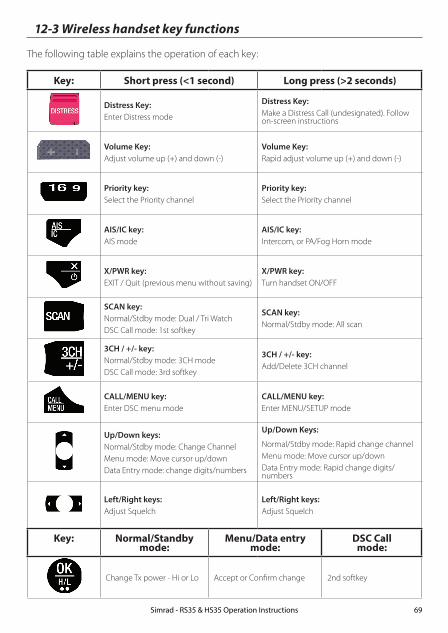
12-3 Wireless handset key functions
The following table explains the operation of each key:
Key: Short press (<1 second) Long press (>2 seconds)
Distress Key:Enter Distress mode
Distress Key:Make a Distress Call (undesignated). Follow on-screen instructions
Volume Key:Adjust volume up (+) and down (-)
Volume Key:Rapid adjust volume up (+) and down (-)
Priority key:Select the Priority channel
Priority key:Select the Priority channel
AIS/IC key:AIS mode
AIS/IC key:Intercom, or PA/Fog Horn mode
X/PWR key:EXIT / Quit (previous menu without saving)
X/PWR key:Turn handset ON/OFF
SCAN key:Normal/Stdby mode: Dual / Tri WatchDSC Call mode: 1st softkey
SCAN key:Normal/Stdby mode: All scan
3CH / +/- key:Normal/Stdby mode: 3CH modeDSC Call mode: 3rd softkey
3CH / +/- key:Add/Delete 3CH channel
CALL/MENU key:Enter DSC menu mode
CALL/MENU key:Enter MENU/SETUP mode
Up/Down keys:Normal/Stdby mode: Change ChannelMenu mode: Move cursor up/downData Entry mode: change digits/numbers
Up/Down Keys:
Normal/Stdby mode: Rapid change channelMenu mode: Move cursor up/downData Entry mode: Rapid change digits/numbers
Left/Right keys:Adjust Squelch
Left/Right keys:Adjust Squelch
Key: Normal/Standby mode:
Menu/Data entry mode:
DSC Call mode:
Change Tx power - Hi or Lo Accept or Confirm change 2nd softkey
Simrad - RS35 & HS35 Operation Instructions 69
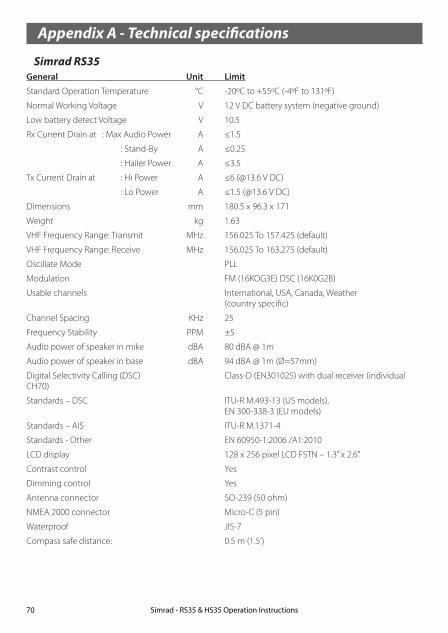
Appendix A - Technical specifications
Simrad RS35General Unit Limit
Standard Operation Temperature °C -20ºC to +55ºC (-4ºF to 131ºF)
Normal Working Voltage V 12 V DC battery system (negative ground)
Low battery detect Voltage V 10.5
Rx Current Drain at : Max Audio Power A ≤1.5
: Stand-By A ≤0.25
: Hailer Power A ≤3.5
Tx Current Drain at : Hi Power A ≤6 (@13.6 V DC)
: Lo Power A ≤1.5 (@13.6 V DC)
Dimensions mm 180.5 x 96.3 x 171
Weight kg 1.63
VHF Frequency Range: Transmit MHz 156.025 To 157.425 (default)
VHF Frequency Range: Receive MHz 156.025 To 163.275 (default)
Oscillate Mode PLL
Modulation FM (16KOG3E) DSC (16K0G2B)
Usable channels International, USA, Canada, Weather (country specific)
Channel Spacing KHz 25
Frequency Stability PPM ±5
Audio power of speaker in mike dBA 80 dBA @ 1m
Audio power of speaker in base dBA 94 dBA @ 1m (Ø=57mm)
Digital Selectivity Calling (DSC) Class-D (EN301025) with dual receiver (individual CH70)
Standards – DSC ITU-R M.493-13 (US models), EN 300-338-3 (EU models)
Standards – AIS ITU-R M.1371-4
Standards - Other EN 60950-1:2006 /A1:2010
LCD display 128 x 256 pixel LCD FSTN – 1.3” x 2.6”
Contrast control Yes
Dimming control Yes
Antenna connector SO-239 (50 ohm)
NMEA 2000 connector Micro-C (5 pin)
Waterproof JIS-7
Compass safe distance: 0.5 m (1.5’)
Simrad - RS35 & HS35 Operation Instructions70
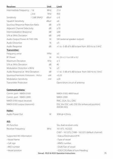
Receiver: Unit Limit
Intermediate Frequency : 1st MHz 21.4
: 2nd KHz 450
Sensitivity : 12dB SINAD dBuV ≤-6
Squelch Sensitivity dBuV ≤6
Spurious Response Rejection Ratio dB ≥70
Adjacent Channel Selectivity dB ≥70
Intermodulation Response dB ≥68
S/N at 3KHz Deviation dB ≥40
Audio Output Power At THD 10% W 5W (external speaker output)
Audio Distortion % ≤5
Audio Response dB +1 to -3 dB of 6 dB/octave from 300 Hz to 3 kHZ
Transmitter:
Frequency error PPM ±5
RF Power W Hi: 23 ± 2 / Lo: 0.8 ± 0.2
Maximum Deviation KHz ± 5
S/N at 3KHz Deviation dB 40
Modulation Distortion ±3KHz % ≤5
Audio Response at 1KHz Deviation dB +1 to -3 dB of 6 dB/octave from 300 Hz to 3 kHZ
Spurious/Harmonic Emissions : Hi/Lo uW <0.25
Modulation Sensitivity mV ≤20
Transmitter Protection Open/short circuit of antenna
Communications:Comm. port - NMEA 0183 NMEA 0183, 4800 baud
Comm. port - NMEA 2000 NMEA 2000
NMEA 0183 input (receive): RMC, GGA, GLL, GNS
NMEA 0183 output (transmit): DSC (for DSC call), DSE (for enhanced position). AIVDM (AIS)
Hailer:
Audio Power Out W 30W @ 4 Ohms
AIS:
AIS function Yes, dual receivers only
Receiver Frequency MHz 161.975, 162.025
CH87 - 161.975; CH88 - 162.025 (default channel)
Supported AIS Information: –Status/Destination/ETA
–Vessel Name –Type of vessel
–Call sign –MMSI number
–IMO number –Draft/Size of vessel
–Vessel position –SOG/COG/Rate of turn/HeadingSimrad - RS35 & HS35 Operation Instructions 71
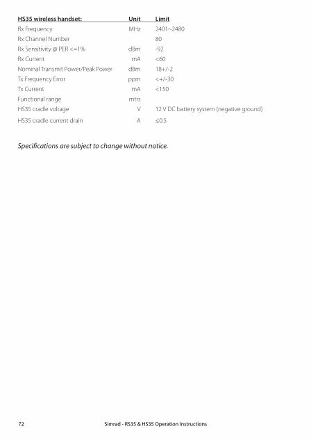
HS35 wireless handset: Unit Limit
Rx Frequency MHz 2401~2480
Rx Channel Number 80
Rx Sensitivity @ PER <=1% dBm -92
Rx Current mA <60
Nominal Transmit Power/Peak Power dBm 18+/-2
Tx Frequency Error ppm <+/-30
Tx Current mA <150
Functional range mtrs
HS35 cradle voltage V 12 V DC battery system (negative ground)
HS35 cradle current drain A ≤0.5
Specifications are subject to change without notice.
Simrad - RS35 & HS35 Operation Instructions72

RS35 NMEA 2000 PGNS 127250 Vessel Heading
127258 Magnetic Variation
129025 Position, Rapid Update
129026 COG & SOG, Rapid Update
129029 GNSS Position Data
129033 Time & Date
129038 Class A position report (Rx,Tx)
129039 Class B position report (Rx,Tx)
129040 Class B extended position report (Rx, Tx)
129041 AIS Aids to Navigation (AtoN) Report
129283 Cross Track Error
129284 Navigation Data
129285 Navigation Route/WP Information
129792 DGNSS Broadcast binary message (Tx)
129793 UTC and date report (Tx)
129794 Class A static and voyage related data (rx, tx)
129795 Addressed binary message (tx)
129796 Acknowledge (tx)
129797 Binary broadcast message (tx)
129798 SAR Aircraft Position report (tx)
129799 Radio Frequency/Mode/Power
129800 UTC/Date enquiry (tx)
129801 Addressed safety msg (rx,tx)
129802 Broadcast safety msg (rx,tx)
129803 Interrogation (tx)
129804 Assignment Mode Command (tx)
129805 Data Link Management message (tx)
129807 AIS Group Assignment
129808 DSC Call Information
129809 AIS Class B “CS” Static Data Report, Part A
129810 AIS Class B “CS” Static Data Report, Part B
130074 Route and WP Service - WP List - WP Name & Position
130842 AIS and VHF Messages (Simrad Proprietary for AIS Class B ‘CS’)
Simrad - RS35 & HS35 Operation Instructions 73

Appendix B - Troubleshooting 1. The transceiver will not power up.
A fuse may have blown or there is no voltage getting to the transceiver.
a) Check the power cable for cuts, breaks, or squashed sections.
b) After checking the wiring, replace the 7 Amp fuse.
c) Check the battery voltage. This must be greater than 10.5V.
2. The transceiver blows the fuse when the power is switched on.
The power wires may have been reversed.
a) Check that the red wire is connected to the positive battery terminal, and the black wire is connected to the negative battery terminal.
3. The speaker makes popping or whining noises when the engine is running.
Electrical noise may be interfering with the transceiver.
a) Re-route the power cables away from the engine.
b) Add a noise suppressor to the power cable.
c) Use resistive spark plug wires and/or use an alternator whine filter.
4. No sound from the external speaker. a) Check that the external speaker cable is physically connected.
b) Check the soldering of the external speaker cable.
5. Transmissions are always on low power, even when high (Hi) power is selected.
The antenna may be faulty.
a) Test the transceiver with a different antenna.
b) Have the antenna checked out.
6. Battery symbol is displayed.
The power supply is too low.
a) Check the battery voltage. This should be at least 10.5 V ± 0.5 V DC.
b) Check the alternator on the vessel.
7. GPS alarm sounds and LCD shows: Please check GPS link! The NO GPS symbol is shown.
GPS data has been lost. This sequence will repeat every 4 hours until GPS data from an opera-tional GPS receiver is available. The GPS cable may faulty or the GPS setting may be incorrect:
a) Manually enter your position and UTC time data (see Section 3.6.1)
b) Check that the GPS cable is physically connected.
c) Check the polarity of the GPS cable.
d) Check the baud rate setting of the GPS if applicable. The baud rate setting should be 4800. Parity should be set to NONE.
Simrad - RS35 & HS35 Operation Instructions74

Appendix C - US & ROW VHF marine channel chartsThe following channel charts are provided for reference only and may not be correct for all regions. It is the operators responsibility to ensure correct channels and frequencies are used for local regulations.
C-1 International channel chartCH TX (MHz) RX (MHz) MODE TRAFFIC TYPE SHIP TO
SHIPSHIP TO SHORE
NAME TAG REMARK
01 156.050 160.650 D Public Correspondence No Yes TELEPHONE
02 156.100 160.700 D Public Correspondence No Yes TELEPHONE
03 156.150 160.750 D Public Correspondence No Yes TELEPHONE
04 156.200 160.800 D Port Operations No Yes PORT OPS
05 156.250 160.850 D Port Operations No Yes PORT OPS/VTS
06 156.300 156.300 S Inter-ship Safety Yes No SAFETY
07 156.350 160.950 D Port Operations No Yes PORT OPS
08 156.400 156.400 S Commercial (inter-ship only) Yes No COMMERCIAL
09 156.450 156.450 S Inter-ship Yes Yes CALLING
10 156.500 156.500 S Commercial Yes Yes COMMERCIAL
11 156.550 156.550 S Port Operations Yes Yes VTS
12 156.600 156.600 S Port Operations Yes Yes PORT OPS/VTS
13 156.650 156.650 S Inter-ship Navigation Safety (bridge-to bridge) Yes No BRIDGE COM
14 156.700 156.700 S Port Operations Yes Yes PORT OPS/VTS
15 156.750 156.750 S Port Operations Yes Yes PORT OPS 1 1W only
16 156.800 156.800 S International Distress, Safety, and Calling Yes Yes DISTRESS
17 156.850 156.850 S State Controlled Yes Yes SAR 1 1W only
18 156.900 161.500 D Port Operations No Yes PORT OPS
19 156.950 161.550 D Ship to Shore No Yes SHIP-SHORE
20 157.000 161.600 D Port Operations No Yes PORT OPS
21 157.050 161.650 D Port Operations No Yes PORT OPS
22 157.100 161.700 D Port Operations No Yes PORT OPS
23 157.150 161.750 D Public Correspondence No Yes TELEPHONE
24 157.200 161.800 D Public Correspondence No Yes TELEPHONE
25 157.250 161.850 D Public Correspondence No Yes TELEPHONE
26 157.300 161.900 D Public Correspondence No Yes TELEPHONE
27 157.350 161.950 D Public Correspondence No Yes TELEPHONE
28 157.400 162.000 D Public Correspondence No Yes TELEPHONE
60 156.025 160.625 D Public Correspondence No Yes TELEPHONE
61 156.075 160.675 D Port Operations No Yes PORT OPS
Simrad - RS35 & HS35 Operation Instructions 75
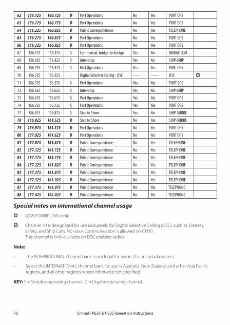
62 156.125 160.725 D Port Operations No Yes PORT OPS
63 156.175 160.775 D Port Operations No Yes PORT OPS
64 156.225 160.825 D Public Correspondence No Yes TELEPHONE
65 156.275 160.875 D Port Operations No Yes PORT OPS
66 156.325 160.925 D Port Operations No Yes PORT OPS
67 156.375 156.375 S Commercial, bridge-to-bridge Yes No BRIDGE COM
68 156.425 156.425 S Inter-ship Yes No SHIP-SHIP
69 156.475 156.475 S Port Operations Yes Yes PORT OPS
70 156.525 156.525 - Digital Selective Calling - DSC ------ ------ DSC 2
71 156.575 156.575 S Port Operations Yes Yes PORT OPS
72 156.625 156.625 S Inter-ship Yes No SHIP-SHIP
73 156.675 156.675 S Port Operations Yes Yes PORT OPS
74 156.725 156.725 S Port Operations Yes Yes PORT OPS
77 156.875 156.875 S Ship to Shore Yes No SHIP-SHORE
78 156.925 161.525 D Ship to Shore No Yes SHIP-SHORE
79 156.975 161.575 D Port Operations No Yes PORT OPS
80 157.025 161.625 D Port Operations No Yes PORT OPS
81 157.075 161.675 D Public Correspondence No Yes TELEPHONE
82 157.125 161.725 D Public Correspondence No Yes TELEPHONE
83 157.175 161.775 D Public Correspondence No Yes TELEPHONE
84 157.225 161.825 D Public Correspondence No Yes TELEPHONE
85 157.275 161.875 D Public Correspondence No Yes TELEPHONE
86 157.325 161.925 D Public Correspondence No Yes TELEPHONE
87 157.375 161.975 D Public Correspondence No Yes TELEPHONE
88 157.425 162.025 D Public Correspondence No Yes TELEPHONE
Special notes on international channel usage1 . LOW POWER (1W) only.
2 . Channel 70 is designated for use exclusively for Digital Selective Calling (DSC), such as Distress, Safety, and Ship Calls. No voice communication is allowed on CH70. This channel is only available on DSC enabled radios.
Note:
• The INTERNATIONAL channel bank is not legal for use in U.S. or Canada waters.
• Select the INTERNATIONAL channel bank for use in Australia, New Zealand and other Asia Pacific regions, and all other regions where otherwise not specified.
KEY: S = Simplex operating channel; D = Duplex operating channel.
Simrad - RS35 & HS35 Operation Instructions76
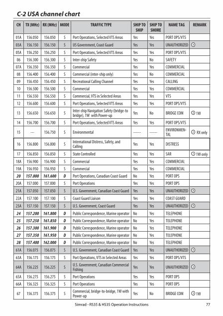
C-2 USA channel chartCH TX (MHz) RX (MHz) MODE TRAFFIC TYPE SHIP TO
SHIPSHIP TO SHORE
NAME TAG REMARK
01A 156.050 156.050 S Port Operations, Selected VTS Areas Yes Yes PORT OPS/VTS
03A 156.150 156.150 S US Government, Coast Guard Yes Yes UNAUTHORIZED 4
05A 156.250 156.250 S Port Operations, Selected VTS Areas Yes Yes PORT OPS/VTS
06 156.300 156.300 S Inter-ship Safety Yes No SAFETY
07A 156.350 156.350 S Commercial Yes Yes COMMERCIAL
08 156.400 156.400 S Commercial (inter-ship only) Yes No COMMERCIAL
09 156.450 156.450 S Recreational Calling Channel Yes Yes CALLING
10 156.500 156.500 S Commercial Yes Yes COMMERCIAL
11 156.550 156.550 S Commercial, VTS in Selected Areas Yes Yes VTS
12 156.600 156.600 S Port Operations, Selected VTS Areas Yes Yes PORT OPS/VTS
13 156.650 156.650 S Inter-ship Navigation Safety (bridge-to bridge), 1W with Power-up Yes No BRIDGE COM 3 1W
14 156.700 156.700 S Port Operations, Selected VTS Areas Yes Yes PORT OPS/VTS
15 --- 156.750 S Environmental ------ ------ ENVIRONMEN-TAL
2 RX only
16 156.800 156.800 S International Distress, Safety, and Calling Yes Yes DISTRESS
17 156.850 156.850 S State Controlled Yes Yes SAR 1 1W only
18A 156.900 156.900 S Commercial Yes Yes COMMERCIAL
19A 156.950 156.950 S Commercial Yes Yes COMMERCIAL
20 157.000 161.600 D Port Operations, Canadian Coast Guard No Yes PORT OPS
20A 157.000 157.000 S Port Operations Yes Yes PORT OPS
21A 157.050 157.050 S U.S. Government, Canadian Coast Guard Yes Yes UNAUTHORIZED 4
22A 157.100 157.100 S Coast Guard Liaison Yes Yes COAST GUARD
23A 157.150 157.150 S U.S. Government, Coast Guard Yes Yes UNAUTHORIZED 4
24 157.200 161.800 D Public Correspondence, Marine operator No Yes TELEPHONE
25 157.250 161.850 D Public Correspondence, Marine operator No Yes TELEPHONE
26 157.300 161.900 D Public Correspondence, Marine operator No Yes TELEPHONE
27 157.350 161.950 D Public Correspondence, Marine operator No Yes TELEPHONE
28 157.400 162.000 D Public Correspondence, Marine operator No Yes TELEPHONE
61A 156.075 156.075 S U.S. Government, Canadian Coast Guard Yes Yes UNAUTHORIZED 4
63A 156.175 156.175 S Port Operations, VTS in Selected Areas Yes Yes PORT OPS/VTS
64A 156.225 156.225 S U.S. Government, Canadian Commercial Fishing Yes Yes UNAUTHORIZED 4
65A 156.275 156.275 S Port Operations Yes Yes PORT OPS
66A 156.325 156.325 S Port Operations Yes Yes PORT OPS
67 156.375 156.375 S Commercial, bridge-to-bridge, 1W with Power-up Yes No BRIDGE COM 3 1W
Simrad - RS35 & HS35 Operation Instructions 77

68 156.425 156.425 S Boat Operations, Recreational Yes No SHIP - SHIP
69 156.475 156.475 S Boat Operations, Recreational Yes Yes PLEASURE
70 156.525 156.525 Digital Selective Calling - DSC ------ ------ DSC 6
71 156.575 156.575 S Boat Operations, Recreational Yes Yes PLEASURE
72 156.625 156.625 S Boat Operations, Recreational Yes No SHIP - SHIP
73 156.675 156.675 S Port Operations Yes Yes PORT OPS
74 156.725 156.725 S Port Operations Yes Yes PORT OPS
77 156.875 156.875 S Port Operations Yes Yes PORT OPS 1 1W only
78A 156.925 156.925 S Boat Operations, Recreational Yes No SHIP - SHIP
79A 156.975 156.975 S Commercial Yes Yes COMMERCIAL
80A 157.025 157.025 S Commercial Yes Yes COMMERCIAL
81A 157.075 157.075 S U.S. Government, Environmental Protec-tion Agency Operations Yes Yes UNAUTHORIZED 4
82A 157.125 157.125 S U.S. Government, Canadian Coast Guard Yes Yes UNAUTHORIZED 4
83A 157.175 157.175 S U.S. Government, Canadian Coast Guard Yes Yes UNAUTHORIZED 4
84 157.225 161.825 D Public Correspondence, Marine Operator No Yes TELEPHONE
84A 157.225 157.225 S Public Correspondence, Marine Operator
85 157.275 161.875 D Public Correspondence, Marine Operator No Yes TELEPHONE
85A 157.275 157.275 S Public Correspondence, Marine Operator
86 157.325 161.925 D Public Correspondence, Marine Operator No Yes TELEPHONE
86A 157.325 157.325 S Public Correspondence, Marine Operator
87 157.375 161.975 D Public Correspondence, Marine Operator No Yes TELEPHONE
87A 157.375 157.375 S Public Correspondence, Marine Operator
88 157.425 162.025 D Public Correspondence, Marine Operator No Yes TELEPHONE
88A 157.425 157.425 S Commercial, Inter-ship Only Yes No COMMERCIAL
Special notes on USA channel usage1 . LOW POWER (1 W) only.2 . Receive Only.3 . LOW POWER (1 W) initially. Override to HIGH POWER by holding down H/L key before transmitting.
Used normally in bridge-to-bridge communications.4 . Lightly shaded simplex channels 03A, 21A, 23A, 61A, 64A, 81A, 82A, and 83A cannot be lawfully used
in U.S. waters unless special authorization is obtained from the U.S. Coast Guard. Not for use by the general public.
5 . The letter “A” illuminated by the channel number indicates the USA channel is simplex.
This same channel is always duplex when selecting International. There is no “A” reference for Interna-tional channels. The letter “B” is only used for some Canadian “Receive only” channels.
6 . Channel 70 is designated for use exclusively for Digital Selective Calling (DSC), such as Distress, Safety, and Ship Calls. No voice communication is allowed on CH70. This channel is only available on DSC enabled radios.
KEY: S = Simplex operating channel; D = Duplex operating channel.
Simrad - RS35 & HS35 Operation Instructions78
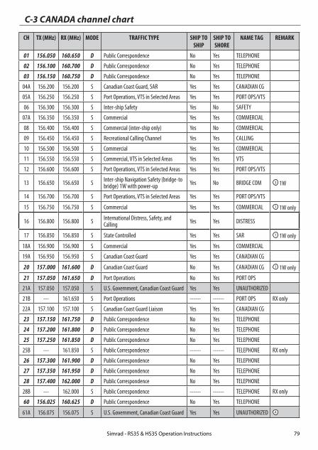
C-3 CANADA channel chart
CH TX (MHz) RX (MHz) MODE TRAFFIC TYPE SHIP TO SHIP
SHIP TO SHORE
NAME TAG REMARK
01 156.050 160.650 D Public Correspondence No Yes TELEPHONE
02 156.100 160.700 D Public Correspondence No Yes TELEPHONE
03 156.150 160.750 D Public Correspondence No Yes TELEPHONE
04A 156.200 156.200 S Canadian Coast Guard, SAR Yes Yes CANADIAN CG
05A 156.250 156.250 S Port Operations, VTS in Selected Areas Yes Yes PORT OPS/VTS
06 156.300 156.300 S Inter-ship Safety Yes No SAFETY
07A 156.350 156.350 S Commercial Yes Yes COMMERCIAL
08 156.400 156.400 S Commercial (inter-ship only) Yes No COMMERCIAL
09 156.450 156.450 S Recreational Calling Channel Yes Yes CALLING
10 156.500 156.500 S Commercial Yes Yes COMMERCIAL
11 156.550 156.550 S Commercial, VTS in Selected Areas Yes Yes VTS
12 156.600 156.600 S Port Operations, VTS in Selected Areas Yes Yes PORT OPS/VTS
13 156.650 156.650 S Inter-ship Navigation Safety (bridge-to bridge) 1W with power-up Yes No BRIDGE COM 3 1W
14 156.700 156.700 S Port Operations, VTS in Selected Areas Yes Yes PORT OPS/VTS
15 156.750 156.750 S Commercial Yes Yes COMMERCIAL 1 1W only
16 156.800 156.800 S International Distress, Safety, and Calling Yes Yes DISTRESS
17 156.850 156.850 S State Controlled Yes Yes SAR 1 1W only
18A 156.900 156.900 S Commercial Yes Yes COMMERCIAL
19A 156.950 156.950 S Canadian Coast Guard Yes Yes CANADIAN CG
20 157.000 161.600 D Canadian Coast Guard No Yes CANADIAN CG 1 1W only
21 157.050 161.650 D Port Operations No Yes PORT OPS
21A 157.050 157.050 S U.S. Government, Canadian Coast Guard Yes Yes UNAUTHORIZED
21B --- 161.650 S Port Operations ------ ------ PORT OPS RX only
22A 157.100 157.100 S Canadian Coast Guard Liaison Yes Yes CANADIAN CG
23 157.150 161.750 D Public Correspondence No Yes TELEPHONE
24 157.200 161.800 D Public Correspondence No Yes TELEPHONE
25 157.250 161.850 D Public Correspondence No Yes TELEPHONE
25B --- 161.850 S Public Correspondence ------ ------ TELEPHONE RX only
26 157.300 161.900 D Public Correspondence No Yes TELEPHONE
27 157.350 161.950 D Public Correspondence No Yes TELEPHONE
28 157.400 162.000 D Public Correspondence No Yes TELEPHONE
28B --- 162.000 S Public Correspondence ------ ------ TELEPHONE RX only
60 156.025 160.625 D Public Correspondence No Yes TELEPHONE
61A 156.075 156.075 S U.S. Government, Canadian Coast Guard Yes Yes UNAUTHORIZED 4
Simrad - RS35 & HS35 Operation Instructions 79

62A 156.125 156.125 S Canadian Coast Guard Yes Yes CANADIAN CG
64 156.225 160.825 D Public Correspondence, Duplex No Yes TELEPHONE
64A 156.225 156.225 S U.S. Government, Canadian Commercial Fishing Yes Yes UNAUTHORIZED 4
65A 156.275 156.275 S Port Operations Yes Yes PORT OPS
66A 156.325 156.325 S Port Operations Yes Yes PORT OPS 1 1W only
67 156.375 156.375 S Commercial, SAR Yes No COMMERCIAL
68 156.425 156.425 S Boat Operations, Recreational Yes No SHIP - SHIP
69 156.475 156.475 S Commercial Fishing Only Yes Yes COMMERCIAL
70 156.525 156.525 S Digital Selective Calling - DSC ------ ------ DSC 6
71 156.575 156.575 S Boat Operations, Recreational Yes Yes PLEASURE
72 156.625 156.625 S Inter-ship Yes No SHIP - SHIP
73 156.675 156.675 S Commercial Fishing Only Yes Yes COMMERCIAL
74 156.725 156.725 S Commercial Fishing Only Yes Yes COMMERCIAL
77 156.875 156.875 S Port Operations Yes Yes PORT OPS 1 1W only
78A 156.925 156.925 S Boat Operations, Recreational Yes No SHIP - SHIP
79A 156.975 156.975 S Commercial Yes Yes COMMERCIAL
80A 157.025 157.025 S Commercial Yes Yes COMMERCIAL
81A 157.075 157.075 S U.S. Government Operations Yes Yes UNAUTHORIZED 4
82A 157.125 157.125 S U.S. Government, Canadian Coast Guard Yes Yes UNAUTHORIZED 4
83 157.175 161.775 D Canadian Coast Guard Yes Yes CANADIAN CG
83A 157.175 157.175 S U.S. Government, Canadian Coast Guard Yes Yes UNAUTHORIZED 4
83B --- 161.775 S Canadian Coast Guard, RX Only ------ ------ CANADIAN CG
84 157.225 161.825 D Public Correspondence, Marine Operator No Yes TELEPHONE
85 157.275 161.875 D Public Correspondence, Marine Operator No Yes TELEPHONE
86 157.325 161.925 D Public Correspondence, Marine Operator No Yes TELEPHONE
87 157.375 161.975 D Public Correspondence, Marine Operator No Yes TELEPHONE
88 157.425 162.025 D Public Correspondence, Marine Operator No Yes TELEPHONE
Special notes on Canada channel usage1 . LOW POWER (1 W) only.
2 . Receive Only.
3 . LOW POWER (1 W) initially. Override to HIGH POWER by holding down H/L key before transmitting. Used normally in bridge-to-bridge communications.
4 . Lightly shaded simplex channels 21A, 23A, 61A, 64A, 81A, 82A, and 83A cannot be lawfully used in Canada waters unless special authorization is obtained from the Canadian Coast Guard. Not for use by the general public.
5 . The letter “A” illuminated by the channel number indicates the Canada channel is simplex. This same channel is always duplex when selecting International. There is no “A” reference for International channels. The letter “B” is only used for some Canadian
Simrad - RS35 & HS35 Operation Instructions80

“Receive only” channels.
6 . Channel 70 is designated for use exclusively for Digital Selective Calling (DSC), such as Distress, Safety, and Ship Calls. No voice communication is allowed on CH70. This channel is only available on DSC enabled radios.
Note: The CANADA mode is not legal to use in U.S. waters.
KEY: S = Simplex operating channel; D = Duplex operating channel.
C-4 US & Canada WEATHER channels
CH RX (MHz) TRAFFIC TYPE NAME REMARK
WX01 162.550 NOAA Weather Channel NOAA WX RX only
WX02 162.400 NOAA Weather Channel NOAA WX RX only
WX03 162.475 NOAA Weather Channel NOAA WX RX only
WX04 162.425 NOAA Weather Channel NOAA WX RX only
WX05 162.450 NOAA Weather Channel NOAA WX RX only
WX06 162.500 NOAA Weather Channel NOAA WX RX only
WX07 162.525 NOAA Weather Channel NOAA WX RX only
WX08 161.650 CANADIAN Weather Channel CANADA WX RX only
WX09 161.775 CANADIAN Weather Channel CANADA WX RX only
WX10 163.275 NOAA Weather Channel NOAA WX RX only
Simrad - RS35 & HS35 Operation Instructions 81

C-5 EAS (Emergency Alert Systems) alerts
National Codes Nature of Activation
Event Codes Message
Emergency Action Notification (National only) EAN WARNING
EAT ADVISORY
National Information Center NIC ADVISORY
National Periodic Test NPT TEST
Required Monthly Test RMT TEST
Required Weekly Test RWT TEST
State and Local Codes Nature of Activation
Event Codes Message
Avalanche Warning AVW WARNING
Avalanche Watch AVA WATCH
Blizzard Warning BZW WARNING
Child Abduction Emergency CAE WARNING
Civil Danger Warning CDW WARNING
Civil Emergency Message CEM WARNING
Coastal Flood Warning CFW WARNING
Coastal Flood Watch CFA WATCH
Dust Storm Warning DSW WARNING
Earthquake Warning EQW WARNING
Evacuation Immediate EVI WARNING
Fire Warning FRW WARNING
Flash Flood Warning FFW WARNING
Flash Flood Watch FFA WATCH
Flash Flood Statement FFS ADVISORY
Flood Warning FLW WARNING
Flood Watch FLA WATCH
Flood Statement FLS ADVISORY
Hazardous Materials Warning HMW WARNING
High Wind Warning HWW WARNING
High Wind Watch HWA WATCH
Simrad - RS35 & HS35 Operation Instructions82

State and Local Codes Nature of Activation
Event Codes Message
Hurricane Warning HUW WARNING
Hurricane Watch HUA WATCH
Hurricane Statement HLS ADVISORY
Law Enforcement Warning LEW WARNING
Local Area Emergency LAE WARNING
911 Telephone Outage Emergency TOE WARNING
Nuclear Power Plant Warning NUW WARNING
Radiological Hazard Warning RHW WARNING
Severe Thunderstorm Warning SVR WARNING
Severe Thunderstorm Watch SVA WATCH
Severe Weather Statement SVS ADVISORY
Shelter in Place Warning SPW WARNING
Special Marine Warning SMW WARNING
Special Weather Statement SPS ADVISORY
Tornado Warning TOR WARNING
Tornado Watch TOA WATCH
Tropical Storm Warning TRW WARNING
Tropical Storm Watch TRA WATCH
Tsunami Warning TSW WARNING
Tsunami Watch TSA WATCH
Volcano Warning VOW WARNING
Winter Storm Warning WSW WARNING
Winter Storm Watch WSA WATCH
For more information about the Emergency Alert System and event codes, visit:
http://www.nws.noaa.gov/os/eas_codes.shtml
Simrad - RS35 & HS35 Operation Instructions 83

D-1 EU international channel chartCH TX (MHz) RX (MHz) MODE TRAFFIC TYPE SHIP TO
SHIPSHIP TO SHORE
NAME TAG REMARK
01 156.050 160.650 D Public Correspondence, Port Op No Yes PHONE-PORTOP
02 156.100 160.700 D Public Correspondence, Port Op No Yes PHONE-PORTOP
03 156.150 160.750 D Public Correspondence, Port Op No Yes PHONE-PORTOP
04 156.200 160.800 D Public Correspondence, Port Op No Yes PHONE-PORTOP
05 156.250 160.850 D Public Correspondence, Port Op No Yes PHONE-PORTOP
06 156.300 156.300 S Inter-ship Safety Yes No SAFETY
07 156.350 160.950 D Public Correspondence, Port Op No Yes PHONE-PORTOP
08 156.400 156.400 S Commercial (inter-ship only) Yes No SHIP-SHIP
09 156.450 156.450 S Inter-ship Yes Yes SHIP-SHIP
10 156.500 156.500 S Inter-ship Yes Yes SHIP-SHIP
11 156.550 156.550 S Port Operations Yes Yes PORT OPS
12 156.600 156.600 S Port Operations Yes Yes PORT OPS
13 156.650 156.650 S Inter-ship Navigation Safety (bridge-to bridge) Yes No SAFETY COM
14 156.700 156.700 S Port Operations Yes Yes PORT OPS
15 156.750 156.750 S Inter-ship Yes Yes PORT OPS 1 1W only
16 156.800 156.800 S International Distress, Safety, and Calling Yes Yes DISTRESS
17 156.850 156.850 S Inter-ship Yes Yes PORT OPS 1 1W only
18 156.900 161.500 D Public Correspondence, Port Op No Yes PHONE-PORTOP
19 156.950 161.550 D Public Correspondence, Port Op No Yes PHONE-PORTOP
20 157.000 161.600 D Public Correspondence, Port Op No Yes PHONE-PORTOP
21 157.050 161.650 D Public Correspondence, Port Op No Yes PHONE-PORTOP
22 157.100 161.700 D Public Correspondence, Port Op No Yes PHONE-PORTOP
23 157.150 161.750 D Public Correspondence, Port Op No Yes PHONE-PORTOP
24 157.200 161.800 D Public Correspondence, Port Op No Yes PHONE-PORTOP
25 157.250 161.850 D Public Correspondence, Port Op No Yes PHONE-PORTOP
26 157.300 161.900 D Public Correspondence, Port Op No Yes PHONE-PORTOP
27 157.350 161.950 D Public Correspondence, Port Op No Yes PHONE-PORTOP
28 157.400 162.000 D Public Correspondence, Port Op No Yes PHONE-PORTOP
60 156.025 160.625 D Public Correspondence, Port Op No Yes PHONE-PORTOP
61 156.075 160.675 D Public Correspondence, Port Op No Yes PHONE-PORTOP
Appendix D - EU VHF marine channel chartsThe following channel charts are provided for reference only and may not be correct for all regions. It is the operators responsibility to ensure correct channels and frequencies are used for local regu-lations. For specific channel information for your country, please refer to local authorities.
Simrad - RS35 & HS35 Operation Instructions84

62 156.125 160.725 D Public Correspondence, Port Op No Yes PHONE-PORTOP
63 156.175 160.775 D Public Correspondence, Port Op No Yes PHONE-PORTOP
64 156.225 160.825 D Public Correspondence, Port Op No Yes PHONE-PORTOP
65 156.275 160.875 D Public Correspondence, Port Op No Yes PHONE-PORTOP
66 156.325 160.925 D Public Correspondence, Port Op No Yes PHONE-PORTOP
67 156.375 156.375 S Commercial, bridge-to-bridge Yes No SHIP-SHIP
68 156.425 156.425 S Port Operations Yes No PORT OPS
69 156.475 156.475 S Inter-ship Yes Yes SHIP-SHIP
70 156.525 156.525 - Digital Selective Calling - DSC ------ ------ DSC 2
71 156.575 156.575 S Port Operations Yes Yes PORT OPS
72 156.625 156.625 S Inter-ship Yes No SHIP-SHIP
73 156.675 156.675 S Inter-ship Yes Yes SHIP-SHIP
74 156.725 156.725 S Port Operations Yes Yes PORT OPS
75 156.775 156.775 S Port Operations Yes Yes PORT OPS 1 1W only
76 156.825 156.825 S Port Operations Yes Yes PORT OPS 1 1W only
77 156.875 156.875 S Inter-ship Yes No SHIP-SHIP
78 156.925 161.525 D Public Correspondence, Port Op No Yes PHONE-PORTOP
79 156.975 161.575 D Public Correspondence, Port Op No Yes PHONE-PORTOP
80 157.025 161.625 D Public Correspondence, Port Op No Yes PHONE-PORTOP
81 157.075 161.675 D Public Correspondence, Port Op No Yes PHONE-PORTOP
82 157.125 161.725 D Public Correspondence, Port Op No Yes PHONE-PORTOP
83 157.175 161.775 D Public Correspondence, Port Op No Yes PHONE-PORTOP
84 157.225 161.825 D Public Correspondence, Port Op No Yes PHONE-PORTOP
85 157.275 161.875 D Public Correspondence, Port Op No Yes PHONE-PORTOP
86 157.325 161.925 D Public Correspondence, Port Op No Yes PHONE-PORTOP
87 157.375 157.375 S Port Operations No Yes PORT OPS 3
88 157.425 157.425 S Port Operations No Yes PORT OPS 3
Special notes on EU international channel usage1 . LOW POWER (1W) only.
2 . Channel 70 is designated for use exclusively for Digital Selective Calling (DSC), such as Distress, Safety, and Ship Calls. No voice communication is allowed on CH70. This channel is only available on DSC enabled radios.
3 . Maybe Duplex in some regions
KEY: S = Simplex operating channel; D = Duplex operating channel.
Simrad - RS35 & HS35 Operation Instructions 85

D-2 Inland waterways country specific table - ATIS ON
For specific channel information for your country, please refer to local authorities.
CH SPECIFIC FOOT-NOTES
TRANSMITTING FREQUENCY (MHZ)
SHIP-TO-SHIP SHIP-TO PORT NAUTICAL INFORMATION
SHIP LAND
60 a) 156.025 160.625 x
01 a) 156.05 160.65 x
61 a) 156.075 160.675 x
02 a) 156.1 160.7 x
62 a) 156.125 160.725 x
03 a) 156.15 160.75 x
63 a) 156.175 160.775 x
04 a) 156.2 160.8 x
64 a) 156.225 160.825 x
05 a) 156.25 160.85 x
65 a) 156.275 160.875 x
06 a) b) 156.3 156.3 x
66 a) 156.325 160.925 x
07 a) 156.35 160.95 x
67 a) c) 156.375 156.375 x
08 a) q) 156.4 156.4 x
68 a) 156.425 156.425 x
09 a) b) c) 156.45 156.45 x
69 a) 156.475 156.475 x
10 e) 156.5 156.5 x
70 a) 156.525 156.525 Digital selective calling for distress, safety and calling
11 156.55 156.55 x
71 156.575 156.575 x
12 156.6 156.6 x
72 a) r) 156.625 156.625 x
13 f) 156.65 156.65 x
73 f) g) 156.675 156.675 x
14 q) 156.7 156.7 x
74 a) 156.725 156.725 x
15 h) 156.75 156.75 x
75 o) 156.775 156.775 x
16 i) 156.8 156.8 x
76 j) d) o) 156.825 156.825 x
17 h) 156.85 156.85 x
Simrad - RS35 & HS35 Operation Instructions86

General remarks to Country Specific table:
1 The channels for service categories ship-to-ship and nautical information may also be used for vessel traffic -sys tems by traffic centres.
2 In some countries, frequencies certain channels are used for an other service category or other radio services. These countries are Austria, Bulgaria, Croatia, the Federal Republic of Yugosla via, Hun gary, Moldova, Romania, the Russian Federation, the Slovak Republic, the Czech Republic (with exemption of channels 08, 09, 72, 74 and 86), Ukraine and the Federal Republic of Yugosla via. The Administra tions concerned should make any possible attempt to make these fre quencies channels as soon as possible available for the radiotelephone service on Inland Waterways and/or the required service catego ry.
77 a) k) 156.875 156.875 x
18 156.9 161.5 x
78 156.925 161.525 x
19 156.95 161.55 x
79 a) 156.975 161.575 x
20 157 161.6 x
80 157.025 161.625 x
21 a) 157.05 161.65 x
81 a) 157.075 161.675 x
22 157.1 161.7 x
82 l) m) 157.125 161.725 x
23 m) 157.15 161.75 x
83 a) m) 157.175 161.775 x
24 m) 157.2 161.8 x
84 m) 157.225 161.825 x
25 m) 157.25 161.85 x
85 a) m) 157.275 161.875 x
26 m) 157.3 161.9 x
86 a) m) 157.325 161.925 x
27 m) 157.35 161.95 x
87 a) d) 157.375 157.375 x
28 m) 157.4 162 x
88 a) p) 157.425 157.425 x
AIS 1 a) n) 161.975 161.975
AIS 2 a) n) 162.025 162.025
Simrad - RS35 & HS35 Operation Instructions 87

Explanation of specific footnotes in Country Specific table:
a. In the countries mentioned under remark 2, it is strictly prohibited to use this channel.
b. This channel is not allowed to be used between Rhine km 150 and km 350.
c. In the Netherlands, this channel is used by for its on-scene communi cations during safety operati ons on the North Sea, IJsselmeer, Wadden zee, Ooster- and Wester schelde.
d. This channel may also be used for piloting, mooring, tugging and for other nautical purposes.
e. This channel is the first ship-to-ship channel, unless the competent authority has designated an other channel. In the countries mentioned under remark 2, it is allowed that the output power is set to a value between 6 and 25 W until 1 January 2005.
f. In the countries mentioned under remark 2, this channel is used for service category ship-to-port authorities.
g. In the Netherlands, this channel is used by its national coastgu ard for communicati ons during oil pollution operations on the North Sea and for safety messages for the North Sea, Wadden zee, IJsselmeer, Ooster- and Westerschelde.
h. This channel may be used only for service category on-board communications.
i. This channel may be used only for communications between sea going vessels and participating land stations in case of distress and safety communica ti ons within the maritime sea-areas. In the countries mentioned under remark 2, this channel may be used only for distress, safety and calling.
j. The output power shall be reduced automatically to a value between 0.5 and 1 W.
k. This channel may be used for communications with a social charac ter.
l. In the Netherlands and Belgium, this channel may be used for trans mit ting mes sages concerning bunkering and victualling. The output power has to be reduced manually to a value between 0.5 and 1 W.
m. This channel may also be used for public correspondence.
n. This channel will be used for an automatic ship identifi cation and surveillance sys tem (AIS) capable of providing worldw ide operating on seas and Inland Waterways.
o. The availability of this channel is on a voluntary basis. All existing equipment shall be capable to of operating on this channel within a ten-year period after the entry into force of this Arrangement.
p. After permission of the competent authority, this channel may be used only for spe cial events on a temporary basis.
q. In the Czech Republic this channel is used for service category nautical information.
r. In the Czech Republic this channel is used for service category ship-to-port authorities.
Simrad - RS35 & HS35 Operation Instructions88
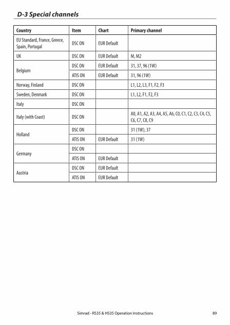
D-3 Special channels
Country Item Chart Primary channel
EU Standard, France, Greece, Spain, Portugal
DSC ON EUR Default
UK DSC ON EUR Default M, M2
BelgiumDSC ON EUR Default 31, 37, 96 (1W)
ATIS ON EUR Default 31, 96 (1W)
Norway, Finland DSC ON L1, L2, L3, F1, F2, F3
Sweden, Denmark DSC ON L1, L2, F1, F2, F3
Italy DSC ON
Italy (with Coast) DSC ON A0, A1, A2, A3, A4, A5, A6, C0, C1, C2, C3, C4, C5, C6, C7, C8, C9
HollandDSC ON 31 (1W), 37
ATIS ON EUR Default 31 (1W)
GermanyDSC ON
ATIS ON EUR Default
AustriaDSC ON EUR Default
ATIS ON EUR Default
Simrad - RS35 & HS35 Operation Instructions 89

Appendix E - MMSI and license informationYou must obtain a user MMSI (Marine Mobile Service Identity) and enter it into your RS35 in order to use the DSC functions. Contact the appropriate authorities in your country. If you are unsure who to contact, consult your Simrad dealer.
The user MMSI is a unique nine digit number, similar to a personal telephone number. It is used on marine transceivers that are capable of using DSC (Digital Select Calling).
Depending upon your location, you may need a radio station license for the RS35 . You may also need an individual operator’s license.
Simrad recommends that you check the requirements of your national radio com-munications authorities before operating DSC functions.
AT - Austria
BE - Belgium
BG - Bulgaria
CY - Cyprus
CZ - Czech Republic
DK - Denmark
EE - Estonia
FI - Finland
FR - France
DE - Germany
GR - Greece
HU - Hungary
IS - Iceland
IE - Ireland
IT - Italy
LI - Liechtenstein
LV - Latvia
LT - Lithuania
LU - Luxembourg
MT - Malta
NL - Netherlands
NO - Norway
PL - Poland
PT - Portugal
RO - Romania
SK - Slovakia
SI - Slovenia
ES - Spain
SE - Sweden
CH - Switzerland
TR - Turkey
UK - United Kingdom
Countries of intended use in the EU:
CAUTION
Under extreme operating conditions, the temperature of the rear heat-sink on this radio may exceed normal surface temperatures. Caution is advised to prevent possible skin burns.
Simrad - RS35 & HS35 Operation Instructions90


1177
*988
-102
64-0
01*


