Embed Size (px)
Citation preview
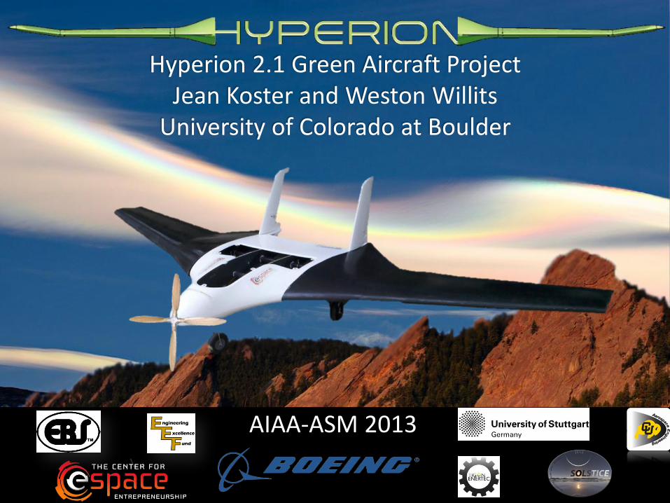
AIAA-ASM 2013
Hyperion 2.1 Green Aircraft Project Jean Koster and Weston Willits
University of Colorado at Boulder
2
Agenda
Hyperion 2012-13
Goals and Team
Manufacturing and FEA
Experiments / Results
System Configuration & Design
Hyperion Goal
3 Hyperion 2012-13
Conceive, design, implement, and operate (CDIO) an aerial vehicle for engineering academic experience. Investigate novel green technologies for improvements in aircraft capabilities and efficiencies.
Goal:
4
Project Progress
Hyperion 2012-13
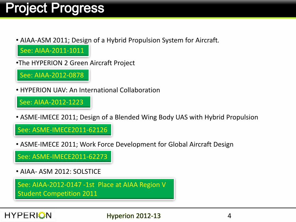
• AIAA-ASM 2011; Design of a Hybrid Propulsion System for Aircraft.
•The HYPERION 2 Green Aircraft Project
• HYPERION UAV: An International Collaboration
• ASME-IMECE 2011; Design of a Blended Wing Body UAS with Hybrid Propulsion
• ASME-IMECE 2011; Work Force Development for Global Aircraft Design
• AIAA- ASM 2012: SOLSTICE
See: AIAA-2012-1223
See: ASME-IMECE2011-62126
See: ASME-IMECE2011-62273
See: AIAA-2011-1011
See: AIAA-2012-0147 -1st Place at AIAA Region V Student Competition 2011
See: AIAA-2012-0878
Hyperion 2.1 Deliverables
5 Hyperion 2012-13
Studies and Deliverables:
Fly R/C with COTS EM
Fly R/C with Hybrid gas-electric Engine
Fly Autonomously with COTS EM
Stretch Goal - Fly Autonomously with Hybrid Engine
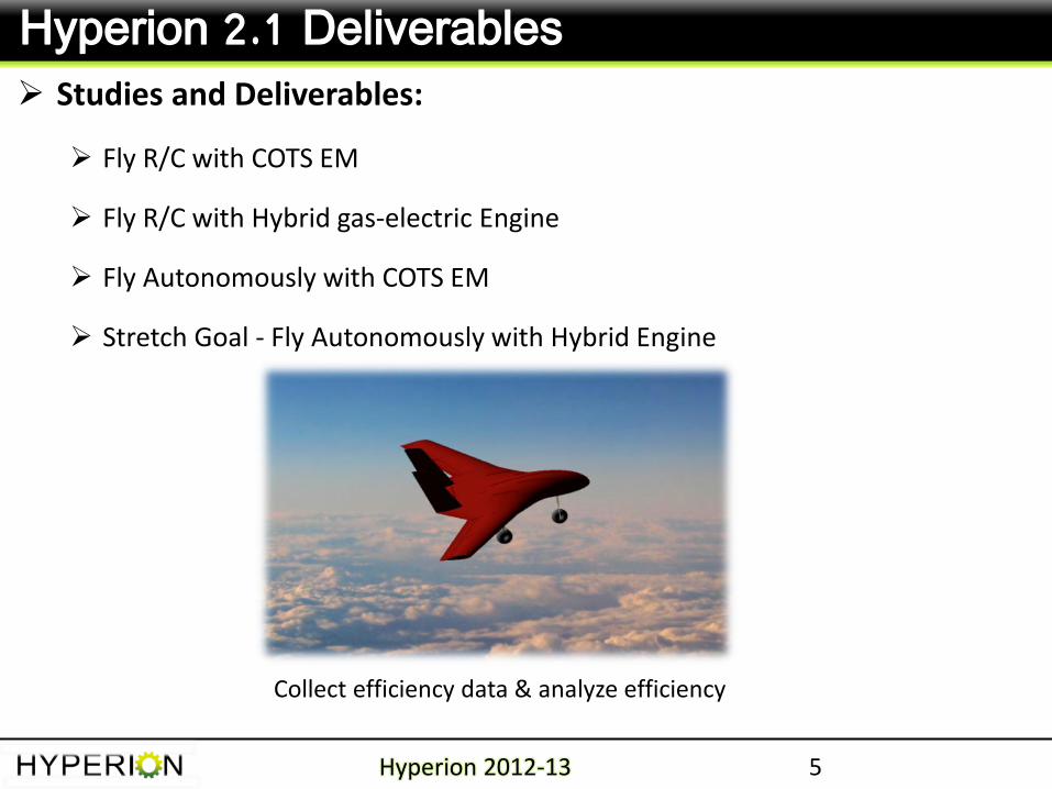
Collect efficiency data & analyze efficiency
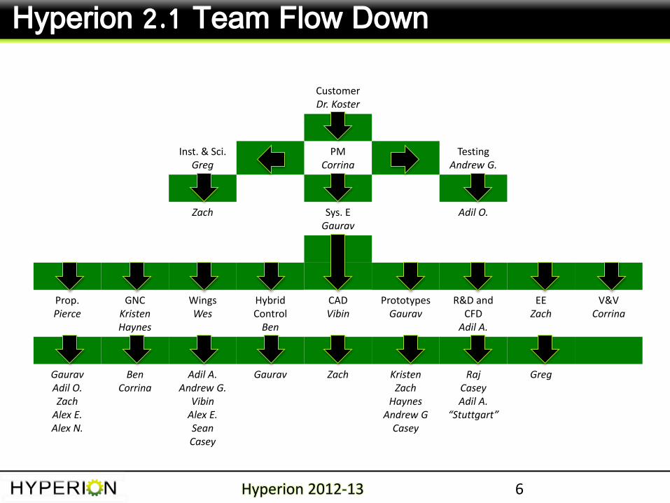
Customer Dr. Koster
Inst. & Sci. Greg
PM Corrina
Testing Andrew G.
Zach Sys. E Gaurav
Adil O.
Prop. Pierce
GNC Kristen Haynes
Wings Wes
Hybrid Control
Ben
CAD Vibin
Prototypes Gaurav
R&D and CFD
Adil A.
EE Zach
V&V Corrina
Gaurav Adil O. Zach
Alex E. Alex N.
Ben Corrina
Adil A. Andrew G.
Vibin Alex E. Sean Casey
Gaurav Zach Kristen Zach
Haynes Andrew G
Casey
Raj Casey Adil A.
“Stuttgart”
Greg
6
Hyperion 2.1 Team Flow Down
Hyperion 2012-13
7
Agenda
Hyperion 2012-13
Goals and Team
Manufacturing and FEA
Experiments / Results
System Configuration & Design
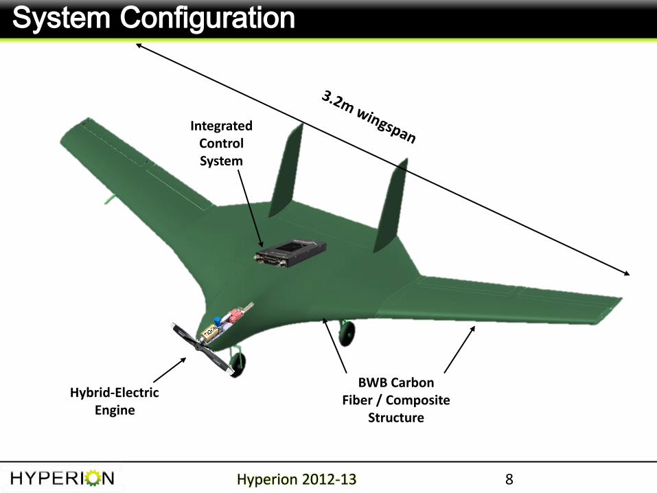
System Configuration
Hybrid-Electric Engine
Hyperion 2012-13 8
BWB Carbon Fiber / Composite
Structure
Integrated Control System
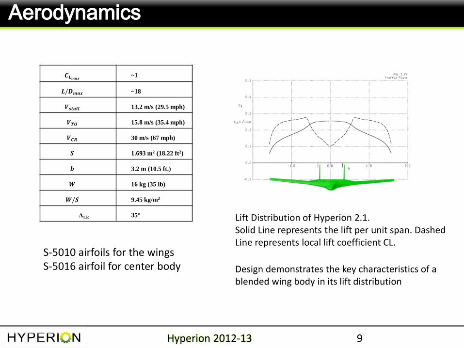
𝑪𝑳𝒎𝒂𝒙 ~1
𝑳/𝑫𝒎𝒂𝒙 ~18
𝑽𝒔𝒕𝒂𝒍𝒍 13.2 m/s (29.5 mph)
𝑽𝑻𝑶 15.8 m/s (35.4 mph)
𝑽𝑪𝑹 30 m/s (67 mph)
𝑺 1.693 m2 (18.22 ft2)
𝒃 3.2 m (10.5 ft.)
𝑾 16 kg (35 lb)
𝑾/𝑺 9.45 kg/m2
ΛLE 35°
Aerodynamics
9 Hyperion 2012-13
Lift Distribution of Hyperion 2.1. Solid Line represents the lift per unit span. Dashed Line represents local lift coefficient CL.
Design demonstrates the key characteristics of a blended wing body in its lift distribution
S-5010 airfoils for the wings S-5016 airfoil for center body
2012 AIAA-ASM Nashville, TN 10
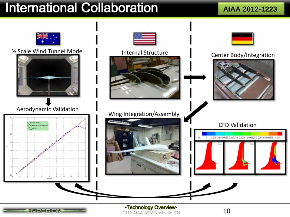
International Collaboration
-Technology Overview-
½ Scale Wind Tunnel Model Internal Structure Center Body/Integration
Aerodynamic Validation
CFD Validation
Wing Integration/Assembly
AIAA 2012-1223
11
Agenda
Hyperion 2012-13
Goals and Team
Manufacturing and FEA
Experiments / Results
System Configuration & Design
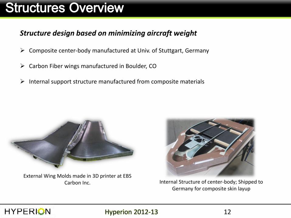
Structures Overview
Hyperion 2012-13 12
Structure design based on minimizing aircraft weight
Composite center-body manufactured at Univ. of Stuttgart, Germany
Carbon Fiber wings manufactured in Boulder, CO
Internal support structure manufactured from composite materials
External Wing Molds made in 3D printer at EBS Carbon Inc. Internal Structure of center-body; Shipped to
Germany for composite skin layup
13
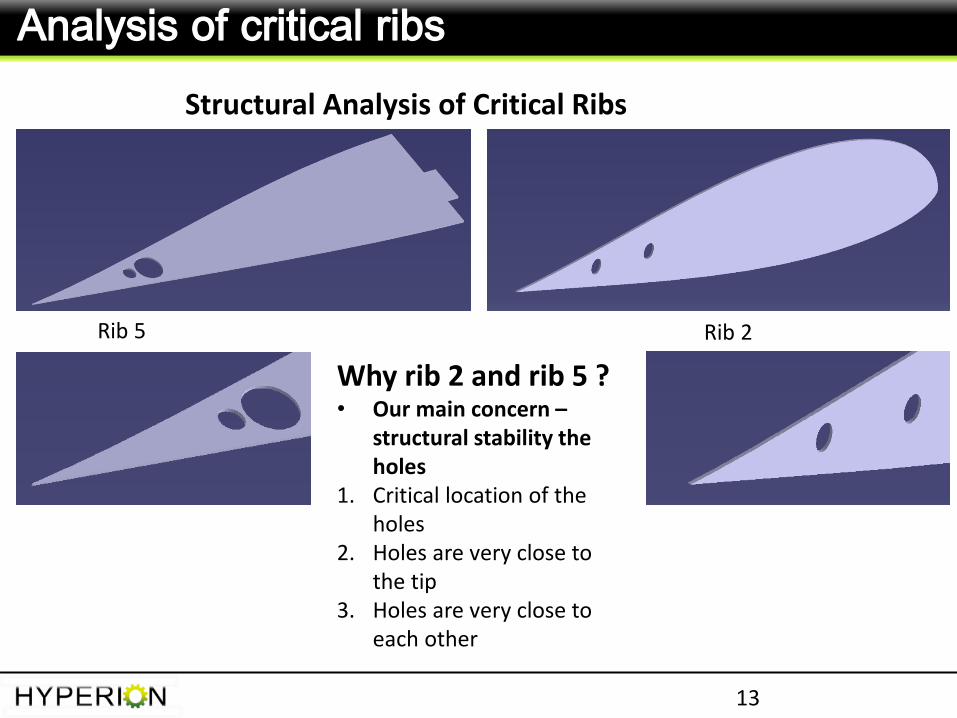
Analysis of critical ribs
Structural Analysis of Critical Ribs
Rib 5 Rib 2
Why rib 2 and rib 5 ? • Our main concern –
structural stability the holes
1. Critical location of the holes
2. Holes are very close to the tip
3. Holes are very close to each other
14
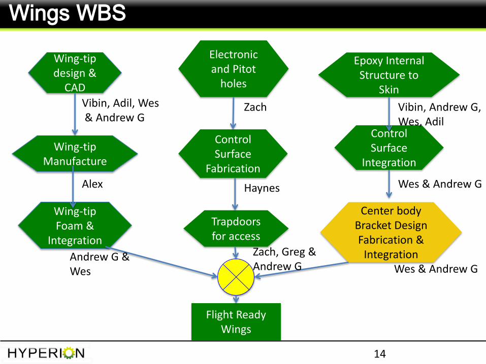
Wings WBS
Flight Ready Wings
Wing-tip design &
CAD
Wing-tip Manufacture
Wing-tip Foam &
Integration
Electronic and Pitot
holes
Control Surface
Fabrication
Trapdoors for access
Epoxy Internal Structure to
Skin
Control Surface
Integration
Center body Bracket Design Fabrication &
Integration
Vibin, Adil, Wes & Andrew G
Alex
Andrew G & Wes
Haynes
Zach
Zach, Greg & Andrew G
Vibin, Andrew G, Wes, Adil
Wes & Andrew G
Wes & Andrew G
15
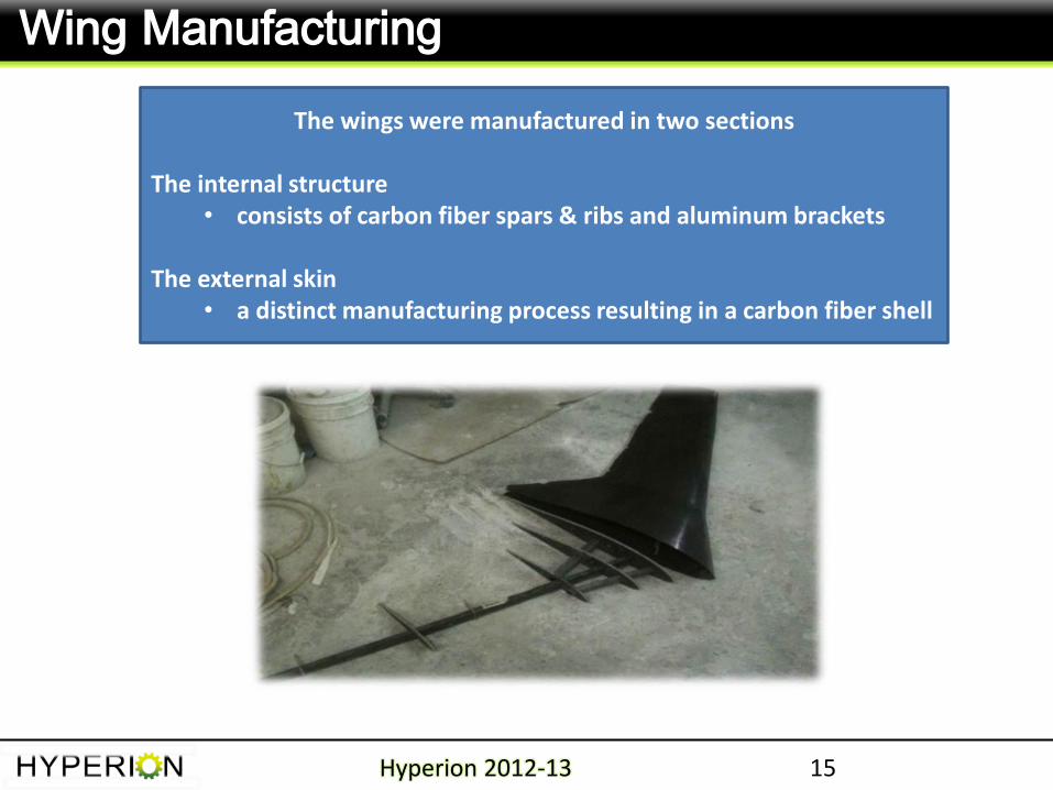
Wing Manufacturing
Hyperion 2012-13
The wings were manufactured in two sections
The internal structure • consists of carbon fiber spars & ribs and aluminum brackets
The external skin
• a distinct manufacturing process resulting in a carbon fiber shell
16
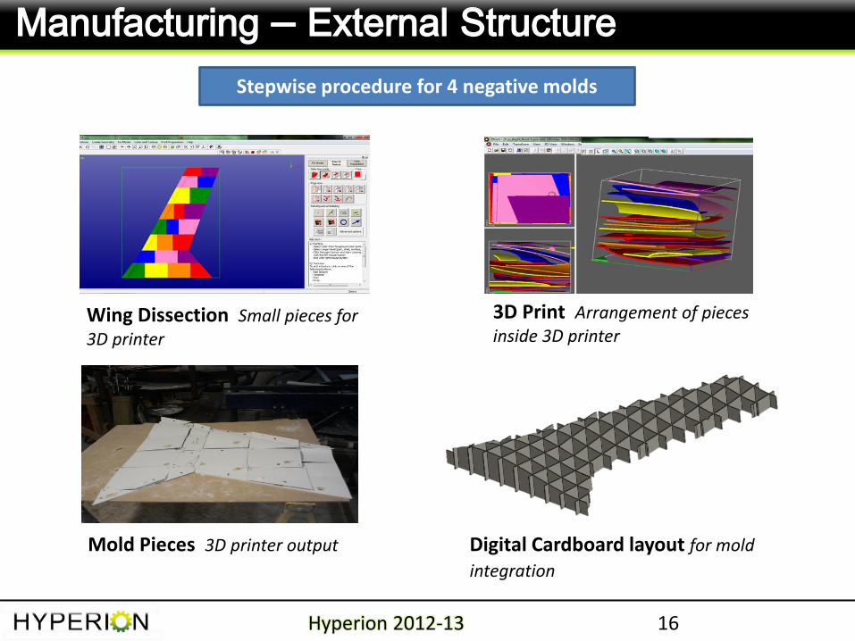
Manufacturing – External Structure
Hyperion 2012-13
Wing Dissection Small pieces for 3D printer
3D Print Arrangement of pieces inside 3D printer
Mold Pieces 3D printer output Digital Cardboard layout for mold
integration
Stepwise procedure for 4 negative molds
17
Manufacturing – External Structure
Hyperion 2012-13
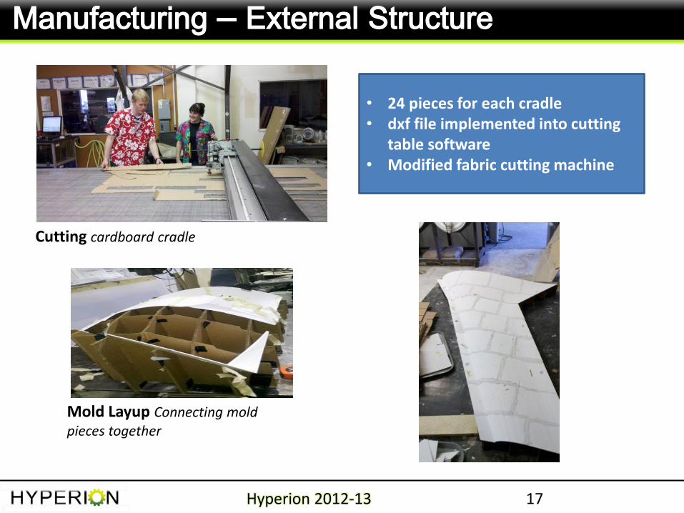
• 24 pieces for each cradle • dxf file implemented into cutting
table software • Modified fabric cutting machine
Mold Layup Connecting mold pieces together
Cutting cardboard cradle
18
Manufacturing – External Structure
Hyperion 2012-13
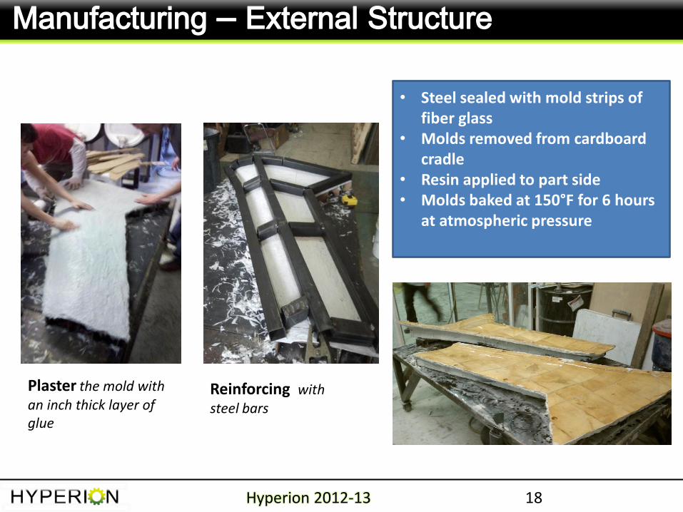
Plaster the mold with an inch thick layer of glue
Reinforcing with steel bars
• Steel sealed with mold strips of fiber glass
• Molds removed from cardboard cradle
• Resin applied to part side • Molds baked at 150°F for 6 hours
at atmospheric pressure
19
Manufacturing – External Structure
Hyperion 2012-13
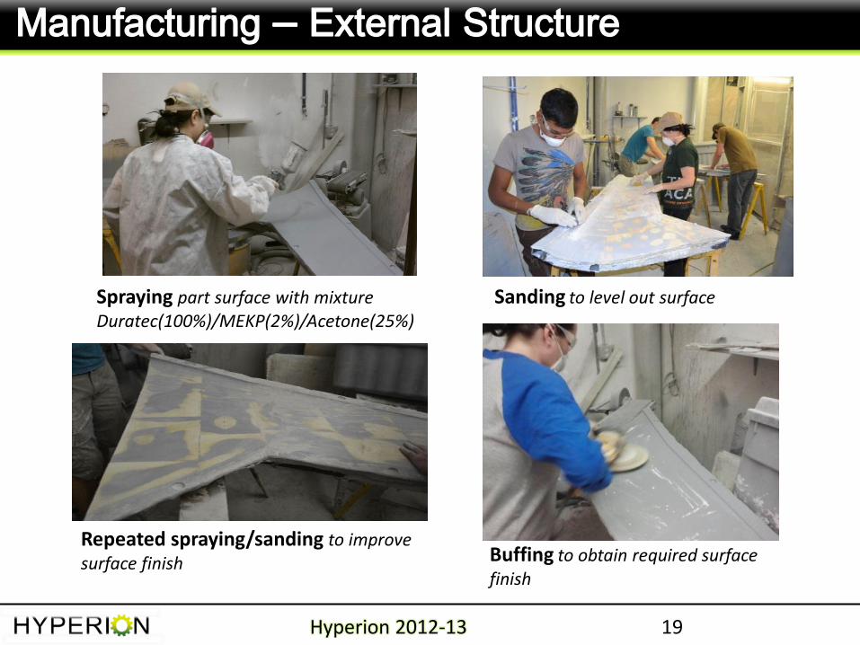
Sanding to level out surface
Repeated spraying/sanding to improve surface finish Buffing to obtain required surface
finish
Spraying part surface with mixture Duratec(100%)/MEKP(2%)/Acetone(25%)
20
Manufacturing – External Structure
Hyperion 2012-13
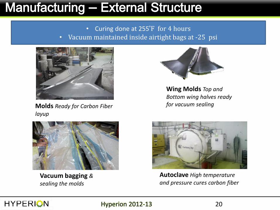
Molds Ready for Carbon Fiber layup
Wing Molds Top and Bottom wing halves ready for vacuum sealing
Autoclave High temperature and pressure cures carbon fiber
Vacuum bagging & sealing the molds
• Curing done at 255 ̊F for 4 hours • Vacuum maintained inside airtight bags at -25 psi
21
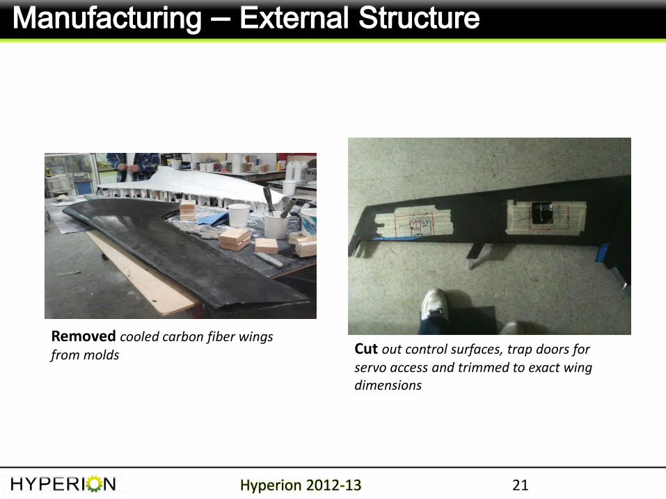
Manufacturing – External Structure
Hyperion 2012-13
Removed cooled carbon fiber wings from molds Cut out control surfaces, trap doors for
servo access and trimmed to exact wing dimensions
22
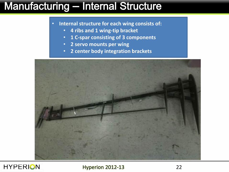
Manufacturing – Internal Structure
Hyperion 2012-13
• Internal structure for each wing consists of: • 4 ribs and 1 wing-tip bracket • 1 C-spar consisting of 3 components • 2 servo mounts per wing • 2 center body integration brackets
23
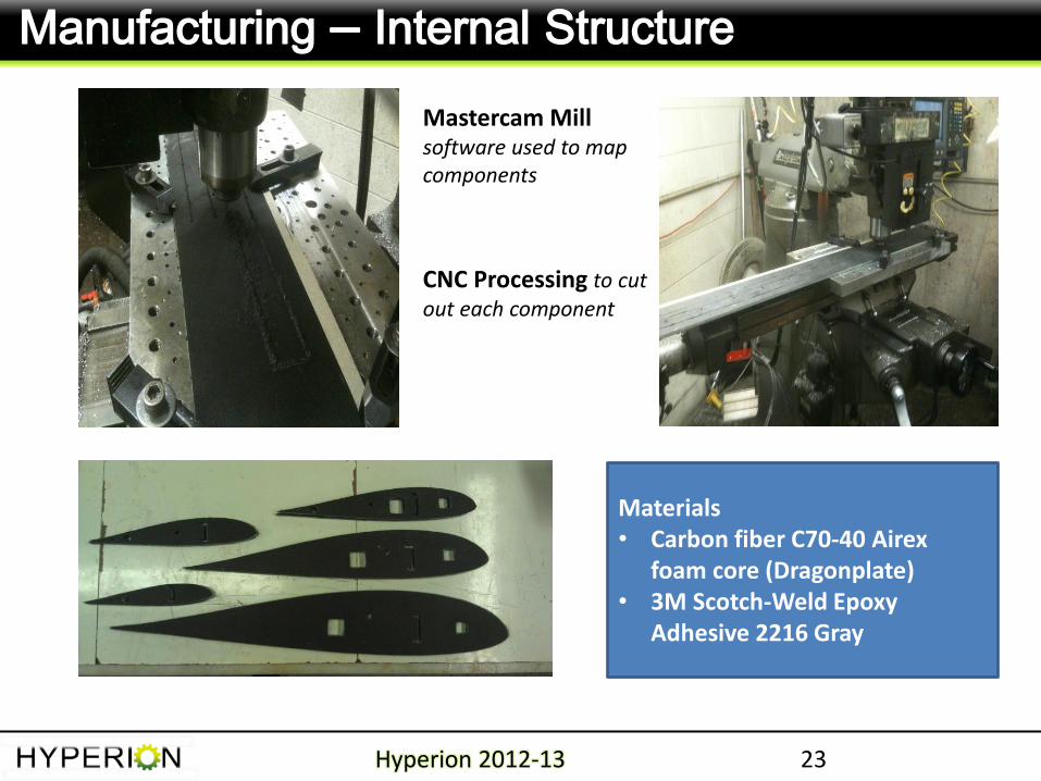
Manufacturing – Internal Structure
Hyperion 2012-13
Mastercam Mill software used to map components
Materials • Carbon fiber C70-40 Airex
foam core (Dragonplate) • 3M Scotch-Weld Epoxy
Adhesive 2216 Gray
CNC Processing to cut out each component
24
Manufacturing – Internal Structure
Hyperion 2012-13
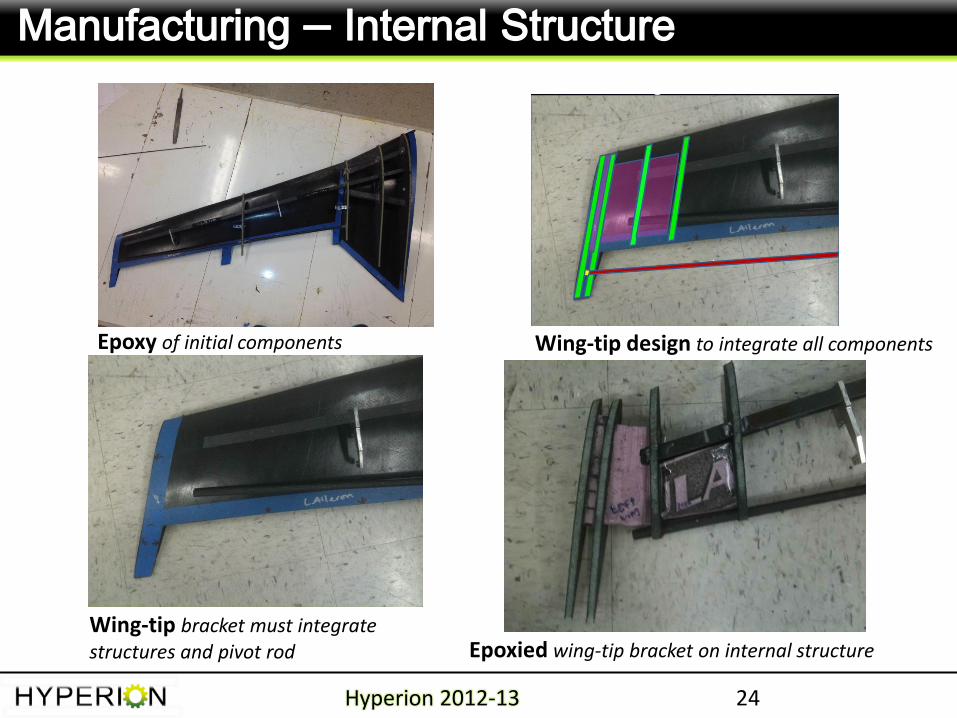
Epoxy of initial components
Wing-tip bracket must integrate structures and pivot rod
Wing-tip design to integrate all components
Epoxied wing-tip bracket on internal structure
25
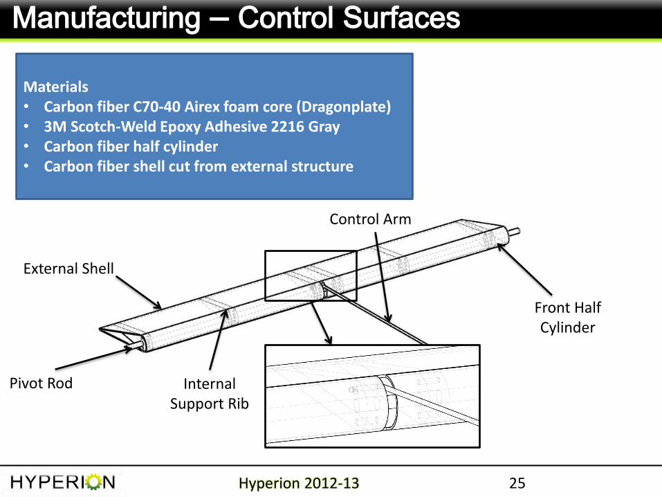
Manufacturing – Control Surfaces
Hyperion 2012-13
External Shell
Internal Support Rib
Control Arm
Front Half Cylinder
Pivot Rod
Materials • Carbon fiber C70-40 Airex foam core (Dragonplate) • 3M Scotch-Weld Epoxy Adhesive 2216 Gray • Carbon fiber half cylinder • Carbon fiber shell cut from external structure
26
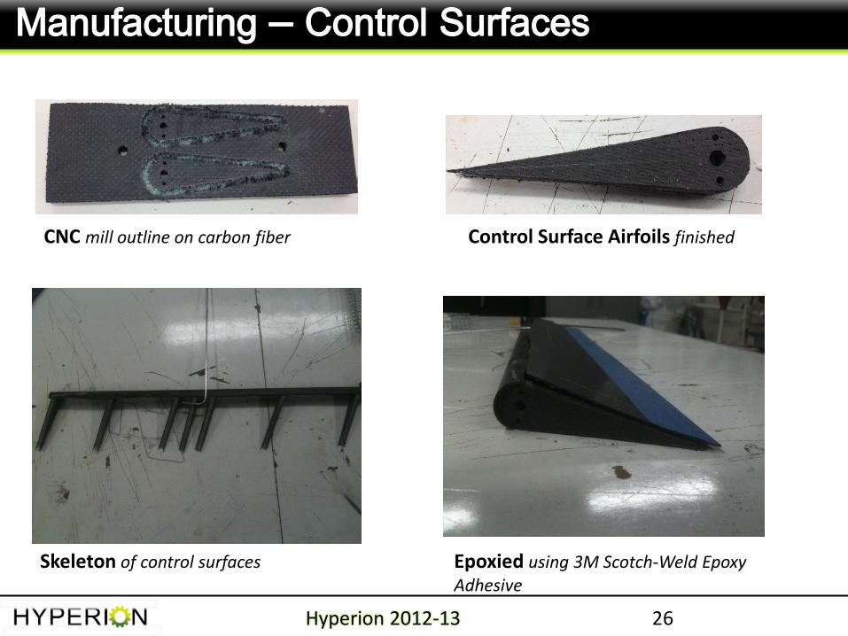
Manufacturing – Control Surfaces
Hyperion 2012-13
CNC mill outline on carbon fiber Control Surface Airfoils finished
Skeleton of control surfaces Epoxied using 3M Scotch-Weld Epoxy Adhesive
27
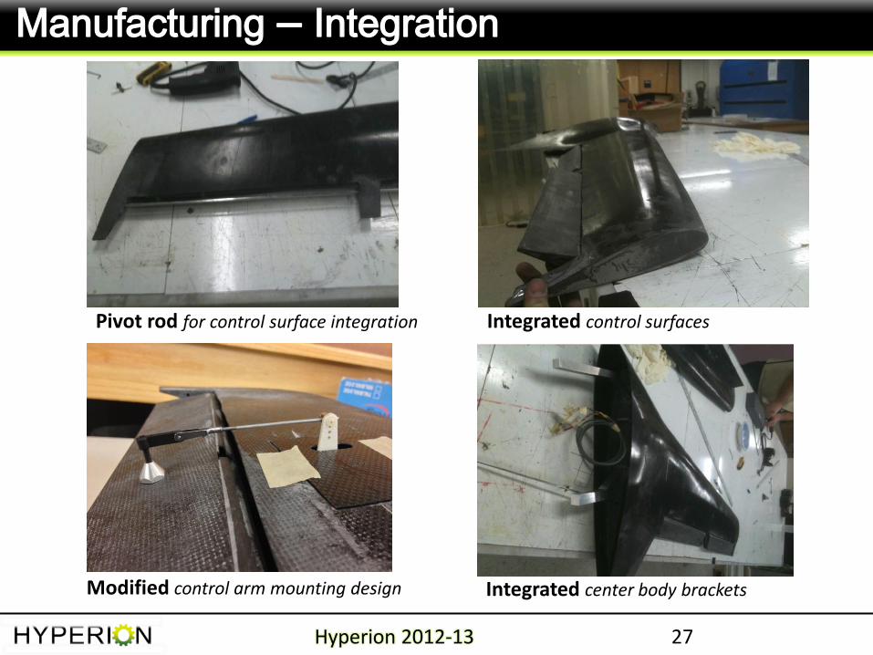
Manufacturing – Integration
Hyperion 2012-13
Pivot rod for control surface integration Integrated control surfaces
Integrated center body brackets Modified control arm mounting design
28
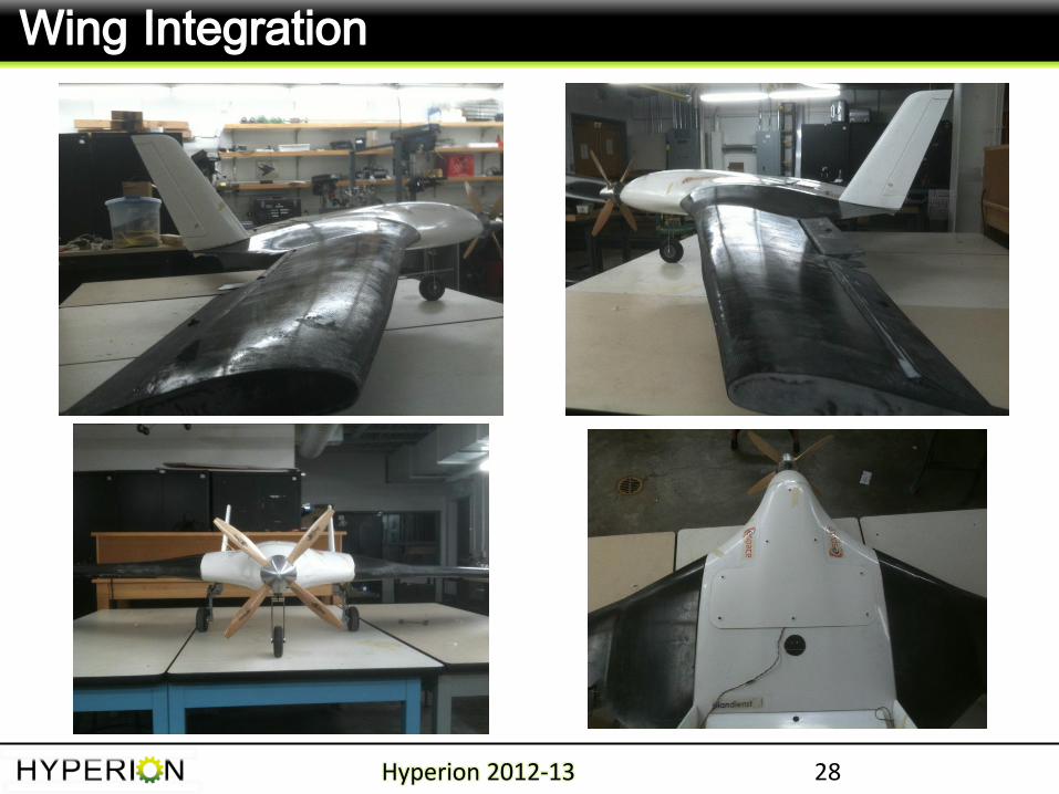
Wing Integration
Hyperion 2012-13
29
Agenda
Hyperion 2012-13
Goals and Team
Manufacturing and FEA
Experiments / Results
System Configuration & Design
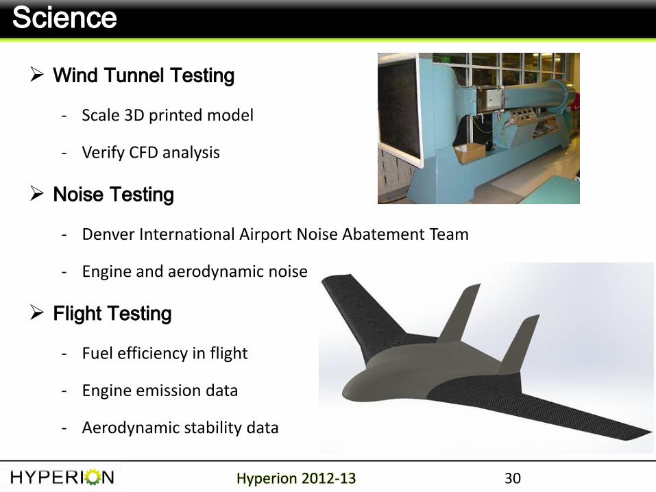
Wind Tunnel Testing
- Scale 3D printed model
- Verify CFD analysis
Noise Testing
- Denver International Airport Noise Abatement Team
- Engine and aerodynamic noise
Flight Testing
- Fuel efficiency in flight
- Engine emission data
- Aerodynamic stability data
30
Science
Hyperion 2012-13
31
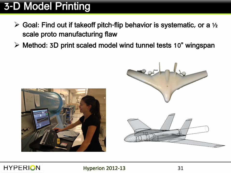
3-D Model Printing
Hyperion 2012-13
Goal: Find out if takeoff pitch-flip behavior is systematic, or a ½ scale proto manufacturing flaw
Method: 3D print scaled model wind tunnel tests 10” wingspan
32
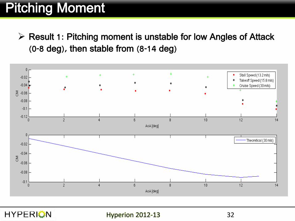
Pitching Moment
Hyperion 2012-13
Result 1: Pitching moment is unstable for low Angles of Attack (0-8 deg), then stable from (8-14 deg)
33
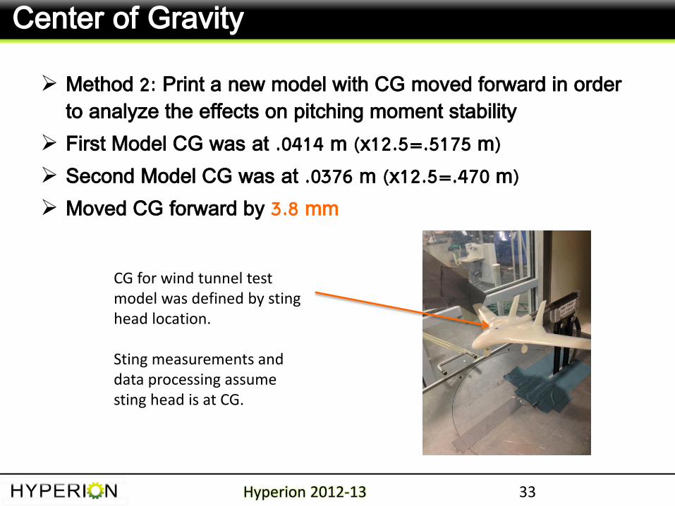
Center of Gravity
Hyperion 2012-13
Method 2: Print a new model with CG moved forward in order to analyze the effects on pitching moment stability
First Model CG was at .0414 m (x12.5=.5175 m)
Second Model CG was at .0376 m (x12.5=.470 m)
Moved CG forward by 3.8 mm
CG for wind tunnel test model was defined by sting head location. Sting measurements and data processing assume sting head is at CG.
34
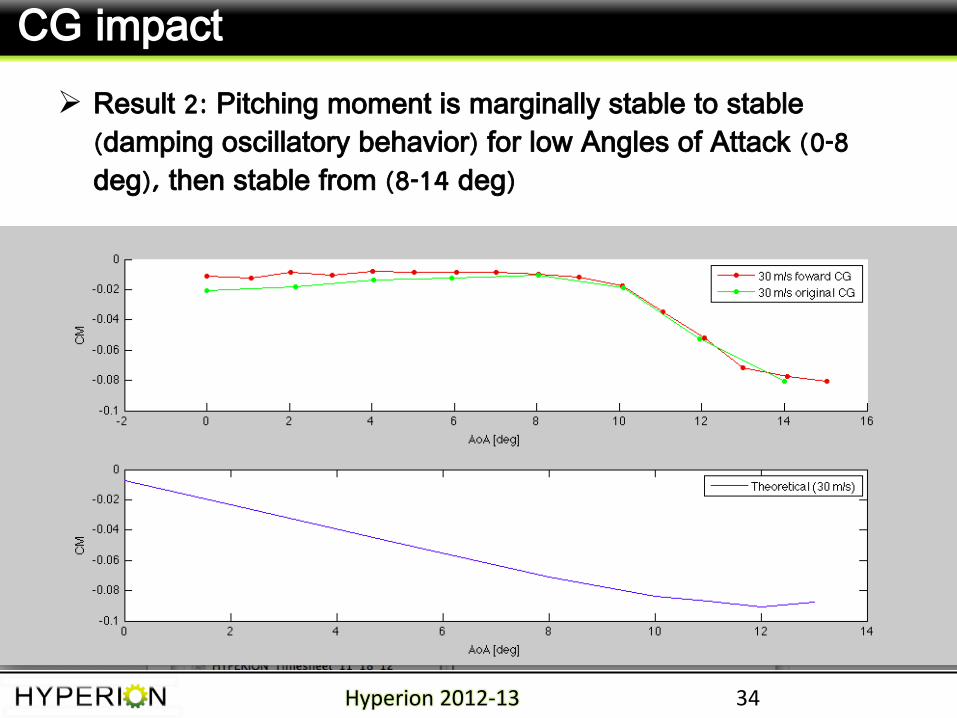
CG impact
Hyperion 2012-13
Result 2: Pitching moment is marginally stable to stable (damping oscillatory behavior) for low Angles of Attack (0-8 deg), then stable from (8-14 deg)
35
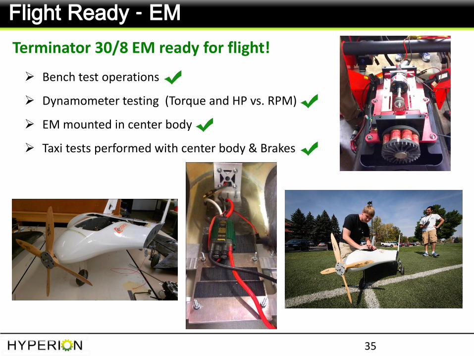
Flight Ready - EM
Terminator 30/8 EM ready for flight!
Bench test operations
Dynamometer testing (Torque and HP vs. RPM)
EM mounted in center body
Taxi tests performed with center body & Brakes
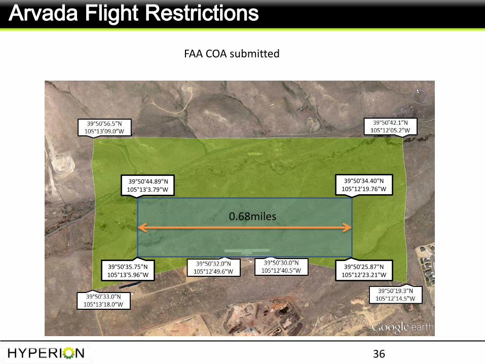
Arvada Flight Restrictions
36
39°50'44.89"N 105°13'3.79"W
39°50'35.75"N105°13'5.96"W
39°50'25.87"N 105°12'23.21"W
39°50'34.40"N 105°12'19.76"W
0.68miles
FAA COA submitted
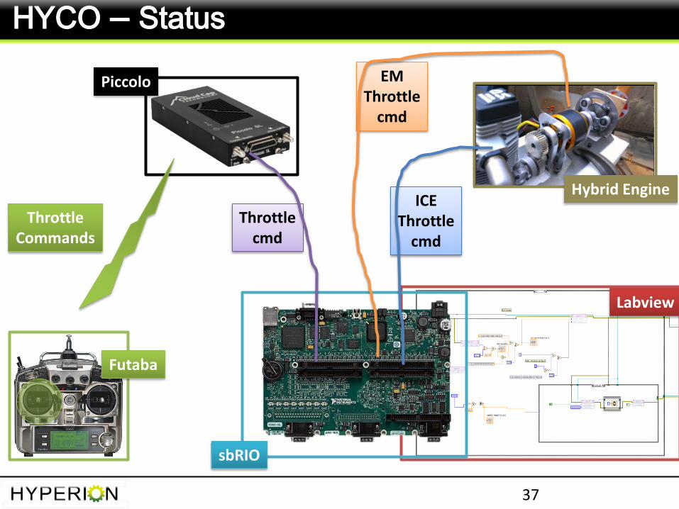
ICE Throttle
cmd
Throttle cmd
37
HYCO – Status
EM Throttle
cmd
Throttle Commands
Labview
sbRIO
Futaba
Piccolo
Hybrid Engine
Propulsion: Terminator EM
- Power Testing
- Reliability Testing
- Taxi Operations with Flight
Propeller
- Endurance Testing
- Structural Integration
GNC: Futaba Control System
- Range Testing
- Integrated ground testing
- Operations Verification
38
Flight Systems Status
EE & Instruments Science
- Electrical Power Systems (EPS)
- Electrical interfaces
- Flight Data Acquisition Systems
- Integrated Operations
Verification
Structures
- Wings: End Caps
- Control Surfaces
- Final Integration
- Final Structural Analysis
39
Acknowledgements
Hyperion 2012-13
Thanks to…
Graduate Student Team members
• Corrina Gibson, PM
• Gauravdev Soin, SE
• Brandon Benjamin
• Weston Willits
• Vibin Sankaranarayanan
• Andrew Gilbert
• Andrew Haynes
• Greg Nelson
• Kristin Uhmeyer
• Pierce Martin
• Zach Dischner
• Adil Ali Mohammed
Undergraduates:
• Alex North
• Casey Myers
Univ. of Stuttgart:
• Benjamin Arnold
• Pascal Weihing
40
Acknowledgements
Hyperion 2012-13
A special thanks to…
Advisors/Sponsors/Customers:
Dr. Jean Koster of CU
Joseph Tanner of CU
Dr. Brian Argrow of CU
Dr. Eric Frew of CU
Trudy Schwartz of CU
Matt Rhode of CU
Mike Kisska of Boeing
Frank Doerner of Boeing
Eric Strauss of EBS Carbon
Consultants:
James Mack (Pilot)
Joe Pirozzoli (R/C Pilot)
Stewart Garrett (R/C Pilot)
DIA Noise Abatement Office
University of Stuttgart: Prof. Claus-Dieter Munz
41
The End
Hyperion 2012-13


