Embed Size (px)
Citation preview
AGRI-ALERT 9600ALARM SYSTEM
INSTALLATION MANUAL

WARNINGS
The warranty can be void if this product is used in a manner not specified by the manufacturer.
Every effort has been made to ensure that this manual is complete, accurate and up-to-date. The informationcontained in it is however subject to change without notice due to further developments.
Manufacturer:
Viatron Electronics5200, Armand-Frappier
St-Hubert (Quebec)Canada
J3Z 1G5
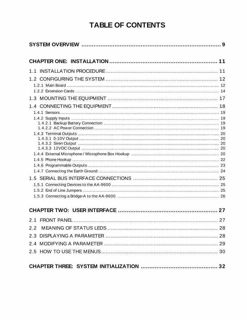
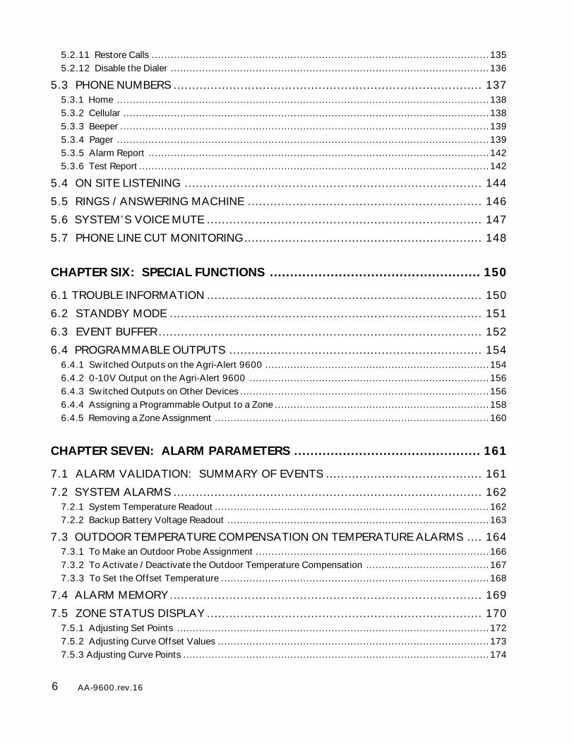
TABLE OF CONTENTS
SYSTEM OVERVIEW ................................................................................ 9
CHAPTER ONE: INSTALLATION .............................................................. 11
1.1 INSTALLATION PROCEDURE ...................................................................... 11
1.2 CONFIGURING THE SYSTEM ...................................................................... 121.2.1 Main Board ................................................................................................................ 121.2.2 Extension Cards .......................................................................................................... 14
1.3 MOUNTING THE EQUIPMENT ..................................................................... 17
1.4 CONNECTING THE EQUIPMENT .................................................................. 181.4.1 Sensors ..................................................................................................................... 191.4.2 Supply Inputs ............................................................................................................. 19
1.4.2.1 Backup Battery Connection ..................................................................................... 191.4.2.2 AC Power Connection ............................................................................................ 19
1.4.3 Terminal Outputs ........................................................................................................ 201.4.3.1 0-10V Output ....................................................................................................... 201.4.3.2 Siren Output ........................................................................................................ 201.4.3.3 12VDC Output ..................................................................................................... 20
1.4.4 External Microphone / Microphone Box Hookup ................................................................. 201.4.5 Phone Hookup ............................................................................................................ 221.4.6 Programmable Outputs ................................................................................................. 231.4.7 Connecting the Earth Ground ......................................................................................... 24
1.5 SERIAL BUS INTERFACE CONNECTIONS ..................................................... 251.5.1 Connecting Devices to the AA-9600 ............................................................................... 251.5.2 End of Line Jumpers .................................................................................................... 251.5.3 Connecting a Bridge-A to the AA-9600 ........................................................................... 26
CHAPTER TWO: USER INTERFACE ......................................................... 27
2.1 FRONT PANEL .......................................................................................... 27
2.2 MEANING OF STATUS LEDS ..................................................................... 28
2.3 DISPLAYING A PARAMETER ...................................................................... 28
2.4 MODIFYING A PARAMETER ....................................................................... 29
2.5 HOW TO USE THE MENUS......................................................................... 30
CHAPTER THREE: SYSTEM INITIALIZATION ............................................ 32
4 AA-9600.rev.16
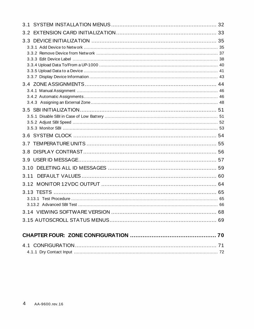
3.1 SYSTEM INSTALLATION MENUS ................................................................ 32
3.2 EXTENSION CARD INITIALIZATION............................................................. 33
3.3 DEVICE INITIALIZATION ............................................................................ 353.3.1 Add Device to Network ................................................................................................ 353.3.2 Remove Device from Network ....................................................................................... 373.3.3 Edit Device Label ........................................................................................................ 383.3.4 Upload Data To/From a UP-1000 ..................................................................................... 403.3.5 Upload Data to a Device ................................................................................................ 413.3.7 Display Device Information ............................................................................................ 43
3.4 ZONE ASSIGNMENTS ................................................................................ 443.4.1 Manual Assignment ..................................................................................................... 463.4.2 Automatic Assignments................................................................................................ 463.4.3 Assigning an External Zone ........................................................................................... 48
3.5 SBI INITIALIZATION................................................................................... 513.5.1 Disable SBI in Case of Low Battery ................................................................................. 513.5.2 Adjust SBI Speed ........................................................................................................ 523.5.3 Monitor SBI ............................................................................................................... 53
3.6 SYSTEM CLOCK ....................................................................................... 54
3.7 TEMPERATURE UNITS ............................................................................... 55
3.8 DISPLAY CONTRAST................................................................................. 56
3.9 USER ID MESSAGE.................................................................................... 57
3.10 DELETING ALL ID MESSAGES .................................................................. 59
3.11 DEFAULT VALUES .................................................................................. 60
3.12 MONITOR 12VDC OUTPUT ...................................................................... 64
3.13 TESTS ................................................................................................... 653.13.1 Test Procedure ......................................................................................................... 653.13.2 Advanced SBI Test .................................................................................................... 66
3.14 VIEWING SOFTWARE VERSION ................................................................ 68
3.15 AUTOSCROLL STATUS MENUS................................................................. 69
CHAPTER FOUR: ZONE CONFIGURATION ................................................ 70
4.1 CONFIGURATION...................................................................................... 714.1.1 Dry Contact Input ....................................................................................................... 72
5AA-9600.rev.16
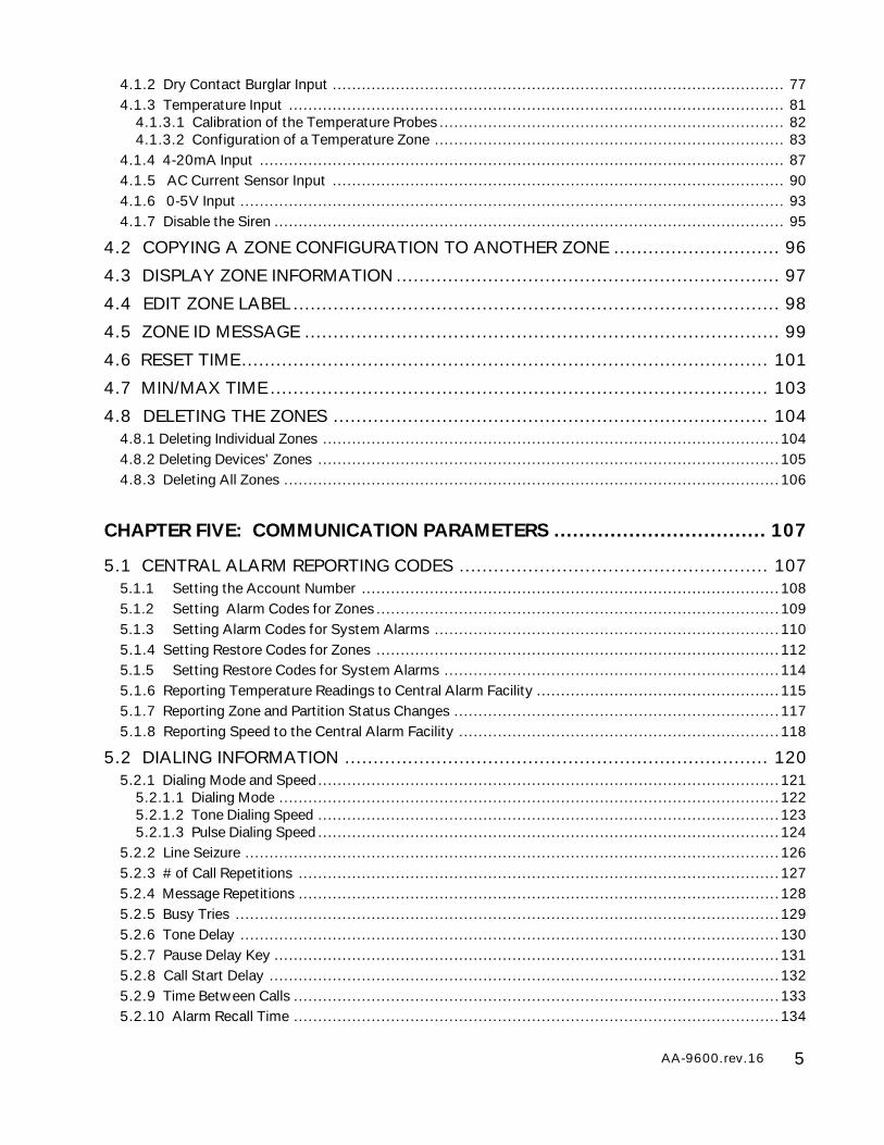
4.1.2 Dry Contact Burglar Input ............................................................................................. 774.1.3 Temperature Input ...................................................................................................... 81
4.1.3.1 Calibration of the Temperature Probes ....................................................................... 824.1.3.2 Configuration of a Temperature Zone ........................................................................ 83
4.1.4 4-20mA Input ............................................................................................................ 874.1.5 AC Current Sensor Input ............................................................................................. 904.1.6 0-5V Input ................................................................................................................ 934.1.7 Disable the Siren ......................................................................................................... 95
4.2 COPYING A ZONE CONFIGURATION TO ANOTHER ZONE ............................. 96
4.3 DISPLAY ZONE INFORMATION ................................................................... 97
4.4 EDIT ZONE LABEL ..................................................................................... 98
4.5 ZONE ID MESSAGE ................................................................................... 99
4.6 RESET TIME............................................................................................ 101
4.7 MIN/MAX TIME ....................................................................................... 103
4.8 DELETING THE ZONES ............................................................................ 1044.8.1 Deleting Individual Zones ..............................................................................................1044.8.2 Deleting Devices’ Zones ...............................................................................................1054.8.3 Deleting All Zones ......................................................................................................106
CHAPTER FIVE: COMMUNICATION PARAMETERS .................................. 107
5.1 CENTRAL ALARM REPORTING CODES ...................................................... 1075.1.1 Setting the Account Number ......................................................................................1085.1.2 Setting Alarm Codes for Zones ...................................................................................1095.1.3 Setting Alarm Codes for System Alarms .......................................................................1105.1.4 Setting Restore Codes for Zones ...................................................................................1125.1.5 Setting Restore Codes for System Alarms .....................................................................1145.1.6 Reporting Temperature Readings to Central Alarm Facility ..................................................1155.1.7 Reporting Zone and Partition Status Changes ...................................................................1175.1.8 Reporting Speed to the Central Alarm Facility ..................................................................118
5.2 DIALING INFORMATION .......................................................................... 1205.2.1 Dialing Mode and Speed...............................................................................................121
5.2.1.1 Dialing Mode .......................................................................................................1225.2.1.2 Tone Dialing Speed ...............................................................................................1235.2.1.3 Pulse Dialing Speed ...............................................................................................124
5.2.2 Line Seizure ..............................................................................................................1265.2.3 # of Call Repetitions ...................................................................................................1275.2.4 Message Repetitions ...................................................................................................1285.2.5 Busy Tries ................................................................................................................1295.2.6 Tone Delay ...............................................................................................................1305.2.7 Pause Delay Key ........................................................................................................1315.2.8 Call Start Delay .........................................................................................................1325.2.9 Time Between Calls ....................................................................................................1335.2.10 Alarm Recall Time ....................................................................................................134
6 AA-9600.rev.16
5.2.11 Restore Calls ...........................................................................................................1355.2.12 Disable the Dialer .....................................................................................................136
5.3 PHONE NUMBERS ................................................................................... 1375.3.1 Home ......................................................................................................................1385.3.2 Cellular ....................................................................................................................1385.3.3 Beeper .....................................................................................................................1395.3.4 Pager ......................................................................................................................1395.3.5 Alarm Report ............................................................................................................1425.3.6 Test Report ...............................................................................................................142
5.4 ON SITE LISTENING ................................................................................ 144
5.5 RINGS / ANSWERING MACHINE ............................................................... 146
5.6 SYSTEM’S VOICE MUTE .......................................................................... 147
5.7 PHONE LINE CUT MONITORING................................................................ 148
CHAPTER SIX: SPECIAL FUNCTIONS .................................................... 150
6.1 TROUBLE INFORMATION .......................................................................... 150
6.2 STANDBY MODE .................................................................................... 151
6.3 EVENT BUFFER....................................................................................... 152
6.4 PROGRAMMABLE OUTPUTS .................................................................... 1546.4.1 Switched Outputs on the Agri-Alert 9600 .......................................................................1546.4.2 0-10V Output on the Agri-Alert 9600 ............................................................................1566.4.3 Switched Outputs on Other Devices ...............................................................................1566.4.4 Assigning a Programmable Output to a Zone ....................................................................1586.4.5 Removing a Zone Assignment .......................................................................................160
CHAPTER SEVEN: ALARM PARAMETERS .............................................. 161
7.1 ALARM VALIDATION: SUMMARY OF EVENTS .......................................... 161
7.2 SYSTEM ALARMS ................................................................................... 1627.2.1 System Temperature Readout .......................................................................................1627.2.2 Backup Battery Voltage Readout ...................................................................................163
7.3 OUTDOOR TEMPERATURE COMPENSATION ON TEMPERATURE ALARMS .... 1647.3.1 To Make an Outdoor Probe Assignment ..........................................................................1667.3.2 To Activate / Deactivate the Outdoor Temperature Compensation .......................................1677.3.3 To Set the Offset Temperature .....................................................................................168
7.4 ALARM MEMORY.................................................................................... 169
7.5 ZONE STATUS DISPLAY .......................................................................... 1707.5.1 Adjusting Set Points ...................................................................................................1727.5.2 Adjusting Curve Offset Values ......................................................................................1737.5.3 Adjusting Curve Points .................................................................................................174
7AA-9600.rev.16
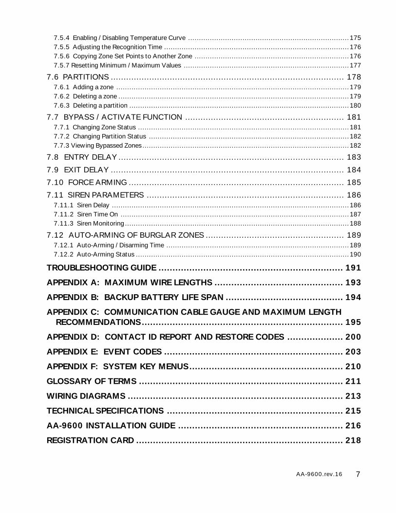
7.5.4 Enabling / Disabling Temperature Curve ..........................................................................1757.5.5 Adjusting the Recognition Time .....................................................................................1767.5.6 Copying Zone Set Points to Another Zone .......................................................................1767.5.7 Resetting Minimum / Maximum Values ............................................................................177
7.6 PARTITIONS ........................................................................................... 1787.6.1 Adding a zone ...........................................................................................................1797.6.2 Deleting a zone ..........................................................................................................1797.6.3 Deleting a partition .....................................................................................................180
7.7 BYPASS / ACTIVATE FUNCTION .............................................................. 1817.7.1 Changing Zone Status .................................................................................................1817.7.2 Changing Partition Status ............................................................................................1827.7.3 Viewing Bypassed Zones...............................................................................................182
7.8 ENTRY DELAY ........................................................................................ 183
7.9 EXIT DELAY ........................................................................................... 184
7.10 FORCE ARMING .................................................................................... 185
7.11 SIREN PARAMETERS ............................................................................. 1867.11.1 Siren Delay .............................................................................................................1867.11.2 Siren Time On .........................................................................................................1877.11.3 Siren Monitoring.......................................................................................................188
7.12 AUTO-ARMING OF BURGLAR ZONES ...................................................... 1897.12.1 Auto-Arming / Disarming Time ....................................................................................1897.12.2 Auto-Arming Status ..................................................................................................190
TROUBLESHOOTING GUIDE .................................................................. 191
APPENDIX A: MAXIMUM WIRE LENGTHS .............................................. 193
APPENDIX B: BACKUP BATTERY LIFE SPAN .......................................... 194
APPENDIX C: COMMUNICATION CABLE GAUGE AND MAXIMUM LENGTHRECOMMENDATIONS........................................................................ 195
APPENDIX D: CONTACT ID REPORT AND RESTORE CODES .................... 200
APPENDIX E: EVENT CODES ................................................................ 203
APPENDIX F: SYSTEM KEY MENUS....................................................... 210
GLOSSARY OF TERMS ......................................................................... 211
WIRING DIAGRAMS ............................................................................. 213
TECHNICAL SPECIFICATIONS ............................................................... 215
AA-9600 INSTALLATION GUIDE ........................................................... 216
REGISTRATION CARD .......................................................................... 218
8 AA-9600.rev.16
NOTICEEvery effort has been made to ensure that this manual is complete, accurate and up-to-date. The information contained in itis however subject to change without notice due to further developments.
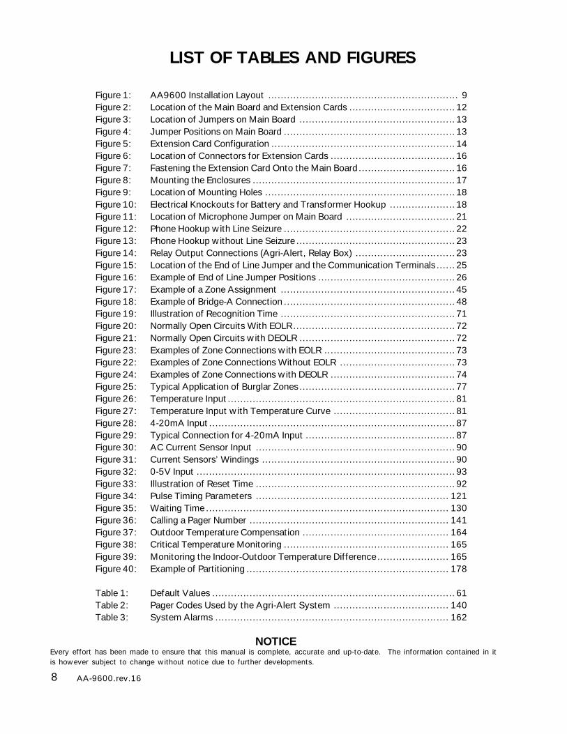
LIST OF TABLES AND FIGURES
Figure 1: AA9600 Installation Layout ............................................................. 9Figure 2: Location of the Main Board and Extension Cards ..................................12Figure 3: Location of Jumpers on Main Board ..................................................13Figure 4: Jumper Positions on Main Board .......................................................13Figure 5: Extension Card Configuration ...........................................................14Figure 6: Location of Connectors for Extension Cards ........................................16Figure 7: Fastening the Extension Card Onto the Main Board...............................16Figure 8: Mounting the Enclosures .................................................................17Figure 9: Location of Mounting Holes .............................................................18Figure 10: Electrical Knockouts for Battery and Transformer Hookup .....................18Figure 11: Location of Microphone Jumper on Main Board ...................................21Figure 12: Phone Hookup with Line Seizure .......................................................22Figure 13: Phone Hookup without Line Seizure ...................................................23Figure 14: Relay Output Connections (Agri-Alert, Relay Box) ................................23Figure 15: Location of the End of Line Jumper and the Communication Terminals......25Figure 16: Example of End of Line Jumper Positions ............................................26Figure 17: Example of a Zone Assignment ........................................................45Figure 18: Example of Bridge-A Connection .......................................................48Figure 19: Illustration of Recognition Time ........................................................71Figure 20: Normally Open Circuits With EOLR....................................................72Figure 21: Normally Open Circuits with DEOLR ..................................................72Figure 23: Examples of Zone Connections with EOLR ..........................................73Figure 22: Examples of Zone Connections Without EOLR .....................................73Figure 24: Examples of Zone Connections with DEOLR ........................................74Figure 25: Typical Application of Burglar Zones..................................................77Figure 26: Temperature Input.........................................................................81Figure 27: Temperature Input with Temperature Curve .......................................81Figure 28: 4-20mA Input...............................................................................87Figure 29: Typical Connection for 4-20mA Input ................................................87Figure 30: AC Current Sensor Input ................................................................90Figure 31: Current Sensors’ Windings ..............................................................90Figure 32: 0-5V Input ...................................................................................93Figure 33: Illustration of Reset Time ................................................................92Figure 34: Pulse Timing Parameters .............................................................. 121Figure 35: Waiting Time .............................................................................. 130Figure 36: Calling a Pager Number ................................................................ 141Figure 37: Outdoor Temperature Compensation ............................................... 164Figure 38: Critical Temperature Monitoring ..................................................... 165Figure 39: Monitoring the Indoor-Outdoor Temperature Difference....................... 165Figure 40: Example of Partitioning ................................................................. 178
Table 1: Default Values ..............................................................................61Table 2: Pager Codes Used by the Agri-Alert System ..................................... 140Table 3: System Alarms ........................................................................... 162
9AA-9600.rev.16
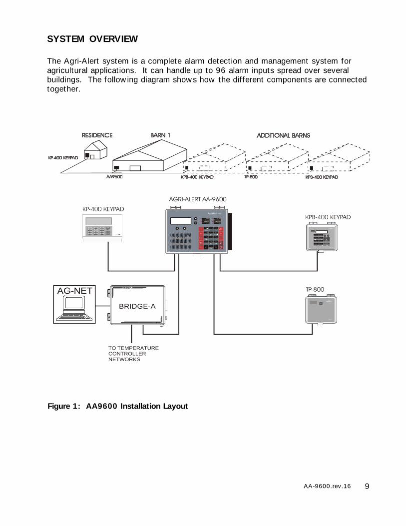
SYSTEM OVERVIEW
The Agri-Alert system is a complete alarm detection and management system foragricultural applications. It can handle up to 96 alarm inputs spread over severalbuildings. The following diagram shows how the different components are connectedtogether.
Figure 1: AA9600 Installation Layout
BRIDGE-A
TO TEMPERATURECONTROLLER NETWORKS
10 AA-9600.rev.16
DEVICE DESCRIPTIONS
The complete system can include up to 98 devices.
AA-9600: the main system with 8 basic zones, two relays and one microphone. Twoextension cards can be added allowing 16 additional zones.
TP-800: a remote extension device that adds 8 zones and a programmable output tothe main system.
KP-400: a keypad for displaying system data from a remote location. Includes 4 drycontact, burglar or temperature zones and one programmable output.
KPB-400: a dust- and moisture-tight keypad for displaying system data from a remotelocation. Includes 4 dry contact, burglar or temperature zones and one programmableoutput.
LB-9600: a device containing 96 LEDs for indicating zone status.
BRIDGE: a computer communication device. Allows the user to operate the completesystem from a computer keyboard or modem. Datalogs up to 4 Agri-Alert systems (4X 96 zones). When used with a Combridge-1 card, the Bridge is compatible withAgBus, allowing the Agri-Alert to fetch temperature readings from existing controllernetworks (see section 3.4.3).
!WARNING
Caution. Carefully read the following text for it contains important infor-mation which, if ignored, may cause the controller to operate improperly.
Pay attention. The following text contains very useful information.
KEYS TO SYMBOLS IN THE MANUAL
11AA-9600.rev.16
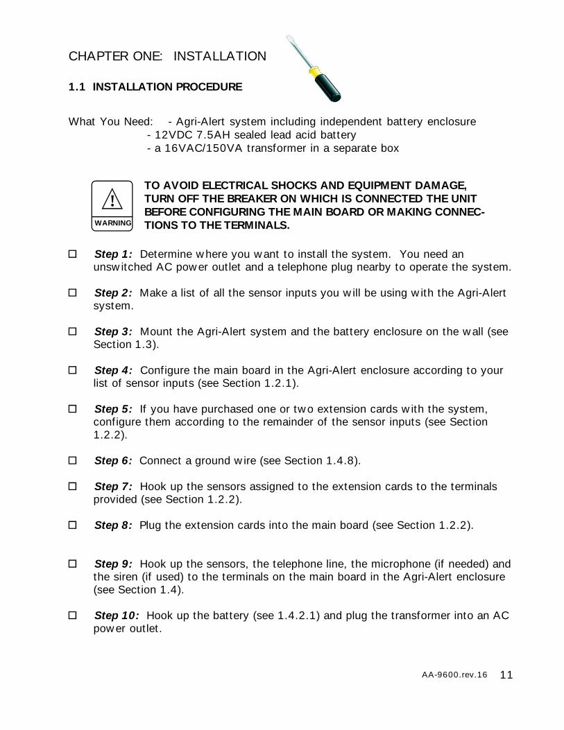
CHAPTER ONE: INSTALLATION
1.1 INSTALLATION PROCEDURE
What You Need: - Agri-Alert system including independent battery enclosure- 12VDC 7.5AH sealed lead acid battery- a 16VAC/150VA transformer in a separate box
Step 1: Determine where you want to install the system. You need anunswitched AC power outlet and a telephone plug nearby to operate the system.
Step 2: Make a list of all the sensor inputs you will be using with the Agri-Alertsystem.
Step 3: Mount the Agri-Alert system and the battery enclosure on the wall (seeSection 1.3).
Step 4: Configure the main board in the Agri-Alert enclosure according to yourlist of sensor inputs (see Section 1.2.1).
Step 5: If you have purchased one or two extension cards with the system,configure them according to the remainder of the sensor inputs (see Section1.2.2).
Step 6: Connect a ground wire (see Section 1.4.8).
Step 7: Hook up the sensors assigned to the extension cards to the terminalsprovided (see Section 1.2.2).
Step 8: Plug the extension cards into the main board (see Section 1.2.2).
Step 9: Hook up the sensors, the telephone line, the microphone (if needed) andthe siren (if used) to the terminals on the main board in the Agri-Alert enclosure(see Section 1.4).
Step 10: Hook up the battery (see 1.4.2.1) and plug the transformer into an ACpower outlet.
TO AVOID ELECTRICAL SHOCKS AND EQUIPMENT DAMAGE,TURN OFF THE BREAKER ON WHICH IS CONNECTED THE UNITBEFORE CONFIGURING THE MAIN BOARD OR MAKING CONNEC-TIONS TO THE TERMINALS.
!WARNING
12 AA-9600.rev.16
1.2 CONFIGURING THE SYSTEM
Before mounting the Agri-Alert system and making the connections, the system mustbe configured to respond to the sensors you will be connecting to it. The main boardis the electronic card located inside the Agri-Alert enclosure. It can handle up to 8sensor inputs. These inputs are called zones. Each extension card you add to themain board provides 8 additional zones. Two extension cards can be added for a totalof 24 zones.
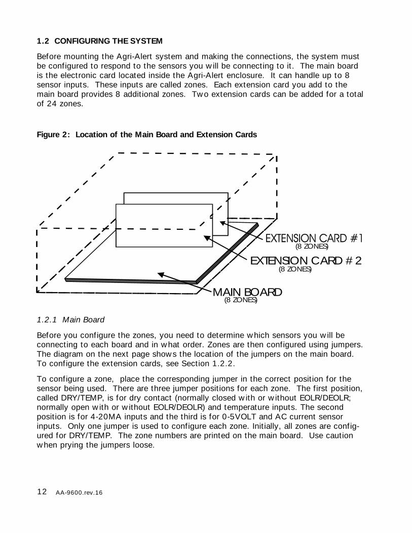
Figure 2: Location of the Main Board and Extension Cards
1.2.1 Main Board
Before you configure the zones, you need to determine which sensors you will beconnecting to each board and in what order. Zones are then configured using jumpers.The diagram on the next page shows the location of the jumpers on the main board.To configure the extension cards, see Section 1.2.2.
To configure a zone, place the corresponding jumper in the correct position for thesensor being used. There are three jumper positions for each zone. The first position,called DRY/TEMP, is for dry contact (normally closed with or without EOLR/DEOLR;normally open with or without EOLR/DEOLR) and temperature inputs. The secondposition is for 4-20MA inputs and the third is for 0-5VOLT and AC current sensorinputs. Only one jumper is used to configure each zone. Initially, all zones are config-ured for DRY/TEMP. The zone numbers are printed on the main board. Use cautionwhen prying the jumpers loose.
MAIN BOARD(8 ZONES)
(8 ZONES)
(8 ZONES)
EXTENSION CARD #2
13AA-9600.rev.16
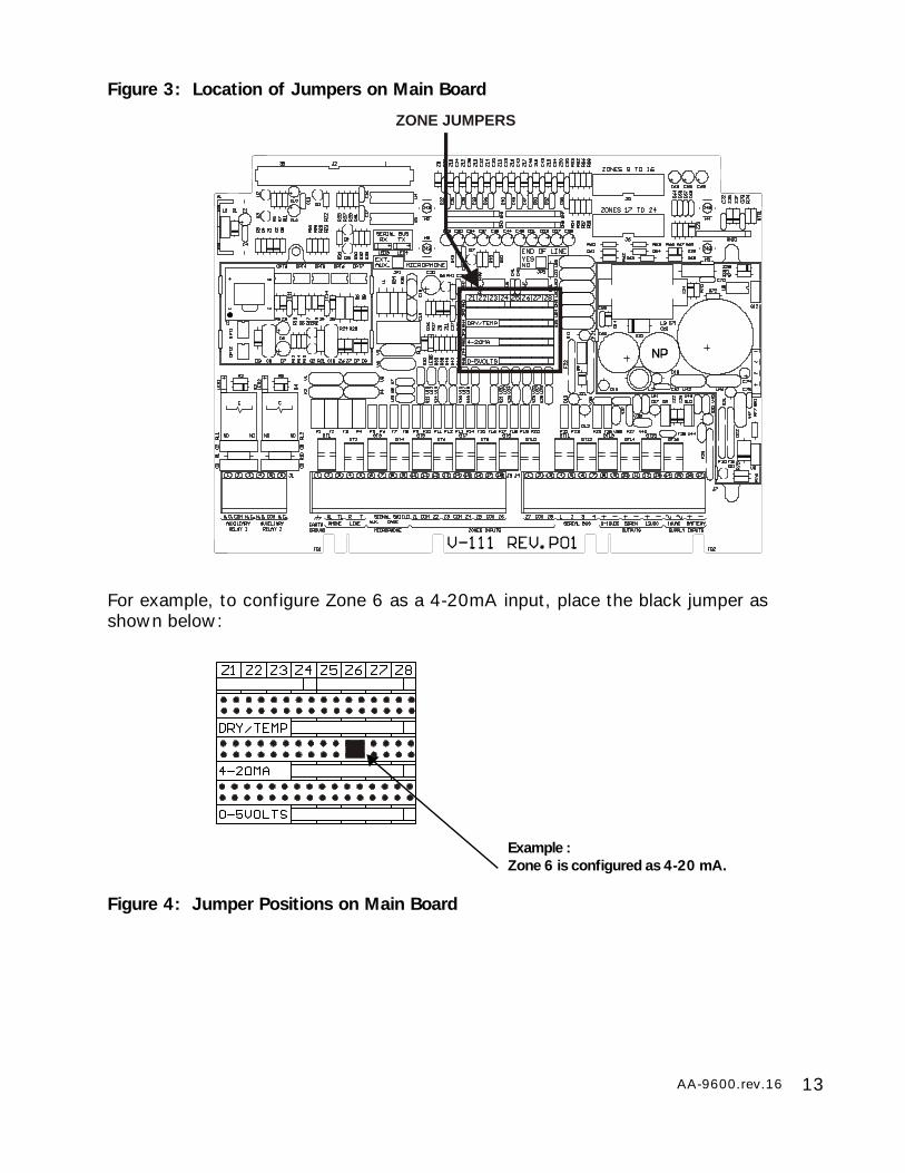
Figure 3: Location of Jumpers on Main Board
For example, to configure Zone 6 as a 4-20mA input, place the black jumper asshown below:
Figure 4: Jumper Positions on Main Board
ZONE JUMPERS
Example :Zone 6 is configured as 4-20 mA.
14 AA-9600.rev.16
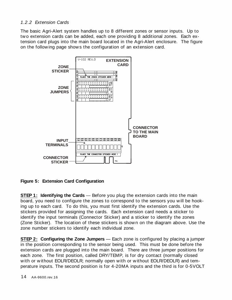
1.2.2 Extension Cards
The basic Agri-Alert system handles up to 8 different zones or sensor inputs. Up totwo extension cards can be added, each one providing 8 additional zones. Each ex-tension card plugs into the main board located in the Agri-Alert enclosure. The figureon the following page shows the configuration of an extension card.
Figure 5: Extension Card Configuration
STEP 1: Identifying the Cards — Before you plug the extension cards into the mainboard, you need to configure the zones to correspond to the sensors you will be hook-ing up to each card. To do this, you must first identify the extension cards. Use thestickers provided for assigning the cards. Each extension card needs a sticker toidentify the input terminals (Connector Sticker) and a sticker to identify the zones(Zone Sticker). The location of these stickers is shown on the diagram above. Use thezone number stickers to identify each individual zone.
STEP 2: Configuring the Zone Jumpers — Each zone is configured by placing a jumperin the position corresponding to the sensor being used. This must be done before theextension cards are plugged into the main board. There are three jumper positions foreach zone. The first position, called DRY/TEMP, is for dry contact (normally closedwith or without EOLR/DEOLR; normally open with or without EOLR/DEOLR) and tem-perature inputs. The second position is for 4-20MA inputs and the third is for 0-5VOLT
CONNECTORTO THE MAIN BOARD
ZONE STICKER
CONNECTORSTICKER
INPUTTERMINALS
EXTENSION CARD
ZONE JUMPERS
15AA-9600.rev.16
and AC current sensor inputs. Only one jumper must be used for each zone. Initially,all zones are configured for DRY/TEMP. The zone numbers are printed on the sticker.
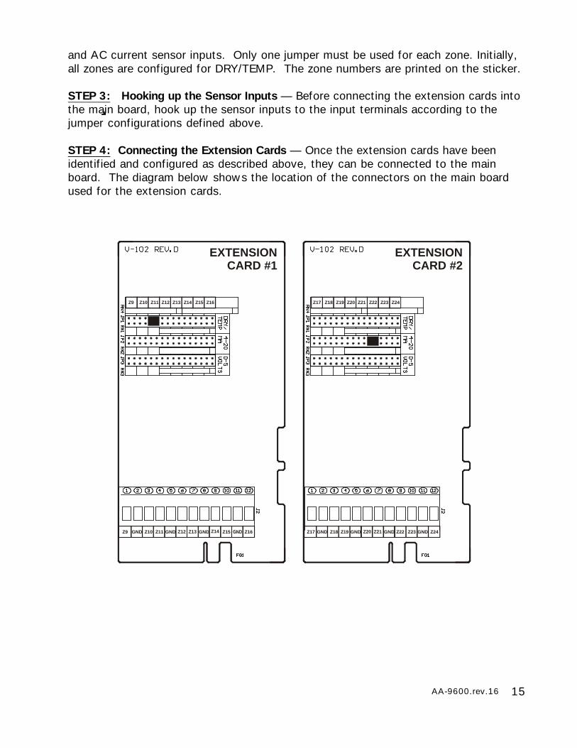
STEP 3: Hooking up the Sensor Inputs — Before connecting the extension cards intothe main board, hook up the sensor inputs to the input terminals according to thejumper configurations defined above.
STEP 4: Connecting the Extension Cards — Once the extension cards have beenidentified and configured as described above, they can be connected to the mainboard. The diagram below shows the location of the connectors on the main boardused for the extension cards.
EXTENSION CARD #1
GND GND GNDZ9 Z10 Z11 Z12 Z13 Z14 Z15 Z16
Z9 Z10 Z11 Z12 Z13 Z14 Z15 Z16
EXTENSION CARD #2
GND GND GND GNDZ17 Z18 Z19 Z20 Z21 Z22 Z23 Z24
Z17 Z18 Z19 Z20 Z21 Z22 Z23 Z24
INPUT TERMINALSZONEJUMPERS
ZONE STICKER
C O N N E C T O RS T I C K E R
C O N N E C T O R T OMAIN BOARD
EXTENSION CARD #1 EXTENSION CARD #2
Z10 Z11 Z12 Z20 Z21 Z22 Z23Z9 Z14 Z15 Z16 Z24 Z25 Z 2 6Z 2 7Z13
Z10 Z11 Z12 Z20 Z 2 3Z 2 7 Z 2 3Z9 Z14 Z15 Z16 Z 2 4 Z 2 5Z 2 6 Z 2 7Z13
16 AA-9600.rev.16
MAIN BOARD
BRACKET
BRACKET
EXTENSION CARD
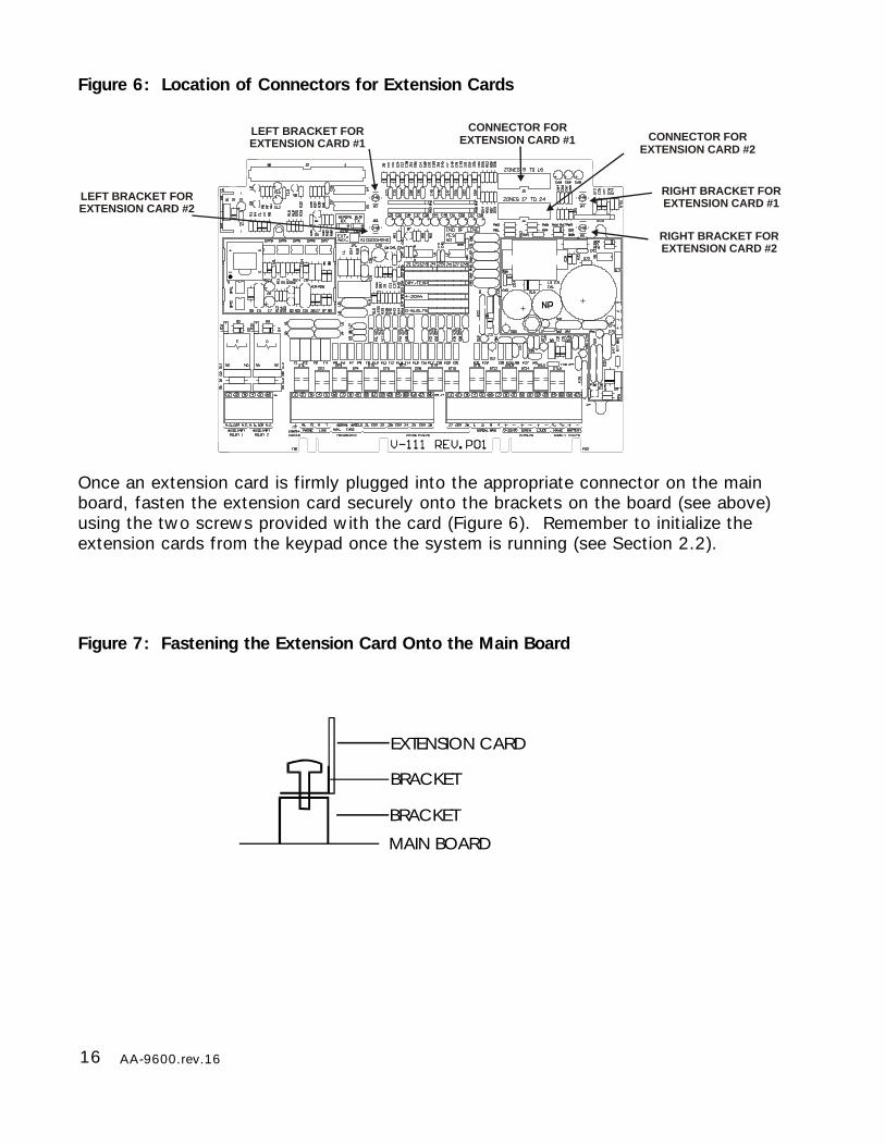
Figure 6: Location of Connectors for Extension Cards
Once an extension card is firmly plugged into the appropriate connector on the mainboard, fasten the extension card securely onto the brackets on the board (see above)using the two screws provided with the card (Figure 6). Remember to initialize theextension cards from the keypad once the system is running (see Section 2.2).
Figure 7: Fastening the Extension Card Onto the Main Board
CONNECTOR FOREXTENSION CARD #1 CONNECTOR FOR
EXTENSION CARD #2
RIGHT BRACKET FOREXTENSION CARD #1
LEFT BRACKET FOREXTENSION CARD #1
RIGHT BRACKET FOREXTENSION CARD #2
LEFT BRACKET FOREXTENSION CARD #2
17AA-9600.rev.16
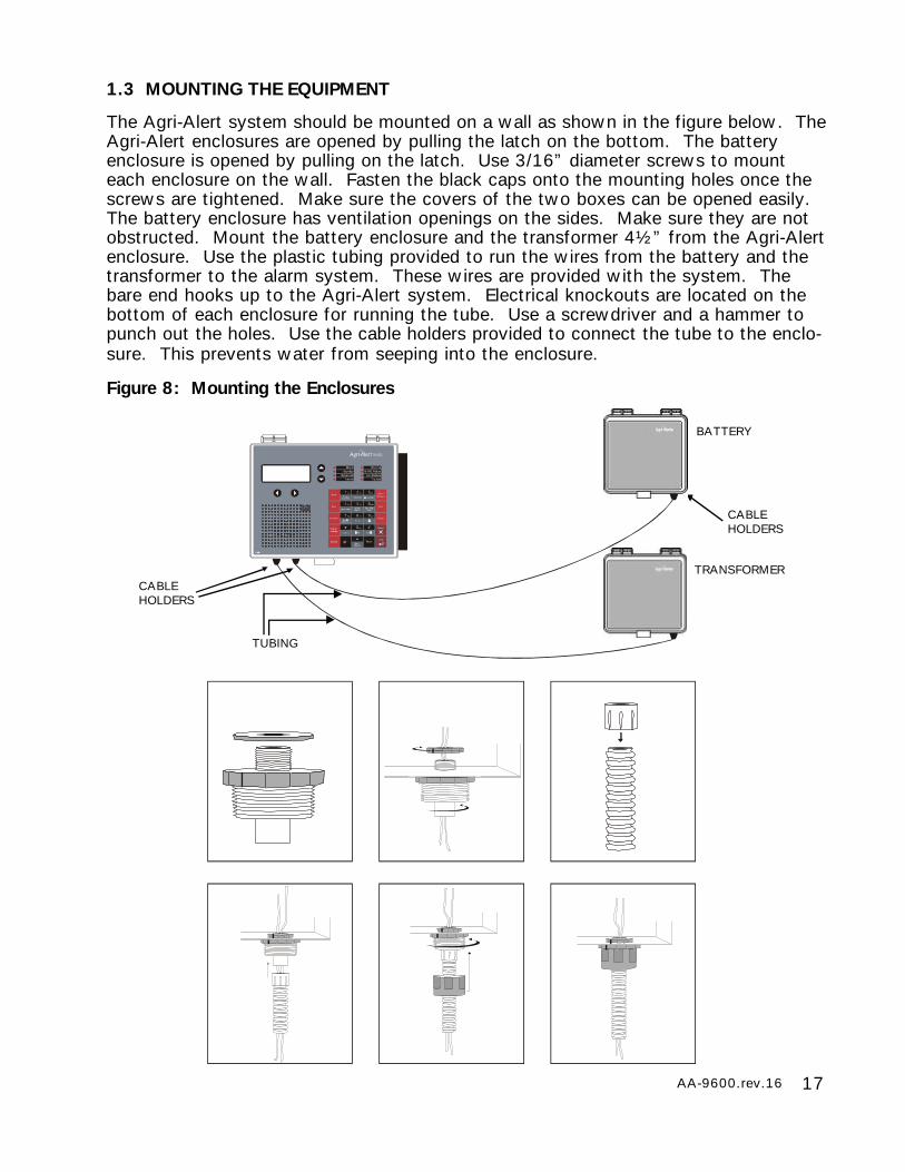
1.3 MOUNTING THE EQUIPMENT
The Agri-Alert system should be mounted on a wall as shown in the figure below. TheAgri-Alert enclosures are opened by pulling the latch on the bottom. The batteryenclosure is opened by pulling on the latch. Use 3/16” diameter screws to mounteach enclosure on the wall. Fasten the black caps onto the mounting holes once thescrews are tightened. Make sure the covers of the two boxes can be opened easily.The battery enclosure has ventilation openings on the sides. Make sure they are notobstructed. Mount the battery enclosure and the transformer 4½” from the Agri-Alertenclosure. Use the plastic tubing provided to run the wires from the battery and thetransformer to the alarm system. These wires are provided with the system. Thebare end hooks up to the Agri-Alert system. Electrical knockouts are located on thebottom of each enclosure for running the tube. Use a screwdriver and a hammer topunch out the holes. Use the cable holders provided to connect the tube to the enclo-sure. This prevents water from seeping into the enclosure.
Figure 8: Mounting the Enclosures
TRANSFORMER
BATTERY
CABLEHOLDERS
CABLEHOLDERS
TUBING
18 AA-9600.rev.16
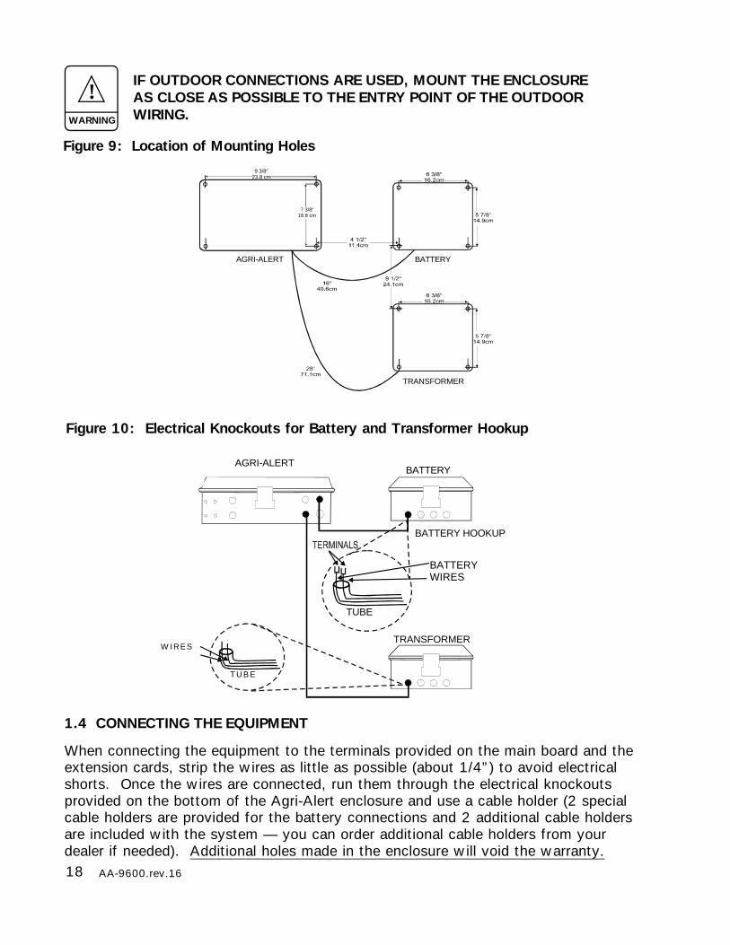
Figure 9: Location of Mounting Holes
IF OUTDOOR CONNECTIONS ARE USED, MOUNT THE ENCLOSUREAS CLOSE AS POSSIBLE TO THE ENTRY POINT OF THE OUTDOORWIRING.
!WARNING
BATTERY
TRANSFORMER
BATTERY HOOKUP
TUBE
BATTERYWIRES
T U B E
W IRES
AGRI-ALERT
1.4 CONNECTING THE EQUIPMENT
When connecting the equipment to the terminals provided on the main board and theextension cards, strip the wires as little as possible (about 1/4”) to avoid electricalshorts. Once the wires are connected, run them through the electrical knockoutsprovided on the bottom of the Agri-Alert enclosure and use a cable holder (2 specialcable holders are provided for the battery connections and 2 additional cable holdersare included with the system — you can order additional cable holders from yourdealer if needed). Additional holes made in the enclosure will void the warranty.
Figure 10: Electrical Knockouts for Battery and Transformer Hookup
BATTERY
TRANSFORMER
AGRI-ALERT
9 3/8“23.8 cm
7 3/8“18.8 cm
19AA-9600.rev.16
BATTERY+
SUPPLY INPUTS
-s
16VAC
s
BLACKRED
BATTERYTRANSF.
REDWIRE(+)
BLACKWIRE(—)
1.4.1 Sensors
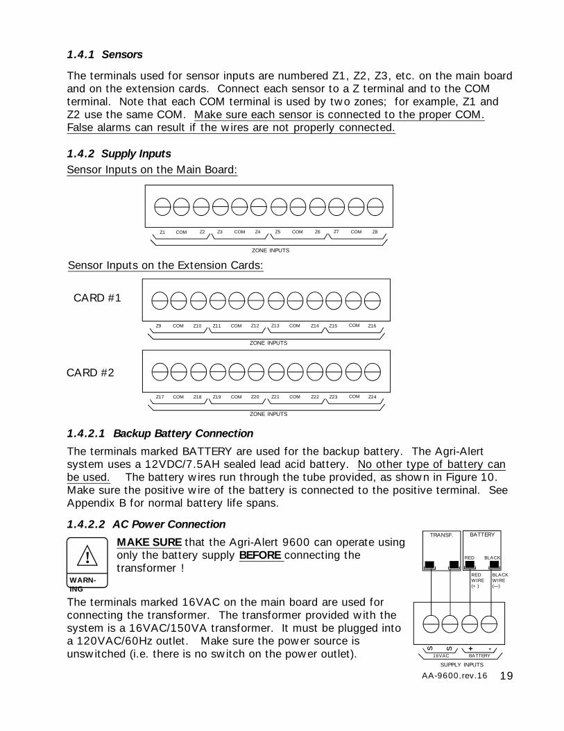
The terminals used for sensor inputs are numbered Z1, Z2, Z3, etc. on the main boardand on the extension cards. Connect each sensor to a Z terminal and to the COMterminal. Note that each COM terminal is used by two zones; for example, Z1 andZ2 use the same COM. Make sure each sensor is connected to the proper COM.False alarms can result if the wires are not properly connected.
1.4.2 Supply Inputs
1.4.2.1 Backup Battery Connection
The terminals marked BATTERY are used for the backup battery. The Agri-Alertsystem uses a 12VDC/7.5AH sealed lead acid battery. No other type of battery canbe used. The battery wires run through the tube provided, as shown in Figure 10.Make sure the positive wire of the battery is connected to the positive terminal. SeeAppendix B for normal battery life spans.
1.4.2.2 AC Power Connection
MAKE SURE that the Agri-Alert 9600 can operate usingonly the battery supply BEFORE connecting thetransformer !
The terminals marked 16VAC on the main board are used forconnecting the transformer. The transformer provided with thesystem is a 16VAC/150VA transformer. It must be plugged intoa 120VAC/60Hz outlet. Make sure the power source isunswitched (i.e. there is no switch on the power outlet).
!WARN-ING
Sensor Inputs on the Main Board:
Sensor Inputs on the Extension Cards:
COMZ1 Z2 COMZ3 Z4 Z5 Z6 Z7 Z8
ZONE INPUTS
COM COM
CARD #1
COMZ9 Z10 COMZ11 Z12 Z13 Z14 Z15 Z16
ZONE INPUTS
COM COM
COMZ17 Z18 COMZ19 Z20 Z21 Z22 Z23 Z24
ZONE INPUTS
COM COM
CARD #2
20 AA-9600.rev.16
1.4.3 Terminal Outputs
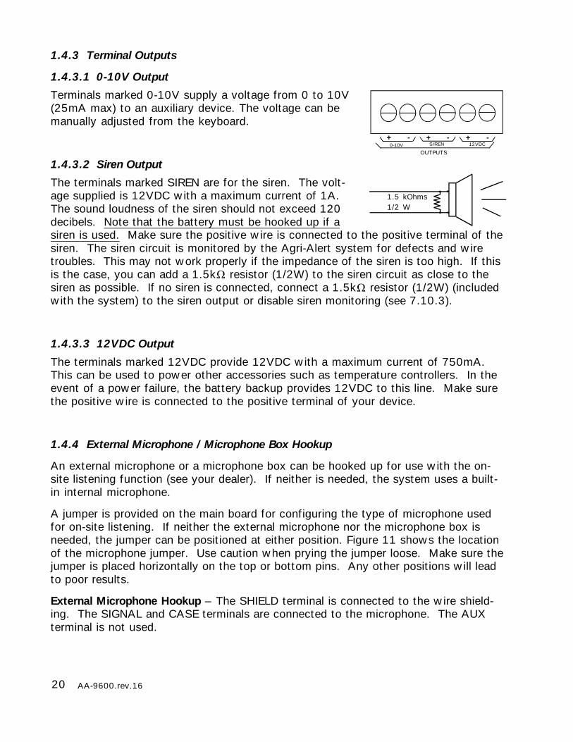
1.4.3.1 0-10V Output
Terminals marked 0-10V supply a voltage from 0 to 10V(25mA max) to an auxiliary device. The voltage can bemanually adjusted from the keyboard.
1.4.3.2 Siren Output
The terminals marked SIREN are for the siren. The volt-age supplied is 12VDC with a maximum current of 1A.The sound loudness of the siren should not exceed 120decibels. Note that the battery must be hooked up if asiren is used. Make sure the positive wire is connected to the positive terminal of thesiren. The siren circuit is monitored by the Agri-Alert system for defects and wiretroubles. This may not work properly if the impedance of the siren is too high. If thisis the case, you can add a 1.5k resistor (1/2W) to the siren circuit as close to thesiren as possible. If no siren is connected, connect a 1.5k resistor (1/2W) (includedwith the system) to the siren output or disable siren monitoring (see 7.10.3).
1.4.3.3 12VDC Output
The terminals marked 12VDC provide 12VDC with a maximum current of 750mA.This can be used to power other accessories such as temperature controllers. In theevent of a power failure, the battery backup provides 12VDC to this line. Make surethe positive wire is connected to the positive terminal of your device.
1.4.4 External Microphone / Microphone Box Hookup
An external microphone or a microphone box can be hooked up for use with the on-site listening function (see your dealer). If neither is needed, the system uses a built-in internal microphone.
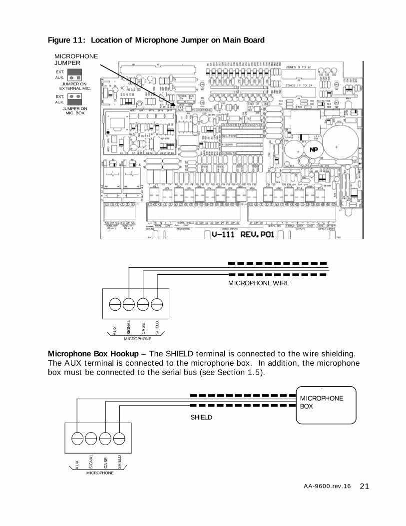
A jumper is provided on the main board for configuring the type of microphone usedfor on-site listening. If neither the external microphone nor the microphone box isneeded, the jumper can be positioned at either position. Figure 11 shows the locationof the microphone jumper. Use caution when prying the jumper loose. Make sure thejumper is placed horizontally on the top or bottom pins. Any other positions will leadto poor results.
External Microphone Hookup – The SHIELD terminal is connected to the wire shield-ing. The SIGNAL and CASE terminals are connected to the microphone. The AUXterminal is not used.
0-10V+
OUTPUTS
-SIREN
+ -12VDC
+ -
1.5 kOhms1/2 W
21AA-9600.rev.16
Figure 11: Location of Microphone Jumper on Main Board
MICROPHONE
AU
X
SIG
NA
L
CA
SE
SH
IELD
MICROPHONE WIRE
JUMPER ON
JUMPER ONMIC. BOX
EXTERNAL MIC.
EXT.
EXT.
AUX.
AUX.
MICROPHONEJUMPER
Microphone Box Hookup – The SHIELD terminal is connected to the wire shielding.The AUX terminal is connected to the microphone box. In addition, the microphonebox must be connected to the serial bus (see Section 1.5).
MICROPHONE
AU
X
SIG
NA
L
CA
SE
SH
IELD
SHIELD
MICROPHONEBOX
22 AA-9600.rev.16
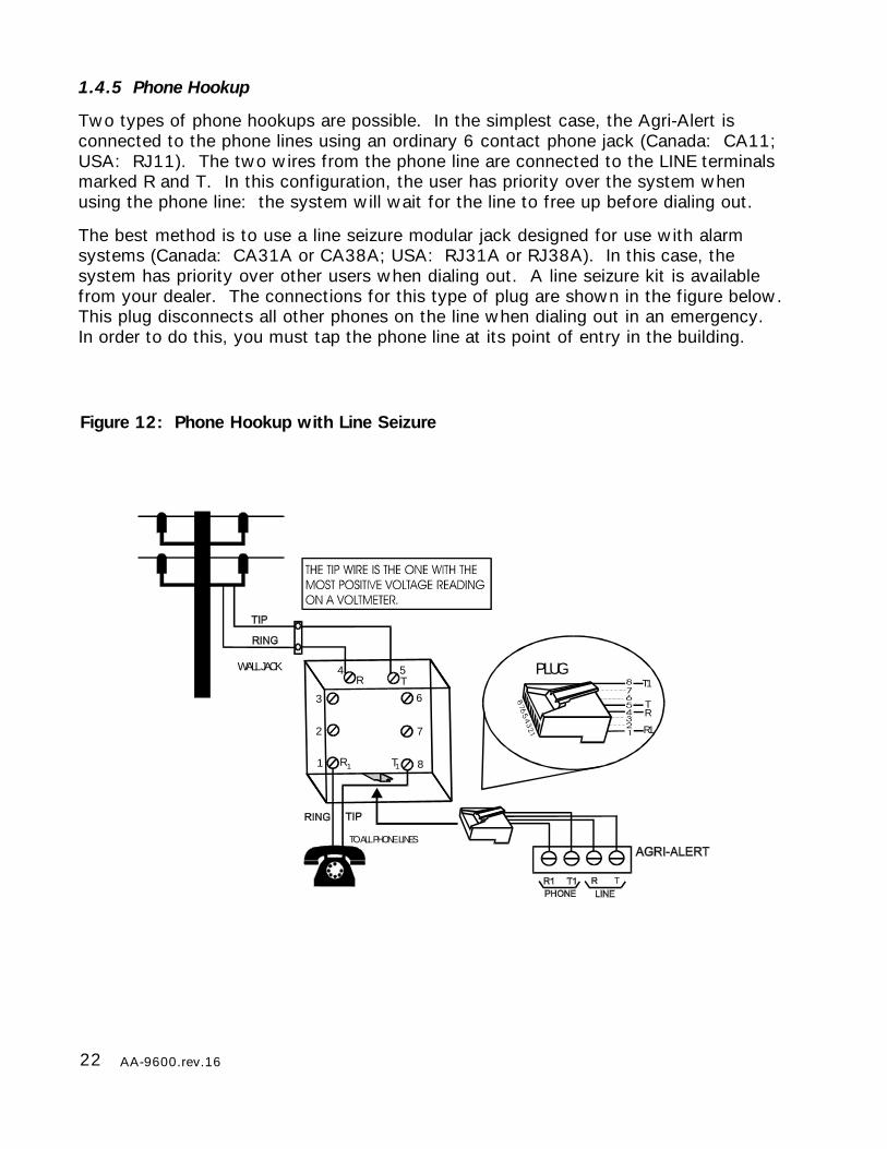
Figure 12: Phone Hookup with Line Seizure
1.4.5 Phone Hookup
Two types of phone hookups are possible. In the simplest case, the Agri-Alert isconnected to the phone lines using an ordinary 6 contact phone jack (Canada: CA11;USA: RJ11). The two wires from the phone line are connected to the LINE terminalsmarked R and T. In this configuration, the user has priority over the system whenusing the phone line: the system will wait for the line to free up before dialing out.
The best method is to use a line seizure modular jack designed for use with alarmsystems (Canada: CA31A or CA38A; USA: RJ31A or RJ38A). In this case, thesystem has priority over other users when dialing out. A line seizure kit is availablefrom your dealer. The connections for this type of plug are shown in the figure below.This plug disconnects all other phones on the line when dialing out in an emergency.In order to do this, you must tap the phone line at its point of entry in the building.
WALL JACK PLUG
TO ALL PHONE LINES
1
R T
2
3
4 5
6
7
8
R1
T1
TR
R1 T1
23AA-9600.rev.16
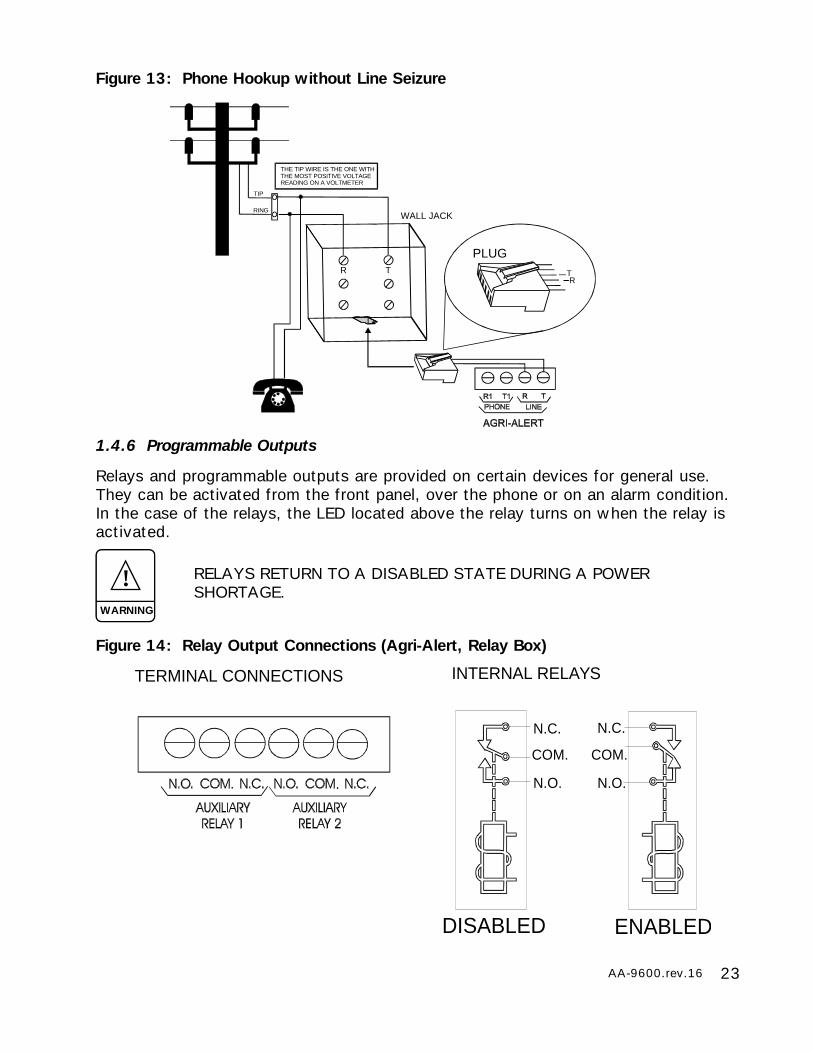
Figure 13: Phone Hookup without Line Seizure
WALL JACK
R T TR
PLUG
TIP
RING
THE TIP WIRE IS THE ONE WITHTHE MOST POSITIVE VOLTAGEREADING ON A VOLTMETER
1.4.6 Programmable Outputs
Relays and programmable outputs are provided on certain devices for general use.They can be activated from the front panel, over the phone or on an alarm condition.In the case of the relays, the LED located above the relay turns on when the relay isactivated.
Figure 14: Relay Output Connections (Agri-Alert, Relay Box)
N.C.
COM.
N.O.
N.C.
COM.
N.O.
INTERNAL RELAYSTERMINAL CONNECTIONS
. .
DISABLED ENABLED
!WARNING
RELAYS RETURN TO A DISABLED STATE DURING A POWERSHORTAGE.
24 AA-9600.rev.16
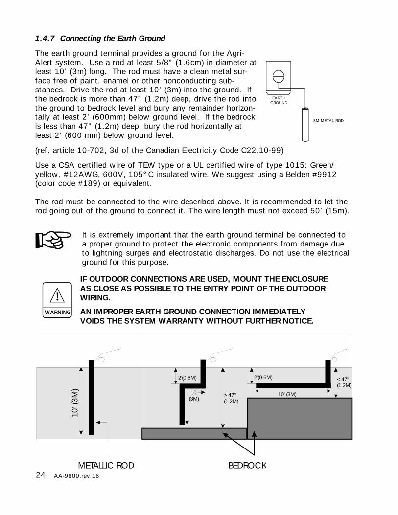
1.4.7 Connecting the Earth Ground
The earth ground terminal provides a ground for the Agri-Alert system. Use a rod at least 5/8” (1.6cm) in diameter atleast 10’ (3m) long. The rod must have a clean metal sur-face free of paint, enamel or other nonconducting sub-stances. Drive the rod at least 10’ (3m) into the ground. Ifthe bedrock is more than 47” (1.2m) deep, drive the rod intothe ground to bedrock level and bury any remainder horizon-tally at least 2’ (600mm) below ground level. If the bedrockis less than 47” (1.2m) deep, bury the rod horizontally atleast 2’ (600 mm) below ground level.
(ref. article 10-702, 3d of the Canadian Electricity Code C22.10-99)
Use a CSA certified wire of TEW type or a UL certified wire of type 1015: Green/yellow, #12AWG, 600V, 105°C insulated wire. We suggest using a Belden #9912(color code #189) or equivalent.
The rod must be connected to the wire described above. It is recommended to let therod going out of the ground to connect it. The wire length must not exceed 50’ (15m).
It is extremely important that the earth ground terminal be connected toa proper ground to protect the electronic components from damage dueto lightning surges and electrostatic discharges. Do not use the electricalground for this purpose.
IF OUTDOOR CONNECTIONS ARE USED, MOUNT THE ENCLOSUREAS CLOSE AS POSSIBLE TO THE ENTRY POINT OF THE OUTDOORWIRING.
AN IMPROPER EARTH GROUND CONNECTION IMMEDIATELYVOIDS THE SYSTEM WARRANTY WITHOUT FURTHER NOTICE.
!WARNING
EARTHGROUND
3M METAL ROD
10' (
3M)
10' (3M)
2'(0.6M)2'(0.6M)
10' (3M)
METALLIC ROD BEDROCK
<47" (1.2M)
>47" (1.2M)
25AA-9600.rev.16
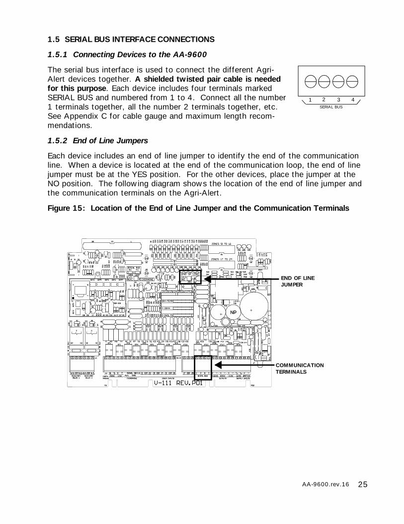
1.5 SERIAL BUS INTERFACE CONNECTIONS
1.5.1 Connecting Devices to the AA-9600
The serial bus interface is used to connect the different Agri-Alert devices together. A shielded twisted pair cable is neededfor this purpose. Each device includes four terminals markedSERIAL BUS and numbered from 1 to 4. Connect all the number1 terminals together, all the number 2 terminals together, etc.See Appendix C for cable gauge and maximum length recom-mendations.
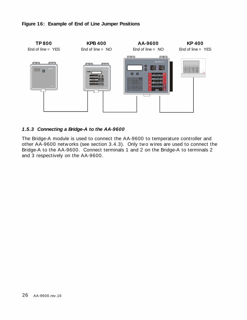
1.5.2 End of Line Jumpers
Each device includes an end of line jumper to identify the end of the communicationline. When a device is located at the end of the communication loop, the end of linejumper must be at the YES position. For the other devices, place the jumper at theNO position. The following diagram shows the location of the end of line jumper andthe communication terminals on the Agri-Alert.
Figure 15: Location of the End of Line Jumper and the Communication Terminals
1SERIAL BUS
2 3 4
END OF LINEJUMPER
COMMUNICATIONTERMINALS
26 AA-9600.rev.16
Figure 16: Example of End of Line Jumper Positions
1.5.3 Connecting a Bridge-A to the AA-9600
The Bridge-A module is used to connect the AA-9600 to temperature controller andother AA-9600 networks (see section 3.4.3). Only two wires are used to connect theBridge-A to the AA-9600. Connect terminals 1 and 2 on the Bridge-A to terminals 2and 3 respectively on the AA-9600.
TP 800End of line = YES
KPB 400End of line = NO
AA-9600End of line = NO
KP 400End of line = YES
27AA-9600.rev.16
CHAPTER TWO: USER INTERFACE
The system displays and prompts for information by using the alphanumeric screen.The keypad is used for data entry and for enabling and disabling the various systemfunctions. The speaker on the front panel delivers voice messages. A built-in piezo-electric warns of illegal entries (3 short beeps) and beeps once when a valid key ispressed. The integrated microphone on the front panel is used to record the user IDmessage and provide on-site listening. The status of some subsystems is displayedusing LEDs on the front panel.
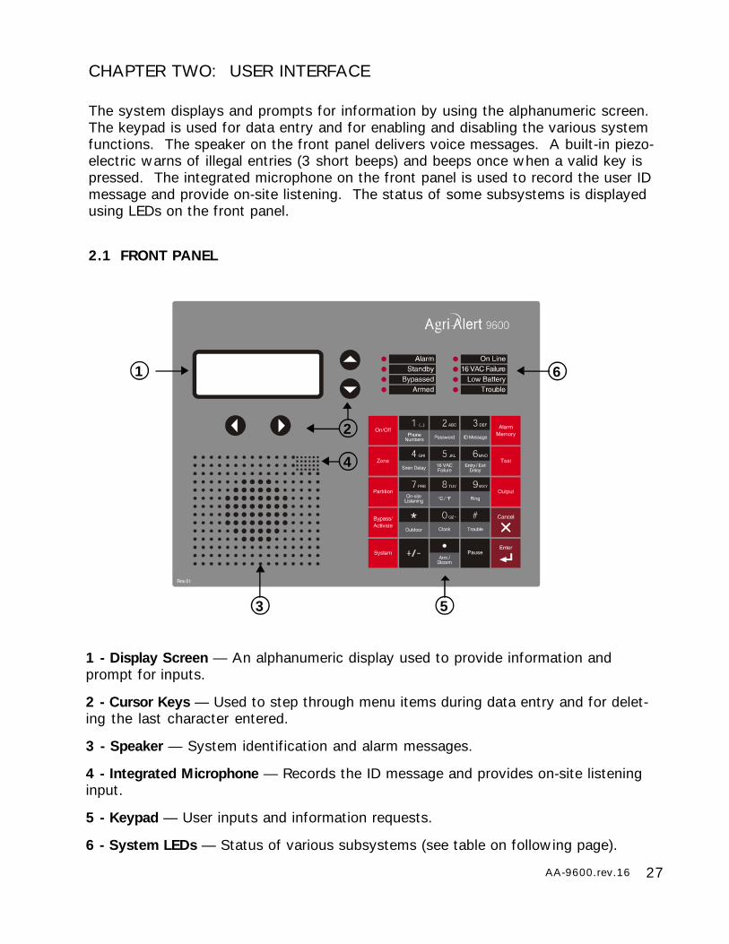
2.1 FRONT PANEL
1 - Display Screen — An alphanumeric display used to provide information andprompt for inputs.
2 - Cursor Keys — Used to step through menu items during data entry and for delet-ing the last character entered.
3 - Speaker — System identification and alarm messages.
4 - Integrated Microphone — Records the ID message and provides on-site listeninginput.
5 - Keypad — User inputs and information requests.
6 - System LEDs — Status of various subsystems (see table on following page).
1
2
4
3 5
6
28 AA-9600.rev.16
L E D M E A N I N G
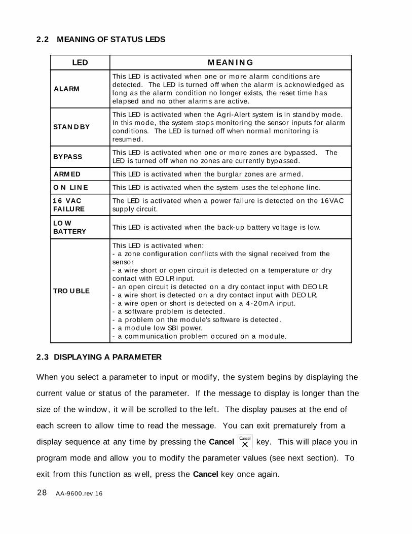
A L A RM
This LED is activated when one or m o re a larm conditions a redetected. The LED is turned o ff when the ala rm is acknowledged aslong as the alarm condition no longer exists, the reset time haselapsed and no other a larm s are active.
STA N D B Y
This LED is activated when the Ag ri-A lert system is in standby mode.In this mode , the system stops monitoring the sensor inputs for alarmcond itions. The LED is turned off when norm a l monitoring isresumed .
B Y PA S S This LED is activated when one or m o re zones a re bypassed. TheLED is turned off when no zones are currently bypassed.
A R M E D This LED is activated when the burglar zones are armed .
O N L I N E This LED is activated when the system uses the telephone line.
1 6 V A CFA I L U R E
The LED is act ivated when a power failure is de tected on the 16VA Csupp ly circuit.
L O WB A T T E R Y This LED is act ivated when the back-up battery vo ltage is low.
T R O U B L E
This LED is activated when:- a zone configuration conflicts with the signal received from thesensor- a wire short or open circuit is de tected on a temperature or drycontact with EOLR input.- an open circuit is detected on a dry contact input with DEOLR.- a wire short is de tected on a dry contact input with DEOLR.- a wire open or short is de tected on a 4-20m A input.- a software problem is de tected .- a problem on the module's so ftware is de tected .- a module low SBI power.- a com m unica tion prob lem occured on a module.
2.2 MEANING OF STATUS LEDS
2.3 DISPLAYING A PARAMETER
When you select a parameter to input or modify, the system begins by displaying the
current value or status of the parameter. If the message to display is longer than the
size of the window, it will be scrolled to the left. The display pauses at the end of
each screen to allow time to read the message. You can exit prematurely from a
display sequence at any time by pressing the Cancel key. This will place you in
program mode and allow you to modify the parameter values (see next section). To
exit from this function as well, press the Cancel key once again.
29AA-9600.rev.16
If a parameter is not completely defined when you try to display it, the messageINCOMPLETE DATA appears on the screen. This may be an indication that the sys-tem will not behave as expected. If, for example, a zone input is not completelyconfigured, the system will not monitor the zone for alarm conditions. Before enablingthe system for normal operation, make sure all parameters are properly defined. Inthe case of phone numbers and zones, the system will display a message periodicallytelling the user which zones and phone numbers are incomplete. To exit from thewarning display, press the Cancel key.
2.4 MODIFYING A PARAMETER
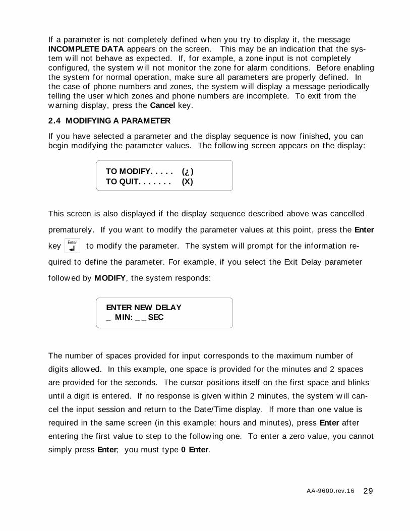
If you have selected a parameter and the display sequence is now finished, you canbegin modifying the parameter values. The following screen appears on the display:
This screen is also displayed if the display sequence described above was cancelled
prematurely. If you want to modify the parameter values at this point, press the Enter
key to modify the parameter. The system will prompt for the information re-
quired to define the parameter. For example, if you select the Exit Delay parameter
followed by MODIFY, the system responds:
The number of spaces provided for input corresponds to the maximum number of
digits allowed. In this example, one space is provided for the minutes and 2 spaces
are provided for the seconds. The cursor positions itself on the first space and blinks
until a digit is entered. If no response is given within 2 minutes, the system will can-
cel the input session and return to the Date/Time display. If more than one value is
required in the same screen (in this example: hours and minutes), press Enter after
entering the first value to step to the following one. To enter a zero value, you cannot
simply press Enter; you must type 0 Enter.
TO MODIFY. . . . . (↵)TO QUIT. . . . . . . (X)
ENTER NEW DELAY_ MIN: _ _ SEC
30 AA-9600.rev.16
DATE . . . . . . . . . (1)TIME . . . . . . . . . (2)
If you make a typing mistake, you can backstep using the back arrow key under-
neath the display window before pressing Enter. The cursor will position itself accord-
ingly. You can enter a negative value if this is allowed (for example, a negative tem-
perature value) by pressing the +/- key either before or after the digits.
After entering a value using the numerical keypad, press Enter to register the value. If
the value entered falls outside the permissible range for that parameter, the system
will beep three times and wait for you to modify the input using the back arrow key.
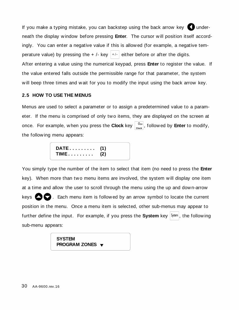
2.5 HOW TO USE THE MENUS
Menus are used to select a parameter or to assign a predetermined value to a param-
eter. If the menu is comprised of only two items, they are displayed on the screen at
once. For example, when you press the Clock key 0QZ-
Clock, followed by Enter to modify,
the following menu appears:
You simply type the number of the item to select that item (no need to press the Enter
key). When more than two menu items are involved, the system will display one item
at a time and allow the user to scroll through the menu using the up and down-arrow
keys . Each menu item is followed by an arrow symbol to locate the current
position in the menu. Once a menu item is selected, other sub-menus may appear to
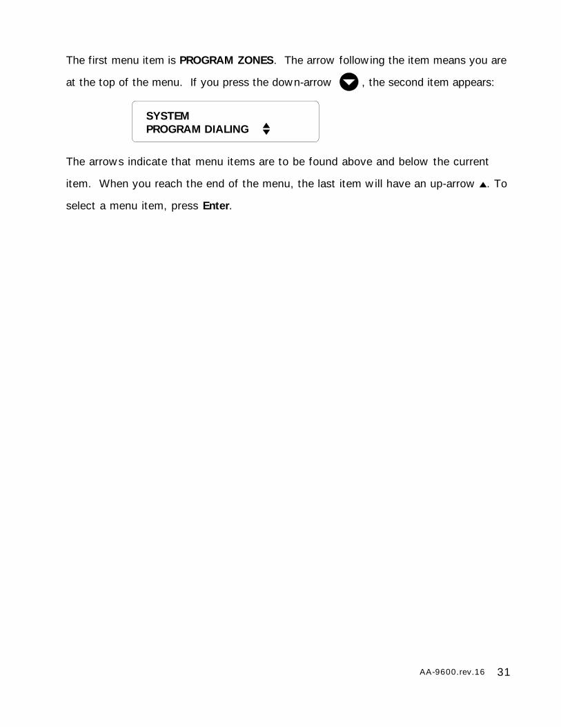
further define the input. For example, if you press the System key , the following
sub-menu appears:
SYSTEMPROGRAM ZONES
31AA-9600.rev.16
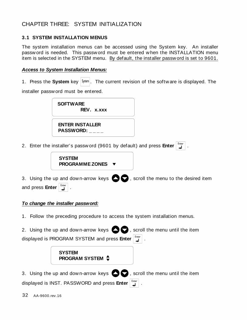
The first menu item is PROGRAM ZONES. The arrow following the item means you are
at the top of the menu. If you press the down-arrow , the second item appears:
The arrows indicate that menu items are to be found above and below the current
item. When you reach the end of the menu, the last item will have an up-arrow . To
select a menu item, press Enter.
SYSTEMPROGRAM DIALING
32 AA-9600.rev.16
CHAPTER THREE: SYSTEM INITIALIZATION
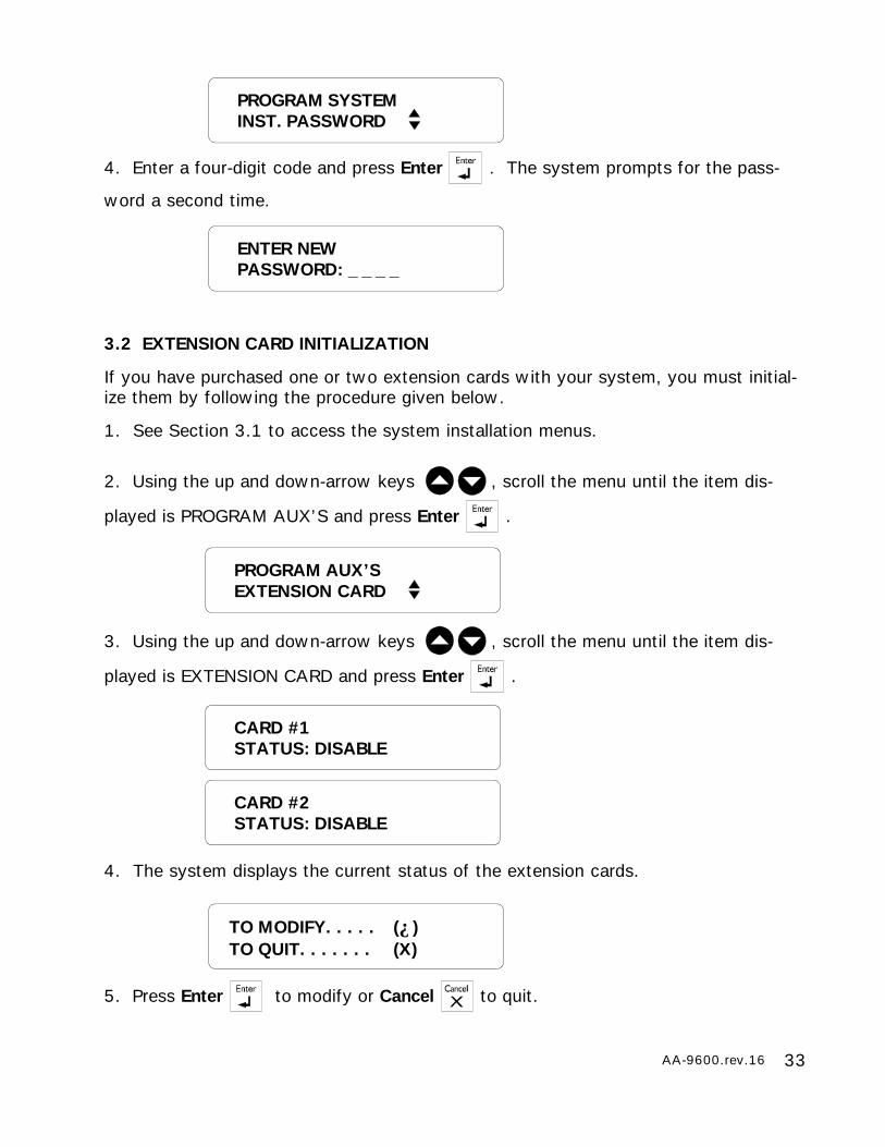
3.1 SYSTEM INSTALLATION MENUS
The system installation menus can be accessed using the System key. An installerpassword is needed. This password must be entered when the INSTALLATION menuitem is selected in the SYSTEM menu. By default, the installer password is set to 9601.
Access to System Installation Menus:
1. Press the System key . The current revision of the software is displayed. The
installer password must be entered.
2. Enter the installer’s password (9601 by default) and press Enter .
3. Using the up and down-arrow keys , scroll the menu to the desired item
and press Enter .
SOFTWAREREV. x.xxx
ENTER INSTALLERPASSWORD: _ _ _ _
SYSTEMPROGRAMME ZONES
To change the installer password:
1. Follow the preceding procedure to access the system installation menus.
2. Using the up and down-arrow keys , scroll the menu until the item
displayed is PROGRAM SYSTEM and press Enter .
3. Using the up and down-arrow keys , scroll the menu until the item
displayed is INST. PASSWORD and press Enter .
SYSTEMPROGRAM SYSTEM
33AA-9600.rev.16
3.2 EXTENSION CARD INITIALIZATION
If you have purchased one or two extension cards with your system, you must initial-ize them by following the procedure given below.
1. See Section 3.1 to access the system installation menus.
2. Using the up and down-arrow keys , scroll the menu until the item dis-
played is PROGRAM AUX’S and press Enter .
3. Using the up and down-arrow keys , scroll the menu until the item dis-
played is EXTENSION CARD and press Enter .
4. The system displays the current status of the extension cards.
5. Press Enter to modify or Cancel to quit.
PROGRAM AUX’SEXTENSION CARD
CARD #1STATUS: DISABLE
CARD #2STATUS: DISABLE
TO MODIFY. . . . . (↵)TO QUIT. . . . . . . (X)
ENTER NEWPASSWORD: _ _ _ _
PROGRAM SYSTEMINST. PASSWORD
4. Enter a four-digit code and press Enter . The system prompts for the pass-
word a second time.
34 AA-9600.rev.16
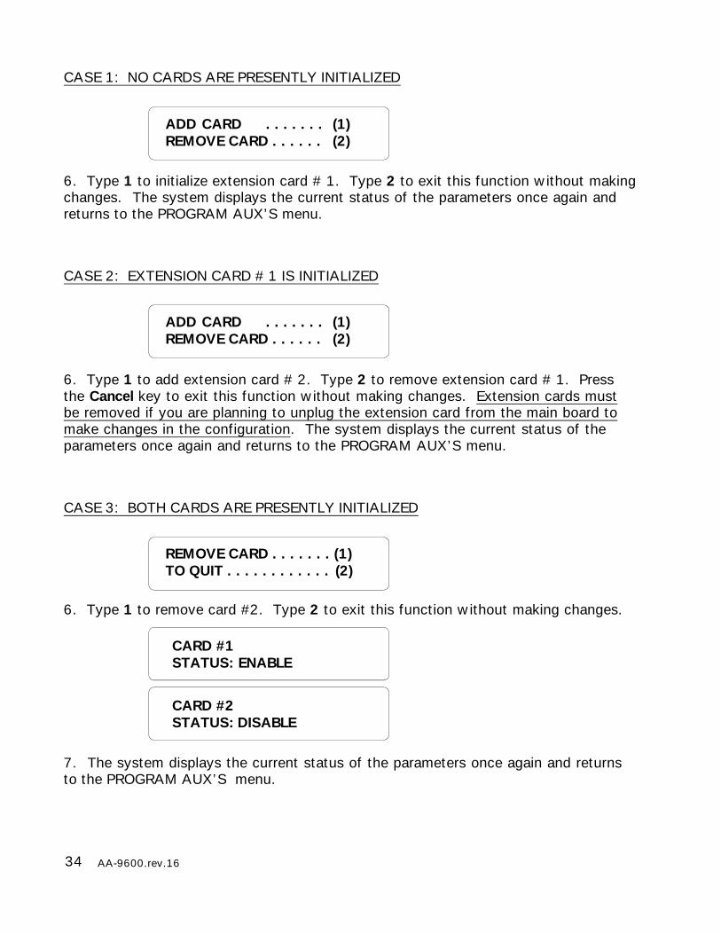
CASE 1: NO CARDS ARE PRESENTLY INITIALIZED
6. Type 1 to initialize extension card # 1. Type 2 to exit this function without makingchanges. The system displays the current status of the parameters once again andreturns to the PROGRAM AUX’S menu.
CASE 2: EXTENSION CARD # 1 IS INITIALIZED
6. Type 1 to add extension card # 2. Type 2 to remove extension card # 1. Pressthe Cancel key to exit this function without making changes. Extension cards mustbe removed if you are planning to unplug the extension card from the main board tomake changes in the configuration. The system displays the current status of theparameters once again and returns to the PROGRAM AUX’S menu.
CASE 3: BOTH CARDS ARE PRESENTLY INITIALIZED
6. Type 1 to remove card #2. Type 2 to exit this function without making changes.
7. The system displays the current status of the parameters once again and returnsto the PROGRAM AUX’S menu.
ADD CARD . . . . . . . (1)REMOVE CARD . . . . . . (2)
REMOVE CARD . . . . . . . (1)TO QUIT . . . . . . . . . . . . (2)
CARD #2STATUS: DISABLE
CARD #1STATUS: ENABLE
ADD CARD . . . . . . . (1)REMOVE CARD . . . . . . (2)
35AA-9600.rev.16
3.3 DEVICE INITIALIZATION
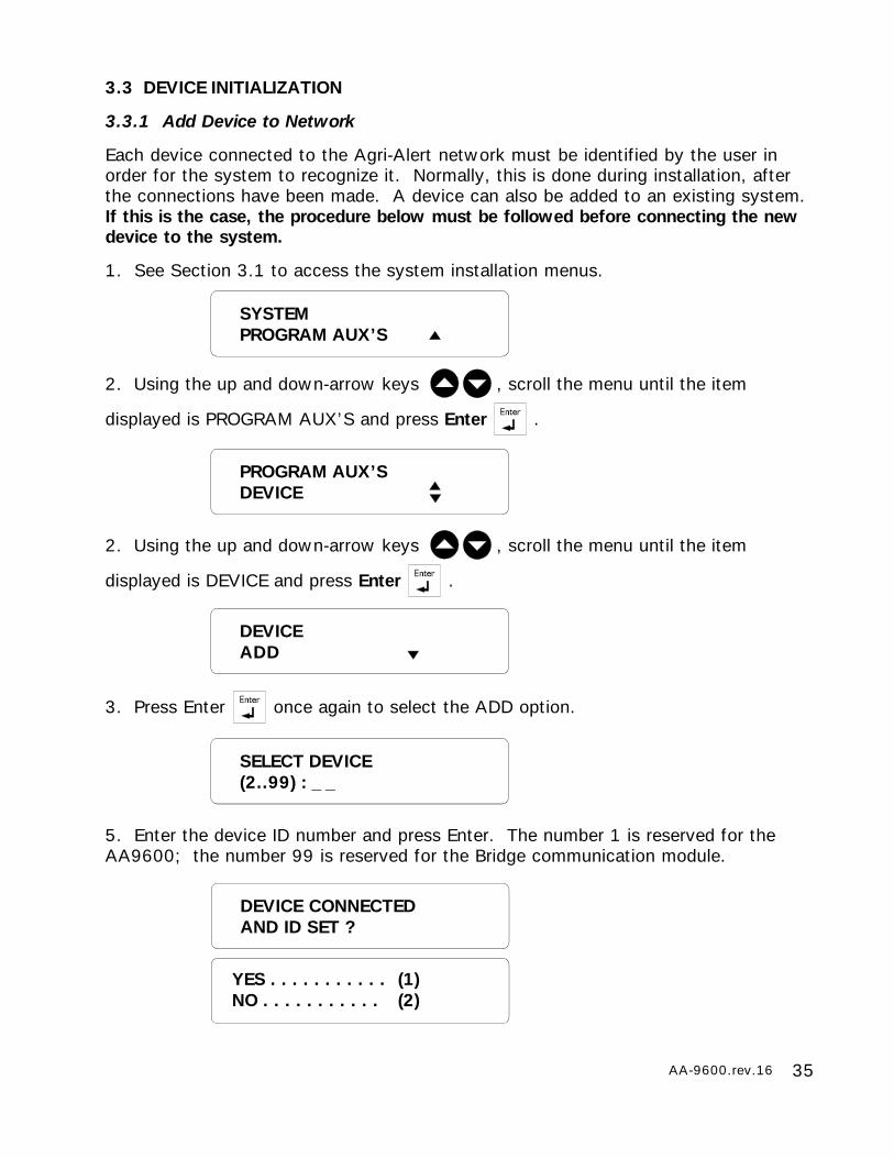
3.3.1 Add Device to Network
Each device connected to the Agri-Alert network must be identified by the user inorder for the system to recognize it. Normally, this is done during installation, afterthe connections have been made. A device can also be added to an existing system.If this is the case, the procedure below must be followed before connecting the newdevice to the system.
1. See Section 3.1 to access the system installation menus.
2. Using the up and down-arrow keys , scroll the menu until the item
displayed is PROGRAM AUX’S and press Enter .
2. Using the up and down-arrow keys , scroll the menu until the item
displayed is DEVICE and press Enter .
3. Press Enter once again to select the ADD option.
5. Enter the device ID number and press Enter. The number 1 is reserved for theAA9600; the number 99 is reserved for the Bridge communication module.
SYSTEMPROGRAM AUX’S
SELECT DEVICE(2..99) : _ _
YES . . . . . . . . . . . (1)NO . . . . . . . . . . . (2)
DEVICE CONNECTEDAND ID SET ?
PROGRAM AUX’SDEVICE
DEVICEADD

36 AA-9600.rev.16
6. Type 1 if the device is already connected to the network; the system continueswith step 9. Type 2 if either the device is not yet connected to the network or the idnumber has not been configured.
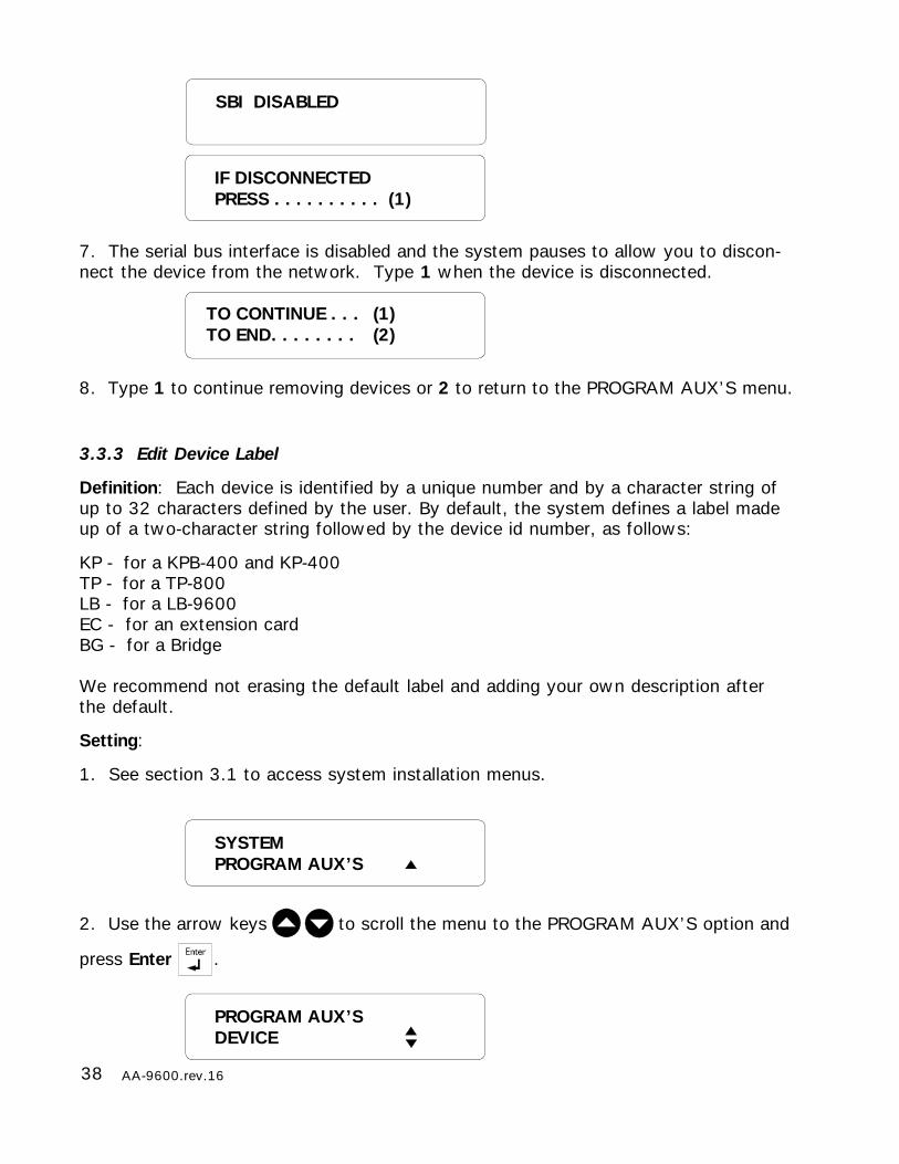
7. The serial bus interface is disabled and the system pauses to allow you to makethe connections. Type 1 to continue the installation procedure, once the device is online. Press cancel to end the procedure without adding the new device.
8. At this point, you must configure the id number on the new device. Refer to theinstallation manual of the device to do this. When you are finished, type 1. PressCancel to end the procedure without adding the new device. When a new device isinstalled, the system checks if it responds normally. The message “DEVICE #XXINSTALLED” is displayed if the device exists; otherwise the message “DEVICE DOESNOT EXIST” is displayed.
9. Type 1 to continue adding devices or 2 to return to the PROGRAM AUX’S menu.
TO CONTINUE . . . (1)TO END. . . . . . . . (2)
CONFIGURE DEVICEID TO #XX
IF CONFIGUREDPRESS. . . . . . . . (1)
IF CONNECTEDPRESS. . . . . . . . . .(1)
SBI DISABLED
CONNECT DEVICE# XX NOW

37AA-9600.rev.16
3.3.2 Remove Device from Network
Follow the procedure below to remove a device before disconnecting it from thenetwork.
1. See Section 3.1 to access the system installation menus.
2. Using the up and down-arrow keys , scroll the menu until the item
displayed is PROGRAM AUX’S and press Enter .
3. Use the arrow keys to scroll the menu to the DEVICE option and press Enter.
4. Use the arrow keys to scroll the menu to the REMOVE option and press Enter.
5. Enter the device identification number and press Enter. The number 1 is reservedfor the AA9600; the number 99 is reserved for the Bridge communication module. Ifthe number entered is not a valid device number, the message “DEVICE DOES NOTEXIST” is displayed and the system goes to step 8.
6. Type 1 if you would like to disconnect the device right now. Type 2 to disconnectthe device at a later time; the system ends the procedure.
PROGRAM AUX’SDEVICE
DEVICEREMOVE
DISCONNECT DEVICE# XX NOW ?
YES . . . . . . . . . . . (1)NO . . . . . . . . . . . (2)
SELECT DEVICE(2..99) : _ _
38 AA-9600.rev.16
3.3.3 Edit Device Label
Definition: Each device is identified by a unique number and by a character string ofup to 32 characters defined by the user. By default, the system defines a label madeup of a two-character string followed by the device id number, as follows:
KP - for a KPB-400 and KP-400TP - for a TP-800LB - for a LB-9600EC - for an extension cardBG - for a Bridge
We recommend not erasing the default label and adding your own description afterthe default.
Setting:
1. See section 3.1 to access system installation menus.
2. Use the arrow keys to scroll the menu to the PROGRAM AUX’S option and
press Enter .
TO CONTINUE . . . (1)TO END. . . . . . . . (2)
SYSTEMPROGRAM AUX’S
PROGRAM AUX’SDEVICE
SBI DISABLED
IF DISCONNECTEDPRESS . . . . . . . . . . (1)
7. The serial bus interface is disabled and the system pauses to allow you to discon-nect the device from the network. Type 1 when the device is disconnected.
8. Type 1 to continue removing devices or 2 to return to the PROGRAM AUX’S menu.

39AA-9600.rev.16
TP#08BREEDER#01
TO CONTINUE . . . (1)TO END. . . . . . . . (2)
SELECT DEVICE(1..99): _ _
3. Use the arrow keys to scroll the menu to the DEVICE option and press
Enter .
4. Use the arrow keys to scroll the menu to the EDIT LABEL option and press
Enter .
5. Enter the device ID number and press Enter. Number 1 is reserved for the
AA9600; number 99 is reserved for the Bridge communication module. If the ID
number is not an installed device, the system displays the message “DEVICE DOES
NOT EXIST” and continues with step 7.
6. Use the numeric keys to type the device label. For example, the number 2 key is
used to type the letters A, B and C: type 2 for A, 22 for B, 222 for C, 2222 for a,
22222 for b and 222222 for c. Use the number 1 key for special characters. Use
the arrow keys to move around the display. Press Enter to end
the edit session.
7. Type 1 to continue editing device labels or 2 to return to the PROGRAM AUX’S menu.
DEVICEEDIT LABEL
40 AA-9600.rev.16
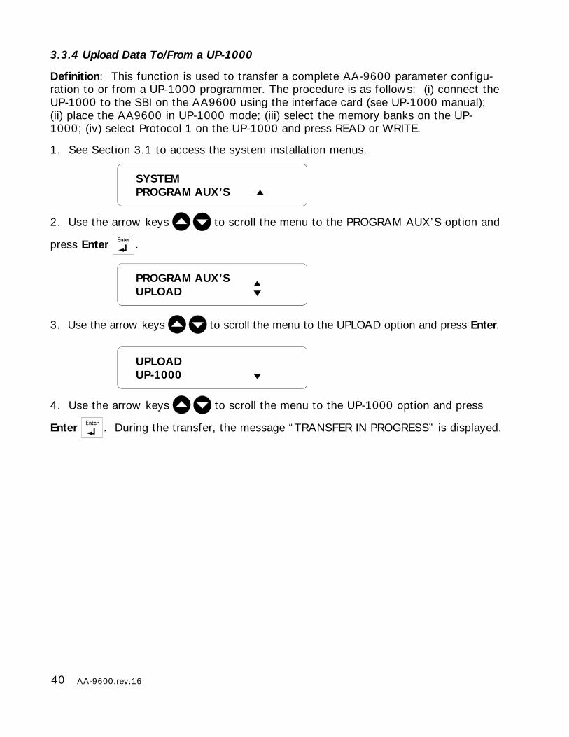
3.3.4 Upload Data To/From a UP-1000
Definition: This function is used to transfer a complete AA-9600 parameter configu-ration to or from a UP-1000 programmer. The procedure is as follows: (i) connect theUP-1000 to the SBI on the AA9600 using the interface card (see UP-1000 manual);(ii) place the AA9600 in UP-1000 mode; (iii) select the memory banks on the UP-1000; (iv) select Protocol 1 on the UP-1000 and press READ or WRITE.
1. See Section 3.1 to access the system installation menus.
2. Use the arrow keys to scroll the menu to the PROGRAM AUX’S option and
press Enter .
3. Use the arrow keys to scroll the menu to the UPLOAD option and press Enter.
4. Use the arrow keys to scroll the menu to the UP-1000 option and press
Enter . During the transfer, the message “TRANSFER IN PROGRESS” is displayed.
UPLOADUP-1000
PROGRAM AUX’SUPLOAD
SYSTEMPROGRAM AUX’S
41AA-9600.rev.16
ALL . . . . . . . . . . . (1)SPECIAL . . . . . . . (2)
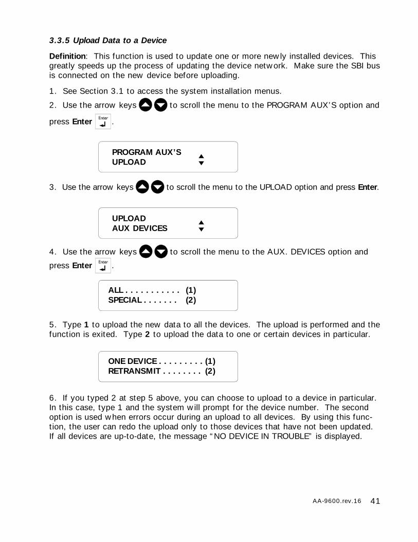
3.3.5 Upload Data to a Device
Definition: This function is used to update one or more newly installed devices. Thisgreatly speeds up the process of updating the device network. Make sure the SBI busis connected on the new device before uploading.
1. See Section 3.1 to access the system installation menus.
2. Use the arrow keys to scroll the menu to the PROGRAM AUX’S option and
press Enter .
3. Use the arrow keys to scroll the menu to the UPLOAD option and press Enter.
4. Use the arrow keys to scroll the menu to the AUX. DEVICES option and
press Enter .
5. Type 1 to upload the new data to all the devices. The upload is performed and thefunction is exited. Type 2 to upload the data to one or certain devices in particular.
6. If you typed 2 at step 5 above, you can choose to upload to a device in particular.In this case, type 1 and the system will prompt for the device number. The secondoption is used when errors occur during an upload to all devices. By using this func-tion, the user can redo the upload only to those devices that have not been updated.If all devices are up-to-date, the message “NO DEVICE IN TROUBLE” is displayed.
PROGRAM AUX’SUPLOAD
UPLOADAUX DEVICES
ONE DEVICE . . . . . . . . . (1)RETRANSMIT . . . . . . . . (2)
42 AA-9600.rev.16
1 2 3 4
SERIAL BUS
AA-9600
1 2 3 4
AA-9600
SERIAL BUS
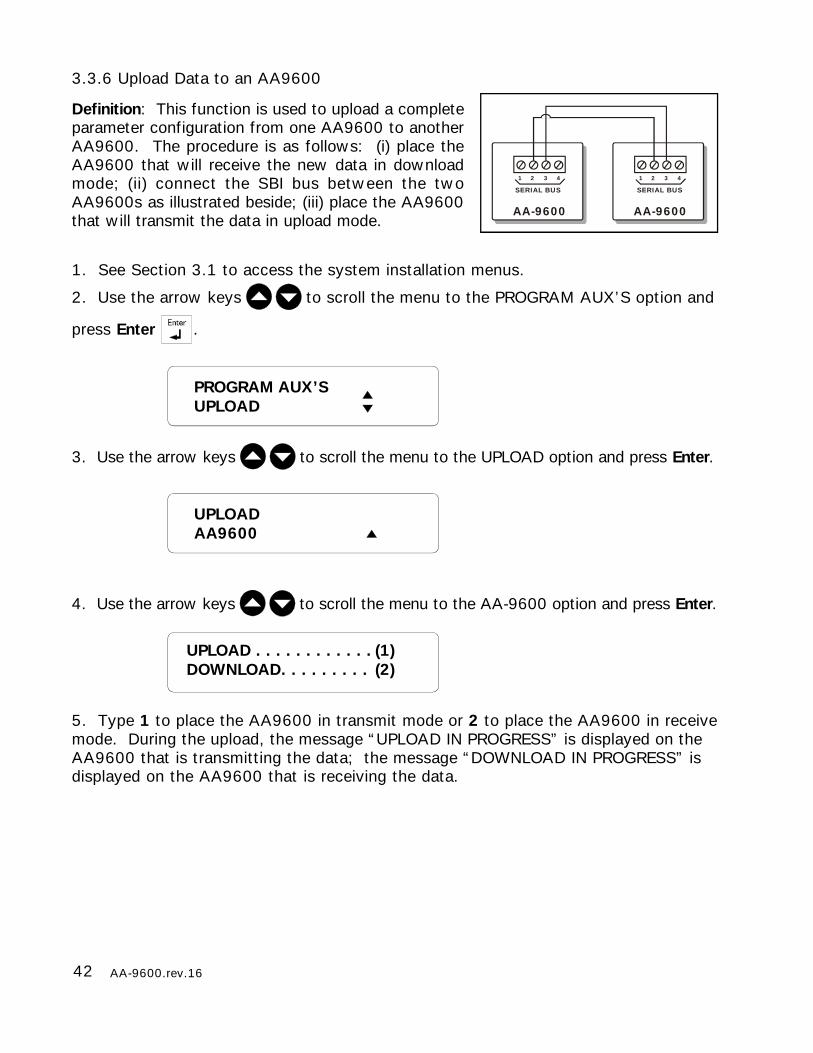
3.3.6 Upload Data to an AA9600
Definition: This function is used to upload a completeparameter configuration from one AA9600 to anotherAA9600. The procedure is as follows: (i) place theAA9600 that will receive the new data in downloadmode; (ii) connect the SBI bus between the twoAA9600s as illustrated beside; (iii) place the AA9600that will transmit the data in upload mode.
1. See Section 3.1 to access the system installation menus.
2. Use the arrow keys to scroll the menu to the PROGRAM AUX’S option and
press Enter .
3. Use the arrow keys to scroll the menu to the UPLOAD option and press Enter.
4. Use the arrow keys to scroll the menu to the AA-9600 option and press Enter.
5. Type 1 to place the AA9600 in transmit mode or 2 to place the AA9600 in receivemode. During the upload, the message “UPLOAD IN PROGRESS” is displayed on theAA9600 that is transmitting the data; the message “DOWNLOAD IN PROGRESS” isdisplayed on the AA9600 that is receiving the data.
PROGRAM AUX’SUPLOAD
UPLOADAA9600
UPLOAD . . . . . . . . . . . . (1)DOWNLOAD. . . . . . . . . (2)
43AA-9600.rev.16
KP #02BARN 3
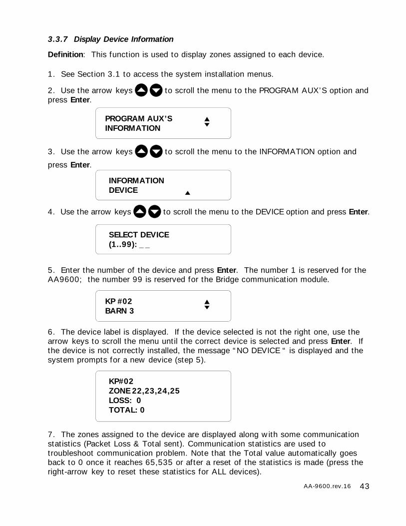
3.3.7 Display Device Information
Definition: This function is used to display zones assigned to each device.
1. See Section 3.1 to access the system installation menus.
2. Use the arrow keys to scroll the menu to the PROGRAM AUX’S option andpress Enter.
3. Use the arrow keys to scroll the menu to the INFORMATION option and
press Enter.
4. Use the arrow keys to scroll the menu to the DEVICE option and press Enter.
5. Enter the number of the device and press Enter. The number 1 is reserved for theAA9600; the number 99 is reserved for the Bridge communication module.
6. The device label is displayed. If the device selected is not the right one, use thearrow keys to scroll the menu until the correct device is selected and press Enter. Ifthe device is not correctly installed, the message “NO DEVICE “ is displayed and thesystem prompts for a new device (step 5).
7. The zones assigned to the device are displayed along with some communicationstatistics (Packet Loss & Total sent). Communication statistics are used totroubleshoot communication problem. Note that the Total value automatically goesback to 0 once it reaches 65,535 or after a reset of the statistics is made (press theright-arrow key to reset these statistics for ALL devices).
INFORMATIONDEVICE
SELECT DEVICE(1..99): _ _
PROGRAM AUX’SINFORMATION
KP#02ZONE 22,23,24,25LOSS: 0TOTAL: 0
44 AA-9600.rev.16
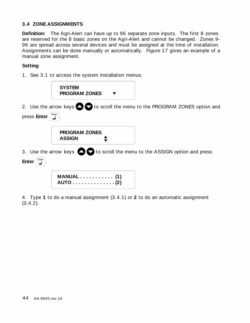
3.4 ZONE ASSIGNMENTS
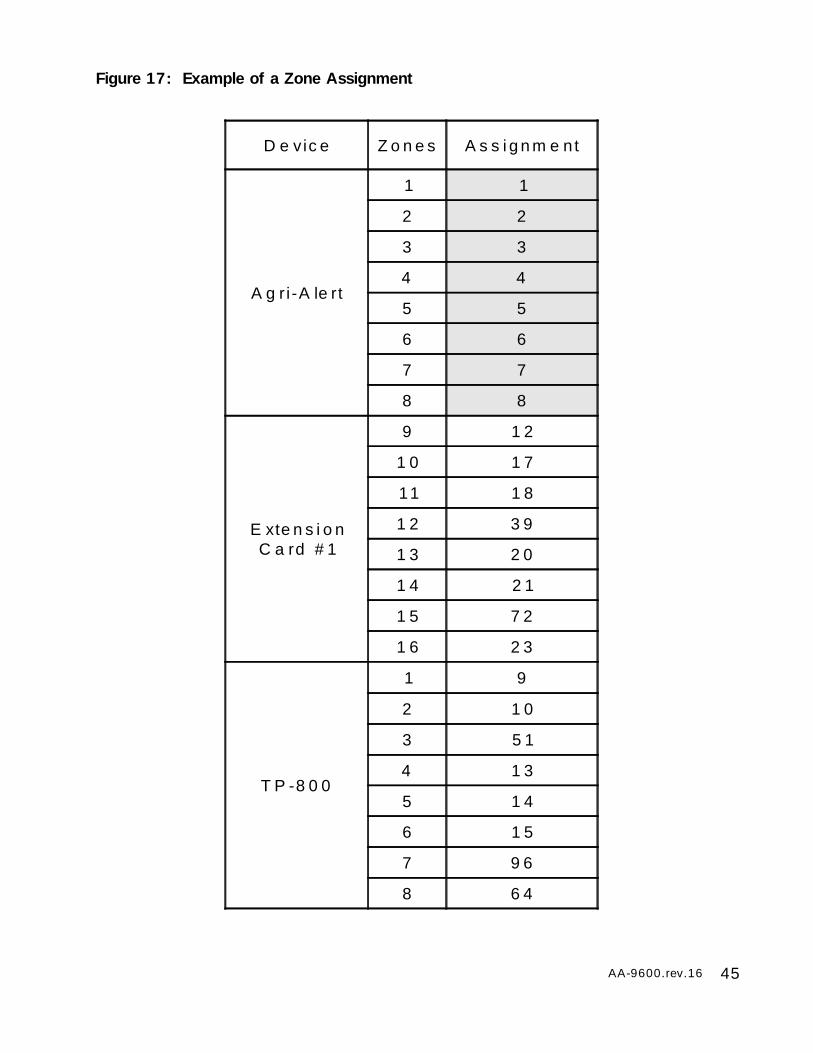
Definition: The Agri-Alert can have up to 96 separate zone inputs. The first 8 zonesare reserved for the 8 basic zones on the Agri-Alert and cannot be changed. Zones 9-96 are spread across several devices and must be assigned at the time of installation.Assignments can be done manually or automatically. Figure 17 gives an example of amanual zone assignment.
Setting:
1. See 3.1 to access the system installation menus.
2. Use the arrow keys to scroll the menu to the PROGRAM ZONES option and
press Enter .
3. Use the arrow keys to scroll the menu to the ASSIGN option and press
Enter .
4. Type 1 to do a manual assignment (3.4.1) or 2 to do an automatic assignment(3.4.2).
MANUAL . . . . . . . . . . . (1)AUTO . . . . . . . . . . . . . . (2)
PROGRAM ZONESASSIGN
SYSTEMPROGRAM ZONES
45AA-9600.rev.16
D e vic e Z o n e s A s s i g n m e nt
A g r i -A le rt
1 1
2 2
3 3
4 4
5 5
6 6
7 7
8 8
E xte n s i o nC a rd # 1
9 1 2
1 0 1 7
11 1 8
1 2 3 9
1 3 2 0
1 4 2 1
1 5 7 2
1 6 2 3
T P -8 0 0
1 9
2 1 0
3 5 1
4 1 3
5 1 4
6 1 5
7 9 6
8 6 4
Figure 17: Example of a Zone Assignment
46 AA-9600.rev.16
SELECT DEVICE’SZONE (1..X): _
TO CONTINUE. . . . . . . . (1)TO END. . . . . . . . . . . . (2)
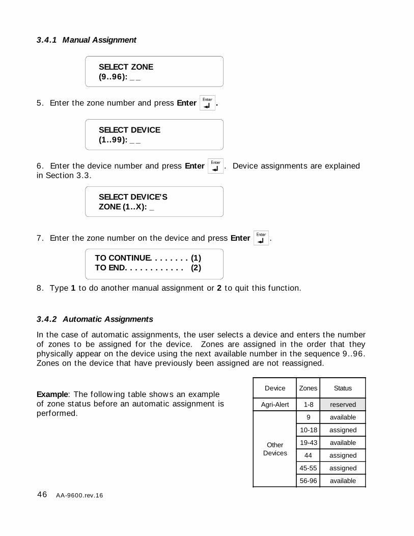
Device Zones Status
Agri-Alert 1-8 reserved
OtherDevices
9 available
10-18 assigned
19-43 available
44 assigned
45-55 assigned
56-96 available
SELECT ZONE(9..96): _ _
SELECT DEVICE(1..99): _ _
3.4.1 Manual Assignment
5. Enter the zone number and press Enter .
6. Enter the device number and press Enter . Device assignments are explainedin Section 3.3.
7. Enter the zone number on the device and press Enter .
8. Type 1 to do another manual assignment or 2 to quit this function.
3.4.2 Automatic Assignments
In the case of automatic assignments, the user selects a device and enters the numberof zones to be assigned for the device. Zones are assigned in the order that theyphysically appear on the device using the next available number in the sequence 9..96.Zones on the device that have previously been assigned are not reassigned.
Example: The following table shows an exampleof zone status before an automatic assignment isperformed.
47AA-9600.rev.16
SELECT DEVICE(1..99): _ _
NUMBER OF ZONES(1..X): _ _
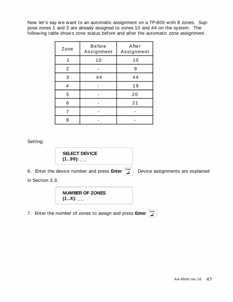
Now let’s say we want to an automatic assignment on a TP-800 with 8 zones. Sup-pose zones 1 and 3 are already assigned to zones 10 and 44 on the system. Thefollowing table shows zone status before and after the automatic zone assignment.
Setting:
6. Enter the device number and press Enter . Device assignments are explained
in Section 3.3.
7. Enter the number of zones to assign and press Enter .
Zone B e foreAss ignment
A fte rAss ignment
1 10 10
2 - 9
3 44 44
4 - 19
5 - 20
6 - 21
7 - -
8 - -
48 AA-9600.rev.16
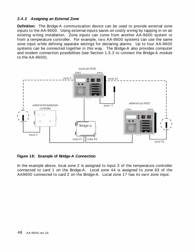
3.4.3 Assigning an External Zone
Definition: The Bridge-A communication device can be used to provide external zoneinputs to the AA-9600. Using external inputs saves on costly wiring by tapping in on anexisting wiring installation. Zone inputs can come from another AA-9600 system orfrom a temperature controller. For example, two AA-9600 systems can use the samezone input while defining separate settings for declaring alarms. Up to four AA-9600systems can be connected together in this way. The Bridge-A also provides computerand modem connection possibilities (see Section 1.5.3 to connect the Bridge-A moduleto the AA-9600).
Figure 18: Example of Bridge-A Connection
In the example above, local zone 2 is assigned to input 3 of the temperature controllerconnected to card 1 on the Bridge-A. Local zone 44 is assigned to zone 93 of theAA9600 connected to card 2 on the Bridge-A. Local zone 17 has its own zone input.
49AA-9600.rev.16
YES . . . . . . . . . . . . . (1)NO . . . . . . . . . . . . . . (2)
EXTERNAL AA9600?
SELECT CARD(1..4): _ _
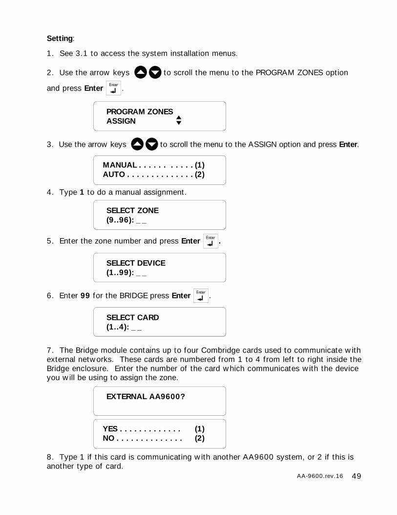
Setting:
1. See 3.1 to access the system installation menus.
2. Use the arrow keys to scroll the menu to the PROGRAM ZONES option
and press Enter .
3. Use the arrow keys to scroll the menu to the ASSIGN option and press Enter.
4. Type 1 to do a manual assignment.
5. Enter the zone number and press Enter .
6. Enter 99 for the BRIDGE press Enter .
7. The Bridge module contains up to four Combridge cards used to communicate withexternal networks. These cards are numbered from 1 to 4 from left to right inside theBridge enclosure. Enter the number of the card which communicates with the deviceyou will be using to assign the zone.
MANUAL . . . . . . . . . . . (1)AUTO . . . . . . . . . . . . . . (2)
SELECT ZONE(9..96): _ _
SELECT DEVICE(1..99): _ _
PROGRAM ZONESASSIGN
8. Type 1 if this card is communicating with another AA9600 system, or 2 if this isanother type of card.
50 AA-9600.rev.16
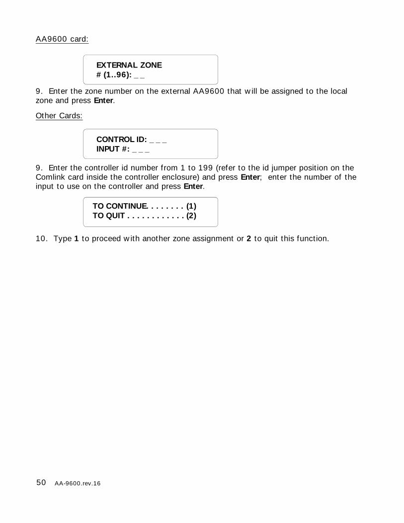
AA9600 card:
9. Enter the zone number on the external AA9600 that will be assigned to the localzone and press Enter.
Other Cards:
9. Enter the controller id number from 1 to 199 (refer to the id jumper position on theComlink card inside the controller enclosure) and press Enter; enter the number of theinput to use on the controller and press Enter.
10. Type 1 to proceed with another zone assignment or 2 to quit this function.
EXTERNAL ZONE# (1..96): _ _
CONTROL ID: _ _ _INPUT #: _ _ _
TO CONTINUE. . . . . . . . (1)TO QUIT . . . . . . . . . . . . (2)
51AA-9600.rev.16
YES . . . . . . . . . . . . . (1)NO . . . . . . . . . . . . . . (2)
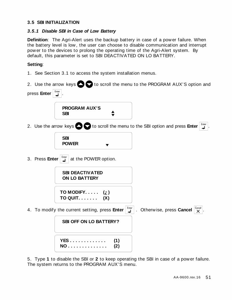
3.5 SBI INITIALIZATION
3.5.1 Disable SBI in Case of Low Battery
Definition: The Agri-Alert uses the backup battery in case of a power failure. Whenthe battery level is low, the user can choose to disable communication and interruptpower to the devices to prolong the operating time of the Agri-Alert system. Bydefault, this parameter is set to SBI DEACTIVATED ON LO BATTERY.
Setting:
1. See Section 3.1 to access the system installation menus.
2. Use the arrow keys to scroll the menu to the PROGRAM AUX’S option and
press Enter .
2. Use the arrow keys to scroll the menu to the SBI option and press Enter .
3. Press Enter at the POWER option.
4. To modify the current setting, press Enter . Otherwise, press Cancel .
5. Type 1 to disable the SBI or 2 to keep operating the SBI in case of a power failure.The system returns to the PROGRAM AUX’S menu.
SBIPOWER
SBI DEACTIVATEDON LO BATTERY
TO MODIFY. . . . . (↵)TO QUIT. . . . . . . (X)
SBI OFF ON LO BATTERY?
PROGRAM AUX’SSBI

52 AA-9600.rev.16
3.5.2 Adjust SBI Speed
Definition: This parameter is useful if you experience frequent communication errorsbetween the Agri-Alert and the external devices. Reducing the SBI speed consider-ably reduces the number of errors. By default, the SBI speed is high.
Setting:
1. See Section 3.1 to access the system installation menus.
2. Use the arrow keys to scroll the menu to the PROGRAM AUX’S option and
press Enter .
3. Use the arrow keys to scroll the menu to the SBI option and press Enter.
4. Use the arrow keys to scroll the menu to the SPEED option and press Enter.
5. To modify the current speed, press Enter . Otherwise, press Cancel .
6. Type 1 for a fast speed and 2 for a slow speed. The system returns to the PRO-GRAM AUX’S menu.
HI . . . . . . . . . . . . . . . . . (1)LO . . . . . . . . . . . . . . . . (2)
SBISPEED
SBI SPEEDHI
TO MODIFY. . . . . (↵)TO QUIT. . . . . . . (X)
PROGRAM AUX’SSBI
53AA-9600.rev.16
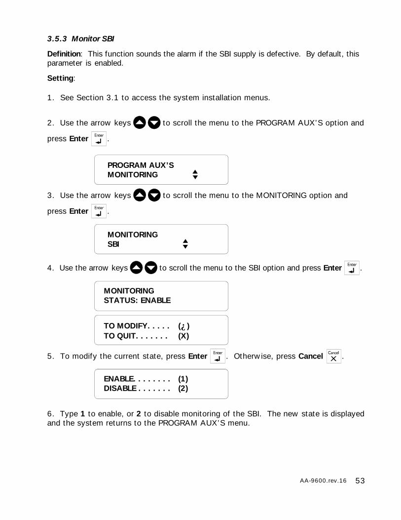
3.5.3 Monitor SBI
Definition: This function sounds the alarm if the SBI supply is defective. By default, thisparameter is enabled.
Setting:
1. See Section 3.1 to access the system installation menus.
2. Use the arrow keys to scroll the menu to the PROGRAM AUX’S option and
press Enter .
3. Use the arrow keys to scroll the menu to the MONITORING option and
press Enter .
4. Use the arrow keys to scroll the menu to the SBI option and press Enter .
5. To modify the current state, press Enter . Otherwise, press Cancel .
6. Type 1 to enable, or 2 to disable monitoring of the SBI. The new state is displayedand the system returns to the PROGRAM AUX’S menu.
MONITORINGSBI
ENABLE. . . . . . . . (1)DISABLE . . . . . . . (2)
MONITORINGSTATUS: ENABLE
TO MODIFY. . . . . (↵)TO QUIT. . . . . . . (X)
PROGRAM AUX’SMONITORING

54 AA-9600.rev.16
3.6 SYSTEM CLOCK
Definition: The system has an internal clock that must be set when you first turn theunit on. As a default, the system clock is set to 12:00 PM JANUARY 1, 2003 in AM/PM format. The battery backup used by the Agri-Alert will keep the time and date incase of a power failure. The system displays the message ADJUST CLOCK periodi-cally if the date and time have not been set.
Setting:
1. Press the Clock key 0QZ-
Clock. The current date and time are displayed.
2. Type Enter to modify the current settings.
3. Type 1 to change the date:
or 2 to change the time:
4. Type 1 for AM/PM time or 2 for 24-hours time.
Note that you must press Enter after typing each value to step to the next one. Forexample, to enter the time 9:14, the sequence is: 9 Enter 14 Enter. If you selectedAM/PM time, an additional screen appears:
5. Type 1 or 2. The system updates the Date/Time display.
ENTER NEW DATE_ _ / _ _ / _ _ _ _ M / D / Y
ENTER NEW TIME_ _ : _ _ (HR:MIN)
AM/PM . . . . . . . . (1)24 HOURS . . . . . . (2)
TO MODIFY. . . . . (↵)TO QUIT. . . . . . . (X)
DATE . . . . . . . . .(1)TIME. . . . . . . . . (2)
AM . . . . . . . . . . . . (1)PM . . . . . . . . . . . . (2)
55AA-9600.rev.16
CELSIUS . . . . . . . . . . . . (1)FAHRENHEIT. . . . . . . . . (2)
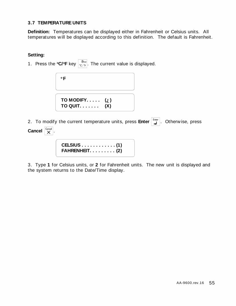
3.7 TEMPERATURE UNITS
Definition: Temperatures can be displayed either in Fahrenheit or Celsius units. Alltemperatures will be displayed according to this definition. The default is Fahrenheit.
Setting:
1. Press the oC/oF key 8TUV . The current value is displayed.
2. To modify the current temperature units, press Enter . Otherwise, press
Cancel .
3. Type 1 for Celsius units, or 2 for Fahrenheit units. The new unit is displayed andthe system returns to the Date/Time display.
TO MODIFY. . . . . (↵)TO QUIT. . . . . . . (X)
o F
56 AA-9600.rev.16
3.8 DISPLAY CONTRAST
Setting:
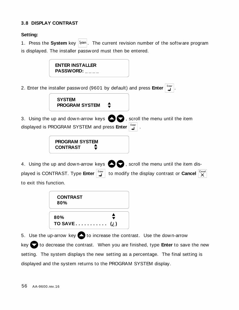
1. Press the System key . The current revision number of the software program
is displayed. The installer password must then be entered.
2. Enter the installer password (9601 by default) and press Enter .
3. Using the up and down-arrow keys , scroll the menu until the item
displayed is PROGRAM SYSTEM and press Enter .
4. Using the up and down-arrow keys , scroll the menu until the item dis-
played is CONTRAST. Type Enter to modify the display contrast or Cancel
to exit this function.
5. Use the up-arrow key to increase the contrast. Use the down-arrow
key to decrease the contrast. When you are finished, type Enter to save the new
setting. The system displays the new setting as a percentage. The final setting is
displayed and the system returns to the PROGRAM SYSTEM display.
ENTER INSTALLERPASSWORD: _ _ _ _
CONTRAST80%
80%TO SAVE . . . . . . . . . . . (↵)
PROGRAM SYSTEMCONTRAST
SYSTEMPROGRAM SYSTEM
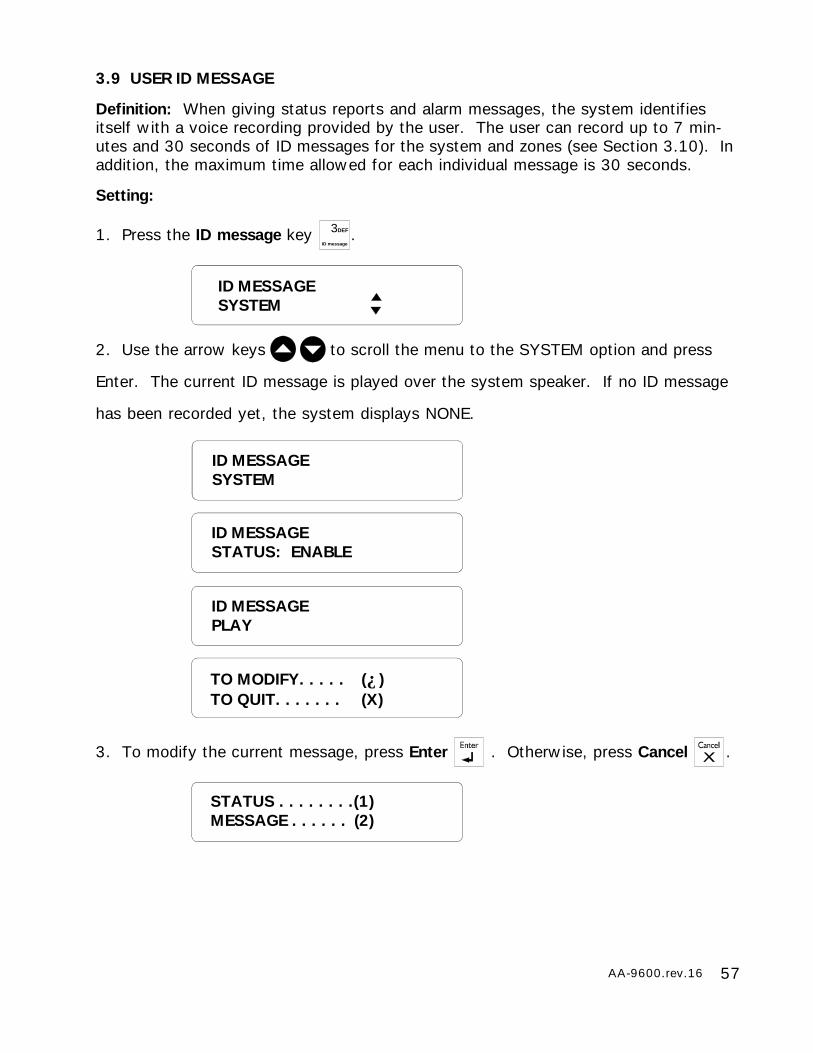
57AA-9600.rev.16
3.9 USER ID MESSAGE
Definition: When giving status reports and alarm messages, the system identifiesitself with a voice recording provided by the user. The user can record up to 7 min-utes and 30 seconds of ID messages for the system and zones (see Section 3.10). Inaddition, the maximum time allowed for each individual message is 30 seconds.
Setting:
1. Press the ID message key 3DEF
ID message.
2. Use the arrow keys to scroll the menu to the SYSTEM option and press
Enter. The current ID message is played over the system speaker. If no ID message
has been recorded yet, the system displays NONE.
3. To modify the current message, press Enter . Otherwise, press Cancel .
ID MESSAGESYSTEM
STATUS . . . . . . . .(1)MESSAGE . . . . . . (2)
ID MESSAGESYSTEM
ID MESSAGESTATUS: ENABLE
ID MESSAGEPLAY
TO MODIFY. . . . . (↵)TO QUIT. . . . . . . (X)
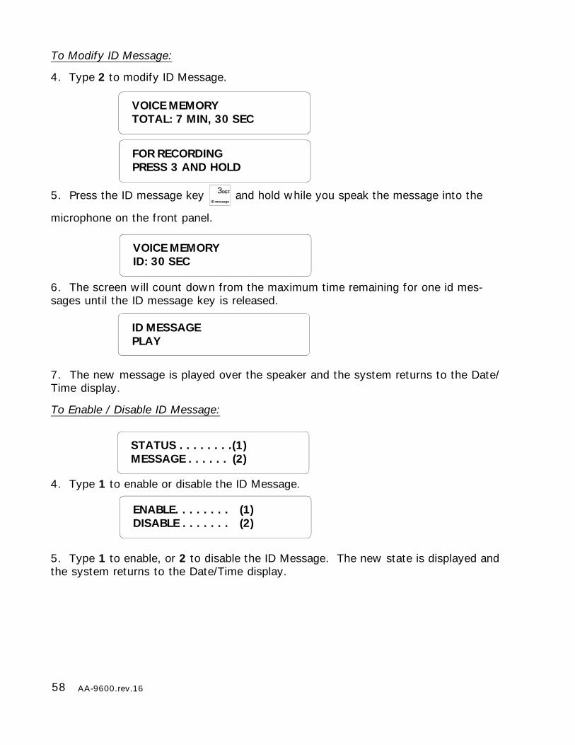
58 AA-9600.rev.16
VOICE MEMORYID: 30 SEC
ID MESSAGEPLAY
ENABLE. . . . . . . . (1)DISABLE . . . . . . . (2)
To Modify ID Message:
4. Type 2 to modify ID Message.
5. Press the ID message key 3DEF
ID message and hold while you speak the message into the
microphone on the front panel.
6. The screen will count down from the maximum time remaining for one id mes-sages until the ID message key is released.
7. The new message is played over the speaker and the system returns to the Date/Time display.
To Enable / Disable ID Message:
4. Type 1 to enable or disable the ID Message.
5. Type 1 to enable, or 2 to disable the ID Message. The new state is displayed andthe system returns to the Date/Time display.
FOR RECORDINGPRESS 3 AND HOLD
STATUS . . . . . . . .(1)MESSAGE . . . . . . (2)
VOICE MEMORYTOTAL: 7 MIN, 30 SEC
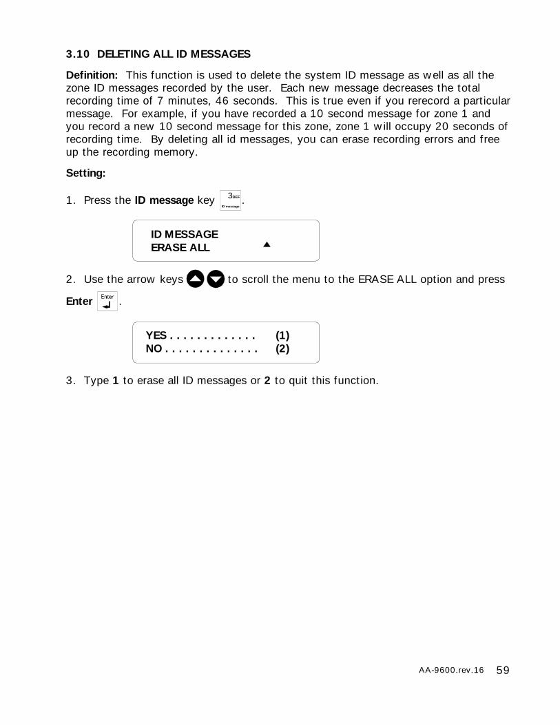
59AA-9600.rev.16
3.10 DELETING ALL ID MESSAGES
Definition: This function is used to delete the system ID message as well as all thezone ID messages recorded by the user. Each new message decreases the totalrecording time of 7 minutes, 46 seconds. This is true even if you rerecord a particularmessage. For example, if you have recorded a 10 second message for zone 1 andyou record a new 10 second message for this zone, zone 1 will occupy 20 seconds ofrecording time. By deleting all id messages, you can erase recording errors and freeup the recording memory.
Setting:
1. Press the ID message key 3DEF
ID message.
2. Use the arrow keys to scroll the menu to the ERASE ALL option and press
Enter .
3. Type 1 to erase all ID messages or 2 to quit this function.
YES . . . . . . . . . . . . . (1)NO . . . . . . . . . . . . . . (2)
ID MESSAGEERASE ALL
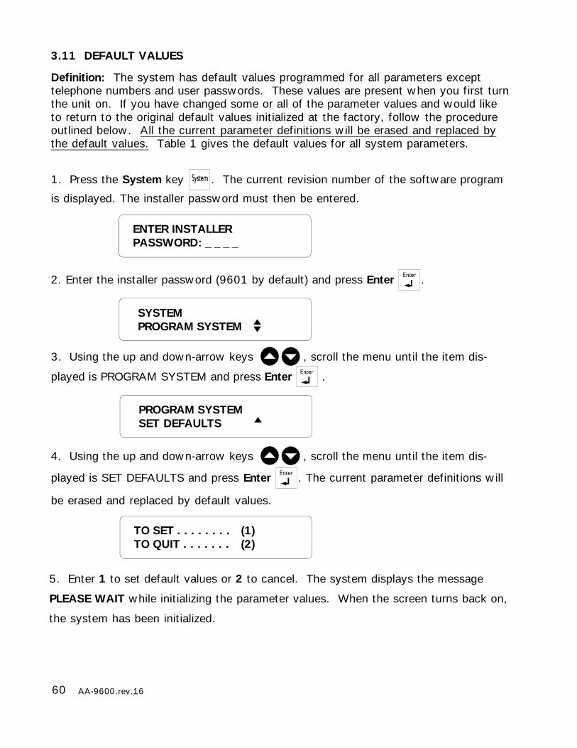
60 AA-9600.rev.16
5. Enter 1 to set default values or 2 to cancel. The system displays the message
PLEASE WAIT while initializing the parameter values. When the screen turns back on,
the system has been initialized.
TO SET . . . . . . . . (1)TO QUIT . . . . . . . (2)
3.11 DEFAULT VALUES
Definition: The system has default values programmed for all parameters excepttelephone numbers and user passwords. These values are present when you first turnthe unit on. If you have changed some or all of the parameter values and would liketo return to the original default values initialized at the factory, follow the procedureoutlined below. All the current parameter definitions will be erased and replaced bythe default values. Table 1 gives the default values for all system parameters.
1. Press the System key . The current revision number of the software program
is displayed. The installer password must then be entered.
2. Enter the installer password (9601 by default) and press Enter .
3. Using the up and down-arrow keys , scroll the menu until the item dis-
played is PROGRAM SYSTEM and press Enter .
4. Using the up and down-arrow keys , scroll the menu until the item dis-
played is SET DEFAULTS and press Enter . The current parameter definitions will
be erased and replaced by default values.
ENTER INSTALLERPASSWORD: _ _ _ _
PROGRAM SYSTEMSET DEFAULTS
SYSTEMPROGRAM SYSTEM
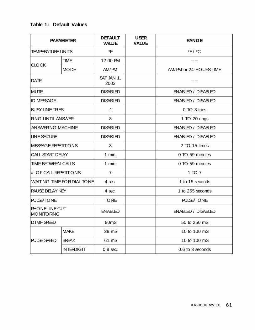
61AA-9600.rev.16
PARAMETER DEFAULTVALUE
USERVALUE RANGE
TEMPERATURE UNITS oF oF / oC
CLOCKTIME 12:00 PM ----
MODE AM/PM AM/PM or 24-HOURS TIME
DATE SAT JAN 1,2003 ----
MUTE DISABLED ENABLED / DISABLED
ID MESSAGE DISABLED ENABLED / DISABLED
BUSY LINE TRIES 1 0 TO 3 tries
RING UNTIL ANSWER 8 1 TO 20 rings
ANSWERING MACHINE DISABLED ENABLED / DISABLED
LINE SEIZURE DISABLED ENABLED / DISABLED
MESSAGE REPETITIONS 3 2 TO 15 times
CALL START DELAY 1 min. 0 TO 59 minutes
TIME BETWEEN CALLS 1 min. 0 TO 59 minutes
# OF CALL REPETITIONS 7 1 TO 7
WAITING TIME FOR DIAL TONE 4 sec. 1 to 15 seconds
PAUSE DELAY KEY 4 sec. 1 to 255 seconds
PULSE/TONE TONE PULSE/TONE
PHONE LINE CUTMONITORING ENABLED ENABLED / DISABLED
DTMF SPEED 80mS 50 to 250 mS
PULSE SPEED
MAKE 39 mS 10 to 100 mS
BREAK 61 mS 10 to 100 mS
INTERDIGIT 0.8 sec. 0.6 to 3 seconds
Table 1: Default Values
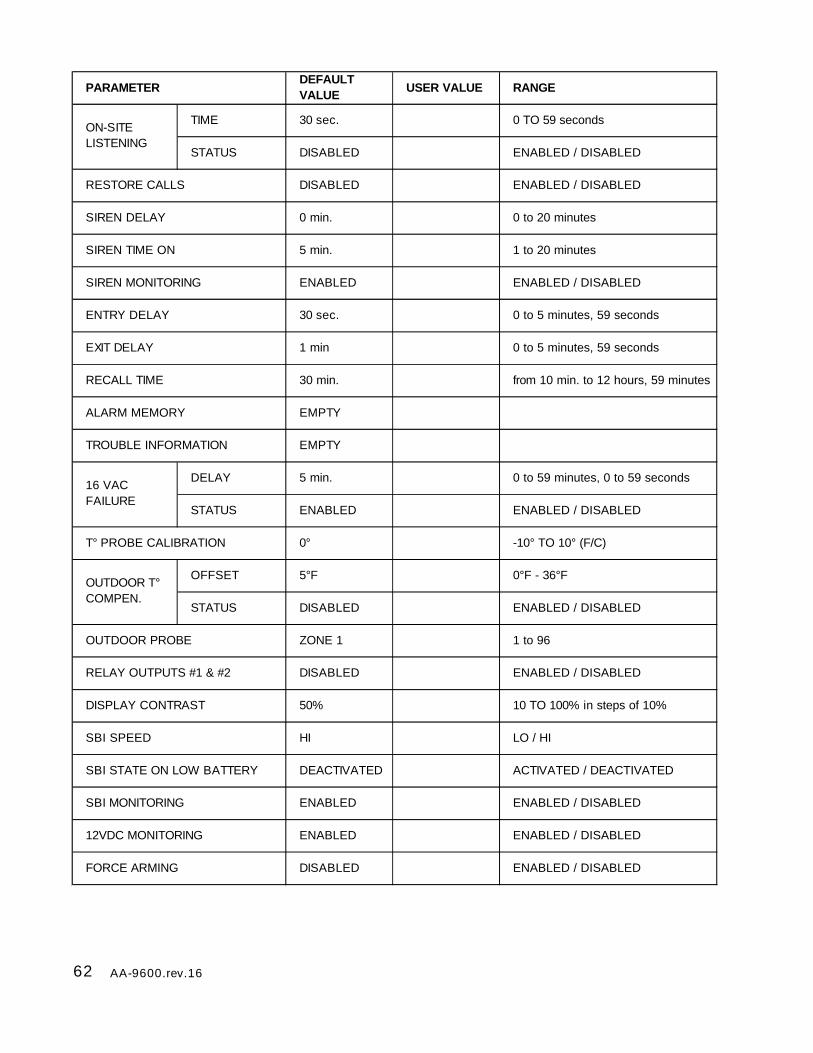
62 AA-9600.rev.16
PARAMETERDEFAULT VALUE
USER VALUE RANGE
TIME 30 sec. 0 TO 59 seconds
STATUS DISABLED ENABLED / DISABLED
RESTORE CALLS DISABLED ENABLED / DISABLED
SIREN DELAY 0 min. 0 to 20 minutes
SIREN TIME ON 5 min. 1 to 20 minutes
SIREN MONITORING ENABLED ENABLED / DISABLED
ENTRY DELAY 30 sec. 0 to 5 minutes, 59 seconds
EXIT DELAY 1 min 0 to 5 minutes, 59 seconds
RECALL TIME 30 min. from 10 min. to 12 hours, 59 minutes
ALARM MEMORY EMPTY
TROUBLE INFORMATION EMPTY
DELAY 5 min. 0 to 59 minutes, 0 to 59 seconds
STATUS ENABLED ENABLED / DISABLED
T° PROBE CALIBRATION 0° -10° TO 10° (F/C)
OFFSET 5°F 0°F - 36°F
STATUS DISABLED ENABLED / DISABLED
OUTDOOR PROBE ZONE 1 1 to 96
RELAY OUTPUTS #1 & #2 DISABLED ENABLED / DISABLED
DISPLAY CONTRAST 50% 10 TO 100% in steps of 10%
SBI SPEED HI LO / HI
SBI STATE ON LOW BATTERY DEACTIVATED ACTIVATED / DEACTIVATED
SBI MONITORING ENABLED ENABLED / DISABLED
12VDC MONITORING ENABLED ENABLED / DISABLED
FORCE ARMING DISABLED ENABLED / DISABLED
ON-SITE LISTENING
16 VACFAILURE
OUTDOOR T° COMPEN.

63AA-9600.rev.16
PARAMETER ZONE 1 ZONE 2 ZONES 3 - 96 RANGE
SENSOR TYPE OUTDOORTEMPERATURE DRY CONTACT TEMPERATURE DRY CONTACT/TEMP./4-
20mA/AC CURRENT/0-5V
OPEN /CLOSEDCIRCUIT
---- N.C. ---- N.O. / N.C.
END OF LINERESISTOR ---- WITHOUT EOLR ---- WITH / WITHOUT EOLR
DIALOUT ENABLED ENABLED ENABLED ENABLED / DISABLED
SIREN ENABLED ENABLED ENABLED ENABLED / DISABLED
RECOGNITIONTIME 1 min. 1 min. 1 min. 0 to 59 hours, 0 to 59
minutes, 0 to 59 seconds
LOW SETPOINT ---- ---- 50°F -40°F to 149°F
HIGH SETPOINT ---- ---- 85°F -40°F to 149°F
CRITICALTEMPERATURE ---- ---- 95°F -40°F to 149°F
Default Zone Configurations
The default reset time on all zones is 1 sec. It ranges from 0 to 59 hours, 59 minutes,59 seconds. By default, zone 1 is a temperature zone assigned to the outdoor probefor the outdoor temperature compensation feature. All zones are disabled initially.
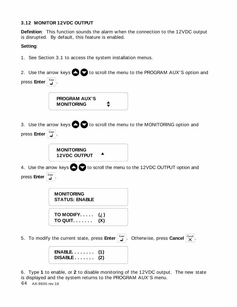
64 AA-9600.rev.16
3.12 MONITOR 12VDC OUTPUT
Definition: This function sounds the alarm when the connection to the 12VDC outputis disrupted. By default, this feature is enabled.
Setting:
1. See Section 3.1 to access the system installation menus.
2. Use the arrow keys to scroll the menu to the PROGRAM AUX’S option and
press Enter .
3. Use the arrow keys to scroll the menu to the MONITORING option and
press Enter .
4. Use the arrow keys to scroll the menu to the 12VDC OUTPUT option and
press Enter .
5. To modify the current state, press Enter . Otherwise, press Cancel .
6. Type 1 to enable, or 2 to disable monitoring of the 12VDC output. The new stateis displayed and the system returns to the PROGRAM AUX’S menu.
ENABLE. . . . . . . . (1)DISABLE . . . . . . . (2)
MONITORINGSTATUS: ENABLE
TO MODIFY. . . . . (↵)TO QUIT. . . . . . . (X)
MONITORING12VDC OUTPUT
PROGRAM AUX’SMONITORING
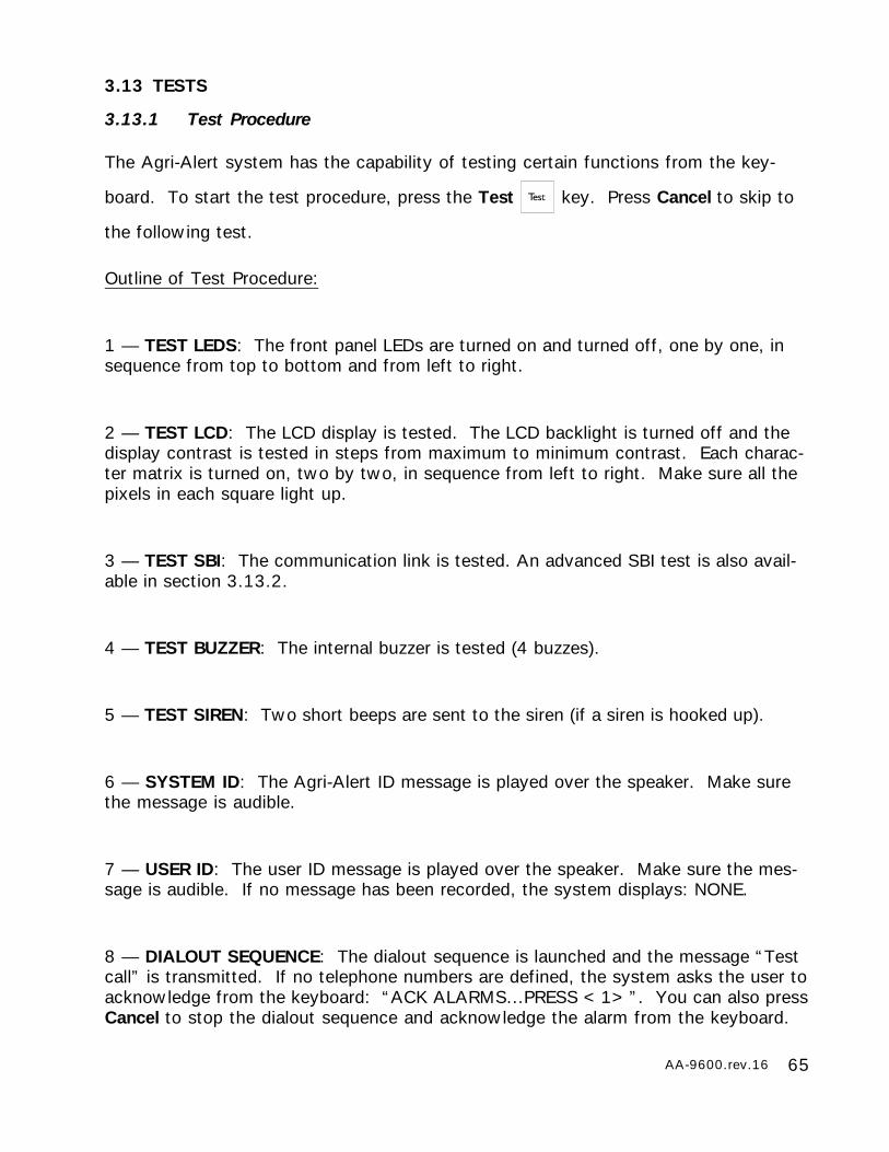
65AA-9600.rev.16
3.13 TESTS
3.13.1 Test Procedure
The Agri-Alert system has the capability of testing certain functions from the key-
board. To start the test procedure, press the Test key. Press Cancel to skip to
the following test.
Outline of Test Procedure:
1 — TEST LEDS: The front panel LEDs are turned on and turned off, one by one, insequence from top to bottom and from left to right.
2 — TEST LCD: The LCD display is tested. The LCD backlight is turned off and thedisplay contrast is tested in steps from maximum to minimum contrast. Each charac-ter matrix is turned on, two by two, in sequence from left to right. Make sure all thepixels in each square light up.
3 — TEST SBI: The communication link is tested. An advanced SBI test is also avail-able in section 3.13.2.
4 — TEST BUZZER: The internal buzzer is tested (4 buzzes).
5 — TEST SIREN: Two short beeps are sent to the siren (if a siren is hooked up).
6 — SYSTEM ID: The Agri-Alert ID message is played over the speaker. Make surethe message is audible.
7 — USER ID: The user ID message is played over the speaker. Make sure the mes-sage is audible. If no message has been recorded, the system displays: NONE.
8 — DIALOUT SEQUENCE: The dialout sequence is launched and the message “Testcall” is transmitted. If no telephone numbers are defined, the system asks the user toacknowledge from the keyboard: “ACK ALARMS...PRESS <1>”. You can also pressCancel to stop the dialout sequence and acknowledge the alarm from the keyboard.

66 AA-9600.rev.16
3.13.2 Advanced SBI Test
The advanced SBI test is used to verify the quality of SBI communication between themain controller and a chosen device. This function is mainly used to investigate com-munication problems and should only be performed by the dealer.
1. Press the System key . The current revision number of the software program
is displayed. The installer password must then be entered.
2. Enter the installer password (9601 by default) and press Enter.
3. Using the up and down-arrow keys , scroll the menu until the item dis-
played is SBI TEST MODE and press Enter .
4. Type in the ID number of the device that needs to be tested then press Enter .
The controller tries to communicate ten times with the selected device then gives the
percentage of times it got a valid reply.
5. Press Cancel once to test another device or press Cancel twice to exit the SBI testmenu.
SOFTWAREREV. x.xxx
ENTER INSTALLERPASSWORD: _ _ _ _
SYSTEMSBI TEST MODE
SELECT DEVICE(2 .. 99): _ _
SELECT DEVICEID #02: 100%
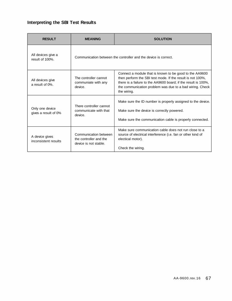
67AA-9600.rev.16
Interpreting the SBI Test Results
RESULT MEANING SOLUTION
All devices give a result of 100%.
Communication between the controller and the device is correct.
All devices give a result of 0%.
The controller cannot communiate with any device.
Connect a module that is known to be good to the AA9600 then perform the SBI test mode. If the result is not 100%, there is a failure to the AA9600 board; if the result is 100%, the communication problem was due to a bad wiring. Check the wiring.
Only one device gives a result of 0%
There controller cannot communicate with that device.
Make sure the ID number is properly assigned to the device.
Make sure the device is correctly powered.
Make sure the communication cable is properly connected.
A device gives inconsistent results
Communication between the controller and the device is not stable.
Make sure communication cable does not run close to a source of electrical interference (i.e. fan or other kind of electical motor).
Check the wiring.

68 AA-9600.rev.16
3.14 VIEWING SOFTWARE VERSION
Settings:
1. Press the System key . The current revision number of the software program
is displayed. The installer password must then be entered.
2. Enter the installer password (9601 by default) and press Enter .
3. Using the up and down-arrow keys , scroll the menu until the item dis-
played is PROGRAM SYSTEM and press Enter .
4. Using the up and down-arrow keys , scroll the menu until the item dis-
played is VERSION SOFTWARE and press Enter . The version of the software is
displayed. The system then returns to PROGRAM SYSTEM menu.
SOFTWAREREV. x.xxx
ENTER INSTALLERPASSWORD: _ _ _ _
PROGRAM SYSTEMVERSION SOFTWARE
SOFTWAREREV. x.xxx
SYSTEMPROGRAM SYSTEM
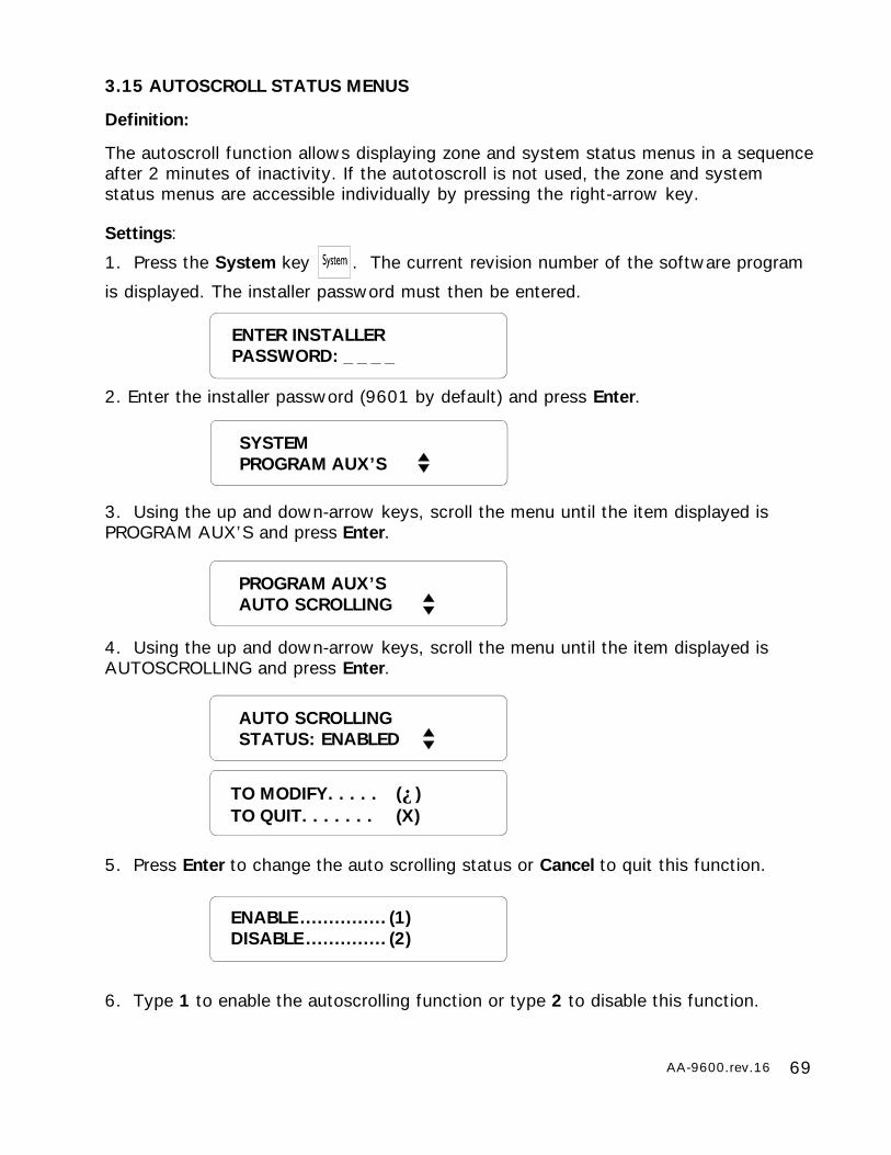
69AA-9600.rev.16
3.15 AUTOSCROLL STATUS MENUS
Definition:
The autoscroll function allows displaying zone and system status menus in a sequenceafter 2 minutes of inactivity. If the autotoscroll is not used, the zone and systemstatus menus are accessible individually by pressing the right-arrow key.
Settings:
1. Press the System key . The current revision number of the software program
is displayed. The installer password must then be entered.
2. Enter the installer password (9601 by default) and press Enter.
3. Using the up and down-arrow keys, scroll the menu until the item displayed isPROGRAM AUX’S and press Enter.
4. Using the up and down-arrow keys, scroll the menu until the item displayed isAUTOSCROLLING and press Enter.
5. Press Enter to change the auto scrolling status or Cancel to quit this function.
6. Type 1 to enable the autoscrolling function or type 2 to disable this function.
ENTER INSTALLERPASSWORD: _ _ _ _
PROGRAM AUX’SAUTO SCROLLING
SYSTEMPROGRAM AUX’S
AUTO SCROLLINGSTATUS: ENABLED
TO MODIFY. . . . . (↵)TO QUIT. . . . . . . (X)
ENABLE ............... (1)DISABLE .............. (2)
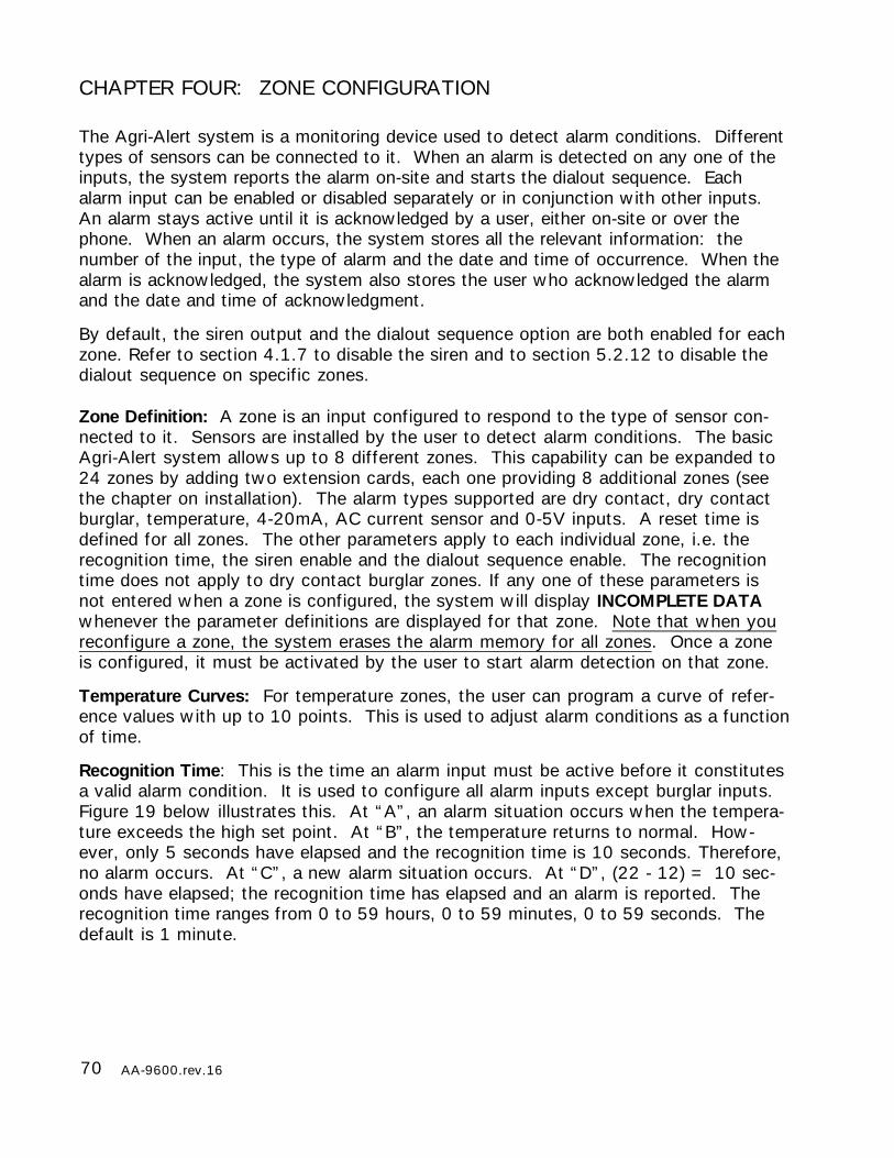
70 AA-9600.rev.16
CHAPTER FOUR: ZONE CONFIGURATION
The Agri-Alert system is a monitoring device used to detect alarm conditions. Differenttypes of sensors can be connected to it. When an alarm is detected on any one of theinputs, the system reports the alarm on-site and starts the dialout sequence. Eachalarm input can be enabled or disabled separately or in conjunction with other inputs.An alarm stays active until it is acknowledged by a user, either on-site or over thephone. When an alarm occurs, the system stores all the relevant information: thenumber of the input, the type of alarm and the date and time of occurrence. When thealarm is acknowledged, the system also stores the user who acknowledged the alarmand the date and time of acknowledgment.
By default, the siren output and the dialout sequence option are both enabled for eachzone. Refer to section 4.1.7 to disable the siren and to section 5.2.12 to disable thedialout sequence on specific zones.
Zone Definition: A zone is an input configured to respond to the type of sensor con-nected to it. Sensors are installed by the user to detect alarm conditions. The basicAgri-Alert system allows up to 8 different zones. This capability can be expanded to24 zones by adding two extension cards, each one providing 8 additional zones (seethe chapter on installation). The alarm types supported are dry contact, dry contactburglar, temperature, 4-20mA, AC current sensor and 0-5V inputs. A reset time isdefined for all zones. The other parameters apply to each individual zone, i.e. therecognition time, the siren enable and the dialout sequence enable. The recognitiontime does not apply to dry contact burglar zones. If any one of these parameters isnot entered when a zone is configured, the system will display INCOMPLETE DATAwhenever the parameter definitions are displayed for that zone. Note that when youreconfigure a zone, the system erases the alarm memory for all zones. Once a zoneis configured, it must be activated by the user to start alarm detection on that zone.
Temperature Curves: For temperature zones, the user can program a curve of refer-ence values with up to 10 points. This is used to adjust alarm conditions as a functionof time.
Recognition Time: This is the time an alarm input must be active before it constitutesa valid alarm condition. It is used to configure all alarm inputs except burglar inputs.Figure 19 below illustrates this. At “A”, an alarm situation occurs when the tempera-ture exceeds the high set point. At “B”, the temperature returns to normal. How-ever, only 5 seconds have elapsed and the recognition time is 10 seconds. Therefore,no alarm occurs. At “C”, a new alarm situation occurs. At “D”, (22 - 12) = 10 sec-onds have elapsed; the recognition time has elapsed and an alarm is reported. Therecognition time ranges from 0 to 59 hours, 0 to 59 minutes, 0 to 59 seconds. Thedefault is 1 minute.

71AA-9600.rev.16
Figure 19: Illustration of Recognition Time
4.1 CONFIGURATION
The following section describes the different types of zones. To configure a zone,
choose the PROGRAM ZONE option after pressing the System key followed by
SETUP (see section 3.1). Note that zones 9-96 must first be assigned to a device
before being configured (see section 3.4).
High Set Point
Low Set Point
Temperature
Time
A B
D
Alarm
Recognition Time = 10 S
C
0 S 5 S 12 S 22 S
ALARM
NO ALARM
ALARM
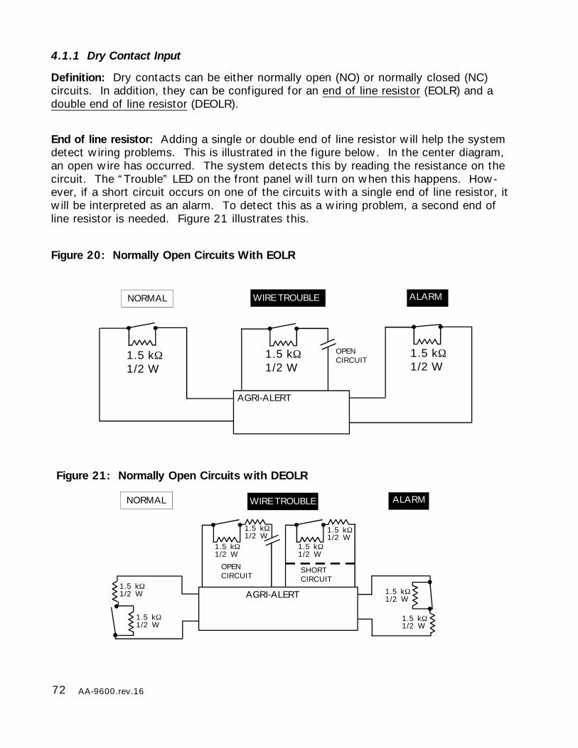
72 AA-9600.rev.16
4.1.1 Dry Contact Input
Definition: Dry contacts can be either normally open (NO) or normally closed (NC)circuits. In addition, they can be configured for an end of line resistor (EOLR) and adouble end of line resistor (DEOLR).
End of line resistor: Adding a single or double end of line resistor will help the systemdetect wiring problems. This is illustrated in the figure below. In the center diagram,an open wire has occurred. The system detects this by reading the resistance on thecircuit. The “Trouble” LED on the front panel will turn on when this happens. How-ever, if a short circuit occurs on one of the circuits with a single end of line resistor, itwill be interpreted as an alarm. To detect this as a wiring problem, a second end ofline resistor is needed. Figure 21 illustrates this.
Figure 20: Normally Open Circuits With EOLR
ALARMWIRE TROUBLENORMAL
1.5 kΩ1/2 W
AGRI-ALERT
OPENCIRCUIT
1.5 kΩ1/2 W
1.5 kΩ1/2 W
Figure 21: Normally Open Circuits with DEOLR
ALARMWIRE TROUBLENORMAL
1.5 kΩ1/2 W
AGRI-ALERT
OPENCIRCUIT
1.5 kΩ1/2 W
1.5 kΩ1/2 W
1.5 kΩ1/2 W
1.5 kΩ1/2 W
1.5 kΩ1/2 W
1.5 kΩ1/2 W
1.5 kΩ1/2 W
SHORTCIRCUIT
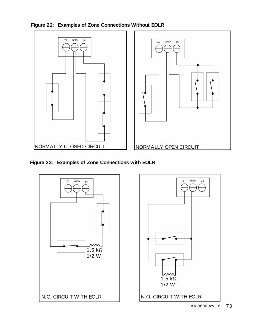
73AA-9600.rev.16
Figure 23: Examples of Zone Connections with EOLR
1.5 kΩ1/2 W
GND Z8Z7
N.C. CIRCUIT WITH EOLR
GND Z8Z7
1.5 kΩ1/2 W
N.O. CIRCUIT WITH EOLR
Figure 22: Examples of Zone Connections Without EOLR
GND Z8Z7
NORMALLY CLOSED CIRCUIT
GND Z8Z7
NORMALLY OPEN CIRCUIT
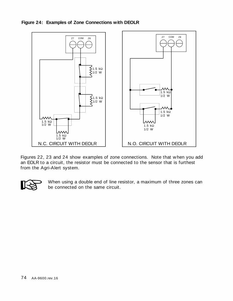
74 AA-9600.rev.16
Figures 22, 23 and 24 show examples of zone connections. Note that when you addan EOLR to a circuit, the resistor must be connected to the sensor that is furthestfrom the Agri-Alert system.
When using a double end of line resistor, a maximum of three zones canbe connected on the same circuit.
Figure 24: Examples of Zone Connections with DEOLR
COM Z8Z7
1.5 kΩ1/2 W
N.C. CIRCUIT WITH DEOLR
1.5 kΩ1/2 W
1.5 kΩ1/2 W
COM Z8Z7
1.5 kΩ1/2 W
N.O. CIRCUIT WITH DEOLR
1.5 kΩ1/2 W
1.5 kΩ1/2 W
1.5 kΩ1/2 W
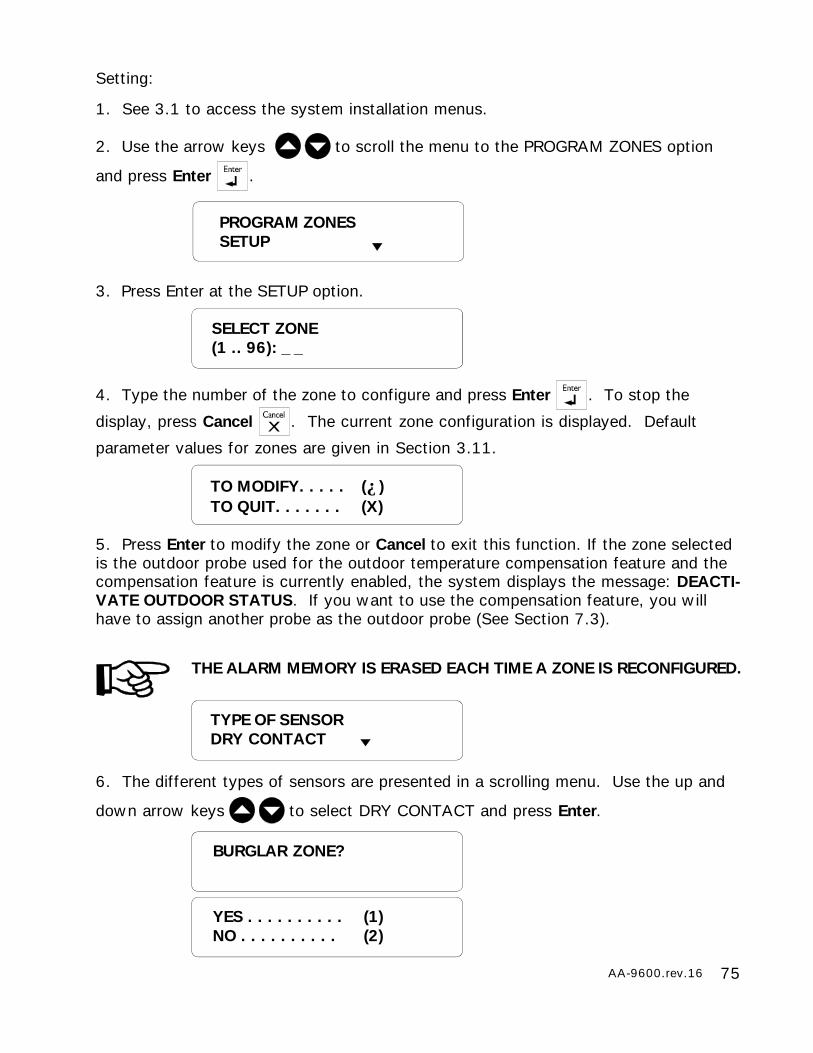
75AA-9600.rev.16
BURGLAR ZONE?
YES . . . . . . . . . . (1)NO . . . . . . . . . . (2)
TYPE OF SENSORDRY CONTACT
Setting:
1. See 3.1 to access the system installation menus.
2. Use the arrow keys to scroll the menu to the PROGRAM ZONES option
and press Enter .
3. Press Enter at the SETUP option.
4. Type the number of the zone to configure and press Enter . To stop the
display, press Cancel . The current zone configuration is displayed. Default
parameter values for zones are given in Section 3.11.
5. Press Enter to modify the zone or Cancel to exit this function. If the zone selectedis the outdoor probe used for the outdoor temperature compensation feature and thecompensation feature is currently enabled, the system displays the message: DEACTI-VATE OUTDOOR STATUS. If you want to use the compensation feature, you willhave to assign another probe as the outdoor probe (See Section 7.3).
THE ALARM MEMORY IS ERASED EACH TIME A ZONE IS RECONFIGURED.
6. The different types of sensors are presented in a scrolling menu. Use the up and
down arrow keys to select DRY CONTACT and press Enter.
SELECT ZONE(1 .. 96): _ _
PROGRAM ZONESSETUP
TO MODIFY. . . . . (↵)TO QUIT. . . . . . . (X)
76 AA-9600.rev.16
NORM. OPEN . . . . . . . . (1)NORM. CLOSED . . . . . . (2)
7. Type 2 for an ordinary dry contact input.
8. Type 1 or 2 according to the configuration desired.
9. Type 1 to configure the input with an end of line resistor. Type 2 to configure theinput without an end of line resistor.
10. Type 1 to configure the input for a single end of line resistor. Type 2 to configurethe input for a double end of line resistor.
11. To enter the recognition time, enter the hours; press Enter. Enter the minutes;press Enter. Enter the seconds; press Enter. It ranges from 0h;0m;0s to 59h;59m;59s.
W/ RESISTOR . . . . (1)W/O RESISTOR . . . (2)
SINGLE. . . . . . . . . . . . . (1)DOUBLE . . . . . . . . . . . . (2)
RECOGNITION TIME _ _ :_ _ : _ _
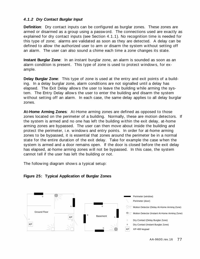
77AA-9600.rev.16
4.1.2 Dry Contact Burglar Input
Definition: Dry contact inputs can be configured as burglar zones. These zones arearmed or disarmed as a group using a password. The connections used are exactly asexplained for dry contact inputs (see Section 4.1.1). No recognition time is needed forthis type of zone; alarms are validated as soon as they are detected. A delay can bedefined to allow the authorized user to arm or disarm the system without setting offan alarm. The user can also sound a chime each time a zone changes its state.
Instant Burglar Zone: In an instant burglar zone, an alarm is sounded as soon as analarm condition is present. This type of zone is used to protect windows, for ex-ample.
Delay Burglar Zone: This type of zone is used at the entry and exit points of a build-ing. In a delay burglar zone, alarm conditions are not signalled until a delay haselapsed. The Exit Delay allows the user to leave the building while arming the sys-tem. The Entry Delay allows the user to enter the building and disarm the systemwithout setting off an alarm. In each case, the same delay applies to all delay burglarzones.
At-Home Arming Zones: At-Home arming zones are defined as opposed to thosezones located on the perimeter of a building. Normally, these are motion detectors. Ifthe system is armed and no one has left the building within the exit delay, at-homearming zones are bypassed. The user can then move about inside the building andprotect the perimeter, i.e. windows and entry points. In order for at-home armingzones to be bypassed, it is essential that zones around the perimeter be in a normalstate for the entire duration of the exit delay. Take for example the case when thesystem is armed and a door remains open. If the door is closed before the exit delayhas elapsed, at-home arming zones will not be bypassed. In this case, the systemcannot tell if the user has left the building or not.
The following diagram shows a typical setup:
Ground Floor
Perimeter (window)
Perimeter (door)
Motion Detector (Delay At-Home Arming Zone)
Dry Contact (Delay Burglar Zone)
Dry Contact (Instant Burglar Zone)
KP-400 keypad
Motion Detector (Instant At-Home Arming Zone)Basement
KP
KP
KP
Figure 25: Typical Application of Burglar Zones
78 AA-9600.rev.16
The key sequence for arming or disarming is as follows:
followed by the password sequence 9 6 0 0 (by default)
If force arming is disabled (see below), all burglar zones must be in a normal state toarm the system, i.e. no alarm conditions must be present. If the arming sequencefails, zones with alarms are listed on the display.
When the system is armed, the system starts beeping and the screen immediatelydisplays a countdown of the exit delay (in minutes and seconds). The keypad islocked at this point: the only key sequence allowed is the disarming sequence. Afterthe exit delay has elapsed, all burglar zones are armed and alarms are immediatelydeclared as they are detected for all burglar zones. The system displays the message“BURGLAR ZONES ARMED” periodically on the screen and the password feature isenabled.
The Password key cannot be accessed at this point unless the burglarzones are disarmed.
When an alarm occurs in a burglar zone with an entry delay, the screen displays acountdown of the entry delay. During this time, the piezoelectric loudspeaker beeps(the loudspeaker stops when the key sequence is entered). If no one has disarmedthe system after the entry delay has elapsed, an alarm is declared. Disarming willaffect all currently active burglar zones. The system displays the message “BUR-GLAR ZONES DISARMED” on the screen.
A burglar zone cannot be included in a partition. If a zone already belonging to apartition needs to be changed to a burglar zone, it must first be removed from thepartition. Otherwise, this is done automatically by the system.
Force Arming: Normally, you cannot arm the system when alarm conditions arepresent on one or more zones. However, if the “Force Arming” option has been en-abled by the installer, (see sec. 7.10), the user can arm the system even if somezones have alarms. This applies only to delay burglar zones, however. An instantburglar zone with an alarm condition would only set off a new alarm as soon as thesystem were armed.
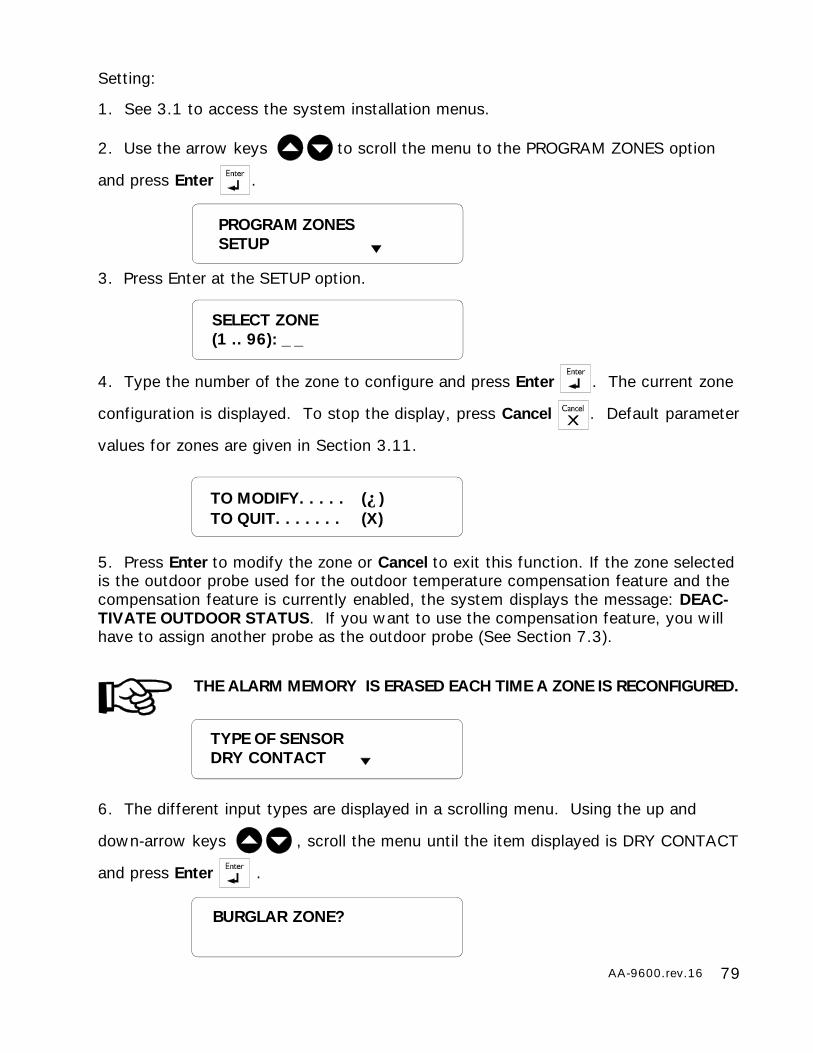
79AA-9600.rev.16
BURGLAR ZONE?
Setting:
1. See 3.1 to access the system installation menus.
2. Use the arrow keys to scroll the menu to the PROGRAM ZONES option
and press Enter .
3. Press Enter at the SETUP option.
4. Type the number of the zone to configure and press Enter . The current zone
configuration is displayed. To stop the display, press Cancel . Default parameter
values for zones are given in Section 3.11.
5. Press Enter to modify the zone or Cancel to exit this function. If the zone selectedis the outdoor probe used for the outdoor temperature compensation feature and thecompensation feature is currently enabled, the system displays the message: DEAC-TIVATE OUTDOOR STATUS. If you want to use the compensation feature, you willhave to assign another probe as the outdoor probe (See Section 7.3).
THE ALARM MEMORY IS ERASED EACH TIME A ZONE IS RECONFIGURED.
6. The different input types are displayed in a scrolling menu. Using the up and
down-arrow keys , scroll the menu until the item displayed is DRY CONTACT
and press Enter .
SELECT ZONE(1 .. 96): _ _
PROGRAM ZONESSETUP
TO MODIFY. . . . . (↵)TO QUIT. . . . . . . (X)
TYPE OF SENSORDRY CONTACT
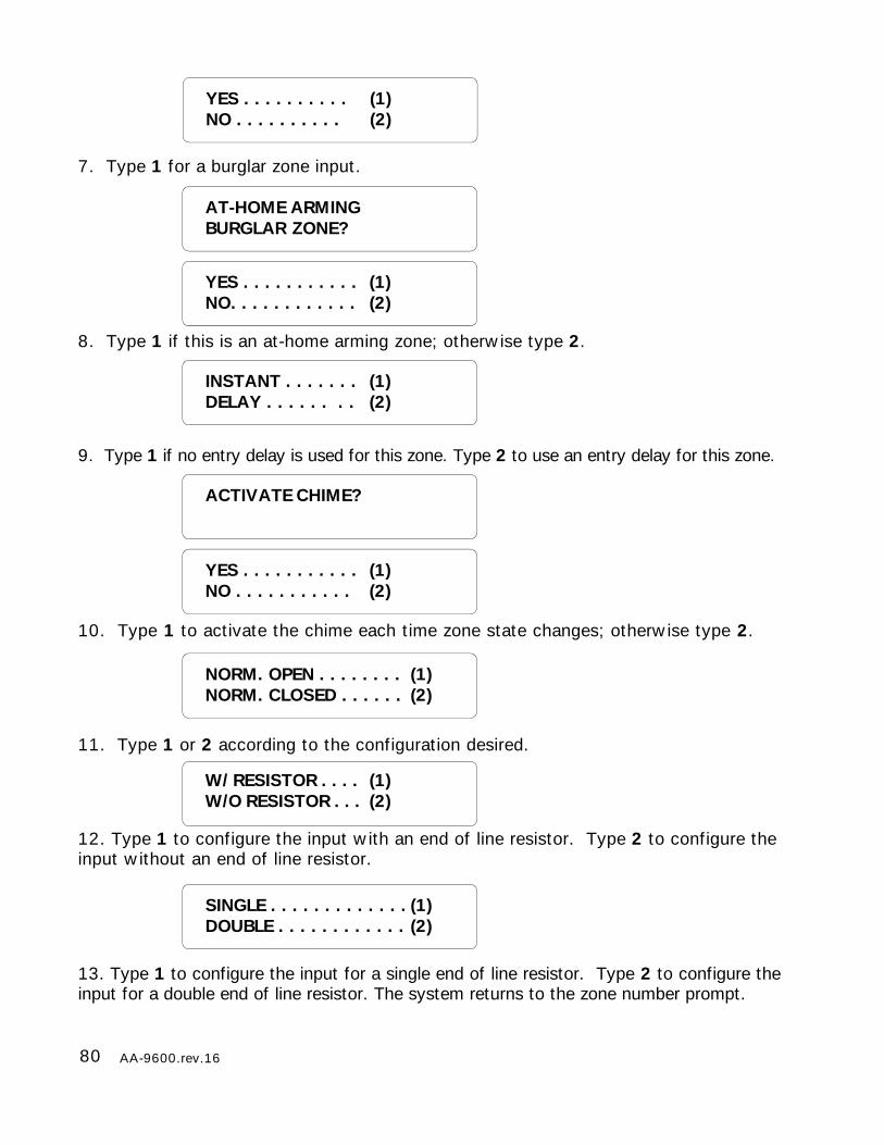
80 AA-9600.rev.16
W/ RESISTOR . . . . (1)W/O RESISTOR . . . (2)
SINGLE . . . . . . . . . . . . . (1)DOUBLE . . . . . . . . . . . . (2)
YES . . . . . . . . . . (1)NO . . . . . . . . . . (2)
7. Type 1 for a burglar zone input.
8. Type 1 if this is an at-home arming zone; otherwise type 2.
9. Type 1 if no entry delay is used for this zone. Type 2 to use an entry delay for this zone.
10. Type 1 to activate the chime each time zone state changes; otherwise type 2.
11. Type 1 or 2 according to the configuration desired.
12. Type 1 to configure the input with an end of line resistor. Type 2 to configure theinput without an end of line resistor.
INSTANT . . . . . . . (1)DELAY . . . . . . . . (2)
ACTIVATE CHIME?
YES . . . . . . . . . . . (1)NO . . . . . . . . . . . (2)
NORM. OPEN . . . . . . . . (1)NORM. CLOSED . . . . . . (2)
YES . . . . . . . . . . . (1)NO. . . . . . . . . . . . (2)
AT-HOME ARMINGBURGLAR ZONE?
13. Type 1 to configure the input for a single end of line resistor. Type 2 to configure theinput for a double end of line resistor. The system returns to the zone number prompt.
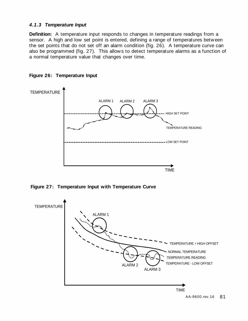
81AA-9600.rev.16
4.1.3 Temperature Input
Definition: A temperature input responds to changes in temperature readings from asensor. A high and low set point is entered, defining a range of temperatures betweenthe set points that do not set off an alarm condition (fig. 26). A temperature curve canalso be programmed (fig. 27). This allows to detect temperature alarms as a function ofa normal temperature value that changes over time.
Figure 26: Temperature Input
TEMPERATURE
TEMPERATURE READING
HIGH SET POINT
LOW SET POINT
TIME
ALARM 1 ALARM 2 ALARM 3
TEMPERATURE
NORMAL TEMPERATURE
TEMPERATURE READING
TEMPERATURE + HIGH OFFSET
TEMPERATURE - LOW OFFSET
TIME
ALARM 1
ALARM 2ALARM 3
Figure 27: Temperature Input with Temperature Curve
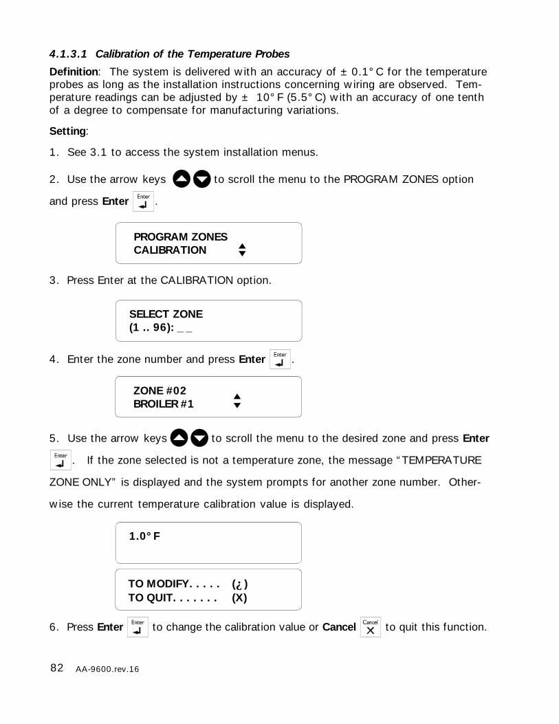
82 AA-9600.rev.16
4.1.3.1 Calibration of the Temperature Probes
Definition: The system is delivered with an accuracy of ±0.1°C for the temperatureprobes as long as the installation instructions concerning wiring are observed. Tem-perature readings can be adjusted by ± 10°F (5.5°C) with an accuracy of one tenthof a degree to compensate for manufacturing variations.
Setting:
1. See 3.1 to access the system installation menus.
2. Use the arrow keys to scroll the menu to the PROGRAM ZONES option
and press Enter .
3. Press Enter at the CALIBRATION option.
4. Enter the zone number and press Enter .
5. Use the arrow keys to scroll the menu to the desired zone and press Enter
. If the zone selected is not a temperature zone, the message “TEMPERATURE
ZONE ONLY” is displayed and the system prompts for another zone number. Other-
wise the current temperature calibration value is displayed.
6. Press Enter to change the calibration value or Cancel to quit this function.
1.0°F
SELECT ZONE(1 .. 96): _ _
TO MODIFY. . . . . (↵)TO QUIT. . . . . . . (X)
PROGRAM ZONESCALIBRATION
ZONE #02BROILER #1

83AA-9600.rev.16
ENTER OFFSET_ _ _ _ °F
7. Enter the offset value (within a tenth of a degree) and press Enter . It ranges
from -10.0 to 10.0°F (-5.6 to 5.6°C)The units are those defined by default for the
system (see Section 3.11). The new offset value is displayed and the system returns
to the PROGRAM ZONES menu.
4.1.3.2 Configuration of a Temperature Zone
1. See 3.1 to access the system installation menus.
2. Use the arrow keys to scroll the menu to the PROGRAM ZONES option
and press Enter .
3. Press Enter at the SETUP option.
4. Type the number of the zone to configure and press Enter . To stop the dis-
play, press Cancel . The current zone configuration is displayed. Default param-
eter values for zones are given in Section 3.11.
5. Press Enter to modify the zone or Cancel to exit this function. If the zone selected isthe outdoor probe used for the outdoor temperature compensation feature and the com-pensation feature is currently enabled, the system displays the message: DEACTIVATEOUTDOOR STATUS. If you want to use the compensation feature, you will have toassign another probe as the outdoor probe (See Section 7.3).
THE ALARM MEMORY IS ERASED EACH TIME A ZONE IS RECONFIGURED.
SELECT ZONE(1 .. 96): _ _
PROGRAM ZONESSETUP
TO MODIFY. . . . . (↵)TO QUIT. . . . . . . (X)
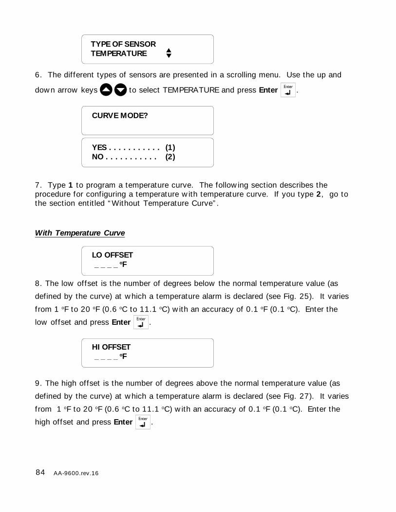
84 AA-9600.rev.16
YES . . . . . . . . . . . (1)NO . . . . . . . . . . . (2)
CURVE MODE?
LO OFFSET _ _ _ _ oF
HI OFFSET _ _ _ _ oF
TYPE OF SENSORTEMPERATURE
6. The different types of sensors are presented in a scrolling menu. Use the up and
down arrow keys to select TEMPERATURE and press Enter .
7. Type 1 to program a temperature curve. The following section describes theprocedure for configuring a temperature with temperature curve. If you type 2, go tothe section entitled “Without Temperature Curve”.
With Temperature Curve
8. The low offset is the number of degrees below the normal temperature value (as
defined by the curve) at which a temperature alarm is declared (see Fig. 25). It varies
from 1 oF to 20 oF (0.6 oC to 11.1 oC) with an accuracy of 0.1 oF (0.1 oC). Enter the
low offset and press Enter .
9. The high offset is the number of degrees above the normal temperature value (as
defined by the curve) at which a temperature alarm is declared (see Fig. 27). It varies
from 1 oF to 20 oF (0.6 oC to 11.1 oC) with an accuracy of 0.1 oF (0.1 oC). Enter the
high offset and press Enter .
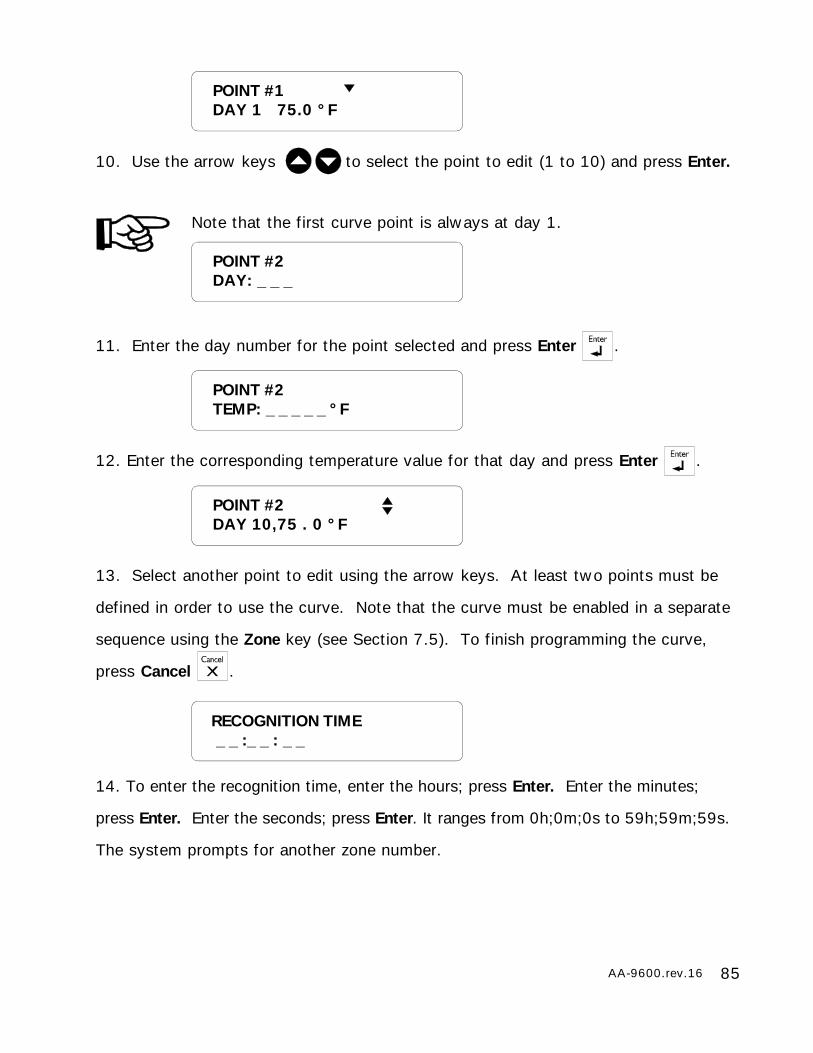
85AA-9600.rev.16
POINT #1DAY 1 75.0 °F
10. Use the arrow keys to select the point to edit (1 to 10) and press Enter.
Note that the first curve point is always at day 1.
11. Enter the day number for the point selected and press Enter .
12. Enter the corresponding temperature value for that day and press Enter .
13. Select another point to edit using the arrow keys. At least two points must be
defined in order to use the curve. Note that the curve must be enabled in a separate
sequence using the Zone key (see Section 7.5). To finish programming the curve,
press Cancel .
14. To enter the recognition time, enter the hours; press Enter. Enter the minutes;
press Enter. Enter the seconds; press Enter. It ranges from 0h;0m;0s to 59h;59m;59s.
The system prompts for another zone number.
POINT #2DAY: _ _ _
RECOGNITION TIME _ _ :_ _ : _ _
POINT #2TEMP: _ _ _ _ _ °F
POINT #2DAY 10,75 . 0 °F
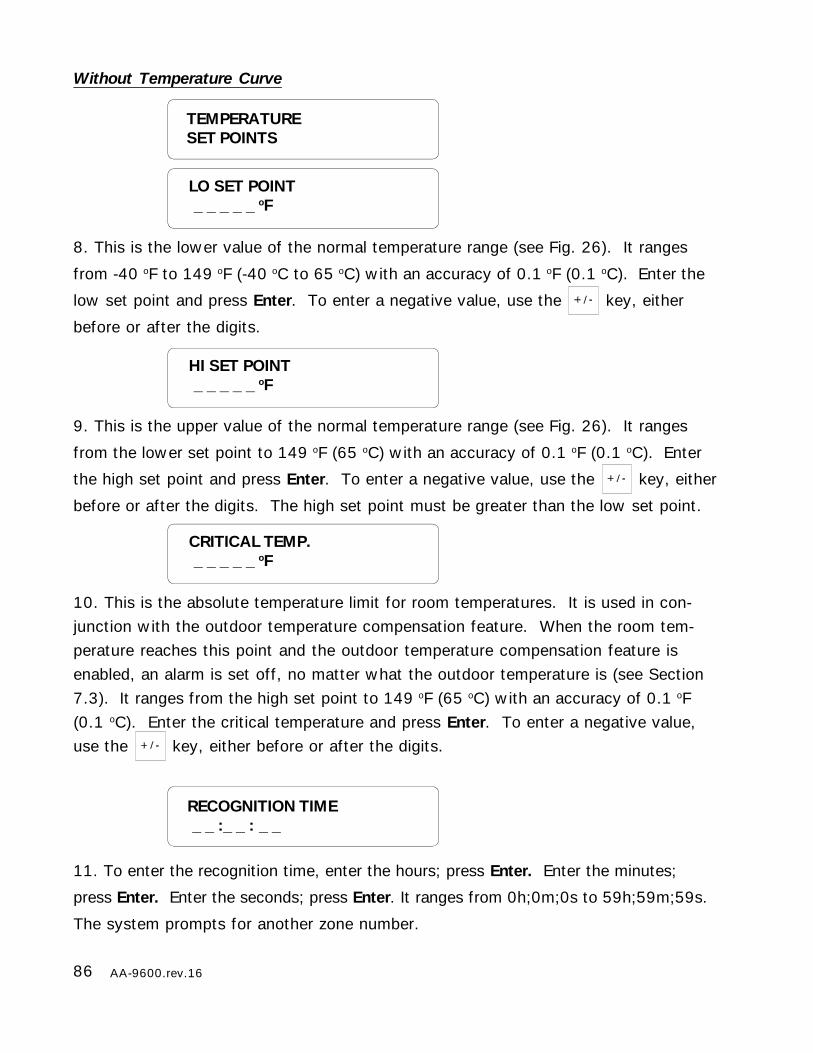
86 AA-9600.rev.16
HI SET POINT _ _ _ _ _ oF
Without Temperature Curve
8. This is the lower value of the normal temperature range (see Fig. 26). It ranges
from -40 oF to 149 oF (-40 oC to 65 oC) with an accuracy of 0.1 oF (0.1 oC). Enter the
low set point and press Enter. To enter a negative value, use the key, either
before or after the digits.
9. This is the upper value of the normal temperature range (see Fig. 26). It ranges
from the lower set point to 149 oF (65 oC) with an accuracy of 0.1 oF (0.1 oC). Enter
the high set point and press Enter. To enter a negative value, use the key, either
before or after the digits. The high set point must be greater than the low set point.
10. This is the absolute temperature limit for room temperatures. It is used in con-junction with the outdoor temperature compensation feature. When the room tem-perature reaches this point and the outdoor temperature compensation feature isenabled, an alarm is set off, no matter what the outdoor temperature is (see Section7.3). It ranges from the high set point to 149 oF (65 oC) with an accuracy of 0.1 oF(0.1 oC). Enter the critical temperature and press Enter. To enter a negative value,use the key, either before or after the digits.
11. To enter the recognition time, enter the hours; press Enter. Enter the minutes;
press Enter. Enter the seconds; press Enter. It ranges from 0h;0m;0s to 59h;59m;59s.
The system prompts for another zone number.
LO SET POINT _ _ _ _ _ oF
TEMPERATURESET POINTS
CRITICAL TEMP. _ _ _ _ _ oF
RECOGNITION TIME _ _ :_ _ : _ _
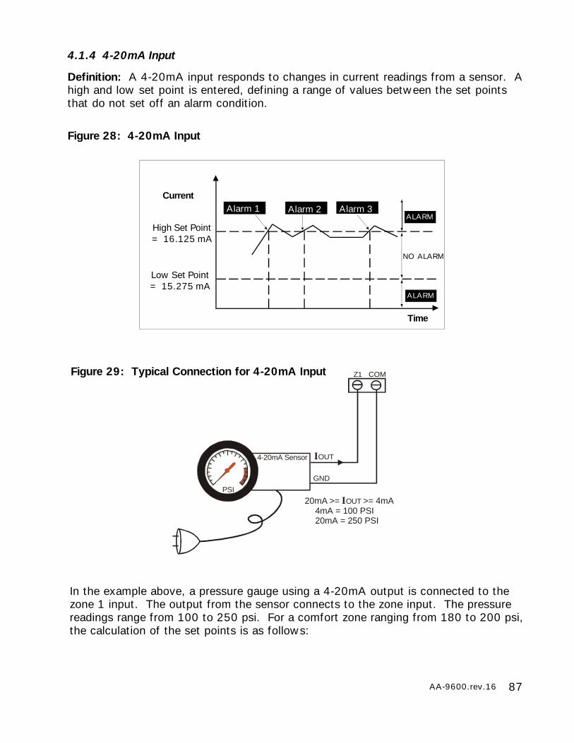
87AA-9600.rev.16
4.1.4 4-20mA Input
Definition: A 4-20mA input responds to changes in current readings from a sensor. Ahigh and low set point is entered, defining a range of values between the set pointsthat do not set off an alarm condition.
Figure 28: 4-20mA Input
High Set Point= 16.125 mA
Low Set Point= 15.275 mA
Current
Time
Alarm 3Alarm 2Alarm 1ALARM
NO ALARM
ALARM
Z1
IOUT
20mA >= IOUT >= 4mA4mA = 100 PSI20mA = 250 PSI
PSI
GND
4-20mA Sensor
COMFigure 29: Typical Connection for 4-20mA Input
In the example above, a pressure gauge using a 4-20mA output is connected to thezone 1 input. The output from the sensor connects to the zone input. The pressurereadings range from 100 to 250 psi. For a comfort zone ranging from 180 to 200 psi,the calculation of the set points is as follows:
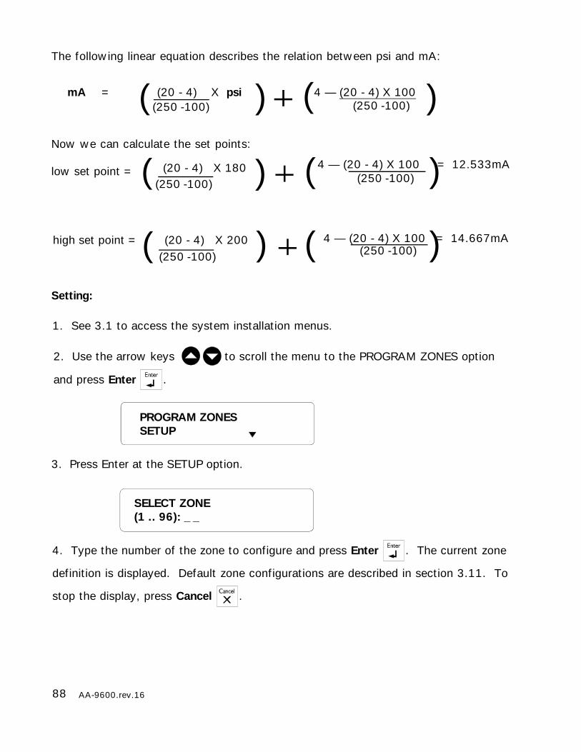
88 AA-9600.rev.16
The following linear equation describes the relation between psi and mA:
mA = (20 - 4) X psi 4 — (20 - 4) X 100(250 -100) (250 -100)( )
Now we can calculate the set points:
low set point = (20 - 4) X 180(250 -100)
4 — (20 - 4) X 100 = 12.533mA(250 -100)( )
high set point = (20 - 4) X 200(250 -100)
4 — (20 - 4) X 100 = 14.667mA(250 -100)( )
Setting:
(
(
(
)
)
)
SELECT ZONE(1 .. 96): _ _
4. Type the number of the zone to configure and press Enter . The current zone
definition is displayed. Default zone configurations are described in section 3.11. To
stop the display, press Cancel .
1. See 3.1 to access the system installation menus.
2. Use the arrow keys to scroll the menu to the PROGRAM ZONES option
and press Enter .
PROGRAM ZONESSETUP
3. Press Enter at the SETUP option.

89AA-9600.rev.16
RECOGNITION TIME _ _ :_ _ : _ _
5. Press Enter to modify the zone or Cancel to exit this function. If the zone selectedis the outdoor probe used for the outdoor temperature compensation feature and thecompensation feature is currently enabled, the system displays the message: DEAC-TIVATE OUTDOOR STATUS. If you want to use the compensation feature, you willhave to assign another probe as the outdoor probe (See Section 7.3).
THE ALARM MEMORY IS ERASED EACH TIME A ZONE IS RECONFIGURED.
6. The different types of sensors are presented in a scrolling menu. Use the up and
down arrow keys to select 4-20MA and press Enter.
7. This is the lower value of the normal current range. It ranges from 4 to 20 mAwith an accuracy of 0.001mA. Enter the low set point and press Enter.
8. This is the upper value of the normal current range. It ranges from the lower setpoint to 20mA with an accuracy of 0.001mA. The value must be greater than thelow set point. Enter the high set point and press Enter.
9. To enter the recognition time, enter the hours; press Enter. Enter the minutes; pressEnter. Enter the seconds; press Enter. It ranges from 0h;0m;0s to 59h;59m;59s. Thesystem returns to the zone number prompt.
LO SET POINT_ _ _ _ _ _ mA
HI SET POINT_ _ _ _ _ _mA
TO MODIFY. . . . . (↵)TO QUIT. . . . . . . (X)
TYPE OF SENSOR4-20mA
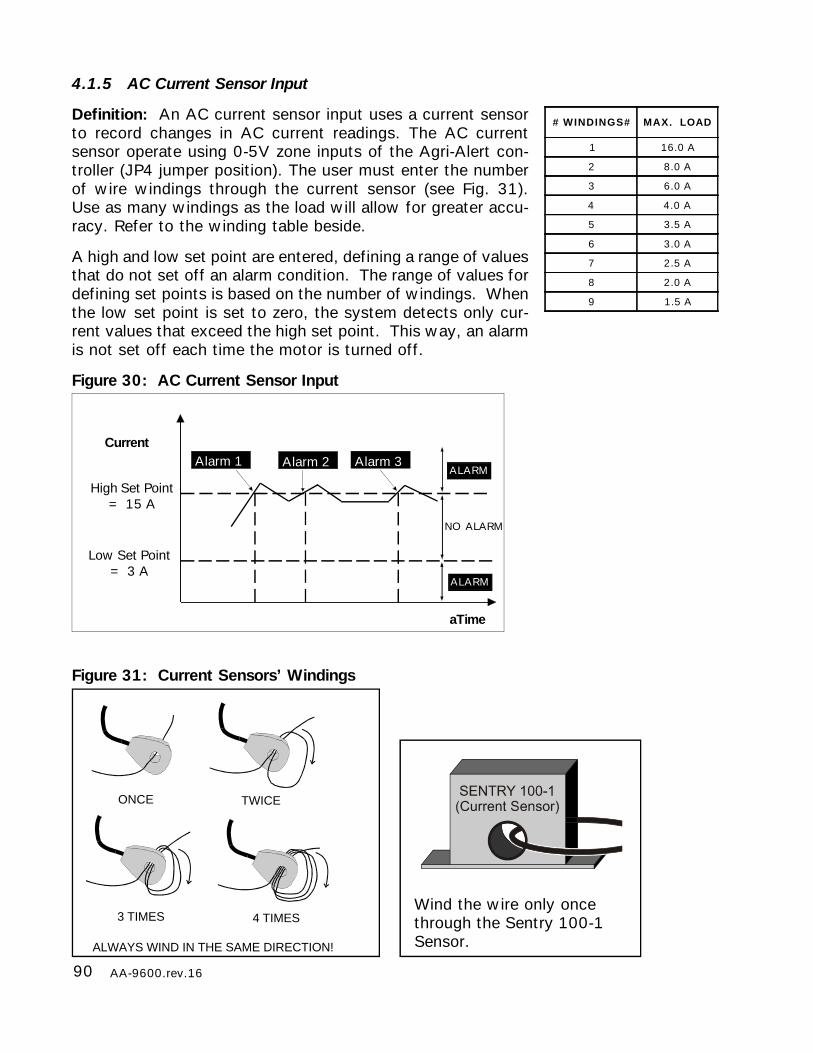
90 AA-9600.rev.16
4.1.5 AC Current Sensor Input
Definition: An AC current sensor input uses a current sensorto record changes in AC current readings. The AC currentsensor operate using 0-5V zone inputs of the Agri-Alert con-troller (JP4 jumper position). The user must enter the numberof wire windings through the current sensor (see Fig. 31).Use as many windings as the load will allow for greater accu-racy. Refer to the winding table beside.
A high and low set point are entered, defining a range of valuesthat do not set off an alarm condition. The range of values fordefining set points is based on the number of windings. Whenthe low set point is set to zero, the system detects only cur-rent values that exceed the high set point. This way, an alarmis not set off each time the motor is turned off.
Figure 30: AC Current Sensor Input
# WINDINGS# MAX. LOAD
1 16.0 A
2 8.0 A
3 6.0 A
4 4.0 A
5 3.5 A
6 3.0 A
7 2.5 A
8 2.0 A
9 1.5 A
ONCE TWICE
3 TIMES
ALWAYS WIND IN THE SAME DIRECTION!
4 TIMESWind the wire only oncethrough the Sentry 100-1Sensor.
High Set Point= 15 A
Low Set Point= 3 A
Current
aTime
Alarm 3Alarm 2Alarm 1
NO ALARM
ALARM
ALARM
Figure 31: Current Sensors’ Windings

91AA-9600.rev.16
TYPE OF SENSORAC CURRENT
Setting:
1. See 3.1 to access the system installation menus.
2. Use the arrow keys to scroll the menu to the PROGRAM ZONES option
and press Enter .
3. Press Enter at the SETUP option.
4. Type the number of the zone to configure and press Enter . The current zone
configuration is displayed. Default parameter values for zones are given in Section
3.11. To stop the display, press Cancel .
5. Press Enter to modify the zone or Cancel to exit this function. If the zone selectedis the outdoor probe used for the outdoor temperature compensation feature and thecompensation feature is currently enabled, the system displays the message: DEACTI-VATE OUTDOOR STATUS. If you want to use the compensation feature, you willhave to assign another probe as the outdoor probe (See Section 7.3).
THE ALARM MEMORY IS ERASED EACH TIME A ZONE IS RECONFIGURED.
6. The different types of sensors are presented in a scrolling menu. Use the up and
down arrow keys to select AC CURRENT and press Enter.
TO MODIFY. . . . . (↵)TO QUIT. . . . . . . (X)
SELECT ZONE(1 .. 96): _ _
PROGRAM ZONESSETUP
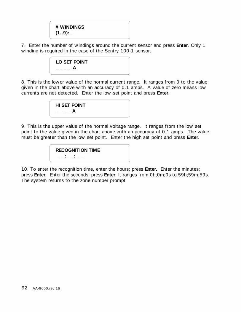
92 AA-9600.rev.16
RECOGNITION TIME _ _ :_ _ : _ _
7. Enter the number of windings around the current sensor and press Enter. Only 1winding is required in the case of the Sentry 100-1 sensor.
8. This is the lower value of the normal current range. It ranges from 0 to the valuegiven in the chart above with an accuracy of 0.1 amps. A value of zero means lowcurrents are not detected. Enter the low set point and press Enter.
9. This is the upper value of the normal voltage range. It ranges from the low setpoint to the value given in the chart above with an accuracy of 0.1 amps. The valuemust be greater than the low set point. Enter the high set point and press Enter.
10. To enter the recognition time, enter the hours; press Enter. Enter the minutes;press Enter. Enter the seconds; press Enter. It ranges from 0h;0m;0s to 59h;59m;59s.The system returns to the zone number prompt
LO SET POINT_ _ _ _ A
HI SET POINT_ _ _ _ A
# WINDINGS(1..9): _
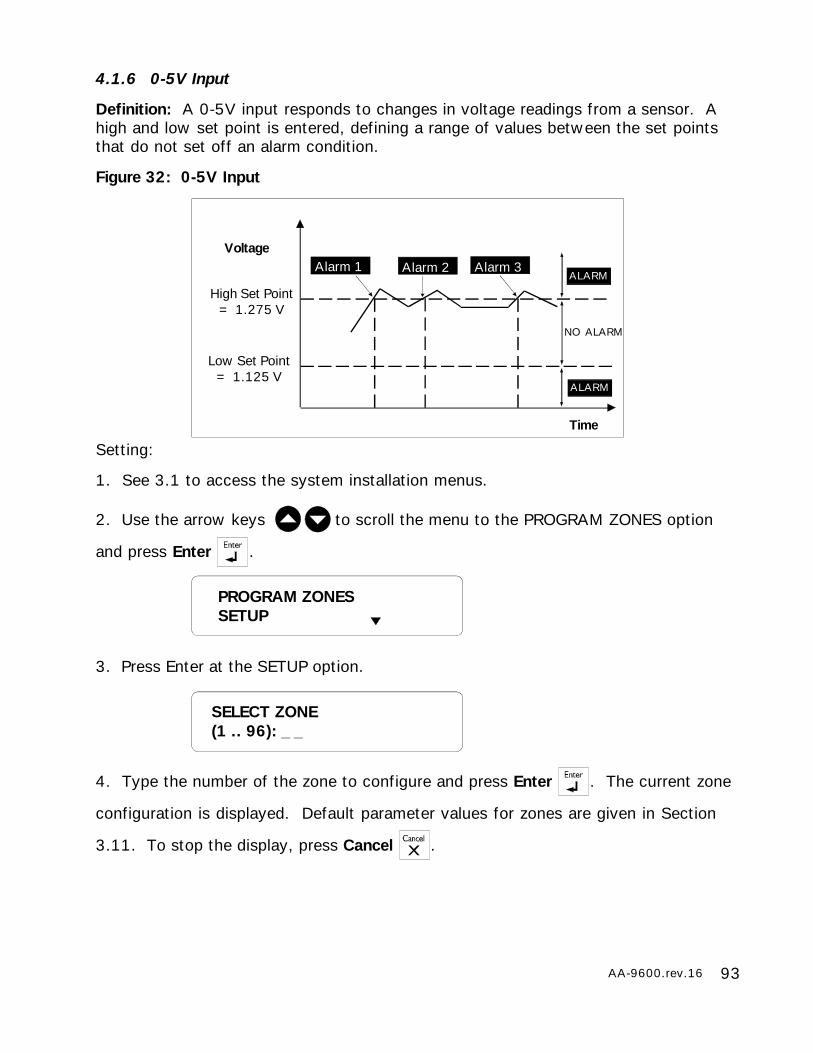
93AA-9600.rev.16
4.1.6 0-5V Input
Definition: A 0-5V input responds to changes in voltage readings from a sensor. Ahigh and low set point is entered, defining a range of values between the set pointsthat do not set off an alarm condition.
Figure 32: 0-5V Input
Setting:
1. See 3.1 to access the system installation menus.
2. Use the arrow keys to scroll the menu to the PROGRAM ZONES option
and press Enter .
3. Press Enter at the SETUP option.
4. Type the number of the zone to configure and press Enter . The current zone
configuration is displayed. Default parameter values for zones are given in Section
3.11. To stop the display, press Cancel .
High Set Point= 1.275 V
Low Set Point= 1.125 V
Voltage
Time
Alarm 3Alarm 2Alarm 1
NO ALARM
ALARM
ALARM
SELECT ZONE(1 .. 96): _ _
PROGRAM ZONESSETUP
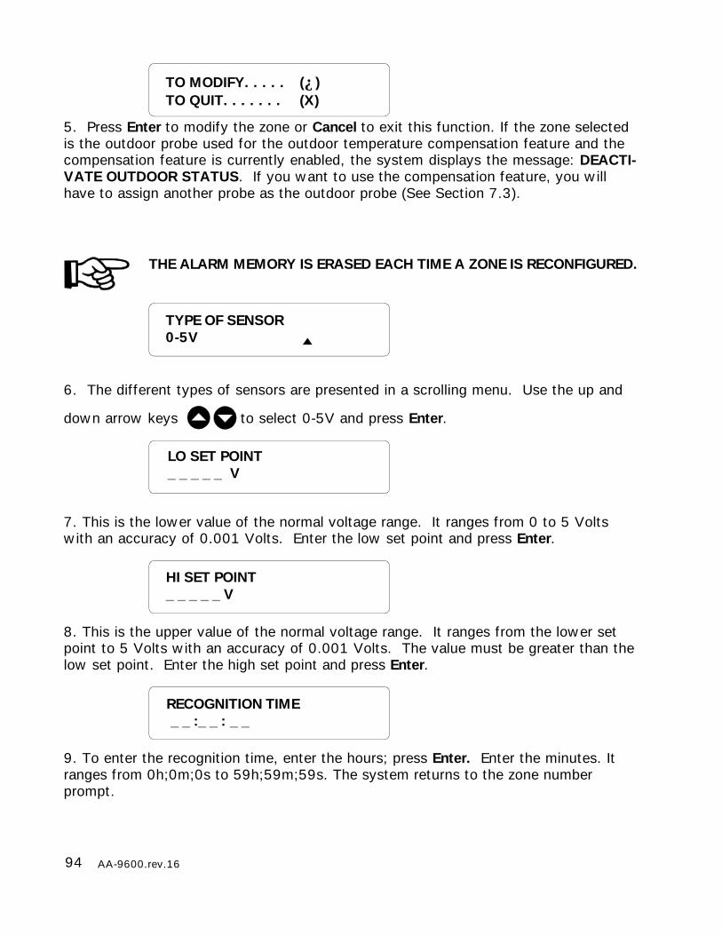
94 AA-9600.rev.16
5. Press Enter to modify the zone or Cancel to exit this function. If the zone selectedis the outdoor probe used for the outdoor temperature compensation feature and thecompensation feature is currently enabled, the system displays the message: DEACTI-VATE OUTDOOR STATUS. If you want to use the compensation feature, you willhave to assign another probe as the outdoor probe (See Section 7.3).
THE ALARM MEMORY IS ERASED EACH TIME A ZONE IS RECONFIGURED.
6. The different types of sensors are presented in a scrolling menu. Use the up and
down arrow keys to select 0-5V and press Enter.
7. This is the lower value of the normal voltage range. It ranges from 0 to 5 Voltswith an accuracy of 0.001 Volts. Enter the low set point and press Enter.
8. This is the upper value of the normal voltage range. It ranges from the lower setpoint to 5 Volts with an accuracy of 0.001 Volts. The value must be greater than thelow set point. Enter the high set point and press Enter.
9. To enter the recognition time, enter the hours; press Enter. Enter the minutes. Itranges from 0h;0m;0s to 59h;59m;59s. The system returns to the zone numberprompt.
LO SET POINT_ _ _ _ _ V
HI SET POINT_ _ _ _ _ V
TO MODIFY. . . . . (↵)TO QUIT. . . . . . . (X)
TYPE OF SENSOR0-5V
RECOGNITION TIME _ _ :_ _ : _ _
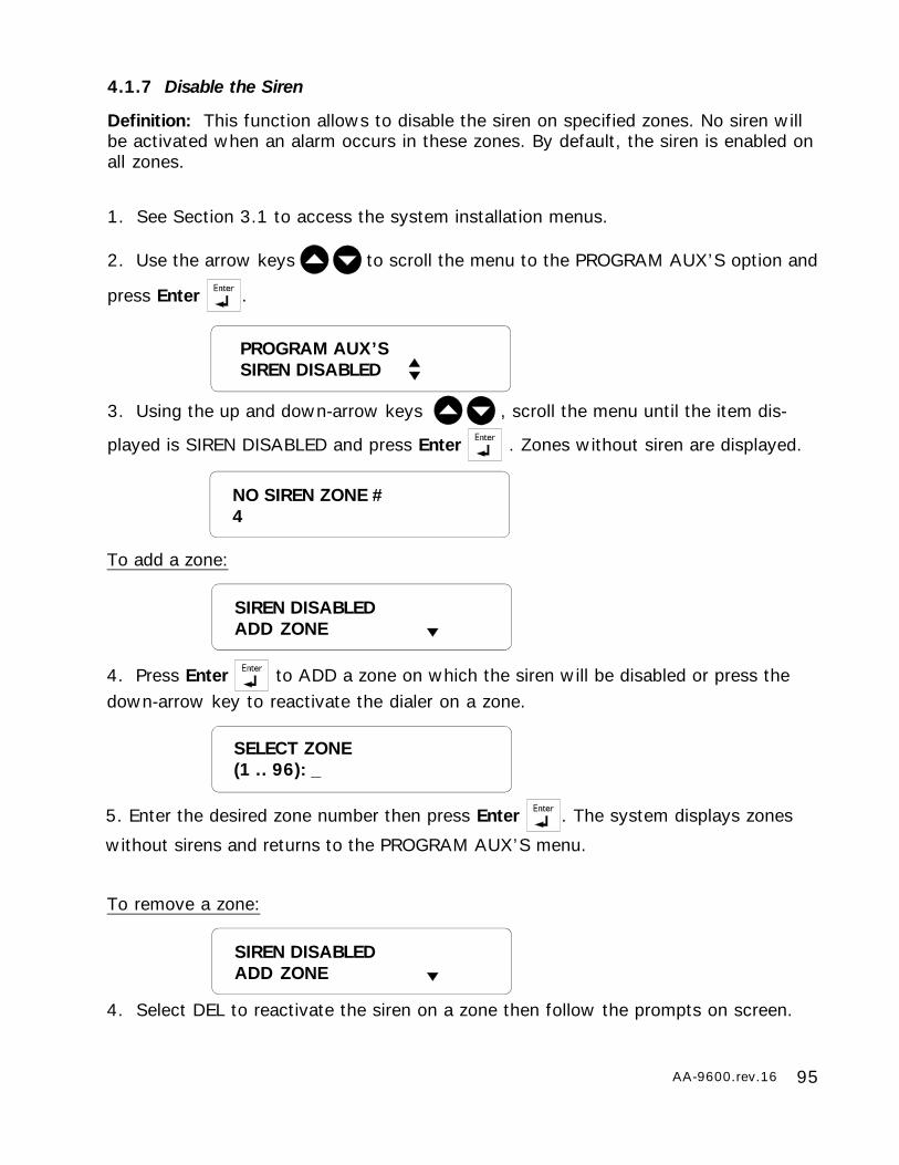
95AA-9600.rev.16
4.1.7 Disable the Siren
Definition: This function allows to disable the siren on specified zones. No siren willbe activated when an alarm occurs in these zones. By default, the siren is enabled onall zones.
1. See Section 3.1 to access the system installation menus.
2. Use the arrow keys to scroll the menu to the PROGRAM AUX’S option and
press Enter .
3. Using the up and down-arrow keys , scroll the menu until the item dis-
played is SIREN DISABLED and press Enter . Zones without siren are displayed.
PROGRAM AUX’SSIREN DISABLED
NO SIREN ZONE #4
To add a zone:
4. Press Enter to ADD a zone on which the siren will be disabled or press thedown-arrow key to reactivate the dialer on a zone.
SIREN DISABLEDADD ZONE
5. Enter the desired zone number then press Enter . The system displays zones
without sirens and returns to the PROGRAM AUX’S menu.
SELECT ZONE(1 .. 96): _
To remove a zone:
4. Select DEL to reactivate the siren on a zone then follow the prompts on screen.
SIREN DISABLEDADD ZONE
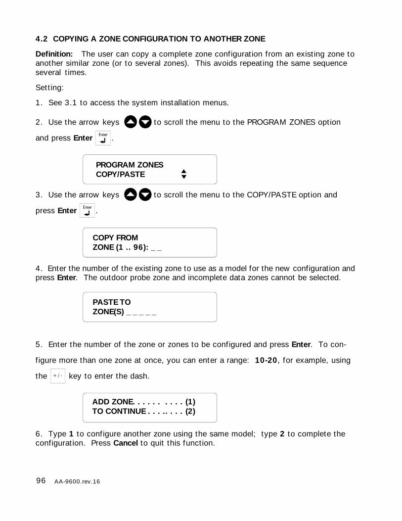
96 AA-9600.rev.16
4.2 COPYING A ZONE CONFIGURATION TO ANOTHER ZONE
Definition: The user can copy a complete zone configuration from an existing zone toanother similar zone (or to several zones). This avoids repeating the same sequenceseveral times.
Setting:
1. See 3.1 to access the system installation menus.
2. Use the arrow keys to scroll the menu to the PROGRAM ZONES option
and press Enter .
3. Use the arrow keys to scroll the menu to the COPY/PASTE option and
press Enter .
4. Enter the number of the existing zone to use as a model for the new configuration andpress Enter. The outdoor probe zone and incomplete data zones cannot be selected.
5. Enter the number of the zone or zones to be configured and press Enter. To con-
figure more than one zone at once, you can enter a range: 10-20, for example, using
the key to enter the dash.
6. Type 1 to configure another zone using the same model; type 2 to complete theconfiguration. Press Cancel to quit this function.
COPY FROMZONE (1 .. 96): _ _
PASTE TOZONE(S) _ _ _ _ _
ADD ZONE. . . . . . . . . . (1)TO CONTINUE . . . .. . . . (2)
PROGRAM ZONESCOPY/PASTE

97AA-9600.rev.16
4.3 DISPLAY ZONE INFORMATION
Definition: This function is used to display the device and input number of a zone.
1. See Section 3.1 to access the system installation menus.
2. Use the arrow keys to scroll the menu to the PROGRAM AUX’S option and
press Enter .
3. Use the arrow keys to scroll the menu to the INFORMATION option and
press Enter .
4. Press Enter at the ZONE option.
5. Enter the number of the zone and press Enter.
6. The zone number and label are displayed. If the zone selected is not the right one,
use the arrow keys to scroll the menu until the correct zone is selected and
press Enter .
7. The zones assigned to the device are displayed. The system returns to the zonenumber prompt (step 5).
SELECT ZONE(1..96): _ _
ZONE#3BARN#4
ZONE#3 KP#01INPUT#1
INFORMATIONZONE
PROGRAM AUX’SINFORMATION
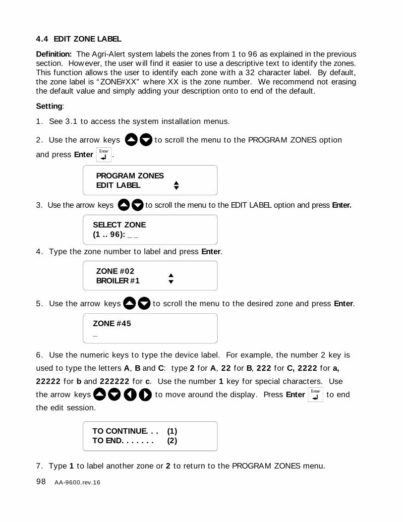
98 AA-9600.rev.16
4.4 EDIT ZONE LABEL
Definition: The Agri-Alert system labels the zones from 1 to 96 as explained in the previoussection. However, the user will find it easier to use a descriptive text to identify the zones.This function allows the user to identify each zone with a 32 character label. By default,the zone label is “ZONE#XX” where XX is the zone number. We recommend not erasingthe default value and simply adding your description onto to end of the default.
Setting:
1. See 3.1 to access the system installation menus.
2. Use the arrow keys to scroll the menu to the PROGRAM ZONES option
and press Enter .
3. Use the arrow keys to scroll the menu to the EDIT LABEL option and press Enter.
4. Type the zone number to label and press Enter.
5. Use the arrow keys to scroll the menu to the desired zone and press Enter.
6. Use the numeric keys to type the device label. For example, the number 2 key is
used to type the letters A, B and C: type 2 for A, 22 for B, 222 for C, 2222 for a,
22222 for b and 222222 for c. Use the number 1 key for special characters. Use
the arrow keys to move around the display. Press Enter to end
the edit session.
7. Type 1 to label another zone or 2 to return to the PROGRAM ZONES menu.
SELECT ZONE(1 .. 96): _ _
ZONE #45_
ZONE #02BROILER #1
PROGRAM ZONESEDIT LABEL
TO CONTINUE. . . (1)TO END. . . . . . . (2)
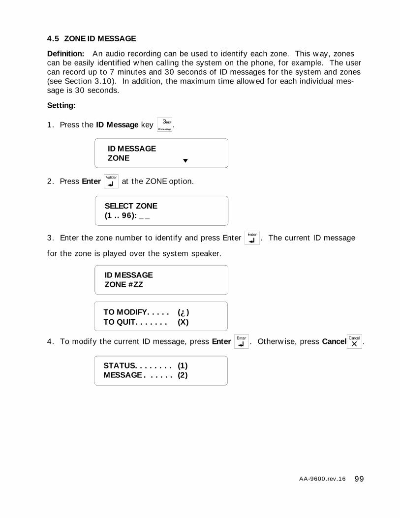
99AA-9600.rev.16
4.5 ZONE ID MESSAGE
Definition: An audio recording can be used to identify each zone. This way, zonescan be easily identified when calling the system on the phone, for example. The usercan record up to 7 minutes and 30 seconds of ID messages for the system and zones(see Section 3.10). In addition, the maximum time allowed for each individual mes-sage is 30 seconds.
Setting:
1. Press the ID Message key 3DEF
ID message.
2. Press Enter at the ZONE option.
3. Enter the zone number to identify and press Enter . The current ID message
for the zone is played over the system speaker.
4. To modify the current ID message, press Enter . Otherwise, press Cancel .
ID MESSAGEZONE
SELECT ZONE(1 .. 96): _ _
ID MESSAGEZONE #ZZ
STATUS. . . . . . . . (1)MESSAGE . . . . . . (2)
TO MODIFY. . . . . (↵)TO QUIT. . . . . . . (X)
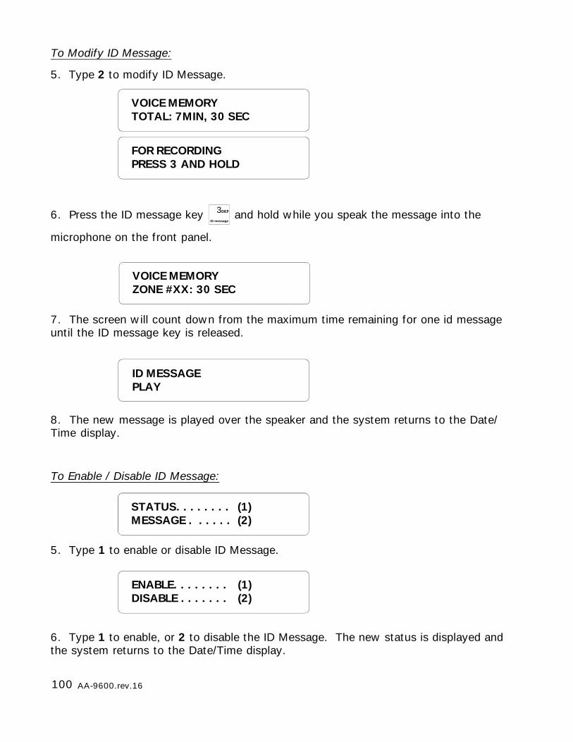
100 AA-9600.rev.16
FOR RECORDINGPRESS 3 AND HOLD
VOICE MEMORYZONE #XX: 30 SEC
ID MESSAGEPLAY
To Modify ID Message:
5. Type 2 to modify ID Message.
6. Press the ID message key 3DEF
ID message and hold while you speak the message into the
microphone on the front panel.
7. The screen will count down from the maximum time remaining for one id messageuntil the ID message key is released.
8. The new message is played over the speaker and the system returns to the Date/Time display.
To Enable / Disable ID Message:
5. Type 1 to enable or disable ID Message.
6. Type 1 to enable, or 2 to disable the ID Message. The new status is displayed andthe system returns to the Date/Time display.
ENABLE. . . . . . . . (1)DISABLE . . . . . . . (2)
STATUS. . . . . . . . (1)MESSAGE . . . . . . (2)
VOICE MEMORYTOTAL: 7MIN, 30 SEC
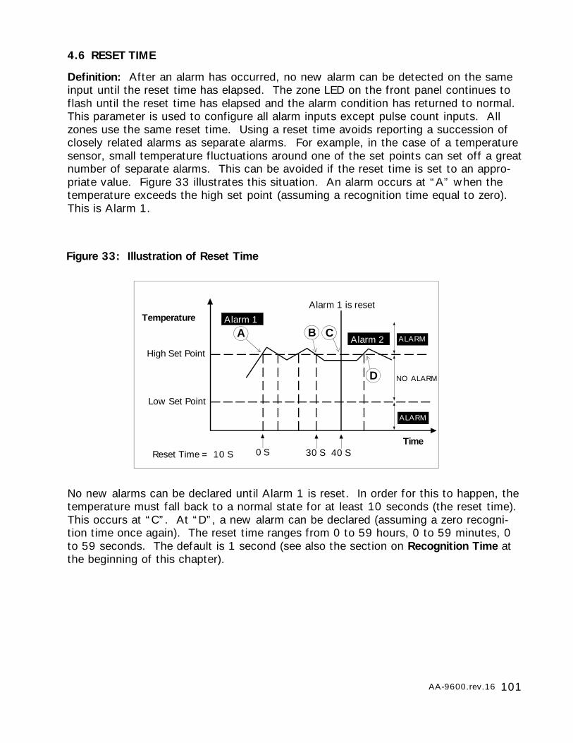
101AA-9600.rev.16
Figure 33: Illustration of Reset Time
High Set Point
Low Set Point
Temperature
Time
A C
Reset Time = 10 S
Alarm 1
Alarm 2
40 S
B
D
0 S 30 S
Alarm 1 is reset
ALARM
NO ALARM
ALARM
4.6 RESET TIME
Definition: After an alarm has occurred, no new alarm can be detected on the sameinput until the reset time has elapsed. The zone LED on the front panel continues toflash until the reset time has elapsed and the alarm condition has returned to normal.This parameter is used to configure all alarm inputs except pulse count inputs. Allzones use the same reset time. Using a reset time avoids reporting a succession ofclosely related alarms as separate alarms. For example, in the case of a temperaturesensor, small temperature fluctuations around one of the set points can set off a greatnumber of separate alarms. This can be avoided if the reset time is set to an appro-priate value. Figure 33 illustrates this situation. An alarm occurs at “A” when thetemperature exceeds the high set point (assuming a recognition time equal to zero).This is Alarm 1.
No new alarms can be declared until Alarm 1 is reset. In order for this to happen, thetemperature must fall back to a normal state for at least 10 seconds (the reset time).This occurs at “C”. At “D”, a new alarm can be declared (assuming a zero recogni-tion time once again). The reset time ranges from 0 to 59 hours, 0 to 59 minutes, 0to 59 seconds. The default is 1 second (see also the section on Recognition Time atthe beginning of this chapter).
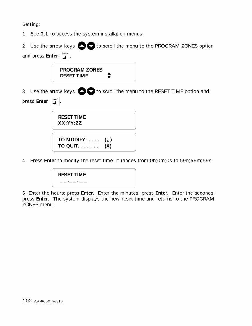
102 AA-9600.rev.16
RESET TIMEXX:YY:ZZ
TO MODIFY. . . . . (↵)TO QUIT. . . . . . . (X)
PROGRAM ZONESRESET TIME
RESET TIME _ _ :_ _ : _ _
Setting:
1. See 3.1 to access the system installation menus.
2. Use the arrow keys to scroll the menu to the PROGRAM ZONES option
and press Enter .
3. Use the arrow keys to scroll the menu to the RESET TIME option and
press Enter .
4. Press Enter to modify the reset time. It ranges from 0h;0m;0s to 59h;59m;59s.
5. Enter the hours; press Enter. Enter the minutes; press Enter. Enter the seconds;press Enter. The system displays the new reset time and returns to the PROGRAMZONES menu.
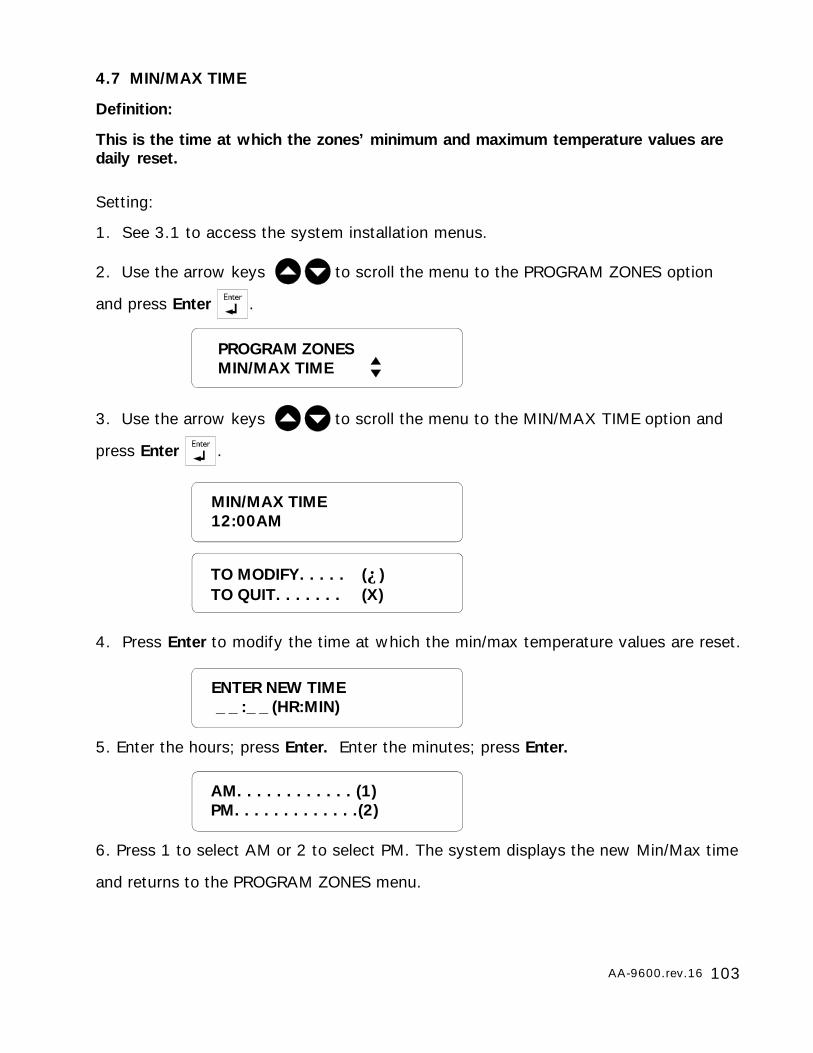
103AA-9600.rev.16
4.7 MIN/MAX TIME
Definition:
This is the time at which the zones’ minimum and maximum temperature values aredaily reset.
MIN/MAX TIME12:00AM
Setting:
1. See 3.1 to access the system installation menus.
2. Use the arrow keys to scroll the menu to the PROGRAM ZONES option
and press Enter .
3. Use the arrow keys to scroll the menu to the MIN/MAX TIME option and
press Enter .
4. Press Enter to modify the time at which the min/max temperature values are reset.
5. Enter the hours; press Enter. Enter the minutes; press Enter.
6. Press 1 to select AM or 2 to select PM. The system displays the new Min/Max time
and returns to the PROGRAM ZONES menu.
TO MODIFY. . . . . (↵)TO QUIT. . . . . . . (X)
PROGRAM ZONESMIN/MAX TIME
ENTER NEW TIME _ _ :_ _ (HR:MIN)
AM. . . . . . . . . . . . (1)PM. . . . . . . . . . . . .(2)
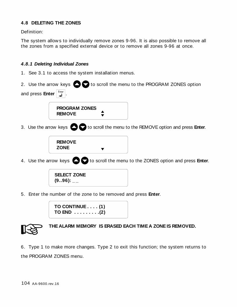
104 AA-9600.rev.16
4.8 DELETING THE ZONES
Definition:
The system allows to individually remove zones 9-96. It is also possible to remove allthe zones from a specified external device or to remove all zones 9-96 at once.
4.8.1 Deleting Individual Zones
1. See 3.1 to access the system installation menus.
2. Use the arrow keys to scroll the menu to the PROGRAM ZONES option
and press Enter .
3. Use the arrow keys to scroll the menu to the REMOVE option and press Enter.
4. Use the arrow keys to scroll the menu to the ZONES option and press Enter.
5. Enter the number of the zone to be removed and press Enter.
THE ALARM MEMORY IS ERASED EACH TIME A ZONE IS REMOVED.
6. Type 1 to make more changes. Type 2 to exit this function; the system returns to
the PROGRAM ZONES menu.
SELECT ZONE(9..96): _ _
PROGRAM ZONESREMOVE
REMOVEZONE
TO CONTINUE . . . . (1)TO END . . . . . . . . .(2)
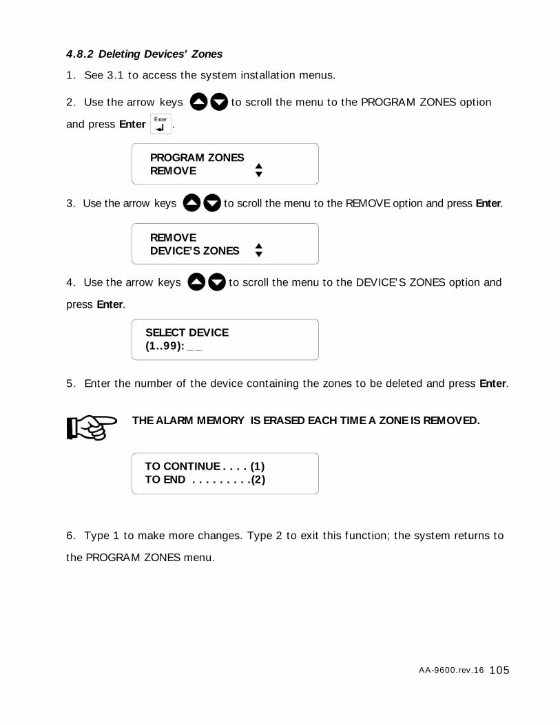
105AA-9600.rev.16
4.8.2 Deleting Devices’ Zones
1. See 3.1 to access the system installation menus.
2. Use the arrow keys to scroll the menu to the PROGRAM ZONES option
and press Enter .
3. Use the arrow keys to scroll the menu to the REMOVE option and press Enter.
4. Use the arrow keys to scroll the menu to the DEVICE’S ZONES option and
press Enter.
5. Enter the number of the device containing the zones to be deleted and press Enter.
THE ALARM MEMORY IS ERASED EACH TIME A ZONE IS REMOVED.
6. Type 1 to make more changes. Type 2 to exit this function; the system returns to
the PROGRAM ZONES menu.
SELECT DEVICE(1..99): _ _
PROGRAM ZONESREMOVE
TO CONTINUE . . . . (1)TO END . . . . . . . . .(2)
REMOVEDEVICE’S ZONES
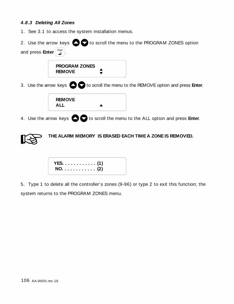
106 AA-9600.rev.16
4.8.3 Deleting All Zones
1. See 3.1 to access the system installation menus.
2. Use the arrow keys to scroll the menu to the PROGRAM ZONES option
and press Enter .
3. Use the arrow keys to scroll the menu to the REMOVE option and press Enter.
4. Use the arrow keys to scroll the menu to the ALL option and press Enter.
THE ALARM MEMORY IS ERASED EACH TIME A ZONE IS REMOVED.
5. Type 1 to delete all the controller’s zones (9-96) or type 2 to exit this function; the
system returns to the PROGRAM ZONES menu.
YES. . . . . . . . . . . . (1) NO. . . . . . . . . . . . (2)
PROGRAM ZONESREMOVE
REMOVEALL
107AA-9600.rev.16
CHAPTER FIVE: COMMUNICATION PARAMETERS
5.1 CENTRAL ALARM REPORTING CODES
Definition: The AA9600 system uses the CONTACT ID protocol for reporting alarmevents and status changes to a central alarm facility. The general format of theinformation sent is as follows:
SSSS XXx YYY GG UUU CC
SSSS- account number
XX - 18 (CONTACT ID)
x - 1 (bypass/disarm); 3 (activate/arm)
YYY - event code
GG - partition number
UUU - password index
CC - checksum
The user must enter the account number which identifies the system to the facility.The user can also change the event codes (YYY) for the various events if they aredifferent from the default values. Event codes include the following items:
- alarm codes used to define an alarm type for each zone and for each type ofsystem alarm
- restore codes used to indicate that the zone or system has returned to its nor-mal state.
- codes used to report zone and partition status changes made by the user
When an alarm occurs, or when the alarm situation is corrected, the appropriate codeis sent to the central alarm facility. If an outstanding alarm is acknowledged beforethe central alarm facility is called, the report or utility code is modified as follows:
- the first digit is changed to ‘7’
- the second and third digits remain unchanged
See Appendix D for a table of CONTACT ID event codes.
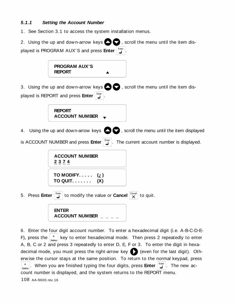
108 AA-9600.rev.16
TO MODIFY. . . . . (↵)TO QUIT. . . . . . . (X)
REPORTACCOUNT NUMBER
ACCOUNT NUMBER2 3 7 4
5.1.1 Setting the Account Number
1. See Section 3.1 to access the system installation menus.
2. Using the up and down-arrow keys , scroll the menu until the item dis-
played is PROGRAM AUX’S and press Enter .
3. Using the up and down-arrow keys , scroll the menu until the item dis-
played is REPORT and press Enter .
4. Using the up and down-arrow keys , scroll the menu until the item displayed
is ACCOUNT NUMBER and press Enter . The current account number is displayed.
5. Press Enter to modify the value or Cancel to quit.
6. Enter the four digit account number. To enter a hexadecimal digit (i.e. A-B-C-D-E-F), press the * key to enter hexadecimal mode. Then press 2 repeatedly to enterA, B, C or 2 and press 3 repeatedly to enter D, E, F or 3. To enter the digit in hexa-decimal mode, you must press the right-arrow key (even for the last digit). Oth-erwise the cursor stays at the same position. To return to the normal keypad, press
* . When you are finished typing the four digits, press Enter . The new ac-count number is displayed, and the system returns to the REPORT menu.
ENTERACCOUNT NUMBER _ _ _ _
PROGRAM AUX’SREPORT
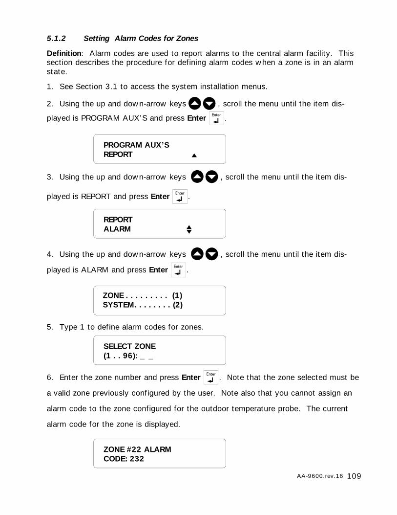
109AA-9600.rev.16
SELECT ZONE(1 . . 96): _ _
5.1.2 Setting Alarm Codes for Zones
Definition: Alarm codes are used to report alarms to the central alarm facility. Thissection describes the procedure for defining alarm codes when a zone is in an alarmstate.
1. See Section 3.1 to access the system installation menus.
2. Using the up and down-arrow keys , scroll the menu until the item dis-
played is PROGRAM AUX’S and press Enter .
3. Using the up and down-arrow keys , scroll the menu until the item dis-
played is REPORT and press Enter .
4. Using the up and down-arrow keys , scroll the menu until the item dis-
played is ALARM and press Enter .
5. Type 1 to define alarm codes for zones.
6. Enter the zone number and press Enter . Note that the zone selected must be
a valid zone previously configured by the user. Note also that you cannot assign an
alarm code to the zone configured for the outdoor temperature probe. The current
alarm code for the zone is displayed.
REPORTALARM
ZONE . . . . . . . . . (1)SYSTEM. . . . . . . . (2)
PROGRAM AUX’SREPORT
ZONE #22 ALARMCODE: 232

110 AA-9600.rev.16
PROGRAM AUX’SREPORT
7. Press Enter to modify the value or Cancel to quit.
8. Enter the three digit alarm code. To enter a hexadecimal digit (i.e. A-B-C-D-E-F),
press the * key to enter hexadecimal mode. Then press 2 repeatedly to enter A,
B, C or 2 and press 3 repeatedly to enter D, E, F or 3. To enter the digit in hexadeci-
mal mode, you must press the right-arrow key (even for the last digit). Otherwise
the cursor stays at the same position. To return to the normal keypad, press * .
When you are finished typing the three digits, press Enter . The new alarm code is
displayed, and the system returns to the REPORT menu.
5.1.3 Setting Alarm Codes for System Alarms
Definition: Alarm codes are used to report alarms tothe central alarm facility. This section describes theprocedure for defining alarm codes for system alarms.The following table gives a description of systemalarms.
Setting:
1. See Section 3.1 to access the system installationmenus.
2. Using the up and down-arrow keys , scroll
the menu until the item displayed is PROGRAM AUX’S
and press Enter .
ENTERCODE : _ _ _
LOW SYSTEM BATTERY
POWER FAILURE
HI SYSTEM TEMPERATURE
LO SYSTEM TEMPERATURE
PHONE LINE CUT
12VDC OUTPUT FAILURE
SIREN TROUBLE
LO SBI VOLTAGE
AUTO STANDBY
SYSTEM TROUBLE
MANUAL TRIGGER TEST
PERIODIC TEST REPORT
TO MODIFY. . . . . (↵)TO QUIT. . . . . . . (X)
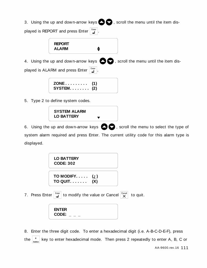
111AA-9600.rev.16
LO BATTERYCODE: 302
TO MODIFY. . . . . (↵)TO QUIT. . . . . . . (X)
ENTERCODE: _ _ _
SYSTEM ALARMLO BATTERY
ZONE . . . . . . . . . (1)SYSTEM. . . . . . . . (2)
3. Using the up and down-arrow keys , scroll the menu until the item dis-
played is REPORT and press Enter .
4. Using the up and down-arrow keys , scroll the menu until the item dis-
played is ALARM and press Enter .
5. Type 2 to define system codes.
6. Using the up and down-arrow keys , scroll the menu to select the type of
system alarm required and press Enter. The current utility code for this alarm type is
displayed.
7. Press Enter to modify the value or Cancel to quit.
8. Enter the three digit code. To enter a hexadecimal digit (i.e. A-B-C-D-E-F), press
the * key to enter hexadecimal mode. Then press 2 repeatedly to enter A, B, C or
REPORTALARM
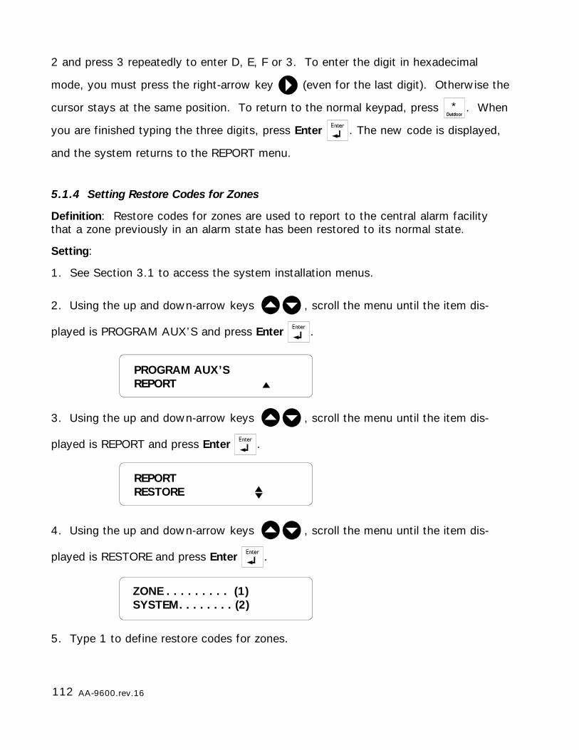
112 AA-9600.rev.16
5.1.4 Setting Restore Codes for Zones
Definition: Restore codes for zones are used to report to the central alarm facilitythat a zone previously in an alarm state has been restored to its normal state.
Setting:
1. See Section 3.1 to access the system installation menus.
2. Using the up and down-arrow keys , scroll the menu until the item dis-
played is PROGRAM AUX’S and press Enter .
3. Using the up and down-arrow keys , scroll the menu until the item dis-
played is REPORT and press Enter .
4. Using the up and down-arrow keys , scroll the menu until the item dis-
played is RESTORE and press Enter .
5. Type 1 to define restore codes for zones.
REPORTRESTORE
PROGRAM AUX’SREPORT
2 and press 3 repeatedly to enter D, E, F or 3. To enter the digit in hexadecimal
mode, you must press the right-arrow key (even for the last digit). Otherwise the
cursor stays at the same position. To return to the normal keypad, press * . When
you are finished typing the three digits, press Enter . The new code is displayed,
and the system returns to the REPORT menu.
ZONE . . . . . . . . . (1)SYSTEM. . . . . . . . (2)
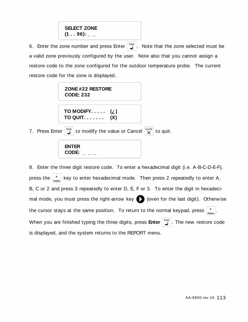
113AA-9600.rev.16
6. Enter the zone number and press Enter . Note that the zone selected must be
a valid zone previously configured by the user. Note also that you cannot assign a
restore code to the zone configured for the outdoor temperature probe. The current
restore code for the zone is displayed.
7. Press Enter to modify the value or Cancel to quit.
8. Enter the three digit restore code. To enter a hexadecimal digit (i.e. A-B-C-D-E-F),
press the * key to enter hexadecimal mode. Then press 2 repeatedly to enter A,
B, C or 2 and press 3 repeatedly to enter D, E, F or 3. To enter the digit in hexadeci-
mal mode, you must press the right-arrow key (even for the last digit). Otherwise
the cursor stays at the same position. To return to the normal keypad, press * .
When you are finished typing the three digits, press Enter . The new restore code
is displayed, and the system returns to the REPORT menu.
TO MODIFY. . . . . (↵)TO QUIT. . . . . . . (X)
ZONE #22 RESTORECODE: 232
ENTERCODE: _ _ _
SELECT ZONE(1 . . 96): _ _
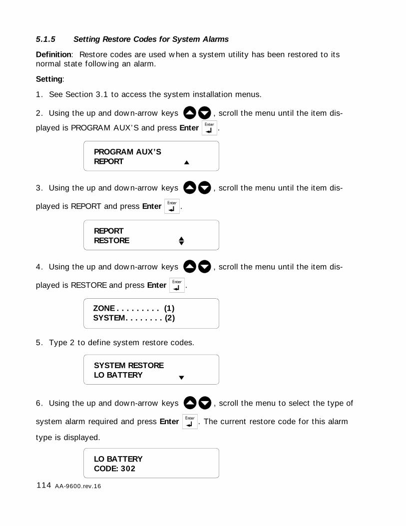
114 AA-9600.rev.16
LO BATTERYCODE: 302
5.1.5 Setting Restore Codes for System Alarms
Definition: Restore codes are used when a system utility has been restored to itsnormal state following an alarm.
Setting:
1. See Section 3.1 to access the system installation menus.
2. Using the up and down-arrow keys , scroll the menu until the item dis-
played is PROGRAM AUX’S and press Enter .
3. Using the up and down-arrow keys , scroll the menu until the item dis-
played is REPORT and press Enter .
4. Using the up and down-arrow keys , scroll the menu until the item dis-
played is RESTORE and press Enter .
5. Type 2 to define system restore codes.
6. Using the up and down-arrow keys , scroll the menu to select the type of
system alarm required and press Enter . The current restore code for this alarm
type is displayed.
SYSTEM RESTORELO BATTERY
ZONE . . . . . . . . . (1)SYSTEM. . . . . . . . (2)
REPORTRESTORE
PROGRAM AUX’SREPORT
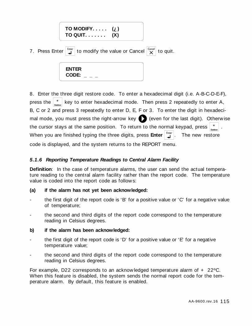
115AA-9600.rev.16
7. Press Enter to modify the value or Cancel to quit.
8. Enter the three digit restore code. To enter a hexadecimal digit (i.e. A-B-C-D-E-F),
press the * key to enter hexadecimal mode. Then press 2 repeatedly to enter A,
B, C or 2 and press 3 repeatedly to enter D, E, F or 3. To enter the digit in hexadeci-
mal mode, you must press the right-arrow key (even for the last digit). Otherwise
the cursor stays at the same position. To return to the normal keypad, press * .
When you are finished typing the three digits, press Enter . The new restore
code is displayed, and the system returns to the REPORT menu.
5.1.6 Reporting Temperature Readings to Central Alarm Facility
Definition: In the case of temperature alarms, the user can send the actual tempera-ture reading to the central alarm facility rather than the report code. The temperaturevalue is coded into the report code as follows:
(a) if the alarm has not yet been acknowledged:
- the first digit of the report code is ‘B’ for a positive value or ‘C’ for a negative valueof temperature;
- the second and third digits of the report code correspond to the temperaturereading in Celsius degrees.
b) if the alarm has been acknowledged:
- the first digit of the report code is ‘D’ for a positive value or ‘E’ for a negativetemperature value;
- the second and third digits of the report code correspond to the temperaturereading in Celsius degrees.
For example, D22 corresponds to an acknowledged temperature alarm of + 22ºC.When this feature is disabled, the system sends the normal report code for the tem-perature alarm. By default, this feature is enabled.
ENTERCODE: _ _ _
TO MODIFY. . . . . (↵)TO QUIT. . . . . . . (X)

116 AA-9600.rev.16
Setting:
1. See Section 3.1 to access the system installation menus.
2. Using the up and down-arrow keys , scroll the menu until the item dis-
played is PROGRAM AUX’S and press Enter .
3. Using the up and down-arrow keys , scroll the menu until the item dis-
played is REPORT and press Enter .
4. Using the up and down-arrow keys , scroll the menu until the item dis-
played is TEMPERATURE and press Enter .
5. Press Enter to modify the status or Cancel to quit.
6. Type 1 to enable reporting of temperature values, or 2 to disable this feature. Thenew status is displayed and the system returns to the REPORT menu.
TO MODIFY. . . . . (↵)TO QUIT. . . . . . . (X)
ENABLE.. . . . . . . . (1)DISABLE . . . . . . . (2)
STATUS: ENABLE
REPORTTEMPERATURE
PROGRAM AUX’SREPORT
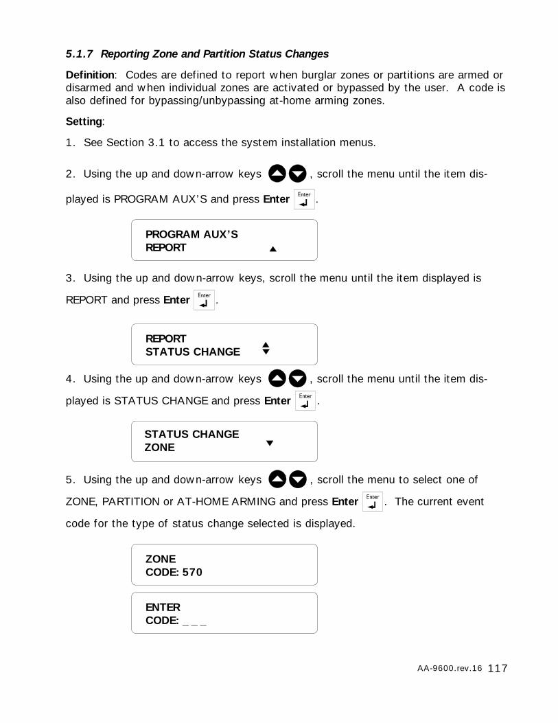
117AA-9600.rev.16
5.1.7 Reporting Zone and Partition Status Changes
Definition: Codes are defined to report when burglar zones or partitions are armed ordisarmed and when individual zones are activated or bypassed by the user. A code isalso defined for bypassing/unbypassing at-home arming zones.
Setting:
1. See Section 3.1 to access the system installation menus.
2. Using the up and down-arrow keys , scroll the menu until the item dis-
played is PROGRAM AUX’S and press Enter .
3. Using the up and down-arrow keys, scroll the menu until the item displayed is
REPORT and press Enter .
4. Using the up and down-arrow keys , scroll the menu until the item dis-
played is STATUS CHANGE and press Enter .
5. Using the up and down-arrow keys , scroll the menu to select one of
ZONE, PARTITION or AT-HOME ARMING and press Enter . The current event
code for the type of status change selected is displayed.
STATUS CHANGEZONE
ZONECODE: 570
ENTERCODE: _ _ _
REPORTSTATUS CHANGE
PROGRAM AUX’SREPORT
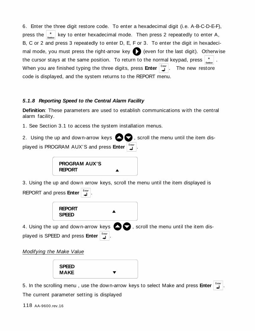
118 AA-9600.rev.16
6. Enter the three digit restore code. To enter a hexadecimal digit (i.e. A-B-C-D-E-F),
press the * key to enter hexadecimal mode. Then press 2 repeatedly to enter A,
B, C or 2 and press 3 repeatedly to enter D, E, F or 3. To enter the digit in hexadeci-
mal mode, you must press the right-arrow key (even for the last digit). Otherwise
the cursor stays at the same position. To return to the normal keypad, press * .
When you are finished typing the three digits, press Enter . The new restore
code is displayed, and the system returns to the REPORT menu.
5.1.8 Reporting Speed to the Central Alarm Facility
Definition: These parameters are used to establish communications with the centralalarm facility.
1. See Section 3.1 to access the system installation menus.
2. Using the up and down-arrow keys , scroll the menu until the item dis-
played is PROGRAM AUX’S and press Enter .
3. Using the up and down arrow keys, scroll the menu until the item displayed is
REPORT and press Enter .
4. Using the up and down-arrow keys , scroll the menu until the item dis-
played is SPEED and press Enter .
Modifying the Make Value
5. In the scrolling menu , use the down-arrow keys to select Make and press Enter .
The current parameter setting is displayed
SPEEDMAKE
REPORTSPEED
PROGRAM AUX’SREPORT
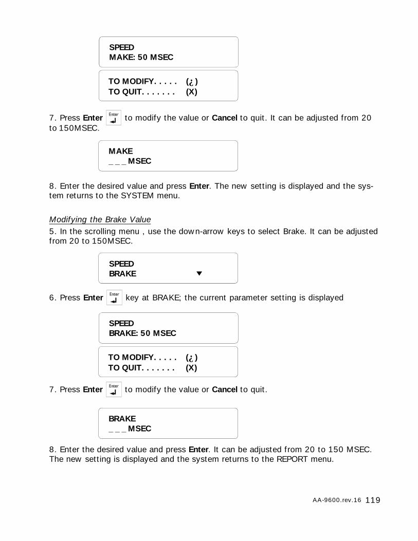
119AA-9600.rev.16
7. Press Enter to modify the value or Cancel to quit. It can be adjusted from 20to 150MSEC.
8. Enter the desired value and press Enter. The new setting is displayed and the sys-tem returns to the SYSTEM menu.
Modifying the Brake Value5. In the scrolling menu , use the down-arrow keys to select Brake. It can be adjustedfrom 20 to 150MSEC.
6. Press Enter key at BRAKE; the current parameter setting is displayed
7. Press Enter to modify the value or Cancel to quit.
8. Enter the desired value and press Enter. It can be adjusted from 20 to 150 MSEC.The new setting is displayed and the system returns to the REPORT menu.
MAKE_ _ _ MSEC
SPEEDBRAKE
SPEEDBRAKE: 50 MSEC
TO MODIFY. . . . . (↵)TO QUIT. . . . . . . (X)
BRAKE_ _ _ MSEC
TO MODIFY. . . . . (↵)TO QUIT. . . . . . . (X)
SPEEDMAKE: 50 MSEC
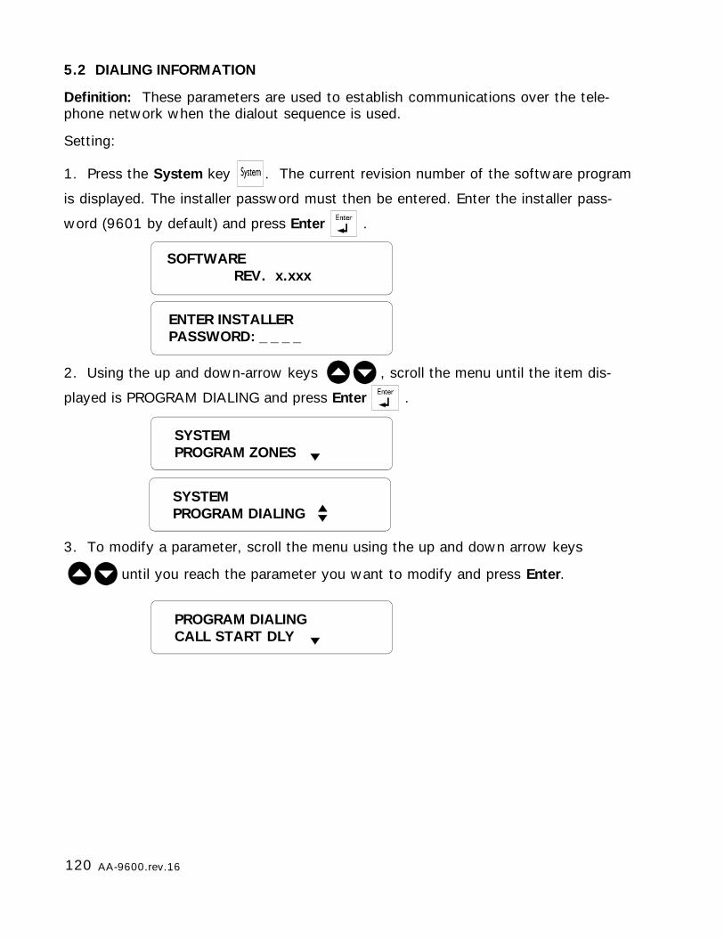
120 AA-9600.rev.16
5.2 DIALING INFORMATION
Definition: These parameters are used to establish communications over the tele-phone network when the dialout sequence is used.
Setting:
1. Press the System key . The current revision number of the software program
is displayed. The installer password must then be entered. Enter the installer pass-
word (9601 by default) and press Enter .
2. Using the up and down-arrow keys , scroll the menu until the item dis-
played is PROGRAM DIALING and press Enter .
3. To modify a parameter, scroll the menu using the up and down arrow keys
until you reach the parameter you want to modify and press Enter.
SOFTWAREREV. x.xxx
SYSTEMPROGRAM ZONES
ENTER INSTALLERPASSWORD: _ _ _ _
SYSTEMPROGRAM DIALING
PROGRAM DIALINGCALL START DLY
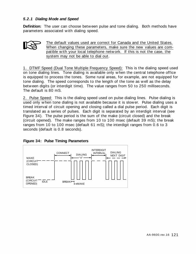
121AA-9600.rev.16
5.2.1 Dialing Mode and Speed
Definition: The user can choose between pulse and tone dialing. Both methods haveparameters associated with dialing speed.
The default values used are correct for Canada and the United States.When changing these parameters, make sure the new values are com-patible with your local telephone network. If this is not the case, thesystem may not be able to dial out.
1. DTMF Speed (Dual Tone Multiple Frequency Speed): This is the dialing speed usedon tone dialing lines. Tone dialing is available only when the central telephone officeis equipped to process the tones. Some rural areas, for example, are not equipped fortone dialing. The speed corresponds to the length of the tone as well as the delaybetween digits (or interdigit time). The value ranges from 50 to 250 milliseconds.The default is 80 mS.
2. Pulse Speed: This is the dialing speed used on pulse dialing lines. Pulse dialing isused only when tone dialing is not available because it is slower. Pulse dialing uses atimed interval of circuit opening and closing called a dial pulse period. Each digit istranslated as a series of pulses. Each digit is separated by an interdigit interval (seeFigure 34). The pulse period is the sum of the make (circuit closed) and the break(circuit opened). The make ranges from 10 to 100 msec (default 39 mS); the breakranges from 10 to 100 msec (default 61 mS); the interdigit ranges from 0.6 to 3seconds (default is 0.8 seconds).
MAKE(CIRCUITCLOSED)
BREAK(CIRCUITOPENED)
CONNECT
IDLE
INTERDIGIT INTERVALDIALING
“4”
DIALINGNEXT DIGIT
BREAKMAKE
Figure 34: Pulse Timing Parameters

122 AA-9600.rev.16
5.2.1.1 Dialing Mode
4. Follow the procedure above for modifying the dialing parameters (Section 5.2).
When you reach the scrolling menu, use the arrow keys to select DIALING
MODE then Enter .
6. Press Enter to modify the value or Cancel to quit.
DIALING MODETONE
5. Type 1 to modify dialing mode. The current dialing mode is displayed.
TONE . . . . . . . . . (1)PULSE . . . . . . . . (2)
7. Type 1 for tone dialing, or 2 for pulse dialing. The new setting is displayed and thesystem returns to the PROGRAM DIALING menu.
MODE . . . . . . . . (1)SPEED . . . . . . . . (2)
TO MODIFY. . . . . (↵)TO QUIT. . . . . . . (X)
PROGRAM DIALINGDIALING MODE
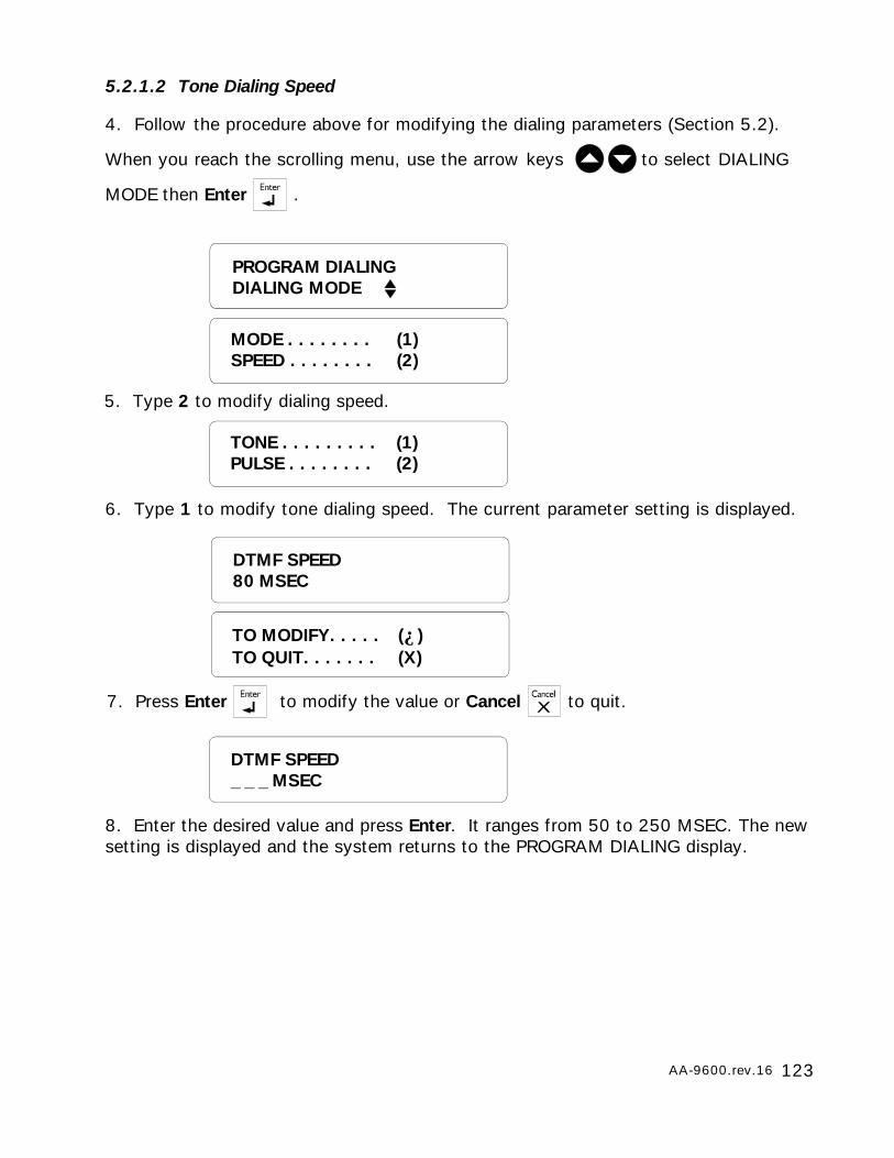
123AA-9600.rev.16
5.2.1.2 Tone Dialing Speed
4. Follow the procedure above for modifying the dialing parameters (Section 5.2).
When you reach the scrolling menu, use the arrow keys to select DIALING
MODE then Enter .
6. Type 1 to modify tone dialing speed. The current parameter setting is displayed.
DTMF SPEED80 MSEC
PROGRAM DIALINGDIALING MODE
5. Type 2 to modify dialing speed.
TONE . . . . . . . . . (1)PULSE . . . . . . . . (2)
MODE . . . . . . . . (1)SPEED . . . . . . . . (2)
8. Enter the desired value and press Enter. It ranges from 50 to 250 MSEC. The newsetting is displayed and the system returns to the PROGRAM DIALING display.
DTMF SPEED_ _ _ MSEC
7. Press Enter to modify the value or Cancel to quit.
TO MODIFY. . . . . (↵)TO QUIT. . . . . . . (X)
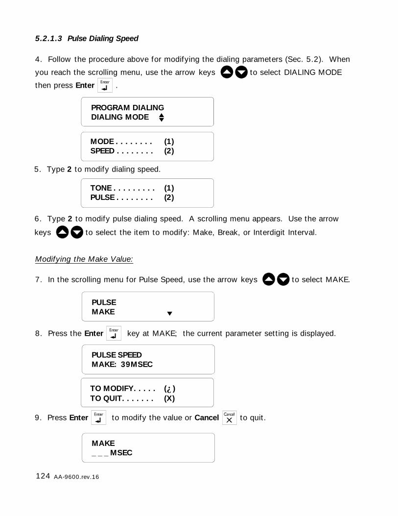
124 AA-9600.rev.16
5.2.1.3 Pulse Dialing Speed
6. Type 2 to modify pulse dialing speed. A scrolling menu appears. Use the arrow
keys to select the item to modify: Make, Break, or Interdigit Interval.
4. Follow the procedure above for modifying the dialing parameters (Sec. 5.2). When
you reach the scrolling menu, use the arrow keys to select DIALING MODE
then press Enter .
PROGRAM DIALINGDIALING MODE
5. Type 2 to modify dialing speed.
TONE . . . . . . . . . (1)PULSE . . . . . . . . (2)
MODE . . . . . . . . (1)SPEED . . . . . . . . (2)
Modifying the Make Value:
PULSEMAKE
7. In the scrolling menu for Pulse Speed, use the arrow keys to select MAKE.
MAKE_ _ _ MSEC
8. Press the Enter key at MAKE; the current parameter setting is displayed.
PULSE SPEEDMAKE: 39MSEC
9. Press Enter to modify the value or Cancel to quit.
TO MODIFY. . . . . (↵)TO QUIT. . . . . . . (X)

125AA-9600.rev.16
10. Enter the desired value and press Enter. Adjustable from 10 to 100 MSEC. Thenew setting is displayed and the system returns to the PROGRAM DIALING menu.
9. Press Enter to modify the value or Cancel to quit.
Modifying the Break Value:
7. In the scrolling menu for Pulse Speed, use the arrow keys to select Break
8. Press the Enter key at BREAK; the current parameter setting is displayed.
PULSEBREAK
PULSE SPEEDBREAK: 61 MSEC
TO MODIFY. . . . . (↵)TO QUIT. . . . . . . (X)
BREAK_ _ _ MSEC
10. Enter the desired value and press Enter. Adjustable from 10 to 100 MSEC. Thenew setting is displayed and the system returns to Pulse Speed scrolling menu.
Modifying the Interdigit Interval:
7. In the scrolling menu for Pulse Speed, use the arrow keys to selectINTERDIGIT
PULSEINTERDIGIT
8. Press the Enter key at INTERDIGIT; the current parameter setting is displayed.
PULSE SPEEDINTERDIGIT: 0.8 SEC
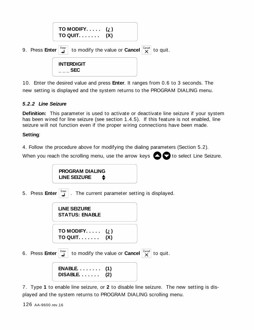
126 AA-9600.rev.16
5.2.2 Line Seizure
Definition: This parameter is used to activate or deactivate line seizure if your systemhas been wired for line seizure (see section 1.4.5). If this feature is not enabled, lineseizure will not function even if the proper wiring connections have been made.
Setting:
10. Enter the desired value and press Enter. It ranges from 0.6 to 3 seconds. Thenew setting is displayed and the system returns to the PROGRAM DIALING menu.
INTERDIGIT_ _ _ SEC
9. Press Enter to modify the value or Cancel to quit.
TO MODIFY. . . . . (↵)TO QUIT. . . . . . . (X)
5. Press Enter . The current parameter setting is displayed.
4. Follow the procedure above for modifying the dialing parameters (Section 5.2).
When you reach the scrolling menu, use the arrow keys to select Line Seizure.
PROGRAM DIALINGLINE SEIZURE
7. Type 1 to enable line seizure, or 2 to disable line seizure. The new setting is dis-played and the system returns to PROGRAM DIALING scrolling menu.
LINE SEIZURESTATUS: ENABLE
6. Press Enter to modify the value or Cancel to quit.
ENABLE. . . . . . . . (1)DISABLE. . . . . . . (2)
TO MODIFY. . . . . (↵)TO QUIT. . . . . . . (X)
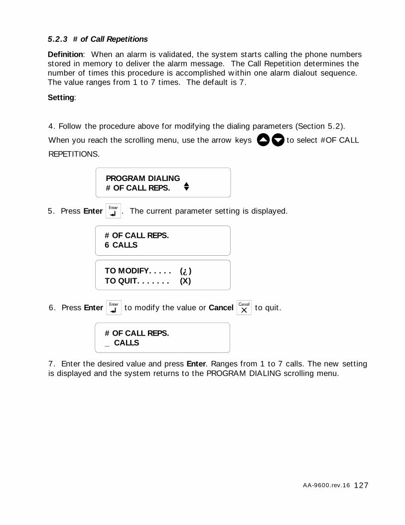
127AA-9600.rev.16
5.2.3 # of Call Repetitions
Definition: When an alarm is validated, the system starts calling the phone numbersstored in memory to deliver the alarm message. The Call Repetition determines thenumber of times this procedure is accomplished within one alarm dialout sequence.The value ranges from 1 to 7 times. The default is 7.
Setting:
7. Enter the desired value and press Enter. Ranges from 1 to 7 calls. The new settingis displayed and the system returns to the PROGRAM DIALING scrolling menu.
# OF CALL REPS._ CALLS
5. Press Enter . The current parameter setting is displayed.
4. Follow the procedure above for modifying the dialing parameters (Section 5.2).
When you reach the scrolling menu, use the arrow keys to select #OF CALL
REPETITIONS.
6. Press Enter to modify the value or Cancel to quit.
PROGRAM DIALING# OF CALL REPS.
# OF CALL REPS.6 CALLS
TO MODIFY. . . . . (↵)TO QUIT. . . . . . . (X)
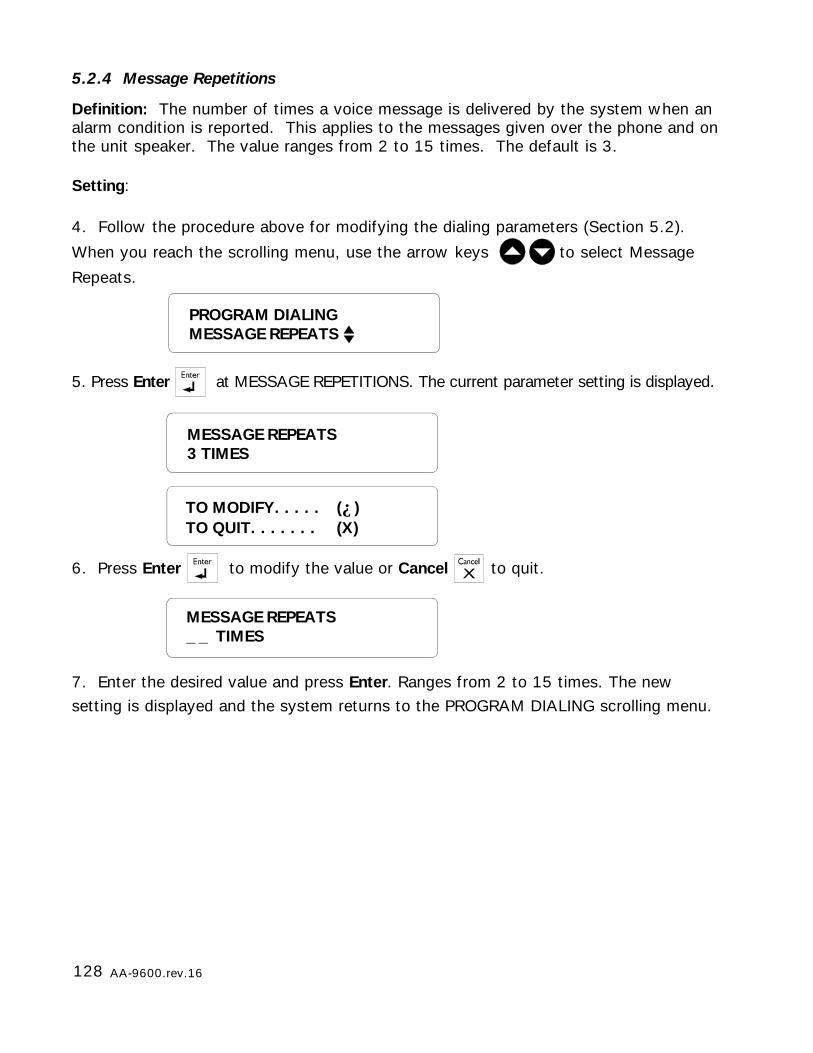
128 AA-9600.rev.16
5.2.4 Message Repetitions
Definition: The number of times a voice message is delivered by the system when analarm condition is reported. This applies to the messages given over the phone and onthe unit speaker. The value ranges from 2 to 15 times. The default is 3.
Setting:
7. Enter the desired value and press Enter. Ranges from 2 to 15 times. The newsetting is displayed and the system returns to the PROGRAM DIALING scrolling menu.
MESSAGE REPEATS_ _ TIMES
5. Press Enter at MESSAGE REPETITIONS. The current parameter setting is displayed.
6. Press Enter to modify the value or Cancel to quit.
MESSAGE REPEATS3 TIMES
TO MODIFY. . . . . (↵)TO QUIT. . . . . . . (X)
PROGRAM DIALINGMESSAGE REPEATS
4. Follow the procedure above for modifying the dialing parameters (Section 5.2).
When you reach the scrolling menu, use the arrow keys to select Message
Repeats.
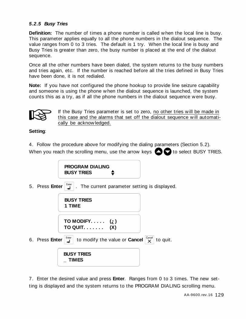
129AA-9600.rev.16
5.2.5 Busy Tries
Definition: The number of times a phone number is called when the local line is busy.This parameter applies equally to all the phone numbers in the dialout sequence. Thevalue ranges from 0 to 3 tries. The default is 1 try. When the local line is busy andBusy Tries is greater than zero, the busy number is placed at the end of the dialoutsequence.
Once all the other numbers have been dialed, the system returns to the busy numbersand tries again, etc. If the number is reached before all the tries defined in Busy Trieshave been done, it is not redialed.
Note: If you have not configured the phone hookup to provide line seizure capabilityand someone is using the phone when the dialout sequence is launched, the systemcounts this as a try, as if all the phone numbers in the dialout sequence were busy.
If the Busy Tries parameter is set to zero, no other tries will be made inthis case and the alarms that set off the dialout sequence will automati-cally be acknowledged.
Setting:
7. Enter the desired value and press Enter. Ranges from 0 to 3 times. The new set-ting is displayed and the system returns to the PROGRAM DIALING scrolling menu.
BUSY TRIES_ TIMES
5. Press Enter . The current parameter setting is displayed.
4. Follow the procedure above for modifying the dialing parameters (Section 5.2).When you reach the scrolling menu, use the arrow keys to select BUSY TRIES.
6. Press Enter to modify the value or Cancel to quit.
BUSY TRIES1 TIME
TO MODIFY. . . . . (↵)TO QUIT. . . . . . . (X)
PROGRAM DIALINGBUSY TRIES
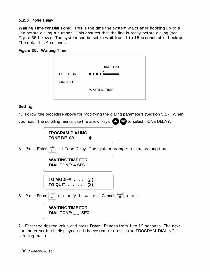
130 AA-9600.rev.16
ON-HOOK
OFF-HOOK
DIAL TONE
WAITING TIME
5.2.6 Tone Delay
Waiting Time for Dial Tone: This is the time the system waits after hooking up to aline before dialing a number. This ensures that the line is ready before dialing (seeFigure 35 below). The system can be set to wait from 1 to 15 seconds after hookup.The default is 4 seconds.
Figure 35: Waiting Time
Setting:
5. Press Enter at Tone Delay. The system prompts for the waiting time.
PROGRAM DIALINGTONE DELAY
4. Follow the procedure above for modifying the dialing parameters (Section 5.2). When
you reach the scrolling menu, use the arrow keys to select TONE DELAY.
WAITING TIME FORDIAL TONE: 4 SEC
TO MODIFY. . . . . (↵)TO QUIT. . . . . . . (X)
WAITING TIME FORDIAL TONE: _ _ SEC
6. Press Enter to modify the value or Cancel to quit.
7. Enter the desired value and press Enter. Ranges from 1 to 15 seconds. The newparameter setting is displayed and the system returns to the PROGRAM DIALINGscrolling menu.
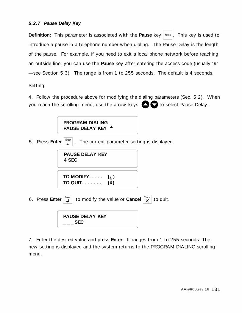
131AA-9600.rev.16
5.2.7 Pause Delay Key
Definition: This parameter is associated with the Pause key . This key is used to
introduce a pause in a telephone number when dialing. The Pause Delay is the length
of the pause. For example, if you need to exit a local phone network before reaching
an outside line, you can use the Pause key after entering the access code (usually ‘9’
—see Section 5.3). The range is from 1 to 255 seconds. The default is 4 seconds.
Setting:
7. Enter the desired value and press Enter. It ranges from 1 to 255 seconds. Thenew setting is displayed and the system returns to the PROGRAM DIALING scrollingmenu.
PAUSE DELAY KEY_ _ _ SEC
5. Press Enter . The current parameter setting is displayed.
PAUSE DELAY KEY4 SEC
6. Press Enter to modify the value or Cancel to quit.
TO MODIFY. . . . . (↵)TO QUIT. . . . . . . (X)
4. Follow the procedure above for modifying the dialing parameters (Sec. 5.2). When
you reach the scrolling menu, use the arrow keys to select Pause Delay.
PROGRAM DIALINGPAUSE DELAY KEY
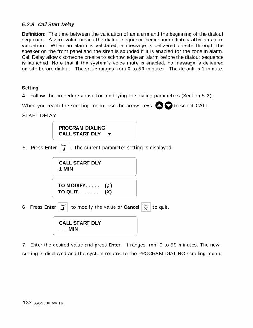
132 AA-9600.rev.16
5.2.8 Call Start Delay
Definition: The time between the validation of an alarm and the beginning of the dialoutsequence. A zero value means the dialout sequence begins immediately after an alarmvalidation. When an alarm is validated, a message is delivered on-site through thespeaker on the front panel and the siren is sounded if it is enabled for the zone in alarm.Call Delay allows someone on-site to acknowledge an alarm before the dialout sequenceis launched. Note that if the system’s voice mute is enabled, no message is deliveredon-site before dialout. The value ranges from 0 to 59 minutes. The default is 1 minute.
Setting:
4. Follow the procedure above for modifying the dialing parameters (Section 5.2).
When you reach the scrolling menu, use the arrow keys to select CALL
START DELAY.
5. Press Enter . The current parameter setting is displayed.
TO MODIFY. . . . . (↵)TO QUIT. . . . . . . (X)
CALL START DLY1 MIN
6. Press Enter to modify the value or Cancel to quit.
CALL START DLY_ _ MIN
7. Enter the desired value and press Enter. It ranges from 0 to 59 minutes. The new
setting is displayed and the system returns to the PROGRAM DIALING scrolling menu.
PROGRAM DIALINGCALL START DLY
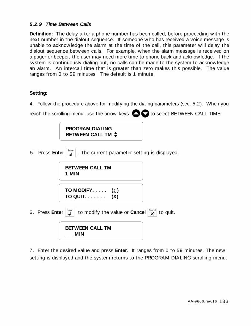
133AA-9600.rev.16
5.2.9 Time Between Calls
Definition: The delay after a phone number has been called, before proceeding with thenext number in the dialout sequence. If someone who has received a voice message isunable to acknowledge the alarm at the time of the call, this parameter will delay thedialout sequence between calls. For example, when the alarm message is received ona pager or beeper, the user may need more time to phone back and acknowledge. If thesystem is continuously dialing out, no calls can be made to the system to acknowledgean alarm. An intercall time that is greater than zero makes this possible. The valueranges from 0 to 59 minutes. The default is 1 minute.
Setting:
4. Follow the procedure above for modifying the dialing parameters (sec. 5.2). When you
reach the scrolling menu, use the arrow keys to select BETWEEN CALL TIME.
5. Press Enter . The current parameter setting is displayed.
BETWEEN CALL TM1 MIN
TO MODIFY. . . . . (↵)TO QUIT. . . . . . . (X)
6. Press Enter to modify the value or Cancel to quit.
BETWEEN CALL TM_ _ MIN
7. Enter the desired value and press Enter. It ranges from 0 to 59 minutes. The newsetting is displayed and the system returns to the PROGRAM DIALING scrolling menu.
PROGRAM DIALINGBETWEEN CALL TM
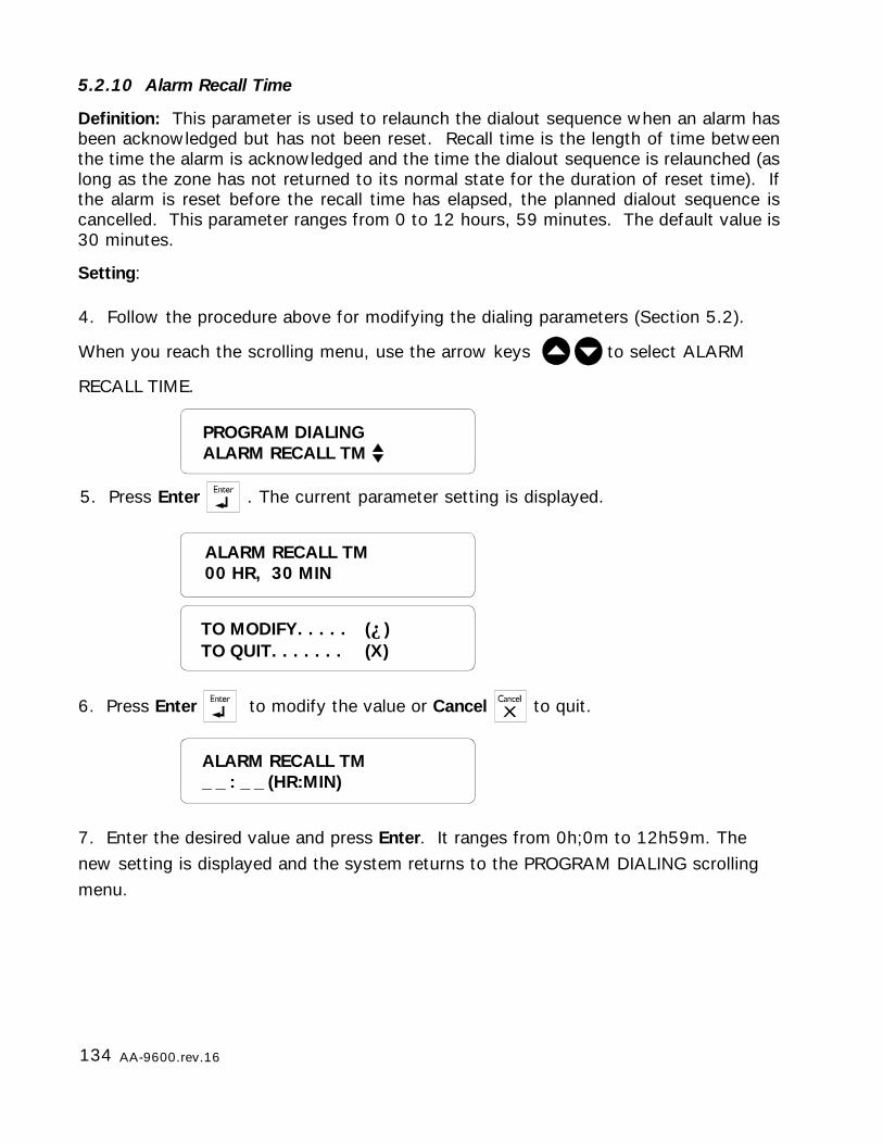
134 AA-9600.rev.16
5.2.10 Alarm Recall Time
Definition: This parameter is used to relaunch the dialout sequence when an alarm hasbeen acknowledged but has not been reset. Recall time is the length of time betweenthe time the alarm is acknowledged and the time the dialout sequence is relaunched (aslong as the zone has not returned to its normal state for the duration of reset time). Ifthe alarm is reset before the recall time has elapsed, the planned dialout sequence iscancelled. This parameter ranges from 0 to 12 hours, 59 minutes. The default value is30 minutes.
Setting:
4. Follow the procedure above for modifying the dialing parameters (Section 5.2).
When you reach the scrolling menu, use the arrow keys to select ALARM
RECALL TIME.
5. Press Enter . The current parameter setting is displayed.
TO MODIFY. . . . . (↵)TO QUIT. . . . . . . (X)
6. Press Enter to modify the value or Cancel to quit.
7. Enter the desired value and press Enter. It ranges from 0h;0m to 12h59m. Thenew setting is displayed and the system returns to the PROGRAM DIALING scrollingmenu.
ALARM RECALL TM_ _ : _ _ (HR:MIN)
ALARM RECALL TM00 HR, 30 MIN
PROGRAM DIALINGALARM RECALL TM
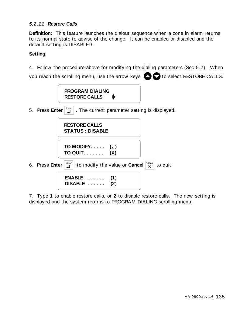
135AA-9600.rev.16
5.2.11 Restore Calls
Definition: This feature launches the dialout sequence when a zone in alarm returnsto its normal state to advise of the change. It can be enabled or disabled and thedefault setting is DISABLED.
Setting:
4. Follow the procedure above for modifying the dialing parameters (Sec 5.2). When
you reach the scrolling menu, use the arrow keys to select RESTORE CALLS.
PROGRAM DIALINGRESTORE CALLS
RESTORE CALLSSTATUS : DISABLE
TO MODIFY. . . . . (↵)TO QUIT. . . . . . . (X)
5. Press Enter . The current parameter setting is displayed.
6. Press Enter to modify the value or Cancel to quit.
ENABLE . . . . . . . (1)DISABLE . . . . . . (2)
7. Type 1 to enable restore calls, or 2 to disable restore calls. The new setting isdisplayed and the system returns to PROGRAM DIALING scrolling menu.
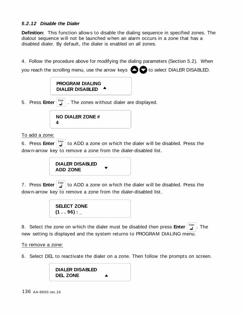
136 AA-9600.rev.16
5.2.12 Disable the Dialer
Definition: This function allows to disable the dialing sequence in specified zones. Thedialout sequence will not be launched when an alarm occurs in a zone that has adisabled dialer. By default, the dialer is enabled on all zones.
4. Follow the procedure above for modifying the dialing parameters (Section 5.2). When
you reach the scrolling menu, use the arrow keys to select DIALER DISABLED.
5. Press Enter . The zones without dialer are displayed.
NO DIALER ZONE #4
To add a zone:
6. Press Enter to ADD a zone on which the dialer will be disabled. Press thedown-arrow key to remove a zone from the dialer-disabled list.
7. Press Enter to ADD a zone on which the dialer will be disabled. Press thedown-arrow key to remove a zone from the dialer-disabled list.
SELECT ZONE(1 . . 96) : _
8. Select the zone on which the dialer must be disabled then press Enter . Thenew setting is displayed and the system returns to PROGRAM DIALING menu.
PROGRAM DIALINGDIALER DISABLED
DIALER DISABLEDADD ZONE
To remove a zone:
6. Select DEL to reactivate the dialer on a zone. Then follow the prompts on screen.
DIALER DISABLEDDEL ZONE
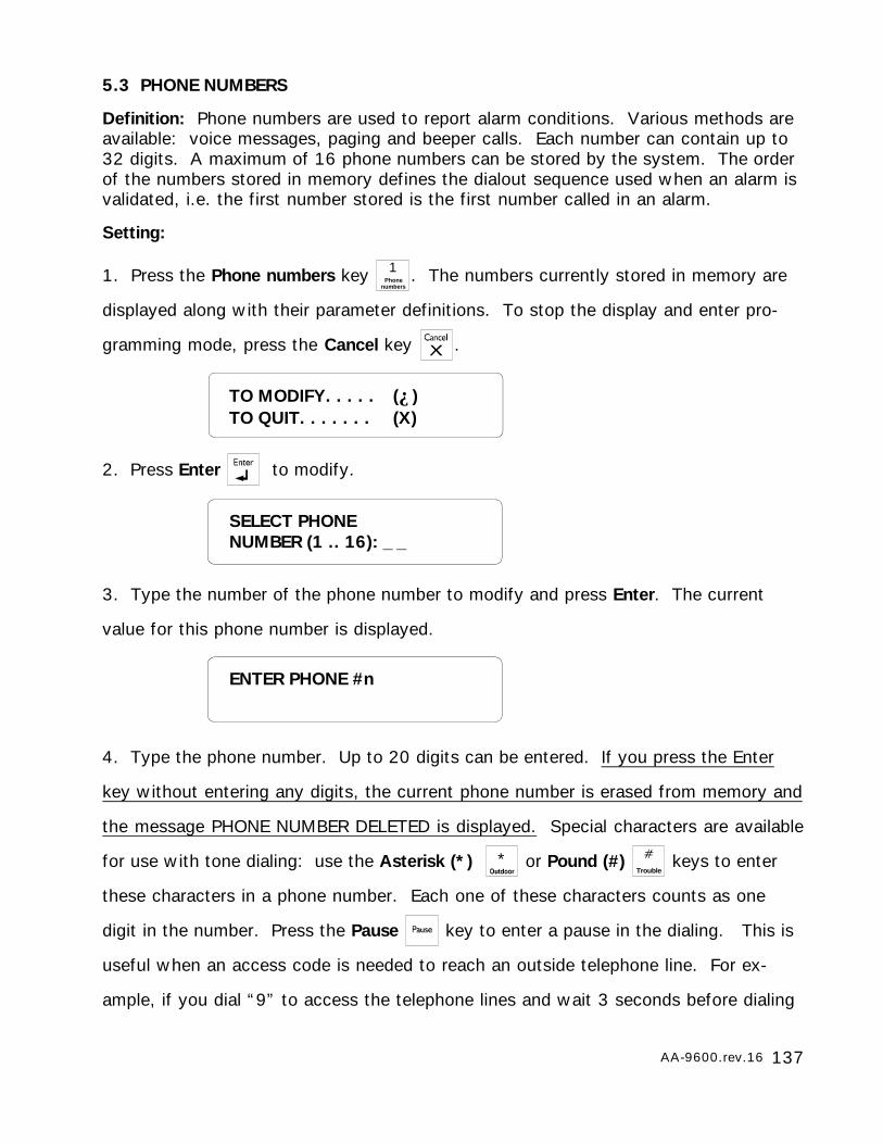
137AA-9600.rev.16
4. Type the phone number. Up to 20 digits can be entered. If you press the Enter
key without entering any digits, the current phone number is erased from memory and
the message PHONE NUMBER DELETED is displayed. Special characters are available
for use with tone dialing: use the Asterisk (*) * or Pound (#) Trouble
keys to enter
these characters in a phone number. Each one of these characters counts as one
digit in the number. Press the Pause key to enter a pause in the dialing. This is
useful when an access code is needed to reach an outside telephone line. For ex-
ample, if you dial “9” to access the telephone lines and wait 3 seconds before dialing
SELECT PHONENUMBER (1 .. 16): _ _
ENTER PHONE #n
5.3 PHONE NUMBERS
Definition: Phone numbers are used to report alarm conditions. Various methods areavailable: voice messages, paging and beeper calls. Each number can contain up to32 digits. A maximum of 16 phone numbers can be stored by the system. The orderof the numbers stored in memory defines the dialout sequence used when an alarm isvalidated, i.e. the first number stored is the first number called in an alarm.
Setting:
1. Press the Phone numbers key 1Phone
numbers. The numbers currently stored in memory are
displayed along with their parameter definitions. To stop the display and enter pro-
gramming mode, press the Cancel key .
2. Press Enter to modify.
3. Type the number of the phone number to modify and press Enter. The current
value for this phone number is displayed.
TO MODIFY. . . . . (↵)TO QUIT. . . . . . . (X)
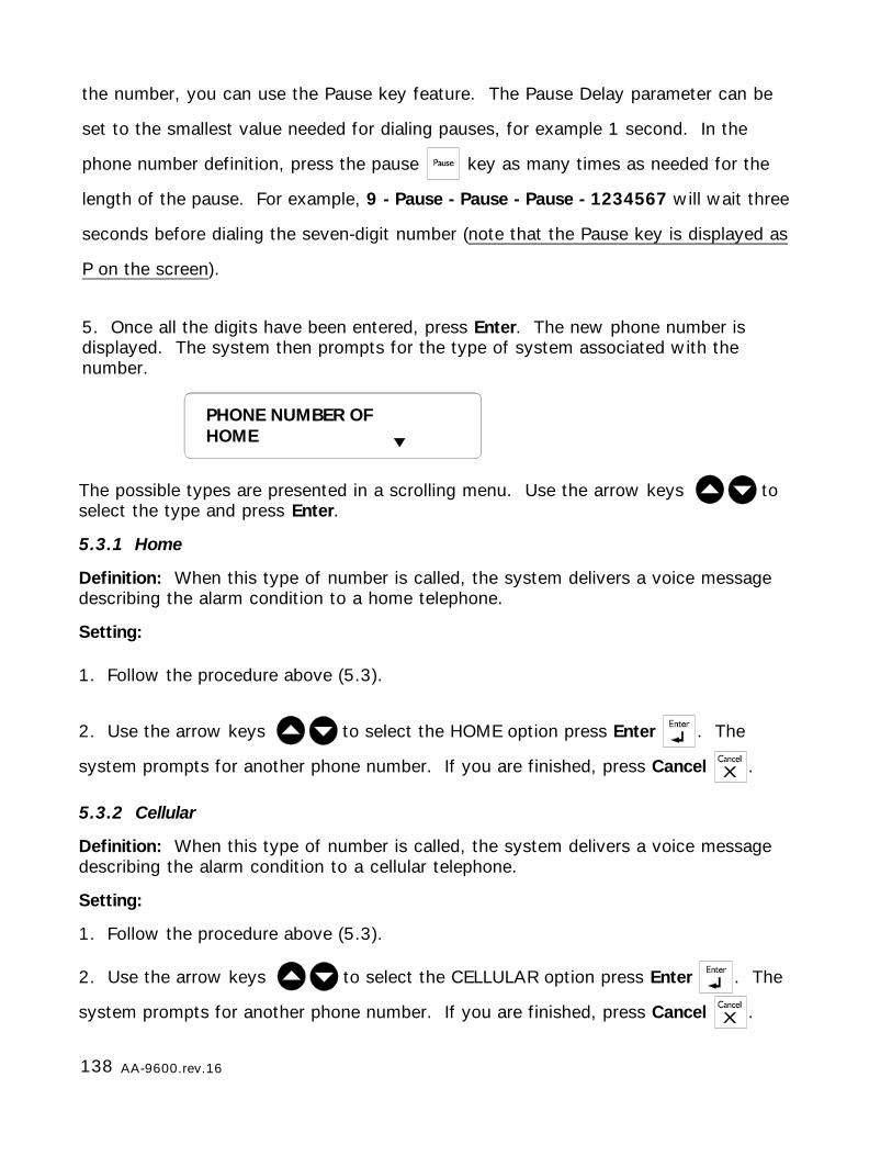
138 AA-9600.rev.16
The possible types are presented in a scrolling menu. Use the arrow keys toselect the type and press Enter.
5.3.1 Home
Definition: When this type of number is called, the system delivers a voice messagedescribing the alarm condition to a home telephone.
Setting:
1. Follow the procedure above (5.3).
2. Use the arrow keys to select the HOME option press Enter . The
system prompts for another phone number. If you are finished, press Cancel .
5.3.2 Cellular
Definition: When this type of number is called, the system delivers a voice messagedescribing the alarm condition to a cellular telephone.
Setting:
1. Follow the procedure above (5.3).
2. Use the arrow keys to select the CELLULAR option press Enter . The
system prompts for another phone number. If you are finished, press Cancel .
the number, you can use the Pause key feature. The Pause Delay parameter can be
set to the smallest value needed for dialing pauses, for example 1 second. In the
phone number definition, press the pause key as many times as needed for the
length of the pause. For example, 9 - Pause - Pause - Pause - 1234567 will wait three
seconds before dialing the seven-digit number (note that the Pause key is displayed as
P on the screen).
5. Once all the digits have been entered, press Enter. The new phone number isdisplayed. The system then prompts for the type of system associated with thenumber.
PHONE NUMBER OFHOME
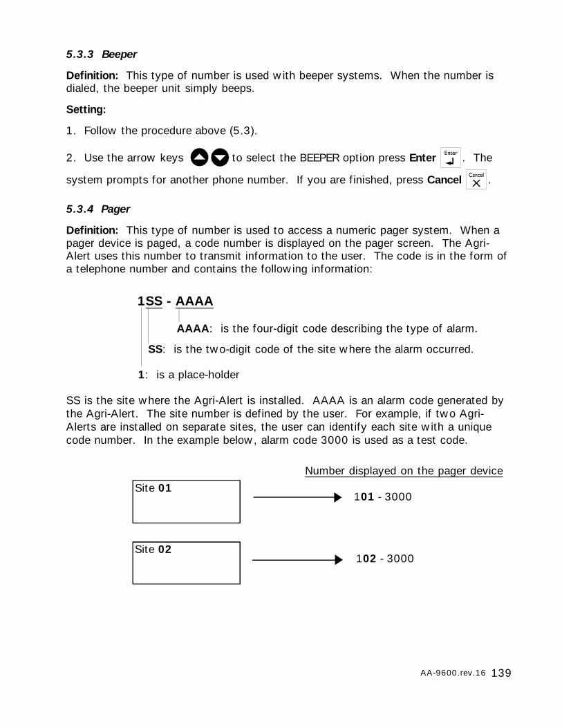
139AA-9600.rev.16
AAAA: is the four-digit code describing the type of alarm.
SS: is the two-digit code of the site where the alarm occurred.
1: is a place-holder
1SS - AAAA
101 - 3000
102 - 3000Site 02
Site 01Number displayed on the pager device
SS is the site where the Agri-Alert is installed. AAAA is an alarm code generated bythe Agri-Alert. The site number is defined by the user. For example, if two Agri-Alerts are installed on separate sites, the user can identify each site with a uniquecode number. In the example below, alarm code 3000 is used as a test code.
5.3.3 Beeper
Definition: This type of number is used with beeper systems. When the number isdialed, the beeper unit simply beeps.
Setting:
1. Follow the procedure above (5.3).
2. Use the arrow keys to select the BEEPER option press Enter . The
system prompts for another phone number. If you are finished, press Cancel .
5.3.4 Pager
Definition: This type of number is used to access a numeric pager system. When apager device is paged, a code number is displayed on the pager screen. The Agri-Alert uses this number to transmit information to the user. The code is in the form ofa telephone number and contains the following information:
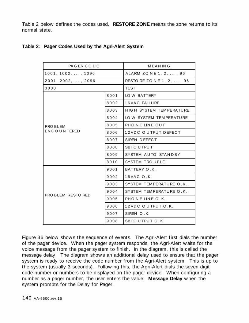
140 AA-9600.rev.16
Figure 36 below shows the sequence of events. The Agri-Alert first dials the numberof the pager device. When the pager system responds, the Agri-Alert waits for thevoice message from the pager system to finish. In the diagram, this is called themessage delay. The diagram shows an additional delay used to ensure that the pagersystem is ready to receive the code number from the Agri-Alert system. This is up tothe system (usually 3 seconds). Following this, the Agri-Alert dials the seven digitcode number or numbers to be displayed on the pager device. When configuring anumber as a pager number, the user enters the value: Message Delay when thesystem prompts for the Delay for Pager.
Table 2: Pager Codes Used by the Agri-Alert System
Table 2 below defines the codes used. RESTORE ZONE means the zone returns to itsnormal state.
PA G E R C O D E M E A N IN G
1 0 0 1 , 1 0 0 2 , . . . , 1 0 9 6 A L A R M Z O N E 1 , 2 , . . . , 9 6
2 0 0 1 , 2 0 0 2 , . . . , 2 0 9 6 R E S TO R E Z O N E 1 , 2 , . . . , 9 6
3 0 0 0 T E S T
P R O B L E ME N C O U N T E R E D
8 0 0 1 LO W B A T T E R Y
8 0 0 2 1 6 V A C FA IL U R E
8 0 0 3 H IG H S Y S T E M T E M P E R A T U R E
8 0 0 4 LO W S Y S T E M T E M P E R A T U R E
8 0 0 5 P H O N E L IN E C U T
8 0 0 6 1 2 V D C O U T P U T D E F E C T
8 0 0 7 S I REN D E F E C T
8 0 0 8 S B I O U T P U T
8 0 0 9 S Y S T E M A U TO STA N D B Y
8 0 1 0 S Y S T E M T R O U B L E
P R O B L E M R E S TO R E D
9 0 0 1 B A T T E R Y O . K .
9 0 0 2 1 6 V A C O . K .
9 0 0 3 S Y S T E M T E M P E R A T U R E O . K .
9 0 0 4 S Y S T E M T E M P E R A T U R E O . K .
9 0 0 5 P H O N E L IN E O . K .
9 0 0 6 1 2 V D C O U T P U T O . K .
9 0 0 7 S I REN O . K .
9 0 0 8 S B I O U T P U T O . K .
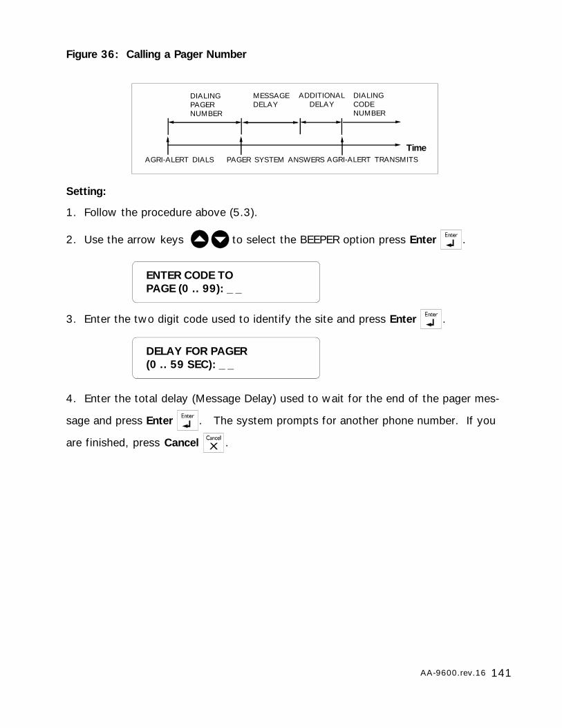
141AA-9600.rev.16
DELAY FOR PAGER(0 .. 59 SEC): _ _
ENTER CODE TOPAGE (0 .. 99): _ _
Figure 36: Calling a Pager Number
Setting:
1. Follow the procedure above (5.3).
2. Use the arrow keys to select the BEEPER option press Enter .
3. Enter the two digit code used to identify the site and press Enter .
4. Enter the total delay (Message Delay) used to wait for the end of the pager mes-
sage and press Enter . The system prompts for another phone number. If you
are finished, press Cancel .
ADDITIONALDELAY
DIALINGPAGERNUMBER
DIALINGCODENUMBER
MESSAGEDELAY
TimePAGER SYSTEM ANSWERS AGRI-ALERT TRANSMITSAGRI-ALERT DIALS
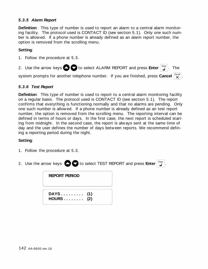
142 AA-9600.rev.16
REPORT PERIOD
DAYS . . . . . . . . . (1)HOURS . . . . . . . . (2)
5.3.5 Alarm Report
Definition: This type of number is used to report an alarm to a central alarm monitor-ing facility. The protocol used is CONTACT ID (see section 5.1). Only one such num-ber is allowed. If a phone number is already defined as an alarm report number, theoption is removed from the scrolling menu.
Setting:
1. Follow the procedure at 5.3.
2. Use the arrow keys to select ALARM REPORT and press Enter . The
system prompts for another telephone number. If you are finished, press Cancel .
5.3.6 Test Report
Definition: This type of number is used to report to a central alarm monitoring facilityon a regular basis. The protocol used is CONTACT ID (see section 5.1). The reportconfirms that everything is functioning normally and that no alarms are pending. Onlyone such number is allowed. If a phone number is already defined as an test reportnumber, the option is removed from the scrolling menu. The reporting interval can bedefined in terms of hours or days. In the first case, the next report is scheduled start-ing from midnight. In the second case, the report is always sent at the same time ofday and the user defines the number of days between reports. We recommend defin-ing a reporting period during the night.
Setting:
1. Follow the procedure at 5.3.
2. Use the arrow keys to select TEST REPORT and press Enter .
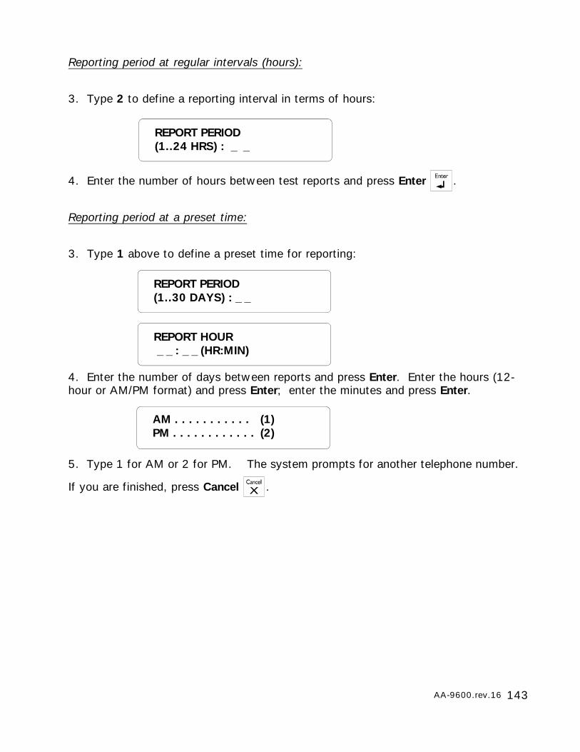
143AA-9600.rev.16
Reporting period at regular intervals (hours):
3. Type 2 to define a reporting interval in terms of hours:
4. Enter the number of hours between test reports and press Enter .
Reporting period at a preset time:
3. Type 1 above to define a preset time for reporting:
4. Enter the number of days between reports and press Enter. Enter the hours (12-hour or AM/PM format) and press Enter; enter the minutes and press Enter.
5. Type 1 for AM or 2 for PM. The system prompts for another telephone number.
If you are finished, press Cancel .
AM . . . . . . . . . . . (1)PM . . . . . . . . . . . . (2)
REPORT PERIOD(1..30 DAYS) : _ _
REPORT PERIOD(1..24 HRS) : _ _
REPORT HOUR _ _ : _ _ (HR:MIN)
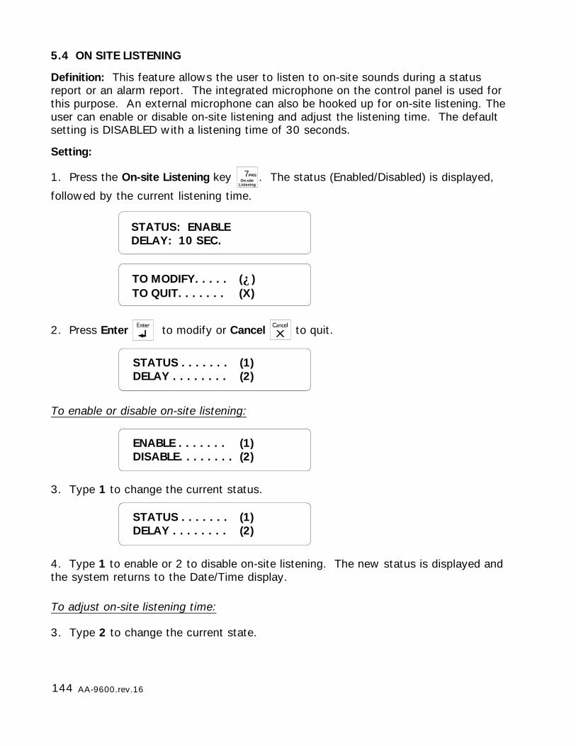
144 AA-9600.rev.16
5.4 ON SITE LISTENING
Definition: This feature allows the user to listen to on-site sounds during a statusreport or an alarm report. The integrated microphone on the control panel is used forthis purpose. An external microphone can also be hooked up for on-site listening. Theuser can enable or disable on-site listening and adjust the listening time. The defaultsetting is DISABLED with a listening time of 30 seconds.
Setting:
1. Press the On-site Listening key 7PRSOn-site
Listening. The status (Enabled/Disabled) is displayed,
followed by the current listening time.
2. Press Enter to modify or Cancel to quit.
To enable or disable on-site listening:
3. Type 1 to change the current status.
4. Type 1 to enable or 2 to disable on-site listening. The new status is displayed andthe system returns to the Date/Time display.
To adjust on-site listening time:
3. Type 2 to change the current state.
STATUS: ENABLEDELAY: 10 SEC.
STATUS . . . . . . . (1)DELAY . . . . . . . . (2)
ENABLE . . . . . . . (1)DISABLE. . . . . . . . (2)
STATUS . . . . . . . (1)DELAY . . . . . . . . (2)
TO MODIFY. . . . . (↵)TO QUIT. . . . . . . (X)

145AA-9600.rev.16
ENTER NEW DELAY_ _ SEC
4. Enter the new delay and press Enter. It ranges from 0 to 59 seconds. The systemdisplays the new delay setting and returns to the Date/Time display.
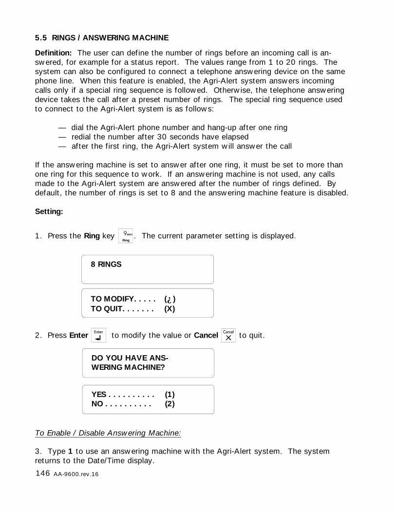
146 AA-9600.rev.16
5.5 RINGS / ANSWERING MACHINE
Definition: The user can define the number of rings before an incoming call is an-swered, for example for a status report. The values range from 1 to 20 rings. Thesystem can also be configured to connect a telephone answering device on the samephone line. When this feature is enabled, the Agri-Alert system answers incomingcalls only if a special ring sequence is followed. Otherwise, the telephone answeringdevice takes the call after a preset number of rings. The special ring sequence usedto connect to the Agri-Alert system is as follows:
— dial the Agri-Alert phone number and hang-up after one ring— redial the number after 30 seconds have elapsed— after the first ring, the Agri-Alert system will answer the call
If the answering machine is set to answer after one ring, it must be set to more thanone ring for this sequence to work. If an answering machine is not used, any callsmade to the Agri-Alert system are answered after the number of rings defined. Bydefault, the number of rings is set to 8 and the answering machine feature is disabled.
Setting:
1. Press the Ring key Ring
. The current parameter setting is displayed.
2. Press Enter to modify the value or Cancel to quit.
8 RINGS
To Enable / Disable Answering Machine:
3. Type 1 to use an answering machine with the Agri-Alert system. The systemreturns to the Date/Time display.
DO YOU HAVE ANS-WERING MACHINE?
YES . . . . . . . . . . (1)NO . . . . . . . . . . (2)
TO MODIFY. . . . . (↵)TO QUIT. . . . . . . (X)
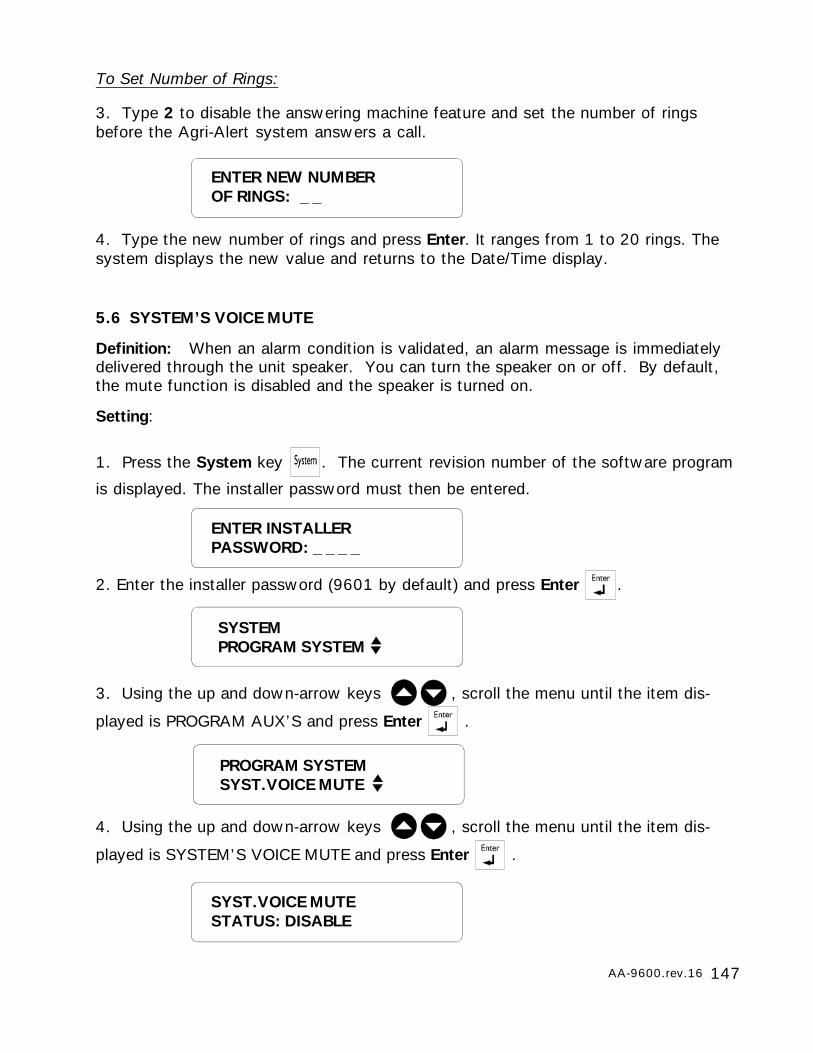
147AA-9600.rev.16
5.6 SYSTEM’S VOICE MUTE
Definition: When an alarm condition is validated, an alarm message is immediatelydelivered through the unit speaker. You can turn the speaker on or off. By default,the mute function is disabled and the speaker is turned on.
Setting:
4. Type the new number of rings and press Enter. It ranges from 1 to 20 rings. Thesystem displays the new value and returns to the Date/Time display.
To Set Number of Rings:
3. Type 2 to disable the answering machine feature and set the number of ringsbefore the Agri-Alert system answers a call.
ENTER NEW NUMBEROF RINGS: _ _
1. Press the System key . The current revision number of the software program
is displayed. The installer password must then be entered.
2. Enter the installer password (9601 by default) and press Enter .
3. Using the up and down-arrow keys , scroll the menu until the item dis-
played is PROGRAM AUX’S and press Enter .
ENTER INSTALLERPASSWORD: _ _ _ _
PROGRAM SYSTEMSYST.VOICE MUTE
SYST.VOICE MUTESTATUS: DISABLE
4. Using the up and down-arrow keys , scroll the menu until the item dis-
played is SYSTEM’S VOICE MUTE and press Enter .
SYSTEMPROGRAM SYSTEM
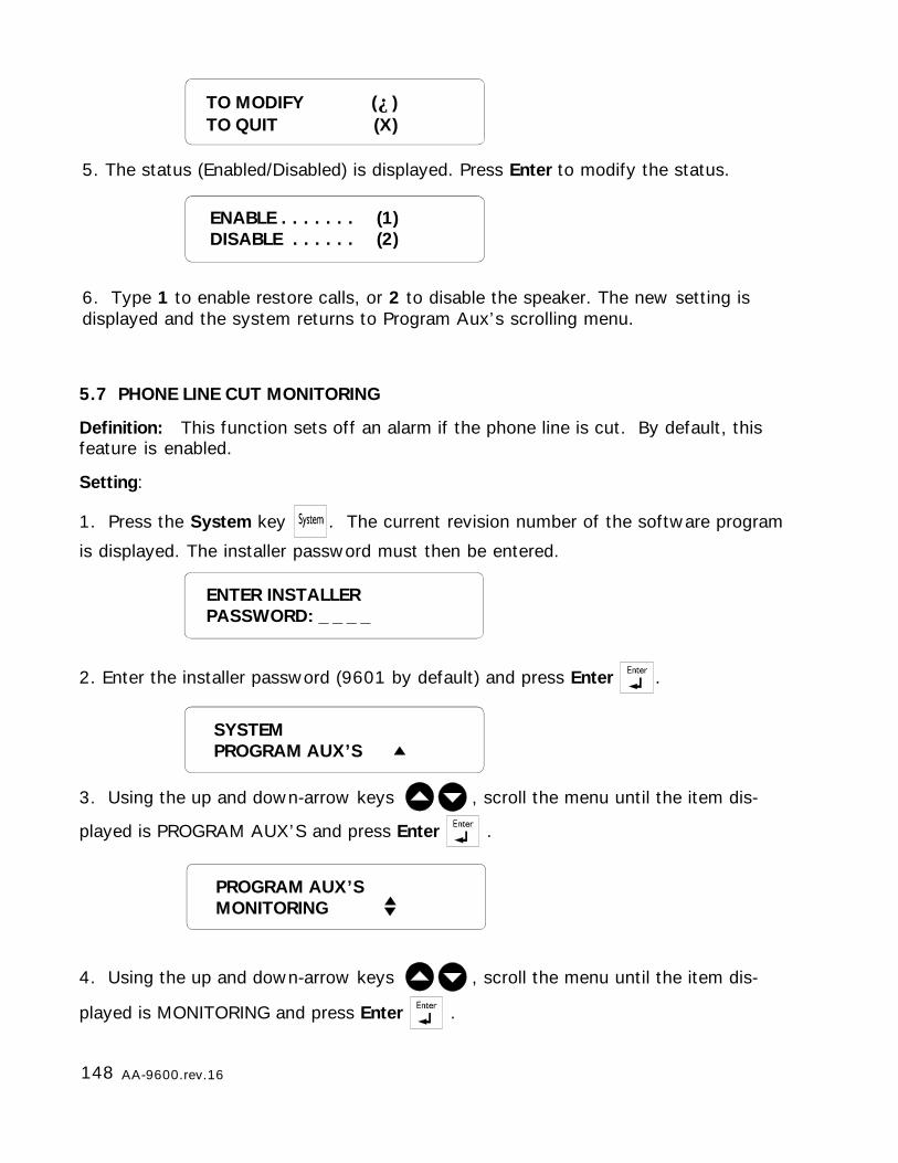
148 AA-9600.rev.16
TO MODIFY (↵)TO QUIT (X)
ENABLE . . . . . . . (1)DISABLE . . . . . . (2)
5. The status (Enabled/Disabled) is displayed. Press Enter to modify the status.
6. Type 1 to enable restore calls, or 2 to disable the speaker. The new setting isdisplayed and the system returns to Program Aux’s scrolling menu.
5.7 PHONE LINE CUT MONITORING
Definition: This function sets off an alarm if the phone line is cut. By default, thisfeature is enabled.
Setting:
1. Press the System key . The current revision number of the software program
is displayed. The installer password must then be entered.
2. Enter the installer password (9601 by default) and press Enter .
3. Using the up and down-arrow keys , scroll the menu until the item dis-
played is PROGRAM AUX’S and press Enter .
4. Using the up and down-arrow keys , scroll the menu until the item dis-
played is MONITORING and press Enter .
ENTER INSTALLERPASSWORD: _ _ _ _
SYSTEMPROGRAM AUX’S
PROGRAM AUX’SMONITORING
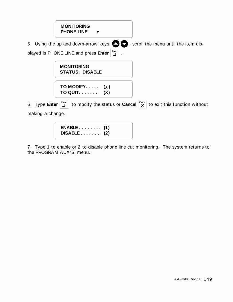
149AA-9600.rev.16
MONITORINGPHONE LINE
MONITORINGSTATUS: DISABLE
ENABLE . . . . . . . . (1)DISABLE . . . . . . . (2)
TO MODIFY. . . . . (↵)TO QUIT. . . . . . . (X)
5. Using the up and down-arrow keys , scroll the menu until the item dis-
played is PHONE LINE and press Enter .
6. Type Enter to modify the status or Cancel to exit this function without
making a change.
7. Type 1 to enable or 2 to disable phone line cut monitoring. The system returns tothe PROGRAM AUX’S. menu.
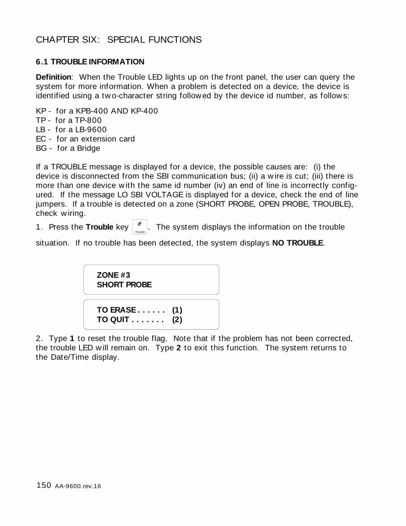
150 AA-9600.rev.16
TO ERASE . . . . . . (1)TO QUIT . . . . . . . (2)
ZONE #3SHORT PROBE
CHAPTER SIX: SPECIAL FUNCTIONS
6.1 TROUBLE INFORMATION
Definition: When the Trouble LED lights up on the front panel, the user can query thesystem for more information. When a problem is detected on a device, the device isidentified using a two-character string followed by the device id number, as follows:
KP - for a KPB-400 AND KP-400TP - for a TP-800LB - for a LB-9600EC - for an extension cardBG - for a Bridge
If a TROUBLE message is displayed for a device, the possible causes are: (i) thedevice is disconnected from the SBI communication bus; (ii) a wire is cut; (iii) there ismore than one device with the same id number (iv) an end of line is incorrectly config-ured. If the message LO SBI VOLTAGE is displayed for a device, check the end of linejumpers. If a trouble is detected on a zone (SHORT PROBE, OPEN PROBE, TROUBLE),check wiring.
1. Press the Trouble key . The system displays the information on the trouble
situation. If no trouble has been detected, the system displays NO TROUBLE.
2. Type 1 to reset the trouble flag. Note that if the problem has not been corrected,the trouble LED will remain on. Type 2 to exit this function. The system returns tothe Date/Time display.
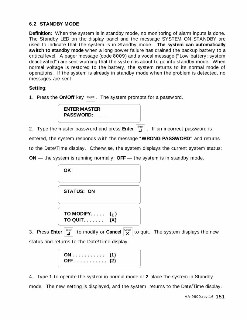
151AA-9600.rev.16
6.2 STANDBY MODE
Definition: When the system is in standby mode, no monitoring of alarm inputs is done.The Standby LED on the display panel and the message SYSTEM ON STANDBY areused to indicate that the system is in Standby mode. The system can automaticallyswitch to standby mode when a long power failure has drained the backup battery to acritical level. A pager message (code 8009) and a vocal message (“Low battery; systemdeactivated”) are sent warning that the system is about to go into standby mode. Whennormal voltage is restored to the battery, the system returns to its normal mode ofoperations. If the system is already in standby mode when the problem is detected, nomessages are sent.
Setting:
1. Press the On/Off key . The system prompts for a password.
2. Type the master password and press Enter . If an incorrect password is
entered, the system responds with the message “WRONG PASSWORD” and returns
to the Date/Time display. Otherwise, the system displays the current system status:
ON — the system is running normally; OFF — the system is in standby mode.
3. Press Enter to modify or Cancel to quit. The system displays the new
status and returns to the Date/Time display.
4. Type 1 to operate the system in normal mode or 2 place the system in Standby
mode. The new setting is displayed, and the system returns to the Date/Time display.
OK
STATUS: ON
TO MODIFY. . . . . (↵)TO QUIT. . . . . . . (X)
ON . . . . . . . . . . . (1)OFF . . . . . . . . . . . (2)
ENTER MASTERPASSWORD: _ _ _ _
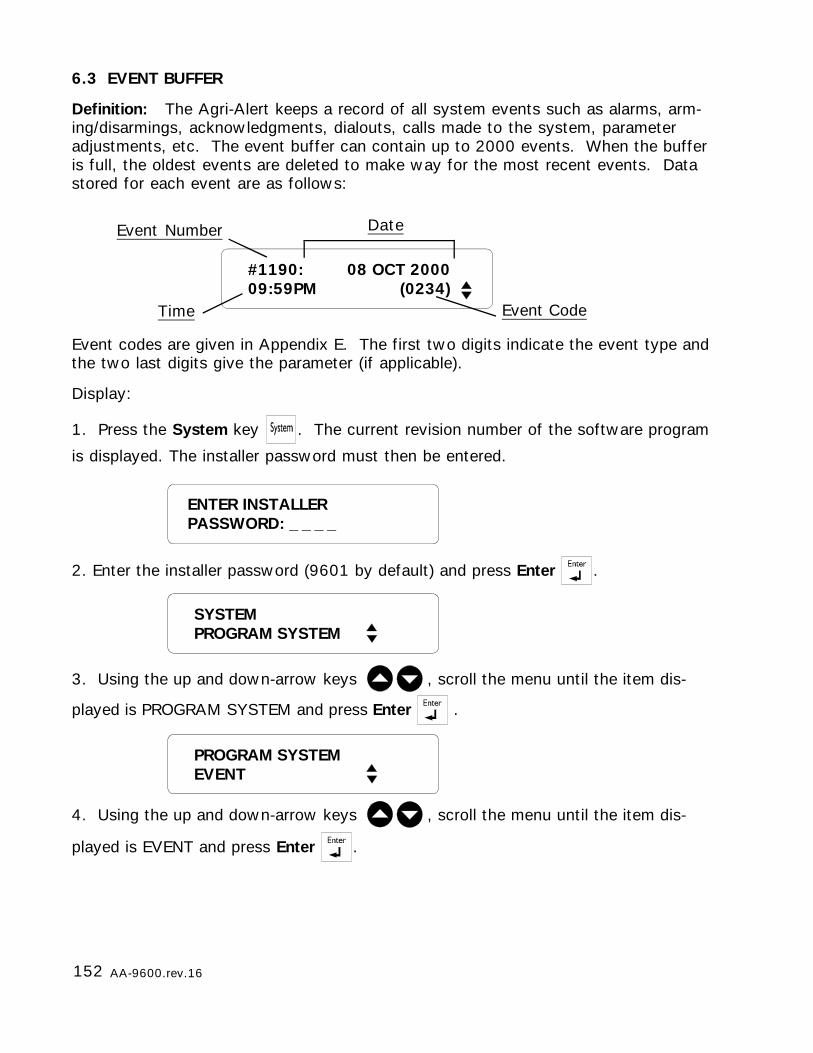
152 AA-9600.rev.16
6.3 EVENT BUFFER
Definition: The Agri-Alert keeps a record of all system events such as alarms, arm-ing/disarmings, acknowledgments, dialouts, calls made to the system, parameteradjustments, etc. The event buffer can contain up to 2000 events. When the bufferis full, the oldest events are deleted to make way for the most recent events. Datastored for each event are as follows:
Event codes are given in Appendix E. The first two digits indicate the event type andthe two last digits give the parameter (if applicable).
Display:
1. Press the System key . The current revision number of the software program
is displayed. The installer password must then be entered.
2. Enter the installer password (9601 by default) and press Enter .
3. Using the up and down-arrow keys , scroll the menu until the item dis-
played is PROGRAM SYSTEM and press Enter .
4. Using the up and down-arrow keys , scroll the menu until the item dis-
played is EVENT and press Enter .
#1190: 08 OCT 200009:59PM (0234)
Event Number
Time
Date
Event Code
ENTER INSTALLERPASSWORD: _ _ _ _
SYSTEMPROGRAM SYSTEM
PROGRAM SYSTEMEVENT
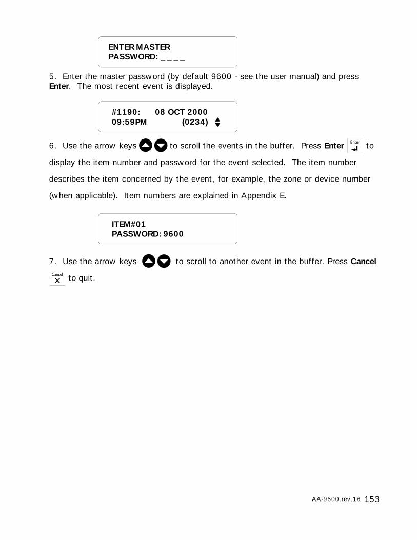
153AA-9600.rev.16
5. Enter the master password (by default 9600 - see the user manual) and pressEnter. The most recent event is displayed.
6. Use the arrow keys to scroll the events in the buffer. Press Enter to
display the item number and password for the event selected. The item number
describes the item concerned by the event, for example, the zone or device number
(when applicable). Item numbers are explained in Appendix E.
7. Use the arrow keys to scroll to another event in the buffer. Press Cancel
to quit.
ITEM#01PASSWORD: 9600
#1190: 08 OCT 200009:59PM (0234)
ENTER MASTERPASSWORD: _ _ _ _
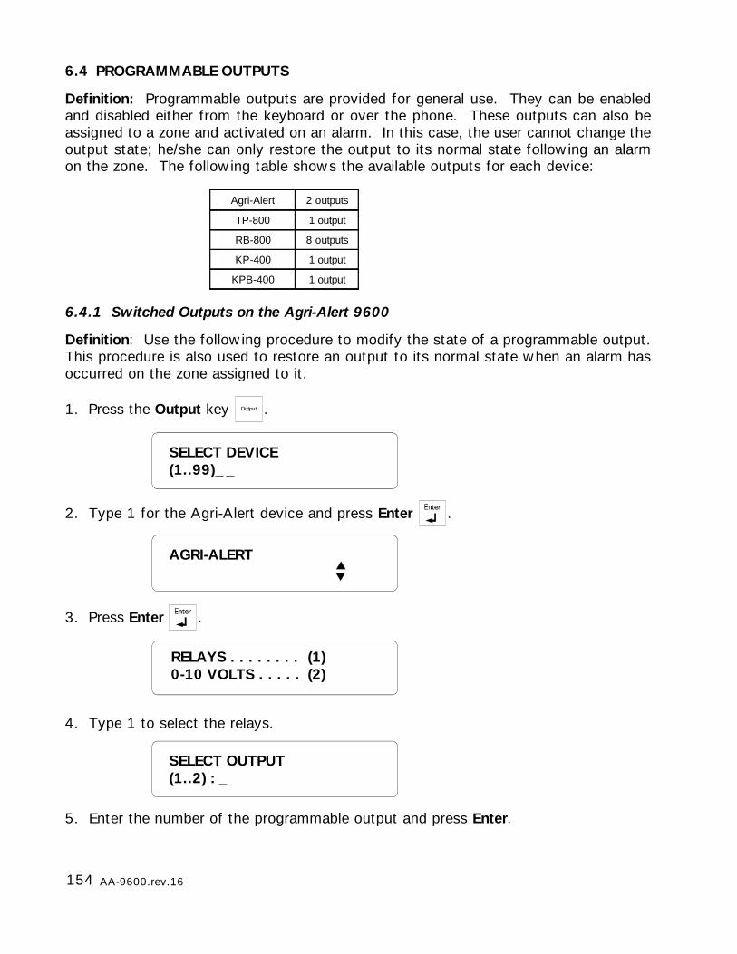
154 AA-9600.rev.16
6.4 PROGRAMMABLE OUTPUTS
Definition: Programmable outputs are provided for general use. They can be enabledand disabled either from the keyboard or over the phone. These outputs can also beassigned to a zone and activated on an alarm. In this case, the user cannot change theoutput state; he/she can only restore the output to its normal state following an alarmon the zone. The following table shows the available outputs for each device:
6.4.1 Switched Outputs on the Agri-Alert 9600
Definition: Use the following procedure to modify the state of a programmable output.This procedure is also used to restore an output to its normal state when an alarm hasoccurred on the zone assigned to it.
1. Press the Output key .
2. Type 1 for the Agri-Alert device and press Enter .
3. Press Enter .
4. Type 1 to select the relays.
5. Enter the number of the programmable output and press Enter.
SELECT OUTPUT(1..2) : _
SELECT DEVICE(1..99)_ _
Agri-Alert 2 outputs
TP-800 1 output
RB-800 8 outputs
KP-400 1 output
KPB-400 1 output
AGRI-ALERT
RELAYS . . . . . . . . (1)0-10 VOLTS . . . . . (2)
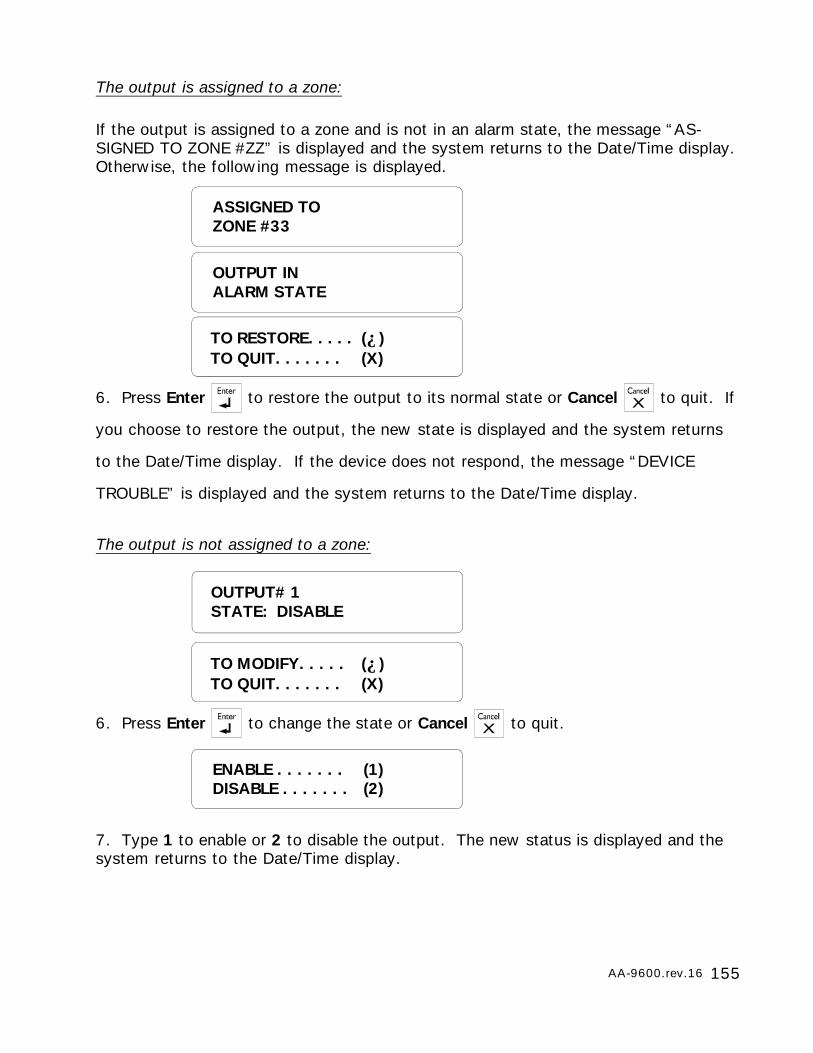
155AA-9600.rev.16
The output is assigned to a zone:
If the output is assigned to a zone and is not in an alarm state, the message “AS-SIGNED TO ZONE #ZZ” is displayed and the system returns to the Date/Time display.Otherwise, the following message is displayed.
6. Press Enter to restore the output to its normal state or Cancel to quit. If
you choose to restore the output, the new state is displayed and the system returns
to the Date/Time display. If the device does not respond, the message “DEVICE
TROUBLE” is displayed and the system returns to the Date/Time display.
The output is not assigned to a zone:
6. Press Enter to change the state or Cancel to quit.
7. Type 1 to enable or 2 to disable the output. The new status is displayed and thesystem returns to the Date/Time display.
OUTPUT INALARM STATE
TO RESTORE. . . . . (↵)TO QUIT. . . . . . . (X)
ASSIGNED TOZONE #33
OUTPUT# 1STATE: DISABLE
ENABLE . . . . . . . (1)DISABLE . . . . . . . (2)
TO MODIFY. . . . . (↵)TO QUIT. . . . . . . (X)
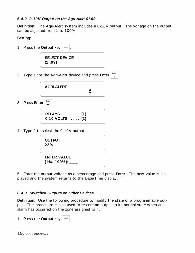
156 AA-9600.rev.16
OUTPUT22%
SELECT DEVICE(1..99)_ _
6.4.2 0-10V Output on the Agri-Alert 9600
Definition: The Agri-Alert system includes a 0-10V output. The voltage on the outputcan be adjusted from 1 to 100%.
Setting:
1. Press the Output key .
2. Type 1 for the Agri-Alert device and press Enter .
3. Press Enter .
4. Type 2 to select the 0-10V output.
5. Enter the output voltage as a percentage and press Enter. The new value is dis-played and the system returns to the Date/Time display.
6.4.3 Switched Outputs on Other Devices
Definition: Use the following procedure to modify the state of a programmable out-put. This procedure is also used to restore an output to its normal state when analarm has occurred on the zone assigned to it.
1. Press the Output key .
ENTER VALUE(1%..100%): _ _ _
AGRI-ALERT
RELAYS . . . . . . . . (1)0-10 VOLTS . . . . . (2)
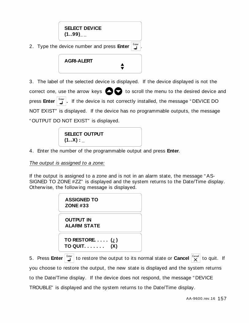
157AA-9600.rev.16
2. Type the device number and press Enter .
3. The label of the selected device is displayed. If the device displayed is not the
correct one, use the arrow keys to scroll the menu to the desired device and
press Enter . If the device is not correctly installed, the message “DEVICE DO
NOT EXIST” is displayed. If the device has no programmable outputs, the message
“OUTPUT DO NOT EXIST” is displayed.
4. Enter the number of the programmable output and press Enter.
The output is assigned to a zone:
If the output is assigned to a zone and is not in an alarm state, the message “AS-SIGNED TO ZONE #ZZ” is displayed and the system returns to the Date/Time display.Otherwise, the following message is displayed.
5. Press Enter to restore the output to its normal state or Cancel to quit. If
you choose to restore the output, the new state is displayed and the system returns
to the Date/Time display. If the device does not respond, the message “DEVICE
TROUBLE” is displayed and the system returns to the Date/Time display.
SELECT OUTPUT(1..X) : _
AGRI-ALERT
SELECT DEVICE(1..99)_ _
OUTPUT INALARM STATE
TO RESTORE. . . . . (↵)TO QUIT. . . . . . . (X)
ASSIGNED TOZONE #33
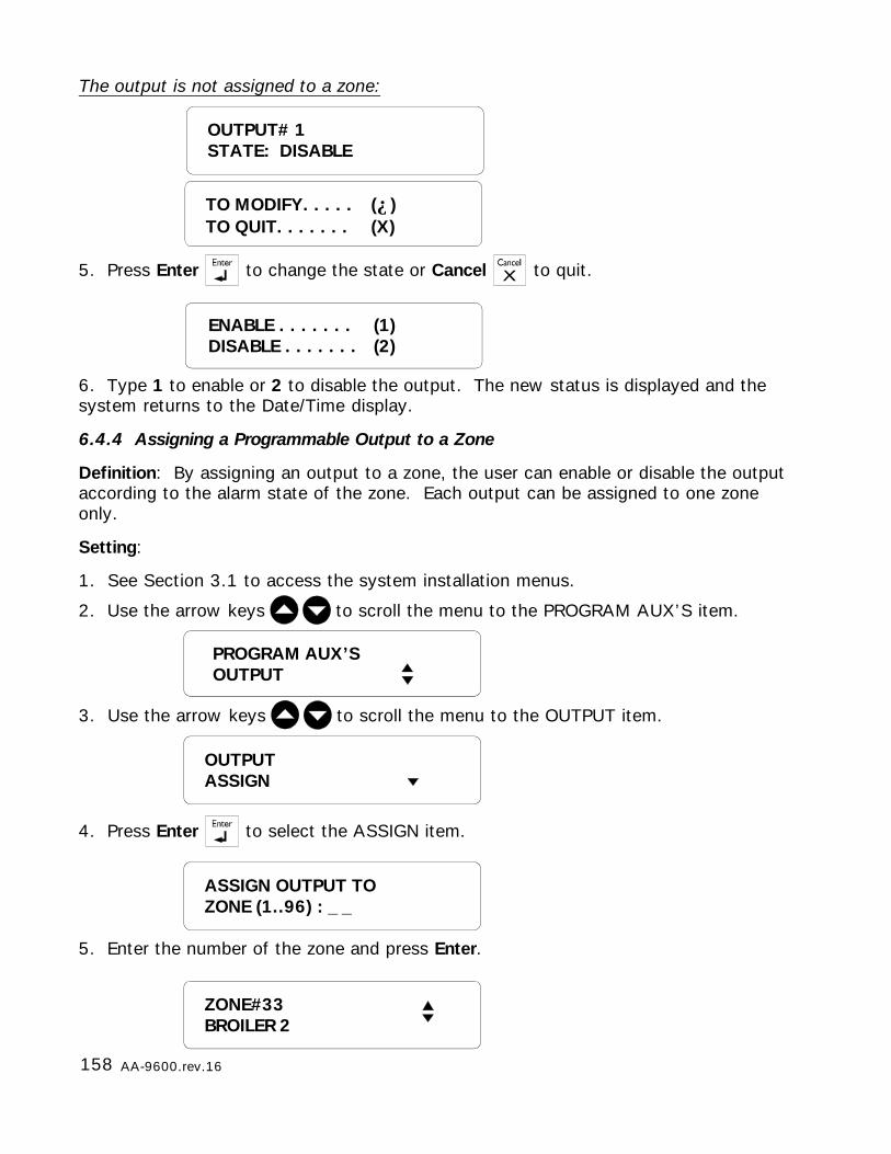
158 AA-9600.rev.16
OUTPUT# 1STATE: DISABLE
ENABLE . . . . . . . (1)DISABLE . . . . . . . (2)
The output is not assigned to a zone:
5. Press Enter to change the state or Cancel to quit.
6. Type 1 to enable or 2 to disable the output. The new status is displayed and thesystem returns to the Date/Time display.
6.4.4 Assigning a Programmable Output to a Zone
Definition: By assigning an output to a zone, the user can enable or disable the outputaccording to the alarm state of the zone. Each output can be assigned to one zoneonly.
Setting:
1. See Section 3.1 to access the system installation menus.
2. Use the arrow keys to scroll the menu to the PROGRAM AUX’S item.
3. Use the arrow keys to scroll the menu to the OUTPUT item.
4. Press Enter to select the ASSIGN item.
5. Enter the number of the zone and press Enter.
OUTPUTASSIGN
ASSIGN OUTPUT TOZONE (1..96) : _ _
TO MODIFY. . . . . (↵)TO QUIT. . . . . . . (X)
PROGRAM AUX’SOUTPUT
ZONE#33BROILER 2
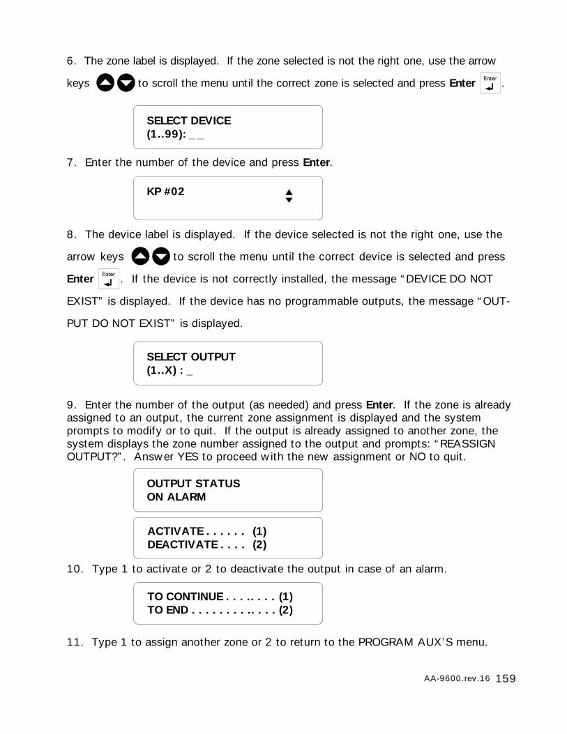
159AA-9600.rev.16
SELECT DEVICE(1..99): _ _
7. Enter the number of the device and press Enter.
8. The device label is displayed. If the device selected is not the right one, use the
arrow keys to scroll the menu until the correct device is selected and press
Enter . If the device is not correctly installed, the message “DEVICE DO NOT
EXIST” is displayed. If the device has no programmable outputs, the message “OUT-
PUT DO NOT EXIST” is displayed.
9. Enter the number of the output (as needed) and press Enter. If the zone is alreadyassigned to an output, the current zone assignment is displayed and the systemprompts to modify or to quit. If the output is already assigned to another zone, thesystem displays the zone number assigned to the output and prompts: “REASSIGNOUTPUT?”. Answer YES to proceed with the new assignment or NO to quit.
10. Type 1 to activate or 2 to deactivate the output in case of an alarm.
11. Type 1 to assign another zone or 2 to return to the PROGRAM AUX’S menu.
KP #02
SELECT OUTPUT(1..X) : _
OUTPUT STATUSON ALARM
ACTIVATE . . . . . . (1)DEACTIVATE . . . . (2)
TO CONTINUE . . . .. . . . (1)TO END . . . . . . . . .. . . . (2)
6. The zone label is displayed. If the zone selected is not the right one, use the arrow
keys to scroll the menu until the correct zone is selected and press Enter .
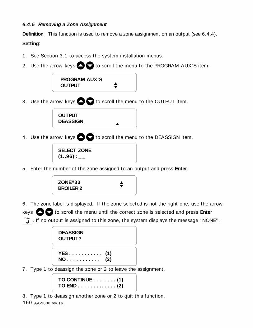
160 AA-9600.rev.16
6.4.5 Removing a Zone Assignment
Definition: This function is used to remove a zone assignment on an output (see 6.4.4).
Setting:
1. See Section 3.1 to access the system installation menus.
2. Use the arrow keys to scroll the menu to the PROGRAM AUX’S item.
3. Use the arrow keys to scroll the menu to the OUTPUT item.
4. Use the arrow keys to scroll the menu to the DEASSIGN item.
5. Enter the number of the zone assigned to an output and press Enter.
6. The zone label is displayed. If the zone selected is not the right one, use the arrow
keys to scroll the menu until the correct zone is selected and press Enter
. If no output is assigned to this zone, the system displays the message “NONE”.
7. Type 1 to deassign the zone or 2 to leave the assignment.
8. Type 1 to deassign another zone or 2 to quit this function.
SELECT ZONE(1..96) : _ _
OUTPUTDEASSIGN
ZONE#33BROILER 2
TO CONTINUE . . .. . . . . (1)TO END . . . . . . . .. . . . . (2)
DEASSIGNOUTPUT?
YES . . . . . . . . . . . (1)NO . . . . . . . . . . . (2)
PROGRAM AUX’SOUTPUT
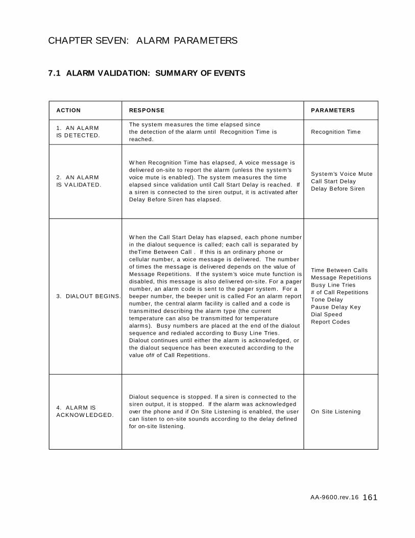
161AA-9600.rev.16
CHAPTER SEVEN: ALARM PARAMETERS
7.1 ALARM VALIDATION: SUMMARY OF EVENTS
ACTION RESPONSE PARAMETERS
1. AN ALARM IS DETECTED.
The system measures the time elapsed since the detection of the alarm until Recognition Time is reached.
Recognition Time
2. AN ALARM IS VALIDATED.
W hen Recognition Time has elapsed, A voice message is delivered on-site to report the alarm (unless the system's voice mute is enabled). The system measures the time elapsed since validation until Call Start Delay is reached. If a siren is connected to the siren output, it is activated after Delay Before S iren has elapsed.
System's Voice MuteCall Start DelayDelay Before S iren
3. DIALOUT BEGINS.
W hen the Call Start Delay has elapsed, each phone number in the dialout sequence is called; each call is separated by theTime Between Call . If this is an ordinary phone or cellular number, a voice message is delivered. The number of times the message is delivered depends on the value of Message Repetitions. If the system 's voice mute function is disabled, this message is also delivered on-s ite. For a pager number, an alarm code is sent to the pager system. For a beeper number, the beeper unit is called For an alarm report number, the central alarm fac ility is called and a code is transmitted describing the alarm type (the current temperature can also be transm itted for temperature alarms). Busy numbers are placed at the end of the dialout sequence and redialed according to Busy Line Tries. Dialout continues until either the alarm is acknowledged, or the dialout sequence has been executed according to the value of# of Call Repetitions .
Time Between CallsMessage RepetitionsBusy Line Tries# of Call Repetitions Tone DelayPause Delay KeyDial SpeedReport Codes
4. ALARM IS ACKNOW LEDGED.
Dialout sequence is stopped. If a siren is connected to the s iren output, it is stopped. If the alarm was acknowledged over the phone and if On Site Listening is enabled, the user can listen to on-site sounds according to the delay defined for on-s ite listening.
On Site Listening
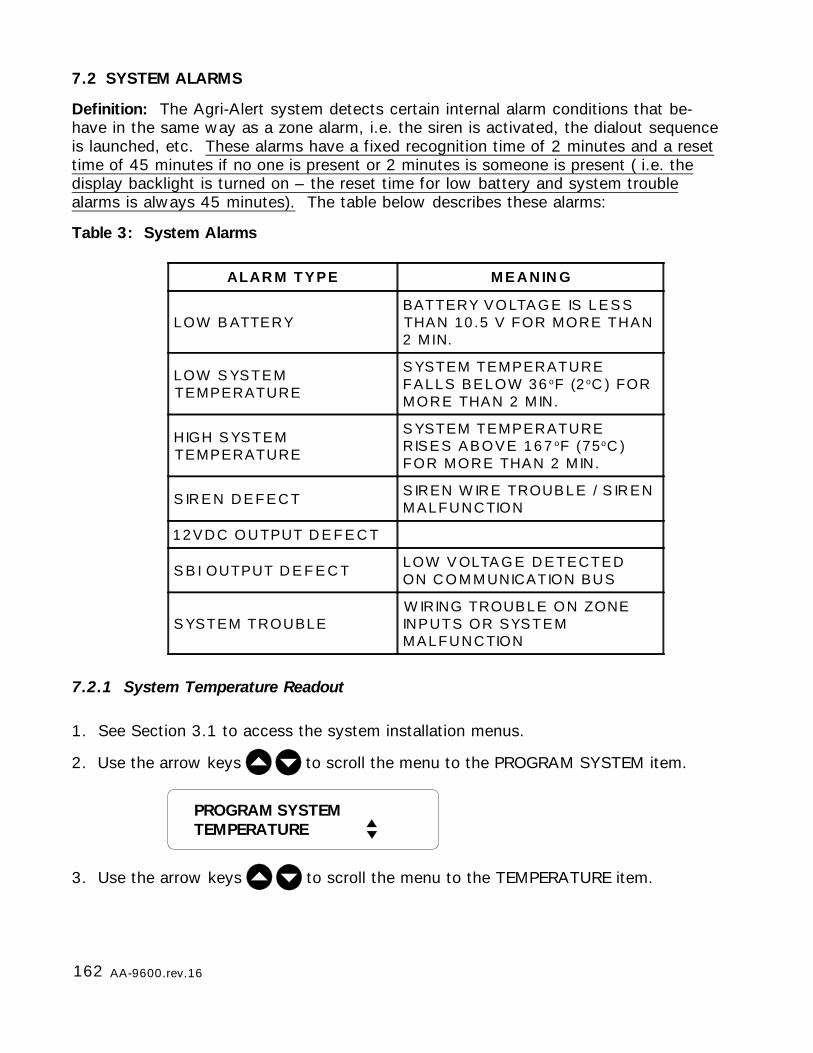
162 AA-9600.rev.16
7.2 SYSTEM ALARMS
Definition: The Agri-Alert system detects certain internal alarm conditions that be-have in the same way as a zone alarm, i.e. the siren is activated, the dialout sequenceis launched, etc. These alarms have a fixed recognition time of 2 minutes and a resettime of 45 minutes if no one is present or 2 minutes is someone is present ( i.e. thedisplay backlight is turned on – the reset time for low battery and system troublealarms is always 45 minutes). The table below describes these alarms:
Table 3: System Alarms
7.2.1 System Temperature Readout
1. See Section 3.1 to access the system installation menus.
2. Use the arrow keys to scroll the menu to the PROGRAM SYSTEM item.
3. Use the arrow keys to scroll the menu to the TEMPERATURE item.
ALAR M T YPE M E A N IN G
LOW B ATTERYBATTERY VOLTA G E IS L E S STHAN 10 .5 V FOR MORE THAN2 MIN.
LOW S YSTEMTEMPERATURE
S YSTEM TEMPERATUREFALLS BELOW 36 oF (2 oC ) FORMORE THAN 2 MIN.
HIGH S YSTEMTEMPERATURE
S YSTEM TEMPERATURERIS E S A B O V E 1 6 7 oF (75oC )FOR MORE THAN 2 MIN.
S IR E N D E F E C T S IREN W IRE TROUB L E / S IR E NMALFUNCTION
1 2 V D C O U TPUT D E F E C T
S B I OUTPUT D E F E C TLOW V OLTA G E D E TECTEDON C O M M UNICATION BUS
S YSTEM TROUBLEW IRING TROUBLE ON ZONEINPUTS OR SYSTEMMALFUNCTION
PROGRAM SYSTEMTEMPERATURE

163AA-9600.rev.16
4. Using the up and down-arrow keys , scroll the menu until the item dis-
played is TEMPERATURE and press Enter .
5. The system returns to the PROGRAM SYSTEM display.
7.2.2 Backup Battery Voltage Readout
See Appendix B for normal battery life spans.
1. See Section 3.1 to access the system installation menus.
2. Use the arrow keys to scroll the menu to the PROGRAM SYSTEM item.
3. Using the up and down-arrow keys , scroll the menu until the item dis-
played is BACKUP BATTERY and press Enter .
4. If the voltage is less than 10 volts, the system displays the warning “LO BATTERY”before displaying the current voltage. The system returns to the PROGRAM SYSTEMdisplay.
SYSTEM TEMP.74.0oF
BACKUP BATTERY12.3 V
PROGRAM SYSTEMBACKUP BATTERY

164 AA-9600.rev.16
7.3 OUTDOOR TEMPERATURE COMPENSATION ON TEMPERATURE ALARMS
Definition: In situations where the outdoor temperature is high, the room temperaturewill rise as warm air enters the building through ventilation inlets. If the high set pointdefined above is not adjusted to take this into account, a high temperature alarm maybe needlessly set off. To avoid this situation, the system can compensate for highoutdoor temperatures when monitoring temperature alarms. When this feature isactivated and the outdoor temperature is close to the high set point, the room tem-perature is monitored with respect to the outdoor temperature. An alarm is set offonly if the room temperature rises above the outdoor temperature by a certain valuecalled the offset. In addition to this, the system also uses a critical high temperatureas an absolute limit on room temperature. When room temperature reaches the criti-cal high temperature, an alarm is set off. To use this feature, an outdoor temperatureprobe must be connected to a temperature zone. The probe must have a pale-coloured (white or grey) PVC casing and should be installed near an air intake.
Critical Temperature: The absolute temperature limit for room temperatures. Whenthe room temperature reaches this point, an alarm is set off, no matter what theoutdoor temperature is.
Offset: In general, the room temperature is greater than the outdoor temperature by acertain number of degrees, called the offset. The offset determines when an alarm isset off. It is the number of degrees the room temperature can rise above the outdoortemperature without setting off an alarm.
The diagram below shows when the outdoor temperature compensation feature takeseffect (if it has been enabled by the user). When the outdoor temperature is greateror equal to the high set point less the offset, the system uses the outdoor temperatureas the reference point for monitoring high temperature alarms.
High Set Point
Outdoor T°
Temperature
Time
Normal AlarmMonitoring
OFFSET
Outdoor T°Compensation
Figure 37: Outdoor Temperature Compensation
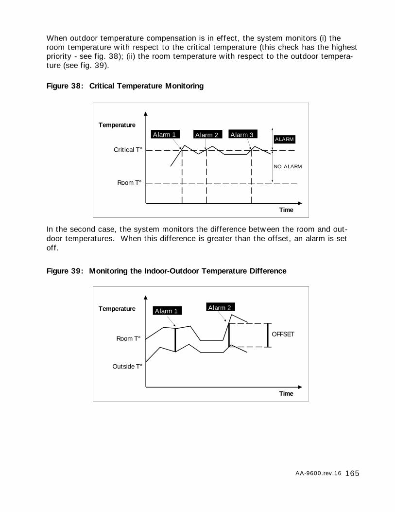
165AA-9600.rev.16
Figure 38: Critical Temperature Monitoring
In the second case, the system monitors the difference between the room and out-door temperatures. When this difference is greater than the offset, an alarm is setoff.
Critical T°
Room T°
Temperature
Time
Alarm 3Alarm 2Alarm 1ALARM
NO ALARM
When outdoor temperature compensation is in effect, the system monitors (i) theroom temperature with respect to the critical temperature (this check has the highestpriority - see fig. 38); (ii) the room temperature with respect to the outdoor tempera-ture (see fig. 39).
Figure 39: Monitoring the Indoor-Outdoor Temperature Difference
Room T°
Outside T°
Temperature
Time
Alarm 2Alarm 1
OFFSET
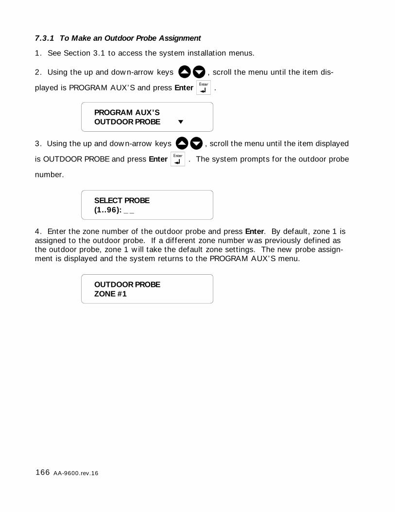
166 AA-9600.rev.16
SELECT PROBE(1..96): _ _
7.3.1 To Make an Outdoor Probe Assignment
1. See Section 3.1 to access the system installation menus.
2. Using the up and down-arrow keys , scroll the menu until the item dis-
played is PROGRAM AUX’S and press Enter .
3. Using the up and down-arrow keys , scroll the menu until the item displayed
is OUTDOOR PROBE and press Enter . The system prompts for the outdoor probe
number.
4. Enter the zone number of the outdoor probe and press Enter. By default, zone 1 isassigned to the outdoor probe. If a different zone number was previously defined asthe outdoor probe, zone 1 will take the default zone settings. The new probe assign-ment is displayed and the system returns to the PROGRAM AUX’S menu.
OUTDOOR PROBEZONE #1
PROGRAM AUX’SOUTDOOR PROBE
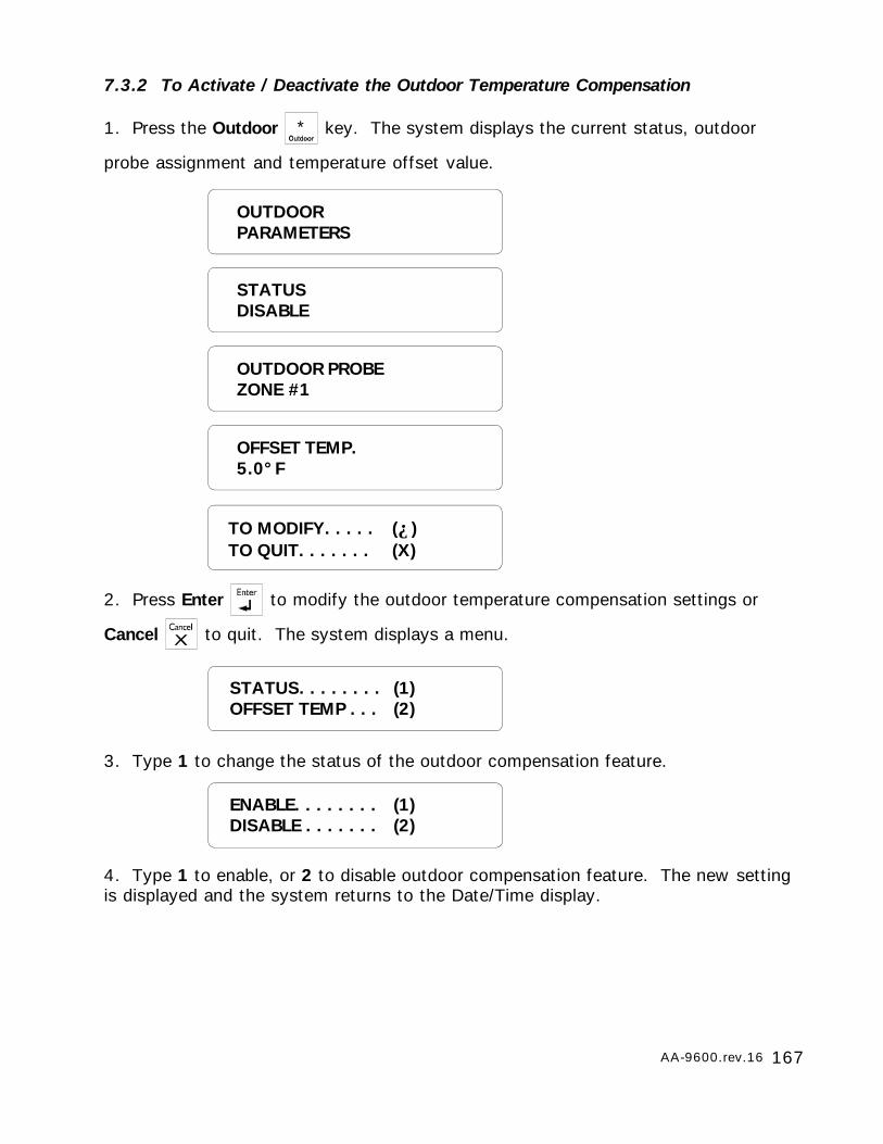
167AA-9600.rev.16
7.3.2 To Activate / Deactivate the Outdoor Temperature Compensation
1. Press the Outdoor * key. The system displays the current status, outdoor
probe assignment and temperature offset value.
2. Press Enter to modify the outdoor temperature compensation settings or
Cancel to quit. The system displays a menu.
3. Type 1 to change the status of the outdoor compensation feature.
4. Type 1 to enable, or 2 to disable outdoor compensation feature. The new settingis displayed and the system returns to the Date/Time display.
OUTDOORPARAMETERS
STATUSDISABLE
OUTDOOR PROBEZONE #1
OFFSET TEMP.5.0°F
STATUS. . . . . . . . (1)OFFSET TEMP . . . (2)
ENABLE. . . . . . . . (1)DISABLE . . . . . . . (2)
TO MODIFY. . . . . (↵)TO QUIT. . . . . . . (X)
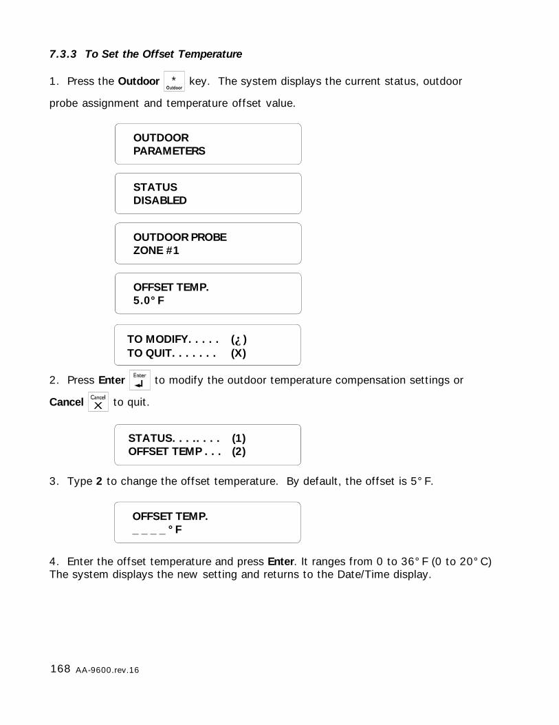
168 AA-9600.rev.16
7.3.3 To Set the Offset Temperature
1. Press the Outdoor * key. The system displays the current status, outdoor
probe assignment and temperature offset value.
2. Press Enter to modify the outdoor temperature compensation settings or
Cancel to quit.
3. Type 2 to change the offset temperature. By default, the offset is 5°F.
4. Enter the offset temperature and press Enter. It ranges from 0 to 36°F (0 to 20°C)The system displays the new setting and returns to the Date/Time display.
OFFSET TEMP._ _ _ _ °F
STATUS. . . .. . . . (1)OFFSET TEMP . . . (2)
OUTDOORPARAMETERS
STATUSDISABLED
OUTDOOR PROBEZONE #1
OFFSET TEMP.5.0°F
TO MODIFY. . . . . (↵)TO QUIT. . . . . . . (X)

169AA-9600.rev.16
7.4 ALARM MEMORY
Definition: Each alarm condition detected by the Agri-Alert system is recorded inmemory for future reference. The parameters stored in memory are the zone number,the alarm type, the time, the date, the user who acknowledged the alarm (if a user isdefined) and the time and date of acknowledgment. The system stores only the lastfifty alarms in memory. It should be noted that if the zones are reconfigured at anytime, the alarm memory recorded up to that time is erased.
If the password feature is enabled, the system requires a password before acknowl-edging an alarm from the keypad (acknowledging over the phone always requires apassword). This password will appear in the alarm memory listing only if the masterpassword is currently logged onto the system. If a user is logged on, the system willnot identify the password that acknowledged the alarm. If, at the time the alarm wasacknowledged, the password feature was not enabled, the alarm memory listing willnot contain the password that acknowledged the alarm.
To access alarm memory, press the Alarm Memory key. If no alarm events are
presently stored in memory, the system returns the message: NONE. To step to the
next alarm entry while the current entry is still scrolling on the display, press the right-
arrow key .
SIREN TROUBLEAT 12:47 PM ON AUG 14 2000ACK AT 01:16 PM ON AUG14 2000
ZONE #1HI CURRENT AT 12:47 PM ON AUG 14 2000ACK BY 1234 AT 01:16 PM ON AUG14 2000
Examples: In the first example, the password of the user that acknowledged thealarm is not identified. This means either no password was entered when the alarmwas acknowledged or the current password is not the master password.
In the second example, the password is identified. This means that a password wasentered when the alarm was acknowledged and the current password is the masterpassword.
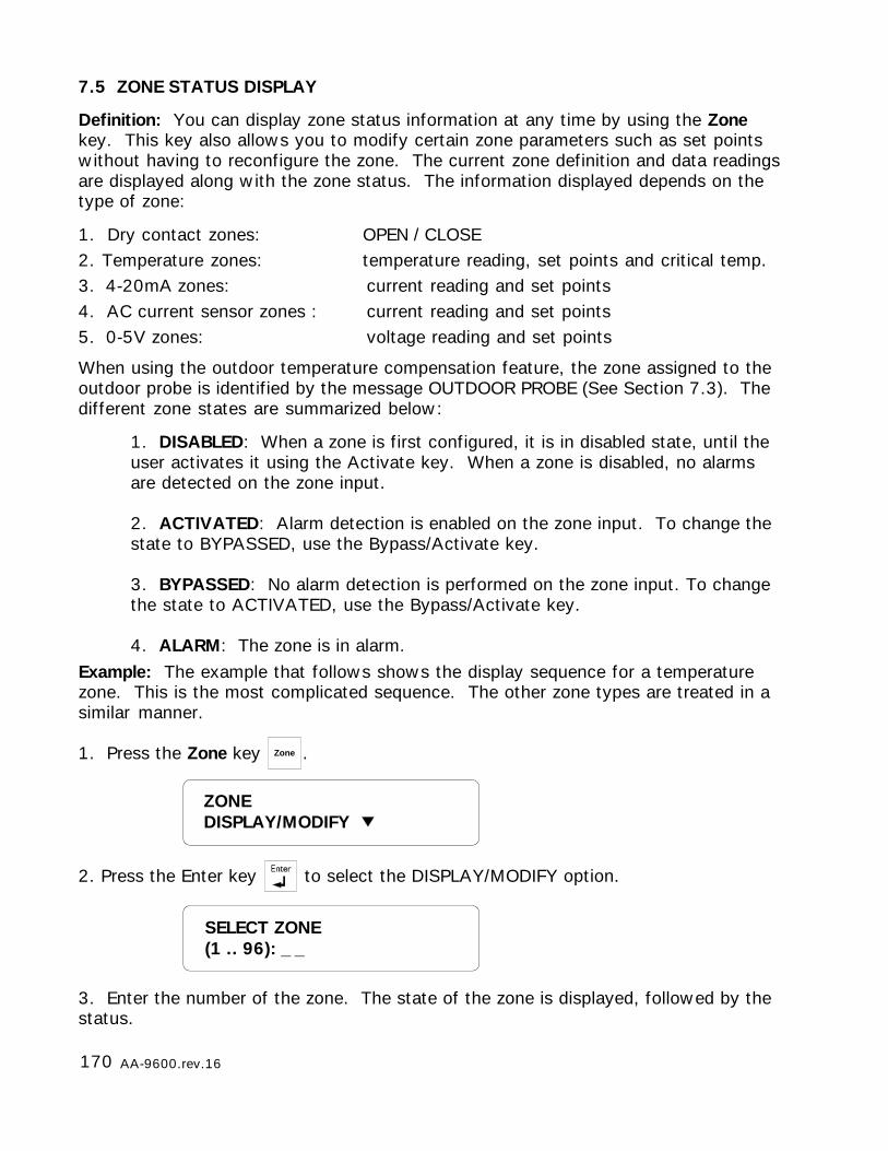
170 AA-9600.rev.16
7.5 ZONE STATUS DISPLAY
Definition: You can display zone status information at any time by using the Zonekey. This key also allows you to modify certain zone parameters such as set pointswithout having to reconfigure the zone. The current zone definition and data readingsare displayed along with the zone status. The information displayed depends on thetype of zone:
1. Dry contact zones: OPEN / CLOSE2. Temperature zones: temperature reading, set points and critical temp.3. 4-20mA zones: current reading and set points4. AC current sensor zones : current reading and set points5. 0-5V zones: voltage reading and set points
When using the outdoor temperature compensation feature, the zone assigned to theoutdoor probe is identified by the message OUTDOOR PROBE (See Section 7.3). Thedifferent zone states are summarized below:
1. DISABLED: When a zone is first configured, it is in disabled state, until theuser activates it using the Activate key. When a zone is disabled, no alarmsare detected on the zone input.
2. ACTIVATED: Alarm detection is enabled on the zone input. To change thestate to BYPASSED, use the Bypass/Activate key.
3. BYPASSED: No alarm detection is performed on the zone input. To changethe state to ACTIVATED, use the Bypass/Activate key.
4. ALARM: The zone is in alarm.Example: The example that follows shows the display sequence for a temperaturezone. This is the most complicated sequence. The other zone types are treated in asimilar manner.
1. Press the Zone key Zone .
2. Press the Enter key to select the DISPLAY/MODIFY option.
3. Enter the number of the zone. The state of the zone is displayed, followed by thestatus.
SELECT ZONE(1 .. 96): _ _
ZONEDISPLAY/MODIFY
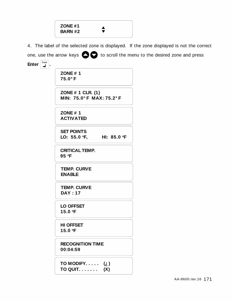
171AA-9600.rev.16
4. The label of the selected zone is displayed. If the zone displayed is not the correct
one, use the arrow keys to scroll the menu to the desired zone and press
Enter .
ZONE #1BARN #2
ZONE # 175.0°F
ZONE # 1 CLR. (1)MIN: 75.0°F MAX: 75.2°F
ZONE # 1ACTIVATED
SET POINTSLO: 55.0 oF, HI: 85.0 oF
CRITICAL TEMP.95 oF
TEMP. CURVEENABLE
TEMP. CURVEDAY : 17
LO OFFSET15.0 oF
HI OFFSET15.0 oF
TO MODIFY. . . . . (↵)TO QUIT. . . . . . . (X)
RECOGNITION TIME00:04:59
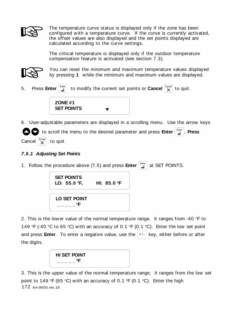
172 AA-9600.rev.16
3. This is the upper value of the normal temperature range. It ranges from the low set
point to 149 oF (65 oC) with an accuracy of 0.1 oF (0.1 oC). Enter the high
HI SET POINT _ _ _ _ _ oF
You can reset the minimum and maximum temperature values displayedby pressing 1 while the minimum and maximum values are displayed.
5. Press Enter to modify the current set points or Cancel to quit.
6. User-adjustable parameters are displayed in a scrolling menu. Use the arrow keys
to scroll the menu to the desired parameter and press Enter . Press
Cancel to quit
7.5.1 Adjusting Set Points
1. Follow the procedure above (7.5) and press Enter at SET POINTS.
2. This is the lower value of the normal temperature range. It ranges from -40 oF to
149 oF (-40 oC to 65 oC) with an accuracy of 0.1 oF (0.1 oC). Enter the low set point
and press Enter. To enter a negative value, use the key, either before or after
the digits.
ZONE #1SET POINTS
SET POINTSLO: 55.0 oF, HI: 85.0 oF
LO SET POINT _ _ _ _ _ oF
The temperature curve status is displayed only if the zone has beenconfigured with a temperature curve. If the curve is currently activated,the offset values are also displayed and the set points displayed arecalculated according to the curve settings.
The critical temperature is displayed only if the outdoor temperaturecompensation feature is activated (see section 7.3).

173AA-9600.rev.16
CRITICAL TEMP. _ _ _ _ _ oF
The following parameter can be accessed only if the outdoor temperaturecompensation feature is activated (see Section 7.3).
4. The critical temperature is displayed only if the outdoor temperature compensation
feature is activated (see Section 7.3). It is the absolute temperature limit for room
temperatures. It is used in conjunction with the outdoor temperature compensation
feature. When the room temperature reaches this point and the outdoor temperature
compensation feature is enabled, an alarm is set off, no matter what the outdoor
temperature is. It ranges from the high set point to 149 oF (65 oC) with an accuracy
of 0.1 oF (0.1 oC). Enter the critical temperature and press Enter. To enter a negative
value, use the key, either before or after the digits.
set point and press Enter. To enter a negative value, use the key, either before
or after the digits. The high set point must be greater than the low set point.
7.5.2 Adjusting Curve Offset Values
1. Follow the procedure above (7.5) and press Enter at OFFSETS.
The following parameters can only be accessed if the zone has beenconfigured with a temperature curve.
2. The low offset is the number of degrees below the normal temperature value (asdefined by the curve) at which a temperature alarm is declared. It varies from 1 oF to20 oF (0.6 oC to 11.1 oC) with an accuracy of 0.1 oF (0.1 oC). Enter the low offset andpress Enter .
LO OFFSET _ _ _ _ _ oF
LO OFFSET15.0 oF
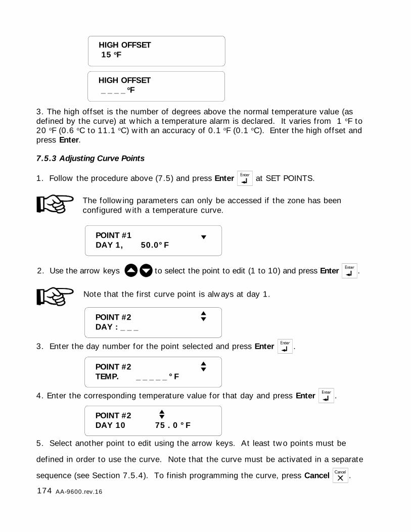
174 AA-9600.rev.16
HIGH OFFSET 15 oF
HIGH OFFSET _ _ _ _ oF
3. The high offset is the number of degrees above the normal temperature value (asdefined by the curve) at which a temperature alarm is declared. It varies from 1 oF to20 oF (0.6 oC to 11.1 oC) with an accuracy of 0.1 oF (0.1 oC). Enter the high offset andpress Enter.
7.5.3 Adjusting Curve Points
1. Follow the procedure above (7.5) and press Enter at SET POINTS.
2. Use the arrow keys to select the point to edit (1 to 10) and press Enter .
Note that the first curve point is always at day 1.
The following parameters can only be accessed if the zone has beenconfigured with a temperature curve.
POINT #2DAY : _ _ _
POINT #1DAY 1, 50.0°F
5. Select another point to edit using the arrow keys. At least two points must be
defined in order to use the curve. Note that the curve must be activated in a separate
sequence (see Section 7.5.4). To finish programming the curve, press Cancel .
POINT #2DAY 10 75 . 0 °F
3. Enter the day number for the point selected and press Enter .
4. Enter the corresponding temperature value for that day and press Enter .
POINT #2TEMP. _ _ _ _ _ °F
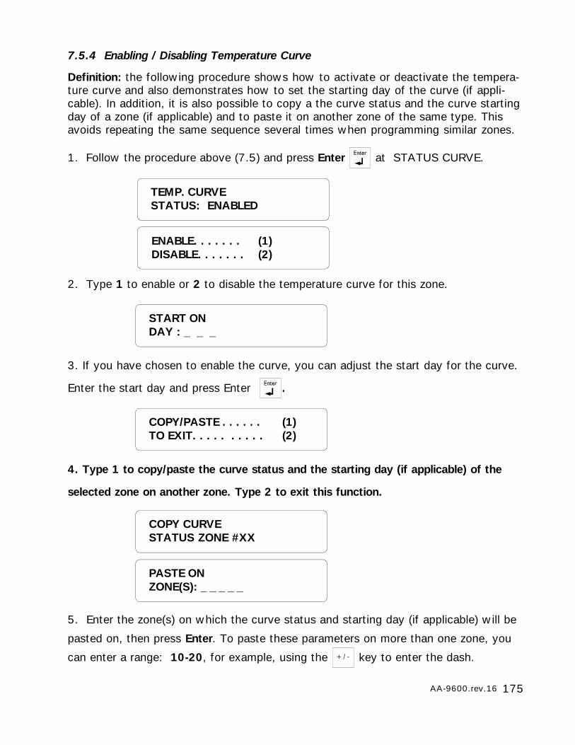
175AA-9600.rev.16
ENABLE. . . . . . . (1)DISABLE. . . . . . . (2)
TEMP. CURVESTATUS: ENABLED
START ONDAY : _ _ _
7.5.4 Enabling / Disabling Temperature Curve
Definition: the following procedure shows how to activate or deactivate the tempera-ture curve and also demonstrates how to set the starting day of the curve (if appli-cable). In addition, it is also possible to copy a the curve status and the curve startingday of a zone (if applicable) and to paste it on another zone of the same type. Thisavoids repeating the same sequence several times when programming similar zones.
1. Follow the procedure above (7.5) and press Enter at STATUS CURVE.
2. Type 1 to enable or 2 to disable the temperature curve for this zone.
3. If you have chosen to enable the curve, you can adjust the start day for the curve.
Enter the start day and press Enter .
4. Type 1 to copy/paste the curve status and the starting day (if applicable) of the
selected zone on another zone. Type 2 to exit this function.
5. Enter the zone(s) on which the curve status and starting day (if applicable) will be
pasted on, then press Enter. To paste these parameters on more than one zone, you
can enter a range: 10-20, for example, using the key to enter the dash.
COPY/PASTE . . . . . . (1)TO EXIT. . . . . . . . . . (2)
COPY CURVESTATUS ZONE #XX
PASTE ONZONE(S): _ _ _ _ _
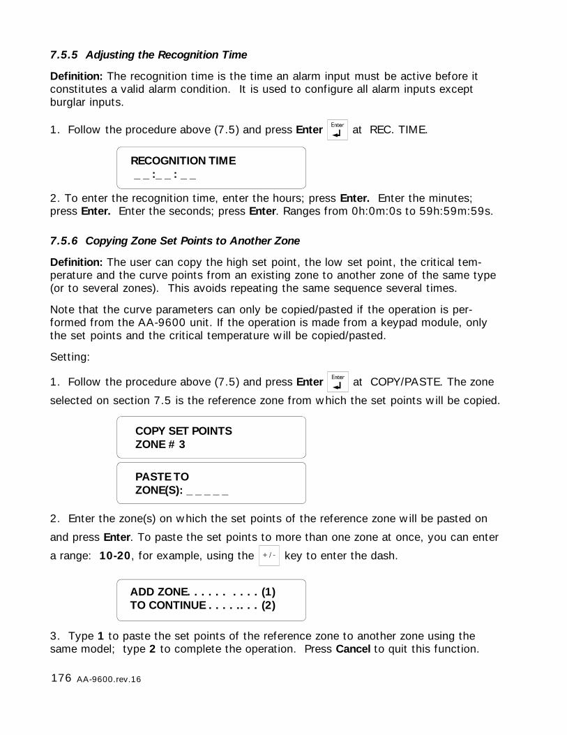
176 AA-9600.rev.16
ADD ZONE. . . . . . . . . . (1)TO CONTINUE . . . . .. . . (2)
COPY SET POINTSZONE # 3
PASTE TOZONE(S): _ _ _ _ _
RECOGNITION TIME _ _ :_ _ : _ _
7.5.5 Adjusting the Recognition Time
Definition: The recognition time is the time an alarm input must be active before itconstitutes a valid alarm condition. It is used to configure all alarm inputs exceptburglar inputs.
1. Follow the procedure above (7.5) and press Enter at REC. TIME.
2. To enter the recognition time, enter the hours; press Enter. Enter the minutes;press Enter. Enter the seconds; press Enter. Ranges from 0h:0m:0s to 59h:59m:59s.
7.5.6 Copying Zone Set Points to Another Zone
Definition: The user can copy the high set point, the low set point, the critical tem-perature and the curve points from an existing zone to another zone of the same type(or to several zones). This avoids repeating the same sequence several times.
Note that the curve parameters can only be copied/pasted if the operation is per-formed from the AA-9600 unit. If the operation is made from a keypad module, onlythe set points and the critical temperature will be copied/pasted.
Setting:
1. Follow the procedure above (7.5) and press Enter at COPY/PASTE. The zone
selected on section 7.5 is the reference zone from which the set points will be copied.
2. Enter the zone(s) on which the set points of the reference zone will be pasted on
and press Enter. To paste the set points to more than one zone at once, you can enter
a range: 10-20, for example, using the key to enter the dash.
3. Type 1 to paste the set points of the reference zone to another zone using thesame model; type 2 to complete the operation. Press Cancel to quit this function.
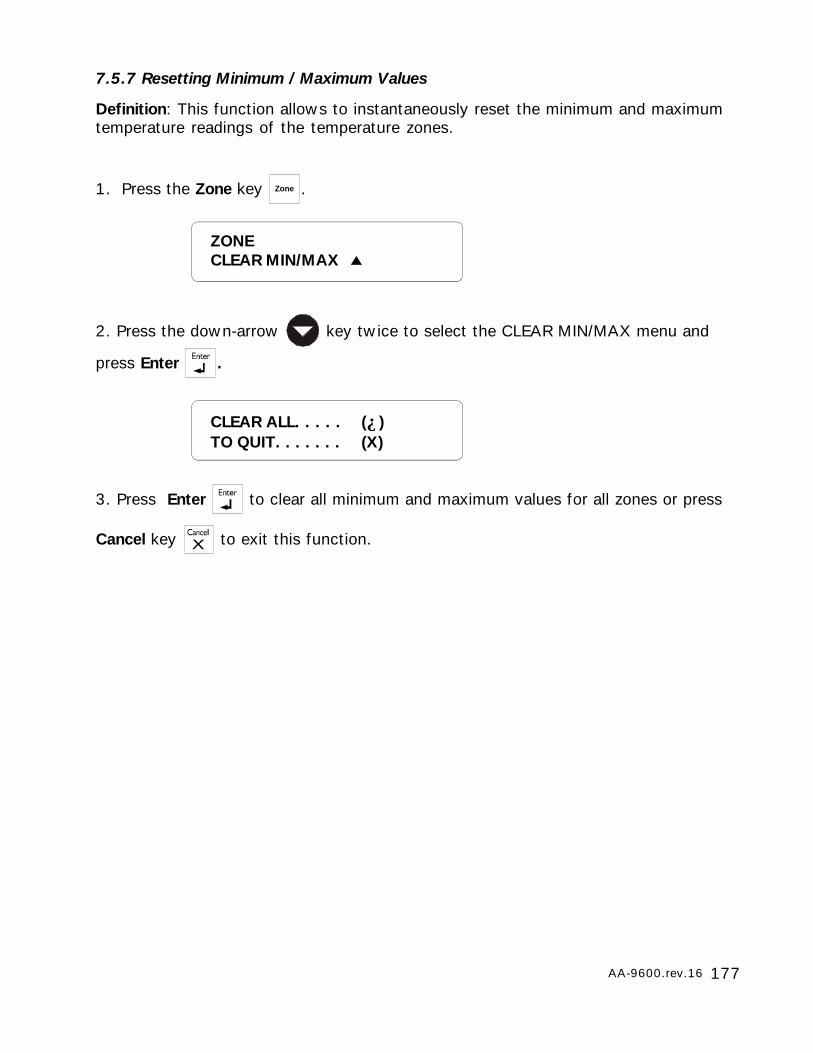
177AA-9600.rev.16
7.5.7 Resetting Minimum / Maximum Values
Definition: This function allows to instantaneously reset the minimum and maximumtemperature readings of the temperature zones.
1. Press the Zone key Zone .
2. Press the down-arrow key twice to select the CLEAR MIN/MAX menu and
press Enter .
3. Press Enter to clear all minimum and maximum values for all zones or press
Cancel key to exit this function.
ZONECLEAR MIN/MAX
CLEAR ALL. . . . . (↵)TO QUIT. . . . . . . (X)
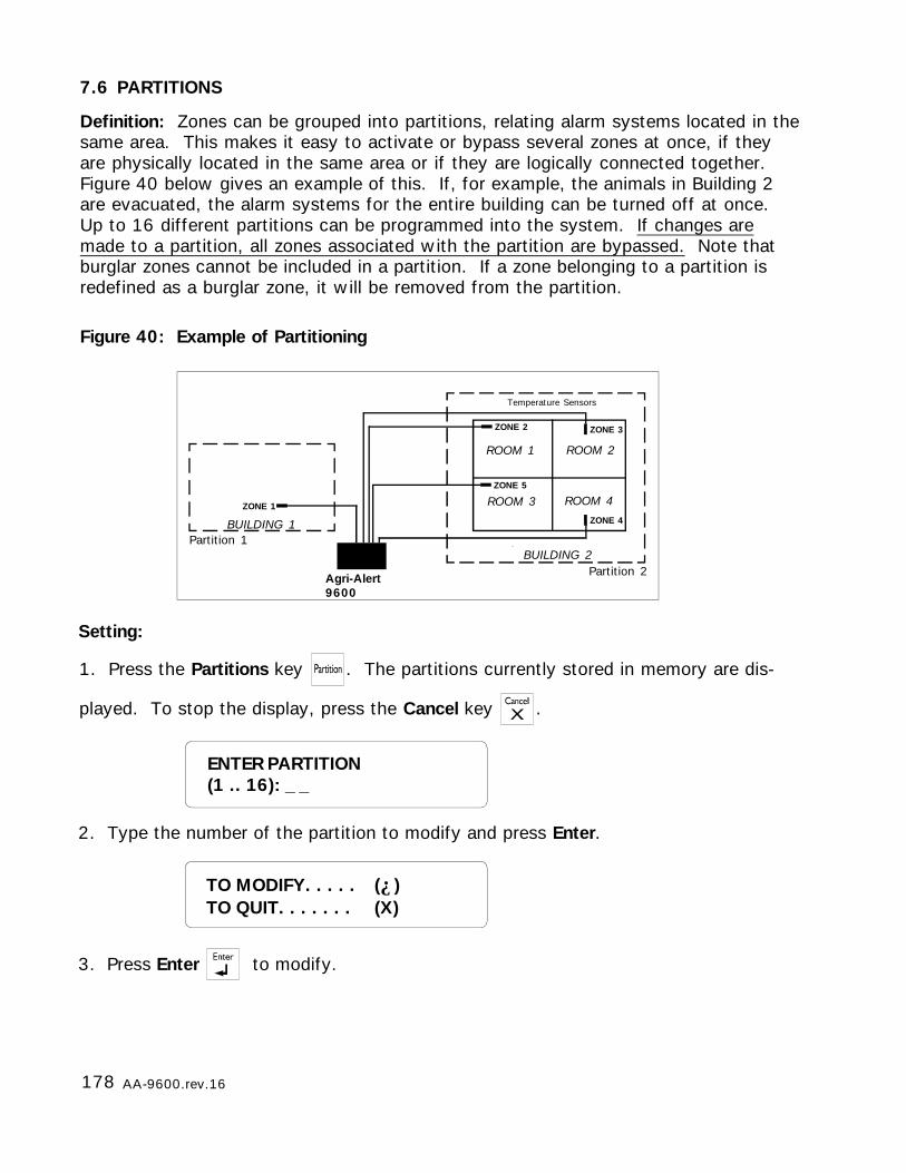
178 AA-9600.rev.16
7.6 PARTITIONS
Definition: Zones can be grouped into partitions, relating alarm systems located in thesame area. This makes it easy to activate or bypass several zones at once, if theyare physically located in the same area or if they are logically connected together.Figure 40 below gives an example of this. If, for example, the animals in Building 2are evacuated, the alarm systems for the entire building can be turned off at once.Up to 16 different partitions can be programmed into the system. If changes aremade to a partition, all zones associated with the partition are bypassed. Note thatburglar zones cannot be included in a partition. If a zone belonging to a partition isredefined as a burglar zone, it will be removed from the partition.
Setting:
1. Press the Partitions key . The partitions currently stored in memory are dis-
played. To stop the display, press the Cancel key .
Figure 40: Example of Partitioning
3. Press Enter to modify.
ENTER PARTITION(1 .. 16): _ _
2. Type the number of the partition to modify and press Enter.
Partition 2Agri-Alert9600
Temperature Sensors
Partition 1
ROOM 1 ROOM 2
ROOM 3 ROOM 4
BUILDING 2
BUILDING 1
ZONE 2 ZONE 3
ZONE 4
ZONE 5
ZONE 1
TO MODIFY. . . . . (↵)TO QUIT. . . . . . . (X)
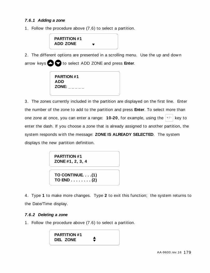
179AA-9600.rev.16
7.6.1 Adding a zone
1. Follow the procedure above (7.6) to select a partition.
2. The different options are presented in a scrolling menu. Use the up and down
arrow keys to select ADD ZONE and press Enter.
3. The zones currently included in the partition are displayed on the first line. Enter
the number of the zone to add to the partition and press Enter. To select more than
one zone at once, you can enter a range: 10-20, for example, using the key to
enter the dash. If you choose a zone that is already assigned to another partition, the
system responds with the message: ZONE IS ALREADY SELECTED. The system
displays the new partition definition.
4. Type 1 to make more changes. Type 2 to exit this function; the system returns to
the Date/Time display.
7.6.2 Deleting a zone
1. Follow the procedure above (7.6) to select a partition.
PARTITION #1ZONE #1, 2, 3, 4
PARTITION #1ADD ZONE
TO CONTINUE. . . .(1)TO END . . . . . . . . (2)
PARTITION #1DEL ZONE
PARTION #1ADDZONE: _ _ _ _ _
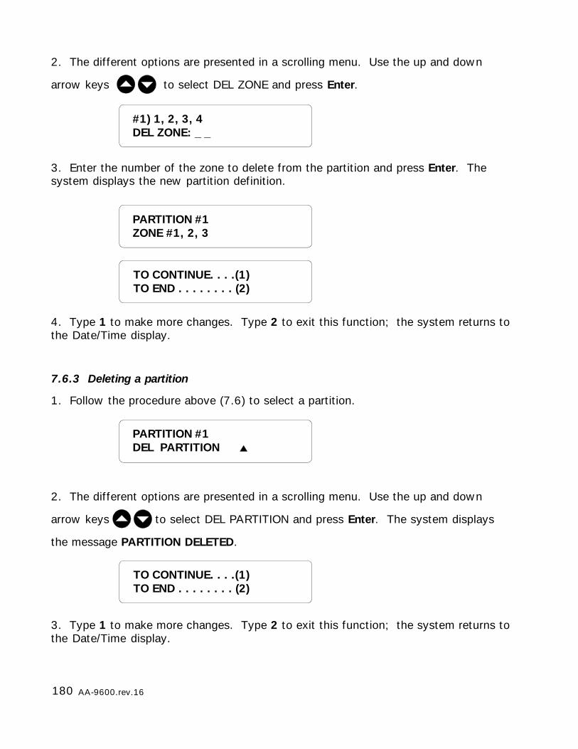
180 AA-9600.rev.16
PARTITION #1ZONE #1, 2, 3
2. The different options are presented in a scrolling menu. Use the up and down
arrow keys to select DEL ZONE and press Enter.
3. Enter the number of the zone to delete from the partition and press Enter. Thesystem displays the new partition definition.
4. Type 1 to make more changes. Type 2 to exit this function; the system returns tothe Date/Time display.
7.6.3 Deleting a partition
1. Follow the procedure above (7.6) to select a partition.
2. The different options are presented in a scrolling menu. Use the up and down
arrow keys to select DEL PARTITION and press Enter. The system displays
the message PARTITION DELETED.
3. Type 1 to make more changes. Type 2 to exit this function; the system returns tothe Date/Time display.
TO CONTINUE. . . .(1)TO END . . . . . . . . (2)
PARTITION #1DEL PARTITION
TO CONTINUE. . . .(1)TO END . . . . . . . . (2)
#1) 1, 2, 3, 4DEL ZONE: _ _
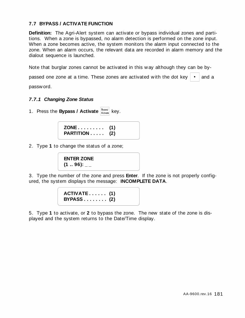
181AA-9600.rev.16
ACTIVATE . . . . . . (1)BYPASS . . . . . . . . (2)
7.7 BYPASS / ACTIVATE FUNCTION
Definition: The Agri-Alert system can activate or bypass individual zones and parti-tions. When a zone is bypassed, no alarm detection is performed on the zone input.When a zone becomes active, the system monitors the alarm input connected to thezone. When an alarm occurs, the relevant data are recorded in alarm memory and thedialout sequence is launched.
Note that burglar zones cannot be activated in this way although they can be by-
passed one zone at a time. These zones are activated with the dot key and a
password.
7.7.1 Changing Zone Status
1. Press the Bypass / Activate key.
2. Type 1 to change the status of a zone;
3. Type the number of the zone and press Enter. If the zone is not properly config-ured, the system displays the message: INCOMPLETE DATA.
5. Type 1 to activate, or 2 to bypass the zone. The new state of the zone is dis-played and the system returns to the Date/Time display.
ZONE . . . . . . . . . (1)PARTITION . . . . . (2)
ENTER ZONE(1 .. 96): _ _
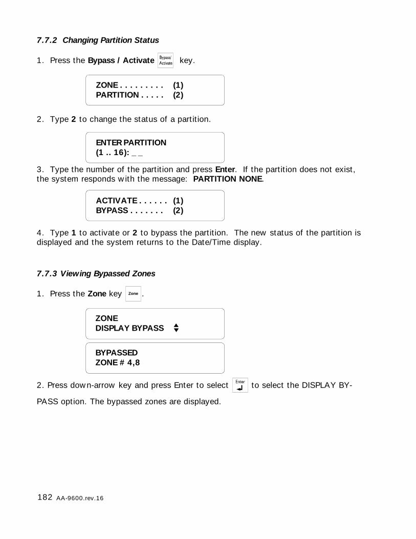
182 AA-9600.rev.16
7.7.2 Changing Partition Status
1. Press the Bypass / Activate key.
2. Type 2 to change the status of a partition.
3. Type the number of the partition and press Enter. If the partition does not exist,the system responds with the message: PARTITION NONE.
4. Type 1 to activate or 2 to bypass the partition. The new status of the partition isdisplayed and the system returns to the Date/Time display.
7.7.3 Viewing Bypassed Zones
1. Press the Zone key Zone .
2. Press down-arrow key and press Enter to select to select the DISPLAY BY-
PASS option. The bypassed zones are displayed.
ZONE . . . . . . . . . (1)PARTITION . . . . . (2)
ENTER PARTITION(1 .. 16): _ _
ACTIVATE . . . . . . (1)BYPASS . . . . . . . (2)
BYPASSEDZONE # 4,8
ZONEDISPLAY BYPASS
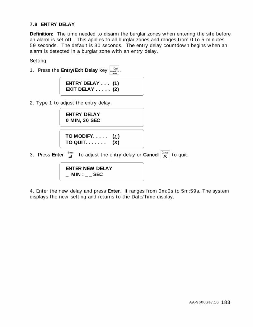
183AA-9600.rev.16
7.8 ENTRY DELAY
Definition: The time needed to disarm the burglar zones when entering the site beforean alarm is set off. This applies to all burglar zones and ranges from 0 to 5 minutes,59 seconds. The default is 30 seconds. The entry delay countdown begins when analarm is detected in a burglar zone with an entry delay.
Setting:
1. Press the Entry/Exit Delay key Entry/ExitDelay
.
2. Type 1 to adjust the entry delay.
3. Press Enter to adjust the entry delay or Cancel to quit.
4. Enter the new delay and press Enter. It ranges from 0m:0s to 5m:59s. The systemdisplays the new setting and returns to the Date/Time display.
ENTRY DELAY . . . (1)EXIT DELAY . . . . . (2)
ENTRY DELAY0 MIN, 30 SEC
ENTER NEW DELAY_ MIN : _ _ SEC
TO MODIFY. . . . . (↵)TO QUIT. . . . . . . (X)
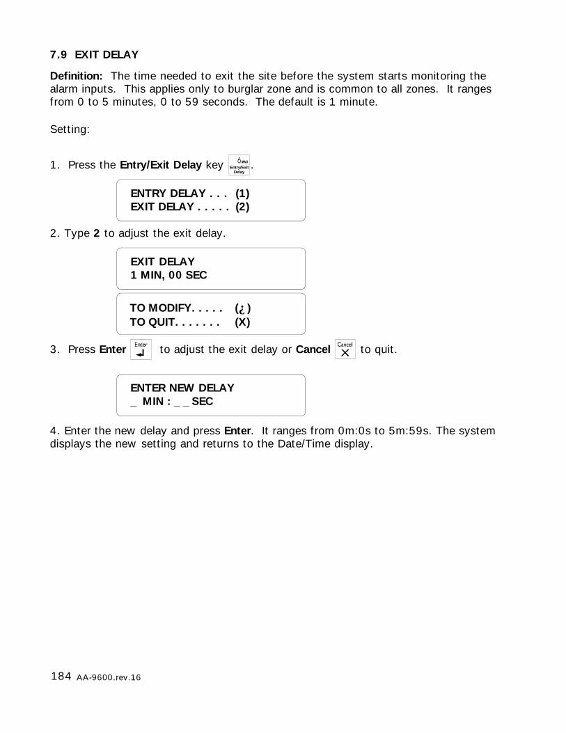
184 AA-9600.rev.16
7.9 EXIT DELAY
Definition: The time needed to exit the site before the system starts monitoring thealarm inputs. This applies only to burglar zone and is common to all zones. It rangesfrom 0 to 5 minutes, 0 to 59 seconds. The default is 1 minute.
Setting:
1. Press the Entry/Exit Delay key Entry/ExitDelay
.
2. Type 2 to adjust the exit delay.
3. Press Enter to adjust the exit delay or Cancel to quit.
4. Enter the new delay and press Enter. It ranges from 0m:0s to 5m:59s. The systemdisplays the new setting and returns to the Date/Time display.
ENTRY DELAY . . . (1)EXIT DELAY . . . . . (2)
EXIT DELAY1 MIN, 00 SEC
ENTER NEW DELAY_ MIN : _ _ SEC
TO MODIFY. . . . . (↵)TO QUIT. . . . . . . (X)

185AA-9600.rev.16
7.10 FORCE ARMING
Definition: Normally, you cannot arm the system when alarm conditions are presenton one or more zones. However, if the “Force Arming” option has been enabled bythe installer, the user can arm the system even if some zones have alarms. This ap-plies only to delay burglar zones, however. An instant burglar zone with an alarmcondition would only set off a new alarm as soon as the system were armed. By de-fault, force arming is disabled.
Setting:
1. See 3.1 to access the system installation menus.
2. Use the arrow keys to scroll the menu to the PROGRAM SYSTEM option
and press Enter .
3. Use the arrow keys to scroll the menu to the FORCE ARMING option and
press Enter .
4. Press Enter to modify the current status or Cancel to exit this function.
5. Type 1 to enable or 2 to disable force arming. The new status is displayed and the
system returns to the PROGRAM SYSTEM menu.
PROGRAM SYSTEMFORCE ARMING
FORCE ARMINGSTATUS: ENABLE
ENABLE . . . . . . . (1)DISABLE . . . . . . . (2)
TO MODIFY. . . . . (↵)TO QUIT. . . . . . . (X)

186 AA-9600.rev.16
7.11 SIREN PARAMETERS
7.11.1 Siren Delay
Definition: The system activates the siren when an alarm condition is detected and ifthe siren is enabled for the zone in alarm. The siren is activated after a user-defineddelay has elapsed. The value ranges from 0 to 20 minutes. The default is 0 minutes.This parameter applies to all zones.
Setting:
1. Press the Siren Delay key Siren delay
.
2. Type 1 to adjust the delay.
3. The current delay is displayed. Press Enter to modify the value or Cancel
to quit.
4. Enter the new delay value and press Enter . It ranges from 0 to 20 minutes.
The new value is displayed and the system returns to the Date/Time display.
DELAY. . . . . . . . . (1)TIME ON . . . . . . . (2)
ENTER NEW DELAY_ _ MIN
1 MIN
TO MODIFY. . . . . (↵)TO QUIT. . . . . . . (X)
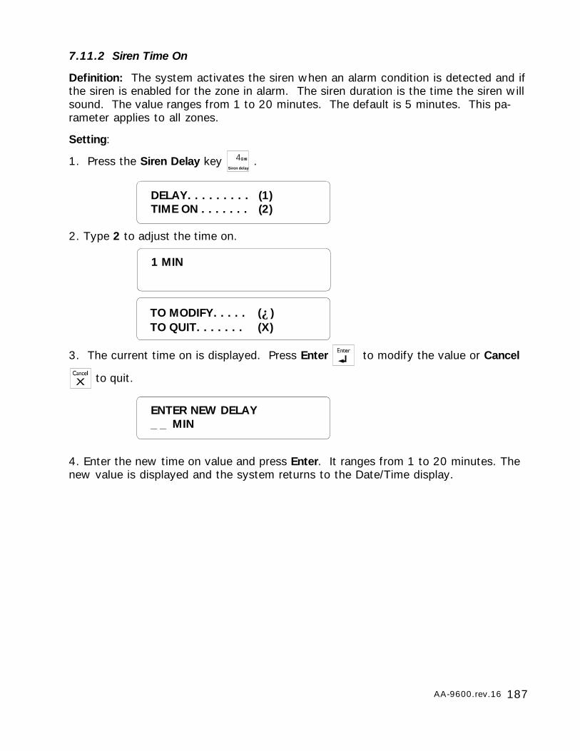
187AA-9600.rev.16
ENTER NEW DELAY_ _ MIN
1 MIN
7.11.2 Siren Time On
Definition: The system activates the siren when an alarm condition is detected and ifthe siren is enabled for the zone in alarm. The siren duration is the time the siren willsound. The value ranges from 1 to 20 minutes. The default is 5 minutes. This pa-rameter applies to all zones.
Setting:
1. Press the Siren Delay key Siren delay
.
2. Type 2 to adjust the time on.
3. The current time on is displayed. Press Enter to modify the value or Cancel
to quit.
4. Enter the new time on value and press Enter. It ranges from 1 to 20 minutes. Thenew value is displayed and the system returns to the Date/Time display.
DELAY. . . . . . . . . (1)TIME ON . . . . . . . (2)
TO MODIFY. . . . . (↵)TO QUIT. . . . . . . (X)
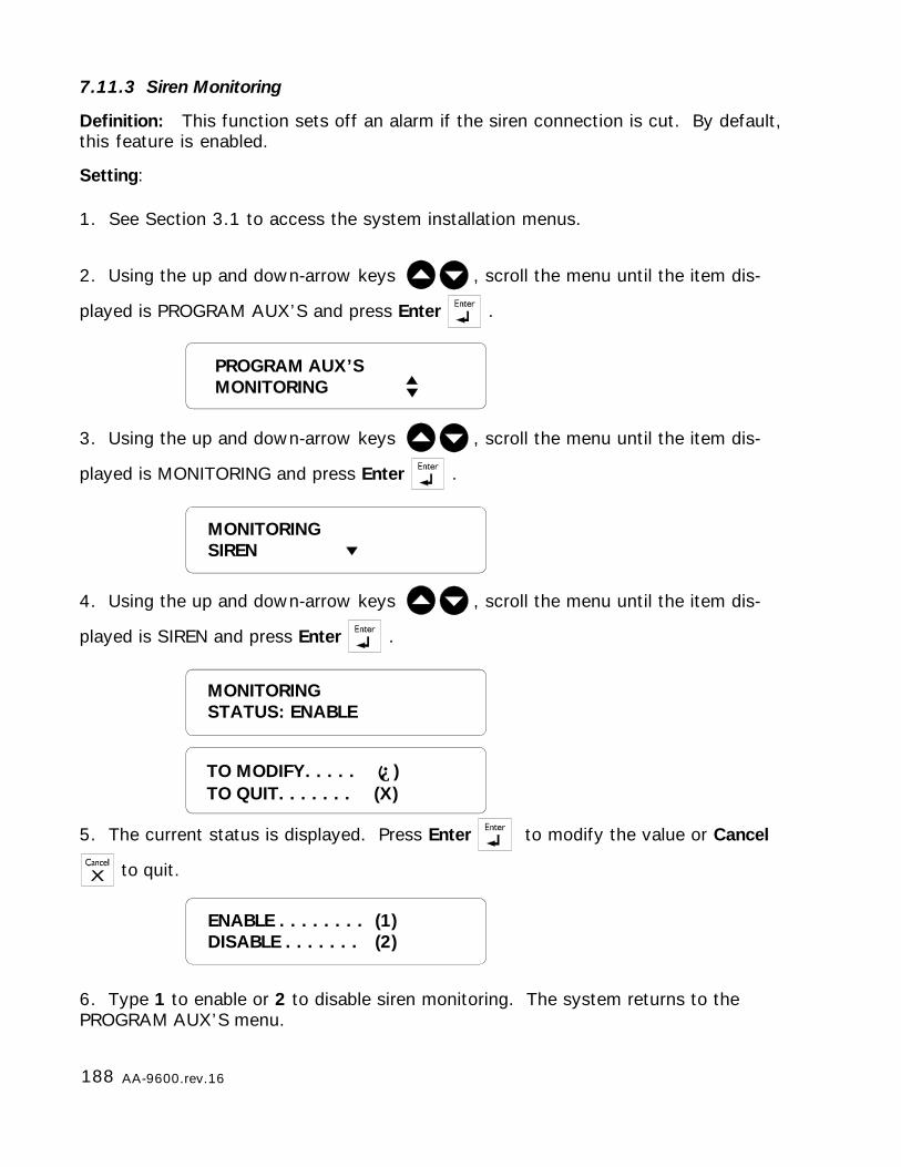
188 AA-9600.rev.16
7.11.3 Siren Monitoring
Definition: This function sets off an alarm if the siren connection is cut. By default,this feature is enabled.
Setting:
1. See Section 3.1 to access the system installation menus.
2. Using the up and down-arrow keys , scroll the menu until the item dis-
played is PROGRAM AUX’S and press Enter .
3. Using the up and down-arrow keys , scroll the menu until the item dis-
played is MONITORING and press Enter .
4. Using the up and down-arrow keys , scroll the menu until the item dis-
played is SIREN and press Enter .
5. The current status is displayed. Press Enter to modify the value or Cancel
to quit.
6. Type 1 to enable or 2 to disable siren monitoring. The system returns to thePROGRAM AUX’S menu.
ENABLE . . . . . . . . (1)DISABLE . . . . . . . (2)
MONITORINGSTATUS: ENABLE
TO MODIFY. . . . . (↵)TO QUIT. . . . . . . (X)
PROGRAM AUX’SMONITORING
MONITORINGSIREN
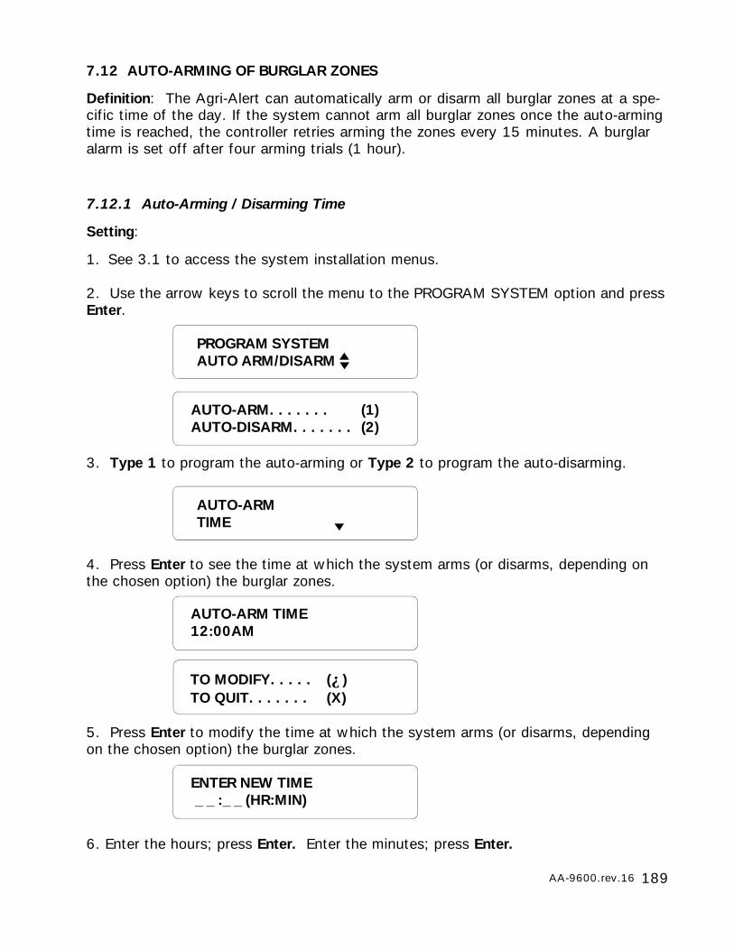
189AA-9600.rev.16
7.12 AUTO-ARMING OF BURGLAR ZONES
Definition: The Agri-Alert can automatically arm or disarm all burglar zones at a spe-cific time of the day. If the system cannot arm all burglar zones once the auto-armingtime is reached, the controller retries arming the zones every 15 minutes. A burglaralarm is set off after four arming trials (1 hour).
7.12.1 Auto-Arming / Disarming Time
Setting:
1. See 3.1 to access the system installation menus.
2. Use the arrow keys to scroll the menu to the PROGRAM SYSTEM option and pressEnter.
3. Type 1 to program the auto-arming or Type 2 to program the auto-disarming.
4. Press Enter to see the time at which the system arms (or disarms, depending onthe chosen option) the burglar zones.
5. Press Enter to modify the time at which the system arms (or disarms, dependingon the chosen option) the burglar zones.
6. Enter the hours; press Enter. Enter the minutes; press Enter.
PROGRAM SYSTEMAUTO ARM/DISARM
AUTO-ARM. . . . . . . (1)AUTO-DISARM. . . . . . . (2)
AUTO-ARMTIME
AUTO-ARM TIME12:00AM
TO MODIFY. . . . . (↵)TO QUIT. . . . . . . (X)
ENTER NEW TIME _ _ :_ _ (HR:MIN)
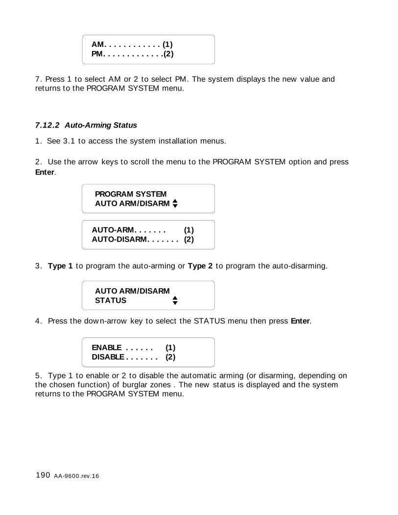
190 AA-9600.rev.16
AM. . . . . . . . . . . . (1)PM. . . . . . . . . . . . .(2)
7. Press 1 to select AM or 2 to select PM. The system displays the new value andreturns to the PROGRAM SYSTEM menu.
7.12.2 Auto-Arming Status
1. See 3.1 to access the system installation menus.
2. Use the arrow keys to scroll the menu to the PROGRAM SYSTEM option and pressEnter.
3. Type 1 to program the auto-arming or Type 2 to program the auto-disarming.
4. Press the down-arrow key to select the STATUS menu then press Enter.
5. Type 1 to enable or 2 to disable the automatic arming (or disarming, depending onthe chosen function) of burglar zones . The new status is displayed and the systemreturns to the PROGRAM SYSTEM menu.
PROGRAM SYSTEMAUTO ARM/DISARM
AUTO-ARM. . . . . . . (1)AUTO-DISARM. . . . . . . (2)
AUTO ARM/DISARMSTATUS
ENABLE . . . . . . (1)DISABLE . . . . . . . (2)
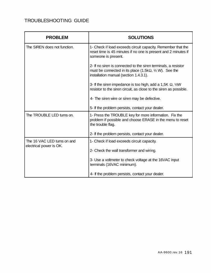
191AA-9600.rev.16
TROUBLESHOOTING GUIDE
PROBLEM SOLUTIONS
The SIREN does not function. 1- Check if load exceeds circuit capacity. Remember that thereset time is 45 minutes if no one is present and 2 minutes ifsomeone is present.
2- If no siren is connected to the siren terminals, a resistormust be connected in its place (1.5kΩ, ½ W). See theinstallation manual (section 1.4.3.1).
3- If the siren impedance is too high, add a 1,5K Ω, ½Wresistor to the siren circuit, as close to the siren as possible.
4- The siren wire or siren may be defective.
5- If the problem persists, contact your dealer.
The TROUBLE LED turns on. 1- Press the TROUBLE key for more information. Fix theproblem if possible and choose ERASE in the menu to resetthe trouble flag.
2- If the problem persists, contact your dealer.
The 16 VAC LED turns on andelectrical power is OK.
1- Check if load exceeds circuit capacity.
2- Check the wall transformer and wiring.
3- Use a voltmeter to check voltage at the 16VAC inputterminals (16VAC minimum).
4- If the problem persists, contact your dealer.
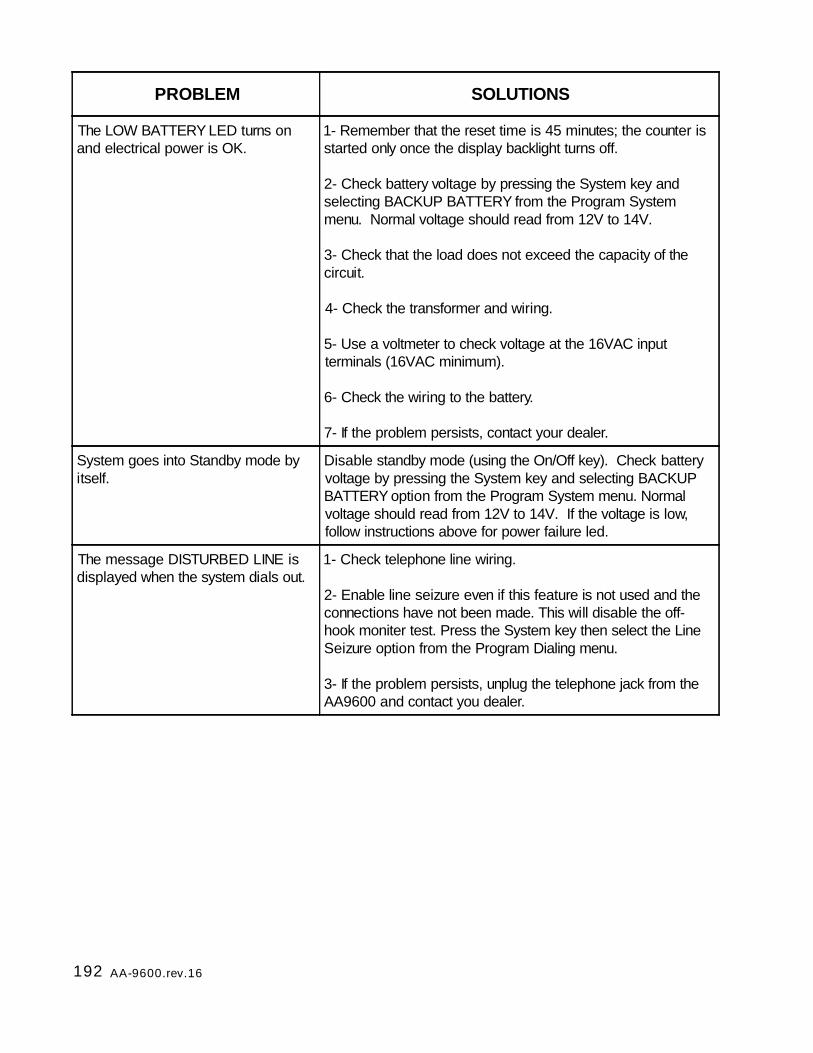
192 AA-9600.rev.16
PROBLEM SOLUTIONS
The LOW BATTERY LED turns onand electrical power is OK.
1- Remember that the reset time is 45 minutes; the counter isstarted only once the display backlight turns off.
2- Check battery voltage by pressing the System key andselecting BACKUP BATTERY from the Program Systemmenu. Normal voltage should read from 12V to 14V.
3- Check that the load does not exceed the capacity of thecircuit.
4- Check the transformer and wiring.
5- Use a voltmeter to check voltage at the 16VAC inputterminals (16VAC minimum).
6- Check the wiring to the battery.
7- If the problem persists, contact your dealer.
System goes into Standby mode byitself.
Disable standby mode (using the On/Off key). Check batteryvoltage by pressing the System key and selecting BACKUPBATTERY option from the Program System menu. Normalvoltage should read from 12V to 14V. If the voltage is low,follow instructions above for power failure led.
The message DISTURBED LINE isdisplayed when the system dials out.
1- Check telephone line wiring.
2- Enable line seizure even if this feature is not used and theconnections have not been made. This will disable the off-hook moniter test. Press the System key then select the LineSeizure option from the Program Dialing menu.
3- If the problem persists, unplug the telephone jack from theAA9600 and contact you dealer.
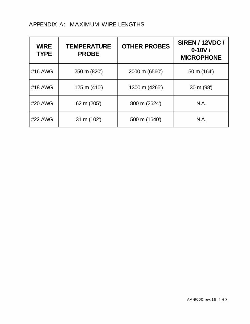
193AA-9600.rev.16
APPENDIX A: MAXIMUM WIRE LENGTHS
WIRETYPE
TEMPERATUREPROBE
OTHER PROBES SIREN / 12VDC /0-10V /
MICROPHONE
#16 AWG 250 m (820') 2000 m (6560') 50 m (164')
#18 AWG 125 m (410') 1300 m (4265') 30 m (98')
#20 AWG 62 m (205') 800 m (2624') N.A.
#22 AWG 31 m (102') 500 m (1640') N.A.
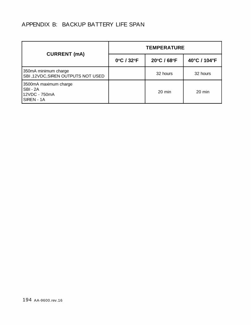
194 AA-9600.rev.16
APPENDIX B: BACKUP BATTERY LIFE SPAN
CURRENT (mA)TEMPERATURE
0oC / 32oF 20oC / 68oF 40°C / 104°F
350mA minimum chargeSBI ,12VDC,SIREN OUTPUTS NOT USED 32 hours 32 hours
3500mA maximum chargeSBI - 2A12VDC - 750mASIREN - 1A
20 min 20 min

195AA-9600.rev.16
APPENDIX C: COMMUNICATION CABLE GAUGE AND MAXIMUMLENGTH RECOMMENDATIONS
On the following pages, maximum distances are given for connecting TP-800 andKPB-400 devices to the AA-9600. Note that each device has an auxiliary load. Forexample, if you connect 2 TP-800 devices and 2 KPB-400 devices to the Agri-Alert,the maximum length for a 22 AWG wire is 1468 feet where each TP-800 and KPB-400 has an auxiliary load of 20mA.
The maximum resistance in Ohms is given by the formula: Rmax = 196 / Pload wherePload is the load power rating in Watts.
The following chart gives the Ohms ratings for different wire gauges:
22 AWG 32.4 Ω/1000ft
20 AWG 20.2 Ω/1000ft
18 AWG 12.78 Ω/1000ft
16 AWG 8.04 Ω/1000ft
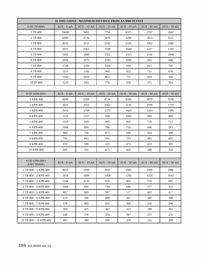
196 AA-9600.rev.16
22 AWG GAUGE - MAXIMUM DISTANCE FROM AA-9600 IN FEET
# OF TP-800's AUX - 0 mA AUX - 10 mA AUX - 20 mA AUX - 30 mA AUX - 40 mA AUX - 50 mA
1 TP-800 10000 9452 7756 6575 5707 5041
2 TP-800 6049 4726 3878 3288 2853 2521
3 TP-800 4033 3151 2585 2192 1902 1680
4 TP-800 3025 2363 1939 1644 1427 1260
5 TP-800 2420 1890 1551 1315 1141 1008
6 TP-800 2016 1575 1293 1096 951 840
7 TP-800 1728 1350 1108 939 815 720
8 TP-800 1512 1182 969 822 713 630
9 TP-800 1344 1050 862 731 634 560
10 TP-800 1210 945 776 658 571 504
# OF KPB-400's AUX - 0 mA AUX - 10 mA AUX - 20 mA AUX - 30 mA AUX - 40 mA AUX - 50 mA
1 KPB-400 6049 5306 4726 4260 3878 3558
2 KPB-400 3025 2653 2363 2130 1939 1779
3 KPB-400 2016 1769 1575 1420 1293 1186
4 KPB-400 1512 1327 1182 1065 969 890
5 KPB-400 1210 1061 945 852 776 712
6 KPB-400 1008 884 788 710 646 593
7 KPB-400 864 758 675 609 554 508
8 KPB-400 756 663 591 533 485 445
9 KPB-400 672 590 525 473 431 395
10 KPB-400 605 531 473 426 388 356
# OF KPB-400'sAND TP-800's AUX - 0 mA AUX - 10 mA AUX - 20 mA AUX - 30 mA AUX - 40 mA AUX - 50 mA
1 TP-800 / 1 KPB-400 4033 3399 2937 2585 2309 2086
2 TP-800 / 2 KPB-400 2016 1699 1468 1293 1154 1043
3 TP-800 / 3 KPB-400 1344 1133 979 862 770 695
4 TP-800 / 4 KPB-400 1008 850 734 646 577 521
5 TP-800 / 5 KPB-400 807 680 587 517 462 417
6 TP-800 / 6 KPB-400 672 566 489 431 385 348
7 TP-800 / 7 KPB-400 576 486 420 369 330 298
8 TP-800 / 8 KPB-400 504 425 367 323 289 261
9 TP-800 / 9 KPB-400 448 378 326 287 257 232
10 TP-800 / 10 KPB-400 403 340 294 259 231 209
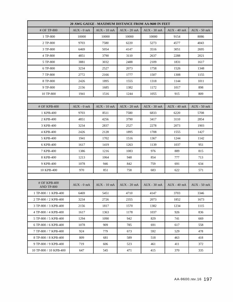
197AA-9600.rev.16
20 AWG GAUGE - MAXIMUM DISTANCE FROM AA-9600 IN FEET
# OF TP-800 AUX - 0 mA AUX - 10 mA AUX - 20 mA AUX - 30 mA AUX - 40 mA AUX - 50 mA
1 TP-800 10000 10000 10000 10000 9154 8086
2 TP-800 9703 7580 6220 5273 4577 4043
3 TP-800 6469 5054 4147 3516 3051 2695
4 TP-800 4851 3790 3110 2637 2288 2021
5 TP-800 3881 3032 2488 2109 1831 1617
6 TP-800 3234 2527 2073 1758 1526 1348
7 TP-800 2772 2166 1777 1507 1308 1155
8 TP-800 2426 1895 1555 1318 1144 1011
9 TP-800 2156 1685 1382 1172 1017 898
10 TP-800 1941 1516 1244 1055 915 809
# OF KPB-400 AUX - 0 mA AUX - 10 mA AUX - 20 mA AUX - 30 mA AUX - 40 mA AUX - 50 mA
1 KPB-400 9703 8511 7580 6833 6220 5708
2 KPB-400 4851 4256 3790 3417 3110 2854
3 KPB-400 3234 2837 2527 2278 2073 1903
4 KPB-400 2426 2128 1895 1708 1555 1427
5 KPB-400 1941 1702 1516 1367 1244 1142
6 KPB-400 1617 1419 1263 1139 1037 951
7 KPB-400 1386 1216 1083 976 889 815
8 KPB-400 1213 1064 948 854 777 713
9 KPB-400 1078 946 842 759 691 634
10 KPB-400 970 851 758 683 622 571
# OF KPB-400AND TP-800 AUX - 0 mA AUX - 10 mA AUX - 20 mA AUX - 30 mA AUX - 40 mA AUX - 50 mA
1 TP-800 / 1 KPB-400 6469 5451 4710 4147 3703 3346
2 TP-800 / 2 KPB-400 3234 2726 2355 2073 1852 1673
3 TP-800 / 3 KPB-400 2156 1817 1570 1382 1234 1115
4 TP-800 / 4 KPB-400 1617 1363 1178 1037 926 836
5 TP-800 / 5 KPB-400 1294 1090 942 829 741 669
6 TP-800 / 6 KPB-400 1078 909 785 691 617 558
7 TP-800 / 7 KPB-400 924 779 673 592 529 478
8 TP-800 / 8 KPB-400 809 681 589 518 463 418
9 TP-800 / 9 KPB-400 719 606 523 461 411 372
10 TP-800 / 10 KPB-400 647 545 471 415 370 335
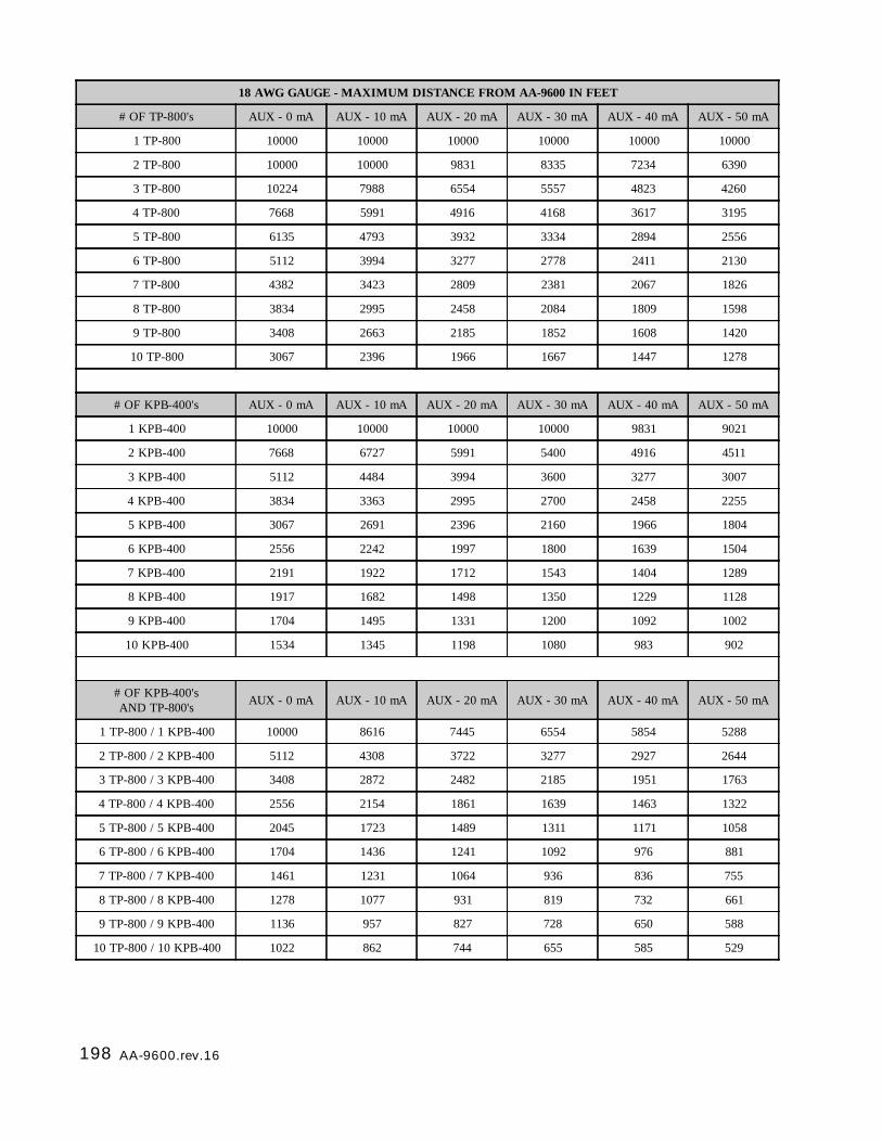
198 AA-9600.rev.16
18 AWG GAUGE - MAXIMUM DISTANCE FROM AA-9600 IN FEET
# OF TP-800's AUX - 0 mA AUX - 10 mA AUX - 20 mA AUX - 30 mA AUX - 40 mA AUX - 50 mA
1 TP-800 10000 10000 10000 10000 10000 10000
2 TP-800 10000 10000 9831 8335 7234 6390
3 TP-800 10224 7988 6554 5557 4823 4260
4 TP-800 7668 5991 4916 4168 3617 3195
5 TP-800 6135 4793 3932 3334 2894 2556
6 TP-800 5112 3994 3277 2778 2411 2130
7 TP-800 4382 3423 2809 2381 2067 1826
8 TP-800 3834 2995 2458 2084 1809 1598
9 TP-800 3408 2663 2185 1852 1608 1420
10 TP-800 3067 2396 1966 1667 1447 1278
# OF KPB-400's AUX - 0 mA AUX - 10 mA AUX - 20 mA AUX - 30 mA AUX - 40 mA AUX - 50 mA
1 KPB-400 10000 10000 10000 10000 9831 9021
2 KPB-400 7668 6727 5991 5400 4916 4511
3 KPB-400 5112 4484 3994 3600 3277 3007
4 KPB-400 3834 3363 2995 2700 2458 2255
5 KPB-400 3067 2691 2396 2160 1966 1804
6 KPB-400 2556 2242 1997 1800 1639 1504
7 KPB-400 2191 1922 1712 1543 1404 1289
8 KPB-400 1917 1682 1498 1350 1229 1128
9 KPB-400 1704 1495 1331 1200 1092 1002
10 KPB-400 1534 1345 1198 1080 983 902
# OF KPB-400'sAND TP-800's AUX - 0 mA AUX - 10 mA AUX - 20 mA AUX - 30 mA AUX - 40 mA AUX - 50 mA
1 TP-800 / 1 KPB-400 10000 8616 7445 6554 5854 5288
2 TP-800 / 2 KPB-400 5112 4308 3722 3277 2927 2644
3 TP-800 / 3 KPB-400 3408 2872 2482 2185 1951 1763
4 TP-800 / 4 KPB-400 2556 2154 1861 1639 1463 1322
5 TP-800 / 5 KPB-400 2045 1723 1489 1311 1171 1058
6 TP-800 / 6 KPB-400 1704 1436 1241 1092 976 881
7 TP-800 / 7 KPB-400 1461 1231 1064 936 836 755
8 TP-800 / 8 KPB-400 1278 1077 931 819 732 661
9 TP-800 / 9 KPB-400 1136 957 827 728 650 588
10 TP-800 / 10 KPB-400 1022 862 744 655 585 529

199AA-9600.rev.16
16 AWG GAUGE - MAXIMUM DISTANCE FROM AA-9600 IN FEET
# OF TP-800's AUX - 0 mA AUX - 10 mA AUX - 20 mA AUX - 30 mA AUX - 40 mA AUX - 50 mA
1 TP-800 10000 10000 10000 10000 10000 10000
2 TP-800 10000 10000 10000 10000 10000 10000
3 TP-800 10000 10000 10000 8833 7666 6772
4 TP-800 12189 9523 7813 6624 5750 5079
5 TP-800 9751 7618 6251 5300 4600 4063
6 TP-800 8126 6348 5209 4416 3833 3386
7 TP-800 6965 5442 4465 3785 3285 2902
8 TP-800 6095 4761 3907 3312 2875 2539
9 TP-800 5417 4232 3473 2944 2555 2257
10 TP-800 4876 3809 3125 2650 2300 2032
# OF KPB-400's AUX - 0 mA AUX - 10 mA AUX - 20 mA AUX - 30 mA AUX - 40 mA AUX - 50 mA
1 KPB-400 10000 10000 10000 10000 10000 10000
2 KPB-400 10000 10000 9523 8584 7813 7170
3 KPB-400 8126 7128 6348 5723 5209 4780
4 KPB-400 6095 5346 4761 4292 3907 3585
5 KPB-400 4876 4277 3809 3434 3125 2868
6 KPB-400 4063 3564 3174 2861 2604 2390
7 KPB-400 3483 3055 2721 2453 2232 2049
8 KPB-400 3047 2673 2381 2146 1953 1793
9 KPB-400 2709 2376 2116 1908 1736 1593
10 KPB-400 2438 2138 1905 1717 1563 1434
# OF KPB-400'sAND TP-800's AUX - 0 mA AUX - 10 mA AUX - 20 mA AUX - 30 mA AUX - 40 mA AUX - 50 mA
1 TP-800 / 1 KPB-400 10000 10000 10000 10000 9305 8406
2 TP-800 / 2 KPB-400 8126 6848 5917 5209 4652 4203
3 TP-800 / 3 KPB-400 5417 4565 3945 3473 3102 2802
4 TP-800 / 4 KPB-400 4063 3424 2959 2604 2326 2102
5 TP-800 / 5 KPB-400 3250 2739 2367 2084 1861 1681
6 TP-800 / 6 KPB-400 2709 2283 1972 1736 1551 1401
7 TP-800 / 7 KPB-400 2322 1957 1691 1488 1329 1201
8 TP-800 / 8 KPB-400 2032 1712 1479 1302 1163 1051
9 TP-800 / 9 KPB-400 1806 1522 1315 1158 1034 934
10 TP-800 / 10 KPB-400 1625 1370 1183 1042 930 841

200 AA-9600.rev.16
100 Medical Alarms 140 General Alarms 301 16VAC Input Trouble
100 Medical 140 Zone Alarm 302 Low system battery
101 Pendant transmitter 141 Pooling loop open 303 RAM checksum bad
102 Fail to report in 142 Pooling loop close 304 ROM checksum bad
110 Fire Alarms 143 Expansion module failure 305 System reset
110 Fire alarm 144 Sensor tamper 306 Panel program changed
111 Smoke 145 Expansion module temper 307 Self-test failure
112 Combustion 146 Silent alarm 308 Auto-standby
113 Water Flow 150-160 24 Hour Non-Burglary 309 Battery test failure
114 Heat 150 24 Hour non-burg 310 Ground fault
115 Pull Station 151 Gas detected 320 Sounder/Relay Troubles
116 Duct 152 Refrigeration 320 Sounder/relay
117 Flame 153 Loss of heat 321 Defective Siren
118 Near alarm 154 Water leakage 322 Bell 2
120 Panic Alarms 155 Foil break 323 Alarm relay
120 Panic alarm 156 Day Trouble 324 Trouble relay
121 Duress 157 Low bottled gas level 325 Reversing
122 Silent 158 High temp 330-340 System Peripheral Troubles
123 Audible 159 Low temp 330 System Periphral
130 Burglar Alarms 161 Low of air flow 331 Polling loop open
130 Burglary 200-210 Fire supervisory 332 Polling loop close
131 Perimeter 200 Fire supervisory 333 Exp. module failure
132 Interior 201 Low water pressure 334 Repeater failure
133 24 Hour 202 Low CC2 335 Local printer pacer out
134 Entry/Exit 203 Gate valve sensor 336 Local printer failure
135 Day/Night 204 Low water level 337 Exp. Mod DC Loss
136 Outdoor 205 Pump activated 338 Exp. Mod Low Batt.
137 Tamper 206 Pump failure 339 Exp. Mod Reset
138 Near Alarm 300-310 System Troubles 341 Exp. Mod Tamper
139 Silent Burg 300
High Internal Temp.Low Internal Temp.12VDC Output TroubleSBI Output TroubleSystem Trouble
APPENDIX D: CONTACT ID REPORT AND RESTORE CODES
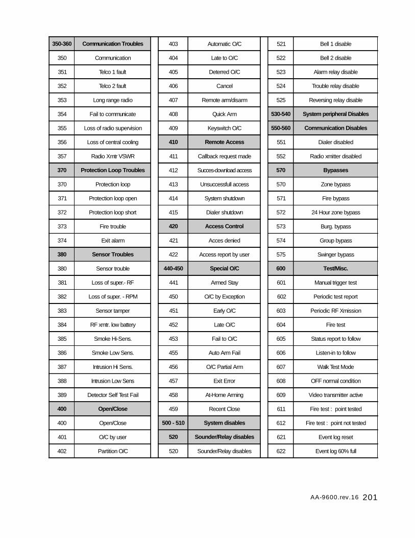
201AA-9600.rev.16
350-360 Communication Troubles 403 Automatic O/C 521 Bell 1 disable
350 Communication 404 Late to O/C 522 Bell 2 disable
351 Telco 1 fault 405 Deterred O/C 523 Alarm relay disable
352 Telco 2 fault 406 Cancel 524 Trouble relay disable
353 Long range radio 407 Remote arm/disarm 525 Reversing relay disable
354 Fail to communicate 408 Quick Arm 530-540 System peripheral Disables
355 Loss of radio supervision 409 Keyswitch O/C 550-560 Communication Disables
356 Loss of central cooling 410 Remote Access 551 Dialer disabled
357 Radio Xmtr VSWR 411 Callback request made 552 Radio xmitter disabled
370 Protection Loop Troubles 412 Succes-download access 570 Bypasses
370 Protection loop 413 Unsuccessfull access 570 Zone bypass
371 Protection loop open 414 System shutdown 571 Fire bypass
372 Protection loop short 415 Dialer shutdown 572 24 Hour zone bypass
373 Fire trouble 420 Access Control 573 Burg. bypass
374 Exit alarm 421 Acces denied 574 Group bypass
380 Sensor Troubles 422 Access report by user 575 Swinger bypass
380 Sensor trouble 440-450 Special O/C 600 Test/Misc.
381 Loss of super.- RF 441 Armed Stay 601 Manual trigger test
382 Loss of super. - RPM 450 O/C by Exception 602 Periodic test report
383 Sensor tamper 451 Early O/C 603 Periodic RF Xmission
384 RF xmtr. low battery 452 Late O/C 604 Fire test
385 Smoke Hi-Sens. 453 Fail to O/C 605 Status report to follow
386 Smoke Low Sens. 455 Auto Arm Fail 606 Listen-in to follow
387 Intrusion Hi Sens. 456 O/C Partial Arm 607 Walk Test Mode
388 Intrusion Low Sens 457 Exit Error 608 OFF normal condition
389 Detector Self Test Fail 458 At-Home Arming 609 Video transmitter active
400 Open/Close 459 Recent Close 611 Fire test : point tested
400 Open/Close 500 - 510 System disables 612 Fire test : point not tested
401 O/C by user 520 Sounder/Relay disables 621 Event log reset
402 Partition O/C 520 Sounder/Relay disables 622 Event log 60% full
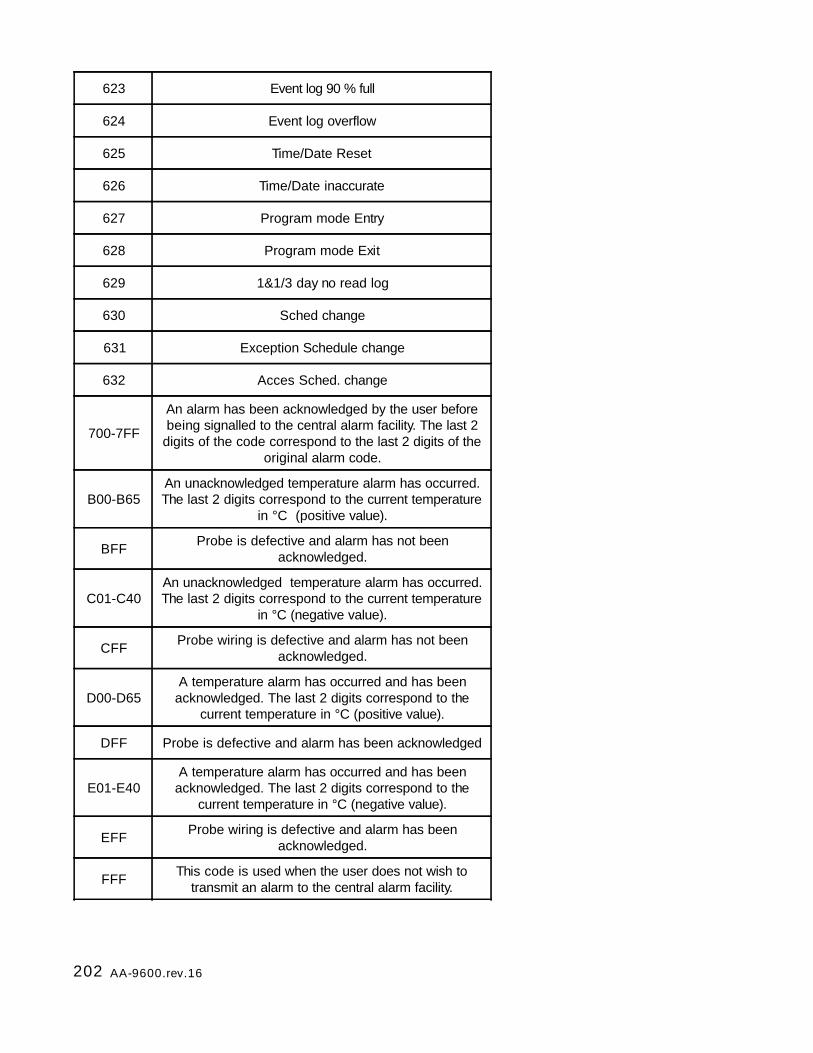
202 AA-9600.rev.16
623 Event log 90 % full
624 Event log overflow
625 Time/Date Reset
626 Time/Date inaccurate
627 Program mode Entry
628 Program mode Exit
629 1&1/3 day no read log
630 Sched change
631 Exception Schedule change
632 Acces Sched. change
700-7FF
An alarm has been acknowledged by the user beforebeing signalled to the central alarm facility. The last 2
digits of the code correspond to the last 2 digits of theoriginal alarm code.
B00-B65An unacknowledged temperature alarm has occurred.The last 2 digits correspond to the current temperature
in °C (positive value).
BFF Probe is defective and alarm has not beenacknowledged.
C01-C40An unacknowledged temperature alarm has occurred.The last 2 digits correspond to the current temperature
in °C (negative value).
CFF Probe wiring is defective and alarm has not beenacknowledged.
D00-D65A temperature alarm has occurred and has been
acknowledged. The last 2 digits correspond to thecurrent temperature in °C (positive value).
DFF Probe is defective and alarm has been acknowledged
E01-E40A temperature alarm has occurred and has been
acknowledged. The last 2 digits correspond to thecurrent temperature in °C (negative value).
EFF Probe wiring is defective and alarm has beenacknowledged.
FFF This code is used when the user does not wish totransmit an alarm to the central alarm facility.
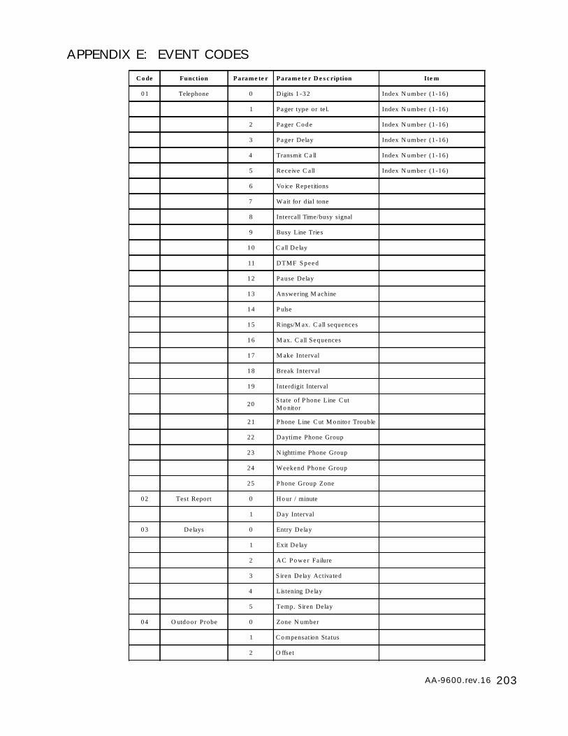
203AA-9600.rev.16
APPENDIX E: EVENT CODES
C o de Function Parame te r Parame te r D e s c ription Ite m
0 1 Telephone 0 D igits 1 -32 Index N umber (1-16)
1 Pager type or te l. Index N umber (1-16)
2 Pager C o d e Index N umber (1-16)
3 Pager Delay Index N umber (1-16)
4 Transmit C a ll Index N umber (1-16)
5 Receive C all Index N umber (1-16)
6 Vo ice Repetitions
7 Wait for dial tone
8 Intercall Time/busy signal
9 Busy Line Tries
1 0 C all De lay
11 DTM F S p e e d
1 2 Pause Delay
1 3 Answering M achine
1 4 P ulse
1 5 Rings/M ax. C all sequences
1 6 M ax. C all Sequences
1 7 M ake Interval
1 8 Break Interval
1 9 Interdigit Interval
20S tate of P hone Line C utM o nitor
2 1 P hone Line C ut M o nito r Trouble
22 Daytime Phone Group
23 N ighttime Phone Group
24 Weekend Phone Group
25 P hone Group Zone
0 2 Test Report 0 H o ur / minute
1 Day Interval
0 3 De lays 0 Entry Delay
1 Exit Delay
2 A C P o w e r Failure
3 S iren Delay Activa ted
4 Listening De lay
5 Temp. Siren Delay
0 4 O utdoor Probe 0 Zone N umber
1 C o mpensation Status
2 O ffset
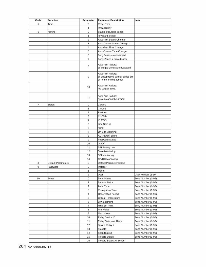
204 AA-9600.rev.16
Code Function Parameter Parameter Description Item
5 Time 0 Reset Time
1 Recall Delay
6 Arming 0 Status of Burglar Zones
1 keyboard locked
2 Auto-Arm Status Change
3 Auto-Disarm Status Change
4 Auto-Arm Time Change
5 Auto-Disarm Time Change
6 Burg.Zones = auto-armed
7 Burg. Zones = auto-disarm.
8Auto-Arm Failure: all burglar zones are bypassed
9Auto-Arm Failure: all unbypassed burglar zones are at-home arming zones!
10Auto-Arm Failure: No burglar zone.
11Auto-Arm Failure: system cannot be armed
7 Status 0 Card#1
1 Card#2
2 Restore
3 12h/24h
4 ID MSG
5 Line Seizure
6 °C/°F
7 On-Site Listening
8 AC Power Failure
9 Password Status
10 On/Off
11 SBI Battery Low
12 Siren Monitoring
13 SBI Monitoring
14 12VDC Monitoring
8 Default Parameters 0 Default Parameter Status
9 Password 0 Installer
1 Master
2 User User Number (1-10)
10 Zones 0 Zone Status Zone Number (1-96)
1 Bypass Status Zone Number (1-96)
2 Zone Type Zone Number (1-96)
3 Recognition Time Zone Number (1-96)
4 Observation Period Zone Number (1-96)
5 Critical Temperature Zone Number (1-96)
6 Low Set Point Zone Number (1-96)
7 High Set Point Zone Number (1-96)
8 Min. Value Zone Number (1-96)
9 Max. Value Zone Number (1-96)
10 Relay Device ID Zone Number (1-96)
11 Relay Status on Alarm Zone Number (1-96)
12 Device Relay # Zone Number (1-96)
13 Trouble Zone Number (1-96)
14 Siren/Dialout Zone Number (1-96)
15 Trouble Status Zone Number (1-96)
16 Trouble Status All Zones

205AA-9600.rev.16
Code Function Parameter Parameter Description Item
11 Partitions 0 Partition #1 Zone Number (1-96)
1 Partition #2 Zone Number (1-96)
2 Partition #3 Zone Number (1-96)
3 Partition #4 Zone Number (1-96)
4 Partition #5 Zone Number (1-96)
5 Partition #6 Zone Number (1-96)
6 Partition #7 Zone Number (1-96)
7 Partition #8 Zone Number (1-96)
8 Partition #9 Zone Number (1-96)
9 Partition #10 Zone Number (1-96)
10 Partition #11 Zone Number (1-96)
11 Partition #12 Zone Number (1-96)
12 Partition #13 Zone Number (1-96)
13 Partition #14 Zone Number (1-96)
14 Partition #15 Zone Number (1-96)
15 Partition #16 Zone Number (1-96)
16 Partition Status Partition Number (1-16)
12 Relays 0-97 Relay Status (Device #) 0 - disabled; 1 - enabled
13 Database 0 Local Zone 1 Device Number (1-99)
1 Local Zone 2 Device Number (1-99)
2 Local Zone 3 Device Number (1-99)
3 Local Zone 4 Device Number (1-99)
4 Local Zone 5 Device Number (1-99)
5 Local Zone 6 Device Number (1-99)
6 Local Zone 7 Device Number (1-99)
7 Local Zone 8 Device Number (1-99)
8 Local Zone 9 Device Number (1-99)
9 Local Zone 10 Device Number (1-99)
10 Local Zone 11 Device Number (1-99)
11 Local Zone 12 Device Number (1-99)
12 Local Zone 13 Device Number (1-99)
13 Local Zone 14 Device Number (1-99)
14 Local Zone 15 Device Number (1-99)
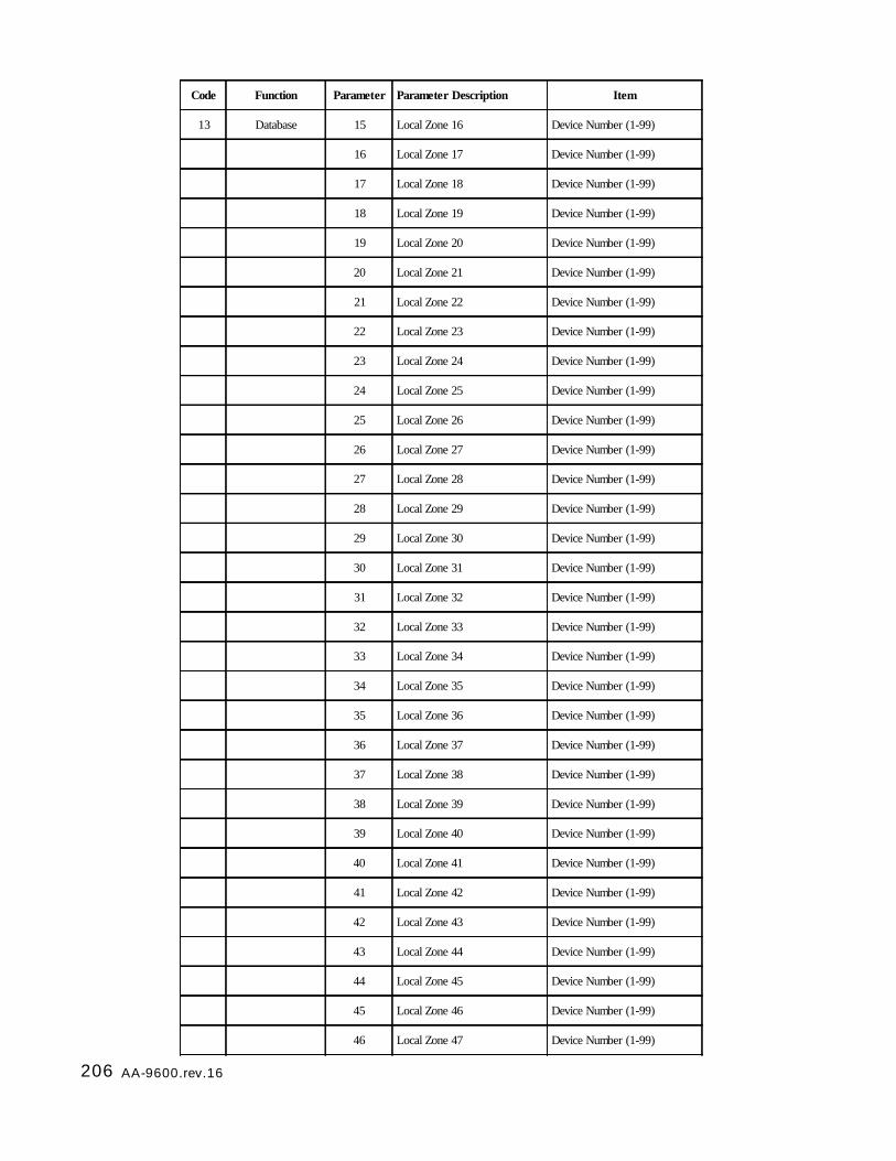
206 AA-9600.rev.16
Code Function Parameter Parameter Description Item
13 Database 15 Local Zone 16 Device Number (1-99)
16 Local Zone 17 Device Number (1-99)
17 Local Zone 18 Device Number (1-99)
18 Local Zone 19 Device Number (1-99)
19 Local Zone 20 Device Number (1-99)
20 Local Zone 21 Device Number (1-99)
21 Local Zone 22 Device Number (1-99)
22 Local Zone 23 Device Number (1-99)
23 Local Zone 24 Device Number (1-99)
24 Local Zone 25 Device Number (1-99)
25 Local Zone 26 Device Number (1-99)
26 Local Zone 27 Device Number (1-99)
27 Local Zone 28 Device Number (1-99)
28 Local Zone 29 Device Number (1-99)
29 Local Zone 30 Device Number (1-99)
30 Local Zone 31 Device Number (1-99)
31 Local Zone 32 Device Number (1-99)
32 Local Zone 33 Device Number (1-99)
33 Local Zone 34 Device Number (1-99)
34 Local Zone 35 Device Number (1-99)
35 Local Zone 36 Device Number (1-99)
36 Local Zone 37 Device Number (1-99)
37 Local Zone 38 Device Number (1-99)
38 Local Zone 39 Device Number (1-99)
39 Local Zone 40 Device Number (1-99)
40 Local Zone 41 Device Number (1-99)
41 Local Zone 42 Device Number (1-99)
42 Local Zone 43 Device Number (1-99)
43 Local Zone 44 Device Number (1-99)
44 Local Zone 45 Device Number (1-99)
45 Local Zone 46 Device Number (1-99)
46 Local Zone 47 Device Number (1-99)
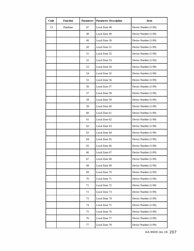
207AA-9600.rev.16
Code Function Parameter Parameter Description Item
13 Database 47 Local Zone 48 Device Number (1-99)
48 Local Zone 49 Device Number (1-99)
49 Local Zone 50 Device Number (1-99)
50 Local Zone 51 Device Number (1-99)
51 Local Zone 52 Device Number (1-99)
52 Local Zone 53 Device Number (1-99)
53 Local Zone 54 Device Number (1-99)
54 Local Zone 55 Device Number (1-99)
55 Local Zone 56 Device Number (1-99)
56 Local Zone 57 Device Number (1-99)
57 Local Zone 58 Device Number (1-99)
58 Local Zone 59 Device Number (1-99)
59 Local Zone 60 Device Number (1-99)
60 Local Zone 61 Device Number (1-99)
61 Local Zone 62 Device Number (1-99)
62 Local Zone 63 Device Number (1-99)
63 Local Zone 64 Device Number (1-99)
64 Local Zone 65 Device Number (1-99)
65 Local Zone 66 Device Number (1-99)
66 Local Zone 67 Device Number (1-99)
67 Local Zone 68 Device Number (1-99)
68 Local Zone 69 Device Number (1-99)
69 Local Zone 70 Device Number (1-99)
70 Local Zone 71 Device Number (1-99)
71 Local Zone 72 Device Number (1-99)
72 Local Zone 73 Device Number (1-99)
73 Local Zone 74 Device Number (1-99)
74 Local Zone 75 Device Number (1-99)
75 Local Zone 76 Device Number (1-99)
76 Local Zone 77 Device Number (1-99)
77 Local Zone 78 Device Number (1-99)
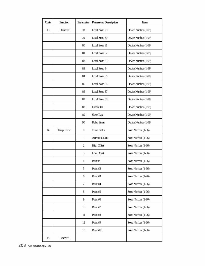
208 AA-9600.rev.16
Code Function Parameter Parameter Description Item
13 Database 78 Local Zone 79 Device Number (1-99)
79 Local Zone 80 Device Number (1-99)
80 Local Zone 81 Device Number (1-99)
81 Local Zone 82 Device Number (1-99)
82 Local Zone 83 Device Number (1-99)
83 Local Zone 84 Device Number (1-99)
84 Local Zone 85 Device Number (1-99)
85 Local Zone 86 Device Number (1-99)
86 Local Zone 87 Device Number (1-99)
87 Local Zone 88 Device Number (1-99)
88 Device ID Device Number (1-99)
89 Slave Type Device Number (1-99)
90 Relay Status Device Number (1-99)
14 Temp. Curve 0 Curve Status Zone Number (1-96)
1 Activation Date Zone Number (1-96)
2 High Offset Zone Number (1-96)
3 Low Offset Zone Number (1-96)
4 Point #1 Zone Number (1-96)
5 Point #2 Zone Number (1-96)
6 Point #3 Zone Number (1-96)
7 Point #4 Zone Number (1-96)
8 Point #5 Zone Number (1-96)
9 Point #6 Zone Number (1-96)
10 Point #7 Zone Number (1-96)
11 Point #8 Zone Number (1-96)
12 Point #9 Zone Number (1-96)
13 Point #10 Zone Number (1-96)
15 Reserved
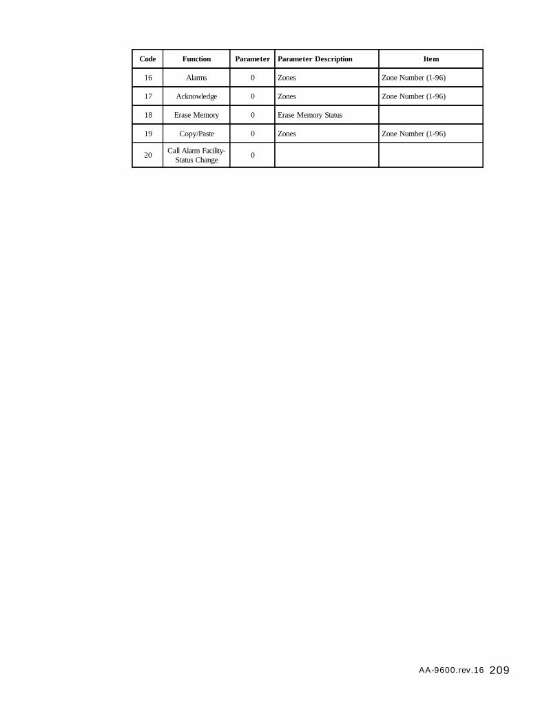
209AA-9600.rev.16
Code Function Parameter Parameter Description Item
16 Alarms 0 Zones Zone Number (1-96)
17 Acknowledge 0 Zones Zone Number (1-96)
18 Erase Memory 0 Erase Memory Status
19 Copy/Paste 0 Zones Zone Number (1-96)
20 Call Alarm Facility-Status Change 0
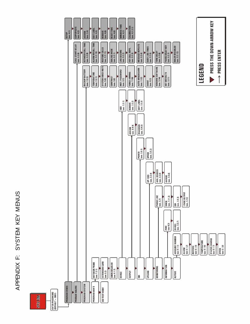
APP
END
IX F
: S
YSTEM
KEY
MEN
US
211AA-9600.rev.16
GLOSSARY OF TERMS
ACKNOWLEDGMENT: The indication to the system that an alarm message has beenreceived. The alarm acknowledgment stops the dialout sequence and can be ex-ecuted over the phone or from the keypad.
ALARM MEMORY: A record of the ten last alarms stored by the system (see Section7.4).
AT-HOME ARMING: Burglar zones around the perimeter are armed but at-home zonesare bypassed after exit delay has elapsed if no one has left the building (see section4.1.2).
BREAK: On pulse dialing lines, the length of the open circuit portion of the pulseperiod (see Section 5.2.1.3).
BURGLAR ZONE: A zone used for detecting break-ins. Delays are provided to allowauthorized entries and exits. All burglar zones are armed or disarmed as a group usinga special key sequence (see Section 4.1.2).
BUSY LINE TRIES: In the dialout sequence, the number of times the system will retrya line when the number is busy. (see Section 5.2.5).
CALL START DELAY: The time between the validation of an alarm and the beginningof the dialout sequence (see Section 5.2.8).
CALL SEQUENCES: In the dialout sequence, the number of times the phone numbersin memory are called for a given alarm (See Section 5.2.3).
DEFAULT: A value permanently stored in memory and used to define a parameter inthe absence of a user-defined value (see Section 3.10).
DIALOUT SEQUENCE: Upon validation of an alarm, the calling of the phone numbersin memory according to a specified order until each number is reached a specifiednumber of times (see Section 5.2).
DTMF SPEED (Dual Tone Multiple Frequency Speed): The dialing speed used on tonedialing lines (see Section 5.2.1.2).
EOLR (End Of Line Resistor): A resistor added to an alarm circuit and used for detect-ing wire problems (see Section 4.1.1).
ENTRY DELAY: The time delay for entering the site without setting off an alarm (seeSection 7.8).
EXIT DELAY: The time delay for exiting the site without setting off an alarm (seeSection 7.9). This applies to burglar zones only.
EXTENSION CARD: An electronic card that plugs into the main board and allows 8additional zone definitions (marked V-102) (see Section 1.2.2).
FORCE ARMING: Delay burglar zones are armed even if they are in an alarm state(see section 7.10).
INTERCALL TIME: In the dialout sequence, the delay after a phone number has beencalled, before proceeding with the next number (see Section 5.2.9).
212 AA-9600.rev.16
INTERDIGIT INTERVAL: On pulse dialing lines, the length of the interval between eachdigit (see Section 5.2.1.3).
LED: Light Emitting Diode — An electronic device used to indicate the status ofvarious functions on the front panel.
MAIN BOARD: The electronic card located at the bottom of the Agri-Alert enclosure(see Section 1.2.1).
MAKE: On pulse dialing lines, the length of the closed circuit portion of the pulseperiod (see Section 5.2.1.3).
MESSAGE REPETITIONS: The number of times a voice message is delivered when analarm condition is reported (See Section 5.2.4).
NORMALLY CLOSED DEVICE: A device that triggers an alarm by opening a closedcircuit path (see Section 4.1.1).
NORMALLY OPEN DEVICE: A device that triggers an alarm by closing an open circuitpath (see Section 4.1.1).
PARTITION: A group of zones used for activating or bypassing several zones at once(see Section 7.6).
PULSE SPEED: This is the dialing speed used on pulse dialing lines, consisting of amake, a break and an interdigit interval (see Section 5.2.1.3).
RECALL TIME: The length of time between the time the alarm is acknowledged andthe time the dialout sequence is relaunched (as long as the zone has not returned toits normal state for the duration of reset time (see Section 5.2.10).
SBI: Communication bus used to connect the Agri-Alert devices together (see section1.5).
SENSOR: A device connected to the Agri-Alert used to detect alarm conditions (seeSection 1.4.1).
SIREN DURATION: The duration of the siren when an alarm condition is reported (seeSection 7.10.1).
ZONE: An input configured to respond to the sensor connected to it (See Section4.1).
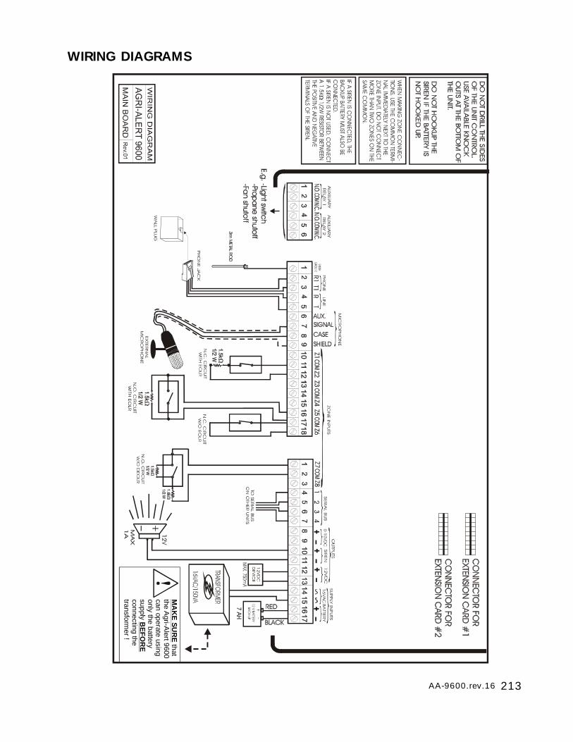
213AA-9600.rev.16
WIRING DIAGRAMS
MA
KE
SU
RE
BE
FO
RE
that the A
gri-Alert 9600
can operate using only the battery supply
connecting the transform
er !
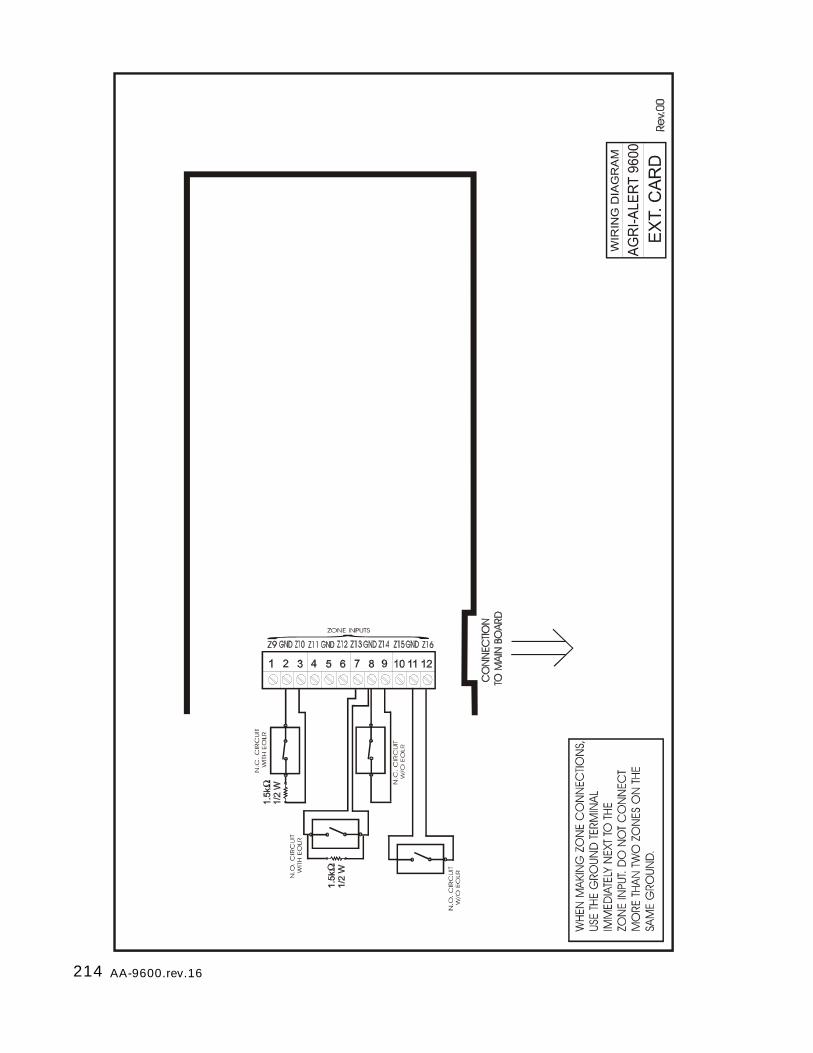
214 AA-9600.rev.16
215AA-9600.rev.16
TECHNICAL SPECIFICATIONS
TYPE: AA9600
SUPPLY INPUT16VAC: 16Vac, 130VA, 50-60HzBATTERY: Rechargeable, sealed, lead-acid, 12V-7.5AH
OUTPUTSAUXILIARY RELAY 1-2: 28Vdc, 5A max.SERIAL BUS: 28Vdc, 2A max.0-10VDC: 0-10Vdc, 25mA max.SIREN: 12Vdc, 1A max.12VDC: 12Vdc, 750mA max.
OPERATING TEMPERATURE: 32 TO 104°F (0 TO 40°C) Indoor use onlyPOLLUTION DEGREE : 2INSTALLATION CATEGORY: 2ALTITUDE: 7900 Ft.Max (2000 Meters Max)HUMIDITY: 95% max.CLEANING: Gentle soap and water.
TYPE: TRANSFORMER BOX
SUPPLY INPUT: 115/230Vac ±10% (SW1 SWITCH), 50-60Hz, 100 W max.Fuse F1 = 3A FAST BLOW
OUTPUT: 16Vac, 130Va
OPERATING TEMPERATURE: 32 TO 104°F (0 TO 40°C) Indoor use onlyPOLLUTION DEGREE : 2INSTALLATION CATEGORY: 2ALTITUDE: 7900 Ft.Max (2000 Meters Max)HUMIDITY: 95% max.CLEANING: Gentle soap and water.
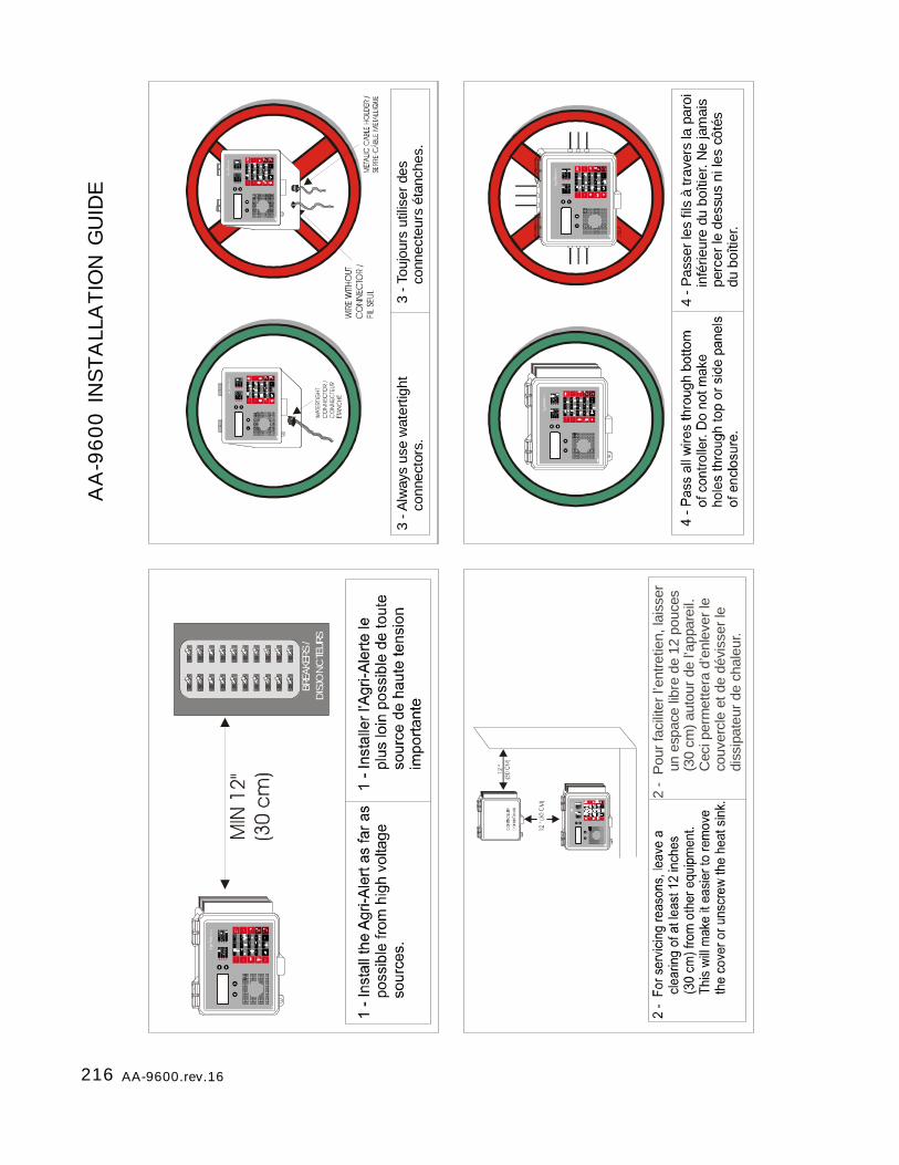
216 AA-9600.rev.16
AA
-9600 I
NSTA
LLA
TIO
N G
UID
E
ON
OFF
ON
OFF
ON
OFF
ON
OFF
ON
OFF
ON
OFF
ON
OFF
ON
OFF
ON
OFF
ON
OFF
ON
OFF
ON
OFF
ON
OFF
ON
OFF
ON
OFF
ON
OFF
ON
OFF
ON
OFF
ON
OF F
ON
OF F
BREA
KERS
/ D
ISJO
NC
TEUR
S
4 - P
asse
r les
fils
à tr
aver
s la
par
oi
i
nfér
ieur
e du
boî
tier.
Ne
jam
ais
p
erce
r le
dess
us n
i les
côt
és
d
u bo
îtier
.
3 - A
lway
s us
e w
ater
tight
con
nect
ors.
3 - T
oujo
urs
utili
ser d
es
c
onne
cteu
rs é
tanc
hes.
2 -
Pou
r fac
ilite
r l’e
ntre
tien,
lais
ser
un
espa
ce li
bre
de 1
2 po
uces
(30
cm) a
utou
r de
l’ap
pare
il.
Cec
i per
met
tera
d’e
nlev
er le
c
ouve
rcle
et d
e dé
viss
er le
d
issi
pate
ur d
e ch
aleu
r.
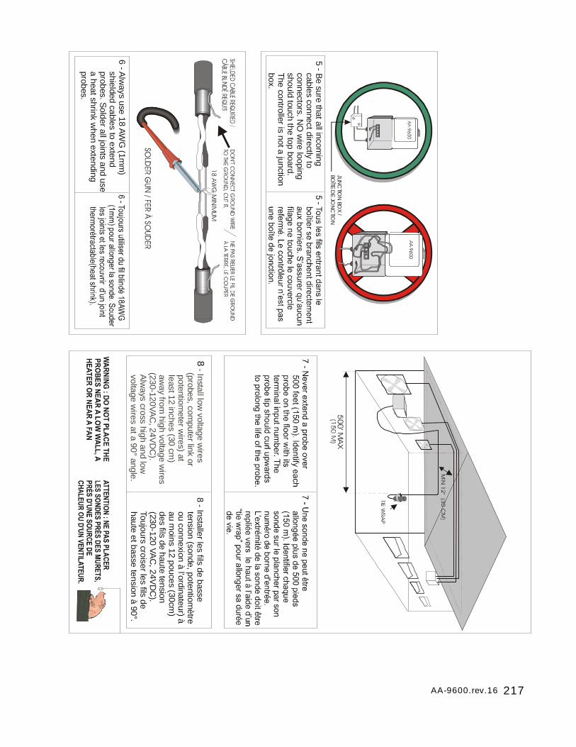
217AA-9600.rev.16
5 - Be sure that all incom
ing cables connect directly to connectors. N
O w
ire looping should touch the top board. The controller is not a junction box.
JUNC
TION
BOX /
BOÎTE D
E JON
CTIO
N
6 - Alw
ays use 18 AWG
(1mm
) shielded cables to extend probes. S
older all joints and use a heat shrink w
hen extending probes.
8 - Install low voltage w
ires (probes, com
puter link or potentiom
eter wires) at
least 12 inches (30 cm)
away from
high voltage wires
(230-120VAC
, 24VD
C).
Alw
ays cross high and low
voltage wires at a 90° angle.
8 - Installer les fils de basse tension (sonde, potentiom
ètre ou connexion à l’ordinateur) à au m
oins 12 pouces (30cm)
des fils de haute tension (230-120 VA
C, 24V
DC
). Toujours croiser les fils de haute et basse tension à 90°.
218 AA-9600.rev.16
REGISTRATION CARD
AGRI-ALERT 9600
Please fill out the following form to receive information on future updates.
Name_________________________________________________________________________
Address_________________________________________________________________________
City___________________________________________________________________________
Phone number_____________________________
Fax_______________________________________
Purchased from____________________________
Date Purchased____________________________
Serial Number_____________________________
Software Version Number__________________ (Press the System key)
Fax this page to: FAX: (450) 926-2780


M 890-00280 rev. 16 REV.01


