Embed Size (px)
Citation preview
ISSN: 2319-5967
ISO 9001:2008 Certified International Journal of Engineering Science and Innovative Technology (IJESIT)
Volume 4, Issue 3, May 2015
199
Abstract—Brake assist is one of the safety system which use in recent cars. It is one of the active system which helps to
save the cars from the collision. Brake assist works in an emergency situation when the driver press brake pedal with
insufficient force. In such case car does not at sufficient distance which leads to accident. In that case brake assist
system determines that situation and it increases brake boost so that car stop at sufficient distance. Brake assist system is
installed after the no of test & great amount of research has been carried out. Brake assist system has been shows that it
reduces the stopping distance by a significant margin. It decreases the stopping distance up to the 20%. Both the
percentages of severe accident involving pedestrians as well as the rate of rear end collision are for lower for the vehicles
equipped with BAS than the vehicles without BAS.
Index Terms— Brake assist system, ABS, ASR, Solenoid, Released system.
I. INTRODUCTION
This history of automobile starts from the invention of I.C engines but real invention was started in 1886 when
the first automobile plant was started by Mercedes Benz. During those days the automobile was not technically
advanced, a motor carriage which could carry two or more person was the definition of automobile .As time
changed the automobile became more & more technologically advanced and its possession became a „status
symbol‟ in society. Earlier while purchasing a car customer think only cost & comfort, but now the people started
concentrating on the safety of the car i.e. how safe the car /as the human life is more valuable than anything else.
The modern day cars like Mercedes Benz, BMW, Rolls Royce, etc. are coming with a number of safety devices
which try to save the human life in case of accident or an emergency. Brake assist is one of the safety system
which use in recent cars. It is one of the active system which helps to save the cars from the collision. Brake
assist works in an emergency situation when the driver press brake pedal with insufficient force. In such case car
does not at sufficient distance which leads to accident. In that case brake assist system determines that situation
and it increases brake boost so that car stop at sufficient distance. Brake assist system is installed after the no of
test & great amount of research has been carried out. Brake assist system has been shows that it reduces the
stopping distance by a significant margin. It decreases the stopping distance up to the 20%. Both the percentages
of severe accident involving pedestrians as well as the rate of rear end collision are for lower for the vehicles
equipped with BAS than the vehicles without BAS. Mercedes Benz became the first company to make the Brake
Assist as the standard equipment on all its models.
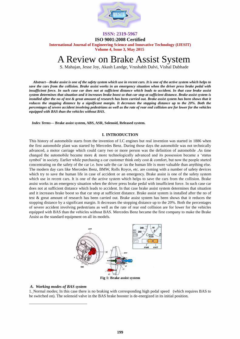
Fig 1: Brake assist system
A. Working modes of BAS system
1. Normal modes: In this case there is no braking with corresponding high pedal speed (which requires BAS to
be switched on). The solenoid valve in the BAS brake booster is de-energized in its initial position.
A Review on Brake Assist System S. Mahajan, Jesse Joy, Akash Landge, Vrushabh Dalvi, Vishal Dabhade
ISSN: 2319-5967
ISO 9001:2008 Certified International Journal of Engineering Science and Innovative Technology (IJESIT)
Volume 4, Issue 3, May 2015
200
2. BAS pressure increase: From the speed at which the brake pedals operated and the vehicle speed, the BAS
control module recognizes that the conditioned for switching on BAS exists. The BAS solenoid valve is actuated
by the BAS control module and the brake booster produces.
3. BAS pressure reduction: the BAS control module receives the information from the BAS release switch that
emergency braking has finished. The BAS solenoid valve is not actuated anymore and the maximum brake boost
is switched off.
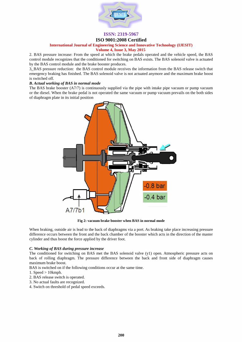
B. Actual working of BAS in normal mode
The BAS brake booster (A7/7) is continuously supplied via the pipe with intake pipe vacuum or pump vacuum
or the diesel. When the brake pedal is not operated the same vacuum or pump vacuum prevails on the both sides
of diaphragm plate in its initial position
Fig 2: vacuum brake booster when BAS in normal mode
When braking, outside air is lead to the back of diaphragms via a port. As braking take place increasing pressure
difference occurs between the front and the back chamber of the booster which acts in the direction of the master
cylinder and thus boost the force applied by the driver foot.
C. Working of BAS during pressure increase
The conditioned for switching on BAS met the BAS solenoid valve (y1) open. Atmospheric pressure acts on
back of rolling diaphragm. The pressure difference between the back and front side of diaphragm causes
maximum brake boost.
BAS is switched on if the following conditions occur at the same time.
1. Speed > 10kmph.
2. BAS release switch is operated.
3. No actual faults are recognized.
4. Switch on threshold of pedal speed exceeds.

ISSN: 2319-5967
ISO 9001:2008 Certified International Journal of Engineering Science and Innovative Technology (IJESIT)
Volume 4, Issue 3, May 2015
201
Fig 3: vacuum brake booster when BAS in working condition
D. Working of BAS during pressure decrease
The BAS release switch (s1) is switched passive. Solenoid valve (y1) is switched off and therefore the amount of
brake pressure which corresponds to the position of brake pedal is generated.
BAS is switched off if one of the following conditions occurs:
1. BAS release switch is not operated
2. Speed less than 30 kmph.
3. If there is no signal from the stop lamp switched after BAS is switched on.
4. A fault is recognized which leads to the actuation of the BAS malfunction indicator lamp.
Fig 4: vacuum brake booster when BAS releases pressure
II. DESCRIPTION OF TOPIC
General
Different types of safety system
There are basically two types of safety systems-:
1. Active safety system.
2. Passive safety system.
Active safety systems -: These systems try to prevent the occurrence of an accident in order to save of a person.
Passive safety systems -: These systems are comes in contact to act after the collision has taken place in order to
save the life of person and prevents vehicle from maximum damage.
Active safety system -:
1.BAS (Brake assist system.)
2.ABS (Antilock braking system.)
3.ASR (acceleration slip regulation.)

ISSN: 2319-5967
ISO 9001:2008 Certified International Journal of Engineering Science and Innovative Technology (IJESIT)
Volume 4, Issue 3, May 2015
202
Passive safety system -:
1.Air bags.
2.Seat belts.
BAS (Brake assist system) -: An active safety device.
Test with the normal value simulator and on a test track have shown that in an emergency situation most driver
press the brake pedal quickly but not hard enough, especially in the initial in the phase of braking.
A distinction is made between:
Hesitant braking -: The driver applies too little pedal force in the initial phase and increases the force too slowly.
Inadequate braking -: the driver applies too little pedal force throughout entire braking.
Brake assist system operates in that condition-: BAS is an active system.
Fig 5: inadequate braking condition Fig 6: stopping distance of car after BAS working
Constructional Details of BAS operating system
General construction
“BRAKE ASSIST” BAS is an active safety system. It is active when the driver brakes very quickly in emergency
situations. According to the speed with which the brake pedal is operated, the system recognizes whether the
emergency braking situations exists. In this the case, a solenoid valve in brake booster is opened, activating the
full booster power. If the driver releases the break, this is recognized and solenoid valve is closed again.
With the BAS brake booster the basic version is extended by the following parts:
1. BAS diaphragm travel sensor for measuring the brake pedal travel.
2. BAS solenoid valve for activation of brake boost.
3. BAS release switch for recognizing the end of braking operation.
4. BAS control module for recording the values & for actuating BAS brake intervention.
Fig 7: component of brake assist system
Components of brake assist system
A7/7 -: BAS brake booster, it gives maximum boost power during the inadequate braking condition.
ISSN: 2319-5967
ISO 9001:2008 Certified International Journal of Engineering Science and Innovative Technology (IJESIT)
Volume 4, Issue 3, May 2015
203
A7/7b1 -: BAS Travel sensor, it measures brake pedal travel by which BAS operate in inadequate braking
condition.
A/7y1 -: BAS solenoid valve, for activation of brake boost.
A7/7s1-: BAS release switch, it acts for recognizing end of braking operation.
BAS brake control module for recording values and for actuating BAS brake intervention.
1. Driver Information on BAS -: For BAS a system malfunction indicator lamp is located in the instrument
cluster. On vehicles with ETS, ASR or ESP this is combined with the malfunction indicator lamp of the
respective traction system.
2. Switching on the ignition and starting the engine-: When the ignition is switched on (ignition/starter
switch position “2”), the malfunction indicator lamp in the instrument cluster (bulb check) comes on and goes off
when the engine is running. If the BAS malfunction indicator lamp comes on when the engine is running, there is
a fault in the BAS. The system is inoperative but the full braking effect with ABS is retained. With the combined
malfunction indicator lamp (BAS/ETS, BAS/ASR, BAS /ASP), the fault may be in the BAS or in the traction
system. In the first case, ETS, ASR, or ESP is retained and the second case BAS function is retained.
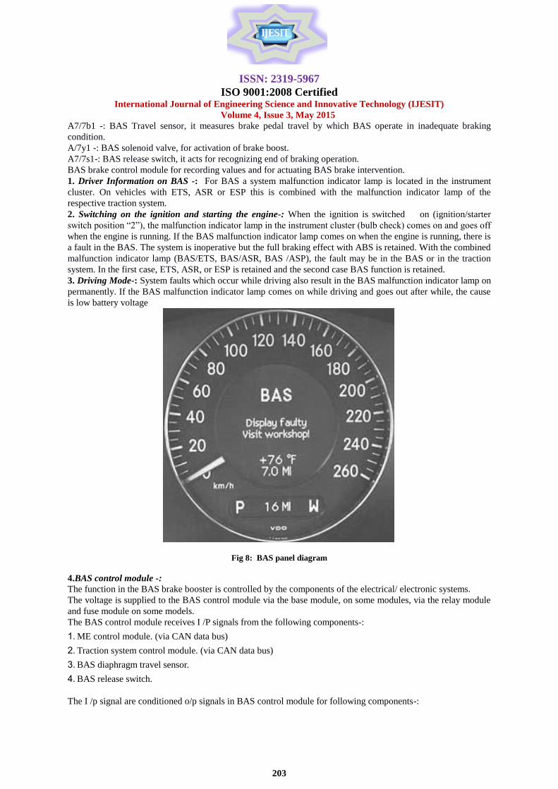
3. Driving Mode-: System faults which occur while driving also result in the BAS malfunction indicator lamp on
permanently. If the BAS malfunction indicator lamp comes on while driving and goes out after while, the cause
is low battery voltage
Fig 8: BAS panel diagram
4.BAS control module -:
The function in the BAS brake booster is controlled by the components of the electrical/ electronic systems.
The voltage is supplied to the BAS control module via the base module, on some modules, via the relay module
and fuse module on some models.
The BAS control module receives I /P signals from the following components-:
1. ME control module. (via CAN data bus)
2. Traction system control module. (via CAN data bus)
3. BAS diaphragm travel sensor.
4. BAS release switch.
The I /p signal are conditioned o/p signals in BAS control module for following components-:
ISSN: 2319-5967
ISO 9001:2008 Certified International Journal of Engineering Science and Innovative Technology (IJESIT)
Volume 4, Issue 3, May 2015
204
1. BAS solenoid valve
2. BAS malfunction indicator lamp(via CAN data bus)
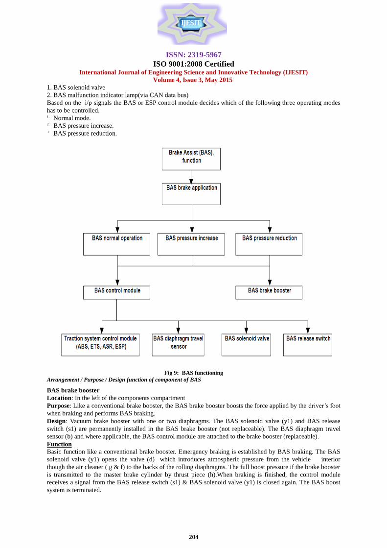
Based on the i/p signals the BAS or ESP control module decides which of the following three operating modes
has to be controlled. 1. Normal mode. 2. BAS pressure increase. 3. BAS pressure reduction.
Fig 9: BAS functioning
Arrangement / Purpose / Design function of component of BAS
BAS brake booster
Location: In the left of the components compartment
Purpose: Like a conventional brake booster, the BAS brake booster boosts the force applied by the driver‟s foot
when braking and performs BAS braking.
Design: Vacuum brake booster with one or two diaphragms. The BAS solenoid valve (y1) and BAS release
switch (s1) are permanently installed in the BAS brake booster (not replaceable). The BAS diaphragm travel
sensor (b) and where applicable, the BAS control module are attached to the brake booster (replaceable).
Function
Basic function like a conventional brake booster. Emergency braking is established by BAS braking. The BAS
solenoid valve (y1) opens the valve (d) which introduces atmospheric pressure from the vehicle interior
though the air cleaner ( g & f) to the backs of the rolling diaphragms. The full boost pressure if the brake booster
is transmitted to the master brake cylinder by thrust piece (h).When braking is finished, the control module
receives a signal from the BAS release switch (s1) & BAS solenoid valve (y1) is closed again. The BAS boost
system is terminated.

ISSN: 2319-5967
ISO 9001:2008 Certified International Journal of Engineering Science and Innovative Technology (IJESIT)
Volume 4, Issue 3, May 2015
205
Arrangement / Purpose / Design function of Release switch
Location:
Supplied a signal to the control module when brake is released.
Function:
When the force applied by the driver‟s foot to the brake pedal almost reduces to zero, movement takes place in
the control value of the BAS brake booster. This is sampled by the release switch and signaled to the BAS
control module.
Fig 10. Release switch and signaled to the BAS control module.
Arrangement/ Purpose / Function of Solenoid valve
Location:
In the BAS brake booster.
Purpose:
To start & finish the BAS application.
Function:
The solenoid of the BAS solenoid valve is actuated by BAS control module & opens the poppet valve. The
poppet valve allows atmospheric pressure to the back of the rolling diaphragm of the brake booster, increasing
the brake pressure.
Fig 11: BAS solenoid valve
ISSN: 2319-5967
ISO 9001:2008 Certified International Journal of Engineering Science and Innovative Technology (IJESIT)
Volume 4, Issue 3, May 2015
206
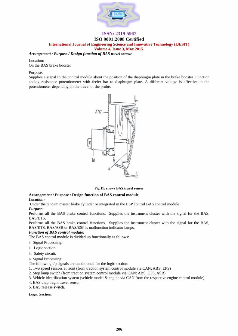
Arrangement / Purpose / Design function of BAS travel sensor
Location:
On the BAS brake booster
Purpose:
Supplies a signal to the control module about the position of the diaphragm plate in the brake booster .Function
analog resistance potentiometer with feeler bar to diaphragm plate. A different voltage is effective in the
potentiometer depending on the travel of the probe.
Fig 11: shows BAS travel sensor
Arrangement / Purpose / Design function of BAS control module
Location:
Under the tandem master brake cylinder or integrated in the ESP control BAS control module
Purpose:
Performs all the BAS brake control functions. Supplies the instrument cluster with the signal for the BAS,
BAS/ETS,
Performs all the BAS brake control functions. Supplies the instrument cluster with the signal for the BAS,
BAS/ETS, BAS/ASR or BAS/ESP is malfunction indicator lamps.
Function of BAS control module:
The BAS control module is divided up functionally as follows:
i. Signal Processing.
ii. Logic section.
iii. Safety circuit.
iv. Signal Processing:
The following i/p signals are conditioned for the logic section:
1. Two speed sensors at front (from traction system control module via CAN; ABS, EPS)
2. Stop lamp switch (from traction system control module via CAN: ABS, ETS, ASR)
3. Vehicle identification system (vehicle model & engine via CAN from the respective engine control module)
4. BAS diaphragm travel sensor
5. BAS release switch.
Logic Section:
ISSN: 2319-5967
ISO 9001:2008 Certified International Journal of Engineering Science and Innovative Technology (IJESIT)
Volume 4, Issue 3, May 2015
207
The initialization and safety check of the system starts after the ignition is switched on. The system is enabled
after a positive outcome. The conditioned i/p signals are processed in the logic section & the following valves
calculated.
1. Vehicle speed from the speed signals of the front wheel.
2. Vehicle acc. From several wheel speeds measured in sequence.
3. Diaphragm speeds: The control module checks the voltage signal from the diaphragm travel sensor every 3
Ms. The pedal speed is calculated from the voltage difference between two successive measurements.
4. Learning a logarithm: calculation of vehicle deceleration for adapting the trigger threshold to different
conditions of the brake system.
5. Switch on threshold: It is calculated from the basic threshold (vehicle identification valves.) vehicle speed,
pedal speed & the values of learning algorithm. If the values determine exceed the specified switch on threshold,
BAS is switched on BAS switch -on is terminated immediately after a signal from BAS release switch.
Safety Circuit:
The purpose of safety circuit is to recognize faulty signal in the control module & faults in the electrical wiring
system. The following components are monitored continuously
1. BAS solenoid valve.
2. BAS diaphragm travel sensor.
3. BAS Release switch
The system switches off if a fault is recognized. This is displayed to the driver by illumination of the BAS,
BAS/ETS, ASR or BAS/ESP malfunction indicator lamps. A fault code is also stored in the control module. The
safety circuit also continuously monitors battery voltage. If the voltage drop below ten volts or exceeds 16-18
volts, the system is switched off until the voltage comes down in the specified range.
Checking & Repair work for BAS
If due to the extent of damage to the vehicle or the position and external appearance of the brake booster after
the accident, it can be seen that the brake booster has received a heavy blow. It is to be replaced.
For example the Indications can be:
1. Hydraulic lines linked.
2. Connections on master brake cylinder leaking.
3. Electrical cables or plug connection damaged.
4. Brake booster housing shows signs of damage.
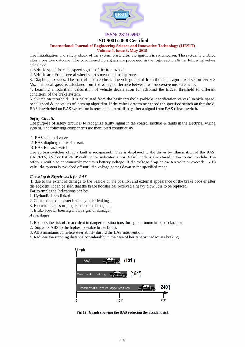
Advantages
1. Reduces the risk of an accident in dangerous situations through optimum brake declaration.
2. Supports ABS to the highest possible brake boost.
3. ABS maintains complete steer ability during the BAS intervention.
4. Reduces the stopping distance considerably in the case of hesitant or inadequate braking.
Fig 12: Graph showing the BAS reducing the accident risk

ISSN: 2319-5967
ISO 9001:2008 Certified International Journal of Engineering Science and Innovative Technology (IJESIT)
Volume 4, Issue 3, May 2015
208
III. CONCLUSION
High growth of automobile industry shows us the results of automobile & mechanical engineering
developments. Apart from quality appearance & economy of the vehicle there is one very important aspect i.e.
“Safety”.
In this report I have concentrated on “BAS” i.e. brake assist system which is an active safety device. The use of
BAS has considerably helped in increasing the braking efficiency of the cars & to prevent accidents in
emergency situations. Cars like. Mercedes Benz use these technologies after a lot of research which makes it one
of the safest cars in the world. In spite of all developments rare cases are always there, which leads to casualties.
Reducing accidents has always been a challenging task for engineers as human life is most precious of all.
REFERENCES [1] Toshiya Hirose, „A Study on the Effect of Brake Assist System (BAS), SAE, 2008-01-0824, (14 April 2008), pp.776-
0790.
[2] John Vincent Bond, Gerald H. Engelmann, Jonas Embark, „Emergency brake assist system‟, US 2003/0085617 A1,
May 8,2003.
[3] Joel c. and Mohan m. Trivedi, „Human Behaviours Predictive Brake Assistance‟ International journal of IEEE
Intelligent Vehicle Synopsis, vol-3, June2006 pp.330-340.
[4] Programmable differential brake for passive haptics Robotics and Autonomous Systems, Volume 58, Issue 3, 31 March
2010, Pages 249-255 Yaroslav Tenzer, Brian L. Davies, Ferdinando Rodriguez y Baena..