Embed Size (px)
Citation preview
419 The International Arab Journal of Information Technology, Vol. 7, No. 4, October 2010
A Novel Radon-Wavelet Based OFDM
System Design and Performance Under
Different Channel Conditions
Abbas Kattoush
EE Engineering Department, Tafila Technical University, Jordan
Abstract: Finite Radon Transform mapper has the ability to increase orthogonality of sub-carriers, it is non sensitive to
channel parameters variations, and has a small constellation energy compared with conventional Fast Fourier Transform
based orthogonal frequency division multiplexing. It is also able to work as a good interleaver which significantly reduces the
bit error rate. Due to its good orthogonality, discrete wavelet transform is used for orthogonal frequency division multiplexing
systems which reduces inter symbol interference and inter carrier interference. This eliminates the need for cyclic prefix and
increases the spectral efficiency of the design. In this paper both Finite Radon Transform and Discrete Wavelet Transform are
implemented in a new design for orthogonal frequency division multiplexing. The new structure was tested and compared with
conventional Fast Fourier Transform -based orthogonal frequency division multiplexing, Radon-based orthogonal frequency
division multiplexing, and discrete wavelet transform -based orthogonal frequency division multiplexing for additive white
Gaussian noise channel, flat fading channel, and multi-path selective fading channel. Simulation tests were generated for
different channels parameters values. The obtained results showed that proposed system has increased spectral efficiency,
reduced inter symbol interference and inter carrier interference, and improved bit error rate performance compared with
other systems.
Keywords: Discrete Wavelet Transform, Finite Radon Transform, radon based OFDM, DWT based OFDM, and OFDM.
Received April 8, 2009; accepted August 4, 2009
1. Introduction
Orthogonal frequency division multiplexing system is
one of the most promising technologies for current and
future wireless communications. It is a form of multi-
carrier modulation technologies where data bits are
encoded to multiple sub-carriers, while being sent
simultaneously [1]. Each sub-carrier in an Orthogonal
Frequency Division Multiplexing (OFDM) system is
modulated in amplitude and phase by the data bits.
Modulation techniques typically used are binary phase
shift keying, Quadrature Phase Shift Keying (QPSK),
Quadrature Amplitude Modulation (QAM), 16-QAM,
64-QAM etc., The process of combining different sub-
carriers to form a composite time-domain signal is
achieved using Fast Fourier Transform (FFT) and
Inverse FFT (IFFT) operations [25].
The main problem in the design of a
communications system over a wireless link is to deal
with multi-path fading, which causes a significant
degradation in terms of both the reliability of the link
and the data rate [20]. Multi-path fading channels have
a severe effect on the performance of wireless
communication systems even those systems that
exhibits efficient bandwidth, like OFDM [12]. There is
always a need for developments in the realization of
these systems as well as efficient channel estimation
and equalization methods to enable these systems to
reach their maximum performance [26]. The OFDM
receiver structure allows relatively straightforward
signal processing to combat channel delay spreads,
which was a prime motivation to use OFDM
modulation methods in several standards [11, 13, 19,
21].
In transmissions over a radio channel, the
orthogonality of the signals is maintained only if the
channel is flat and time-invariant, channels with a
Doppler spread and the corresponding time variations
corrupt the orthogonality of the OFDM sub-carrier
waveforms [6]. In a dispersive channel, self-
interference occurs among successive symbols at the
same sub-carrier casing Inter Symbol Interference
(ISI), as well as among signals at different sub-carriers
casing Inter Carrier Interference (ICI). For a time-
invariant but frequency-selective channel, ICI, as well
as ISI, can effectively be avoided by inserting a cyclic
prefix before each block of parallel data symbols at the
cost of power loss and bandwidth expansion [25].
The Radon Transform (RT) was first introduced by
Johann Radon (1917) and the theory, basic aspects, and
applications of this transform are studied in [4, 7]
while the Finite RAdon Transform (FRAT) was first
studied by [3]. RT is the underlying fundamental
concept used for computerized tomography scanning,
as well for a wide range of other disciplines, including
420 The International Arab Journal of Information Technology, Vol. 7, No. 4, October 2010
radar imaging, geophysical imaging, nondestructive
testing and medical imaging [11]. Recently FRAT was
proposed as a mapping technique in OFDM system [2].
Conventional OFDM/QAM systems are robust for
multi-path channels due to the cyclically prefixed
guard interval which is inserted between consequent
symbols to cancel ISI. However, this guard interval
decreases the spectral efficiency of the OFDM system
as the corresponding amount [24]. Thus, there have
been approaches of wavelet-based OFDM which does
not require the use of the guard interval [10, 14, 15, 23,
27, 28, 29]. It is found that OFDM based on Haar
orthonormal wavelets (DWT-OFDM) are capable of
reducing the ISI and ICI, which are caused by the loss
in orthogonality between the carriers.
In this paper the idea of one dimensional serial
Radon based OFDM proposed in [2] is developed
farther towards increasing spectral efficiency and
reducing BER. Further performance gains and higher
spectral efficiency were made by combining both
FRAT and DWT in the design of OFDM system.
Simulation results show that proposed system has
better performance than Fourier, Radon, and wavelet
based OFDM under different channel conditions.
The paper is organized as follows. In section 2 we
describe the serial one-dimensional OFDM system and
provide the algorithm for computing the mapping data;
in section 3 we describe and provide a fast discrete
wavelet transform computation algorithm used in
proposed system design; in section 4 we describe the
proposed Radon-wavelet-OFDM system and in section
5 we provide the simulation analyze and discussions of
the obtained results; Finally in section 6, a conclusion
is presented to summarize the main outcomes of this
paper.
2. The Radon-Based OFDM
Radon-based OFDM was recently proposed in [2], it
was found that as a result of applying FRAT, the Bit
Error Rate (BER) performance was improved
significantly, especially in the existence of multi-path
fading channels. Also, it is found that Radon-based
OFDM structure is less sensitive to channel parameters
variation, like maximum delay, path gain, and
maximum Doppler shift in selective fading channels as
compared with standard OFDM structure.
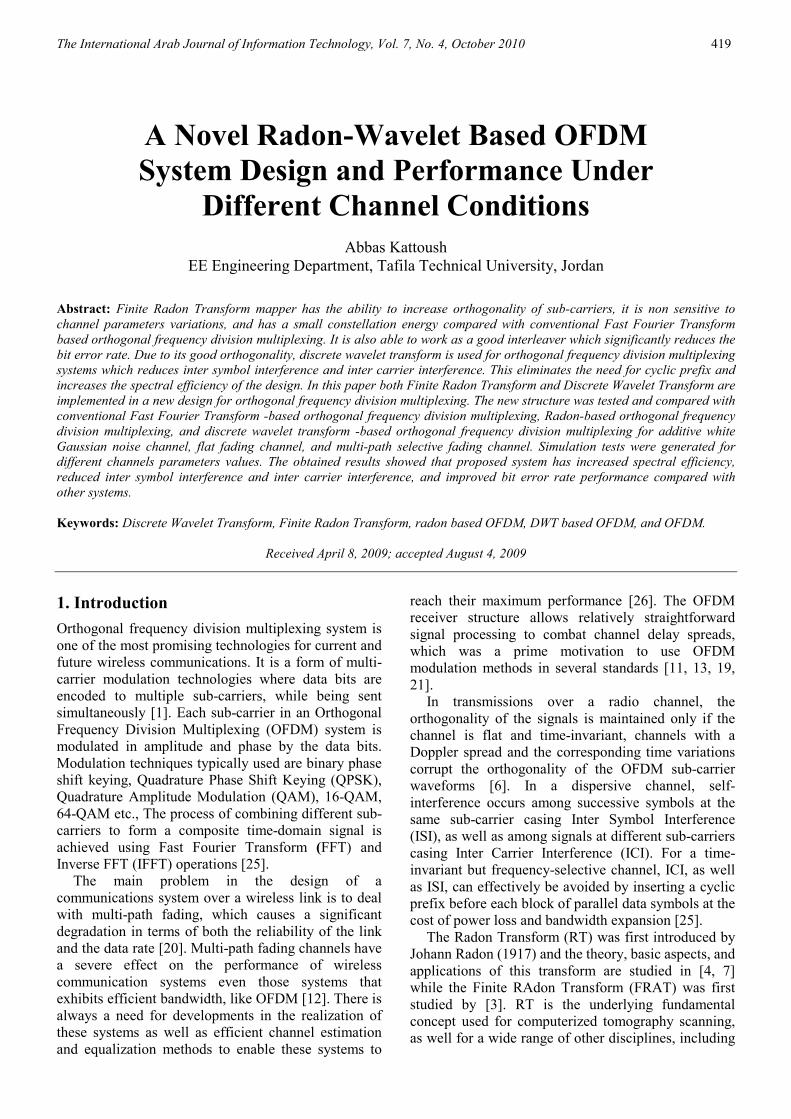
In Radon based OFDM system, FRAT mapping is
used instead of QAM mapping [2] as shown in Figure
1. The other processing parts of the system remain the
same as in conventional QAM OFDM system. It is
known that FFT based OFDM obtain the required
orthogonality between sub-carriers from the suitability
of IFFT algorithm [12, 25, 26]. Using FRAT mapping
with the OFDM structure increases the orthogonality
between sub-carriers since FRAT computation uses
one-Dimensional (1-D) IFFT algorithm. Also FRAT is
designed to increase the spectral efficiency of the
OFDM system through increasing the bit per Hertz of
the mapping. Sub carriers are generated using N points
Discrete Fourier Transform (DFT) and Guard Interval
(GI) inserted at start of each symbol is used to reduce
ISI.
The procedure steps of using the Radon based
OFDM mapping is as follows:
Step 1: suppose )(kd is the serial data stream to be
transmitted using OFDM modulation scheme.
Converting )(kd from serial form to parallel form will
construct a one dimensional vector containing the data
symbols to be transmitted,
( )Tnddddkd ...... )( 210= (1)
where, k and n are the time index and the vector length
respectively.
S/PFRAT
Mapper 1-D
IFFT
OFDM Receiver
OFDM Transmitter
Input
Data
Add Guard
IntervalP/S Channel +
AWGN
S/PRemove
Guard
1-D
FFT
FRAT
DemapperP/S
1-D Serial OFDM Signal
Pilot
Symbols
Channel
Compens.
Channel
Estimator
Figure 1. Serial Radon based OFDM transceiver.
Step 2: convert the data packet represented by the
vector d(k) from one-dimensional vector to a pxp two
dimensional matrix D(K), where p should be a prime
number according to the matrix resize operation.
Step 3: take the 2-D FFT of the matrix D(K) to obtain
the matrix, F(r, s). For simplicity it will be labeled by
F.
∑ ∑−
=
−
=
− −=1
0
1
0
)/2()/2(),(),(p
m
p
n
nspjrmpj eenmDsrF ππ (2)
Step 4: redistribute the elements of the matrix F
according to the optimum ordering algorithm given in
[17], so, the dimensions of the resultant matrix will be
)1( +× pp and will be denoted by the symbol optF .
The two matrixes for FRAT window= 7 are given by:
49
42
35
28
21
14
7
48
41
34
27
20
13
6
47
40
33
26
19
12
5
46
39
32
25
18
11
4
45
38
31
24
17
10
3
44
37
30
23
16
9
2
43
36
29
22
15
8
1
=
fffffff
fffffff
fffffff
fffffff
fffffff
fffffff
fffffff
F
45
44
37
43
42
49
48
7
40
38
24
36
27
41
39
6
35
32
11
29
12
33
30
5
23
26
47
22
46
25
28
4
18
20
34
15
31
17
19
3
13
14
21
8
16
9
10
2
1 1
1
1
1
1
1
1
=
ffffffff
ffffffff
ffffffff
ffffffff
ffffffff
ffffffff
ffffffff
optF
(3)
(4)
A Novel Radon-Wavelet Based OFDM System Design and Performance under Different Channel Conditions 421
Step 5: take the 1D-IFFT for each column of the matrix
optF to obtain the matrix of Radon coefficients, R :
∑−
=
=1
0
2
1 N
k
opt
p
knj
eFp
R
π
(5)
Step 6: construct the complex matrix R from the real
matrix R such that its dimensions will be
2/)1( +× pp according to:
1,,, ++= jijiml rjrr , pjpi ≤≤≤≤ 0,0 (6)
where, mlr , refers to the elements of the matrix R ,
while jir , refers to the elements of the matrix R .
Matrixes R and R are given by:
1,
3,
2,
1,
1,1
2,1
1,1
1,2
3,2
2,2
1,2
1,1
3,1
2,1
1,1
+
+−−−
+
+
=
ppr
pr
pr
pr
ppr
pr
pr
prrrr
prrrr
KK
KK
MKKMMM
MKKMMM
KK
KK
R
(7)
1,,
21
1,1,1
2111
12,2
423,2
2212
11,1
4131
2111
+++
+−+
−−+
−
++++
++++
=
ppjr
ppr
p,jr
p,r
ppjr
ppr
,pjr
,pr
,pjr
pr
,jrr
,jr
,r
,pjr
pr
,jr
,r
,jr
,r
KK
KK
MMKKMMM
MMKKMMM
KK
KK
R
(8)
Complex matrix construction is made for a purpose of
increasing bit per Hertz of mapping before resizing
mapped data.
Step 7: resize the matrix R to a one dimensional
vector )(kr of length 2/)1( +× pp .
( )T)/p(p ...... r rrrkr 21210 )( += (9)
Step 8: take the 1D-IFFT for the vector, )(kr to obtain
the sub-channel modulation.
2/)1(
0
2
1
2/)1(
1)(
+
=
∑−
+=
pp
k
knj
eC
N
r(k)kspp
π
(10)
where Nc number of carriers.
Step 9: finally, convert the vector )(ks to serial data
symbols: ns ...... s ss ,,,, 210 .
3. Fast Discrete Wavelet Transform
Computation
If we regard the wavelet transform as a filter bank then
we can consider wavelet transforming a signal, as
passing it through this filter bank. The outputs at
different filter stages are the wavelet and scaling
function transform coefficients, this is known as sub-
band coding.
The following two equations state that the wavelet
and scaling function coefficients on a certain scale can
be found by calculating a weighted sum of the scaling
function coefficients from the previous scale [5, 8].
( ) ( ) ( )∑ +−=m
jj makmhka 1 2 (11)
( ) ( ) ( )∑ +−=m
jj mbkmgkb 1 2 (12)
This means that equations 11 and 12 together form one
stage of an iterated digital filter bank and it is referred
to the coefficients h(k) as the scaling filter and to the
coefficients g(k) as the wavelet filter. It is shown that
the orthogonality requires that the wavelet coefficients
are related to the scaling function coefficients by [5]:
( ) ( ) ( )khkgk −−= 11 , for a finite even length-n h(k).
( ) ( ) ( )knhkgk −−−= 11 (13)
In wavelet analysis we often speak of approximations
and details. The approximations are the high-scale low-
frequency components of the signal and the details are
the low-scale high-frequency components [9, 16]. The
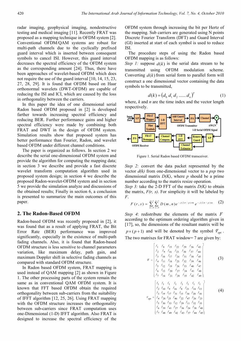
implementation of equations 11 and 12 is illustrated in
Figure 2. In this figure two levels of decomposition
are depicted, h and g are low-pass and high-pass filters
corresponding to the coefficients h(k) and g(k)
respectively. The down-pointing arrows denote a
decimation or down-sampling by two. This splitting,
filtering and decimation can be repeated on the scaling
coefficients to give the two-scale structure.
The first stage of two banks divides the spectrum
of aj+1,k into a low-pass and high-pass band, resulting
in the scaling coefficients and wavelet coefficients at
lower scale aj,k and bj,k. The second stage then divides
the low-pass band into another lower low-pass band
and a band-pass band.
If the number of coefficients is two, then for
computing FDWT consider the following
transformation matrix:
( ) ( )
( ) ( )
( ) ( )( ) ( )
( ) ( )
( ) ( )
=
100000
1000
0010
100000
1000
0010
gg
gg
gg
hh
hh
hh
T r
LL
LLMMMM
MMLL
LL
LL
LLMMMM
LL
LL
(14)
Here the blank entries are zero, and if the number
of coefficients is four, then for computing FDWT
consider the following transformation matrix:
422 The International Arab Journal of Information Technology, Vol. 7, No. 4, October 2010
h 2↓
g 2↓
h 2↓
g 2↓ kja ,1+
kja ,
kjb ,
kja ,1−
kjb ,1−
Figure 2. The filter bank for calculating the wavelet coefficients.
( ) ( ) ( ) ( )
( ) ( ) ( ) ( )
( ) ( ) ( ) ( )( ) ( ) ( ) ( )
( ) ( ) ( ) ( )
( ) ( ) ( ) ( )( ) ( ) ( ) ( )
=
1000000032
3210000000
0000321000
00003210
1000000032
0000321000
0000003210
gggg
gggg
gggg
gggg
hhhh
hhhh
hhhh
Tr
L
L
MMMMLMMMMMM
L
LMM
L
MMMMLMMMMMM
L
L
(15)
By examining the transformation matrices of the
scalar wavelet as shown in equations 14 and 15
respectively, it can be seen that the first row generates
one component of the data convolved with the low-
pass filter coefficients {h(0), h(1), …}. Likewise the
second, third, and other upper half rows are formed.
The lower half rows perform a different convolution,
with high pass filter coefficients {g(0),g(1), …}. The
overall action of the matrix is to perform two related
convolutions, then to decimate each of them by half
(throw away half the values), and interleave the
remaining halves. By using equation 13 the
transformation matrices becomes:
( ) ( )( ) ( )
( ) ( )( ) ( )
( ) ( )
( ) ( )
−
−
−=
010000
0100
0001
100000
1000
0010
hh
hh
hh
hh
hh
hh
Tr
LL
LLMMMM
MMLL
LL
LL
LLMMMM
LL
LL
(16)
( ) ( ) ( ) ( )( ) ( ) ( ) ( )
( ) ( ) ( ) ( )( ) ( ) ( ) ( )
( ) ( ) ( ) ( )
( ) ( ) ( ) ( )( ) ( ) ( ) ( )
−−
−−
−−
−−=
2300000001
0123000000
0000012300
00000123
1000000032
0000321000
0000003210
hhhh
hhhh
hhhh
hhhh
hhhh
hhhh
hhhh
Tr
L
L
MMMMLMMMMMM
L
LMM
L
MMMMLMMMMMM
L
L
(17)
It is useful to think of the filter
{h(0),h(1),h(2),h(3)…} as being a smoothing filter H,
which something like a moving average of four points.
While because of the minus signs, the filter G={h(3),-
h(2),h(1),-h(0),…}, is not a smoothing filter. For such
characterization to be useful, it must be possible to
reconstruct the original data vector of length N from its
N/2 smooth and its N/2 detail [18]. The requirement of
the matrices to be orthogonal leads to that its inverse is
just the transposed matrix:
( ) ( )( ) ( )
( ) ( )( ) ( )
( ) ( )( ) ( )
−
−
−
=
00001000
10000000
0000
000010
010000
000001
001000
hh
hh
hh
hh
hh
hh
Ti
MMLLMMMM
LLLL
LL
LL
LL
LL
(18)
( ) ( ) ( ) ( )( ) ( ) ( ) ( )( ) ( ) ( ) ( )( ) ( ) ( ) ( )
( ) ( ) ( ) ( )( ) ( ) ( ) ( )
( ) ( )( ) ( )
( ) ( )( ) ( )( ) ( ) ( ) ( )( ) ( ) ( ) ( )
20130000
31020000
0210
0300
000
000000300
001000200
002000130
003100020
000200013
000310002
000023001
100032000
−−
−
−
−−
−−
−−
=
hhhh
hhhh
hh
hh
hh
hh
hhhh
hhhh
hhhh
hhhh
hhhh
hhhh
Ti
MMMMMMMMMMMM
LLL
LLL
LLL
LLL
LLL
LLL
LLL
LLL
For a length 2 ( )kh , there are no degrees of freedom
left after satisfying the required conditions. These
requirements are [5]:
( ) ( )( ) ( )
=+
=+
110
21 0
22 hh
hh (20)
which are uniquely satisfied by :
( ) ( ){ }
==2
1 ,
2
11 , 02 hhh D
(21)
These are the Haar scaling function coefficients, which
are also the length 2 Daubechies coefficients. For the
length-4 coefficients sequence, there is one degree of
freedom or one parameter that gives all the coefficients
that satisfy the required conditions:
( ) ( ) ( ) ( )( ) ( ) ( ) ( )( ) ( ) ( ) ( )
=+
=+++
=+++
03 1 2 0
13210
23 2 1 0
2222
hhhh
hhhh
hhhh
(22)
Letting the parameter be the angle α , the coefficients
become
( ) ( ) ( )( ) ( ) ( )( ) ( ) ( )( ) ( ) ( )
−−=
−+=
++=
+−=
22sincos13
22sincos12
22sincos11
22sincos10
αα
αα
αα
αα
h
h
h
h
(23)
(19)
A Novel Radon-Wavelet Based OFDM System Design and Performance under Different Channel Conditions 423
These equations give length-2 Haar coefficients for
23,2 ππ and length-4 Daubechies coefficients for
3πα = . These daubechies-4 coefficients have a
particularly clean form:
−−++
=24
31,
24
33,
24
33,
24
314Dh
To compute a single level FDWT for 1-D signal the
next steps should be followed:
a. Input vector should be of length N, where N must be
power of two.
b. Construct a transformation matrix: using
transformation matrices given in equations 14 and
15, Transformation of input vector, which can be
done by applying matrix multiplication to the NxN
constructed transformation matrix by the N*1 input
vector. For example let us take a general 1-D signal
X. [ ]76543210 xxxxxxxxX = , for an
8x1 input 1-D signal, X construct a 88×
transformation matrix, Tr, using Haar coefficients
filter:
( ) ( )( ) ( )
( ) ( )( ) ( )
( ) ( )( ) ( )
( ) ( )( ) ( )
−
−
−
−=
01000000
00010000
00000100
00000001
10000000
00100000
00001000
00000010
hh
hh
hh
hh
hh
hh
hh
hh
Tr
or using Db4 coefficients filter:
( ) ( ) ( ) ( )
( ) ( ) ( ) ( )( ) ( ) ( ) ( )
( ) ( ) ( ) ( )( ) ( ) ( ) ( )
( ) ( ) ( ) ( )( ) ( ) ( ) ( )
( ) ( ) ( ) ( )
−−
−−
−−
−−=
23000001
01230000
00012300
00000123
10000032
32100000
00321000
00003210
hhhh
hhhh
hhhh
hhhh
hhhh
hhhh
hhhh
hhhh
Tr
Transformation of input vector is done as follows:
[Z]N*1 =[Tr]N*N x [X]N*1. To reconstruct the original
signal from the Discrete Wavelet Transformed (DWT)
signal, Inverse Fast Discrete Wavelet Transform
(IFDWT) should be used. The inverse transformation
matrix is the transpose of the transformation matrix as
the transform is orthogonal. To compute a single level
IFDWT for 1-D signal the next steps should be
followed:
a. Let X be the Nx1 wavelet transformed vector.
b. Construct NxN reconstruction matrix, Ti, using
transformation matrices given in equations 18 and
19.
c. Reconstruction of input vector, which can be done
by applying matrix multiplication to the NxN
reconstruction matrix, Ti, by the Nx1 wavelet
transformed vector. For example, let X be the input
1-D signal, [ ]76543210 xxxxxxxxX = , for
an 18× input 1-D signal, X, construct a
88× reconstruction matrix, Ti, using Haar
coefficients filter:
( ) ( )( ) ( )
( ) ( )( ) ( )
( ) ( )( ) ( )
( ) ( )( ) ( )
−
−
−
−
=
00001000
10000000
00000100
01000000
00000010
00100000
00000001
00010000
hh
hh
hh
hh
hh
hh
hh
hh
Ti
or using Db4 coefficients filter:
( ) ( ) ( ) ( )( ) ( ) ( ) ( )( ) ( ) ( ) ( )( ) ( ) ( ) ( )
( ) ( ) ( ) ( )( ) ( ) ( ) ( )
( ) ( ) ( ) ( )( ) ( ) ( ) ( )
−−
−−
−−
−−
=
20001300
31000200
02000130
03100020
00200013
00310002
00023001
10032000
hhhh
hhhh
hhhh
hhhh
hhhh
hhhh
hhhh
hhhh
Ti
Reconstruction of input vector can be done as follows:
[Z]N*1 = [Ti]NxN x [X]N*1
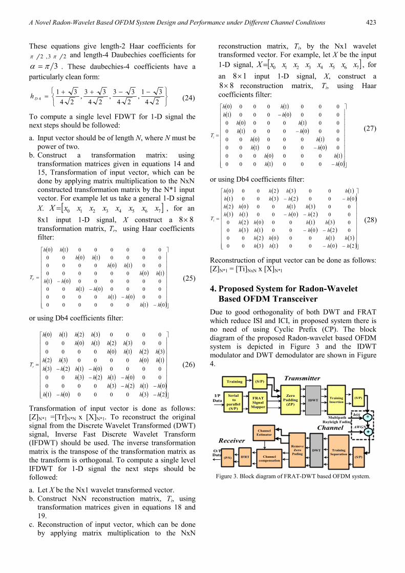
4. Proposed System for Radon-Wavelet
Based OFDM Transceiver
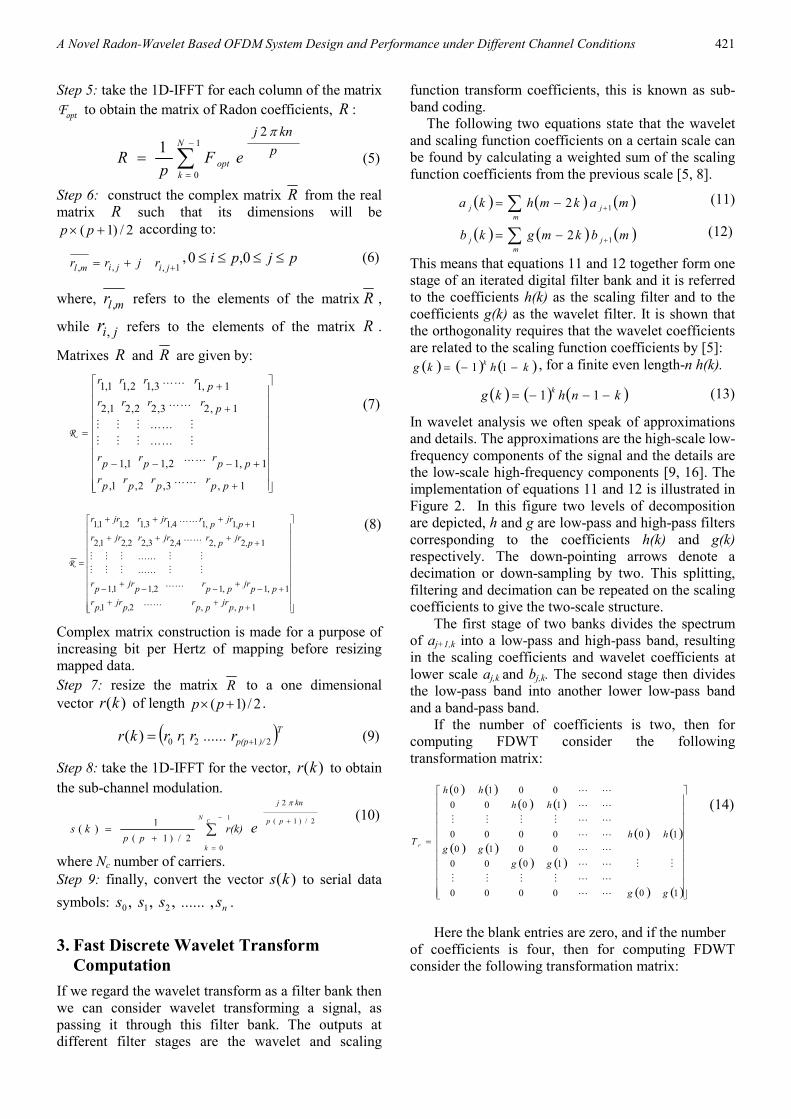
Due to good orthogonality of both DWT and FRAT
which reduce ISI and ICI, in proposed system there is
no need of using Cyclic Prefix (CP). The block
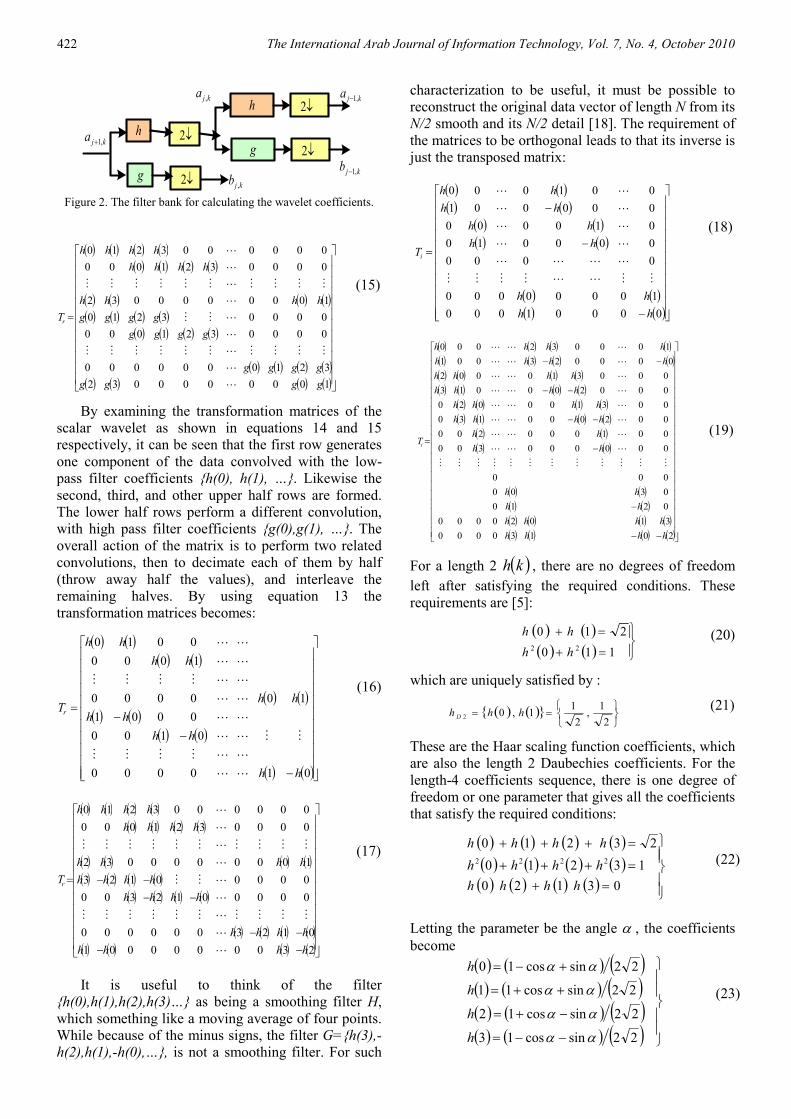
diagram of the proposed Radon-wavelet based OFDM
system is depicted in Figure 3 and the IDWT
modulator and DWT demodulator are shown in Figure
4.
Serial
to
parallel
(S/P)
I/P
DataFRAT
Signal
Mapper
Zero
Padding
(ZP)
Training (S/P)
IDWTTraining
Insertion
(S/P)
(S/P)
Training
Separation
Remove
Zero
PadingChannel
compensation
Channel
Estimator
IFRT(P/S)DataO/P DWT
Multipath
Rayleigh Fading
AWGN
+
*h(t)
Receiver
Transmitter
Channel
Figure 3. Block diagram of FRAT-DWT based OFDM system.
(25)
(26)
(27)
(28)
(24)
424 The International Arab Journal of Information Technology, Vol. 7, No. 4, October 2010
DWT-OFDM Modulator
IDWTZero Pad
DWTZero pad
removal
DWT-OFDM DeModulator
I/P to
OFDM
Modulator
O/P from
OFDM
Demodulator
O/P from
OFDM
Modulator
I/P to
OFDM
Demodulator
Figure 4. DWT-OFDM modulation- demodulation.
The processes of Serial to Parallel (S/P) converter,
signal demapper, and the insertion of training sequence
are the same as in the system of FFT-OFDM. Also the
zeros are added as in the FFT based case and for the
same reasons. After that the IDWT is applied to the
signal. The main and important difference between
FFT based OFDM and DWT based OFDM is that in
wavelet based OFDM cyclic prefix is not added to
OFDM symbols. Therefore the data rates in wavelet
based OFDM is higher than those of the FFT based
OFDM. At the receiver, the zeros padded at the
transmitter are removed, and the other operations of
channel estimation, channel compensation, signal
demapping and Parallel to Serial (P/S) are performed
in the same manner as in FFT based OFDM..
In conventional OFDM system, the length of input
data frame is 60 symbols, and after (S/P) conversion
and QAM mapping the length becomes 30 symbols.
Zero padding operation makes the length 64 symbols
which are the input to IFFT (sub-carrier modulation).
After adding CP (usually 40% of the length of the
frame), the frame length becomes 90 symbols. Since
OFDM operations applied to training symbols are the
same as those applied to transmitted data (except the
mapping operation), the length of training symbols is
also 90 symbols. The training and data frames are
transmitted as one frame starting with training, so the
length of transmitted frame is 180 symbols [22]. In
proposed system, the length of the input data frame
must be (pxp), where P is a prime number. The closest
number to 60 is 7x7, which makes the frame length 49
symbols. This is because the input of FRAT must be a
two dimensional matrix with size (pxp).
5. Simulation Results of the Proposed
System
Four types of OFDM systems were simulated: FFT-
OFDM, Radon-OFDM, DWT-OFDM and proposed
Radon-DWT based OFDM systems using MATLAB
version 7. The BER performances of the four systems
were found for different channel models: AWGN
channel, flat fading channel, and selective fading
channel. System parameters used through the
simulations are: sec1.0 µ=ST , FRAT window: 7 by 7,
and DWT bins 64=N .
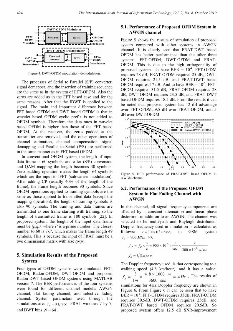
5.1. Performance of Proposed OFDM System in
AWGN channel
Figure 5 shows the results of simulation of proposed
system compared with other systems in AWGN
channel. It is clearly seen that FRAT-DWT based
OFDM has better performance than the other three
systems: FFT-OFDM, DWT-OFDM and FRAT-
OFDM. This is due to the high orthogonality of
proposed system. To have BER = 10-4, FFT-OFDM
requires 28 dB, FRAT-OFDM requires 25 dB, DWT-
OFDM requires 21.5 dB, and FRAT-DWT based
OFDM requires 17 dB. And to have BER = 10-5, FFT-
OFDM requires 31.5 dB, FRAT-OFDM requires 28
dB, DWT-OFDM requires 23.5 dB, and FRAT-DWT
based OFDM requires 18.5 dB. From the results it can
be noted that proposed system has 12 dB advantage
over FFT-OFDM, 9.5 dB over FRAT-OFDM, and 5
dB over DWT-OFDM.
0 5 10 15 20 25 30 35 40
10-4
10-3
10-2
10-1
100
BER
SNR
FFT- OFDMFRAT - OFDMDWT - OFDMRadon-DWT - OFDM
Figure 5. BER performance of FRAT-DWT based OFDM in
AWGN channel.
5.2. Performance of the Proposed OFDM
System in Flat Fading Channel with
AWGN
In this channel, all signal frequency components are
affected by a constant attenuation and linear phase
distortion, in addition to an AWGN. The channel was
selected to be multi-path and Rayleigh distributed.
Doppler frequency used in simulation is calculated as
follows: sec/10300 6mc ×= , in GSM system
MHzf c 900= so,
sec8
6
10300sec
110900
mcd
v
c
vff
×××=×= ×
vmf d ×= )1(3
The Doppler frequency used, is that corresponding to a
walking speed (4.8 km/hour), and it has a value:
Hzm
mfd
4sec3600
10008.4
1
3=
××= , The results of
simulations for 4Hz Doppler frequency are shown in
Figure 6. From Figure 6 it can be seen that to have
BER = 10-5, FFT-OFDM requires 33dB, FRAT-OFDM
requires 30.5dB, DWT-OFDM requires 25dB, and
FRAT-DWT based OFDM requires 20.5dB. So
proposed system offers 12.5 dB SNR-improvement
A Novel Radon-Wavelet Based OFDM System Design and Performance under Different Channel Conditions 425
compared with FFT-OFDM, 10 dB compared with
FRAT-OFDM, and 4.5dB compared with DWT-
OFDM for this channel model. Other Doppler-Shift
frequencies were used for proposed system simulation
over the flat fading Rayleigh channel; the values used
are 80Hz corresponding to car speed (96 km/hour),
300Hz corresponding to Helicopter speed (360
km/hour), and 500Hz corresponding to airplane speed
(600 km/hour), and the same results were obtained for
these frequencies. The reason for best performance
results of FRAT-DWT based OFDM is the good
orthogonality of Radon transform and the excellent
orthogonality of DWT.
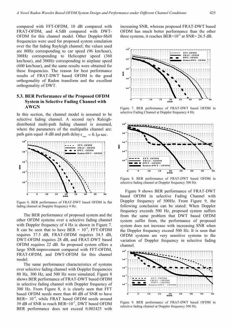
5.3. BER Performance of the Proposed OFDM
System in Selective Fading Channel with
AWGN
In this section, the channel model is assumed to be
selective fading channel. A second ray's Raleigh-
distributed multi-path fading channel is assumed,
where the parameters of the multipaths channel are:
path gain equal -8 dB and path delay sec1.0max
µτ = .
0 5 10 15 20 25 30 35 40
10-4
10-3
10-2
10-1
100
BER
SNR
FFT- OFDM
FRAT - OFDMDWT - OFDM
Radon-DWT - OFDM
Figure 6. BER performance of FRAT-DWT based OFDM in flat fading channel at Doppler frequency 4 Hz.
The BER performance of proposed system and the
other OFDM systems over a selective fading channel
with Doppler frequency of 4 Hz is shown in Figure 7.
It can be seen that to have BER = 10-5, FFT-OFDM
requires 37.5 dB, FRAT-OFDM requires 34.5 dB,
DWT-OFDM requires 28 dB, and FRAT-DWT based
OFDM requires 22 dB. So proposed system offers a
large SNR-improvement compared with FFT-OFDM,
FRAT-OFDM, and DWT-OFDM for this channel
model.
The same performance characteristics of systems
over selective fading channel with Doppler frequencies
80 Hz, 300 Hz, and 500 Hz were simulated. Figure 8
shows BER performance of FRAT-DWT based OFDM
in selective fading channel with Doppler frequency of
300 Hz. From Figure 8, it is clearly seen that FFT
based OFDM needs more than 40 dB of SNR to have
BER= 10-4, while FRAT based OFDM needs around
39 dB of SNR to reach BER=10-5, DWT based OFDM
BER performance does not exceed 0.002425 with
increasing SNR, whereas proposed FRAT-DWT based
OFDM has much better performance than the other
three systems, it reaches BER=10-5 at SNR= 26.5 dB.
0 5 10 15 20 25 30 35 40
10-4
10-3
10-2
10-1
100
BER
SNR
FFT- OFDMFRAT - OFDMDWT - OFDM
Radon-DWT - OFDM
Figure 7. BER performance of FRAT-DWT based OFDM in
selective Fading Channel at Doppler frequency 4 Hz.
0 5 10 15 20 25 30 35 40
10-4
10-3
10-2
10-1
100
BER
SNR
FFT- OFDM
FRAT - OFDM
DWT - OFDM
Radon-DWT - OFDM
Figure 8. BER performance of FRAT-DWT based OFDM in
selective fading channel at Doppler frequency 300 Hz.
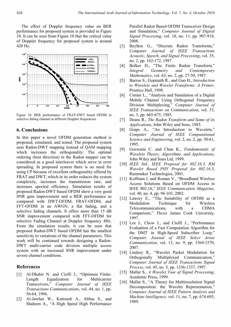
Figure 9 shows BER performance of FRAT-DWT
based OFDM in selective Fading Channel with
Doppler frequency of 500Hz. From Figure 9, the
following conclusion can be stated: When Doppler
frequency exceeds 500 Hz, proposed system suffers
from the same problem that DWT based OFDM
system suffer from, the performance of proposed
system does not increase with increasing SNR when
the Doppler frequency exceed 500 Hz. It is seen that
OFDM systems are very sensitive systems to the
variation of Doppler frequency in selective fading
channel.
0 5 10 15 20 25 30 35 40
10-4
10-3
10-2
10-1
100
SNR
FFT- OFDM
FRAT - OFDMDWT - OFDM
Radon-DWT - OFDM
Figure 9. BER performance of FRAT-DWT based OFDM in selective fading channel at Doppler frequency 500 Hz.
426 The International Arab Journal of Information Technology, Vol. 7, No. 4, October 2010
The effect of Doppler frequency value on BER
performance for proposed system is provided in Figure
10. It can be seen from Figure 10 that the critical value
of Doppler frequency for proposed system is around
420 Hz.
0 5 10 15 20 25 30 35 40
10-4
10-3
10-2
10-1
100
BER
SNR
4Hz
80Hz
415Hz
500Hz
410Hz
Figure 10. BER performance of FRAT-DWT based OFDM in
selective fading channel at different Doppler frequencies.
6. Conclusions
In this paper a novel OFDM generation method is
proposed, simulated, and tested. The proposed system
uses Radon-DWT mapping instead of QAM mapping
which increases the orthogonality. The optimal
ordering (best direction) in the Radon mapper can be
considered as a good interleaver which serve in error
spreading. In proposed system there is no need for
using CP because of excellent orthogonality offered by
FRAT and DWT, which in its order reduces the system
complexity, increases the transmission rate, and
increases spectral efficiency. Simulation results of
proposed Radon-DWT based OFDM show a very good
SNR gain improvement and a BER performance as
compared with DWT-OFDM, FRAT-OFDM, and
FFT-OFDM in an AWGN, a flat fading, and a
selective fading channels. It offers more than 15 dB
SNR improvement compared with FFT-OFDM for
selective Fading Channel at Doppler frequency 4Hz.
From the simulation results, it can be seen that
proposed Radon-DWT based OFDM has the smallest
sensitivity to variations of the channel parameters. This
work will be continued towards designing a Radon-
DWT multi-carrier code division multiple access
system with an increased SNR improvement under
severe channel conditions.
References
[1] Al-Dhahir N. and Cioffi J., “Optimum Finite-
Length Equalization for Multicarrier
Transceivers,” Computer Journal of IEEE
Transactions Communications, vol. 44, no. 1, pp.
56-64, 1996.
[2] Al-Jawhar W., Kattoush A., Abbas S., and
Shaheen A., “A High Speed High Performance
Parallel Radon Based OFDM Transceiver Design
and Simulation,” Computer Journal of Digital
Signal Processing, vol. 18, no. 11, pp. 907-918,
2008.
[3] Beylkin G., “Discrete Radon Transforms,”
Computer Journal of IEEE Transactions
Acoustic, Speech, and Signal Processing, vol. 35,
no. 2, pp. 162-172, 1987.
[4] Bolker D., “The Finite Radon Transform,”
Integral Geometry and Contemporary
Mathematics, vol. 63, no. 2, pp. 27-50, 1987.
[5] Burrus S., Gopinath R., and Guo H., Introduction
to Wavelets and Wavelet Transforms: A Primer,
Prentice Hall, 1998.
[6] Cimini L., “Analysis and Simulation of a Digital
Mobile Channel Using Orthogonal Frequency
Division Multiplexing,” Computer Journal of
IEEE Transactions on Communication, vol. 33,
no. 3, pp. 665-675, 1985.
[7] Deans R., The Radon Transform and Some of its
Applications, John Wiley and Sons, 1983.
[8] Graps A., “An Introduction to Wavelets,”
Computer Journal of IEEE Computational
Science and Engineering, vol. 2, no. 2, pp. 50-61,
1995.
[9] Goswami C. and Chan K., Fundamentals of
Wavelets Theory, Algorithms, and Applications,
John Wiley and Sons Ltd, 1999.
[10] IEEE Std., IEEE Proposal for 802.16.3, RM
Wavelet Based PHY Proposal for 802.16.3,
Rainmaker Technologies, 2001.
[11] Koffman I. and Roman V., “Broadband Wireless
Access Solutions Based on OFDM Access in
IEEE 802.16,” IEEE Communication Magazine,
vol. 40, no. 4, pp. 96-103, 2002.
[12] Lawrey E., “The Suitability of OFDM as a
Modulation Technique for Wireless
Telecommunications, with a CDMA
Comparison,” Thesis James Cook University,
1997.
[13] Lee I., Chow J., and Cioffi J., “Performance
Evaluation of a Fast Computation Algorithm for
the DMT in High-Speed Subscriber Loop,”
Computer Journal of IEEE Select Areas
Communication, vol. 13, no. 9, pp. 1564-1570,
2007.
[14] Lindsey R., “Wavelet Packet Modulation for
Orthogonally Multiplexed Communication,”
Computer Journal of IEEE Transactions Signal
Process, vol. 45, no. 5, pp. 1336-1337, 1997.
[15] Mallat S., A Wavelet Tour of Signal Processing,
Academic Press, 1999.
[16] Mallat S., “A Theory for Multiresolution Signal
Decomposition: the Wavelet Representation,”
Computer Journal of IEEE Pattern Analysis and
Machine Intelligence, vol. 11, no. 7, pp. 674-693,
1989.
A Novel Radon-Wavelet Based OFDM System Design and Performance under Different Channel Conditions 427
[17] Minh N. and Martin V., “The Finite Ridgelet
Transform for Image Representation,” Computer
Journal of IEEE Transactions Image Processing,
vol. 12, no. 1, pp. 16-28, 2003.
[18] Mohammed J., “VIDEO Image Compression
Based on Multiwavelets Transform,” PhD
Thesis, University of Baghdad, 2004.
[19] Nee V. and Prasad R., OFDM for Wireless
Multimedia Communications, Artech House,
2000.
[20] Nghi H., Ha H., and Le-Ngoc T., “Bit-
Interleaved Coded OFDM with Signal Space
Diversity: Subcarrier Grouping and Rotation
Matrix Design,” Computer Journal of IEEE
Transactions on Signal Processing, vol. 55, no.
3, pp. 1137-1149, 2007.
[21] Prasad R., OFDM for Wireless Communications
Systems, Artech House Publishers, 2004.
[22] Proakis G., Digital Communications, McGraw
Hill, 2001.
[23] Resnikoff L., Raymond J., and Wells O., Wavelet
Analysis, The Scalable Structure of Information,
Springer, 1998.
[24] SeungWon K. and KyungHi C., “A Novel
Channel Estimation Scheme for OFDM/OQAM-
IOTA System,” Computer Journal of Electronics
and Telecommunications Research Institute, vol.
29, no. 4, pp. 430-436, 2007.
[25] Weinstein S. and Ebert P., “Data Transmission
by Frequency Division Multiplexing Using the
Discrete Fourier Transform,” Computer Journal
of IEEE Transactions Communications Tech,
vol. 19, no. 3, pp. 628-634, 1971.
[26] Won G., Kyung C., and Yong C., “An
Equalization Technique for Orthogonal
Frequency Division Multiplexing Systems in
Time-Variant Multipath Channels,” Computer
Journal of IEEE Transactions on
Communications, vol. 47, no. 1, pp. 27-32, 1999.
[27] Zhang X., Xu P., Zhang G., and Bi G., “Study on
Complex Wavelet Packet Based OFDM
Modulation,” Computer Journal of ACTA
Electron, vol. 30, no. 4, pp. 476-479, 2002.
[28] Zhang H., Yuan D., Jiang M., and Wu D.,
“Research of DFT-OFDM and DWT-OFDM on
Different Transmission Scenarios,” in
Proceedings of IEEE ICITA’2004, China, pp.
125- 127, 2004.
[29] Zhang H., Dongfeng Y., Matthias P., “Novel
Study on PAPRs Reduction in Wavelet-Based
Multicarrier Modulation Systems,” Computer
Journal of Elsevier Digital Signal Processing,
vol. 17, no. 3, pp. 272-279, 2007.
Abbas Kattoush received his MS
and PhD degrees in communication
engineering from USSR in 1979 and
1984, respectively. For 10 years he
was a technical manager of a leading
SAKHER computers company. He
was a pioneer in computer
networking and software engineering in Jordan. From
1993 to 2000 he worked at Applied Science University
Amman Jordan where he was a founding member of
the Department of Electrical and Computer
Engineering. From 2000 to 2008 he was an associate
professor at Electrical and Computer Engineering
Department at Al-Isra University, Amman-Jordan.


95 The International Arab Journal of Information Technology, Vol. 7, No. 4, October 2010


